EP2776603B1 - PASSIVATION, pH PROTECTIVE OR LUBRICITY COATING FOR PHARMACEUTICAL PACKAGE, COATING PROCESS AND APPARATUS - Google Patents
PASSIVATION, pH PROTECTIVE OR LUBRICITY COATING FOR PHARMACEUTICAL PACKAGE, COATING PROCESS AND APPARATUS Download PDFInfo
- Publication number
- EP2776603B1 EP2776603B1 EP12848314.6A EP12848314A EP2776603B1 EP 2776603 B1 EP2776603 B1 EP 2776603B1 EP 12848314 A EP12848314 A EP 12848314A EP 2776603 B1 EP2776603 B1 EP 2776603B1
- Authority
- EP
- European Patent Office
- Prior art keywords
- injection
- coating
- passivation layer
- layer
- pharmaceutical package
- Prior art date
- Legal status (The legal status is an assumption and is not a legal conclusion. Google has not performed a legal analysis and makes no representation as to the accuracy of the status listed.)
- Active
Links
Images




Classifications
-
- B—PERFORMING OPERATIONS; TRANSPORTING
- B65—CONVEYING; PACKING; STORING; HANDLING THIN OR FILAMENTARY MATERIAL
- B65D—CONTAINERS FOR STORAGE OR TRANSPORT OF ARTICLES OR MATERIALS, e.g. BAGS, BARRELS, BOTTLES, BOXES, CANS, CARTONS, CRATES, DRUMS, JARS, TANKS, HOPPERS, FORWARDING CONTAINERS; ACCESSORIES, CLOSURES, OR FITTINGS THEREFOR; PACKAGING ELEMENTS; PACKAGES
- B65D25/00—Details of other kinds or types of rigid or semi-rigid containers
- B65D25/14—Linings or internal coatings
-
- A—HUMAN NECESSITIES
- A61—MEDICAL OR VETERINARY SCIENCE; HYGIENE
- A61M—DEVICES FOR INTRODUCING MEDIA INTO, OR ONTO, THE BODY; DEVICES FOR TRANSDUCING BODY MEDIA OR FOR TAKING MEDIA FROM THE BODY; DEVICES FOR PRODUCING OR ENDING SLEEP OR STUPOR
- A61M5/00—Devices for bringing media into the body in a subcutaneous, intra-vascular or intramuscular way; Accessories therefor, e.g. filling or cleaning devices, arm-rests
- A61M5/178—Syringes
- A61M5/31—Details
- A61M5/3129—Syringe barrels
-
- B—PERFORMING OPERATIONS; TRANSPORTING
- B65—CONVEYING; PACKING; STORING; HANDLING THIN OR FILAMENTARY MATERIAL
- B65D—CONTAINERS FOR STORAGE OR TRANSPORT OF ARTICLES OR MATERIALS, e.g. BAGS, BARRELS, BOTTLES, BOXES, CANS, CARTONS, CRATES, DRUMS, JARS, TANKS, HOPPERS, FORWARDING CONTAINERS; ACCESSORIES, CLOSURES, OR FITTINGS THEREFOR; PACKAGING ELEMENTS; PACKAGES
- B65D25/00—Details of other kinds or types of rigid or semi-rigid containers
- B65D25/02—Internal fittings
- B65D25/04—Partitions
-
- C—CHEMISTRY; METALLURGY
- C23—COATING METALLIC MATERIAL; COATING MATERIAL WITH METALLIC MATERIAL; CHEMICAL SURFACE TREATMENT; DIFFUSION TREATMENT OF METALLIC MATERIAL; COATING BY VACUUM EVAPORATION, BY SPUTTERING, BY ION IMPLANTATION OR BY CHEMICAL VAPOUR DEPOSITION, IN GENERAL; INHIBITING CORROSION OF METALLIC MATERIAL OR INCRUSTATION IN GENERAL
- C23C—COATING METALLIC MATERIAL; COATING MATERIAL WITH METALLIC MATERIAL; SURFACE TREATMENT OF METALLIC MATERIAL BY DIFFUSION INTO THE SURFACE, BY CHEMICAL CONVERSION OR SUBSTITUTION; COATING BY VACUUM EVAPORATION, BY SPUTTERING, BY ION IMPLANTATION OR BY CHEMICAL VAPOUR DEPOSITION, IN GENERAL
- C23C16/00—Chemical coating by decomposition of gaseous compounds, without leaving reaction products of surface material in the coating, i.e. chemical vapour deposition [CVD] processes
- C23C16/04—Coating on selected surface areas, e.g. using masks
- C23C16/045—Coating cavities or hollow spaces, e.g. interior of tubes; Infiltration of porous substrates
-
- C—CHEMISTRY; METALLURGY
- C23—COATING METALLIC MATERIAL; COATING MATERIAL WITH METALLIC MATERIAL; CHEMICAL SURFACE TREATMENT; DIFFUSION TREATMENT OF METALLIC MATERIAL; COATING BY VACUUM EVAPORATION, BY SPUTTERING, BY ION IMPLANTATION OR BY CHEMICAL VAPOUR DEPOSITION, IN GENERAL; INHIBITING CORROSION OF METALLIC MATERIAL OR INCRUSTATION IN GENERAL
- C23C—COATING METALLIC MATERIAL; COATING MATERIAL WITH METALLIC MATERIAL; SURFACE TREATMENT OF METALLIC MATERIAL BY DIFFUSION INTO THE SURFACE, BY CHEMICAL CONVERSION OR SUBSTITUTION; COATING BY VACUUM EVAPORATION, BY SPUTTERING, BY ION IMPLANTATION OR BY CHEMICAL VAPOUR DEPOSITION, IN GENERAL
- C23C16/00—Chemical coating by decomposition of gaseous compounds, without leaving reaction products of surface material in the coating, i.e. chemical vapour deposition [CVD] processes
- C23C16/22—Chemical coating by decomposition of gaseous compounds, without leaving reaction products of surface material in the coating, i.e. chemical vapour deposition [CVD] processes characterised by the deposition of inorganic material, other than metallic material
- C23C16/30—Deposition of compounds, mixtures or solid solutions, e.g. borides, carbides, nitrides
-
- C—CHEMISTRY; METALLURGY
- C23—COATING METALLIC MATERIAL; COATING MATERIAL WITH METALLIC MATERIAL; CHEMICAL SURFACE TREATMENT; DIFFUSION TREATMENT OF METALLIC MATERIAL; COATING BY VACUUM EVAPORATION, BY SPUTTERING, BY ION IMPLANTATION OR BY CHEMICAL VAPOUR DEPOSITION, IN GENERAL; INHIBITING CORROSION OF METALLIC MATERIAL OR INCRUSTATION IN GENERAL
- C23C—COATING METALLIC MATERIAL; COATING MATERIAL WITH METALLIC MATERIAL; SURFACE TREATMENT OF METALLIC MATERIAL BY DIFFUSION INTO THE SURFACE, BY CHEMICAL CONVERSION OR SUBSTITUTION; COATING BY VACUUM EVAPORATION, BY SPUTTERING, BY ION IMPLANTATION OR BY CHEMICAL VAPOUR DEPOSITION, IN GENERAL
- C23C16/00—Chemical coating by decomposition of gaseous compounds, without leaving reaction products of surface material in the coating, i.e. chemical vapour deposition [CVD] processes
- C23C16/22—Chemical coating by decomposition of gaseous compounds, without leaving reaction products of surface material in the coating, i.e. chemical vapour deposition [CVD] processes characterised by the deposition of inorganic material, other than metallic material
- C23C16/30—Deposition of compounds, mixtures or solid solutions, e.g. borides, carbides, nitrides
- C23C16/36—Carbonitrides
-
- C—CHEMISTRY; METALLURGY
- C23—COATING METALLIC MATERIAL; COATING MATERIAL WITH METALLIC MATERIAL; CHEMICAL SURFACE TREATMENT; DIFFUSION TREATMENT OF METALLIC MATERIAL; COATING BY VACUUM EVAPORATION, BY SPUTTERING, BY ION IMPLANTATION OR BY CHEMICAL VAPOUR DEPOSITION, IN GENERAL; INHIBITING CORROSION OF METALLIC MATERIAL OR INCRUSTATION IN GENERAL
- C23C—COATING METALLIC MATERIAL; COATING MATERIAL WITH METALLIC MATERIAL; SURFACE TREATMENT OF METALLIC MATERIAL BY DIFFUSION INTO THE SURFACE, BY CHEMICAL CONVERSION OR SUBSTITUTION; COATING BY VACUUM EVAPORATION, BY SPUTTERING, BY ION IMPLANTATION OR BY CHEMICAL VAPOUR DEPOSITION, IN GENERAL
- C23C16/00—Chemical coating by decomposition of gaseous compounds, without leaving reaction products of surface material in the coating, i.e. chemical vapour deposition [CVD] processes
- C23C16/22—Chemical coating by decomposition of gaseous compounds, without leaving reaction products of surface material in the coating, i.e. chemical vapour deposition [CVD] processes characterised by the deposition of inorganic material, other than metallic material
- C23C16/30—Deposition of compounds, mixtures or solid solutions, e.g. borides, carbides, nitrides
- C23C16/40—Oxides
- C23C16/401—Oxides containing silicon
-
- C—CHEMISTRY; METALLURGY
- C23—COATING METALLIC MATERIAL; COATING MATERIAL WITH METALLIC MATERIAL; CHEMICAL SURFACE TREATMENT; DIFFUSION TREATMENT OF METALLIC MATERIAL; COATING BY VACUUM EVAPORATION, BY SPUTTERING, BY ION IMPLANTATION OR BY CHEMICAL VAPOUR DEPOSITION, IN GENERAL; INHIBITING CORROSION OF METALLIC MATERIAL OR INCRUSTATION IN GENERAL
- C23C—COATING METALLIC MATERIAL; COATING MATERIAL WITH METALLIC MATERIAL; SURFACE TREATMENT OF METALLIC MATERIAL BY DIFFUSION INTO THE SURFACE, BY CHEMICAL CONVERSION OR SUBSTITUTION; COATING BY VACUUM EVAPORATION, BY SPUTTERING, BY ION IMPLANTATION OR BY CHEMICAL VAPOUR DEPOSITION, IN GENERAL
- C23C16/00—Chemical coating by decomposition of gaseous compounds, without leaving reaction products of surface material in the coating, i.e. chemical vapour deposition [CVD] processes
- C23C16/44—Chemical coating by decomposition of gaseous compounds, without leaving reaction products of surface material in the coating, i.e. chemical vapour deposition [CVD] processes characterised by the method of coating
- C23C16/50—Chemical coating by decomposition of gaseous compounds, without leaving reaction products of surface material in the coating, i.e. chemical vapour deposition [CVD] processes characterised by the method of coating using electric discharges
- C23C16/505—Chemical coating by decomposition of gaseous compounds, without leaving reaction products of surface material in the coating, i.e. chemical vapour deposition [CVD] processes characterised by the method of coating using electric discharges using radio frequency discharges
- C23C16/507—Chemical coating by decomposition of gaseous compounds, without leaving reaction products of surface material in the coating, i.e. chemical vapour deposition [CVD] processes characterised by the method of coating using electric discharges using radio frequency discharges using external electrodes, e.g. in tunnel type reactors
-
- A—HUMAN NECESSITIES
- A61—MEDICAL OR VETERINARY SCIENCE; HYGIENE
- A61J—CONTAINERS SPECIALLY ADAPTED FOR MEDICAL OR PHARMACEUTICAL PURPOSES; DEVICES OR METHODS SPECIALLY ADAPTED FOR BRINGING PHARMACEUTICAL PRODUCTS INTO PARTICULAR PHYSICAL OR ADMINISTERING FORMS; DEVICES FOR ADMINISTERING FOOD OR MEDICINES ORALLY; BABY COMFORTERS; DEVICES FOR RECEIVING SPITTLE
- A61J1/00—Containers specially adapted for medical or pharmaceutical purposes
- A61J1/05—Containers specially adapted for medical or pharmaceutical purposes for collecting, storing or administering blood, plasma or medical fluids ; Infusion or perfusion containers
-
- A—HUMAN NECESSITIES
- A61—MEDICAL OR VETERINARY SCIENCE; HYGIENE
- A61M—DEVICES FOR INTRODUCING MEDIA INTO, OR ONTO, THE BODY; DEVICES FOR TRANSDUCING BODY MEDIA OR FOR TAKING MEDIA FROM THE BODY; DEVICES FOR PRODUCING OR ENDING SLEEP OR STUPOR
- A61M5/00—Devices for bringing media into the body in a subcutaneous, intra-vascular or intramuscular way; Accessories therefor, e.g. filling or cleaning devices, arm-rests
- A61M5/178—Syringes
- A61M5/31—Details
- A61M2005/3103—Leak prevention means for distal end of syringes, i.e. syringe end for mounting a needle
- A61M2005/3107—Leak prevention means for distal end of syringes, i.e. syringe end for mounting a needle for needles
- A61M2005/3109—Caps sealing the needle bore by use of, e.g. air-hardening adhesive, elastomer or epoxy resin
-
- A—HUMAN NECESSITIES
- A61—MEDICAL OR VETERINARY SCIENCE; HYGIENE
- A61M—DEVICES FOR INTRODUCING MEDIA INTO, OR ONTO, THE BODY; DEVICES FOR TRANSDUCING BODY MEDIA OR FOR TAKING MEDIA FROM THE BODY; DEVICES FOR PRODUCING OR ENDING SLEEP OR STUPOR
- A61M5/00—Devices for bringing media into the body in a subcutaneous, intra-vascular or intramuscular way; Accessories therefor, e.g. filling or cleaning devices, arm-rests
- A61M5/178—Syringes
- A61M5/31—Details
- A61M5/3129—Syringe barrels
- A61M2005/3131—Syringe barrels specially adapted for improving sealing or sliding
Definitions
- the present invention relates to the technical field of coated surfaces, for example interior surfaces of pharmaceutical packages
- the present invention relates to a pharmaceutical package.
- a method for coating an inner or interior surface of a pharmaceutical package is also described.
- the present disclosure also relates to improved methods for processing pharmaceutical packages, for example multiple identical pharmaceutical packages or other vessels used for pharmaceutical preparation storage and delivery, venipuncture and other medical sample collection.
- Such pharmaceutical packages are used in large numbers for these purposes, and must be relatively economical to manufacture and yet highly reliable in storage and use.
- borosilicate glass vessels such as vials or pre-filled syringes.
- the relatively strong, impermeable and inert surface of borosilicate glass has performed adequately for most drug products.
- the recent advent of costly, complex and sensitive biologics as well as such advanced delivery systems as auto injectors has exposed the physical and chemical shortcomings of glass pharmaceutical packages, including possible contamination from metals, flaking, delamination, and breakage, among other problems.
- glass contains several components which can leach out during storage and cause damage to the stored material.
- borosilicate pharmaceutical packages exhibit a number of drawbacks.
- Glass is manufactured from sand containing a heterogeneous mixture of many elements (silicon, oxygen, boron, aluminum, sodium, calcium) with trace levels of other alkali and earth metals.
- Type I borosilicate glass consists of approximately 76% SiO 2 , 10.5% B 2 O 3 , 5% Al 2 O 3 , 7% Na 2 O and 1.5% CaO and often contains trace metals such as iron, magnesium, zinc, copper and others.
- the heterogeneous nature of borosilicate glass creates a non-uniform surface chemistry at the molecular level. Glass forming processes used to create glass vessels expose some portions of the vessels to temperatures as great as 1200°C. Under such high temperatures alkali ions migrate to the local surface and form oxides.
- ions extracted from borosilicate glass devices may be involved in degradation, aggregation and denaturation of some biologics.
- Many proteins and other biologics must be lyophilized (freeze dried), because they are not sufficiently stable in solution in glass vials or syringes.
- silicone oil is typically used as a lubricant to allow the plunger tip, piston, stopper, or seal to slide in the barrel.
- Silicone oil has been implicated in the precipitation of protein solutions such as insulin and some other biologics. Additionally, the silicone oil coating or layer is often non-uniform, resulting in syringe failures in the market.
- Glass pharmaceutical packages are prone to breakage or degradation during manufacture, filling operations, shipping and use, which means that glass particulates may enter the drug.
- the presence of glass particles has led to many FDA Warning Letters and to product recalls.
- plastic and glass pharmaceutical packages each offer certain advantages in pharmaceutical primary packaging, neither is optimal for all drugs, biologics or other therapeutics.
- plastic pharmaceutical packages in particular plastic syringes, with gas and solute barrier properties which approach the properties of glass.
- plastic syringes with sufficient lubricity and/or passivation or protective properties and a lubricity and/or passivation layer or pH protective coating which can be compatible with the syringe contents.
- glass vessels with surfaces that do not tend to delaminate or dissolve or leach constituents when in contact with the vessel contents.
- Prefilled syringes are commonly prepared and sold so the syringe does not need to be filled before use, and can be disposed of after use.
- the syringe can be prefilled with saline solution, a dye for injection, or a pharmaceutically active preparation, for some examples.
- the prefilled syringe can be capped at the distal end, as with a cap (or, if the hypodermic needle is preinstalled, a needle shield that can also be a cap), and can be closed at the proximal end by its drawn plunger tip, piston, stopper, or seal.
- the prefilled syringe can be wrapped in a sterile package before use.
- a hypodermic needle or another delivery conduit can be attached to the distal end of the barrel, the delivery conduit or syringe can be moved to a use position (such as by inserting the hypodermic needle into a patient's blood vessel or into an apparatus to be rinsed with the contents of the syringe), and the plunger tip, piston, stopper, or seal can be advanced in the barrel to inject the contents of the barrel.
- An important consideration regarding medical syringes can be to ensure that the plunger tip, piston, stopper, or seal can move at a constant speed and with a constant force when it is pressed into the barrel.
- a similar consideration applies to vessels such as pharmaceutical vials which have to be closed by a stopper, and to the stopper itself, and more generally to any surface which is to provide smooth operation of moving parts and/or be passivated or protectively coated.
- DE 10 2004 017236 A1 describes a vessel made from a polymer substrate coated with an organic bonding layer, an inorganic barrier layer, and an organic protective layer.
- An aspect of the invention is a pharmaceutical package comprising a vessel, a barrier coating or layer, and a passivation layer or pH protective coating on the vessel.
- a fluid composition may be contained in the vessel.
- the calculated shelf life of the package containing the fluid composition can be more than six months at a storage temperature of 4°C.
- the vessel has a lumen defined at least in part by a wall.
- the wall has an interior surface facing the lumen and an outer surface.
- the barrier coating or layer is made of SiO x , wherein x is from 1.5 to 2.9, from 2 to 1000 nm thick.
- the barrier coating or layer of SiO x has an interior surface facing the lumen and an outer surface facing the wall interior surface.
- the passivation layer or pH protective coating is made of SiO x C y or SiN x C y wherein x is from 0.5 to 2.4 and y is from 0.6 to 3.
- x can be about 1.1 and y can be about 1.1.
- the passivation layer or pH protective coating has an interior surface facing the lumen and an outer surface facing the interior surface of the barrier coating or layer. The passivation layer or pH protective coating is effective to increase the calculated shelf life of the package (total Si / Si dissolution rate).
- the fluid composition can be contained in the lumen and can have a pH between 4 and 10, alternatively between 5 and 9.
- RF is radio frequency
- First and “second” or similar references to, for example, processing stations or processing devices refer to the minimum number of processing stations or devices that are present, but do not necessarily represent the order or total number of processing stations and devices. These terms do not limit the number of processing stations or the particular processing carried out at the respective stations.
- an "organosilicon precursor” is a compound having at least one of the linkages: or which is a tetravalent silicon atom connected to an oxygen or nitrogen atom and an organic carbon atom (an organic carbon atom being a carbon atom bonded to at least one hydrogen atom).
- a volatile organosilicon precursor defined as such a precursor that can be supplied as a vapor in a PECVD apparatus, can be an optional organosilicon precursor.
- the organosilicon precursor can be selected from the group consisting of a linear siloxane, a monocyclic siloxane, a polycyclic siloxane, a polysilsesquioxane, an alkyl trimethoxysilane, a linear silazane, a monocyclic silazane, a polycyclic silazane, a polysilsesquiazane, and a combination of any two or more of these precursors.
- the feed amounts of PECVD precursors, gaseous reactant or process gases, and carrier gas are sometimes expressed in "standard volumes" in the specification and claims.
- the standard volume of a charge or other fixed amount of gas is the volume the fixed amount of the gas would occupy at a standard temperature and pressure (without regard to the actual temperature and pressure of delivery).
- Standard volumes can be measured using different units of volume, and still be within the scope of the present disclosure and claims.
- the same fixed amount of gas could be expressed as the number of standard cubic centimeters, the number of standard cubic meters, or the number of standard cubic feet.
- Standard volumes can also be defined using different standard temperatures and pressures, and still be within the scope of the present disclosure and claims.
- the standard temperature might be 0°C and the standard pressure might be 760 Torr (as is conventional), or the standard temperature might be 20°C and the standard pressure might be 1 Torr. But whatever standard is used in a given case, when comparing relative amounts of two or more different gases without specifying particular parameters, the same units of volume, standard temperature, and standard pressure are to be used relative to each gas, unless otherwise indicated.
- the corresponding feed rates of PECVD precursors, gaseous reactant or process gases, and carrier gas are expressed in standard volumes per unit of time in the specification.
- the flow rates are expressed as standard cubic centimeters per minute, abbreviated as sccm.
- other units of time can be used, such as seconds or hours, but consistent parameters are to be used when comparing the flow rates of two or more gases, unless otherwise indicated.
- a "vessel" in the context of the present invention can be any type of article with at least one opening and a wall defining an inner or interior surface.
- the substrate can be the inside wall of a vessel having a lumen.
- the invention is not necessarily limited to pharmaceutical packages of a particular volume, pharmaceutical packages are contemplated in which the lumen can have a void volume of from 0.5 to 50 mL, optionally from 1 to 10 mL, optionally from 0.5 to 5 mL, optionally from 1 to 3 mL.
- the substrate surface can be part or all of the inner or interior surface of a vessel having at least one opening and an inner or interior surface.
- a vessel in the context of the present invention can have one or more openings.
- One or two openings like the openings of a sample tube (one opening) or a syringe barrel (two openings) are preferred. If the vessel has two openings, they can be the same size or different sizes. If there is more than one opening, one opening can be used for the gas inlet for a PECVD coating method, while the other openings are either capped or open.
- a vessel according to the present invention can be a sample tube, for example for collecting or storing biological fluids like blood or urine, a syringe (or a part thereof, for example a syringe barrel) for storing or delivering a biologically active compound or composition, for example a medicament or pharmaceutical composition, a vial for storing biological materials or biologically active compounds or compositions, a pipe, for example a catheter for transporting biological materials or biologically active compounds or compositions, or a cuvette for holding fluids, for example for holding biological materials or biologically active compounds or compositions.
- a sample tube for example for collecting or storing biological fluids like blood or urine
- a syringe or a part thereof, for example a syringe barrel
- a biologically active compound or composition for example a medicament or pharmaceutical composition
- a vial for storing biological materials or biologically active compounds or compositions
- a pipe for example a catheter for transporting biological materials or biologically active compounds or compositions
- the vessel can be provided with a reagent or preservative for sample collection or analysis.
- a vessel for blood can contain a compound or composition in its lumen, for example citrate or a citrate containing composition.
- a vessel can be of any shape, a vessel having a substantially cylindrical wall adjacent to at least one of its open ends being preferred.
- the interior wall of the vessel can be cylindrically shaped, like, for example in a sample tube or a syringe barrel. Sample tubes and syringes or their parts (for example syringe barrels) are contemplated.
- a “hydrophobic layer” in the context of the present invention means that the coating or layer lowers the wetting tension of a surface coated with the coating or layer, compared to the corresponding uncoated surface. Hydrophobicity can be thus a function of both the uncoated substrate and the coating or layer. The same applies with appropriate alterations for other contexts wherein the term “hydrophobic” is used.
- the term “hydrophilic” means the opposite, i.e. that the wetting tension is increased compared to a reference sample.
- the present hydrophobic layers are primarily defined by their hydrophobicity and the process conditions providing hydrophobicity. Suitable hydrophobic coatings or layers and their application, properties, and use are described in U.S. Patent No. 7,985,188 . Dual functional passivation layers or pH protective coatings that also have the properties of hydrophobic coatings or layers can be provided for any embodiment of the present invention.
- w, x, y, and z are applicable to the empirical composition Si w O x C y H z throughout this specification.
- the values of w, x, y, and z used throughout this specification should be understood as ratios or an empirical formula (for example for a coating or layer), rather than as a limit on the number or type of atoms in a molecule.
- octamethylcyclotetrasiloxane which has the molecular composition Si 4 O 4 C 8 H 24 , can be described by the following empirical formula, arrived at by dividing each of w, x, y, and z in the molecular formula by 4, the largest common factor: Si 1 O 1 C 2 H 6 .
- w, x, y, and z are also not limited to integers.
- (acyclic) octamethyltrisiloxane, molecular composition Si 3 O 2 C 8 H 24 is reducible to Si 1 O 0.67 C 2.67 H 8 .
- SiO x C y H z can be described as equivalent to SiO x C y , it is not necessary to show the presence of hydrogen in any proportion to show the presence of SiO x C y .
- wetting tension is a specific measure for the hydrophobicity or hydrophilicity of a surface.
- An optional wetting tension measurement method in the context of the present invention is ASTM D 2578 or a modification of the method described in ASTM D 2578. This method uses standard wetting tension solutions (called dyne solutions) to determine the solution that comes nearest to wetting a plastic film surface for exactly two seconds. This is the film's wetting tension.
- the procedure utilized can be varied herein from ASTM D 2578 in that the substrates are not flat plastic films, but are tubes made according to the Protocol for Forming PET Tube and (except for controls) coated according to the Protocol for Coating Tube Interior with Hydrophobic Coating or Layer (see Example 9 of EP2251671 A2 ).
- a “lubricity coating or layer” according to the present invention is a coating or layer which has a lower frictional resistance than the uncoated surface.
- a "passivation layer or pH protective coating” according to the present invention passivates or protects an underlying surface or layer from a fluid composition contacting the layer (as more extensively defined elsewhere in this specification).
- Fritional resistance can be static frictional resistance and/or kinetic frictional resistance.
- One of the optional embodiments of the present invention can be a syringe barrel coated with a lubricity and passivation layer or pH protective coating.
- the relevant static frictional resistance in the context of the present invention is the breakout force as defined herein
- the relevant kinetic frictional resistance in the context of the present invention is the plunger sliding force as defined herein.
- the plunger sliding force as defined and determined herein is suitable to determine the presence or absence and the lubricity of a lubricity and passivation layer or pH protective coating in the context of the present invention whenever the coating or layer is applied to any syringe or syringe part, for example to the inner wall of a syringe barrel.
- the breakout force can be of particular relevance for evaluation of the coating or layer effect on a prefilled syringe, i.e. a syringe which can be filled after coating and can be stored for some time, for example several months or even years, before the plunger tip, piston, stopper, or seal is moved again (has to be "broken out”).
- the "plunger sliding force” (synonym to “glide force,” “maintenance force”, or F m , also used in this description) in the context of the present invention is the force required to maintain movement of a plunger tip, piston, stopper, or seal in a syringe barrel, for example during aspiration or dispense. It can advantageously be determined using the ISO 7886-1:1993 test described herein and known in the art. A synonym for "plunger sliding force” often used in the art is “plunger force” or “pushing force”.
- the "plunger breakout force” (synonym to “breakout force”, “break loose force”, “initiation force”, Fi, also used in this description) in the context of the present invention is the initial force required to move the plunger tip, piston, stopper, or seal in a syringe, for example in a prefilled syringe.
- Sliding force and breakout force are sometimes used herein to describe the forces required to advance a stopper or other closure into a pharmaceutical package, such as a medical sample tube or a vial, to seat the stopper in a vessel to close the vessel. Its use can be analogous to use in the context of a syringe and its plunger tip, piston, stopper, or seal, and the measurement of these forces for a vessel and its closure are contemplated to be analogous to the measurement of these forces for a syringe, except that at least in most cases no liquid is ejected from a vessel when advancing the closure to a seated position.
- “Slidably” means that the plunger tip, piston, stopper, or seal or other removable part can be permitted to slide in a syringe barrel or other vessel.
- Coatings of SiO x are deposited by plasma enhanced chemical vapor deposition (PECVD) or other chemical vapor deposition processes on the vessel of a pharmaceutical package, in particular a thermoplastic package, to serve as a barrier coating or layer preventing oxygen, air, carbon dioxide, or other gases from entering the vessel and optionally to prevent leaching of the pharmaceutical material into or through the package wall.
- PECVD plasma enhanced chemical vapor deposition
- the barrier coating or layer can be effective to reduce the ingress of atmospheric gas, for example oxygen, into the lumen compared to a vessel without a barrier coating.
- the vapor-deposited coating or layer optionally can also, or alternatively, be a solute barrier coating or layer.
- a concern of converting from glass to plastic syringes centers around the potential for leachable materials from plastics.
- the coatings or layers derived from non-metal gaseous precursors for example HMDSO or OMCTS or other organosilicon compounds, will contain no trace metals and function as a barrier coating or layer to inorganic, metals and organic solutes, preventing leaching of these species from the coated substrate into syringe fluids.
- the same plasma passivation layer or pH protective coating technology offers potential to provide a solute barrier to the plunger tip, piston, stopper, or seal, typically made of elastomeric plastic compositions containing even higher levels of leachable organic oligomers and catalysts.
- certain syringes prefilled with synthetic and biological pharmaceutical formulations are very oxygen and moisture sensitive.
- a critical factor in the conversion from glass to plastic syringe barrels will be the improvement of plastic oxygen and moisture barrier performance.
- the plasma passivation layer or pH protective coating technology can be suitable to maintain the SiO x barrier coating or layer for protection against oxygen and moisture over an extended shelf life.
- solutes in drugs usefully excluded by a barrier layer include antibacterial preservatives, antioxidants, chelating agents, pH buffers, and combinations of any of these.
- the vapor-deposited coating or layer optionally can be a solvent barrier coating or layer for a solvent comprising a co-solvent used to increase drug solubilization.
- the vapor-deposited coating or layer optionally can be a barrier coating or layer for water, glycerin, propylene glycol, methanol, ethanol, n-propanol, isopropanol, acetone, benzyl alcohol, polyethylene glycol, cotton seed oil, benzene, dioxane, or combinations of any two or more of these.
- the vapor-deposited coating or layer optionally can be a metal ion barrier coating or layer.
- the vapor-deposited coating or layer optionally can be a barrel wall material barrier coating or layer, to prevent or reduce the leaching of barrel material such as any of the base barrel resins mentioned previously and any other ingredients in their respective compositions.
- barrier coatings or layers of SiO x are eroded or dissolved by some fluid compositions, for example aqueous compositions having a pH above about 5. Since coatings applied by chemical vapor deposition can be very thin - tens to hundreds of nanometers thick - even a relatively slow rate of erosion can remove or reduce the effectiveness of the barrier coating or layer in less time than the desired shelf life of a product package. This can be particularly a problem for fluid pharmaceutical compositions, since many of them have a pH of roughly 7, or more broadly in the range of 5 to 9, similar to the pH of blood and other human or animal fluids. The higher the pH of the pharmaceutical preparation, the more quickly it erodes or dissolves the SiO x coating.
- borosilicate glass surfaces are eroded or dissolved by some fluid compositions, for example aqueous compositions having a pH above about 5.
- aqueous compositions having a pH above about 5 This can be particularly a problem for fluid pharmaceutical compositions, since many of them have a pH of roughly 7, or more broadly in the range of 5 to 9, similar to the pH of blood and other human or animal fluids.
- the higher the pH of the pharmaceutical preparation the more quickly it erodes or dissolves the glass. Delamination of the glass can also result from such erosion or dissolution, as small particles of glass are undercut by the aqueous compositions having a pH above about 5.
- passivation layers or pH protective coatings of SiO x C y or SiN x C y formed from cyclic polysiloxane precursors which passivation layers or pH protective coatings have a substantial organic component, do not erode quickly when exposed to fluid compositions, and in fact erode or dissolve more slowly when the fluid compositions have higher pHs within the range of 5 to 9.
- the dissolution rate of a passivation layer or pH protective coating made from the precursor octamethylcyclotetrasiloxane, or OMCTS can be quite slow.
- passivation layers or pH protective coatings of SiO x C y or SiN x C y can therefore be used to cover a barrier coating or layer of SiO x , retaining the benefits of the barrier coating or layer by passivating or protecting it from the fluid composition in the pharmaceutical package.
- passivation layers or pH protective coatings of SiO x C y or SiN x C y also can be used to cover a glass surface, for example a borosilicate glass surface, preventing delamination, erosion and dissolution of the glass, by passivating or protecting it from the fluid composition in the pharmaceutical package.
- SiO x C y or SiN x C y coatings deposited from linear siloxane or linear silazane precursors, for example hexamethyldisiloxane (HMDSO), are believed to contain fragments of the original precursor to a large degree and low organic content.
- Such SiO x C y or SiN x C y coatings have a degree of water miscibility or swellability, allowing them to be attacked by aqueous solutions.
- a vessel with a passivation layer or pH protective coating as described herein and/or prepared according to a method described herein can be used for reception and/or storage and/or delivery of a compound or composition.
- the compound or composition can be sensitive, for example air-sensitive, oxygen-sensitive, sensitive to humidity and/or sensitive to mechanical influences. It can be a biologically active compound or composition, for example a pharmaceutical preparation or medicament like insulin or a composition comprising insulin.
- a prefilled syringe can be especially considered which contains injectable or other liquid drugs like insulin.
- the compound or composition can be a biological fluid, optionally a bodily fluid, for example blood or a blood fraction.
- the compound or composition can be a product to be administrated to a subject in need thereof, for example a product to be injected, like blood (as in transfusion of blood from a donor to a recipient or reintroduction of blood from a patient back to the patient) or insulin.
- a vessel with a passivation layer or pH protective coating as described herein and/or prepared according to a method described herein can further be used for protecting a compound or composition contained in its interior space against mechanical and/or chemical effects of the surface of the vessel material. For example, it can be used for preventing or reducing precipitation and/or clotting or platelet activation of the compound or a component of the composition, for example insulin precipitation or blood clotting or platelet activation.
- Such environmental compound can be a gas or liquid, for example an atmospheric gas or liquid containing oxygen, air, and/or water vapor.
- a barrier coating or layer 30 and a passivation layer or pH protective coating 34 may be applied directly or indirectly to at least a portion of the interior wall 16 of a vessel, such as any of the pharmaceutical packages 210 of FIGS. 7-8 , or a sample collection tube, for example a blood collection tube and/or a closed-ended sample collection tube.
- At least a portion of the internal wall 16 of the pharmaceutical package 210 comprises or consists essentially of a polymer, for example a polyolefin (for example a cyclic olefin polymer, a cyclic olefin copolymer, or polypropylene), a polyester, for example polyethylene terephthalate or polyethylene naphthalate, a polycarbonate, polylactic acid, or any combination, composite or blend of any two or more of the above materials.
- a polyolefin for example a cyclic olefin polymer, a cyclic olefin copolymer, or polypropylene
- a polyester for example polyethylene terephthalate or polyethylene naphthalate
- a polycarbonate for example polyethylene terephthalate or polyethylene naphthalate
- polylactic acid for example a polylactic acid, or any combination, composite or blend of any two or more of the above materials.
- At least a portion of the internal wall 16 of the pharmaceutical package 210 comprises or consists essentially of glass, for example borosilicate glass.
- the polymeric material can be a silicone elastomer or a thermoplastic polyurethane, as two examples, or any material suitable for contact with blood, or with insulin.
- a coated substrate is contemplated for storing insulin.
- the pharmaceutical package 210 comprises a syringe barrel.
- the pharmaceutical package comprises a cartridge.
- the pharmaceutical package comprises a vial.
- the pharmaceutical package comprises a blister package.
- the pharmaceutical package comprises an ampoule.
- the vessel can be a length of tubing from about 1 cm to about 200 cm, optionally from about 1 cm to about 150 cm, optionally from about 1 cm to about 120 cm, optionally from about 1 cm to about 100 cm, optionally from about 1 cm to about 80 cm, optionally from about 1 cm to about 60 cm, optionally from about 1 cm to about 40 cm, optionally from about 1 cm to about 30 cm long, and processing it with a probe electrode as described below.
- relative motion between the PECVD or other chemical vapor deposition probe and the vessel can be useful during passivation layer or pH protective coating formation. This can be done, for example, by moving the vessel with respect to the probe or moving the probe with respect to the vessel.
- the barrier coating or layer discussed below can be thinner or less complete than would be preferred to provide the high gas barrier integrity needed in an evacuated blood collection tube, and thus the long shelf life needed to store a liquid material in contact with the barrier coating or layer for an extended period.
- the vessel can have a central axis.
- the vessel wall can be sufficiently flexible to be flexed at least once at 20°C, without breaking the wall, over a range from at least substantially straight to a bending radius at the central axis of not more than 100 times as great as the outer diameter of the vessel.
- the bending radius at the central axis can be, for example, not more than 90 times as great as, or not more than 80 times as great as, or not more than 70 times as great as, or not more than 60 times as great as, or not more than 50 times as great as, or not more than 40 times as great as, or not more than 30 times as great as, or not more than 20 times as great as, or not more than 10 times as great as, or not more than 9 times as great as, or not more than 8 times as great as, or not more than 7 times as great as, or not more than 6 times as great as, or not more than 5 times as great as, or not more than 4 times as great as, or not more than 3 times as great as, or not more than 2 times as great as, or not more than, the outer diameter of the vessel.
- the vessel wall can be a fluid-contacting surface made of flexible material.
- the vessel lumen can be the fluid flow passage of a pump.
- the vessel can be a blood containing vessel.
- the passivation layer or pH protective coating can be effective to reduce the clotting or platelet activation of blood exposed to the inner or interior surface, compared to the same type of wall uncoated with a hydrophobic layer.
- a hydrophobic layer will reduce the adhesion or clot forming tendency of the blood, as compared to its properties in contact with an unmodified polymeric or SiO x surface.
- This property is contemplated to reduce or potentially eliminate the need for treating the blood with heparin, as by reducing the necessary blood concentration of heparin in a patient undergoing surgery of a type requiring blood to be removed from the patient and then returned to the patient, as when using a heart-lung machine during cardiac surgery. It is contemplated that this will reduce the complications of surgery involving the passage of blood through such a pharmaceutical package, by reducing the bleeding complications resulting from the use of heparin.
- Another embodiment can be a vessel including a wall and having an inner or interior surface defining a lumen.
- the inner or interior surface can have an at least partial passivation layer or pH protective coating that presents a hydrophobic surface, the passivation layer or pH protective coating being effective to reduce the clotting or platelet activation of blood exposed to the inner or interior surface.
- a vessel examples include a blood transfusion bag, a blood sample collection vessel in which a sample has been collected, the tubing of a heart-lung machine, a flexible-walled blood collection bag, or tubing used to collect a patient's blood during surgery and reintroduce the blood into the patient's vasculature.
- a particularly suitable pump can be a centrifugal pump or a peristaltic pump.
- the vessel has a wall; the wall has an inner or interior surface defining a lumen.
- the inner or interior surface of the wall has an at least partial passivation layer or pH protective coating, which optionally also presents a hydrophobic surface.
- the vessel can contain blood viable for return to the vascular system of a patient disposed within the lumen in contact with the hydrophobic layer.
- An embodiment can be a blood containing vessel including a wall and having an inner or interior surface defining a lumen.
- the inner or interior surface has an at least partial passivation layer or pH protective coating that optionally also presents a hydrophobic surface.
- the passivation layer or pH protective coating consists essentially of SiO x C y where x and y are as defined in this specification.
- the vessel contains blood viable for return to the vascular system of a patient disposed within the lumen in contact with the hydrophobic coating or layer.
- Coating can be carried out under conditions effective to form a hydrophobic passivation layer or pH protective coating on the substrate.
- the hydrophobic characteristics of the passivation layer or pH protective coating can be set by setting the ratio of the oxidizing gas to the organosilicon precursor in the gaseous reactant, and/or by setting the electric power used for generating the plasma.
- the passivation layer or pH protective coating can have a lower wetting tension than the uncoated surface, optionally a wetting tension of from 20 to 72 dyne/cm, optionally from 30 to 60 dynes/cm, optionally from 30 to 40 dynes/cm, optionally 34 dyne/cm.
- the passivation layer or pH protective coating can be more hydrophobic than the uncoated surface.
- the vessel can have an inner diameter of at least 2 mm, or at least 4 mm.
- the vessel can be a tube.
- the lumen can have at least two open ends.
- the vessel of FIGS. 1-7 is a syringe, which is a contemplated type of vessel provided with a passivation layer or pH protective coating.
- the syringe can comprise a syringe barrel 14 and a plunger tip, piston, stopper, or seal 36.
- the internal wall 16 defines at least a portion of the syringe barrel 250.
- the plunger tip, piston, stopper, or seal 36 can be a relatively sliding part of the syringe, with respect to the syringe barrel 250.
- the term “syringe” is broadly defined to include cartridges, injection "pens,” and other types of barrels or reservoirs adapted to be assembled with one or more other components to provide a functional syringe.
- a “syringe” is also broadly defined to include related articles such as auto-injectors, which provide a mechanism for dispensing the contents.
- a capped pre-assembly 12 can be provided comprising a barrel 14, a dispensing portion 20, and a shield 28.
- the capped pre-assembly 12 can be a complete article or it can be a portion of a complete article adapted to dispense fluid, such as a syringe, a cartridge, or a catheter.
- the barrel 14 has an internal wall 16 defining a barrel lumen 18.
- the barrel 14 can further include an opening 32 spaced from the dispensing portion 20 and communicating through the internal wall 16.
- Such an opening can be conventional, for example, in a syringe or cartridge, where a typical example can be the back opening 32 of a prefilled syringe barrel, through which the plunger tip, piston, stopper, or seal 36 can be inserted after the barrel lumen 18 is filled with a suitable pharmaceutical preparation or other fluid material 40 to be dispensed.
- the barrel 14 can be formed, for example, by molding, although the manner of its formation is not critical and it can also be formed, for example, by machining a solid preform.
- the barrel can be molded by injection molding thermoplastic material, although it can also be formed by blow molding or a combined method.
- the barrel 14 can be formed by placing a dispensing portion 20 as described below in an injection mold and injection molding thermoplastic material about the dispensing portion, thus forming the barrel and securing the dispensing portion to the barrel.
- the dispensing portion and the barrel can be molded or otherwise formed as a single piece, or can be formed separately and joined in other ways.
- the barrel of any embodiment can be made of any suitable material.
- Several barrel materials particularly contemplated are COC (cyclic olefin copolymer), COP (cyclic olefin polymer), PET (polyethylene terephthalate), and polypropylene.
- the dispensing portion 20 of the capped pre-assembly 12 can be provided to serve as an outlet for fluid dispensed from the barrel lumen 18 of a completed article made from the capped pre-assembly 12.
- a suitable dispensing portion illustrated in the Figures can be a hypodermic needle 20.
- the dispensing portion 20 can instead be a needle-free dispenser.
- a suitable needle-free dispenser can be a blunt or flexible dispensing portion intended to be received in a complementary coupling to transfer fluid material 40.
- blunt or flexible dispensing portions are well known for use in syringes, intravenous infusion systems, and other systems and equipment to dispense material while avoiding the hazard of working with a sharp needle that may accidentally stick a health professional or other person.
- Another example of a needle-free dispenser can be a fluid jet or spray injection system that injects a free jet or spray of fluid directly through a patient's skin, without the need for an intermediate needle. Any type of dispensing portion 20, whether a hypodermic needle or any form of needle-free dispenser, is contemplated for use according to any embodiment of the present invention.
- the dispensing portion 20 is or can be secured to the barrel 14 and includes a proximal opening 22, a distal opening 24, and a dispensing portion lumen 26.
- the proximal opening 22 communicates with the barrel lumen 18.
- the distal opening 24 can be located outside the barrel 14.
- the dispensing portion lumen 26 communicates between the proximal and distal openings 22, 24 of the dispensing portion 20.
- the distal opening 24 can be at the sharpened tip of a hypodermic needle 20.
- the shield 28 can be secured to the barrel 14 and at least substantially isolates the distal opening 24 of the dispensing portion 20 from pressure conditions outside the shield 28.
- the shield 28 sufficiently isolates portions of the assembly 12 to provide a sufficient bio-barrier to facilitate safe use of the capped pre-assembly 12 for transdermal injections.
- the shield 28 can isolate the distal opening 24 in various ways. Effective isolation can be provided at least partially due to contact between the shield 28 and the distal opening 24, as shown in present FIGS. 2, 3 , 4 , and 7 .
- the tip of the dispensing portion 20 can be buried in the material of the shield 28.
- effective isolation can be provided at least partially due to contact between the shield 28 and the barrel 14, as also shown in present FIGS. 2, 3 , 4 , and 7 .
- the primary line of contact between the shield 28 and the barrel 14 can be at a rib 42 (best seen in FIG. 3 ) encircling and seated against a generally cylindrical surface 44 at the nose of the barrel 14.
- effective isolation can be provided due to both of these types of contact as illustrated in FIGS. 2-3 .
- the shield 28 of any embodiment optionally can have a latching mechanism, best shown in FIG. 3 , including a barb 46 and a catch 48 which engage to hold the shield 28 in place.
- the catch 48 can be made of sufficiently resilient material to allow the shield 28 to be removed and replaced easily.
- the shield 28 can be a specially formed needle shield.
- the original use of a needle shield is to cover the hypodermic needle before use, preventing accidental needle sticks and preventing contamination of the needle before it is injected in a patient or an injection port.
- a comparable shield preferably is used, even if the dispensing portion 20 is a needle-free dispenser, to prevent contamination of the dispenser during handling.
- the shield 28 can be formed in any suitable way.
- the shield 28 can be formed by molding thermoplastic material.
- the thermoplastic material can be elastomeric material or other material that can be suitable for forming a seal.
- One suitable category of elastomeric materials is known generically as thermoplastic elastomer (TPE).
- TPE thermoplastic elastomer
- An example of a suitable thermoplastic elastomer for making a shield 28 is Stelmi® Formulation 4800 (flexible shield formulation). Any other material having suitable characteristics can instead be used in any embodiment.
- the shield 28 can be sufficiently permeable to a sterilizing gas to sterilize the portions of the assembly 12 isolated by the shield.
- a sterilizing gas is ethylene oxide.
- Shields 28 are available that are sufficiently permeable to the sterilizing gas that parts isolated by the shield can nonetheless be sterilized.
- An example of a shield formulation sufficiently permeable to accommodate ethylene oxide gas sterilization can be Stelmi® Formulation 4800.
- FIGS. 7-8 Three embodiments of the invention having many common features are those of FIGS. 7-8 . Some of their common features are the following, indicated in many cases by common reference characters or names. The nature of the features of each embodiment can be as described later in the specification.
- the pharmaceutical packages of FIGS. 7-8 each include a vessel 210, a fluid composition 40, an SiO x barrier coating or layer 30, and a passivation layer or pH protective coating 34.
- Each vessel 210 has a lumen 18 defined at least in part by a wall interior portion 16 made of thermoplastic material.
- the internal wall 16 has an interior surface facing the lumen 18 and an outer surface.
- the fluid composition 40 can be contained in the lumen 18 and can have a pH between 4 and 10, alternatively between 5 and 9.
- the barrier coating or layer 30 is located between the inner or interior surface of the thermoplastic internal wall 16 and the fluid material 40.
- the barrier coating or layer 286 of SiO x can be supported by the thermoplastic internal wall 16.
- the barrier coating or layer 286 can have the characteristic of being subject to being measurably diminished in barrier improvement factor in less than six months as a result of attack by the fluid material 40.
- the barrier coating or layer 286 as described elsewhere in this specification, or in U.S. Patent No. 7,985,188 can be used in any embodiment.
- the barrier coating or layer 30 is effective to reduce the ingress of atmospheric gas into the lumen 18, compared to an uncoated container otherwise the same as the pharmaceutical package 210.
- the barrier coating or layer for any embodiment defined in this specification (unless otherwise specified in a particular instance) is optionally applied by PECVD as indicated in U.S. Pat. No. 7,985,188 .
- the barrier improvement factor (BIF) of the barrier coating or layer can be determined by providing two groups of identical containers, adding a barrier coating or layer to one group of containers, testing a barrier property (such as the rate of outgassing in micrograms per minute or another suitable measure) on containers having a barrier coating or layer, doing the same test on containers lacking a barrier coating or layer, and taking a ratio of the properties of the materials with versus without a barrier coating or layer. For example, if the rate of outgassing through the barrier coating or layer is one-third the rate of outgassing without a barrier coating or layer, the barrier coating or layer has a BIF of 3.
- the barrier coating is an "SiO x " coating, and contains silicon, oxygen, and optionally other elements, in which x, the ratio of oxygen to silicon atoms, is from 1.5 to 2.9, or 1.5 to 2.6, or about 2. These alternative definitions of x apply to any use of the term SiO x in this specification.
- the barrier coating or layer is applied to the interior of a pharmaceutical package, for example a sample collection tube, a syringe barrel, a vial, or another type of vessel.
- the barrier coating or layer 30 is of SiO x , from 2 to 1000 nm thick, the barrier coating or layer 30 of SiO x having an interior surface facing the lumen 18 and an outer surface facing the internal wall 16.
- the barrier coating or layer 30 is effective to reduce the ingress of atmospheric gas into the lumen 18 compared to an uncoated pharmaceutical package 210.
- One suitable barrier composition can be one where x is 2.3, for example.
- the barrier coating or layer such as 30 of any embodiment can be applied at a thickness of at least 2 nm, or at least 4 nm, or at least 7 nm, or at least 10 nm, or at least 20 nm, or at least 30 nm, or at least 40 nm, or at least 50 nm, or at least 100 nm, or at least 150 nm, or at least 200 nm, or at least 300 nm, or at least 400 nm, or at least 500 nm, or at least 600 nm, or at least 700 nm, or at least 800 nm, or at least 900 nm.
- the barrier coating or layer can be up to 1000 nm, or at most 900 nm, or at most 800 nm, or at most 700 nm, or at most 600 nm, or at most 500 nm, or at most 400 nm, or at most 300 nm, or at most 200 nm, or at most 100 nm, or at most 90 nm, or at most 80 nm, or at most 70 nm, or at most 60 nm, or at most 50 nm, or at most 40 nm, or at most 30 nm, or at most 20 nm, or at most 10 nm, or at most 5 nm thick.
- the thickness of the SiO x barrier coating or layer can be measured, for example, by transmission electron microscopy (TEM), and its composition can be measured by X-ray photoelectron spectroscopy (XPS).
- TEM transmission electron microscopy
- XPS X-ray photoelectron spectroscopy
- the barrier coating described herein can be applied to a variety of pharmaceutical packages made from plastic or glass, for example to plastic tubes, vials, and syringes.
- a passivation layer or pH protective coating 34 of SiO x C y can be applied, for example, by PECVD directly or indirectly to the barrier coating or layer 30 so it is located between the barrier coating or layer 30 and the fluid material 40 in the finished article.
- the passivation layer or pH protective coating 34 has an interior surface facing the lumen 18 and an outer surface facing the interior surface of the barrier coating or layer 30.
- the passivation layer or pH protective coating 34 can be supported by the thermoplastic internal wall 16.
- the passivation layer or pH protective coating 34 is effective to keep the barrier coating or layer 30 at least substantially undissolved as a result of attack by a fluid material 40 having a pH between 4 and 10 for a period of at least six months.
- the passivation layer or pH protective coating is composed of Si w O x C y H z (or its equivalent SiO x C y ) or Si w N x C y H z (or its equivalent SiN x C y ), each as defined in this specification.
- the passivation layer or pH protective coating thus in one aspect has the formula Si w O x C y H z , or its equivalent SiO x C y , for example where w is 1, x is from 0.5 to 2.4, y is from 0.6 to 3, and z (if defined) is from 2 to 9.
- the atomic ratio can be determined by XPS (X-ray photoelectron spectroscopy). XPS does not detect hydrogen atoms, so it is customary, when determining the atomic ratio by XPS, to omit hydrogen from the stated formulation.
- the formulation thus can be typically expressed as Si w O x C y , where w is 1, x is from 0.5 to 2.4, and y is from 0.6 to 3, with no limitation on z.
- the atomic ratios of Si, O, and C in the passivation layer or pH protective coating can be, as several options:
- the passivation layer or pH protective coating can have atomic concentrations normalized to 100% carbon, oxygen, and silicon, as determined by X-ray photoelectron spectroscopy (XPS) of less than 50% carbon and more than 25% silicon.
- the atomic concentrations can be from 25 to 45% carbon, 25 to 65% silicon, and 10 to 35% oxygen.
- the atomic concentrations can be from 30 to 40% carbon, 32 to 52% silicon, and 20 to 27% oxygen.
- the atomic concentrations can be from 33 to 37% carbon, 37 to 47% silicon, and 22 to 26% oxygen.
- the atomic concentration of carbon in the protective layer can be greater than the atomic concentration of carbon in the atomic formula for the organosilicon precursor.
- the atomic concentration of carbon increases by from 1 to 80 atomic percent, alternatively from 10 to 70 atomic percent, alternatively from 20 to 60 atomic percent, alternatively from 30 to 50 atomic percent, alternatively from 35 to 45 atomic percent, alternatively from 37 to 41 atomic percent.
- the atomic ratio of carbon to oxygen in the passivation layer or pH protective coating can be increased in comparison to the organosilicon precursor, and/or the atomic ratio of oxygen to silicon can be decreased in comparison to the organosilicon precursor.
- the passivation layer or pH protective coating can have an atomic concentration of silicon, normalized to 100% of carbon, oxygen, and silicon, as determined by X-ray photoelectron spectroscopy (XPS), less than the atomic concentration of silicon in the atomic formula for the feed gas.
- XPS X-ray photoelectron spectroscopy
- the atomic concentration of silicon decreases by from 1 to 80 atomic percent, alternatively by from 10 to 70 atomic percent, alternatively by from 20 to 60 atomic percent, alternatively by from 30 to 55 atomic percent, alternatively by from 40 to 50 atomic percent, alternatively by from 42 to 46 atomic percent.
- a passivation layer or pH protective coating is contemplated that can be characterized by a sum formula wherein the atomic ratio C : O can be increased and/or the atomic ratio Si : O can be decreased in comparison to the sum formula of the organosilicon precursor.
- the passivation layer or pH protective coating can have a density between 1.25 and 1.65 g/cm 3 , alternatively between 1.35 and 1.55 g/cm 3 , alternatively between 1.4 and 1.5 g/cm 3 , alternatively between 1.4 and 1.5 g/cm 3 , alternatively between 1.44 and 1.48 g/cm 3 , as determined by X-ray reflectivity (XRR).
- the organosilicon compound can be octamethylcyclotetrasiloxane and the passivation layer or pH protective coating can have a density which can be higher than the density of a passivation layer or pH protective coating made from HMDSO as the organosilicon compound under the same PECVD reaction conditions.
- the passivation layer or pH protective coating optionally can have an RMS surface roughness value (measured by AFM) of from 2 to 9, optionally from 6 to 8, optionally from 6.4 to 7.8.
- the R a surface roughness value of the passivation layer or pH protective coating, measured by AFM can be from 4 to 6, optionally from 4.6 to 5.8.
- the R max surface roughness value of the passivation layer or pH protective coating, measured by AFM can be from 70 to 160, optionally from 84 to 142, optionally from 90 to 130.
- the rate of erosion, dissolution, or leaching (different names for related concepts) of the construction including a passivation layer or pH protective coating 34, if directly contacted by the fluid material 40, can be less than the rate of erosion, dissolution, or leaching of the barrier coating or layer 30, if directly contacted by the fluid material 40.
- the passivation layer or pH protective coating 34 can be effective to isolate or protect the barrier coating or layer 30 from the fluid material 40 at least for sufficient time to allow the barrier coating or layer to act as a barrier during the shelf life of the pharmaceutical package 210.
- An FTIR absorbance spectrum of the passivation layer or pH protective coating 34 of any embodiment of Figures 7-8 has a ratio greater than 0.75 between the maximum amplitude of the Si-O-Si symmetrical stretch peak normally located between 1000 and 1040 cm -1 , and the maximum amplitude of the Si-O-Si asymmetric stretch peak normally located between 1060 and 1100 cm -1 .
- this ratio can be at least 0.8, or at least 0.9, or at least 1.0, or at least 1.1, or at least 1.2.
- This ratio can be at most 1.7, or at most 1.6, or at most 1.5, or at most 1.4, or at most 1.3. Any minimum ratio stated here can be combined with any maximum ratio stated here, as an alternative embodiment of the invention of FIGS. 7-8 .
- the passivation layer or pH protective coating in the absence of the medicament, can have a non-oily appearance. This appearance has been observed in some instances to distinguish an effective passivation layer or pH protective coating from a lubricity layer, which in some instances has been observed to have an oily (i.e. shiny) appearance.
- the silicon dissolution rate by a 50 mM potassium phosphate buffer diluted in water for injection, adjusted to pH 8 with concentrated nitric acid, and containing 0.2 wt. % polysorbate-80 surfactant, (measured in the absence of the medicament, to avoid changing the dissolution reagent), at 40°C, can be less than 170 ppb/day.
- the silicon dissolution rate can be measured by determining the total silicon leached from the vessel into its contents, and does not distinguish between the silicon derived from the passivation layer or pH protective coating 34, the lubricity layer 287, the barrier coating or layer 30, or other materials present.
- the silicon dissolution rate can be less than 160 ppb/day, or less than 140 ppb/day, or less than 120 ppb/day, or less than 100 ppb/day, or less than 90 ppb/day, or less than 80 ppb/day.
- the silicon dissolution rate can be more than 10 ppb/day, or more than 20 ppb/day, or more than 30 ppb/day, or more than 40 ppb/day, or more than 50 ppb/day, or more than 60 ppb/day. Any minimum rate stated here can be combined with any maximum rate stated here, as an alternative embodiment of the invention of FIGS. 7-8 .
- the total silicon content of the passivation layer or pH protective coating and barrier coating or layer, upon dissolution into a test composition with a pH of 8 from the vessel can be less than 66 ppm, or less than 60 ppm, or less than 50 ppm, or less than 40 ppm, or less than 30 ppm, or less than 20 ppm.
- the calculated shelf life of the package can be more than six months, or more than 1 year, or more than 18 months, or more than 2 years, or more than 21 ⁇ 2 years, or more than 3 years, or more than 4 years, or more than 5 years, or more than 10 years, or more than 20 years.
- the calculated shelf life of the package can be less than 60 years. Any minimum time stated here can be combined with any maximum time stated here, as an alternative embodiment of the invention of FIGS. 7-8 .
- ATR attenuated total reflection
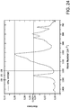
- the O-Parameter is defined in U.S. Patent No. 8,067,070 , which claims an O-parameter value of most broadly from 0.4 to 0.9. It can be measured from physical analysis of an FTIR amplitude versus wave number plot to find the numerator and denominator of the above expression, as shown in Fig. 24 , which is the same as Fig. 5 of U.S. Patent No.
- the O-Parameter can also be measured from digital wave number versus absorbance data.
- U.S. Patent No. 8,067,070 asserts that its claimed O-parameter range provides a superior passivation layer or pH protective coating, relying on experiments only with HMDSO and HMDSN, which are both non-cyclic siloxanes.
- the PECVD precursor is a cyclic siloxane, for example OMCTS
- OMCTS cyclic siloxane
- the O-parameter can have a value of from 0.1 to 0.39, or from 0.15 to 0.37, or from 0.17 to 0.35.
- ATR attenuated total reflection
- the N-Parameter is also described in U.S. Patent No. 8,067,070 , and can be measured analogously to the O-Parameter except that intensities at two specific wave numbers are used - neither of these wave numbers is a range.
- a passivation layer or pH protective coating with an N-Parameter of 0.7 to 1.6.
- the present inventors have made better coatings employing a passivation layer or pH protective coating 34 having an N-Parameter lower than 0.7, as described above.
- the N-parameter can have a value of 0.3 to lower than 0.7, or from 0.4 to 0.6, or from at least 0.53 to lower than 0.7.
- the inventors offer the following theory of operation of the passivation layer or pH protective coating described here.
- the invention is not limited by the accuracy of this theory or to the embodiments predictable by use of this theory.
- the dissolution rate of the SiO x barrier coating or layer, or of glass is believed to be dependent on SiO bonding within the layer or glass. Oxygen bonding sites (silanols) are believed to increase the dissolution rate.
- the OMCTS-based passivation layer or pH protective coating bonds with the silanol sites on the SiO x barrier coating or layer, or glass, to "heal" or passivate the SiO x surface or glass and thus dramatically reduce the dissolution rate.
- the thickness of the OMCTS layer is not the primary means of protection - the primary means can be passivation of the SiO x or glass surface.
- a passivation layer or pH protective coating as described in this specification can be improved by increasing the crosslink density of the passivation layer or pH protective coating.
- the passivation layer or pH protective coating 34 and lubricity layers of any embodiment of Figures 7-8 can be either separate layers with a sharp transition or a single, graduated layer that transitions between the passivation layer or pH protective coating 34 and the lubricity layer, without a sharp interface between them.
- Another optional expedient contemplated here, for adjacent layers of SiO x and a passivation layer or pH protective coating can be a graded composite of SiO x and Si w O x C y , or its equivalent SiO x C y , as defined in the Definition Section.
- a graded composite can be separate layers of a lubricity and/or protective and/or barrier coating or layer or coating with a transition or interface of intermediate composition between them, or separate layers of a lubricity and/or protective and/or hydrophobic layer and SiO x with an intermediate distinct passivation layer or pH protective coating of intermediate composition between them, or a single coating or layer that changes continuously or in steps from a composition of a lubricity and/or protective and/or hydrophobic layer to a composition more like SiO x , going through the passivation layer or pH protective coating in a normal direction.
- the composition of SiO x can be applied directly to the substrate and graduate to a composition further from the surface of a passivation layer or pH protective coating, and optionally can further graduate to another type of coating or layer, such as a hydrophobic coating or layer or a lubricity coating or layer.
- an adhesion coating or layer for example Si w O x C y , or its equivalent SiO x C y , optionally can be applied directly to the substrate before applying the barrier coating or layer.
- a graduated passivation layer or pH protective coating is particularly contemplated if a layer of one composition is better for adhering to the substrate than another, in which case the better-adhering composition can, for example, be applied directly to the substrate. It is contemplated that the more distant portions of the graded passivation layer or pH protective coating can be less compatible with the substrate than the adjacent portions of the graded passivation layer or pH protective coating, since at any point the passivation layer or pH protective coating can be changing gradually in properties, so adjacent portions at nearly the same depth of the passivation layer or pH protective coating have nearly identical composition, and more widely physically separated portions at substantially different depths can have more diverse properties.
- a passivation layer or pH protective coating portion that forms a better barrier against transfer of material to or from the substrate can be directly against the substrate, to prevent the more remote passivation layer or pH protective coating portion that forms a poorer barrier from being contaminated with the material intended to be barred or impeded by the barrier.
- the applied coatings or layers instead of being graded, optionally can have sharp transitions between one layer and the next, without a substantial gradient of composition.
- Such passivation layer or pH protective coating can be made, for example, by providing the gases to produce a layer as a steady state flow in a non-plasma state, then energizing the system with a brief plasma discharge to form a coating or layer on the substrate.
- the gases for the previous passivation layer or pH protective coating are cleared out and the gases for the next passivation layer or pH protective coating are applied in a steady-state fashion before energizing the plasma and again forming a distinct layer on the surface of the substrate or its outermost previous passivation layer or pH protective coating, with little if any gradual transition at the interface.
- the low-pressure PECVD process described in U.S. Patent No. 7,985,188 can be used to provide the barrier coating or layer, lubricity coating or layer, and/or passivation layer or pH protective coating described in this specification. A brief synopsis of that process follows, with reference to present FIGS. 4-6 .
- a PECVD apparatus or coating station 60 suitable for the present purpose includes a vessel holder 50, an inner electrode defined by the probe 108, an outer electrode 160, and a power supply 162.
- the pre-assembly 12 seated on the vessel holder 50 defines a plasma reaction chamber, which optionally can be a vacuum chamber.
- a source of vacuum 98, a reactant gas source 144, a gas feed (probe 108) or a combination of two or more of these can be supplied.
- the PECVD apparatus can be used for atmospheric-pressure PECVD, in which case the plasma reaction chamber defined by the pre-assembly 12 does not need to function as a vacuum chamber.
- the vessel holder 50 comprises a gas inlet port 104 for conveying a gas into the pre-assembly 12 seated on the opening 82.
- the gas inlet port 104 can have a sliding seal provided for example by at least one O-ring 106, or two O-rings in series, or three O-rings in series, which can seat against a cylindrical probe 108 when the probe 108 is inserted through the gas inlet port 104.
- the probe 108 can be a gas inlet conduit that extends to a gas delivery port at its distal end 110.
- the distal end 110 can be inserted at an appropriate depth in the pre-assembly 12 for providing one or more PECVD reactants and other precursor feed or process gases.
- FIG. 6 shows additional optional details of the coating station 60 that are usable, for example, with all the illustrated apparatus.
- the coating station 60 can also have a main vacuum valve 574 in its vacuum line 576 leading to the pressure sensor 152.
- a manual bypass valve 578 can be provided in the bypass line 580.
- a vent valve 582 controls flow at the vent 404.
- Flow out of the PECVD gas or precursor source 144 can be controlled by a main reactant gas valve 584 regulating flow through the main reactant feed line 586.
- One component of the gas source 144 can be the organosilicon liquid reservoir 588, containing the precursor.
- the contents of the reservoir 588 can be drawn through the organosilicon capillary line 590, which optionally can be provided at a suitable length to provide the desired flow rate.
- Flow of organosilicon vapor can be controlled by the organosilicon shut-off valve 592.
- Pressure can be applied to the headspace 614 of the liquid reservoir 588, for example a pressure in the range of 0-15 psi (0 to 78 cm.
- a pressure source 616 such as pressurized air connected to the headspace 614 by a pressure line 618 to establish repeatable organosilicon liquid delivery that is not dependent on atmospheric pressure (and the fluctuations therein).
- the reservoir 588 can be sealed and the capillary connection 620 can be at the bottom of the reservoir 588 to ensure that only neat organosilicon liquid (not the pressurized gas from the headspace 614) flows through the capillary tube 590.
- the organosilicon liquid optionally can be heated above ambient temperature, if necessary or desirable to cause the organosilicon liquid to evaporate, forming an organosilicon vapor.
- the apparatus can advantageously include heated delivery lines from the exit of the precursor reservoir to as close as possible to the gas inlet into the syringe. Preheating can be useful, for example, when feeding OMCTS.
- Oxidant gas can be provided from the oxidant gas tank 594 via an oxidant gas feed line 596 controlled by a mass flow controller 598 and provided with an oxidant shut-off valve 600.
- each such reservoir such as 602 can have an appropriate feed line 604 and shut-off valve 606.
- the processing station 60 can include an electrode 160 fed by a radio frequency power supply 162 for providing an electric field for generating plasma within the pre-assembly 12 during processing.
- the probe 108 can be electrically conductive and can be grounded, thus providing a counter-electrode within the pre-assembly 12.
- the outer electrode 160 can be grounded and the probe 108 can be directly connected to the power supply 162.
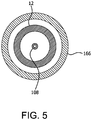
- the outer electrode 160 can either be generally cylindrical as illustrated in FIGS. 4 and 5 or a generally U-shaped elongated channel as illustrated in FIG. 6 ( FIG. 5 being an alternative of the section taken along section line A-A of FIG. 4 ).
- Each illustrated apparatus can have one or more sidewalls, such as 164 and 166, and optionally a top end 168, disposed about the pre-assembly 12 in close proximity.
- a barrier coating or layer 30 can be applied directly or indirectly to at least a portion of the internal wall 16 of the barrel 14.
- the barrier coating or layer 30 can be applied while the pre-assembly 12 is capped, though this is not a requirement.
- the barrier coating or layer 30 can be an SiO x barrier coating or layer applied by plasma enhanced chemical vapor deposition (PECVD), under conditions substantially as described in U.S. Pat. No. 7,985,188 .
- PECVD plasma enhanced chemical vapor deposition
- the barrier coating or layer 30 can be applied under conditions effective to maintain communication between the barrel lumen 18 and the dispensing portion lumen 26 via the proximal opening 22 at the end of the applying step.
- the barrier coating or layer 30 optionally can be applied through the opening 32.
- the barrier coating or layer 30 optionally can be applied by introducing a vapor-phase precursor material through the opening and employing chemical vapor deposition to deposit a reaction product of the precursor material on the internal wall of the barrel.
- the precursor material for forming the barrier coating optionally can be any of the precursors described in U.S. Pat. No. 7,985,188 or in this specification for formation of the passivating layer or pH protective coating.
- the reactant vapor material optionally can comprise an oxidant gas.
- the reactant vapor material optionally can comprise oxygen.
- the reactant vapor material optionally can comprise a carrier gas.
- the reactant vapor material optionally can include helium, argon, krypton, xenon, neon, or a combination of two or more of these.
- the reactant vapor material optionally can include argon.
- the reactant vapor material optionally can be a precursor material mixture with one or more oxidant gases and a carrier gas applied in a partial vacuum through the opening and employing chemical vapor deposition to deposit a reaction product of the precursor material mixture on the internal wall of the barrel.
- the reactant vapor material optionally can be passed through the opening at sub-atmospheric pressure.
- Plasma optionally can be generated in the barrel lumen 18 by placing an inner electrode into the barrel lumen 18 through the opening 32, placing an outer electrode outside the barrel 14 and using the electrodes to apply plasma-inducing electromagnetic energy which optionally can be radio frequency energy, in the barrel lumen 18. If a different arrangement is used, the plasma-inducing electromagnetic energy can be microwave energy or other forms of electromagnetic energy.
- the electromagnetic energy optionally can be direct current.
- the electromagnetic energy optionally can be alternating current.
- the alternating current optionally can be modulated at frequencies including audio, or microwave, or radio, or a combination of two or more of audio, microwave, or radio.
- the electromagnetic energy optionally can be applied across the barrel lumen (18).
- the method includes applying a second or further coating or layer of the same material or a different material.
- the first coating or layer is an SiO x barrier coating or layer, and a further coating or layer is placed directly or indirectly over the barrier coating or layer.
- a further coating or layer in any embodiment is a passivation layer or pH protective coating 34.
- the organosilicon precursor for any of the processes for forming the barrier coating or layer, the passivation layer or pH protective coating, or a lubricity coating or layer can include any of the following precursors.
- organosilicon precursor is defined throughout this specification most broadly as a compound having at least one of the linkages: or
- the first structure immediately above is a tetravalent silicon atom connected to an oxygen atom and an organic carbon atom (an organic carbon atom being a carbon atom bonded to at least one hydrogen atom).
- the second structure immediately above is a tetravalent silicon atom connected to an -NH- linkage and an organic carbon atom (an organic carbon atom being a carbon atom bonded to at least one hydrogen atom).
- the organosilicon precursor can be selected from the group consisting of a linear siloxane, a monocyclic siloxane, a polycyclic siloxane, a polysilsesquioxane, a linear silazane, a monocyclic silazane, a polycyclic silazane, a polysilsesquiazane, and a combination of any two or more of these precursors.
- a precursor though not within the two formulas immediately above, can be an alkyl trimethoxysilane.
- an oxygen-containing precursor for example a Siloxane
- a representative predicted empirical composition resulting from PECVD under conditions forming a hydrophobic or lubricating passivation layer or pH protective coating would be Si w O x C y H z or its equivalent SiO x C y as defined in the Definition Section
- a representative predicted empirical composition resulting from PECVD under conditions forming a barrier coating or layer would be SiO x , where x in this formula is from about 1.5 to about 2.9.
- a nitrogen-containing precursor for example a silazane
- the predicted composition would be Si w* N x* C y* H z* , i.e.
- Si w O x C y H z or its equivalent SiO x C y as specified in the Definition Section O is replaced by N and the indices for H are adapted to the higher valency of N as compared to O (3 instead of 2).
- the latter adaptation will generally follow the ratio of w, x, y and z in a Siloxane to the corresponding indices in its aza counterpart.
- Si w* N x* C y* H z* (or its equivalent SiN x* C y* ) in which w*, x*, y*, and z* are defined the same as w, x, y, and z for the siloxane counterparts, but for an optional deviation in the number of hydrogen atoms.
- One type of precursor starting material having the above empirical formula can be a linear siloxane, for example a material having the following formula: in which each R can be independently selected from alkyl, for example methyl, ethyl, propyl, isopropyl, butyl, isobutyl, t-butyl, vinyl, alkyne, and n can be 1, 2, 3, 4, or greater, optionally two or greater.
- contemplated linear siloxanes are hexamethyldisiloxane (HMDSO) (particularly for forming the barrier coating or layer 30 of a vessel), octamethyltrisiloxane, decamethyltetrasiloxane, dodecamethylpentasiloxane, or combinations of two or more of these.
- HMDSO hexamethyldisiloxane
- octamethyltrisiloxane decamethyltetrasiloxane
- dodecamethylpentasiloxane or combinations of two or more of these.
- the analogous silazanes in which -NH- can be substituted for the oxygen atom in the above structure are also useful for making analogous passivation layers or pH protective coatings or layers.
- contemplated linear silazanes are octamethyltrisilazane, decamethyltetrasilazane, or combinations of two or more of these.
- precursor starting material can be a monocyclic siloxane, for example a material having the following structural formula: in which R can be defined as for the linear structure and "a" can be from 3 to 10, or the analogous monocyclic silazanes.
- contemplated hetero-substituted and unsubstituted monocyclic siloxanes and silazanes include: 1,3,5-trimethyl-1,3,5-tris(3,3,3-trifluoropropyl)methyl]cyclotrisiloxane 2,4,6,8-tetramethyl-2,4,6,8-tetravinylcyclotetrasiloxane, pentamethylcyclopentasiloxane, pentavinylpentamethylcyclopentasiloxane, hexamethylcyclotrisiloxane, hexaphenylcyclotrisiloxane (HMCTS), octamethylcyclotetrasiloxane (OMCTS), decamethylcyclopentasiloxane (DMCPS), 2,2,4,4,6,6,8,8-octamethyl-1,5-dimethano-3,7-dioxa-2,4,6,8-tetrasiloxane oct
- Cyclic organosilazanes are also contemplated, such as octamethylcyclotetrasilazane, 1,3,5,7-tetravinyl-1,3,5,7-tetramethylcyclotetrasilazane hexamethylcyclotrisilazane, octamethylcyclotetrasilazane, decamethylcyclopentasilazane, dodecamethylcyclohexasilazane, or combinations of any two or more of these.
- Another type of precursor starting material can be a polycyclic siloxane, for example a material having one of the following structural formulas: in which Y can be oxygen or nitrogen, E is silicon, and Z is a hydrogen atom or an organic substituent, for example alkyl such as methyl, ethyl, propyl, isopropyl, butyl, isobutyl, t-butyl, vinyl, alkyne.
- Y oxygen
- the respective structures from left to right, are a silatrane, a silquasilatrane, and a silproatrane.
- Y is nitrogen
- the respective structures are an azasilatrane, an azasilquasiatrane, and an azasilproatrane.
- polysilsesquioxane can be a polysilsesquioxane, with the empirical formula RSiO 1.5 and the structural formula: in which each R is a hydrogen atom or an organic substituent, for example alkyl such as methyl, ethyl, propyl, isopropyl, butyl, isobutyl, t-butyl, vinyl, alkyne.
- R is a hydrogen atom or an organic substituent
- alkyl such as methyl, ethyl, propyl, isopropyl, butyl, isobutyl, t-butyl, vinyl, alkyne.
- SST-eM01 poly(methylsilsesquioxane) in which each R can be methyl
- SST-3MH1.1 poly(methyl-hydridosilsesquioxane) in which 90% of the R groups are methyl, 10% are hydrogen atoms.
- a contemplated precursor is methylsilatrane, CAS No. 2288-13-3 , in which each Y is oxygen and Z is methyl, methylazasilatrane, poly(methylsilsesquioxane) (for example SST-eM01 poly(methylsilsesquioxane)), in which each R optionally can be methyl, SST-3MH1.1 poly(Methyl-Hydridosilsesquioxane) (for example SST-3MH1.1 poly(Methyl-Hydridosilsesquioxane)), in which 90% of the R groups are methyl and 10% are hydrogen atoms, or a combination of any two or more of these.
- analogous polysilsesquiazanes in which -NH- can be substituted for the oxygen atom in the above structure are also useful for making an analogous passivation layer or pH protective coating.
- contemplated polysilsesquiazanes are a poly(methylsilsesquiazane), in which each R can be methyl, and a poly(methyl-hydridosilsesquiazane, in which 90% of the R groups are methyl, 10% are hydrogen atoms. Combinations of two or more of these are also contemplated.
- One particularly contemplated precursor for the barrier coating or layer according to the present invention can be a linear siloxane, for example hexamethyldisiloxane or HMDSO.
- One particularly contemplated precursor for the lubricity coating or layer and the passivation layer or pH protective coating according to the present invention can be a cyclic siloxane, for example octamethylcyclotetrasiloxane (OMCTS).
- the OMCTS or other cyclic siloxane molecule provides several advantages over other siloxane materials.
- its ring structure is believed to result in a less dense passivation layer or pH protective coating (as compared to a passivation layer or pH protective coating prepared from HMDSO).
- the molecule also is believed to allow selective ionization so that the final structure and chemical composition of the passivation layer or pH protective coating can be directly controlled through the application of the plasma power.
- Other organosilicon molecules are readily ionized (fractured) so that it can be more difficult to retain the original structure of the molecule.
- the applying step optionally can be carried out by vaporizing the precursor and providing it in the vicinity of the substrate.
- OMCTS can be vaporized by heating it to about 50°C before applying it to the PECVD apparatus.
- Cyclic organosilicon precursors in particular monocyclic organosilicon precursors (like the monocyclic precursors listed elsewhere in present description), and specifically OMCTS, are particularly suitable to achieve a passivation layer or pH protective coating.
- the organosilicon precursor can be delivered at a rate of equal to or less than 10 sccm, optionally equal to or less than 6 sccm, optionally equal to or less than 2.5 sccm, optionally equal to or less than 1.5 sccm, optionally equal to or less than 1.25 sccm. Larger pharmaceutical packages or other changes in conditions or scale may require more or less of the precursor.
- O 2 can be present in an amount (which can, for example be expressed by the flow rate in sccm) which can be less than one order of magnitude greater than the organosilicon amount.
- the amount of O 2 typically can be at least one order of magnitude higher than the amount of organosilicon precursor.
- the volume ratio (in sccm) of organosilicon precursor to O 2 for a passivation layer or pH protective coating can be in the range from 0.1 : 1 to 10 : 1, optionally in the range from 0.3 : 1 to 8 : 1, optionally in the range from 0.5 : 1 to 5 : 1, optionally from 1 : 1 to 3 : 1.
- the process gas can contain this ratio of gases for preparing a lubricity and/or passivation layer or pH protective coating:
- Exemplary reaction conditions for preparing a passivation layer or pH protective coating according to the present invention in a 3 ml sample size syringe with a 1/8" diameter tube (open at the end) are as follows: Flow rate ranges: OMCTS: 0.5 - 10 sccm Oxygen: 0.1 - 10 sccm Argon: 1.0 - 200 sccm Power: 0.1 - 500 watts
- the proportions of precursor, oxygen, and Argon can be, for example: OMCTS: 0.5 - 5.0 sccm
- proportions of precursor, oxygen, and Argon and the power level can be, for example: Specific Flow rates:
- the coatings can vary from the above proportions, however.
- the following proportions of gases can be used:
- the presence of the precursor and O 2 in the volume ratios as given in Tables 9-11 can be specifically suitable to achieve a passivation layer or pH protective coating.
- a carrier gas can be absent in the reaction mixture; or it can be present.
- Suitable carrier gases include any noble gas, for example Argon, Helium, Neon, Xenon or combinations of two or more of these.
- the carrier gas is typically present in a volume (in sccm) exceeding the volume of the organosilicon precursor.
- the ratio of the organosilicon precursor to carrier gas can be from 1 : 1 to 1 : 50, optionally from 1 : 5 to 1 : 40, optionally from 1 : 10 to 1 : 30.
- One function of the carrier gas can be to dilute the reactants in the plasma, encouraging the formation of a coating on the substrate instead of powdered reaction products that do not adhere to the substrate and are largely removed with the exhaust gases.
- One preferred combination of process gases includes octamethylcyclotetrasiloxane (OMCTS) or another cyclic siloxane as the precursor; O 2 , nitrous oxide (N 2 O), ozone (O 3 ), or another oxidizing gas, which means any other gas that oxidizes the precursor during PECVD at the conditions employed, preferably O 2 ; and a carrier gas, for example a noble carrier gas, for example Argon (Ar).
- the gaseous reactant or process gas can be at least substantially free of nitrogen. This combination is contemplated to improve the resulting passivation layer or pH protective coating.
- a passivation layer or pH protective coating 34 is applied directly or indirectly over the barrier coating or layer 30, and optionally can be applied to a pre-assembly such as 12 while the pre-assembly is capped, under conditions effective to maintain communication between the barrel lumen 18 and the dispensing portion lumen 26 via the proximal opening 22 at the end of applying the passivation layer or pH protective coating 34.
- the presently disclosed passivation layer or pH protective coating also can reduce the dissolution of glass by contents having the pH values indicated as attacking SiO x coatings or layers.
- a pharmaceutical package 210 is contemplated as shown in any embodiment, for example FIGS. 7-8 , comprising a vessel or vessel part made of glass; a barrier coating or layer or layer such as 30 on the vessel or vessel part; a passivation layer or pH protective coating such as 34 on the vessel, vessel part, or barrier coating or layer or layer; and a pharmaceutical composition or preparation contained within the vessel.
- the barrier coating or layer can be optional because a glass vessel wall in itself is an extremely good barrier coating or layer.
- the barrier coating or layer is contemplated to provide a barrier coating or layer primarily to provide isolation: in other words, to prevent contact and interchange of material of any kind, such as ions of the glass or constituents of the pharmaceutical composition or preparation between the vessel wall and the contents of the vessel.
- the protective layer as defined in this specification can be contemplated to perform the isolation function independently, at least to a degree.
- This passivation coating or pH protection layer can be contemplated to provide a useful function on glass in contact with the pharmaceutical composition or preparation, as the present working examples show that borosilicate glass, commonly used today for pharmaceutical packaging, can be dissolved by a fluid composition having a pH exceeding 5. Particularly in applications where such dissolution can be disadvantageous or perceived to be disadvantageous, the present passivation layers or protective coatings or layers will find utility.
- the vessel can be made, for example of glass of any type used in medical or laboratory applications, such as soda-lime glass, borosilicate glass, or other glass formulations.
- One function of a passivation layer or pH protective coating on a glass vessel can be to reduce the ingress of ions in the glass, either intentionally or as impurities, for example sodium, calcium, or others, from the glass to the contents of the pharmaceutical package, such as a reagent or blood in an evacuated blood collection tube.
- a dual functional protective / lubricity coating or layer can be used on a glass vessel in whole or in part, such as selectively at surfaces contacted in sliding relation to other parts, to provide lubricity, for example to ease the insertion or removal of a stopper or passage of a sliding element such as a piston in a syringe, as well as to provide the isolation of a passivation layer or pH protective coating.
- Still another reason to coat a glass vessel can be to prevent a reagent or intended sample for the pharmaceutical package, such as blood, from sticking to the wall of the vessel or an increase in the rate of coagulation of the blood in contact with the wall of the vessel, as well as to provide the isolation of a passivation layer or pH protective coating.
- the precursor can be contacted with a plasma made by energizing the vicinity of the precursor with electrodes powered at radio frequency, optionally a frequency of 10 kHz to 2.45 GHz, optionally from 10 kHz to less than 300 MHz, optionally from 1 to 50 MHz, optionally from 10 to 15 MHz, alternatively from 13 to 14 MHz, optionally at or about 13.56 MHz.
- the plasma in the PECVD process can be generated at RF frequency, although microwave or other electromagnetic energy can also be used.
- the plasma can be generated with an electric power of from 0.1 to 500 W, optionally from 0.1 to 400 W, optionally from 0.1 to 300 W, optionally from 1 to 250 W, optionally from 1 to 200 W, even optionally from 10 to 150 W, optionally from 20 to 150 W, for example of 40 W, optionally from 40 to 150 W, even optionally from 60 to 150 W.
- PECVD can be initiated by applying an initial higher power level within the stated range, followed by a subsequent lower power level within the stated range.
- the initial higher power level can be applied, for example, for from 1 to 3 seconds.
- the subsequent lower power level can applied, for example, for the remainder of PECVD.
- the precursor can be contacted with a plasma made by energizing the vicinity of the precursor with electrodes supplied with electric power at from 0.1 to 25 W, optionally from 1 to 22 W, optionally from 1 to 10 W, even optionally from 1 to 5 W, optionally from 2 to 4 W, for example of 3 W, optionally from 3 to 17 W, even optionally from 5 to 14 W, for example 6 or 7.5 W, optionally from 7 to 11 W, for example of 8 W.
- a plasma made by energizing the vicinity of the precursor with electrodes supplied with electric power at from 0.1 to 25 W, optionally from 1 to 22 W, optionally from 1 to 10 W, even optionally from 1 to 5 W, optionally from 2 to 4 W, for example of 3 W, optionally from 3 to 17 W, even optionally from 5 to 14 W, for example 6 or 7.5 W, optionally from 7 to 11 W, for example of 8 W.
- the ratio of the electrode power to the plasma volume can be less than 100 W/ml, optionally can be from 0.1 to 100 W/mL, optionally can be from 5 W/ml to 75 W/ml, optionally can be from 6 W/ml to 60 W/ml, optionally can be from 10 W/ml to 50 W/ml, optionally from 20 W/ml to 40 W/ml.
- These power levels are suitable for applying passivation layers or protective coatings or layers to syringes and sample tubes and pharmaceutical packages of similar geometry having a void volume of 5 mL in which PECVD plasma can be generated. It is contemplated that for larger or smaller objects the power applied, in Watts, should be increased or reduced accordingly to scale the process to the size of the substrate.
- the precursor can be contacted with a plasma made by energizing the vicinity of the precursor with electrodes supplied with electric power density at less than 10 W/ml of plasma volume, alternatively from 6 W/ml to 0.1 W/ml of plasma volume, alternatively from 5 W/ml to 0.1 W/ml of plasma volume, alternatively from 4 W/ml to 0.1 W/ml of plasma volume, alternatively from 2 W/ml to 0.2 W/ml of plasma volume, alternatively from 10 W/ml to 50 W/ml, optionally from 20 W/ml to 40 W/ml.
- a plasma made by energizing the vicinity of the precursor with electrodes supplied with electric power density at less than 10 W/ml of plasma volume, alternatively from 6 W/ml to 0.1 W/ml of plasma volume, alternatively from 5 W/ml to 0.1 W/ml of plasma volume, alternatively from 4 W/ml to 0.1 W/ml of plasma volume, alternatively from 2 W/ml to 0.2 W
- the passivation layer or pH protective coating can be applied by PECVD at a power level per of more than 22,000 kJ/kg of mass of precursor, or more than 30,000 kJ/kg of mass of precursor, or more than 40,000 kJ/kg of mass of precursor, or more than 50,000 kJ/kg of mass of precursor, or more than 60,000 kJ/kg of mass of precursor, or more than 62,000 kJ/kg of mass of precursor, or more than 70,000 kJ/kg of mass of precursor, or more than 80,000 kJ/kg of mass of precursor, or more than 100,000 kJ/kg of mass of precursor, or more than 200,000 kJ/kg of mass of precursor, or more than 300,000 kJ/kg of mass of precursor, or more than 400,000 kJ/kg of mass of precursor, or more than 500,000 kJ/kg of mass of precursor.
- the passivation layer or pH protective coating 34 can be applied by PECVD at a power level per of less than 2,000,000 kJ/kg of mass of precursor, or less than1,000,000 kJ/kg of mass of precursor, or less than 700,000 kJ/kg of mass of precursor, or less than 500,000 kJ/kg of mass of precursor, or less than 100,000 kJ/kg of mass of precursor, or less than 90,000 kJ/kg of mass of precursor, or less than 81,000 kJ/kg of mass of precursor.
- the deposition time can be from 1 to 30 sec, alternatively from 2 to 10 sec, alternatively from 3 to 9 sec.
- the purposes for optionally limiting deposition time can be to avoid overheating the substrate, to increase the rate of production, and to reduce the use of process gas and its constituents.
- the purposes for optionally extending deposition time can be to provide a thicker passivation layer or pH protective coating for particular deposition conditions.
- HMDZ hexamethylene disilazane
- This passivation layer or pH protective coating treatment is contemplated to be a surface treatment of the SiO x barrier coating or layer with HMDZ. It is contemplated that HMDZ will react with the -OH sites that are present in the silicon dioxide coating, resulting in the evolution of NH 3 and bonding of S-(CH 3 ) 3 to the silicon (it is contemplated that hydrogen atoms will be evolved and bond with nitrogen from the HMDZ to produce NH 3 ).
- this HMDZ passivation layer or pH protective coating can be accomplished through several possible paths.
- One contemplated path can be dehydration/vaporization of the HMDZ at ambient temperature.
- an SiO x surface can be deposited, for example using hexamethylene disiloxane (HMDSO).
- HMDSO hexamethylene disiloxane
- the as-coated silicon dioxide surface then can be reacted with HMDZ vapor.
- the vacuum can be maintained.
- the HMDSO and oxygen are pumped away and a base vacuum is achieved. Once base vacuum is achieved, HMDZ vapor can be flowed over the surface of the silicon dioxide (as coated on the part of interest) at pressures from the mTorr range to many Torr.
- the HMDZ then can be pumped away (with the resulting NH 3 that is a byproduct of the reaction).
- the amount of NH 3 in the gas stream can be monitored (with a residual gas analyzer -- RGA -- as an example) and when there is no more NH 3 detected, the reaction is complete.
- the part then can be vented to atmosphere (with a clean dry gas or nitrogen).
- the resulting surface then can be found to have been passivated or protected. It is contemplated that this method optionally can be accomplished without forming a plasma.
- the vacuum can be broken before dehydration/vaporization of the HMDZ.
- Dehydration/vaporization of the HMDZ can then be carried out in either the same apparatus used for formation of the SiO x barrier coating or layer or different apparatus.
- Dehydration/vaporization of HMDZ at an elevated temperature is also contemplated.
- the above process can alternatively be carried out at an elevated temperature exceeding room temperature up to about 150°C.
- the maximum temperature can be determined by the material from which the coated part is constructed. An upper temperature should be selected that will not distort or otherwise damage the part being coated.
- Dehydration/ vaporization of HMDZ with a plasma assist is also contemplated. After carrying out any of the above dehydration/vaporization, once the HMDZ vapor is admitted into the part, plasma can be generated.
- the plasma power can range from a few watts to 100+ watts (similar powers as used to deposit the SiO x ). The above is not limited to HMDZ and could be applicable to any molecule that will react with hydrogen, for example any of the nitrogen-containing precursors described in this specification.
- Uniform plasma means regular plasma that does not include a substantial amount of hollow cathode plasma (which has higher emission intensity than regular plasma and can be manifested as a localized area of higher intensity interrupting the more uniform intensity of the regular plasma).
- any of the passivation layer or pH protective coating processes described in this specification can also be carried out without using the article to be coated to contain the plasma.
- external surfaces of medical devices for example catheters, surgical instruments, closures, and others can be passivated or protected by sputtering the coating, employing a radio frequency target.
- the fluid material 40 can have a pH between 5 and 6, optionally between 6 and 7, optionally between 7 and 8, optionally between 8 and 9, optionally between 6.5 and 7.5, optionally between 7.5 and 8.5, optionally between 8.5 and 9.
- the fluid material 40 can be a liquid at 20°C and ambient pressure at sea level, which is defined as a pressure of 760 mm Hg.
- the fluid material 40 can be an aqueous liquid.
- the fluid material 40 comprises a member or a combination of two or more members selected from the group consisting of:
- the fluid material 40 can be an inhalation anesthetic, a drug, or a diagnostic test material. Any of these fluid materials 40 can be an injectable material, a volatile material capable of being inhaled, or otherwise capable of being introduced into a subject.
- a vessel with a passivation layer or pH protective coating as described herein can also be evacuated and stored in an evacuated state.
- the passivation layer or pH protective coating allows better maintenance of the vacuum in comparison to a corresponding vessel without a passivation layer or pH protective coating.
- the vessel with a passivation layer or pH protective coating can be a blood collection tube.
- the tube can also contain an agent for preventing blood clotting or platelet activation, for example EDTA or heparin.
- kits including a vessel having a passivation layer or pH protective coating as defined in any embodiment herein on a substrate as defined in any embodiment herein.
- the kit additionally includes a medicament or diagnostic agent as defined in any embodiment herein which is contained in the vessel with a passivation layer or pH protective coating in contact with the coating or layer; and/or a hypodermic needle, double-ended needle, or other delivery conduit; and/or an instruction sheet.
- passivation layer or pH protective coating for preventing or reducing precipitation and/or clotting or platelet activation of a compound or a component of the composition in contact with the coating or layer.
- a coated substrate for storing insulin.
- precipitation of the insulin can be prevented or reduced by providing a vessel to contain the insulin having a contact surface including a passivation layer or pH protective coating.
- the compound or a component of the composition can be blood or a blood fraction, and blood clotting or platelet activation can be prevented or reduced by storing the blood in the blood collection tube in contact with a passivation layer or pH protective coating.
- the blood collection tube can contain an agent for preventing blood clotting or platelet activation, for example ethylenediaminetetraacetic acid (EDTA), a sodium salt thereof, or heparin.
- EDTA ethylenediaminetetraacetic acid
- the blood collection tube can include a passivation layer or pH protective coating for preventing the agent from attacking an SiO x barrier coating or layer in the vessel.
- the use of a coated substrate according to any described embodiment is contemplated for storing blood.
- the stored blood can be viable for return to the vascular system of a patient.
- a coating or layer according to any described embodiment can be contemplated as (i) a lubricity coating having a lower frictional resistance than the uncoated surface; and/or (ii) a hydrophobic layer that can be more hydrophobic than the uncoated surface.
- the thickness of a PECVD coating or layer such as the passivation layer or pH protective coating, the barrier coating or layer, the lubricity coating or layer, and/or a composite of any two or more of these layers can be measured, for example, by transmission electron microscopy (TEM).
- TEM transmission electron microscopy
- An exemplary TEM image for a lubricity and/or passivation layer or pH protective coating on an SiO x barrier coating or layer is shown in Fig. 11 .
- An exemplary TEM image for an SiO x barrier coating or layer on a substrate is shown in Fig. 12 .
- Samples can be prepared for Focused Ion Beam (FIB) cross-sectioning in two ways. Either the samples can be first coated with a thin layer of carbon (50-100nm thick) and then coated with a sputtered coating or layer of platinum (50-100nm thick) using a K575X Emitech passivation layer or pH protective coating system, or the samples can be coated directly with the protective sputtered Pt layer.
- the coated samples can be placed in an FEI FIB200 FIB system.
- An additional coating or layer of platinum can be FIB-deposited by injection of an organometallic gas while rastering the 30kV gallium ion beam over the area of interest.
- the area of interest for each sample can be chosen to be a location half way down the length of the syringe barrel.
- Thin cross sections measuring approximately 15 ⁇ m ("micrometers") long, 2 ⁇ m wide and 15 ⁇ m deep can be extracted from the die surface using an in-situ FIB lift-out technique.
- the cross sections can be attached to a 200 mesh copper TEM grid using FIB-deposited platinum.
- One or two windows in each section, measuring about 8 ⁇ m wide, can be thinned to electron transparency using the gallium ion beam of the FEI FIB.
- Cross-sectional image analysis of the prepared samples can be performed utilizing either a Transmission Electron Microscope (TEM), or a Scanning Transmission Electron Microscope (STEM), or both. All imaging data can be recorded digitally.
- TEM Transmission Electron Microscope
- STEM Scanning Transmission Electron Microscope
- the grid with the thinned foils can be transferred to a Hitachi HD2300 dedicated STEM.
- Scanning transmitted electron images can be acquired at appropriate magnifications in atomic number contrast mode (ZC) and transmitted electron mode (TE). The following instrument settings can be used.
- the sample grids can be transferred to a Hitachi HF2000 transmission electron microscope. Transmitted electron images can be acquired at appropriate magnifications.
- the relevant instrument settings used during image acquisition can be those given below.
- the pharmaceutical packages tested in the subsequent working examples were formed and coated according to the following exemplary protocols, except as otherwise indicated in individual examples.
- Particular parameter values given in the following basic protocols for example the electric power and gaseous reactant or process gas flow, are typical values. When parameter values were changed in comparison to these typical values, this will be indicated in the subsequent working examples. The same applies to the type and composition of the gaseous reactant or process gas.
- the conditions given here are for a COC syringe barrel, and can be modified as appropriate for syringe barrels made of other materials.
- the apparatus as generally shown in FIG. 4 can be used to hold a syringe barrel with butt sealing at the base of the syringe barrel.
- the syringe barrel is carefully moved into the sealing position over the extended probe or counter electrode 108 and pushed against a plasma screen.
- the plasma screen is fit snugly around the probe or counter electrode 108 insuring good electrical contact.
- the probe or counter electrode 108 is grounded to the casing of the RF matching network.
- the gas delivery port 110 is connected to a manual ball valve or similar apparatus for venting, a thermocouple pressure gauge and a bypass valve connected to the vacuum pumping line.
- the gas system is connected to the gas delivery port 110 allowing the gaseous reactant or process gas, octamethylcyclotetrasiloxane (OMCTS) (or the specific gaseous reactant or process gas reported for a particular example) to be flowed through the gas delivery port 110 (under process pressures) into the interior of the syringe barrel.
- OCTS octamethylcyclotetrasiloxane
- the gas system is comprised of a commercially available heated mass flow vaporization system that heats the OMCTS to about 100°C.
- the heated mass flow vaporization system is connected to liquid octamethylcyclotetrasiloxane (Alfa Aesar® Part Number A12540, 98%).
- the OMCTS flow rate is set to the specific organosilicon precursor flow reported for a particular example. To ensure no condensation of the vaporized OMCTS flow past this point, the gas stream is diverted to the pumping line when it is not flowing into the interior of the COC syringe barrel for processing.
- the vacuum pump valve is opened to the vessel holder 50 and the interior of the COC syringe barrel.
- a vacuum pump and blower comprise the vacuum pump system.
- the pumping system allows the interior of the COC syringe barrel to be reduced to pressure(s) of less than 100 mTorr while the gaseous reactant or process gases is flowing at the indicated rates.
- the vessel holder 50 assembly is moved into the electrode 160 assembly.
- the gas stream (OMCTS vapor) is flowed into the gas delivery port 110 (by adjusting the 3-way valve from the pumping line to the gas delivery port 110).
- the plasma for PECVD if used, can be generated at reduced pressure and the reduced pressure can be less than 300 mTorr, optionally less than 200 mTorr, even optionally less than 100 mTorr.
- Pressure inside the COC syringe barrel can be, as one example, approximately 140 mTorr as measured by a capacitance manometer (MKS) installed on the pumping line near the valve that controls the vacuum.
- MKS capacitance manometer
- the pressure inside the gas delivery port 110 and gas system is also measured with the thermocouple vacuum gauge that is connected to the gas system. This pressure is typically less than 6 Torr.
- the RF power supply is turned on to its fixed power level or as otherwise indicated in a specific example or description.
- the physical and chemical properties of the passivation layer or pH protective coating can be set by setting the ratio of oxidizing gas to the organosilicon precursor in the gaseous reactant, and/or by setting the electric power used for generating the plasma.
- a 600 Watt RF power supply is used (at 13.56 MHz) at a fixed power level or as otherwise indicated in a specific example or description.
- the RF power supply is connected to an auto match which matches the complex impedance of the plasma (to be created in the vessel) to the output impedance of the RF power supply.
- the forward power is as stated and the reflected power is 0 Watts so that the stated power is delivered to the interior of the vessel.
- the RF power supply is controlled by a laboratory timer and the power on time set to 10 seconds (or a different time stated in a given example).
- uniform plasma is established inside the interior of the vessel.
- the plasma is maintained for the entire passivation layer or pH protective coating time, until the RF power is terminated by the timer.
- the plasma produces a passivation layer or pH protective coating on the interior of the vessel.
- the gas flow is diverted back to the vacuum line and the vacuum valve is closed.
- the vent valve is then opened, returning the interior of the COC syringe barrel to atmospheric pressure (approximately 760 Torr).
- the treated vessel is then carefully removed from the vessel holder 50 assembly (after moving the vessel holder 50 assembly out of the electrode 160 assembly).
- a similar protocol is used for applying a passivation layer or pH protective coating to vials.
- This protocol is used to determine the total amount of silicon coatings present on the entire vessel wall.
- a supply of 0.1 N potassium hydroxide (KOH) aqueous solution is prepared, taking care to avoid contact between the solution or ingredients and glass.
- the water used is purified water, 18 M' ⁇ quality.
- a Perkin Elmer Optima Model 7300DV ICP-OES instrument is used for the measurement except as otherwise indicated.
- each device (vial, syringe, tube, or the like) to be tested and its cap and crimp (in the case of a vial) or other closure are weighed empty to 0.001 g, then filled completely with the KOH solution (with no headspace), capped, crimped, and reweighed to 0.001 g.
- each vial is placed in a sonicating water bath at 40°C for a minimum of 8-10 hours. The digestion step is carried out to quantitatively remove the silicon coatings from the vessel wall into the KOH solution. After this digestion step, the vials are removed from the sonicating water bath and allowed to cool to room temperature. The contents of the vials are transferred into 15 ml ICP tubes. The total Si concentration is run on each solution by ICP/OES following the operating procedure for the ICP/OES.
- the total Si concentration is reported as parts per billion of Si in the KOH solution. This concentration represents the total amount of silicon coatings that were on the vessel wall before the digestion step was used to remove it.
- the total Si concentration can also be determined for fewer than all the silicon layers on the vessel, as when an SiO x barrier coating or layer is applied, an SiO x C y second layer (for example, a lubricity layer or a passivation layer or pH protective coating) is then applied, and it is desired to know the total silicon concentration of just the SiO x C y layer.
- This determination is made by preparing two sets of vessels, one set to which only the SiO x layer is applied and the other set to which the same SiO x layer is applied, followed by the SiO x C y layer or other layers of interest.
- the total Si concentration for each set of vessels is determined in the same manner as described above. The difference between the two Si concentrations is the total Si concentration of the SiO x C y second layer.
- the amount of silicon dissolved from the wall of the vessel by a test solution is determined, in parts per billion (ppb), for example to evaluate the dissolution rate of the test solution.
- This determination of dissolved silicon is made by storing the test solution in a vessel provided with an SiO x and/or SiO x C y coating or layer under test conditions, then removing a sample of the solution from the vessel and testing the Si concentration of the sample.
- the test is done in the same manner as the Protocol for Total Silicon Measurement, except that the digestion step of that protocol is replaced by storage of the test solution in the vessel as described in this protocol.
- the total Si concentration is reported as parts per billion of Si in the test solution
- the average dissolution rates reported in the working examples are determined as follows.
- a series of test vessels having a known total silicon measurement are filled with the desired test solution analogous to the manner of filling the vials with the KOH solution in the Protocol for Total Silicon Measurement.
- the test solution can be a physiologically inactive test solution as employed in the present working examples or a physiologically active pharmaceutical preparation intended to be stored in the vessels to form a pharmaceutical package).
- the test solution is stored in respective vessels for several different amounts of time, then analyzed for the Si concentration in parts per billion in the test solution for each storage time.
- the respective storage times and Si concentrations are then plotted. The plots are studied to find a series of substantially linear points having the steepest slope.
- linear plots of dissolution versus time data are prepared by using a least squares linear regression program to find a linear plot corresponding to the first five data points of each of the experimental plots. The slope of each linear plot is then determined and reported as representing the average dissolution rate applicable to the test, measured in parts per billion of Si dissolved in the test solution per unit of time.
- the calculated shelf life values reported in the working examples below are determined by extrapolation of the total silicon measurements and average dissolution rates, respectively determined as described in the Protocol for Total Silicon Measurement and the Protocol for Determining Average Dissolution Rate. The assumption is made that under the indicated storage conditions the SiO x C y passivation layer or pH protective coating will be removed at the average dissolution rate until the coating is entirely removed. Thus, the total silicon measurement for the vessel, divided by the dissolution rate, gives the period of time required for the test solution to totally dissolve the SiO x C y coating. This period of time is reported as the calculated shelf life. Unlike commercial shelf life calculations, no safety factor is calculated. Instead, the calculated shelf life is the calculated time to failure.
- the sample was mounted onto the sample holder with conductive graphite adhesive, then put into a Denton Desk IV SEM Sample Preparation System, and a thin (approximately 50 ⁇ ) gold passivation layer or pH protective coating was sputtered onto the inner or interior surface of the syringe.
- the gold passivation layer or pH protective coating is required to eliminate charging of the surface during measurement.
- the sample was removed from the sputter system and mounted onto the sample stage of a Jeol JSM 6390 SEM (Scanning Electron Microscope). The sample was pumped down to at least 1 x 10 -6 Torr in the sample compartment. Once the sample reached the required vacuum level, the slit valve was opened and the sample was moved into the analysis station.
- Jeol JSM 6390 SEM Sccanning Electron Microscope
- the sample was imaged at a coarse resolution first, then higher magnification images were accumulated.
- the SEM images provided in the Figures are 5 ⁇ m edge-to-edge (horizontal and vertical).
- AFM images were collected using a NanoScope III Dimension 3000 machine (Digital Instruments, Santa Barbara, California, USA). The instrument was calibrated against a NIST traceable standard. Etched silicon scanning probe microscopy (SPM) tips were used. Image processing procedures involving auto-flattening, plane fitting or convolution were employed. One 10 ⁇ m x 10 ⁇ m area was imaged. Roughness analyses were performed and were expressed in: (1) Root-Mean-Square Roughness, RMS; 2 Mean Roughness, Ra; and (3) Maximum Height (Peak-to-Valley), R max , all measured in nm (see Table 5).
- each sample was imaged over the 10 ⁇ m x 10 ⁇ m area, followed by three cross sections selected by the analyst to cut through features in the 10 ⁇ m x 10 ⁇ m images.
- the vertical depth of the features was measures using the cross section tool.
- a Root-Mean-Square Roughness (RMS) in nanometers was reported.
- the Digital Instruments Nanoscope III AFM/STM acquires and stores 3-dimensional representations of surfaces in a digital format. These surfaces can be analyzed in a variety of ways.
- the Nanoscope III software can perform a roughness analysis of any AFM or STM image.
- the product of this analysis is a single page reproducing the selected image in top view.
- To the upper right of the image is the "Image Statistics” box, which lists the calculated characteristics of the whole image minus any areas excluded by a stopband (a box with an X through it). Similar additional statistics can be calculated for a selected portion of the image and these are listed in the "Box Statistics” in the lower right portion of the page. What follows is a description and explanation of these statistics.
- Z Range (R p ) The difference between the highest and lowest points in the image. The value is not corrected for tilt in the plane of the image; therefore, plane fitting or flattening the data will change the value.
- Mean The average of all of the Z values in the imaged area. This value is not corrected for the tilt in the plane of the image; therefore, plane fitting or flattening the data will change this value.
- Mean roughness (R a ): This is the mean value of the surface relative to the Center Plane and is calculated using the formula: R a 1 / L x L y ⁇ o Ly ⁇ o Lx f x y dxdy where f(x,y) is the surface relative to the Center plane, and L x and L y are the dimensions of the surface.
- Max height (R max ) This is the difference in height between the highest and lowest points of the surface relative to the Mean Plane.
- Center Plane A flat plane that is parallel to the Mean Plane. The volumes enclosed by the image surface above and below the center plane are equal.
- Mean Plane The image data has a minimum variance about this flat plane. It results from a first order least squares fit on the Z data.
- thermoplastic vessels instead of glass vessels, and protecting barrier coatings, instead of preventing glass delamination
- the testing of the passivation layer or pH protective coating is analogous in either type of vessel.
- Syringe samples were produced as follows.
- a COC 8007 extended barrel syringe was produced according to the Protocol for Forming COC Syringe Barrel.
- An SiO x coating or layer was applied to some of the syringes according to the Protocol for Coating Syringe Barrel Interior with SiO x .
- a lubricity and/or passivation layer or pH protective coating was applied to the SiO x coated syringes according to the Protocol for Coating Syringe Barrel Interior with OMCTS Lubricity Coating, modified as follows.
- the OMCTS was supplied from a vaporizer, due to its low volatility. Argon carrier gas was used.
- the process conditions were set to the following:
- the coater was later determined to have a small leak while producing the L2 samples identified in the Table, which resulted in an estimated oxygen flow of 1.0 sccm.
- the L3 samples were produced without introducing oxygen.
- Syringes coated with silicone oil were included as a reference since this is the current industry standard.
- lubricity coatings produced according to these working examples are also contemplated to function as passivation layers or pH protective coatings or layers to increase the shelf life of the vessels, compared to similar vessels provided with a barrier coating or layer but no lubricity coating or layer.
- Syringe samples were produced as follows.
- a COC 8007 extended barrel syringe was produced according to the Protocol for Forming COC Syringe Barrel.
- An SiO x passivation layer or pH protective coating was applied to the syringe barrels according to the Protocol for Coating Syringe Barrel Interior with SiO x .
- a lubricity and/or passivation layer or pH protective coating was applied to the SiO x coated syringes according to the Protocol for Coating Syringe Barrel Interior with OMCTS, modified as follows.
- Argon carrier gas and oxygen were used where noted in Table 2. The process conditions were set to the following, or as indicated in Table 2:
- the lubricity results are shown in Table 2 (Initiation Force and Maintenance Force), illustrating under these test conditions as well that the lubricity and/or passivation layer or pH protective coating on Syringes E and F markedly improved their lubricity compared to Syringes G which lacked any lubricity and/or passivation layer or pH protective coating.
- the lubricity and/or passivation layer or pH protective coating on Syringes E and F also markedly improved their lubricity compared to Syringes H which contained the standard lubricity coating or layer in the industry.
- Syringes E, F, and G were also tested to determine total extractable silicon levels (representing extraction of the organosilicon-based PECVD passivation layer or pH protective coating) using the Protocol for Measuring Dissolved Silicon in a Vessel, modified and supplemented as shown in this example.
- the silicon was extracted using saline water digestion.
- the tip of each syringe plunger tip, piston, stopper, or seal was covered with PTFE tape to prevent extracting material from the elastomeric tip material, then inserted into the syringe barrel base.
- the syringe barrel was filled with two milliliters of 0.9% aqueous saline solution via a hypodermic needle inserted through the Luer tip of the syringe. This is an appropriate test for extractables because many prefilled syringes are used to contain and deliver saline solution.
- the Luer tip was plugged with a piece of PTFE beading of appropriate diameter.
- the syringe was set into a PTFE test stand with the Luer tip facing up and placed in an oven at 50°C for 72 hours.
- a static or a dynamic mode was used to remove the saline solution from the syringe barrel.
- the syringe plunger tip, piston, stopper, or seal was removed from the test stand, and the fluid in the syringe was decanted into a vessel.
- the dynamic mode indicated in Table 2 the Luer tip seal was removed and the plunger tip, piston, stopper, or seal was depressed to push fluid through the syringe barrel and expel the contents into a vessel.
- the fluid obtained from each syringe barrel was brought to a volume of 50ml using 18.2M ⁇ -cm deionized water and further diluted 2x to minimize sodium background during analysis.
- the CVH barrels contained two milliliters and the commercial barrels contained 2.32 milliliters.
- Syringe samples I, J, and K employing three different lubricity and/or passivation layers or pH protective coatings or layers, were produced in the same manner as for Examples E-H except as follows or as indicated in Table 3:
- Syringe I had a three-component passivation layer or pH protective coating employing OMCTS, oxygen, and carrier gas.
- Syringe J had a two component passivation layer or pH protective coating employing OMCTS and oxygen, but no carrier gas.
- Syringe K had a one-component passivation layer or pH protective coating (OMCTS only). Syringes I, J, and K were then tested for lubricity as described for Examples E-H.
- lubricity coatings produced according to these working examples are also contemplated to function as passivation layers or pH protective coatings or layers to increase the shelf life of the vessels, compared to similar vessels provided with a barrier coating or layer but no lubricity coating or layer.
- Examples I-K using an OMCTS precursor gas were repeated in Examples L-N, except that HMDSO was used as the precursor in Examples L-N.
- the results are shown in Table 3. The results show that for the tested three-component, two-component, and one-component lubricity coating or layer, the OMCTS passivation layer or pH protective coating provided lower resistance, thus better lubricity, than the HMDSO passivation layer or pH protective coating, demonstrating the value of OMCTS as the precursor gas for lubricity.
- lubricity coatings produced according to these working examples are also contemplated to function as passivation layers or pH protective coatings or layers to increase the shelf life of the vessels, compared to similar vessels provided with a barrier coating or layer but no lubricity coating or layer.
- the surface roughness of the lubricity and/or passivation layer or pH protective coating was correlated with lubricity and/or protective performance.
- OMCTS lubricity coatings or layers were applied with previously described equipment with the indicated specific process conditions (Table 5) onto one milliliter COC 6013 molded syringe barrels. Plunger force measurements (F i , F m ) (Table 5) were performed with previously described equipment under the same protocols. Scanning electron spectroscopy (SEM) photomicrographs (Table 5, Figs. 9 and 10 ) and atomic force microscopy (AFM) Root Mean Square (RMS) and other roughness determinations (Tables 5 and 6) were made using the procedures indicated below. Average RMS values are taken from three different RMS readings on the surface. The plunger force tests, AFM and SEM tests reported in Table 5 were performed on different samples due to the nature of the individual tests which prohibited a performance of all tests on one sample.
- Example W which has a higher surface roughness (compare Example Q in Table 5) has much lower F i and F m friction values (Table 6) than Example X or Y.
- the F m test shown in Table 6 was interrupted before reaching the measured value of F m for Examples X and Y because the F m value was too high.
- lubricity coatings produced according to these working examples are also contemplated to function as passivation layers or pH protective coatings or layers to increase the shelf life of the vessels, compared to similar vessels provided with a barrier coating or layer but no lubricity coating or layer.
- Table 8 shows a summary of the above OMCTS coatings or layers and their F i and F m values. It should be understood that the initial lubricity and/or passivation layer or pH protective coating work (C-K; roughness not known) was to identify the lowest possible plunger tip, piston, stopper, or seal advancing force attainable. From subsequent market input, it was determined that the lowest achievable force was not necessarily most desirable, for example because of premature release. Thus, the PECVD reaction parameters were varied to obtain a plunger tip, piston, stopper, or seal force of practical market use.
- C-K pH protective coating work
- Example Z Lubricity and/or passivation layer or pH protective coating Extractables
- Silicon extractables from syringes were measured using ICP-MS analysis as described in the Protocol for Measuring Dissolved Silicon in a Vessel. The syringes were evaluated in both static and dynamic situations.
- the Protocol for Measuring Dissolved Silicon in a Vessel modified as follows, describes the test procedure:
- Test solutions - 50 mM buffer solutions at pH 3, 6, 7, 8, 9, and 12 are prepared. Buffers are selected having appropriate pKa values to provide the pH values being studied. A potassium phosphate buffer is selected for pH 3, 7, 8 and 12, a sodium citrate buffer is utilized for pH 6 and tris buffer is selected for pH 9. 3 ml of each test solution is placed in borosilicate glass 5 ml pharmaceutical vials and SiO x coated 5 ml thermoplastic pharmaceutical vials. The vials are all closed with standard coated stoppers and crimped.
- the vials are placed in storage at 20 - 25°C and pulled at various time points for inductively coupled plasma spectrometer (ICP) analysis of Si content in the solutions contained in the vials, in parts per billion (ppb) by weight, for different storage times.
- ICP inductively coupled plasma spectrometer
- the Protocol for Determining Average Dissolution Rate Si content is used to monitor the rate of glass dissolution, except as modified here.
- the data is plotted to determine an average rate of dissolution of borosilicate glass or SiO x coating at each pH condition. Representative plots at pH 6 through 8 are Figs. 13-15 .
- the rate of Si dissolution in ppb is converted to a predicted thickness (nm) rate of Si dissolution by determining the total weight of Si removed, then using a surface area calculation of the amount of vial surface (11.65 cm 2 ) exposed to the solution and a density of SiO x of 2.2 g/cm 3 .
- FIG. 16 shows the predicted initial thickness of the SiO x coating required, based on the conditions and assumptions of this example (assuming a residual SiO x coating of at least 30 nm at the end of the desired shelf life of two years, and assuming storage at 20 to 25°C). As FIG.
- the predicted initial thickness of the coating is about 36 nm at pH 5, about 80 nm at pH 6, about 230 nm at pH 7, about 400 nm at pH 7.5, about 750 nm at pH 8, and about 2600 nm at pH 9.
- the coating thicknesses in FIG. 16 represent atypically harsh case scenarios for pharma and biotech products. Most biotech products and many pharma products are stored at refrigerated conditions and none are typically recommended for storage above room temperature. As a general rule of thumb, storage at a lower temperature reduces the thickness required, all other conditions being equivalent.
- the SiO x coating dissolves more slowly than borosilicate glass at a pH lower than 8.
- the SiO x coating shows a linear, monophasic dissolution over time, whereas borosilicate glass tends to show a more rapid dissolution in the early hours of exposure to solutions, followed by a slower linear dissolution. This may be due to surface accumulation of some salts and elements on borosilicate during the forming process relative to the uniform composition of the SiO x coating.
- the vessels are 5 mL vials (the vials are normally filled with product to 5 mL; their capacity without headspace, when capped, is about 7.5 mL) composed of cyclic olefin co-polymer (COC, Topas® 6013M-07).
- the SiO x coated vials are coated over the SiO x with an SiO x C y coating produced in a PECVD process using an OMCTS precursor gas according to the Protocol for Coating Syringe Barrel Interior with OMCTS Lubricity Coating set forth above, except that the same coating equipment is used as for the SiO x coating.
- the special adaptations in the protocol for coating a syringe are not used. The following conditions are used.
- Protocol for Determining Average Dissolution Rate is followed.
- Two buffered pH test solutions are used in the remainder of the experiment, respectively at pH 4 and pH 8 to test the effect of pH on dissolution rate.
- Both test solutions are 50 mM buffers using potassium phosphate as the buffer, diluted in water for injection (WFI) (0.1 um sterilized, filtered). The pH is adjusted to pH 4 or 8, respectively, with concentrated nitric acid.
- WFI water for injection
- 25 vials are filled with 7.5 ml per vial of pH 4 buffered test solution and 25 other vials are filled with 7.5 ml per vial of pH 8 buffered test solution (note the fill level is to the top of the vial - no head space).
- the vials are closed using prewashed butyl stoppers and aluminum crimps.
- the vials at each pH are split into two groups. One group at each pH containing 12 vials is stored at 4°C and the second group of 13 vials is stored at 23°C
- the vials are sampled at Days 1, 3, 6, and 8.
- the Protocol for Measuring Dissolved Silicon in a Vessel is used, except as otherwise indicated in this example.
- the analytical result is reported on the basis of parts per billion of silicon in the buffered test solutions of each vial.
- a dissolution rate is calculated in terms of parts per billion per day as described above in the Protocol for Determining Average Dissolution Rate.
- the OMCTS lubricity layer needs to be about 2.5 times thicker - resulting in dissolution of 33945 ppb versus the 14,371 ppb representing the entire mass of coating tested - to achieve a 3-year calculated shelf life.
- Comparative Example AA and Example BB above can be compared as follows, where the "lubricity coating" is the coating of SiO x C y referred to in Example BB. Shelf Life Conditions -- pH 8 and 23° C Vial with SiOx Vial with SiOx + Lubricity Coating Si Dissolution Rate (PPB/day) 1,250 7
- Fig. 17 and Row A (SiO x with OMCTS coating) versus C (SiO x without OMCTS coating) show that the OMCTS lubricity layer is also an effective passivation layer or pH protective coating to the SiO x coating at pH 8.
- the OMCTS coating reduced the one-day dissolution rate from 2504 ug/L ("u” or ⁇ or the Greek letter "mu” as used herein are identical, and are abbreviations for "micro”) to 165 ug/L.
- a cyclic olefin copolymer (COC) resin was injection molded to form a batch of 5ml vials. Silicon chips were adhered with double-sided adhesive tape to the internal walls of the vials. The vials and chips were coated with a two layer coating by plasma enhanced chemical vapor deposition (PECVD). The first layer was composed of SiO x with barrier coating or layer properties as defined in the present disclosure, and the second layer was an SiO x C y passivation layer or pH protective coating.
- PECVD plasma enhanced chemical vapor deposition
- a precursor gas mixture comprising OMCTS, argon, and oxygen was introduced inside each vial.
- the gas inside the vial was excited between capacitively coupled electrodes by a radio-frequency (13.56 MHz) power source as described in connection with FIGS. 4-6 .
- the monomer flow rate (F m ) in units of sccm, oxygen flow rate (F o ) in units of sccm, argon flowrate in sccm, and power (W) in units of watts are shown in Table 9.
- W/FM in units of kJ/kg, was calculated from process parameters W, F m , F o and the molecular weight, M in g/mol, of the individual gas species.
- W/FM is defined as the energy input per unit mass of polymerizing gases.
- Polymerizing gases are defined as those species that are incorporated into the growing coating such as the monomer and oxygen.
- Non-polymerizing gases by contrast, are those species that are not incorporated into the growing coating, such as argon, helium and neon.
- PECVD processing at high W/FM is believed to have resulted in higher monomer fragmentation, producing organosiloxane coatings with higher cross-link density.
- PECVD processing at low W/FM is believed to have resulted in lower monomer fragmentation producing organosiloxane coatings with a relatively lower cross-link density.
- the relative cross-link density of samples 5, 6, 2, and 3 was compared between different coatings by measuring FTIR absorbance spectra.
- the spectra of samples 5, 6, 2, and 3 are provided in Figs. 20-23 .
- the ratio of the peak absorbance at the symmetric stretching mode (1000-1040 cm -1 ) versus the peak absorbance at the asymmetric stretching mode (1060-1100 cm -1 ) of the Si-O-Si bond was measured, and the ratio of these two measurements was calculated, all as shown in Table 9.
- the respective ratios were found to have a linear correlation to the composite parameter W/FM as shown in Figs. 18 and 19 .
- the calculated silicon dissolution by contents of the vial at a pH of 8 and 40°C was reduced for the non-oily coatings, and the resulting shelf life was 1381 days in one case and 1147 days in another, as opposed to the much shorter shelf lives and higher rates of dissolution for oily coatings.
- Calculated shelf life was determined as shown for Example AA.
- the calculated shelf life also correlated linearly to the ratio of symmetric to asymmetric stretching modes of the Si-O-Si bond in organosiloxane passivation layers or pH protective coatings.
- Sample 6 can be particularly compared to Sample 5.
- An organosiloxane, pH passivation layer or pH protective coating was deposited according to the process conditions of sample 6 in Table 9. The coating was deposited at a high W/FM. This resulted in a non-oily coating with a high Si-O-Si sym/asym ratio of 0.958, which resulted in a low rate of dissolution of 84.1ppb/day (measured by the Protocol for Determining Average Dissolution Rate) and long shelf life of 1147 days (measured by the Protocol for Determining Calculated Shelf Life).
- An organosiloxane pH passivation layer or pH protective coating was deposited according to the process conditions of sample 5 in Table 9.
- the coating was deposited at a moderate W/FM. This resulted in an oily coating with a low Si-O-Si sym/asym ratio of 0.673, which resulted in a high rate of dissolution of 236.7 ppb/day (following the Protocol for Determining Average Dissolution Rate) and shorter shelf life of 271 days (following the Protocol for Determining Calculated Shelf Life).
- the FTIR spectrum of this coating is shown in FIG. 22 , which exhibits a relatively high asymmetric Si-O-Si peak absorbance compared to the symmetric Si-O-Si peak absorbance. This is an indication of a lower cross-link density coating, which is contemplated to be an unfavorable characteristic for pH protection and long shelf life.
- Sample 2 can be particularly compared to Sample 3.
- a passivation layer or pH protective coating was deposited according to the process conditions of sample 2 in Table 9. The coating was deposited at a low W/FM. This resulted in a coating that exhibited a low Si-O-Si sym/asym ratio of 0.582, which resulted in a high rate of dissolution of 174ppb/day and short shelf life of 107 days.
- the FTIR spectrum of this coating is shown in Figure 20 , which exhibits a relatively high asymmetric Si-O-Si peak absorbance compared to the symmetric Si-O-Si peak absorbance. This is an indication of a lower cross-link density coating, which is an unfavorable characteristic for pH protection and long shelf life.
- An organosiloxane, pH passivation layer or pH protective coating was deposited according to the process conditions of sample 3 in Table 9.
- the coating was deposited at a high W/FM. This resulted in a non-oily coating with a high Si-O-Si sym/asym ratio of 0.947, which resulted in a low rate of Si dissolution of 79.5ppb/day (following the Protocol for Determining Average Dissolution Rate) and long shelf life of 1381 days (following the Protocol for Determining Calculated Shelf Life).
- the FTIR spectrum of this coating is shown in Figure 21 , which exhibits a relatively similar asymmetric Si-O-Si peak absorbance compared to the symmetric Si-O-Si peak absorbance. This is an indication of a higher cross-link density coating, which is a preferred characteristic for pH protection and long shelf life.
- Example BB An experiment similar to Example BB was carried out, modified as indicated in this example and in Table 10 (where the results are tabulated).
- 100 5 mL COP vials were made and coated with an SiO x barrier coating or layer and an OMCTS-based passivation layer or pH protective coating as described previously, except that for Sample PC194 only the passivation layer or pH protective coating was applied.
- the coating quantity was again measured in parts per billion extracted from the surfaces of the vials to remove the entire passivation layer or pH protective coating, as reported in Table 10.
- test solutions used for dissolution contained either 0.02 or 0.2 wt.% polysorbate-80 surfactant, as well as a buffer to maintain a pH of 8. Dissolution tests were carried out at either 23°C or 40°C.
- the longest calculated shelf lives corresponded with the use of an RF power level of 150 Watts and a corresponding high W/FM value. It is believed that the use of a higher power level causes higher cross-link density of the passivation layer or pH protective coating.
- the 150 Watt data in Table 11 is taken under somewhat different conditions than the other data, so it is not directly comparable with the 20 - 100 Watt data discussed above.
- the FTIR data of samples 6 and 8 of Table 11 was taken from the upper portion of the vial and the FTIR data of samples 7 and 9 of Table 11 was taken from the lower portion of the vial.
- the amount of OMCTS was cut in half for samples 8 and 9 of Table 11, compared to samples 6 and 7. Reducing the oxygen level while maintaining a power level of 150 W raised the symmetric / asymmetric ratio still further, as shown by comparing samples 6 and 7 to samples 8 and 9 in Table 11.
- Table 12 shows the calculated O-Parameters and N-Parameters (as defined in U.S. Pat. No. 8,067,070 ) for the experiments summarized in Table 11. As Table 12 shows, the O-Parameters ranged from 0.134 to 0.343, and the N-Parameters ranged from 0.408 to 0.623 - all outside the ranges claimed in U.S. Pat. No. 8,067,070 .
- the test purpose was to determine the contact angle or surface energy on the inside surface of two kinds of plastic vials and one kind of glass vial.
- the specimens that underwent testing and analysis reported here are three kinds of vials.
- the specimens are (A) an uncoated COP vial, (B) an SiO x + passivation layer or pH protective coating on a COP vial prepared according to the above Protocol for Coating Syringe Barrel Interior with SiO x , followed by the Protocol for Coating Syringe Barrel Interior with OMCTS Passivation layer or pH protective coating, and (C) a glass vial. Small pieces were obtained by cutting the plastic vials or crushing the glass vial in order to test the inside surface.
- the analysis instrument for the contact angle tests is the Contact Angle Meter model DM-701, made by Kyowa Interface Science Co., Ltd. (Tokyo, Japan). To obtain the contact angle, five water droplets were deposited on the inside surface of small pieces obtained from each specimen. The testing conditions and parameters are summarized below. Both plastic vials were cut and trimmed, while the glass vial needed to be crushed. The best representative pieces for each specimen were selected for testing. A drop size of 1 ⁇ L (one microliter) was used for all samples. Due to the curvature of the specimens, a curvature correction routine was used to accurately measure the contact angle. The second table below contains the values for the radius of curvature used for each specimen.
- the specimen made from COP plus passivation layer or pH protective coating had the highest average contact angle of all tested specimens.
- the average contact angle for specimen made from COP plus passivation layer or pH protective coating was 99.1°.
- the average contact angle for the uncoated COP specimen was 90.5°.
- the glass specimen had a significantly lower average contact angle at 10.6°. This data shows the utility of the passivation layer or pH protective coating to raise the contact angle of the uncoated COP vessel. It is expected that an SiO x coated vessel without the passivation layer or pH protective coating would exhibit a result similar to glass, which shows a hydrophilic coating the relative to the passivation layer or pH protective coating.
- the purpose of this example was to evaluate the recoverability or drainage of a slightly viscous aqueous solution from glass, COP and coated vials.
- This study evaluated the recovery of a 30 cps (centipoise) carbohydrate solution in water-for-injection from (A) an uncoated COP vial, (B) an SiO x + passivation layer or pH protective coating on a COP vial prepared according to the above Protocol for Coating Syringe Barrel Interior with SiO x , followed by the Protocol for Coating Syringe Barrel Interior with OMCTS Passivation layer or pH protective coating, and (C) a glass vial.
- Bi-layer coated (SiO x barrier coating or layer plus passivation layer or pH protective coating) glass vials were subjected to a wide range of chemical and physical challenges:
Landscapes
- Chemical & Material Sciences (AREA)
- Engineering & Computer Science (AREA)
- Mechanical Engineering (AREA)
- General Chemical & Material Sciences (AREA)
- Chemical Kinetics & Catalysis (AREA)
- Materials Engineering (AREA)
- Metallurgy (AREA)
- Organic Chemistry (AREA)
- Inorganic Chemistry (AREA)
- Health & Medical Sciences (AREA)
- Biomedical Technology (AREA)
- Veterinary Medicine (AREA)
- Vascular Medicine (AREA)
- Heart & Thoracic Surgery (AREA)
- Hematology (AREA)
- Life Sciences & Earth Sciences (AREA)
- Animal Behavior & Ethology (AREA)
- General Health & Medical Sciences (AREA)
- Public Health (AREA)
- Anesthesiology (AREA)
- Physics & Mathematics (AREA)
- Plasma & Fusion (AREA)
- Medicinal Preparation (AREA)
- Medical Preparation Storing Or Oral Administration Devices (AREA)
- Infusion, Injection, And Reservoir Apparatuses (AREA)
- Pharmaceuticals Containing Other Organic And Inorganic Compounds (AREA)
- Acyclic And Carbocyclic Compounds In Medicinal Compositions (AREA)
Applications Claiming Priority (4)
| Application Number | Priority Date | Filing Date | Title |
|---|---|---|---|
| US201161558885P | 2011-11-11 | 2011-11-11 | |
| US201261636377P | 2012-04-20 | 2012-04-20 | |
| US201261645003P | 2012-05-09 | 2012-05-09 | |
| PCT/US2012/064489 WO2013071138A1 (en) | 2011-11-11 | 2012-11-09 | PASSIVATION, pH PROTECTIVE OR LUBRICITY COATING FOR PHARMACEUTICAL PACKAGE, COATING PROCESS AND APPARATUS |
Publications (3)
| Publication Number | Publication Date |
|---|---|
| EP2776603A1 EP2776603A1 (en) | 2014-09-17 |
| EP2776603A4 EP2776603A4 (en) | 2015-08-19 |
| EP2776603B1 true EP2776603B1 (en) | 2019-03-06 |
Family
ID=48290615
Family Applications (1)
| Application Number | Title | Priority Date | Filing Date |
|---|---|---|---|
| EP12848314.6A Active EP2776603B1 (en) | 2011-11-11 | 2012-11-09 | PASSIVATION, pH PROTECTIVE OR LUBRICITY COATING FOR PHARMACEUTICAL PACKAGE, COATING PROCESS AND APPARATUS |
Country Status (7)
| Country | Link |
|---|---|
| US (6) | US10189603B2 (https=) |
| EP (1) | EP2776603B1 (https=) |
| JP (1) | JP6095678B2 (https=) |
| CN (1) | CN103930595A (https=) |
| AU (1) | AU2012318242A1 (https=) |
| CA (1) | CA2855353C (https=) |
| WO (1) | WO2013071138A1 (https=) |
Families Citing this family (105)
| Publication number | Priority date | Publication date | Assignee | Title |
|---|---|---|---|---|
| US8537958B2 (en) | 2009-02-04 | 2013-09-17 | General Fusion, Inc. | Systems and methods for compressing plasma |
| PT2251454E (pt) | 2009-05-13 | 2014-10-01 | Sio2 Medical Products Inc | Revestimento e inspeção de vaso |
| TWI540132B (zh) | 2009-06-08 | 2016-07-01 | 亞培公司 | Bcl-2族群抑制劑之口服醫藥劑型 |
| US9458536B2 (en) | 2009-07-02 | 2016-10-04 | Sio2 Medical Products, Inc. | PECVD coating methods for capped syringes, cartridges and other articles |
| US11624115B2 (en) | 2010-05-12 | 2023-04-11 | Sio2 Medical Products, Inc. | Syringe with PECVD lubrication |
| UA113500C2 (xx) | 2010-10-29 | 2017-02-10 | Одержані екструзією розплаву тверді дисперсії, що містять індукуючий апоптоз засіб | |
| US9878101B2 (en) | 2010-11-12 | 2018-01-30 | Sio2 Medical Products, Inc. | Cyclic olefin polymer vessels and vessel coating methods |
| US9272095B2 (en) | 2011-04-01 | 2016-03-01 | Sio2 Medical Products, Inc. | Vessels, contact surfaces, and coating and inspection apparatus and methods |
| US11116695B2 (en) | 2011-11-11 | 2021-09-14 | Sio2 Medical Products, Inc. | Blood sample collection tube |
| CA2855353C (en) | 2011-11-11 | 2021-01-19 | Sio2 Medical Products, Inc. | Passivation, ph protective or lubricity coating for pharmaceutical package, coating process and apparatus |
| US9155734B2 (en) | 2012-03-07 | 2015-10-13 | Mallinckrodt Llc | Stability of hydromorphone hydrochloride solutions |
| EP2846755A1 (en) | 2012-05-09 | 2015-03-18 | SiO2 Medical Products, Inc. | Saccharide protective coating for pharmaceutical package |
| US20150297800A1 (en) | 2012-07-03 | 2015-10-22 | Sio2 Medical Products, Inc. | SiOx BARRIER FOR PHARMACEUTICAL PACKAGE AND COATING PROCESS |
| US9596745B2 (en) * | 2012-08-29 | 2017-03-14 | General Fusion Inc. | Apparatus for accelerating and compressing plasma |
| FR2994851B1 (fr) * | 2012-09-04 | 2015-08-21 | Rexam Healthcare La Verpillier | Dispositif d'injection de liquide pharmaceutique configure pour etre pre-rempli |
| US9664626B2 (en) | 2012-11-01 | 2017-05-30 | Sio2 Medical Products, Inc. | Coating inspection method |
| WO2014078666A1 (en) | 2012-11-16 | 2014-05-22 | Sio2 Medical Products, Inc. | Method and apparatus for detecting rapid barrier coating integrity characteristics |
| AU2013352436B2 (en) | 2012-11-30 | 2018-10-25 | Sio2 Medical Products, Inc. | Controlling the uniformity of PECVD deposition on medical syringes, cartridges, and the like |
| US9764093B2 (en) | 2012-11-30 | 2017-09-19 | Sio2 Medical Products, Inc. | Controlling the uniformity of PECVD deposition |
| US9662450B2 (en) | 2013-03-01 | 2017-05-30 | Sio2 Medical Products, Inc. | Plasma or CVD pre-treatment for lubricated pharmaceutical package, coating process and apparatus |
| CN105392916B (zh) | 2013-03-11 | 2019-03-08 | Sio2医药产品公司 | 涂布包装材料 |
| US9937099B2 (en) | 2013-03-11 | 2018-04-10 | Sio2 Medical Products, Inc. | Trilayer coated pharmaceutical packaging with low oxygen transmission rate |
| SG11201506886TA (en) | 2013-03-14 | 2015-09-29 | Bayer Healthcare Llc | Monoclonal antibodies against antithrombin beta complexed with heparin |
| EP2971227B1 (en) | 2013-03-15 | 2017-11-15 | Si02 Medical Products, Inc. | Coating method. |
| EP3044568B1 (en) | 2013-09-12 | 2020-09-09 | SiO2 Medical Products, Inc. | Rapid, non-destructive, selective infrared spectrometry analysis of organic coatings on molded articles |
| EP3057632B1 (en) * | 2013-10-15 | 2020-06-17 | SiO2 Medical Products, Inc. | Methods and apparatuses for injection molding walled structures |
| JP6302082B2 (ja) * | 2014-03-03 | 2018-03-28 | ピコサン オーワイPicosun Oy | Aldコーティングによるガスコンテナ内部の保護 |
| EP3041803B1 (en) * | 2014-03-13 | 2019-11-27 | Stevanato Group International A. S. | Method of handling a liquid drug formulation |
| WO2015148471A1 (en) | 2014-03-28 | 2015-10-01 | Sio2 Medical Products, Inc. | Antistatic coatings for plastic vessels |
| JP6291318B2 (ja) * | 2014-03-31 | 2018-03-14 | テルモ株式会社 | ロクロニウム臭化物注射液充填プレフィルドシリンジ |
| EP3183944B1 (en) | 2014-08-19 | 2018-10-03 | General Fusion, Inc. | System and method for controlling plasma magnetic field |
| US20190092916A1 (en) | 2014-12-17 | 2019-03-28 | Sio2 Medical Products, Inc. | Plasma treatment with non-polymerizing compounds that leads to reduced biomolecule adhesion to thermoplastic articles |
| CN107106780B (zh) | 2014-12-23 | 2020-10-16 | 莫茨制药有限及两合公司 | 肉毒杆菌毒素预填充式容器 |
| WO2016111913A1 (en) * | 2015-01-05 | 2016-07-14 | Boston Scientific Scimed, Inc. | Biodegradable drug eluting microsphere for the treatment of solid tumors |
| CN107206175B (zh) | 2015-02-03 | 2021-06-01 | 莫茨制药有限及两合公司 | 肉毒杆菌毒素预填充式容器 |
| EP3268619B1 (en) | 2015-03-11 | 2020-05-06 | General Fusion, Inc. | Modular compression chamber |
| DE102015207228A1 (de) * | 2015-04-21 | 2016-10-27 | Vetter Pharma-Fertigung GmbH & Co. KG | Primärpackmittel und Verfahren zur Herstellung eines Primärpackmittels |
| EP3289007B1 (en) | 2015-04-30 | 2024-12-25 | Si02 Medical Products, Inc. | Plasma treatment with non-polymerizing compounds that leads to reduced dilute biomolecule adhesion to thermoplastic articles |
| KR102786617B1 (ko) | 2015-08-18 | 2025-03-26 | 에스아이오2 메디컬 프로덕츠, 엘엘씨 | 산소 전달률이 낮은, 의약품 및 다른 제품의 포장용기 |
| CA3199034C (en) * | 2015-08-24 | 2025-09-09 | Dmk Pharmaceuticals Corporation | SYRINGE-TYPE DEVICES |
| KR102368081B1 (ko) * | 2015-09-18 | 2022-02-25 | 삼성디스플레이 주식회사 | 유기 발광 표시 장치의 제조방법 및 이를 이용하여 제조된 유기 발광 표시 장치 |
| US9978586B2 (en) * | 2015-11-06 | 2018-05-22 | Fei Company | Method of material deposition |
| EP3862384A3 (en) | 2015-11-16 | 2022-04-13 | Si02 Medical Products, Inc. | Polymeric substrate with a surface having reduced biomolecule adhesion, and thermoplastic articles of such substrate |
| GB201520483D0 (en) * | 2015-11-20 | 2016-01-06 | Semblant Ltd | Coated Medical devices |
| US20190093226A1 (en) * | 2016-04-08 | 2019-03-28 | Sio2 Medical Products, Inc. | Method for applying a pecvd lubricity layer with a moving gas inlet |
| TWI737742B (zh) | 2016-06-22 | 2021-09-01 | 德商梅茲製藥有限兩合公司 | 肉毒桿菌毒素的預填充式注射器系統、具有其之套組以及其之使用 |
| CN107778350B (zh) * | 2016-08-25 | 2021-04-13 | 成都圣诺生物制药有限公司 | 一种合成罗米地辛的方法 |
| BR112019004935A2 (pt) | 2016-09-13 | 2019-06-04 | Allergan, Inc. | composições de toxina clostridial não proteíca estabilizada |
| JP2018052861A (ja) * | 2016-09-29 | 2018-04-05 | ノーベルファーマ株式会社 | ホスフェニトインナトリウム注射剤 |
| US10493207B2 (en) * | 2017-02-27 | 2019-12-03 | W. L. Gore & Associates, Inc. | Medical delivery devices having low lubricant syringe barrels |
| CN106996891B (zh) * | 2017-05-22 | 2023-06-13 | 上海市第一人民医院 | 一种用于不贴壁细胞免疫染色的染色管及染色方法 |
| CN107385411B (zh) * | 2017-06-24 | 2019-03-29 | 淮阴医疗器械有限公司 | 手术缝合针表面的等离子体前处理方法及处理装置 |
| WO2019021906A1 (ja) * | 2017-07-24 | 2019-01-31 | 三菱瓦斯化学株式会社 | シリンジバレル及びシリンジ |
| US12180581B2 (en) | 2017-09-18 | 2024-12-31 | Waters Technologies Corporation | Use of vapor deposition coated flow paths for improved chromatography of metal interacting analytes |
| US11709155B2 (en) | 2017-09-18 | 2023-07-25 | Waters Technologies Corporation | Use of vapor deposition coated flow paths for improved chromatography of metal interacting analytes |
| US12181452B2 (en) | 2017-09-18 | 2024-12-31 | Waters Technologies Corporation | Use of vapor deposition coated flow paths for improved chromatography of metal interacting analytes |
| US11709156B2 (en) | 2017-09-18 | 2023-07-25 | Waters Technologies Corporation | Use of vapor deposition coated flow paths for improved analytical analysis |
| US10811144B2 (en) | 2017-11-06 | 2020-10-20 | General Fusion Inc. | System and method for plasma generation and compression |
| CN108078918B (zh) * | 2017-12-28 | 2020-01-21 | 石药银湖制药有限公司 | 一种提高硫酸特布他林注射液稳定性的处理方法 |
| FR3077821B1 (fr) * | 2018-02-09 | 2020-12-18 | Coating Plasma Ind | Film de protection a base de silicium pour adhesif, son procede de fabrication et ses utilisations |
| JP2021514781A (ja) * | 2018-03-06 | 2021-06-17 | ダブリュ.エル.ゴア アンド アソシエイツ,インコーポレイティドW.L. Gore & Associates, Incorporated | 低潤滑剤疎水性シリンジバレルを有するメディカルデリバリーデバイス |
| EP3775315A1 (en) * | 2018-03-27 | 2021-02-17 | SiO2 Medical Products, Inc. | Vessels, containers, and surfaces coated with water barrier coatings |
| US11027072B2 (en) | 2018-05-25 | 2021-06-08 | Adamis Pharmaceuticals Corporation | Emergency devices |
| NZ769954A (en) | 2018-05-25 | 2023-06-30 | Adamis Pharmaceuticals Corp | Syringe devices for use in an emergency |
| CA3116589A1 (en) | 2018-10-26 | 2020-04-30 | Ocuphire Pharma, Inc. | Methods and compositions for treatment of presbyopia, mydriasis, and other ocular disorders |
| CN112912123A (zh) * | 2018-10-26 | 2021-06-04 | 贝克顿迪金森法国公司 | 用于医疗注射装置的针罩 |
| EP3873569A1 (en) | 2018-10-29 | 2021-09-08 | SiO2 Medical Products, Inc. | Primary containers with improved protein drug stability and lower immune response |
| CN109632934B (zh) * | 2018-12-29 | 2021-10-01 | 上海微谱化工技术服务有限公司 | 一种枸橼酸舒芬太尼与生产系统相容性的分析方法 |
| CA3127768A1 (en) * | 2019-01-25 | 2020-07-30 | Sio2 Medical Products, Inc. | Common contact surfaces for use in the manufacture, packaging, delivery, and assessment of biopharmaceutical products |
| USD926970S1 (en) * | 2019-02-04 | 2021-08-03 | Portal Instruments, Inc. | Injector cartridge |
| EP3930867B1 (en) | 2019-02-27 | 2025-11-12 | Waters Technologies Corporation | Chromatographic seal and coated flow paths for minimizing analyte adsorption |
| CN109771369A (zh) * | 2019-02-28 | 2019-05-21 | 南京济群医药科技股份有限公司 | 一种液体止鼾器及其制备工艺 |
| CN110702669A (zh) * | 2019-09-19 | 2020-01-17 | 湖北科益药业股份有限公司 | 一种快速阿昔洛韦凝胶含量测定的方法 |
| JP7640549B2 (ja) | 2019-12-12 | 2025-03-05 | ノバルティス アーゲー | 注射デバイス及び注射溶液移し替えシステム |
| CN113049839B (zh) * | 2019-12-27 | 2022-11-29 | 桂林英美特生物技术研究所 | 一种稳定的肝功能类复合质控品 |
| US11918936B2 (en) | 2020-01-17 | 2024-03-05 | Waters Technologies Corporation | Performance and dynamic range for oligonucleotide bioanalysis through reduction of non specific binding |
| CN111391050B (zh) * | 2020-03-26 | 2021-12-17 | 广州海有生物科技有限公司 | 一种环保防腐剂及其制备方法 |
| CN115397399B (zh) * | 2020-04-08 | 2025-06-27 | 玫帝托克斯股份有限公司 | 一种易于控制排出速度且稳定的肉毒杆菌毒素预填充式注射器剂型 |
| WO2022211865A1 (en) * | 2021-03-31 | 2022-10-06 | Sio2 Medical Products, Inc. | Atomic layer deposition coated pharmaceutical packaging and improved syringes and vials, e.g. for lyophilized/cold-chain drugs/vaccines |
| CN111760075B (zh) * | 2020-07-08 | 2021-08-13 | 西南交通大学 | 抗菌抗凝血涂层及其制备方法和医用材料 |
| CN111929384A (zh) * | 2020-07-31 | 2020-11-13 | 淄博鲁瑞精细化工有限公司 | 利用hs-gc外标法测定有机硅柔软剂中残留甲基硅氧烷含量的方法 |
| US12352734B2 (en) | 2020-09-24 | 2025-07-08 | Waters Technologies Corporation | Chromatographic hardware improvements for separation of reactive molecules |
| CN112062833A (zh) * | 2020-10-09 | 2020-12-11 | 国药集团武汉血液制品有限公司 | 一种从血浆组分ⅳ沉淀中提取人血白蛋白的方法 |
| CN112552208B (zh) * | 2021-01-25 | 2022-06-10 | 井冈山大学 | 一种用于滴眼液质量检测的荧光分子及其制备和应用 |
| CN112871099B (zh) * | 2021-02-03 | 2022-01-11 | 江南大学 | 一种多孔醇溶蛋白微球的制备方法及其产品 |
| US11278634B1 (en) | 2021-02-12 | 2022-03-22 | Extrovis Ag | Stable parenteral composition of lacosamide |
| CN113041404B (zh) * | 2021-03-19 | 2022-04-05 | 北京化工大学 | 一种基于疏水改性多孔淀粉的具有超声成像能力的医用导管的制备方法及其产品 |
| CN113083039A (zh) * | 2021-04-15 | 2021-07-09 | 中国农业大学 | 一种绿色高效制备玉米秸秆基三醋酸纤维素多孔膜的方法 |
| CN113447583A (zh) * | 2021-06-25 | 2021-09-28 | 河北冀安检测服务有限公司 | 一种盐酸氨溴索氯化钠注射液与包材相容性的检测方法 |
| US11957178B2 (en) | 2021-11-15 | 2024-04-16 | Apackaging Group Llc | Aerosol actuator |
| WO2023172587A1 (en) * | 2022-03-07 | 2023-09-14 | Opus Life Sciences Llc | Fluorescein formulations and kits |
| CN115747779A (zh) * | 2022-10-20 | 2023-03-07 | 合肥江航飞机装备股份有限公司 | 一种毛细管内腔酸洗-钝化装置及方法 |
| CN115678048B (zh) * | 2022-11-27 | 2024-05-31 | 福州大学 | 一种可促进创面愈合并减少疤痕形成的可注射复合水凝胶及其制备方法和应用 |
| CN116788643B (zh) * | 2023-05-11 | 2026-03-27 | 沈阳药科大学 | 一种具有涂层的溶液容器及该涂层的制备方法 |
| CN116855065B (zh) * | 2023-07-05 | 2024-04-05 | 山东雷德新材料有限公司 | 一种低动摩擦系数的密封件及其制备方法 |
| CN116617467B (zh) * | 2023-07-20 | 2023-09-19 | 南京医科大学第二附属医院 | 一种抗凝血涂层、管道及其制备方法和应用 |
| US20250073125A1 (en) * | 2023-09-06 | 2025-03-06 | Opus Life Sciences, Llc | High ph formulations and kits |
| CN117816239B (zh) * | 2023-12-12 | 2026-01-30 | 南京师范大学 | 一种具有类过氧化氢酶活性的Fe-Ag/CMP纳米聚合物的制备及应用 |
| CN117838984A (zh) * | 2024-01-31 | 2024-04-09 | 远大医药(中国)有限公司制剂分公司 | 一种含肾上腺素药液的预灌封装置、组合物及其制备方法 |
| US12109173B1 (en) | 2024-02-06 | 2024-10-08 | Innovative Scientific Products, Inc. | Pharmaceutical container with pH protective layer deposited by atomic layer deposition |
| CN118792097A (zh) * | 2024-07-05 | 2024-10-18 | 广东晶索新材料科技有限公司 | 切削液原料组合物以及切削液的制备方法 |
| CN119018473A (zh) * | 2024-07-08 | 2024-11-26 | 中国牧工商集团有限公司 | 一种兽药用高相容性液体制剂包装容器及其制备方法 |
| CN118534023B (zh) * | 2024-07-26 | 2024-10-15 | 天津瑞元科技有限公司 | 一种多功能自动进样系统 |
| CN119184024A (zh) * | 2024-08-27 | 2024-12-27 | 南京农业大学 | 一种提高动物早期胚胎定植数量和促进胚胎发育的方法 |
| CN120305294A (zh) * | 2025-06-18 | 2025-07-15 | 四川省肿瘤医院 | 一种双层涂层益生菌复合物及其制备方法和用途 |
Family Cites Families (1078)
| Publication number | Priority date | Publication date | Assignee | Title |
|---|---|---|---|---|
| FR891892A (fr) | 1942-11-17 | 1944-03-22 | Aiguille d'injection | |
| GB752822A (en) | 1953-03-12 | 1956-07-18 | Onera (Off Nat Aerospatiale) | Improvements in rate of flow meters, especially for liquids |
| US3039524A (en) | 1958-11-03 | 1962-06-19 | Du Pont | Filaments having improved crimp characteristics and products containing same |
| US3355947A (en) | 1959-02-26 | 1967-12-05 | Rockwell Mfg Co | Viscosity compensated turbine flow meter |
| DE1147836B (de) | 1959-09-26 | 1963-04-25 | Nadler Werke | Verfahren zum Sterilisieren von breifoermigen vegetabilischen Nahrungsmitteln |
| DE1147838B (de) | 1960-10-12 | 1963-04-25 | Andre Michels | Antrieb der Ecken-Verriegelungsorgane eines Stempels in einer Vorrichtung zum Aufrichten eines Zuschnitts aus Papier, Pappe od. dgl. zu einer Schachtel |
| US3274267A (en) | 1963-09-23 | 1966-09-20 | Union Carbide Corp | Cyclic alpha-perfluoro-di-p-xylylenes |
| US3297465A (en) | 1963-12-31 | 1967-01-10 | Ibm | Method for producing organic plasma and for depositing polymer films |
| US3442686A (en) | 1964-03-13 | 1969-05-06 | Du Pont | Low permeability transparent packaging films |
| FR1475825A (fr) | 1966-02-21 | 1967-04-07 | Compteurs Comp D | Perfectionnements aux mesureurs à turbine pour le comptage de volumes de fluides |
| US3838598A (en) | 1969-03-28 | 1974-10-01 | Brunswick Corp | Capillary flow meter |
| US3590634A (en) | 1969-05-05 | 1971-07-06 | Stanford Research Inst | Instrument for determining permeation rates through a membrane |
| GB1363762A (en) | 1971-06-28 | 1974-08-14 | Atomic Energy Authority Uk | Fluid flow meters |
| US3957653A (en) | 1975-04-03 | 1976-05-18 | Becton, Dickinson And Company | Apparatus for collection, separation and isolation of blood |
| US4111326A (en) | 1976-03-04 | 1978-09-05 | Becton, Dickinson And Company | Closure for air evacuated container |
| US4187952A (en) | 1976-03-04 | 1980-02-12 | Becton, Dickinson And Company | Cannula pierceable, self-sealing closure |
| US4162528A (en) | 1976-05-18 | 1979-07-24 | Bell Telephone Laboratories, Incorporated | X-ray-fluorescence measurement of thin film thicknesses |
| GB1513426A (en) | 1976-06-01 | 1978-06-07 | Aspro Nicholas Ltd | Packaging |
| NO137663C (no) | 1976-09-30 | 1978-03-29 | Ken Heimreid | Fremgangsmaate ved undersoekelse av ukoagulert blod |
| GB1566251A (en) | 1976-10-15 | 1980-04-30 | Gervase Instr Ltd | Flow meters |
| JPS6010132B2 (ja) | 1976-11-18 | 1985-03-15 | 村田機械株式会社 | 捲覆糸 |
| US4168330A (en) | 1977-10-13 | 1979-09-18 | Rca Corporation | Method of depositing a silicon oxide layer |
| US4484479A (en) | 1978-04-05 | 1984-11-27 | Richard Eckhardt | Gas flow metering |
| US4392218A (en) | 1979-01-02 | 1983-07-05 | Lanier Business Products, Inc. | Apparatus for identifying a dictate station by providing an automatically generated sequence of signals and a manually entered sequence of signals |
| US4289726A (en) | 1979-07-02 | 1981-09-15 | Potoczky Joseph B | Apparatus and method for injection molding of elongated hollow plastic container walls |
| JPS5627330A (en) | 1979-08-15 | 1981-03-17 | Yoshino Kogyosho Co Ltd | Heat treatment for internal wall surface of saturated polyester resin biaxially stretched bottle |
| US4293078A (en) | 1979-11-01 | 1981-10-06 | Becton, Dickinson And Company | Vacuum indicator closure for a blood collection tube |
| US4486378A (en) | 1980-05-07 | 1984-12-04 | Toyo Seikan Kaisha Ltd. | Plastic bottles and process for preparation thereof |
| US4391128A (en) | 1981-04-20 | 1983-07-05 | Air Products And Chemicals, Inc. | Back-diffusion quality control method for barrier treated containers |
| US4452679A (en) | 1981-10-07 | 1984-06-05 | Becton Dickinson And Company | Substrate with chemically modified surface and method of manufacture thereof |
| US4422896A (en) | 1982-01-26 | 1983-12-27 | Materials Research Corporation | Magnetically enhanced plasma process and apparatus |
| JPS58154602A (ja) | 1982-03-10 | 1983-09-14 | Nippon Kokan Kk <Nkk> | テイン・フリ−・スチ−ルの表面被膜厚測定方法及び装置 |
| JPH0635323B2 (ja) | 1982-06-25 | 1994-05-11 | 株式会社日立製作所 | 表面処理方法 |
| US4522510A (en) | 1982-07-26 | 1985-06-11 | Therma-Wave, Inc. | Thin film thickness measurement with thermal waves |
| DE3239379A1 (de) | 1982-10-23 | 1984-04-26 | Helmut Fischer GmbH & Co Institut für Elektronik und Meßtechnik, 7032 Sindelfingen | Vorrichtung zum messen der dicke duenner schichten |
| JPS5987307A (ja) | 1982-11-11 | 1984-05-19 | Nippon Kokan Kk <Nkk> | 表面被膜の膜厚測定装置 |
| US4483737A (en) | 1983-01-31 | 1984-11-20 | University Of Cincinnati | Method and apparatus for plasma etching a substrate |
| JPS59154029A (ja) | 1983-02-23 | 1984-09-03 | Nippon Telegr & Teleph Corp <Ntt> | 絶縁膜形成方法 |
| JPS59168310A (ja) | 1983-03-02 | 1984-09-22 | エナ−ジ−・コンバ−シヨン・デバイセス・インコ−ポレ−テツド | 薄膜の厚みを測定する方法及び装置 |
| US4478873A (en) | 1983-05-23 | 1984-10-23 | American Optical Corporation | Method imparting anti-static, anti-reflective properties to ophthalmic lenses |
| JPS6010132A (ja) | 1983-06-29 | 1985-01-19 | Shimadzu Corp | 光学測定器 |
| CA1199854A (en) | 1983-08-31 | 1986-01-28 | Majesty (Her) The Queen In Right Of Canada As Represented By The Minister Of National Defence | Laminar flow element |
| US4524616A (en) | 1983-09-02 | 1985-06-25 | Tylan Corporation | Adjustable laminar flow bypass |
| US4524089A (en) | 1983-11-22 | 1985-06-18 | Olin Corporation | Three-step plasma treatment of copper foils to enhance their laminate adhesion |
| US4552791A (en) | 1983-12-09 | 1985-11-12 | Cosden Technology, Inc. | Plastic container with decreased gas permeability |
| JPH0627323B2 (ja) | 1983-12-26 | 1994-04-13 | 株式会社日立製作所 | スパツタリング方法及びその装置 |
| AT379069B (de) | 1984-01-11 | 1985-11-11 | Greiner & Soehne C A | Blutprobenroehrchen |
| JPS60158316A (ja) | 1984-01-30 | 1985-08-19 | Osaka Gas Co Ltd | タ−ビン式流量計 |
| GR850153B (https=) | 1984-02-06 | 1985-03-29 | Obrist Ag Crown | |
| JPS6113626A (ja) | 1984-06-29 | 1986-01-21 | Hitachi Ltd | プラズマ処理装置 |
| JPS6130036A (ja) | 1984-07-23 | 1986-02-12 | Fujitsu Ltd | マイクロ波プラズマ処理装置 |
| EP0173164B1 (en) | 1984-08-31 | 1988-11-09 | Hitachi, Ltd. | Microwave assisting sputtering |
| US4668365A (en) | 1984-10-25 | 1987-05-26 | Applied Materials, Inc. | Apparatus and method for magnetron-enhanced plasma-assisted chemical vapor deposition |
| DE3444270A1 (de) | 1984-12-05 | 1986-06-05 | Helmut Fischer GmbH & Co Institut für Elektronik und Meßtechnik, 7032 Sindelfingen | Vorrichtung zum messen der dicke duenner schichten |
| JPH0740468B2 (ja) | 1984-12-11 | 1995-05-01 | 株式会社日立製作所 | 高周波プラズマ発生装置 |
| JPS61183462A (ja) | 1985-02-06 | 1986-08-16 | Yuugou Giken:Kk | 磁石やコイルの磁場を利用したパイプ等の内面イオンプレ−テイング装置及びその方法 |
| CH667528A5 (de) | 1985-03-15 | 1988-10-14 | Alusuisse | Verfahren zum bestimmen der dicke von transparenten lackschichten und vorrichtung zu dessen ausfuehrung. |
| US4767414A (en) | 1985-05-16 | 1988-08-30 | Becton, Dickinson And Company | Ionizing plasma lubricant method |
| EP0221005A3 (de) | 1985-09-07 | 1987-12-02 | Wagner, Wolfgang, Dr.med. | Injektionsvorrichtung mit Sensor |
| JPS6289401A (ja) | 1985-10-11 | 1987-04-23 | Mitsubishi Electric Corp | 列車における各種車載機器類の監視システム |
| US4667620A (en) | 1985-10-29 | 1987-05-26 | Cosden Technology, Inc. | Method and apparatus for making plastic containers having decreased gas permeability |
| JPS6289401U (https=) | 1985-11-25 | 1987-06-08 | ||
| JPS62180069A (ja) | 1986-02-05 | 1987-08-07 | Kobe Steel Ltd | 管内面の被覆方法 |
| US4824444A (en) | 1986-04-11 | 1989-04-25 | Applied Membrane Technology, Inc. | Gas permselective composite membrane prepared by plasma polymerization coating techniques |
| JP2575653B2 (ja) | 1986-06-06 | 1997-01-29 | 日新電機株式会社 | 金属製筒形被コ−ティング材の筒内面への薄膜形成方法 |
| US6248219B1 (en) | 1986-06-23 | 2001-06-19 | Unaxis Balzers Aktiengesellschaft | Process and apparatus for sputter etching or sputter coating |
| JPS638524A (ja) | 1986-06-30 | 1988-01-14 | Yamatake Honeywell Co Ltd | 差圧発信器 |
| ZA874580B (https=) | 1986-07-04 | 1988-01-04 | ||
| US4778721A (en) | 1986-07-09 | 1988-10-18 | Battelle Memorial Institute | Method of forming abrasion-resistant plasma coatings and resulting articles |
| US4697717A (en) | 1986-08-18 | 1987-10-06 | Becton, Dickinson And Company | Rubber/plastic stopper composite with mechanical adhesive joints |
| DE3729347A1 (de) | 1986-09-05 | 1988-03-17 | Mitsubishi Electric Corp | Plasmaprozessor |
| DE3632748A1 (de) | 1986-09-26 | 1988-04-07 | Ver Foerderung Inst Kunststoff | Verfahren zur beschichtung von hohlkoerpern |
| US4756964A (en) | 1986-09-29 | 1988-07-12 | The Dow Chemical Company | Barrier films having an amorphous carbon coating and methods of making |
| JP2587924B2 (ja) | 1986-10-11 | 1997-03-05 | 日本電信電話株式会社 | 薄膜形成装置 |
| US4725481A (en) | 1986-10-31 | 1988-02-16 | E. I. Du Pont De Nemours And Company | Vapor-permeable, waterproof bicomponent structure |
| JPS63124521A (ja) | 1986-11-14 | 1988-05-28 | Shin Etsu Chem Co Ltd | X線リソグラフイ−用マスク表面の処理方法 |
| US4741446A (en) | 1986-12-29 | 1988-05-03 | Becton, Dickinson And Company | Computer generated stopper |
| EP0273741B1 (en) | 1986-12-29 | 1991-10-23 | Sumitomo Metal Industries, Ltd. | Plasma apparatus |
| US4853102A (en) | 1987-01-07 | 1989-08-01 | Hitachi, Ltd. | Sputtering process and an apparatus for carrying out the same |
| SU1530913A1 (ru) | 1987-01-13 | 1989-12-23 | Казахский научно-исследовательский институт энергетики | Расходомер |
| EP0275965B1 (en) | 1987-01-19 | 1995-05-31 | Hitachi, Ltd. | Plasma operation apparatus |
| EP0284867A2 (en) | 1987-04-03 | 1988-10-05 | Tegal Corporation | Dry etching apparatus using surface magnetic field confinement of plasma |
| US5028566A (en) | 1987-04-10 | 1991-07-02 | Air Products And Chemicals, Inc. | Method of forming silicon dioxide glass films |
| US5000994A (en) | 1987-04-13 | 1991-03-19 | The West Company, Incorporated | Pharmaceutical elastomeric coating |
| US4808453A (en) | 1987-04-13 | 1989-02-28 | Romberg Val G | Pharmaceutical elastomeric coating |
| US4973504A (en) | 1987-04-13 | 1990-11-27 | The West Company Incorporated | Pharmaceutical elastomeric coating |
| US4926791A (en) | 1987-04-27 | 1990-05-22 | Semiconductor Energy Laboratory Co., Ltd. | Microwave plasma apparatus employing helmholtz coils and ioffe bars |
| US5203959A (en) | 1987-04-27 | 1993-04-20 | Semiconductor Energy Laboratory Co., Ltd. | Microwave plasma etching and deposition method employing first and second magnetic fields |
| EP0375778B1 (en) | 1987-06-19 | 1993-09-08 | Terumo Kabushiki Kaisha | Medical instrument and production thereof |
| ZA884511B (en) | 1987-07-15 | 1989-03-29 | Boc Group Inc | Method of plasma enhanced silicon oxide deposition |
| JPS6423105A (en) | 1987-07-17 | 1989-01-25 | Japan Aviation Electron | Film thickness evaluating device |
| KR920002864B1 (ko) | 1987-07-20 | 1992-04-06 | 가부시기가이샤 히다찌세이사꾸쇼 | 플라즈마 처리방법 및 그 장치 |
| JPS6428509A (en) | 1987-07-23 | 1989-01-31 | Nippon Kokan Kk | Apparatus for measuring thickness of film |
| US4842704A (en) | 1987-07-29 | 1989-06-27 | Collins George J | Magnetron deposition of ceramic oxide-superconductor thin films |
| JPH0832958B2 (ja) | 1987-08-24 | 1996-03-29 | ゼネラル・エレクトリック・カンパニイ | 耐摩耗性プラスチック物品の製造法 |
| US4809876A (en) | 1987-08-27 | 1989-03-07 | Aluminum Company Of America | Container body having improved gas barrier properties |
| US4880120A (en) | 1987-09-02 | 1989-11-14 | The Coca-Cola Company | Plastic container inspection process |
| GB2210826B (en) | 1987-10-19 | 1992-08-12 | Bowater Packaging Ltd | Barrier packaging materials |
| DE3738993A1 (de) | 1987-11-17 | 1989-05-24 | Philips Patentverwaltung | Verfahren zur glimmentladungsaktivierten reaktiven abscheidung von metall aus einer gasphase |
| US4886086A (en) | 1987-12-23 | 1989-12-12 | Graco, Inc. | Non-degrading pressure regulator |
| JPH0668152B2 (ja) | 1988-01-27 | 1994-08-31 | 株式会社半導体エネルギー研究所 | 薄膜形成装置 |
| US5798027A (en) | 1988-02-08 | 1998-08-25 | Optical Coating Laboratory, Inc. | Process for depositing optical thin films on both planar and non-planar substrates |
| US4844986A (en) | 1988-02-16 | 1989-07-04 | Becton, Dickinson And Company | Method for preparing lubricated surfaces and product |
| JPH01225775A (ja) | 1988-03-04 | 1989-09-08 | Toyo Sutoufuaa Chem:Kk | 管状材料内面に対するセラミック・コーティング膜の形成方法 |
| US5041303A (en) | 1988-03-07 | 1991-08-20 | Polyplasma Incorporated | Process for modifying large polymeric surfaces |
| US5275299A (en) | 1988-04-15 | 1994-01-04 | C. A. Greiner & Sohne Gesellschaft Mbh | Closure device for an in particular evacuable cylindrical housing |
| US4880675A (en) | 1988-04-25 | 1989-11-14 | Air Products And Chemicals, Inc. | Hot-fillable plastic containers |
| US5409782A (en) | 1988-05-02 | 1995-04-25 | Orient Watch Company | Composite film |
| JP2599176B2 (ja) | 1988-05-02 | 1997-04-09 | オリエント時計 株式会社 | 金色装飾品 |
| EP0343017A3 (en) | 1988-05-20 | 1990-05-23 | Nec Corporation | Reactive ion etching apparatus |
| US4883686A (en) | 1988-05-26 | 1989-11-28 | Energy Conversion Devices, Inc. | Method for the high rate plasma deposition of high quality material |
| DE3820237C1 (https=) | 1988-06-14 | 1989-09-14 | Max-Planck-Gesellschaft Zur Foerderung Der Wissenschaften Ev, 3400 Goettingen, De | |
| US4948628A (en) | 1988-07-01 | 1990-08-14 | Becton, Dickinson And Company | Method for plasma treatment of small diameter tubes |
| US4846101A (en) | 1988-07-01 | 1989-07-11 | Becton, Dickinson And Company | Apparatus for plasma treatment of small diameter tubes |
| JPH0224502A (ja) | 1988-07-12 | 1990-01-26 | Dainippon Screen Mfg Co Ltd | 膜厚測定方法 |
| US4869203A (en) | 1988-07-18 | 1989-09-26 | Vapor Technologies Inc. | Apparatus for coating a metal gas-pressure bottle or tank |
| DE3926023A1 (de) | 1988-09-06 | 1990-03-15 | Schott Glaswerke | Cvd-beschichtungsverfahren zur herstellung von schichten und vorrichtung zur durchfuehrung des verfahrens |
| CA1335495C (en) | 1988-12-22 | 1995-05-09 | Renate Foerch | Modification of polymer surfaces by two-step reactions |
| GB8905075D0 (en) | 1989-03-06 | 1989-04-19 | Nordiko Ltd | Electrode assembly and apparatus |
| US5472660A (en) | 1989-03-08 | 1995-12-05 | Fortex, Inc. | Method for the manufacture of shaped products of biaxially oriented polymeric material |
| DE3908418C2 (de) | 1989-03-15 | 1999-06-02 | Buck Chem Tech Werke | Verfahren zum Innenbeschichten von Kunststoff-Behältern und Vorrichtung zum Beschichten |
| US4999014A (en) | 1989-05-04 | 1991-03-12 | Therma-Wave, Inc. | Method and apparatus for measuring thickness of thin films |
| US5042951A (en) | 1989-09-19 | 1991-08-27 | Therma-Wave, Inc. | High resolution ellipsometric apparatus |
| US5225024A (en) | 1989-05-08 | 1993-07-06 | Applied Materials, Inc. | Magnetically enhanced plasma reactor system for semiconductor processing |
| EP0396919A3 (en) | 1989-05-08 | 1991-07-10 | Applied Materials, Inc. | Plasma reactor and method for semiconductor processing |
| JPH02298024A (ja) | 1989-05-12 | 1990-12-10 | Tadahiro Omi | リアクティブイオンエッチング装置 |
| US5429070A (en) | 1989-06-13 | 1995-07-04 | Plasma & Materials Technologies, Inc. | High density plasma deposition and etching apparatus |
| US5297561A (en) | 1989-06-15 | 1994-03-29 | Hulon Walter C | Blood collection tube assembly |
| US5032202A (en) | 1989-10-03 | 1991-07-16 | Martin Marietta Energy Systems, Inc. | Plasma generating apparatus for large area plasma processing |
| US5044199A (en) | 1989-11-13 | 1991-09-03 | Dxl International, Inc. | Flowmeter |
| JP2905828B2 (ja) | 1989-12-05 | 1999-06-14 | 株式会社吉野工業所 | シリンジ筒成形装置とシリンジ筒成形方法 |
| US5067491A (en) | 1989-12-08 | 1991-11-26 | Becton, Dickinson And Company | Barrier coating on blood contacting devices |
| JPH03183759A (ja) | 1989-12-12 | 1991-08-09 | Toyobo Co Ltd | 積層プラスチックフイルムおよびその製造方法 |
| JP2706546B2 (ja) | 1990-03-08 | 1998-01-28 | 日東工器株式会社 | 内周面円筒状体のコーティング方法 |
| US5064083A (en) | 1990-03-08 | 1991-11-12 | The West Company, Incorporated | Closure device |
| AT401341B (de) | 1990-03-09 | 1996-08-26 | Greiner & Soehne C A | Verschlussvorrichtung für ein, insbesondere evakuierbares gehäuse |
| DE4008405C1 (https=) | 1990-03-16 | 1991-07-11 | Schott Glaswerke, 6500 Mainz, De | |
| JPH03271374A (ja) | 1990-03-22 | 1991-12-03 | Toshiba Corp | 薄膜形成装置 |
| JPH04374A (ja) | 1990-04-16 | 1992-01-06 | Mitsubishi Heavy Ind Ltd | プラスチック基板表面の硬化保護膜製造方法 |
| JPH04375A (ja) | 1990-04-16 | 1992-01-06 | Mitsubishi Heavy Ind Ltd | プラスチック基板表面の硬化保護膜製造方法 |
| JPH04373A (ja) | 1990-04-16 | 1992-01-06 | Mitsubishi Heavy Ind Ltd | プラスチック基板表面の硬化保護膜製造方法 |
| US5085904A (en) | 1990-04-20 | 1992-02-04 | E. I. Du Pont De Nemours And Company | Barrier materials useful for packaging |
| US5084356A (en) | 1990-04-20 | 1992-01-28 | E. I. Du Pont De Nemours And Company | Film coated with glass barrier layer with metal dopant |
| JPH0414440A (ja) | 1990-05-07 | 1992-01-20 | Toray Ind Inc | 積層フィルム |
| US5443645A (en) | 1990-05-19 | 1995-08-22 | Canon Kabushiki Kaisha | Microwave plasma CVD apparatus comprising coaxially aligned multiple gas pipe gas feed structure |
| DE4026367A1 (de) | 1990-06-25 | 1992-03-12 | Leybold Ag | Vorrichtung zum beschichten von substraten |
| US5131752A (en) | 1990-06-28 | 1992-07-21 | Tamarack Scientific Co., Inc. | Method for film thickness endpoint control |
| US6251792B1 (en) | 1990-07-31 | 2001-06-26 | Applied Materials, Inc. | Plasma etch processes |
| US5082542A (en) | 1990-08-02 | 1992-01-21 | Texas Instruments Incorporated | Distributed-array magnetron-plasma processing module and method |
| US5079481A (en) | 1990-08-02 | 1992-01-07 | Texas Instruments Incorporated | Plasma-assisted processing magneton with magnetic field adjustment |
| EP0470777A3 (en) | 1990-08-07 | 1993-06-02 | The Boc Group, Inc. | Thin gas barrier films and rapid deposition method therefor |
| US5192849A (en) | 1990-08-10 | 1993-03-09 | Texas Instruments Incorporated | Multipurpose low-thermal-mass chuck for semiconductor processing equipment |
| JPH04110617A (ja) | 1990-08-31 | 1992-04-13 | Nippon Tairan Kk | マスフローコントローラーの分流構造 |
| JP2916942B2 (ja) | 1990-09-14 | 1999-07-05 | 住友重機械工業株式会社 | 管内面のプラズマcvd処理方法及びその装置 |
| CA2051219C (en) | 1990-09-14 | 2001-06-19 | Yuji Komiya | Method of preparing laminated packaging material |
| DE69122212T2 (de) | 1990-10-25 | 1997-01-30 | Matsushita Electric Industrial Co., Ltd., Kadoma, Osaka | Durch chemische Adsorption laminierter monomolekularer Film und Verfahren zu seiner Herstellung |
| US5240774A (en) | 1990-10-25 | 1993-08-31 | Matsushita Electric Industrial Co., Ltd. | Fluorocarbon-based coating film and method of manufacturing the same |
| US5779802A (en) | 1990-12-10 | 1998-07-14 | Imec V.Z.W. | Thin film deposition chamber with ECR-plasma source |
| JP2965359B2 (ja) | 1991-01-07 | 1999-10-18 | 積水化学工業株式会社 | 血液検査用容器 |
| JPH04236770A (ja) | 1991-01-17 | 1992-08-25 | Kobe Steel Ltd | 真空アーク蒸着のアークスポットの制御方法及び蒸発源 |
| FR2671931A1 (fr) | 1991-01-22 | 1992-07-24 | Metal Process | Dispositif de repartition d'une energie micro-onde pour l'excitation d'un plasma. |
| US5330578A (en) | 1991-03-12 | 1994-07-19 | Semiconductor Energy Laboratory Co., Ltd. | Plasma treatment apparatus |
| DE4109619C1 (https=) | 1991-03-23 | 1992-08-06 | Leybold Ag, 6450 Hanau, De | |
| JP2501490B2 (ja) | 1991-03-25 | 1996-05-29 | 日新製鋼株式会社 | タンデム圧延機の板厚制御装置 |
| CA2067691C (en) | 1991-05-13 | 1995-12-12 | James A. Burns | Stopper-shield combination closure |
| US5189446A (en) | 1991-05-17 | 1993-02-23 | International Business Machines Corporation | Plasma wafer processing tool having closed electron cyclotron resonance |
| DE4119362A1 (de) | 1991-06-12 | 1992-12-17 | Leybold Ag | Teilchenquelle, insbesondere fuer reaktive ionenaetz- und plasmaunterstuetzte cvd-verfahren |
| JPH056688A (ja) | 1991-06-20 | 1993-01-14 | Fujitsu Ltd | サンプル・アンド・ホールド回路 |
| US5888414A (en) | 1991-06-27 | 1999-03-30 | Applied Materials, Inc. | Plasma reactor and processes using RF inductive coupling and scavenger temperature control |
| US6518195B1 (en) | 1991-06-27 | 2003-02-11 | Applied Materials, Inc. | Plasma reactor using inductive RF coupling, and processes |
| JP2635267B2 (ja) | 1991-06-27 | 1997-07-30 | アプライド マテリアルズ インコーポレイテッド | Rfプラズマ処理装置 |
| US5633711A (en) | 1991-07-08 | 1997-05-27 | Massachusettes Institute Of Technology | Measurement of material properties with optically induced phonons |
| DE4122802C1 (https=) | 1991-07-10 | 1992-12-17 | Schott Glaswerke, 6500 Mainz, De | |
| US5198725A (en) | 1991-07-12 | 1993-03-30 | Lam Research Corporation | Method of producing flat ecr layer in microwave plasma device and apparatus therefor |
| US5271274A (en) | 1991-08-14 | 1993-12-21 | The Board Of Trustees Of The Leland Stanford Junior University | Thin film process monitoring techniques using acoustic waves |
| US5204141A (en) | 1991-09-18 | 1993-04-20 | Air Products And Chemicals, Inc. | Deposition of silicon dioxide films at temperatures as low as 100 degree c. by lpcvd using organodisilane sources |
| JP3105962B2 (ja) | 1991-09-20 | 2000-11-06 | 株式会社豊田中央研究所 | 固体潤滑性を有する非晶質薄膜およびその製造方法 |
| US5224441A (en) | 1991-09-27 | 1993-07-06 | The Boc Group, Inc. | Apparatus for rapid plasma treatments and method |
| EP0535810B1 (en) | 1991-10-03 | 1996-03-06 | Becton, Dickinson and Company | Blood collection tube assembly |
| CA2268719C (en) | 1991-10-03 | 2001-08-28 | Becton, Dickinson And Company | Blood collection tube assembly |
| EP0537950B1 (en) | 1991-10-17 | 1997-04-02 | Applied Materials, Inc. | Plasma reactor |
| JP2647585B2 (ja) | 1991-11-28 | 1997-08-27 | 三菱電機株式会社 | 自動薄膜計測装置 |
| US5333049A (en) | 1991-12-06 | 1994-07-26 | Hughes Aircraft Company | Apparatus and method for interferometrically measuring the thickness of thin films using full aperture irradiation |
| US5372851A (en) | 1991-12-16 | 1994-12-13 | Matsushita Electric Industrial Co., Ltd. | Method of manufacturing a chemically adsorbed film |
| US5397956A (en) | 1992-01-13 | 1995-03-14 | Tokyo Electron Limited | Electron beam excited plasma system |
| DE4204082A1 (de) | 1992-02-12 | 1993-08-19 | Leybold Ag | Verfahren zur herstellung einer haftvermittelnden schicht auf werkstueckoberflaechen |
| JPH05263223A (ja) | 1992-03-14 | 1993-10-12 | Nitto Kohki Co Ltd | 内側部を有する被コーティング体のコーティング方法及び装置 |
| US5302266A (en) | 1992-03-20 | 1994-04-12 | International Business Machines Corporation | Method and apparatus for filing high aspect patterns with metal |
| DE4209384C1 (https=) | 1992-03-23 | 1993-04-22 | Fraunhofer-Gesellschaft Zur Foerderung Der Angewandten Forschung Ev, 8000 Muenchen, De | |
| US5444207A (en) | 1992-03-26 | 1995-08-22 | Kabushiki Kaisha Toshiba | Plasma generating device and surface processing device and method for processing wafers in a uniform magnetic field |
| EP0574100B1 (en) | 1992-04-16 | 1999-05-12 | Mitsubishi Jukogyo Kabushiki Kaisha | Plasma CVD method and apparatus therefor |
| DE4214401C1 (en) | 1992-04-30 | 1993-03-11 | Max-Planck-Gesellschaft Zur Foerderung Der Wissenschaften Ev, 3400 Goettingen, De | Plasma-aided CVD of coating inside hollow body - by introducing atmos. contg. cpd. vapour into cavity at below atmos. pressure and passing microwaves into cavity |
| CA2095674A1 (en) | 1992-05-13 | 1993-11-14 | Nicholas A. Grippi | Blood collection tube assembly |
| DE69304252T2 (de) | 1992-05-27 | 1997-01-09 | Matsushita Electric Ind Co Ltd | Verfahren zur Herstellung eines chemisch adsorbierten Filmes |
| MX9303141A (es) | 1992-05-28 | 1994-04-29 | Polar Materials Inc | Metodos y aparatos para depositar recubrimientos de barrera. |
| US5486701A (en) | 1992-06-16 | 1996-01-23 | Prometrix Corporation | Method and apparatus for measuring reflectance in two wavelength bands to enable determination of thin film thickness |
| US5252178A (en) | 1992-06-24 | 1993-10-12 | Texas Instruments Incorporated | Multi-zone plasma processing method and apparatus |
| US5286297A (en) | 1992-06-24 | 1994-02-15 | Texas Instruments Incorporated | Multi-electrode plasma processing apparatus |
| US5308649A (en) | 1992-06-26 | 1994-05-03 | Polar Materials, Inc. | Methods for externally treating a container with application of internal bias gas |
| JPH0610132A (ja) | 1992-06-29 | 1994-01-18 | Nagasaki Pref Gov | 有機シリコン化合物薄膜の製造方法 |
| US5812261A (en) | 1992-07-08 | 1998-09-22 | Active Impulse Systems, Inc. | Method and device for measuring the thickness of opaque and transparent films |
| CA2100275A1 (en) | 1992-07-22 | 1994-01-23 | Mitchell K. Antoon, Jr. | Blood collection assembly |
| US5272735A (en) | 1992-08-03 | 1993-12-21 | Combustion Engineering, Inc. | Sputtering process burnable poison coating |
| US5531683A (en) | 1992-08-13 | 1996-07-02 | Science Incorporated | Mixing and delivery syringe assembly |
| US5292370A (en) | 1992-08-14 | 1994-03-08 | Martin Marietta Energy Systems, Inc. | Coupled microwave ECR and radio-frequency plasma source for plasma processing |
| US5260095A (en) | 1992-08-21 | 1993-11-09 | Battelle Memorial Institute | Vacuum deposition and curing of liquid monomers |
| GB9219450D0 (en) | 1992-09-15 | 1992-10-28 | Glaverbel | Thin film thickness monitoring and control |
| TW267975B (https=) | 1992-10-20 | 1996-01-11 | Toppan Printing Co Ltd | |
| US5433345A (en) | 1992-10-28 | 1995-07-18 | Dai Nippon Printing Co., Ltd. | Bag-in-carton and pouring spout thereof |
| JP2501490Y2 (ja) | 1992-11-24 | 1996-06-19 | 正雄 筑波 | 額縁類取付具 |
| CA2085805A1 (en) | 1992-12-18 | 1994-06-19 | Jaromir Friedrich | Fluid flow rate measuring apparatus |
| AU669754B2 (en) | 1992-12-18 | 1996-06-20 | Becton Dickinson & Company | Barrier coating |
| CA2110761A1 (en) | 1992-12-18 | 1994-06-19 | Yelena G. Tropsha | Barrier label |
| US5298587A (en) | 1992-12-21 | 1994-03-29 | The Dow Chemical Company | Protective film for articles and method |
| TW249313B (https=) | 1993-03-06 | 1995-06-11 | Tokyo Electron Co | |
| JP3274217B2 (ja) | 1993-04-05 | 2002-04-15 | 株式会社リコー | 液晶表示装置の製造方法 |
| AU5914994A (en) | 1993-04-21 | 1994-10-27 | Bend Research, Inc. | Plasma polymerization and surface modification inside hollow micro-substrates |
| US5494170A (en) | 1993-05-06 | 1996-02-27 | Becton Dickinson And Company | Combination stopper-shield closure |
| US5632396A (en) | 1993-05-06 | 1997-05-27 | Becton, Dickinson And Company | Combination stopper-shield closure |
| PE9895A1 (es) | 1993-05-13 | 1995-05-15 | Coca Cola Co | Metodo para obtener un envase para bebidas teniendo una superficie interna con una permeabilidad/absorcion relativamente baja |
| IL109589A0 (en) | 1993-05-14 | 1994-08-26 | Hughes Aircraft Co | Apparatus and method for performing high spatial resolution thin film layer thickness metrology |
| DE4316349C2 (de) | 1993-05-15 | 1996-09-05 | Ver Foerderung Inst Kunststoff | Verfahren zur Innenbeschichtung von Hohlkörpern mit organischen Deckschichten durch Plasmapolymerisation, sowie Vorrichtung zur Durchführung des Verfahrens |
| EP0705149B1 (de) | 1993-06-01 | 1998-06-03 | Kautex Textron GmbH & Co. KG. | Verfahren zum herstellen einer polymeren beschichtung an kunststoff-hohlkörpern |
| CH685755A5 (de) | 1993-06-03 | 1995-09-29 | Tetra Pak Suisse Sa | Verfahren zur Herstellung eines Schichtstoffes. |
| JP2803017B2 (ja) | 1993-06-07 | 1998-09-24 | 工業技術院長 | 抗血栓性医用材料及び医療用具並びにこれらの製造方法、製造装置及びプラズマ処理装置 |
| US5361921A (en) | 1993-06-29 | 1994-11-08 | Becton Dickinson And Company | Combination stopper-shield closure |
| JP3369261B2 (ja) | 1993-08-02 | 2003-01-20 | 東洋紡績株式会社 | ガスバリア性容器 |
| US5356029A (en) | 1993-08-25 | 1994-10-18 | Kaneka Texas Corporation | Bin-type bulk fluid container |
| JP3183759B2 (ja) | 1993-08-26 | 2001-07-09 | 株式会社三協精機製作所 | 負荷測定装置 |
| US5433786A (en) | 1993-08-27 | 1995-07-18 | The Dow Chemical Company | Apparatus for plasma enhanced chemical vapor deposition comprising shower head electrode with magnet disposed therein |
| JPH0768614A (ja) | 1993-09-03 | 1995-03-14 | Olympus Optical Co Ltd | 光学素子の射出成形金型および射出成形方法 |
| US5512399A (en) | 1993-09-21 | 1996-04-30 | Fuji Electric Co., Ltd. | Organic photo sensitive member for electrophotography |
| CA2130388A1 (en) | 1993-09-23 | 1995-03-24 | Joel L. Williams | Process for barrier coating of plastic objects |
| US5364666A (en) | 1993-09-23 | 1994-11-15 | Becton, Dickinson And Company | Process for barrier coating of plastic objects |
| US5381228A (en) | 1993-09-30 | 1995-01-10 | Hoover Universal, Inc. | Rapid estimation of the oxygen permeation rate of a thin film on a plastic container |
| AU694143B2 (en) | 1993-10-04 | 1998-07-16 | 3M Innovative Properties Company | Cross-linked acrylate coating material useful for forming capacitor dielectrics and oxygen barriers |
| US5440446A (en) | 1993-10-04 | 1995-08-08 | Catalina Coatings, Inc. | Acrylate coating material |
| US5571366A (en) | 1993-10-20 | 1996-11-05 | Tokyo Electron Limited | Plasma processing apparatus |
| US5449432A (en) | 1993-10-25 | 1995-09-12 | Applied Materials, Inc. | Method of treating a workpiece with a plasma and processing reactor having plasma igniter and inductive coupler for semiconductor fabrication |
| FR2711647B1 (fr) | 1993-10-27 | 1996-01-19 | Europ Propulsion | Procédé d'infiltration chimique en phase vapeur d'un matériau au sein d'un substrat poreux à température de surface contrôlée. |
| US5679412A (en) | 1993-10-28 | 1997-10-21 | Manfred R. Kuehnle | Method and apparatus for producing gas impermeable, chemically inert container structures for food and volatile substances |
| JPH07126419A (ja) | 1993-11-04 | 1995-05-16 | Toppan Printing Co Ltd | ガスバリア性積層体 |
| US5413813A (en) | 1993-11-23 | 1995-05-09 | Enichem S.P.A. | CVD of silicon-based ceramic materials on internal surface of a reactor |
| US5354286A (en) | 1993-12-07 | 1994-10-11 | Survival Technology, Inc. | Injection device having polyparaxylylene coated container |
| AT400802B (de) | 1993-12-16 | 1996-03-25 | Greiner & Soehne C A | Haltevorrichtung für ein blutprobenentnahmeröhrchen einer blutabnahmevorrichtung |
| US5871700A (en) | 1993-12-21 | 1999-02-16 | C.A. Greiner & Sohne Gesellschaft M.B.H. | Holding device with a cylindrical container and blood sampling tube with such a holding device |
| US5439736A (en) | 1994-01-21 | 1995-08-08 | Neomecs Incorporated | Gas plasma polymerized permselective membrane |
| EP0665304B1 (en) | 1994-01-31 | 1997-08-13 | Nissin Electric Company, Limited | Method of manufacturing a tube having a film on its inner peripheral surface and apparatus for manufacturing the same |
| CH687601A5 (de) | 1994-02-04 | 1997-01-15 | Tetra Pak Suisse Sa | Verfahren zur Herstellung von im Innern sterilen Verpackungen mit hervorragenden Sperreigenschaften. |
| US5565248A (en) | 1994-02-09 | 1996-10-15 | The Coca-Cola Company | Method and apparatus for coating hollow containers through plasma-assisted deposition of an inorganic substance |
| EP0693975B2 (en) | 1994-02-16 | 2003-07-30 | The Coca-Cola Company | Hollow containers with inert or impermeable inner surface through plasma-assisted surface reaction or on-surface polymerization |
| US6149982A (en) | 1994-02-16 | 2000-11-21 | The Coca-Cola Company | Method of forming a coating on an inner surface |
| US5618619A (en) | 1994-03-03 | 1997-04-08 | Monsanto Company | Highly abrasion-resistant, flexible coatings for soft substrates |
| US5569810A (en) | 1994-03-18 | 1996-10-29 | Samco International, Inc. | Method of and system for processing halogenated hydrocarbons |
| US5620523A (en) | 1994-04-11 | 1997-04-15 | Canon Sales Co., Inc. | Apparatus for forming film |
| US5593550A (en) | 1994-05-06 | 1997-01-14 | Medtronic, Inc. | Plasma process for reducing friction within the lumen of polymeric tubing |
| JPH07304127A (ja) | 1994-05-13 | 1995-11-21 | Toppan Printing Co Ltd | ガスバリヤー性包装材料およびその製造方法 |
| US5670415A (en) | 1994-05-24 | 1997-09-23 | Depositech, Inc. | Method and apparatus for vacuum deposition of highly ionized media in an electromagnetic controlled environment |
| US5514246A (en) | 1994-06-02 | 1996-05-07 | Micron Technology, Inc. | Plasma reactors and method of cleaning a plasma reactor |
| GB9411626D0 (en) | 1994-06-10 | 1994-08-03 | Smithkline Beecham Plc | Package |
| JP3687975B2 (ja) | 1994-07-01 | 2005-08-24 | エドワーズ ライフサイエンシーズ コーポレイション | 自己由来の微小血管内皮細胞を含む脂肪組織を採取する方法 |
| US5452082A (en) | 1994-07-05 | 1995-09-19 | Uop | Flow cell with leakage detection |
| US5536253A (en) | 1994-07-15 | 1996-07-16 | Habley Medical Technology Corporation | Pre-filled safety syringe having a retractable needle |
| JPH0825244A (ja) | 1994-07-21 | 1996-01-30 | Besutoma Kk | ボルト継手における締結力の管理装置 |
| US5578103A (en) | 1994-08-17 | 1996-11-26 | Corning Incorporated | Alkali metal ion migration control |
| US5521351A (en) | 1994-08-30 | 1996-05-28 | Wisconsin Alumni Research Foundation | Method and apparatus for plasma surface treatment of the interior of hollow forms |
| US5510155A (en) | 1994-09-06 | 1996-04-23 | Becton, Dickinson And Company | Method to reduce gas transmission |
| JPH0884773A (ja) | 1994-09-14 | 1996-04-02 | Taisei Kako Kk | 非晶性樹脂製の抜き勾配を有しない注射筒及びその射出成形方法 |
| US5545375A (en) | 1994-10-03 | 1996-08-13 | Becton, Dickinson And Company | Blood collection tube assembly |
| DE4437050A1 (de) | 1994-10-17 | 1996-04-18 | Leybold Ag | Vorrichtung zum Behandeln von Oberflächen von Hohlkörpern, insbesondere von Innenflächen von Kraftstofftanks |
| DE4438360C2 (de) | 1994-10-27 | 1999-05-20 | Schott Glas | Vorfüllbare partikelarme, sterile Einmalspritze für die Injektion von Präparaten und Verfahren zu ihrer Herstellung |
| DE4438359C2 (de) | 1994-10-27 | 2001-10-04 | Schott Glas | Behälter aus Kunststoff mit einer Sperrbeschichtung |
| US6083628A (en) | 1994-11-04 | 2000-07-04 | Sigma Laboratories Of Arizona, Inc. | Hybrid polymer film |
| DE4445427C2 (de) | 1994-12-20 | 1997-04-30 | Schott Glaswerke | Plasma-CVD-Verfahren zur Herstellung einer Gradientenschicht |
| DE4445969C1 (de) | 1994-12-22 | 1996-03-14 | Schott Glaswerke | Spritzenzylinder für eine Zweikammer-Fertigspritze, Zweikammer-Fertigspritze und Verfahren zum Herstellen und Füllen derselben |
| JP3022229B2 (ja) | 1994-12-26 | 2000-03-15 | 東洋製罐株式会社 | プラスチックス材料からなる立体形状の容器に均一の膜厚の珪素酸化物被膜を形成する方法 |
| WO1996023834A1 (en) | 1995-02-01 | 1996-08-08 | Schneider (Usa) Inc. | Process for hydrophilicization of hydrophobic polymers |
| JPH08288096A (ja) | 1995-02-13 | 1996-11-01 | Mitsubishi Electric Corp | プラズマ処理装置 |
| EP0728676A1 (en) | 1995-02-25 | 1996-08-28 | TNT Limited | Sampling device for a flexible container |
| US5877895A (en) | 1995-03-20 | 1999-03-02 | Catalina Coatings, Inc. | Multicolor interference coating |
| JP2920187B2 (ja) | 1995-04-28 | 1999-07-19 | 日新電機株式会社 | 管体内周面に膜形成する方法及び装置 |
| US5674321A (en) | 1995-04-28 | 1997-10-07 | Applied Materials, Inc. | Method and apparatus for producing plasma uniformity in a magnetic field-enhanced plasma reactor |
| US5485091A (en) | 1995-05-12 | 1996-01-16 | International Business Machines Corporation | Contactless electrical thin oxide measurements |
| US5513515A (en) | 1995-05-15 | 1996-05-07 | Modern Controls, Inc. | Method for measuring permeability of a material |
| US5555471A (en) | 1995-05-24 | 1996-09-10 | Wyko Corporation | Method for measuring thin-film thickness and step height on the surface of thin-film/substrate test samples by phase-shifting interferometry |
| JPH095038A (ja) | 1995-06-15 | 1997-01-10 | Nkk Corp | クロメート処理鋼板のクロメート被膜厚測定方法及び装置 |
| KR100463008B1 (ko) | 1995-06-26 | 2005-06-16 | 제너럴 일렉트릭 캄파니 | 복수의피복층을구비한보호열장벽피복재복합물 |
| US5840167A (en) | 1995-08-14 | 1998-11-24 | Lg Semicon Co., Ltd | Sputtering deposition apparatus and method utilizing charged particles |
| WO1997011482A2 (en) | 1995-09-05 | 1997-03-27 | Lsi Logic Corporation | Removal of halogens and photoresist from wafers |
| US5837903A (en) | 1995-09-22 | 1998-11-17 | The Scott Fetzer Company Inc. | Device for measuring exhaust flowrate using laminar flow element |
| US5779716A (en) | 1995-10-06 | 1998-07-14 | Metamorphic Surgical Devices, Inc. | Device for removing solid objects from body canals, cavities and organs |
| US5591898A (en) | 1995-10-12 | 1997-01-07 | Modern Controls, Inc. | Method for measuring material permeability characteristics |
| DE69628441T2 (de) | 1995-10-13 | 2004-04-29 | Dow Global Technologies, Inc., Midland | Verfahren zur herstellung von beschichteten kunststoffoberflächen |
| DK0769456T3 (da) | 1995-10-18 | 2000-12-18 | Daikyo Seiko Ltd | Plasthætte og fremgangsmåde til fremstilling af denne |
| US6210791B1 (en) | 1995-11-30 | 2001-04-03 | General Electric Company | Article with a diffuse reflective barrier coating and a low-emissity coating thereon, and its preparation |
| US5985103A (en) | 1995-12-19 | 1999-11-16 | Micron Technology, Inc. | Method for improved bottom and side wall coverage of high aspect ratio features |
| US5658438A (en) | 1995-12-19 | 1997-08-19 | Micron Technology, Inc. | Sputter deposition method for improved bottom and side wall coverage of high aspect ratio features |
| US6471822B1 (en) | 1996-01-24 | 2002-10-29 | Applied Materials, Inc. | Magnetically enhanced inductively coupled plasma reactor with magnetically confined plasma |
| TW303480B (en) | 1996-01-24 | 1997-04-21 | Applied Materials Inc | Magnetically confined plasma reactor for processing a semiconductor wafer |
| US5686157A (en) | 1996-01-30 | 1997-11-11 | Becton, Dickinson And Company | Blood collection tube assembly |
| US5763033A (en) | 1996-01-30 | 1998-06-09 | Becton, Dickinson And Company | Blood collection tube assembly |
| US5955161A (en) | 1996-01-30 | 1999-09-21 | Becton Dickinson And Company | Blood collection tube assembly |
| US5716683A (en) | 1996-01-30 | 1998-02-10 | Becton, Dickinson And Company | Blood collection tube assembly |
| US5683771A (en) | 1996-01-30 | 1997-11-04 | Becton, Dickinson And Company | Blood collection tube assembly |
| US5702770A (en) | 1996-01-30 | 1997-12-30 | Becton, Dickinson And Company | Method for plasma processing |
| CA2277679C (en) | 1996-01-30 | 2003-06-10 | Becton, Dickinson And Company | Blood collection tube assembly |
| TW434301B (en) | 1996-01-30 | 2001-05-16 | Becton Dickinson Co | Non-ideal barrier coating composition comprising organic and inorganic materials |
| US5738920A (en) | 1996-01-30 | 1998-04-14 | Becton, Dickinson And Company | Blood collection tube assembly |
| US5737179A (en) | 1996-02-07 | 1998-04-07 | Catalina Coatings, Inc. | Metallized film capacitor |
| US5667840A (en) | 1996-02-27 | 1997-09-16 | Becton Dickinson And Company | Lubricant soluble fluorescent agent and method for its use in a system for detection of lubricant coatings |
| US6160350A (en) | 1996-03-25 | 2000-12-12 | Sumitomo Heavy Industries, Ltd. | Ion plating apparatus |
| US6106678A (en) | 1996-03-29 | 2000-08-22 | Lam Research Corporation | Method of high density plasma CVD gap-filling |
| EP0896640B1 (en) | 1996-04-22 | 2002-02-06 | N.V. Bekaert S.A. | Diamond-like nanocomposite compositions |
| US5888591A (en) | 1996-05-06 | 1999-03-30 | Massachusetts Institute Of Technology | Chemical vapor deposition of fluorocarbon polymer thin films |
| US6020196A (en) | 1996-05-09 | 2000-02-01 | Baxter International Inc. | Devices for harvesting and homogenizing adipose tissue containing autologous endothelial cells |
| JP3256459B2 (ja) | 1996-05-20 | 2002-02-12 | 株式会社大協精工 | 衛生品用容器及びその製造方法 |
| EP0814114A1 (en) | 1996-06-18 | 1997-12-29 | Becton, Dickinson and Company | Barrier coating |
| JPH108254A (ja) | 1996-06-21 | 1998-01-13 | Toyota Motor Corp | 二酸化ケイ素層の形成方法 |
| US6190992B1 (en) | 1996-07-15 | 2001-02-20 | Micron Technology, Inc. | Method to achieve rough silicon surface on both sides of container for enhanced capacitance/area electrodes |
| US6145688A (en) | 1996-07-17 | 2000-11-14 | Smith; James C. | Closure device for containers |
| US6161712A (en) | 1996-07-22 | 2000-12-19 | Becton Dickinson And Company | Ball and socket closure |
| DE19629877C1 (de) | 1996-07-24 | 1997-03-27 | Schott Glaswerke | CVD-Verfahren und Vorrichtung zur Innenbeschichtung von Hohlkörpern |
| US5900284A (en) | 1996-07-30 | 1999-05-04 | The Dow Chemical Company | Plasma generating device and method |
| AT404317B (de) | 1996-08-02 | 1998-10-27 | Greiner & Soehne C A | Verschlussvorrichtung, trennvorrichtung sowie aufnahmebehälter für eine aufnahmeeinrichtung |
| JP3198065B2 (ja) | 1996-08-19 | 2001-08-13 | 株式会社大協精工 | 衛生品用容器 |
| JP3945664B2 (ja) | 1996-09-06 | 2007-07-18 | 治 高井 | 撥水性酸化シリコン皮膜の製造方法 |
| US5750892A (en) | 1996-09-27 | 1998-05-12 | Teledyne Industries, Inc. | Laminar flow element with inboard sensor taps and coaxial laminar flow guides |
| US5792940A (en) | 1996-09-30 | 1998-08-11 | Becton, Dickinson And Company | Rapid evaluation of thin-film barrier coatings on thick substrates via transient response measurements |
| US5691007A (en) | 1996-09-30 | 1997-11-25 | Becton Dickinson And Company | Process for depositing barrier film on three-dimensional articles |
| US5766362A (en) | 1996-09-30 | 1998-06-16 | Becton Dickinson And Company | Apparatus for depositing barrier film on three-dimensional articles |
| US5807343A (en) | 1996-09-30 | 1998-09-15 | Becton Dickinson And Company | Protective sealing barrier for a syringe |
| US6112695A (en) | 1996-10-08 | 2000-09-05 | Nano Scale Surface Systems, Inc. | Apparatus for plasma deposition of a thin film onto the interior surface of a container |
| US6027619A (en) | 1996-12-19 | 2000-02-22 | Micron Technology, Inc. | Fabrication of field emission array with filtered vacuum cathodic arc deposition |
| US5913140A (en) | 1996-12-23 | 1999-06-15 | Lam Research Corporation | Method for reduction of plasma charging damage during chemical vapor deposition |
| CZ221299A3 (cs) | 1996-12-23 | 1999-11-17 | Novo Nordisk A/S | Lékový zásobník z polymeru lineárního olefinu pro skladování kapalných léčiv |
| AR009439A1 (es) | 1996-12-23 | 2000-04-12 | Novartis Ag | Un articulo que comprende un sustrato con un recubrimiento polimerico primario que porta grupos reactivos predominantemente en su superficie, unmetodo para preparar dicho articulo, un articulo que posee un recubrimiento de tipo hibrido y una lente de contacto |
| US7268179B2 (en) | 1997-02-03 | 2007-09-11 | Cytonix Corporation | Hydrophobic coating compositions, articles coated with said compositions, and processes for manufacturing same |
| US5824607A (en) | 1997-02-06 | 1998-10-20 | Applied Materials, Inc. | Plasma confinement for an inductively coupled plasma reactor |
| DE19706255C2 (de) | 1997-02-18 | 2000-11-30 | Schott Glas | Sterilisierbarer Glasbehälter für medizinische Zwecke, insbesondere zur Aufbewahrung pharmazeutischer oder diagnostischer Produkte |
| DE19707645A1 (de) | 1997-02-26 | 1998-08-27 | Leybold Ag | Verfahren zur Schichtdickenanalyse und stofflichen Konzentrationsbestimmung dünner Schichten |
| US6223683B1 (en) | 1997-03-14 | 2001-05-01 | The Coca-Cola Company | Hollow plastic containers with an external very thin coating of low permeability to gases and vapors through plasma-assisted deposition of inorganic substances and method and system for making the coating |
| US20020155299A1 (en) | 1997-03-14 | 2002-10-24 | Harris Caroline S. | Photo-induced hydrophilic article and method of making same |
| JP3582287B2 (ja) | 1997-03-26 | 2004-10-27 | 株式会社日立製作所 | エッチング装置 |
| US5800880A (en) | 1997-03-26 | 1998-09-01 | Tetra Laval Holdings & Finance, S.A. | Process for coating the interior wall of a container with a SiOx barrier layer |
| US6017317A (en) | 1997-03-26 | 2000-01-25 | Becton Dickinson And Company | Assembly for collecting blood or other body fluids |
| WO1998045871A1 (en) | 1997-04-04 | 1998-10-15 | Alexander Igorevich Dodonov | Producing electric arc plasma in a curvilinear plasmaguide and substrate coating |
| US6261643B1 (en) | 1997-04-08 | 2001-07-17 | General Electric Company | Protected thermal barrier coating composite with multiple coatings |
| US5880034A (en) | 1997-04-29 | 1999-03-09 | Princeton University | Reduction of semiconductor structure damage during reactive ion etching |
| US5814738A (en) | 1997-05-01 | 1998-09-29 | Mccrometer, Inc. | Fluid flow meter and mixer having removable and replaceable displacement member |
| US5837888A (en) | 1997-05-14 | 1998-11-17 | Modern Controls, Inc. | Process for measuring vapor transmission through materials |
| JP3387775B2 (ja) | 1997-05-22 | 2003-03-17 | 株式会社大協精工 | 注射器用密封栓及びプレフィルド注射器 |
| JPH10335314A (ja) | 1997-06-05 | 1998-12-18 | Mitsubishi Electric Corp | プラズマ処理装置及び基板処理方法 |
| JPH111770A (ja) | 1997-06-06 | 1999-01-06 | Anelva Corp | スパッタリング装置及びスパッタリング方法 |
| US6110544A (en) | 1997-06-26 | 2000-08-29 | General Electric Company | Protective coating by high rate arc plasma deposition |
| CA2241678C (en) | 1997-06-26 | 2007-08-28 | General Electric Company | Silicon dioxide deposition by plasma activated evaporation process |
| US6135053A (en) | 1997-07-16 | 2000-10-24 | Canon Kabushiki Kaisha | Apparatus for forming a deposited film by plasma chemical vapor deposition |
| US6001429A (en) | 1997-08-07 | 1999-12-14 | Becton Dickinson And Company | Apparatus and method for plasma processing |
| US5861546A (en) | 1997-08-20 | 1999-01-19 | Sagi; Nehemiah Hemi | Intelligent gas flow measurement and leak detection apparatus |
| US6110395A (en) | 1997-08-26 | 2000-08-29 | Trikon Technologies, Inc. | Method and structure for controlling plasma uniformity |
| US5902461A (en) | 1997-09-03 | 1999-05-11 | Applied Materials, Inc. | Apparatus and method for enhancing uniformity of a metal film formed on a substrate with the aid of an inductively coupled plasma |
| DE19739321C2 (de) | 1997-09-09 | 2001-09-27 | Helmut Fischer Gmbh & Co | Verfahren und Einrichtung zum Bestimmen der Meßunsicherheit bei Röntgenfluoreszenz-Schichtdickenmessungen |
| US5919420A (en) | 1997-09-12 | 1999-07-06 | Becton Dickinson And Company | Ball and socket closure for specimen collection container incorporating a resilient elastomeric seal |
| US5972297A (en) | 1997-09-12 | 1999-10-26 | Becton, Dickinson & Company | Ball and socket closure for specimen collection container incorporating a septum |
| US6032813A (en) | 1997-09-12 | 2000-03-07 | Becton, Dickinson And Company | Ball and socket closure for specimen collection container incorporating an integral flexible seal |
| US5948364A (en) | 1997-09-12 | 1999-09-07 | Becton Dickinson & Company | Ball and socket closure for specimen collection container |
| US6350415B1 (en) | 1997-09-12 | 2002-02-26 | Becton, Dickinson And Company | Ball and socket closure for specimen collection container incorporating a dimple locking mechanism |
| US6757056B1 (en) | 2001-03-26 | 2004-06-29 | Candela Instruments | Combined high speed optical profilometer and ellipsometer |
| JPH11102799A (ja) | 1997-09-26 | 1999-04-13 | Mitsubishi Electric Corp | プラズマ発生装置 |
| TW449623B (en) | 1997-09-30 | 2001-08-11 | Tetra Laval Holdings & Amp Fin | Method and apparatus for treating the inside surface of plastic bottles in a plasma enhanced process |
| WO1999017333A1 (en) | 1997-09-30 | 1999-04-08 | Tetra Laval Holdings & Finance S.A. | Device and method for treating the inside surface of a plastic container with a narrow opening in a plasma enhanced process |
| JPH11108833A (ja) | 1997-10-06 | 1999-04-23 | Mitsubishi Chemical Corp | 物質の分光分析法 |
| JPH11106920A (ja) | 1997-10-08 | 1999-04-20 | Nissin Electric Co Ltd | 容器及びその製造方法 |
| US6124212A (en) | 1997-10-08 | 2000-09-26 | Taiwan Semiconductor Manufacturing Co. | High density plasma (HDP) etch method for suppressing micro-loading effects when etching polysilicon layers |
| WO1999023273A1 (de) | 1997-11-03 | 1999-05-14 | Siemens Aktiengesellschaft | Beschichtungsverfahren und vorrichtung |
| GB9723222D0 (en) | 1997-11-04 | 1998-01-07 | Pilkington Plc | Coating glass |
| US6051151A (en) | 1997-11-12 | 2000-04-18 | International Business Machines Corporation | Apparatus and method of producing a negative ion plasma |
| SE511139C2 (sv) | 1997-11-20 | 1999-08-09 | Hana Barankova | Plasmabearbetningsapparat med vridbara magneter |
| US6136165A (en) | 1997-11-26 | 2000-10-24 | Cvc Products, Inc. | Apparatus for inductively-coupled-plasma-enhanced ionized physical-vapor deposition |
| US5961911A (en) | 1997-12-05 | 1999-10-05 | Becton Dickinson And Company | Process for manufacture of closure assembly |
| KR100256173B1 (ko) | 1997-12-22 | 2000-05-15 | 윤종용 | 반도체장치 제조용 플라즈마 식각 챔버 |
| JPH11193470A (ja) | 1997-12-26 | 1999-07-21 | Canon Inc | 堆積膜形成装置及び堆積膜形成方法 |
| US6162443A (en) | 1998-01-09 | 2000-12-19 | Abbott Laboratories | Container for an inhalation anesthetic |
| DE19801861C2 (de) | 1998-01-20 | 2001-10-18 | Schott Glas | Verfahren zum Herstellen eines hohlen, innenbeschichteten Glasformkörpers |
| JPH11218418A (ja) | 1998-02-03 | 1999-08-10 | Seiko Instruments Inc | インライン蛍光x線膜厚モニタ |
| US6163006A (en) | 1998-02-06 | 2000-12-19 | Astex-Plasmaquest, Inc. | Permanent magnet ECR plasma source with magnetic field optimization |
| US6103074A (en) | 1998-02-14 | 2000-08-15 | Phygen, Inc. | Cathode arc vapor deposition method and apparatus |
| US5993745A (en) | 1998-03-04 | 1999-11-30 | Roche Diagnostics Corporation | Archival storage tray for multiple test tubes |
| JP3669138B2 (ja) | 1998-03-05 | 2005-07-06 | 日新電機株式会社 | プラズマcvd法、プラズマcvd装置及び電極 |
| US6189484B1 (en) | 1999-03-05 | 2001-02-20 | Applied Materials Inc. | Plasma reactor having a helicon wave high density plasma source |
| US6482509B2 (en) | 1998-03-06 | 2002-11-19 | Novo Nordisk A/S | Coating system providing low friction |
| AU3001299A (en) | 1998-03-13 | 1999-09-27 | Becton Dickinson & Company | Method for manufacturing, filling and packaging medical containers |
| JP3698887B2 (ja) | 1998-03-16 | 2005-09-21 | 株式会社アルバック | ダイヤモンド状炭素膜の製造装置 |
| US6243938B1 (en) | 1998-03-17 | 2001-06-12 | Becton, Dickinson And Company | Low silicone plastic prefillable syringe |
| WO1999047192A1 (en) | 1998-03-17 | 1999-09-23 | Becton Dickinson And Company | Prefillable syringe comprising a polymeric silicone lubrication |
| DE19912737A1 (de) | 1998-03-19 | 2000-06-21 | Henning Nagel | Verfahren zur Herstellung von porösen SiO¶x¶-Schichten und poröse SiO¶x¶-Schichten |
| FR2776540B1 (fr) | 1998-03-27 | 2000-06-02 | Sidel Sa | Recipient en matiere a effet barriere et procede et appareil pour sa fabrication |
| CA2326202C (en) | 1998-03-31 | 2008-06-17 | Universiteit Gent | Method and apparatus for deposition of biaxially textured coatings |
| JPH11297673A (ja) | 1998-04-15 | 1999-10-29 | Hitachi Ltd | プラズマ処理装置及びクリーニング方法 |
| KR100386793B1 (ko) | 1998-04-21 | 2003-06-09 | 가부시키가이샤 히타치세이사쿠쇼 | 박막의 막두께 계측 방법 및 그 장치 및 이를 이용한 박막디바이스의 제조 방법 및 그 제조 장치 |
| US6068884A (en) | 1998-04-28 | 2000-05-30 | Silcon Valley Group Thermal Systems, Llc | Method of making low κ dielectric inorganic/organic hybrid films |
| CA2236703C (en) | 1998-05-05 | 2002-01-29 | Morihiro Sudo | Sliding piston for syringe |
| US6217716B1 (en) | 1998-05-06 | 2001-04-17 | Novellus Systems, Inc. | Apparatus and method for improving target erosion in hollow cathode magnetron sputter source |
| US6035717A (en) | 1998-05-12 | 2000-03-14 | Krautkramer Branson, Inc. | Method and apparatus for measuring the thickness of a coated material |
| US6271047B1 (en) | 1998-05-21 | 2001-08-07 | Nikon Corporation | Layer-thickness detection methods and apparatus for wafers and the like, and polishing apparatus comprising same |
| US6015595A (en) | 1998-05-28 | 2000-01-18 | Felts; John T. | Multiple source deposition plasma apparatus |
| JPH11344316A (ja) | 1998-05-29 | 1999-12-14 | Futec Inc | 膜厚測定方法 |
| US6093175A (en) | 1998-06-05 | 2000-07-25 | Becton Dickinson And Company | Localized lubrication of syringe barrels and stoppers |
| WO2000000399A1 (fr) | 1998-06-30 | 2000-01-06 | Nippon Zeon Co., Ltd. | Recipient et produit moule par soufflage |
| US20010042510A1 (en) | 1998-07-08 | 2001-11-22 | The Coca-Cola Company | Hollow containers with inert or impermeable inner surface through plasma-assisted surface reaction or on-surface polymerization |
| DE19830794B4 (de) | 1998-07-09 | 2005-10-27 | Singulus Technologies Ag | Schichtdickenmeßsystem und -verfahren |
| US7798993B2 (en) | 1998-07-29 | 2010-09-21 | Becton, Dickinson And Company | Single use syringe |
| US6018987A (en) | 1998-08-03 | 2000-02-01 | Mocon, Inc. | Apparatus for measuring gas transmission through container closures |
| JP3437772B2 (ja) | 1998-08-17 | 2003-08-18 | 長崎県 | 管内面の表面処理方法及び装置 |
| US6125687A (en) | 1998-08-20 | 2000-10-03 | International Business Machines Corporation | Apparatus for measuring outgassing of volatile materials from an object |
| US6009743A (en) | 1998-08-24 | 2000-01-04 | Mocon, Inc. | Apparatus and method for online or offline measurement of vapor transmission through sheet materials |
| KR100430807B1 (ko) | 1998-09-28 | 2004-05-10 | 동경 엘렉트론 주식회사 | 플라즈마 성막 방법 |
| EP0992610A3 (en) | 1998-09-30 | 2003-10-15 | Becton Dickinson and Company | Barrier coating on plastic substrates and process for its deposition |
| US6165138A (en) | 1998-09-30 | 2000-12-26 | Becton Dickinson And Company | Self-sealing closure for a medical speciman collection container |
| JP2000109076A (ja) | 1998-10-01 | 2000-04-18 | Toppan Printing Co Ltd | 内面コートボトルおよびその製造方法 |
| US6236459B1 (en) | 1998-11-05 | 2001-05-22 | University Of Miami | Thin film measuring device and method |
| US6596401B1 (en) | 1998-11-10 | 2003-07-22 | C. R. Bard Inc. | Silane copolymer compositions containing active agents |
| KR100341565B1 (ko) | 1998-11-11 | 2002-06-22 | 김윤 | 젖음성이 우수한 표면을 갖는 불소계 수지 |
| US6486081B1 (en) | 1998-11-13 | 2002-11-26 | Applied Materials, Inc. | Gas distribution system for a CVD processing chamber |
| US6263249B1 (en) | 1999-02-26 | 2001-07-17 | Medtronic, Inc. | Medical electrical lead having controlled texture surface and method of making same |
| US6204922B1 (en) | 1998-12-11 | 2001-03-20 | Filmetrics, Inc. | Rapid and accurate thin film measurement of individual layers in a multi-layered or patterned sample |
| IT1304783B1 (it) | 1998-12-14 | 2001-03-29 | Tre Esse Progettazione Biomedi | Metodo ed apparato per eseguire un trattamento terapeuticointramiocardico. |
| EP1140278B1 (en) | 1998-12-14 | 2004-05-19 | Tre Esse Progettazione Biomedica S.r.l | Catheter system for performing intramyocardiac therapeutic treatment |
| IT1310330B1 (it) | 1999-02-05 | 2002-02-13 | Tre Esse Progettazione Biomedi | Sistema a catetere per eseguire un trattamento terapeuticointramiocardico. |
| US6207238B1 (en) | 1998-12-16 | 2001-03-27 | Battelle Memorial Institute | Plasma enhanced chemical deposition for high and/or low index of refraction polymers |
| WO2000037206A2 (en) | 1998-12-23 | 2000-06-29 | Applied Science And Technology, Inc. | Permanent magnet ecr plasma source with integrated multipolar magnetic confinement |
| AT407007B (de) | 1998-12-23 | 2000-11-27 | Greiner Labortechnik Gmbh | Aufnahmeeinrichtung für ein einsatzelement |
| US6165542A (en) | 1998-12-23 | 2000-12-26 | United Technologies Corporation | Method for fabricating and inspecting coatings |
| US6188079B1 (en) | 1999-01-12 | 2001-02-13 | Owens-Brockway Glass Container Inc. | Measurement of hot container wall thickness |
| US6774018B2 (en) | 1999-02-01 | 2004-08-10 | Sigma Laboratories Of Arizona, Inc. | Barrier coatings produced by atmospheric glow discharge |
| US6193853B1 (en) | 1999-02-25 | 2001-02-27 | Cametoid Limited | Magnetron sputtering method and apparatus |
| US6284986B1 (en) | 1999-03-15 | 2001-09-04 | Seh America, Inc. | Method of determining the thickness of a layer on a silicon substrate |
| SE520491C2 (sv) | 1999-04-07 | 2003-07-15 | Tetra Laval Holdings & Finance | Förpackningslaminat med barriäregenskaper mot gas och aromämnen |
| US6645354B1 (en) | 2000-04-07 | 2003-11-11 | Vladimir I. Gorokhovsky | Rectangular cathodic arc source and method of steering an arc spot |
| US6929727B2 (en) | 1999-04-12 | 2005-08-16 | G & H Technologies, Llc | Rectangular cathodic arc source and method of steering an arc spot |
| DE59912579D1 (de) | 1999-04-28 | 2006-02-02 | Alcan Tech & Man Ag | Verfahren und Vorrichtung zur Herstellung von Packungen |
| US6582823B1 (en) | 1999-04-30 | 2003-06-24 | North Carolina State University | Wear-resistant polymeric articles and methods of making the same |
| DE19921303C1 (de) | 1999-05-07 | 2000-10-12 | Schott Glas | Glasbehälter für medizinische Zwecke |
| AU4744000A (en) | 1999-05-28 | 2000-12-18 | Novo Nordisk A/S | Injection-moulded stopper for medical containers |
| US6306132B1 (en) | 1999-06-17 | 2001-10-23 | Vivant Medical | Modular biopsy and microwave ablation needle delivery apparatus adapted to in situ assembly and method of use |
| US6399944B1 (en) | 1999-07-09 | 2002-06-04 | Fei Company | Measurement of film thickness by inelastic electron scattering |
| US6085927A (en) | 1999-07-12 | 2000-07-11 | Owens-Illinois Closure Inc. | Container with insert to reduce effective volume and package incorporating same |
| DE19932082A1 (de) | 1999-07-12 | 2001-01-18 | Schott Glas | Interferenzoptisches Schmalbandfilter |
| US6185992B1 (en) | 1999-07-15 | 2001-02-13 | Veeco Instruments Inc. | Method and system for increasing the accuracy of a probe-based instrument measuring a heated sample |
| JP3226512B2 (ja) | 1999-07-19 | 2001-11-05 | 東洋ガラス株式会社 | ガラス容器のコーティング検査方法及び装置 |
| US6083313A (en) | 1999-07-27 | 2000-07-04 | Advanced Refractory Technologies, Inc. | Hardcoats for flat panel display substrates |
| US6054188A (en) | 1999-08-02 | 2000-04-25 | Becton Dickinson And Company | Non-ideal barrier coating architecture and process for applying the same to plastic substrates |
| DE19938724A1 (de) | 1999-08-16 | 2001-02-22 | Tetra Laval Holdings & Finance | Vorrichtung zur Herstellung von Kunststoffbehältern mittels Streckblasformen |
| US6143140A (en) | 1999-08-16 | 2000-11-07 | Applied Materials, Inc. | Method and apparatus to improve the side wall and bottom coverage in IMP process by using magnetic field |
| US6602206B1 (en) | 1999-08-18 | 2003-08-05 | Becton, Dickinson And Company | Stopper-shield assembly |
| US6410926B1 (en) | 1999-10-01 | 2002-06-25 | Ppg Industries Ohio, Inc. | Coating with optical taggent |
| CA2286414A1 (en) | 1999-10-04 | 2001-04-04 | Zhibo Gan | Non-separation heterogenous assay for biological substance |
| US6959284B1 (en) | 1999-10-06 | 2005-10-25 | John L. Howes | Containerized liquid coating product supply business method |
| US6623861B2 (en) | 2001-04-16 | 2003-09-23 | Battelle Memorial Institute | Multilayer plastic substrates |
| US6413645B1 (en) | 2000-04-20 | 2002-07-02 | Battelle Memorial Institute | Ultrabarrier substrates |
| US6322661B1 (en) | 1999-11-15 | 2001-11-27 | Lam Research Corporation | Method and apparatus for controlling the volume of a plasma |
| SE521904C2 (sv) | 1999-11-26 | 2003-12-16 | Ladislav Bardos | Anordning för hybridplasmabehandling |
| SE0004353L (sv) | 1999-12-06 | 2001-06-07 | Greiner Bio One Gmbh | Anordning i form av ett kärl och/eller förslutning |
| US6584828B2 (en) | 1999-12-17 | 2003-07-01 | Atc, Inc. | Method and apparatus of nondestructive testing a sealed product for leaks |
| US6308556B1 (en) | 1999-12-17 | 2001-10-30 | Atc, Inc. | Method and apparatus of nondestructive testing a sealed product for leaks |
| DE19961574A1 (de) | 1999-12-21 | 2001-07-19 | Koenig & Bauer Ag | Zylinder einer Rollenrotationsdruckmaschine |
| DE19963122A1 (de) | 1999-12-24 | 2001-06-28 | Tetra Laval Holdings & Finance | Anordnung zum Einkoppeln von Mikrowellenenergie in eine Behandlungskammer |
| WO2001054816A1 (de) | 2000-01-27 | 2001-08-02 | Greiner Bio-One Gmbh | Behälter zur aufnahme von flüssigkeiten |
| DE10004274A1 (de) | 2000-02-01 | 2001-08-02 | Tetra Laval Holdings & Finance | Vorrichtung zum Beschichten der inneren Oberfläche eines Hohlkörpers |
| JP3697250B2 (ja) | 2000-02-24 | 2005-09-21 | 三菱重工業株式会社 | プラズマ処理装置及び炭素被覆形成プラスチック容器の製造方法 |
| JP4492985B2 (ja) | 2000-02-24 | 2010-06-30 | 三菱商事プラスチック株式会社 | 液体医薬品用プラスチック容器及び液体医薬品の保存回収方法 |
| JP3947399B2 (ja) | 2000-03-01 | 2007-07-18 | プラスティック テクノロジーズ インコーポレイテッド | プラスチック容器の壁厚を測定するための方法及び装置 |
| DE10010831A1 (de) | 2000-03-10 | 2001-09-13 | Pierre Flecher | Niederdruck-Mikrowellenplasmabehandlung von Kunststoffflaschen |
| US20010038894A1 (en) | 2000-03-14 | 2001-11-08 | Minoru Komada | Gas barrier film |
| DE10012446B4 (de) | 2000-03-15 | 2007-06-14 | Tetra Laval Holdings & Finance S.A. | Verfahren zum Messen der Gasdurchlässigkeit einer Beschichtung auf einer Kunststoffwandung und Vorrichtung zur Durchführung des Verfahrens |
| AT414209B (de) | 2000-03-17 | 2006-10-15 | Greiner Bio One Gmbh | Sammelgefäss für flüssigkeiten |
| US6853141B2 (en) | 2002-05-22 | 2005-02-08 | Daniel J. Hoffman | Capacitively coupled plasma reactor with magnetic plasma control |
| US6382441B1 (en) | 2000-03-22 | 2002-05-07 | Becton, Dickinson And Company | Plastic tube and resealable closure having protective collar |
| KR100458779B1 (ko) | 2000-03-27 | 2004-12-03 | 미츠비시 쥬고교 가부시키가이샤 | 금속막의 제작방법 및 그 제작장치 |
| US20030010454A1 (en) | 2000-03-27 | 2003-01-16 | Bailey Andrew D. | Method and apparatus for varying a magnetic field to control a volume of a plasma |
| US7067034B2 (en) | 2000-03-27 | 2006-06-27 | Lam Research Corporation | Method and apparatus for plasma forming inner magnetic bucket to control a volume of a plasma |
| US20040039401A1 (en) | 2000-03-31 | 2004-02-26 | Chow Alan Y. | Implant instrument |
| CA2305938C (en) | 2000-04-10 | 2007-07-03 | Vladimir I. Gorokhovsky | Filtered cathodic arc deposition method and apparatus |
| DE10018015A1 (de) | 2000-04-11 | 2001-10-25 | Infineon Technologies Ag | Anordnung zur Durchführung eines plasmabasierten Verfahrens |
| DE10019355A1 (de) | 2000-04-18 | 2001-10-31 | Schott Glas | Glaskörper mit erhöhter Festigkeit |
| US6562189B1 (en) | 2000-05-19 | 2003-05-13 | Applied Materials Inc. | Plasma reactor with a tri-magnet plasma confinement apparatus |
| GB0012170D0 (en) | 2000-05-20 | 2000-07-12 | Harcostar Drums Limited | Treatment of plastics containers |
| JP2001338912A (ja) | 2000-05-29 | 2001-12-07 | Tokyo Electron Ltd | プラズマ処理装置および処理方法 |
| US6213985B1 (en) | 2000-06-06 | 2001-04-10 | Bracco Diagnostics, Inc. | Tapered syringe barrel with tapered plunger |
| CA2409282A1 (en) | 2000-06-06 | 2001-12-13 | Ing-Feng Hu | Barrier layer for polymers and containers |
| US6394979B1 (en) | 2000-06-09 | 2002-05-28 | Inviro Medical Devices Ltd. | Cannula for use with a medical syringe |
| KR20030036223A (ko) | 2000-06-14 | 2003-05-09 | 더 프록터 앤드 갬블 캄파니 | 경질 표면을 개질시키기 위한 장기간 지속형 피막 및 이의도포방법 |
| DE60115894T2 (de) | 2000-06-20 | 2006-08-24 | Mitsui Chemicals, Inc. | Vernetzte kautschukzusammensetzungen und deren anwendung |
| US6375022B1 (en) | 2000-06-30 | 2002-04-23 | Becton, Dickinson And Company | Resealable closure for containers |
| JP3860954B2 (ja) | 2000-07-07 | 2006-12-20 | 株式会社日立グローバルストレージテクノロジーズ | リアルタイムパーティクルフィルタを具備したプラズマ処理装置 |
| US6352629B1 (en) | 2000-07-10 | 2002-03-05 | Applied Materials, Inc. | Coaxial electromagnet in a magnetron sputtering reactor |
| US6346596B1 (en) | 2000-07-14 | 2002-02-12 | Valspar Corporation | Gas barrier polymer composition |
| US6354452B1 (en) | 2000-07-25 | 2002-03-12 | Becton, Dickinson And Company | Collection container assembly |
| US6749078B2 (en) | 2000-07-25 | 2004-06-15 | Becton, Dickinson And Company | Collection assembly |
| JP2002107134A (ja) | 2000-07-27 | 2002-04-10 | Seiko Instruments Inc | 蛍光x線膜厚計 |
| EP1178134A1 (fr) | 2000-08-04 | 2002-02-06 | Cold Plasma Applications C.P.A. | Procédé et dispositif pour traiter des substrats métalliques au défilé par plasma |
| US20020185226A1 (en) | 2000-08-10 | 2002-12-12 | Lea Leslie Michael | Plasma processing apparatus |
| GB0100958D0 (en) | 2001-01-13 | 2001-02-28 | Surface Technology Systems Ltd | Plasma processing apparatus |
| US6720052B1 (en) | 2000-08-24 | 2004-04-13 | The Coca-Cola Company | Multilayer polymeric/inorganic oxide structure with top coat for enhanced gas or vapor barrier and method for making same |
| JP2002089717A (ja) | 2000-09-14 | 2002-03-27 | Terumo Corp | ガスケット |
| US6638876B2 (en) | 2000-09-19 | 2003-10-28 | Mattson Technology, Inc. | Method of forming dielectric films |
| US6946394B2 (en) | 2000-09-20 | 2005-09-20 | Kla-Tencor Technologies | Methods and systems for determining a characteristic of a layer formed on a specimen by a deposition process |
| CH694949A5 (de) | 2000-09-22 | 2005-09-30 | Tetra Laval Holdings & Finance | Verfahren und Vorrichtung zur Behandlung von Oberflaechen mit Hilfe eines Glimmentladungs-Plasmas. |
| ES2214444T5 (es) | 2000-10-04 | 2008-02-16 | Dow Corning Ireland Limited | Metodo y aparato para formar un recubrimiento. |
| US6551267B1 (en) | 2000-10-18 | 2003-04-22 | Becton, Dickinson And Company | Medical article having blood-contacting surface |
| FR2815954B1 (fr) | 2000-10-27 | 2003-02-21 | Commissariat Energie Atomique | Procede et dispositif de depot par plasma a la resonance cyclotron electronique de nanotubes de carbone monoparois et nanotubes ainsi obtenus |
| KR20030051765A (ko) | 2000-11-01 | 2003-06-25 | 어플라이드 머티어리얼즈 인코포레이티드 | 기판내의 고 애스펙트 비 형성체의 에칭 |
| US20070258894A1 (en) | 2000-11-08 | 2007-11-08 | Melker Richard J | System and Method for Real-Time Diagnosis, Treatment, and Therapeutic Drug Monitoring |
| US20050054942A1 (en) | 2002-01-22 | 2005-03-10 | Melker Richard J. | System and method for therapeutic drug monitoring |
| FR2816926B1 (fr) | 2000-11-20 | 2003-02-14 | Becton Dickinson France | Emballage multifonctionnels, et plus particulierement emballages destines a transporter des produits sterilises ou destines a etre sterilises |
| US20020070647A1 (en) | 2000-12-11 | 2002-06-13 | Andrey Ginovker | Nanostructure plasma source |
| JP4698020B2 (ja) | 2000-12-19 | 2011-06-08 | テルモ株式会社 | 薬剤収納容器 |
| WO2002049925A1 (fr) | 2000-12-21 | 2002-06-27 | Mitsubishi Shoji Plastics Corporation | Appareil de fabrication de recipients de plastique revetus de dlc leur procede de fabrication associe et procede de nettoyage de l'electrode interieure |
| JP2002206167A (ja) | 2000-12-28 | 2002-07-26 | Toshiba Corp | プラズマコーティング装置及びプラズマコーティング方法 |
| AU2002237947B2 (en) | 2001-01-24 | 2008-02-21 | Becton, Dickinson And Company | Lubricious coating for medical device |
| US6597193B2 (en) | 2001-01-26 | 2003-07-22 | Semiconductor Diagnostics, Inc. | Steady state method for measuring the thickness and the capacitance of ultra thin dielectric in the presence of substantial leakage current |
| US6680621B2 (en) | 2001-01-26 | 2004-01-20 | Semiconductor Diagnostics, Inc. | Steady state method for measuring the thickness and the capacitance of ultra thin dielectric in the presence of substantial leakage current |
| US6640615B1 (en) | 2001-01-26 | 2003-11-04 | Darrell R. Morrow | System for determining the integrity of a package or packaging material based on its transmission of a test gas |
| EP1229068B1 (en) | 2001-02-06 | 2005-09-14 | Shibuya Kogyo Co., Ltd. | Method and apparatus for modifying the inner surface of containers made of polymeric compound |
| US6673199B1 (en) | 2001-03-07 | 2004-01-06 | Applied Materials, Inc. | Shaping a plasma with a magnetic field to control etch rate uniformity |
| DE10112731A1 (de) | 2001-03-14 | 2002-10-02 | Schott Glas | Beschichtung von Substraten |
| DE10114401B4 (de) | 2001-03-23 | 2005-03-17 | Tetra Laval Holdings & Finance S.A. | Verfahren zum Blasformen eines Behälters aus Kunststoff und zum Beschichten des Behälterinneren |
| US20020182101A1 (en) | 2001-03-27 | 2002-12-05 | Pavel Koulik | Process and device for plasma surface treatment |
| US7288293B2 (en) | 2001-03-27 | 2007-10-30 | Apit Corp. S.A. | Process for plasma surface treatment and device for realizing the process |
| JP3833900B2 (ja) | 2001-03-28 | 2006-10-18 | 株式会社東芝 | エッチング装置およびエッチング方法 |
| JP3954319B2 (ja) | 2001-03-28 | 2007-08-08 | 株式会社東芝 | 薄膜の膜厚モニタリング方法及び基板温度測定方法 |
| JP4085593B2 (ja) | 2001-03-29 | 2008-05-14 | 日新電機株式会社 | 真空アーク蒸着装置 |
| US20040161623A1 (en) | 2001-03-29 | 2004-08-19 | Domine Joseph D | Ionomer laminates and articles formed from ionomer laminates |
| AT500247B1 (de) | 2001-03-30 | 2007-06-15 | Greiner Bio One Gmbh | Aufnahmeeinrichtung, insbesondere für körperflüssigkeiten, mit einer trennvorrichtung sowie trennvorrichtung hierzu |
| US20020150709A1 (en) | 2001-04-16 | 2002-10-17 | Hetzler Kevin George | Method of fusing a component to a medical storage or transfer device and container assembly |
| US6595961B2 (en) | 2001-04-16 | 2003-07-22 | Becton, Dickinson And Company | Sterilizable transfer or storage device for medicaments, drugs and vaccines |
| WO2002086185A1 (en) | 2001-04-20 | 2002-10-31 | Applied Process Technologies | Penning discharge plasma source |
| US20020153103A1 (en) | 2001-04-20 | 2002-10-24 | Applied Process Technologies, Inc. | Plasma treatment apparatus |
| DE10119571C1 (de) | 2001-04-21 | 2002-11-28 | Schott Glas | Verfahren zum gleichmäßigen Beschichten von Hohlkörpern und deren Verwendung |
| US20030119193A1 (en) | 2001-04-25 | 2003-06-26 | Robert Hess | System and method for high throughput screening of droplets |
| DK1253216T3 (da) | 2001-04-27 | 2004-03-22 | Europ Economic Community | Fremgangsmåde og apparat til sekventiel plasmabehandling |
| TW570876B (en) | 2001-05-11 | 2004-01-11 | Toyo Seikan Kaisha Ltd | Silicon oxide film |
| US20020170495A1 (en) | 2001-05-17 | 2002-11-21 | Ngk Insulators, Ltd. | Method for fabricating a thin film and apparatus for fabricating a thin film |
| US7180849B2 (en) | 2001-05-18 | 2007-02-20 | Sharp Kabushiki Kaisha | Optical storage medium enabling uniform light transmittance, optical read/write apparatus for same, and optical read/write method for same |
| DE10124225B4 (de) | 2001-05-18 | 2006-03-02 | Tetra Laval Holdings & Finance S.A. | Verfahren und Vorrichtung zum Bestimmen der Permeation einer Barriereschicht |
| US7362425B2 (en) | 2001-05-18 | 2008-04-22 | Meeks Steven W | Wide spatial frequency topography and roughness measurement |
| US20030215652A1 (en) | 2001-06-04 | 2003-11-20 | O'connor Paul J. | Transmission barrier layer for polymers and containers |
| US20030123302A1 (en) | 2001-06-05 | 2003-07-03 | Thompson Robert F. | Limited play optical devices with interstitial reactive layer and methods of making same |
| JP3678361B2 (ja) | 2001-06-08 | 2005-08-03 | 大日本印刷株式会社 | ガスバリアフィルム |
| US6397776B1 (en) | 2001-06-11 | 2002-06-04 | General Electric Company | Apparatus for large area chemical vapor deposition using multiple expanding thermal plasma generators |
| WO2002100928A1 (en) | 2001-06-12 | 2002-12-19 | North Carolina State University | Barrier coatings for elastomeric materials |
| JP4774635B2 (ja) | 2001-06-15 | 2011-09-14 | 凸版印刷株式会社 | 3次元中空容器への薄膜成膜装置及びそれを用いた薄膜成膜方法 |
| MXPA03011486A (es) | 2001-06-18 | 2004-03-18 | Becton Dickinson Co | Envases multicapa y proceso para formar envases multicapa. |
| US20030031806A1 (en) | 2001-07-10 | 2003-02-13 | Jinks Philip A. | Medicinal inhalation devices and components coated using thermal chemical vapor deposition |
| JP3932836B2 (ja) | 2001-07-27 | 2007-06-20 | 株式会社日立製作所 | 薄膜の膜厚計測方法及びその装置並びにそれを用いたデバイスの製造方法 |
| DE10138696A1 (de) | 2001-08-07 | 2003-03-06 | Schott Glas | Verfahren und Vorrichtung zum gleichzeitigen Beschichten und Formen eines dreidimensionalen Körpers |
| DE10139305A1 (de) | 2001-08-07 | 2003-03-06 | Schott Glas | Verbundmaterial aus einem Substratmaterial und einem Barriereschichtmaterial |
| JP2003050115A (ja) | 2001-08-07 | 2003-02-21 | Seiko Instruments Inc | X線膜厚計 |
| US20030029837A1 (en) | 2001-08-10 | 2003-02-13 | Applied Materials, Inc. | Dielectric etch plasma chamber utilizing a magnetic filter to optimize plasma characteristics |
| EP1419286A1 (en) | 2001-08-20 | 2004-05-19 | Nova-Plasma Inc. | Coatings with low permeation of gases and vapors |
| JP4812991B2 (ja) | 2001-09-20 | 2011-11-09 | 東京エレクトロン株式会社 | プラズマ処理装置 |
| EP1430270A4 (en) | 2001-09-21 | 2006-10-25 | Kmac | METHOD AND DEVICE FOR MEASURING THE THICK PROFILE AND THE DISTRIBUTION OF THIN FILM MULTI-LAYER REFRACTIVE INDICES BY TWO-DIMENSIONAL REFLECTOMETRY |
| US20030058413A1 (en) | 2001-09-26 | 2003-03-27 | Barnhurst Jeffrey E. | Visible light modifier and method |
| DE10150738C1 (de) | 2001-10-13 | 2003-05-22 | Schott Glas | Verfahren zur Herstellung eines Glasrohres mit strahlungsabsorbierender alterungsbeständiger Beschichtung sowie desssen Verwendung |
| US6766682B2 (en) | 2001-10-19 | 2004-07-27 | Desert Cryogenics Llc | Precise measurement system for barrier materials |
| US6887578B2 (en) | 2001-10-30 | 2005-05-03 | Massachusetts Institute Of Technology | Fluorocarbon-organosilicon copolymers and coatings prepared by hot-filament chemical vapor deposition |
| US7569035B1 (en) | 2001-11-02 | 2009-08-04 | Meridian Medical Technologies, Inc. | Automatic injector with anti-coring needle |
| DE10154404C1 (de) | 2001-11-06 | 2003-06-18 | Ovd Kinegram Ag Zug | Verfahren und Vorrichtung zur Messung physikalischer Kenngrößen von dünnen, optisch transparenten Schichten und Vorrichtung zur Durchführung des Verfahrens |
| AU2002366086A1 (en) | 2001-11-15 | 2003-06-10 | Ionic Fusion Corporation | Ionic plasma deposition apparatus |
| US6948448B2 (en) | 2001-11-27 | 2005-09-27 | General Electric Company | Apparatus and method for depositing large area coatings on planar surfaces |
| JP2003234331A (ja) | 2001-12-05 | 2003-08-22 | Tokyo Electron Ltd | プラズマエッチング方法およびプラズマエッチング装置 |
| JP4067817B2 (ja) | 2001-12-07 | 2008-03-26 | 日精エー・エス・ビー機械株式会社 | 容器のコーティング装置 |
| WO2003053801A1 (fr) | 2001-12-13 | 2003-07-03 | Mitsubishi Heavy Industries, Ltd. | Systeme de formation de revetements de carbone sur la surface interieur de recipients de plastique et procede de production de recipients de plastique a revetement interieur de carbone |
| US7348055B2 (en) | 2001-12-21 | 2008-03-25 | Surmodics, Inc. | Reagent and method for providing coatings on surfaces |
| DE10201110B4 (de) | 2002-01-15 | 2006-09-28 | Schott Ag | Behälter für Parenteralia/Injectabila |
| US6752899B1 (en) | 2002-01-16 | 2004-06-22 | Advanced Micro Devices, Inc. | Acoustic microbalance for in-situ deposition process monitoring and control |
| JP3953821B2 (ja) | 2002-01-17 | 2007-08-08 | ファブソリューション株式会社 | 膜厚測定方法および膜厚測定装置 |
| EP1491154A1 (en) | 2002-01-22 | 2004-12-29 | JFE Steel Corporation | Ceramic-coated instruments for medical use, ceramic-coated instruments for studying living organisms and process for producing the same |
| JP2003305121A (ja) | 2002-04-16 | 2003-10-28 | Jfe Steel Kk | 医療用セラミック被覆針の製造方法 |
| DE10202311B4 (de) | 2002-01-23 | 2007-01-04 | Schott Ag | Vorrichtung und Verfahren zur Plasmabehandlung von dielektrischen Körpern |
| ATE402277T1 (de) | 2002-02-05 | 2008-08-15 | Dow Global Technologies Inc | Chemische dampfphasenabscheidung auf einem substrat mittels eines korona-plasmas |
| JP3863029B2 (ja) | 2002-02-07 | 2006-12-27 | 大成化工株式会社 | 肩部を有する容器内面への粉体塗装装置並びに粉体塗装方法 |
| US6684683B2 (en) | 2002-02-27 | 2004-02-03 | General Electric Company | Method and apparatus for characterizing the barrier properties of members of combinatorial libraries |
| US6816570B2 (en) | 2002-03-07 | 2004-11-09 | Kla-Tencor Corporation | Multi-technique thin film analysis tool |
| JP4031654B2 (ja) | 2002-03-12 | 2008-01-09 | 三菱商事プラスチック株式会社 | Cvd成膜装置及びcvd成膜装置用内部電極の清掃方法 |
| JP4124609B2 (ja) | 2002-04-03 | 2008-07-23 | エスアイアイ・ナノテクノロジー株式会社 | 半導体製造工程におけるパターン部膜厚の測定方法と測定装置 |
| AU2003236309A1 (en) | 2002-04-08 | 2003-10-20 | Kabushiki Kaisha Toshiba | Plasma etching method |
| WO2003085716A1 (en) | 2002-04-08 | 2003-10-16 | Tokyo Electron Limited | Plasma etching method and plasma etching device |
| GB0209291D0 (en) | 2002-04-24 | 2002-06-05 | Trikon Technologies Ltd | Plasma processing apparatus |
| US6876154B2 (en) | 2002-04-24 | 2005-04-05 | Trikon Holdings Limited | Plasma processing apparatus |
| US20060228497A1 (en) | 2002-05-08 | 2006-10-12 | Satyendra Kumar | Plasma-assisted coating |
| US20050233091A1 (en) | 2002-05-08 | 2005-10-20 | Devendra Kumar | Plasma-assisted coating |
| EP1537253A1 (de) | 2002-05-24 | 2005-06-08 | Schott Ag | Vorrichtung und verfahren zur behandlung von werkst cken |
| EP1507890B1 (de) | 2002-05-24 | 2015-09-02 | KHS Corpoplast GmbH | Verfahren und vorrichtung zur plasmabehandlung von werkstücken |
| US7926446B2 (en) | 2002-05-24 | 2011-04-19 | Schott Ag | Multi-place coating apparatus and process for plasma coating |
| US20060086320A1 (en) | 2002-05-24 | 2006-04-27 | Michael Lizenberg | Method and device for plasma treating workpieces |
| DE50303336D1 (de) | 2002-05-24 | 2006-06-22 | Schott Ag | Vorrichtung für CVD-Behandlungen |
| US7699933B2 (en) | 2002-05-24 | 2010-04-20 | Khs Corpoplast Gmbh & Co. Kg | Method and device for the plasma treatment of workpieces |
| AU2003236789A1 (en) | 2002-05-24 | 2003-12-12 | Sig Technology Ltd. | Method and device for handling workpieces |
| CA2484824A1 (en) | 2002-05-24 | 2003-12-04 | Schott Ag | Coating device comprising a conveying device |
| WO2003100129A1 (de) | 2002-05-24 | 2003-12-04 | Schott Ag | Rundläufermaschine für cvd-beschichtungen |
| DE50302862D1 (de) | 2002-05-24 | 2006-05-18 | Schott Ag | Vorrichtung für CVD-Beschichtungen |
| CN2546041Y (zh) | 2002-05-28 | 2003-04-23 | 无锡市宇寿医疗器械有限公司 | 安全自毁式注射器 |
| ATE521545T1 (de) | 2002-05-28 | 2011-09-15 | Kirin Brewery | Mit einem überzug aus diamantähnlichem kohlenstoff beschichteter kunststoffbehälter |
| JP4168671B2 (ja) | 2002-05-31 | 2008-10-22 | 凸版印刷株式会社 | 3次元中空容器の薄膜成膜装置 |
| JP3611324B2 (ja) | 2002-06-03 | 2005-01-19 | 信越化学工業株式会社 | マグネトロンプラズマ用磁場発生装置 |
| EP1510595A4 (en) | 2002-06-05 | 2007-05-09 | Mitsubishi Shoji Plastics Corp | METHOD AND DEVICE FOR CLEANING A GAS INSERTION TUBE OF RAW MATERIALS USED IN A VAPOR PHASE CHEMICAL DEPOSITION FILM FORMING APPARATUS |
| JP2004008509A (ja) | 2002-06-07 | 2004-01-15 | Terumo Corp | シリンジ用ガスケット、シリンジ及びシリンジ用ガスケットの製造方法 |
| US6764714B2 (en) | 2002-06-11 | 2004-07-20 | Southwest Research Institute | Method for depositing coatings on the interior surfaces of tubular walls |
| US7052736B2 (en) | 2002-06-11 | 2006-05-30 | Southwest Research Institute | Method for depositing coatings on the interior surfaces of tubular structures |
| US20080090425A9 (en) | 2002-06-12 | 2008-04-17 | Christopher Olsen | Two-step post nitridation annealing for lower EOT plasma nitrided gate dielectrics |
| JP4080799B2 (ja) | 2002-06-28 | 2008-04-23 | 三井金属鉱業株式会社 | 金属材表面への誘電体フィラー含有ポリイミド被膜の形成方法並びにプリント配線板用のキャパシタ層形成用の銅張積層板の製造方法及びその製造方法で得られた銅張積層板 |
| TWI283899B (en) | 2002-07-09 | 2007-07-11 | Applied Materials Inc | Capacitively coupled plasma reactor with magnetic plasma control |
| JP4385657B2 (ja) | 2002-07-15 | 2009-12-16 | 凸版印刷株式会社 | 成膜装置および成膜方法 |
| KR100390540B1 (ko) | 2002-07-31 | 2003-07-04 | 에이엔 에스 주식회사 | 마그네트론 플라즈마 에칭장치 |
| US6995377B2 (en) | 2002-08-02 | 2006-02-07 | Plastipak Packaging, Inc. | Process and apparatus for testing bottles |
| EP1388594B1 (de) | 2002-08-07 | 2010-01-06 | Schott Ag | Verfahren zum Herstellen von glatten Barriereschichten und Verbundmaterial mit glatter Barriereschicht |
| US7109070B2 (en) | 2002-08-07 | 2006-09-19 | Schot Glas | Production of a composite material having a biodegradable plastic substrate and at least one coating |
| US7399500B2 (en) | 2002-08-07 | 2008-07-15 | Schott Ag | Rapid process for the production of multilayer barrier layers |
| EP1388593B1 (de) | 2002-08-07 | 2015-12-30 | Schott AG | Schnelles Verfahren zur Herstellung von Mehrfachlagen-Barriereschichten |
| WO2004018304A2 (en) | 2002-08-20 | 2004-03-04 | Becton, Dickinson And Company | Collection assembly |
| US20050211383A1 (en) | 2002-08-21 | 2005-09-29 | Koji Miyata | Magnetron plasma-use magnetic field generation device |
| US20040040372A1 (en) | 2002-08-30 | 2004-03-04 | George Plester | Method for determining the permeation of gases into or out of plastic packages and for determination of shelf-life with respect to gas permeation |
| AU2003268274A1 (en) | 2002-09-04 | 2004-03-29 | Becton, Dickinson And Company | Collection assembly |
| US6758949B2 (en) | 2002-09-10 | 2004-07-06 | Applied Materials, Inc. | Magnetically confined metal plasma sputter source with magnetic control of ion and neutral densities |
| US7015640B2 (en) | 2002-09-11 | 2006-03-21 | General Electric Company | Diffusion barrier coatings having graded compositions and devices incorporating the same |
| DE10242086A1 (de) | 2002-09-11 | 2004-04-15 | Sig Technology Ltd. | Behälter zur Verpackung von Produkten, Vorrichtung zur Verarbeitung von Kunstoff sowie Verfahren zur Behälterherstellung |
| DE10242698B3 (de) | 2002-09-13 | 2004-03-25 | Fresenius Hemocare Gmbh | Siliziumoxid-beschichtetes Behältnis |
| EP1537055A1 (de) | 2002-09-14 | 2005-06-08 | Schott AG | Beschichteter gegenstand |
| AT413648B (de) | 2002-10-02 | 2006-04-15 | Greiner Bio One Gmbh | Aufnahmevorrichtung mit verstellbarem abdeckelement |
| DE10246181A1 (de) | 2002-10-02 | 2004-04-15 | Fraunhofer-Gesellschaft zur Förderung der angewandten Forschung e.V. | Verfahren und Einrichtung zum plasmaaktivierten Bedampfen von konkav geformten Substraten |
| CH707466B1 (de) | 2002-10-03 | 2014-07-15 | Tetra Laval Holdings & Finance | Vorrichtung zur Durchführung eines Plasma-unterstützten Prozesses. |
| US6863731B2 (en) | 2002-10-18 | 2005-03-08 | Controls Corporation Of America | System for deposition of inert barrier coating to increase corrosion resistance |
| JP2004156444A (ja) | 2002-11-01 | 2004-06-03 | Mitsubishi Heavy Ind Ltd | 遮熱コーティング劣化診断方法 |
| CN100347229C (zh) | 2002-11-12 | 2007-11-07 | 陶氏环球技术公司 | 在容器中沉积等离子体涂层的方法和设备 |
| WO2004044039A2 (en) | 2002-11-12 | 2004-05-27 | Dow Global Technologies Inc. | Process and apparatus for depositing plasma coating onto a container |
| US6965221B2 (en) | 2002-11-12 | 2005-11-15 | O2Micro International Limited | Controller for DC to DC converter |
| DE10353540A1 (de) | 2002-11-15 | 2004-05-27 | Laure, Stefan, Dr. | Verfahren und Vorrichtung zum Beschichten von röhrenförmigen Bauteilen |
| JP4238015B2 (ja) | 2002-11-19 | 2009-03-11 | 大日本印刷株式会社 | プラスチック製容器の製造法 |
| JP3970169B2 (ja) | 2002-11-20 | 2007-09-05 | 三菱商事プラスチック株式会社 | Dlc膜コーティングプラスチック容器の製造方法 |
| JP2004200646A (ja) | 2002-12-05 | 2004-07-15 | Advanced Lcd Technologies Development Center Co Ltd | プラズマ処理装置およびプラズマ処理方法 |
| US8066854B2 (en) | 2002-12-18 | 2011-11-29 | Metascape Llc | Antimicrobial coating methods |
| US7059268B2 (en) | 2002-12-20 | 2006-06-13 | Tokyo Electron Limited | Method, apparatus and magnet assembly for enhancing and localizing a capacitively coupled plasma |
| JP2004203682A (ja) | 2002-12-25 | 2004-07-22 | Sumitomo Electric Ind Ltd | 光ファイバプリフォームの製造方法および製造装置 |
| US6800852B2 (en) | 2002-12-27 | 2004-10-05 | Revera Incorporated | Nondestructive characterization of thin films using measured basis spectra |
| US6891158B2 (en) | 2002-12-27 | 2005-05-10 | Revera Incorporated | Nondestructive characterization of thin films based on acquired spectrum |
| KR20050100367A (ko) | 2003-01-02 | 2005-10-18 | 바이오포스 나노사이언스, 인크. | 소용적 샘플 내의 분자 분석용 방법 및 장치 |
| US7252651B2 (en) | 2003-01-07 | 2007-08-07 | Becton, Dickinson And Company | Disposable injection device |
| AT413947B (de) | 2003-01-27 | 2006-07-15 | Greiner Bio One Gmbh | Medizinische baugruppe sowie eine schutzvorrichtung, ein einstichelement und eine handhabungsvorrichtung für diese baugruppe |
| JP2004229750A (ja) | 2003-01-28 | 2004-08-19 | Nipro Corp | プレフィルドシリンジ及びそのバレルの製造方法 |
| US6989675B2 (en) | 2003-03-13 | 2006-01-24 | Multimetrixs Llc | Method and apparatus for precision measurement of film thickness |
| US7288311B2 (en) | 2003-02-10 | 2007-10-30 | Dai Nippon Printing Co., Ltd. | Barrier film |
| JP4233085B2 (ja) | 2003-02-17 | 2009-03-04 | 日本碍子株式会社 | 薄膜作製方法および装置 |
| US7303789B2 (en) | 2003-02-17 | 2007-12-04 | Ngk Insulators, Ltd. | Methods for producing thin films on substrates by plasma CVD |
| JP2004253683A (ja) | 2003-02-21 | 2004-09-09 | Komatsu Ltd | レジストアウトガス計測装置 |
| JP2006519070A (ja) | 2003-02-27 | 2006-08-24 | バクスター・インターナショナル・インコーポレイテッド | 注射器のためのピストンアセンブリ |
| JP3699474B2 (ja) | 2003-02-28 | 2005-09-28 | 鹿毛 剛 | プラスチック成形体のガスバリア性測定方法 |
| US7332227B2 (en) | 2003-03-14 | 2008-02-19 | Becton, Dickinson And Company | Non-volatile lubricant system for medical devices |
| EP3156096B1 (en) | 2003-03-25 | 2018-05-09 | Becton, Dickinson and Company | Iv catheter and needle assembly and method |
| US6946164B2 (en) | 2003-03-26 | 2005-09-20 | E.I. Du Pont Nemours And Company | Thin nanometer-controlled polymer film gradient |
| WO2004087989A1 (ja) | 2003-03-28 | 2004-10-14 | Toyo Seikan Kaisha, Ltd. | プラズマcvd法による化学蒸着膜及びその形成方法 |
| US6864773B2 (en) | 2003-04-04 | 2005-03-08 | Applied Materials, Inc. | Variable field magnet apparatus |
| JP4252347B2 (ja) | 2003-04-07 | 2009-04-08 | 三菱商事プラスチック株式会社 | ガスバリア性薄膜コーティングプラスチック容器の製造方法 |
| US7972467B2 (en) | 2003-04-17 | 2011-07-05 | Applied Materials Inc. | Apparatus and method to confine plasma and reduce flow resistance in a plasma reactor |
| AT500525A1 (de) | 2003-04-17 | 2006-01-15 | Greiner Bio One Gmbh | Aufnahmevorrichtung sowie aus einer dichtungsvorrichtung und kappe gebildete verschlussvorrichtung |
| US7431989B2 (en) | 2003-05-06 | 2008-10-07 | Tribofilm Research, Inc. | Article with lubricated surface and method |
| KR100509298B1 (ko) | 2003-05-31 | 2005-08-22 | 한국과학기술연구원 | 무기질 박막이 코팅된 직접메탄올 연료전지용 복합고분자 전해질막의 제조 방법 |
| JP4202841B2 (ja) | 2003-06-30 | 2008-12-24 | 株式会社Sumco | 表面研磨装置 |
| US20050057754A1 (en) | 2003-07-08 | 2005-03-17 | Smith David E. A. | Measurement of thin film properties using plasmons |
| JP2005029855A (ja) | 2003-07-08 | 2005-02-03 | Fuji Electric Device Technology Co Ltd | 真空アーク蒸着装置、真空アーク蒸着法、および磁気記録媒体 |
| DE10330981B4 (de) | 2003-07-09 | 2010-04-01 | Medion Diagnostics Ag | Vorrichtung und Verfahren zur simultanen Durchführung von Blutgruppenbestimmung, Serumgegenprobe und Antikörpersuch-Test |
| JP2005035597A (ja) | 2003-07-14 | 2005-02-10 | Fuji Seal International Inc | プラスチック製容器におけるガスバリア性薄膜の保護方法 |
| JP4437647B2 (ja) | 2003-07-17 | 2010-03-24 | 三菱商事プラスチック株式会社 | ガスバリア膜コーティングプラスチック容器の製造方法 |
| JP4179941B2 (ja) | 2003-07-24 | 2008-11-12 | 独立行政法人科学技術振興機構 | 薄膜状試料用x線回折測定容器 |
| US7189218B2 (en) | 2003-08-07 | 2007-03-13 | Edward Lichtenberg | Needle apparatus with quick/safe release mechanism |
| US20050037331A1 (en) | 2003-08-13 | 2005-02-17 | William Galbraith | Apparatuses and methods for reducing albumin in samples |
| JP3811150B2 (ja) | 2003-09-05 | 2006-08-16 | 株式会社東芝 | 膜厚測定方法、膜厚測定システム、半導体装置の製造方法及び膜厚測定システム制御プログラム |
| EP1668413A2 (en) | 2003-09-05 | 2006-06-14 | Schott AG | Phase shift mask blank with increased uniformity |
| US7029803B2 (en) | 2003-09-05 | 2006-04-18 | Schott Ag | Attenuating phase shift mask blank and photomask |
| US7932678B2 (en) | 2003-09-12 | 2011-04-26 | General Plasma, Inc. | Magnetic mirror plasma source and method using same |
| US7150299B2 (en) | 2003-09-12 | 2006-12-19 | Air Products And Chemicals, Inc. | Assembly and method for containing, receiving and storing fluids and for dispensing gas from a fluid control and gas delivery assembly having an integrated fluid flow restrictor |
| US7087437B2 (en) | 2003-09-16 | 2006-08-08 | Vici Gig Harbor Group, Inc. | Direct vial surface sorbent micro extraction device and method |
| US20070017870A1 (en) | 2003-09-30 | 2007-01-25 | Belov Yuri P | Multicapillary device for sample preparation |
| US20050075611A1 (en) | 2003-10-01 | 2005-04-07 | Hetzler Kevin G. | Low extractable, thermoplastic syringe and tip cap |
| US20050075612A1 (en) | 2003-10-03 | 2005-04-07 | Baxter International Inc. | Parylene coated fluid flow regulator |
| JP2005114461A (ja) | 2003-10-06 | 2005-04-28 | Hitachi Industries Co Ltd | 薄膜厚さ測定方法及び装置 |
| US6844075B1 (en) | 2003-10-06 | 2005-01-18 | General Electric Company | Environmental barrier coating |
| DE10347338A1 (de) | 2003-10-11 | 2005-05-19 | Schott Ag | Dünnstsubstrathalter |
| US7381311B2 (en) | 2003-10-21 | 2008-06-03 | The United States Of America As Represented By The Secretary Of The Air Force | Filtered cathodic-arc plasma source |
| FR2861386B1 (fr) | 2003-10-23 | 2006-02-17 | Saint Gobain | Substrat, notamment substrat verrier, portant une couche a propriete photocatalytique revetue d'une couche mince protectrice. |
| JP2005132416A (ja) | 2003-10-30 | 2005-05-26 | Toppan Printing Co Ltd | 酸化珪素薄膜コーティング中空容器 |
| US6981403B2 (en) | 2003-10-31 | 2006-01-03 | Mocon, Inc. | Method and apparatus for measuring gas transmission rates of deformable or brittle materials |
| DE10351467B4 (de) | 2003-11-04 | 2011-07-07 | Schott Ag, 55122 | Gegenstand mit leicht reinigbarer Oberfläche und Verfahren zu seiner Herstellung |
| EP1713577B1 (en) | 2003-11-20 | 2020-05-13 | Sigma-Aldrich Co. LLC | Polysilazane thermosetting polymers for use in chromatographic systems and applications |
| US7494941B2 (en) | 2003-11-20 | 2009-02-24 | Hitachi Kokusai Electric Inc. | Manufacturing method of semiconductor device, and substrate processing apparatus |
| DE10354625A1 (de) | 2003-11-22 | 2005-06-30 | Sig Technology Ltd. | Verfahren zur Bestimmung der Gasdurchlässigkeit von Behälterwandungen, Behälter mit Oberflächenbeschichtung sowie Beschichtungseinrichtung mit Messvorrichtung |
| US7513953B1 (en) | 2003-11-25 | 2009-04-07 | Nano Scale Surface Systems, Inc. | Continuous system for depositing films onto plastic bottles and method |
| WO2005051525A1 (en) | 2003-11-25 | 2005-06-09 | Polyvalor, Limited Partnership | Permeation barrier coating or layer with modulated properties and methods of making the same |
| JP2005160888A (ja) | 2003-12-05 | 2005-06-23 | Terumo Corp | シリンジ用ガスケット、シリンジ及びシリンジ用ガスケットの製造方法 |
| CA2550117A1 (en) | 2003-12-16 | 2005-06-30 | Genentech, Inc. | Novel gene disruptions, compositions and methods relating thereto |
| ATE483580T1 (de) | 2003-12-22 | 2010-10-15 | Novo Nordisk As | Durchsichtiger, flexibler, undurchlässiger kunststoffbehälter zur lagerung von pharmazeutischen flüssigkeiten |
| US8110043B2 (en) | 2004-01-08 | 2012-02-07 | University Of Virginia Patent Foundation | Apparatus and method for applying coatings onto the interior surfaces of components and related structures produced therefrom |
| DE102004001603B4 (de) | 2004-01-09 | 2009-03-05 | Schott Ag | Behälter mit Innendekor |
| JP2005200044A (ja) | 2004-01-14 | 2005-07-28 | Dainippon Printing Co Ltd | プラスチック製容器およびその製造法 |
| KR20050076827A (ko) | 2004-01-22 | 2005-07-28 | 쇼오트 아게 | 초 고투과율 위상편이 마스크 블랭크 |
| AT500459B1 (de) | 2004-01-23 | 2010-08-15 | Greiner Bio One Gmbh | Verfahren zum zusammenbau einer kappe mit einem aufnahmebehälter |
| JP3914925B2 (ja) | 2004-01-28 | 2007-05-16 | 株式会社リガク | 膜厚測定方法及び装置 |
| US20070031457A1 (en) | 2004-02-06 | 2007-02-08 | Dubensky Thomas W Jr | Modified Bacillus anthracis, vaccine compositions and methods of use thereof |
| CA2555242A1 (en) | 2004-02-12 | 2005-09-01 | Valspar Sourcing, Inc. | Methods of coating interior container surfaces and containers containing internal coatings |
| US7534733B2 (en) | 2004-02-23 | 2009-05-19 | Corning Incorporated | Synthetic silica glass optical material having high resistance to laser induced damage |
| JP2005241524A (ja) | 2004-02-27 | 2005-09-08 | Sii Nanotechnology Inc | 走査型プローブ顕微鏡および該顕微鏡による測定方法 |
| CN1965104A (zh) | 2004-03-09 | 2007-05-16 | 埃克阿泰克有限责任公司 | 膨胀式热等离子沉积系统 |
| WO2005087978A1 (en) | 2004-03-09 | 2005-09-22 | Exatec, Llc | Plasma coating system for non-planar substrates |
| JP4323991B2 (ja) | 2004-03-19 | 2009-09-02 | 大日本スクリーン製造株式会社 | 分光反射率測定装置、膜厚測定装置および分光反射率測定方法 |
| JP2005271997A (ja) | 2004-03-22 | 2005-10-06 | Kazuo Saito | ペットボトルの内壁保護膜 |
| DE102004017236B4 (de) * | 2004-04-05 | 2012-10-25 | Schott Ag | Verbundmaterial mit verbesserter chemischer Beständigkeit und Verfahren zu dessen Herstellung |
| US20050260504A1 (en) | 2004-04-08 | 2005-11-24 | Hans Becker | Mask blank having a protection layer |
| JP4527431B2 (ja) | 2004-04-08 | 2010-08-18 | 東京エレクトロン株式会社 | プラズマ処理装置 |
| US7378054B2 (en) | 2004-04-16 | 2008-05-27 | Savvipharm Inc | Specimen collecting, processing and analytical assembly |
| WO2005103605A1 (en) | 2004-04-22 | 2005-11-03 | Opo Sprl | Instrument for measuring the thickness of a coating on bottles |
| US7232038B2 (en) | 2004-04-27 | 2007-06-19 | Whitney Steven G | Disposable test tube rack |
| US8038858B1 (en) | 2004-04-28 | 2011-10-18 | Alameda Applied Sciences Corp | Coaxial plasma arc vapor deposition apparatus and method |
| US7867366B1 (en) | 2004-04-28 | 2011-01-11 | Alameda Applied Sciences Corp. | Coaxial plasma arc vapor deposition apparatus and method |
| US20080131638A1 (en) | 2004-05-04 | 2008-06-05 | Becton, Dickinson And Company | Multilayer barrier containers having increased adhesion and durability |
| US7112541B2 (en) | 2004-05-06 | 2006-09-26 | Applied Materials, Inc. | In-situ oxide capping after CVD low k deposition |
| GB0410749D0 (en) | 2004-05-14 | 2004-06-16 | Dow Corning Ireland Ltd | Coating apparatus |
| EP1744795A1 (en) | 2004-05-14 | 2007-01-24 | Becton, Dickinson and Company | Articles having bioactive surfaces and solvent-free methods of preparation thereof |
| US7444955B2 (en) | 2004-05-19 | 2008-11-04 | Sub-One Technology, Inc. | Apparatus for directing plasma flow to coat internal passageways |
| DE502005001350D1 (de) | 2004-05-29 | 2007-10-11 | Gerresheimer Buende Gmbh | Spritzenverschluss und Verfahren zum Herstellen eines Spritzenverschlusses |
| CN1964919B (zh) | 2004-06-11 | 2010-08-25 | 株式会社丰田中央研究所 | 金属氧化物纳米多孔体、用于得到它的被覆组合物以及它们的制造方法 |
| DE102004028369B4 (de) | 2004-06-11 | 2007-05-31 | Schott Ag | Verfahren und Vorrichtung zum Behandeln von Substraten in einer Rundläuferanlage |
| US7220687B2 (en) | 2004-06-25 | 2007-05-22 | Applied Materials, Inc. | Method to improve water-barrier performance by changing film surface morphology |
| US7421885B2 (en) | 2004-06-28 | 2008-09-09 | Air Products And Chemicals, Inc. | Method for characterizing porous low dielectric constant films |
| US20060079839A1 (en) | 2004-06-29 | 2006-04-13 | Becton, Dickinson And Company | Single-use syringe |
| US20060079848A1 (en) | 2004-06-29 | 2006-04-13 | Becton, Dickinson And Company | Non-skin penetrating reconstituting syringe |
| US7246551B2 (en) | 2004-07-09 | 2007-07-24 | Protedyne Corporation | Liquid handling device with surface features at a seal |
| US20060014309A1 (en) | 2004-07-13 | 2006-01-19 | Sachdev Krishna G | Temporary chip attach method using reworkable conductive adhesive interconnections |
| DE102004034418B4 (de) | 2004-07-15 | 2009-06-25 | Schott Ag | Verfahren zur Herstellung struktuierter optischer Filterschichten auf Substraten |
| DE102004034417B4 (de) | 2004-07-15 | 2007-09-27 | Schott Ag | Verfahren zur Herstellung eines beschichteten Substrats mit gewölbter Oberfläche |
| US7300684B2 (en) | 2004-07-15 | 2007-11-27 | Sub-One Technology, Inc. | Method and system for coating internal surfaces of prefabricated process piping in the field |
| US7118538B2 (en) | 2004-07-19 | 2006-10-10 | Greiner Bio-One Gmbh | Holding device for a medical device |
| DE102004035335A1 (de) | 2004-07-21 | 2006-02-16 | Schott Ag | Reinraumfähige Beschichtungsanlage |
| DE102004035336A1 (de) | 2004-07-21 | 2006-02-16 | Schott Ag | Reinraumfähige Beschichtungsanlage |
| DE102004036170B4 (de) | 2004-07-26 | 2007-10-11 | Schott Ag | Vakuumbeschichtungsanlage und Verfahren zur Vakuumbeschichtung und deren Verwendung |
| US7238382B2 (en) | 2004-07-30 | 2007-07-03 | Tokyo Electron Limited | Method and system for characterizing porous materials |
| DE102004037542A1 (de) | 2004-08-03 | 2006-02-23 | Chemetall Gmbh | Verfahren zum Schützen einer metallischen Oberfläche mit einer korrosionsinhibierenden Beschichtung |
| EP1626278A3 (en) | 2004-08-03 | 2006-06-21 | OnChip Cellomics Consortium | Cellomics system |
| EP1799883A2 (en) | 2004-08-18 | 2007-06-27 | Dow Corning Corporation | Coated substrates and methods for their preparation |
| JP2006064416A (ja) | 2004-08-24 | 2006-03-09 | Takeshi Kage | プラスチック成形体のガスバリア性測定方法及びそのガスバリア性測定装置。 |
| FR2874606B1 (fr) | 2004-08-26 | 2006-10-13 | Saint Gobain | Procede de transfert d'une molecule organique fonctionnelle sur un substrat transparent |
| US20060042755A1 (en) | 2004-08-30 | 2006-03-02 | Plasmamed, Llc | Large surface area dry etcher |
| US20060046006A1 (en) | 2004-08-31 | 2006-03-02 | Bastion Bradley J | Multilayer polymeric barrier film, flexible packaging made therewith, and methods |
| DE102004042431B4 (de) | 2004-08-31 | 2008-07-03 | Schott Ag | Verfahren und Vorrichtung zur Plasmabeschichtung von Werkstücken mit spektraler Auswertung der Prozessparameter und Verwendung der Vorrichtung |
| GB0419772D0 (en) | 2004-09-07 | 2004-10-06 | Scalar Technologies Ltd | Method and apparatus for thin film metrology |
| CA2583498A1 (en) | 2004-09-09 | 2006-03-16 | Microfluidic Systems Inc. | A handheld and portable microfluidic device to automatically prepare nucleic acids for analysis |
| US20070048456A1 (en) | 2004-09-14 | 2007-03-01 | Keshner Marvin S | Plasma enhanced chemical vapor deposition apparatus and method |
| JP2006083408A (ja) | 2004-09-14 | 2006-03-30 | Shin Meiwa Ind Co Ltd | 真空成膜装置 |
| EP1634819B1 (en) | 2004-09-14 | 2008-08-13 | Daikyo Seiko, LTD. | Drug container and rubber closure. |
| US7480363B2 (en) | 2004-09-15 | 2009-01-20 | Ge Betz, Inc. | Converting a digital radiograph to an absolute thickness map |
| DE102004045046B4 (de) | 2004-09-15 | 2007-01-04 | Schott Ag | Verfahren und Vorrichtung zum Aufbringen einer elektrisch leitfähigen transparenten Beschichtung auf ein Substrat |
| JP4545073B2 (ja) | 2004-09-17 | 2010-09-15 | 三菱重工業株式会社 | ガスバリア膜及び容器 |
| US7648487B2 (en) | 2004-09-28 | 2010-01-19 | Nipro Corporation | Syringe |
| WO2006037124A2 (en) | 2004-09-28 | 2006-04-06 | Mallinckrodt Inc. | Container with constrained quality maintenance agent |
| FR2876094B1 (fr) | 2004-10-04 | 2009-01-09 | Saint Gobain | Substrat en verre pour ecran de visualisation. |
| PT1807009E (pt) | 2004-10-05 | 2015-02-25 | Univ California | Cânula escalonada |
| US7520965B2 (en) | 2004-10-12 | 2009-04-21 | Southwest Research Institute | Magnetron sputtering apparatus and method for depositing a coating using same |
| US20060076231A1 (en) | 2004-10-12 | 2006-04-13 | Southwest Research Institute | Method for magnetron sputter deposition |
| US20070281108A1 (en) | 2004-10-13 | 2007-12-06 | Weikart Christopher M | Process for Plasma Coating |
| JP4412661B2 (ja) | 2004-10-15 | 2010-02-10 | 信越化学工業株式会社 | プラズマ処理装置及びプラズマ処理方法 |
| JP4171452B2 (ja) | 2004-10-18 | 2008-10-22 | 三菱重工食品包装機械株式会社 | バリア膜形成用内部電極及び成膜装置 |
| BE1016251A3 (fr) | 2004-10-27 | 2006-06-06 | Ct Rech Metallurgiques Asbl | Procede ameliore et appareil pour la mesure de l'epaisseur d'une couche d'oxyde. |
| DE102004053707B8 (de) | 2004-11-03 | 2008-08-28 | Schott Ag | Verfahren zur Herstellung eines Glaskeramik-Artikels mit Diffusionsbarriere und Verwendung eines verfahrensgemäß hergestellten Glaskeramik-Artikels |
| DE102004053708A1 (de) | 2004-11-03 | 2006-05-04 | Schott Ag | Verfahren zur Herstellung eines Erzeugnisses mit Antibeschlag-Beschichtung, sowie verfahrensgemäß herstellbares Erzeugnis |
| DE102004053706A1 (de) | 2004-11-03 | 2006-05-04 | Schott Ag | Gegenstand mit Barrierebeschichtung und Verfahren zur Herstellung eines solchen Gegenstandes |
| JP2008519411A (ja) | 2004-11-05 | 2008-06-05 | ダウ・コーニング・アイルランド・リミテッド | プラズマシステム |
| AT414322B (de) | 2004-11-29 | 2007-03-15 | Greiner Bio One Gmbh | Trennvorrichtung, insbesondere für körperflüssigkeiten, sowie aufnahmeeinrichtung mit einer derartigen trennvorrichtung |
| JP2006153770A (ja) | 2004-11-30 | 2006-06-15 | Omron Corp | 分光計測装置 |
| JP4566719B2 (ja) | 2004-12-02 | 2010-10-20 | 麒麟麦酒株式会社 | 炭素膜コーティングプラスチック容器の製造方法、プラズマcvd成膜装置及びそのプラスチック容器 |
| US8097725B2 (en) | 2004-12-03 | 2012-01-17 | Roche Diagnostics Operations, Inc. | Luminescent indicator dye and optical sensor |
| US7534615B2 (en) | 2004-12-03 | 2009-05-19 | Cryovac, Inc. | Process for detecting leaks in sealed packages |
| CN2766863Y (zh) | 2004-12-23 | 2006-03-29 | 许亮 | 无痛注射针 |
| JP2006181027A (ja) | 2004-12-27 | 2006-07-13 | Daikyo Seiko Ltd | 注射器用ピストン |
| WO2006069469A1 (en) | 2004-12-27 | 2006-07-06 | Sae Magnetics (H.K.) Ltd. | Method of nano thin film thickness measurement by auger electron spectrscopy |
| DE102004063703A1 (de) | 2004-12-28 | 2006-07-06 | Schott Ag | Vakuumbeschichtungssystem |
| US7297640B2 (en) | 2005-01-13 | 2007-11-20 | Chartered Semiconductor Manufacturing Ltd. | Method for reducing argon diffusion from high density plasma films |
| JP4929727B2 (ja) | 2005-02-14 | 2012-05-09 | 東洋製罐株式会社 | プラズマ処理用ガス供給管 |
| US7202564B2 (en) | 2005-02-16 | 2007-04-10 | International Business Machines Corporation | Advanced low dielectric constant organosilicon plasma chemical vapor deposition films |
| JP4515280B2 (ja) | 2005-02-17 | 2010-07-28 | 麒麟麦酒株式会社 | ガスバリア薄膜が成膜されたプラスチック容器の製造装置及びその製造方法 |
| US7339682B2 (en) | 2005-02-25 | 2008-03-04 | Verity Instruments, Inc. | Heterodyne reflectometer for film thickness monitoring and method for implementing |
| US7541069B2 (en) | 2005-03-07 | 2009-06-02 | Sub-One Technology, Inc. | Method and system for coating internal surfaces using reverse-flow cycling |
| US7608151B2 (en) | 2005-03-07 | 2009-10-27 | Sub-One Technology, Inc. | Method and system for coating sections of internal surfaces |
| CN101184983A (zh) | 2005-03-16 | 2008-05-21 | 雅拓晶科生物系统(私人)有限公司 | 用于传输、封闭和分析流体样品的方法和装置 |
| US20060210425A1 (en) | 2005-03-21 | 2006-09-21 | Laura Mirkarimi | Inorganic coatings for optical and other applications |
| CN101151544B (zh) | 2005-03-28 | 2011-08-03 | 株式会社半导体能源研究所 | 半导体器件、其制造方法、及其测量方法 |
| US7785862B2 (en) | 2005-04-07 | 2010-08-31 | 454 Life Sciences Corporation | Thin film coated microwell arrays |
| US7682816B2 (en) | 2005-04-07 | 2010-03-23 | 454 Life Sciences Corporation | Thin film coated microwell arrays and methods of using same |
| EP1869433A1 (en) | 2005-04-15 | 2007-12-26 | Luxcel Biosciences Limited | Assessment of biological or chemical samples |
| JP4122011B2 (ja) | 2005-04-15 | 2008-07-23 | 株式会社アルバック | ダイヤモンド状炭素膜の形成方法 |
| EP1715289A1 (en) | 2005-04-21 | 2006-10-25 | Nederlandse Organisatie Voor Toegepast-Natuurwetenschappelijk Onderzoek Tno | An optical light reflection method |
| WO2006121556A2 (en) | 2005-05-06 | 2006-11-16 | Dow Global Technologies Inc. | Process for plasma coating a polypropylene object |
| DE102005023582B4 (de) | 2005-05-18 | 2009-04-16 | Schott Ag | Verfahren zur Herstellung von innenvergüteten Glasrohren |
| CH697471B1 (de) * | 2005-05-20 | 2008-10-31 | Tetra Laval Holdings & Finance | Kunststofffilm, Kunststofffolie oder Kunststoffbehà lter mit Barriereschicht. |
| WO2006128564A1 (en) | 2005-05-31 | 2006-12-07 | Baxter International Inc. | Polypropylene hollow barrel with sliding coated rubber piston |
| US20070005024A1 (en) | 2005-06-10 | 2007-01-04 | Jan Weber | Medical devices having superhydrophobic surfaces, superhydrophilic surfaces, or both |
| WO2007003502A2 (de) | 2005-07-01 | 2007-01-11 | Siemens Aktiengesellschaft | Parylen-beschichtung und verfahren zum herstellen einer parylen-beschichtung |
| US20070009673A1 (en) | 2005-07-06 | 2007-01-11 | Asm Japan K.K. | Insulation film and method for manufacturing same |
| FR2889204B1 (fr) | 2005-07-26 | 2007-11-30 | Sidel Sas | Appareil pour le depot pecvd d'une couche barriere interne sur un recipient, comprenant une ligne de gaz isolee par electrovanne |
| US8475886B2 (en) | 2005-08-05 | 2013-07-02 | Corning Incorporated | Methods for producing surfaces that resist non-specific protein binding and cell attachment |
| US7745547B1 (en) | 2005-08-05 | 2010-06-29 | Becton, Dickinson And Company | Multi-arm cyclic or cubic siloxane-based formulations for drug delivery |
| JP2007050898A (ja) | 2005-08-17 | 2007-03-01 | Toppan Printing Co Ltd | 成膜容器の製造方法およびその製造装置 |
| WO2007020170A1 (de) | 2005-08-17 | 2007-02-22 | Siemens Aktiengesellschaft | Verfahren zum ermitteln der schichtdicke einer tbc-beschichtung wenigstens einer schaufel von einer strömungsmaschine, entsprechende tbc-schichtdickenmessvorrichtung zur durchführung der verfahren sowie verwendung des verfahrens und der tbc-schichtdickenmessvorrichtung |
| DE102005040266A1 (de) | 2005-08-24 | 2007-03-01 | Schott Ag | Verfahren und Vorrichtung zur innenseitigen Plasmabehandlung von Hohlkörpern |
| ATE540296T1 (de) | 2005-08-24 | 2012-01-15 | Southside Thermal Sciences Sts Ltd | Messsystem und -verfahren |
| JP5275543B2 (ja) | 2005-08-31 | 2013-08-28 | 株式会社吉野工業所 | 高いバリア性を有する合成樹脂製容器 |
| US20070049048A1 (en) | 2005-08-31 | 2007-03-01 | Shahid Rauf | Method and apparatus for improving nitrogen profile during plasma nitridation |
| WO2007089216A1 (en) | 2005-09-01 | 2007-08-09 | Gorokhovsky Vladimir I | Plasma vapor deposition method and apparatus utilizing bipolar bias controller |
| US8786439B2 (en) | 2005-09-02 | 2014-07-22 | Wg Security Products | Active antenna |
| CN1993493A (zh) | 2005-09-05 | 2007-07-04 | 福来技术公司 | Dlc制膜装置 |
| US20070051629A1 (en) | 2005-09-08 | 2007-03-08 | Vladislav Dolnik | Poly(amino saccharide) wall coating for electrophoretic separations in capillaries and microchannels |
| CA2622429A1 (en) | 2005-09-20 | 2007-03-29 | Dow Global Technologies Inc. | Process for plasma assisted coating a nanocomposite object |
| US20090022981A1 (en) | 2005-09-20 | 2009-01-22 | Mitsubishi Plastics, Inc. | Laminated film having gas barrier characteristics |
| FR2891279B1 (fr) | 2005-09-27 | 2007-12-14 | Centre Nat Rech Scient | Nouvelles puces pour la detection par le plasmon de surface (spr) |
| AT502522A3 (de) | 2005-10-04 | 2007-12-15 | Greiner Bio One Gmbh | Trennvorrichtung, aufnahmeeinrichtung sowie verfahren zum trennen |
| DE102005050432A1 (de) | 2005-10-21 | 2007-05-03 | Rap.Id Particle Systems Gmbh | Vorrichtung und Verfahren zur Charakterisierung von Gleitmittel und Hydrophobierungsfilmen in pharmazeutischen Behältnissen bezüglich Dicke und Homogenität |
| ES2383226T3 (es) | 2005-11-07 | 2012-06-19 | Fraunhofer-Gesellschaft zur Förderung der angewandten Forschung e.V. | Barnices con eliminador de oxígeno y eventualmente función indicadora de oxígeno para el recubrimiento o la adhesión así como productos producidos con los mismos |
| DE102005058133A1 (de) | 2005-11-30 | 2007-05-31 | Schott Ag | Spritze mit Verschluss |
| EP1960279B1 (en) | 2005-12-01 | 2011-10-19 | CSP Technologies, Inc. | Bottle shaped container |
| US7409313B2 (en) | 2005-12-16 | 2008-08-05 | General Electric Company | Method and apparatus for nondestructive evaluation of insulative coating |
| US20070148326A1 (en) | 2005-12-28 | 2007-06-28 | Hastings Mitchell R | Syringe |
| KR100730414B1 (ko) | 2005-12-29 | 2007-06-19 | 제일모직주식회사 | 항균 및 대전방지 복합 기능성 하드코팅 조성물, 이의 코팅방법 및 이를 이용한 하드코팅 투명시트 |
| US8025915B2 (en) | 2006-01-11 | 2011-09-27 | Schott Ag | Method of preparing a macromolecule deterrent surface on a pharmaceutical package |
| US20070168187A1 (en) | 2006-01-13 | 2007-07-19 | Samuel Fletcher | Real time voice analysis and method for providing speech therapy |
| US20070166187A1 (en) | 2006-01-18 | 2007-07-19 | Song Jing F | Stabilization of paricalcitol using chlorobutyl or chlorinated butyl stoppers |
| WO2007092585A2 (en) | 2006-02-08 | 2007-08-16 | Becton, Dickinson And Company | Biological specimen collection and storage devices |
| US20070184657A1 (en) | 2006-02-09 | 2007-08-09 | Tokyo Electron Limited | Etching method |
| US20080045880A1 (en) | 2006-02-11 | 2008-02-21 | Rune Kjeken | Device and method for single-needle in vivo electroporation |
| CA3063263C (en) | 2006-02-11 | 2024-01-16 | Genetronics, Inc. | Device and method for single-needle in vivo electroporation |
| JP2006179948A (ja) | 2006-02-14 | 2006-07-06 | Renesas Technology Corp | 半導体装置の製造方法および半導体装置 |
| JP5438325B2 (ja) | 2006-02-14 | 2014-03-12 | 日立造船株式会社 | ボトルの内部を照射する方法 |
| ATE406926T1 (de) | 2006-02-14 | 2008-09-15 | Gerresheimer Buende Gmbh | Verfahren zum herstellen von vorfüllbaren spritzen |
| DE102006009822B4 (de) | 2006-03-01 | 2013-04-18 | Schott Ag | Verfahren zur Plasmabehandlung von Glasoberflächen, dessen Verwendung sowie Glassubstrat und dessen Verwendung |
| JP2007231386A (ja) | 2006-03-02 | 2007-09-13 | Toppan Printing Co Ltd | プラズマを使用した容器処理装置 |
| US20070205096A1 (en) | 2006-03-06 | 2007-09-06 | Makoto Nagashima | Magnetron based wafer processing |
| JP4693120B2 (ja) | 2006-03-15 | 2011-06-01 | 国立大学法人 長崎大学 | 極細長軸体へのコーティング方法および極細長軸体へのコーティング装置 |
| JP2009530775A (ja) | 2006-03-17 | 2009-08-27 | ジェネラル・プラズマ・インコーポレーテッド | ミラーマグネトロンプラズマ源 |
| US8545865B2 (en) | 2006-03-24 | 2013-10-01 | Boston Scientific Scimed, Inc. | Medical devices having polymer brushes |
| US8521471B2 (en) | 2006-03-24 | 2013-08-27 | University Of Utah Research Foundation | Measurement of thickness of dielectric films on surfaces |
| US7943242B2 (en) | 2006-03-30 | 2011-05-17 | Becton, Dickinson And Company | Sealing members, articles using the same and methods of reducing sticktion |
| US8075995B2 (en) | 2006-03-30 | 2011-12-13 | Becton, Dickinson And Company | Coating system, articles and assembly using the same and methods of reducing sticktion |
| US8916001B2 (en) | 2006-04-05 | 2014-12-23 | Gvd Corporation | Coated molds and related methods and components |
| US20070243618A1 (en) | 2006-04-11 | 2007-10-18 | Oxysense, Inc. | Device and method for non-invasive oxygen sensing of sealed packages |
| US20070259184A1 (en) | 2006-05-04 | 2007-11-08 | Commonwealth Scientific And Industrial Research Organisation | Method of mounting objects for chemical vapour deposition |
| WO2007133378A1 (en) | 2006-05-11 | 2007-11-22 | Dow Global Technologies Inc. | Multi-wall plastic sheet having an internal plasma-enhanced chemical vapor deposition coating and process for manufacturing the same |
| US8273222B2 (en) | 2006-05-16 | 2012-09-25 | Southwest Research Institute | Apparatus and method for RF plasma enhanced magnetron sputter deposition |
| DE102006023018A1 (de) | 2006-05-17 | 2007-11-22 | Strämke, Siegfried, Dr. | Plasmaverfahren zur Oberflächenbehandlung von Werkstücken |
| AT503747B1 (de) | 2006-05-18 | 2009-05-15 | Greiner Bio One Gmbh | Aufnahmeeinrichtung für eine medizinische vorrichtung |
| ITRM20060277A1 (it) | 2006-05-24 | 2007-11-25 | Sipa Societa Industrializzazio | Impianto e processo di verniciatura di contenitori |
| US7624622B1 (en) | 2006-05-26 | 2009-12-01 | Mocon, Inc. | Method of measuring the transmission rate of a permeant through a container and determining shelf life of a packaged product within the container |
| US7825038B2 (en) | 2006-05-30 | 2010-11-02 | Applied Materials, Inc. | Chemical vapor deposition of high quality flow-like silicon dioxide using a silicon containing precursor and atomic oxygen |
| US20070281117A1 (en) | 2006-06-02 | 2007-12-06 | Xtent, Inc. | Use of plasma in formation of biodegradable stent coating |
| JP2008000287A (ja) | 2006-06-21 | 2008-01-10 | Terumo Corp | 医療用具コーティング用摺動性組成物および摺動性被膜保有医療用具 |
| US7645696B1 (en) | 2006-06-22 | 2010-01-12 | Novellus Systems, Inc. | Deposition of thin continuous PVD seed layers having improved adhesion to the barrier layer |
| FR2903622B1 (fr) | 2006-07-17 | 2008-10-03 | Sidel Participations | Dispositif pour le depot d'un revetement sur une face interne d'un recipient |
| US8197452B2 (en) | 2006-07-28 | 2012-06-12 | Becton, Dickinson And Company | Vascular access device non-adhering surfaces |
| JP5127180B2 (ja) | 2006-07-31 | 2013-01-23 | 株式会社大協精工 | 医療用容器および該医療用容器の処理方法 |
| US7740792B2 (en) | 2006-08-03 | 2010-06-22 | Medrad, Inc. | Methods of molding a syringe |
| US20080033370A1 (en) | 2006-08-03 | 2008-02-07 | Becton, Dickinson And Company | Binary needle attachment mechanisms |
| DE102006061585B4 (de) | 2006-08-23 | 2013-11-28 | Singulus Technologies Ag | Verfahren und Vorrichtung zur Rotationsbeschichtung von Substraten |
| US20080050932A1 (en) | 2006-08-23 | 2008-02-28 | Applied Materials, Inc. | Overall defect reduction for PECVD films |
| US7552620B2 (en) | 2006-09-07 | 2009-06-30 | 3M Innovative Properties Company | Fluid permeation testing method employing mass spectrometry |
| US7555934B2 (en) | 2006-09-07 | 2009-07-07 | 3M Innovative Properties Company | Fluid permeation testing apparatus employing mass spectrometry |
| ATE515278T1 (de) | 2006-09-15 | 2011-07-15 | Becton Dickinson Co | Medizinische komponenten mit reibungsarmen beschichteten oberflächen und verfahren zur reduzierung der haftreibung |
| WO2008034058A2 (en) | 2006-09-15 | 2008-03-20 | Becton, Dickinson And Company | Medical components having coated surfaces exhibiting low friction and methods of reducing sticktion |
| JP2008086855A (ja) | 2006-09-29 | 2008-04-17 | Fujifilm Corp | 生化学用器具 |
| JP5257915B2 (ja) | 2006-09-29 | 2013-08-07 | 国立大学法人東北大学 | 膜塗布装置および膜塗布方法 |
| WO2008042878A1 (en) | 2006-10-05 | 2008-04-10 | Polyone Corporation | Thermoplastic elastomers containing organoclays |
| US8062266B2 (en) | 2006-10-11 | 2011-11-22 | Becton, Dickinson And Company | Vascular access device including a tear-resistant septum |
| DE102006048658B4 (de) * | 2006-10-14 | 2014-03-27 | Khs Corpoplast Gmbh | PICVD-Beschichtung für Kunststoffbehälter und Verfahren zu deren Herstellung |
| US20080139003A1 (en) | 2006-10-26 | 2008-06-12 | Shahid Pirzada | Barrier coating deposition for thin film devices using plasma enhanced chemical vapor deposition process |
| US20080102206A1 (en) | 2006-11-01 | 2008-05-01 | Sigurd Wagner | Multilayered coatings for use on electronic devices or other articles |
| EP2096191B1 (en) | 2006-11-02 | 2015-04-01 | Asahi Glass Company, Limited | Ethylene-tetrafluoroethylene copolymer molded product and method for producing the same |
| EP1918966A1 (en) | 2006-11-02 | 2008-05-07 | Dow Corning Corporation | Method for forming a film with a graded bandgap by deposition of an amorphous material from a plasma |
| US9492596B2 (en) | 2006-11-06 | 2016-11-15 | Atrium Medical Corporation | Barrier layer with underlying medical device and one or more reinforcing support structures |
| DE102007037527B4 (de) | 2006-11-10 | 2013-05-08 | Schott Ag | Verfahren zum Beschichten von Gegenständen mit Wechselschichten |
| DE102006053366A1 (de) | 2006-11-10 | 2008-05-15 | Schott Ag | Verfahren und Vorrichtung zur plasmaunterstützten chemischen Dampfphasenabscheidung |
| US7780866B2 (en) | 2006-11-15 | 2010-08-24 | Applied Materials, Inc. | Method of plasma confinement for enhancing magnetic control of plasma radial distribution |
| US7744567B2 (en) | 2006-11-22 | 2010-06-29 | Becton, Dickinson And Company | Reducing withdrawal force in a safety IV catheter |
| US8092605B2 (en) | 2006-11-28 | 2012-01-10 | Applied Materials, Inc. | Magnetic confinement of a plasma |
| US8115326B2 (en) | 2006-11-30 | 2012-02-14 | Corning Incorporated | Flexible substrates having a thin-film barrier |
| AT504533A1 (de) | 2006-12-05 | 2008-06-15 | Greiner Bio One Gmbh | Probenbehältnis |
| DE102006058771B4 (de) | 2006-12-12 | 2018-03-01 | Schott Ag | Behälter mit verbesserter Restentleerbarkeit und Verfahren zu dessen Herstellung |
| US7813047B2 (en) | 2006-12-15 | 2010-10-12 | Hand Held Products, Inc. | Apparatus and method comprising deformable lens element |
| US20080145271A1 (en) | 2006-12-19 | 2008-06-19 | Kidambi Srikanth S | Method of using sulfur-based corrosion inhibitors for galvanized metal surfaces |
| FR2911071A1 (fr) | 2007-01-09 | 2008-07-11 | Becton Dickinson France Soc Pa | Procede et equipement pour la decontamination par rayonnement d'un produit tel qu'un emballage contenant des dispositifs medicaux. |
| CN201002786Y (zh) | 2007-01-12 | 2008-01-09 | 石家庄第一橡胶股份有限公司 | 镀膜瓶塞 |
| JP2008174793A (ja) | 2007-01-18 | 2008-07-31 | Nanotec Corp | 成膜装置及び成膜方法。 |
| CN101715393B (zh) | 2007-01-29 | 2014-04-30 | 格林科特以色列有限公司 | 制备薄的多金属扩散涂层的方法 |
| US20080202414A1 (en) | 2007-02-23 | 2008-08-28 | General Electric Company | Methods and devices for coating an interior surface of a plastic container |
| US8409441B2 (en) | 2007-02-27 | 2013-04-02 | Deka Products Limited Partnership | Blood treatment systems and methods |
| DE102007011589A1 (de) | 2007-03-08 | 2008-09-11 | Schott Ag | Fördereinrichtung für Precursor |
| CN101668879B (zh) | 2007-03-28 | 2012-05-09 | 陶氏康宁公司 | 含硅和碳的阻挡层的卷到卷等离子体增强化学气相沉积方法 |
| US20080260966A1 (en) | 2007-04-22 | 2008-10-23 | Applied Materials, Inc. | Plasma processing method |
| US8790312B2 (en) | 2007-04-26 | 2014-07-29 | Daikyo Seiko Ltd. | Needle-equipped syringe barrel and needle-equipped syringe |
| US20080277332A1 (en) | 2007-05-11 | 2008-11-13 | Becton, Dickinson And Company | Micromachined membrane filter device for a glaucoma implant and method for making the same |
| US8029875B2 (en) | 2007-05-23 | 2011-10-04 | Southwest Research Institute | Plasma immersion ion processing for coating of hollow substrates |
| US7922880B1 (en) | 2007-05-24 | 2011-04-12 | Novellus Systems, Inc. | Method and apparatus for increasing local plasma density in magnetically confined plasma |
| KR20080105617A (ko) | 2007-05-31 | 2008-12-04 | 삼성모바일디스플레이주식회사 | 화학기상증착장치 및 플라즈마강화 화학기상증착장치 |
| CN201056331Y (zh) | 2007-05-31 | 2008-05-07 | 许奕新 | 一种带涂层的包装瓶 |
| US8723332B2 (en) | 2007-06-11 | 2014-05-13 | Invensas Corporation | Electrically interconnected stacked die assemblies |
| KR20080111801A (ko) | 2007-06-20 | 2008-12-24 | 삼성전자주식회사 | 플라즈마 공정장치 및 그 방법 |
| US20100174239A1 (en) | 2007-06-27 | 2010-07-08 | Ofer Yodfat | Tubing for Fluid Delivery Device |
| US7563425B2 (en) | 2007-06-28 | 2009-07-21 | Korea Advanced Institute Of Science And Technology | Carbonnitride nanotubes with nano-sized pores on their stems, their preparation method and control method of size and quantity of pore thereof |
| FR2918301B1 (fr) | 2007-07-06 | 2011-06-24 | Sidel Participations | Revetement barriere depose par plasma comprenant au moins trois couches, procede d'obtention d'un tel revetement et recipient revetu d'un tel revetement |
| CH702317B1 (it) | 2007-08-02 | 2011-06-15 | Stevanato Group Internat As | Struttura di confezione di flaconi in vetro ad uso farmaceutico. |
| US20100159011A1 (en) | 2007-08-03 | 2010-06-24 | University Of Massachusetts Medical School | Compositions For Biomedical Applications |
| WO2009020129A1 (ja) | 2007-08-08 | 2009-02-12 | Ulvac, Inc. | プラズマ処理方法及びプラズマ処理装置 |
| WO2009021257A1 (de) | 2007-08-13 | 2009-02-19 | Greiner Bio-One Gmbh | Medizinische trenneinrichtung |
| US20090061237A1 (en) | 2007-08-28 | 2009-03-05 | International Business Machines Corporation | LOW k POROUS SiCOH DIELECTRIC AND INTEGRATION WITH POST FILM FORMATION TREATMENT |
| JP2010538108A (ja) | 2007-08-31 | 2010-12-09 | コーニング インコーポレイテッド | 高分子基板の反応表面 |
| WO2009030974A1 (en) | 2007-09-03 | 2009-03-12 | Becton Dickinson France | Medical device and lubricant coating therefor |
| WO2009030975A1 (en) | 2007-09-03 | 2009-03-12 | Becton Dickinson France | Medical device comprising a siliconized chamber and a coated closure means |
| WO2009030976A1 (en) | 2007-09-03 | 2009-03-12 | Becton Dickinson France | Medical device and smooth coating therefor |
| KR100917913B1 (ko) | 2007-09-05 | 2009-09-16 | 한국표준과학연구원 | Cars 현미경을 이용한 유기 박막의 화학종 및 두께동시 광학분석장치 |
| US20090069790A1 (en) | 2007-09-07 | 2009-03-12 | Edward Maxwell Yokley | Surface properties of polymeric materials with nanoscale functional coating |
| DE102007045455A1 (de) | 2007-09-24 | 2009-04-09 | Schott Ag | Verfahren zur Herstellung von Wafern aus Ingots |
| JP5711868B2 (ja) | 2007-09-28 | 2015-05-07 | テルモ株式会社 | 安定なエダラボン含有水性製剤 |
| US8231568B2 (en) | 2007-10-16 | 2012-07-31 | Nordson Corporation | Syringes with a reduced susceptibility to freeze-thaw void formation and methods of manufacturing such syringes |
| CN101889209A (zh) | 2007-10-22 | 2010-11-17 | 贝克顿·迪金森公司 | 评价在含有机基聚硅氧烷的悬浮液中蛋白质聚集的方法和用含蛋白质溶液的有机基聚硅氧烷涂布的医疗制品 |
| WO2009053947A2 (en) | 2007-10-22 | 2009-04-30 | Becton Dickinson France | Surface coating to prevent cation leaching |
| CN100566764C (zh) | 2007-10-26 | 2009-12-09 | 哈尔滨医科大学 | 一种用于药物涂层血管支架的药物涂层载体及药物涂层血管支架的制备方法 |
| US8227025B2 (en) | 2007-11-02 | 2012-07-24 | Gvd Corporation | Conductive polymer coatings and methods of forming the same |
| DE102007056240A1 (de) | 2007-11-22 | 2009-05-28 | Henke-Sass, Wolf Gmbh | Spritze |
| KR100935976B1 (ko) | 2007-12-07 | 2010-01-08 | 삼성전기주식회사 | 무선랜 시스템에서 다중 목적지 데이터 전송 방법 |
| JP5230185B2 (ja) | 2007-12-13 | 2013-07-10 | 富士フイルム株式会社 | 反応性スパッタリング装置および反応性スパッタリングの方法 |
| GB2468240A (en) | 2007-12-19 | 2010-09-01 | Ajjer Llc | high throughput methods for analysis of contamination in environmental samples |
| DE102007062977B4 (de) | 2007-12-21 | 2018-07-19 | Schott Ag | Verfahren zur Herstellung von Prozessgasen für die Dampfphasenabscheidung |
| US8277025B2 (en) | 2008-01-16 | 2012-10-02 | Zamtec Limited | Printhead cartridge with no paper path obstructions |
| JP5286553B2 (ja) | 2008-02-05 | 2013-09-11 | 東洋製罐株式会社 | 高周波プラズマ処理装置及び高周波プラズマ処理方法 |
| WO2009112053A1 (en) | 2008-03-12 | 2009-09-17 | Ricardo Enrique Biana | Plasma system |
| US8173221B2 (en) | 2008-03-18 | 2012-05-08 | MCT Research & Development | Protective coatings for metals |
| FR2929295A1 (fr) | 2008-03-25 | 2009-10-02 | Becton Dickinson France Soc Pa | Appareil pour le traitement par plasma de corps creux |
| US20110079582A1 (en) | 2008-03-31 | 2011-04-07 | Akira Yonesu | Plasma generating device and method |
| US20090263668A1 (en) | 2008-04-21 | 2009-10-22 | 3M Innovative Properties Company | Durable coating of an oligomer and methods of applying |
| US7632549B2 (en) | 2008-05-05 | 2009-12-15 | Asm Japan K.K. | Method of forming a high transparent carbon film |
| EP2320972B1 (en) | 2008-05-08 | 2020-07-01 | MiniPumps, LLC | Implantable drug-delivery devices |
| DE102008023027B4 (de) | 2008-05-09 | 2012-06-28 | Von Ardenne Anlagentechnik Gmbh | Elektrodenanordnung für magnetfeldgeführte plasmagestützte Prozesse im Vakuum |
| US8062470B2 (en) | 2008-05-12 | 2011-11-22 | Yuri Glukhoy | Method and apparatus for application of thin coatings from plasma onto inner surfaces of hollow containers |
| US7967945B2 (en) | 2008-05-30 | 2011-06-28 | Yuri Glukhoy | RF antenna assembly for treatment of inner surfaces of tubes with inductively coupled plasma |
| WO2009158613A1 (en) | 2008-06-26 | 2009-12-30 | West Pharmaceutical Services, Inc. | Method of coating polyxylylene onto flouropolymer surfaces and devices coated thereby |
| US20090326517A1 (en) * | 2008-06-27 | 2009-12-31 | Toralf Bork | Fluidic capillary chip for regulating drug flow rates of infusion pumps |
| KR100995700B1 (ko) | 2008-07-14 | 2010-11-22 | 한국전기연구원 | 3차원 표면형상을 갖는 원통형 가공물을 위한 유도 결합형플라즈마 공정 챔버 및 방법 |
| US7796844B2 (en) | 2008-07-22 | 2010-09-14 | The Hong Kong Polytechnic University | Temperature-compensated fibre optic strain gauge |
| US20110174220A1 (en) | 2008-07-25 | 2011-07-21 | Dr. Laure Plasmatechnologie Gmbh | Device for Plasma-Assisted Coating of the Inner Side of Tubular Components |
| US8288513B2 (en) | 2008-07-25 | 2012-10-16 | Becton, Dickinson And Company | Defined cell culturing surfaces and methods of use |
| WO2010017185A1 (en) | 2008-08-04 | 2010-02-11 | Agc Flat Glass North America, Inc. | Plasma source and methods for depositing thin film coatings using plasma enhanced chemical vapor deposition |
| DE102008037159A1 (de) | 2008-08-08 | 2010-02-11 | Krones Ag | Vorrichtung und Verfahren zur Plasmabehandlung von Hohlkörpern |
| JP5914907B2 (ja) | 2008-08-11 | 2016-05-11 | 株式会社オートネットワーク技術研究所 | 防錆剤および表面処理金属材 |
| JP5093686B2 (ja) | 2008-08-27 | 2012-12-12 | 富士電機株式会社 | 磁気記録媒体用保護膜の形成方法 |
| EP3536363A1 (en) | 2008-09-22 | 2019-09-11 | Becton, Dickinson and Company | Systems for coating the interior of a container |
| DE102008051614B4 (de) | 2008-10-09 | 2012-09-20 | Schott Ag | Verfahren zur Herstellung von Packmitteln aus Glas für Pharmaprodukte |
| US9018098B2 (en) | 2008-10-23 | 2015-04-28 | Lam Research Corporation | Silicon etch with passivation using chemical vapor deposition |
| EP2349034A4 (en) | 2008-10-24 | 2013-12-11 | Gvd Corp | COATING PROCESSES, SYSTEMS AND RELATED ARTICLES |
| US20100104770A1 (en) | 2008-10-27 | 2010-04-29 | Asm Japan K.K. | Two-step formation of hydrocarbon-based polymer film |
| JP5012761B2 (ja) | 2008-10-30 | 2012-08-29 | 大日本印刷株式会社 | プラスチック製容器の製造法 |
| JP5012762B2 (ja) | 2008-10-30 | 2012-08-29 | 大日本印刷株式会社 | プラスチック製容器の製造法 |
| US20100132762A1 (en) * | 2008-12-02 | 2010-06-03 | Georgia Tech Research Corporation | Environmental barrier coating for organic semiconductor devices and methods thereof |
| DE102008062881B4 (de) | 2008-12-16 | 2021-04-08 | Schott Ag | Verfahren zur Herstellung eines hohlen Glasformkörpers |
| US20100174245A1 (en) | 2009-01-08 | 2010-07-08 | Ward Dean Halverson | System for pretreating the lumen of a catheter |
| WO2010132589A2 (en) | 2009-05-13 | 2010-11-18 | Cv Holdings, Llc | Outgassing method for inspecting a coated surface |
| US20100190036A1 (en) | 2009-01-27 | 2010-07-29 | Kyriakos Komvopoulos | Systems and Methods for Surface Modification by Filtered Cathodic Vacuum Arc |
| EP2218465A1 (de) | 2009-02-02 | 2010-08-18 | KHS GmbH | Vorrichtung zum Sterilisieren eines Behälters |
| US8469928B2 (en) | 2009-02-11 | 2013-06-25 | Becton, Dickinson And Company | Systems and methods for providing a flushable catheter assembly |
| US8679063B2 (en) | 2009-02-11 | 2014-03-25 | Becton, Dickinson And Company | Systems and methods for providing a catheter assembly |
| US8388583B2 (en) | 2009-08-20 | 2013-03-05 | Becton, Dickinson And Company | Systems and methods for providing a flushable catheter assembly |
| US8574203B2 (en) | 2009-02-11 | 2013-11-05 | Becton, Dickinson And Company | Systems and methods for providing a flushable catheter assembly |
| US9260781B2 (en) | 2009-02-18 | 2016-02-16 | Council Of Scientific And Industrial Research | Process to deposit diamond like carbon as surface of a shaped object |
| DE102009011960B4 (de) | 2009-03-10 | 2013-06-13 | Schott Ag | Verfahren zur Überwachung von Plasma-Entladungen |
| KR20100104119A (ko) | 2009-03-16 | 2010-09-29 | 삼성전자주식회사 | 박막 형성 장치 및 그의 박막 형성 방법 |
| WO2010107720A2 (en) | 2009-03-18 | 2010-09-23 | Tuan Vo-Dinh | Up and down conversion systems for production of emitted light from various energy sources |
| US8197910B2 (en) | 2009-04-27 | 2012-06-12 | Becton, Dickinson And Company | Methods for producing synthetic surfaces that mimic collagen coated surfaces for cell culture |
| FR2944982B1 (fr) | 2009-04-30 | 2011-10-14 | Commissariat Energie Atomique | Procede de preparation d'un substrat metallise,ledit substrat et ses utilisations |
| PT2251454E (pt) | 2009-05-13 | 2014-10-01 | Sio2 Medical Products Inc | Revestimento e inspeção de vaso |
| JP5710600B2 (ja) | 2009-05-13 | 2015-04-30 | エスアイオーツー・メディカル・プロダクツ・インコーポレイテッド | 被覆表面検査のためのガス放出方法 |
| US7985188B2 (en) * | 2009-05-13 | 2011-07-26 | Cv Holdings Llc | Vessel, coating, inspection and processing apparatus |
| KR20100126208A (ko) | 2009-05-21 | 2010-12-01 | 조지아 테크 리서치 코포레이션 | 항미생물성 자외선 역변환 조성물 |
| US9458536B2 (en) | 2009-07-02 | 2016-10-04 | Sio2 Medical Products, Inc. | PECVD coating methods for capped syringes, cartridges and other articles |
| FR2948177B1 (fr) | 2009-07-16 | 2011-08-05 | Inst Francais Du Petrole | Procede de combustion en boucle chimique avec controle independant de la circulation des solides |
| CN102471877A (zh) | 2009-07-17 | 2012-05-23 | 株式会社爱发科 | 成膜装置以及成膜方法 |
| KR20110020186A (ko) | 2009-08-21 | 2011-03-02 | 한양대학교 산학협력단 | 고분자 전해질형 연료 전지용 고분자 전해질 막, 이의 제조 방법 및 이를 포함하는 고분자 전해질형 연료 전지 시스템 |
| JP2011060885A (ja) | 2009-09-08 | 2011-03-24 | Tokyo Electron Ltd | プラズマ処理装置及びプラズマ処理方法 |
| DE102009041132B4 (de) | 2009-09-14 | 2014-08-14 | Schott Ag | Verfahren zur Herstellung einer Gleitschicht und pharmazeutisches Packmittel mit Gleitschicht |
| US20110065798A1 (en) | 2009-09-17 | 2011-03-17 | Becton, Dickinson And Company | Anti-infective lubricant for medical devices and methods for preparing the same |
| CN102665803A (zh) | 2009-09-22 | 2012-09-12 | 药物混合系统股份公司 | 具有可移动活塞的密封容器 |
| CN102725202B (zh) | 2009-10-09 | 2015-03-25 | 西氏制药服务德国有限公司及两合公司 | 具有阻挡层的弹性封罩及其制造方法 |
| EP3308816B1 (en) | 2009-10-29 | 2020-02-12 | W.L. Gore & Associates, Inc | Syringe stopper coated with densified expanded ptfe |
| US9597458B2 (en) | 2009-10-29 | 2017-03-21 | W. L. Gore & Associates, Inc. | Fluoropolymer barrier materials for containers |
| US20110111132A1 (en) | 2009-11-09 | 2011-05-12 | Electric Power Research Institute, Inc. | System and method for depositing coatings on inner surface of tubular structure |
| WO2011060033A1 (en) | 2009-11-10 | 2011-05-19 | Immunolight, L.L.C. | Up and down coversion systems for production of emitted light from various energy sources including radio frequency, microwave energy and magnetic induction sources for upconversion |
| JP5357710B2 (ja) | 2009-11-16 | 2013-12-04 | 東京エレクトロン株式会社 | 基板処理方法,基板処理装置,プログラムを記録した記録媒体 |
| US20110152820A1 (en) | 2009-12-22 | 2011-06-23 | Medtronic Minimed, Inc. | Barrier coatings for fluids contacting medical devices |
| FR2954326B1 (fr) | 2009-12-23 | 2013-01-18 | Valois Sas | Procede de traitement de surface d'un dispositif de distribution de produit fluide. |
| WO2011090717A1 (en) | 2009-12-28 | 2011-07-28 | Gvd Corporation | Coating methods, systems, and related articles |
| US8475843B2 (en) | 2009-12-31 | 2013-07-02 | Surmodics, Inc. | Silyl ether-modified hydrophilic polymers and uses for medical articles |
| US20130211344A1 (en) | 2009-12-31 | 2013-08-15 | Nestor Rodriguez | Medical components having coated surfaces exhibiting low friction and/or low gas/liquid permeability |
| EP2531232B1 (en) | 2010-02-05 | 2016-10-19 | DEKA Products Limited Partnership | Infusion pump apparatus and heated fill adapter system |
| US8747631B2 (en) | 2010-03-15 | 2014-06-10 | Southwest Research Institute | Apparatus and method utilizing a double glow discharge plasma for sputter cleaning |
| JP5226031B2 (ja) | 2010-04-13 | 2013-07-03 | テルモ株式会社 | 薬剤収容容器 |
| EP2381246A1 (en) | 2010-04-26 | 2011-10-26 | Becton Dickinson France | Device, kit and method for inspection of an article |
| WO2011137437A2 (en) | 2010-04-30 | 2011-11-03 | Bayer Pharma Aktiengesellschaft | Displacement syringe |
| EP2569611B1 (en) | 2010-05-12 | 2018-10-03 | SiO2 Medical Products, Inc. | Vessel outgassing inspection methods |
| US9186879B2 (en) | 2010-05-28 | 2015-11-17 | Taiyo Yuden Chemical Technology Co., Ltd. | Screen-printing stencil having amorphous carbon films and manufacturing method therefor |
| US8802603B2 (en) | 2010-06-17 | 2014-08-12 | Becton, Dickinson And Company | Medical components having coated surfaces exhibiting low friction and low reactivity |
| US9067706B2 (en) | 2010-06-22 | 2015-06-30 | Novo Nordisk A/S | Medical container protected against cracking |
| WO2011163368A1 (en) | 2010-06-24 | 2011-12-29 | Cdw Investments, Llc | Hyperechogenic needles |
| US9381687B2 (en) | 2010-06-29 | 2016-07-05 | Sio2 Medical Products, Inc. | Syringe with integrated needle |
| EP2910358B1 (en) | 2010-07-16 | 2018-12-05 | SiO2 Medical Products, Inc. | Syringe assembly |
| US20120021136A1 (en) | 2010-07-20 | 2012-01-26 | Varian Semiconductor Equipment Associates, Inc. | System and method for controlling plasma deposition uniformity |
| US8623324B2 (en) | 2010-07-21 | 2014-01-07 | Aat Bioquest Inc. | Luminescent dyes with a water-soluble intramolecular bridge and their biological conjugates |
| US9145874B2 (en) | 2010-08-09 | 2015-09-29 | Msnw Llc | Apparatus, systems and methods for establishing plasma and using plasma in a rotating magnetic field |
| US8932259B2 (en) | 2010-09-13 | 2015-01-13 | Becton, Dickinson And Company | Catheter assembly |
| IT1402399B1 (it) | 2010-10-21 | 2013-09-04 | Protec Surface Technologies S R L | Canna perfezionata. |
| US8773020B2 (en) | 2010-10-22 | 2014-07-08 | Applied Materials, Inc. | Apparatus for forming a magnetic field and methods of use thereof |
| US8476162B2 (en) | 2010-10-27 | 2013-07-02 | Applied Materials, Inc. | Methods of forming layers on substrates |
| UA97584C2 (ru) | 2010-11-08 | 2012-02-27 | Национальный Научный Центр "Харьковский Физико-Технический Институт" | СПОСОБ ТРАНСПОРТИРОВКИ Вакуумно-дуговой Катодной ПЛАЗМЫ С фильтрованием От макрочастиц И УСТРОЙСТВО ДЛЯ ЕГО ОСУЩЕСТВЛЕНИЯ |
| US9878101B2 (en) | 2010-11-12 | 2018-01-30 | Sio2 Medical Products, Inc. | Cyclic olefin polymer vessels and vessel coating methods |
| US8921516B2 (en) | 2010-12-08 | 2014-12-30 | Corning Incorporated | Synthetic, defined fibronectin mimetic peptides and surfaces modified with the same |
| DE102010055155A1 (de) | 2010-12-15 | 2012-06-21 | Khs Corpoplast Gmbh | Verfahren zur Plasmabehandlung von Werkstücken sowie Werkstück mit Gasbarriereschicht |
| JP2012149278A (ja) | 2011-01-17 | 2012-08-09 | Mitsui Chemicals Inc | シリコン含有膜の製造方法 |
| CN103703085B (zh) | 2011-01-19 | 2016-09-28 | 哈佛学院院长等 | 光滑注液多孔表面和其生物学应用 |
| DE102011009057B4 (de) | 2011-01-20 | 2015-12-10 | Schott Ag | Plasma-Behandlungsvorrichtung zur Herstellung von Beschichtungen und Verfahren zur innenseitigen Plasmabehandlung von Behältern |
| US10081864B2 (en) | 2011-03-10 | 2018-09-25 | Kaiatech, Inc | Method and apparatus for treating containers |
| JP5801586B2 (ja) | 2011-03-31 | 2015-10-28 | テルモ株式会社 | 脂肪乳剤プレフィルドシリンジ製剤 |
| US9272095B2 (en) | 2011-04-01 | 2016-03-01 | Sio2 Medical Products, Inc. | Vessels, contact surfaces, and coating and inspection apparatus and methods |
| US8871319B2 (en) | 2011-04-12 | 2014-10-28 | The Procter & Gamble Company | Flexible barrier packaging derived from renewable resources |
| DE102011076754A1 (de) | 2011-05-31 | 2012-12-06 | Schott Ag | Substratelement für die Beschichtung mit einer Easy-to-clean Beschichtung |
| WO2013017547A1 (en) | 2011-07-29 | 2013-02-07 | Dsm Ip Assets B.V. | Medical device comprising a wetted hydrophilic coating |
| US20130046375A1 (en) | 2011-08-17 | 2013-02-21 | Meng Chen | Plasma modified medical devices and methods |
| US10388493B2 (en) | 2011-09-16 | 2019-08-20 | Lam Research Corporation | Component of a substrate support assembly producing localized magnetic fields |
| CN103957966B (zh) | 2011-09-27 | 2017-09-29 | 贝克顿迪金森法国公司 | 等离子体处理过的硅油作为医用注射装置中的涂层的用途 |
| FR2980789B1 (fr) | 2011-09-29 | 2013-10-25 | Commissariat Energie Atomique | Procede de fabrication d'un objet a partir d'une solution sol-gel |
| SE1250261A1 (sv) | 2011-10-31 | 2013-05-01 | Billerudkorsnaes Gaevle Froevi Ab | Bestrykningskomposition, ett förfarande för bestrykning av ett substrat, ettbestruket substrat, ett förpackningsmaterial och vätskeförpackning |
| CA2855353C (en) | 2011-11-11 | 2021-01-19 | Sio2 Medical Products, Inc. | Passivation, ph protective or lubricity coating for pharmaceutical package, coating process and apparatus |
| EP2602354A1 (en) | 2011-12-05 | 2013-06-12 | Pivot a.s. | Filtered cathodic vacuum arc deposition apparatus and method |
| JP2013116289A (ja) | 2011-12-05 | 2013-06-13 | Daikyo Seiko Ltd | 医薬品用注射器 |
| CA2860934A1 (en) | 2012-01-10 | 2013-07-18 | President And Fellows Of Harvard College | Modification of surfaces for fluid and solid repellency |
| DE102012201955A1 (de) | 2012-02-09 | 2013-08-14 | Krones Ag | Powerlanze und plasmaunterstützte Beschichtung mit Hochfrequenzeinkopplung |
| CN102581274B (zh) | 2012-03-08 | 2014-06-11 | 中国工程物理研究院化工材料研究所 | 一种化学气相沉积包覆微纳米金属粉的方法 |
| US9068565B2 (en) | 2012-05-03 | 2015-06-30 | Becton, Dickinson And Company | Container and method for storing a pharmaceutical agent |
| JP5899044B2 (ja) | 2012-05-08 | 2016-04-06 | 三菱樹脂株式会社 | ガスバリア性フィルム |
| WO2013170044A1 (en) | 2012-05-09 | 2013-11-14 | Sio2 Medical Products, Inc. | Inspection methods for pecvd coatings |
| EP2846755A1 (en) | 2012-05-09 | 2015-03-18 | SiO2 Medical Products, Inc. | Saccharide protective coating for pharmaceutical package |
| JP6010222B2 (ja) | 2012-05-29 | 2016-10-19 | ベクトン ディキンソン フランス | 潤滑性コーティングおよび該コーティングを含む医用注射デバイス |
| LT3679922T (lt) | 2012-06-01 | 2021-10-25 | Novartis Ag | Švirkštas |
| US9034442B2 (en) | 2012-11-30 | 2015-05-19 | Corning Incorporated | Strengthened borosilicate glass containers with improved damage tolerance |
| CN106170582A (zh) | 2012-07-03 | 2016-11-30 | Sio2医药产品公司 | 药物包装的SiOx 阻隔物和涂布方法 |
| DE202013000688U1 (de) | 2012-07-03 | 2013-03-05 | Novartis Ag | Glas-Spritze |
| US9133412B2 (en) | 2012-07-09 | 2015-09-15 | Tribofilm Research, Inc. | Activated gaseous species for improved lubrication |
| US9630224B2 (en) | 2012-07-13 | 2017-04-25 | President And Fellows Of Harvard College | Slippery liquid-infused porous surfaces having improved stability |
| US20150209846A1 (en) | 2012-07-13 | 2015-07-30 | President And Fellows Of Harvard College | Structured Flexible Supports and Films for Liquid-Infused Omniphobic Surfaces |
| WO2014012079A1 (en) | 2012-07-13 | 2014-01-16 | President And Fellows Of Harvard College | Multifunctional repellent materials |
| WO2014015060A2 (en) | 2012-07-20 | 2014-01-23 | Lbp Manufacturing, Inc. | Microwave heating of heat-expandable materials for making packaging substrates and products |
| TWI501441B (zh) | 2012-08-24 | 2015-09-21 | 財團法人工業技術研究院 | 非連續複合阻障層、其形成方法及包含其之封裝結構 |
| FR2994851B1 (fr) | 2012-09-04 | 2015-08-21 | Rexam Healthcare La Verpillier | Dispositif d'injection de liquide pharmaceutique configure pour etre pre-rempli |
| WO2014059012A1 (en) | 2012-10-12 | 2014-04-17 | Sio2 Medical Products, Inc. | Process for the internal coating of hollow bodies |
| US9664626B2 (en) | 2012-11-01 | 2017-05-30 | Sio2 Medical Products, Inc. | Coating inspection method |
| WO2014078666A1 (en) | 2012-11-16 | 2014-05-22 | Sio2 Medical Products, Inc. | Method and apparatus for detecting rapid barrier coating integrity characteristics |
| US10117806B2 (en) | 2012-11-30 | 2018-11-06 | Corning Incorporated | Strengthened glass containers resistant to delamination and damage |
| AU2013352436B2 (en) | 2012-11-30 | 2018-10-25 | Sio2 Medical Products, Inc. | Controlling the uniformity of PECVD deposition on medical syringes, cartridges, and the like |
| US9662450B2 (en) | 2013-03-01 | 2017-05-30 | Sio2 Medical Products, Inc. | Plasma or CVD pre-treatment for lubricated pharmaceutical package, coating process and apparatus |
| CN105392916B (zh) | 2013-03-11 | 2019-03-08 | Sio2医药产品公司 | 涂布包装材料 |
| EP2971227B1 (en) | 2013-03-15 | 2017-11-15 | Si02 Medical Products, Inc. | Coating method. |
| DE102013103676A1 (de) | 2013-04-11 | 2014-10-30 | Schott Ag | Behälter mit geringer Partikelemission und reibkontrollierter Trockengleitoberfläche, sowie Verfahren zu dessen Herstellung |
| JP6274213B2 (ja) | 2013-08-07 | 2018-02-07 | コニカミノルタ株式会社 | ガスバリア性フィルム |
| JP6317086B2 (ja) | 2013-10-02 | 2018-04-25 | 住友ゴム工業株式会社 | プレフィルドシリンジ用ガスケット |
| JP2017531812A (ja) | 2014-10-06 | 2017-10-26 | ゼブラシー インコーポレイテッド | 注射筒潤滑被覆の品質管理 |
| DE102014223398A1 (de) | 2014-11-17 | 2016-05-19 | Henkel Ag & Co. Kgaa | Mittel und Verfahren zur temporären Verformung keratinhaltiger Fasern |
| EP3229870B1 (en) | 2014-12-08 | 2024-11-13 | F. Hoffmann-La Roche AG | Versatile syringe platform |
| JP6289401B2 (ja) | 2015-02-24 | 2018-03-07 | 沖電気工業株式会社 | スポットサイズ変換器 |
| WO2016135755A1 (en) | 2015-02-27 | 2016-09-01 | Mylan Laboratories Limited | Amorphous apremilast, premixes thereof, and novel crystalline forms of apremilast |
-
2012
- 2012-11-09 CA CA2855353A patent/CA2855353C/en active Active
- 2012-11-09 AU AU2012318242A patent/AU2012318242A1/en not_active Abandoned
- 2012-11-09 US US14/357,418 patent/US10189603B2/en active Active
- 2012-11-09 CN CN201280055031.6A patent/CN103930595A/zh active Pending
- 2012-11-09 WO PCT/US2012/064489 patent/WO2013071138A1/en not_active Ceased
- 2012-11-09 JP JP2014541335A patent/JP6095678B2/ja active Active
- 2012-11-09 EP EP12848314.6A patent/EP2776603B1/en active Active
-
2018
- 2018-12-19 US US16/226,463 patent/US10577154B2/en active Active
-
2020
- 2020-03-02 US US16/806,589 patent/US11148856B2/en active Active
-
2021
- 2021-09-24 US US17/484,944 patent/US11724860B2/en active Active
-
2022
- 2022-11-16 US US17/988,450 patent/US11884446B2/en active Active
-
2023
- 2023-12-20 US US18/390,669 patent/US20240417138A1/en active Pending
Also Published As
| Publication number | Publication date |
|---|---|
| CA2855353C (en) | 2021-01-19 |
| CA2855353A1 (en) | 2013-05-16 |
| US11724860B2 (en) | 2023-08-15 |
| US11884446B2 (en) | 2024-01-30 |
| WO2013071138A1 (en) | 2013-05-16 |
| AU2012318242A1 (en) | 2013-05-30 |
| JP2014533177A (ja) | 2014-12-11 |
| EP2776603A1 (en) | 2014-09-17 |
| JP6095678B2 (ja) | 2017-03-15 |
| US20190233167A1 (en) | 2019-08-01 |
| US20220161969A1 (en) | 2022-05-26 |
| US20200270025A1 (en) | 2020-08-27 |
| CN103930595A (zh) | 2014-07-16 |
| US20230150727A1 (en) | 2023-05-18 |
| EP2776603A4 (en) | 2015-08-19 |
| US20150021339A1 (en) | 2015-01-22 |
| US10577154B2 (en) | 2020-03-03 |
| US11148856B2 (en) | 2021-10-19 |
| US10189603B2 (en) | 2019-01-29 |
| US20240417138A1 (en) | 2024-12-19 |
Similar Documents
| Publication | Publication Date | Title |
|---|---|---|
| US11884446B2 (en) | Passivation, pH protective or lubricity coating for pharmaceutical package, coating process and apparatus | |
| US20250242092A1 (en) | SiOx BARRIER FOR PHARMACEUTICAL PACKAGE AND COATING PROCESS | |
| US12257371B2 (en) | SiOx barrier for pharmaceutical package and coating process | |
| US12239606B2 (en) | PECVD coated pharmaceutical packaging | |
| US11406765B2 (en) | Controlling the uniformity of PECVD deposition | |
| US20130041241A1 (en) | Pecvd coating methods for capped syringes, cartridges and other articles |
Legal Events
| Date | Code | Title | Description |
|---|---|---|---|
| PUAI | Public reference made under article 153(3) epc to a published international application that has entered the european phase |
Free format text: ORIGINAL CODE: 0009012 |
|
| 17P | Request for examination filed |
Effective date: 20140610 |
|
| AK | Designated contracting states |
Kind code of ref document: A1 Designated state(s): AL AT BE BG CH CY CZ DE DK EE ES FI FR GB GR HR HU IE IS IT LI LT LU LV MC MK MT NL NO PL PT RO RS SE SI SK SM TR |
|
| DAX | Request for extension of the european patent (deleted) | ||
| RA4 | Supplementary search report drawn up and despatched (corrected) |
Effective date: 20150716 |
|
| RIC1 | Information provided on ipc code assigned before grant |
Ipc: C23C 16/04 20060101ALI20150710BHEP Ipc: C23C 16/40 20060101AFI20150710BHEP Ipc: C23C 16/507 20060101ALI20150710BHEP |
|
| STAA | Information on the status of an ep patent application or granted ep patent |
Free format text: STATUS: EXAMINATION IS IN PROGRESS |
|
| 17Q | First examination report despatched |
Effective date: 20170719 |
|
| GRAP | Despatch of communication of intention to grant a patent |
Free format text: ORIGINAL CODE: EPIDOSNIGR1 |
|
| STAA | Information on the status of an ep patent application or granted ep patent |
Free format text: STATUS: GRANT OF PATENT IS INTENDED |
|
| INTG | Intention to grant announced |
Effective date: 20180919 |
|
| GRAS | Grant fee paid |
Free format text: ORIGINAL CODE: EPIDOSNIGR3 |
|
| GRAA | (expected) grant |
Free format text: ORIGINAL CODE: 0009210 |
|
| STAA | Information on the status of an ep patent application or granted ep patent |
Free format text: STATUS: THE PATENT HAS BEEN GRANTED |
|
| AK | Designated contracting states |
Kind code of ref document: B1 Designated state(s): AL AT BE BG CH CY CZ DE DK EE ES FI FR GB GR HR HU IE IS IT LI LT LU LV MC MK MT NL NO PL PT RO RS SE SI SK SM TR |
|
| REG | Reference to a national code |
Ref country code: GB Ref legal event code: FG4D |
|
| REG | Reference to a national code |
Ref country code: CH Ref legal event code: EP Ref country code: AT Ref legal event code: REF Ref document number: 1104663 Country of ref document: AT Kind code of ref document: T Effective date: 20190315 |
|
| REG | Reference to a national code |
Ref country code: DE Ref legal event code: R096 Ref document number: 602012057569 Country of ref document: DE |
|
| REG | Reference to a national code |
Ref country code: IE Ref legal event code: FG4D |
|
| REG | Reference to a national code |
Ref country code: NL Ref legal event code: MP Effective date: 20190306 |
|
| REG | Reference to a national code |
Ref country code: LT Ref legal event code: MG4D |
|
| PG25 | Lapsed in a contracting state [announced via postgrant information from national office to epo] |
Ref country code: LT Free format text: LAPSE BECAUSE OF FAILURE TO SUBMIT A TRANSLATION OF THE DESCRIPTION OR TO PAY THE FEE WITHIN THE PRESCRIBED TIME-LIMIT Effective date: 20190306 Ref country code: FI Free format text: LAPSE BECAUSE OF FAILURE TO SUBMIT A TRANSLATION OF THE DESCRIPTION OR TO PAY THE FEE WITHIN THE PRESCRIBED TIME-LIMIT Effective date: 20190306 Ref country code: NO Free format text: LAPSE BECAUSE OF FAILURE TO SUBMIT A TRANSLATION OF THE DESCRIPTION OR TO PAY THE FEE WITHIN THE PRESCRIBED TIME-LIMIT Effective date: 20190606 Ref country code: SE Free format text: LAPSE BECAUSE OF FAILURE TO SUBMIT A TRANSLATION OF THE DESCRIPTION OR TO PAY THE FEE WITHIN THE PRESCRIBED TIME-LIMIT Effective date: 20190306 |
|
| PG25 | Lapsed in a contracting state [announced via postgrant information from national office to epo] |
Ref country code: HR Free format text: LAPSE BECAUSE OF FAILURE TO SUBMIT A TRANSLATION OF THE DESCRIPTION OR TO PAY THE FEE WITHIN THE PRESCRIBED TIME-LIMIT Effective date: 20190306 Ref country code: GR Free format text: LAPSE BECAUSE OF FAILURE TO SUBMIT A TRANSLATION OF THE DESCRIPTION OR TO PAY THE FEE WITHIN THE PRESCRIBED TIME-LIMIT Effective date: 20190607 Ref country code: BG Free format text: LAPSE BECAUSE OF FAILURE TO SUBMIT A TRANSLATION OF THE DESCRIPTION OR TO PAY THE FEE WITHIN THE PRESCRIBED TIME-LIMIT Effective date: 20190606 Ref country code: LV Free format text: LAPSE BECAUSE OF FAILURE TO SUBMIT A TRANSLATION OF THE DESCRIPTION OR TO PAY THE FEE WITHIN THE PRESCRIBED TIME-LIMIT Effective date: 20190306 Ref country code: RS Free format text: LAPSE BECAUSE OF FAILURE TO SUBMIT A TRANSLATION OF THE DESCRIPTION OR TO PAY THE FEE WITHIN THE PRESCRIBED TIME-LIMIT Effective date: 20190306 Ref country code: NL Free format text: LAPSE BECAUSE OF FAILURE TO SUBMIT A TRANSLATION OF THE DESCRIPTION OR TO PAY THE FEE WITHIN THE PRESCRIBED TIME-LIMIT Effective date: 20190306 |
|
| REG | Reference to a national code |
Ref country code: AT Ref legal event code: MK05 Ref document number: 1104663 Country of ref document: AT Kind code of ref document: T Effective date: 20190306 |
|
| PG25 | Lapsed in a contracting state [announced via postgrant information from national office to epo] |
Ref country code: SK Free format text: LAPSE BECAUSE OF FAILURE TO SUBMIT A TRANSLATION OF THE DESCRIPTION OR TO PAY THE FEE WITHIN THE PRESCRIBED TIME-LIMIT Effective date: 20190306 Ref country code: RO Free format text: LAPSE BECAUSE OF FAILURE TO SUBMIT A TRANSLATION OF THE DESCRIPTION OR TO PAY THE FEE WITHIN THE PRESCRIBED TIME-LIMIT Effective date: 20190306 Ref country code: CZ Free format text: LAPSE BECAUSE OF FAILURE TO SUBMIT A TRANSLATION OF THE DESCRIPTION OR TO PAY THE FEE WITHIN THE PRESCRIBED TIME-LIMIT Effective date: 20190306 Ref country code: PT Free format text: LAPSE BECAUSE OF FAILURE TO SUBMIT A TRANSLATION OF THE DESCRIPTION OR TO PAY THE FEE WITHIN THE PRESCRIBED TIME-LIMIT Effective date: 20190706 Ref country code: ES Free format text: LAPSE BECAUSE OF FAILURE TO SUBMIT A TRANSLATION OF THE DESCRIPTION OR TO PAY THE FEE WITHIN THE PRESCRIBED TIME-LIMIT Effective date: 20190306 Ref country code: AL Free format text: LAPSE BECAUSE OF FAILURE TO SUBMIT A TRANSLATION OF THE DESCRIPTION OR TO PAY THE FEE WITHIN THE PRESCRIBED TIME-LIMIT Effective date: 20190306 Ref country code: IT Free format text: LAPSE BECAUSE OF FAILURE TO SUBMIT A TRANSLATION OF THE DESCRIPTION OR TO PAY THE FEE WITHIN THE PRESCRIBED TIME-LIMIT Effective date: 20190306 Ref country code: EE Free format text: LAPSE BECAUSE OF FAILURE TO SUBMIT A TRANSLATION OF THE DESCRIPTION OR TO PAY THE FEE WITHIN THE PRESCRIBED TIME-LIMIT Effective date: 20190306 |
|
| PG25 | Lapsed in a contracting state [announced via postgrant information from national office to epo] |
Ref country code: PL Free format text: LAPSE BECAUSE OF FAILURE TO SUBMIT A TRANSLATION OF THE DESCRIPTION OR TO PAY THE FEE WITHIN THE PRESCRIBED TIME-LIMIT Effective date: 20190306 Ref country code: SM Free format text: LAPSE BECAUSE OF FAILURE TO SUBMIT A TRANSLATION OF THE DESCRIPTION OR TO PAY THE FEE WITHIN THE PRESCRIBED TIME-LIMIT Effective date: 20190306 |
|
| REG | Reference to a national code |
Ref country code: DE Ref legal event code: R097 Ref document number: 602012057569 Country of ref document: DE |
|
| PG25 | Lapsed in a contracting state [announced via postgrant information from national office to epo] |
Ref country code: IS Free format text: LAPSE BECAUSE OF FAILURE TO SUBMIT A TRANSLATION OF THE DESCRIPTION OR TO PAY THE FEE WITHIN THE PRESCRIBED TIME-LIMIT Effective date: 20190706 Ref country code: AT Free format text: LAPSE BECAUSE OF FAILURE TO SUBMIT A TRANSLATION OF THE DESCRIPTION OR TO PAY THE FEE WITHIN THE PRESCRIBED TIME-LIMIT Effective date: 20190306 |
|
| PLBE | No opposition filed within time limit |
Free format text: ORIGINAL CODE: 0009261 |
|
| STAA | Information on the status of an ep patent application or granted ep patent |
Free format text: STATUS: NO OPPOSITION FILED WITHIN TIME LIMIT |
|
| PG25 | Lapsed in a contracting state [announced via postgrant information from national office to epo] |
Ref country code: DK Free format text: LAPSE BECAUSE OF FAILURE TO SUBMIT A TRANSLATION OF THE DESCRIPTION OR TO PAY THE FEE WITHIN THE PRESCRIBED TIME-LIMIT Effective date: 20190306 |
|
| 26N | No opposition filed |
Effective date: 20191209 |
|
| PG25 | Lapsed in a contracting state [announced via postgrant information from national office to epo] |
Ref country code: SI Free format text: LAPSE BECAUSE OF FAILURE TO SUBMIT A TRANSLATION OF THE DESCRIPTION OR TO PAY THE FEE WITHIN THE PRESCRIBED TIME-LIMIT Effective date: 20190306 |
|
| PG25 | Lapsed in a contracting state [announced via postgrant information from national office to epo] |
Ref country code: TR Free format text: LAPSE BECAUSE OF FAILURE TO SUBMIT A TRANSLATION OF THE DESCRIPTION OR TO PAY THE FEE WITHIN THE PRESCRIBED TIME-LIMIT Effective date: 20190306 |
|
| PG25 | Lapsed in a contracting state [announced via postgrant information from national office to epo] |
Ref country code: MC Free format text: LAPSE BECAUSE OF FAILURE TO SUBMIT A TRANSLATION OF THE DESCRIPTION OR TO PAY THE FEE WITHIN THE PRESCRIBED TIME-LIMIT Effective date: 20190306 Ref country code: LU Free format text: LAPSE BECAUSE OF NON-PAYMENT OF DUE FEES Effective date: 20191109 |
|
| REG | Reference to a national code |
Ref country code: BE Ref legal event code: MM Effective date: 20191130 |
|
| PG25 | Lapsed in a contracting state [announced via postgrant information from national office to epo] |
Ref country code: IE Free format text: LAPSE BECAUSE OF NON-PAYMENT OF DUE FEES Effective date: 20191109 |
|
| PG25 | Lapsed in a contracting state [announced via postgrant information from national office to epo] |
Ref country code: BE Free format text: LAPSE BECAUSE OF NON-PAYMENT OF DUE FEES Effective date: 20191130 |
|
| PG25 | Lapsed in a contracting state [announced via postgrant information from national office to epo] |
Ref country code: CY Free format text: LAPSE BECAUSE OF FAILURE TO SUBMIT A TRANSLATION OF THE DESCRIPTION OR TO PAY THE FEE WITHIN THE PRESCRIBED TIME-LIMIT Effective date: 20190306 |
|
| PG25 | Lapsed in a contracting state [announced via postgrant information from national office to epo] |
Ref country code: MT Free format text: LAPSE BECAUSE OF FAILURE TO SUBMIT A TRANSLATION OF THE DESCRIPTION OR TO PAY THE FEE WITHIN THE PRESCRIBED TIME-LIMIT Effective date: 20190306 Ref country code: HU Free format text: LAPSE BECAUSE OF FAILURE TO SUBMIT A TRANSLATION OF THE DESCRIPTION OR TO PAY THE FEE WITHIN THE PRESCRIBED TIME-LIMIT; INVALID AB INITIO Effective date: 20121109 |
|
| PG25 | Lapsed in a contracting state [announced via postgrant information from national office to epo] |
Ref country code: MK Free format text: LAPSE BECAUSE OF FAILURE TO SUBMIT A TRANSLATION OF THE DESCRIPTION OR TO PAY THE FEE WITHIN THE PRESCRIBED TIME-LIMIT Effective date: 20190306 |
|
| P01 | Opt-out of the competence of the unified patent court (upc) registered |
Effective date: 20230426 |
|
| REG | Reference to a national code |
Ref country code: CH Ref legal event code: U11 Free format text: ST27 STATUS EVENT CODE: U-0-0-U10-U11 (AS PROVIDED BY THE NATIONAL OFFICE) Effective date: 20251201 |
|
| PGFP | Annual fee paid to national office [announced via postgrant information from national office to epo] |
Ref country code: DE Payment date: 20251128 Year of fee payment: 14 |
|
| PGFP | Annual fee paid to national office [announced via postgrant information from national office to epo] |
Ref country code: GB Payment date: 20251127 Year of fee payment: 14 |
|
| PGFP | Annual fee paid to national office [announced via postgrant information from national office to epo] |
Ref country code: FR Payment date: 20251125 Year of fee payment: 14 |
|
| PGFP | Annual fee paid to national office [announced via postgrant information from national office to epo] |
Ref country code: CH Payment date: 20251201 Year of fee payment: 14 |