EP2776603B1 - PASSIVATION, pH PROTECTIVE OR LUBRICITY COATING FOR PHARMACEUTICAL PACKAGE, COATING PROCESS AND APPARATUS - Google Patents
PASSIVATION, pH PROTECTIVE OR LUBRICITY COATING FOR PHARMACEUTICAL PACKAGE, COATING PROCESS AND APPARATUS Download PDFInfo
- Publication number
- EP2776603B1 EP2776603B1 EP12848314.6A EP12848314A EP2776603B1 EP 2776603 B1 EP2776603 B1 EP 2776603B1 EP 12848314 A EP12848314 A EP 12848314A EP 2776603 B1 EP2776603 B1 EP 2776603B1
- Authority
- EP
- European Patent Office
- Prior art keywords
- injection
- coating
- passivation layer
- layer
- pharmaceutical package
- Prior art date
- Legal status (The legal status is an assumption and is not a legal conclusion. Google has not performed a legal analysis and makes no representation as to the accuracy of the status listed.)
- Active
Links
- 238000000576 coating method Methods 0.000 title claims description 264
- 239000011248 coating agent Substances 0.000 title claims description 231
- 238000002161 passivation Methods 0.000 title claims description 204
- 230000001681 protective effect Effects 0.000 title description 10
- 230000004888 barrier function Effects 0.000 claims description 135
- 239000002243 precursor Substances 0.000 claims description 132
- 229910052814 silicon oxide Inorganic materials 0.000 claims description 104
- 239000007789 gas Substances 0.000 claims description 103
- VYPSYNLAJGMNEJ-UHFFFAOYSA-N Silicium dioxide Chemical compound O=[Si]=O VYPSYNLAJGMNEJ-UHFFFAOYSA-N 0.000 claims description 88
- 239000000203 mixture Substances 0.000 claims description 78
- XUIMIQQOPSSXEZ-UHFFFAOYSA-N Silicon Chemical compound [Si] XUIMIQQOPSSXEZ-UHFFFAOYSA-N 0.000 claims description 63
- 229910052710 silicon Inorganic materials 0.000 claims description 63
- 239000010703 silicon Substances 0.000 claims description 59
- 239000012530 fluid Substances 0.000 claims description 56
- 239000011521 glass Substances 0.000 claims description 55
- 238000000623 plasma-assisted chemical vapour deposition Methods 0.000 claims description 54
- 239000012159 carrier gas Substances 0.000 claims description 47
- 238000004090 dissolution Methods 0.000 claims description 47
- -1 monocyclic siloxane Chemical class 0.000 claims description 30
- 229920000089 Cyclic olefin copolymer Polymers 0.000 claims description 26
- 239000004713 Cyclic olefin copolymer Substances 0.000 claims description 21
- KWYUFKZDYYNOTN-UHFFFAOYSA-M Potassium hydroxide Chemical compound [OH-].[K+] KWYUFKZDYYNOTN-UHFFFAOYSA-M 0.000 claims description 16
- 238000003860 storage Methods 0.000 claims description 16
- XLYOFNOQVPJJNP-UHFFFAOYSA-N water Chemical compound O XLYOFNOQVPJJNP-UHFFFAOYSA-N 0.000 claims description 16
- 238000005033 Fourier transform infrared spectroscopy Methods 0.000 claims description 13
- 230000001590 oxidative effect Effects 0.000 claims description 12
- 229910004205 SiNX Inorganic materials 0.000 claims description 10
- KPUWHANPEXNPJT-UHFFFAOYSA-N disiloxane Chemical class [SiH3]O[SiH3] KPUWHANPEXNPJT-UHFFFAOYSA-N 0.000 claims description 10
- 238000000862 absorption spectrum Methods 0.000 claims description 7
- 230000003628 erosive effect Effects 0.000 claims description 7
- 230000002829 reductive effect Effects 0.000 claims description 7
- 229910002808 Si–O–Si Inorganic materials 0.000 claims description 6
- 238000005102 attenuated total reflection Methods 0.000 claims description 6
- 125000002950 monocyclic group Chemical group 0.000 claims description 6
- 229920000734 polysilsesquioxane polymer Polymers 0.000 claims description 4
- 239000007864 aqueous solution Substances 0.000 claims description 3
- 125000003367 polycyclic group Chemical group 0.000 claims description 3
- 239000000244 polyoxyethylene sorbitan monooleate Substances 0.000 claims description 3
- 235000010482 polyoxyethylene sorbitan monooleate Nutrition 0.000 claims description 3
- 229940068968 polysorbate 80 Drugs 0.000 claims description 3
- 229920000053 polysorbate 80 Polymers 0.000 claims description 3
- 239000008057 potassium phosphate buffer Substances 0.000 claims description 3
- XBRVPWBNRAPVCC-UHFFFAOYSA-N 4,6,11-trioxa-1-aza-5$l^{3}-silabicyclo[3.3.3]undecane Chemical compound C1CO[Si]2OCCN1CCO2 XBRVPWBNRAPVCC-UHFFFAOYSA-N 0.000 claims description 2
- GRYLNZFGIOXLOG-UHFFFAOYSA-N Nitric acid Chemical compound O[N+]([O-])=O GRYLNZFGIOXLOG-UHFFFAOYSA-N 0.000 claims description 2
- 229910017604 nitric acid Inorganic materials 0.000 claims description 2
- 229910052756 noble gas Inorganic materials 0.000 claims description 2
- 229920000747 poly(lactic acid) Polymers 0.000 claims description 2
- 239000004417 polycarbonate Substances 0.000 claims description 2
- 229920000515 polycarbonate Polymers 0.000 claims description 2
- 229920000728 polyester Polymers 0.000 claims description 2
- 239000004626 polylactic acid Substances 0.000 claims description 2
- 229920000098 polyolefin Polymers 0.000 claims description 2
- 239000004094 surface-active agent Substances 0.000 claims description 2
- 239000008215 water for injection Substances 0.000 claims description 2
- 229920001577 copolymer Polymers 0.000 claims 1
- 239000010410 layer Substances 0.000 description 396
- 239000007924 injection Substances 0.000 description 295
- 238000002347 injection Methods 0.000 description 295
- 229940090044 injection Drugs 0.000 description 292
- 239000011253 protective coating Substances 0.000 description 183
- 239000000463 material Substances 0.000 description 67
- HMMGMWAXVFQUOA-UHFFFAOYSA-N octamethylcyclotetrasiloxane Chemical compound C[Si]1(C)O[Si](C)(C)O[Si](C)(C)O[Si](C)(C)O1 HMMGMWAXVFQUOA-UHFFFAOYSA-N 0.000 description 55
- 229910052760 oxygen Inorganic materials 0.000 description 55
- 239000001301 oxygen Substances 0.000 description 54
- 238000000034 method Methods 0.000 description 53
- QVGXLLKOCUKJST-UHFFFAOYSA-N atomic oxygen Chemical compound [O] QVGXLLKOCUKJST-UHFFFAOYSA-N 0.000 description 52
- 239000000523 sample Substances 0.000 description 52
- 210000004369 blood Anatomy 0.000 description 45
- 239000008280 blood Substances 0.000 description 45
- 239000000243 solution Substances 0.000 description 42
- XKRFYHLGVUSROY-UHFFFAOYSA-N Argon Chemical compound [Ar] XKRFYHLGVUSROY-UHFFFAOYSA-N 0.000 description 36
- 238000012360 testing method Methods 0.000 description 35
- 239000003795 chemical substances by application Substances 0.000 description 33
- 239000007800 oxidant agent Substances 0.000 description 33
- 230000008569 process Effects 0.000 description 33
- 239000000758 substrate Substances 0.000 description 27
- NOESYZHRGYRDHS-UHFFFAOYSA-N insulin Chemical compound N1C(=O)C(NC(=O)C(CCC(N)=O)NC(=O)C(CCC(O)=O)NC(=O)C(C(C)C)NC(=O)C(NC(=O)CN)C(C)CC)CSSCC(C(NC(CO)C(=O)NC(CC(C)C)C(=O)NC(CC=2C=CC(O)=CC=2)C(=O)NC(CCC(N)=O)C(=O)NC(CC(C)C)C(=O)NC(CCC(O)=O)C(=O)NC(CC(N)=O)C(=O)NC(CC=2C=CC(O)=CC=2)C(=O)NC(CSSCC(NC(=O)C(C(C)C)NC(=O)C(CC(C)C)NC(=O)C(CC=2C=CC(O)=CC=2)NC(=O)C(CC(C)C)NC(=O)C(C)NC(=O)C(CCC(O)=O)NC(=O)C(C(C)C)NC(=O)C(CC(C)C)NC(=O)C(CC=2NC=NC=2)NC(=O)C(CO)NC(=O)CNC2=O)C(=O)NCC(=O)NC(CCC(O)=O)C(=O)NC(CCCNC(N)=N)C(=O)NCC(=O)NC(CC=3C=CC=CC=3)C(=O)NC(CC=3C=CC=CC=3)C(=O)NC(CC=3C=CC(O)=CC=3)C(=O)NC(C(C)O)C(=O)N3C(CCC3)C(=O)NC(CCCCN)C(=O)NC(C)C(O)=O)C(=O)NC(CC(N)=O)C(O)=O)=O)NC(=O)C(C(C)CC)NC(=O)C(CO)NC(=O)C(C(C)O)NC(=O)C1CSSCC2NC(=O)C(CC(C)C)NC(=O)C(NC(=O)C(CCC(N)=O)NC(=O)C(CC(N)=O)NC(=O)C(NC(=O)C(N)CC=1C=CC=CC=1)C(C)C)CC1=CN=CN1 NOESYZHRGYRDHS-UHFFFAOYSA-N 0.000 description 26
- 229920003023 plastic Polymers 0.000 description 25
- 239000004033 plastic Substances 0.000 description 25
- 229910052799 carbon Inorganic materials 0.000 description 24
- 229940054534 ophthalmic solution Drugs 0.000 description 24
- 239000002997 ophthalmic solution Substances 0.000 description 24
- 239000000376 reactant Substances 0.000 description 24
- 239000003814 drug Substances 0.000 description 22
- OKTJSMMVPCPJKN-UHFFFAOYSA-N Carbon Chemical compound [C] OKTJSMMVPCPJKN-UHFFFAOYSA-N 0.000 description 21
- 230000002209 hydrophobic effect Effects 0.000 description 21
- 150000001875 compounds Chemical class 0.000 description 20
- 229910052786 argon Inorganic materials 0.000 description 18
- 102000002265 Human Growth Hormone Human genes 0.000 description 17
- 108010000521 Human Growth Hormone Proteins 0.000 description 17
- 239000000854 Human Growth Hormone Substances 0.000 description 17
- FAPWRFPIFSIZLT-UHFFFAOYSA-M Sodium chloride Chemical compound [Na+].[Cl-] FAPWRFPIFSIZLT-UHFFFAOYSA-M 0.000 description 17
- UQEAIHBTYFGYIE-UHFFFAOYSA-N hexamethyldisiloxane Chemical compound C[Si](C)(C)O[Si](C)(C)C UQEAIHBTYFGYIE-UHFFFAOYSA-N 0.000 description 17
- 238000005259 measurement Methods 0.000 description 17
- 239000000047 product Substances 0.000 description 17
- 239000007788 liquid Substances 0.000 description 16
- 239000000825 pharmaceutical preparation Substances 0.000 description 16
- 102000004877 Insulin Human genes 0.000 description 15
- 108090001061 Insulin Proteins 0.000 description 15
- 229940079593 drug Drugs 0.000 description 15
- 239000012085 test solution Substances 0.000 description 15
- 229940125681 anticonvulsant agent Drugs 0.000 description 14
- 239000001961 anticonvulsive agent Substances 0.000 description 14
- 239000005388 borosilicate glass Substances 0.000 description 14
- 229940102213 injectable suspension Drugs 0.000 description 14
- 229940100688 oral solution Drugs 0.000 description 14
- WCUXLLCKKVVCTQ-UHFFFAOYSA-M Potassium chloride Chemical compound [Cl-].[K+] WCUXLLCKKVVCTQ-UHFFFAOYSA-M 0.000 description 13
- 238000004458 analytical method Methods 0.000 description 13
- 125000004435 hydrogen atom Chemical group [H]* 0.000 description 13
- 229940125396 insulin Drugs 0.000 description 13
- 239000011241 protective layer Substances 0.000 description 13
- 230000000699 topical effect Effects 0.000 description 13
- 238000004833 X-ray photoelectron spectroscopy Methods 0.000 description 12
- 238000004630 atomic force microscopy Methods 0.000 description 12
- 229920000669 heparin Polymers 0.000 description 12
- 125000002496 methyl group Chemical group [H]C([H])([H])* 0.000 description 12
- 229940097496 nasal spray Drugs 0.000 description 12
- 239000007922 nasal spray Substances 0.000 description 12
- 238000012545 processing Methods 0.000 description 12
- HTTJABKRGRZYRN-UHFFFAOYSA-N Heparin Chemical compound OC1C(NC(=O)C)C(O)OC(COS(O)(=O)=O)C1OC1C(OS(O)(=O)=O)C(O)C(OC2C(C(OS(O)(=O)=O)C(OC3C(C(O)C(O)C(O3)C(O)=O)OS(O)(=O)=O)C(CO)O2)NS(O)(=O)=O)C(C(O)=O)O1 HTTJABKRGRZYRN-UHFFFAOYSA-N 0.000 description 11
- 230000002924 anti-infective effect Effects 0.000 description 11
- 229960005475 antiinfective agent Drugs 0.000 description 11
- 230000006870 function Effects 0.000 description 11
- 239000003792 electrolyte Substances 0.000 description 10
- 239000012632 extractable Substances 0.000 description 10
- 229940041682 inhalant solution Drugs 0.000 description 10
- 238000001990 intravenous administration Methods 0.000 description 10
- 238000002360 preparation method Methods 0.000 description 10
- 239000000725 suspension Substances 0.000 description 10
- IJGRMHOSHXDMSA-UHFFFAOYSA-N Atomic nitrogen Chemical compound N#N IJGRMHOSHXDMSA-UHFFFAOYSA-N 0.000 description 9
- 150000001721 carbon Chemical group 0.000 description 9
- 238000006243 chemical reaction Methods 0.000 description 9
- 238000009472 formulation Methods 0.000 description 9
- 229940071643 prefilled syringe Drugs 0.000 description 9
- YNDXUCZADRHECN-JNQJZLCISA-N triamcinolone acetonide Chemical compound C1CC2=CC(=O)C=C[C@]2(C)[C@]2(F)[C@@H]1[C@@H]1C[C@H]3OC(C)(C)O[C@@]3(C(=O)CO)[C@@]1(C)C[C@@H]2O YNDXUCZADRHECN-JNQJZLCISA-N 0.000 description 9
- 230000008016 vaporization Effects 0.000 description 9
- 238000009736 wetting Methods 0.000 description 9
- BPYKTIZUTYGOLE-IFADSCNNSA-N Bilirubin Chemical compound N1C(=O)C(C)=C(C=C)\C1=C\C1=C(C)C(CCC(O)=O)=C(CC2=C(C(C)=C(\C=C/3C(=C(C=C)C(=O)N\3)C)N2)CCC(O)=O)N1 BPYKTIZUTYGOLE-IFADSCNNSA-N 0.000 description 8
- LFQSCWFLJHTTHZ-UHFFFAOYSA-N Ethanol Chemical compound CCO LFQSCWFLJHTTHZ-UHFFFAOYSA-N 0.000 description 8
- WQZGKKKJIJFFOK-GASJEMHNSA-N Glucose Natural products OC[C@H]1OC(O)[C@H](O)[C@@H](O)[C@@H]1O WQZGKKKJIJFFOK-GASJEMHNSA-N 0.000 description 8
- WQZGKKKJIJFFOK-VFUOTHLCSA-N beta-D-glucose Chemical compound OC[C@H]1O[C@@H](O)[C@H](O)[C@@H](O)[C@@H]1O WQZGKKKJIJFFOK-VFUOTHLCSA-N 0.000 description 8
- 229960000074 biopharmaceutical Drugs 0.000 description 8
- 229940100692 oral suspension Drugs 0.000 description 8
- 230000010118 platelet activation Effects 0.000 description 8
- 150000003431 steroids Chemical class 0.000 description 8
- 238000009834 vaporization Methods 0.000 description 8
- XRASPMIURGNCCH-UHFFFAOYSA-N zoledronic acid Chemical compound OP(=O)(O)C(P(O)(O)=O)(O)CN1C=CN=C1 XRASPMIURGNCCH-UHFFFAOYSA-N 0.000 description 8
- QGZKDVFQNNGYKY-UHFFFAOYSA-N Ammonia Chemical compound N QGZKDVFQNNGYKY-UHFFFAOYSA-N 0.000 description 7
- OYPRJOBELJOOCE-UHFFFAOYSA-N Calcium Chemical compound [Ca] OYPRJOBELJOOCE-UHFFFAOYSA-N 0.000 description 7
- HVRLZEKDTUEKQH-NOILCQHBSA-N Olopatadine hydrochloride Chemical compound Cl.C1OC2=CC=C(CC(O)=O)C=C2C(=C/CCN(C)C)\C2=CC=CC=C21 HVRLZEKDTUEKQH-NOILCQHBSA-N 0.000 description 7
- 230000005540 biological transmission Effects 0.000 description 7
- 229910052791 calcium Inorganic materials 0.000 description 7
- 239000011575 calcium Substances 0.000 description 7
- 238000005229 chemical vapour deposition Methods 0.000 description 7
- 230000000875 corresponding effect Effects 0.000 description 7
- 229960002897 heparin Drugs 0.000 description 7
- 230000001965 increasing effect Effects 0.000 description 7
- 239000003112 inhibitor Substances 0.000 description 7
- 230000000977 initiatory effect Effects 0.000 description 7
- 238000002955 isolation Methods 0.000 description 7
- 238000002386 leaching Methods 0.000 description 7
- RGLRXNKKBLIBQS-XNHQSDQCSA-N leuprolide acetate Chemical compound CC(O)=O.CCNC(=O)[C@@H]1CCCN1C(=O)[C@H](CCCNC(N)=N)NC(=O)[C@H](CC(C)C)NC(=O)[C@@H](CC(C)C)NC(=O)[C@@H](NC(=O)[C@H](CO)NC(=O)[C@H](CC=1C2=CC=CC=C2NC=1)NC(=O)[C@H](CC=1N=CNC=1)NC(=O)[C@H]1NC(=O)CC1)CC1=CC=C(O)C=C1 RGLRXNKKBLIBQS-XNHQSDQCSA-N 0.000 description 7
- 238000012423 maintenance Methods 0.000 description 7
- 229910052757 nitrogen Inorganic materials 0.000 description 7
- 239000008194 pharmaceutical composition Substances 0.000 description 7
- BASFCYQUMIYNBI-UHFFFAOYSA-N platinum Chemical compound [Pt] BASFCYQUMIYNBI-UHFFFAOYSA-N 0.000 description 7
- 229920002545 silicone oil Polymers 0.000 description 7
- 239000007858 starting material Substances 0.000 description 7
- ZDRRIRUAESZNIH-BZGUUIOASA-N (2s)-1-[(4r,7s,10s,13s,16s,19r)-19-amino-7-(2-amino-2-oxoethyl)-13-[(2s)-butan-2-yl]-10-[(1r)-1-hydroxyethyl]-16-[(4-hydroxyphenyl)methyl]-6,9,12,15,18-pentaoxo-1,2-dithia-5,8,11,14,17-pentazacycloicosane-4-carbonyl]-n-[(2s)-1-[(2-amino-2-oxoethyl)amino]- Chemical compound C([C@H]1C(=O)N[C@H](C(N[C@H](C(=O)N[C@@H](CC(N)=O)C(=O)N[C@@H](CSSC[C@H](N)C(=O)N1)C(=O)N1[C@@H](CCC1)C(=O)N[C@@H](CC(C)C)C(=O)NCC(N)=O)[C@@H](C)O)=O)[C@@H](C)CC)C1=CC=C(O)C=C1 ZDRRIRUAESZNIH-BZGUUIOASA-N 0.000 description 6
- 108010000437 Deamino Arginine Vasopressin Proteins 0.000 description 6
- DGAQECJNVWCQMB-PUAWFVPOSA-M Ilexoside XXIX Chemical compound C[C@@H]1CC[C@@]2(CC[C@@]3(C(=CC[C@H]4[C@]3(CC[C@@H]5[C@@]4(CC[C@@H](C5(C)C)OS(=O)(=O)[O-])C)C)[C@@H]2[C@]1(C)O)C)C(=O)O[C@H]6[C@@H]([C@H]([C@@H]([C@H](O6)CO)O)O)O.[Na+] DGAQECJNVWCQMB-PUAWFVPOSA-M 0.000 description 6
- XEEYBQQBJWHFJM-UHFFFAOYSA-N Iron Chemical compound [Fe] XEEYBQQBJWHFJM-UHFFFAOYSA-N 0.000 description 6
- 108010057021 Menotropins Proteins 0.000 description 6
- GQPLMRYTRLFLPF-UHFFFAOYSA-N Nitrous Oxide Chemical compound [O-][N+]#N GQPLMRYTRLFLPF-UHFFFAOYSA-N 0.000 description 6
- 108010047196 Urofollitropin Proteins 0.000 description 6
- 239000003416 antiarrhythmic agent Substances 0.000 description 6
- 239000002585 base Substances 0.000 description 6
- 230000015572 biosynthetic process Effects 0.000 description 6
- 239000002131 composite material Substances 0.000 description 6
- 230000018044 dehydration Effects 0.000 description 6
- 238000006297 dehydration reaction Methods 0.000 description 6
- 239000008121 dextrose Substances 0.000 description 6
- 230000029087 digestion Effects 0.000 description 6
- VLARUOGDXDTHEH-UHFFFAOYSA-L disodium cromoglycate Chemical compound [Na+].[Na+].O1C(C([O-])=O)=CC(=O)C2=C1C=CC=C2OCC(O)COC1=CC=CC2=C1C(=O)C=C(C([O-])=O)O2 VLARUOGDXDTHEH-UHFFFAOYSA-L 0.000 description 6
- 238000013265 extended release Methods 0.000 description 6
- PIZALBORPSCYJU-QSQMUHTISA-H gadofosveset Chemical compound O.[Na+].[Na+].[Na+].[Gd+3].C1CC(OP([O-])(=O)OC[C@@H](CN(CCN(CC([O-])=O)CC([O-])=O)CC(=O)[O-])N(CC([O-])=O)CC([O-])=O)CCC1(C=1C=CC=CC=1)C1=CC=CC=C1 PIZALBORPSCYJU-QSQMUHTISA-H 0.000 description 6
- DPNNNPAKRZOSMO-UHFFFAOYSA-K gadoteridol Chemical compound [Gd+3].CC(O)CN1CCN(CC([O-])=O)CCN(CC([O-])=O)CCN(CC([O-])=O)CC1 DPNNNPAKRZOSMO-UHFFFAOYSA-K 0.000 description 6
- JYGXADMDTFJGBT-VWUMJDOOSA-N hydrocortisone Chemical compound O=C1CC[C@]2(C)[C@H]3[C@@H](O)C[C@](C)([C@@](CC4)(O)C(=O)CO)[C@@H]4[C@@H]3CCC2=C1 JYGXADMDTFJGBT-VWUMJDOOSA-N 0.000 description 6
- CGIGDMFJXJATDK-UHFFFAOYSA-N indomethacin Chemical compound CC1=C(CC(O)=O)C2=CC(OC)=CC=C2N1C(=O)C1=CC=C(Cl)C=C1 CGIGDMFJXJATDK-UHFFFAOYSA-N 0.000 description 6
- 238000004519 manufacturing process Methods 0.000 description 6
- KBOPZPXVLCULAV-UHFFFAOYSA-N mesalamine Chemical compound NC1=CC=C(O)C(C(O)=O)=C1 KBOPZPXVLCULAV-UHFFFAOYSA-N 0.000 description 6
- PLBHSZGDDKCEHR-LFYFAGGJSA-N methylprednisolone acetate Chemical compound C([C@@]12C)=CC(=O)C=C1[C@@H](C)C[C@@H]1[C@@H]2[C@@H](O)C[C@]2(C)[C@@](O)(C(=O)COC(C)=O)CC[C@H]21 PLBHSZGDDKCEHR-LFYFAGGJSA-N 0.000 description 6
- GRVOTVYEFDAHCL-RTSZDRIGSA-N morphine sulfate pentahydrate Chemical compound O.O.O.O.O.OS(O)(=O)=O.O([C@H]1[C@H](C=C[C@H]23)O)C4=C5[C@@]12CCN(C)[C@@H]3CC5=CC=C4O.O([C@H]1[C@H](C=C[C@H]23)O)C4=C5[C@@]12CCN(C)[C@@H]3CC5=CC=C4O GRVOTVYEFDAHCL-RTSZDRIGSA-N 0.000 description 6
- BDJRBEYXGGNYIS-UHFFFAOYSA-N nonanedioic acid Chemical compound OC(=O)CCCCCCCC(O)=O BDJRBEYXGGNYIS-UHFFFAOYSA-N 0.000 description 6
- GMVPRGQOIOIIMI-DWKJAMRDSA-N prostaglandin E1 Chemical compound CCCCC[C@H](O)\C=C\[C@H]1[C@H](O)CC(=O)[C@@H]1CCCCCCC(O)=O GMVPRGQOIOIIMI-DWKJAMRDSA-N 0.000 description 6
- 238000005086 pumping Methods 0.000 description 6
- 229910052708 sodium Inorganic materials 0.000 description 6
- 239000011734 sodium Substances 0.000 description 6
- 229960004532 somatropin Drugs 0.000 description 6
- 230000003068 static effect Effects 0.000 description 6
- 229920001169 thermoplastic Polymers 0.000 description 6
- 239000004416 thermosoftening plastic Substances 0.000 description 6
- NLVFBUXFDBBNBW-PBSUHMDJSA-N tobramycin Chemical compound N[C@@H]1C[C@H](O)[C@@H](CN)O[C@@H]1O[C@H]1[C@H](O)[C@@H](O[C@@H]2[C@@H]([C@@H](N)[C@H](O)[C@@H](CO)O2)O)[C@H](N)C[C@@H]1N NLVFBUXFDBBNBW-PBSUHMDJSA-N 0.000 description 6
- 238000004627 transmission electron microscopy Methods 0.000 description 6
- FFTVPQUHLQBXQZ-KVUCHLLUSA-N (4s,4as,5ar,12ar)-4,7-bis(dimethylamino)-1,10,11,12a-tetrahydroxy-3,12-dioxo-4a,5,5a,6-tetrahydro-4h-tetracene-2-carboxamide Chemical compound C1C2=C(N(C)C)C=CC(O)=C2C(O)=C2[C@@H]1C[C@H]1[C@H](N(C)C)C(=O)C(C(N)=O)=C(O)[C@@]1(O)C2=O FFTVPQUHLQBXQZ-KVUCHLLUSA-N 0.000 description 5
- UCTWMZQNUQWSLP-VIFPVBQESA-N (R)-adrenaline Chemical compound CNC[C@H](O)C1=CC=C(O)C(O)=C1 UCTWMZQNUQWSLP-VIFPVBQESA-N 0.000 description 5
- PHIQHXFUZVPYII-ZCFIWIBFSA-N (R)-carnitine Chemical compound C[N+](C)(C)C[C@H](O)CC([O-])=O PHIQHXFUZVPYII-ZCFIWIBFSA-N 0.000 description 5
- 108010022366 Carcinoembryonic Antigen Proteins 0.000 description 5
- 102100025475 Carcinoembryonic antigen-related cell adhesion molecule 5 Human genes 0.000 description 5
- 206010053567 Coagulopathies Diseases 0.000 description 5
- 101800000414 Corticotropin Proteins 0.000 description 5
- KCXVZYZYPLLWCC-UHFFFAOYSA-N EDTA Chemical compound OC(=O)CN(CC(O)=O)CCN(CC(O)=O)CC(O)=O KCXVZYZYPLLWCC-UHFFFAOYSA-N 0.000 description 5
- 102000001554 Hemoglobins Human genes 0.000 description 5
- 108010054147 Hemoglobins Proteins 0.000 description 5
- 108010000817 Leuprolide Proteins 0.000 description 5
- YSDQQAXHVYUZIW-QCIJIYAXSA-N Liraglutide Chemical compound C([C@@H](C(=O)N[C@@H](CC(C)C)C(=O)N[C@@H](CCC(O)=O)C(=O)NCC(=O)N[C@@H](CCC(N)=O)C(=O)N[C@@H](C)C(=O)N[C@@H](C)C(=O)N[C@@H](CCCCNC(=O)CC[C@H](NC(=O)CCCCCCCCCCCCCCC)C(O)=O)C(=O)N[C@@H](CCC(O)=O)C(=O)N[C@@H](CC=1C=CC=CC=1)C(=O)N[C@@H]([C@@H](C)CC)C(=O)N[C@@H](C)C(=O)N[C@@H](CC=1C2=CC=CC=C2NC=1)C(=O)N[C@@H](CC(C)C)C(=O)N[C@@H](C(C)C)C(=O)N[C@@H](CCCNC(N)=N)C(=O)NCC(=O)N[C@@H](CCCNC(N)=N)C(=O)NCC(O)=O)NC(=O)[C@H](CO)NC(=O)[C@H](CO)NC(=O)[C@@H](NC(=O)[C@H](CC(O)=O)NC(=O)[C@H](CO)NC(=O)[C@@H](NC(=O)[C@H](CC=1C=CC=CC=1)NC(=O)[C@@H](NC(=O)CNC(=O)[C@H](CCC(O)=O)NC(=O)[C@H](C)NC(=O)[C@@H](N)CC=1NC=NC=1)[C@@H](C)O)[C@@H](C)O)C(C)C)C1=CC=C(O)C=C1 YSDQQAXHVYUZIW-QCIJIYAXSA-N 0.000 description 5
- 108010019598 Liraglutide Proteins 0.000 description 5
- TZIZWYVVGLXXFV-FLRHRWPCSA-N Triamcinolone hexacetonide Chemical compound C1CC2=CC(=O)C=C[C@]2(C)[C@]2(F)[C@@H]1[C@@H]1C[C@H]3OC(C)(C)O[C@@]3(C(=O)COC(=O)CC(C)(C)C)[C@@]1(C)C[C@@H]2O TZIZWYVVGLXXFV-FLRHRWPCSA-N 0.000 description 5
- BNPSSFBOAGDEEL-UHFFFAOYSA-N albuterol sulfate Chemical compound OS(O)(=O)=O.CC(C)(C)NCC(O)C1=CC=C(O)C(CO)=C1.CC(C)(C)NCC(O)C1=CC=C(O)C(CO)=C1 BNPSSFBOAGDEEL-UHFFFAOYSA-N 0.000 description 5
- 230000003288 anthiarrhythmic effect Effects 0.000 description 5
- RCHHVVGSTHAVPF-ZPHPLDECSA-N apidra Chemical compound C([C@@H](C(=O)N[C@@H](CC(C)C)C(=O)N[C@H]1CSSC[C@H]2C(=O)N[C@H](C(=O)N[C@@H](CO)C(=O)N[C@H](C(=O)N[C@H](C(N[C@@H](CO)C(=O)N[C@@H](CC(C)C)C(=O)N[C@@H](CC=3C=CC(O)=CC=3)C(=O)N[C@@H](CCC(N)=O)C(=O)N[C@@H](CC(C)C)C(=O)N[C@@H](CCC(O)=O)C(=O)N[C@@H](CC(N)=O)C(=O)N[C@@H](CC=3C=CC(O)=CC=3)C(=O)N[C@@H](CSSC[C@H](NC(=O)[C@H](C(C)C)NC(=O)[C@H](CC(C)C)NC(=O)[C@H](CC=3C=CC(O)=CC=3)NC(=O)[C@H](CC(C)C)NC(=O)[C@H](C)NC(=O)[C@H](CCC(O)=O)NC(=O)[C@H](C(C)C)NC(=O)[C@H](CC(C)C)NC(=O)[C@H](CC=3N=CNC=3)NC(=O)[C@H](CO)NC(=O)CNC1=O)C(=O)NCC(=O)N[C@@H](CCC(O)=O)C(=O)N[C@@H](CCCNC(N)=N)C(=O)NCC(=O)N[C@@H](CC=1C=CC=CC=1)C(=O)N[C@@H](CC=1C=CC=CC=1)C(=O)N[C@@H](CC=1C=CC(O)=CC=1)C(=O)N[C@@H]([C@@H](C)O)C(=O)N1[C@@H](CCC1)C(=O)N[C@@H](CCC(O)=O)C(=O)N[C@@H]([C@@H](C)O)C(O)=O)C(=O)N[C@@H](CC(N)=O)C(O)=O)=O)CSSC[C@@H](C(N2)=O)NC(=O)[C@H](CCC(N)=O)NC(=O)[C@H](CCC(O)=O)NC(=O)[C@H](C(C)C)NC(=O)[C@@H](NC(=O)CN)[C@@H](C)CC)[C@@H](C)CC)[C@@H](C)O)NC(=O)[C@H](CCC(N)=O)NC(=O)[C@H](CCCCN)NC(=O)[C@@H](NC(=O)[C@@H](N)CC=1C=CC=CC=1)C(C)C)C1=CNC=N1 RCHHVVGSTHAVPF-ZPHPLDECSA-N 0.000 description 5
- MQTOSJVFKKJCRP-BICOPXKESA-N azithromycin Chemical compound O([C@@H]1[C@@H](C)C(=O)O[C@@H]([C@@]([C@H](O)[C@@H](C)N(C)C[C@H](C)C[C@@](C)(O)[C@H](O[C@H]2[C@@H]([C@H](C[C@@H](C)O2)N(C)C)O)[C@H]1C)(C)O)CC)[C@H]1C[C@@](C)(OC)[C@@H](O)[C@H](C)O1 MQTOSJVFKKJCRP-BICOPXKESA-N 0.000 description 5
- 238000004364 calculation method Methods 0.000 description 5
- 230000035602 clotting Effects 0.000 description 5
- IDLFZVILOHSSID-OVLDLUHVSA-N corticotropin Chemical compound C([C@@H](C(=O)N[C@@H](CO)C(=O)N[C@@H](CCSC)C(=O)N[C@@H](CCC(O)=O)C(=O)N[C@@H](CC=1NC=NC=1)C(=O)N[C@@H](CC=1C=CC=CC=1)C(=O)N[C@@H](CCCNC(N)=N)C(=O)N[C@@H](CC=1C2=CC=CC=C2NC=1)C(=O)NCC(=O)N[C@@H](CCCCN)C(=O)N1[C@@H](CCC1)C(=O)N[C@@H](C(C)C)C(=O)NCC(=O)N[C@@H](CCCCN)C(=O)N[C@@H](CCCCN)C(=O)N[C@@H](CCCNC(N)=N)C(=O)N[C@@H](CCCNC(N)=N)C(=O)N1[C@@H](CCC1)C(=O)N[C@@H](C(C)C)C(=O)N[C@@H](CCCCN)C(=O)N[C@@H](C(C)C)C(=O)N[C@@H](CC=1C=CC(O)=CC=1)C(=O)N1[C@@H](CCC1)C(=O)N[C@@H](CC(N)=O)C(=O)NCC(=O)N[C@@H](C)C(=O)N[C@@H](CCC(O)=O)C(=O)N[C@@H](CC(O)=O)C(=O)N[C@@H](CCC(O)=O)C(=O)N[C@@H](CO)C(=O)N[C@@H](C)C(=O)N[C@@H](CCC(O)=O)C(=O)N[C@@H](C)C(=O)N[C@@H](CC=1C=CC=CC=1)C(=O)N1[C@@H](CCC1)C(=O)N[C@@H](CC(C)C)C(=O)N[C@@H](CCC(O)=O)C(=O)N[C@@H](CC=1C=CC=CC=1)C(O)=O)NC(=O)[C@@H](N)CO)C1=CC=C(O)C=C1 IDLFZVILOHSSID-OVLDLUHVSA-N 0.000 description 5
- 229960000258 corticotropin Drugs 0.000 description 5
- 125000004122 cyclic group Chemical group 0.000 description 5
- 238000000151 deposition Methods 0.000 description 5
- 230000008021 deposition Effects 0.000 description 5
- OSRUSFPMRGDLAG-QMGYSKNISA-N dorzolamide hydrochloride Chemical compound [Cl-].CC[NH2+][C@H]1C[C@H](C)S(=O)(=O)C2=C1C=C(S(N)(=O)=O)S2 OSRUSFPMRGDLAG-QMGYSKNISA-N 0.000 description 5
- 230000001976 improved effect Effects 0.000 description 5
- 238000009616 inductively coupled plasma Methods 0.000 description 5
- PBGKTOXHQIOBKM-FHFVDXKLSA-N insulin (human) Chemical compound C([C@@H](C(=O)N[C@@H](CC(C)C)C(=O)N[C@H]1CSSC[C@H]2C(=O)N[C@H](C(=O)N[C@@H](CO)C(=O)N[C@H](C(=O)N[C@H](C(N[C@@H](CO)C(=O)N[C@@H](CC(C)C)C(=O)N[C@@H](CC=3C=CC(O)=CC=3)C(=O)N[C@@H](CCC(N)=O)C(=O)N[C@@H](CC(C)C)C(=O)N[C@@H](CCC(O)=O)C(=O)N[C@@H](CC(N)=O)C(=O)N[C@@H](CC=3C=CC(O)=CC=3)C(=O)N[C@@H](CSSC[C@H](NC(=O)[C@H](C(C)C)NC(=O)[C@H](CC(C)C)NC(=O)[C@H](CC=3C=CC(O)=CC=3)NC(=O)[C@H](CC(C)C)NC(=O)[C@H](C)NC(=O)[C@H](CCC(O)=O)NC(=O)[C@H](C(C)C)NC(=O)[C@H](CC(C)C)NC(=O)[C@H](CC=3NC=NC=3)NC(=O)[C@H](CO)NC(=O)CNC1=O)C(=O)NCC(=O)N[C@@H](CCC(O)=O)C(=O)N[C@@H](CCCNC(N)=N)C(=O)NCC(=O)N[C@@H](CC=1C=CC=CC=1)C(=O)N[C@@H](CC=1C=CC=CC=1)C(=O)N[C@@H](CC=1C=CC(O)=CC=1)C(=O)N[C@@H]([C@@H](C)O)C(=O)N1[C@@H](CCC1)C(=O)N[C@@H](CCCCN)C(=O)N[C@@H]([C@@H](C)O)C(O)=O)C(=O)N[C@@H](CC(N)=O)C(O)=O)=O)CSSC[C@@H](C(N2)=O)NC(=O)[C@H](CCC(N)=O)NC(=O)[C@H](CCC(O)=O)NC(=O)[C@H](C(C)C)NC(=O)[C@@H](NC(=O)CN)[C@@H](C)CC)[C@@H](C)CC)[C@@H](C)O)NC(=O)[C@H](CCC(N)=O)NC(=O)[C@H](CC(N)=O)NC(=O)[C@@H](NC(=O)[C@@H](N)CC=1C=CC=CC=1)C(C)C)C1=CN=CN1 PBGKTOXHQIOBKM-FHFVDXKLSA-N 0.000 description 5
- 108700039926 insulin glulisine Proteins 0.000 description 5
- MJIHNNLFOKEZEW-UHFFFAOYSA-N lansoprazole Chemical compound CC1=C(OCC(F)(F)F)C=CN=C1CS(=O)C1=NC2=CC=CC=C2N1 MJIHNNLFOKEZEW-UHFFFAOYSA-N 0.000 description 5
- 229910052751 metal Inorganic materials 0.000 description 5
- 239000002184 metal Substances 0.000 description 5
- 150000002739 metals Chemical class 0.000 description 5
- CMWTZPSULFXXJA-VIFPVBQESA-N naproxen Chemical compound C1=C([C@H](C)C(O)=O)C=CC2=CC(OC)=CC=C21 CMWTZPSULFXXJA-VIFPVBQESA-N 0.000 description 5
- 229910000069 nitrogen hydride Inorganic materials 0.000 description 5
- 230000036961 partial effect Effects 0.000 description 5
- 229920001223 polyethylene glycol Polymers 0.000 description 5
- 239000000377 silicon dioxide Substances 0.000 description 5
- 230000003746 surface roughness Effects 0.000 description 5
- 239000012815 thermoplastic material Substances 0.000 description 5
- 230000007704 transition Effects 0.000 description 5
- BMKDZUISNHGIBY-ZETCQYMHSA-N (+)-dexrazoxane Chemical compound C([C@H](C)N1CC(=O)NC(=O)C1)N1CC(=O)NC(=O)C1 BMKDZUISNHGIBY-ZETCQYMHSA-N 0.000 description 4
- FCSXYHUNDAXDRH-OKMNHOJOSA-N (2r,3r)-2,3-dihydroxybutanedioic acid;n-[2-hydroxy-5-[(1r)-1-hydroxy-2-[[(2r)-1-(4-methoxyphenyl)propan-2-yl]amino]ethyl]phenyl]formamide Chemical compound OC(=O)[C@H](O)[C@@H](O)C(O)=O.C1=CC(OC)=CC=C1C[C@@H](C)NC[C@H](O)C1=CC=C(O)C(NC=O)=C1 FCSXYHUNDAXDRH-OKMNHOJOSA-N 0.000 description 4
- ZBVJFYPGLGEMIN-OYLNGHKZSA-N (2s)-n-[(2s)-1-[[(2s)-1-[[(2s)-1-[[(2s)-1-[[(2r)-1-[[(2s)-1-[[(2s)-1-[(2s)-2-[(2-amino-2-oxoethyl)carbamoyl]pyrrolidin-1-yl]-5-(diaminomethylideneamino)-1-oxopentan-2-yl]amino]-4-methyl-1-oxopentan-2-yl]amino]-3-(1h-indol-3-yl)-1-oxopropan-2-yl]amino]-3-( Chemical compound C1=CC=C2C(CC=3C4=CC=CC=C4C=C(C=3O)C(=O)O)=C(O)C(C(O)=O)=CC2=C1.C([C@@H](C(=O)N[C@H](CC=1C2=CC=CC=C2NC=1)C(=O)N[C@@H](CC(C)C)C(=O)N[C@@H](CCCNC(N)=N)C(=O)N1[C@@H](CCC1)C(=O)NCC(N)=O)NC(=O)[C@H](CO)NC(=O)[C@H](CC=1C2=CC=CC=C2NC=1)NC(=O)[C@H](CC=1N=CNC=1)NC(=O)[C@H]1NC(=O)CC1)C1=CC=C(O)C=C1 ZBVJFYPGLGEMIN-OYLNGHKZSA-N 0.000 description 4
- WUIABRMSWOKTOF-OYALTWQYSA-N 3-[[2-[2-[2-[[(2s,3r)-2-[[(2s,3s,4r)-4-[[(2s,3r)-2-[[6-amino-2-[(1s)-3-amino-1-[[(2s)-2,3-diamino-3-oxopropyl]amino]-3-oxopropyl]-5-methylpyrimidine-4-carbonyl]amino]-3-[(2r,3s,4s,5s,6s)-3-[(2r,3s,4s,5r,6r)-4-carbamoyloxy-3,5-dihydroxy-6-(hydroxymethyl)ox Chemical compound OS([O-])(=O)=O.N([C@H](C(=O)N[C@H](C)[C@@H](O)[C@H](C)C(=O)N[C@@H]([C@H](O)C)C(=O)NCCC=1SC=C(N=1)C=1SC=C(N=1)C(=O)NCCC[S+](C)C)[C@@H](O[C@H]1[C@H]([C@@H](O)[C@H](O)[C@H](CO)O1)O[C@@H]1[C@H]([C@@H](OC(N)=O)[C@H](O)[C@@H](CO)O1)O)C=1NC=NC=1)C(=O)C1=NC([C@H](CC(N)=O)NC[C@H](N)C(N)=O)=NC(N)=C1C WUIABRMSWOKTOF-OYALTWQYSA-N 0.000 description 4
- VOMKSBFLAZZBOW-UHFFFAOYSA-N 3-{2-[4-(6-fluoro-1,2-benzoxazol-3-yl)piperidin-1-yl]ethyl}-2-methyl-4-oxo-6,7,8,9-tetrahydropyrido[1,2-a]pyrimidin-9-yl hexadecanoate Chemical compound FC1=CC=C2C(C3CCN(CC3)CCC3=C(C)N=C4N(C3=O)CCCC4OC(=O)CCCCCCCCCCCCCCC)=NOC2=C1 VOMKSBFLAZZBOW-UHFFFAOYSA-N 0.000 description 4
- ZHSKUOZOLHMKEA-UHFFFAOYSA-N 4-[5-[bis(2-chloroethyl)amino]-1-methylbenzimidazol-2-yl]butanoic acid;hydron;chloride Chemical compound Cl.ClCCN(CCCl)C1=CC=C2N(C)C(CCCC(O)=O)=NC2=C1 ZHSKUOZOLHMKEA-UHFFFAOYSA-N 0.000 description 4
- XAUDJQYHKZQPEU-KVQBGUIXSA-N 5-aza-2'-deoxycytidine Chemical compound O=C1N=C(N)N=CN1[C@@H]1O[C@H](CO)[C@@H](O)C1 XAUDJQYHKZQPEU-KVQBGUIXSA-N 0.000 description 4
- DQOGWKZQQBYYMW-LQGIGNHCSA-N 5-methyl-6-[(3,4,5-trimethoxyanilino)methyl]quinazoline-2,4-diamine;(2s,3s,4s,5r,6s)-3,4,5,6-tetrahydroxyoxane-2-carboxylic acid Chemical compound O[C@H]1O[C@H](C(O)=O)[C@@H](O)[C@H](O)[C@H]1O.COC1=C(OC)C(OC)=CC(NCC=2C(=C3C(N)=NC(N)=NC3=CC=2)C)=C1 DQOGWKZQQBYYMW-LQGIGNHCSA-N 0.000 description 4
- MKBLHFILKIKSQM-UHFFFAOYSA-N 9-methyl-3-[(2-methyl-1h-imidazol-3-ium-3-yl)methyl]-2,3-dihydro-1h-carbazol-4-one;chloride Chemical compound Cl.CC1=NC=CN1CC1C(=O)C(C=2C(=CC=CC=2)N2C)=C2CC1 MKBLHFILKIKSQM-UHFFFAOYSA-N 0.000 description 4
- KWTQSFXGGICVPE-WCCKRBBISA-N Arginine hydrochloride Chemical compound Cl.OC(=O)[C@@H](N)CCCN=C(N)N KWTQSFXGGICVPE-WCCKRBBISA-N 0.000 description 4
- 108010006654 Bleomycin Proteins 0.000 description 4
- DTPWZYSUQQHRKD-VIUAGAKSSA-N CC(O)=O.CC[C@H](C)[C@H](NC(=O)[C@@H]1CCCN1C(=O)CNC(=O)[C@H](Cc1ccccc1)NC(=O)[C@H](CC(N)=O)NC(=O)[C@H](CC(N)=O)NC(=O)[C@H](CO)NC(=O)[C@H](CO)NC(=O)[C@H](Cc1c[nH]cn1)NC(=O)[C@@H](NC(=O)[C@H](CC(C)C)NC(=O)[C@H](Cc1ccccc1)NC(=O)[C@H](CC(N)=O)NC(=O)[C@H](C)NC(=O)[C@H](CC(C)C)NC(=O)[C@H](CCCNC(N)=N)NC(=O)[C@H](CCC(N)=O)NC(=O)[C@@H](NC(=O)[C@H](C)NC(=O)[C@@H]1CSSC[C@H](NC(=O)[C@@H](N)CCCCN)C(=O)N[C@@H](CC(N)=O)C(=O)N[C@@H]([C@@H](C)O)C(=O)N[C@@H](C)C(=O)N[C@@H]([C@@H](C)O)C(=O)N1)[C@@H](C)O)C(C)C)C(=O)N[C@@H](CC(C)C)C(=O)N1CCC[C@H]1C(=O)N1CCC[C@H]1C(=O)N[C@@H]([C@@H](C)O)C(=O)N[C@@H](CC(N)=O)C(=O)N[C@@H](C(C)C)C(=O)NCC(=O)N[C@@H](CO)C(=O)N[C@@H](CC(N)=O)C(=O)N[C@@H]([C@@H](C)O)C(=O)N[C@@H](Cc1ccc(O)cc1)C(N)=O Chemical compound CC(O)=O.CC[C@H](C)[C@H](NC(=O)[C@@H]1CCCN1C(=O)CNC(=O)[C@H](Cc1ccccc1)NC(=O)[C@H](CC(N)=O)NC(=O)[C@H](CC(N)=O)NC(=O)[C@H](CO)NC(=O)[C@H](CO)NC(=O)[C@H](Cc1c[nH]cn1)NC(=O)[C@@H](NC(=O)[C@H](CC(C)C)NC(=O)[C@H](Cc1ccccc1)NC(=O)[C@H](CC(N)=O)NC(=O)[C@H](C)NC(=O)[C@H](CC(C)C)NC(=O)[C@H](CCCNC(N)=N)NC(=O)[C@H](CCC(N)=O)NC(=O)[C@@H](NC(=O)[C@H](C)NC(=O)[C@@H]1CSSC[C@H](NC(=O)[C@@H](N)CCCCN)C(=O)N[C@@H](CC(N)=O)C(=O)N[C@@H]([C@@H](C)O)C(=O)N[C@@H](C)C(=O)N[C@@H]([C@@H](C)O)C(=O)N1)[C@@H](C)O)C(C)C)C(=O)N[C@@H](CC(C)C)C(=O)N1CCC[C@H]1C(=O)N1CCC[C@H]1C(=O)N[C@@H]([C@@H](C)O)C(=O)N[C@@H](CC(N)=O)C(=O)N[C@@H](C(C)C)C(=O)NCC(=O)N[C@@H](CO)C(=O)N[C@@H](CC(N)=O)C(=O)N[C@@H]([C@@H](C)O)C(=O)N[C@@H](Cc1ccc(O)cc1)C(N)=O DTPWZYSUQQHRKD-VIUAGAKSSA-N 0.000 description 4
- WEDIKSVWBUKTRA-WTKGVUNUSA-N CC[C@H](C)[C@H](NC(=O)CN)C(=O)N[C@@H](C(C)C)C(=O)N[C@@H](CCC(O)=O)C(=O)N[C@@H](CCC(N)=O)C(=O)N[C@H]1CSSC[C@@H]2NC(=O)[C@@H](NC(=O)[C@H](CO)NC(=O)[C@@H](NC(=O)[C@H](CSSC[C@H](NC(=O)[C@H](CC(C)C)NC(=O)[C@H](Cc3c[nH]cn3)NC(=O)[C@H](CCC(N)=O)NC(=O)[C@H](CC(N)=O)NC(=O)[C@@H](NC(=O)[C@@H](N)Cc3ccccc3)C(C)C)C(=O)NCC(=O)N[C@@H](CO)C(=O)N[C@@H](Cc3c[nH]cn3)C(=O)N[C@@H](CC(C)C)C(=O)N[C@@H](C(C)C)C(=O)N[C@@H](CCC(O)=O)C(=O)N[C@@H](C)C(=O)N[C@@H](CC(C)C)C(=O)N[C@@H](Cc3ccc(O)cc3)C(=O)N[C@@H](CC(C)C)C(=O)N[C@@H](C(C)C)C(=O)N[C@@H](CSSC[C@H](NC(=O)[C@H](Cc3ccc(O)cc3)NC(=O)[C@H](CC(N)=O)NC(=O)[C@H](CCC(O)=O)NC(=O)[C@H](CC(C)C)NC(=O)[C@H](CCC(N)=O)NC(=O)[C@H](Cc3ccc(O)cc3)NC(=O)[C@H](CC(C)C)NC(=O)[C@H](CO)NC2=O)C(=O)N[C@@H](CC(N)=O)C(O)=O)C(=O)NCC(=O)N[C@@H](CCC(O)=O)C(=O)N[C@@H](CCCNC(N)=N)C(=O)NCC(=O)N[C@@H](Cc2ccccc2)C(=O)N[C@@H](Cc2ccccc2)C(=O)N[C@@H](Cc2ccc(O)cc2)C(=O)N[C@@H]([C@@H](C)O)C(=O)N[C@@H](CC(O)=O)C(=O)N[C@@H](CCCCN)C(=O)N[C@@H]([C@@H](C)O)C(O)=O)NC1=O)[C@@H](C)O)[C@@H](C)CC Chemical compound CC[C@H](C)[C@H](NC(=O)CN)C(=O)N[C@@H](C(C)C)C(=O)N[C@@H](CCC(O)=O)C(=O)N[C@@H](CCC(N)=O)C(=O)N[C@H]1CSSC[C@@H]2NC(=O)[C@@H](NC(=O)[C@H](CO)NC(=O)[C@@H](NC(=O)[C@H](CSSC[C@H](NC(=O)[C@H](CC(C)C)NC(=O)[C@H](Cc3c[nH]cn3)NC(=O)[C@H](CCC(N)=O)NC(=O)[C@H](CC(N)=O)NC(=O)[C@@H](NC(=O)[C@@H](N)Cc3ccccc3)C(C)C)C(=O)NCC(=O)N[C@@H](CO)C(=O)N[C@@H](Cc3c[nH]cn3)C(=O)N[C@@H](CC(C)C)C(=O)N[C@@H](C(C)C)C(=O)N[C@@H](CCC(O)=O)C(=O)N[C@@H](C)C(=O)N[C@@H](CC(C)C)C(=O)N[C@@H](Cc3ccc(O)cc3)C(=O)N[C@@H](CC(C)C)C(=O)N[C@@H](C(C)C)C(=O)N[C@@H](CSSC[C@H](NC(=O)[C@H](Cc3ccc(O)cc3)NC(=O)[C@H](CC(N)=O)NC(=O)[C@H](CCC(O)=O)NC(=O)[C@H](CC(C)C)NC(=O)[C@H](CCC(N)=O)NC(=O)[C@H](Cc3ccc(O)cc3)NC(=O)[C@H](CC(C)C)NC(=O)[C@H](CO)NC2=O)C(=O)N[C@@H](CC(N)=O)C(O)=O)C(=O)NCC(=O)N[C@@H](CCC(O)=O)C(=O)N[C@@H](CCCNC(N)=N)C(=O)NCC(=O)N[C@@H](Cc2ccccc2)C(=O)N[C@@H](Cc2ccccc2)C(=O)N[C@@H](Cc2ccc(O)cc2)C(=O)N[C@@H]([C@@H](C)O)C(=O)N[C@@H](CC(O)=O)C(=O)N[C@@H](CCCCN)C(=O)N[C@@H]([C@@H](C)O)C(O)=O)NC1=O)[C@@H](C)O)[C@@H](C)CC WEDIKSVWBUKTRA-WTKGVUNUSA-N 0.000 description 4
- CURLTUGMZLYLDI-UHFFFAOYSA-N Carbon dioxide Chemical compound O=C=O CURLTUGMZLYLDI-UHFFFAOYSA-N 0.000 description 4
- LIRCDOVJWUGTMW-ZWNOBZJWSA-N Chloramphenicol succinate Chemical compound OC(=O)CCC(=O)OC[C@@H](NC(=O)C(Cl)Cl)[C@H](O)C1=CC=C([N+]([O-])=O)C=C1 LIRCDOVJWUGTMW-ZWNOBZJWSA-N 0.000 description 4
- 102400000739 Corticotropin Human genes 0.000 description 4
- UHDGCWIWMRVCDJ-CCXZUQQUSA-N Cytarabine Chemical compound O=C1N=C(N)C=CN1[C@H]1[C@@H](O)[C@H](O)[C@@H](CO)O1 UHDGCWIWMRVCDJ-CCXZUQQUSA-N 0.000 description 4
- BXZVVICBKDXVGW-NKWVEPMBSA-N Didanosine Chemical compound O1[C@H](CO)CC[C@@H]1N1C(NC=NC2=O)=C2N=C1 BXZVVICBKDXVGW-NKWVEPMBSA-N 0.000 description 4
- AOJJSUZBOXZQNB-TZSSRYMLSA-N Doxorubicin Chemical compound O([C@H]1C[C@@](O)(CC=2C(O)=C3C(=O)C=4C=CC=C(C=4C(=O)C3=C(O)C=21)OC)C(=O)CO)[C@H]1C[C@H](N)[C@H](O)[C@H](C)O1 AOJJSUZBOXZQNB-TZSSRYMLSA-N 0.000 description 4
- VWLHWLSRQJQWRG-UHFFFAOYSA-O Edrophonum Chemical compound CC[N+](C)(C)C1=CC=CC(O)=C1 VWLHWLSRQJQWRG-UHFFFAOYSA-O 0.000 description 4
- MPBVHIBUJCELCL-UHFFFAOYSA-N Ibandronate Chemical compound CCCCCN(C)CCC(O)(P(O)(O)=O)P(O)(O)=O MPBVHIBUJCELCL-UHFFFAOYSA-N 0.000 description 4
- PCIOHQNIRPWFMV-WXXKFALUSA-N Ibutilide fumarate Chemical compound OC(=O)\C=C\C(O)=O.CCCCCCCN(CC)CCCC(O)C1=CC=C(NS(C)(=O)=O)C=C1.CCCCCCCN(CC)CCCC(O)C1=CC=C(NS(C)(=O)=O)C=C1 PCIOHQNIRPWFMV-WXXKFALUSA-N 0.000 description 4
- XDXDZDZNSLXDNA-TZNDIEGXSA-N Idarubicin Chemical compound C1[C@H](N)[C@H](O)[C@H](C)O[C@H]1O[C@@H]1C2=C(O)C(C(=O)C3=CC=CC=C3C3=O)=C3C(O)=C2C[C@@](O)(C(C)=O)C1 XDXDZDZNSLXDNA-TZNDIEGXSA-N 0.000 description 4
- 108010073961 Insulin Aspart Proteins 0.000 description 4
- DUGOZIWVEXMGBE-UHFFFAOYSA-N Methylphenidate Chemical compound C=1C=CC=CC=1C(C(=O)OC)C1CCCCN1 DUGOZIWVEXMGBE-UHFFFAOYSA-N 0.000 description 4
- FQISKWAFAHGMGT-SGJOWKDISA-M Methylprednisolone sodium succinate Chemical compound [Na+].C([C@@]12C)=CC(=O)C=C1[C@@H](C)C[C@@H]1[C@@H]2[C@@H](O)C[C@]2(C)[C@@](O)(C(=O)COC(=O)CCC([O-])=O)CC[C@H]21 FQISKWAFAHGMGT-SGJOWKDISA-M 0.000 description 4
- ZDZOTLJHXYCWBA-VCVYQWHSSA-N N-debenzoyl-N-(tert-butoxycarbonyl)-10-deacetyltaxol Chemical compound O([C@H]1[C@H]2[C@@](C([C@H](O)C3=C(C)[C@@H](OC(=O)[C@H](O)[C@@H](NC(=O)OC(C)(C)C)C=4C=CC=CC=4)C[C@]1(O)C3(C)C)=O)(C)[C@@H](O)C[C@H]1OC[C@]12OC(=O)C)C(=O)C1=CC=CC=C1 ZDZOTLJHXYCWBA-VCVYQWHSSA-N 0.000 description 4
- 108090000445 Parathyroid hormone Proteins 0.000 description 4
- 229930182555 Penicillin Natural products 0.000 description 4
- 102000004270 Peptidyl-Dipeptidase A Human genes 0.000 description 4
- 108090000882 Peptidyl-Dipeptidase A Proteins 0.000 description 4
- 108010072866 Prostate-Specific Antigen Proteins 0.000 description 4
- 102100038358 Prostate-specific antigen Human genes 0.000 description 4
- UIIMBOGNXHQVGW-UHFFFAOYSA-M Sodium bicarbonate Chemical compound [Na+].OC([O-])=O UIIMBOGNXHQVGW-UHFFFAOYSA-M 0.000 description 4
- 238000003917 TEM image Methods 0.000 description 4
- 108010049264 Teriparatide Proteins 0.000 description 4
- 108010050144 Triptorelin Pamoate Proteins 0.000 description 4
- 108010059993 Vancomycin Proteins 0.000 description 4
- 108010079650 abobotulinumtoxinA Proteins 0.000 description 4
- 238000002835 absorbance Methods 0.000 description 4
- XQEJFZYLWPSJOV-XJQYZYIXSA-N acetic acid;(4r,7s,10s,13r,16s,19r)-10-(4-aminobutyl)-19-[[(2r)-2-amino-3-phenylpropanoyl]amino]-16-benzyl-n-[(2r,3r)-1,3-dihydroxybutan-2-yl]-7-[(1r)-1-hydroxyethyl]-13-(1h-indol-3-ylmethyl)-6,9,12,15,18-pentaoxo-1,2-dithia-5,8,11,14,17-pentazacycloicosa Chemical compound CC(O)=O.C([C@@H](N)C(=O)N[C@H]1CSSC[C@H](NC(=O)[C@H]([C@@H](C)O)NC(=O)[C@H](CCCCN)NC(=O)[C@@H](CC=2C3=CC=CC=C3NC=2)NC(=O)[C@H](CC=2C=CC=CC=2)NC1=O)C(=O)N[C@H](CO)[C@H](O)C)C1=CC=CC=C1 XQEJFZYLWPSJOV-XJQYZYIXSA-N 0.000 description 4
- 239000003570 air Substances 0.000 description 4
- 108010060162 alglucerase Proteins 0.000 description 4
- 230000001078 anti-cholinergic effect Effects 0.000 description 4
- 230000003474 anti-emetic effect Effects 0.000 description 4
- 239000000935 antidepressant agent Substances 0.000 description 4
- 229940005513 antidepressants Drugs 0.000 description 4
- 239000002111 antiemetic agent Substances 0.000 description 4
- 229940121375 antifungal agent Drugs 0.000 description 4
- 229940125715 antihistaminic agent Drugs 0.000 description 4
- 239000000739 antihistaminic agent Substances 0.000 description 4
- 239000003430 antimalarial agent Substances 0.000 description 4
- 230000008901 benefit Effects 0.000 description 4
- CPFJLLXFNPCTDW-BWSPSPBFSA-N benzatropine mesylate Chemical compound CS([O-])(=O)=O.O([C@H]1C[C@H]2CC[C@@H](C1)[NH+]2C)C(C=1C=CC=CC=1)C1=CC=CC=C1 CPFJLLXFNPCTDW-BWSPSPBFSA-N 0.000 description 4
- 230000023555 blood coagulation Effects 0.000 description 4
- 229940124630 bronchodilator Drugs 0.000 description 4
- SIEYLFHKZGLBNX-UHFFFAOYSA-N bupivacaine hydrochloride (anhydrous) Chemical compound [Cl-].CCCC[NH+]1CCCCC1C(=O)NC1=C(C)C=CC=C1C SIEYLFHKZGLBNX-UHFFFAOYSA-N 0.000 description 4
- BMQGVNUXMIRLCK-OAGWZNDDSA-N cabazitaxel Chemical compound O([C@H]1[C@@H]2[C@]3(OC(C)=O)CO[C@@H]3C[C@@H]([C@]2(C(=O)[C@H](OC)C2=C(C)[C@@H](OC(=O)[C@H](O)[C@@H](NC(=O)OC(C)(C)C)C=3C=CC=CC=3)C[C@]1(O)C2(C)C)C)OC)C(=O)C1=CC=CC=C1 BMQGVNUXMIRLCK-OAGWZNDDSA-N 0.000 description 4
- 229940097649 carnitor Drugs 0.000 description 4
- GJPGCACMCURAKH-YQCFNCLSSA-L chembl2364574 Chemical compound [Ca+2].O=C1C2=C([O-])C=CC=C2[C@H](C)[C@@H]2C1=C(O)[C@]1(O)C(=O)C(C(N)=O)=C(O)[C@@H](N(C)C)[C@@H]1[C@H]2O.O=C1C2=C([O-])C=CC=C2[C@H](C)[C@@H]2C1=C(O)[C@]1(O)C(=O)C(C(N)=O)=C(O)[C@@H](N(C)C)[C@@H]1[C@H]2O GJPGCACMCURAKH-YQCFNCLSSA-L 0.000 description 4
- 239000003153 chemical reaction reagent Substances 0.000 description 4
- 229960002579 chloramphenicol sodium succinate Drugs 0.000 description 4
- MYSWGUAQZAJSOK-UHFFFAOYSA-N ciprofloxacin Chemical compound C12=CC(N3CCNCC3)=C(F)C=C2C(=O)C(C(=O)O)=CN1C1CC1 MYSWGUAQZAJSOK-UHFFFAOYSA-N 0.000 description 4
- BTYHAFSDANBVMJ-UHFFFAOYSA-N conivaptan hydrochloride Chemical compound Cl.C12=CC=CC=C2C=2NC(C)=NC=2CCN1C(=O)C(C=C1)=CC=C1NC(=O)C1=CC=CC=C1C1=CC=CC=C1 BTYHAFSDANBVMJ-UHFFFAOYSA-N 0.000 description 4
- 239000000470 constituent Substances 0.000 description 4
- 108700033697 corticorelin ovine Proteins 0.000 description 4
- DDRJAANPRJIHGJ-UHFFFAOYSA-N creatinine Chemical compound CN1CC(=O)NC1=N DDRJAANPRJIHGJ-UHFFFAOYSA-N 0.000 description 4
- RMRCNWBMXRMIRW-BYFNXCQMSA-M cyanocobalamin Chemical compound N#C[Co+]N([C@]1([H])[C@H](CC(N)=O)[C@]\2(CCC(=O)NC[C@H](C)OP(O)(=O)OC3[C@H]([C@H](O[C@@H]3CO)N3C4=CC(C)=C(C)C=C4N=C3)O)C)C/2=C(C)\C([C@H](C/2(C)C)CCC(N)=O)=N\C\2=C\C([C@H]([C@@]/2(CC(N)=O)C)CCC(N)=O)=N\C\2=C(C)/C2=N[C@]1(C)[C@@](C)(CC(N)=O)[C@@H]2CCC(N)=O RMRCNWBMXRMIRW-BYFNXCQMSA-M 0.000 description 4
- LTWQNYPDAUSXBC-CDJGKPBYSA-L dantrolene sodium hemiheptahydrate Chemical compound O.O.O.O.O.O.O.[Na+].[Na+].C1=CC([N+](=O)[O-])=CC=C1C(O1)=CC=C1\C=N\N1C(=O)[N-]C(=O)C1.C1=CC([N+](=O)[O-])=CC=C1C(O1)=CC=C1\C=N\N1C(=O)[N-]C(=O)C1 LTWQNYPDAUSXBC-CDJGKPBYSA-L 0.000 description 4
- 230000032798 delamination Effects 0.000 description 4
- YNKFCNRZZPFMEX-XHPDKPNGSA-N desmopressin acetate trihydrate Chemical compound O.O.O.CC(O)=O.C([C@H]1C(=O)N[C@H](C(N[C@@H](CC(N)=O)C(=O)N[C@@H](CSSCCC(=O)N[C@@H](CC=2C=CC(O)=CC=2)C(=O)N1)C(=O)N1[C@@H](CCC1)C(=O)N[C@H](CCCNC(N)=N)C(=O)NCC(N)=O)=O)CCC(=O)N)C1=CC=CC=C1 YNKFCNRZZPFMEX-XHPDKPNGSA-N 0.000 description 4
- 229960000605 dexrazoxane Drugs 0.000 description 4
- AAOVKJBEBIDNHE-UHFFFAOYSA-N diazepam Chemical compound N=1CC(=O)N(C)C2=CC=C(Cl)C=C2C=1C1=CC=CC=C1 AAOVKJBEBIDNHE-UHFFFAOYSA-N 0.000 description 4
- KXZOIWWTXOCYKR-UHFFFAOYSA-M diclofenac potassium Chemical compound [K+].[O-]C(=O)CC1=CC=CC=C1NC1=C(Cl)C=CC=C1Cl KXZOIWWTXOCYKR-UHFFFAOYSA-M 0.000 description 4
- 229960002656 didanosine Drugs 0.000 description 4
- LWYLQNWMSGFCOZ-UHFFFAOYSA-L disodium 2,6-bis(propan-2-yl)phenoxymethyl phosphate Chemical compound [Na+].[Na+].CC(C)C1=CC=CC(C(C)C)=C1OCOP([O-])([O-])=O LWYLQNWMSGFCOZ-UHFFFAOYSA-L 0.000 description 4
- GQPXYJNXTAFDLT-UHFFFAOYSA-L disodium;(2,5-dioxo-4,4-diphenylimidazolidin-1-yl)methyl phosphate Chemical compound [Na+].[Na+].O=C1N(COP([O-])(=O)[O-])C(=O)NC1(C=1C=CC=CC=1)C1=CC=CC=C1 GQPXYJNXTAFDLT-UHFFFAOYSA-L 0.000 description 4
- SLYTULCOCGSBBJ-UHFFFAOYSA-I disodium;2-[[2-[bis(carboxylatomethyl)amino]-3-(4-ethoxyphenyl)propyl]-[2-[bis(carboxylatomethyl)amino]ethyl]amino]acetate;gadolinium(3+) Chemical compound [Na+].[Na+].[Gd+3].CCOC1=CC=C(CC(CN(CCN(CC([O-])=O)CC([O-])=O)CC([O-])=O)N(CC([O-])=O)CC([O-])=O)C=C1 SLYTULCOCGSBBJ-UHFFFAOYSA-I 0.000 description 4
- AVAACINZEOAHHE-VFZPANTDSA-N doripenem Chemical compound C=1([C@H](C)[C@@H]2[C@H](C(N2C=1C(O)=O)=O)[C@H](O)C)S[C@@H]1CN[C@H](CNS(N)(=O)=O)C1 AVAACINZEOAHHE-VFZPANTDSA-N 0.000 description 4
- 230000009977 dual effect Effects 0.000 description 4
- WHWZLSFABNNENI-UHFFFAOYSA-N epinastine Chemical compound C1C2=CC=CC=C2C2CN=C(N)N2C2=CC=CC=C21 WHWZLSFABNNENI-UHFFFAOYSA-N 0.000 description 4
- FEBLZLNTKCEFIT-VSXGLTOVSA-N fluocinolone acetonide Chemical compound C1([C@@H](F)C2)=CC(=O)C=C[C@]1(C)[C@]1(F)[C@@H]2[C@@H]2C[C@H]3OC(C)(C)O[C@@]3(C(=O)CO)[C@@]2(C)C[C@@H]1O FEBLZLNTKCEFIT-VSXGLTOVSA-N 0.000 description 4
- OCDAWJYGVOLXGZ-VPVMAENOSA-K gadobenate dimeglumine Chemical compound [Gd+3].CNC[C@H](O)[C@@H](O)[C@H](O)[C@H](O)CO.CNC[C@H](O)[C@@H](O)[C@H](O)[C@H](O)CO.OC(=O)CN(CC([O-])=O)CCN(CC([O-])=O)CCN(CC(O)=O)C(C([O-])=O)COCC1=CC=CC=C1 OCDAWJYGVOLXGZ-VPVMAENOSA-K 0.000 description 4
- BTCSSZJGUNDROE-UHFFFAOYSA-N gamma-aminobutyric acid Chemical class NCCCC(O)=O BTCSSZJGUNDROE-UHFFFAOYSA-N 0.000 description 4
- 229960003297 gemtuzumab ozogamicin Drugs 0.000 description 4
- 239000003193 general anesthetic agent Substances 0.000 description 4
- LZYXPFZBAZTOCH-UHFFFAOYSA-N hexyl 5-amino-4-oxopentanoate;hydron;chloride Chemical compound Cl.CCCCCCOC(=O)CCC(=O)CN LZYXPFZBAZTOCH-UHFFFAOYSA-N 0.000 description 4
- 238000010253 intravenous injection Methods 0.000 description 4
- 239000000193 iodinated contrast media Substances 0.000 description 4
- 150000002500 ions Chemical class 0.000 description 4
- GURKHSYORGJETM-WAQYZQTGSA-N irinotecan hydrochloride (anhydrous) Chemical compound Cl.C1=C2C(CC)=C3CN(C(C4=C([C@@](C(=O)OC4)(O)CC)C=4)=O)C=4C3=NC2=CC=C1OC(=O)N(CC1)CCC1N1CCCCC1 GURKHSYORGJETM-WAQYZQTGSA-N 0.000 description 4
- VHVPQPYKVGDNFY-ZPGVKDDISA-N itraconazole Chemical compound O=C1N(C(C)CC)N=CN1C1=CC=C(N2CCN(CC2)C=2C=CC(OC[C@@H]3O[C@](CN4N=CN=C4)(OC3)C=3C(=CC(Cl)=CC=3)Cl)=CC=2)C=C1 VHVPQPYKVGDNFY-ZPGVKDDISA-N 0.000 description 4
- VPPJLAIAVCUEMN-GFCCVEGCSA-N lacosamide Chemical compound COC[C@@H](NC(C)=O)C(=O)NCC1=CC=CC=C1 VPPJLAIAVCUEMN-GFCCVEGCSA-N 0.000 description 4
- 229960004338 leuprorelin Drugs 0.000 description 4
- HPHUVLMMVZITSG-LURJTMIESA-N levetiracetam Chemical compound CC[C@@H](C(N)=O)N1CCCC1=O HPHUVLMMVZITSG-LURJTMIESA-N 0.000 description 4
- 239000002502 liposome Substances 0.000 description 4
- 239000006194 liquid suspension Substances 0.000 description 4
- 108010000594 mecasermin Proteins 0.000 description 4
- KDXZREBVGAGZHS-UHFFFAOYSA-M methohexital sodium Chemical compound [Na+].CCC#CC(C)C1(CC=C)C(=O)N=C([O-])N(C)C1=O KDXZREBVGAGZHS-UHFFFAOYSA-M 0.000 description 4
- VAOCPAMSLUNLGC-UHFFFAOYSA-N metronidazole Chemical group CC1=NC=C([N+]([O-])=O)N1CCO VAOCPAMSLUNLGC-UHFFFAOYSA-N 0.000 description 4
- KKZJGLLVHKMTCM-UHFFFAOYSA-N mitoxantrone Chemical compound O=C1C2=C(O)C=CC(O)=C2C(=O)C2=C1C(NCCNCCO)=CC=C2NCCNCCO KKZJGLLVHKMTCM-UHFFFAOYSA-N 0.000 description 4
- DQCKKXVULJGBQN-XFWGSAIBSA-N naltrexone Chemical compound N1([C@@H]2CC3=CC=C(C=4O[C@@H]5[C@](C3=4)([C@]2(CCC5=O)O)CC1)O)CC1CC1 DQCKKXVULJGBQN-XFWGSAIBSA-N 0.000 description 4
- 229940063149 nutropin Drugs 0.000 description 4
- 229960005017 olanzapine Drugs 0.000 description 4
- KVWDHTXUZHCGIO-UHFFFAOYSA-N olanzapine Chemical compound C1CN(C)CCN1C1=NC2=CC=CC=C2NC2=C1C=C(C)S2 KVWDHTXUZHCGIO-UHFFFAOYSA-N 0.000 description 4
- QEEJLLNYQOBRRM-KSHGRFHLSA-N ovine crf Chemical compound C([C@@H](C(=O)N[C@@H](CO)C(=O)N[C@@H](CC(N)=O)C(=O)N[C@@H](CCCNC(N)=N)C(=O)N[C@@H](CCCCN)C(=O)N[C@@H](CC(C)C)C(=O)N[C@@H](CC(C)C)C(=O)N[C@@H](CC(O)=O)C(=O)N[C@@H]([C@@H](C)CC)C(=O)N[C@@H](C)C(N)=O)NC(=O)[C@H](C)NC(=O)[C@H](CCC(N)=O)NC(=O)[C@H](CCC(N)=O)NC(=O)[C@H](C)NC(=O)[C@H](CC(C)C)NC(=O)[C@H](CCC(N)=O)NC(=O)[C@H](CC(O)=O)NC(=O)[C@H](C)NC(=O)[C@H](CCCCN)NC(=O)[C@@H](NC(=O)[C@H](CCSC)NC(=O)[C@H](CCC(O)=O)NC(=O)[C@H](CC(C)C)NC(=O)[C@@H](NC(=O)[C@H](CCC(O)=O)NC(=O)[C@H](CCCNC(N)=N)NC(=O)[C@H](CC(C)C)NC(=O)[C@H](CC(C)C)NC(=O)[C@H](CC=1NC=NC=1)NC(=O)[C@H](CC=1C=CC=CC=1)NC(=O)[C@@H](NC(=O)[C@H](CC(C)C)NC(=O)[C@H](CC(O)=O)NC(=O)[C@H](CC(C)C)NC(=O)[C@H](CO)NC(=O)[C@@H](NC(=O)[C@H]1N(CCC1)C(=O)[C@H]1N(CCC1)C(=O)[C@H](CCC(O)=O)NC(=O)[C@H](CCC(N)=O)NC(=O)[C@@H](N)CO)[C@@H](C)CC)[C@@H](C)O)C(C)C)[C@@H](C)O)C1=CN=CN1 QEEJLLNYQOBRRM-KSHGRFHLSA-N 0.000 description 4
- DRKHJSDSSUXYTE-UHFFFAOYSA-L oxidanium;2-[bis[2-[carboxylatomethyl-[2-(2-methoxyethylamino)-2-oxoethyl]amino]ethyl]amino]acetate;gadolinium(3+) Chemical compound [OH3+].[Gd+3].COCCNC(=O)CN(CC([O-])=O)CCN(CC([O-])=O)CCN(CC([O-])=O)CC(=O)NCCOC DRKHJSDSSUXYTE-UHFFFAOYSA-L 0.000 description 4
- 229960000635 paliperidone palmitate Drugs 0.000 description 4
- 150000002960 penicillins Chemical class 0.000 description 4
- 229960002516 physostigmine salicylate Drugs 0.000 description 4
- HZOTZTANVBDFOF-PBCQUBLHSA-N physostigmine salicylate Chemical compound OC(=O)C1=CC=CC=C1O.C12=CC(OC(=O)NC)=CC=C2N(C)[C@@H]2[C@@]1(C)CCN2C HZOTZTANVBDFOF-PBCQUBLHSA-N 0.000 description 4
- 229920000139 polyethylene terephthalate Polymers 0.000 description 4
- 239000005020 polyethylene terephthalate Substances 0.000 description 4
- 239000001103 potassium chloride Substances 0.000 description 4
- 235000011164 potassium chloride Nutrition 0.000 description 4
- NMMVKSMGBDRONO-UHFFFAOYSA-N potassium;9-methyl-3-(1,2,4-triaza-3-azanidacyclopenta-1,4-dien-5-yl)pyrido[1,2-a]pyrimidin-4-one Chemical compound [K+].CC1=CC=CN(C2=O)C1=NC=C2C1=NN=N[N-]1 NMMVKSMGBDRONO-UHFFFAOYSA-N 0.000 description 4
- OGSBUKJUDHAQEA-WMCAAGNKSA-N pralatrexate Chemical compound C1=NC2=NC(N)=NC(N)=C2N=C1CC(CC#C)C1=CC=C(C(=O)N[C@@H](CCC(O)=O)C(O)=O)C=C1 OGSBUKJUDHAQEA-WMCAAGNKSA-N 0.000 description 4
- 238000001556 precipitation Methods 0.000 description 4
- LOUPRKONTZGTKE-LHHVKLHASA-N quinidine Chemical compound C([C@H]([C@H](C1)C=C)C2)C[N@@]1[C@H]2[C@@H](O)C1=CC=NC2=CC=C(OC)C=C21 LOUPRKONTZGTKE-LHHVKLHASA-N 0.000 description 4
- 229960003614 regadenoson Drugs 0.000 description 4
- LZPZPHGJDAGEJZ-AKAIJSEGSA-N regadenoson Chemical compound C1=C(C(=O)NC)C=NN1C1=NC(N)=C(N=CN2[C@H]3[C@@H]([C@H](O)[C@@H](CO)O3)O)C2=N1 LZPZPHGJDAGEJZ-AKAIJSEGSA-N 0.000 description 4
- 230000000241 respiratory effect Effects 0.000 description 4
- OYTJKRAYGYRUJK-FMCCZJBLSA-M rocuronium bromide Chemical compound [Br-].N1([C@@H]2[C@@H](O)C[C@@H]3CC[C@H]4[C@@H]5C[C@@H]([C@@H]([C@]5(CC[C@@H]4[C@@]3(C)C2)C)OC(=O)C)[N+]2(CC=C)CCCC2)CCOCC1 OYTJKRAYGYRUJK-FMCCZJBLSA-M 0.000 description 4
- OHRURASPPZQGQM-GCCNXGTGSA-N romidepsin Chemical compound O1C(=O)[C@H](C(C)C)NC(=O)C(=C/C)/NC(=O)[C@H]2CSSCC\C=C\[C@@H]1CC(=O)N[C@H](C(C)C)C(=O)N2 OHRURASPPZQGQM-GCCNXGTGSA-N 0.000 description 4
- OHRURASPPZQGQM-UHFFFAOYSA-N romidepsin Natural products O1C(=O)C(C(C)C)NC(=O)C(=CC)NC(=O)C2CSSCCC=CC1CC(=O)NC(C(C)C)C(=O)N2 OHRURASPPZQGQM-UHFFFAOYSA-N 0.000 description 4
- 108010091666 romidepsin Proteins 0.000 description 4
- DFEYYRMXOJXZRJ-UHFFFAOYSA-N sevoflurane Chemical compound FCOC(C(F)(F)F)C(F)(F)F DFEYYRMXOJXZRJ-UHFFFAOYSA-N 0.000 description 4
- 235000012239 silicon dioxide Nutrition 0.000 description 4
- 239000011780 sodium chloride Substances 0.000 description 4
- GNMBMOULKUXEQF-UHFFFAOYSA-M sodium;2-(3-fluoro-4-phenylphenyl)propanoate;dihydrate Chemical compound O.O.[Na+].FC1=CC(C(C([O-])=O)C)=CC=C1C1=CC=CC=C1 GNMBMOULKUXEQF-UHFFFAOYSA-M 0.000 description 4
- PTJRZVJXXNYNLN-UHFFFAOYSA-M sodium;2h-pyrazolo[3,4-d]pyrimidin-1-id-4-one Chemical compound [Na+].[O-]C1=NC=NC2=C1C=NN2 PTJRZVJXXNYNLN-UHFFFAOYSA-M 0.000 description 4
- BNHGKKNINBGEQL-UHFFFAOYSA-M sodium;5-ethyl-5-(3-methylbutyl)pyrimidin-3-ide-2,4,6-trione Chemical compound [Na+].CC(C)CCC1(CC)C(=O)NC(=O)[N-]C1=O BNHGKKNINBGEQL-UHFFFAOYSA-M 0.000 description 4
- 229940073928 somatropin injection Drugs 0.000 description 4
- 229940063138 sporanox Drugs 0.000 description 4
- 230000001954 sterilising effect Effects 0.000 description 4
- 239000000126 substance Substances 0.000 description 4
- IHCDKJZZFOUARO-UHFFFAOYSA-M sulfacetamide sodium Chemical compound O.[Na+].CC(=O)[N-]S(=O)(=O)C1=CC=C(N)C=C1 IHCDKJZZFOUARO-UHFFFAOYSA-M 0.000 description 4
- 108010089019 telavancin Proteins 0.000 description 4
- OGBMKVWORPGQRR-UMXFMPSGSA-N teriparatide Chemical compound C([C@H](NC(=O)[C@H](CCSC)NC(=O)[C@H](CC(C)C)NC(=O)[C@H](CCC(N)=O)NC(=O)[C@@H](NC(=O)[C@H](CCC(O)=O)NC(=O)[C@H](CO)NC(=O)[C@@H](NC(=O)[C@@H](N)CO)C(C)C)[C@@H](C)CC)C(=O)N[C@@H](CC(N)=O)C(=O)N[C@@H](CC(C)C)C(=O)NCC(=O)N[C@@H](CCCCN)C(=O)N[C@@H](CC=1N=CNC=1)C(=O)N[C@@H](CC(C)C)C(=O)N[C@@H](CC(N)=O)C(=O)N[C@@H](CO)C(=O)N[C@@H](CCSC)C(=O)N[C@@H](CCC(O)=O)C(=O)N[C@@H](CCCNC(N)=N)C(=O)N[C@@H](C(C)C)C(=O)N[C@@H](CCC(O)=O)C(=O)N[C@@H](CC=1C2=CC=CC=C2NC=1)C(=O)N[C@@H](CC(C)C)C(=O)N[C@@H](CCCNC(N)=N)C(=O)N[C@@H](CCCCN)C(=O)N[C@@H](CCCCN)C(=O)N[C@@H](CC(C)C)C(=O)N[C@@H](CCC(N)=O)C(=O)N[C@@H](CC(O)=O)C(=O)N[C@@H](C(C)C)C(=O)N[C@@H](CC=1N=CNC=1)C(=O)N[C@@H](CC(N)=O)C(=O)N[C@@H](CC=1C=CC=CC=1)C(O)=O)C1=CNC=N1 OGBMKVWORPGQRR-UMXFMPSGSA-N 0.000 description 4
- PAJMKGZZBBTTOY-ZFORQUDYSA-N treprostinil Chemical compound C1=CC=C(OCC(O)=O)C2=C1C[C@@H]1[C@@H](CC[C@@H](O)CCCCC)[C@H](O)C[C@@H]1C2 PAJMKGZZBBTTOY-ZFORQUDYSA-N 0.000 description 4
- 229960002117 triamcinolone acetonide Drugs 0.000 description 4
- DFHAXXVZCFXGOQ-UHFFFAOYSA-K trisodium phosphonoformate Chemical compound [Na+].[Na+].[Na+].[O-]C(=O)P([O-])([O-])=O DFHAXXVZCFXGOQ-UHFFFAOYSA-K 0.000 description 4
- 229960001572 vancomycin hydrochloride Drugs 0.000 description 4
- LCTORFDMHNKUSG-XTTLPDOESA-N vancomycin monohydrochloride Chemical compound Cl.O([C@@H]1[C@@H](O)[C@H](O)[C@@H](CO)O[C@H]1OC1=C2C=C3C=C1OC1=CC=C(C=C1Cl)[C@@H](O)[C@H](C(N[C@@H](CC(N)=O)C(=O)N[C@H]3C(=O)N[C@H]1C(=O)N[C@H](C(N[C@@H](C3=CC(O)=CC(O)=C3C=3C(O)=CC=C1C=3)C(O)=O)=O)[C@H](O)C1=CC=C(C(=C1)Cl)O2)=O)NC(=O)[C@@H](CC(C)C)NC)[C@H]1C[C@](C)(N)[C@H](O)[C@H](C)O1 LCTORFDMHNKUSG-XTTLPDOESA-N 0.000 description 4
- YTZALCGQUPRCGW-ZSFNYQMMSA-N verteporfin Chemical compound N1C(C=C2C(=C(CCC(O)=O)C(C=C3C(CCC(=O)OC)=C(C)C(N3)=C3)=N2)C)=C(C=C)C(C)=C1C=C1C2=CC=C(C(=O)OC)[C@@H](C(=O)OC)[C@@]2(C)C3=N1 YTZALCGQUPRCGW-ZSFNYQMMSA-N 0.000 description 4
- AQTQHPDCURKLKT-PNYVAJAMSA-N vincristine sulfate Chemical compound OS(O)(=O)=O.C([C@H](C[C@]1(C(=O)OC)C=2C(=CC3=C([C@]45[C@H]([C@@]([C@H](OC(C)=O)[C@]6(CC)C=CCN([C@H]56)CC4)(O)C(=O)OC)N3C=O)C=2)OC)C[C@@](C2)(O)CC)N2CCC2=C1NC1=CC=CC=C21 AQTQHPDCURKLKT-PNYVAJAMSA-N 0.000 description 4
- HBOMLICNUCNMMY-XLPZGREQSA-N zidovudine Chemical compound O=C1NC(=O)C(C)=CN1[C@@H]1O[C@H](CO)[C@@H](N=[N+]=[N-])C1 HBOMLICNUCNMMY-XLPZGREQSA-N 0.000 description 4
- 229960004276 zoledronic acid Drugs 0.000 description 4
- GMVPRGQOIOIIMI-UHFFFAOYSA-N (8R,11R,12R,13E,15S)-11,15-Dihydroxy-9-oxo-13-prostenoic acid Natural products CCCCCC(O)C=CC1C(O)CC(=O)C1CCCCCCC(O)=O GMVPRGQOIOIIMI-UHFFFAOYSA-N 0.000 description 3
- FIEYHAAMDAPVCH-UHFFFAOYSA-N 2-methyl-1h-quinazolin-4-one Chemical compound C1=CC=C2NC(C)=NC(=O)C2=C1 FIEYHAAMDAPVCH-UHFFFAOYSA-N 0.000 description 3
- CSCPPACGZOOCGX-UHFFFAOYSA-N Acetone Chemical compound CC(C)=O CSCPPACGZOOCGX-UHFFFAOYSA-N 0.000 description 3
- 108010082126 Alanine transaminase Proteins 0.000 description 3
- MBUVEWMHONZEQD-UHFFFAOYSA-N Azeptin Chemical compound C1CN(C)CCCC1N1C(=O)C2=CC=CC=C2C(CC=2C=CC(Cl)=CC=2)=N1 MBUVEWMHONZEQD-UHFFFAOYSA-N 0.000 description 3
- KPYSYYIEGFHWSV-UHFFFAOYSA-N Baclofen Chemical compound OC(=O)CC(CN)C1=CC=C(Cl)C=C1 KPYSYYIEGFHWSV-UHFFFAOYSA-N 0.000 description 3
- UHOVQNZJYSORNB-UHFFFAOYSA-N Benzene Chemical compound C1=CC=CC=C1 UHOVQNZJYSORNB-UHFFFAOYSA-N 0.000 description 3
- VOVIALXJUBGFJZ-KWVAZRHASA-N Budesonide Chemical compound C1CC2=CC(=O)C=C[C@]2(C)[C@@H]2[C@@H]1[C@@H]1C[C@H]3OC(CCC)O[C@@]3(C(=O)CO)[C@@]1(C)C[C@@H]2O VOVIALXJUBGFJZ-KWVAZRHASA-N 0.000 description 3
- KRKNYBCHXYNGOX-UHFFFAOYSA-K Citrate Chemical compound [O-]C(=O)CC(O)(CC([O-])=O)C([O-])=O KRKNYBCHXYNGOX-UHFFFAOYSA-K 0.000 description 3
- RYGMFSIKBFXOCR-UHFFFAOYSA-N Copper Chemical compound [Cu] RYGMFSIKBFXOCR-UHFFFAOYSA-N 0.000 description 3
- PMATZTZNYRCHOR-CGLBZJNRSA-N Cyclosporin A Chemical compound CC[C@@H]1NC(=O)[C@H]([C@H](O)[C@H](C)C\C=C\C)N(C)C(=O)[C@H](C(C)C)N(C)C(=O)[C@H](CC(C)C)N(C)C(=O)[C@H](CC(C)C)N(C)C(=O)[C@@H](C)NC(=O)[C@H](C)NC(=O)[C@H](CC(C)C)N(C)C(=O)[C@H](C(C)C)NC(=O)[C@H](CC(C)C)N(C)C(=O)CN(C)C1=O PMATZTZNYRCHOR-CGLBZJNRSA-N 0.000 description 3
- FBPFZTCFMRRESA-KVTDHHQDSA-N D-Mannitol Chemical compound OC[C@@H](O)[C@@H](O)[C@H](O)[C@H](O)CO FBPFZTCFMRRESA-KVTDHHQDSA-N 0.000 description 3
- 108010019673 Darbepoetin alfa Proteins 0.000 description 3
- RTZKZFJDLAIYFH-UHFFFAOYSA-N Diethyl ether Chemical compound CCOCC RTZKZFJDLAIYFH-UHFFFAOYSA-N 0.000 description 3
- 108010074604 Epoetin Alfa Proteins 0.000 description 3
- 108010008165 Etanercept Proteins 0.000 description 3
- LYCAIKOWRPUZTN-UHFFFAOYSA-N Ethylene glycol Chemical compound OCCO LYCAIKOWRPUZTN-UHFFFAOYSA-N 0.000 description 3
- GHASVSINZRGABV-UHFFFAOYSA-N Fluorouracil Chemical compound FC1=CNC(=O)NC1=O GHASVSINZRGABV-UHFFFAOYSA-N 0.000 description 3
- 108020004206 Gamma-glutamyltransferase Proteins 0.000 description 3
- COCFEDIXXNGUNL-RFKWWTKHSA-N Insulin glargine Chemical compound C([C@@H](C(=O)N[C@@H](CC(C)C)C(=O)N[C@H]1CSSC[C@H]2C(=O)N[C@H](C(=O)N[C@@H](CO)C(=O)N[C@H](C(=O)N[C@H](C(N[C@@H](CO)C(=O)N[C@@H](CC(C)C)C(=O)N[C@@H](CC=3C=CC(O)=CC=3)C(=O)N[C@@H](CCC(N)=O)C(=O)N[C@@H](CC(C)C)C(=O)N[C@@H](CCC(O)=O)C(=O)N[C@@H](CC(N)=O)C(=O)N[C@@H](CC=3C=CC(O)=CC=3)C(=O)N[C@@H](CSSC[C@H](NC(=O)[C@H](C(C)C)NC(=O)[C@H](CC(C)C)NC(=O)[C@H](CC=3C=CC(O)=CC=3)NC(=O)[C@H](CC(C)C)NC(=O)[C@H](C)NC(=O)[C@H](CCC(O)=O)NC(=O)[C@H](C(C)C)NC(=O)[C@H](CC(C)C)NC(=O)[C@H](CC=3NC=NC=3)NC(=O)[C@H](CO)NC(=O)CNC1=O)C(=O)NCC(=O)N[C@@H](CCC(O)=O)C(=O)N[C@@H](CCCNC(N)=N)C(=O)NCC(=O)N[C@@H](CC=1C=CC=CC=1)C(=O)N[C@@H](CC=1C=CC=CC=1)C(=O)N[C@@H](CC=1C=CC(O)=CC=1)C(=O)N[C@@H]([C@@H](C)O)C(=O)N1[C@@H](CCC1)C(=O)N[C@@H](CCCCN)C(=O)N[C@@H]([C@@H](C)O)C(=O)N[C@@H](CCCNC(N)=N)C(=O)N[C@@H](CCCNC(N)=N)C(O)=O)C(=O)NCC(O)=O)=O)CSSC[C@@H](C(N2)=O)NC(=O)[C@H](CCC(N)=O)NC(=O)[C@H](CCC(O)=O)NC(=O)[C@H](C(C)C)NC(=O)[C@@H](NC(=O)CN)[C@@H](C)CC)[C@@H](C)CC)[C@@H](C)O)NC(=O)[C@H](CCC(N)=O)NC(=O)[C@H](CC(N)=O)NC(=O)[C@@H](NC(=O)[C@@H](N)CC=1C=CC=CC=1)C(C)C)C1=CN=CN1 COCFEDIXXNGUNL-RFKWWTKHSA-N 0.000 description 3
- 102000051628 Interleukin-1 receptor antagonist Human genes 0.000 description 3
- 108700021006 Interleukin-1 receptor antagonist Proteins 0.000 description 3
- NNJVILVZKWQKPM-UHFFFAOYSA-N Lidocaine Chemical compound CCN(CC)CC(=O)NC1=C(C)C=CC=C1C NNJVILVZKWQKPM-UHFFFAOYSA-N 0.000 description 3
- OKKJLVBELUTLKV-UHFFFAOYSA-N Methanol Chemical compound OC OKKJLVBELUTLKV-UHFFFAOYSA-N 0.000 description 3
- 102000003982 Parathyroid hormone Human genes 0.000 description 3
- LRJOMUJRLNCICJ-JZYPGELDSA-N Prednisolone acetate Chemical compound C1CC2=CC(=O)C=C[C@]2(C)[C@@H]2[C@@H]1[C@@H]1CC[C@@](C(=O)COC(=O)C)(O)[C@@]1(C)C[C@@H]2O LRJOMUJRLNCICJ-JZYPGELDSA-N 0.000 description 3
- DNIAPMSPPWPWGF-UHFFFAOYSA-N Propylene glycol Chemical compound CC(O)CO DNIAPMSPPWPWGF-UHFFFAOYSA-N 0.000 description 3
- RWRDLPDLKQPQOW-UHFFFAOYSA-N Pyrrolidine Chemical compound C1CCNC1 RWRDLPDLKQPQOW-UHFFFAOYSA-N 0.000 description 3
- OEXHQOGQTVQTAT-SSZRJXQFSA-N [(1r,5s)-8-methyl-8-propan-2-yl-8-azoniabicyclo[3.2.1]octan-3-yl] (2r)-3-hydroxy-2-phenylpropanoate Chemical compound C1([C@H](CO)C(=O)OC2C[C@H]3CC[C@@H](C2)[N+]3(C)C(C)C)=CC=CC=C1 OEXHQOGQTVQTAT-SSZRJXQFSA-N 0.000 description 3
- 150000001345 alkine derivatives Chemical class 0.000 description 3
- 125000000217 alkyl group Chemical group 0.000 description 3
- 229960000711 alprostadil Drugs 0.000 description 3
- 229940024606 amino acid Drugs 0.000 description 3
- 235000001014 amino acid Nutrition 0.000 description 3
- 150000001413 amino acids Chemical class 0.000 description 3
- 229960005260 amiodarone Drugs 0.000 description 3
- IYIKLHRQXLHMJQ-UHFFFAOYSA-N amiodarone Chemical compound CCCCC=1OC2=CC=CC=C2C=1C(=O)C1=CC(I)=C(OCCN(CC)CC)C(I)=C1 IYIKLHRQXLHMJQ-UHFFFAOYSA-N 0.000 description 3
- 239000003708 ampul Substances 0.000 description 3
- 229940035676 analgesics Drugs 0.000 description 3
- 229940035674 anesthetics Drugs 0.000 description 3
- 239000005557 antagonist Substances 0.000 description 3
- 239000000730 antalgic agent Substances 0.000 description 3
- 230000000118 anti-neoplastic effect Effects 0.000 description 3
- 239000003472 antidiabetic agent Substances 0.000 description 3
- 229940125683 antiemetic agent Drugs 0.000 description 3
- 229940125688 antiparkinson agent Drugs 0.000 description 3
- 239000000939 antiparkinson agent Substances 0.000 description 3
- 239000000164 antipsychotic agent Substances 0.000 description 3
- 239000003443 antiviral agent Substances 0.000 description 3
- 229940112930 apidra Drugs 0.000 description 3
- 229940087508 aristospan Drugs 0.000 description 3
- 229940003197 astepro Drugs 0.000 description 3
- WZPBZJONDBGPKJ-VEHQQRBSSA-N aztreonam Chemical compound O=C1N(S([O-])(=O)=O)[C@@H](C)[C@@H]1NC(=O)C(=N/OC(C)(C)C(O)=O)\C1=CSC([NH3+])=N1 WZPBZJONDBGPKJ-VEHQQRBSSA-N 0.000 description 3
- 229940035070 baclofen injection Drugs 0.000 description 3
- 239000002876 beta blocker Substances 0.000 description 3
- 239000012620 biological material Substances 0.000 description 3
- 239000000168 bronchodilator agent Substances 0.000 description 3
- 125000000484 butyl group Chemical group [H]C([*])([H])C([H])([H])C([H])([H])C([H])([H])[H] 0.000 description 3
- BBBFJLBPOGFECG-VJVYQDLKSA-N calcitonin Chemical compound N([C@H](C(=O)N[C@@H](CC(C)C)C(=O)NCC(=O)N[C@@H](CCCCN)C(=O)N[C@@H](CC(C)C)C(=O)N[C@@H](CO)C(=O)N[C@@H](CCC(N)=O)C(=O)N[C@@H](CCC(O)=O)C(=O)N[C@@H](CC(C)C)C(=O)N[C@@H](CC=1NC=NC=1)C(=O)N[C@@H](CCCCN)C(=O)N[C@@H](CC(C)C)C(=O)N[C@@H](CCC(N)=O)C(=O)N[C@@H]([C@@H](C)O)C(=O)N[C@@H](CC=1C=CC(O)=CC=1)C(=O)N1[C@@H](CCC1)C(=O)N[C@@H](CCCNC(N)=N)C(=O)N[C@@H]([C@@H](C)O)C(=O)N[C@@H](CC(N)=O)C(=O)N[C@@H]([C@@H](C)O)C(=O)NCC(=O)N[C@@H](CO)C(=O)NCC(=O)N[C@@H]([C@@H](C)O)C(=O)N1[C@@H](CCC1)C(N)=O)C(C)C)C(=O)[C@@H]1CSSC[C@H](N)C(=O)N[C@@H](CO)C(=O)N[C@@H](CC(N)=O)C(=O)N[C@@H](CC(C)C)C(=O)N[C@@H](CO)C(=O)N[C@@H]([C@@H](C)O)C(=O)N1 BBBFJLBPOGFECG-VJVYQDLKSA-N 0.000 description 3
- 230000008859 change Effects 0.000 description 3
- 239000007795 chemical reaction product Substances 0.000 description 3
- VDHAWDNDOKGFTD-MRXNPFEDSA-N cinacalcet Chemical compound N([C@H](C)C=1C2=CC=CC=C2C=CC=1)CCCC1=CC=CC(C(F)(F)F)=C1 VDHAWDNDOKGFTD-MRXNPFEDSA-N 0.000 description 3
- 230000015271 coagulation Effects 0.000 description 3
- 238000005345 coagulation Methods 0.000 description 3
- 238000011109 contamination Methods 0.000 description 3
- 229910052802 copper Inorganic materials 0.000 description 3
- 239000010949 copper Substances 0.000 description 3
- 229960000265 cromoglicic acid Drugs 0.000 description 3
- 239000000850 decongestant Substances 0.000 description 3
- 229940124581 decongestants Drugs 0.000 description 3
- 230000007423 decrease Effects 0.000 description 3
- 229940003382 depo-medrol Drugs 0.000 description 3
- 229960004281 desmopressin Drugs 0.000 description 3
- 229960002845 desmopressin acetate Drugs 0.000 description 3
- 239000008355 dextrose injection Substances 0.000 description 3
- 239000000385 dialysis solution Substances 0.000 description 3
- 229960003529 diazepam Drugs 0.000 description 3
- LTMHDMANZUZIPE-PUGKRICDSA-N digoxin Chemical compound C1[C@H](O)[C@H](O)[C@@H](C)O[C@H]1O[C@@H]1[C@@H](C)O[C@@H](O[C@@H]2[C@H](O[C@@H](O[C@@H]3C[C@@H]4[C@]([C@@H]5[C@H]([C@]6(CC[C@@H]([C@@]6(C)[C@H](O)C5)C=5COC(=O)C=5)O)CC4)(C)CC3)C[C@@H]2O)C)C[C@@H]1O LTMHDMANZUZIPE-PUGKRICDSA-N 0.000 description 3
- 238000005516 engineering process Methods 0.000 description 3
- 229940089602 epinephrine injection Drugs 0.000 description 3
- 125000001495 ethyl group Chemical group [H]C([H])([H])C([H])([H])* 0.000 description 3
- 229940079405 ferumoxides Drugs 0.000 description 3
- 238000011049 filling Methods 0.000 description 3
- 229960003023 gadofosveset trisodium Drugs 0.000 description 3
- 229960005451 gadoteridol Drugs 0.000 description 3
- 102000006640 gamma-Glutamyltransferase Human genes 0.000 description 3
- XUBOMFCQGDBHNK-UHFFFAOYSA-N gatifloxacin Chemical compound FC1=CC(C(C(C(O)=O)=CN2C3CC3)=O)=C2C(OC)=C1N1CCNC(C)C1 XUBOMFCQGDBHNK-UHFFFAOYSA-N 0.000 description 3
- 229940113058 gatifloxacin ophthalmic solution Drugs 0.000 description 3
- 239000003163 gonadal steroid hormone Substances 0.000 description 3
- 208000002672 hepatitis B Diseases 0.000 description 3
- 229940088597 hormone Drugs 0.000 description 3
- 239000005556 hormone Substances 0.000 description 3
- 239000001257 hydrogen Substances 0.000 description 3
- 229910052739 hydrogen Inorganic materials 0.000 description 3
- 230000005661 hydrophobic surface Effects 0.000 description 3
- 238000003384 imaging method Methods 0.000 description 3
- 230000006872 improvement Effects 0.000 description 3
- 238000001095 inductively coupled plasma mass spectrometry Methods 0.000 description 3
- 238000001802 infusion Methods 0.000 description 3
- 239000004615 ingredient Substances 0.000 description 3
- 229940102223 injectable solution Drugs 0.000 description 3
- 238000010884 ion-beam technique Methods 0.000 description 3
- DGAIEPBNLOQYER-UHFFFAOYSA-N iopromide Chemical compound COCC(=O)NC1=C(I)C(C(=O)NCC(O)CO)=C(I)C(C(=O)N(C)CC(O)CO)=C1I DGAIEPBNLOQYER-UHFFFAOYSA-N 0.000 description 3
- 229910052742 iron Inorganic materials 0.000 description 3
- WTFXARWRTYJXII-UHFFFAOYSA-N iron(2+);iron(3+);oxygen(2-) Chemical compound [O-2].[O-2].[O-2].[O-2].[Fe+2].[Fe+3].[Fe+3] WTFXARWRTYJXII-UHFFFAOYSA-N 0.000 description 3
- 125000000959 isobutyl group Chemical group [H]C([H])([H])C([H])(C([H])([H])[H])C([H])([H])* 0.000 description 3
- 125000001449 isopropyl group Chemical group [H]C([H])([H])C([H])(*)C([H])([H])[H] 0.000 description 3
- 229940063699 lanoxin Drugs 0.000 description 3
- 239000012633 leachable Substances 0.000 description 3
- DMKSVUSAATWOCU-HROMYWEYSA-N loteprednol etabonate Chemical compound C1CC2=CC(=O)C=C[C@]2(C)[C@@H]2[C@@H]1[C@@H]1CC[C@@](C(=O)OCCl)(OC(=O)OCC)[C@@]1(C)C[C@@H]2O DMKSVUSAATWOCU-HROMYWEYSA-N 0.000 description 3
- 229940118179 lovenox Drugs 0.000 description 3
- 239000000314 lubricant Substances 0.000 description 3
- 235000010355 mannitol Nutrition 0.000 description 3
- 229940080526 mannitol injection Drugs 0.000 description 3
- 229960001293 methylprednisolone acetate Drugs 0.000 description 3
- 229940110254 minocin Drugs 0.000 description 3
- 239000003607 modifier Substances 0.000 description 3
- 239000003158 myorelaxant agent Substances 0.000 description 3
- LZVVYYJRTRDVNF-JFGBDZIUSA-N n,n'-dibenzylethane-1,2-diamine;2-(diethylamino)ethyl 4-aminobenzoate;(2s,5r,6r)-3,3-dimethyl-7-oxo-6-[(2-phenylacetyl)amino]-4-thia-1-azabicyclo[3.2.0]heptane-2-carboxylic acid Chemical compound CCN(CC)CCOC(=O)C1=CC=C(N)C=C1.C=1C=CC=CC=1CNCCNCC1=CC=CC=C1.N([C@H]1[C@H]2SC([C@@H](N2C1=O)C(O)=O)(C)C)C(=O)CC1=CC=CC=C1.N([C@H]1[C@H]2SC([C@@H](N2C1=O)C(O)=O)(C)C)C(=O)CC1=CC=CC=C1.N([C@H]1[C@H]2SC([C@@H](N2C1=O)C(O)=O)(C)C)C(=O)CC1=CC=CC=C1 LZVVYYJRTRDVNF-JFGBDZIUSA-N 0.000 description 3
- 229940100656 nasal solution Drugs 0.000 description 3
- QJGQUHMNIGDVPM-UHFFFAOYSA-N nitrogen group Chemical group [N] QJGQUHMNIGDVPM-UHFFFAOYSA-N 0.000 description 3
- 239000001272 nitrous oxide Substances 0.000 description 3
- 229940112879 novolog Drugs 0.000 description 3
- 238000010943 off-gassing Methods 0.000 description 3
- 229960003139 olopatadine hydrochloride Drugs 0.000 description 3
- 229940100654 ophthalmic suspension Drugs 0.000 description 3
- 150000003961 organosilicon compounds Chemical class 0.000 description 3
- 125000004430 oxygen atom Chemical group O* 0.000 description 3
- 238000004806 packaging method and process Methods 0.000 description 3
- 239000000199 parathyroid hormone Substances 0.000 description 3
- 229960001319 parathyroid hormone Drugs 0.000 description 3
- 108010044644 pegfilgrastim Proteins 0.000 description 3
- 239000000106 platelet aggregation inhibitor Substances 0.000 description 3
- 229910052697 platinum Inorganic materials 0.000 description 3
- 229920003209 poly(hydridosilsesquioxane) Polymers 0.000 description 3
- 229920003217 poly(methylsilsesquioxane) Polymers 0.000 description 3
- 239000004810 polytetrafluoroethylene Substances 0.000 description 3
- 229920001343 polytetrafluoroethylene Polymers 0.000 description 3
- 108010029667 pramlintide Proteins 0.000 description 3
- 125000001436 propyl group Chemical group [H]C([*])([H])C([H])([H])C([H])([H])[H] 0.000 description 3
- 239000011541 reaction mixture Substances 0.000 description 3
- 238000001878 scanning electron micrograph Methods 0.000 description 3
- 229960002078 sevoflurane Drugs 0.000 description 3
- 239000007787 solid Substances 0.000 description 3
- 239000002904 solvent Substances 0.000 description 3
- 239000007921 spray Substances 0.000 description 3
- 238000001356 surgical procedure Methods 0.000 description 3
- 229910052713 technetium Inorganic materials 0.000 description 3
- GKLVYJBZJHMRIY-UHFFFAOYSA-N technetium atom Chemical compound [Tc] GKLVYJBZJHMRIY-UHFFFAOYSA-N 0.000 description 3
- 125000000999 tert-butyl group Chemical group [H]C([H])([H])C(*)(C([H])([H])[H])C([H])([H])[H] 0.000 description 3
- 229920002725 thermoplastic elastomer Polymers 0.000 description 3
- 229940100613 topical solution Drugs 0.000 description 3
- 230000002485 urinary effect Effects 0.000 description 3
- 230000002792 vascular Effects 0.000 description 3
- 229940007428 victoza Drugs 0.000 description 3
- 229960002110 vincristine sulfate Drugs 0.000 description 3
- 125000000391 vinyl group Chemical group [H]C([*])=C([H])[H] 0.000 description 3
- 229920002554 vinyl polymer Polymers 0.000 description 3
- 229910052724 xenon Inorganic materials 0.000 description 3
- FHNFHKCVQCLJFQ-UHFFFAOYSA-N xenon atom Chemical compound [Xe] FHNFHKCVQCLJFQ-UHFFFAOYSA-N 0.000 description 3
- DNXHEGUUPJUMQT-UHFFFAOYSA-N (+)-estrone Natural products OC1=CC=C2C3CCC(C)(C(CC4)=O)C4C3CCC2=C1 DNXHEGUUPJUMQT-UHFFFAOYSA-N 0.000 description 2
- JWZZKOKVBUJMES-UHFFFAOYSA-N (+-)-Isoprenaline Chemical compound CC(C)NCC(O)C1=CC=C(O)C(O)=C1 JWZZKOKVBUJMES-UHFFFAOYSA-N 0.000 description 2
- OGNSCSPNOLGXSM-UHFFFAOYSA-N (+/-)-DABA Natural products NCCC(N)C(O)=O OGNSCSPNOLGXSM-UHFFFAOYSA-N 0.000 description 2
- CNXNMLQATFFYLX-ICTDYHGOSA-N (1r,3s,5z)-5-[(2e)-2-[(1r,3as,7ar)-1-[(e,2r,5s)-5-cyclopropyl-5-hydroxypent-3-en-2-yl]-7a-methyl-2,3,3a,5,6,7-hexahydro-1h-inden-4-ylidene]ethylidene]-4-methylidenecyclohexane-1,3-diol;[2-[(8s,9r,10s,11s,13s,14s,16s,17r)-9-fluoro-11-hydroxy-10,13,16-trime Chemical compound C1([C@H](O)/C=C/[C@@H](C)[C@@H]2[C@]3(CCCC(/[C@@H]3CC2)=C\C=C\2C([C@@H](O)C[C@H](O)C/2)=C)C)CC1.C1CC2=CC(=O)C=C[C@]2(C)[C@]2(F)[C@@H]1[C@@H]1C[C@H](C)[C@@](C(=O)COC(=O)CC)(OC(=O)CC)[C@@]1(C)C[C@@H]2O CNXNMLQATFFYLX-ICTDYHGOSA-N 0.000 description 2
- IHHXIUAEPKVVII-APFIOPMWSA-N (2s)-2,6-diaminohexanoic acid;(2r)-2-[4-(2-methylpropyl)phenyl]propanoic acid Chemical compound NCCCC[C@H](N)C(O)=O.CC(C)CC1=CC=C([C@@H](C)C(O)=O)C=C1 IHHXIUAEPKVVII-APFIOPMWSA-N 0.000 description 2
- MCEOYGQHDKBYFT-KTABZWLNSA-N (2s)-6-amino-2-[[(2r)-2-[[(2s)-6-amino-2-[[(2s)-2-amino-3-[[2-[2-[(2s,5s,8s,11r,14s,17s)-14-(4-aminobutyl)-5-benzyl-8-[(4-hydroxyphenyl)methyl]-11-(1h-indol-3-ylmethyl)-4-methyl-3,6,9,12,15,18-hexaoxo-17-propan-2-yl-1,4,7,10,13,16-hexazacyclooctadec-2-yl] Chemical compound [Tc].C([C@H]1C(=O)N[C@H](CC=2C3=CC=CC=C3NC=2)C(=O)N[C@@H](CCCCN)C(=O)N[C@H](C(N[C@@H](CCSCC(=O)NC[C@H](N)C(=O)N[C@@H](CCCCN)C(=O)N[C@@H](CS)C(=O)N[C@@H](CCCCN)C(N)=O)C(=O)N(C)[C@@H](CC=2C=CC=CC=2)C(=O)N1)=O)C(C)C)C1=CC=C(O)C=C1 MCEOYGQHDKBYFT-KTABZWLNSA-N 0.000 description 2
- XWMVMWTVLSLJGY-FAJPTIRJSA-N (2s,5r,6r)-6-[[(2r)-2-carboxy-2-thiophen-3-ylacetyl]amino]-3,3-dimethyl-7-oxo-4-thia-1-azabicyclo[3.2.0]heptane-2-carboxylic acid;(2r,3z,5r)-3-(2-hydroxyethylidene)-7-oxo-4-oxa-1-azabicyclo[3.2.0]heptane-2-carboxylic acid Chemical compound OC(=O)[C@H]1C(=C/CO)/O[C@@H]2CC(=O)N21.C=1([C@@H](C(O)=O)C(=O)N[C@H]2[C@H]3SC([C@@H](N3C2=O)C(O)=O)(C)C)C=CSC=1 XWMVMWTVLSLJGY-FAJPTIRJSA-N 0.000 description 2
- VCOPTHOUUNAYKQ-WBTCAYNUSA-N (3s)-3,6-diamino-n-[[(2s,5s,8e,11s,15s)-15-amino-11-[(6r)-2-amino-1,4,5,6-tetrahydropyrimidin-6-yl]-8-[(carbamoylamino)methylidene]-2-(hydroxymethyl)-3,6,9,12,16-pentaoxo-1,4,7,10,13-pentazacyclohexadec-5-yl]methyl]hexanamide;(3s)-3,6-diamino-n-[[(2s,5s,8 Chemical compound N1C(=O)\C(=C/NC(N)=O)NC(=O)[C@H](CNC(=O)C[C@@H](N)CCCN)NC(=O)[C@H](C)NC(=O)[C@@H](N)CNC(=O)[C@@H]1[C@@H]1NC(N)=NCC1.N1C(=O)\C(=C/NC(N)=O)NC(=O)[C@H](CNC(=O)C[C@@H](N)CCCN)NC(=O)[C@H](CO)NC(=O)[C@@H](N)CNC(=O)[C@@H]1[C@@H]1NC(N)=NCC1 VCOPTHOUUNAYKQ-WBTCAYNUSA-N 0.000 description 2
- HMLGSIZOMSVISS-ONJSNURVSA-N (7r)-7-[[(2z)-2-(2-amino-1,3-thiazol-4-yl)-2-(2,2-dimethylpropanoyloxymethoxyimino)acetyl]amino]-3-ethenyl-8-oxo-5-thia-1-azabicyclo[4.2.0]oct-2-ene-2-carboxylic acid Chemical compound N([C@@H]1C(N2C(=C(C=C)CSC21)C(O)=O)=O)C(=O)\C(=N/OCOC(=O)C(C)(C)C)C1=CSC(N)=N1 HMLGSIZOMSVISS-ONJSNURVSA-N 0.000 description 2
- METKIMKYRPQLGS-GFCCVEGCSA-N (R)-atenolol Chemical compound CC(C)NC[C@@H](O)COC1=CC=C(CC(N)=O)C=C1 METKIMKYRPQLGS-GFCCVEGCSA-N 0.000 description 2
- CHDPSNLJFOQTRK-LMOVPXPDSA-N (S)-betaxolol hydrochloride Chemical compound [Cl-].C1=CC(OC[C@@H](O)C[NH2+]C(C)C)=CC=C1CCOCC1CC1 CHDPSNLJFOQTRK-LMOVPXPDSA-N 0.000 description 2
- TWBNMYSKRDRHAT-RCWTXCDDSA-N (S)-timolol hemihydrate Chemical compound O.CC(C)(C)NC[C@H](O)COC1=NSN=C1N1CCOCC1.CC(C)(C)NC[C@H](O)COC1=NSN=C1N1CCOCC1 TWBNMYSKRDRHAT-RCWTXCDDSA-N 0.000 description 2
- OBRNDARFFFHCGE-PERKLWIXSA-N (S,S)-formoterol fumarate Chemical compound OC(=O)\C=C\C(O)=O.C1=CC(OC)=CC=C1C[C@H](C)NC[C@@H](O)C1=CC=C(O)C(NC=O)=C1.C1=CC(OC)=CC=C1C[C@H](C)NC[C@@H](O)C1=CC=C(O)C(NC=O)=C1 OBRNDARFFFHCGE-PERKLWIXSA-N 0.000 description 2
- PMGQWSIVQFOFOQ-BDUVBVHRSA-N (e)-but-2-enedioic acid;(2r)-2-[2-[1-(4-chlorophenyl)-1-phenylethoxy]ethyl]-1-methylpyrrolidine Chemical compound OC(=O)\C=C\C(O)=O.CN1CCC[C@@H]1CCOC(C)(C=1C=CC(Cl)=CC=1)C1=CC=CC=C1 PMGQWSIVQFOFOQ-BDUVBVHRSA-N 0.000 description 2
- RATSWNOMCHFQGJ-XODSYJLDSA-N (e)-but-2-enedioic acid;n-[2-hydroxy-5-[1-hydroxy-2-[1-(4-methoxyphenyl)propan-2-ylamino]ethyl]phenyl]formamide;dihydrate Chemical compound O.O.OC(=O)\C=C\C(O)=O.C1=CC(OC)=CC=C1CC(C)NCC(O)C1=CC=C(O)C(NC=O)=C1.C1=CC(OC)=CC=C1CC(C)NCC(O)C1=CC=C(O)C(NC=O)=C1 RATSWNOMCHFQGJ-XODSYJLDSA-N 0.000 description 2
- NCCJWSXETVVUHK-ZYSAIPPVSA-N (z)-7-[(2r)-2-amino-2-carboxyethyl]sulfanyl-2-[[(1s)-2,2-dimethylcyclopropanecarbonyl]amino]hept-2-enoic acid;(5r,6s)-3-[2-(aminomethylideneamino)ethylsulfanyl]-6-[(1r)-1-hydroxyethyl]-7-oxo-1-azabicyclo[3.2.0]hept-2-ene-2-carboxylic acid Chemical compound C1C(SCC\N=C/N)=C(C(O)=O)N2C(=O)[C@H]([C@H](O)C)[C@H]21.CC1(C)C[C@@H]1C(=O)N\C(=C/CCCCSC[C@H](N)C(O)=O)C(O)=O NCCJWSXETVVUHK-ZYSAIPPVSA-N 0.000 description 2
- GMRQFYUYWCNGIN-ZVUFCXRFSA-N 1,25-dihydroxy vitamin D3 Chemical compound C1([C@@H]2CC[C@@H]([C@]2(CCC1)C)[C@@H](CCCC(C)(C)O)C)=CC=C1C[C@@H](O)C[C@H](O)C1=C GMRQFYUYWCNGIN-ZVUFCXRFSA-N 0.000 description 2
- UOTMYNBWXDUBNX-UHFFFAOYSA-N 1-[(3,4-dimethoxyphenyl)methyl]-6,7-dimethoxyisoquinolin-2-ium;chloride Chemical compound Cl.C1=C(OC)C(OC)=CC=C1CC1=NC=CC2=CC(OC)=C(OC)C=C12 UOTMYNBWXDUBNX-UHFFFAOYSA-N 0.000 description 2
- WJFKNYWRSNBZNX-UHFFFAOYSA-N 10H-phenothiazine Chemical compound C1=CC=C2NC3=CC=CC=C3SC2=C1 WJFKNYWRSNBZNX-UHFFFAOYSA-N 0.000 description 2
- VOXZDWNPVJITMN-ZBRFXRBCSA-N 17β-estradiol Chemical compound OC1=CC=C2[C@H]3CC[C@](C)([C@H](CC4)O)[C@@H]4[C@@H]3CCC2=C1 VOXZDWNPVJITMN-ZBRFXRBCSA-N 0.000 description 2
- BPKAHTKRCLCHEA-FOPGHSPUSA-N 19-Nor-1-α,25-dihydroxyvitamin D2 Chemical compound C1([C@@H]2CC[C@@H]([C@]2(CCC1)C)[C@@H](C=C[C@H](C)C(C)(C)O)C)=CC=C1C[C@@H](O)C[C@H](O)C1 BPKAHTKRCLCHEA-FOPGHSPUSA-N 0.000 description 2
- FIADVASZMLCQIF-UHFFFAOYSA-N 2,2,4,4,6,6,8,8-octamethyl-1,3,5,7,2,4,6,8-tetrazatetrasilocane Chemical compound C[Si]1(C)N[Si](C)(C)N[Si](C)(C)N[Si](C)(C)N1 FIADVASZMLCQIF-UHFFFAOYSA-N 0.000 description 2
- BFUUJUGQJUTPAF-UHFFFAOYSA-N 2-(3-amino-4-propoxybenzoyl)oxyethyl-diethylazanium;chloride Chemical compound [Cl-].CCCOC1=CC=C(C(=O)OCC[NH+](CC)CC)C=C1N BFUUJUGQJUTPAF-UHFFFAOYSA-N 0.000 description 2
- PADGNZFOVSZIKZ-UHFFFAOYSA-N 2-(chloromethyl)oxirane;hydrogen carbonate;prop-2-enylazanium Chemical compound NCC=C.OC(O)=O.ClCC1CO1 PADGNZFOVSZIKZ-UHFFFAOYSA-N 0.000 description 2
- VHVPQPYKVGDNFY-DFMJLFEVSA-N 2-[(2r)-butan-2-yl]-4-[4-[4-[4-[[(2r,4s)-2-(2,4-dichlorophenyl)-2-(1,2,4-triazol-1-ylmethyl)-1,3-dioxolan-4-yl]methoxy]phenyl]piperazin-1-yl]phenyl]-1,2,4-triazol-3-one Chemical compound O=C1N([C@H](C)CC)N=CN1C1=CC=C(N2CCN(CC2)C=2C=CC(OC[C@@H]3O[C@](CN4N=CN=C4)(OC3)C=3C(=CC(Cl)=CC=3)Cl)=CC=2)C=C1 VHVPQPYKVGDNFY-DFMJLFEVSA-N 0.000 description 2
- XNACDNPGABUBFR-FKNPGSCZSA-N 2-[(3-iodanylphenyl)methyl]guanidine;sulfuric acid Chemical compound OS(O)(=O)=O.NC(N)=NCC1=CC=CC([123I])=C1.NC(N)=NCC1=CC=CC([123I])=C1 XNACDNPGABUBFR-FKNPGSCZSA-N 0.000 description 2
- ZCXUVYAZINUVJD-RCVQEXLNSA-N 2-deoxy-2-((18)F)fluoro-beta-D-glucose Chemical compound OC[C@H]1O[C@@H](O)[C@H]([18F])[C@@H](O)[C@@H]1O ZCXUVYAZINUVJD-RCVQEXLNSA-N 0.000 description 2
- PPWLAQVKIFDULF-UHFFFAOYSA-N 2-phenyl-1h-pyrrolo[2,3-b]pyridine Chemical compound N1C2=NC=CC=C2C=C1C1=CC=CC=C1 PPWLAQVKIFDULF-UHFFFAOYSA-N 0.000 description 2
- TUATYNXRYJTQTQ-BVRBKCERSA-N 3,6-diamino-n-[[(2s,5s,8z,11s,15s)-15-amino-11-(2-amino-1,4,5,6-tetrahydropyrimidin-6-yl)-8-[(carbamoylamino)methylidene]-2-(hydroxymethyl)-3,6,9,12,16-pentaoxo-1,4,7,10,13-pentazacyclohexadec-5-yl]methyl]hexanamide;3,6-diamino-n-[[(2s,5s,8z,11s,15s)-15-a Chemical compound OS(O)(=O)=O.OS(O)(=O)=O.N1C(=O)\C(=C\NC(N)=O)NC(=O)[C@H](CNC(=O)CC(N)CCCN)NC(=O)[C@H](C)NC(=O)[C@@H](N)CNC(=O)[C@@H]1C1NC(=N)NCC1.N1C(=O)\C(=C\NC(N)=O)NC(=O)[C@H](CNC(=O)CC(N)CCCN)NC(=O)[C@H](CO)NC(=O)[C@@H](N)CNC(=O)[C@@H]1C1NC(=N)NCC1 TUATYNXRYJTQTQ-BVRBKCERSA-N 0.000 description 2
- MEAPRSDUXBHXGD-UHFFFAOYSA-N 3-chloro-n-(4-propan-2-ylphenyl)propanamide Chemical compound CC(C)C1=CC=C(NC(=O)CCCl)C=C1 MEAPRSDUXBHXGD-UHFFFAOYSA-N 0.000 description 2
- CYDQOEWLBCCFJZ-UHFFFAOYSA-N 4-(4-fluorophenyl)oxane-4-carboxylic acid Chemical compound C=1C=C(F)C=CC=1C1(C(=O)O)CCOCC1 CYDQOEWLBCCFJZ-UHFFFAOYSA-N 0.000 description 2
- DZLQWMNVOBAZGC-UHFFFAOYSA-N 5-methyl-4,6,11-trioxa-1-aza-5-silabicyclo[3.3.3]undecane Chemical compound O1CCN2CCO[Si]1(C)OCC2 DZLQWMNVOBAZGC-UHFFFAOYSA-N 0.000 description 2
- MJZJYWCQPMNPRM-UHFFFAOYSA-N 6,6-dimethyl-1-[3-(2,4,5-trichlorophenoxy)propoxy]-1,6-dihydro-1,3,5-triazine-2,4-diamine Chemical compound CC1(C)N=C(N)N=C(N)N1OCCCOC1=CC(Cl)=C(Cl)C=C1Cl MJZJYWCQPMNPRM-UHFFFAOYSA-N 0.000 description 2
- GSDSWSVVBLHKDQ-UHFFFAOYSA-N 9-fluoro-3-methyl-10-(4-methylpiperazin-1-yl)-7-oxo-2,3-dihydro-7H-[1,4]oxazino[2,3,4-ij]quinoline-6-carboxylic acid Chemical compound FC1=CC(C(C(C(O)=O)=C2)=O)=C3N2C(C)COC3=C1N1CCN(C)CC1 GSDSWSVVBLHKDQ-UHFFFAOYSA-N 0.000 description 2
- RZVAJINKPMORJF-UHFFFAOYSA-N Acetaminophen Chemical compound CC(=O)NC1=CC=C(O)C=C1 RZVAJINKPMORJF-UHFFFAOYSA-N 0.000 description 2
- 239000000275 Adrenocorticotropic Hormone Substances 0.000 description 2
- 102100036475 Alanine aminotransferase 1 Human genes 0.000 description 2
- 108010088751 Albumins Proteins 0.000 description 2
- 102000009027 Albumins Human genes 0.000 description 2
- 102000002260 Alkaline Phosphatase Human genes 0.000 description 2
- 108020004774 Alkaline Phosphatase Proteins 0.000 description 2
- GOLCXWYRSKYTSP-UHFFFAOYSA-N Arsenious Acid Chemical compound O1[As]2O[As]1O2 GOLCXWYRSKYTSP-UHFFFAOYSA-N 0.000 description 2
- QTGIAADRBBLJGA-UHFFFAOYSA-N Articaine Chemical compound CCCNC(C)C(=O)NC=1C(C)=CSC=1C(=O)OC QTGIAADRBBLJGA-UHFFFAOYSA-N 0.000 description 2
- 241000844174 Asclera Species 0.000 description 2
- KUVIULQEHSCUHY-XYWKZLDCSA-N Beclometasone Chemical compound C1CC2=CC(=O)C=C[C@]2(C)[C@]2(Cl)[C@@H]1[C@@H]1C[C@H](C)[C@@](C(=O)COC(=O)CC)(OC(=O)CC)[C@@]1(C)C[C@@H]2O KUVIULQEHSCUHY-XYWKZLDCSA-N 0.000 description 2
- KXDAEFPNCMNJSK-UHFFFAOYSA-N Benzamide Chemical compound NC(=O)C1=CC=CC=C1 KXDAEFPNCMNJSK-UHFFFAOYSA-N 0.000 description 2
- 229940078581 Bone resorption inhibitor Drugs 0.000 description 2
- 102000055006 Calcitonin Human genes 0.000 description 2
- 108060001064 Calcitonin Proteins 0.000 description 2
- UXVMQQNJUSDDNG-UHFFFAOYSA-L Calcium chloride Chemical compound [Cl-].[Cl-].[Ca+2] UXVMQQNJUSDDNG-UHFFFAOYSA-L 0.000 description 2
- 108010065839 Capreomycin Proteins 0.000 description 2
- UGFAIRIUMAVXCW-UHFFFAOYSA-N Carbon monoxide Chemical compound [O+]#[C-] UGFAIRIUMAVXCW-UHFFFAOYSA-N 0.000 description 2
- 229930186147 Cephalosporin Natural products 0.000 description 2
- HEDRZPFGACZZDS-UHFFFAOYSA-N Chloroform Chemical compound ClC(Cl)Cl HEDRZPFGACZZDS-UHFFFAOYSA-N 0.000 description 2
- GJSURZIOUXUGAL-UHFFFAOYSA-N Clonidine Chemical compound ClC1=CC=CC(Cl)=C1NC1=NCCN1 GJSURZIOUXUGAL-UHFFFAOYSA-N 0.000 description 2
- 239000000055 Corticotropin-Releasing Hormone Substances 0.000 description 2
- 108010013198 Daptomycin Proteins 0.000 description 2
- XMSXQFUHVRWGNA-UHFFFAOYSA-N Decamethylcyclopentasiloxane Chemical compound C[Si]1(C)O[Si](C)(C)O[Si](C)(C)O[Si](C)(C)O[Si](C)(C)O1 XMSXQFUHVRWGNA-UHFFFAOYSA-N 0.000 description 2
- SHWNNYZBHZIQQV-UHFFFAOYSA-J EDTA monocalcium diisodium salt Chemical compound [Na+].[Na+].[Ca+2].[O-]C(=O)CN(CC([O-])=O)CCN(CC([O-])=O)CC([O-])=O SHWNNYZBHZIQQV-UHFFFAOYSA-J 0.000 description 2
- 241000792859 Enema Species 0.000 description 2
- 108010032976 Enfuvirtide Proteins 0.000 description 2
- ULGZDMOVFRHVEP-RWJQBGPGSA-N Erythromycin Chemical compound O([C@@H]1[C@@H](C)C(=O)O[C@@H]([C@@]([C@H](O)[C@@H](C)C(=O)[C@H](C)C[C@@](C)(O)[C@H](O[C@H]2[C@@H]([C@H](C[C@@H](C)O2)N(C)C)O)[C@H]1C)(C)O)CC)[C@H]1C[C@@](C)(OC)[C@@H](O)[C@H](C)O1 ULGZDMOVFRHVEP-RWJQBGPGSA-N 0.000 description 2
- UOACKFBJUYNSLK-XRKIENNPSA-N Estradiol Cypionate Chemical compound O([C@H]1CC[C@H]2[C@H]3[C@@H](C4=CC=C(O)C=C4CC3)CC[C@@]21C)C(=O)CCC1CCCC1 UOACKFBJUYNSLK-XRKIENNPSA-N 0.000 description 2
- IAYPIBMASNFSPL-UHFFFAOYSA-N Ethylene oxide Chemical compound C1CO1 IAYPIBMASNFSPL-UHFFFAOYSA-N 0.000 description 2
- ITIONVBQFUNVJV-UHFFFAOYSA-N Etomidoline Chemical compound C12=CC=CC=C2C(=O)N(CC)C1NC(C=C1)=CC=C1OCCN1CCCCC1 ITIONVBQFUNVJV-UHFFFAOYSA-N 0.000 description 2
- 108010011459 Exenatide Proteins 0.000 description 2
- HTQBXNHDCUEHJF-XWLPCZSASA-N Exenatide Chemical compound C([C@@H](C(=O)N[C@@H]([C@@H](C)CC)C(=O)N[C@@H](CCC(O)=O)C(=O)N[C@@H](CC=1C2=CC=CC=C2NC=1)C(=O)N[C@@H](CC(C)C)C(=O)N[C@@H](CCCCN)C(=O)N[C@@H](CC(N)=O)C(=O)NCC(=O)NCC(=O)N1[C@@H](CCC1)C(=O)N[C@@H](CO)C(=O)N[C@@H](CO)C(=O)NCC(=O)N[C@@H](C)C(=O)N1[C@@H](CCC1)C(=O)N1[C@@H](CCC1)C(=O)N1[C@@H](CCC1)C(=O)N[C@@H](CO)C(N)=O)NC(=O)[C@H](CC(C)C)NC(=O)[C@H](CCCNC(N)=N)NC(=O)[C@@H](NC(=O)[C@H](C)NC(=O)[C@H](CCC(O)=O)NC(=O)[C@H](CCC(O)=O)NC(=O)[C@H](CCC(O)=O)NC(=O)[C@H](CCSC)NC(=O)[C@H](CCC(N)=O)NC(=O)[C@H](CCCCN)NC(=O)[C@H](CO)NC(=O)[C@H](CC(C)C)NC(=O)[C@H](CC(O)=O)NC(=O)[C@H](CO)NC(=O)[C@@H](NC(=O)[C@H](CC=1C=CC=CC=1)NC(=O)[C@@H](NC(=O)CNC(=O)[C@H](CCC(O)=O)NC(=O)CNC(=O)[C@@H](N)CC=1NC=NC=1)[C@@H](C)O)[C@@H](C)O)C(C)C)C1=CC=CC=C1 HTQBXNHDCUEHJF-XWLPCZSASA-N 0.000 description 2
- 108010029961 Filgrastim Proteins 0.000 description 2
- 108010072051 Glatiramer Acetate Proteins 0.000 description 2
- 208000010412 Glaucoma Diseases 0.000 description 2
- PEDCQBHIVMGVHV-UHFFFAOYSA-N Glycerine Chemical compound OCC(O)CO PEDCQBHIVMGVHV-UHFFFAOYSA-N 0.000 description 2
- VPNYRYCIDCJBOM-UHFFFAOYSA-M Glycopyrronium bromide Chemical compound [Br-].C1[N+](C)(C)CCC1OC(=O)C(O)(C=1C=CC=CC=1)C1CCCC1 VPNYRYCIDCJBOM-UHFFFAOYSA-M 0.000 description 2
- QYZRTBKYBJRGJB-PCMHIUKPSA-N Granisetron hydrochloride Chemical compound Cl.C1=CC=C2C(C(=O)NC3C[C@H]4CCC[C@@H](C3)N4C)=NN(C)C2=C1 QYZRTBKYBJRGJB-PCMHIUKPSA-N 0.000 description 2
- MUQNGPZZQDCDFT-JNQJZLCISA-N Halcinonide Chemical compound C1CC2=CC(=O)CC[C@]2(C)[C@]2(F)[C@@H]1[C@@H]1C[C@H]3OC(C)(C)O[C@@]3(C(=O)CCl)[C@@]1(C)C[C@@H]2O MUQNGPZZQDCDFT-JNQJZLCISA-N 0.000 description 2
- 208000032843 Hemorrhage Diseases 0.000 description 2
- 101000976075 Homo sapiens Insulin Proteins 0.000 description 2
- 101001018026 Homo sapiens Lysosomal alpha-glucosidase Proteins 0.000 description 2
- UFHFLCQGNIYNRP-UHFFFAOYSA-N Hydrogen Chemical compound [H][H] UFHFLCQGNIYNRP-UHFFFAOYSA-N 0.000 description 2
- 229920001612 Hydroxyethyl starch Polymers 0.000 description 2
- 108010000178 IGF-I-IGFBP-3 complex Proteins 0.000 description 2
- HEFNNWSXXWATRW-UHFFFAOYSA-N Ibuprofen Chemical compound CC(C)CC1=CC=C(C(C)C(O)=O)C=C1 HEFNNWSXXWATRW-UHFFFAOYSA-N 0.000 description 2
- 229920002177 Icodextrin Polymers 0.000 description 2
- 108060003951 Immunoglobulin Proteins 0.000 description 2
- 108010057186 Insulin Glargine Proteins 0.000 description 2
- 108010078049 Interferon alpha-2 Proteins 0.000 description 2
- 108010050904 Interferons Proteins 0.000 description 2
- 102000014150 Interferons Human genes 0.000 description 2
- JUZNIMUFDBIJCM-ANEDZVCMSA-N Invanz Chemical compound O=C([C@H]1NC[C@H](C1)SC=1[C@H](C)[C@@H]2[C@H](C(N2C=1C(O)=O)=O)[C@H](O)C)NC1=CC=CC(C(O)=O)=C1 JUZNIMUFDBIJCM-ANEDZVCMSA-N 0.000 description 2
- AMDBBAQNWSUWGN-UHFFFAOYSA-N Ioversol Chemical compound OCCN(C(=O)CO)C1=C(I)C(C(=O)NCC(O)CO)=C(I)C(C(=O)NCC(O)CO)=C1I AMDBBAQNWSUWGN-UHFFFAOYSA-N 0.000 description 2
- PIWKPBJCKXDKJR-UHFFFAOYSA-N Isoflurane Chemical compound FC(F)OC(Cl)C(F)(F)F PIWKPBJCKXDKJR-UHFFFAOYSA-N 0.000 description 2
- KFZMGEQAYNKOFK-UHFFFAOYSA-N Isopropanol Chemical compound CC(C)O KFZMGEQAYNKOFK-UHFFFAOYSA-N 0.000 description 2
- PWKSKIMOESPYIA-BYPYZUCNSA-N L-N-acetyl-Cysteine Chemical compound CC(=O)N[C@@H](CS)C(O)=O PWKSKIMOESPYIA-BYPYZUCNSA-N 0.000 description 2
- GSDSWSVVBLHKDQ-JTQLQIEISA-N Levofloxacin Chemical compound C([C@@H](N1C2=C(C(C(C(O)=O)=C1)=O)C=C1F)C)OC2=C1N1CCN(C)CC1 GSDSWSVVBLHKDQ-JTQLQIEISA-N 0.000 description 2
- 102100033342 Lysosomal acid glucosylceramidase Human genes 0.000 description 2
- FYYHWMGAXLPEAU-UHFFFAOYSA-N Magnesium Chemical compound [Mg] FYYHWMGAXLPEAU-UHFFFAOYSA-N 0.000 description 2
- CSNNHWWHGAXBCP-UHFFFAOYSA-L Magnesium sulfate Chemical compound [Mg+2].[O-][S+2]([O-])([O-])[O-] CSNNHWWHGAXBCP-UHFFFAOYSA-L 0.000 description 2
- ABSPRNADVQNDOU-UHFFFAOYSA-N Menaquinone 1 Natural products C1=CC=C2C(=O)C(CC=C(C)C)=C(C)C(=O)C2=C1 ABSPRNADVQNDOU-UHFFFAOYSA-N 0.000 description 2
- 241001465754 Metazoa Species 0.000 description 2
- QPCDCPDFJACHGM-UHFFFAOYSA-N N,N-bis{2-[bis(carboxymethyl)amino]ethyl}glycine Chemical compound OC(=O)CN(CC(O)=O)CCN(CC(=O)O)CCN(CC(O)=O)CC(O)=O QPCDCPDFJACHGM-UHFFFAOYSA-N 0.000 description 2
- 108010021717 Nafarelin Proteins 0.000 description 2
- CMWTZPSULFXXJA-UHFFFAOYSA-N Naproxen Natural products C1=C(C(C)C(O)=O)C=CC2=CC(OC)=CC=C21 CMWTZPSULFXXJA-UHFFFAOYSA-N 0.000 description 2
- PVNIIMVLHYAWGP-UHFFFAOYSA-N Niacin Chemical class OC(=O)C1=CC=CN=C1 PVNIIMVLHYAWGP-UHFFFAOYSA-N 0.000 description 2
- 108010016076 Octreotide Proteins 0.000 description 2
- 108010072194 Ovidrel Proteins 0.000 description 2
- 101800000989 Oxytocin Proteins 0.000 description 2
- CZYWHNTUXNGDGR-UHFFFAOYSA-L Pamidronate disodium Chemical compound O.O.O.O.O.[Na+].[Na+].NCCC(O)(P(O)([O-])=O)P(O)([O-])=O CZYWHNTUXNGDGR-UHFFFAOYSA-L 0.000 description 2
- CXOFVDLJLONNDW-UHFFFAOYSA-N Phenytoin Chemical compound N1C(=O)NC(=O)C1(C=1C=CC=CC=1)C1=CC=CC=C1 CXOFVDLJLONNDW-UHFFFAOYSA-N 0.000 description 2
- 229920001363 Polidocanol Polymers 0.000 description 2
- 239000004743 Polypropylene Substances 0.000 description 2
- RJKFOVLPORLFTN-LEKSSAKUSA-N Progesterone Chemical compound C1CC2=CC(=O)CC[C@]2(C)[C@@H]2[C@@H]1[C@@H]1CC[C@H](C(=O)C)[C@@]1(C)CC2 RJKFOVLPORLFTN-LEKSSAKUSA-N 0.000 description 2
- 108010057464 Prolactin Proteins 0.000 description 2
- 102000003946 Prolactin Human genes 0.000 description 2
- KAESVJOAVNADME-UHFFFAOYSA-N Pyrrole Chemical compound C=1C=CNC=1 KAESVJOAVNADME-UHFFFAOYSA-N 0.000 description 2
- 239000008156 Ringer's lactate solution Substances 0.000 description 2
- 229940124941 Rotarix Drugs 0.000 description 2
- IRHXGOXEBNJUSN-YOXDLBRISA-N Saquinavir mesylate Chemical compound CS(O)(=O)=O.C([C@@H]([C@H](O)CN1C[C@H]2CCCC[C@H]2C[C@H]1C(=O)NC(C)(C)C)NC(=O)[C@H](CC(N)=O)NC(=O)C=1N=C2C=CC=CC2=CC=1)C1=CC=CC=C1 IRHXGOXEBNJUSN-YOXDLBRISA-N 0.000 description 2
- VMHLLURERBWHNL-UHFFFAOYSA-M Sodium acetate Chemical compound [Na+].CC([O-])=O VMHLLURERBWHNL-UHFFFAOYSA-M 0.000 description 2
- 102000005157 Somatostatin Human genes 0.000 description 2
- 108010056088 Somatostatin Proteins 0.000 description 2
- OJCZPLDERGDQRJ-UHFFFAOYSA-N Sufentanil citrate Chemical compound OC(=O)CC(O)(C(O)=O)CC(O)=O.C1CN(CCC=2SC=CC=2)CCC1(COC)N(C(=O)CC)C1=CC=CC=C1 OJCZPLDERGDQRJ-UHFFFAOYSA-N 0.000 description 2
- 229940100389 Sulfonylurea Drugs 0.000 description 2
- CBPNZQVSJQDFBE-FUXHJELOSA-N Temsirolimus Chemical compound C1C[C@@H](OC(=O)C(C)(CO)CO)[C@H](OC)C[C@@H]1C[C@@H](C)[C@H]1OC(=O)[C@@H]2CCCCN2C(=O)C(=O)[C@](O)(O2)[C@H](C)CC[C@H]2C[C@H](OC)/C(C)=C/C=C/C=C/[C@@H](C)C[C@@H](C)C(=O)[C@H](OC)[C@H](O)/C(C)=C/[C@@H](C)C(=O)C1 CBPNZQVSJQDFBE-FUXHJELOSA-N 0.000 description 2
- MUMGGOZAMZWBJJ-DYKIIFRCSA-N Testostosterone Chemical group O=C1CC[C@]2(C)[C@H]3CC[C@](C)([C@H](CC4)O)[C@@H]4[C@@H]3CCC2=C1 MUMGGOZAMZWBJJ-DYKIIFRCSA-N 0.000 description 2
- WYURNTSHIVDZCO-UHFFFAOYSA-N Tetrahydrofuran Chemical compound C1CCOC1 WYURNTSHIVDZCO-UHFFFAOYSA-N 0.000 description 2
- 108010066702 Thyrotropin Alfa Proteins 0.000 description 2
- 102000004338 Transferrin Human genes 0.000 description 2
- 108090000901 Transferrin Proteins 0.000 description 2
- 239000007983 Tris buffer Substances 0.000 description 2
- 108060008682 Tumor Necrosis Factor Proteins 0.000 description 2
- 102000000852 Tumor Necrosis Factor-alpha Human genes 0.000 description 2
- XSQUKJJJFZCRTK-UHFFFAOYSA-N Urea Chemical compound NC(N)=O XSQUKJJJFZCRTK-UHFFFAOYSA-N 0.000 description 2
- 102000003990 Urokinase-type plasminogen activator Human genes 0.000 description 2
- 108090000435 Urokinase-type plasminogen activator Proteins 0.000 description 2
- NIJJYAXOARWZEE-UHFFFAOYSA-N Valproic acid Chemical compound CCCC(C(O)=O)CCC NIJJYAXOARWZEE-UHFFFAOYSA-N 0.000 description 2
- 108010004977 Vasopressins Proteins 0.000 description 2
- 102000002852 Vasopressins Human genes 0.000 description 2
- JXLYSJRDGCGARV-WWYNWVTFSA-N Vinblastine Natural products O=C(O[C@H]1[C@](O)(C(=O)OC)[C@@H]2N(C)c3c(cc(c(OC)c3)[C@]3(C(=O)OC)c4[nH]c5c(c4CCN4C[C@](O)(CC)C[C@H](C3)C4)cccc5)[C@@]32[C@H]2[C@@]1(CC)C=CCN2CC3)C JXLYSJRDGCGARV-WWYNWVTFSA-N 0.000 description 2
- 238000000560 X-ray reflectometry Methods 0.000 description 2
- OUUYBRCCFUEMLH-YDALLXLXSA-N [(1s)-2-[4-[bis(2-chloroethyl)amino]phenyl]-1-carboxyethyl]azanium;chloride Chemical compound Cl.OC(=O)[C@@H](N)CC1=CC=C(N(CCCl)CCCl)C=C1 OUUYBRCCFUEMLH-YDALLXLXSA-N 0.000 description 2
- RRDRHWJDBOGQHN-JWCTVYNTSA-N [2-[(2s,5r,8s,11s,14r,17s,22s)-17-[(1r)-1-hydroxyethyl]-22-[[(2s)-2-[[(2s,3r)-3-hydroxy-2-[[(2s)-2-[6-methyloctanoyl(sulfomethyl)amino]-4-(sulfomethylamino)butanoyl]amino]butyl]amino]-4-(sulfomethylamino)butanoyl]amino]-5,8-bis(2-methylpropyl)-3,6,9,12,15 Chemical compound CCC(C)CCCCC(=O)N(CS(O)(=O)=O)[C@@H](CCNCS(O)(=O)=O)C(=O)N[C@H]([C@@H](C)O)CN[C@@H](CCNCS(O)(=O)=O)C(=O)N[C@H]1CCNC(=O)[C@H]([C@@H](C)O)NC(=O)[C@@H](CCNCS(O)(=O)=O)NC(=O)[C@H](CCNCS(O)(=O)=O)NC(=O)[C@H](CC(C)C)NC(=O)[C@@H](CC(C)C)NC(=O)[C@H](CCNCS(O)(=O)=O)NC1=O RRDRHWJDBOGQHN-JWCTVYNTSA-N 0.000 description 2
- PNNCWTXUWKENPE-UHFFFAOYSA-N [N].NC(N)=O Chemical compound [N].NC(N)=O PNNCWTXUWKENPE-UHFFFAOYSA-N 0.000 description 2
- 229940022720 acetadote Drugs 0.000 description 2
- 229940048171 acetazolamide injection Drugs 0.000 description 2
- JUGOREOARAHOCO-UHFFFAOYSA-M acetylcholine chloride Chemical compound [Cl-].CC(=O)OCC[N+](C)(C)C JUGOREOARAHOCO-UHFFFAOYSA-M 0.000 description 2
- 229940021715 acetylcysteine injection Drugs 0.000 description 2
- 229940119059 actemra Drugs 0.000 description 2
- 229940058641 actidose Drugs 0.000 description 2
- ORILYTVJVMAKLC-UHFFFAOYSA-N adamantane Chemical compound C1C(C2)CC3CC1CC2C3 ORILYTVJVMAKLC-UHFFFAOYSA-N 0.000 description 2
- 229940060202 adenoscan Drugs 0.000 description 2
- OIRDTQYFTABQOQ-KQYNXXCUSA-N adenosine Chemical compound C1=NC=2C(N)=NC=NC=2N1[C@@H]1O[C@H](CO)[C@@H](O)[C@H]1O OIRDTQYFTABQOQ-KQYNXXCUSA-N 0.000 description 2
- 229940068274 adenosine injection Drugs 0.000 description 2
- 230000001919 adrenal effect Effects 0.000 description 2
- 239000003732 agents acting on the eye Substances 0.000 description 2
- 229940057282 albuterol sulfate Drugs 0.000 description 2
- 229960003122 alglucerase Drugs 0.000 description 2
- 239000003513 alkali Substances 0.000 description 2
- 229940098174 alkeran Drugs 0.000 description 2
- 229960003235 allopurinol sodium Drugs 0.000 description 2
- 229940062334 aloprim Drugs 0.000 description 2
- SVEBYYWCXTVYCR-LBPRGKRZSA-N alpha-methyl-L-dopa ethyl ester Chemical compound CCOC(=O)[C@@](C)(N)CC1=CC=C(O)C(O)=C1 SVEBYYWCXTVYCR-LBPRGKRZSA-N 0.000 description 2
- 229940060610 alrex Drugs 0.000 description 2
- 229940040476 alsuma Drugs 0.000 description 2
- 229940064746 ammonul Drugs 0.000 description 2
- 229960005143 amobarbital sodium Drugs 0.000 description 2
- 229940021809 amprenavir oral solution Drugs 0.000 description 2
- 229960004238 anakinra Drugs 0.000 description 2
- 239000002269 analeptic agent Substances 0.000 description 2
- 239000003242 anti bacterial agent Substances 0.000 description 2
- 230000001858 anti-Xa Effects 0.000 description 2
- 230000003429 anti-cardiolipin effect Effects 0.000 description 2
- 230000000078 anti-malarial effect Effects 0.000 description 2
- 230000003460 anti-nuclear Effects 0.000 description 2
- 230000002682 anti-psoriatic effect Effects 0.000 description 2
- 230000002921 anti-spasmodic effect Effects 0.000 description 2
- 230000000840 anti-viral effect Effects 0.000 description 2
- 229940088710 antibiotic agent Drugs 0.000 description 2
- 239000003146 anticoagulant agent Substances 0.000 description 2
- 229940127219 anticoagulant drug Drugs 0.000 description 2
- 229940125708 antidiabetic agent Drugs 0.000 description 2
- 239000000427 antigen Substances 0.000 description 2
- 102000036639 antigens Human genes 0.000 description 2
- 108091007433 antigens Proteins 0.000 description 2
- 239000003524 antilipemic agent Substances 0.000 description 2
- 229940034982 antineoplastic agent Drugs 0.000 description 2
- 239000002246 antineoplastic agent Substances 0.000 description 2
- 229940127218 antiplatelet drug Drugs 0.000 description 2
- 229940030999 antipsoriatics Drugs 0.000 description 2
- 229940005529 antipsychotics Drugs 0.000 description 2
- 229940124575 antispasmodic agent Drugs 0.000 description 2
- 229940121383 antituberculosis agent Drugs 0.000 description 2
- 229940121357 antivirals Drugs 0.000 description 2
- 239000002249 anxiolytic agent Substances 0.000 description 2
- 230000000949 anxiolytic effect Effects 0.000 description 2
- 229940005530 anxiolytics Drugs 0.000 description 2
- 229940059707 anzemet Drugs 0.000 description 2
- 229960000612 arformoterol tartrate Drugs 0.000 description 2
- 229960003589 arginine hydrochloride Drugs 0.000 description 2
- 229940030689 arsenic trioxide injection Drugs 0.000 description 2
- 229940091102 asclera Drugs 0.000 description 2
- METKIMKYRPQLGS-UHFFFAOYSA-N atenolol Chemical compound CC(C)NCC(O)COC1=CC=C(CC(N)=O)C=C1 METKIMKYRPQLGS-UHFFFAOYSA-N 0.000 description 2
- 229960002274 atenolol Drugs 0.000 description 2
- 238000001636 atomic emission spectroscopy Methods 0.000 description 2
- 229960002945 atracurium besylate Drugs 0.000 description 2
- XXZSQOVSEBAPGS-UHFFFAOYSA-L atracurium besylate Chemical compound [O-]S(=O)(=O)C1=CC=CC=C1.[O-]S(=O)(=O)C1=CC=CC=C1.C1=C(OC)C(OC)=CC=C1CC1[N+](CCC(=O)OCCCCCOC(=O)CC[N+]2(C)C(C3=CC(OC)=C(OC)C=C3CC2)CC=2C=C(OC)C(OC)=CC=2)(C)CCC2=CC(OC)=C(OC)C=C21 XXZSQOVSEBAPGS-UHFFFAOYSA-L 0.000 description 2
- 229940073066 azactam Drugs 0.000 description 2
- 229960004335 azelastine hydrochloride Drugs 0.000 description 2
- YEJAJYAHJQIWNU-UHFFFAOYSA-N azelastine hydrochloride Chemical compound Cl.C1CN(C)CCCC1N1C(=O)C2=CC=CC=C2C(CC=2C=CC(Cl)=CC=2)=N1 YEJAJYAHJQIWNU-UHFFFAOYSA-N 0.000 description 2
- 229960004099 azithromycin Drugs 0.000 description 2
- 229940000104 aztreonam injection Drugs 0.000 description 2
- 230000003385 bacteriostatic effect Effects 0.000 description 2
- 229940058606 bal in oil Drugs 0.000 description 2
- 229940125717 barbiturate Drugs 0.000 description 2
- 229940088007 benadryl Drugs 0.000 description 2
- 238000005452 bending Methods 0.000 description 2
- 229940049706 benzodiazepine Drugs 0.000 description 2
- 229940024774 benztropine mesylate Drugs 0.000 description 2
- YWGDOWXRIALTES-NRFANRHFSA-N bepotastine Chemical compound C1CN(CCCC(=O)O)CCC1O[C@H](C=1N=CC=CC=1)C1=CC=C(Cl)C=C1 YWGDOWXRIALTES-NRFANRHFSA-N 0.000 description 2
- 229940097320 beta blocking agent Drugs 0.000 description 2
- 229940006072 bimatoprost ophthalmic solution Drugs 0.000 description 2
- 239000013060 biological fluid Substances 0.000 description 2
- 208000034158 bleeding Diseases 0.000 description 2
- 230000000740 bleeding effect Effects 0.000 description 2
- 229960004395 bleomycin sulfate Drugs 0.000 description 2
- 229940057194 bleph-10 Drugs 0.000 description 2
- 239000002617 bone density conservation agent Substances 0.000 description 2
- 229940028101 boniva Drugs 0.000 description 2
- KVWNWTZZBKCOPM-UHFFFAOYSA-M bretylium tosylate Chemical compound CC1=CC=C(S([O-])(=O)=O)C=C1.CC[N+](C)(C)CC1=CC=CC=C1Br KVWNWTZZBKCOPM-UHFFFAOYSA-M 0.000 description 2
- 229960000722 brinzolamide Drugs 0.000 description 2
- HCRKCZRJWPKOAR-JTQLQIEISA-N brinzolamide Chemical compound CCN[C@H]1CN(CCCOC)S(=O)(=O)C2=C1C=C(S(N)(=O)=O)S2 HCRKCZRJWPKOAR-JTQLQIEISA-N 0.000 description 2
- 229940041773 brinzolamide ophthalmic suspension Drugs 0.000 description 2
- 229940031472 brovana Drugs 0.000 description 2
- 239000000872 buffer Substances 0.000 description 2
- 229960003150 bupivacaine Drugs 0.000 description 2
- 229940084891 byetta Drugs 0.000 description 2
- 229940097712 calcijex Drugs 0.000 description 2
- LWQQLNNNIPYSNX-UROSTWAQSA-N calcipotriol Chemical compound C1([C@H](O)/C=C/[C@@H](C)[C@@H]2[C@]3(CCCC(/[C@@H]3CC2)=C\C=C\2C([C@@H](O)C[C@H](O)C/2)=C)C)CC1 LWQQLNNNIPYSNX-UROSTWAQSA-N 0.000 description 2
- 229960004015 calcitonin Drugs 0.000 description 2
- 235000020964 calcitriol Nutrition 0.000 description 2
- 239000011612 calcitriol Substances 0.000 description 2
- 239000001110 calcium chloride Substances 0.000 description 2
- 229910001628 calcium chloride Inorganic materials 0.000 description 2
- 229940087511 calcium disodium versenate Drugs 0.000 description 2
- 235000008207 calcium folinate Nutrition 0.000 description 2
- 239000011687 calcium folinate Substances 0.000 description 2
- KVUAALJSMIVURS-ZEDZUCNESA-L calcium folinate Chemical compound [Ca+2].C1NC=2NC(N)=NC(=O)C=2N(C=O)C1CNC1=CC=C(C(=O)N[C@@H](CCC([O-])=O)C([O-])=O)C=C1 KVUAALJSMIVURS-ZEDZUCNESA-L 0.000 description 2
- AYFCVLSUPGCQKD-UHFFFAOYSA-I calcium;trisodium;2-[bis[2-[bis(carboxylatomethyl)amino]ethyl]amino]acetate Chemical compound [Na+].[Na+].[Na+].[Ca+2].[O-]C(=O)CN(CC([O-])=O)CCN(CC(=O)[O-])CCN(CC([O-])=O)CC([O-])=O AYFCVLSUPGCQKD-UHFFFAOYSA-I 0.000 description 2
- 229940027138 cambia Drugs 0.000 description 2
- 229940088954 camptosar Drugs 0.000 description 2
- 229940079940 canakinumab injection Drugs 0.000 description 2
- LEMUFSYUPGXXCM-JNEQYSBXSA-N caninsulin Chemical compound [Zn].C([C@@H](C(=O)N[C@@H](CC(C)C)C(=O)N[C@H]1CSSC[C@H]2C(=O)N[C@H](C(=O)N[C@@H](CO)C(=O)N[C@H](C(=O)N[C@H](C(N[C@@H](CO)C(=O)N[C@@H](CC(C)C)C(=O)N[C@@H](CC=3C=CC(O)=CC=3)C(=O)N[C@@H](CCC(N)=O)C(=O)N[C@@H](CC(C)C)C(=O)N[C@@H](CCC(O)=O)C(=O)N[C@@H](CC(N)=O)C(=O)N[C@@H](CC=3C=CC(O)=CC=3)C(=O)N[C@@H](CSSC[C@H](NC(=O)[C@H](C(C)C)NC(=O)[C@H](CC(C)C)NC(=O)[C@H](CC=3C=CC(O)=CC=3)NC(=O)[C@H](CC(C)C)NC(=O)[C@H](C)NC(=O)[C@H](CCC(O)=O)NC(=O)[C@H](C(C)C)NC(=O)[C@H](CC(C)C)NC(=O)[C@H](CC3N=CN=C3)NC(=O)[C@H](CO)NC(=O)CNC1=O)C(=O)NCC(=O)N[C@@H](CCC(O)=O)C(=O)N[C@@H](CCCNC(N)=N)C(=O)NCC(=O)N[C@@H](CC=1C=CC=CC=1)C(=O)N[C@@H](CC=1C=CC=CC=1)C(=O)N[C@@H](CC=1C=CC(O)=CC=1)C(=O)N[C@@H]([C@@H](C)O)C(=O)N1[C@@H](CCC1)C(=O)N[C@@H](CCCCN)C(=O)N[C@@H](C(C)O)C(O)=O)C(=O)N[C@@H](CC(N)=O)C(O)=O)=O)CSSC[C@@H](C(N2)=O)NC(=O)[C@H](CCC(N)=O)NC(=O)[C@H](CCC(O)=O)NC(=O)[C@H](C(C)C)NC(=O)[C@@H](NC(=O)CN)[C@@H](C)CC)[C@@H](C)CC)[C@@H](C)O)NC(=O)[C@H](CCC(N)=O)NC(=O)[C@H](CC(N)=O)NC(=O)[C@@H](NC(=O)[C@@H](N)CC=1C=CC=CC=1)C(C)C)C1C=NC=N1 LEMUFSYUPGXXCM-JNEQYSBXSA-N 0.000 description 2
- 229960004602 capreomycin Drugs 0.000 description 2
- 229910002092 carbon dioxide Inorganic materials 0.000 description 2
- 239000003489 carbonate dehydratase inhibitor Substances 0.000 description 2
- 239000002327 cardiovascular agent Substances 0.000 description 2
- 229940125692 cardiovascular agent Drugs 0.000 description 2
- 230000015556 catabolic process Effects 0.000 description 2
- FLKYBGKDCCEQQM-WYUVZMMLSA-M cefazolin sodium Chemical compound [Na+].S1C(C)=NN=C1SCC1=C(C([O-])=O)N2C(=O)[C@@H](NC(=O)CN3N=NN=C3)[C@H]2SC1 FLKYBGKDCCEQQM-WYUVZMMLSA-M 0.000 description 2
- LRAJHPGSGBRUJN-OMIVUECESA-N cefepime hydrochloride Chemical compound O.Cl.[Cl-].S([C@@H]1[C@@H](C(N1C=1C(O)=O)=O)NC(=O)\C(=N/OC)C=2N=C(N)SC=2)CC=1C[N+]1(C)CCCC1 LRAJHPGSGBRUJN-OMIVUECESA-N 0.000 description 2
- 229960000927 cefepime hydrochloride Drugs 0.000 description 2
- 229960004755 ceftriaxone Drugs 0.000 description 2
- VAAUVRVFOQPIGI-SPQHTLEESA-N ceftriaxone Chemical compound S([C@@H]1[C@@H](C(N1C=1C(O)=O)=O)NC(=O)\C(=N/OC)C=2N=C(N)SC=2)CC=1CSC1=NC(=O)C(=O)NN1C VAAUVRVFOQPIGI-SPQHTLEESA-N 0.000 description 2
- 229940079135 celestone soluspan Drugs 0.000 description 2
- 239000003576 central nervous system agent Substances 0.000 description 2
- 229940125693 central nervous system agent Drugs 0.000 description 2
- 229940124587 cephalosporin Drugs 0.000 description 2
- 150000001780 cephalosporins Chemical class 0.000 description 2
- 229940029783 cerebyx Drugs 0.000 description 2
- 239000002738 chelating agent Substances 0.000 description 2
- JTZPPHUZZDKEOC-RBQAPOGLSA-A chembl2367706 Chemical compound O[Al](O)O.O[Al](O)O.O[Al](O)O.O[Al](O)O.O[Al](O)O.O[Al](O)O.O[Al](O)O.O[Al](O)O.O[Al](O)OS(=O)(=O)O[C@@H]1[C@@H](OS(=O)(=O)O[Al](O)O)[C@H](OS(=O)(=O)O[Al](O)O)[C@@H](COS(=O)(=O)O[Al](O)O)O[C@H]1O[C@@]1(COS(=O)(=O)O[Al](O)O)[C@@H](OS(=O)(=O)O[Al](O)O)[C@H](OS(=O)(=O)O[Al](O)O)[C@@H](OS(=O)(=O)O[Al](O)O)O1 JTZPPHUZZDKEOC-RBQAPOGLSA-A 0.000 description 2
- QTFFGPOXNNGTGZ-LIFGOUTFSA-N chembl2368924 Chemical compound O.CS(O)(=O)=O.C1=CC=C2C(C(O[C@@H]3C[C@@H]4C[C@H]5C[C@@H](N4CC5=O)C3)=O)=CNC2=C1 QTFFGPOXNNGTGZ-LIFGOUTFSA-N 0.000 description 2
- HVYWMOMLDIMFJA-DPAQBDIFSA-N cholesterol Chemical compound C1C=C2C[C@@H](O)CC[C@]2(C)[C@@H]2[C@@H]1[C@@H]1CC[C@H]([C@H](C)CCCC(C)C)[C@@]1(C)CC2 HVYWMOMLDIMFJA-DPAQBDIFSA-N 0.000 description 2
- 229960004681 choriogonadotropin alfa Drugs 0.000 description 2
- DHSUYTOATWAVLW-WFVMDLQDSA-N cilastatin Chemical compound CC1(C)C[C@@H]1C(=O)N\C(=C/CCCCSC[C@H](N)C(O)=O)C(O)=O DHSUYTOATWAVLW-WFVMDLQDSA-N 0.000 description 2
- 229940088515 ciloxan Drugs 0.000 description 2
- 229960003315 cinacalcet Drugs 0.000 description 2
- LOUPRKONTZGTKE-UHFFFAOYSA-N cinchonine Natural products C1C(C(C2)C=C)CCN2C1C(O)C1=CC=NC2=CC=C(OC)C=C21 LOUPRKONTZGTKE-UHFFFAOYSA-N 0.000 description 2
- 229960003405 ciprofloxacin Drugs 0.000 description 2
- 229960002689 clemastine fumarate Drugs 0.000 description 2
- WDDPHFBMKLOVOX-AYQXTPAHSA-N clofarabine Chemical compound C1=NC=2C(N)=NC(Cl)=NC=2N1[C@@H]1O[C@H](CO)[C@@H](O)[C@@H]1F WDDPHFBMKLOVOX-AYQXTPAHSA-N 0.000 description 2
- DGBIGWXXNGSACT-UHFFFAOYSA-N clonazepam Chemical compound C12=CC([N+](=O)[O-])=CC=C2NC(=O)CN=C1C1=CC=CC=C1Cl DGBIGWXXNGSACT-UHFFFAOYSA-N 0.000 description 2
- 229940078069 clonidine injection Drugs 0.000 description 2
- 229910052681 coesite Inorganic materials 0.000 description 2
- 229940097480 cogentin Drugs 0.000 description 2
- 229940108538 colistimethate Drugs 0.000 description 2
- 108700028201 colistinmethanesulfonic acid Proteins 0.000 description 2
- 229940105597 colyte Drugs 0.000 description 2
- 238000004891 communication Methods 0.000 description 2
- 239000012141 concentrate Substances 0.000 description 2
- 235000008504 concentrate Nutrition 0.000 description 2
- 229940035811 conjugated estrogen Drugs 0.000 description 2
- 238000010276 construction Methods 0.000 description 2
- 229960001970 corticorelin ovine Drugs 0.000 description 2
- 229960001809 corticorelin ovine triflutate Drugs 0.000 description 2
- 229940111645 cortisporin Drugs 0.000 description 2
- 229940042783 corvert Drugs 0.000 description 2
- 229940109239 creatinine Drugs 0.000 description 2
- 229910052906 cristobalite Inorganic materials 0.000 description 2
- 229940021392 cubicin Drugs 0.000 description 2
- 229940071660 cuvposa Drugs 0.000 description 2
- 235000000639 cyanocobalamin Nutrition 0.000 description 2
- 239000011666 cyanocobalamin Substances 0.000 description 2
- 229960002104 cyanocobalamin Drugs 0.000 description 2
- 229940033200 cyclosporine oral solution Drugs 0.000 description 2
- 229940077926 cytarabine liposome injection Drugs 0.000 description 2
- 230000009089 cytolysis Effects 0.000 description 2
- 229940059359 dacogen Drugs 0.000 description 2
- 229940119321 dantrium Drugs 0.000 description 2
- 229960003710 dantrolene sodium Drugs 0.000 description 2
- DOAKLVKFURWEDJ-QCMAZARJSA-N daptomycin Chemical compound C([C@H]1C(=O)O[C@H](C)[C@@H](C(NCC(=O)N[C@@H](CCCN)C(=O)N[C@@H](CC(O)=O)C(=O)N[C@H](C)C(=O)N[C@@H](CC(O)=O)C(=O)NCC(=O)N[C@H](CO)C(=O)N[C@H](C(=O)N1)[C@H](C)CC(O)=O)=O)NC(=O)[C@H](CC(O)=O)NC(=O)[C@@H](CC(N)=O)NC(=O)[C@H](CC=1C2=CC=CC=C2NC=1)NC(=O)CCCCCCCCC)C(=O)C1=CC=CC=C1N DOAKLVKFURWEDJ-QCMAZARJSA-N 0.000 description 2
- 229940032301 daptomycin injection Drugs 0.000 description 2
- 229960003603 decitabine Drugs 0.000 description 2
- 230000003247 decreasing effect Effects 0.000 description 2
- 238000006731 degradation reaction Methods 0.000 description 2
- 229960000935 dehydrated alcohol Drugs 0.000 description 2
- 229940080113 denosumab injection Drugs 0.000 description 2
- 229940075922 depacon Drugs 0.000 description 2
- 230000001419 dependent effect Effects 0.000 description 2
- 229940063223 depo-provera Drugs 0.000 description 2
- 229940070968 depocyt Drugs 0.000 description 2
- 229940049377 depodur Drugs 0.000 description 2
- DPYMFVXJLLWWEU-UHFFFAOYSA-N desflurane Chemical compound FC(F)OC(F)C(F)(F)F DPYMFVXJLLWWEU-UHFFFAOYSA-N 0.000 description 2
- UREBDLICKHMUKA-CXSFZGCWSA-N dexamethasone Chemical compound C1CC2=CC(=O)C=C[C@]2(C)[C@]2(F)[C@@H]1[C@@H]1C[C@@H](C)[C@@](C(=O)CO)(O)[C@@]1(C)C[C@@H]2O UREBDLICKHMUKA-CXSFZGCWSA-N 0.000 description 2
- 229940033055 dexamethasone ophthalmic suspension Drugs 0.000 description 2
- 229940039227 diagnostic agent Drugs 0.000 description 2
- 239000000032 diagnostic agent Substances 0.000 description 2
- 238000002405 diagnostic procedure Methods 0.000 description 2
- 229960004515 diclofenac potassium Drugs 0.000 description 2
- KPHWPUGNDIVLNH-UHFFFAOYSA-M diclofenac sodium Chemical compound [Na+].[O-]C(=O)CC1=CC=CC=C1NC1=C(Cl)C=CC=C1Cl KPHWPUGNDIVLNH-UHFFFAOYSA-M 0.000 description 2
- 229960001193 diclofenac sodium Drugs 0.000 description 2
- 229940004223 digoxin injection Drugs 0.000 description 2
- ADYPXRFPBQGGAH-UMYZUSPBSA-N dihydroergotamine mesylate Chemical compound CS(O)(=O)=O.C([C@H]1C(=O)N2CCC[C@H]2[C@]2(O)O[C@@](C(N21)=O)(C)NC(=O)[C@H]1CN([C@H]2[C@@H](C=3C=CC=C4NC=C(C=34)C2)C1)C)C1=CC=CC=C1 ADYPXRFPBQGGAH-UMYZUSPBSA-N 0.000 description 2
- GGWBHVILAJZWKJ-UHFFFAOYSA-N dimethyl-[[5-[2-[[1-(methylamino)-2-nitroethenyl]amino]ethylsulfanylmethyl]furan-2-yl]methyl]azanium;chloride Chemical compound Cl.[O-][N+](=O)C=C(NC)NCCSCC1=CC=C(CN(C)C)O1 GGWBHVILAJZWKJ-UHFFFAOYSA-N 0.000 description 2
- PCHPORCSPXIHLZ-UHFFFAOYSA-N diphenhydramine hydrochloride Chemical compound [Cl-].C=1C=CC=CC=1C(OCC[NH+](C)C)C1=CC=CC=C1 PCHPORCSPXIHLZ-UHFFFAOYSA-N 0.000 description 2
- 229960002768 dipyridamole Drugs 0.000 description 2
- IZEKFCXSFNUWAM-UHFFFAOYSA-N dipyridamole Chemical compound C=12N=C(N(CCO)CCO)N=C(N3CCCCC3)C2=NC(N(CCO)CCO)=NC=1N1CCCCC1 IZEKFCXSFNUWAM-UHFFFAOYSA-N 0.000 description 2
- NJDNXYGOVLYJHP-UHFFFAOYSA-L disodium;2-(3-oxido-6-oxoxanthen-9-yl)benzoate Chemical compound [Na+].[Na+].[O-]C(=O)C1=CC=CC=C1C1=C2C=CC(=O)C=C2OC2=CC([O-])=CC=C21 NJDNXYGOVLYJHP-UHFFFAOYSA-L 0.000 description 2
- GRIXGZQULWMCLU-UHFFFAOYSA-L disodium;7-[[2-carboxylato-2-(4-hydroxyphenyl)acetyl]amino]-7-methoxy-3-[(1-methyltetrazol-5-yl)sulfanylmethyl]-8-oxo-5-oxa-1-azabicyclo[4.2.0]oct-2-ene-2-carboxylate Chemical compound [Na+].[Na+].C12OCC(CSC=3N(N=NN=3)C)=C(C([O-])=O)N2C(=O)C1(OC)NC(=O)C(C([O-])=O)C1=CC=C(O)C=C1 GRIXGZQULWMCLU-UHFFFAOYSA-L 0.000 description 2
- 239000002934 diuretic Substances 0.000 description 2
- 229940030606 diuretics Drugs 0.000 description 2
- 229960003668 docetaxel Drugs 0.000 description 2
- 229960003218 dolasetron mesylate Drugs 0.000 description 2
- 229940111539 doribax Drugs 0.000 description 2
- 229960000895 doripenem Drugs 0.000 description 2
- 229960002506 dorzolamide hydrochloride Drugs 0.000 description 2
- HKXBNHCUPKIYDM-CGMHZMFXSA-N doxercalciferol Chemical compound C1(/[C@@H]2CC[C@@H]([C@]2(CCC1)C)[C@H](C)/C=C/[C@H](C)C(C)C)=C\C=C1\C[C@@H](O)C[C@H](O)C1=C HKXBNHCUPKIYDM-CGMHZMFXSA-N 0.000 description 2
- 229940036576 doxercalciferol injection Drugs 0.000 description 2
- 229940115080 doxil Drugs 0.000 description 2
- 229960004679 doxorubicin Drugs 0.000 description 2
- 229960003788 doxycycline calcium Drugs 0.000 description 2
- 229940126534 drug product Drugs 0.000 description 2
- 229940073153 duraclon Drugs 0.000 description 2
- 229940089529 duramorph Drugs 0.000 description 2
- 229940098753 dysport Drugs 0.000 description 2
- 108010011867 ecallantide Proteins 0.000 description 2
- 229940067757 ecallantide injection Drugs 0.000 description 2
- OVXQHPWHMXOFRD-UHFFFAOYSA-M ecothiopate iodide Chemical compound [I-].CCOP(=O)(OCC)SCC[N+](C)(C)C OVXQHPWHMXOFRD-UHFFFAOYSA-M 0.000 description 2
- 229940095629 edetate calcium disodium Drugs 0.000 description 2
- 229960003748 edrophonium Drugs 0.000 description 2
- 230000000694 effects Effects 0.000 description 2
- 238000001962 electrophoresis Methods 0.000 description 2
- 229940112573 elestat Drugs 0.000 description 2
- 229960002856 eliglustat Drugs 0.000 description 2
- 229940120655 eloxatin Drugs 0.000 description 2
- 229940014768 emend injection Drugs 0.000 description 2
- 229940110528 enalaprilat injection Drugs 0.000 description 2
- 239000007920 enema Substances 0.000 description 2
- 229940095399 enema Drugs 0.000 description 2
- 229960000305 enflurane Drugs 0.000 description 2
- JPGQOUSTVILISH-UHFFFAOYSA-N enflurane Chemical compound FC(F)OC(F)(F)C(F)Cl JPGQOUSTVILISH-UHFFFAOYSA-N 0.000 description 2
- PEASPLKKXBYDKL-FXEVSJAOSA-N enfuvirtide Chemical compound C([C@@H](C(=O)N[C@@H](CO)C(=O)N[C@@H](CC(C)C)C(=O)N[C@@H]([C@@H](C)CC)C(=O)N[C@@H](CCC(O)=O)C(=O)N[C@@H](CCC(O)=O)C(=O)N[C@@H](CO)C(=O)N[C@@H](CCC(N)=O)C(=O)N[C@@H](CC(N)=O)C(=O)N[C@@H](CCC(N)=O)C(=O)N[C@@H](CCC(N)=O)C(=O)N[C@@H](CCC(O)=O)C(=O)N[C@@H](CCCCN)C(=O)N[C@@H](CC(N)=O)C(=O)N[C@@H](CCC(O)=O)C(=O)N[C@@H](CCC(N)=O)C(=O)N[C@@H](CCC(O)=O)C(=O)N[C@@H](CC(C)C)C(=O)N[C@@H](CC(C)C)C(=O)N[C@@H](CCC(O)=O)C(=O)N[C@@H](CC(C)C)C(=O)N[C@@H](CC(O)=O)C(=O)N[C@@H](CCCCN)C(=O)N[C@@H](CC=1C2=CC=CC=C2NC=1)C(=O)N[C@@H](C)C(=O)N[C@@H](CO)C(=O)N[C@@H](CC(C)C)C(=O)N[C@@H](CC=1C2=CC=CC=C2NC=1)C(=O)N[C@@H](CC(N)=O)C(=O)N[C@@H](CC=1C2=CC=CC=C2NC=1)C(=O)N[C@@H](CC=1C=CC=CC=1)C(N)=O)NC(=O)[C@@H](NC(=O)[C@H](CC(C)C)NC(=O)[C@H](CO)NC(=O)[C@@H](NC(=O)[C@H](CC=1C=CC(O)=CC=1)NC(C)=O)[C@@H](C)O)[C@@H](C)CC)C1=CN=CN1 PEASPLKKXBYDKL-FXEVSJAOSA-N 0.000 description 2
- 229940072357 enlon Drugs 0.000 description 2
- 229960005153 enoxaparin sodium Drugs 0.000 description 2
- 229960003449 epinastine Drugs 0.000 description 2
- 229940107273 ertapenem injection Drugs 0.000 description 2
- 229940059622 erythromycin topical solution Drugs 0.000 description 2
- 239000003797 essential amino acid Substances 0.000 description 2
- 235000020776 essential amino acid Nutrition 0.000 description 2
- 229960005416 estradiol cypionate Drugs 0.000 description 2
- VUCAHVBMSFIGAI-ZFINNJDLSA-M estrone sodium sulfate Chemical compound [Na+].[O-]S(=O)(=O)OC1=CC=C2[C@H]3CC[C@](C)(C(CC4)=O)[C@@H]4[C@@H]3CCC2=C1 VUCAHVBMSFIGAI-ZFINNJDLSA-M 0.000 description 2
- 229960000403 etanercept Drugs 0.000 description 2
- 229960004756 ethanol Drugs 0.000 description 2
- HAPOVYFOVVWLRS-UHFFFAOYSA-N ethosuximide Chemical compound CCC1(C)CC(=O)NC1=O HAPOVYFOVVWLRS-UHFFFAOYSA-N 0.000 description 2
- 229940059965 ethosuximide oral solution Drugs 0.000 description 2
- QSRVZCCJDKYRRF-YDALLXLXSA-N ethyl (2s)-2-amino-3-(3,4-dihydroxyphenyl)-2-methylpropanoate;hydrochloride Chemical compound Cl.CCOC(=O)[C@@](C)(N)CC1=CC=C(O)C(O)=C1 QSRVZCCJDKYRRF-YDALLXLXSA-N 0.000 description 2
- 239000003172 expectorant agent Substances 0.000 description 2
- 238000002474 experimental method Methods 0.000 description 2
- 238000013213 extrapolation Methods 0.000 description 2
- 229940005526 famotidine injection Drugs 0.000 description 2
- 229940086604 feraheme Drugs 0.000 description 2
- 229940096892 ferumoxytol injection Drugs 0.000 description 2
- 229940063190 flagyl Drugs 0.000 description 2
- GIUYCYHIANZCFB-FJFJXFQQSA-N fludarabine phosphate Chemical compound C1=NC=2C(N)=NC(F)=NC=2N1[C@@H]1O[C@H](COP(O)(O)=O)[C@@H](O)[C@@H]1O GIUYCYHIANZCFB-FJFJXFQQSA-N 0.000 description 2
- 229960005304 fludarabine phosphate Drugs 0.000 description 2
- 229960002889 fludeoxyglucose (18f) Drugs 0.000 description 2
- OFBIFZUFASYYRE-UHFFFAOYSA-N flumazenil Chemical compound C1N(C)C(=O)C2=CC(F)=CC=C2N2C=NC(C(=O)OCC)=C21 OFBIFZUFASYYRE-UHFFFAOYSA-N 0.000 description 2
- 229960000676 flunisolide Drugs 0.000 description 2
- GNBHRKFJIUUOQI-UHFFFAOYSA-N fluorescein Chemical compound O1C(=O)C2=CC=CC=C2C21C1=CC=C(O)C=C1OC1=CC(O)=CC=C21 GNBHRKFJIUUOQI-UHFFFAOYSA-N 0.000 description 2
- FAOZLTXFLGPHNG-KNAQIMQKSA-N fluorometholone Chemical compound C([C@@]12C)=CC(=O)C=C1[C@@H](C)C[C@@H]1[C@]2(F)[C@@H](O)C[C@]2(C)[C@@](O)(C(C)=O)CC[C@H]21 FAOZLTXFLGPHNG-KNAQIMQKSA-N 0.000 description 2
- 229960003898 flurbiprofen sodium Drugs 0.000 description 2
- WMWTYOKRWGGJOA-CENSZEJFSA-N fluticasone propionate Chemical compound C1([C@@H](F)C2)=CC(=O)C=C[C@]1(C)[C@]1(F)[C@@H]2[C@@H]2C[C@@H](C)[C@@](C(=O)SCF)(OC(=O)CC)[C@@]2(C)C[C@@H]1O WMWTYOKRWGGJOA-CENSZEJFSA-N 0.000 description 2
- 229940014144 folate Drugs 0.000 description 2
- 235000019152 folic acid Nutrition 0.000 description 2
- 239000011724 folic acid Substances 0.000 description 2
- OVBPIULPVIDEAO-LBPRGKRZSA-N folic acid Chemical compound C=1N=C2NC(N)=NC(=O)C2=NC=1CNC1=CC=C(C(=O)N[C@@H](CCC(O)=O)C(O)=O)C=C1 OVBPIULPVIDEAO-LBPRGKRZSA-N 0.000 description 2
- 229940001300 follistim Drugs 0.000 description 2
- 229940110990 follitropin alfa injection Drugs 0.000 description 2
- 108010081934 follitropin beta Proteins 0.000 description 2
- 229940110945 follitropin beta injection Drugs 0.000 description 2
- 229940039573 folotyn Drugs 0.000 description 2
- KANJSNBRCNMZMV-ABRZTLGGSA-N fondaparinux Chemical compound O[C@@H]1[C@@H](NS(O)(=O)=O)[C@@H](OC)O[C@H](COS(O)(=O)=O)[C@H]1O[C@H]1[C@H](OS(O)(=O)=O)[C@@H](O)[C@H](O[C@@H]2[C@@H]([C@@H](OS(O)(=O)=O)[C@H](O[C@H]3[C@@H]([C@@H](O)[C@H](O[C@@H]4[C@@H]([C@@H](O)[C@H](O)[C@@H](COS(O)(=O)=O)O4)NS(O)(=O)=O)[C@H](O3)C(O)=O)O)[C@@H](COS(O)(=O)=O)O2)NS(O)(=O)=O)[C@H](C(O)=O)O1 KANJSNBRCNMZMV-ABRZTLGGSA-N 0.000 description 2
- 229960000193 formoterol fumarate Drugs 0.000 description 2
- 229940053641 forteo Drugs 0.000 description 2
- VRQHBYGYXDWZDL-OOZCZQCLSA-N fosaprepitant dimeglumine Chemical compound CNC[C@H](O)[C@@H](O)[C@H](O)[C@H](O)CO.CNC[C@H](O)[C@@H](O)[C@H](O)[C@H](O)CO.O([C@@H]([C@@H]1C=2C=CC(F)=CC=2)O[C@H](C)C=2C=C(C=C(C=2)C(F)(F)F)C(F)(F)F)CCN1CC1=NN(P(O)(O)=O)C(=O)N1 VRQHBYGYXDWZDL-OOZCZQCLSA-N 0.000 description 2
- 229940044880 fosaprepitant dimeglumine Drugs 0.000 description 2
- 229960000848 foscarnet sodium Drugs 0.000 description 2
- 229940108452 foscavir Drugs 0.000 description 2
- 229960001934 fosphenytoin sodium Drugs 0.000 description 2
- 229960001026 fospropofol disodium Drugs 0.000 description 2
- 229940096814 gadobenate dimeglumine Drugs 0.000 description 2
- 229960002059 gadoversetamide Drugs 0.000 description 2
- 229940075342 gadoxetate disodium Drugs 0.000 description 2
- CKHJYUSOUQDYEN-UHFFFAOYSA-N gallium(3+) Chemical compound [Ga+3] CKHJYUSOUQDYEN-UHFFFAOYSA-N 0.000 description 2
- 229960003692 gamma aminobutyric acid Drugs 0.000 description 2
- GJNXBNATEDXMAK-PFLSVRRQSA-N ganirelix Chemical compound C([C@@H](C(=O)N[C@H](CCCCN=C(NCC)NCC)C(=O)N[C@@H](CC(C)C)C(=O)N[C@@H](CCCCN=C(NCC)NCC)C(=O)N1[C@@H](CCC1)C(=O)N[C@H](C)C(N)=O)NC(=O)[C@H](CO)NC(=O)[C@@H](CC=1C=NC=CC=1)NC(=O)[C@@H](CC=1C=CC(Cl)=CC=1)NC(=O)[C@@H](CC=1C=C2C=CC=CC2=CC=1)NC(C)=O)C1=CC=C(O)C=C1 GJNXBNATEDXMAK-PFLSVRRQSA-N 0.000 description 2
- 229940062737 gengraf Drugs 0.000 description 2
- 238000007496 glass forming Methods 0.000 description 2
- 239000008103 glucose Substances 0.000 description 2
- 229940071651 glycopyrrolate oral solution Drugs 0.000 description 2
- PCHJSUWPFVWCPO-UHFFFAOYSA-N gold Chemical compound [Au] PCHJSUWPFVWCPO-UHFFFAOYSA-N 0.000 description 2
- 229910052737 gold Inorganic materials 0.000 description 2
- 239000010931 gold Substances 0.000 description 2
- 229940047742 golimumab injection Drugs 0.000 description 2
- 229940035638 gonadotropin-releasing hormone Drugs 0.000 description 2
- 229940057854 gonal f Drugs 0.000 description 2
- 229960003607 granisetron hydrochloride Drugs 0.000 description 2
- 239000000122 growth hormone Substances 0.000 description 2
- 229940059065 halcinonide topical solution Drugs 0.000 description 2
- 229940028332 halog Drugs 0.000 description 2
- 229960003132 halothane Drugs 0.000 description 2
- BCQZXOMGPXTTIC-UHFFFAOYSA-N halothane Chemical compound FC(F)(F)C(Cl)Br BCQZXOMGPXTTIC-UHFFFAOYSA-N 0.000 description 2
- 238000010438 heat treatment Methods 0.000 description 2
- 229940062743 hectorol Drugs 0.000 description 2
- 239000001307 helium Substances 0.000 description 2
- 229910052734 helium Inorganic materials 0.000 description 2
- SWQJXJOGLNCZEY-UHFFFAOYSA-N helium atom Chemical compound [He] SWQJXJOGLNCZEY-UHFFFAOYSA-N 0.000 description 2
- 238000005534 hematocrit Methods 0.000 description 2
- 238000002615 hemofiltration Methods 0.000 description 2
- 229940097294 hexaminolevulinate hydrochloride Drugs 0.000 description 2
- 102000045921 human GAA Human genes 0.000 description 2
- 229960000890 hydrocortisone Drugs 0.000 description 2
- QYZRTBKYBJRGJB-UHFFFAOYSA-N hydron;1-methyl-n-(9-methyl-9-azabicyclo[3.3.1]nonan-3-yl)indazole-3-carboxamide;chloride Chemical compound Cl.C1=CC=C2C(C(=O)NC3CC4CCCC(C3)N4C)=NN(C)C2=C1 QYZRTBKYBJRGJB-UHFFFAOYSA-N 0.000 description 2
- 229940118072 hydroquinone 30 mg/ml topical solution Drugs 0.000 description 2
- YOZNUFWCRFCGIH-BYFNXCQMSA-L hydroxocobalamin Chemical compound O[Co+]N([C@]1([H])[C@H](CC(N)=O)[C@]\2(CCC(=O)NC[C@H](C)OP(O)(=O)OC3[C@H]([C@H](O[C@@H]3CO)N3C4=CC(C)=C(C)C=C4N=C3)O)C)C/2=C(C)\C([C@H](C/2(C)C)CCC(N)=O)=N\C\2=C\C([C@H]([C@@]/2(CC(N)=O)C)CCC(N)=O)=N\C\2=C(C)/C2=N[C@]1(C)[C@@](C)(CC(N)=O)[C@@H]2CCC(N)=O YOZNUFWCRFCGIH-BYFNXCQMSA-L 0.000 description 2
- 229960005236 ibandronic acid Drugs 0.000 description 2
- 229960001680 ibuprofen Drugs 0.000 description 2
- 229960005472 ibutilide fumarate Drugs 0.000 description 2
- 229960001176 idarubicin hydrochloride Drugs 0.000 description 2
- 108010072166 idursulfase Proteins 0.000 description 2
- 229940071829 ilaris Drugs 0.000 description 2
- 102000018358 immunoglobulin Human genes 0.000 description 2
- 108010024001 incobotulinumtoxinA Proteins 0.000 description 2
- 229940023383 increlex Drugs 0.000 description 2
- 229940089536 indocin Drugs 0.000 description 2
- 229960000905 indomethacin Drugs 0.000 description 2
- 230000001939 inductive effect Effects 0.000 description 2
- 239000003983 inhalation anesthetic agent Substances 0.000 description 2
- 238000001746 injection moulding Methods 0.000 description 2
- 229910052500 inorganic mineral Inorganic materials 0.000 description 2
- 229960004717 insulin aspart Drugs 0.000 description 2
- 229960000696 insulin glulisine Drugs 0.000 description 2
- 229940047124 interferons Drugs 0.000 description 2
- 229940065638 intron a Drugs 0.000 description 2
- 229940054114 invanz Drugs 0.000 description 2
- 229960001361 ipratropium bromide Drugs 0.000 description 2
- KEWHKYJURDBRMN-ZEODDXGYSA-M ipratropium bromide hydrate Chemical compound O.[Br-].O([C@H]1C[C@H]2CC[C@@H](C1)[N@@+]2(C)C(C)C)C(=O)C(CO)C1=CC=CC=C1 KEWHKYJURDBRMN-ZEODDXGYSA-M 0.000 description 2
- 229960000779 irinotecan hydrochloride Drugs 0.000 description 2
- 229940097452 iron sucrose injection Drugs 0.000 description 2
- 230000002262 irrigation Effects 0.000 description 2
- 238000003973 irrigation Methods 0.000 description 2
- 229940011083 istodax Drugs 0.000 description 2
- 229960004130 itraconazole Drugs 0.000 description 2
- 229940003775 itraconazole oral solution Drugs 0.000 description 2
- 229940025735 jevtana Drugs 0.000 description 2
- VBGWSQKGUZHFPS-VGMMZINCSA-N kalbitor Chemical compound C([C@H]1C(=O)N[C@@H](CC(N)=O)C(=O)N[C@H](C(N[C@@H](CC=2C=CC=CC=2)C(=O)N[C@H](C(=O)N[C@@H](CCCNC(N)=N)C(=O)N[C@@H](CCC(N)=O)C(=O)N[C@@H]2C(=O)N[C@@H](CCC(O)=O)C(=O)N[C@@H](CCC(O)=O)C(=O)N[C@@H](CC=3C=CC=CC=3)C(=O)N[C@H](C(=O)N[C@@H](CC=3C=CC(O)=CC=3)C(=O)NCC(=O)NCC(=O)N[C@H]3CSSC[C@H](NC(=O)[C@@H]4CCCN4C(=O)CNC(=O)[C@H](CC(O)=O)NC(=O)[C@H](CC(O)=O)NC(=O)[C@H](C)NC(=O)[C@H](CCCCN)NC(=O)[C@H](CC=4C=CC=CC=4)NC(=O)[C@H](C)NC(=O)[C@@H](NC(=O)[C@H](CC=4C=CC=CC=4)NC(=O)[C@H](CO)NC(=O)[C@H](CC=4NC=NC=4)NC(=O)[C@H](CCSC)NC(=O)[C@H](C)NC(=O)[C@@H](N)CCC(O)=O)CSSC[C@H](NC(=O)[C@H](CCSC)NC(=O)[C@H](CCCCN)NC(=O)[C@H](CCCCN)NC(=O)[C@@H](NC(=O)[C@H](CCC(O)=O)NC(=O)[C@H](CCC(O)=O)NC(=O)[C@H](CC(C)C)NC(=O)[C@H](CO)NC(=O)[C@H](CCC(O)=O)NC(=O)[C@H](CC=4C=CC=CC=4)NC(=O)[C@H](CCCNC(N)=N)NC(=O)[C@H](CC(N)=O)NC(=O)[C@H](CCC(N)=O)NC(=O)[C@H](CC(N)=O)NC(=O)CNC(=O)[C@H](CCC(O)=O)NC3=O)CSSC2)C(=O)N[C@@H]([C@H](C)O)C(=O)N[C@@H](CCCNC(N)=N)C(=O)N[C@@H](CC(O)=O)C(O)=O)C(=O)N[C@@H](CCCNC(N)=N)C(=O)N[C@@H](C)C(=O)N[C@@H](C)C(=O)N[C@@H](CC=2NC=NC=2)C(=O)N2CCC[C@H]2C(=O)N[C@@H](CCCNC(N)=N)C(=O)N[C@@H](CC=2C3=CC=CC=C3NC=2)C(=O)N[C@@H](CC=2C=CC=CC=2)C(=O)N1)[C@@H](C)CC)[C@H](C)O)=O)[C@@H](C)CC)C1=CC=CC=C1 VBGWSQKGUZHFPS-VGMMZINCSA-N 0.000 description 2
- 229940018902 kalbitor Drugs 0.000 description 2
- 229940062717 keppra Drugs 0.000 description 2
- BWHLPLXXIDYSNW-UHFFFAOYSA-N ketorolac tromethamine Chemical compound OCC(N)(CO)CO.OC(=O)C1CCN2C1=CC=C2C(=O)C1=CC=CC=C1 BWHLPLXXIDYSNW-UHFFFAOYSA-N 0.000 description 2
- 229940094857 kinlytic Drugs 0.000 description 2
- 229960002623 lacosamide Drugs 0.000 description 2
- 229960003174 lansoprazole Drugs 0.000 description 2
- 229940060975 lantus Drugs 0.000 description 2
- 239000002346 layers by function Substances 0.000 description 2
- 229960002293 leucovorin calcium Drugs 0.000 description 2
- 210000000265 leukocyte Anatomy 0.000 description 2
- 229960004002 levetiracetam Drugs 0.000 description 2
- 229940114474 levofloxacin ophthalmic solution Drugs 0.000 description 2
- YECIFGHRMFEPJK-UHFFFAOYSA-N lidocaine hydrochloride monohydrate Chemical compound O.[Cl-].CC[NH+](CC)CC(=O)NC1=C(C)C=CC=C1C YECIFGHRMFEPJK-UHFFFAOYSA-N 0.000 description 2
- 229960002701 liraglutide Drugs 0.000 description 2
- 229940038523 live rotavirus vaccine Drugs 0.000 description 2
- 230000033001 locomotion Effects 0.000 description 2
- 229940101459 loteprednol etabonate ophthalmic suspension Drugs 0.000 description 2
- 229940076783 lucentis Drugs 0.000 description 2
- 229940065268 lusedra Drugs 0.000 description 2
- 239000003120 macrolide antibiotic agent Substances 0.000 description 2
- 239000011777 magnesium Substances 0.000 description 2
- 229910052749 magnesium Inorganic materials 0.000 description 2
- 239000003628 mammalian target of rapamycin inhibitor Substances 0.000 description 2
- 229960001311 mecasermin Drugs 0.000 description 2
- 229960003613 mecasermin rinfabate Drugs 0.000 description 2
- 230000007246 mechanism Effects 0.000 description 2
- PSGAAPLEWMOORI-PEINSRQWSA-N medroxyprogesterone acetate Chemical compound C([C@@]12C)CC(=O)C=C1[C@@H](C)C[C@@H]1[C@@H]2CC[C@]2(C)[C@@](OC(C)=O)(C(C)=O)CC[C@H]21 PSGAAPLEWMOORI-PEINSRQWSA-N 0.000 description 2
- RQZAXGRLVPAYTJ-GQFGMJRRSA-N megestrol acetate Chemical compound C1=C(C)C2=CC(=O)CC[C@]2(C)[C@@H]2[C@@H]1[C@@H]1CC[C@@](C(C)=O)(OC(=O)C)[C@@]1(C)CC2 RQZAXGRLVPAYTJ-GQFGMJRRSA-N 0.000 description 2
- 229960004296 megestrol acetate Drugs 0.000 description 2
- SGDBTWWWUNNDEQ-LBPRGKRZSA-N melphalan Chemical compound OC(=O)[C@@H](N)CC1=CC=C(N(CCCl)CCCl)C=C1 SGDBTWWWUNNDEQ-LBPRGKRZSA-N 0.000 description 2
- 229940101514 melquin-3 Drugs 0.000 description 2
- 229960004963 mesalazine Drugs 0.000 description 2
- 230000002503 metabolic effect Effects 0.000 description 2
- 229960002683 methohexital Drugs 0.000 description 2
- 229960001620 methohexital sodium Drugs 0.000 description 2
- RFKMCNOHBTXSMU-UHFFFAOYSA-N methoxyflurane Chemical compound COC(F)(F)C(Cl)Cl RFKMCNOHBTXSMU-UHFFFAOYSA-N 0.000 description 2
- 229960002455 methoxyflurane Drugs 0.000 description 2
- 229960001782 methyldopate Drugs 0.000 description 2
- 229960001823 methyldopate hydrochloride Drugs 0.000 description 2
- 229940060942 methylin Drugs 0.000 description 2
- 229960001344 methylphenidate Drugs 0.000 description 2
- 229960000334 methylprednisolone sodium succinate Drugs 0.000 description 2
- BLWNYSZZZWQCKO-UHFFFAOYSA-N metipranolol hydrochloride Chemical compound [Cl-].CC(C)[NH2+]CC(O)COC1=CC(C)=C(OC(C)=O)C(C)=C1C BLWNYSZZZWQCKO-UHFFFAOYSA-N 0.000 description 2
- 229940046602 metipranolol ophthalmic solution Drugs 0.000 description 2
- TTWJBBZEZQICBI-UHFFFAOYSA-N metoclopramide Chemical compound CCN(CC)CCNC(=O)C1=CC(Cl)=C(N)C=C1OC TTWJBBZEZQICBI-UHFFFAOYSA-N 0.000 description 2
- 229940116859 metoclopramide injection Drugs 0.000 description 2
- 229960000282 metronidazole Drugs 0.000 description 2
- 229940101580 micro-k Drugs 0.000 description 2
- 235000010755 mineral Nutrition 0.000 description 2
- 239000011707 mineral Substances 0.000 description 2
- 229960004023 minocycline Drugs 0.000 description 2
- 229960001156 mitoxantrone Drugs 0.000 description 2
- WOFMFGQZHJDGCX-ZULDAHANSA-N mometasone furoate Chemical compound O([C@]1([C@@]2(C)C[C@H](O)[C@]3(Cl)[C@@]4(C)C=CC(=O)C=C4CC[C@H]3[C@@H]2C[C@H]1C)C(=O)CCl)C(=O)C1=CC=CO1 WOFMFGQZHJDGCX-ZULDAHANSA-N 0.000 description 2
- 229940068938 morphine injection Drugs 0.000 description 2
- 229960004715 morphine sulfate Drugs 0.000 description 2
- RAHBGWKEPAQNFF-UHFFFAOYSA-N motesanib Chemical compound C=1C=C2C(C)(C)CNC2=CC=1NC(=O)C1=CC=CN=C1NCC1=CC=NC=C1 RAHBGWKEPAQNFF-UHFFFAOYSA-N 0.000 description 2
- 238000000465 moulding Methods 0.000 description 2
- 229940074923 mozobil Drugs 0.000 description 2
- HAXVBVDETFUQGV-LNQHITRNSA-L mupirocin calcium (anhydrous) Chemical compound [Ca+2].C[C@H](O)[C@H](C)[C@@H]1O[C@H]1C[C@@H]1[C@@H](O)[C@@H](O)[C@H](C\C(C)=C\C(=O)OCCCCCCCCC([O-])=O)OC1.C[C@H](O)[C@H](C)[C@@H]1O[C@H]1C[C@@H]1[C@@H](O)[C@@H](O)[C@H](C\C(C)=C\C(=O)OCCCCCCCCC([O-])=O)OC1 HAXVBVDETFUQGV-LNQHITRNSA-L 0.000 description 2
- 210000003205 muscle Anatomy 0.000 description 2
- WIIZEEPFHXAUND-UHFFFAOYSA-N n-[[4-[2-(dimethylamino)ethoxy]phenyl]methyl]-3,4,5-trimethoxybenzamide;hydron;chloride Chemical compound Cl.COC1=C(OC)C(OC)=CC(C(=O)NCC=2C=CC(OCCN(C)C)=CC=2)=C1 WIIZEEPFHXAUND-UHFFFAOYSA-N 0.000 description 2
- FSBTYDWUUWLHBD-UDXTWCDOSA-N nafarelin acetate hydrate Chemical compound O.CC(O)=O.C([C@@H](C(=O)N[C@H](CC=1C=C2C=CC=CC2=CC=1)C(=O)N[C@@H](CC(C)C)C(=O)N[C@@H](CCCN=C(N)N)C(=O)N1[C@@H](CCC1)C(=O)NCC(N)=O)NC(=O)[C@H](CO)NC(=O)[C@H](CC=1C2=CC=CC=C2NC=1)NC(=O)[C@H](CC=1NC=NC=1)NC(=O)[C@H]1NC(=O)CC1)C1=CC=C(O)C=C1 FSBTYDWUUWLHBD-UDXTWCDOSA-N 0.000 description 2
- 229940092138 nafcillin injection Drugs 0.000 description 2
- 229960001775 nafcillin sodium Drugs 0.000 description 2
- OCXSDHJRMYFTMA-KMFBOIRUSA-M nafcillin sodium monohydrate Chemical compound O.[Na+].C1=CC=CC2=C(C(=O)N[C@@H]3C(N4[C@H](C(C)(C)S[C@@H]43)C([O-])=O)=O)C(OCC)=CC=C21 OCXSDHJRMYFTMA-KMFBOIRUSA-M 0.000 description 2
- 229960003086 naltrexone Drugs 0.000 description 2
- 229960002009 naproxen Drugs 0.000 description 2
- 239000006199 nebulizer Substances 0.000 description 2
- 229910052754 neon Inorganic materials 0.000 description 2
- GKAOGPIIYCISHV-UHFFFAOYSA-N neon atom Chemical compound [Ne] GKAOGPIIYCISHV-UHFFFAOYSA-N 0.000 description 2
- 229940068808 neoprofen Drugs 0.000 description 2
- OSZNNLWOYWAHSS-UHFFFAOYSA-M neostigmine methyl sulfate Chemical compound COS([O-])(=O)=O.CN(C)C(=O)OC1=CC=CC([N+](C)(C)C)=C1 OSZNNLWOYWAHSS-UHFFFAOYSA-M 0.000 description 2
- 229960002253 neostigmine methylsulfate Drugs 0.000 description 2
- QEFAQIPZVLVERP-UHFFFAOYSA-N nepafenac Chemical compound NC(=O)CC1=CC=CC(C(=O)C=2C=CC=CC=2)=C1N QEFAQIPZVLVERP-UHFFFAOYSA-N 0.000 description 2
- 229940069697 nepafenac ophthalmic suspension Drugs 0.000 description 2
- 229940101041 nephramine Drugs 0.000 description 2
- 229940063708 neutrexin Drugs 0.000 description 2
- 229940012664 nevanac Drugs 0.000 description 2
- 229960000564 nitrofurantoin Drugs 0.000 description 2
- NXFQHRVNIOXGAQ-YCRREMRBSA-N nitrofurantoin Chemical compound O1C([N+](=O)[O-])=CC=C1\C=N\N1C(=O)NC(=O)C1 NXFQHRVNIOXGAQ-YCRREMRBSA-N 0.000 description 2
- 229940075677 nitrofurantoin oral suspension Drugs 0.000 description 2
- 229940103453 novolin Drugs 0.000 description 2
- 229940099075 noxafil Drugs 0.000 description 2
- 235000016709 nutrition Nutrition 0.000 description 2
- 229960000988 nystatin Drugs 0.000 description 2
- VQOXZBDYSJBXMA-NQTDYLQESA-N nystatin A1 Chemical compound O[C@H]1[C@@H](N)[C@H](O)[C@@H](C)O[C@H]1O[C@H]1/C=C/C=C/C=C/C=C/CC/C=C/C=C/[C@H](C)[C@@H](O)[C@@H](C)[C@H](C)OC(=O)C[C@H](O)C[C@H](O)C[C@H](O)CC[C@@H](O)[C@H](O)C[C@](O)(C[C@H](O)[C@H]2C(O)=O)O[C@H]2C1 VQOXZBDYSJBXMA-NQTDYLQESA-N 0.000 description 2
- 229940075687 nystatin oral suspension Drugs 0.000 description 2
- CXQXSVUQTKDNFP-UHFFFAOYSA-N octamethyltrisiloxane Chemical compound C[Si](C)(C)O[Si](C)(C)O[Si](C)(C)C CXQXSVUQTKDNFP-UHFFFAOYSA-N 0.000 description 2
- 229960001494 octreotide acetate Drugs 0.000 description 2
- 229940098932 ocufen Drugs 0.000 description 2
- 229960002450 ofatumumab Drugs 0.000 description 2
- 229940012876 ofatumumab injection Drugs 0.000 description 2
- 229940110744 ofloxacin ophthalmic solution Drugs 0.000 description 2
- 229940110841 ofloxacin otic solution Drugs 0.000 description 2
- 229960004114 olopatadine Drugs 0.000 description 2
- 229960000770 ondansetron hydrochloride Drugs 0.000 description 2
- 229940125702 ophthalmic agent Drugs 0.000 description 2
- 229940100022 optipranolol Drugs 0.000 description 2
- AHLBNYSZXLDEJQ-FWEHEUNISA-N orlistat Chemical compound CCCCCCCCCCC[C@H](OC(=O)[C@H](CC(C)C)NC=O)C[C@@H]1OC(=O)[C@H]1CCCCCC AHLBNYSZXLDEJQ-FWEHEUNISA-N 0.000 description 2
- 229940064457 osmitrol Drugs 0.000 description 2
- 229940112876 ovidrel Drugs 0.000 description 2
- UWYHMGVUTGAWSP-JKIFEVAISA-N oxacillin Chemical compound N([C@@H]1C(N2[C@H](C(C)(C)S[C@@H]21)C(O)=O)=O)C(=O)C1=C(C)ON=C1C1=CC=CC=C1 UWYHMGVUTGAWSP-JKIFEVAISA-N 0.000 description 2
- 229960001019 oxacillin Drugs 0.000 description 2
- 229940104914 oxaliplatin injection Drugs 0.000 description 2
- XNOPRXBHLZRZKH-MQYCRUOZSA-N oxytocin Chemical compound C([C@H]1C(=O)N[C@H](C(N[C@@H](CCC(N)=O)C(=O)N[C@@H](CC(N)=O)C(=O)N[C@@H](CSSC[C@H](N)C(=O)N1)C(=O)N1C(CCC1)C(=O)N[C@@H](CC(C)C)C(=O)NCC(N)=O)=O)[C@@H](C)CC)C1=CC=C(O)C=C1 XNOPRXBHLZRZKH-MQYCRUOZSA-N 0.000 description 2
- XNOPRXBHLZRZKH-DSZYJQQASA-N oxytocin Chemical compound C([C@H]1C(=O)N[C@H](C(N[C@@H](CCC(N)=O)C(=O)N[C@@H](CC(N)=O)C(=O)N[C@@H](CSSC[C@H](N)C(=O)N1)C(=O)N1[C@@H](CCC1)C(=O)N[C@@H](CC(C)C)C(=O)NCC(N)=O)=O)[C@@H](C)CC)C1=CC=C(O)C=C1 XNOPRXBHLZRZKH-DSZYJQQASA-N 0.000 description 2
- 229940082408 oxytocin injection Drugs 0.000 description 2
- 229960003978 pamidronic acid Drugs 0.000 description 2
- 229960001972 panitumumab Drugs 0.000 description 2
- 229940114601 panitumumab injection Drugs 0.000 description 2
- 229960003207 papaverine hydrochloride Drugs 0.000 description 2
- 229940100746 papaverine injection Drugs 0.000 description 2
- 229940105640 paricalcitol injection Drugs 0.000 description 2
- 239000002245 particle Substances 0.000 description 2
- HQQSBEDKMRHYME-UHFFFAOYSA-N pefloxacin mesylate Chemical compound [H+].CS([O-])(=O)=O.C1=C2N(CC)C=C(C(O)=O)C(=O)C2=CC(F)=C1N1CCN(C)CC1 HQQSBEDKMRHYME-UHFFFAOYSA-N 0.000 description 2
- 229960001373 pegfilgrastim Drugs 0.000 description 2
- 229960004439 pemirolast Drugs 0.000 description 2
- 229960004811 pemirolast potassium Drugs 0.000 description 2
- IQWHCHZFYPIVRV-UHFFFAOYSA-I pentasodium;[2-[17-(1-hydroxyethyl)-22-[[2-[[3-hydroxy-2-[[2-(6-methyloctanoylamino)-4-(sulfonatomethylamino)butanoyl]amino]butanoyl]amino]-4-(sulfonatomethylamino)butanoyl]amino]-5,8-bis(2-methylpropyl)-3,6,9,12,15,18,23-heptaoxo-11,14-bis[2-(sulfonatome Chemical compound [Na+].[Na+].[Na+].[Na+].[Na+].CCC(C)CCCCC(=O)NC(CCNCS([O-])(=O)=O)C(=O)NC(C(C)O)C(=O)NC(CCNCS([O-])(=O)=O)C(=O)NC1CCNC(=O)C(C(C)O)NC(=O)C(CCNCS([O-])(=O)=O)NC(=O)C(CCNCS([O-])(=O)=O)NC(=O)C(CC(C)C)NC(=O)C(CC(C)C)NC(=O)C(CCNCS([O-])(=O)=O)NC1=O IQWHCHZFYPIVRV-UHFFFAOYSA-I 0.000 description 2
- 229940119446 pentetate calcium trisodium Drugs 0.000 description 2
- 229940083701 pentetate zinc trisodium Drugs 0.000 description 2
- 229940100119 perforomist Drugs 0.000 description 2
- 230000035699 permeability Effects 0.000 description 2
- 238000009512 pharmaceutical packaging Methods 0.000 description 2
- 229950000688 phenothiazine Drugs 0.000 description 2
- 229960003056 phentolamine mesylate Drugs 0.000 description 2
- OCYSGIYOVXAGKQ-FVGYRXGTSA-N phenylephrine hydrochloride Chemical compound [H+].[Cl-].CNC[C@H](O)C1=CC=CC(O)=C1 OCYSGIYOVXAGKQ-FVGYRXGTSA-N 0.000 description 2
- 229940074977 phenytoin oral suspension Drugs 0.000 description 2
- SHUZOJHMOBOZST-UHFFFAOYSA-N phylloquinone Natural products CC(C)CCCCC(C)CCC(C)CCCC(=CCC1=C(C)C(=O)c2ccccc2C1=O)C SHUZOJHMOBOZST-UHFFFAOYSA-N 0.000 description 2
- MBWXNTAXLNYFJB-NKFFZRIASA-N phylloquinone Chemical compound C1=CC=C2C(=O)C(C/C=C(C)/CCC[C@H](C)CCC[C@H](C)CCCC(C)C)=C(C)C(=O)C2=C1 MBWXNTAXLNYFJB-NKFFZRIASA-N 0.000 description 2
- 235000019175 phylloquinone Nutrition 0.000 description 2
- 239000011772 phylloquinone Substances 0.000 description 2
- 229960001898 phytomenadione Drugs 0.000 description 2
- 229960002292 piperacillin Drugs 0.000 description 2
- WCMIIGXFCMNQDS-IDYPWDAWSA-M piperacillin sodium Chemical compound [Na+].O=C1C(=O)N(CC)CCN1C(=O)N[C@H](C=1C=CC=CC=1)C(=O)N[C@@H]1C(=O)N2[C@@H](C([O-])=O)C(C)(C)S[C@@H]21 WCMIIGXFCMNQDS-IDYPWDAWSA-M 0.000 description 2
- 229940030215 pitocin Drugs 0.000 description 2
- 239000002985 plastic film Substances 0.000 description 2
- 229920006255 plastic film Polymers 0.000 description 2
- YIQPUIGJQJDJOS-UHFFFAOYSA-N plerixafor Chemical compound C=1C=C(CN2CCNCCCNCCNCCC2)C=CC=1CN1CCCNCCNCCCNCC1 YIQPUIGJQJDJOS-UHFFFAOYSA-N 0.000 description 2
- 229940092853 plerixafor injection Drugs 0.000 description 2
- YJGVMLPVUAXIQN-XVVDYKMHSA-N podophyllotoxin Chemical compound COC1=C(OC)C(OC)=CC([C@@H]2C3=CC=4OCOC=4C=C3[C@H](O)[C@@H]3[C@@H]2C(OC3)=O)=C1 YJGVMLPVUAXIQN-XVVDYKMHSA-N 0.000 description 2
- ONJQDTZCDSESIW-UHFFFAOYSA-N polidocanol Chemical compound CCCCCCCCCCCCOCCOCCOCCOCCOCCOCCOCCOCCOCCO ONJQDTZCDSESIW-UHFFFAOYSA-N 0.000 description 2
- 229940025913 polidocanol injection Drugs 0.000 description 2
- 108010060832 polymyxin B drug combination neomycin hydrocortisone Proteins 0.000 description 2
- 229920001155 polypropylene Polymers 0.000 description 2
- RAGOYPUPXAKGKH-XAKZXMRKSA-N posaconazole Chemical compound O=C1N([C@H]([C@H](C)O)CC)N=CN1C1=CC=C(N2CCN(CC2)C=2C=CC(OC[C@H]3C[C@@](CN4N=CN=C4)(OC3)C=3C(=CC(F)=CC=3)F)=CC=2)C=C1 RAGOYPUPXAKGKH-XAKZXMRKSA-N 0.000 description 2
- 229940096325 posaconazole oral suspension Drugs 0.000 description 2
- 229940059097 powder for oral solution Drugs 0.000 description 2
- 229960000214 pralatrexate Drugs 0.000 description 2
- 229960002800 prednisolone acetate Drugs 0.000 description 2
- 229940063238 premarin Drugs 0.000 description 2
- 239000003755 preservative agent Substances 0.000 description 2
- 229940027836 primaxin Drugs 0.000 description 2
- 229940097325 prolactin Drugs 0.000 description 2
- 229940092597 prolia Drugs 0.000 description 2
- BDERNNFJNOPAEC-UHFFFAOYSA-N propan-1-ol Chemical compound CCCO BDERNNFJNOPAEC-UHFFFAOYSA-N 0.000 description 2
- 229960004604 propranolol hydrochloride Drugs 0.000 description 2
- AQHHHDLHHXJYJD-UHFFFAOYSA-N propranolol hydrochloride Natural products C1=CC=C2C(OCC(O)CNC(C)C)=CC=CC2=C1 AQHHHDLHHXJYJD-UHFFFAOYSA-N 0.000 description 2
- 235000018102 proteins Nutrition 0.000 description 2
- 102000004169 proteins and genes Human genes 0.000 description 2
- 108090000623 proteins and genes Proteins 0.000 description 2
- MIXMJCQRHVAJIO-TZHJZOAOSA-N qk4dys664x Chemical compound O.C1([C@@H](F)C2)=CC(=O)C=C[C@]1(C)[C@@H]1[C@@H]2[C@@H]2C[C@H]3OC(C)(C)O[C@@]3(C(=O)CO)[C@@]2(C)C[C@@H]1O.C1([C@@H](F)C2)=CC(=O)C=C[C@]1(C)[C@@H]1[C@@H]2[C@@H]2C[C@H]3OC(C)(C)O[C@@]3(C(=O)CO)[C@@]2(C)C[C@@H]1O MIXMJCQRHVAJIO-TZHJZOAOSA-N 0.000 description 2
- 229960001404 quinidine Drugs 0.000 description 2
- XHKUDCCTVQUHJQ-LCYSNFERSA-N quinidine D-gluconate Chemical compound OC[C@@H](O)[C@@H](O)[C@H](O)[C@@H](O)C(O)=O.C([C@H]([C@H](C1)C=C)C2)C[N@@]1[C@H]2[C@@H](O)C1=CC=NC2=CC=C(OC)C=C21 XHKUDCCTVQUHJQ-LCYSNFERSA-N 0.000 description 2
- 229960002454 quinidine gluconate Drugs 0.000 description 2
- 229940112957 quixin Drugs 0.000 description 2
- 229940011279 ranibizumab injection Drugs 0.000 description 2
- 229960001520 ranitidine hydrochloride Drugs 0.000 description 2
- GGWBHVILAJZWKJ-KJEVSKRMSA-N ranitidine hydrochloride Chemical compound [H+].[Cl-].[O-][N+](=O)\C=C(/NC)NCCSCC1=CC=C(CN(C)C)O1 GGWBHVILAJZWKJ-KJEVSKRMSA-N 0.000 description 2
- 239000012713 reactive precursor Substances 0.000 description 2
- 229940044551 receptor antagonist Drugs 0.000 description 2
- 239000002464 receptor antagonist Substances 0.000 description 2
- 229940107023 reclast Drugs 0.000 description 2
- 229940080693 reglan Drugs 0.000 description 2
- 239000011347 resin Substances 0.000 description 2
- 229920005989 resin Polymers 0.000 description 2
- 210000001995 reticulocyte Anatomy 0.000 description 2
- 229940064914 retrovir Drugs 0.000 description 2
- 229960004641 rituximab Drugs 0.000 description 2
- 229960003682 rocuronium bromide Drugs 0.000 description 2
- 229960003452 romidepsin Drugs 0.000 description 2
- 108010017584 romiplostim Proteins 0.000 description 2
- 229940063148 rowasa Drugs 0.000 description 2
- 229940106773 sabril Drugs 0.000 description 2
- 108700014314 sandostatinLAR Proteins 0.000 description 2
- 238000004621 scanning probe microscopy Methods 0.000 description 2
- 238000007789 sealing Methods 0.000 description 2
- 229940003547 septocaine Drugs 0.000 description 2
- 210000002966 serum Anatomy 0.000 description 2
- 229940068638 simponi Drugs 0.000 description 2
- 239000001632 sodium acetate Substances 0.000 description 2
- 235000017281 sodium acetate Nutrition 0.000 description 2
- WXMKPNITSTVMEF-UHFFFAOYSA-M sodium benzoate Chemical compound [Na+].[O-]C(=O)C1=CC=CC=C1 WXMKPNITSTVMEF-UHFFFAOYSA-M 0.000 description 2
- 239000004299 sodium benzoate Substances 0.000 description 2
- 235000010234 sodium benzoate Nutrition 0.000 description 2
- 235000017557 sodium bicarbonate Nutrition 0.000 description 2
- 229910000030 sodium bicarbonate Inorganic materials 0.000 description 2
- 239000008354 sodium chloride injection Substances 0.000 description 2
- 239000001540 sodium lactate Substances 0.000 description 2
- 235000011088 sodium lactate Nutrition 0.000 description 2
- 229940005581 sodium lactate Drugs 0.000 description 2
- 229940006198 sodium phenylacetate Drugs 0.000 description 2
- AEQFSUDEHCCHBT-UHFFFAOYSA-M sodium valproate Chemical compound [Na+].CCCC(C([O-])=O)CCC AEQFSUDEHCCHBT-UHFFFAOYSA-M 0.000 description 2
- TUPFOYXHAYOHIB-YCAIQWGJSA-M sodium;(2s,5r,6r)-6-[[(2r)-2-[(4-ethyl-2,3-dioxopiperazine-1-carbonyl)amino]-2-phenylacetyl]amino]-3,3-dimethyl-7-oxo-4-thia-1-azabicyclo[3.2.0]heptane-2-carboxylate;(2s,3s,5r)-3-methyl-4,4,7-trioxo-3-(triazol-1-ylmethyl)-4$l^{6}-thia-1-azabicyclo[3.2.0]h Chemical compound [Na+].C([C@]1(C)S([C@H]2N(C(C2)=O)[C@H]1C(O)=O)(=O)=O)N1C=CN=N1.O=C1C(=O)N(CC)CCN1C(=O)N[C@H](C=1C=CC=CC=1)C(=O)N[C@@H]1C(=O)N2[C@@H](C([O-])=O)C(C)(C)S[C@@H]21 TUPFOYXHAYOHIB-YCAIQWGJSA-M 0.000 description 2
- JGMJQSFLQWGYMQ-UHFFFAOYSA-M sodium;2,6-dichloro-n-phenylaniline;acetate Chemical compound [Na+].CC([O-])=O.ClC1=CC=CC(Cl)=C1NC1=CC=CC=C1 JGMJQSFLQWGYMQ-UHFFFAOYSA-M 0.000 description 2
- JJICLMJFIKGAAU-UHFFFAOYSA-M sodium;2-amino-9-(1,3-dihydroxypropan-2-yloxymethyl)purin-6-olate Chemical compound [Na+].NC1=NC([O-])=C2N=CN(COC(CO)CO)C2=N1 JJICLMJFIKGAAU-UHFFFAOYSA-M 0.000 description 2
- MQRFYYBWKRACSJ-UHFFFAOYSA-N sodium;[2-(9-fluoro-11,17-dihydroxy-10,13,16-trimethyl-3-oxo-6,7,8,11,12,14,15,16-octahydrocyclopenta[a]phenanthren-17-yl)-2-oxoethyl] dihydrogen phosphate Chemical compound [Na+].C1CC2=CC(=O)C=CC2(C)C2(F)C1C1CC(C)C(C(=O)COP(O)(O)=O)(O)C1(C)CC2O MQRFYYBWKRACSJ-UHFFFAOYSA-N 0.000 description 2
- MIXCUJKCXRNYFM-UHFFFAOYSA-M sodium;diiodomethanesulfonate;n-propyl-n-[2-(2,4,6-trichlorophenoxy)ethyl]imidazole-1-carboxamide Chemical compound [Na+].[O-]S(=O)(=O)C(I)I.C1=CN=CN1C(=O)N(CCC)CCOC1=C(Cl)C=C(Cl)C=C1Cl MIXCUJKCXRNYFM-UHFFFAOYSA-M 0.000 description 2
- 229940087854 solu-medrol Drugs 0.000 description 2
- NHXLMOGPVYXJNR-ATOGVRKGSA-N somatostatin Chemical class C([C@H]1C(=O)N[C@H](C(N[C@@H](CO)C(=O)N[C@@H](CSSC[C@@H](C(=O)N[C@@H](CCCCN)C(=O)N[C@@H](CC(N)=O)C(=O)N[C@@H](CC=2C=CC=CC=2)C(=O)N[C@@H](CC=2C=CC=CC=2)C(=O)N[C@@H](CC=2C3=CC=CC=C3NC=2)C(=O)N[C@@H](CCCCN)C(=O)N[C@H](C(=O)N1)[C@@H](C)O)NC(=O)CNC(=O)[C@H](C)N)C(O)=O)=O)[C@H](O)C)C1=CC=CC=C1 NHXLMOGPVYXJNR-ATOGVRKGSA-N 0.000 description 2
- 229960000553 somatostatin Drugs 0.000 description 2
- 229940071598 stelara Drugs 0.000 description 2
- 239000008174 sterile solution Substances 0.000 description 2
- 239000000021 stimulant Substances 0.000 description 2
- 230000000638 stimulation Effects 0.000 description 2
- 229910052682 stishovite Inorganic materials 0.000 description 2
- 125000001424 substituent group Chemical group 0.000 description 2
- KZNICNPSHKQLFF-UHFFFAOYSA-N succinimide Chemical compound O=C1CCC(=O)N1 KZNICNPSHKQLFF-UHFFFAOYSA-N 0.000 description 2
- 229940028426 sufenta Drugs 0.000 description 2
- GGCSSNBKKAUURC-UHFFFAOYSA-N sufentanil Chemical compound C1CN(CCC=2SC=CC=2)CCC1(COC)N(C(=O)CC)C1=CC=CC=C1 GGCSSNBKKAUURC-UHFFFAOYSA-N 0.000 description 2
- 229960001204 sufentanil citrate Drugs 0.000 description 2
- 229960000551 sulfacetamide sodium Drugs 0.000 description 2
- 229950006904 sulfisoxazole acetyl Drugs 0.000 description 2
- 229940097432 sumatriptan injection Drugs 0.000 description 2
- PORMUFZNYQJOEI-UHFFFAOYSA-N sumatriptan succinate Chemical compound OC(=O)CCC(O)=O.CNS(=O)(=O)CC1=CC=C2NC=C(CCN(C)C)C2=C1 PORMUFZNYQJOEI-UHFFFAOYSA-N 0.000 description 2
- 229940099093 symlin Drugs 0.000 description 2
- 239000006188 syrup Substances 0.000 description 2
- 235000020357 syrup Nutrition 0.000 description 2
- 229940063683 taxotere Drugs 0.000 description 2
- LPQZKKCYTLCDGQ-WEDXCCLWSA-N tazobactam Chemical compound C([C@]1(C)S([C@H]2N(C(C2)=O)[C@H]1C(O)=O)(=O)=O)N1C=CN=N1 LPQZKKCYTLCDGQ-WEDXCCLWSA-N 0.000 description 2
- 229960003865 tazobactam Drugs 0.000 description 2
- ONUMZHGUFYIKPM-MXNFEBESSA-N telavancin Chemical compound O1[C@@H](C)[C@@H](O)[C@](NCCNCCCCCCCCCC)(C)C[C@@H]1O[C@H]1[C@H](OC=2C3=CC=4[C@H](C(N[C@H]5C(=O)N[C@H](C(N[C@@H](C6=CC(O)=C(CNCP(O)(O)=O)C(O)=C6C=6C(O)=CC=C5C=6)C(O)=O)=O)[C@H](O)C5=CC=C(C(=C5)Cl)O3)=O)NC(=O)[C@H](CC(N)=O)NC(=O)[C@H](NC(=O)[C@@H](CC(C)C)NC)[C@H](O)C3=CC=C(C(=C3)Cl)OC=2C=4)O[C@H](CO)[C@@H](O)[C@@H]1O ONUMZHGUFYIKPM-MXNFEBESSA-N 0.000 description 2
- 229960005240 telavancin Drugs 0.000 description 2
- GSSIWSIRBWAZHG-ACOPVEIWSA-N telavancin hydrochloride Chemical compound Cl.O1[C@@H](C)[C@@H](O)[C@](NCCNCCCCCCCCCC)(C)C[C@@H]1O[C@H]1[C@H](OC=2C3=CC=4[C@H](C(N[C@H]5C(=O)N[C@H](C(N[C@@H](C6=CC(O)=C(CNCP(O)(O)=O)C(O)=C6C=6C(O)=CC=C5C=6)C(O)=O)=O)[C@H](O)C5=CC=C(C(=C5)Cl)O3)=O)NC(=O)[C@H](CC(N)=O)NC(=O)[C@H](NC(=O)[C@@H](CC(C)C)NC)[C@H](O)C3=CC=C(C(=C3)Cl)OC=2C=4)O[C@H](CO)[C@@H](O)[C@@H]1O GSSIWSIRBWAZHG-ACOPVEIWSA-N 0.000 description 2
- 229940011901 temsirolimus injection Drugs 0.000 description 2
- 229940108485 tenormin Drugs 0.000 description 2
- 229960005460 teriparatide Drugs 0.000 description 2
- IMCGHZIGRANKHV-AJNGGQMLSA-N tert-butyl (3s,5s)-2-oxo-5-[(2s,4s)-5-oxo-4-propan-2-yloxolan-2-yl]-3-propan-2-ylpyrrolidine-1-carboxylate Chemical compound O1C(=O)[C@H](C(C)C)C[C@H]1[C@H]1N(C(=O)OC(C)(C)C)C(=O)[C@H](C(C)C)C1 IMCGHZIGRANKHV-AJNGGQMLSA-N 0.000 description 2
- CIJQTPFWFXOSEO-NDMITSJXSA-J tetrasodium;(2r,3r,4s)-2-[(2r,3s,4r,5r,6s)-5-acetamido-6-[(1r,2r,3r,4r)-4-[(2r,3s,4r,5r,6r)-5-acetamido-6-[(4r,5r,6r)-2-carboxylato-4,5-dihydroxy-6-[[(1r,3r,4r,5r)-3-hydroxy-4-(sulfonatoamino)-6,8-dioxabicyclo[3.2.1]octan-2-yl]oxy]oxan-3-yl]oxy-2-(hydroxy Chemical compound [Na+].[Na+].[Na+].[Na+].O([C@@H]1[C@@H](COS(O)(=O)=O)O[C@@H]([C@@H]([C@H]1O)NC(C)=O)O[C@@H]1C(C[C@H]([C@@H]([C@H]1O)O)O[C@@H]1[C@@H](CO)O[C@H](OC2C(O[C@@H](OC3[C@@H]([C@@H](NS([O-])(=O)=O)[C@@H]4OC[C@H]3O4)O)[C@H](O)[C@H]2O)C([O-])=O)[C@H](NC(C)=O)[C@H]1C)C([O-])=O)[C@@H]1OC(C([O-])=O)=C[C@H](O)[C@H]1O CIJQTPFWFXOSEO-NDMITSJXSA-J 0.000 description 2
- ZFXYFBGIUFBOJW-UHFFFAOYSA-N theophylline Chemical compound O=C1N(C)C(=O)N(C)C2=C1NC=N2 ZFXYFBGIUFBOJW-UHFFFAOYSA-N 0.000 description 2
- XUIIKFGFIJCVMT-UHFFFAOYSA-N thyroxine-binding globulin Natural products IC1=CC(CC([NH3+])C([O-])=O)=CC(I)=C1OC1=CC(I)=C(O)C(I)=C1 XUIIKFGFIJCVMT-UHFFFAOYSA-N 0.000 description 2
- 229940028300 tigan Drugs 0.000 description 2
- 229940027257 timentin Drugs 0.000 description 2
- 229960000707 tobramycin Drugs 0.000 description 2
- 229940114462 tobramycin injection Drugs 0.000 description 2
- 229940113667 tocilizumab injection Drugs 0.000 description 2
- 239000003860 topical agent Substances 0.000 description 2
- 229940100411 torisel Drugs 0.000 description 2
- 238000012546 transfer Methods 0.000 description 2
- 239000012581 transferrin Substances 0.000 description 2
- 229940066958 treanda Drugs 0.000 description 2
- 229940032510 trelstar Drugs 0.000 description 2
- 229960005032 treprostinil Drugs 0.000 description 2
- 229960004221 triamcinolone hexacetonide Drugs 0.000 description 2
- 229910052905 tridymite Inorganic materials 0.000 description 2
- UFTFJSFQGQCHQW-UHFFFAOYSA-N triformin Chemical compound O=COCC(OC=O)COC=O UFTFJSFQGQCHQW-UHFFFAOYSA-N 0.000 description 2
- 229960002575 trimethobenzamide hydrochloride Drugs 0.000 description 2
- 229960000538 trimetrexate glucuronate Drugs 0.000 description 2
- 229960000294 triptorelin pamoate Drugs 0.000 description 2
- 229940086984 trisenox Drugs 0.000 description 2
- HVASDHJNLYRZEA-UHFFFAOYSA-I trisodium;zinc;2-[bis[2-[bis(carboxylatomethyl)amino]ethyl]amino]acetate Chemical compound [Na+].[Na+].[Na+].[Zn+2].[O-]C(=O)CN(CC([O-])=O)CCN(CC(=O)[O-])CCN(CC([O-])=O)CC([O-])=O HVASDHJNLYRZEA-UHFFFAOYSA-I 0.000 description 2
- 229940108420 trusopt Drugs 0.000 description 2
- 239000000814 tuberculostatic agent Substances 0.000 description 2
- 229940014025 tyvaso Drugs 0.000 description 2
- QTFFGPOXNNGTGZ-RCSCTSIBSA-N u3c8e5bwkr Chemical compound O.CS(O)(=O)=O.C1=CC=C2C(C(OC3C[C@@H]4CC5C[C@@H](N4CC5=O)C3)=O)=CNC2=C1 QTFFGPOXNNGTGZ-RCSCTSIBSA-N 0.000 description 2
- 229960004371 urofollitropin Drugs 0.000 description 2
- 229960005356 urokinase Drugs 0.000 description 2
- 229960003824 ustekinumab Drugs 0.000 description 2
- 229960005486 vaccine Drugs 0.000 description 2
- 229960000604 valproic acid Drugs 0.000 description 2
- 229940054353 vaprisol Drugs 0.000 description 2
- 229940035081 venofer Drugs 0.000 description 2
- 229960003895 verteporfin Drugs 0.000 description 2
- 229940020733 vibativ Drugs 0.000 description 2
- 229940063678 vibramycin Drugs 0.000 description 2
- PJDFLNIOAUIZSL-UHFFFAOYSA-N vigabatrin Chemical compound C=CC(N)CCC(O)=O PJDFLNIOAUIZSL-UHFFFAOYSA-N 0.000 description 2
- 229940112770 vigabatrin oral solution Drugs 0.000 description 2
- 229940089285 vimpat Drugs 0.000 description 2
- KDQAABAKXDWYSZ-PNYVAJAMSA-N vinblastine sulfate Chemical compound OS(O)(=O)=O.C([C@H](C[C@]1(C(=O)OC)C=2C(=CC3=C([C@]45[C@H]([C@@]([C@H](OC(C)=O)[C@]6(CC)C=CCN([C@H]56)CC4)(O)C(=O)OC)N3C)C=2)OC)C[C@@](C2)(O)CC)N2CCC2=C1NC1=CC=CC=C21 KDQAABAKXDWYSZ-PNYVAJAMSA-N 0.000 description 2
- 229960004982 vinblastine sulfate Drugs 0.000 description 2
- 229940061392 visudyne Drugs 0.000 description 2
- 229940088594 vitamin Drugs 0.000 description 2
- 235000013343 vitamin Nutrition 0.000 description 2
- 239000011782 vitamin Substances 0.000 description 2
- 229930003231 vitamin Natural products 0.000 description 2
- 229940057739 vivitrol Drugs 0.000 description 2
- 239000011800 void material Substances 0.000 description 2
- 229940018272 xeomin Drugs 0.000 description 2
- 229940108322 zantac Drugs 0.000 description 2
- 229940063682 zarontin Drugs 0.000 description 2
- 229940052212 zemplar Drugs 0.000 description 2
- 229940098506 zemuron Drugs 0.000 description 2
- 229960002555 zidovudine Drugs 0.000 description 2
- UVJDUBUJJFBKLD-UHFFFAOYSA-L zinc;2-[bis[2-[bis(carboxylatomethyl)amino]ethyl]amino]acetate;hydron Chemical compound [H+].[H+].[H+].[Zn+2].[O-]C(=O)CN(CC([O-])=O)CCN(CC(=O)[O-])CCN(CC([O-])=O)CC([O-])=O UVJDUBUJJFBKLD-UHFFFAOYSA-L 0.000 description 2
- 229940072251 zithromax Drugs 0.000 description 2
- 229940072018 zofran Drugs 0.000 description 2
- 229940002005 zometa Drugs 0.000 description 2
- 229940104666 zosyn Drugs 0.000 description 2
- 229940109235 zymar Drugs 0.000 description 2
- XWTYSIMOBUGWOL-UHFFFAOYSA-N (+-)-Terbutaline Chemical compound CC(C)(C)NCC(O)C1=CC(O)=CC(O)=C1 XWTYSIMOBUGWOL-UHFFFAOYSA-N 0.000 description 1
- VDPLLINNMXFNQX-UHFFFAOYSA-N (1-aminocyclohexyl)methanol Chemical compound OCC1(N)CCCCC1 VDPLLINNMXFNQX-UHFFFAOYSA-N 0.000 description 1
- PROQIPRRNZUXQM-UHFFFAOYSA-N (16alpha,17betaOH)-Estra-1,3,5(10)-triene-3,16,17-triol Natural products OC1=CC=C2C3CCC(C)(C(C(O)C4)O)C4C3CCC2=C1 PROQIPRRNZUXQM-UHFFFAOYSA-N 0.000 description 1
- KXNPVXPOPUZYGB-IOVMHBDKSA-N (2R,4R)-1-[(2S)-5-(diaminomethylideneamino)-2-[(3-methyl-1,2,3,4-tetrahydroquinolin-8-yl)sulfonylamino]-1-oxopentyl]-4-methyl-2-piperidinecarboxylic acid Chemical compound OC(=O)[C@H]1C[C@H](C)CCN1C(=O)[C@H](CCCN=C(N)N)NS(=O)(=O)C1=CC=CC2=C1NCC(C)C2 KXNPVXPOPUZYGB-IOVMHBDKSA-N 0.000 description 1
- PGOHTUIFYSHAQG-LJSDBVFPSA-N (2S)-6-amino-2-[[(2S)-5-amino-2-[[(2S)-2-[[(2S)-2-[[(2S)-2-[[(2S)-4-amino-2-[[(2S)-2-[[(2S)-2-[[(2S)-2-[[(2S)-2-[[(2S)-5-amino-2-[[(2S)-5-amino-2-[[(2S)-2-[[(2S)-2-[[(2S)-2-[[(2S,3R)-2-[[(2S)-5-amino-2-[[(2S)-2-[[(2S)-2-[[(2S,3R)-2-[[(2S)-2-[[(2S)-2-[[(2S)-2-[[(2S)-2-[[(2S)-5-amino-2-[[(2S)-1-[(2S,3R)-2-[[(2S)-2-[[(2S)-2-[[(2R)-2-[[(2S)-2-[[(2S)-2-[[2-[[(2S)-2-[[(2S)-2-[[(2S)-2-[[(2S)-1-[(2S)-2-[[(2S)-2-[[(2S)-2-[[(2S)-2-amino-4-methylsulfanylbutanoyl]amino]-3-(1H-indol-3-yl)propanoyl]amino]-5-carbamimidamidopentanoyl]amino]propanoyl]pyrrolidine-2-carbonyl]amino]-3-methylbutanoyl]amino]-4-methylpentanoyl]amino]-4-methylpentanoyl]amino]acetyl]amino]-3-hydroxypropanoyl]amino]-4-methylpentanoyl]amino]-3-sulfanylpropanoyl]amino]-4-methylsulfanylbutanoyl]amino]-5-carbamimidamidopentanoyl]amino]-3-hydroxybutanoyl]pyrrolidine-2-carbonyl]amino]-5-oxopentanoyl]amino]-3-hydroxypropanoyl]amino]-3-hydroxypropanoyl]amino]-3-(1H-imidazol-5-yl)propanoyl]amino]-4-methylpentanoyl]amino]-3-hydroxybutanoyl]amino]-3-(1H-indol-3-yl)propanoyl]amino]-5-carbamimidamidopentanoyl]amino]-5-oxopentanoyl]amino]-3-hydroxybutanoyl]amino]-3-hydroxypropanoyl]amino]-3-carboxypropanoyl]amino]-3-hydroxypropanoyl]amino]-5-oxopentanoyl]amino]-5-oxopentanoyl]amino]-3-phenylpropanoyl]amino]-5-carbamimidamidopentanoyl]amino]-3-methylbutanoyl]amino]-4-methylpentanoyl]amino]-4-oxobutanoyl]amino]-5-carbamimidamidopentanoyl]amino]-3-(1H-indol-3-yl)propanoyl]amino]-4-carboxybutanoyl]amino]-5-oxopentanoyl]amino]hexanoic acid Chemical compound CSCC[C@H](N)C(=O)N[C@@H](Cc1c[nH]c2ccccc12)C(=O)N[C@@H](CCCNC(N)=N)C(=O)N[C@@H](C)C(=O)N1CCC[C@H]1C(=O)N[C@@H](C(C)C)C(=O)N[C@@H](CC(C)C)C(=O)N[C@@H](CC(C)C)C(=O)NCC(=O)N[C@@H](CO)C(=O)N[C@@H](CC(C)C)C(=O)N[C@@H](CS)C(=O)N[C@@H](CCSC)C(=O)N[C@@H](CCCNC(N)=N)C(=O)N[C@@H]([C@@H](C)O)C(=O)N1CCC[C@H]1C(=O)N[C@@H](CCC(N)=O)C(=O)N[C@@H](CO)C(=O)N[C@@H](CO)C(=O)N[C@@H](Cc1cnc[nH]1)C(=O)N[C@@H](CC(C)C)C(=O)N[C@@H]([C@@H](C)O)C(=O)N[C@@H](Cc1c[nH]c2ccccc12)C(=O)N[C@@H](CCCNC(N)=N)C(=O)N[C@@H](CCC(N)=O)C(=O)N[C@@H]([C@@H](C)O)C(=O)N[C@@H](CO)C(=O)N[C@@H](CC(O)=O)C(=O)N[C@@H](CO)C(=O)N[C@@H](CCC(N)=O)C(=O)N[C@@H](CCC(N)=O)C(=O)N[C@@H](Cc1ccccc1)C(=O)N[C@@H](CCCNC(N)=N)C(=O)N[C@@H](C(C)C)C(=O)N[C@@H](CC(C)C)C(=O)N[C@@H](CC(N)=O)C(=O)N[C@@H](CCCNC(N)=N)C(=O)N[C@@H](Cc1c[nH]c2ccccc12)C(=O)N[C@@H](CCC(O)=O)C(=O)N[C@@H](CCC(N)=O)C(=O)N[C@@H](CCCCN)C(O)=O PGOHTUIFYSHAQG-LJSDBVFPSA-N 0.000 description 1
- RDEIXVOBVLKYNT-VQBXQJRRSA-N (2r,3r,4r,5r)-2-[(1s,2s,3r,4s,6r)-4,6-diamino-3-[(2r,3r,6s)-3-amino-6-(1-aminoethyl)oxan-2-yl]oxy-2-hydroxycyclohexyl]oxy-5-methyl-4-(methylamino)oxane-3,5-diol;(2r,3r,4r,5r)-2-[(1s,2s,3r,4s,6r)-4,6-diamino-3-[(2r,3r,6s)-3-amino-6-(aminomethyl)oxan-2-yl]o Chemical compound OS(O)(=O)=O.O1C[C@@](O)(C)[C@H](NC)[C@@H](O)[C@H]1O[C@@H]1[C@@H](O)[C@H](O[C@@H]2[C@@H](CC[C@@H](CN)O2)N)[C@@H](N)C[C@H]1N.O1C[C@@](O)(C)[C@H](NC)[C@@H](O)[C@H]1O[C@@H]1[C@@H](O)[C@H](O[C@@H]2[C@@H](CC[C@H](O2)C(C)N)N)[C@@H](N)C[C@H]1N.O1[C@H](C(C)NC)CC[C@@H](N)[C@H]1O[C@H]1[C@H](O)[C@@H](O[C@@H]2[C@@H]([C@@H](NC)[C@@](C)(O)CO2)O)[C@H](N)C[C@@H]1N RDEIXVOBVLKYNT-VQBXQJRRSA-N 0.000 description 1
- KPPBAEVZLDHCOK-JHBYREIPSA-N (2s,3s)-3-[[(2z)-2-(2-azaniumyl-1,3-thiazol-4-yl)-2-(2-carboxypropan-2-yloxyimino)acetyl]amino]-2-methyl-4-oxoazetidine-1-sulfonate;(2s)-2,6-diaminohexanoic acid Chemical compound NCCCC[C@H](N)C(O)=O.O=C1N(S([O-])(=O)=O)[C@@H](C)[C@@H]1NC(=O)C(=N/OC(C)(C)C(O)=O)\C1=CSC([NH3+])=N1 KPPBAEVZLDHCOK-JHBYREIPSA-N 0.000 description 1
- ZOPNBMMVVZRSGH-NRFANRHFSA-N (3s)-3-[4-[[3-[4-(trifluoromethyl)phenyl]phenyl]methoxy]phenyl]hex-4-ynoic acid Chemical compound C1=CC([C@H](CC(O)=O)C#CC)=CC=C1OCC1=CC=CC(C=2C=CC(=CC=2)C(F)(F)F)=C1 ZOPNBMMVVZRSGH-NRFANRHFSA-N 0.000 description 1
- YCNCXQNUXCHRRX-ZHPDPMBESA-N (5s)-2-[[(1r,3s,4s)-3-bicyclo[2.2.1]heptanyl]amino]-5-methyl-5-propan-2-yl-1,3-thiazol-4-one Chemical compound N([C@@H]1[C@@]2([H])CC[C@](C2)(C1)[H])C1=NC(=O)[C@](C)(C(C)C)S1 YCNCXQNUXCHRRX-ZHPDPMBESA-N 0.000 description 1
- MINDHVHHQZYEEK-UHFFFAOYSA-N (E)-(2S,3R,4R,5S)-5-[(2S,3S,4S,5S)-2,3-epoxy-5-hydroxy-4-methylhexyl]tetrahydro-3,4-dihydroxy-(beta)-methyl-2H-pyran-2-crotonic acid ester with 9-hydroxynonanoic acid Natural products CC(O)C(C)C1OC1CC1C(O)C(O)C(CC(C)=CC(=O)OCCCCCCCCC(O)=O)OC1 MINDHVHHQZYEEK-UHFFFAOYSA-N 0.000 description 1
- 229930182837 (R)-adrenaline Natural products 0.000 description 1
- NWIUTZDMDHAVTP-QGZVFWFLSA-N (R)-betaxolol Chemical compound C1=CC(OC[C@H](O)CNC(C)C)=CC=C1CCOCC1CC1 NWIUTZDMDHAVTP-QGZVFWFLSA-N 0.000 description 1
- WLRMANUAADYWEA-NWASOUNVSA-N (S)-timolol maleate Chemical compound OC(=O)\C=C/C(O)=O.CC(C)(C)NC[C@H](O)COC1=NSN=C1N1CCOCC1 WLRMANUAADYWEA-NWASOUNVSA-N 0.000 description 1
- JYEUMXHLPRZUAT-UHFFFAOYSA-N 1,2,3-triazine Chemical compound C1=CN=NN=C1 JYEUMXHLPRZUAT-UHFFFAOYSA-N 0.000 description 1
- RYHBNJHYFVUHQT-UHFFFAOYSA-N 1,4-Dioxane Chemical compound C1COCCO1 RYHBNJHYFVUHQT-UHFFFAOYSA-N 0.000 description 1
- UUUHXMGGBIUAPW-UHFFFAOYSA-N 1-[1-[2-[[5-amino-2-[[1-[5-(diaminomethylideneamino)-2-[[1-[3-(1h-indol-3-yl)-2-[(5-oxopyrrolidine-2-carbonyl)amino]propanoyl]pyrrolidine-2-carbonyl]amino]pentanoyl]pyrrolidine-2-carbonyl]amino]-5-oxopentanoyl]amino]-3-methylpentanoyl]pyrrolidine-2-carbon Chemical compound C1CCC(C(=O)N2C(CCC2)C(O)=O)N1C(=O)C(C(C)CC)NC(=O)C(CCC(N)=O)NC(=O)C1CCCN1C(=O)C(CCCN=C(N)N)NC(=O)C1CCCN1C(=O)C(CC=1C2=CC=CC=C2NC=1)NC(=O)C1CCC(=O)N1 UUUHXMGGBIUAPW-UHFFFAOYSA-N 0.000 description 1
- WKBPZYKAUNRMKP-UHFFFAOYSA-N 1-[2-(2,4-dichlorophenyl)pentyl]1,2,4-triazole Chemical compound C=1C=C(Cl)C=C(Cl)C=1C(CCC)CN1C=NC=N1 WKBPZYKAUNRMKP-UHFFFAOYSA-N 0.000 description 1
- IBDOVKSLMMFQPJ-IUPOGUASSA-N 1-[2-[(4ar,11r,11as)-11-methyl-9-(trifluoromethyl)-1,3,4,4a,5,6,11,11a-octahydropyrido[4,3-b]carbazol-2-yl]ethyl]cyclohexane-1-carboxylic acid;benzenesulfonic acid Chemical compound OS(=O)(=O)C1=CC=CC=C1.C([C@@H]1[C@H](C=2C3=CC(=CC=C3NC=2C[C@H]1CC1)C(F)(F)F)C)N1CCC1(C(O)=O)CCCCC1 IBDOVKSLMMFQPJ-IUPOGUASSA-N 0.000 description 1
- ZJNLYGOUHDJHMG-UHFFFAOYSA-N 1-n,4-n-bis(5-methylhexan-2-yl)benzene-1,4-diamine Chemical compound CC(C)CCC(C)NC1=CC=C(NC(C)CCC(C)C)C=C1 ZJNLYGOUHDJHMG-UHFFFAOYSA-N 0.000 description 1
- GZCWLCBFPRFLKL-UHFFFAOYSA-N 1-prop-2-ynoxypropan-2-ol Chemical compound CC(O)COCC#C GZCWLCBFPRFLKL-UHFFFAOYSA-N 0.000 description 1
- DBPWSSGDRRHUNT-UHFFFAOYSA-N 17alpha-hydroxy progesterone Natural products C1CC2=CC(=O)CCC2(C)C2C1C1CCC(C(=O)C)(O)C1(C)CC2 DBPWSSGDRRHUNT-UHFFFAOYSA-N 0.000 description 1
- DBPWSSGDRRHUNT-CEGNMAFCSA-N 17α-hydroxyprogesterone Chemical compound C1CC2=CC(=O)CC[C@]2(C)[C@@H]2[C@@H]1[C@@H]1CC[C@@](C(=O)C)(O)[C@@]1(C)CC2 DBPWSSGDRRHUNT-CEGNMAFCSA-N 0.000 description 1
- SVUOLADPCWQTTE-UHFFFAOYSA-N 1h-1,2-benzodiazepine Chemical compound N1N=CC=CC2=CC=CC=C12 SVUOLADPCWQTTE-UHFFFAOYSA-N 0.000 description 1
- YTABFIFDRVBCGW-UHFFFAOYSA-N 2,2,4,4,6,6,8,8,10,10-decamethyl-1,3,5,7,9,2,4,6,8,10-pentaoxapentasilecane;2,2,4,4,6,6,8,8,10,10,12,12-dodecamethyl-1,3,5,7,9,11-hexaoxa-2,4,6,8,10,12-hexasilacyclododecane Chemical compound C[Si]1(C)O[Si](C)(C)O[Si](C)(C)O[Si](C)(C)O[Si](C)(C)O1.C[Si]1(C)O[Si](C)(C)O[Si](C)(C)O[Si](C)(C)O[Si](C)(C)O[Si](C)(C)O1 YTABFIFDRVBCGW-UHFFFAOYSA-N 0.000 description 1
- LLJDKBHNCLNSAT-UHFFFAOYSA-N 2,2,4,4,6,6,8,8,10,10-decamethyl-1,3,5,7,9,2,4,6,8,10-pentazapentasilecane Chemical compound C[Si]1(C)N[Si](C)(C)N[Si](C)(C)N[Si](C)(C)N[Si](C)(C)N1 LLJDKBHNCLNSAT-UHFFFAOYSA-N 0.000 description 1
- VSIKJPJINIDELZ-UHFFFAOYSA-N 2,2,4,4,6,6,8,8-octakis-phenyl-1,3,5,7,2,4,6,8-tetraoxatetrasilocane Chemical compound O1[Si](C=2C=CC=CC=2)(C=2C=CC=CC=2)O[Si](C=2C=CC=CC=2)(C=2C=CC=CC=2)O[Si](C=2C=CC=CC=2)(C=2C=CC=CC=2)O[Si]1(C=1C=CC=CC=1)C1=CC=CC=C1 VSIKJPJINIDELZ-UHFFFAOYSA-N 0.000 description 1
- VCYDUTCMKSROID-UHFFFAOYSA-N 2,2,4,4,6,6-hexakis-phenyl-1,3,5,2,4,6-trioxatrisilinane Chemical compound O1[Si](C=2C=CC=CC=2)(C=2C=CC=CC=2)O[Si](C=2C=CC=CC=2)(C=2C=CC=CC=2)O[Si]1(C=1C=CC=CC=1)C1=CC=CC=C1 VCYDUTCMKSROID-UHFFFAOYSA-N 0.000 description 1
- WGGNJZRNHUJNEM-UHFFFAOYSA-N 2,2,4,4,6,6-hexamethyl-1,3,5,2,4,6-triazatrisilinane Chemical compound C[Si]1(C)N[Si](C)(C)N[Si](C)(C)N1 WGGNJZRNHUJNEM-UHFFFAOYSA-N 0.000 description 1
- ZBXBDQPVXIIXJS-UHFFFAOYSA-N 2,4,6,8,10-pentakis(ethenyl)-2,4,6,8,10-pentamethyl-1,3,5,7,9,2,4,6,8,10-pentaoxapentasilecane Chemical compound C=C[Si]1(C)O[Si](C)(C=C)O[Si](C)(C=C)O[Si](C)(C=C)O[Si](C)(C=C)O1 ZBXBDQPVXIIXJS-UHFFFAOYSA-N 0.000 description 1
- PUNGSQUVTIDKNU-UHFFFAOYSA-N 2,4,6,8,10-pentamethyl-1,3,5,7,9,2$l^{3},4$l^{3},6$l^{3},8$l^{3},10$l^{3}-pentaoxapentasilecane Chemical compound C[Si]1O[Si](C)O[Si](C)O[Si](C)O[Si](C)O1 PUNGSQUVTIDKNU-UHFFFAOYSA-N 0.000 description 1
- VMAWODUEPLAHOE-UHFFFAOYSA-N 2,4,6,8-tetrakis(ethenyl)-2,4,6,8-tetramethyl-1,3,5,7,2,4,6,8-tetraoxatetrasilocane Chemical compound C=C[Si]1(C)O[Si](C)(C=C)O[Si](C)(C=C)O[Si](C)(C=C)O1 VMAWODUEPLAHOE-UHFFFAOYSA-N 0.000 description 1
- TWALPEXSVOIFMC-UHFFFAOYSA-N 2,4,6,8-tetrakis(ethenyl)-2,4,6,8-tetramethyl-1,3,5,7,2,4,6,8-tetrazatetrasilocane Chemical compound C=C[Si]1(C)N[Si](C)(C=C)N[Si](C)(C=C)N[Si](C)(C=C)N1 TWALPEXSVOIFMC-UHFFFAOYSA-N 0.000 description 1
- VTAKZNRDSPNOAU-UHFFFAOYSA-M 2-(chloromethyl)oxirane;hydron;prop-2-en-1-amine;n-prop-2-enyldecan-1-amine;trimethyl-[6-(prop-2-enylamino)hexyl]azanium;dichloride Chemical compound Cl.[Cl-].NCC=C.ClCC1CO1.CCCCCCCCCCNCC=C.C[N+](C)(C)CCCCCCNCC=C VTAKZNRDSPNOAU-UHFFFAOYSA-M 0.000 description 1
- DKSKRBVXRDGYAS-UHFFFAOYSA-N 2-[4-[4-(butylcarbamoyl)-2-[(2,4-dichlorophenyl)sulfonylamino]phenoxy]-3-methoxyphenyl]acetic acid Chemical compound C=1C=C(Cl)C=C(Cl)C=1S(=O)(=O)NC1=CC(C(=O)NCCCC)=CC=C1OC1=CC=C(CC(O)=O)C=C1OC DKSKRBVXRDGYAS-UHFFFAOYSA-N 0.000 description 1
- PFWVGKROPKKEDW-UHFFFAOYSA-N 2-[4-[4-(tert-butylcarbamoyl)-2-[(2-chloro-4-cyclopropylphenyl)sulfonylamino]phenoxy]-5-chloro-2-fluorophenyl]acetic acid Chemical compound C=1C=C(C2CC2)C=C(Cl)C=1S(=O)(=O)NC1=CC(C(=O)NC(C)(C)C)=CC=C1OC1=CC(F)=C(CC(O)=O)C=C1Cl PFWVGKROPKKEDW-UHFFFAOYSA-N 0.000 description 1
- RTQWWZBSTRGEAV-PKHIMPSTSA-N 2-[[(2s)-2-[bis(carboxymethyl)amino]-3-[4-(methylcarbamoylamino)phenyl]propyl]-[2-[bis(carboxymethyl)amino]propyl]amino]acetic acid Chemical compound CNC(=O)NC1=CC=C(C[C@@H](CN(CC(C)N(CC(O)=O)CC(O)=O)CC(O)=O)N(CC(O)=O)CC(O)=O)C=C1 RTQWWZBSTRGEAV-PKHIMPSTSA-N 0.000 description 1
- NBGAYCYFNGPNPV-UHFFFAOYSA-N 2-aminooxybenzoic acid Chemical class NOC1=CC=CC=C1C(O)=O NBGAYCYFNGPNPV-UHFFFAOYSA-N 0.000 description 1
- VIEXGYLWFCRXOB-UHFFFAOYSA-N 2-ethenoxyprop-1-ene Chemical compound CC(=C)OC=C VIEXGYLWFCRXOB-UHFFFAOYSA-N 0.000 description 1
- KVZLHPXEUGJPAH-UHFFFAOYSA-N 2-oxidanylpropanoic acid Chemical compound CC(O)C(O)=O.CC(O)C(O)=O KVZLHPXEUGJPAH-UHFFFAOYSA-N 0.000 description 1
- OOUGLTULBSNHNF-UHFFFAOYSA-N 3-[5-(2-fluorophenyl)-1,2,4-oxadiazol-3-yl]benzoic acid Chemical compound OC(=O)C1=CC=CC(C=2N=C(ON=2)C=2C(=CC=CC=2)F)=C1 OOUGLTULBSNHNF-UHFFFAOYSA-N 0.000 description 1
- WHBMMWSBFZVSSR-UHFFFAOYSA-N 3-hydroxybutyric acid Chemical compound CC(O)CC(O)=O WHBMMWSBFZVSSR-UHFFFAOYSA-N 0.000 description 1
- VOUAQYXWVJDEQY-QENPJCQMSA-N 33017-11-7 Chemical compound OC(=O)CC[C@H](N)C(=O)N[C@@H](C)C(=O)N[C@@H](CCC(O)=O)C(=O)N[C@@H](CC(O)=O)C(=O)N[C@@H](CC(C)C)C(=O)N[C@@H](CCC(N)=O)C(=O)N[C@@H](C(C)C)C(=O)NCC(=O)N[C@@H](CCC(N)=O)C(=O)N[C@@H](C(C)C)C(=O)N[C@@H](CCC(O)=O)C(=O)N[C@@H](CC(C)C)C(=O)NCC(=O)NCC(=O)NCC(=O)N1CCC[C@H]1C(=O)NCC(=O)N[C@@H](C)C(=O)NCC(=O)N[C@@H](CO)C(=O)N[C@@H](CC(C)C)C(=O)N[C@@H](CCC(N)=O)C(=O)N1[C@H](C(=O)N[C@@H](CC(C)C)C(=O)N[C@@H](C)C(=O)N[C@@H](CC(C)C)C(=O)N[C@@H](CCC(O)=O)C(=O)NCC(=O)N[C@@H](CO)C(=O)N[C@@H](CC(C)C)C(=O)N[C@@H](CCC(N)=O)C(O)=O)CCC1 VOUAQYXWVJDEQY-QENPJCQMSA-N 0.000 description 1
- WFFZGYRTVIPBFN-UHFFFAOYSA-N 3h-indene-1,2-dione Chemical class C1=CC=C2C(=O)C(=O)CC2=C1 WFFZGYRTVIPBFN-UHFFFAOYSA-N 0.000 description 1
- WTJXVDPDEQKTCV-UHFFFAOYSA-N 4,7-bis(dimethylamino)-1,10,11,12a-tetrahydroxy-3,12-dioxo-4a,5,5a,6-tetrahydro-4h-tetracene-2-carboxamide;hydron;chloride Chemical compound Cl.C1C2=C(N(C)C)C=CC(O)=C2C(O)=C2C1CC1C(N(C)C)C(=O)C(C(N)=O)=C(O)C1(O)C2=O WTJXVDPDEQKTCV-UHFFFAOYSA-N 0.000 description 1
- DYUTXEVRMPFGTH-UHFFFAOYSA-N 4-(2,5-dimethylphenyl)-5-methyl-1,3-thiazol-2-amine Chemical compound S1C(N)=NC(C=2C(=CC=C(C)C=2)C)=C1C DYUTXEVRMPFGTH-UHFFFAOYSA-N 0.000 description 1
- SWLAMJPTOQZTAE-UHFFFAOYSA-N 4-[2-[(5-chloro-2-methoxybenzoyl)amino]ethyl]benzoic acid Chemical class COC1=CC=C(Cl)C=C1C(=O)NCCC1=CC=C(C(O)=O)C=C1 SWLAMJPTOQZTAE-UHFFFAOYSA-N 0.000 description 1
- XSXIALFLJUWMMT-NOQYICHDSA-N 4-[3-(4-butoxyphenoxy)propyl]morpholine;[2-[(8s,9s,10r,11s,13s,14s,17r)-11,17-dihydroxy-10,13-dimethyl-3-oxo-2,6,7,8,9,11,12,14,15,16-decahydro-1h-cyclopenta[a]phenanthren-17-yl]-2-oxoethyl] acetate;hydrochloride Chemical compound Cl.C1=CC(OCCCC)=CC=C1OCCCN1CCOCC1.C1CC2=CC(=O)CC[C@]2(C)[C@@H]2[C@@H]1[C@@H]1CC[C@@](C(=O)COC(=O)C)(O)[C@@]1(C)C[C@@H]2O XSXIALFLJUWMMT-NOQYICHDSA-N 0.000 description 1
- QTQGHKVYLQBJLO-UHFFFAOYSA-N 4-methylbenzenesulfonate;(4-methyl-1-oxo-1-phenylmethoxypentan-2-yl)azanium Chemical compound CC1=CC=C(S(O)(=O)=O)C=C1.CC(C)CC(N)C(=O)OCC1=CC=CC=C1 QTQGHKVYLQBJLO-UHFFFAOYSA-N 0.000 description 1
- 102000035037 5-HT3 receptors Human genes 0.000 description 1
- 108091005477 5-HT3 receptors Proteins 0.000 description 1
- 239000002677 5-alpha reductase inhibitor Substances 0.000 description 1
- LCGTWRLJTMHIQZ-UHFFFAOYSA-N 5H-dibenzo[b,f]azepine Chemical compound C1=CC2=CC=CC=C2NC2=CC=CC=C21 LCGTWRLJTMHIQZ-UHFFFAOYSA-N 0.000 description 1
- RTAPDZBZLSXHQQ-UHFFFAOYSA-N 8-methyl-3,7-dihydropurine-2,6-dione Chemical class N1C(=O)NC(=O)C2=C1N=C(C)N2 RTAPDZBZLSXHQQ-UHFFFAOYSA-N 0.000 description 1
- 239000005541 ACE inhibitor Substances 0.000 description 1
- 108010079335 AMG 745 Proteins 0.000 description 1
- 108010005042 AMG-220 Proteins 0.000 description 1
- 102000013563 Acid Phosphatase Human genes 0.000 description 1
- 108010051457 Acid Phosphatase Proteins 0.000 description 1
- 208000002874 Acne Vulgaris Diseases 0.000 description 1
- 206010056867 Activated protein C resistance Diseases 0.000 description 1
- 229940124963 Afluria Drugs 0.000 description 1
- PQSUYGKTWSAVDQ-ZVIOFETBSA-N Aldosterone Chemical compound C([C@@]1([C@@H](C(=O)CO)CC[C@H]1[C@@H]1CC2)C=O)[C@H](O)[C@@H]1[C@]1(C)C2=CC(=O)CC1 PQSUYGKTWSAVDQ-ZVIOFETBSA-N 0.000 description 1
- PQSUYGKTWSAVDQ-UHFFFAOYSA-N Aldosterone Natural products C1CC2C3CCC(C(=O)CO)C3(C=O)CC(O)C2C2(C)C1=CC(=O)CC2 PQSUYGKTWSAVDQ-UHFFFAOYSA-N 0.000 description 1
- OGSPWJRAVKPPFI-UHFFFAOYSA-N Alendronic Acid Chemical compound NCCCC(O)(P(O)(O)=O)P(O)(O)=O OGSPWJRAVKPPFI-UHFFFAOYSA-N 0.000 description 1
- 229940077274 Alpha glucosidase inhibitor Drugs 0.000 description 1
- XYLJNLCSTIOKRM-UHFFFAOYSA-N Alphagan Chemical compound C1=CC2=NC=CN=C2C(Br)=C1NC1=NCCN1 XYLJNLCSTIOKRM-UHFFFAOYSA-N 0.000 description 1
- ITPDYQOUSLNIHG-UHFFFAOYSA-N Amiodarone hydrochloride Chemical compound [Cl-].CCCCC=1OC2=CC=CC=C2C=1C(=O)C1=CC(I)=C(OCC[NH+](CC)CC)C(I)=C1 ITPDYQOUSLNIHG-UHFFFAOYSA-N 0.000 description 1
- 239000004382 Amylase Substances 0.000 description 1
- 108010065511 Amylases Proteins 0.000 description 1
- 102000013142 Amylases Human genes 0.000 description 1
- WZPBZJONDBGPKJ-UHFFFAOYSA-N Antibiotic SQ 26917 Natural products O=C1N(S(O)(=O)=O)C(C)C1NC(=O)C(=NOC(C)(C)C(O)=O)C1=CSC(N)=N1 WZPBZJONDBGPKJ-UHFFFAOYSA-N 0.000 description 1
- 102000004411 Antithrombin III Human genes 0.000 description 1
- 108090000935 Antithrombin III Proteins 0.000 description 1
- 108010071619 Apolipoproteins Proteins 0.000 description 1
- 102000007592 Apolipoproteins Human genes 0.000 description 1
- CEUORZQYGODEFX-UHFFFAOYSA-N Aripirazole Chemical compound ClC1=CC=CC(N2CCN(CCCCOC=3C=C4NC(=O)CCC4=CC=3)CC2)=C1Cl CEUORZQYGODEFX-UHFFFAOYSA-N 0.000 description 1
- 108010003415 Aspartate Aminotransferases Proteins 0.000 description 1
- 102000004625 Aspartate Aminotransferases Human genes 0.000 description 1
- 229940124290 BCR-ABL tyrosine kinase inhibitor Drugs 0.000 description 1
- OMPJBNCRMGITSC-UHFFFAOYSA-N Benzoylperoxide Chemical compound C=1C=CC=CC=1C(=O)OOC(=O)C1=CC=CC=C1 OMPJBNCRMGITSC-UHFFFAOYSA-N 0.000 description 1
- 229940122361 Bisphosphonate Drugs 0.000 description 1
- 102000004506 Blood Proteins Human genes 0.000 description 1
- 108010017384 Blood Proteins Proteins 0.000 description 1
- ZOXJGFHDIHLPTG-UHFFFAOYSA-N Boron Chemical compound [B] ZOXJGFHDIHLPTG-UHFFFAOYSA-N 0.000 description 1
- 108010075254 C-Peptide Proteins 0.000 description 1
- 108010074051 C-Reactive Protein Proteins 0.000 description 1
- 102100032752 C-reactive protein Human genes 0.000 description 1
- 229940124292 CD20 monoclonal antibody Drugs 0.000 description 1
- 229940124294 CD33 monoclonal antibody Drugs 0.000 description 1
- 229940124296 CD52 monoclonal antibody Drugs 0.000 description 1
- 229940045513 CTLA4 antagonist Drugs 0.000 description 1
- GAGWJHPBXLXJQN-UORFTKCHSA-N Capecitabine Chemical compound C1=C(F)C(NC(=O)OCCCCC)=NC(=O)N1[C@H]1[C@H](O)[C@H](O)[C@@H](C)O1 GAGWJHPBXLXJQN-UORFTKCHSA-N 0.000 description 1
- KXDHJXZQYSOELW-UHFFFAOYSA-M Carbamate Chemical compound NC([O-])=O KXDHJXZQYSOELW-UHFFFAOYSA-M 0.000 description 1
- 229940122072 Carbonic anhydrase inhibitor Drugs 0.000 description 1
- JFPVXVDWJQMJEE-QMTHXVAHSA-N Cefuroxime Chemical compound N([C@@H]1C(N2C(=C(COC(N)=O)CS[C@@H]21)C(O)=O)=O)C(=O)C(=NOC)C1=CC=CO1 JFPVXVDWJQMJEE-QMTHXVAHSA-N 0.000 description 1
- 108700027941 Celsior Proteins 0.000 description 1
- 229910052684 Cerium Inorganic materials 0.000 description 1
- 108010075016 Ceruloplasmin Proteins 0.000 description 1
- 102100023321 Ceruloplasmin Human genes 0.000 description 1
- 241000283153 Cetacea Species 0.000 description 1
- 108091006146 Channels Proteins 0.000 description 1
- 229940122444 Chemokine receptor antagonist Drugs 0.000 description 1
- GHXZTYHSJHQHIJ-UHFFFAOYSA-N Chlorhexidine Chemical compound C=1C=C(Cl)C=CC=1NC(N)=NC(N)=NCCCCCCN=C(N)N=C(N)NC1=CC=C(Cl)C=C1 GHXZTYHSJHQHIJ-UHFFFAOYSA-N 0.000 description 1
- LUKZNWIVRBCLON-GXOBDPJESA-N Ciclesonide Chemical compound C1([C@H]2O[C@@]3([C@H](O2)C[C@@H]2[C@@]3(C[C@H](O)[C@@H]3[C@@]4(C)C=CC(=O)C=C4CC[C@H]32)C)C(=O)COC(=O)C(C)C)CCCCC1 LUKZNWIVRBCLON-GXOBDPJESA-N 0.000 description 1
- 229920002905 Colesevelam Polymers 0.000 description 1
- 108010071942 Colony-Stimulating Factors Proteins 0.000 description 1
- 102000007644 Colony-Stimulating Factors Human genes 0.000 description 1
- 108010028780 Complement C3 Proteins 0.000 description 1
- 102000016918 Complement C3 Human genes 0.000 description 1
- 108010091893 Cosyntropin Proteins 0.000 description 1
- 108010091326 Cryoglobulins Proteins 0.000 description 1
- LVZWSLJZHVFIQJ-UHFFFAOYSA-N Cyclopropane Chemical compound C1CC1 LVZWSLJZHVFIQJ-UHFFFAOYSA-N 0.000 description 1
- 108010036949 Cyclosporine Proteins 0.000 description 1
- 239000003154 D dimer Substances 0.000 description 1
- XUIIKFGFIJCVMT-GFCCVEGCSA-N D-thyroxine Chemical compound IC1=CC(C[C@@H](N)C(O)=O)=CC(I)=C1OC1=CC(I)=C(O)C(I)=C1 XUIIKFGFIJCVMT-GFCCVEGCSA-N 0.000 description 1
- 238000009007 Diagnostic Kit Methods 0.000 description 1
- MYMOFIZGZYHOMD-UHFFFAOYSA-N Dioxygen Chemical compound O=O MYMOFIZGZYHOMD-UHFFFAOYSA-N 0.000 description 1
- 102100020743 Dipeptidase 1 Human genes 0.000 description 1
- 229940124213 Dipeptidyl peptidase 4 (DPP IV) inhibitor Drugs 0.000 description 1
- 229940123907 Disease modifying antirheumatic drug Drugs 0.000 description 1
- XIQVNETUBQGFHX-UHFFFAOYSA-N Ditropan Chemical compound C=1C=CC=CC=1C(O)(C(=O)OCC#CCN(CC)CC)C1CCCCC1 XIQVNETUBQGFHX-UHFFFAOYSA-N 0.000 description 1
- 108010049047 Echinocandins Proteins 0.000 description 1
- 201000009273 Endometriosis Diseases 0.000 description 1
- 102000004190 Enzymes Human genes 0.000 description 1
- 108090000790 Enzymes Proteins 0.000 description 1
- RSEPBGGWRJCQGY-RBRWEJTLSA-N Estradiol valerate Chemical compound C1CC2=CC(O)=CC=C2[C@@H]2[C@@H]1[C@@H]1CC[C@H](OC(=O)CCCC)[C@@]1(C)CC2 RSEPBGGWRJCQGY-RBRWEJTLSA-N 0.000 description 1
- 102100038595 Estrogen receptor Human genes 0.000 description 1
- 229940102550 Estrogen receptor antagonist Drugs 0.000 description 1
- VGGSQFUCUMXWEO-UHFFFAOYSA-N Ethene Chemical compound C=C VGGSQFUCUMXWEO-UHFFFAOYSA-N 0.000 description 1
- 239000005977 Ethylene Substances 0.000 description 1
- BPNZYADGDZPRTK-UDUYQYQQSA-N Exametazime Chemical compound O/N=C(\C)[C@@H](C)NCC(C)(C)CN[C@H](C)C(\C)=N\O BPNZYADGDZPRTK-UDUYQYQQSA-N 0.000 description 1
- 108010054218 Factor VIII Proteins 0.000 description 1
- 102000001690 Factor VIII Human genes 0.000 description 1
- 229940124135 Factor VIII inhibitor Drugs 0.000 description 1
- 229940123583 Factor Xa inhibitor Drugs 0.000 description 1
- 241000027355 Ferocactus setispinus Species 0.000 description 1
- 102000008857 Ferritin Human genes 0.000 description 1
- 108050000784 Ferritin Proteins 0.000 description 1
- 238000008416 Ferritin Methods 0.000 description 1
- 108010073385 Fibrin Proteins 0.000 description 1
- 102000009123 Fibrin Human genes 0.000 description 1
- BWGVNKXGVNDBDI-UHFFFAOYSA-N Fibrin monomer Chemical compound CNC(=O)CNC(=O)CN BWGVNKXGVNDBDI-UHFFFAOYSA-N 0.000 description 1
- 108010049003 Fibrinogen Proteins 0.000 description 1
- 102000008946 Fibrinogen Human genes 0.000 description 1
- 102000003972 Fibroblast growth factor 7 Human genes 0.000 description 1
- 108090000385 Fibroblast growth factor 7 Proteins 0.000 description 1
- 229940124896 Fluarix Drugs 0.000 description 1
- POPFMWWJOGLOIF-XWCQMRHXSA-N Flurandrenolide Chemical compound C1([C@@H](F)C2)=CC(=O)CC[C@]1(C)[C@@H]1[C@@H]2[C@@H]2C[C@H]3OC(C)(C)O[C@@]3(C(=O)CO)[C@@]2(C)C[C@@H]1O POPFMWWJOGLOIF-XWCQMRHXSA-N 0.000 description 1
- 102000001390 Fructose-Bisphosphate Aldolase Human genes 0.000 description 1
- 108010068561 Fructose-Bisphosphate Aldolase Proteins 0.000 description 1
- 229940124897 Gardasil Drugs 0.000 description 1
- 102400000921 Gastrin Human genes 0.000 description 1
- 108010052343 Gastrins Proteins 0.000 description 1
- CEAZRRDELHUEMR-URQXQFDESA-N Gentamicin Chemical compound O1[C@H](C(C)NC)CC[C@@H](N)[C@H]1O[C@H]1[C@H](O)[C@@H](O[C@@H]2[C@@H]([C@@H](NC)[C@@](C)(O)CO2)O)[C@H](N)C[C@@H]1N CEAZRRDELHUEMR-URQXQFDESA-N 0.000 description 1
- 229930182566 Gentamicin Natural products 0.000 description 1
- 102000006395 Globulins Human genes 0.000 description 1
- 108010044091 Globulins Proteins 0.000 description 1
- 102400000321 Glucagon Human genes 0.000 description 1
- 108060003199 Glucagon Proteins 0.000 description 1
- 102000003886 Glycoproteins Human genes 0.000 description 1
- 108090000288 Glycoproteins Proteins 0.000 description 1
- 239000000579 Gonadotropin-Releasing Hormone Substances 0.000 description 1
- 108010086677 Gonadotropins Proteins 0.000 description 1
- 102000006771 Gonadotropins Human genes 0.000 description 1
- 102100039619 Granulocyte colony-stimulating factor Human genes 0.000 description 1
- 102000018997 Growth Hormone Human genes 0.000 description 1
- 108010051696 Growth Hormone Proteins 0.000 description 1
- 102100020948 Growth hormone receptor Human genes 0.000 description 1
- 108010023302 HDL Cholesterol Proteins 0.000 description 1
- 229940125497 HER2 kinase inhibitor Drugs 0.000 description 1
- 229940121710 HMGCoA reductase inhibitor Drugs 0.000 description 1
- 102000014702 Haptoglobin Human genes 0.000 description 1
- 108050005077 Haptoglobin Proteins 0.000 description 1
- 229940124914 Havrix Drugs 0.000 description 1
- 229940121827 Hedgehog pathway inhibitor Drugs 0.000 description 1
- 241000590002 Helicobacter pylori Species 0.000 description 1
- 208000005176 Hepatitis C Diseases 0.000 description 1
- 229940122957 Histamine H2 receptor antagonist Drugs 0.000 description 1
- 101001081555 Homo sapiens Plasma protease C1 inhibitor Proteins 0.000 description 1
- 108010090613 Human Regular Insulin Proteins 0.000 description 1
- 102000013266 Human Regular Insulin Human genes 0.000 description 1
- 108010003272 Hyaluronate lyase Proteins 0.000 description 1
- 102000001974 Hyaluronidases Human genes 0.000 description 1
- 206010058179 Hypertensive emergency Diseases 0.000 description 1
- 229940083346 IAP antagonist Drugs 0.000 description 1
- 102100029199 Iduronate 2-sulfatase Human genes 0.000 description 1
- 229940124915 Infanrix Drugs 0.000 description 1
- 206010069803 Injury associated with device Diseases 0.000 description 1
- 108010089308 Insulin Detemir Proteins 0.000 description 1
- 108010065920 Insulin Lispro Proteins 0.000 description 1
- 108090000723 Insulin-Like Growth Factor I Proteins 0.000 description 1
- 102000014429 Insulin-like growth factor Human genes 0.000 description 1
- 102000008133 Iron-Binding Proteins Human genes 0.000 description 1
- 108010035210 Iron-Binding Proteins Proteins 0.000 description 1
- 108010041872 Islet Amyloid Polypeptide Proteins 0.000 description 1
- 102000036770 Islet Amyloid Polypeptide Human genes 0.000 description 1
- 102000005237 Isophane Insulin Human genes 0.000 description 1
- PWWVAXIEGOYWEE-UHFFFAOYSA-N Isophenergan Chemical compound C1=CC=C2N(CC(C)N(C)C)C3=CC=CC=C3SC2=C1 PWWVAXIEGOYWEE-UHFFFAOYSA-N 0.000 description 1
- KJHKTHWMRKYKJE-SUGCFTRWSA-N Kaletra Chemical compound N1([C@@H](C(C)C)C(=O)N[C@H](C[C@H](O)[C@H](CC=2C=CC=CC=2)NC(=O)COC=2C(=CC=CC=2C)C)CC=2C=CC=CC=2)CCCNC1=O KJHKTHWMRKYKJE-SUGCFTRWSA-N 0.000 description 1
- 229940124091 Keratolytic Drugs 0.000 description 1
- 229940124919 Kinrix Drugs 0.000 description 1
- FFEARJCKVFRZRR-UHFFFAOYSA-N L-Methionine Natural products CSCCC(N)C(O)=O FFEARJCKVFRZRR-UHFFFAOYSA-N 0.000 description 1
- 102000003855 L-lactate dehydrogenase Human genes 0.000 description 1
- 108700023483 L-lactate dehydrogenases Proteins 0.000 description 1
- FBOZXECLQNJBKD-ZDUSSCGKSA-N L-methotrexate Chemical compound C=1N=C2N=C(N)N=C(N)C2=NC=1CN(C)C1=CC=C(C(=O)N[C@@H](CCC(O)=O)C(O)=O)C=C1 FBOZXECLQNJBKD-ZDUSSCGKSA-N 0.000 description 1
- XUIIKFGFIJCVMT-LBPRGKRZSA-N L-thyroxine Chemical compound IC1=CC(C[C@H]([NH3+])C([O-])=O)=CC(I)=C1OC1=CC(I)=C(O)C(I)=C1 XUIIKFGFIJCVMT-LBPRGKRZSA-N 0.000 description 1
- 239000005551 L01XE03 - Erlotinib Substances 0.000 description 1
- 102000016267 Leptin Human genes 0.000 description 1
- 108010092277 Leptin Proteins 0.000 description 1
- OJMMVQQUTAEWLP-UHFFFAOYSA-N Lincomycin Natural products CN1CC(CCC)CC1C(=O)NC(C(C)O)C1C(O)C(O)C(O)C(SC)O1 OJMMVQQUTAEWLP-UHFFFAOYSA-N 0.000 description 1
- YEJCDKJIEMIWRQ-UHFFFAOYSA-N Linopirdine Chemical compound O=C1N(C=2C=CC=CC=2)C2=CC=CC=C2C1(CC=1C=CN=CC=1)CC1=CC=NC=C1 YEJCDKJIEMIWRQ-UHFFFAOYSA-N 0.000 description 1
- 108090001060 Lipase Proteins 0.000 description 1
- 102000004882 Lipase Human genes 0.000 description 1
- 239000004367 Lipase Substances 0.000 description 1
- 108010004718 Lipoglycopeptides Proteins 0.000 description 1
- 229940124647 MEK inhibitor Drugs 0.000 description 1
- 229930195725 Mannitol Natural products 0.000 description 1
- 229940124904 Menactra Drugs 0.000 description 1
- 239000006038 Mepron® Substances 0.000 description 1
- XOGTZOOQQBDUSI-UHFFFAOYSA-M Mesna Chemical compound [Na+].[O-]S(=O)(=O)CCS XOGTZOOQQBDUSI-UHFFFAOYSA-M 0.000 description 1
- 102000003979 Mineralocorticoid Receptors Human genes 0.000 description 1
- 108090000375 Mineralocorticoid Receptors Proteins 0.000 description 1
- 229940123685 Monoamine oxidase inhibitor Drugs 0.000 description 1
- 102100030856 Myoglobin Human genes 0.000 description 1
- 108010062374 Myoglobin Proteins 0.000 description 1
- 229940124821 NNRTIs Drugs 0.000 description 1
- KKCBUQHMOMHUOY-UHFFFAOYSA-N Na2O Inorganic materials [O-2].[Na+].[Na+] KKCBUQHMOMHUOY-UHFFFAOYSA-N 0.000 description 1
- 108010010379 NeoTect Proteins 0.000 description 1
- 229930193140 Neomycin Natural products 0.000 description 1
- 229940122313 Nucleoside reverse transcriptase inhibitor Drugs 0.000 description 1
- 241000283973 Oryctolagus cuniculus Species 0.000 description 1
- CBENFWSGALASAD-UHFFFAOYSA-N Ozone Chemical compound [O-][O+]=O CBENFWSGALASAD-UHFFFAOYSA-N 0.000 description 1
- 239000012661 PARP inhibitor Substances 0.000 description 1
- 108010067035 Pancrelipase Proteins 0.000 description 1
- 102100036893 Parathyroid hormone Human genes 0.000 description 1
- 229940124908 Pediarix Drugs 0.000 description 1
- 108010087702 Penicillinase Proteins 0.000 description 1
- OAICVXFJPJFONN-UHFFFAOYSA-N Phosphorus Chemical compound [P] OAICVXFJPJFONN-UHFFFAOYSA-N 0.000 description 1
- 108091000080 Phosphotransferase Proteins 0.000 description 1
- 102100027637 Plasma protease C1 inhibitor Human genes 0.000 description 1
- 229940121906 Poly ADP ribose polymerase inhibitor Drugs 0.000 description 1
- 239000002202 Polyethylene glycol Substances 0.000 description 1
- 108010093965 Polymyxin B Proteins 0.000 description 1
- ZLMJMSJWJFRBEC-UHFFFAOYSA-N Potassium Chemical compound [K] ZLMJMSJWJFRBEC-UHFFFAOYSA-N 0.000 description 1
- 102000007584 Prealbumin Human genes 0.000 description 1
- 108010071690 Prealbumin Proteins 0.000 description 1
- 101800004937 Protein C Proteins 0.000 description 1
- 102000017975 Protein C Human genes 0.000 description 1
- 229940096437 Protein S Drugs 0.000 description 1
- 108010066124 Protein S Proteins 0.000 description 1
- 102000029301 Protein S Human genes 0.000 description 1
- 102100027378 Prothrombin Human genes 0.000 description 1
- 108010094028 Prothrombin Proteins 0.000 description 1
- VNYBTNPBYXSMOO-UHFFFAOYSA-M Pyridostigmine bromide Chemical compound [Br-].CN(C)C(=O)OC1=CC=C[N+](C)=C1 VNYBTNPBYXSMOO-UHFFFAOYSA-M 0.000 description 1
- 102000014128 RANK Ligand Human genes 0.000 description 1
- 108010025832 RANK Ligand Proteins 0.000 description 1
- 108090000783 Renin Proteins 0.000 description 1
- 102100028255 Renin Human genes 0.000 description 1
- IWUCXVSUMQZMFG-AFCXAGJDSA-N Ribavirin Chemical compound N1=C(C(=O)N)N=CN1[C@H]1[C@H](O)[C@H](O)[C@@H](CO)O1 IWUCXVSUMQZMFG-AFCXAGJDSA-N 0.000 description 1
- 229930189077 Rifamycin Natural products 0.000 description 1
- XTZNCVSCVHTPAI-UHFFFAOYSA-N Salmeterol xinafoate Chemical compound C1=CC=CC2=C(O)C(C(=O)O)=CC=C21.C1=C(O)C(CO)=CC(C(O)CNCCCCCCOCCCCC=2C=CC=CC=2)=C1 XTZNCVSCVHTPAI-UHFFFAOYSA-N 0.000 description 1
- 101800001700 Saposin-D Proteins 0.000 description 1
- 102100034201 Sclerostin Human genes 0.000 description 1
- 108050006698 Sclerostin Proteins 0.000 description 1
- 229940121991 Serotonin and norepinephrine reuptake inhibitor Drugs 0.000 description 1
- 102000005686 Serum Globulins Human genes 0.000 description 1
- 108010045362 Serum Globulins Proteins 0.000 description 1
- 229910018540 Si C Inorganic materials 0.000 description 1
- 108010068542 Somatotropin Receptors Proteins 0.000 description 1
- 101000857870 Squalus acanthias Gonadoliberin Proteins 0.000 description 1
- 101150092197 Stimate gene Proteins 0.000 description 1
- 241000187747 Streptomyces Species 0.000 description 1
- NHUHCSRWZMLRLA-UHFFFAOYSA-N Sulfisoxazole Chemical compound CC1=NOC(NS(=O)(=O)C=2C=CC(N)=CC=2)=C1C NHUHCSRWZMLRLA-UHFFFAOYSA-N 0.000 description 1
- GKLVYJBZJHMRIY-OUBTZVSYSA-N Technetium-99 Chemical compound [99Tc] GKLVYJBZJHMRIY-OUBTZVSYSA-N 0.000 description 1
- 108010039185 Tenecteplase Proteins 0.000 description 1
- PDMMFKSKQVNJMI-BLQWBTBKSA-N Testosterone propionate Chemical compound C1CC2=CC(=O)CC[C@]2(C)[C@@H]2[C@@H]1[C@@H]1CC[C@H](OC(=O)CC)[C@@]1(C)CC2 PDMMFKSKQVNJMI-BLQWBTBKSA-N 0.000 description 1
- 239000004098 Tetracycline Substances 0.000 description 1
- 239000004433 Thermoplastic polyurethane Substances 0.000 description 1
- 229940123464 Thiazolidinedione Drugs 0.000 description 1
- FOCVUCIESVLUNU-UHFFFAOYSA-N Thiotepa Chemical compound C1CN1P(N1CC1)(=S)N1CC1 FOCVUCIESVLUNU-UHFFFAOYSA-N 0.000 description 1
- 108090000190 Thrombin Proteins 0.000 description 1
- 229940122388 Thrombin inhibitor Drugs 0.000 description 1
- 108010000499 Thromboplastin Proteins 0.000 description 1
- 102000002262 Thromboplastin Human genes 0.000 description 1
- 108010061174 Thyrotropin Proteins 0.000 description 1
- 102000011923 Thyrotropin Human genes 0.000 description 1
- DQHNAVOVODVIMG-UHFFFAOYSA-M Tiotropium bromide Chemical compound [Br-].C1C(C2C3O2)[N+](C)(C)C3CC1OC(=O)C(O)(C=1SC=CC=1)C1=CC=CS1 DQHNAVOVODVIMG-UHFFFAOYSA-M 0.000 description 1
- 108090000373 Tissue Plasminogen Activator Proteins 0.000 description 1
- 102000003978 Tissue Plasminogen Activator Human genes 0.000 description 1
- XGMPVBXKDAHORN-RBWIMXSLSA-N Triamcinolone diacetate Chemical compound C1CC2=CC(=O)C=C[C@]2(C)[C@]2(F)[C@@H]1[C@@H]1C[C@@H](OC(C)=O)[C@@](C(=O)COC(=O)C)(O)[C@@]1(C)C[C@@H]2O XGMPVBXKDAHORN-RBWIMXSLSA-N 0.000 description 1
- XSTXAVWGXDQKEL-UHFFFAOYSA-N Trichloroethylene Chemical group ClC=C(Cl)Cl XSTXAVWGXDQKEL-UHFFFAOYSA-N 0.000 description 1
- 229940123445 Tricyclic antidepressant Drugs 0.000 description 1
- GSEJCLTVZPLZKY-UHFFFAOYSA-N Triethanolamine Chemical compound OCCN(CCO)CCO GSEJCLTVZPLZKY-UHFFFAOYSA-N 0.000 description 1
- OGQXAZJUVVPCRL-UHFFFAOYSA-N Tropin-alpha-methyl-buttersaeure-ester Natural products C1C(OC(=O)C(C)CC)CC2CCC1N2C OGQXAZJUVVPCRL-UHFFFAOYSA-N 0.000 description 1
- 229940124922 Twinrix Drugs 0.000 description 1
- 108010057266 Type A Botulinum Toxins Proteins 0.000 description 1
- 208000037386 Typhoid Diseases 0.000 description 1
- LEHOTFFKMJEONL-UHFFFAOYSA-N Uric Acid Chemical compound N1C(=O)NC(=O)C2=C1NC(=O)N2 LEHOTFFKMJEONL-UHFFFAOYSA-N 0.000 description 1
- TVWHNULVHGKJHS-UHFFFAOYSA-N Uric acid Natural products N1C(=O)NC(=O)C2NC(=O)NC21 TVWHNULVHGKJHS-UHFFFAOYSA-N 0.000 description 1
- 229940124304 VEGF/VEGFR inhibitor Drugs 0.000 description 1
- 229940124937 Vaqta Drugs 0.000 description 1
- 229940116211 Vasopressin antagonist Drugs 0.000 description 1
- QYKIQEUNHZKYBP-UHFFFAOYSA-N Vinyl ether Chemical compound C=COC=C QYKIQEUNHZKYBP-UHFFFAOYSA-N 0.000 description 1
- 229930003779 Vitamin B12 Natural products 0.000 description 1
- HCHKCACWOHOZIP-UHFFFAOYSA-N Zinc Chemical compound [Zn] HCHKCACWOHOZIP-UHFFFAOYSA-N 0.000 description 1
- YYAZJTUGSQOFHG-IAVNQIGZSA-N [(6s,8s,10s,11s,13s,14s,16r,17r)-6,9-difluoro-17-(fluoromethylsulfanylcarbonyl)-11-hydroxy-10,13,16-trimethyl-3-oxo-6,7,8,11,12,14,15,16-octahydrocyclopenta[a]phenanthren-17-yl] propanoate;2-(hydroxymethyl)-4-[1-hydroxy-2-[6-(4-phenylbutoxy)hexylamino]eth Chemical compound C1=C(O)C(CO)=CC(C(O)CNCCCCCCOCCCCC=2C=CC=CC=2)=C1.C1([C@@H](F)C2)=CC(=O)C=C[C@]1(C)C1(F)[C@@H]2[C@@H]2C[C@@H](C)[C@@](C(=O)SCF)(OC(=O)CC)[C@@]2(C)C[C@@H]1O YYAZJTUGSQOFHG-IAVNQIGZSA-N 0.000 description 1
- DIWYZKVHTDTHLD-UHFFFAOYSA-N [[[[[dimethyl-(trimethylsilylamino)silyl]amino]-dimethylsilyl]amino]-dimethylsilyl]methane Chemical compound C[Si](N[Si](N[Si](N[Si](C)(C)C)(C)C)(C)C)(C)C DIWYZKVHTDTHLD-UHFFFAOYSA-N 0.000 description 1
- NHOWCIXIMZMPAY-UHFFFAOYSA-N [[[dimethyl-(trimethylsilylamino)silyl]amino]-dimethylsilyl]methane Chemical compound C[Si](C)(C)N[Si](C)(C)N[Si](C)(C)C NHOWCIXIMZMPAY-UHFFFAOYSA-N 0.000 description 1
- YFCGDEUVHLPRCZ-UHFFFAOYSA-N [dimethyl(trimethylsilyloxy)silyl]oxy-dimethyl-trimethylsilyloxysilane Chemical compound C[Si](C)(C)O[Si](C)(C)O[Si](C)(C)O[Si](C)(C)C YFCGDEUVHLPRCZ-UHFFFAOYSA-N 0.000 description 1
- WMHSRBZIJNQHKT-FFKFEZPRSA-N abacavir sulfate Chemical compound OS(O)(=O)=O.C=12N=CN([C@H]3C=C[C@@H](CO)C3)C2=NC(N)=NC=1NC1CC1.C=12N=CN([C@H]3C=C[C@@H](CO)C3)C2=NC(N)=NC=1NC1CC1 WMHSRBZIJNQHKT-FFKFEZPRSA-N 0.000 description 1
- AIWRTTMUVOZGPW-HSPKUQOVSA-N abarelix Chemical compound C([C@@H](C(=O)N[C@H](CC(N)=O)C(=O)N[C@@H](CC(C)C)C(=O)N[C@@H](CCCCNC(C)C)C(=O)N1[C@@H](CCC1)C(=O)N[C@H](C)C(N)=O)N(C)C(=O)[C@H](CO)NC(=O)[C@@H](CC=1C=NC=CC=1)NC(=O)[C@@H](CC=1C=CC(Cl)=CC=1)NC(=O)[C@@H](CC=1C=C2C=CC=CC2=CC=1)NC(C)=O)C1=CC=C(O)C=C1 AIWRTTMUVOZGPW-HSPKUQOVSA-N 0.000 description 1
- 108010023617 abarelix Proteins 0.000 description 1
- 229960002184 abarelix Drugs 0.000 description 1
- 229940056213 abilify Drugs 0.000 description 1
- 238000009825 accumulation Methods 0.000 description 1
- 229940056215 accuneb Drugs 0.000 description 1
- 229940016213 acetaminophen oral solution Drugs 0.000 description 1
- YQNQNVDNTFHQSW-UHFFFAOYSA-N acetic acid [2-[[(5-nitro-2-thiazolyl)amino]-oxomethyl]phenyl] ester Chemical compound CC(=O)OC1=CC=CC=C1C(=O)NC1=NC=C([N+]([O-])=O)S1 YQNQNVDNTFHQSW-UHFFFAOYSA-N 0.000 description 1
- FHEAIOHRHQGZPC-KIWGSFCNSA-N acetic acid;(2s)-2-amino-3-(4-hydroxyphenyl)propanoic acid;(2s)-2-aminopentanedioic acid;(2s)-2-aminopropanoic acid;(2s)-2,6-diaminohexanoic acid Chemical compound CC(O)=O.C[C@H](N)C(O)=O.NCCCC[C@H](N)C(O)=O.OC(=O)[C@@H](N)CCC(O)=O.OC(=O)[C@@H](N)CC1=CC=C(O)C=C1 FHEAIOHRHQGZPC-KIWGSFCNSA-N 0.000 description 1
- 229960004266 acetylcholine chloride Drugs 0.000 description 1
- 229960004150 aciclovir Drugs 0.000 description 1
- MKUXAQIIEYXACX-UHFFFAOYSA-N aciclovir Chemical compound N1C(N)=NC(=O)C2=C1N(COCCO)C=N2 MKUXAQIIEYXACX-UHFFFAOYSA-N 0.000 description 1
- 206010000496 acne Diseases 0.000 description 1
- 229940099983 activase Drugs 0.000 description 1
- 125000002015 acyclic group Chemical group 0.000 description 1
- 229940102614 adacel Drugs 0.000 description 1
- 229960002964 adalimumab Drugs 0.000 description 1
- LZCDAPDGXCYOEH-UHFFFAOYSA-N adapalene Chemical compound C1=C(C(O)=O)C=CC2=CC(C3=CC=C(C(=C3)C34CC5CC(CC(C5)C3)C4)OC)=CC=C21 LZCDAPDGXCYOEH-UHFFFAOYSA-N 0.000 description 1
- 230000006978 adaptation Effects 0.000 description 1
- 239000000853 adhesive Substances 0.000 description 1
- 230000001070 adhesive effect Effects 0.000 description 1
- 229940053798 adrenaclick Drugs 0.000 description 1
- UCTWMZQNUQWSLP-UHFFFAOYSA-N adrenaline Chemical compound CNCC(O)C1=CC=C(O)C(O)=C1 UCTWMZQNUQWSLP-UHFFFAOYSA-N 0.000 description 1
- 230000001800 adrenalinergic effect Effects 0.000 description 1
- 229940090167 advair Drugs 0.000 description 1
- 108010056760 agalsidase beta Proteins 0.000 description 1
- 230000002776 aggregation Effects 0.000 description 1
- 238000004220 aggregation Methods 0.000 description 1
- 229940064582 akten Drugs 0.000 description 1
- 229940087458 alcaine Drugs 0.000 description 1
- 229960002478 aldosterone Drugs 0.000 description 1
- 229940022705 aldurazyme Drugs 0.000 description 1
- 229960004593 alglucosidase alfa Drugs 0.000 description 1
- LZKANMYVPJZLEW-UHFFFAOYSA-N aliflurane Chemical compound COC1(F)C(F)(F)C1(F)Cl LZKANMYVPJZLEW-UHFFFAOYSA-N 0.000 description 1
- 229950001587 aliflurane Drugs 0.000 description 1
- 229940054685 alinia Drugs 0.000 description 1
- 229940100198 alkylating agent Drugs 0.000 description 1
- 239000002168 alkylating agent Substances 0.000 description 1
- 229940078679 alocril Drugs 0.000 description 1
- 108010050122 alpha 1-Antitrypsin Proteins 0.000 description 1
- 102000015395 alpha 1-Antitrypsin Human genes 0.000 description 1
- 229940024142 alpha 1-antitrypsin Drugs 0.000 description 1
- 239000003888 alpha glucosidase inhibitor Substances 0.000 description 1
- 108010026331 alpha-Fetoproteins Proteins 0.000 description 1
- 102000013529 alpha-Fetoproteins Human genes 0.000 description 1
- 229940124308 alpha-adrenoreceptor antagonist Drugs 0.000 description 1
- 229940003677 alphagan Drugs 0.000 description 1
- 230000004075 alteration Effects 0.000 description 1
- 229940126675 alternative medicines Drugs 0.000 description 1
- 229910052782 aluminium Inorganic materials 0.000 description 1
- XAGFODPZIPBFFR-UHFFFAOYSA-N aluminium Chemical compound [Al] XAGFODPZIPBFFR-UHFFFAOYSA-N 0.000 description 1
- PNEYBMLMFCGWSK-UHFFFAOYSA-N aluminium oxide Inorganic materials [O-2].[O-2].[O-2].[Al+3].[Al+3] PNEYBMLMFCGWSK-UHFFFAOYSA-N 0.000 description 1
- 229940099032 alvesco Drugs 0.000 description 1
- 229940126575 aminoglycoside Drugs 0.000 description 1
- 239000002380 aminotransferase inhibitor Substances 0.000 description 1
- 229910021529 ammonia Inorganic materials 0.000 description 1
- 229940124323 amoebicide Drugs 0.000 description 1
- 229940042450 amphadase Drugs 0.000 description 1
- 229960001830 amprenavir Drugs 0.000 description 1
- YMARZQAQMVYCKC-OEMFJLHTSA-N amprenavir Chemical compound C([C@@H]([C@H](O)CN(CC(C)C)S(=O)(=O)C=1C=CC(N)=CC=1)NC(=O)O[C@@H]1COCC1)C1=CC=CC=C1 YMARZQAQMVYCKC-OEMFJLHTSA-N 0.000 description 1
- 235000019418 amylase Nutrition 0.000 description 1
- 239000003263 anabolic agent Substances 0.000 description 1
- 229940070021 anabolic steroids Drugs 0.000 description 1
- 230000000202 analgesic effect Effects 0.000 description 1
- 229940059281 analpram hc Drugs 0.000 description 1
- 229940072359 anaprox Drugs 0.000 description 1
- 108700024685 ancestim Proteins 0.000 description 1
- 239000003098 androgen Substances 0.000 description 1
- 229940030486 androgens Drugs 0.000 description 1
- 239000002333 angiotensin II receptor antagonist Substances 0.000 description 1
- 229940044094 angiotensin-converting-enzyme inhibitor Drugs 0.000 description 1
- 150000001450 anions Chemical class 0.000 description 1
- 230000000954 anitussive effect Effects 0.000 description 1
- 229940069428 antacid Drugs 0.000 description 1
- 239000003159 antacid agent Substances 0.000 description 1
- 230000000507 anthelmentic effect Effects 0.000 description 1
- 229940124339 anthelmintic agent Drugs 0.000 description 1
- 239000000921 anthelmintic agent Substances 0.000 description 1
- 230000002280 anti-androgenic effect Effects 0.000 description 1
- 239000004004 anti-anginal agent Substances 0.000 description 1
- 230000001772 anti-angiogenic effect Effects 0.000 description 1
- 230000001088 anti-asthma Effects 0.000 description 1
- 230000000844 anti-bacterial effect Effects 0.000 description 1
- 230000003476 anti-centromere Effects 0.000 description 1
- 230000003178 anti-diabetic effect Effects 0.000 description 1
- 230000001142 anti-diarrhea Effects 0.000 description 1
- 230000003172 anti-dna Effects 0.000 description 1
- 230000001315 anti-hyperlipaemic effect Effects 0.000 description 1
- 230000003276 anti-hypertensive effect Effects 0.000 description 1
- 230000002961 anti-hyperuricemic effect Effects 0.000 description 1
- 229940121363 anti-inflammatory agent Drugs 0.000 description 1
- 239000002260 anti-inflammatory agent Substances 0.000 description 1
- 230000000340 anti-metabolite Effects 0.000 description 1
- 239000000883 anti-obesity agent Substances 0.000 description 1
- 230000000244 anti-pseudomonal effect Effects 0.000 description 1
- 230000003356 anti-rheumatic effect Effects 0.000 description 1
- 230000002421 anti-septic effect Effects 0.000 description 1
- 230000001494 anti-thymocyte effect Effects 0.000 description 1
- 230000001147 anti-toxic effect Effects 0.000 description 1
- 230000002365 anti-tubercular Effects 0.000 description 1
- 230000002303 anti-venom Effects 0.000 description 1
- 239000000059 antiamebic agent Substances 0.000 description 1
- 239000000051 antiandrogen Substances 0.000 description 1
- 229940030495 antiandrogen sex hormone and modulator of the genital system Drugs 0.000 description 1
- 229940124345 antianginal agent Drugs 0.000 description 1
- 239000000924 antiasthmatic agent Substances 0.000 description 1
- 229940124286 antibiotics/antineoplastics Drugs 0.000 description 1
- 229940065524 anticholinergics inhalants for obstructive airway diseases Drugs 0.000 description 1
- 229940125714 antidiarrheal agent Drugs 0.000 description 1
- 239000003793 antidiarrheal agent Substances 0.000 description 1
- 239000000729 antidote Substances 0.000 description 1
- 229940075522 antidotes Drugs 0.000 description 1
- 229940006133 antiglaucoma drug and miotics carbonic anhydrase inhibitors Drugs 0.000 description 1
- 239000002255 antigout agent Substances 0.000 description 1
- 229960002708 antigout preparations Drugs 0.000 description 1
- 239000003409 antileprotic agent Substances 0.000 description 1
- 229940033495 antimalarials Drugs 0.000 description 1
- 229940100197 antimetabolite Drugs 0.000 description 1
- 239000002256 antimetabolite Substances 0.000 description 1
- 229940125684 antimigraine agent Drugs 0.000 description 1
- 239000002282 antimigraine agent Substances 0.000 description 1
- 229940124289 antineoplastic interferon Drugs 0.000 description 1
- 229940125710 antiobesity agent Drugs 0.000 description 1
- 239000003963 antioxidant agent Substances 0.000 description 1
- 239000003435 antirheumatic agent Substances 0.000 description 1
- 229940111121 antirheumatic drug quinolines Drugs 0.000 description 1
- 229960005348 antithrombin iii Drugs 0.000 description 1
- 239000003200 antithyroid agent Substances 0.000 description 1
- 229940043671 antithyroid preparations Drugs 0.000 description 1
- 239000003434 antitussive agent Substances 0.000 description 1
- 229940124584 antitussives Drugs 0.000 description 1
- 239000003920 antivertigo agent Substances 0.000 description 1
- 239000002830 appetite depressant Substances 0.000 description 1
- 238000013459 approach Methods 0.000 description 1
- IMOZEMNVLZVGJZ-QGZVFWFLSA-N apremilast Chemical compound C1=C(OC)C(OCC)=CC([C@@H](CS(C)(=O)=O)N2C(C3=C(NC(C)=O)C=CC=C3C2=O)=O)=C1 IMOZEMNVLZVGJZ-QGZVFWFLSA-N 0.000 description 1
- 229960001164 apremilast Drugs 0.000 description 1
- 229940115115 aranesp Drugs 0.000 description 1
- KXNPVXPOPUZYGB-XYVMCAHJSA-N argatroban Chemical compound OC(=O)[C@H]1C[C@H](C)CCN1C(=O)[C@H](CCCN=C(N)N)NS(=O)(=O)C1=CC=CC2=C1NC[C@H](C)C2 KXNPVXPOPUZYGB-XYVMCAHJSA-N 0.000 description 1
- 229960003856 argatroban Drugs 0.000 description 1
- 229940033590 argatroban injection Drugs 0.000 description 1
- KBZOIRJILGZLEJ-LGYYRGKSSA-N argipressin Chemical compound C([C@H]1C(=O)N[C@@H](CCC(N)=O)C(=O)N[C@@H](CC(N)=O)C(=O)N[C@@H](CSSC[C@@H](C(N[C@@H](CC=2C=CC(O)=CC=2)C(=O)N1)=O)N)C(=O)N1[C@@H](CCC1)C(=O)N[C@@H](CCCN=C(N)N)C(=O)NCC(N)=O)C1=CC=CC=C1 KBZOIRJILGZLEJ-LGYYRGKSSA-N 0.000 description 1
- 229940104697 arixtra Drugs 0.000 description 1
- 239000003886 aromatase inhibitor Substances 0.000 description 1
- 229940046844 aromatase inhibitors Drugs 0.000 description 1
- 229910052785 arsenic Inorganic materials 0.000 description 1
- RQNWIZPPADIBDY-UHFFFAOYSA-N arsenic atom Chemical compound [As] RQNWIZPPADIBDY-UHFFFAOYSA-N 0.000 description 1
- 229940072224 asacol Drugs 0.000 description 1
- 229940053670 asmanex Drugs 0.000 description 1
- 238000003556 assay Methods 0.000 description 1
- 239000003212 astringent agent Substances 0.000 description 1
- 229960003995 ataluren Drugs 0.000 description 1
- 239000012298 atmosphere Substances 0.000 description 1
- 125000004429 atom Chemical group 0.000 description 1
- 238000000089 atomic force micrograph Methods 0.000 description 1
- KUCQYCKVKVOKAY-CTYIDZIISA-N atovaquone Chemical compound C1([C@H]2CC[C@@H](CC2)C2=C(C(C3=CC=CC=C3C2=O)=O)O)=CC=C(Cl)C=C1 KUCQYCKVKVOKAY-CTYIDZIISA-N 0.000 description 1
- 239000003693 atypical antipsychotic agent Substances 0.000 description 1
- 229940127236 atypical antipsychotics Drugs 0.000 description 1
- 229940120638 avastin Drugs 0.000 description 1
- 229940006387 azasite Drugs 0.000 description 1
- 229940058137 azelex Drugs 0.000 description 1
- 229940006385 azithromycin ophthalmic solution Drugs 0.000 description 1
- 229960003644 aztreonam Drugs 0.000 description 1
- 229960001212 bacterial vaccine Drugs 0.000 description 1
- 239000008228 bacteriostatic water for injection Substances 0.000 description 1
- 229940028420 bactroban Drugs 0.000 description 1
- HNYOPLTXPVRDBG-UHFFFAOYSA-N barbituric acid Chemical compound O=C1CC(=O)NC(=O)N1 HNYOPLTXPVRDBG-UHFFFAOYSA-N 0.000 description 1
- 210000002469 basement membrane Anatomy 0.000 description 1
- 210000003651 basophil Anatomy 0.000 description 1
- ZYGHJZDHTFUPRJ-UHFFFAOYSA-N benzo-alpha-pyrone Natural products C1=CC=C2OC(=O)C=CC2=C1 ZYGHJZDHTFUPRJ-UHFFFAOYSA-N 0.000 description 1
- 150000001557 benzodiazepines Chemical class 0.000 description 1
- 229960002071 bepotastine Drugs 0.000 description 1
- 229940004035 bepreve Drugs 0.000 description 1
- 102000015736 beta 2-Microglobulin Human genes 0.000 description 1
- 108010081355 beta 2-Microglobulin Proteins 0.000 description 1
- 239000003781 beta lactamase inhibitor Substances 0.000 description 1
- 108010051210 beta-Fructofuranosidase Proteins 0.000 description 1
- 229940030611 beta-adrenergic blocking agent Drugs 0.000 description 1
- 229940126813 beta-lactamase inhibitor Drugs 0.000 description 1
- 229940006071 betamethasone injectable suspension Drugs 0.000 description 1
- 229940059222 betimol Drugs 0.000 description 1
- 229940059219 betoptic s Drugs 0.000 description 1
- 229920000080 bile acid sequestrant Polymers 0.000 description 1
- 229940096699 bile acid sequestrants Drugs 0.000 description 1
- AQOKCDNYWBIDND-FTOWTWDKSA-N bimatoprost Chemical compound CCNC(=O)CCC\C=C/C[C@H]1[C@@H](O)C[C@@H](O)[C@@H]1\C=C\[C@@H](O)CCC1=CC=CC=C1 AQOKCDNYWBIDND-FTOWTWDKSA-N 0.000 description 1
- 150000004663 bisphosphonates Chemical class 0.000 description 1
- 229940082649 blood substitutes and perfusion irrigating solutions Drugs 0.000 description 1
- 210000004204 blood vessel Anatomy 0.000 description 1
- 238000000071 blow moulding Methods 0.000 description 1
- 210000001124 body fluid Anatomy 0.000 description 1
- 229910052796 boron Inorganic materials 0.000 description 1
- 229940066189 botox cosmetic Drugs 0.000 description 1
- 229940054242 bravelle Drugs 0.000 description 1
- 229940088499 brethine Drugs 0.000 description 1
- 229960002624 bretylium tosilate Drugs 0.000 description 1
- 229960004895 bretylium tosylate Drugs 0.000 description 1
- 229950005901 briobacept Drugs 0.000 description 1
- 229960003735 brodalumab Drugs 0.000 description 1
- 229960003655 bromfenac Drugs 0.000 description 1
- 229940069834 bromfenac ophthalmic solution Drugs 0.000 description 1
- PPOSVVJOVKVBPW-UHFFFAOYSA-L bromfenac sodium salt sesquihydrate Chemical compound O.O.O.[Na+].[Na+].NC1=C(CC([O-])=O)C=CC=C1C(=O)C1=CC=C(Br)C=C1.NC1=C(CC([O-])=O)C=CC=C1C(=O)C1=CC=C(Br)C=C1 PPOSVVJOVKVBPW-UHFFFAOYSA-L 0.000 description 1
- 229960004436 budesonide Drugs 0.000 description 1
- 239000007853 buffer solution Substances 0.000 description 1
- 229940097706 buminate Drugs 0.000 description 1
- 229960001050 bupivacaine hydrochloride Drugs 0.000 description 1
- 239000006227 byproduct Substances 0.000 description 1
- RYYVLZVUVIJVGH-UHFFFAOYSA-N caffeine Chemical class CN1C(=O)N(C)C(=O)C2=C1N=CN2C RYYVLZVUVIJVGH-UHFFFAOYSA-N 0.000 description 1
- 229940023964 caffeine and sodium benzoate Drugs 0.000 description 1
- 229960002882 calcipotriol Drugs 0.000 description 1
- 239000000480 calcium channel blocker Substances 0.000 description 1
- PMDQGYMGQKTCSX-HQROKSDRSA-L calcium;[(2r,3s)-1-[(4-aminophenyl)sulfonyl-(2-methylpropyl)amino]-3-[[(3s)-oxolan-3-yl]oxycarbonylamino]-4-phenylbutan-2-yl] phosphate Chemical compound [Ca+2].C([C@@H]([C@H](OP([O-])([O-])=O)CN(CC(C)C)S(=O)(=O)C=1C=CC(N)=CC=1)NC(=O)O[C@@H]1COCC1)C1=CC=CC=C1 PMDQGYMGQKTCSX-HQROKSDRSA-L 0.000 description 1
- BPKIGYQJPYCAOW-FFJTTWKXSA-I calcium;potassium;disodium;(2s)-2-hydroxypropanoate;dichloride;dihydroxide;hydrate Chemical compound O.[OH-].[OH-].[Na+].[Na+].[Cl-].[Cl-].[K+].[Ca+2].C[C@H](O)C([O-])=O BPKIGYQJPYCAOW-FFJTTWKXSA-I 0.000 description 1
- BMLSTPRTEKLIPM-UHFFFAOYSA-I calcium;potassium;disodium;hydrogen carbonate;dichloride;dihydroxide;hydrate Chemical compound O.[OH-].[OH-].[Na+].[Na+].[Cl-].[Cl-].[K+].[Ca+2].OC([O-])=O BMLSTPRTEKLIPM-UHFFFAOYSA-I 0.000 description 1
- 229940112129 campath Drugs 0.000 description 1
- 229940112112 capex Drugs 0.000 description 1
- 229940001981 carac Drugs 0.000 description 1
- 229940027088 carafate Drugs 0.000 description 1
- 239000004202 carbamide Substances 0.000 description 1
- 229940041011 carbapenems Drugs 0.000 description 1
- 239000001569 carbon dioxide Substances 0.000 description 1
- 229910002091 carbon monoxide Inorganic materials 0.000 description 1
- 230000000747 cardiac effect Effects 0.000 description 1
- 238000007675 cardiac surgery Methods 0.000 description 1
- 239000003054 catalyst Substances 0.000 description 1
- 150000003943 catecholamines Chemical class 0.000 description 1
- 229940015688 caverject Drugs 0.000 description 1
- 229940117322 cayston Drugs 0.000 description 1
- 229940020835 cefazolin injection Drugs 0.000 description 1
- 229960004261 cefotaxime Drugs 0.000 description 1
- AZZMGZXNTDTSME-JUZDKLSSSA-M cefotaxime sodium Chemical compound [Na+].N([C@@H]1C(N2C(=C(COC(C)=O)CS[C@@H]21)C([O-])=O)=O)C(=O)\C(=N/OC)C1=CSC(N)=N1 AZZMGZXNTDTSME-JUZDKLSSSA-M 0.000 description 1
- 210000004027 cell Anatomy 0.000 description 1
- 229940107810 cellcept Drugs 0.000 description 1
- 229940021306 centany Drugs 0.000 description 1
- 229940097228 centrally acting antiadrenergic agent Drugs 0.000 description 1
- 229940049197 cerezyme Drugs 0.000 description 1
- ZMIGMASIKSOYAM-UHFFFAOYSA-N cerium Chemical compound [Ce][Ce][Ce][Ce][Ce][Ce][Ce][Ce][Ce][Ce][Ce][Ce][Ce][Ce][Ce][Ce][Ce][Ce][Ce][Ce][Ce][Ce][Ce][Ce][Ce][Ce][Ce][Ce][Ce][Ce][Ce][Ce][Ce][Ce][Ce][Ce][Ce][Ce] ZMIGMASIKSOYAM-UHFFFAOYSA-N 0.000 description 1
- 229960003115 certolizumab pegol Drugs 0.000 description 1
- 229940098128 cerumenex Drugs 0.000 description 1
- TZRFSLHOCZEXCC-HIVFKXHNSA-N chembl2219536 Chemical compound N1([C@H]2C[C@@H]([C@H](O2)COP(O)(=O)S[C@@H]2[C@H](O[C@H](C2)N2C3=C(C(NC(N)=N3)=O)N=C2)COP(O)(=O)S[C@@H]2[C@H](O[C@H](C2)N2C(NC(=O)C(C)=C2)=O)COP(O)(=O)S[C@@H]2[C@H](O[C@H](C2)N2C(N=C(N)C(C)=C2)=O)COP(O)(=O)S[C@@H]2[C@H](O[C@H](C2)N2C(NC(=O)C(C)=C2)=O)COP(O)(=O)S[C@@H]2[C@H](O[C@H](C2)N2C3=C(C(NC(N)=N3)=O)N=C2)COP(O)(=O)S[C@@H]2[C@H](O[C@H](C2)N2C3=NC=NC(N)=C3N=C2)COP(O)(=O)S[C@H]2[C@H]([C@@H](O[C@@H]2COP(O)(=O)S[C@H]2[C@H]([C@@H](O[C@@H]2COP(O)(=O)S[C@H]2[C@H]([C@@H](O[C@@H]2COP(O)(=O)S[C@H]2[C@H]([C@@H](O[C@@H]2COP(O)(=O)S[C@H]2[C@H]([C@@H](O[C@@H]2CO)N2C3=C(C(NC(N)=N3)=O)N=C2)OCCOC)N2C(N=C(N)C(C)=C2)=O)OCCOC)N2C(N=C(N)C(C)=C2)=O)OCCOC)N2C(NC(=O)C(C)=C2)=O)OCCOC)N2C(N=C(N)C(C)=C2)=O)OCCOC)SP(O)(=O)OC[C@H]2O[C@H](C[C@@H]2SP(O)(=O)OC[C@H]2O[C@H](C[C@@H]2SP(O)(=O)OC[C@H]2O[C@H](C[C@@H]2SP(O)(=O)OC[C@@H]2[C@H]([C@H]([C@@H](O2)N2C3=C(C(NC(N)=N3)=O)N=C2)OCCOC)SP(O)(=O)OC[C@H]2[C@@H]([C@@H]([C@H](O2)N2C(N=C(N)C(C)=C2)=O)OCCOC)SP(O)(=O)OC[C@H]2[C@@H]([C@@H]([C@H](O2)N2C3=NC=NC(N)=C3N=C2)OCCOC)SP(O)(=O)OC[C@H]2[C@@H]([C@@H]([C@H](O2)N2C(N=C(N)C(C)=C2)=O)OCCOC)SP(O)(=O)OC[C@H]2[C@H](O)[C@@H]([C@H](O2)N2C(N=C(N)C(C)=C2)=O)OCCOC)N2C(N=C(N)C(C)=C2)=O)N2C(NC(=O)C(C)=C2)=O)N2C(NC(=O)C(C)=C2)=O)C=C(C)C(N)=NC1=O TZRFSLHOCZEXCC-HIVFKXHNSA-N 0.000 description 1
- AOXOCDRNSPFDPE-UKEONUMOSA-N chembl413654 Chemical compound C([C@H](C(=O)NCC(=O)N[C@H](CC=1C2=CC=CC=C2NC=1)C(=O)N[C@H](CCSC)C(=O)N[C@H](CC(O)=O)C(=O)N[C@H](CC=1C=CC=CC=1)C(N)=O)NC(=O)[C@@H](C)NC(=O)[C@@H](CCC(O)=O)NC(=O)[C@@H](CCC(O)=O)NC(=O)[C@@H](CCC(O)=O)NC(=O)[C@H](CCC(O)=O)NC(=O)[C@H](CCC(O)=O)NC(=O)[C@H](CC(C)C)NC(=O)[C@H](CC=1C2=CC=CC=C2NC=1)NC(=O)[C@H]1N(CCC1)C(=O)CNC(=O)[C@@H](N)CCC(O)=O)C1=CC=C(O)C=C1 AOXOCDRNSPFDPE-UKEONUMOSA-N 0.000 description 1
- 230000002925 chemical effect Effects 0.000 description 1
- 239000002559 chemokine receptor antagonist Substances 0.000 description 1
- 239000003467 chloride channel stimulating agent Substances 0.000 description 1
- HRYZWHHZPQKTII-UHFFFAOYSA-N chloroethane Chemical compound CCCl HRYZWHHZPQKTII-UHFFFAOYSA-N 0.000 description 1
- 235000012000 cholesterol Nutrition 0.000 description 1
- 230000001906 cholesterol absorption Effects 0.000 description 1
- 239000000064 cholinergic agonist Substances 0.000 description 1
- 239000000812 cholinergic antagonist Substances 0.000 description 1
- 230000001713 cholinergic effect Effects 0.000 description 1
- 239000000544 cholinesterase inhibitor Substances 0.000 description 1
- 230000002057 chronotropic effect Effects 0.000 description 1
- 229960003749 ciclopirox Drugs 0.000 description 1
- SCKYRAXSEDYPSA-UHFFFAOYSA-N ciclopirox Chemical compound ON1C(=O)C=C(C)C=C1C1CCCCC1 SCKYRAXSEDYPSA-UHFFFAOYSA-N 0.000 description 1
- 229940034200 ciclopirox topical solution Drugs 0.000 description 1
- 229940090100 cimzia Drugs 0.000 description 1
- 229940021285 ciprodex Drugs 0.000 description 1
- DQLATGHUWYMOKM-UHFFFAOYSA-L cisplatin Chemical compound N[Pt](N)(Cl)Cl DQLATGHUWYMOKM-UHFFFAOYSA-L 0.000 description 1
- 229960004316 cisplatin Drugs 0.000 description 1
- 229940105442 cisplatin injection Drugs 0.000 description 1
- 229960000928 clofarabine Drugs 0.000 description 1
- 229940103380 clolar Drugs 0.000 description 1
- 229960003120 clonazepam Drugs 0.000 description 1
- 239000011247 coating layer Substances 0.000 description 1
- AGVAZMGAQJOSFJ-WZHZPDAFSA-M cobalt(2+);[(2r,3s,4r,5s)-5-(5,6-dimethylbenzimidazol-1-yl)-4-hydroxy-2-(hydroxymethyl)oxolan-3-yl] [(2r)-1-[3-[(1r,2r,3r,4z,7s,9z,12s,13s,14z,17s,18s,19r)-2,13,18-tris(2-amino-2-oxoethyl)-7,12,17-tris(3-amino-3-oxopropyl)-3,5,8,8,13,15,18,19-octamethyl-2 Chemical compound [Co+2].N#[C-].[N-]([C@@H]1[C@H](CC(N)=O)[C@@]2(C)CCC(=O)NC[C@@H](C)OP(O)(=O)O[C@H]3[C@H]([C@H](O[C@@H]3CO)N3C4=CC(C)=C(C)C=C4N=C3)O)\C2=C(C)/C([C@H](C\2(C)C)CCC(N)=O)=N/C/2=C\C([C@H]([C@@]/2(CC(N)=O)C)CCC(N)=O)=N\C\2=C(C)/C2=N[C@]1(C)[C@@](C)(CC(N)=O)[C@@H]2CCC(N)=O AGVAZMGAQJOSFJ-WZHZPDAFSA-M 0.000 description 1
- FDJOLVPMNUYSCM-WZHZPDAFSA-L cobalt(3+);[(2r,3s,4r,5s)-5-(5,6-dimethylbenzimidazol-1-yl)-4-hydroxy-2-(hydroxymethyl)oxolan-3-yl] [(2r)-1-[3-[(1r,2r,3r,4z,7s,9z,12s,13s,14z,17s,18s,19r)-2,13,18-tris(2-amino-2-oxoethyl)-7,12,17-tris(3-amino-3-oxopropyl)-3,5,8,8,13,15,18,19-octamethyl-2 Chemical compound [Co+3].N#[C-].N([C@@H]([C@]1(C)[N-]\C([C@H]([C@@]1(CC(N)=O)C)CCC(N)=O)=C(\C)/C1=N/C([C@H]([C@@]1(CC(N)=O)C)CCC(N)=O)=C\C1=N\C([C@H](C1(C)C)CCC(N)=O)=C/1C)[C@@H]2CC(N)=O)=C\1[C@]2(C)CCC(=O)NC[C@@H](C)OP([O-])(=O)O[C@H]1[C@@H](O)[C@@H](N2C3=CC(C)=C(C)C=C3N=C2)O[C@@H]1CO FDJOLVPMNUYSCM-WZHZPDAFSA-L 0.000 description 1
- FDJOLVPMNUYSCM-UVKKECPRSA-L cobalt(3+);[(2r,3s,4r,5s)-5-(5,6-dimethylbenzimidazol-1-yl)-4-hydroxy-2-(hydroxymethyl)oxolan-3-yl] [(2r)-1-[3-[(2r,3r,4z,7s,9z,12s,13s,14z,17s,18s,19r)-2,13,18-tris(2-amino-2-oxoethyl)-7,12,17-tris(3-amino-3-oxopropyl)-3,5,8,8,13,15,18,19-octamethyl-2,7, Chemical compound [Co+3].N#[C-].C1([C@H](CC(N)=O)[C@@]2(C)CCC(=O)NC[C@@H](C)OP([O-])(=O)O[C@H]3[C@H]([C@H](O[C@@H]3CO)N3C4=CC(C)=C(C)C=C4N=C3)O)[N-]\C2=C(C)/C([C@H](C\2(C)C)CCC(N)=O)=N/C/2=C\C([C@H]([C@@]/2(CC(N)=O)C)CCC(N)=O)=N\C\2=C(C)/C2=N[C@]1(C)[C@@](C)(CC(N)=O)[C@@H]2CCC(N)=O FDJOLVPMNUYSCM-UVKKECPRSA-L 0.000 description 1
- 108700021073 cold agglutinins Proteins 0.000 description 1
- 229940047120 colony stimulating factors Drugs 0.000 description 1
- 239000012612 commercial material Substances 0.000 description 1
- 230000000052 comparative effect Effects 0.000 description 1
- 230000000295 complement effect Effects 0.000 description 1
- 229940087613 comtan Drugs 0.000 description 1
- 238000009833 condensation Methods 0.000 description 1
- 230000005494 condensation Effects 0.000 description 1
- 229940088030 condylox Drugs 0.000 description 1
- 230000001268 conjugating effect Effects 0.000 description 1
- 229940124558 contraceptive agent Drugs 0.000 description 1
- 239000003433 contraceptive agent Substances 0.000 description 1
- 239000002872 contrast media Substances 0.000 description 1
- 229940038717 copaxone Drugs 0.000 description 1
- 229940069235 cordran Drugs 0.000 description 1
- 230000002596 correlated effect Effects 0.000 description 1
- 230000001054 cortical effect Effects 0.000 description 1
- 239000003246 corticosteroid Substances 0.000 description 1
- 229910052593 corundum Inorganic materials 0.000 description 1
- 239000006184 cosolvent Substances 0.000 description 1
- 229940069275 cosopt Drugs 0.000 description 1
- ZOEFCCMDUURGSE-SQKVDDBVSA-N cosyntropin Chemical compound C([C@@H](C(=O)N[C@@H](CO)C(=O)N[C@@H](CCSC)C(=O)N[C@@H](CCC(O)=O)C(=O)N[C@@H](CC=1NC=NC=1)C(=O)N[C@@H](CC=1C=CC=CC=1)C(=O)N[C@@H](CCCNC(N)=N)C(=O)N[C@@H](CC=1C2=CC=CC=C2NC=1)C(=O)NCC(=O)N[C@@H](CCCCN)C(=O)N1[C@@H](CCC1)C(=O)N[C@@H](C(C)C)C(=O)NCC(=O)N[C@@H](CCCCN)C(=O)N[C@@H](CCCCN)C(=O)N[C@@H](CCCNC(N)=N)C(=O)N[C@@H](CCCNC(N)=N)C(=O)N1[C@@H](CCC1)C(=O)N[C@@H](C(C)C)C(=O)N[C@@H](CCCCN)C(=O)N[C@@H](C(C)C)C(=O)N[C@@H](CC=1C=CC(O)=CC=1)C(=O)N1[C@@H](CCC1)C(O)=O)NC(=O)[C@@H](N)CO)C1=CC=C(O)C=C1 ZOEFCCMDUURGSE-SQKVDDBVSA-N 0.000 description 1
- 239000002385 cottonseed oil Substances 0.000 description 1
- 235000012343 cottonseed oil Nutrition 0.000 description 1
- 235000001671 coumarin Nutrition 0.000 description 1
- 125000000332 coumarinyl group Chemical class O1C(=O)C(=CC2=CC=CC=C12)* 0.000 description 1
- 230000008878 coupling Effects 0.000 description 1
- 238000010168 coupling process Methods 0.000 description 1
- 238000005859 coupling reaction Methods 0.000 description 1
- 229940111134 coxibs Drugs 0.000 description 1
- 239000006071 cream Substances 0.000 description 1
- 238000004132 cross linking Methods 0.000 description 1
- DNTGGZPQPQTDQF-XBXARRHUSA-N crotamiton Chemical compound C/C=C/C(=O)N(CC)C1=CC=CC=C1C DNTGGZPQPQTDQF-XBXARRHUSA-N 0.000 description 1
- 229940018869 cutivate Drugs 0.000 description 1
- 229940029525 cyanokit Drugs 0.000 description 1
- 229940109295 cyclogyl Drugs 0.000 description 1
- 239000003255 cyclooxygenase 2 inhibitor Substances 0.000 description 1
- SKYSRIRYMSLOIN-UHFFFAOYSA-N cyclopentolate Chemical group C1CCCC1(O)C(C(=O)OCCN(C)C)C1=CC=CC=C1 SKYSRIRYMSLOIN-UHFFFAOYSA-N 0.000 description 1
- JJRDHFIVAPVZJN-UHFFFAOYSA-N cyclotrisiloxane Chemical compound O1[SiH2]O[SiH2]O[SiH2]1 JJRDHFIVAPVZJN-UHFFFAOYSA-N 0.000 description 1
- 229940087451 cytovene Drugs 0.000 description 1
- 229950007409 dacetuzumab Drugs 0.000 description 1
- 229960002806 daclizumab Drugs 0.000 description 1
- 229960004969 dalteparin Drugs 0.000 description 1
- 229960005029 darbepoetin alfa Drugs 0.000 description 1
- GHVNFZFCNZKVNT-UHFFFAOYSA-N decanoic acid Chemical compound CCCCCCCCCC(O)=O GHVNFZFCNZKVNT-UHFFFAOYSA-N 0.000 description 1
- CZWCKYRVOZZJNM-USOAJAOKSA-N dehydroepiandrosterone sulfate Chemical compound C1[C@@H](OS(O)(=O)=O)CC[C@]2(C)[C@H]3CC[C@](C)(C(CC4)=O)[C@@H]4[C@@H]3CC=C21 CZWCKYRVOZZJNM-USOAJAOKSA-N 0.000 description 1
- 239000008367 deionised water Substances 0.000 description 1
- 229910021641 deionized water Inorganic materials 0.000 description 1
- 229940075844 delatestryl Drugs 0.000 description 1
- 229940005558 delestrogen Drugs 0.000 description 1
- 230000036425 denaturation Effects 0.000 description 1
- 238000004925 denaturation Methods 0.000 description 1
- 229960001251 denosumab Drugs 0.000 description 1
- 239000007854 depigmenting agent Substances 0.000 description 1
- 229940094111 depo-testosterone Drugs 0.000 description 1
- 238000005137 deposition process Methods 0.000 description 1
- 230000000994 depressogenic effect Effects 0.000 description 1
- 229940000033 dermatological agent Drugs 0.000 description 1
- 239000003241 dermatological agent Substances 0.000 description 1
- 229940035332 dermotic Drugs 0.000 description 1
- 229960003537 desflurane Drugs 0.000 description 1
- 108010073652 desirudin Proteins 0.000 description 1
- 229940075527 detoxifying agent for antineoplastic treatment Drugs 0.000 description 1
- 230000001627 detrimental effect Effects 0.000 description 1
- 229960003957 dexamethasone Drugs 0.000 description 1
- 239000008356 dextrose and sodium chloride injection Substances 0.000 description 1
- 229940127043 diagnostic radiopharmaceutical Drugs 0.000 description 1
- 235000014113 dietary fatty acids Nutrition 0.000 description 1
- 235000015872 dietary supplement Nutrition 0.000 description 1
- 229940002658 differin Drugs 0.000 description 1
- 108091007734 digestive enzymes Proteins 0.000 description 1
- 102000038379 digestive enzymes Human genes 0.000 description 1
- 239000012895 dilution Substances 0.000 description 1
- 238000010790 dilution Methods 0.000 description 1
- 230000003292 diminished effect Effects 0.000 description 1
- 239000003603 dipeptidyl peptidase IV inhibitor Substances 0.000 description 1
- 229940030136 diphenhydramine injection Drugs 0.000 description 1
- 229940042406 direct acting antivirals neuraminidase inhibitors Drugs 0.000 description 1
- 229940042399 direct acting antivirals protease inhibitors Drugs 0.000 description 1
- 208000037265 diseases, disorders, signs and symptoms Diseases 0.000 description 1
- 208000035475 disorder Diseases 0.000 description 1
- 238000009826 distribution Methods 0.000 description 1
- 229940099170 ditropan Drugs 0.000 description 1
- FBZANXDWQAVSTQ-UHFFFAOYSA-N dodecamethylpentasiloxane Chemical compound C[Si](C)(C)O[Si](C)(C)O[Si](C)(C)O[Si](C)(C)O[Si](C)(C)C FBZANXDWQAVSTQ-UHFFFAOYSA-N 0.000 description 1
- 229940087203 dodecamethylpentasiloxane Drugs 0.000 description 1
- 239000000221 dopamine uptake inhibitor Substances 0.000 description 1
- 230000003291 dopaminomimetic effect Effects 0.000 description 1
- 108010067396 dornase alfa Proteins 0.000 description 1
- IAVUPMFITXYVAF-XPUUQOCRSA-N dorzolamide Chemical compound CCN[C@H]1C[C@H](C)S(=O)(=O)C2=C1C=C(S(N)(=O)=O)S2 IAVUPMFITXYVAF-XPUUQOCRSA-N 0.000 description 1
- 229960003933 dorzolamide Drugs 0.000 description 1
- 229940075049 dovonex Drugs 0.000 description 1
- 229940055061 drug used in alcohol dependence Drugs 0.000 description 1
- 239000003221 ear drop Substances 0.000 description 1
- 229940047652 ear drops Drugs 0.000 description 1
- 239000002961 echo contrast media Substances 0.000 description 1
- 229960002445 echothiophate iodide Drugs 0.000 description 1
- 229960001484 edetic acid Drugs 0.000 description 1
- 229940013191 edex Drugs 0.000 description 1
- 229940099302 efudex Drugs 0.000 description 1
- 229940121647 egfr inhibitor Drugs 0.000 description 1
- 229940012882 elaprase Drugs 0.000 description 1
- 239000013536 elastomeric material Substances 0.000 description 1
- 230000005684 electric field Effects 0.000 description 1
- 238000001941 electron spectroscopy Methods 0.000 description 1
- 230000003028 elevating effect Effects 0.000 description 1
- FJZZPCZKBUKGGU-AUSIDOKSSA-N eliglustat Chemical compound C([C@@H](NC(=O)CCCCCCC)[C@H](O)C=1C=C2OCCOC2=CC=1)N1CCCC1 FJZZPCZKBUKGGU-AUSIDOKSSA-N 0.000 description 1
- KUBARPMUNHKBIQ-VTHUDJRQSA-N eliglustat tartrate Chemical compound OC(=O)[C@H](O)[C@@H](O)C(O)=O.C([C@@H](NC(=O)CCCCCCC)[C@H](O)C=1C=C2OCCOC2=CC=1)N1CCCC1.C([C@@H](NC(=O)CCCCCCC)[C@H](O)C=1C=C2OCCOC2=CC=1)N1CCCC1 KUBARPMUNHKBIQ-VTHUDJRQSA-N 0.000 description 1
- 229940073610 elocon Drugs 0.000 description 1
- 239000003974 emollient agent Substances 0.000 description 1
- 229940073621 enbrel Drugs 0.000 description 1
- 229960002062 enfuvirtide Drugs 0.000 description 1
- 229960000610 enoxaparin Drugs 0.000 description 1
- JRURYQJSLYLRLN-BJMVGYQFSA-N entacapone Chemical compound CCN(CC)C(=O)C(\C#N)=C\C1=CC(O)=C(O)C([N+]([O-])=O)=C1 JRURYQJSLYLRLN-BJMVGYQFSA-N 0.000 description 1
- 230000007613 environmental effect Effects 0.000 description 1
- 229940088598 enzyme Drugs 0.000 description 1
- 210000003979 eosinophil Anatomy 0.000 description 1
- 229960005139 epinephrine Drugs 0.000 description 1
- 229940015979 epipen Drugs 0.000 description 1
- YJGVMLPVUAXIQN-UHFFFAOYSA-N epipodophyllotoxin Natural products COC1=C(OC)C(OC)=CC(C2C3=CC=4OCOC=4C=C3C(O)C3C2C(OC3)=O)=C1 YJGVMLPVUAXIQN-UHFFFAOYSA-N 0.000 description 1
- 229940074057 epivir hbv Drugs 0.000 description 1
- 229960003388 epoetin alfa Drugs 0.000 description 1
- 108010002601 epoetin beta Proteins 0.000 description 1
- 229940089118 epogen Drugs 0.000 description 1
- 229950009760 epratuzumab Drugs 0.000 description 1
- 230000008029 eradication Effects 0.000 description 1
- 229940082789 erbitux Drugs 0.000 description 1
- AAKJLRGGTJKAMG-UHFFFAOYSA-N erlotinib Chemical compound C=12C=C(OCCOC)C(OCCOC)=CC2=NC=NC=1NC1=CC=CC(C#C)=C1 AAKJLRGGTJKAMG-UHFFFAOYSA-N 0.000 description 1
- 210000003743 erythrocyte Anatomy 0.000 description 1
- 229960005309 estradiol Drugs 0.000 description 1
- 229930182833 estradiol Natural products 0.000 description 1
- 229960004766 estradiol valerate Drugs 0.000 description 1
- 229960001348 estriol Drugs 0.000 description 1
- PROQIPRRNZUXQM-ZXXIGWHRSA-N estriol Chemical compound OC1=CC=C2[C@H]3CC[C@](C)([C@H]([C@H](O)C4)O)[C@@H]4[C@@H]3CCC2=C1 PROQIPRRNZUXQM-ZXXIGWHRSA-N 0.000 description 1
- 229940011871 estrogen Drugs 0.000 description 1
- 239000000262 estrogen Substances 0.000 description 1
- 229940011957 ethiodized oil Drugs 0.000 description 1
- 229960003750 ethyl chloride Drugs 0.000 description 1
- 229940063164 eurax Drugs 0.000 description 1
- 238000011156 evaluation Methods 0.000 description 1
- 230000029142 excretion Effects 0.000 description 1
- 229940047296 exenatide injection Drugs 0.000 description 1
- 230000003419 expectorant effect Effects 0.000 description 1
- 229940066493 expectorants Drugs 0.000 description 1
- 238000000605 extraction Methods 0.000 description 1
- 229940049774 extraneal Drugs 0.000 description 1
- 239000002880 extraneal Substances 0.000 description 1
- 229940014516 fabrazyme Drugs 0.000 description 1
- 108010091897 factor V Leiden Proteins 0.000 description 1
- 229960000301 factor viii Drugs 0.000 description 1
- XUFQPHANEAPEMJ-UHFFFAOYSA-N famotidine Chemical compound NC(N)=NC1=NC(CSCCC(N)=NS(N)(=O)=O)=CS1 XUFQPHANEAPEMJ-UHFFFAOYSA-N 0.000 description 1
- 239000000194 fatty acid Substances 0.000 description 1
- 229930195729 fatty acid Natural products 0.000 description 1
- 150000004665 fatty acids Chemical class 0.000 description 1
- WKGXYQFOCVYPAC-UHFFFAOYSA-N felbamate Chemical compound NC(=O)OCC(COC(N)=O)C1=CC=CC=C1 WKGXYQFOCVYPAC-UHFFFAOYSA-N 0.000 description 1
- 229940099239 felbatol Drugs 0.000 description 1
- 229940125753 fibrate Drugs 0.000 description 1
- 229950003499 fibrin Drugs 0.000 description 1
- 108010052295 fibrin fragment D Proteins 0.000 description 1
- 229940012952 fibrinogen Drugs 0.000 description 1
- 229960004177 filgrastim Drugs 0.000 description 1
- 229940053636 finacea Drugs 0.000 description 1
- 229940041006 first-generation cephalosporins Drugs 0.000 description 1
- 229940034975 flo-pred Drugs 0.000 description 1
- 229940085861 flovent Drugs 0.000 description 1
- 229960004381 flumazenil Drugs 0.000 description 1
- 229960001347 fluocinolone acetonide Drugs 0.000 description 1
- 229940058429 fluorometholone ophthalmic suspension Drugs 0.000 description 1
- 229940064300 fluoroplex Drugs 0.000 description 1
- 239000011888 foil Substances 0.000 description 1
- 229960001318 fondaparinux Drugs 0.000 description 1
- 229940107791 foradil Drugs 0.000 description 1
- 229940084362 forane Drugs 0.000 description 1
- BPZSYCZIITTYBL-UHFFFAOYSA-N formoterol Chemical compound C1=CC(OC)=CC=C1CC(C)NCC(O)C1=CC=C(O)C(NC=O)=C1 BPZSYCZIITTYBL-UHFFFAOYSA-N 0.000 description 1
- 229940001490 fosamax Drugs 0.000 description 1
- 229950005309 fostamatinib Drugs 0.000 description 1
- GKDRMWXFWHEQQT-UHFFFAOYSA-N fostamatinib Chemical compound COC1=C(OC)C(OC)=CC(NC=2N=C(NC=3N=C4N(COP(O)(O)=O)C(=O)C(C)(C)OC4=CC=3)C(F)=CN=2)=C1 GKDRMWXFWHEQQT-UHFFFAOYSA-N 0.000 description 1
- 229940041010 fourth-generation cephalosporins Drugs 0.000 description 1
- 239000012634 fragment Substances 0.000 description 1
- 229940087051 fragmin Drugs 0.000 description 1
- 229960001625 furazolidone Drugs 0.000 description 1
- PLHJDBGFXBMTGZ-WEVVVXLNSA-N furazolidone Chemical compound O1C([N+](=O)[O-])=CC=C1\C=N\N1C(=O)OCC1 PLHJDBGFXBMTGZ-WEVVVXLNSA-N 0.000 description 1
- 229940099052 fuzeon Drugs 0.000 description 1
- 208000001130 gallstones Diseases 0.000 description 1
- 230000028579 gamma-aminobutyric acid uptake involved in synaptic transmission Effects 0.000 description 1
- 229940009600 gammagard Drugs 0.000 description 1
- 229960002963 ganciclovir Drugs 0.000 description 1
- 108700032141 ganirelix Proteins 0.000 description 1
- 229960003794 ganirelix Drugs 0.000 description 1
- 229940125695 gastrointestinal agent Drugs 0.000 description 1
- 239000004083 gastrointestinal agent Substances 0.000 description 1
- 229940005494 general anesthetics Drugs 0.000 description 1
- 229940063135 genotropin Drugs 0.000 description 1
- 229960002518 gentamicin Drugs 0.000 description 1
- 230000002070 germicidal effect Effects 0.000 description 1
- 229960003776 glatiramer acetate Drugs 0.000 description 1
- RKGLLHCSSVJTAN-YYICOITRSA-N glucagen Chemical compound Cl.C([C@@H](C(=O)N[C@H](C(=O)N[C@@H](CCC(N)=O)C(=O)N[C@@H](CC=1C2=CC=CC=C2NC=1)C(=O)N[C@@H](CC(C)C)C(=O)N[C@@H](CCSC)C(=O)N[C@@H](CC(N)=O)C(=O)N[C@@H]([C@@H](C)O)C(O)=O)C(C)C)NC(=O)[C@H](CC(O)=O)NC(=O)[C@H](CCC(N)=O)NC(=O)[C@H](C)NC(=O)[C@H](CCCNC(N)=N)NC(=O)[C@H](CCCNC(N)=N)NC(=O)[C@H](CO)NC(=O)[C@H](CC(O)=O)NC(=O)[C@H](CC(C)C)NC(=O)[C@H](CC=1C=CC(O)=CC=1)NC(=O)[C@H](CCCCN)NC(=O)[C@H](CO)NC(=O)[C@H](CC=1C=CC(O)=CC=1)NC(=O)[C@H](CC(O)=O)NC(=O)[C@H](CO)NC(=O)[C@@H](NC(=O)[C@H](CC=1C=CC=CC=1)NC(=O)[C@@H](NC(=O)CNC(=O)[C@H](CCC(N)=O)NC(=O)[C@H](CO)NC(=O)[C@@H](N)CC=1NC=NC=1)[C@@H](C)O)[C@@H](C)O)C1=CC=CC=C1 RKGLLHCSSVJTAN-YYICOITRSA-N 0.000 description 1
- 229940095886 glucagen Drugs 0.000 description 1
- MASNOZXLGMXCHN-ZLPAWPGGSA-N glucagon Chemical compound C([C@@H](C(=O)N[C@H](C(=O)N[C@@H](CCC(N)=O)C(=O)N[C@@H](CC=1C2=CC=CC=C2NC=1)C(=O)N[C@@H](CC(C)C)C(=O)N[C@@H](CCSC)C(=O)N[C@@H](CC(N)=O)C(=O)N[C@@H]([C@@H](C)O)C(O)=O)C(C)C)NC(=O)[C@H](CC(O)=O)NC(=O)[C@H](CCC(N)=O)NC(=O)[C@H](C)NC(=O)[C@H](CCCNC(N)=N)NC(=O)[C@H](CCCNC(N)=N)NC(=O)[C@H](CO)NC(=O)[C@H](CC(O)=O)NC(=O)[C@H](CC(C)C)NC(=O)[C@H](CC=1C=CC(O)=CC=1)NC(=O)[C@H](CCCCN)NC(=O)[C@H](CO)NC(=O)[C@H](CC=1C=CC(O)=CC=1)NC(=O)[C@H](CC(O)=O)NC(=O)[C@H](CO)NC(=O)[C@@H](NC(=O)[C@H](CC=1C=CC=CC=1)NC(=O)[C@@H](NC(=O)CNC(=O)[C@H](CCC(N)=O)NC(=O)[C@H](CO)NC(=O)[C@@H](N)CC=1NC=NC=1)[C@@H](C)O)[C@@H](C)O)C1=CC=CC=C1 MASNOZXLGMXCHN-ZLPAWPGGSA-N 0.000 description 1
- 229960004666 glucagon Drugs 0.000 description 1
- 239000003862 glucocorticoid Substances 0.000 description 1
- 235000011187 glycerol Nutrition 0.000 description 1
- XLXSAKCOAKORKW-AQJXLSMYSA-N gonadorelin Chemical compound C([C@@H](C(=O)NCC(=O)N[C@@H](CC(C)C)C(=O)N[C@@H](CCCNC(N)=N)C(=O)N1[C@@H](CCC1)C(=O)NCC(N)=O)NC(=O)[C@H](CO)NC(=O)[C@H](CC=1C2=CC=CC=C2NC=1)NC(=O)[C@H](CC=1N=CNC=1)NC(=O)[C@H]1NC(=O)CC1)C1=CC=C(O)C=C1 XLXSAKCOAKORKW-AQJXLSMYSA-N 0.000 description 1
- 239000002622 gonadotropin Substances 0.000 description 1
- 239000003933 gonadotropin antagonist Substances 0.000 description 1
- 229940094892 gonadotropins Drugs 0.000 description 1
- 239000010439 graphite Substances 0.000 description 1
- 229910002804 graphite Inorganic materials 0.000 description 1
- 229940095895 haldol Drugs 0.000 description 1
- LNEPOXFFQSENCJ-UHFFFAOYSA-N haloperidol Chemical compound C1CC(O)(C=2C=CC(Cl)=CC=2)CCN1CCCC(=O)C1=CC=C(F)C=C1 LNEPOXFFQSENCJ-UHFFFAOYSA-N 0.000 description 1
- 229940047551 haloperidol injection Drugs 0.000 description 1
- 230000036541 health Effects 0.000 description 1
- 229940037467 helicobacter pylori Drugs 0.000 description 1
- 210000003958 hematopoietic stem cell Anatomy 0.000 description 1
- 229940089988 hep-lock Drugs 0.000 description 1
- 239000002607 heparin antagonist Substances 0.000 description 1
- 208000006454 hepatitis Diseases 0.000 description 1
- 231100000283 hepatitis Toxicity 0.000 description 1
- 208000005252 hepatitis A Diseases 0.000 description 1
- 229940022353 herceptin Drugs 0.000 description 1
- 239000008241 heterogeneous mixture Substances 0.000 description 1
- ACGUYXCXAPNIKK-UHFFFAOYSA-N hexachlorophene Chemical compound OC1=C(Cl)C=C(Cl)C(Cl)=C1CC1=C(O)C(Cl)=CC(Cl)=C1Cl ACGUYXCXAPNIKK-UHFFFAOYSA-N 0.000 description 1
- HTDJPCNNEPUOOQ-UHFFFAOYSA-N hexamethylcyclotrisiloxane Chemical compound C[Si]1(C)O[Si](C)(C)O[Si](C)(C)O1 HTDJPCNNEPUOOQ-UHFFFAOYSA-N 0.000 description 1
- 125000004836 hexamethylene group Chemical group [H]C([H])([*:2])C([H])([H])C([H])([H])C([H])([H])C([H])([H])C([H])([H])[*:1] 0.000 description 1
- 210000003630 histaminocyte Anatomy 0.000 description 1
- 239000003276 histone deacetylase inhibitor Substances 0.000 description 1
- 229940121372 histone deacetylase inhibitor Drugs 0.000 description 1
- 238000002657 hormone replacement therapy Methods 0.000 description 1
- 229940124299 hormone/antineoplastic Drugs 0.000 description 1
- WNRQPCUGRUFHED-DETKDSODSA-N humalog Chemical compound C([C@H](NC(=O)[C@H](CC(C)C)NC(=O)[C@H](CO)NC(=O)[C@H](CS)NC(=O)[C@H]([C@@H](C)CC)NC(=O)[C@H](CO)NC(=O)[C@H]([C@@H](C)O)NC(=O)[C@H](CS)NC(=O)[C@H](CS)NC(=O)[C@H](CCC(N)=O)NC(=O)[C@H](CCC(O)=O)NC(=O)[C@H](C(C)C)NC(=O)[C@@H](NC(=O)CN)[C@@H](C)CC)C(=O)N[C@@H](CCC(N)=O)C(=O)N[C@@H](CC(C)C)C(=O)N[C@@H](CCC(O)=O)C(=O)N[C@@H](CC(N)=O)C(=O)N[C@@H](CC=1C=CC(O)=CC=1)C(=O)N[C@@H](CS)C(=O)N[C@@H](CC(N)=O)C(O)=O)C1=CC=C(O)C=C1.C([C@@H](C(=O)N[C@@H](CC(C)C)C(=O)N[C@H](C(=O)N[C@@H](CCC(O)=O)C(=O)N[C@@H](C)C(=O)N[C@@H](CC(C)C)C(=O)N[C@@H](CC=1C=CC(O)=CC=1)C(=O)N[C@@H](CC(C)C)C(=O)N[C@@H](C(C)C)C(=O)N[C@@H](CS)C(=O)NCC(=O)N[C@@H](CCC(O)=O)C(=O)N[C@@H](CCCNC(N)=N)C(=O)NCC(=O)N[C@@H](CC=1C=CC=CC=1)C(=O)N[C@@H](CC=1C=CC=CC=1)C(=O)N[C@@H](CC=1C=CC(O)=CC=1)C(=O)N[C@@H]([C@@H](C)O)C(=O)N[C@@H](CCCCN)C(=O)N1[C@@H](CCC1)C(=O)N[C@@H]([C@@H](C)O)C(O)=O)C(C)C)NC(=O)[C@H](CO)NC(=O)CNC(=O)[C@H](CS)NC(=O)[C@H](CC(C)C)NC(=O)[C@H](CC=1NC=NC=1)NC(=O)[C@H](CCC(N)=O)NC(=O)[C@H](CC(N)=O)NC(=O)[C@@H](NC(=O)[C@@H](N)CC=1C=CC=CC=1)C(C)C)C1=CN=CN1 WNRQPCUGRUFHED-DETKDSODSA-N 0.000 description 1
- 229940038661 humalog Drugs 0.000 description 1
- 229940065770 humatrope Drugs 0.000 description 1
- 229940048921 humira Drugs 0.000 description 1
- 229940103471 humulin Drugs 0.000 description 1
- 229960002773 hyaluronidase Drugs 0.000 description 1
- WJRBRSLFGCUECM-UHFFFAOYSA-N hydantoin Chemical compound O=C1CNC(=O)N1 WJRBRSLFGCUECM-UHFFFAOYSA-N 0.000 description 1
- 229940091173 hydantoin Drugs 0.000 description 1
- 229960002764 hydrocodone bitartrate Drugs 0.000 description 1
- 229960001401 hydrocortisone sodium succinate Drugs 0.000 description 1
- VWQWXZAWFPZJDA-CGVGKPPMSA-N hydrocortisone succinate Chemical compound O=C1CC[C@]2(C)[C@H]3[C@@H](O)C[C@](C)([C@@](CC4)(O)C(=O)COC(=O)CCC(O)=O)[C@@H]4[C@@H]3CCC2=C1 VWQWXZAWFPZJDA-CGVGKPPMSA-N 0.000 description 1
- WVLOADHCBXTIJK-YNHQPCIGSA-N hydromorphone Chemical compound O([C@H]1C(CC[C@H]23)=O)C4=C5[C@@]12CCN(C)[C@@H]3CC5=CC=C4O WVLOADHCBXTIJK-YNHQPCIGSA-N 0.000 description 1
- 229960002738 hydromorphone hydrochloride Drugs 0.000 description 1
- 229960001103 hydroxocobalamin Drugs 0.000 description 1
- 235000004867 hydroxocobalamin Nutrition 0.000 description 1
- 239000011704 hydroxocobalamin Substances 0.000 description 1
- 229940050526 hydroxyethylstarch Drugs 0.000 description 1
- 239000002471 hydroxymethylglutaryl coenzyme A reductase inhibitor Substances 0.000 description 1
- 239000003326 hypnotic agent Substances 0.000 description 1
- 230000000147 hypnotic effect Effects 0.000 description 1
- 239000005554 hypnotics and sedatives Substances 0.000 description 1
- 229960001001 ibritumomab tiuxetan Drugs 0.000 description 1
- 229940016836 icodextrin Drugs 0.000 description 1
- 229960002396 idursulfase Drugs 0.000 description 1
- 238000010191 image analysis Methods 0.000 description 1
- 108010039650 imiglucerase Proteins 0.000 description 1
- 229940090436 imitrex Drugs 0.000 description 1
- 239000000677 immunologic agent Substances 0.000 description 1
- 239000003018 immunosuppressive agent Substances 0.000 description 1
- 229940125721 immunosuppressive agent Drugs 0.000 description 1
- 201000001881 impotence Diseases 0.000 description 1
- 239000012535 impurity Substances 0.000 description 1
- 238000001727 in vivo Methods 0.000 description 1
- 238000011065 in-situ storage Methods 0.000 description 1
- 238000010348 incorporation Methods 0.000 description 1
- MGXWVYUBJRZYPE-YUGYIWNOSA-N incretin Chemical class C([C@@H](C(=O)N[C@@H](CO)C(=O)N[C@@H]([C@@H](C)CC)C(=O)N[C@@H](C)C(=O)N[C@@H](CCSC)C(=O)N[C@@H](CC(O)=O)C(=O)N[C@@H](CCCCN)C(=O)N[C@@H]([C@@H](C)CC)C(=O)N[C@@H](CC=1NC=NC=1)C(=O)N[C@@H](CCC(N)=O)C(=O)N[C@@H](CCC(N)=O)C(=O)N[C@@H](CC(O)=O)C(=O)N[C@@H](CC=1C=CC=CC=1)C(=O)N[C@@H](C(C)C)C(=O)N[C@@H](CC(N)=O)C(=O)N[C@@H](CC=1C2=CC=CC=C2NC=1)C(=O)N[C@@H](CC(C)C)C(=O)N[C@@H](CC(C)C)C(=O)N[C@@H](C)C(=O)N[C@@H](CCC(N)=O)C(=O)N[C@@H](CCCCN)C(=O)NCC(=O)N[C@@H](CCCCN)C(=O)N[C@@H](CCCCN)C(=O)N[C@@H](CC(N)=O)C(=O)N[C@@H](CC(O)=O)C(=O)N[C@@H](CC=1C2=CC=CC=C2NC=1)C(=O)N[C@@H](CCCCN)C(=O)N[C@@H](CC=1NC=NC=1)C(=O)N[C@@H](CC(N)=O)C(=O)N[C@@H]([C@@H](C)CC)C(=O)N[C@@H]([C@@H](C)O)C(=O)N[C@@H](CCC(N)=O)C(O)=O)NC(=O)[C@H](CC(O)=O)NC(=O)[C@H](CO)NC(=O)[C@@H](NC(=O)[C@H](CC=1C=CC=CC=1)NC(=O)[C@@H](NC(=O)CNC(=O)[C@H](CCC(O)=O)NC(=O)[C@H](C)NC(=O)[C@@H](N)CC=1C=CC(O)=CC=1)[C@@H](C)O)[C@@H](C)CC)C1=CC=C(O)C=C1 MGXWVYUBJRZYPE-YUGYIWNOSA-N 0.000 description 1
- 239000000859 incretin Substances 0.000 description 1
- 238000002354 inductively-coupled plasma atomic emission spectroscopy Methods 0.000 description 1
- 229940125369 inhaled corticosteroids Drugs 0.000 description 1
- 229940095443 innohep Drugs 0.000 description 1
- 239000004041 inotropic agent Substances 0.000 description 1
- 238000003780 insertion Methods 0.000 description 1
- 230000037431 insertion Effects 0.000 description 1
- 229940124525 integrase strand transfer inhibitor Drugs 0.000 description 1
- 230000010354 integration Effects 0.000 description 1
- 229960003521 interferon alfa-2a Drugs 0.000 description 1
- 229940088976 invirase Drugs 0.000 description 1
- 229960002603 iopromide Drugs 0.000 description 1
- 229940001952 iprivask Drugs 0.000 description 1
- 239000013010 irrigating solution Substances 0.000 description 1
- 229940101737 isoflo Drugs 0.000 description 1
- 229960002725 isoflurane Drugs 0.000 description 1
- 229940112586 kaletra Drugs 0.000 description 1
- 229940065223 kepivance Drugs 0.000 description 1
- 210000002510 keratinocyte Anatomy 0.000 description 1
- 230000001530 keratinolytic effect Effects 0.000 description 1
- 239000003410 keratolytic agent Substances 0.000 description 1
- 239000003835 ketolide antibiotic agent Substances 0.000 description 1
- 229960004384 ketorolac tromethamine Drugs 0.000 description 1
- 229940043355 kinase inhibitor Drugs 0.000 description 1
- 229940054136 kineret Drugs 0.000 description 1
- 229940073092 klonopin Drugs 0.000 description 1
- 229910052743 krypton Inorganic materials 0.000 description 1
- DNNSSWSSYDEUBZ-UHFFFAOYSA-N krypton atom Chemical compound [Kr] DNNSSWSSYDEUBZ-UHFFFAOYSA-N 0.000 description 1
- JTEGQNOMFQHVDC-NKWVEPMBSA-N lamivudine Chemical compound O=C1N=C(N)C=CN1[C@H]1O[C@@H](CO)SC1 JTEGQNOMFQHVDC-NKWVEPMBSA-N 0.000 description 1
- 229960002486 laronidase Drugs 0.000 description 1
- 239000008141 laxative Substances 0.000 description 1
- 229940125722 laxative agent Drugs 0.000 description 1
- 229940039781 leptin Drugs 0.000 description 1
- NRYBAZVQPHGZNS-ZSOCWYAHSA-N leptin Chemical compound O=C([C@H](CO)NC(=O)[C@H](CC(C)C)NC(=O)[C@H](CC(O)=O)NC(=O)[C@H](CC(C)C)NC(=O)[C@H](CCC(N)=O)NC(=O)[C@H](CC=1C2=CC=CC=C2NC=1)NC(=O)[C@H](CC(C)C)NC(=O)[C@@H](NC(=O)[C@H](CC(O)=O)NC(=O)[C@H](CCC(N)=O)NC(=O)[C@H](CC(C)C)NC(=O)[C@H](CO)NC(=O)CNC(=O)[C@H](CCC(N)=O)NC(=O)[C@@H](N)CC(C)C)CCSC)N1CCC[C@H]1C(=O)NCC(=O)N[C@@H](CS)C(O)=O NRYBAZVQPHGZNS-ZSOCWYAHSA-N 0.000 description 1
- 150000002617 leukotrienes Chemical class 0.000 description 1
- 229940102988 levemir Drugs 0.000 description 1
- UGOZVNFCFYTPAZ-IOXYNQHNSA-N levemir Chemical compound CCCCCCCCCCCCCC(=O)NCCCC[C@@H](C(O)=O)NC(=O)[C@@H]1CCCN1C(=O)[C@H]([C@@H](C)O)NC(=O)[C@@H](NC(=O)[C@H](CC=1C=CC=CC=1)NC(=O)[C@H](CC=1C=CC=CC=1)NC(=O)CNC(=O)[C@H](CCCNC(N)=N)NC(=O)[C@H](CCC(O)=O)NC(=O)CNC(=O)[C@H]1NC(=O)[C@H](C(C)C)NC(=O)[C@H](CC(C)C)NC(=O)[C@H](CC=2C=CC(O)=CC=2)NC(=O)[C@H](CC(C)C)NC(=O)[C@H](C)NC(=O)[C@H](CCC(O)=O)NC(=O)[C@H](C(C)C)NC(=O)[C@H](CC(C)C)NC(=O)[C@H](CC=2N=CNC=2)NC(=O)[C@H](CO)NC(=O)CNC(=O)[C@@H](NC(=O)[C@H](CC(C)C)NC(=O)[C@H](CC=2N=CNC=2)NC(=O)[C@H](CCC(N)=O)NC(=O)[C@H](CC(N)=O)NC(=O)[C@@H](NC(=O)[C@@H](N)CC=2C=CC=CC=2)C(C)C)CSSC[C@@H]2NC(=O)[C@@H](NC(=O)[C@H](CCC(N)=O)NC(=O)[C@H](CCC(O)=O)NC(=O)[C@@H](NC(=O)[C@@H](NC(=O)CN)[C@@H](C)CC)C(C)C)CSSC[C@H](NC(=O)[C@H]([C@@H](C)CC)NC(=O)[C@H](CO)NC(=O)[C@H]([C@@H](C)O)NC2=O)C(=O)N[C@@H](CO)C(=O)N[C@@H](CC(C)C)C(=O)N[C@@H](CC=2C=CC(O)=CC=2)C(=O)N[C@@H](CCC(N)=O)C(=O)N[C@@H](CC(C)C)C(=O)N[C@@H](CCC(O)=O)C(=O)N[C@@H](CC(N)=O)C(=O)N[C@@H](CC=2C=CC(O)=CC=2)C(=O)N[C@@H](CSSC1)C(=O)N[C@@H](CC(N)=O)C(O)=O)CC1=CC=C(O)C=C1 UGOZVNFCFYTPAZ-IOXYNQHNSA-N 0.000 description 1
- 229960004771 levobetaxolol Drugs 0.000 description 1
- 229960000236 levobetaxolol hydrochloride Drugs 0.000 description 1
- 229960001518 levocarnitine Drugs 0.000 description 1
- 229940080535 levocarnitine injection Drugs 0.000 description 1
- 229950008325 levothyroxine Drugs 0.000 description 1
- 229940113354 lexiva Drugs 0.000 description 1
- 229960004194 lidocaine Drugs 0.000 description 1
- 229960004393 lidocaine hydrochloride Drugs 0.000 description 1
- 230000000670 limiting effect Effects 0.000 description 1
- OJMMVQQUTAEWLP-KIDUDLJLSA-N lincomycin Chemical class CN1C[C@H](CCC)C[C@H]1C(=O)N[C@H]([C@@H](C)O)[C@@H]1[C@H](O)[C@H](O)[C@@H](O)[C@@H](SC)O1 OJMMVQQUTAEWLP-KIDUDLJLSA-N 0.000 description 1
- 229960005287 lincomycin Drugs 0.000 description 1
- TYZROVQLWOKYKF-ZDUSSCGKSA-N linezolid Chemical compound O=C1O[C@@H](CNC(=O)C)CN1C(C=C1F)=CC=C1N1CCOCC1 TYZROVQLWOKYKF-ZDUSSCGKSA-N 0.000 description 1
- MPVGZUGXCQEXTM-UHFFFAOYSA-N linifanib Chemical compound CC1=CC=C(F)C(NC(=O)NC=2C=CC(=CC=2)C=2C=3C(N)=NNC=3C=CC=2)=C1 MPVGZUGXCQEXTM-UHFFFAOYSA-N 0.000 description 1
- 235000019421 lipase Nutrition 0.000 description 1
- 239000011344 liquid material Substances 0.000 description 1
- 239000012263 liquid product Substances 0.000 description 1
- 239000003589 local anesthetic agent Substances 0.000 description 1
- 239000002171 loop diuretic Substances 0.000 description 1
- 229940089568 lortab Drugs 0.000 description 1
- 229940080267 lotemax Drugs 0.000 description 1
- 230000001050 lubricating effect Effects 0.000 description 1
- 229940112534 lumigan Drugs 0.000 description 1
- 229940091827 lumizyme Drugs 0.000 description 1
- 239000003580 lung surfactant Substances 0.000 description 1
- 229940066294 lung surfactant Drugs 0.000 description 1
- 229940087857 lupron Drugs 0.000 description 1
- 206010025135 lupus erythematosus Diseases 0.000 description 1
- 230000001926 lymphatic effect Effects 0.000 description 1
- 210000004698 lymphocyte Anatomy 0.000 description 1
- 230000002132 lysosomal effect Effects 0.000 description 1
- 229940124302 mTOR inhibitor Drugs 0.000 description 1
- 238000003754 machining Methods 0.000 description 1
- 229940041033 macrolides Drugs 0.000 description 1
- 229910052943 magnesium sulfate Inorganic materials 0.000 description 1
- 229940098829 magnesium sulfate injection Drugs 0.000 description 1
- 235000019341 magnesium sulphate Nutrition 0.000 description 1
- 229940116557 magnetic resonance imaging contrast media Drugs 0.000 description 1
- 201000005857 malignant hypertension Diseases 0.000 description 1
- 239000000594 mannitol Substances 0.000 description 1
- 229940106885 marcaine Drugs 0.000 description 1
- 229940021422 maxipime Drugs 0.000 description 1
- 238000000691 measurement method Methods 0.000 description 1
- 229950004994 meglitinide Drugs 0.000 description 1
- 229940032750 menopur Drugs 0.000 description 1
- 229940003745 mepron Drugs 0.000 description 1
- 229940101533 mesnex Drugs 0.000 description 1
- 229940090002 mestinon Drugs 0.000 description 1
- 229910021645 metal ion Inorganic materials 0.000 description 1
- 229960000485 methotrexate Drugs 0.000 description 1
- VNKYTQGIUYNRMY-UHFFFAOYSA-N methoxypropane Chemical compound CCCOC VNKYTQGIUYNRMY-UHFFFAOYSA-N 0.000 description 1
- CXKWCBBOMKCUKX-UHFFFAOYSA-M methylene blue Chemical compound [Cl-].C1=CC(N(C)C)=CC2=[S+]C3=CC(N(C)C)=CC=C3N=C21 CXKWCBBOMKCUKX-UHFFFAOYSA-M 0.000 description 1
- 229940027990 methylene blue injection Drugs 0.000 description 1
- ZIYVHBGGAOATLY-UHFFFAOYSA-N methylmalonic acid Chemical compound OC(=O)C(C)C(O)=O ZIYVHBGGAOATLY-UHFFFAOYSA-N 0.000 description 1
- 229960000907 methylthioninium chloride Drugs 0.000 description 1
- 229940101566 miacalcin Drugs 0.000 description 1
- HPNSFSBZBAHARI-UHFFFAOYSA-N micophenolic acid Natural products OC1=C(CC=C(C)CCC(O)=O)C(OC)=C(C)C2=C1C(=O)OC2 HPNSFSBZBAHARI-UHFFFAOYSA-N 0.000 description 1
- 229960003793 midazolam Drugs 0.000 description 1
- DDLIGBOFAVUZHB-UHFFFAOYSA-N midazolam Chemical compound C12=CC(Cl)=CC=C2N2C(C)=NC=C2CN=C1C1=CC=CC=C1F DDLIGBOFAVUZHB-UHFFFAOYSA-N 0.000 description 1
- 229940034688 midazolam injection Drugs 0.000 description 1
- 229940009945 migranal Drugs 0.000 description 1
- 239000002395 mineralocorticoid Substances 0.000 description 1
- 229960002421 minocycline hydrochloride Drugs 0.000 description 1
- 229960004778 mipomersen Drugs 0.000 description 1
- 108091060283 mipomersen Proteins 0.000 description 1
- 239000002829 mitogen activated protein kinase inhibitor Substances 0.000 description 1
- 230000000394 mitotic effect Effects 0.000 description 1
- 230000004048 modification Effects 0.000 description 1
- 238000012986 modification Methods 0.000 description 1
- 239000002899 monoamine oxidase inhibitor Substances 0.000 description 1
- 210000001616 monocyte Anatomy 0.000 description 1
- 229950003968 motesanib Drugs 0.000 description 1
- 230000000510 mucolytic effect Effects 0.000 description 1
- 229940066491 mucolytics Drugs 0.000 description 1
- 229940124303 multikinase inhibitor Drugs 0.000 description 1
- MINDHVHHQZYEEK-HBBNESRFSA-N mupirocin Chemical compound C[C@H](O)[C@H](C)[C@@H]1O[C@H]1C[C@@H]1[C@@H](O)[C@@H](O)[C@H](C\C(C)=C\C(=O)OCCCCCCCCC(O)=O)OC1 MINDHVHHQZYEEK-HBBNESRFSA-N 0.000 description 1
- 229940035363 muscle relaxants Drugs 0.000 description 1
- 239000002637 mydriatic agent Substances 0.000 description 1
- 230000002911 mydriatic effect Effects 0.000 description 1
- 229940103023 myozyme Drugs 0.000 description 1
- XNSAINXGIQZQOO-UHFFFAOYSA-N n-[1-(2-carbamoylpyrrolidin-1-yl)-3-(1h-imidazol-5-yl)-1-oxopropan-2-yl]-5-oxopyrrolidine-2-carboxamide Chemical compound NC(=O)C1CCCN1C(=O)C(NC(=O)C1NC(=O)CC1)CC1=CN=CN1 XNSAINXGIQZQOO-UHFFFAOYSA-N 0.000 description 1
- YUTIXVXZQIQWGY-UHFFFAOYSA-N n-[4-[6-[4-(trifluoromethyl)phenyl]pyrimidin-4-yl]oxy-1,3-benzothiazol-2-yl]acetamide Chemical compound C1=CC=C2SC(NC(=O)C)=NC2=C1OC(N=CN=1)=CC=1C1=CC=C(C(F)(F)F)C=C1 YUTIXVXZQIQWGY-UHFFFAOYSA-N 0.000 description 1
- 229960004309 nafarelin acetate Drugs 0.000 description 1
- 229940090008 naprosyn Drugs 0.000 description 1
- 239000004084 narcotic analgesic agent Substances 0.000 description 1
- 230000003533 narcotic effect Effects 0.000 description 1
- 229940002297 nasacort Drugs 0.000 description 1
- 229940037525 nasal preparations Drugs 0.000 description 1
- OELFLUMRDSZNSF-BRWVUGGUSA-N nateglinide Chemical compound C1C[C@@H](C(C)C)CC[C@@H]1C(=O)N[C@@H](C(O)=O)CC1=CC=CC=C1 OELFLUMRDSZNSF-BRWVUGGUSA-N 0.000 description 1
- JLYAXFNOILIKPP-KXQOOQHDSA-N navitoclax Chemical compound C([C@@H](NC1=CC=C(C=C1S(=O)(=O)C(F)(F)F)S(=O)(=O)NC(=O)C1=CC=C(C=C1)N1CCN(CC1)CC1=C(CCC(C1)(C)C)C=1C=CC(Cl)=CC=1)CSC=1C=CC=CC=1)CN1CCOCC1 JLYAXFNOILIKPP-KXQOOQHDSA-N 0.000 description 1
- 229950004847 navitoclax Drugs 0.000 description 1
- JQEKDNLKIVGXAU-UHFFFAOYSA-L nedocromil sodium Chemical compound [Na+].[Na+].CCN1C(C([O-])=O)=CC(=O)C2=C1C(CCC)=C1OC(C([O-])=O)=CC(=O)C1=C2 JQEKDNLKIVGXAU-UHFFFAOYSA-L 0.000 description 1
- QAGYKUNXZHXKMR-HKWSIXNMSA-N nelfinavir Chemical compound CC1=C(O)C=CC=C1C(=O)N[C@H]([C@H](O)CN1[C@@H](C[C@@H]2CCCC[C@@H]2C1)C(=O)NC(C)(C)C)CSC1=CC=CC=C1 QAGYKUNXZHXKMR-HKWSIXNMSA-N 0.000 description 1
- 229940105623 neo-synephrine Drugs 0.000 description 1
- 229960004927 neomycin Drugs 0.000 description 1
- 229940071846 neulasta Drugs 0.000 description 1
- 229940029345 neupogen Drugs 0.000 description 1
- 239000000842 neuromuscular blocking agent Substances 0.000 description 1
- 210000000440 neutrophil Anatomy 0.000 description 1
- NQDJXKOVJZTUJA-UHFFFAOYSA-N nevirapine Chemical compound C12=NC=CC=C2C(=O)NC=2C(C)=CC=NC=2N1C1CC1 NQDJXKOVJZTUJA-UHFFFAOYSA-N 0.000 description 1
- 229940057462 nexterone Drugs 0.000 description 1
- 229960003512 nicotinic acid Drugs 0.000 description 1
- 235000001968 nicotinic acid Nutrition 0.000 description 1
- 239000011664 nicotinic acid Substances 0.000 description 1
- 150000002823 nitrates Chemical class 0.000 description 1
- 125000004433 nitrogen atom Chemical group N* 0.000 description 1
- 239000000041 non-steroidal anti-inflammatory agent Substances 0.000 description 1
- 229940021182 non-steroidal anti-inflammatory drug Drugs 0.000 description 1
- 229910052755 nonmetal Inorganic materials 0.000 description 1
- 239000002767 noradrenalin uptake inhibitor Substances 0.000 description 1
- 229940063137 norditropin Drugs 0.000 description 1
- 229940127221 norepinephrine reuptake inhibitor Drugs 0.000 description 1
- 239000002417 nutraceutical Substances 0.000 description 1
- 235000021436 nutraceutical agent Nutrition 0.000 description 1
- 229950005751 ocrelizumab Drugs 0.000 description 1
- 239000003921 oil Substances 0.000 description 1
- 235000019198 oils Nutrition 0.000 description 1
- 229940080527 omnitrope Drugs 0.000 description 1
- 229940077446 onabotulinumtoxina Drugs 0.000 description 1
- 238000011017 operating method Methods 0.000 description 1
- 229940100655 ophthalmic gel Drugs 0.000 description 1
- 230000003287 optical effect Effects 0.000 description 1
- 229940035567 orencia Drugs 0.000 description 1
- 150000002894 organic compounds Chemical class 0.000 description 1
- 125000002524 organometallic group Chemical group 0.000 description 1
- 229960001243 orlistat Drugs 0.000 description 1
- PGZUMBJQJWIWGJ-ONAKXNSWSA-N oseltamivir phosphate Chemical compound OP(O)(O)=O.CCOC(=O)C1=C[C@@H](OC(CC)CC)[C@H](NC(C)=O)[C@@H](N)C1 PGZUMBJQJWIWGJ-ONAKXNSWSA-N 0.000 description 1
- 229940125703 otic agent Drugs 0.000 description 1
- 229940100683 otic suspension Drugs 0.000 description 1
- 238000013021 overheating Methods 0.000 description 1
- COWNFYYYZFRNOY-UHFFFAOYSA-N oxazolidinedione Chemical compound O=C1COC(=O)N1 COWNFYYYZFRNOY-UHFFFAOYSA-N 0.000 description 1
- 239000003002 pH adjusting agent Substances 0.000 description 1
- 239000006174 pH buffer Substances 0.000 description 1
- 229960002404 palifermin Drugs 0.000 description 1
- 229960005489 paracetamol Drugs 0.000 description 1
- 229940090118 patanase Drugs 0.000 description 1
- 229940097078 patanol Drugs 0.000 description 1
- 229940097097 pediapred Drugs 0.000 description 1
- 108010092851 peginterferon alfa-2b Proteins 0.000 description 1
- 229940106366 pegintron Drugs 0.000 description 1
- 229950009506 penicillinase Drugs 0.000 description 1
- 229940104188 pennsaid Drugs 0.000 description 1
- 229940072273 pepcid Drugs 0.000 description 1
- 239000000137 peptide hydrolase inhibitor Substances 0.000 description 1
- 229940097133 periogard Drugs 0.000 description 1
- 229940079358 peripheral opioid receptor antagonist Drugs 0.000 description 1
- 239000000810 peripheral vasodilating agent Substances 0.000 description 1
- 229960002116 peripheral vasodilator Drugs 0.000 description 1
- 229940097224 peripherally acting antiadrenergic agent Drugs 0.000 description 1
- 230000002572 peristaltic effect Effects 0.000 description 1
- 239000012466 permeate Substances 0.000 description 1
- 229960002087 pertuzumab Drugs 0.000 description 1
- WVDDGKGOMKODPV-ZQBYOMGUSA-N phenyl(114C)methanol Chemical compound O[14CH2]C1=CC=CC=C1 WVDDGKGOMKODPV-ZQBYOMGUSA-N 0.000 description 1
- 229960003733 phenylephrine hydrochloride Drugs 0.000 description 1
- YZTJYBJCZXZGCT-UHFFFAOYSA-N phenylpiperazine Chemical compound C1CNCCN1C1=CC=CC=C1 YZTJYBJCZXZGCT-UHFFFAOYSA-N 0.000 description 1
- 229940112493 phisohex Drugs 0.000 description 1
- 229940100008 phospholine iodide Drugs 0.000 description 1
- 229910052698 phosphorus Inorganic materials 0.000 description 1
- 239000011574 phosphorus Substances 0.000 description 1
- 102000020233 phosphotransferase Human genes 0.000 description 1
- 239000003757 phosphotransferase inhibitor Substances 0.000 description 1
- 229940037129 plain mineralocorticoids for systemic use Drugs 0.000 description 1
- 229940081860 plasma-lyte 148 Drugs 0.000 description 1
- 229940095642 plasma-lyte 56 Drugs 0.000 description 1
- 229940068585 podofilox Drugs 0.000 description 1
- 229940054075 podofilox topical solution Drugs 0.000 description 1
- 229920003207 poly(ethylene-2,6-naphthalate) Polymers 0.000 description 1
- 150000004291 polyenes Chemical class 0.000 description 1
- 239000011112 polyethylene naphthalate Substances 0.000 description 1
- 229920000642 polymer Polymers 0.000 description 1
- 229920000307 polymer substrate Polymers 0.000 description 1
- 229920000024 polymyxin B Polymers 0.000 description 1
- 229960005266 polymyxin b Drugs 0.000 description 1
- 239000003910 polypeptide antibiotic agent Substances 0.000 description 1
- 229920001296 polysiloxane Polymers 0.000 description 1
- 229920000136 polysorbate Polymers 0.000 description 1
- 239000011591 potassium Substances 0.000 description 1
- 229910052700 potassium Inorganic materials 0.000 description 1
- 239000003286 potassium sparing diuretic agent Substances 0.000 description 1
- 229940097241 potassium-sparing diuretic Drugs 0.000 description 1
- DWHGNUUWCJZQHO-ZVDZYBSKSA-M potassium;(2s,5r,6r)-6-[[(2r)-2-amino-2-(4-hydroxyphenyl)acetyl]amino]-3,3-dimethyl-7-oxo-4-thia-1-azabicyclo[3.2.0]heptane-2-carboxylic acid;(2r,3z,5r)-3-(2-hydroxyethylidene)-7-oxo-4-oxa-1-azabicyclo[3.2.0]heptane-2-carboxylate Chemical compound [K+].[O-]C(=O)[C@H]1C(=C/CO)/O[C@@H]2CC(=O)N21.C1([C@@H](N)C(=O)N[C@H]2[C@H]3SC([C@@H](N3C2=O)C(O)=O)(C)C)=CC=C(O)C=C1 DWHGNUUWCJZQHO-ZVDZYBSKSA-M 0.000 description 1
- 229960004457 pramlintide acetate Drugs 0.000 description 1
- VJZLQIPZNBPASX-OJJGEMKLSA-L prednisolone sodium phosphate Chemical compound [Na+].[Na+].O=C1C=C[C@]2(C)[C@H]3[C@@H](O)C[C@](C)([C@@](CC4)(O)C(=O)COP([O-])([O-])=O)[C@@H]4[C@@H]3CCC2=C1 VJZLQIPZNBPASX-OJJGEMKLSA-L 0.000 description 1
- XOFYZVNMUHMLCC-ZPOLXVRWSA-N prednisone Chemical compound O=C1C=C[C@]2(C)[C@H]3C(=O)C[C@](C)([C@@](CC4)(O)C(=O)CO)[C@@H]4[C@@H]3CCC2=C1 XOFYZVNMUHMLCC-ZPOLXVRWSA-N 0.000 description 1
- 230000002028 premature Effects 0.000 description 1
- 230000002335 preservative effect Effects 0.000 description 1
- 229940032668 prevacid Drugs 0.000 description 1
- 238000009516 primary packaging Methods 0.000 description 1
- 229940012484 proair Drugs 0.000 description 1
- 239000006041 probiotic Substances 0.000 description 1
- 235000018291 probiotics Nutrition 0.000 description 1
- 229940029359 procrit Drugs 0.000 description 1
- 239000000186 progesterone Substances 0.000 description 1
- 229960003387 progesterone Drugs 0.000 description 1
- 239000000583 progesterone congener Substances 0.000 description 1
- 239000002379 progesterone receptor modulator Substances 0.000 description 1
- 229940073108 proglycem Drugs 0.000 description 1
- 230000000135 prohibitive effect Effects 0.000 description 1
- 229960003910 promethazine Drugs 0.000 description 1
- 229960002244 promethazine hydrochloride Drugs 0.000 description 1
- XXPDBLUZJRXNNZ-UHFFFAOYSA-N promethazine hydrochloride Chemical compound Cl.C1=CC=C2N(CC(C)N(C)C)C3=CC=CC=C3SC2=C1 XXPDBLUZJRXNNZ-UHFFFAOYSA-N 0.000 description 1
- 229960001371 proparacaine hydrochloride Drugs 0.000 description 1
- MWWATHDPGQKSAR-UHFFFAOYSA-N propyne Chemical compound CC#C MWWATHDPGQKSAR-UHFFFAOYSA-N 0.000 description 1
- BHMBVRSPMRCCGG-OUTUXVNYSA-M prostaglandin D2(1-) Chemical compound CCCCC[C@H](O)\C=C\[C@@H]1[C@@H](C\C=C/CCCC([O-])=O)[C@@H](O)CC1=O BHMBVRSPMRCCGG-OUTUXVNYSA-M 0.000 description 1
- BHMBVRSPMRCCGG-UHFFFAOYSA-N prostaglandine D2 Natural products CCCCCC(O)C=CC1C(CC=CCCCC(O)=O)C(O)CC1=O BHMBVRSPMRCCGG-UHFFFAOYSA-N 0.000 description 1
- 229960000856 protein c Drugs 0.000 description 1
- 230000006920 protein precipitation Effects 0.000 description 1
- 239000012460 protein solution Substances 0.000 description 1
- 229940039716 prothrombin Drugs 0.000 description 1
- 229940126409 proton pump inhibitor Drugs 0.000 description 1
- 239000000612 proton pump inhibitor Substances 0.000 description 1
- 229940072266 pulmicort Drugs 0.000 description 1
- 208000002815 pulmonary hypertension Diseases 0.000 description 1
- 229940107568 pulmozyme Drugs 0.000 description 1
- 239000008213 purified water Substances 0.000 description 1
- 239000002212 purine nucleoside Substances 0.000 description 1
- 239000010453 quartz Substances 0.000 description 1
- 150000003248 quinolines Chemical class 0.000 description 1
- 150000007660 quinolones Chemical class 0.000 description 1
- 229940014063 qvar Drugs 0.000 description 1
- 229940121896 radiopharmaceutical Drugs 0.000 description 1
- 239000012217 radiopharmaceutical Substances 0.000 description 1
- 230000002799 radiopharmaceutical effect Effects 0.000 description 1
- 229940099538 rapamune Drugs 0.000 description 1
- 229940053146 rebetol Drugs 0.000 description 1
- 239000013074 reference sample Substances 0.000 description 1
- 230000001105 regulatory effect Effects 0.000 description 1
- 239000003488 releasing hormone Substances 0.000 description 1
- 229940116176 remicade Drugs 0.000 description 1
- 229940020428 renagel Drugs 0.000 description 1
- 239000002461 renin inhibitor Substances 0.000 description 1
- 229940086526 renin-inhibitors Drugs 0.000 description 1
- 229940047681 renvela Drugs 0.000 description 1
- 239000012858 resilient material Substances 0.000 description 1
- 229960003292 rifamycin Drugs 0.000 description 1
- 229940081561 rocephin Drugs 0.000 description 1
- YOQYDUAUSFAUER-UHFFFAOYSA-N roflurane Chemical compound COC(F)(F)C(F)Br YOQYDUAUSFAUER-UHFFFAOYSA-N 0.000 description 1
- 229950000548 roflurane Drugs 0.000 description 1
- 229940098196 romazicon Drugs 0.000 description 1
- 229960004262 romiplostim Drugs 0.000 description 1
- 229940072413 sacrosidase oral solution Drugs 0.000 description 1
- 229940063153 saizen Drugs 0.000 description 1
- 150000003873 salicylate salts Chemical class 0.000 description 1
- 108010068072 salmon calcitonin Proteins 0.000 description 1
- 150000003839 salts Chemical class 0.000 description 1
- 239000004576 sand Substances 0.000 description 1
- 229940063122 sandimmune Drugs 0.000 description 1
- 229960003542 saquinavir mesylate Drugs 0.000 description 1
- 108010038379 sargramostim Proteins 0.000 description 1
- 210000004761 scalp Anatomy 0.000 description 1
- 239000003229 sclerosing agent Substances 0.000 description 1
- 229940041008 second-generation cephalosporins Drugs 0.000 description 1
- 229940125723 sedative agent Drugs 0.000 description 1
- 239000000932 sedative agent Substances 0.000 description 1
- 238000004062 sedimentation Methods 0.000 description 1
- 239000000333 selective estrogen receptor modulator Substances 0.000 description 1
- 229940095743 selective estrogen receptor modulator Drugs 0.000 description 1
- 229940124834 selective serotonin reuptake inhibitor Drugs 0.000 description 1
- 239000012896 selective serotonin reuptake inhibitor Substances 0.000 description 1
- WUWDLXZGHZSWQZ-WQLSENKSSA-N semaxanib Chemical compound N1C(C)=CC(C)=C1\C=C/1C2=CC=CC=C2NC\1=O WUWDLXZGHZSWQZ-WQLSENKSSA-N 0.000 description 1
- 229940116949 sensipar Drugs 0.000 description 1
- 229940063629 sensorcaine Drugs 0.000 description 1
- 229940117012 serostim Drugs 0.000 description 1
- 239000003775 serotonin noradrenalin reuptake inhibitor Substances 0.000 description 1
- 230000002295 serotoninergic effect Effects 0.000 description 1
- ZNSIZMQNQCNRBW-UHFFFAOYSA-N sevelamer Chemical compound NCC=C.ClCC1CO1 ZNSIZMQNQCNRBW-UHFFFAOYSA-N 0.000 description 1
- 229960005441 sevelamer carbonate Drugs 0.000 description 1
- 229940095745 sex hormone and modulator of the genital system progesterone receptor modulator Drugs 0.000 description 1
- 239000002911 sialidase inhibitor Substances 0.000 description 1
- SCPYDCQAZCOKTP-UHFFFAOYSA-N silanol Chemical compound [SiH3]O SCPYDCQAZCOKTP-UHFFFAOYSA-N 0.000 description 1
- 150000004819 silanols Chemical class 0.000 description 1
- 229910010271 silicon carbide Inorganic materials 0.000 description 1
- 229920002379 silicone rubber Polymers 0.000 description 1
- QFJCIRLUMZQUOT-HPLJOQBZSA-N sirolimus Chemical compound C1C[C@@H](O)[C@H](OC)C[C@@H]1C[C@@H](C)[C@H]1OC(=O)[C@@H]2CCCCN2C(=O)C(=O)[C@](O)(O2)[C@H](C)CC[C@H]2C[C@H](OC)/C(C)=C/C=C/C=C/[C@@H](C)C[C@@H](C)C(=O)[C@H](OC)[C@H](O)/C(C)=C/[C@@H](C)C(=O)C1 QFJCIRLUMZQUOT-HPLJOQBZSA-N 0.000 description 1
- 210000002027 skeletal muscle Anatomy 0.000 description 1
- 229940125706 skeletal muscle relaxant agent Drugs 0.000 description 1
- 210000003491 skin Anatomy 0.000 description 1
- 150000003384 small molecules Chemical class 0.000 description 1
- 230000005586 smoking cessation Effects 0.000 description 1
- 239000005361 soda-lime glass Substances 0.000 description 1
- JWBPVFVNISJVEM-UHFFFAOYSA-M sodium caffeine benzoate Chemical compound [Na+].[O-]C(=O)C1=CC=CC=C1.CN1C(=O)N(C)C(=O)C2=C1N=CN2C JWBPVFVNISJVEM-UHFFFAOYSA-M 0.000 description 1
- 239000001509 sodium citrate Substances 0.000 description 1
- NLJMYIDDQXHKNR-UHFFFAOYSA-K sodium citrate Chemical compound O.O.[Na+].[Na+].[Na+].[O-]C(=O)CC(O)(CC([O-])=O)C([O-])=O NLJMYIDDQXHKNR-UHFFFAOYSA-K 0.000 description 1
- YVOFSHPIJOYKSH-NLYBMVFSSA-M sodium rifomycin sv Chemical class [Na+].OC1=C(C(O)=C2C)C3=C([O-])C=C1NC(=O)\C(C)=C/C=C/[C@H](C)[C@H](O)[C@@H](C)[C@@H](O)[C@@H](C)[C@H](OC(C)=O)[C@H](C)[C@@H](OC)\C=C\O[C@@]1(C)OC2=C3C1=O YVOFSHPIJOYKSH-NLYBMVFSSA-M 0.000 description 1
- 159000000000 sodium salts Chemical class 0.000 description 1
- RMLUKZWYIKEASN-UHFFFAOYSA-M sodium;2-amino-9-(2-hydroxyethoxymethyl)purin-6-olate Chemical compound [Na+].O=C1[N-]C(N)=NC2=C1N=CN2COCCO RMLUKZWYIKEASN-UHFFFAOYSA-M 0.000 description 1
- 229940088542 solu-cortef Drugs 0.000 description 1
- 230000007928 solubilization Effects 0.000 description 1
- 238000005063 solubilization Methods 0.000 description 1
- 241000894007 species Species 0.000 description 1
- 229940046810 spiriva Drugs 0.000 description 1
- 238000004544 sputter deposition Methods 0.000 description 1
- 239000003381 stabilizer Substances 0.000 description 1
- 238000010186 staining Methods 0.000 description 1
- 229940103422 stalevo Drugs 0.000 description 1
- 229940110862 starlix Drugs 0.000 description 1
- 238000004659 sterilization and disinfection Methods 0.000 description 1
- 229940034337 stimate Drugs 0.000 description 1
- 230000004936 stimulating effect Effects 0.000 description 1
- 229960002317 succinimide Drugs 0.000 description 1
- 229940035681 sucraid Drugs 0.000 description 1
- 229960004291 sucralfate Drugs 0.000 description 1
- JFNWFXVFBDDWCX-UHFFFAOYSA-N sulfisoxazole acetyl Chemical compound C=1C=C(N)C=CC=1S(=O)(=O)N(C(=O)C)C=1ON=C(C)C=1C JFNWFXVFBDDWCX-UHFFFAOYSA-N 0.000 description 1
- 229940124530 sulfonamide Drugs 0.000 description 1
- 150000003456 sulfonamides Chemical class 0.000 description 1
- 150000003467 sulfuric acid derivatives Chemical class 0.000 description 1
- KQKPFRSPSRPDEB-UHFFFAOYSA-N sumatriptan Chemical compound CNS(=O)(=O)CC1=CC=C2NC=C(CCN(C)C)C2=C1 KQKPFRSPSRPDEB-UHFFFAOYSA-N 0.000 description 1
- 229940076556 sumavel Drugs 0.000 description 1
- 230000001629 suppression Effects 0.000 description 1
- 229940107091 suprane Drugs 0.000 description 1
- 238000004381 surface treatment Methods 0.000 description 1
- 229940086546 synarel Drugs 0.000 description 1
- 229940094890 synthetic ovulation stimulants Drugs 0.000 description 1
- 230000009885 systemic effect Effects 0.000 description 1
- 229940037128 systemic glucocorticoids Drugs 0.000 description 1
- 229940061367 tamiflu Drugs 0.000 description 1
- 229940120982 tarceva Drugs 0.000 description 1
- 108700016787 technetium Tc 99m depreotide Proteins 0.000 description 1
- 229940102809 technetium tc 99m exametazime Drugs 0.000 description 1
- RZXZIZDRFQFCTA-UHFFFAOYSA-N teflurane Chemical compound FC(Br)C(F)(F)F RZXZIZDRFQFCTA-UHFFFAOYSA-N 0.000 description 1
- 229950010846 teflurane Drugs 0.000 description 1
- JCQBWMAWTUBARI-UHFFFAOYSA-N tert-butyl 3-ethenylpiperidine-1-carboxylate Chemical compound CC(C)(C)OC(=O)N1CCCC(C=C)C1 JCQBWMAWTUBARI-UHFFFAOYSA-N 0.000 description 1
- 238000010998 test method Methods 0.000 description 1
- 229960000921 testosterone cypionate Drugs 0.000 description 1
- HPFVBGJFAYZEBE-ZLQWOROUSA-N testosterone cypionate Chemical compound O([C@H]1CC[C@H]2[C@H]3[C@@H]([C@]4(CCC(=O)C=C4CC3)C)CC[C@@]21C)C(=O)CCC1CCCC1 HPFVBGJFAYZEBE-ZLQWOROUSA-N 0.000 description 1
- 229960003484 testosterone enanthate Drugs 0.000 description 1
- VOCBWIIFXDYGNZ-IXKNJLPQSA-N testosterone enanthate Chemical compound C1CC2=CC(=O)CC[C@]2(C)[C@@H]2[C@@H]1[C@@H]1CC[C@H](OC(=O)CCCCCC)[C@@]1(C)CC2 VOCBWIIFXDYGNZ-IXKNJLPQSA-N 0.000 description 1
- 229960001712 testosterone propionate Drugs 0.000 description 1
- 235000019364 tetracycline Nutrition 0.000 description 1
- 150000003522 tetracyclines Chemical class 0.000 description 1
- 229940040944 tetracyclines Drugs 0.000 description 1
- YLQBMQCUIZJEEH-UHFFFAOYSA-N tetrahydrofuran Natural products C=1C=COC=1 YLQBMQCUIZJEEH-UHFFFAOYSA-N 0.000 description 1
- KTAVBOYXMBQFGR-MAODNAKNSA-J tetrasodium;(6r,7r)-7-[[(2z)-2-(2-amino-1,3-thiazol-4-yl)-2-methoxyimino-1-oxidoethylidene]amino]-3-[(2-methyl-5,6-dioxo-1h-1,2,4-triazin-3-yl)sulfanylmethyl]-8-oxo-5-thia-1-azabicyclo[4.2.0]oct-2-ene-2-carboxylate;heptahydrate Chemical compound O.O.O.O.O.O.O.[Na+].[Na+].[Na+].[Na+].S([C@@H]1[C@@H](C(N1C=1C([O-])=O)=O)NC(=O)\C(=N/OC)C=2N=C(N)SC=2)CC=1CSC1=NC(=O)C([O-])=NN1C.S([C@@H]1[C@@H](C(N1C=1C([O-])=O)=O)NC(=O)\C(=N/OC)C=2N=C(N)SC=2)CC=1CSC1=NC(=O)C([O-])=NN1C KTAVBOYXMBQFGR-MAODNAKNSA-J 0.000 description 1
- AXNBRPOESGBANA-KTTJZPQESA-F tetrasodium;dioxido-oxo-(phosphonatomethyl)-$l^{5}-phosphane;technetium-99(4+) Chemical compound [Na+].[Na+].[Na+].[Na+].[99Tc+4].[O-]P([O-])(=O)CP([O-])([O-])=O.[O-]P([O-])(=O)CP([O-])([O-])=O AXNBRPOESGBANA-KTTJZPQESA-F 0.000 description 1
- 229940030326 tev tropin Drugs 0.000 description 1
- GBECUEIQVRDUKB-UHFFFAOYSA-M thallium monochloride Chemical compound [Tl]Cl GBECUEIQVRDUKB-UHFFFAOYSA-M 0.000 description 1
- 229960000278 theophylline Drugs 0.000 description 1
- 229940127044 therapeutic radiopharmaceutical Drugs 0.000 description 1
- 229920002803 thermoplastic polyurethane Polymers 0.000 description 1
- 239000003451 thiazide diuretic agent Substances 0.000 description 1
- 150000001467 thiazolidinediones Chemical class 0.000 description 1
- 229960001196 thiotepa Drugs 0.000 description 1
- 229940089624 thiotepa injection Drugs 0.000 description 1
- 150000005075 thioxanthenes Chemical class 0.000 description 1
- 229940041007 third-generation cephalosporins Drugs 0.000 description 1
- 229960004072 thrombin Drugs 0.000 description 1
- 239000003868 thrombin inhibitor Substances 0.000 description 1
- 229960000103 thrombolytic agent Drugs 0.000 description 1
- 230000002537 thrombolytic effect Effects 0.000 description 1
- 229940107955 thymoglobulin Drugs 0.000 description 1
- 210000001685 thyroid gland Anatomy 0.000 description 1
- 229960000902 thyrotropin alfa Drugs 0.000 description 1
- 229940034208 thyroxine Drugs 0.000 description 1
- 229960004089 tigecycline Drugs 0.000 description 1
- FPZLLRFZJZRHSY-HJYUBDRYSA-N tigecycline Chemical class C([C@H]1C2)C3=C(N(C)C)C=C(NC(=O)CNC(C)(C)C)C(O)=C3C(=O)C1=C(O)[C@@]1(O)[C@@H]2[C@H](N(C)C)C(O)=C(C(N)=O)C1=O FPZLLRFZJZRHSY-HJYUBDRYSA-N 0.000 description 1
- 229960004605 timolol Drugs 0.000 description 1
- 229960005221 timolol maleate Drugs 0.000 description 1
- 229940034744 timoptic Drugs 0.000 description 1
- SYRHIZPPCHMRIT-UHFFFAOYSA-N tin(4+) Chemical compound [Sn+4] SYRHIZPPCHMRIT-UHFFFAOYSA-N 0.000 description 1
- 229940113038 tnkase Drugs 0.000 description 1
- 229940035289 tobi Drugs 0.000 description 1
- 229940035274 tobradex Drugs 0.000 description 1
- 229940125712 tocolytic agent Drugs 0.000 description 1
- 239000003675 tocolytic agent Substances 0.000 description 1
- 229940026754 topical antivirals Drugs 0.000 description 1
- 229940061102 topical suspension Drugs 0.000 description 1
- 229960005267 tositumomab Drugs 0.000 description 1
- 229960001612 trastuzumab emtansine Drugs 0.000 description 1
- MKPLKVHSHYCHOC-AHTXBMBWSA-N travoprost Chemical compound CC(C)OC(=O)CCC\C=C/C[C@H]1[C@@H](O)C[C@@H](O)[C@@H]1\C=C\[C@@H](O)COC1=CC=CC(C(F)(F)F)=C1 MKPLKVHSHYCHOC-AHTXBMBWSA-N 0.000 description 1
- 238000011282 treatment Methods 0.000 description 1
- 108010075758 trebananib Proteins 0.000 description 1
- 229960004320 triamcinolone diacetate Drugs 0.000 description 1
- UBOXGVDOUJQMTN-UHFFFAOYSA-N trichloroethylene Natural products ClCC(Cl)Cl UBOXGVDOUJQMTN-UHFFFAOYSA-N 0.000 description 1
- 239000003029 tricyclic antidepressant agent Substances 0.000 description 1
- 229940038017 triesence Drugs 0.000 description 1
- LENZDBCJOHFCAS-UHFFFAOYSA-N tris Chemical compound OCC(N)(CO)CO LENZDBCJOHFCAS-UHFFFAOYSA-N 0.000 description 1
- 108010013283 trolamine polypeptide oleate-condensate Proteins 0.000 description 1
- 239000011123 type I (borosilicate glass) Substances 0.000 description 1
- 201000008297 typhoid fever Diseases 0.000 description 1
- 229940121358 tyrosine kinase inhibitor Drugs 0.000 description 1
- 239000005483 tyrosine kinase inhibitor Substances 0.000 description 1
- 229940056521 ultane Drugs 0.000 description 1
- 229960003853 ultrasound contrast media Drugs 0.000 description 1
- 229940116269 uric acid Drugs 0.000 description 1
- 210000002700 urine Anatomy 0.000 description 1
- 229940110983 urofollitropin injection Drugs 0.000 description 1
- 239000002432 uterotonic agent Substances 0.000 description 1
- 229940072690 valium Drugs 0.000 description 1
- 239000012808 vapor phase Substances 0.000 description 1
- 239000006200 vaporizer Substances 0.000 description 1
- 210000005166 vasculature Anatomy 0.000 description 1
- 229940124549 vasodilator Drugs 0.000 description 1
- 239000003071 vasodilator agent Substances 0.000 description 1
- 229960003726 vasopressin Drugs 0.000 description 1
- 239000003038 vasopressin antagonist Substances 0.000 description 1
- 238000013022 venting Methods 0.000 description 1
- 229940070384 ventolin Drugs 0.000 description 1
- 229940010175 vfend Drugs 0.000 description 1
- 239000002821 viper venom Substances 0.000 description 1
- 229940023080 viracept Drugs 0.000 description 1
- 229960004854 viral vaccine Drugs 0.000 description 1
- 229940098802 viramune Drugs 0.000 description 1
- 235000019163 vitamin B12 Nutrition 0.000 description 1
- 239000011715 vitamin B12 Substances 0.000 description 1
- 150000003722 vitamin derivatives Chemical class 0.000 description 1
- 229940075601 voluven Drugs 0.000 description 1
- BCEHBSKCWLPMDN-MGPLVRAMSA-N voriconazole Chemical compound C1([C@H](C)[C@](O)(CN2N=CN=C2)C=2C(=CC(F)=CC=2)F)=NC=NC=C1F BCEHBSKCWLPMDN-MGPLVRAMSA-N 0.000 description 1
- 229940053867 xeloda Drugs 0.000 description 1
- 229940002552 xenical Drugs 0.000 description 1
- 229940099073 xolair Drugs 0.000 description 1
- 229910001845 yogo sapphire Inorganic materials 0.000 description 1
- 229940052255 ziagen Drugs 0.000 description 1
- 229910052725 zinc Inorganic materials 0.000 description 1
- 239000011701 zinc Substances 0.000 description 1
- 229940049909 zingo Drugs 0.000 description 1
- 229940107931 zovirax Drugs 0.000 description 1
- 229940079008 zymaxid Drugs 0.000 description 1
- 229940061740 zyvox Drugs 0.000 description 1
Images


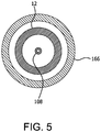


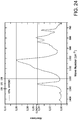
Classifications
-
- B—PERFORMING OPERATIONS; TRANSPORTING
- B65—CONVEYING; PACKING; STORING; HANDLING THIN OR FILAMENTARY MATERIAL
- B65D—CONTAINERS FOR STORAGE OR TRANSPORT OF ARTICLES OR MATERIALS, e.g. BAGS, BARRELS, BOTTLES, BOXES, CANS, CARTONS, CRATES, DRUMS, JARS, TANKS, HOPPERS, FORWARDING CONTAINERS; ACCESSORIES, CLOSURES, OR FITTINGS THEREFOR; PACKAGING ELEMENTS; PACKAGES
- B65D25/00—Details of other kinds or types of rigid or semi-rigid containers
- B65D25/14—Linings or internal coatings
-
- A—HUMAN NECESSITIES
- A61—MEDICAL OR VETERINARY SCIENCE; HYGIENE
- A61M—DEVICES FOR INTRODUCING MEDIA INTO, OR ONTO, THE BODY; DEVICES FOR TRANSDUCING BODY MEDIA OR FOR TAKING MEDIA FROM THE BODY; DEVICES FOR PRODUCING OR ENDING SLEEP OR STUPOR
- A61M5/00—Devices for bringing media into the body in a subcutaneous, intra-vascular or intramuscular way; Accessories therefor, e.g. filling or cleaning devices, arm-rests
- A61M5/178—Syringes
- A61M5/31—Details
- A61M5/3129—Syringe barrels
-
- B—PERFORMING OPERATIONS; TRANSPORTING
- B65—CONVEYING; PACKING; STORING; HANDLING THIN OR FILAMENTARY MATERIAL
- B65D—CONTAINERS FOR STORAGE OR TRANSPORT OF ARTICLES OR MATERIALS, e.g. BAGS, BARRELS, BOTTLES, BOXES, CANS, CARTONS, CRATES, DRUMS, JARS, TANKS, HOPPERS, FORWARDING CONTAINERS; ACCESSORIES, CLOSURES, OR FITTINGS THEREFOR; PACKAGING ELEMENTS; PACKAGES
- B65D25/00—Details of other kinds or types of rigid or semi-rigid containers
- B65D25/02—Internal fittings
- B65D25/04—Partitions
-
- C—CHEMISTRY; METALLURGY
- C23—COATING METALLIC MATERIAL; COATING MATERIAL WITH METALLIC MATERIAL; CHEMICAL SURFACE TREATMENT; DIFFUSION TREATMENT OF METALLIC MATERIAL; COATING BY VACUUM EVAPORATION, BY SPUTTERING, BY ION IMPLANTATION OR BY CHEMICAL VAPOUR DEPOSITION, IN GENERAL; INHIBITING CORROSION OF METALLIC MATERIAL OR INCRUSTATION IN GENERAL
- C23C—COATING METALLIC MATERIAL; COATING MATERIAL WITH METALLIC MATERIAL; SURFACE TREATMENT OF METALLIC MATERIAL BY DIFFUSION INTO THE SURFACE, BY CHEMICAL CONVERSION OR SUBSTITUTION; COATING BY VACUUM EVAPORATION, BY SPUTTERING, BY ION IMPLANTATION OR BY CHEMICAL VAPOUR DEPOSITION, IN GENERAL
- C23C16/00—Chemical coating by decomposition of gaseous compounds, without leaving reaction products of surface material in the coating, i.e. chemical vapour deposition [CVD] processes
- C23C16/04—Coating on selected surface areas, e.g. using masks
- C23C16/045—Coating cavities or hollow spaces, e.g. interior of tubes; Infiltration of porous substrates
-
- C—CHEMISTRY; METALLURGY
- C23—COATING METALLIC MATERIAL; COATING MATERIAL WITH METALLIC MATERIAL; CHEMICAL SURFACE TREATMENT; DIFFUSION TREATMENT OF METALLIC MATERIAL; COATING BY VACUUM EVAPORATION, BY SPUTTERING, BY ION IMPLANTATION OR BY CHEMICAL VAPOUR DEPOSITION, IN GENERAL; INHIBITING CORROSION OF METALLIC MATERIAL OR INCRUSTATION IN GENERAL
- C23C—COATING METALLIC MATERIAL; COATING MATERIAL WITH METALLIC MATERIAL; SURFACE TREATMENT OF METALLIC MATERIAL BY DIFFUSION INTO THE SURFACE, BY CHEMICAL CONVERSION OR SUBSTITUTION; COATING BY VACUUM EVAPORATION, BY SPUTTERING, BY ION IMPLANTATION OR BY CHEMICAL VAPOUR DEPOSITION, IN GENERAL
- C23C16/00—Chemical coating by decomposition of gaseous compounds, without leaving reaction products of surface material in the coating, i.e. chemical vapour deposition [CVD] processes
- C23C16/22—Chemical coating by decomposition of gaseous compounds, without leaving reaction products of surface material in the coating, i.e. chemical vapour deposition [CVD] processes characterised by the deposition of inorganic material, other than metallic material
- C23C16/30—Deposition of compounds, mixtures or solid solutions, e.g. borides, carbides, nitrides
- C23C16/36—Carbonitrides
-
- C—CHEMISTRY; METALLURGY
- C23—COATING METALLIC MATERIAL; COATING MATERIAL WITH METALLIC MATERIAL; CHEMICAL SURFACE TREATMENT; DIFFUSION TREATMENT OF METALLIC MATERIAL; COATING BY VACUUM EVAPORATION, BY SPUTTERING, BY ION IMPLANTATION OR BY CHEMICAL VAPOUR DEPOSITION, IN GENERAL; INHIBITING CORROSION OF METALLIC MATERIAL OR INCRUSTATION IN GENERAL
- C23C—COATING METALLIC MATERIAL; COATING MATERIAL WITH METALLIC MATERIAL; SURFACE TREATMENT OF METALLIC MATERIAL BY DIFFUSION INTO THE SURFACE, BY CHEMICAL CONVERSION OR SUBSTITUTION; COATING BY VACUUM EVAPORATION, BY SPUTTERING, BY ION IMPLANTATION OR BY CHEMICAL VAPOUR DEPOSITION, IN GENERAL
- C23C16/00—Chemical coating by decomposition of gaseous compounds, without leaving reaction products of surface material in the coating, i.e. chemical vapour deposition [CVD] processes
- C23C16/22—Chemical coating by decomposition of gaseous compounds, without leaving reaction products of surface material in the coating, i.e. chemical vapour deposition [CVD] processes characterised by the deposition of inorganic material, other than metallic material
- C23C16/30—Deposition of compounds, mixtures or solid solutions, e.g. borides, carbides, nitrides
- C23C16/40—Oxides
- C23C16/401—Oxides containing silicon
-
- C—CHEMISTRY; METALLURGY
- C23—COATING METALLIC MATERIAL; COATING MATERIAL WITH METALLIC MATERIAL; CHEMICAL SURFACE TREATMENT; DIFFUSION TREATMENT OF METALLIC MATERIAL; COATING BY VACUUM EVAPORATION, BY SPUTTERING, BY ION IMPLANTATION OR BY CHEMICAL VAPOUR DEPOSITION, IN GENERAL; INHIBITING CORROSION OF METALLIC MATERIAL OR INCRUSTATION IN GENERAL
- C23C—COATING METALLIC MATERIAL; COATING MATERIAL WITH METALLIC MATERIAL; SURFACE TREATMENT OF METALLIC MATERIAL BY DIFFUSION INTO THE SURFACE, BY CHEMICAL CONVERSION OR SUBSTITUTION; COATING BY VACUUM EVAPORATION, BY SPUTTERING, BY ION IMPLANTATION OR BY CHEMICAL VAPOUR DEPOSITION, IN GENERAL
- C23C16/00—Chemical coating by decomposition of gaseous compounds, without leaving reaction products of surface material in the coating, i.e. chemical vapour deposition [CVD] processes
- C23C16/44—Chemical coating by decomposition of gaseous compounds, without leaving reaction products of surface material in the coating, i.e. chemical vapour deposition [CVD] processes characterised by the method of coating
- C23C16/50—Chemical coating by decomposition of gaseous compounds, without leaving reaction products of surface material in the coating, i.e. chemical vapour deposition [CVD] processes characterised by the method of coating using electric discharges
- C23C16/505—Chemical coating by decomposition of gaseous compounds, without leaving reaction products of surface material in the coating, i.e. chemical vapour deposition [CVD] processes characterised by the method of coating using electric discharges using radio frequency discharges
- C23C16/507—Chemical coating by decomposition of gaseous compounds, without leaving reaction products of surface material in the coating, i.e. chemical vapour deposition [CVD] processes characterised by the method of coating using electric discharges using radio frequency discharges using external electrodes, e.g. in tunnel type reactors
-
- A—HUMAN NECESSITIES
- A61—MEDICAL OR VETERINARY SCIENCE; HYGIENE
- A61J—CONTAINERS SPECIALLY ADAPTED FOR MEDICAL OR PHARMACEUTICAL PURPOSES; DEVICES OR METHODS SPECIALLY ADAPTED FOR BRINGING PHARMACEUTICAL PRODUCTS INTO PARTICULAR PHYSICAL OR ADMINISTERING FORMS; DEVICES FOR ADMINISTERING FOOD OR MEDICINES ORALLY; BABY COMFORTERS; DEVICES FOR RECEIVING SPITTLE
- A61J1/00—Containers specially adapted for medical or pharmaceutical purposes
- A61J1/05—Containers specially adapted for medical or pharmaceutical purposes for collecting, storing or administering blood, plasma or medical fluids ; Infusion or perfusion containers
-
- A—HUMAN NECESSITIES
- A61—MEDICAL OR VETERINARY SCIENCE; HYGIENE
- A61M—DEVICES FOR INTRODUCING MEDIA INTO, OR ONTO, THE BODY; DEVICES FOR TRANSDUCING BODY MEDIA OR FOR TAKING MEDIA FROM THE BODY; DEVICES FOR PRODUCING OR ENDING SLEEP OR STUPOR
- A61M5/00—Devices for bringing media into the body in a subcutaneous, intra-vascular or intramuscular way; Accessories therefor, e.g. filling or cleaning devices, arm-rests
- A61M5/178—Syringes
- A61M5/31—Details
- A61M2005/3103—Leak prevention means for distal end of syringes, i.e. syringe end for mounting a needle
- A61M2005/3107—Leak prevention means for distal end of syringes, i.e. syringe end for mounting a needle for needles
- A61M2005/3109—Caps sealing the needle bore by use of, e.g. air-hardening adhesive, elastomer or epoxy resin
-
- A—HUMAN NECESSITIES
- A61—MEDICAL OR VETERINARY SCIENCE; HYGIENE
- A61M—DEVICES FOR INTRODUCING MEDIA INTO, OR ONTO, THE BODY; DEVICES FOR TRANSDUCING BODY MEDIA OR FOR TAKING MEDIA FROM THE BODY; DEVICES FOR PRODUCING OR ENDING SLEEP OR STUPOR
- A61M5/00—Devices for bringing media into the body in a subcutaneous, intra-vascular or intramuscular way; Accessories therefor, e.g. filling or cleaning devices, arm-rests
- A61M5/178—Syringes
- A61M5/31—Details
- A61M5/3129—Syringe barrels
- A61M2005/3131—Syringe barrels specially adapted for improving sealing or sliding
Definitions
- the present invention relates to the technical field of coated surfaces, for example interior surfaces of pharmaceutical packages
- the present invention relates to a pharmaceutical package.
- a method for coating an inner or interior surface of a pharmaceutical package is also described.
- the present disclosure also relates to improved methods for processing pharmaceutical packages, for example multiple identical pharmaceutical packages or other vessels used for pharmaceutical preparation storage and delivery, venipuncture and other medical sample collection.
- Such pharmaceutical packages are used in large numbers for these purposes, and must be relatively economical to manufacture and yet highly reliable in storage and use.
- borosilicate glass vessels such as vials or pre-filled syringes.
- the relatively strong, impermeable and inert surface of borosilicate glass has performed adequately for most drug products.
- the recent advent of costly, complex and sensitive biologics as well as such advanced delivery systems as auto injectors has exposed the physical and chemical shortcomings of glass pharmaceutical packages, including possible contamination from metals, flaking, delamination, and breakage, among other problems.
- glass contains several components which can leach out during storage and cause damage to the stored material.
- borosilicate pharmaceutical packages exhibit a number of drawbacks.
- Glass is manufactured from sand containing a heterogeneous mixture of many elements (silicon, oxygen, boron, aluminum, sodium, calcium) with trace levels of other alkali and earth metals.
- Type I borosilicate glass consists of approximately 76% SiO 2 , 10.5% B 2 O 3 , 5% Al 2 O 3 , 7% Na 2 O and 1.5% CaO and often contains trace metals such as iron, magnesium, zinc, copper and others.
- the heterogeneous nature of borosilicate glass creates a non-uniform surface chemistry at the molecular level. Glass forming processes used to create glass vessels expose some portions of the vessels to temperatures as great as 1200°C. Under such high temperatures alkali ions migrate to the local surface and form oxides.
- ions extracted from borosilicate glass devices may be involved in degradation, aggregation and denaturation of some biologics.
- Many proteins and other biologics must be lyophilized (freeze dried), because they are not sufficiently stable in solution in glass vials or syringes.
- silicone oil is typically used as a lubricant to allow the plunger tip, piston, stopper, or seal to slide in the barrel.
- Silicone oil has been implicated in the precipitation of protein solutions such as insulin and some other biologics. Additionally, the silicone oil coating or layer is often non-uniform, resulting in syringe failures in the market.
- Glass pharmaceutical packages are prone to breakage or degradation during manufacture, filling operations, shipping and use, which means that glass particulates may enter the drug.
- the presence of glass particles has led to many FDA Warning Letters and to product recalls.
- plastic and glass pharmaceutical packages each offer certain advantages in pharmaceutical primary packaging, neither is optimal for all drugs, biologics or other therapeutics.
- plastic pharmaceutical packages in particular plastic syringes, with gas and solute barrier properties which approach the properties of glass.
- plastic syringes with sufficient lubricity and/or passivation or protective properties and a lubricity and/or passivation layer or pH protective coating which can be compatible with the syringe contents.
- glass vessels with surfaces that do not tend to delaminate or dissolve or leach constituents when in contact with the vessel contents.
- Prefilled syringes are commonly prepared and sold so the syringe does not need to be filled before use, and can be disposed of after use.
- the syringe can be prefilled with saline solution, a dye for injection, or a pharmaceutically active preparation, for some examples.
- the prefilled syringe can be capped at the distal end, as with a cap (or, if the hypodermic needle is preinstalled, a needle shield that can also be a cap), and can be closed at the proximal end by its drawn plunger tip, piston, stopper, or seal.
- the prefilled syringe can be wrapped in a sterile package before use.
- a hypodermic needle or another delivery conduit can be attached to the distal end of the barrel, the delivery conduit or syringe can be moved to a use position (such as by inserting the hypodermic needle into a patient's blood vessel or into an apparatus to be rinsed with the contents of the syringe), and the plunger tip, piston, stopper, or seal can be advanced in the barrel to inject the contents of the barrel.
- An important consideration regarding medical syringes can be to ensure that the plunger tip, piston, stopper, or seal can move at a constant speed and with a constant force when it is pressed into the barrel.
- a similar consideration applies to vessels such as pharmaceutical vials which have to be closed by a stopper, and to the stopper itself, and more generally to any surface which is to provide smooth operation of moving parts and/or be passivated or protectively coated.
- DE 10 2004 017236 A1 describes a vessel made from a polymer substrate coated with an organic bonding layer, an inorganic barrier layer, and an organic protective layer.
- An aspect of the invention is a pharmaceutical package comprising a vessel, a barrier coating or layer, and a passivation layer or pH protective coating on the vessel.
- a fluid composition may be contained in the vessel.
- the calculated shelf life of the package containing the fluid composition can be more than six months at a storage temperature of 4°C.
- the vessel has a lumen defined at least in part by a wall.
- the wall has an interior surface facing the lumen and an outer surface.
- the barrier coating or layer is made of SiO x , wherein x is from 1.5 to 2.9, from 2 to 1000 nm thick.
- the barrier coating or layer of SiO x has an interior surface facing the lumen and an outer surface facing the wall interior surface.
- the passivation layer or pH protective coating is made of SiO x C y or SiN x C y wherein x is from 0.5 to 2.4 and y is from 0.6 to 3.
- x can be about 1.1 and y can be about 1.1.
- the passivation layer or pH protective coating has an interior surface facing the lumen and an outer surface facing the interior surface of the barrier coating or layer. The passivation layer or pH protective coating is effective to increase the calculated shelf life of the package (total Si / Si dissolution rate).
- the fluid composition can be contained in the lumen and can have a pH between 4 and 10, alternatively between 5 and 9.
- RF is radio frequency
- First and “second” or similar references to, for example, processing stations or processing devices refer to the minimum number of processing stations or devices that are present, but do not necessarily represent the order or total number of processing stations and devices. These terms do not limit the number of processing stations or the particular processing carried out at the respective stations.
- an "organosilicon precursor” is a compound having at least one of the linkages: or which is a tetravalent silicon atom connected to an oxygen or nitrogen atom and an organic carbon atom (an organic carbon atom being a carbon atom bonded to at least one hydrogen atom).
- a volatile organosilicon precursor defined as such a precursor that can be supplied as a vapor in a PECVD apparatus, can be an optional organosilicon precursor.
- the organosilicon precursor can be selected from the group consisting of a linear siloxane, a monocyclic siloxane, a polycyclic siloxane, a polysilsesquioxane, an alkyl trimethoxysilane, a linear silazane, a monocyclic silazane, a polycyclic silazane, a polysilsesquiazane, and a combination of any two or more of these precursors.
- the feed amounts of PECVD precursors, gaseous reactant or process gases, and carrier gas are sometimes expressed in "standard volumes" in the specification and claims.
- the standard volume of a charge or other fixed amount of gas is the volume the fixed amount of the gas would occupy at a standard temperature and pressure (without regard to the actual temperature and pressure of delivery).
- Standard volumes can be measured using different units of volume, and still be within the scope of the present disclosure and claims.
- the same fixed amount of gas could be expressed as the number of standard cubic centimeters, the number of standard cubic meters, or the number of standard cubic feet.
- Standard volumes can also be defined using different standard temperatures and pressures, and still be within the scope of the present disclosure and claims.
- the standard temperature might be 0°C and the standard pressure might be 760 Torr (as is conventional), or the standard temperature might be 20°C and the standard pressure might be 1 Torr. But whatever standard is used in a given case, when comparing relative amounts of two or more different gases without specifying particular parameters, the same units of volume, standard temperature, and standard pressure are to be used relative to each gas, unless otherwise indicated.
- the corresponding feed rates of PECVD precursors, gaseous reactant or process gases, and carrier gas are expressed in standard volumes per unit of time in the specification.
- the flow rates are expressed as standard cubic centimeters per minute, abbreviated as sccm.
- other units of time can be used, such as seconds or hours, but consistent parameters are to be used when comparing the flow rates of two or more gases, unless otherwise indicated.
- a "vessel" in the context of the present invention can be any type of article with at least one opening and a wall defining an inner or interior surface.
- the substrate can be the inside wall of a vessel having a lumen.
- the invention is not necessarily limited to pharmaceutical packages of a particular volume, pharmaceutical packages are contemplated in which the lumen can have a void volume of from 0.5 to 50 mL, optionally from 1 to 10 mL, optionally from 0.5 to 5 mL, optionally from 1 to 3 mL.
- the substrate surface can be part or all of the inner or interior surface of a vessel having at least one opening and an inner or interior surface.
- a vessel in the context of the present invention can have one or more openings.
- One or two openings like the openings of a sample tube (one opening) or a syringe barrel (two openings) are preferred. If the vessel has two openings, they can be the same size or different sizes. If there is more than one opening, one opening can be used for the gas inlet for a PECVD coating method, while the other openings are either capped or open.
- a vessel according to the present invention can be a sample tube, for example for collecting or storing biological fluids like blood or urine, a syringe (or a part thereof, for example a syringe barrel) for storing or delivering a biologically active compound or composition, for example a medicament or pharmaceutical composition, a vial for storing biological materials or biologically active compounds or compositions, a pipe, for example a catheter for transporting biological materials or biologically active compounds or compositions, or a cuvette for holding fluids, for example for holding biological materials or biologically active compounds or compositions.
- a sample tube for example for collecting or storing biological fluids like blood or urine
- a syringe or a part thereof, for example a syringe barrel
- a biologically active compound or composition for example a medicament or pharmaceutical composition
- a vial for storing biological materials or biologically active compounds or compositions
- a pipe for example a catheter for transporting biological materials or biologically active compounds or compositions
- the vessel can be provided with a reagent or preservative for sample collection or analysis.
- a vessel for blood can contain a compound or composition in its lumen, for example citrate or a citrate containing composition.
- a vessel can be of any shape, a vessel having a substantially cylindrical wall adjacent to at least one of its open ends being preferred.
- the interior wall of the vessel can be cylindrically shaped, like, for example in a sample tube or a syringe barrel. Sample tubes and syringes or their parts (for example syringe barrels) are contemplated.
- a “hydrophobic layer” in the context of the present invention means that the coating or layer lowers the wetting tension of a surface coated with the coating or layer, compared to the corresponding uncoated surface. Hydrophobicity can be thus a function of both the uncoated substrate and the coating or layer. The same applies with appropriate alterations for other contexts wherein the term “hydrophobic” is used.
- the term “hydrophilic” means the opposite, i.e. that the wetting tension is increased compared to a reference sample.
- the present hydrophobic layers are primarily defined by their hydrophobicity and the process conditions providing hydrophobicity. Suitable hydrophobic coatings or layers and their application, properties, and use are described in U.S. Patent No. 7,985,188 . Dual functional passivation layers or pH protective coatings that also have the properties of hydrophobic coatings or layers can be provided for any embodiment of the present invention.
- w, x, y, and z are applicable to the empirical composition Si w O x C y H z throughout this specification.
- the values of w, x, y, and z used throughout this specification should be understood as ratios or an empirical formula (for example for a coating or layer), rather than as a limit on the number or type of atoms in a molecule.
- octamethylcyclotetrasiloxane which has the molecular composition Si 4 O 4 C 8 H 24 , can be described by the following empirical formula, arrived at by dividing each of w, x, y, and z in the molecular formula by 4, the largest common factor: Si 1 O 1 C 2 H 6 .
- w, x, y, and z are also not limited to integers.
- (acyclic) octamethyltrisiloxane, molecular composition Si 3 O 2 C 8 H 24 is reducible to Si 1 O 0.67 C 2.67 H 8 .
- SiO x C y H z can be described as equivalent to SiO x C y , it is not necessary to show the presence of hydrogen in any proportion to show the presence of SiO x C y .
- wetting tension is a specific measure for the hydrophobicity or hydrophilicity of a surface.
- An optional wetting tension measurement method in the context of the present invention is ASTM D 2578 or a modification of the method described in ASTM D 2578. This method uses standard wetting tension solutions (called dyne solutions) to determine the solution that comes nearest to wetting a plastic film surface for exactly two seconds. This is the film's wetting tension.
- the procedure utilized can be varied herein from ASTM D 2578 in that the substrates are not flat plastic films, but are tubes made according to the Protocol for Forming PET Tube and (except for controls) coated according to the Protocol for Coating Tube Interior with Hydrophobic Coating or Layer (see Example 9 of EP2251671 A2 ).
- a “lubricity coating or layer” according to the present invention is a coating or layer which has a lower frictional resistance than the uncoated surface.
- a "passivation layer or pH protective coating” according to the present invention passivates or protects an underlying surface or layer from a fluid composition contacting the layer (as more extensively defined elsewhere in this specification).
- Fritional resistance can be static frictional resistance and/or kinetic frictional resistance.
- One of the optional embodiments of the present invention can be a syringe barrel coated with a lubricity and passivation layer or pH protective coating.
- the relevant static frictional resistance in the context of the present invention is the breakout force as defined herein
- the relevant kinetic frictional resistance in the context of the present invention is the plunger sliding force as defined herein.
- the plunger sliding force as defined and determined herein is suitable to determine the presence or absence and the lubricity of a lubricity and passivation layer or pH protective coating in the context of the present invention whenever the coating or layer is applied to any syringe or syringe part, for example to the inner wall of a syringe barrel.
- the breakout force can be of particular relevance for evaluation of the coating or layer effect on a prefilled syringe, i.e. a syringe which can be filled after coating and can be stored for some time, for example several months or even years, before the plunger tip, piston, stopper, or seal is moved again (has to be "broken out”).
- the "plunger sliding force” (synonym to “glide force,” “maintenance force”, or F m , also used in this description) in the context of the present invention is the force required to maintain movement of a plunger tip, piston, stopper, or seal in a syringe barrel, for example during aspiration or dispense. It can advantageously be determined using the ISO 7886-1:1993 test described herein and known in the art. A synonym for "plunger sliding force” often used in the art is “plunger force” or “pushing force”.
- the "plunger breakout force” (synonym to “breakout force”, “break loose force”, “initiation force”, Fi, also used in this description) in the context of the present invention is the initial force required to move the plunger tip, piston, stopper, or seal in a syringe, for example in a prefilled syringe.
- Sliding force and breakout force are sometimes used herein to describe the forces required to advance a stopper or other closure into a pharmaceutical package, such as a medical sample tube or a vial, to seat the stopper in a vessel to close the vessel. Its use can be analogous to use in the context of a syringe and its plunger tip, piston, stopper, or seal, and the measurement of these forces for a vessel and its closure are contemplated to be analogous to the measurement of these forces for a syringe, except that at least in most cases no liquid is ejected from a vessel when advancing the closure to a seated position.
- “Slidably” means that the plunger tip, piston, stopper, or seal or other removable part can be permitted to slide in a syringe barrel or other vessel.
- Coatings of SiO x are deposited by plasma enhanced chemical vapor deposition (PECVD) or other chemical vapor deposition processes on the vessel of a pharmaceutical package, in particular a thermoplastic package, to serve as a barrier coating or layer preventing oxygen, air, carbon dioxide, or other gases from entering the vessel and optionally to prevent leaching of the pharmaceutical material into or through the package wall.
- PECVD plasma enhanced chemical vapor deposition
- the barrier coating or layer can be effective to reduce the ingress of atmospheric gas, for example oxygen, into the lumen compared to a vessel without a barrier coating.
- the vapor-deposited coating or layer optionally can also, or alternatively, be a solute barrier coating or layer.
- a concern of converting from glass to plastic syringes centers around the potential for leachable materials from plastics.
- the coatings or layers derived from non-metal gaseous precursors for example HMDSO or OMCTS or other organosilicon compounds, will contain no trace metals and function as a barrier coating or layer to inorganic, metals and organic solutes, preventing leaching of these species from the coated substrate into syringe fluids.
- the same plasma passivation layer or pH protective coating technology offers potential to provide a solute barrier to the plunger tip, piston, stopper, or seal, typically made of elastomeric plastic compositions containing even higher levels of leachable organic oligomers and catalysts.
- certain syringes prefilled with synthetic and biological pharmaceutical formulations are very oxygen and moisture sensitive.
- a critical factor in the conversion from glass to plastic syringe barrels will be the improvement of plastic oxygen and moisture barrier performance.
- the plasma passivation layer or pH protective coating technology can be suitable to maintain the SiO x barrier coating or layer for protection against oxygen and moisture over an extended shelf life.
- solutes in drugs usefully excluded by a barrier layer include antibacterial preservatives, antioxidants, chelating agents, pH buffers, and combinations of any of these.
- the vapor-deposited coating or layer optionally can be a solvent barrier coating or layer for a solvent comprising a co-solvent used to increase drug solubilization.
- the vapor-deposited coating or layer optionally can be a barrier coating or layer for water, glycerin, propylene glycol, methanol, ethanol, n-propanol, isopropanol, acetone, benzyl alcohol, polyethylene glycol, cotton seed oil, benzene, dioxane, or combinations of any two or more of these.
- the vapor-deposited coating or layer optionally can be a metal ion barrier coating or layer.
- the vapor-deposited coating or layer optionally can be a barrel wall material barrier coating or layer, to prevent or reduce the leaching of barrel material such as any of the base barrel resins mentioned previously and any other ingredients in their respective compositions.
- barrier coatings or layers of SiO x are eroded or dissolved by some fluid compositions, for example aqueous compositions having a pH above about 5. Since coatings applied by chemical vapor deposition can be very thin - tens to hundreds of nanometers thick - even a relatively slow rate of erosion can remove or reduce the effectiveness of the barrier coating or layer in less time than the desired shelf life of a product package. This can be particularly a problem for fluid pharmaceutical compositions, since many of them have a pH of roughly 7, or more broadly in the range of 5 to 9, similar to the pH of blood and other human or animal fluids. The higher the pH of the pharmaceutical preparation, the more quickly it erodes or dissolves the SiO x coating.
- borosilicate glass surfaces are eroded or dissolved by some fluid compositions, for example aqueous compositions having a pH above about 5.
- aqueous compositions having a pH above about 5 This can be particularly a problem for fluid pharmaceutical compositions, since many of them have a pH of roughly 7, or more broadly in the range of 5 to 9, similar to the pH of blood and other human or animal fluids.
- the higher the pH of the pharmaceutical preparation the more quickly it erodes or dissolves the glass. Delamination of the glass can also result from such erosion or dissolution, as small particles of glass are undercut by the aqueous compositions having a pH above about 5.
- passivation layers or pH protective coatings of SiO x C y or SiN x C y formed from cyclic polysiloxane precursors which passivation layers or pH protective coatings have a substantial organic component, do not erode quickly when exposed to fluid compositions, and in fact erode or dissolve more slowly when the fluid compositions have higher pHs within the range of 5 to 9.
- the dissolution rate of a passivation layer or pH protective coating made from the precursor octamethylcyclotetrasiloxane, or OMCTS can be quite slow.
- passivation layers or pH protective coatings of SiO x C y or SiN x C y can therefore be used to cover a barrier coating or layer of SiO x , retaining the benefits of the barrier coating or layer by passivating or protecting it from the fluid composition in the pharmaceutical package.
- passivation layers or pH protective coatings of SiO x C y or SiN x C y also can be used to cover a glass surface, for example a borosilicate glass surface, preventing delamination, erosion and dissolution of the glass, by passivating or protecting it from the fluid composition in the pharmaceutical package.
- SiO x C y or SiN x C y coatings deposited from linear siloxane or linear silazane precursors, for example hexamethyldisiloxane (HMDSO), are believed to contain fragments of the original precursor to a large degree and low organic content.
- Such SiO x C y or SiN x C y coatings have a degree of water miscibility or swellability, allowing them to be attacked by aqueous solutions.
- a vessel with a passivation layer or pH protective coating as described herein and/or prepared according to a method described herein can be used for reception and/or storage and/or delivery of a compound or composition.
- the compound or composition can be sensitive, for example air-sensitive, oxygen-sensitive, sensitive to humidity and/or sensitive to mechanical influences. It can be a biologically active compound or composition, for example a pharmaceutical preparation or medicament like insulin or a composition comprising insulin.
- a prefilled syringe can be especially considered which contains injectable or other liquid drugs like insulin.
- the compound or composition can be a biological fluid, optionally a bodily fluid, for example blood or a blood fraction.
- the compound or composition can be a product to be administrated to a subject in need thereof, for example a product to be injected, like blood (as in transfusion of blood from a donor to a recipient or reintroduction of blood from a patient back to the patient) or insulin.
- a vessel with a passivation layer or pH protective coating as described herein and/or prepared according to a method described herein can further be used for protecting a compound or composition contained in its interior space against mechanical and/or chemical effects of the surface of the vessel material. For example, it can be used for preventing or reducing precipitation and/or clotting or platelet activation of the compound or a component of the composition, for example insulin precipitation or blood clotting or platelet activation.
- Such environmental compound can be a gas or liquid, for example an atmospheric gas or liquid containing oxygen, air, and/or water vapor.
- a barrier coating or layer 30 and a passivation layer or pH protective coating 34 may be applied directly or indirectly to at least a portion of the interior wall 16 of a vessel, such as any of the pharmaceutical packages 210 of FIGS. 7-8 , or a sample collection tube, for example a blood collection tube and/or a closed-ended sample collection tube.
- At least a portion of the internal wall 16 of the pharmaceutical package 210 comprises or consists essentially of a polymer, for example a polyolefin (for example a cyclic olefin polymer, a cyclic olefin copolymer, or polypropylene), a polyester, for example polyethylene terephthalate or polyethylene naphthalate, a polycarbonate, polylactic acid, or any combination, composite or blend of any two or more of the above materials.
- a polyolefin for example a cyclic olefin polymer, a cyclic olefin copolymer, or polypropylene
- a polyester for example polyethylene terephthalate or polyethylene naphthalate
- a polycarbonate for example polyethylene terephthalate or polyethylene naphthalate
- polylactic acid for example a polylactic acid, or any combination, composite or blend of any two or more of the above materials.
- At least a portion of the internal wall 16 of the pharmaceutical package 210 comprises or consists essentially of glass, for example borosilicate glass.
- the polymeric material can be a silicone elastomer or a thermoplastic polyurethane, as two examples, or any material suitable for contact with blood, or with insulin.
- a coated substrate is contemplated for storing insulin.
- the pharmaceutical package 210 comprises a syringe barrel.
- the pharmaceutical package comprises a cartridge.
- the pharmaceutical package comprises a vial.
- the pharmaceutical package comprises a blister package.
- the pharmaceutical package comprises an ampoule.
- the vessel can be a length of tubing from about 1 cm to about 200 cm, optionally from about 1 cm to about 150 cm, optionally from about 1 cm to about 120 cm, optionally from about 1 cm to about 100 cm, optionally from about 1 cm to about 80 cm, optionally from about 1 cm to about 60 cm, optionally from about 1 cm to about 40 cm, optionally from about 1 cm to about 30 cm long, and processing it with a probe electrode as described below.
- relative motion between the PECVD or other chemical vapor deposition probe and the vessel can be useful during passivation layer or pH protective coating formation. This can be done, for example, by moving the vessel with respect to the probe or moving the probe with respect to the vessel.
- the barrier coating or layer discussed below can be thinner or less complete than would be preferred to provide the high gas barrier integrity needed in an evacuated blood collection tube, and thus the long shelf life needed to store a liquid material in contact with the barrier coating or layer for an extended period.
- the vessel can have a central axis.
- the vessel wall can be sufficiently flexible to be flexed at least once at 20°C, without breaking the wall, over a range from at least substantially straight to a bending radius at the central axis of not more than 100 times as great as the outer diameter of the vessel.
- the bending radius at the central axis can be, for example, not more than 90 times as great as, or not more than 80 times as great as, or not more than 70 times as great as, or not more than 60 times as great as, or not more than 50 times as great as, or not more than 40 times as great as, or not more than 30 times as great as, or not more than 20 times as great as, or not more than 10 times as great as, or not more than 9 times as great as, or not more than 8 times as great as, or not more than 7 times as great as, or not more than 6 times as great as, or not more than 5 times as great as, or not more than 4 times as great as, or not more than 3 times as great as, or not more than 2 times as great as, or not more than, the outer diameter of the vessel.
- the vessel wall can be a fluid-contacting surface made of flexible material.
- the vessel lumen can be the fluid flow passage of a pump.
- the vessel can be a blood containing vessel.
- the passivation layer or pH protective coating can be effective to reduce the clotting or platelet activation of blood exposed to the inner or interior surface, compared to the same type of wall uncoated with a hydrophobic layer.
- a hydrophobic layer will reduce the adhesion or clot forming tendency of the blood, as compared to its properties in contact with an unmodified polymeric or SiO x surface.
- This property is contemplated to reduce or potentially eliminate the need for treating the blood with heparin, as by reducing the necessary blood concentration of heparin in a patient undergoing surgery of a type requiring blood to be removed from the patient and then returned to the patient, as when using a heart-lung machine during cardiac surgery. It is contemplated that this will reduce the complications of surgery involving the passage of blood through such a pharmaceutical package, by reducing the bleeding complications resulting from the use of heparin.
- Another embodiment can be a vessel including a wall and having an inner or interior surface defining a lumen.
- the inner or interior surface can have an at least partial passivation layer or pH protective coating that presents a hydrophobic surface, the passivation layer or pH protective coating being effective to reduce the clotting or platelet activation of blood exposed to the inner or interior surface.
- a vessel examples include a blood transfusion bag, a blood sample collection vessel in which a sample has been collected, the tubing of a heart-lung machine, a flexible-walled blood collection bag, or tubing used to collect a patient's blood during surgery and reintroduce the blood into the patient's vasculature.
- a particularly suitable pump can be a centrifugal pump or a peristaltic pump.
- the vessel has a wall; the wall has an inner or interior surface defining a lumen.
- the inner or interior surface of the wall has an at least partial passivation layer or pH protective coating, which optionally also presents a hydrophobic surface.
- the vessel can contain blood viable for return to the vascular system of a patient disposed within the lumen in contact with the hydrophobic layer.
- An embodiment can be a blood containing vessel including a wall and having an inner or interior surface defining a lumen.
- the inner or interior surface has an at least partial passivation layer or pH protective coating that optionally also presents a hydrophobic surface.
- the passivation layer or pH protective coating consists essentially of SiO x C y where x and y are as defined in this specification.
- the vessel contains blood viable for return to the vascular system of a patient disposed within the lumen in contact with the hydrophobic coating or layer.
- Coating can be carried out under conditions effective to form a hydrophobic passivation layer or pH protective coating on the substrate.
- the hydrophobic characteristics of the passivation layer or pH protective coating can be set by setting the ratio of the oxidizing gas to the organosilicon precursor in the gaseous reactant, and/or by setting the electric power used for generating the plasma.
- the passivation layer or pH protective coating can have a lower wetting tension than the uncoated surface, optionally a wetting tension of from 20 to 72 dyne/cm, optionally from 30 to 60 dynes/cm, optionally from 30 to 40 dynes/cm, optionally 34 dyne/cm.
- the passivation layer or pH protective coating can be more hydrophobic than the uncoated surface.
- the vessel can have an inner diameter of at least 2 mm, or at least 4 mm.
- the vessel can be a tube.
- the lumen can have at least two open ends.
- the vessel of FIGS. 1-7 is a syringe, which is a contemplated type of vessel provided with a passivation layer or pH protective coating.
- the syringe can comprise a syringe barrel 14 and a plunger tip, piston, stopper, or seal 36.
- the internal wall 16 defines at least a portion of the syringe barrel 250.
- the plunger tip, piston, stopper, or seal 36 can be a relatively sliding part of the syringe, with respect to the syringe barrel 250.
- the term “syringe” is broadly defined to include cartridges, injection "pens,” and other types of barrels or reservoirs adapted to be assembled with one or more other components to provide a functional syringe.
- a “syringe” is also broadly defined to include related articles such as auto-injectors, which provide a mechanism for dispensing the contents.
- a capped pre-assembly 12 can be provided comprising a barrel 14, a dispensing portion 20, and a shield 28.
- the capped pre-assembly 12 can be a complete article or it can be a portion of a complete article adapted to dispense fluid, such as a syringe, a cartridge, or a catheter.
- the barrel 14 has an internal wall 16 defining a barrel lumen 18.
- the barrel 14 can further include an opening 32 spaced from the dispensing portion 20 and communicating through the internal wall 16.
- Such an opening can be conventional, for example, in a syringe or cartridge, where a typical example can be the back opening 32 of a prefilled syringe barrel, through which the plunger tip, piston, stopper, or seal 36 can be inserted after the barrel lumen 18 is filled with a suitable pharmaceutical preparation or other fluid material 40 to be dispensed.
- the barrel 14 can be formed, for example, by molding, although the manner of its formation is not critical and it can also be formed, for example, by machining a solid preform.
- the barrel can be molded by injection molding thermoplastic material, although it can also be formed by blow molding or a combined method.
- the barrel 14 can be formed by placing a dispensing portion 20 as described below in an injection mold and injection molding thermoplastic material about the dispensing portion, thus forming the barrel and securing the dispensing portion to the barrel.
- the dispensing portion and the barrel can be molded or otherwise formed as a single piece, or can be formed separately and joined in other ways.
- the barrel of any embodiment can be made of any suitable material.
- Several barrel materials particularly contemplated are COC (cyclic olefin copolymer), COP (cyclic olefin polymer), PET (polyethylene terephthalate), and polypropylene.
- the dispensing portion 20 of the capped pre-assembly 12 can be provided to serve as an outlet for fluid dispensed from the barrel lumen 18 of a completed article made from the capped pre-assembly 12.
- a suitable dispensing portion illustrated in the Figures can be a hypodermic needle 20.
- the dispensing portion 20 can instead be a needle-free dispenser.
- a suitable needle-free dispenser can be a blunt or flexible dispensing portion intended to be received in a complementary coupling to transfer fluid material 40.
- blunt or flexible dispensing portions are well known for use in syringes, intravenous infusion systems, and other systems and equipment to dispense material while avoiding the hazard of working with a sharp needle that may accidentally stick a health professional or other person.
- Another example of a needle-free dispenser can be a fluid jet or spray injection system that injects a free jet or spray of fluid directly through a patient's skin, without the need for an intermediate needle. Any type of dispensing portion 20, whether a hypodermic needle or any form of needle-free dispenser, is contemplated for use according to any embodiment of the present invention.
- the dispensing portion 20 is or can be secured to the barrel 14 and includes a proximal opening 22, a distal opening 24, and a dispensing portion lumen 26.
- the proximal opening 22 communicates with the barrel lumen 18.
- the distal opening 24 can be located outside the barrel 14.
- the dispensing portion lumen 26 communicates between the proximal and distal openings 22, 24 of the dispensing portion 20.
- the distal opening 24 can be at the sharpened tip of a hypodermic needle 20.
- the shield 28 can be secured to the barrel 14 and at least substantially isolates the distal opening 24 of the dispensing portion 20 from pressure conditions outside the shield 28.
- the shield 28 sufficiently isolates portions of the assembly 12 to provide a sufficient bio-barrier to facilitate safe use of the capped pre-assembly 12 for transdermal injections.
- the shield 28 can isolate the distal opening 24 in various ways. Effective isolation can be provided at least partially due to contact between the shield 28 and the distal opening 24, as shown in present FIGS. 2, 3 , 4 , and 7 .
- the tip of the dispensing portion 20 can be buried in the material of the shield 28.
- effective isolation can be provided at least partially due to contact between the shield 28 and the barrel 14, as also shown in present FIGS. 2, 3 , 4 , and 7 .
- the primary line of contact between the shield 28 and the barrel 14 can be at a rib 42 (best seen in FIG. 3 ) encircling and seated against a generally cylindrical surface 44 at the nose of the barrel 14.
- effective isolation can be provided due to both of these types of contact as illustrated in FIGS. 2-3 .
- the shield 28 of any embodiment optionally can have a latching mechanism, best shown in FIG. 3 , including a barb 46 and a catch 48 which engage to hold the shield 28 in place.
- the catch 48 can be made of sufficiently resilient material to allow the shield 28 to be removed and replaced easily.
- the shield 28 can be a specially formed needle shield.
- the original use of a needle shield is to cover the hypodermic needle before use, preventing accidental needle sticks and preventing contamination of the needle before it is injected in a patient or an injection port.
- a comparable shield preferably is used, even if the dispensing portion 20 is a needle-free dispenser, to prevent contamination of the dispenser during handling.
- the shield 28 can be formed in any suitable way.
- the shield 28 can be formed by molding thermoplastic material.
- the thermoplastic material can be elastomeric material or other material that can be suitable for forming a seal.
- One suitable category of elastomeric materials is known generically as thermoplastic elastomer (TPE).
- TPE thermoplastic elastomer
- An example of a suitable thermoplastic elastomer for making a shield 28 is Stelmi® Formulation 4800 (flexible shield formulation). Any other material having suitable characteristics can instead be used in any embodiment.
- the shield 28 can be sufficiently permeable to a sterilizing gas to sterilize the portions of the assembly 12 isolated by the shield.
- a sterilizing gas is ethylene oxide.
- Shields 28 are available that are sufficiently permeable to the sterilizing gas that parts isolated by the shield can nonetheless be sterilized.
- An example of a shield formulation sufficiently permeable to accommodate ethylene oxide gas sterilization can be Stelmi® Formulation 4800.
- FIGS. 7-8 Three embodiments of the invention having many common features are those of FIGS. 7-8 . Some of their common features are the following, indicated in many cases by common reference characters or names. The nature of the features of each embodiment can be as described later in the specification.
- the pharmaceutical packages of FIGS. 7-8 each include a vessel 210, a fluid composition 40, an SiO x barrier coating or layer 30, and a passivation layer or pH protective coating 34.
- Each vessel 210 has a lumen 18 defined at least in part by a wall interior portion 16 made of thermoplastic material.
- the internal wall 16 has an interior surface facing the lumen 18 and an outer surface.
- the fluid composition 40 can be contained in the lumen 18 and can have a pH between 4 and 10, alternatively between 5 and 9.
- the barrier coating or layer 30 is located between the inner or interior surface of the thermoplastic internal wall 16 and the fluid material 40.
- the barrier coating or layer 286 of SiO x can be supported by the thermoplastic internal wall 16.
- the barrier coating or layer 286 can have the characteristic of being subject to being measurably diminished in barrier improvement factor in less than six months as a result of attack by the fluid material 40.
- the barrier coating or layer 286 as described elsewhere in this specification, or in U.S. Patent No. 7,985,188 can be used in any embodiment.
- the barrier coating or layer 30 is effective to reduce the ingress of atmospheric gas into the lumen 18, compared to an uncoated container otherwise the same as the pharmaceutical package 210.
- the barrier coating or layer for any embodiment defined in this specification (unless otherwise specified in a particular instance) is optionally applied by PECVD as indicated in U.S. Pat. No. 7,985,188 .
- the barrier improvement factor (BIF) of the barrier coating or layer can be determined by providing two groups of identical containers, adding a barrier coating or layer to one group of containers, testing a barrier property (such as the rate of outgassing in micrograms per minute or another suitable measure) on containers having a barrier coating or layer, doing the same test on containers lacking a barrier coating or layer, and taking a ratio of the properties of the materials with versus without a barrier coating or layer. For example, if the rate of outgassing through the barrier coating or layer is one-third the rate of outgassing without a barrier coating or layer, the barrier coating or layer has a BIF of 3.
- the barrier coating is an "SiO x " coating, and contains silicon, oxygen, and optionally other elements, in which x, the ratio of oxygen to silicon atoms, is from 1.5 to 2.9, or 1.5 to 2.6, or about 2. These alternative definitions of x apply to any use of the term SiO x in this specification.
- the barrier coating or layer is applied to the interior of a pharmaceutical package, for example a sample collection tube, a syringe barrel, a vial, or another type of vessel.
- the barrier coating or layer 30 is of SiO x , from 2 to 1000 nm thick, the barrier coating or layer 30 of SiO x having an interior surface facing the lumen 18 and an outer surface facing the internal wall 16.
- the barrier coating or layer 30 is effective to reduce the ingress of atmospheric gas into the lumen 18 compared to an uncoated pharmaceutical package 210.
- One suitable barrier composition can be one where x is 2.3, for example.
- the barrier coating or layer such as 30 of any embodiment can be applied at a thickness of at least 2 nm, or at least 4 nm, or at least 7 nm, or at least 10 nm, or at least 20 nm, or at least 30 nm, or at least 40 nm, or at least 50 nm, or at least 100 nm, or at least 150 nm, or at least 200 nm, or at least 300 nm, or at least 400 nm, or at least 500 nm, or at least 600 nm, or at least 700 nm, or at least 800 nm, or at least 900 nm.
- the barrier coating or layer can be up to 1000 nm, or at most 900 nm, or at most 800 nm, or at most 700 nm, or at most 600 nm, or at most 500 nm, or at most 400 nm, or at most 300 nm, or at most 200 nm, or at most 100 nm, or at most 90 nm, or at most 80 nm, or at most 70 nm, or at most 60 nm, or at most 50 nm, or at most 40 nm, or at most 30 nm, or at most 20 nm, or at most 10 nm, or at most 5 nm thick.
- the thickness of the SiO x barrier coating or layer can be measured, for example, by transmission electron microscopy (TEM), and its composition can be measured by X-ray photoelectron spectroscopy (XPS).
- TEM transmission electron microscopy
- XPS X-ray photoelectron spectroscopy
- the barrier coating described herein can be applied to a variety of pharmaceutical packages made from plastic or glass, for example to plastic tubes, vials, and syringes.
- a passivation layer or pH protective coating 34 of SiO x C y can be applied, for example, by PECVD directly or indirectly to the barrier coating or layer 30 so it is located between the barrier coating or layer 30 and the fluid material 40 in the finished article.
- the passivation layer or pH protective coating 34 has an interior surface facing the lumen 18 and an outer surface facing the interior surface of the barrier coating or layer 30.
- the passivation layer or pH protective coating 34 can be supported by the thermoplastic internal wall 16.
- the passivation layer or pH protective coating 34 is effective to keep the barrier coating or layer 30 at least substantially undissolved as a result of attack by a fluid material 40 having a pH between 4 and 10 for a period of at least six months.
- the passivation layer or pH protective coating is composed of Si w O x C y H z (or its equivalent SiO x C y ) or Si w N x C y H z (or its equivalent SiN x C y ), each as defined in this specification.
- the passivation layer or pH protective coating thus in one aspect has the formula Si w O x C y H z , or its equivalent SiO x C y , for example where w is 1, x is from 0.5 to 2.4, y is from 0.6 to 3, and z (if defined) is from 2 to 9.
- the atomic ratio can be determined by XPS (X-ray photoelectron spectroscopy). XPS does not detect hydrogen atoms, so it is customary, when determining the atomic ratio by XPS, to omit hydrogen from the stated formulation.
- the formulation thus can be typically expressed as Si w O x C y , where w is 1, x is from 0.5 to 2.4, and y is from 0.6 to 3, with no limitation on z.
- the atomic ratios of Si, O, and C in the passivation layer or pH protective coating can be, as several options:
- the passivation layer or pH protective coating can have atomic concentrations normalized to 100% carbon, oxygen, and silicon, as determined by X-ray photoelectron spectroscopy (XPS) of less than 50% carbon and more than 25% silicon.
- the atomic concentrations can be from 25 to 45% carbon, 25 to 65% silicon, and 10 to 35% oxygen.
- the atomic concentrations can be from 30 to 40% carbon, 32 to 52% silicon, and 20 to 27% oxygen.
- the atomic concentrations can be from 33 to 37% carbon, 37 to 47% silicon, and 22 to 26% oxygen.
- the atomic concentration of carbon in the protective layer can be greater than the atomic concentration of carbon in the atomic formula for the organosilicon precursor.
- the atomic concentration of carbon increases by from 1 to 80 atomic percent, alternatively from 10 to 70 atomic percent, alternatively from 20 to 60 atomic percent, alternatively from 30 to 50 atomic percent, alternatively from 35 to 45 atomic percent, alternatively from 37 to 41 atomic percent.
- the atomic ratio of carbon to oxygen in the passivation layer or pH protective coating can be increased in comparison to the organosilicon precursor, and/or the atomic ratio of oxygen to silicon can be decreased in comparison to the organosilicon precursor.
- the passivation layer or pH protective coating can have an atomic concentration of silicon, normalized to 100% of carbon, oxygen, and silicon, as determined by X-ray photoelectron spectroscopy (XPS), less than the atomic concentration of silicon in the atomic formula for the feed gas.
- XPS X-ray photoelectron spectroscopy
- the atomic concentration of silicon decreases by from 1 to 80 atomic percent, alternatively by from 10 to 70 atomic percent, alternatively by from 20 to 60 atomic percent, alternatively by from 30 to 55 atomic percent, alternatively by from 40 to 50 atomic percent, alternatively by from 42 to 46 atomic percent.
- a passivation layer or pH protective coating is contemplated that can be characterized by a sum formula wherein the atomic ratio C : O can be increased and/or the atomic ratio Si : O can be decreased in comparison to the sum formula of the organosilicon precursor.
- the passivation layer or pH protective coating can have a density between 1.25 and 1.65 g/cm 3 , alternatively between 1.35 and 1.55 g/cm 3 , alternatively between 1.4 and 1.5 g/cm 3 , alternatively between 1.4 and 1.5 g/cm 3 , alternatively between 1.44 and 1.48 g/cm 3 , as determined by X-ray reflectivity (XRR).
- the organosilicon compound can be octamethylcyclotetrasiloxane and the passivation layer or pH protective coating can have a density which can be higher than the density of a passivation layer or pH protective coating made from HMDSO as the organosilicon compound under the same PECVD reaction conditions.
- the passivation layer or pH protective coating optionally can have an RMS surface roughness value (measured by AFM) of from 2 to 9, optionally from 6 to 8, optionally from 6.4 to 7.8.
- the R a surface roughness value of the passivation layer or pH protective coating, measured by AFM can be from 4 to 6, optionally from 4.6 to 5.8.
- the R max surface roughness value of the passivation layer or pH protective coating, measured by AFM can be from 70 to 160, optionally from 84 to 142, optionally from 90 to 130.
- the rate of erosion, dissolution, or leaching (different names for related concepts) of the construction including a passivation layer or pH protective coating 34, if directly contacted by the fluid material 40, can be less than the rate of erosion, dissolution, or leaching of the barrier coating or layer 30, if directly contacted by the fluid material 40.
- the passivation layer or pH protective coating 34 can be effective to isolate or protect the barrier coating or layer 30 from the fluid material 40 at least for sufficient time to allow the barrier coating or layer to act as a barrier during the shelf life of the pharmaceutical package 210.
- An FTIR absorbance spectrum of the passivation layer or pH protective coating 34 of any embodiment of Figures 7-8 has a ratio greater than 0.75 between the maximum amplitude of the Si-O-Si symmetrical stretch peak normally located between 1000 and 1040 cm -1 , and the maximum amplitude of the Si-O-Si asymmetric stretch peak normally located between 1060 and 1100 cm -1 .
- this ratio can be at least 0.8, or at least 0.9, or at least 1.0, or at least 1.1, or at least 1.2.
- This ratio can be at most 1.7, or at most 1.6, or at most 1.5, or at most 1.4, or at most 1.3. Any minimum ratio stated here can be combined with any maximum ratio stated here, as an alternative embodiment of the invention of FIGS. 7-8 .
- the passivation layer or pH protective coating in the absence of the medicament, can have a non-oily appearance. This appearance has been observed in some instances to distinguish an effective passivation layer or pH protective coating from a lubricity layer, which in some instances has been observed to have an oily (i.e. shiny) appearance.
- the silicon dissolution rate by a 50 mM potassium phosphate buffer diluted in water for injection, adjusted to pH 8 with concentrated nitric acid, and containing 0.2 wt. % polysorbate-80 surfactant, (measured in the absence of the medicament, to avoid changing the dissolution reagent), at 40°C, can be less than 170 ppb/day.
- the silicon dissolution rate can be measured by determining the total silicon leached from the vessel into its contents, and does not distinguish between the silicon derived from the passivation layer or pH protective coating 34, the lubricity layer 287, the barrier coating or layer 30, or other materials present.
- the silicon dissolution rate can be less than 160 ppb/day, or less than 140 ppb/day, or less than 120 ppb/day, or less than 100 ppb/day, or less than 90 ppb/day, or less than 80 ppb/day.
- the silicon dissolution rate can be more than 10 ppb/day, or more than 20 ppb/day, or more than 30 ppb/day, or more than 40 ppb/day, or more than 50 ppb/day, or more than 60 ppb/day. Any minimum rate stated here can be combined with any maximum rate stated here, as an alternative embodiment of the invention of FIGS. 7-8 .
- the total silicon content of the passivation layer or pH protective coating and barrier coating or layer, upon dissolution into a test composition with a pH of 8 from the vessel can be less than 66 ppm, or less than 60 ppm, or less than 50 ppm, or less than 40 ppm, or less than 30 ppm, or less than 20 ppm.
- the calculated shelf life of the package can be more than six months, or more than 1 year, or more than 18 months, or more than 2 years, or more than 21 ⁇ 2 years, or more than 3 years, or more than 4 years, or more than 5 years, or more than 10 years, or more than 20 years.
- the calculated shelf life of the package can be less than 60 years. Any minimum time stated here can be combined with any maximum time stated here, as an alternative embodiment of the invention of FIGS. 7-8 .
- ATR attenuated total reflection
- the O-Parameter is defined in U.S. Patent No. 8,067,070 , which claims an O-parameter value of most broadly from 0.4 to 0.9. It can be measured from physical analysis of an FTIR amplitude versus wave number plot to find the numerator and denominator of the above expression, as shown in Fig. 24 , which is the same as Fig. 5 of U.S. Patent No.
- the O-Parameter can also be measured from digital wave number versus absorbance data.
- U.S. Patent No. 8,067,070 asserts that its claimed O-parameter range provides a superior passivation layer or pH protective coating, relying on experiments only with HMDSO and HMDSN, which are both non-cyclic siloxanes.
- the PECVD precursor is a cyclic siloxane, for example OMCTS
- OMCTS cyclic siloxane
- the O-parameter can have a value of from 0.1 to 0.39, or from 0.15 to 0.37, or from 0.17 to 0.35.
- ATR attenuated total reflection
- the N-Parameter is also described in U.S. Patent No. 8,067,070 , and can be measured analogously to the O-Parameter except that intensities at two specific wave numbers are used - neither of these wave numbers is a range.
- a passivation layer or pH protective coating with an N-Parameter of 0.7 to 1.6.
- the present inventors have made better coatings employing a passivation layer or pH protective coating 34 having an N-Parameter lower than 0.7, as described above.
- the N-parameter can have a value of 0.3 to lower than 0.7, or from 0.4 to 0.6, or from at least 0.53 to lower than 0.7.
- the inventors offer the following theory of operation of the passivation layer or pH protective coating described here.
- the invention is not limited by the accuracy of this theory or to the embodiments predictable by use of this theory.
- the dissolution rate of the SiO x barrier coating or layer, or of glass is believed to be dependent on SiO bonding within the layer or glass. Oxygen bonding sites (silanols) are believed to increase the dissolution rate.
- the OMCTS-based passivation layer or pH protective coating bonds with the silanol sites on the SiO x barrier coating or layer, or glass, to "heal" or passivate the SiO x surface or glass and thus dramatically reduce the dissolution rate.
- the thickness of the OMCTS layer is not the primary means of protection - the primary means can be passivation of the SiO x or glass surface.
- a passivation layer or pH protective coating as described in this specification can be improved by increasing the crosslink density of the passivation layer or pH protective coating.
- the passivation layer or pH protective coating 34 and lubricity layers of any embodiment of Figures 7-8 can be either separate layers with a sharp transition or a single, graduated layer that transitions between the passivation layer or pH protective coating 34 and the lubricity layer, without a sharp interface between them.
- Another optional expedient contemplated here, for adjacent layers of SiO x and a passivation layer or pH protective coating can be a graded composite of SiO x and Si w O x C y , or its equivalent SiO x C y , as defined in the Definition Section.
- a graded composite can be separate layers of a lubricity and/or protective and/or barrier coating or layer or coating with a transition or interface of intermediate composition between them, or separate layers of a lubricity and/or protective and/or hydrophobic layer and SiO x with an intermediate distinct passivation layer or pH protective coating of intermediate composition between them, or a single coating or layer that changes continuously or in steps from a composition of a lubricity and/or protective and/or hydrophobic layer to a composition more like SiO x , going through the passivation layer or pH protective coating in a normal direction.
- the composition of SiO x can be applied directly to the substrate and graduate to a composition further from the surface of a passivation layer or pH protective coating, and optionally can further graduate to another type of coating or layer, such as a hydrophobic coating or layer or a lubricity coating or layer.
- an adhesion coating or layer for example Si w O x C y , or its equivalent SiO x C y , optionally can be applied directly to the substrate before applying the barrier coating or layer.
- a graduated passivation layer or pH protective coating is particularly contemplated if a layer of one composition is better for adhering to the substrate than another, in which case the better-adhering composition can, for example, be applied directly to the substrate. It is contemplated that the more distant portions of the graded passivation layer or pH protective coating can be less compatible with the substrate than the adjacent portions of the graded passivation layer or pH protective coating, since at any point the passivation layer or pH protective coating can be changing gradually in properties, so adjacent portions at nearly the same depth of the passivation layer or pH protective coating have nearly identical composition, and more widely physically separated portions at substantially different depths can have more diverse properties.
- a passivation layer or pH protective coating portion that forms a better barrier against transfer of material to or from the substrate can be directly against the substrate, to prevent the more remote passivation layer or pH protective coating portion that forms a poorer barrier from being contaminated with the material intended to be barred or impeded by the barrier.
- the applied coatings or layers instead of being graded, optionally can have sharp transitions between one layer and the next, without a substantial gradient of composition.
- Such passivation layer or pH protective coating can be made, for example, by providing the gases to produce a layer as a steady state flow in a non-plasma state, then energizing the system with a brief plasma discharge to form a coating or layer on the substrate.
- the gases for the previous passivation layer or pH protective coating are cleared out and the gases for the next passivation layer or pH protective coating are applied in a steady-state fashion before energizing the plasma and again forming a distinct layer on the surface of the substrate or its outermost previous passivation layer or pH protective coating, with little if any gradual transition at the interface.
- the low-pressure PECVD process described in U.S. Patent No. 7,985,188 can be used to provide the barrier coating or layer, lubricity coating or layer, and/or passivation layer or pH protective coating described in this specification. A brief synopsis of that process follows, with reference to present FIGS. 4-6 .
- a PECVD apparatus or coating station 60 suitable for the present purpose includes a vessel holder 50, an inner electrode defined by the probe 108, an outer electrode 160, and a power supply 162.
- the pre-assembly 12 seated on the vessel holder 50 defines a plasma reaction chamber, which optionally can be a vacuum chamber.
- a source of vacuum 98, a reactant gas source 144, a gas feed (probe 108) or a combination of two or more of these can be supplied.
- the PECVD apparatus can be used for atmospheric-pressure PECVD, in which case the plasma reaction chamber defined by the pre-assembly 12 does not need to function as a vacuum chamber.
- the vessel holder 50 comprises a gas inlet port 104 for conveying a gas into the pre-assembly 12 seated on the opening 82.
- the gas inlet port 104 can have a sliding seal provided for example by at least one O-ring 106, or two O-rings in series, or three O-rings in series, which can seat against a cylindrical probe 108 when the probe 108 is inserted through the gas inlet port 104.
- the probe 108 can be a gas inlet conduit that extends to a gas delivery port at its distal end 110.
- the distal end 110 can be inserted at an appropriate depth in the pre-assembly 12 for providing one or more PECVD reactants and other precursor feed or process gases.
- FIG. 6 shows additional optional details of the coating station 60 that are usable, for example, with all the illustrated apparatus.
- the coating station 60 can also have a main vacuum valve 574 in its vacuum line 576 leading to the pressure sensor 152.
- a manual bypass valve 578 can be provided in the bypass line 580.
- a vent valve 582 controls flow at the vent 404.
- Flow out of the PECVD gas or precursor source 144 can be controlled by a main reactant gas valve 584 regulating flow through the main reactant feed line 586.
- One component of the gas source 144 can be the organosilicon liquid reservoir 588, containing the precursor.
- the contents of the reservoir 588 can be drawn through the organosilicon capillary line 590, which optionally can be provided at a suitable length to provide the desired flow rate.
- Flow of organosilicon vapor can be controlled by the organosilicon shut-off valve 592.
- Pressure can be applied to the headspace 614 of the liquid reservoir 588, for example a pressure in the range of 0-15 psi (0 to 78 cm.
- a pressure source 616 such as pressurized air connected to the headspace 614 by a pressure line 618 to establish repeatable organosilicon liquid delivery that is not dependent on atmospheric pressure (and the fluctuations therein).
- the reservoir 588 can be sealed and the capillary connection 620 can be at the bottom of the reservoir 588 to ensure that only neat organosilicon liquid (not the pressurized gas from the headspace 614) flows through the capillary tube 590.
- the organosilicon liquid optionally can be heated above ambient temperature, if necessary or desirable to cause the organosilicon liquid to evaporate, forming an organosilicon vapor.
- the apparatus can advantageously include heated delivery lines from the exit of the precursor reservoir to as close as possible to the gas inlet into the syringe. Preheating can be useful, for example, when feeding OMCTS.
- Oxidant gas can be provided from the oxidant gas tank 594 via an oxidant gas feed line 596 controlled by a mass flow controller 598 and provided with an oxidant shut-off valve 600.
- each such reservoir such as 602 can have an appropriate feed line 604 and shut-off valve 606.
- the processing station 60 can include an electrode 160 fed by a radio frequency power supply 162 for providing an electric field for generating plasma within the pre-assembly 12 during processing.
- the probe 108 can be electrically conductive and can be grounded, thus providing a counter-electrode within the pre-assembly 12.
- the outer electrode 160 can be grounded and the probe 108 can be directly connected to the power supply 162.
- the outer electrode 160 can either be generally cylindrical as illustrated in FIGS. 4 and 5 or a generally U-shaped elongated channel as illustrated in FIG. 6 ( FIG. 5 being an alternative of the section taken along section line A-A of FIG. 4 ).
- Each illustrated apparatus can have one or more sidewalls, such as 164 and 166, and optionally a top end 168, disposed about the pre-assembly 12 in close proximity.
- a barrier coating or layer 30 can be applied directly or indirectly to at least a portion of the internal wall 16 of the barrel 14.
- the barrier coating or layer 30 can be applied while the pre-assembly 12 is capped, though this is not a requirement.
- the barrier coating or layer 30 can be an SiO x barrier coating or layer applied by plasma enhanced chemical vapor deposition (PECVD), under conditions substantially as described in U.S. Pat. No. 7,985,188 .
- PECVD plasma enhanced chemical vapor deposition
- the barrier coating or layer 30 can be applied under conditions effective to maintain communication between the barrel lumen 18 and the dispensing portion lumen 26 via the proximal opening 22 at the end of the applying step.
- the barrier coating or layer 30 optionally can be applied through the opening 32.
- the barrier coating or layer 30 optionally can be applied by introducing a vapor-phase precursor material through the opening and employing chemical vapor deposition to deposit a reaction product of the precursor material on the internal wall of the barrel.
- the precursor material for forming the barrier coating optionally can be any of the precursors described in U.S. Pat. No. 7,985,188 or in this specification for formation of the passivating layer or pH protective coating.
- the reactant vapor material optionally can comprise an oxidant gas.
- the reactant vapor material optionally can comprise oxygen.
- the reactant vapor material optionally can comprise a carrier gas.
- the reactant vapor material optionally can include helium, argon, krypton, xenon, neon, or a combination of two or more of these.
- the reactant vapor material optionally can include argon.
- the reactant vapor material optionally can be a precursor material mixture with one or more oxidant gases and a carrier gas applied in a partial vacuum through the opening and employing chemical vapor deposition to deposit a reaction product of the precursor material mixture on the internal wall of the barrel.
- the reactant vapor material optionally can be passed through the opening at sub-atmospheric pressure.
- Plasma optionally can be generated in the barrel lumen 18 by placing an inner electrode into the barrel lumen 18 through the opening 32, placing an outer electrode outside the barrel 14 and using the electrodes to apply plasma-inducing electromagnetic energy which optionally can be radio frequency energy, in the barrel lumen 18. If a different arrangement is used, the plasma-inducing electromagnetic energy can be microwave energy or other forms of electromagnetic energy.
- the electromagnetic energy optionally can be direct current.
- the electromagnetic energy optionally can be alternating current.
- the alternating current optionally can be modulated at frequencies including audio, or microwave, or radio, or a combination of two or more of audio, microwave, or radio.
- the electromagnetic energy optionally can be applied across the barrel lumen (18).
- the method includes applying a second or further coating or layer of the same material or a different material.
- the first coating or layer is an SiO x barrier coating or layer, and a further coating or layer is placed directly or indirectly over the barrier coating or layer.
- a further coating or layer in any embodiment is a passivation layer or pH protective coating 34.
- the organosilicon precursor for any of the processes for forming the barrier coating or layer, the passivation layer or pH protective coating, or a lubricity coating or layer can include any of the following precursors.
- organosilicon precursor is defined throughout this specification most broadly as a compound having at least one of the linkages: or
- the first structure immediately above is a tetravalent silicon atom connected to an oxygen atom and an organic carbon atom (an organic carbon atom being a carbon atom bonded to at least one hydrogen atom).
- the second structure immediately above is a tetravalent silicon atom connected to an -NH- linkage and an organic carbon atom (an organic carbon atom being a carbon atom bonded to at least one hydrogen atom).
- the organosilicon precursor can be selected from the group consisting of a linear siloxane, a monocyclic siloxane, a polycyclic siloxane, a polysilsesquioxane, a linear silazane, a monocyclic silazane, a polycyclic silazane, a polysilsesquiazane, and a combination of any two or more of these precursors.
- a precursor though not within the two formulas immediately above, can be an alkyl trimethoxysilane.
- an oxygen-containing precursor for example a Siloxane
- a representative predicted empirical composition resulting from PECVD under conditions forming a hydrophobic or lubricating passivation layer or pH protective coating would be Si w O x C y H z or its equivalent SiO x C y as defined in the Definition Section
- a representative predicted empirical composition resulting from PECVD under conditions forming a barrier coating or layer would be SiO x , where x in this formula is from about 1.5 to about 2.9.
- a nitrogen-containing precursor for example a silazane
- the predicted composition would be Si w* N x* C y* H z* , i.e.
- Si w O x C y H z or its equivalent SiO x C y as specified in the Definition Section O is replaced by N and the indices for H are adapted to the higher valency of N as compared to O (3 instead of 2).
- the latter adaptation will generally follow the ratio of w, x, y and z in a Siloxane to the corresponding indices in its aza counterpart.
- Si w* N x* C y* H z* (or its equivalent SiN x* C y* ) in which w*, x*, y*, and z* are defined the same as w, x, y, and z for the siloxane counterparts, but for an optional deviation in the number of hydrogen atoms.
- One type of precursor starting material having the above empirical formula can be a linear siloxane, for example a material having the following formula: in which each R can be independently selected from alkyl, for example methyl, ethyl, propyl, isopropyl, butyl, isobutyl, t-butyl, vinyl, alkyne, and n can be 1, 2, 3, 4, or greater, optionally two or greater.
- contemplated linear siloxanes are hexamethyldisiloxane (HMDSO) (particularly for forming the barrier coating or layer 30 of a vessel), octamethyltrisiloxane, decamethyltetrasiloxane, dodecamethylpentasiloxane, or combinations of two or more of these.
- HMDSO hexamethyldisiloxane
- octamethyltrisiloxane decamethyltetrasiloxane
- dodecamethylpentasiloxane or combinations of two or more of these.
- the analogous silazanes in which -NH- can be substituted for the oxygen atom in the above structure are also useful for making analogous passivation layers or pH protective coatings or layers.
- contemplated linear silazanes are octamethyltrisilazane, decamethyltetrasilazane, or combinations of two or more of these.
- precursor starting material can be a monocyclic siloxane, for example a material having the following structural formula: in which R can be defined as for the linear structure and "a" can be from 3 to 10, or the analogous monocyclic silazanes.
- contemplated hetero-substituted and unsubstituted monocyclic siloxanes and silazanes include: 1,3,5-trimethyl-1,3,5-tris(3,3,3-trifluoropropyl)methyl]cyclotrisiloxane 2,4,6,8-tetramethyl-2,4,6,8-tetravinylcyclotetrasiloxane, pentamethylcyclopentasiloxane, pentavinylpentamethylcyclopentasiloxane, hexamethylcyclotrisiloxane, hexaphenylcyclotrisiloxane (HMCTS), octamethylcyclotetrasiloxane (OMCTS), decamethylcyclopentasiloxane (DMCPS), 2,2,4,4,6,6,8,8-octamethyl-1,5-dimethano-3,7-dioxa-2,4,6,8-tetrasiloxane oct
- Cyclic organosilazanes are also contemplated, such as octamethylcyclotetrasilazane, 1,3,5,7-tetravinyl-1,3,5,7-tetramethylcyclotetrasilazane hexamethylcyclotrisilazane, octamethylcyclotetrasilazane, decamethylcyclopentasilazane, dodecamethylcyclohexasilazane, or combinations of any two or more of these.
- Another type of precursor starting material can be a polycyclic siloxane, for example a material having one of the following structural formulas: in which Y can be oxygen or nitrogen, E is silicon, and Z is a hydrogen atom or an organic substituent, for example alkyl such as methyl, ethyl, propyl, isopropyl, butyl, isobutyl, t-butyl, vinyl, alkyne.
- Y oxygen
- the respective structures from left to right, are a silatrane, a silquasilatrane, and a silproatrane.
- Y is nitrogen
- the respective structures are an azasilatrane, an azasilquasiatrane, and an azasilproatrane.
- polysilsesquioxane can be a polysilsesquioxane, with the empirical formula RSiO 1.5 and the structural formula: in which each R is a hydrogen atom or an organic substituent, for example alkyl such as methyl, ethyl, propyl, isopropyl, butyl, isobutyl, t-butyl, vinyl, alkyne.
- R is a hydrogen atom or an organic substituent
- alkyl such as methyl, ethyl, propyl, isopropyl, butyl, isobutyl, t-butyl, vinyl, alkyne.
- SST-eM01 poly(methylsilsesquioxane) in which each R can be methyl
- SST-3MH1.1 poly(methyl-hydridosilsesquioxane) in which 90% of the R groups are methyl, 10% are hydrogen atoms.
- a contemplated precursor is methylsilatrane, CAS No. 2288-13-3 , in which each Y is oxygen and Z is methyl, methylazasilatrane, poly(methylsilsesquioxane) (for example SST-eM01 poly(methylsilsesquioxane)), in which each R optionally can be methyl, SST-3MH1.1 poly(Methyl-Hydridosilsesquioxane) (for example SST-3MH1.1 poly(Methyl-Hydridosilsesquioxane)), in which 90% of the R groups are methyl and 10% are hydrogen atoms, or a combination of any two or more of these.
- analogous polysilsesquiazanes in which -NH- can be substituted for the oxygen atom in the above structure are also useful for making an analogous passivation layer or pH protective coating.
- contemplated polysilsesquiazanes are a poly(methylsilsesquiazane), in which each R can be methyl, and a poly(methyl-hydridosilsesquiazane, in which 90% of the R groups are methyl, 10% are hydrogen atoms. Combinations of two or more of these are also contemplated.
- One particularly contemplated precursor for the barrier coating or layer according to the present invention can be a linear siloxane, for example hexamethyldisiloxane or HMDSO.
- One particularly contemplated precursor for the lubricity coating or layer and the passivation layer or pH protective coating according to the present invention can be a cyclic siloxane, for example octamethylcyclotetrasiloxane (OMCTS).
- the OMCTS or other cyclic siloxane molecule provides several advantages over other siloxane materials.
- its ring structure is believed to result in a less dense passivation layer or pH protective coating (as compared to a passivation layer or pH protective coating prepared from HMDSO).
- the molecule also is believed to allow selective ionization so that the final structure and chemical composition of the passivation layer or pH protective coating can be directly controlled through the application of the plasma power.
- Other organosilicon molecules are readily ionized (fractured) so that it can be more difficult to retain the original structure of the molecule.
- the applying step optionally can be carried out by vaporizing the precursor and providing it in the vicinity of the substrate.
- OMCTS can be vaporized by heating it to about 50°C before applying it to the PECVD apparatus.
- Cyclic organosilicon precursors in particular monocyclic organosilicon precursors (like the monocyclic precursors listed elsewhere in present description), and specifically OMCTS, are particularly suitable to achieve a passivation layer or pH protective coating.
- the organosilicon precursor can be delivered at a rate of equal to or less than 10 sccm, optionally equal to or less than 6 sccm, optionally equal to or less than 2.5 sccm, optionally equal to or less than 1.5 sccm, optionally equal to or less than 1.25 sccm. Larger pharmaceutical packages or other changes in conditions or scale may require more or less of the precursor.
- O 2 can be present in an amount (which can, for example be expressed by the flow rate in sccm) which can be less than one order of magnitude greater than the organosilicon amount.
- the amount of O 2 typically can be at least one order of magnitude higher than the amount of organosilicon precursor.
- the volume ratio (in sccm) of organosilicon precursor to O 2 for a passivation layer or pH protective coating can be in the range from 0.1 : 1 to 10 : 1, optionally in the range from 0.3 : 1 to 8 : 1, optionally in the range from 0.5 : 1 to 5 : 1, optionally from 1 : 1 to 3 : 1.
- the process gas can contain this ratio of gases for preparing a lubricity and/or passivation layer or pH protective coating:
- Exemplary reaction conditions for preparing a passivation layer or pH protective coating according to the present invention in a 3 ml sample size syringe with a 1/8" diameter tube (open at the end) are as follows: Flow rate ranges: OMCTS: 0.5 - 10 sccm Oxygen: 0.1 - 10 sccm Argon: 1.0 - 200 sccm Power: 0.1 - 500 watts
- the proportions of precursor, oxygen, and Argon can be, for example: OMCTS: 0.5 - 5.0 sccm
- proportions of precursor, oxygen, and Argon and the power level can be, for example: Specific Flow rates:
- the coatings can vary from the above proportions, however.
- the following proportions of gases can be used:
- the presence of the precursor and O 2 in the volume ratios as given in Tables 9-11 can be specifically suitable to achieve a passivation layer or pH protective coating.
- a carrier gas can be absent in the reaction mixture; or it can be present.
- Suitable carrier gases include any noble gas, for example Argon, Helium, Neon, Xenon or combinations of two or more of these.
- the carrier gas is typically present in a volume (in sccm) exceeding the volume of the organosilicon precursor.
- the ratio of the organosilicon precursor to carrier gas can be from 1 : 1 to 1 : 50, optionally from 1 : 5 to 1 : 40, optionally from 1 : 10 to 1 : 30.
- One function of the carrier gas can be to dilute the reactants in the plasma, encouraging the formation of a coating on the substrate instead of powdered reaction products that do not adhere to the substrate and are largely removed with the exhaust gases.
- One preferred combination of process gases includes octamethylcyclotetrasiloxane (OMCTS) or another cyclic siloxane as the precursor; O 2 , nitrous oxide (N 2 O), ozone (O 3 ), or another oxidizing gas, which means any other gas that oxidizes the precursor during PECVD at the conditions employed, preferably O 2 ; and a carrier gas, for example a noble carrier gas, for example Argon (Ar).
- the gaseous reactant or process gas can be at least substantially free of nitrogen. This combination is contemplated to improve the resulting passivation layer or pH protective coating.
- a passivation layer or pH protective coating 34 is applied directly or indirectly over the barrier coating or layer 30, and optionally can be applied to a pre-assembly such as 12 while the pre-assembly is capped, under conditions effective to maintain communication between the barrel lumen 18 and the dispensing portion lumen 26 via the proximal opening 22 at the end of applying the passivation layer or pH protective coating 34.
- the presently disclosed passivation layer or pH protective coating also can reduce the dissolution of glass by contents having the pH values indicated as attacking SiO x coatings or layers.
- a pharmaceutical package 210 is contemplated as shown in any embodiment, for example FIGS. 7-8 , comprising a vessel or vessel part made of glass; a barrier coating or layer or layer such as 30 on the vessel or vessel part; a passivation layer or pH protective coating such as 34 on the vessel, vessel part, or barrier coating or layer or layer; and a pharmaceutical composition or preparation contained within the vessel.
- the barrier coating or layer can be optional because a glass vessel wall in itself is an extremely good barrier coating or layer.
- the barrier coating or layer is contemplated to provide a barrier coating or layer primarily to provide isolation: in other words, to prevent contact and interchange of material of any kind, such as ions of the glass or constituents of the pharmaceutical composition or preparation between the vessel wall and the contents of the vessel.
- the protective layer as defined in this specification can be contemplated to perform the isolation function independently, at least to a degree.
- This passivation coating or pH protection layer can be contemplated to provide a useful function on glass in contact with the pharmaceutical composition or preparation, as the present working examples show that borosilicate glass, commonly used today for pharmaceutical packaging, can be dissolved by a fluid composition having a pH exceeding 5. Particularly in applications where such dissolution can be disadvantageous or perceived to be disadvantageous, the present passivation layers or protective coatings or layers will find utility.
- the vessel can be made, for example of glass of any type used in medical or laboratory applications, such as soda-lime glass, borosilicate glass, or other glass formulations.
- One function of a passivation layer or pH protective coating on a glass vessel can be to reduce the ingress of ions in the glass, either intentionally or as impurities, for example sodium, calcium, or others, from the glass to the contents of the pharmaceutical package, such as a reagent or blood in an evacuated blood collection tube.
- a dual functional protective / lubricity coating or layer can be used on a glass vessel in whole or in part, such as selectively at surfaces contacted in sliding relation to other parts, to provide lubricity, for example to ease the insertion or removal of a stopper or passage of a sliding element such as a piston in a syringe, as well as to provide the isolation of a passivation layer or pH protective coating.
- Still another reason to coat a glass vessel can be to prevent a reagent or intended sample for the pharmaceutical package, such as blood, from sticking to the wall of the vessel or an increase in the rate of coagulation of the blood in contact with the wall of the vessel, as well as to provide the isolation of a passivation layer or pH protective coating.
- the precursor can be contacted with a plasma made by energizing the vicinity of the precursor with electrodes powered at radio frequency, optionally a frequency of 10 kHz to 2.45 GHz, optionally from 10 kHz to less than 300 MHz, optionally from 1 to 50 MHz, optionally from 10 to 15 MHz, alternatively from 13 to 14 MHz, optionally at or about 13.56 MHz.
- the plasma in the PECVD process can be generated at RF frequency, although microwave or other electromagnetic energy can also be used.
- the plasma can be generated with an electric power of from 0.1 to 500 W, optionally from 0.1 to 400 W, optionally from 0.1 to 300 W, optionally from 1 to 250 W, optionally from 1 to 200 W, even optionally from 10 to 150 W, optionally from 20 to 150 W, for example of 40 W, optionally from 40 to 150 W, even optionally from 60 to 150 W.
- PECVD can be initiated by applying an initial higher power level within the stated range, followed by a subsequent lower power level within the stated range.
- the initial higher power level can be applied, for example, for from 1 to 3 seconds.
- the subsequent lower power level can applied, for example, for the remainder of PECVD.
- the precursor can be contacted with a plasma made by energizing the vicinity of the precursor with electrodes supplied with electric power at from 0.1 to 25 W, optionally from 1 to 22 W, optionally from 1 to 10 W, even optionally from 1 to 5 W, optionally from 2 to 4 W, for example of 3 W, optionally from 3 to 17 W, even optionally from 5 to 14 W, for example 6 or 7.5 W, optionally from 7 to 11 W, for example of 8 W.
- a plasma made by energizing the vicinity of the precursor with electrodes supplied with electric power at from 0.1 to 25 W, optionally from 1 to 22 W, optionally from 1 to 10 W, even optionally from 1 to 5 W, optionally from 2 to 4 W, for example of 3 W, optionally from 3 to 17 W, even optionally from 5 to 14 W, for example 6 or 7.5 W, optionally from 7 to 11 W, for example of 8 W.
- the ratio of the electrode power to the plasma volume can be less than 100 W/ml, optionally can be from 0.1 to 100 W/mL, optionally can be from 5 W/ml to 75 W/ml, optionally can be from 6 W/ml to 60 W/ml, optionally can be from 10 W/ml to 50 W/ml, optionally from 20 W/ml to 40 W/ml.
- These power levels are suitable for applying passivation layers or protective coatings or layers to syringes and sample tubes and pharmaceutical packages of similar geometry having a void volume of 5 mL in which PECVD plasma can be generated. It is contemplated that for larger or smaller objects the power applied, in Watts, should be increased or reduced accordingly to scale the process to the size of the substrate.
- the precursor can be contacted with a plasma made by energizing the vicinity of the precursor with electrodes supplied with electric power density at less than 10 W/ml of plasma volume, alternatively from 6 W/ml to 0.1 W/ml of plasma volume, alternatively from 5 W/ml to 0.1 W/ml of plasma volume, alternatively from 4 W/ml to 0.1 W/ml of plasma volume, alternatively from 2 W/ml to 0.2 W/ml of plasma volume, alternatively from 10 W/ml to 50 W/ml, optionally from 20 W/ml to 40 W/ml.
- a plasma made by energizing the vicinity of the precursor with electrodes supplied with electric power density at less than 10 W/ml of plasma volume, alternatively from 6 W/ml to 0.1 W/ml of plasma volume, alternatively from 5 W/ml to 0.1 W/ml of plasma volume, alternatively from 4 W/ml to 0.1 W/ml of plasma volume, alternatively from 2 W/ml to 0.2 W
- the passivation layer or pH protective coating can be applied by PECVD at a power level per of more than 22,000 kJ/kg of mass of precursor, or more than 30,000 kJ/kg of mass of precursor, or more than 40,000 kJ/kg of mass of precursor, or more than 50,000 kJ/kg of mass of precursor, or more than 60,000 kJ/kg of mass of precursor, or more than 62,000 kJ/kg of mass of precursor, or more than 70,000 kJ/kg of mass of precursor, or more than 80,000 kJ/kg of mass of precursor, or more than 100,000 kJ/kg of mass of precursor, or more than 200,000 kJ/kg of mass of precursor, or more than 300,000 kJ/kg of mass of precursor, or more than 400,000 kJ/kg of mass of precursor, or more than 500,000 kJ/kg of mass of precursor.
- the passivation layer or pH protective coating 34 can be applied by PECVD at a power level per of less than 2,000,000 kJ/kg of mass of precursor, or less than1,000,000 kJ/kg of mass of precursor, or less than 700,000 kJ/kg of mass of precursor, or less than 500,000 kJ/kg of mass of precursor, or less than 100,000 kJ/kg of mass of precursor, or less than 90,000 kJ/kg of mass of precursor, or less than 81,000 kJ/kg of mass of precursor.
- the deposition time can be from 1 to 30 sec, alternatively from 2 to 10 sec, alternatively from 3 to 9 sec.
- the purposes for optionally limiting deposition time can be to avoid overheating the substrate, to increase the rate of production, and to reduce the use of process gas and its constituents.
- the purposes for optionally extending deposition time can be to provide a thicker passivation layer or pH protective coating for particular deposition conditions.
- HMDZ hexamethylene disilazane
- This passivation layer or pH protective coating treatment is contemplated to be a surface treatment of the SiO x barrier coating or layer with HMDZ. It is contemplated that HMDZ will react with the -OH sites that are present in the silicon dioxide coating, resulting in the evolution of NH 3 and bonding of S-(CH 3 ) 3 to the silicon (it is contemplated that hydrogen atoms will be evolved and bond with nitrogen from the HMDZ to produce NH 3 ).
- this HMDZ passivation layer or pH protective coating can be accomplished through several possible paths.
- One contemplated path can be dehydration/vaporization of the HMDZ at ambient temperature.
- an SiO x surface can be deposited, for example using hexamethylene disiloxane (HMDSO).
- HMDSO hexamethylene disiloxane
- the as-coated silicon dioxide surface then can be reacted with HMDZ vapor.
- the vacuum can be maintained.
- the HMDSO and oxygen are pumped away and a base vacuum is achieved. Once base vacuum is achieved, HMDZ vapor can be flowed over the surface of the silicon dioxide (as coated on the part of interest) at pressures from the mTorr range to many Torr.
- the HMDZ then can be pumped away (with the resulting NH 3 that is a byproduct of the reaction).
- the amount of NH 3 in the gas stream can be monitored (with a residual gas analyzer -- RGA -- as an example) and when there is no more NH 3 detected, the reaction is complete.
- the part then can be vented to atmosphere (with a clean dry gas or nitrogen).
- the resulting surface then can be found to have been passivated or protected. It is contemplated that this method optionally can be accomplished without forming a plasma.
- the vacuum can be broken before dehydration/vaporization of the HMDZ.
- Dehydration/vaporization of the HMDZ can then be carried out in either the same apparatus used for formation of the SiO x barrier coating or layer or different apparatus.
- Dehydration/vaporization of HMDZ at an elevated temperature is also contemplated.
- the above process can alternatively be carried out at an elevated temperature exceeding room temperature up to about 150°C.
- the maximum temperature can be determined by the material from which the coated part is constructed. An upper temperature should be selected that will not distort or otherwise damage the part being coated.
- Dehydration/ vaporization of HMDZ with a plasma assist is also contemplated. After carrying out any of the above dehydration/vaporization, once the HMDZ vapor is admitted into the part, plasma can be generated.
- the plasma power can range from a few watts to 100+ watts (similar powers as used to deposit the SiO x ). The above is not limited to HMDZ and could be applicable to any molecule that will react with hydrogen, for example any of the nitrogen-containing precursors described in this specification.
- Uniform plasma means regular plasma that does not include a substantial amount of hollow cathode plasma (which has higher emission intensity than regular plasma and can be manifested as a localized area of higher intensity interrupting the more uniform intensity of the regular plasma).
- any of the passivation layer or pH protective coating processes described in this specification can also be carried out without using the article to be coated to contain the plasma.
- external surfaces of medical devices for example catheters, surgical instruments, closures, and others can be passivated or protected by sputtering the coating, employing a radio frequency target.
- the fluid material 40 can have a pH between 5 and 6, optionally between 6 and 7, optionally between 7 and 8, optionally between 8 and 9, optionally between 6.5 and 7.5, optionally between 7.5 and 8.5, optionally between 8.5 and 9.
- the fluid material 40 can be a liquid at 20°C and ambient pressure at sea level, which is defined as a pressure of 760 mm Hg.
- the fluid material 40 can be an aqueous liquid.
- the fluid material 40 comprises a member or a combination of two or more members selected from the group consisting of:
- the fluid material 40 can be an inhalation anesthetic, a drug, or a diagnostic test material. Any of these fluid materials 40 can be an injectable material, a volatile material capable of being inhaled, or otherwise capable of being introduced into a subject.
- a vessel with a passivation layer or pH protective coating as described herein can also be evacuated and stored in an evacuated state.
- the passivation layer or pH protective coating allows better maintenance of the vacuum in comparison to a corresponding vessel without a passivation layer or pH protective coating.
- the vessel with a passivation layer or pH protective coating can be a blood collection tube.
- the tube can also contain an agent for preventing blood clotting or platelet activation, for example EDTA or heparin.
- kits including a vessel having a passivation layer or pH protective coating as defined in any embodiment herein on a substrate as defined in any embodiment herein.
- the kit additionally includes a medicament or diagnostic agent as defined in any embodiment herein which is contained in the vessel with a passivation layer or pH protective coating in contact with the coating or layer; and/or a hypodermic needle, double-ended needle, or other delivery conduit; and/or an instruction sheet.
- passivation layer or pH protective coating for preventing or reducing precipitation and/or clotting or platelet activation of a compound or a component of the composition in contact with the coating or layer.
- a coated substrate for storing insulin.
- precipitation of the insulin can be prevented or reduced by providing a vessel to contain the insulin having a contact surface including a passivation layer or pH protective coating.
- the compound or a component of the composition can be blood or a blood fraction, and blood clotting or platelet activation can be prevented or reduced by storing the blood in the blood collection tube in contact with a passivation layer or pH protective coating.
- the blood collection tube can contain an agent for preventing blood clotting or platelet activation, for example ethylenediaminetetraacetic acid (EDTA), a sodium salt thereof, or heparin.
- EDTA ethylenediaminetetraacetic acid
- the blood collection tube can include a passivation layer or pH protective coating for preventing the agent from attacking an SiO x barrier coating or layer in the vessel.
- the use of a coated substrate according to any described embodiment is contemplated for storing blood.
- the stored blood can be viable for return to the vascular system of a patient.
- a coating or layer according to any described embodiment can be contemplated as (i) a lubricity coating having a lower frictional resistance than the uncoated surface; and/or (ii) a hydrophobic layer that can be more hydrophobic than the uncoated surface.
- the thickness of a PECVD coating or layer such as the passivation layer or pH protective coating, the barrier coating or layer, the lubricity coating or layer, and/or a composite of any two or more of these layers can be measured, for example, by transmission electron microscopy (TEM).
- TEM transmission electron microscopy
- An exemplary TEM image for a lubricity and/or passivation layer or pH protective coating on an SiO x barrier coating or layer is shown in Fig. 11 .
- An exemplary TEM image for an SiO x barrier coating or layer on a substrate is shown in Fig. 12 .
- Samples can be prepared for Focused Ion Beam (FIB) cross-sectioning in two ways. Either the samples can be first coated with a thin layer of carbon (50-100nm thick) and then coated with a sputtered coating or layer of platinum (50-100nm thick) using a K575X Emitech passivation layer or pH protective coating system, or the samples can be coated directly with the protective sputtered Pt layer.
- the coated samples can be placed in an FEI FIB200 FIB system.
- An additional coating or layer of platinum can be FIB-deposited by injection of an organometallic gas while rastering the 30kV gallium ion beam over the area of interest.
- the area of interest for each sample can be chosen to be a location half way down the length of the syringe barrel.
- Thin cross sections measuring approximately 15 ⁇ m ("micrometers") long, 2 ⁇ m wide and 15 ⁇ m deep can be extracted from the die surface using an in-situ FIB lift-out technique.
- the cross sections can be attached to a 200 mesh copper TEM grid using FIB-deposited platinum.
- One or two windows in each section, measuring about 8 ⁇ m wide, can be thinned to electron transparency using the gallium ion beam of the FEI FIB.
- Cross-sectional image analysis of the prepared samples can be performed utilizing either a Transmission Electron Microscope (TEM), or a Scanning Transmission Electron Microscope (STEM), or both. All imaging data can be recorded digitally.
- TEM Transmission Electron Microscope
- STEM Scanning Transmission Electron Microscope
- the grid with the thinned foils can be transferred to a Hitachi HD2300 dedicated STEM.
- Scanning transmitted electron images can be acquired at appropriate magnifications in atomic number contrast mode (ZC) and transmitted electron mode (TE). The following instrument settings can be used.
- the sample grids can be transferred to a Hitachi HF2000 transmission electron microscope. Transmitted electron images can be acquired at appropriate magnifications.
- the relevant instrument settings used during image acquisition can be those given below.
- the pharmaceutical packages tested in the subsequent working examples were formed and coated according to the following exemplary protocols, except as otherwise indicated in individual examples.
- Particular parameter values given in the following basic protocols for example the electric power and gaseous reactant or process gas flow, are typical values. When parameter values were changed in comparison to these typical values, this will be indicated in the subsequent working examples. The same applies to the type and composition of the gaseous reactant or process gas.
- the conditions given here are for a COC syringe barrel, and can be modified as appropriate for syringe barrels made of other materials.
- the apparatus as generally shown in FIG. 4 can be used to hold a syringe barrel with butt sealing at the base of the syringe barrel.
- the syringe barrel is carefully moved into the sealing position over the extended probe or counter electrode 108 and pushed against a plasma screen.
- the plasma screen is fit snugly around the probe or counter electrode 108 insuring good electrical contact.
- the probe or counter electrode 108 is grounded to the casing of the RF matching network.
- the gas delivery port 110 is connected to a manual ball valve or similar apparatus for venting, a thermocouple pressure gauge and a bypass valve connected to the vacuum pumping line.
- the gas system is connected to the gas delivery port 110 allowing the gaseous reactant or process gas, octamethylcyclotetrasiloxane (OMCTS) (or the specific gaseous reactant or process gas reported for a particular example) to be flowed through the gas delivery port 110 (under process pressures) into the interior of the syringe barrel.
- OCTS octamethylcyclotetrasiloxane
- the gas system is comprised of a commercially available heated mass flow vaporization system that heats the OMCTS to about 100°C.
- the heated mass flow vaporization system is connected to liquid octamethylcyclotetrasiloxane (Alfa Aesar® Part Number A12540, 98%).
- the OMCTS flow rate is set to the specific organosilicon precursor flow reported for a particular example. To ensure no condensation of the vaporized OMCTS flow past this point, the gas stream is diverted to the pumping line when it is not flowing into the interior of the COC syringe barrel for processing.
- the vacuum pump valve is opened to the vessel holder 50 and the interior of the COC syringe barrel.
- a vacuum pump and blower comprise the vacuum pump system.
- the pumping system allows the interior of the COC syringe barrel to be reduced to pressure(s) of less than 100 mTorr while the gaseous reactant or process gases is flowing at the indicated rates.
- the vessel holder 50 assembly is moved into the electrode 160 assembly.
- the gas stream (OMCTS vapor) is flowed into the gas delivery port 110 (by adjusting the 3-way valve from the pumping line to the gas delivery port 110).
- the plasma for PECVD if used, can be generated at reduced pressure and the reduced pressure can be less than 300 mTorr, optionally less than 200 mTorr, even optionally less than 100 mTorr.
- Pressure inside the COC syringe barrel can be, as one example, approximately 140 mTorr as measured by a capacitance manometer (MKS) installed on the pumping line near the valve that controls the vacuum.
- MKS capacitance manometer
- the pressure inside the gas delivery port 110 and gas system is also measured with the thermocouple vacuum gauge that is connected to the gas system. This pressure is typically less than 6 Torr.
- the RF power supply is turned on to its fixed power level or as otherwise indicated in a specific example or description.
- the physical and chemical properties of the passivation layer or pH protective coating can be set by setting the ratio of oxidizing gas to the organosilicon precursor in the gaseous reactant, and/or by setting the electric power used for generating the plasma.
- a 600 Watt RF power supply is used (at 13.56 MHz) at a fixed power level or as otherwise indicated in a specific example or description.
- the RF power supply is connected to an auto match which matches the complex impedance of the plasma (to be created in the vessel) to the output impedance of the RF power supply.
- the forward power is as stated and the reflected power is 0 Watts so that the stated power is delivered to the interior of the vessel.
- the RF power supply is controlled by a laboratory timer and the power on time set to 10 seconds (or a different time stated in a given example).
- uniform plasma is established inside the interior of the vessel.
- the plasma is maintained for the entire passivation layer or pH protective coating time, until the RF power is terminated by the timer.
- the plasma produces a passivation layer or pH protective coating on the interior of the vessel.
- the gas flow is diverted back to the vacuum line and the vacuum valve is closed.
- the vent valve is then opened, returning the interior of the COC syringe barrel to atmospheric pressure (approximately 760 Torr).
- the treated vessel is then carefully removed from the vessel holder 50 assembly (after moving the vessel holder 50 assembly out of the electrode 160 assembly).
- a similar protocol is used for applying a passivation layer or pH protective coating to vials.
- This protocol is used to determine the total amount of silicon coatings present on the entire vessel wall.
- a supply of 0.1 N potassium hydroxide (KOH) aqueous solution is prepared, taking care to avoid contact between the solution or ingredients and glass.
- the water used is purified water, 18 M' ⁇ quality.
- a Perkin Elmer Optima Model 7300DV ICP-OES instrument is used for the measurement except as otherwise indicated.
- each device (vial, syringe, tube, or the like) to be tested and its cap and crimp (in the case of a vial) or other closure are weighed empty to 0.001 g, then filled completely with the KOH solution (with no headspace), capped, crimped, and reweighed to 0.001 g.
- each vial is placed in a sonicating water bath at 40°C for a minimum of 8-10 hours. The digestion step is carried out to quantitatively remove the silicon coatings from the vessel wall into the KOH solution. After this digestion step, the vials are removed from the sonicating water bath and allowed to cool to room temperature. The contents of the vials are transferred into 15 ml ICP tubes. The total Si concentration is run on each solution by ICP/OES following the operating procedure for the ICP/OES.
- the total Si concentration is reported as parts per billion of Si in the KOH solution. This concentration represents the total amount of silicon coatings that were on the vessel wall before the digestion step was used to remove it.
- the total Si concentration can also be determined for fewer than all the silicon layers on the vessel, as when an SiO x barrier coating or layer is applied, an SiO x C y second layer (for example, a lubricity layer or a passivation layer or pH protective coating) is then applied, and it is desired to know the total silicon concentration of just the SiO x C y layer.
- This determination is made by preparing two sets of vessels, one set to which only the SiO x layer is applied and the other set to which the same SiO x layer is applied, followed by the SiO x C y layer or other layers of interest.
- the total Si concentration for each set of vessels is determined in the same manner as described above. The difference between the two Si concentrations is the total Si concentration of the SiO x C y second layer.
- the amount of silicon dissolved from the wall of the vessel by a test solution is determined, in parts per billion (ppb), for example to evaluate the dissolution rate of the test solution.
- This determination of dissolved silicon is made by storing the test solution in a vessel provided with an SiO x and/or SiO x C y coating or layer under test conditions, then removing a sample of the solution from the vessel and testing the Si concentration of the sample.
- the test is done in the same manner as the Protocol for Total Silicon Measurement, except that the digestion step of that protocol is replaced by storage of the test solution in the vessel as described in this protocol.
- the total Si concentration is reported as parts per billion of Si in the test solution
- the average dissolution rates reported in the working examples are determined as follows.
- a series of test vessels having a known total silicon measurement are filled with the desired test solution analogous to the manner of filling the vials with the KOH solution in the Protocol for Total Silicon Measurement.
- the test solution can be a physiologically inactive test solution as employed in the present working examples or a physiologically active pharmaceutical preparation intended to be stored in the vessels to form a pharmaceutical package).
- the test solution is stored in respective vessels for several different amounts of time, then analyzed for the Si concentration in parts per billion in the test solution for each storage time.
- the respective storage times and Si concentrations are then plotted. The plots are studied to find a series of substantially linear points having the steepest slope.
- linear plots of dissolution versus time data are prepared by using a least squares linear regression program to find a linear plot corresponding to the first five data points of each of the experimental plots. The slope of each linear plot is then determined and reported as representing the average dissolution rate applicable to the test, measured in parts per billion of Si dissolved in the test solution per unit of time.
- the calculated shelf life values reported in the working examples below are determined by extrapolation of the total silicon measurements and average dissolution rates, respectively determined as described in the Protocol for Total Silicon Measurement and the Protocol for Determining Average Dissolution Rate. The assumption is made that under the indicated storage conditions the SiO x C y passivation layer or pH protective coating will be removed at the average dissolution rate until the coating is entirely removed. Thus, the total silicon measurement for the vessel, divided by the dissolution rate, gives the period of time required for the test solution to totally dissolve the SiO x C y coating. This period of time is reported as the calculated shelf life. Unlike commercial shelf life calculations, no safety factor is calculated. Instead, the calculated shelf life is the calculated time to failure.
- the sample was mounted onto the sample holder with conductive graphite adhesive, then put into a Denton Desk IV SEM Sample Preparation System, and a thin (approximately 50 ⁇ ) gold passivation layer or pH protective coating was sputtered onto the inner or interior surface of the syringe.
- the gold passivation layer or pH protective coating is required to eliminate charging of the surface during measurement.
- the sample was removed from the sputter system and mounted onto the sample stage of a Jeol JSM 6390 SEM (Scanning Electron Microscope). The sample was pumped down to at least 1 x 10 -6 Torr in the sample compartment. Once the sample reached the required vacuum level, the slit valve was opened and the sample was moved into the analysis station.
- Jeol JSM 6390 SEM Sccanning Electron Microscope
- the sample was imaged at a coarse resolution first, then higher magnification images were accumulated.
- the SEM images provided in the Figures are 5 ⁇ m edge-to-edge (horizontal and vertical).
- AFM images were collected using a NanoScope III Dimension 3000 machine (Digital Instruments, Santa Barbara, California, USA). The instrument was calibrated against a NIST traceable standard. Etched silicon scanning probe microscopy (SPM) tips were used. Image processing procedures involving auto-flattening, plane fitting or convolution were employed. One 10 ⁇ m x 10 ⁇ m area was imaged. Roughness analyses were performed and were expressed in: (1) Root-Mean-Square Roughness, RMS; 2 Mean Roughness, Ra; and (3) Maximum Height (Peak-to-Valley), R max , all measured in nm (see Table 5).
- each sample was imaged over the 10 ⁇ m x 10 ⁇ m area, followed by three cross sections selected by the analyst to cut through features in the 10 ⁇ m x 10 ⁇ m images.
- the vertical depth of the features was measures using the cross section tool.
- a Root-Mean-Square Roughness (RMS) in nanometers was reported.
- the Digital Instruments Nanoscope III AFM/STM acquires and stores 3-dimensional representations of surfaces in a digital format. These surfaces can be analyzed in a variety of ways.
- the Nanoscope III software can perform a roughness analysis of any AFM or STM image.
- the product of this analysis is a single page reproducing the selected image in top view.
- To the upper right of the image is the "Image Statistics” box, which lists the calculated characteristics of the whole image minus any areas excluded by a stopband (a box with an X through it). Similar additional statistics can be calculated for a selected portion of the image and these are listed in the "Box Statistics” in the lower right portion of the page. What follows is a description and explanation of these statistics.
- Z Range (R p ) The difference between the highest and lowest points in the image. The value is not corrected for tilt in the plane of the image; therefore, plane fitting or flattening the data will change the value.
- Mean The average of all of the Z values in the imaged area. This value is not corrected for the tilt in the plane of the image; therefore, plane fitting or flattening the data will change this value.
- Mean roughness (R a ): This is the mean value of the surface relative to the Center Plane and is calculated using the formula: R a 1 / L x L y ⁇ o Ly ⁇ o Lx f x y dxdy where f(x,y) is the surface relative to the Center plane, and L x and L y are the dimensions of the surface.
- Max height (R max ) This is the difference in height between the highest and lowest points of the surface relative to the Mean Plane.
- Center Plane A flat plane that is parallel to the Mean Plane. The volumes enclosed by the image surface above and below the center plane are equal.
- Mean Plane The image data has a minimum variance about this flat plane. It results from a first order least squares fit on the Z data.
- thermoplastic vessels instead of glass vessels, and protecting barrier coatings, instead of preventing glass delamination
- the testing of the passivation layer or pH protective coating is analogous in either type of vessel.
- Syringe samples were produced as follows.
- a COC 8007 extended barrel syringe was produced according to the Protocol for Forming COC Syringe Barrel.
- An SiO x coating or layer was applied to some of the syringes according to the Protocol for Coating Syringe Barrel Interior with SiO x .
- a lubricity and/or passivation layer or pH protective coating was applied to the SiO x coated syringes according to the Protocol for Coating Syringe Barrel Interior with OMCTS Lubricity Coating, modified as follows.
- the OMCTS was supplied from a vaporizer, due to its low volatility. Argon carrier gas was used.
- the process conditions were set to the following:
- the coater was later determined to have a small leak while producing the L2 samples identified in the Table, which resulted in an estimated oxygen flow of 1.0 sccm.
- the L3 samples were produced without introducing oxygen.
- Syringes coated with silicone oil were included as a reference since this is the current industry standard.
- lubricity coatings produced according to these working examples are also contemplated to function as passivation layers or pH protective coatings or layers to increase the shelf life of the vessels, compared to similar vessels provided with a barrier coating or layer but no lubricity coating or layer.
- Syringe samples were produced as follows.
- a COC 8007 extended barrel syringe was produced according to the Protocol for Forming COC Syringe Barrel.
- An SiO x passivation layer or pH protective coating was applied to the syringe barrels according to the Protocol for Coating Syringe Barrel Interior with SiO x .
- a lubricity and/or passivation layer or pH protective coating was applied to the SiO x coated syringes according to the Protocol for Coating Syringe Barrel Interior with OMCTS, modified as follows.
- Argon carrier gas and oxygen were used where noted in Table 2. The process conditions were set to the following, or as indicated in Table 2:
- the lubricity results are shown in Table 2 (Initiation Force and Maintenance Force), illustrating under these test conditions as well that the lubricity and/or passivation layer or pH protective coating on Syringes E and F markedly improved their lubricity compared to Syringes G which lacked any lubricity and/or passivation layer or pH protective coating.
- the lubricity and/or passivation layer or pH protective coating on Syringes E and F also markedly improved their lubricity compared to Syringes H which contained the standard lubricity coating or layer in the industry.
- Syringes E, F, and G were also tested to determine total extractable silicon levels (representing extraction of the organosilicon-based PECVD passivation layer or pH protective coating) using the Protocol for Measuring Dissolved Silicon in a Vessel, modified and supplemented as shown in this example.
- the silicon was extracted using saline water digestion.
- the tip of each syringe plunger tip, piston, stopper, or seal was covered with PTFE tape to prevent extracting material from the elastomeric tip material, then inserted into the syringe barrel base.
- the syringe barrel was filled with two milliliters of 0.9% aqueous saline solution via a hypodermic needle inserted through the Luer tip of the syringe. This is an appropriate test for extractables because many prefilled syringes are used to contain and deliver saline solution.
- the Luer tip was plugged with a piece of PTFE beading of appropriate diameter.
- the syringe was set into a PTFE test stand with the Luer tip facing up and placed in an oven at 50°C for 72 hours.
- a static or a dynamic mode was used to remove the saline solution from the syringe barrel.
- the syringe plunger tip, piston, stopper, or seal was removed from the test stand, and the fluid in the syringe was decanted into a vessel.
- the dynamic mode indicated in Table 2 the Luer tip seal was removed and the plunger tip, piston, stopper, or seal was depressed to push fluid through the syringe barrel and expel the contents into a vessel.
- the fluid obtained from each syringe barrel was brought to a volume of 50ml using 18.2M ⁇ -cm deionized water and further diluted 2x to minimize sodium background during analysis.
- the CVH barrels contained two milliliters and the commercial barrels contained 2.32 milliliters.
- Syringe samples I, J, and K employing three different lubricity and/or passivation layers or pH protective coatings or layers, were produced in the same manner as for Examples E-H except as follows or as indicated in Table 3:
- Syringe I had a three-component passivation layer or pH protective coating employing OMCTS, oxygen, and carrier gas.
- Syringe J had a two component passivation layer or pH protective coating employing OMCTS and oxygen, but no carrier gas.
- Syringe K had a one-component passivation layer or pH protective coating (OMCTS only). Syringes I, J, and K were then tested for lubricity as described for Examples E-H.
- lubricity coatings produced according to these working examples are also contemplated to function as passivation layers or pH protective coatings or layers to increase the shelf life of the vessels, compared to similar vessels provided with a barrier coating or layer but no lubricity coating or layer.
- Examples I-K using an OMCTS precursor gas were repeated in Examples L-N, except that HMDSO was used as the precursor in Examples L-N.
- the results are shown in Table 3. The results show that for the tested three-component, two-component, and one-component lubricity coating or layer, the OMCTS passivation layer or pH protective coating provided lower resistance, thus better lubricity, than the HMDSO passivation layer or pH protective coating, demonstrating the value of OMCTS as the precursor gas for lubricity.
- lubricity coatings produced according to these working examples are also contemplated to function as passivation layers or pH protective coatings or layers to increase the shelf life of the vessels, compared to similar vessels provided with a barrier coating or layer but no lubricity coating or layer.
- the surface roughness of the lubricity and/or passivation layer or pH protective coating was correlated with lubricity and/or protective performance.
- OMCTS lubricity coatings or layers were applied with previously described equipment with the indicated specific process conditions (Table 5) onto one milliliter COC 6013 molded syringe barrels. Plunger force measurements (F i , F m ) (Table 5) were performed with previously described equipment under the same protocols. Scanning electron spectroscopy (SEM) photomicrographs (Table 5, Figs. 9 and 10 ) and atomic force microscopy (AFM) Root Mean Square (RMS) and other roughness determinations (Tables 5 and 6) were made using the procedures indicated below. Average RMS values are taken from three different RMS readings on the surface. The plunger force tests, AFM and SEM tests reported in Table 5 were performed on different samples due to the nature of the individual tests which prohibited a performance of all tests on one sample.
- Example W which has a higher surface roughness (compare Example Q in Table 5) has much lower F i and F m friction values (Table 6) than Example X or Y.
- the F m test shown in Table 6 was interrupted before reaching the measured value of F m for Examples X and Y because the F m value was too high.
- lubricity coatings produced according to these working examples are also contemplated to function as passivation layers or pH protective coatings or layers to increase the shelf life of the vessels, compared to similar vessels provided with a barrier coating or layer but no lubricity coating or layer.
- Table 8 shows a summary of the above OMCTS coatings or layers and their F i and F m values. It should be understood that the initial lubricity and/or passivation layer or pH protective coating work (C-K; roughness not known) was to identify the lowest possible plunger tip, piston, stopper, or seal advancing force attainable. From subsequent market input, it was determined that the lowest achievable force was not necessarily most desirable, for example because of premature release. Thus, the PECVD reaction parameters were varied to obtain a plunger tip, piston, stopper, or seal force of practical market use.
- C-K pH protective coating work
- Example Z Lubricity and/or passivation layer or pH protective coating Extractables
- Silicon extractables from syringes were measured using ICP-MS analysis as described in the Protocol for Measuring Dissolved Silicon in a Vessel. The syringes were evaluated in both static and dynamic situations.
- the Protocol for Measuring Dissolved Silicon in a Vessel modified as follows, describes the test procedure:
- Test solutions - 50 mM buffer solutions at pH 3, 6, 7, 8, 9, and 12 are prepared. Buffers are selected having appropriate pKa values to provide the pH values being studied. A potassium phosphate buffer is selected for pH 3, 7, 8 and 12, a sodium citrate buffer is utilized for pH 6 and tris buffer is selected for pH 9. 3 ml of each test solution is placed in borosilicate glass 5 ml pharmaceutical vials and SiO x coated 5 ml thermoplastic pharmaceutical vials. The vials are all closed with standard coated stoppers and crimped.
- the vials are placed in storage at 20 - 25°C and pulled at various time points for inductively coupled plasma spectrometer (ICP) analysis of Si content in the solutions contained in the vials, in parts per billion (ppb) by weight, for different storage times.
- ICP inductively coupled plasma spectrometer
- the Protocol for Determining Average Dissolution Rate Si content is used to monitor the rate of glass dissolution, except as modified here.
- the data is plotted to determine an average rate of dissolution of borosilicate glass or SiO x coating at each pH condition. Representative plots at pH 6 through 8 are Figs. 13-15 .
- the rate of Si dissolution in ppb is converted to a predicted thickness (nm) rate of Si dissolution by determining the total weight of Si removed, then using a surface area calculation of the amount of vial surface (11.65 cm 2 ) exposed to the solution and a density of SiO x of 2.2 g/cm 3 .
- FIG. 16 shows the predicted initial thickness of the SiO x coating required, based on the conditions and assumptions of this example (assuming a residual SiO x coating of at least 30 nm at the end of the desired shelf life of two years, and assuming storage at 20 to 25°C). As FIG.
- the predicted initial thickness of the coating is about 36 nm at pH 5, about 80 nm at pH 6, about 230 nm at pH 7, about 400 nm at pH 7.5, about 750 nm at pH 8, and about 2600 nm at pH 9.
- the coating thicknesses in FIG. 16 represent atypically harsh case scenarios for pharma and biotech products. Most biotech products and many pharma products are stored at refrigerated conditions and none are typically recommended for storage above room temperature. As a general rule of thumb, storage at a lower temperature reduces the thickness required, all other conditions being equivalent.
- the SiO x coating dissolves more slowly than borosilicate glass at a pH lower than 8.
- the SiO x coating shows a linear, monophasic dissolution over time, whereas borosilicate glass tends to show a more rapid dissolution in the early hours of exposure to solutions, followed by a slower linear dissolution. This may be due to surface accumulation of some salts and elements on borosilicate during the forming process relative to the uniform composition of the SiO x coating.
- the vessels are 5 mL vials (the vials are normally filled with product to 5 mL; their capacity without headspace, when capped, is about 7.5 mL) composed of cyclic olefin co-polymer (COC, Topas® 6013M-07).
- the SiO x coated vials are coated over the SiO x with an SiO x C y coating produced in a PECVD process using an OMCTS precursor gas according to the Protocol for Coating Syringe Barrel Interior with OMCTS Lubricity Coating set forth above, except that the same coating equipment is used as for the SiO x coating.
- the special adaptations in the protocol for coating a syringe are not used. The following conditions are used.
- Protocol for Determining Average Dissolution Rate is followed.
- Two buffered pH test solutions are used in the remainder of the experiment, respectively at pH 4 and pH 8 to test the effect of pH on dissolution rate.
- Both test solutions are 50 mM buffers using potassium phosphate as the buffer, diluted in water for injection (WFI) (0.1 um sterilized, filtered). The pH is adjusted to pH 4 or 8, respectively, with concentrated nitric acid.
- WFI water for injection
- 25 vials are filled with 7.5 ml per vial of pH 4 buffered test solution and 25 other vials are filled with 7.5 ml per vial of pH 8 buffered test solution (note the fill level is to the top of the vial - no head space).
- the vials are closed using prewashed butyl stoppers and aluminum crimps.
- the vials at each pH are split into two groups. One group at each pH containing 12 vials is stored at 4°C and the second group of 13 vials is stored at 23°C
- the vials are sampled at Days 1, 3, 6, and 8.
- the Protocol for Measuring Dissolved Silicon in a Vessel is used, except as otherwise indicated in this example.
- the analytical result is reported on the basis of parts per billion of silicon in the buffered test solutions of each vial.
- a dissolution rate is calculated in terms of parts per billion per day as described above in the Protocol for Determining Average Dissolution Rate.
- the OMCTS lubricity layer needs to be about 2.5 times thicker - resulting in dissolution of 33945 ppb versus the 14,371 ppb representing the entire mass of coating tested - to achieve a 3-year calculated shelf life.
- Comparative Example AA and Example BB above can be compared as follows, where the "lubricity coating" is the coating of SiO x C y referred to in Example BB. Shelf Life Conditions -- pH 8 and 23° C Vial with SiOx Vial with SiOx + Lubricity Coating Si Dissolution Rate (PPB/day) 1,250 7
- Fig. 17 and Row A (SiO x with OMCTS coating) versus C (SiO x without OMCTS coating) show that the OMCTS lubricity layer is also an effective passivation layer or pH protective coating to the SiO x coating at pH 8.
- the OMCTS coating reduced the one-day dissolution rate from 2504 ug/L ("u” or ⁇ or the Greek letter "mu” as used herein are identical, and are abbreviations for "micro”) to 165 ug/L.
- a cyclic olefin copolymer (COC) resin was injection molded to form a batch of 5ml vials. Silicon chips were adhered with double-sided adhesive tape to the internal walls of the vials. The vials and chips were coated with a two layer coating by plasma enhanced chemical vapor deposition (PECVD). The first layer was composed of SiO x with barrier coating or layer properties as defined in the present disclosure, and the second layer was an SiO x C y passivation layer or pH protective coating.
- PECVD plasma enhanced chemical vapor deposition
- a precursor gas mixture comprising OMCTS, argon, and oxygen was introduced inside each vial.
- the gas inside the vial was excited between capacitively coupled electrodes by a radio-frequency (13.56 MHz) power source as described in connection with FIGS. 4-6 .
- the monomer flow rate (F m ) in units of sccm, oxygen flow rate (F o ) in units of sccm, argon flowrate in sccm, and power (W) in units of watts are shown in Table 9.
- W/FM in units of kJ/kg, was calculated from process parameters W, F m , F o and the molecular weight, M in g/mol, of the individual gas species.
- W/FM is defined as the energy input per unit mass of polymerizing gases.
- Polymerizing gases are defined as those species that are incorporated into the growing coating such as the monomer and oxygen.
- Non-polymerizing gases by contrast, are those species that are not incorporated into the growing coating, such as argon, helium and neon.
- PECVD processing at high W/FM is believed to have resulted in higher monomer fragmentation, producing organosiloxane coatings with higher cross-link density.
- PECVD processing at low W/FM is believed to have resulted in lower monomer fragmentation producing organosiloxane coatings with a relatively lower cross-link density.
- the relative cross-link density of samples 5, 6, 2, and 3 was compared between different coatings by measuring FTIR absorbance spectra.
- the spectra of samples 5, 6, 2, and 3 are provided in Figs. 20-23 .
- the ratio of the peak absorbance at the symmetric stretching mode (1000-1040 cm -1 ) versus the peak absorbance at the asymmetric stretching mode (1060-1100 cm -1 ) of the Si-O-Si bond was measured, and the ratio of these two measurements was calculated, all as shown in Table 9.
- the respective ratios were found to have a linear correlation to the composite parameter W/FM as shown in Figs. 18 and 19 .
- the calculated silicon dissolution by contents of the vial at a pH of 8 and 40°C was reduced for the non-oily coatings, and the resulting shelf life was 1381 days in one case and 1147 days in another, as opposed to the much shorter shelf lives and higher rates of dissolution for oily coatings.
- Calculated shelf life was determined as shown for Example AA.
- the calculated shelf life also correlated linearly to the ratio of symmetric to asymmetric stretching modes of the Si-O-Si bond in organosiloxane passivation layers or pH protective coatings.
- Sample 6 can be particularly compared to Sample 5.
- An organosiloxane, pH passivation layer or pH protective coating was deposited according to the process conditions of sample 6 in Table 9. The coating was deposited at a high W/FM. This resulted in a non-oily coating with a high Si-O-Si sym/asym ratio of 0.958, which resulted in a low rate of dissolution of 84.1ppb/day (measured by the Protocol for Determining Average Dissolution Rate) and long shelf life of 1147 days (measured by the Protocol for Determining Calculated Shelf Life).
- An organosiloxane pH passivation layer or pH protective coating was deposited according to the process conditions of sample 5 in Table 9.
- the coating was deposited at a moderate W/FM. This resulted in an oily coating with a low Si-O-Si sym/asym ratio of 0.673, which resulted in a high rate of dissolution of 236.7 ppb/day (following the Protocol for Determining Average Dissolution Rate) and shorter shelf life of 271 days (following the Protocol for Determining Calculated Shelf Life).
- the FTIR spectrum of this coating is shown in FIG. 22 , which exhibits a relatively high asymmetric Si-O-Si peak absorbance compared to the symmetric Si-O-Si peak absorbance. This is an indication of a lower cross-link density coating, which is contemplated to be an unfavorable characteristic for pH protection and long shelf life.
- Sample 2 can be particularly compared to Sample 3.
- a passivation layer or pH protective coating was deposited according to the process conditions of sample 2 in Table 9. The coating was deposited at a low W/FM. This resulted in a coating that exhibited a low Si-O-Si sym/asym ratio of 0.582, which resulted in a high rate of dissolution of 174ppb/day and short shelf life of 107 days.
- the FTIR spectrum of this coating is shown in Figure 20 , which exhibits a relatively high asymmetric Si-O-Si peak absorbance compared to the symmetric Si-O-Si peak absorbance. This is an indication of a lower cross-link density coating, which is an unfavorable characteristic for pH protection and long shelf life.
- An organosiloxane, pH passivation layer or pH protective coating was deposited according to the process conditions of sample 3 in Table 9.
- the coating was deposited at a high W/FM. This resulted in a non-oily coating with a high Si-O-Si sym/asym ratio of 0.947, which resulted in a low rate of Si dissolution of 79.5ppb/day (following the Protocol for Determining Average Dissolution Rate) and long shelf life of 1381 days (following the Protocol for Determining Calculated Shelf Life).
- the FTIR spectrum of this coating is shown in Figure 21 , which exhibits a relatively similar asymmetric Si-O-Si peak absorbance compared to the symmetric Si-O-Si peak absorbance. This is an indication of a higher cross-link density coating, which is a preferred characteristic for pH protection and long shelf life.
- Example BB An experiment similar to Example BB was carried out, modified as indicated in this example and in Table 10 (where the results are tabulated).
- 100 5 mL COP vials were made and coated with an SiO x barrier coating or layer and an OMCTS-based passivation layer or pH protective coating as described previously, except that for Sample PC194 only the passivation layer or pH protective coating was applied.
- the coating quantity was again measured in parts per billion extracted from the surfaces of the vials to remove the entire passivation layer or pH protective coating, as reported in Table 10.
- test solutions used for dissolution contained either 0.02 or 0.2 wt.% polysorbate-80 surfactant, as well as a buffer to maintain a pH of 8. Dissolution tests were carried out at either 23°C or 40°C.
- the longest calculated shelf lives corresponded with the use of an RF power level of 150 Watts and a corresponding high W/FM value. It is believed that the use of a higher power level causes higher cross-link density of the passivation layer or pH protective coating.
- the 150 Watt data in Table 11 is taken under somewhat different conditions than the other data, so it is not directly comparable with the 20 - 100 Watt data discussed above.
- the FTIR data of samples 6 and 8 of Table 11 was taken from the upper portion of the vial and the FTIR data of samples 7 and 9 of Table 11 was taken from the lower portion of the vial.
- the amount of OMCTS was cut in half for samples 8 and 9 of Table 11, compared to samples 6 and 7. Reducing the oxygen level while maintaining a power level of 150 W raised the symmetric / asymmetric ratio still further, as shown by comparing samples 6 and 7 to samples 8 and 9 in Table 11.
- Table 12 shows the calculated O-Parameters and N-Parameters (as defined in U.S. Pat. No. 8,067,070 ) for the experiments summarized in Table 11. As Table 12 shows, the O-Parameters ranged from 0.134 to 0.343, and the N-Parameters ranged from 0.408 to 0.623 - all outside the ranges claimed in U.S. Pat. No. 8,067,070 .
- the test purpose was to determine the contact angle or surface energy on the inside surface of two kinds of plastic vials and one kind of glass vial.
- the specimens that underwent testing and analysis reported here are three kinds of vials.
- the specimens are (A) an uncoated COP vial, (B) an SiO x + passivation layer or pH protective coating on a COP vial prepared according to the above Protocol for Coating Syringe Barrel Interior with SiO x , followed by the Protocol for Coating Syringe Barrel Interior with OMCTS Passivation layer or pH protective coating, and (C) a glass vial. Small pieces were obtained by cutting the plastic vials or crushing the glass vial in order to test the inside surface.
- the analysis instrument for the contact angle tests is the Contact Angle Meter model DM-701, made by Kyowa Interface Science Co., Ltd. (Tokyo, Japan). To obtain the contact angle, five water droplets were deposited on the inside surface of small pieces obtained from each specimen. The testing conditions and parameters are summarized below. Both plastic vials were cut and trimmed, while the glass vial needed to be crushed. The best representative pieces for each specimen were selected for testing. A drop size of 1 ⁇ L (one microliter) was used for all samples. Due to the curvature of the specimens, a curvature correction routine was used to accurately measure the contact angle. The second table below contains the values for the radius of curvature used for each specimen.
- the specimen made from COP plus passivation layer or pH protective coating had the highest average contact angle of all tested specimens.
- the average contact angle for specimen made from COP plus passivation layer or pH protective coating was 99.1°.
- the average contact angle for the uncoated COP specimen was 90.5°.
- the glass specimen had a significantly lower average contact angle at 10.6°. This data shows the utility of the passivation layer or pH protective coating to raise the contact angle of the uncoated COP vessel. It is expected that an SiO x coated vessel without the passivation layer or pH protective coating would exhibit a result similar to glass, which shows a hydrophilic coating the relative to the passivation layer or pH protective coating.
- the purpose of this example was to evaluate the recoverability or drainage of a slightly viscous aqueous solution from glass, COP and coated vials.
- This study evaluated the recovery of a 30 cps (centipoise) carbohydrate solution in water-for-injection from (A) an uncoated COP vial, (B) an SiO x + passivation layer or pH protective coating on a COP vial prepared according to the above Protocol for Coating Syringe Barrel Interior with SiO x , followed by the Protocol for Coating Syringe Barrel Interior with OMCTS Passivation layer or pH protective coating, and (C) a glass vial.
- Bi-layer coated (SiO x barrier coating or layer plus passivation layer or pH protective coating) glass vials were subjected to a wide range of chemical and physical challenges:
Description
- The present invention relates to the technical field of coated surfaces, for example interior surfaces of pharmaceutical packages The present invention relates to a pharmaceutical package. A method for coating an inner or interior surface of a pharmaceutical package is also described.
- The present disclosure also relates to improved methods for processing pharmaceutical packages, for example multiple identical pharmaceutical packages or other vessels used for pharmaceutical preparation storage and delivery, venipuncture and other medical sample collection. Such pharmaceutical packages are used in large numbers for these purposes, and must be relatively economical to manufacture and yet highly reliable in storage and use.
- One important consideration in manufacturing pharmaceutical packages for storing or other contact with fluids, for example vials and pre-filled syringes, is that the contents of the pharmaceutical package desirably will have a substantial shelf life. During this shelf life, it can be important to isolate the material filling the pharmaceutical package from the vessel wall containing it, or from barrier coatings or layers or other functional layers applied to the pharmaceutical package wall to avoid leaching material from the pharmaceutical package wall, barrier coating or layer, or other functional layers into the prefilled contents or vice versa.
- Since many of these pharmaceutical packages are inexpensive and used in large quantities, for certain applications it will be useful to reliably obtain the necessary shelf life without increasing the manufacturing cost to a prohibitive level.
- For decades, most parenteral therapeutics have been delivered to end users in Type I medical grade borosilicate glass vessels such as vials or pre-filled syringes. The relatively strong, impermeable and inert surface of borosilicate glass has performed adequately for most drug products. However, the recent advent of costly, complex and sensitive biologics as well as such advanced delivery systems as auto injectors has exposed the physical and chemical shortcomings of glass pharmaceutical packages, including possible contamination from metals, flaking, delamination, and breakage, among other problems. Moreover, glass contains several components which can leach out during storage and cause damage to the stored material.
- In more detail, borosilicate pharmaceutical packages exhibit a number of drawbacks.
- Glass is manufactured from sand containing a heterogeneous mixture of many elements (silicon, oxygen, boron, aluminum, sodium, calcium) with trace levels of other alkali and earth metals. Type I borosilicate glass consists of approximately 76% SiO2, 10.5% B2O3, 5% Al2O3, 7% Na2O and 1.5% CaO and often contains trace metals such as iron, magnesium, zinc, copper and others. The heterogeneous nature of borosilicate glass creates a non-uniform surface chemistry at the molecular level. Glass forming processes used to create glass vessels expose some portions of the vessels to temperatures as great as 1200°C. Under such high temperatures alkali ions migrate to the local surface and form oxides. The presence of ions extracted from borosilicate glass devices may be involved in degradation, aggregation and denaturation of some biologics. Many proteins and other biologics must be lyophilized (freeze dried), because they are not sufficiently stable in solution in glass vials or syringes.
- In glass syringes, silicone oil is typically used as a lubricant to allow the plunger tip, piston, stopper, or seal to slide in the barrel. Silicone oil has been implicated in the precipitation of protein solutions such as insulin and some other biologics. Additionally, the silicone oil coating or layer is often non-uniform, resulting in syringe failures in the market.
- Glass pharmaceutical packages are prone to breakage or degradation during manufacture, filling operations, shipping and use, which means that glass particulates may enter the drug. The presence of glass particles has led to many FDA Warning Letters and to product recalls.
- Glass-forming processes do not yield the tight dimensional tolerances required for some of the newer auto-injectors and delivery systems.
- As a result, some companies have turned to plastic pharmaceutical packages, which provide tighter dimensional tolerances and less breakage than glass.
- Although plastic is superior to glass with respect to breakage, dimensional tolerances and surface uniformity, its use for primary pharmaceutical packaging remains limited due to the following shortcomings:
- Gas (oxygen) permeability: Plastic allows small molecule gases to permeate into (or out of) the device. The permeability of plastics to gases can be significantly greater than that of glass and, in many cases (as with oxygen-sensitive drugs such as epinephrine), plastics previously have been unacceptable for that reason.
- Water vapor transmission: Plastics allow water vapor to pass through devices to a greater degree than glass. This can be detrimental to the shelf life of a solid (lyophilized) drug. Alternatively, a liquid product may lose water in an arid environment.
- Leachables and extractables: Plastic pharmaceutical packages contain organic compounds that can leach out or be extracted into the drug product. These compounds can contaminate the drug and/or negatively impact the drug's stability.
- Clearly, while plastic and glass pharmaceutical packages each offer certain advantages in pharmaceutical primary packaging, neither is optimal for all drugs, biologics or other therapeutics. Thus, there can be a desire for plastic pharmaceutical packages, in particular plastic syringes, with gas and solute barrier properties which approach the properties of glass. Moreover, there can be a need for plastic syringes with sufficient lubricity and/or passivation or protective properties and a lubricity and/or passivation layer or pH protective coating which can be compatible with the syringe contents. There also can be a need for glass vessels with surfaces that do not tend to delaminate or dissolve or leach constituents when in contact with the vessel contents.
- There are additional considerations to be taken into account when manufacturing a prefilled syringe. Prefilled syringes are commonly prepared and sold so the syringe does not need to be filled before use, and can be disposed of after use. The syringe can be prefilled with saline solution, a dye for injection, or a pharmaceutically active preparation, for some examples.
- Commonly, the prefilled syringe can be capped at the distal end, as with a cap (or, if the hypodermic needle is preinstalled, a needle shield that can also be a cap), and can be closed at the proximal end by its drawn plunger tip, piston, stopper, or seal. The prefilled syringe can be wrapped in a sterile package before use. To use the prefilled syringe, the packaging and cap are removed, optionally a hypodermic needle or another delivery conduit can be attached to the distal end of the barrel, the delivery conduit or syringe can be moved to a use position (such as by inserting the hypodermic needle into a patient's blood vessel or into an apparatus to be rinsed with the contents of the syringe), and the plunger tip, piston, stopper, or seal can be advanced in the barrel to inject the contents of the barrel.
- An important consideration regarding medical syringes can be to ensure that the plunger tip, piston, stopper, or seal can move at a constant speed and with a constant force when it is pressed into the barrel. A similar consideration applies to vessels such as pharmaceutical vials which have to be closed by a stopper, and to the stopper itself, and more generally to any surface which is to provide smooth operation of moving parts and/or be passivated or protectively coated.
- A list of documents of possible relevance includes
US Pat. Nos. 7,901,783 ;6,068,884 ;4,844,986 ; and8,067,070 andU.S. Publ. Appl. Nos. 2008/0090039 ,2011/0152820 ,2006/0046006 and2004/0267194 . -
DE 10 2004 017236 A1 describes a vessel made from a polymer substrate coated with an organic bonding layer, an inorganic barrier layer, and an organic protective layer. - The invention is defined by the claims.
- An aspect of the invention is a pharmaceutical package comprising a vessel, a barrier coating or layer, and a passivation layer or pH protective coating on the vessel. A fluid composition may be contained in the vessel. The calculated shelf life of the package containing the fluid composition can be more than six months at a storage temperature of 4°C.
- The vessel has a lumen defined at least in part by a wall. The wall has an interior surface facing the lumen and an outer surface.
- The barrier coating or layer is made of SiOx, wherein x is from 1.5 to 2.9, from 2 to 1000 nm thick. The barrier coating or layer of SiOx has an interior surface facing the lumen and an outer surface facing the wall interior surface.
- The passivation layer or pH protective coating is made of SiOxCy or SiNxCy wherein x is from 0.5 to 2.4 and y is from 0.6 to 3. Optionally in one embodiment, x can be about 1.1 and y can be about 1.1. The passivation layer or pH protective coating has an interior surface facing the lumen and an outer surface facing the interior surface of the barrier coating or layer. The passivation layer or pH protective coating is effective to increase the calculated shelf life of the package (total Si / Si dissolution rate).
- The fluid composition can be contained in the lumen and can have a pH between 4 and 10, alternatively between 5 and 9.
- Other aspects of the invention will become apparent to a person of ordinary skill in the art after reviewing the present disclosure and claims.
-
-
FIG. 1 is an elevation view of a capped pre-assembly according to an embodiment of the disclosure. -
FIG. 2 is a longitudinal section of the capped pre-assembly ofFIG. 1 . -
FIG. 3 is an enlarged fragmentary view of the capped pre-assembly ofFIGS. 1 and2 . -
FIG. 4 is a schematic longitudinal section of the capped pre-assembly ofFIGS. 1 and2 seated on a chemical vapor deposition coating station. -
FIG. 5 is a section taken along section lines A-A ofFIG. 4 . -
FIG. 6 is a schematic view showing more details of the chemical vapor deposition coating station shown inFIGS. 4 and5 . -
FIG. 7 is a view similar toFIG. 2 of the capped pre-assembly ofFIGS. 1-6 , filled with a pharmaceutical preparation and fitted with a plunger tip, piston, stopper, or seal to define a pre-filled syringe. In the option shown, a plunger tip, piston, stopper, or seal and plunger push rod are installed. -
FIG. 8 is a longitudinal section of a vial fitted with a septum and crimp and having the same barrier coating or layer, passivation layer or pH protective coating, and other common features ofFIG. 7 . -
FIG. 9 shows a SEM image of Example P. The horizontal edge-to-edge scale is 5 µm. -
FIG. 10 shows a SEM image of Example S. The horizontal edge-to-edge scale is 5 µm. -
FIG. 11 shows a TEM image of a passivation layer or pH protective coating according to the invention coated on an SiOx barrier coating or layer, which in turn is coated on a COC substrate. -
FIG. 12 shows a TEM image of an SiO2 barrier coating or layer which is coated on a COC substrate. -
Fig. 13 is a plot of silicon dissolution versus exposure time atpH 6 for a glass container versus a plastic container having an SiOx barrier coating or layer coated in the inside wall. -
Fig. 14 is a plot of silicon dissolution versus exposure time atpH 7 for a glass container versus a plastic container having an SiOx barrier coating or layer coated in the inside wall. -
Fig. 15 is a plot of silicon dissolution versus exposure time atpH 8 for a glass container versus a plastic container having an SiOx barrier coating or layer coated in the inside wall. -
Fig. 16 is a plot of the SiOx coating thickness necessary initially to leave a 30 nm residual coating thickness when stored with solutions at different nominal pH values from 3 to 9. -
Fig. 17 shows the silicon dissolution rates atpH -
Fig. 18 is a plot of the ratio of Si-O-Si symmetric/asymmetric stretching mode versus energy input per unit mass (W/FM or KJ/kg) of a PECVD coating using as the reactive precursor gases OMCTS and oxygen. -
Fig. 19 is a plot of silicon shelf life (days) versus energy input per unit mass (W/FM or KJ/kg) of a PECVD coating using as the reactive precursor gases OMCTS and oxygen. -
Fig. 20 is a Fourier Transform Infrared Spectrophotometer (FTIR) absorbance spectrum of a PECVD coating. -
Fig. 21 is a Fourier Transform Infrared Spectrophotometer (FTIR) absorbance spectrum of a PECVD coating. -
Fig. 22 is a Fourier Transform Infrared Spectrophotometer (FTIR) absorbance spectrum of a PECVD coating. -
Fig. 23 is a Fourier Transform Infrared Spectrophotometer (FTIR) absorbance spectrum of a PECVD coating. -
Fig. 24 is a Fourier Transform Infrared Spectrophotometer (FTIR) absorbance spectrum of a PECVD coating, originally presented asFIG. 5 ofU.S. Pat. No.8,067,070 , annotated to show the calculation of the O-Parameter referred to in that patent. - The following reference characters are used in the drawing figures:
12 Capped pre-assembly 14 Barrel 16 Internal wall 18 Barrel lumen 20 Dispensing portion 22 Proximal opening 24 Distal opening 26 Dispensing portion lumen 27 Shield 30 Barrier coating or layer 32 Opening 34 Passivation layer or pH protective coating 36 plunger tip, piston, stopper, or seal 38 Push rod 40 Fluid material 42 Rib 44 Cylindrical surface 46 Barb 48 Catch 50 Vessel holder 52 Plot 54 Plot 60 coating station 82 Opening 84 Closed end 92 Vessel port 94 Vacuum duct 96 Vacuum port 98 Vacuum source 100 O-ring (of 92) 102 O-ring (of 96) 104 Gas inlet port 106 O-ring (of 100) 108 Probe (counter electrode) 110 Gas delivery port (of 108) 114 Housing (of 50 or 112) 116 Collar 118 Exterior surface (of 80) 144 PECVD gas source 152 Pressure gauge 160 Electrode 162 Power supply 164 Sidewall (of 160) 166 Sidewall (of 160) 168 Closed end (of 160) 200 Electrode 210 Pharmaceutical package 404 Exhaust 574 Main vacuum valve 576 Vacuum line 578 Manual bypass valve 580 Bypass line 582 Vent valve 584 Main reactant gas valve 586 Main reactant feed line 588 Organosilicon liquid reservoir 590 Organosilicon feed line (capillary) 592 Organosilicon shut-off valve 594 Oxygen tank 596 Oxygen feed line 598 Mass flow controller 600 Oxygen shut-off valve 602 Additional reservoir 604 Feed line 606 Shut-off valve 614 Headspace 616 Pressure source 618 Pressure line 620 Capillary connection - In the context of the present invention, the following definitions and abbreviations are used:
- RF is radio frequency.
- The term "at least" in the context of the present invention means "equal or more" than the integer following the term. The word "comprising" does not exclude other elements or steps, and the indefinite article "a" or "an" does not exclude a plurality unless indicated otherwise. Whenever a parameter range is indicated, it is intended to disclose the parameter values given as limits of the range and all values of the parameter falling within said range.
- "First" and "second" or similar references to, for example, processing stations or processing devices refer to the minimum number of processing stations or devices that are present, but do not necessarily represent the order or total number of processing stations and devices. These terms do not limit the number of processing stations or the particular processing carried out at the respective stations.
- For purposes of the present invention, an "organosilicon precursor" is a compound having at least one of the linkages:


- The feed amounts of PECVD precursors, gaseous reactant or process gases, and carrier gas are sometimes expressed in "standard volumes" in the specification and claims. The standard volume of a charge or other fixed amount of gas is the volume the fixed amount of the gas would occupy at a standard temperature and pressure (without regard to the actual temperature and pressure of delivery). Standard volumes can be measured using different units of volume, and still be within the scope of the present disclosure and claims. For example, the same fixed amount of gas could be expressed as the number of standard cubic centimeters, the number of standard cubic meters, or the number of standard cubic feet. Standard volumes can also be defined using different standard temperatures and pressures, and still be within the scope of the present disclosure and claims. For example, the standard temperature might be 0°C and the standard pressure might be 760 Torr (as is conventional), or the standard temperature might be 20°C and the standard pressure might be 1 Torr. But whatever standard is used in a given case, when comparing relative amounts of two or more different gases without specifying particular parameters, the same units of volume, standard temperature, and standard pressure are to be used relative to each gas, unless otherwise indicated.
- The corresponding feed rates of PECVD precursors, gaseous reactant or process gases, and carrier gas are expressed in standard volumes per unit of time in the specification. For example, in the working examples the flow rates are expressed as standard cubic centimeters per minute, abbreviated as sccm. As with the other parameters, other units of time can be used, such as seconds or hours, but consistent parameters are to be used when comparing the flow rates of two or more gases, unless otherwise indicated.
- A "vessel" in the context of the present invention can be any type of article with at least one opening and a wall defining an inner or interior surface. The substrate can be the inside wall of a vessel having a lumen. Though the invention is not necessarily limited to pharmaceutical packages of a particular volume, pharmaceutical packages are contemplated in which the lumen can have a void volume of from 0.5 to 50 mL, optionally from 1 to 10 mL, optionally from 0.5 to 5 mL, optionally from 1 to 3 mL. The substrate surface can be part or all of the inner or interior surface of a vessel having at least one opening and an inner or interior surface.
- A vessel in the context of the present invention can have one or more openings. One or two openings, like the openings of a sample tube (one opening) or a syringe barrel (two openings) are preferred. If the vessel has two openings, they can be the same size or different sizes. If there is more than one opening, one opening can be used for the gas inlet for a PECVD coating method, while the other openings are either capped or open. A vessel according to the present invention can be a sample tube, for example for collecting or storing biological fluids like blood or urine, a syringe (or a part thereof, for example a syringe barrel) for storing or delivering a biologically active compound or composition, for example a medicament or pharmaceutical composition, a vial for storing biological materials or biologically active compounds or compositions, a pipe, for example a catheter for transporting biological materials or biologically active compounds or compositions, or a cuvette for holding fluids, for example for holding biological materials or biologically active compounds or compositions.
- The vessel can be provided with a reagent or preservative for sample collection or analysis. For example, a vessel for blood can contain a compound or composition in its lumen, for example citrate or a citrate containing composition.
- A vessel can be of any shape, a vessel having a substantially cylindrical wall adjacent to at least one of its open ends being preferred. Generally, the interior wall of the vessel can be cylindrically shaped, like, for example in a sample tube or a syringe barrel. Sample tubes and syringes or their parts (for example syringe barrels) are contemplated.
- A "hydrophobic layer" in the context of the present invention means that the coating or layer lowers the wetting tension of a surface coated with the coating or layer, compared to the corresponding uncoated surface. Hydrophobicity can be thus a function of both the uncoated substrate and the coating or layer. The same applies with appropriate alterations for other contexts wherein the term "hydrophobic" is used. The term "hydrophilic" means the opposite, i.e. that the wetting tension is increased compared to a reference sample. The present hydrophobic layers are primarily defined by their hydrophobicity and the process conditions providing hydrophobicity. Suitable hydrophobic coatings or layers and their application, properties, and use are described in
U.S. Patent No. 7,985,188 . Dual functional passivation layers or pH protective coatings that also have the properties of hydrophobic coatings or layers can be provided for any embodiment of the present invention. - The values of w, x, y, and z are applicable to the empirical composition SiwOxCyHz throughout this specification. The values of w, x, y, and z used throughout this specification should be understood as ratios or an empirical formula (for example for a coating or layer), rather than as a limit on the number or type of atoms in a molecule. For example, octamethylcyclotetrasiloxane, which has the molecular composition Si4O4C8H24, can be described by the following empirical formula, arrived at by dividing each of w, x, y, and z in the molecular formula by 4, the largest common factor: Si1O1C2H6. The values of w, x, y, and z are also not limited to integers. For example, (acyclic) octamethyltrisiloxane, molecular composition Si3O2C8H24, is reducible to Si1O0.67C2.67H8. Also, although SiOxCyHz can be described as equivalent to SiOxCy, it is not necessary to show the presence of hydrogen in any proportion to show the presence of SiOxCy.
- "Wetting tension" is a specific measure for the hydrophobicity or hydrophilicity of a surface. An optional wetting tension measurement method in the context of the present invention is ASTM D 2578 or a modification of the method described in ASTM D 2578. This method uses standard wetting tension solutions (called dyne solutions) to determine the solution that comes nearest to wetting a plastic film surface for exactly two seconds. This is the film's wetting tension. The procedure utilized can be varied herein from ASTM D 2578 in that the substrates are not flat plastic films, but are tubes made according to the Protocol for Forming PET Tube and (except for controls) coated according to the Protocol for Coating Tube Interior with Hydrophobic Coating or Layer (see Example 9 of
EP2251671 A2 ). - A "lubricity coating or layer" according to the present invention is a coating or layer which has a lower frictional resistance than the uncoated surface.
- A "passivation layer or pH protective coating" according to the present invention passivates or protects an underlying surface or layer from a fluid composition contacting the layer (as more extensively defined elsewhere in this specification).
- "Frictional resistance" can be static frictional resistance and/or kinetic frictional resistance.
- One of the optional embodiments of the present invention can be a syringe barrel coated with a lubricity and passivation layer or pH protective coating. In this contemplated embodiment, the relevant static frictional resistance in the context of the present invention is the breakout force as defined herein, and the relevant kinetic frictional resistance in the context of the present invention is the plunger sliding force as defined herein. For example, the plunger sliding force as defined and determined herein is suitable to determine the presence or absence and the lubricity of a lubricity and passivation layer or pH protective coating in the context of the present invention whenever the coating or layer is applied to any syringe or syringe part, for example to the inner wall of a syringe barrel. The breakout force can be of particular relevance for evaluation of the coating or layer effect on a prefilled syringe, i.e. a syringe which can be filled after coating and can be stored for some time, for example several months or even years, before the plunger tip, piston, stopper, or seal is moved again (has to be "broken out").
- The "plunger sliding force" (synonym to "glide force," "maintenance force", or Fm, also used in this description) in the context of the present invention is the force required to maintain movement of a plunger tip, piston, stopper, or seal in a syringe barrel, for example during aspiration or dispense. It can advantageously be determined using the ISO 7886-1:1993 test described herein and known in the art. A synonym for "plunger sliding force" often used in the art is "plunger force" or "pushing force".
- The "plunger breakout force" (synonym to "breakout force", "break loose force", "initiation force", Fi, also used in this description) in the context of the present invention is the initial force required to move the plunger tip, piston, stopper, or seal in a syringe, for example in a prefilled syringe.
- Both "plunger sliding force" and "plunger breakout force" and methods for their measurement are described in more detail in subsequent parts of this description. These two forces can be expressed in N, lbs or kg and all three units are used herein. These units correlate as follows: 1N = 0.102 kg = 0.2248 lbs (pounds).
- Sliding force and breakout force are sometimes used herein to describe the forces required to advance a stopper or other closure into a pharmaceutical package, such as a medical sample tube or a vial, to seat the stopper in a vessel to close the vessel. Its use can be analogous to use in the context of a syringe and its plunger tip, piston, stopper, or seal, and the measurement of these forces for a vessel and its closure are contemplated to be analogous to the measurement of these forces for a syringe, except that at least in most cases no liquid is ejected from a vessel when advancing the closure to a seated position.
- "Slidably" means that the plunger tip, piston, stopper, or seal or other removable part can be permitted to slide in a syringe barrel or other vessel.
- Coatings of SiOx are deposited by plasma enhanced chemical vapor deposition (PECVD) or other chemical vapor deposition processes on the vessel of a pharmaceutical package, in particular a thermoplastic package, to serve as a barrier coating or layer preventing oxygen, air, carbon dioxide, or other gases from entering the vessel and optionally to prevent leaching of the pharmaceutical material into or through the package wall. The barrier coating or layer can be effective to reduce the ingress of atmospheric gas, for example oxygen, into the lumen compared to a vessel without a barrier coating.
- In any embodiment the vapor-deposited coating or layer optionally can also, or alternatively, be a solute barrier coating or layer. A concern of converting from glass to plastic syringes centers around the potential for leachable materials from plastics. With plasma coating technology, the coatings or layers derived from non-metal gaseous precursors, for example HMDSO or OMCTS or other organosilicon compounds, will contain no trace metals and function as a barrier coating or layer to inorganic, metals and organic solutes, preventing leaching of these species from the coated substrate into syringe fluids. In addition to leaching control of plastic syringes, the same plasma passivation layer or pH protective coating technology offers potential to provide a solute barrier to the plunger tip, piston, stopper, or seal, typically made of elastomeric plastic compositions containing even higher levels of leachable organic oligomers and catalysts.
- Moreover, certain syringes prefilled with synthetic and biological pharmaceutical formulations are very oxygen and moisture sensitive. A critical factor in the conversion from glass to plastic syringe barrels will be the improvement of plastic oxygen and moisture barrier performance. The plasma passivation layer or pH protective coating technology can be suitable to maintain the SiOx barrier coating or layer for protection against oxygen and moisture over an extended shelf life.
- Examples of solutes in drugs usefully excluded by a barrier layer in any embodiment include antibacterial preservatives, antioxidants, chelating agents, pH buffers, and combinations of any of these. In any embodiment the vapor-deposited coating or layer optionally can be a solvent barrier coating or layer for a solvent comprising a co-solvent used to increase drug solubilization.
- In any embodiment the vapor-deposited coating or layer optionally can be a barrier coating or layer for water, glycerin, propylene glycol, methanol, ethanol, n-propanol, isopropanol, acetone, benzyl alcohol, polyethylene glycol, cotton seed oil, benzene, dioxane, or combinations of any two or more of these.
- In any embodiment the vapor-deposited coating or layer optionally can be a metal ion barrier coating or layer.
- In any embodiment the vapor-deposited coating or layer optionally can be a barrel wall material barrier coating or layer, to prevent or reduce the leaching of barrel material such as any of the base barrel resins mentioned previously and any other ingredients in their respective compositions.
- The inventors have found, however, that such barrier coatings or layers of SiOx are eroded or dissolved by some fluid compositions, for example aqueous compositions having a pH above about 5. Since coatings applied by chemical vapor deposition can be very thin - tens to hundreds of nanometers thick - even a relatively slow rate of erosion can remove or reduce the effectiveness of the barrier coating or layer in less time than the desired shelf life of a product package. This can be particularly a problem for fluid pharmaceutical compositions, since many of them have a pH of roughly 7, or more broadly in the range of 5 to 9, similar to the pH of blood and other human or animal fluids. The higher the pH of the pharmaceutical preparation, the more quickly it erodes or dissolves the SiOx coating.
- The inventors have further found that without a protective coating borosilicate glass surfaces are eroded or dissolved by some fluid compositions, for example aqueous compositions having a pH above about 5. This can be particularly a problem for fluid pharmaceutical compositions, since many of them have a pH of roughly 7, or more broadly in the range of 5 to 9, similar to the pH of blood and other human or animal fluids. The higher the pH of the pharmaceutical preparation, the more quickly it erodes or dissolves the glass. Delamination of the glass can also result from such erosion or dissolution, as small particles of glass are undercut by the aqueous compositions having a pH above about 5.
- The inventors have further found that certain passivation layers or pH protective coatings of SiOxCy or SiNxCy formed from cyclic polysiloxane precursors, which passivation layers or pH protective coatings have a substantial organic component, do not erode quickly when exposed to fluid compositions, and in fact erode or dissolve more slowly when the fluid compositions have higher pHs within the range of 5 to 9. For example, at
pH 8, the dissolution rate of a passivation layer or pH protective coating made from the precursor octamethylcyclotetrasiloxane, or OMCTS, can be quite slow. These passivation layers or pH protective coatings of SiOxCy or SiNxCy can therefore be used to cover a barrier coating or layer of SiOx, retaining the benefits of the barrier coating or layer by passivating or protecting it from the fluid composition in the pharmaceutical package. These passivation layers or pH protective coatings of SiOxCy or SiNxCy also can be used to cover a glass surface, for example a borosilicate glass surface, preventing delamination, erosion and dissolution of the glass, by passivating or protecting it from the fluid composition in the pharmaceutical package. - Although the present invention does not depend upon the accuracy of the following theory, it is believed that the material properties of an effective SiOxCy passivation layer or pH protective coating and those of an effective lubricity layer as described in
U.S. Pat. No. 7,985,188 and in International ApplicationPCT/US11/36097 are similar in some instances, such that a coating having the characteristics of a lubricity layer as described in certain working examples of this specification,U.S. Pat. No. 7,985,188 , or International ApplicationPCT/US11/36097 will also in certain cases serve as well as a passivation layer or pH protective coating to passivate or protect the barrier coating or layer of the package and vice versa. - Although the present invention does not depend upon the accuracy of the following theory, it is further believed that the most effective lubricity and/or passivation layers or pH protective coatings are those made from cyclic siloxanes and silazanes as described in this disclosure. SiOxCy or SiNxCy coatings deposited from linear siloxane or linear silazane precursors, for example hexamethyldisiloxane (HMDSO), are believed to contain fragments of the original precursor to a large degree and low organic content. Such SiOxCy or SiNxCy coatings have a degree of water miscibility or swellability, allowing them to be attacked by aqueous solutions. SiOxCy or SiNxCy coatings deposited from cyclic siloxane or cyclic silazane precursors, for example octamethylcyclotetrasiloxane (OMCTS), however, are believed to include more intact cyclic siloxane rings and longer series of repeating units of the precursor structure. These coatings are believed to be nanoporous but structured and hydrophobic, and these properties are believed to contribute to their success as passivation layers or pH protective coatings. This is shown, for example, in
U.S. Pat. No. 7,901,783 . - The present invention will now be described more fully, with reference to the accompanying drawings, in which several embodiments are shown. This invention can, however, be embodied in many different forms and should not be construed as limited to the embodiments set forth here. Rather, these embodiments are examples of the invention, which has the full scope indicated by the language of the claims. Like numbers refer to like or corresponding elements throughout. The following disclosure relates to all embodiments unless specifically limited to a certain embodiment.
- A vessel with a passivation layer or pH protective coating as described herein and/or prepared according to a method described herein can be used for reception and/or storage and/or delivery of a compound or composition. The compound or composition can be sensitive, for example air-sensitive, oxygen-sensitive, sensitive to humidity and/or sensitive to mechanical influences. It can be a biologically active compound or composition, for example a pharmaceutical preparation or medicament like insulin or a composition comprising insulin. A prefilled syringe can be especially considered which contains injectable or other liquid drugs like insulin.
- In another aspect, the compound or composition can be a biological fluid, optionally a bodily fluid, for example blood or a blood fraction. In certain aspects of the present invention, the compound or composition can be a product to be administrated to a subject in need thereof, for example a product to be injected, like blood (as in transfusion of blood from a donor to a recipient or reintroduction of blood from a patient back to the patient) or insulin.
- A vessel with a passivation layer or pH protective coating as described herein and/or prepared according to a method described herein can further be used for protecting a compound or composition contained in its interior space against mechanical and/or chemical effects of the surface of the vessel material. For example, it can be used for preventing or reducing precipitation and/or clotting or platelet activation of the compound or a component of the composition, for example insulin precipitation or blood clotting or platelet activation.
- It can further be used for protecting a compound or composition contained in its interior against the environment outside of the pharmaceutical package, for example by preventing or reducing the entry of one or more compounds from the environment surrounding the vessel into the interior space of the vessel. Such environmental compound can be a gas or liquid, for example an atmospheric gas or liquid containing oxygen, air, and/or water vapor.
- Referring to the Figures, a barrier coating or
layer 30 and a passivation layer or pHprotective coating 34 may be applied directly or indirectly to at least a portion of theinterior wall 16 of a vessel, such as any of thepharmaceutical packages 210 ofFIGS. 7-8 , or a sample collection tube, for example a blood collection tube and/or a closed-ended sample collection tube. - Optionally for any of the embodiments of
FIGS. 7-8 , at least a portion of theinternal wall 16 of thepharmaceutical package 210 comprises or consists essentially of a polymer, for example a polyolefin (for example a cyclic olefin polymer, a cyclic olefin copolymer, or polypropylene), a polyester, for example polyethylene terephthalate or polyethylene naphthalate, a polycarbonate, polylactic acid, or any combination, composite or blend of any two or more of the above materials. - Optionally for any of the embodiments of
FIGS. 7-8 , at least a portion of theinternal wall 16 of thepharmaceutical package 210 comprises or consists essentially of glass, for example borosilicate glass. - As an optional feature of any of the foregoing embodiments the polymeric material can be a silicone elastomer or a thermoplastic polyurethane, as two examples, or any material suitable for contact with blood, or with insulin. For example, the use of a coated substrate is contemplated for storing insulin.
- Optionally, as for the embodiments of
FIG. 7 , thepharmaceutical package 210 comprises a syringe barrel. - Optionally, the pharmaceutical package comprises a cartridge.
- Optionally, as for the embodiments of
FIG. 8 , the pharmaceutical package comprises a vial. - Optionally, the pharmaceutical package comprises a blister package.
- Optionally, the pharmaceutical package comprises an ampoule.
- Alternatively, the vessel can be a length of tubing from about 1 cm to about 200 cm, optionally from about 1 cm to about 150 cm, optionally from about 1 cm to about 120 cm, optionally from about 1 cm to about 100 cm, optionally from about 1 cm to about 80 cm, optionally from about 1 cm to about 60 cm, optionally from about 1 cm to about 40 cm, optionally from about 1 cm to about 30 cm long, and processing it with a probe electrode as described below. Particularly for the longer lengths in the above ranges, it is contemplated that relative motion between the PECVD or other chemical vapor deposition probe and the vessel can be useful during passivation layer or pH protective coating formation. This can be done, for example, by moving the vessel with respect to the probe or moving the probe with respect to the vessel.
- In these embodiments, it is contemplated that the barrier coating or layer discussed below can be thinner or less complete than would be preferred to provide the high gas barrier integrity needed in an evacuated blood collection tube, and thus the long shelf life needed to store a liquid material in contact with the barrier coating or layer for an extended period.
- As an optional feature of any of the foregoing embodiments the vessel can have a central axis. As an optional feature of any of the foregoing embodiments the vessel wall can be sufficiently flexible to be flexed at least once at 20°C, without breaking the wall, over a range from at least substantially straight to a bending radius at the central axis of not more than 100 times as great as the outer diameter of the vessel.
- As an optional feature of any of the foregoing embodiments the bending radius at the central axis can be, for example, not more than 90 times as great as, or not more than 80 times as great as, or not more than 70 times as great as, or not more than 60 times as great as, or not more than 50 times as great as, or not more than 40 times as great as, or not more than 30 times as great as, or not more than 20 times as great as, or not more than 10 times as great as, or not more than 9 times as great as, or not more than 8 times as great as, or not more than 7 times as great as, or not more than 6 times as great as, or not more than 5 times as great as, or not more than 4 times as great as, or not more than 3 times as great as, or not more than 2 times as great as, or not more than, the outer diameter of the vessel.
- As an optional feature of any of the foregoing embodiments the vessel wall can be a fluid-contacting surface made of flexible material.
- As an optional feature of any of the foregoing embodiments the vessel lumen can be the fluid flow passage of a pump.
- As an optional feature of any of the foregoing embodiments the vessel can be a blood containing vessel. The passivation layer or pH protective coating can be effective to reduce the clotting or platelet activation of blood exposed to the inner or interior surface, compared to the same type of wall uncoated with a hydrophobic layer.
- It is contemplated that the incorporation of a hydrophobic layer will reduce the adhesion or clot forming tendency of the blood, as compared to its properties in contact with an unmodified polymeric or SiOx surface. This property is contemplated to reduce or potentially eliminate the need for treating the blood with heparin, as by reducing the necessary blood concentration of heparin in a patient undergoing surgery of a type requiring blood to be removed from the patient and then returned to the patient, as when using a heart-lung machine during cardiac surgery. It is contemplated that this will reduce the complications of surgery involving the passage of blood through such a pharmaceutical package, by reducing the bleeding complications resulting from the use of heparin.
- Another embodiment can be a vessel including a wall and having an inner or interior surface defining a lumen. The inner or interior surface can have an at least partial passivation layer or pH protective coating that presents a hydrophobic surface, the passivation layer or pH protective coating being effective to reduce the clotting or platelet activation of blood exposed to the inner or interior surface.
- Several examples of such a vessel are a blood transfusion bag, a blood sample collection vessel in which a sample has been collected, the tubing of a heart-lung machine, a flexible-walled blood collection bag, or tubing used to collect a patient's blood during surgery and reintroduce the blood into the patient's vasculature. If the vessel includes a pump for pumping blood, a particularly suitable pump can be a centrifugal pump or a peristaltic pump. The vessel has a wall; the wall has an inner or interior surface defining a lumen. The inner or interior surface of the wall has an at least partial passivation layer or pH protective coating, which optionally also presents a hydrophobic surface. Optionally, the vessel can contain blood viable for return to the vascular system of a patient disposed within the lumen in contact with the hydrophobic layer.
- An embodiment can be a blood containing vessel including a wall and having an inner or interior surface defining a lumen. The inner or interior surface has an at least partial passivation layer or pH protective coating that optionally also presents a hydrophobic surface. The passivation layer or pH protective coating consists essentially of SiOxCy where x and y are as defined in this specification. The vessel contains blood viable for return to the vascular system of a patient disposed within the lumen in contact with the hydrophobic coating or layer.
- Coating can be carried out under conditions effective to form a hydrophobic passivation layer or pH protective coating on the substrate. Optionally, the hydrophobic characteristics of the passivation layer or pH protective coating can be set by setting the ratio of the oxidizing gas to the organosilicon precursor in the gaseous reactant, and/or by setting the electric power used for generating the plasma. Optionally, the passivation layer or pH protective coating can have a lower wetting tension than the uncoated surface, optionally a wetting tension of from 20 to 72 dyne/cm, optionally from 30 to 60 dynes/cm, optionally from 30 to 40 dynes/cm, optionally 34 dyne/cm. Optionally, the passivation layer or pH protective coating can be more hydrophobic than the uncoated surface.
- In an optional embodiment, the vessel can have an inner diameter of at least 2 mm, or at least 4 mm.
- As an optional feature of any of the foregoing embodiments the vessel can be a tube.
- As an optional feature of any of the foregoing embodiments the lumen can have at least two open ends.
- The vessel of
FIGS. 1-7 is a syringe, which is a contemplated type of vessel provided with a passivation layer or pH protective coating. The syringe can comprise asyringe barrel 14 and a plunger tip, piston, stopper, orseal 36. Theinternal wall 16 defines at least a portion of thesyringe barrel 250. The plunger tip, piston, stopper, or seal 36 can be a relatively sliding part of the syringe, with respect to thesyringe barrel 250. The term "syringe" is broadly defined to include cartridges, injection "pens," and other types of barrels or reservoirs adapted to be assembled with one or more other components to provide a functional syringe. A "syringe" is also broadly defined to include related articles such as auto-injectors, which provide a mechanism for dispensing the contents. - As one way to make the syringe, a capped pre-assembly 12 can be provided comprising a
barrel 14, a dispensingportion 20, and ashield 28. The capped pre-assembly 12 can be a complete article or it can be a portion of a complete article adapted to dispense fluid, such as a syringe, a cartridge, or a catheter. - The
barrel 14 has aninternal wall 16 defining abarrel lumen 18. Optionally in any embodiment, thebarrel 14 can further include anopening 32 spaced from the dispensingportion 20 and communicating through theinternal wall 16. Such an opening can be conventional, for example, in a syringe or cartridge, where a typical example can be theback opening 32 of a prefilled syringe barrel, through which the plunger tip, piston, stopper, or seal 36 can be inserted after thebarrel lumen 18 is filled with a suitable pharmaceutical preparation or otherfluid material 40 to be dispensed. - The
barrel 14 can be formed, for example, by molding, although the manner of its formation is not critical and it can also be formed, for example, by machining a solid preform. Preferably, the barrel can be molded by injection molding thermoplastic material, although it can also be formed by blow molding or a combined method. - As one preferred example, the
barrel 14 can be formed by placing a dispensingportion 20 as described below in an injection mold and injection molding thermoplastic material about the dispensing portion, thus forming the barrel and securing the dispensing portion to the barrel. Alternatively, the dispensing portion and the barrel can be molded or otherwise formed as a single piece, or can be formed separately and joined in other ways. The barrel of any embodiment can be made of any suitable material. Several barrel materials particularly contemplated are COC (cyclic olefin copolymer), COP (cyclic olefin polymer), PET (polyethylene terephthalate), and polypropylene. - The dispensing
portion 20 of the capped pre-assembly 12 can be provided to serve as an outlet for fluid dispensed from thebarrel lumen 18 of a completed article made from the capped pre-assembly 12. One example of a suitable dispensing portion illustrated in the Figures can be ahypodermic needle 20. - Alternatively, in any embodiment the dispensing
portion 20 can instead be a needle-free dispenser. One example of a suitable needle-free dispenser can be a blunt or flexible dispensing portion intended to be received in a complementary coupling to transferfluid material 40. Such blunt or flexible dispensing portions are well known for use in syringes, intravenous infusion systems, and other systems and equipment to dispense material while avoiding the hazard of working with a sharp needle that may accidentally stick a health professional or other person. Another example of a needle-free dispenser can be a fluid jet or spray injection system that injects a free jet or spray of fluid directly through a patient's skin, without the need for an intermediate needle. Any type of dispensingportion 20, whether a hypodermic needle or any form of needle-free dispenser, is contemplated for use according to any embodiment of the present invention. - The dispensing
portion 20 is or can be secured to thebarrel 14 and includes aproximal opening 22, adistal opening 24, and a dispensingportion lumen 26. Theproximal opening 22 communicates with thebarrel lumen 18. Thedistal opening 24 can be located outside thebarrel 14. The dispensingportion lumen 26 communicates between the proximal anddistal openings portion 20. In the illustrated embodiment, thedistal opening 24 can be at the sharpened tip of ahypodermic needle 20. - The
shield 28 can be secured to thebarrel 14 and at least substantially isolates thedistal opening 24 of the dispensingportion 20 from pressure conditions outside theshield 28. Optionally in any embodiment, theshield 28 sufficiently isolates portions of theassembly 12 to provide a sufficient bio-barrier to facilitate safe use of the capped pre-assembly 12 for transdermal injections. - The
shield 28 can isolate thedistal opening 24 in various ways. Effective isolation can be provided at least partially due to contact between theshield 28 and thedistal opening 24, as shown in presentFIGS. 2, 3 ,4 , and7 . In the illustrated embodiment, the tip of the dispensingportion 20 can be buried in the material of theshield 28. Alternatively in any embodiment, effective isolation can be provided at least partially due to contact between theshield 28 and thebarrel 14, as also shown in presentFIGS. 2, 3 ,4 , and7 . In the illustrated embodiment, the primary line of contact between theshield 28 and thebarrel 14 can be at a rib 42 (best seen inFIG. 3 ) encircling and seated against a generallycylindrical surface 44 at the nose of thebarrel 14. Alternatively in any embodiment, effective isolation can be provided due to both of these types of contact as illustrated inFIGS. 2-3 . - The
shield 28 of any embodiment optionally can have a latching mechanism, best shown inFIG. 3 , including abarb 46 and acatch 48 which engage to hold theshield 28 in place. Thecatch 48 can be made of sufficiently resilient material to allow theshield 28 to be removed and replaced easily. - If the dispensing
portion 20 is a hypodermic needle, theshield 28 can be a specially formed needle shield. The original use of a needle shield is to cover the hypodermic needle before use, preventing accidental needle sticks and preventing contamination of the needle before it is injected in a patient or an injection port. A comparable shield preferably is used, even if the dispensingportion 20 is a needle-free dispenser, to prevent contamination of the dispenser during handling. - The
shield 28 can be formed in any suitable way. For example, theshield 28 can be formed by molding thermoplastic material. Optionally in any embodiment, the thermoplastic material can be elastomeric material or other material that can be suitable for forming a seal. One suitable category of elastomeric materials is known generically as thermoplastic elastomer (TPE). An example of a suitable thermoplastic elastomer for making ashield 28 is Stelmi® Formulation 4800 (flexible shield formulation). Any other material having suitable characteristics can instead be used in any embodiment. - As another optional feature in any embodiment the
shield 28 can be sufficiently permeable to a sterilizing gas to sterilize the portions of theassembly 12 isolated by the shield. One example of a suitable sterilizing gas is ethylene oxide.Shields 28 are available that are sufficiently permeable to the sterilizing gas that parts isolated by the shield can nonetheless be sterilized. An example of a shield formulation sufficiently permeable to accommodate ethylene oxide gas sterilization can be Stelmi® Formulation 4800. - Three embodiments of the invention having many common features are those of
FIGS. 7-8 . Some of their common features are the following, indicated in many cases by common reference characters or names. The nature of the features of each embodiment can be as described later in the specification. - The pharmaceutical packages of
FIGS. 7-8 each include avessel 210, afluid composition 40, an SiOx barrier coating orlayer 30, and a passivation layer or pHprotective coating 34. Eachvessel 210 has alumen 18 defined at least in part by a wallinterior portion 16 made of thermoplastic material. - The
internal wall 16 has an interior surface facing thelumen 18 and an outer surface. - The
fluid composition 40 can be contained in thelumen 18 and can have a pH between 4 and 10, alternatively between 5 and 9. - In the
pharmaceutical package 210 the barrier coating orlayer 30 is located between the inner or interior surface of the thermoplasticinternal wall 16 and thefluid material 40. The barrier coating or layer 286 of SiOx can be supported by the thermoplasticinternal wall 16. The barrier coating or layer 286 can have the characteristic of being subject to being measurably diminished in barrier improvement factor in less than six months as a result of attack by thefluid material 40. The barrier coating or layer 286 as described elsewhere in this specification, or inU.S. Patent No. 7,985,188 , can be used in any embodiment. - The barrier coating or
layer 30 is effective to reduce the ingress of atmospheric gas into thelumen 18, compared to an uncoated container otherwise the same as the pharmaceutical package 210.The barrier coating or layer for any embodiment defined in this specification (unless otherwise specified in a particular instance) is optionally applied by PECVD as indicated inU.S. Pat. No. 7,985,188 . - The barrier improvement factor (BIF) of the barrier coating or layer can be determined by providing two groups of identical containers, adding a barrier coating or layer to one group of containers, testing a barrier property (such as the rate of outgassing in micrograms per minute or another suitable measure) on containers having a barrier coating or layer, doing the same test on containers lacking a barrier coating or layer, and taking a ratio of the properties of the materials with versus without a barrier coating or layer. For example, if the rate of outgassing through the barrier coating or layer is one-third the rate of outgassing without a barrier coating or layer, the barrier coating or layer has a BIF of 3.
- The barrier coating is an "SiOx" coating, and contains silicon, oxygen, and optionally other elements, in which x, the ratio of oxygen to silicon atoms, is from 1.5 to 2.9, or 1.5 to 2.6, or about 2. These alternative definitions of x apply to any use of the term SiOx in this specification. The barrier coating or layer is applied to the interior of a pharmaceutical package, for example a sample collection tube, a syringe barrel, a vial, or another type of vessel.
- The barrier coating or
layer 30 is of SiOx, from 2 to 1000 nm thick, the barrier coating orlayer 30 of SiOx having an interior surface facing thelumen 18 and an outer surface facing theinternal wall 16. The barrier coating orlayer 30 is effective to reduce the ingress of atmospheric gas into thelumen 18 compared to anuncoated pharmaceutical package 210. One suitable barrier composition can be one where x is 2.3, for example. - For example, the barrier coating or layer such as 30 of any embodiment can be applied at a thickness of at least 2 nm, or at least 4 nm, or at least 7 nm, or at least 10 nm, or at least 20 nm, or at least 30 nm, or at least 40 nm, or at least 50 nm, or at least 100 nm, or at least 150 nm, or at least 200 nm, or at least 300 nm, or at least 400 nm, or at least 500 nm, or at least 600 nm, or at least 700 nm, or at least 800 nm, or at least 900 nm. The barrier coating or layer can be up to 1000 nm, or at most 900 nm, or at most 800 nm, or at most 700 nm, or at most 600 nm, or at most 500 nm, or at most 400 nm, or at most 300 nm, or at most 200 nm, or at most 100 nm, or at most 90 nm, or at most 80 nm, or at most 70 nm, or at most 60 nm, or at most 50 nm, or at most 40 nm, or at most 30 nm, or at most 20 nm, or at most 10 nm, or at most 5 nm thick. Specific thickness ranges composed of any one of the minimum thicknesses expressed above, plus any equal or greater one of the maximum thicknesses expressed above, are expressly contemplated. The thickness of the SiOx barrier coating or layer can be measured, for example, by transmission electron microscopy (TEM), and its composition can be measured by X-ray photoelectron spectroscopy (XPS). The barrier coating described herein can be applied to a variety of pharmaceutical packages made from plastic or glass, for example to plastic tubes, vials, and syringes.
- A passivation layer or pH
protective coating 34 of SiOxCy can be applied, for example, by PECVD directly or indirectly to the barrier coating orlayer 30 so it is located between the barrier coating orlayer 30 and thefluid material 40 in the finished article. The passivation layer or pHprotective coating 34 has an interior surface facing thelumen 18 and an outer surface facing the interior surface of the barrier coating orlayer 30. The passivation layer or pHprotective coating 34 can be supported by the thermoplasticinternal wall 16. The passivation layer or pHprotective coating 34 is effective to keep the barrier coating orlayer 30 at least substantially undissolved as a result of attack by afluid material 40 having a pH between 4 and 10 for a period of at least six months. - The passivation layer or pH protective coating is composed of SiwOxCyHz (or its equivalent SiOxCy) or SiwNxCyHz (or its equivalent SiNxCy), each as defined in this specification. Taking into account the H atoms, the passivation layer or pH protective coating thus in one aspect has the formula SiwOxCyHz, or its equivalent SiOxCy, for example where w is 1, x is from 0.5 to 2.4, y is from 0.6 to 3, and z (if defined) is from 2 to 9.
- The atomic ratio can be determined by XPS (X-ray photoelectron spectroscopy). XPS does not detect hydrogen atoms, so it is customary, when determining the atomic ratio by XPS, to omit hydrogen from the stated formulation. The formulation thus can be typically expressed as SiwOxCy, where w is 1, x is from 0.5 to 2.4, and y is from 0.6 to 3, with no limitation on z.
- The atomic ratios of Si, O, and C in the passivation layer or pH protective coating can be, as several options:
- Si 100: O 50-150 : C 90-200 (i.e. w = 1, x = 0.5 to 1.5, y = 0.9 to 2);
- Si 100: O 70-130 : C 90-200 (i.e. w = 1, x = 0.7 to 1.3, y = 0.9 to 2)
- Si 100: O 80-120 : C 90-150 (i.e. w = 1, x = 0.8 to 1.2, y = 0.9 to 1.5)
- Si 100: O 90-120 : C 90-140 (i.e. w = 1, x = 0.9 to 1.2, y = 0.9 to 1.4), or
- Si 100: O 92-107 : C 116-133 (i.e. w = 1, x = 0.92 to 1.07, y = 1.16 to 1.33)
- Typically, such a coating or layer would contain 36% to 41% carbon normalized to 100% carbon plus oxygen plus silicon. Alternatively, the passivation layer or pH protective coating can have atomic concentrations normalized to 100% carbon, oxygen, and silicon, as determined by X-ray photoelectron spectroscopy (XPS) of less than 50% carbon and more than 25% silicon. Alternatively, the atomic concentrations can be from 25 to 45% carbon, 25 to 65% silicon, and 10 to 35% oxygen. Alternatively, the atomic concentrations can be from 30 to 40% carbon, 32 to 52% silicon, and 20 to 27% oxygen. Alternatively, the atomic concentrations can be from 33 to 37% carbon, 37 to 47% silicon, and 22 to 26% oxygen.
- Optionally, the atomic concentration of carbon in the protective layer, normalized to 100% of carbon, oxygen, and silicon, as determined by X-ray photoelectron spectroscopy (XPS), can be greater than the atomic concentration of carbon in the atomic formula for the organosilicon precursor. For example, embodiments are contemplated in which the atomic concentration of carbon increases by from 1 to 80 atomic percent, alternatively from 10 to 70 atomic percent, alternatively from 20 to 60 atomic percent, alternatively from 30 to 50 atomic percent, alternatively from 35 to 45 atomic percent, alternatively from 37 to 41 atomic percent.
- Optionally, the atomic ratio of carbon to oxygen in the passivation layer or pH protective coating can be increased in comparison to the organosilicon precursor, and/or the atomic ratio of oxygen to silicon can be decreased in comparison to the organosilicon precursor.
- Optionally, the passivation layer or pH protective coating can have an atomic concentration of silicon, normalized to 100% of carbon, oxygen, and silicon, as determined by X-ray photoelectron spectroscopy (XPS), less than the atomic concentration of silicon in the atomic formula for the feed gas. For example, embodiments are contemplated in which the atomic concentration of silicon decreases by from 1 to 80 atomic percent, alternatively by from 10 to 70 atomic percent, alternatively by from 20 to 60 atomic percent, alternatively by from 30 to 55 atomic percent, alternatively by from 40 to 50 atomic percent, alternatively by from 42 to 46 atomic percent.
- As another option, a passivation layer or pH protective coating is contemplated that can be characterized by a sum formula wherein the atomic ratio C : O can be increased and/or the atomic ratio Si : O can be decreased in comparison to the sum formula of the organosilicon precursor.
- The passivation layer or pH protective coating can have a density between 1.25 and 1.65 g/cm3, alternatively between 1.35 and 1.55 g/cm3, alternatively between 1.4 and 1.5 g/cm3, alternatively between 1.4 and 1.5 g/cm3, alternatively between 1.44 and 1.48 g/cm3, as determined by X-ray reflectivity (XRR). Optionally, the organosilicon compound can be octamethylcyclotetrasiloxane and the passivation layer or pH protective coating can have a density which can be higher than the density of a passivation layer or pH protective coating made from HMDSO as the organosilicon compound under the same PECVD reaction conditions.
- The passivation layer or pH protective coating optionally can have an RMS surface roughness value (measured by AFM) of from 2 to 9, optionally from 6 to 8, optionally from 6.4 to 7.8. The Ra surface roughness value of the passivation layer or pH protective coating, measured by AFM, can be from 4 to 6, optionally from 4.6 to 5.8. The Rmax surface roughness value of the passivation layer or pH protective coating, measured by AFM, can be from 70 to 160, optionally from 84 to 142, optionally from 90 to 130.
- The rate of erosion, dissolution, or leaching (different names for related concepts) of the construction including a passivation layer or pH
protective coating 34, if directly contacted by thefluid material 40, can be less than the rate of erosion, dissolution, or leaching of the barrier coating orlayer 30, if directly contacted by thefluid material 40. - The passivation layer or pH
protective coating 34 can be effective to isolate or protect the barrier coating orlayer 30 from thefluid material 40 at least for sufficient time to allow the barrier coating or layer to act as a barrier during the shelf life of thepharmaceutical package 210. - An FTIR absorbance spectrum of the passivation layer or pH
protective coating 34 of any embodiment ofFigures 7-8 has a ratio greater than 0.75 between the maximum amplitude of the Si-O-Si symmetrical stretch peak normally located between 1000 and 1040 cm-1, and the maximum amplitude of the Si-O-Si asymmetric stretch peak normally located between 1060 and 1100 cm-1. Alternatively in any embodiment, this ratio can be at least 0.8, or at least 0.9, or at least 1.0, or at least 1.1, or at least 1.2. This ratio can be at most 1.7, or at most 1.6, or at most 1.5, or at most 1.4, or at most 1.3. Any minimum ratio stated here can be combined with any maximum ratio stated here, as an alternative embodiment of the invention ofFIGS. 7-8 . - Optionally, in any embodiment of
Figures 7-8 the passivation layer or pH protective coating, in the absence of the medicament, can have a non-oily appearance. This appearance has been observed in some instances to distinguish an effective passivation layer or pH protective coating from a lubricity layer, which in some instances has been observed to have an oily (i.e. shiny) appearance. - Optionally, in any embodiment of
Figures 7-8 the silicon dissolution rate by a 50 mM potassium phosphate buffer diluted in water for injection, adjusted topH 8 with concentrated nitric acid, and containing 0.2 wt. % polysorbate-80 surfactant, (measured in the absence of the medicament, to avoid changing the dissolution reagent), at 40°C, can be less than 170 ppb/day. (Polysorbate-80 is a common ingredient of pharmaceutical preparations, available for example as Tween®-80 from Uniqema Americas LLC, Wilmington Delaware.) As will be seen from the working examples, the silicon dissolution rate can be measured by determining the total silicon leached from the vessel into its contents, and does not distinguish between the silicon derived from the passivation layer or pHprotective coating 34, thelubricity layer 287, the barrier coating orlayer 30, or other materials present. - Optionally, in any embodiment of
Figures 7-8 the silicon dissolution rate can be less than 160 ppb/day, or less than 140 ppb/day, or less than 120 ppb/day, or less than 100 ppb/day, or less than 90 ppb/day, or less than 80 ppb/day. Optionally, in any embodiment ofFigures 7-8 the silicon dissolution rate can be more than 10 ppb/day, or more than 20 ppb/day, or more than 30 ppb/day, or more than 40 ppb/day, or more than 50 ppb/day, or more than 60 ppb/day. Any minimum rate stated here can be combined with any maximum rate stated here, as an alternative embodiment of the invention ofFIGS. 7-8 . - Optionally, in any embodiment of
Figures 7-8 the total silicon content of the passivation layer or pH protective coating and barrier coating or layer, upon dissolution into a test composition with a pH of 8 from the vessel, can be less than 66 ppm, or less than 60 ppm, or less than 50 ppm, or less than 40 ppm, or less than 30 ppm, or less than 20 ppm. - Optionally, in any embodiment of
Figures 7-8 the calculated shelf life of the package (total Si / Si dissolution rate) can be more than six months, or more than 1 year, or more than 18 months, or more than 2 years, or more than 2½ years, or more than 3 years, or more than 4 years, or more than 5 years, or more than 10 years, or more than 20 years. Optionally, in any embodiment ofFigures 7-8 the calculated shelf life of the package (total Si / Si dissolution rate) can be less than 60 years. Any minimum time stated here can be combined with any maximum time stated here, as an alternative embodiment of the invention ofFIGS. 7-8 . - The passivation layer or pH
protective coating 34 optionally can have an O-Parameter measured with attenuated total reflection (ATR) of less than 0.4, measured as:
U.S. Patent No. 8,067,070 , which claims an O-parameter value of most broadly from 0.4 to 0.9. It can be measured from physical analysis of an FTIR amplitude versus wave number plot to find the numerator and denominator of the above expression, as shown inFig. 24 , which is the same asFig. 5 ofU.S. Patent No. 8,067,070 , except annotated to show interpolation of the wave number and absorbance scales to arrive at an absorbance at 1253 cm-1 of 0.0424 and a maximum absorbance at 1000 to 1100 cm-1 of 0.08, resulting in a calculated O-parameter of 0.53. The O-Parameter can also be measured from digital wave number versus absorbance data. -
U.S. Patent No. 8,067,070 asserts that its claimed O-parameter range provides a superior passivation layer or pH protective coating, relying on experiments only with HMDSO and HMDSN, which are both non-cyclic siloxanes. Surprisingly, it has been found by the present inventors that if the PECVD precursor is a cyclic siloxane, for example OMCTS, O-parameters outside the ranges claimed inU.S. Patent No. 8,067,070 , using OMCTS, can provide better results than are obtained inU.S. Patent No. 8,067,070 with HMDSO. - Alternatively in the embodiment of
FIGS. 7-8 , the O-parameter can have a value of from 0.1 to 0.39, or from 0.15 to 0.37, or from 0.17 to 0.35. - Even another aspect of the invention can be a composite material as just described, exemplified in
FIGS. 7-8 , wherein the passivation layer or pH protective coating shows an N-Parameter measured with attenuated total reflection (ATR) of less than 0.7, measured as:
U.S. Patent No. 8,067,070 , and can be measured analogously to the O-Parameter except that intensities at two specific wave numbers are used - neither of these wave numbers is a range.U.S. Patent No. 8,067,070 claims a passivation layer or pH protective coating with an N-Parameter of 0.7 to 1.6. Again, the present inventors have made better coatings employing a passivation layer or pHprotective coating 34 having an N-Parameter lower than 0.7, as described above. Alternatively, the N-parameter can have a value of 0.3 to lower than 0.7, or from 0.4 to 0.6, or from at least 0.53 to lower than 0.7. - The inventors offer the following theory of operation of the passivation layer or pH protective coating described here. The invention is not limited by the accuracy of this theory or to the embodiments predictable by use of this theory.
- The dissolution rate of the SiOx barrier coating or layer, or of glass, is believed to be dependent on SiO bonding within the layer or glass. Oxygen bonding sites (silanols) are believed to increase the dissolution rate.
- It is believed that the OMCTS-based passivation layer or pH protective coating bonds with the silanol sites on the SiOx barrier coating or layer, or glass, to "heal" or passivate the SiOx surface or glass and thus dramatically reduce the dissolution rate. In this hypothesis, the thickness of the OMCTS layer is not the primary means of protection - the primary means can be passivation of the SiOx or glass surface. It is contemplated that a passivation layer or pH protective coating as described in this specification can be improved by increasing the crosslink density of the passivation layer or pH protective coating.
- The passivation layer or pH
protective coating 34 and lubricity layers of any embodiment ofFigures 7-8 can be either separate layers with a sharp transition or a single, graduated layer that transitions between the passivation layer or pHprotective coating 34 and the lubricity layer, without a sharp interface between them. Another optional expedient contemplated here, for adjacent layers of SiOx and a passivation layer or pH protective coating, can be a graded composite of SiOx and SiwOxCy, or its equivalent SiOxCy, as defined in the Definition Section. - A graded composite can be separate layers of a lubricity and/or protective and/or barrier coating or layer or coating with a transition or interface of intermediate composition between them, or separate layers of a lubricity and/or protective and/or hydrophobic layer and SiOx with an intermediate distinct passivation layer or pH protective coating of intermediate composition between them, or a single coating or layer that changes continuously or in steps from a composition of a lubricity and/or protective and/or hydrophobic layer to a composition more like SiOx, going through the passivation layer or pH protective coating in a normal direction.
- For example, the composition of SiOx can be applied directly to the substrate and graduate to a composition further from the surface of a passivation layer or pH protective coating, and optionally can further graduate to another type of coating or layer, such as a hydrophobic coating or layer or a lubricity coating or layer. Additionally, in any embodiment an adhesion coating or layer, for example SiwOxCy, or its equivalent SiOxCy, optionally can be applied directly to the substrate before applying the barrier coating or layer.
- A graduated passivation layer or pH protective coating is particularly contemplated if a layer of one composition is better for adhering to the substrate than another, in which case the better-adhering composition can, for example, be applied directly to the substrate. It is contemplated that the more distant portions of the graded passivation layer or pH protective coating can be less compatible with the substrate than the adjacent portions of the graded passivation layer or pH protective coating, since at any point the passivation layer or pH protective coating can be changing gradually in properties, so adjacent portions at nearly the same depth of the passivation layer or pH protective coating have nearly identical composition, and more widely physically separated portions at substantially different depths can have more diverse properties. It is also contemplated that a passivation layer or pH protective coating portion that forms a better barrier against transfer of material to or from the substrate can be directly against the substrate, to prevent the more remote passivation layer or pH protective coating portion that forms a poorer barrier from being contaminated with the material intended to be barred or impeded by the barrier.
- The applied coatings or layers, instead of being graded, optionally can have sharp transitions between one layer and the next, without a substantial gradient of composition. Such passivation layer or pH protective coating can be made, for example, by providing the gases to produce a layer as a steady state flow in a non-plasma state, then energizing the system with a brief plasma discharge to form a coating or layer on the substrate. If a subsequent passivation layer or pH protective coating is to be applied, the gases for the previous passivation layer or pH protective coating are cleared out and the gases for the next passivation layer or pH protective coating are applied in a steady-state fashion before energizing the plasma and again forming a distinct layer on the surface of the substrate or its outermost previous passivation layer or pH protective coating, with little if any gradual transition at the interface.
- The low-pressure PECVD process described in
U.S. Patent No. 7,985,188 can be used to provide the barrier coating or layer, lubricity coating or layer, and/or passivation layer or pH protective coating described in this specification. A brief synopsis of that process follows, with reference to presentFIGS. 4-6 . - A PECVD apparatus or
coating station 60 suitable for the present purpose includes avessel holder 50, an inner electrode defined by theprobe 108, anouter electrode 160, and apower supply 162. The pre-assembly 12 seated on thevessel holder 50 defines a plasma reaction chamber, which optionally can be a vacuum chamber. Optionally, a source ofvacuum 98, areactant gas source 144, a gas feed (probe 108) or a combination of two or more of these can be supplied. - The PECVD apparatus can be used for atmospheric-pressure PECVD, in which case the plasma reaction chamber defined by the pre-assembly 12 does not need to function as a vacuum chamber.
- Referring to
FIGS. 4-6 , thevessel holder 50 comprises agas inlet port 104 for conveying a gas into the pre-assembly 12 seated on theopening 82. Thegas inlet port 104 can have a sliding seal provided for example by at least one O-ring 106, or two O-rings in series, or three O-rings in series, which can seat against acylindrical probe 108 when theprobe 108 is inserted through thegas inlet port 104. Theprobe 108 can be a gas inlet conduit that extends to a gas delivery port at itsdistal end 110. Thedistal end 110 can be inserted at an appropriate depth in the pre-assembly 12 for providing one or more PECVD reactants and other precursor feed or process gases. -
FIG. 6 shows additional optional details of thecoating station 60 that are usable, for example, with all the illustrated apparatus. Thecoating station 60 can also have amain vacuum valve 574 in itsvacuum line 576 leading to thepressure sensor 152. Amanual bypass valve 578 can be provided in thebypass line 580. Avent valve 582 controls flow at thevent 404. - Flow out of the PECVD gas or
precursor source 144 can be controlled by a mainreactant gas valve 584 regulating flow through the mainreactant feed line 586. One component of thegas source 144 can be theorganosilicon liquid reservoir 588, containing the precursor. The contents of thereservoir 588 can be drawn through theorganosilicon capillary line 590, which optionally can be provided at a suitable length to provide the desired flow rate. Flow of organosilicon vapor can be controlled by the organosilicon shut-offvalve 592. Pressure can be applied to theheadspace 614 of theliquid reservoir 588, for example a pressure in the range of 0-15 psi (0 to 78 cm. Hg), from apressure source 616 such as pressurized air connected to theheadspace 614 by apressure line 618 to establish repeatable organosilicon liquid delivery that is not dependent on atmospheric pressure (and the fluctuations therein). Thereservoir 588 can be sealed and thecapillary connection 620 can be at the bottom of thereservoir 588 to ensure that only neat organosilicon liquid (not the pressurized gas from the headspace 614) flows through thecapillary tube 590. The organosilicon liquid optionally can be heated above ambient temperature, if necessary or desirable to cause the organosilicon liquid to evaporate, forming an organosilicon vapor. To accomplish this heating, the apparatus can advantageously include heated delivery lines from the exit of the precursor reservoir to as close as possible to the gas inlet into the syringe. Preheating can be useful, for example, when feeding OMCTS. - Oxidant gas can be provided from the
oxidant gas tank 594 via an oxidantgas feed line 596 controlled by amass flow controller 598 and provided with an oxidant shut-offvalve 600. - Optionally in any apparatus, other precursor, oxidant, and/or carrier gas reservoirs such as 602 can be provided to supply additional materials if needed for a particular deposition process. Each such reservoir such as 602 can have an
appropriate feed line 604 and shut-offvalve 606. - Referring especially to
FIG. 4 , theprocessing station 60 can include anelectrode 160 fed by a radiofrequency power supply 162 for providing an electric field for generating plasma within the pre-assembly 12 during processing. In this apparatus, theprobe 108 can be electrically conductive and can be grounded, thus providing a counter-electrode within the pre-assembly 12. Alternatively, in any apparatus theouter electrode 160 can be grounded and theprobe 108 can be directly connected to thepower supply 162. - In the apparatus of
FIGS. 4-6 , theouter electrode 160 can either be generally cylindrical as illustrated inFIGS. 4 and5 or a generally U-shaped elongated channel as illustrated inFIG. 6 (FIG. 5 being an alternative of the section taken along section line A-A ofFIG. 4 ). Each illustrated apparatus can have one or more sidewalls, such as 164 and 166, and optionally atop end 168, disposed about the pre-assembly 12 in close proximity. - When carrying out the present method, a barrier coating or
layer 30 can be applied directly or indirectly to at least a portion of theinternal wall 16 of thebarrel 14. The barrier coating orlayer 30 can be applied while the pre-assembly 12 is capped, though this is not a requirement. The barrier coating orlayer 30 can be an SiOx barrier coating or layer applied by plasma enhanced chemical vapor deposition (PECVD), under conditions substantially as described inU.S. Pat. No. 7,985,188 . The barrier coating orlayer 30 can be applied under conditions effective to maintain communication between thebarrel lumen 18 and the dispensingportion lumen 26 via theproximal opening 22 at the end of the applying step. - The barrier coating or
layer 30 optionally can be applied through theopening 32. - The barrier coating or
layer 30 optionally can be applied by introducing a vapor-phase precursor material through the opening and employing chemical vapor deposition to deposit a reaction product of the precursor material on the internal wall of the barrel. - The precursor material for forming the barrier coating optionally can be any of the precursors described in
U.S. Pat. No. 7,985,188 or in this specification for formation of the passivating layer or pH protective coating. - The reactant vapor material optionally can comprise an oxidant gas.
- The reactant vapor material optionally can comprise oxygen.
- The reactant vapor material optionally can comprise a carrier gas.
- The reactant vapor material optionally can include helium, argon, krypton, xenon, neon, or a combination of two or more of these.
- The reactant vapor material optionally can include argon.
- The reactant vapor material optionally can be a precursor material mixture with one or more oxidant gases and a carrier gas applied in a partial vacuum through the opening and employing chemical vapor deposition to deposit a reaction product of the precursor material mixture on the internal wall of the barrel.
- The reactant vapor material optionally can be passed through the opening at sub-atmospheric pressure.
- Plasma optionally can be generated in the
barrel lumen 18 by placing an inner electrode into thebarrel lumen 18 through theopening 32, placing an outer electrode outside thebarrel 14 and using the electrodes to apply plasma-inducing electromagnetic energy which optionally can be radio frequency energy, in thebarrel lumen 18. If a different arrangement is used, the plasma-inducing electromagnetic energy can be microwave energy or other forms of electromagnetic energy. - The electromagnetic energy optionally can be direct current.
- The electromagnetic energy optionally can be alternating current. The alternating current optionally can be modulated at frequencies including audio, or microwave, or radio, or a combination of two or more of audio, microwave, or radio.
- The electromagnetic energy optionally can be applied across the barrel lumen (18).
- In addition to applying a first coating or layer as described above, the method includes applying a second or further coating or layer of the same material or a different material. The first coating or layer is an SiOx barrier coating or layer, and a further coating or layer is placed directly or indirectly over the barrier coating or layer. Such a further coating or layer in any embodiment is a passivation layer or pH
protective coating 34. - The organosilicon precursor for any of the processes for forming the barrier coating or layer, the passivation layer or pH protective coating, or a lubricity coating or layer can include any of the following precursors.
- An "organosilicon precursor" is defined throughout this specification most broadly as a compound having at least one of the linkages:


- Optionally, the organosilicon precursor can be selected from the group consisting of a linear siloxane, a monocyclic siloxane, a polycyclic siloxane, a polysilsesquioxane, a linear silazane, a monocyclic silazane, a polycyclic silazane, a polysilsesquiazane, and a combination of any two or more of these precursors. Also contemplated as a precursor, though not within the two formulas immediately above, can be an alkyl trimethoxysilane.
- If an oxygen-containing precursor (for example a Siloxane) is used, a representative predicted empirical composition resulting from PECVD under conditions forming a hydrophobic or lubricating passivation layer or pH protective coating would be SiwOxCyHz or its equivalent SiOxCy as defined in the Definition Section, while a representative predicted empirical composition resulting from PECVD under conditions forming a barrier coating or layer would be SiOx, where x in this formula is from about 1.5 to about 2.9. If a nitrogen-containing precursor (for example a silazane) is used, the predicted composition would be Siw*Nx*Cy*Hz*, i.e. in SiwOxCyHz or its equivalent SiOxCy as specified in the Definition Section, O is replaced by N and the indices for H are adapted to the higher valency of N as compared to O (3 instead of 2). The latter adaptation will generally follow the ratio of w, x, y and z in a Siloxane to the corresponding indices in its aza counterpart. In a particular aspect of the invention, Siw*Nx*Cy*Hz* (or its equivalent SiNx*Cy*) in which w*, x*, y*, and z* are defined the same as w, x, y, and z for the siloxane counterparts, but for an optional deviation in the number of hydrogen atoms.
- One type of precursor starting material having the above empirical formula can be a linear siloxane, for example a material having the following formula:

layer 30 of a vessel),
octamethyltrisiloxane,
decamethyltetrasiloxane,
dodecamethylpentasiloxane,
or combinations of two or more of these. The analogous silazanes in which -NH- can be substituted for the oxygen atom in the above structure are also useful for making analogous passivation layers or pH protective coatings or layers. Several examples of contemplated linear silazanes are octamethyltrisilazane, decamethyltetrasilazane, or combinations of two or more of these. - Another type of precursor starting material, among the preferred starting materials in the present context, can be a monocyclic siloxane, for example a material having the following structural formula:

cyclotrisiloxane - Another type of precursor starting material, among the preferred starting materials in the present context, can be a polycyclic siloxane, for example a material having one of the following structural formulas:

- Another type of polycyclic siloxane precursor starting material, among the preferred starting materials in the present context, can be a polysilsesquioxane, with the empirical formula RSiO1.5 and the structural formula:

- The analogous polysilsesquiazanes in which -NH- can be substituted for the oxygen atom in the above structure are also useful for making an analogous passivation layer or pH protective coating. Examples of contemplated polysilsesquiazanes are a poly(methylsilsesquiazane), in which each R can be methyl, and a poly(methyl-hydridosilsesquiazane, in which 90% of the R groups are methyl, 10% are hydrogen atoms. Combinations of two or more of these are also contemplated.
- One particularly contemplated precursor for the barrier coating or layer according to the present invention can be a linear siloxane, for example hexamethyldisiloxane or HMDSO. One particularly contemplated precursor for the lubricity coating or layer and the passivation layer or pH protective coating according to the present invention can be a cyclic siloxane, for example octamethylcyclotetrasiloxane (OMCTS).
- It is believed that the OMCTS or other cyclic siloxane molecule provides several advantages over other siloxane materials. First, its ring structure is believed to result in a less dense passivation layer or pH protective coating (as compared to a passivation layer or pH protective coating prepared from HMDSO). The molecule also is believed to allow selective ionization so that the final structure and chemical composition of the passivation layer or pH protective coating can be directly controlled through the application of the plasma power. Other organosilicon molecules are readily ionized (fractured) so that it can be more difficult to retain the original structure of the molecule.
- In any of the PECVD methods, the applying step optionally can be carried out by vaporizing the precursor and providing it in the vicinity of the substrate. For example, OMCTS can be vaporized by heating it to about 50°C before applying it to the PECVD apparatus.
- Cyclic organosilicon precursors, in particular monocyclic organosilicon precursors (like the monocyclic precursors listed elsewhere in present description), and specifically OMCTS, are particularly suitable to achieve a passivation layer or pH protective coating.
- The organosilicon precursor can be delivered at a rate of equal to or less than 10 sccm, optionally equal to or less than 6 sccm, optionally equal to or less than 2.5 sccm, optionally equal to or less than 1.5 sccm, optionally equal to or less than 1.25 sccm. Larger pharmaceutical packages or other changes in conditions or scale may require more or less of the precursor.
- Generally, for a passivation layer or pH protective coating, O2 can be present in an amount (which can, for example be expressed by the flow rate in sccm) which can be less than one order of magnitude greater than the organosilicon amount. In contrast, in order to achieve a barrier coating or layer, the amount of O2 typically can be at least one order of magnitude higher than the amount of organosilicon precursor.
- As some specific examples of suitable proportions of the respective constituents, the volume ratio (in sccm) of organosilicon precursor to O2 for a passivation layer or pH protective coating can be in the range from 0.1 : 1 to 10 : 1, optionally in the range from 0.3 : 1 to 8 : 1, optionally in the range from 0.5 : 1 to 5 : 1, optionally from 1 : 1 to 3 : 1. Some non-exhaustive alternative selections and suitable proportions of the precursor gas, oxygen, and a carrier gas are provided below.
- The process gas can contain this ratio of gases for preparing a lubricity and/or passivation layer or pH protective coating:
- from 0.5 to 10 standard volumes of the precursor;
- from 1 to 100 standard volumes of a carrier gas,
- from 0.1 to 10 standard volumes of an oxidizing agent.
- from 1 to 6 standard volumes of the precursor;
- from 1 to 80 standard volumes of a carrier gas,
- from 0.1 to 2 standard volumes of an oxidizing agent.
- from 2 to 4 standard volumes of the precursor;
- from 1 to 100 standard volumes of a carrier gas,
- from 0.1 to 2 standard volumes of an oxidizing agent.
- from 1 to 6 standard volumes of the precursor;
- from 3 to 70 standard volumes of a carrier gas,
- from 0.1 to 2 standard volumes of an oxidizing agent.
- from 2 to 4 standard volumes of the precursor;
- from 3 to 70 standard volumes of a carrier gas,
- from 0.1 to 2 standard volumes of an oxidizing agent.
- from 1 to 6 standard volumes of the precursor;
- from 1 to 100 standard volumes of a carrier gas,
- from 0.2 to 1.5 standard volumes of an oxidizing agent.
- from 2 to 4 standard volumes of the precursor;
- from 1 to 100 standard volumes of a carrier gas,
- from 0.2 to 1.5 standard volumes of an oxidizing agent.
- from 1 to 6 standard volumes of the precursor;
- from 3 to 70 standard volumes of a carrier gas,
- from 0.2 to 1.5 standard volumes of an oxidizing agent.
- from 2 to 4 standard volumes of the precursor;
- from 3 to 70 standard volumes of a carrier gas,
- from 0.2 to 1.5 standard volumes of an oxidizing agent.
- from 1 to 6 standard volumes of the precursor;
- from 1 to 100 standard volumes of a carrier gas,
- from 0.2 to 1 standard volumes of an oxidizing agent.
- from 2 to 4 standard volumes of the precursor;
- from 1 to 100 standard volumes of a carrier gas,
- from 0.2 to 1 standard volumes of an oxidizing agent.
- from 1 to 6 standard volumes of the precursor;
- from 3 to 70 standard volumes of a carrier gas,
- from 0.2 to 1 standard volumes of an oxidizing agent.
- 2 to 4 standard volumes of the precursor;
- from 3 to 70 standard volumes of a carrier gas,
- from 0.2 to 1 standard volumes of an oxidizing agent.
- from 1 to 6 standard volumes of the precursor;
- from 5 to 100 standard volumes of a carrier gas,
- from 0.1 to 2 standard volumes of an oxidizing agent.
- from 2 to 4 standard volumes of the precursor;
- from 5 to 100 standard volumes of a carrier gas,
- from 0.1 to 2 standard volumes of an oxidizing agent.
- from 1 to 6 standard volumes of the precursor;
- from 10 to 70 standard volumes of a carrier gas,
- from 0.1 to 2 standard volumes of an oxidizing agent.
- from 2 to 4 standard volumes of the precursor;
- from 10 to 70 standard volumes of a carrier gas,
- from 0.1 to 2 standard volumes of an oxidizing agent.
- from 1 to 6 standard volumes of the precursor;
- from 5 to 100 standard volumes of a carrier gas,
- from 0.5 to 1.5 standard volumes of an oxidizing agent.
- from 2 to 4 standard volumes of the precursor;
- from 5 to 100 standard volumes of a carrier gas,
- from 0.5 to 1.5 standard volumes of an oxidizing agent.
- from 1 to 6 standard volumes of the precursor;
- from 10 to 70 standard volumes of a carrier gas,
- from 0.5 to 1.5 standard volumes of an oxidizing agent.
- from 2 to 4 standard volumes of the precursor;
- from 10 to 70 standard volumes of a carrier gas,
- from 0.5 to 1.5 standard volumes of an oxidizing agent.
- from 1 to 6 standard volumes of the precursor;
- from 5 to 100 standard volumes of a carrier gas,
- from 0.8 to 1.2 standard volumes of an oxidizing agent.
- from 2 to 4 standard volumes of the precursor;
- from 5 to 100 standard volumes of a carrier gas,
- from 0.8 to 1.2 standard volumes of an oxidizing agent.
- from 1 to 6 standard volumes of the precursor;
- from 10 to 70 standard volumes of a carrier gas,
- from 0.8 to 1.2 standard volumes of an oxidizing agent.
- 2 to 4 standard volumes of the precursor;
- from 10 to 70 standard volumes of a carrier gas,
- from 0.8 to 1.2 standard volumes of an oxidizing agent.
- Exemplary reaction conditions for preparing a passivation layer or pH protective coating according to the present invention in a 3 ml sample size syringe with a 1/8" diameter tube (open at the end) are as follows:
Flow rate ranges: OMCTS: 0.5 - 10 sccm Oxygen: 0.1 - 10 sccm Argon: 1.0 - 200 sccm Power: 0.1 - 500 watts - In another example the proportions of precursor, oxygen, and Argon can be, for example:
OMCTS: 0.5 - 5.0 sccm Oxygen: 0.1 - 5.0 sccm Argon: 1.0 - 20 sccm - In yet another example the proportions of precursor, oxygen, and Argon and the power level can be, for example:
Specific Flow rates: - OMCTS: 2.0 sccm
- Oxygen: 0.7 sccm
- Argon: 7.0 sccm
- Power: 3.5 watts
- The coatings can vary from the above proportions, however. For example, to provide a coating with lubricity which also serves as a passivation layer or pH protection coating, the following proportions of gases can be used:
- from 0.5 to 10 standard volumes, optionally from 1 to 6 standard volumes, optionally from 2 to 4 standard volumes, optionally equal to or less than 6 standard volumes, optionally equal to or less than 2.5 standard volumes, optionally equal to or less than 1.5 standard volumes, optionally equal to or less than 1.25 standard volumes of the precursor, for example OMCTS or one of the other precursors described herein;
- from 0 to 100 standard volumes, optionally from 1 to 80 standard volumes, optionally from 5 to 100 standard volumes, optionally from 10 to 70 standard volumes, of a carrier gas described herein;
- from 0.1 to 10 standard volumes, optionally from 0.1 to 2 standard volumes, optionally from 0.2 to 1.5 standard volumes, optionally from 0.2 to 1 standard volumes, optionally from 0.5 to 1.5 standard volumes, optionally from 0.8 to 1.2 standard volumes of an oxidizing agent.
- The presence of the precursor and O2 in the volume ratios as given in Tables 9-11 can be specifically suitable to achieve a passivation layer or pH protective coating.
- A carrier gas can be absent in the reaction mixture; or it can be present. Suitable carrier gases include any noble gas, for example Argon, Helium, Neon, Xenon or combinations of two or more of these. When the carrier gas is present in the reaction mixture, it is typically present in a volume (in sccm) exceeding the volume of the organosilicon precursor. For example, the ratio of the organosilicon precursor to carrier gas can be from 1 : 1 to 1 : 50, optionally from 1 : 5 to 1 : 40, optionally from 1 : 10 to 1 : 30. One function of the carrier gas can be to dilute the reactants in the plasma, encouraging the formation of a coating on the substrate instead of powdered reaction products that do not adhere to the substrate and are largely removed with the exhaust gases.
- The addition of Argon gas has been found to improve the performance of the passivation layer or pH
protective coating 34. It is believed that additional ionization of the molecule in the presence of Argon contributes to this performance. The Si-O-Si bonds of the molecule have a high bond energy followed by the Si-C, with the C-H bonds being the weakest. Passivation or pH protection appear to be achieved when a portion of the C-H bonds are broken. This allows the connecting (cross-linking) of the structure as it grows. Addition of oxygen (with the Argon) is understood to enhance this process. A small amount of oxygen can also provide C-O bonding to which other molecules can bond. The combination of breaking C-H bonds and adding oxygen all at low pressure and power leads to a chemical structure that can be solid while providing passivation or pH protection. - One preferred combination of process gases includes octamethylcyclotetrasiloxane (OMCTS) or another cyclic siloxane as the precursor; O2, nitrous oxide (N2O), ozone (O3), or another oxidizing gas, which means any other gas that oxidizes the precursor during PECVD at the conditions employed, preferably O2; and a carrier gas, for example a noble carrier gas, for example Argon (Ar). The gaseous reactant or process gas can be at least substantially free of nitrogen. This combination is contemplated to improve the resulting passivation layer or pH protective coating.
- A passivation layer or pH
protective coating 34 is applied directly or indirectly over the barrier coating orlayer 30, and optionally can be applied to a pre-assembly such as 12 while the pre-assembly is capped, under conditions effective to maintain communication between thebarrel lumen 18 and the dispensingportion lumen 26 via theproximal opening 22 at the end of applying the passivation layer or pHprotective coating 34. - The presently disclosed passivation layer or pH protective coating also can reduce the dissolution of glass by contents having the pH values indicated as attacking SiOx coatings or layers.
- A
pharmaceutical package 210 is contemplated as shown in any embodiment, for exampleFIGS. 7-8 , comprising a vessel or vessel part made of glass; a barrier coating or layer or layer such as 30 on the vessel or vessel part; a passivation layer or pH protective coating such as 34 on the vessel, vessel part, or barrier coating or layer or layer; and a pharmaceutical composition or preparation contained within the vessel. - In a glass vessel the barrier coating or layer can be optional because a glass vessel wall in itself is an extremely good barrier coating or layer. The barrier coating or layer is contemplated to provide a barrier coating or layer primarily to provide isolation: in other words, to prevent contact and interchange of material of any kind, such as ions of the glass or constituents of the pharmaceutical composition or preparation between the vessel wall and the contents of the vessel. The protective layer as defined in this specification can be contemplated to perform the isolation function independently, at least to a degree. This passivation coating or pH protection layer can be contemplated to provide a useful function on glass in contact with the pharmaceutical composition or preparation, as the present working examples show that borosilicate glass, commonly used today for pharmaceutical packaging, can be dissolved by a fluid composition having a pH exceeding 5. Particularly in applications where such dissolution can be disadvantageous or perceived to be disadvantageous, the present passivation layers or protective coatings or layers will find utility.
- The vessel can be made, for example of glass of any type used in medical or laboratory applications, such as soda-lime glass, borosilicate glass, or other glass formulations. One function of a passivation layer or pH protective coating on a glass vessel can be to reduce the ingress of ions in the glass, either intentionally or as impurities, for example sodium, calcium, or others, from the glass to the contents of the pharmaceutical package, such as a reagent or blood in an evacuated blood collection tube. Alternatively, a dual functional protective / lubricity coating or layer can be used on a glass vessel in whole or in part, such as selectively at surfaces contacted in sliding relation to other parts, to provide lubricity, for example to ease the insertion or removal of a stopper or passage of a sliding element such as a piston in a syringe, as well as to provide the isolation of a passivation layer or pH protective coating. Still another reason to coat a glass vessel, for example with a dual functional hydrophobic and passivation layer or pH protective coating, can be to prevent a reagent or intended sample for the pharmaceutical package, such as blood, from sticking to the wall of the vessel or an increase in the rate of coagulation of the blood in contact with the wall of the vessel, as well as to provide the isolation of a passivation layer or pH protective coating.
- The precursor can be contacted with a plasma made by energizing the vicinity of the precursor with electrodes powered at radio frequency, optionally a frequency of 10 kHz to 2.45 GHz, optionally from 10 kHz to less than 300 MHz, optionally from 1 to 50 MHz, optionally from 10 to 15 MHz, alternatively from 13 to 14 MHz, optionally at or about 13.56 MHz. Typically, the plasma in the PECVD process can be generated at RF frequency, although microwave or other electromagnetic energy can also be used. For providing a protective layer on the interior of a vessel by a plasma reaction carried out within the vessel, the plasma can be generated with an electric power of from 0.1 to 500 W, optionally from 0.1 to 400 W, optionally from 0.1 to 300 W, optionally from 1 to 250 W, optionally from 1 to 200 W, even optionally from 10 to 150 W, optionally from 20 to 150 W, for example of 40 W, optionally from 40 to 150 W, even optionally from 60 to 150 W.
- For any PECVD process herein, PECVD can be initiated by applying an initial higher power level within the stated range, followed by a subsequent lower power level within the stated range. The initial higher power level can be applied, for example, for from 1 to 3 seconds. The subsequent lower power level can applied, for example, for the remainder of PECVD.
- For forming a coating intended to provide lubricity in addition to passivation or pH protection, the precursor can be contacted with a plasma made by energizing the vicinity of the precursor with electrodes supplied with electric power at from 0.1 to 25 W, optionally from 1 to 22 W, optionally from 1 to 10 W, even optionally from 1 to 5 W, optionally from 2 to 4 W, for example of 3 W, optionally from 3 to 17 W, even optionally from 5 to 14 W, for example 6 or 7.5 W, optionally from 7 to 11 W, for example of 8 W.
- The ratio of the electrode power to the plasma volume can be less than 100 W/ml, optionally can be from 0.1 to 100 W/mL, optionally can be from 5 W/ml to 75 W/ml, optionally can be from 6 W/ml to 60 W/ml, optionally can be from 10 W/ml to 50 W/ml, optionally from 20 W/ml to 40 W/ml. These power levels are suitable for applying passivation layers or protective coatings or layers to syringes and sample tubes and pharmaceutical packages of similar geometry having a void volume of 5 mL in which PECVD plasma can be generated. It is contemplated that for larger or smaller objects the power applied, in Watts, should be increased or reduced accordingly to scale the process to the size of the substrate.
- For forming a coating intended to provide lubricity in addition to passivation or pH protection, the precursor can be contacted with a plasma made by energizing the vicinity of the precursor with electrodes supplied with electric power density at less than 10 W/ml of plasma volume, alternatively from 6 W/ml to 0.1 W/ml of plasma volume, alternatively from 5 W/ml to 0.1 W/ml of plasma volume, alternatively from 4 W/ml to 0.1 W/ml of plasma volume, alternatively from 2 W/ml to 0.2 W/ml of plasma volume, alternatively from 10 W/ml to 50 W/ml, optionally from 20 W/ml to 40 W/ml.
- Optionally, in any embodiment of
Figures 7-8 the passivation layer or pH protective coating can be applied by PECVD at a power level per of more than 22,000 kJ/kg of mass of precursor, or more than 30,000 kJ/kg of mass of precursor, or more than 40,000 kJ/kg of mass of precursor, or more than 50,000 kJ/kg of mass of precursor, or more than 60,000 kJ/kg of mass of precursor, or more than 62,000 kJ/kg of mass of precursor, or more than 70,000 kJ/kg of mass of precursor, or more than 80,000 kJ/kg of mass of precursor, or more than 100,000 kJ/kg of mass of precursor, or more than 200,000 kJ/kg of mass of precursor, or more than 300,000 kJ/kg of mass of precursor, or more than 400,000 kJ/kg of mass of precursor, or more than 500,000 kJ/kg of mass of precursor. - Optionally, in any embodiment of
Figures 7-8 the passivation layer or pHprotective coating 34 can be applied by PECVD at a power level per of less than 2,000,000 kJ/kg of mass of precursor, or less than1,000,000 kJ/kg of mass of precursor, or less than 700,000 kJ/kg of mass of precursor, or less than 500,000 kJ/kg of mass of precursor, or less than 100,000 kJ/kg of mass of precursor, or less than 90,000 kJ/kg of mass of precursor, or less than 81,000 kJ/kg of mass of precursor. - For a PECVD process the deposition time can be from 1 to 30 sec, alternatively from 2 to 10 sec, alternatively from 3 to 9 sec. The purposes for optionally limiting deposition time can be to avoid overheating the substrate, to increase the rate of production, and to reduce the use of process gas and its constituents. The purposes for optionally extending deposition time can be to provide a thicker passivation layer or pH protective coating for particular deposition conditions.
- Other methods can be used to apply the passivation layer or pH protective coating. For example, hexamethylene disilazane (HMDZ) can be used as the precursor. HMDZ has the advantage of containing no oxygen in its molecular structure. This passivation layer or pH protective coating treatment is contemplated to be a surface treatment of the SiOx barrier coating or layer with HMDZ. It is contemplated that HMDZ will react with the -OH sites that are present in the silicon dioxide coating, resulting in the evolution of NH3 and bonding of S-(CH3)3 to the silicon (it is contemplated that hydrogen atoms will be evolved and bond with nitrogen from the HMDZ to produce NH3).
- It is contemplated that this HMDZ passivation layer or pH protective coating can be accomplished through several possible paths.
- One contemplated path can be dehydration/vaporization of the HMDZ at ambient temperature. First, an SiOx surface can be deposited, for example using hexamethylene disiloxane (HMDSO). The as-coated silicon dioxide surface then can be reacted with HMDZ vapor. For example, as soon as the SiOx surface is deposited onto the article of interest, the vacuum can be maintained. The HMDSO and oxygen are pumped away and a base vacuum is achieved. Once base vacuum is achieved, HMDZ vapor can be flowed over the surface of the silicon dioxide (as coated on the part of interest) at pressures from the mTorr range to many Torr. The HMDZ then can be pumped away (with the resulting NH3 that is a byproduct of the reaction). The amount of NH3 in the gas stream can be monitored (with a residual gas analyzer -- RGA -- as an example) and when there is no more NH3 detected, the reaction is complete. The part then can be vented to atmosphere (with a clean dry gas or nitrogen). The resulting surface then can be found to have been passivated or protected. It is contemplated that this method optionally can be accomplished without forming a plasma.
- Alternatively, after formation of the SiOx barrier coating or layer, the vacuum can be broken before dehydration/vaporization of the HMDZ. Dehydration/vaporization of the HMDZ can then be carried out in either the same apparatus used for formation of the SiOx barrier coating or layer or different apparatus.
- Dehydration/vaporization of HMDZ at an elevated temperature is also contemplated. The above process can alternatively be carried out at an elevated temperature exceeding room temperature up to about 150°C. The maximum temperature can be determined by the material from which the coated part is constructed. An upper temperature should be selected that will not distort or otherwise damage the part being coated.
- Dehydration/ vaporization of HMDZ with a plasma assist is also contemplated. After carrying out any of the above dehydration/vaporization, once the HMDZ vapor is admitted into the part, plasma can be generated. The plasma power can range from a few watts to 100+ watts (similar powers as used to deposit the SiOx). The above is not limited to HMDZ and could be applicable to any molecule that will react with hydrogen, for example any of the nitrogen-containing precursors described in this specification.
- Surprisingly, it has been found that the above stated coatings or layers can be applied to the capped pre-assembly 12 with substantially no deposition of the vapor-deposited
coating 30 in the dispensingportion lumen 26. This is shown by a working example below. - In certain cases, the generation of uniform plasma throughout the portion of the vessel to be coated is contemplated, as it has been found in certain instances to generate a better passivation layer or pH protective coating. Uniform plasma means regular plasma that does not include a substantial amount of hollow cathode plasma (which has higher emission intensity than regular plasma and can be manifested as a localized area of higher intensity interrupting the more uniform intensity of the regular plasma).
- It is further contemplated that any of the passivation layer or pH protective coating processes described in this specification can also be carried out without using the article to be coated to contain the plasma. For example, external surfaces of medical devices, for example catheters, surgical instruments, closures, and others can be passivated or protected by sputtering the coating, employing a radio frequency target.
- Optionally for any of the embodiments of
FIGS. 7-8 , thefluid material 40 can have a pH between 5 and 6, optionally between 6 and 7, optionally between 7 and 8, optionally between 8 and 9, optionally between 6.5 and 7.5, optionally between 7.5 and 8.5, optionally between 8.5 and 9. - Optionally for any of the embodiments of
FIGS. 7-8 , thefluid material 40 can be a liquid at 20°C and ambient pressure at sea level, which is defined as a pressure of 760 mm Hg. - Optionally for any of the embodiments of
FIGS. 7-8 , thefluid material 40 can be an aqueous liquid. - Optionally for any of the embodiments of
FIGS. 7-8 , thefluid material 40 comprises a member or a combination of two or more members selected from the group consisting of: -
- Aliflurane
- Chloroform
- Cyclopropane
- Desflurane (Suprane)
- Diethyl Ether
- Enflurane (Ethrane)
- Ethyl Chloride
- Ethylene
- Halothane (Fluothane)
- Isoflurane (Forane, Isoflo)
- Isopropenyl vinyl ether
- Methoxyflurane
- methoxyflurane,
- Methoxypropane
- Nitrous Oxide
- Roflurane
- Sevoflurane (Sevorane, Ultane, Sevoflo)
- Teflurane
- Trichloroethylene
- Vinyl Ether
- Xenon
-
- Ablavar (Gadofosveset Trisodium Injection)
- Abarelix Depot
- Abobotulinumtoxin A Injection (Dysport)
- ABT-263
- ABT-869
- ABX-EFG
- Accretropin (Somatropin Injection)
- Acetadote (Acetylcysteine Injection)
- Acetazolamide Injection (Acetazolamide Injection)
- Acetylcysteine Injection (Acetadote)
- Actemra (Tocilizumab Injection)
- Acthrel (Corticorelin Ovine Triflutate for Injection)
- Actummune
- Activase
- Acyclovir for Injection (Zovirax Injection)
- Adacel
- Adalimumab
- Adenoscan (Adenosine Injection)
- Adenosine Injection (Adenoscan)
- Adrenaclick
- AdreView (lobenguane I 123 Injection for Intravenous Use)
- Afluria
- Ak-Fluor (Fluorescein Injection)
- Aldurazyme (Laronidase)
- Alglucerase Injection (Ceredase)
- Alkeran Injection (Melphalan Hcl Injection)
- Allopurinol Sodium for Injection (Aloprim)
- Aloprim (Allopurinol Sodium for Injection)
- Alprostadil
- Alsuma (Sumatriptan Injection)
- ALTU-238
- Amino Acid Injections
- Aminosyn
- Apidra
- Apremilast
- Alprostadil Dual Chamber System for Injection (Caverject Impulse)
- AMG 009
- AMG 076
-
AMG 102 -
AMG 108 -
AMG 114 -
AMG 162 - AMG 220
- AMG 221
- AMG 222
- AMG 223
- AMG 317
- AMG 379
- AMG 386
- AMG 403
- AMG 477
- AMG 479
- AMG 517
- AMG 531
- AMG 557
- AMG 623
- AMG 655
- AMG 706
- AMG 714
- AMG 745
- AMG 785
- AMG 811
- AMG 827
- AMG 837
- AMG 853
- AMG 951
- Amiodarone HCl Injection (Amiodarone HCl Injection)
- Amobarbital Sodium Injection (Amytal Sodium)
- Amytal Sodium (Amobarbital Sodium Injection)
- Anakinra
- Anti-Abeta
- Anti-Beta7
- Anti-Beta20
- Anti-CD4
- Anti-CD20
- Anti-CD40
- Anti-IFNalpha
- Anti-IL13
- Anti-OX40L
- Anti-oxLDS
- Anti-NGF
- Anti-NRP1
- Arixtra
- Amphadase (Hyaluronidase Inj)
- Ammonul (Sodium Phenylacetate and Sodium Benzoate Injection)
- Anaprox
- Anzemet Injection (Dolasetron Mesylate Injection)
- Apidra (Insulin Glulisine [rDNA origin] Inj)
- Apomab
- Aranesp (darbepoetin alfa)
- Argatroban (Argatroban Injection)
- Arginine Hydrochloride Injection (R-
Gene 10 - Aristocort
- Aristospan
- Arsenic Trioxide Injection (Trisenox)
- Articane HCI and Epinephrine Injection (Septocaine)
- Arzerra (Ofatumumab Injection)
- Asclera (Polidocanol Injection)
- Ataluren
- Ataluren-DMD
- Atenolol Inj (Tenormin I.V. Injection)
- Atracurium Besylate Injection (Atracurium Besylate Injection)
- Avastin
- Azactam Injection (Aztreonam Injection)
- Azithromycin (Zithromax Injection)
- Aztreonam Injection (Azactam Injection)
- Baclofen Injection (Lioresal Intrathecal)
- Bacteriostatic Water (Bacteriostatic Water for Injection)
- Baclofen Injection (Lioresal Intrathecal)
- Bal in Oil Ampules (Dimercarprol Injection)
- BayHepB
- BayTet
- Benadryl
- Bendamustine Hydrochloride Injection (Treanda)
- Benztropine Mesylate Injection (Cogentin)
- Betamethasone Injectable Suspension (Celestone Soluspan)
- Bexxar
-
Bicillin C-R 900/300 (Penicillin G Benzathine and Penicillin G Procaine Injection) - Blenoxane (Bleomycin Sulfate Injection)
- Bleomycin Sulfate Injection (Blenoxane)
- Boniva Injection (Ibandronate Sodium Injection)
- Botox Cosmetic (OnabotulinumtoxinA for Injection)
- BR3-FC
- Bravelle (Urofollitropin Injection)
- Bretylium (Bretylium Tosylate Injection)
- Brevital Sodium (Methohexital Sodium for Injection)
- Brethine
- Briobacept
- BTT-1023
- Bupivacaine HCl
- Byetta
- Ca-DTPA (Pentetate Calcium Trisodium Inj)
- Cabazitaxel Injection (Jevtana)
- Caffeine Alkaloid (Caffeine and Sodium Benzoate Injection)
- Calcijex Injection (Calcitrol)
- Calcitrol (Calcijex Injection)
- Calcium Chloride (
Calcium Chloride Injection 10%) - Calcium Disodium Versenate (Edetate Calcium Disodium Injection)
- Campath (Altemtuzumab)
- Camptosar Injection (Irinotecan Hydrochloride)
- Canakinumab Injection (Ilaris)
- Capastat Sulfate (Capreomycin for Injection)
- Capreomycin for Injection (Capastat Sulfate)
- Cardiolite (Prep kit for Technetium Tc99 Sestamibi for Injection)
- Carticel
- Cathflo
- Cefazolin and Dextrose for Injection (Cefazolin Injection)
- Cefepime Hydrochloride
- Cefotaxime
- Ceftriaxone
- Cerezyme
- Carnitor Injection
- Caverject
- Celestone Soluspan
- Celsior
- Cerebyx (Fosphenytoin Sodium Injection)
- Ceredase (Alglucerase Injection)
- Ceretec (Technetium Tc99m Exametazime Injection)
- Certolizumab
- CF-101
- Chloramphenicol Sodium Succinate (Chloramphenicol Sodium Succinate Injection)
- Chloramphenicol Sodium Succinate Injection (Chloramphenicol Sodium Succinate)
- Cholestagel (Colesevelam HCL)
- Choriogonadotropin Alfa Injection (Ovidrel)
- Cimzia
- Cisplatin (Cisplatin Injection)
- Clolar (Clofarabine Injection)
- Clomiphine Citrate
- Clonidine Injection (Duraclon)
- Cogentin (Benztropine Mesylate Injection)
- Colistimethate Injection (Coly-Mycin M)
- Coly-Mycin M (Colistimethate Injection)
- Compath
- Conivaptan Hcl Injection (Vaprisol)
- Conjugated Estrogens for Injection (Premarin Injection) Copaxone
- Corticorelin Ovine Triflutate for Injection (Acthrel)
- Corvert (Ibutilide Fumarate Injection)
- Cubicin (Daptomycin Injection)
- CF-101
- Cyanokit (Hydroxocobalamin for Injection)
- Cytarabine Liposome Injection (DepoCyt)
- Cyanocobalamin
- Cytovene (ganciclovir)
- D.H.E. 45
- Dacetuzumab
- Dacogen (Decitabine Injection)
- Dalteparin
- Dantrium IV (Dantrolene Sodium for Injection)
- Dantrolene Sodium for Injection (Dantrium IV)
- Daptomycin Injection (Cubicin)
- Darbepoietin Alfa
- DDAVP Injection (Desmopressin Acetate Injection)
- Decavax
- Decitabine Injection (Dacogen)
- Dehydrated Alcohol (Dehydrated Alcohol Injection)
- Denosumab Injection (Prolia)
- Delatestryl
- Delestrogen
- Delteparin Sodium
- Depacon (Valproate Sodium Injection)
- Depo Medrol (Methylprednisolone Acetate Injectable Suspension)
- DepoCyt (Cytarabine Liposome Injection)
- DepoDur (Morphine Sulfate XR Liposome Injection)
- Desmopressin Acetate Injection (DDAVP Injection)
- Depo-Estradiol
- Depo-Provera 104mg/ml
- Depo-Provera 150mg/ml
- Depo-Testosterone
- Dexrazoxane for Injection, Intravenous Infusion Only (Totect)
- Dextrose / Electrolytes
- Dextrose and Sodium Chloride Inj (Dextrose 5% in 0.9% Sodium Chloride)
- Dextrose
- Diazepam Injection (Diazepam Injection)
- Digoxin Injection (Lanoxin Injection)
- Dilaudid-HP (Hydromorphone Hydrochloride Injection)
- Dimercarprol Injection (Bal in Oil Ampules)
- Diphenhydramine Injection (Benadryl Injection)
- Dipyridamole Injection (Dipyridamole Injection)
- DMOAD
- Docetaxel for Injection (Taxotere)
- Dolasetron Mesylate Injection (Anzemet Injection)
- Doribax (Doripenem for Injection)
- Doripenem for Injection (Doribax)
- Doxercalciferol Injection (Hectorol Injection)
- Doxil (Doxorubicin Hcl Liposome Injection)
- Doxorubicin Hcl Liposome Injection (Doxil)
- Duraclon (Clonidine Injection)
- Duramorph (Morphine Injection)
- Dysport (Abobotulinumtoxin A Injection)
- Ecallantide Injection (Kalbitor)
- EC-Naprosyn (naproxen)
- Edetate Calcium Disodium Injection (Calcium Disodium Versenate)
- Edex (Alprostadil for Injection)
- Engerix
- Edrophonium Injection (Enlon)
- Eliglustat Tartate
- Eloxatin (Oxaliplatin Injection)
- Emend Injection (Fosaprepitant Dimeglumine Injection)
- Enalaprilat Injection (Enalaprilat Injection)
- Enlon (Edrophonium Injection)
- Enoxaparin Sodium Injection (Lovenox)
- Eovist (Gadoxetate Disodium Injection)
- Enbrel (etanercept)
- Enoxaparin
- Epicel
- Epinepherine
- Epipen
- Epipen Jr.
- Epratuzumab
- Erbitux
- Ertapenem Injection (Invanz)
- Erythropoieten
- Essential Amino Acid Injection (Nephramine)
- Estradiol Cypionate
- Estradiol Valerate
- Etanercept
- Exenatide Injection (Byetta)
- Evlotra
- Fabrazyme (Adalsidase beta)
- Famotidine Injection
- FDG (
Fludeoxyglucose F 18 Injection) - Feraheme (Ferumoxytol Injection)
- Feridex I.V. (Ferumoxides Injectable Solution)
- Fertinex
- Ferumoxides Injectable Solution (Feridex I.V.)
- Ferumoxytol Injection (Feraheme)
- Flagyl Injection (Metronidazole Injection)
- Fluarix
- Fludara (Fludarabine Phosphate)
-
Fludeoxyglucose F 18 Injection (FDG) - Fluorescein Injection (Ak-Fluor)
- Follistim AQ Cartridge (Follitropin Beta Injection)
- Follitropin Alfa Injection (Gonal-f RFF)
- Follitropin Beta Injection (Follistim AQ Cartridge)
- Folotyn (Pralatrexate Solution for Intravenous Injection)
- Fondaparinux
- Forteo (Teriparatide (rDNA origin) Injection)
- Fostamatinib
- Fosaprepitant Dimeglumine Injection (Emend Injection)
- Foscarnet Sodium Injection (Foscavir)
- Foscavir (Foscarnet Sodium Injection)
- Fosphenytoin Sodium Injection (Cerebyx)
- Fospropofol Disodium Injection (Lusedra)
- Fragmin
- Fuzeon (enfuvirtide)
- GA101
- Gadobenate Dimeglumine Injection (Multihance)
- Gadofosveset Trisodium Injection (Ablavar)
- Gadoteridol Injection Solution (ProHance)
- Gadoversetamide Injection (OptiMARK)
- Gadoxetate Disodium Injection (Eovist)
- Ganirelix (Ganirelix Acetate Injection)
- Gardasil
- GC1008
- GDFD
- Gemtuzumab Ozogamicin for Injection (Mylotarg)
- Genotropin
- Gentamicin Injection
- GENZ-112638
- Golimumab Injection (Simponi Injection)
- Gonal-f RFF (Follitropin Alfa Injection)
- Granisetron Hydrochloride (Kytril Injection)
- Gentamicin Sulfate
- Glatiramer Acetate
- Glucagen
- Glucagon
- HAE1
- Haldol (Haloperidol Injection)
- Havrix
- Hectorol Injection (Doxercalciferol Injection)
- Hedgehog Pathway Inhibitor
- Heparin
- Herceptin
- hG-CSF
- Humalog
- Human Growth Hormone
- Humatrope
- HuMax
- Humegon
- Humira
- Humulin
- Ibandronate Sodium Injection (Boniva Injection)
- Ibuprofen Lysine Injection (NeoProfen)
- Ibutilide Fumarate Injection (Corvert)
- Idamycin PFS (Idarubicin Hydrochloride Injection)
- Idarubicin Hydrochloride Injection (Idamycin PFS)
- Ilaris (Canakinumab Injection)
- Imipenem and Cilastatin for Injection (Primaxin I.V.)
- Imitrex
- Incobotulinumtoxin A for Injection (Xeomin)
- Increlex (Mecasermin [rDNA origin] Injection)
- Indocin IV (Indomethacin Inj)
- Indomethacin Inj (Indocin IV)
- Infanrix
- Innohep
- Insulin
- Insulin Aspart [rDNA origin] Inj (NovoLog)
- Insulin Glargine [rDNA origin] Injection (Lantus)
- Insulin Glulisine [rDNA origin] Inj (Apidra)
- Interferon alfa-2b, Recombinant for Injection (Intron A)
- Intron A (Interferon alfa-2b, Recombinant for Injection)
- Invanz (Ertapenem Injection)
- Invega Sustenna (Paliperidone Palmitate Extended-Release Injectable Suspension)
- Invirase (saquinavir mesylate)
- lobenguane I 123 Injection for Intravenous Use (AdreView)
- lopromide Injection (Ultravist)
- loversol Injection (Optiray Injection)
- Iplex (Mecasermin Rinfabate [rDNA origin] Injection)
- Iprivask
- Irinotecan Hydrochloride (Camptosar Injection)
- Iron Sucrose Injection (Venofer)
- Istodax (Romidepsin for Injection)
- Itraconazole Injection (Sporanox Injection)
- Jevtana (Cabazitaxel Injection)
- Jonexa
- Kalbitor (Ecallantide Injection)
- KCL in D5NS (Potassium Chloride in 5% Dextrose and Sodium Chloride Injection)
- KCL in D5W
- KCL in NS
-
Kenalog 10 Injection (Triamcinolone Acetonide Injectable Suspension) - Kepivance (Palifermin)
- Keppra Injection (Levetiracetam)
- Keratinocyte
- KFG
- Kinase Inhibitor
- Kineret (Anakinra)
- Kinlytic (Urokinase Injection)
- Kinrix
- Klonopin (clonazepam)
- Kytril Injection (Granisetron Hydrochloride)
- lacosamide Tablet and Injection (Vimpat)
- Lactated Ringer's
- Lanoxin Injection (Digoxin Injection)
- Lansoprazole for Injection (Prevacid I.V.)
- Lantus
- Leucovorin Calcium (Leucovorin Calcium Injection)
- Lente (L)
- Leptin
- Levemir
- Leukine Sargramostim
- Leuprolide Acetate
- Levothyroxine
- Levetiracetam (Keppra Injection)
- Lovenox
- Levocarnitine Injection (Carnitor Injection)
- Lexiscan (Regadenoson Injection)
- Lioresal Intrathecal (Baclofen Injection)
- Liraglutide [rDNA] Injection (Victoza)
- Lovenox (Enoxaparin Sodium Injection)
- Lucentis (Ranibizumab Injection)
- Lumizyme
- Lupron (Leuprolide Acetate Injection)
- Lusedra (Fospropofol Disodium Injection)
- Maci
- Magnesium Sulfate (Magnesium Sulfate Injection)
- Mannitol Injection (Mannitol IV)
- Marcaine (Bupivacaine Hydrochloride and Epinephrine Injection)
- Maxipime (Cefepime Hydrochloride for Injection)
- MDP Multidose Kit of Technetium Injection (Technetium Tc99m Medronate Injection)
- Mecasermin [rDNA origin] Injection (Increlex)
- Mecasermin Rinfabate [rDNA origin] Injection (Iplex)
- Melphalan Hcl Injection (Alkeran Injection)
- Methotrexate
- Menactra
- Menopur (Menotropins Injection)
- Menotropins for Injection (Repronex)
- Methohexital Sodium for Injection (Brevital Sodium)
- Methyldopate Hydrochloride Injection, Solution (Methyldopate Hcl)
- Methylene Blue (Methylene Blue Injection)
- Methylprednisolone Acetate Injectable Suspension (Depo Medrol)
- MetMab
- Metoclopramide Injection (Reglan Injection)
- Metrodin (Urofollitropin for Injection)
- Metronidazole Injection (Flagyl Injection)
- Miacalcin
- Midazolam (Midazolam Injection)
- Mimpara (Cinacalet)
- Minocin Injection (Minocycline Inj)
- Minocycline Inj (Minocin Injection)
- Mipomersen
- Mitoxantrone for Injection Concentrate (Novantrone)
- Morphine Injection (Duramorph)
- Morphine Sulfate XR Liposome Injection (DepoDur)
- Morrhuate Sodium (Morrhuate Sodium Injection)
- Motesanib
- Mozobil (Plerixafor Injection)
- Multihance (Gadobenate Dimeglumine Injection)
- Multiple Electrolytes and Dextrose Injection
- Multiple Electrolytes Injection
- Mylotarg (Gemtuzumab Ozogamicin for Injection)
- Myozyme (Alglucosidase alfa)
- Nafcillin Injection (Nafcillin Sodium)
- Nafcillin Sodium (Nafcillin Injection)
- Naltrexone XR Inj (Vivitrol)
- Naprosyn (naproxen)
- NeoProfen (Ibuprofen Lysine Injection)
- Nandrol Decanoate
- Neostigmine Methylsulfate (Neostigmine Methylsulfate Injection)
- NEO-GAA
- NeoTect (Technetium Tc 99m Depreotide Injection)
- Nephramine (Essential Amino Acid Injection)
- Neulasta (pegfilgrastim)
- Neupogen (Filgrastim)
- Novolin
- Novolog
- NeoRecormon
- Neutrexin (Trimetrexate Glucuronate Inj)
- NPH (N)
- Nexterone (Amiodarone HCl Injection)
- Norditropin (Somatropin Injection)
- Normal Saline (Sodium Chloride Injection)
- Novantrone (Mitoxantrone for Injection Concentrate)
- Novolin 70/30 Innolet (70% NPH, Human Insulin Isophane Suspension and 30% Regular, Human Insulin Injection)
- NovoLog (Insulin Aspart [rDNA origin] Inj)
- Nplate (romiplostim)
- Nutropin (Somatropin (rDNA origin) for Inj)
- Nutropin AQ
- Nutropin Depot (Somatropin (rDNA origin) for Inj)
- Octreotide Acetate Injection (Sandostatin LAR)
- Ocrelizumab
- Ofatumumab Injection (Arzerra)
- Olanzapine Extended Release Injectable Suspension (Zyprexa Relprevv)
- Omnitarg
- Omnitrope (Somatropin [rDNA origin] Injection)
- Ondansetron Hydrochloride Injection (Zofran Injection)
- OptiMARK (Gadoversetamide Injection)
- Optiray Injection (loversol Injection)
- Orencia
- Osmitrol Injection in Aviva (Mannitol Injection in Aviva Plastic Pharmaceutical package 210)
- Osmitrol Injection in Viaflex (Mannitol Injection in Viaflex Plastic Pharmaceutical package 210)
- Osteoprotegrin
- Ovidrel (Choriogonadotropin Alfa Injection)
- Oxacillin (Oxacillin for Injection)
- Oxaliplatin Injection (Eloxatin)
- Oxytocin Injection (Pitocin)
- Paliperidone Palmitate Extended-Release Injectable Suspension (Invega Sustenna)
- Pamidronate Disodium Injection (Pamidronate Disodium Injection)
- Panitumumab Injection for Intravenous Use (Vectibix)
- Papaverine Hydrochloride Injection (Papaverine Injection)
- Papaverine Injection (Papaverine Hydrochloride Injection)
- Parathyroid Hormone
- Paricalcitol Injection Fliptop Vial (Zemplar Injection)
- PARP Inhibitor
- Pediarix
- PEGIntron
- Peginterferon
- Pegfilgrastim
- Penicillin G Benzathine and Penicillin G Procaine
- Pentetate Calcium Trisodium Inj (Ca-DTPA)
- Pentetate Zinc Trisodium Injection (Zn-DTPA)
- Pepcid Injection (Famotidine Injection)
- Pergonal
- Pertuzumab
- Phentolamine Mesylate (Phentolamine Mesylate for Injection)
- Physostigmine Salicylate (Physostigmine Salicylate (injection))
- Physostigmine Salicylate (injection) (Physostigmine Salicylate)
- Piperacillin and Tazobactam Injection (Zosyn)
- Pitocin (Oxytocin Injection)
- Plasma-Lyte 148 (Multiple Electrolytes Inj)
- Plasma-Lyte 56 and Dextrose (Multiple Electrolytes and Dextrose Injection in Viaflex Plastic Pharmaceutical package 210)
- PlasmaLyte
- Plerixafor Injection (Mozobil)
- Polidocanol Injection (Asclera)
- Potassium Chloride
- Pralatrexate Solution for Intravenous Injection (Folotyn)
- Pramlintide Acetate Injection (Symlin)
- Premarin Injection (Conjugated Estrogens for Injection)
- Prep kit for Technetium Tc99 Sestamibi for Injection (Cardiolite)
- Prevacid I.V. (Lansoprazole for Injection)
- Primaxin I.V. (Imipenem and Cilastatin for Injection)
- Prochymal
- Procrit
- Progesterone
- ProHance (Gadoteridol Injection Solution)
- Prolia (Denosumab Injection)
- Promethazine HCl Injection (Promethazine Hydrochloride Injection)
- Propranolol Hydrochloride Injection (Propranolol Hydrochloride Injection)
- Quinidine Gluconate Injection (Quinidine Injection)
- Quinidine Injection (Quinidine Gluconate Injection)
- R-Gene 10 (Arginine Hydrochloride Injection)
- Ranibizumab Injection (Lucentis)
- Ranitidine Hydrochloride Injection (Zantac Injection)
- Raptiva
- Reclast (Zoledronic Acid Injection)
- Recombivarix HB
- Regadenoson Injection (Lexiscan)
- Reglan Injection (Metoclopramide Injection)
- Remicade
- Renagel
- Renvela (Sevelamer Carbonate)
- Repronex (Menotropins for Injection)
- Retrovir IV (Zidovudine Injection)
- rhApo2L/TRAIL
- Ringer's and 5% Dextrose Injection (Ringers in Dextrose)
- Ringer's Injection (Ringers Injection)
- Rituxan
- Rituximab
- Rocephin (ceftriaxone)
- Rocuronium Bromide Injection (Zemuron)
- Roferon-A (interferon alfa-2a)
- Romazicon (flumazenil)
- Romidepsin for Injection (Istodax)
- Saizen (Somatropin Injection)
- Sandostatin LAR (Octreotide Acetate Injection)
- Sclerostin Ab
- Sensipar (cinacalcet)
- Sensorcaine (Bupivacaine HCl Injections)
- Septocaine (Articane HCI and Epinephrine Injection)
- Serostim LQ (Somatropin (rDNA origin) Injection)
- Simponi Injection (Golimumab Injection)
- Sodium Acetate (Sodium Acetate Injection)
- Sodium Bicarbonate (
Sodium Bicarbonate 5% Injection) - Sodium Lactate (Sodium Lactate Injection in AVIVA)
- Sodium Phenylacetate and Sodium Benzoate Injection (Ammonul)
- Somatropin (rDNA origin) for Inj (Nutropin)
- Sporanox Injection (Itraconazole Injection)
- Stelara Injection (Ustekinumab)
- Stemgen
- Sufenta (Sufentanil Citrate Injection)
- Sufentanil Citrate Injection (Sufenta)
- Sumavel
- Sumatriptan Injection (Alsuma)
- Symlin
- Symlin Pen
- Systemic Hedgehog Antagonist
- Synvisc-One (Hylan G-F 20 Single Intra-articular Injection)
- Tarceva
- Taxotere (Docetaxel for Injection)
- Technetium Tc 99m
- Telavancin for Injection (Vibativ)
- Temsirolimus Injection (Torisel)
- Tenormin I.V. Injection (Atenolol Inj)
- Teriparatide (rDNA origin) Injection (Forteo)
- Testosterone Cypionate
- Testosterone Enanthate
- Testosterone Propionate
- Tev-Tropin (Somatropin, rDNA Origin, for Injection)
- tgAAC94
- Thallous Chloride
- Theophylline
- Thiotepa (Thiotepa Injection)
- Thymoglobulin (Anti-Thymocyte Globulin (Rabbit)
- Thyrogen (Thyrotropin Alfa for Injection)
- Ticarcillin Disodium and Clavulanate Potassium Galaxy (Timentin Injection)
- Tigan Injection (Trimethobenzamide Hydrochloride Injectable)
- Timentin Injection (Ticarcillin Disodium and Clavulanate Potassium Galaxy)
- TNKase
- Tobramycin Injection (Tobramycin Injection)
- Tocilizumab Injection (Actemra)
- Torisel (Temsirolimus Injection)
- Totect (Dexrazoxane for Injection, Intravenous Infusion Only)
- Trastuzumab-DM1
- Travasol (Amino Acids (Injection))
- Treanda (Bendamustine Hydrochloride Injection)
- Trelstar (Triptorelin Pamoate for Injectable Suspension)
- Triamcinolone Acetonide
- Triamcinolone Diacetate
- Triamcinolone Hexacetonide Injectable Suspension (
Aristospan Injection 20 mg) - Triesence (Triamcinolone Acetonide Injectable Suspension)
- Trimethobenzamide Hydrochloride Injectable (Tigan Injection)
- Trimetrexate Glucuronate Inj (Neutrexin)
- Triptorelin Pamoate for Injectable Suspension (Trelstar)
- Twinject
- Trivaris (Triamcinolone Acetonide Injectable Suspension)
- Trisenox (Arsenic Trioxide Injection)
- Twinrix
- Typhoid Vi
- Ultravist (Iopromide Injection)
- Urofollitropin for Injection (Metrodin)
- Urokinase Injection (Kinlytic)
- Ustekinumab (Stelara Injection)
- Ultralente (U)
- Valium (diazepam)
- Valproate Sodium Injection (Depacon)
- Valtropin (Somatropin Injection)
- Vancomycin Hydrochloride (Vancomycin Hydrochloride Injection)
- Vancomycin Hydrochloride Injection (Vancomycin Hydrochloride)
- Vaprisol (Conivaptan Hcl Injection)
- VAQTA
- Vasovist (Gadofosveset Trisodium Injection for Intravenous Use)
- Vectibix (Panitumumab Injection for Intravenous Use)
- Venofer (Iron Sucrose Injection)
- Verteporfin Inj (Visudyne)
- Vibativ (Telavancin for Injection)
- Victoza (Liraglutide [rDNA] Injection)
- Vimpat (lacosamide Tablet and Injection)
- Vinblastine Sulfate (Vinblastine Sulfate Injection)
- Vincasar PFS (Vincristine Sulfate Injection)
- Victoza
- Vincristine Sulfate (Vincristine Sulfate Injection)
- Visudyne (Verteporfin Inj)
- Vitamin B-12
- Vivitrol (Naltrexone XR Inj)
- Voluven (Hydroxyethyl Starch in Sodium Chloride Injection)
- Xeloda
- Xenical (orlistat)
- Xeomin (Incobotulinumtoxin A for Injection)
- Xolair
- Zantac Injection (Ranitidine Hydrochloride Injection)
- Zemplar Injection (Paricalcitol Injection Fliptop Vial)
- Zemuron (Rocuronium Bromide Injection)
- Zenapax (daclizumab)
- Zevalin
- Zidovudine Injection (Retrovir IV)
- Zithromax Injection (Azithromycin)
- Zn-DTPA (Pentetate Zinc Trisodium Injection)
- Zofran Injection (Ondansetron Hydrochloride Injection)
- Zingo
- Zoledronic Acid for Inj (Zometa)
- Zoledronic Acid Injection (Reclast)
- Zometa (Zoledronic Acid for Inj)
- Zosyn (Piperacillin and Tazobactam Injection)
- Zyprexa Relprevv (Olanzapine Extended Release Injectable Suspension)
-
- Abilify
- AccuNeb (Albuterol Sulfate Inhalation Solution)
- Actidose Aqua (Activated Charcoal Suspension)
- Activated Charcoal Suspension (Actidose Aqua)
- Advair
- Agenerase Oral Solution (Amprenavir Oral Solution)
- Akten (Lidocaine Hydrochloride Ophthalmic Gel)
- Alamast (Pemirolast Potassium Ophthalmic Solution)
- Albumin (Human) 5% Solution (
Buminate 5%) - Albuterol Sulfate Inhalation Solution
- Alinia
- Alocril
- Alphagan
- Alrex
- Alvesco
- Amprenavir Oral Solution
- Analpram-HC
- Arformoterol Tartrate Inhalation Solution (Brovana)
-
Aristospan Injection 20 mg (Triamcinolone Hexacetonide Injectable Suspension) Asacol - Asmanex
- Astepro
- Astepro (Azelastine Hydrochloride Nasal Spray)
- Atrovent Nasal Spray (Ipratropium Bromide Nasal Spray)
- Atrovent Nasal Spray .06
- Augmentin ES-600
- Azasite (Azithromycin Ophthalmic Solution)
- Azelaic Acid (Finacea Gel)
- Azelastine Hydrochloride Nasal Spray (Astepro)
- Azelex (Azelaic Acid Cream)
- Azopt (Brinzolamide Ophthalmic Suspension)
- Bacteriostatic Saline
- Balanced Salt
- Bepotastine
- Bactroban Nasal
- Bactroban
- Beclovent
- Benzac W
- Betimol
- Betoptic S
- Bepreve
- Bimatoprost Ophthalmic Solution
- Bleph 10 (Sulfacetamide Sodium
Ophthalmic Solution 10%) Brinzolamide Ophthalmic Suspension (Azopt) - Bromfenac Ophthalmic Solution (Xibrom)
- Bromhist
- Brovana (Arformoterol Tartrate Inhalation Solution)
- Budesonide Inhalation Suspension (Pulmicort Respules)
- Cambia (Diclofenac Potassium for Oral Solution)
- Capex
- Carac
- Carboxine-PSE
- Carnitor
- Cayston (Aztreonam for Inhalation Solution)
- Cellcept
- Centany
- Cerumenex
- Ciloxan Ophthalmic Solution (Ciprofloxacin HCL Ophthalmic Solution)
- Ciprodex
- Ciprofloxacin HCL Ophthalmic Solution (Ciloxan Ophthalmic Solution)
- Clemastine Fumarate Syrup (Clemastine Fumarate Syrup)
- CoLyte (PEG Electrolytes Solution)
- Combiven
- Comtan
- Condylox
- Cordran
- Cortisporin Ophthalmic Suspension
- Cortisporin Otic Suspension
- Cromolyn Sodium Inhalation Solution (Intal Nebulizer Solution)
- Cromolyn Sodium Ophthalmic Solution (Opticrom)
- Crystalline Amino Acid Solution with Electrolytes (Aminosyn Electrolytes)
- Cutivate
- Cuvposa (Glycopyrrolate Oral Solution)
- Cyanocobalamin (CaloMist Nasal Spray)
- Cyclosporine Oral Solution (Gengraf Oral Solution)
- Cyclogyl
- Cysview (Hexaminolevulinate Hydrochloride Intravesical Solution)
- DermOtic Oil (Fluocinolone Acetonide Oil Ear Drops)
- Desmopressin Acetate Nasal Spray
- DDAVP
- Derma-Smoothe/FS
- Dexamethasone Intensol
- Dianeal Low Calcium
- Dianeal PD
- Diclofenac Potassium for Oral Solution (Cambia)
- Didanosine Pediatric Powder for Oral Solution (Videx)
- Differin
- Dilantin 125 (Phenytoin Oral Suspension)
- Ditropan
- Dorzolamide Hydrochloride Ophthalmic Solution (Trusopt)
- Dorzolamide Hydrochloride-Timolol Maleate Ophthalmic Solution (Cosopt)
- Dovonex Scalp (Calcipotriene Solution)
- Doxycycline Calcium Oral Suspension (Vibramycin Oral)
- Efudex
- Elaprase (Idursulfase Solution)
- Elestat (Epinastine HCI Ophthalmic Solution)
- Elocon
- Epinastine HCI Ophthalmic Solution (Elestat)
- Epivir HBV
- Epogen (Epoetin alfa)
- Erythromycin Topical Solution 1.5% (Staticin)
- Ethiodol (Ethiodized Oil)
- Ethosuximide Oral Solution (Zarontin Oral Solution)
- Eurax
- Extraneal (Icodextrin Peritoneal Dialysis Solution)
- Felbatol
- Feridex I.V. (Ferumoxides Injectable Solution)
- Flovent
- Floxin Otic (Ofloxacin Otic Solution)
- Flo-Pred (Prednisolone Acetate Oral Suspension)
- Fluoroplex
- Flunisolide Nasal Solution (Flunisolide Nasal Spray .025%)
- Fluorometholone Ophthalmic Suspension (FML)
- Flurbiprofen Sodium Ophthalmic Solution (Ocufen)
- FML
- Foradil
- Formoterol Fumarate Inhalation Solution (Perforomist)
- Fosamax
- Furadantin (Nitrofurantoin Oral Suspension)
- Furoxone
- Gammagard Liquid (Immune Globulin Intravenous (Human) 10%)
- Gantrisin (Acetyl Sulfisoxazole Pediatric Suspension)
- Gatifloxacin Ophthalmic Solution (Zymar)
- Gengraf Oral Solution (Cyclosporine Oral Solution)
- Glycopyrrolate Oral Solution (Cuvposa)
- Halcinonide Topical Solution (Halog Solution)
- Halog Solution (Halcinonide Topical Solution)
- HEP-LOCK U/P (Preservative-Free Heparin Lock Flush Solution)
- Heparin Lock Flush Solution (
Hepflush 10 - Hexaminolevulinate Hydrochloride Intravesical Solution (Cysview)
- Hydrocodone Bitartrate and Acetaminophen Oral Solution (Lortab Elixir)
-
Hydroquinone 3% Topical Solution (Melquin-3 Topical Solution) - IAP Antagonist
- Isopto
- Ipratropium Bromide Nasal Spray (Atrovent Nasal Spray)
- Itraconazole Oral Solution (Sporanox Oral Solution)
- Ketorolac Tromethamine Ophthalmic Solution (Acular LS)
- Kaletra
- Lanoxin
- Lexiva
- Leuprolide Acetate for Depot Suspension (Lupron Depot 11.25 mg)
- Levobetaxolol Hydrochloride Ophthalmic Suspension (Betaxon)
- Levocarnitine Tablets, Oral Solution, Sugar-Free (Carnitor)
- Levofloxacin Ophthalmic Solution 0.5% (Quixin)
- Lidocaine HCI Sterile Solution (Xylocaine MPF Sterile Solution)
- Lok Pak (Heparin Lock Flush Solution)
- Lorazepam Intensol
- Lortab Elixir (Hydrocodone Bitartrate and Acetaminophen Oral Solution)
- Lotemax (Loteprednol Etabonate Ophthalmic Suspension)
- Loteprednol Etabonate Ophthalmic Suspension (Alrex)
- Low Calcium Peritoneal Dialysis Solutions (Dianeal Low Calcium)
- Lumigan (Bimatoprost Ophthalmic Solution 0.03% for Glaucoma)
- Lupron Depot 11.25 mg (Leuprolide Acetate for Depot Suspension)
- Megestrol Acetate Oral Suspension (Megestrol Acetate Oral Suspension)
- MEK Inhibitor
- Mepron
- Mesnex
- Mestinon
- Mesalamine Rectal Suspension Enema (Rowasa)
- Melquin-3 Topical Solution (
Hydroquinone 3% Topical Solution) - MetMab
- Methyldopate Hcl (Methyldopate Hydrochloride Injection, Solution)
- Methylin Oral Solution (Methylphenidate HCI
Oral Solution 5 mg/5 mL and 10 mg/5 mL) - Methylprednisolone Acetate Injectable Suspension (Depo Medrol)
- Methylphenidate HCI
Oral Solution 5 mg/5 mL and 10 mg/5 mL (Methylin Oral Solution) - Methylprednisolone sodium succinate (Solu Medrol)
- Metipranolol Ophthalmic Solution (Optipranolol)
- Migranal
- Miochol-E (Acetylcholine Chloride Intraocular Solution)
- Micro-K for Liquid Suspension (Potassium Chloride Extended Release Formulation for Liquid Suspension)
- Minocin (Minocycline Hydrochloride Oral Suspension)
- Nasacort
- Neomycin and Polymyxin B Sulfates and Hydrocortisone Nepafenac Ophthalmic Suspension (Nevanac)
- Nevanac (Nepafenac Ophthalmic Suspension)
- Nitrofurantoin Oral Suspension (Furadantin)
- Noxafil (Posaconazole Oral Suspension)
- Nystatin (oral) (Nystatin Oral Suspension)
- Nystatin Oral Suspension (Nystatin (oral))
- Ocufen (Flurbiprofen Sodium Ophthalmic Solution)
- Ofloxacin Ophthalmic Solution (Ofloxacin Ophthalmic Solution)
- Ofloxacin Otic Solution (Floxin Otic)
- Olopatadine Hydrochloride Ophthalmic Solution (Pataday)
- Opticrom (Cromolyn Sodium Ophthalmic Solution)
- Optipranolol (Metipranolol Ophthalmic Solution)
- Patanol
- Pediapred
- PerioGard
- Phenytoin Oral Suspension (Dilantin 125)
- Phisohex
- Posaconazole Oral Suspension (Noxafil)
- Potassium Chloride Extended Release Formulation for Liquid Suspension (Micro-K for Liquid Suspension)
- Pataday (Olopatadine Hydrochloride Ophthalmic Solution)
- Patanase Nasal Spray (Olopatadine Hydrochloride Nasal Spray)
- PEG Electrolytes Solution (CoLyte)
- Pemirolast Potassium Ophthalmic Solution (Alamast)
- Penlac (Ciclopirox Topical Solution)
- PENNSAID (Diclofenac Sodium Topical Solution)
- Perforomist (Formoterol Fumarate Inhalation Solution)
- Peritoneal Dialysis Solution
- Phenylephrine Hydrochloride Ophthalmic Solution (Neo-Synephrine)
- Phospholine Iodide (Echothiophate Iodide for Ophthalmic Solution)
- Podofilox (Podofilox Topical Solution)
- Pred Forte (Prednisolone Acetate Ophthalmic Suspension)
- Pralatrexate Solution for Intravenous Injection (Folotyn)
- Pred Mild
- Prednisone Intensol
- Prednisolone Acetate Ophthalmic Suspension (Pred Forte)
- Prevacid
- PrismaSol Solution (Sterile Hemofiltration Hemodiafiltration Solution)
- ProAir
- Proglycem
- ProHance (Gadoteridol Injection Solution)
- Proparacaine Hydrochloride Ophthalmic Solution (Alcaine)
- Propine
- Pulmicort
- Pulmozyme
- Quixin (Levofloxacin Ophthalmic Solution 0.5%)
- QVAR
- Rapamune
- Rebetol
- Relacon-HC
- Rotarix (Rotavirus Vaccine, Live, Oral Suspension)
- Rotavirus Vaccine, Live, Oral Suspension (Rotarix)
- Rowasa (Mesalamine Rectal Suspension Enema)
- Sabril (Vigabatrin Oral Solution)
- Sacrosidase Oral Solution (Sucraid)
- Sandimmune
- Sepra
- Serevent Diskus
- Solu Cortef (Hydrocortisone Sodium Succinate)
- Solu Medrol (Methylprednisolone sodium succinate)
- Spiriva
- Sporanox Oral Solution (Itraconazole Oral Solution)
- Staticin (Erythromycin Topical Solution 1.5%)
- Stalevo
- Starlix
- Sterile Hemofiltration Hemodiafiltration Solution (PrismaSol Solution)
- Stimate
- Sucralfate (Carafate Suspension)
- Sulfacetamide Sodium
Ophthalmic Solution 10% (Bleph 10 - Synarel Nasal Solution (Nafarelin Acetate Nasal Solution for Endometriosis)
- Taclonex Scalp (Calcipotriene and Betamethasone Dipropionate Topical Suspension)
- Tamiflu
- Tobi
- TobraDex
- Tobradex ST (Tobramycin / Dexamethasone Ophthalmic Suspension 0.3%/0.05%)
- Tobramycin / Dexamethasone Ophthalmic Suspension 0.3%/0.05% (Tobradex ST)
- Timolol
- Timoptic
- Travatan Z
- Treprostinil Inhalation Solution (Tyvaso)
- Trusopt (Dorzolamide Hydrochloride Ophthalmic Solution)
- Tyvaso (Treprostinil Inhalation Solution)
- Ventolin
- Vfend
- Vibramycin Oral (Doxycycline Calcium Oral Suspension)
- Videx (Didanosine Pediatric Powder for Oral Solution)
- Vigabatrin Oral Solution (Sabril)
- Viokase
- Viracept
- Viramune
- Vitamin K1 (Fluid Colloidal Solution of Vitamin K1)
- Voltaren Ophthalmic (Diclofenac Sodium Ophthalmic Solution)
- Zarontin Oral Solution (Ethosuximide Oral Solution)
- Ziagen
- Zyvox
- Zymar (Gatifloxacin Ophthalmic Solution)
- Zymaxid (Gatifloxacin Ophthalmic Solution)
- Drug Classes
- 5-alpha-reductase inhibitors
- 5-aminosalicylates
- 5HT3 receptor antagonists
- adamantane antivirals
- adrenal cortical steroids
- adrenal corticosteroid inhibitors
- adrenergic bronchodilators
- agents for hypertensive emergencies
- agents for pulmonary hypertension
- aldosterone receptor antagonists
- alkylating agents
- alpha-adrenoreceptor antagonists
- alpha-glucosidase inhibitors
- alternative medicines
- amebicides
- aminoglycosides
- aminopenicillins
- aminosalicylates
- amylin analogs
- Analgesic Combinations
- Analgesics
- androgens and anabolic steroids
- angiotensin converting enzyme inhibitors
- angiotensin II inhibitors
- anorectal preparations
- anorexiants
- antacids
- anthelmintics
- anti-angiogenic ophthalmic agents
- anti-CTLA-4 monoclonal antibodies
- anti-infectives
- antiadrenergic agents, centrally acting
- antiadrenergic agents, peripherally acting
- antiandrogens
- antianginal agents
- antiarrhythmic agents
- antiasthmatic combinations
- antibiotics/antineoplastics
- anticholinergic antiemetics
- anticholinergic antiparkinson agents
- anticholinergic bronchodilators
- anticholinergic chronotropic agents
- anticholinergics/antispasmodics
- anticoagulants
- anticonvulsants
- antidepressants
- antidiabetic agents
- antidiabetic combinations
- antidiarrheals
- antidiuretic hormones
- antidotes
- antiemetic/antivertigo agents
- antifungals
- antigonadotropic agents
- antigout agents
- antihistamines
- antihyperlipidemic agents
- antihyperlipidemic combinations
- antihypertensive combinations
- antihyperuricemic agents
- antimalarial agents
- antimalarial combinations
- antimalarial quinolines
- antimetabolites
- antimigraine agents
- antineoplastic detoxifying agents
- antineoplastic interferons
- antineoplastic monoclonal antibodies
- antineoplastics
- antiparkinson agents
- antiplatelet agents
- antipseudomonal penicillins
- antipsoriatics
- antipsychotics
- antirheumatics
- antiseptic and germicides
- antithyroid agents
- antitoxins and antivenins
- antituberculosis agents
- antituberculosis combinations
- antitussives
- antiviral agents
- antiviral combinations
- antiviral interferons
- anxiolytics, sedatives, and hypnotics
- aromatase inhibitors
- atypical antipsychotics
- azole antifungals
- bacterial vaccines
- barbiturate anticonvulsants
- barbiturates
- BCR-ABL tyrosine kinase inhibitors
- benzodiazepine anticonvulsants
- benzodiazepines
- beta-adrenergic blocking agents
- beta-lactamase inhibitors
- bile acid sequestrants
- biologicals
- bisphosphonates
- bone resorption inhibitors
- bronchodilator combinations
- bronchodilators
- calcitonin
- calcium channel blocking agents
- carbamate anticonvulsants
- carbapenems
- carbonic anhydrase inhibitor anticonvulsants
- carbonic anhydrase inhibitors
- cardiac stressing agents
- cardioselective beta blockers
- cardiovascular agents
- catecholamines
- CD20 monoclonal antibodies
- CD33 monoclonal antibodies
- CD52 monoclonal antibodies
- central nervous system agents
- cephalosporins
- cerumenolytics
- chelating agents
- chemokine receptor antagonist
- chloride channel activators
- cholesterol absorption inhibitors
- cholinergic agonists
- cholinergic muscle stimulants
- cholinesterase inhibitors
- CNS stimulants
- coagulation modifiers
- colony stimulating factors
- contraceptives
- corticotropin
- coumarins and indandiones
- cox-2 inhibitors
- decongestants
- dermatological agents
- diagnostic radiopharmaceuticals
- dibenzazepine anticonvulsants
- digestive enzymes
-
dipeptidyl peptidase 4 inhibitors - diuretics
- dopaminergic antiparkinsonism agents
- drugs used in alcohol dependence
- echinocandins
- EGFR inhibitors
- estrogen receptor antagonists
- estrogens
- expectorants
- factor Xa inhibitors
- fatty acid derivative anticonvulsants
- fibric acid derivatives
- first generation cephalosporins
- fourth generation cephalosporins
- functional bowel disorder agents
- gallstone solubilizing agents
- gamma-aminobutyric acid analogs
- gamma-aminobutyric acid reuptake inhibitors
- gamma-aminobutyric acid transaminase inhibitors
- gastrointestinal agents
- general anesthetics
- genitourinary tract agents
- GI stimulants
- glucocorticoids
- glucose elevating agents
- glycopeptide antibiotics
- glycoprotein platelet inhibitors
- glycylcyclines
- gonadotropin releasing hormones
- gonadotropin-releasing hormone antagonists
- gonadotropins
- group I antiarrhythmics
- group II antiarrhythmics
- group III antiarrhythmics
- group IV antiarrhythmics
- group V antiarrhythmics
- growth hormone receptor blockers
- growth hormones
- H. pylori eradication agents
- H2 antagonists
- hematopoietic stem cell mobilizer
- heparin antagonists
- heparins
- HER2 inhibitors
- herbal products
- histone deacetylase inhibitors
- hormone replacement therapy
- hormones
- hormones/antineoplastics
- hydantoin anticonvulsants
- illicit (street) drugs
- immune globulins
- immunologic agents
- immunosuppressive agents
- impotence agents
- in vivo diagnostic biologicals
- incretin mimetics
- inhaled anti-infectives
- inhaled corticosteroids
- inotropic agents
- insulin
- insulin-like growth factor
- integrase strand transfer inhibitor
- interferons
- intravenous nutritional products
- iodinated contrast media
- ionic iodinated contrast media
- iron products
- ketolides
- laxatives
- leprostatics
- leukotriene modifiers
- lincomycin derivatives
- lipoglycopeptides
- local injectable anesthetics
- loop diuretics
- lung surfactants
- lymphatic staining agents
- lysosomal enzymes
- macrolide derivatives
- macrolides
- magnetic resonance imaging contrast media
- mast cell stabilizers
- medical gas
- meglitinides
- metabolic agents
- methylxanthines
- mineralocorticoids
- minerals and electrolytes
- miscellaneous agents
- miscellaneous analgesics
- miscellaneous antibiotics
- miscellaneous anticonvulsants
- miscellaneous antidepressants
- miscellaneous antidiabetic agents
- miscellaneous antiemetics
- miscellaneous antifungals
- miscellaneous antihyperlipidemic agents
- miscellaneous antimalarials
- miscellaneous antineoplastics
- miscellaneous antiparkinson agents
- miscellaneous antipsychotic agents
- miscellaneous antituberculosis agents
- miscellaneous antivirals
- miscellaneous anxiolytics, sedatives and hypnotics
- miscellaneous biologicals
- miscellaneous bone resorption inhibitors
- miscellaneous cardiovascular agents
- miscellaneous central nervous system agents
- miscellaneous coagulation modifiers
- miscellaneous diuretics
- miscellaneous genitourinary tract agents
- miscellaneous GI agents
- miscellaneous hormones
- miscellaneous metabolic agents
- miscellaneous ophthalmic agents
- miscellaneous otic agents
- miscellaneous respiratory agents
- miscellaneous sex hormones
- miscellaneous topical agents
- miscellaneous uncategorized agents
- miscellaneous vaginal agents
- mitotic inhibitors
- monoamine oxidase inhibitors
- monoclonal antibodies
- mouth and throat products
- mTOR inhibitors
- mTOR kinase inhibitors
- mucolytics
- multikinase inhibitors
- muscle relaxants
- mydriatics
- narcotic analgesic combinations
- narcotic analgesics
- nasal anti-infectives
- nasal antihistamines and decongestants
- nasal lubricants and irrigations
- nasal preparations
- nasal steroids
- natural penicillins
- neuraminidase inhibitors
- neuromuscular blocking agents
- next generation cephalosporins
- nicotinic acid derivatives
- nitrates
- NNRTIs
- non-cardioselective beta blockers
- non-iodinated contrast media
- non-ionic iodinated contrast media
- non-sulfonylureas
- nonsteroidal anti-inflammatory agents
- norepinephrine reuptake inhibitors
- norepinephrine-dopamine reuptake inhibitors
- nucleoside reverse transcriptase inhibitors (NRTIs)
- nutraceutical products
- nutritional products
- ophthalmic anesthetics
- ophthalmic anti-infectives
- ophthalmic anti-inflammatory agents
- ophthalmic antihistamines and decongestants
- ophthalmic diagnostic agents
- ophthalmic glaucoma agents
- ophthalmic lubricants and irrigations
- ophthalmic preparations
- ophthalmic steroids
- ophthalmic steroids with anti-infectives
- ophthalmic surgical agents
- oral nutritional supplements
- otic anesthetics
- otic anti-infectives
- otic preparations
- otic steroids
- otic steroids with anti-infectives
- oxazolidinedione anticonvulsants
- parathyroid hormone and analogs
- penicillinase resistant penicillins
- penicillins
- peripheral opioid receptor antagonists
- peripheral vasodilators
- peripherally acting antiobesity agents
- phenothiazine antiemetics
- phenothiazine antipsychotics
- phenylpiperazine antidepressants
- plasma expanders
- platelet aggregation inhibitors
- platelet-stimulating agents
- polyenes
- potassium-sparing diuretics
- probiotics
- progesterone receptor modulators
- progestins
- prolactin inhibitors
- prostaglandin D2 antagonists
- protease inhibitors
- proton pump inhibitors
- psoralens
- psychotherapeutic agents
- psychotherapeutic combinations
- purine nucleosides
- pyrrolidine anticonvulsants
- quinolones
- radiocontrast agents
- radiologic adjuncts
- radiologic agents
- radiologic conjugating agents
- radiopharmaceuticals
- RANK ligand inhibitors
- recombinant human erythropoietins
- renin inhibitors
- respiratory agents
- respiratory inhalant products
- rifamycin derivatives
- salicylates
- sclerosing agents
- second generation cephalosporins
- selective estrogen receptor modulators
- selective serotonin reuptake inhibitors
- serotonin-norepinephrine reuptake inhibitors
- serotoninergic neuroenteric modulators
- sex hormone combinations
- sex hormones
- skeletal muscle relaxant combinations
- skeletal muscle relaxants
- smoking cessation agents
- somatostatin and somatostatin analogs
- spermicides
- statins
- sterile irrigating solutions
- streptomyces derivatives
- succinimide anticonvulsants
- sulfonamides
- sulfonylureas
- synthetic ovulation stimulants
- tetracyclic antidepressants
- tetracyclines
- therapeutic radiopharmaceuticals
- thiazide diuretics
- thiazolidinediones
- thioxanthenes
- third generation cephalosporins
- thrombin inhibitors
- thrombolytics
- thyroid drugs
- tocolytic agents
- topical acne agents
- topical agents
- topical anesthetics
- topical anti-infectives
- topical antibiotics
- topical antifungals
- topical antihistamines
- topical antipsoriatics
- topical antivirals
- topical astringents
- topical debriding agents
- topical depigmenting agents
- topical emollients
- topical keratolytics
- topical steroids
- topical steroids with anti-infectives
- toxoids
- triazine anticonvulsants
- tricyclic antidepressants
- trifunctional monoclonal antibodies
- tumor necrosis factor (TNF) inhibitors
- tyrosine kinase inhibitors
- ultrasound contrast media
- upper respiratory combinations
- urea anticonvulsants
- urinary anti-infectives
- urinary antispasmodics
- urinary pH modifiers
- uterotonic agents
- vaccine
- vaccine combinations
- vaginal anti-infectives
- vaginal preparations
- vasodilators
- vasopressin antagonists
- vasopressors
- VEGF/VEGFR inhibitors
- viral vaccines
- viscosupplementation agents
- vitamin and mineral combinations
- vitamins
-
- 17-Hydroxyprogesterone
- ACE (Angiotensin I converting enzyme)
- Acetaminophen
- Acid phosphatase
- ACTH
- Activated clotting time
- Activated protein C resistance
- Adrenocorticotropic hormone (ACTH)
- Alanine aminotransferase (ALT)
- Albumin
- Aldolase
- Aldosterone
- Alkaline phosphatase
- Alkaline phosphatase (ALP)
- Alpha1-antitrypsin
- Alpha-fetoprotein
- Alpha-fetoprotien
- Ammonia levels
- Amylase
- ANA (antinuclear antbodies)
- ANA (antinuclear antibodies)
- Angiotensin-converting enzyme (ACE)
- Anion gap
- Anticardiolipin antibody
- Anticardiolipin antivbodies (ACA)
- Anti-centromere antibody
- Antidiuretic hormone
- Anti-DNA
- Anti-Dnase-B
- Anti-Gliadin antibody
- Anti-glomerular basement membrane antibody
- Anti-HBc (Hepatitis B core antibodies
- Anti-HBs (Hepatitis B surface antibody
- Antiphospholipid antibody
- Anti-RNA polymerase
- Anti-Smith (Sm) antibodies
- Anti-Smooth Muscle antibody
- Antistreptolysin O (ASO)
- Antithrombin III
- Anti-Xa activity
- Anti-Xa assay
- Apolipoproteins
- Arsenic
- Aspartate aminotransferase (AST)
- B12
- Basophil
- Beta-2-Microglobulin
- Beta-hydroxybutyrate
- B-HCG
- Bilirubin
- Bilirubin, direct
- Bilirubin, indirect
- Bilirubin, total
- Bleeding time
- Blood gases (arterial)
- Blood urea nitrogen (BUN)
- BUN
- BUN (blood urea nitrogen)
- CA 125
- CA 15-3
- CA 19-9
- Calcitonin
- Calcium
- Calcium (ionized)
- Carbon monoxide (CO)
- Carcinoembryonic antigen (CEA)
- CBC
- CEA
- CEA (carcinoembryonic antigen)
- Ceruloplasmin
- CH50Chloride
- Cholesterol
- Cholesterol, HDL
- Clot lysis time
- Clot retraction time
- CMP
- CO2
- Cold agglutinins
- Complement C3
- Copper
- Corticotrophin releasing hormone (CRH) stimulation test Cortisol
- Cortrosyn stimulation test
- C-peptide
- CPK (Total)
- CPK-MB
- C-reactive protein
- Creatinine
- Creatinine kinase (CK)
- Cryoglobulins
- DAT (Direct antiglobulin test)
- D-Dimer
- Dexamethasone suppression test
- DHEA-S
- Dilute Russell viper venom
- Elliptocytes
- Eosinophil
- Erythrocyte sedimentation rate (ESR)
- Estradiol
- Estriol
- Ethanol
- Ethylene glycol
- Euglobulin lysis
- Factor V Leiden
- Factor VIII inhibitor
- Factor VIII level
- Ferritin
- Fibrin split products
- Fibrinogen
- Folate
- Folate (serum
- Fractional excretion of sodium (FENA)
- FSH (follicle stimulating factor)
- FTA-ABS
- Gamma glutamyl transferase (GGT)
- Gastrin
- GGTP (Gamma glutamyl transferase)
- Glucose
- Growth hormone
- Haptoglobin
- HBeAg (Hepatitis Be antigen)
- HBs-Ag (Hepatitis B surface antigen)
- Helicobacter pylori
- Hematocrit
- Hematocrit (HCT)
- Hemoglobin
- Hemoglobin A1C
- Hemoglobin electrophoresis
- Hepatitis A antibodies
- Hepatitis C antibodies
- IAT (Indirect antiglobulin test)
- Immunofixation (IFE)
- Iron
- Lactate dehydrogenase (LDH)
- Lactic acid (lactate)
- LDH
- LH (Leutinizing hormone
- Lipase
- Lupus anticoagulant
- Lymphocyte
- Magnesium
- MCH (mean corpuscular hemoglobin
- MCHC (mean corpuscular hemoglobin concentration)
- MCV (mean corpuscular volume)
- Methylmalonate
- Monocyte
- MPV (mean platelet volume)
- Myoglobin
- Neutrophil
- Parathyroid hormone (PTH)
- Phosphorus
- Platelets (plt)
- Potassium
- Prealbumin
- Prolactin
- Prostate specific antigen (PSA)
- Protein C
- Protein S
- PSA (prostate specific antigen)
- PT (Prothrombin time)
- PTT (Partial thromboplastin time)
- RDW (red cell distribution width)
- Renin
- Rennin
- Reticulocyte count
- reticulocytes
- Rheumatoid factor (RF)
- Sed Rate
- Serum glutamic-pyruvic transaminase (SGPT
- Serum protein electrophoresis (SPEP)
- Sodium
- T3-resin uptake (T3RU)
- T4, Free
- Thrombin time
- Thyroid stimulating hormone (TSH)
- Thyroxine (T4
- Total iron binding capacity (TIBC)
- Total protein
- Transferrin
- Transferrin saturation
- Triglyceride (TG)
- Troponin
- Uric acid
- Vitamin B12
- White blood cells (WBC)
- Widal test
- As several examples, the
fluid material 40 can be an inhalation anesthetic, a drug, or a diagnostic test material. Any of thesefluid materials 40 can be an injectable material, a volatile material capable of being inhaled, or otherwise capable of being introduced into a subject. - A vessel with a passivation layer or pH protective coating as described herein can also be evacuated and stored in an evacuated state. For example, the passivation layer or pH protective coating allows better maintenance of the vacuum in comparison to a corresponding vessel without a passivation layer or pH protective coating. In one aspect of this embodiment, the vessel with a passivation layer or pH protective coating can be a blood collection tube. The tube can also contain an agent for preventing blood clotting or platelet activation, for example EDTA or heparin.
- Even another use can be a medical or diagnostic kit including a vessel having a passivation layer or pH protective coating as defined in any embodiment herein on a substrate as defined in any embodiment herein. Optionally, the kit additionally includes a medicament or diagnostic agent as defined in any embodiment herein which is contained in the vessel with a passivation layer or pH protective coating in contact with the coating or layer; and/or a hypodermic needle, double-ended needle, or other delivery conduit; and/or an instruction sheet.
- Use of the passivation layer or pH protective coating according to any described embodiment is contemplated for preventing or reducing precipitation and/or clotting or platelet activation of a compound or a component of the composition in contact with the coating or layer.
- The use of a coated substrate according to any described embodiment is contemplated for storing insulin. As one option, precipitation of the insulin can be prevented or reduced by providing a vessel to contain the insulin having a contact surface including a passivation layer or pH protective coating.
- As another option, the compound or a component of the composition can be blood or a blood fraction, and blood clotting or platelet activation can be prevented or reduced by storing the blood in the blood collection tube in contact with a passivation layer or pH protective coating. Optionally, the blood collection tube can contain an agent for preventing blood clotting or platelet activation, for example ethylenediaminetetraacetic acid (EDTA), a sodium salt thereof, or heparin. The blood collection tube can include a passivation layer or pH protective coating for preventing the agent from attacking an SiOx barrier coating or layer in the vessel. The use of a coated substrate according to any described embodiment is contemplated for storing blood. Optionally, the stored blood can be viable for return to the vascular system of a patient.
- Other uses of a coating or layer according to any described embodiment can be contemplated as (i) a lubricity coating having a lower frictional resistance than the uncoated surface; and/or (ii) a hydrophobic layer that can be more hydrophobic than the uncoated surface.
- The thickness of a PECVD coating or layer such as the passivation layer or pH protective coating, the barrier coating or layer, the lubricity coating or layer, and/or a composite of any two or more of these layers can be measured, for example, by transmission electron microscopy (TEM). An exemplary TEM image for a lubricity and/or passivation layer or pH protective coating on an SiOx barrier coating or layer is shown in
Fig. 11 . An exemplary TEM image for an SiOx barrier coating or layer on a substrate is shown inFig. 12 . - The TEM can be carried out, for example, as follows. Samples can be prepared for Focused Ion Beam (FIB) cross-sectioning in two ways. Either the samples can be first coated with a thin layer of carbon (50-100nm thick) and then coated with a sputtered coating or layer of platinum (50-100nm thick) using a K575X Emitech passivation layer or pH protective coating system, or the samples can be coated directly with the protective sputtered Pt layer. The coated samples can be placed in an FEI FIB200 FIB system. An additional coating or layer of platinum can be FIB-deposited by injection of an organometallic gas while rastering the 30kV gallium ion beam over the area of interest. The area of interest for each sample can be chosen to be a location half way down the length of the syringe barrel. Thin cross sections measuring approximately 15µm ("micrometers") long, 2µm wide and 15µm deep can be extracted from the die surface using an in-situ FIB lift-out technique. The cross sections can be attached to a 200 mesh copper TEM grid using FIB-deposited platinum. One or two windows in each section, measuring about 8µm wide, can be thinned to electron transparency using the gallium ion beam of the FEI FIB.
- Cross-sectional image analysis of the prepared samples can be performed utilizing either a Transmission Electron Microscope (TEM), or a Scanning Transmission Electron Microscope (STEM), or both. All imaging data can be recorded digitally. For STEM imaging, the grid with the thinned foils can be transferred to a Hitachi HD2300 dedicated STEM. Scanning transmitted electron images can be acquired at appropriate magnifications in atomic number contrast mode (ZC) and transmitted electron mode (TE). The following instrument settings can be used.
Instrument Scanning Transmission Electron Microscope Manufacturer/Model Hitachi HD2300 Accelerating Voltage 200kV Objective Aperture # 2 Condenser Lens 1 Setting1.672 Instrument Scanning Transmission Electron Microscope Condenser Lens 2 Setting 1.747 Approximate Objective Lens Setting 5.86 ZC Mode Projector Lens 1.149 TE Mode Projector Lens 0.7 Image Acquisition Pixel Resolution 1280x960 Acquisition Time 20sec.(x4 - For TEM analysis the sample grids can be transferred to a Hitachi HF2000 transmission electron microscope. Transmitted electron images can be acquired at appropriate magnifications. The relevant instrument settings used during image acquisition can be those given below.
Instrument Transmission Electron Microscope Manufacturer/Model Hitachi HF2000 Accelerating Voltage 200 kV Condenser Lens 1 0.78 Condenser Lens 20 Objective Lens 6.34 Condenser Lens Aperture # 1 Objective Lens Aperture for imaging # 3 Selective Area Aperture for SAD N/A - The pharmaceutical packages tested in the subsequent working examples were formed and coated according to the following exemplary protocols, except as otherwise indicated in individual examples. Particular parameter values given in the following basic protocols, for example the electric power and gaseous reactant or process gas flow, are typical values. When parameter values were changed in comparison to these typical values, this will be indicated in the subsequent working examples. The same applies to the type and composition of the gaseous reactant or process gas.
- In some instances, the reference characters and Figures mentioned in the following protocols and additional details can be found in
U.S. Patent No. 7,985,188 . - The apparatus and protocol generally as found in
U.S. Patent No. 7,985,188 were used for coating syringe barrel interiors with an SiOx barrier coating or layer, in some cases with minor variations. A similar apparatus and protocol were used for coating vials with an SiOx barrier coating or layer, in some cases with minor variations. - Syringe barrels already interior coated with a barrier coating or layer of SiOx, as previously identified, are further interior coated with a passivation layer or pH protective coating as previously identified, generally following the protocols of
U.S. Patent No. 7,985,188 for applying the lubricity coating or layer, except with modified conditions in certain instances as noted in the working examples. The conditions given here are for a COC syringe barrel, and can be modified as appropriate for syringe barrels made of other materials. The apparatus as generally shown inFIG. 4 can be used to hold a syringe barrel with butt sealing at the base of the syringe barrel. - The syringe barrel is carefully moved into the sealing position over the extended probe or
counter electrode 108 and pushed against a plasma screen. The plasma screen is fit snugly around the probe orcounter electrode 108 insuring good electrical contact. The probe orcounter electrode 108 is grounded to the casing of the RF matching network. - The
gas delivery port 110 is connected to a manual ball valve or similar apparatus for venting, a thermocouple pressure gauge and a bypass valve connected to the vacuum pumping line. In addition, the gas system is connected to thegas delivery port 110 allowing the gaseous reactant or process gas, octamethylcyclotetrasiloxane (OMCTS) (or the specific gaseous reactant or process gas reported for a particular example) to be flowed through the gas delivery port 110 (under process pressures) into the interior of the syringe barrel. - The gas system is comprised of a commercially available heated mass flow vaporization system that heats the OMCTS to about 100°C. The heated mass flow vaporization system is connected to liquid octamethylcyclotetrasiloxane (Alfa Aesar® Part Number A12540, 98%). The OMCTS flow rate is set to the specific organosilicon precursor flow reported for a particular example. To ensure no condensation of the vaporized OMCTS flow past this point, the gas stream is diverted to the pumping line when it is not flowing into the interior of the COC syringe barrel for processing.
- Once the syringe barrel is installed, the vacuum pump valve is opened to the
vessel holder 50 and the interior of the COC syringe barrel. A vacuum pump and blower comprise the vacuum pump system. The pumping system allows the interior of the COC syringe barrel to be reduced to pressure(s) of less than 100 mTorr while the gaseous reactant or process gases is flowing at the indicated rates. - Once the base vacuum level is achieved, the
vessel holder 50 assembly is moved into theelectrode 160 assembly. The gas stream (OMCTS vapor) is flowed into the gas delivery port 110 (by adjusting the 3-way valve from the pumping line to the gas delivery port 110). The plasma for PECVD, if used, can be generated at reduced pressure and the reduced pressure can be less than 300 mTorr, optionally less than 200 mTorr, even optionally less than 100 mTorr. Pressure inside the COC syringe barrel can be, as one example, approximately 140 mTorr as measured by a capacitance manometer (MKS) installed on the pumping line near the valve that controls the vacuum. In addition to the COC syringe barrel pressure, the pressure inside thegas delivery port 110 and gas system is also measured with the thermocouple vacuum gauge that is connected to the gas system. This pressure is typically less than 6 Torr. - Once the gas is flowing to the interior of the COC syringe barrel, the RF power supply is turned on to its fixed power level or as otherwise indicated in a specific example or description. The physical and chemical properties of the passivation layer or pH protective coating can be set by setting the ratio of oxidizing gas to the organosilicon precursor in the gaseous reactant, and/or by setting the electric power used for generating the plasma. A 600 Watt RF power supply is used (at 13.56 MHz) at a fixed power level or as otherwise indicated in a specific example or description. The RF power supply is connected to an auto match which matches the complex impedance of the plasma (to be created in the vessel) to the output impedance of the RF power supply. The forward power is as stated and the reflected power is 0 Watts so that the stated power is delivered to the interior of the vessel. The RF power supply is controlled by a laboratory timer and the power on time set to 10 seconds (or a different time stated in a given example).
- Upon initiation of the RF power, uniform plasma is established inside the interior of the vessel. The plasma is maintained for the entire passivation layer or pH protective coating time, until the RF power is terminated by the timer. The plasma produces a passivation layer or pH protective coating on the interior of the vessel.
- After applying the passivation layer or pH protective coating, the gas flow is diverted back to the vacuum line and the vacuum valve is closed. The vent valve is then opened, returning the interior of the COC syringe barrel to atmospheric pressure (approximately 760 Torr). The treated vessel is then carefully removed from the
vessel holder 50 assembly (after moving thevessel holder 50 assembly out of theelectrode 160 assembly). - A similar protocol is used for applying a passivation layer or pH protective coating to vials.
- This protocol is used to determine the total amount of silicon coatings present on the entire vessel wall. A supply of 0.1 N potassium hydroxide (KOH) aqueous solution is prepared, taking care to avoid contact between the solution or ingredients and glass. The water used is purified water, 18 M'Ω quality. A Perkin Elmer Optima Model 7300DV ICP-OES instrument is used for the measurement except as otherwise indicated.
- Each device (vial, syringe, tube, or the like) to be tested and its cap and crimp (in the case of a vial) or other closure are weighed empty to 0.001 g, then filled completely with the KOH solution (with no headspace), capped, crimped, and reweighed to 0.001 g. In a digestion step, each vial is placed in a sonicating water bath at 40°C for a minimum of 8-10 hours. The digestion step is carried out to quantitatively remove the silicon coatings from the vessel wall into the KOH solution. After this digestion step, the vials are removed from the sonicating water bath and allowed to cool to room temperature. The contents of the vials are transferred into 15 ml ICP tubes. The total Si concentration is run on each solution by ICP/OES following the operating procedure for the ICP/OES.
- The total Si concentration is reported as parts per billion of Si in the KOH solution. This concentration represents the total amount of silicon coatings that were on the vessel wall before the digestion step was used to remove it.
- The total Si concentration can also be determined for fewer than all the silicon layers on the vessel, as when an SiOx barrier coating or layer is applied, an SiOxCy second layer (for example, a lubricity layer or a passivation layer or pH protective coating) is then applied, and it is desired to know the total silicon concentration of just the SiOxCy layer. This determination is made by preparing two sets of vessels, one set to which only the SiOx layer is applied and the other set to which the same SiOx layer is applied, followed by the SiOxCy layer or other layers of interest. The total Si concentration for each set of vessels is determined in the same manner as described above. The difference between the two Si concentrations is the total Si concentration of the SiOxCy second layer.
- In some of the working examples, the amount of silicon dissolved from the wall of the vessel by a test solution is determined, in parts per billion (ppb), for example to evaluate the dissolution rate of the test solution. This determination of dissolved silicon is made by storing the test solution in a vessel provided with an SiOx and/or SiOxCy coating or layer under test conditions, then removing a sample of the solution from the vessel and testing the Si concentration of the sample. The test is done in the same manner as the Protocol for Total Silicon Measurement, except that the digestion step of that protocol is replaced by storage of the test solution in the vessel as described in this protocol. The total Si concentration is reported as parts per billion of Si in the test solution
- The average dissolution rates reported in the working examples are determined as follows. A series of test vessels having a known total silicon measurement are filled with the desired test solution analogous to the manner of filling the vials with the KOH solution in the Protocol for Total Silicon Measurement. (The test solution can be a physiologically inactive test solution as employed in the present working examples or a physiologically active pharmaceutical preparation intended to be stored in the vessels to form a pharmaceutical package). The test solution is stored in respective vessels for several different amounts of time, then analyzed for the Si concentration in parts per billion in the test solution for each storage time. The respective storage times and Si concentrations are then plotted. The plots are studied to find a series of substantially linear points having the steepest slope.
- The plot of dissolution amount (ppb Si) versus days decreases in slope with time. It is believed that the dissolution rate is not flattening out because the Si layer has been fully digested by the test solution.
- For the PC194 test data in Table 10 below, linear plots of dissolution versus time data are prepared by using a least squares linear regression program to find a linear plot corresponding to the first five data points of each of the experimental plots. The slope of each linear plot is then determined and reported as representing the average dissolution rate applicable to the test, measured in parts per billion of Si dissolved in the test solution per unit of time.
- The calculated shelf life values reported in the working examples below are determined by extrapolation of the total silicon measurements and average dissolution rates, respectively determined as described in the Protocol for Total Silicon Measurement and the Protocol for Determining Average Dissolution Rate. The assumption is made that under the indicated storage conditions the SiOxCy passivation layer or pH protective coating will be removed at the average dissolution rate until the coating is entirely removed. Thus, the total silicon measurement for the vessel, divided by the dissolution rate, gives the period of time required for the test solution to totally dissolve the SiOxCy coating. This period of time is reported as the calculated shelf life. Unlike commercial shelf life calculations, no safety factor is calculated. Instead, the calculated shelf life is the calculated time to failure.
- It should be understood that because the plot of ppb Si versus hours decreases in slope with time, an extrapolation from relatively short measurement times to relatively long calculated shelf lives is believed to be a "worst case" test that tends to underestimate the calculated shelf life actually obtainable.
- SEM Sample Preparation: Each syringe sample was cut in half along its length (to expose the inner or interior surface). The top of the syringe (Luer end) was cut off to make the sample smaller.
- The sample was mounted onto the sample holder with conductive graphite adhesive, then put into a Denton Desk IV SEM Sample Preparation System, and a thin (approximately 50 Å) gold passivation layer or pH protective coating was sputtered onto the inner or interior surface of the syringe. The gold passivation layer or pH protective coating is required to eliminate charging of the surface during measurement.
- The sample was removed from the sputter system and mounted onto the sample stage of a Jeol JSM 6390 SEM (Scanning Electron Microscope). The sample was pumped down to at least 1 x 10⁻⁶ Torr in the sample compartment. Once the sample reached the required vacuum level, the slit valve was opened and the sample was moved into the analysis station.
- The sample was imaged at a coarse resolution first, then higher magnification images were accumulated. The SEM images provided in the Figures are 5 µm edge-to-edge (horizontal and vertical).
- AFM images were collected using a
NanoScope III Dimension 3000 machine (Digital Instruments, Santa Barbara, California, USA). The instrument was calibrated against a NIST traceable standard. Etched silicon scanning probe microscopy (SPM) tips were used. Image processing procedures involving auto-flattening, plane fitting or convolution were employed. One 10 µm x 10 µm area was imaged. Roughness analyses were performed and were expressed in: (1) Root-Mean-Square Roughness, RMS; 2 Mean Roughness, Ra; and (3) Maximum Height (Peak-to-Valley), Rmax, all measured in nm (see Table 5). For the roughness analyses, each sample was imaged over the 10 µm x 10 µm area, followed by three cross sections selected by the analyst to cut through features in the 10 µm x 10 µm images. The vertical depth of the features was measures using the cross section tool. For each cross section, a Root-Mean-Square Roughness (RMS) in nanometers was reported. These RMS values along with the average of the three cross sections for each sample are listed in Table 5. - Additional analysis of the 10 µm x 10 µm images represented by Examples Q, T and V was carried out. For this analysis three cross sections were extracted from each image. The locations of the cross sections were selected by the analyst to cut through features in the images. The vertical depth of the features was measured using the cross section tool.
- The Digital Instruments Nanoscope III AFM/STM acquires and stores 3-dimensional representations of surfaces in a digital format. These surfaces can be analyzed in a variety of ways.
- The Nanoscope III software can perform a roughness analysis of any AFM or STM image. The product of this analysis is a single page reproducing the selected image in top view. To the upper right of the image is the "Image Statistics" box, which lists the calculated characteristics of the whole image minus any areas excluded by a stopband (a box with an X through it). Similar additional statistics can be calculated for a selected portion of the image and these are listed in the "Box Statistics" in the lower right portion of the page. What follows is a description and explanation of these statistics.
- Z Range (Rp): The difference between the highest and lowest points in the image. The value is not corrected for tilt in the plane of the image; therefore, plane fitting or flattening the data will change the value.
- Mean: The average of all of the Z values in the imaged area. This value is not corrected for the tilt in the plane of the image; therefore, plane fitting or flattening the data will change this value.
- RMS (Rq): This is the standard deviation of the Z values (or RMS roughness) in the image. It is calculated according to the formula:

where Zavg is the average Z value within the image; Z1 is the current value of Z; and N is the number of points in the image. This value is not corrected for tilt in the plane of the image; therefore, plane fitting or flattening the data will change this value. - Mean roughness (Ra): This is the mean value of the surface relative to the Center Plane and is calculated using the formula:

- Max height (Rmax): This is the difference in height between the highest and lowest points of the surface relative to the Mean Plane.
- Surface area: (Optical calculation): This is the area of the 3-dimensional surface of the imaged area. It is calculated by taking the sum of the areas of the triangles formed by 3 adjacent data points throughout the image.
- Surface area diff: (Optional calculation) This is the amount that the Surface area is in excess of the imaged area. It is expressed as a percentage and is calculated according to the formula:

- Center Plane: A flat plane that is parallel to the Mean Plane. The volumes enclosed by the image surface above and below the center plane are equal.
- Mean Plane: The image data has a minimum variance about this flat plane. It results from a first order least squares fit on the Z data.
- The working examples follow. While much of the testing is carried out using thermoplastic vessels, instead of glass vessels, and protecting barrier coatings, instead of preventing glass delamination, the testing of the passivation layer or pH protective coating is analogous in either type of vessel.
- Syringe samples were produced as follows. A COC 8007 extended barrel syringe was produced according to the Protocol for Forming COC Syringe Barrel. An SiOx coating or layer was applied to some of the syringes according to the Protocol for Coating Syringe Barrel Interior with SiOx. A lubricity and/or passivation layer or pH protective coating was applied to the SiOx coated syringes according to the Protocol for Coating Syringe Barrel Interior with OMCTS Lubricity Coating, modified as follows. The OMCTS was supplied from a vaporizer, due to its low volatility. Argon carrier gas was used. The process conditions were set to the following:
- OMCTS - 3 sccm
- Argon gas - 65 sccm
- Power - 6 watts
- Time - 10 seconds
- The coater was later determined to have a small leak while producing the L2 samples identified in the Table, which resulted in an estimated oxygen flow of 1.0 sccm. The L3 samples were produced without introducing oxygen.
- Several syringes were then tested for lubricity using a Genesis Packaging Plunger Force Tester (Model SFT-01 Syringe Force Tester, manufactured by Genesis Machinery, Lionville, PA) according to the Protocol for Lubricity Testing. Both the initiation force and maintenance forces (in Newtons) were noted relative to an uncoated sample, and are reported in Table 1.
- Syringes coated with silicone oil were included as a reference since this is the current industry standard.
- The lubricity coatings produced according to these working examples are also contemplated to function as passivation layers or pH protective coatings or layers to increase the shelf life of the vessels, compared to similar vessels provided with a barrier coating or layer but no lubricity coating or layer.
- Syringe samples were produced as follows. A COC 8007 extended barrel syringe was produced according to the Protocol for Forming COC Syringe Barrel. An SiOx passivation layer or pH protective coating was applied to the syringe barrels according to the Protocol for Coating Syringe Barrel Interior with SiOx. A lubricity and/or passivation layer or pH protective coating was applied to the SiOx coated syringes according to the Protocol for Coating Syringe Barrel Interior with OMCTS, modified as follows. Argon carrier gas and oxygen were used where noted in Table 2. The process conditions were set to the following, or as indicated in Table 2:
- OMCTS -3 sccm (when used)
- Argon gas -7.8 sccm (when used)
- Oxygen 0.38 sccm (when used)
- Power - 3 watts
- Power on time - 10 seconds
- Syringes E and F prepared under these conditions, Syringes G prepared under these conditions except without a lubricity layer or a passivation layer or pH protective coating, and Syringes H (a commercial syringe coated with silicone oil) were then tested for lubricity using a Genesis Packaging Plunger Force Tester according to the Protocol for Lubricity Testing. Both the initiation force and maintenance forces (in Newtons) were noted relative to an uncoated sample, and are reported in Table 2. Syringes coated with silicone oil were included as a reference since this is the current industry standard.
- The lubricity results are shown in Table 2 (Initiation Force and Maintenance Force), illustrating under these test conditions as well that the lubricity and/or passivation layer or pH protective coating on Syringes E and F markedly improved their lubricity compared to Syringes G which lacked any lubricity and/or passivation layer or pH protective coating. The lubricity and/or passivation layer or pH protective coating on Syringes E and F also markedly improved their lubricity compared to Syringes H which contained the standard lubricity coating or layer in the industry.
- Syringes E, F, and G were also tested to determine total extractable silicon levels (representing extraction of the organosilicon-based PECVD passivation layer or pH protective coating) using the Protocol for Measuring Dissolved Silicon in a Vessel, modified and supplemented as shown in this example.
- The silicon was extracted using saline water digestion. The tip of each syringe plunger tip, piston, stopper, or seal was covered with PTFE tape to prevent extracting material from the elastomeric tip material, then inserted into the syringe barrel base. The syringe barrel was filled with two milliliters of 0.9% aqueous saline solution via a hypodermic needle inserted through the Luer tip of the syringe. This is an appropriate test for extractables because many prefilled syringes are used to contain and deliver saline solution. The Luer tip was plugged with a piece of PTFE beading of appropriate diameter. The syringe was set into a PTFE test stand with the Luer tip facing up and placed in an oven at 50°C for 72 hours.
- Then, either a static or a dynamic mode was used to remove the saline solution from the syringe barrel. According to the static mode indicated in Table 2, the syringe plunger tip, piston, stopper, or seal was removed from the test stand, and the fluid in the syringe was decanted into a vessel. According to the dynamic mode indicated in Table 2, the Luer tip seal was removed and the plunger tip, piston, stopper, or seal was depressed to push fluid through the syringe barrel and expel the contents into a vessel. In either case, the fluid obtained from each syringe barrel was brought to a volume of 50ml using 18.2MΩ-cm deionized water and further diluted 2x to minimize sodium background during analysis. The CVH barrels contained two milliliters and the commercial barrels contained 2.32 milliliters.
- Next, the fluid recovered from each syringe was tested for extractable silicon using the Protocol for Measuring Dissolved Silicon in a Vessel. The instrument used was a Perkin Elmer Elan DRC II equipped with a Cetac ASX-520 autosampler. The following ICP-MS conditions were employed:
- Nebulizer: Quartz Meinhardt
- Spray Chamber: Cyclonic
- RF (radio frequency) power: 1550 Watts
- Argon (Ar) Flow: 15.0 L/min
- Auxiliary Ar Flow: 1.2 L/min
- Nebulizer Gas Flow: 0.88 L/min
- Integration time: 80 sec
- Scanning mode: Peak hopping
- RPq (The RPq is a rejection parameter) for Cerium as CeO (m/z 156: < 2 %
- Aliquots from aqueous dilutions obtained from Syringes E, F, and G were injected and analyzed for Si in concentration units of micrograms per liter. The results of this test are shown in Table 2. While the results are not quantitative, they do indicate that extractables from the lubricity and/or passivation layer or pH protective coating are not clearly higher than the extractables for the SiOx barrier coating or layer only. Also, the static mode produced far less extractables than the dynamic mode, which was expected.
- Syringe samples I, J, and K, employing three different lubricity and/or passivation layers or pH protective coatings or layers, were produced in the same manner as for Examples E-H except as follows or as indicated in Table 3:
- OMCTS -2.5 sccm
- Argon gas -7.6 sccm (when used)
- Oxygen 0.38 sccm (when used)
- Power - 3 watts
- Power on time - 10 seconds
- Syringe I had a three-component passivation layer or pH protective coating employing OMCTS, oxygen, and carrier gas. Syringe J had a two component passivation layer or pH protective coating employing OMCTS and oxygen, but no carrier gas. Syringe K had a one-component passivation layer or pH protective coating (OMCTS only). Syringes I, J, and K were then tested for lubricity as described for Examples E-H.
- The lubricity results are shown in Table 3 (Initiation Force and Maintenance Force). Syringe I with a three-component passivation layer or pH protective coating employing OMCTS, oxygen, and carrier gas provided the best lubricity results for both initiation force and maintenance force. Syringe J omitting the carrier gas yielded intermediate results. Syringe K had a one-component passivation layer or pH protective coating (OMCTS only), and provided the lowest lubricity. This example shows that the addition of both a carrier gas and oxygen to the process gas improved lubricity under the tested conditions.
- The lubricity coatings produced according to these working examples are also contemplated to function as passivation layers or pH protective coatings or layers to increase the shelf life of the vessels, compared to similar vessels provided with a barrier coating or layer but no lubricity coating or layer.
- Examples I-K using an OMCTS precursor gas were repeated in Examples L-N, except that HMDSO was used as the precursor in Examples L-N. The results are shown in Table 3. The results show that for the tested three-component, two-component, and one-component lubricity coating or layer, the OMCTS passivation layer or pH protective coating provided lower resistance, thus better lubricity, than the HMDSO passivation layer or pH protective coating, demonstrating the value of OMCTS as the precursor gas for lubricity.
- The lubricity coatings produced according to these working examples are also contemplated to function as passivation layers or pH protective coatings or layers to increase the shelf life of the vessels, compared to similar vessels provided with a barrier coating or layer but no lubricity coating or layer.
- In these examples the surface roughness of the lubricity and/or passivation layer or pH protective coating was correlated with lubricity and/or protective performance.
- OMCTS lubricity coatings or layers were applied with previously described equipment with the indicated specific process conditions (Table 5) onto one milliliter COC 6013 molded syringe barrels. Plunger force measurements (Fi, Fm) (Table 5) were performed with previously described equipment under the same protocols. Scanning electron spectroscopy (SEM) photomicrographs (Table 5,
Figs. 9 and 10 ) and atomic force microscopy (AFM) Root Mean Square (RMS) and other roughness determinations (Tables 5 and 6) were made using the procedures indicated below. Average RMS values are taken from three different RMS readings on the surface. The plunger force tests, AFM and SEM tests reported in Table 5 were performed on different samples due to the nature of the individual tests which prohibited a performance of all tests on one sample. - Comparison of Fi/Fm to SEM photomicrograph to AFM Average RMS values clearly indicates that lower plunger forces are realized with non-continuous, rougher OMCTS plasma-coated surfaces (cf. Samples O to Q vs. R to V).
- Further testing was carried out on sister samples Examples W, X, and Y, respectively made under conditions similar to Example Q, T, and V, to show the Fi and Fm values corresponding to the AFM roughness data. Example W which has a higher surface roughness (compare Example Q in Table 5) has much lower Fi and Fm friction values (Table 6) than Example X or Y. The Fm test shown in Table 6 was interrupted before reaching the measured value of Fm for Examples X and Y because the Fm value was too high.
- The lubricity coatings produced according to these working examples are also contemplated to function as passivation layers or pH protective coatings or layers to increase the shelf life of the vessels, compared to similar vessels provided with a barrier coating or layer but no lubricity coating or layer.
- Table 8 shows a summary of the above OMCTS coatings or layers and their Fi and Fm values. It should be understood that the initial lubricity and/or passivation layer or pH protective coating work (C-K; roughness not known) was to identify the lowest possible plunger tip, piston, stopper, or seal advancing force attainable. From subsequent market input, it was determined that the lowest achievable force was not necessarily most desirable, for example because of premature release. Thus, the PECVD reaction parameters were varied to obtain a plunger tip, piston, stopper, or seal force of practical market use.
- Silicon extractables from syringes were measured using ICP-MS analysis as described in the Protocol for Measuring Dissolved Silicon in a Vessel. The syringes were evaluated in both static and dynamic situations. The Protocol for Measuring Dissolved Silicon in a Vessel, modified as follows, describes the test procedure:
- Syringe filled with 2 ml of 0.9% saline solution.
- Syringe placed in a stand - stored at 50°C for 72 hours.
- After 72 hours saline solution test for dissolved silicon.
- Dissolved silicon measured before and after saline solution expelled through syringe.
- The extractable silicon levels from a silicone oil coated glass syringe and a lubricity and/or pH protective coated and SiOx coated COC syringe are shown in Table 7. Precision of the ICP-MS total silicon measurement is +/- 3%.
- The Protocol for Measuring Dissolved Silicon in a Vessel is followed, except as modified here. Test solutions - 50 mM buffer solutions at
pH pH pH 6 and tris buffer is selected for pH 9. 3 ml of each test solution is placed inborosilicate glass 5 ml pharmaceutical vials and SiOx coated 5 ml thermoplastic pharmaceutical vials. The vials are all closed with standard coated stoppers and crimped. The vials are placed in storage at 20 - 25°C and pulled at various time points for inductively coupled plasma spectrometer (ICP) analysis of Si content in the solutions contained in the vials, in parts per billion (ppb) by weight, for different storage times. - The Protocol for Determining Average Dissolution Rate Si content is used to monitor the rate of glass dissolution, except as modified here. The data is plotted to determine an average rate of dissolution of borosilicate glass or SiOx coating at each pH condition. Representative plots at
pH 6 through 8 areFigs. 13-15 . - The rate of Si dissolution in ppb is converted to a predicted thickness (nm) rate of Si dissolution by determining the total weight of Si removed, then using a surface area calculation of the amount of vial surface (11.65 cm2) exposed to the solution and a density of SiOx of 2.2 g/cm3.
FIG. 16 shows the predicted initial thickness of the SiOx coating required, based on the conditions and assumptions of this example (assuming a residual SiOx coating of at least 30 nm at the end of the desired shelf life of two years, and assuming storage at 20 to 25°C). AsFIG. 16 shows, the predicted initial thickness of the coating is about 36 nm atpH 5, about 80 nm atpH 6, about 230 nm atpH 7, about 400 nm at pH 7.5, about 750 nm atpH 8, and about 2600 nm at pH 9. - The coating thicknesses in
FIG. 16 represent atypically harsh case scenarios for pharma and biotech products. Most biotech products and many pharma products are stored at refrigerated conditions and none are typically recommended for storage above room temperature. As a general rule of thumb, storage at a lower temperature reduces the thickness required, all other conditions being equivalent. - The following conclusions are reached, based on this test. First, the amount of dissolved Si in the SiOx coating or glass increases exponentially with increasing pH. Second, the SiOx coating dissolves more slowly than borosilicate glass at a pH lower than 8. The SiOx coating shows a linear, monophasic dissolution over time, whereas borosilicate glass tends to show a more rapid dissolution in the early hours of exposure to solutions, followed by a slower linear dissolution. This may be due to surface accumulation of some salts and elements on borosilicate during the forming process relative to the uniform composition of the SiOx coating. This result incidentally suggests the utility of an SiOx coating on the wall of a borosilicate glass vial to reduce dissolution of the glass at a pH lower than 8. Third, PECVD applied barrier coatings or layers for vials in which pharmaceutical preparations are stored will need to be adapted to the specific pharmaceutical preparation and proposed storage conditions (or vice versa), at least in some instances in which the pharmaceutical preparation interacts with the barrier coating or layer significantly.
- An experiment is conducted with vessels coated with SiOx coating + OMCTS lubricity layer, to test the lubricity layer for its functionality as a passivation layer or pH protective coating. The vessels are 5 mL vials (the vials are normally filled with product to 5 mL; their capacity without headspace, when capped, is about 7.5 mL) composed of cyclic olefin co-polymer (COC, Topas® 6013M-07).
- Sixty vessels are coated on their interior surfaces with an SiOx coating produced in a plasma enhanced chemical vapor deposition (PECVD) process using a HMDSO precursor gas according to the Protocol for Coating Syringe Barrel Interior with SiOx set forth above, except that equipment suitable for coating a vial is used. The following conditions are used.
- HMDSO flow rate: 0.47 sccm
- Oxygen flow rate: 7.5 sccm
- RF power: 70 Watts
- Coating time: 12 seconds (includes a 2-sec RF power ramp-up time)
- Next the SiOx coated vials are coated over the SiOx with an SiOxCy coating produced in a PECVD process using an OMCTS precursor gas according to the Protocol for Coating Syringe Barrel Interior with OMCTS Lubricity Coating set forth above, except that the same coating equipment is used as for the SiOx coating. Thus, the special adaptations in the protocol for coating a syringe are not used. The following conditions are used.
- OMCTS flow rate: 2.5 sccm
- Argon flow rate: 10 sccm
- Oxygen flow rate: 0.7 sccm
- RF power: 3.4 Watts
- Coating time: 5 seconds
- Eight vials are selected and the total deposited quantity of PECVD coating (SiOx + SiOxCy) is determined with a Perkin Elmer Optima Model 7300DV ICP-OES instrument, using the Protocol for Total Silicon Measurement set forth above. This measurement determines the total amount of silicon in both coatings, and does not distinguish between the respective SiOx and SiOxCy coatings. The results are shown below.
Quantity of SiOx + Lubricity layer on Vials Vial Total Silicon ug/ L 1 13844 2 14878 3 14387 4 13731 5 15260 6 15017 7 15118 8 12736 Mean 14371 StdDev 877 - In the following work, except as indicated otherwise in this example, the Protocol for Determining Average Dissolution Rate is followed. Two buffered pH test solutions are used in the remainder of the experiment, respectively at
pH 4 andpH 8 to test the effect of pH on dissolution rate. Both test solutions are 50 mM buffers using potassium phosphate as the buffer, diluted in water for injection (WFI) (0.1 um sterilized, filtered). The pH is adjusted topH - 25 vials are filled with 7.5 ml per vial of
pH 4 buffered test solution and 25 other vials are filled with 7.5 ml per vial ofpH 8 buffered test solution (note the fill level is to the top of the vial - no head space). The vials are closed using prewashed butyl stoppers and aluminum crimps. The vials at each pH are split into two groups. One group at each pH containing 12 vials is stored at 4°C and the second group of 13 vials is stored at 23°C - The vials are sampled at
Days Shelf Life Conditions 23° C Vial SiOx + Lubricity Coating at pH 4Vial SiOx + Lubricity Coating at pH 8Si Dissolution Rate (PPB/day) 31 7 Shelf Life Conditions 4° CVial SiOx + Lubricity Coating at pH 4Vial SiOx + Lubricity Coating at pH 8Si Dissolution Rate (PPB/day) 7 11 - The observations of Si dissolution versus time for the OMCTS-based coating at pH8 and
pH 4 indicate thepH 4 rates are higher at ambient conditions. Thus, thepH 4 rates are used to determine how much material would need to be initially applied to leave a coating of adequate thickness at the end of the shelf life, taking account of the amount of the initial coating that would be dissolved. The results of this calculation are:Vial with SiOx + Lubricity Coating at pH 4Si Dissolution Rate (PPB/day) 31 Mass of Coating Tested (Total Si) 14,371 Shelf Life (days) at 23°C 464 Shelf Life (years) at 23°C 1.3 Required Mass of Coating (Total Si) -- 2-years 22,630 Required Mass of Coating (Total Si) -- 3-years 33,945 - Based on this calculation, the OMCTS lubricity layer needs to be about 2.5 times thicker - resulting in dissolution of 33945 ppb versus the 14,371 ppb representing the entire mass of coating tested - to achieve a 3-year calculated shelf life.
- The results of Comparative Example AA and Example BB above can be compared as follows, where the "lubricity coating" is the coating of SiOxCy referred to in Example BB.
Shelf Life Conditions -- pH 8 and 23° CVial with SiOx Vial with SiOx + Lubricity Coating Si Dissolution Rate (PPB/day) 1,250 7 - This data shows that the silicon dissolution rate of SiOx alone is reduced by more than 2 orders of magnitude at
pH 8 in vials also coated with SiOxCy coatings. - Another comparison is shown by the following data from several different experiments carried out under similar accelerated dissolution conditions, of which the 1-day data is also presented in
Fig. 17 .Silicon Dissolution with pH 8 at 40°C(ug/L) Vial Coating Description 1 day 2 days 3 days 4 days 7 days 10 days 15 days A. SiOx made with HMDSO Plasma + SiwOxCy or its equivalent SiOxCy made with OMCTS Plasma 165 211 226 252 435 850 1,364 B. SiwOxCy or its equivalent SiOxCy made with OMCTS Plasma 109 107 76 69 74 158 198 C. SiOx made with HMDSO Plasma 2,504 4,228 5,226 5,650 9,292 10,177 9,551 D. SiOx made with HMDSO Plasma + SiwOxCy or its equivalent SiOxCy made with HMDSO Plasma 1,607 1,341 3,927 10,182 18,148 20,446 21,889 E. SiwOxCy or its equivalent SiOxCy made with HMDSO Plasma 1,515 1,731 1,813 1,743 2,890 3,241 3,812 -
Fig. 17 and Row A (SiOx with OMCTS coating) versus C (SiOx without OMCTS coating) show that the OMCTS lubricity layer is also an effective passivation layer or pH protective coating to the SiOx coating atpH 8. The OMCTS coating reduced the one-day dissolution rate from 2504 ug/L ("u" or µ or the Greek letter "mu" as used herein are identical, and are abbreviations for "micro") to 165 ug/L. This data also shows that an HMDSO-based SiwOxCy (or its equivalent SiOxCy) overcoat (Row D) provided a far higher dissolution rate than an OMCTS-based SiwOxCy (or its equivalent SiOxCy) overcoat (Row A). This data shows that a substantial benefit can be obtained by using a cyclic precursor versus a linear one. - Samples 1-6 as listed in Table 9 were prepared as described in Example AA, with further details as follows.
- A cyclic olefin copolymer (COC) resin was injection molded to form a batch of 5ml vials. Silicon chips were adhered with double-sided adhesive tape to the internal walls of the vials. The vials and chips were coated with a two layer coating by plasma enhanced chemical vapor deposition (PECVD). The first layer was composed of SiOx with barrier coating or layer properties as defined in the present disclosure, and the second layer was an SiOxCy passivation layer or pH protective coating.
- A precursor gas mixture comprising OMCTS, argon, and oxygen was introduced inside each vial. The gas inside the vial was excited between capacitively coupled electrodes by a radio-frequency (13.56 MHz) power source as described in connection with
FIGS. 4-6 . The monomer flow rate (Fm) in units of sccm, oxygen flow rate (Fo) in units of sccm, argon flowrate in sccm, and power (W) in units of watts are shown in Table 9. - A composite parameter, W/FM in units of kJ/kg, was calculated from process parameters W, Fm, Fo and the molecular weight, M in g/mol, of the individual gas species. W/FM is defined as the energy input per unit mass of polymerizing gases. Polymerizing gases are defined as those species that are incorporated into the growing coating such as the monomer and oxygen. Non-polymerizing gases, by contrast, are those species that are not incorporated into the growing coating, such as argon, helium and neon.
- In this test, PECVD processing at high W/FM is believed to have resulted in higher monomer fragmentation, producing organosiloxane coatings with higher cross-link density. PECVD processing at low W/FM, by comparison, is believed to have resulted in lower monomer fragmentation producing organosiloxane coatings with a relatively lower cross-link density.
- The relative cross-link density of
samples samples Figs. 20-23 . In each spectrum, the ratio of the peak absorbance at the symmetric stretching mode (1000-1040 cm-1) versus the peak absorbance at the asymmetric stretching mode (1060-1100 cm-1) of the Si-O-Si bond was measured, and the ratio of these two measurements was calculated, all as shown in Table 9. The respective ratios were found to have a linear correlation to the composite parameter W/FM as shown inFigs. 18 and 19 . - A qualitative relation - whether the coating appeared oily (shiny, often with iridescence) or non-oily (non-shiny) when applied on the silicon chips - was also found to correlate with the W/FM values in Table 9. Oily appearing coatings deposited at lower W/FM values, as confirmed by Table 9, are believed to have a lower crosslink density, as determined by their lower sym/asym ratio, relative to the non-oily coatings that were deposited at higher W/FM and a higher cross-link density. The only exception to this general rule of thumb was
sample 2 in Table 9. It is believed that the coating ofsample 2 exhibited a non-oily appearance because it was too thin to see. Thus, an oiliness observation was not reported in Table 9 forsample 2. The chips were analyzed by FTIR in transmission mode, with the infrared spectrum transmitted through the chip and sample coating, and the transmission through an uncoated null chip subtracted. - Non-oily organosiloxane layers produced at higher W/FM values, which protect the underlying SiOx coating from aqueous solutions at elevated pH and temperature, were preferred because they provided lower Si dissolution and a longer shelf life, as confirmed by Table 9. For example, the calculated silicon dissolution by contents of the vial at a pH of 8 and 40°C was reduced for the non-oily coatings, and the resulting shelf life was 1381 days in one case and 1147 days in another, as opposed to the much shorter shelf lives and higher rates of dissolution for oily coatings. Calculated shelf life was determined as shown for Example AA. The calculated shelf life also correlated linearly to the ratio of symmetric to asymmetric stretching modes of the Si-O-Si bond in organosiloxane passivation layers or pH protective coatings.
-
Sample 6 can be particularly compared toSample 5. An organosiloxane, pH passivation layer or pH protective coating was deposited according to the process conditions ofsample 6 in Table 9. The coating was deposited at a high W/FM. This resulted in a non-oily coating with a high Si-O-Si sym/asym ratio of 0.958, which resulted in a low rate of dissolution of 84.1ppb/day (measured by the Protocol for Determining Average Dissolution Rate) and long shelf life of 1147 days (measured by the Protocol for Determining Calculated Shelf Life). The FTIR spectrum of this coating is shown inFigure 23 , which exhibits a relatively similar asymmetric Si-O-Si peak absorbance compared to the symmetric Si-O-Si peak absorbance. This is an indication of a higher cross-link density coating, which is a preferred characteristic for pH protection and long shelf life. - An organosiloxane pH passivation layer or pH protective coating was deposited according to the process conditions of
sample 5 in Table 9. The coating was deposited at a moderate W/FM. This resulted in an oily coating with a low Si-O-Si sym/asym ratio of 0.673, which resulted in a high rate of dissolution of 236.7 ppb/day (following the Protocol for Determining Average Dissolution Rate) and shorter shelf life of 271 days (following the Protocol for Determining Calculated Shelf Life). The FTIR spectrum of this coating is shown inFIG. 22 , which exhibits a relatively high asymmetric Si-O-Si peak absorbance compared to the symmetric Si-O-Si peak absorbance. This is an indication of a lower cross-link density coating, which is contemplated to be an unfavorable characteristic for pH protection and long shelf life. -
Sample 2 can be particularly compared toSample 3. A passivation layer or pH protective coating was deposited according to the process conditions ofsample 2 in Table 9. The coating was deposited at a low W/FM. This resulted in a coating that exhibited a low Si-O-Si sym/asym ratio of 0.582, which resulted in a high rate of dissolution of 174ppb/day and short shelf life of 107 days. The FTIR spectrum of this coating is shown inFigure 20 , which exhibits a relatively high asymmetric Si-O-Si peak absorbance compared to the symmetric Si-O-Si peak absorbance. This is an indication of a lower cross-link density coating, which is an unfavorable characteristic for pH protection and long shelf life. - An organosiloxane, pH passivation layer or pH protective coating was deposited according to the process conditions of
sample 3 in Table 9. The coating was deposited at a high W/FM. This resulted in a non-oily coating with a high Si-O-Si sym/asym ratio of 0.947, which resulted in a low rate of Si dissolution of 79.5ppb/day (following the Protocol for Determining Average Dissolution Rate) and long shelf life of 1381 days (following the Protocol for Determining Calculated Shelf Life). The FTIR spectrum of this coating is shown inFigure 21 , which exhibits a relatively similar asymmetric Si-O-Si peak absorbance compared to the symmetric Si-O-Si peak absorbance. This is an indication of a higher cross-link density coating, which is a preferred characteristic for pH protection and long shelf life. - An experiment similar to Example BB was carried out, modified as indicated in this example and in Table 10 (where the results are tabulated). 100 5 mL COP vials were made and coated with an SiOx barrier coating or layer and an OMCTS-based passivation layer or pH protective coating as described previously, except that for Sample PC194 only the passivation layer or pH protective coating was applied. The coating quantity was again measured in parts per billion extracted from the surfaces of the vials to remove the entire passivation layer or pH protective coating, as reported in Table 10.
- In this example, several different coating dissolution conditions were employed. The test solutions used for dissolution contained either 0.02 or 0.2 wt.% polysorbate-80 surfactant, as well as a buffer to maintain a pH of 8. Dissolution tests were carried out at either 23°C or 40°C.
- Multiple vials were filled with each test solution, stored at the indicated temperature, and analyzed at several intervals to determine the extraction profile and the amount of silicon extracted. An average dissolution rate for protracted storage times was then calculated by extrapolating the data obtained according to the Protocol for Determining Average Dissolution Rate. The results were calculated as described previously and are shown in Table 10. Of particular note, as shown on Table 10, were the very long calculated shelf lives of the filled packages provided with a PC 194 passivation layer or pH protective coating:
- 21045 days (over 57 years) based on storage at a pH of 8, 0.02 wt.% polysorbate-80 surfactant, at 23°C;
- 38768 days (over 100 years) based on storage at a pH of 8, 0.2 wt.% polysorbate-80 surfactant, at 23°C;
- 8184 days (over 22 years) based on storage at a pH of 8, 0.02 wt.% polysorbate-80 surfactant, at 40°C; and
- 14732 days (over 40 years) based on storage at a pH of 8, 0.2 wt.% polysorbate-80 surfactant, at 40°C.
- Referring to Table 10, the longest calculated shelf lives corresponded with the use of an RF power level of 150 Watts and a corresponding high W/FM value. It is believed that the use of a higher power level causes higher cross-link density of the passivation layer or pH protective coating.
- Another series of experiments similar to those of Example EE are run, showing the effect of progressively increasing the RF power level on the FTIR absorbance spectrum of the passivation layer or pH protective coating. The results are tabulated in Table 11, which in each instance shows a symmetric / asymmetric ratio greater than 0.75 between the maximum amplitude of the Si-O-Si symmetrical stretch peak normally located between about 1000 and 1040 cm-1, and the maximum amplitude of the Si-O-Si asymmetric stretch peak normally located between about 1060 and about 1100 cm-1. Thus, the symmetric / asymmetric ratio is 0.79 at a power level of 20 W, 1.21 or 1.22 at power levels of 40, 60, or 80 W, and 1.26 at 100 Watts under otherwise comparable conditions.
- The 150 Watt data in Table 11 is taken under somewhat different conditions than the other data, so it is not directly comparable with the 20 - 100 Watt data discussed above. The FTIR data of
samples samples 7 and 9 of Table 11 was taken from the lower portion of the vial. Also, the amount of OMCTS was cut in half forsamples 8 and 9 of Table 11, compared tosamples samples samples 8 and 9 in Table 11. - It is believed that, other conditions being equal, increasing the symmetric / asymmetric ratio increases the shelf life of a vessel filled with a material having a pH exceeding 5.
- Table 12 shows the calculated O-Parameters and N-Parameters (as defined in
U.S. Pat. No. 8,067,070 ) for the experiments summarized in Table 11. As Table 12 shows, the O-Parameters ranged from 0.134 to 0.343, and the N-Parameters ranged from 0.408 to 0.623 - all outside the ranges claimed inU.S. Pat. No. 8,067,070 . - The test purpose was to determine the contact angle or surface energy on the inside surface of two kinds of plastic vials and one kind of glass vial.
- The specimens that underwent testing and analysis reported here are three kinds of vials. The specimens are (A) an uncoated COP vial, (B) an SiOx + passivation layer or pH protective coating on a COP vial prepared according to the above Protocol for Coating Syringe Barrel Interior with SiOx, followed by the Protocol for Coating Syringe Barrel Interior with OMCTS Passivation layer or pH protective coating, and (C) a glass vial. Small pieces were obtained by cutting the plastic vials or crushing the glass vial in order to test the inside surface.
- The analysis instrument for the contact angle tests is the Contact Angle Meter model DM-701, made by Kyowa Interface Science Co., Ltd. (Tokyo, Japan). To obtain the contact angle, five water droplets were deposited on the inside surface of small pieces obtained from each specimen. The testing conditions and parameters are summarized below. Both plastic vials were cut and trimmed, while the glass vial needed to be crushed. The best representative pieces for each specimen were selected for testing. A drop size of 1 µL (one microliter) was used for all samples. Due to the curvature of the specimens, a curvature correction routine was used to accurately measure the contact angle. The second table below contains the values for the radius of curvature used for each specimen.
-
Test instrument - DM-701 Contact Angle Meter Liquid Dispenser - 22 gauge stainless steel needle Drop Size - 1 µL Test liquid Distilled water Environment Ambient air, room temperature - Radius of Curvature for each Vial Specimen
Specimen Radius of Curvature (µm, micrometers) COP 9240 COP plus passivation layer or pH protective coating 9235 Glass 9900 - The contact angle results for each specimen are provided below.
- The specimen made from COP plus passivation layer or pH protective coating had the highest average contact angle of all tested specimens. The average contact angle for specimen made from COP plus passivation layer or pH protective coating was 99.1°. The average contact angle for the uncoated COP specimen was 90.5°. The glass specimen had a significantly lower average contact angle at 10.6°. This data shows the utility of the passivation layer or pH protective coating to raise the contact angle of the uncoated COP vessel. It is expected that an SiOx coated vessel without the passivation layer or pH protective coating would exhibit a result similar to glass, which shows a hydrophilic coating the relative to the passivation layer or pH protective coating.
Table Contact Angle Results for Each Tested Specimen (degrees) Specimen Test 1 Test 2Test 3Test 4Test 5Ave. Std.Dev. COP 88.9 91.9 89.1 91.4 91.1 90.5 1.4 COP/Pass. 98.9 96.8 102.2 98.3 99.5 99.1 2.0 Glass 11.6 10.6 10.1 10.4 10.4 10.6 0.6 Note: "Pass." means passivation layer or pH protective coating. - The purpose of this example was to evaluate the recoverability or drainage of a slightly viscous aqueous solution from glass, COP and coated vials.
- This study evaluated the recovery of a 30 cps (centipoise) carbohydrate solution in water-for-injection from (A) an uncoated COP vial, (B) an SiOx + passivation layer or pH protective coating on a COP vial prepared according to the above Protocol for Coating Syringe Barrel Interior with SiOx, followed by the Protocol for Coating Syringe Barrel Interior with OMCTS Passivation layer or pH protective coating, and (C) a glass vial.
- 2.0 ml of the carbohydrate solution was pipetted into 30 vials each of glass, COP and vials coated with a passivation layer or pH protective coating. The solution was aspirated from the vials with a 10 ml syringe, through a 23 gauge, 1.5" needle. The vials were tipped to one side as the solution was aspirated to maximize the amount recovered. The same technique and similar withdrawal time was used for all vials. The vials were weighed empty, after placing 2.0 ml of the solution to the vial and at the conclusion of aspirating the solution from the vial. The amount delivered to the vial (A) was determined by subtracting the weight of the empty vial from the weight of the vial with the 2.0 ml of solution. The weight of solution not recovered (B) was determined by subtracting the weight of the empty vial from the weight of the vials after aspirating the solution from the vial. The percent unrecovered was determined by dividing B by A and multiplying by 100.
- It was observed during the aspiration of drug product that the glass vials remained wetted with the solution. The COP vial repelled the liquid and as the solution was aspirated from the vials. This helped with recovery but droplets were observed to bead on the sidewalls of the vials during the aspiration. The vials coated with a passivation layer or pH protective coating also repelled the liquid during aspiration but no beading of solution on the sidewalls was observed.
- The conclusion was that vials coated with a passivation layer or pH protective coating do not wet with aqueous solutions as do glass vials, leading to superior recovery of drug product relative to glass. Vials coated with a passivation layer or pH protective coating were not observed to cause beading of solution on sidewall during aspiration of aqueous products; therefore, coated vials performed better than uncoated COP vials in product recovery experiments.
- Bi-layer coated (SiOx barrier coating or layer plus passivation layer or pH protective coating) glass vials were subjected to a wide range of chemical and physical challenges:
- pH 2.5 to 9.5
- Water for Injection (WFI) contained in the vial;
- Variety of buffers - acetate, citrate, phosphate and HEPES contained in the vial;
- 4-(2-hydroxyethyl)-1-piperazineethanesulfonic acid contained in the vial.
- Ionic strengths from 0 to 600 milliosmoles per kilogram
- Tween 80 concentrations up to 2%
- Temperatures up to 40°C.
| Example | Lubricity, passivation layer or pH protective coating Type | Monomer | Coating Time (sec) | OMCTS Flow Rate (sccm) | O2 Flow Rate (sccm) | Carrier Gas (Ar) Flow Rate (sccm) | Power (Watts) | Initiation Force, Fi (N, Kg.) | Mainte nance Force, Fm (N, Kg.) | |
| A | Uncoated COC | n/a | n/a | n/a | n/a | n/a | n/a | >11 N | >11 N | |
| (Control) | >1.1 Kg. | >1.1 Kg. | ||||||||
| B | Silicone oil on COC | n/a | n/a | n/a | n/a | n/a | n/a | 8.2 N | 6.3 N | |
| (Industry Standard) | 0.84 Kg. | 0.64 Kg. | ||||||||
| C | L3 lubricity coating or layer over SiOx on | OMCTS | 10 | 3 | 0 | 65 | 6 | 4.6 N | 4.6 N | |
| (without Oxygen) | 0.47 Kg. | 0.47 Kg. | ||||||||
| D | L2 lubricity and/or passivation layer or pH protective coating over SiOx on | OMCTS | 10 | 3 | 1 | 65 | 6 | 4.8 N | 3.5 N | |
| (with Oxygen) | 0.49 Kg. | 0.36 Kg. |
| Example | OMCTS (sccm) | O2 (sccm) | Ar (sccm) | Initiation Force, Fi (N) | Mainte nance Force, Fm (N) | ICPMS (µg. /liter) | ICPMS Mode |
| E | 3.0 | 0.38 | 7.8 | 4.8 | 3.5 | <5 | static |
| F | 3.0 | 0.38 | 7.8 | 5.4 | 4.3 | 38 | dynamic |
| G (SiOx only) | n/a | n/a | n/a | 13 | 11 | <5 | static |
| H (silicone oil) | n/a | n/a | n/a | 8.2 | 6.3 |
| Example | OMCTS (sccm) | O2 (sccm) | Ar (sccm) | Initiation Force, Fi (N) | Mainte nance Force, Fm (N) |
| I | 2.5 | 0.38 | 7.6 | 5.1 | 4.4 |
| J | 2.5 | 0.38 | - | 7.1 | 6.2 |
| K | 2.5 | - | - | 8.2 | 7.2 |
| Example | HMDSO (sccm) | O2 (sccm) | Ar (sccm) | Initiation Force, Fi (N) | Mainte nance Force, Fm (N) |
| L | 2.5 | 0.38 | 7.6 | 9 | 8.4 |
| M | 2.5 | 0.38 | - | >11 | >11 |
| N | 2.5 | - | - | >11 | >11 |
| Plunger Force | |||||||||
| Example | OMCTS (seem) | Ar/O2 (seem) | Power (Watts) | Dep. Time (sec) | Fi (lbs, Kg) | Fm (lbs, Kg) | SEM Micrograph (5 micronAF Vertical) | AFM RMS (nanometers) | |
| O | Baseline OMCTS Lubricity | 2.0 | 10/0.38 | 3.5 | 10 | 4.66,2.11 (ave) | 3.47,1.57 (ave) | ||
| P | | ||||||||
| Q | 19.6, 9.9, 9.4 (Average=13.0 | ||||||||
| R | High Power OMCTS Lubricity | 2.0 | 10/0.38 | 4.5 | 10 | 4.9, 2.2 | 7.6, 3.4 | ||
| S | | ||||||||
| T | 12.5, 8.4, 6.1 (Average=6.3) | ||||||||
| U | No O2 OMCTS Lubricity | 2.0 | 10/0 | 3.4 | 10 | 4.9, 2.2 | 9.7, 4.4 (stopped) | ||
| V | 1.9, 2.6, 3.0 (Average=2.3) | ||||||||
| SiOx/Lub | Coater | Mode | Siloxane Feed | Ar/O2 | Power (W) | Dep. Time (Sec.) | Fi (lb., Kg.) | Fm (lb., Kg.) | |
| Example W SiOx/Baseline OMCTS Lub | SiOx: | Auto-Tube | Auto | HMDSO 52.5 in, 133.4 cm. | 0 sccm Ar, 90 sccm O2 | 37 | 7 | ∼ | ∼ |
| Lubricity: | Auto-S | same | OMCTS, 2.0 sccm | 10 sccm Ar 0.38 sccm O2 | 3,4 | 10 | 2.9, 1.3 | 3.3, 1.5 | |
| Example X SiOx/High Pwr OMCTS Lub | SiOx: | same | same | same | same | 37 | 7 | ∼ | ∼ |
| Lubricity: | same | same | same | same | 4,5 | 10 | 5, 2.3 | 9.5, 4.3 stopped | |
| Example Y SiOx/No O2 OMCTS Lub | SiOx: | Auto-Tube | same | same | 0 sccm Ar, 90 sccm O2 | 37 | 7 | ∼ | ∼ |
| Lubricity: | Auto-S | same | same | 10 sccm Ar 0 sccm O2 | 3,4 | 10 | 5.6, | 9.5, 4.3 stopped |
| Silicon Extractables Comparison of Lubricity Coatings | ||
| Package Type | Static (ug/L) | Dynamic (ug/L) |
| Cyclic Olefin Syringe with CV Holdings SiOCH Lubricity Coating | 70 | 81 |
| Borocilicate Glass Syringe with silicone oil | 825 | 835 |
| Example | OMCTS (sccm) | O2 (sccm) | Ar (sccm) | Power (Watt) | Dep Time (sec) | Fi(lbs) | Fm(lbs) |
| C | 3.0 | 0.00 | 65 | 6 | 10 | 1.0 | 1.0 |
| D | 3.0 | 1.00 | 65 | 6 | 10 | 1.1 | 0.8 |
| E | 3.0 | 0.38 | 7.8 | 6 | 10 | 0.8 | 1.1 |
| F | 3.0 | 0.38 | 7.8 | 6 | 10 | 1.2 | 1.0 |
| I | 2.5 | 0.38 | 7.6 | 6 | 10 | 1.1 | 1.0 |
| J | 2.5 | 0.38 | 0.0 | 6 | 10 | 1.6 | 1.4 |
| K | 2.5 | 0.00 | 0.0 | 6 | 10 | 1.8 | 1.6 |
| O | 2.0 | 0.38 | 10 | 3.5 | 10 | 4.6 | 3.5 |
| R | 2.0 | 0.38 | 10 | 4.5 | 10 | 4.9 | 7.6 |
| U | 2.0 | 0.00 | 10 | 3.4 | 10 | 4.9 | 9.7(stop) |
| W | 2.0 | 0.38 | 10 | 3.4 | 10 | 2.9 | 3.3 |
| X | 2.0 | 0.38 | 10 | 4.5 | 10 | 5.0 | 9.5 (stop) |
| Y | 2.0 | 0.00 | 10 | 3.4 | 10 | 5.6 | 9.5 (stop) |
| Process Parameters | Si Dissolution @ pH8/40°C | FTIR Absorbance | ||||||||||
| Flow Rate Samples | OMCTS | Ar | O2 Flow Rate | Power (W) | W/FM (kJ/kg) | Total Si (ppb) | Shelf life (days) | Rate of Dissolution (ppb/day) | Si-O-Si sym stretch (1000-1040cm-1) | Si-O-Si asym stretch (1060-1100cm-1) | Ratio Si-O-Si (sym/asym) | Oiliness |
| 1 | 3 | 10 | 0.5 | 14 | 21613 | 43464 | 385 | 293.18 | 0.153 | 0.219 | 0.700 | YES |
| 2 | 3 | 20 | 0.5 | 2 | 3088 | 7180 | 107 | 174.08 | 0.011 | 0.020 | 0.582 | NA |
| 3 | 1 | 20 | 0.5 | 14 | 62533 | 42252.17 | 1381 | 79.53 | 0.093 | 0.098 | 0.947 | NO |
| 4 | 2 | 15 | 0.5 | 8 | 18356 | 27398 | 380 | 187.63 | 0.106 | 0.141 | 0.748 | YES |
| 5 | 3 | 20 | 0.5 | 14 | 21613 | 24699 | 271 | 236.73 | 0.135 | 0.201 | 0.673 | YES |
| 6 | 1 | 10 | 0.5 | 14 | 62533 | 37094 | 1147 | 84.1 | 0.134 | 0.140 | 0.958 | NO |
| Sample | OMCTS Flow Rate (sccm) | Argon Flow Rate (sccm) | O2 Flow Rate (sccm) | Power (W) | Plasma Duration (sec) | W/FM (kJ/kg) | Total Si (ppb) (OMCTS) layer) | Calculated Shelf-life (days) | Average Rate of Dissolution (ppb/day) |
| Process Parameters | Si Dissolution @ pH8/23°C/0.02% Tween®-80 | ||||||||
| PC194 | 0.5 | 20 | 0.5 | 150 | 20 | 1223335 | 73660 | 21045 | 3.5 |
| 018 | 1.0 | 20 | 0.5 | 18 | 15 | 77157 | 42982 | 1330 | 32.3 |
| Process Parameters | Si Dissolution @ pH8/23°C/0.2% Tween®-80 | ||||||||
| PC194 | 0.5 | 20 | 0.5 | 150 | 20 | 1223335 | 73660 | 38768 | 1.9 |
| 018 | 1.0 | 20 | 0.5 | 18 | 15 | 77157 | 42982 | 665 | 64.6 |
| 048 | 4 | 80 | 2 | 35 | 20 | 37507 | 56520 | 1074 | 52.62 |
| Process Parameters | Si Dissolution @ pH8/40°C/0.02% Tween®-80 | ||||||||
| PC194 | 0.5 | 20 | 0.5 | 150 | 20 | 1223335 | 73660 | 8184 | 9 |
| 018 | 1.0 | 20 | 0.5 | 18 | 15 | 77157 | 42982 | 511 | 84 |
| Process Parameters | Si Dissolution @ pH8/40°C/0.2% Tween®-80 | ||||||||
| PC194 | 0.5 | 20 | 0.5 | 150 | 20 | 1223335 | 73660 | 14732 | 5 |
| 018 | 1.0 | 20 | 0.5 | 18 | 15 | 77157 | 42982 | 255 | 168 |
| Samples ID | OMCTS Flow Rate (sccm) | Argon Flow Rate (sccm) | O2 Flow Rate (sccm) | Power (W) | Plasma Duration (sec) | W/FM (kJ/kg) | Symmetric Stretch Peak at 1000-1040 cm-1 | Asymmetric Stretch Peak at 1060-1100 cm-1 | Symmetric / Asymmetric Ratio |
| Process Parameters | FTIR Results | ||||||||
| 1 | 1 | 20 | 0.5 | 20 | 20 | 85,730 | 0.0793 | 0.1007 | 0.79 |
| 2 | 1 | 20 | 0.5 | 40 | 20 | 171,460 | 0.0619 | 0.0507 | 1.22 |
| 3 | 1 | 20 | 0.5 | 60 | 20 | 257,190 | 0.1092 | 0.0904 | 1.21 |
| 4 | 1 | 20 | 0.5 | 80 | 20 | 342,919 | 0.1358 | 0.1116 | 1.22 |
| 5 | 1 | 20 | 0.5 | 100 | 20 | 428,649 | 0.209 | 0.1658 | 1.26 |
| 6 | 1 | 20 | 0.5 | 150 | 20 | 642,973 | 0.2312 | 0.1905 | 1.21 |
| 7 | 1 | 20 | 0.5 | 150 | 20 | 642,973 | 0.2324 | 0.1897 | 1.23 |
| 8 | 0.5 | 20 | 0.5 | 150 | 20 | 1,223,335 | 0.1713 | 0.1353 | 1.27 |
| 9 | 0.5 | 20 | 0.5 | 150 | 20 | 1,223,335 | 0.1475 | 0.1151 | 1.28 |
| Samples ID | OMCTS Flow Rate (sccm) | Argon Flow Rate (sccm) | O2 Flow Rate (sccm) | Power (W) | Plasma Duration (sec) | W/FM (kJ/kg) | O- Parameter | N- Parameter | |
| Process Parameters | |||||||||
| 1 | 1 | 20 | 0.5 | 20 | 20 | 85,730 | 0.343 | 0.436 | |
| 2 | 1 | 20 | 0.5 | 40 | 20 | 171,460 | 0.267 | 0.408 | |
| 3 | 1 | 20 | 0.5 | 60 | 20 | 257,190 | 0.311 | 0.457 | |
| 4 | 1 | 20 | 0.5 | 80 | 20 | 342,919 | 0.270 | 0.421 | |
| 5 | 1 | 20 | 0.5 | 100 | 20 | 428,649 | 0.177 | 0.406 | |
| 6 | 1 | 20 | 0.5 | 150 | 20 | 642,973 | 0.151 | 0.453 | |
| 7 | 1 | 20 | 0.5 | 150 | 20 | 642,973 | 0.151 | 0.448 | |
| 8 | 0.5 | 20 | 0.5 | 150 | 20 | 1,223,335 | 0.134 | 0.623 | |
| 9 | 0.5 | 20 | 0.5 | 150 | 20 | 1,223,335 | 0.167 | 0.609 | |
Claims (21)
- A pharmaceutical package (210) comprising:• a vessel (14) having a lumen (18) defined at least in part by a wall (16), the wall having an interior surface facing the lumen and an outer surface;• a barrier coating (30) of SiOx, wherein x is from 1.5 to 2.9, from 2 to 1000 nm thick, the barrier coating of SiOx having an interior surface facing the lumen and an outer surface facing the wall interior surface, the barrier coating being effective to reduce the ingress of atmospheric gas into the lumen compared to an vessel without a barrier coating;• a passivation layer (34) of SiOxCy or SiNxCy,wherein x is from 0.5 to 2.4 and y is from 0.6 to 3, the passivation layer having an interior surface facing the lumen and an outer surface facing the interior surface of the barrier coating;
an FTIR absorbance spectrum of the passivation layer has a ratio greater than 0.75 and at most 1.7, between: the maximum amplitude of the Si-O-Si symmetrical stretch peak between 1000 and 1040 cm-1, and the maximum amplitude of the Si-O-Si asymmetric stretch peak between 1060 and 1100 cm-1; and
the passivation layer is between 100 and 700 nm thick and effective to keep the barrier coating at least substantially undissolved as a result of attack by a fluid composition having a pH between 4 and 10 for a period of at least six months. - The pharmaceutical package (210) of claim 1, additionally comprising:• a fluid composition (40) contained in the lumen (18) and having a pH between 4 and 10;wherein the calculated shelf life of the pharmaceutical package containing the fluid composition is more than six months at a storage temperature of 4°C.
- The pharmaceutical package of claim 2, having a minimum shelf life, after the pharmaceutical package is filled with the fluid composition, of at least two years, wherein the shelf life is determined at 4°C.
- The pharmaceutical package of any preceding claim, in which at least a portion of the wall of the vessel comprises or consists essentially of a polyolefin, a cyclic olefin polymer, a cyclic olefin copolymer, a polyester, a polycarbonate, polylactic acid, glass, or a combination or copolymer of these.
- The pharmaceutical package of any preceding claim, in which the vessel comprises a syringe barrel, a cartridge, a vial, or a blister package.
- The pharmaceutical package of any preceding claim, in which the barrier coating is from 10 nm to 300 nm thick.
- The pharmaceutical package of any preceding claim, in which the passivation layer is applied by PECVD of a precursor feed comprising a linear siloxane, a linear silazane, a monocyclic siloxane, a polycyclic siloxane, a polysilsesquioxane, a monocyclic silazane, a polycyclic silazane, a polysilsesquiazane, a silatrane, a silquasilatrane, a silproatrane, an azasilatrane, an azasilquasiatrane, an azasilproatrane, or a combination of any two or more of these precursors.
- The pharmaceutical package of claim 7, in which the precursor feed further comprises an oxidizing gas.
- The pharmaceutical package of any preceding claim 7-8, in which the precursor feed further comprises a noble gas.
- The pharmaceutical package of any preceding claim 7-9, in which the precursor feed comprises:• from 0.5 to 10 standard volumes of the organosilicon precursor;• from 0.1 to 10 standard volumes of an oxidizing gas; and• from 1 to 100 standard volumes of a carrier gas.
- The pharmaceutical package of any preceding claim, in which the rate of erosion of the passivation layer, if directly contacted by a fluid composition having a pH of 8, is from 5% to 20% of the rate of erosion of the barrier coating or layer, if directly contacted by the same fluid composition under the same conditions.
- The pharmaceutical package of any preceding claim, in which the fluid composition removes the passivation layer at a rate of 1 nm or less of passivation layer thickness per 44 hours of contact.
- The pharmaceutical package of any preceding claim, in which the passivation layer is effective to provide a lower frictional resistance than the uncoated interior surface.
- The pharmaceutical package of claim 13 wherein the frictional resistance is reduced by at least 45% in comparison to the uncoated interior surface.
- The pharmaceutical package of any preceding claim, in which the passivation layer is effective to reduce the frictional resistance between a portion of the wall contacted by the fluid composition and a relatively sliding part after the package is assembled, wherein the filled package is a syringe comprising a syringe barrel and a relatively sliding part, wherein the wall defines at least a portion of the syringe barrel and the relatively sliding part comprises a plunger tip, piston, stopper, or seal.
- The pharmaceutical package of any preceding claim, in which the silicon dissolution rate by a 50 mM potassium phosphate buffer diluted in water for injection, adjusted to pH 8 with concentrated nitric acid, and containing 0.2 wt. % polysorbate-80 surfactant from the vessel is less than 170 ppb/day.
- The pharmaceutical package of any preceding claim, in which the total silicon content of the passivation layer and barrier coating or layer, upon dissolution into 0.1 N potassium hydroxide aqueous solution at 40°C from the vessel, is less than 66 ppm.
- The pharmaceutical package of any preceding claim, in which the calculated shelf life (total Si / Si dissolution rate) is more than 2 years and less than 5 years, after the pharmaceutical package is filled with the fluid composition.
- The pharmaceutical package of any preceding claim, in which the passivation layer is applied by PECVD at a power level of from 1 to 250 W.
- The pharmaceutical package of claim 19, in which the ratio of the electrode power to the plasma volume is from 6 W/ml to 60 W/ml.
- The pharmaceutical package of any preceding claim, in which the passivation layer has an O-Parameter measured with attenuated total reflection (ATR) of less than 0.4, alternatively from 0.1 to 0.39, or from 0.15 to 0.37, or from 0.17 to 0.35, measured as:

Applications Claiming Priority (4)
| Application Number | Priority Date | Filing Date | Title |
|---|---|---|---|
| US201161558885P | 2011-11-11 | 2011-11-11 | |
| US201261636377P | 2012-04-20 | 2012-04-20 | |
| US201261645003P | 2012-05-09 | 2012-05-09 | |
| PCT/US2012/064489 WO2013071138A1 (en) | 2011-11-11 | 2012-11-09 | PASSIVATION, pH PROTECTIVE OR LUBRICITY COATING FOR PHARMACEUTICAL PACKAGE, COATING PROCESS AND APPARATUS |
Publications (3)
| Publication Number | Publication Date |
|---|---|
| EP2776603A1 EP2776603A1 (en) | 2014-09-17 |
| EP2776603A4 EP2776603A4 (en) | 2015-08-19 |
| EP2776603B1 true EP2776603B1 (en) | 2019-03-06 |
Family
ID=48290615
Family Applications (1)
| Application Number | Title | Priority Date | Filing Date |
|---|---|---|---|
| EP12848314.6A Active EP2776603B1 (en) | 2011-11-11 | 2012-11-09 | PASSIVATION, pH PROTECTIVE OR LUBRICITY COATING FOR PHARMACEUTICAL PACKAGE, COATING PROCESS AND APPARATUS |
Country Status (7)
| Country | Link |
|---|---|
| US (5) | US10189603B2 (en) |
| EP (1) | EP2776603B1 (en) |
| JP (1) | JP6095678B2 (en) |
| CN (1) | CN103930595A (en) |
| AU (1) | AU2012318242A1 (en) |
| CA (1) | CA2855353C (en) |
| WO (1) | WO2013071138A1 (en) |
Families Citing this family (85)
| Publication number | Priority date | Publication date | Assignee | Title |
|---|---|---|---|---|
| RU2503159C2 (en) | 2009-02-04 | 2013-12-27 | Дженерал Фьюжен, Инк. | Apparatus for compressing plasma and method of compressing plasma |
| WO2013170052A1 (en) | 2012-05-09 | 2013-11-14 | Sio2 Medical Products, Inc. | Saccharide protective coating for pharmaceutical package |
| EP3222749A1 (en) | 2009-05-13 | 2017-09-27 | SiO2 Medical Products, Inc. | Outgassing method for inspecting a coated surface |
| TWI471321B (en) | 2009-06-08 | 2015-02-01 | Abbott Gmbh & Co Kg | Pharmaceutical dosage form for oral administration of a bcl-2 family inhibitor |
| US9458536B2 (en) | 2009-07-02 | 2016-10-04 | Sio2 Medical Products, Inc. | PECVD coating methods for capped syringes, cartridges and other articles |
| US11624115B2 (en) | 2010-05-12 | 2023-04-11 | Sio2 Medical Products, Inc. | Syringe with PECVD lubrication |
| UA113500C2 (en) | 2010-10-29 | 2017-02-10 | MEL EXTRUSION SOLID DISPERSIONS CONTAINING AN APOPTOSIS-INDUCING AGENT | |
| US9878101B2 (en) | 2010-11-12 | 2018-01-30 | Sio2 Medical Products, Inc. | Cyclic olefin polymer vessels and vessel coating methods |
| US9272095B2 (en) | 2011-04-01 | 2016-03-01 | Sio2 Medical Products, Inc. | Vessels, contact surfaces, and coating and inspection apparatus and methods |
| US9554968B2 (en) | 2013-03-11 | 2017-01-31 | Sio2 Medical Products, Inc. | Trilayer coated pharmaceutical packaging |
| EP2776603B1 (en) | 2011-11-11 | 2019-03-06 | SiO2 Medical Products, Inc. | PASSIVATION, pH PROTECTIVE OR LUBRICITY COATING FOR PHARMACEUTICAL PACKAGE, COATING PROCESS AND APPARATUS |
| US11116695B2 (en) | 2011-11-11 | 2021-09-14 | Sio2 Medical Products, Inc. | Blood sample collection tube |
| US9155734B2 (en) | 2012-03-07 | 2015-10-13 | Mallinckrodt Llc | Stability of hydromorphone hydrochloride solutions |
| WO2014032186A1 (en) * | 2012-08-29 | 2014-03-06 | General Fusion, Inc. | Apparatus for accelerating and compressing plasma |
| FR2994851B1 (en) * | 2012-09-04 | 2015-08-21 | Rexam Healthcare La Verpillier | APPARATUS FOR INJECTING PHARMACEUTICAL LIQUID CONFIGURED TO BE PRE-FILLED |
| CA2890066C (en) | 2012-11-01 | 2021-11-09 | Sio2 Medical Products, Inc. | Coating inspection method |
| EP2920567B1 (en) | 2012-11-16 | 2020-08-19 | SiO2 Medical Products, Inc. | Method and apparatus for detecting rapid barrier coating integrity characteristics |
| CN105705676B (en) | 2012-11-30 | 2018-09-07 | Sio2医药产品公司 | Control the uniformity of the PECVD depositions on injector for medical purpose, cylindrantherae etc. |
| US9764093B2 (en) | 2012-11-30 | 2017-09-19 | Sio2 Medical Products, Inc. | Controlling the uniformity of PECVD deposition |
| US20160015898A1 (en) | 2013-03-01 | 2016-01-21 | Sio2 Medical Products, Inc. | Plasma or cvd pre-treatment for lubricated pharmaceutical package, coating process and apparatus |
| US9937099B2 (en) | 2013-03-11 | 2018-04-10 | Sio2 Medical Products, Inc. | Trilayer coated pharmaceutical packaging with low oxygen transmission rate |
| CA2916421A1 (en) | 2013-03-14 | 2014-09-25 | Bayer Healthcare Llc | Monoclonal antibodies against antithrombin beta complexed with heparin |
| US9863042B2 (en) | 2013-03-15 | 2018-01-09 | Sio2 Medical Products, Inc. | PECVD lubricity vessel coating, coating process and apparatus providing different power levels in two phases |
| EP3044568B1 (en) | 2013-09-12 | 2020-09-09 | SiO2 Medical Products, Inc. | Rapid, non-destructive, selective infrared spectrometry analysis of organic coatings on molded articles |
| CA2927340C (en) * | 2013-10-15 | 2024-02-27 | Sio2 Medical Products, Inc. | Methods and apparatuses for injection molding walled structures |
| JP6302082B2 (en) * | 2014-03-03 | 2018-03-28 | ピコサン オーワイPicosun Oy | Protection inside gas container by ALD coating |
| BR112016010475B1 (en) * | 2014-03-13 | 2021-07-20 | Stevanato Group International A.S. | METHOD OF HANDLING A LIQUID PHARMACEUTICAL FORMULATION |
| EP3122917B1 (en) | 2014-03-28 | 2020-05-06 | SiO2 Medical Products, Inc. | Antistatic coatings for plastic vessels |
| JP6291318B2 (en) * | 2014-03-31 | 2018-03-14 | テルモ株式会社 | Rocuronium bromide injection filled prefilled syringe |
| CA2958399C (en) | 2014-08-19 | 2017-07-04 | General Fusion Inc. | System and method for controlling plasma magnetic field |
| WO2016100557A2 (en) | 2014-12-17 | 2016-06-23 | Sio2 Medical Products, Inc. | Plasma treatment with non-polymerizing compounds that leads to reduced biomolecule adhesion to thermoplastic articles |
| AU2015371726B2 (en) | 2014-12-23 | 2020-10-22 | Merz Pharma Gmbh & Co. Kgaa | Botulinum toxin prefilled container |
| EP3242653A1 (en) * | 2015-01-05 | 2017-11-15 | Boston Scientific Scimed Inc. | Biodegradable drug eluting microsphere for the treatment of solid tumors |
| SG11201706247VA (en) * | 2015-02-03 | 2017-08-30 | Merz Pharma Gmbh & Co Kgaa | Botulinum toxin prefilled container |
| CN107429717B (en) | 2015-03-11 | 2020-06-05 | 全面熔合有限公司 | Modular compression chamber |
| DE102015207228A1 (en) * | 2015-04-21 | 2016-10-27 | Vetter Pharma-Fertigung GmbH & Co. KG | Primary packaging and method of making a primary packaging |
| KR20180008427A (en) | 2015-04-30 | 2018-01-24 | 에스아이오2 메디컬 프로덕츠, 인크. | Plasma treatment using a non-polymerizable compound to reduce dilution of biomolecule adhesion to thermoplastic articles |
| WO2017031354A2 (en) | 2015-08-18 | 2017-02-23 | Sio2 Medical Products, Inc. | Pharmaceutical and other packaging with low oxygen transmission rate |
| WO2017034618A1 (en) * | 2015-08-24 | 2017-03-02 | Adamis Pharmaceuticals Corporation | Syringe devices |
| KR102368081B1 (en) * | 2015-09-18 | 2022-02-25 | 삼성디스플레이 주식회사 | Manufacturing method for organic light emitting display and organic light emitting diode display using the same |
| US9978586B2 (en) * | 2015-11-06 | 2018-05-22 | Fei Company | Method of material deposition |
| US11248100B2 (en) | 2015-11-16 | 2022-02-15 | Sio2 Medical Products, Inc | Polymeric surface having reduced biomolecule adhesion to thermoplastic articles of such substrate |
| GB201520483D0 (en) * | 2015-11-20 | 2016-01-06 | Semblant Ltd | Coated Medical devices |
| CA3020326A1 (en) * | 2016-04-08 | 2017-10-12 | Sio2 Medical Products, Inc. | Method for applying a pecvd lubricity layer with a moving gas inlet |
| TWI737742B (en) * | 2016-06-22 | 2021-09-01 | 德商梅茲製藥有限兩合公司 | Botulinum toxin prefilled syringe system, kit having the same and use thereof |
| CN107778350B (en) * | 2016-08-25 | 2021-04-13 | 成都圣诺生物制药有限公司 | Method for synthesizing romidepsin |
| TW202247855A (en) | 2016-09-13 | 2022-12-16 | 美商愛力根公司 | Non-protein clostridial toxin compositions |
| JP2018052861A (en) * | 2016-09-29 | 2018-04-05 | ノーベルファーマ株式会社 | Fosphenytoin sodium injection |
| CN106996891B (en) * | 2017-05-22 | 2023-06-13 | 上海市第一人民医院 | Staining tube and staining method for non-adherent cell immunostaining |
| CN107385411B (en) * | 2017-06-24 | 2019-03-29 | 淮阴医疗器械有限公司 | The plasma pre-treating method and processing unit of operation stitching wire surface |
| EP3659648B1 (en) * | 2017-07-24 | 2023-08-23 | Mitsubishi Gas Chemical Company, Inc. | Syringe barrel and syringe |
| US11709156B2 (en) | 2017-09-18 | 2023-07-25 | Waters Technologies Corporation | Use of vapor deposition coated flow paths for improved analytical analysis |
| US11709155B2 (en) | 2017-09-18 | 2023-07-25 | Waters Technologies Corporation | Use of vapor deposition coated flow paths for improved chromatography of metal interacting analytes |
| US10811144B2 (en) | 2017-11-06 | 2020-10-20 | General Fusion Inc. | System and method for plasma generation and compression |
| CN108078918B (en) * | 2017-12-28 | 2020-01-21 | 石药银湖制药有限公司 | Treatment method for improving stability of terbutaline sulfate injection |
| FR3077821B1 (en) | 2018-02-09 | 2020-12-18 | Coating Plasma Ind | SILICON-BASED PROTECTIVE FILM FOR ADHESIVE, ITS MANUFACTURING PROCESS AND ITS USES |
| WO2019191269A1 (en) * | 2018-03-27 | 2019-10-03 | Sio2 Medical Products, Inc. | Vessels, containers, and surfaces coated with water barrier coatings |
| WO2019227061A1 (en) | 2018-05-25 | 2019-11-28 | Adamis Pharmaceuticals Corporation | Emergency devices |
| US20210379294A1 (en) * | 2018-10-26 | 2021-12-09 | Becton Dickinson France | Needle Cover for a Medical Injection Device |
| US20220016348A1 (en) | 2018-10-29 | 2022-01-20 | Sio2 Medical Products, Inc. | Primary containers with improved protein drug stability and lower immune response |
| CN109632934B (en) * | 2018-12-29 | 2021-10-01 | 上海微谱化工技术服务有限公司 | Method for analyzing compatibility of sufentanil citrate and production system |
| CA3127768A1 (en) * | 2019-01-25 | 2020-07-30 | Sio2 Medical Products, Inc. | Common contact surfaces for use in the manufacture, packaging, delivery, and assessment of biopharmaceutical products |
| USD926970S1 (en) * | 2019-02-04 | 2021-08-03 | Portal Instruments, Inc. | Injector cartridge |
| CN109771369A (en) * | 2019-02-28 | 2019-05-21 | 南京济群医药科技股份有限公司 | A kind of liquid snore stopper and its preparation process |
| CN110702669A (en) * | 2019-09-19 | 2020-01-17 | 湖北科益药业股份有限公司 | Method for rapidly determining content of acyclovir gel |
| JP2023506180A (en) | 2019-12-12 | 2023-02-15 | ノバルティス アーゲー | Injection device and injection solution transfer system |
| CN113049839B (en) * | 2019-12-27 | 2022-11-29 | 桂林英美特生物技术研究所 | Stable liver function composite quality control product |
| US11918936B2 (en) | 2020-01-17 | 2024-03-05 | Waters Technologies Corporation | Performance and dynamic range for oligonucleotide bioanalysis through reduction of non specific binding |
| CN111391050B (en) * | 2020-03-26 | 2021-12-17 | 广州海有生物科技有限公司 | Environment-friendly preservative and preparation method thereof |
| US20230165946A1 (en) * | 2020-04-08 | 2023-06-01 | Medytox Inc. | Botulinum toxin pre-filled injectable formulation that facilitates discharge rate control and is stable |
| CN111760075B (en) * | 2020-07-08 | 2021-08-13 | 西南交通大学 | Antibacterial anticoagulation coating, preparation method thereof and medical material |
| CN111929384A (en) * | 2020-07-31 | 2020-11-13 | 淄博鲁瑞精细化工有限公司 | Method for determining content of residual methyl siloxane in organic silicon softening agent by using HS-GC external standard method |
| CN112062833A (en) * | 2020-10-09 | 2020-12-11 | 国药集团武汉血液制品有限公司 | Method for extracting human serum albumin from plasma component IV precipitate |
| CN112552208B (en) * | 2021-01-25 | 2022-06-10 | 井冈山大学 | Fluorescent molecule for eye drop quality detection and preparation and application thereof |
| CN112871099B (en) * | 2021-02-03 | 2022-01-11 | 江南大学 | Preparation method of porous alcohol-soluble protein microspheres and product thereof |
| US11278634B1 (en) | 2021-02-12 | 2022-03-22 | Extrovis Ag | Stable parenteral composition of lacosamide |
| CN113041404B (en) * | 2021-03-19 | 2022-04-05 | 北京化工大学 | Preparation method of medical catheter with ultrasonic imaging capability based on hydrophobic modified porous starch and product thereof |
| JP2024513061A (en) * | 2021-03-31 | 2024-03-21 | エスアイオーツー・メディカル・プロダクツ・インコーポレイテッド | Atomic layer deposition coated pharmaceutical packaging and improved syringes and vials for e.g. freeze-dried/cold chain drugs/vaccines |
| CN113083039A (en) * | 2021-04-15 | 2021-07-09 | 中国农业大学 | Method for green and efficient preparation of corn straw-based cellulose triacetate porous membrane |
| CN113447583A (en) * | 2021-06-25 | 2021-09-28 | 河北冀安检测服务有限公司 | Method for detecting compatibility of ambroxol hydrochloride sodium chloride injection and packaging material |
| US11957178B2 (en) | 2021-11-15 | 2024-04-16 | Apackaging Group Llc | Aerosol actuator |
| US11793891B2 (en) * | 2022-03-07 | 2023-10-24 | Opus Life Sciences, Llc | Fluorescein formulations and kits |
| CN115678048A (en) * | 2022-11-27 | 2023-02-03 | 福州大学 | Injectable composite hydrogel capable of promoting wound healing and reducing scar formation and preparation method and application thereof |
| CN116855065B (en) * | 2023-07-05 | 2024-04-05 | 山东雷德新材料有限公司 | Sealing element with low dynamic friction coefficient and preparation method thereof |
| CN116617467B (en) * | 2023-07-20 | 2023-09-19 | 南京医科大学第二附属医院 | Anticoagulation coating, pipeline, preparation method and application thereof |
Family Cites Families (1087)
| Publication number | Priority date | Publication date | Assignee | Title |
|---|---|---|---|---|
| FR891892A (en) | 1942-11-17 | 1944-03-22 | Injection needle | |
| GB752822A (en) | 1953-03-12 | 1956-07-18 | Onera (Off Nat Aerospatiale) | Improvements in rate of flow meters, especially for liquids |
| US3039524A (en) | 1958-11-03 | 1962-06-19 | Du Pont | Filaments having improved crimp characteristics and products containing same |
| US3355947A (en) | 1959-02-26 | 1967-12-05 | Rockwell Mfg Co | Viscosity compensated turbine flow meter |
| DE1147836B (en) | 1959-09-26 | 1963-04-25 | Nadler Werke | Process for the sterilization of pulpy vegetable foods |
| DE1147838B (en) | 1960-10-12 | 1963-04-25 | Andre Michels | Drive of the corner locking elements of a stamp in a device for erecting a blank made of paper, cardboard or the like to form a box |
| US3274267A (en) | 1963-09-23 | 1966-09-20 | Union Carbide Corp | Cyclic alpha-perfluoro-di-p-xylylenes |
| US3297465A (en) | 1963-12-31 | 1967-01-10 | Ibm | Method for producing organic plasma and for depositing polymer films |
| US3442686A (en) | 1964-03-13 | 1969-05-06 | Du Pont | Low permeability transparent packaging films |
| FR1475825A (en) | 1966-02-21 | 1967-04-07 | Compteurs Comp D | Improvements to turbine meters for metering volumes of fluids |
| US3838598A (en) | 1969-03-28 | 1974-10-01 | Brunswick Corp | Capillary flow meter |
| US3590634A (en) | 1969-05-05 | 1971-07-06 | Stanford Research Inst | Instrument for determining permeation rates through a membrane |
| GB1363762A (en) | 1971-06-28 | 1974-08-14 | Atomic Energy Authority Uk | Fluid flow meters |
| US3957653A (en) | 1975-04-03 | 1976-05-18 | Becton, Dickinson And Company | Apparatus for collection, separation and isolation of blood |
| US4111326A (en) | 1976-03-04 | 1978-09-05 | Becton, Dickinson And Company | Closure for air evacuated container |
| US4187952A (en) | 1976-03-04 | 1980-02-12 | Becton, Dickinson And Company | Cannula pierceable, self-sealing closure |
| US4162528A (en) | 1976-05-18 | 1979-07-24 | Bell Telephone Laboratories, Incorporated | X-ray-fluorescence measurement of thin film thicknesses |
| GB1513426A (en) | 1976-06-01 | 1978-06-07 | Aspro Nicholas Ltd | Packaging |
| NO137663C (en) | 1976-09-30 | 1978-03-29 | Ken Heimreid | PROCEDURES FOR EXAMINATION OF UNCOAGULATED BLOOD |
| GB1566251A (en) | 1976-10-15 | 1980-04-30 | Gervase Instr Ltd | Flow meters |
| JPS6010132B2 (en) | 1976-11-18 | 1985-03-15 | 村田機械株式会社 | wrapped thread |
| US4168330A (en) | 1977-10-13 | 1979-09-18 | Rca Corporation | Method of depositing a silicon oxide layer |
| US4484479A (en) | 1978-04-05 | 1984-11-27 | Richard Eckhardt | Gas flow metering |
| US4392218A (en) | 1979-01-02 | 1983-07-05 | Lanier Business Products, Inc. | Apparatus for identifying a dictate station by providing an automatically generated sequence of signals and a manually entered sequence of signals |
| US4289726A (en) | 1979-07-02 | 1981-09-15 | Potoczky Joseph B | Apparatus and method for injection molding of elongated hollow plastic container walls |
| JPS5627330A (en) | 1979-08-15 | 1981-03-17 | Yoshino Kogyosho Co Ltd | Heat treatment for internal wall surface of saturated polyester resin biaxially stretched bottle |
| US4293078A (en) | 1979-11-01 | 1981-10-06 | Becton, Dickinson And Company | Vacuum indicator closure for a blood collection tube |
| US4486378A (en) | 1980-05-07 | 1984-12-04 | Toyo Seikan Kaisha Ltd. | Plastic bottles and process for preparation thereof |
| US4391128A (en) | 1981-04-20 | 1983-07-05 | Air Products And Chemicals, Inc. | Back-diffusion quality control method for barrier treated containers |
| US4452679A (en) | 1981-10-07 | 1984-06-05 | Becton Dickinson And Company | Substrate with chemically modified surface and method of manufacture thereof |
| US4422896A (en) | 1982-01-26 | 1983-12-27 | Materials Research Corporation | Magnetically enhanced plasma process and apparatus |
| JPS58154602A (en) | 1982-03-10 | 1983-09-14 | Nippon Kokan Kk <Nkk> | Method and apparatus for measuring film thickness of surface of tin-free steel |
| JPH0635323B2 (en) | 1982-06-25 | 1994-05-11 | 株式会社日立製作所 | Surface treatment method |
| US4522510A (en) | 1982-07-26 | 1985-06-11 | Therma-Wave, Inc. | Thin film thickness measurement with thermal waves |
| DE3239379A1 (en) | 1982-10-23 | 1984-04-26 | Helmut Fischer GmbH & Co Institut für Elektronik und Meßtechnik, 7032 Sindelfingen | DEVICE FOR MEASURING THE THICKNESS LAYERS |
| JPS5987307A (en) | 1982-11-11 | 1984-05-19 | Nippon Kokan Kk <Nkk> | Measuring device of thickness of surface film |
| US4483737A (en) | 1983-01-31 | 1984-11-20 | University Of Cincinnati | Method and apparatus for plasma etching a substrate |
| JPS59154029A (en) | 1983-02-23 | 1984-09-03 | Nippon Telegr & Teleph Corp <Ntt> | Formation of insulating film |
| JPS59168310A (en) | 1983-03-02 | 1984-09-22 | エナ−ジ−・コンバ−シヨン・デバイセス・インコ−ポレ−テツド | Method and device for measuring thickness of thin-film |
| US4478873A (en) | 1983-05-23 | 1984-10-23 | American Optical Corporation | Method imparting anti-static, anti-reflective properties to ophthalmic lenses |
| JPS6010132A (en) | 1983-06-29 | 1985-01-19 | Shimadzu Corp | Optical measuring instrument |
| CA1199854A (en) | 1983-08-31 | 1986-01-28 | Majesty (Her) The Queen In Right Of Canada As Represented By The Minister Of National Defence | Laminar flow element |
| US4524616A (en) | 1983-09-02 | 1985-06-25 | Tylan Corporation | Adjustable laminar flow bypass |
| US4524089A (en) | 1983-11-22 | 1985-06-18 | Olin Corporation | Three-step plasma treatment of copper foils to enhance their laminate adhesion |
| US4552791A (en) | 1983-12-09 | 1985-11-12 | Cosden Technology, Inc. | Plastic container with decreased gas permeability |
| JPH0627323B2 (en) | 1983-12-26 | 1994-04-13 | 株式会社日立製作所 | Sputtering method and apparatus |
| AT379069B (en) | 1984-01-11 | 1985-11-11 | Greiner & Soehne C A | BLOOD SAMPLES |
| JPS60158316A (en) | 1984-01-30 | 1985-08-19 | Osaka Gas Co Ltd | Turbine type flowmeter |
| GR850153B (en) | 1984-02-06 | 1985-03-29 | Obrist Ag Crown | |
| JPS6113626A (en) | 1984-06-29 | 1986-01-21 | Hitachi Ltd | Plasma processor |
| JPS6130036A (en) | 1984-07-23 | 1986-02-12 | Fujitsu Ltd | Microwave plasma processing apparatus |
| EP0173164B1 (en) | 1984-08-31 | 1988-11-09 | Hitachi, Ltd. | Microwave assisting sputtering |
| US4668365A (en) | 1984-10-25 | 1987-05-26 | Applied Materials, Inc. | Apparatus and method for magnetron-enhanced plasma-assisted chemical vapor deposition |
| DE3444270A1 (en) | 1984-12-05 | 1986-06-05 | Helmut Fischer GmbH & Co Institut für Elektronik und Meßtechnik, 7032 Sindelfingen | DEVICE FOR MEASURING THE THICKNESS LAYERS |
| JPH0740468B2 (en) | 1984-12-11 | 1995-05-01 | 株式会社日立製作所 | High frequency plasma generator |
| JPS61183462A (en) | 1985-02-06 | 1986-08-16 | Yuugou Giken:Kk | Apparatus and method for ion plating inner surface of pipe and the like utilizing magnetic field of magnet and coil |
| CH667528A5 (en) | 1985-03-15 | 1988-10-14 | Alusuisse | METHOD FOR DETERMINING THE THICKNESS OF TRANSPARENT PAINT LAYERS AND DEVICE FOR IMPLEMENTING IT. |
| US4767414A (en) | 1985-05-16 | 1988-08-30 | Becton, Dickinson And Company | Ionizing plasma lubricant method |
| EP0221005A3 (en) | 1985-09-07 | 1987-12-02 | Wagner, Wolfgang, Dr.med. | Injection device with sensor |
| JPS6289401A (en) | 1985-10-11 | 1987-04-23 | Mitsubishi Electric Corp | Monitoring system for various type automotive device in train |
| US4667620A (en) | 1985-10-29 | 1987-05-26 | Cosden Technology, Inc. | Method and apparatus for making plastic containers having decreased gas permeability |
| JPS6289401U (en) | 1985-11-25 | 1987-06-08 | ||
| JPS62180069A (en) | 1986-02-05 | 1987-08-07 | Kobe Steel Ltd | Method for coating inside surface of pipe |
| US4824444A (en) | 1986-04-11 | 1989-04-25 | Applied Membrane Technology, Inc. | Gas permselective composite membrane prepared by plasma polymerization coating techniques |
| JP2575653B2 (en) | 1986-06-06 | 1997-01-29 | 日新電機株式会社 | Method for forming a thin film on the inner surface of a metal cylindrical coated material |
| US6248219B1 (en) | 1986-06-23 | 2001-06-19 | Unaxis Balzers Aktiengesellschaft | Process and apparatus for sputter etching or sputter coating |
| JPS638524A (en) | 1986-06-30 | 1988-01-14 | Yamatake Honeywell Co Ltd | Differential pressure transmitter |
| ZA874580B (en) | 1986-07-04 | 1988-01-04 | ||
| US4778721A (en) | 1986-07-09 | 1988-10-18 | Battelle Memorial Institute | Method of forming abrasion-resistant plasma coatings and resulting articles |
| US4697717A (en) | 1986-08-18 | 1987-10-06 | Becton, Dickinson And Company | Rubber/plastic stopper composite with mechanical adhesive joints |
| DE3729347A1 (en) | 1986-09-05 | 1988-03-17 | Mitsubishi Electric Corp | PLASMA PROCESSOR |
| DE3632748A1 (en) | 1986-09-26 | 1988-04-07 | Ver Foerderung Inst Kunststoff | Method of coating hollow bodies |
| US4756964A (en) | 1986-09-29 | 1988-07-12 | The Dow Chemical Company | Barrier films having an amorphous carbon coating and methods of making |
| JP2587924B2 (en) | 1986-10-11 | 1997-03-05 | 日本電信電話株式会社 | Thin film forming equipment |
| US4725481A (en) | 1986-10-31 | 1988-02-16 | E. I. Du Pont De Nemours And Company | Vapor-permeable, waterproof bicomponent structure |
| JPS63124521A (en) | 1986-11-14 | 1988-05-28 | Shin Etsu Chem Co Ltd | Method for treating mask surface for x-ray lithography |
| DE3774098D1 (en) | 1986-12-29 | 1991-11-28 | Sumitomo Metal Ind | PLASMA UNIT. |
| US4741446A (en) | 1986-12-29 | 1988-05-03 | Becton, Dickinson And Company | Computer generated stopper |
| US4853102A (en) | 1987-01-07 | 1989-08-01 | Hitachi, Ltd. | Sputtering process and an apparatus for carrying out the same |
| SU1530913A1 (en) | 1987-01-13 | 1989-12-23 | Казахский научно-исследовательский институт энергетики | Flow meter |
| KR960015609B1 (en) | 1987-01-19 | 1996-11-18 | 미쓰다 가쓰시게 | Plasma operation apparatus |
| JPS63124521U (en) | 1987-02-07 | 1988-08-15 | ||
| EP0284867A2 (en) | 1987-04-03 | 1988-10-05 | Tegal Corporation | Dry etching apparatus using surface magnetic field confinement of plasma |
| US5028566A (en) | 1987-04-10 | 1991-07-02 | Air Products And Chemicals, Inc. | Method of forming silicon dioxide glass films |
| US5000994A (en) | 1987-04-13 | 1991-03-19 | The West Company, Incorporated | Pharmaceutical elastomeric coating |
| US4973504A (en) | 1987-04-13 | 1990-11-27 | The West Company Incorporated | Pharmaceutical elastomeric coating |
| US4808453A (en) | 1987-04-13 | 1989-02-28 | Romberg Val G | Pharmaceutical elastomeric coating |
| JPH0672306B2 (en) | 1987-04-27 | 1994-09-14 | 株式会社半導体エネルギー研究所 | Plasma processing apparatus and plasma processing method |
| US5203959A (en) | 1987-04-27 | 1993-04-20 | Semiconductor Energy Laboratory Co., Ltd. | Microwave plasma etching and deposition method employing first and second magnetic fields |
| KR910005704B1 (en) | 1987-06-19 | 1991-08-02 | 데루모 가부시끼가이샤 | Medical instrument and production thereof |
| ZA884511B (en) | 1987-07-15 | 1989-03-29 | Boc Group Inc | Method of plasma enhanced silicon oxide deposition |
| JPS6423105A (en) | 1987-07-17 | 1989-01-25 | Japan Aviation Electron | Film thickness evaluating device |
| KR920002864B1 (en) | 1987-07-20 | 1992-04-06 | 가부시기가이샤 히다찌세이사꾸쇼 | Apparatus for treating matrial by using plasma |
| JPS6428509A (en) | 1987-07-23 | 1989-01-31 | Nippon Kokan Kk | Apparatus for measuring thickness of film |
| US4842704A (en) | 1987-07-29 | 1989-06-27 | Collins George J | Magnetron deposition of ceramic oxide-superconductor thin films |
| EP0327639B1 (en) | 1987-08-24 | 1992-01-08 | General Electric Company | Abrasion-resistant plastic articles and method for making them |
| US4809876A (en) | 1987-08-27 | 1989-03-07 | Aluminum Company Of America | Container body having improved gas barrier properties |
| US4880120A (en) | 1987-09-02 | 1989-11-14 | The Coca-Cola Company | Plastic container inspection process |
| GB2210826B (en) | 1987-10-19 | 1992-08-12 | Bowater Packaging Ltd | Barrier packaging materials |
| DE3738993A1 (en) | 1987-11-17 | 1989-05-24 | Philips Patentverwaltung | METHOD FOR THE GLIMATE CHARGE-ACTIVATED REACTIVE DEPOSITION OF METAL FROM A GAS PHASE |
| US4886086A (en) | 1987-12-23 | 1989-12-12 | Graco, Inc. | Non-degrading pressure regulator |
| JPH0668152B2 (en) | 1988-01-27 | 1994-08-31 | 株式会社半導体エネルギー研究所 | Thin film forming equipment |
| US5798027A (en) | 1988-02-08 | 1998-08-25 | Optical Coating Laboratory, Inc. | Process for depositing optical thin films on both planar and non-planar substrates |
| US4844986A (en) | 1988-02-16 | 1989-07-04 | Becton, Dickinson And Company | Method for preparing lubricated surfaces and product |
| JPH01225775A (en) | 1988-03-04 | 1989-09-08 | Toyo Sutoufuaa Chem:Kk | Formation of ceramic coating film on inner surface of tubular material |
| US5041303A (en) | 1988-03-07 | 1991-08-20 | Polyplasma Incorporated | Process for modifying large polymeric surfaces |
| US5275299A (en) | 1988-04-15 | 1994-01-04 | C. A. Greiner & Sohne Gesellschaft Mbh | Closure device for an in particular evacuable cylindrical housing |
| US4880675A (en) | 1988-04-25 | 1989-11-14 | Air Products And Chemicals, Inc. | Hot-fillable plastic containers |
| JP2599176B2 (en) | 1988-05-02 | 1997-04-09 | オリエント時計 株式会社 | Golden ornaments |
| US5409782A (en) | 1988-05-02 | 1995-04-25 | Orient Watch Company | Composite film |
| EP0343017A3 (en) | 1988-05-20 | 1990-05-23 | Nec Corporation | Reactive ion etching apparatus |
| US4883686A (en) | 1988-05-26 | 1989-11-28 | Energy Conversion Devices, Inc. | Method for the high rate plasma deposition of high quality material |
| DE3820237C1 (en) | 1988-06-14 | 1989-09-14 | Max-Planck-Gesellschaft Zur Foerderung Der Wissenschaften Ev, 3400 Goettingen, De | |
| US4846101A (en) | 1988-07-01 | 1989-07-11 | Becton, Dickinson And Company | Apparatus for plasma treatment of small diameter tubes |
| US4948628A (en) | 1988-07-01 | 1990-08-14 | Becton, Dickinson And Company | Method for plasma treatment of small diameter tubes |
| JPH0224502A (en) | 1988-07-12 | 1990-01-26 | Dainippon Screen Mfg Co Ltd | Film-thickness measuring method |
| US4869203A (en) | 1988-07-18 | 1989-09-26 | Vapor Technologies Inc. | Apparatus for coating a metal gas-pressure bottle or tank |
| DE3926023A1 (en) | 1988-09-06 | 1990-03-15 | Schott Glaswerke | CVD COATING METHOD FOR PRODUCING LAYERS AND DEVICE FOR CARRYING OUT THE METHOD |
| CA1335495C (en) | 1988-12-22 | 1995-05-09 | Renate Foerch | Modification of polymer surfaces by two-step reactions |
| GB8905075D0 (en) | 1989-03-06 | 1989-04-19 | Nordiko Ltd | Electrode assembly and apparatus |
| US5472660A (en) | 1989-03-08 | 1995-12-05 | Fortex, Inc. | Method for the manufacture of shaped products of biaxially oriented polymeric material |
| DE3908418C2 (en) | 1989-03-15 | 1999-06-02 | Buck Chem Tech Werke | Process for the internal coating of plastic containers and device for coating |
| US4999014A (en) | 1989-05-04 | 1991-03-12 | Therma-Wave, Inc. | Method and apparatus for measuring thickness of thin films |
| US5042951A (en) | 1989-09-19 | 1991-08-27 | Therma-Wave, Inc. | High resolution ellipsometric apparatus |
| US5225024A (en) | 1989-05-08 | 1993-07-06 | Applied Materials, Inc. | Magnetically enhanced plasma reactor system for semiconductor processing |
| EP0396919A3 (en) | 1989-05-08 | 1991-07-10 | Applied Materials, Inc. | Plasma reactor and method for semiconductor processing |
| JPH02298024A (en) | 1989-05-12 | 1990-12-10 | Tadahiro Omi | Reactive ion etching apparatus |
| US5429070A (en) | 1989-06-13 | 1995-07-04 | Plasma & Materials Technologies, Inc. | High density plasma deposition and etching apparatus |
| US5297561A (en) | 1989-06-15 | 1994-03-29 | Hulon Walter C | Blood collection tube assembly |
| US5032202A (en) | 1989-10-03 | 1991-07-16 | Martin Marietta Energy Systems, Inc. | Plasma generating apparatus for large area plasma processing |
| US5044199A (en) | 1989-11-13 | 1991-09-03 | Dxl International, Inc. | Flowmeter |
| JP2905828B2 (en) | 1989-12-05 | 1999-06-14 | 株式会社吉野工業所 | Syringe cylinder molding apparatus and syringe cylinder molding method |
| US5067491A (en) | 1989-12-08 | 1991-11-26 | Becton, Dickinson And Company | Barrier coating on blood contacting devices |
| JPH03183759A (en) | 1989-12-12 | 1991-08-09 | Toyobo Co Ltd | Laminated plastic film and its production |
| US5064083A (en) | 1990-03-08 | 1991-11-12 | The West Company, Incorporated | Closure device |
| JP2706546B2 (en) | 1990-03-08 | 1998-01-28 | 日東工器株式会社 | Coating method for inner peripheral cylindrical body |
| AT401341B (en) | 1990-03-09 | 1996-08-26 | Greiner & Soehne C A | LOCKING DEVICE FOR A PARTICULARLY EVACUABLE HOUSING |
| DE4008405C1 (en) | 1990-03-16 | 1991-07-11 | Schott Glaswerke, 6500 Mainz, De | |
| JPH03271374A (en) | 1990-03-22 | 1991-12-03 | Toshiba Corp | Thin film forming device |
| JPH04374A (en) | 1990-04-16 | 1992-01-06 | Mitsubishi Heavy Ind Ltd | Production of hardened protective film on surface of plastic substrate |
| JPH04375A (en) | 1990-04-16 | 1992-01-06 | Mitsubishi Heavy Ind Ltd | Production of hardened protective film on surface of plastic substrate |
| JPH04373A (en) | 1990-04-16 | 1992-01-06 | Mitsubishi Heavy Ind Ltd | Production of hardened protective film on surface of plastic substrate |
| US5084356A (en) | 1990-04-20 | 1992-01-28 | E. I. Du Pont De Nemours And Company | Film coated with glass barrier layer with metal dopant |
| US5085904A (en) | 1990-04-20 | 1992-02-04 | E. I. Du Pont De Nemours And Company | Barrier materials useful for packaging |
| JPH0414440A (en) | 1990-05-07 | 1992-01-20 | Toray Ind Inc | Laminated film |
| US5443645A (en) | 1990-05-19 | 1995-08-22 | Canon Kabushiki Kaisha | Microwave plasma CVD apparatus comprising coaxially aligned multiple gas pipe gas feed structure |
| DE4026367A1 (en) | 1990-06-25 | 1992-03-12 | Leybold Ag | DEVICE FOR COATING SUBSTRATES |
| US5131752A (en) | 1990-06-28 | 1992-07-21 | Tamarack Scientific Co., Inc. | Method for film thickness endpoint control |
| US6251792B1 (en) | 1990-07-31 | 2001-06-26 | Applied Materials, Inc. | Plasma etch processes |
| US5082542A (en) | 1990-08-02 | 1992-01-21 | Texas Instruments Incorporated | Distributed-array magnetron-plasma processing module and method |
| US5079481A (en) | 1990-08-02 | 1992-01-07 | Texas Instruments Incorporated | Plasma-assisted processing magneton with magnetic field adjustment |
| EP0470777A3 (en) | 1990-08-07 | 1993-06-02 | The Boc Group, Inc. | Thin gas barrier films and rapid deposition method therefor |
| US5192849A (en) | 1990-08-10 | 1993-03-09 | Texas Instruments Incorporated | Multipurpose low-thermal-mass chuck for semiconductor processing equipment |
| JPH04110617A (en) | 1990-08-31 | 1992-04-13 | Nippon Tairan Kk | Divided flow structure of mass flow controller |
| JP2916942B2 (en) | 1990-09-14 | 1999-07-05 | 住友重機械工業株式会社 | Plasma CVD treatment method and apparatus for inner surface of tube |
| CA2051219C (en) | 1990-09-14 | 2001-06-19 | Yuji Komiya | Method of preparing laminated packaging material |
| US5240774A (en) | 1990-10-25 | 1993-08-31 | Matsushita Electric Industrial Co., Ltd. | Fluorocarbon-based coating film and method of manufacturing the same |
| EP0484746B1 (en) | 1990-10-25 | 1996-09-18 | Matsushita Electric Industrial Co., Ltd. | Chemically adsorbed monomolecular lamination film and method of manufacturing the same |
| US5779802A (en) | 1990-12-10 | 1998-07-14 | Imec V.Z.W. | Thin film deposition chamber with ECR-plasma source |
| JP2965359B2 (en) | 1991-01-07 | 1999-10-18 | 積水化学工業株式会社 | Blood test container |
| JPH04236770A (en) | 1991-01-17 | 1992-08-25 | Kobe Steel Ltd | Method for controlling arc spot in vacuum arc deposition and vaporization source |
| FR2671931A1 (en) | 1991-01-22 | 1992-07-24 | Metal Process | DEVICE FOR DISTRIBUTING MICROWAVE ENERGY FOR EXCITATION OF PLASMA |
| US5330578A (en) | 1991-03-12 | 1994-07-19 | Semiconductor Energy Laboratory Co., Ltd. | Plasma treatment apparatus |
| DE4109619C1 (en) | 1991-03-23 | 1992-08-06 | Leybold Ag, 6450 Hanau, De | |
| JP2501490B2 (en) | 1991-03-25 | 1996-05-29 | 日新製鋼株式会社 | Plate thickness controller for tandem rolling mill |
| CA2067691C (en) | 1991-05-13 | 1995-12-12 | James A. Burns | Stopper-shield combination closure |
| US5189446A (en) | 1991-05-17 | 1993-02-23 | International Business Machines Corporation | Plasma wafer processing tool having closed electron cyclotron resonance |
| DE4119362A1 (en) | 1991-06-12 | 1992-12-17 | Leybold Ag | PARTICLE SOURCE, ESPECIALLY FOR REACTIVE ION NETWORK AND PLASMA SUPPORTED CVD PROCESSES |
| JPH056688A (en) | 1991-06-20 | 1993-01-14 | Fujitsu Ltd | Sample and hold circuit |
| US5888414A (en) | 1991-06-27 | 1999-03-30 | Applied Materials, Inc. | Plasma reactor and processes using RF inductive coupling and scavenger temperature control |
| US6518195B1 (en) | 1991-06-27 | 2003-02-11 | Applied Materials, Inc. | Plasma reactor using inductive RF coupling, and processes |
| KR100255703B1 (en) | 1991-06-27 | 2000-05-01 | 조셉 제이. 스위니 | Device of plasma using electromagnetic rf |
| US5633711A (en) | 1991-07-08 | 1997-05-27 | Massachusettes Institute Of Technology | Measurement of material properties with optically induced phonons |
| DE4122802C1 (en) | 1991-07-10 | 1992-12-17 | Schott Glaswerke, 6500 Mainz, De | |
| US5198725A (en) | 1991-07-12 | 1993-03-30 | Lam Research Corporation | Method of producing flat ecr layer in microwave plasma device and apparatus therefor |
| US5271274A (en) | 1991-08-14 | 1993-12-21 | The Board Of Trustees Of The Leland Stanford Junior University | Thin film process monitoring techniques using acoustic waves |
| US5204141A (en) | 1991-09-18 | 1993-04-20 | Air Products And Chemicals, Inc. | Deposition of silicon dioxide films at temperatures as low as 100 degree c. by lpcvd using organodisilane sources |
| JP3105962B2 (en) | 1991-09-20 | 2000-11-06 | 株式会社豊田中央研究所 | Amorphous thin film having solid lubricity and method for producing the same |
| US5224441A (en) | 1991-09-27 | 1993-07-06 | The Boc Group, Inc. | Apparatus for rapid plasma treatments and method |
| EP0535810B1 (en) | 1991-10-03 | 1996-03-06 | Becton, Dickinson and Company | Blood collection tube assembly |
| CA2268719C (en) | 1991-10-03 | 2001-08-28 | Becton, Dickinson And Company | Blood collection tube assembly |
| DE69218720T2 (en) | 1991-10-17 | 1997-07-17 | Applied Materials Inc | Plasma reactor |
| JP2647585B2 (en) | 1991-11-28 | 1997-08-27 | 三菱電機株式会社 | Automatic thin film measuring device |
| US5333049A (en) | 1991-12-06 | 1994-07-26 | Hughes Aircraft Company | Apparatus and method for interferometrically measuring the thickness of thin films using full aperture irradiation |
| US5372851A (en) | 1991-12-16 | 1994-12-13 | Matsushita Electric Industrial Co., Ltd. | Method of manufacturing a chemically adsorbed film |
| US5397956A (en) | 1992-01-13 | 1995-03-14 | Tokyo Electron Limited | Electron beam excited plasma system |
| DE4204082A1 (en) | 1992-02-12 | 1993-08-19 | Leybold Ag | METHOD FOR PRODUCING A ADHESIVE LAYER ON WORKPIECE SURFACES |
| JPH05263223A (en) | 1992-03-14 | 1993-10-12 | Nitto Kohki Co Ltd | Method for coating body to be coated having inner part and device therefor |
| US5302266A (en) | 1992-03-20 | 1994-04-12 | International Business Machines Corporation | Method and apparatus for filing high aspect patterns with metal |
| DE4209384C1 (en) | 1992-03-23 | 1993-04-22 | Fraunhofer-Gesellschaft Zur Foerderung Der Angewandten Forschung Ev, 8000 Muenchen, De | |
| US5444207A (en) | 1992-03-26 | 1995-08-22 | Kabushiki Kaisha Toshiba | Plasma generating device and surface processing device and method for processing wafers in a uniform magnetic field |
| DE69324849T2 (en) | 1992-04-16 | 1999-09-23 | Mitsubishi Heavy Ind Ltd | Method and device for plasma-assisted chemical vapor deposition |
| DE4214401C1 (en) | 1992-04-30 | 1993-03-11 | Max-Planck-Gesellschaft Zur Foerderung Der Wissenschaften Ev, 3400 Goettingen, De | Plasma-aided CVD of coating inside hollow body - by introducing atmos. contg. cpd. vapour into cavity at below atmos. pressure and passing microwaves into cavity |
| CA2095674A1 (en) | 1992-05-13 | 1993-11-14 | Nicholas A. Grippi | Blood collection tube assembly |
| DE69304252T2 (en) | 1992-05-27 | 1997-01-09 | Matsushita Electric Ind Co Ltd | Process for the production of a chemically adsorbed film |
| MX9303141A (en) | 1992-05-28 | 1994-04-29 | Polar Materials Inc | METHODS AND DEVICES FOR DEPOSITING BARRIER COATINGS. |
| US5486701A (en) | 1992-06-16 | 1996-01-23 | Prometrix Corporation | Method and apparatus for measuring reflectance in two wavelength bands to enable determination of thin film thickness |
| US5286297A (en) | 1992-06-24 | 1994-02-15 | Texas Instruments Incorporated | Multi-electrode plasma processing apparatus |
| US5252178A (en) | 1992-06-24 | 1993-10-12 | Texas Instruments Incorporated | Multi-zone plasma processing method and apparatus |
| US5308649A (en) | 1992-06-26 | 1994-05-03 | Polar Materials, Inc. | Methods for externally treating a container with application of internal bias gas |
| JPH0610132A (en) | 1992-06-29 | 1994-01-18 | Nagasaki Pref Gov | Production of thin film of organosilicon compound |
| US5812261A (en) | 1992-07-08 | 1998-09-22 | Active Impulse Systems, Inc. | Method and device for measuring the thickness of opaque and transparent films |
| CA2100275A1 (en) | 1992-07-22 | 1994-01-23 | Mitchell K. Antoon, Jr. | Blood collection assembly |
| US5272735A (en) | 1992-08-03 | 1993-12-21 | Combustion Engineering, Inc. | Sputtering process burnable poison coating |
| US5531683A (en) | 1992-08-13 | 1996-07-02 | Science Incorporated | Mixing and delivery syringe assembly |
| US5292370A (en) | 1992-08-14 | 1994-03-08 | Martin Marietta Energy Systems, Inc. | Coupled microwave ECR and radio-frequency plasma source for plasma processing |
| US5260095A (en) | 1992-08-21 | 1993-11-09 | Battelle Memorial Institute | Vacuum deposition and curing of liquid monomers |
| GB9219450D0 (en) | 1992-09-15 | 1992-10-28 | Glaverbel | Thin film thickness monitoring and control |
| TW267975B (en) | 1992-10-20 | 1996-01-11 | Toppan Printing Co Ltd | |
| US5433345A (en) | 1992-10-28 | 1995-07-18 | Dai Nippon Printing Co., Ltd. | Bag-in-carton and pouring spout thereof |
| JP2501490Y2 (en) | 1992-11-24 | 1996-06-19 | 正雄 筑波 | Frame attachment |
| CA2085805A1 (en) | 1992-12-18 | 1994-06-19 | Jaromir Friedrich | Fluid flow rate measuring apparatus |
| CA2110761A1 (en) | 1992-12-18 | 1994-06-19 | Yelena G. Tropsha | Barrier label |
| AU669754B2 (en) | 1992-12-18 | 1996-06-20 | Becton Dickinson & Company | Barrier coating |
| US5298587A (en) | 1992-12-21 | 1994-03-29 | The Dow Chemical Company | Protective film for articles and method |
| TW249313B (en) | 1993-03-06 | 1995-06-11 | Tokyo Electron Co | |
| JP3274217B2 (en) | 1993-04-05 | 2002-04-15 | 株式会社リコー | Manufacturing method of liquid crystal display device |
| AU5914994A (en) | 1993-04-21 | 1994-10-27 | Bend Research, Inc. | Plasma polymerization and surface modification inside hollow micro-substrates |
| US5494170A (en) | 1993-05-06 | 1996-02-27 | Becton Dickinson And Company | Combination stopper-shield closure |
| US5632396A (en) | 1993-05-06 | 1997-05-27 | Becton, Dickinson And Company | Combination stopper-shield closure |
| PE9895A1 (en) | 1993-05-13 | 1995-05-15 | Coca Cola Co | METHOD FOR OBTAINING A BEVERAGE CONTAINER HAVING AN INTERNAL SURFACE WITH A RELATIVELY LOW PERMEABILITY / ABSORPTION |
| IL109589A0 (en) | 1993-05-14 | 1994-08-26 | Hughes Aircraft Co | Apparatus and method for performing high spatial resolution thin film layer thickness metrology |
| DE4316349C2 (en) | 1993-05-15 | 1996-09-05 | Ver Foerderung Inst Kunststoff | Process for the internal coating of hollow bodies with organic cover layers by plasma polymerization, and device for carrying out the process |
| US5677010A (en) | 1993-06-01 | 1997-10-14 | Kautex Werke Reinold Hagen Aktiengesellschaft | Method for producing a polymer coating inside hollow plastic articles |
| CH685755A5 (en) | 1993-06-03 | 1995-09-29 | Tetra Pak Suisse Sa | A process for preparing a laminate. |
| JP2803017B2 (en) | 1993-06-07 | 1998-09-24 | 工業技術院長 | Antithrombotic medical material and medical device, and their manufacturing method, manufacturing apparatus, and plasma processing apparatus |
| US5361921A (en) | 1993-06-29 | 1994-11-08 | Becton Dickinson And Company | Combination stopper-shield closure |
| JP3369261B2 (en) | 1993-08-02 | 2003-01-20 | 東洋紡績株式会社 | Gas barrier container |
| US5356029A (en) | 1993-08-25 | 1994-10-18 | Kaneka Texas Corporation | Bin-type bulk fluid container |
| JP3183759B2 (en) | 1993-08-26 | 2001-07-09 | 株式会社三協精機製作所 | Load measuring device |
| US5433786A (en) | 1993-08-27 | 1995-07-18 | The Dow Chemical Company | Apparatus for plasma enhanced chemical vapor deposition comprising shower head electrode with magnet disposed therein |
| JPH0768614A (en) | 1993-09-03 | 1995-03-14 | Olympus Optical Co Ltd | Injection molding die and injection molding method for optical element |
| US5512399A (en) | 1993-09-21 | 1996-04-30 | Fuji Electric Co., Ltd. | Organic photo sensitive member for electrophotography |
| CA2130388A1 (en) | 1993-09-23 | 1995-03-24 | Joel L. Williams | Process for barrier coating of plastic objects |
| US5364666A (en) | 1993-09-23 | 1994-11-15 | Becton, Dickinson And Company | Process for barrier coating of plastic objects |
| US5381228A (en) | 1993-09-30 | 1995-01-10 | Hoover Universal, Inc. | Rapid estimation of the oxygen permeation rate of a thin film on a plastic container |
| BR9407741A (en) | 1993-10-04 | 1997-02-12 | Catalina Coatings Inc | Acrylate coating |
| US5440446A (en) | 1993-10-04 | 1995-08-08 | Catalina Coatings, Inc. | Acrylate coating material |
| US5571366A (en) | 1993-10-20 | 1996-11-05 | Tokyo Electron Limited | Plasma processing apparatus |
| US5449432A (en) | 1993-10-25 | 1995-09-12 | Applied Materials, Inc. | Method of treating a workpiece with a plasma and processing reactor having plasma igniter and inductive coupler for semiconductor fabrication |
| FR2711647B1 (en) | 1993-10-27 | 1996-01-19 | Europ Propulsion | Process for the chemical vapor infiltration of a material into a porous substrate at a controlled surface temperature. |
| US5679412A (en) | 1993-10-28 | 1997-10-21 | Manfred R. Kuehnle | Method and apparatus for producing gas impermeable, chemically inert container structures for food and volatile substances |
| JPH07126419A (en) | 1993-11-04 | 1995-05-16 | Toppan Printing Co Ltd | Gas-barrier laminate |
| US5413813A (en) | 1993-11-23 | 1995-05-09 | Enichem S.P.A. | CVD of silicon-based ceramic materials on internal surface of a reactor |
| US5354286A (en) | 1993-12-07 | 1994-10-11 | Survival Technology, Inc. | Injection device having polyparaxylylene coated container |
| AT400802B (en) | 1993-12-16 | 1996-03-25 | Greiner & Soehne C A | HOLDING DEVICE FOR A BLOOD SAMPLING TUBE OF A BLOOD SAMPLING DEVICE |
| US5871700A (en) | 1993-12-21 | 1999-02-16 | C.A. Greiner & Sohne Gesellschaft M.B.H. | Holding device with a cylindrical container and blood sampling tube with such a holding device |
| US5439736A (en) | 1994-01-21 | 1995-08-08 | Neomecs Incorporated | Gas plasma polymerized permselective membrane |
| DE69500531T2 (en) | 1994-01-31 | 1998-02-26 | Nissin Electric Co Ltd | Process for producing a tube with a film covering on the inner peripheral surface and device for producing it |
| CH687601A5 (en) | 1994-02-04 | 1997-01-15 | Tetra Pak Suisse Sa | Process for the production of internally sterile packaging with excellent barrier properties. |
| US5565248A (en) | 1994-02-09 | 1996-10-15 | The Coca-Cola Company | Method and apparatus for coating hollow containers through plasma-assisted deposition of an inorganic substance |
| ZA951048B (en) | 1994-02-16 | 1995-10-12 | Coca Cola Co | Hollow containers with inert or impermeable inner surface through plasma-assisted surface reaction or on-surface polymerization |
| US6149982A (en) | 1994-02-16 | 2000-11-21 | The Coca-Cola Company | Method of forming a coating on an inner surface |
| US5618619A (en) | 1994-03-03 | 1997-04-08 | Monsanto Company | Highly abrasion-resistant, flexible coatings for soft substrates |
| US5569810A (en) | 1994-03-18 | 1996-10-29 | Samco International, Inc. | Method of and system for processing halogenated hydrocarbons |
| US5620523A (en) | 1994-04-11 | 1997-04-15 | Canon Sales Co., Inc. | Apparatus for forming film |
| US5593550A (en) | 1994-05-06 | 1997-01-14 | Medtronic, Inc. | Plasma process for reducing friction within the lumen of polymeric tubing |
| JPH07304127A (en) | 1994-05-13 | 1995-11-21 | Toppan Printing Co Ltd | Gas barrier packaging material and production thereof |
| US5670415A (en) | 1994-05-24 | 1997-09-23 | Depositech, Inc. | Method and apparatus for vacuum deposition of highly ionized media in an electromagnetic controlled environment |
| US5514246A (en) | 1994-06-02 | 1996-05-07 | Micron Technology, Inc. | Plasma reactors and method of cleaning a plasma reactor |
| GB9411626D0 (en) | 1994-06-10 | 1994-08-03 | Smithkline Beecham Plc | Package |
| EP0955951B1 (en) | 1994-07-01 | 2005-08-24 | Edwards Lifesciences Corporation | Device for harvesting adipose tissue containing autologous microvascular endothelial cells |
| US5452082A (en) | 1994-07-05 | 1995-09-19 | Uop | Flow cell with leakage detection |
| US5536253A (en) | 1994-07-15 | 1996-07-16 | Habley Medical Technology Corporation | Pre-filled safety syringe having a retractable needle |
| JPH0825244A (en) | 1994-07-21 | 1996-01-30 | Besutoma Kk | Control device for fastening force of bolt joint |
| US5578103A (en) | 1994-08-17 | 1996-11-26 | Corning Incorporated | Alkali metal ion migration control |
| US5521351A (en) | 1994-08-30 | 1996-05-28 | Wisconsin Alumni Research Foundation | Method and apparatus for plasma surface treatment of the interior of hollow forms |
| US5510155A (en) | 1994-09-06 | 1996-04-23 | Becton, Dickinson And Company | Method to reduce gas transmission |
| JPH0884773A (en) | 1994-09-14 | 1996-04-02 | Taisei Kako Kk | Syringe cylinder made of amorphous resin without draft angle and method for injection molding thereof |
| US5545375A (en) | 1994-10-03 | 1996-08-13 | Becton, Dickinson And Company | Blood collection tube assembly |
| DE4437050A1 (en) | 1994-10-17 | 1996-04-18 | Leybold Ag | Device for treating surfaces of hollow bodies, in particular inner surfaces of fuel tanks |
| DE4438360C2 (en) | 1994-10-27 | 1999-05-20 | Schott Glas | Pre-fillable, low-particle, sterile disposable syringe for the injection of preparations and methods for their manufacture |
| DE4438359C2 (en) | 1994-10-27 | 2001-10-04 | Schott Glas | Plastic container with a barrier coating |
| US6083628A (en) | 1994-11-04 | 2000-07-04 | Sigma Laboratories Of Arizona, Inc. | Hybrid polymer film |
| DE4445427C2 (en) | 1994-12-20 | 1997-04-30 | Schott Glaswerke | Plasma CVD method for producing a gradient layer |
| DE4445969C1 (en) | 1994-12-22 | 1996-03-14 | Schott Glaswerke | Syringe cylinder with two compartments for two constituents |
| JP3022229B2 (en) | 1994-12-26 | 2000-03-15 | 東洋製罐株式会社 | Method for forming silicon oxide film of uniform thickness on three-dimensional container made of plastics material |
| DE69625799T2 (en) | 1995-02-01 | 2003-10-23 | Schneider Usa Inc | METHOD FOR HYDROPHILIZING HYDROPHOBIC POLYMERS |
| JPH08288096A (en) | 1995-02-13 | 1996-11-01 | Mitsubishi Electric Corp | Plasma treatment device |
| EP0728676A1 (en) | 1995-02-25 | 1996-08-28 | TNT Limited | Sampling device for a flexible container |
| US5877895A (en) | 1995-03-20 | 1999-03-02 | Catalina Coatings, Inc. | Multicolor interference coating |
| US5674321A (en) | 1995-04-28 | 1997-10-07 | Applied Materials, Inc. | Method and apparatus for producing plasma uniformity in a magnetic field-enhanced plasma reactor |
| JP2920187B2 (en) | 1995-04-28 | 1999-07-19 | 日新電機株式会社 | Method and apparatus for forming a film on the peripheral surface of a tube |
| US5485091A (en) | 1995-05-12 | 1996-01-16 | International Business Machines Corporation | Contactless electrical thin oxide measurements |
| US5513515A (en) | 1995-05-15 | 1996-05-07 | Modern Controls, Inc. | Method for measuring permeability of a material |
| US5555471A (en) | 1995-05-24 | 1996-09-10 | Wyko Corporation | Method for measuring thin-film thickness and step height on the surface of thin-film/substrate test samples by phase-shifting interferometry |
| JPH095038A (en) | 1995-06-15 | 1997-01-10 | Nkk Corp | Chromate treatment steel plate and chromate film thickness measuring method and apparatus |
| WO1997001436A1 (en) | 1995-06-26 | 1997-01-16 | General Electric Company | Protected thermal barrier coating composite with multiple coatings |
| US5840167A (en) | 1995-08-14 | 1998-11-24 | Lg Semicon Co., Ltd | Sputtering deposition apparatus and method utilizing charged particles |
| WO1997011482A2 (en) | 1995-09-05 | 1997-03-27 | Lsi Logic Corporation | Removal of halogens and photoresist from wafers |
| US5837903A (en) | 1995-09-22 | 1998-11-17 | The Scott Fetzer Company Inc. | Device for measuring exhaust flowrate using laminar flow element |
| US5779716A (en) | 1995-10-06 | 1998-07-14 | Metamorphic Surgical Devices, Inc. | Device for removing solid objects from body canals, cavities and organs |
| US5591898A (en) | 1995-10-12 | 1997-01-07 | Modern Controls, Inc. | Method for measuring material permeability characteristics |
| US5718967A (en) | 1995-10-13 | 1998-02-17 | The Dow Chemical Company | Coated plastic substrate |
| ATE195697T1 (en) | 1995-10-18 | 2000-09-15 | Daikyo Seiko Ltd | PLASTIC CAP AND METHOD FOR PRODUCING SAME |
| US6210791B1 (en) | 1995-11-30 | 2001-04-03 | General Electric Company | Article with a diffuse reflective barrier coating and a low-emissity coating thereon, and its preparation |
| US5658438A (en) | 1995-12-19 | 1997-08-19 | Micron Technology, Inc. | Sputter deposition method for improved bottom and side wall coverage of high aspect ratio features |
| US5985103A (en) | 1995-12-19 | 1999-11-16 | Micron Technology, Inc. | Method for improved bottom and side wall coverage of high aspect ratio features |
| TW303480B (en) | 1996-01-24 | 1997-04-21 | Applied Materials Inc | Magnetically confined plasma reactor for processing a semiconductor wafer |
| US6471822B1 (en) | 1996-01-24 | 2002-10-29 | Applied Materials, Inc. | Magnetically enhanced inductively coupled plasma reactor with magnetically confined plasma |
| US5683771A (en) | 1996-01-30 | 1997-11-04 | Becton, Dickinson And Company | Blood collection tube assembly |
| US5702770A (en) | 1996-01-30 | 1997-12-30 | Becton, Dickinson And Company | Method for plasma processing |
| US5738920A (en) | 1996-01-30 | 1998-04-14 | Becton, Dickinson And Company | Blood collection tube assembly |
| US5955161A (en) | 1996-01-30 | 1999-09-21 | Becton Dickinson And Company | Blood collection tube assembly |
| TW434301B (en) | 1996-01-30 | 2001-05-16 | Becton Dickinson Co | Non-ideal barrier coating composition comprising organic and inorganic materials |
| US5686157A (en) | 1996-01-30 | 1997-11-11 | Becton, Dickinson And Company | Blood collection tube assembly |
| US5716683A (en) | 1996-01-30 | 1998-02-10 | Becton, Dickinson And Company | Blood collection tube assembly |
| CA2277679C (en) | 1996-01-30 | 2003-06-10 | Becton, Dickinson And Company | Blood collection tube assembly |
| US5763033A (en) | 1996-01-30 | 1998-06-09 | Becton, Dickinson And Company | Blood collection tube assembly |
| US5737179A (en) | 1996-02-07 | 1998-04-07 | Catalina Coatings, Inc. | Metallized film capacitor |
| US5667840A (en) | 1996-02-27 | 1997-09-16 | Becton Dickinson And Company | Lubricant soluble fluorescent agent and method for its use in a system for detection of lubricant coatings |
| US6160350A (en) | 1996-03-25 | 2000-12-12 | Sumitomo Heavy Industries, Ltd. | Ion plating apparatus |
| US6106678A (en) | 1996-03-29 | 2000-08-22 | Lam Research Corporation | Method of high density plasma CVD gap-filling |
| US6200675B1 (en) | 1996-04-22 | 2001-03-13 | N.V. Bekaert S.A. | Diamond-like nanocomposite compositions |
| US5888591A (en) | 1996-05-06 | 1999-03-30 | Massachusetts Institute Of Technology | Chemical vapor deposition of fluorocarbon polymer thin films |
| US6020196A (en) | 1996-05-09 | 2000-02-01 | Baxter International Inc. | Devices for harvesting and homogenizing adipose tissue containing autologous endothelial cells |
| JP3256459B2 (en) | 1996-05-20 | 2002-02-12 | 株式会社大協精工 | Sanitary goods container and method for producing the same |
| EP0814114A1 (en) | 1996-06-18 | 1997-12-29 | Becton, Dickinson and Company | Barrier coating |
| JPH108254A (en) | 1996-06-21 | 1998-01-13 | Toyota Motor Corp | Formation of silicon dioxide layer |
| US6190992B1 (en) | 1996-07-15 | 2001-02-20 | Micron Technology, Inc. | Method to achieve rough silicon surface on both sides of container for enhanced capacitance/area electrodes |
| US6145688A (en) | 1996-07-17 | 2000-11-14 | Smith; James C. | Closure device for containers |
| US6161712A (en) | 1996-07-22 | 2000-12-19 | Becton Dickinson And Company | Ball and socket closure |
| DE19629877C1 (en) | 1996-07-24 | 1997-03-27 | Schott Glaswerke | CVD for internal coating of hollow articles with barrier film |
| US5900284A (en) | 1996-07-30 | 1999-05-04 | The Dow Chemical Company | Plasma generating device and method |
| AT404317B (en) | 1996-08-02 | 1998-10-27 | Greiner & Soehne C A | LOCKING DEVICE, DISCONNECTING DEVICE AND RECEIVING CONTAINER FOR A RECEIVING DEVICE |
| JP3198065B2 (en) | 1996-08-19 | 2001-08-13 | 株式会社大協精工 | Hygiene container |
| JP3945664B2 (en) | 1996-09-06 | 2007-07-18 | 治 高井 | Method for producing water-repellent silicon oxide film |
| US5750892A (en) | 1996-09-27 | 1998-05-12 | Teledyne Industries, Inc. | Laminar flow element with inboard sensor taps and coaxial laminar flow guides |
| US5766362A (en) | 1996-09-30 | 1998-06-16 | Becton Dickinson And Company | Apparatus for depositing barrier film on three-dimensional articles |
| US5807343A (en) | 1996-09-30 | 1998-09-15 | Becton Dickinson And Company | Protective sealing barrier for a syringe |
| US5792940A (en) | 1996-09-30 | 1998-08-11 | Becton, Dickinson And Company | Rapid evaluation of thin-film barrier coatings on thick substrates via transient response measurements |
| US5691007A (en) | 1996-09-30 | 1997-11-25 | Becton Dickinson And Company | Process for depositing barrier film on three-dimensional articles |
| US6112695A (en) | 1996-10-08 | 2000-09-05 | Nano Scale Surface Systems, Inc. | Apparatus for plasma deposition of a thin film onto the interior surface of a container |
| US6027619A (en) | 1996-12-19 | 2000-02-22 | Micron Technology, Inc. | Fabrication of field emission array with filtered vacuum cathodic arc deposition |
| WO1998027926A1 (en) | 1996-12-23 | 1998-07-02 | Novo Nordisk A/S | A medicament container of polymer of linear olefin for storing a liquid medicament |
| AR009439A1 (en) | 1996-12-23 | 2000-04-12 | Novartis Ag | AN ARTICLE THAT INCLUDES A SUBSTRATE WITH A PRIMARY POLYMERIC COATING THAT CARRIES REACTIVE GROUPS PREDOMINANTLY ON ITS SURFACE, A METHOD FOR PREPARING SUCH AN ARTICLE, AN ARTICLE THAT HAS A HYBRID-TYPE COATING AND A CONTACT LENS |
| US5913140A (en) | 1996-12-23 | 1999-06-15 | Lam Research Corporation | Method for reduction of plasma charging damage during chemical vapor deposition |
| US7268179B2 (en) | 1997-02-03 | 2007-09-11 | Cytonix Corporation | Hydrophobic coating compositions, articles coated with said compositions, and processes for manufacturing same |
| US5824607A (en) | 1997-02-06 | 1998-10-20 | Applied Materials, Inc. | Plasma confinement for an inductively coupled plasma reactor |
| DE19706255C2 (en) | 1997-02-18 | 2000-11-30 | Schott Glas | Sterilizable glass container for medical purposes, in particular for storing pharmaceutical or diagnostic products |
| DE19707645A1 (en) | 1997-02-26 | 1998-08-27 | Leybold Ag | Layer thickness determination |
| US20020155299A1 (en) | 1997-03-14 | 2002-10-24 | Harris Caroline S. | Photo-induced hydrophilic article and method of making same |
| US6223683B1 (en) | 1997-03-14 | 2001-05-01 | The Coca-Cola Company | Hollow plastic containers with an external very thin coating of low permeability to gases and vapors through plasma-assisted deposition of inorganic substances and method and system for making the coating |
| JP3582287B2 (en) | 1997-03-26 | 2004-10-27 | 株式会社日立製作所 | Etching equipment |
| US5800880A (en) | 1997-03-26 | 1998-09-01 | Tetra Laval Holdings & Finance, S.A. | Process for coating the interior wall of a container with a SiOx barrier layer |
| US6017317A (en) | 1997-03-26 | 2000-01-25 | Becton Dickinson And Company | Assembly for collecting blood or other body fluids |
| WO1998045871A1 (en) | 1997-04-04 | 1998-10-15 | Alexander Igorevich Dodonov | Producing electric arc plasma in a curvilinear plasmaguide and substrate coating |
| US6261643B1 (en) | 1997-04-08 | 2001-07-17 | General Electric Company | Protected thermal barrier coating composite with multiple coatings |
| US5880034A (en) | 1997-04-29 | 1999-03-09 | Princeton University | Reduction of semiconductor structure damage during reactive ion etching |
| US5814738A (en) | 1997-05-01 | 1998-09-29 | Mccrometer, Inc. | Fluid flow meter and mixer having removable and replaceable displacement member |
| US5837888A (en) | 1997-05-14 | 1998-11-17 | Modern Controls, Inc. | Process for measuring vapor transmission through materials |
| JP3387775B2 (en) | 1997-05-22 | 2003-03-17 | 株式会社大協精工 | Sealing stopper for syringe and prefilled syringe |
| JPH10335314A (en) | 1997-06-05 | 1998-12-18 | Mitsubishi Electric Corp | Plasma processing device and substrate processing method |
| JPH111770A (en) | 1997-06-06 | 1999-01-06 | Anelva Corp | Sputtering apparatus and sputtering method |
| JPH1171676A (en) | 1997-06-26 | 1999-03-16 | General Electric Co <Ge> | Deposition of silicon dioxide by plasma-activated vaporization process |
| US6110544A (en) | 1997-06-26 | 2000-08-29 | General Electric Company | Protective coating by high rate arc plasma deposition |
| US6135053A (en) | 1997-07-16 | 2000-10-24 | Canon Kabushiki Kaisha | Apparatus for forming a deposited film by plasma chemical vapor deposition |
| US6001429A (en) | 1997-08-07 | 1999-12-14 | Becton Dickinson And Company | Apparatus and method for plasma processing |
| US5861546A (en) | 1997-08-20 | 1999-01-19 | Sagi; Nehemiah Hemi | Intelligent gas flow measurement and leak detection apparatus |
| US6110395A (en) | 1997-08-26 | 2000-08-29 | Trikon Technologies, Inc. | Method and structure for controlling plasma uniformity |
| US5902461A (en) | 1997-09-03 | 1999-05-11 | Applied Materials, Inc. | Apparatus and method for enhancing uniformity of a metal film formed on a substrate with the aid of an inductively coupled plasma |
| DE19739321C2 (en) | 1997-09-09 | 2001-09-27 | Helmut Fischer Gmbh & Co | Method and device for determining the measurement uncertainty in X-ray fluorescence layer thickness measurements |
| US5919420A (en) | 1997-09-12 | 1999-07-06 | Becton Dickinson And Company | Ball and socket closure for specimen collection container incorporating a resilient elastomeric seal |
| US5948364A (en) | 1997-09-12 | 1999-09-07 | Becton Dickinson & Company | Ball and socket closure for specimen collection container |
| US5972297A (en) | 1997-09-12 | 1999-10-26 | Becton, Dickinson & Company | Ball and socket closure for specimen collection container incorporating a septum |
| US6350415B1 (en) | 1997-09-12 | 2002-02-26 | Becton, Dickinson And Company | Ball and socket closure for specimen collection container incorporating a dimple locking mechanism |
| US6032813A (en) | 1997-09-12 | 2000-03-07 | Becton, Dickinson And Company | Ball and socket closure for specimen collection container incorporating an integral flexible seal |
| US6757056B1 (en) | 2001-03-26 | 2004-06-29 | Candela Instruments | Combined high speed optical profilometer and ellipsometer |
| JPH11102799A (en) | 1997-09-26 | 1999-04-13 | Mitsubishi Electric Corp | Plasma generator |
| WO1999017333A1 (en) | 1997-09-30 | 1999-04-08 | Tetra Laval Holdings & Finance S.A. | Device and method for treating the inside surface of a plastic container with a narrow opening in a plasma enhanced process |
| BR9812701A (en) | 1997-09-30 | 2000-08-22 | Tetra Laval Holdings & Finance | Method and apparatus for the treatment of the inner surface of plastic bottles in a plasma-intensified process |
| JPH11108833A (en) | 1997-10-06 | 1999-04-23 | Mitsubishi Chemical Corp | Method for spectroscopic analysis of substance |
| JPH11106920A (en) | 1997-10-08 | 1999-04-20 | Nissin Electric Co Ltd | Container and its production |
| US6124212A (en) | 1997-10-08 | 2000-09-26 | Taiwan Semiconductor Manufacturing Co. | High density plasma (HDP) etch method for suppressing micro-loading effects when etching polysilicon layers |
| DE59801545D1 (en) | 1997-11-03 | 2001-10-25 | Siemens Ag | COATING METHOD AND DEVICE |
| GB9723222D0 (en) | 1997-11-04 | 1998-01-07 | Pilkington Plc | Coating glass |
| US6051151A (en) | 1997-11-12 | 2000-04-18 | International Business Machines Corporation | Apparatus and method of producing a negative ion plasma |
| SE511139C2 (en) | 1997-11-20 | 1999-08-09 | Hana Barankova | Plasma processing apparatus with rotatable magnets |
| US6136165A (en) | 1997-11-26 | 2000-10-24 | Cvc Products, Inc. | Apparatus for inductively-coupled-plasma-enhanced ionized physical-vapor deposition |
| US5961911A (en) | 1997-12-05 | 1999-10-05 | Becton Dickinson And Company | Process for manufacture of closure assembly |
| KR100256173B1 (en) | 1997-12-22 | 2000-05-15 | 윤종용 | Plasma etching chamber for fabricating semiconductor device |
| JPH11193470A (en) | 1997-12-26 | 1999-07-21 | Canon Inc | Deposited film forming device and formation of deposited film |
| US6162443A (en) | 1998-01-09 | 2000-12-19 | Abbott Laboratories | Container for an inhalation anesthetic |
| DE19801861C2 (en) | 1998-01-20 | 2001-10-18 | Schott Glas | Process for producing a hollow, internally coated molded glass body |
| JPH11218418A (en) | 1998-02-03 | 1999-08-10 | Seiko Instruments Inc | In-line fluorescence x-ray film thickness monitor |
| US6163006A (en) | 1998-02-06 | 2000-12-19 | Astex-Plasmaquest, Inc. | Permanent magnet ECR plasma source with magnetic field optimization |
| US6103074A (en) | 1998-02-14 | 2000-08-15 | Phygen, Inc. | Cathode arc vapor deposition method and apparatus |
| US5993745A (en) | 1998-03-04 | 1999-11-30 | Roche Diagnostics Corporation | Archival storage tray for multiple test tubes |
| JP3669138B2 (en) | 1998-03-05 | 2005-07-06 | 日新電機株式会社 | Plasma CVD method, plasma CVD apparatus and electrode |
| US6482509B2 (en) | 1998-03-06 | 2002-11-19 | Novo Nordisk A/S | Coating system providing low friction |
| US6189484B1 (en) | 1999-03-05 | 2001-02-20 | Applied Materials Inc. | Plasma reactor having a helicon wave high density plasma source |
| US6189292B1 (en) | 1998-03-13 | 2001-02-20 | Becton Dickinson And Company | Method and apparatus for manufacturing, filling and packaging medical devices and medical containers |
| JP3698887B2 (en) | 1998-03-16 | 2005-09-21 | 株式会社アルバック | Diamond-like carbon film production equipment |
| DE19983045T1 (en) | 1998-03-17 | 2001-03-22 | Becton Dickinson Co | Prefillable syringe with a polymer silicone lubricant |
| US6243938B1 (en) | 1998-03-17 | 2001-06-12 | Becton, Dickinson And Company | Low silicone plastic prefillable syringe |
| DE19912737A1 (en) | 1998-03-19 | 2000-06-21 | Henning Nagel | Production of porous silicon oxide film useful as antireflection coating on glass or transparent plastics, involves using self-shading or atoms and molecules in plasma-enhanced chemical vapor deposition |
| FR2776540B1 (en) | 1998-03-27 | 2000-06-02 | Sidel Sa | BARRIER-EFFECT CONTAINER AND METHOD AND APPARATUS FOR ITS MANUFACTURING |
| AU746645C (en) | 1998-03-31 | 2003-02-20 | N.V. Bekaert S.A. | Method and apparatus for deposition of biaxially textured coatings |
| JPH11297673A (en) | 1998-04-15 | 1999-10-29 | Hitachi Ltd | Plasma processor and cleaning method |
| WO1999054924A1 (en) | 1998-04-21 | 1999-10-28 | Hitachi, Ltd. | Apparatus and method for measuring thickness of thin film and method and apparatus for manufacturing thin film device using the same |
| US6068884A (en) | 1998-04-28 | 2000-05-30 | Silcon Valley Group Thermal Systems, Llc | Method of making low κ dielectric inorganic/organic hybrid films |
| US5951527A (en) | 1998-05-05 | 1999-09-14 | Daikyo Seiko, Ltd | Sliding piston for syringe |
| US6217716B1 (en) | 1998-05-06 | 2001-04-17 | Novellus Systems, Inc. | Apparatus and method for improving target erosion in hollow cathode magnetron sputter source |
| US6035717A (en) | 1998-05-12 | 2000-03-14 | Krautkramer Branson, Inc. | Method and apparatus for measuring the thickness of a coated material |
| US6271047B1 (en) | 1998-05-21 | 2001-08-07 | Nikon Corporation | Layer-thickness detection methods and apparatus for wafers and the like, and polishing apparatus comprising same |
| US6015595A (en) | 1998-05-28 | 2000-01-18 | Felts; John T. | Multiple source deposition plasma apparatus |
| JPH11344316A (en) | 1998-05-29 | 1999-12-14 | Futec Inc | Film thickness measuring method |
| US6093175A (en) | 1998-06-05 | 2000-07-25 | Becton Dickinson And Company | Localized lubrication of syringe barrels and stoppers |
| EP1123869A4 (en) | 1998-06-30 | 2009-07-01 | Nippon Zeon Co | Container and blow-molded product |
| US20010042510A1 (en) | 1998-07-08 | 2001-11-22 | The Coca-Cola Company | Hollow containers with inert or impermeable inner surface through plasma-assisted surface reaction or on-surface polymerization |
| DE19830794B4 (en) | 1998-07-09 | 2005-10-27 | Singulus Technologies Ag | Coating thickness measurement system and method |
| US7798993B2 (en) | 1998-07-29 | 2010-09-21 | Becton, Dickinson And Company | Single use syringe |
| US6018987A (en) | 1998-08-03 | 2000-02-01 | Mocon, Inc. | Apparatus for measuring gas transmission through container closures |
| JP3437772B2 (en) | 1998-08-17 | 2003-08-18 | 長崎県 | Surface treatment method and apparatus for pipe inner surface |
| US6125687A (en) | 1998-08-20 | 2000-10-03 | International Business Machines Corporation | Apparatus for measuring outgassing of volatile materials from an object |
| US6009743A (en) | 1998-08-24 | 2000-01-04 | Mocon, Inc. | Apparatus and method for online or offline measurement of vapor transmission through sheet materials |
| KR100430807B1 (en) | 1998-09-28 | 2004-05-10 | 동경 엘렉트론 주식회사 | Method of plasma-assisted film deposition |
| EP0992610A3 (en) | 1998-09-30 | 2003-10-15 | Becton Dickinson and Company | Barrier coating on plastic substrates and process for its deposition |
| US6165138A (en) | 1998-09-30 | 2000-12-26 | Becton Dickinson And Company | Self-sealing closure for a medical speciman collection container |
| JP2000109076A (en) | 1998-10-01 | 2000-04-18 | Toppan Printing Co Ltd | Inner surface-coated bottle and manufacture thereof |
| US6236459B1 (en) | 1998-11-05 | 2001-05-22 | University Of Miami | Thin film measuring device and method |
| US6596401B1 (en) | 1998-11-10 | 2003-07-22 | C. R. Bard Inc. | Silane copolymer compositions containing active agents |
| KR100341565B1 (en) | 1998-11-11 | 2002-06-22 | 김윤 | Fluorinated resins having a surface with high wettability |
| US6486081B1 (en) | 1998-11-13 | 2002-11-26 | Applied Materials, Inc. | Gas distribution system for a CVD processing chamber |
| US6263249B1 (en) | 1999-02-26 | 2001-07-17 | Medtronic, Inc. | Medical electrical lead having controlled texture surface and method of making same |
| US6204922B1 (en) | 1998-12-11 | 2001-03-20 | Filmetrics, Inc. | Rapid and accurate thin film measurement of individual layers in a multi-layered or patterned sample |
| DE69917484T2 (en) | 1998-12-14 | 2005-05-12 | Tre Esse Progettazione Biomedica S.R.L. | CATHETER SYSTEM FOR CARRYING OUT INTRAMYOCARDIAL THERAPEUTIC TREATMENT |
| IT1310330B1 (en) | 1999-02-05 | 2002-02-13 | Tre Esse Progettazione Biomedi | Multilumen catheter for performing intramyocardiac treatment, has dual lumen system to separately release diagnostic tracer and therapeutic fluids |
| IT1304783B1 (en) | 1998-12-14 | 2001-03-29 | Tre Esse Progettazione Biomedi | Multilumen catheter for performing intramyocardiac treatment, has dual lumen system to separately release diagnostic tracer and therapeutic fluids |
| US6207238B1 (en) | 1998-12-16 | 2001-03-27 | Battelle Memorial Institute | Plasma enhanced chemical deposition for high and/or low index of refraction polymers |
| AT407007B (en) | 1998-12-23 | 2000-11-27 | Greiner Labortechnik Gmbh | RECEIVING DEVICE FOR AN INSERT ELEMENT |
| WO2000037206A2 (en) | 1998-12-23 | 2000-06-29 | Applied Science And Technology, Inc. | Permanent magnet ecr plasma source with integrated multipolar magnetic confinement |
| US6165542A (en) | 1998-12-23 | 2000-12-26 | United Technologies Corporation | Method for fabricating and inspecting coatings |
| US6188079B1 (en) | 1999-01-12 | 2001-02-13 | Owens-Brockway Glass Container Inc. | Measurement of hot container wall thickness |
| US6774018B2 (en) | 1999-02-01 | 2004-08-10 | Sigma Laboratories Of Arizona, Inc. | Barrier coatings produced by atmospheric glow discharge |
| US6193853B1 (en) | 1999-02-25 | 2001-02-27 | Cametoid Limited | Magnetron sputtering method and apparatus |
| US6284986B1 (en) | 1999-03-15 | 2001-09-04 | Seh America, Inc. | Method of determining the thickness of a layer on a silicon substrate |
| SE520491C2 (en) | 1999-04-07 | 2003-07-15 | Tetra Laval Holdings & Finance | Packaging laminate with barrier properties against gas and flavorings |
| US6929727B2 (en) | 1999-04-12 | 2005-08-16 | G & H Technologies, Llc | Rectangular cathodic arc source and method of steering an arc spot |
| US6645354B1 (en) | 2000-04-07 | 2003-11-11 | Vladimir I. Gorokhovsky | Rectangular cathodic arc source and method of steering an arc spot |
| EP1048746B1 (en) | 1999-04-28 | 2005-09-21 | Alcan Technology & Management AG | Method and apparatus for making packages |
| US6582823B1 (en) | 1999-04-30 | 2003-06-24 | North Carolina State University | Wear-resistant polymeric articles and methods of making the same |
| DE19921303C1 (en) | 1999-05-07 | 2000-10-12 | Schott Glas | Medical glass container, for holding pharmaceutical or medical diagnostic solution, has an inner PECVD non-stick layer containing silicon, oxygen, carbon and hydrogen |
| DE60025482T2 (en) | 1999-05-28 | 2006-09-28 | Novo Nordisk A/S | SPRAYED STOPPER FOR DRUG CONTAINERS |
| US6306132B1 (en) | 1999-06-17 | 2001-10-23 | Vivant Medical | Modular biopsy and microwave ablation needle delivery apparatus adapted to in situ assembly and method of use |
| US6399944B1 (en) | 1999-07-09 | 2002-06-04 | Fei Company | Measurement of film thickness by inelastic electron scattering |
| US6085927A (en) | 1999-07-12 | 2000-07-11 | Owens-Illinois Closure Inc. | Container with insert to reduce effective volume and package incorporating same |
| DE19932082A1 (en) | 1999-07-12 | 2001-01-18 | Schott Glas | Interference optical narrow band filter |
| US6185992B1 (en) | 1999-07-15 | 2001-02-13 | Veeco Instruments Inc. | Method and system for increasing the accuracy of a probe-based instrument measuring a heated sample |
| JP3226512B2 (en) | 1999-07-19 | 2001-11-05 | 東洋ガラス株式会社 | Glass container coating inspection method and apparatus |
| US6083313A (en) | 1999-07-27 | 2000-07-04 | Advanced Refractory Technologies, Inc. | Hardcoats for flat panel display substrates |
| US6054188A (en) | 1999-08-02 | 2000-04-25 | Becton Dickinson And Company | Non-ideal barrier coating architecture and process for applying the same to plastic substrates |
| DE19938724A1 (en) | 1999-08-16 | 2001-02-22 | Tetra Laval Holdings & Finance | Device for the production of plastic containers by means of stretch blow molding |
| US6143140A (en) | 1999-08-16 | 2000-11-07 | Applied Materials, Inc. | Method and apparatus to improve the side wall and bottom coverage in IMP process by using magnetic field |
| US6602206B1 (en) | 1999-08-18 | 2003-08-05 | Becton, Dickinson And Company | Stopper-shield assembly |
| US6410926B1 (en) | 1999-10-01 | 2002-06-25 | Ppg Industries Ohio, Inc. | Coating with optical taggent |
| CA2286414A1 (en) | 1999-10-04 | 2001-04-04 | Zhibo Gan | Non-separation heterogenous assay for biological substance |
| US6959284B1 (en) | 1999-10-06 | 2005-10-25 | John L. Howes | Containerized liquid coating product supply business method |
| US6413645B1 (en) | 2000-04-20 | 2002-07-02 | Battelle Memorial Institute | Ultrabarrier substrates |
| US6623861B2 (en) | 2001-04-16 | 2003-09-23 | Battelle Memorial Institute | Multilayer plastic substrates |
| US6322661B1 (en) | 1999-11-15 | 2001-11-27 | Lam Research Corporation | Method and apparatus for controlling the volume of a plasma |
| SE521904C2 (en) | 1999-11-26 | 2003-12-16 | Ladislav Bardos | Hybrid Plasma Treatment Device |
| SE0004353L (en) | 1999-12-06 | 2001-06-07 | Greiner Bio One Gmbh | Device in the form of a vessel and / or seal |
| US6584828B2 (en) | 1999-12-17 | 2003-07-01 | Atc, Inc. | Method and apparatus of nondestructive testing a sealed product for leaks |
| US6308556B1 (en) | 1999-12-17 | 2001-10-30 | Atc, Inc. | Method and apparatus of nondestructive testing a sealed product for leaks |
| DE19961574A1 (en) | 1999-12-21 | 2001-07-19 | Koenig & Bauer Ag | Cylinder of a web-fed rotary printing press |
| DE19963122A1 (en) | 1999-12-24 | 2001-06-28 | Tetra Laval Holdings & Finance | Plasma chemical vapor deposition assembly has a cylindrical structure with a waveguide system to couple the microwave energy with a gas feed to coat the interior of plastics containers of all shapes and sizes without modification |
| AU2001229866A1 (en) | 2000-01-27 | 2001-08-07 | Greiner Bio-One Gmbh | Container for holding fluids |
| DE10004274A1 (en) | 2000-02-01 | 2001-08-02 | Tetra Laval Holdings & Finance | Apparatus to coat the inner surface of a hollow body comprises a feed pipe for process gas and a waste gas line outside of the hollow body connected to a waste gas pipe |
| JP4492985B2 (en) | 2000-02-24 | 2010-06-30 | 三菱商事プラスチック株式会社 | Liquid medicine plastic container and liquid medicine storage and recovery method |
| JP3697250B2 (en) | 2000-02-24 | 2005-09-21 | 三菱重工業株式会社 | Plasma processing apparatus and method for producing carbon coating-formed plastic container |
| JP3947399B2 (en) | 2000-03-01 | 2007-07-18 | プラスティック テクノロジーズ インコーポレイテッド | Method and apparatus for measuring wall thickness of plastic containers |
| DE10010831A1 (en) | 2000-03-10 | 2001-09-13 | Pierre Flecher | Low pressure microwave plasma treatment method for plastic bottles involves filling bottles with process gas and subjecting to microwaves from a plasma in a vacuum chamber |
| US20010038894A1 (en) | 2000-03-14 | 2001-11-08 | Minoru Komada | Gas barrier film |
| DE10012446B4 (en) | 2000-03-15 | 2007-06-14 | Tetra Laval Holdings & Finance S.A. | Method for measuring the gas permeability of a coating on a plastic wall and apparatus for carrying out the method |
| US6853141B2 (en) | 2002-05-22 | 2005-02-08 | Daniel J. Hoffman | Capacitively coupled plasma reactor with magnetic plasma control |
| AT414209B (en) | 2000-03-17 | 2006-10-15 | Greiner Bio One Gmbh | COLLECTION TANK FOR LIQUIDS |
| US6382441B1 (en) | 2000-03-22 | 2002-05-07 | Becton, Dickinson And Company | Plastic tube and resealable closure having protective collar |
| WO2001073159A1 (en) | 2000-03-27 | 2001-10-04 | Mitsubishi Heavy Industries, Ltd. | Method for forming metallic film and apparatus for forming the same |
| US7067034B2 (en) | 2000-03-27 | 2006-06-27 | Lam Research Corporation | Method and apparatus for plasma forming inner magnetic bucket to control a volume of a plasma |
| US20030010454A1 (en) | 2000-03-27 | 2003-01-16 | Bailey Andrew D. | Method and apparatus for varying a magnetic field to control a volume of a plasma |
| US20040039401A1 (en) | 2000-03-31 | 2004-02-26 | Chow Alan Y. | Implant instrument |
| CA2305938C (en) | 2000-04-10 | 2007-07-03 | Vladimir I. Gorokhovsky | Filtered cathodic arc deposition method and apparatus |
| DE10018015A1 (en) | 2000-04-11 | 2001-10-25 | Infineon Technologies Ag | Arrangement for carrying out plasma-based process especially for ionised physical vapour deposition (IPVD) for metal deposition in microelectronics components manufacture |
| DE10019355A1 (en) | 2000-04-18 | 2001-10-31 | Schott Glas | Vitreous body with increased strength |
| US6562189B1 (en) | 2000-05-19 | 2003-05-13 | Applied Materials Inc. | Plasma reactor with a tri-magnet plasma confinement apparatus |
| GB0012170D0 (en) | 2000-05-20 | 2000-07-12 | Harcostar Drums Limited | Treatment of plastics containers |
| JP2001338912A (en) | 2000-05-29 | 2001-12-07 | Tokyo Electron Ltd | Plasma processing equipment and method for processing thereof |
| WO2001094448A2 (en) | 2000-06-06 | 2001-12-13 | The Dow Chemical Company | Barrier layer for polymers and containers |
| US6213985B1 (en) | 2000-06-06 | 2001-04-10 | Bracco Diagnostics, Inc. | Tapered syringe barrel with tapered plunger |
| US6394979B1 (en) | 2000-06-09 | 2002-05-28 | Inviro Medical Devices Ltd. | Cannula for use with a medical syringe |
| JP4097136B2 (en) | 2000-06-14 | 2008-06-11 | ザ プロクター アンド ギャンブル カンパニー | Long-term durability coating for modifying hard surfaces and method of application |
| KR100767334B1 (en) | 2000-06-20 | 2007-10-17 | 미쓰이 가가쿠 가부시키가이샤 | Crosslinkable rubber composition and use thereof |
| US6375022B1 (en) | 2000-06-30 | 2002-04-23 | Becton, Dickinson And Company | Resealable closure for containers |
| JP3860954B2 (en) | 2000-07-07 | 2006-12-20 | 株式会社日立グローバルストレージテクノロジーズ | Plasma processing apparatus with real-time particle filter |
| US6352629B1 (en) | 2000-07-10 | 2002-03-05 | Applied Materials, Inc. | Coaxial electromagnet in a magnetron sputtering reactor |
| US6346596B1 (en) | 2000-07-14 | 2002-02-12 | Valspar Corporation | Gas barrier polymer composition |
| US6749078B2 (en) | 2000-07-25 | 2004-06-15 | Becton, Dickinson And Company | Collection assembly |
| US6354452B1 (en) | 2000-07-25 | 2002-03-12 | Becton, Dickinson And Company | Collection container assembly |
| JP2002107134A (en) | 2000-07-27 | 2002-04-10 | Seiko Instruments Inc | Thickness meter for x-ray fluorescence film |
| EP1178134A1 (en) | 2000-08-04 | 2002-02-06 | Cold Plasma Applications C.P.A. | Process and apparatus for the continuous plasma treatment of metallic substrates |
| US20020185226A1 (en) | 2000-08-10 | 2002-12-12 | Lea Leslie Michael | Plasma processing apparatus |
| GB0100958D0 (en) | 2001-01-13 | 2001-02-28 | Surface Technology Systems Ltd | Plasma processing apparatus |
| US6720052B1 (en) | 2000-08-24 | 2004-04-13 | The Coca-Cola Company | Multilayer polymeric/inorganic oxide structure with top coat for enhanced gas or vapor barrier and method for making same |
| JP2002089717A (en) | 2000-09-14 | 2002-03-27 | Terumo Corp | Gasket |
| ATE489726T1 (en) | 2000-09-19 | 2010-12-15 | Mattson Tech Inc | METHOD FOR FORMING DIELECTRIC FILM |
| US7196782B2 (en) | 2000-09-20 | 2007-03-27 | Kla-Tencor Technologies Corp. | Methods and systems for determining a thin film characteristic and an electrical property of a specimen |
| CH694949A5 (en) | 2000-09-22 | 2005-09-30 | Tetra Laval Holdings & Finance | Method and apparatus for the treatment of surfaces by means of a glow discharge plasma. |
| BR0114200B1 (en) | 2000-10-04 | 2011-05-03 | "Method and apparatus for forming a coating on a substrate". | |
| US6551267B1 (en) | 2000-10-18 | 2003-04-22 | Becton, Dickinson And Company | Medical article having blood-contacting surface |
| FR2815954B1 (en) | 2000-10-27 | 2003-02-21 | Commissariat Energie Atomique | PROCESS AND DEVICE FOR DEPOSIT BY PLASMA AT THE ELECTRONIC CYCLOTRON RESONANCE OF MONOPAROIS CARBON NANOTUBES AND NANOTUBES THUS OBTAINED |
| EP1330839A2 (en) | 2000-11-01 | 2003-07-30 | Applied Materials, Inc. | Etching of high aspect ratio features in a substrate |
| US20070258894A1 (en) | 2000-11-08 | 2007-11-08 | Melker Richard J | System and Method for Real-Time Diagnosis, Treatment, and Therapeutic Drug Monitoring |
| US20050054942A1 (en) | 2002-01-22 | 2005-03-10 | Melker Richard J. | System and method for therapeutic drug monitoring |
| FR2816926B1 (en) | 2000-11-20 | 2003-02-14 | Becton Dickinson France | MULTIFUNCTIONAL PACKAGING, AND MORE PARTICULARLY PACKAGING INTENDED TO TRANSPORT STERILIZED OR PRODUCTS INTENDED TO BE STERILIZED |
| US20020070647A1 (en) | 2000-12-11 | 2002-06-13 | Andrey Ginovker | Nanostructure plasma source |
| JP4698020B2 (en) | 2000-12-19 | 2011-06-08 | テルモ株式会社 | Drug storage container |
| AU2001222223A1 (en) | 2000-12-21 | 2002-07-01 | Mitsubishi Shoji Plastics Corporation | Apparatus for manufacturing dlc-film-coated plastic container, method of manufacturing the same, and method for cleaning inner electrode |
| JP2002206167A (en) | 2000-12-28 | 2002-07-26 | Toshiba Corp | Plasma coating apparatus, and plasma coating method |
| WO2002078748A2 (en) | 2001-01-24 | 2002-10-10 | Becton Dickinson And Company | Lubricious coating for medical device |
| US6640615B1 (en) | 2001-01-26 | 2003-11-04 | Darrell R. Morrow | System for determining the integrity of a package or packaging material based on its transmission of a test gas |
| US6680621B2 (en) | 2001-01-26 | 2004-01-20 | Semiconductor Diagnostics, Inc. | Steady state method for measuring the thickness and the capacitance of ultra thin dielectric in the presence of substantial leakage current |
| US6597193B2 (en) | 2001-01-26 | 2003-07-22 | Semiconductor Diagnostics, Inc. | Steady state method for measuring the thickness and the capacitance of ultra thin dielectric in the presence of substantial leakage current |
| DE60206084T2 (en) | 2001-02-06 | 2006-01-12 | Shibuya Kogyo Co., Ltd., Kanazawa | Method and apparatus for modifying the inner surface of plastic containers |
| US6673199B1 (en) | 2001-03-07 | 2004-01-06 | Applied Materials, Inc. | Shaping a plasma with a magnetic field to control etch rate uniformity |
| DE10112731A1 (en) | 2001-03-14 | 2002-10-02 | Schott Glas | Coating of substrates |
| DE10114401B4 (en) | 2001-03-23 | 2005-03-17 | Tetra Laval Holdings & Finance S.A. | Method for blow molding a container made of plastic and for coating the container interior |
| US20020182101A1 (en) | 2001-03-27 | 2002-12-05 | Pavel Koulik | Process and device for plasma surface treatment |
| US7288293B2 (en) | 2001-03-27 | 2007-10-30 | Apit Corp. S.A. | Process for plasma surface treatment and device for realizing the process |
| JP3954319B2 (en) | 2001-03-28 | 2007-08-08 | 株式会社東芝 | Thin film thickness monitoring method and substrate temperature measurement method |
| JP3833900B2 (en) | 2001-03-28 | 2006-10-18 | 株式会社東芝 | Etching apparatus and etching method |
| JP4085593B2 (en) | 2001-03-29 | 2008-05-14 | 日新電機株式会社 | Vacuum arc evaporation system |
| US20040161623A1 (en) | 2001-03-29 | 2004-08-19 | Domine Joseph D | Ionomer laminates and articles formed from ionomer laminates |
| AT500247B1 (en) | 2001-03-30 | 2007-06-15 | Greiner Bio One Gmbh | RECEIVING DEVICE, ESPECIALLY FOR BODY FLUIDS, WITH A SEPARATION DEVICE AND SEPARATING DEVICE THEREFOR |
| US20020150709A1 (en) | 2001-04-16 | 2002-10-17 | Hetzler Kevin George | Method of fusing a component to a medical storage or transfer device and container assembly |
| US6595961B2 (en) | 2001-04-16 | 2003-07-22 | Becton, Dickinson And Company | Sterilizable transfer or storage device for medicaments, drugs and vaccines |
| US6911779B2 (en) | 2001-04-20 | 2005-06-28 | John Madocks | Magnetic mirror plasma source |
| US20020153103A1 (en) | 2001-04-20 | 2002-10-24 | Applied Process Technologies, Inc. | Plasma treatment apparatus |
| DE10119571C1 (en) | 2001-04-21 | 2002-11-28 | Schott Glas | Process for the uniform coating of hollow bodies and their use |
| US20030119193A1 (en) | 2001-04-25 | 2003-06-26 | Robert Hess | System and method for high throughput screening of droplets |
| PT1253216E (en) | 2001-04-27 | 2004-04-30 | Europ Economic Community | METHOD AND APPARATUS FOR PLASMA SEQUENTIAL TREATMENT |
| TW570876B (en) | 2001-05-11 | 2004-01-11 | Toyo Seikan Kaisha Ltd | Silicon oxide film |
| JP4014440B2 (en) | 2001-05-11 | 2007-11-28 | 松下電器産業株式会社 | Information recording apparatus, information recording method, and information recording system |
| US20020170495A1 (en) | 2001-05-17 | 2002-11-21 | Ngk Insulators, Ltd. | Method for fabricating a thin film and apparatus for fabricating a thin film |
| US7362425B2 (en) | 2001-05-18 | 2008-04-22 | Meeks Steven W | Wide spatial frequency topography and roughness measurement |
| DE10124225B4 (en) | 2001-05-18 | 2006-03-02 | Tetra Laval Holdings & Finance S.A. | Method and device for determining the permeation of a barrier layer |
| US7180849B2 (en) | 2001-05-18 | 2007-02-20 | Sharp Kabushiki Kaisha | Optical storage medium enabling uniform light transmittance, optical read/write apparatus for same, and optical read/write method for same |
| US20030215652A1 (en) | 2001-06-04 | 2003-11-20 | O'connor Paul J. | Transmission barrier layer for polymers and containers |
| JP4392594B2 (en) | 2001-06-05 | 2010-01-06 | フレックスプレイ テクノロジーズ,インク. | Optical device with a gap reactive layer and limited service life and method for producing the same |
| JP3678361B2 (en) | 2001-06-08 | 2005-08-03 | 大日本印刷株式会社 | Gas barrier film |
| US6397776B1 (en) | 2001-06-11 | 2002-06-04 | General Electric Company | Apparatus for large area chemical vapor deposition using multiple expanding thermal plasma generators |
| WO2002100928A1 (en) | 2001-06-12 | 2002-12-19 | North Carolina State University | Barrier coatings for elastomeric materials |
| JP4774635B2 (en) | 2001-06-15 | 2011-09-14 | 凸版印刷株式会社 | Thin film deposition apparatus for three-dimensional hollow container and thin film deposition method using the same |
| EP2305446B1 (en) | 2001-06-18 | 2018-08-01 | Becton, Dickinson and Company | Process for forming multilayer containers |
| WO2003006181A1 (en) | 2001-07-10 | 2003-01-23 | 3M Innovative Properties Company | Coated medicinal inhalation devices and components method |
| JP3932836B2 (en) | 2001-07-27 | 2007-06-20 | 株式会社日立製作所 | Thin film thickness measuring method and apparatus, and device manufacturing method using the same |
| DE10138696A1 (en) | 2001-08-07 | 2003-03-06 | Schott Glas | Method and device for simultaneously coating and shaping a three-dimensional body |
| JP2003050115A (en) | 2001-08-07 | 2003-02-21 | Seiko Instruments Inc | X-ray film thickness meter |
| DE10139305A1 (en) | 2001-08-07 | 2003-03-06 | Schott Glas | Composite material made of a substrate material and a barrier layer material |
| US20030029837A1 (en) | 2001-08-10 | 2003-02-13 | Applied Materials, Inc. | Dielectric etch plasma chamber utilizing a magnetic filter to optimize plasma characteristics |
| WO2003016589A1 (en) | 2001-08-20 | 2003-02-27 | Nova-Plasma Inc. | Coatings with low permeation of gases and vapors |
| JP4812991B2 (en) | 2001-09-20 | 2011-11-09 | 東京エレクトロン株式会社 | Plasma processing equipment |
| JP4242767B2 (en) | 2001-09-21 | 2009-03-25 | ケイマック | Thin film characteristic measuring apparatus using two-dimensional detector and measuring method thereof |
| US20030058413A1 (en) | 2001-09-26 | 2003-03-27 | Barnhurst Jeffrey E. | Visible light modifier and method |
| DE10150738C1 (en) | 2001-10-13 | 2003-05-22 | Schott Glas | Process for producing a glass tube with a radiation-absorbing, aging-resistant coating and its use |
| US6766682B2 (en) | 2001-10-19 | 2004-07-27 | Desert Cryogenics Llc | Precise measurement system for barrier materials |
| EP1448807A4 (en) | 2001-10-30 | 2005-07-13 | Massachusetts Inst Technology | Fluorocarbon-organosilicon copolymers and coatings prepared by hot-filament chemical vapor deposition |
| US7569035B1 (en) | 2001-11-02 | 2009-08-04 | Meridian Medical Technologies, Inc. | Automatic injector with anti-coring needle |
| DE10154404C1 (en) | 2001-11-06 | 2003-06-18 | Ovd Kinegram Ag Zug | Method and device for measuring physical parameters of thin, optically transparent layers and device for carrying out the method |
| JP2005509752A (en) | 2001-11-15 | 2005-04-14 | アイオニック フュージョン コーポレイション | Ion plasma deposition system |
| US6948448B2 (en) | 2001-11-27 | 2005-09-27 | General Electric Company | Apparatus and method for depositing large area coatings on planar surfaces |
| JP2003234331A (en) | 2001-12-05 | 2003-08-22 | Tokyo Electron Ltd | Plasma etching method and apparatus |
| JP4067817B2 (en) | 2001-12-07 | 2008-03-26 | 日精エー・エス・ビー機械株式会社 | Container coating equipment |
| AU2002354470B2 (en) | 2001-12-13 | 2007-05-10 | Mitsubishi Heavy Industries Machinery Systems, Ltd. | System for forming carbon film on inner surface of plastic container and method for producing plastic container having inner surface coated with carbon film |
| US7348055B2 (en) | 2001-12-21 | 2008-03-25 | Surmodics, Inc. | Reagent and method for providing coatings on surfaces |
| DE10201110B4 (en) | 2002-01-15 | 2006-09-28 | Schott Ag | Container for Parenteralia / Injectabila |
| US6752899B1 (en) | 2002-01-16 | 2004-06-22 | Advanced Micro Devices, Inc. | Acoustic microbalance for in-situ deposition process monitoring and control |
| JP3953821B2 (en) | 2002-01-17 | 2007-08-08 | ファブソリューション株式会社 | Film thickness measuring method and film thickness measuring apparatus |
| JP2003305121A (en) | 2002-04-16 | 2003-10-28 | Jfe Steel Kk | Method for manufacturing medical ceramic-coated needle |
| WO2003061490A1 (en) | 2002-01-22 | 2003-07-31 | Kawasaki Steel Corporation | Ceramic-coated instruments for medical use, ceramic-coated instruments for studying living organisms and process for producing the same |
| DE10202311B4 (en) | 2002-01-23 | 2007-01-04 | Schott Ag | Apparatus and method for the plasma treatment of dielectric bodies |
| ATE402277T1 (en) | 2002-02-05 | 2008-08-15 | Dow Global Technologies Inc | CHEMICAL VAPOR PHASE DEPOSITION ON A SUBSTRATE USING A CORONA PLASMA |
| JP3863029B2 (en) | 2002-02-07 | 2006-12-27 | 大成化工株式会社 | Powder coating apparatus and powder coating method on inner surface of container having shoulder |
| US6684683B2 (en) | 2002-02-27 | 2004-02-03 | General Electric Company | Method and apparatus for characterizing the barrier properties of members of combinatorial libraries |
| US6816570B2 (en) | 2002-03-07 | 2004-11-09 | Kla-Tencor Corporation | Multi-technique thin film analysis tool |
| JP4031654B2 (en) | 2002-03-12 | 2008-01-09 | 三菱商事プラスチック株式会社 | CVD film forming apparatus and method for cleaning internal electrode for CVD film forming apparatus |
| JP4124609B2 (en) | 2002-04-03 | 2008-07-23 | エスアイアイ・ナノテクノロジー株式会社 | Method and apparatus for measuring film thickness of pattern part in semiconductor manufacturing process |
| AU2003236309A1 (en) | 2002-04-08 | 2003-10-20 | Kabushiki Kaisha Toshiba | Plasma etching method |
| AU2003236307A1 (en) | 2002-04-08 | 2003-10-20 | Kabushiki Kaisha Toshiba | Plasma etching method and plasma etching device |
| US6876154B2 (en) | 2002-04-24 | 2005-04-05 | Trikon Holdings Limited | Plasma processing apparatus |
| GB0209291D0 (en) | 2002-04-24 | 2002-06-05 | Trikon Technologies Ltd | Plasma processing apparatus |
| US20050233091A1 (en) | 2002-05-08 | 2005-10-20 | Devendra Kumar | Plasma-assisted coating |
| US20060228497A1 (en) | 2002-05-08 | 2006-10-12 | Satyendra Kumar | Plasma-assisted coating |
| DE50303336D1 (en) | 2002-05-24 | 2006-06-22 | Schott Ag | Device for CVD treatments |
| AU2003232621A1 (en) | 2002-05-24 | 2003-12-12 | Sig Technology Ltd. | Method and device for plasma treating workpieces |
| US7699933B2 (en) | 2002-05-24 | 2010-04-20 | Khs Corpoplast Gmbh & Co. Kg | Method and device for the plasma treatment of workpieces |
| DE50302671D1 (en) | 2002-05-24 | 2006-05-11 | Sig Technology Ltd | METHOD AND DEVICE FOR HANDLING WORKPIECES |
| AU2003238400A1 (en) | 2002-05-24 | 2003-12-12 | Schott Ag | Coating device comprising a conveying device |
| JP4386832B2 (en) | 2002-05-24 | 2009-12-16 | ショット アクチエンゲゼルシャフト | Rotating device for CVD coating |
| MXPA04011663A (en) | 2002-05-24 | 2005-07-05 | Schott Ag | Multistation coating device and method for plasma coating. |
| EP1507886B1 (en) | 2002-05-24 | 2015-09-30 | KHS Corpoplast GmbH | Method and device for plasma treating workpieces |
| ATE322561T1 (en) | 2002-05-24 | 2006-04-15 | Schott Ag | APPARATUS FOR CVD COATINGS |
| US7810448B2 (en) | 2002-05-24 | 2010-10-12 | Schott Ag | Apparatus and method for the treating of workpieces |
| ATE506270T1 (en) | 2002-05-28 | 2011-05-15 | Kirin Brewery | DEVICE FOR COATING A PLASTIC CONTAINER WITH A DIAMOND-LIKE CARBON LAYER |
| CN2546041Y (en) | 2002-05-28 | 2003-04-23 | 无锡市宇寿医疗器械有限公司 | Safety self-destroy injector |
| JP4168671B2 (en) | 2002-05-31 | 2008-10-22 | 凸版印刷株式会社 | Thin film deposition system for 3D hollow containers |
| JP3611324B2 (en) | 2002-06-03 | 2005-01-19 | 信越化学工業株式会社 | Magnetron plasma magnetic field generator |
| WO2003104523A1 (en) | 2002-06-05 | 2003-12-18 | 三菱商事プラスチック株式会社 | Method and device for cleaning raw material gas introduction tube used in cvd film forming apparatus |
| JP2004008509A (en) | 2002-06-07 | 2004-01-15 | Terumo Corp | Syringe gasket and manufacturing method therefor, and syringe |
| US7052736B2 (en) | 2002-06-11 | 2006-05-30 | Southwest Research Institute | Method for depositing coatings on the interior surfaces of tubular structures |
| US6764714B2 (en) | 2002-06-11 | 2004-07-20 | Southwest Research Institute | Method for depositing coatings on the interior surfaces of tubular walls |
| US20080090425A9 (en) | 2002-06-12 | 2008-04-17 | Christopher Olsen | Two-step post nitridation annealing for lower EOT plasma nitrided gate dielectrics |
| JP4080799B2 (en) | 2002-06-28 | 2008-04-23 | 三井金属鉱業株式会社 | Method for forming polyimide film containing dielectric filler on metal material surface, method for producing copper clad laminate for forming capacitor layer for printed wiring board, and copper clad laminate obtained by the method |
| TWI283899B (en) | 2002-07-09 | 2007-07-11 | Applied Materials Inc | Capacitively coupled plasma reactor with magnetic plasma control |
| JP4385657B2 (en) | 2002-07-15 | 2009-12-16 | 凸版印刷株式会社 | Film forming apparatus and film forming method |
| KR100390540B1 (en) | 2002-07-31 | 2003-07-04 | 에이엔 에스 주식회사 | Magnetron plasma etching apparatus |
| US6995377B2 (en) | 2002-08-02 | 2006-02-07 | Plastipak Packaging, Inc. | Process and apparatus for testing bottles |
| EP1388594B1 (en) | 2002-08-07 | 2010-01-06 | Schott Ag | Composite material with smooth barrier layer and process for its production |
| US7109070B2 (en) | 2002-08-07 | 2006-09-19 | Schot Glas | Production of a composite material having a biodegradable plastic substrate and at least one coating |
| US7399500B2 (en) | 2002-08-07 | 2008-07-15 | Schott Ag | Rapid process for the production of multilayer barrier layers |
| EP1388593B1 (en) | 2002-08-07 | 2015-12-30 | Schott AG | Rapid process for producing multilayer barrier coatings |
| ES2637439T3 (en) | 2002-08-20 | 2017-10-13 | Becton, Dickinson And Company | Method to collect a sample |
| AU2003257652A1 (en) | 2002-08-21 | 2004-03-11 | Shin-Etsu Chemical Co., Ltd. | Magnetron plasma-use magnetic field generation device |
| US20040040372A1 (en) | 2002-08-30 | 2004-03-04 | George Plester | Method for determining the permeation of gases into or out of plastic packages and for determination of shelf-life with respect to gas permeation |
| US7959866B2 (en) | 2002-09-04 | 2011-06-14 | Becton, Dickinson And Company | Collection assembly |
| US6758949B2 (en) | 2002-09-10 | 2004-07-06 | Applied Materials, Inc. | Magnetically confined metal plasma sputter source with magnetic control of ion and neutral densities |
| DE10242086A1 (en) | 2002-09-11 | 2004-04-15 | Sig Technology Ltd. | Containers for packaging products, device for processing plastic and methods for producing containers |
| US7015640B2 (en) | 2002-09-11 | 2006-03-21 | General Electric Company | Diffusion barrier coatings having graded compositions and devices incorporating the same |
| DE10242698B3 (en) | 2002-09-13 | 2004-03-25 | Fresenius Hemocare Gmbh | Container made from silica-coated entropy-elastic film, useful especially as blood transfusion bag, has increased water vapor permeability after stretching |
| JP2005538028A (en) | 2002-09-14 | 2005-12-15 | ショット アクチエンゲゼルシャフト | Coating |
| AT413648B (en) | 2002-10-02 | 2006-04-15 | Greiner Bio One Gmbh | RECORDING DEVICE WITH ADJUSTABLE COVERING ELEMENT |
| DE10246181A1 (en) | 2002-10-02 | 2004-04-15 | Fraunhofer-Gesellschaft zur Förderung der angewandten Forschung e.V. | Plasma coating, etching or treatment of concave surfaces in vacuum, directs electron beam from arc source along magnetic field lines into cavity of substrate |
| CH707466B1 (en) | 2002-10-03 | 2014-07-15 | Tetra Laval Holdings & Finance | Apparatus for performing a plasma-assisted process. |
| US6863731B2 (en) | 2002-10-18 | 2005-03-08 | Controls Corporation Of America | System for deposition of inert barrier coating to increase corrosion resistance |
| JP2004156444A (en) | 2002-11-01 | 2004-06-03 | Mitsubishi Heavy Ind Ltd | Thermal barrier coating degradation diagnosing method |
| CN100347229C (en) | 2002-11-12 | 2007-11-07 | 陶氏环球技术公司 | Process and apparatus for depositing plasma coating onto a container |
| US6965221B2 (en) | 2002-11-12 | 2005-11-15 | O2Micro International Limited | Controller for DC to DC converter |
| EP1572786A2 (en) | 2002-11-12 | 2005-09-14 | Dow Global Technologies Inc. | Process and apparatus for depositing plasma coating onto a container |
| DE10353540A1 (en) | 2002-11-15 | 2004-05-27 | Laure, Stefan, Dr. | Process for the plasma-supported coating of a tubular component comprises inserting a source containing coating material into the component, evacuating the inner chamber of the component, and producing a high frequency magnetic field |
| JP4238015B2 (en) | 2002-11-19 | 2009-03-11 | 大日本印刷株式会社 | Manufacturing method for plastic containers |
| JP3970169B2 (en) | 2002-11-20 | 2007-09-05 | 三菱商事プラスチック株式会社 | DLC film coated plastic container manufacturing method |
| JP2004200646A (en) | 2002-12-05 | 2004-07-15 | Advanced Lcd Technologies Development Center Co Ltd | Plasma processing system and plasma processing method |
| US8066854B2 (en) | 2002-12-18 | 2011-11-29 | Metascape Llc | Antimicrobial coating methods |
| US7059268B2 (en) | 2002-12-20 | 2006-06-13 | Tokyo Electron Limited | Method, apparatus and magnet assembly for enhancing and localizing a capacitively coupled plasma |
| JP2004203682A (en) | 2002-12-25 | 2004-07-22 | Sumitomo Electric Ind Ltd | Method and apparatus for manufacturing optical fiber preform |
| US6891158B2 (en) | 2002-12-27 | 2005-05-10 | Revera Incorporated | Nondestructive characterization of thin films based on acquired spectrum |
| US6800852B2 (en) | 2002-12-27 | 2004-10-05 | Revera Incorporated | Nondestructive characterization of thin films using measured basis spectra |
| WO2004060044A2 (en) | 2003-01-02 | 2004-07-22 | Bioforce Nanosciences, Inc. | Method and apparatus for molecular analysis in small sample volumes |
| US7252651B2 (en) | 2003-01-07 | 2007-08-07 | Becton, Dickinson And Company | Disposable injection device |
| AT413947B (en) | 2003-01-27 | 2006-07-15 | Greiner Bio One Gmbh | MEDICAL ASSEMBLY, AND A PROTECTION DEVICE, AN ARTICLE AND HANDLING DEVICE FOR THIS MODULE |
| JP2004229750A (en) | 2003-01-28 | 2004-08-19 | Nipro Corp | Prefilled syringe and production method for barrel thereof |
| US6989675B2 (en) | 2003-03-13 | 2006-01-24 | Multimetrixs Llc | Method and apparatus for precision measurement of film thickness |
| US7288311B2 (en) | 2003-02-10 | 2007-10-30 | Dai Nippon Printing Co., Ltd. | Barrier film |
| US7303789B2 (en) | 2003-02-17 | 2007-12-04 | Ngk Insulators, Ltd. | Methods for producing thin films on substrates by plasma CVD |
| JP4233085B2 (en) | 2003-02-17 | 2009-03-04 | 日本碍子株式会社 | Thin film manufacturing method and apparatus |
| JP2004253683A (en) | 2003-02-21 | 2004-09-09 | Komatsu Ltd | Resist outgas measuring instrument |
| EP1596909A2 (en) | 2003-02-27 | 2005-11-23 | Baxter International Inc. | Piston assembly for syringe |
| EP1602912A1 (en) | 2003-02-28 | 2005-12-07 | Kage, Tsuyoshi | Method of measuring gas barrier property of plastic molding |
| US7332227B2 (en) | 2003-03-14 | 2008-02-19 | Becton, Dickinson And Company | Non-volatile lubricant system for medical devices |
| EP3381495B1 (en) | 2003-03-25 | 2020-07-15 | Becton, Dickinson and Company | Iv catheter and needle assembly and method |
| US6946164B2 (en) | 2003-03-26 | 2005-09-20 | E.I. Du Pont Nemours And Company | Thin nanometer-controlled polymer film gradient |
| KR101162377B1 (en) | 2003-03-28 | 2012-07-09 | 도요 세이칸 가부시키가이샤 | Chemical vapor deposition film formed by plasma cvd process and method for forming same |
| US6864773B2 (en) | 2003-04-04 | 2005-03-08 | Applied Materials, Inc. | Variable field magnet apparatus |
| JP4252347B2 (en) | 2003-04-07 | 2009-04-08 | 三菱商事プラスチック株式会社 | Method for producing gas barrier thin film coated plastic container |
| US7972467B2 (en) | 2003-04-17 | 2011-07-05 | Applied Materials Inc. | Apparatus and method to confine plasma and reduce flow resistance in a plasma reactor |
| AT500525A1 (en) | 2003-04-17 | 2006-01-15 | Greiner Bio One Gmbh | RECEIVING DEVICE AND SEALING DEVICE AND CAP SHAPED LOCKING DEVICE |
| US7431989B2 (en) | 2003-05-06 | 2008-10-07 | Tribofilm Research, Inc. | Article with lubricated surface and method |
| KR100509298B1 (en) | 2003-05-31 | 2005-08-22 | 한국과학기술연구원 | Method to manufacture composite polymer electrolyte membranes coated with inorganic thin films for direct methanol fuel cells |
| JP4202841B2 (en) | 2003-06-30 | 2008-12-24 | 株式会社Sumco | Surface polishing equipment |
| US20050057754A1 (en) | 2003-07-08 | 2005-03-17 | Smith David E. A. | Measurement of thin film properties using plasmons |
| JP2005029855A (en) | 2003-07-08 | 2005-02-03 | Fuji Electric Device Technology Co Ltd | Vacuum arc deposition system, vacuum arc deposition method, and magnetic recording medium |
| DE10330981B4 (en) | 2003-07-09 | 2010-04-01 | Medion Diagnostics Ag | Apparatus and method for simultaneously performing blood grouping, serum cross-checking and antibody-screening |
| JP2005035597A (en) | 2003-07-14 | 2005-02-10 | Fuji Seal International Inc | Method of protecting gas-barrier film in plastic container |
| JP4437647B2 (en) | 2003-07-17 | 2010-03-24 | 三菱商事プラスチック株式会社 | Method for producing gas container coated plastic container |
| JP4179941B2 (en) | 2003-07-24 | 2008-11-12 | 独立行政法人科学技術振興機構 | X-ray diffraction measurement container for thin film sample |
| US7189218B2 (en) | 2003-08-07 | 2007-03-13 | Edward Lichtenberg | Needle apparatus with quick/safe release mechanism |
| US20050037331A1 (en) | 2003-08-13 | 2005-02-17 | William Galbraith | Apparatuses and methods for reducing albumin in samples |
| TW200513812A (en) | 2003-09-05 | 2005-04-16 | Schott Ag | Attenuating phase shift mask blank and photomask |
| JP3811150B2 (en) | 2003-09-05 | 2006-08-16 | 株式会社東芝 | Film thickness measuring method, film thickness measuring system, semiconductor device manufacturing method, and film thickness measuring system control program |
| US7029803B2 (en) | 2003-09-05 | 2006-04-18 | Schott Ag | Attenuating phase shift mask blank and photomask |
| WO2005028697A1 (en) | 2003-09-12 | 2005-03-31 | Applied Process Technologies, Inc. | Magnetic mirror plasma source and method using same |
| US7150299B2 (en) | 2003-09-12 | 2006-12-19 | Air Products And Chemicals, Inc. | Assembly and method for containing, receiving and storing fluids and for dispensing gas from a fluid control and gas delivery assembly having an integrated fluid flow restrictor |
| US7087437B2 (en) | 2003-09-16 | 2006-08-08 | Vici Gig Harbor Group, Inc. | Direct vial surface sorbent micro extraction device and method |
| JP4000373B2 (en) | 2003-09-26 | 2007-10-31 | 独立行政法人物質・材料研究機構 | Synthesis method of zinc sulfide in zinc oxide crystals by co-implantation of ions |
| US20070017870A1 (en) | 2003-09-30 | 2007-01-25 | Belov Yuri P | Multicapillary device for sample preparation |
| US20050075611A1 (en) | 2003-10-01 | 2005-04-07 | Hetzler Kevin G. | Low extractable, thermoplastic syringe and tip cap |
| US20050075612A1 (en) | 2003-10-03 | 2005-04-07 | Baxter International Inc. | Parylene coated fluid flow regulator |
| US6844075B1 (en) | 2003-10-06 | 2005-01-18 | General Electric Company | Environmental barrier coating |
| JP2005114461A (en) | 2003-10-06 | 2005-04-28 | Hitachi Industries Co Ltd | Thin film thickness measurement method and apparatus |
| JP4000374B2 (en) | 2003-10-10 | 2007-10-31 | 独立行政法人物質・材料研究機構 | Semiconductor metal oxide photocatalyst and method for decomposing hazardous chemicals using the same |
| DE10347338A1 (en) | 2003-10-11 | 2005-05-19 | Schott Ag | Dünnstsubstrathalter |
| US7381311B2 (en) | 2003-10-21 | 2008-06-03 | The United States Of America As Represented By The Secretary Of The Air Force | Filtered cathodic-arc plasma source |
| FR2861386B1 (en) | 2003-10-23 | 2006-02-17 | Saint Gobain | SUBSTRATE, IN PARTICULAR GLASS SUBSTRATE, CARRYING A PHOTOCATALYTIC LAYER COATED WITH A PROTECTIVE THIN LAYER. |
| JP2005132416A (en) | 2003-10-30 | 2005-05-26 | Toppan Printing Co Ltd | Silicon oxide film coating hollow container |
| US6981403B2 (en) | 2003-10-31 | 2006-01-03 | Mocon, Inc. | Method and apparatus for measuring gas transmission rates of deformable or brittle materials |
| DE10351467B4 (en) | 2003-11-04 | 2011-07-07 | Schott Ag, 55122 | An article with an easily cleanable surface and process for its preparation |
| JP4000375B2 (en) | 2003-11-19 | 2007-10-31 | 独立行政法人産業技術総合研究所 | Stimulated scattering container |
| WO2005052544A2 (en) | 2003-11-20 | 2005-06-09 | Sigma-Aldrich Co. | Polysilazane thermosetting polymers for use in chromatographic systems and applications |
| CN1868042A (en) | 2003-11-20 | 2006-11-22 | 株式会社日立国际电气 | Method for manufacturing semiconductor device and substrate processing apparatus |
| DE10354625A1 (en) | 2003-11-22 | 2005-06-30 | Sig Technology Ltd. | Method for determining the gas permeability of container walls, containers with surface coating and coating device with measuring device |
| WO2005051525A1 (en) | 2003-11-25 | 2005-06-09 | Polyvalor, Limited Partnership | Permeation barrier coating or layer with modulated properties and methods of making the same |
| US7513953B1 (en) | 2003-11-25 | 2009-04-07 | Nano Scale Surface Systems, Inc. | Continuous system for depositing films onto plastic bottles and method |
| JP2005160888A (en) | 2003-12-05 | 2005-06-23 | Terumo Corp | Gasket for syringe, and manufacturing method for syringe and gasket for syringe |
| JP2007518404A (en) | 2003-12-16 | 2007-07-12 | ジェネンテック・インコーポレーテッド | Novel gene disruption, compositions and methods relating thereto |
| DE602004029496D1 (en) | 2003-12-22 | 2010-11-18 | Novo Nordisk As | CONTAINER FOR STORING PHARMACEUTICAL LIQUIDS |
| US8110043B2 (en) | 2004-01-08 | 2012-02-07 | University Of Virginia Patent Foundation | Apparatus and method for applying coatings onto the interior surfaces of components and related structures produced therefrom |
| DE102004001603B4 (en) | 2004-01-09 | 2009-03-05 | Schott Ag | Container with interior decor |
| JP2005200044A (en) | 2004-01-14 | 2005-07-28 | Dainippon Printing Co Ltd | Plastic container and manufacturing method for the same |
| KR20050076827A (en) | 2004-01-22 | 2005-07-28 | 쇼오트 아게 | Ultra high transmission phase shift mask blanks |
| AT500459B1 (en) | 2004-01-23 | 2010-08-15 | Greiner Bio One Gmbh | METHOD FOR ASSEMBLING A CAP WITH A RECEIVING CONTAINER |
| JP3914925B2 (en) | 2004-01-28 | 2007-05-16 | 株式会社リガク | Film thickness measuring method and apparatus |
| US20070031457A1 (en) | 2004-02-06 | 2007-02-08 | Dubensky Thomas W Jr | Modified Bacillus anthracis, vaccine compositions and methods of use thereof |
| CA2555242A1 (en) | 2004-02-12 | 2005-09-01 | Valspar Sourcing, Inc. | Methods of coating interior container surfaces and containers containing internal coatings |
| US7534733B2 (en) | 2004-02-23 | 2009-05-19 | Corning Incorporated | Synthetic silica glass optical material having high resistance to laser induced damage |
| JP2005241524A (en) | 2004-02-27 | 2005-09-08 | Sii Nanotechnology Inc | Scanning probe microscope and measuring method using it |
| CN1965104A (en) | 2004-03-09 | 2007-05-16 | 埃克阿泰克有限责任公司 | Expanding thermal plasma deposition system |
| EP1725699A1 (en) | 2004-03-09 | 2006-11-29 | Exatec, LLC. | Plasma coating system for non-planar substrates |
| JP4323991B2 (en) | 2004-03-19 | 2009-09-02 | 大日本スクリーン製造株式会社 | Spectral reflectance measuring device, film thickness measuring device, and spectral reflectance measuring method |
| JP2005271997A (en) | 2004-03-22 | 2005-10-06 | Kazuo Saito | Protective film of inner wall of pet bottle |
| DE102004017236B4 (en) * | 2004-04-05 | 2012-10-25 | Schott Ag | Composite having improved chemical resistance and method of making the same |
| JP4527431B2 (en) | 2004-04-08 | 2010-08-18 | 東京エレクトロン株式会社 | Plasma processing equipment |
| US20050260504A1 (en) | 2004-04-08 | 2005-11-24 | Hans Becker | Mask blank having a protection layer |
| US7378054B2 (en) | 2004-04-16 | 2008-05-27 | Savvipharm Inc | Specimen collecting, processing and analytical assembly |
| WO2005103605A1 (en) | 2004-04-22 | 2005-11-03 | Opo Sprl | Instrument for measuring the thickness of a coating on bottles |
| US7232038B2 (en) | 2004-04-27 | 2007-06-19 | Whitney Steven G | Disposable test tube rack |
| US8038858B1 (en) | 2004-04-28 | 2011-10-18 | Alameda Applied Sciences Corp | Coaxial plasma arc vapor deposition apparatus and method |
| US7867366B1 (en) | 2004-04-28 | 2011-01-11 | Alameda Applied Sciences Corp. | Coaxial plasma arc vapor deposition apparatus and method |
| US20080131638A1 (en) | 2004-05-04 | 2008-06-05 | Becton, Dickinson And Company | Multilayer barrier containers having increased adhesion and durability |
| US7112541B2 (en) | 2004-05-06 | 2006-09-26 | Applied Materials, Inc. | In-situ oxide capping after CVD low k deposition |
| GB0410749D0 (en) | 2004-05-14 | 2004-06-16 | Dow Corning Ireland Ltd | Coating apparatus |
| US7815922B2 (en) | 2004-05-14 | 2010-10-19 | Becton, Dickinson And Company | Articles having bioactive surfaces and solvent-free methods of preparation thereof |
| US7444955B2 (en) | 2004-05-19 | 2008-11-04 | Sub-One Technology, Inc. | Apparatus for directing plasma flow to coat internal passageways |
| DK1600190T3 (en) | 2004-05-29 | 2007-12-27 | Gerresheimer Buende Gmbh | Syringe closure device and method for manufacturing a syringe closure device |
| WO2005121025A1 (en) | 2004-06-11 | 2005-12-22 | Kabushiki Kaisha Toyota Chuo Kenkyusho | Metal oxide nanoporous body, coating composition for obtaining same, methods for producing those |
| DE102004028369B4 (en) | 2004-06-11 | 2007-05-31 | Schott Ag | Method and device for treating substrates in a rotary machine |
| US7220687B2 (en) | 2004-06-25 | 2007-05-22 | Applied Materials, Inc. | Method to improve water-barrier performance by changing film surface morphology |
| US7421885B2 (en) | 2004-06-28 | 2008-09-09 | Air Products And Chemicals, Inc. | Method for characterizing porous low dielectric constant films |
| US20060079848A1 (en) | 2004-06-29 | 2006-04-13 | Becton, Dickinson And Company | Non-skin penetrating reconstituting syringe |
| US20060079839A1 (en) | 2004-06-29 | 2006-04-13 | Becton, Dickinson And Company | Single-use syringe |
| US7246551B2 (en) | 2004-07-09 | 2007-07-24 | Protedyne Corporation | Liquid handling device with surface features at a seal |
| US20060014309A1 (en) | 2004-07-13 | 2006-01-19 | Sachdev Krishna G | Temporary chip attach method using reworkable conductive adhesive interconnections |
| DE102004034417B4 (en) | 2004-07-15 | 2007-09-27 | Schott Ag | Process for the preparation of a coated substrate with a curved surface |
| DE102004034418B4 (en) | 2004-07-15 | 2009-06-25 | Schott Ag | Process for producing structured optical filter layers on substrates |
| US7300684B2 (en) | 2004-07-15 | 2007-11-27 | Sub-One Technology, Inc. | Method and system for coating internal surfaces of prefabricated process piping in the field |
| US7118538B2 (en) | 2004-07-19 | 2006-10-10 | Greiner Bio-One Gmbh | Holding device for a medical device |
| DE102004035336A1 (en) | 2004-07-21 | 2006-02-16 | Schott Ag | Cleanable coating system |
| DE102004035335A1 (en) | 2004-07-21 | 2006-02-16 | Schott Ag | Cleanable coating system |
| DE102004036170B4 (en) | 2004-07-26 | 2007-10-11 | Schott Ag | Vacuum coating system and method for vacuum coating and their use |
| US7238382B2 (en) | 2004-07-30 | 2007-07-03 | Tokyo Electron Limited | Method and system for characterizing porous materials |
| EP1626278A3 (en) | 2004-08-03 | 2006-06-21 | OnChip Cellomics Consortium | Cellomics system |
| DE102004037542A1 (en) | 2004-08-03 | 2006-02-23 | Chemetall Gmbh | Method, useful to protect metallic surface with corrosion inhibitor composition coating comprises applying coating on metallic surface, where the components comprising: deposit substance; and further components and/or matrix substance |
| WO2007001337A2 (en) | 2004-08-18 | 2007-01-04 | Dow Corning Corporation | Coated substrates and methods for their preparation |
| JP2006064416A (en) | 2004-08-24 | 2006-03-09 | Takeshi Kage | Method and apparatus for measuring gas barrier property of plastic molded body |
| FR2874606B1 (en) | 2004-08-26 | 2006-10-13 | Saint Gobain | METHOD FOR TRANSFERRING A FUNCTIONAL ORGANIC MOLECULE TO A TRANSPARENT SUBSTRATE |
| US20060042755A1 (en) | 2004-08-30 | 2006-03-02 | Plasmamed, Llc | Large surface area dry etcher |
| US20060046006A1 (en) | 2004-08-31 | 2006-03-02 | Bastion Bradley J | Multilayer polymeric barrier film, flexible packaging made therewith, and methods |
| DE102004042431B4 (en) | 2004-08-31 | 2008-07-03 | Schott Ag | Method and device for plasma coating of workpieces with spectral evaluation of the process parameters and use of the device |
| GB0419772D0 (en) | 2004-09-07 | 2004-10-06 | Scalar Technologies Ltd | Method and apparatus for thin film metrology |
| CA2583498A1 (en) | 2004-09-09 | 2006-03-16 | Microfluidic Systems Inc. | A handheld and portable microfluidic device to automatically prepare nucleic acids for analysis |
| JP2006083408A (en) | 2004-09-14 | 2006-03-30 | Shin Meiwa Ind Co Ltd | Vacuum film-forming apparatus |
| US20070048456A1 (en) | 2004-09-14 | 2007-03-01 | Keshner Marvin S | Plasma enhanced chemical vapor deposition apparatus and method |
| ES2310791T3 (en) | 2004-09-14 | 2009-01-16 | Daikyo Seiko, Ltd. | CONTAINER FOR MEDICINES AND RUBBER CLOSURE. |
| US7480363B2 (en) | 2004-09-15 | 2009-01-20 | Ge Betz, Inc. | Converting a digital radiograph to an absolute thickness map |
| DE102004045046B4 (en) | 2004-09-15 | 2007-01-04 | Schott Ag | Method and device for applying an electrically conductive transparent coating to a substrate |
| JP4545073B2 (en) | 2004-09-17 | 2010-09-15 | 三菱重工業株式会社 | Gas barrier membrane and container |
| EP1640031A3 (en) | 2004-09-28 | 2006-06-07 | Nipro Corporation | Syringe coated with lubricant containing silicone oil and silica powder |
| US20080093245A1 (en) | 2004-09-28 | 2008-04-24 | Periasamy Muthunadar P | Container with constrained quality maintenance agent |
| FR2876094B1 (en) | 2004-10-04 | 2009-01-09 | Saint Gobain | GLASS SUBSTRATE FOR DISPLAY SCREEN. |
| PL2572661T3 (en) | 2004-10-05 | 2020-06-01 | Genzyme Corporation | Stepped cannula |
| US7520965B2 (en) | 2004-10-12 | 2009-04-21 | Southwest Research Institute | Magnetron sputtering apparatus and method for depositing a coating using same |
| US20060076231A1 (en) | 2004-10-12 | 2006-04-13 | Southwest Research Institute | Method for magnetron sputter deposition |
| US20070281108A1 (en) | 2004-10-13 | 2007-12-06 | Weikart Christopher M | Process for Plasma Coating |
| JP4412661B2 (en) | 2004-10-15 | 2010-02-10 | 信越化学工業株式会社 | Plasma processing apparatus and plasma processing method |
| JP4171452B2 (en) | 2004-10-18 | 2008-10-22 | 三菱重工食品包装機械株式会社 | Barrier film forming internal electrode and film forming apparatus |
| BE1016251A3 (en) | 2004-10-27 | 2006-06-06 | Ct Rech Metallurgiques Asbl | Improved method and apparatus for measuring the thickness of a layer oxide. |
| DE102004053708A1 (en) | 2004-11-03 | 2006-05-04 | Schott Ag | Process for the production of a product with anti-fog coating, as well as product according to the method |
| DE102004053706A1 (en) | 2004-11-03 | 2006-05-04 | Schott Ag | Barrier coated article and method of making such article |
| DE102004053707B8 (en) | 2004-11-03 | 2008-08-28 | Schott Ag | Process for producing a glass-ceramic article with diffusion barrier and use of a glass-ceramic article produced according to the method |
| WO2006048649A1 (en) | 2004-11-05 | 2006-05-11 | Dow Corning Ireland Limited | Plasma system |
| AT414322B (en) | 2004-11-29 | 2007-03-15 | Greiner Bio One Gmbh | SEPARATING DEVICE, ESPECIALLY FOR BODY FLUIDS, AND RECORDING EQUIPMENT WITH SUCH A SEPARATING DEVICE |
| JP2006153770A (en) | 2004-11-30 | 2006-06-15 | Omron Corp | Spectral measurement apparatus |
| JP4566719B2 (en) | 2004-12-02 | 2010-10-20 | 麒麟麦酒株式会社 | Carbon film coated plastic container manufacturing method, plasma CVD film forming apparatus and plastic container |
| US8097725B2 (en) | 2004-12-03 | 2012-01-17 | Roche Diagnostics Operations, Inc. | Luminescent indicator dye and optical sensor |
| US7534615B2 (en) | 2004-12-03 | 2009-05-19 | Cryovac, Inc. | Process for detecting leaks in sealed packages |
| CN2766863Y (en) | 2004-12-23 | 2006-03-29 | 许亮 | Painless injection needle |
| JP2006181027A (en) | 2004-12-27 | 2006-07-13 | Daikyo Seiko Ltd | Piston for syringe |
| CN101091101A (en) | 2004-12-27 | 2007-12-19 | 新科实业有限公司 | Method for measuring nano film thickness through Auger electronic energy spectrum |
| DE102004063703A1 (en) | 2004-12-28 | 2006-07-06 | Schott Ag | Vacuum coating system |
| US7297640B2 (en) | 2005-01-13 | 2007-11-20 | Chartered Semiconductor Manufacturing Ltd. | Method for reducing argon diffusion from high density plasma films |
| JP4929727B2 (en) | 2005-02-14 | 2012-05-09 | 東洋製罐株式会社 | Gas supply pipe for plasma processing |
| US7202564B2 (en) | 2005-02-16 | 2007-04-10 | International Business Machines Corporation | Advanced low dielectric constant organosilicon plasma chemical vapor deposition films |
| JP4515280B2 (en) | 2005-02-17 | 2010-07-28 | 麒麟麦酒株式会社 | Apparatus and method for manufacturing a plastic container having a gas barrier thin film formed thereon |
| US7339682B2 (en) | 2005-02-25 | 2008-03-04 | Verity Instruments, Inc. | Heterodyne reflectometer for film thickness monitoring and method for implementing |
| US7608151B2 (en) | 2005-03-07 | 2009-10-27 | Sub-One Technology, Inc. | Method and system for coating sections of internal surfaces |
| US7541069B2 (en) | 2005-03-07 | 2009-06-02 | Sub-One Technology, Inc. | Method and system for coating internal surfaces using reverse-flow cycling |
| US20090220948A1 (en) | 2005-03-16 | 2009-09-03 | Attogenix Biosystems Pte Ltd. | Methods and Device for Transmitting, Enclosing and Analysing Fluid Samples |
| US20060210425A1 (en) | 2005-03-21 | 2006-09-21 | Laura Mirkarimi | Inorganic coatings for optical and other applications |
| US8822272B2 (en) | 2005-03-28 | 2014-09-02 | Semiconductor Energy Laboratory Co., Ltd. | Semiconductor device, manufacturing method thereof, and measuring method thereof |
| US7785862B2 (en) | 2005-04-07 | 2010-08-31 | 454 Life Sciences Corporation | Thin film coated microwell arrays |
| US7682816B2 (en) | 2005-04-07 | 2010-03-23 | 454 Life Sciences Corporation | Thin film coated microwell arrays and methods of using same |
| JP4122011B2 (en) | 2005-04-15 | 2008-07-23 | 株式会社アルバック | Method for forming diamond-like carbon film |
| US8642285B2 (en) | 2005-04-15 | 2014-02-04 | Luxcel Biosciences Limited | Assessment of consumption or release of a gaseous analyte from biological or chemical samples |
| EP1715289A1 (en) | 2005-04-21 | 2006-10-25 | Nederlandse Organisatie Voor Toegepast-Natuurwetenschappelijk Onderzoek Tno | An optical light reflection method |
| MX2007013849A (en) | 2005-05-06 | 2008-01-24 | Dow Global Technologies Inc | Process for plasma coating a polypropylene object. |
| DE102005023582B4 (en) | 2005-05-18 | 2009-04-16 | Schott Ag | Process for the production of internally tempered glass tubes |
| CH697471B1 (en) * | 2005-05-20 | 2008-10-31 | Tetra Laval Holdings & Finance | Plastic film, -foil or -container for packaging hydrated products such as food and beverage, includes silicon surface, and barrier layer structure with corrosion protective layer, layer improving barrier effect and adhesion-promoting layer |
| WO2006128564A1 (en) | 2005-05-31 | 2006-12-07 | Baxter International Inc. | Polypropylene hollow barrel with sliding coated rubber piston |
| US20070005024A1 (en) | 2005-06-10 | 2007-01-04 | Jan Weber | Medical devices having superhydrophobic surfaces, superhydrophilic surfaces, or both |
| WO2007003502A2 (en) | 2005-07-01 | 2007-01-11 | Siemens Aktiengesellschaft | Parylene coating and method for the production thereof |
| US20070009673A1 (en) | 2005-07-06 | 2007-01-11 | Asm Japan K.K. | Insulation film and method for manufacturing same |
| FR2889204B1 (en) | 2005-07-26 | 2007-11-30 | Sidel Sas | APPARATUS FOR THE PECVD DEPOSITION OF AN INTERNAL BARRIER LAYER ON A CONTAINER, COMPRISING A GAS LINE ISOLATED BY ELECTROVANNE |
| US8475886B2 (en) | 2005-08-05 | 2013-07-02 | Corning Incorporated | Methods for producing surfaces that resist non-specific protein binding and cell attachment |
| US7745547B1 (en) | 2005-08-05 | 2010-06-29 | Becton, Dickinson And Company | Multi-arm cyclic or cubic siloxane-based formulations for drug delivery |
| JP2007050898A (en) | 2005-08-17 | 2007-03-01 | Toppan Printing Co Ltd | Method and apparatus for manufacturing film deposition container |
| JP4847527B2 (en) | 2005-08-17 | 2011-12-28 | シーメンス アクチエンゲゼルシヤフト | Method for detecting the thickness of a TBC coating on at least one blade of a fluid machine, a TBC coating thickness measuring device for carrying out this method, and the use of this method and a TBC coating thickness measuring device |
| DE102005040266A1 (en) | 2005-08-24 | 2007-03-01 | Schott Ag | Method and device for inside plasma treatment of hollow bodies |
| WO2007023292A2 (en) | 2005-08-24 | 2007-03-01 | Southside Thermal Sciences (Sts) Limited | Measurement, coating and monitoring system and method |
| US20070049048A1 (en) | 2005-08-31 | 2007-03-01 | Shahid Rauf | Method and apparatus for improving nitrogen profile during plasma nitridation |
| JP5275543B2 (en) | 2005-08-31 | 2013-08-28 | 株式会社吉野工業所 | Synthetic resin container with high barrier properties |
| WO2007089216A1 (en) | 2005-09-01 | 2007-08-09 | Gorokhovsky Vladimir I | Plasma vapor deposition method and apparatus utilizing bipolar bias controller |
| US8786439B2 (en) | 2005-09-02 | 2014-07-22 | Wg Security Products | Active antenna |
| JP4859673B2 (en) | 2005-09-05 | 2012-01-25 | 日本リビング株式会社 | DLC film forming equipment |
| US20070051629A1 (en) | 2005-09-08 | 2007-03-08 | Vladislav Dolnik | Poly(amino saccharide) wall coating for electrophoretic separations in capillaries and microchannels |
| WO2007035741A2 (en) | 2005-09-20 | 2007-03-29 | Dow Global Technologies Inc. | Process for plasma assisted coating a nanocomposite object |
| WO2007034773A1 (en) | 2005-09-20 | 2007-03-29 | Mitsubishi Plastics, Inc. | Laminated film having gas barrier characteristics |
| FR2891279B1 (en) | 2005-09-27 | 2007-12-14 | Centre Nat Rech Scient | NEW CHIPS FOR SURFACE PLASMON DETECTION (SPR) |
| AT502522A3 (en) | 2005-10-04 | 2007-12-15 | Greiner Bio One Gmbh | DISCONNECTION DEVICE, RECORDING DEVICE AND METHOD OF DISCONNECTING |
| DE102005050432A1 (en) | 2005-10-21 | 2007-05-03 | Rap.Id Particle Systems Gmbh | Measurement method for measuring layer thicknesses and layer homogeneity in containers coated with slip additives and water-repellant finishings focuses polychromatic light inside the containers |
| US20090117389A1 (en) | 2005-11-07 | 2009-05-07 | Fraunhofer-Gesellschaft Zur Foerderung Der Angewandten Forschung | Coating Materials with Oxygen Scavenger and/or Oxygen Indicator Function for Coating or Bonding and Products Produced Therewith |
| DE102005058133A1 (en) | 2005-11-30 | 2007-05-31 | Schott Ag | Syringe, has sealing element and syringe body whereby annular, flexible deformable area can be pressed in sealing manner, by means of closing cap, on outer surface of cannula |
| WO2007065162A2 (en) | 2005-12-01 | 2007-06-07 | Csp Technologies, Inc. | Bottle shaped container with integrated sleeve |
| US7409313B2 (en) | 2005-12-16 | 2008-08-05 | General Electric Company | Method and apparatus for nondestructive evaluation of insulative coating |
| US20070148326A1 (en) | 2005-12-28 | 2007-06-28 | Hastings Mitchell R | Syringe |
| KR100730414B1 (en) | 2005-12-29 | 2007-06-19 | 제일모직주식회사 | Antibacterial and antistatic multifunctional hard coating composition, its coating method and hard coating transparent sheet using it |
| US8025915B2 (en) | 2006-01-11 | 2011-09-27 | Schott Ag | Method of preparing a macromolecule deterrent surface on a pharmaceutical package |
| US20070168187A1 (en) | 2006-01-13 | 2007-07-19 | Samuel Fletcher | Real time voice analysis and method for providing speech therapy |
| US20070166187A1 (en) | 2006-01-18 | 2007-07-19 | Song Jing F | Stabilization of paricalcitol using chlorobutyl or chlorinated butyl stoppers |
| WO2007092586A2 (en) | 2006-02-08 | 2007-08-16 | Becton, Dickinson And Company | Blood collection device, method, and system for using the same |
| US20070184657A1 (en) | 2006-02-09 | 2007-08-09 | Tokyo Electron Limited | Etching method |
| US20080045880A1 (en) | 2006-02-11 | 2008-02-21 | Rune Kjeken | Device and method for single-needle in vivo electroporation |
| EP1981581B1 (en) | 2006-02-11 | 2016-04-13 | Genetronics, Inc. | Device for single-needle in vivo electroporation |
| ATE406926T1 (en) | 2006-02-14 | 2008-09-15 | Gerresheimer Buende Gmbh | METHOD FOR PRODUCING PREFILLABLE SYRINGES |
| JP2006179948A (en) | 2006-02-14 | 2006-07-06 | Renesas Technology Corp | Semiconductor device and method of manufacturing device |
| WO2007095205A2 (en) | 2006-02-14 | 2007-08-23 | Advanced Electron Beams, Inc. | Electron beam emitter |
| DE102006009822B4 (en) | 2006-03-01 | 2013-04-18 | Schott Ag | Process for the plasma treatment of glass surfaces, their use and glass substrate and its use |
| JP2007231386A (en) | 2006-03-02 | 2007-09-13 | Toppan Printing Co Ltd | Container treatment apparatus using plasma |
| US20070205096A1 (en) | 2006-03-06 | 2007-09-06 | Makoto Nagashima | Magnetron based wafer processing |
| JP4693120B2 (en) | 2006-03-15 | 2011-06-01 | 国立大学法人 長崎大学 | Coating method for extra-long shaft body and coating apparatus for extra-long shaft body |
| EP2007916A2 (en) | 2006-03-17 | 2008-12-31 | General Plasma, Inc. | Mirror magnetron plasma source |
| US8545865B2 (en) | 2006-03-24 | 2013-10-01 | Boston Scientific Scimed, Inc. | Medical devices having polymer brushes |
| WO2007112328A2 (en) | 2006-03-24 | 2007-10-04 | University Of Utah Research Foundation | Measurement of thickness of dielectric films on surfaces |
| US8075995B2 (en) | 2006-03-30 | 2011-12-13 | Becton, Dickinson And Company | Coating system, articles and assembly using the same and methods of reducing sticktion |
| US7943242B2 (en) | 2006-03-30 | 2011-05-17 | Becton, Dickinson And Company | Sealing members, articles using the same and methods of reducing sticktion |
| US8916001B2 (en) | 2006-04-05 | 2014-12-23 | Gvd Corporation | Coated molds and related methods and components |
| US20070243618A1 (en) | 2006-04-11 | 2007-10-18 | Oxysense, Inc. | Device and method for non-invasive oxygen sensing of sealed packages |
| US20070259184A1 (en) | 2006-05-04 | 2007-11-08 | Commonwealth Scientific And Industrial Research Organisation | Method of mounting objects for chemical vapour deposition |
| WO2007133378A1 (en) | 2006-05-11 | 2007-11-22 | Dow Global Technologies Inc. | Multi-wall plastic sheet having an internal plasma-enhanced chemical vapor deposition coating and process for manufacturing the same |
| US8273222B2 (en) | 2006-05-16 | 2012-09-25 | Southwest Research Institute | Apparatus and method for RF plasma enhanced magnetron sputter deposition |
| DE102006023018A1 (en) | 2006-05-17 | 2007-11-22 | Strämke, Siegfried, Dr. | Plasma process for surface treatment of workpieces |
| AT503747B1 (en) | 2006-05-18 | 2009-05-15 | Greiner Bio One Gmbh | RECORDING DEVICE FOR A MEDICAL DEVICE |
| ITRM20060277A1 (en) | 2006-05-24 | 2007-11-25 | Sipa Societa Industrializzazio | PLANT AND PROCESS OF CONTAINER PAINTING |
| US7624622B1 (en) | 2006-05-26 | 2009-12-01 | Mocon, Inc. | Method of measuring the transmission rate of a permeant through a container and determining shelf life of a packaged product within the container |
| US7825038B2 (en) | 2006-05-30 | 2010-11-02 | Applied Materials, Inc. | Chemical vapor deposition of high quality flow-like silicon dioxide using a silicon containing precursor and atomic oxygen |
| US20070281117A1 (en) | 2006-06-02 | 2007-12-06 | Xtent, Inc. | Use of plasma in formation of biodegradable stent coating |
| JP2008000287A (en) | 2006-06-21 | 2008-01-10 | Terumo Corp | Sliding composition for coating medical appliance and medical appliance with sliding coat |
| US7645696B1 (en) | 2006-06-22 | 2010-01-12 | Novellus Systems, Inc. | Deposition of thin continuous PVD seed layers having improved adhesion to the barrier layer |
| FR2903622B1 (en) | 2006-07-17 | 2008-10-03 | Sidel Participations | DEVICE FOR DEPOSITING A COATING ON AN INTERNAL SIDE OF A CONTAINER |
| US8197452B2 (en) | 2006-07-28 | 2012-06-12 | Becton, Dickinson And Company | Vascular access device non-adhering surfaces |
| JP5127180B2 (en) | 2006-07-31 | 2013-01-23 | 株式会社大協精工 | MEDICAL CONTAINER AND METHOD FOR TREATING THE MEDICAL CONTAINER |
| US20080033370A1 (en) | 2006-08-03 | 2008-02-07 | Becton, Dickinson And Company | Binary needle attachment mechanisms |
| US7740792B2 (en) | 2006-08-03 | 2010-06-22 | Medrad, Inc. | Methods of molding a syringe |
| US20080050932A1 (en) | 2006-08-23 | 2008-02-28 | Applied Materials, Inc. | Overall defect reduction for PECVD films |
| DE102006061585B4 (en) | 2006-08-23 | 2013-11-28 | Singulus Technologies Ag | Method and device for spin coating substrates |
| US7555934B2 (en) | 2006-09-07 | 2009-07-07 | 3M Innovative Properties Company | Fluid permeation testing apparatus employing mass spectrometry |
| US7552620B2 (en) | 2006-09-07 | 2009-06-30 | 3M Innovative Properties Company | Fluid permeation testing method employing mass spectrometry |
| WO2008034060A2 (en) | 2006-09-15 | 2008-03-20 | Becton, Dickinson And Company | Medical components having coated surfaces exhibiting low friction and methods of reducing sticktion |
| JP5498790B2 (en) | 2006-09-15 | 2014-05-21 | ベクトン・ディキンソン・アンド・カンパニー | Medical parts having a coated surface exhibiting low friction and methods for reducing stiction |
| JP5257915B2 (en) | 2006-09-29 | 2013-08-07 | 国立大学法人東北大学 | Film coating apparatus and film coating method |
| JP2008086855A (en) | 2006-09-29 | 2008-04-17 | Fujifilm Corp | Biochemical instrument |
| US20100144920A1 (en) | 2006-10-05 | 2010-06-10 | Polyone Corporation | Thermoplastic elastomers containing organoclays |
| US8062266B2 (en) | 2006-10-11 | 2011-11-22 | Becton, Dickinson And Company | Vascular access device including a tear-resistant septum |
| DE102006048658B4 (en) | 2006-10-14 | 2014-03-27 | Khs Corpoplast Gmbh | PICVD coating for plastic containers and process for their manufacture |
| US20080139003A1 (en) | 2006-10-26 | 2008-06-12 | Shahid Pirzada | Barrier coating deposition for thin film devices using plasma enhanced chemical vapor deposition process |
| US20080102206A1 (en) | 2006-11-01 | 2008-05-01 | Sigurd Wagner | Multilayered coatings for use on electronic devices or other articles |
| EP1918966A1 (en) | 2006-11-02 | 2008-05-07 | Dow Corning Corporation | Method for forming a film with a graded bandgap by deposition of an amorphous material from a plasma |
| EP2096191B1 (en) | 2006-11-02 | 2015-04-01 | Asahi Glass Company, Limited | Ethylene-tetrafluoroethylene copolymer molded product and method for producing the same |
| US9492596B2 (en) * | 2006-11-06 | 2016-11-15 | Atrium Medical Corporation | Barrier layer with underlying medical device and one or more reinforcing support structures |
| DE102006053366A1 (en) | 2006-11-10 | 2008-05-15 | Schott Ag | Method and apparatus for plasma enhanced chemical vapor deposition |
| DE102007037527B4 (en) | 2006-11-10 | 2013-05-08 | Schott Ag | Process for coating objects with alternating layers |
| US7780866B2 (en) | 2006-11-15 | 2010-08-24 | Applied Materials, Inc. | Method of plasma confinement for enhancing magnetic control of plasma radial distribution |
| US7744567B2 (en) | 2006-11-22 | 2010-06-29 | Becton, Dickinson And Company | Reducing withdrawal force in a safety IV catheter |
| US8092605B2 (en) | 2006-11-28 | 2012-01-10 | Applied Materials, Inc. | Magnetic confinement of a plasma |
| US8115326B2 (en) | 2006-11-30 | 2012-02-14 | Corning Incorporated | Flexible substrates having a thin-film barrier |
| AT504533A1 (en) | 2006-12-05 | 2008-06-15 | Greiner Bio One Gmbh | SAMPLE PACKAGE |
| DE102006058771B4 (en) | 2006-12-12 | 2018-03-01 | Schott Ag | Container with improved emptiness and method for its production |
| US7813047B2 (en) | 2006-12-15 | 2010-10-12 | Hand Held Products, Inc. | Apparatus and method comprising deformable lens element |
| US20080145271A1 (en) | 2006-12-19 | 2008-06-19 | Kidambi Srikanth S | Method of using sulfur-based corrosion inhibitors for galvanized metal surfaces |
| FR2911071A1 (en) | 2007-01-09 | 2008-07-11 | Becton Dickinson France Soc Pa | METHOD AND EQUIPMENT FOR RADIATION DECONTAMINATION OF A PRODUCT SUCH AS A PACKAGE CONTAINING MEDICAL DEVICES |
| CN201002786Y (en) | 2007-01-12 | 2008-01-09 | 石家庄第一橡胶股份有限公司 | Bottle stopper coated with film |
| JP2008174793A (en) | 2007-01-18 | 2008-07-31 | Nanotec Corp | Film-forming apparatus and film-forming method |
| CN101715393B (en) | 2007-01-29 | 2014-04-30 | 格林科特以色列有限公司 | Methods of preparing thin polymetal diffusion coatings |
| US20080202414A1 (en) | 2007-02-23 | 2008-08-28 | General Electric Company | Methods and devices for coating an interior surface of a plastic container |
| US8409441B2 (en) | 2007-02-27 | 2013-04-02 | Deka Products Limited Partnership | Blood treatment systems and methods |
| DE102007011589A1 (en) | 2007-03-08 | 2008-09-11 | Schott Ag | Conveyor for precursor |
| KR20090126273A (en) | 2007-03-28 | 2009-12-08 | 다우 코닝 코포레이션 | Roll-to-roll plasma enhanced chemical vapor deposition method of barrier layers comprising silicon and carbon |
| US20080260966A1 (en) | 2007-04-22 | 2008-10-23 | Applied Materials, Inc. | Plasma processing method |
| EP3106189A1 (en) | 2007-04-26 | 2016-12-21 | Daikyo Seiko, LTD. | Mold and method for molding same for needle-equipped syringe barrel and needle-equipped syringe |
| US20080277332A1 (en) | 2007-05-11 | 2008-11-13 | Becton, Dickinson And Company | Micromachined membrane filter device for a glaucoma implant and method for making the same |
| US8029875B2 (en) | 2007-05-23 | 2011-10-04 | Southwest Research Institute | Plasma immersion ion processing for coating of hollow substrates |
| US7922880B1 (en) | 2007-05-24 | 2011-04-12 | Novellus Systems, Inc. | Method and apparatus for increasing local plasma density in magnetically confined plasma |
| CN201056331Y (en) | 2007-05-31 | 2008-05-07 | 许奕新 | Packing bottle with coating |
| KR20080105617A (en) | 2007-05-31 | 2008-12-04 | 삼성모바일디스플레이주식회사 | Chemical vapor deposition apparatus and plasma enhanced chemical vapor deposition apparatus |
| US8723332B2 (en) | 2007-06-11 | 2014-05-13 | Invensas Corporation | Electrically interconnected stacked die assemblies |
| KR20080111801A (en) | 2007-06-20 | 2008-12-24 | 삼성전자주식회사 | Plasma processing apparatus and method thereof |
| US20100174239A1 (en) | 2007-06-27 | 2010-07-08 | Ofer Yodfat | Tubing for Fluid Delivery Device |
| US7563425B2 (en) | 2007-06-28 | 2009-07-21 | Korea Advanced Institute Of Science And Technology | Carbonnitride nanotubes with nano-sized pores on their stems, their preparation method and control method of size and quantity of pore thereof |
| FR2918301B1 (en) | 2007-07-06 | 2011-06-24 | Sidel Participations | PLASMA REMOVABLE BARRIER COATING COMPRISING AT LEAST THREE LAYERS, PROCESS FOR OBTAINING SUCH COATING AND CONTAINER COATED WITH SUCH COATING |
| CH702317B1 (en) | 2007-08-02 | 2011-06-15 | Stevanato Group Internat As | Structure of the pack of glass vials for pharmaceutical use. |
| WO2009020550A2 (en) | 2007-08-03 | 2009-02-12 | University Of Massachusetts Medical School | Composites for biomedical applications |
| US8389958B2 (en) | 2009-03-18 | 2013-03-05 | Duke University | Up and down conversion systems for production of emitted light from various energy sources |
| WO2009020129A1 (en) | 2007-08-08 | 2009-02-12 | Ulvac, Inc. | Plasma processing method and plasma processing apparatus |
| WO2009021257A1 (en) | 2007-08-13 | 2009-02-19 | Greiner Bio-One Gmbh | Medical separator |
| US20090061237A1 (en) | 2007-08-28 | 2009-03-05 | International Business Machines Corporation | LOW k POROUS SiCOH DIELECTRIC AND INTEGRATION WITH POST FILM FORMATION TREATMENT |
| WO2009032117A2 (en) | 2007-08-31 | 2009-03-12 | Corning Incorporated | Reactive surface on a polymeric substrate |
| WO2009030976A1 (en) | 2007-09-03 | 2009-03-12 | Becton Dickinson France | Medical device and smooth coating therefor |
| WO2009030974A1 (en) | 2007-09-03 | 2009-03-12 | Becton Dickinson France | Medical device and lubricant coating therefor |
| WO2009030975A1 (en) | 2007-09-03 | 2009-03-12 | Becton Dickinson France | Medical device comprising a siliconized chamber and a coated closure means |
| KR100917913B1 (en) | 2007-09-05 | 2009-09-16 | 한국표준과학연구원 | Spectral analyzer for measuring the thickness and identification of chemicals of organic thin films using CARS microscopy |
| US20090069790A1 (en) | 2007-09-07 | 2009-03-12 | Edward Maxwell Yokley | Surface properties of polymeric materials with nanoscale functional coating |
| DE102007045455A1 (en) | 2007-09-24 | 2009-04-09 | Schott Ag | Process for producing wafers from ingots |
| JP5711868B2 (en) | 2007-09-28 | 2015-05-07 | テルモ株式会社 | Stable edaravone-containing aqueous formulation |
| US8231568B2 (en) | 2007-10-16 | 2012-07-31 | Nordson Corporation | Syringes with a reduced susceptibility to freeze-thaw void formation and methods of manufacturing such syringes |
| CN106443002A (en) | 2007-10-22 | 2017-02-22 | 贝克顿·迪金森公司 | Methods for evaluating the aggregation of a protein in a suspension including organic polysiloxane |
| WO2009053947A2 (en) | 2007-10-22 | 2009-04-30 | Becton Dickinson France | Surface coating to prevent cation leaching |
| CN100566764C (en) | 2007-10-26 | 2009-12-09 | 哈尔滨医科大学 | A kind of preparation method that is used for the medicine coating carrier and the medicine coating blood vessel support of medicine coating blood vessel support |
| US8227025B2 (en) | 2007-11-02 | 2012-07-24 | Gvd Corporation | Conductive polymer coatings and methods of forming the same |
| DE102007056240A1 (en) | 2007-11-22 | 2009-05-28 | Henke-Sass, Wolf Gmbh | syringe |
| KR100935976B1 (en) | 2007-12-07 | 2010-01-08 | 삼성전기주식회사 | Method of transmitting data to multi destinations in wireless lan system |
| JP5230185B2 (en) | 2007-12-13 | 2013-07-10 | 富士フイルム株式会社 | Reactive sputtering apparatus and reactive sputtering method |
| GB2468240A (en) | 2007-12-19 | 2010-09-01 | Ajjer Llc | high throughput methods for analysis of contamination in environmental samples |
| DE102007062977B4 (en) | 2007-12-21 | 2018-07-19 | Schott Ag | Process for the production of process gases for the vapor phase separation |
| US8277025B2 (en) | 2008-01-16 | 2012-10-02 | Zamtec Limited | Printhead cartridge with no paper path obstructions |
| JP5286553B2 (en) | 2008-02-05 | 2013-09-11 | 東洋製罐株式会社 | High frequency plasma processing apparatus and high frequency plasma processing method |
| US8505480B2 (en) | 2008-03-12 | 2013-08-13 | Alytus Corporation S.A. | Plasma system |
| US8173221B2 (en) | 2008-03-18 | 2012-05-08 | MCT Research & Development | Protective coatings for metals |
| FR2929295A1 (en) | 2008-03-25 | 2009-10-02 | Becton Dickinson France Soc Pa | APPARATUS FOR PLASMA TREATMENT OF HOLLOW BODIES |
| WO2009123243A1 (en) | 2008-03-31 | 2009-10-08 | 国立大学法人琉球大学 | Plasma generating device and method |
| US20090263668A1 (en) | 2008-04-21 | 2009-10-22 | 3M Innovative Properties Company | Durable coating of an oligomer and methods of applying |
| US7632549B2 (en) | 2008-05-05 | 2009-12-15 | Asm Japan K.K. | Method of forming a high transparent carbon film |
| CN103394142B (en) | 2008-05-08 | 2015-08-19 | 迷你泵有限责任公司 | Implantable drug delivery devices with for filling equipment and the method for this device |
| DE102008023027B4 (en) | 2008-05-09 | 2012-06-28 | Von Ardenne Anlagentechnik Gmbh | Electrode arrangement for magnetic-field-guided plasma-assisted processes in vacuum |
| US8062470B2 (en) | 2008-05-12 | 2011-11-22 | Yuri Glukhoy | Method and apparatus for application of thin coatings from plasma onto inner surfaces of hollow containers |
| US7967945B2 (en) | 2008-05-30 | 2011-06-28 | Yuri Glukhoy | RF antenna assembly for treatment of inner surfaces of tubes with inductively coupled plasma |
| WO2009158613A1 (en) | 2008-06-26 | 2009-12-30 | West Pharmaceutical Services, Inc. | Method of coating polyxylylene onto flouropolymer surfaces and devices coated thereby |
| US20090326517A1 (en) * | 2008-06-27 | 2009-12-31 | Toralf Bork | Fluidic capillary chip for regulating drug flow rates of infusion pumps |
| KR100995700B1 (en) | 2008-07-14 | 2010-11-22 | 한국전기연구원 | Method And Chamber For Inductively Coupled Plasma Processing For Cylinderical Material With Three-dimensional Surface |
| US7796844B2 (en) | 2008-07-22 | 2010-09-14 | The Hong Kong Polytechnic University | Temperature-compensated fibre optic strain gauge |
| DE102009034872A1 (en) | 2008-07-25 | 2010-02-18 | Dr. Laure Plasmatechnologie Gmbh | Device for plasma-assisted coating of the inside of tubular components by means of a high-frequency magnetic field |
| US8288513B2 (en) | 2008-07-25 | 2012-10-16 | Becton, Dickinson And Company | Defined cell culturing surfaces and methods of use |
| TWI641292B (en) | 2008-08-04 | 2018-11-11 | Agc北美平面玻璃公司 | Plasma source |
| DE102008037159A1 (en) | 2008-08-08 | 2010-02-11 | Krones Ag | Apparatus and method for the plasma treatment of hollow bodies |
| JP5914907B2 (en) | 2008-08-11 | 2016-05-11 | 株式会社オートネットワーク技術研究所 | Rust preventive and surface-treated metal |
| JP5093686B2 (en) | 2008-08-27 | 2012-12-12 | 富士電機株式会社 | Method for forming protective film for magnetic recording medium |
| CN102209800A (en) | 2008-09-22 | 2011-10-05 | 贝克顿·迪金森公司 | Systems, apparatus and methods for coating the interior of a container using a photolysis and/or thermal chemical vapor deposition process |
| DE102008051614B4 (en) | 2008-10-09 | 2012-09-20 | Schott Ag | Process for the production of glass packaging materials for pharmaceutical products |
| US9018098B2 (en) | 2008-10-23 | 2015-04-28 | Lam Research Corporation | Silicon etch with passivation using chemical vapor deposition |
| US8668972B2 (en) | 2008-10-24 | 2014-03-11 | Gvd Corporation | Coating methods and coated syringe |
| US20100104770A1 (en) | 2008-10-27 | 2010-04-29 | Asm Japan K.K. | Two-step formation of hydrocarbon-based polymer film |
| JP5012762B2 (en) | 2008-10-30 | 2012-08-29 | 大日本印刷株式会社 | Manufacturing method for plastic containers |
| JP5012761B2 (en) | 2008-10-30 | 2012-08-29 | 大日本印刷株式会社 | Manufacturing method for plastic containers |
| US20100132762A1 (en) | 2008-12-02 | 2010-06-03 | Georgia Tech Research Corporation | Environmental barrier coating for organic semiconductor devices and methods thereof |
| DE102008062881B4 (en) | 2008-12-16 | 2021-04-08 | Schott Ag | Process for the production of a hollow molded glass body |
| US20100174245A1 (en) | 2009-01-08 | 2010-07-08 | Ward Dean Halverson | System for pretreating the lumen of a catheter |
| WO2010132589A2 (en) | 2009-05-13 | 2010-11-18 | Cv Holdings, Llc | Outgassing method for inspecting a coated surface |
| US20100190036A1 (en) | 2009-01-27 | 2010-07-29 | Kyriakos Komvopoulos | Systems and Methods for Surface Modification by Filtered Cathodic Vacuum Arc |
| EP2218465A1 (en) | 2009-02-02 | 2010-08-18 | KHS GmbH | Apparatus for sterilising a container |
| US8469928B2 (en) | 2009-02-11 | 2013-06-25 | Becton, Dickinson And Company | Systems and methods for providing a flushable catheter assembly |
| US8679063B2 (en) | 2009-02-11 | 2014-03-25 | Becton, Dickinson And Company | Systems and methods for providing a catheter assembly |
| US8574203B2 (en) | 2009-02-11 | 2013-11-05 | Becton, Dickinson And Company | Systems and methods for providing a flushable catheter assembly |
| US8388583B2 (en) | 2009-08-20 | 2013-03-05 | Becton, Dickinson And Company | Systems and methods for providing a flushable catheter assembly |
| EP2398933B1 (en) | 2009-02-18 | 2013-08-07 | Council of Scientific & Industrial Research | Process to deposit diamond like carbon as protective coating on inner surface of a shaped object |
| DE102009011960B4 (en) | 2009-03-10 | 2013-06-13 | Schott Ag | Method for monitoring plasma discharges |
| KR20100104119A (en) | 2009-03-16 | 2010-09-29 | 삼성전자주식회사 | Thin film forming apparatus and method for forming the thin film with the same |
| US8197910B2 (en) | 2009-04-27 | 2012-06-12 | Becton, Dickinson And Company | Methods for producing synthetic surfaces that mimic collagen coated surfaces for cell culture |
| FR2944982B1 (en) | 2009-04-30 | 2011-10-14 | Commissariat Energie Atomique | PROCESS FOR PREPARING A METALLIZED SUBSTRATE, ANDTHE SUBSTRATE AND USES THEREOF |
| WO2013170052A1 (en) | 2012-05-09 | 2013-11-14 | Sio2 Medical Products, Inc. | Saccharide protective coating for pharmaceutical package |
| EP3222749A1 (en) | 2009-05-13 | 2017-09-27 | SiO2 Medical Products, Inc. | Outgassing method for inspecting a coated surface |
| US7985188B2 (en) | 2009-05-13 | 2011-07-26 | Cv Holdings Llc | Vessel, coating, inspection and processing apparatus |
| JP5710600B2 (en) | 2009-05-13 | 2015-04-30 | エスアイオーツー・メディカル・プロダクツ・インコーポレイテッド | Gas release method for coating surface inspection |
| KR20100126208A (en) | 2009-05-21 | 2010-12-01 | 조지아 테크 리서치 코포레이션 | Antimicrobial uv up-conversion composition |
| US9458536B2 (en) | 2009-07-02 | 2016-10-04 | Sio2 Medical Products, Inc. | PECVD coating methods for capped syringes, cartridges and other articles |
| FR2948177B1 (en) | 2009-07-16 | 2011-08-05 | Inst Francais Du Petrole | CHEMICAL LOOP COMBUSTION PROCESS WITH INDEPENDENT CONTROL OF SOLIDS CIRCULATION |
| CN102471877A (en) | 2009-07-17 | 2012-05-23 | 株式会社爱发科 | Film formation apparatus and film forming method |
| KR20110020186A (en) | 2009-08-21 | 2011-03-02 | 한양대학교 산학협력단 | Polymer electrolyte for polymer electrolyte membrane fuel cell, method of preparing same, and polyer electrolyte membrane fuel cell system including same |
| JP2011060885A (en) | 2009-09-08 | 2011-03-24 | Tokyo Electron Ltd | Plasma processing apparatus and plasma processing method |
| DE102009041132B4 (en) | 2009-09-14 | 2014-08-14 | Schott Ag | Method for producing a sliding layer and pharmaceutical packaging with sliding layer |
| US20110065798A1 (en) | 2009-09-17 | 2011-03-17 | Becton, Dickinson And Company | Anti-infective lubricant for medical devices and methods for preparing the same |
| CN102665803A (en) | 2009-09-22 | 2012-09-12 | 药物混合系统股份公司 | Sealed container comprising a displaceable piston |
| EP2485957B1 (en) | 2009-10-09 | 2013-12-11 | West Pharmaceutical Services Deutschland GmbH & Co. Kg | Elastomeric closure with barrier layer and method for its manufacture |
| US9597458B2 (en) | 2009-10-29 | 2017-03-21 | W. L. Gore & Associates, Inc. | Fluoropolymer barrier materials for containers |
| EP2493534B1 (en) | 2009-10-29 | 2017-04-05 | W.L. Gore & Associates, Inc. | Syringe stopper coated with expanded ptfe |
| US20110111132A1 (en) | 2009-11-09 | 2011-05-12 | Electric Power Research Institute, Inc. | System and method for depositing coatings on inner surface of tubular structure |
| CN102870235B (en) | 2009-11-10 | 2016-11-23 | 免疫之光有限责任公司 | The Up/Down Conversion system launching light is produced for the various energy sources from the radio frequency included for up-conversion, microwave energy and magnetic induction source |
| JP5357710B2 (en) | 2009-11-16 | 2013-12-04 | 東京エレクトロン株式会社 | Substrate processing method, substrate processing apparatus, and recording medium recording program |
| US20110152820A1 (en) | 2009-12-22 | 2011-06-23 | Medtronic Minimed, Inc. | Barrier coatings for fluids contacting medical devices |
| FR2954326B1 (en) | 2009-12-23 | 2013-01-18 | Valois Sas | METHOD FOR SURFACE TREATMENT OF A FLUID PRODUCT DISPENSING DEVICE |
| US8900663B2 (en) | 2009-12-28 | 2014-12-02 | Gvd Corporation | Methods for coating articles |
| US20130211344A1 (en) | 2009-12-31 | 2013-08-15 | Nestor Rodriguez | Medical components having coated surfaces exhibiting low friction and/or low gas/liquid permeability |
| EP2519270B1 (en) | 2009-12-31 | 2017-02-15 | Surmodics, Inc. | Silyl ether-modified hydrophilic polymers and uses for medical articles |
| JP6150523B2 (en) | 2010-02-05 | 2017-06-21 | デカ・プロダクツ・リミテッド・パートナーシップ | Infusion pump apparatus, method and system |
| US8747631B2 (en) | 2010-03-15 | 2014-06-10 | Southwest Research Institute | Apparatus and method utilizing a double glow discharge plasma for sputter cleaning |
| JP5226031B2 (en) | 2010-04-13 | 2013-07-03 | テルモ株式会社 | Drug container |
| EP2381246A1 (en) | 2010-04-26 | 2011-10-26 | Becton Dickinson France | Device, kit and method for inspection of an article |
| CN103037921A (en) | 2010-04-30 | 2013-04-10 | 拜耳药业股份公司 | Displacement Syringe |
| EP2569611B1 (en) | 2010-05-12 | 2018-10-03 | SiO2 Medical Products, Inc. | Vessel outgassing inspection methods |
| KR101479488B1 (en) | 2010-05-28 | 2015-01-06 | 다이요 가가쿠 고교 가부시키가이샤 | Screen-printing stencil having amorphous carbon films and manufacturing method therefor |
| US8802603B2 (en) | 2010-06-17 | 2014-08-12 | Becton, Dickinson And Company | Medical components having coated surfaces exhibiting low friction and low reactivity |
| JP2013538241A (en) | 2010-06-22 | 2013-10-10 | ノボ・ノルデイスク・エー/エス | Medical container protected against cracks |
| US8628475B2 (en) | 2010-06-24 | 2014-01-14 | Cdw Investments, Llc | Hyperechogenic needles |
| EP2605862B1 (en) | 2010-06-29 | 2020-04-29 | SiO2 Medical Products, Inc. | Syringe with integrated needle |
| WO2012009653A1 (en) | 2010-07-16 | 2012-01-19 | Cv Holdings, Llc | Injection molding process and product produced using the same |
| US20120021136A1 (en) | 2010-07-20 | 2012-01-26 | Varian Semiconductor Equipment Associates, Inc. | System and method for controlling plasma deposition uniformity |
| US8623324B2 (en) | 2010-07-21 | 2014-01-07 | Aat Bioquest Inc. | Luminescent dyes with a water-soluble intramolecular bridge and their biological conjugates |
| US9145874B2 (en) | 2010-08-09 | 2015-09-29 | Msnw Llc | Apparatus, systems and methods for establishing plasma and using plasma in a rotating magnetic field |
| US8932259B2 (en) | 2010-09-13 | 2015-01-13 | Becton, Dickinson And Company | Catheter assembly |
| IT1402399B1 (en) | 2010-10-21 | 2013-09-04 | Protec Surface Technologies S R L | PERFECT CANE. |
| US8773020B2 (en) | 2010-10-22 | 2014-07-08 | Applied Materials, Inc. | Apparatus for forming a magnetic field and methods of use thereof |
| US8476162B2 (en) | 2010-10-27 | 2013-07-02 | Applied Materials, Inc. | Methods of forming layers on substrates |
| UA97584C2 (en) | 2010-11-08 | 2012-02-27 | Национальный Научный Центр "Харьковский Физико-Технический Институт" | METHOD For TRANSPORTATION vacuum-arc cathode plasma with FILTERING OF MACROparticles AND DEVICE FOR realization thereof |
| US9878101B2 (en) | 2010-11-12 | 2018-01-30 | Sio2 Medical Products, Inc. | Cyclic olefin polymer vessels and vessel coating methods |
| US8921516B2 (en) | 2010-12-08 | 2014-12-30 | Corning Incorporated | Synthetic, defined fibronectin mimetic peptides and surfaces modified with the same |
| DE102010055155A1 (en) | 2010-12-15 | 2012-06-21 | Khs Corpoplast Gmbh | Method for plasma treatment of workpieces and workpiece with gas barrier layer |
| JP2012149278A (en) | 2011-01-17 | 2012-08-09 | Mitsui Chemicals Inc | Method for producing silicon-containing film |
| EP2665783A2 (en) | 2011-01-19 | 2013-11-27 | President and Fellows of Harvard College | Slippery liquid-infused porous surfaces and biological applications thereof |
| DE102011009057B4 (en) | 2011-01-20 | 2015-12-10 | Schott Ag | Plasma treatment apparatus for the production of coatings and methods for the internal plasma treatment of containers |
| EP2683836B1 (en) | 2011-03-10 | 2021-02-17 | Kaiatech, Inc. | Method and apparatus for treating containers |
| JP5801586B2 (en) | 2011-03-31 | 2015-10-28 | テルモ株式会社 | Fat emulsion prefilled syringe formulation |
| US9272095B2 (en) | 2011-04-01 | 2016-03-01 | Sio2 Medical Products, Inc. | Vessels, contact surfaces, and coating and inspection apparatus and methods |
| US8871319B2 (en) | 2011-04-12 | 2014-10-28 | The Procter & Gamble Company | Flexible barrier packaging derived from renewable resources |
| DE102011076754A1 (en) | 2011-05-31 | 2012-12-06 | Schott Ag | Substrate element for the coating with an easy-to-clean coating |
| CN103561789A (en) | 2011-07-29 | 2014-02-05 | 帝斯曼知识产权资产管理有限公司 | Medical device comprising a wetted hydrophilic coating |
| US20130046375A1 (en) | 2011-08-17 | 2013-02-21 | Meng Chen | Plasma modified medical devices and methods |
| US10388493B2 (en) | 2011-09-16 | 2019-08-20 | Lam Research Corporation | Component of a substrate support assembly producing localized magnetic fields |
| MX356788B (en) | 2011-09-27 | 2018-06-13 | Becton Dickinson France | Use of plasma treated silicone oil as a coating in a medical injection device. |
| FR2980789B1 (en) | 2011-09-29 | 2013-10-25 | Commissariat Energie Atomique | METHOD FOR MANUFACTURING AN OBJECT FROM A SOL-GEL SOLUTION |
| SE1250261A1 (en) | 2011-10-31 | 2013-05-01 | Billerudkorsnaes Gaevle Froevi Ab | Coating composition, a method for coating a substrate, a coated substrate, a packaging material and liquid packaging |
| EP2776603B1 (en) | 2011-11-11 | 2019-03-06 | SiO2 Medical Products, Inc. | PASSIVATION, pH PROTECTIVE OR LUBRICITY COATING FOR PHARMACEUTICAL PACKAGE, COATING PROCESS AND APPARATUS |
| US9554968B2 (en) | 2013-03-11 | 2017-01-31 | Sio2 Medical Products, Inc. | Trilayer coated pharmaceutical packaging |
| FR2982914B1 (en) | 2011-11-22 | 2014-01-17 | Snecma | HALL EFFECTOR |
| JP2013116289A (en) | 2011-12-05 | 2013-06-13 | Daikyo Seiko Ltd | Medicine syringe |
| EP2602354A1 (en) | 2011-12-05 | 2013-06-12 | Pivot a.s. | Filtered cathodic vacuum arc deposition apparatus and method |
| JP6388541B2 (en) | 2012-01-10 | 2018-09-12 | プレジデント アンド フェローズ オブ ハーバード カレッジ | Surface modification for fluid and solid resilience |
| DE102012201955A1 (en) | 2012-02-09 | 2013-08-14 | Krones Ag | Power lance and plasma-enhanced coating with high-frequency coupling |
| CN102581274B (en) | 2012-03-08 | 2014-06-11 | 中国工程物理研究院化工材料研究所 | Method for coating micro/nano-metal powder by chemical vapor deposition |
| US9068565B2 (en) | 2012-05-03 | 2015-06-30 | Becton, Dickinson And Company | Container and method for storing a pharmaceutical agent |
| JP5899044B2 (en) | 2012-05-08 | 2016-04-06 | 三菱樹脂株式会社 | Gas barrier film |
| WO2013170044A1 (en) | 2012-05-09 | 2013-11-14 | Sio2 Medical Products, Inc. | Inspection methods for pecvd coatings |
| EP3910046B1 (en) | 2012-05-29 | 2022-11-30 | Becton Dickinson France | Process for manufacturing a lubricant coating |
| DK3858405T3 (en) | 2012-06-01 | 2023-07-03 | Novartis Ag | SYRINGE |
| US9034442B2 (en) | 2012-11-30 | 2015-05-19 | Corning Incorporated | Strengthened borosilicate glass containers with improved damage tolerance |
| JP6488232B2 (en) | 2012-07-03 | 2019-03-20 | エスアイオーツー・メディカル・プロダクツ・インコーポレイテッド | Drug package SiOx barrier and coating process |
| JOP20200175A1 (en) | 2012-07-03 | 2017-06-16 | Novartis Ag | Syringe |
| US9133412B2 (en) | 2012-07-09 | 2015-09-15 | Tribofilm Research, Inc. | Activated gaseous species for improved lubrication |
| US10011800B2 (en) | 2012-07-13 | 2018-07-03 | President And Fellows Of Harvard College | Slips surface based on metal-containing compound |
| WO2014012078A2 (en) | 2012-07-13 | 2014-01-16 | President And Fellows Of Harvard College | Selective wetting and transport surfaces |
| US9630224B2 (en) | 2012-07-13 | 2017-04-25 | President And Fellows Of Harvard College | Slippery liquid-infused porous surfaces having improved stability |
| CA2879732A1 (en) | 2012-07-20 | 2014-01-23 | Lbp Manufacturing, Inc. | Microwave heating of heat-expandable materials for making packaging substrates and products |
| TWI501441B (en) | 2012-08-24 | 2015-09-21 | Ind Tech Res Inst | Discontinuous compound barrier layer, method for forming the same and package using the same |
| FR2994851B1 (en) | 2012-09-04 | 2015-08-21 | Rexam Healthcare La Verpillier | APPARATUS FOR INJECTING PHARMACEUTICAL LIQUID CONFIGURED TO BE PRE-FILLED |
| WO2014059012A1 (en) | 2012-10-12 | 2014-04-17 | Sio2 Medical Products, Inc. | Process for the internal coating of hollow bodies |
| CA2890066C (en) | 2012-11-01 | 2021-11-09 | Sio2 Medical Products, Inc. | Coating inspection method |
| EP2920567B1 (en) | 2012-11-16 | 2020-08-19 | SiO2 Medical Products, Inc. | Method and apparatus for detecting rapid barrier coating integrity characteristics |
| CN105705676B (en) | 2012-11-30 | 2018-09-07 | Sio2医药产品公司 | Control the uniformity of the PECVD depositions on injector for medical purpose, cylindrantherae etc. |
| US10117806B2 (en) | 2012-11-30 | 2018-11-06 | Corning Incorporated | Strengthened glass containers resistant to delamination and damage |
| US20160015898A1 (en) | 2013-03-01 | 2016-01-21 | Sio2 Medical Products, Inc. | Plasma or cvd pre-treatment for lubricated pharmaceutical package, coating process and apparatus |
| US9863042B2 (en) | 2013-03-15 | 2018-01-09 | Sio2 Medical Products, Inc. | PECVD lubricity vessel coating, coating process and apparatus providing different power levels in two phases |
| DE102013103676A1 (en) | 2013-04-11 | 2014-10-30 | Schott Ag | Containers with low particulate emission and frictionally controlled dry sliding surface, and process for its production |
| US20160186009A1 (en) | 2013-08-07 | 2016-06-30 | Konica Minolta, Inc. | Gas barrier film |
| JP6317086B2 (en) | 2013-10-02 | 2018-04-25 | 住友ゴム工業株式会社 | Gasket for prefilled syringe |
| US9327079B2 (en) | 2014-10-06 | 2016-05-03 | ZebraSci, Inc | Syringe barrel lubricant coverage quality control |
| DE102014223398A1 (en) | 2014-11-17 | 2016-05-19 | Henkel Ag & Co. Kgaa | Means and methods for temporary deformation of keratinous fibers |
| CN111297550B (en) | 2014-12-08 | 2022-07-22 | 豪夫迈·罗氏有限公司 | Universal syringe platform |
| JP6289401B2 (en) | 2015-02-24 | 2018-03-07 | 沖電気工業株式会社 | Spot size converter |
| WO2016135755A1 (en) | 2015-02-27 | 2016-09-01 | Mylan Laboratories Limited | Amorphous apremilast, premixes thereof, and novel crystalline forms of apremilast |
| JP7041579B2 (en) | 2018-04-19 | 2022-03-24 | 文化シヤッター株式会社 | Shutter curtain construction device for shutter device and its construction method |
| CN112805536A (en) | 2018-09-24 | 2021-05-14 | 株式会社尼康 | Encoder, drive device, robot device, control system, and control method thereof |
| JP7126419B2 (en) | 2018-09-26 | 2022-08-26 | 株式会社エクセディ | power transmission device |
-
2012
- 2012-11-09 EP EP12848314.6A patent/EP2776603B1/en active Active
- 2012-11-09 US US14/357,418 patent/US10189603B2/en active Active
- 2012-11-09 AU AU2012318242A patent/AU2012318242A1/en not_active Abandoned
- 2012-11-09 WO PCT/US2012/064489 patent/WO2013071138A1/en active Application Filing
- 2012-11-09 JP JP2014541335A patent/JP6095678B2/en active Active
- 2012-11-09 CA CA2855353A patent/CA2855353C/en active Active
- 2012-11-09 CN CN201280055031.6A patent/CN103930595A/en active Pending
-
2018
- 2018-12-19 US US16/226,463 patent/US10577154B2/en active Active
-
2020
- 2020-03-02 US US16/806,589 patent/US11148856B2/en active Active
-
2021
- 2021-09-24 US US17/484,944 patent/US11724860B2/en active Active
-
2022
- 2022-11-16 US US17/988,450 patent/US11884446B2/en active Active
Also Published As
| Publication number | Publication date |
|---|---|
| US20200270025A1 (en) | 2020-08-27 |
| EP2776603A4 (en) | 2015-08-19 |
| US20230150727A1 (en) | 2023-05-18 |
| US20190233167A1 (en) | 2019-08-01 |
| US20220161969A1 (en) | 2022-05-26 |
| CA2855353A1 (en) | 2013-05-16 |
| US11884446B2 (en) | 2024-01-30 |
| US10577154B2 (en) | 2020-03-03 |
| US11724860B2 (en) | 2023-08-15 |
| JP6095678B2 (en) | 2017-03-15 |
| AU2012318242A1 (en) | 2013-05-30 |
| CN103930595A (en) | 2014-07-16 |
| JP2014533177A (en) | 2014-12-11 |
| US10189603B2 (en) | 2019-01-29 |
| US11148856B2 (en) | 2021-10-19 |
| US20150021339A1 (en) | 2015-01-22 |
| WO2013071138A1 (en) | 2013-05-16 |
| EP2776603A1 (en) | 2014-09-17 |
| CA2855353C (en) | 2021-01-19 |
Similar Documents
| Publication | Publication Date | Title |
|---|---|---|
| US11884446B2 (en) | Passivation, pH protective or lubricity coating for pharmaceutical package, coating process and apparatus | |
| US11684546B2 (en) | PECVD coated pharmaceutical packaging | |
| US11406765B2 (en) | Controlling the uniformity of PECVD deposition | |
| US20210330869A1 (en) | SiOx BARRIER FOR PHARMACEUTICAL PACKAGE AND COATING PROCESS | |
| EP2870273B1 (en) | Coating process | |
| US20130041241A1 (en) | Pecvd coating methods for capped syringes, cartridges and other articles | |
| WO2014059012A1 (en) | Process for the internal coating of hollow bodies |
Legal Events
| Date | Code | Title | Description |
|---|---|---|---|
| PUAI | Public reference made under article 153(3) epc to a published international application that has entered the european phase |
Free format text: ORIGINAL CODE: 0009012 |
|
| 17P | Request for examination filed |
Effective date: 20140610 |
|
| AK | Designated contracting states |
Kind code of ref document: A1 Designated state(s): AL AT BE BG CH CY CZ DE DK EE ES FI FR GB GR HR HU IE IS IT LI LT LU LV MC MK MT NL NO PL PT RO RS SE SI SK SM TR |
|
| DAX | Request for extension of the european patent (deleted) | ||
| RA4 | Supplementary search report drawn up and despatched (corrected) |
Effective date: 20150716 |
|
| RIC1 | Information provided on ipc code assigned before grant |
Ipc: C23C 16/04 20060101ALI20150710BHEP Ipc: C23C 16/40 20060101AFI20150710BHEP Ipc: C23C 16/507 20060101ALI20150710BHEP |
|
| STAA | Information on the status of an ep patent application or granted ep patent |
Free format text: STATUS: EXAMINATION IS IN PROGRESS |
|
| 17Q | First examination report despatched |
Effective date: 20170719 |
|
| GRAP | Despatch of communication of intention to grant a patent |
Free format text: ORIGINAL CODE: EPIDOSNIGR1 |
|
| STAA | Information on the status of an ep patent application or granted ep patent |
Free format text: STATUS: GRANT OF PATENT IS INTENDED |
|
| INTG | Intention to grant announced |
Effective date: 20180919 |
|
| GRAS | Grant fee paid |
Free format text: ORIGINAL CODE: EPIDOSNIGR3 |
|
| GRAA | (expected) grant |
Free format text: ORIGINAL CODE: 0009210 |
|
| STAA | Information on the status of an ep patent application or granted ep patent |
Free format text: STATUS: THE PATENT HAS BEEN GRANTED |
|
| AK | Designated contracting states |
Kind code of ref document: B1 Designated state(s): AL AT BE BG CH CY CZ DE DK EE ES FI FR GB GR HR HU IE IS IT LI LT LU LV MC MK MT NL NO PL PT RO RS SE SI SK SM TR |
|
| REG | Reference to a national code |
Ref country code: GB Ref legal event code: FG4D |
|
| REG | Reference to a national code |
Ref country code: CH Ref legal event code: EP Ref country code: AT Ref legal event code: REF Ref document number: 1104663 Country of ref document: AT Kind code of ref document: T Effective date: 20190315 |
|
| REG | Reference to a national code |
Ref country code: DE Ref legal event code: R096 Ref document number: 602012057569 Country of ref document: DE |
|
| REG | Reference to a national code |
Ref country code: IE Ref legal event code: FG4D |
|
| REG | Reference to a national code |
Ref country code: NL Ref legal event code: MP Effective date: 20190306 |
|
| REG | Reference to a national code |
Ref country code: LT Ref legal event code: MG4D |
|
| PG25 | Lapsed in a contracting state [announced via postgrant information from national office to epo] |
Ref country code: LT Free format text: LAPSE BECAUSE OF FAILURE TO SUBMIT A TRANSLATION OF THE DESCRIPTION OR TO PAY THE FEE WITHIN THE PRESCRIBED TIME-LIMIT Effective date: 20190306 Ref country code: FI Free format text: LAPSE BECAUSE OF FAILURE TO SUBMIT A TRANSLATION OF THE DESCRIPTION OR TO PAY THE FEE WITHIN THE PRESCRIBED TIME-LIMIT Effective date: 20190306 Ref country code: NO Free format text: LAPSE BECAUSE OF FAILURE TO SUBMIT A TRANSLATION OF THE DESCRIPTION OR TO PAY THE FEE WITHIN THE PRESCRIBED TIME-LIMIT Effective date: 20190606 Ref country code: SE Free format text: LAPSE BECAUSE OF FAILURE TO SUBMIT A TRANSLATION OF THE DESCRIPTION OR TO PAY THE FEE WITHIN THE PRESCRIBED TIME-LIMIT Effective date: 20190306 |
|
| PG25 | Lapsed in a contracting state [announced via postgrant information from national office to epo] |
Ref country code: HR Free format text: LAPSE BECAUSE OF FAILURE TO SUBMIT A TRANSLATION OF THE DESCRIPTION OR TO PAY THE FEE WITHIN THE PRESCRIBED TIME-LIMIT Effective date: 20190306 Ref country code: GR Free format text: LAPSE BECAUSE OF FAILURE TO SUBMIT A TRANSLATION OF THE DESCRIPTION OR TO PAY THE FEE WITHIN THE PRESCRIBED TIME-LIMIT Effective date: 20190607 Ref country code: BG Free format text: LAPSE BECAUSE OF FAILURE TO SUBMIT A TRANSLATION OF THE DESCRIPTION OR TO PAY THE FEE WITHIN THE PRESCRIBED TIME-LIMIT Effective date: 20190606 Ref country code: LV Free format text: LAPSE BECAUSE OF FAILURE TO SUBMIT A TRANSLATION OF THE DESCRIPTION OR TO PAY THE FEE WITHIN THE PRESCRIBED TIME-LIMIT Effective date: 20190306 Ref country code: RS Free format text: LAPSE BECAUSE OF FAILURE TO SUBMIT A TRANSLATION OF THE DESCRIPTION OR TO PAY THE FEE WITHIN THE PRESCRIBED TIME-LIMIT Effective date: 20190306 Ref country code: NL Free format text: LAPSE BECAUSE OF FAILURE TO SUBMIT A TRANSLATION OF THE DESCRIPTION OR TO PAY THE FEE WITHIN THE PRESCRIBED TIME-LIMIT Effective date: 20190306 |
|
| REG | Reference to a national code |
Ref country code: AT Ref legal event code: MK05 Ref document number: 1104663 Country of ref document: AT Kind code of ref document: T Effective date: 20190306 |
|
| PG25 | Lapsed in a contracting state [announced via postgrant information from national office to epo] |
Ref country code: SK Free format text: LAPSE BECAUSE OF FAILURE TO SUBMIT A TRANSLATION OF THE DESCRIPTION OR TO PAY THE FEE WITHIN THE PRESCRIBED TIME-LIMIT Effective date: 20190306 Ref country code: RO Free format text: LAPSE BECAUSE OF FAILURE TO SUBMIT A TRANSLATION OF THE DESCRIPTION OR TO PAY THE FEE WITHIN THE PRESCRIBED TIME-LIMIT Effective date: 20190306 Ref country code: CZ Free format text: LAPSE BECAUSE OF FAILURE TO SUBMIT A TRANSLATION OF THE DESCRIPTION OR TO PAY THE FEE WITHIN THE PRESCRIBED TIME-LIMIT Effective date: 20190306 Ref country code: PT Free format text: LAPSE BECAUSE OF FAILURE TO SUBMIT A TRANSLATION OF THE DESCRIPTION OR TO PAY THE FEE WITHIN THE PRESCRIBED TIME-LIMIT Effective date: 20190706 Ref country code: ES Free format text: LAPSE BECAUSE OF FAILURE TO SUBMIT A TRANSLATION OF THE DESCRIPTION OR TO PAY THE FEE WITHIN THE PRESCRIBED TIME-LIMIT Effective date: 20190306 Ref country code: AL Free format text: LAPSE BECAUSE OF FAILURE TO SUBMIT A TRANSLATION OF THE DESCRIPTION OR TO PAY THE FEE WITHIN THE PRESCRIBED TIME-LIMIT Effective date: 20190306 Ref country code: IT Free format text: LAPSE BECAUSE OF FAILURE TO SUBMIT A TRANSLATION OF THE DESCRIPTION OR TO PAY THE FEE WITHIN THE PRESCRIBED TIME-LIMIT Effective date: 20190306 Ref country code: EE Free format text: LAPSE BECAUSE OF FAILURE TO SUBMIT A TRANSLATION OF THE DESCRIPTION OR TO PAY THE FEE WITHIN THE PRESCRIBED TIME-LIMIT Effective date: 20190306 |
|
| PG25 | Lapsed in a contracting state [announced via postgrant information from national office to epo] |
Ref country code: PL Free format text: LAPSE BECAUSE OF FAILURE TO SUBMIT A TRANSLATION OF THE DESCRIPTION OR TO PAY THE FEE WITHIN THE PRESCRIBED TIME-LIMIT Effective date: 20190306 Ref country code: SM Free format text: LAPSE BECAUSE OF FAILURE TO SUBMIT A TRANSLATION OF THE DESCRIPTION OR TO PAY THE FEE WITHIN THE PRESCRIBED TIME-LIMIT Effective date: 20190306 |
|
| REG | Reference to a national code |
Ref country code: DE Ref legal event code: R097 Ref document number: 602012057569 Country of ref document: DE |
|
| PG25 | Lapsed in a contracting state [announced via postgrant information from national office to epo] |
Ref country code: IS Free format text: LAPSE BECAUSE OF FAILURE TO SUBMIT A TRANSLATION OF THE DESCRIPTION OR TO PAY THE FEE WITHIN THE PRESCRIBED TIME-LIMIT Effective date: 20190706 Ref country code: AT Free format text: LAPSE BECAUSE OF FAILURE TO SUBMIT A TRANSLATION OF THE DESCRIPTION OR TO PAY THE FEE WITHIN THE PRESCRIBED TIME-LIMIT Effective date: 20190306 |
|
| PLBE | No opposition filed within time limit |
Free format text: ORIGINAL CODE: 0009261 |
|
| STAA | Information on the status of an ep patent application or granted ep patent |
Free format text: STATUS: NO OPPOSITION FILED WITHIN TIME LIMIT |
|
| PG25 | Lapsed in a contracting state [announced via postgrant information from national office to epo] |
Ref country code: DK Free format text: LAPSE BECAUSE OF FAILURE TO SUBMIT A TRANSLATION OF THE DESCRIPTION OR TO PAY THE FEE WITHIN THE PRESCRIBED TIME-LIMIT Effective date: 20190306 |
|
| 26N | No opposition filed |
Effective date: 20191209 |
|
| PG25 | Lapsed in a contracting state [announced via postgrant information from national office to epo] |
Ref country code: SI Free format text: LAPSE BECAUSE OF FAILURE TO SUBMIT A TRANSLATION OF THE DESCRIPTION OR TO PAY THE FEE WITHIN THE PRESCRIBED TIME-LIMIT Effective date: 20190306 |
|
| PG25 | Lapsed in a contracting state [announced via postgrant information from national office to epo] |
Ref country code: TR Free format text: LAPSE BECAUSE OF FAILURE TO SUBMIT A TRANSLATION OF THE DESCRIPTION OR TO PAY THE FEE WITHIN THE PRESCRIBED TIME-LIMIT Effective date: 20190306 |
|
| PG25 | Lapsed in a contracting state [announced via postgrant information from national office to epo] |
Ref country code: MC Free format text: LAPSE BECAUSE OF FAILURE TO SUBMIT A TRANSLATION OF THE DESCRIPTION OR TO PAY THE FEE WITHIN THE PRESCRIBED TIME-LIMIT Effective date: 20190306 Ref country code: LU Free format text: LAPSE BECAUSE OF NON-PAYMENT OF DUE FEES Effective date: 20191109 |
|
| REG | Reference to a national code |
Ref country code: BE Ref legal event code: MM Effective date: 20191130 |
|
| PG25 | Lapsed in a contracting state [announced via postgrant information from national office to epo] |
Ref country code: IE Free format text: LAPSE BECAUSE OF NON-PAYMENT OF DUE FEES Effective date: 20191109 |
|
| PG25 | Lapsed in a contracting state [announced via postgrant information from national office to epo] |
Ref country code: BE Free format text: LAPSE BECAUSE OF NON-PAYMENT OF DUE FEES Effective date: 20191130 |
|
| PG25 | Lapsed in a contracting state [announced via postgrant information from national office to epo] |
Ref country code: CY Free format text: LAPSE BECAUSE OF FAILURE TO SUBMIT A TRANSLATION OF THE DESCRIPTION OR TO PAY THE FEE WITHIN THE PRESCRIBED TIME-LIMIT Effective date: 20190306 |
|
| PG25 | Lapsed in a contracting state [announced via postgrant information from national office to epo] |
Ref country code: MT Free format text: LAPSE BECAUSE OF FAILURE TO SUBMIT A TRANSLATION OF THE DESCRIPTION OR TO PAY THE FEE WITHIN THE PRESCRIBED TIME-LIMIT Effective date: 20190306 Ref country code: HU Free format text: LAPSE BECAUSE OF FAILURE TO SUBMIT A TRANSLATION OF THE DESCRIPTION OR TO PAY THE FEE WITHIN THE PRESCRIBED TIME-LIMIT; INVALID AB INITIO Effective date: 20121109 |
|
| PG25 | Lapsed in a contracting state [announced via postgrant information from national office to epo] |
Ref country code: MK Free format text: LAPSE BECAUSE OF FAILURE TO SUBMIT A TRANSLATION OF THE DESCRIPTION OR TO PAY THE FEE WITHIN THE PRESCRIBED TIME-LIMIT Effective date: 20190306 |
|
| PGFP | Annual fee paid to national office [announced via postgrant information from national office to epo] |
Ref country code: GB Payment date: 20221128 Year of fee payment: 11 Ref country code: FR Payment date: 20221123 Year of fee payment: 11 Ref country code: DE Payment date: 20221125 Year of fee payment: 11 |
|
| PGFP | Annual fee paid to national office [announced via postgrant information from national office to epo] |
Ref country code: CH Payment date: 20221205 Year of fee payment: 11 |
|
| P01 | Opt-out of the competence of the unified patent court (upc) registered |
Effective date: 20230426 |