EP1229068B1 - Method and apparatus for modifying the inner surface of containers made of polymeric compound - Google Patents
Method and apparatus for modifying the inner surface of containers made of polymeric compound Download PDFInfo
- Publication number
- EP1229068B1 EP1229068B1 EP02002554A EP02002554A EP1229068B1 EP 1229068 B1 EP1229068 B1 EP 1229068B1 EP 02002554 A EP02002554 A EP 02002554A EP 02002554 A EP02002554 A EP 02002554A EP 1229068 B1 EP1229068 B1 EP 1229068B1
- Authority
- EP
- European Patent Office
- Prior art keywords
- container
- reception chamber
- modifying
- polymeric compound
- electrode
- Prior art date
- Legal status (The legal status is an assumption and is not a legal conclusion. Google has not performed a legal analysis and makes no representation as to the accuracy of the status listed.)
- Expired - Lifetime
Links
Images


Classifications
-
- C—CHEMISTRY; METALLURGY
- C08—ORGANIC MACROMOLECULAR COMPOUNDS; THEIR PREPARATION OR CHEMICAL WORKING-UP; COMPOSITIONS BASED THEREON
- C08J—WORKING-UP; GENERAL PROCESSES OF COMPOUNDING; AFTER-TREATMENT NOT COVERED BY SUBCLASSES C08B, C08C, C08F, C08G or C08H
- C08J7/00—Chemical treatment or coating of shaped articles made of macromolecular substances
- C08J7/12—Chemical modification
- C08J7/123—Treatment by wave energy or particle radiation
-
- C—CHEMISTRY; METALLURGY
- C23—COATING METALLIC MATERIAL; COATING MATERIAL WITH METALLIC MATERIAL; CHEMICAL SURFACE TREATMENT; DIFFUSION TREATMENT OF METALLIC MATERIAL; COATING BY VACUUM EVAPORATION, BY SPUTTERING, BY ION IMPLANTATION OR BY CHEMICAL VAPOUR DEPOSITION, IN GENERAL; INHIBITING CORROSION OF METALLIC MATERIAL OR INCRUSTATION IN GENERAL
- C23C—COATING METALLIC MATERIAL; COATING MATERIAL WITH METALLIC MATERIAL; SURFACE TREATMENT OF METALLIC MATERIAL BY DIFFUSION INTO THE SURFACE, BY CHEMICAL CONVERSION OR SUBSTITUTION; COATING BY VACUUM EVAPORATION, BY SPUTTERING, BY ION IMPLANTATION OR BY CHEMICAL VAPOUR DEPOSITION, IN GENERAL
- C23C14/00—Coating by vacuum evaporation, by sputtering or by ion implantation of the coating forming material
- C23C14/04—Coating on selected surface areas, e.g. using masks
- C23C14/046—Coating cavities or hollow spaces, e.g. interior of tubes; Infiltration of porous substrates
-
- C—CHEMISTRY; METALLURGY
- C23—COATING METALLIC MATERIAL; COATING MATERIAL WITH METALLIC MATERIAL; CHEMICAL SURFACE TREATMENT; DIFFUSION TREATMENT OF METALLIC MATERIAL; COATING BY VACUUM EVAPORATION, BY SPUTTERING, BY ION IMPLANTATION OR BY CHEMICAL VAPOUR DEPOSITION, IN GENERAL; INHIBITING CORROSION OF METALLIC MATERIAL OR INCRUSTATION IN GENERAL
- C23C—COATING METALLIC MATERIAL; COATING MATERIAL WITH METALLIC MATERIAL; SURFACE TREATMENT OF METALLIC MATERIAL BY DIFFUSION INTO THE SURFACE, BY CHEMICAL CONVERSION OR SUBSTITUTION; COATING BY VACUUM EVAPORATION, BY SPUTTERING, BY ION IMPLANTATION OR BY CHEMICAL VAPOUR DEPOSITION, IN GENERAL
- C23C14/00—Coating by vacuum evaporation, by sputtering or by ion implantation of the coating forming material
- C23C14/22—Coating by vacuum evaporation, by sputtering or by ion implantation of the coating forming material characterised by the process of coating
- C23C14/48—Ion implantation
-
- H—ELECTRICITY
- H01—ELECTRIC ELEMENTS
- H01J—ELECTRIC DISCHARGE TUBES OR DISCHARGE LAMPS
- H01J37/00—Discharge tubes with provision for introducing objects or material to be exposed to the discharge, e.g. for the purpose of examination or processing thereof
- H01J37/32—Gas-filled discharge tubes
- H01J37/32009—Arrangements for generation of plasma specially adapted for examination or treatment of objects, e.g. plasma sources
- H01J37/32412—Plasma immersion ion implantation
Definitions
- the present invention relates to a method and apparatus for modifying the surface of a container made of a polymeric compound, and more particularly relates to a method and apparatus for modifying the interior side surface of, for example, a PET (polyethylene terephthalate) container into a material having low permeability to gases, such as DLC (diamond-like carbon), according to the generic parts of claim 1 and 4.
- a PET polyethylene terephthalate
- DLC diamond-like carbon
- PET containers are often used as containers for beverages because of their light weight, impact-resistance and resealability.
- the PET containers had a defect that they were permeated by oxygen and carbon dioxide. Accordingly, the PET containers were inadequate for use as containers filled with beer or carbonated beverages. Thus, the PET containers had a defect that they could not be used as containers for such beverages.
- only the inner surface of a PET container can be coated with a hard carbon film so that permeation of oxygen or carbon dioxide can be blocked by the hard carbon film.
- a method for modifying a surface of a container made of a polymeric compound containing carbon including the step of: implanting ions into the container so as to modify a surface layer of the container into a material that is not permeable by carbon dioxide gas and oxygen or a material that is hard to be permeated by carbon dioxide gas and oxygen.
- apparatus for modifying a surface of a container made of a polymeric compound including: a reception chamber which can receive the container while keeping airtightness; a vacuum pump for evacuating the reception chamber; a plasma generating unit for generating plasma in the reception chamber; an electrode inserted into the container received in the reception chamber; and a high voltage power source for applying high voltage pulses to the electrode; wherein an interior side surface layer of the container received in the reception chamber is modified into a material that is not permeable by carbon dioxide gas and oxygen or a material that is hard to be permeated by carbon dioxide gas and oxygen.
- the surface layer of the container made of a polymeric compound can be modified into a material that is not permeable by carbon dioxide gas and oxygen or a material that is hard to be permeated by carbon dioxide gas and oxygen.
- a polymeric compound container which is not permeated or is hard to be permeated by carbon dioxide gas or oxygen.
- the surface layer of the container itself is modified, there is no fear that the modified surface layer peels off.
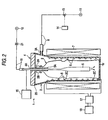
- a modifying apparatus 1 modifies the interior side surface of a PET container 2.
- This modifying apparatus 1 has a cup-like reception chamber 3 which can receive the PET container 2, a cover 4 for closing a top opening of the reception chamber 3, a tube-like electrode 5 provided in the cover 4, a coil 6 disposed in an inner circumferential portion of the reception chamber 3, and a solenoid coil 7 disposed to surround the reception chamber 3 and the coil 6.
- the PET container 2 having a surface which will be modified by the modifying apparatus 1 has an opening portion 2A at its top, and a threaded portion 2B in the outer circumferential portion of the top. A not-shown cap is screwed to the threaded portion 2B.
- the PET container 2 is transparent and colorless, and a plurality of annular projections 2C are formed at required places of its body for the purpose of reinforcement. That is, the PET container 2 having a surface which will be modified by the modifying apparatus 1 is a general PET container known in the related art, and is designed so that liquid such as beverage is filled into the inside of the PET container 2 through the opening portion 2A.
- the PET container 2 configured thus is supplied into the reception chamber 3 so that the opening portion 2A faces upward.
- the reception chamber 3 is made of a conductive material and formed into a cup-like shape with a wide mouth in the top portion.
- a suction port 3A is formed in a position close to the top portion.
- a normally closed electromagnetic on-off valve 13 is provided in the middle of the conduit 8. The operation of the electromagnetic on-off valve 13 is controlled by a control unit 14.
- the reception chamber 3 When the electromagnetic on-off valve 13 is opened by the control unit 14, the reception chamber 3 is evacuated through the conduit 8 and the suction port 3A.
- the reception chamber 3 made of a conductive material is electrically connected to a constant voltage body such as the ground.
- the cover 4 is made of a conductive material formed into a disc-like shape.
- the cover 4 can be moved up and down above the reception chamber 3 by a not-shown elevating mechanism.
- a through hole 4A is formed at a center portion of the cover 4.
- a support portion 5Aof the electrode 5 penetrates the through hole 4A slidably while keeping airtightness.
- the support portion 5A is formed out of a cylindrical insulating material, and fitted in a predetermined position of the electrode 5.
- an annular seal member 29 is planted in the outer circumferential portion of the lower surface of the cover 4.
- the electrode 5 is made of a conductive pipe, and electrically connected to a DC high voltage power source 15.
- the upper end portion of the electrode 5 is made to project over the upper surface of the cover 4.
- One end of a conduit 16 is connected to the upper end portion of the electrode 5.
- the other end of the conduit 16 is connected to a gas supply source 12.
- argon gas is reserved in the gas supply source 12.
- Anormally closed electromagnetic on-off valve 21 is provided in the middle of the conduit 16. The operation of the electromagnetic on-off valve 21 is also controlled by the control unit 14. When the electromagnetic on-off valve 21 is opened by the control unit 14, argon gas is supplied into the reception chamber 3 from the supply source 12 through the conduit 16. In such a manner, the electrode 5 also serves as a gas introduction tube in this embodiment.
- the PET container 2 is received in the reception chamber 3 by a not-shown conveying mechanism in the state where the cover 4 is located in its rising limit position apart from the top of the reception chamber 3 by the elevating mechanism. After that, the cover 4 is moved down to its falling limit position by the elevating mechanism so that the electrode 5 is inserted into the container 2 in the reception chamber 3. After that, the cover 4 is mounted on the top portion of the reception chamber 3 so as to close the top opening portion of the reception chamber 3. In this airtight state, the reception chamber 3 is evacuated through the conduit 8, and argon gas is then supplied to the whole area of the internal space of the reception chamber 3 including the internal space of the PET container 2 through the conduit 16 and the electrode 5.
- the support portion 5A of the electrode 5 is located on the interior side of the top opening portion 2A and the threaded portion 2B of the PET container 2.
- the electrode 5 itself can be further lifted up by a predetermined distance relatively to the cover 4 by the elevating mechanism (Fig. 3).
- the support portion 5A made of an insulating material is located above the top opening portion 2A of the PET container 2.
- the operation of the DC high voltage power source 15 connected to the electrode 5 is controlled by the control unit 14.
- the high voltage power source 15 is designed to apply positive high voltage pulses to the electrode 5 when an operating instruction is transmitted from the control unit 14 to the high voltage power source 15.
- the coil 6 provided in the inner circumferential portion of the reception chamber 3 is electrically insulated from the reception chamber 3.
- the coil 6 is connected to a high frequency power source 18 ranging from several of MHz to several hundreds of MHz through a matching circuit 17 disposed outside the reception chamber 3.
- the operation of the high frequency power source 18 is also controlled by the control unit 14.
- the high frequency power source 18 is designed to apply a high frequency current ranging from several of MHz to several hundreds of MHz to the coil 6 when an operating instruction is transmitted from the control unit 14 to the high frequency power source 18.
- the solenoid coil 7 disposed to surround the reception chamber 3 is connected to a not-shown power source.
- the solenoid coil 7 is excited to generate a DC magnetic field.
- a plasma generating unit for generating plasma is constituted by the coil 6, the matching circuit 17 and the high frequency power source 18.
- the interior side surface of the PET container 2 is modified through the following process by the modifying apparatus 1.
- the cover 4 is retained in its rising limit position apart from and above the top portion of the reception chamber 3 by a not-shown elevating mechanism. In this state, the PET container 2 is conveyed to a position above the reception chamber 3 by a not-shown conveying mechanism and then received in the reception chamber 3 (Fig. 1).
- the cover 4 is moved down to its falling limit position by the elevating mechanism.
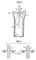
- the electrode 5 is inserted into the PET container 2 through the opening portion 2A while the top opening portion of the reception chamber 3 is made airtight by the cover 4 (Fig. 2).
- control unit 14 switches the power source for the solenoid coil 7 so as to make a current flow into the solenoid coil 7 and thereby excite the solenoid coil 7.
- a magnetic field is generated all over the internal space of the reception chamber 3 receiving the PET container 2.
- control unit 14 opens the electromagnetic on-off valve 13 for a predetermined period of time.
- the reception chamber 3 is evacuated through the conduit 8 so that the pressure in the internal space of the reception chamber 3 becomes lower than the atmospheric pressure.
- the control unit 14 opens the electromagnetic on-off valve 21 provided in the conduit 16 for a predetermined period of time.
- argon gas is introduced into the internal space of the PET container 2 through the conduit 16. That is, the argon gas intervenes between the spaces inside and outside the PET container 2 in the reception chamber 3.
- control unit 14 transmits an operating instruction to the high frequency power source 18 so that a high frequency current ranging from several of MHz to several hundreds of MHz is applied from the high frequency power source to the coil 6.
- a high frequency current ranging from several of MHz to several hundreds of MHz is applied from the high frequency power source to the coil 6.
- plasma is generated in the reception chamber 3.
- control unit 14 transmits an operating instruction to the high voltage power source 15 so that a series of positive high voltage pulses are applied from the high voltage power source 15 to the electrode 5.
- ions of the plasma interior the PET container 2 are implanted into its interior side surface.
- the PET container 2 is an insulator
- the surface potential increases due to the ion charge-up during ion implantation.
- the surface is exposed to the plasma during the pause of the pulse.
- the surface is neutralized to recover its original potential. Then, ion implantation is carried out again until the next pulse.
- the electrode 5 is moved up by a predetermined height relatively to the cover 4 by the elevating mechanism (Fig. 3). Then, high voltage pulses are applied to carry out ion implantation again. Accordingly, the support portion 5A of the electrode 5 is supported above the top portion of the PET container 2. Thus, ions are also implanted surely into the interior side surface of the threaded portion 2B where the support portion 5A had been located.
- ions are implanted thus into the whole area of the interior side surface of the PET container 2. Accordingly, the material itself of the interior side surface of the PET container 2 originally containing carbon are modified into DLC (diamond-like carbon) throughout (see Fig. 4). That is, in this embodiment, the original surface of the PET container 2 is not coated with DLC but the material itself of the surface of the PET container 2 is modified into DLC so that a DLC layer 22 is formed all over the interior side surface as shown on the right of Fig. 4.
- DLC diamond-like carbon
- the electrode 5 does not always have to be moved up to the position in Fig. 3 from the position in Fig. 2 after ion implantation.
- the cover 4 is moved up to its rising limit position by the elevating mechanism so as to open the reception chamber 3 and extract the electrode 5 from the PET container 2.
- the cover 4 is not moved up directly in the state where the reception chamber 3 is closed, but moved up by the elevating mechanism after the reception chamber 3 is once made open to the atmosphere through the conduit 8.
- the PET container 2 subjected to the treatment is extracted by a not-shown extracting mechanism, while a new PET container 2 is received in the reception chamber 3. Then, the interior side surface of the new PET container 2 is modified into a DLC layer 22 in the process described above.
- the whole area of the interior side surface of the PET container 2 is modified into the DLC layer 22. Accordingly, it is possible to provide the PET container 2 which is transparent and colorless or slightly colored and which can prevent the permeation of carbon dioxide gas and oxygen or is hard to be permeated by carbon dioxide gas and oxygen. It is therefore possible to provide the PET container 2 which is suitable not only as a container for general beverages such as mineral water but also a container for carbonated beverages such as beer.
- the material itself of the interior side surface of the PET container 2 is modified into DLC.
- the DLC layer 22 peels off. Accordingly, after liquid such as a beverage is filled up into the PET container 2, there is no fear that pieces of peeled DLC are mixed into the liquid. It is possible to provide a safe container for beverage use.
- the period of time required for forming the DLC layer 22 in the interior side surface of the PET container 2 in this embodiment is one over several parts in the related-art technique in which the surface is coated with a DLC film. It is therefore possible to provide the modifying apparatus 1 and the modifying method fast in treatment speed.
- the PET container 2 having an interior side surface which has been modified according to this embodiment can be recycled throughout.
- argon gas reserved in the gas supply source 12 is supplied into the reception chamber 3
- hydrocarbon gas or nitrogen gas may be used in place of the argon gas.
- the following configuration may be adopted as a second embodiment of the modifying apparatus 1. That is, the gas supply source 12, the conduit 16 and the electromagnetic on-off valve 21 in the first embodiment shown in Figs. 1 to 3 may be omitted in the second embodiment, while the others are arranged similarly to those in the first embodiment.
- the second embodiment not a pipe-like one but a rod-like one is used as the electrode 5 .
- a plasma generating unit for generating plasma is constituted by the coil 6, the matching circuit 17 and the high frequency power source 18.
- treatment is carried out in the following process.
- the PET container 2 is conveyed to a position above the reception chamber 3 by a not-shown conveying mechanism, and then received in the reception chamber 3.
- the cover 4 is moved down to its falling limit position by the elevating mechanism.
- the electrode 5 is inserted into the PET container 2 while the top opening portion of the reception chamber 3 is closed by the cover 4.
- control unit 14 switches the power source for the solenoid coil 7 so as to make a current flow into the solenoid coil 7 to thereby excite the solenoid coil 7.
- a magnetic field is generated in the reception chamber 3.
- control unit 14 opens the electromagnetic on-off valve 13 for a predetermined period of time.
- the reception chamber 3 is evacuated.
- control unit 14 transmits an operating instruction to the high frequency power source 18 so that a high frequency current ranging from several of MHz to several hundreds of MHz is applied from the high frequency power source to the coil 6.
- a high frequency current ranging from several of MHz to several hundreds of MHz is applied from the high frequency power source to the coil 6.
- plasma is generated in the reception chamber 3.
- control unit 14 transmits an operating instruction to the high voltage power source 15 so that positive high voltage pulses are applied from the high voltage power source 15 to the electrode 5.
- ions of the plasma inside the PET container 2 are implanted into the PET container 2 from its interior side surface.
- the whole area of the interior side surface of the PET container 2 is modified into a DCL layer 22.
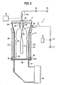
- Figs. 5 and 6 show a third embodiment of the invention.
- a plurality of permanent magnets 25 are used in place of the solenoid coil 7 in the first embodiment, and a magnetron 26 is used in place of the coil 6, the matching circuit 17 and the high frequency power source 18 likewise.
- a flange portion 3C is formed in a bottom outer circumferential portion of a cylindrical body portion.
- a quartz sheet is superposed on the lower surface of the flange portion 3C.
- a bottom surface 3B of the reception chamber 3 is constituted by the quartz sheet.
- a flange-like connection portion 27A formed on the side of a waveguide 27 is fitted to the outer circumferential portions of the quartz sheet (bottom surface 3B) and the flange portion 3C.
- an annular seal member 28 is provided between the flange portion 3C and the quartz sheet as the bottom surface 3B so as to keep airtightness between these two members.
- the magnetron 26 is connected to the other end of the waveguide 27 while keeping airtightness.
- the operation of the magnetron 26 is also controlled by the control unit 14.
- a microwave of 2.45 GHz is supplied into the reception chamber 3.
- the rod-like permanent magnets 25 are disposed at even pitches in the circumferential direction.
- the permanent magnets 25 adjacent to each other are disposed so that magnetic poles in contact with the outer circumferential surface of the reception chamber 3 are different from each other.
- a magnetic field is always formed near the inner circumferential portion of the reception chamber 3 close to these permanent magnets 25 by the permanent magnets 25.
- an annular seal member 29 is attached to the outer circumferential portion of the lower surface of the cover 4.
- a plasma generating unit for generating plasma is constituted by the waveguide 27 and the magnetron 26.
- the surface of the PET container 2 is modified in the following manner by the modifying apparatus 1 configured thus according to the third embodiment.
- the PET container 2 conveyed by a not-shown conveying mechanism is received in the reception chamber 3.
- the cover 4 is moved down to its falling limit position by the elevating mechanism.
- the electrode 5 is inserted into the PET container 2 through the opening portion 2A while the top opening portion of the reception chamber 3 is made airtight by the cover 4 (Fig. 5).
- control unit 14 opens the electromagnetic on-off valve 13 for a predetermined period of time.
- the reception chamber 3 is evacuated through the conduit 8 so that the pressure in the internal space of the reception chamber 3 becomes lower than the atmospheric pressure.
- the control unit 14 opens the electromagnetic on-off valve 21 provided in the conduit 16 for a predetermined period of time.
- argon gas is introduced into the internal space of the PET container 2 through the conduit 16. That is, the argon gas intervenes between the spaces inside and outside the PET container 2 in the reception chamber 3.
- the pressure in the reception chamber 3 at this time is not higher than the atmospheric pressure.
- control unit 14 operates the magnetron 26 so that a microwave of 2.45 GHz is supplied from the magnetron 26 toward the bottom surface 3B of the reception chamber 3.
- the microwave is supplied into the reception chamber 3 so that plasma is generated in the argon gas in the reception chamber 3.
- control unit 14 transmits an operating instruction to the DC high voltage power source 15 so that positive high voltage pulses are applied from the high voltage power source 15 to the electrode 5.
- ions of the plasma inside the PET container 2 are implanted into its interior side surface.
- an operating instruction may be transmitted again to the high voltage power source 15.
- ions are implanted into the interior side surface of the PET container 2 again.
- Fig. 7 shows a fourth embodiment of the invention.
- a waveguide 27 and a magnetron 26 are used in place of the coil 6, the matching circuit 17 and the high frequency power source 18 in the first embodiment.
- one end of the waveguide 27 is connected to the upper surface center portion of the cover 4 made of a conductive material.
- the top portion of the electrode 5 is designed to penetrate the waveguide 27 while keeping airtightness, so as to project upward.
- An end portion of the conduit 16 is connected to the top portion of the electrode 5.
- the magnetron 26 similar to that in the third embodiment is connected to the other end of the waveguide 27 while keeping airtightness.
- the operation of the magnetron 26 is also controlled by the control unit 14. When the magnetron 26 is operated by the control unit 14, a microwave is supplied toward the bottom surface 3B of the reception chamber 3.
- the end portion of the waveguide 27 is connected to the cover 4. Therefore, a not-shown elevating mechanismmoves up the cover 4, the electrode 5 and the waveguide 27.
- an annular seal member 29 is attached to the outer circumferential portion of the lower surface of the cover 4.
- a plasma generating unit for generating plasma is constituted by the waveguide 27 and the magnetron 26.
- the surface of the PET container 2 is modified in the following manner by the modifying apparatus 1 configured thus according to the fourth embodiment.
- the PET container 2 conveyed by a not-shown conveying mechanism is received in the reception chamber 3.
- the cover 4 and so on are moved down to their falling limit positions by the elevating mechanism.
- the electrode 5 is inserted into the PET container 2 through the opening portion 2A while the top opening portion of the reception chamber 3 is made airtight by the cover 4 (Fig. 7).
- control unit 14 switches the power source for the solenoid coil 7 so as to make a current flow into the solenoid coil 7 to thereby excite the solenoid coil 7.
- a magnetic field is formed in the reception chamber 3.
- control unit 14 opens the electromagnetic on-off valve 13 for a predetermined period of time.
- the reception chamber 3 is evacuated through the conduit 8 so that the pressure in the internal space of the reception chamber 3 becomes lower than the atmospheric pressure.
- the control unit 14 opens the electromagnetic on-off valve 21 provided in the conduit 16 for a predetermined period of time.
- argon gas is introduced into the internal space of the PET container 2 through the conduit 16. That is, the argon gas intervenes between the spaces inside and outside the PET container 2 in the reception chamber 3.
- the pressure in the reception chamber 3 at this time is not higher than the atmospheric pressure.
- control unit 14 operates the magnetron 26 so that a microwave is supplied from the magnetron 26 toward the cover 4.
- plasma is generated in the argon gas in the reception chamber 3.
- the control unit 14 transmits an operating instruction to the DC high voltage power source 15 so that positive high voltage pulses are applied from the high voltage power source 15 to the electrode 5.
- an operating instruction may be transmitted again to the high voltage power source 15.
- ions are implanted into the interior side surface of the PET container 2 again.
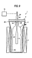
- Figs. 8 and 9 show a fifth embodiment of the invention.
- the coil 6, the matching circuit 17 and the high frequency power source 18 in the first embodiment are therefore omitted.
- the other configuration is the same as that in the first embodiment, and detailed description thereof will be omitted.
- the high voltage power source 15 is also used as a plasma generating unit for generating plasma.
- the surface of the PET container 2 is modified in the following manner.
- the PET container 2 conveyed by a not-shown conveying mechanism is received in the reception chamber 3.
- the cover 4 is moved down to its falling limit position by the elevating mechanism.
- the electrode 5 is inserted into the PET container 2 through the opening portion 2A while the top opening portion of the reception chamber 3 is made airtight by the cover 4 (Fig. 8).
- control unit 14 switches the power source for the solenoid coil 7 so as to make a current flow into the solenoid coil 7 to thereby excite the solenoid coil 7.
- a magnetic field is formed in the reception chamber 3.
- control unit 14 opens the electromagnetic on-off valve 13 for a predetermined period of time.
- the reception chamber 3 is evacuated through the conduit 8 so that the pressure in the internal space of the reception chamber 3 becomes lower than the atmospheric pressure.
- the control unit 14 opens the electromagnetic on-off valve 21 provided in the conduit 16 for a predetermined period of time.
- argon gas is introduced into the internal space of the PET container 2 through the conduit 16. That is, the argon gas intervenes between the spaces inside and outside the PET container 2 in the reception chamber 3. Incidentally, the pressure in the reception chamber 3 at this time is lower than the atmospheric pressure.
- control unit 14 transmits an operating instruction to the DC high voltage power source 15 so that positive high voltage pulses are applied from the high voltage power source 15 to the electrode 5.
- the control unit 14 transmits an operating instruction to the DC high voltage power source 15 so that positive high voltage pulses are applied from the high voltage power source 15 to the electrode 5.
- an operating instruction may be transmitted again to the high voltage power source 15.
- ions are implanted into the interior side surface of the PET container 2 again.
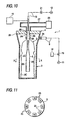
- Figs. 10 and 11 show a sixth embodiment of the invention.
- the solenoid coil 7 in the fourth embodiment shown in Fig. 7 is omitted, and in place of the solenoid coil 7, a plurality of permanent magnets 25 are provided.
- rod-like permanent magnets 25 are disposed at even pitches in the circumferential direction.
- the permanent magnets 25 adjacent to each other are disposed so that the positions of magnetic poles in contact with the inner circumferential surface of the electrode 5 are different from each other.
- a magnetic field is always formed in the electrode 5 itself by the plurality of permanent magnets 25.
- the other configuration is the same as that in the fourth embodiment shown in Fig. 7, and detailed description thereof will be therefore omitted.
- the surface of the PET container 2 is modified in the following manner by the modifying apparatus 1 configured thus according to the sixth embodiment.
- the PET container 2 conveyed by a not-shown conveying mechanism is received in the reception chamber 3.
- the cover 4 and so on are moved down to their falling limit positions by the elevating mechanism.
- the electrode 5 is inserted into the PET container 2 through the opening portion 2A while the top opening portion of the reception chamber 3 is made airtight by the cover 4 (Fig. 10).
- control unit 14 opens the electromagnetic on-off valve 13 for a predetermined period of time.
- the reception chamber 3 is evacuated through the conduit 8 so that the pressure in the internal space of the reception chamber 3 becomes lower than the atmospheric pressure.
- the control unit 14 opens the electromagnetic on-off valve 21 provided in the conduit 16 for a predetermined period of time.
- argon gas is introduced into the internal space of the PET container 2 through the conduit 16. That is, the argon gas intervenes between the spaces inside and outside the PET container 2 in the reception chamber 3.
- the pressure in the reception chamber 3 at this time is not higher than the atmospheric pressure.
- control unit 14 operates the magnetron 26 so that a microwave is supplied from the magnetron 26 toward the cover 4.
- plasma is generated in the argon gas in the reception chamber 3.
- control unit 14 transmits an operating instruction to the DC high voltage power source 15 so that positive high voltage pulses are applied from the high voltage power source 15 to the electrode 5.
- ions in the plasma on the interior side of the PET container 2 are implanted into the PET container 2 from its interior side surface.
- an operating instruction may be transmitted again to the high voltage power source 15.
- ions are implanted into the PET container 2 from its interior side surface again.
- the surface layer of a container made of a polymeric compound can be modified into a material that is not permeable by carbon dioxide gas and oxygen or into a material that is hard to be permeated by carbon dioxide gas and oxygen.
Landscapes
- Chemical & Material Sciences (AREA)
- Chemical Kinetics & Catalysis (AREA)
- Engineering & Computer Science (AREA)
- Organic Chemistry (AREA)
- Materials Engineering (AREA)
- Mechanical Engineering (AREA)
- Metallurgy (AREA)
- Health & Medical Sciences (AREA)
- General Chemical & Material Sciences (AREA)
- Medicinal Chemistry (AREA)
- Polymers & Plastics (AREA)
- Physics & Mathematics (AREA)
- Plasma & Fusion (AREA)
- Analytical Chemistry (AREA)
- Treatments Of Macromolecular Shaped Articles (AREA)
- Plasma Technology (AREA)
- Details Of Rigid Or Semi-Rigid Containers (AREA)
Description
- The present invention relates to a method and apparatus for modifying the surface of a container made of a polymeric compound, and more particularly relates to a method and apparatus for modifying the interior side surface of, for example, a PET (polyethylene terephthalate) container into a material having low permeability to gases, such as DLC (diamond-like carbon), according to the generic parts of
claim - Such a method and apparatus are known from EP 0773166 A1, wherein a carbon film-coated plastic container is obtained by forming a diamond-like carbon film on an inner surface of a container. Similar methods and apparatus are also known from US 6112695, WO 95/22413, WO 99/17334 and US 6001429.
- In recent years, PET containers are often used as containers for beverages because of their light weight, impact-resistance and resealability.
- Despite such features, the PET containers had a defect that they were permeated by oxygen and carbon dioxide. Accordingly, the PET containers were inadequate for use as containers filled with beer or carbonated beverages. Thus, the PET containers had a defect that they could not be used as containers for such beverages.
- Therefore, in the related art, apparatus and a method for coating the inner surface of a PET container with a hard carbon film has been proposed to solve the defect of the PET container (for example, Japanese Patent No. 2788412).
- According to the apparatus and the method disclosed in the patent, only the inner surface of a PET container can be coated with a hard carbon film so that permeation of oxygen or carbon dioxide can be blocked by the hard carbon film.
- However, in the apparatus and the method disclosed in the patent, carbon-based gas as a raw material for the hard carbon film was supplied into the PET container, and plasma was then generated to make the carbon-based gas adhere to the interior side surface of the container so as to form the hard carbon film. In other words, the apparatus and the method disclosed in the patent was only a technique for coating the interior side surface of the container with the hard carbon film without modifying the interior side surface of the container itself.
- Accordingly, when the PET container manufactured by the apparatus and the method disclosed in the patent was filled with a beverage, there was a fear that the hard carbon film with which the container was coated might peel off and get mixed into the beverage. Thus, there was a defect that the PET container was short of reliability as a container for beverage.
- It is therefore an object of the invention to provide a container in which permeation of oxygen and carbon dioxide can be prevented or made difficult, while there is no fear that the interior side surface of the container peels off after the container is filled with a beverage.
- That is, according to the invention, there is provided a method for modifying a surface of a container made of a polymeric compound containing carbon, including the step of: implanting ions into the container so as to modify a surface layer of the container into a material that is not permeable by carbon dioxide gas and oxygen or a material that is hard to be permeated by carbon dioxide gas and oxygen.
- Further, according to the invention, there is provided apparatus for modifying a surface of a container made of a polymeric compound including: a reception chamber which can receive the container while keeping airtightness; a vacuum pump for evacuating the reception chamber; a plasma generating unit for generating plasma in the reception chamber; an electrode inserted into the container received in the reception chamber; and a high voltage power source for applying high voltage pulses to the electrode; wherein an interior side surface layer of the container received in the reception chamber is modified into a material that is not permeable by carbon dioxide gas and oxygen or a material that is hard to be permeated by carbon dioxide gas and oxygen.
- With such a configuration, the surface layer of the container made of a polymeric compound can be modified into a material that is not permeable by carbon dioxide gas and oxygen or a material that is hard to be permeated by carbon dioxide gas and oxygen. Thus, it is possible to provide a polymeric compound container which is not permeated or is hard to be permeated by carbon dioxide gas or oxygen. In addition, because the surface layer of the container itself is modified, there is no fear that the modified surface layer peels off.
- Accordingly, it is possible to provide a polymeric compound container suitable for beer or carbonated beverage.
- Features and advantages of the invention will be evident from the following detailed description of the preferred embodiments described in conjunction with the attached drawings.
- In the accompanying drawings:
- Fig. 1 is a sectional view showing a first embodiment of the invention;
- Fig. 2 is a sectional view showing the first embodiment of the invention;
- Fig. 3 is an end view showing another state of a main portion shown in Fig. 2;
- Fig. 4 is a sectional view of a main portion of a PET container showing the state of the surface which has not yet been modified by the apparatus shown in Fig. 1 and the state of the surface which has been modified;
- Fig. 5 is a sectional view showing a third embodiment of the invention;
- Fig. 6 is a sectional view of a main portion taken on line VI-VI in Fig. 5;
- Fig. 7 is a sectional view showing a fourth embodiment of the invention;
- Fig. 8 is a sectional view showing a fifth embodiment of the invention;
- Fig. 9 is a sectional view of the fifth embodiment showing a state different from that in Fig. 8;
- Fig. 10 is a sectional view showing a sixth embodiment of the invention; and
- Fig. 11 is a sectional view of a main portion taken on line X-X in Fig. 10.
-
- The invention will be described below with respect to its embodiments shown in the drawings. In Figs. 1 to 3, a modifying
apparatus 1 modifies the interior side surface of aPET container 2. - This modifying
apparatus 1 has a cup-like reception chamber 3 which can receive thePET container 2, acover 4 for closing a top opening of thereception chamber 3, a tube-like electrode 5 provided in thecover 4, acoil 6 disposed in an inner circumferential portion of thereception chamber 3, and asolenoid coil 7 disposed to surround thereception chamber 3 and thecoil 6. - The
PET container 2 having a surface which will be modified by the modifyingapparatus 1 has anopening portion 2A at its top, and a threadedportion 2B in the outer circumferential portion of the top. A not-shown cap is screwed to the threadedportion 2B. ThePET container 2 is transparent and colorless, and a plurality ofannular projections 2C are formed at required places of its body for the purpose of reinforcement. That is, thePET container 2 having a surface which will be modified by the modifyingapparatus 1 is a general PET container known in the related art, and is designed so that liquid such as beverage is filled into the inside of thePET container 2 through theopening portion 2A. ThePET container 2 configured thus is supplied into thereception chamber 3 so that theopening portion 2A faces upward. - The
reception chamber 3 is made of a conductive material and formed into a cup-like shape with a wide mouth in the top portion. Asuction port 3A is formed in a position close to the top portion. - One end of a
conduit 8 is connected to thesuction port 3A while the other end of theconduit 8 is connected to avacuum pump 11. A normally closed electromagnetic on-offvalve 13 is provided in the middle of theconduit 8. The operation of the electromagnetic on-offvalve 13 is controlled by acontrol unit 14. - When the electromagnetic on-off
valve 13 is opened by thecontrol unit 14, thereception chamber 3 is evacuated through theconduit 8 and thesuction port 3A. Incidentally, thereception chamber 3 made of a conductive material is electrically connected to a constant voltage body such as the ground. - Next, the
cover 4 is made of a conductive material formed into a disc-like shape. Thecover 4 can be moved up and down above thereception chamber 3 by a not-shown elevating mechanism. A throughhole 4A is formed at a center portion of thecover 4. A support portion 5Aof theelectrode 5 penetrates the throughhole 4A slidably while keeping airtightness. Thesupport portion 5A is formed out of a cylindrical insulating material, and fitted in a predetermined position of theelectrode 5. Incidentally, anannular seal member 29 is planted in the outer circumferential portion of the lower surface of thecover 4. Thus, when thecover 4 is mounted on the top opening portion of thereception chamber 3 to thereby close thereception chamber 3, airtightness is kept between the top opening portion of thereception chamber 3 and thecover 4. - The
electrode 5 is made of a conductive pipe, and electrically connected to a DC highvoltage power source 15. The upper end portion of theelectrode 5 is made to project over the upper surface of thecover 4. One end of aconduit 16 is connected to the upper end portion of theelectrode 5. The other end of theconduit 16 is connected to agas supply source 12. In this embodiment, argon gas is reserved in thegas supply source 12. Anormally closed electromagnetic on-offvalve 21 is provided in the middle of theconduit 16. The operation of the electromagnetic on-offvalve 21 is also controlled by thecontrol unit 14. When the electromagnetic on-offvalve 21 is opened by thecontrol unit 14, argon gas is supplied into thereception chamber 3 from thesupply source 12 through theconduit 16. In such a manner, theelectrode 5 also serves as a gas introduction tube in this embodiment. - As will be described later, the
PET container 2 is received in thereception chamber 3 by a not-shown conveying mechanism in the state where thecover 4 is located in its rising limit position apart from the top of thereception chamber 3 by the elevating mechanism. After that, thecover 4 is moved down to its falling limit position by the elevating mechanism so that theelectrode 5 is inserted into thecontainer 2 in thereception chamber 3. After that, thecover 4 is mounted on the top portion of thereception chamber 3 so as to close the top opening portion of thereception chamber 3. In this airtight state, thereception chamber 3 is evacuated through theconduit 8, and argon gas is then supplied to the whole area of the internal space of thereception chamber 3 including the internal space of thePET container 2 through theconduit 16 and theelectrode 5. - In addition, as shown in Fig. 2, in the state where the top opening of the
reception chamber 3 is closed by thecover 4, thesupport portion 5A of theelectrode 5 is located on the interior side of thetop opening portion 2A and the threadedportion 2B of thePET container 2. In this state, theelectrode 5 itself can be further lifted up by a predetermined distance relatively to thecover 4 by the elevating mechanism (Fig. 3). In this state of Fig. 3, thesupport portion 5A made of an insulating material is located above thetop opening portion 2A of thePET container 2. - The operation of the DC high
voltage power source 15 connected to theelectrode 5 is controlled by thecontrol unit 14. The highvoltage power source 15 is designed to apply positive high voltage pulses to theelectrode 5 when an operating instruction is transmitted from thecontrol unit 14 to the highvoltage power source 15. - Next, the
coil 6 provided in the inner circumferential portion of thereception chamber 3 is electrically insulated from thereception chamber 3. Thecoil 6 is connected to a highfrequency power source 18 ranging from several of MHz to several hundreds of MHz through amatching circuit 17 disposed outside thereception chamber 3. The operation of the highfrequency power source 18 is also controlled by thecontrol unit 14. The highfrequency power source 18 is designed to apply a high frequency current ranging from several of MHz to several hundreds of MHz to thecoil 6 when an operating instruction is transmitted from thecontrol unit 14 to the highfrequency power source 18. - Further, the
solenoid coil 7 disposed to surround thereception chamber 3 is connected to a not-shown power source. When an operating instruction is transmitted from thecontrol unit 14 to the power source, thesolenoid coil 7 is excited to generate a DC magnetic field. - In this embodiment, a plasma generating unit for generating plasma is constituted by the
coil 6, the matchingcircuit 17 and the highfrequency power source 18. - In the configuration described above, the interior side surface of the
PET container 2 is modified through the following process by the modifyingapparatus 1. - That is, when the
PET container 2 has not yet been received in thereception chamber 3, thecover 4 is retained in its rising limit position apart from and above the top portion of thereception chamber 3 by a not-shown elevating mechanism. In this state, thePET container 2 is conveyed to a position above thereception chamber 3 by a not-shown conveying mechanism and then received in the reception chamber 3 (Fig. 1). - Next, the
cover 4 is moved down to its falling limit position by the elevating mechanism. Thus, theelectrode 5 is inserted into thePET container 2 through theopening portion 2A while the top opening portion of thereception chamber 3 is made airtight by the cover 4 (Fig. 2). - Next, the
control unit 14 switches the power source for thesolenoid coil 7 so as to make a current flow into thesolenoid coil 7 and thereby excite thesolenoid coil 7. Thus, a magnetic field is generated all over the internal space of thereception chamber 3 receiving thePET container 2. - Next, the
control unit 14 opens the electromagnetic on-offvalve 13 for a predetermined period of time. Thus, thereception chamber 3 is evacuated through theconduit 8 so that the pressure in the internal space of thereception chamber 3 becomes lower than the atmospheric pressure. - Next, in this state, the
control unit 14 opens the electromagnetic on-offvalve 21 provided in theconduit 16 for a predetermined period of time. Thus, argon gas is introduced into the internal space of thePET container 2 through theconduit 16. That is, the argon gas intervenes between the spaces inside and outside thePET container 2 in thereception chamber 3. - After that, the
control unit 14 transmits an operating instruction to the highfrequency power source 18 so that a high frequency current ranging from several of MHz to several hundreds of MHz is applied from the high frequency power source to thecoil 6. Thus, plasma is generated in thereception chamber 3. - Further, in this state, the
control unit 14 transmits an operating instruction to the highvoltage power source 15 so that a series of positive high voltage pulses are applied from the highvoltage power source 15 to theelectrode 5. Thus, ions of the plasma interior thePET container 2 are implanted into its interior side surface. - Here, because the
PET container 2 is an insulator, the surface potential increases due to the ion charge-up during ion implantation. However, the surface is exposed to the plasma during the pause of the pulse. Thus, the surface is neutralized to recover its original potential. Then, ion implantation is carried out again until the next pulse. - Next, in this state, the
electrode 5 is moved up by a predetermined height relatively to thecover 4 by the elevating mechanism (Fig. 3). Then, high voltage pulses are applied to carry out ion implantation again. Accordingly, thesupport portion 5A of theelectrode 5 is supported above the top portion of thePET container 2. Thus, ions are also implanted surely into the interior side surface of the threadedportion 2B where thesupport portion 5A had been located. - In this embodiment, ions are implanted thus into the whole area of the interior side surface of the
PET container 2. Accordingly, the material itself of the interior side surface of thePET container 2 originally containing carbon are modified into DLC (diamond-like carbon) throughout (see Fig. 4). That is, in this embodiment, the original surface of thePET container 2 is not coated with DLC but the material itself of the surface of thePET container 2 is modified into DLC so that aDLC layer 22 is formed all over the interior side surface as shown on the right of Fig. 4. - Incidentally, in the work process, the
electrode 5 does not always have to be moved up to the position in Fig. 3 from the position in Fig. 2 after ion implantation. - When the work of modifying the surface of one
PET container 2 is completed in such a manner, thecover 4 is moved up to its rising limit position by the elevating mechanism so as to open thereception chamber 3 and extract theelectrode 5 from thePET container 2. Incidentally, it is preferable that thecover 4 is not moved up directly in the state where thereception chamber 3 is closed, but moved up by the elevating mechanism after thereception chamber 3 is once made open to the atmosphere through theconduit 8. - After that, the
PET container 2 subjected to the treatment is extracted by a not-shown extracting mechanism, while anew PET container 2 is received in thereception chamber 3. Then, the interior side surface of thenew PET container 2 is modified into aDLC layer 22 in the process described above. - As has been described above, in this embodiment, the whole area of the interior side surface of the
PET container 2 is modified into theDLC layer 22. Accordingly, it is possible to provide thePET container 2 which is transparent and colorless or slightly colored and which can prevent the permeation of carbon dioxide gas and oxygen or is hard to be permeated by carbon dioxide gas and oxygen. It is therefore possible to provide thePET container 2 which is suitable not only as a container for general beverages such as mineral water but also a container for carbonated beverages such as beer. - In addition, unlike the related art in which a DLC film is deposited on the interior side surface of a
container 2 so that the interior side surface is coated with the DLC film, in this embodiment, the material itself of the interior side surface of thePET container 2 is modified into DLC. Thus, there is no fear that theDLC layer 22 peels off. Accordingly, after liquid such as a beverage is filled up into thePET container 2, there is no fear that pieces of peeled DLC are mixed into the liquid. It is possible to provide a safe container for beverage use. - Further, the period of time required for forming the
DLC layer 22 in the interior side surface of thePET container 2 in this embodiment is one over several parts in the related-art technique in which the surface is coated with a DLC film. It is therefore possible to provide the modifyingapparatus 1 and the modifying method fast in treatment speed. - In addition, the
PET container 2 having an interior side surface which has been modified according to this embodiment can be recycled throughout. Incidentally, although description in this embodiment has been made on the case where argon gas reserved in thegas supply source 12 is supplied into thereception chamber 3, hydrocarbon gas or nitrogen gas may be used in place of the argon gas. - Next, though not illustrated, the following configuration may be adopted as a second embodiment of the modifying
apparatus 1. That is, thegas supply source 12, theconduit 16 and the electromagnetic on-offvalve 21 in the first embodiment shown in Figs. 1 to 3 may be omitted in the second embodiment, while the others are arranged similarly to those in the first embodiment. Incidentally, in the second embodiment, not a pipe-like one but a rod-like one is used as theelectrode 5 . In this second embodiment, a plasma generating unit for generating plasma is constituted by thecoil 6, the matchingcircuit 17 and the highfrequency power source 18. In such a modifyingapparatus 1 according to the second embodiment, treatment is carried out in the following process. - That is, while the
cover 4 and theelectrode 5 are retained in their rising limit positions by an elevating mechanism, thePET container 2 is conveyed to a position above thereception chamber 3 by a not-shown conveying mechanism, and then received in thereception chamber 3. - Next, the
cover 4 is moved down to its falling limit position by the elevating mechanism. Thus, theelectrode 5 is inserted into thePET container 2 while the top opening portion of thereception chamber 3 is closed by thecover 4. - At the same time, the
control unit 14 switches the power source for thesolenoid coil 7 so as to make a current flow into thesolenoid coil 7 to thereby excite thesolenoid coil 7. Thus, a magnetic field is generated in thereception chamber 3. - After that, the
control unit 14 opens the electromagnetic on-offvalve 13 for a predetermined period of time. Thus, thereception chamber 3 is evacuated. - After that, the
control unit 14 transmits an operating instruction to the highfrequency power source 18 so that a high frequency current ranging from several of MHz to several hundreds of MHz is applied from the high frequency power source to thecoil 6. Thus, plasma is generated in thereception chamber 3. - Further, in this state, the
control unit 14 transmits an operating instruction to the highvoltage power source 15 so that positive high voltage pulses are applied from the highvoltage power source 15 to theelectrode 5. Thus, ions of the plasma inside thePET container 2 are implanted into thePET container 2 from its interior side surface. - Thus, the whole area of the interior side surface of the
PET container 2 is modified into aDCL layer 22. - Also in the second embodiment configured thus, it is possible to obtain functions and effects similar to those in the first embodiment.
- Next, Figs. 5 and 6 show a third embodiment of the invention. In brief, in this third embodiment, a plurality of
permanent magnets 25 are used in place of thesolenoid coil 7 in the first embodiment, and amagnetron 26 is used in place of thecoil 6, the matchingcircuit 17 and the highfrequency power source 18 likewise. - That is, in the
reception chamber 3 in the third embodiment, aflange portion 3C is formed in a bottom outer circumferential portion of a cylindrical body portion. A quartz sheet is superposed on the lower surface of theflange portion 3C. Abottom surface 3B of thereception chamber 3 is constituted by the quartz sheet. In addition, in this state, a flange-like connection portion 27A formed on the side of awaveguide 27 is fitted to the outer circumferential portions of the quartz sheet (bottom surface 3B) and theflange portion 3C. Thus, thereception chamber 3 and thewaveguide 27 are connected. Incidentally, anannular seal member 28 is provided between theflange portion 3C and the quartz sheet as thebottom surface 3B so as to keep airtightness between these two members. - Then, the
magnetron 26 is connected to the other end of thewaveguide 27 while keeping airtightness. The operation of themagnetron 26 is also controlled by thecontrol unit 14. When themagnetron 26 is operated by thecontrol unit 14, a microwave of 2.45 GHz is supplied into thereception chamber 3. - Next, in this embodiment, in the outer circumferential portion of the
reception chamber 3, the rod-likepermanent magnets 25 are disposed at even pitches in the circumferential direction. Here, thepermanent magnets 25 adjacent to each other are disposed so that magnetic poles in contact with the outer circumferential surface of thereception chamber 3 are different from each other. Thus, in the third embodiment, a magnetic field is always formed near the inner circumferential portion of thereception chamber 3 close to thesepermanent magnets 25 by thepermanent magnets 25. - Further, in this embodiment, an
annular seal member 29 is attached to the outer circumferential portion of the lower surface of thecover 4. When the top opening of thereception chamber 3 is closed by thecover 4, the airtightness between thecover 4 and the top opening portion of thereception chamber 3 is kept by theseal member 29. In the third embodiment, a plasma generating unit for generating plasma is constituted by thewaveguide 27 and themagnetron 26. - The other configuration is the same as that in the first embodiment, and detailed description thereof will be therefore omitted. [0015]
- The surface of the
PET container 2 is modified in the following manner by the modifyingapparatus 1 configured thus according to the third embodiment. - That is, in the state where the
cover 4 and theelectrode 5 are retained in their rising limit positions by a not-shown elevating mechanism, thePET container 2 conveyed by a not-shown conveying mechanism is received in thereception chamber 3. - Next, the
cover 4 is moved down to its falling limit position by the elevating mechanism. Thus, theelectrode 5 is inserted into thePET container 2 through theopening portion 2A while the top opening portion of thereception chamber 3 is made airtight by the cover 4 (Fig. 5). - Because a magnetic field is formed in the inner circumferential portion of the
reception chamber 3 by the plurality ofpermanent magnets 25, magnetic force by thepermanent magnets 25 also acts on thePET container 2 received in thereception chamber 3. - Next, the
control unit 14 opens the electromagnetic on-offvalve 13 for a predetermined period of time. Thus, thereception chamber 3 is evacuated through theconduit 8 so that the pressure in the internal space of thereception chamber 3 becomes lower than the atmospheric pressure. - Next, in this state, the
control unit 14 opens the electromagnetic on-offvalve 21 provided in theconduit 16 for a predetermined period of time. Thus, argon gas is introduced into the internal space of thePET container 2 through theconduit 16. That is, the argon gas intervenes between the spaces inside and outside thePET container 2 in thereception chamber 3. Incidentally, the pressure in thereception chamber 3 at this time is not higher than the atmospheric pressure. - After that, the
control unit 14 operates themagnetron 26 so that a microwave of 2.45 GHz is supplied from themagnetron 26 toward thebottom surface 3B of thereception chamber 3. Thus, the microwave is supplied into thereception chamber 3 so that plasma is generated in the argon gas in thereception chamber 3. - Further, in this state, the
control unit 14 transmits an operating instruction to the DC highvoltage power source 15 so that positive high voltage pulses are applied from the highvoltage power source 15 to theelectrode 5. Thus, ions of the plasma inside thePET container 2 are implanted into its interior side surface. - Incidentally, if necessary, after the
electrode 5 is then moved up by a predetermined height relatively to thecover 4 by the elevating mechanism, an operating instruction may be transmitted again to the highvoltage power source 15. Thus, ions are implanted into the interior side surface of thePET container 2 again. - Also in the third embodiment configured thus, it is possible to obtain functions and effects similar to those in the first embodiment. [0016]
- Next, Fig. 7 shows a fourth embodiment of the invention. In brief, in this fourth embodiment, a
waveguide 27 and amagnetron 26 are used in place of thecoil 6, the matchingcircuit 17 and the highfrequency power source 18 in the first embodiment. - That is, in the fourth embodiment, one end of the
waveguide 27 is connected to the upper surface center portion of thecover 4 made of a conductive material. The top portion of theelectrode 5 is designed to penetrate thewaveguide 27 while keeping airtightness, so as to project upward. An end portion of theconduit 16 is connected to the top portion of theelectrode 5. Themagnetron 26 similar to that in the third embodiment is connected to the other end of thewaveguide 27 while keeping airtightness. The operation of themagnetron 26 is also controlled by thecontrol unit 14. When themagnetron 26 is operated by thecontrol unit 14, a microwave is supplied toward thebottom surface 3B of thereception chamber 3. - In the fourth embodiment, the end portion of the
waveguide 27 is connected to thecover 4. Therefore, a not-shown elevating mechanismmoves up thecover 4, theelectrode 5 and thewaveguide 27. - Further, in this embodiment, an
annular seal member 29 is attached to the outer circumferential portion of the lower surface of thecover 4. When the top opening of thereception chamber 3 is closed by thecover 4, the airtightness between thecover 4 and the top opening portion of thereception chamber 3 is kept by theseal member 29. In the fourth embodiment, a plasma generating unit for generating plasma is constituted by thewaveguide 27 and themagnetron 26. - The other configuration is the same as that in the first embodiment, and detailed description thereof will be therefore omitted. [0017]
- The surface of the
PET container 2 is modified in the following manner by the modifyingapparatus 1 configured thus according to the fourth embodiment. - That is, in the state where the
cover 4, theelectrode 5 and thewaveguide 27 are retained in their rising limit positions by a not-shown elevating mechanism, thePET container 2 conveyed by a not-shown conveying mechanism is received in thereception chamber 3. - Next, the
cover 4 and so on are moved down to their falling limit positions by the elevating mechanism. Thus, theelectrode 5 is inserted into thePET container 2 through theopening portion 2A while the top opening portion of thereception chamber 3 is made airtight by the cover 4 (Fig. 7). - At the same time, the
control unit 14 switches the power source for thesolenoid coil 7 so as to make a current flow into thesolenoid coil 7 to thereby excite thesolenoid coil 7. Thus, a magnetic field is formed in thereception chamber 3. - Next, the
control unit 14 opens the electromagnetic on-offvalve 13 for a predetermined period of time. Thus, thereception chamber 3 is evacuated through theconduit 8 so that the pressure in the internal space of thereception chamber 3 becomes lower than the atmospheric pressure. - Next, in this state, the
control unit 14 opens the electromagnetic on-offvalve 21 provided in theconduit 16 for a predetermined period of time. Thus, argon gas is introduced into the internal space of thePET container 2 through theconduit 16. That is, the argon gas intervenes between the spaces inside and outside thePET container 2 in thereception chamber 3. Incidentally, the pressure in thereception chamber 3 at this time is not higher than the atmospheric pressure. - After that, the
control unit 14 operates themagnetron 26 so that a microwave is supplied from themagnetron 26 toward thecover 4. Thus, plasma is generated in the argon gas in thereception chamber 3. - Further, in this state, the
control unit 14 transmits an operating instruction to the DC highvoltage power source 15 so that positive high voltage pulses are applied from the highvoltage power source 15 to theelectrode 5. Thus, ions in the plasma on the interior side of thePET container 2 are implanted into thePET container 2 from its interior side surface.
Incidentally, if necessary, after theelectrode 5 is then moved up by a predetermined height relatively to thecover 4 by the elevating mechanism, an operating instruction may be transmitted again to the highvoltage power source 15. Thus, ions are implanted into the interior side surface of thePET container 2 again. - Also in the fourth embodiment configured thus, it is possible to obtain functions and effects similar to those in the first embodiment.
- Next, Figs. 8 and 9 show a fifth embodiment of the invention. In the fifth embodiment, the
coil 6, the matchingcircuit 17 and the highfrequency power source 18 in the first embodiment are therefore omitted. The other configuration is the same as that in the first embodiment, and detailed description thereof will be omitted. In the fifth embodiment, the highvoltage power source 15 is also used as a plasma generating unit for generating plasma. In the fifth embodiment, the surface of thePET container 2 is modified in the following manner. - That is, in the state where the
cover 4 and theelectrode 5 are retained in their rising limit positions by a not-shown elevating mechanism, thePET container 2 conveyed by a not-shown conveying mechanism is received in thereception chamber 3. - Next, the
cover 4 is moved down to its falling limit position by the elevating mechanism. Thus, theelectrode 5 is inserted into thePET container 2 through theopening portion 2A while the top opening portion of thereception chamber 3 is made airtight by the cover 4 (Fig. 8). - At the same time, the
control unit 14 switches the power source for thesolenoid coil 7 so as to make a current flow into thesolenoid coil 7 to thereby excite thesolenoid coil 7. Thus, a magnetic field is formed in thereception chamber 3. - Next, the
control unit 14 opens the electromagnetic on-offvalve 13 for a predetermined period of time. Thus, thereception chamber 3 is evacuated through theconduit 8 so that the pressure in the internal space of thereception chamber 3 becomes lower than the atmospheric pressure. - Next, in this state, the
control unit 14 opens the electromagnetic on-offvalve 21 provided in theconduit 16 for a predetermined period of time. Thus, argon gas is introduced into the internal space of thePET container 2 through theconduit 16. That is, the argon gas intervenes between the spaces inside and outside thePET container 2 in thereception chamber 3. Incidentally, the pressure in thereception chamber 3 at this time is lower than the atmospheric pressure. - After that, the
control unit 14 transmits an operating instruction to the DC highvoltage power source 15 so that positive high voltage pulses are applied from the highvoltage power source 15 to theelectrode 5. Thus, at the same time that plasma is generated on the interior side of thePET container 2, ions in the generated plasma are implanted into thePET container 2 from its interior side surface. As a result, the interior side surface of thePET container 2 is modified into DLC. - Incidentally, if necessary, after the
electrode 5 is then moved up by a predetermined height relatively to thecover 4 by the elevating mechanism, an operating instruction may be transmitted again to the highvoltage power source 15. Thus, as soon as plasma is generated on the interior side of thePET container 2 again, ions are implanted into the interior side surface of thePET container 2 again. - Also in the fifth embodiment configured thus, it is possible to obtain functions and effects similar to those in the first embodiment. [0019]
- Next, Figs. 10 and 11 show a sixth embodiment of the invention. In the sixth embodiment, the
solenoid coil 7 in the fourth embodiment shown in Fig. 7 is omitted, and in place of thesolenoid coil 7, a plurality ofpermanent magnets 25 are provided. - That is, in the sixth embodiment, in the inner circumferential portion of the
electrode 5 lower than thesupport portion 5A, rod-likepermanent magnets 25 are disposed at even pitches in the circumferential direction. As shown in Fig. 11, thepermanent magnets 25 adjacent to each other are disposed so that the positions of magnetic poles in contact with the inner circumferential surface of theelectrode 5 are different from each other. Thus, in the sixth embodiment, a magnetic field is always formed in theelectrode 5 itself by the plurality ofpermanent magnets 25. The other configuration is the same as that in the fourth embodiment shown in Fig. 7, and detailed description thereof will be therefore omitted. - The surface of the
PET container 2 is modified in the following manner by the modifyingapparatus 1 configured thus according to the sixth embodiment. - That is, in the state where the
cover 4, theelectrode 5 and thewaveguide 27 are retained in their rising limit positions by a not-shown elevating mechanism, thePET container 2 conveyed by a not-shown conveying mechanism is received in thereception chamber 3. - Next, the
cover 4 and so on are moved down to their falling limit positions by the elevating mechanism. Thus, theelectrode 5 is inserted into thePET container 2 through theopening portion 2A while the top opening portion of thereception chamber 3 is made airtight by the cover 4 (Fig. 10). - By the plurality of
permanent magnets 25, a magnetic field is formed in theelectrode 5 inserted into thereception chamber 3. - After that, the
control unit 14 opens the electromagnetic on-offvalve 13 for a predetermined period of time. Thus, thereception chamber 3 is evacuated through theconduit 8 so that the pressure in the internal space of thereception chamber 3 becomes lower than the atmospheric pressure. - Next, in this state, the
control unit 14 opens the electromagnetic on-offvalve 21 provided in theconduit 16 for a predetermined period of time. Thus, argon gas is introduced into the internal space of thePET container 2 through theconduit 16. That is, the argon gas intervenes between the spaces inside and outside thePET container 2 in thereception chamber 3. Incidentally, the pressure in thereception chamber 3 at this time is not higher than the atmospheric pressure. - After that, the
control unit 14 operates themagnetron 26 so that a microwave is supplied from themagnetron 26 toward thecover 4. Thus, plasma is generated in the argon gas in thereception chamber 3. - Further, in this state, the
control unit 14 transmits an operating instruction to the DC highvoltage power source 15 so that positive high voltage pulses are applied from the highvoltage power source 15 to theelectrode 5. Thus, ions in the plasma on the interior side of thePET container 2 are implanted into thePET container 2 from its interior side surface. - Incidentally, after the
electrode 5 is then moved up by a height equal to the vertical length of thesupport portion 5A relatively to thecover 4 by the elevating mechanism, an operating instruction may be transmitted again to the highvoltage power source 15. Thus, ions are implanted into thePET container 2 from its interior side surface again. - Also in the sixth embodiment configured thus, it is possible to obtain functions and effects similar to those in each of the previously described embodiments.
- As has been described above, according to the invention, it is possible to obtain an effect that the surface layer of a container made of a polymeric compound can be modified into a material that is not permeable by carbon dioxide gas and oxygen or into a material that is hard to be permeated by carbon dioxide gas and oxygen.
Claims (11)
- A method for modifying a surface of a container (2) made of a polymeric compound containing carbon, so as to modify a surface layer of said container into a material that is not permeable by carbon dioxide gas and oxygen or a material that is hard to be permeated by carbon dioxide gas and oxygen, wherein
ions are generated by a plasma inside of said container (2),
characterized in that
the surface modfication (22) is achieved by implanting the ions into the already existing surface layer of the container (2), whereby the ions are implanted by applying high-voltage pulses to an electrode (5) disposed inside the container (2). - A method for modifying a surface of a container (2) made of a polymeric compound according to claim 1, wherein the high voltage pulses applied to the electrode (5) are positive.
- A method for modifying a surface of a container (2) made of a polymeric compound according to claim 1, wherein said container (2) made of a polymeric compound is one of a container made of polyethylene terephthalate and a container made of synthetic resin.
- An apparatus for modifying a surface of a container (2) made of a polymeric compound comprising:characterized bya reception chamber (3) adapted for receiving said container while keeping air tightness,a vacuum pump (11) for evacuating said reception chamber (3); and
the presence of both,
a plasma generating unit (6,17,18;26,27) in said reception chamber (3) as a means of generating plasma;
and an electrode (5) adapted for being inserted into said container (2) received in said reception chamber (3), together with a high voltage power source (15) for applying high voltage pulses to said electrode (5), as a means of implanting ions;
wherein the interior side surface layer of said container (2) received in said reception chamber (3) is modified into a material that is not permeable by carbon dioxide gas and oxygen or a material that is hard to be permeated by carbon dioxide gas and oxygen. - An apparatus for modifying a surface of a container (2) made of a polymeric compound according to claim 4, further comprising a magnetic field generating unit for generating a magnetic field in said reception chamber (3).
- An apparatus for modifying a surface of a container (2) made of a polymeric compound according to claim 5, further comprising a gas supply source (12) fore supplying gas into said reception chamber (3).
- An apparatus for modifying a surface of a container (2) made of a polymeric compound according to claim 5, said plasma generating unit including:a coil (6) provided in an inner circumferential portion of said reception chamber 3; anda high frequency power source (18) for applying a high frequency current to said coil through a matching circuit (17).
- An apparatus for modifying a surface of a container (2) made of a polymeric compound according to claim 5, said plasma generating unit including:a magnetron (26) for supplying a microwave into said reception chamber (3) through a waveguide (27).
- An apparatus for modifying a surface of a container (2) made of a polymeric compound according to claim 5, wherein said magnetic generating unit includes one of a solenoid coil (7) provided to surround said reception chamber (3) and a plurality of permanent magnets (25) disposed to surround said reception chamber (3).
- An apparatus for modifying a surface of a container (2) made of a polymeric compound according to claim 4, wherein said high voltage power source (12) applies positive high voltage pulses to said electrode (5).
- An apparatus for modifying a surface of a container (2) made of a polymeric compound according to claim 4, wherein said container (2) made of a polymeric compound is one of a container (2) made of polyethylene terephthalate and a container made of synthetic resin.
Applications Claiming Priority (2)
| Application Number | Priority Date | Filing Date | Title |
|---|---|---|---|
| JP2001029176 | 2001-02-06 | ||
| JP2001029176A JP3952695B2 (en) | 2000-05-26 | 2001-02-06 | Method and apparatus for surface modification of polymer compound container |
Publications (2)
| Publication Number | Publication Date |
|---|---|
| EP1229068A1 EP1229068A1 (en) | 2002-08-07 |
| EP1229068B1 true EP1229068B1 (en) | 2005-09-14 |
Family
ID=18893553
Family Applications (1)
| Application Number | Title | Priority Date | Filing Date |
|---|---|---|---|
| EP02002554A Expired - Lifetime EP1229068B1 (en) | 2001-02-06 | 2002-02-04 | Method and apparatus for modifying the inner surface of containers made of polymeric compound |
Country Status (3)
| Country | Link |
|---|---|
| US (1) | US20020117114A1 (en) |
| EP (1) | EP1229068B1 (en) |
| DE (1) | DE60206084T2 (en) |
Families Citing this family (28)
| Publication number | Priority date | Publication date | Assignee | Title |
|---|---|---|---|---|
| US20030087030A1 (en) * | 1999-12-27 | 2003-05-08 | Kenichi Hama | Pet container for foods and drinks containing recycled resin and having dlc coating film formed on surface thereof |
| US7618348B2 (en) | 2004-06-21 | 2009-11-17 | Hakooz Joe S | Compact multimode device for low impact therapeutic exercise |
| US9260781B2 (en) | 2009-02-18 | 2016-02-16 | Council Of Scientific And Industrial Research | Process to deposit diamond like carbon as surface of a shaped object |
| DK2251453T3 (en) | 2009-05-13 | 2014-07-07 | Sio2 Medical Products Inc | container Holder |
| US9545360B2 (en) | 2009-05-13 | 2017-01-17 | Sio2 Medical Products, Inc. | Saccharide protective coating for pharmaceutical package |
| US9458536B2 (en) | 2009-07-02 | 2016-10-04 | Sio2 Medical Products, Inc. | PECVD coating methods for capped syringes, cartridges and other articles |
| US11624115B2 (en) | 2010-05-12 | 2023-04-11 | Sio2 Medical Products, Inc. | Syringe with PECVD lubrication |
| US9878101B2 (en) | 2010-11-12 | 2018-01-30 | Sio2 Medical Products, Inc. | Cyclic olefin polymer vessels and vessel coating methods |
| US9272095B2 (en) | 2011-04-01 | 2016-03-01 | Sio2 Medical Products, Inc. | Vessels, contact surfaces, and coating and inspection apparatus and methods |
| JP6095678B2 (en) | 2011-11-11 | 2017-03-15 | エスアイオーツー・メディカル・プロダクツ・インコーポレイテッド | Passivation, pH protection or slippery coatings for pharmaceutical packages, coating processes and equipment |
| US11116695B2 (en) | 2011-11-11 | 2021-09-14 | Sio2 Medical Products, Inc. | Blood sample collection tube |
| SG11201403305VA (en) * | 2011-12-27 | 2014-09-26 | Kirin Brewery | Apparatus for forming thin film |
| DE102012201955A1 (en) * | 2012-02-09 | 2013-08-14 | Krones Ag | Power lance and plasma-enhanced coating with high-frequency coupling |
| US20150297800A1 (en) | 2012-07-03 | 2015-10-22 | Sio2 Medical Products, Inc. | SiOx BARRIER FOR PHARMACEUTICAL PACKAGE AND COATING PROCESS |
| CN104854257B (en) | 2012-11-01 | 2018-04-13 | Sio2医药产品公司 | coating inspection method |
| EP2920567B1 (en) | 2012-11-16 | 2020-08-19 | SiO2 Medical Products, Inc. | Method and apparatus for detecting rapid barrier coating integrity characteristics |
| CA2892294C (en) | 2012-11-30 | 2021-07-27 | Sio2 Medical Products, Inc. | Controlling the uniformity of pecvd deposition on medical syringes, cartridges, and the like |
| US9764093B2 (en) | 2012-11-30 | 2017-09-19 | Sio2 Medical Products, Inc. | Controlling the uniformity of PECVD deposition |
| EP2961858B1 (en) | 2013-03-01 | 2022-09-07 | Si02 Medical Products, Inc. | Coated syringe. |
| US9937099B2 (en) | 2013-03-11 | 2018-04-10 | Sio2 Medical Products, Inc. | Trilayer coated pharmaceutical packaging with low oxygen transmission rate |
| CN110074968B (en) | 2013-03-11 | 2021-12-21 | Sio2医药产品公司 | Coated packaging material |
| WO2014144926A1 (en) | 2013-03-15 | 2014-09-18 | Sio2 Medical Products, Inc. | Coating method |
| US10259922B2 (en) * | 2013-11-06 | 2019-04-16 | The Board Of Trustees Of The Leland Stanford Junior University | Methods for modifying a hydrophobic polymer surface and devices thereof |
| EP3114250B1 (en) * | 2014-03-03 | 2024-05-01 | Picosun Oy | Protecting an interior of a gas container with an ald coating |
| EP3122917B1 (en) | 2014-03-28 | 2020-05-06 | SiO2 Medical Products, Inc. | Antistatic coatings for plastic vessels |
| KR102786617B1 (en) | 2015-08-18 | 2025-03-26 | 에스아이오2 메디컬 프로덕츠, 엘엘씨 | Packaging containers for pharmaceuticals and other products with low oxygen permeability |
| TWI551712B (en) * | 2015-09-02 | 2016-10-01 | 財團法人工業技術研究院 | Coating apparatus for inner container and method thereof |
| DE102017108992A1 (en) * | 2017-04-26 | 2018-10-31 | Khs Corpoplast Gmbh | Device for internal coating of containers |
Family Cites Families (26)
| Publication number | Priority date | Publication date | Assignee | Title |
|---|---|---|---|---|
| US4667620A (en) * | 1985-10-29 | 1987-05-26 | Cosden Technology, Inc. | Method and apparatus for making plastic containers having decreased gas permeability |
| FR2592874B1 (en) * | 1986-01-14 | 1990-08-03 | Centre Nat Rech Scient | PROCESS FOR DIPPING A GLASS OR VITREOUS OBJECT AND OBJECT THUS DIPPED |
| US4764394A (en) * | 1987-01-20 | 1988-08-16 | Wisconsin Alumni Research Foundation | Method and apparatus for plasma source ion implantation |
| US5578130A (en) * | 1990-12-12 | 1996-11-26 | Semiconductor Energy Laboratory Co., Ltd. | Apparatus and method for depositing a film |
| US5695827A (en) * | 1991-07-01 | 1997-12-09 | Boeing North American, Inc. | Surface protection of gamma and alpha-2 titanium aluminides by ion implantation |
| US5192697A (en) * | 1992-01-27 | 1993-03-09 | Chartered Semiconductor Manufacturing Pte Ltd. | SOG curing by ion implantation |
| US5679412A (en) * | 1993-10-28 | 1997-10-21 | Manfred R. Kuehnle | Method and apparatus for producing gas impermeable, chemically inert container structures for food and volatile substances |
| ATE179914T1 (en) * | 1994-02-16 | 1999-05-15 | Coca Cola Co | HOLLOW CONTAINER HAVING INERT OR IMPERMEABLE INNER SURFACE BY PLASMA ASSISTED SURFACE REACTION OR IN SITU POLYMERIZATION |
| US5558718A (en) * | 1994-04-08 | 1996-09-24 | The Regents, University Of California | Pulsed source ion implantation apparatus and method |
| GB9412793D0 (en) * | 1994-06-24 | 1994-08-17 | Atomic Energy Authority Uk | Surface treatment of plastic films |
| JPH0853116A (en) * | 1994-08-11 | 1996-02-27 | Kirin Brewery Co Ltd | Carbon film coated plastic container |
| US5521351A (en) * | 1994-08-30 | 1996-05-28 | Wisconsin Alumni Research Foundation | Method and apparatus for plasma surface treatment of the interior of hollow forms |
| US5952060A (en) * | 1996-06-14 | 1999-09-14 | Applied Materials, Inc. | Use of carbon-based films in extending the lifetime of substrate processing system components |
| JP2856157B2 (en) * | 1996-07-16 | 1999-02-10 | 日本電気株式会社 | Method for manufacturing semiconductor device |
| US5707691A (en) * | 1996-08-27 | 1998-01-13 | The Coca-Cola Company | Coating hollow containers by in-situ polymerization of monomers in bi-axially orientated form |
| US6112695A (en) * | 1996-10-08 | 2000-09-05 | Nano Scale Surface Systems, Inc. | Apparatus for plasma deposition of a thin film onto the interior surface of a container |
| US5911832A (en) * | 1996-10-10 | 1999-06-15 | Eaton Corporation | Plasma immersion implantation with pulsed anode |
| WO1998037259A1 (en) * | 1997-02-19 | 1998-08-27 | Kirin Beer Kabushiki Kaisha | Method and apparatus for producing plastic container having carbon film coating |
| US6271498B1 (en) * | 1997-06-23 | 2001-08-07 | Nissin Electric Co., Ltd | Apparatus for vaporizing liquid raw material and method of cleaning CVD apparatus |
| US6001429A (en) * | 1997-08-07 | 1999-12-14 | Becton Dickinson And Company | Apparatus and method for plasma processing |
| AU747272B2 (en) * | 1997-09-30 | 2002-05-09 | Tetra Laval Holdings & Finance Sa | Method and apparatus for treating the inside surface of plastic bottles in a plasma enhanced process |
| AU9092298A (en) * | 1997-09-30 | 1999-04-23 | Tetra Laval Holdings & Finance Sa | Device and method for treating the inside surface of a plastic container with a narrow opening in a plasma enhanced process |
| US6020592A (en) * | 1998-08-03 | 2000-02-01 | Varian Semiconductor Equipment Associates, Inc. | Dose monitor for plasma doping system |
| US6508911B1 (en) * | 1999-08-16 | 2003-01-21 | Applied Materials Inc. | Diamond coated parts in a plasma reactor |
| FR2799994B1 (en) * | 1999-10-25 | 2002-06-07 | Sidel Sa | DEVICE FOR TREATING A CONTAINER USING A LOW PRESSURE PLASMA COMPRISING AN IMPROVED VACUUM CIRCUIT |
| US6182604B1 (en) * | 1999-10-27 | 2001-02-06 | Varian Semiconductor Equipment Associates, Inc. | Hollow cathode for plasma doping system |
-
2002
- 2002-02-04 EP EP02002554A patent/EP1229068B1/en not_active Expired - Lifetime
- 2002-02-04 DE DE60206084T patent/DE60206084T2/en not_active Expired - Lifetime
- 2002-02-05 US US10/062,405 patent/US20020117114A1/en not_active Abandoned
Also Published As
| Publication number | Publication date |
|---|---|
| EP1229068A1 (en) | 2002-08-07 |
| DE60206084D1 (en) | 2005-10-20 |
| DE60206084T2 (en) | 2006-01-12 |
| US20020117114A1 (en) | 2002-08-29 |
Similar Documents
| Publication | Publication Date | Title |
|---|---|---|
| EP1229068B1 (en) | Method and apparatus for modifying the inner surface of containers made of polymeric compound | |
| KR100472217B1 (en) | Vacuum circuit for a device for treating a receptacle with low pressure plasma | |
| US6242053B1 (en) | Process for coating plastic containers or glass containers by means of a PCVD coating process | |
| US7926446B2 (en) | Multi-place coating apparatus and process for plasma coating | |
| US6376028B1 (en) | Device and method for treating the inside surface of a plastic container with a narrow opening in a plasma enhanced process | |
| RU2199792C2 (en) | Process and device for plasma working of internal surfaces of plastic bottles | |
| RU2189401C2 (en) | Container coated by material with barrier effect, method and device for manufacture thereof | |
| US8062470B2 (en) | Method and apparatus for application of thin coatings from plasma onto inner surfaces of hollow containers | |
| US20010039922A1 (en) | Processing chamber | |
| US20090229521A1 (en) | Method and device for microwave plasma deposition of a coating on a thermoplastic container surface | |
| US20100206232A1 (en) | Machine for the plasma treatment of containers, comprising offset depressurization/pressurization circuits | |
| US11898241B2 (en) | Method for a treatment to deposit a barrier coating | |
| US20050016459A1 (en) | Method of depositing coating by plasma; device for implementing the method and coating obtained by said method | |
| JPWO2009078361A1 (en) | Plasma sterilizer | |
| JP3952695B2 (en) | Method and apparatus for surface modification of polymer compound container | |
| US7838071B2 (en) | Container-treatment method comprising vacuum pumping phases, and machine for implementing same | |
| WO2003000559A1 (en) | Manufacturing device for dlc film coated plastic container, dlc film coated plastic container, and method of manufacturing the dlc film coated plastic container | |
| JP2005105294A (en) | CVD film forming apparatus and CVD film coated plastic container manufacturing method | |
| WO2005035826A1 (en) | Plasma cvd film-forming apparatus | |
| KR101613432B1 (en) | A equipment of modifying a surface in a polymer tube inner side and a surface modifying method therewith | |
| JP2002339063A (en) | Ion implanter | |
| JP2005526911A (en) | Plasma processing method and apparatus for workpiece | |
| Hubert et al. | Method and Apparatus for Coating a Substrate |
Legal Events
| Date | Code | Title | Description |
|---|---|---|---|
| PUAI | Public reference made under article 153(3) epc to a published international application that has entered the european phase |
Free format text: ORIGINAL CODE: 0009012 |
|
| AK | Designated contracting states |
Kind code of ref document: A1 Designated state(s): AT BE CH CY DE DK ES FI FR GB GR IE IT LI LU MC NL PT SE TR |
|
| AX | Request for extension of the european patent |
Free format text: AL;LT;LV;MK;RO;SI |
|
| 17P | Request for examination filed |
Effective date: 20020913 |
|
| 17Q | First examination report despatched |
Effective date: 20021113 |
|
| AKX | Designation fees paid |
Designated state(s): DE FR IT |
|
| GRAP | Despatch of communication of intention to grant a patent |
Free format text: ORIGINAL CODE: EPIDOSNIGR1 |
|
| RIN1 | Information on inventor provided before grant (corrected) |
Inventor name: SAKUDO, NORIYUKI Inventor name: IKENAGA, NORIAKIC/O SHIBUYA KOGYO CO., LTD. |
|
| GRAS | Grant fee paid |
Free format text: ORIGINAL CODE: EPIDOSNIGR3 |
|
| GRAA | (expected) grant |
Free format text: ORIGINAL CODE: 0009210 |
|
| AK | Designated contracting states |
Kind code of ref document: B1 Designated state(s): DE FR IT |
|
| REF | Corresponds to: |
Ref document number: 60206084 Country of ref document: DE Date of ref document: 20051020 Kind code of ref document: P |
|
| ET | Fr: translation filed | ||
| PLBE | No opposition filed within time limit |
Free format text: ORIGINAL CODE: 0009261 |
|
| STAA | Information on the status of an ep patent application or granted ep patent |
Free format text: STATUS: NO OPPOSITION FILED WITHIN TIME LIMIT |
|
| 26N | No opposition filed |
Effective date: 20060615 |
|
| PGFP | Annual fee paid to national office [announced via postgrant information from national office to epo] |
Ref country code: IT Payment date: 20120215 Year of fee payment: 11 |
|
| PGFP | Annual fee paid to national office [announced via postgrant information from national office to epo] |
Ref country code: FR Payment date: 20130301 Year of fee payment: 12 Ref country code: DE Payment date: 20130131 Year of fee payment: 12 |
|
| REG | Reference to a national code |
Ref country code: DE Ref legal event code: R119 Ref document number: 60206084 Country of ref document: DE |
|
| REG | Reference to a national code |
Ref country code: FR Ref legal event code: ST Effective date: 20141031 |
|
| REG | Reference to a national code |
Ref country code: DE Ref legal event code: R119 Ref document number: 60206084 Country of ref document: DE Effective date: 20140902 |
|
| PG25 | Lapsed in a contracting state [announced via postgrant information from national office to epo] |
Ref country code: DE Free format text: LAPSE BECAUSE OF NON-PAYMENT OF DUE FEES Effective date: 20140902 Ref country code: FR Free format text: LAPSE BECAUSE OF NON-PAYMENT OF DUE FEES Effective date: 20140228 |
|
| PG25 | Lapsed in a contracting state [announced via postgrant information from national office to epo] |
Ref country code: IT Free format text: LAPSE BECAUSE OF NON-PAYMENT OF DUE FEES Effective date: 20140204 |