EP2498207A1 - Wireless ic tag, reader/writer, and information processing system - Google Patents
Wireless ic tag, reader/writer, and information processing system Download PDFInfo
- Publication number
- EP2498207A1 EP2498207A1 EP10828262A EP10828262A EP2498207A1 EP 2498207 A1 EP2498207 A1 EP 2498207A1 EP 10828262 A EP10828262 A EP 10828262A EP 10828262 A EP10828262 A EP 10828262A EP 2498207 A1 EP2498207 A1 EP 2498207A1
- Authority
- EP
- European Patent Office
- Prior art keywords
- wireless
- coil
- tag
- antenna
- shaped
- Prior art date
- Legal status (The legal status is an assumption and is not a legal conclusion. Google has not performed a legal analysis and makes no representation as to the accuracy of the status listed.)
- Granted
Links
- 230000010365 information processing Effects 0.000 title claims abstract description 35
- 238000004804 winding Methods 0.000 claims abstract description 23
- 239000000758 substrate Substances 0.000 claims description 26
- 239000004020 conductor Substances 0.000 claims description 23
- 238000007789 sealing Methods 0.000 claims description 9
- 229910000859 α-Fe Inorganic materials 0.000 claims description 9
- 238000000034 method Methods 0.000 claims description 3
- 230000008569 process Effects 0.000 claims description 3
- 238000004891 communication Methods 0.000 abstract description 28
- 238000012546 transfer Methods 0.000 abstract description 10
- 230000004048 modification Effects 0.000 description 10
- 238000012986 modification Methods 0.000 description 10
- 239000002184 metal Substances 0.000 description 7
- 239000000523 sample Substances 0.000 description 7
- 230000000694 effects Effects 0.000 description 5
- 230000005684 electric field Effects 0.000 description 5
- 230000004907 flux Effects 0.000 description 5
- 239000000463 material Substances 0.000 description 5
- 238000013461 design Methods 0.000 description 4
- 238000010586 diagram Methods 0.000 description 4
- 239000010410 layer Substances 0.000 description 4
- 239000003990 capacitor Substances 0.000 description 3
- 239000000919 ceramic Substances 0.000 description 2
- 230000006870 function Effects 0.000 description 2
- 229920005989 resin Polymers 0.000 description 2
- 239000011347 resin Substances 0.000 description 2
- 230000004044 response Effects 0.000 description 2
- 230000005856 abnormality Effects 0.000 description 1
- 239000000853 adhesive Substances 0.000 description 1
- 230000001070 adhesive effect Effects 0.000 description 1
- 230000005540 biological transmission Effects 0.000 description 1
- 230000015572 biosynthetic process Effects 0.000 description 1
- 230000000903 blocking effect Effects 0.000 description 1
- 230000003247 decreasing effect Effects 0.000 description 1
- 230000005611 electricity Effects 0.000 description 1
- 230000005672 electromagnetic field Effects 0.000 description 1
- 239000003822 epoxy resin Substances 0.000 description 1
- 230000006698 induction Effects 0.000 description 1
- 230000002093 peripheral effect Effects 0.000 description 1
- 229920000647 polyepoxide Polymers 0.000 description 1
- 239000011241 protective layer Substances 0.000 description 1
- 230000009467 reduction Effects 0.000 description 1
- 230000003068 static effect Effects 0.000 description 1
Images


Classifications
-
- H—ELECTRICITY
- H01—ELECTRIC ELEMENTS
- H01Q—ANTENNAS, i.e. RADIO AERIALS
- H01Q7/00—Loop antennas with a substantially uniform current distribution around the loop and having a directional radiation pattern in a plane perpendicular to the plane of the loop
-
- G—PHYSICS
- G01—MEASURING; TESTING
- G01S—RADIO DIRECTION-FINDING; RADIO NAVIGATION; DETERMINING DISTANCE OR VELOCITY BY USE OF RADIO WAVES; LOCATING OR PRESENCE-DETECTING BY USE OF THE REFLECTION OR RERADIATION OF RADIO WAVES; ANALOGOUS ARRANGEMENTS USING OTHER WAVES
- G01S13/00—Systems using the reflection or reradiation of radio waves, e.g. radar systems; Analogous systems using reflection or reradiation of waves whose nature or wavelength is irrelevant or unspecified
- G01S13/74—Systems using reradiation of radio waves, e.g. secondary radar systems; Analogous systems
- G01S13/75—Systems using reradiation of radio waves, e.g. secondary radar systems; Analogous systems using transponders powered from received waves, e.g. using passive transponders, or using passive reflectors
- G01S13/751—Systems using reradiation of radio waves, e.g. secondary radar systems; Analogous systems using transponders powered from received waves, e.g. using passive transponders, or using passive reflectors wherein the responder or reflector radiates a coded signal
-
- G—PHYSICS
- G06—COMPUTING; CALCULATING OR COUNTING
- G06K—GRAPHICAL DATA READING; PRESENTATION OF DATA; RECORD CARRIERS; HANDLING RECORD CARRIERS
- G06K19/00—Record carriers for use with machines and with at least a part designed to carry digital markings
- G06K19/06—Record carriers for use with machines and with at least a part designed to carry digital markings characterised by the kind of the digital marking, e.g. shape, nature, code
- G06K19/067—Record carriers with conductive marks, printed circuits or semiconductor circuit elements, e.g. credit or identity cards also with resonating or responding marks without active components
- G06K19/07—Record carriers with conductive marks, printed circuits or semiconductor circuit elements, e.g. credit or identity cards also with resonating or responding marks without active components with integrated circuit chips
- G06K19/077—Constructional details, e.g. mounting of circuits in the carrier
- G06K19/07749—Constructional details, e.g. mounting of circuits in the carrier the record carrier being capable of non-contact communication, e.g. constructional details of the antenna of a non-contact smart card
- G06K19/07773—Antenna details
- G06K19/07777—Antenna details the antenna being of the inductive type
- G06K19/07779—Antenna details the antenna being of the inductive type the inductive antenna being a coil
- G06K19/07783—Antenna details the antenna being of the inductive type the inductive antenna being a coil the coil being planar
-
- G—PHYSICS
- G06—COMPUTING; CALCULATING OR COUNTING
- G06K—GRAPHICAL DATA READING; PRESENTATION OF DATA; RECORD CARRIERS; HANDLING RECORD CARRIERS
- G06K19/00—Record carriers for use with machines and with at least a part designed to carry digital markings
- G06K19/06—Record carriers for use with machines and with at least a part designed to carry digital markings characterised by the kind of the digital marking, e.g. shape, nature, code
- G06K19/067—Record carriers with conductive marks, printed circuits or semiconductor circuit elements, e.g. credit or identity cards also with resonating or responding marks without active components
- G06K19/07—Record carriers with conductive marks, printed circuits or semiconductor circuit elements, e.g. credit or identity cards also with resonating or responding marks without active components with integrated circuit chips
- G06K19/077—Constructional details, e.g. mounting of circuits in the carrier
- G06K19/07749—Constructional details, e.g. mounting of circuits in the carrier the record carrier being capable of non-contact communication, e.g. constructional details of the antenna of a non-contact smart card
- G06K19/07773—Antenna details
- G06K19/07777—Antenna details the antenna being of the inductive type
- G06K19/07784—Antenna details the antenna being of the inductive type the inductive antenna consisting of a plurality of coils stacked on top of one another
-
- H—ELECTRICITY
- H01—ELECTRIC ELEMENTS
- H01Q—ANTENNAS, i.e. RADIO AERIALS
- H01Q1/00—Details of, or arrangements associated with, antennas
- H01Q1/12—Supports; Mounting means
- H01Q1/22—Supports; Mounting means by structural association with other equipment or articles
- H01Q1/2208—Supports; Mounting means by structural association with other equipment or articles associated with components used in interrogation type services, i.e. in systems for information exchange between an interrogator/reader and a tag/transponder, e.g. in Radio Frequency Identification [RFID] systems
- H01Q1/2216—Supports; Mounting means by structural association with other equipment or articles associated with components used in interrogation type services, i.e. in systems for information exchange between an interrogator/reader and a tag/transponder, e.g. in Radio Frequency Identification [RFID] systems used in interrogator/reader equipment
-
- H—ELECTRICITY
- H01—ELECTRIC ELEMENTS
- H01Q—ANTENNAS, i.e. RADIO AERIALS
- H01Q1/00—Details of, or arrangements associated with, antennas
- H01Q1/12—Supports; Mounting means
- H01Q1/22—Supports; Mounting means by structural association with other equipment or articles
- H01Q1/2208—Supports; Mounting means by structural association with other equipment or articles associated with components used in interrogation type services, i.e. in systems for information exchange between an interrogator/reader and a tag/transponder, e.g. in Radio Frequency Identification [RFID] systems
- H01Q1/2225—Supports; Mounting means by structural association with other equipment or articles associated with components used in interrogation type services, i.e. in systems for information exchange between an interrogator/reader and a tag/transponder, e.g. in Radio Frequency Identification [RFID] systems used in active tags, i.e. provided with its own power source or in passive tags, i.e. deriving power from RF signal
-
- H—ELECTRICITY
- H04—ELECTRIC COMMUNICATION TECHNIQUE
- H04B—TRANSMISSION
- H04B5/00—Near-field transmission systems, e.g. inductive or capacitive transmission systems
- H04B5/20—Near-field transmission systems, e.g. inductive or capacitive transmission systems characterised by the transmission technique; characterised by the transmission medium
- H04B5/24—Inductive coupling
- H04B5/26—Inductive coupling using coils
- H04B5/263—Multiple coils at either side
-
- H—ELECTRICITY
- H04—ELECTRIC COMMUNICATION TECHNIQUE
- H04B—TRANSMISSION
- H04B5/00—Near-field transmission systems, e.g. inductive or capacitive transmission systems
- H04B5/40—Near-field transmission systems, e.g. inductive or capacitive transmission systems characterised by components specially adapted for near-field transmission
- H04B5/43—Antennas
-
- H—ELECTRICITY
- H04—ELECTRIC COMMUNICATION TECHNIQUE
- H04B—TRANSMISSION
- H04B5/00—Near-field transmission systems, e.g. inductive or capacitive transmission systems
- H04B5/70—Near-field transmission systems, e.g. inductive or capacitive transmission systems specially adapted for specific purposes
- H04B5/77—Near-field transmission systems, e.g. inductive or capacitive transmission systems specially adapted for specific purposes for interrogation
-
- Y—GENERAL TAGGING OF NEW TECHNOLOGICAL DEVELOPMENTS; GENERAL TAGGING OF CROSS-SECTIONAL TECHNOLOGIES SPANNING OVER SEVERAL SECTIONS OF THE IPC; TECHNICAL SUBJECTS COVERED BY FORMER USPC CROSS-REFERENCE ART COLLECTIONS [XRACs] AND DIGESTS
- Y02—TECHNOLOGIES OR APPLICATIONS FOR MITIGATION OR ADAPTATION AGAINST CLIMATE CHANGE
- Y02D—CLIMATE CHANGE MITIGATION TECHNOLOGIES IN INFORMATION AND COMMUNICATION TECHNOLOGIES [ICT], I.E. INFORMATION AND COMMUNICATION TECHNOLOGIES AIMING AT THE REDUCTION OF THEIR OWN ENERGY USE
- Y02D30/00—Reducing energy consumption in communication networks
- Y02D30/70—Reducing energy consumption in communication networks in wireless communication networks
Definitions
- the present invention relates to wireless integrated circuit (IC) tags. More particularly, the present invention relates to a wireless IC tag used in a Radio Frequency Identification (RFID) system, a reader-writer communicating with the wireless IC tag, and an information processing system including the wireless IC tag.
- RFID Radio Frequency Identification
- Radio Frequency Identification systems have been developed as article management systems.
- RFID Radio Frequency Identification
- a reader-writer producing an induction electromagnetic field communicates with a wireless tag in a non-contact manner to transmit information.
- the wireless tag is attached to an article and stores certain information.
- a wireless IC tag including two coil-shaped antennas is described in PTL 1 as a wireless tag used in an RFID system of this type. The two coil-shaped antennas are connected in series to each other so as to draw a figure of eight.
- the wireless IC tag since the two coil-shaped antennas have opposite winding directions in the wireless IC tag, the wireless IC tag has a disadvantage in that, in response to reception of a high-frequency magnetic field radiated from a loop antenna of the reader-writer, a current occurring in one coil-shaped antenna is offset by a current occurring in the other coil-shaped antenna. Accordingly, there is a problem in that the energy transfer efficiency between the wireless IC tag and the reader-writer is reduced to decrease the communication distance.
- a wireless IC tag includes a wireless IC chip and at least two coil-shaped antennas. One end of each of the at least two coil-shaped antennas is electrically connected to the wireless IC chip, and the other ends of the at least two coil-shaped antennas are electrically connected to each other.
- the winding axes of the at least two coil-shaped antennas are arranged at different positions, and the at least two coil-shaped antennas have the same winding direction.
- a reader-writer includes an antenna and an information processing portion.
- the antenna includes a first coil-shaped antenna portion and a second coil-shaped antenna portion. One end of each of the first and second coil-shaped antenna portions is electrically connected to the information processing portion, and the other ends of the first and second coil-shaped antenna portions are electrically connected to each other.
- the winding axes of the first and second coil-shaped antenna portions are arranged at different positions, and the first and second coil-shaped antenna portions have the same winding direction.
- An information processing system includes the wireless IC tag according to the first embodiment and a reader-writer.
- the reader-writer processes information on the wireless IC tag.
- the information processing system may include the reader-writer according to the second embodiment.
- the multiple coil-shaped antennas transmit and receive high-frequency signals (for example, within the ultra high frequency (UHF) band or the high frequency (HF) band) at a relatively short distance.
- the winding axes of the multiple coil-shaped antennas (coil-shaped antenna portions) are arranged at different positions and the multiple coil-shaped antennas (coil-shaped antenna portions) have the same winding direction. Accordingly, the energy transfer efficiency is improved without offset of currents occurring in the respective antennas (antenna portions).
- the present invention it is possible to improve the energy transfer efficiency between the antenna of the reader-writer and the antennas of the wireless IC tag to increase the communication distance.
- a wireless IC tag 1A includes a wireless IC chip 10 that processes transmission and reception signals having certain frequencies and two coil-shaped antennas 20A and 20B, as shown in Fig. 1 .
- the wireless IC chip 10 includes a clock circuit, a logic circuit, a memory circuit, and so on and necessary information is stored in the wireless IC chip 10.
- a pair of input-output terminal electrodes (not shown) is provided on the rear face of the wireless IC chip 10.
- the coil-shaped antennas 20A and 20B are each formed of conductors that are wound in a coil shape. One end of the coil-shaped antenna 20A and one end of the coil-shaped antenna 20B are electrically connected to the input-output terminal electrodes on the wireless IC chip 10. The other end of the coil-shaped antenna 20A is electrically connected to the other end of the coil-shaped antenna 20B.
- the winding axes of the antennas 20A and 20B are arranged at different positions in a plan view, and the winding direction of the antenna 20A is the same as that of the antenna 20B so that the direction of the magnetic field caused by a current flowing through the antenna 20A at a certain moment is the same as that of the magnetic field caused by a current flowing through the antenna 20B at the certain moment.
- the antennas 20A and 20B are each formed of multiple coil conductors that are stacked in a substrate 21, as described below with reference to Fig. 3 .
- the wireless IC chip 10 is mounted on the substrate 21.
- the wireless IC tag 1A is capable of communicating with a reader-writer 50, and the wireless IC tag 1A and the reader-writer 50 composes an information processing system.
- the reader-writer 50 includes a common information processing circuit 51 and an antenna 52.
- the antenna 52 is a loop-shaped magnetic field antenna having an area substantially equal to the area resulting from addition of the area of the antenna 20A of the wireless IC tag 1A to the area of the antenna 20B thereof.
- proximity of the antenna 52 of the reader-writer 50 to the wireless IC tag 1A causes a magnetic flux based on a signal of a certain frequency radiated from the antenna 52 to pass through the antennas 20A and 20B.
- a current flows through the antennas 20A and 20B.
- the antenna 52 is electromagnetically coupled to the antennas 20A and 20B.
- This current is supplied to the wireless IC chip 10 to operate the wireless IC chip 10.
- a response signal from the wireless IC chip 10 is radiated from the coil-shaped antennas 20A and 20B to the antenna 52 and is read by the information processing circuit 51 of the reader-writer 50.
- the energy transfer efficiency is improved without offset of the currents occurring in the respective antennas 20A and 20B.
- the communication distance between the antenna 52 and the antennas 20A and 20B is increased.
- forming the antennas 20A and 20B in a layered structure and providing the coil conductors so that the coil conductors are overlaid on one another in a plan view allows the opening space of the coil to be increased, thus increasing the amount of intersecting magnetic flux. As a result, the communication distance is further increased.
- the compact loop-shaped antenna is used as the antenna 52 of the reader-writer 50 and the communication with the wireless IC tag 1A is mainly through the magnetic field in this first embodiment. Since the attenuation in distance of the magnetic field is larger than that of the electric field, the communication is established in a relatively close state. Accordingly, it is possible to limit the communication with only the wireless IC tags that are targets for reading in the reader-writer 50 and there is no possibility of erroneous communication with peripheral wireless IC tags that are not targets for reading.
- the imaginary part of the impedance of the wireless IC chip 10 desirably has conjugate relationship with the imaginary parts of the impedances of the coil-shaped antennas 20A and 20B at the frequencies of signals used in the communication.
- the resonant frequencies of the antennas 20A and 20B are desirably near a usable frequency. It is further desirable that the real part of the impedance of the wireless IC chip 10 coincide with the real parts of the impedances of the coil-shaped antennas 20A and 20B.
- the coil-shaped antennas 20A and 20B that are of a layered type and that each have a larger opening allows a higher inductance value to be achieved even in a small size and, thus, the wireless IC tag 1A itself is reduced in size.
- Setting the usable frequency to a shorter wavelength around 950 MHz allows the wireless IC tag 1A to be further reduced in size.
- the wireless IC tag 1A can have a compact size of, for example, 3.2 mm long, 1.6 mm wide, and 0.5 mm high.
- the wireless IC tag 1A may be mounted on an article by using a double-sided tape or adhesive or may be attached to an article with a seal, a label, a tape, and the like. In this case, any of the side of the wireless IC chip 10 and the side of the antennas 20A and 20B may be directed to the surface of the article.
- a sealing member 22 made of resin or ceramic may be provided on the substrate 21 to seal the wireless IC chip 10 with the sealing member 22.
- the sealing member 22 may be made of the same material as that of the substrate 21 described below.
- the sealing member 22 can be used to protect the wireless IC chip 10.
- the sealing member 22 having a flat surface can be used to facilitate the attachment to an article.
- the substrate 21 is manufactured by stacking multiple sheets on which electrode, conductors, and via-hole conductors are provided. Electrodes 31a and 31b to be connected to the input-output terminal electrodes of the wireless IC chip 10 are provided on a first layer. Coil conductors 32a, 32b, 33a, 33b, 34a, and 34b are provided on second to fourth layers. A connection coil conductor 35 is provided on a fifth layer. The coil conductors 32a, 32b to 34a, and 34b are respectively connected to each other in a coil shape via a via-hole conductor 36a and 36b to compose the antenna 20A and 20B.
- the other ends of the respective coil conductors are connected to both ends of the coil conductors 35 via via-hole 37a and 37b.
- One end of the antenna 20A is connected to the electrode 31a via a via-hole conductor 38a, and one end of the antenna 20B is connected to the electrode 31b via a via-hole conductor 38b.
- each sheet of the substrate 21 may be made of a common resin having a relative permittivity of three to four, each sheet of the substrate 21 is preferably made of a material having a higher permittivity, for example, ceramic having a relative permittivity of seven or more.
- the coil-shaped antennas 20A and 20B can be of a layered type to stabilize the operation, in addition to the increase in size of the opening.
- the capacitance of the coil conductors is determined by the material between the coil conductors (the material of the sheets)
- the effect of the permittivity of an article to which the wireless IC tag 1A is to be attached is small (the variation in stray capacitance is not easy to occur) and the inductance of the coils is less varied. Accordingly, the resonant frequency is less varied and, thus, the constant communication distance is achieved.
- a material having a high permittivity can be used for the substrate 21 to substantially determine the impedance of the coils in the substrate 21 and the wireless IC tag 1A is less affected by the environment in which the wireless IC tag 1A is used.
- the wireless IC tag 1A is used with being attached to various articles.
- the wireless IC tag 1A may be used with being attached on a metal plate 81, as shown in Fig. 4 .
- the side of the wireless IC chip 10 of the wireless IC tag 1A can be directed to the metal plate 81 to realize the reliable communication between the wireless IC tag 1A and the reader-writer 50.
- the sealing member 22 severs as a passage of the magnetic flux. Even when the antennas 20A and 20B are directed to the metal plate 81 for attachment, it is possible to ensure the passage of the magnetic flux between the wireless IC tag 1A and the metal plate 81 by arranging the antennas 20A and 20B at an upper position of the substrate 21 as much as possible.
- the wireless IC tag 1A may be embedded in a recess 82a of a metal body 82, as shown in Fig. 5 . Even when the antenna 52 of the reader-writer 50 has the same small size as the wireless IC tag 1A, the magnetic field can be concentrated in the tag 1A to realize the reliable communication. In this case, a gap is preferably provided between the wireless IC tag 1A and a wall portion of the recess 82a as a passage of the magnetic flux.
- the reader-writer 50 may have planar electric field antennas 53A and 53B shown in Fig. 6 , instead of the loop-shaped antenna. Since the coil-shaped antennas 20A and 20B of the wireless IC tag 1A are divided into two, a difference in voltage occurs in each of the antennas 20A and 20B to produce an electric field. Accordingly, it is possible to operate the reader-writer 50 even with the planar electric field antennas 53A and 53B.
- the reader-writer 50 may have a loop-shaped magnetic field antenna 54 having multiple turns, as shown in Fig. 7 .
- the communication distance can be increased because of an increase in the strength of the magnetic field.
- the reader-writer 50 may have a first coil-shaped antenna portion 55A and a second coil-shaped antenna portion 55B, like the coil-shaped antennas 20A and 20B, as shown in Fig. 8 .
- One end of the coil-shaped antenna portion 55A and one end of the coil-shaped antenna portion 55B are electrically connected to the information processing circuit 51.
- the other end of the coil-shaped antenna portion 55A is electrically connected to the other end of the coil-shaped antenna portion 55B.
- the winding axes of the antenna portions 55A and 55B are arranged at different positions in a plan view and the winding direction of the antenna portion 55A is the same as that of the antenna portion 55B.
- the coil-shaped antenna portions 55A and 55B have the same winding direction, the coil-shaped antenna portions 55A and 55B have effects and advantages similar to those of the coil-shaped antennas 20A and 20B. Specifically, the energy transfer efficiency in the communication with the wireless IC tag is improved and the communication distance is increased. In addition, this contributes to a reduction in size of the reader-writer 50.
- the antenna according to the third modification is used, the two coil-shaped antennas are not necessarily used for the wireless IC tag.
- a matching circuit including inductors L1 and L2 and a capacitor C may be provided between the antenna 52 and the information processing circuit 51 of the reader-writer 50. Since the impedance matching can be achieved at the usable frequency in this case, the energy transfer efficiency between the information processing circuit 51 and the antenna 52 is improved to increase the communication distance even with small power.
- the matching circuit may have a circuit configuration other than the one shown in Fig. 9 .
- wireless IC tag 1A Another example of the information processing system using the wireless IC tag 1A will now be described. Another wireless IC tag other than the wireless IC tag 1A may be used.
- this information processing system transfers information between a reader-writer and the wireless IC tag 1A in a non-contact manner and transmits and receives high-frequency signals within the UHF band or the super high frequency (SHF) band.
- the reader-writer includes an antenna head 60 in which a loop antenna 62 is provided on a surface of a supporting member 61 made of a hard member, such as epoxy resin.
- This loop antenna 62 is formed of a one-turn loop-shaped conductor including power feed portions 62a and 62b at both ends.
- the power feed portions 62a and 62b are connected to an information processing circuit (not shown) of the reader-writer via a coaxial cable 65.
- the power feed portions 62a and 62b are connected to an electrode on a surface opposite to the surface where the antenna 62 is provided via through holes, and the electrode is connected to the coaxial cable 65.
- the wireless IC tag 1A is described as the first embodiment with reference to Fig. 2 and Fig. 3 .
- a matching circuit including a capacitance element C and an inductance element L is provided between the coaxial cable 65 and the loop antenna 62.
- the power feed portion 62a is connected an internal conductor 66 of the coaxial cable 65 via the matching circuit
- the power feed portion 62b is connected to an external conductor 67 of the coaxial cable 65 via the matching circuit.
- the capacitance element C and the inductance element L can be arranged on a surface opposite to the surface where the antenna is provided to ensure the distance from the antenna 62 and to form the matching circuit with the antenna 62 with a small area without blocking the magnetic field occurring from the antenna 62.
- the coaxial cable 65 is composed of a 50 ⁇ line and the impedance matching between the coaxial cable 65 and the loop antenna 62 is performed by the matching circuit.
- the antenna head 60 which is mounted to a grip portion 70 via the coaxial cable 65, is a pen-type head capable of being used with being gripped by a person with his/her hand.
- the information processing system is used in a mode in which the antenna of the reader-writer is close to the wireless IC tag and performs the communication only with target wireless IC tags.
- a wireless IC tag 1B includes outer electrodes 23A and 23B provided on a surface (bottom face) of the substrate 21 including the antennas 20A and 20B so as to oppose the antennas 20A and 20B, respectively, as shown in Fig. 12 .
- the remaining configuration of the wireless IC tag 1B is the same as that of the wireless IC tag 1A.
- the provision of the outer electrodes 23A and 23B allows the wireless IC tag 1B to be soldered to an article, such as a printed wiring board.
- the probe desirably has an impedance that is conjugate of the impedance between the outer electrodes 23A and 23B.
- a difference in voltage occurs between the antennas 20A and 20B and a difference in voltage also occurs between the outer electrodes 23A and 23B capacitively or electromagnetically coupled to the antennas 20A and 20B, respectively. Accordingly, bringing the probe into contact with the outer electrodes 23A and 23B or making the probe close to the outer electrodes 23A and 23B to cause the differences in voltage allows the wireless IC tag 1B to operate.
- meander-shaped boost antennas 24A and 24B may be connected to the outer electrodes 23A and 23B, respectively, as shown in Fig. 13 .
- the boost antennas 24A and 24B are of an electric-field emission type, loop-shaped magnetic-field emission type boost antennas may be used.
- the formation of the outer electrodes 23A and 23B on the surface of the substrate 21, as in the second embodiment, allows the wireless IC tag to be operated with the probe and allows the communication with the reader-writer in a relatively remote state to established, in addition to the communication with the reader-writer established in a relatively close state.
- the outer electrodes 23A and 23B provided on the wireless IC tag 1B are electrically connected to the coil-shaped antennas 20A and 20B, respectively, as shown in Fig. 14 .
- An equivalent circuit of the wireless IC tag 1C is shown in Fig. 15 .
- capacitances C1 and C2 may be respectively provided between the outer electrodes 23A and 23B and the coil-shaped antennas 20A and 20B. (refer to Fig. 16 ).
- Directly electrically connecting the outer electrodes 23A and 23B to the coil-shaped antennas 20A and 20B, respectively, as shown in Fig. 14 allows the relationship in voltage between the outer electrodes 23A and 23B and the coil-shaped antennas 20A and 20B to be easily determined, thus easily setting the impedance of the outer electrodes 23A and 23B to various values.
- Connecting the outer electrodes 23A and 23B to the coil-shaped antennas 20A and 20B via the capacitances C1 and C2, respectively, as shown in Fig. 16 allows the wireless IC chip 10 to be protected from intrusion of static electricity because the outer electrodes 23A and 23B are not directly connected to the wireless IC chip 10.
- a wireless IC tag 1D the two coil-shaped antennas 20A and 20B are differentiated in the number of turns, as shown in Fig. 17(A) and Fig. 17(B) .
- the remaining configuration of the wireless IC tag 1D is the same as that of the wireless IC tag 1A.
- the effects and advantages in this case are basically similar to those of the wireless IC tag 1A.
- the degree of freedom in design of the antennas 20A and 20B is improved and the antennas 20A and 20B have different inductances, the design of the impedance is facilitated with the outer electrodes 23A and 23B being provided.
- a wireless IC tag 1E In a wireless IC tag 1E according to a fifth embodiment, the two coil-shaped antennas 20A and 20B are differentiated in size, as shown in Fig. 18 .
- the remaining configuration of the wireless IC tag 1E is the same as that of the wireless IC tag 1A. Even when the size on the left side is differentiated from the size on the right side in the above manner, the effects and advantages in this case are basically similar to those of the wireless IC tag 1A.
- the degree of freedom in design of the antennas 20A and 20B is improved and the antennas 20A and 20B have different inductances, the design of the impedance is facilitated with the outer electrodes 23A and 23B being provided.
- a coil-shaped large-diameter antenna 20C wounded on the substantially entire area of the substrate 21 is combined with a coil-shaped small-diameter antenna 20D, as shown in Fig. 19(A), Fig. 19(B), and Fig. 19(C) .
- the remaining configuration of the wireless IC tag 1H is the same as that of the wireless IC tag 1A.
- Fig. 19(A) shows a case in which the coil-shaped small-diameter antenna 20D is arranged immediately below the coil-shaped large-diameter antenna 20C so that the coil-shaped large-diameter antenna 20C and the coil-shaped small-diameter antenna 20D are differentiated in the winding axis.
- Fig. 19(B) shows a case in which the coil-shaped small-diameter antenna 20D is arranged immediately over the coil-shaped large-diameter antenna 20C so that the coil-shaped large-diameter antenna 20C and the coil-shaped small-diameter antenna 20D are differentiated in the winding axis.
- Fig. 19(B) shows a case in which the coil-shaped small-diameter antenna 20D is arranged immediately over the coil-shaped large-diameter antenna 20C so that the coil-shaped large-diameter antenna 20C and the coil-shaped small-diameter antenna 20D are differentiated in the winding axi
- 19(C) shows a case in which the two coil-shaped small-diameter antennas 20D are arranged immediately below the coil-shaped large-diameter antenna 20C so that the coil-shaped large-diameter antenna 20C and the coil-shaped small-diameter antennas 20D are differentiated in the winding axis.
- These two coil-shaped small-diameter antennas 20D may be arranged immediately over the coil-shaped large-diameter antenna 20C.
- the large-diameter antenna 20C functions as a main antenna for communication to increase the communication distance.
- the small-diameter antenna 20D functions as a sub-antenna for communication and also functions as an impedance matching adjustment element.
- the arrangement of the small-diameter antenna 20D at the side near the wireless IC chip 10, as shown in Fig. 19(B) further facilitates the impedance adjustment with the small-diameter antenna 20D.
- the number of the coil-shaped antennas may be three or more in the embodiments described above.
- another coil-shaped antenna may be provided between the coil-shaped antennas 20A and 20B.
- a ferrite sheet 25 is attached on a bottom face of the substrate 21, as shown in Fig. 20(A) .
- the remaining configuration of the wireless IC tag 1F is the same as that of the wireless IC tag 1A.
- the ferrite sheet 25 may be attached on the top face of the substrate 21, as shown in Fig. 20(B) .
- the ferrite sheet 25 also functions as a protective layer of the wireless IC chip 10.
- the ferrite sheet 25 may be provided on the top face of the sealing member 22 shown in Fig. 2 .
- the communication distance is decreased because the metal plate 81 blocks the passing-through of the magnetic field.
- the provision of the ferrite sheet 25 on the bottom face of the substrate 21 causes the magnetic field to pass through the ferrite sheet 25 to increase the communication distance.
- a chip part 29 (for example, an inductor or a capacitor) is installed on the substrate 21, as shown in Fig. 21 .
- the chip part 29 may be provided in the coil-shaped antenna 20A or 20B in the circuit.
- the remaining configuration of the wireless IC tag 1G is the same as that of the wireless IC tag 1A.
- a capacitor may be installed in parallel to the wireless IC chip 10.
- the wireless IC tag, the reader-writer, and the information processing system according to the present invention are not limited to the embodiments described above, and changes and variations may be made within the spirit and scope of the invention.
- the wireless IC chip is mounted on the substrate where the antennas are provided in the above embodiments, the wireless IC chip may be mounted in the substrate. Alternatively, the antennas may be provided on a re-wiring layer of the wireless IC chip.
- the present invention is useful for the wireless IC tag, the reader-writer, and the information processing system.
- the present invention is superior in the improved energy transfer efficiency between the antenna of the reader-writer and the antennas of the wireless IC tag and the increased communication distance.
Landscapes
- Engineering & Computer Science (AREA)
- Computer Networks & Wireless Communication (AREA)
- Physics & Mathematics (AREA)
- General Physics & Mathematics (AREA)
- Computer Hardware Design (AREA)
- Microelectronics & Electronic Packaging (AREA)
- Theoretical Computer Science (AREA)
- Radar, Positioning & Navigation (AREA)
- Remote Sensing (AREA)
- Signal Processing (AREA)
- Near-Field Transmission Systems (AREA)
- Details Of Aerials (AREA)
Abstract
Description
- The present invention relates to wireless integrated circuit (IC) tags. More particularly, the present invention relates to a wireless IC tag used in a Radio Frequency Identification (RFID) system, a reader-writer communicating with the wireless IC tag, and an information processing system including the wireless IC tag.
- Hitherto, Radio Frequency Identification (RFID) systems have been developed as article management systems. In such an RFID system, a reader-writer producing an induction electromagnetic field communicates with a wireless tag in a non-contact manner to transmit information. The wireless tag is attached to an article and stores certain information. A wireless IC tag including two coil-shaped antennas is described in
PTL 1 as a wireless tag used in an RFID system of this type. The two coil-shaped antennas are connected in series to each other so as to draw a figure of eight. - However, since the two coil-shaped antennas have opposite winding directions in the wireless IC tag, the wireless IC tag has a disadvantage in that, in response to reception of a high-frequency magnetic field radiated from a loop antenna of the reader-writer, a current occurring in one coil-shaped antenna is offset by a current occurring in the other coil-shaped antenna. Accordingly, there is a problem in that the energy transfer efficiency between the wireless IC tag and the reader-writer is reduced to decrease the communication distance.
-
- PTL 1: Japanese Unexamined Patent Application Publication No.
2004-126750 - It is an object of the present invention to provide a wireless IC tag, a reader-writer, and an information processing system capable of improving the energy transfer efficiency to increase the communication distance. Solution to Problem
- In order to achieve the above object, a wireless IC tag according to a first embodiment of the present invention includes a wireless IC chip and at least two coil-shaped antennas. One end of each of the at least two coil-shaped antennas is electrically connected to the wireless IC chip, and the other ends of the at least two coil-shaped antennas are electrically connected to each other. The winding axes of the at least two coil-shaped antennas are arranged at different positions, and the at least two coil-shaped antennas have the same winding direction.
- A reader-writer according to a second embodiment of the present invention includes an antenna and an information processing portion. The antenna includes a first coil-shaped antenna portion and a second coil-shaped antenna portion. One end of each of the first and second coil-shaped antenna portions is electrically connected to the information processing portion, and the other ends of the first and second coil-shaped antenna portions are electrically connected to each other. The winding axes of the first and second coil-shaped antenna portions are arranged at different positions, and the first and second coil-shaped antenna portions have the same winding direction.
- An information processing system according to a third embodiment of the present invention includes the wireless IC tag according to the first embodiment and a reader-writer. The reader-writer processes information on the wireless IC tag.
- The information processing system according to the third embodiment may include the reader-writer according to the second embodiment.
- In the wireless IC tag, the reader-writer, and the information processing system, the multiple coil-shaped antennas (coil-shaped antenna portions) transmit and receive high-frequency signals (for example, within the ultra high frequency (UHF) band or the high frequency (HF) band) at a relatively short distance. The winding axes of the multiple coil-shaped antennas (coil-shaped antenna portions) are arranged at different positions and the multiple coil-shaped antennas (coil-shaped antenna portions) have the same winding direction. Accordingly, the energy transfer efficiency is improved without offset of currents occurring in the respective antennas (antenna portions). Advantageous Effects of Invention
- According to the present invention, it is possible to improve the energy transfer efficiency between the antenna of the reader-writer and the antennas of the wireless IC tag to increase the communication distance.
-
- [
Fig. 1] Fig. 1 is a perspective view showing an information processing system including a wireless IC tag according to a first embodiment. - [
Fig. 2] Fig. 2 is a perspective view showing the wireless IC tag shown inFig. 1 . - [
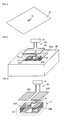
Fig. 3] Fig. 3 is a perspective view showing a layered structure of coil-shaped antennas of the wireless IC tag shown inFig. 2 . - [
Fig. 4] Fig. 4 is a perspective view showing a first example of how the wireless IC tag is mounted. - [
Fig. 5] Fig. 5 is a perspective view showing a second example of how the wireless IC tag is mounted. - [
Fig. 6] Fig. 6 is a perspective view showing a first modification of an antenna of a reader-writer. - [
Fig. 7] Fig. 7 is a perspective view showing a second modification of the antenna of the reader-writer. - [
Fig. 8] Fig. 8 is a perspective view showing a third modification of the antenna of the reader-writer. - [
Fig. 9] Fig. 9 is a perspective view showing a fourth modification of the antenna of the reader-writer. - [
Fig. 10] Fig. 10 is a descriptive view showing another example of the information processing system. - [
Fig. 11] Fig. 11 includes diagrams of the information processing system shown inFig. 10 :Fig. 11(A) is a perspective view of an antenna at a reader-writer side andFig. 11(B) is a block diagram of a circuit. - [
Fig. 12] Fig. 12 is a perspective view showing a wireless IC tag according to a second embodiment. - [
Fig. 13] Fig. 13 is a perspective view showing the wireless IC tag shown inFig. 12 and boost antennas. - [
Fig. 14] Fig. 14 is a perspective view showing a wireless IC tag according to a third embodiment. - [
Fig. 15] Fig. 15 is an equivalent circuit diagram of the wireless IC tag shown inFig. 14 . - [
Fig. 16] Fig. 16 is an equivalent circuit diagram of a modification of the wireless IC tag shown inFig. 14 . - [
Fig. 17] Fig. 17(A) and Fig. 17(B) are perspective views showing a wireless IC tag according to a fourth embodiment. - [
Fig. 18] Fig. 18 is a perspective view showing a wireless IC tag according to a fifth embodiment. - [
Fig. 19] Fig. 19(A), Fig. 19(B), and Fig. 19(C) are perspective views showing a wireless IC tag according to a sixth embodiment. - [
Fig. 20] Fig. 20(A) and Fig. 20(B) are perspective views showing a wireless IC tag according to a seventh embodiment. - [
Fig. 21] Fig. 21 is a perspective view showing a wireless IC tag according to an eighth embodiment. Description of Embodiments - Embodiments of a wireless IC tag, a reader-writer, and an information processing system according to the present invention will herein be described with reference to the attached drawings.
- A wireless IC tag 1A according to a first embodiment includes a
wireless IC chip 10 that processes transmission and reception signals having certain frequencies and two coil-shaped antennas Fig. 1 . - The
wireless IC chip 10 includes a clock circuit, a logic circuit, a memory circuit, and so on and necessary information is stored in thewireless IC chip 10. A pair of input-output terminal electrodes (not shown) is provided on the rear face of thewireless IC chip 10. - The coil-
shaped antennas shaped antenna 20A and one end of the coil-shaped antenna 20B are electrically connected to the input-output terminal electrodes on thewireless IC chip 10. The other end of the coil-shaped antenna 20A is electrically connected to the other end of the coil-shaped antenna 20B. The winding axes of theantennas antenna 20A is the same as that of theantenna 20B so that the direction of the magnetic field caused by a current flowing through theantenna 20A at a certain moment is the same as that of the magnetic field caused by a current flowing through theantenna 20B at the certain moment. Theantennas substrate 21, as described below with reference toFig. 3 . Thewireless IC chip 10 is mounted on thesubstrate 21. - The wireless IC tag 1A is capable of communicating with a reader-
writer 50, and the wireless IC tag 1A and the reader-writer 50 composes an information processing system. The reader-writer 50 includes a commoninformation processing circuit 51 and anantenna 52. Theantenna 52 is a loop-shaped magnetic field antenna having an area substantially equal to the area resulting from addition of the area of theantenna 20A of the wireless IC tag 1A to the area of theantenna 20B thereof. - In this information processing system, proximity of the
antenna 52 of the reader-writer 50 to the wireless IC tag 1A causes a magnetic flux based on a signal of a certain frequency radiated from theantenna 52 to pass through theantennas antennas antenna 52 is electromagnetically coupled to theantennas wireless IC chip 10 to operate thewireless IC chip 10. In contrast, a response signal from thewireless IC chip 10 is radiated from the coil-shapedantennas antenna 52 and is read by theinformation processing circuit 51 of the reader-writer 50. - Since the winding direction of the coil-shaped
antenna 20A is the same as that of the coil-shapedantenna 20B, the energy transfer efficiency is improved without offset of the currents occurring in therespective antennas antenna 52 and theantennas antennas - The compact loop-shaped antenna is used as the
antenna 52 of the reader-writer 50 and the communication with the wireless IC tag 1A is mainly through the magnetic field in this first embodiment. Since the attenuation in distance of the magnetic field is larger than that of the electric field, the communication is established in a relatively close state. Accordingly, it is possible to limit the communication with only the wireless IC tags that are targets for reading in the reader-writer 50 and there is no possibility of erroneous communication with peripheral wireless IC tags that are not targets for reading. - The imaginary part of the impedance of the
wireless IC chip 10 desirably has conjugate relationship with the imaginary parts of the impedances of the coil-shapedantennas antennas wireless IC chip 10 coincide with the real parts of the impedances of the coil-shapedantennas - In particular, the coil-shaped
antennas - The wireless IC tag 1A may be mounted on an article by using a double-sided tape or adhesive or may be attached to an article with a seal, a label, a tape, and the like. In this case, any of the side of the
wireless IC chip 10 and the side of theantennas - In addition, as shown in
Fig. 2 , a sealingmember 22 made of resin or ceramic may be provided on thesubstrate 21 to seal thewireless IC chip 10 with the sealingmember 22. The sealingmember 22 may be made of the same material as that of thesubstrate 21 described below. The sealingmember 22 can be used to protect thewireless IC chip 10. The sealingmember 22 having a flat surface can be used to facilitate the attachment to an article. - An example of the layered structure of the coil-shaped
antennas Fig. 3 . Thesubstrate 21 is manufactured by stacking multiple sheets on which electrode, conductors, and via-hole conductors are provided.Electrodes 31a and 31b to be connected to the input-output terminal electrodes of thewireless IC chip 10 are provided on a first layer.Coil conductors connection coil conductor 35 is provided on a fifth layer. Thecoil conductors 32a, 32b to 34a, and 34b are respectively connected to each other in a coil shape via a via-hole conductor 36a and 36b to compose theantenna coil conductors 35 via via-hole 37a and 37b. One end of theantenna 20A is connected to the electrode 31a via a via-hole conductor 38a, and one end of theantenna 20B is connected to theelectrode 31b via a via-hole conductor 38b. - Although each sheet of the
substrate 21 may be made of a common resin having a relative permittivity of three to four, each sheet of thesubstrate 21 is preferably made of a material having a higher permittivity, for example, ceramic having a relative permittivity of seven or more. - The coil-shaped
antennas substrate 21 to substantially determine the impedance of the coils in thesubstrate 21 and the wireless IC tag 1A is less affected by the environment in which the wireless IC tag 1A is used. - The wireless IC tag 1A is used with being attached to various articles. For example, the wireless IC tag 1A may be used with being attached on a
metal plate 81, as shown inFig. 4 . In this case, the side of thewireless IC chip 10 of the wireless IC tag 1A can be directed to themetal plate 81 to realize the reliable communication between the wireless IC tag 1A and the reader-writer 50. In this case, the sealingmember 22 severs as a passage of the magnetic flux. Even when theantennas metal plate 81 for attachment, it is possible to ensure the passage of the magnetic flux between the wireless IC tag 1A and themetal plate 81 by arranging theantennas substrate 21 as much as possible. - In addition, the wireless IC tag 1A may be embedded in a recess 82a of a
metal body 82, as shown inFig. 5 . Even when theantenna 52 of the reader-writer 50 has the same small size as the wireless IC tag 1A, the magnetic field can be concentrated in the tag 1A to realize the reliable communication. In this case, a gap is preferably provided between the wireless IC tag 1A and a wall portion of the recess 82a as a passage of the magnetic flux. - The reader-
writer 50 may have planarelectric field antennas Fig. 6 , instead of the loop-shaped antenna. Since the coil-shapedantennas antennas writer 50 even with the planarelectric field antennas - The reader-
writer 50 may have a loop-shapedmagnetic field antenna 54 having multiple turns, as shown inFig. 7 . The communication distance can be increased because of an increase in the strength of the magnetic field. - The reader-
writer 50 may have a first coil-shapedantenna portion 55A and a second coil-shapedantenna portion 55B, like the coil-shapedantennas Fig. 8 . One end of the coil-shapedantenna portion 55A and one end of the coil-shapedantenna portion 55B are electrically connected to theinformation processing circuit 51. The other end of the coil-shapedantenna portion 55A is electrically connected to the other end of the coil-shapedantenna portion 55B. The winding axes of theantenna portions antenna portion 55A is the same as that of theantenna portion 55B. - Since the coil-shaped
antenna portions antenna portions antennas writer 50. When the antenna according to the third modification is used, the two coil-shaped antennas are not necessarily used for the wireless IC tag. - As shown in
Fig. 9 , a matching circuit including inductors L1 and L2 and a capacitor C may be provided between theantenna 52 and theinformation processing circuit 51 of the reader-writer 50. Since the impedance matching can be achieved at the usable frequency in this case, the energy transfer efficiency between theinformation processing circuit 51 and theantenna 52 is improved to increase the communication distance even with small power. The matching circuit may have a circuit configuration other than the one shown inFig. 9 . - Another example of the information processing system using the wireless IC tag 1A will now be described. Another wireless IC tag other than the wireless IC tag 1A may be used.
- As shown in
Fig. 10 , this information processing system transfers information between a reader-writer and the wireless IC tag 1A in a non-contact manner and transmits and receives high-frequency signals within the UHF band or the super high frequency (SHF) band. As shown inFig. 11(A) , the reader-writer includes anantenna head 60 in which aloop antenna 62 is provided on a surface of a supportingmember 61 made of a hard member, such as epoxy resin. Thisloop antenna 62 is formed of a one-turn loop-shaped conductor includingpower feed portions power feed portions coaxial cable 65. In this example, thepower feed portions antenna 62 is provided via through holes, and the electrode is connected to thecoaxial cable 65. The wireless IC tag 1A is described as the first embodiment with reference toFig. 2 and Fig. 3 . - As shown in
Fig. 11(B) , a matching circuit including a capacitance element C and an inductance element L is provided between thecoaxial cable 65 and theloop antenna 62. Thepower feed portion 62a is connected aninternal conductor 66 of thecoaxial cable 65 via the matching circuit, and thepower feed portion 62b is connected to anexternal conductor 67 of thecoaxial cable 65 via the matching circuit. The capacitance element C and the inductance element L can be arranged on a surface opposite to the surface where the antenna is provided to ensure the distance from theantenna 62 and to form the matching circuit with theantenna 62 with a small area without blocking the magnetic field occurring from theantenna 62. Thecoaxial cable 65 is composed of a 50Ω line and the impedance matching between thecoaxial cable 65 and theloop antenna 62 is performed by the matching circuit. As shown inFig. 10 , theantenna head 60, which is mounted to agrip portion 70 via thecoaxial cable 65, is a pen-type head capable of being used with being gripped by a person with his/her hand. - The information processing system is used in a mode in which the antenna of the reader-writer is close to the wireless IC tag and performs the communication only with target wireless IC tags.
- A wireless IC tag 1B according to a second embodiment includes
outer electrodes substrate 21 including theantennas antennas Fig. 12 . The remaining configuration of the wireless IC tag 1B is the same as that of the wireless IC tag 1A. The provision of theouter electrodes - Bringing a probe (not shown) into contact with the
outer electrodes outer electrodes outer electrodes antennas outer electrodes antennas outer electrodes outer electrodes antenna 52 and the wireless IC tag 1B in the reading with theantenna 52, such a problem does not occur in the reading with the probe and it is possible to realize the reliable reading. In addition, it is also possible to measure the impedance between theouter electrodes - In the wireless IC tag 1B, meander-shaped
boost antennas outer electrodes Fig. 13 . Although theboost antennas - In other words, the formation of the
outer electrodes substrate 21, as in the second embodiment, allows the wireless IC tag to be operated with the probe and allows the communication with the reader-writer in a relatively remote state to established, in addition to the communication with the reader-writer established in a relatively close state. - In a
wireless IC tag 1C according to a third embodiment, theouter electrodes antennas Fig. 14 . An equivalent circuit of thewireless IC tag 1C is shown inFig. 15 . Alternatively, capacitances C1 and C2 may be respectively provided between theouter electrodes antennas Fig. 16 ). - Directly electrically connecting the
outer electrodes antennas Fig. 14 , allows the relationship in voltage between theouter electrodes antennas outer electrodes outer electrodes antennas Fig. 16 , allows thewireless IC chip 10 to be protected from intrusion of static electricity because theouter electrodes wireless IC chip 10. - In a
wireless IC tag 1D according to a fourth embodiment, the two coil-shapedantennas Fig. 17(A) and Fig. 17(B) . The remaining configuration of thewireless IC tag 1D is the same as that of the wireless IC tag 1A. Even when the number of turns on the left side is differentiated from the number of turns on the right side in the above manner, the effects and advantages in this case are basically similar to those of the wireless IC tag 1A. In addition, since the degree of freedom in design of theantennas antennas outer electrodes - In a wireless IC tag 1E according to a fifth embodiment, the two coil-shaped
antennas Fig. 18 . The remaining configuration of the wireless IC tag 1E is the same as that of the wireless IC tag 1A. Even when the size on the left side is differentiated from the size on the right side in the above manner, the effects and advantages in this case are basically similar to those of the wireless IC tag 1A. In addition, since the degree of freedom in design of theantennas antennas outer electrodes - In a
wireless IC tag 1H according to a sixth embodiment, a coil-shaped large-diameter antenna 20C wounded on the substantially entire area of thesubstrate 21 is combined with a coil-shaped small-diameter antenna 20D, as shown inFig. 19(A), Fig. 19(B), and Fig. 19(C) . The remaining configuration of thewireless IC tag 1H is the same as that of the wireless IC tag 1A. -
Fig. 19(A) shows a case in which the coil-shaped small-diameter antenna 20D is arranged immediately below the coil-shaped large-diameter antenna 20C so that the coil-shaped large-diameter antenna 20C and the coil-shaped small-diameter antenna 20D are differentiated in the winding axis.Fig. 19(B) shows a case in which the coil-shaped small-diameter antenna 20D is arranged immediately over the coil-shaped large-diameter antenna 20C so that the coil-shaped large-diameter antenna 20C and the coil-shaped small-diameter antenna 20D are differentiated in the winding axis.Fig. 19(C) shows a case in which the two coil-shaped small-diameter antennas 20D are arranged immediately below the coil-shaped large-diameter antenna 20C so that the coil-shaped large-diameter antenna 20C and the coil-shaped small-diameter antennas 20D are differentiated in the winding axis. These two coil-shaped small-diameter antennas 20D may be arranged immediately over the coil-shaped large-diameter antenna 20C. - When the coil-shaped large-
diameter antenna 20C is combined with the coil-shaped small-diameter antenna 20D as in the sixth embodiment, the large-diameter antenna 20C functions as a main antenna for communication to increase the communication distance. The small-diameter antenna 20D functions as a sub-antenna for communication and also functions as an impedance matching adjustment element. In addition, the arrangement of the small-diameter antenna 20D at the side near thewireless IC chip 10, as shown inFig. 19(B) , further facilitates the impedance adjustment with the small-diameter antenna 20D. - The number of the coil-shaped antennas may be three or more in the embodiments described above. For example, another coil-shaped antenna may be provided between the coil-shaped
antennas - In a wireless IC tag 1F according to a seventh embodiment, a
ferrite sheet 25 is attached on a bottom face of thesubstrate 21, as shown inFig. 20(A) . The remaining configuration of the wireless IC tag 1F is the same as that of the wireless IC tag 1A. Theferrite sheet 25 may be attached on the top face of thesubstrate 21, as shown inFig. 20(B) . When theferrite sheet 25 is provided on the top face of the substrate, theferrite sheet 25 also functions as a protective layer of thewireless IC chip 10. Theferrite sheet 25 may be provided on the top face of the sealingmember 22 shown inFig. 2 . - When the wireless IC tag is attached on the
metal plate 81, as shown inFig. 4 , the communication distance is decreased because themetal plate 81 blocks the passing-through of the magnetic field. However, the provision of theferrite sheet 25 on the bottom face of thesubstrate 21 causes the magnetic field to pass through theferrite sheet 25 to increase the communication distance. - In a wireless IC tag 1G according to an eighth embodiment, a chip part 29 (for example, an inductor or a capacitor) is installed on the
substrate 21, as shown inFig. 21 . Thechip part 29 may be provided in the coil-shapedantenna wireless IC chip 10. - The wireless IC tag, the reader-writer, and the information processing system according to the present invention are not limited to the embodiments described above, and changes and variations may be made within the spirit and scope of the invention.
- For example, although the wireless IC chip is mounted on the substrate where the antennas are provided in the above embodiments, the wireless IC chip may be mounted in the substrate. Alternatively, the antennas may be provided on a re-wiring layer of the wireless IC chip.
- As described above, the present invention is useful for the wireless IC tag, the reader-writer, and the information processing system. In particular, the present invention is superior in the improved energy transfer efficiency between the antenna of the reader-writer and the antennas of the wireless IC tag and the increased communication distance. Reference Signs List
-
- 1A to 1H
- wireless IC tag
- 10
- wireless IC chip
- 20A, 20B
- coil-shaped antenna
- 20C
- coil-shaped large-diameter antenna
- 20D
- coil-shaped small-diameter antenna
- 21
- substrate
- 22
- sealing member
- 23A, 23B
- outer electrode
- 24A, 24B
- boost antenna
- 25
- ferrite sheet
- 32a, 32b to 34a, 34b
- coil conductor
- 50
- reader-writer
- 51
- information processing circuit
- 52, 53A, 53B, 54, 62
- antenna
- 55A, 55B
- coil-shaped antenna portion
Claims (13)
- A wireless IC tag comprising a wireless IC chip and at least two coil-shaped antennas,
wherein one end of each of the at least two coil-shaped antennas is electrically connected to the wireless IC chip and the other ends of the at least two coil-shaped antennas are electrically connected to each other, and
wherein the winding axes of the at least two coil-shaped antennas are arranged at different positions, and the at least two coil-shaped antennas have the same winding direction. - The wireless IC tag according to Claim 1,
wherein the at least two coil-shaped antennas are each composed of multiple coil conductors stacked in a substrate. - The wireless IC tag according to Claim 2,
wherein the coil conductors are provided so that the coil conductors are overlaid on one another in the direction of the winding axes in a plan view. - The wireless IC tag according to Claim 2 or 3,
wherein the wireless IC chip is installed on the substrate and is covered with a sealing member. - The wireless IC tag according to any of Claims 2 to 4,
wherein a ferrite layer is provided on a top face or a bottom face of the substrate. - The wireless IC tag according to any of Claims 1 to 5,
wherein the at least two coil-shaped antennas are provided in the substrate and an outer electrode is provided on the substrate. - The wireless IC tag according to Claim 6,
wherein the at least two coil-shaped antennas are electrically connected to the outer electrode. - The wireless IC tag according to Claim 6 or 7, further comprising:at least one boost antenna opposing the outer electrode.
- A reader-writer comprising an antenna and an information processing portion,
wherein the antenna includes a first coil-shaped antenna portion and a second coil-shaped antenna portion,
wherein one end of each of the first and second coil-shaped antenna portions is electrically connected to the information processing portion, and the other ends of the first and second coil-shaped antenna portions are electrically connected to each other, and
wherein the winding axes of the first and second coil-shaped antenna portions are arranged at different positions, and the first and second coil-shaped antenna portions have the same winding direction. - An information processing system comprising the wireless IC tag according to any of Claims 1 to 8 and a reader-writer,
wherein the reader-writer processes information on the wireless IC tag. - The information processing system according to Claim 10,
wherein the reader-writer includes a loop antenna having a size substantially equal to the size of the coil-shaped antennas of the wireless IC tag. - The information processing system according to Claim 11,
wherein the reader-writer is the reader-writer according to Claim 9. - The information processing system according to Claim 11 or 12,
wherein the reader-writer includes a matching circuit in its loop antenna.
Applications Claiming Priority (3)
| Application Number | Priority Date | Filing Date | Title |
|---|---|---|---|
| JP2009253227 | 2009-11-04 | ||
| JP2010084009 | 2010-03-31 | ||
| PCT/JP2010/069417 WO2011055702A1 (en) | 2009-11-04 | 2010-11-01 | Wireless ic tag, reader/writer, and information processing system |
Publications (3)
| Publication Number | Publication Date |
|---|---|
| EP2498207A1 true EP2498207A1 (en) | 2012-09-12 |
| EP2498207A4 EP2498207A4 (en) | 2013-09-04 |
| EP2498207B1 EP2498207B1 (en) | 2014-12-31 |
Family
ID=43969942
Family Applications (1)
| Application Number | Title | Priority Date | Filing Date |
|---|---|---|---|
| EP10828262.5A Active EP2498207B1 (en) | 2009-11-04 | 2010-11-01 | Wireless ic tag, reader/writer, and information processing system |
Country Status (5)
| Country | Link |
|---|---|
| US (1) | US9178279B2 (en) |
| EP (1) | EP2498207B1 (en) |
| JP (1) | JP5299518B2 (en) |
| CN (1) | CN102473244B (en) |
| WO (1) | WO2011055702A1 (en) |
Cited By (1)
| Publication number | Priority date | Publication date | Assignee | Title |
|---|---|---|---|---|
| GB2491447B (en) * | 2010-03-24 | 2014-10-22 | Murata Manufacturing Co | RFID system |
Families Citing this family (38)
| Publication number | Priority date | Publication date | Assignee | Title |
|---|---|---|---|---|
| US11476566B2 (en) | 2009-03-09 | 2022-10-18 | Nucurrent, Inc. | Multi-layer-multi-turn structure for high efficiency wireless communication |
| FR2965978B1 (en) * | 2010-10-07 | 2012-10-19 | Tdf | LARGE BANDWIDE SURFACE WAVE DIMENSIONAL ANTENNA |
| US8763914B2 (en) * | 2012-01-17 | 2014-07-01 | On Track Innovations Ltd. | Decoupled contactless bi-directional systems and methods |
| FR2985863B1 (en) * | 2012-01-18 | 2014-02-14 | Inside Secure | ANTENNA CIRCUIT FOR NFC DEVICE |
| WO2013125610A1 (en) * | 2012-02-24 | 2013-08-29 | 株式会社村田製作所 | Antenna device and wireless communication device |
| JP5639606B2 (en) * | 2012-02-27 | 2014-12-10 | 三智商事株式会社 | Wireless IC tag |
| JP5668894B2 (en) | 2012-04-25 | 2015-02-12 | 株式会社村田製作所 | Wireless IC device and wireless communication terminal |
| CN102708398A (en) * | 2012-06-21 | 2012-10-03 | 中国科学院上海微系统与信息技术研究所 | RFID tag with phase change memory |
| JP2014175586A (en) * | 2013-03-12 | 2014-09-22 | Nippon Soken Inc | Magnetic field resonance coil device |
| KR101727936B1 (en) * | 2012-11-01 | 2017-04-18 | 한국전자통신연구원 | Tag integrated circuit apparatus and method for fabricating tag integrated circuit apparatus |
| TWI473383B (en) * | 2012-11-06 | 2015-02-11 | Configuration antenna with concentrated magnetic field | |
| JP2014174647A (en) * | 2013-03-06 | 2014-09-22 | Krd Corporation Kk | Rfid tag, holding member, tag mounting body having rfid tag mounted in holding member, and attachment structure of rfid tag |
| US10418711B2 (en) * | 2013-07-19 | 2019-09-17 | Geotoll, Inc. | RFID antenna structure for increased range when coupled with a mobile device |
| JP6079520B2 (en) * | 2013-09-12 | 2017-02-15 | 凸版印刷株式会社 | Non-contact IC label |
| JP5776868B1 (en) * | 2013-12-26 | 2015-09-09 | 株式会社村田製作所 | ANTENNA DEVICE AND ELECTRONIC DEVICE |
| WO2015166832A1 (en) * | 2014-04-28 | 2015-11-05 | 株式会社 村田製作所 | Wireless ic device, clip-shaped rfid tag, and article having rfid tag |
| KR101563428B1 (en) * | 2014-05-27 | 2015-10-26 | 재단법인대구경북과학기술원 | Near-field system |
| JP2016076827A (en) * | 2014-10-07 | 2016-05-12 | 日本電信電話株式会社 | Communication system, communication method, transmitter, and receiver |
| CN106462792B (en) * | 2014-11-27 | 2019-07-05 | 株式会社村田制作所 | RFIC module and the RFID label tag for having the RFIC module |
| CN108370095A (en) * | 2015-08-06 | 2018-08-03 | 薄膜电子有限公司 | Wireless communication device and production and preparation method thereof with integrated ferrite shielding and antenna |
| US11205848B2 (en) | 2015-08-07 | 2021-12-21 | Nucurrent, Inc. | Method of providing a single structure multi mode antenna having a unitary body construction for wireless power transmission using magnetic field coupling |
| US10063100B2 (en) | 2015-08-07 | 2018-08-28 | Nucurrent, Inc. | Electrical system incorporating a single structure multimode antenna for wireless power transmission using magnetic field coupling |
| US10658847B2 (en) * | 2015-08-07 | 2020-05-19 | Nucurrent, Inc. | Method of providing a single structure multi mode antenna for wireless power transmission using magnetic field coupling |
| EP3166181A1 (en) * | 2015-11-05 | 2017-05-10 | Gemalto Sa | Method for manufacturing a radiofrequency antenna on a mounting and antenna thus obtained |
| DE102016106698A1 (en) * | 2016-04-12 | 2017-10-12 | Infineon Technologies Ag | Chip card and method for producing a chip card |
| US10522912B2 (en) * | 2016-05-12 | 2019-12-31 | Tdk Corporation | Antenna device and mobile wireless device provided with the same |
| CN106372708B (en) * | 2016-08-26 | 2023-08-08 | 无锡朗帆信息科技有限公司 | RFID electronic tag manufactured by using ceramic lamination and used for sharing metal, nonmetal and liquid and manufacturing method |
| CN106374209B (en) * | 2016-10-12 | 2023-06-06 | 深圳市信维通信股份有限公司 | Patch type NFC antenna and antenna system |
| CN108627180A (en) * | 2017-03-23 | 2018-10-09 | 南宁富桂精密工业有限公司 | Passive sensor arrangement |
| KR102335846B1 (en) * | 2017-04-17 | 2021-12-07 | 삼성전자주식회사 | Electronic device comprising a plurality of coils |
| JP7075729B2 (en) * | 2017-06-28 | 2022-05-26 | 株式会社ユニバーサルエンターテインメント | Non-contact information medium and its manufacturing method |
| CN211655071U (en) * | 2017-10-20 | 2020-10-09 | 株式会社村田制作所 | Card type radio communication apparatus |
| CN117034997A (en) * | 2017-10-24 | 2023-11-10 | 艾利丹尼森零售信息服务公司 | Planar conductive device forming a coil for an RFID tag when folded |
| CN108108774B (en) * | 2017-11-03 | 2023-05-23 | 上海蜂之舞电子有限公司 | Metal article electronic tag identification method based on ultrahigh frequency RFID technology |
| CN108448227A (en) * | 2018-03-28 | 2018-08-24 | 武汉纺织大学 | A kind of reader antenna suitable for intensive counter |
| CN110543926A (en) * | 2018-05-29 | 2019-12-06 | 上海普阅信息科技有限公司 | Ultra-wideband ultrahigh frequency surgical instrument electronic tag based on inductive coupling principle |
| CN114424207A (en) * | 2019-09-19 | 2022-04-29 | 胡斯华纳有限公司 | Wireless identification tag and corresponding reader |
| SE545998C2 (en) * | 2019-09-19 | 2024-04-09 | Husqvarna Ab | Wireless identification tags and corresponding readers |
Citations (5)
| Publication number | Priority date | Publication date | Assignee | Title |
|---|---|---|---|---|
| US20050040997A1 (en) * | 2002-09-27 | 2005-02-24 | Hiraku Akiho | Electronic device with communication capability |
| JP2006074348A (en) * | 2004-09-01 | 2006-03-16 | Denso Wave Inc | Coil antenna for non-contact communication apparatus and its manufacturing method |
| JP2008217406A (en) * | 2007-03-05 | 2008-09-18 | Dainippon Printing Co Ltd | Non-contact data carrier device |
| US20090160719A1 (en) * | 2007-12-20 | 2009-06-25 | Murata Manufacturing Co., Ltd. | Radio frequency ic device |
| US20090262041A1 (en) * | 2007-07-18 | 2009-10-22 | Murata Manufacturing Co., Ltd. | Wireless ic device |
Family Cites Families (428)
| Publication number | Priority date | Publication date | Assignee | Title |
|---|---|---|---|---|
| US3364564A (en) | 1965-06-28 | 1968-01-23 | Gregory Ind Inc | Method of producing welding studs dischargeable in end-to-end relationship |
| JPS5754964B2 (en) | 1974-05-08 | 1982-11-20 | ||
| JPS60238817A (en) * | 1984-05-12 | 1985-11-27 | Citizen Watch Co Ltd | Liquid crystal display device |
| JPS6193701A (en) | 1984-10-13 | 1986-05-12 | Toyota Motor Corp | Antenna system for automobile |
| JPS61284102A (en) | 1985-06-11 | 1986-12-15 | Oki Electric Ind Co Ltd | Antenna for portable radio equipment |
| JPS62127140U (en) | 1986-02-03 | 1987-08-12 | ||
| WO1989007347A1 (en) | 1988-02-04 | 1989-08-10 | Uniscan Ltd. | Magnetic field concentrator |
| JPH0744114B2 (en) | 1988-12-16 | 1995-05-15 | 株式会社村田製作所 | Multilayer chip coil |
| JPH02164105A (en) | 1988-12-19 | 1990-06-25 | Mitsubishi Electric Corp | Spiral antenna |
| US5253969A (en) | 1989-03-10 | 1993-10-19 | Sms Schloemann-Siemag Aktiengesellschaft | Feeding system for strip material, particularly in treatment plants for metal strips |
| JP2662742B2 (en) | 1990-03-13 | 1997-10-15 | 株式会社村田製作所 | Bandpass filter |
| JP2763664B2 (en) | 1990-07-25 | 1998-06-11 | 日本碍子株式会社 | Wiring board for distributed constant circuit |
| JPH04150011A (en) | 1990-10-12 | 1992-05-22 | Tdk Corp | Composite electronic component |
| JPH04167500A (en) | 1990-10-30 | 1992-06-15 | Omron Corp | Printed-circuit board management system |
| JP2539367Y2 (en) | 1991-01-30 | 1997-06-25 | 株式会社村田製作所 | Multilayer electronic components |
| NL9100176A (en) | 1991-02-01 | 1992-03-02 | Nedap Nv | Antenna configuration for contactless identification label - forms part of tuned circuit of ID or credit card interrogated via inductive coupling |
| JP2558330Y2 (en) | 1991-02-06 | 1997-12-24 | オムロン株式会社 | Electromagnetic coupling type electronic equipment |
| NL9100347A (en) | 1991-02-26 | 1992-03-02 | Nedap Nv | Integrated transformer circuit for ID or credit card - is interrogated via contactless inductive coupling using capacitor to form tuned circuit |
| JPH04321190A (en) | 1991-04-22 | 1992-11-11 | Mitsubishi Electric Corp | Antenna circuit and its production for non-contact type portable storage |
| JPH0745933Y2 (en) | 1991-06-07 | 1995-10-18 | 太陽誘電株式会社 | Multilayer ceramic inductance element |
| EP0522806B1 (en) | 1991-07-08 | 1996-11-20 | Nippon Telegraph And Telephone Corporation | Retractable antenna system |
| JPH05327331A (en) | 1992-05-15 | 1993-12-10 | Matsushita Electric Works Ltd | Printed antenna |
| JP3186235B2 (en) | 1992-07-30 | 2001-07-11 | 株式会社村田製作所 | Resonator antenna |
| JPH0677729A (en) | 1992-08-25 | 1994-03-18 | Mitsubishi Electric Corp | Antenna integrated microwave circuit |
| JPH06177635A (en) | 1992-12-07 | 1994-06-24 | Mitsubishi Electric Corp | Cross dipole antenna system |
| JPH06260949A (en) | 1993-03-03 | 1994-09-16 | Seiko Instr Inc | Radio equipment |
| JPH07183836A (en) | 1993-12-22 | 1995-07-21 | San'eisha Mfg Co Ltd | Coupling filter device for distribution line carrier communication |
| US5491483A (en) | 1994-01-05 | 1996-02-13 | Texas Instruments Incorporated | Single loop transponder system and method |
| US6096431A (en) | 1994-07-25 | 2000-08-01 | Toppan Printing Co., Ltd. | Biodegradable cards |
| JP3427527B2 (en) | 1994-12-26 | 2003-07-22 | 凸版印刷株式会社 | Biodegradable laminate and biodegradable card |
| JP2999374B2 (en) | 1994-08-10 | 2000-01-17 | 太陽誘電株式会社 | Multilayer chip inductor |
| JP3141692B2 (en) | 1994-08-11 | 2001-03-05 | 松下電器産業株式会社 | Millimeter wave detector |
| DE4431754C1 (en) | 1994-09-06 | 1995-11-23 | Siemens Ag | Carrier element for ic module of chip card |
| US5528222A (en) | 1994-09-09 | 1996-06-18 | International Business Machines Corporation | Radio frequency circuit and memory in thin flexible package |
| JPH0887580A (en) | 1994-09-14 | 1996-04-02 | Omron Corp | Data carrier and ball game |
| JP3064840B2 (en) | 1994-12-22 | 2000-07-12 | ソニー株式会社 | IC card |
| JP2837829B2 (en) | 1995-03-31 | 1998-12-16 | 松下電器産業株式会社 | Inspection method for semiconductor device |
| JPH08279027A (en) | 1995-04-04 | 1996-10-22 | Toshiba Corp | Radio communication card |
| US5955723A (en) | 1995-05-03 | 1999-09-21 | Siemens Aktiengesellschaft | Contactless chip card |
| JPH08307126A (en) | 1995-05-09 | 1996-11-22 | Kyocera Corp | Container structure of antenna |
| JP3637982B2 (en) | 1995-06-27 | 2005-04-13 | 株式会社荏原電産 | Inverter-driven pump control system |
| US5629241A (en) | 1995-07-07 | 1997-05-13 | Hughes Aircraft Company | Microwave/millimeter wave circuit structure with discrete flip-chip mounted elements, and method of fabricating the same |
| JP3150575B2 (en) | 1995-07-18 | 2001-03-26 | 沖電気工業株式会社 | Tag device and manufacturing method thereof |
| GB2305075A (en) | 1995-09-05 | 1997-03-26 | Ibm | Radio Frequency Tag for Electronic Apparatus |
| DE19534229A1 (en) | 1995-09-15 | 1997-03-20 | Licentia Gmbh | Transponder arrangement |
| JPH0993029A (en) | 1995-09-21 | 1997-04-04 | Matsushita Electric Ind Co Ltd | Antenna device |
| JP3882218B2 (en) | 1996-03-04 | 2007-02-14 | ソニー株式会社 | optical disk |
| JP3471160B2 (en) | 1996-03-18 | 2003-11-25 | 株式会社東芝 | Monolithic antenna |
| JPH09270623A (en) | 1996-03-29 | 1997-10-14 | Murata Mfg Co Ltd | Antenna system |
| JPH09284038A (en) | 1996-04-17 | 1997-10-31 | Nhk Spring Co Ltd | Antenna equipment of non-contact data carrier |
| JP3427663B2 (en) | 1996-06-18 | 2003-07-22 | 凸版印刷株式会社 | Non-contact IC card |
| AUPO055296A0 (en) | 1996-06-19 | 1996-07-11 | Integrated Silicon Design Pty Ltd | Enhanced range transponder system |
| US6104311A (en) | 1996-08-26 | 2000-08-15 | Addison Technologies | Information storage and identification tag |
| AU4705097A (en) | 1996-10-09 | 1998-05-05 | Evc Rigid Film Gmbh | Method and connection arrangement for producing a smart card |
| JPH10171954A (en) | 1996-12-05 | 1998-06-26 | Hitachi Maxell Ltd | Non-contact type ic card |
| JP3279205B2 (en) | 1996-12-10 | 2002-04-30 | 株式会社村田製作所 | Surface mount antenna and communication equipment |
| JPH10193849A (en) | 1996-12-27 | 1998-07-28 | Rohm Co Ltd | Circuit chip-mounted card and circuit chip module |
| JPH10193851A (en) | 1997-01-08 | 1998-07-28 | Denso Corp | Non-contact card |
| DE19703029A1 (en) | 1997-01-28 | 1998-07-30 | Amatech Gmbh & Co Kg | Transmission module for a transponder device and transponder device and method for operating a transponder device |
| EP0966775A4 (en) | 1997-03-10 | 2004-09-22 | Prec Dynamics Corp | Reactively coupled elements in circuits on flexible substrates |
| JPH10293828A (en) | 1997-04-18 | 1998-11-04 | Omron Corp | Data carrier, coil module, reader-writer, and clothing data acquiring method |
| JPH11346114A (en) | 1997-06-11 | 1999-12-14 | Matsushita Electric Ind Co Ltd | Antenna device |
| JPH1125244A (en) | 1997-06-27 | 1999-01-29 | Toshiba Chem Corp | Non-contact data carrier package |
| JP3621560B2 (en) | 1997-07-24 | 2005-02-16 | 三菱電機株式会社 | Electromagnetic induction data carrier system |
| JPH1175329A (en) | 1997-08-29 | 1999-03-16 | Hitachi Ltd | Non-contact type ic card system |
| JPH1185937A (en) | 1997-09-02 | 1999-03-30 | Nippon Lsi Card Kk | Non-contact lsi card and method for inspecting the same |
| JPH1188241A (en) | 1997-09-04 | 1999-03-30 | Nippon Steel Corp | Data carrier system |
| JPH11103209A (en) | 1997-09-26 | 1999-04-13 | Fujitsu Ten Ltd | Radio wave reception equipment |
| JP3853930B2 (en) | 1997-09-26 | 2006-12-06 | 株式会社マースエンジニアリング | Non-contact data carrier package and manufacturing method thereof |
| JPH11149536A (en) | 1997-11-14 | 1999-06-02 | Toppan Printing Co Ltd | Composite ic card |
| JP3800765B2 (en) | 1997-11-14 | 2006-07-26 | 凸版印刷株式会社 | Compound IC card |
| EP1031939B1 (en) | 1997-11-14 | 2005-09-14 | Toppan Printing Co., Ltd. | Composite ic card |
| JP3800766B2 (en) | 1997-11-14 | 2006-07-26 | 凸版印刷株式会社 | Compound IC module and compound IC card |
| JPH11175678A (en) | 1997-12-09 | 1999-07-02 | Toppan Printing Co Ltd | Ic module and ic card on which the module is loaded |
| JP3296276B2 (en) * | 1997-12-11 | 2002-06-24 | 株式会社村田製作所 | Chip antenna |
| JPH11220319A (en) | 1998-01-30 | 1999-08-10 | Sharp Corp | Antenna system |
| JPH11219420A (en) | 1998-02-03 | 1999-08-10 | Tokin Corp | Ic card module, ic card and their manufacture |
| JPH11261325A (en) | 1998-03-10 | 1999-09-24 | Shiro Sugimura | Coil element and its manufacture |
| JP4260917B2 (en) | 1998-03-31 | 2009-04-30 | 株式会社東芝 | Loop antenna |
| EP0987789A4 (en) | 1998-03-31 | 2004-09-22 | Matsushita Electric Ind Co Ltd | Antenna unit and digital television receiver |
| US5936150A (en) | 1998-04-13 | 1999-08-10 | Rockwell Science Center, Llc | Thin film resonant chemical sensor with resonant acoustic isolator |
| CN1267267A (en) | 1998-04-14 | 2000-09-20 | 德克萨斯黎伯迪纸板箱公司 | Container for compressors and other goods |
| JP4030651B2 (en) | 1998-05-12 | 2008-01-09 | 三菱電機株式会社 | Mobile phone |
| JPH11328352A (en) | 1998-05-19 | 1999-11-30 | Tokin Corp | Connection structure between antenna and ic chip, and ic card |
| US6107920A (en) | 1998-06-09 | 2000-08-22 | Motorola, Inc. | Radio frequency identification tag having an article integrated antenna |
| US6018299A (en) | 1998-06-09 | 2000-01-25 | Motorola, Inc. | Radio frequency identification tag having a printed antenna and method |
| JP2000021639A (en) | 1998-07-02 | 2000-01-21 | Sharp Corp | Inductor, resonance circuit using the same, matching circuit, antenna circuit, and oscillation circuit |
| JP2000022421A (en) | 1998-07-03 | 2000-01-21 | Murata Mfg Co Ltd | Chip antenna and radio device mounted with it |
| JP2000021128A (en) | 1998-07-03 | 2000-01-21 | Nippon Steel Corp | Disk-shaped storage medium and its accommodation case |
| US6173897B1 (en) * | 1998-07-27 | 2001-01-16 | John W. Halpern | Universal card interface module for contact free cards |
| EP0977145A3 (en) | 1998-07-28 | 2002-11-06 | Kabushiki Kaisha Toshiba | Radio IC card |
| JP2000311226A (en) | 1998-07-28 | 2000-11-07 | Toshiba Corp | Radio ic card and its production and read and write system of the same |
| JP2000059260A (en) | 1998-08-04 | 2000-02-25 | Sony Corp | Storage device |
| ES2198938T3 (en) | 1998-08-14 | 2004-02-01 | 3M Innovative Properties Company | APPLICATION FOR A RADIO FREQUENCY IDENTIFICATION SYSTEM. |
| CA2338522C (en) | 1998-08-14 | 2009-04-07 | 3M Innovative Properties Company | Radio frequency identification systems applications |
| JP4411670B2 (en) | 1998-09-08 | 2010-02-10 | 凸版印刷株式会社 | Non-contact IC card manufacturing method |
| JP4508301B2 (en) | 1998-09-16 | 2010-07-21 | 大日本印刷株式会社 | Non-contact IC card |
| JP3632466B2 (en) | 1998-10-23 | 2005-03-23 | 凸版印刷株式会社 | Inspection device and inspection method for non-contact IC card |
| JP3924962B2 (en) | 1998-10-30 | 2007-06-06 | 株式会社デンソー | ID tag for dishes |
| JP2000137779A (en) | 1998-10-30 | 2000-05-16 | Hitachi Maxell Ltd | Non-contact information medium and production thereof |
| JP2000137785A (en) | 1998-10-30 | 2000-05-16 | Sony Corp | Manufacture of noncontact type ic card and noncontact type ic card |
| US6837438B1 (en) | 1998-10-30 | 2005-01-04 | Hitachi Maxell, Ltd. | Non-contact information medium and communication system utilizing the same |
| JP2000148948A (en) | 1998-11-05 | 2000-05-30 | Sony Corp | Non-contact ic label and its manufacture |
| JP2000172812A (en) | 1998-12-08 | 2000-06-23 | Hitachi Maxell Ltd | Noncontact information medium |
| FR2787640B1 (en) | 1998-12-22 | 2003-02-14 | Gemplus Card Int | ARRANGEMENT OF AN ANTENNA IN A METALLIC ENVIRONMENT |
| JP4144954B2 (en) * | 1999-01-08 | 2008-09-03 | 横浜ゴム株式会社 | Tire transponder scanner |
| JP3088404B2 (en) | 1999-01-14 | 2000-09-18 | 埼玉日本電気株式会社 | Mobile radio terminal and built-in antenna |
| JP2000222540A (en) | 1999-02-03 | 2000-08-11 | Hitachi Maxell Ltd | Non-contact type semiconductor tag |
| JP2000228602A (en) | 1999-02-08 | 2000-08-15 | Alps Electric Co Ltd | Resonance line |
| JP2000243797A (en) | 1999-02-18 | 2000-09-08 | Sanken Electric Co Ltd | Semiconductor wafer, and cutting method thereof, and semiconductor wafer assembly and cutting method thereof |
| JP3967487B2 (en) | 1999-02-23 | 2007-08-29 | 株式会社東芝 | IC card |
| JP2000251049A (en) | 1999-03-03 | 2000-09-14 | Konica Corp | Card and production thereof |
| JP4106673B2 (en) | 1999-03-05 | 2008-06-25 | 株式会社エフ・イー・シー | Antenna device using coil unit, printed circuit board |
| JP4349597B2 (en) | 1999-03-26 | 2009-10-21 | 大日本印刷株式会社 | IC chip manufacturing method and memory medium manufacturing method incorporating the same |
| JP3751178B2 (en) | 1999-03-30 | 2006-03-01 | 日本碍子株式会社 | Transceiver |
| US6542050B1 (en) | 1999-03-30 | 2003-04-01 | Ngk Insulators, Ltd. | Transmitter-receiver |
| JP2000286634A (en) | 1999-03-30 | 2000-10-13 | Ngk Insulators Ltd | Antenna system and its manufacture |
| JP3067764B1 (en) | 1999-03-31 | 2000-07-24 | 株式会社豊田自動織機製作所 | Mobile communication coupler, mobile body, and mobile communication method |
| JP2000321984A (en) | 1999-05-12 | 2000-11-24 | Hitachi Ltd | Label with rf-id tag |
| JP4286977B2 (en) | 1999-07-02 | 2009-07-01 | 大日本印刷株式会社 | Non-contact type IC card and its antenna characteristic adjustment method |
| JP3557130B2 (en) | 1999-07-14 | 2004-08-25 | 新光電気工業株式会社 | Method for manufacturing semiconductor device |
| JP2001043340A (en) | 1999-07-29 | 2001-02-16 | Toppan Printing Co Ltd | Composite ic card |
| JP2001066990A (en) | 1999-08-31 | 2001-03-16 | Sumitomo Bakelite Co Ltd | Protective filter and protection method of ic tag |
| US6259369B1 (en) | 1999-09-30 | 2001-07-10 | Moore North America, Inc. | Low cost long distance RFID reading |
| JP2001101369A (en) | 1999-10-01 | 2001-04-13 | Matsushita Electric Ind Co Ltd | Rf tag |
| JP3451373B2 (en) | 1999-11-24 | 2003-09-29 | オムロン株式会社 | Manufacturing method of data carrier capable of reading electromagnetic wave |
| JP4186149B2 (en) | 1999-12-06 | 2008-11-26 | 株式会社エフ・イー・シー | Auxiliary antenna for IC card |
| JP2001188890A (en) | 2000-01-05 | 2001-07-10 | Omron Corp | Non-contact tag |
| JP2001240046A (en) | 2000-02-25 | 2001-09-04 | Toppan Forms Co Ltd | Container and manufacturing method thereof |
| JP2001257292A (en) | 2000-03-10 | 2001-09-21 | Hitachi Maxell Ltd | Semiconductor device |
| JP2001256457A (en) | 2000-03-13 | 2001-09-21 | Toshiba Corp | Semiconductor device, its manufacture and ic card communication system |
| JP2003529163A (en) | 2000-03-28 | 2003-09-30 | ルカトロン アーゲー | RFID label having member for adjusting resonance frequency |
| JP4624536B2 (en) | 2000-04-04 | 2011-02-02 | 大日本印刷株式会社 | Non-contact data carrier device |
| JP4624537B2 (en) | 2000-04-04 | 2011-02-02 | 大日本印刷株式会社 | Non-contact data carrier device, storage |
| JP2001319380A (en) | 2000-05-11 | 2001-11-16 | Mitsubishi Materials Corp | Optical disk with rfid |
| JP2001331976A (en) | 2000-05-17 | 2001-11-30 | Casio Comput Co Ltd | Optical recording type recording medium |
| JP4223174B2 (en) | 2000-05-19 | 2009-02-12 | Dxアンテナ株式会社 | Film antenna |
| JP2001339226A (en) | 2000-05-26 | 2001-12-07 | Nec Saitama Ltd | Antenna system |
| JP2001344574A (en) | 2000-05-30 | 2001-12-14 | Mitsubishi Materials Corp | Antenna device for interrogator |
| JP2001352176A (en) | 2000-06-05 | 2001-12-21 | Fuji Xerox Co Ltd | Multilayer printed wiring board and manufacturing method of multilayer printed wiring board |
| EP1290618A2 (en) | 2000-06-06 | 2003-03-12 | Battelle Memorial Institute | Remote communication system |
| JP2002157564A (en) | 2000-11-21 | 2002-05-31 | Toyo Aluminium Kk | Antenna coil for ic card and its manufacturing method |
| US6400323B2 (en) | 2000-06-23 | 2002-06-04 | Toyo Aluminium Kabushiki Kaisha | Antenna coil for IC card and manufacturing method thereof |
| JP2004503125A (en) | 2000-07-04 | 2004-01-29 | クレディパス カンパニー リミテッド | Passive transponder recognition system and credit card transponder |
| JP4138211B2 (en) | 2000-07-06 | 2008-08-27 | 株式会社村田製作所 | Electronic component and manufacturing method thereof, collective electronic component, mounting structure of electronic component, and electronic apparatus |
| JP2002024776A (en) | 2000-07-07 | 2002-01-25 | Nippon Signal Co Ltd:The | Ic card reader/writer |
| JP2001076111A (en) | 2000-07-12 | 2001-03-23 | Hitachi Kokusai Electric Inc | Resonance circuit |
| JP2002032731A (en) | 2000-07-14 | 2002-01-31 | Sony Corp | Non-contact information exchange card |
| US7088249B2 (en) | 2000-07-19 | 2006-08-08 | Hanex Co., Ltd. | Housing structure for RFID tag, installation structure for RFID tag, and communication using such RFID tag |
| RU2163739C1 (en) | 2000-07-20 | 2001-02-27 | Криштопов Александр Владимирович | Antenna |
| JP2002042076A (en) | 2000-07-21 | 2002-02-08 | Dainippon Printing Co Ltd | Non-contact data carrier and booklet therewith |
| JP3075400U (en) | 2000-08-03 | 2001-02-16 | 昌栄印刷株式会社 | Non-contact IC card |
| JP2002063557A (en) | 2000-08-21 | 2002-02-28 | Mitsubishi Materials Corp | Tag for rfid |
| JP2002076750A (en) | 2000-08-24 | 2002-03-15 | Murata Mfg Co Ltd | Antenna device and radio equipment equipped with it |
| JP3481575B2 (en) | 2000-09-28 | 2003-12-22 | 寛児 川上 | antenna |
| JP4615695B2 (en) | 2000-10-19 | 2011-01-19 | 三星エスディーエス株式会社 | IC module for IC card and IC card using it |
| US6634564B2 (en) | 2000-10-24 | 2003-10-21 | Dai Nippon Printing Co., Ltd. | Contact/noncontact type data carrier module |
| JP4628611B2 (en) | 2000-10-27 | 2011-02-09 | 三菱マテリアル株式会社 | antenna |
| JP4432254B2 (en) | 2000-11-20 | 2010-03-17 | 株式会社村田製作所 | Surface mount antenna structure and communication device including the same |
| JP2002185358A (en) | 2000-11-24 | 2002-06-28 | Supersensor Pty Ltd | Method for fitting rf transponder to container |
| JP4641096B2 (en) | 2000-12-07 | 2011-03-02 | 大日本印刷株式会社 | Non-contact data carrier device and wiring member for booster antenna |
| JP2002183676A (en) * | 2000-12-08 | 2002-06-28 | Hitachi Ltd | Information reader |
| JP2002183690A (en) | 2000-12-11 | 2002-06-28 | Hitachi Maxell Ltd | Noncontact ic tag device |
| AU2002226093A1 (en) | 2000-12-15 | 2002-06-24 | Electrox Corp. | Process for the manufacture of novel, inexpensive radio frequency identificationdevices |
| JP3788325B2 (en) | 2000-12-19 | 2006-06-21 | 株式会社村田製作所 | Multilayer coil component and manufacturing method thereof |
| JP3621655B2 (en) | 2001-04-23 | 2005-02-16 | 株式会社ハネックス中央研究所 | RFID tag structure and manufacturing method thereof |
| TW531976B (en) | 2001-01-11 | 2003-05-11 | Hanex Co Ltd | Communication apparatus and installing structure, manufacturing method and communication method |
| KR20020061103A (en) | 2001-01-12 | 2002-07-22 | 후루까와덴끼고오교 가부시끼가이샤 | Antenna device and terminal with the antenna device |
| JP2002280821A (en) | 2001-01-12 | 2002-09-27 | Furukawa Electric Co Ltd:The | Antenna system and terminal equipment |
| JP2002232221A (en) | 2001-01-30 | 2002-08-16 | Alps Electric Co Ltd | Transmission and reception unit |
| JPWO2002061675A1 (en) | 2001-01-31 | 2004-06-03 | 株式会社ルネサステクノロジ | Non-contact identification medium |
| JP4662400B2 (en) | 2001-02-05 | 2011-03-30 | 大日本印刷株式会社 | Articles with coil-on-chip semiconductor modules |
| ATE499725T1 (en) | 2001-03-02 | 2011-03-15 | Nxp Bv | MODULE AND ELECTRONIC DEVICE |
| JP4712986B2 (en) | 2001-03-06 | 2011-06-29 | 大日本印刷株式会社 | Liquid container with RFID tag |
| JP3772778B2 (en) | 2001-03-30 | 2006-05-10 | 三菱マテリアル株式会社 | Antenna coil, identification tag using the same, reader / writer device, reader device and writer device |
| JP2002298109A (en) | 2001-03-30 | 2002-10-11 | Toppan Forms Co Ltd | Contactless ic medium and manufacturing method thereof |
| JP3570386B2 (en) | 2001-03-30 | 2004-09-29 | 松下電器産業株式会社 | Portable information terminal with built-in wireless function |
| JP2002308437A (en) | 2001-04-16 | 2002-10-23 | Dainippon Printing Co Ltd | Inspection system using rfid tag |
| JP2002319812A (en) | 2001-04-20 | 2002-10-31 | Oji Paper Co Ltd | Data carrier adhesion method |
| JP4700831B2 (en) | 2001-04-23 | 2011-06-15 | 株式会社ハネックス | RFID tag communication distance expansion method |
| JP2005236339A (en) | 2001-07-19 | 2005-09-02 | Oji Paper Co Ltd | Ic chip mounted body |
| FI112550B (en) | 2001-05-31 | 2003-12-15 | Rafsec Oy | Smart label and smart label path |
| JP2002366917A (en) | 2001-06-07 | 2002-12-20 | Hitachi Ltd | Ic card incorporating antenna |
| JP2002362613A (en) | 2001-06-07 | 2002-12-18 | Toppan Printing Co Ltd | Laminated packaging material having non-contact ic, packaging container using laminated packaging material and method for detecting opened seal of packaging container |
| JP4710174B2 (en) | 2001-06-13 | 2011-06-29 | 株式会社村田製作所 | Balanced LC filter |
| JP4882167B2 (en) | 2001-06-18 | 2012-02-22 | 大日本印刷株式会社 | Card-integrated form with non-contact IC chip |
| JP2002373029A (en) | 2001-06-18 | 2002-12-26 | Hitachi Ltd | Method for preventing illegal copy of software by using ic tag |
| JP4759854B2 (en) | 2001-06-19 | 2011-08-31 | 株式会社寺岡精工 | Mounting method of IC tag to metal object and IC tag built-in marker |
| JP2003087008A (en) | 2001-07-02 | 2003-03-20 | Ngk Insulators Ltd | Laminated type dielectric filter |
| JP4058919B2 (en) | 2001-07-03 | 2008-03-12 | 日立化成工業株式会社 | Non-contact IC label, non-contact IC card, non-contact IC label or IC module for non-contact IC card |
| JP2003026177A (en) | 2001-07-12 | 2003-01-29 | Toppan Printing Co Ltd | Packaging member with non-contact type ic chip |
| JP2003030612A (en) | 2001-07-19 | 2003-01-31 | Oji Paper Co Ltd | Ic chip mounting body |
| DE60131270T2 (en) | 2001-07-26 | 2008-08-21 | Irdeto Access B.V. | Time Valid reasoning system |
| JP3629448B2 (en) | 2001-07-27 | 2005-03-16 | Tdk株式会社 | ANTENNA DEVICE AND ELECTRONIC DEVICE HAVING THE SAME |
| JP4731060B2 (en) | 2001-07-31 | 2011-07-20 | トッパン・フォームズ株式会社 | RF-ID inspection method and inspection system |
| JP2003058840A (en) | 2001-08-14 | 2003-02-28 | Hirano Design Sekkei:Kk | Information protection management program utilizing rfid-loaded computer recording medium |
| JP2003069335A (en) | 2001-08-28 | 2003-03-07 | Hitachi Kokusai Electric Inc | Auxiliary antenna |
| JP2003067711A (en) | 2001-08-29 | 2003-03-07 | Toppan Forms Co Ltd | Article provided with ic chip mounting body or antenna part |
| JP2003078336A (en) | 2001-08-30 | 2003-03-14 | Tokai Univ | Laminated spiral antenna |
| JP2003078333A (en) | 2001-08-30 | 2003-03-14 | Murata Mfg Co Ltd | Radio communication apparatus |
| JP4843885B2 (en) | 2001-08-31 | 2011-12-21 | 凸版印刷株式会社 | Fraud prevention label with IC memory chip |
| JP4514374B2 (en) | 2001-09-05 | 2010-07-28 | トッパン・フォームズ株式会社 | RF-ID inspection system |
| JP4747467B2 (en) | 2001-09-07 | 2011-08-17 | 大日本印刷株式会社 | Non-contact IC tag |
| JP2003085520A (en) | 2001-09-11 | 2003-03-20 | Oji Paper Co Ltd | Manufacturing method for ic card |
| JP2003087044A (en) | 2001-09-12 | 2003-03-20 | Mitsubishi Materials Corp | Antenna for rfid and rfid system having the antenna |
| JP4845306B2 (en) | 2001-09-25 | 2011-12-28 | トッパン・フォームズ株式会社 | RF-ID inspection system |
| JP4698096B2 (en) | 2001-09-25 | 2011-06-08 | トッパン・フォームズ株式会社 | RF-ID inspection system |
| JP2003110344A (en) | 2001-09-26 | 2003-04-11 | Hitachi Metals Ltd | Surface-mounting type antenna and antenna device mounting the same |
| JP2003132330A (en) | 2001-10-25 | 2003-05-09 | Sato Corp | Rfid label printer |
| JP2003134007A (en) | 2001-10-30 | 2003-05-09 | Auto Network Gijutsu Kenkyusho:Kk | System and method for exchanging signal between on- vehicle equipment |
| JP3908514B2 (en) | 2001-11-20 | 2007-04-25 | 大日本印刷株式会社 | Package with IC tag and method of manufacturing package with IC tag |
| JP3984458B2 (en) | 2001-11-20 | 2007-10-03 | 大日本印刷株式会社 | Manufacturing method of package with IC tag |
| US6812707B2 (en) | 2001-11-27 | 2004-11-02 | Mitsubishi Materials Corporation | Detection element for objects and detection device using the same |
| JP3894540B2 (en) | 2001-11-30 | 2007-03-22 | トッパン・フォームズ株式会社 | Interposer with conductive connection |
| JP2003188338A (en) | 2001-12-13 | 2003-07-04 | Sony Corp | Circuit board and its manufacturing method |
| JP3700777B2 (en) | 2001-12-17 | 2005-09-28 | 三菱マテリアル株式会社 | Electrode structure of RFID tag and method for adjusting resonance frequency using the electrode |
| JP2003188620A (en) | 2001-12-19 | 2003-07-04 | Murata Mfg Co Ltd | Antenna integral with module |
| JP4028224B2 (en) | 2001-12-20 | 2007-12-26 | 大日本印刷株式会社 | Paper IC card substrate having non-contact communication function |
| JP3895175B2 (en) | 2001-12-28 | 2007-03-22 | Ntn株式会社 | Dielectric resin integrated antenna |
| JP2003209421A (en) | 2002-01-17 | 2003-07-25 | Dainippon Printing Co Ltd | Rfid tag having transparent antenna and production method therefor |
| JP3915092B2 (en) | 2002-01-21 | 2007-05-16 | 株式会社エフ・イー・シー | Booster antenna for IC card |
| JP2003233780A (en) | 2002-02-06 | 2003-08-22 | Mitsubishi Electric Corp | Data communication device |
| JP3998992B2 (en) | 2002-02-14 | 2007-10-31 | 大日本印刷株式会社 | Method for forming antenna pattern on IC chip mounted on web and package with IC tag |
| JP2003243918A (en) | 2002-02-18 | 2003-08-29 | Dainippon Printing Co Ltd | Antenna for non-contact ic tag, and non-contact ic tag |
| JP2003249813A (en) | 2002-02-25 | 2003-09-05 | Tecdia Kk | Tag for rfid with loop antenna |
| US7119693B1 (en) | 2002-03-13 | 2006-10-10 | Celis Semiconductor Corp. | Integrated circuit with enhanced coupling |
| JP2003288560A (en) | 2002-03-27 | 2003-10-10 | Toppan Forms Co Ltd | Interposer and inlet sheet with antistatic function |
| US7129834B2 (en) | 2002-03-28 | 2006-10-31 | Kabushiki Kaisha Toshiba | String wireless sensor and its manufacturing method |
| JP2003309418A (en) | 2002-04-17 | 2003-10-31 | Alps Electric Co Ltd | Dipole antenna |
| JP2003317060A (en) | 2002-04-22 | 2003-11-07 | Dainippon Printing Co Ltd | Ic card |
| JP2003317052A (en) | 2002-04-24 | 2003-11-07 | Smart Card:Kk | Ic tag system |
| JP3879098B2 (en) | 2002-05-10 | 2007-02-07 | 株式会社エフ・イー・シー | Booster antenna for IC card |
| JP3979178B2 (en) | 2002-05-14 | 2007-09-19 | 凸版印刷株式会社 | Non-contact IC medium module and non-contact IC medium |
| US6753814B2 (en) | 2002-06-27 | 2004-06-22 | Harris Corporation | Dipole arrangements using dielectric substrates of meta-materials |
| JP3863464B2 (en) | 2002-07-05 | 2006-12-27 | 株式会社ヨコオ | Filter built-in antenna |
| JP3803085B2 (en) | 2002-08-08 | 2006-08-02 | 株式会社日立製作所 | Wireless IC tag |
| JP4107381B2 (en) | 2002-08-23 | 2008-06-25 | 横浜ゴム株式会社 | Pneumatic tire |
| JP2004088218A (en) | 2002-08-23 | 2004-03-18 | Tokai Univ | Planar antenna |
| JP4273724B2 (en) | 2002-08-29 | 2009-06-03 | カシオ電子工業株式会社 | Consumables unauthorized use prevention system |
| JP2004096566A (en) | 2002-09-02 | 2004-03-25 | Toenec Corp | Inductive communication equipment |
| CN1809948A (en) | 2002-09-20 | 2006-07-26 | 美国快捷半导体有限公司 | RFID tag wide bandwidth logarithmic spiral antenna method and system |
| JP2004126750A (en) | 2002-09-30 | 2004-04-22 | Toppan Forms Co Ltd | Information write/read device, antenna and rf-id medium |
| JP3958667B2 (en) | 2002-10-16 | 2007-08-15 | 株式会社日立国際電気 | Loop antenna for reader / writer, and article management shelf and book management system provided with the loop antenna |
| JP2006507721A (en) | 2002-10-17 | 2006-03-02 | アンビエント・コーポレイション | Filter for segmenting communication power lines |
| JP2004213582A (en) | 2003-01-09 | 2004-07-29 | Mitsubishi Materials Corp | Rfid tag, reader/writer and rfid system with tag |
| JP3735635B2 (en) | 2003-02-03 | 2006-01-18 | 松下電器産業株式会社 | ANTENNA DEVICE AND RADIO COMMUNICATION DEVICE USING THE SAME |
| JP2004234595A (en) | 2003-02-03 | 2004-08-19 | Matsushita Electric Ind Co Ltd | Information recording medium reader |
| EP1445821A1 (en) | 2003-02-06 | 2004-08-11 | Matsushita Electric Industrial Co., Ltd. | Portable radio communication apparatus provided with a boom portion |
| US7225992B2 (en) | 2003-02-13 | 2007-06-05 | Avery Dennison Corporation | RFID device tester and method |
| JP2004253858A (en) | 2003-02-18 | 2004-09-09 | Minerva:Kk | Booster antenna device for ic tag |
| JP4010263B2 (en) | 2003-03-14 | 2007-11-21 | 富士電機ホールディングス株式会社 | Antenna and data reader |
| JP2004280390A (en) | 2003-03-14 | 2004-10-07 | Toppan Forms Co Ltd | Rf-id media and method for manufacturing the same |
| JP4034676B2 (en) | 2003-03-20 | 2008-01-16 | 日立マクセル株式会社 | Non-contact communication type information carrier |
| JP2004297249A (en) | 2003-03-26 | 2004-10-21 | Matsushita Electric Ind Co Ltd | Coupler between different phase lines, mounting method therefor, and coupling method between different phase lines |
| JP2004297681A (en) | 2003-03-28 | 2004-10-21 | Toppan Forms Co Ltd | Non-contact information recording medium |
| JP2004304370A (en) | 2003-03-28 | 2004-10-28 | Sony Corp | Antenna coil and communication equipment |
| JP4208631B2 (en) | 2003-04-17 | 2009-01-14 | 日本ミクロン株式会社 | Manufacturing method of semiconductor device |
| JP2004326380A (en) | 2003-04-24 | 2004-11-18 | Dainippon Printing Co Ltd | Rfid tag |
| JP2004334268A (en) | 2003-04-30 | 2004-11-25 | Dainippon Printing Co Ltd | Paper slip ic tag, book/magazine with it, and book with it |
| JP2004336250A (en) | 2003-05-02 | 2004-11-25 | Taiyo Yuden Co Ltd | Antenna matching circuit, and mobile communication apparatus and dielectric antenna having the same |
| JP2004343000A (en) | 2003-05-19 | 2004-12-02 | Fujikura Ltd | Semiconductor module, non-contact integrated circuit tag having the semiconductor module, and method of manufacturing semiconductor module |
| JP2004362190A (en) | 2003-06-04 | 2004-12-24 | Hitachi Ltd | Semiconductor device |
| JP4828088B2 (en) | 2003-06-05 | 2011-11-30 | 凸版印刷株式会社 | IC tag |
| JP2005005866A (en) | 2003-06-10 | 2005-01-06 | Alps Electric Co Ltd | Antenna-integrated module |
| JP4210559B2 (en) | 2003-06-23 | 2009-01-21 | 大日本印刷株式会社 | Sheet with IC tag and manufacturing method thereof |
| JP2005033461A (en) | 2003-07-11 | 2005-02-03 | Mitsubishi Materials Corp | Rfid system and structure of antenna therein |
| JP4333303B2 (en) * | 2003-09-19 | 2009-09-16 | ブラザー工業株式会社 | Wireless tag and wireless tag generation device |
| JP3982476B2 (en) | 2003-10-01 | 2007-09-26 | ソニー株式会社 | Communications system |
| JP4062233B2 (en) | 2003-10-20 | 2008-03-19 | トヨタ自動車株式会社 | Loop antenna device |
| JP4680489B2 (en) | 2003-10-21 | 2011-05-11 | 三菱電機株式会社 | Information record reading system |
| JP3570430B1 (en) | 2003-10-29 | 2004-09-29 | オムロン株式会社 | Loop coil antenna |
| JP4402426B2 (en) | 2003-10-30 | 2010-01-20 | 大日本印刷株式会社 | Temperature change detection system |
| JP4343655B2 (en) | 2003-11-12 | 2009-10-14 | 株式会社日立製作所 | antenna |
| JP4451125B2 (en) | 2003-11-28 | 2010-04-14 | シャープ株式会社 | Small antenna |
| JP2005165839A (en) | 2003-12-04 | 2005-06-23 | Nippon Signal Co Ltd:The | Reader/writer, ic tag, article control device, and optical disk device |
| JP4177241B2 (en) | 2003-12-04 | 2008-11-05 | 株式会社日立情報制御ソリューションズ | Wireless IC tag antenna, wireless IC tag, and container with wireless IC tag |
| US6999028B2 (en) | 2003-12-23 | 2006-02-14 | 3M Innovative Properties Company | Ultra high frequency radio frequency identification tag |
| JP4326936B2 (en) | 2003-12-24 | 2009-09-09 | シャープ株式会社 | Wireless tag |
| JP4089680B2 (en) | 2003-12-25 | 2008-05-28 | 三菱マテリアル株式会社 | Antenna device |
| KR101007529B1 (en) | 2003-12-25 | 2011-01-14 | 미쓰비시 마테리알 가부시키가이샤 | Antenna device and communication apparatus |
| EP1548674A1 (en) | 2003-12-25 | 2005-06-29 | Hitachi, Ltd. | Radio IC tag, method and apparatus for manufacturing the same |
| JP2005210676A (en) | 2003-12-25 | 2005-08-04 | Hitachi Ltd | Wireless ic tag, and method and apparatus for manufacturing the same |
| JP2005190417A (en) | 2003-12-26 | 2005-07-14 | Taketani Shoji:Kk | Fixed object management system and individual identifier for use therein |
| JP4218519B2 (en) | 2003-12-26 | 2009-02-04 | 戸田工業株式会社 | Magnetic field antenna, wireless system and communication system using the same |
| EP1706857A4 (en) | 2004-01-22 | 2011-03-09 | Mikoh Corp | A modular radio frequency identification tagging method |
| JP4271591B2 (en) | 2004-01-30 | 2009-06-03 | 双信電機株式会社 | Antenna device |
| KR101270180B1 (en) | 2004-01-30 | 2013-05-31 | 가부시키가이샤 한도오따이 에네루기 켄큐쇼 | An inspection apparatus, inspenction method, and method for manufacturing a semiconductor device |
| JP2005229474A (en) | 2004-02-16 | 2005-08-25 | Olympus Corp | Information terminal device |
| JP4393228B2 (en) | 2004-02-27 | 2010-01-06 | シャープ株式会社 | Small antenna and wireless tag provided with the same |
| JP2005252853A (en) | 2004-03-05 | 2005-09-15 | Fec Inc | Antenna for rf-id |
| CN1926721A (en) | 2004-03-24 | 2007-03-07 | 株式会社内田洋行 | Recording medium IC tag sticking sheet and recording medium |
| JP2005275870A (en) | 2004-03-25 | 2005-10-06 | Matsushita Electric Ind Co Ltd | Insertion type radio communication medium device and electronic equipment |
| JP2005284352A (en) | 2004-03-26 | 2005-10-13 | Toshiba Corp | Portable electronic equipment |
| JP4067510B2 (en) | 2004-03-31 | 2008-03-26 | シャープ株式会社 | Television receiver |
| JP2005293537A (en) | 2004-04-05 | 2005-10-20 | Fuji Xynetics Kk | Cardboard with ic tag |
| US8139759B2 (en) | 2004-04-16 | 2012-03-20 | Panasonic Corporation | Line state detecting apparatus and transmitting apparatus and receiving apparatus of balanced transmission system |
| JP2005311205A (en) | 2004-04-23 | 2005-11-04 | Nec Corp | Semiconductor device |
| JP2005340759A (en) | 2004-04-27 | 2005-12-08 | Sony Corp | Magnetic core member for antenna module, antenna module, and personal digital assistant equipped with this |
| JP2005322119A (en) | 2004-05-11 | 2005-11-17 | Ic Brains Co Ltd | Device for preventing illegal taking of article equipped with ic tag |
| JP2005321305A (en) | 2004-05-10 | 2005-11-17 | Murata Mfg Co Ltd | Electronic component measurement jig |
| JP4360276B2 (en) | 2004-06-02 | 2009-11-11 | 船井電機株式会社 | Optical disc having wireless IC tag and optical disc reproducing apparatus |
| JP4551122B2 (en) | 2004-05-26 | 2010-09-22 | 株式会社岩田レーベル | RFID label affixing device |
| US7317396B2 (en) | 2004-05-26 | 2008-01-08 | Funai Electric Co., Ltd. | Optical disc having RFID tag, optical disc apparatus, and system for preventing unauthorized copying |
| JP2005345802A (en) | 2004-06-03 | 2005-12-15 | Casio Comput Co Ltd | Imaging device, replacement unit used for the imaging device, and replacement unit use control method and program |
| JP2005352858A (en) | 2004-06-11 | 2005-12-22 | Hitachi Maxell Ltd | Communication type recording medium |
| JP4348282B2 (en) | 2004-06-11 | 2009-10-21 | 株式会社日立製作所 | Wireless IC tag and method of manufacturing wireless IC tag |
| JP4530140B2 (en) | 2004-06-28 | 2010-08-25 | Tdk株式会社 | Soft magnetic material and antenna device using the same |
| JP4359198B2 (en) | 2004-06-30 | 2009-11-04 | 株式会社日立製作所 | IC tag mounting substrate manufacturing method |
| JP4328682B2 (en) | 2004-07-13 | 2009-09-09 | 富士通株式会社 | Radio tag antenna structure for optical recording medium and optical recording medium housing case with radio tag antenna |
| JP2006033312A (en) | 2004-07-15 | 2006-02-02 | Matsushita Electric Ind Co Ltd | Antenna and antenna fitting method |
| JP2004362602A (en) | 2004-07-26 | 2004-12-24 | Hitachi Ltd | Rfid tag |
| JP2006039902A (en) | 2004-07-27 | 2006-02-09 | Ntn Corp | Uhf band radio ic tag |
| JP2006039947A (en) | 2004-07-27 | 2006-02-09 | Daido Steel Co Ltd | Composite magnetic sheet |
| JP2006042059A (en) | 2004-07-28 | 2006-02-09 | Tdk Corp | Radio communication apparatus and impedance controlling method thereof |
| JP2006042097A (en) | 2004-07-29 | 2006-02-09 | Kyocera Corp | Antenna wiring board |
| JP4653440B2 (en) | 2004-08-13 | 2011-03-16 | 富士通株式会社 | RFID tag and manufacturing method thereof |
| JP4482403B2 (en) | 2004-08-30 | 2010-06-16 | 日本発條株式会社 | Non-contact information medium |
| JP4125275B2 (en) | 2004-09-02 | 2008-07-30 | 日本電信電話株式会社 | Non-contact IC medium control system |
| JP2005129019A (en) | 2004-09-03 | 2005-05-19 | Sony Chem Corp | Ic card |
| JP2006080367A (en) | 2004-09-10 | 2006-03-23 | Brother Ind Ltd | Inductance element, radio tag circuit element, tagged tape roll, and manufacturing method of inductance element |
| JP2006092630A (en) | 2004-09-22 | 2006-04-06 | Sony Corp | Optical disk and manufacturing method therefor |
| JP4600742B2 (en) | 2004-09-30 | 2010-12-15 | ブラザー工業株式会社 | Print head and tag label producing apparatus |
| JP2006107296A (en) | 2004-10-08 | 2006-04-20 | Dainippon Printing Co Ltd | Non-contact ic tag and antenna for non-contact ic tag |
| GB2419779A (en) | 2004-10-29 | 2006-05-03 | Hewlett Packard Development Co | Document having conductive tracks for coupling to a memory tag and a reader |
| WO2006048663A1 (en) | 2004-11-05 | 2006-05-11 | Qinetiq Limited | Detunable rf tags |
| JP4088797B2 (en) | 2004-11-18 | 2008-05-21 | 日本電気株式会社 | RFID tag |
| JP2006148518A (en) | 2004-11-19 | 2006-06-08 | Matsushita Electric Works Ltd | Adjuster and adjusting method of non-contact ic card |
| JP2006151402A (en) | 2004-11-25 | 2006-06-15 | Rengo Co Ltd | Corrugated box with radio tag |
| US7545328B2 (en) | 2004-12-08 | 2009-06-09 | Electronics And Telecommunications Research Institute | Antenna using inductively coupled feeding method, RFID tag using the same and antenna impedance matching method thereof |
| JP4281683B2 (en) | 2004-12-16 | 2009-06-17 | 株式会社デンソー | IC tag mounting structure |
| JP4541246B2 (en) | 2004-12-24 | 2010-09-08 | トッパン・フォームズ株式会社 | Non-contact IC module |
| JP4942998B2 (en) | 2004-12-24 | 2012-05-30 | 株式会社半導体エネルギー研究所 | Semiconductor device and manufacturing method of semiconductor device |
| WO2006068286A1 (en) | 2004-12-24 | 2006-06-29 | Semiconductor Energy Laboratory Co., Ltd. | Semiconductor device |
| JP4737505B2 (en) | 2005-01-14 | 2011-08-03 | 日立化成工業株式会社 | IC tag inlet and manufacturing method of IC tag inlet |
| JP4711692B2 (en) | 2005-02-01 | 2011-06-29 | 富士通株式会社 | Meander line antenna |
| JP2006232292A (en) | 2005-02-22 | 2006-09-07 | Nippon Sheet Glass Co Ltd | Container with electronic tag, and rfid system |
| JP2006237674A (en) | 2005-02-22 | 2006-09-07 | Suncall Corp | Patch antenna and rfid inlet |
| EP2333561A3 (en) | 2005-03-10 | 2014-06-11 | Gen-Probe Incorporated | System for performing multi-formatted assays |
| JP4330575B2 (en) | 2005-03-17 | 2009-09-16 | 富士通株式会社 | Tag antenna |
| JP4437965B2 (en) | 2005-03-22 | 2010-03-24 | Necトーキン株式会社 | Wireless tag |
| JP2006270681A (en) | 2005-03-25 | 2006-10-05 | Sony Corp | Portable equipment |
| JP4087859B2 (en) | 2005-03-25 | 2008-05-21 | 東芝テック株式会社 | Wireless tag |
| CN101142711B (en) | 2005-04-01 | 2012-07-04 | 富士通株式会社 | RFID label suitable for metal and RFID label section of the same |
| JP4750450B2 (en) | 2005-04-05 | 2011-08-17 | 富士通株式会社 | RFID tag |
| JP2006302219A (en) | 2005-04-25 | 2006-11-02 | Fujita Denki Seisakusho:Kk | Rfid tag communication range setting device |
| JP4771115B2 (en) | 2005-04-27 | 2011-09-14 | 日立化成工業株式会社 | IC tag |
| JP4452865B2 (en) | 2005-04-28 | 2010-04-21 | 智三 太田 | Wireless IC tag device and RFID system |
| JP4529786B2 (en) | 2005-04-28 | 2010-08-25 | 株式会社日立製作所 | Signal processing circuit and non-contact IC card and tag using the same |
| JP4740645B2 (en) | 2005-05-17 | 2011-08-03 | 富士通株式会社 | Manufacturing method of semiconductor device |
| JP2007013120A (en) | 2005-05-30 | 2007-01-18 | Semiconductor Energy Lab Co Ltd | Semiconductor device |
| US7688272B2 (en) | 2005-05-30 | 2010-03-30 | Semiconductor Energy Laboratory Co., Ltd. | Semiconductor device |
| JP4255931B2 (en) | 2005-06-01 | 2009-04-22 | 日本電信電話株式会社 | Non-contact IC medium and control device |
| JP2007007888A (en) | 2005-06-28 | 2007-01-18 | Oji Paper Co Ltd | Non-contact ic chip mount body mounting corrugated cardboard and its manufacturing method |
| JP2007018067A (en) | 2005-07-05 | 2007-01-25 | Kobayashi Kirokushi Co Ltd | Rfid tag and rfid system |
| JP2007028002A (en) | 2005-07-13 | 2007-02-01 | Matsushita Electric Ind Co Ltd | Antenna of reader/writer, and communication system |
| JP4720348B2 (en) | 2005-08-04 | 2011-07-13 | パナソニック株式会社 | Antenna for RF-ID reader / writer device, RF-ID reader / writer device using the antenna, and RF-ID system |
| JP4737716B2 (en) | 2005-08-11 | 2011-08-03 | ブラザー工業株式会社 | RFID tag IC circuit holder, tag tape roll, RFID tag cartridge |
| JP4801951B2 (en) | 2005-08-18 | 2011-10-26 | 富士通フロンテック株式会社 | RFID tag |
| JP2007065822A (en) | 2005-08-30 | 2007-03-15 | Sofueru:Kk | Radio ic tag, intermediate ic tag body, intermediate ic tag body set and method for manufacturing radio ic tag |
| DE102005042444B4 (en) | 2005-09-06 | 2007-10-11 | Ksw Microtec Ag | Arrangement for an RFID transponder antenna |
| JP4725261B2 (en) | 2005-09-12 | 2011-07-13 | オムロン株式会社 | RFID tag inspection method |
| JP4384102B2 (en) | 2005-09-13 | 2009-12-16 | 株式会社東芝 | Portable radio device and antenna device |
| JP4075919B2 (en) | 2005-09-29 | 2008-04-16 | オムロン株式会社 | Antenna unit and non-contact IC tag |
| JP4826195B2 (en) | 2005-09-30 | 2011-11-30 | 大日本印刷株式会社 | RFID tag |
| JP2007116347A (en) | 2005-10-19 | 2007-05-10 | Mitsubishi Materials Corp | Tag antenna and mobile radio equipment |
| JP4774273B2 (en) | 2005-10-31 | 2011-09-14 | 株式会社サトー | RFID label and RFID label attaching method |
| JP2007159083A (en) | 2005-11-09 | 2007-06-21 | Alps Electric Co Ltd | Antenna matching circuit |
| JP2007150642A (en) | 2005-11-28 | 2007-06-14 | Hitachi Ulsi Systems Co Ltd | Interrogator for wireless tag, antenna for wireless tag, wireless tag system, and wireless tag selector |
| JP2007150868A (en) | 2005-11-29 | 2007-06-14 | Renesas Technology Corp | Electronic equipment and method of manufacturing the same |
| US7573388B2 (en) | 2005-12-08 | 2009-08-11 | The Kennedy Group, Inc. | RFID device with augmented grain |
| JP4560480B2 (en) | 2005-12-13 | 2010-10-13 | Necトーキン株式会社 | Wireless tag |
| JP2007166379A (en) * | 2005-12-15 | 2007-06-28 | Fujitsu Ltd | Loop antenna and electronic apparatus with same |
| JP4815211B2 (en) | 2005-12-22 | 2011-11-16 | 株式会社サトー | RFID label and RFID label attaching method |
| JP4848764B2 (en) | 2005-12-26 | 2011-12-28 | 大日本印刷株式会社 | Non-contact data carrier device |
| EP3367500B1 (en) | 2006-01-19 | 2021-08-11 | Murata Manufacturing Co., Ltd. | Wireless ic device |
| WO2007083575A1 (en) | 2006-01-19 | 2007-07-26 | Murata Manufacturing Co., Ltd. | Radio ic device |
| US7519328B2 (en) | 2006-01-19 | 2009-04-14 | Murata Manufacturing Co., Ltd. | Wireless IC device and component for wireless IC device |
| US20090231106A1 (en) | 2006-01-27 | 2009-09-17 | Totoku Electric Co., Ltd. | Tag Apparatus,Transceiver Apparatus, and Tag System |
| CN101390111B (en) | 2006-02-22 | 2012-01-11 | 东洋制罐株式会社 | Base material for RFID tag adapted to metallic material |
| JP4026080B2 (en) | 2006-02-24 | 2007-12-26 | オムロン株式会社 | Antenna and RFID tag |
| KR20080098412A (en) | 2006-03-06 | 2008-11-07 | 미쓰비시덴키 가부시키가이샤 | Rfid tag, method for manufacturing rfid tag and method for arranging rfid tag |
| JP3933191B1 (en) | 2006-03-13 | 2007-06-20 | 株式会社村田製作所 | Portable electronic devices |
| JP2007287128A (en) | 2006-03-22 | 2007-11-01 | Orient Sokki Computer Kk | Non-contact ic medium |
| JP4735368B2 (en) | 2006-03-28 | 2011-07-27 | 富士通株式会社 | Planar antenna |
| JP4854362B2 (en) | 2006-03-30 | 2012-01-18 | 富士通株式会社 | RFID tag and manufacturing method thereof |
| JP4927625B2 (en) | 2006-03-31 | 2012-05-09 | ニッタ株式会社 | Magnetic shield sheet, non-contact IC card communication improving method, and non-contact IC card container |
| JP4998463B2 (en) | 2006-04-10 | 2012-08-15 | 株式会社村田製作所 | Wireless IC device |
| CN101346852B (en) | 2006-04-14 | 2012-12-26 | 株式会社村田制作所 | Wireless IC device |
| BRPI0702888B1 (en) | 2006-04-14 | 2019-09-17 | Murata Manufacturing Co., Ltd | ANTENNA |
| ATE526648T1 (en) | 2006-04-26 | 2011-10-15 | Murata Manufacturing Co | ITEM WITH ELECTROMAGNETICALLY COUPLED MODULES |
| US9064198B2 (en) | 2006-04-26 | 2015-06-23 | Murata Manufacturing Co., Ltd. | Electromagnetic-coupling-module-attached article |
| JP4803253B2 (en) | 2006-04-26 | 2011-10-26 | 株式会社村田製作所 | Article with power supply circuit board |
| US7589675B2 (en) | 2006-05-19 | 2009-09-15 | Industrial Technology Research Institute | Broadband antenna |
| JP2007324865A (en) | 2006-05-31 | 2007-12-13 | Sony Chemical & Information Device Corp | Antenna circuit, and transponder |
| EP2023275B1 (en) | 2006-06-01 | 2011-04-27 | Murata Manufacturing Co. Ltd. | Radio frequency ic device and composite component for radio frequency ic device |
| JP4957724B2 (en) | 2006-07-11 | 2012-06-20 | 株式会社村田製作所 | Antenna and wireless IC device |
| JP2008033716A (en) | 2006-07-31 | 2008-02-14 | Sankyo Kk | Coin type rfid tag |
| JP4836899B2 (en) | 2006-09-05 | 2011-12-14 | パナソニック株式会社 | Magnetic striped array sheet, RFID magnetic sheet, electromagnetic shielding sheet, and manufacturing method thereof |
| US7981528B2 (en) | 2006-09-05 | 2011-07-19 | Panasonic Corporation | Magnetic sheet with stripe-arranged magnetic grains, RFID magnetic sheet, magnetic shielding sheet and method of manufacturing the same |
| JP4770655B2 (en) | 2006-09-12 | 2011-09-14 | 株式会社村田製作所 | Wireless IC device |
| JP2008083867A (en) | 2006-09-26 | 2008-04-10 | Matsushita Electric Works Ltd | Memory card socket |
| JP4913529B2 (en) | 2006-10-13 | 2012-04-11 | トッパン・フォームズ株式会社 | RFID media |
| JP2008107947A (en) | 2006-10-24 | 2008-05-08 | Toppan Printing Co Ltd | Rfid tag |
| DE102006057369A1 (en) | 2006-12-04 | 2008-06-05 | Airbus Deutschland Gmbh | Radio frequency identification tag for e.g. identifying metal container, has radio frequency identification scanning antenna with conductor loop that is aligned diagonally or perpendicularly to attachment surface |
| JP4452782B2 (en) * | 2006-12-20 | 2010-04-21 | 仁川大學校産學協力團 | Multiple loop antenna for RFID reader, RFID reader having the same, and RFID system having the same |
| WO2008081699A1 (en) * | 2006-12-28 | 2008-07-10 | Philtech Inc. | Base sheet |
| JP2008197714A (en) | 2007-02-08 | 2008-08-28 | Dainippon Printing Co Ltd | Non-contact data carrier device, and auxiliary antenna for non-contact data carrier |
| JP2008226093A (en) * | 2007-03-15 | 2008-09-25 | Sanden Corp | Adjusting method of rfid tag reader |
| EP2133827B1 (en) | 2007-04-06 | 2012-04-25 | Murata Manufacturing Co. Ltd. | Radio ic device |
| JP5170087B2 (en) | 2007-04-13 | 2013-03-27 | 株式会社村田製作所 | Portable electronic devices |
| DE112008000065B4 (en) | 2007-05-10 | 2011-07-07 | Murata Manufacturing Co., Ltd., Kyoto-fu | Wireless IC device |
| JP4666102B2 (en) | 2007-05-11 | 2011-04-06 | 株式会社村田製作所 | Wireless IC device |
| JP4770792B2 (en) | 2007-05-18 | 2011-09-14 | パナソニック電工株式会社 | Antenna device |
| JP5266675B2 (en) * | 2007-07-04 | 2013-08-21 | 株式会社村田製作所 | Inspection system for electromagnetic coupling module and method for manufacturing electromagnetic coupling module using the inspection system |
| JP2009017284A (en) | 2007-07-05 | 2009-01-22 | Panasonic Corp | Antenna device |
| CN104540317B (en) | 2007-07-17 | 2018-11-02 | 株式会社村田制作所 | printed wiring substrate |
| JP5167709B2 (en) | 2007-07-17 | 2013-03-21 | 株式会社村田製作所 | Wireless IC device, inspection system thereof, and method of manufacturing wireless IC device using the inspection system |
| JP4867830B2 (en) | 2007-07-18 | 2012-02-01 | 株式会社村田製作所 | Wireless IC device |
| CN102915462B (en) | 2007-07-18 | 2017-03-01 | 株式会社村田制作所 | Wireless IC device |
| US20090021352A1 (en) | 2007-07-18 | 2009-01-22 | Murata Manufacturing Co., Ltd. | Radio frequency ic device and electronic apparatus |
| US7830311B2 (en) | 2007-07-18 | 2010-11-09 | Murata Manufacturing Co., Ltd. | Wireless IC device and electronic device |
| KR20090020885A (en) * | 2007-08-24 | 2009-02-27 | 서울산업대학교 산학협력단 | An inductively coupled radio frequency identification system |
| US8730121B2 (en) * | 2007-08-31 | 2014-05-20 | Tyco Fire & Security Gmbh | Large scale folded dipole antenna for near-field RFID applications |
| JP2009182630A (en) | 2008-01-30 | 2009-08-13 | Dainippon Printing Co Ltd | Booster antenna board, booster antenna board sheet and non-contact type data carrier device |
| EP2251934B1 (en) | 2008-03-03 | 2018-05-02 | Murata Manufacturing Co. Ltd. | Wireless ic device and wireless communication system |
| JP4609604B2 (en) | 2008-05-21 | 2011-01-12 | 株式会社村田製作所 | Wireless IC device |
| JP4557186B2 (en) | 2008-06-25 | 2010-10-06 | 株式会社村田製作所 | Wireless IC device and manufacturing method thereof |
| JP3148168U (en) | 2008-10-21 | 2009-02-05 | 株式会社村田製作所 | Wireless IC device |
-
2010
- 2010-11-01 EP EP10828262.5A patent/EP2498207B1/en active Active
- 2010-11-01 CN CN201080031921.4A patent/CN102473244B/en active Active
- 2010-11-01 WO PCT/JP2010/069417 patent/WO2011055702A1/en active Application Filing
- 2010-11-01 JP JP2011539361A patent/JP5299518B2/en active Active
-
2011
- 2011-12-19 US US13/329,354 patent/US9178279B2/en active Active
Patent Citations (5)
| Publication number | Priority date | Publication date | Assignee | Title |
|---|---|---|---|---|
| US20050040997A1 (en) * | 2002-09-27 | 2005-02-24 | Hiraku Akiho | Electronic device with communication capability |
| JP2006074348A (en) * | 2004-09-01 | 2006-03-16 | Denso Wave Inc | Coil antenna for non-contact communication apparatus and its manufacturing method |
| JP2008217406A (en) * | 2007-03-05 | 2008-09-18 | Dainippon Printing Co Ltd | Non-contact data carrier device |
| US20090262041A1 (en) * | 2007-07-18 | 2009-10-22 | Murata Manufacturing Co., Ltd. | Wireless ic device |
| US20090160719A1 (en) * | 2007-12-20 | 2009-06-25 | Murata Manufacturing Co., Ltd. | Radio frequency ic device |
Non-Patent Citations (1)
| Title |
|---|
| See also references of WO2011055702A1 * |
Cited By (1)
| Publication number | Priority date | Publication date | Assignee | Title |
|---|---|---|---|---|
| GB2491447B (en) * | 2010-03-24 | 2014-10-22 | Murata Manufacturing Co | RFID system |
Also Published As
| Publication number | Publication date |
|---|---|
| JP5299518B2 (en) | 2013-09-25 |
| US20120086556A1 (en) | 2012-04-12 |
| CN102473244B (en) | 2014-10-08 |
| US9178279B2 (en) | 2015-11-03 |
| WO2011055702A1 (en) | 2011-05-12 |
| JPWO2011055702A1 (en) | 2013-03-28 |
| EP2498207A4 (en) | 2013-09-04 |
| EP2498207B1 (en) | 2014-12-31 |
| CN102473244A (en) | 2012-05-23 |
Similar Documents
| Publication | Publication Date | Title |
|---|---|---|
| EP2498207B1 (en) | Wireless ic tag, reader/writer, and information processing system | |
| US11392784B2 (en) | RFID system | |
| US9117157B2 (en) | Wireless IC device and electromagnetic coupling module | |
| US8418928B2 (en) | Wireless IC device component and wireless IC device | |
| US8668151B2 (en) | Wireless IC device | |
| US8177138B2 (en) | Radio IC device | |
| EP2251934B1 (en) | Wireless ic device and wireless communication system | |
| US9016592B2 (en) | Antenna device and communication terminal apparatus | |
| JP5418737B2 (en) | Antenna apparatus and wireless device | |
| US20140035793A1 (en) | Antenna device and communication terminal apparatus | |
| US20140176382A1 (en) | Antenna device and communication terminal apparatus | |
| US9104950B2 (en) | Antenna and wireless IC device | |
| US20120325916A1 (en) | Rfid module and rfid device | |
| WO2011055701A1 (en) | Communication terminal and information processing system | |
| JP5672874B2 (en) | Wireless IC tag and RFID system | |
| JP5605251B2 (en) | Wireless IC device | |
| JP5630166B2 (en) | Wireless IC tag and RFID system | |
| EP3611670B1 (en) | Rfid tag and rfid attached material | |
| JP6555320B2 (en) | Wireless IC tag and RFID system | |
| JP5983724B2 (en) | Wireless IC tag and RFID system |
Legal Events
| Date | Code | Title | Description |
|---|---|---|---|
| PUAI | Public reference made under article 153(3) epc to a published international application that has entered the european phase |
Free format text: ORIGINAL CODE: 0009012 |
|
| 17P | Request for examination filed |
Effective date: 20111121 |
|
| AK | Designated contracting states |
Kind code of ref document: A1 Designated state(s): AL AT BE BG CH CY CZ DE DK EE ES FI FR GB GR HR HU IE IS IT LI LT LU LV MC MK MT NL NO PL PT RO RS SE SI SK SM TR |
|
| DAX | Request for extension of the european patent (deleted) | ||
| A4 | Supplementary search report drawn up and despatched |
Effective date: 20130802 |
|
| RIC1 | Information provided on ipc code assigned before grant |
Ipc: H04B 5/02 20060101ALI20130729BHEP Ipc: G06K 19/077 20060101ALI20130729BHEP Ipc: G06K 17/00 20060101ALI20130729BHEP Ipc: G06K 19/07 20060101AFI20130729BHEP Ipc: G01S 13/75 20060101ALI20130729BHEP Ipc: H01Q 7/06 20060101ALI20130729BHEP |
|
| GRAP | Despatch of communication of intention to grant a patent |
Free format text: ORIGINAL CODE: EPIDOSNIGR1 |
|
| INTG | Intention to grant announced |
Effective date: 20140716 |
|
| GRAS | Grant fee paid |
Free format text: ORIGINAL CODE: EPIDOSNIGR3 |
|
| GRAA | (expected) grant |
Free format text: ORIGINAL CODE: 0009210 |
|
| AK | Designated contracting states |
Kind code of ref document: B1 Designated state(s): AL AT BE BG CH CY CZ DE DK EE ES FI FR GB GR HR HU IE IS IT LI LT LU LV MC MK MT NL NO PL PT RO RS SE SI SK SM TR |
|
| REG | Reference to a national code |
Ref country code: CH Ref legal event code: EP Ref country code: GB Ref legal event code: FG4D |
|
| REG | Reference to a national code |
Ref country code: IE Ref legal event code: FG4D |
|
| REG | Reference to a national code |
Ref country code: AT Ref legal event code: REF Ref document number: 704794 Country of ref document: AT Kind code of ref document: T Effective date: 20150215 |
|
| REG | Reference to a national code |
Ref country code: DE Ref legal event code: R096 Ref document number: 602010021514 Country of ref document: DE Effective date: 20150219 |
|
| PG25 | Lapsed in a contracting state [announced via postgrant information from national office to epo] |
Ref country code: LT Free format text: LAPSE BECAUSE OF FAILURE TO SUBMIT A TRANSLATION OF THE DESCRIPTION OR TO PAY THE FEE WITHIN THE PRESCRIBED TIME-LIMIT Effective date: 20141231 Ref country code: FI Free format text: LAPSE BECAUSE OF FAILURE TO SUBMIT A TRANSLATION OF THE DESCRIPTION OR TO PAY THE FEE WITHIN THE PRESCRIBED TIME-LIMIT Effective date: 20141231 Ref country code: NO Free format text: LAPSE BECAUSE OF FAILURE TO SUBMIT A TRANSLATION OF THE DESCRIPTION OR TO PAY THE FEE WITHIN THE PRESCRIBED TIME-LIMIT Effective date: 20150331 |
|
| REG | Reference to a national code |
Ref country code: NL Ref legal event code: VDEP Effective date: 20141231 |
|
| REG | Reference to a national code |
Ref country code: LT Ref legal event code: MG4D |
|
| PG25 | Lapsed in a contracting state [announced via postgrant information from national office to epo] |
Ref country code: RS Free format text: LAPSE BECAUSE OF FAILURE TO SUBMIT A TRANSLATION OF THE DESCRIPTION OR TO PAY THE FEE WITHIN THE PRESCRIBED TIME-LIMIT Effective date: 20141231 Ref country code: GR Free format text: LAPSE BECAUSE OF FAILURE TO SUBMIT A TRANSLATION OF THE DESCRIPTION OR TO PAY THE FEE WITHIN THE PRESCRIBED TIME-LIMIT Effective date: 20150401 Ref country code: HR Free format text: LAPSE BECAUSE OF FAILURE TO SUBMIT A TRANSLATION OF THE DESCRIPTION OR TO PAY THE FEE WITHIN THE PRESCRIBED TIME-LIMIT Effective date: 20141231 Ref country code: SE Free format text: LAPSE BECAUSE OF FAILURE TO SUBMIT A TRANSLATION OF THE DESCRIPTION OR TO PAY THE FEE WITHIN THE PRESCRIBED TIME-LIMIT Effective date: 20141231 Ref country code: LV Free format text: LAPSE BECAUSE OF FAILURE TO SUBMIT A TRANSLATION OF THE DESCRIPTION OR TO PAY THE FEE WITHIN THE PRESCRIBED TIME-LIMIT Effective date: 20141231 |
|
| REG | Reference to a national code |
Ref country code: AT Ref legal event code: MK05 Ref document number: 704794 Country of ref document: AT Kind code of ref document: T Effective date: 20141231 |
|
| PG25 | Lapsed in a contracting state [announced via postgrant information from national office to epo] |
Ref country code: NL Free format text: LAPSE BECAUSE OF FAILURE TO SUBMIT A TRANSLATION OF THE DESCRIPTION OR TO PAY THE FEE WITHIN THE PRESCRIBED TIME-LIMIT Effective date: 20141231 |
|
| PG25 | Lapsed in a contracting state [announced via postgrant information from national office to epo] |
Ref country code: RO Free format text: LAPSE BECAUSE OF FAILURE TO SUBMIT A TRANSLATION OF THE DESCRIPTION OR TO PAY THE FEE WITHIN THE PRESCRIBED TIME-LIMIT Effective date: 20141231 Ref country code: ES Free format text: LAPSE BECAUSE OF FAILURE TO SUBMIT A TRANSLATION OF THE DESCRIPTION OR TO PAY THE FEE WITHIN THE PRESCRIBED TIME-LIMIT Effective date: 20141231 Ref country code: SK Free format text: LAPSE BECAUSE OF FAILURE TO SUBMIT A TRANSLATION OF THE DESCRIPTION OR TO PAY THE FEE WITHIN THE PRESCRIBED TIME-LIMIT Effective date: 20141231 Ref country code: CZ Free format text: LAPSE BECAUSE OF FAILURE TO SUBMIT A TRANSLATION OF THE DESCRIPTION OR TO PAY THE FEE WITHIN THE PRESCRIBED TIME-LIMIT Effective date: 20141231 |
|
| PG25 | Lapsed in a contracting state [announced via postgrant information from national office to epo] |
Ref country code: PL Free format text: LAPSE BECAUSE OF FAILURE TO SUBMIT A TRANSLATION OF THE DESCRIPTION OR TO PAY THE FEE WITHIN THE PRESCRIBED TIME-LIMIT Effective date: 20141231 Ref country code: IS Free format text: LAPSE BECAUSE OF FAILURE TO SUBMIT A TRANSLATION OF THE DESCRIPTION OR TO PAY THE FEE WITHIN THE PRESCRIBED TIME-LIMIT Effective date: 20150430 Ref country code: AT Free format text: LAPSE BECAUSE OF FAILURE TO SUBMIT A TRANSLATION OF THE DESCRIPTION OR TO PAY THE FEE WITHIN THE PRESCRIBED TIME-LIMIT Effective date: 20141231 |
|
| REG | Reference to a national code |
Ref country code: DE Ref legal event code: R097 Ref document number: 602010021514 Country of ref document: DE |
|
| PG25 | Lapsed in a contracting state [announced via postgrant information from national office to epo] |
Ref country code: DK Free format text: LAPSE BECAUSE OF FAILURE TO SUBMIT A TRANSLATION OF THE DESCRIPTION OR TO PAY THE FEE WITHIN THE PRESCRIBED TIME-LIMIT Effective date: 20141231 Ref country code: EE Free format text: LAPSE BECAUSE OF FAILURE TO SUBMIT A TRANSLATION OF THE DESCRIPTION OR TO PAY THE FEE WITHIN THE PRESCRIBED TIME-LIMIT Effective date: 20141231 |
|
| PLBE | No opposition filed within time limit |
Free format text: ORIGINAL CODE: 0009261 |
|
| STAA | Information on the status of an ep patent application or granted ep patent |
Free format text: STATUS: NO OPPOSITION FILED WITHIN TIME LIMIT |
|
| 26N | No opposition filed |
Effective date: 20151001 |
|
| PG25 | Lapsed in a contracting state [announced via postgrant information from national office to epo] |
Ref country code: IT Free format text: LAPSE BECAUSE OF FAILURE TO SUBMIT A TRANSLATION OF THE DESCRIPTION OR TO PAY THE FEE WITHIN THE PRESCRIBED TIME-LIMIT Effective date: 20141231 |
|
| PG25 | Lapsed in a contracting state [announced via postgrant information from national office to epo] |
Ref country code: SI Free format text: LAPSE BECAUSE OF FAILURE TO SUBMIT A TRANSLATION OF THE DESCRIPTION OR TO PAY THE FEE WITHIN THE PRESCRIBED TIME-LIMIT Effective date: 20141231 |
|
| PG25 | Lapsed in a contracting state [announced via postgrant information from national office to epo] |
Ref country code: BE Free format text: LAPSE BECAUSE OF FAILURE TO SUBMIT A TRANSLATION OF THE DESCRIPTION OR TO PAY THE FEE WITHIN THE PRESCRIBED TIME-LIMIT Effective date: 20141231 |
|
| REG | Reference to a national code |
Ref country code: DE Ref legal event code: R119 Ref document number: 602010021514 Country of ref document: DE |
|
| PG25 | Lapsed in a contracting state [announced via postgrant information from national office to epo] |
Ref country code: LU Free format text: LAPSE BECAUSE OF FAILURE TO SUBMIT A TRANSLATION OF THE DESCRIPTION OR TO PAY THE FEE WITHIN THE PRESCRIBED TIME-LIMIT Effective date: 20151101 Ref country code: MC Free format text: LAPSE BECAUSE OF FAILURE TO SUBMIT A TRANSLATION OF THE DESCRIPTION OR TO PAY THE FEE WITHIN THE PRESCRIBED TIME-LIMIT Effective date: 20141231 |
|
| REG | Reference to a national code |
Ref country code: CH Ref legal event code: PL |
|
| PG25 | Lapsed in a contracting state [announced via postgrant information from national office to epo] |
Ref country code: CH Free format text: LAPSE BECAUSE OF NON-PAYMENT OF DUE FEES Effective date: 20151130 Ref country code: LI Free format text: LAPSE BECAUSE OF NON-PAYMENT OF DUE FEES Effective date: 20151130 |
|
| REG | Reference to a national code |
Ref country code: IE Ref legal event code: MM4A |
|
| REG | Reference to a national code |
Ref country code: FR Ref legal event code: ST Effective date: 20160729 |
|
| PG25 | Lapsed in a contracting state [announced via postgrant information from national office to epo] |
Ref country code: DE Free format text: LAPSE BECAUSE OF NON-PAYMENT OF DUE FEES Effective date: 20160601 Ref country code: IE Free format text: LAPSE BECAUSE OF NON-PAYMENT OF DUE FEES Effective date: 20151101 |
|
| PG25 | Lapsed in a contracting state [announced via postgrant information from national office to epo] |
Ref country code: FR Free format text: LAPSE BECAUSE OF NON-PAYMENT OF DUE FEES Effective date: 20151130 |
|
| PG25 | Lapsed in a contracting state [announced via postgrant information from national office to epo] |
Ref country code: SM Free format text: LAPSE BECAUSE OF FAILURE TO SUBMIT A TRANSLATION OF THE DESCRIPTION OR TO PAY THE FEE WITHIN THE PRESCRIBED TIME-LIMIT Effective date: 20141231 Ref country code: BG Free format text: LAPSE BECAUSE OF FAILURE TO SUBMIT A TRANSLATION OF THE DESCRIPTION OR TO PAY THE FEE WITHIN THE PRESCRIBED TIME-LIMIT Effective date: 20141231 Ref country code: HU Free format text: LAPSE BECAUSE OF FAILURE TO SUBMIT A TRANSLATION OF THE DESCRIPTION OR TO PAY THE FEE WITHIN THE PRESCRIBED TIME-LIMIT; INVALID AB INITIO Effective date: 20101101 |
|
| PG25 | Lapsed in a contracting state [announced via postgrant information from national office to epo] |
Ref country code: CY Free format text: LAPSE BECAUSE OF FAILURE TO SUBMIT A TRANSLATION OF THE DESCRIPTION OR TO PAY THE FEE WITHIN THE PRESCRIBED TIME-LIMIT Effective date: 20141231 |
|
| PG25 | Lapsed in a contracting state [announced via postgrant information from national office to epo] |
Ref country code: MT Free format text: LAPSE BECAUSE OF FAILURE TO SUBMIT A TRANSLATION OF THE DESCRIPTION OR TO PAY THE FEE WITHIN THE PRESCRIBED TIME-LIMIT Effective date: 20141231 Ref country code: TR Free format text: LAPSE BECAUSE OF FAILURE TO SUBMIT A TRANSLATION OF THE DESCRIPTION OR TO PAY THE FEE WITHIN THE PRESCRIBED TIME-LIMIT Effective date: 20141231 |
|
| PG25 | Lapsed in a contracting state [announced via postgrant information from national office to epo] |
Ref country code: MK Free format text: LAPSE BECAUSE OF FAILURE TO SUBMIT A TRANSLATION OF THE DESCRIPTION OR TO PAY THE FEE WITHIN THE PRESCRIBED TIME-LIMIT Effective date: 20141231 |
|
| PG25 | Lapsed in a contracting state [announced via postgrant information from national office to epo] |
Ref country code: PT Free format text: LAPSE BECAUSE OF FAILURE TO SUBMIT A TRANSLATION OF THE DESCRIPTION OR TO PAY THE FEE WITHIN THE PRESCRIBED TIME-LIMIT Effective date: 20141231 |
|
| PG25 | Lapsed in a contracting state [announced via postgrant information from national office to epo] |
Ref country code: AL Free format text: LAPSE BECAUSE OF FAILURE TO SUBMIT A TRANSLATION OF THE DESCRIPTION OR TO PAY THE FEE WITHIN THE PRESCRIBED TIME-LIMIT Effective date: 20141231 |
|
| PGFP | Annual fee paid to national office [announced via postgrant information from national office to epo] |
Ref country code: GB Payment date: 20231123 Year of fee payment: 14 |