WO2012114917A1 - 会話システム、及び、会話システム用指輪 - Google Patents
会話システム、及び、会話システム用指輪 Download PDFInfo
- Publication number
- WO2012114917A1 WO2012114917A1 PCT/JP2012/053231 JP2012053231W WO2012114917A1 WO 2012114917 A1 WO2012114917 A1 WO 2012114917A1 JP 2012053231 W JP2012053231 W JP 2012053231W WO 2012114917 A1 WO2012114917 A1 WO 2012114917A1
- Authority
- WO
- WIPO (PCT)
- Prior art keywords
- unit
- short
- ring
- wireless communication
- communication unit
- Prior art date
Links
- 238000004891 communication Methods 0.000 claims abstract description 176
- 230000005236 sound signal Effects 0.000 claims abstract description 65
- 210000000845 cartilage Anatomy 0.000 claims description 109
- 230000006870 function Effects 0.000 claims description 29
- 210000004728 ear cartilage Anatomy 0.000 claims description 18
- 241000746998 Tragus Species 0.000 claims description 12
- 230000005540 biological transmission Effects 0.000 description 41
- 239000000758 substrate Substances 0.000 description 31
- 238000000034 method Methods 0.000 description 13
- 238000010586 diagram Methods 0.000 description 11
- 210000000613 ear canal Anatomy 0.000 description 9
- 238000012545 processing Methods 0.000 description 5
- 230000009471 action Effects 0.000 description 2
- 210000000988 bone and bone Anatomy 0.000 description 2
- 230000001413 cellular effect Effects 0.000 description 2
- 210000003027 ear inner Anatomy 0.000 description 2
- 230000000694 effects Effects 0.000 description 2
- 238000010295 mobile communication Methods 0.000 description 2
- 230000004048 modification Effects 0.000 description 2
- 238000012986 modification Methods 0.000 description 2
- 210000003454 tympanic membrane Anatomy 0.000 description 2
- XLYOFNOQVPJJNP-UHFFFAOYSA-N water Substances O XLYOFNOQVPJJNP-UHFFFAOYSA-N 0.000 description 2
- HBBGRARXTFLTSG-UHFFFAOYSA-N Lithium ion Chemical compound [Li+] HBBGRARXTFLTSG-UHFFFAOYSA-N 0.000 description 1
- 208000003443 Unconsciousness Diseases 0.000 description 1
- 230000003044 adaptive effect Effects 0.000 description 1
- 210000000481 breast Anatomy 0.000 description 1
- 239000003990 capacitor Substances 0.000 description 1
- 230000008859 change Effects 0.000 description 1
- 238000006243 chemical reaction Methods 0.000 description 1
- 210000000860 cochlear nerve Anatomy 0.000 description 1
- 239000000470 constituent Substances 0.000 description 1
- 238000010168 coupling process Methods 0.000 description 1
- 238000011161 development Methods 0.000 description 1
- 210000000959 ear middle Anatomy 0.000 description 1
- 210000005069 ears Anatomy 0.000 description 1
- 230000005684 electric field Effects 0.000 description 1
- 238000005401 electroluminescence Methods 0.000 description 1
- 230000005674 electromagnetic induction Effects 0.000 description 1
- 230000001939 inductive effect Effects 0.000 description 1
- 239000004973 liquid crystal related substance Substances 0.000 description 1
- 229910001416 lithium ion Inorganic materials 0.000 description 1
- 239000000463 material Substances 0.000 description 1
- 230000003340 mental effect Effects 0.000 description 1
- 238000009774 resonance method Methods 0.000 description 1
- 230000004044 response Effects 0.000 description 1
- 229920002379 silicone rubber Polymers 0.000 description 1
- 210000004243 sweat Anatomy 0.000 description 1
- 238000005406 washing Methods 0.000 description 1
Images

Classifications
-
- H—ELECTRICITY
- H04—ELECTRIC COMMUNICATION TECHNIQUE
- H04R—LOUDSPEAKERS, MICROPHONES, GRAMOPHONE PICK-UPS OR LIKE ACOUSTIC ELECTROMECHANICAL TRANSDUCERS; DEAF-AID SETS; PUBLIC ADDRESS SYSTEMS
- H04R1/00—Details of transducers, loudspeakers or microphones
- H04R1/02—Casings; Cabinets ; Supports therefor; Mountings therein
- H04R1/028—Casings; Cabinets ; Supports therefor; Mountings therein associated with devices performing functions other than acoustics, e.g. electric candles
-
- A—HUMAN NECESSITIES
- A44—HABERDASHERY; JEWELLERY
- A44C—PERSONAL ADORNMENTS, e.g. JEWELLERY; COINS
- A44C9/00—Finger-rings
-
- H—ELECTRICITY
- H04—ELECTRIC COMMUNICATION TECHNIQUE
- H04R—LOUDSPEAKERS, MICROPHONES, GRAMOPHONE PICK-UPS OR LIKE ACOUSTIC ELECTROMECHANICAL TRANSDUCERS; DEAF-AID SETS; PUBLIC ADDRESS SYSTEMS
- H04R1/00—Details of transducers, loudspeakers or microphones
- H04R1/46—Special adaptations for use as contact microphones, e.g. on musical instrument, on stethoscope
-
- H—ELECTRICITY
- H04—ELECTRIC COMMUNICATION TECHNIQUE
- H04R—LOUDSPEAKERS, MICROPHONES, GRAMOPHONE PICK-UPS OR LIKE ACOUSTIC ELECTROMECHANICAL TRANSDUCERS; DEAF-AID SETS; PUBLIC ADDRESS SYSTEMS
- H04R17/00—Piezoelectric transducers; Electrostrictive transducers
- H04R17/005—Piezoelectric transducers; Electrostrictive transducers using a piezoelectric polymer
-
- H—ELECTRICITY
- H04—ELECTRIC COMMUNICATION TECHNIQUE
- H04R—LOUDSPEAKERS, MICROPHONES, GRAMOPHONE PICK-UPS OR LIKE ACOUSTIC ELECTROMECHANICAL TRANSDUCERS; DEAF-AID SETS; PUBLIC ADDRESS SYSTEMS
- H04R25/00—Deaf-aid sets, i.e. electro-acoustic or electro-mechanical hearing aids; Electric tinnitus maskers providing an auditory perception
- H04R25/55—Deaf-aid sets, i.e. electro-acoustic or electro-mechanical hearing aids; Electric tinnitus maskers providing an auditory perception using an external connection, either wireless or wired
- H04R25/554—Deaf-aid sets, i.e. electro-acoustic or electro-mechanical hearing aids; Electric tinnitus maskers providing an auditory perception using an external connection, either wireless or wired using a wireless connection, e.g. between microphone and amplifier or using Tcoils
-
- H—ELECTRICITY
- H04—ELECTRIC COMMUNICATION TECHNIQUE
- H04R—LOUDSPEAKERS, MICROPHONES, GRAMOPHONE PICK-UPS OR LIKE ACOUSTIC ELECTROMECHANICAL TRANSDUCERS; DEAF-AID SETS; PUBLIC ADDRESS SYSTEMS
- H04R25/00—Deaf-aid sets, i.e. electro-acoustic or electro-mechanical hearing aids; Electric tinnitus maskers providing an auditory perception
- H04R25/55—Deaf-aid sets, i.e. electro-acoustic or electro-mechanical hearing aids; Electric tinnitus maskers providing an auditory perception using an external connection, either wireless or wired
- H04R25/558—Remote control, e.g. of amplification, frequency
-
- H—ELECTRICITY
- H04—ELECTRIC COMMUNICATION TECHNIQUE
- H04R—LOUDSPEAKERS, MICROPHONES, GRAMOPHONE PICK-UPS OR LIKE ACOUSTIC ELECTROMECHANICAL TRANSDUCERS; DEAF-AID SETS; PUBLIC ADDRESS SYSTEMS
- H04R2201/00—Details of transducers, loudspeakers or microphones covered by H04R1/00 but not provided for in any of its subgroups
- H04R2201/02—Details casings, cabinets or mounting therein for transducers covered by H04R1/02 but not provided for in any of its subgroups
- H04R2201/023—Transducers incorporated in garment, rucksacks or the like
-
- H—ELECTRICITY
- H04—ELECTRIC COMMUNICATION TECHNIQUE
- H04R—LOUDSPEAKERS, MICROPHONES, GRAMOPHONE PICK-UPS OR LIKE ACOUSTIC ELECTROMECHANICAL TRANSDUCERS; DEAF-AID SETS; PUBLIC ADDRESS SYSTEMS
- H04R2420/00—Details of connection covered by H04R, not provided for in its groups
- H04R2420/03—Connection circuits to selectively connect loudspeakers or headphones to amplifiers
-
- H—ELECTRICITY
- H04—ELECTRIC COMMUNICATION TECHNIQUE
- H04R—LOUDSPEAKERS, MICROPHONES, GRAMOPHONE PICK-UPS OR LIKE ACOUSTIC ELECTROMECHANICAL TRANSDUCERS; DEAF-AID SETS; PUBLIC ADDRESS SYSTEMS
- H04R2460/00—Details of hearing devices, i.e. of ear- or headphones covered by H04R1/10 or H04R5/033 but not provided for in any of their subgroups, or of hearing aids covered by H04R25/00 but not provided for in any of its subgroups
- H04R2460/13—Hearing devices using bone conduction transducers
-
- H—ELECTRICITY
- H04—ELECTRIC COMMUNICATION TECHNIQUE
- H04R—LOUDSPEAKERS, MICROPHONES, GRAMOPHONE PICK-UPS OR LIKE ACOUSTIC ELECTROMECHANICAL TRANSDUCERS; DEAF-AID SETS; PUBLIC ADDRESS SYSTEMS
- H04R25/00—Deaf-aid sets, i.e. electro-acoustic or electro-mechanical hearing aids; Electric tinnitus maskers providing an auditory perception
- H04R25/04—Deaf-aid sets, i.e. electro-acoustic or electro-mechanical hearing aids; Electric tinnitus maskers providing an auditory perception comprising pocket amplifiers
-
- H—ELECTRICITY
- H04—ELECTRIC COMMUNICATION TECHNIQUE
- H04W—WIRELESS COMMUNICATION NETWORKS
- H04W4/00—Services specially adapted for wireless communication networks; Facilities therefor
- H04W4/80—Services using short range communication, e.g. near-field communication [NFC], radio-frequency identification [RFID] or low energy communication
Definitions
- the present invention relates to a conversation system using cartilage conduction and a conversation system ring.
- Patent Document 1 as a method of using a bone conduction speaker having a vibration surface that comes into contact with the tragus, the pressure of contact between the vibration surface and the tragus is adjusted by manual operation, thereby increasing the level of external noise.
- it has been proposed to change the transmission ratio of voice information via cartilage guidance and voice information via air guidance.
- an object of the present invention is to provide a useful conversation system using cartilage conduction and a conversation system ring.
- a conversation system is a conversation system having a ring and a conversation device body, wherein the ring includes a first short-range wireless communication unit and a first short-range wireless communication unit.
- a vibration output unit provided at a position in contact with a finger to convert the audio signal received by the cartilage conduction vibration and output, and a first power source for supplying power to the first short-range wireless communication unit and the vibration output unit
- the conversation device body includes a second short-range wireless communication unit that wirelessly communicates with the first short-range wireless communication unit, a microphone, and a voice picked up by the microphone.
- a configuration (first configuration) including: an audio signal output unit that outputs to the audio signal; and a second power supply unit that supplies power to the second short-range wireless communication unit, the microphone, and the audio signal output unit.
- the vibration output unit In the conversation system having the first configuration, when the finger contacts the ear cartilage, the vibration output unit outputs a cartilage conduction vibration that can be transmitted to the ear cartilage via the finger (second configuration). ).
- the ring further includes a power switch for turning on / off the power of the first power supply unit, and the second power supply unit is configured to transmit the first short-range wireless communication. It is preferable to adopt a configuration (third configuration) in which remote control is performed according to the on / off state of the power switch transmitted from the unit via the second short-range wireless communication unit.
- the conversation system is a conversation system having a ring and a conversation device body, wherein the ring is used to transmit a power switch for turning on / off the power and an on / off state of the power switch.
- a first short-range wireless communication unit and a first power supply unit that supplies power to the first short-range wireless communication unit, wherein the conversation device main body wirelessly communicates with the first short-range wireless communication unit.
- a distance wireless communication unit a microphone, a voice signal output unit that outputs a voice picked up by the microphone as a conversation device voice, and the first short-range wireless communication unit and the second short-range wireless communication unit
- a second power supply unit that is remotely controlled according to the on / off state of the power switch and supplies power to the microphone and the audio signal output unit (fourth configuration).
- the conversation system ring according to the present invention is a ring used in a conversation system, which converts a short-range wireless communication unit and a voice signal received by the short-range wireless communication unit into cartilage conduction vibration and outputs the same. Therefore, a configuration (fifth configuration) is provided that includes a vibration output unit provided at a position in contact with the finger and a power supply unit that supplies power to the short-range wireless communication unit and the vibration output unit.
- the conversation system ring having the fifth configuration further includes a power switch for turning on / off the power supply unit, and the short-range wireless communication unit sets the power switch on / off state to the outside. (6th configuration).
- the power switch has a self-holding function for holding the on state for a predetermined self-time, and the counting operation of the self-holding time is performed by the power switch. It is good to have a configuration (seventh configuration) that is reset and restarted at each ON operation.
- the vibration output unit includes a piezoelectric bimorph
- the power supply unit includes a booster circuit for driving the piezoelectric bimorph (eighth configuration). It is good to make it.
- the vibration output unit may include a configuration including an electromagnetic vibration unit (a ninth configuration).
- the conversation system may be configured as a hearing aid system (tenth configuration).
- the conversation system ring having the fifth configuration may be configured to further include a microphone (11th configuration).
- the conversation system may be a mobile phone system (a twelfth configuration).
- the conversation system ring having the twelfth configuration further includes a control unit that starts power feeding by the power supply unit by receiving an incoming signal via the short-range wireless communication unit (thirteenth configuration). ).
- the conversation system ring having the thirteenth configuration may further have a configuration (fourteenth configuration) further including an incoming call vibration unit for notifying an incoming call by the incoming signal.
- the vibration output unit may be configured to also serve as the incoming call vibration unit (fifteenth configuration).
- the conversation system ring having the twelfth configuration further includes a manual operation switch, and the short-range wireless communication unit outputs a signal corresponding to a reception / call operation by the manual switch to the mobile phone. It is good to make it the structure (16th structure) to do.
- the vibration output unit includes a piezoelectric bimorph
- the power supply unit includes a booster circuit for driving the piezoelectric bimorph (a seventeenth configuration). It is good to make it.
- the vibration output unit may include a configuration including an electromagnetic vibration unit (eighteenth configuration).
- the vibration output unit outputs a cartilage conduction vibration that can be transmitted to the ear cartilage via the finger when the finger comes into contact with the ear cartilage (a nineteenth aspect). Configuration).
- the ear cartilage may be a tragus cartilage (twentieth configuration).
- a useful conversation system using cartilage conduction can be provided.
- FIG. 1 A block diagram showing a first embodiment of a conversation system (a hearing aid system including a ring and a hearing aid body).
- Block diagram showing a fourth embodiment (ring type mobile phone) of a conversation system Sectional drawing which shows one structural example of the ring 1 typically Sectional drawing which shows the example of 1 structure of the main unit 10 typically Sectional drawing which shows the example of 1 structure of the power supply unit 20 typically Sectional drawing which shows one structural example of the communication unit 30 typically
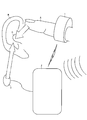
- FIG. 1 is a schematic diagram schematically showing an overall image of a conversation system according to the present invention.
- a conversation system (such as a hearing aid system or a mobile phone system) according to the present invention includes a ring 1, a conversation device main body 2, and an earpiece 3.
- the ring 1 and the conversation device main body 2 are provided as separate bodies (among the first to fourth embodiments described later, in particular, the first embodiment (FIG. 2) and the third embodiment). (Configuration corresponding to FIG. 4) is depicted.
- the earpiece 3 is removed from the conversation device main body 2, and therefore it is not normally assumed that the ring 1 and the earpiece 3 are used at the same time.
- the ring 1 is attached to the user's finger A (for example, the third joint), converts the audio signal input from the conversation device main body 2 into cartilage conduction vibration, and transmits it to the finger A.
- the cartilage conduction vibration is transmitted to the finger A
- the cartilage conduction generated by the ring 1 is performed.
- the vibration is transmitted to the ear cartilage C via the finger A.
- the audio signal from the conversation device main body 2 is transmitted to the cartilage around the ear canal as a cartilage conduction sound, and air conduction generated inside the ear canal is generated and transmitted to the eardrum, and a part is directly transmitted to the inner ear through the cartilage.
- the example of the ear cartilage C used as the contact point of the finger A is the cartilage around the ear canal entrance including the tragus.
- the contact point of the finger A is not limited to this, but may be various ear cartilage sites, but the cartilage around the ear canal entrance including the tragus is effective for generating air conduction sound inside the ear canal based on cartilage conduction.
- the ear hole part is a part that is generally conscious as a part that listens to sound, and is suitable for guiding an unconscious action of placing the finger A on the ear.
- the finger A when the finger A is applied to the ear canal entrance, the finger A naturally hits the protruding tragus, so that the tragus is particularly noticed as a contact portion.
- the tragus since the tragus has a structure in which the ear canal is closed by pushing it, it is also suitable for inducing the effect of the ear plug bone which will be described later. The configuration and operation of the ring 1 will be described in detail later.
- the conversation device main body 2 is carried in the user's hand (such as a breast pocket) and transmits an audio signal to the ring 1 or the earpiece 3.
- the conversation system according to the present invention is a hearing aid system
- the hearing aid body is the conversation device body 2
- the sound detected by the microphone is converted into an electrical sound signal and transmitted to the ring 1 or the earpiece 3.
- the conversation system according to the present invention is a mobile phone system
- the mobile phone main body becomes the conversation device main body 2, and a voice signal received via the telephone line is transmitted to the ring 1 or the earpiece 3.
- the configuration and operation of the conversation device main body 2 will be described in detail later.
- the earpiece 3 is a small acoustic speaker that converts an audio signal input from the conversation device body 2 into air vibration. Therefore, when the earpiece 3 is attached to the ear B, the audio signal from the conversation device main body 2 is transmitted as an air conduction sound to the auditory nerve (inner ear) via the eardrum (middle ear).
- the conversation system according to the present invention can be used, for example, as a hearing aid system suitable for a user whose ears have become a little far away.
- the user of this hearing aid system does not usually wear the earpiece 3 on the ear B, and only temporarily hears the finger A when hearing aid is necessary (for example, when the other party's voice is low or far).
- By abutting on the cartilage C it becomes possible to assist the listening of the sound using the cartilage conduction.
- the operation of bringing the finger A into contact with the ear cartilage C is similar to the natural operation of listening to the voice of the other party, so that there is no sense of incongruity for the user himself / herself and for the conversation partner and surrounding people.
- the conversation device main body 3 is configured to be able to perform hearing in the same manner as an existing hearing aid system.
- the hearing aid system includes the ring 1 for transmitting the cartilage conduction vibration to the ear cartilage C through the finger A
- the user wears the unpleasant earpiece 3 unless the hearing aid is necessary. You can live a daily life without.
- the user can immediately assist in listening to the sound by a natural operation of bringing the finger A into contact with the ear cartilage C.
- the ring 1 is in the form of being worn on the finger A, it is less uncomfortable when worn compared to the earpiece 3 worn on the ear B, and the physical burden or mental burden on the user is greatly reduced. Is also possible.
- FIG. 1 illustrates a configuration in which the ring 1 and the conversation device main body 2 are provided separately from each other, but the configuration of the present invention is not limited to this, and the ring 1 includes the conversation device main body 2. Functions may be incorporated as appropriate. Such a modification will be described in detail in the second embodiment (FIG. 3) and the fourth embodiment (FIG. 5), among the first to fourth embodiments described below.
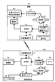
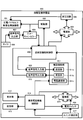
- FIG. 2 is a block diagram illustrating a first embodiment of the conversation system (a hearing aid system including a ring and a hearing aid main body), and corresponds to the schematic diagram of FIG. 1.
- the hearing aid system of the first embodiment includes a ring 100 and a hearing aid main body 200.
- a ring 100 corresponds to the ring 1 of FIG. 1 and includes a piezoelectric bimorph cartilage conduction vibration unit 101, a drive unit 102, a control unit 103, a power supply unit 104, a booster circuit 105, a self-holding timer 106, and a remote control switch.
- An operation unit 107 and a short-range communication unit 108 are included.
- the piezoelectric bimorph cartilage conduction vibration unit 101 is a vibration output unit that generates cartilage conduction vibration and transmits it to the finger A (see FIG. 1).
- the piezoelectric bimorph cartilage conduction vibration unit 101 is provided at a position where the ring 100 comes into contact with the finger A while the ring 100 is attached to the finger A.
- the piezoelectric bimorph cartilage conduction vibration unit 101 needs to receive a boosted voltage from the booster circuit 105 as a piezoelectric bimorph drive voltage.
- the method of the cartilage conduction vibration unit is not limited to the method using the piezoelectric bimorph, and for example, an electromagnetic cartilage conduction vibration unit may be used.
- an electromagnetic cartilage conduction vibration unit may be used.
- the circuit configuration can be simplified.
- the driving unit 102 drives the piezoelectric bimorph cartilage conduction vibration unit 101 based on an instruction from the control unit 103.
- the control unit 103 is a main body (for example, CPU [Central Processing Unit]) that comprehensively controls the operation of the ring 100.
- the control unit 103 performs drive control of the piezoelectric bimorph cartilage conduction vibration unit 101 via the drive unit 102 so as to convert and output the audio signal received by the short-range communication unit 108 into cartilage conduction vibration.
- the power supply unit 104 generates a predetermined internal voltage from the battery voltage and supplies power to each unit of the ring 100.
- the booster circuit 105 boosts the internal voltage generated by the power supply unit 104 to generate a drive voltage for the piezoelectric bimorph cartilage conduction vibration unit 101.
- a booster switching regulator or a booster charge pump can be used as the booster circuit 105.
- the self-holding timer 106 controls the control unit 103 and the power supply unit so as to hold the ring 100 in an on state for a predetermined self-holding time Ton (for example, 5 minutes) after the power-on operation is received by the remote control switch operation unit 107.
- Ton a predetermined self-holding time Ton
- the counting operation of the self-holding time Ton by the self-holding timer 106 is reset and restarted every time a power-on operation is accepted by the remote control switch operation unit 107. Accordingly, when the remote control switch operation unit 107 accepts a power-on operation again during the counting operation of the self-holding time Ton by the self-holding timer 106, the ring 100 is turned on for the self-holding time Ton from that point.
- the power-on period of the ring 100 is extended so as to hold it.
- the self-holding timer 106 sends an instruction to the control unit 103 and the power supply unit 104 so as to switch the ring 100 to the off state. .
- the ring 100 is automatically held after being held on for the self-holding time Ton. 100 is switched off. Accordingly, hearing aid can be performed over a relatively long period of time without requiring a complicated power on / off operation. In addition, since the power is automatically turned off when the self-holding time Ton elapses, power consumption of the ring 100 can be suppressed.
- the count of the self-holding time Ton is restarted from the last operation only by repeating the power-on operation at a natural timing shorter than the self-holding time Ton.
- the power-on period of the ring 100 can be extended.
- a piezoelectric bimorph is used as the cartilage conduction vibration unit 101 as in the embodiment, for example, depending on the booster circuit, a predetermined time may be required until the drive voltage reaches a predetermined target value. Immediately after that, hearing aid using cartilage conduction cannot be performed. For this reason, if the power-on operation of the ring 100 is performed whenever necessary, an important statement immediately after the power-on may be missed.
- the self-holding timer 106 is configured as described above, the power-on unit 104 and the booster circuit 105 are turned on for at least the self-holding time Ton after the power-on operation is accepted by the remote control switch operation unit 107 once. Since it can be kept in a state, it is possible to reduce the possibility of the above-mentioned disadvantages.
- Remote control switch operation unit 107 is a user interface that accepts a power-on operation of ring 100.
- a push button is employed as the remote control switch operation unit 107, the user can perform a power-on operation of the ring 100 with only one push of the remote control switch operation unit 107.
- the near field communication unit 108 performs wireless communication with the near field communication unit 201 provided in the hearing aid main body 200 based on an instruction from the control unit 103.
- the short-range communication unit 108 receives an audio signal from the short-range communication unit 201 and sends it to the control unit 103.
- the short-range communication unit 108 transmits a remote control switch operation signal from the control unit 103 to the short-range communication unit 201.
- the remote control switch operation signal is an information signal indicating whether or not the power-on operation is accepted by the remote control switch operation unit 107, in other words, whether or not the ring 100 is in an on state.
- a wireless communication module IC compliant with a wireless communication standard such as Bluetooth (registered trademark) can be suitably used.
- the hearing aid main body 200 corresponds to the conversation device main body 2 of FIG. 1, and the short-range communication unit 201, earpiece connection unit 202, control unit 203, audio signal output unit 204, microphone 205, switch operation unit 206, and so on. , A power switch 207 and a power supply unit 208.
- the near field communication unit 201 performs wireless communication with the near field communication unit 108 provided in the ring 100 based on an instruction from the control unit 203.
- the short-range communication unit 201 transmits an audio signal from the control unit 203 to the short-range communication unit 108.
- the short-range communication unit 201 receives a remote control switch operation signal from the short-range communication unit 108 and sends it to the control unit 203.
- a wireless communication module IC that conforms to a wireless communication standard such as Zigbee (registered trademark) or Bluetooth (registered trademark) can be suitably used.
- the earpiece connection unit 202 is an interface for connecting the acoustic earpiece 3 (see FIG. 1). If it is the structure provided with the earpiece connection part 202, the hearing aid system which has the cartilage conduction type ring 100 based on the existing hearing aid system which consists of the normal earpiece 3 (refer FIG. 1) and the hearing aid main body 200 is comprised. Can do.
- the control unit 203 is a main body (for example, CPU) that comprehensively controls the operation of the hearing aid main body 200. For example, when the hearing aid main body 200 is set to the standby state, the control unit 203 transmits a remote control switch operation signal (on / off state of the ring 100) transmitted from the short-range communication unit 108 via the short-range communication unit 201. , And remote control (on / off control) of the power switch 207 is performed in accordance with the remote control switch operation signal.
- a remote control switch operation signal on / off state of the ring 100
- the control unit 203 is configured to turn on the hearing aid main body 200 (more specifically, the power switch 207) in conjunction with the ring 100 being turned on.
- the power consumption of the entire hearing aid system is reduced as much as possible when hearing aid is not necessary, while the entire hearing aid system can be immediately turned on when the need for hearing aid occurs. Become.
- the ring 100 can also be used as a remote controller (remote power switch) of the hearing aid main body 200.
- a remote controller remote power switch
- the piezoelectric bimorph cartilage conduction vibration unit 101, the drive unit 102, and the booster circuit 105 are not required among the components depicted in FIG. It becomes.
- the audio signal output unit 204 performs various signal processing (such as noise removal processing) on the audio signal generated by the microphone 205 and outputs the processed signal to the control unit 203.
- various signal processing such as noise removal processing
- the microphone 205 converts ambient sound into an electrical sound signal.
- the switch operation unit 206 is a user interface that receives an operation switching operation of the hearing aid main body 200.
- the hearing aid main body 200 is provided with three operation states (always-on state, always-off state, and standby state).
- the always-on state the hearing aid main body 200 is always turned on regardless of the on / off state of the ring 100. This operation state may be selected in the case where hearing is regularly performed using the earpiece 3 (see FIG. 1).
- the always-off state the hearing aid main body 200 is always turned off regardless of the on / off state of the ring 100. This operating state may be selected when there is no need for hearing aid (when the user is sleeping, etc.).
- the standby state as described above, the on / off state of the hearing aid main body 200 is remotely controlled in conjunction with the on / off state of the ring 100. This operation state may be selected when emergency hearing is performed using the ring 100.
- the power switch 207 performs on / off control of the power unit 208 based on instructions from the control unit 203 and the switch control unit 206.
- the power supply unit 208 generates a predetermined internal voltage from the battery voltage and supplies power to each unit of the hearing aid main body 200.
- the power supply unit 208 connects the circuit blocks (the control unit 201 and the short-range communication unit 203) necessary for waiting for a remote control switch operation signal transmitted wirelessly from the ring 100. While power supply is continued, power supply to the remaining circuit blocks is stopped.
- FIG. 3 is a block diagram showing a second embodiment of the conversation system (a hearing aid system including only a ring).
- the ring 300 forming the hearing aid system of the second embodiment is a combination of the ring 100 of FIG. 2 and the hearing aid main body 200, and includes a piezoelectric bimorph cartilage conduction vibration unit 301, a drive unit 302, a control unit 303, A power supply unit 304, a booster circuit 305, a self-holding timer 306, a remote control switch operation unit 307, a microphone 308, an audio signal output unit 309, and an echo canceller 310 are included.
- the piezoelectric bimorph cartilage conduction vibration unit 301 the drive unit 302, the control unit 303, the power supply unit 304, the booster circuit 305, the self-holding timer 306, the remote control switch operation unit 307, the microphone 308, and the audio signal
- the output unit 309 includes the piezoelectric bimorph cartilage conduction vibration unit 101, the drive unit 102, the control unit 103, the power supply unit 104, the booster circuit 105, the self-holding timer 106, the remote control switch operation unit 107, the microphone 205, and the audio signal shown in FIG. This corresponds to the output unit 204. Therefore, in the following description, characteristic components and operations of the second embodiment will be focused on, and descriptions overlapping with the first embodiment will be omitted as appropriate.
- the control unit 303 drives the piezoelectric bimorph cartilage conduction vibration unit 301 via the drive unit 302 so as to convert the sound signal transmitted from the sound signal output unit 309 via the echo canceller 310 into cartilage conduction vibration and output it. Take control.
- the echo canceller 310 generates a pseudo echo signal from the drive signal supplied from the drive unit 302 to the piezoelectric bimorph cartilage conduction vibration unit 301 by an adaptive filter or the like, and adds it to the audio signal from the audio signal output unit 309.
- the echo component the vibration component of the piezoelectric bimorph cartilage conduction vibration unit 301 detected by the microphone 308 included in the sound signal from the sound signal output unit 309 is appropriately canceled. It becomes possible to do.
- a hearing aid system using the ring 300 with a built-in microphone eliminates the need for a hearing aid main body, so that the portability of the hearing aid system can be improved.
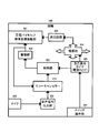
- FIG. 4 is a block diagram showing a third embodiment of the conversation system (a mobile phone system including a ring and a mobile phone body).
- the mobile phone system according to the third embodiment includes a ring-type transmission / reception attachment 400 and a mobile phone main body 500.
- a ring-type transmission / reception attachment 400 corresponds to the ring 1 of FIG. 1, and includes a piezoelectric bimorph cartilage conduction vibration unit 401, a drive unit 402, a control unit 403, a power supply unit 404, a booster circuit 405, a microphone 406, An audio signal output unit 407, an echo canceller 408, a short-range communication unit 409, and a reception / call operation unit 410 are included.
- the piezoelectric bimorph cartilage conduction vibration unit 401 is a vibration output unit that generates cartilage conduction vibration and transmits it to the finger A (see FIG. 1).
- the piezoelectric bimorph cartilage conduction vibration unit 401 is provided at a position where the ring-type transmission / reception attachment 400 is in contact with the finger A when the finger-type transmission / reception attachment 400 is attached to the finger A.
- the piezoelectric bimorph cartilage conduction vibration unit 401 needs to receive a boosted voltage from the booster circuit 405 as a piezoelectric bimorph drive voltage.
- the piezoelectric bimorph cartilage conduction vibration unit 401 By combining the piezoelectric bimorph cartilage conduction vibration unit 401 and the booster circuit 405, it is possible to realize a compact cartilage conduction vibration unit suitable for mounting on the ring-type transmission / reception attachment 400.
- the method of the cartilage conduction vibration unit is not limited to the method using the piezoelectric bimorph, and for example, an electromagnetic cartilage conduction vibration unit may be used.
- an electromagnetic type cartilage conduction vibration part since a booster circuit is not required, the circuit configuration can be simplified.
- the driving unit 402 drives the piezoelectric bimorph cartilage conduction vibration unit 401 based on an instruction from the control unit 403.
- the control unit 403 is a main body (for example, a CPU) that performs overall control of the operation of the ring-type transmission / reception attachment 400. For example, the control unit 403 performs drive control of the piezoelectric bimorph cartilage conduction vibration unit 401 via the drive unit 402 so that the received voice signal received by the short-range communication unit 409 is converted into cartilage conduction vibration and output. . In addition, the control unit 403 performs communication control of the short-range communication unit 409 so that the transmission voice signal generated by the microphone 406 is wirelessly transmitted to the mobile phone body 500.
- a main body for example, a CPU
- control unit 403 performs drive control of the piezoelectric bimorph cartilage conduction vibration unit 401 via the drive unit 402 so as to generate an incoming notification vibration in response to the incoming signal from the mobile phone body 500.
- the piezoelectric bimorph cartilage conduction vibration unit 401 is also used as the incoming vibration unit, the ring-type transmission / reception attachment 400 does not need to be enlarged.
- an incoming vibration unit dedicated to incoming notification may be provided.
- control unit 403 is configured such that when the incoming signal from the mobile phone body 500 is received by the short-range communication unit 409 or when the user's call operation is received by the reception / call operation unit 410, On / off control of the power supply unit 404 is performed so that power supply to each unit of the mold transmission / reception attachment 400 is started. With this configuration, it is possible to reduce the power consumption of the ring-type transmission / reception attachment 400 and extend the battery driving time.
- the power supply unit 404 generates a predetermined internal voltage from the battery voltage and supplies power to each unit of the ring-type transmission / reception attachment 400. Note that when the ring-type transmission / reception attachment 400 is in a standby state, the power supply unit 404 waits for an incoming signal wirelessly transmitted from the mobile phone body 500 and a circuit block (waiting for a call operation by the user) ( The power supply to the control unit 403, the short-range communication unit 409, and the reception / calling operation unit 410) is continued, while the power supply to the remaining circuit blocks is stopped.
- the booster circuit 405 boosts the internal voltage generated by the power supply unit 404 to generate a drive voltage for the piezoelectric bimorph cartilage conduction vibration unit 401.
- a booster switching regulator or a booster charge pump can be used as the booster circuit 105.
- the microphone 406 converts surrounding sound (sound emitted by the user) into an electrical sound signal.
- the audio signal output unit 407 performs various signal processing (such as noise removal processing) on the audio signal generated by the microphone 406 and outputs the processed signal to the echo canceller 408.
- various signal processing such as noise removal processing
- the echo canceller 408 generates a pseudo echo signal from the drive signal supplied from the drive unit 402 to the piezoelectric bimorph cartilage conduction vibration unit 401, adds this to the audio signal from the audio signal output unit 407, and outputs it to the control unit 403. To do.
- the echo component vibration component of the piezoelectric bimorph cartilage conduction vibration unit 401 detected by the microphone 406 included in the audio signal from the audio signal output unit 407 is appropriately canceled. It becomes possible to do.
- the near field communication unit 409 performs wireless communication with the near field communication unit 501 provided in the mobile phone main body 400 based on an instruction from the control unit 403.
- the short-range communication unit 409 receives the received voice signal from the short-range communication unit 501 and sends it to the control unit 403. Further, the short-range communication unit 409 transmits the transmission voice signal obtained by the microphone 406 to the short-range communication unit 501.
- the short-range communication unit 409 transmits a signal corresponding to the reception / call operation accepted by the reception / call operation unit 410 (hereinafter referred to as a reception / call operation signal) to the short-range communication unit 501.
- a wireless communication module IC that conforms to a wireless communication standard such as Bluetooth (registered trademark) can be suitably used.
- the reception / call operation unit 410 is a user interface (manual operation switch) that receives a reception / call operation by a user.
- the mobile phone main body 500 corresponds to the conversation device main body 2 of FIG. 1, and includes a short-range communication unit 501, an audio signal input unit 502, an audio signal output unit 503, a telephone function unit 504, and a microphone 505. , A speaker 506, a display unit 507, a storage unit 508, a control unit 509, a power supply unit 510, a power switch 511, and a switch operation unit 512.
- the near field communication unit 501 performs wireless communication with the near field communication unit 409 provided in the ring type transmission / reception attachment 400 based on an instruction from the control unit 509. As a specific example, the near field communication unit 501 transmits the received voice signal from the voice signal output unit 503 to the near field communication unit 409. In addition, the short-range communication unit 501 receives a transmission voice signal from the short-range communication unit 108 and sends it to the voice signal input unit 502. The short-range communication unit 501 receives a call / call operation signal from the short-range communication unit 409 and sends it to the control unit 509.
- the short-range communication unit 501 As the short-range communication unit 501, a wireless communication module IC that conforms to a wireless communication standard such as Bluetooth (registered trademark) can be suitably used. Accordingly, the short-range communication unit 501 can perform short-range wireless communication with not only the ring-type transmission / reception attachment 400 but also the transmission / reception attachment such as an in-vehicle audio device or a headset.
- a wireless communication standard such as Bluetooth (registered trademark)
- the short-range communication unit 501 can perform short-range wireless communication with not only the ring-type transmission / reception attachment 400 but also the transmission / reception attachment such as an in-vehicle audio device or a headset.
- the voice signal input unit 502 sends the transmission voice signal received by the short-range communication unit 501 to the telephone function unit 504 (particularly the transmission unit 504a).
- the voice signal output unit 503 sends the received voice signal received by the telephone function unit 504 (particularly, the receiving unit 504b) to the near field communication unit 501.
- the telephone function unit 504 can make a voice call via a wireless telephone line using the transmitter unit 504a and the receiver unit 504b.
- the telephone function unit 504 can also perform data communication via a wireless telephone line using the telephone communication unit 504c.
- the telephone function unit 504 determines whether short-range wireless communication is established between the mobile phone body 500 and the external device (ring-type transmission / reception attachment 400 in FIG. 4) via the short-range communication unit 501. Accordingly, a function of switching input / output destinations of the transmitter 504a and receiver 504b is provided. For example, when short-range wireless communication is established between the mobile phone main body 500 and the ring-type transmission / reception attachment 400, a transmission voice signal is transmitted from the voice signal input unit 502 to the transmission unit 504a, and the incoming call is received. The received voice signal is transmitted from the unit 504 b to the voice signal output unit 503.
- a transmission voice signal is transmitted from the microphone 505 to the transmission unit 504a, and from the reception unit 504b.
- the received voice signal is transmitted to the speaker 506. That is, in the former case, a voice call using the ring-type transmission / reception attachment 400 is performed, and in the latter case, a voice call using only the mobile phone main body 500 is performed.
- the microphone 505 converts the surrounding voice (voice uttered by the user) into an electrical voice signal and outputs it to the transmitter 504a. Note that the microphone 505 acquires the transmitted voice during a voice call using only the mobile phone body 500.
- Speaker 506 outputs a ring tone and various guidance voices according to control from control unit 509.
- the speaker 506 also outputs a received voice during a voice call using only the mobile phone main body 500. Note that the earpiece 3 in FIG. 1 can be used as the speaker 506.
- the display unit 507 displays characters and images in accordance with control from the control unit 509.
- a liquid crystal display or an organic EL [Electro Luminescence] display can be suitably used as the display unit 507.
- the storage unit 508 stores various programs that are read and executed by the control unit 509.
- the storage unit 37 is also used as a temporary storage area for data necessary for the operation of the control unit 509 and a development area for various programs.
- the control unit 509 is a main body (for example, a CPU) that comprehensively controls the operation of the mobile phone body 500.
- the power supply unit 510 generates a predetermined internal voltage from the battery voltage and supplies power to each unit of the mobile phone body 500.
- the power switch 511 performs on / off control of the power supply unit 510 based on instructions from the control unit 509 and the switch operation unit 512.
- the switch operation unit 512 is a user interface that accepts user operations. Note that, as the switch operation unit 512, in addition to various keys and buttons, a touch panel or the like can be preferably used.
- the user can confirm the incoming call and the voice without touching the mobile phone body 500 at all. It is possible to make a call.
- the vibration of the cartilage conduction vibrator can also be used as a vibration body for the manner mode. In this case, since vibration is sensed by a finger instead of an ear, it is not necessary to set the vibration frequency to an audible range, and a low frequency that can be easily felt by a finger can be used.
- the manner mode vibrating body is not limited to the case where the cartilage conduction vibrator is also used, and a separate vibrating body may be employed.
- the cartilage conduction vibrator, the small microphone, and the separate manner mode vibrating body function unit may be separately housed in the ring-type transmission / reception attachment, and these may be connected by short-range communication.
- the cartilage conduction vibrator is housed in the first ring-type transmission / reception attachment attached to the finger of the hand that is easy to touch the dominant ear, and the first attachment attached to the finger of the other hand.
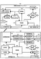
- FIG. 5 is a block diagram showing a fourth embodiment (ring type mobile phone) of the conversation system.
- the ring type mobile phone 600 forming the conversation system of the fourth embodiment has a configuration in which the ring type transmission / reception attachment 400 and the mobile phone body 500 of FIG.
- a piezoelectric bimorph cartilage conduction vibration unit 601 a drive unit 602, transmission / reception function control unit 603, power supply unit 604, booster circuit 605, microphone 606, audio signal output unit 607, echo canceller 608, audio signal input unit 609, audio signal output unit 610, ,
- a telephone function unit 611 a display unit 612, a storage unit 613, a mobile phone function control unit 614, a power supply unit 615, a power switch 616, and a switch operation unit 617.
- Piezoelectric bimorph cartilage conduction vibration unit 401 drive unit 402, control unit 403, power supply unit 404, booster circuit 405, microphone 406, audio signal output unit 407, echo canceller 408, audio signal input unit 502, audio signal output unit in FIG. 503, telephone function unit 504, display unit 507, storage unit 508, control unit 509, power supply unit 510, power supply Switch 511, and corresponds to the switch operation unit 512.
- the ring-type mobile phone 600 has a configuration in which the unnecessary short-range communication units 409 and 501 are removed after combining the ring-type transmission / reception attachment 400 and the mobile phone body 500 of FIG. With such a ring-type mobile phone 600, the mobile phone main body is not necessary, and the portability of the mobile phone system can be improved.
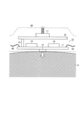
- FIG. 6 is a cross-sectional view schematically showing a configuration example of the ring 1.
- the ring 1 of this configuration example has a structure for applying a cartilage conduction vibration to the third joint of the finger A, more specifically, a ring structure that is attached to the third joint of the finger A and provides the cartilage conduction vibration.
- the ring 1 of this configuration example includes a main unit 10, a power supply unit 20, a communication unit 30, a cable 40, and a ring type housing 50.
- the main unit 10 is a unit for mainly applying cartilage conduction vibration to the finger A, and is housed in the ring-shaped housing 50 so that the finger-shaped housing 50 is on the back side of the finger A when the finger-shaped housing 50 is attached to the finger A. Has been. The internal configuration and operation of the main unit 10 will be described in detail later.
- the power supply unit 20 is a unit that mainly supplies power to the main unit 10 and the communication unit 30, and when the ring type casing 50 is attached to the finger A, the ring type casing is located on the back side of the finger A. 50.
- the internal configuration and operation of the power supply unit 20 will be described in detail later.
- the communication unit 30 is a unit that mainly performs wireless communication with the conversation device main body 2, and is housed in the ring-shaped housing 50 so as to be on the back side of the finger A when the ring-shaped housing 50 is attached to the finger A. ing.
- the internal configuration and operation of the communication unit 30 will be described in detail later.
- the cable 40 is housed in a ring-shaped housing 50 so as to electrically connect the main unit 10, the power supply unit 20, and the communication unit 30.
- FPC Flexible Printed Circuits
- the cable 40 FPC [Flexible Printed Circuits] etc. other than a general covered electric wire can be used suitably.
- the ring-shaped housing 50 houses the main unit 10, the power supply unit 20, the communication unit 30, and the cable 40, and is attached to the third joint of the finger A.
- the ring 1 As described above, if the ring 1 is attached to the third joint of the finger A, the ring 1 drops from the finger A in daily life unless the user intentionally removes the ring 1 from the finger A. Therefore, it is possible to construct a conversation system that does not restrict user behavior.
- the ring-shaped housing 50 is formed of a flexible material (silicon rubber or the like), it is possible to give a large degree of freedom to the size that the ring 1 can be attached.
- the ring-shaped housing 50 has a waterproof structure. By adopting such a configuration, even when wet with water (rain) or sweat, it becomes difficult to break down. When the ring 1 is shared by many people, the ring 1 can be kept clean by washing the entire ring-type housing 50 with water.
- the configuration in which the main unit 10, the power supply unit 20, and the communication unit 30 are independent units has been described as an example, but the configuration of the present invention is not limited to this, Multiple units may be combined into one. Further, the storage positions of the main unit 10, the power supply unit 20, and the communication unit 30 in the ring-shaped housing 50 are not limited to the above configuration example.
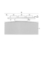
- FIG. 7 is a cross-sectional view schematically showing a configuration example of the main unit 10.
- the main unit 10 of this configuration example includes a first substrate 11, a piezoelectric bimorph cartilage conduction vibration unit 12, a control unit 13, a drive unit 14, a connector 15, a second substrate 16, and an operation unit 17. Including.
- the piezoelectric bimorph cartilage conduction vibration unit 12 is mounted on the surface of the first substrate 11, and the control unit 13 and the drive unit 14 are directly mounted on the back surface of the first substrate 11.
- a cable 40 for establishing electrical connection with the power supply unit 20 and the communication unit 30 is also connected to the first substrate 11.
- electrical connection is established between the front surface and the back surface of the first substrate 11 through through holes and vias.
- the piezoelectric bimorph cartilage conduction vibration part 12 is a vibration output part that generates cartilage conduction vibration and transmits it to the finger A (FIG. 1).
- the piezoelectric bimorph cartilage conduction vibration part 101 (FIG. 2), the piezoelectric bimorph cartilage conduction vibration, and the like. This corresponds to the vibration part 301 (FIG. 3), the piezoelectric bimorph cartilage conduction vibration part 401 (FIG. 4), or the piezoelectric bimorph cartilage conduction vibration part 601 (FIG. 5).
- the piezoelectric bimorph cartilage conduction vibration unit 12 is provided at a position in contact with the finger A while the ring 1 is attached to the finger A.
- the control unit 13 is a main body (for example, a CPU) that comprehensively controls the operation of the ring 1, and includes the control unit 103 (FIG. 2), the control unit 303 (FIG. 3), the control unit 403 (FIG. 4), Alternatively, it corresponds to the transmission / reception function control unit 603 and the mobile phone function control unit 614 (FIG. 5).
- the drive unit 14 is a driver that drives the piezoelectric bimorph cartilage conduction vibration unit 12 in accordance with an instruction from the control unit 13.
- the drive unit 102 (FIG. 2), the drive unit 302 (FIG. 3), and the drive unit 402. (FIG. 4) or corresponds to the drive unit 602 (FIG. 5).
- the connector 15 is a conductive part for vertically stacking the first substrate 11 and the second substrate 16.
- the operation unit 17 is directly mounted on the front surface of the second substrate 16, and the connector 15 is connected to the back surface of the second substrate 16. In addition, electrical connection is established between the front surface and the back surface of the second substrate 16 through through holes and vias.
- the area of the first substrate 11 and the area of the second substrate 16 can be reduced as compared with the configuration in which all circuit elements are mounted on one substrate. Can do. Therefore, the main unit 10 can be accommodated in a size that does not protrude from the third joint of the finger A, and thus the user does not need to be aware of wearing the ring 1.
- the operation unit 17 is a user interface that accepts user operations.
- the remote control switch operation unit 107 (FIG. 2), the switch operation unit 307 (FIG. 3), the call / call operation unit 410 (FIG. 4), This corresponds to the switch operation unit 617 (FIG. 5).
- the operation unit 17 may be configured to be provided on the side surface of the ring instead of the upper surface of the ring as shown in FIG. 7 in order to avoid inadvertent misoperation such as when the back of the hand collides with a door or the like.
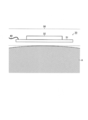
- FIG. 8 is a cross-sectional view schematically showing a configuration example of the power supply unit 20.
- the power supply unit 20 of this configuration example includes a substrate 21, a battery 22, a power supply unit 23, a booster circuit 24, and a charging circuit 25.
- the battery 22 is directly mounted on the front surface of the substrate 21, and the power supply unit 23, the booster circuit 24, and the charging circuit 25 are directly mounted on the back surface of the substrate 21. Further, a cable 40 for establishing electrical connection with the main unit 10 is also connected to the substrate 21. Note that electrical connection is established between the front surface and the back surface of the substrate 21 through through holes and vias. Thus, by effectively utilizing both surfaces of the substrate 21, the area of the substrate 21 can be reduced, so that the power supply unit 20 can be reduced in size, and the user can wear the ring 1 as a result. You don't have to be aware of
- the battery 22 is a power supply source necessary for driving the ring 1, and a lithium ion secondary battery, an electric double layer capacitor, or the like can be suitably used.
- the battery-driven ring 1 does not need to be connected with an external power supply cable, and thus does not restrict the user's action when constructing a conversation system using the ring 1.
- the battery 22 with high flatness is disposed immediately above the finger A, it is possible to increase the affinity when the ring 1 is attached to the third joint of the finger A, Does not require the user to be aware of wearing the ring 1.
- the power supply unit 23 is a DC / DC converter that generates a predetermined internal voltage from the battery voltage supplied from the battery 22 and supplies power to each part of the ring 1.
- the power supply unit 104 (FIG. 2) This corresponds to the unit 304 (FIG. 3), the power supply unit 404 (FIG. 4), or the power supply unit 604 and the power supply unit 615 (FIG. 5).
- the booster circuit 24 is a circuit block that boosts the internal voltage generated by the power supply unit 23 to generate a drive voltage for the piezoelectric bimorph cartilage conduction vibration unit 12.
- the booster circuit 105 (FIG. 2) and the booster circuit 305 described above. (FIG. 3) corresponds to the booster circuit 405 (FIG. 4) or the booster circuit 605 (FIG. 5).
- the charging circuit 25 performs charging control of the battery 22 by receiving external power supply.
- the external power supply method may be a contact method using a USB [Universal Serial Bus] cable, or a non-contact method such as an electromagnetic induction method, an electric field coupling method, and a magnetic field resonance method. It may be. With such a configuration having the battery 22 charging means, battery replacement work is not required, and the convenience of the ring 1 can be improved.
- a non-contact method as a power supply method to the charging circuit 25 from the viewpoint of completely eliminating external terminals.
- FIG. 9 is a cross-sectional view schematically showing a configuration example of the communication unit 30.
- the communication unit 30 of this configuration example includes a substrate 31 and a wireless communication circuit 32.
- a wireless communication circuit 32 is directly mounted on the surface of the substrate 31. Further, a cable 40 for establishing electrical connection with the main unit 10 is also connected to the substrate 31.
- the wireless communication circuit 32 is a circuit block that performs short-distance wireless communication with the conversation device body or performs a voice call via a wireless telephone line.
- the short-range communication unit 108 (FIG. 2), This corresponds to the distance communication unit 409 (FIG. 4) or the telephone function unit 611 (FIG. 5).
- the conversation system disclosed in the present specification is a conversation system having a ring and a conversation device main body, and the ring is received by a first short-range wireless communication unit and the first short-range wireless communication unit.
- a vibration output unit provided at a position in contact with a finger to convert and output a cartilage conduction vibration to a cartilage conduction vibration; a first power supply unit that feeds power to the first short-range wireless communication unit and the vibration output unit;
- the conversation device body includes a second short-range wireless communication unit that wirelessly communicates with the first short-range wireless communication unit, a microphone, and a voice signal picked up by the microphone to the second short-range wireless communication unit.
- a second power supply unit that supplies power to the second short-range wireless communication unit, the microphone, and the voice signal output unit (a twenty-first configuration).
- the ring further includes a power switch for turning on / off the power supply of the first power supply unit, and the second power supply unit includes the first short-range wireless communication.
- the remote control may be performed in accordance with the on / off state of the power switch transmitted from the unit via the second short-range wireless communication unit (22nd configuration).
- the power switch has a self-holding function of holding the on state for a predetermined self-holding time, and the counting operation of the self-holding time is performed by the power switch. It may be configured to be reset and restarted at each ON operation (a 23rd configuration).
- the vibration output unit includes a piezoelectric bimorph
- the first power supply unit includes a booster circuit for driving the piezoelectric bimorph ( (24th configuration)
- the vibration output unit may include a configuration (25th configuration) including an electromagnetic vibration unit.
- the conversation device main body may be configured to be further connectable to an acoustic earpiece (a twenty-sixth configuration).
- the conversation system having any one of the twenty-first to twenty-sixth configurations may be configured as a hearing aid system (a twenty-seventh configuration).
- the ring may further include a microphone (a twenty-eighth configuration).
- the conversation system having the twenty-eighth configuration may be a mobile phone system (29th configuration).
- the conversation system disclosed in the present specification is a conversation system having a ring and a conversation device main body, and the ring includes a power switch for turning on / off a power supply and an on / off state of the power switch.
- a first short-range wireless communication unit for transmitting the first short-range wireless communication unit, and a first power supply unit for supplying power to the first short-range wireless communication unit, wherein the conversation device main body is wirelessly connected to the first short-range wireless communication unit.
- a second short-range wireless communication unit a microphone, a voice signal output unit that outputs a voice picked up by the microphone as a conversation device voice, and the second short-range wireless communication unit from the first short-range wireless communication unit.
- a second power supply unit that is remotely controlled according to the on / off state of the power switch transmitted via the power supply and supplies power to the microphone and the audio signal output unit (30th configuration). .
- a conversation system ring disclosed in the present specification is a ring used in a conversation system, and a short-range wireless communication unit and a voice signal received by the short-range wireless communication unit are subjected to cartilage conduction vibration.
- a vibration output unit provided at a position in contact with a finger for conversion into an output and a power supply unit that supplies power to the short-range wireless communication unit and the vibration output unit (31st configuration) ing.
- the conversation system ring of the thirty-first configuration further includes a power switch for turning on / off the power supply, and the short-range wireless communication unit sets the power switch on / off state to the outside (32th configuration).
- the power switch has a self-holding function for holding it on for a predetermined self-time, and the counting operation of the self-holding time is performed by the power switch. It may be configured to be reset and restarted at each ON operation (33rd configuration).
- the vibration output unit includes a piezoelectric bimorph
- the power supply unit includes a booster circuit for driving the piezoelectric bimorph ( (34th configuration).
- the vibration output section may be configured to include an electromagnetic vibration section (thirty-fifth configuration).
- the conversation system may be configured to be a hearing aid system (36th configuration).
- the conversation system ring composed of any one of the 31st, 34th and 35th configurations may be configured to further include a microphone (37th configuration).
- the conversation system may be configured as a mobile phone system (a thirty-eighth configuration).
- the ring for a mobile phone disclosed in the present specification is a ring used with a mobile phone, and a short-range wireless communication unit and a voice received from the mobile phone received by the short-range wireless communication unit
- a vibration output unit provided at a position in contact with a finger to convert a signal into cartilage conduction vibration and output, and a microphone for converting sound into an electric signal and transmitting the signal from the short-range wireless communication unit to the mobile phone
- a short-range wireless communication unit, the vibration output unit, and a power supply unit that supplies power to the microphone (a 39th configuration).
- the mobile phone ring having the above-described thirty-ninth configuration further includes a control unit (40th configuration) for starting power feeding by the power source unit by receiving an incoming signal via the short-range wireless communication unit. ).
- the mobile phone ring having the fortieth configuration may be configured to further include an incoming call vibration unit for notifying an incoming call by the incoming call signal (41st configuration).
- the mobile phone ring having the forty-first configuration may be configured such that the vibration output unit also serves as the incoming call vibration unit (forty-second configuration).
- the mobile phone ring having any one of the 39th to 42nd configurations further includes a manual operation switch, and the short-range wireless communication unit outputs a signal corresponding to a call / call operation performed by the manual switch.
- a configuration for outputting to the mobile phone (a forty-third configuration) is preferable.
- the vibration output unit includes a piezoelectric bimorph
- the power supply unit includes a booster circuit for driving the piezoelectric bimorph ( (44th configuration).
- the vibration output section may include an electromagnetic vibration section (45th configuration).
- the ring-type mobile phone disclosed in this specification is in contact with a finger to convert a mobile phone communication unit and a voice signal received by the mobile phone communication unit into a cartilage conduction vibration and output it.
- a vibration output unit provided at a position; a microphone for converting sound into an electrical signal to be transmitted from the mobile phone communication unit; the mobile phone communication unit; the vibration output unit; and a power supply unit for supplying power to the microphone And (the 46th configuration).
- the ring type mobile phone having the forty-sixth configuration may further have a configuration (forty-seventh configuration) further including an incoming call vibration unit for notifying an incoming call.
- the ring type mobile phone having the above-mentioned 47th configuration may have a configuration (48th configuration) in which the vibration output section also serves as the incoming vibration section.
- the vibration output section includes a piezoelectric bimorph
- the power supply section includes a booster circuit for driving the piezoelectric bimorph (49th Configuration).
- the vibration output unit may include an electromagnetic vibration unit (a 50th configuration).
- the audio listening method disclosed in the present specification includes a step of converting an audio signal into cartilage conduction vibration and transmitting it to a finger, and a step of bringing the finger into contact with the cartilage (No. 51). It is said that.
- the cartilage may be a tragus cartilage (52th configuration).
- the hearing aid system and the mobile phone system have been described as independent conversation systems.
- the configuration of the present invention is not limited to this, and includes both a hearing aid function and a mobile phone function. It is also possible to construct a conversation system.
- the present invention can be used, for example, to realize a useful hearing aid system or a mobile phone system using cartilage conduction.
Landscapes
- Engineering & Computer Science (AREA)
- Physics & Mathematics (AREA)
- Acoustics & Sound (AREA)
- Signal Processing (AREA)
- Computer Networks & Wireless Communication (AREA)
- General Health & Medical Sciences (AREA)
- Health & Medical Sciences (AREA)
- Neurosurgery (AREA)
- Otolaryngology (AREA)
- Multimedia (AREA)
- Telephone Function (AREA)
- Details Of Audible-Bandwidth Transducers (AREA)
- Telephone Set Structure (AREA)
Abstract
本明細書に開示されている会話システムは、指輪100と会話機器200本体を有し、指輪100は、第1近距離無線通信部108と、第1近距離無線通信部108によって受信される音声信号を軟骨伝導振動に変換して出力するために指に接触する位置に設けられる振動出力部101と、第1近距離無線通信部108及び振動出力部101に給電する第1電源部104と、を含み、会話機器本体200は、第1近距離無線通信部108と無線通信する第2近距離無線通信部201と、マイク205と、マイク205が拾う音声を第2近距離無線通信部201に音声信号として出力させる音声信号出力部204と、第2近距離無線通信部201、マイク205、及び、音声信号出力部204に給電する第2電源部208と、を含む。
Description
本発明は、軟骨伝導を利用した会話システム、及び、会話システム用指輪に関する。
特許文献1では、耳珠に当接される振動面を備えた骨伝導スピーカの使用方法として、振動面と耳珠との当接する圧力を手動操作によって調節することにより、外部騒音の大きさに合わせて軟骨導経由の音声情報と気導経由の音声情報の伝達比率を変更することが提案されている。
しかしながら、軟骨伝導を利用した会話システムの有用性を高めるためには、さらに検討すべき課題が多い。
本発明は、本願の発明者らにより見出された上記の課題に鑑み、軟骨伝導を利用した有用な会話システム、及び、会話システム用指輪を提供することを目的とする。
上記目的を達成するために、本発明に係る会話システムは、指輪と会話機器本体を有する会話システムであって、前記指輪は、第1近距離無線通信部と、前記第1近距離無線通信部によって受信される音声信号を軟骨伝導振動に変換して出力するために指に接触する位置に設けられる振動出力部と、前記第1近距離無線通信部及び前記振動出力部に給電する第1電源部と、を含み、前記会話機器本体は、前記第1近距離無線通信部と無線通信する第2近距離無線通信部と、マイクと、前記マイクが拾う音声を前記第2近距離無線通信部に音声信号として出力させる音声信号出力部と、前記第2近距離無線通信部、前記マイク、及び、前記音声信号出力部に給電する第2電源部と、を含む構成(第1の構成)とされている。
なお、上記第1の構成から成る会話システムにおいて、前記振動出力部は、指が耳軟骨に接触したとき、指を介して耳軟骨に伝達可能な軟骨伝導振動を出力する構成(第2の構成)にするとよい。
また、上記第1の構成から成る会話システムにおいて、前記指輪は、さらに、前記第1電源部の電源をオン/オフする電源スイッチを含み、前記第2電源部は、前記第1近距離無線通信部から前記第2近距離無線通信部を介して伝達される前記電源スイッチのオン/オフ状態に応じてリモートコントロールされる構成(第3の構成)にするとよい。
また、本発明に係る会話システムは、指輪と会話機器本体を有する会話システムであって、前記指輪は、電源をオン/オフする電源スイッチと、前記電源スイッチのオン/オフ状態を伝達するための第1近距離無線通信部と、前記第1近距離無線通信部に給電する第1電源部と、を含み、前記会話機器本体は、前記第1近距離無線通信部と無線通信する第2近距離無線通信部と、マイクと、前記マイクが拾う音声を会話機器音声として出力する音声信号出力部と、前記第1近距離無線通信部から前記第2近距離無線通信部を介して伝達される前記電源スイッチのオン/オフ状態に応じてリモートコントロールされ、前記マイク及び前記音声信号出力部に給電する第2電源部と、を含む構成(第4の構成)とされている。
また、本発明に係る会話システム用指輪は、会話システムに用いられる指輪であって、近距離無線通信部と、前記近距離無線通信部によって受信される音声信号を軟骨伝導振動に変換して出力するために指に接触する位置に設けられる振動出力部と、前記近距離無線通信部及び前記振動出力部に給電する電源部を有する構成(第5の構成)とされている。
なお、上記第5の構成から成る会話システム用指輪は、前記電源部の電源をオン/オフする電源スイッチをさらに有し、前記近距離無線通信部は、前記電源スイッチのオン/オフ状態を外部に出力する構成(第6の構成)にするとよい。
また、上記第6の構成から成る会話システム用指輪において、前記電源スイッチは、所定の自己時間にわたってオン状態を保持する自己保持機能を備えており、前記自己保持時間のカウント動作は、前記電源スイッチのオン操作毎にリセットされて再スタートされる構成(第7の構成)にするとよい。
また、上記第5の構成から成る会話システム用指輪において、前記振動出力部は、圧電バイモルフを含み、前記電源部は、前記圧電バイモルフを駆動するための昇圧回路を含む構成(第8の構成)にするとよい。
また、上記第5の構成から成る会話システム用指輪において、前記振動出力部は、電磁式振動部を含む構成(第9の構成)にするとよい。
また、上記第5の構成から成る会話システム用指輪において、前記会話システムは、補聴器システムである構成(第10の構成)にするとよい。
また、上記第5の構成から成る会話システム用指輪は、マイクをさらに有する構成(第11の構成)にするとよい。
また、上記第5の構成から成る会話システム用指輪において、前記会話システムは、携帯電話システムである構成(第12の構成)にするとよい。
また、上記第12の構成から成る会話システム用指輪は、前記近距離無線通信部を介して着信信号を受信することにより前記電源部による給電を開始させる制御部をさらに有する構成(第13の構成)にするとよい。
また、上記第13の構成から成る会話システム用指輪は、前記着信信号により着信を告知する着信振動部をさらに有する構成(第14の構成)にするとよい。
また、上記第14の構成から成る会話システム用指輪において、前記振動出力部が前記着信振動部を兼ねている構成(第15の構成)にするとよい。
また、上記第12の構成から成る会話システム用指輪は、手動操作スイッチをさらに有し、前記近距離無線通信部は、前記手動スイッチによる受話・発呼操作に応じた信号を前記携帯電話に出力する構成(第16の構成)にするとよい。
また、上記第12の構成から成る会話システム用指輪において、前記振動出力部は、圧電バイモルフを含み、前記電源部は、前記圧電バイモルフを駆動するための昇圧回路を含む構成(第17の構成)にするとよい。
また、上記第12の構成から成る会話システム用指輪において、前記振動出力部は、電磁式振動部を含む構成(第18の構成)にするとよい。
また、上記第5の構成から成る会話システム用指輪において、前記振動出力部は、指が耳軟骨に接触したとき指を介して耳軟骨に伝達可能な軟骨伝導振動を出力する構成(第19の構成)にするとよい。
また、上記第19の構成から成る会話システム用指輪において、前記耳軟骨は、耳珠の軟骨である構成(第20の構成)にするとよい。
本発明によれば、軟骨伝導を利用した有用な会話システムを提供することができる。
<システム全体像>
図1は、本発明に係る会話システムの全体像を概略的に示す模式図である。本発明に係る会話システム(補聴器システムや携帯電話システムなど)は、指輪1と、会話機器本体2と、イヤーピース3と、を有する。図1では、指輪1と会話機器本体2とが各々別体として設けられた構成(後出の第1~第4実施形態のうち、特に、第1実施形態(図2)や第3実施形態(図4)に相当する構成)が描写されている。なお、指輪1の使用が予定されているときは、イヤーピース3は会話機器本体2から取り外されるので、指輪1とイヤーピース3が同時に用いられることは通常想定されていない。
図1は、本発明に係る会話システムの全体像を概略的に示す模式図である。本発明に係る会話システム(補聴器システムや携帯電話システムなど)は、指輪1と、会話機器本体2と、イヤーピース3と、を有する。図1では、指輪1と会話機器本体2とが各々別体として設けられた構成(後出の第1~第4実施形態のうち、特に、第1実施形態(図2)や第3実施形態(図4)に相当する構成)が描写されている。なお、指輪1の使用が予定されているときは、イヤーピース3は会話機器本体2から取り外されるので、指輪1とイヤーピース3が同時に用いられることは通常想定されていない。
指輪1は、ユーザの指A(例えば第3関節)に装着されて、会話機器本体2から入力される音声信号を軟骨伝導振動に変換して指Aに伝達する。指Aに軟骨伝導振動が伝達されている状態で、ユーザが指Aを耳B付近の軟骨C(以下では、耳軟骨Cと略称する)に当接させると、指輪1で生成された軟骨伝導振動が指Aを介して耳軟骨Cに伝達される。その結果、会話機器本体2からの音声信号が軟骨伝導音として外耳道周囲の軟骨に伝わり、外耳道内部で発生する気導を生じて鼓膜に伝達されるとともに、一部が軟骨を通じて直接内耳に伝達される。なお、指Aの当接先となる耳軟骨Cの例は、耳珠を含む外耳道入口部周囲軟骨である。指Aの当接先はこれに限らず、種々の耳軟骨部位でよいが、耳珠を含む外耳道入口部周囲軟骨は、軟骨伝導に基づき外耳道内部で気導音を発生させるのに効果的であるとともに、耳穴部は音を聞く部位として一般に意識されている部位であり、指Aを耳に当てる無意識の動作を導くのに好適である。また、このような動作により、外耳道入口部に指Aを当てたとき、突出している耳珠に指Aが自然に当たるので、特に耳珠が接触部として注目される。さらに、耳珠はこれを押すことにより耳穴を塞ぐ構造になっているので、後述の耳栓骨導効果を導く上でも好適である。なお、指輪1の構成及び動作については、後ほど詳細に説明する。
会話機器本体2は、ユーザの手元(胸ポケットなど)に携帯されて、指輪1やイヤーピース3に音声信号を伝達する。例えば、本発明に係る会話システムが補聴器システムである場合には、補聴器本体が会話機器本体2となり、マイクで検出された音声が電気的な音声信号に変換されて指輪1やイヤーピース3に伝達される。また、本発明に係る会話システムが携帯電話システムである場合には、携帯電話本体が会話機器本体2となり、電話回線を介して受信された音声信号が指輪1やイヤーピース3に伝達される。なお、会話機器本体2の構成及び動作については、後ほど詳細に説明する。
イヤーピース3は、会話機器本体2から入力される音声信号を空気振動に変換する音響式の小型スピーカである。従って、イヤーピース3を耳Bに装着すると、会話機器本体2からの音声信号が気導音として鼓膜(中耳)経由で聴覚神経(内耳)に伝達される。
本発明に係る会話システムは、例えば、少し耳が遠くなり始めたユーザにとって好適な補聴器システムとして利用することができる。この補聴器システムのユーザは、通常はイヤーピース3を耳Bに装着せず、補聴の必要が生じた場合(例えば、相手の声が小さかったり遠かったりする場合)にのみ、臨時的に指Aを耳軟骨Cに当接させることにより、軟骨伝導を利用して音声の聴取を補助することが可能となる。なお、指Aを耳軟骨Cに当接させる動作は、相手の声に耳を傾ける自然な動作に似ているので、ユーザ本人にとっても会話相手や周囲の人間にとっても違和感がない。また、指Aの押圧力を増して耳珠などにより外耳道を塞ぐか、或いは、指先で外耳道を直接塞ぐことにより、いわゆる耳栓骨導効果によって補聴能力を高めることも可能となる。なお、会話機器本体3は、ユーザがイヤーピース3を耳Bに装着することを望むとき、これを接続すれば、既存の補聴器システムと同様の態様で補聴を行うことができるよう構成される。
このように、指Aを介して耳軟骨Cに軟骨伝導振動を伝達させるための指輪1を備えた補聴システムであれば、ユーザは、補聴の必要がない限り、不愉快なイヤーピース3を装着することなく日常的な生活を送ることができる。また、ユーザは、補聴の必要が生じた場合には、指Aを耳軟骨Cに当接させるという自然な動作によって、即座に音声の聴取を補助することができる。また、指輪1は、指Aへの装着という形態をとるので、耳Bに装着されるイヤーピース3と比べて装着時の違和感が小さく、ユーザの肉体的負担ないしは精神的負担を大幅に軽減することも可能となる。
なお、図1では、指輪1と会話機器本体2とが各々別体として設けられた構成を例示したが、本発明の構成はこれに限定されるものではなく、指輪1に会話機器本体2の機能を適宜組み込んでも構わない。このような変形例については、以下に挙げる第1~第4実施形態のうち、特に、第2実施形態(図3)や第4実施形態(図5)で詳細に説明する。
<第1実施形態>
図2は、会話システムの第1実施形態(指輪と補聴器本体を含む補聴器システム)を示すブロック図であり、図1の模式図に該当する構成である。第1実施形態の補聴器システムは、指輪100と、補聴器本体200と、を有する。
図2は、会話システムの第1実施形態(指輪と補聴器本体を含む補聴器システム)を示すブロック図であり、図1の模式図に該当する構成である。第1実施形態の補聴器システムは、指輪100と、補聴器本体200と、を有する。
指輪100は、図1の指輪1に相当し、圧電バイモルフ軟骨伝導振動部101と、駆動部102と、制御部103と、電源部104と、昇圧回路105と、自己保持タイマ106と、リモコンスイッチ操作部107と、近距離通信部108と、を含む。
圧電バイモルフ軟骨伝導振動部101は、軟骨伝導振動を生成して指A(図1を参照)に伝達する振動出力部である。圧電バイモルフ軟骨伝導振動部101は、指輪100が指Aに装着されている状態で指Aと接触する位置に設けられている。圧電バイモルフ軟骨伝導振動部101は、圧電バイモルフの駆動電圧として、昇圧回路105から昇圧電圧の供給を受ける必要がある。圧電バイモルフ軟骨伝導振動部101と昇圧回路105との組み合せにより、指輪100への実装に適したコンパクトな軟骨伝導振動部を実現することが可能となる。ただし、軟骨伝導振動部の方式については、圧電バイモルフを利用した方式に限定されるものではなく、例えば電磁式の軟骨伝導振動部を用いても構わない。なお、電磁式の軟骨伝導振動部を用いる場合には、昇圧回路を必要としないので、回路構成を簡略化することが可能となる。
駆動部102は、制御部103からの指示に基づいて圧電バイモルフ軟骨伝導振動部101を駆動する。
制御部103は、指輪100の動作を統括的に制御する主体(例えばCPU[Central Processing Unit])である。例えば、制御部103は、近距離通信部108で受信された音声信号を軟骨伝導振動に変換して出力するように、駆動部102を介して圧電バイモルフ軟骨伝導振動部101の駆動制御を行う。
電源部104は、バッテリ電圧から所定の内部電圧を生成して指輪100の各部に電力供給を行う。
昇圧回路105は、電源部104で生成された内部電圧を昇圧して圧電バイモルフ軟骨伝導振動部101の駆動電圧を生成する。なお、昇圧回路105としては、昇圧型スイッチングレギュレータや昇圧型チャージポンプを用いることができる。
自己保持タイマ106は、リモコンスイッチ操作部107で電源オン操作が受け付けられた後、所定の自己保持時間Ton(例えば5分間)にわたって指輪100をオン状態に保持するように、制御部103や電源部104に指示を送る電源スイッチである。なお、自己保持タイマ106による自己保持時間Tonのカウント動作は、リモコンスイッチ操作部107で電源オン操作が受け付けられる毎にリセットされて再スタートされる。従って、自己保持タイマ106による自己保持時間Tonのカウント動作中に、リモコンスイッチ操作部107で再度の電源オン操作が受け付けられた場合には、その時点から自己保持時間Tonにわたって指輪100をオン状態に保持するように、指輪100の電源オン期間が延長される。一方、自己保持時間Tonにわたってリモコンスイッチ操作部107で電源オン操作が受け付けられなかった場合、自己保持タイマ106は、指輪100をオフ状態に切り替えるように、制御部103や電源部104に指示を送る。
このような自己保持タイマ106を備えた構成であれば、リモコンスイッチ操作部107で電源オン操作が受け付けられてから、自己保持時間Tonにわたって指輪100がオン状態に保持された後、自動的に指輪100がオフ状態に切り替えられる。従って、煩雑な電源オン/オフ操作を必要とせずに比較的まとまった時間にわたって補聴を行うことができる。また、自己保持時間Tonが経過すれば自動的に電源がオフになるので、指輪100の電力浪費を抑えることが可能となる。
また、上記の自己保持タイマ106を備えた構成であれば、自己保持時間Tonよりも短い自然なタイミングで電源オン操作を繰り返すだけでその最後の操作から自己保持時間Tonのカウントが再スタートするので、指輪100の電源オン期間を延長することができる。
ところで、例えば実施例のように圧電バイモルフを軟骨伝導振動部101として用いた場合、昇圧回路によっては駆動電圧が所定の目標値に到達するまでの所定の時間を要する場合があり、指輪100の起動直後には軟骨伝導を利用した補聴を行うことができない。そのため、必要の都度、指輪100の電源オン操作を行っていたのでは、電源オン直後の重要な発言を聞き漏らすおそれがある。これに対して、上記の自己保持タイマ106を備えた構成であれば、一度リモコンスイッチ操作部107で電源オン操作が受け付けられてから、少なくとも自己保持時間Tonにわたって電源部104や昇圧回路105をオン状態に保持することができるので、上記の不都合が生じるおそれを低減することが可能となる。
リモコンスイッチ操作部107は、指輪100の電源オン操作を受け付けるユーザインターフェイスである。例えば、リモコンスイッチ操作部107としてプッシュボタンを採用した場合、ユーザはリモコンスイッチ操作部107をワンプッシュするだけで、指輪100の電源オン操作を行うことができる。
近距離通信部108は、制御部103からの指示に基づいて、補聴器本体200に設けられた近距離通信部201との間で無線通信を行う。具体例を挙げると、近距離通信部108は、近距離通信部201からの音声信号を受信して制御部103に送出する。また、近距離通信部108は、制御部103からのリモコンスイッチ操作信号を近距離通信部201に送信する。上記のリモコンスイッチ操作信号とは、リモコンスイッチ操作部107で電源オン操作が受け付けられた状態であるか否か、言い換えれば、指輪100がオン状態であるか否かを示す情報信号である。なお、近距離通信部108としては、やBluetooth(登録商標)などの無線通信規格に準拠した無線通信モジュールICを好適に用いることができる。
補聴器本体200は、図1の会話機器本体2に相当し、近距離通信部201と、イヤーピース接続部202と、制御部203と、音声信号出力部204と、マイク205と、スイッチ操作部206と、電源スイッチ207と、電源部208と、を含む。
近距離通信部201は、制御部203からの指示に基づいて、指輪100に設けられた近距離通信部108との間で無線通信を行う。具体的な例を挙げると、近距離通信部201は、制御部203からの音声信号を近距離通信部108に送信する。また、近距離通信部201は、近距離通信部108からのリモコンスイッチ操作信号を受信して制御部203に送出する。なお、近距離通信部201としては、Zigbee(登録商標)やBluetooth(登録商標)などの無線通信規格に準拠した無線通信モジュールICを好適に用いることができる。
イヤーピース接続部202は、音響式のイヤーピース3(図1を参照)を接続するためのインターフェイスである。イヤーピース接続部202を備えた構成であれば、通常のイヤーピース3(図1を参照)と補聴器本体200から成る既存の補聴器システムをベースとして、軟骨伝導方式の指輪100を有する補聴器システムを構成することができる。
制御部203は、補聴器本体200の動作を統括的に制御する主体(例えばCPU)である。例えば、制御部203は、補聴器本体200が待機状態に設定されているとき、近距離通信部108から近距離通信部201を介して伝達されるリモコンスイッチ操作信号(指輪100のオン/オフ状態)を監視し、このリモコンスイッチ操作信号に応じて電源スイッチ207のリモートコントロール(オン/オフ制御)を行う。
補聴器システムでは、バッテリ容量(バッテリ駆動時間)が特に問題となる。そこで、制御部203は、指輪100がオン状態とされたことに連動して、補聴器本体200(より具体的には電源スイッチ207)をオン状態とするように構成されている。このような構成とすることにより、補聴の必要がないときには補聴器システム全体の消費電力を極力低減しておく一方、補聴の必要が生じたときには即座に補聴器システム全体をオン状態とすることが可能となる。
また、イヤーピース3(図1を参照)を用いて補聴を行う場合には、指輪100を補聴器本体200のリモートコントローラ(リモート電源スイッチ)として兼用することも可能である。このような構成とすることにより、補聴器本体200のリモートコントローラを別途用意する必要がなくなる上、リモートコントローラを紛失する恐れも少なくなる。なお、指輪100に補聴器本体200のリモートコントロール機能のみを持たせる場合には、図2に描写された構成要素のうち、圧電バイモルフ軟骨伝導振動部101、駆動部102、及び、昇圧回路105が不要となる。
音声信号出力部204は、マイク205で生成された音声信号に種々の信号処理(ノイズ除去処理など)を施して制御部203に出力する。
マイク205は、周囲の音声を電気的な音声信号に変換する。
スイッチ操作部206は、補聴器本体200の動作切替操作を受け付けるユーザインターフェイスである。補聴器本体200には、3つの動作状態(常時オン状態、常時オフ状態、及び、待機状態)が用意されている。常時オン状態では、指輪100のオン/オフ状態に依ることなく、補聴器本体200が常にオン状態とされる。この動作状態は、イヤーピース3(図1を参照)を用いて定常的に補聴を行う場合に選択すればよい。常時オフ状態では、指輪100のオン/オフ状態に依ることなく、補聴器本体200が常にオフ状態とされる。この動作状態は、補聴の必要性が全くない場合(ユーザが就寝している場合など)に選択すればよい。待機状態では、先にも述べたように、指輪100のオン/オフ状態に連動して、補聴器本体200のオン/オフ状態がリモートコントロールされる。この動作状態は、指輪100を用いて緊急的に補聴を行う場合などに選択すればよい。
電源スイッチ207は、制御部203及びスイッチ制御部206の指示に基づいて、電源部208のオン/オフ制御を行う。
電源部208は、バッテリ電圧から所定の内部電圧を生成して補聴器本体200の各部に電力供給を行う。なお、補聴器本体200が待機状態とされている場合、電源部208は、指輪100から無線送信されるリモコンスイッチ操作信号の待ち受けに必要な回路ブロック(制御部201及び近距離通信部203)への電力供給を継続する一方、その余の回路ブロックに対する電力供給を停止する。
<第2実施形態>
図3は、会話システムの第2実施形態(指輪のみから成る補聴器システム)を示すブロック図である。第2実施形態の補聴器システムを形成する指輪300は、図2の指輪100と補聴器本体200とを組み合わせた構成であり、圧電バイモルフ軟骨伝導振動部301と、駆動部302と、制御部303と、電源部304と、昇圧回路305と、自己保持タイマ306と、リモコンスイッチ操作部307と、マイク308と、音声信号出力部309と、エコーキャンセラ310とを含む。
図3は、会話システムの第2実施形態(指輪のみから成る補聴器システム)を示すブロック図である。第2実施形態の補聴器システムを形成する指輪300は、図2の指輪100と補聴器本体200とを組み合わせた構成であり、圧電バイモルフ軟骨伝導振動部301と、駆動部302と、制御部303と、電源部304と、昇圧回路305と、自己保持タイマ306と、リモコンスイッチ操作部307と、マイク308と、音声信号出力部309と、エコーキャンセラ310とを含む。
図3に示した構成要素のうち、圧電バイモルフ軟骨伝導振動部301、駆動部302、制御部303、電源部304、昇圧回路305、自己保持タイマ306、リモコンスイッチ操作部307、マイク308、音声信号出力部309は、それぞれ、図2の圧電バイモルフ軟骨伝導振動部101、駆動部102、制御部103、電源部104、昇圧回路105、自己保持タイマ106、リモコンスイッチ操作部107、マイク205、音声信号出力部204に相当する。そこで、以下では、第2実施形態の特徴的な構成要素や動作についての説明を重点的に行い、第1実施形態と重複する説明は適宜割愛する。
制御部303は、音声信号出力部309からエコーキャンセラ310を介して伝達される音声信号を軟骨伝導振動に変換して出力するように、駆動部302を介して圧電バイモルフ軟骨伝導振動部301の駆動制御を行う。
エコーキャンセラ310は、駆動部302から圧電バイモルフ軟骨伝導振動部301に供給される駆動信号から適応フィルタなどによって疑似エコー信号を生成し、これを音声信号出力部309からの音声信号に加算する。このようなエコーキャンセラ310を設けた構成であれば、音声信号出力部309からの音声信号に含まれるエコー成分(マイク308で検出された圧電バイモルフ軟骨伝導振動部301の振動成分)を適切にキャンセルすることが可能となる。
上記したように、マイク内蔵型の指輪300を用いた補聴器システムであれば、補聴器本体が不要となるので、補聴器システムの携帯性を高めることが可能となる。
<第3実施形態>
図4は、会話システムの第3実施形態(指輪と携帯電話本体を含む携帯電話システム)を示すブロック図である。第3実施形態の携帯電話システムは、指輪型送受話アタッチメント400と、携帯電話本体500と、を有する。
図4は、会話システムの第3実施形態(指輪と携帯電話本体を含む携帯電話システム)を示すブロック図である。第3実施形態の携帯電話システムは、指輪型送受話アタッチメント400と、携帯電話本体500と、を有する。
指輪型送受話アタッチメント400は、図1の指輪1に相当し、圧電バイモルフ軟骨伝導振動部401と、駆動部402と、制御部403と、電源部404と、昇圧回路405と、マイク406と、音声信号出力部407と、エコーキャンセラ408と、近距離通信部409と、受話・発呼操作部410と、を含む。
圧電バイモルフ軟骨伝導振動部401は、軟骨伝導振動を生成して指A(図1を参照)に伝達する振動出力部である。圧電バイモルフ軟骨伝導振動部401は、指輪型送受話アタッチメント400が指Aに装着されている状態において指Aと接触する位置に設けられている。圧電バイモルフ軟骨伝導振動部401は、圧電バイモルフの駆動電圧として、昇圧回路405から昇圧電圧の供給を受ける必要がある。圧電バイモルフ軟骨伝導振動部401と昇圧回路405との組み合せにより、指輪型送受話アタッチメント400への実装に適したコンパクトな軟骨伝導振動部を実現することが可能となる。ただし、軟骨伝導振動部の方式については、圧電バイモルフを利用した方式に限定されるものではなく、例えば電磁式の軟骨伝導振動部を用いても構わない。なお、電磁式の軟骨伝導振動部を用いる場合には、昇圧回路を必要としないので、回路構成を簡略化することが可能となる。
駆動部402は、制御部403からの指示に基づいて圧電バイモルフ軟骨伝導振動部401を駆動する。
制御部403は、指輪型送受話アタッチメント400の動作を統括制御する主体(例えばCPU)である。例えば、制御部403は、近距離通信部409で受信された受話音声信号を軟骨伝導振動に変換して出力するように、駆動部402を介して圧電バイモルフ軟骨伝導振動部401の駆動制御を行う。また、制御部403は、マイク406で生成された送話音声信号を携帯電話本体500に無線送信するように、近距離通信部409の通信制御を行う。
また、制御部403は、携帯電話本体500からの着信信号に応じて着信告知用のバイブレーションを生成するように、駆動部402を介して圧電バイモルフ軟骨伝導振動部401の駆動制御を行う。このような構成とすることにより、携帯電話本体500に着信があったことをユーザに告知することが可能となる。なお、圧電バイモルフ軟骨伝導振動部401を着信振動部として兼用すれば、指輪型送受話アタッチメント400の大型化を招かずに済む。もちろん、圧電バイモルフ軟骨伝導振動部401とは別に、着信告知専用の着信振動部を設けても構わない。
また、制御部403は、近距離通信部409で携帯電話本体500からの着信信号が受信されたとき、或いは、受話・発呼操作部410でユーザの発呼操作が受け付けられたときに、指輪型送受話アタッチメント400各部への電力供給を開始するように、電源部404のオン/オフ制御を行う。このような構成とすることにより、指輪型送受話アタッチメント400の消費電力を低減して、バッテリ駆動時間を延ばすことが可能となる。
電源部404は、バッテリ電圧から所定の内部電圧を生成して指輪型送受話アタッチメント400の各部に電力供給を行う。なお、指輪型送受話アタッチメント400が待機状態とされている場合、電源部404は、携帯電話本体500から無線送信される着信信号の待ち受けと、ユーザによる発呼操作の待ち受けに必要な回路ブロック(制御部403、近距離通信部409、及び、受話・発呼操作部410)への電力供給を継続する一方、その余の回路ブロックに対する電力供給を停止する。
昇圧回路405は、電源部404で生成された内部電圧を昇圧して圧電バイモルフ軟骨伝導振動部401の駆動電圧を生成する。なお、昇圧回路105としては、昇圧型スイッチングレギュレータや昇圧型チャージポンプを用いることができる。
マイク406は、周囲の音声(ユーザの発する音声)を電気的な音声信号に変換する。
音声信号出力部407は、マイク406で生成された音声信号に種々の信号処理(ノイズ除去処理など)を施してエコーキャンセラ408に出力する。
エコーキャンセラ408は、駆動部402から圧電バイモルフ軟骨伝導振動部401に供給される駆動信号から疑似エコー信号を生成し、これを音声信号出力部407からの音声信号に加算して制御部403に出力する。このようなエコーキャンセラ408を設けた構成であれば、音声信号出力部407からの音声信号に含まれるエコー成分(マイク406で検出された圧電バイモルフ軟骨伝導振動部401の振動成分)を適切にキャンセルすることが可能となる。
近距離通信部409は、制御部403からの指示に基づいて、携帯電話本体400に設けられた近距離通信部501との間で無線通信を行う。具体例を挙げると、近距離通信部409は、近距離通信部501からの受話音声信号を受信して制御部403に送出する。また、近距離通信部409は、マイク406で得られた送話音声信号を近距離通信部501に送信する。また、近距離通信部409は、受話・発呼操作部410で受け付けられた受話・発呼操作に応じた信号(以下、受話・発呼操作信号と呼ぶ)を近距離通信部501に送信する。なお、近距離通信部409としては、Bluetooth(登録商標)などの無線通信規格に準拠した無線通信モジュールICを好適に用いることができる。
受話・発呼操作部410は、ユーザによる受話・発呼操作を受け付けるユーザインターフェイス(手動操作スイッチ)である。
携帯電話本体500は、図1の会話機器本体2に相当するものであり、近距離通信部501と、音声信号入力部502と、音声信号出力部503と、電話機能部504と、マイク505と、スピーカ506と、表示部507と、記憶部508と、制御部509と、電源部510と、電源スイッチ511と、スイッチ操作部512と、を含む。
近距離通信部501は、制御部509からの指示に基づいて、指輪型送受話アタッチメント400に設けられた近距離通信部409との間で無線通信を行う。具体的な例を挙げると、近距離通信部501は、音声信号出力部503からの受話音声信号を近距離通信部409に送信する。また、近距離通信部501は、近距離通信部108からの送話音声信号を受信して音声信号入力部502に送出する。また、近距離通信部501は、近距離通信部409からの受話・発呼操作信号を受信して制御部509に送出する。なお、近距離通信部501としては、Bluetooth(登録商標)などの無線通信規格に準拠した無線通信モジュールICを好適に用いることができる。従って、近距離通信部501は、指輪型送受話アタッチメント400だけでなく、車載オーディオ機器やヘッドセットなどの送受話アタッチメントとの間で近距離無線通信を行うことも可能である。
音声信号入力部502は、近距離通信部501で受信された送話音声信号を電話機能部504(特に送話部504a)に送出する。
音声信号出力部503は、電話機能部504(特に受話部504b)で受信された受話音声信号を近距離通信部501に送出する。
電話機能部504は、送話部504a及び受話部504bを用いて無線電話回線を介した音声通話を行うことが可能である。また、電話機能部504は、電話通信部504cを用いて無線電話回線を介したデータ通信を行うことも可能である。
また、電話機能部504は、近距離通信部501を介して携帯電話本体500と外部機器(図4では指輪型送受話アタッチメント400)との間で近距離無線通信が確立されているか否かに応じて、送話部504a及び受話部504bの入出力先を切り替える機能を備えている。例えば、携帯電話本体500と指輪型送受話アタッチメント400との間で近距離無線通信が確立されている場合には、音声信号入力部502から送話部504aに送話音声信号が伝達され、受話部504bから音声信号出力部503に受話音声信号が伝達される。一方、携帯電話本体500と指輪型送受話アタッチメント400との間で近距離無線通信が確立されていない場合には、マイク505から送話部504aに送話音声信号が伝達され、受話部504bからスピーカ506に受話音声信号が伝達される。すなわち、前者の場合には、指輪型送受話アタッチメント400を用いた音声通話が行われ、後者の場合には、携帯電話本体500のみを用いた音声通話が行われる。
マイク505は、周囲の音声(ユーザの発する音声)を電気的な音声信号に変換して送話部504aに出力する。なお、マイク505は、携帯電話本体500のみを用いた音声通話時において、送話音声の取得を行う。
スピーカ506は、制御部509からの制御に応じて、着信音や種々の案内音声を出力する。また、スピーカ506は、携帯電話本体500のみを用いた音声通話時において、受話音声の出力も行う。なお、スピーカ506として、図1のイヤーピース3を用いることも可能である。
表示部507は、制御部509からの制御に応じて、文字や画像の表示を行う。なお、表示部507としては、液晶ディスプレイや有機EL[Electro Luminescence]ディスプレイを好適に用いることができる。
記憶部508は、制御部509に読み込まれて実行される各種プログラムを記憶する。また、記憶部37は、制御部509の動作に必要なデータの一時格納領域や各種プログラムの展開領域としても用いられる。
制御部509は、携帯電話本体500の動作を統括的に制御する主体(例えばCPU)である。
電源部510は、バッテリ電圧から所定の内部電圧を生成して携帯電話本体500の各部に電力供給を行う。
電源スイッチ511は、制御部509及びスイッチ操作部512の指示に基づいて、電源部510のオン/オフ制御を行う。
スイッチ操作部512は、ユーザ操作を受け付けるユーザインターフェイスである。なお、スイッチ操作部512としては、各種キーやボタンのほか、タッチパネルなどを好適に用いることが可能である。
上記したように、軟骨伝導振動子と小型マイクロホンを備えた指輪型送受話アタッチメント400を用いて携帯電話システムを構築することにより、ユーザは、携帯電話本体500に一切触れることなく、着信確認や音声通話を行うことが可能となる。なお、軟骨伝導振動子の振動は、マナーモード用の振動体として兼用することができる。この場合、振動は耳でなく指で感じるので振動周波数を可聴域とする必要はなく、指で感じやすい低周波とすることも可能である。なお、マナーモード用の振動体は、軟骨伝導振動子を兼用する場合に限らず、別体の振動体を採用してもよい。
なお、図4では、携帯電話本体500に指輪型送受話アタッチメント400を一つだけ接続する構成を例に挙げて説明を行ったが、本発明の構成はこれに限定されるものではなく、複数の指輪型送受話アタッチメントに上記軟骨伝導振動子、小型マイクロホンおよび別体のマナーモード用振動体機能部を分離して収納し、これらの間を近距離通信で結ぶよう構成してもよい。このような構成とすることにより、例えば、利き耳に触れやすい手の指に装着される第1の指輪型送受話アタッチメントに軟骨伝導振動子を収納し、他方の手の指に装着される第2の指輪型送受話アタッチメントに小型マイクロホンを収納するなどして、ハウリングの低減を図ることが可能となる。また、マナーモード用の振動体の制御は情報量が少なくてよいので、Zigbee(登録商標)などの近距離通信手段を採用することも可能である。なお、第3実施形態のブロック500としては、通常のサイズの携帯電話だけでなく、電話機能を有する大画面の携帯通信端末などを採用してもよい。この場合、図4における「携帯電話本体500」は、「大画面の携帯通信端末500」などと読み替えるものとする。
<第4実施形態>
図5は、会話システムの第4実施形態(指輪型携帯電話)を示すブロック図である。第4実施形態の会話システムを形成する指輪型携帯電話600は、図4の指輪型送受話アタッチメント400と携帯電話本体500とを組み合わせた構成であり、圧電バイモルフ軟骨伝導振動部601と、駆動部602と、送受話機能制御部603と、電源部604と、昇圧回路605と、マイク606と、音声信号出力部607と、エコーキャンセラ608と、音声信号入力部609と、音声信号出力部610と、電話機能部611と、表示部612と、記憶部613と、携帯電話機能制御部614と、電源部615と、電源スイッチ616と、スイッチ操作部617と、を含む。
図5は、会話システムの第4実施形態(指輪型携帯電話)を示すブロック図である。第4実施形態の会話システムを形成する指輪型携帯電話600は、図4の指輪型送受話アタッチメント400と携帯電話本体500とを組み合わせた構成であり、圧電バイモルフ軟骨伝導振動部601と、駆動部602と、送受話機能制御部603と、電源部604と、昇圧回路605と、マイク606と、音声信号出力部607と、エコーキャンセラ608と、音声信号入力部609と、音声信号出力部610と、電話機能部611と、表示部612と、記憶部613と、携帯電話機能制御部614と、電源部615と、電源スイッチ616と、スイッチ操作部617と、を含む。
図5に示した構成要素のうち、圧電バイモルフ軟骨伝導振動部601、駆動部602、送受話機能制御部603、電源部604、昇圧回路605、マイク606、音声信号出力部607、エコーキャンセラ608、音声信号入力部609、音声信号出力部610、電話機能部611、表示部612、記憶部613、携帯電話機能制御部614、電源部615、電源スイッチ616、及び、スイッチ操作部617は、それぞれ、図4の圧電バイモルフ軟骨伝導振動部401、駆動部402、制御部403、電源部404、昇圧回路405、マイク406、音声信号出力部407、エコーキャンセラ408、音声信号入力部502、音声信号出力部503、電話機能部504、表示部507、記憶部508、制御部509、電源部510、電源スイッチ511、及び、スイッチ操作部512に相当する。
すなわち、指輪型携帯電話600は、図4の指輪型送受話アタッチメント400と携帯電話本体500とを組み合わせた上で、不要となる近距離通信部409及び501を取り除いた構成であると言える。このような指輪型携帯電話600であれば、携帯電話本体が不要となるので、携帯電話システムの携帯性を高めることが可能となる。
<指輪>
図6は、指輪1の一構成例を模式的に示す断面図である。本構成例の指輪1は、指Aの第3関節に軟骨伝導振動を与えるための構造、より具体的には、指Aの第3関節に装着されて軟骨伝導振動を与えるための指輪構造を有する。なお、構成要素に着目すると、本構成例の指輪1は、主ユニット10と、電源ユニット20と、通信ユニット30と、ケーブル40と、指輪型筐体50と、を有する。
図6は、指輪1の一構成例を模式的に示す断面図である。本構成例の指輪1は、指Aの第3関節に軟骨伝導振動を与えるための構造、より具体的には、指Aの第3関節に装着されて軟骨伝導振動を与えるための指輪構造を有する。なお、構成要素に着目すると、本構成例の指輪1は、主ユニット10と、電源ユニット20と、通信ユニット30と、ケーブル40と、指輪型筐体50と、を有する。
主ユニット10は、主として指Aに軟骨伝導振動を与えるためのユニットであり、指輪型筐体50が指Aに装着されたときに指Aの甲側となるように指輪型筐体50に収納されている。なお、主ユニット10の内部構成や動作については、後ほど詳細に説明する。
電源ユニット20は、主として主ユニット10や通信ユニット30への電力供給を行うユニットであり、指輪型筐体50が指Aに装着されたときに指Aの甲側となるように指輪型筐体50に収納されている。なお、電源ユニット20の内部構成や動作については、後ほど詳細に説明する。
通信ユニット30は、主として会話機器本体2と無線通信を行うユニットであり、指輪型筐体50が指Aに装着されたときに指Aの甲側となるように指輪型筐体50に収納されている。なお、通信ユニット30の内部構成や動作については、後ほど詳細に説明する。
ケーブル40は、主ユニット10、電源ユニット20、及び、通信ユニット30の相互間を電気的に接続するように指輪型筐体50に収納されている。なお、ケーブル40としては、一般的な被覆電線のほか、FPC[Flexible Printed Circuits]などを好適に用いることができる。
指輪型筐体50は、主ユニット10、電源ユニット20、通信ユニット30、及び、ケーブル40を収納しており、指Aの第3関節に装着される。
上記のように、指Aの第3関節に装着される指輪1であれば、ユーザが意図的に指輪1を指Aから外そうとしない限り、日常生活の中で指輪1が指Aから脱落してしまうおそれは殆どないので、ユーザの行動を制約しない会話システムを構築することが可能となる。
なお、指輪型筐体50を可撓性素材(シリコンゴムなど)で形成すれば、指輪1の装着可能サイズに大きな自由度を持たせることが可能となる。
また、指輪型筐体50は、防水構造としておくことが望ましい。このような構成とすることにより、水(雨)や汗などに濡れても故障しにくくなる。また、指輪1を多人数で共用する場合には、指輪型筐体50を丸ごと水洗いすることにより、指輪1を清潔に保つことが可能となる。
また、上記の構成例では、主ユニット10、電源ユニット20、及び、通信ユニット30をそれぞれ独立したユニットとした構成を例に挙げたが、本発明の構成はこれに限定されるものではなく、複数のユニットを一つにまとめても構わない。また、指輪型筐体50内における主ユニット10、電源ユニット20、及び、通信ユニット30の収納位置についても、上記の構成例に限定されるものではない。
<主ユニット>
図7は、主ユニット10の一構成例を模式的に示す断面図である。本構成例の主ユニット10は、第1基板11と、圧電バイモルフ軟骨伝導振動部12と、制御部13と、駆動部14と、コネクタ15と、第2基板16と、操作部17と、を含む。
図7は、主ユニット10の一構成例を模式的に示す断面図である。本構成例の主ユニット10は、第1基板11と、圧電バイモルフ軟骨伝導振動部12と、制御部13と、駆動部14と、コネクタ15と、第2基板16と、操作部17と、を含む。
第1基板11の表面には圧電バイモルフ軟骨伝導振動部12が実装されており、第1基板11の裏面には制御部13と駆動部14が直接実装されている。また、第1基板11には、電源ユニット20や通信ユニット30との電気的接続を確立するためのケーブル40も接続されている。なお、第1基板11の表面と裏面との間には、スルーホールやビアを介して電気的な接続が確立されている。このように、第1基板11の両面を有効に活用することにより、第1基板11の面積を縮小することができるので、主ユニット10を指Aの第3関節からはみ出さない程度の大きさに収めることが可能となり、延いては、ユーザに指輪1の装着を意識させずに済む。
圧電バイモルフ軟骨伝導振動部12は、軟骨伝導振動を生成して指A(図1)に伝達する振動出力部であり、先出の圧電バイモルフ軟骨伝導振動部101(図2)、圧電バイモルフ軟骨伝導振動部301(図3)、圧電バイモルフ軟骨伝導振動部401(図4)、または、圧電バイモルフ軟骨伝導振動部601(図5)に相当する。図7で示したように、圧電バイモルフ軟骨伝導振動部12は、指輪1が指Aに装着されている状態で指Aと接触する位置に設けられている。
制御部13は、指輪1の動作を統括的に制御する主体(例えばCPU)であり、先出の制御部103(図2)、制御部303(図3)、制御部403(図4)、或いは、送受話機能制御部603及び携帯電話機能制御部614(図5)に相当する。
駆動部14は、制御部13からの指示に応じて圧電バイモルフ軟骨伝導振動部12を駆動するドライバであり、先出の駆動部102(図2)、駆動部302(図3)、駆動部402(図4)、または、駆動部602(図5)に相当する。
コネクタ15は、第1基板11と第2基板16を縦に積み重ねるための導電部である。
第2基板16の表面には操作部17が直接実装されており、第2基板16の裏面にはコネクタ15が接続されている。なお、第2基板16の表面と裏面との間には、スルーホールやビアを介して電気的な接続が確立されている。
このように、複数基板の積層構造を採用することにより、1枚の基板に全ての回路要素を実装した構成に比べて、第1基板11の面積と第2基板16の面積をそれぞれ縮小することができる。従って、主ユニット10を指Aの第3関節からはみ出さない程度の大きさに収めることが可能となり、延いては、ユーザに指輪1の装着を意識させずに済む。
操作部17は、ユーザ操作を受け付けるユーザインターフェイスであり、先出のリモコンスイッチ操作部107(図2)、スイッチ操作部307(図3)、受話・発呼操作部410(図4)、または、スイッチ操作部617(図5)に相当する。なお、操作部17は手の甲がドア等に衝突した際等の不用意な誤操作を避けるため、図7のような指輪の上面ではなく、指輪の側面に設けるよう構成してもよい。
<電源ユニット>
図8は、電源ユニット20の一構成例を模式的に示す断面図である。本構成例の電源ユニット20は、基板21と、バッテリ22と、電源部23と、昇圧回路24と、充電回路25と、を含む。
図8は、電源ユニット20の一構成例を模式的に示す断面図である。本構成例の電源ユニット20は、基板21と、バッテリ22と、電源部23と、昇圧回路24と、充電回路25と、を含む。
基板21の表面にはバッテリ22が直接実装されており、基板21の裏面には電源部23、昇圧回路24、及び、充電回路25が直接実装されている。また、基板21には、主ユニット10との電気的接続を確立するためのケーブル40も接続されている。なお、基板21の表面と裏面との間には、スルーホールやビアを介して電気的な接続が確立されている。このように、基板21の両面を有効に活用することにより、基板21の面積を縮小することができるので、電源ユニット20を小型化することが可能となり、延いては、ユーザに指輪1の装着を意識させずに済む。
バッテリ22は、指輪1の駆動に必要な電力供給源であり、リチウムイオン二次電池や電気二重層キャパシタなどを好適に用いることができる。このように、バッテリ駆動方式の指輪1であれば、外部からの給電ケーブルを接続する必要がないので、指輪1を用いた会話システムの構築に際してユーザの行動を制約せずに済む。なお、本構成例では、平坦性の高いバッテリ22が指Aの直上に配置されているので、指輪1を指Aの第3関節に装着した際の親和性を高めることが可能となり、延いては、ユーザに指輪1の装着を意識させずに済む。
電源部23は、バッテリ22から供給されるバッテリ電圧から所定の内部電圧を生成して指輪1の各部に電力供給を行うDC/DCコンバータであり、先出の電源部104(図2)、電源部304(図3)、電源部404(図4)、或いは、電源部604及び電源部615(図5)に相当する。
昇圧回路24は、電源部23で生成された内部電圧を昇圧して圧電バイモルフ軟骨伝導振動部12の駆動電圧を生成する回路ブロックであり、先出の昇圧回路105(図2)、昇圧回路305(図3)、昇圧回路405(図4)、或いは、昇圧回路605(図5)に相当する。
充電回路25は、外部からの電力供給を受けてバッテリ22の充電制御を行う。なお、外部からの電力供給方式としては、USB[Universal Serial Bus]ケーブルなどを用いる接触方式であってもよいし、或いは、電磁誘導方式、電界結合方式、及び、磁界共鳴方式などの非接触方式であってもよい。このようなバッテリ22の充電手段を有する構成であれば、電池交換作業が不要となるので、指輪1の利便性を高めることができる。なお、指輪型筐体50を防水構造とする際には、外部端子を完全に排除するという観点から、充電回路25への電力供給方式として非接触方式を採用することが望ましい。
<通信ユニット>
図9は、通信ユニット30の一構成例を模式的に示す断面図である。本構成例の通信ユニット30は、基板31と、無線通信回路32と、を含む。
図9は、通信ユニット30の一構成例を模式的に示す断面図である。本構成例の通信ユニット30は、基板31と、無線通信回路32と、を含む。
基板31の表面には無線通信回路32が直接的に実装されている。また、基板31には主ユニット10との電気的接続を確立するためのケーブル40も接続されている。
無線通信回路32は、会話機器本体との間で近距離無線通信を行ったり、無線電話回線を介した音声通話を行う回路ブロックであり、先出の近距離通信部108(図2)、近距離通信部409(図4)、或いは、電話機能部611(図5)に相当する。
<開示のまとめ>
本明細書中に開示されている会話システムは、指輪と会話機器本体を有する会話システムであって、前記指輪は、第1近距離無線通信部と、前記第1近距離無線通信部によって受信される音声信号を軟骨伝導振動に変換して出力するために指に接触する位置に設けられる振動出力部と、前記第1近距離無線通信部及び前記振動出力部に給電する第1電源部と、を含み、前記会話機器本体は、前記第1近距離無線通信部と無線通信する第2近距離無線通信部と、マイクと、前記マイクが拾う音声を前記第2近距離無線通信部に音声信号として出力させる音声信号出力部と、前記第2近距離無線通信部、前記マイク、及び、前記音声信号出力部に給電する第2電源部と、を含む構成(第21の構成)とされている。
本明細書中に開示されている会話システムは、指輪と会話機器本体を有する会話システムであって、前記指輪は、第1近距離無線通信部と、前記第1近距離無線通信部によって受信される音声信号を軟骨伝導振動に変換して出力するために指に接触する位置に設けられる振動出力部と、前記第1近距離無線通信部及び前記振動出力部に給電する第1電源部と、を含み、前記会話機器本体は、前記第1近距離無線通信部と無線通信する第2近距離無線通信部と、マイクと、前記マイクが拾う音声を前記第2近距離無線通信部に音声信号として出力させる音声信号出力部と、前記第2近距離無線通信部、前記マイク、及び、前記音声信号出力部に給電する第2電源部と、を含む構成(第21の構成)とされている。
なお、上記第21の構成から成る会話システムにおいて、前記指輪は、さらに、前記第1電源部の電源をオン/オフする電源スイッチを含み、前記第2電源部は、前記第1近距離無線通信部から前記第2近距離無線通信部を介して伝達される前記電源スイッチのオン/オフ状態に応じてリモートコントロールされる構成(第22の構成)にするとよい。
また、上記第22の構成から成る会話システムにおいて、前記電源スイッチは、所定の自己保持時間にわたってオン状態を保持する自己保持機能を備えており、前記自己保持時間のカウント動作は、前記電源スイッチのオン操作毎にリセットされて再スタートされる構成(第23の構成)にするとよい。
また、上記第21~第23いずれかの構成から成る会話システムにおいて、前記振動出力部は、圧電バイモルフを含み、前記第1電源部は、前記圧電バイモルフを駆動するための昇圧回路を含む構成(第24の構成)にするとよい。
また、上記第21~第23いずれかの構成から成る会話システムにおいて、前記振動出力部は、電磁式振動部を含む構成(第25の構成)にするとよい。
また、上記第21~第25いずれかの構成から成る会話システムにおいて、前記会話機器本体は、さらに音響式のイヤーピースに接続可能である構成(第26の構成)にするとよい。
また、上記第21~第26いずれかの構成から成る会話システムは、補聴器システムである構成(第27の構成)にするとよい。
また、上記第21、第24、及び、第25いずれかの構成から成る会話システムにおいて、前記指輪は、さらに、マイクを含む構成(第28の構成)にするとよい。
また、上記第28の構成から成る会話システムは、携帯電話システムである構成(第29の構成)にするとよい。
また、本明細書中に開示されている会話システムは、指輪と会話機器本体を有する会話システムであって、前記指輪は、電源をオン/オフする電源スイッチと、前記電源スイッチのオン/オフ状態を伝達するための第1近距離無線通信部と、前記第1近距離無線通信部に給電する第1電源部と、を含み、前記会話機器本体は、前記第1近距離無線通信部と無線通信する第2近距離無線通信部と、マイクと、前記マイクが拾う音声を会話機器音声として出力する音声信号出力部と、前記第1近距離無線通信部から前記第2近距離無線通信部を介して伝達される前記電源スイッチのオン/オフ状態に応じてリモートコントロールされ、前記マイク及び前記音声信号出力部に給電する第2電源部と、を含む構成(第30の構成)とされている。
また、本明細書中に開示されている会話システム用指輪は、会話システムに用いられる指輪であって、近距離無線通信部と、前記近距離無線通信部によって受信される音声信号を軟骨伝導振動に変換して出力するために指に接触する位置に設けられる振動出力部と、前記近距離無線通信部及び前記振動出力部に給電する電源部と、を有する構成(第31の構成)とされている。
なお、上記第31の構成から成る会話システム用指輪は、前記電源部の電源をオン/オフする電源スイッチをさらに有し、前記近距離無線通信部は、前記電源スイッチのオン/オフ状態を外部に出力する構成(第32の構成)にするとよい。
また、上記第32の構成から成る会話システム用指輪において、前記電源スイッチは、所定の自己時間にわたってオン状態を保持する自己保持機能を備えており、前記自己保持時間のカウント動作は、前記電源スイッチのオン操作毎にリセットされて再スタートされる構成(第33の構成)にするとよい。
また、上記第31~第33いずれかの構成から成る会話システム用指輪において、前記振動出力部は、圧電バイモルフを含み、前記電源部は、前記圧電バイモルフを駆動するための昇圧回路を含む構成(第34の構成)にするとよい。
また、上記第31~第33いずれかの構成から成る会話システム用指輪において、前記振動出力部は、電磁式振動部を含む構成(第35の構成)にするとよい。
また、上記第31~第35いずれかの構成から成る会話システム用指輪において、前記会話システムは、補聴器システムである構成(第36の構成)にするとよい。
また、上記第31、第34、及び、第35いずれかの構成から成る会話システム用指輪は、マイクをさらに有する構成(第37の構成)にするとよい。
また、上記第37の構成から成る会話システム用指輪において、前記会話システムは、携帯電話システムである構成(第38の構成)にするとよい。
また、本明細書中に開示されている携帯電話用指輪は、携帯電話と共に用いられる指輪であって、近距離無線通信部と、前記近距離無線通信部によって受信される前記携帯電話からの音声信号を軟骨伝導振動に変換して出力するために指に接触する位置に設けられる振動出力部と、音声を電気信号に変換して前記近距離無線通信部から前記携帯電話に送信させるためのマイクと、前記近距離無線通信部、前記振動出力部、及び、前記マイクに給電する電源部とを有する構成(第39の構成)とされている。
なお、上記第39の構成から成る携帯電話用指輪は、前記近距離無線通信部を介して着信信号を受信することにより前記電源部による給電を開始させる制御部をさらに有する構成(第40の構成)にするとよい。
また、上記第40の構成から成る携帯電話用指輪は、前記着信信号により着信を告知する着信振動部をさらに有する構成(第41の構成)にするとよい。
また、上記第41の構成から成る携帯電話用指輪は、前記振動出力部が前記着信振動部を兼ねている構成(第42の構成)にするとよい。
また、上記第39~第42いずれかの構成から成る携帯電話用指輪は、手動操作スイッチをさらに有し、前記近距離無線通信部は、前記手動スイッチによる受話・発呼操作に応じた信号を前記携帯電話に出力する構成(第43の構成)にするとよい。
また、上記第39~第43いずれかの構成から成る携帯電話用指輪において、前記振動出力部は、圧電バイモルフを含み、前記電源部は、前記圧電バイモルフを駆動するための昇圧回路を含む構成(第44の構成)にするとよい。
また、上記第39~第43いずれかの構成から成る携帯電話用指輪において、前記振動出力部は、電磁式振動部を含む構成(第45の構成)にするとよい。
また、本明細書中に開示されている指輪型携帯電話は、携帯電話通信部と、前記携帯電話通信部によって受信される音声信号を軟骨伝導振動に変換して出力するために指に接触する位置に設けられる振動出力部と、音声を電気信号に変換して前記携帯電話通信部から送信させるためのマイクと、前記携帯電話通信部、前記振動出力部、及び、前記マイクに給電する電源部と、を有する構成(第46の構成)とされている。
なお、上記第46の構成から成る指輪型携帯電話は、着信を告知する着信振動部をさらに有する構成(第47の構成)にするとよい。
また、上記第47の構成から成る指輪型携帯電話は、前記振動出力部が前記着信振動部を兼ねている構成(第48の構成)にするとよい。
また、上記第46~第48の構成から成る指輪型携帯電話において、前記振動出力部は圧電バイモルフを含み、前記電源部は、前記圧電バイモルフを駆動するための昇圧回路を含む構成(第49の構成)にするとよい。
また、上記第46~第48いずれかの構成から成る指輪型携帯電話において、前記振動出力部は、電磁式振動部を含む構成(第50の構成)にするとよい。
また、本明細書中に開示されている音声聴取方法は、音声信号を軟骨伝導振動に変換して指に伝達するステップと、前記指を軟骨に当接させるステップと、を有する構成(第51の構成)とされている。
なお、上記第51の構成から成る音声聴取方法において、前記軟骨は、耳珠の軟骨である構成(第52の構成)にするとよい。
<その他の変形例>
なお、本発明の構成は、上記実施形態のほか、発明の主旨を逸脱しない範囲で種々の変更を加えることが可能である。すなわち、上記実施形態は、全ての点で例示であって、制限的なものではないと考えられるべきであり、本発明の技術的範囲は、上記実施形態の説明ではなく、特許請求の範囲によって示されるものであり、特許請求の範囲と均等の意味及び範囲内に属する全ての変更が含まれると理解されるべきである。
なお、本発明の構成は、上記実施形態のほか、発明の主旨を逸脱しない範囲で種々の変更を加えることが可能である。すなわち、上記実施形態は、全ての点で例示であって、制限的なものではないと考えられるべきであり、本発明の技術的範囲は、上記実施形態の説明ではなく、特許請求の範囲によって示されるものであり、特許請求の範囲と均等の意味及び範囲内に属する全ての変更が含まれると理解されるべきである。
例えば、上記実施形態では、補聴器システムと携帯電話システムを各々独立した会話システムとして説明を行ったが、本発明の構成はこれに限定されるものではなく、補聴器機能と携帯電話機能の双方を備えた会話システムを構築することも可能である。
本発明は、例えば、軟骨伝導を利用した有用な補聴器システムや携帯電話システムを実現するために利用することが可能である。
A 指
B 耳
C 耳軟骨(耳珠)
1 指輪
2 会話機器本体
3 イヤーピース
10 主ユニット
11 第1基板
12 圧電バイモルフ軟骨伝導振動部
13 制御部
14 駆動部
15 コネクタ
16 第2基板
17 操作部
20 電源ユニット
21 基板
22 バッテリ
23 電源部
24 昇圧回路
25 充電回路
30 通信ユニット
31 基板
32 無線通信回路
40 ケーブル
50 指輪型筐体
100 指輪
101 圧電バイモルフ軟骨伝導振動部
102 駆動部
103 制御部
104 電源部
105 昇圧回路
106 自己保持タイマ(電源スイッチ)
107 リモコンスイッチ操作部
108 近距離通信部
200 補聴器本体
201 近距離通信部
202 イヤーピース接続部
203 制御部
204 音声信号出力部
205 マイク
206 スイッチ操作部
207 電源スイッチ
208 電源部
300 指輪
301 圧電バイモルフ軟骨伝導振動部
302 駆動部
303 制御部
304 電源部
305 昇圧回路
306 自己保持タイマ(電源スイッチ)
307 リモコンスイッチ操作部
308 マイク
309 音声信号出力部
310 エコーキャンセラ
400 指輪型送受話アタッチメント
401 圧電バイモルフ軟骨伝導振動部
402 駆動部
403 制御部
404 電源部
405 昇圧回路
406 マイク
407 音声信号出力部
408 エコーキャンセラ
409 近距離通信部
410 受話・発呼操作部
500 携帯電話本体
501 近距離通信部
502 音声信号入力部
503 音声信号出力部
504 電話機能部
504a 送話部
504b 受話部
504c 電話通信部
505 マイク
506 スピーカ
507 表示部
508 記憶部
509 制御部
510 電源部
511 電源スイッチ
512 スイッチ操作部
600 指輪型携帯電話
601 圧電バイモルフ軟骨伝導振動部
602 駆動部
603 制御部
604 電源部
605 昇圧回路
606 マイク
607 音声信号出力部
608 エコーキャンセラ
609 音声信号入力部
610 音声信号出力部
611 電話機能部
611a 送話部
611b 受話部
611c 電話通信部
612 表示部
613 記憶部
614 制御部
615 電源部
616 電源スイッチ
617 スイッチ操作部
Claims (20)
- 指輪と会話機器本体を有する会話システムであって、
前記指輪は、
第1近距離無線通信部と、
前記第1近距離無線通信部によって受信される音声信号を軟骨伝導振動に変換して出力するために指に接触する位置に設けられる振動出力部と、
前記第1近距離無線通信部及び前記振動出力部に給電する第1電源部と、
を含み、
前記会話機器本体は、
前記第1近距離無線通信部と無線通信する第2近距離無線通信部と、
マイクと、
前記マイクが拾う音声を前記第2近距離無線通信部に音声信号として出力させる音声信号出力部と、
前記第2近距離無線通信部、前記マイク、及び、前記音声信号出力部に給電する第2電源部と、
を含むことを特徴とする会話システム。 - 前記振動出力部は、指が耳軟骨に接触したとき指を介して耳軟骨に伝達可能な軟骨伝導振動を出力することを特徴とする請求項1に記載の会話システム。
- 前記指輪は、さらに、前記第1電源部の電源をオン/オフする電源スイッチを含み、
前記第2電源部は、前記第1近距離無線通信部から前記第2近距離無線通信部を介して伝達される前記電源スイッチのオン/オフ状態に応じてリモートコントロールされることを特徴とする請求項1に記載の会話システム。 - 指輪と会話機器本体を有する会話システムであって、
前記指輪は、
電源をオン/オフする電源スイッチと、
前記電源スイッチのオン/オフ状態を伝達するための第1近距離無線通信部と、
前記第1近距離無線通信部に給電する第1電源部と、
を含み、
前記会話機器本体は、
前記第1近距離無線通信部と無線通信する第2近距離無線通信部と、
マイクと、
前記マイクが拾う音声を会話機器音声として出力する音声信号出力部と、
前記第1近距離無線通信部から前記第2近距離無線通信部を介して伝達される前記電源スイッチのオン/オフ状態に応じてリモートコントロールされ、前記マイク及び前記音声信号出力部に給電する第2電源部と、
を含むことを特徴とする会話システム。 - 会話システムに用いられる指輪であって、
近距離無線通信部と、
前記近距離無線通信部によって受信される音声信号を軟骨伝導振動に変換して出力するために指に接触する位置に設けられる振動出力部と、
前記近距離無線通信部及び前記振動出力部に給電する電源部と、
を有することを特徴とする会話システム用指輪。 - 前記電源部の電源をオン/オフする電源スイッチをさらに有し、
前記近距離無線通信部は、前記電源スイッチのオン/オフ状態を外部に出力することを特徴とする請求項5に記載の会話システム用指輪。 - 前記電源スイッチは、所定の自己時間にわたってオン状態を保持する自己保持機能を備えており、前記自己保持時間のカウント動作は、前記電源スイッチのオン操作毎にリセットされて再スタートされることを特徴とする請求項6に記載の会話システム用指輪。
- 前記振動出力部は、圧電バイモルフを含み、前記電源部は、前記圧電バイモルフを駆動するための昇圧回路を含むことを特徴とする請求項5に記載の会話システム用指輪。
- 前記振動出力部は、電磁式振動部を含むことを特徴とする請求項5に記載の会話システム用指輪。
- 前記会話システムは、補聴器システムであることを特徴とする請求項5に記載の会話システム用指輪。
- マイクをさらに有することを特徴とする請求項5に記載の会話システム用指輪。
- 前記会話システムは、携帯電話システムであることを特徴とする請求項5に記載の会話システム用指輪。
- 前記近距離無線通信部を介して着信信号を受信することにより前記電源部による給電を開始させる制御部をさらに有することを特徴とする請求項12に記載の会話システム用指輪。
- 前記着信信号により着信を告知する着信振動部をさらに有することを特徴とする請求項13に記載の会話システム用指輪。
- 前記振動出力部が前記着信振動部を兼ねていることを特徴とする請求項14に記載の会話システム用指輪。
- 手動操作スイッチをさらに有し、前記近距離無線通信部は、前記手動スイッチによる受話・発呼操作に応じた信号を前記携帯電話に出力することを特徴とする請求項12に記載の会話システム用指輪。
- 前記振動出力部は、圧電バイモルフを含み、前記電源部は、前記圧電バイモルフを駆動するための昇圧回路を含むことを特徴とする請求項12に記載の会話システム用指輪。
- 前記振動出力部は、電磁式振動部を含むことを特徴とする請求項12に記載の携帯電話用指輪。
- 前記振動出力部は、指が耳軟骨に接触したとき指を介して耳軟骨に伝達可能な軟骨伝導振動を出力することを特徴とする請求項5に記載の会話システム用指輪。
- 前記耳軟骨は、耳珠の軟骨であることを特徴とする請求項19に記載の会話システム用指輪。
Priority Applications (3)
| Application Number | Priority Date | Filing Date | Title |
|---|---|---|---|
| US13/985,913 US9020170B2 (en) | 2011-02-25 | 2012-02-13 | Hearing system and finger ring for the hearing system |
| US14/676,085 US9485559B2 (en) | 2011-02-25 | 2015-04-01 | Hearing system and finger ring for the hearing system |
| US15/285,581 US9980024B2 (en) | 2011-02-25 | 2016-10-05 | Hearing system and finger ring for the hearing system |
Applications Claiming Priority (2)
| Application Number | Priority Date | Filing Date | Title |
|---|---|---|---|
| JP2011-040293 | 2011-02-25 | ||
| JP2011040293A JP5783352B2 (ja) | 2011-02-25 | 2011-02-25 | 会話システム、会話システム用指輪、携帯電話用指輪、指輪型携帯電話、及び、音声聴取方法 |
Related Child Applications (2)
| Application Number | Title | Priority Date | Filing Date |
|---|---|---|---|
| US13/985,913 A-371-Of-International US9020170B2 (en) | 2011-02-25 | 2012-02-13 | Hearing system and finger ring for the hearing system |
| US14/676,085 Continuation US9485559B2 (en) | 2011-02-25 | 2015-04-01 | Hearing system and finger ring for the hearing system |
Publications (1)
| Publication Number | Publication Date |
|---|---|
| WO2012114917A1 true WO2012114917A1 (ja) | 2012-08-30 |
Family
ID=46720699
Family Applications (1)
| Application Number | Title | Priority Date | Filing Date |
|---|---|---|---|
| PCT/JP2012/053231 WO2012114917A1 (ja) | 2011-02-25 | 2012-02-13 | 会話システム、及び、会話システム用指輪 |
Country Status (3)
| Country | Link |
|---|---|
| US (3) | US9020170B2 (ja) |
| JP (1) | JP5783352B2 (ja) |
| WO (1) | WO2012114917A1 (ja) |
Cited By (13)
| Publication number | Priority date | Publication date | Assignee | Title |
|---|---|---|---|---|
| JP2015099974A (ja) * | 2013-11-18 | 2015-05-28 | 株式会社ファインウェル | 受話方法および送受話装置 |
| US9980024B2 (en) | 2011-02-25 | 2018-05-22 | Rohm Co., Ltd. | Hearing system and finger ring for the hearing system |
| US10013862B2 (en) | 2014-08-20 | 2018-07-03 | Rohm Co., Ltd. | Watching system, watching detection device, and watching notification device |
| US10075574B2 (en) | 2013-08-23 | 2018-09-11 | Rohm Co., Ltd. | Mobile telephone |
| US10079925B2 (en) | 2012-01-20 | 2018-09-18 | Rohm Co., Ltd. | Mobile telephone |
| US10103766B2 (en) | 2013-10-24 | 2018-10-16 | Rohm Co., Ltd. | Wristband-type handset and wristband-type alerting device |
| US10158947B2 (en) | 2012-01-20 | 2018-12-18 | Rohm Co., Ltd. | Mobile telephone utilizing cartilage conduction |
| US10356231B2 (en) | 2014-12-18 | 2019-07-16 | Finewell Co., Ltd. | Cartilage conduction hearing device using an electromagnetic vibration unit, and electromagnetic vibration unit |
| US10778824B2 (en) | 2016-01-19 | 2020-09-15 | Finewell Co., Ltd. | Pen-type handset |
| US10779075B2 (en) | 2010-12-27 | 2020-09-15 | Finewell Co., Ltd. | Incoming/outgoing-talk unit and incoming-talk unit |
| US10795321B2 (en) | 2015-09-16 | 2020-10-06 | Finewell Co., Ltd. | Wrist watch with hearing function |
| US10967521B2 (en) | 2015-07-15 | 2021-04-06 | Finewell Co., Ltd. | Robot and robot system |
| US11526033B2 (en) | 2018-09-28 | 2022-12-13 | Finewell Co., Ltd. | Hearing device |
Families Citing this family (14)
| Publication number | Priority date | Publication date | Assignee | Title |
|---|---|---|---|---|
| US9313306B2 (en) | 2010-12-27 | 2016-04-12 | Rohm Co., Ltd. | Mobile telephone cartilage conduction unit for making contact with the ear cartilage |
| US9313609B2 (en) * | 2012-12-28 | 2016-04-12 | Joseph Nicholi Prencipe | Contact information social exchange method and system |
| JP2015061285A (ja) * | 2013-09-20 | 2015-03-30 | 株式会社ファインウェル | 送受話装置および送受話方法 |
| JP6315434B2 (ja) * | 2013-10-24 | 2018-04-25 | 株式会社ファインウェル | 送受話装置 |
| JP6298641B2 (ja) * | 2014-01-23 | 2018-03-20 | 株式会社ファインウェル | 報知装置 |
| US9628922B2 (en) | 2014-02-24 | 2017-04-18 | Gn Hearing A/S | Hearing aid radio power supply |
| US9973837B2 (en) * | 2014-06-24 | 2018-05-15 | David W. Carroll | Finger-wearable mobile communication device |
| KR102467703B1 (ko) * | 2014-07-15 | 2022-11-17 | 삼성전자주식회사 | 루프 형상의 안테나를 포함하는 전자 장치 |
| JP6410678B2 (ja) | 2015-06-30 | 2018-10-24 | マクセルホールディングス株式会社 | 電源制御機構とこれを備えた電子機器、補聴器、および、電源制御方法 |
| WO2017005199A1 (en) * | 2015-07-07 | 2017-01-12 | Origami Group Limited | Wrist and finger communication device |
| KR101939774B1 (ko) * | 2015-07-15 | 2019-01-17 | 삼성전자주식회사 | 웨어러블 디바이스 및 웨어러블 디바이스의 동작 방법. |
| WO2017017681A2 (en) * | 2015-07-30 | 2017-02-02 | Rahamim Yishai | Wearable device for stimulating and monitoring activity in body organs |
| US9716779B1 (en) * | 2016-08-31 | 2017-07-25 | Maxine Nicodemus | Wireless communication system |
| US11762202B1 (en) | 2020-03-31 | 2023-09-19 | Snap Inc. | Ring-mounted flexible circuit remote control |
Citations (8)
| Publication number | Priority date | Publication date | Assignee | Title |
|---|---|---|---|---|
| JPH10136480A (ja) * | 1996-10-28 | 1998-05-22 | Masao Endo | 難聴者のための音認識方法及び装置 |
| JP2000049935A (ja) * | 1998-03-18 | 2000-02-18 | Nippon Telegr & Teleph Corp <Ntt> | 装着型通信装置 |
| JP2004128915A (ja) * | 2002-10-03 | 2004-04-22 | Nippon Telegr & Teleph Corp <Ntt> | 装着型通信装置 |
| JP2005348193A (ja) * | 2004-06-04 | 2005-12-15 | Nec Tokin Corp | 受話器 |
| JP2006211317A (ja) * | 2005-01-28 | 2006-08-10 | Nec Tokin Corp | 骨伝導スピーカ |
| JP2006333058A (ja) * | 2005-05-26 | 2006-12-07 | Takao Kanbe | 骨伝導式携帯電話 |
| JP2009159577A (ja) * | 2007-12-25 | 2009-07-16 | Haruo Matsuda | ソリッドソニックスピーカシステム |
| JP2009232443A (ja) * | 2008-02-29 | 2009-10-08 | Nec Tokin Corp | 受話装置 |
Family Cites Families (473)
| Publication number | Priority date | Publication date | Assignee | Title |
|---|---|---|---|---|
| US2045404A (en) | 1933-05-24 | 1936-06-23 | Sonotone Corp | Piezoelectric vibrator device |
| JPS5194220A (en) | 1975-02-15 | 1976-08-18 | Denkishingo shindohenkansochi | |
| JPS585758Y2 (ja) | 1978-12-15 | 1983-01-31 | 株式会社小松製作所 | 管埋設用掘進機 |
| JPS5588497A (en) | 1978-12-25 | 1980-07-04 | Matsushita Electric Ind Co Ltd | Ear receiver |
| JPS5821267Y2 (ja) | 1979-07-16 | 1983-05-06 | 松下電器産業株式会社 | 受話器 |
| JPS5690018U (ja) | 1979-12-14 | 1981-07-18 | ||
| JPS5689086A (en) | 1979-12-20 | 1981-07-20 | Seiko Epson Corp | Display device for digital watch |
| US4351166A (en) | 1980-11-10 | 1982-09-28 | Juliette Belin | Ring |
| JPH07107146B2 (ja) | 1981-07-08 | 1995-11-15 | 田岡化学工業株式会社 | 接着剤組成物 |
| JPS58182398A (ja) | 1982-04-19 | 1983-10-25 | Takeshi Yoshii | 送受話兼用型電磁式骨伝導・鼓膜振動音マイクロホン |
| JPS58182398U (ja) | 1982-05-31 | 1983-12-05 | 株式会社東芝 | 放電灯の点灯装置 |
| JPS60116800U (ja) | 1984-01-17 | 1985-08-07 | イ−スタンエレクトリツク株式会社 | 補聴器 |
| JPH0329424Y2 (ja) | 1985-01-31 | 1991-06-24 | ||
| JPS62208680A (ja) | 1986-03-07 | 1987-09-12 | Murata Mfg Co Ltd | 積層バイモルフ |
| JPS63115728U (ja) | 1987-01-22 | 1988-07-26 | ||
| JPS63140753U (ja) | 1987-03-06 | 1988-09-16 | ||
| JPH0749902Y2 (ja) | 1987-03-11 | 1995-11-13 | 岩崎通信機株式会社 | 骨伝導受話器 |
| FR2629624B1 (fr) | 1988-04-05 | 1990-11-16 | Framatome Sa | Procede de determination et d'evaluation de la capacite de retour en puissance d'un reacteur nucleaire a eau pressurisee |
| JPH0630494Y2 (ja) | 1988-05-25 | 1994-08-17 | 日本発条株式会社 | 車両用スタビライザ装置 |
| JPH0262199A (ja) | 1988-08-02 | 1990-03-02 | B Shriver Simeon | 骨伝導型音声聴取装置および方法 |
| JPH0262199U (ja) | 1988-10-31 | 1990-05-09 | ||
| JPH0329424A (ja) | 1989-06-27 | 1991-02-07 | Oki Electric Ind Co Ltd | ハンズフリー電話用エコーキャンセラ回路 |
| JPH03117995U (ja) | 1990-03-14 | 1991-12-05 | ||
| JPH0490298A (ja) | 1990-08-02 | 1992-03-24 | Matsushita Electric Ind Co Ltd | 補聴器 |
| JP3235865B2 (ja) | 1991-06-03 | 2001-12-04 | パイオニア株式会社 | イヤースピーカ |
| US5956682A (en) | 1991-06-06 | 1999-09-21 | Lj Laboratories, Llc | Picture frame with associated audio messages and position sensitive or speech recognition device |
| JPH0541297A (ja) | 1991-07-31 | 1993-02-19 | Ishikawajima Harima Heavy Ind Co Ltd | Sor装置の真空排気装置 |
| JP2894035B2 (ja) | 1991-09-18 | 1999-05-24 | 日産自動車株式会社 | 能動型騒音制御装置 |
| JPH05183618A (ja) | 1991-12-27 | 1993-07-23 | Sony Corp | 電話機 |
| US5295193A (en) | 1992-01-22 | 1994-03-15 | Hiroshi Ono | Device for picking up bone-conducted sound in external auditory meatus and communication device using the same |
| JPH05292167A (ja) | 1992-04-13 | 1993-11-05 | Sony Corp | 電話器 |
| US5323468A (en) | 1992-06-30 | 1994-06-21 | Bottesch H Werner | Bone-conductive stereo headphones |
| JP3101842B2 (ja) | 1992-07-06 | 2000-10-23 | アツデン株式会社 | 指向性マイクロホン装置 |
| JP2698320B2 (ja) * | 1993-08-31 | 1998-01-19 | 日本電信電話株式会社 | 常装着型入力システム、常装着型意図伝達システム、常装着型音楽用キーボードシステム及び常装着型点字入出力システム |
| JPH07107146A (ja) | 1993-10-05 | 1995-04-21 | Mitsubishi Electric Corp | 骨伝導イヤホンマイクを用いたコードレス電話装置 |
| JPH07131268A (ja) | 1993-10-29 | 1995-05-19 | Casio Comput Co Ltd | 電話機 |
| JPH0739150U (ja) | 1993-12-14 | 1995-07-14 | アツデン株式会社 | 携帯用電話機 |
| JP3907215B2 (ja) | 1994-01-18 | 2007-04-18 | 富士通テン株式会社 | 騒音制御装置 |
| JP3003950U (ja) | 1994-05-09 | 1994-11-01 | 株式会社京浜特殊印刷 | 外国語学習用増幅器 |
| CN2198618Y (zh) | 1994-05-19 | 1995-05-24 | 刘瓒澄 | 立体电视眼镜 |
| KR970008927B1 (en) | 1994-06-21 | 1997-05-30 | Lg Electronics Inc | The power saving apparatus of cellular phone |
| JPH0833026A (ja) | 1994-07-15 | 1996-02-02 | Nitsuko Corp | 無線機器におけるバッテリー支持装置 |
| JPH0879338A (ja) | 1994-08-30 | 1996-03-22 | Sanyo Electric Co Ltd | 携帯電話装置 |
| JP3009206U (ja) | 1994-09-19 | 1995-04-04 | リオン電子株式会社 | 圧電駆動型搬送装置 |
| JPH0890986A (ja) | 1994-09-28 | 1996-04-09 | Pilot Corp:The | 筆記具 |
| JPH08102780A (ja) | 1994-09-30 | 1996-04-16 | Nippon Telegr & Teleph Corp <Ntt> | 電話機用補聴器 |
| JPH08111703A (ja) | 1994-10-07 | 1996-04-30 | Matsushita Electric Ind Co Ltd | 移動無線電話装置 |
| JP3418808B2 (ja) | 1995-02-27 | 2003-06-23 | 富士通株式会社 | 移動通信用端末機 |
| JPH08256080A (ja) | 1995-03-16 | 1996-10-01 | Sharp Corp | 携帯情報機器 |
| JPH0923256A (ja) | 1995-07-07 | 1997-01-21 | Oki Electric Ind Co Ltd | 電話機構造 |
| JP3050147B2 (ja) | 1995-12-20 | 2000-06-12 | 東ソー株式会社 | 空気分離用吸着剤、その製造法並びにそれを用いた空気分離方法 |
| JP2888287B2 (ja) | 1996-07-25 | 1999-05-10 | 日本電気株式会社 | 電話機 |
| WO1998005148A1 (fr) | 1996-07-29 | 1998-02-05 | Nihon Velbon Seiki Kogyo Kabushiki Kaisha | Ensemble telephone de type montre-bracelet |
| KR19980022845U (ko) | 1996-10-29 | 1998-07-25 | 배순훈 | 진공청소기의 연장관 연결구조 |
| JPH10200608A (ja) | 1997-01-10 | 1998-07-31 | Shuichi Osawa | 携帯電話機 |
| JPH11112672A (ja) | 1997-09-30 | 1999-04-23 | Mitsubishi Electric Corp | 多地点通話装置 |
| JPH11163980A (ja) | 1997-12-01 | 1999-06-18 | Daisan Kikaku Kk | 携帯電話用の着信感知装身具 |
| JP2589555Y2 (ja) | 1997-12-04 | 1999-01-27 | 日本電気株式会社 | 電池収納構造 |
| JP3050147U (ja) | 1997-12-24 | 1998-06-30 | 嘉正 平田 | 難聴者用簡易型携帯電話機 |
| DE69926290T2 (de) * | 1998-03-18 | 2006-04-13 | Nippon Telegraph And Telephone Corp. | Tragbares Kommunikationsgerät mit Anordnung zum Knochenleitungshören |
| JP3298578B2 (ja) | 1998-03-18 | 2002-07-02 | 日本電信電話株式会社 | 装着型コマンド入力装置 |
| JPH11298595A (ja) | 1998-04-10 | 1999-10-29 | Mitsubishi Electric Corp | 通信装置 |
| JP3207158B2 (ja) | 1998-05-11 | 2001-09-10 | 株式会社テムコジャパン | 骨導スピ−カ−とマイクロホンを備えたヘッドセット |
| JPH11352138A (ja) | 1998-06-04 | 1999-12-24 | Seiko Instruments Inc | 磁気力顕微鏡 |
| JP2000013294A (ja) | 1998-06-24 | 2000-01-14 | Nippon Telegr & Teleph Corp <Ntt> | 無線送受話器 |
| JP3160714B2 (ja) | 1998-07-08 | 2001-04-25 | 株式会社シコー技研 | 携帯無線通信機 |
| US6463157B1 (en) | 1998-10-06 | 2002-10-08 | Analytical Engineering, Inc. | Bone conduction speaker and microphone |
| US6950126B1 (en) | 1998-11-19 | 2005-09-27 | Nikon Corporation | Camera capable of communicating with other communication device |
| JP4281182B2 (ja) | 1998-11-19 | 2009-06-17 | 株式会社ニコン | 通信機能付きカメラ |
| JP3064055U (ja) | 1999-02-08 | 1999-12-14 | 照美 森屋 | 受話口と送話口の距離が適切な細型携帯電話 |
| JP3537128B2 (ja) | 1999-04-01 | 2004-06-14 | 日本電信電話株式会社 | ヘッドホン |
| JP2000324217A (ja) | 1999-05-07 | 2000-11-24 | Ntt Docomo Inc | 携帯機器における音情報伝達装置および携帯機器 |
| JP4142836B2 (ja) | 1999-10-29 | 2008-09-03 | 株式会社インターナショナル インテリジェント インフォメーション | ペンフォンpda |
| JP3750910B2 (ja) | 1999-12-13 | 2006-03-01 | セイコーインスツル株式会社 | 情報処理装置及び情報処理方法 |
| JP3541765B2 (ja) | 1999-12-21 | 2004-07-14 | 日本電気株式会社 | テレビ電話装置 |
| US6720708B2 (en) | 2000-01-07 | 2004-04-13 | Lewis Athanas | Mechanical-to-acoustical transformer and multi-media flat film speaker |
| JP3070222U (ja) | 2000-01-11 | 2000-07-28 | 勲 伊藤 | 骨伝導受話機 |
| JP2001287183A (ja) | 2000-01-31 | 2001-10-16 | Matsushita Electric Works Ltd | 自動搬送ロボット |
| JP2001268211A (ja) | 2000-03-21 | 2001-09-28 | Xanavi Informatics Corp | 電話機用ハンズフリー装置 |
| JP3556151B2 (ja) | 2000-05-09 | 2004-08-18 | 株式会社テムコジャパン | 骨伝導スピーカを用いた送受話装置 |
| JP2001333161A (ja) | 2000-05-18 | 2001-11-30 | Nec Corp | 携帯端末 |
| JP2001339504A (ja) | 2000-05-26 | 2001-12-07 | Sharp Corp | 無線通信機 |
| JP2001352395A (ja) | 2000-06-07 | 2001-12-21 | Sony Corp | 携帯端末装置 |
| CA2411817C (en) | 2000-06-12 | 2006-05-16 | United Parcel Service Of America, Inc. | Systems, methods and apparatuses for real-time tracking of packages |
| EP1212885B1 (en) | 2000-06-21 | 2009-04-29 | Seiko Epson Corporation | Mobile telephone and radio communication device cooperatively processing incoming call |
| JP2002084575A (ja) * | 2000-06-21 | 2002-03-22 | Seiko Epson Corp | 装着型無線通信装置、携帯電話装置、それらの制御方法、無線通信システムの制御方法、制御プログラムおよび記録媒体 |
| JP2002016720A (ja) | 2000-06-29 | 2002-01-18 | Matsushita Electric Ind Co Ltd | 情報通信装置 |
| JP3745602B2 (ja) | 2000-07-27 | 2006-02-15 | インターナショナル・ビジネス・マシーンズ・コーポレーション | 身体セット型スピーカ装置 |
| US20040105566A1 (en) | 2000-07-27 | 2004-06-03 | International Business Machines Corporation | Body set type speaker unit |
| JP2002036158A (ja) | 2000-07-27 | 2002-02-05 | Yamaha Motor Co Ltd | 自律機能を有する電子機器 |
| JP2002041411A (ja) | 2000-07-28 | 2002-02-08 | Nippon Telegr & Teleph Corp <Ntt> | テキスト読み上げロボット、その制御方法及びテキスト読み上げロボット制御プログラムを記録した記録媒体 |
| JP4059618B2 (ja) | 2000-07-31 | 2008-03-12 | 株式会社ケンウッド | 通信端末 |
| JP3949912B2 (ja) | 2000-08-08 | 2007-07-25 | 株式会社エヌ・ティ・ティ・ドコモ | 携帯型電子機器、電子機器、振動発生器、振動による報知方法および報知制御方法 |
| WO2002021881A1 (fr) | 2000-09-04 | 2002-03-14 | Applied Electronics Laboratories, Inc. | Fenetre d'affichage presentant une fonction d'entree-sortie |
| JP3831190B2 (ja) | 2000-10-02 | 2006-10-11 | 株式会社エヌ・ティ・ティ・ドコモ | アクチュエータ支持装置及び該アクチュエータ支持装置を備えた身体装着型送受話装置 |
| JP3312902B2 (ja) | 2000-11-24 | 2002-08-12 | 株式会社テムコジャパン | 難聴者用携帯電話機アタッチメント |
| JP2002171321A (ja) | 2000-11-30 | 2002-06-14 | Toshiba Corp | 移動無線端末 |
| JP2002223475A (ja) | 2001-01-25 | 2002-08-09 | Nec Telecom Syst Ltd | 携帯通信端末,腕時計および着信方式ならびに着信方法 |
| TW510139B (en) | 2001-01-26 | 2002-11-11 | Kirk Acoustics As | An electroacoustic transducer and a coil and a magnet circuit therefor |
| JP3404384B2 (ja) | 2001-02-09 | 2003-05-06 | 太平洋セメント株式会社 | 圧電トランスインバータ |
| JP2002262377A (ja) | 2001-02-28 | 2002-09-13 | Taiyo Yuden Co Ltd | 骨導ピックアップ素子及びそのユニット |
| US7616771B2 (en) | 2001-04-27 | 2009-11-10 | Virginia Commonwealth University | Acoustic coupler for skin contact hearing enhancement devices |
| JP3532535B2 (ja) | 2001-05-31 | 2004-05-31 | 株式会社テムコジャパン | 送受話装置 |
| JP2002368839A (ja) | 2001-06-06 | 2002-12-20 | Matsushita Electric Ind Co Ltd | 電話機及び該電話機の音声信号周波数補正方法 |
| JP3763570B2 (ja) | 2001-06-28 | 2006-04-05 | 松下電器産業株式会社 | スピーカシステム、携帯端末装置および電子機器 |
| JP2003101625A (ja) | 2001-07-05 | 2003-04-04 | Mieko Tsuyusaki | 携帯電話装置及び電話装置 |
| JP2003032343A (ja) | 2001-07-17 | 2003-01-31 | Mitsubishi Electric Corp | 携帯電話機 |
| JP2003032768A (ja) | 2001-07-19 | 2003-01-31 | Matsushita Electric Ind Co Ltd | ヘッドホン |
| JP3699018B2 (ja) | 2001-07-25 | 2005-09-28 | 埼玉日本電気株式会社 | 電話機の自動音量調整装置 |
| JP3834494B2 (ja) | 2001-09-19 | 2006-10-18 | 株式会社ケンウッド | 圧電スピーカ装置 |
| JP2003103220A (ja) | 2001-09-28 | 2003-04-08 | Nec Tokin Corp | 生体伝導アクチュエータ |
| JP2003173375A (ja) | 2001-09-28 | 2003-06-20 | Toshiba Corp | 生活管理端末装置、生活管理方法並びに生活管理システム |
| JP2003111175A (ja) | 2001-10-01 | 2003-04-11 | Yukio Masuda | 送受音装置 |
| JP2003125473A (ja) | 2001-10-10 | 2003-04-25 | Nec Tokin Corp | 筐体振動圧電アクチュエータ及び携帯用電子装置 |
| JP4313560B2 (ja) | 2001-10-31 | 2009-08-12 | パナソニック株式会社 | 携帯電話 |
| JP3678694B2 (ja) | 2001-11-02 | 2005-08-03 | Necビューテクノロジー株式会社 | 対話型端末装置、その通話制御方法、およびそのプログラム |
| JP2003145048A (ja) | 2001-11-16 | 2003-05-20 | Nec Tokin Corp | 骨伝導振動アクチュエータ及び携帯用電子装置 |
| JP2003169115A (ja) | 2001-11-29 | 2003-06-13 | Kyocera Corp | 折り畳み式携帯電話機 |
| US6639987B2 (en) | 2001-12-11 | 2003-10-28 | Motorola, Inc. | Communication device with active equalization and method therefor |
| JP2003188985A (ja) | 2001-12-20 | 2003-07-04 | Matsushita Electric Ind Co Ltd | ワイヤレスヘッドセット、これを用いたヘルメット、インターネット電話システム、車両用ハンズフリーシステム、通信システム、クレジット処理システムおよびキャッシュサービスシステム |
| JP4202640B2 (ja) | 2001-12-25 | 2008-12-24 | 株式会社東芝 | 短距離無線通信用ヘッドセット、これを用いたコミュニケーションシステム、および短距離無線通信における音響処理方法 |
| US20030119566A1 (en) | 2001-12-26 | 2003-06-26 | E-Lead Electronic Co., Ltd. | Hand-free device equipped with expansion function modules |
| JP2003211087A (ja) | 2002-01-22 | 2003-07-29 | Nec Tokin Corp | 振動アクチュエータ及びディスプレイ装置 |
| JP2003218989A (ja) * | 2002-01-24 | 2003-07-31 | Fdk Corp | 着信装置 |
| US20030174856A1 (en) | 2002-01-25 | 2003-09-18 | Leif Johannsen | Flexible diaphragm with integrated coil |
| DE60324665D1 (de) | 2002-01-25 | 2008-12-24 | Sonion Horsens As | Flexible membran mit integrierter spule |
| JP4203246B2 (ja) | 2002-03-14 | 2008-12-24 | 京セラ株式会社 | 携帯通信装置 |
| JP2003274470A (ja) | 2002-03-19 | 2003-09-26 | Denso Corp | 骨伝導音声振動検出素子、骨伝導音声振動検出素子の製造方法および音声認識システム |
| GB0207732D0 (en) | 2002-04-03 | 2002-05-15 | Ttpcomm Ltd | Wireless communication terminals |
| JP2003300015A (ja) | 2002-04-05 | 2003-10-21 | Nec Tokin Corp | 振動アクチュエータの駆動方法、及び携帯機器 |
| JP2003319022A (ja) | 2002-04-26 | 2003-11-07 | Sanyo Electric Co Ltd | 携帯電話装置 |
| CA2485100C (en) | 2002-05-06 | 2012-10-09 | David Goldberg | Localized audio networks and associated digital accessories |
| JP2003348208A (ja) | 2002-05-29 | 2003-12-05 | Temuko Japan:Kk | 骨伝導スピーカを備えた携帯電話機 |
| JP3090729U (ja) | 2002-06-13 | 2002-12-26 | 蕃夫 鈴木 | 筆記用ペン型セパレート送受話器 |
| US20040087346A1 (en) | 2002-07-25 | 2004-05-06 | Leif Johannsen | Mobile handset and assembly having multi-loudspeaker system |
| CN102843629A (zh) | 2002-07-26 | 2012-12-26 | 奥克利有限公司 | 无线交互式头戴式耳麦 |
| JP3985094B2 (ja) | 2002-07-30 | 2007-10-03 | 透 加藤 | 骨導スピーカ装置及び通信システム |
| JP3937982B2 (ja) | 2002-08-29 | 2007-06-27 | ソニー株式会社 | 入出力装置および入出力装置を有する電子機器 |
| CN1679371B (zh) | 2002-08-30 | 2010-12-29 | 国立大学法人奈良先端科学技术大学院大学 | 传声器和通信接口系统 |
| CN100593351C (zh) | 2002-10-08 | 2010-03-03 | 日本电气株式会社 | 阵列装置以及便携式终端 |
| JP3875178B2 (ja) | 2002-11-05 | 2007-01-31 | 日本電信電話株式会社 | ヘッドホン装置 |
| JP4244130B2 (ja) | 2002-11-07 | 2009-03-25 | ソニー・エリクソン・モバイルコミュニケーションズ株式会社 | 携帯端末システム及び携帯端末装置 |
| JP4712294B2 (ja) | 2002-11-08 | 2011-06-29 | 株式会社半導体エネルギー研究所 | 表示装置 |
| SG143934A1 (en) | 2002-11-08 | 2008-07-29 | Semiconductor Energy Lab | Display appliance |
| JP2004173018A (ja) | 2002-11-20 | 2004-06-17 | Toshiba Life Engineering Kk | ヘルメット用通信装置 |
| JP2004187031A (ja) | 2002-12-04 | 2004-07-02 | Temuko Japan:Kk | 骨伝導スピーカーを用いた携帯電話機 |
| JP2004190699A (ja) | 2002-12-06 | 2004-07-08 | Sony Corp | クリップおよびクリップのクランプ方法 |
| JP2004205839A (ja) | 2002-12-25 | 2004-07-22 | Fuji Iryoki:Kk | 補聴器具 |
| JP4069294B2 (ja) | 2002-12-26 | 2008-04-02 | Tdk株式会社 | イヤフォン、音声伝達装置 |
| JP2004266321A (ja) | 2003-01-22 | 2004-09-24 | Hitachi Maxell Ltd | 耳装着型の通話装置 |
| JP2004233316A (ja) | 2003-02-03 | 2004-08-19 | Matsushita Electric Ind Co Ltd | 無線通信機能付き時計 |
| JP2004252626A (ja) | 2003-02-19 | 2004-09-09 | Tokyo Shinyu:Kk | 情報端末装置へのメッセージ伝達方法 |
| US7409234B2 (en) | 2003-03-07 | 2008-08-05 | Cardo Systems, Inc. | Wireless communication headset with exchangeable attachments |
| JP4121398B2 (ja) | 2003-03-10 | 2008-07-23 | ソフトバンクモバイル株式会社 | 携帯電話機 |
| JP2004289443A (ja) | 2003-03-20 | 2004-10-14 | Tdk Corp | 振動装置及びこれを用いた携帯用電話 |
| US7098776B2 (en) | 2003-04-16 | 2006-08-29 | Massachusetts Institute Of Technology | Methods and apparatus for vibrotactile communication |
| JP2004357198A (ja) | 2003-05-30 | 2004-12-16 | Sharp Corp | イヤホン |
| KR100548357B1 (ko) | 2003-06-23 | 2006-02-02 | 엘지전자 주식회사 | 휴대단말기의 수신신호 증폭레벨 자동제어장치 및 방법 |
| JP2005020234A (ja) | 2003-06-25 | 2005-01-20 | Nec Commun Syst Ltd | 携帯電話機 |
| US7442164B2 (en) | 2003-07-23 | 2008-10-28 | Med-El Elektro-Medizinische Gerate Gesellschaft M.B.H. | Totally implantable hearing prosthesis |
| US7257372B2 (en) | 2003-09-30 | 2007-08-14 | Sony Ericsson Mobile Communications Ab | Bluetooth enabled hearing aid |
| JP2005142729A (ja) | 2003-11-05 | 2005-06-02 | Casio Comput Co Ltd | 腕時計型通信装置 |
| JP4542328B2 (ja) | 2003-11-06 | 2010-09-15 | 京セラ株式会社 | 折り畳み式携帯端末機 |
| JP4272040B2 (ja) | 2003-11-28 | 2009-06-03 | 京セラ株式会社 | 携帯通信端末機 |
| JP3965383B2 (ja) | 2003-12-17 | 2007-08-29 | 松下電器産業株式会社 | 携帯端末装置 |
| US7079876B2 (en) | 2003-12-23 | 2006-07-18 | Isaac Levy | Wireless telephone headset built into eyeglasses |
| JP4118917B2 (ja) | 2003-12-26 | 2008-07-16 | 株式会社テムコジャパン | 骨伝導スピーカを用いた音響装置 |
| CN1843019A (zh) | 2004-01-16 | 2006-10-04 | 株式会社坦姆科日本 | 使用骨传导装置的携带式电话机 |
| CA2535671A1 (en) | 2004-01-16 | 2005-07-28 | Temco Japan Co., Ltd. | Portable telephone using bone conduction device |
| JP2005223717A (ja) | 2004-02-06 | 2005-08-18 | Sharp Corp | オーディオアンプ |
| JP2005229324A (ja) | 2004-02-13 | 2005-08-25 | Hiroshi Fukamizu | 骨伝導スピーカ |
| US7443283B2 (en) | 2004-02-19 | 2008-10-28 | Massachusetts Institute Of Technology | Methods and apparatus for connecting an intimate group by exchanging awareness cues and text, voice instant messages, and two-way voice communications |
| US7499686B2 (en) | 2004-02-24 | 2009-03-03 | Microsoft Corporation | Method and apparatus for multi-sensory speech enhancement on a mobile device |
| US7660456B2 (en) | 2004-03-09 | 2010-02-09 | Hoya Corporation | Mask fabrication supporting method, mask blank providing method, and mask blank dealing system |
| JP4307488B2 (ja) | 2004-03-19 | 2009-08-05 | 株式会社テムコジャパン | 骨伝導デバイスユニット並びにそれを用いた携帯電話機及びヘッドセット |
| JPWO2005096664A1 (ja) | 2004-03-31 | 2008-02-21 | 株式会社テムコジャパン | ハイブリッドスピーカ及びハイブリッドスピーカユニット |
| WO2005096599A1 (ja) | 2004-03-31 | 2005-10-13 | Temco Japan Co., Ltd. | 骨伝導スピーカを用いた通話装置 |
| JP4073890B2 (ja) | 2004-04-22 | 2008-04-09 | シャープ株式会社 | 薄膜回路基板、及びそれを備えた圧電式スピーカ装置及び表示装置並びに音源内蔵型表示装置 |
| US8526646B2 (en) | 2004-05-10 | 2013-09-03 | Peter V. Boesen | Communication device |
| JP2005328125A (ja) | 2004-05-12 | 2005-11-24 | Nec Tokin Corp | イヤフォン |
| JP2005340927A (ja) | 2004-05-24 | 2005-12-08 | Toyota Industries Corp | 自己発電機能付き携帯型ラジオ受信機 |
| JP2005352024A (ja) | 2004-06-09 | 2005-12-22 | Murata Mfg Co Ltd | 眼鏡型インタフェース装置及びセキュリティシステム |
| JP2006005625A (ja) | 2004-06-17 | 2006-01-05 | Nec Tokin Corp | 音響振動発生装置 |
| JP4126291B2 (ja) | 2004-06-23 | 2008-07-30 | 三菱重工業株式会社 | ロボットの制御プログラム更新方法及び該システム |
| JP2006011591A (ja) | 2004-06-23 | 2006-01-12 | Denso Corp | 個人認証システム |
| JP2006007919A (ja) | 2004-06-24 | 2006-01-12 | Mazda Motor Corp | 車両用操作ユニット |
| US7555136B2 (en) * | 2004-06-25 | 2009-06-30 | Victorion Technology Co., Ltd. | Nasal bone conduction wireless communication transmitting device |
| JP2006019812A (ja) | 2004-06-30 | 2006-01-19 | Panasonic Mobile Communications Co Ltd | 携帯電話機及び携帯電話機の筐体成型方法 |
| WO2006006313A1 (ja) | 2004-07-08 | 2006-01-19 | Matsushita Electric Industrial Co., Ltd. | 携帯端末装置 |
| JPWO2006011604A1 (ja) | 2004-07-30 | 2008-05-01 | 松下電器産業株式会社 | スピーカシステム、携帯端末装置および電子機器 |
| JP2006050056A (ja) | 2004-08-02 | 2006-02-16 | Matsushita Electric Ind Co Ltd | 折り畳み式携帯無線機 |
| JP2006051300A (ja) | 2004-08-09 | 2006-02-23 | Tadao Sato | 生体血流の観察方法 |
| JP2006066972A (ja) | 2004-08-24 | 2006-03-09 | Nec Tokin Corp | スピーカ装置 |
| JP2006067049A (ja) | 2004-08-25 | 2006-03-09 | Nec Tokin Corp | 複合型スピーカ |
| CN1791283B (zh) | 2004-12-16 | 2010-06-23 | 致胜科技股份有限公司 | 鼻骨传导助听装置 |
| JP2008511217A (ja) | 2004-08-27 | 2008-04-10 | ビクトリオン テクノロジー カンパニー リミテッド | 鼻骨伝導式無線通信伝送装置 |
| KR100640891B1 (ko) * | 2004-09-02 | 2006-11-02 | 엘지전자 주식회사 | 무선 tv 파워 on/off 장치 및 방법 |
| JP2006074671A (ja) | 2004-09-06 | 2006-03-16 | Taiyo Yuden Co Ltd | ヘッドセット |
| CA2579556A1 (en) | 2004-09-07 | 2006-03-16 | Temco Japan Co., Ltd. | Spectacle type communication device |
| JP2006086581A (ja) | 2004-09-14 | 2006-03-30 | Nec Tokin Corp | 無線通信機能付ヘッドセット、無線通信システム及びコンピュータプログラム |
| JP4535819B2 (ja) | 2004-09-24 | 2010-09-01 | Necアクセステクニカ株式会社 | 駆動回路および該駆動回路を備える携帯機器 |
| JP2006109326A (ja) * | 2004-10-08 | 2006-04-20 | Nec Corp | 携帯端末のセキュリティシステムおよびそのセキュリティ方法 |
| US7283850B2 (en) | 2004-10-12 | 2007-10-16 | Microsoft Corporation | Method and apparatus for multi-sensory speech enhancement on a mobile device |
| JP2006115060A (ja) | 2004-10-13 | 2006-04-27 | Makitekku:Kk | 耳挿入型イヤホン |
| US7522065B2 (en) | 2004-10-15 | 2009-04-21 | Microsoft Corporation | Method and apparatus for proximity sensing in a portable electronic device |
| JP4267554B2 (ja) | 2004-10-29 | 2009-05-27 | ホシデン株式会社 | 電子機器の表示部構造及びこれを備えた電子機器 |
| JP4462011B2 (ja) | 2004-11-01 | 2010-05-12 | 日本電気株式会社 | Tv機能付き携帯端末装置およびtvアンテナ兼入力ペン |
| JP4541111B2 (ja) | 2004-11-17 | 2010-09-08 | Necトーキン株式会社 | 骨伝導スピーカの使用方法及び骨伝導受話装置の使用方法 |
| JP2006155734A (ja) | 2004-11-29 | 2006-06-15 | Kyocera Corp | 携帯機器及び携帯機器セット並びにそのディスクドライブ装置の保護方法 |
| JP2006157318A (ja) | 2004-11-29 | 2006-06-15 | Nec Tokin Corp | 骨伝導スピーカーユニット |
| CN1617632A (zh) | 2004-11-30 | 2005-05-18 | 陈奚平 | 头戴式音响装置以及一种声道再现方法 |
| US20060158064A1 (en) | 2004-12-02 | 2006-07-20 | Kazuo Asakawa | Piezoelectric sounding body and electronic device |
| JP2006165702A (ja) | 2004-12-02 | 2006-06-22 | Taiyo Yuden Co Ltd | 圧電発音体及び電子機器 |
| JP4649971B2 (ja) | 2004-12-08 | 2011-03-16 | 日本電気株式会社 | ヘッドセットおよび携帯通信システム |
| JP2006166300A (ja) | 2004-12-10 | 2006-06-22 | Ricoh Co Ltd | 携帯端末、通信システム、携帯端末における音声消音方法、プログラムおよび記録媒体 |
| FI20041625A (fi) | 2004-12-17 | 2006-06-18 | Nokia Corp | Menetelmä korvakanavasignaalin muuntamiseksi, korvakanavamuunnin ja kuulokkeet |
| JP4355652B2 (ja) | 2004-12-27 | 2009-11-04 | 埼玉日本電気株式会社 | 電子機器及びその防塵構造 |
| JP4266923B2 (ja) | 2004-12-27 | 2009-05-27 | 埼玉日本電気株式会社 | フラットパネルスピーカ実装方法、電子機器の組立方法、ガスケット部材、振動板及びフラットパネルスピーカ |
| WO2006075440A1 (ja) | 2005-01-11 | 2006-07-20 | Nec Corporation | 圧電アクチュエータおよび電子機器 |
| JP2006197267A (ja) | 2005-01-13 | 2006-07-27 | Toshiba Corp | 骨伝導スピーカ内蔵枕 |
| JP4715208B2 (ja) | 2005-01-14 | 2011-07-06 | 日本電気株式会社 | 携帯電話機 |
| EP1850628A4 (en) | 2005-01-31 | 2012-10-03 | Akita Electronics Systems Co Ltd | BONE LINE SPEAKER SET, ELECTRONIC EQUIPMENT, ELECTRONIC TRANSLATION SYSTEM, HEARING PERCEPTION SYSTEM, NAVIGATION DEVICE AND PORTABLE TELEPHONE |
| JP2006217088A (ja) | 2005-02-01 | 2006-08-17 | Sharp Corp | 聴覚伝送システム |
| JP2006217321A (ja) | 2005-02-04 | 2006-08-17 | Matsushita Electric Ind Co Ltd | ヘッドセット、および通信システム |
| JP2006229647A (ja) | 2005-02-18 | 2006-08-31 | Nec Tokin Corp | 骨伝導用音響用振動子 |
| JP4346567B2 (ja) | 2005-02-21 | 2009-10-21 | シャープ株式会社 | 携帯情報端末 |
| JP2006238072A (ja) | 2005-02-25 | 2006-09-07 | Nec Tokin Corp | 音響振動発生用圧電バイモルフ素子 |
| JP3798799B2 (ja) | 2005-03-18 | 2006-07-19 | 松下電器産業株式会社 | テレビ電話装置 |
| ATE388862T1 (de) | 2005-03-21 | 2008-03-15 | Delphi Tech Inc | Lenkradanordnung |
| KR100703402B1 (ko) | 2005-03-24 | 2007-04-03 | 삼성전자주식회사 | 다방향으로 촬영되는 카메라 렌즈 모듈을 구비한 휴대단말기 |
| JP2006283541A (ja) | 2005-04-03 | 2006-10-19 | Kaiji Suzuki | 貼着仕上げ材の下地部材本体と、その貼着仕上げ材の下地部材本体を使用した仕上げ工法。 |
| JP2005341543A (ja) | 2005-04-04 | 2005-12-08 | Noriyuki Sugimoto | 節電型自動録画機能付き携帯電話機 |
| US8448326B2 (en) | 2005-04-08 | 2013-05-28 | Microsoft Corporation | Method of manufacturing an accelerometer |
| JP2006295786A (ja) | 2005-04-14 | 2006-10-26 | Matsushita Electric Ind Co Ltd | データ送受信システム、データ送信方法及び無線通信端末装置 |
| JP2006303618A (ja) | 2005-04-15 | 2006-11-02 | Hosiden Corp | スピーカ駆動システム |
| JP4308799B2 (ja) | 2005-05-09 | 2009-08-05 | ホシデン株式会社 | 圧電アクチュエータ及びそれを用いたフラットパネルスピーカ |
| KR100633052B1 (ko) | 2005-05-23 | 2006-10-12 | 삼성전자주식회사 | 이동통신 단말기에서 청각장애인을 위한 자계 발생 장치 |
| JP2006339914A (ja) | 2005-05-31 | 2006-12-14 | Sharp Corp | 電子機器 |
| US8331603B2 (en) | 2005-06-03 | 2012-12-11 | Nokia Corporation | Headset |
| JP2006345025A (ja) | 2005-06-07 | 2006-12-21 | Matsushita Electric Ind Co Ltd | 電話装置およびその音声処理方法 |
| JP2007003702A (ja) | 2005-06-22 | 2007-01-11 | Ntt Docomo Inc | 雑音除去装置、通信端末、及び、雑音除去方法 |
| JP2007006369A (ja) | 2005-06-27 | 2007-01-11 | Pioneer Electronic Corp | リモコン及びそのリモコンを有する視聴システム |
| JP2007010518A (ja) | 2005-06-30 | 2007-01-18 | Canon Inc | カンチレバーセンサを利用するターゲット物質の検出方法及び検出装置 |
| US7822215B2 (en) | 2005-07-07 | 2010-10-26 | Face International Corp | Bone-conduction hearing-aid transducer having improved frequency response |
| JP2007019898A (ja) | 2005-07-08 | 2007-01-25 | Toshiba Corp | 携帯電話機 |
| JP4548783B2 (ja) | 2005-07-08 | 2010-09-22 | Necトーキン株式会社 | ヘッドホン |
| JP2007020051A (ja) | 2005-07-11 | 2007-01-25 | Hitachi Ltd | 電子機器及びセンサネットシステム |
| JP2007028469A (ja) | 2005-07-21 | 2007-02-01 | Nec Tokin Corp | 音響振動発生素子、音響振動発生素子の製造方法及び音響振動発生装置 |
| JP2007051395A (ja) | 2005-08-18 | 2007-03-01 | Nippon Mmi Technology Kk | ヘルメット用通信システム |
| JP4072864B2 (ja) | 2005-09-05 | 2008-04-09 | アイテック株式会社 | 眼鏡フレーム用モダン |
| JP4511437B2 (ja) | 2005-09-09 | 2010-07-28 | Necトーキン株式会社 | 音響信号発生用圧電装置 |
| JP2007081276A (ja) | 2005-09-16 | 2007-03-29 | Ariose Electronics Co Ltd | 圧電セラミックス複合体とそれによって構成された圧電アクチュエータ、圧電ラッパまたは圧電ブザー |
| JP4369976B2 (ja) | 2005-09-20 | 2009-11-25 | 株式会社テムコジャパン | 骨伝導スピーカホルダー及びこれを用いた骨伝導スピーカユニット |
| JP2007096386A (ja) | 2005-09-27 | 2007-04-12 | Akita Denshi Systems:Kk | スピーカ |
| JP4683635B2 (ja) | 2005-09-30 | 2011-05-18 | Necトーキン株式会社 | 受話装置 |
| JP2007104548A (ja) | 2005-10-07 | 2007-04-19 | Nec Tokin Corp | 受話装置 |
| US11428937B2 (en) | 2005-10-07 | 2022-08-30 | Percept Technologies | Enhanced optical and perceptual digital eyewear |
| JP2007104603A (ja) | 2005-10-07 | 2007-04-19 | Sony Corp | 携帯音声駆動装置 |
| JP2007133698A (ja) | 2005-11-10 | 2007-05-31 | Sony Ericsson Mobilecommunications Japan Inc | 携帯端末 |
| JP2007165938A (ja) | 2005-11-18 | 2007-06-28 | Nec Tokin Corp | 受話装置 |
| JP2007142920A (ja) | 2005-11-21 | 2007-06-07 | Hosiden Corp | フラットパネルスピーカ及びこれを用いた電子機器 |
| JP2007180827A (ja) | 2005-12-27 | 2007-07-12 | Citizen Electronics Co Ltd | パネル型スピーカ |
| JP2007189578A (ja) | 2006-01-16 | 2007-07-26 | Nec Tokin Corp | 受話装置及び携帯電話機 |
| JP2007214883A (ja) | 2006-02-09 | 2007-08-23 | Nec Tokin Corp | 受話装置 |
| JP2007228508A (ja) | 2006-02-27 | 2007-09-06 | Nec Tokin Corp | 受話装置 |
| JP4931907B2 (ja) | 2006-02-27 | 2012-05-16 | パナソニック株式会社 | ウェアラブル端末、および、携帯撮像収音装置、およびそれらを実現する装置、方法、プログラム |
| WO2007099707A1 (ja) | 2006-02-28 | 2007-09-07 | Temco Japan Co., Ltd. | メガネ型音響・通信機器 |
| EP2011367B1 (en) | 2006-03-22 | 2014-12-03 | Bone Tone Communications Ltd. | Method and system for bone conduction sound propagation |
| JP4849319B2 (ja) | 2006-03-31 | 2012-01-11 | 株式会社国際電気通信基礎技術研究所 | 磁気共鳴画像化装置 |
| US8469712B2 (en) | 2006-03-31 | 2013-06-25 | Research In Motion | Handheld electronic device including indication of a selected data source, and associated method |
| JP2007281916A (ja) | 2006-04-07 | 2007-10-25 | Nittetsu Elex Co Ltd | イヤホンマイク |
| JP4761459B2 (ja) | 2006-04-10 | 2011-08-31 | Necトーキン株式会社 | 圧電振動ユニット及び圧電式スピーカ |
| KR101128170B1 (ko) | 2006-05-10 | 2012-03-23 | 엘지전자 주식회사 | 음향 트랜스듀서를 갖는 휴대 단말기 및 그 제어방법 |
| JP3833243B1 (ja) | 2006-05-15 | 2006-10-11 | 真一 坂本 | 携帯電話機の着信通知方法 |
| JP2007307124A (ja) | 2006-05-18 | 2007-11-29 | Azden Corp | Mri装置における音声通信装置 |
| JP4471958B2 (ja) | 2006-06-15 | 2010-06-02 | ツインバード工業株式会社 | 防水ケース |
| JP4771475B2 (ja) | 2006-06-19 | 2011-09-14 | Necトーキン株式会社 | 骨伝導スピーカ |
| JP2008000709A (ja) | 2006-06-23 | 2008-01-10 | Mitsubishi Rayon Co Ltd | メタクリル酸製造用ヘテロポリ酸系触媒の製造方法 |
| JP4886392B2 (ja) | 2006-06-30 | 2012-02-29 | シナノケンシ株式会社 | パワーアシスト装置 |
| JP4587991B2 (ja) | 2006-07-07 | 2010-11-24 | 株式会社エヌ・ティ・ティ・ドコモ | 携帯電話機 |
| JP4861079B2 (ja) | 2006-07-10 | 2012-01-25 | Necトーキン株式会社 | 骨伝導レシーバ |
| KR20080009602A (ko) | 2006-07-24 | 2008-01-29 | 엘지전자 주식회사 | 골전도 오디오 송수신 장치 및 그 방법 |
| JP2008042324A (ja) | 2006-08-02 | 2008-02-21 | Toyota Motor Corp | 振動発生装置及びスピーカ装置 |
| JP4358846B2 (ja) | 2006-08-15 | 2009-11-04 | 株式会社エヌ・ティ・ティ・ドコモ | 移動体端末装置及びその操作支援方法 |
| JP4553879B2 (ja) | 2006-08-30 | 2010-09-29 | 富士通株式会社 | 電子機器 |
| CN101513081A (zh) | 2006-09-07 | 2009-08-19 | 株式会社坦姆科日本 | 骨传导扬声器 |
| KR100857877B1 (ko) | 2006-09-14 | 2008-09-17 | 유메디칼 주식회사 | 자동차폐가 가능한 순음청력검사장치 |
| JP2008085417A (ja) | 2006-09-26 | 2008-04-10 | Yamaha Corp | スピーカ音声強調装置 |
| JP2008092164A (ja) | 2006-09-29 | 2008-04-17 | Sharp Corp | 携帯端末 |
| JP2008092313A (ja) | 2006-10-03 | 2008-04-17 | Kyocera Corp | 骨伝導式音声出力装置 |
| KR100829811B1 (ko) | 2006-11-06 | 2008-05-19 | 주식회사 바이오사운드랩 | 안경에 탈부착되는 무선형 헤드셋 |
| JP2008124531A (ja) | 2006-11-08 | 2008-05-29 | Nec Electronics Corp | 半導体装置およびオーディオプロセッサチップ |
| JP2008121796A (ja) | 2006-11-13 | 2008-05-29 | Jtekt Corp | 油圧作動式クラッチ装置および同クラッチ装置をクラッチ機構とする駆動力伝達装置 |
| JP2008135991A (ja) | 2006-11-28 | 2008-06-12 | Kyocera Corp | 携帯電話機および音声出力制御方法 |
| JP4899096B2 (ja) | 2006-12-04 | 2012-03-21 | 並木精密宝石株式会社 | 骨伝導スピーカを搭載した携帯電話 |
| JP2008141687A (ja) | 2006-12-05 | 2008-06-19 | Funai Electric Co Ltd | 携帯端末機器 |
| JP4281791B2 (ja) | 2006-12-11 | 2009-06-17 | 株式会社日立製作所 | 情報通信端末システム |
| JP2008148086A (ja) | 2006-12-12 | 2008-06-26 | Wecom Kenkyusho:Kk | 軟骨伝導スピーカ |
| JP2008153783A (ja) | 2006-12-14 | 2008-07-03 | Hitachi Ltd | 無線通信システムおよび無線端末装置 |
| JP4786519B2 (ja) | 2006-12-19 | 2011-10-05 | 三菱重工業株式会社 | ロボットによる物体を移動するサービスに必要な情報の取得方法と該方法を用いたロボットによる物体移動サービスシステム |
| JP5401759B2 (ja) | 2007-01-16 | 2014-01-29 | ソニー株式会社 | 音声出力装置、音声出力方法、音声出力システムおよび音声出力処理用プログラム |
| JP4401396B2 (ja) | 2007-01-16 | 2010-01-20 | 株式会社エヌ・ティ・ティ・ドコモ | 音出力装置 |
| JP4282721B2 (ja) | 2007-01-31 | 2009-06-24 | 株式会社東芝 | 携帯端末装置 |
| JP2008227806A (ja) | 2007-03-12 | 2008-09-25 | Yamaha Corp | 骨伝導スピーカ装置 |
| JP2008227123A (ja) | 2007-03-13 | 2008-09-25 | Seiko Epson Corp | 圧電振動体の製造方法および製造装置 |
| KR101353417B1 (ko) | 2007-03-16 | 2014-01-22 | 엘지전자 주식회사 | 이동통신 단말기 |
| JP2008229531A (ja) | 2007-03-22 | 2008-10-02 | Citizen Electronics Co Ltd | 磁気駆動型平面振動体の駆動方法 |
| JP5034595B2 (ja) | 2007-03-27 | 2012-09-26 | ソニー株式会社 | 音響再生装置および音響再生方法 |
| US20080239061A1 (en) | 2007-03-30 | 2008-10-02 | Cok Ronald S | First portable communication device |
| JP2008263383A (ja) | 2007-04-11 | 2008-10-30 | Sony Ericsson Mobilecommunications Japan Inc | 発声音キャンセル装置、及び発声音のキャンセル方法 |
| US20100098269A1 (en) * | 2008-10-16 | 2010-04-22 | Sonitus Medical, Inc. | Systems and methods to provide communication, positioning and monitoring of user status |
| JP5010985B2 (ja) | 2007-05-30 | 2012-08-29 | 株式会社日立製作所 | センサノード |
| GB0710378D0 (en) | 2007-05-31 | 2007-07-11 | New Transducers Ltd | Audio apparatus |
| JP2009010593A (ja) | 2007-06-27 | 2009-01-15 | Yamaha Corp | 携帯通信端末 |
| WO2009015210A2 (en) | 2007-07-23 | 2009-01-29 | Asius Technologies, Llc | Diaphonic acoustic transduction coupler and ear bud |
| JP2009044510A (ja) | 2007-08-09 | 2009-02-26 | Ntt Docomo Inc | 移動機、サーバ、および、移動機における映像再生方法 |
| JP2009077260A (ja) | 2007-09-21 | 2009-04-09 | Pioneer Electronic Corp | 情報処理装置及び情報処理方法等 |
| JP2009088942A (ja) | 2007-09-28 | 2009-04-23 | Cosmo Gear Kk | イヤホン装置 |
| KR100954562B1 (ko) | 2007-10-01 | 2010-04-22 | (주)디오컴 | 다중 채널 헤드셋 |
| JP2009094986A (ja) | 2007-10-12 | 2009-04-30 | Nec Tokin Corp | 受話装置 |
| JP2009111820A (ja) | 2007-10-31 | 2009-05-21 | Nippon Mmi Technology Kk | 骨伝導イヤホン |
| JP4882113B2 (ja) | 2007-11-02 | 2012-02-22 | Necカシオモバイルコミュニケーションズ株式会社 | 筐体のバイブレータ構造、及び携帯電子機器 |
| TW200922261A (en) | 2007-11-09 | 2009-05-16 | Chi Mei Comm Systems Inc | Portable electronic device and a noise suppressing method thereof |
| JP2009118396A (ja) | 2007-11-09 | 2009-05-28 | Nec Tokin Corp | 送受話装置 |
| SG152939A1 (en) | 2007-11-22 | 2009-06-29 | Creative Tech Ltd | An ear bud earphone with variable noise isolation, a cushion for an ear bud earphone and a corresponding method |
| JP2009147680A (ja) | 2007-12-14 | 2009-07-02 | Yamatatsugumi:Kk | 携帯電話機 |
| KR100922337B1 (ko) | 2007-12-15 | 2009-10-21 | 구연영 | 고무 귓 청을 구비한 이어폰 |
| GB0725111D0 (en) | 2007-12-21 | 2008-01-30 | Wolfson Microelectronics Plc | Lower rate emulation |
| JP5024035B2 (ja) | 2007-12-27 | 2012-09-12 | コスモギア株式会社 | Pttリモコン装置、ハンズフリー通話システム及びハンズフリー通話方法 |
| JP2009171249A (ja) | 2008-01-16 | 2009-07-30 | Sony Corp | 集音装置、記録装置及び記録方法 |
| JP5088150B2 (ja) | 2008-01-18 | 2012-12-05 | トヨタ自動車株式会社 | ロボット、及びロボットの制御方法 |
| US8699742B2 (en) | 2008-02-11 | 2014-04-15 | Bone Tone Communications Ltd. | Sound system and a method for providing sound |
| JP2009246954A (ja) | 2008-02-22 | 2009-10-22 | Nec Tokin Corp | 受話装置 |
| US8542095B2 (en) | 2008-02-22 | 2013-09-24 | Nec Corporation | Biometric authentication device, biometric authentication method, and storage medium |
| JP5019615B2 (ja) | 2008-02-29 | 2012-09-05 | Necトーキン株式会社 | 振動発生装置 |
| US20090226020A1 (en) | 2008-03-04 | 2009-09-10 | Sonitus Medical, Inc. | Dental bone conduction hearing appliance |
| US8150075B2 (en) | 2008-03-04 | 2012-04-03 | Sonitus Medical, Inc. | Dental bone conduction hearing appliance |
| CN101978704A (zh) | 2008-03-17 | 2011-02-16 | 株式会社坦姆科日本 | 骨传导扩音器及使用骨传导扩音器的听取装置 |
| US8852251B2 (en) | 2008-03-31 | 2014-10-07 | Cochlear Limited | Mechanical fixation system for a prosthetic device |
| JP2009260883A (ja) | 2008-04-21 | 2009-11-05 | Three S Denki Seisakusho:Kk | 難聴者用イヤホン |
| JP2009267616A (ja) | 2008-04-23 | 2009-11-12 | Asahi Kasei Electronics Co Ltd | 音響トランスデューサおよびその製造方法 |
| JP4513040B2 (ja) | 2008-04-30 | 2010-07-28 | 謙治 佐藤 | 音響装置 |
| WO2009136498A1 (ja) | 2008-05-08 | 2009-11-12 | 株式会社テムコジャパン | マイクロホンの防振支持方法及び防振支持構造 |
| KR101039090B1 (ko) | 2008-05-21 | 2011-06-20 | 박의봉 | 스피커장치 |
| JPWO2009141912A1 (ja) | 2008-05-23 | 2011-09-29 | 日本エムエムアイテクノロジー株式会社 | イヤホン装置 |
| JP3144392U (ja) | 2008-06-16 | 2008-08-28 | 真幸電機株式会社 | ヘッドホーンに取り付ける骨伝導デバイス |
| JP5146147B2 (ja) | 2008-06-25 | 2013-02-20 | コスモギア株式会社 | 骨伝導マイク・スピーカ通話装置 |
| JP4631939B2 (ja) | 2008-06-27 | 2011-02-16 | ソニー株式会社 | ノイズ低減音声再生装置およびノイズ低減音声再生方法 |
| WO2010005045A1 (ja) | 2008-07-09 | 2010-01-14 | Hiroshige Hatsunori | 薄型マイクロフォン及びマイクロフォン付きヘルメット |
| CN201216023Y (zh) | 2008-07-18 | 2009-04-01 | 航宇救生装备有限公司 | 骨导式耳麦 |
| JP5206234B2 (ja) | 2008-08-27 | 2013-06-12 | 富士通株式会社 | 雑音抑圧装置、携帯電話機、雑音抑圧方法及びコンピュータプログラム |
| CN102067625B (zh) | 2008-09-04 | 2014-06-25 | 株式会社坦姆科日本 | 耳罩式双向通话用耳麦 |
| US8265329B2 (en) | 2008-09-05 | 2012-09-11 | Apple Inc. | Compact housing for portable electronic device with internal speaker |
| JP2010068299A (ja) | 2008-09-11 | 2010-03-25 | Yamaha Corp | イヤホン |
| CN101355823A (zh) | 2008-09-18 | 2009-01-28 | 陈奚平 | 采用骨传导扬声器的耳塞式耳机 |
| KR101006207B1 (ko) | 2008-09-25 | 2011-01-07 | 김형호 | 잡음차단수단을 갖는 헤드셋 |
| JP2010087810A (ja) | 2008-09-30 | 2010-04-15 | Wecom Kenkyusho:Kk | 耳穴式骨伝導レシーバ |
| KR101014077B1 (ko) | 2008-10-14 | 2011-02-10 | 엘지이노텍 주식회사 | 무선 헤드 셋 |
| JP2010094799A (ja) | 2008-10-17 | 2010-04-30 | Littleisland Inc | 人型ロボット |
| WO2010050154A1 (ja) | 2008-10-27 | 2010-05-06 | 日本電気株式会社 | 情報処理装置 |
| JP4680291B2 (ja) | 2008-10-31 | 2011-05-11 | 哲郎 渡邊 | 多機能型振動発生装置 |
| TW201018982A (en) | 2008-11-04 | 2010-05-16 | Neovictory Technology Co Ltd | Sphenoid temporal bone conduction communication and/or hearing aid device |
| KR20110099693A (ko) | 2008-11-10 | 2011-09-08 | 본 톤 커뮤니케이션즈 엘티디. | 스테레오 및 모노 신호를 재생하는 이어피스 및 방법 |
| JP2010124287A (ja) | 2008-11-20 | 2010-06-03 | Sharp Corp | 携帯電話 |
| CN101753221A (zh) | 2008-11-28 | 2010-06-23 | 新兴盛科技股份有限公司 | 蝶颞骨传导通讯与/或助听装置 |
| TWI391880B (zh) | 2008-12-05 | 2013-04-01 | Univ Chang Gung | Wearable motion sensing device and method thereof |
| US8630425B2 (en) | 2008-12-12 | 2014-01-14 | Cisco Technology, Inc. | Apparatus, system, and method for audio communications |
| JP2010147727A (ja) | 2008-12-17 | 2010-07-01 | Scalar Corp | ヘッドマウントディスプレイの取付け器具、ヘッドマウントディスプレイ、内視鏡手術システム |
| JP5269618B2 (ja) | 2009-01-05 | 2013-08-21 | 株式会社オーディオテクニカ | 骨伝導マイクロホン内蔵ヘッドセット |
| US20100178957A1 (en) | 2009-01-13 | 2010-07-15 | Chao Chen | Mobile device having an impact resistant input |
| JP5228932B2 (ja) | 2009-01-16 | 2013-07-03 | 沖電気工業株式会社 | 音信号調整装置、プログラム及び方法、並びに、電話装置 |
| US8290546B2 (en) | 2009-02-23 | 2012-10-16 | Apple Inc. | Audio jack with included microphone |
| JP2010207963A (ja) | 2009-03-10 | 2010-09-24 | Nippon Telegr & Teleph Corp <Ntt> | ロボットハンドの被着装置 |
| JP2010224665A (ja) | 2009-03-19 | 2010-10-07 | Sony Corp | 光触覚変換システム、及び触覚フィードバックの提供方法 |
| JP2010232755A (ja) | 2009-03-26 | 2010-10-14 | Kddi Corp | ハンズフリー通話装置、指向性調整方法、指向性調整プログラム |
| JP5433280B2 (ja) | 2009-04-07 | 2014-03-05 | 日立オムロンターミナルソリューションズ株式会社 | 情報処理装置、携帯型端末、および機能制御プログラム |
| WO2010116510A1 (ja) | 2009-04-09 | 2010-10-14 | 日本エムエムアイテクノロジー株式会社 | マイクロフォン装置およびヘッドセット装置 |
| JP2010258701A (ja) | 2009-04-23 | 2010-11-11 | Ntt Docomo Inc | 通信端末及び音量レベルの調整方法 |
| JP2010268336A (ja) | 2009-05-18 | 2010-11-25 | Panasonic Corp | タッチパネル付き情報端末 |
| US8655003B2 (en) | 2009-06-02 | 2014-02-18 | Koninklijke Philips N.V. | Earphone arrangement and method of operation therefor |
| JP2010283541A (ja) | 2009-06-03 | 2010-12-16 | Fujitsu Ltd | 携帯型無線通信装置およびその制御方法 |
| JP5257262B2 (ja) | 2009-06-18 | 2013-08-07 | 富士通モバイルコミュニケーションズ株式会社 | 移動通信装置 |
| JP2011008503A (ja) | 2009-06-25 | 2011-01-13 | Denso Wave Inc | セキュリティ端末装置 |
| JP2011010791A (ja) | 2009-07-01 | 2011-01-20 | Infoscience Corp | 咀嚼状態認識装置 |
| JP2011015193A (ja) | 2009-07-02 | 2011-01-20 | Funai Electric Co Ltd | 音声出力装置 |
| JP5246455B2 (ja) | 2009-07-09 | 2013-07-24 | 日本電気株式会社 | イベント報知装置、イベント報知方法、プログラムおよび記録媒体 |
| JP5104820B2 (ja) | 2009-07-10 | 2012-12-19 | 株式会社島津製作所 | 表示装置 |
| JP5611550B2 (ja) | 2009-07-13 | 2014-10-22 | シャープ株式会社 | 携帯電話機、携帯電話機の制御方法、およびプログラム |
| JP2011035560A (ja) | 2009-07-30 | 2011-02-17 | Fujitsu Toshiba Mobile Communications Ltd | 拡声装置 |
| EP2471165B1 (en) | 2009-08-25 | 2019-12-25 | SES-imagotag | High efficiency regulated charge pump |
| JP5368911B2 (ja) | 2009-08-27 | 2013-12-18 | 京セラ株式会社 | 電子機器 |
| US8816981B2 (en) | 2009-08-31 | 2014-08-26 | Nissha Printing Co., Ltd. | Mount structure of touch panel with vibration function |
| JP5306944B2 (ja) | 2009-08-31 | 2013-10-02 | 日本写真印刷株式会社 | スピーカ兼用タッチパネルの実装構造 |
| JP2011059376A (ja) | 2009-09-10 | 2011-03-24 | Pioneer Electronic Corp | 雑音低減装置付きヘッドフォン |
| JP2011087142A (ja) | 2009-10-15 | 2011-04-28 | Prefectural Univ Of Hiroshima | 貼付型骨伝導補聴器 |
| WO2010000878A2 (en) | 2009-10-27 | 2010-01-07 | Phonak Ag | Speech enhancement method and system |
| JP5531605B2 (ja) | 2009-12-21 | 2014-06-25 | 明子 中谷 | 骨伝導スピーカ及び骨伝導ヘッドホン装置 |
| JP5407848B2 (ja) | 2009-12-25 | 2014-02-05 | 富士通株式会社 | マイクロホンの指向性制御装置 |
| DK2629551T3 (en) | 2009-12-29 | 2015-03-02 | Gn Resound As | Binaural hearing aid system |
| TW201123815A (en) | 2009-12-31 | 2011-07-01 | C Media Electronics Inc | Method for providing background sound to communication device and system applying the method |
| US20110180542A1 (en) | 2010-01-22 | 2011-07-28 | Ryan Drollinger | Methods for reducing fluid loss in fluid-bearing systems |
| JP2011223556A (ja) | 2010-03-25 | 2011-11-04 | Kyocera Corp | 携帯端末装置 |
| WO2011121740A1 (ja) | 2010-03-30 | 2011-10-06 | 富士通株式会社 | 電話機、及び電話機の音声調整方法 |
| JP2011212167A (ja) | 2010-03-31 | 2011-10-27 | Japan Health Science Foundation | 生体情報入力用トランスデューサ、生体情報発信装置、生体情報監視装置及び生体情報監視システム |
| JP5650431B2 (ja) | 2010-04-14 | 2015-01-07 | ラピスセミコンダクタ株式会社 | チャージポンプ型の昇圧回路及び昇圧方法 |
| JP5465076B2 (ja) | 2010-04-23 | 2014-04-09 | 京セラ株式会社 | 携帯端末装置 |
| JP4843721B2 (ja) | 2010-04-30 | 2011-12-21 | 株式会社東芝 | テレビジョン装置、電子機器、および揺動支持機構 |
| KR101688139B1 (ko) | 2010-05-14 | 2016-12-20 | 엘지전자 주식회사 | 이동 단말기 |
| US8515089B2 (en) | 2010-06-04 | 2013-08-20 | Apple Inc. | Active noise cancellation decisions in a portable audio device |
| US9099077B2 (en) | 2010-06-04 | 2015-08-04 | Apple Inc. | Active noise cancellation decisions using a degraded reference |
| US8761421B2 (en) | 2011-01-14 | 2014-06-24 | Audiotoniq, Inc. | Portable electronic device and computer-readable medium for remote hearing aid profile storage |
| WO2011159349A1 (en) | 2010-06-14 | 2011-12-22 | Audiotoniq, Inc. | Hearing aid system |
| US9167339B2 (en) | 2010-07-07 | 2015-10-20 | Iii Holdings 4, Llc | Hearing damage limiting headphones |
| US20120010735A1 (en) | 2010-07-09 | 2012-01-12 | Eyal Gilboa | Earpiece attaching system and method |
| CA2807808A1 (en) | 2010-08-09 | 2012-02-16 | #3248362 Nova Scotia Limited | Personal listening device |
| US8515110B2 (en) | 2010-09-30 | 2013-08-20 | Audiotoniq, Inc. | Hearing aid with automatic mode change capabilities |
| JP2012109663A (ja) | 2010-11-15 | 2012-06-07 | Sharp Corp | 骨伝導受話装置 |
| US10687150B2 (en) | 2010-11-23 | 2020-06-16 | Audiotoniq, Inc. | Battery life monitor system and method |
| US8816536B2 (en) | 2010-11-24 | 2014-08-26 | Georgia-Pacific Consumer Products Lp | Apparatus and method for wirelessly powered dispensing |
| US8521239B2 (en) | 2010-12-27 | 2013-08-27 | Rohm Co., Ltd. | Mobile telephone |
| US8918149B2 (en) | 2010-12-27 | 2014-12-23 | Rohm Co., Ltd. | Mobile telephone |
| JP6282025B2 (ja) | 2011-10-03 | 2018-02-21 | 株式会社ファインウェル | 携帯電話 |
| JP2013128161A (ja) | 2011-12-16 | 2013-06-27 | Hitachi Media Electoronics Co Ltd | 移動通信端末用モジュール、及び移動通信端末 |
| CN105049566A (zh) | 2010-12-27 | 2015-11-11 | 罗姆股份有限公司 | 呼入通话单元 |
| JP5215377B2 (ja) | 2010-12-27 | 2013-06-19 | 裕司 細井 | 携帯電話 |
| JP5837368B2 (ja) | 2011-09-02 | 2015-12-24 | 株式会社ファインウェル | 携帯電話 |
| JP5663735B2 (ja) | 2011-02-14 | 2015-02-04 | 株式会社ファインウェル | 携帯電話、携帯電話システムおよび送受話ユニット |
| US9313306B2 (en) | 2010-12-27 | 2016-04-12 | Rohm Co., Ltd. | Mobile telephone cartilage conduction unit for making contact with the ear cartilage |
| JP2012142679A (ja) | 2010-12-28 | 2012-07-26 | Sanyo Electric Co Ltd | テレビ電話装置 |
| US8525868B2 (en) | 2011-01-13 | 2013-09-03 | Qualcomm Incorporated | Variable beamforming with a mobile platform |
| JP5648490B2 (ja) | 2011-01-19 | 2015-01-07 | 凸版印刷株式会社 | 偽造防止ラベル |
| JP2012156781A (ja) | 2011-01-26 | 2012-08-16 | Nec Casio Mobile Communications Ltd | 携帯通信端末 |
| CN102075633B (zh) | 2011-02-11 | 2013-11-06 | 华为终端有限公司 | 一种信息提示方法及移动终端 |
| JP5687331B2 (ja) | 2011-02-24 | 2015-03-18 | 京セラ株式会社 | 防水型電子機器 |
| JP5783352B2 (ja) | 2011-02-25 | 2015-09-24 | 株式会社ファインウェル | 会話システム、会話システム用指輪、携帯電話用指輪、指輪型携帯電話、及び、音声聴取方法 |
| JP2012182553A (ja) | 2011-02-28 | 2012-09-20 | Toshiba Corp | 再生装置、オーディオデータ補正装置、および再生方法 |
| US20120253236A1 (en) | 2011-04-04 | 2012-10-04 | Snow Buddy L | Methods and apparatuses for delivering external therapeutic stimulation to animals and humans |
| JP2012249097A (ja) | 2011-05-27 | 2012-12-13 | Kyocera Corp | 音声出力装置 |
| JP5689751B2 (ja) | 2011-06-09 | 2015-03-25 | Kddi株式会社 | 携帯端末装置 |
| JP2013005212A (ja) | 2011-06-16 | 2013-01-07 | Kddi Corp | 携帯端末装置 |
| US9020168B2 (en) | 2011-08-30 | 2015-04-28 | Nokia Corporation | Apparatus and method for audio delivery with different sound conduction transducers |
| JP5838676B2 (ja) | 2011-09-12 | 2016-01-06 | セイコーエプソン株式会社 | 腕装着型の電子機器およびその制御方法 |
| JP5918660B2 (ja) | 2011-09-13 | 2016-05-18 | Kddi株式会社 | 音声伝達装置 |
| JP2013255212A (ja) | 2011-09-13 | 2013-12-19 | Kddi Corp | 通話装置 |
| WO2013047609A1 (ja) | 2011-09-30 | 2013-04-04 | 京セラ株式会社 | 携帯電子機器 |
| US8631357B2 (en) | 2011-10-31 | 2014-01-14 | Apple Inc. | Dual function scroll wheel input |
| JP2013105272A (ja) | 2011-11-11 | 2013-05-30 | Canon Inc | 表示制御装置及び表示制御方法、プログラム、並びに記憶媒体 |
| JP2013115638A (ja) | 2011-11-29 | 2013-06-10 | Sanyo Electric Co Ltd | テレビ電話装置 |
| JP5464674B2 (ja) | 2011-12-20 | 2014-04-09 | Necインフロンティア株式会社 | 近接センサの誤検出防止方法、誤検出防止装置及び誤検出防止プログラム並びに誤検出防止装置を含む端末 |
| JP2013128896A (ja) | 2011-12-22 | 2013-07-04 | Kddi Corp | 振動装置 |
| US9208146B2 (en) | 2012-01-17 | 2015-12-08 | Sin El Gim | System for providing universal communication that employs a dictionary database |
| JP2014229991A (ja) | 2013-05-20 | 2014-12-08 | 裕司 細井 | イヤホン |
| CN104247453B (zh) | 2012-01-20 | 2018-06-05 | 罗姆股份有限公司 | 移动电话 |
| JP5901374B2 (ja) | 2012-03-22 | 2016-04-06 | 株式会社ファインウェル | 携帯電話 |
| JP2013168775A (ja) | 2012-02-15 | 2013-08-29 | Nec Saitama Ltd | 携帯電話機 |
| JP5822396B2 (ja) | 2012-03-23 | 2015-11-24 | シャープ株式会社 | 携帯電話装置、及び、制御方法 |
| WO2013145739A1 (ja) | 2012-03-29 | 2013-10-03 | 京セラ株式会社 | 電子機器、パネルユニット |
| WO2013145740A1 (ja) | 2012-03-29 | 2013-10-03 | 京セラ株式会社 | 電子機器、パネルユニット、電子機器用ユニット |
| TW201342313A (zh) | 2012-04-10 | 2013-10-16 | Nat Univ Tsing Hua | 語音辨識照護之方法及其系統 |
| JP5108161B1 (ja) | 2012-05-07 | 2012-12-26 | 勝男 人見 | 独居者向けの安否確認システム |
| JP2013255091A (ja) | 2012-06-07 | 2013-12-19 | Kyocera Corp | 音響伝達装置 |
| JP2014003488A (ja) | 2012-06-19 | 2014-01-09 | Kyocera Corp | 音響伝達装置 |
| EP2869591B1 (en) | 2012-06-29 | 2020-12-09 | FINEWELL Co., Ltd. | Stereo earphone |
| JP6091842B2 (ja) | 2012-10-29 | 2017-03-08 | 株式会社システムクラフト | 居住者見守り装置、居住者見守りプログラム及び居住者の見守り方法 |
| TWM452360U (zh) | 2012-11-02 | 2013-05-01 | Univ Southern Taiwan Sci & Tec | 聽障人士用手錶 |
| JP5941427B2 (ja) | 2013-03-28 | 2016-06-29 | ビッグローブ株式会社 | 情報処理装置、装着状態検出方法、及びプログラム |
| JP2015061285A (ja) | 2013-09-20 | 2015-03-30 | 株式会社ファインウェル | 送受話装置および送受話方法 |
| CN108551507A (zh) | 2013-08-23 | 2018-09-18 | 罗姆股份有限公司 | 呼出/呼入通话器、受话器、耳机、名片、非接触型ic卡、移动电话及其使用方法 |
| US9705548B2 (en) | 2013-10-24 | 2017-07-11 | Rohm Co., Ltd. | Wristband-type handset and wristband-type alerting device |
| JP6298641B2 (ja) | 2014-01-23 | 2018-03-20 | 株式会社ファインウェル | 報知装置 |
| JP6315434B2 (ja) | 2013-10-24 | 2018-04-25 | 株式会社ファインウェル | 送受話装置 |
| JP6108551B2 (ja) | 2013-10-28 | 2017-04-05 | 俊道 妻木 | 動作補助装置 |
| CN110251080B (zh) | 2014-02-11 | 2022-04-26 | 苹果公司 | 检测正在穿戴可穿戴电子设备的肢体 |
-
2011
- 2011-02-25 JP JP2011040293A patent/JP5783352B2/ja active Active
-
2012
- 2012-02-13 WO PCT/JP2012/053231 patent/WO2012114917A1/ja active Application Filing
- 2012-02-13 US US13/985,913 patent/US9020170B2/en active Active
-
2015
- 2015-04-01 US US14/676,085 patent/US9485559B2/en active Active
-
2016
- 2016-10-05 US US15/285,581 patent/US9980024B2/en active Active
Patent Citations (8)
| Publication number | Priority date | Publication date | Assignee | Title |
|---|---|---|---|---|
| JPH10136480A (ja) * | 1996-10-28 | 1998-05-22 | Masao Endo | 難聴者のための音認識方法及び装置 |
| JP2000049935A (ja) * | 1998-03-18 | 2000-02-18 | Nippon Telegr & Teleph Corp <Ntt> | 装着型通信装置 |
| JP2004128915A (ja) * | 2002-10-03 | 2004-04-22 | Nippon Telegr & Teleph Corp <Ntt> | 装着型通信装置 |
| JP2005348193A (ja) * | 2004-06-04 | 2005-12-15 | Nec Tokin Corp | 受話器 |
| JP2006211317A (ja) * | 2005-01-28 | 2006-08-10 | Nec Tokin Corp | 骨伝導スピーカ |
| JP2006333058A (ja) * | 2005-05-26 | 2006-12-07 | Takao Kanbe | 骨伝導式携帯電話 |
| JP2009159577A (ja) * | 2007-12-25 | 2009-07-16 | Haruo Matsuda | ソリッドソニックスピーカシステム |
| JP2009232443A (ja) * | 2008-02-29 | 2009-10-08 | Nec Tokin Corp | 受話装置 |
Cited By (20)
| Publication number | Priority date | Publication date | Assignee | Title |
|---|---|---|---|---|
| US10779075B2 (en) | 2010-12-27 | 2020-09-15 | Finewell Co., Ltd. | Incoming/outgoing-talk unit and incoming-talk unit |
| US9980024B2 (en) | 2011-02-25 | 2018-05-22 | Rohm Co., Ltd. | Hearing system and finger ring for the hearing system |
| US10158947B2 (en) | 2012-01-20 | 2018-12-18 | Rohm Co., Ltd. | Mobile telephone utilizing cartilage conduction |
| US10778823B2 (en) | 2012-01-20 | 2020-09-15 | Finewell Co., Ltd. | Mobile telephone and cartilage-conduction vibration source device |
| US10079925B2 (en) | 2012-01-20 | 2018-09-18 | Rohm Co., Ltd. | Mobile telephone |
| US10834506B2 (en) | 2012-06-29 | 2020-11-10 | Finewell Co., Ltd. | Stereo earphone |
| US10506343B2 (en) | 2012-06-29 | 2019-12-10 | Finewell Co., Ltd. | Earphone having vibration conductor which conducts vibration, and stereo earphone including the same |
| US10237382B2 (en) | 2013-08-23 | 2019-03-19 | Finewell Co., Ltd. | Mobile telephone |
| US10075574B2 (en) | 2013-08-23 | 2018-09-11 | Rohm Co., Ltd. | Mobile telephone |
| US10103766B2 (en) | 2013-10-24 | 2018-10-16 | Rohm Co., Ltd. | Wristband-type handset and wristband-type alerting device |
| JP2015099974A (ja) * | 2013-11-18 | 2015-05-28 | 株式会社ファインウェル | 受話方法および送受話装置 |
| US10380864B2 (en) | 2014-08-20 | 2019-08-13 | Finewell Co., Ltd. | Watching system, watching detection device, and watching notification device |
| US10013862B2 (en) | 2014-08-20 | 2018-07-03 | Rohm Co., Ltd. | Watching system, watching detection device, and watching notification device |
| US10356231B2 (en) | 2014-12-18 | 2019-07-16 | Finewell Co., Ltd. | Cartilage conduction hearing device using an electromagnetic vibration unit, and electromagnetic vibration unit |
| US10848607B2 (en) | 2014-12-18 | 2020-11-24 | Finewell Co., Ltd. | Cycling hearing device and bicycle system |
| US11601538B2 (en) | 2014-12-18 | 2023-03-07 | Finewell Co., Ltd. | Headset having right- and left-ear sound output units with through-holes formed therein |
| US10967521B2 (en) | 2015-07-15 | 2021-04-06 | Finewell Co., Ltd. | Robot and robot system |
| US10795321B2 (en) | 2015-09-16 | 2020-10-06 | Finewell Co., Ltd. | Wrist watch with hearing function |
| US10778824B2 (en) | 2016-01-19 | 2020-09-15 | Finewell Co., Ltd. | Pen-type handset |
| US11526033B2 (en) | 2018-09-28 | 2022-12-13 | Finewell Co., Ltd. | Hearing device |
Also Published As
| Publication number | Publication date |
|---|---|
| US20170026727A1 (en) | 2017-01-26 |
| JP2012178695A (ja) | 2012-09-13 |
| US9485559B2 (en) | 2016-11-01 |
| US9020170B2 (en) | 2015-04-28 |
| US20130322670A1 (en) | 2013-12-05 |
| US9980024B2 (en) | 2018-05-22 |
| JP5783352B2 (ja) | 2015-09-24 |
| US20150208153A1 (en) | 2015-07-23 |
Similar Documents
| Publication | Publication Date | Title |
|---|---|---|
| JP5783352B2 (ja) | 会話システム、会話システム用指輪、携帯電話用指輪、指輪型携帯電話、及び、音声聴取方法 | |
| KR101848669B1 (ko) | 휴대용 음향기기 | |
| EP2285134A1 (en) | Headset | |
| CN107094201B (zh) | 信息处理设备 | |
| CN104853282A (zh) | 带骨传导功能的智能穿戴设备及音频输出处理方法 | |
| US20130324047A1 (en) | True stereo wireless headset and method | |
| CN204498354U (zh) | 带骨传导功能的智能穿戴设备 | |
| KR101124459B1 (ko) | 마이크 착탈형 근거리 무선통신 헤드셋 | |
| CN205232420U (zh) | 一种耳机、具有通话功能的设备和装置 | |
| JP2007259276A (ja) | 無線通信通話ユニット | |
| JP2006246420A (ja) | 移動通信周辺機器 | |
| JP2016201811A (ja) | 聴取方法 | |
| CN108124214B (zh) | 一种蓝牙耳机及其组合 | |
| JP2015216677A (ja) | 会話システム、会話システム用指輪、携帯電話用指輪、指輪型携帯電話、及び、音声聴取方法 | |
| US20160182699A1 (en) | Multifunction Stylus | |
| KR100808634B1 (ko) | 손목시계형 무선 통신 단말기 | |
| CN209882093U (zh) | 一种耳背式助听器 | |
| WO2014207820A1 (ja) | 電子機器および制御方法 | |
| CN219041956U (zh) | 一种助听耳机的充电盒 | |
| JP6369981B2 (ja) | 振動装置 | |
| KR20010067943A (ko) | 휴대전화에 착탈이 가능한 카메라 장치 | |
| JP2013197730A (ja) | 軟骨伝導振動源装置 | |
| CN107885074A (zh) | 一种骨传导蓝牙手表 | |
| TW201305845A (zh) | 電子配件 | |
| JP2019118149A (ja) | 通話ユニット、及び通話システム |
Legal Events
| Date | Code | Title | Description |
|---|---|---|---|
| 121 | Ep: the epo has been informed by wipo that ep was designated in this application |
Ref document number: 12750200 Country of ref document: EP Kind code of ref document: A1 |
|
| WWE | Wipo information: entry into national phase |
Ref document number: 13985913 Country of ref document: US |
|
| NENP | Non-entry into the national phase |
Ref country code: DE |
|
| 122 | Ep: pct application non-entry in european phase |
Ref document number: 12750200 Country of ref document: EP Kind code of ref document: A1 |