EP2096709A1 - Radio ic device - Google Patents
Radio ic device Download PDFInfo
- Publication number
- EP2096709A1 EP2096709A1 EP08865022A EP08865022A EP2096709A1 EP 2096709 A1 EP2096709 A1 EP 2096709A1 EP 08865022 A EP08865022 A EP 08865022A EP 08865022 A EP08865022 A EP 08865022A EP 2096709 A1 EP2096709 A1 EP 2096709A1
- Authority
- EP
- European Patent Office
- Prior art keywords
- wireless
- feeder circuit
- inductance elements
- circuit board
- feeder
- Prior art date
- Legal status (The legal status is an assumption and is not a legal conclusion. Google has not performed a legal analysis and makes no representation as to the accuracy of the status listed.)
- Granted
Links
- 230000005855 radiation Effects 0.000 claims abstract description 159
- 230000005540 biological transmission Effects 0.000 claims abstract description 14
- 239000000919 ceramic Substances 0.000 claims description 9
- 230000006870 function Effects 0.000 claims description 7
- 239000011347 resin Substances 0.000 claims description 7
- 229920005989 resin Polymers 0.000 claims description 7
- 239000004020 conductor Substances 0.000 description 42
- 239000000758 substrate Substances 0.000 description 27
- 238000010586 diagram Methods 0.000 description 16
- 230000008878 coupling Effects 0.000 description 11
- 238000010168 coupling process Methods 0.000 description 11
- 238000005859 coupling reaction Methods 0.000 description 11
- 230000000694 effects Effects 0.000 description 11
- 229910052751 metal Inorganic materials 0.000 description 11
- 239000002184 metal Substances 0.000 description 11
- 239000003989 dielectric material Substances 0.000 description 8
- 239000000696 magnetic material Substances 0.000 description 8
- 239000003990 capacitor Substances 0.000 description 5
- 238000004891 communication Methods 0.000 description 5
- 238000010304 firing Methods 0.000 description 5
- 238000004519 manufacturing process Methods 0.000 description 5
- 239000000853 adhesive Substances 0.000 description 4
- 230000001070 adhesive effect Effects 0.000 description 4
- 238000007747 plating Methods 0.000 description 4
- 230000004044 response Effects 0.000 description 4
- 238000013461 design Methods 0.000 description 3
- 239000007769 metal material Substances 0.000 description 3
- 238000012546 transfer Methods 0.000 description 3
- 238000000034 method Methods 0.000 description 2
- 230000008569 process Effects 0.000 description 2
- 229910000859 α-Fe Inorganic materials 0.000 description 2
- 229920000106 Liquid crystal polymer Polymers 0.000 description 1
- 239000004977 Liquid-crystal polymers (LCPs) Substances 0.000 description 1
- 239000004642 Polyimide Substances 0.000 description 1
- 229910000831 Steel Inorganic materials 0.000 description 1
- 229910052782 aluminium Inorganic materials 0.000 description 1
- XAGFODPZIPBFFR-UHFFFAOYSA-N aluminium Chemical compound [Al] XAGFODPZIPBFFR-UHFFFAOYSA-N 0.000 description 1
- 230000003321 amplification Effects 0.000 description 1
- 230000015572 biosynthetic process Effects 0.000 description 1
- 230000006698 induction Effects 0.000 description 1
- 238000012986 modification Methods 0.000 description 1
- 230000004048 modification Effects 0.000 description 1
- 238000003199 nucleic acid amplification method Methods 0.000 description 1
- 229920001721 polyimide Polymers 0.000 description 1
- 238000012545 processing Methods 0.000 description 1
- 230000008054 signal transmission Effects 0.000 description 1
- 239000010959 steel Substances 0.000 description 1
- 238000004804 winding Methods 0.000 description 1
Images


Classifications
-
- H—ELECTRICITY
- H01—ELECTRIC ELEMENTS
- H01Q—ANTENNAS, i.e. RADIO AERIALS
- H01Q1/00—Details of, or arrangements associated with, antennas
- H01Q1/12—Supports; Mounting means
- H01Q1/22—Supports; Mounting means by structural association with other equipment or articles
- H01Q1/2208—Supports; Mounting means by structural association with other equipment or articles associated with components used in interrogation type services, i.e. in systems for information exchange between an interrogator/reader and a tag/transponder, e.g. in Radio Frequency Identification [RFID] systems
- H01Q1/2225—Supports; Mounting means by structural association with other equipment or articles associated with components used in interrogation type services, i.e. in systems for information exchange between an interrogator/reader and a tag/transponder, e.g. in Radio Frequency Identification [RFID] systems used in active tags, i.e. provided with its own power source or in passive tags, i.e. deriving power from RF signal
-
- G—PHYSICS
- G06—COMPUTING; CALCULATING OR COUNTING
- G06K—GRAPHICAL DATA READING; PRESENTATION OF DATA; RECORD CARRIERS; HANDLING RECORD CARRIERS
- G06K19/00—Record carriers for use with machines and with at least a part designed to carry digital markings
- G06K19/06—Record carriers for use with machines and with at least a part designed to carry digital markings characterised by the kind of the digital marking, e.g. shape, nature, code
- G06K19/067—Record carriers with conductive marks, printed circuits or semiconductor circuit elements, e.g. credit or identity cards also with resonating or responding marks without active components
- G06K19/07—Record carriers with conductive marks, printed circuits or semiconductor circuit elements, e.g. credit or identity cards also with resonating or responding marks without active components with integrated circuit chips
- G06K19/077—Constructional details, e.g. mounting of circuits in the carrier
- G06K19/07749—Constructional details, e.g. mounting of circuits in the carrier the record carrier being capable of non-contact communication, e.g. constructional details of the antenna of a non-contact smart card
-
- H—ELECTRICITY
- H05—ELECTRIC TECHNIQUES NOT OTHERWISE PROVIDED FOR
- H05K—PRINTED CIRCUITS; CASINGS OR CONSTRUCTIONAL DETAILS OF ELECTRIC APPARATUS; MANUFACTURE OF ASSEMBLAGES OF ELECTRICAL COMPONENTS
- H05K1/00—Printed circuits
- H05K1/02—Details
-
- H—ELECTRICITY
- H01—ELECTRIC ELEMENTS
- H01F—MAGNETS; INDUCTANCES; TRANSFORMERS; SELECTION OF MATERIALS FOR THEIR MAGNETIC PROPERTIES
- H01F17/00—Fixed inductances of the signal type
- H01F17/0006—Printed inductances
- H01F17/0013—Printed inductances with stacked layers
- H01F2017/002—Details of via holes for interconnecting the layers
Definitions
- the present invention relates to wireless integrated circuit (IC) devices. More particularly, the present invention relates to a wireless IC device used in a radio frequency identification (RFID) system.
- RFID radio frequency identification
- Patent Document 1 proposes a wireless tag used in an RFID system of this kind.
- an antenna and a matching circuit are formed on a flexible substrate and an IC chip is arranged on the substrate so as to be electrically conducted to the antenna and the matching circuit.
- the matching circuit is provided by forming a loop coil (inductor) on the substrate.
- the wireless tag disclosed in Patent Document 1 has a drawback that the inductance of the loop coil can be varied depending on the permittivity of an article to which the wireless tag is appended and/or the surrounding environment of the article to vary the characteristics of the matching circuit for impedance matching between the IC chip and the antenna because the matching circuit is bare on the flexible substrate.
- the variation in the characteristics of the matching circuit causes a problem that a loss occurs in transmission of a signal between the IC chip and the antenna to reduce the radiation characteristics of the antenna.
- a wireless IC device of a first embodiment of the present invention includes:
- the wireless IC device Since the resonant frequencies of signals are set in the feeder circuit in the above wireless IC devices, the wireless IC device normally operates even if the wireless IC device is mounted on various articles and a variation in the radiation characteristics is suppressed, thus eliminating the need for changing the design of the radiation strip, etc. for every article.
- the at least two inductance elements composing the feeder circuit are wound in opposite directions, the magnetic fields generated in the inductance elements are offset by each other to decrease the Q value, thus suppressing the steepness of the resonance characteristics to broaden the resonance characteristics near the resonant frequency.
- the magnetic fields have opposite directions, one magnetic field directs upward when the other magnetic field directs downward. These directions correspond to the positive and negative phases of an AC power supply and almost 100% of energy can be transferred to the radiation strip via the magnetic-field energy.
- the frequency of a transmission signal radiated from the radiation strip and the frequency of a reception signal supplied to the wireless IC substantially correspond to the resonant frequency of the resonant circuit, and the maximum gain of a signal is substantially determined by at least one of the size and shape of the feeder circuit and the distance and the medium between the feeder circuit and the radiation strip. Since the frequencies of the transmission and reception signals are determined in the feeder circuit board, the frequency characteristics are not varied even if, for example, the wireless IC device is rolled or is sandwiched between dielectric materials, thus achieving the stable frequency characteristics regardless of the shape, size, and arrangement of the radiation strip.
- the feeder circuit including a resonant circuit and/or a matching circuit is provided between the wireless IC and the radiation strip, it is possible to effectively prevent the resonant frequency and the radiation characteristics from being affected by, for example, an article to which the wireless IC device is adhered.
- the at least two inductance elements composing the feeder circuit are helically formed with being wound in opposite directions, the magnetic fields generated in the inductance elements are offset by each other to broaden the resonance characteristics near the resonant frequency.
- the feeder circuit including a resonant circuit and/or a matching circuit that includes at least two inductance elements on the main face of the wireless IC where the input-output terminal electrodes are formed eliminates the need to provide the feeder circuit board, thus reducing the size and height of the wireless IC device.
- a wireless IC device of a first embodiment includes a wireless IC chip 10 processing transmission and reception signals having predetermined frequencies and a feeder circuit board 20 on which the wireless IC chip 10 is mounted, which are shown in Fig. 3 .
- the wireless IC device of the first embodiment also includes a radiation substrate 30 shown in Fig. 2(A) or Fig. 2(B) .
- the feeder circuit board 20 includes a feeder circuit 21 (described in detail below with reference to Fig. 4 ) that includes a resonant circuit and/or a matching circuit including inductance elements L1 and L2.
- the inductance of the inductance element L1 is different from that of the inductance element L2 and the inductance element L1 is out of phase with and magnetically coupled to the inductance element L2 (indicated by a mutual inductance M).
- the wireless IC chip 10 includes a clock circuit, a logic circuit, a memory circuit, and so on. Necessary information is stored in the wireless IC chip 10.
- a pair of input-output terminal electrodes and a pair of mounting terminal electrodes, which are not shown in the drawings, are provided on the rear face of the wireless IC chip 10. As shown in Fig. 3 , the input-output terminal electrodes are electrically connected to feeder terminal electrodes 42a and 42b formed on the feeder circuit board 20 via metal bumps or the likes, and the mounting terminal electrodes are electrically connected to mounting electrodes 43a and 43b formed on the feeder circuit board 20 via metal bumps or the likes.
- a loop radiation strip 32 made of a nonmagnetic metal material is formed along the periphery on a flexible resin film base 31.
- the feeder circuit board 20 is adhered to one end 32a of the radiation strip 32 and the other end 32b thereof via adhesive.
- the ends 32a and 32b are each coupled to either of the inductance elements L1 and L2 in the feeder circuit 21.
- a magnetic body 33 is arranged inside the loop of the radiation strip 32.
- Fig. 2(B) shows a state where the feeder circuit board 20 on which the wireless IC chip 10 is mounted is adhered on the radiation strip 32 on the radiation substrate 30.
- the inductance elements L1 and L2 included in the feeder circuit 21 are out of phase with and magnetically coupled to each other to resonate with the frequency processed by the wireless IC chip 10 and to be electromagnetically coupled to the ends 32a and 32b of the radiation strip 32.
- the feeder circuit 21 matches the impedance (normally 50 ⁇ ) of the wireless IC chip 10 with the impedance (a spatial impedance of 377 ⁇ ) of the radiation strip 32.
- the feeder circuit 21 supplies a transmission signal that is sent from the wireless IC chip 10 and that has a predetermined frequency to the radiation strip 32 and selects a reception signal having a predetermined frequency from the signals received by the radiation strip 32 to supply the selected signal to the wireless IC chip 10.
- the wireless IC chip 10 operates in response to the signal received by the radiation strip 32 and a response signal from the wireless IC chip 10 is externally radiated from the radiation strip 32.
- the wireless IC device since the resonant frequency of a signal is set in the feeder circuit 21 provided on the feeder circuit board 20 in the wireless IC device, the wireless IC device normally operates even if the wireless IC device is mounted on various articles and a variation in the radiation characteristics is suppressed, thus eliminating the need for changing the design of the radiation strip 32, etc. for every article.
- the frequency of a transmission signal radiated from the radiation strip 32 and the frequency of a reception signal supplied to the wireless IC chip 10 substantially correspond to the resonant frequency of the feeder circuit 21 on the feeder circuit board 20.
- the maximum gain of a signal is substantially determined by at least one of the size and shape of the feeder circuit 21 and the distance and the medium between the feeder circuit and the radiation strip.
- the frequency characteristics are not varied even if, for example, the wireless IC device is rolled or is sandwiched between dielectric materials, thus achieving the stable frequency characteristics regardless of the shape, size, and arrangement of the radiation strip 32.
- the feeder circuit board 20 is manufactured by layering, attaching by pressure, and firing ceramic sheets 41a to 41h made of a dielectric material or a magnetic material.
- Feeder terminal electrodes 42a and 42b, mounting electrodes 43a and 43b, and via-hole conductors 44a, 44b, 45a, and 45b are formed on the top-layer sheet 41a.
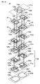
- Wiring electrodes 46a and 46b composing the inductance elements L1 and L2, respectively, are formed on the respective layers from the second-layer sheet 41b to the eighth-layer sheet 41h.
- Via-hole conductors 47a, 47b, 48a, and 48b are formed on the layers from the second-layer sheet 41b to the eighth-layer sheet 41h, if needed.
- Layering the above sheets 41a to 41h forms the inductance element L1 in which the wiring electrodes 46a are helically connected to each other via the via-hole conductor 47a and forms the inductance element L2 in which the wiring electrodes 46b are helically connected to each other via the via-hole conductor 47b.
- a capacitance is generated between the lines of the wiring electrodes 46a and 46b.
- An end 46a-1 of the wiring electrode 46a on the sheet 41b is connected to the feeder terminal electrode 42a via the via-hole conductor 45a, and an end 46a-2 of the wiring electrode 46a on the sheet 41h is connected to the feeder terminal electrode 42b via the via-hole conductors 48a and 45b.
- An end 46b-1 of the wiring electrode 46b on the sheet 41b is connected to the feeder terminal electrode 42b via the via-hole conductor 44b, and an end 46b-2 of the wiring electrode 46b on the sheet 41h is connected to the feeder terminal electrode 42a via the via-hole conductors 48b and 44a.
- the inductance elements L1 and L2 are wound in opposite directions around the winding axes that are substantially parallel to each other in the above feeder circuit 21, the magnetic field generated in the inductance element L1 is offset by the magnetic field generated in the inductance element L2. It is necessary to increase the lengths of the wiring electrodes 46a and 46b to some extent in order to generate a desired inductance because the magnetic fields are offset by each other. This reduces the Q value to suppress the steepness of the resonance characteristics, thereby broaden the resonance characteristics near the resonant frequency.
- the inductance elements L1 and L2 are formed at different left-side and right-side positions.
- the direction of the magnetic field generated in the inductance element L1 is opposite to that of the magnetic field generated in the inductance element L2. Accordingly, when the feeder circuit 21 is coupled to the ends 32a and 32b of the loop radiation strip 32, a current excited at the end 32a flows in the direction opposite to the direction in which a current excited at the end 32b flows and, therefore, signals can be transmitted and received with the loop radiation strip 32.
- the inductance elements L1 and L2 may be coupled to different radiation strips.
- the radiation strip 32 is composed of a loop electrode having the one end 32a and the other end 32b, and the ends 32a and 32b are coupled to the different inductance elements L1 and L2, respectively.
- the magnetic body 33 made of, for example, ferrite is arranged inside the loop of the loop electrode. The presence of the magnetic body 33 causes amplification of the magnetic field generated around the radiation strip 32 composed of the loop electrode to increase the communication distance.
- the magnetic body 33 may not necessarily be provided and may be omitted.
- the feeder circuit board 20 is made of a magnetic material and the inductance elements L1 and L2 are formed in the magnetic body, a higher inductance is generated and the frequencies around 13.56 MHz are supported.
- the magnetic material preferably has a permittivity ⁇ of around 400.
- the feeder circuit board 20 may be a multilayer board made of ceramics or resin or may be a board in which flexible sheets made of a dielectric material, such as polyimide or liquid crystal polymer, are layered. Particularly, incorporating the inductance elements L1 and L2 in the feeder circuit board 20 causes the feeder circuit 21 to be less susceptible to the outside of the board, thereby suppressing a variation in the radiation characteristics.
- the feeder circuit board 20 may not be adhered on the ends 32a and 32b of the radiation strip 32.
- the feeder circuit board 20 may be arranged in proximity to the ends 32a and 32b.
- a wireless IC device of a second embodiment basically has a structure similar to that of the first embodiment. As shown in Fig. 5 , the wireless IC device of the second embodiment differs from the first embodiment in that, in a perspective plan view of the feeder circuit board 20, planer electrodes 49a and 49b are provided on the rear face of a sheet 41i that is the bottom layer of the feeder circuit board 20.
- the planer electrodes 49a and 49b have the same outer dimensions as those of the inductance elements L1 and L2 or have outer dimensions smaller than those of the inductance elements L1 and L2.
- Via-hole conductors are arranged at the respective ends 46a-2 and 46b-2 of the wiring electrodes 46a and 46b forming the inductance elements L1 and L2.
- the via-hole conductors are connected to the feeder terminal electrodes 42a and 42b and are also connected to the planer electrodes 49a and 49b via via-hole conductors 48c and 48d formed in the sheet 41i.
- the provision of the planer electrodes 49a and 49b allows a variation in coupling between the feeder circuit 21 and the radiation strip 32 to be suppressed.
- the planer electrodes 49a and 49b may not be electrically connected to the wiring electrodes 46a and 46b.
- the planer electrodes 49a and 49b may be electrically connected to the radiation strip 32.
- the feeder circuit board 20 on which the wireless IC chip 10 is mounted is adhered on an end 53b of an electrode 53 and an electrode 54, which are formed on the front face of a radiation substrate 50, with adhesive.
- the wireless IC chip 10 of the third embodiment has the same structure as that of the first embodiment.
- the radiation substrate 50 has the spiral electrode 53 and the electrode 54 that are formed on the front face of a flexible resin film base 51 and that function as a radiation strip 52.
- the radiation substrate 50 has a spiral electrode 55 that is provided on the rear face of the flexible resin film base 51 and that functions as the radiation strip 52.
- An end 53a of the electrode 53 is electrically connected to an end 55a of the electrode 55 via a via-hole conductor 56a and an end 55b of the electrode 55 is electrically connected to the electrode 54 via a via-hole conductor 56b.
- a magnetic body 57 made of, for example, ferrite is formed on the rear face of the substrate 50.
- the magnetic body 57 is formed on the electrode 55 inside the outline of the electrode 55.
- the magnetic body 57 may be made of a magnetic metal material. In this case, it is necessary to electrically insulate the magnetic body 57 from the electrode 55.
- inductance elements L1 and L2 having different inductances are magnetically coupled to each other in phase (a mutual inductance M1), and inductance elements L3 and L4 having different inductances are magnetically coupled to each other in phase (the mutual inductance M1).
- the inductance elements L1 and L2 are out of phase with and magnetically coupled to the inductance elements L3 and L4 (indicated by a mutual inductance M2).
- the feeder circuit 21 including a resonant circuit and/or a matching circuit that include the inductance elements L1, L2, L3, and L4 will be described below with reference to Fig. 8 .
- the inductance elements L1 and L2 included in the feeder circuit 21 are out of phase with and magnetically coupled to the inductance elements L3 and L4 included in the feeder circuit 21 to resonate with the frequency processed by the wireless IC chip 10 and to be electromagnetically coupled to the electrode end 53b and the electrode 54 of the loop radiation strip 52.
- Feeder terminal electrode 62a and 62b in the feeder circuit 21 are electrically connected to input-output terminal electrodes (not shown) of the wireless IC chip 10 to match the impedance (normally 50 ⁇ ) of the wireless IC chip 10 with the impedance (a spatial impedance of 377 ⁇ ) of the radiation strip 52.
- a signal of a positive polarity is applied to the electrode 54 of the radiation strip 52
- a signal of a negative polarity is applied to the electrode end 53b.
- a current flows in the direction from the positive polarity (the electrode 54) to the negative polarity (the electrode end 53b) to transmit the signal between the radiation strip 52 and the feeder circuit 21.
- the feeder circuit 21 transmits a transmission signal that is sent from the wireless IC chip 10 and that has a predetermined frequency to the radiation strip 52 and selects a reception signal having a predetermined frequency from the signals received by the radiation strip 52 to supply the selected reception signal to the wireless IC chip 10, as in the first embodiment. Consequently, in the wireless IC device, the wireless IC chip 10 operates in response to the signal received by the radiation strip 52 and a response signal from the wireless IC chip 10 is externally radiated from the radiation strip 52. As described above, the operation and effect of the third embodiment are basically the same as those of the first embodiment.
- the feeder circuit board 20 is manufactured by layering, attaching by pressure, and firing ceramic sheets 61a to 61h made of a dielectric material or a magnetic material.
- the feeder terminal electrodes 62a and 62b, mounting electrodes 63a and 63b, and via-hole conductors 64a, 64b, 65a, and 65b are formed on the top-layer sheet 61a.
- Wiring electrodes 66a, 66b, 66c, and 66d composing the inductance elements L1, L2, L3, and L4 are formed on the layers from the second-layer sheet 61b to the eighth-layer sheet 61h.
- Via-hole conductors 67a, 67b, 68a, and 68b are formed on the layers from the second-layer sheet 61b to the eighth-layer sheet 61h, if needed.
- the inductance element L1 in which the wiring electrodes 66a are helically connected to each other via the via-hole conductor 67a and forms the inductance element L2 in which the wiring electrodes 66b are helically connected to each other via the via-hole conductor 67b.
- An end 66-1 where the wiring electrode 66a is integrated with the wiring electrode 66b on the sheet 61b is connected to the feeder terminal electrode 62a via the via-hole conductors 65a, and an end 66-2 where the wiring electrode 66a is integrated with the wiring electrode 66b on the sheet 41h is connected to the feeder terminal electrode 62b via the via-hole conductors 68a and 65b.
- An end 66-3 where the wiring electrode 66c is integrated with the wiring electrode 66d on the sheet 61b is connected to the feeder terminal electrode 62b via the via-hole conductors 64b, and 66-4 where the wiring electrode 66c is integrated with the wiring electrode 66d on the sheet 61h is connected to the feeder terminal electrode 62a via the via-hole conductors 68b and 64a.
- the operation of the feeder circuit 21 having the above structure is basically the same as that of the feeder circuit 21 described above in the first embodiment.
- the inductance elements L1 and L2 are formed of the two wiring electrodes 66a and 66b, which are adjacent to each other on the same plane
- the inductance elements L3 and L4 are formed of the wiring electrodes 66c and 66d, which are adjacent to each other on the same plane
- the lengths of the wiring electrodes or the distance between the electrodes can be varied to broaden the resonance characteristics.
- the radiation strip 52 is composed of a loop electrode having one end electrode 53a and the other end electrode 54, and the end electrodes 53a and 54 are coupled to the inductance elements L1 and L2 and the inductance elements L3 and L4, respectively. Since the magnetic body 57 is arranged inside the outline of the loop of the loop electrode, the magnetic field generated around the radiation strip 52 composed of the loop electrode is amplified to increase the communication distance.
- the magnetic body 57 may not necessarily be provided and may be omitted.
- a wireless IC device of a fourth embodiment includes the wireless IC chip 10, the feeder circuit board 20, and a radiation substrate 130 on which a radiation strip 132 is formed, as shown in Fig. 9 .
- the wireless IC chip 10 of the fourth embodiment has the same structure as that of the first embodiment.
- the feeder circuit board 20 includes the two inductance elements L1 and L2.
- Feeder terminal electrodes 72a and 72b and mounting electrodes 73a and 73b provided on the front face of the feeder circuit board 20 are electrically connected to input-output terminal electrodes and mounting terminal electrodes (which are not shown) below the wireless IC chip 10.
- the radiation strip 132 is helically formed on a half area of the front face of a base 131 made of ceramics and an auxiliary electrode 133 is helically formed on the other half area.
- the feeder circuit board 20 on which the wireless IC chip 10 is mounted is adhered on the radiation strip 132 with adhesive.
- an end 133a at the central portion of the auxiliary electrode 133 is connected to an electrode 135 formed on the rear face of the base 131 via a via-hole conductor 134, and an end 135a of the electrode 135 is capacitively coupled to an end 132a at the central portion of the radiation strip 132.
- the electrode 135 may be formed inside the base 131.
- the feeder circuit board 20 is manufactured by layering, attaching by pressure, and firing ceramic sheets 71a to 71e made of a dielectric material or a magnetic material, as shown in Fig. 10 .
- the feeder terminal electrodes 72a and 72b, the mounting electrodes 73a and 73b, and via-hole conductors 74a and 74b are formed on the top-layer sheet 71a.
- Wiring electrodes 75a and 75b composing the inductance elements L1 and L2, respectively, and via-hole conductors 76a, 76b, and 77 are formed on the layers from the second-layer sheet 71b to the fourth-layer sheet 71d.
- a wiring electrode 75 is formed on the bottom-layer sheet 71e.
- the wiring electrodes 75a and 75 are formed in a state where the wiring electrodes 75a and 75 are bare along the periphery of the sheets 71b to 71e.
- Layering the above sheets 71a to 71e forms the inductance element L1 in which the wiring electrodes 75a are helically connected to each other via the via-hole conductor 76a and forms the inductance element L2 in which the wiring electrodes 75b are helically connected to each other via the via-hole conductor 76b.
- the wiring electrodes 75a and 75b branch off on the sheet 71b and the wiring electrodes 75a and 75b are integrated into the wiring electrode 75 on the bottom-layer sheet 71e.
- a capacitance is generated between the lines of the wiring electrodes 75a and 75b.
- An end 75c where the wiring electrode 75a is integrated with the wiring electrode 75b on the sheet 71b is connected to the feeder terminal electrode 72b via the via-hole conductor 74b, an end 75d of the wiring electrode 75 on the sheet 71e is connected to the wiring electrodes 75a and 75b via the via-hole conductors 76a and 76b on the sheet 71d above the sheet 71e, and an end 75e of the wiring electrode 75 is connected to the feeder terminal electrode 72a via the via-hole conductors 77 and 74a.
- the feeder circuit 21 which has the above structure and which includes the inductance elements L1 and L2, has an equivalent circuit similar to that of the feeder circuit 21 shown in Fig. 1 .
- the inductance element L1 is out of phase with and electromagnetically coupled to the inductance element L2 to resonate with the frequency processed by the wireless IC chip 10 and to be electromagnetically coupled to the radiation strip 132.
- the feeder circuit 21 matches the impedance (normally 50 ⁇ ) of the wireless IC chip 10 with the impedance (a spatial impedance of 377 ⁇ ) of the radiation strip 132.
- the operation and effect of the fourth embodiment are the same as those of the first embodiment.
- part (the wiring electrodes 75a and 75) of the inductance elements L1 and L2 is bare along the side faces of the feeder circuit board 20 in the fourth embodiment, the part that is exposed to the outside also functions as the radiation strip.
- the part of the inductance elements L1 and L2 exposed to the outside is electromagnetically coupled to the radiation strip 132 and the auxiliary electrode 133 on the side faces of the feeder circuit board 20, so that the radiation characteristics are improved.
- the external dimension of the auxiliary electrode 133 is the same as or greater than that of the feeder circuit board 20 and, thus, the coupling to the magnetic field radiated from the rear face and the side faces of the feeder circuit board 20 is easily achieved.
- a wireless IC device of a fifth embodiment includes the feeder circuit board 20 shown in Fig. 11 .
- the wireless IC chip 10 and the radiation substrate 30, which are the remaining components of the wireless IC device, are the same as those described in the first embodiment.
- the feeder circuit board 20 is manufactured by layering, attaching by pressure, and firing ceramic sheets 81a to 81e made of a dielectric material or a magnetic material.
- Feeder terminal electrodes 82a and 82b, mounting electrodes 83a and 83b, and via-hole conductors 84a and 84b are formed on the top-layer sheet 81a.
- a wiring electrode 85 and via-hole conductors 86a, 86b, 87a, and 87b are formed on the second-layer sheet 81b.
- Wiring electrodes 85a and 85b composing the inductance elements L1 and L2 and the via-hole conductors 86a, 86b, 87a, and 87b are formed on the third-layer sheet 81c.
- the wiring electrodes 85a and 85b composing the inductance elements L1 and L2 are formed on the fourth-layer sheet 81d.
- Planer electrodes 88a and 88b are formed on rear face of the bottom-layer sheet 81e
- Layering the above sheets 81a to 81e forms the inductance element L1 in which the wiring electrodes 85a are helically connected to each other via the via-hole conductor 86a and forms the inductance element L2 in which the wiring electrodes 85b are helically connected to each other via the via-hole conductor 86b.
- a capacitance is generated between the lines of the wiring electrodes 85a and 85b.
- the wiring electrodes 85a and 85b are integrated into the wiring electrode 85 on the sheet 81b, an end 85a' of the wiring electrode 85a on the sheet 81d is connected to the feeder terminal electrode 82a via the via-hole conductors 87a and 84a, and an end 85b' of the wiring electrode 85b on the sheet 81d is connected to the feeder terminal electrode 82b via the via-hole conductors 87b and 84b.
- the feeder circuit 21 which has the above structure and which includes the inductance elements L1 and L2, has an equivalent circuit similar to that of the feeder circuit 21 shown in Fig. 1 .
- the inductance element L1 is out of phase with and electromagnetically coupled to the inductance element L2 to resonate with the frequency processed by the wireless IC chip 10 and to be electromagnetically coupled to the radiation strip 32.
- the feeder circuit 21 matches the impedance (normally 50 ⁇ ) of the wireless IC chip 10 with the impedance (a spatial impedance of 377 ⁇ ) of the radiation strip 32.
- the operation and effect of the fifth embodiment are the same as those of the first embodiment.
- the provision of the planer electrodes 88a and 88b on the rear face of the feeder circuit board 20 allows a variation in coupling between the feeder circuit 21 and the radiation strip 32 to be suppressed.
- the planer electrodes 88a and 88b may not necessarily be provided.
- a wireless IC device of a sixth embodiment includes the feeder circuit board 20 shown in Fig. 12 .
- the wireless IC chip 10 and the radiation substrate 30, which are the remaining components of the wireless IC device, are the same as those described in the first embodiment.
- the structure of the feeder circuit board 20 is basically the same as that of the feeder circuit board 20 shown in the first embodiment.
- Wiring electrodes 101a and 101b helically connected to each other form the inductance elements L1 and L2, respectively.
- the inductance elements L1 and L2 have different inductances and are out of phase with and magnetically coupled to each other.
- Planer electrodes 102a and 102b are arranged beneath the inductance elements L1 and L2, and wiring electrodes 103 helically connected to each other form a magnetic-field receiving coil 104.
- the magnetic-field receiving coil 104 is connected in series to the planer electrodes 102a and 102b and has an auxiliary radiation function for coupling the feeder circuit 21 to the radiation strip 32 (refer to Fig. 2 ).
- the feeder circuit 21 of the sixth embodiment which includes the inductance elements L1 and L2, has an equivalent circuit similar to that of the feeder circuit 21 shown in Fig. 1 .
- the inductance element L1 is out of phase with and electromagnetically coupled to the inductance element L2 to resonate with the frequency processed by the wireless IC chip 10 and to be electromagnetically coupled to the radiation strip 32.
- the feeder circuit 21 matches the impedance (normally 50 ⁇ ) of the wireless IC chip 10 with the impedance (a spatial impedance of 377 ⁇ ) of the radiation strip 32. Accordingly, the operation and effect of the sixth embodiment are similar to those of the first embodiment.
- a wireless IC device of a seventh embodiment includes the feeder circuit board 20 shown in Fig. 13 .
- the wireless IC chip 10 and the radiation substrate 30, which are the remaining components of the wireless IC device, are the same as those described in the first embodiment.
- wiring electrodes 111a and 111b that are adjacent to each other and that are helically connected to each other form the inductance elements L1 and L2, respectively.
- the inductance elements L1 and L2 have different inductances and are out of phase with and magnetically coupled to each other.
- Planer electrodes 112a and 112b are arranged beneath the inductance elements L1 and L2, and wiring electrodes 113 that are helically connected to each other form a magnetic-field receiving coil 114.
- the magnetic-field receiving coil 114 is connected in series to the planer electrodes 112a and 112b and has an auxiliary radiation function for coupling the feeder circuit 21 to the radiation strip 32 (refer to Fig. 2 ).
- the feeder circuit 21 of the seventh embodiment which includes the inductance elements L1 and L2, has an equivalent circuit similar to that of the feeder circuit 21 shown in Fig. 1 .
- the inductance element L1 is out of phase with and electromagnetically coupled to the inductance element L2 to resonate with the frequency processed by the wireless IC chip 10 and to be electromagnetically coupled to the radiation strip 32.
- the feeder circuit 21 matches the impedance (normally 50 ⁇ ) of the wireless IC chip 10 with the impedance (a spatial impedance of 377 ⁇ ) of the radiation strip 32. Accordingly, the operation and effect of the seventh embodiment are similar to those of the first embodiment.
- the inductance elements L1 and L2 are composed of the two wiring electrodes 111a and 111b that are adjacent to each other on the same plane, respectively, the lengths of the wiring electrodes 111a and 111b or the distance between the wiring electrodes 111a and 11b can be varied to broaden the resonance characteristics.
- a wireless IC device of an eighth embodiment includes the feeder circuit board 20 shown in Fig. 14 .
- the feeder circuit 21 on the feeder circuit board 20 is basically the same as in the fifth embodiment (refer to Fig. 11 ). Specifically, feeder terminal electrodes 122a and 122b and mounting electrode 123a and 123b are formed on a sheet 121a, and wiring electrodes 125a and 125b are formed on sheets 121b to 121g. Planer electrodes 128a and 128b are formed on a sheet 121h.
- the inductance elements L1 and L2 are formed by helically connecting the wiring electrodes 125a and 125b, respectively, and the wiring electrodes 125a and 125b are integrated into a wiring electrode 125 on the sheet 121b.
- An end 125a' of the wiring electrode 125a on the sheet 121g is connected to the feeder terminal electrode 122a and an end 125b' of the wiring electrode 125b on the sheet 121g is connected to the feeder terminal electrode 122b.
- the feeder circuit 21 which has the above structure and which includes the inductance elements L1 and L2, has an equivalent circuit shown in Fig. 15 .
- the inductance elements L1 and L2 connected in series to the wireless IC chip 10 are out of phase with and electromagnetically coupled to each other to resonate with the frequency processed by the wireless IC chip 10 and to be electromagnetically coupled to the radiation strip 52 (may be the radiation strip 32).
- the feeder circuit 21 matches the impedance (normally 50 ⁇ ) of the wireless IC chip 10 with the impedance (a spatial impedance of 377 ⁇ ) of the radiation strip 32, 52.
- the operation and effect of the eighth embodiment are similar to those of the first embodiment.
- the provision of the planer electrodes 128a and 128b on the rear face of the feeder circuit board 20 allows a variation in coupling between the feeder circuit 21 and the radiation strip 32, 52 to be suppressed.
- the planer electrodes 128a and 128b may not necessarily be provided.
- the positions where the ends of the inductance elements L1 and L2 are connected to the feeder terminal electrodes 122a and 122b can be varied and the ends 125a' and 125b' can be electrically opened to compose an auxiliary matching circuit.
- extending electrodes 125a" and 125b" are formed for the wiring electrodes 125a and 125b on the sheet 121e and the extending electrodes 125a" and 125b" are connected to the feeder terminal electrodes 122a and 122b, respectively.
- the ends 125a' and 125b' of the wiring electrodes 125a and 125b on the sheet 121g are electrically opened to form an auxiliary matching circuit 129 by using the wiring electrodes 125a and 125b on the sheets 121f and 121g.
- the extending electrodes 125a" and 125b" connected to the feeder terminal electrodes 122a and 122b, respectively, may be any of the wiring electrodes 125a and 125b provided on the sheets 121c to 121f.
- An equivalent circuit including the extending electrodes 125a" and 125b" is shown in Fig. 17 .
- the formation of the auxiliary matching circuit 129 enables fine adjustment of the matching state.
- the feeder circuit board 20 provided with the wireless IC chip 10 is adhered on the radiation substrate 30, as shown in Fig. 18 , and the radiation substrate 30 is adhered to a depression 141 on the front face or the rear face of a metal can 140, as shown in Fig. 19 .
- the metal can 140 is made of a metallic material, such as steel or aluminum.
- the feeder circuit board 20 is the same as the one shown in the first embodiment and has the feeder circuit 21 shown in Fig. 4 .
- the radiation substrate 30 has the loop radiation strip 32 shown in Fig. 2 formed thereon.
- the radiation strip 32 is provided on the film base 31 and has the ends 32a and 32b.
- the film base 31 and the radiation strip 32 shown in Fig. 2 have quadrangular shapes whereas the film base 31 and the radiation strip 32 of the ninth embodiment have elliptical shapes, as shown in Fig. 18 .
- the radiation substrate 30 provided with the wireless IC chip 10 and the feeder circuit board 20 is adhered on the bottom of the depression 141 via a mount 142 having adhesive on both sides.
- a depth H1 of the depression 141 is about five mm and a distance H2 from the bottom of the depression 141 to the radiation strip 32 is around two to three mm.
- the wireless IC chip 10 does not preferably protrude from the depression 141.
- the operation and effect of the ninth embodiment are similar to those of the first embodiment.
- magnetic fields ⁇ (refer to Fig. 20 ) are generated around the loop radiation strip 32. Since the magnetic fields do not pass through a metal, arranging a metal in parallel with and close to the radiation strip 32 causes the magnetic fields generated around the radiation strip 32 to be blocked by the metal. In such a case, the magnetic fields are not sufficiently radiated externally to cause the insufficient operation of the wireless IC device.
- arranging the radiation strip 32 away from the bottom of the depression 141 of the radiation strip metal can 140 by about a few millimeters via, for example, the mount 142 allows the magnetic fields ⁇ to be radiated from the radiation strip 32 to ensure the operation of the wireless IC device.
- the radiation substrate 30 provided with the feeder circuit board 20 may be embedded in the mount 142.
- the radiation substrate 30 may have a thickness similar to that of the mount 142 and the feeder circuit board 20 may be embedded in a depression formed in the radiation substrate 30.
- the wireless IC chip 10 may be arranged so as to be sandwiched between the feeder circuit board 20 and the radiation substrate 30. With the above structures, it is possible to protect the wireless IC chip and the feeder circuit board 20 from dropping or impact to improve the mechanical strength of the wireless IC device.
- the wireless IC device is adhered to the metal can 140 in the ninth embodiment, the object to which the wireless IC device is adhered is not restricted to the metal can.
- the wireless IC device may be adhered to any metallic article, such as a metallic case or a ground electrode on the circuit board.
- the feeder circuit boards each include the feeder circuit board provided with the feeder circuit including a resonant circuit and/or a matching circuit in the above embodiments.
- a feeder circuit including a resonant circuit and/or a matching circuit that include at least two inductance elements may be provided on the rear face (the main face) of the wireless IC chip where the input-output terminal electrodes are formed, without providing the feeder circuit board.
- Such wireless IC devices will be described as a tenth embodiment and an eleventh embodiment.
- a feeder circuit 150 shown in Fig. 21 as an equivalent circuit is provided on the rear face of the wireless IC chip 10.
- the feeder circuit 150 is composed of the two helically-formed inductance elements L1 and L2 that are wound in opposite directions and that are connected in series to each other.
- Feeder terminal electrodes 151a and 151b provided at ends of the respective inductance elements L1 and L2 are electrically conducted to an input terminal electrode and an output terminal electrode of the wireless IC chip 10.
- the inductance elements L1 and L2 are out of phase with and electromagnetically coupled to each other, a resonant circuit composed of the inductance elements L1 and L2 and a stray capacitance between the lines resonates with the frequency processed by the wireless IC chip 10, and the inductance elements L1 and L2 are electromagnetically coupled to a radiation strip (for example, the ends 32a and 32b of the radiation strip 32 shown in Fig. 2 ). Accordingly, the operation and effect of the tenth embodiment is similar to those of the first embodiment.
- a midpoint between the inductance elements L1 and L2 serves as a virtual ground.
- the impedance of the feeder circuit 150 is designed so as to make a complex conjugate with the impedance of the wireless IC chip 10. Since the inductance elements L1 and L2 are formed in a layered state shown in Fig. 22 , the inductance elements L1 and L2 have different inductances depending on the distance to the radiation strip. Accordingly, an insulating layer 159 is formed on the rear face of the wireless IC chip 10 to fix the distance from the radiation strip and to protect the inductance elements L1 and L2.
- the feeder circuit 150 is manufactured through processes shown in Fig. 22 .
- an insulating layer 154 is formed on the electrode layer 153.
- an electrode layer 155 is formed on the insulating layer 154 by plating or the like and the electrode layer 155 is etched into a certain shape (refer to Fig. 22(f) ). This state is shown in Fig. 23(B) .
- the insulating layer 159 is formed on the electrode layer 155.
- the feeder circuit 150 shown in Fig. 24 as an equivalent circuit is provided on the rear face of the wireless IC chip 10.
- a capacitor C is provided between the inductance elements L1 and L2 in the equivalent circuit (refer to Fig. 21 ) shown in the ninth embodiment to form a serial resonant circuit.
- the operation and effect of the eleventh embodiment are similar to those of the first embodiment.
- the feeder circuit 150 shown in Fig. 24 is manufactured through processes shown in Fig. 25 .
- the insulating layer 152 is formed on the electrode layer 157.
- the electrode layer 153 is formed on the insulating layer 152 by plating or the like and the electrode layer 153 is etched into a certain shape (refer to Fig. 25(f) ). This state is shown in Fig. 26(B) . Electrodes 153a and 153b opposing the capacitor electrode 157a are formed at this stage.
- the insulating layer 154 is formed on the electrode layer 153. Subsequently, the electrode layer 155 and the insulating layer 159 are formed in the manner shown in Figs. 22(e), (f), and (g) . The state after the electrode layer 155 is formed is shown in Fig. 26(C) .
- a wireless IC device of a twelfth embodiment includes a feeder circuit 200 in which the helically-formed inductance elements L1 and L2 wound in opposite directions are connected in series to each other, as shown in an equivalent circuit in Fig. 27(A) .
- Both ends of a radiation strip 212 composed of a loop electrode including an inductance component L10 are electrically conducted to both ends of the inductance elements L1 and L2.
- Feeder terminal electrodes 201a and 201b connected to the input terminal electrode and the output terminal electrode of the wireless IC chip 10 are formed at both ends of the feeder circuit 200.
- a capacitor C is provided in parallel with the inductance elements L1 and L2.
- the remaining structure is similar to the structure of the twelfth embodiment.
- a wireless IC device of a fourteenth embodiment includes the feeder circuit 200 in which the helically-formed inductance elements L1 and L2 wound in opposite directions are connected in series to each other, as shown in an equivalent circuit in Fig. 28(A) .
- Helical inductance components L11 and L12 provided at both ends of the radiation strip 212 composed of the loop electrode including the inductance component L10 are electromagnetically coupled to the inductance elements L1 and L2, respectively.
- the feeder terminal electrodes 201a and 201b connected to the input terminal electrode and the output terminal electrode of the wireless IC chip 10 are formed at both ends of the feeder circuit 200.
- a wireless IC device of a fifteenth embodiment as shown in an equivalent circuit in Fig. 28(B) , the capacitor C is provided in parallel with the inductance elements L1 and L2.
- the remaining structure is similar to the structure of the fourteenth embodiment.
- the helical receiving electrodes are provided at both ends of the radiation strip 212 so as to oppose the inductance elements L1 and L2 in the feeder circuit 200. This allows the direction of the magnetic field generated around the inductance component L10 of the radiation strip 212 to be the same as the direction of the magnetic field generated in the feeder circuit 200, thus improving the degree of coupling between the feeder circuit 200 and the radiation strip 212.
- the inductance elements and the helical ends of the radiation strip 212 (L1 and L11 and L2 and L12), which are formed so as to be coupled to each other, are formed so as to be wound in the same direction in a perspective plan view of the feeder circuit 200.
- the magnetic fields of the same direction are generated in the respective two helical electrodes (L1 and L11 and L2 and L12) arranged so as to be opposed to each other in the perspective plan view, thus further increasing the degree of the magnetic-field coupling between the feeder circuit 200 and the radiation strip 212.
- the inductance (L10) of the loop electrode of the radiation strip 212 is set to a value higher than the inductances of the inductance elements L1 and L2 in the feeder circuit 200. Since signals generated in the feeder circuit 200 can be transmitted and received with the magnetic field generated around the radiation strip 212, it is possible to suppress an occurrence of communication failure with a reader-writer.
- these wireless IC devices each include the wireless IC chip 10, a feeder circuit board 220, and a radiation substrate 210 provided with the radiation strip 212 (refer to Fig. 31 ).
- the feeder terminal electrodes 201a and 201b are formed on the front face of the feeder circuit board 220 (refer to Fig. 29(B) ) and planar electrodes 202a and 202b are provided on the rear face thereof (refer to Fig. 29(C) ).
- the planar electrodes 202a and 202b have the operation and effect described in the second embodiment (refer to Fig. 5 ).
- the planar electrodes 202a and 202b may be omitted.
- the feeder circuit 200 shown in Fig. 30 is formed inside the feeder circuit board 220.
- the feeder circuit board 220 is manufactured by layering, attaching by pressure, and firing ceramic sheets made of a dielectric material or a magnetic material.
- the feeder terminal electrodes 201a and 201b and mounting electrodes 201c and 201d are formed on a top-layer sheet 231a.
- Connection electrodes 203a and 203b are formed on a second-layer sheet 231b.
- Wiring electrodes 204a and 204b composing the inductance elements L1 and L2, respectively, are formed on the sheets from a third-layer sheet 231c to a seventh-layer sheet 231g.
- Layering the above sheets 231a to 231g forms the inductance element L1 in which the wiring electrodes 204a are helically connected to each other via a via-hole conductor 205a and forms the inductance element L2 in which the wiring electrodes 204b are helically connected to each other via a via-hole conductor 205b.
- One end of the inductance element L1 (the wiring electrode 204a) is conductively connected to one end of the inductance element L2 (the wiring electrode 204b) on the sheet 231c, and the other end of the inductance element L1 and the other end of the inductance element L2 are connected to the feeder terminal electrodes 201a and 201b, respectively, via the connection electrodes 203a and 203b and via-hole conductors 206a and 206b.
- the feeder circuit 200 having the above structure has the same operation and effect as those described in the first and second embodiments. Particularly, in the feeder circuit 200 shown in Fig. 30 , one end of the inductance element L1 is conductively connected to one end of the inductance element L2 near the top layer in the multilayer body, and the other end of the inductance element L1 and the other end of the inductance element L2 are connected to the wireless IC chip 10.
- the inductance element L1 is conductively connected to the inductance element L2 near the top layer in the multilayer body, which is away from the radiation strip 212, and the inductance elements L1 and L2 are wound in opposite directions near the bottom layer in the multilayer body, which is electromagnetically coupled to the radiation strip 212, so that the efficiency of energy transfer is improved.
- the radiation strip 212 having one end 212a and the other end 212b is helically formed on the front face of the flexible resin film base 211 and an electrode 213 adjacent to the end 212a is formed.
- the electrode 213 is electrically conducted to the other end 212b of the radiation strip 212 via a connection electrode 214 formed on the rear face of the base 211 and a via-hole conductor.
- the feeder circuit board 220 on which the wireless IC chip 10 is mounted is coupled to the end 212a of the radiation strip 212 and an end 213a of the electrode 213.
- the end 212a of the radiation strip 212 and the end 213a of the electrode 213 may have planer shapes, as shown in Fig. 31(B) , or may be helically formed, as shown in Fig. 31(C) .
- the case where the end 212a of the radiation strip 212 and the end 213a of the electrode 213 are helically formed corresponds to the fourteenth and fifteenth embodiments.
- the at least two inductance elements may be formed at different positions in a perspective plan view of the feeder circuit in the wireless IC devices described above.
- the feeder circuit can be coupled to two different radiation strips.
- the at least two inductance elements may be formed of two wiring electrodes adjacent to each other on the same plane. When one inductance element is composed of two adjacent wiring electrodes, the length of the wiring electrodes or the distance between the wiring electrodes can be varied to broaden the resonance characteristics.
- the feeder circuit board may be formed of a multilayer body, and the planer electrodes having outer dimensions that are the same as or smaller than those of the at least two inductance elements may be provided inside or on the front face of the bottom layer of the multilayer body in a perspective plan view of the feeder circuit board.
- the provision of the planer electrodes allows a variation in coupling between the feeder circuit and the radiation strip to be suppressed.
- the feeder circuit board may include a magnetic body and the at least two inductance elements may be formed inside the magnetic body.
- the inclusion of the magnetic body in the feeder circuit board achieves a higher inductance and allows frequencies around 13.56-MHz band to be supported.
- one end of a inductance element may be conductively connected to one end of the other inductance element near the top layer in the multilayer body and the other ends of the inductance elements may be coupled to the wireless IC.
- the two inductance elements are conductively connected to each other near the top layer in the multilayer body, which is away from the radiation strip, and are wound in opposite directions near the bottom layer in the multilayer body, which is electromagnetically coupled to the radiation strip, so that the efficiency of energy transfer is improved.
- the radiation strip may be composed of a loop electrode having one end and the other end.
- the one end and the other end may be coupled to the at least two different inductance elements and may be helically formed with being wound in opposite directions. Since the direction of the magnetic field generated at the side of the radiation strip can be the same direction as that of the magnetic field generated in the feeder circuit, the degree of coupling between the feeder circuit and the radiation strip is increased. It is preferred that the inductance element and the helical end of the radiation strip, which are formed so as to be coupled to each other, be formed so as to be wound in the same direction in a perspective plan view of the feeder circuit.
- the magnetic fields of the same direction are generated in the two helical electrodes arranged so as to be opposed to each other in the perspective plan view, so that the magnetic-field coupling between the feeder circuit and the radiation strip is further increased. Furthermore, it is preferred that the inductances of the loop electrodes be higher than those of the inductance elements in the feeder circuit. Since signals generated in the feeder circuit can be transmitted and received with the magnetic field generated around the radiation strip, it is possible to suppress an occurrence of communication failure with a reader-writer.
- the magnetic body may be arranged inside or on the front face of the loop of the loop electrode. In this case, the magnetic field generated around the radiation strip composed of the loop electrode is amplified, thus increasing the communication distance.
- the at least two inductance elements may be connected in series to the wireless IC, may be connected in parallel to the wireless IC, or may have substantially the same inductance.
- Multiple mounting electrodes for mounting the wireless IC may be formed on the main face of the feeder circuit board and the at least two mounting electrodes may be electrically conducted to each other via the feeder circuit.
- the at least two mounting electrodes may be balanced input-output terminal electrodes.
- the feeder circuit may include an auxiliary matching circuit in which one end may be electrically connected to a predetermined position in the feeder circuit and the other end is electrically opened.
- the auxiliary matching circuit enables fine adjustment of the matching state.
- the at least two mounting electrodes may be balanced input-output terminal electrodes.
- Part of the at least two inductance elements may be bare along the side faces of the feeder circuit board and the part that is exposed to the outside may be structured so as to also function as the radiation strip.
- the part of the inductance elements is electromagnetically coupled to the radiation strip on the side faces of the feeder circuit board to improve the radiation characteristics.
- the feeder circuit board may be a multilayer board made of ceramics or resin or may be a flexible board. Particularly, incorporating the inductance elements composing the feeder circuit in the board causes the feeder circuit to be less susceptible to the outside of the board, thereby suppressing a variation in the radiation characteristics.
- the at least two inductance elements may be conductively connected in series to each other. In this case, it is possible to reliably generate the magnetic fields of different directions in the inductance elements.
- the wireless IC device according to the present invention is not restricted to the above embodiments and various modifications may occur insofar as they are within the scope of the present invention.
- the wireless IC may not be of a chip type and may be integrated with the feeder circuit board.
- the radiation strip may adopt various shapes.
- the present invention is useful for a wireless IC device.
- the wireless IC device of the present invention is excellent in that the wireless IC device is less susceptible to, for example, the environment in which the wireless IC device is used, is capable of suppressing a variation in the radiation characteristics, and is capable of being used in a wideband.
Abstract
Description
- The present invention relates to wireless integrated circuit (IC) devices. More particularly, the present invention relates to a wireless IC device used in a radio frequency identification (RFID) system.
- Hitherto, RFID systems have been developed as management systems of articles. In a typical RFID system, a reader-writer generating an induction field communicates with a wireless tag (also referred to as a wireless IC device) that is appended to an article and that stores certain information in a non-contact manner to transmit information.
Patent Document 1 proposes a wireless tag used in an RFID system of this kind. In the wireless tag proposed inPatent Document 1, an antenna and a matching circuit are formed on a flexible substrate and an IC chip is arranged on the substrate so as to be electrically conducted to the antenna and the matching circuit. The matching circuit is provided by forming a loop coil (inductor) on the substrate. - However, the wireless tag disclosed in
Patent Document 1 has a drawback that the inductance of the loop coil can be varied depending on the permittivity of an article to which the wireless tag is appended and/or the surrounding environment of the article to vary the characteristics of the matching circuit for impedance matching between the IC chip and the antenna because the matching circuit is bare on the flexible substrate. The variation in the characteristics of the matching circuit causes a problem that a loss occurs in transmission of a signal between the IC chip and the antenna to reduce the radiation characteristics of the antenna. In addition, it is necessary to complicatedly design the antenna for every article in accordance with, for example, the permittivity of the article to which the antenna is pasted because the frequency used by the wireless tag is determined by the length of the antenna. - [Patent Document 1] Japanese Unexamined Patent Application Publication No.
2006-80367 - It is an object of the present invention to provide a wireless IC device that is less susceptible to, for example, the environment in which the wireless IC device is used, that is capable of suppressing a variation in the radiation characteristics, and that is capable of being used in a wideband.
Means for Solving the Problems - In order to achieve the above object, a wireless IC device of a first embodiment of the present invention includes:
- a wireless IC;
- a feeder circuit that is coupled to the wireless IC, that is provided on a main face of the wireless IC where input-output terminal electrodes are formed, and that includes a resonant circuit and/or a matching circuit including at least two inductance elements; and
- a radiation strip on which the feeder circuit is adhered or to which the feeder circuit is arranged in proximity and which radiates a transmission signal supplied from the feeder circuit and/or supplies a received signal to the feeder circuit.
- A wireless IC device of a second embodiment of the present invention includes:
- a wireless IC;
- a feeder circuit board provided with a feeder circuit that is coupled to the wireless IC and that includes a resonant circuit and/or a matching circuit including at least two inductance elements; and
- a radiation strip on which the feeder circuit is adhered or to which the feeder circuit is arranged in proximity and which radiates a transmission signal supplied from the feeder circuit and/or supplies a received signal to the feeder circuit.
- Since the resonant frequencies of signals are set in the feeder circuit in the above wireless IC devices, the wireless IC device normally operates even if the wireless IC device is mounted on various articles and a variation in the radiation characteristics is suppressed, thus eliminating the need for changing the design of the radiation strip, etc. for every article. Particularly, since the at least two inductance elements composing the feeder circuit are wound in opposite directions, the magnetic fields generated in the inductance elements are offset by each other to decrease the Q value, thus suppressing the steepness of the resonance characteristics to broaden the resonance characteristics near the resonant frequency. In addition, since the magnetic fields have opposite directions, one magnetic field directs upward when the other magnetic field directs downward. These directions correspond to the positive and negative phases of an AC power supply and almost 100% of energy can be transferred to the radiation strip via the magnetic-field energy.
- The frequency of a transmission signal radiated from the radiation strip and the frequency of a reception signal supplied to the wireless IC substantially correspond to the resonant frequency of the resonant circuit, and the maximum gain of a signal is substantially determined by at least one of the size and shape of the feeder circuit and the distance and the medium between the feeder circuit and the radiation strip. Since the frequencies of the transmission and reception signals are determined in the feeder circuit board, the frequency characteristics are not varied even if, for example, the wireless IC device is rolled or is sandwiched between dielectric materials, thus achieving the stable frequency characteristics regardless of the shape, size, and arrangement of the radiation strip.
- According to the present invention, since the feeder circuit including a resonant circuit and/or a matching circuit is provided between the wireless IC and the radiation strip, it is possible to effectively prevent the resonant frequency and the radiation characteristics from being affected by, for example, an article to which the wireless IC device is adhered. In addition, since the at least two inductance elements composing the feeder circuit are helically formed with being wound in opposite directions, the magnetic fields generated in the inductance elements are offset by each other to broaden the resonance characteristics near the resonant frequency. The provision of the feeder circuit including a resonant circuit and/or a matching circuit that includes at least two inductance elements on the main face of the wireless IC where the input-output terminal electrodes are formed eliminates the need to provide the feeder circuit board, thus reducing the size and height of the wireless IC device.
-
- [
Fig. 1] Fig. 1 is an equivalent circuit diagram showing a feeder circuit composing a wireless IC device of a first embodiment. - [
Fig. 2] Fig. 2 includes diagrams showing a radiation strip composing the wireless IC device of the first embodiment:Fig. 2(A) is a plan view andFig. 2(B) is a plan view showing a state where a feeder circuit board is adhered. - [
Fig. 3] Fig. 3 is a perspective view showing a state where a wireless IC chip is mounted on the feeder circuit board composing the wireless IC device of the first embodiment. - [
Fig. 4] Fig. 4 includes plan views showing a layering structure of the feeder circuit board of the wireless IC device of the first embodiment. - [
Fig. 5] Fig. 5 includes plan views showing a layering structure of a feeder circuit board of a wireless IC device of a second embodiment. - [
Fig. 6] Fig. 6 is an equivalent circuit diagram of a wireless IC device of a third embodiment. - [
Fig. 7] Fig. 7 includes diagrams showing a radiation strip of the wireless IC device of the third embodiment: Fig. 3(A) is a plan view, Fig. 3(B) is a rear view, and Fig. 3(C) is a plan view of a magnetic body provided on the rear face. - [
Fig. 8] Fig. 8 includes plan views showing a layering structure of a feeder circuit board of the wireless IC device of the third embodiment. - [
Fig. 9] Fig. 9 is a perspective view of a wireless IC device of a fourth embodiment. - [
Fig. 10] Fig. 10 includes plan views showing a layering structure of a feeder circuit board of the wireless IC device of the fourth embodiment. - [
Fig. 11] Fig. 11 includes plan views showing a layering structure of a feeder circuit board of a wireless IC device of a fifth embodiment. - [
Fig. 12] Fig. 12 includes perspective views showing a layering structure of a feeder circuit board of a wireless IC device of a sixth embodiment. - [
Fig. 13] Fig. 13 includes perspective views showing a layering structure of a feeder circuit board of a wireless IC device of a seventh embodiment. - [
Fig. 14] Fig. 14 includes perspective views showing a layering structure of a feeder circuit board of a wireless IC device of an eighth embodiment. - [
Fig. 15] Fig. 15 is an equivalent circuit diagram of the feeder circuit board shown inFig. 14 . - [
Fig. 16] Fig. 16 includes perspective views showing another layering structure of the feeder circuit board of the wireless IC device of the eighth embodiment. - [
Fig. 17] Fig. 17 is an equivalent circuit diagram of the feeder circuit board shown inFig. 16 . - [
Fig. 18] Fig. 18 is a perspective view showing a wireless IC device of a ninth embodiment. - [
Fig. 19] Fig. 19 is a perspective view showing a state where the wireless IC device of the ninth embodiment is mounted on a metal can. - [
Fig. 20] Fig. 20 is a partially enlarged cross-sectional view ofFig. 19 . - [
Fig. 21] Fig. 21 is an equivalent circuit diagram showing a feeder circuit composing a wireless IC device of a tenth embodiment. - [
Fig. 22] Fig. 22 includes diagrams illustrating a manufacturing process of a feeder circuit board of the wireless IC device of the tenth embodiment. - [
Fig. 23] Fig. 23 includes rear views showing intermediate states of the manufacturing process shown inFig. 22 . - [
Fig. 24] Fig. 24 is an equivalent circuit diagram showing a feeder circuit composing a wireless IC device of an eleventh embodiment. - [
Fig. 25] Fig. 25 includes diagrams illustrating a manufacturing process of a feeder circuit board of the wireless IC device of the eleventh embodiment. - [
Fig. 26] Fig. 26 includes rear views showing intermediate states of the manufacturing process shown inFig. 25 . - [
Fig. 27] Fig. 27(A) is an equivalent circuit diagram showing a feeder circuit of a wireless IC device of a twelfth embodiment andFig. 27(B) is an equivalent circuit diagram showing a feeder circuit of a wireless IC device of a thirteenth embodiment. - [
Fig. 28] Fig. 28 (A) is an equivalent circuit diagram showing a feeder circuit of a wireless IC device of a fourteenth embodiment andFig. 28(B) is an equivalent circuit diagram showing a feeder circuit of a wireless IC device of a fifteenth embodiment. - [
Fig. 29] Fig. 29 includes diagrams showing wireless IC devices from the twelfth embodiment to the fifteenth embodiment:Fig. 29(A) is a front view,Fig. 29(B) is a plan view, andFig. 29(C) and Fig. 29(D) are rear views. - [
Fig. 30] Fig. 30 includes plan views showing a layering structure of a feeder circuit board of each of the wireless IC devices from the twelfth embodiment to the fifteenth embodiment. - [
Fig. 31] Fig. 31 includes diagrams showing the wireless IC device from the twelfth embodiment to the fifteenth embodiment:Fig. 31(A) is a plan view in a state where the feeder circuit board is mounted on a radiation strip,Fig. 31(B) is a plan view showing a first example of the radiation strip,Fig. 31(C) is a plan view showing a second example of the radiation strip, andFig. 31(D) is a rear view of the radiation strip. -
- L1 to L4
- inductance element
- 10
- wireless IC chip
- 20, 220
- feeder circuit board
- 21, 150, 200
- feeder circuit
- 30, 50, 130, 210
- radiation substrate
- 32, 52, 132, 212
- radiation strip
- 33
- magnetic body
- 46a, 46b
- wiring electrode
- 49a, 49b
- magnetic body
- 66a to 66d
- wiring electrode
- 75a, 75b
- wiring electrode
- 85a, 85b
- wiring electrode
- 88a, 88b
- magnetic body
- 101a, 101b
- wiring electrode
- 111a, 111b
- wiring electrode
- 112a, 112b
- magnetic body
- 125a, 125b
- wiring electrode
- 128a, 128b
- magnetic body
- 129
- auxiliary matching circuit
- 133
- auxiliary electrode
- 204a, 204b
- wiring electrode
- Embodiments of a wireless IC device according to the present invention will herein be described with reference to the attached drawings.
- A wireless IC device of a first embodiment includes a
wireless IC chip 10 processing transmission and reception signals having predetermined frequencies and afeeder circuit board 20 on which thewireless IC chip 10 is mounted, which are shown inFig. 3 . The wireless IC device of the first embodiment also includes aradiation substrate 30 shown inFig. 2(A) or Fig. 2(B) . - As shown in
Fig. 1 as an equivalent circuit, thefeeder circuit board 20 includes a feeder circuit 21 (described in detail below with reference toFig. 4 ) that includes a resonant circuit and/or a matching circuit including inductance elements L1 and L2. The inductance of the inductance element L1 is different from that of the inductance element L2 and the inductance element L1 is out of phase with and magnetically coupled to the inductance element L2 (indicated by a mutual inductance M). - The
wireless IC chip 10 includes a clock circuit, a logic circuit, a memory circuit, and so on. Necessary information is stored in thewireless IC chip 10. A pair of input-output terminal electrodes and a pair of mounting terminal electrodes, which are not shown in the drawings, are provided on the rear face of thewireless IC chip 10. As shown inFig. 3 , the input-output terminal electrodes are electrically connected tofeeder terminal electrodes feeder circuit board 20 via metal bumps or the likes, and the mounting terminal electrodes are electrically connected to mountingelectrodes 43a and 43b formed on thefeeder circuit board 20 via metal bumps or the likes. - On the
radiation substrate 30, as shown inFig. 2 , aloop radiation strip 32 made of a nonmagnetic metal material is formed along the periphery on a flexibleresin film base 31. Thefeeder circuit board 20 is adhered to oneend 32a of theradiation strip 32 and theother end 32b thereof via adhesive. The ends 32a and 32b are each coupled to either of the inductance elements L1 and L2 in thefeeder circuit 21. Amagnetic body 33 is arranged inside the loop of theradiation strip 32.Fig. 2(B) shows a state where thefeeder circuit board 20 on which thewireless IC chip 10 is mounted is adhered on theradiation strip 32 on theradiation substrate 30. - The inductance elements L1 and L2 included in the
feeder circuit 21 are out of phase with and magnetically coupled to each other to resonate with the frequency processed by thewireless IC chip 10 and to be electromagnetically coupled to theends radiation strip 32. Thefeeder circuit 21 matches the impedance (normally 50Ω) of thewireless IC chip 10 with the impedance (a spatial impedance of 377Ω) of theradiation strip 32. - Accordingly, the
feeder circuit 21 supplies a transmission signal that is sent from thewireless IC chip 10 and that has a predetermined frequency to theradiation strip 32 and selects a reception signal having a predetermined frequency from the signals received by theradiation strip 32 to supply the selected signal to thewireless IC chip 10. As a result, in this wireless IC device, thewireless IC chip 10 operates in response to the signal received by theradiation strip 32 and a response signal from thewireless IC chip 10 is externally radiated from theradiation strip 32. - As described above, since the resonant frequency of a signal is set in the
feeder circuit 21 provided on thefeeder circuit board 20 in the wireless IC device, the wireless IC device normally operates even if the wireless IC device is mounted on various articles and a variation in the radiation characteristics is suppressed, thus eliminating the need for changing the design of theradiation strip 32, etc. for every article. The frequency of a transmission signal radiated from theradiation strip 32 and the frequency of a reception signal supplied to thewireless IC chip 10 substantially correspond to the resonant frequency of thefeeder circuit 21 on thefeeder circuit board 20. The maximum gain of a signal is substantially determined by at least one of the size and shape of thefeeder circuit 21 and the distance and the medium between the feeder circuit and the radiation strip. Since the frequencies of the transmission and reception signals are determined by thefeeder circuit board 20, the frequency characteristics are not varied even if, for example, the wireless IC device is rolled or is sandwiched between dielectric materials, thus achieving the stable frequency characteristics regardless of the shape, size, and arrangement of theradiation strip 32. - The structure of the
feeder circuit board 20 will now be described with reference toFig. 4 . Thefeeder circuit board 20 is manufactured by layering, attaching by pressure, and firingceramic sheets 41a to 41h made of a dielectric material or a magnetic material.Feeder terminal electrodes electrodes 43a and 43b, and via-hole conductors layer sheet 41a.Wiring electrodes layer sheet 41b to the eighth-layer sheet 41h. Via-hole conductors layer sheet 41b to the eighth-layer sheet 41h, if needed. - Layering the
above sheets 41a to 41h forms the inductance element L1 in which thewiring electrodes 46a are helically connected to each other via the via-hole conductor 47a and forms the inductance element L2 in which thewiring electrodes 46b are helically connected to each other via the via-hole conductor 47b. A capacitance is generated between the lines of thewiring electrodes - An
end 46a-1 of thewiring electrode 46a on thesheet 41b is connected to thefeeder terminal electrode 42a via the via-hole conductor 45a, and anend 46a-2 of thewiring electrode 46a on thesheet 41h is connected to thefeeder terminal electrode 42b via the via-hole conductors end 46b-1 of thewiring electrode 46b on thesheet 41b is connected to thefeeder terminal electrode 42b via the via-hole conductor 44b, and anend 46b-2 of thewiring electrode 46b on thesheet 41h is connected to thefeeder terminal electrode 42a via the via-hole conductors - Since the inductance elements L1 and L2 are wound in opposite directions around the winding axes that are substantially parallel to each other in the
above feeder circuit 21, the magnetic field generated in the inductance element L1 is offset by the magnetic field generated in the inductance element L2. It is necessary to increase the lengths of thewiring electrodes - In a perspective plan view of the
feeder circuit board 20, the inductance elements L1 and L2 are formed at different left-side and right-side positions. The direction of the magnetic field generated in the inductance element L1 is opposite to that of the magnetic field generated in the inductance element L2. Accordingly, when thefeeder circuit 21 is coupled to theends loop radiation strip 32, a current excited at theend 32a flows in the direction opposite to the direction in which a current excited at theend 32b flows and, therefore, signals can be transmitted and received with theloop radiation strip 32. The inductance elements L1 and L2 may be coupled to different radiation strips. - The
radiation strip 32 is composed of a loop electrode having the oneend 32a and theother end 32b, and theends magnetic body 33 made of, for example, ferrite is arranged inside the loop of the loop electrode. The presence of themagnetic body 33 causes amplification of the magnetic field generated around theradiation strip 32 composed of the loop electrode to increase the communication distance. Themagnetic body 33 may not necessarily be provided and may be omitted. - Since the
feeder circuit board 20 is made of a magnetic material and the inductance elements L1 and L2 are formed in the magnetic body, a higher inductance is generated and the frequencies around 13.56 MHz are supported. In addition, even if a variation in manufacturing or permittivity between the sheets made of a magnetic material occurs, a variation in impedance between the magnetic sheets and thewireless IC chip 10 can be accommodated. The magnetic material preferably has a permittivity µ of around 400. - Setting the inductances of the two inductance elements L1 and L2 to substantially the same value allows the magnetic fields of the same magnitude to be generated in the inductance elements L1 and L2. Accordingly, the magnetic fields generated in the inductance elements L1 and L2 have the same amount of offset to allow the resonance characteristics near the resonant frequency to be broadened.
- The
feeder circuit board 20 may be a multilayer board made of ceramics or resin or may be a board in which flexible sheets made of a dielectric material, such as polyimide or liquid crystal polymer, are layered. Particularly, incorporating the inductance elements L1 and L2 in thefeeder circuit board 20 causes thefeeder circuit 21 to be less susceptible to the outside of the board, thereby suppressing a variation in the radiation characteristics. - The
feeder circuit board 20 may not be adhered on theends radiation strip 32. Thefeeder circuit board 20 may be arranged in proximity to theends - A wireless IC device of a second embodiment basically has a structure similar to that of the first embodiment. As shown in
Fig. 5 , the wireless IC device of the second embodiment differs from the first embodiment in that, in a perspective plan view of thefeeder circuit board 20,planer electrodes 49a and 49b are provided on the rear face of asheet 41i that is the bottom layer of thefeeder circuit board 20. Theplaner electrodes 49a and 49b have the same outer dimensions as those of the inductance elements L1 and L2 or have outer dimensions smaller than those of the inductance elements L1 and L2. - Via-hole conductors are arranged at the respective ends 46a-2 and 46b-2 of the
wiring electrodes feeder terminal electrodes planer electrodes 49a and 49b via via-hole conductors 48c and 48d formed in thesheet 41i. The provision of theplaner electrodes 49a and 49b allows a variation in coupling between thefeeder circuit 21 and theradiation strip 32 to be suppressed. - The
planer electrodes 49a and 49b may not be electrically connected to thewiring electrodes planer electrodes 49a and 49b may be electrically connected to theradiation strip 32. - In a wireless IC device of a third embodiment, as shown in
Fig. 7(A) , thefeeder circuit board 20 on which thewireless IC chip 10 is mounted is adhered on anend 53b of anelectrode 53 and anelectrode 54, which are formed on the front face of aradiation substrate 50, with adhesive. Thewireless IC chip 10 of the third embodiment has the same structure as that of the first embodiment. - As shown in
Fig. 7(A) , theradiation substrate 50 has thespiral electrode 53 and theelectrode 54 that are formed on the front face of a flexibleresin film base 51 and that function as aradiation strip 52. As shown inFig. 7(B) , theradiation substrate 50 has aspiral electrode 55 that is provided on the rear face of the flexibleresin film base 51 and that functions as theradiation strip 52. - An end 53a of the
electrode 53 is electrically connected to an end 55a of theelectrode 55 via a via-hole conductor 56a and anend 55b of theelectrode 55 is electrically connected to theelectrode 54 via a via-hole conductor 56b. Amagnetic body 57 made of, for example, ferrite is formed on the rear face of thesubstrate 50. Themagnetic body 57 is formed on theelectrode 55 inside the outline of theelectrode 55. Themagnetic body 57 may be made of a magnetic metal material. In this case, it is necessary to electrically insulate themagnetic body 57 from theelectrode 55. - In the
feeder circuit board 20, as shown inFig. 6 as an equivalent circuit, inductance elements L1 and L2 having different inductances are magnetically coupled to each other in phase (a mutual inductance M1), and inductance elements L3 and L4 having different inductances are magnetically coupled to each other in phase (the mutual inductance M1). The inductance elements L1 and L2 are out of phase with and magnetically coupled to the inductance elements L3 and L4 (indicated by a mutual inductance M2). Thefeeder circuit 21 including a resonant circuit and/or a matching circuit that include the inductance elements L1, L2, L3, and L4 will be described below with reference toFig. 8 . - The inductance elements L1 and L2 included in the
feeder circuit 21 are out of phase with and magnetically coupled to the inductance elements L3 and L4 included in thefeeder circuit 21 to resonate with the frequency processed by thewireless IC chip 10 and to be electromagnetically coupled to theelectrode end 53b and theelectrode 54 of theloop radiation strip 52.Feeder terminal electrode feeder circuit 21 are electrically connected to input-output terminal electrodes (not shown) of thewireless IC chip 10 to match the impedance (normally 50Ω) of thewireless IC chip 10 with the impedance (a spatial impedance of 377Ω) of theradiation strip 52. - In the third embodiment, when a signal of a positive polarity is applied to the
electrode 54 of theradiation strip 52, a signal of a negative polarity is applied to theelectrode end 53b. As a result, a current flows in the direction from the positive polarity (the electrode 54) to the negative polarity (theelectrode end 53b) to transmit the signal between theradiation strip 52 and thefeeder circuit 21. - Accordingly, the
feeder circuit 21 transmits a transmission signal that is sent from thewireless IC chip 10 and that has a predetermined frequency to theradiation strip 52 and selects a reception signal having a predetermined frequency from the signals received by theradiation strip 52 to supply the selected reception signal to thewireless IC chip 10, as in the first embodiment. Consequently, in the wireless IC device, thewireless IC chip 10 operates in response to the signal received by theradiation strip 52 and a response signal from thewireless IC chip 10 is externally radiated from theradiation strip 52. As described above, the operation and effect of the third embodiment are basically the same as those of the first embodiment. - The structure of the
feeder circuit board 20 will now be described with reference toFig. 8 . Thefeeder circuit board 20 is manufactured by layering, attaching by pressure, and firingceramic sheets 61a to 61h made of a dielectric material or a magnetic material. Thefeeder terminal electrodes electrodes 63a and 63b, and via-hole conductors layer sheet 61a.Wiring electrodes layer sheet 61b to the eighth-layer sheet 61h. Via-hole conductors layer sheet 61b to the eighth-layer sheet 61h, if needed. - Layering the
above sheets 61a to 61h forms the inductance element L1 in which thewiring electrodes 66a are helically connected to each other via the via-hole conductor 67a and forms the inductance element L2 in which thewiring electrodes 66b are helically connected to each other via the via-hole conductor 67b. In addition, the inductance element L3 in which thewiring electrodes 66c are helically connected to each other via the via-hole conductor 67c is formed and the inductance element L4 in which thewiring electrodes 66d are helically connected to each other via the via-hole conductor 67d is formed. Capacitances are generated between the lines of thewiring electrodes - An end 66-1 where the
wiring electrode 66a is integrated with thewiring electrode 66b on thesheet 61b is connected to thefeeder terminal electrode 62a via the via-hole conductors 65a, and an end 66-2 where thewiring electrode 66a is integrated with thewiring electrode 66b on thesheet 41h is connected to thefeeder terminal electrode 62b via the via-hole conductors 68a and 65b. An end 66-3 where thewiring electrode 66c is integrated with thewiring electrode 66d on thesheet 61b is connected to thefeeder terminal electrode 62b via the via-hole conductors 64b, and 66-4 where thewiring electrode 66c is integrated with thewiring electrode 66d on thesheet 61h is connected to thefeeder terminal electrode 62a via the via-hole conductors 68b and 64a. - The operation of the
feeder circuit 21 having the above structure is basically the same as that of thefeeder circuit 21 described above in the first embodiment. Particularly, since the inductance elements L1 and L2 are formed of the twowiring electrodes wiring electrodes - The
radiation strip 52 is composed of a loop electrode having one end electrode 53a and theother end electrode 54, and theend electrodes 53a and 54 are coupled to the inductance elements L1 and L2 and the inductance elements L3 and L4, respectively. Since themagnetic body 57 is arranged inside the outline of the loop of the loop electrode, the magnetic field generated around theradiation strip 52 composed of the loop electrode is amplified to increase the communication distance. Themagnetic body 57 may not necessarily be provided and may be omitted. - A wireless IC device of a fourth embodiment includes the
wireless IC chip 10, thefeeder circuit board 20, and aradiation substrate 130 on which aradiation strip 132 is formed, as shown inFig. 9 . - The
wireless IC chip 10 of the fourth embodiment has the same structure as that of the first embodiment. Thefeeder circuit board 20 includes the two inductance elements L1 and L2.Feeder terminal electrodes electrodes feeder circuit board 20 are electrically connected to input-output terminal electrodes and mounting terminal electrodes (which are not shown) below thewireless IC chip 10. - On the
radiation substrate 130, theradiation strip 132 is helically formed on a half area of the front face of a base 131 made of ceramics and anauxiliary electrode 133 is helically formed on the other half area. Thefeeder circuit board 20 on which thewireless IC chip 10 is mounted is adhered on theradiation strip 132 with adhesive. In theauxiliary electrode 133, an end 133a at the central portion of theauxiliary electrode 133 is connected to anelectrode 135 formed on the rear face of thebase 131 via a via-hole conductor 134, and an end 135a of theelectrode 135 is capacitively coupled to an end 132a at the central portion of theradiation strip 132. Theelectrode 135 may be formed inside thebase 131. - The
feeder circuit board 20 is manufactured by layering, attaching by pressure, and firing ceramic sheets 71a to 71e made of a dielectric material or a magnetic material, as shown inFig. 10 . Thefeeder terminal electrodes electrodes hole conductors 74a and 74b are formed on the top-layer sheet 71a.Wiring electrodes hole conductors layer sheet 71b to the fourth-layer sheet 71d. Awiring electrode 75 is formed on the bottom-layer sheet 71e. Thewiring electrodes wiring electrodes sheets 71b to 71e. - Layering the above sheets 71a to 71e forms the inductance element L1 in which the
wiring electrodes 75a are helically connected to each other via the via-hole conductor 76a and forms the inductance element L2 in which thewiring electrodes 75b are helically connected to each other via the via-hole conductor 76b. Thewiring electrodes sheet 71b and thewiring electrodes wiring electrode 75 on the bottom-layer sheet 71e. A capacitance is generated between the lines of thewiring electrodes - An end 75c where the
wiring electrode 75a is integrated with thewiring electrode 75b on thesheet 71b is connected to thefeeder terminal electrode 72b via the via-hole conductor 74b, anend 75d of thewiring electrode 75 on the sheet 71e is connected to thewiring electrodes hole conductors sheet 71d above the sheet 71e, and an end 75e of thewiring electrode 75 is connected to thefeeder terminal electrode 72a via the via-hole conductors 77 and 74a. - The
feeder circuit 21, which has the above structure and which includes the inductance elements L1 and L2, has an equivalent circuit similar to that of thefeeder circuit 21 shown inFig. 1 . The inductance element L1 is out of phase with and electromagnetically coupled to the inductance element L2 to resonate with the frequency processed by thewireless IC chip 10 and to be electromagnetically coupled to theradiation strip 132. Thefeeder circuit 21 matches the impedance (normally 50Ω) of thewireless IC chip 10 with the impedance (a spatial impedance of 377Ω) of theradiation strip 132. - Accordingly, the operation and effect of the fourth embodiment are the same as those of the first embodiment. Particularly, since part (the
wiring electrodes 75a and 75) of the inductance elements L1 and L2 is bare along the side faces of thefeeder circuit board 20 in the fourth embodiment, the part that is exposed to the outside also functions as the radiation strip. In addition, the part of the inductance elements L1 and L2 exposed to the outside is electromagnetically coupled to theradiation strip 132 and theauxiliary electrode 133 on the side faces of thefeeder circuit board 20, so that the radiation characteristics are improved. The external dimension of theauxiliary electrode 133 is the same as or greater than that of thefeeder circuit board 20 and, thus, the coupling to the magnetic field radiated from the rear face and the side faces of thefeeder circuit board 20 is easily achieved. - A wireless IC device of a fifth embodiment includes the
feeder circuit board 20 shown inFig. 11 . Thewireless IC chip 10 and theradiation substrate 30, which are the remaining components of the wireless IC device, are the same as those described in the first embodiment. - The
feeder circuit board 20 is manufactured by layering, attaching by pressure, and firing ceramic sheets 81a to 81e made of a dielectric material or a magnetic material.
Feeder terminal electrodes electrodes 83a and 83b, and via-hole conductors 84a and 84b are formed on the top-layer sheet 81a. Awiring electrode 85 and via-hole conductors layer sheet 81b.Wiring electrodes hole conductors layer sheet 81c. Thewiring electrodes layer sheet 81d.Planer electrodes - Layering the above sheets 81a to 81e forms the inductance element L1 in which the
wiring electrodes 85a are helically connected to each other via the via-hole conductor 86a and forms the inductance element L2 in which thewiring electrodes 85b are helically connected to each other via the via-hole conductor 86b. A capacitance is generated between the lines of thewiring electrodes - The
wiring electrodes wiring electrode 85 on thesheet 81b, anend 85a' of thewiring electrode 85a on thesheet 81d is connected to thefeeder terminal electrode 82a via the via-hole conductors 87a and 84a, and anend 85b' of thewiring electrode 85b on thesheet 81d is connected to thefeeder terminal electrode 82b via the via-hole conductors - The
feeder circuit 21, which has the above structure and which includes the inductance elements L1 and L2, has an equivalent circuit similar to that of thefeeder circuit 21 shown inFig. 1 . The inductance element L1 is out of phase with and electromagnetically coupled to the inductance element L2 to resonate with the frequency processed by thewireless IC chip 10 and to be electromagnetically coupled to theradiation strip 32. Thefeeder circuit 21 matches the impedance (normally 50Ω) of thewireless IC chip 10 with the impedance (a spatial impedance of 377Ω) of theradiation strip 32. - Accordingly, the operation and effect of the fifth embodiment are the same as those of the first embodiment. Particularly, the provision of the
planer electrodes feeder circuit board 20 allows a variation in coupling between thefeeder circuit 21 and theradiation strip 32 to be suppressed. Theplaner electrodes - A wireless IC device of a sixth embodiment includes the
feeder circuit board 20 shown inFig. 12 . Thewireless IC chip 10 and theradiation substrate 30, which are the remaining components of the wireless IC device, are the same as those described in the first embodiment. - The structure of the
feeder circuit board 20 is basically the same as that of thefeeder circuit board 20 shown in the first embodiment.Wiring electrodes -
Planer electrodes 102a and 102b are arranged beneath the inductance elements L1 and L2, andwiring electrodes 103 helically connected to each other form a magnetic-field receiving coil 104. The magnetic-field receiving coil 104 is connected in series to theplaner electrodes 102a and 102b and has an auxiliary radiation function for coupling thefeeder circuit 21 to the radiation strip 32 (refer toFig. 2 ). - The
feeder circuit 21 of the sixth embodiment, which includes the inductance elements L1 and L2, has an equivalent circuit similar to that of thefeeder circuit 21 shown inFig. 1 . The inductance element L1 is out of phase with and electromagnetically coupled to the inductance element L2 to resonate with the frequency processed by thewireless IC chip 10 and to be electromagnetically coupled to theradiation strip 32. Thefeeder circuit 21 matches the impedance (normally 50Ω) of thewireless IC chip 10 with the impedance (a spatial impedance of 377Ω) of theradiation strip 32. Accordingly, the operation and effect of the sixth embodiment are similar to those of the first embodiment. - A wireless IC device of a seventh embodiment includes the
feeder circuit board 20 shown inFig. 13 . Thewireless IC chip 10 and theradiation substrate 30, which are the remaining components of the wireless IC device, are the same as those described in the first embodiment. - In the
feeder circuit board 20,wiring electrodes -
Planer electrodes 112a and 112b are arranged beneath the inductance elements L1 and L2, andwiring electrodes 113 that are helically connected to each other form a magnetic-field receiving coil 114. The magnetic-field receiving coil 114 is connected in series to theplaner electrodes 112a and 112b and has an auxiliary radiation function for coupling thefeeder circuit 21 to the radiation strip 32 (refer toFig. 2 ). - The
feeder circuit 21 of the seventh embodiment, which includes the inductance elements L1 and L2, has an equivalent circuit similar to that of thefeeder circuit 21 shown inFig. 1 . The inductance element L1 is out of phase with and electromagnetically coupled to the inductance element L2 to resonate with the frequency processed by thewireless IC chip 10 and to be electromagnetically coupled to theradiation strip 32. Thefeeder circuit 21 matches the impedance (normally 50Ω) of thewireless IC chip 10 with the impedance (a spatial impedance of 377Ω) of theradiation strip 32. Accordingly, the operation and effect of the seventh embodiment are similar to those of the first embodiment. - Particularly, in the seventh embodiment, since the inductance elements L1 and L2 are composed of the two
wiring electrodes wiring electrodes wiring electrodes 111a and 11b can be varied to broaden the resonance characteristics. - A wireless IC device of an eighth embodiment includes the
feeder circuit board 20 shown inFig. 14 . Thefeeder circuit 21 on thefeeder circuit board 20 is basically the same as in the fifth embodiment (refer toFig. 11 ). Specifically,feeder terminal electrodes electrode 123a and 123b are formed on a sheet 121a, andwiring electrodes sheets 121b to 121g.Planer electrodes 128a and 128b are formed on asheet 121h. - The inductance elements L1 and L2 are formed by helically connecting the
wiring electrodes wiring electrodes wiring electrode 125 on thesheet 121b. Anend 125a' of thewiring electrode 125a on thesheet 121g is connected to thefeeder terminal electrode 122a and anend 125b' of thewiring electrode 125b on thesheet 121g is connected to thefeeder terminal electrode 122b. - The
feeder circuit 21, which has the above structure and which includes the inductance elements L1 and L2, has an equivalent circuit shown inFig. 15 . The inductance elements L1 and L2 connected in series to thewireless IC chip 10 are out of phase with and electromagnetically coupled to each other to resonate with the frequency processed by thewireless IC chip 10 and to be electromagnetically coupled to the radiation strip 52 (may be the radiation strip 32). Thefeeder circuit 21 matches the impedance (normally 50Ω) of thewireless IC chip 10 with the impedance (a spatial impedance of 377Ω) of theradiation strip - Accordingly, the operation and effect of the eighth embodiment are similar to those of the first embodiment. Particularly, the provision of the
planer electrodes 128a and 128b on the rear face of thefeeder circuit board 20 allows a variation in coupling between thefeeder circuit 21 and theradiation strip planer electrodes 128a and 128b may not necessarily be provided. - Furthermore, in the eighth embodiment, the positions where the ends of the inductance elements L1 and L2 are connected to the
feeder terminal electrodes ends 125a' and 125b' can be electrically opened to compose an auxiliary matching circuit. - For example, as shown in
Fig. 16 , extendingelectrodes 125a" and 125b" are formed for thewiring electrodes electrodes 125a" and 125b" are connected to thefeeder terminal electrodes ends 125a' and 125b' of thewiring electrodes sheet 121g are electrically opened to form anauxiliary matching circuit 129 by using thewiring electrodes sheets electrodes 125a" and 125b" connected to thefeeder terminal electrodes wiring electrodes sheets 121c to 121f. An equivalent circuit including the extendingelectrodes 125a" and 125b" is shown inFig. 17 . The formation of theauxiliary matching circuit 129 enables fine adjustment of the matching state. - In a wireless IC device of a ninth embodiment, the
feeder circuit board 20 provided with thewireless IC chip 10 is adhered on theradiation substrate 30, as shown inFig. 18 , and theradiation substrate 30 is adhered to adepression 141 on the front face or the rear face of a metal can 140, as shown inFig. 19 . The metal can 140 is made of a metallic material, such as steel or aluminum. Thefeeder circuit board 20 is the same as the one shown in the first embodiment and has thefeeder circuit 21 shown inFig. 4 . Theradiation substrate 30 has theloop radiation strip 32 shown inFig. 2 formed thereon. Theradiation strip 32 is provided on thefilm base 31 and has theends film base 31 and theradiation strip 32 shown inFig. 2 have quadrangular shapes whereas thefilm base 31 and theradiation strip 32 of the ninth embodiment have elliptical shapes, as shown inFig. 18 . - As shown in
Fig. 20 , theradiation substrate 30 provided with thewireless IC chip 10 and thefeeder circuit board 20 is adhered on the bottom of thedepression 141 via amount 142 having adhesive on both sides. A depth H1 of thedepression 141 is about five mm and a distance H2 from the bottom of thedepression 141 to theradiation strip 32 is around two to three mm. Thewireless IC chip 10 does not preferably protrude from thedepression 141. - The operation and effect of the ninth embodiment are similar to those of the first embodiment. Upon transmission or reception of a signal, magnetic fields φ (refer to
Fig. 20 ) are generated around theloop radiation strip 32. Since the magnetic fields do not pass through a metal, arranging a metal in parallel with and close to theradiation strip 32 causes the magnetic fields generated around theradiation strip 32 to be blocked by the metal. In such a case, the magnetic fields are not sufficiently radiated externally to cause the insufficient operation of the wireless IC device. Accordingly, as in the ninth embodiment, arranging theradiation strip 32 away from the bottom of thedepression 141 of the radiation strip metal can 140 by about a few millimeters via, for example, themount 142 allows the magnetic fields φ to be radiated from theradiation strip 32 to ensure the operation of the wireless IC device. - The
radiation substrate 30 provided with thefeeder circuit board 20 may be embedded in themount 142. Alternatively, theradiation substrate 30 may have a thickness similar to that of themount 142 and thefeeder circuit board 20 may be embedded in a depression formed in theradiation substrate 30. Alternatively, thewireless IC chip 10 may be arranged so as to be sandwiched between thefeeder circuit board 20 and theradiation substrate 30.
With the above structures, it is possible to protect the wireless IC chip and thefeeder circuit board 20 from dropping or impact to improve the mechanical strength of the wireless IC device. Although the wireless IC device is adhered to the metal can 140 in the ninth embodiment, the object to which the wireless IC device is adhered is not restricted to the metal can. The wireless IC device may be adhered to any metallic article, such as a metallic case or a ground electrode on the circuit board. - The feeder circuit boards each include the feeder circuit board provided with the feeder circuit including a resonant circuit and/or a matching circuit in the above embodiments. However, a feeder circuit including a resonant circuit and/or a matching circuit that include at least two inductance elements may be provided on the rear face (the main face) of the wireless IC chip where the input-output terminal electrodes are formed, without providing the feeder circuit board. Such wireless IC devices will be described as a tenth embodiment and an eleventh embodiment.
- In a wireless IC device of the tenth embodiment, a
feeder circuit 150 shown inFig. 21 as an equivalent circuit is provided on the rear face of thewireless IC chip 10.
Thefeeder circuit 150 is composed of the two helically-formed inductance elements L1 and L2 that are wound in opposite directions and that are connected in series to each other.Feeder terminal electrodes wireless IC chip 10. The inductance elements L1 and L2 are out of phase with and electromagnetically coupled to each other, a resonant circuit composed of the inductance elements L1 and L2 and a stray capacitance between the lines resonates with the frequency processed by thewireless IC chip 10, and the inductance elements L1 and L2 are electromagnetically coupled to a radiation strip (for example, theends radiation strip 32 shown inFig. 2 ). Accordingly, the operation and effect of the tenth embodiment is similar to those of the first embodiment. - In the
feeder circuit 150, a midpoint between the inductance elements L1 and L2 serves as a virtual ground. In addition, the impedance of thefeeder circuit 150 is designed so as to make a complex conjugate with the impedance of thewireless IC chip 10. Since the inductance elements L1 and L2 are formed in a layered state shown inFig. 22 , the inductance elements L1 and L2 have different inductances depending on the distance to the radiation strip. Accordingly, an insulatinglayer 159 is formed on the rear face of thewireless IC chip 10 to fix the distance from the radiation strip and to protect the inductance elements L1 and L2. - The
feeder circuit 150 is manufactured through processes shown inFig. 22 . First, as shown inFig. 22(a) , an insulatinglayer 152 is formed on the rear face of thewireless IC chip 10. The insulatinglayer 152 is not formed at the parts where the input-output terminal electrodes are provided. Next, as shown inFig. 22(b) , anelectrode layer 153 is formed on the insulatinglayer 152 by plating or the like and theelectrode layer 153 is etched into a certain shape (refer toFig. 22(c) ). This state is shown inFig. 23(A) . - Next, as shown in
Fig. 22(d) , an insulatinglayer 154 is formed on theelectrode layer 153. In addition, as shown inFig. 22(e) , anelectrode layer 155 is formed on the insulatinglayer 154 by plating or the like and theelectrode layer 155 is etched into a certain shape (refer toFig. 22(f) ). This state is shown inFig. 23(B) . In addition, as shown inFig. 22(g) , the insulatinglayer 159 is formed on theelectrode layer 155. - In a wireless IC device of the eleventh embodiment, the
feeder circuit 150 shown inFig. 24 as an equivalent circuit is provided on the rear face of thewireless IC chip 10. In thefeeder circuit 150, a capacitor C is provided between the inductance elements L1 and L2 in the equivalent circuit (refer toFig. 21 ) shown in the ninth embodiment to form a serial resonant circuit. The operation and effect of the eleventh embodiment are similar to those of the first embodiment. - The
feeder circuit 150 shown inFig. 24 is manufactured through processes shown inFig. 25 . First, as shown inFig. 25(a) , an insulatinglayer 156 is formed on the rear face of thewireless IC chip 10. The insulatinglayer 156 is not formed at the parts where the input-output terminal electrodes are provided. Next, as shown inFig. 25(b) , anelectrode layer 157 is formed on the insulatinglayer 156 by plating or the like and theelectrode layer 157 is etched into a certain shape (refer toFig. 25(c) ). This state is shown inFig. 26(A) , in which an electrode 157a remaining at a central portion serves as a capacitor electrode. - Next, as shown in
Fig. 25(d) , the insulatinglayer 152 is formed on theelectrode layer 157. In addition, as shown inFig. 25(e) , theelectrode layer 153 is formed on the insulatinglayer 152 by plating or the like and theelectrode layer 153 is etched into a certain shape (refer toFig. 25(f) ). This state is shown inFig. 26(B) .Electrodes 153a and 153b opposing the capacitor electrode 157a are formed at this stage. - In addition, as shown in
Fig. 25(g) , the insulatinglayer 154 is formed on theelectrode layer 153.
Subsequently, theelectrode layer 155 and the insulatinglayer 159 are formed in the manner shown inFigs. 22(e), (f), and (g) . The state after theelectrode layer 155 is formed is shown inFig. 26(C) . - A wireless IC device of a twelfth embodiment includes a
feeder circuit 200 in which the helically-formed inductance elements L1 and L2 wound in opposite directions are connected in series to each other, as shown in an equivalent circuit inFig. 27(A) . Both ends of aradiation strip 212 composed of a loop electrode including an inductance component L10 are electrically conducted to both ends of the inductance elements L1 and L2.Feeder terminal electrodes wireless IC chip 10 are formed at both ends of thefeeder circuit 200. - In a wireless IC device of a thirteenth embodiment, as shown in an equivalent circuit in
Fig. 27(B) , a capacitor C is provided in parallel with the inductance elements L1 and L2. The remaining structure is similar to the structure of the twelfth embodiment. - A wireless IC device of a fourteenth embodiment includes the
feeder circuit 200 in which the helically-formed inductance elements L1 and L2 wound in opposite directions are connected in series to each other, as shown in an equivalent circuit inFig. 28(A) . Helical inductance components L11 and L12 provided at both ends of theradiation strip 212 composed of the loop electrode including the inductance component L10 are electromagnetically coupled to the inductance elements L1 and L2, respectively. Thefeeder terminal electrodes wireless IC chip 10 are formed at both ends of thefeeder circuit 200. - In a wireless IC device of a fifteenth embodiment, as shown in an equivalent circuit in
Fig. 28(B) , the capacitor C is provided in parallel with the inductance elements L1 and L2. The remaining structure is similar to the structure of the fourteenth embodiment. - In the fourteenth embodiment and the fifteenth embodiment, the helical receiving electrodes (the inductance components L11 and L12) are provided at both ends of the
radiation strip 212 so as to oppose the inductance elements L1 and L2 in thefeeder circuit 200. This allows the direction of the magnetic field generated around the inductance component L10 of theradiation strip 212 to be the same as the direction of the magnetic field generated in thefeeder circuit 200, thus improving the degree of coupling between thefeeder circuit 200 and theradiation strip 212. - Setting the helical directions of the receiving electrodes (the inductance components L11 and L12) provided at both ends of the
radiation strip 212 to opposite directions causes the efficiency of energy transfer to be improved. In addition, the inductance elements and the helical ends of the radiation strip 212 (L1 and L11 and L2 and L12), which are formed so as to be coupled to each other, are formed so as to be wound in the same direction in a perspective plan view of thefeeder circuit 200. The magnetic fields of the same direction are generated in the respective two helical electrodes (L1 and L11 and L2 and L12) arranged so as to be opposed to each other in the perspective plan view, thus further increasing the degree of the magnetic-field coupling between thefeeder circuit 200 and theradiation strip 212. - Furthermore, the inductance (L10) of the loop electrode of the
radiation strip 212 is set to a value higher than the inductances of the inductance elements L1 and L2 in thefeeder circuit 200. Since signals generated in thefeeder circuit 200 can be transmitted and received with the magnetic field generated around theradiation strip 212, it is possible to suppress an occurrence of communication failure with a reader-writer. - Specific structures from the twelfth embodiment to the fifteenth embodiment shown as the equivalent circuits will now be described. As shown in
Fig. 29 , these wireless IC devices each include thewireless IC chip 10, afeeder circuit board 220, and aradiation substrate 210 provided with the radiation strip 212 (refer toFig. 31 ). Thefeeder terminal electrodes Fig. 29(B) ) andplanar electrodes 202a and 202b are provided on the rear face thereof (refer toFig. 29(C) ). Theplanar electrodes 202a and 202b have the operation and effect described in the second embodiment (refer toFig. 5 ). As shown inFig. 29(D) , theplanar electrodes 202a and 202b may be omitted. - The
feeder circuit 200 shown inFig. 30 is formed inside thefeeder circuit board 220. Thefeeder circuit board 220 is manufactured by layering, attaching by pressure, and firing ceramic sheets made of a dielectric material or a magnetic material. Thefeeder terminal electrodes electrodes layer sheet 231b.Wiring electrodes layer sheet 231c to a seventh-layer sheet 231g. - Layering the above sheets 231a to 231g forms the inductance element L1 in which the
wiring electrodes 204a are helically connected to each other via a via-hole conductor 205a and forms the inductance element L2 in which thewiring electrodes 204b are helically connected to each other via a via-hole conductor 205b. One end of the inductance element L1 (thewiring electrode 204a) is conductively connected to one end of the inductance element L2 (thewiring electrode 204b) on thesheet 231c, and the other end of the inductance element L1 and the other end of the inductance element L2 are connected to thefeeder terminal electrodes hole conductors - The
feeder circuit 200 having the above structure has the same operation and effect as those described in the first and second embodiments. Particularly, in thefeeder circuit 200 shown inFig. 30 , one end of the inductance element L1 is conductively connected to one end of the inductance element L2 near the top layer in the multilayer body, and the other end of the inductance element L1 and the other end of the inductance element L2 are connected to thewireless IC chip 10. Specifically, the inductance element L1 is conductively connected to the inductance element L2 near the top layer in the multilayer body, which is away from theradiation strip 212, and the inductance elements L1 and L2 are wound in opposite directions near the bottom layer in the multilayer body, which is electromagnetically coupled to theradiation strip 212, so that the efficiency of energy transfer is improved. - In the
radiation substrate 210, as shown inFig. 31 , theradiation strip 212 having one end 212a and theother end 212b is helically formed on the front face of the flexibleresin film base 211 and anelectrode 213 adjacent to the end 212a is formed. Theelectrode 213 is electrically conducted to theother end 212b of theradiation strip 212 via aconnection electrode 214 formed on the rear face of thebase 211 and a via-hole conductor. Thefeeder circuit board 220 on which thewireless IC chip 10 is mounted is coupled to the end 212a of theradiation strip 212 and an end 213a of theelectrode 213. - The end 212a of the
radiation strip 212 and the end 213a of theelectrode 213 may have planer shapes, as shown inFig. 31(B) , or may be helically formed, as shown inFig. 31(C) . The case where the end 212a of theradiation strip 212 and the end 213a of theelectrode 213 are helically formed corresponds to the fourteenth and fifteenth embodiments. - The at least two inductance elements may be formed at different positions in a perspective plan view of the feeder circuit in the wireless IC devices described above. For example, the feeder circuit can be coupled to two different radiation strips. Alternatively, the at least two inductance elements may be formed of two wiring electrodes adjacent to each other on the same plane. When one inductance element is composed of two adjacent wiring electrodes, the length of the wiring electrodes or the distance between the wiring electrodes can be varied to broaden the resonance characteristics.
- The feeder circuit board may be formed of a multilayer body, and the planer electrodes having outer dimensions that are the same as or smaller than those of the at least two inductance elements may be provided inside or on the front face of the bottom layer of the multilayer body in a perspective plan view of the feeder circuit board. The provision of the planer electrodes allows a variation in coupling between the feeder circuit and the radiation strip to be suppressed.
- The feeder circuit board may include a magnetic body and the at least two inductance elements may be formed inside the magnetic body. The inclusion of the magnetic body in the feeder circuit board achieves a higher inductance and allows frequencies around 13.56-MHz band to be supported.
- Of the at least two inductance elements, one end of a inductance element may be conductively connected to one end of the other inductance element near the top layer in the multilayer body and the other ends of the inductance elements may be coupled to the wireless IC. Specifically, the two inductance elements are conductively connected to each other near the top layer in the multilayer body, which is away from the radiation strip, and are wound in opposite directions near the bottom layer in the multilayer body, which is electromagnetically coupled to the radiation strip, so that the efficiency of energy transfer is improved.
- The radiation strip may be composed of a loop electrode having one end and the other end. In this case, the one end and the other end may be coupled to the at least two different inductance elements and may be helically formed with being wound in opposite directions. Since the direction of the magnetic field generated at the side of the radiation strip can be the same direction as that of the magnetic field generated in the feeder circuit, the degree of coupling between the feeder circuit and the radiation strip is increased. It is preferred that the inductance element and the helical end of the radiation strip, which are formed so as to be coupled to each other, be formed so as to be wound in the same direction in a perspective plan view of the feeder circuit. In this case, the magnetic fields of the same direction are generated in the two helical electrodes arranged so as to be opposed to each other in the perspective plan view, so that the magnetic-field coupling between the feeder circuit and the radiation strip is further increased. Furthermore, it is preferred that the inductances of the loop electrodes be higher than those of the inductance elements in the feeder circuit. Since signals generated in the feeder circuit can be transmitted and received with the magnetic field generated around the radiation strip, it is possible to suppress an occurrence of communication failure with a reader-writer.
- The magnetic body may be arranged inside or on the front face of the loop of the loop electrode. In this case, the magnetic field generated around the radiation strip composed of the loop electrode is amplified, thus increasing the communication distance.
- The at least two inductance elements may be connected in series to the wireless IC, may be connected in parallel to the wireless IC, or may have substantially the same inductance.
- Multiple mounting electrodes for mounting the wireless IC may be formed on the main face of the feeder circuit board and the at least two mounting electrodes may be electrically conducted to each other via the feeder circuit. The at least two mounting electrodes may be balanced input-output terminal electrodes. The feeder circuit may include an auxiliary matching circuit in which one end may be electrically connected to a predetermined position in the feeder circuit and the other end is electrically opened.
The auxiliary matching circuit enables fine adjustment of the matching state. In addition, the at least two mounting electrodes may be balanced input-output terminal electrodes. - Part of the at least two inductance elements may be bare along the side faces of the feeder circuit board and the part that is exposed to the outside may be structured so as to also function as the radiation strip. In this case, the part of the inductance elements is electromagnetically coupled to the radiation strip on the side faces of the feeder circuit board to improve the radiation characteristics.
- The feeder circuit board may be a multilayer board made of ceramics or resin or may be a flexible board. Particularly, incorporating the inductance elements composing the feeder circuit in the board causes the feeder circuit to be less susceptible to the outside of the board, thereby suppressing a variation in the radiation characteristics.
- The at least two inductance elements may be conductively connected in series to each other. In this case, it is possible to reliably generate the magnetic fields of different directions in the inductance elements.
- The wireless IC device according to the present invention is not restricted to the above embodiments and various modifications may occur insofar as they are within the scope of the present invention.
- For example, the wireless IC may not be of a chip type and may be integrated with the feeder circuit board. The radiation strip may adopt various shapes.
- As described above, the present invention is useful for a wireless IC device. Particularly, the wireless IC device of the present invention is excellent in that the wireless IC device is less susceptible to, for example, the environment in which the wireless IC device is used, is capable of suppressing a variation in the radiation characteristics, and is capable of being used in a wideband.
Claims (24)
- A wireless IC device comprising:a wireless IC;a feeder circuit that is coupled to the wireless IC, that is provided on a main face of the wireless IC where input-output terminal electrodes are formed, and that includes a resonant circuit and/or a matching circuit including at least two inductance elements; anda radiation strip on which the feeder circuit is adhered or to which the feeder circuit is arranged in proximity and which radiates a transmission signal supplied from the feeder circuit and/or supplies a received signal to the feeder circuit,wherein the at least two inductance elements are helically formed with being wound in opposite directions.
- A wireless IC device comprising:a wireless IC;a feeder circuit board provided with a feeder circuit that is coupled to the wireless IC and that includes a resonant circuit and/or a matching circuit including at least two inductance elements; anda radiation strip on which the feeder circuit board is adhered or to which the feeder circuit board is arranged in proximity and which radiates a transmission signal supplied from the feeder circuit and/or supplies a received signal to the feeder circuit,wherein the at least two inductance elements are helically formed with being wound in opposite directions.
- The wireless IC device according to Claim 1 or 2,
wherein the resonant frequencies of the transmission signal and/or the reception signal substantially correspond to the self-resonant frequency of the resonant circuit. - The wireless IC device according to any of Claims 1 to 3,
wherein the at least two inductance elements are formed at different positions in a perspective plan view of the feeder circuit. - The wireless IC device according to any of Claims 1 to 4,
wherein the at least two inductance elements are formed of two wiring electrodes adjacent to each other on the same plane. - The wireless IC device according to any of Claims 2 to 5,
wherein the feeder circuit board is formed of a multilayer body, and planer electrodes having outer dimensions that are the same as or smaller than those of the at least two inductance elements are provided inside or on the front face of the bottom layer of the multilayer body in a perspective plan view of the feeder circuit board. - The wireless IC device according to any of Claims 2 to 6,
wherein the feeder circuit board includes a magnetic body, and the at least two inductance elements are formed inside and/or on the front face of the magnetic body. - The wireless IC device according to any of Claims 1 to 7,
wherein one ends of the at least two inductance elements are conductively connected to each other near the top layer of a multilayer body and the other ends thereof are coupled to the wireless IC. - The wireless IC device according to any of Claims 1 to 8,
wherein the radiation strip is composed of a loop electrode having one end and the other end, and the one end the other end are coupled to the at least two different inductance elements and are helically formed with being wound in opposite directions. - The wireless IC device according to Claim 9,
wherein the inductance elements and the helical ends of the radiation strip, which are formed so as to be coupled to each other, are formed so as to be wound in the same direction in a perspective plan view of the feeder circuit. - The wireless IC device according to Claim 9 or 10,
wherein the inductance of the loop electrode is higher than those of the inductance elements in the feeder circuit. - The wireless IC device according to any of Claims 9 to 11,
wherein a magnetic body is arranged inside or on the front face of the loop of the loop electrode. - The wireless IC device according to any of Claims 1 to 12,
wherein the at least two inductance elements are connected in series to the wireless IC. - The wireless IC device according to any of Claims 1 to 12,
wherein the at least two inductance elements are connected in parallel to the wireless IC. - The wireless IC device according to any of Claims 1 to 14,
wherein the at least two inductance elements have substantially the same inductance. - The wireless IC device according to any of Claims 2 to 15,
wherein multiple mounting electrodes for mounting the wireless IC are formed on the main face of the feeder circuit board and at least two mounting electrodes are electrically conducted to each other via the feeder circuit. - The wireless IC device according to Claim 16,
wherein the at least two mounting electrodes are balanced input-output terminal electrodes. - The wireless IC device according to any of Claims 1 to 17,
wherein the feeder circuit includes an auxiliary matching circuit in which one end is electrically connected to a predetermined position in the feeder circuit and the other end is electrically opened. - The wireless IC device according to any of Claims 2 to 18,
wherein part of the at least two inductance elements is bare along the side faces of the feeder circuit board and the part that is exposed to the outside also functions as a radiation strip. - The wireless IC device according to any of Claims 2 to 19,
wherein the feeder circuit board is a multilayer board made of ceramics or resin. - The wireless IC device according to any of Claims 2 to 19,
wherein the feeder circuit board is a flexible board. - The wireless IC device according to any of Claims 1 to 21,
wherein the at least two inductance elements are conductively connected in series to each other. - The wireless IC device according to any of Claims 1 to 22,
wherein the at least two inductance elements are connected in parallel to each other. - The wireless IC device according to any of Claims 1 to 22,
wherein the at least two inductance elements are connected in series to each other.
Priority Applications (1)
| Application Number | Priority Date | Filing Date | Title |
|---|---|---|---|
| EP11185009.5A EP2408064B1 (en) | 2007-12-20 | 2008-12-08 | Wireless IC device |
Applications Claiming Priority (4)
| Application Number | Priority Date | Filing Date | Title |
|---|---|---|---|
| JP2007329360 | 2007-12-20 | ||
| JP2008177236 | 2008-07-07 | ||
| JP2008213164 | 2008-08-21 | ||
| PCT/JP2008/072260 WO2009081719A1 (en) | 2007-12-20 | 2008-12-08 | Radio ic device |
Related Child Applications (2)
| Application Number | Title | Priority Date | Filing Date |
|---|---|---|---|
| EP11185009.5A Division EP2408064B1 (en) | 2007-12-20 | 2008-12-08 | Wireless IC device |
| EP11185009.5 Division-Into | 2011-10-13 |
Publications (3)
| Publication Number | Publication Date |
|---|---|
| EP2096709A1 true EP2096709A1 (en) | 2009-09-02 |
| EP2096709A4 EP2096709A4 (en) | 2010-08-18 |
| EP2096709B1 EP2096709B1 (en) | 2012-04-25 |
Family
ID=40787963
Family Applications (2)
| Application Number | Title | Priority Date | Filing Date |
|---|---|---|---|
| EP08865022A Active EP2096709B1 (en) | 2007-12-20 | 2008-12-08 | Radio ic device |
| EP11185009.5A Active EP2408064B1 (en) | 2007-12-20 | 2008-12-08 | Wireless IC device |
Family Applications After (1)
| Application Number | Title | Priority Date | Filing Date |
|---|---|---|---|
| EP11185009.5A Active EP2408064B1 (en) | 2007-12-20 | 2008-12-08 | Wireless IC device |
Country Status (7)
| Country | Link |
|---|---|
| US (2) | US7990337B2 (en) |
| EP (2) | EP2096709B1 (en) |
| JP (2) | JP4462388B2 (en) |
| KR (2) | KR101082702B1 (en) |
| CN (1) | CN101595599B (en) |
| AT (1) | ATE555518T1 (en) |
| WO (1) | WO2009081719A1 (en) |
Cited By (54)
| Publication number | Priority date | Publication date | Assignee | Title |
|---|---|---|---|---|
| US8336786B2 (en) | 2010-03-12 | 2012-12-25 | Murata Manufacturing Co., Ltd. | Wireless communication device and metal article |
| US8400365B2 (en) | 2009-11-20 | 2013-03-19 | Murata Manufacturing Co., Ltd. | Antenna device and mobile communication terminal |
| US8413907B2 (en) | 2007-07-17 | 2013-04-09 | Murata Manufacturing Co., Ltd. | Wireless IC device and electronic apparatus |
| US8424769B2 (en) | 2010-07-08 | 2013-04-23 | Murata Manufacturing Co., Ltd. | Antenna and RFID device |
| US8424762B2 (en) | 2007-04-14 | 2013-04-23 | Murata Manufacturing Co., Ltd. | Wireless IC device and component for wireless IC device |
| US8531346B2 (en) | 2007-04-26 | 2013-09-10 | Murata Manufacturing Co., Ltd. | Wireless IC device |
| US8544759B2 (en) | 2009-01-09 | 2013-10-01 | Murata Manufacturing., Ltd. | Wireless IC device, wireless IC module and method of manufacturing wireless IC module |
| US8552870B2 (en) | 2007-07-09 | 2013-10-08 | Murata Manufacturing Co., Ltd. | Wireless IC device |
| US8590797B2 (en) | 2008-05-21 | 2013-11-26 | Murata Manufacturing Co., Ltd. | Wireless IC device |
| US8602310B2 (en) | 2010-03-03 | 2013-12-10 | Murata Manufacturing Co., Ltd. | Radio communication device and radio communication terminal |
| US8613395B2 (en) | 2011-02-28 | 2013-12-24 | Murata Manufacturing Co., Ltd. | Wireless communication device |
| US8676117B2 (en) | 2006-01-19 | 2014-03-18 | Murata Manufacturing Co., Ltd. | Wireless IC device and component for wireless IC device |
| US8680971B2 (en) | 2009-09-28 | 2014-03-25 | Murata Manufacturing Co., Ltd. | Wireless IC device and method of detecting environmental state using the device |
| US8690070B2 (en) | 2009-04-14 | 2014-04-08 | Murata Manufacturing Co., Ltd. | Wireless IC device component and wireless IC device |
| US8692718B2 (en) | 2008-11-17 | 2014-04-08 | Murata Manufacturing Co., Ltd. | Antenna and wireless IC device |
| US8718727B2 (en) | 2009-12-24 | 2014-05-06 | Murata Manufacturing Co., Ltd. | Antenna having structure for multi-angled reception and mobile terminal including the antenna |
| US8720789B2 (en) | 2012-01-30 | 2014-05-13 | Murata Manufacturing Co., Ltd. | Wireless IC device |
| US8740093B2 (en) | 2011-04-13 | 2014-06-03 | Murata Manufacturing Co., Ltd. | Radio IC device and radio communication terminal |
| US8757500B2 (en) | 2007-05-11 | 2014-06-24 | Murata Manufacturing Co., Ltd. | Wireless IC device |
| US8770489B2 (en) | 2011-07-15 | 2014-07-08 | Murata Manufacturing Co., Ltd. | Radio communication device |
| US8797225B2 (en) | 2011-03-08 | 2014-08-05 | Murata Manufacturing Co., Ltd. | Antenna device and communication terminal apparatus |
| US8797148B2 (en) | 2008-03-03 | 2014-08-05 | Murata Manufacturing Co., Ltd. | Radio frequency IC device and radio communication system |
| US8814056B2 (en) | 2011-07-19 | 2014-08-26 | Murata Manufacturing Co., Ltd. | Antenna device, RFID tag, and communication terminal apparatus |
| US8847831B2 (en) | 2009-07-03 | 2014-09-30 | Murata Manufacturing Co., Ltd. | Antenna and antenna module |
| US8853549B2 (en) | 2009-09-30 | 2014-10-07 | Murata Manufacturing Co., Ltd. | Circuit substrate and method of manufacturing same |
| US8870077B2 (en) | 2008-08-19 | 2014-10-28 | Murata Manufacturing Co., Ltd. | Wireless IC device and method for manufacturing same |
| US8878739B2 (en) | 2011-07-14 | 2014-11-04 | Murata Manufacturing Co., Ltd. | Wireless communication device |
| US8905296B2 (en) | 2011-12-01 | 2014-12-09 | Murata Manufacturing Co., Ltd. | Wireless integrated circuit device and method of manufacturing the same |
| US8937576B2 (en) | 2011-04-05 | 2015-01-20 | Murata Manufacturing Co., Ltd. | Wireless communication device |
| US8944335B2 (en) | 2010-09-30 | 2015-02-03 | Murata Manufacturing Co., Ltd. | Wireless IC device |
| US8976075B2 (en) | 2009-04-21 | 2015-03-10 | Murata Manufacturing Co., Ltd. | Antenna device and method of setting resonant frequency of antenna device |
| US8981906B2 (en) | 2010-08-10 | 2015-03-17 | Murata Manufacturing Co., Ltd. | Printed wiring board and wireless communication system |
| US8991713B2 (en) | 2011-01-14 | 2015-03-31 | Murata Manufacturing Co., Ltd. | RFID chip package and RFID tag |
| US9024725B2 (en) | 2009-11-04 | 2015-05-05 | Murata Manufacturing Co., Ltd. | Communication terminal and information processing system |
| US9024837B2 (en) | 2010-03-31 | 2015-05-05 | Murata Manufacturing Co., Ltd. | Antenna and wireless communication device |
| US9104950B2 (en) | 2009-01-30 | 2015-08-11 | Murata Manufacturing Co., Ltd. | Antenna and wireless IC device |
| US9117157B2 (en) | 2009-10-02 | 2015-08-25 | Murata Manufacturing Co., Ltd. | Wireless IC device and electromagnetic coupling module |
| US9166291B2 (en) | 2010-10-12 | 2015-10-20 | Murata Manufacturing Co., Ltd. | Antenna device and communication terminal apparatus |
| US9165239B2 (en) | 2006-04-26 | 2015-10-20 | Murata Manufacturing Co., Ltd. | Electromagnetic-coupling-module-attached article |
| US9178279B2 (en) | 2009-11-04 | 2015-11-03 | Murata Manufacturing Co., Ltd. | Wireless IC tag, reader-writer, and information processing system |
| US9236651B2 (en) | 2010-10-21 | 2016-01-12 | Murata Manufacturing Co., Ltd. | Communication terminal device |
| US9281873B2 (en) | 2008-05-26 | 2016-03-08 | Murata Manufacturing Co., Ltd. | Wireless IC device system and method of determining authenticity of wireless IC device |
| US9378452B2 (en) | 2011-05-16 | 2016-06-28 | Murata Manufacturing Co., Ltd. | Radio IC device |
| US9444143B2 (en) | 2009-10-16 | 2016-09-13 | Murata Manufacturing Co., Ltd. | Antenna and wireless IC device |
| US9460320B2 (en) | 2009-10-27 | 2016-10-04 | Murata Manufacturing Co., Ltd. | Transceiver and radio frequency identification tag reader |
| US9461363B2 (en) | 2009-11-04 | 2016-10-04 | Murata Manufacturing Co., Ltd. | Communication terminal and information processing system |
| US9460376B2 (en) | 2007-07-18 | 2016-10-04 | Murata Manufacturing Co., Ltd. | Radio IC device |
| US9543642B2 (en) | 2011-09-09 | 2017-01-10 | Murata Manufacturing Co., Ltd. | Antenna device and wireless device |
| US9558384B2 (en) | 2010-07-28 | 2017-01-31 | Murata Manufacturing Co., Ltd. | Antenna apparatus and communication terminal instrument |
| US9692128B2 (en) | 2012-02-24 | 2017-06-27 | Murata Manufacturing Co., Ltd. | Antenna device and wireless communication device |
| US9727765B2 (en) | 2010-03-24 | 2017-08-08 | Murata Manufacturing Co., Ltd. | RFID system including a reader/writer and RFID tag |
| US9761923B2 (en) | 2011-01-05 | 2017-09-12 | Murata Manufacturing Co., Ltd. | Wireless communication device |
| US10013650B2 (en) | 2010-03-03 | 2018-07-03 | Murata Manufacturing Co., Ltd. | Wireless communication module and wireless communication device |
| US10235544B2 (en) | 2012-04-13 | 2019-03-19 | Murata Manufacturing Co., Ltd. | Inspection method and inspection device for RFID tag |
Families Citing this family (47)
| Publication number | Priority date | Publication date | Assignee | Title |
|---|---|---|---|---|
| JP4281850B2 (en) | 2006-06-30 | 2009-06-17 | 株式会社村田製作所 | optical disk |
| WO2008050535A1 (en) | 2006-09-26 | 2008-05-02 | Murata Manufacturing Co., Ltd. | Electromagnetically coupled module and article with electromagnetically coupled module |
| US20090021352A1 (en) | 2007-07-18 | 2009-01-22 | Murata Manufacturing Co., Ltd. | Radio frequency ic device and electronic apparatus |
| JP4561932B2 (en) * | 2007-07-18 | 2010-10-13 | 株式会社村田製作所 | Wireless IC device |
| ATE555518T1 (en) | 2007-12-20 | 2012-05-15 | Murata Manufacturing Co | IC RADIO DEVICE |
| WO2009081683A1 (en) | 2007-12-26 | 2009-07-02 | Murata Manufacturing Co., Ltd. | Antenna apparatus and wireless ic device |
| WO2009142068A1 (en) | 2008-05-22 | 2009-11-26 | 株式会社村田製作所 | Wireless ic device and method for manufacturing the same |
| WO2009145218A1 (en) | 2008-05-28 | 2009-12-03 | 株式会社村田製作所 | Wireless ic device and component for a wireless ic device |
| JP4557186B2 (en) | 2008-06-25 | 2010-10-06 | 株式会社村田製作所 | Wireless IC device and manufacturing method thereof |
| JP4671001B2 (en) | 2008-07-04 | 2011-04-13 | 株式会社村田製作所 | Wireless IC device |
| JP5429182B2 (en) | 2008-10-24 | 2014-02-26 | 株式会社村田製作所 | Wireless IC device |
| CN102197537B (en) | 2008-10-29 | 2014-06-18 | 株式会社村田制作所 | Wireless IC device |
| US8089418B2 (en) * | 2008-12-04 | 2012-01-03 | Intel Corporation | Antenna structure |
| DE112009003613B4 (en) | 2009-01-16 | 2020-12-17 | Murata Manufacturing Co., Ltd. | IC COMPONENT |
| JP2010200309A (en) * | 2009-01-30 | 2010-09-09 | Tdk Corp | Proximity antenna and wireless communication device |
| EP2416355B1 (en) * | 2009-04-02 | 2016-12-21 | Murata Manufacturing Co., Ltd. | Circuit board |
| JP5532678B2 (en) * | 2009-05-26 | 2014-06-25 | ソニー株式会社 | COMMUNICATION DEVICE, ANTENNA DEVICE, AND COMMUNICATION SYSTEM |
| CN102449846B (en) | 2009-06-03 | 2015-02-04 | 株式会社村田制作所 | Wireless IC device and production method thereof |
| JP5516580B2 (en) | 2009-06-19 | 2014-06-11 | 株式会社村田製作所 | Wireless IC device and method for coupling power feeding circuit and radiation plate |
| TWI449066B (en) * | 2010-01-19 | 2014-08-11 | Murata Manufacturing Co | High coupling degree transformers, electronic circuits and electronic machines |
| CN102341957B (en) * | 2010-01-19 | 2014-01-22 | 株式会社村田制作所 | Antenna device and communication terminal apparatus |
| CN104953242B (en) * | 2010-01-19 | 2019-03-26 | 株式会社村田制作所 | Antenna assembly and communication terminal device |
| JP5376041B2 (en) | 2010-02-19 | 2013-12-25 | 株式会社村田製作所 | Composite printed wiring board and wireless communication system |
| JP2011211309A (en) * | 2010-03-29 | 2011-10-20 | Sony Corp | Antenna module and electronic apparatus |
| JPWO2011122162A1 (en) * | 2010-03-31 | 2013-07-08 | 株式会社村田製作所 | Composite antenna and composite wireless communication device |
| WO2011135934A1 (en) * | 2010-04-26 | 2011-11-03 | 株式会社村田製作所 | Communication terminal and card antenna module |
| JP5170156B2 (en) | 2010-05-14 | 2013-03-27 | 株式会社村田製作所 | Wireless IC device |
| JP5299351B2 (en) | 2010-05-14 | 2013-09-25 | 株式会社村田製作所 | Wireless IC device |
| EP2453581A4 (en) * | 2010-08-11 | 2014-04-09 | Murata Manufacturing Co | Frequency-stabilizing circuit, antenna apparatus and communication terminal device |
| JP5234071B2 (en) | 2010-09-03 | 2013-07-10 | 株式会社村田製作所 | RFIC module |
| JP2012064683A (en) * | 2010-09-15 | 2012-03-29 | Murata Mfg Co Ltd | Lamination coil |
| JP5234084B2 (en) * | 2010-11-05 | 2013-07-10 | 株式会社村田製作所 | Antenna device and communication terminal device |
| US10381720B2 (en) | 2010-12-08 | 2019-08-13 | Nxp B.V. | Radio frequency identification (RFID) integrated circuit (IC) and matching network/antenna embedded in surface mount devices (SMD) |
| JP5709690B2 (en) * | 2011-08-17 | 2015-04-30 | タイコエレクトロニクスジャパン合同会社 | antenna |
| JP5472550B2 (en) * | 2011-12-22 | 2014-04-16 | 株式会社村田製作所 | Magnetic antenna, antenna device and electronic apparatus |
| WO2013145311A1 (en) * | 2012-03-30 | 2013-10-03 | 富士通株式会社 | Rfid tag |
| WO2014129279A1 (en) * | 2013-02-19 | 2014-08-28 | 株式会社村田製作所 | Inductor bridge and electronic device |
| KR102010523B1 (en) * | 2013-07-31 | 2019-08-13 | 삼성전자주식회사 | Antenna device and electronic device habing it |
| CN206003966U (en) * | 2014-01-30 | 2017-03-08 | 株式会社村田制作所 | Wireless Telecom Equipment |
| KR101762778B1 (en) | 2014-03-04 | 2017-07-28 | 엘지이노텍 주식회사 | Wireless communication and charge substrate and wireless communication and charge device |
| CN106134000B (en) * | 2014-04-28 | 2019-04-02 | 株式会社村田制作所 | The article of Wireless IC device, clip-like RFID label tag and subsidiary RFID label tag |
| KR101892689B1 (en) | 2014-10-14 | 2018-08-28 | 삼성전기주식회사 | Chip electronic component and board having the same mounted thereon |
| US9839134B2 (en) | 2015-12-22 | 2017-12-05 | Intel Corporation | Flexible integrated circuit that includes an antenna |
| KR102649484B1 (en) | 2017-01-18 | 2024-03-20 | 주식회사 위츠 | Double loop antenna |
| JP6936022B2 (en) | 2017-03-07 | 2021-09-15 | ローム株式会社 | Printed wiring board and switching power supply using this |
| JP6789202B2 (en) * | 2017-11-27 | 2020-11-25 | 株式会社エスケーエレクトロニクス | Booster antenna |
| KR102410205B1 (en) * | 2019-12-12 | 2022-06-20 | 한국전자통신연구원 | Probe antennas, probing systems, and power density measurement methods for measuring power density in near field electromagnetic fields |
Citations (1)
| Publication number | Priority date | Publication date | Assignee | Title |
|---|---|---|---|---|
| US20070052613A1 (en) * | 2005-09-06 | 2007-03-08 | Sebastian Gallschuetz | Radio frequency identification transponder antenna |
Family Cites Families (331)
| Publication number | Priority date | Publication date | Assignee | Title |
|---|---|---|---|---|
| US3364564A (en) | 1965-06-28 | 1968-01-23 | Gregory Ind Inc | Method of producing welding studs dischargeable in end-to-end relationship |
| JPS5754964B2 (en) | 1974-05-08 | 1982-11-20 | ||
| JPS6193701A (en) | 1984-10-13 | 1986-05-12 | Toyota Motor Corp | Antenna system for automobile |
| JPS62127140A (en) | 1985-11-26 | 1987-06-09 | Hitachi Chem Co Ltd | Resin coated sand for shell mold |
| US5253969A (en) | 1989-03-10 | 1993-10-19 | Sms Schloemann-Siemag Aktiengesellschaft | Feeding system for strip material, particularly in treatment plants for metal strips |
| JP2763664B2 (en) | 1990-07-25 | 1998-06-11 | 日本碍子株式会社 | Wiring board for distributed constant circuit |
| NL9100176A (en) | 1991-02-01 | 1992-03-02 | Nedap Nv | Antenna configuration for contactless identification label - forms part of tuned circuit of ID or credit card interrogated via inductive coupling |
| NL9100347A (en) | 1991-02-26 | 1992-03-02 | Nedap Nv | Integrated transformer circuit for ID or credit card - is interrogated via contactless inductive coupling using capacitor to form tuned circuit |
| JPH04321190A (en) | 1991-04-22 | 1992-11-11 | Mitsubishi Electric Corp | Antenna circuit and its production for non-contact type portable storage |
| EP0522806B1 (en) | 1991-07-08 | 1996-11-20 | Nippon Telegraph And Telephone Corporation | Retractable antenna system |
| JPH05327331A (en) | 1992-05-15 | 1993-12-10 | Matsushita Electric Works Ltd | Printed antenna |
| JP3186235B2 (en) | 1992-07-30 | 2001-07-11 | 株式会社村田製作所 | Resonator antenna |
| JPH0677729A (en) | 1992-08-25 | 1994-03-18 | Mitsubishi Electric Corp | Antenna integrated microwave circuit |
| JPH06177635A (en) | 1992-12-07 | 1994-06-24 | Mitsubishi Electric Corp | Cross dipole antenna system |
| JPH07183836A (en) | 1993-12-22 | 1995-07-21 | San'eisha Mfg Co Ltd | Coupling filter device for distribution line carrier communication |
| US5491483A (en) | 1994-01-05 | 1996-02-13 | Texas Instruments Incorporated | Single loop transponder system and method |
| US6096431A (en) | 1994-07-25 | 2000-08-01 | Toppan Printing Co., Ltd. | Biodegradable cards |
| JP3141692B2 (en) | 1994-08-11 | 2001-03-05 | 松下電器産業株式会社 | Millimeter wave detector |
| US5528222A (en) | 1994-09-09 | 1996-06-18 | International Business Machines Corporation | Radio frequency circuit and memory in thin flexible package |
| JPH0887580A (en) | 1994-09-14 | 1996-04-02 | Omron Corp | Data carrier and ball game |
| JP2837829B2 (en) | 1995-03-31 | 1998-12-16 | 松下電器産業株式会社 | Inspection method for semiconductor device |
| JPH08279027A (en) | 1995-04-04 | 1996-10-22 | Toshiba Corp | Radio communication card |
| US5955723A (en) | 1995-05-03 | 1999-09-21 | Siemens Aktiengesellschaft | Contactless chip card |
| JPH08307126A (en) | 1995-05-09 | 1996-11-22 | Kyocera Corp | Container structure of antenna |
| JP3637982B2 (en) | 1995-06-27 | 2005-04-13 | 株式会社荏原電産 | Inverter-driven pump control system |
| US5629241A (en) | 1995-07-07 | 1997-05-13 | Hughes Aircraft Company | Microwave/millimeter wave circuit structure with discrete flip-chip mounted elements, and method of fabricating the same |
| JP3150575B2 (en) | 1995-07-18 | 2001-03-26 | 沖電気工業株式会社 | Tag device and manufacturing method thereof |
| GB2305075A (en) | 1995-09-05 | 1997-03-26 | Ibm | Radio Frequency Tag for Electronic Apparatus |
| DE19534229A1 (en) | 1995-09-15 | 1997-03-20 | Licentia Gmbh | Transponder arrangement |
| JP3882218B2 (en) | 1996-03-04 | 2007-02-14 | ソニー株式会社 | optical disk |
| JP3471160B2 (en) | 1996-03-18 | 2003-11-25 | 株式会社東芝 | Monolithic antenna |
| JPH09270623A (en) | 1996-03-29 | 1997-10-14 | Murata Mfg Co Ltd | Antenna system |
| AUPO055296A0 (en) | 1996-06-19 | 1996-07-11 | Integrated Silicon Design Pty Ltd | Enhanced range transponder system |
| US6104311A (en) | 1996-08-26 | 2000-08-15 | Addison Technologies | Information storage and identification tag |
| US6190942B1 (en) | 1996-10-09 | 2001-02-20 | Pav Card Gmbh | Method and connection arrangement for producing a smart card |
| JPH10171954A (en) | 1996-12-05 | 1998-06-26 | Hitachi Maxell Ltd | Non-contact type ic card |
| JPH10193849A (en) | 1996-12-27 | 1998-07-28 | Rohm Co Ltd | Circuit chip-mounted card and circuit chip module |
| DE19703029A1 (en) | 1997-01-28 | 1998-07-30 | Amatech Gmbh & Co Kg | Transmission module for a transponder device and transponder device and method for operating a transponder device |
| EP0966775A4 (en) | 1997-03-10 | 2004-09-22 | Prec Dynamics Corp | Reactively coupled elements in circuits on flexible substrates |
| JPH10293828A (en) | 1997-04-18 | 1998-11-04 | Omron Corp | Data carrier, coil module, reader-writer, and clothing data acquiring method |
| EP1031939B1 (en) | 1997-11-14 | 2005-09-14 | Toppan Printing Co., Ltd. | Composite ic card |
| JP3800766B2 (en) | 1997-11-14 | 2006-07-26 | 凸版印刷株式会社 | Compound IC module and compound IC card |
| JP3800765B2 (en) | 1997-11-14 | 2006-07-26 | 凸版印刷株式会社 | Compound IC card |
| JPH11219420A (en) | 1998-02-03 | 1999-08-10 | Tokin Corp | Ic card module, ic card and their manufacture |
| JPH11261325A (en) | 1998-03-10 | 1999-09-24 | Shiro Sugimura | Coil element and its manufacture |
| WO1999050932A1 (en) | 1998-03-31 | 1999-10-07 | Matsushita Electric Industrial Co., Ltd. | Antenna unit and digital television receiver |
| US5936150A (en) | 1998-04-13 | 1999-08-10 | Rockwell Science Center, Llc | Thin film resonant chemical sensor with resonant acoustic isolator |
| CN1267267A (en) | 1998-04-14 | 2000-09-20 | 德克萨斯黎伯迪纸板箱公司 | Container for compressors and other goods |
| US6018299A (en) | 1998-06-09 | 2000-01-25 | Motorola, Inc. | Radio frequency identification tag having a printed antenna and method |
| US6107920A (en) | 1998-06-09 | 2000-08-22 | Motorola, Inc. | Radio frequency identification tag having an article integrated antenna |
| JP2000021639A (en) | 1998-07-02 | 2000-01-21 | Sharp Corp | Inductor, resonance circuit using the same, matching circuit, antenna circuit, and oscillation circuit |
| JP2000022421A (en) | 1998-07-03 | 2000-01-21 | Murata Mfg Co Ltd | Chip antenna and radio device mounted with it |
| EP0977145A3 (en) | 1998-07-28 | 2002-11-06 | Kabushiki Kaisha Toshiba | Radio IC card |
| JP2000311226A (en) | 1998-07-28 | 2000-11-07 | Toshiba Corp | Radio ic card and its production and read and write system of the same |
| JP2000059260A (en) | 1998-08-04 | 2000-02-25 | Sony Corp | Storage device |
| ES2198938T3 (en) | 1998-08-14 | 2004-02-01 | 3M Innovative Properties Company | APPLICATION FOR A RADIO FREQUENCY IDENTIFICATION SYSTEM. |
| KR100699755B1 (en) | 1998-08-14 | 2007-03-27 | 쓰리엠 이노베이티브 프로퍼티즈 캄파니 | Radio frequency identification systems applications |
| JP4411670B2 (en) | 1998-09-08 | 2010-02-10 | 凸版印刷株式会社 | Non-contact IC card manufacturing method |
| JP4508301B2 (en) | 1998-09-16 | 2010-07-21 | 大日本印刷株式会社 | Non-contact IC card |
| JP3632466B2 (en) | 1998-10-23 | 2005-03-23 | 凸版印刷株式会社 | Inspection device and inspection method for non-contact IC card |
| US6837438B1 (en) | 1998-10-30 | 2005-01-04 | Hitachi Maxell, Ltd. | Non-contact information medium and communication system utilizing the same |
| JP2000137785A (en) | 1998-10-30 | 2000-05-16 | Sony Corp | Manufacture of noncontact type ic card and noncontact type ic card |
| JP2000137779A (en) | 1998-10-30 | 2000-05-16 | Hitachi Maxell Ltd | Non-contact information medium and production thereof |
| JP3924962B2 (en) | 1998-10-30 | 2007-06-06 | 株式会社デンソー | ID tag for dishes |
| JP2000148948A (en) | 1998-11-05 | 2000-05-30 | Sony Corp | Non-contact ic label and its manufacture |
| JP2000172812A (en) | 1998-12-08 | 2000-06-23 | Hitachi Maxell Ltd | Noncontact information medium |
| JP3088404B2 (en) | 1999-01-14 | 2000-09-18 | 埼玉日本電気株式会社 | Mobile radio terminal and built-in antenna |
| JP2000222540A (en) | 1999-02-03 | 2000-08-11 | Hitachi Maxell Ltd | Non-contact type semiconductor tag |
| JP2000228602A (en) | 1999-02-08 | 2000-08-15 | Alps Electric Co Ltd | Resonance line |
| JP2000243797A (en) | 1999-02-18 | 2000-09-08 | Sanken Electric Co Ltd | Semiconductor wafer, and cutting method thereof, and semiconductor wafer assembly and cutting method thereof |
| JP3967487B2 (en) | 1999-02-23 | 2007-08-29 | 株式会社東芝 | IC card |
| JP2000251049A (en) | 1999-03-03 | 2000-09-14 | Konica Corp | Card and production thereof |
| JP4106673B2 (en) | 1999-03-05 | 2008-06-25 | 株式会社エフ・イー・シー | Antenna device using coil unit, printed circuit board |
| JP4349597B2 (en) | 1999-03-26 | 2009-10-21 | 大日本印刷株式会社 | IC chip manufacturing method and memory medium manufacturing method incorporating the same |
| US6542050B1 (en) | 1999-03-30 | 2003-04-01 | Ngk Insulators, Ltd. | Transmitter-receiver |
| JP3751178B2 (en) | 1999-03-30 | 2006-03-01 | 日本碍子株式会社 | Transceiver |
| JP2000286634A (en) | 1999-03-30 | 2000-10-13 | Ngk Insulators Ltd | Antenna system and its manufacture |
| JP3067764B1 (en) | 1999-03-31 | 2000-07-24 | 株式会社豊田自動織機製作所 | Mobile communication coupler, mobile body, and mobile communication method |
| JP2000321984A (en) | 1999-05-12 | 2000-11-24 | Hitachi Ltd | Label with rf-id tag |
| JP3557130B2 (en) | 1999-07-14 | 2004-08-25 | 新光電気工業株式会社 | Method for manufacturing semiconductor device |
| JP2001043340A (en) | 1999-07-29 | 2001-02-16 | Toppan Printing Co Ltd | Composite ic card |
| US6259369B1 (en) | 1999-09-30 | 2001-07-10 | Moore North America, Inc. | Low cost long distance RFID reading |
| JP3451373B2 (en) | 1999-11-24 | 2003-09-29 | オムロン株式会社 | Manufacturing method of data carrier capable of reading electromagnetic wave |
| JP4186149B2 (en) | 1999-12-06 | 2008-11-26 | 株式会社エフ・イー・シー | Auxiliary antenna for IC card |
| JP2001188890A (en) | 2000-01-05 | 2001-07-10 | Omron Corp | Non-contact tag |
| JP2001240046A (en) | 2000-02-25 | 2001-09-04 | Toppan Forms Co Ltd | Container and manufacturing method thereof |
| JP2001257292A (en) | 2000-03-10 | 2001-09-21 | Hitachi Maxell Ltd | Semiconductor device |
| JP2001256457A (en) | 2000-03-13 | 2001-09-21 | Toshiba Corp | Semiconductor device, its manufacture and ic card communication system |
| EP1269412A1 (en) | 2000-03-28 | 2003-01-02 | Lucatron AG | Rfid label with an element for regulating the resonance frequency |
| JP4624537B2 (en) | 2000-04-04 | 2011-02-02 | 大日本印刷株式会社 | Non-contact data carrier device, storage |
| JP2001319380A (en) | 2000-05-11 | 2001-11-16 | Mitsubishi Materials Corp | Optical disk with rfid |
| JP2001331976A (en) | 2000-05-17 | 2001-11-30 | Casio Comput Co Ltd | Optical recording type recording medium |
| JP4223174B2 (en) | 2000-05-19 | 2009-02-12 | Dxアンテナ株式会社 | Film antenna |
| JP2001339226A (en) | 2000-05-26 | 2001-12-07 | Nec Saitama Ltd | Antenna system |
| JP2001344574A (en) | 2000-05-30 | 2001-12-14 | Mitsubishi Materials Corp | Antenna device for interrogator |
| JP2001352176A (en) | 2000-06-05 | 2001-12-21 | Fuji Xerox Co Ltd | Multilayer printed wiring board and manufacturing method of multilayer printed wiring board |
| JP2003536302A (en) | 2000-06-06 | 2003-12-02 | バッテル メモリアル インスティテュート | Telecommunications systems and methods |
| JP2002157564A (en) | 2000-11-21 | 2002-05-31 | Toyo Aluminium Kk | Antenna coil for ic card and its manufacturing method |
| EP1172760B1 (en) | 2000-06-23 | 2004-12-01 | Toyo Aluminium Kabushiki Kaisha | Antenna coil for IC card and manufacturing method thereof |
| US6894624B2 (en) | 2000-07-04 | 2005-05-17 | Credipass Co., Ltd. | Passive transponder identification and credit-card type transponder |
| JP4138211B2 (en) | 2000-07-06 | 2008-08-27 | 株式会社村田製作所 | Electronic component and manufacturing method thereof, collective electronic component, mounting structure of electronic component, and electronic apparatus |
| JP2002024776A (en) | 2000-07-07 | 2002-01-25 | Nippon Signal Co Ltd:The | Ic card reader/writer |
| US7088249B2 (en) | 2000-07-19 | 2006-08-08 | Hanex Co., Ltd. | Housing structure for RFID tag, installation structure for RFID tag, and communication using such RFID tag |
| RU2163739C1 (en) | 2000-07-20 | 2001-02-27 | Криштопов Александр Владимирович | Antenna |
| JP2002042076A (en) | 2000-07-21 | 2002-02-08 | Dainippon Printing Co Ltd | Non-contact data carrier and booklet therewith |
| JP3075400U (en) | 2000-08-03 | 2001-02-16 | 昌栄印刷株式会社 | Non-contact IC card |
| JP2002063557A (en) | 2000-08-21 | 2002-02-28 | Mitsubishi Materials Corp | Tag for rfid |
| JP2002076750A (en) | 2000-08-24 | 2002-03-15 | Murata Mfg Co Ltd | Antenna device and radio equipment equipped with it |
| JP4615695B2 (en) | 2000-10-19 | 2011-01-19 | 三星エスディーエス株式会社 | IC module for IC card and IC card using it |
| US6634564B2 (en) | 2000-10-24 | 2003-10-21 | Dai Nippon Printing Co., Ltd. | Contact/noncontact type data carrier module |
| JP4628611B2 (en) | 2000-10-27 | 2011-02-09 | 三菱マテリアル株式会社 | antenna |
| JP4432254B2 (en) | 2000-11-20 | 2010-03-17 | 株式会社村田製作所 | Surface mount antenna structure and communication device including the same |
| JP2002185358A (en) | 2000-11-24 | 2002-06-28 | Supersensor Pty Ltd | Method for fitting rf transponder to container |
| JP4641096B2 (en) | 2000-12-07 | 2011-03-02 | 大日本印刷株式会社 | Non-contact data carrier device and wiring member for booster antenna |
| JP2002183690A (en) | 2000-12-11 | 2002-06-28 | Hitachi Maxell Ltd | Noncontact ic tag device |
| AU2002226093A1 (en) | 2000-12-15 | 2002-06-24 | Electrox Corp. | Process for the manufacture of novel, inexpensive radio frequency identificationdevices |
| JP3788325B2 (en) | 2000-12-19 | 2006-06-21 | 株式会社村田製作所 | Multilayer coil component and manufacturing method thereof |
| JP3621655B2 (en) | 2001-04-23 | 2005-02-16 | 株式会社ハネックス中央研究所 | RFID tag structure and manufacturing method thereof |
| TW531976B (en) | 2001-01-11 | 2003-05-11 | Hanex Co Ltd | Communication apparatus and installing structure, manufacturing method and communication method |
| JP2002280821A (en) | 2001-01-12 | 2002-09-27 | Furukawa Electric Co Ltd:The | Antenna system and terminal equipment |
| KR20020061103A (en) | 2001-01-12 | 2002-07-22 | 후루까와덴끼고오교 가부시끼가이샤 | Antenna device and terminal with the antenna device |
| JP2002232221A (en) | 2001-01-30 | 2002-08-16 | Alps Electric Co Ltd | Transmission and reception unit |
| WO2002061675A1 (en) | 2001-01-31 | 2002-08-08 | Hitachi, Ltd. | Non-contact identification medium |
| JP4662400B2 (en) | 2001-02-05 | 2011-03-30 | 大日本印刷株式会社 | Articles with coil-on-chip semiconductor modules |
| CN1310376C (en) | 2001-03-02 | 2007-04-11 | 皇家菲利浦电子有限公司 | Module and electronic device |
| JP4712986B2 (en) | 2001-03-06 | 2011-06-29 | 大日本印刷株式会社 | Liquid container with RFID tag |
| JP3570386B2 (en) | 2001-03-30 | 2004-09-29 | 松下電器産業株式会社 | Portable information terminal with built-in wireless function |
| JP2002298109A (en) | 2001-03-30 | 2002-10-11 | Toppan Forms Co Ltd | Contactless ic medium and manufacturing method thereof |
| JP2002308437A (en) | 2001-04-16 | 2002-10-23 | Dainippon Printing Co Ltd | Inspection system using rfid tag |
| JP2002319812A (en) | 2001-04-20 | 2002-10-31 | Oji Paper Co Ltd | Data carrier adhesion method |
| JP4700831B2 (en) | 2001-04-23 | 2011-06-15 | 株式会社ハネックス | RFID tag communication distance expansion method |
| JP2005236339A (en) | 2001-07-19 | 2005-09-02 | Oji Paper Co Ltd | Ic chip mounted body |
| FI112550B (en) | 2001-05-31 | 2003-12-15 | Rafsec Oy | Smart label and smart label path |
| JP2002366917A (en) | 2001-06-07 | 2002-12-20 | Hitachi Ltd | Ic card incorporating antenna |
| JP2002362613A (en) | 2001-06-07 | 2002-12-18 | Toppan Printing Co Ltd | Laminated packaging material having non-contact ic, packaging container using laminated packaging material and method for detecting opened seal of packaging container |
| JP4710174B2 (en) | 2001-06-13 | 2011-06-29 | 株式会社村田製作所 | Balanced LC filter |
| JP4882167B2 (en) | 2001-06-18 | 2012-02-22 | 大日本印刷株式会社 | Card-integrated form with non-contact IC chip |
| JP2002373029A (en) | 2001-06-18 | 2002-12-26 | Hitachi Ltd | Method for preventing illegal copy of software by using ic tag |
| JP4759854B2 (en) | 2001-06-19 | 2011-08-31 | 株式会社寺岡精工 | Mounting method of IC tag to metal object and IC tag built-in marker |
| JP2003087008A (en) | 2001-07-02 | 2003-03-20 | Ngk Insulators Ltd | Laminated type dielectric filter |
| JP4058919B2 (en) | 2001-07-03 | 2008-03-12 | 日立化成工業株式会社 | Non-contact IC label, non-contact IC card, non-contact IC label or IC module for non-contact IC card |
| JP2003026177A (en) | 2001-07-12 | 2003-01-29 | Toppan Printing Co Ltd | Packaging member with non-contact type ic chip |
| JP2003030612A (en) | 2001-07-19 | 2003-01-31 | Oji Paper Co Ltd | Ic chip mounting body |
| ES2295105T3 (en) | 2001-07-26 | 2008-04-16 | Irdeto Access B.V. | SYSTEM FOR THE VALIDATION OF TIME TIME. |
| JP3629448B2 (en) | 2001-07-27 | 2005-03-16 | Tdk株式会社 | ANTENNA DEVICE AND ELECTRONIC DEVICE HAVING THE SAME |
| JP2003069335A (en) | 2001-08-28 | 2003-03-07 | Hitachi Kokusai Electric Inc | Auxiliary antenna |
| JP2003067711A (en) | 2001-08-29 | 2003-03-07 | Toppan Forms Co Ltd | Article provided with ic chip mounting body or antenna part |
| JP2003078333A (en) | 2001-08-30 | 2003-03-14 | Murata Mfg Co Ltd | Radio communication apparatus |
| JP2003078336A (en) | 2001-08-30 | 2003-03-14 | Tokai Univ | Laminated spiral antenna |
| JP4514374B2 (en) | 2001-09-05 | 2010-07-28 | トッパン・フォームズ株式会社 | RF-ID inspection system |
| JP4747467B2 (en) | 2001-09-07 | 2011-08-17 | 大日本印刷株式会社 | Non-contact IC tag |
| JP2003085520A (en) | 2001-09-11 | 2003-03-20 | Oji Paper Co Ltd | Manufacturing method for ic card |
| JP4845306B2 (en) | 2001-09-25 | 2011-12-28 | トッパン・フォームズ株式会社 | RF-ID inspection system |
| JP4698096B2 (en) | 2001-09-25 | 2011-06-08 | トッパン・フォームズ株式会社 | RF-ID inspection system |
| JP2003110344A (en) | 2001-09-26 | 2003-04-11 | Hitachi Metals Ltd | Surface-mounting type antenna and antenna device mounting the same |
| JP2003132330A (en) | 2001-10-25 | 2003-05-09 | Sato Corp | Rfid label printer |
| JP2003134007A (en) | 2001-10-30 | 2003-05-09 | Auto Network Gijutsu Kenkyusho:Kk | System and method for exchanging signal between on- vehicle equipment |
| JP3984458B2 (en) | 2001-11-20 | 2007-10-03 | 大日本印刷株式会社 | Manufacturing method of package with IC tag |
| JP3908514B2 (en) | 2001-11-20 | 2007-04-25 | 大日本印刷株式会社 | Package with IC tag and method of manufacturing package with IC tag |
| US6812707B2 (en) | 2001-11-27 | 2004-11-02 | Mitsubishi Materials Corporation | Detection element for objects and detection device using the same |
| JP3894540B2 (en) | 2001-11-30 | 2007-03-22 | トッパン・フォームズ株式会社 | Interposer with conductive connection |
| JP2003188338A (en) | 2001-12-13 | 2003-07-04 | Sony Corp | Circuit board and its manufacturing method |
| JP3700777B2 (en) | 2001-12-17 | 2005-09-28 | 三菱マテリアル株式会社 | Electrode structure of RFID tag and method for adjusting resonance frequency using the electrode |
| JP2003188620A (en) | 2001-12-19 | 2003-07-04 | Murata Mfg Co Ltd | Antenna integral with module |
| JP4028224B2 (en) | 2001-12-20 | 2007-12-26 | 大日本印刷株式会社 | Paper IC card substrate having non-contact communication function |
| JP3895175B2 (en) | 2001-12-28 | 2007-03-22 | Ntn株式会社 | Dielectric resin integrated antenna |
| JP2003209421A (en) | 2002-01-17 | 2003-07-25 | Dainippon Printing Co Ltd | Rfid tag having transparent antenna and production method therefor |
| JP3915092B2 (en) | 2002-01-21 | 2007-05-16 | 株式会社エフ・イー・シー | Booster antenna for IC card |
| JP2003216919A (en) | 2002-01-23 | 2003-07-31 | Toppan Forms Co Ltd | Rf-id media |
| JP2003233780A (en) | 2002-02-06 | 2003-08-22 | Mitsubishi Electric Corp | Data communication device |
| JP3998992B2 (en) | 2002-02-14 | 2007-10-31 | 大日本印刷株式会社 | Method for forming antenna pattern on IC chip mounted on web and package with IC tag |
| JP2003243918A (en) | 2002-02-18 | 2003-08-29 | Dainippon Printing Co Ltd | Antenna for non-contact ic tag, and non-contact ic tag |
| JP2003249813A (en) | 2002-02-25 | 2003-09-05 | Tecdia Kk | Tag for rfid with loop antenna |
| US7119693B1 (en) | 2002-03-13 | 2006-10-10 | Celis Semiconductor Corp. | Integrated circuit with enhanced coupling |
| JP2003288560A (en) | 2002-03-27 | 2003-10-10 | Toppan Forms Co Ltd | Interposer and inlet sheet with antistatic function |
| US7129834B2 (en) | 2002-03-28 | 2006-10-31 | Kabushiki Kaisha Toshiba | String wireless sensor and its manufacturing method |
| JP2003309418A (en) | 2002-04-17 | 2003-10-31 | Alps Electric Co Ltd | Dipole antenna |
| JP2003317060A (en) | 2002-04-22 | 2003-11-07 | Dainippon Printing Co Ltd | Ic card |
| JP2003317052A (en) | 2002-04-24 | 2003-11-07 | Smart Card:Kk | Ic tag system |
| JP3879098B2 (en) | 2002-05-10 | 2007-02-07 | 株式会社エフ・イー・シー | Booster antenna for IC card |
| JP3979178B2 (en) | 2002-05-14 | 2007-09-19 | 凸版印刷株式会社 | Non-contact IC medium module and non-contact IC medium |
| US6753814B2 (en) | 2002-06-27 | 2004-06-22 | Harris Corporation | Dipole arrangements using dielectric substrates of meta-materials |
| JP3863464B2 (en) | 2002-07-05 | 2006-12-27 | 株式会社ヨコオ | Filter built-in antenna |
| JP3803085B2 (en) | 2002-08-08 | 2006-08-02 | 株式会社日立製作所 | Wireless IC tag |
| JP4107381B2 (en) | 2002-08-23 | 2008-06-25 | 横浜ゴム株式会社 | Pneumatic tire |
| JP2004096566A (en) | 2002-09-02 | 2004-03-25 | Toenec Corp | Inductive communication equipment |
| KR101148268B1 (en) | 2002-09-20 | 2012-05-21 | 페어차일드 세미컨덕터 코포레이션 | Rfid tag wide bandwidth logarithmic spiral antenna method and system |
| CA2502107A1 (en) | 2002-10-17 | 2004-04-29 | Ambient Corporation | Repeaters sharing a common medium for communications |
| JP2004213582A (en) | 2003-01-09 | 2004-07-29 | Mitsubishi Materials Corp | Rfid tag, reader/writer and rfid system with tag |
| JP2004234595A (en) | 2003-02-03 | 2004-08-19 | Matsushita Electric Ind Co Ltd | Information recording medium reader |
| JP3735635B2 (en) | 2003-02-03 | 2006-01-18 | 松下電器産業株式会社 | ANTENNA DEVICE AND RADIO COMMUNICATION DEVICE USING THE SAME |
| EP1445821A1 (en) | 2003-02-06 | 2004-08-11 | Matsushita Electric Industrial Co., Ltd. | Portable radio communication apparatus provided with a boom portion |
| US7225992B2 (en) | 2003-02-13 | 2007-06-05 | Avery Dennison Corporation | RFID device tester and method |
| JP2004253858A (en) | 2003-02-18 | 2004-09-09 | Minerva:Kk | Booster antenna device for ic tag |
| JP2004280390A (en) | 2003-03-14 | 2004-10-07 | Toppan Forms Co Ltd | Rf-id media and method for manufacturing the same |
| JP4034676B2 (en) | 2003-03-20 | 2008-01-16 | 日立マクセル株式会社 | Non-contact communication type information carrier |
| JP2004297249A (en) | 2003-03-26 | 2004-10-21 | Matsushita Electric Ind Co Ltd | Coupler between different phase lines, mounting method therefor, and coupling method between different phase lines |
| JP2004304370A (en) | 2003-03-28 | 2004-10-28 | Sony Corp | Antenna coil and communication equipment |
| JP2004297681A (en) | 2003-03-28 | 2004-10-21 | Toppan Forms Co Ltd | Non-contact information recording medium |
| JP4208631B2 (en) | 2003-04-17 | 2009-01-14 | 日本ミクロン株式会社 | Manufacturing method of semiconductor device |
| JP2004326380A (en) | 2003-04-24 | 2004-11-18 | Dainippon Printing Co Ltd | Rfid tag |
| JP2004334268A (en) | 2003-04-30 | 2004-11-25 | Dainippon Printing Co Ltd | Paper slip ic tag, book/magazine with it, and book with it |
| JP2004336250A (en) * | 2003-05-02 | 2004-11-25 | Taiyo Yuden Co Ltd | Antenna matching circuit, and mobile communication apparatus and dielectric antenna having the same |
| JP2004343000A (en) | 2003-05-19 | 2004-12-02 | Fujikura Ltd | Semiconductor module, non-contact integrated circuit tag having the semiconductor module, and method of manufacturing semiconductor module |
| JP2004362190A (en) | 2003-06-04 | 2004-12-24 | Hitachi Ltd | Semiconductor device |
| JP4828088B2 (en) | 2003-06-05 | 2011-11-30 | 凸版印刷株式会社 | IC tag |
| JP2005005866A (en) | 2003-06-10 | 2005-01-06 | Alps Electric Co Ltd | Antenna-integrated module |
| JP3982476B2 (en) | 2003-10-01 | 2007-09-26 | ソニー株式会社 | Communications system |
| JP4062233B2 (en) | 2003-10-20 | 2008-03-19 | トヨタ自動車株式会社 | Loop antenna device |
| JP4680489B2 (en) | 2003-10-21 | 2011-05-11 | 三菱電機株式会社 | Information record reading system |
| JP3570430B1 (en) | 2003-10-29 | 2004-09-29 | オムロン株式会社 | Loop coil antenna |
| JP4402426B2 (en) | 2003-10-30 | 2010-01-20 | 大日本印刷株式会社 | Temperature change detection system |
| JP4343655B2 (en) | 2003-11-12 | 2009-10-14 | 株式会社日立製作所 | antenna |
| JP4451125B2 (en) | 2003-11-28 | 2010-04-14 | シャープ株式会社 | Small antenna |
| JP2005165839A (en) | 2003-12-04 | 2005-06-23 | Nippon Signal Co Ltd:The | Reader/writer, ic tag, article control device, and optical disk device |
| JP4177241B2 (en) | 2003-12-04 | 2008-11-05 | 株式会社日立情報制御ソリューションズ | Wireless IC tag antenna, wireless IC tag, and container with wireless IC tag |
| US6999028B2 (en) | 2003-12-23 | 2006-02-14 | 3M Innovative Properties Company | Ultra high frequency radio frequency identification tag |
| JP4326936B2 (en) | 2003-12-24 | 2009-09-09 | シャープ株式会社 | Wireless tag |
| EP1548674A1 (en) | 2003-12-25 | 2005-06-29 | Hitachi, Ltd. | Radio IC tag, method and apparatus for manufacturing the same |
| KR100995265B1 (en) | 2003-12-25 | 2010-11-19 | 미쓰비시 마테리알 가부시키가이샤 | Antenna device and communication apparatus |
| JP2005210676A (en) | 2003-12-25 | 2005-08-04 | Hitachi Ltd | Wireless ic tag, and method and apparatus for manufacturing the same |
| JP4089680B2 (en) | 2003-12-25 | 2008-05-28 | 三菱マテリアル株式会社 | Antenna device |
| JP2005190417A (en) | 2003-12-26 | 2005-07-14 | Taketani Shoji:Kk | Fixed object management system and individual identifier for use therein |
| KR101107555B1 (en) | 2004-01-22 | 2012-01-31 | 미코 코포레이션 | A modular radio frequency identification tagging method |
| JP4271591B2 (en) | 2004-01-30 | 2009-06-03 | 双信電機株式会社 | Antenna device |
| KR101270180B1 (en) | 2004-01-30 | 2013-05-31 | 가부시키가이샤 한도오따이 에네루기 켄큐쇼 | An inspection apparatus, inspenction method, and method for manufacturing a semiconductor device |
| JP2005229474A (en) | 2004-02-16 | 2005-08-25 | Olympus Corp | Information terminal device |
| JP4393228B2 (en) | 2004-02-27 | 2010-01-06 | シャープ株式会社 | Small antenna and wireless tag provided with the same |
| JP2005252853A (en) | 2004-03-05 | 2005-09-15 | Fec Inc | Antenna for rf-id |
| JP4374346B2 (en) | 2004-03-24 | 2009-12-02 | 株式会社内田洋行 | IC tag affixing sheet for optical recording media |
| JP2005275870A (en) | 2004-03-25 | 2005-10-06 | Matsushita Electric Ind Co Ltd | Insertion type radio communication medium device and electronic equipment |
| JP2005284352A (en) | 2004-03-26 | 2005-10-13 | Toshiba Corp | Portable electronic equipment |
| JP4067510B2 (en) | 2004-03-31 | 2008-03-26 | シャープ株式会社 | Television receiver |
| JP2005293537A (en) | 2004-04-05 | 2005-10-20 | Fuji Xynetics Kk | Cardboard with ic tag |
| US8139759B2 (en) | 2004-04-16 | 2012-03-20 | Panasonic Corporation | Line state detecting apparatus and transmitting apparatus and receiving apparatus of balanced transmission system |
| JP2005311205A (en) | 2004-04-23 | 2005-11-04 | Nec Corp | Semiconductor device |
| JP2005340759A (en) | 2004-04-27 | 2005-12-08 | Sony Corp | Magnetic core member for antenna module, antenna module, and personal digital assistant equipped with this |
| JP2005322119A (en) | 2004-05-11 | 2005-11-17 | Ic Brains Co Ltd | Device for preventing illegal taking of article equipped with ic tag |
| JP2005321305A (en) | 2004-05-10 | 2005-11-17 | Murata Mfg Co Ltd | Electronic component measurement jig |
| JP4551122B2 (en) | 2004-05-26 | 2010-09-22 | 株式会社岩田レーベル | RFID label affixing device |
| JP4360276B2 (en) | 2004-06-02 | 2009-11-11 | 船井電機株式会社 | Optical disc having wireless IC tag and optical disc reproducing apparatus |
| US7317396B2 (en) | 2004-05-26 | 2008-01-08 | Funai Electric Co., Ltd. | Optical disc having RFID tag, optical disc apparatus, and system for preventing unauthorized copying |
| JP2005345802A (en) | 2004-06-03 | 2005-12-15 | Casio Comput Co Ltd | Imaging device, replacement unit used for the imaging device, and replacement unit use control method and program |
| JP4348282B2 (en) | 2004-06-11 | 2009-10-21 | 株式会社日立製作所 | Wireless IC tag and method of manufacturing wireless IC tag |
| JP2005352858A (en) | 2004-06-11 | 2005-12-22 | Hitachi Maxell Ltd | Communication type recording medium |
| JP4359198B2 (en) | 2004-06-30 | 2009-11-04 | 株式会社日立製作所 | IC tag mounting substrate manufacturing method |
| JP4328682B2 (en) | 2004-07-13 | 2009-09-09 | 富士通株式会社 | Radio tag antenna structure for optical recording medium and optical recording medium housing case with radio tag antenna |
| JP2004362602A (en) | 2004-07-26 | 2004-12-24 | Hitachi Ltd | Rfid tag |
| JP4653440B2 (en) | 2004-08-13 | 2011-03-16 | 富士通株式会社 | RFID tag and manufacturing method thereof |
| JP2005129019A (en) | 2004-09-03 | 2005-05-19 | Sony Chem Corp | Ic card |
| JP2006080367A (en) | 2004-09-10 | 2006-03-23 | Brother Ind Ltd | Inductance element, radio tag circuit element, tagged tape roll, and manufacturing method of inductance element |
| JP4600742B2 (en) | 2004-09-30 | 2010-12-15 | ブラザー工業株式会社 | Print head and tag label producing apparatus |
| JP2006107296A (en) | 2004-10-08 | 2006-04-20 | Dainippon Printing Co Ltd | Non-contact ic tag and antenna for non-contact ic tag |
| GB2419779A (en) | 2004-10-29 | 2006-05-03 | Hewlett Packard Development Co | Document having conductive tracks for coupling to a memory tag and a reader |
| US20070268113A1 (en) | 2004-11-05 | 2007-11-22 | Johnson Daniel R | Detunable Rf Tags |
| JP4088797B2 (en) | 2004-11-18 | 2008-05-21 | 日本電気株式会社 | RFID tag |
| JP2006148518A (en) | 2004-11-19 | 2006-06-08 | Matsushita Electric Works Ltd | Adjuster and adjusting method of non-contact ic card |
| JP2006151402A (en) | 2004-11-25 | 2006-06-15 | Rengo Co Ltd | Corrugated box with radio tag |
| US7545328B2 (en) | 2004-12-08 | 2009-06-09 | Electronics And Telecommunications Research Institute | Antenna using inductively coupled feeding method, RFID tag using the same and antenna impedance matching method thereof |
| JP4281683B2 (en) | 2004-12-16 | 2009-06-17 | 株式会社デンソー | IC tag mounting structure |
| JP4942998B2 (en) | 2004-12-24 | 2012-05-30 | 株式会社半導体エネルギー研究所 | Semiconductor device and manufacturing method of semiconductor device |
| EP1829102A4 (en) | 2004-12-24 | 2014-08-13 | Semiconductor Energy Lab | Semiconductor device |
| JP4541246B2 (en) | 2004-12-24 | 2010-09-08 | トッパン・フォームズ株式会社 | Non-contact IC module |
| JP4737505B2 (en) | 2005-01-14 | 2011-08-03 | 日立化成工業株式会社 | IC tag inlet and manufacturing method of IC tag inlet |
| US7714794B2 (en) * | 2005-01-19 | 2010-05-11 | Behzad Tavassoli Hozouri | RFID antenna |
| JP4711692B2 (en) | 2005-02-01 | 2011-06-29 | 富士通株式会社 | Meander line antenna |
| JP2006232292A (en) | 2005-02-22 | 2006-09-07 | Nippon Sheet Glass Co Ltd | Container with electronic tag, and rfid system |
| JP2006237674A (en) | 2005-02-22 | 2006-09-07 | Suncall Corp | Patch antenna and rfid inlet |
| US7964413B2 (en) | 2005-03-10 | 2011-06-21 | Gen-Probe Incorporated | Method for continuous mode processing of multiple reaction receptacles in a real-time amplification assay |
| JP4330575B2 (en) | 2005-03-17 | 2009-09-16 | 富士通株式会社 | Tag antenna |
| JP4437965B2 (en) | 2005-03-22 | 2010-03-24 | Necトーキン株式会社 | Wireless tag |
| JP4087859B2 (en) | 2005-03-25 | 2008-05-21 | 東芝テック株式会社 | Wireless tag |
| EP1865574B1 (en) | 2005-04-01 | 2015-06-17 | Fujitsu Frontech Limited | Rfid tag applicable to metal and rfid tag section of the same |
| JP4750450B2 (en) | 2005-04-05 | 2011-08-17 | 富士通株式会社 | RFID tag |
| JP2006302219A (en) | 2005-04-25 | 2006-11-02 | Fujita Denki Seisakusho:Kk | Rfid tag communication range setting device |
| JP4771115B2 (en) | 2005-04-27 | 2011-09-14 | 日立化成工業株式会社 | IC tag |
| JP4529786B2 (en) | 2005-04-28 | 2010-08-25 | 株式会社日立製作所 | Signal processing circuit and non-contact IC card and tag using the same |
| JP4452865B2 (en) | 2005-04-28 | 2010-04-21 | 智三 太田 | Wireless IC tag device and RFID system |
| JP4740645B2 (en) | 2005-05-17 | 2011-08-03 | 富士通株式会社 | Manufacturing method of semiconductor device |
| US7688272B2 (en) | 2005-05-30 | 2010-03-30 | Semiconductor Energy Laboratory Co., Ltd. | Semiconductor device |
| JP4255931B2 (en) | 2005-06-01 | 2009-04-22 | 日本電信電話株式会社 | Non-contact IC medium and control device |
| JP2007007888A (en) | 2005-06-28 | 2007-01-18 | Oji Paper Co Ltd | Non-contact ic chip mount body mounting corrugated cardboard and its manufacturing method |
| JP4720348B2 (en) | 2005-08-04 | 2011-07-13 | パナソニック株式会社 | Antenna for RF-ID reader / writer device, RF-ID reader / writer device using the antenna, and RF-ID system |
| JP4737716B2 (en) | 2005-08-11 | 2011-08-03 | ブラザー工業株式会社 | RFID tag IC circuit holder, tag tape roll, RFID tag cartridge |
| JP4801951B2 (en) | 2005-08-18 | 2011-10-26 | 富士通フロンテック株式会社 | RFID tag |
| JP4384102B2 (en) | 2005-09-13 | 2009-12-16 | 株式会社東芝 | Portable radio device and antenna device |
| JP4075919B2 (en) | 2005-09-29 | 2008-04-16 | オムロン株式会社 | Antenna unit and non-contact IC tag |
| JP4826195B2 (en) | 2005-09-30 | 2011-11-30 | 大日本印刷株式会社 | RFID tag |
| JP4774273B2 (en) | 2005-10-31 | 2011-09-14 | 株式会社サトー | RFID label and RFID label attaching method |
| JP2007159083A (en) | 2005-11-09 | 2007-06-21 | Alps Electric Co Ltd | Antenna matching circuit |
| TWI293819B (en) * | 2005-11-14 | 2008-02-21 | Chant Sincere Co Ltd | Chip antenna |
| JP2007150642A (en) * | 2005-11-28 | 2007-06-14 | Hitachi Ulsi Systems Co Ltd | Interrogator for wireless tag, antenna for wireless tag, wireless tag system, and wireless tag selector |
| JP2007150868A (en) | 2005-11-29 | 2007-06-14 | Renesas Technology Corp | Electronic equipment and method of manufacturing the same |
| CN101322142B (en) * | 2005-12-07 | 2011-04-13 | Nxp股份有限公司 | Circuit arrangement for a transponder and method for operating a circuit arrangement |
| US7573388B2 (en) | 2005-12-08 | 2009-08-11 | The Kennedy Group, Inc. | RFID device with augmented grain |
| JP4815211B2 (en) | 2005-12-22 | 2011-11-16 | 株式会社サトー | RFID label and RFID label attaching method |
| JP4848764B2 (en) | 2005-12-26 | 2011-12-28 | 大日本印刷株式会社 | Non-contact data carrier device |
| US7519328B2 (en) * | 2006-01-19 | 2009-04-14 | Murata Manufacturing Co., Ltd. | Wireless IC device and component for wireless IC device |
| JP4123306B2 (en) | 2006-01-19 | 2008-07-23 | 株式会社村田製作所 | Wireless IC device |
| EP2375495A1 (en) | 2006-01-19 | 2011-10-12 | Murata Manufacturing Co., Ltd. | Wireless IC device |
| US20090231106A1 (en) | 2006-01-27 | 2009-09-17 | Totoku Electric Co., Ltd. | Tag Apparatus,Transceiver Apparatus, and Tag System |
| JP4026080B2 (en) | 2006-02-24 | 2007-12-26 | オムロン株式会社 | Antenna and RFID tag |
| EP1993170A4 (en) | 2006-03-06 | 2011-11-16 | Mitsubishi Electric Corp | Rfid tag, method for manufacturing rfid tag and method for arranging rfid tag |
| JP2007287128A (en) | 2006-03-22 | 2007-11-01 | Orient Sokki Computer Kk | Non-contact ic medium |
| JP4735368B2 (en) | 2006-03-28 | 2011-07-27 | 富士通株式会社 | Planar antenna |
| JP4854362B2 (en) | 2006-03-30 | 2012-01-18 | 富士通株式会社 | RFID tag and manufacturing method thereof |
| JP4998463B2 (en) | 2006-04-10 | 2012-08-15 | 株式会社村田製作所 | Wireless IC device |
| WO2007119304A1 (en) | 2006-04-14 | 2007-10-25 | Murata Manufacturing Co., Ltd. | Wireless ic device |
| JP4135770B2 (en) | 2006-04-14 | 2008-08-20 | 株式会社村田製作所 | antenna |
| KR100963057B1 (en) * | 2006-04-26 | 2010-06-14 | 가부시키가이샤 무라타 세이사쿠쇼 | Article provided with electromagnetically coupled module |
| EP2012388B1 (en) | 2006-04-26 | 2011-12-28 | Murata Manufacturing Co. Ltd. | Article provided with feed circuit board |
| US9064198B2 (en) | 2006-04-26 | 2015-06-23 | Murata Manufacturing Co., Ltd. | Electromagnetic-coupling-module-attached article |
| US7589675B2 (en) | 2006-05-19 | 2009-09-15 | Industrial Technology Research Institute | Broadband antenna |
| JP2007324865A (en) | 2006-05-31 | 2007-12-13 | Sony Chemical & Information Device Corp | Antenna circuit, and transponder |
| JP4775440B2 (en) | 2006-06-01 | 2011-09-21 | 株式会社村田製作所 | Wireless IC device and composite component for wireless IC device |
| JP4957724B2 (en) | 2006-07-11 | 2012-06-20 | 株式会社村田製作所 | Antenna and wireless IC device |
| JP2008033716A (en) | 2006-07-31 | 2008-02-14 | Sankyo Kk | Coin type rfid tag |
| JP4913529B2 (en) | 2006-10-13 | 2012-04-11 | トッパン・フォームズ株式会社 | RFID media |
| JP2008107947A (en) | 2006-10-24 | 2008-05-08 | Toppan Printing Co Ltd | Rfid tag |
| DE102006057369A1 (en) | 2006-12-04 | 2008-06-05 | Airbus Deutschland Gmbh | Radio frequency identification tag for e.g. identifying metal container, has radio frequency identification scanning antenna with conductor loop that is aligned diagonally or perpendicularly to attachment surface |
| JP5150618B2 (en) * | 2007-03-29 | 2013-02-20 | パナソニック株式会社 | Antenna device and portable terminal device |
| EP2133827B1 (en) | 2007-04-06 | 2012-04-25 | Murata Manufacturing Co. Ltd. | Radio ic device |
| US8009101B2 (en) * | 2007-04-06 | 2011-08-30 | Murata Manufacturing Co., Ltd. | Wireless IC device |
| CN101568934A (en) | 2007-05-10 | 2009-10-28 | 株式会社村田制作所 | Wireless IC device |
| JP4666102B2 (en) | 2007-05-11 | 2011-04-06 | 株式会社村田製作所 | Wireless IC device |
| JP4561932B2 (en) | 2007-07-18 | 2010-10-13 | 株式会社村田製作所 | Wireless IC device |
| US7830311B2 (en) | 2007-07-18 | 2010-11-09 | Murata Manufacturing Co., Ltd. | Wireless IC device and electronic device |
| ATE520167T1 (en) * | 2007-10-03 | 2011-08-15 | Assa Abloy Ab | COUPLING DEVICE FOR A TRANSPONDER AND CHIP CARD HAVING SUCH A DEVICE |
| ATE555518T1 (en) | 2007-12-20 | 2012-05-15 | Murata Manufacturing Co | IC RADIO DEVICE |
| JP5267463B2 (en) | 2008-03-03 | 2013-08-21 | 株式会社村田製作所 | Wireless IC device and wireless communication system |
| JP5418600B2 (en) * | 2009-10-27 | 2014-02-19 | 株式会社村田製作所 | Transceiver and RFID tag reader |
-
2008
- 2008-12-08 AT AT08865022T patent/ATE555518T1/en active
- 2008-12-08 WO PCT/JP2008/072260 patent/WO2009081719A1/en active Application Filing
- 2008-12-08 CN CN2008800035605A patent/CN101595599B/en active Active
- 2008-12-08 EP EP08865022A patent/EP2096709B1/en active Active
- 2008-12-08 JP JP2009515654A patent/JP4462388B2/en active Active
- 2008-12-08 KR KR1020117009090A patent/KR101082702B1/en active IP Right Grant
- 2008-12-08 KR KR1020097011293A patent/KR101047189B1/en active IP Right Grant
- 2008-12-08 EP EP11185009.5A patent/EP2408064B1/en active Active
- 2008-12-17 US US12/336,629 patent/US7990337B2/en active Active
-
2009
- 2009-10-30 JP JP2009249816A patent/JP5056830B2/en active Active
-
2011
- 2011-06-20 US US13/163,803 patent/US8610636B2/en active Active
Patent Citations (1)
| Publication number | Priority date | Publication date | Assignee | Title |
|---|---|---|---|---|
| US20070052613A1 (en) * | 2005-09-06 | 2007-03-08 | Sebastian Gallschuetz | Radio frequency identification transponder antenna |
Non-Patent Citations (1)
| Title |
|---|
| See also references of WO2009081719A1 * |
Cited By (68)
| Publication number | Priority date | Publication date | Assignee | Title |
|---|---|---|---|---|
| US8725071B2 (en) | 2006-01-19 | 2014-05-13 | Murata Manufacturing Co., Ltd. | Wireless IC device and component for wireless IC device |
| US8676117B2 (en) | 2006-01-19 | 2014-03-18 | Murata Manufacturing Co., Ltd. | Wireless IC device and component for wireless IC device |
| US9165239B2 (en) | 2006-04-26 | 2015-10-20 | Murata Manufacturing Co., Ltd. | Electromagnetic-coupling-module-attached article |
| US8424762B2 (en) | 2007-04-14 | 2013-04-23 | Murata Manufacturing Co., Ltd. | Wireless IC device and component for wireless IC device |
| US8531346B2 (en) | 2007-04-26 | 2013-09-10 | Murata Manufacturing Co., Ltd. | Wireless IC device |
| US8757500B2 (en) | 2007-05-11 | 2014-06-24 | Murata Manufacturing Co., Ltd. | Wireless IC device |
| US8662403B2 (en) | 2007-07-04 | 2014-03-04 | Murata Manufacturing Co., Ltd. | Wireless IC device and component for wireless IC device |
| US8552870B2 (en) | 2007-07-09 | 2013-10-08 | Murata Manufacturing Co., Ltd. | Wireless IC device |
| US8413907B2 (en) | 2007-07-17 | 2013-04-09 | Murata Manufacturing Co., Ltd. | Wireless IC device and electronic apparatus |
| US9830552B2 (en) | 2007-07-18 | 2017-11-28 | Murata Manufacturing Co., Ltd. | Radio IC device |
| US9460376B2 (en) | 2007-07-18 | 2016-10-04 | Murata Manufacturing Co., Ltd. | Radio IC device |
| US8797148B2 (en) | 2008-03-03 | 2014-08-05 | Murata Manufacturing Co., Ltd. | Radio frequency IC device and radio communication system |
| US8973841B2 (en) | 2008-05-21 | 2015-03-10 | Murata Manufacturing Co., Ltd. | Wireless IC device |
| US9022295B2 (en) | 2008-05-21 | 2015-05-05 | Murata Manufacturing Co., Ltd. | Wireless IC device |
| US8590797B2 (en) | 2008-05-21 | 2013-11-26 | Murata Manufacturing Co., Ltd. | Wireless IC device |
| US9281873B2 (en) | 2008-05-26 | 2016-03-08 | Murata Manufacturing Co., Ltd. | Wireless IC device system and method of determining authenticity of wireless IC device |
| US8870077B2 (en) | 2008-08-19 | 2014-10-28 | Murata Manufacturing Co., Ltd. | Wireless IC device and method for manufacturing same |
| US8917211B2 (en) | 2008-11-17 | 2014-12-23 | Murata Manufacturing Co., Ltd. | Antenna and wireless IC device |
| US8692718B2 (en) | 2008-11-17 | 2014-04-08 | Murata Manufacturing Co., Ltd. | Antenna and wireless IC device |
| DE112009002384B4 (en) * | 2008-11-17 | 2021-05-06 | Murata Manufacturing Co., Ltd. | Antenna and wireless IC component |
| US8544759B2 (en) | 2009-01-09 | 2013-10-01 | Murata Manufacturing., Ltd. | Wireless IC device, wireless IC module and method of manufacturing wireless IC module |
| US9104950B2 (en) | 2009-01-30 | 2015-08-11 | Murata Manufacturing Co., Ltd. | Antenna and wireless IC device |
| US8690070B2 (en) | 2009-04-14 | 2014-04-08 | Murata Manufacturing Co., Ltd. | Wireless IC device component and wireless IC device |
| US8876010B2 (en) | 2009-04-14 | 2014-11-04 | Murata Manufacturing Co., Ltd | Wireless IC device component and wireless IC device |
| US9203157B2 (en) | 2009-04-21 | 2015-12-01 | Murata Manufacturing Co., Ltd. | Antenna device and method of setting resonant frequency of antenna device |
| US9564678B2 (en) | 2009-04-21 | 2017-02-07 | Murata Manufacturing Co., Ltd. | Antenna device and method of setting resonant frequency of antenna device |
| US8976075B2 (en) | 2009-04-21 | 2015-03-10 | Murata Manufacturing Co., Ltd. | Antenna device and method of setting resonant frequency of antenna device |
| US8847831B2 (en) | 2009-07-03 | 2014-09-30 | Murata Manufacturing Co., Ltd. | Antenna and antenna module |
| US8680971B2 (en) | 2009-09-28 | 2014-03-25 | Murata Manufacturing Co., Ltd. | Wireless IC device and method of detecting environmental state using the device |
| US8853549B2 (en) | 2009-09-30 | 2014-10-07 | Murata Manufacturing Co., Ltd. | Circuit substrate and method of manufacturing same |
| US9117157B2 (en) | 2009-10-02 | 2015-08-25 | Murata Manufacturing Co., Ltd. | Wireless IC device and electromagnetic coupling module |
| US9444143B2 (en) | 2009-10-16 | 2016-09-13 | Murata Manufacturing Co., Ltd. | Antenna and wireless IC device |
| US9460320B2 (en) | 2009-10-27 | 2016-10-04 | Murata Manufacturing Co., Ltd. | Transceiver and radio frequency identification tag reader |
| US9024725B2 (en) | 2009-11-04 | 2015-05-05 | Murata Manufacturing Co., Ltd. | Communication terminal and information processing system |
| US9178279B2 (en) | 2009-11-04 | 2015-11-03 | Murata Manufacturing Co., Ltd. | Wireless IC tag, reader-writer, and information processing system |
| US9461363B2 (en) | 2009-11-04 | 2016-10-04 | Murata Manufacturing Co., Ltd. | Communication terminal and information processing system |
| US8704716B2 (en) | 2009-11-20 | 2014-04-22 | Murata Manufacturing Co., Ltd. | Antenna device and mobile communication terminal |
| US8400365B2 (en) | 2009-11-20 | 2013-03-19 | Murata Manufacturing Co., Ltd. | Antenna device and mobile communication terminal |
| US8718727B2 (en) | 2009-12-24 | 2014-05-06 | Murata Manufacturing Co., Ltd. | Antenna having structure for multi-angled reception and mobile terminal including the antenna |
| US8602310B2 (en) | 2010-03-03 | 2013-12-10 | Murata Manufacturing Co., Ltd. | Radio communication device and radio communication terminal |
| US10013650B2 (en) | 2010-03-03 | 2018-07-03 | Murata Manufacturing Co., Ltd. | Wireless communication module and wireless communication device |
| US8336786B2 (en) | 2010-03-12 | 2012-12-25 | Murata Manufacturing Co., Ltd. | Wireless communication device and metal article |
| US8528829B2 (en) | 2010-03-12 | 2013-09-10 | Murata Manufacturing Co., Ltd. | Wireless communication device and metal article |
| US9727765B2 (en) | 2010-03-24 | 2017-08-08 | Murata Manufacturing Co., Ltd. | RFID system including a reader/writer and RFID tag |
| US9024837B2 (en) | 2010-03-31 | 2015-05-05 | Murata Manufacturing Co., Ltd. | Antenna and wireless communication device |
| US8424769B2 (en) | 2010-07-08 | 2013-04-23 | Murata Manufacturing Co., Ltd. | Antenna and RFID device |
| US9558384B2 (en) | 2010-07-28 | 2017-01-31 | Murata Manufacturing Co., Ltd. | Antenna apparatus and communication terminal instrument |
| US8981906B2 (en) | 2010-08-10 | 2015-03-17 | Murata Manufacturing Co., Ltd. | Printed wiring board and wireless communication system |
| US8944335B2 (en) | 2010-09-30 | 2015-02-03 | Murata Manufacturing Co., Ltd. | Wireless IC device |
| US9166291B2 (en) | 2010-10-12 | 2015-10-20 | Murata Manufacturing Co., Ltd. | Antenna device and communication terminal apparatus |
| US9236651B2 (en) | 2010-10-21 | 2016-01-12 | Murata Manufacturing Co., Ltd. | Communication terminal device |
| US9761923B2 (en) | 2011-01-05 | 2017-09-12 | Murata Manufacturing Co., Ltd. | Wireless communication device |
| US8991713B2 (en) | 2011-01-14 | 2015-03-31 | Murata Manufacturing Co., Ltd. | RFID chip package and RFID tag |
| US8757502B2 (en) | 2011-02-28 | 2014-06-24 | Murata Manufacturing Co., Ltd. | Wireless communication device |
| US8960561B2 (en) | 2011-02-28 | 2015-02-24 | Murata Manufacturing Co., Ltd. | Wireless communication device |
| US8613395B2 (en) | 2011-02-28 | 2013-12-24 | Murata Manufacturing Co., Ltd. | Wireless communication device |
| US8797225B2 (en) | 2011-03-08 | 2014-08-05 | Murata Manufacturing Co., Ltd. | Antenna device and communication terminal apparatus |
| US8937576B2 (en) | 2011-04-05 | 2015-01-20 | Murata Manufacturing Co., Ltd. | Wireless communication device |
| US8740093B2 (en) | 2011-04-13 | 2014-06-03 | Murata Manufacturing Co., Ltd. | Radio IC device and radio communication terminal |
| US9378452B2 (en) | 2011-05-16 | 2016-06-28 | Murata Manufacturing Co., Ltd. | Radio IC device |
| US8878739B2 (en) | 2011-07-14 | 2014-11-04 | Murata Manufacturing Co., Ltd. | Wireless communication device |
| US8770489B2 (en) | 2011-07-15 | 2014-07-08 | Murata Manufacturing Co., Ltd. | Radio communication device |
| US8814056B2 (en) | 2011-07-19 | 2014-08-26 | Murata Manufacturing Co., Ltd. | Antenna device, RFID tag, and communication terminal apparatus |
| US9543642B2 (en) | 2011-09-09 | 2017-01-10 | Murata Manufacturing Co., Ltd. | Antenna device and wireless device |
| US8905296B2 (en) | 2011-12-01 | 2014-12-09 | Murata Manufacturing Co., Ltd. | Wireless integrated circuit device and method of manufacturing the same |
| US8720789B2 (en) | 2012-01-30 | 2014-05-13 | Murata Manufacturing Co., Ltd. | Wireless IC device |
| US9692128B2 (en) | 2012-02-24 | 2017-06-27 | Murata Manufacturing Co., Ltd. | Antenna device and wireless communication device |
| US10235544B2 (en) | 2012-04-13 | 2019-03-19 | Murata Manufacturing Co., Ltd. | Inspection method and inspection device for RFID tag |
Also Published As
| Publication number | Publication date |
|---|---|
| KR101082702B1 (en) | 2011-11-15 |
| JP4462388B2 (en) | 2010-05-12 |
| EP2408064A1 (en) | 2012-01-18 |
| WO2009081719A1 (en) | 2009-07-02 |
| ATE555518T1 (en) | 2012-05-15 |
| JP5056830B2 (en) | 2012-10-24 |
| KR20110049922A (en) | 2011-05-12 |
| JPWO2009081719A1 (en) | 2011-05-06 |
| US20110254752A1 (en) | 2011-10-20 |
| KR20090088386A (en) | 2009-08-19 |
| US8610636B2 (en) | 2013-12-17 |
| EP2096709B1 (en) | 2012-04-25 |
| CN101595599A (en) | 2009-12-02 |
| EP2408064B1 (en) | 2020-08-05 |
| US20090160719A1 (en) | 2009-06-25 |
| KR101047189B1 (en) | 2011-07-06 |
| CN101595599B (en) | 2013-05-01 |
| JP2010074839A (en) | 2010-04-02 |
| EP2096709A4 (en) | 2010-08-18 |
| US7990337B2 (en) | 2011-08-02 |
Similar Documents
| Publication | Publication Date | Title |
|---|---|---|
| EP2096709B1 (en) | Radio ic device | |
| JP6137362B2 (en) | Wireless IC device component and wireless IC device | |
| EP2498207B1 (en) | Wireless ic tag, reader/writer, and information processing system | |
| US9117157B2 (en) | Wireless IC device and electromagnetic coupling module | |
| EP2256861B1 (en) | Radio ic device | |
| EP2251934B1 (en) | Wireless ic device and wireless communication system | |
| US8081125B2 (en) | Antenna and radio IC device | |
| US10164321B2 (en) | Wireless communication device | |
| CN211655071U (en) | Card type radio communication apparatus | |
| JP5092599B2 (en) | Wireless IC device | |
| JP5092600B2 (en) | Wireless IC device |
Legal Events
| Date | Code | Title | Description |
|---|---|---|---|
| PUAI | Public reference made under article 153(3) epc to a published international application that has entered the european phase |
Free format text: ORIGINAL CODE: 0009012 |
|
| 17P | Request for examination filed |
Effective date: 20090505 |
|
| AK | Designated contracting states |
Kind code of ref document: A1 Designated state(s): AT BE BG CH CY CZ DE DK EE ES FI FR GB GR HR HU IE IS IT LI LT LU LV MC MT NL NO PL PT RO SE SI SK TR |
|
| A4 | Supplementary search report drawn up and despatched |
Effective date: 20100720 |
|
| DAX | Request for extension of the european patent (deleted) | ||
| GRAP | Despatch of communication of intention to grant a patent |
Free format text: ORIGINAL CODE: EPIDOSNIGR1 |
|
| GRAS | Grant fee paid |
Free format text: ORIGINAL CODE: EPIDOSNIGR3 |
|
| GRAA | (expected) grant |
Free format text: ORIGINAL CODE: 0009210 |
|
| AK | Designated contracting states |
Kind code of ref document: B1 Designated state(s): AT BE BG CH CY CZ DE DK EE ES FI FR GB GR HR HU IE IS IT LI LT LU LV MC MT NL NO PL PT RO SE SI SK TR |
|
| REG | Reference to a national code |
Ref country code: GB Ref legal event code: FG4D |
|
| REG | Reference to a national code |
Ref country code: DE Ref legal event code: R082 Ref document number: 602008015271 Country of ref document: DE Representative=s name: SCHOPPE, ZIMMERMANN, STOECKELER, ZINKLER, SCHE, DE Ref country code: CH Ref legal event code: EP Ref country code: DE Ref legal event code: R082 Ref document number: 602008015271 Country of ref document: DE Representative=s name: SCHOPPE, ZIMMERMANN, STOECKELER, ZINKLER & PAR, DE |
|
| REG | Reference to a national code |
Ref country code: AT Ref legal event code: REF Ref document number: 555518 Country of ref document: AT Kind code of ref document: T Effective date: 20120515 |
|
| REG | Reference to a national code |
Ref country code: IE Ref legal event code: FG4D |
|
| REG | Reference to a national code |
Ref country code: DE Ref legal event code: R096 Ref document number: 602008015271 Country of ref document: DE Effective date: 20120621 |
|
| REG | Reference to a national code |
Ref country code: NL Ref legal event code: VDEP Effective date: 20120425 |
|
| REG | Reference to a national code |
Ref country code: AT Ref legal event code: MK05 Ref document number: 555518 Country of ref document: AT Kind code of ref document: T Effective date: 20120425 |
|
| LTIE | Lt: invalidation of european patent or patent extension |
Effective date: 20120425 |
|
| PG25 | Lapsed in a contracting state [announced via postgrant information from national office to epo] |
Ref country code: PL Free format text: LAPSE BECAUSE OF FAILURE TO SUBMIT A TRANSLATION OF THE DESCRIPTION OR TO PAY THE FEE WITHIN THE PRESCRIBED TIME-LIMIT Effective date: 20120425 Ref country code: LT Free format text: LAPSE BECAUSE OF FAILURE TO SUBMIT A TRANSLATION OF THE DESCRIPTION OR TO PAY THE FEE WITHIN THE PRESCRIBED TIME-LIMIT Effective date: 20120425 Ref country code: CY Free format text: LAPSE BECAUSE OF FAILURE TO SUBMIT A TRANSLATION OF THE DESCRIPTION OR TO PAY THE FEE WITHIN THE PRESCRIBED TIME-LIMIT Effective date: 20120425 Ref country code: NO Free format text: LAPSE BECAUSE OF FAILURE TO SUBMIT A TRANSLATION OF THE DESCRIPTION OR TO PAY THE FEE WITHIN THE PRESCRIBED TIME-LIMIT Effective date: 20120725 Ref country code: IS Free format text: LAPSE BECAUSE OF FAILURE TO SUBMIT A TRANSLATION OF THE DESCRIPTION OR TO PAY THE FEE WITHIN THE PRESCRIBED TIME-LIMIT Effective date: 20120825 Ref country code: FI Free format text: LAPSE BECAUSE OF FAILURE TO SUBMIT A TRANSLATION OF THE DESCRIPTION OR TO PAY THE FEE WITHIN THE PRESCRIBED TIME-LIMIT Effective date: 20120425 Ref country code: SE Free format text: LAPSE BECAUSE OF FAILURE TO SUBMIT A TRANSLATION OF THE DESCRIPTION OR TO PAY THE FEE WITHIN THE PRESCRIBED TIME-LIMIT Effective date: 20120425 |
|
| PG25 | Lapsed in a contracting state [announced via postgrant information from national office to epo] |
Ref country code: HR Free format text: LAPSE BECAUSE OF FAILURE TO SUBMIT A TRANSLATION OF THE DESCRIPTION OR TO PAY THE FEE WITHIN THE PRESCRIBED TIME-LIMIT Effective date: 20120425 Ref country code: LV Free format text: LAPSE BECAUSE OF FAILURE TO SUBMIT A TRANSLATION OF THE DESCRIPTION OR TO PAY THE FEE WITHIN THE PRESCRIBED TIME-LIMIT Effective date: 20120425 Ref country code: SI Free format text: LAPSE BECAUSE OF FAILURE TO SUBMIT A TRANSLATION OF THE DESCRIPTION OR TO PAY THE FEE WITHIN THE PRESCRIBED TIME-LIMIT Effective date: 20120425 Ref country code: GR Free format text: LAPSE BECAUSE OF FAILURE TO SUBMIT A TRANSLATION OF THE DESCRIPTION OR TO PAY THE FEE WITHIN THE PRESCRIBED TIME-LIMIT Effective date: 20120726 Ref country code: PT Free format text: LAPSE BECAUSE OF FAILURE TO SUBMIT A TRANSLATION OF THE DESCRIPTION OR TO PAY THE FEE WITHIN THE PRESCRIBED TIME-LIMIT Effective date: 20120827 |
|
| PG25 | Lapsed in a contracting state [announced via postgrant information from national office to epo] |
Ref country code: BE Free format text: LAPSE BECAUSE OF FAILURE TO SUBMIT A TRANSLATION OF THE DESCRIPTION OR TO PAY THE FEE WITHIN THE PRESCRIBED TIME-LIMIT Effective date: 20120425 |
|
| PG25 | Lapsed in a contracting state [announced via postgrant information from national office to epo] |
Ref country code: DK Free format text: LAPSE BECAUSE OF FAILURE TO SUBMIT A TRANSLATION OF THE DESCRIPTION OR TO PAY THE FEE WITHIN THE PRESCRIBED TIME-LIMIT Effective date: 20120425 Ref country code: NL Free format text: LAPSE BECAUSE OF FAILURE TO SUBMIT A TRANSLATION OF THE DESCRIPTION OR TO PAY THE FEE WITHIN THE PRESCRIBED TIME-LIMIT Effective date: 20120425 Ref country code: AT Free format text: LAPSE BECAUSE OF FAILURE TO SUBMIT A TRANSLATION OF THE DESCRIPTION OR TO PAY THE FEE WITHIN THE PRESCRIBED TIME-LIMIT Effective date: 20120425 Ref country code: EE Free format text: LAPSE BECAUSE OF FAILURE TO SUBMIT A TRANSLATION OF THE DESCRIPTION OR TO PAY THE FEE WITHIN THE PRESCRIBED TIME-LIMIT Effective date: 20120425 Ref country code: CZ Free format text: LAPSE BECAUSE OF FAILURE TO SUBMIT A TRANSLATION OF THE DESCRIPTION OR TO PAY THE FEE WITHIN THE PRESCRIBED TIME-LIMIT Effective date: 20120425 Ref country code: SK Free format text: LAPSE BECAUSE OF FAILURE TO SUBMIT A TRANSLATION OF THE DESCRIPTION OR TO PAY THE FEE WITHIN THE PRESCRIBED TIME-LIMIT Effective date: 20120425 Ref country code: RO Free format text: LAPSE BECAUSE OF FAILURE TO SUBMIT A TRANSLATION OF THE DESCRIPTION OR TO PAY THE FEE WITHIN THE PRESCRIBED TIME-LIMIT Effective date: 20120425 |
|
| PG25 | Lapsed in a contracting state [announced via postgrant information from national office to epo] |
Ref country code: IT Free format text: LAPSE BECAUSE OF FAILURE TO SUBMIT A TRANSLATION OF THE DESCRIPTION OR TO PAY THE FEE WITHIN THE PRESCRIBED TIME-LIMIT Effective date: 20120425 |
|
| PLBE | No opposition filed within time limit |
Free format text: ORIGINAL CODE: 0009261 |
|
| STAA | Information on the status of an ep patent application or granted ep patent |
Free format text: STATUS: NO OPPOSITION FILED WITHIN TIME LIMIT |
|
| 26N | No opposition filed |
Effective date: 20130128 |
|
| PG25 | Lapsed in a contracting state [announced via postgrant information from national office to epo] |
Ref country code: ES Free format text: LAPSE BECAUSE OF FAILURE TO SUBMIT A TRANSLATION OF THE DESCRIPTION OR TO PAY THE FEE WITHIN THE PRESCRIBED TIME-LIMIT Effective date: 20120805 |
|
| REG | Reference to a national code |
Ref country code: DE Ref legal event code: R097 Ref document number: 602008015271 Country of ref document: DE Effective date: 20130128 |
|
| PG25 | Lapsed in a contracting state [announced via postgrant information from national office to epo] |
Ref country code: BG Free format text: LAPSE BECAUSE OF FAILURE TO SUBMIT A TRANSLATION OF THE DESCRIPTION OR TO PAY THE FEE WITHIN THE PRESCRIBED TIME-LIMIT Effective date: 20120725 Ref country code: MC Free format text: LAPSE BECAUSE OF NON-PAYMENT OF DUE FEES Effective date: 20121231 |
|
| REG | Reference to a national code |
Ref country code: CH Ref legal event code: PL |
|
| REG | Reference to a national code |
Ref country code: IE Ref legal event code: MM4A |
|
| PG25 | Lapsed in a contracting state [announced via postgrant information from national office to epo] |
Ref country code: LI Free format text: LAPSE BECAUSE OF NON-PAYMENT OF DUE FEES Effective date: 20121231 Ref country code: IE Free format text: LAPSE BECAUSE OF NON-PAYMENT OF DUE FEES Effective date: 20121208 Ref country code: CH Free format text: LAPSE BECAUSE OF NON-PAYMENT OF DUE FEES Effective date: 20121231 |
|
| PG25 | Lapsed in a contracting state [announced via postgrant information from national office to epo] |
Ref country code: MT Free format text: LAPSE BECAUSE OF FAILURE TO SUBMIT A TRANSLATION OF THE DESCRIPTION OR TO PAY THE FEE WITHIN THE PRESCRIBED TIME-LIMIT Effective date: 20120425 |
|
| PG25 | Lapsed in a contracting state [announced via postgrant information from national office to epo] |
Ref country code: TR Free format text: LAPSE BECAUSE OF FAILURE TO SUBMIT A TRANSLATION OF THE DESCRIPTION OR TO PAY THE FEE WITHIN THE PRESCRIBED TIME-LIMIT Effective date: 20120425 |
|
| PG25 | Lapsed in a contracting state [announced via postgrant information from national office to epo] |
Ref country code: LU Free format text: LAPSE BECAUSE OF NON-PAYMENT OF DUE FEES Effective date: 20121208 |
|
| PG25 | Lapsed in a contracting state [announced via postgrant information from national office to epo] |
Ref country code: HU Free format text: LAPSE BECAUSE OF FAILURE TO SUBMIT A TRANSLATION OF THE DESCRIPTION OR TO PAY THE FEE WITHIN THE PRESCRIBED TIME-LIMIT Effective date: 20081208 |
|
| REG | Reference to a national code |
Ref country code: FR Ref legal event code: PLFP Year of fee payment: 8 |
|
| REG | Reference to a national code |
Ref country code: FR Ref legal event code: PLFP Year of fee payment: 9 |
|
| REG | Reference to a national code |
Ref country code: FR Ref legal event code: PLFP Year of fee payment: 10 |
|
| PGFP | Annual fee paid to national office [announced via postgrant information from national office to epo] |
Ref country code: GB Payment date: 20231220 Year of fee payment: 16 |
|
| PGFP | Annual fee paid to national office [announced via postgrant information from national office to epo] |
Ref country code: FR Payment date: 20231221 Year of fee payment: 16 Ref country code: DE Payment date: 20231214 Year of fee payment: 16 |