EP1728591A2 - Meuleuse d'angle - Google Patents
Meuleuse d'angle Download PDFInfo
- Publication number
- EP1728591A2 EP1728591A2 EP06116907A EP06116907A EP1728591A2 EP 1728591 A2 EP1728591 A2 EP 1728591A2 EP 06116907 A EP06116907 A EP 06116907A EP 06116907 A EP06116907 A EP 06116907A EP 1728591 A2 EP1728591 A2 EP 1728591A2
- Authority
- EP
- European Patent Office
- Prior art keywords
- power tool
- trigger
- housing
- flange
- spindle
- Prior art date
- Legal status (The legal status is an assumption and is not a legal conclusion. Google has not performed a legal analysis and makes no representation as to the accuracy of the status listed.)
- Withdrawn
Links
Images


Classifications
-
- B—PERFORMING OPERATIONS; TRANSPORTING
- B24—GRINDING; POLISHING
- B24B—MACHINES, DEVICES, OR PROCESSES FOR GRINDING OR POLISHING; DRESSING OR CONDITIONING OF ABRADING SURFACES; FEEDING OF GRINDING, POLISHING, OR LAPPING AGENTS
- B24B23/00—Portable grinding machines, e.g. hand-guided; Accessories therefor
- B24B23/02—Portable grinding machines, e.g. hand-guided; Accessories therefor with rotating grinding tools; Accessories therefor
- B24B23/022—Spindle-locking devices, e.g. for mounting or removing the tool
-
- B—PERFORMING OPERATIONS; TRANSPORTING
- B24—GRINDING; POLISHING
- B24B—MACHINES, DEVICES, OR PROCESSES FOR GRINDING OR POLISHING; DRESSING OR CONDITIONING OF ABRADING SURFACES; FEEDING OF GRINDING, POLISHING, OR LAPPING AGENTS
- B24B23/00—Portable grinding machines, e.g. hand-guided; Accessories therefor
- B24B23/02—Portable grinding machines, e.g. hand-guided; Accessories therefor with rotating grinding tools; Accessories therefor
- B24B23/028—Angle tools
-
- B—PERFORMING OPERATIONS; TRANSPORTING
- B24—GRINDING; POLISHING
- B24B—MACHINES, DEVICES, OR PROCESSES FOR GRINDING OR POLISHING; DRESSING OR CONDITIONING OF ABRADING SURFACES; FEEDING OF GRINDING, POLISHING, OR LAPPING AGENTS
- B24B45/00—Means for securing grinding wheels on rotary arbors
- B24B45/006—Quick mount and release means for disc-like wheels, e.g. on power tools
-
- B—PERFORMING OPERATIONS; TRANSPORTING
- B24—GRINDING; POLISHING
- B24B—MACHINES, DEVICES, OR PROCESSES FOR GRINDING OR POLISHING; DRESSING OR CONDITIONING OF ABRADING SURFACES; FEEDING OF GRINDING, POLISHING, OR LAPPING AGENTS
- B24B55/00—Safety devices for grinding or polishing machines; Accessories fitted to grinding or polishing machines for keeping tools or parts of the machine in good working condition
- B24B55/06—Dust extraction equipment on grinding or polishing machines
- B24B55/10—Dust extraction equipment on grinding or polishing machines specially designed for portable grinding machines, e.g. hand-guided
- B24B55/102—Dust extraction equipment on grinding or polishing machines specially designed for portable grinding machines, e.g. hand-guided with rotating tools
-
- B—PERFORMING OPERATIONS; TRANSPORTING
- B25—HAND TOOLS; PORTABLE POWER-DRIVEN TOOLS; MANIPULATORS
- B25B—TOOLS OR BENCH DEVICES NOT OTHERWISE PROVIDED FOR, FOR FASTENING, CONNECTING, DISENGAGING OR HOLDING
- B25B23/00—Details of, or accessories for, spanners, wrenches, screwdrivers
- B25B23/14—Arrangement of torque limiters or torque indicators in wrenches or screwdrivers
- B25B23/141—Mechanical overload release couplings
-
- B—PERFORMING OPERATIONS; TRANSPORTING
- B25—HAND TOOLS; PORTABLE POWER-DRIVEN TOOLS; MANIPULATORS
- B25B—TOOLS OR BENCH DEVICES NOT OTHERWISE PROVIDED FOR, FOR FASTENING, CONNECTING, DISENGAGING OR HOLDING
- B25B23/00—Details of, or accessories for, spanners, wrenches, screwdrivers
- B25B23/14—Arrangement of torque limiters or torque indicators in wrenches or screwdrivers
- B25B23/147—Arrangement of torque limiters or torque indicators in wrenches or screwdrivers specially adapted for electrically operated wrenches or screwdrivers
-
- B—PERFORMING OPERATIONS; TRANSPORTING
- B25—HAND TOOLS; PORTABLE POWER-DRIVEN TOOLS; MANIPULATORS
- B25F—COMBINATION OR MULTI-PURPOSE TOOLS NOT OTHERWISE PROVIDED FOR; DETAILS OR COMPONENTS OF PORTABLE POWER-DRIVEN TOOLS NOT PARTICULARLY RELATED TO THE OPERATIONS PERFORMED AND NOT OTHERWISE PROVIDED FOR
- B25F5/00—Details or components of portable power-driven tools not particularly related to the operations performed and not otherwise provided for
- B25F5/001—Gearings, speed selectors, clutches or the like specially adapted for rotary tools
-
- B—PERFORMING OPERATIONS; TRANSPORTING
- B25—HAND TOOLS; PORTABLE POWER-DRIVEN TOOLS; MANIPULATORS
- B25F—COMBINATION OR MULTI-PURPOSE TOOLS NOT OTHERWISE PROVIDED FOR; DETAILS OR COMPONENTS OF PORTABLE POWER-DRIVEN TOOLS NOT PARTICULARLY RELATED TO THE OPERATIONS PERFORMED AND NOT OTHERWISE PROVIDED FOR
- B25F5/00—Details or components of portable power-driven tools not particularly related to the operations performed and not otherwise provided for
- B25F5/008—Cooling means
-
- H—ELECTRICITY
- H01—ELECTRIC ELEMENTS
- H01H—ELECTRIC SWITCHES; RELAYS; SELECTORS; EMERGENCY PROTECTIVE DEVICES
- H01H9/00—Details of switching devices, not covered by groups H01H1/00 - H01H7/00
- H01H9/02—Bases, casings, or covers
- H01H9/06—Casing of switch constituted by a handle serving a purpose other than the actuation of the switch, e.g. by the handle of a vacuum cleaner
-
- H—ELECTRICITY
- H02—GENERATION; CONVERSION OR DISTRIBUTION OF ELECTRIC POWER
- H02K—DYNAMO-ELECTRIC MACHINES
- H02K7/00—Arrangements for handling mechanical energy structurally associated with dynamo-electric machines, e.g. structural association with mechanical driving motors or auxiliary dynamo-electric machines
- H02K7/14—Structural association with mechanical loads, e.g. with hand-held machine tools or fans
- H02K7/145—Hand-held machine tool
Definitions
- the present invention generally relates to angle grinders.
- Angle grinding tools are commonly used for applications such as grinding and sanding.
- Angle grinders typically include a rotary shaft for driving a grinding wheel mounted thereon.
- the present application describes several improvements to angle grinders.
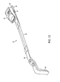
- the angle grinder 10 preferably includes a housing 12 having a handle portion 14, a field case 16, and a gear case 18.
- the handle portion 14 is preferably fixedly attached to a first end 20 of the field case 16 and the gear case 18 is preferably fixedly attached to a second end 22 of the field case 16.
- the handle portion 14 preferably supports a switch 24 and associated components.
- the handle portion 14 also preferably supports a particle separation assembly 26.
- the field case 16 preferably supports a motor 28 having a motor spindle 30 that extends into the gear case 18 for driving gearset 32 supported therein.
- a wheel spindle 34 preferably extends from gear case 18 and is driven by the motor spindle 30 through the gearset 32.
- the axis of rotation of motor spindle 30 is generally perpendicular to the axis of rotation of the wheel spindle 34.
- a grinder wheel 36 is preferably selectively attachable to the wheel spindle 34 and is rotatably driven thereby.
- the motor 28 may also have a second spindle 38 that extends into the handle portion 14 for rotatably driving a fan 40, associated with the particle separation assembly 26.
- the motor 28 preferably is in electrical communication with the switch 24 through wires (not shown).
- the switch 24 is further in electrical communication with a power source via a cord 42 including a plug (not shown).
- the handle portion 14 preferably includes an opening 44, opposite the connection end, through which the cord 42 runs.
- a trigger 46 preferably is in mechanical communication with the switch 24 for selectively supplying power to the motor 28. Mechanical actuation of the trigger 46 preferably results in actuation of the switch 24 thereby resulting in operation the angle grinder 10.
- the paddle trigger 48 preferably includes a paddle portion 50 with a first arm 52 extending therefrom.
- a second arm 54 preferably extends upward from and generally perpendicular to the first arm 52.
- a face 56 of the second arm 54 may be in contact with the switch 24 for selectively actuating the switch 24.
- Pivot posts 58 perpendicularly extend from either side of the first arm 52.
- the pivot posts 58 are received into apertures 60 of the handle portion 14 for facilitating pivotal support of the paddle trigger 48.
- the paddle trigger 48 is biased to an OFF position as shown in FIGS. 4 and 5.
- Switch 24 preferably includes a biasing member such as a spring (not shown) to bias the paddle trigger 48 to the OFF position.
- a biasing member such as a spring (not shown) to bias the paddle trigger 48 to the OFF position.
- depression of the paddle portion 50 toward the handle portion 14 preferably pivots the paddle trigger 48, pivoting the first and second arms 52, 54. Second arm 54 pivots towards switch 24 operating the switch to ON, thus initiating operation of the angle grinder 10.
- a locking member 60 may further be included and is used to engage the trigger paddle 48 locking the trigger paddle 48 in a depressed position, thereby keeping the angle grinder 10 continuously activated.
- locking member 60 preferably is slideably supported within the handle portion 14.
- Locking member 60 is preferably supported by a plurality of housing surfaces 62, 64a-g, 66 on both ends thereby minimizing the degrees of freedom of movement for the locking member 60. By minimizing the degrees of freedom of movement, the locking member 60 is more securely supported in the handle portion 14 providing a stronger and more durable interface with the trigger paddle 48.
- the locking member 60 preferably has a head portion 66 for user interface and a body portion 68 which includes a collar 70 for abutment with a biasing member.
- a biasing member 72 such as a spring, is preferably included to bias the locking member 60 in an outwardly or unengaged position.
- the locking member 60 may also have a lock protrusion 74 designed to engage a bracket 76 (shown in FIG. 9) located on the second leg 54 of the trigger paddle 48.
- the locking member 60 is shown engaging the trigger paddle 48.
- a user preferably depresses the paddle trigger 48 towards handle portion 14 and pushes the locking member 60 inwardly engaging the lock protrusion 74 of the locking member 60 and the bracket 76 of the trigger paddle 48.
- the lock protrusion 74 and the bracket 76 do not disengage once engaged.
- the user preferably further depresses the trigger paddle 48 toward the handle portion 14 disengaging the lock protrusion 74 from the bracket 76 thereby disengaging locking member 60 and trigger paddle 48.
- the biasing force of the biasing member 72 returns the locking member 60 to its unengaged position and the biasing force from the biasing member of the switch 24 returns the trigger paddle 48 back to the OFF position.
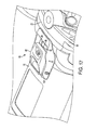
- the slider button trigger 80 preferably includes a slider button 82 attached to a first link member 84 via posts 90.
- a second link member 86 is fixedly attached to the first link member 84, however, in an alternate embodiment, there may only be one link member.
- a face 88 of the second link member 86 may be in contact with the switch 24 for selectively actuating the switch 24.
- Posts 90 preferably extend from the under side of the slider button 82 through an aperture 94 of an engagement member 92 of the field case 16 for sliding movement of the slider button trigger 80.
- the engagement member 92 is preferably fixedly attached to the field case 16 of angle grinder 10 and has a first end 93 and second end 95. In a preferred embodiment, the engagement member 92 is formed from metal.
- the first link member 84 of the slider button trigger 80 has a generally diamond-shaped profile. This shape assists in preventing jamming of the sliding movement of slider button trigger 80 resulting from the presence of artifacts, particles, or dust that may have entered into the housing 12 of the angle grinder 10.
- the second link member 86 in a preferred embodiment, is formed from metal to reduce any deformation of shape of the second link member 86 and to further reduce any jamming of the sliding movement of the slider button trigger 80 resulting from the presence of artifacts, particles, or dust that may have entered into the housing 12 of the angle grinder 10.
- the slider button 82 may be molded onto an insert 96, preferably made from metal, having a hook portion 98. Slider button 82 also may include a pivot 100 which preferably is integral with or fixedly attached to the slider button 82. As described below, these features assist in the actuation of the angle grinder 10.
- the slider button trigger 80 is biased to an OFF position as shown in FIGS. 13, 15 and 17 through 18.
- Switch 24 preferably includes a biasing member such as a spring (not shown) to bias the slider button trigger 80 to the OFF position.
- a biasing member such as a spring (not shown) to bias the slider button trigger 80 to the OFF position.
- sliding movement of the slider button trigger 80 towards the second end 22 of the field case 16 preferably moves the second link member 86, the first link member 84, slider button 82, and insert 96 toward the second end 22 of the field case 16.
- the sliding movement of the second link member 86 towards switch 24 operates the switch to ON, thus initiating operation of the angle grinder 10.
- the slider button trigger 80 may also include a pivoting feature that allows the slider button trigger 80 to engage a portion of the field case 16 after it has been slidingly moved toward the second end 22 of the field case 16, locking it in place, thereby keeping the angle grinder 10 continuously activated.
- the slider button trigger 80 is shown in the locked position.
- a user slideably moves the slider button trigger 80 towards the second end 22 of the field case 16.
- the slider button 82 as well as the insert 96 slide and pivot with respect to the field case 16.
- the rear portion of slider button 82 pivots upwardly away from the field case 16 while the front portion of slider button 82 and insert 96 pivot downwardly toward the field case 16 about pivot 100.
- the sliding and pivoting movement allows the hook 98 of the insert 96 to engage the second end 95 of the engagement member 92, locking the slider button trigger 80 in place. Since both the engagement member 92 and the insert 96 are preferably made from metal, the wear on the engaging portions of these structures is reduced.
- a user preferably depresses the rear portion of the slider button 82 toward the field case 16. This pivots the front end of the slider button 82 and the insert 96 upwardly away from the field case 16 disengaging the hook 98 of the insert 96 from the second end 95 of the engagement member 95, thereby disengaging slider button trigger 80.
- the biasing force from the biasing member of switch 24 returns the slider button trigger 80 back to the OFF position.
- the pivoting feature of the slider button trigger 80 may also assist in preventing jamming of the slider button trigger 80 during use.
- the slider button 82 pivots with respect to the field case 16.
- the rear portion of slider button 82 pivots upwardly away from the field case 16 pulling the posts 90 as well as the first link member 84 upwardly. This results in the first link member 84 and the second link member 86 contacting the inner surface of the housing 12 as the slider button trigger 80 is slideably moved.
- the downward pivoting of the rear portion of the slider button 82 results in the downward movement of the posts 90 and the first link member 84. This results in the first link member 84 and the second link member 86 moving downwardly away from the inner surface of the housing 12.
- first and second link members 84, 86 The contact and non-contact of the first and second link members 84, 86 with the inner surface of the housing 12 will dislodge and allow for the escape of any artifacts, particles or dust that may have attached to the inner surface of the housing 12 or may have attached to the first and second link members 84, 86.
- the slider button 82 may be molded and/or shaped for easier interfacing by the user.
- a portion 101 of the field case 16 surrounding the slider button 82 may also be molded and/or shaped, for example in an recessed, arcuate fashion, to allow for greater access to the slider button 82 by a user.
- a second aperture 104 may be included in the field case 16 for assisting with the evacuation of any dust, particles, or artifacts that may have entered into the housing 12 of the angle grinder 10.
- the second aperture 104 may be located proximate to aperture 94, near the second end 22 of the field case 16.
- Aperture 94 and second aperture 104 are preferably disposed in functional positions with respect to a front fan 106 located in the field case 16.
- angle grinder 10 includes an airflow assembly for circulating air through the field case 16.
- the airflow assembly preferably includes a baffle 108 located between the motor 28 and the field case 16 and the front fan 106.
- the baffle 108 and the fan 106 create a high-pressure zone around the fan 106 and a low-pressure zone behind the baffle 108 and the fan 106.
- any artifacts, particles, or dust that enter into angle grinder 10 via the aperture 94 are directed towards and blown out the second aperture 104 rather than blown towards the motor 28.
- This arrangement helps prevent jamming of the slider button trigger 80 and, more specifically, helps prevent the jamming of the slider button 82 with respect to the field case 16. This arrangement also helps reduce the ingestion and buildup of artifacts, particles, or dust in the housing 12 of the angle grinder 10.
- angle grinder 10 may include a particle separation assembly 26 located in the handle portion 14.
- the particle separation assembly 26 is also designed to remove any artifacts, particles, or dust that may have been ingested by the angle grinder 10.
- the particle separation assembly 26 includes a fan 40, a baffle 114, and an exhaust channel 116.
- a channel or raceway integral with the inner surface of handle portion 14 may be used to collect the ingested artifacts, particles, or dust.
- the particle separation assembly 26 may be driven by the motor 28.
- the fan 40 may be axially connected to the motor 28 via the second motor spindle 38.
- the motor 28 via second motor spindle 38 may be rotatably driven fan 40.
- the rotation of the fan 40 creates a twisting or rotational air current which draws air from the handle portion 14 of the angle grinder 10 and pushes it out of the exhaust channel 116.
- the twisting or rotational air current also results in the creation of centrifugal forces which moves any artifacts, particles, or dust that may have been ingested by the angle grinder 10 outwardly into a channel 118 of the baffle 114.
- the blades 41 of the fan 40 may also physically contact the ingested artifacts, particles, or dust pushing them into the channel 118 of the baffle 114.
- the exhaust channel 116 is preferably in communication with channel 118 of the baffle 114, so any artifacts, particles, or dust that are drawn into channel 118 are then pushed out of the angle grinder 10 via an exit in the exhaust channel 116.
- the geometry of exhaust channel 116 changes from first end 120 to second end 122.
- the dimensions of the exhaust channel 116 gradually increase from the first end 120 to the second end 122, thus the area of the exhaust channel 116 gradually increases from the first end 120 to the second end 122.
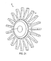
- the fan 40 of the particle separation assembly 26 is shown.
- the blades 41 of the fan 40 can be thinned to reduce the speed of the air exiting the exhaust channel 116.
- the blades 41 of the fan 40 can be pitched or angled to increase the air speed exiting the exhaust channel 116.
- the fan 40 may also include a labyrinth feature 43 to seal and protect the bearing 39 located on second motor spindle 38 from the artifacts, particles, or dust ingested by the angle grinder 10.
- the fan 40 has a generally cylindrical opening 45 for receiving the second motor spindle 38.
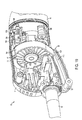
- the motor 28 in the angle grinder 10 may preferably be a universal series motor of a type commonly known in the art.
- the motor 28 generally includes the motor spindle 30, the second motor spindle 38, a motor armature, a field pole, field windings, a commutator 129, at least one brush holder assembly 130, and at least one electrical lead 132.
- the electrical lead 132 links the brush 134 to the switch 24 for selective connection with a power source. More specifically, the brush 134, via the electrical lead 132 and wires 133 (not shown), provides the electrical connection between the rotating commutator 129 and the stationary switch 24 for providing power to the motor 28.
- the brush 134 In order for the motor 28 to function properly and perform efficiently, the brush 134 should constantly and evenly contact the commutator 129. Additionally, during the life of the motor 28, the brush 134 gradually wears. Therefore, a compensation device, such as a spring 136, is included to continually press the brush 134 into contact with the commutator 129. Furthermore, the brush holder assembly 130 is pivotably attached to the housing in the handle portion 14 of the angle grinder 10 to allow the brush 134 to move as it wears.
- the brush holder assembly 130 includes the brush 134 and a brush arm 138.
- the brush arm 138 preferably is comprised of a base portion 140, an arm portion 142, and a brush engaging portion 144.
- the brush engaging portion 144 includes a channel 145 for receiving an end of the spring 136 and the base portion 140 includes a generally cylindrical opening 141 for pivotably receiving a portion of the housing 12.
- the base portion 140 also preferably includes rings 146, made from felt or similar material, to prevent jamming of the pivoting motion of the brush arm 138.
- the rings 146 are preferably axially received on the base portion 140 of the brush arm 138.
- the brush arm 138 is made from a non-conductive material such as plastic.
- the brush arm 138 as well as the spring 136 are insulated and not part of the electrical connection between the switch 24 and the brush 134.
- a problem that has existed with angle grinders is that during operation, there is a possibility that heated grinding artifacts may be ingested by the angle grinder. Once ingested, these heated artifacts, typically attracted to the live portions of the electrical connection between the brush and the switch, accumulate and sinter in that location, eventually melting and destroying the housing in that area.
- By removing the spring and brush arm from the electrical path there are fewer live portions and consequently a smaller attraction area for the ingested heated artifacts. As a result, the ingested particles do not accumulate and sinter in a single location.
- a pivoting feature and the compensation device is used to ensure that the brush 134 is constantly and evenly contacting the commutator 129.
- the brush arm 138 may also be dimensioned in such a fashion as to further ensure the brush 134 is in even and constant with the commutator 129.
- the length of the arm portion 142 along with the location of the pivot point in the base portion 140 of the brush arm 138 can be determined such that a constant connection between the brush 134 and the commutator 129 is further ensured.
- the brush 134 may be attached to the brush arm 138 via a brush box (not shown) rather than being directly connected to the brush arm 138 via the brush engaging portion 144.
- angle grinder 10 may include a tactile overload indicator to warn the user of possible overloading on the motor 28.
- the angle grinder 10 has a grinder wheel 36 that is driven by the motor 28.
- the grinder wheel 36 while cutting through the desired material, may slow down or get stuck on the material being cut. This results in extra loading on the motor which could result in a shorter life for the motor 28.
- the angle grinder 10 may include the overload indicator.
- the overload indicator is a module 150 wired into the circuitry that provides power to the motor 28 of the angle grinder 10.
- the module 150 is located in series with the switch (paddle trigger 48 or slider button trigger 80) and via an included sensor, the module 150 detects current surges that result from the overloading of the motor 28. When a current surge is detected, the module 150 pulses providing the user with a tactile warning of the overload on the motor 28. As long as the current surge is present, the module 150 will continue to pulse for a programmed amount of time. Once that programmed amount of time has lapsed, the module 150 will stop pulsing. In another preferred embodiment, the module 150 will automatically cut the power to the motor 28 once the programmed amount of time has lapsed.
- angle grinder 10 may also include a spindle lock assembly 160 in the gear case 18 to assist the user with removal of the grinder wheel 36.
- the spindle lock assembly 160 preferably includes a spindle lock 162 and a locking pin 168.
- the spindle lock 162 is axially disposed on the wheel spindle 34 below driving gearset 32.
- spindle lock 162 cannot rotate independently of the wheel spindle 34.
- the spindle lock 162 preferably includes channels 164 for receiving the locking pin 168. Channels 164 may also include a raised feature such as ramps 166 located along the sides of channels 164.
- the ramps 166 are designed to prevent the locking pin from engaging channels 164 if the spindle lock 162 has a rotational speed that is too great. This prevents the user from accidentally engaging the spindle lock 162 and damaging the spindle lock 162 or the locking pin 168.
- the locking pin 168 preferably includes a head portion 170, for user interface, attached to a pin portion 172.
- a biasing member such as spring 174 is located around the pin portion 168, proximate to the head portion 166. The biasing member biases the locking pin 168 outwardly, away from the spindle lock 162.
- the locking pin 168 is preferably disposed in the gearcase 18 in a diagonally offset position. Furthermore, the locking spindle 162 is preferably formed so that channels 164 are angled to receive the locking pin 168 in the diagonally offset position.
- the diagonal offset placement of the locking pin 168 offers both structural and ergonomic advantages. Structurally, the diagonal placement of the locking pin 168 allows the locking pin 168 to be located in a stronger section of the gearcase 18. Ergonomically, the diagonal placement of the locking pin 168 allows the locking pin 168 to be located in a position that allows the user to simultaneously grip the angle grinder 10 and the locking pin 168 more easily than the prior art grinders.
- the spindle lock assembly 160 is used to assist with removal of the grinder wheel 36.
- a user depressed the locking pin 168 by pushing the head portion 166 of the locking pin 168 inwardly with respect to the gear case 18. This moves the pin portion 172 diagonally downwards into one of the channels 164 of spindle lock 162. Once in the channel 164, the pin portion 172 of locking pin 168 abuts a side 165 of the channel 164 preventing spindle lock 162 and thus wheel spindle 34 from rotating. A user can then remove the grinder wheel 36 from the angle grinder 10.
- angle grinder 10 may also include an anti-locking flange assembly 180 in the gear case 18.
- the grinder wheel was held in place on the wheel spindle by two flanges, one on each side of the grinder wheel.
- the upper flange was slidingly received on the wheel spindle while the lower flange was threadingly received on the wheel spindle.
- the threadedly attached flange had a tendency to over-tighten. This over-tightening potentially resulted in the flanges, particularly the threadingly attached flange, locking on to the wheel spindle preventing the user from being able to remove the grinder wheel when it came time to change the grinder wheel.
- the anti-locking flange assembly 180 of the present invention is designed to prevent the flanges holding the grinder wheel 36 from over-tightening during operation of the angle grinder 10.
- the anti-locking flange assembly 180 preferably includes a truncated annular portion 182, having at least one truncated end 183, on the wheel spindle 34, an upper flange 184 and a lower flange 186.
- the truncated annular portion 182 has two truncated ends 183 located diametrically opposite to each other.
- the lower end of wheel spindle 34 preferably has a threaded portion 184.
- the truncated annular portion 182 slideably receives the upper flange 184 and the threaded portion 184 threadingly receives lower flange 186.
- the grinder wheel 36 is disposed between the upper flange 184 and the lower flange 186 on the wheel spindle 34.
- the upper flange 184 preferably has a first collar 188, a stepped, annular through-hole 190 for slideably receiving the truncated annular portion 182 of the wheel spindle 34, and a second collar 192 for receipt into a labyrinth feature in gear case 18, discussed below.
- the first collar 188 preferably has at least one, preferably two, protrusions 194 that extend from the first collar 188 toward the stepped, annular through-hole 190.
- the protrusion 194 has two engagement ends 196 that are disposed at an angle ranging between 140° and 170° with respect to each other. In a preferred embodiment, the angle between the engagement ends 196 is 165°.
- the protrusion 194 and the truncated annular portion 182 of the wheel spindle 34 assist in preventing the flanges holding the grinder wheel 36 from over-tightening during operation of the angle grinder 10.
- the upper flange 184 may also have a collar 200 (shown in FIG. 1) on its end 198.
- the collar 200 may be used to assist in centering the grinding wheel 36 on wheel spindle 34.
- the upper flange 184 may also include an elastomeric material on its end 198 to dampen the impact the grinder wheel 36 may impart on the threaded coupling joint between the spindle wheel 34 and the lower flange 186.
- the upper flange 184 may also include a lubricious material coating, such as nickel Teflon, on its end 198 to reduce the amount of torque necessary to remove the grinder wheel 36.
- the lower flange 186 preferably has a first surface 204, a second surface 206 and an outer surface 208.
- the outer surface 208 may include texturing, such as knurls, to facilitate the removal of the lower flange 186.
- the lower flange 186 also preferably has a stepped, annular through-bore 210 for receiving the wheel spindle 34. In a preferred embodiment, at least a portion of the through-bore 210 is threaded for threaded engagement with the threaded portion 184 of wheel spindle 34.
- the lower flange 186 may include a collar 214. The collar 214 can be used to assist in centering the grinding wheel 36 on wheel spindle 34.
- the lower flange 186 may also include tool-engaging structures such as aperture 212 to allow the lower flange 186 to be removed using a tool.
- the lower flange 186 in a preferred embodiment, has a generally annular shape. However, in alternate embodiments, the lower flange 186 may have any shape that facilitates its removal by a user. For example, the lower flange 186 may be shaped to include a plurality of sides rather than being annular. In another embodiment, the lower flange 186 may be toroidal with a central diameter that is larger than the diameter near first surface 204 and second surface 206.
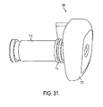
- lower flange 186 may have a biased lever 213 to assist in the removal of the flange. The user can use the lever 213 to provide the necessary torque to remove the lower flange 186.
- the lower flange 186 preferably includes a cup portion 219 and a cover portion 221 disposed on the cup portion 219, preferably, forming a toroid.
- the lower flange 186 also has a stepped, annular through-bore 210 for receiving the wheel spindle 34. In a preferred embodiment, at least a portion of the through-bore 210 is threaded for threaded engagement with the threaded portion 184 of wheel spindle 34.
- a biasing member 223, such as a disc spring, may be disposed within lower flange 186.
- the biasing member 223 interacts with a leg portion 225 of the lever 217 to keep the lever 217 in one of the following two positions: the first position is an outward position; generally perpendicular to first surface 204 of the lower flange 186, and the second position is a flush position, where the lever 217 is flush with the first surface 204 of the lower flange 186.
- the lever 217 may also include pivot protrusion 227 to keep the lever 217 attached to the lower flange 186.
- the anti-locking flange system 180 is designed to prevent the flanges holding the grinder wheel 36 from over-tightening during operation of the angle grinder 10.
- the wheel spindle 34 is shown slideably received in upper flange 184.
- at least a portion of the truncated end 183 of the truncated annular portion 182 of the wheel spindle 34 abuts at least a portion of the engagement end 196 of the protrusion 194, while a portion of the truncated end 183 does not abut anything.
- This partial abutment allows the upper flange 184 to rotate with respect to the wheel spindle 34 before abutment occurs.
- the ability of the upper flange 184 to partially rotate with respect to the wheel spindle 34 creates torsional play in the anti-locking flange assembly 180.
- the torsional play prevents the over-tightening of the assembly by transmitting at least a portion of the torsional loading.
- the upper flange 184 may have at least one truncated portion 300 and the wheel spindle 34 may have at least one truncated portion having an arcuate protrusion 302.
- This alternate embodiment also is designed to prevent the flanges holding the grinder wheel 36 from over-tightening during operation of the angle grinder 10.
- the lower flange 186 is threadingly received on the wheel spindle 34, and, in cooperation with the upper flange 184, is used to hold the grinder wheel 36 in place on the wheel spindle 34.
- the lower flange 186 may continue to tighten, thereby increasing the load on itself, the grinder wheel 36 and the upper flange 184.
- the user would find removal of the lower flange 186 and consequently the grinder wheel 36 to be very difficult.
- the torsional play in the anti-locking flange assembly 180 allows the upper flange 184 and the threadingly attached flange 186 to move several degrees with respect to the wheel spindle 34, decreasing the load on the lower flange 186.
- This decrease in load results in the reduction of the continued tightening the assembly experiences while the angle grinder 10 is being used, allowing the user to more easily remove the grinder wheel 36.
- anti-locking flange assembly 180 may include an accessory interfacing member (not shown).
- the accessory interfacing member is preferably disposed between the upper flange 184 and the lower flange 186 and interfaces with an accessory such as the grinder wheel 36.
- the accessory interfacing member preferably has a threaded through bore for engagement with the wheel spindle 34.
- one side of the interface member is flat for increased bearing contact with an accessory that is threadably attachable while the other side of the member has a piloting flange for contact with an accessory that is slideably attachable via a pilot hole.
- the accessory interfacing member may be made from an elastomeric material for increased compliance or may be made from a more traditional material such as plastic or metal.
- the angle grinder 10 in a preferred embodiment, may include a labyrinth feature in the gear case 18 to minimize the dust and debris that may reach the wheel spindle bearing 230.
- the upper flange 184 includes the second collar 192 which extends into a groove 232 in the gear case 18 forming the labyrinth feature.
- the angle grinder 10 has a grinder wheel 36 that is driven by the motor 28.
- the grinder wheel 36 while cutting through the desired material, may slow down or get stuck on the material being cut. This results in extra loading on the motor which could result in a shorter life for the motor 28.
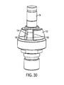
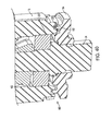
- angle grinder 10 may include a clutch mechanism 240.
- the clutch mechanism 240 is located on the wheel spindle 34 proximate to driving gearset 32 and includes a clutch member 242, a biasing member 244, and wheel spindle gear 246.
- a nut member 248 is disposed on the wheel spindle 34 to abut the biasing member 244.
- the wheel spindle gear 246, via a through-bore, is rotationally disposed on the wheel spindle 34, so that it can rotate independent of the wheel spindle 34.
- the wheel spindle 34 extends through and beyond the wheel spindle gear 246.
- the wheel spindle gear 246 engages with and is driven by motor spindle gear 248.
- Motor spindle gear 248 is attached to motor spindle 30 which is driven by motor 28.
- the wheel spindle gear 246 also includes an aperture having a preferably cone shaped contact surface 250 for engaging the clutch member 242.
- the clutch 242 is rotationally connected to the wheel spindle 34, so the clutch 242 cannot spin independently of the wheel spindle 34. However, the clutch 242 can slide along the longitudinal axis of the wheel spindle 34.
- the biasing member 244 biases the clutch member 242 towards the wheel spindle gear 246.
- the clutch member 242 is also preferably conically shaped and frictionally engages the conical surface 250 of the wheel spindle gear 246 when biased towards the wheel spindle gear 246. When the clutch member 242 and the wheel spindle gear 246 contact each other, the wheel spindle 34 rotates together with the wheel spindle gear 246.
- the rotational speed difference between the motor spindle 30 and the wheel spindle 34 will result in the frictional force that rotationally holds the clutch 242 together with the wheel spindle gear 246 being overcome and the clutch 242 slipping with respect to the wheel spindle gear 246.
- the motor spindle 30 and motor spindle gear 248 can continue rotating at its normal speed while the wheel spindle 34 will stop rotating. This will prevent any overloading on the motor 28.
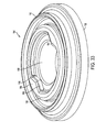
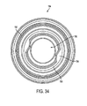
- a tolerance ring 250 may be used as a clutch mechanism.
- the tolerance ring 250 is fixedly attached to the wheel spindle 34 and cannot move independent to the wheel spindle 34.
- the wheel spindle gear 246 is disposed around the tolerance ring as can be seen in FIG 43.
- the tolerance ring 250 has a generally sinusoidal shape and functions as a biasing member providing an outwardly biasing force frictionally engaging the wheel spindle gear 246.
- the tolerance ring 250 operates in a similar manner to the clutch member 242, such that if there is a great enough rotational speed difference between the motor spindle 30 and the wheel spindle 34, the frictional force that rotationally holds the tolerance ring 250 together with the wheel spindle gear 246 will be overcome and the tolerance ring 250 will slip with respect to the wheel spindle gear 246 allowing the motor spindle 30 and motor spindle gear 248 to continue rotating at its normal speed while the wheel spindle 34 will stop rotating.
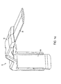
- the angle grinder 10 may also include ergonomic features on the housing 12 of the angle grinder 10.
- the handle portion 14 of the angle grinder 10 may include an ergonomic saddle feature 15 which is a depression in the housing 12 designed to allow the base of the palm of the user's hand to rest thereon. This allows for a more comfortable grip of the angle grinder 10.
- the angle grinder 10 may also include an arcuate portion 17 on the field case 16.
- This arcuate portion 17 is curved to match the curve formed by the user's hand when holding the field case 16 of the angle grinder 10.
- the curve of the arcuate portion 17 on field case 16 provides the user with a better ergonomic fit, thereby reducing the user's hand fatigue.
- the angle grinder 10 may also include an arcuate front portion of the gear case 18. This arcuate front portion allows the user to get closer to the workpiece for the cutting, grinding, or sanding of the workpiece.
Landscapes
- Engineering & Computer Science (AREA)
- Mechanical Engineering (AREA)
- Power Engineering (AREA)
- Finish Polishing, Edge Sharpening, And Grinding By Specific Grinding Devices (AREA)
- Braking Systems And Boosters (AREA)
- Valve Device For Special Equipments (AREA)
- Cutting Tools, Boring Holders, And Turrets (AREA)
- Surface Acoustic Wave Elements And Circuit Networks Thereof (AREA)
- Magnetic Heads (AREA)
- Portable Power Tools In General (AREA)
Applications Claiming Priority (3)
| Application Number | Priority Date | Filing Date | Title |
|---|---|---|---|
| US68062105P | 2005-05-13 | 2005-05-13 | |
| US11/409,904 US8087977B2 (en) | 2005-05-13 | 2006-04-24 | Angle grinder |
| EP06113426A EP1724057A3 (fr) | 2005-05-13 | 2006-05-03 | Meuleuse d'angle |
Related Parent Applications (1)
| Application Number | Title | Priority Date | Filing Date |
|---|---|---|---|
| EP06113426A Division EP1724057A3 (fr) | 2005-05-13 | 2006-05-03 | Meuleuse d'angle |
Publications (2)
| Publication Number | Publication Date |
|---|---|
| EP1728591A2 true EP1728591A2 (fr) | 2006-12-06 |
| EP1728591A3 EP1728591A3 (fr) | 2007-02-14 |
Family
ID=36956063
Family Applications (8)
| Application Number | Title | Priority Date | Filing Date |
|---|---|---|---|
| EP06116907A Withdrawn EP1728591A3 (fr) | 2005-05-13 | 2006-05-03 | Meuleuse d'angle |
| EP09162667A Not-in-force EP2095907B1 (fr) | 2005-05-13 | 2006-05-03 | Outil électrique |
| EP06116908A Not-in-force EP1728592B1 (fr) | 2005-05-13 | 2006-05-03 | Meuleuse d'angle |
| EP06116913A Withdrawn EP1724059A3 (fr) | 2005-05-13 | 2006-05-03 | Meuleuse d'angle |
| EP06116910A Withdrawn EP1724058A3 (fr) | 2005-05-13 | 2006-05-03 | Meuleuse d'angle |
| EP06116915A Withdrawn EP1724060A3 (fr) | 2005-05-13 | 2006-05-03 | Meuleuse d'angle |
| EP08103026A Withdrawn EP1950006A1 (fr) | 2005-05-13 | 2006-05-03 | Meuleuse angulaire |
| EP06113426A Withdrawn EP1724057A3 (fr) | 2005-05-13 | 2006-05-03 | Meuleuse d'angle |
Family Applications After (7)
| Application Number | Title | Priority Date | Filing Date |
|---|---|---|---|
| EP09162667A Not-in-force EP2095907B1 (fr) | 2005-05-13 | 2006-05-03 | Outil électrique |
| EP06116908A Not-in-force EP1728592B1 (fr) | 2005-05-13 | 2006-05-03 | Meuleuse d'angle |
| EP06116913A Withdrawn EP1724059A3 (fr) | 2005-05-13 | 2006-05-03 | Meuleuse d'angle |
| EP06116910A Withdrawn EP1724058A3 (fr) | 2005-05-13 | 2006-05-03 | Meuleuse d'angle |
| EP06116915A Withdrawn EP1724060A3 (fr) | 2005-05-13 | 2006-05-03 | Meuleuse d'angle |
| EP08103026A Withdrawn EP1950006A1 (fr) | 2005-05-13 | 2006-05-03 | Meuleuse angulaire |
| EP06113426A Withdrawn EP1724057A3 (fr) | 2005-05-13 | 2006-05-03 | Meuleuse d'angle |
Country Status (10)
| Country | Link |
|---|---|
| US (5) | US8087977B2 (fr) |
| EP (8) | EP1728591A3 (fr) |
| JP (1) | JP2006315172A (fr) |
| KR (5) | KR100818326B1 (fr) |
| CN (3) | CN102069442B (fr) |
| AT (2) | ATE417702T1 (fr) |
| AU (1) | AU2006201841A1 (fr) |
| CA (1) | CA2544958A1 (fr) |
| DE (2) | DE602006017279D1 (fr) |
| NZ (1) | NZ546986A (fr) |
Families Citing this family (77)
| Publication number | Priority date | Publication date | Assignee | Title |
|---|---|---|---|---|
| US8087977B2 (en) * | 2005-05-13 | 2012-01-03 | Black & Decker Inc. | Angle grinder |
| US8277292B2 (en) | 2007-04-30 | 2012-10-02 | Whelan Patrick J | Inline handheld power tool |
| JP2010000565A (ja) * | 2008-06-19 | 2010-01-07 | Hitachi Koki Co Ltd | ねじ締め機 |
| BRPI0817072A2 (pt) * | 2007-10-02 | 2015-03-24 | Hitachi Koki Kk | Ferramentas acionadas por energia |
| EP2103394A1 (fr) * | 2008-03-18 | 2009-09-23 | X'Pole Precision Tools, Inc. | Outil double action à transmission automatique |
| DE102008041716A1 (de) * | 2008-08-29 | 2010-03-04 | Robert Bosch Gmbh | Handwerkzeugmaschine mit Bürstenmotor |
| JP5255959B2 (ja) * | 2008-09-03 | 2013-08-07 | 株式会社マキタ | 作業工具 |
| US20110039482A1 (en) * | 2009-07-29 | 2011-02-17 | Terry Timmons | Grinder |
| US8418778B2 (en) | 2010-01-07 | 2013-04-16 | Black & Decker Inc. | Power screwdriver having rotary input control |
| US9259832B2 (en) * | 2010-08-25 | 2016-02-16 | Makita Corporation | Handheld electrical power tools |
| DE102010043182A1 (de) * | 2010-10-29 | 2012-05-03 | Robert Bosch Gmbh | Tragbare Werkzeugmaschine |
| DE102011076370A1 (de) | 2011-05-24 | 2012-11-29 | Robert Bosch Gmbh | Werkzeugmaschinenbremsvorrichtung |
| JP5826526B2 (ja) * | 2011-06-08 | 2015-12-02 | 株式会社マキタ | 電動工具 |
| US9120202B2 (en) | 2011-06-30 | 2015-09-01 | Black & Decker Inc. | Shield assembly for a power tool |
| US9481080B2 (en) | 2011-07-29 | 2016-11-01 | Black & Decker Inc. | Multispeed power tool |
| US11059160B2 (en) | 2011-07-29 | 2021-07-13 | Black & Decker Inc. | Multispeed power tool |
| US8905822B2 (en) | 2011-10-07 | 2014-12-09 | Black & Decker Inc. | Clamp nut |
| CN103379982B (zh) * | 2011-10-26 | 2016-12-21 | 凯德科株式会社 | 具有偏心转轴的研磨装置 |
| DE102011089717A1 (de) | 2011-12-23 | 2013-06-27 | Robert Bosch Gmbh | Werkzeugmaschinenschaltvorrichtung |
| DE102011089718A1 (de) * | 2011-12-23 | 2013-06-27 | Robert Bosch Gmbh | Werkzeugmaschine |
| DE102011089719A1 (de) * | 2011-12-23 | 2013-06-27 | Robert Bosch Gmbh | Elektrisch betreibbare Werkzeugmaschine |
| DE102012201593A1 (de) * | 2012-02-03 | 2013-08-08 | Robert Bosch Gmbh | Handwerkzeugmaschinenvorrichtung |
| DE202012002267U1 (de) * | 2012-03-07 | 2012-04-18 | Jakob Löwer Inh. von Schumann GmbH & Co. KG | Tellerschleifer einer Vorrichtung zum Entgraten und/oder Verrunden von metallenen Werkstücken im Durchlaufverfahren |
| US8872049B2 (en) | 2012-04-18 | 2014-10-28 | Milwaukee Electric Tool Corporation | Trigger lock-on lock-off mechanism |
| EP2666595A1 (fr) * | 2012-05-22 | 2013-11-27 | Robert Bosch Gmbh | Train planétaire avec embrayage de protection |
| US9143015B2 (en) | 2012-05-23 | 2015-09-22 | Black & Decker Inc. | Brush holder for a brush assembly for a power tool motor |
| KR101269303B1 (ko) * | 2012-08-13 | 2013-05-29 | 최병근 | 표면 처리 장치 |
| US9956676B2 (en) | 2013-01-09 | 2018-05-01 | Techtronic Power Tools Technology Limited | Tool with rotatable head |
| US9550283B2 (en) * | 2013-01-24 | 2017-01-24 | Ingersoll-Rand Company | Power tool with spindle lock |
| US9755368B2 (en) * | 2013-07-19 | 2017-09-05 | Foxconn Interconnect Technology Limited | Flippable electrical connector |
| DE102013215821A1 (de) * | 2013-08-09 | 2015-02-12 | Robert Bosch Gmbh | Handwerkzeugmaschine mit einem elektromotorischen Antrieb als Direktantrieb |
| US9289878B2 (en) * | 2013-08-30 | 2016-03-22 | Ingersoll-Rand Company | Grinders with friction drives |
| US20150159869A1 (en) * | 2013-10-31 | 2015-06-11 | Kurt W. Stevenson | Portable, solar rechargeable, battery powered, flameless igniting device |
| US9868199B2 (en) | 2014-01-29 | 2018-01-16 | Black & Decker Inc. | Paddle assembly on a compact sander |
| CN106456189B (zh) * | 2014-03-20 | 2019-02-15 | 史赛克公司 | 具有双手通用的安全开关的手术工具 |
| EP2923802A1 (fr) * | 2014-03-25 | 2015-09-30 | HILTI Aktiengesellschaft | Refroidissement de courroie |
| JP6277042B2 (ja) * | 2014-04-01 | 2018-02-07 | 株式会社マキタ | 電動工具 |
| JP6316649B2 (ja) * | 2014-05-09 | 2018-04-25 | 株式会社マキタ | 電動工具 |
| US9475172B2 (en) | 2014-07-15 | 2016-10-25 | Milwaukee Electric Tool Corporation | Adjustable guard for power tool |
| DE102014214982A1 (de) * | 2014-07-30 | 2016-02-04 | Robert Bosch Gmbh | Elektrowerkzeugmaschine |
| CN105437004A (zh) * | 2015-12-03 | 2016-03-30 | 成都格瑞思文化传播有限公司 | 新型建筑墙面打磨机 |
| US9889536B2 (en) | 2015-12-31 | 2018-02-13 | Brett George Bradshaw | Angle grinder control systems |
| DE102016209637A1 (de) * | 2016-06-02 | 2017-12-07 | Robert Bosch Gmbh | Handwerkzeugmaschine mit einer Schalteinheit |
| US10682714B2 (en) * | 2016-08-31 | 2020-06-16 | Robert Bosch Tool Corporation | Oscillating interface for an oscillating power tool |
| JP6692277B2 (ja) * | 2016-11-14 | 2020-05-13 | 株式会社ミツバ | アクチュエータおよび車両ドア開閉用アクチュエータ |
| DE102016224226A1 (de) * | 2016-12-06 | 2018-06-07 | Robert Bosch Gmbh | Handwerkzeugmaschine mit einer Spindellockvorrichtung |
| DE102017201311A1 (de) * | 2017-01-27 | 2018-08-02 | Robert Bosch Gmbh | Handwerkzeugmaschine |
| CN106625139B (zh) * | 2017-02-22 | 2018-07-06 | 浙江荣鹏气动工具有限公司 | 一种自带扳手的气动磨光机 |
| CN110678299A (zh) * | 2017-05-12 | 2020-01-10 | 杰尼斯·彼得罗维奇 | 用于电动工具冷却空气清洁的灰尘清洁设备 |
| JP6953803B2 (ja) * | 2017-05-31 | 2021-10-27 | 工機ホールディングス株式会社 | 電動工具 |
| US10818450B2 (en) | 2017-06-14 | 2020-10-27 | Black & Decker Inc. | Paddle switch |
| CN107756658A (zh) * | 2017-09-18 | 2018-03-06 | 陈彬 | 一种建筑用切割装置及其工作方法 |
| WO2019063752A2 (fr) | 2017-09-29 | 2019-04-04 | Saint-Gobain Performance Plastics Rencol Limited | Anneau de tolérance |
| CN108022771B (zh) * | 2017-12-19 | 2023-06-09 | 高斯(杭州)智能科技有限公司 | 一种磁力开关和机械式旋转手柄二合一装置 |
| DE102018202517A1 (de) * | 2018-02-20 | 2019-08-22 | Robert Bosch Gmbh | Positioniervorrichtung für eine Werkzeugmaschine, Werkzeugmaschine mit einer Positioniervorrichtung sowie Verfahren zu einer Positionierung einer Abtriebsspindel einer Werkzeugmaschine und/oder eines an der Abtriebsspindel der Werkzeugmaschine angeordneten Einsatzwerkzeugs |
| US10971966B2 (en) * | 2018-05-14 | 2021-04-06 | Black & Decker Inc. | Power tool with partition assembly between transmission and motor |
| US11813729B2 (en) | 2018-05-14 | 2023-11-14 | Black & Decker Inc. | Power tool with partition assembly between transmission and motor |
| DE102018208048A1 (de) * | 2018-05-23 | 2019-11-28 | Robert Bosch Gmbh | Handwerkzeugmaschine |
| USD891892S1 (en) * | 2018-06-14 | 2020-08-04 | Robert Bosch Gmbh | Angle grinder |
| CN110640589A (zh) * | 2018-06-26 | 2020-01-03 | 南京德朔实业有限公司 | 角磨和手持式电动工具 |
| CN108599510B (zh) * | 2018-07-09 | 2023-10-13 | 国网江苏省电力有限公司盐城供电分公司 | 一种螺丝刀具用无刷直流电机 |
| CN110932233B (zh) * | 2018-09-18 | 2022-08-02 | 南京泉峰科技有限公司 | 电动工具及其控制方法 |
| CN210115785U (zh) * | 2018-12-17 | 2020-02-28 | 米沃奇电动工具公司 | 角磨机 |
| US20210234492A1 (en) * | 2019-04-17 | 2021-07-29 | Milwaukee Electric Tool Corporation | Overload control in a power tool |
| USD892584S1 (en) | 2019-04-18 | 2020-08-11 | Harbor Freight Tools Usa, Inc. | Angle grinder |
| DE102019207976A1 (de) * | 2019-05-29 | 2020-12-03 | Robert Bosch Gmbh | Handwerkzeugmaschinenvorrichtung |
| US10946507B1 (en) * | 2019-10-04 | 2021-03-16 | Master Air Tool Co., Ltd. | Power tool |
| DE102019216863A1 (de) * | 2019-10-31 | 2021-05-06 | Robert Bosch Gmbh | Handwerkzeugmaschine |
| CN110990904B (zh) * | 2020-01-07 | 2020-08-04 | 黄河科技学院 | 用于云计算平台的安全防护接口装置 |
| CN113146434A (zh) * | 2020-01-07 | 2021-07-23 | 株式会社牧田 | 研磨机 |
| CN111775009B (zh) * | 2020-07-23 | 2022-05-24 | 佛山市文狮家居制品有限公司 | 一种木塑板材加工用打磨设备 |
| US20220063047A1 (en) * | 2020-08-28 | 2022-03-03 | Black & Decker Inc. | Retention flange for power tool |
| CN114649154B (zh) * | 2020-12-21 | 2023-08-04 | 南京泉峰科技有限公司 | 开关机构以及电动工具 |
| CN113182996B (zh) * | 2021-05-24 | 2022-09-16 | 有维科技(苏州)有限公司 | 一种具有减震及防尘功能的角磨机 |
| CN113547428A (zh) * | 2021-08-05 | 2021-10-26 | 中国十七冶集团有限公司 | 一种建筑修缮雕花修饰机 |
| CN115122210B (zh) * | 2022-07-11 | 2024-01-16 | 海安海太铸造有限公司 | 一种零部件铸造加工用的打磨抛光装置 |
| CN115338749B (zh) * | 2022-07-26 | 2023-08-25 | 高庆英 | 一种可自动扩大打磨面积与防止堵塞的汽车外壳打磨装置 |
Citations (3)
| Publication number | Priority date | Publication date | Assignee | Title |
|---|---|---|---|---|
| US4765099A (en) * | 1986-12-11 | 1988-08-23 | Tanner John G | Sanding and dust collecting apparatus |
| DE19800047A1 (de) * | 1997-02-27 | 1998-09-03 | Bosch Gmbh Robert | Elektrohandwerkzeug mit Staubabsaugung |
| DE10161616A1 (de) * | 2001-12-14 | 2003-06-26 | Bosch Gmbh Robert | Handwerkzeugmaschine mit Motorluftkühlung und Spanabsaugung |
Family Cites Families (402)
| Publication number | Priority date | Publication date | Assignee | Title |
|---|---|---|---|---|
| DE1073606B (de) | 1960-01-21 | Wilhelm Bender, CaIw (WÜrtt.) | Elektrisches Handwerkszeug mit von einer anderen Stelle herangeführter Kühlluft | |
| US394417A (en) | 1888-12-11 | Poele | ||
| US731740A (en) | 1902-03-24 | 1903-06-23 | Gen Electric | Commutator-brush. |
| DE429619C (de) | 1920-08-15 | 1926-05-31 | Siemens Schuckertwerke G M B H | Buerstenhalter mit unter Federkraft stehendem, schwingendem Tragarm |
| DE482136C (de) | 1927-12-17 | 1929-09-07 | Sachsenwerk Licht & Kraft Ag | Kuehlluftreinigungseinrichtung fuer elektrische Maschinen mit Durchzugsbelueftung, bei der die Kuehlluft mittels eines Ventilators in das Maschineninnere gesaugt wird |
| US1971790A (en) * | 1932-06-22 | 1934-08-28 | Arthur W Mall | Portable power tool |
| US2079143A (en) * | 1935-01-19 | 1937-05-04 | Albertson & Co Inc | Sanding machine |
| US2201420A (en) * | 1937-09-13 | 1940-05-21 | Wodack Electric Tool Corp | Abrading machine |
| US2192845A (en) | 1937-09-28 | 1940-03-05 | Gen Electric | Power unit |
| DE736475C (de) | 1940-06-20 | 1943-06-18 | Graetz Ag | Anordnung eines Wellenlagers in dem verjuengten Gehaeuse von Elektromotoren |
| US2348341A (en) | 1940-07-29 | 1944-05-09 | Chicago Electric Mfg Co | Motor |
| DE881831C (de) | 1942-09-01 | 1953-07-02 | Siemens Ag | Schleifbuerstenhalterung fuer Kommutatoren oder elektrische Schleifringanordnungen |
| DE923803C (de) | 1952-10-15 | 1955-02-21 | Ringsdorff Werke Gmbh | Buerstenhalter mit Buerste |
| US2987636A (en) | 1953-07-09 | 1961-06-06 | Sunbeam Corp | Electric mixer |
| US2987638A (en) * | 1954-08-26 | 1961-06-06 | Lux Clock Mfg Company Inc | Bearing construction for motors |
| DE944976C (de) | 1955-02-18 | 1956-06-28 | Joachim Csaki Dipl Ing | Filter fuer luftgekuehlte Maschine, insbesondere Elektrohandwerkzeugmaschine |
| DE1719274U (de) | 1955-05-26 | 1956-03-22 | Duss Maschf | Elektro-handschleifer. |
| DE1007870B (de) | 1956-01-30 | 1957-05-09 | Licentia Gmbh | Durch einen geschlossenen, mantelgekuehlten Kommutatormotor angetriebenes Elektrowerkzeug mit Aussenbelueftung |
| DE1006950B (de) | 1956-02-06 | 1957-04-25 | Alb Urbahn & Comp Werkzeug Und | Mittels Drehstrommotor angetriebenes Elektrowerkzeug |
| DE1030443B (de) | 1956-05-07 | 1958-05-22 | Wilhelm Bender | Elektromotor mit Staubfiltereinrichtung |
| US2905266A (en) * | 1957-08-16 | 1959-09-22 | Torit Mfg Company | Separators |
| DE1046169B (de) | 1957-09-12 | 1958-12-11 | Wilhelm Bender | Elektromotor mit Staubfiltereinrichtung |
| DE1763649U (de) | 1958-02-01 | 1958-03-20 | Continental Gummi Werke Ag | Antriebs- und foerderelement mit einem als zugorgan dienenden keilriemen. |
| DE1763401U (de) | 1958-02-03 | 1958-03-20 | Hermann Kaiser | Regenschutzbekleidung. |
| US3077340A (en) | 1958-08-25 | 1963-02-12 | Sunbeam Corp | Electric mixer |
| GB915808A (en) | 1959-07-09 | 1963-01-16 | Havilland Engine Co Ltd | Control in nuclear reactors |
| DE1110740B (de) | 1959-11-06 | 1961-07-13 | Bosch Gmbh Robert | Schutzisolierte elektrische Handwerkzeugmaschine mit Lagerschild und Getriebegehaeuse aus Metall |
| DE1887318U (de) | 1960-12-28 | 1964-02-13 | Ernst Stegmann | Bearbeitungs-, insbesondere biege- und stanzautomat fuer draht- und bandmaterial. |
| DE1843271U (de) | 1961-03-04 | 1961-12-14 | Schmid & Wezel | Intensiv-belueftung speziell fuer drehstromhandmotoren. |
| CH398768A (de) | 1961-11-13 | 1966-03-15 | Heemaf N V Aktiengesellschaft | Elektrische Maschine mit Luftkühlung und einem Staubabscheider |
| DE1154863B (de) | 1962-07-17 | 1963-09-26 | Wilhelm Bender | UEber den gesamten aeusseren Umfang eines Elektromotors, insbesondere fuer handgetragene Werkzeugmaschinen, sich erstreckendes Grossflaechenstaubfilter |
| CH406888A (de) | 1962-11-19 | 1966-01-31 | Suhner Willy | Elektro-Winkelhandschleifgerät mit Lüftung |
| US3305281A (en) * | 1963-07-19 | 1967-02-21 | Champ Items Inc | Idler arm repair kit |
| US3325948A (en) * | 1964-03-11 | 1967-06-20 | Skil Corp | Belt sander |
| US3266535A (en) * | 1964-06-01 | 1966-08-16 | Singer Co | Safety blade clamping means for portable power saws |
| DE1929390U (de) | 1965-10-14 | 1965-12-16 | Metabowerke Kg | Winkelschleifer. |
| CH456301A (de) | 1965-11-19 | 1968-07-15 | Mets Owerke Kg Closs Rauch & S | Elektrisch angetriebene Bohrmaschine |
| DE1932292U (de) | 1965-12-31 | 1966-02-10 | Maerklin & Cie Gmbh Geb | Buerstenfederung fuer kollektoren von elektrokleinstmotoren. |
| DE1952876U (de) | 1966-07-08 | 1967-01-05 | Wilhelm Bender | Ueber den aeusseren umfang eiens elektromotors sich erstrekkendes grossflaechenfilter, insbesondere fuer handgetragene werkzeugmaschinen. |
| US3474575A (en) * | 1967-01-18 | 1969-10-28 | Black & Decker Mfg Co | Housing and handle construction for a belt-type sander |
| US3535829A (en) * | 1968-05-21 | 1970-10-27 | Singer Co | Belt cleaners for belt sanders |
| US3530337A (en) | 1968-11-06 | 1970-09-22 | Thomas Moore | Electrical motor overload indicator and voltage cutout device |
| DE2007849C3 (de) * | 1970-02-20 | 1975-07-03 | Robert Bosch Gmbh, 7000 Stuttgart | Vorrichtung zum kraftschlüssigen Befestigen eines Zahnrades auf einer keillosen Welle |
| US3797336A (en) | 1970-03-02 | 1974-03-19 | W Howe | Quick connect nut |
| DE7010521U (de) | 1970-03-21 | 1971-08-26 | Bosch Gmbh Robert | Abschaltkohlebuerste. |
| DE2039793A1 (de) | 1970-08-04 | 1972-02-10 | Danow George Prof Dipl Ing | Buerstenapparat mit kastenloser Fuehrung und selbsteinstellbarer Buerste |
| DE7031833U (de) | 1970-08-26 | 1971-04-15 | Heid & Co Gmbh Kg Kohlebuerste | Halterung von kohlebuersten, insbesondere fuer schleifringe |
| JPS4838578B1 (fr) * | 1970-12-18 | 1973-11-19 | ||
| DE2156770C3 (de) | 1971-11-16 | 1974-06-20 | Hermann 7031 Maichingen Hefner | Vorrichtung zur lösbaren Befestigung einer Schleifscheibe oder dergleichen auf einer Treibspindel |
| US3731556A (en) | 1971-11-17 | 1973-05-08 | Cincinnati Milacron Inc | Dynamic balancing apparatus |
| DE2158598B2 (de) | 1971-11-26 | 1974-05-09 | Metabowerke Kg, Closs, Rauch & Schnizler, 7440 Nuertingen | Schmiervorrichtung für Getriebe mit Betrieb in allen Lagen |
| US3797338A (en) * | 1972-04-07 | 1974-03-19 | M Molnar | Machine for mass production of both medium and short lengths of tubing |
| US3824745A (en) | 1972-08-21 | 1974-07-23 | A Hutchins | Suction system for abrading tool |
| US3760570A (en) | 1972-09-05 | 1973-09-25 | Black & Decker Mfg Co | Centrifugally responsive brake for rotary tool |
| US4188288A (en) * | 1972-11-30 | 1980-02-12 | Hein, Lehmann Ag | Screen with tubular frame systems coupled for rectilinear motion |
| US3847233A (en) | 1973-06-29 | 1974-11-12 | Black & Decker Mfg Co | Trigger mechanism for hand-operated power device providing automatic lock-off and manual lock-on operation |
| US3854020A (en) | 1973-06-29 | 1974-12-10 | Black & Decker Mfg Co | Trigger mechanism for hand-operated power device including stationary locking device which provides lock-off and lock-on operation |
| US3873796A (en) | 1973-07-06 | 1975-03-25 | Black & Decker Mfg Co | Trigger mechanism for hand-operated power device including independently operable locking devices providing automatic lock off and manual lock-on operation |
| US3872951A (en) | 1973-11-06 | 1975-03-25 | Black & Decker Mfg Co | Spindle locking mechanism for rotary power device |
| US3866493A (en) * | 1974-04-01 | 1975-02-18 | Chester A Ringerud | Air-operated hand tool |
| US3961433A (en) | 1974-06-21 | 1976-06-08 | The Raymond Lee Organization Inc. | Picture poster viewer |
| US3899852A (en) | 1974-08-23 | 1975-08-19 | Singer Co | Spindle drive assembly for a surface-treating machine |
| US4007401A (en) | 1974-09-09 | 1977-02-08 | Westinghouse Electric Corporation | Current sensitive circuit protection system |
| US3902284A (en) * | 1974-12-17 | 1975-09-02 | Singer Co | Low profile blower assembly for portable belt sanders |
| US4020359A (en) | 1975-03-24 | 1977-04-26 | Davy Powergas Limited | Electrical control system |
| US3999176A (en) | 1975-04-07 | 1976-12-21 | Westinghouse Electric Corporation | Indicator light circuit providing normal and emergency indication |
| US4058936A (en) * | 1976-01-20 | 1977-11-22 | Miksa Marton | Vacuum sander |
| GB1519421A (en) | 1976-02-18 | 1978-07-26 | Trico Folberth Ltd | Brush mountings |
| DE2626003A1 (de) | 1976-06-10 | 1977-12-22 | Schulte Elektrotech | Mehrpoliger druckschalter mit ueberstromausloesung und unterspannungs- bzw. phasenausfallschutz |
| CH607574A5 (en) | 1976-08-13 | 1978-08-31 | Wachendorf L & Co Ag | Brush holder for electrical machines |
| NL7711072A (nl) | 1976-10-23 | 1978-04-25 | Textima Ag | Pers, in het bijzonder voor metaalbewerking. |
| DE7802306U1 (de) | 1977-02-10 | 1978-05-03 | Valentini, Guido, Vermezzo, Mailand (Italien) | Transportable, kreisende, elektrische schleifmaschine |
| DE7709148U1 (de) | 1977-03-24 | 1977-07-14 | Christian Geyer Gmbh & Co, 8500 Nuernberg | Abstandshalter für Leitungsdrähte in Dachständerrohren |
| DE2739982A1 (de) * | 1977-09-06 | 1979-03-22 | Bosch Gmbh Robert | Tragbare geradschleifmaschine |
| DE7728401U1 (de) | 1977-09-14 | 1979-07-19 | Marton, Miksa, Windsor, Ontario (Kanada) | Tellerhandschleifmaschine |
| US4420986A (en) * | 1977-11-01 | 1983-12-20 | K. K. Toyoda Jidoshokki Seisakusho | Sliding shoe for a rotatable swash-plate type refrigerant gas compressor |
| DE2850120A1 (de) | 1977-11-21 | 1979-05-23 | Black & Decker Mfg Co | Schalter-betaetigungseinrichtung |
| US4145848A (en) | 1978-01-24 | 1979-03-27 | Hutchins Manufacturing Co. | Rotary abrading tool |
| DE2813956B1 (de) | 1978-03-31 | 1979-04-26 | Siemens Ag | Kollektormotor mit einer in einer OEffnung des Motorgehaeuses fixierbaren Kunststoff-Buerstentragplatte |
| US4232414A (en) | 1978-07-10 | 1980-11-11 | Cooper Industries, Inc. | Free-wheeling overspeed grinder device |
| US4186288A (en) | 1978-09-01 | 1980-01-29 | Stackpole Components Company | Slide switch |
| US4681023A (en) * | 1978-10-25 | 1987-07-21 | Karl Eickmann | Slide bearing portions on outer faces of piston shoes |
| JPS5928151B2 (ja) | 1978-11-04 | 1984-07-11 | ファナック株式会社 | 電動機駆動用インバ−タ回路の保護方式 |
| US4205732A (en) * | 1979-03-07 | 1980-06-03 | Ingersoll-Rand Company | Muffler for portable pneumatic tool |
| DE2919669A1 (de) | 1979-05-16 | 1980-11-20 | Licentia Gmbh | Spannmutter fuer winkelschleifer |
| US4250587A (en) | 1979-07-02 | 1981-02-17 | Beck John W Jr | Scrubbing device |
| DE2927331A1 (de) | 1979-07-06 | 1981-02-05 | Bosch Gmbh Robert | Buerstenhalter mit buerstenabhebevorrichtung |
| DE3001907C2 (de) | 1980-01-19 | 1982-11-18 | Licentia Patent-Verwaltungs-Gmbh, 6000 Frankfurt | Einrichtung zum Arretieren der Antriebsspindel von Winkelschleifern und dergleichen handgeführter Elektrowerkzeuge |
| DE3004316C2 (de) | 1980-02-06 | 1983-12-29 | Skf Kugellagerfabriken Gmbh, 8720 Schweinfurt | Lagerung einer Welle eines Maschinenelementes |
| US4278371A (en) | 1980-02-29 | 1981-07-14 | Milwaukee Electric Tool Corporation | Safety interlock for electro-magnetic drill stand |
| US4568252A (en) * | 1980-03-07 | 1986-02-04 | Kabushiki Kaisha Toyoda Jidoshokki Seisakusho | Swash-plate type compressor |
| US4295295A (en) | 1980-03-17 | 1981-10-20 | Tyco Industries, Inc. | Pick-up shoe and motor contact assembly for toy vehicle |
| WO1981002767A1 (fr) * | 1980-03-28 | 1981-10-01 | Taiho Kogyo Co Ltd | Patin pour compresseur du type a plateau oscillant et son procede de fabrication |
| NL8003635A (nl) | 1980-06-24 | 1982-01-18 | Noord Ver Metaal | In de hand te houden inrichting voor het bijwerken van de klauwen van een of tweehoevige dieren, zoals koeien. |
| DE3023803A1 (de) | 1980-06-25 | 1982-01-21 | Siemens AG, 1000 Berlin und 8000 München | Kollektormotor |
| DE3023691A1 (de) | 1980-06-25 | 1982-01-21 | Robert Bosch Gmbh, 7000 Stuttgart | Schalter mit einem bedienmittel, insbesondere an einer handwerkzeugmaschine |
| US4334332A (en) | 1980-08-06 | 1982-06-15 | Downs Edgar S | Motor-driven cap-gripper and can-opener |
| DE3031915A1 (de) | 1980-08-23 | 1982-04-08 | Robert Bosch Gmbh, 7000 Stuttgart | Vorrichtung zum feststellen der abnutzung der kohlebuerste eines elektromotors |
| US4343502A (en) * | 1980-10-09 | 1982-08-10 | Ingersoll-Rand Company | Doorknob construction |
| US4434586A (en) | 1980-12-03 | 1984-03-06 | Robert Bosch Gmbh | Machine tool, especially a hand-held power tool with a turnable clamping element for clamping a tool on the tool spindle |
| DE3110912A1 (de) | 1981-03-20 | 1982-09-30 | Licentia Patent-Verwaltungs-Gmbh, 6000 Frankfurt | Spannvorrichtung fuer die schleifscheibe eines winkelschleifers |
| JPS57171601U (fr) * | 1981-04-24 | 1982-10-28 | ||
| DE3118831A1 (de) | 1981-05-12 | 1983-01-27 | Hans 8801 Schillingsfürst Heinlein | Filteranordnung |
| US4400995A (en) | 1981-09-23 | 1983-08-30 | Milwaukee Electric Tool Corporation | Spindle lock with impacting capability |
| CH653280A5 (de) | 1981-10-08 | 1985-12-31 | Ceka Elektrowerkzeuge Ag & Co | Schaltvorrichtung fuer den antriebsmotor eines elektrowerkzeuges. |
| US4536670A (en) | 1981-12-14 | 1985-08-20 | Morganite Incorporated | Electrical brushes with wear sensors |
| NL8200652A (nl) | 1982-02-18 | 1983-09-16 | Skil Nederland Nv | Elektromotor met verbeterde borstelkonstruktie. |
| DE8214078U1 (de) | 1982-05-14 | 1982-10-07 | Uhde Gmbh, 4600 Dortmund | Abstandshalter fuer rohrleitungen |
| JPS5923125U (ja) | 1982-08-03 | 1984-02-13 | アルプス電気株式会社 | スライドスイツチ |
| US4476602A (en) | 1982-08-13 | 1984-10-16 | Black & Decker, Inc. | Portable electric scrubber |
| JPS5930653U (ja) | 1982-08-20 | 1984-02-25 | マブチモ−タ−株式会社 | 小型モ−タのブラシ装置 |
| JPS5937859U (ja) | 1982-08-30 | 1984-03-09 | マブチモ−タ−株式会社 | ブラシ装置 |
| DE3317425A1 (de) | 1983-05-13 | 1984-08-09 | Daimler-Benz Ag, 7000 Stuttgart | Halterung fuer ein bearbeitungswerkzeug an einem roboterkopf |
| US4467896A (en) | 1983-06-17 | 1984-08-28 | Black & Decker Inc. | Locking mechanism for a rotary power machine |
| JPS6026188A (ja) * | 1983-07-20 | 1985-02-09 | Taiho Kogyo Co Ltd | 斜板式コンプレツサ |
| DE3328955A1 (de) | 1983-08-11 | 1985-02-21 | Robert Bosch Gmbh, 7000 Stuttgart | Winkelschleifer mit einer sicherheitskupplung |
| DE3341874C1 (de) | 1983-09-08 | 1984-07-19 | Schulte-Elektrotechnik GmbH & Co KG, 5880 Lüdenscheid | Schalteranordnung mit Nullspannungsauslösung |
| DE8327966U1 (de) | 1983-09-29 | 1984-01-26 | Karl M. Reich Maschinenfabrik GmbH, 7440 Nürtingen | Schaltschieber fuer elektrowerkzeuge |
| DE3336713A1 (de) | 1983-10-08 | 1985-04-25 | Mannesmann Rexroth GmbH, 8770 Lohr | Gleichlaufregelung fuer hydraulische mehrzylinderantriebe |
| EP0171446B1 (fr) | 1984-08-13 | 1987-11-25 | Siemens Aktiengesellschaft | Protection thermique contre les surcharges pour un moteur commutateur ou moteur à bagues |
| WO1986001936A1 (fr) | 1984-09-11 | 1986-03-27 | Heinrich Kopp Gmbh & Co. Kg | Boitier de commutation pour un interrupteur (de protection) du moteur et dispositif de declenchement pour installation dans des appareils electriques |
| DE8427601U1 (de) | 1984-09-19 | 1985-05-30 | Siemens AG, 1000 Berlin und 8000 München | Hammer-buerstenhaltersystem fuer einen kommutatormotor |
| US4550277A (en) | 1984-09-24 | 1985-10-29 | Black & Decker Inc. | Overload detection and warning system for electric motors in power tools and the like |
| JPS6194541A (ja) * | 1984-10-16 | 1986-05-13 | Matsushita Electric Ind Co Ltd | ブラシ装置 |
| US4683804A (en) * | 1985-01-18 | 1987-08-04 | Taiho Kogyo Kabushiki Kaisha | Swash plate type compressor shoe |
| DE3501947A1 (de) | 1985-01-22 | 1986-07-24 | Apag Elektronik AG, Dübendorf, Zürich | Elektrowerkzeug, insbesondere winkelschleifer |
| DE8504518U1 (de) | 1985-02-18 | 1985-05-15 | Papst-Motoren GmbH & Co KG, 7742 St Georgen | Vorrichtung zur zugentlasteten unterbringung der litzenanschluesse bei elektro-kleinmotoren |
| US4604538A (en) | 1985-02-19 | 1986-08-05 | General Motors Corporation | Air cooling for diode-rectified alternating current generators |
| US4770316A (en) | 1985-02-25 | 1988-09-13 | Black & Decker Inc. | Power device housing with lubricant anti-wicking facility |
| DE3512365A1 (de) | 1985-04-04 | 1986-10-16 | C. & E. Fein Gmbh & Co, 7000 Stuttgart | Handgefuehrtes elektrowerkzeug mit einer bremseinrichtung |
| DE3528741A1 (de) * | 1985-08-10 | 1987-02-12 | Bosch Gmbh Robert | Betaetigungsvorrichtung fuer einen schalter, insbesondere an einer handwerkzeugmaschine |
| DE8525046U1 (de) | 1985-09-02 | 1986-06-26 | Siemens AG, 1000 Berlin und 8000 München | Bürstenanordnung für Kommutatormotore |
| DE3531309A1 (de) | 1985-09-02 | 1987-03-05 | Siemens Ag | Buerstenanordnung fuer kommutatormotore |
| JPH0323824Y2 (fr) | 1985-12-09 | 1991-05-23 | ||
| DE3546394A1 (de) | 1985-12-31 | 1987-07-02 | Metabowerke Kg | Durchzugsbeluefteter elektromotor |
| DE8601684U1 (fr) | 1986-01-23 | 1987-05-21 | Siemens Ag, 1000 Berlin Und 8000 Muenchen, De | |
| DE3607377A1 (de) | 1986-03-06 | 1987-09-10 | Metabowerke Kg | Elektromotorisch angetriebener schleifer |
| CH673356A5 (fr) | 1986-04-14 | 1990-02-28 | Portescap | |
| DE8705640U1 (fr) | 1986-06-27 | 1987-10-29 | Schulte-Elektrotechnik Gmbh & Co Kg, 5880 Luedenscheid, De | |
| IT8622437V0 (it) | 1986-07-02 | 1986-07-02 | Valentini Guido | Utensile elettrico manuale con motore e condotto di scarico della polvere inclusi nell'impugnatura. |
| DE3623555A1 (de) | 1986-07-12 | 1988-02-04 | Fein C & E | Befestigungseinrichtung fuer scheibenfoermige werkzeuge an der werkzeugspindel einer tragbaren elektrowerkzeugmaschine |
| DE3638952A1 (de) | 1986-11-14 | 1988-05-26 | Marquardt Gmbh | Elektrischer schalter |
| SE461907B (sv) | 1986-12-01 | 1990-04-09 | Hans Claesson | Draggankare |
| DE8632779U1 (fr) | 1986-12-06 | 1987-02-05 | Metabowerke Gmbh & Co, 7440 Nuertingen, De | |
| DE3643067A1 (de) | 1986-12-17 | 1988-06-23 | Bosch Gmbh Robert | Spanneinrichtung zum axialen festspannen eines werkzeuges, insbesondere einer scheibe |
| DE3644441A1 (de) | 1986-12-24 | 1988-07-07 | Bosch Gmbh Robert | Spanneinrichtung zum loesbaren befestigen eines werkzeuges, insbesondere einer scheibe |
| DE3700968A1 (de) | 1987-01-15 | 1988-08-04 | Bosch Gmbh Robert | Spanneinrichtung zum axialen festspannen eines werkzeuges, insbesondere einer scheibe |
| US4742257A (en) * | 1987-01-29 | 1988-05-03 | General Motors Corporation | Totally enclosed fan cooled induction motor with improved cooling |
| DE8705840U1 (fr) | 1987-04-22 | 1987-06-04 | Leichtmetall-Auto-Zubehoer Walter H.S. Albrecht Gmbh & Co Kg, 4150 Krefeld, De | |
| US5100275A (en) | 1987-05-20 | 1992-03-31 | Schirrmacher Wendell E | Quick locking fasteners |
| JPH0448134Y2 (fr) * | 1987-05-29 | 1992-11-12 | ||
| DE3718891A1 (de) | 1987-06-05 | 1988-12-22 | Bayer Ag | Mischungen aus polyarylensulfiden und polyestern und deren verwendung |
| DE3722629C2 (de) | 1987-07-09 | 1995-01-19 | Metabowerke Kg | Elektrowerkzeug mit Bremseinrichtung |
| GB2207296A (en) | 1987-07-20 | 1989-01-25 | Johnson Electric Ind Mfg | Brush gear for an electric motor |
| DE3724747A1 (de) | 1987-07-25 | 1989-02-02 | Fein C & E | Schleifgeraet mit staubabsaugeinrichtung |
| DE3876781D1 (de) * | 1987-09-09 | 1993-01-28 | Heinz Frei | Stufenlos regelbarer antrieb. |
| DE3736535A1 (de) | 1987-10-28 | 1989-05-18 | Hoffmann Elektrokohle | Schleifkontaktanordnung, insbesondere fuer eine kohlebuerste |
| DE3741484C1 (de) | 1987-12-08 | 1989-08-24 | Fein C & E | Handwerkzeugmaschine mit automatischer Arretierung der Arbeitsspindel |
| DE3741536A1 (de) | 1987-12-08 | 1989-06-22 | Erhard Pauls | Bremsvorrichtung zur abbremsung von rotierenden maschinenelementen wie z. b. des rotors einer hand-winkelschleifmaschine |
| DE3809930A1 (de) | 1988-03-24 | 1989-10-05 | Bosch Gmbh Robert | Exzenterschleifer |
| GB8812292D0 (en) | 1988-05-24 | 1988-06-29 | Black & Decker Inc | Improvements in/relating to power tools |
| DE3841181A1 (de) | 1988-12-07 | 1990-06-13 | Bosch Gmbh Robert | Handwerkzeugmaschine mit einer mehrteiligen handbetaetigbaren schnellspanneinrichtung |
| DE3844617A1 (de) | 1988-08-26 | 1990-03-22 | Licentia Gmbh | Elektrowerkzeugmaschine mit einer kombinierten einrichtung zur stillstandsbremsung und zum spannen des werkzeugs |
| DE3828954A1 (de) | 1988-08-26 | 1990-03-08 | Licentia Gmbh | Einrichtung zur stillstandsbremsung eines mit einem winkelgetriebe ausgeruesteten elektrowerkzeugs |
| DE8811964U1 (fr) | 1988-09-21 | 1989-07-20 | Siemens Ag, 1000 Berlin Und 8000 Muenchen, De | |
| DE8812072U1 (fr) | 1988-09-23 | 1989-07-20 | Siemens Ag, 1000 Berlin Und 8000 Muenchen, De | |
| DE3836317A1 (de) | 1988-10-25 | 1990-04-26 | Vdo Schindling | Buerstenanordnung fuer einen elektromotor |
| DE3838317A1 (de) | 1988-11-11 | 1990-07-05 | Niessing Geb | Verfahren und vorrichtung zum fassen von edelsteinen, insbesondere von brillanten |
| US4987516A (en) * | 1988-12-19 | 1991-01-22 | Ag Communication Systems Corporation | Substrate carrier device |
| GB2226709B (en) | 1988-12-30 | 1993-05-26 | Johnson Electric Ind Mfg | Terminal arrangement for an electric motor |
| US4876797A (en) * | 1989-01-17 | 1989-10-31 | Alvaro Zapata | Reduced vibration portable gas operated hand saw |
| US4932183A (en) * | 1989-01-19 | 1990-06-12 | Kawneer Company, Inc. | Bellows splice sleeve |
| DE3902874A1 (de) * | 1989-02-01 | 1990-08-09 | Fein C & E | Adapter zum befestigen eines zusatzwerkzeugs |
| DE8905006U1 (fr) | 1989-04-20 | 1990-02-15 | Siemens Ag, 1000 Berlin Und 8000 Muenchen, De | |
| KR910004780Y1 (ko) * | 1989-05-19 | 1991-07-04 | 삼성전기 주식회사 | 브러쉬 지지장치 |
| DE3916495A1 (de) | 1989-05-20 | 1990-11-22 | Bosch Gmbh Robert | Handwerkzeug mit einem getriebegehaeuse mit dichtring |
| US5028826A (en) | 1989-06-02 | 1991-07-02 | Mitsubishi Denki K.K. | Fan arrangement for a vehicular AC generator |
| DE3922514A1 (de) | 1989-07-08 | 1991-01-17 | Licentia Gmbh | Einrichtung zur verbesserung der kuehlung des kollektors von elektrowerkzeugen |
| EP0408986B1 (fr) | 1989-07-15 | 1995-01-18 | Kress-elektrik GmbH + Co. Elektromotorenfabrik | Dispositif de couplage pour la commutation électrique d'outils électriques |
| DE4004464A1 (de) | 1989-07-15 | 1991-01-24 | Kress Elektrik Gmbh & Co | Elektrowerkzeug |
| ATE116490T1 (de) | 1989-07-15 | 1995-01-15 | Kress Elektrik Gmbh & Co | Elektrowerkzeug. |
| US5006669A (en) | 1989-07-18 | 1991-04-09 | Siemens Aktiengesellschaft | End member for a longitudinally divided cable sleeve |
| EP0408966A3 (en) | 1989-07-19 | 1991-04-24 | Siemens Aktiengesellschaft | Electrophotographic recording material and process for its manufacture |
| IL91283A0 (en) | 1989-08-11 | 1990-03-19 | Gerard O Reilly | Grinding tool and spacer assembly for use therein |
| US4932163A (en) | 1989-08-29 | 1990-06-12 | Chilton Douglas L | Dust control system for an abrasive grinder |
| DE8910426U1 (fr) | 1989-08-31 | 1990-07-05 | Siemens Ag, 1000 Berlin Und 8000 Muenchen, De | |
| JPH0393444A (ja) * | 1989-09-04 | 1991-04-18 | Matsushita Electric Ind Co Ltd | ブラシ組立品 |
| US5114317A (en) | 1989-10-23 | 1992-05-19 | Sundstrand Corporation | Low weight fan with internal cooling |
| US4967516A (en) | 1989-12-13 | 1990-11-06 | Ryobi Motor Products Corp. | Debris collection system for a surface treating tool |
| DE4003029A1 (de) | 1990-02-02 | 1991-08-08 | Bosch Gmbh Robert | Handgefuehrte werkzeugmaschine mit radialgeblaese |
| DE4008161C1 (en) | 1990-03-15 | 1991-05-23 | Telefunken Electronic Gmbh, 7100 Heilbronn, De | Integrated circuitry projecting and controlling electrical appts. - has voltage limiter delivering pulse signal to counter if mains voltage is applied in-front of main switch |
| DE4107431A1 (de) | 1990-03-15 | 1991-09-19 | Telefunken Electronic Gmbh | Schaltung zum schutz und zum steuern elektrischer geraete |
| DE4102014C2 (de) | 1990-03-28 | 1998-04-30 | Atlas Copco Elektrowerkzeuge | Handgeführte Elektrowerkzeugmaschine mit Überlastkupplung |
| SE465960B (sv) * | 1990-05-04 | 1991-11-25 | Atlas Copco Tools Ab | Vibrationsdaempad handhaallen rotationsslipmaskin |
| US5038523A (en) | 1990-05-08 | 1991-08-13 | The United States Of America As Represented By The Secretary Of The Navy | Seawater hydraulic rotary disk tool |
| CH680174A5 (fr) | 1990-05-23 | 1992-06-30 | Weber Ag | |
| DE4016774A1 (de) | 1990-05-25 | 1991-11-28 | Bosch Gmbh Robert | Von hand fuehrbare elektrische werkzeugmaschine |
| GB2244868B (en) | 1990-06-05 | 1994-03-30 | Johnson Electric Sa | Temperature control in an electric motor |
| US5051552A (en) | 1990-07-16 | 1991-09-24 | Ilinois Tool Works Inc. | Slide selector switch mechanism |
| DE59006072D1 (de) | 1990-08-23 | 1994-07-14 | Siemens Ag | Motor-Getriebe-Antriebseinheit, insbesondere Kraftfahrzeug-Fensterheberantrieb. |
| HUT70006A (en) | 1990-09-12 | 1995-09-28 | Matthews | Fastener particularly for grinding wheel |
| EP0495181B1 (fr) | 1991-01-16 | 1994-04-13 | C. & E. FEIN GmbH & Co. | Meuleuse portative avec dispositif d'accouplement rapide |
| JPH04102783U (ja) | 1991-02-15 | 1992-09-04 | 日東工器株式会社 | Dcバツテリ駆動型ハンド工具 |
| DE4105340C2 (de) | 1991-02-21 | 1993-09-30 | Atlas Copco Elektrowerkzeuge | Handgeführter Winkelschleifer mit einer Bremsanordnung und einer eine Stirnverzahnung oder dergleichen formschlüssige Verbindung aufweisenden Einrichtung zum Sichern des Spannflansches gegen selbsttätiges Lösen beim Bremsvorgang |
| US5227950A (en) | 1991-03-01 | 1993-07-13 | Westinghouse Electric Corp. | Shaft grounding brush and holder |
| EP0503651B1 (fr) * | 1991-03-13 | 1995-08-23 | Ebara Corporation | Appareil de déminéralisation régénérable électriquement |
| US5207028A (en) | 1991-05-17 | 1993-05-04 | Black & Decker Inc. | Tool element subassembly and method of manufacturing same |
| JP3244718B2 (ja) | 1991-05-22 | 2002-01-07 | 株式会社マキタ | 回転工具における回転刃具の固止装置 |
| DE4119325A1 (de) | 1991-06-12 | 1992-12-17 | Licentia Gmbh | Motorisch angetriebenes werkzeug |
| DE4119941A1 (de) | 1991-06-17 | 1993-01-07 | Frischmuth & Freitag Diamant U | Verfahren und anordnung zum schutz eines elektrischen antriebsmotors eines elektrowerkzeugs |
| ES2066512T3 (es) | 1991-07-05 | 1995-03-01 | Fein C & E | Maquina herramienta portatil. |
| US5464365A (en) | 1991-09-21 | 1995-11-07 | Robert Bosch Gmbh | Motor-driven hand-held machine tool |
| DE9112104U1 (fr) | 1991-09-27 | 1993-01-28 | Robert Bosch Gmbh, 7000 Stuttgart, De | |
| DE9112975U1 (fr) | 1991-10-18 | 1993-02-11 | Baer Elektrowerke Gmbh & Co Kg, 5885 Schalksmuehle, De | |
| IT221984Z2 (it) | 1991-10-29 | 1994-12-29 | Taf Srl | Disco abrasivo per macchine smerigliatrici, con mezzi di aggancio perfezionati |
| GB9123502D0 (en) * | 1991-11-06 | 1992-01-02 | Black & Decker Inc | Sanding apparatus |
| DE9116586U1 (fr) | 1991-11-11 | 1993-07-15 | Siemens Ag, 8000 Muenchen, De | |
| DE9206940U1 (fr) | 1992-05-13 | 1992-09-03 | Straetner, Heinz, 4300 Essen, De | |
| US5357179A (en) * | 1992-06-19 | 1994-10-18 | Pace, Incorporated | Handheld low voltage machining tool |
| DE4220227A1 (de) | 1992-06-20 | 1993-12-23 | Bosch Gmbh Robert | Laufrad für einen Radiallüfter |
| DE9208940U1 (de) | 1992-07-03 | 1993-11-04 | Bosch Gmbh Robert | Handwerkzeugmaschine mit Staubabsaugung |
| DE4233729A1 (de) | 1992-10-07 | 1994-04-14 | Bosch Gmbh Robert | Exzentertellerschleifer mit Schleiftellerbremse |
| DE4233727A1 (de) | 1992-10-07 | 1994-04-14 | Bosch Gmbh Robert | Exzentertellerschleifer |
| DE9213624U1 (fr) | 1992-10-09 | 1992-12-03 | Bsg-Schalttechnik Gmbh & Co Kg, 7460 Balingen, De | |
| CH683166A5 (de) | 1992-10-09 | 1994-01-31 | Karl Meier | Vorrichtung zum Entfernen von flächigen Belagstoffen. |
| US5218790A (en) | 1992-11-12 | 1993-06-15 | Huang Kan Chi | Pneumatically operated debris-removable grinding tool |
| FR2698032B1 (fr) | 1992-11-16 | 1995-10-06 | Metabowerke Gmbh | Dispositif de serrage rapide destine au serrage axial d'un outil en forme de disque. |
| WO1994013964A1 (fr) | 1992-12-10 | 1994-06-23 | Norman Leslie Matthews | Attache amelioree |
| JPH06238557A (ja) * | 1992-12-25 | 1994-08-30 | Hitachi Koki Co Ltd | 砥石取付け用固定側フランジ |
| US5437173A (en) | 1993-02-18 | 1995-08-01 | Truth Division Of Spx Corporation | Window lock with indicator |
| DE4305317C2 (de) | 1993-02-20 | 1995-10-12 | Metabowerke Kg | Schnellspanneinrichtung zum axialen Festspannen eines scheibenförmigen Werkzeugs |
| DE4306009C2 (de) | 1993-02-26 | 1996-05-09 | Fein C & E | Absaugeinrichtung für eine Flächenschleifmaschine |
| JPH0768464A (ja) | 1993-09-03 | 1995-03-14 | Hitachi Koki Co Ltd | 固定側フランジ |
| DE4336620C2 (de) | 1993-10-27 | 1997-07-03 | Fein C & E | Elektrowerkzeug mit einer nur bei ausgeschaltetem Motor betätigbaren Spannvorrichtung |
| US5419737A (en) | 1993-10-28 | 1995-05-30 | Ryobi Motor Products Corp. | Random orbital sanding machine having a removable debris container |
| DE4337023B4 (de) | 1993-10-29 | 2007-08-09 | Robert Bosch Gmbh | Motorgetriebene Handwerkzeugmaschine |
| DE4341214C2 (de) | 1993-12-03 | 1996-11-07 | Kloeckner Moeller Gmbh | Auslöseeinheit für Leistungs- oder Schutzschalter |
| DE4341931A1 (de) | 1993-12-09 | 1995-06-14 | Bosch Gmbh Robert | Maschine mit einem umlaufenden Teil |
| US5580302A (en) * | 1994-02-28 | 1996-12-03 | Black & Decker Inc. | Random orbit sander having air directing baffle |
| DE4407418C2 (de) * | 1994-03-03 | 1998-02-19 | Black & Decker Inc | Schalteranordnung, insbesondere für eine Oberfräse |
| JP3333627B2 (ja) | 1994-04-06 | 2002-10-15 | 株式会社マキタ | 回転研削工具のツール固止装置 |
| ES2168363T3 (es) | 1994-05-03 | 2002-06-16 | Saint Gobain Abrasives Inc | Accesorio para una muela angular. |
| PL187063B1 (pl) | 1994-05-20 | 2004-05-31 | Eti Technologies Inc | Urządzenie do usuwania niewyważenia w członie obrotowym i sposób usuwania niewyważenia w członie obrotowym |
| US5563461A (en) | 1994-06-10 | 1996-10-08 | Emerson Electric Co. | Motor fan baffle |
| JPH0811045A (ja) | 1994-06-30 | 1996-01-16 | Shinano Seisakusho:Kk | 空気圧を動力源とする研磨工具 |
| DE4424427C2 (de) | 1994-07-12 | 1996-07-25 | Fedag Romanshorn Fa | Betätigungsanordnung mit einem Mikroschalter |
| US5581891A (en) * | 1994-08-12 | 1996-12-10 | Black & Decker Inc. | Hedge trimmer with combination shearing and sawing blade assembly |
| US5477845A (en) * | 1994-08-12 | 1995-12-26 | Zuzelo; Edward A. | Saw blade and mounting means for the same |
| DE4432059A1 (de) | 1994-09-09 | 1996-03-14 | Bosch Gmbh Robert | Schaltung zum Betreiben eines Elektromotors |
| DE4432973B4 (de) | 1994-09-16 | 2009-10-01 | Robert Bosch Gmbh | Elektrische Handwerkzeugmaschine mit einer Spindelarretierung |
| US5564969A (en) * | 1995-02-01 | 1996-10-15 | Cliffield Industries Ltd. | Hand-held polisher |
| DE19507955A1 (de) | 1995-03-07 | 1996-09-12 | Jan Nieberle | ESW-Ergonomischer Sicherheits-Winkeltrennschleifer |
| DE19509147C1 (de) | 1995-03-14 | 1996-05-23 | Atlas Copco Elektrowerkzeuge | Spanneinrichtung zum Festlegen eines scheibenförmigen Werkzeugs |
| DE19510291C2 (de) | 1995-03-22 | 1998-09-24 | Bosch Gmbh Robert | Handwerkzeugmaschine mit Bremseinrichtung |
| DE59605901D1 (de) | 1995-03-24 | 2000-10-26 | Marquardt Gmbh | Verfahren und Schaltungsanordnung zum Betrieb eines Elektromotors |
| US5542380A (en) | 1995-03-28 | 1996-08-06 | Wci Outdoor Products, Inc. | Integrated dynamic air cleaner |
| DE19614580C2 (de) * | 1995-04-14 | 2000-10-05 | Makita Corp | Ventilationseinrichtung in einem Motorwerkzeug |
| GB9509869D0 (en) | 1995-05-16 | 1995-07-12 | Johnson Electric Sa | Brush assembly for an electric motor |
| JP3376168B2 (ja) * | 1995-06-14 | 2003-02-10 | 株式会社マキタ | ブラシの取付構造 |
| US5637035A (en) | 1995-06-28 | 1997-06-10 | Milwaukee Electric Tool Corporation | Adjustable guard arrangement for power tool |
| US5793141A (en) | 1995-06-28 | 1998-08-11 | Milwaukee Electric Tool Corp. | Plug-in modular brush cartridge |
| DE19530542A1 (de) | 1995-08-19 | 1997-02-20 | Bosch Gmbh Robert | Handwerkzeugmaschine mit Staubabsaugeinrichtung |
| DE29514330U1 (de) | 1995-09-07 | 1995-11-02 | Atlas Copco Elektrowerkzeuge | Betätigungsvorrichtung für einen Schalter einer Werkzeugmaschine |
| SE505096C2 (sv) | 1995-10-30 | 1997-06-23 | Skf Ab | Automatisk balanseringsanordning för storskaliga roterande enheter eller system |
| US5577600A (en) * | 1995-11-21 | 1996-11-26 | Emerson Electric Co. | Switch lock-out device for power tool |
| KR100200691B1 (ko) | 1995-12-15 | 1999-06-15 | 윤종용 | 상관이중 샘플링 장치 |
| WO1997023326A1 (fr) | 1995-12-22 | 1997-07-03 | Habermehl G Lyle | Outil a main electrique dote d'un interrupteur d'arret/marche en partie arriere d'une poignee ergonomique |
| JPH09185925A (ja) | 1995-12-28 | 1997-07-15 | Tokai Rika Co Ltd | スライドスイッチ |
| JP3543041B2 (ja) | 1996-01-30 | 2004-07-14 | 光洋精工株式会社 | 電動パワーステアリング装置 |
| DE29605144U1 (de) | 1996-03-20 | 1996-05-15 | Burger Hans Joachim | Anpaß-Schutzhelm |
| US5834996A (en) | 1996-04-18 | 1998-11-10 | Ellenberger & Poensgen Gmbh | Electric switch having undervoltage tripping |
| SE510981C2 (sv) | 1996-05-07 | 1999-07-19 | Atlas Copco Tools Ab | Portabel slipmaskin med utbytbar slitdel |
| SE510972C2 (sv) | 1996-05-07 | 1999-07-19 | Atlas Copco Tools Ab | Portabelt kraftverktyg med balanseringsanordning |
| FR2748613B1 (fr) | 1996-05-13 | 1998-07-31 | Rockwell Lvs | Ensemble boitier collecteur et connecteur de motoreducteur |
| DE69604276T2 (de) | 1996-05-13 | 2000-04-20 | Black & Decker Inc | Anti-Rückschlag- und Durchbruchmomentsteuerung für ein Motorwerkzeug |
| US5638945A (en) * | 1996-06-10 | 1997-06-17 | Ryobi North America, Inc. | Locking trigger mechanism for a portable power tool |
| DE29612231U1 (de) | 1996-07-13 | 1996-09-12 | Atlas Copco Elektrowerkzeuge | Spanneinrichtung zum Festlegen eines Werkzeugs |
| US5718621A (en) * | 1996-09-11 | 1998-02-17 | Turley; Edward Michael | Reversible angle grinder with top arbour lock |
| DE19650224A1 (de) | 1996-12-04 | 1998-06-10 | Bosch Gmbh Robert | Kommutatormotor |
| KR20000057372A (ko) | 1996-12-05 | 2000-09-15 | 클라우스 포스, 게오르그 뮐러 | 수동 공작기 |
| DE19650364A1 (de) | 1996-12-05 | 1998-06-10 | Bosch Gmbh Robert | Handwerkzeugmaschine |
| DE29622019U1 (de) | 1996-12-18 | 1998-04-16 | Bosch Gmbh Robert | Handwerkzeugmaschine |
| JP3351698B2 (ja) | 1996-12-27 | 2002-12-03 | 株式会社ミツバ | ブラシホルダ装置 |
| US6257970B1 (en) | 1997-01-23 | 2001-07-10 | Hao Chien Chao | Ergonomically friendly random orbital construction |
| DE29702947U1 (de) | 1997-02-21 | 1998-06-18 | Bosch Gmbh Robert | Winkelschleifer |
| CN2290444Y (zh) * | 1997-02-27 | 1998-09-09 | 林智勇 | 无尘角磨机 |
| IT1298434B1 (it) * | 1997-02-27 | 2000-01-10 | Bosch Gmbh Robert | Utensile elettrico portatile con aspirazione della polvere |
| DE19711552C1 (de) | 1997-03-20 | 1998-09-24 | Gansow Maschbau Gmbh Co Kg | Motorisch drehbare Platte mit Reinigungswerkzeugen für eine Fußbodenreinigungsmaschine |
| US6120362A (en) | 1997-06-09 | 2000-09-19 | Porter-Cable Corporation | Ergonomic grinder |
| NL1006539C2 (nl) | 1997-07-10 | 1999-01-12 | Skf Ind Trading & Dev | Werkwijze voor het uitvoeren van een warmtebehandeling op metalen ringen, en aldus verkregen lagerring. |
| KR200163023Y1 (ko) * | 1997-08-07 | 1999-12-15 | 이종수 | 정류자 모터의 카본브러시 자동 컷오프 장치 |
| JP3285080B2 (ja) * | 1997-08-07 | 2002-05-27 | 大豊工業株式会社 | シューとその製造方法 |
| DE19737239A1 (de) | 1997-08-27 | 1999-03-11 | Bosch Gmbh Robert | Elektromotor |
| DE29716245U1 (de) | 1997-09-10 | 1999-01-21 | Bosch Gmbh Robert | Elektrohandwerkzeugmaschine |
| JP3499731B2 (ja) * | 1997-10-16 | 2004-02-23 | 株式会社マキタ | 電動工具の集塵構造 |
| DE19750038A1 (de) | 1997-11-12 | 1999-05-20 | Elektrische Geraete Gmbh & Co | Vorrichtung zur Kontaktierung von Lamellen eines Kollektors eines Elektromotors |
| FR2771787B1 (fr) | 1997-12-01 | 1999-12-31 | Skf France | Roue libre avec dispositif d'auto-equilibrage integre |
| DE19807439A1 (de) | 1998-02-23 | 1999-08-26 | Bosch Gmbh Robert | Handwerkzeugmaschine, insbesondere Winkelschleifer |
| US6139411A (en) * | 1998-03-03 | 2000-10-31 | Ryobi North America, Inc. | Disc sander |
| AUPP315298A0 (en) | 1998-04-23 | 1998-05-14 | Matthews, Norman Leslie | Improved fastener |
| US6102632A (en) | 1998-04-23 | 2000-08-15 | Black & Decker Inc. | Two speed right angle drill |
| US6272960B1 (en) * | 1998-06-03 | 2001-08-14 | Black & Decker Inc. | Chop saw |
| AU4334699A (en) | 1998-06-05 | 1999-12-20 | Milwaukee Electric Tool Corporation | Braking and control circuit for electric power tools |
| US5969312A (en) * | 1998-06-24 | 1999-10-19 | S-B Power Tool Company | Ambidextrous powers-switch lock-out mechanism |
| DE29816970U1 (de) | 1998-09-11 | 2000-01-20 | Bosch Gmbh Robert | Winkelschleifmaschine mit schwenkbarer Werkzeugaufnahme |
| US6277013B1 (en) | 1998-10-05 | 2001-08-21 | Makita Corporation | Electric power tool having an improved impact cushioning mechanism |
| DE19850224A1 (de) | 1998-10-26 | 2000-05-31 | Humboldt Uni Zu Berlin Univers | Anordnung zur Punktion von Gefäßen, inneren Organen und raumfordernden Prozessen |
| AT409469B (de) | 1998-11-10 | 2002-08-26 | Swarovski Tyrolit Schleif | Spanneinrichtung für schleifscheiben |
| DE19854468A1 (de) * | 1998-11-25 | 2000-06-08 | Flex Elektrowerkzeuge Gmbh | Handwerkzeugmaschine |
| IT1302805B1 (it) | 1998-11-30 | 2000-09-29 | Giannino Landoni | Macchina multiaghi per cucitura/trapuntatura a punto annodatoe/o a punto doppia catenella |
| DE29821418U1 (de) | 1998-12-01 | 2000-04-20 | Witte Horst Entwicklung | Grundplatte zum Aufbau von Vorrichtungen zum Aufbau von Werkstücken |
| US7238021B1 (en) * | 1998-12-03 | 2007-07-03 | Johnson Gary E | Powered cutting surface with protective guard for equine teeth |
| DE19932578B4 (de) | 1998-12-09 | 2005-04-14 | Helga Gabriel | Handführbare Vorrichtung zum Schleifen und/oder Trennen eines Werkstücks mit einem abdeckbaren Taster |
| JP3260330B2 (ja) * | 1998-12-14 | 2002-02-25 | サンデン株式会社 | 斜板式圧縮機のピストンとシューとの係合構造 |
| DE19858233A1 (de) | 1998-12-17 | 2000-06-29 | Bosch Gmbh Robert | Elektrischer Getriebemotor für Fahrzeugaggregate |
| DE19860396A1 (de) | 1998-12-28 | 2000-06-29 | Bosch Gmbh Robert | Elektromotor mit elektromagnetischer Bremse |
| US6244943B1 (en) * | 1998-12-30 | 2001-06-12 | Guther Bohler Gmbh | Surface-processing apparatus |
| ES2235423T3 (es) * | 1998-12-31 | 2005-07-01 | C. & E. FEIN GMBH | Herramienta electrica, especialmente amoladora angular. |
| DE19900882A1 (de) | 1999-01-12 | 2000-07-13 | Bosch Gmbh Robert | Handwerkzeugmaschine |
| JP3345365B2 (ja) | 1999-01-29 | 2002-11-18 | マブチモーター株式会社 | 小型モータ |
| DE19904728A1 (de) | 1999-02-05 | 2000-08-10 | Interelectric Ag Sachseln | Elektromotor mit einem Kommutator |
| GB9904607D0 (en) * | 1999-03-01 | 1999-04-21 | Stedman Kenneth B | Wheel hub |
| JP2000257555A (ja) * | 1999-03-08 | 2000-09-19 | Toyota Autom Loom Works Ltd | 圧縮機 |
| US6227013B1 (en) * | 1999-03-31 | 2001-05-08 | Whirlpool Corporation | Wash plate for a clothes washer |
| DE29923577U1 (de) | 1999-04-01 | 2000-11-30 | Mets Owerke Gmbh & Co | Elektroschleifgerät |
| DE19914855B4 (de) | 1999-04-01 | 2004-04-22 | Metabowerke Gmbh | Handschleifmaschine mit einer in Umfangsrichtung verstellbaren Schutzhaube |
| DE19919331A1 (de) | 1999-04-28 | 2000-11-02 | Ellenberger & Poensgen | Unterspannungsauslöser |
| DE19924547A1 (de) * | 1999-05-28 | 2000-11-30 | Bosch Gmbh Robert | Handwerkzeugmaschine mit Staubabsaugung |
| US6386961B1 (en) * | 1999-07-19 | 2002-05-14 | Thomas D. Cureton | Hand held grinder |
| DE19938176A1 (de) | 1999-08-16 | 2001-03-08 | Bosch Gmbh Robert | Handwerkzeugmaschine |
| DE19941620A1 (de) * | 1999-09-01 | 2001-03-08 | Bosch Gmbh Robert | Handwerkzeugmaschine |
| DE19944564A1 (de) | 1999-09-17 | 2001-03-22 | Bosch Gmbh Robert | Handwerkzeugmaschine |
| JP3672774B2 (ja) | 1999-10-12 | 2005-07-20 | 株式会社マキタ | 携帯用電動工具における電装品の装着構造 |
| DE19959920B4 (de) | 1999-12-11 | 2004-03-25 | Metabowerke Gmbh | Elektrische Handwerkzeugmaschine, insbesondere Winkelschleifmaschine mit drehbarer Wartungsöffnung |
| DE20000223U1 (de) | 2000-01-10 | 2001-05-23 | Bosch Gmbh Robert | Winkelschleifer mit Elektroantrieb |
| DE10000702A1 (de) | 2000-01-10 | 2001-07-12 | Bosch Gmbh Robert | Winkelschleifer |
| SE516370C2 (en) | 2000-03-08 | 2002-01-08 | Portable power tool, such as an angle grinder, has an anti-vibration ball type balancing unit, and an auxiliary balancer to counteract both static and dynamic vibration forces | |
| FI109588B (fi) * | 2000-03-27 | 2002-09-13 | Cimcorp Oy | Tavarayksiköiden käsittelyjärjestely ja menetelmä tavarayksiköiden käsittelemiseksi |
| US6367618B1 (en) | 2000-04-10 | 2002-04-09 | Unova Ip Corp. | Friction roll conveyor clutch apparatus |
| US6595196B2 (en) * | 2000-06-22 | 2003-07-22 | Michael Bath | Dust-free masonry cutting tool |
| DE10130063A1 (de) | 2000-06-30 | 2002-03-21 | Porter Cable Corp | Fugenbearbeitungssystem |
| EP1168390A1 (fr) | 2000-06-30 | 2002-01-02 | SIGNAL LUX ITALIA S.p.A. | Interrupteur électrique auto-ouvrant |
| EP1303711A2 (fr) | 2000-07-03 | 2003-04-23 | SKF Autobalance Systems AB | Dispositif d'equilibrage automatique rentable et fiable permettant des utilisations a vitesses elevees |
| DE10034466A1 (de) | 2000-07-15 | 2002-01-24 | Bosch Gmbh Robert | Handwerkzeugmaschine |
| DE10034468A1 (de) | 2000-07-15 | 2002-01-31 | Kreyenborg Verwaltungen | Siebwechsler mit Schmelzepumpe |
| DE10034952A1 (de) | 2000-07-19 | 2002-01-31 | Schaeffler Waelzlager Ohg | Einrichtung zum selbsttätigen Auswuchten |
| DE10039739A1 (de) | 2000-08-16 | 2002-02-28 | C & E Fein Gmbh & Co Kg | Elektrowerkzeug mit Schnellspanneinrichtung |
| DE10041631A1 (de) | 2000-08-24 | 2002-03-07 | Hilti Ag | Universal-Elektromotor für Handwerkzeuggeräte |
| DE10049334C2 (de) | 2000-10-05 | 2002-07-25 | Vermop Salmon Gmbh | Halter für einen Wischmoppbezug und Wischsystem |
| DE10059976A1 (de) * | 2000-12-02 | 2002-06-06 | Bosch Gmbh Robert | Handwerkzeugmaschine |
| DE10059975A1 (de) | 2000-12-02 | 2002-06-06 | Bosch Gmbh Robert | Handwerkzeugmaschine |
| JP3853590B2 (ja) | 2000-12-15 | 2006-12-06 | 株式会社マキタ | 電動工具 |
| SE517535C2 (sv) | 2000-12-21 | 2002-06-18 | Skf Ab | Rullningslager |
| SE0004770D0 (sv) | 2000-12-20 | 2000-12-20 | Skf Autobalance Systems Ab | Flange connection |
| TW496238U (en) | 2000-12-26 | 2002-07-21 | Mobiletron Electronics Co Ltd | Safety structure for replacing of grinding wheel for grinder |
| JP3711877B2 (ja) | 2001-03-02 | 2005-11-02 | 日立工機株式会社 | 電動工具 |
| NL1017556C1 (nl) | 2001-03-09 | 2002-09-10 | Hendrikus Andreas Pet Schollen | Verbeterde handschuur-/polijstmachine voor het verwijderen van krassen op diverse soorten oppervlakken, zoals glas, steen, kunststof e.d. |
| DE10118035A1 (de) | 2001-04-11 | 2002-11-07 | Bosch Gmbh Robert | Elektromotor mit Bremse |
| JP4159263B2 (ja) | 2001-04-19 | 2008-10-01 | 株式会社ミツバ | モータ |
| DE10124571A1 (de) | 2001-05-14 | 2002-11-21 | C & E Fein Gmbh & Co Kg | Kraftgetriebener Winkelschrauber |
| US6715380B2 (en) | 2001-05-14 | 2004-04-06 | C. & E. Fein Gmbh & Co. Kg | Power-driven screwdriver |
| DE10124971B4 (de) * | 2001-05-21 | 2013-06-20 | Hilti Aktiengesellschaft | Schnellspanneinrichtung für eine Kreissäge |
| US6734584B1 (en) * | 2001-06-11 | 2004-05-11 | Reliance Electric Technologies, Llc | Thermal barrier and cooling air deflector for totally enclosed motor |
| DE10131220C1 (de) | 2001-06-28 | 2003-03-06 | Metabowerke Gmbh | Elektrohandwerkzeug mit einer Überlastkupplung |
| DE10131266A1 (de) | 2001-06-29 | 2003-01-09 | Bosch Gmbh Robert | Handschleifmaschine |
| USD468179S1 (en) | 2001-07-11 | 2003-01-07 | Makita Corporation | Portable electric grinder |
| JP4110769B2 (ja) | 2001-08-27 | 2008-07-02 | 三菱電機株式会社 | 回路遮断器 |
| JP4032693B2 (ja) | 2001-10-19 | 2008-01-16 | 富士電機機器制御株式会社 | 回路しゃ断器の早入り補助スイッチ付き不足電圧引外し装置 |
| USD479969S1 (en) | 2001-11-15 | 2003-09-30 | Black & Decker, Inc. | Angle grinder |
| JP3898942B2 (ja) | 2001-11-30 | 2007-03-28 | 並木精密宝石株式会社 | ブラシ装置及びブラシ付きモータ |
| DE20119835U1 (de) | 2001-12-06 | 2003-04-10 | Bosch Gmbh Robert | Handwerkzeugmaschine mit Spindelstop |
| AU2002361704A1 (en) * | 2001-12-12 | 2003-06-23 | The Regents Of The University Of California | Integrated crystal mounting and alignment system for high-throughput biological crystallography |
| DE10161026A1 (de) | 2001-12-12 | 2003-06-26 | Hilti Ag | Selbstsicherndes Schraubelement |
| US6843627B2 (en) | 2001-12-12 | 2005-01-18 | Credo Technology Corporation | Wrenchless blade clamp assembly |
| DE10161615A1 (de) | 2001-12-14 | 2003-06-26 | Bosch Gmbh Robert | Handwerkzeugmaschine mit einem Gehäuse mit Lüftungsschlitzen |
| DK1327497T3 (da) | 2002-01-10 | 2006-07-31 | Black & Decker Inc | Gearhus |
| US6974362B2 (en) | 2002-05-14 | 2005-12-13 | Skf Autobalance Systems Ab | System and method for automatically compensating for unbalanced resistance forces |
| USD479452S1 (en) | 2002-07-08 | 2003-09-09 | Lg Industrial Systems Co., Ltd. | Hand grinder |
| DE10231249B4 (de) | 2002-07-11 | 2008-04-30 | Robert Bosch Gmbh | Handwerkzeugmaschine |
| USD491033S1 (en) | 2002-07-29 | 2004-06-08 | Positec Power Tools (Suzhou) Co., Ltd. | Angle grinder |
| US6805208B2 (en) * | 2002-08-02 | 2004-10-19 | Black & Decker Inc. | Switch lock-off mechanism for power tools |
| CA2397024C (fr) * | 2002-08-07 | 2008-02-19 | Edward M. Turley | Mecanisme d'interrupteur pour meuleuse reversible |
| US6753490B2 (en) * | 2002-10-16 | 2004-06-22 | S-B Power Tool Corporation | Ambidextrous switch lockout system |
| DE10248924A1 (de) | 2002-10-17 | 2004-04-29 | C. & E. Fein Gmbh & Co Kg | Elektrowerkzeug |
| DE10248921A1 (de) | 2002-10-17 | 2004-05-13 | C. & E. Fein Gmbh & Co Kg | Elektrowerkzeug |
| DE10248866B4 (de) * | 2002-10-18 | 2016-03-17 | Robert Bosch Gmbh | Handwerkzeugmaschine |
| EP1449618A1 (fr) | 2003-02-19 | 2004-08-25 | Firma Neudecker & Jolitz GmbH & Co. | Ecrou à serrage rapide |
| JP4223837B2 (ja) | 2003-02-28 | 2009-02-12 | 並木精密宝石株式会社 | ブラシ装置及びブラシ付きモータ |
| FR2854090B1 (fr) | 2003-04-24 | 2006-05-19 | Jean Claude Maret | Dispositif de securite pour machines electrique en particulier tronconneuse |
| KR20040110880A (ko) * | 2003-06-20 | 2004-12-31 | 엘지산전 주식회사 | 브러시 조립체 |
| US7338348B2 (en) * | 2003-08-29 | 2008-03-04 | Black & Decker Inc. | Dust collection system for a belt sander |
| US6787721B1 (en) * | 2003-12-19 | 2004-09-07 | Wen-Sheng Huang | Safety switch of screwdriver |
| US20050146206A1 (en) * | 2003-12-22 | 2005-07-07 | Jeff Moreau | Staked spindle nut system |
| JP4557555B2 (ja) * | 2004-01-08 | 2010-10-06 | 株式会社マキタ | 電動工具 |
| US7942617B2 (en) * | 2004-01-14 | 2011-05-17 | Robert Bosch Tool Corporation | Nose tip control for cordless high speed rotary tool |
| CN1950181A (zh) * | 2004-03-15 | 2007-04-18 | 麦克斯泰克制造公司 | 带有用于连接附件的改进连接装置的旋转工具 |
| US6896604B1 (en) * | 2004-04-27 | 2005-05-24 | Precision Concrete Cutting, Inc. | Handheld flush-cutting concrete saw having a dust abatement vacuum hood |
| WO2006008057A1 (fr) * | 2004-07-15 | 2006-01-26 | Marquardt Gmbh | Outil electrique, notamment outil electrique sans fil |
| US7270641B2 (en) * | 2004-09-01 | 2007-09-18 | Appliance Development Corporation | Apparatus for abrading hair and exfoliating skin |
| US8087977B2 (en) * | 2005-05-13 | 2012-01-03 | Black & Decker Inc. | Angle grinder |
| US7428881B2 (en) * | 2005-10-25 | 2008-09-30 | Jay Drelinger | Rotary nail filing apparatus for animals |
| WO2007143719A2 (fr) * | 2006-06-07 | 2007-12-13 | A.O. Smith Corporation | Moteur refroidi par ventilateur totalement confiné |
-
2006
- 2006-04-24 US US11/409,904 patent/US8087977B2/en active Active
- 2006-04-27 CA CA002544958A patent/CA2544958A1/fr not_active Abandoned
- 2006-05-02 AU AU2006201841A patent/AU2006201841A1/en not_active Abandoned
- 2006-05-03 EP EP06116907A patent/EP1728591A3/fr not_active Withdrawn
- 2006-05-03 AT AT06116908T patent/ATE417702T1/de not_active IP Right Cessation
- 2006-05-03 EP EP09162667A patent/EP2095907B1/fr not_active Not-in-force
- 2006-05-03 DE DE602006017279T patent/DE602006017279D1/de active Active
- 2006-05-03 DE DE602006004252T patent/DE602006004252D1/de active Active
- 2006-05-03 EP EP06116908A patent/EP1728592B1/fr not_active Not-in-force
- 2006-05-03 EP EP06116913A patent/EP1724059A3/fr not_active Withdrawn
- 2006-05-03 EP EP06116910A patent/EP1724058A3/fr not_active Withdrawn
- 2006-05-03 EP EP06116915A patent/EP1724060A3/fr not_active Withdrawn
- 2006-05-03 AT AT09162667T patent/ATE482791T1/de not_active IP Right Cessation
- 2006-05-03 EP EP08103026A patent/EP1950006A1/fr not_active Withdrawn
- 2006-05-03 EP EP06113426A patent/EP1724057A3/fr not_active Withdrawn
- 2006-05-05 NZ NZ546986A patent/NZ546986A/en unknown
- 2006-05-12 JP JP2006134315A patent/JP2006315172A/ja not_active Withdrawn
- 2006-05-15 CN CN201010549904.1A patent/CN102069442B/zh not_active Expired - Fee Related
- 2006-05-15 CN CN200910170750A patent/CN101704212A/zh active Pending
- 2006-05-15 CN CN2006100996291A patent/CN1876323B/zh not_active Expired - Fee Related
- 2006-05-15 KR KR1020060043538A patent/KR100818326B1/ko not_active IP Right Cessation
-
2007
- 2007-10-31 KR KR1020070110271A patent/KR20070110477A/ko not_active Application Discontinuation
- 2007-10-31 KR KR1020070110275A patent/KR20070108506A/ko not_active Application Discontinuation
- 2007-10-31 KR KR1020070110258A patent/KR20070108504A/ko not_active Application Discontinuation
- 2007-10-31 KR KR1020070110262A patent/KR20070108505A/ko not_active Application Discontinuation
-
2008
- 2008-02-19 US US12/070,514 patent/US8716618B2/en active Active
- 2008-02-19 US US12/070,534 patent/US7722444B2/en not_active Expired - Fee Related
- 2008-02-20 US US12/070,678 patent/US8087976B2/en active Active
-
2011
- 2011-12-01 US US13/308,892 patent/US8292700B2/en active Active
Patent Citations (3)
| Publication number | Priority date | Publication date | Assignee | Title |
|---|---|---|---|---|
| US4765099A (en) * | 1986-12-11 | 1988-08-23 | Tanner John G | Sanding and dust collecting apparatus |
| DE19800047A1 (de) * | 1997-02-27 | 1998-09-03 | Bosch Gmbh Robert | Elektrohandwerkzeug mit Staubabsaugung |
| DE10161616A1 (de) * | 2001-12-14 | 2003-06-26 | Bosch Gmbh Robert | Handwerkzeugmaschine mit Motorluftkühlung und Spanabsaugung |
Also Published As
Similar Documents
| Publication | Publication Date | Title |
|---|---|---|
| EP1728592B1 (fr) | Meuleuse d'angle | |
| CA1240933A (fr) | Mecanisme de calage sur outil mecanique tournant | |
| EP2248633B1 (fr) | Outil électrique doté d'un dispositif intégré de rétention de foret | |
| US6293859B1 (en) | Electric power tool with rotatable handle | |
| US5380132A (en) | Depth adjusting system for a power tool | |
| EP3251791B1 (fr) | Levier réversible pour un ensemble de protection d'un outil électrique | |
| US20200189066A1 (en) | Angle grinder | |
| NZ556572A (en) | Power tool | |
| FR2992398A1 (fr) | Dispositif de capot de protection |
Legal Events
| Date | Code | Title | Description |
|---|---|---|---|
| PUAI | Public reference made under article 153(3) epc to a published international application that has entered the european phase |
Free format text: ORIGINAL CODE: 0009012 |
|
| 17P | Request for examination filed |
Effective date: 20060710 |
|
| AC | Divisional application: reference to earlier application |
Ref document number: 1724057 Country of ref document: EP Kind code of ref document: P |
|
| AK | Designated contracting states |
Kind code of ref document: A2 Designated state(s): AT BE BG CH CY CZ DE DK EE ES FI FR GB GR HU IE IS IT LI LT LU LV MC NL PL PT RO SE SI SK TR |
|
| AX | Request for extension of the european patent |
Extension state: AL BA HR MK YU |
|
| PUAL | Search report despatched |
Free format text: ORIGINAL CODE: 0009013 |
|
| AK | Designated contracting states |
Kind code of ref document: A3 Designated state(s): AT BE BG CH CY CZ DE DK EE ES FI FR GB GR HU IE IS IT LI LT LU LV MC NL PL PT RO SE SI SK TR |
|
| AX | Request for extension of the european patent |
Extension state: AL BA HR MK YU |
|
| 17Q | First examination report despatched |
Effective date: 20070322 |
|
| AKX | Designation fees paid |
Designated state(s): AT BE BG CH CY CZ DE DK EE ES FI FR GB GR HU IE IS IT LI LT LU LV MC NL PL PT RO SE SI SK TR |
|
| STAA | Information on the status of an ep patent application or granted ep patent |
Free format text: STATUS: THE APPLICATION IS DEEMED TO BE WITHDRAWN |
|
| 18D | Application deemed to be withdrawn |
Effective date: 20081105 |