EP3486729B1 - Rotational force transmitting part - Google Patents
Rotational force transmitting part Download PDFInfo
- Publication number
- EP3486729B1 EP3486729B1 EP18207343.7A EP18207343A EP3486729B1 EP 3486729 B1 EP3486729 B1 EP 3486729B1 EP 18207343 A EP18207343 A EP 18207343A EP 3486729 B1 EP3486729 B1 EP 3486729B1
- Authority
- EP
- European Patent Office
- Prior art keywords
- coupling
- cartridge
- axis
- drum
- rotational force
- Prior art date
- Legal status (The legal status is an assumption and is not a legal conclusion. Google has not performed a legal analysis and makes no representation as to the accuracy of the status listed.)
- Active
Links
- 230000008878 coupling Effects 0.000 claims description 968
- 238000010168 coupling process Methods 0.000 claims description 968
- 238000005859 coupling reaction Methods 0.000 claims description 968
- 238000004519 manufacturing process Methods 0.000 claims description 20
- 238000000034 method Methods 0.000 description 154
- 230000008569 process Effects 0.000 description 129
- 230000001105 regulatory effect Effects 0.000 description 57
- 230000033001 locomotion Effects 0.000 description 52
- 230000005540 biological transmission Effects 0.000 description 39
- 238000011144 upstream manufacturing Methods 0.000 description 30
- 230000000694 effects Effects 0.000 description 24
- 239000000463 material Substances 0.000 description 24
- 230000006870 function Effects 0.000 description 19
- 230000002093 peripheral effect Effects 0.000 description 14
- 230000014759 maintenance of location Effects 0.000 description 13
- 239000011347 resin Substances 0.000 description 13
- 229920005989 resin Polymers 0.000 description 13
- 238000012546 transfer Methods 0.000 description 12
- 230000004044 response Effects 0.000 description 11
- 238000004140 cleaning Methods 0.000 description 10
- 238000003780 insertion Methods 0.000 description 9
- 230000037431 insertion Effects 0.000 description 9
- 238000003754 machining Methods 0.000 description 9
- 229910052751 metal Inorganic materials 0.000 description 8
- 239000002184 metal Substances 0.000 description 8
- 230000002829 reductive effect Effects 0.000 description 7
- 230000033228 biological regulation Effects 0.000 description 6
- 238000000465 moulding Methods 0.000 description 6
- 238000009434 installation Methods 0.000 description 5
- 239000000696 magnetic material Substances 0.000 description 5
- 238000012423 maintenance Methods 0.000 description 5
- 238000013459 approach Methods 0.000 description 4
- 230000008859 change Effects 0.000 description 4
- 238000006243 chemical reaction Methods 0.000 description 4
- 230000006835 compression Effects 0.000 description 4
- 238000007906 compression Methods 0.000 description 4
- 238000001746 injection moulding Methods 0.000 description 4
- 230000007246 mechanism Effects 0.000 description 4
- 238000003825 pressing Methods 0.000 description 4
- 239000012260 resinous material Substances 0.000 description 4
- 229930182556 Polyacetal Natural products 0.000 description 3
- 230000015572 biosynthetic process Effects 0.000 description 3
- 230000003247 decreasing effect Effects 0.000 description 3
- 229920001971 elastomer Polymers 0.000 description 3
- 230000003287 optical effect Effects 0.000 description 3
- 229920000515 polycarbonate Polymers 0.000 description 3
- 239000004417 polycarbonate Substances 0.000 description 3
- 229920006324 polyoxymethylene Polymers 0.000 description 3
- 238000012545 processing Methods 0.000 description 3
- 230000009467 reduction Effects 0.000 description 3
- 229920000049 Carbon (fiber) Polymers 0.000 description 2
- XEEYBQQBJWHFJM-UHFFFAOYSA-N Iron Chemical compound [Fe] XEEYBQQBJWHFJM-UHFFFAOYSA-N 0.000 description 2
- 239000004917 carbon fiber Substances 0.000 description 2
- 238000005520 cutting process Methods 0.000 description 2
- 230000000994 depressogenic effect Effects 0.000 description 2
- 239000013013 elastic material Substances 0.000 description 2
- 239000003365 glass fiber Substances 0.000 description 2
- 230000012447 hatching Effects 0.000 description 2
- 230000002452 interceptive effect Effects 0.000 description 2
- 239000007769 metal material Substances 0.000 description 2
- 238000003756 stirring Methods 0.000 description 2
- 230000009471 action Effects 0.000 description 1
- 229910052782 aluminium Inorganic materials 0.000 description 1
- XAGFODPZIPBFFR-UHFFFAOYSA-N aluminium Chemical compound [Al] XAGFODPZIPBFFR-UHFFFAOYSA-N 0.000 description 1
- 238000004873 anchoring Methods 0.000 description 1
- 230000008901 benefit Effects 0.000 description 1
- 239000003086 colorant Substances 0.000 description 1
- 238000002788 crimping Methods 0.000 description 1
- 230000001419 dependent effect Effects 0.000 description 1
- 238000013461 design Methods 0.000 description 1
- 238000011161 development Methods 0.000 description 1
- 230000018109 developmental process Effects 0.000 description 1
- 239000000806 elastomer Substances 0.000 description 1
- 229910052742 iron Inorganic materials 0.000 description 1
- 230000000670 limiting effect Effects 0.000 description 1
- VNWKTOKETHGBQD-UHFFFAOYSA-N methane Chemical compound C VNWKTOKETHGBQD-UHFFFAOYSA-N 0.000 description 1
- 238000002156 mixing Methods 0.000 description 1
- 230000004048 modification Effects 0.000 description 1
- 238000012986 modification Methods 0.000 description 1
- 230000000149 penetrating effect Effects 0.000 description 1
- 230000035515 penetration Effects 0.000 description 1
- 230000002265 prevention Effects 0.000 description 1
- 230000000717 retained effect Effects 0.000 description 1
- 238000000926 separation method Methods 0.000 description 1
- 239000007787 solid Substances 0.000 description 1
- 230000006641 stabilisation Effects 0.000 description 1
- 238000011105 stabilization Methods 0.000 description 1
- 229910001220 stainless steel Inorganic materials 0.000 description 1
- 239000010935 stainless steel Substances 0.000 description 1
- 238000003466 welding Methods 0.000 description 1
Images


Classifications
-
- G—PHYSICS
- G03—PHOTOGRAPHY; CINEMATOGRAPHY; ANALOGOUS TECHNIQUES USING WAVES OTHER THAN OPTICAL WAVES; ELECTROGRAPHY; HOLOGRAPHY
- G03G—ELECTROGRAPHY; ELECTROPHOTOGRAPHY; MAGNETOGRAPHY
- G03G15/00—Apparatus for electrographic processes using a charge pattern
- G03G15/75—Details relating to xerographic drum, band or plate, e.g. replacing, testing
- G03G15/757—Drive mechanisms for photosensitive medium, e.g. gears
-
- G—PHYSICS
- G03—PHOTOGRAPHY; CINEMATOGRAPHY; ANALOGOUS TECHNIQUES USING WAVES OTHER THAN OPTICAL WAVES; ELECTROGRAPHY; HOLOGRAPHY
- G03G—ELECTROGRAPHY; ELECTROPHOTOGRAPHY; MAGNETOGRAPHY
- G03G15/00—Apparatus for electrographic processes using a charge pattern
- G03G15/02—Apparatus for electrographic processes using a charge pattern for laying down a uniform charge, e.g. for sensitising; Corona discharge devices
-
- G—PHYSICS
- G03—PHOTOGRAPHY; CINEMATOGRAPHY; ANALOGOUS TECHNIQUES USING WAVES OTHER THAN OPTICAL WAVES; ELECTROGRAPHY; HOLOGRAPHY
- G03G—ELECTROGRAPHY; ELECTROPHOTOGRAPHY; MAGNETOGRAPHY
- G03G15/00—Apparatus for electrographic processes using a charge pattern
- G03G15/06—Apparatus for electrographic processes using a charge pattern for developing
-
- G—PHYSICS
- G03—PHOTOGRAPHY; CINEMATOGRAPHY; ANALOGOUS TECHNIQUES USING WAVES OTHER THAN OPTICAL WAVES; ELECTROGRAPHY; HOLOGRAPHY
- G03G—ELECTROGRAPHY; ELECTROPHOTOGRAPHY; MAGNETOGRAPHY
- G03G15/00—Apparatus for electrographic processes using a charge pattern
- G03G15/75—Details relating to xerographic drum, band or plate, e.g. replacing, testing
- G03G15/751—Details relating to xerographic drum, band or plate, e.g. replacing, testing relating to drum
-
- G—PHYSICS
- G03—PHOTOGRAPHY; CINEMATOGRAPHY; ANALOGOUS TECHNIQUES USING WAVES OTHER THAN OPTICAL WAVES; ELECTROGRAPHY; HOLOGRAPHY
- G03G—ELECTROGRAPHY; ELECTROPHOTOGRAPHY; MAGNETOGRAPHY
- G03G21/00—Arrangements not provided for by groups G03G13/00 - G03G19/00, e.g. cleaning, elimination of residual charge
- G03G21/16—Mechanical means for facilitating the maintenance of the apparatus, e.g. modular arrangements
- G03G21/1661—Mechanical means for facilitating the maintenance of the apparatus, e.g. modular arrangements means for handling parts of the apparatus in the apparatus
- G03G21/1671—Mechanical means for facilitating the maintenance of the apparatus, e.g. modular arrangements means for handling parts of the apparatus in the apparatus for the photosensitive element
-
- G—PHYSICS
- G03—PHOTOGRAPHY; CINEMATOGRAPHY; ANALOGOUS TECHNIQUES USING WAVES OTHER THAN OPTICAL WAVES; ELECTROGRAPHY; HOLOGRAPHY
- G03G—ELECTROGRAPHY; ELECTROPHOTOGRAPHY; MAGNETOGRAPHY
- G03G21/00—Arrangements not provided for by groups G03G13/00 - G03G19/00, e.g. cleaning, elimination of residual charge
- G03G21/16—Mechanical means for facilitating the maintenance of the apparatus, e.g. modular arrangements
- G03G21/18—Mechanical means for facilitating the maintenance of the apparatus, e.g. modular arrangements using a processing cartridge, whereby the process cartridge comprises at least two image processing means in a single unit
- G03G21/1839—Means for handling the process cartridge in the apparatus body
- G03G21/1842—Means for handling the process cartridge in the apparatus body for guiding and mounting the process cartridge, positioning, alignment, locks
- G03G21/1853—Means for handling the process cartridge in the apparatus body for guiding and mounting the process cartridge, positioning, alignment, locks the process cartridge being mounted perpendicular to the axis of the photosensitive member
-
- G—PHYSICS
- G03—PHOTOGRAPHY; CINEMATOGRAPHY; ANALOGOUS TECHNIQUES USING WAVES OTHER THAN OPTICAL WAVES; ELECTROGRAPHY; HOLOGRAPHY
- G03G—ELECTROGRAPHY; ELECTROPHOTOGRAPHY; MAGNETOGRAPHY
- G03G21/00—Arrangements not provided for by groups G03G13/00 - G03G19/00, e.g. cleaning, elimination of residual charge
- G03G21/16—Mechanical means for facilitating the maintenance of the apparatus, e.g. modular arrangements
- G03G21/18—Mechanical means for facilitating the maintenance of the apparatus, e.g. modular arrangements using a processing cartridge, whereby the process cartridge comprises at least two image processing means in a single unit
- G03G21/1839—Means for handling the process cartridge in the apparatus body
- G03G21/1857—Means for handling the process cartridge in the apparatus body for transmitting mechanical drive power to the process cartridge, drive mechanisms, gears, couplings, braking mechanisms
- G03G21/186—Axial couplings
-
- G—PHYSICS
- G03—PHOTOGRAPHY; CINEMATOGRAPHY; ANALOGOUS TECHNIQUES USING WAVES OTHER THAN OPTICAL WAVES; ELECTROGRAPHY; HOLOGRAPHY
- G03G—ELECTROGRAPHY; ELECTROPHOTOGRAPHY; MAGNETOGRAPHY
- G03G2221/00—Processes not provided for by group G03G2215/00, e.g. cleaning or residual charge elimination
- G03G2221/16—Mechanical means for facilitating the maintenance of the apparatus, e.g. modular arrangements and complete machine concepts
- G03G2221/1651—Mechanical means for facilitating the maintenance of the apparatus, e.g. modular arrangements and complete machine concepts for connecting the different parts
- G03G2221/1657—Mechanical means for facilitating the maintenance of the apparatus, e.g. modular arrangements and complete machine concepts for connecting the different parts transmitting mechanical drive power
Definitions
- This object is achieved by a method of manufacturing a rotational force transmitting part of an electrophotographic photosensitive drum for a main assembly of an electrophotographic image forming apparatus having the features of claim 1.
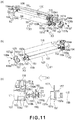
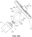
- the user attaches (mounts) the cartridge B to a cartridge mounting portion 130a of the apparatus main assembly A by gripping a grip.
- a driving shaft 180 ( Figure 17 ) of the apparatus main assembly A and a coupling member 150 (described later) as a rotational force transmitting part of the cartridge B are connected with each other in synchronism with the mounting operation of the cartridge B.
- the photosensitive drum 107 or the like is rotated by receiving the rotational force from the apparatus main assembly A.
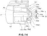
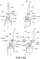
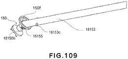
- the base 151b is provided with a drum shaft 153 outwardly projected with respect to the direction of the axis L1.
- This drum shaft 153 is co-axial with the drum engaging portion 151a. These are fixed so as to be co-axial with the rotation axis L1.
- the fixing method thereof the press-fitting, the bonding, the insert molding, and so on are available, and they are selected properly.
- the rib 157e is a semi-circular rib.
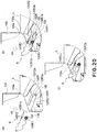
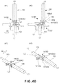
- the rib 157e is disposed at the downstream with respect to the mounting direction X4 of the cartridge B. Therefore, as shown in Figure 10 (c) , the driven portion 150a side of the axis L2 is greatly pivotable in the direction X4. In other words, the driving portion 150b side of the axis L2 is greatly pivotable in the direction of angle ⁇ 3) at phase ( Figure 9(a) at which the rib 157e is not disposed.
- Figure 10 (c) illustrates the state where the axis L2 inclined.
- the coupling 150 is pivotably mounted in any direction relative to the drum shaft 153. More particularly, the coupling 150 is revolvable. Therefore, as shown in Figure 23 , it can incline toward the mounting direction X4 irrespective of the phase of the drum shaft 153 relative to the mounting direction X4 of the cartridge (B). In addition, the inclination angle of the coupling 150 is set, so that regardless of the phases of the drive shaft 180 and the coupling 150, the free end position 150A1 is made closer to the photosensitive drum 107 than the axial free end 180b3 with respect to the direction of the axis L1.
- the coupling is pivotably mounted to the axis L1. And, the coupling 150 in the state in which it overlaps with the drive shaft 180 with respect to the direction of the axis L1 can be disengaged from the drive shaft 180 because the coupling inclines correspondingly to the dismounting operation of the cartridge (B). More particularly, by moving the cartridge (B) in the direction substantially perpendicular to the axial direction of the drive shaft 180, the coupling 150 which covers the drive shaft 180 can be disengaged from the drive shaft 180.
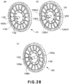
- the coupling 1550 is provided with a tapered surface (the inclined plane) 1550e, 1550h. And, a force is produced in the thrust direction by the rotation of the drive shaft 181.
- the positioning, with respect to the direction of the axis L1, of the coupling 1550 and the photosensitive drum 107 is effected by this thrust force.
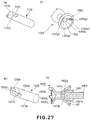
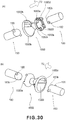
- Figure 29 and Figure 30 this will be described in detail.
- Figure 29 is a perspective view and a top plan view of the coupling alone.
- Figure 30 is an exploded perspective view which illustrates the drive shaft, the drum shaft, and the coupling.
- the this embodiment is effective not only for the case of the mounting and the dismounting of the cartridge (B) relative to the apparatus main assembly (A) but also the case of the dismounting only of the cartridge (B) from the apparatus main assembly (A).
- this embodiment is effective at the time of demounting the cartridge (B) from the apparatus main assembly (A) by moving in the direction substantially perpendicular to the direction of the axis L3. This is because$ even if the drive shaft 180 stops with the predetermined phase, the pin 182 and rotational force receiving surface 14150e1, 14150e2 (150e) are in engagement relative to each other. For this reason, in order to disengage the coupling 14150 (150) from the drive shaft 180, the coupling 14150 (150) needs to pivot.
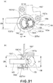
- the inserting portion 14150v is constituted by the two surfaces 14150i1, 14150 i2. And, the standby openings 14150g 1 or 14150g2 are provided in these surfaces 14150i1, 14150 i2 (the Figure 36a Figure 36e ).
- a rotational force transmission surface (rotational force transmitting portion) 14150h 14150h 1 or 14150h2 is provided.
- the pin (the rotational force receiving portion) 155a contacts with the rotational force transmission surfaces 14150h 1 or 14150h2. By this, the rotational force is transmitted to the photosensitive drum 107 from the coupling 14150.
- the coupling 14150 can be inclined in any direction relative to the drum shaft 153.
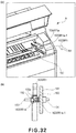
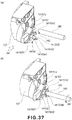
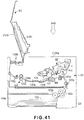
- FIG. 41 A typical clamshell type image forming apparatus is shown in Figure 41 .
- the apparatus main assembly A2 comprises a lower casing D2 and an upper casing E2.
- the upper casing E2 is provided with a door 2109 and an inside exposure device 2101 of the door 2109. Therefore, when the upper casing E2 is opened upward, the exposure device 2101 retracts. And, an upper portion of the cartridge set portion 2130a is opened.
- the user mounts the cartridge B-2 to a set portion 2130a the user drops the cartridge B-2 on X4B downward. The mounting completes with this, and therefore, the mounting of the cartridge is easy.
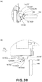
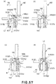
- Figure 49 the engaging operation (a part of mounting operation of the cartridge) for engaging the coupling 3150 with the drive shaft 180 will be described.
- Figures 49 (a1) and (b1) illustrate the state immediately before the engagement
- Figure 49 (a2) and (b2) illustrate the state of the completion of the engagement.
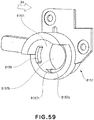
- the locking member 3159 is pasted on the upstreammost portion, with respect to cartridge mounting direction X4, of the inner surface 3157i of the bearing member 3157.
- the present invention is not limited to this example.
- any position which can maintain the inclined state thereof is usable.
- the locking member 3159 is pasted on the bearing member 3157.
- the locking member 3159 is the member fixed to the cartridge B, it may be pasted on any position.
- the axis L2 can incline toward the downstream with respect to the mounting direction of the cartridge relative to the axis L1
- the number of the urging members may be any.
- the single urging member as for the energizing position, it is desirably the downstreammost position with respect to the mounting direction X4 of the cartridge.
- the coupling 4150 can be stably inclined toward the downstream with respect to the mounting direction.
- the urging member is a compression coil spring in the present embodiment.
- the urging member if an elastic force can be produced as with the flat spring, the torsion spring, the rubber, the sponge, and so on, it may be any.
- a certain amount of stroke is required. Therefore, as with the coil spring etc, it is desirable that the stroke can be provided.
- the axis L2 inclines toward the downstream with respect to the mounting direction X4 relative to the axis L1 (disengaging angular position). More particularly, in this embodiment, the angle of the pre-engagement angular position and the angle of the disengaging angular position relative to the axis L1 are equivalent relative to each other. This is because the coupling 4150 is urged by the elastic force of the spring.
- the urging member 4159 described in this embodiment is provided in the rib 4157e of the bearing member 4157.
- the present embodiment is not limited to such an example.
- it may be another portion of the bearing member 4157 and may be any member fixed to the cartridge B (other than the bearing member).
- the axis L2 of the coupling 5150 inclines toward the mounting direction X4 relative to the axis L1 beforehand (pre-engagement angular position).
- the free end position 5150A1 is closer to the photosensitive drum than the free end 180b3 in the direction of the axis L1.
- the free end position 5150A2 is closer to the pin 182 than the free end 180b3.
- the flange portion 5150j is in contact with the locking surface 5157k1, and the inclined state of the coupling 5150 is maintained.
- the locking member 5157k is provided in the downstreammost side with respect to the mounting direction X4. However, if the inclination toward the predetermined direction of the axis L2 can be maintained, the position of the locking member 5157k may be any.
- the free end surface 180b or the pin 182 free end contacts to the driving shaft receiving surface 8150f of the coupling 8150 by the cartridge B moving to the mounting direction X4.
- the axis L2 approaches so that it may become substantially co-axial with the axis L1 by the contact force (mounting force of the cartridge) thereof.
- the flange portion 8150j separates from the magnet member 8159, and is in the non-contact state.
- the axis L1 and the axis L2 become substantially co-axial.
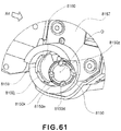
- the coupling 8150 is in the rotation latency state ( Figure 62 (a2), Figure (b2)) (rotational force transmitting angular position).
- the bearing member 6157 is provided with an opening 6157v. And, the opening 6157v and the locking portion (locking member) 6159a engage with each other. By this, a free end 6159a1 of the locking portion 6159a projects into a space portion 6157b of the bearing member 6157. As will be described hereinafter, the state of inclining the coupling 6150 by this locking portion 6159a is maintained.
- the locking member 6159 is mounted to the space 6157p of the bearing member 6157.
- the spring member 6158 is mounted by the boss 6157m of the hole 6159b and the bearing member 6157.
- the step opposite from the step to mount is followed. More particularly, by moving the cartridge B in the dismounting direction, the free end portion 180b of the drive shaft (the main assembly side engaging portion) 180 pushes the receiving surface 6150f (the cartridge side contact portion). By this, the axis L2 begins ( Figure 68 (c) ) to incline relative to the axis L1. And, the coupling 6150 passes by the shaft free-end 180b3 completely ( Figure 68 (b) ). The hook portion 6159c spaces from the rib 6131a immediately after that. And, the locking portion free end 6159a1 contacts to the lower surface 6150j2 of the flange portion. Therefore, the inclined state of the coupling 6150 is maintained ( Figure 68 (a) ). More particularly, the coupling 6150 is pivoted to the disengaging angular position from the rotational force transmitting angular position (swinging).
- the present embodiment may be implemented with Embodiments 4-7. In this case, mounting and dismounting operations of the coupling can be ensured.
- the reason for the inclination of the coupling 7150 is as follows.
- the connecting portion 7150c receives the reaction force corresponding to the weight of the cartridge B from the guide rib 7130R1a. And, the reaction force applies to the regulating portion 7157h 1 or 7157h2 for regulating the inclining direction. By this, the coupling is inclined to the predetermined direction.
- the coupling 7150 receives a force in the direction opposite from the mounting direction X4 by this frictional force.
- the frictional force produced by the coefficient of friction between the connecting portion 7150c and the guide rib 7130R1a is smaller than the force for pivoting the coupling 7150 to the downstream with respect to the mounting direction X4 by the reaction force. Therefore, the coupling 7150 overcomes the frictional force is pivoted to the downstream with respect to the mounting direction X4.
- the connecting portion 7150c contacts the coupling 7150 to the rib 7130R1a.
- the coupling 7150 is taken out in the state inclined toward the downstream with respect to the mounting direction.
- the coupling 5150 is pivoted to the disengaging angular position from the rotational force transmitting angular position (swinging).
- the coupling is inclined toward the mounting direction by applying the weight to the guide rib.
- the weight not only the weight, the spring force and so on may be utilized further.
- the coupling is inclined by the connecting portion of the coupling receiving the force.
- the present embodiment is not limited to this example.
- the coupling is inclined by receiving the force from a contact portion of the main assembly, the portion other than the connecting portion may be contacted to the contact portion.
- the force F is divided into a component force F1 and a component force F2.
- the upper surface of the coupling 150 is regulated by the regulating portion 140R1a. Therefore, the coupling 150 is inclined toward the mounting direction (X4) by the component force F2. More particularly, the coupling 150 is inclined toward the pre-engagement angular position. By this, the coupling 150 becomes engageable with the drive shaft 180.
- the downstream free end position 10150A1 with respect to the mounting direction needs to pass the free end portion 180b3 of the drive shaft 180.
- the axis L2 inclines by more than angle ⁇ 104. By this, the coupling moves to the position where the free end position 150A1 does not interfere with the free end portion 180b3 ( Figure 88 (a) ).
- Embodiment 1 The point in which the present embodiment is different from Embodiment 1 is in the engaging operation and the structure with respect to it relative to the drive shaft of the coupling.
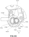
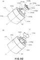
- Figure 92 illustrates the coupling held at the end of the photosensitive drum 107 (cylindrical drum 107a) a part of driving side of the photosensitive drum 107 is shown, and the others are omitted for simplicity.
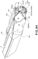
- FIG 93 (b) an example is shown in Figure 93 (b) , wherein the coupling 15150 is mounted to the end part of the cylindrical drum 107a of the photosensitive drum 107, so that it is slantable in any direction.
- one end of the coupling is mounted not to the drum shaft (projection) but into the recess (rotational force receiving member) provided at the end part of the cylinder 107a.
- the coupling 15150 is pivotable also in any direction relative to the axis L1.
- the driven portion 15150a the configuration described with respect to Embodiment 1 is shown, but it may be a configuration of the driven portion of the coupling described in Embodiment 10 or Embodiment 11.
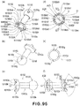
- this drum unit U is assembled into the second frame 118 (drum frame), and it is constituted as the detachably mountable cartridge to the apparatus main assembly.
- the coupling 15150 mainly comprises three portions ( Figure 95 (c) ).
- a first portion is a driven portion (a portion to be driven) 15150a which has a rotational force reception surface (rotational force receiving portion) 15150e (15150e1-15150e4) for engaging with a drive shaft 180 and receiving a rotational force from a pin 182.
- a second portion is a driving portion 15150b which engages with a drum flange 15151 (pin 15155 (rotational force receiving member)), and transmits a rotational force.
- a third portion is a connecting portion 15150c which connects the driven portion 15150a and the driving portion 15150b.
- the materials of these portions are resin materials, such as polyacetal, the polycarbonate, and PPS.
- the driven portion 15150a and the connecting portion 15150c are inserted in the direction X33 into the flange 15151.
- the positioning member 15150p (driving portion 15150b) which has the bearing surface 15150i is put in the direction of an arrow X32.
- the pin 15155 penetrates a fixing hole 15150g of the positioning member 15150p, and the fixing hole 15150r of the connecting portion 15150c. By this, the positioning member 15150p is fixed to the connecting portion 15150c.
- the rotational force transmission surfaces 15150h 1, 15150h2 are desirably disposed diametrically opposed (180 degrees) on the same circumference.
- Designated by 15151c is a gear, and has a function of transmitting a rotational force received by the coupling 15150 from the drive shaft 180 to the developing roller 110.
- the gear 15151c is integrally molded with the flange 15151.
- the coupling 15150 is inclined rightward in Figure 100 (a3) (b3). As shown in this Figure, when the coupling 15150 inclines in the orthogonal direction of the opening 15151g, it rotates in the opening 15151g.
- the pin 15155 rotates about the axis line AY of the pin 15155.
- the opening 15151g is formed slightly overwidely in the circumferential direction.
- the free end position 15150A1 passes by the drive shaft free-end 180b3. Thereafter, the driving shaft receiving surface 150f of conical shape or the driven projection 150d contacts to the free end portion 180b of the drive shaft 180, or the rotational force drive transmission pin 182.
- the receiving surface 150f and/or the projection 150d are the contact portions of the cartridge side.
- the free end portion 180b and/or the pin 182 are the engaging portions of the main assembly side.
- the coupling 15150 is inclined so that the axis L2 becomes substantially co-axial with the axis L1 ( Figure 103 (c) ).
- the supporting portion 17150p becomes movable along the conical portion 17151i and the edge line 17156a of retaining member.
- the coupling 17150 can be inclined assuredly.
- the supporting portion 17150p is pivotable (swingable) relative to the conical portion 17151i.
- a gap is provided in order to permit the pivoting of the coupling 17150. Therefore, the effects similar to the effects described in Embodiment 17 are provided.
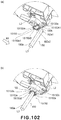
- the photosensitive drum 107 is provided with a helical gear 15151c at the end which has the coupling 15150.
- the gear 15151c transmits the rotational force received by the coupling 15150 from the apparatus main assembly A to the developing roller 110 and, with respect to the direction of the axis L1 of the photosensitive drum 107, the position in which the gear 15151c is provided, and the position in which the rotational force transmitting pin (rotational force transmitting portion) 15150h1, h2 is provided overlap relative to each other (the overlapping position is shown by 3 in Figure 98 ).
- the coupling can pivot to the disengaging angular position irrespective of the phase at which the rotating force applying portion stops.
- a gap is provided between the rotating force transmitting portion (for example, 150h, 1550h, 9150h, 14150h, 15150h) and the rotating force receiving member for example, pin 155, 1355. 9155, 13155, 15155, 15151h) so that coupling member is capable of tilting relative to the axis of the electrophotographic photosensitive drum substantially in all directions, wherein the rotating force transmitting portion is provided at an end of the electrophotographic photosensitive drum and is movable relative to the rotating force receiving member, and the rotating force transmitting portion and the rotating force receiving member are engageable to each other in a rotational direction of the coupling member.
- the coupling is mounted to the end of the drum in this manner.
- the coupling is capable of inclination substantially in all directions relative to the axis L1.
- the whirling motion is not a motion with which the coupling itself rotates about the axis L2, but the inclined axis L2 rotates about the axis L1 of the photosensitive drum, although the whirling here does not preclude the rotation of the coupling per se about the axis L2 of the coupling 150.
- the photosensitive drum in the drive connecting portion between the main assembly and the cartridge, can rotate smoothly as compared with the case of the engagement between gears.
- the axis of the drum coupling member can take the different angular positions relative to the axis of the photosensitive drum.
- the drum coupling member can be engaged with the drive shaft in the direction substantially perpendicular to the axis of the drive shaft provided in the main assembly by this structure.
- the drum coupling member can be disengaged from the drive shaft in the direction substantially perpendicular to the axis of the drive shaft.
- the present invention can be applied to the process cartridge, the electrophotographic photosensitive member drum unit, the rotational force transmitting portion (drum coupling member), and the electrophotographic image forming device.
Landscapes
- Physics & Mathematics (AREA)
- General Physics & Mathematics (AREA)
- Engineering & Computer Science (AREA)
- Computer Vision & Pattern Recognition (AREA)
- Plasma & Fusion (AREA)
- Electrophotography Configuration And Component (AREA)
- Discharging, Photosensitive Material Shape In Electrophotography (AREA)
- Devices For Conveying Motion By Means Of Endless Flexible Members (AREA)
- Rolls And Other Rotary Bodies (AREA)
Applications Claiming Priority (5)
| Application Number | Priority Date | Filing Date | Title |
|---|---|---|---|
| JP2006346191 | 2006-12-22 | ||
| JP2007042666 | 2007-02-22 | ||
| JP2007330304A JP4948382B2 (ja) | 2006-12-22 | 2007-12-21 | 感光ドラム取り付け用カップリング部材 |
| EP07860561.5A EP2062099B1 (en) | 2006-12-22 | 2007-12-25 | Use of a coupling member or use of an electrophotographic photosensitive drum having a coupling member |
| PCT/JP2007/075366 WO2008081966A1 (en) | 2006-12-22 | 2007-12-25 | Rotational force transmitting part |
Related Parent Applications (1)
| Application Number | Title | Priority Date | Filing Date |
|---|---|---|---|
| EP07860561.5A Division EP2062099B1 (en) | 2006-12-22 | 2007-12-25 | Use of a coupling member or use of an electrophotographic photosensitive drum having a coupling member |
Publications (2)
| Publication Number | Publication Date |
|---|---|
| EP3486729A1 EP3486729A1 (en) | 2019-05-22 |
| EP3486729B1 true EP3486729B1 (en) | 2020-10-07 |
Family
ID=39166737
Family Applications (2)
| Application Number | Title | Priority Date | Filing Date |
|---|---|---|---|
| EP18207343.7A Active EP3486729B1 (en) | 2006-12-22 | 2007-12-25 | Rotational force transmitting part |
| EP07860561.5A Active EP2062099B1 (en) | 2006-12-22 | 2007-12-25 | Use of a coupling member or use of an electrophotographic photosensitive drum having a coupling member |
Family Applications After (1)
| Application Number | Title | Priority Date | Filing Date |
|---|---|---|---|
| EP07860561.5A Active EP2062099B1 (en) | 2006-12-22 | 2007-12-25 | Use of a coupling member or use of an electrophotographic photosensitive drum having a coupling member |
Country Status (16)
| Country | Link |
|---|---|
| US (10) | US8295734B2 (ru) |
| EP (2) | EP3486729B1 (ru) |
| JP (1) | JP4948382B2 (ru) |
| KR (6) | KR101367045B1 (ru) |
| CN (7) | CN101583910B (ru) |
| AU (1) | AU2007340402B2 (ru) |
| BR (2) | BR122015016845B1 (ru) |
| CA (5) | CA2670072C (ru) |
| DE (1) | DE112007003046B4 (ru) |
| HK (4) | HK1132339A1 (ru) |
| MX (4) | MX347646B (ru) |
| MY (2) | MY182592A (ru) |
| RU (8) | RU2521160C2 (ru) |
| SG (3) | SG10201507914WA (ru) |
| TW (6) | TWI456363B (ru) |
| WO (1) | WO2008081966A1 (ru) |
Families Citing this family (118)
| Publication number | Priority date | Publication date | Assignee | Title |
|---|---|---|---|---|
| EP2259664B1 (en) | 2004-07-21 | 2017-10-18 | Mevion Medical Systems, Inc. | A programmable radio frequency waveform generator for a synchrocyclotron |
| JP4498407B2 (ja) | 2006-12-22 | 2010-07-07 | キヤノン株式会社 | プロセスカートリッジ、電子写真画像形成装置、及び、電子写真感光体ドラムユニット |
| JP4948382B2 (ja) | 2006-12-22 | 2012-06-06 | キヤノン株式会社 | 感光ドラム取り付け用カップリング部材 |
| JP5311854B2 (ja) * | 2007-03-23 | 2013-10-09 | キヤノン株式会社 | 電子写真画像形成装置、現像装置、及び、カップリング部材 |
| US7711287B2 (en) * | 2007-05-15 | 2010-05-04 | Canon Kabushiki Kaisha | Cartridge and electrophotographic image forming apparatus |
| JP4912381B2 (ja) * | 2007-10-30 | 2012-04-11 | キヤノン株式会社 | 駆動伝達装置、及び画像形成装置 |
| US9261821B2 (en) | 2007-10-30 | 2016-02-16 | Canon Kabushiki Kaisha | Image forming apparatus |
| JP5328230B2 (ja) | 2008-06-10 | 2013-10-30 | キヤノン株式会社 | カートリッジ、及び、前記カートリッジを用いた電子写真画像形成装置 |
| JP5288900B2 (ja) * | 2008-06-20 | 2013-09-11 | キヤノン株式会社 | プロセスカートリッジ及び電子写真画像形成装置 |
| JP5127584B2 (ja) * | 2008-06-20 | 2013-01-23 | キヤノン株式会社 | ドラムユニット、及び、電子写真画像形成装置 |
| JP5283986B2 (ja) * | 2008-06-20 | 2013-09-04 | キヤノン株式会社 | ドラムユニット、及び、電子写真画像形成装置 |
| JP5306050B2 (ja) * | 2008-06-20 | 2013-10-02 | キヤノン株式会社 | カートリッジ、カップリング部材の取り付け方法、及び、カップリング部材の取り外し方法 |
| JP5495671B2 (ja) * | 2008-08-27 | 2014-05-21 | キヤノン株式会社 | 現像カートリッジ、及び、カップリング部材 |
| JP5371627B2 (ja) | 2008-08-27 | 2013-12-18 | キヤノン株式会社 | 現像装置、現像カートリッジ、及び、電子写真画像形成装置 |
| JP5424749B2 (ja) * | 2008-09-01 | 2014-02-26 | キヤノン株式会社 | カートリッジ |
| JP4663801B2 (ja) * | 2008-09-01 | 2011-04-06 | キヤノン株式会社 | プロセスカートリッジ及び画像形成装置 |
| JP5419584B2 (ja) | 2008-09-01 | 2014-02-19 | キヤノン株式会社 | カートリッジ及び電子写真画像形成装置 |
| JP5147607B2 (ja) * | 2008-09-01 | 2013-02-20 | キヤノン株式会社 | 画像形成装置 |
| WO2010024471A1 (ja) | 2008-09-01 | 2010-03-04 | キヤノン株式会社 | 現像カートリッジ、プロセスカートリッジ及び電子写真画像形成装置 |
| US8029284B2 (en) * | 2008-09-29 | 2011-10-04 | Maxillent Ltd. | Implants, tools, and methods for sinus lift and lateral ridge augmentation |
| JP5451028B2 (ja) * | 2008-10-28 | 2014-03-26 | キヤノン株式会社 | 駆動伝達装置及び画像形成装置 |
| US8249483B2 (en) * | 2008-12-08 | 2012-08-21 | Mitsubishi Kagaku Imaging Corporation | Method and devices for remanufacturing printer cartridges |
| JP4803267B2 (ja) * | 2009-02-17 | 2011-10-26 | 富士ゼロックス株式会社 | 画像形成装置 |
| JP5506236B2 (ja) * | 2009-04-30 | 2014-05-28 | キヤノン株式会社 | カートリッジ、及び電子写真画像形成装置 |
| JP5751779B2 (ja) * | 2009-10-30 | 2015-07-22 | キヤノン株式会社 | 現像装置、現像カートリッジ、プロセスカートリッジ、及び、画像形成装置 |
| JP5554963B2 (ja) * | 2009-10-30 | 2014-07-23 | キヤノン株式会社 | 現像カートリッジ及びプロセスカートリッジ |
| JP5430349B2 (ja) * | 2009-10-30 | 2014-02-26 | キヤノン株式会社 | 現像カートリッジ |
| JP5428846B2 (ja) | 2009-12-24 | 2014-02-26 | ブラザー工業株式会社 | カートリッジ |
| JP5029682B2 (ja) * | 2009-12-25 | 2012-09-19 | ブラザー工業株式会社 | 現像カートリッジ |
| JP4911228B2 (ja) | 2010-01-29 | 2012-04-04 | ブラザー工業株式会社 | カートリッジおよび画像形成装置 |
| JP5683281B2 (ja) | 2010-02-02 | 2015-03-11 | キヤノン株式会社 | ドラムユニット |
| JP5649328B2 (ja) * | 2010-05-10 | 2015-01-07 | キヤノン株式会社 | 画像形成装置 |
| CN103592831A (zh) * | 2010-09-20 | 2014-02-19 | 科企有限公司 | 感光鼓连接组件 |
| CN102478769B (zh) * | 2010-11-19 | 2014-08-27 | 珠海赛纳打印科技股份有限公司 | 一种感光鼓驱动组件 |
| US8892004B2 (en) | 2011-03-29 | 2014-11-18 | Static Control Components, Inc. | Drive gear for extended drive shaft |
| US8644733B2 (en) | 2011-03-29 | 2014-02-04 | Static Control Components, Inc. | Cartridge drive shaft gear |
| JP5273194B2 (ja) * | 2011-04-28 | 2013-08-28 | ブラザー工業株式会社 | カートリッジ |
| KR101848393B1 (ko) * | 2011-11-18 | 2018-04-13 | 에스프린팅솔루션 주식회사 | 화상형성장치 및 화상형성장치의 동력전달구조 |
| CN112698561B (zh) * | 2011-12-06 | 2023-11-28 | 佳能株式会社 | 盒、感光鼓传动装置组装方法及电子照相成像设备 |
| JP5355679B2 (ja) | 2011-12-27 | 2013-11-27 | キヤノン株式会社 | プロセスカートリッジ及び画像形成装置 |
| JP5901327B2 (ja) | 2012-02-09 | 2016-04-06 | キヤノン株式会社 | 現像装置、プロセスカートリッジ、および画像形成装置 |
| JP5928887B2 (ja) * | 2012-05-30 | 2016-06-01 | 富士ゼロックス株式会社 | 構造体及び画像形成装置 |
| JP5943716B2 (ja) * | 2012-06-04 | 2016-07-05 | キヤノン株式会社 | 現像カートリッジ |
| JP6108728B2 (ja) | 2012-08-31 | 2017-04-05 | キヤノン株式会社 | 梱包材及びカートリッジ |
| CN104813749B (zh) * | 2012-09-28 | 2019-07-02 | 梅维昂医疗系统股份有限公司 | 控制粒子束的强度 |
| US9681531B2 (en) | 2012-09-28 | 2017-06-13 | Mevion Medical Systems, Inc. | Control system for a particle accelerator |
| US8909102B2 (en) * | 2012-10-31 | 2014-12-09 | Clover Technologies Group, LLP | Electrophotographic drum gear flange socket configurations |
| JP5949585B2 (ja) * | 2013-01-30 | 2016-07-06 | コニカミノルタ株式会社 | 回転動力伝達機構、および感光体ドラム装置 |
| US9182733B2 (en) | 2013-02-07 | 2015-11-10 | Canon Kabushiki Kaisha | Developer supply cartridge, process cartridge and image forming apparatus |
| JP6020237B2 (ja) * | 2013-02-15 | 2016-11-02 | 三菱化学株式会社 | 軸受部材、端部部材、感光体ドラムユニット、及び軸受部材の製造方法 |
| JP2014191025A (ja) | 2013-03-26 | 2014-10-06 | Mitsubishi Chemicals Corp | 軸受部材、端部部材、感光体ドラムユニット、及びプロセスカートリッジ |
| TW201502724A (zh) | 2013-07-08 | 2015-01-16 | Gen Plastic Ind Co Ltd | 感光鼓的傳動組件 |
| US9098048B2 (en) | 2013-08-13 | 2015-08-04 | General Plastic Industrial Co., Ltd. | Transmission device for photosensitive drum |
| USRE46847E1 (en) | 2013-07-08 | 2018-05-15 | General Plastic Industrial Co., Ltd. | Transmission device for photosensitive drum |
| USRE46863E1 (en) | 2013-07-08 | 2018-05-22 | General Plastic Industrial Co., Ltd. | Transmission device for photosensitive drum |
| US9031465B2 (en) | 2013-08-13 | 2015-05-12 | General Plastic Industrial Co., Ltd. | Transmission device for photosensitive drum |
| US9091994B2 (en) | 2013-08-13 | 2015-07-28 | General Plastic Industrial Co., Ltd. | Transmission device for photosensitive drum |
| JP6415198B2 (ja) * | 2013-09-12 | 2018-10-31 | キヤノン株式会社 | カートリッジ |
| US9740163B2 (en) * | 2013-09-29 | 2017-08-22 | Ninestar Corporation | Rotational force driving assembly process cartridge |
| JP6128405B2 (ja) * | 2013-09-29 | 2017-05-17 | エーペックス テクノロジー カンパニー リミテッドApex Technology Co., Ltd. | 回転力駆動アセンブリ及びプロセスカートリッジ |
| CN104516224B (zh) * | 2013-09-29 | 2018-10-09 | 纳思达股份有限公司 | 一种旋转力驱动组件以及处理盒 |
| JP2015121776A (ja) * | 2013-11-19 | 2015-07-02 | 三菱化学株式会社 | プロセスカートリッジ、感光体ドラムユニット、及び一組の端部部材 |
| JP6292077B2 (ja) | 2014-03-06 | 2018-03-14 | 三菱ケミカル株式会社 | 端部部材、感光体ドラムユニット、現像ローラユニットおよびプロセスカートリッジ |
| JP6277909B2 (ja) * | 2014-03-07 | 2018-02-14 | 三菱ケミカル株式会社 | 軸部材、端部部材、感光体ドラムユニット、現像ローラユニット、プロセスカートリッジ |
| JP6376782B2 (ja) | 2014-03-10 | 2018-08-22 | キヤノン株式会社 | カートリッジ及び画像形成装置 |
| CN105093889A (zh) * | 2014-04-16 | 2015-11-25 | 珠海艾派克科技股份有限公司 | 一种处理盒 |
| US9829855B2 (en) * | 2014-05-22 | 2017-11-28 | Lexmark International, Inc. | Drive coupler |
| JP2016014850A (ja) * | 2014-06-09 | 2016-01-28 | 三菱化学株式会社 | 軸部材、端部部材、感光体ドラムユニット、現像ローラユニット、プロセスカートリッジ |
| DE102015104038A1 (de) | 2014-06-20 | 2015-12-24 | General Plastic Industrial Co., Ltd. | Übertragungseinrichtung für eine photosensitive Trommel und Trommelvorrichtung damit |
| JP6265080B2 (ja) * | 2014-07-10 | 2018-01-24 | 三菱ケミカル株式会社 | 端部部材、感光体ドラムユニット、現像ローラユニットおよびプロセスカートリッジ |
| JP6131223B2 (ja) * | 2014-07-17 | 2017-05-17 | 京セラドキュメントソリューションズ株式会社 | 駆動伝達機構およびこれを備える画像形成装置 |
| EP3153933A4 (en) * | 2014-07-25 | 2017-06-28 | Apex Technology Co., Ltd. | Rotational force drive component, processing box and image formation device |
| TWI573001B (zh) | 2014-08-15 | 2017-03-01 | A drive assembly, and a photosensitive drum unit having the drive assembly | |
| TWI547774B (zh) | 2014-08-15 | 2016-09-01 | 感光鼓的傳動組件 | |
| CN105549351A (zh) | 2014-10-31 | 2016-05-04 | 三菱化学株式会社 | 端部部件、处理盒及处理盒的脱离方法 |
| CN108614402B (zh) * | 2014-11-13 | 2019-06-25 | 纳思达股份有限公司 | 处理盒及驱动组件 |
| SG11201704199QA (en) | 2014-11-28 | 2017-06-29 | Canon Kk | Cartridge and electrophotographic image forming apparatus |
| JP6552194B2 (ja) * | 2014-12-26 | 2019-07-31 | キヤノン株式会社 | 画像形成装置、及び画像形成装置に着脱可能なユニット |
| JP2016148783A (ja) | 2015-02-12 | 2016-08-18 | 三菱化学株式会社 | 軸部材、端部部材、感光体ドラムユニット、現像ローラユニット、プロセスカートリッジ |
| JP6512864B2 (ja) | 2015-02-27 | 2019-05-15 | キヤノン株式会社 | カートリッジ、プロセスカートリッジ、画像形成装置 |
| KR102271625B1 (ko) | 2015-02-27 | 2021-06-30 | 캐논 가부시끼가이샤 | 카트리지 |
| CA3028569A1 (en) | 2015-02-27 | 2016-09-01 | Canon Kabushiki Kaisha | Drum unit, cartridge and coupling member |
| JP6794117B2 (ja) | 2015-03-10 | 2020-12-02 | キヤノン株式会社 | ドラムシリンダユニット、カップリング部材の取り付け方法、ドラムユニット |
| MY193258A (en) * | 2015-03-10 | 2022-09-28 | Canon Kk | Drum cylinder unit, method for attaching coupling member, and drum unit |
| US20160282798A1 (en) | 2015-03-24 | 2016-09-29 | Mitsubishi Chemical Corporation | Transmission device for a photosensitive drum |
| JP6873604B2 (ja) | 2015-06-05 | 2021-05-19 | キヤノン株式会社 | プロセスカートリッジ、および、電子写真画像形成装置 |
| CN106292236B (zh) * | 2015-06-08 | 2021-05-28 | 江西镭博钛电子科技有限公司 | 一种处理盒 |
| WO2016204246A1 (ja) * | 2015-06-17 | 2016-12-22 | 三菱化学株式会社 | 端部部材、感光体ドラムユニット、プロセスカートリッジ |
| JP1543378S (ru) * | 2015-07-22 | 2016-02-08 | ||
| JP1543379S (ru) * | 2015-07-22 | 2016-02-08 | ||
| BR112018006163B1 (pt) * | 2015-09-30 | 2023-11-14 | Canon Kabushiki Kaisha | Unidade de tambor, cartucho de processo e aparelho de formação de imagem |
| JP6833402B2 (ja) * | 2015-10-14 | 2021-02-24 | キヤノン株式会社 | カートリッジ及び画像形成装置 |
| US9952555B2 (en) * | 2015-10-14 | 2018-04-24 | Canon Kabushiki Kaisha | Cartridge configured to be removably attachable to an image forming apparatus |
| CN108475031A (zh) * | 2015-12-07 | 2018-08-31 | 三菱化学株式会社 | 端部部件、感光鼓单元、处理盒 |
| CN105589313A (zh) * | 2016-02-04 | 2016-05-18 | 上福全球科技股份有限公司 | 碳粉匣的传动组件 |
| CN110727191A (zh) * | 2016-02-26 | 2020-01-24 | 中山诚威科技有限公司 | 一种处理盒 |
| JP6773886B2 (ja) * | 2016-04-13 | 2020-10-21 | ナインスター コーポレーション | プロセスカートリッジ |
| GB2567779B (en) | 2016-08-26 | 2021-08-18 | Canon Kk | Cartridge and image forming apparatus |
| KR102380993B1 (ko) | 2016-08-26 | 2022-03-30 | 캐논 가부시끼가이샤 | 드럼 유닛, 카트리지, 전자 사진 화상 형성 장치 및 커플링 부재 |
| CA3034218A1 (en) * | 2016-08-26 | 2018-03-01 | Canon Kabushiki Kaisha | Drum unit, cartridge, electrophotographic image forming apparatus, and coupling member |
| CN108107696B (zh) * | 2016-09-28 | 2022-08-05 | 纳思达股份有限公司 | 一种驱动组件及其处理盒和电子成像装置 |
| US9588478B1 (en) | 2016-09-30 | 2017-03-07 | Roy Fan | Drive coupling and transmitting assembly for photosensitive drum and toner cartridges |
| JP6957205B2 (ja) | 2017-05-31 | 2021-11-02 | キヤノン株式会社 | カートリッジおよび画像形成装置 |
| CN208239812U (zh) * | 2017-06-30 | 2018-12-14 | 纳思达股份有限公司 | 处理盒的动力接收单元、旋转部件以及处理盒 |
| CN111465435A (zh) * | 2017-08-31 | 2020-07-28 | 科乐美游乐株式会社 | 输送装置 |
| JP6625109B2 (ja) * | 2017-10-30 | 2019-12-25 | キヤノン株式会社 | 画像形成装置 |
| BR112020011659A2 (pt) * | 2017-12-13 | 2020-11-17 | Canon Kabushiki Kaisha | cartucho e aparelho de formação de imagem |
| KR20190075752A (ko) | 2017-12-21 | 2019-07-01 | 휴렛-팩커드 디벨롭먼트 컴퍼니, 엘.피. | 회전력을 받는 커플러를 구비하는 카트리지 |
| JP7080678B2 (ja) | 2018-03-13 | 2022-06-06 | キヤノン株式会社 | カートリッジ |
| WO2019174172A1 (zh) | 2018-03-14 | 2019-09-19 | 珠海天威飞马打印耗材有限公司 | 处理盒及电子照相成像装置 |
| US10416604B1 (en) * | 2018-04-18 | 2019-09-17 | Jiangxi Yibo E-Tech Co.Ltd. | Process cartridge |
| US10338513B1 (en) * | 2018-04-18 | 2019-07-02 | Jiangxi Yibo E-Tech Co., Ltd. | Process cartridge |
| JP7366599B2 (ja) | 2018-06-25 | 2023-10-23 | キヤノン株式会社 | カートリッジ |
| US20210300096A1 (en) * | 2018-11-09 | 2021-09-30 | Hewlett-Packard Development Company, L.P. | Alterations of print drive assemblies |
| US20220227592A1 (en) * | 2019-09-09 | 2022-07-21 | Hewlett-Packard Development Company, L.P. | Peripheral device with gear train protection |
| JP7418109B2 (ja) * | 2019-09-30 | 2024-01-19 | キヤノン株式会社 | 画像形成装置 |
| WO2021126236A1 (en) * | 2019-12-20 | 2021-06-24 | Hewlett-Packard Development Company, L.P. | Print agent applicator positioning devices |
| CA3191746A1 (en) * | 2020-09-17 | 2022-03-24 | Canon Kabushiki Kaisha | Cartridge, drum unit, and image forming apparatus |
Family Cites Families (328)
| Publication number | Priority date | Publication date | Assignee | Title |
|---|---|---|---|---|
| US899913A (en) | 1907-12-13 | 1908-09-29 | Hugh Robertson Shaw | Power-transmission universal joint. |
| US2300514A (en) | 1940-02-21 | 1942-11-03 | Westinghouse Electric & Mfg Co | Dial attaching device |
| US2292676A (en) | 1941-08-21 | 1942-08-11 | Leon F Thiry | Rubber ball and socket joint |
| US3406534A (en) | 1966-10-10 | 1968-10-22 | Chapper John | Universal coupling |
| US3490841A (en) | 1968-01-15 | 1970-01-20 | Ibm | Photoconductor drum locator |
| US3818380A (en) | 1969-03-28 | 1974-06-18 | R Tyre | Single component controlled rc bridge |
| US3815386A (en) | 1971-02-02 | 1974-06-11 | Kamyr Ab | Device for bleaching of cellulosic pulp |
| US3922883A (en) | 1974-10-03 | 1975-12-02 | Motorola Inc | Anti-backlash universal coupling |
| DE2559008C2 (de) | 1974-12-28 | 1982-08-05 | Ricoh Co., Ltd., Tokyo | Antriebsvorrichtung für eine Typenscheibe |
| US4065941A (en) * | 1975-05-16 | 1978-01-03 | Koto Sangyo Kabushiki Kaisha | Universal joint |
| US4167321A (en) | 1976-09-14 | 1979-09-11 | Olympus Optical Co., Ltd. | Photosensitive drum for electrographic apparatus |
| DE7903031U1 (de) | 1979-02-05 | 1979-07-12 | Basf Ag, 6700 Ludwigshafen | Andruckvorrichtung fuer flexible aufzeichnungstraeger, insbesondere solche in huellen |
| US4433767A (en) | 1979-07-16 | 1984-02-28 | Thor Charles C | Power transmission mechanism |
| JPS57153844A (en) | 1981-03-05 | 1982-09-22 | Sato Co Ltd | Device for printing and pasting label |
| JPS57153844U (ru) | 1981-03-23 | 1982-09-27 | ||
| US4457738A (en) | 1982-04-19 | 1984-07-03 | Xerox Corporation | Anti-backlash double universal flexible coupling |
| JPS59116951U (ja) | 1983-01-25 | 1984-08-07 | 京セラミタ株式会社 | 複写機の動力伝達装置 |
| GB2141520B (en) | 1983-06-08 | 1986-08-28 | Xerox Corp | Drive shaft connector |
| JPS59228281A (ja) | 1983-06-10 | 1984-12-21 | Fuji Xerox Co Ltd | 電子複写機の感光体駆動装置 |
| US4451117A (en) | 1983-11-04 | 1984-05-29 | Goode Robert C | Digital watch magnifying element |
| JPS60249729A (ja) | 1984-05-23 | 1985-12-10 | Fuji Xerox Co Ltd | 脱着可能な2自由度接手 |
| EP0164792B1 (de) | 1984-06-13 | 1988-12-28 | Hasler AG | Vorrichtung zum kraftschlüssigen Verbinden zweier Wellen |
| JPS6192967A (ja) | 1984-10-09 | 1986-05-10 | Nissan Motor Co Ltd | スペアタイヤ格納装置 |
| JPH055575Y2 (ru) | 1984-11-26 | 1993-02-15 | ||
| US4833502A (en) | 1985-07-11 | 1989-05-23 | Canon Kabushiki Kaisha | Image forming apparatus having an image bearing member reciprocally movable in the direction of the rotational axis thereof |
| GB2180796B (en) | 1985-09-17 | 1990-05-09 | Canon Kk | Replaceable image bearing member for an image forming apparatus. |
| FR2587510B1 (fr) | 1985-09-17 | 1991-01-11 | Canon Kk | Element de support d'image, cartouche de traitement contenant un tel element et appareil de formation d'images |
| US4835565A (en) | 1986-06-11 | 1989-05-30 | Ricoh Company, Ltd. | Image developing device for electrophotography |
| JPS634252A (ja) | 1986-06-24 | 1988-01-09 | Canon Inc | プロセスカ−トリツジ及びこのカ−トリツジを使用する画像形成装置 |
| US4873549A (en) | 1987-03-03 | 1989-10-10 | Mita Industrial Co., Ltd. | Device for detecting the life of an image forming process unit, opening of a seal of the unit and attachment of the unit to an image forming apparatus |
| JPH01164818A (ja) | 1987-12-20 | 1989-06-28 | Konica Corp | 軸間接続装置 |
| JPH01164818U (ru) | 1988-05-07 | 1989-11-17 | ||
| JPH0271278A (ja) | 1988-09-06 | 1990-03-09 | Ricoh Co Ltd | 画像形成装置 |
| US4915493A (en) | 1989-01-04 | 1990-04-10 | Magna International Inc. | Automotive rear view mirror assembly |
| FR2645607B1 (fr) | 1989-04-07 | 1991-08-16 | Nacam | Dispositif rapide d'accouplement d'arbres menant et mene et son application, notamment a une direction d'automobile |
| JPH02304459A (ja) | 1989-05-19 | 1990-12-18 | Hitachi Ltd | 電子写真プリンタのドラム駆動装置 |
| US5094651A (en) | 1989-06-28 | 1992-03-10 | Cornay Paul J | Universal joint having hemispherical cup-shaped yoke and exterior, lubricating ring |
| US5290203A (en) | 1989-07-25 | 1994-03-01 | Gkn Automotive, Inc. | Constant velocity universal joint having high stress resistance |
| JPH03125166A (ja) | 1989-10-11 | 1991-05-28 | Ricoh Co Ltd | 現像装置 |
| US5128715A (en) | 1990-03-19 | 1992-07-07 | Fuji Xerox Co., Ltd. | Print cartidge and image forming apparatus employing the same |
| JPH03125166U (ru) | 1990-03-30 | 1991-12-18 | ||
| JPH0830168B2 (ja) | 1990-08-20 | 1996-03-27 | 松下電器産業株式会社 | 電子部品用不燃セメント |
| JPH04119363A (ja) | 1990-09-10 | 1992-04-20 | Konica Corp | 画像形成装置 |
| JP3179153B2 (ja) | 1990-12-25 | 2001-06-25 | 株式会社リコー | 回転型現像装置 |
| JPH04240870A (ja) | 1991-01-25 | 1992-08-28 | Canon Inc | カラー画像形成装置の駆動伝達装置 |
| US5210574A (en) | 1991-03-08 | 1993-05-11 | Mita Industrial Co., Ltd. | Photosensitive drum body-mounting mechanism including a drive coupling member with a coupling protrusion adapted to bite into the inner surface of the mechanism's photosensitive drum |
| JPH04119363U (ja) | 1991-04-05 | 1992-10-26 | 株式会社ゼクセル | ラジアルピストンポンプ |
| KR940009803B1 (ko) | 1991-08-08 | 1994-10-17 | 구인회 | 일정각 속도비의 로울러-캠 치차장치 |
| US5177854A (en) | 1991-10-03 | 1993-01-12 | Xerox Corp | Distortion-free method of mounting an end piece on a thin-walled hollow tube |
| JP3058213B2 (ja) | 1991-12-26 | 2000-07-04 | エヌティエヌ株式会社 | 等速自在継手 |
| US5331373A (en) | 1992-03-13 | 1994-07-19 | Canon Kabushiki Kaisha | Image forming apparatus, process cartridge mountable within it and method for attaching photosensitive drum to process cartridge |
| JP3347361B2 (ja) * | 1992-06-12 | 2002-11-20 | キヤノン株式会社 | 画像形成装置 |
| DE69317607T2 (de) | 1992-06-30 | 1998-08-20 | Canon Kk | Photoempfindliche Trommel, Prozesskassette und Bilderzeugungsgerät |
| JP3352155B2 (ja) | 1992-06-30 | 2002-12-03 | キヤノン株式会社 | プロセスカートリッジ及び画像形成装置 |
| JP2999636B2 (ja) | 1992-09-21 | 2000-01-17 | キヤノン株式会社 | 画像形成装置 |
| JP3253186B2 (ja) | 1992-09-24 | 2002-02-04 | キヤノン株式会社 | 円筒に係合部材を結合する結合方法、円筒部材及びプロセスカートリッジ |
| US5463446A (en) | 1993-05-20 | 1995-10-31 | Canon Kabushiki Kaisha | Rotary member a process cartridge and an assembling method for rolling members |
| JPH06332285A (ja) | 1993-05-25 | 1994-12-02 | Ricoh Co Ltd | 回転型現像装置 |
| JP3135447B2 (ja) | 1994-01-27 | 2001-02-13 | 富士通株式会社 | 磁気ディスクドライブの制御方法及びその装置 |
| JP3517263B2 (ja) | 1994-02-03 | 2004-04-12 | Ntn株式会社 | 静圧気体軸受スピンドル |
| JPH07217665A (ja) | 1994-02-04 | 1995-08-15 | Sutanree Works Japan:Kk | 自在軸継手及び自在軸継手を含んでなる自在工具 |
| US5816720A (en) * | 1994-03-15 | 1998-10-06 | Interbold | Printer mechanism for automated teller machine |
| JP3869868B2 (ja) | 1994-04-27 | 2007-01-17 | キヤノン株式会社 | プロセスカートリッジ及び画像形成装置 |
| JP3337859B2 (ja) | 1994-04-26 | 2002-10-28 | キヤノン株式会社 | プロセスカートリッジ及び画像形成装置 |
| US5583618A (en) | 1994-05-31 | 1996-12-10 | Matsushita Electric Industrial Co., Ltd. | Process cartridge and image generating apparatus |
| US5647802A (en) | 1994-06-02 | 1997-07-15 | Torvec, Inc. | Variable-angle gears |
| JPH0830168A (ja) | 1994-07-14 | 1996-02-02 | Tec Corp | 画像形成装置 |
| US5562357A (en) | 1994-08-10 | 1996-10-08 | Larry C. Y. Lee | Snap-fit ball joint |
| US5738586A (en) * | 1994-09-09 | 1998-04-14 | Consolidated Devices Inc. | Semi-universal torque coupling |
| CZ74397A3 (en) | 1994-09-26 | 1997-08-13 | Lippert H Gmbh | Tool for mechanical working of a surface |
| CA2160649C (en) | 1994-10-17 | 1999-11-23 | Yoshiya Nomura | Toner container, toner container assembling method, process cartridge, and electrophotographic image forming apparatus |
| US5599265A (en) * | 1994-12-19 | 1997-02-04 | Xerox Corporation | Barbed ring flange assembly |
| JP3839932B2 (ja) | 1996-09-26 | 2006-11-01 | キヤノン株式会社 | プロセスカートリッジ及び電子写真画像形成装置及び電子写真感光体ドラム及びカップリング |
| JP2875203B2 (ja) | 1995-03-27 | 1999-03-31 | キヤノン株式会社 | 電子写真画像形成装置、プロセスカートリッジ、駆動力伝達部品、及び、電子写真感光体ドラム |
| JPH08292704A (ja) | 1995-04-21 | 1996-11-05 | Canon Inc | プロセスカートリッジ及び電子写真画像形成装置 |
| JP3323696B2 (ja) | 1995-06-13 | 2002-09-09 | キヤノン株式会社 | アース部材及び電子写真感光体ドラム及びプロセスカートリッジ及び電子写真画像形成装置 |
| JP3315560B2 (ja) | 1995-06-13 | 2002-08-19 | キヤノン株式会社 | プロセスカートリッジ及び電子写真画像形成装置及び電子写真感光体ドラムの取り付け方法 |
| JP3372719B2 (ja) | 1995-07-11 | 2003-02-04 | キヤノン株式会社 | プロセスカートリッジ及び画像形成装置 |
| JP3251152B2 (ja) | 1995-07-26 | 2002-01-28 | キヤノン株式会社 | 現像装置及びプロセスカートリッジ |
| JP3530644B2 (ja) | 1995-07-31 | 2004-05-24 | キヤノン株式会社 | 現像フレーム及びプロセスカートリッジ及び電子写真画像形成装置 |
| JP3359194B2 (ja) | 1995-07-31 | 2002-12-24 | キヤノン株式会社 | 現像ホルダ及びプロセスカートリッジ及び電子写真画像形成装置 |
| JP3402872B2 (ja) | 1995-08-25 | 2003-05-06 | キヤノン株式会社 | プロセスカートリッジの再生方法及びプロセスカートリッジ |
| JPH0962079A (ja) | 1995-08-25 | 1997-03-07 | Canon Inc | プロセスカートリッジのトナー再充填方法及びプロセスカートリッジ |
| JP3656667B2 (ja) | 1995-12-08 | 2005-06-08 | セイコーエプソン株式会社 | 電子写真方式の像担持体及びこれを用いた画像形成装置 |
| JPH09177807A (ja) | 1995-12-21 | 1997-07-11 | Ricoh Co Ltd | 二軸のジョイント機構 |
| JP3505020B2 (ja) | 1995-12-26 | 2004-03-08 | Ntn株式会社 | 固定型等速自在継手 |
| JP3372418B2 (ja) | 1996-02-21 | 2003-02-04 | 株式会社リコー | 画像形成装置 |
| US5809380A (en) | 1996-03-14 | 1998-09-15 | Matsushita Electric Industrial Co., Ltd. | Color image forming apparatus with plural color units |
| US5983055A (en) | 1996-03-19 | 1999-11-09 | Sharp Kabushiki Kaisha | Photosensitive element for electrophotography |
| US6240266B1 (en) | 1996-03-21 | 2001-05-29 | Canon Kabushiki Kaisha | Process cartridge and drum mount for photosensitive drum |
| US6226478B1 (en) | 1996-03-21 | 2001-05-01 | Canon Kabushiki Kaisha | Process cartridge having drive mount for photosensitive drum |
| US5749028A (en) | 1996-06-26 | 1998-05-05 | Xerox Corporation | Multi-size photoreceptor flange bearing |
| JP3382465B2 (ja) | 1996-07-04 | 2003-03-04 | キヤノン株式会社 | プロセスカートリッジ及び電子写真画像形成装置 |
| JP3372772B2 (ja) * | 1996-07-22 | 2003-02-04 | キヤノン株式会社 | プロセスカートリッジ及び電子写真画像形成装置 |
| JP3332818B2 (ja) | 1996-08-29 | 2002-10-07 | キヤノン株式会社 | プロセスカートリッジ及び電子写真画像形成装置及び接続端子の接続方法 |
| JP3363751B2 (ja) | 1996-08-29 | 2003-01-08 | キヤノン株式会社 | プロセスカートリッジ及び電子写真画像形成装置 |
| JP3323754B2 (ja) | 1996-08-30 | 2002-09-09 | キヤノン株式会社 | プロセスカートリッジ及び電子写真画像形成装置 |
| JP3342362B2 (ja) | 1996-09-20 | 2002-11-05 | キヤノン株式会社 | プロセスカートリッジ及び電子写真画像形成装置 |
| JP3745047B2 (ja) * | 1996-09-26 | 2006-02-15 | キヤノン株式会社 | 電子写真画像形成装置及びプロセスカートリッジ |
| JPH10153938A (ja) * | 1996-09-26 | 1998-06-09 | Canon Inc | 電子写真画像形成装置及びプロセスカートリッジ |
| JP3492109B2 (ja) | 1996-09-26 | 2004-02-03 | キヤノン株式会社 | プロセスカートリッジ及び電子写真画像形成装置 |
| JP3969805B2 (ja) * | 1996-09-26 | 2007-09-05 | キヤノン株式会社 | 電子写真画像形成装置 |
| JP3869913B2 (ja) | 1996-09-30 | 2007-01-17 | キヤノン株式会社 | 電子写真画像形成装置に用いられる円筒部材及びプロセスカートリッジ |
| JPH10133450A (ja) | 1996-11-05 | 1998-05-22 | Matsushita Electric Ind Co Ltd | カラー画像形成装置 |
| JP3352370B2 (ja) | 1996-11-14 | 2002-12-03 | キヤノン株式会社 | プロセスカートリッジ及び電子写真画像形成装置 |
| US5848334A (en) | 1996-11-18 | 1998-12-08 | Xerox Corporation | Drive coupling with plural intimate planar contact |
| JPH10222041A (ja) | 1996-12-03 | 1998-08-21 | Canon Inc | プロセスカートリッジ及び電子写真画像形成装置 |
| JP3363727B2 (ja) | 1996-12-12 | 2003-01-08 | キヤノン株式会社 | プロセスカートリッジ及び電子写真画像形成装置及びプロセスカートリッジの組立方法及び廃トナー容器の組立方法 |
| JP3745111B2 (ja) | 1997-03-18 | 2006-02-15 | キヤノン株式会社 | 結合部材、プロセスカートリッジ、及び、プロセスカートリッジの組立方法 |
| JP3789040B2 (ja) * | 1997-03-28 | 2006-06-21 | キヤノン株式会社 | 電子写真画像形成装置 |
| JPH10331845A (ja) | 1997-05-29 | 1998-12-15 | Minolta Co Ltd | 円筒回転体の支持機構 |
| JP3609919B2 (ja) | 1997-06-19 | 2005-01-12 | 京セラミタ株式会社 | 画像形成装置用の軸継手 |
| JPH1115265A (ja) | 1997-06-20 | 1999-01-22 | Ricoh Co Ltd | 画像形成装置 |
| JP3728104B2 (ja) | 1997-07-03 | 2005-12-21 | キヤノン株式会社 | 現像カートリッジサイドカバー及び現像カートリッジ |
| JP3799162B2 (ja) | 1997-07-03 | 2006-07-19 | キヤノン株式会社 | 現像カートリッジ及び電子写真画像形成装置 |
| JPH1173010A (ja) * | 1997-07-03 | 1999-03-16 | Canon Inc | 現像カートリッジ及び電子写真画像形成装置 |
| JP3679614B2 (ja) | 1997-07-03 | 2005-08-03 | キヤノン株式会社 | シャッター及び現像カートリッジ及び電子写真画像形成装置 |
| JP3332813B2 (ja) | 1997-08-01 | 2002-10-07 | キヤノン株式会社 | プロセスカートリッジ及び電子写真画像形成装置 |
| JP3371770B2 (ja) * | 1997-09-08 | 2003-01-27 | 富士ゼロックス株式会社 | 画像形成装置 |
| US6058280A (en) | 1997-11-14 | 2000-05-02 | Xerox Corporation | Molded quick change photoreceptor support |
| JPH11249495A (ja) | 1998-03-03 | 1999-09-17 | Canon Inc | アース部材、円筒部材、プロセスカートリッジ、電子写真画像形成装置 |
| JPH11249494A (ja) | 1998-03-03 | 1999-09-17 | Canon Inc | ドラムフランジ、円筒部材、プロセスカートリッジ、電子写真画像形成装置 |
| JPH11282326A (ja) | 1998-03-26 | 1999-10-15 | Canon Inc | プロセスカートリッジ及び電子写真画像形成装置 |
| US5845175A (en) | 1998-03-27 | 1998-12-01 | Xerox Corporation | Rigid interference gear mount for enhanced motion quality |
| JPH11282250A (ja) | 1998-03-30 | 1999-10-15 | Canon Inc | 現像装置及びプロセスカートリッジ |
| JPH11282251A (ja) | 1998-03-30 | 1999-10-15 | Canon Inc | 現像装置及びプロセスカートリッジ |
| JPH11303883A (ja) * | 1998-04-22 | 1999-11-02 | Mita Ind Co Ltd | 軸継手、感光体ドラム用動力伝達ユニット及び画像形成装置 |
| US6152826A (en) | 1998-04-29 | 2000-11-28 | Hand Tool Design Corporation | Impact universal joint |
| JPH11325097A (ja) | 1998-05-15 | 1999-11-26 | Koyo Seiko Co Ltd | 軸とヨークの結合構造 |
| JP3439342B2 (ja) | 1998-06-03 | 2003-08-25 | 京セラミタ株式会社 | 画像形成装置 |
| US6615006B2 (en) | 1998-06-30 | 2003-09-02 | Steven Bruce Michlin | Electrical contact device for a developer roller |
| JP2000137360A (ja) | 1998-08-28 | 2000-05-16 | Matsushita Electric Ind Co Ltd | 画像形成装置及びこれに用いる像形成ユニット |
| US6546220B1 (en) | 1998-08-28 | 2003-04-08 | Matsushita Electric Industrial Co., Ltd. | Image forming apparatus with plural color image forming units moveable into image forming position |
| JP2000075732A (ja) | 1998-08-28 | 2000-03-14 | Matsushita Electric Ind Co Ltd | 像形成ユニット及び画像形成装置 |
| JP2000120715A (ja) | 1998-10-08 | 2000-04-25 | Shizuo Mishima | 回転運動伝達機構 |
| JP3673658B2 (ja) | 1998-10-28 | 2005-07-20 | キヤノン株式会社 | プロセスカートリッジ及び電子写真画像形成装置 |
| JP2000131945A (ja) | 1998-10-26 | 2000-05-12 | Canon Inc | 現像装置およびプロセスカートリッジ |
| JP3684092B2 (ja) | 1998-10-26 | 2005-08-17 | キヤノン株式会社 | 電子写真画像形成装置 |
| JP3697090B2 (ja) | 1998-10-26 | 2005-09-21 | キヤノン株式会社 | 電子写真画像形成装置 |
| RU2143343C1 (ru) * | 1998-11-03 | 1999-12-27 | Самсунг Электроникс Ко., Лтд. | Микроинжектор и способ изготовления микроинжектора |
| JP3542731B2 (ja) * | 1998-11-27 | 2004-07-14 | シャープ株式会社 | 画像形成装置 |
| JP2000170783A (ja) | 1998-12-03 | 2000-06-20 | Canon Inc | 回転力伝達機構、シート給送装置、及び画像形成装置 |
| US6330410B1 (en) | 1999-02-26 | 2001-12-11 | Brother Kogyo Kabushiki Kaisha | Photosensitive member cartridge |
| JP4219469B2 (ja) | 1999-03-04 | 2009-02-04 | Ntn株式会社 | 等速自在継手 |
| JP3679645B2 (ja) | 1999-03-29 | 2005-08-03 | キヤノン株式会社 | プロセスカートリッジ |
| JP2000280348A (ja) | 1999-04-02 | 2000-10-10 | Canon Inc | 円筒部材およびこれを用いた電子写真感光体ドラム、プロセスカートリッジ |
| US6336012B1 (en) | 1999-04-30 | 2002-01-01 | Canon Kabushiki Kaisha | Developing device, process cartridge and electric energy supply part to developing roller |
| JP3320398B2 (ja) | 1999-05-20 | 2002-09-03 | キヤノン株式会社 | プロセスカートリッジおよび電子写真画像形成装置 |
| JP3748506B2 (ja) | 1999-05-20 | 2006-02-22 | キヤノン株式会社 | プロセスカートリッジ及びプロセスカートリッジの組立方法 |
| JP3320399B2 (ja) | 1999-05-20 | 2002-09-03 | キヤノン株式会社 | プロセスカートリッジ及びプロセスカートリッジの組み立て方法及び電子写真画像形成装置 |
| US6118962A (en) | 1999-05-26 | 2000-09-12 | Xerox Corporation | Automatic camming of a developer module |
| SE9902207L (sv) | 1999-06-11 | 2000-12-12 | Sca Hygiene Prod Ab | Användning av fukttät förpackning för absorberande alster innehållande fuktkänsliga tillsatser |
| JP3507372B2 (ja) | 1999-09-03 | 2004-03-15 | キヤノン株式会社 | 現像装置及びプロセスカートリッジ及び電子写真画像形成装置 |
| US6385420B1 (en) | 1999-10-06 | 2002-05-07 | Canon Kabushiki Kaisha | Charging apparatus for contacting and separating charging member by use of moving force of body to be charged |
| JP3679665B2 (ja) | 1999-11-19 | 2005-08-03 | キヤノン株式会社 | 間隙保証部材および現像装置および帯電装置およびプロセスカートリッジ |
| JP3478797B2 (ja) | 1999-12-28 | 2003-12-15 | キヤノン株式会社 | プロセスカートリッジ及び電子写真画像形成装置 |
| JP2001194954A (ja) | 2000-01-11 | 2001-07-19 | Fuji Xerox Co Ltd | 電子写真感光体に内在させる充填部材の固定方法、並びに、電子写真感光体および電子写真用プロセスカートリッジ |
| JP2001201996A (ja) | 2000-01-18 | 2001-07-27 | Canon Inc | 画像形成装置およびプロセスカートリッジ |
| US6549736B2 (en) | 2000-01-19 | 2003-04-15 | Canon Kabushiki Kaisha | Process cartridge, engaging member therefor and method for mounting developing roller and magnet |
| US6487278B1 (en) | 2000-02-29 | 2002-11-26 | Ameritech Corporation | Method and system for interfacing systems unified messaging with legacy systems located behind corporate firewalls |
| JP3188439B1 (ja) | 2000-03-07 | 2001-07-16 | キヤノン株式会社 | プロセスカートリッジの再生産方法 |
| JP2002062735A (ja) | 2000-06-09 | 2002-02-28 | Canon Inc | 現像装置 |
| DE60144502D1 (de) | 2000-06-09 | 2011-06-09 | Canon Kk | Entwicklungsgerät, Arbeitseinheit und flexibele Dichtung |
| JP3283501B2 (ja) | 2000-06-28 | 2002-05-20 | キヤノン株式会社 | プロセスカートリッジの再生産方法 |
| JP3716716B2 (ja) | 2000-07-10 | 2005-11-16 | 富士ゼロックス株式会社 | 回転体の駆動装置及びこれを用いた画像形成装置 |
| JP4514170B2 (ja) | 2000-07-11 | 2010-07-28 | キヤノン株式会社 | カップリング装置及びこれを備えた画像形成装置 |
| JP4046933B2 (ja) * | 2000-08-02 | 2008-02-13 | キヤノン株式会社 | 駆動伝達装置及びこれを備える画像形成装置 |
| US6301458B1 (en) * | 2000-08-03 | 2001-10-09 | Toshiba Tec Kabushiki Kaisha | Image forming apparatus |
| US6549738B2 (en) | 2000-08-30 | 2003-04-15 | Oki Data Corporation | Image forming cartridge and image forming apparatus having a photoreceptor drum that rotates at a constant velocity and is stably grounded |
| US6349191B1 (en) | 2000-10-02 | 2002-02-19 | Xerox Corporation | Replaceable container assembly for storing material for delivery to or from a printing machine |
| JP2002182446A (ja) | 2000-10-04 | 2002-06-26 | Canon Inc | 駆動力伝達部品および電子写真感光体ドラムおよびプロセスカートリッジおよび電子写真画像形成装置 |
| US6829455B2 (en) | 2000-10-20 | 2004-12-07 | Canon Kabushiki Kaisha | Driving force transmission mechanism, image forming apparatus equipped with such a mechanism, and process unit of such an apparatus |
| KR100402391B1 (ko) | 2000-10-26 | 2003-10-22 | 삼성전자주식회사 | 메모리 카드 시스템 |
| JP3432218B2 (ja) | 2000-10-31 | 2003-08-04 | キヤノン株式会社 | プロセスカートリッジ、負荷発生部材及び電子写真画像形成装置 |
| US6490426B1 (en) | 2000-11-03 | 2002-12-03 | Xerox Corporation | Modular imaging member flange assembly |
| JP3667243B2 (ja) | 2000-12-01 | 2005-07-06 | キヤノン株式会社 | プロセスカートリッジ及びプロセスカートリッジの装着機構及び電子写真画像形成装置 |
| JP2002244382A (ja) | 2000-12-13 | 2002-08-30 | Canon Inc | プロセスカートリッジ及び電気接点部材及び電子写真画像形成装置 |
| JP3658315B2 (ja) | 2000-12-19 | 2005-06-08 | キヤノン株式会社 | プロセスカートリッジ及び電子写真画像形成装置 |
| JP4677093B2 (ja) | 2000-12-25 | 2011-04-27 | キヤノン株式会社 | プロセスカートリッジ |
| US6654580B2 (en) | 2000-12-27 | 2003-11-25 | Matsushita Electric Industrial Co., Ltd. | Image forming apparatus |
| US6397029B1 (en) | 2001-01-11 | 2002-05-28 | Lexmark International, Inc | Coupler for an image-forming apparatus |
| JP3985453B2 (ja) | 2001-01-12 | 2007-10-03 | 松下電工株式会社 | 電力変換装置 |
| US6714746B2 (en) | 2001-01-23 | 2004-03-30 | Canon Kabushiki Kaisha | Image forming apparatus rotationally driving image bearing member and contact electrifying member of process cartridge and process cartridge comprising image bearing member and contact electrifying member |
| JP3542583B2 (ja) | 2001-02-02 | 2004-07-14 | キヤノン株式会社 | プロセスカートリッジ及び電子写真感光体ドラム及び電子写真画像形成装置及びカラー電子写真画像形成装置 |
| JP4240825B2 (ja) | 2001-02-21 | 2009-03-18 | いすゞ自動車株式会社 | 変速機のシフトアクチュエータ |
| JP2002258551A (ja) | 2001-02-28 | 2002-09-11 | Canon Inc | 電子写真画像形成装置及びプロセスカートリッジ |
| JP4672885B2 (ja) | 2001-03-01 | 2011-04-20 | キヤノン株式会社 | 現像装置及びプロセスカートリッジ |
| US6699550B2 (en) | 2001-04-12 | 2004-03-02 | Bridgestone Corporation | Base-body for photosensitive drum and photosensitive drum with the use of the same |
| JP3564080B2 (ja) | 2001-04-27 | 2004-09-08 | キヤノン株式会社 | プロセスカートリッジの再生産方法 |
| JP3840063B2 (ja) | 2001-04-27 | 2006-11-01 | キヤノン株式会社 | プロセスカートリッジ |
| JP4310069B2 (ja) | 2001-04-27 | 2009-08-05 | キヤノン株式会社 | 磁気シールを有する現像装置 |
| JP3542569B2 (ja) | 2001-04-27 | 2004-07-14 | キヤノン株式会社 | プロセスカートリッジの再生産方法 |
| EP1415387A4 (en) | 2001-07-05 | 2006-08-23 | Power One Inc | METHOD AND DEVICE FOR CONTROLLING SYNCHRONOUS RECTIFIER OF A CURRENT TRANSFORMER |
| JP4447191B2 (ja) | 2001-09-12 | 2010-04-07 | 株式会社リコー | 駆動機構の軸受構造、画像読取装置および画像形成装置 |
| JP2003162203A (ja) | 2001-09-13 | 2003-06-06 | Canon Inc | ユニット及び現像カートリッジ及びプロセスカートリッジ及びトナーカートリッジ及び電子写真画像形成装置 |
| KR100381598B1 (ko) | 2001-09-18 | 2003-04-26 | 삼성전자주식회사 | 커플링장치와 현상카트리지 및 이를 채용한 전자사진방식인쇄기 |
| US6517439B1 (en) | 2001-09-19 | 2003-02-11 | Maytag Corporation | U-joint construction |
| KR100381601B1 (ko) * | 2001-09-26 | 2003-04-26 | 삼성전자주식회사 | 커플링장치와 현상카트리지 및 이를 채용한 전자사진방식인쇄기 |
| JP4240870B2 (ja) | 2001-10-15 | 2009-03-18 | 出光興産株式会社 | プロピレン−エチレンランダム共重合体及びその製造方法 |
| JP2003162137A (ja) | 2001-11-27 | 2003-06-06 | Canon Inc | トナーカートリッジ |
| KR100423475B1 (ko) | 2001-11-27 | 2004-03-18 | 삼성전자주식회사 | 커플링장치 |
| US6572480B1 (en) | 2001-12-05 | 2003-06-03 | Visteon Global Technologies, Inc. | Polygon universal joint |
| JP3793457B2 (ja) | 2001-12-27 | 2006-07-05 | 京セラミタ株式会社 | 画像形成装置用の駆動機構 |
| JP2003202727A (ja) | 2002-01-08 | 2003-07-18 | Canon Inc | 画像形成装置 |
| US6795671B2 (en) | 2002-01-15 | 2004-09-21 | Canon Kabushiki Kaisha | Image forming apparatus featuring switchable, contact and spaced, clutch-operated developing units |
| JP2003215917A (ja) | 2002-01-24 | 2003-07-30 | Canon Inc | 現像装置、プロセスカートリッジ及び画像形成装置 |
| JP3595798B2 (ja) | 2002-01-31 | 2004-12-02 | キヤノン株式会社 | プロセスカートリッジおよび電子写真画像形成装置 |
| JP2003247535A (ja) | 2002-02-26 | 2003-09-05 | Bridgestone Corp | 円筒状支持体 |
| US6947677B2 (en) | 2002-02-26 | 2005-09-20 | Canon Kabushiki Kaisha | Image forming apparatus with developing apparatus and method thereof |
| JP4072362B2 (ja) | 2002-03-14 | 2008-04-09 | キヤノン株式会社 | 現像装置及びプロセスカートリッジ及び画像形成装置 |
| JP3997817B2 (ja) | 2002-04-02 | 2007-10-24 | ブラザー工業株式会社 | 現像装置および画像形成装置 |
| JP2003307931A (ja) | 2002-04-17 | 2003-10-31 | Canon Inc | プロセスカートリッジ及び電子写真画像形成装置 |
| JP2003307993A (ja) | 2002-04-17 | 2003-10-31 | Canon Inc | 電子写真感光体ドラム、プロセスカートリッジ及び電子写真画像形成装置 |
| JP2003307992A (ja) | 2002-04-17 | 2003-10-31 | Canon Inc | プロセスカートリッジ及び電子写真画像形成装置 |
| JP4174380B2 (ja) * | 2002-07-04 | 2008-10-29 | キヤノン株式会社 | 電子写真感光体ドラム及びプロセスカートリッジ |
| JP2004045603A (ja) * | 2002-07-10 | 2004-02-12 | Konica Minolta Holdings Inc | 画像形成装置 |
| JP2004085593A (ja) | 2002-08-22 | 2004-03-18 | Ricoh Co Ltd | 現像担持体への駆動伝達装置および駆動伝達方法、ならびに画像形成装置 |
| JP2004101690A (ja) | 2002-09-06 | 2004-04-02 | Canon Inc | 現像装置及びプロセスカートリッジ及び電子写真画像形成装置 |
| DE50303250D1 (de) | 2002-09-13 | 2006-06-08 | Polymold Ag | Spritzvorrichtung mit in einer spritzdornhalterung eingesetzten temperierbaren spritzdornen zum blasformen von kunststoffhohlkörpern |
| US7035573B2 (en) | 2002-09-24 | 2006-04-25 | Canon Kabushiki Kaisha | Developing apparatus having developer carrying screw with a plurality of inclination angles |
| JP3913153B2 (ja) | 2002-09-30 | 2007-05-09 | キヤノン株式会社 | 給電接点部材及びプロセスカートリッジ及び画像形成装置 |
| JP4314006B2 (ja) | 2002-09-30 | 2009-08-12 | キヤノン株式会社 | 画像形成装置 |
| JP3944045B2 (ja) | 2002-09-30 | 2007-07-11 | キヤノン株式会社 | 現像剤供給容器及び電子写真画像形成装置 |
| JP2004144240A (ja) | 2002-10-25 | 2004-05-20 | Ntn Corp | トリポード型等速自在継手 |
| JP4047135B2 (ja) | 2002-10-31 | 2008-02-13 | キヤノン株式会社 | トナー補給容器の再生産方法 |
| JP2004151563A (ja) | 2002-10-31 | 2004-05-27 | Canon Inc | プロセスカートリッジの再生産方法 |
| JP3970161B2 (ja) | 2002-11-08 | 2007-09-05 | キヤノン株式会社 | プロセスカートリッジの再生産方法 |
| EP1563345A4 (en) | 2002-11-19 | 2010-01-06 | William D Himes | DEVELOPER CARTRIDGE WITH EDGE |
| JP2004177835A (ja) | 2002-11-29 | 2004-06-24 | Canon Inc | 部品及び部品の供給方法 |
| JP4018517B2 (ja) | 2002-11-29 | 2007-12-05 | キヤノン株式会社 | 部品 |
| US6869366B2 (en) * | 2002-12-19 | 2005-03-22 | Easco Hand Tools Inc. | Universal joint |
| JP2004198822A (ja) | 2002-12-19 | 2004-07-15 | Fuji Xerox Co Ltd | 駆動力伝達装置、および画像形成装置 |
| CN1205459C (zh) | 2002-12-26 | 2005-06-08 | 上海华辰科技发展有限公司 | 涵洞式流量计 |
| GB2397136A (en) | 2003-01-10 | 2004-07-14 | Gcc Man Ltd | A toner cartridge |
| JP2004246058A (ja) | 2003-02-13 | 2004-09-02 | Fuji Xerox Co Ltd | 画像形成装置 |
| JP4228196B2 (ja) | 2003-02-21 | 2009-02-25 | Nok株式会社 | 画像形成ドラム用防振ゴム及びその組立方法 |
| US7121205B2 (en) * | 2003-03-14 | 2006-10-17 | Ricoh Company, Limited | Device for and method of coupling shafts, image formation apparatus, process cartridge, and belt unit |
| EP1630625A4 (en) | 2003-05-22 | 2012-10-03 | Mitsubishi Chem Corp | PHOTOSENSITIVE BODY DRUM, METHOD AND DEVICE FOR ASSEMBLING THE SAME, AND IMAGE FORMING DEVICE USING THE DRUM |
| JP4126254B2 (ja) | 2003-06-30 | 2008-07-30 | 株式会社リコー | 画像形成装置 |
| JP2005077743A (ja) | 2003-08-29 | 2005-03-24 | Canon Inc | 現像フレーム、プロセスカートリッジ及び電子写真画像形成装置 |
| JP3970217B2 (ja) | 2003-08-29 | 2007-09-05 | キヤノン株式会社 | 電子写真画像形成装置 |
| JP4227488B2 (ja) | 2003-08-29 | 2009-02-18 | キヤノン株式会社 | 駆動伝達装置及び画像形成装置 |
| JP4681833B2 (ja) * | 2003-09-19 | 2011-05-11 | 株式会社リコー | 画像形成装置 |
| JP2005148445A (ja) | 2003-11-17 | 2005-06-09 | Canon Inc | 現像装置、プロセスカートリッジ、電子写真画像形成装置及び端部規制部材 |
| JP2005156654A (ja) * | 2003-11-21 | 2005-06-16 | Canon Inc | 帯電装置、プロセスカートリッジおよび画像形成装置 |
| US7020410B2 (en) | 2003-11-21 | 2006-03-28 | Mitsubishi Chemical America, Inc. | Grounding plate assembly for a drum in an image forming apparatus |
| JP3782807B2 (ja) | 2003-11-28 | 2006-06-07 | キヤノン株式会社 | プロセスカートリッジ、及び電子写真感光体ドラムの取り付け方法 |
| JP4049736B2 (ja) | 2003-11-28 | 2008-02-20 | 京セラミタ株式会社 | 画像形成装置 |
| JP4652783B2 (ja) | 2003-12-10 | 2011-03-16 | キヤノン株式会社 | 現像剤供給容器 |
| JP4110143B2 (ja) | 2004-01-30 | 2008-07-02 | キヤノン株式会社 | 電子写真画像形成装置、電子写真画像形成装置に着脱可能なユニット及びプロセスカートリッジ |
| US7228090B2 (en) | 2004-02-26 | 2007-06-05 | Konica Minolta Business Technologies, Inc. | Image forming apparatus with a removable process unit capable of securing rotation transmission accuracy without stressing a holding portion despite shaft misalignment |
| JP3885062B2 (ja) | 2004-03-30 | 2007-02-21 | キヤノン株式会社 | 電子写真感光体ドラム、プロセスカートリッジおよび電子写真画像形成装置 |
| US7164875B2 (en) | 2004-03-30 | 2007-01-16 | Canon Kabushiki Kaisha | Electrophotographic image forming apparatus having a plurality of mounting portions for detachably mounting a plurality process cartridges |
| JP3970274B2 (ja) | 2004-03-31 | 2007-09-05 | キヤノン株式会社 | プロセスカートリッジ及び電子写真画像形成装置 |
| JP4656558B2 (ja) | 2004-04-09 | 2011-03-23 | 株式会社三共 | 会員サービス提供システム |
| JP4110128B2 (ja) | 2004-04-26 | 2008-07-02 | キヤノン株式会社 | プロセスカートリッジ、電子写真画像形成装置及び軸受部材 |
| JP2005316192A (ja) | 2004-04-28 | 2005-11-10 | Canon Inc | 電子写真画像形成装置 |
| JP3840232B2 (ja) | 2004-05-06 | 2006-11-01 | キヤノン株式会社 | プロセスカートリッジ |
| JP3885074B2 (ja) * | 2004-05-11 | 2007-02-21 | キヤノン株式会社 | 電子写真感光体ドラム、プロセスカートリッジ、及び電子写真画像形成装置 |
| JP4604550B2 (ja) | 2004-05-24 | 2011-01-05 | ブラザー工業株式会社 | 画像形成装置およびプロセスカートリッジ |
| US7366443B2 (en) * | 2004-06-22 | 2008-04-29 | Ntn Corporation | Constant-velocity joint and image-forming device |
| EP1610188B1 (en) | 2004-06-22 | 2012-03-07 | Brother Kogyo Kabushiki Kaisha | Image-forming device |
| EP1762752A4 (en) | 2004-06-22 | 2011-08-03 | Nobuyoshi Sugitani | GEAR MECHANISM, PLANETARY WHEEL DEVICE, ROTARY BEARING DEVICE, AND MAGIC PLANETARY WHEEL SPEED REDUCER |
| US7283770B2 (en) | 2004-06-28 | 2007-10-16 | Samsung Electronics Co., Ltd | Image forming apparatus adapted to overlap image errors from driving unit and image bearing bodies and method of manufacturing same |
| US20060008289A1 (en) | 2004-07-06 | 2006-01-12 | Canon Kabushiki Kaisha | Electrophotographic image forming apparatus and process cartridge |
| WO2006014821A2 (en) | 2004-07-23 | 2006-02-09 | Gcc Ip Pty Ltd | Driving force member |
| JP2006039364A (ja) | 2004-07-29 | 2006-02-09 | Canon Inc | ドラム駆動力伝達装置、プロセスカートリッジ及び電子写真画像形成装置 |
| JP3970279B2 (ja) | 2004-07-30 | 2007-09-05 | キヤノン株式会社 | プロセスカートリッジ及び電子写真画像形成装置 |
| US7457570B2 (en) | 2004-08-06 | 2008-11-25 | Ricoh Company, Ltd. | Image forming apparatus including a magnetic brush developing system using a two-component developer comprising toner and carrier |
| KR100605165B1 (ko) | 2004-08-13 | 2006-07-28 | 삼성전자주식회사 | 화상형성장치 |
| JP3826148B2 (ja) | 2004-08-26 | 2006-09-27 | キヤノン株式会社 | プロセスカートリッジ及び電子写真画像形成装置 |
| JP4431467B2 (ja) * | 2004-09-03 | 2010-03-17 | 株式会社リコー | 画像形成装置。 |
| JP4617122B2 (ja) | 2004-09-08 | 2011-01-19 | キヤノン株式会社 | 現像剤搬送部材、現像装置、および、プロセスカートリッジ |
| JP4711755B2 (ja) | 2004-09-13 | 2011-06-29 | Ntn株式会社 | 画像形成装置 |
| JP2006084935A (ja) | 2004-09-17 | 2006-03-30 | Ricoh Co Ltd | 軸連結装置、その連結装置を有する伝動装置及び該伝動装置を有する画像形成装置 |
| JP4621094B2 (ja) | 2004-09-20 | 2011-01-26 | オセ−テクノロジーズ・ベー・ヴエー | 画像位置合せ装置 |
| US7289752B2 (en) | 2004-09-24 | 2007-10-30 | Ntn Corporation | Tripod type constant-velocity joint and image-forming device |
| JP4886182B2 (ja) | 2004-09-27 | 2012-02-29 | キヤノン株式会社 | カートリッジ、プロセスカートリッジ、及び、電子写真画像形成装置 |
| JP3950882B2 (ja) | 2004-10-06 | 2007-08-01 | キヤノン株式会社 | 電子写真画像形成装置 |
| JP3950883B2 (ja) | 2004-10-06 | 2007-08-01 | キヤノン株式会社 | 電子写真画像形成装置 |
| JP4710476B2 (ja) | 2004-10-28 | 2011-06-29 | ブラザー工業株式会社 | 画像形成装置 |
| JP2006133436A (ja) | 2004-11-05 | 2006-05-25 | Oki Data Corp | 画像形成装置 |
| JP4799851B2 (ja) | 2004-11-15 | 2011-10-26 | 株式会社リコー | 画像形成装置 |
| JP4711669B2 (ja) | 2004-12-10 | 2011-06-29 | Ntn株式会社 | 画像形成装置 |
| JP5049486B2 (ja) * | 2004-12-13 | 2012-10-17 | キヤノン株式会社 | 画像形成装置及びそれに適用される像担持ユニット |
| JP4526400B2 (ja) | 2005-01-26 | 2010-08-18 | 京セラミタ株式会社 | 軸継ぎ手及びこれを備えた画像形成装置 |
| JP2006208916A (ja) * | 2005-01-31 | 2006-08-10 | Ricoh Co Ltd | 画像形成装置 |
| JP4239100B2 (ja) | 2005-01-31 | 2009-03-18 | ブラザー工業株式会社 | 現像カートリッジ及び画像形成装置 |
| JP2006284622A (ja) | 2005-03-31 | 2006-10-19 | Konica Minolta Business Technologies Inc | 画像形成装置 |
| JP4794892B2 (ja) | 2005-04-11 | 2011-10-19 | キヤノン株式会社 | プロセスカートリッジ及び電子写真画像形成装置 |
| JP2007052185A (ja) | 2005-08-17 | 2007-03-01 | Ntn Corp | 画像形成装置 |
| CN1851282B (zh) * | 2005-04-21 | 2012-06-27 | Ntn株式会社 | 等速联轴器及图像形成装置 |
| JP4603441B2 (ja) | 2005-07-29 | 2010-12-22 | Ntn株式会社 | 等速ジョイント |
| KR100608067B1 (ko) | 2005-04-22 | 2006-08-02 | 삼성전자주식회사 | 감광드럼 및 이를 구비한 현상 카트리지와 화상형성장치 |
| JP4681946B2 (ja) * | 2005-05-27 | 2011-05-11 | キヤノン株式会社 | プロセスカートリッジ、現像カートリッジ及び電子写真画像形成装置 |
| KR100636239B1 (ko) | 2005-06-02 | 2006-10-19 | 삼성전자주식회사 | 전자사진방식 칼라화상형성장치 |
| US8010011B2 (en) | 2005-07-05 | 2011-08-30 | Katun Corporation | Removably mountable frame for an image processsing apparatus, a removably mountable adaptor for an image processing apparatus and cartridges for use with a removably frame and removably mountable adaptor |
| JP2007051692A (ja) | 2005-08-18 | 2007-03-01 | Mitsuya Kenkyusho:Kk | ユニバーサルジョイント |
| US7236722B2 (en) | 2005-08-25 | 2007-06-26 | Lexmark International, Inc. | Helically splined drive member for an image forming device |
| JP2007069868A (ja) | 2005-09-09 | 2007-03-22 | Nissan Motor Co Ltd | ステアリング装置のシャフトジョイント構造及びステアリング装置 |
| JP4536628B2 (ja) | 2005-09-16 | 2010-09-01 | 株式会社リコー | 画像形成装置、プロセスカートリッジ、画像形成方法 |
| JP2007121774A (ja) | 2005-09-27 | 2007-05-17 | Ricoh Co Ltd | 回転体駆動装置及び画像形成装置 |
| JP2007147881A (ja) | 2005-11-25 | 2007-06-14 | Brother Ind Ltd | 現像カートリッジおよび画像形成装置 |
| JP4487927B2 (ja) | 2005-12-26 | 2010-06-23 | ブラザー工業株式会社 | 画像形成装置 |
| JP4386034B2 (ja) | 2005-12-27 | 2009-12-16 | ブラザー工業株式会社 | 画像形成装置 |
| JP4240326B2 (ja) | 2005-12-27 | 2009-03-18 | ブラザー工業株式会社 | 画像形成装置および現像カートリッジ |
| JP4796396B2 (ja) | 2006-01-27 | 2011-10-19 | 京セラミタ株式会社 | 画像形成装置 |
| JP4758247B2 (ja) | 2006-02-20 | 2011-08-24 | 株式会社東芝 | 駆動伝達機構およびこれを備えた画像形成装置 |
| JP4802796B2 (ja) | 2006-03-23 | 2011-10-26 | ブラザー工業株式会社 | 現像カートリッジ、像担持体ユニットおよび画像形成装置 |
| JP4600331B2 (ja) | 2006-03-29 | 2010-12-15 | ブラザー工業株式会社 | 画像形成装置 |
| KR100788037B1 (ko) | 2006-04-05 | 2007-12-24 | 주식회사 파캔오피씨 | 프린터 카트리지용 감광성 드럼 및 이의 장착방법 |
| JP4364214B2 (ja) | 2006-05-13 | 2009-11-11 | 村田機械株式会社 | 駆動伝達機構及びこれを用いた画像形成装置 |
| US7942426B2 (en) | 2006-07-12 | 2011-05-17 | Black & Decker Inc. | Pivotal/rigid accessories for power and hand tools |
| KR101248870B1 (ko) | 2006-08-25 | 2013-03-28 | 삼성전자주식회사 | 토너 공급장치, 그 토너 공급장치를 구비하는 현상장치 및화상형성장치 |
| US20080102966A1 (en) | 2006-10-27 | 2008-05-01 | Torvec, Inc. | Spherical Universal Coupling |
| US7537410B2 (en) | 2006-10-31 | 2009-05-26 | Xerox Corporation | Coupling apparatus |
| JP4948382B2 (ja) | 2006-12-22 | 2012-06-06 | キヤノン株式会社 | 感光ドラム取り付け用カップリング部材 |
| JP4498407B2 (ja) | 2006-12-22 | 2010-07-07 | キヤノン株式会社 | プロセスカートリッジ、電子写真画像形成装置、及び、電子写真感光体ドラムユニット |
| JP4095649B1 (ja) | 2006-12-28 | 2008-06-04 | キヤノン株式会社 | 電子写真画像形成装置、プロセスカートリッジ、及び移動部材 |
| JP5311854B2 (ja) | 2007-03-23 | 2013-10-09 | キヤノン株式会社 | 電子写真画像形成装置、現像装置、及び、カップリング部材 |
| US7630667B2 (en) | 2007-05-07 | 2009-12-08 | General Plastic Industrial Co., Ltd. | Supporting apparatus for a photosensitive drum |
| US7664436B2 (en) | 2007-05-15 | 2010-02-16 | Canon Kabushiki Kaisha | Color electrophotographic image forming apparatus |
| JP4604063B2 (ja) | 2007-06-11 | 2010-12-22 | キヤノン株式会社 | 画像形成装置 |
| JP5135031B2 (ja) | 2007-10-05 | 2013-01-30 | 株式会社リコー | 連結装置および画像形成装置 |
| KR20090044054A (ko) | 2007-10-31 | 2009-05-07 | 삼성전자주식회사 | 감광체, 이를 구비하는 화상형성장치 및 감광체의 조립방법 |
| JP5328230B2 (ja) | 2008-06-10 | 2013-10-30 | キヤノン株式会社 | カートリッジ、及び、前記カートリッジを用いた電子写真画像形成装置 |
| JP5371627B2 (ja) | 2008-08-27 | 2013-12-18 | キヤノン株式会社 | 現像装置、現像カートリッジ、及び、電子写真画像形成装置 |
| JP5029664B2 (ja) | 2009-09-09 | 2012-09-19 | ブラザー工業株式会社 | 画像形成装置およびカートリッジ |
-
2007
- 2007-12-21 JP JP2007330304A patent/JP4948382B2/ja active Active
- 2007-12-24 TW TW096149779A patent/TWI456363B/zh active
- 2007-12-24 TW TW106134075A patent/TWI638248B/zh active
- 2007-12-24 TW TW101141802A patent/TWI501052B/zh active
- 2007-12-24 TW TW098135942A patent/TWI429828B/zh active
- 2007-12-24 TW TW101141806A patent/TWI499873B/zh active
- 2007-12-24 TW TW104120724A patent/TWI631436B/zh active
- 2007-12-25 CN CN2007800475121A patent/CN101583910B/zh active Active
- 2007-12-25 EP EP18207343.7A patent/EP3486729B1/en active Active
- 2007-12-25 DE DE112007003046.1T patent/DE112007003046B4/de active Active
- 2007-12-25 MY MYPI2015002565A patent/MY182592A/en unknown
- 2007-12-25 CN CN201310276178.4A patent/CN103345135B/zh active Active
- 2007-12-25 CN CN201310275129.9A patent/CN103383534B/zh active Active
- 2007-12-25 CN CN201510660802.XA patent/CN105446106B/zh active Active
- 2007-12-25 SG SG10201507914WA patent/SG10201507914WA/en unknown
- 2007-12-25 MX MX2016013174A patent/MX347646B/es unknown
- 2007-12-25 EP EP07860561.5A patent/EP2062099B1/en active Active
- 2007-12-25 CN CN201310276196.2A patent/CN103345138B/zh active Active
- 2007-12-25 CA CA2670072A patent/CA2670072C/en active Active
- 2007-12-25 AU AU2007340402A patent/AU2007340402B2/en active Active
- 2007-12-25 CN CN201310275156.6A patent/CN103439870B/zh active Active
- 2007-12-25 KR KR1020117016752A patent/KR101367045B1/ko active IP Right Grant
- 2007-12-25 MY MYPI20092604A patent/MY158797A/en unknown
- 2007-12-25 CA CA3041252A patent/CA3041252C/en active Active
- 2007-12-25 CA CA3113338A patent/CA3113338A1/en active Pending
- 2007-12-25 BR BR122015016845A patent/BR122015016845B1/pt active IP Right Grant
- 2007-12-25 KR KR1020097015474A patent/KR101082200B1/ko active IP Right Grant
- 2007-12-25 SG SG2010065621A patent/SG179297A1/en unknown
- 2007-12-25 MX MX2015013764A patent/MX342692B/es unknown
- 2007-12-25 KR KR1020127023226A patent/KR101367028B1/ko active IP Right Grant
- 2007-12-25 KR KR1020097025688A patent/KR101216915B1/ko active IP Right Grant
- 2007-12-25 WO PCT/JP2007/075366 patent/WO2008081966A1/en active Application Filing
- 2007-12-25 SG SG2011095817A patent/SG191446A1/en unknown
- 2007-12-25 CN CN201310276561.XA patent/CN103324057B/zh active Active
- 2007-12-25 CA CA2883912A patent/CA2883912C/en active Active
- 2007-12-25 BR BRPI0721104-0 patent/BRPI0721104B1/pt active IP Right Grant
- 2007-12-25 CA CA3006479A patent/CA3006479C/en active Active
- 2007-12-25 MX MX2009005493A patent/MX2009005493A/es active IP Right Grant
- 2007-12-25 KR KR1020117016749A patent/KR101367055B1/ko active IP Right Grant
- 2007-12-25 KR KR1020127023228A patent/KR101366926B1/ko active IP Right Grant
- 2007-12-26 US US11/964,469 patent/US8295734B2/en active Active
-
2009
- 2009-05-25 MX MX2020011123A patent/MX2020011123A/es unknown
- 2009-12-31 HK HK09112355.5A patent/HK1132339A1/xx unknown
-
2012
- 2012-07-18 RU RU2012130771/28A patent/RU2521160C2/ru active
- 2012-09-14 US US13/617,916 patent/US8452210B2/en active Active
- 2012-12-04 US US13/693,656 patent/US8532533B2/en active Active
-
2013
- 2013-07-30 US US13/953,779 patent/US9176468B2/en active Active
- 2013-12-04 US US14/096,738 patent/US8676090B1/en active Active
-
2014
- 2014-02-06 HK HK14101113.4A patent/HK1187991A1/zh unknown
- 2014-02-26 HK HK14101842.2A patent/HK1188835A1/zh unknown
- 2014-04-18 RU RU2014115669A patent/RU2612948C2/ru active
-
2015
- 2015-06-02 US US14/728,722 patent/US9772602B2/en active Active
-
2016
- 2016-06-13 HK HK16106776.9A patent/HK1218786A1/zh unknown
-
2017
- 2017-03-06 RU RU2017107188A patent/RU2656290C1/ru active
- 2017-09-14 US US15/704,421 patent/US10209670B2/en active Active
-
2018
- 2018-05-22 RU RU2018118790A patent/RU2698283C1/ru active
- 2018-12-28 US US16/234,808 patent/US10429794B2/en active Active
-
2019
- 2019-08-08 RU RU2019125159A patent/RU2719734C1/ru active
- 2019-09-09 US US16/564,646 patent/US10845756B2/en active Active
-
2020
- 2020-04-14 RU RU2020113454A patent/RU2730747C1/ru active
- 2020-08-20 RU RU2020127733A patent/RU2747373C1/ru active
- 2020-10-22 US US17/076,968 patent/US11156956B2/en active Active
-
2021
- 2021-04-23 RU RU2021111621A patent/RU2766426C1/ru active
Non-Patent Citations (1)
| Title |
|---|
| None * |
Also Published As
Similar Documents
| Publication | Publication Date | Title |
|---|---|---|
| EP3486729B1 (en) | Rotational force transmitting part | |
| EP3246762B1 (en) | Image forming apparatus | |
| AU2020260580B2 (en) | Rotational force transmitting part | |
| AU2017245286B2 (en) | Process cartridge, electrophotographic image forming apparatus, and electrophotographic photosensitive drum unit | |
| AU2011250737B2 (en) | Rotational force transmitting part |
Legal Events
| Date | Code | Title | Description |
|---|---|---|---|
| PUAI | Public reference made under article 153(3) epc to a published international application that has entered the european phase |
Free format text: ORIGINAL CODE: 0009012 |
|
| STAA | Information on the status of an ep patent application or granted ep patent |
Free format text: STATUS: THE APPLICATION HAS BEEN PUBLISHED |
|
| AC | Divisional application: reference to earlier application |
Ref document number: 2062099 Country of ref document: EP Kind code of ref document: P |
|
| AK | Designated contracting states |
Kind code of ref document: A1 Designated state(s): AT BE BG CH CY CZ DE DK EE ES FI FR GB GR HU IE IS IT LI LT LU LV MC MT NL PL PT RO SE SI SK TR |
|
| STAA | Information on the status of an ep patent application or granted ep patent |
Free format text: STATUS: REQUEST FOR EXAMINATION WAS MADE |
|
| 17P | Request for examination filed |
Effective date: 20191122 |
|
| RBV | Designated contracting states (corrected) |
Designated state(s): AT BE BG CH CY CZ DE DK EE ES FI FR GB GR HU IE IS IT LI LT LU LV MC MT NL PL PT RO SE SI SK TR |
|
| GRAP | Despatch of communication of intention to grant a patent |
Free format text: ORIGINAL CODE: EPIDOSNIGR1 |
|
| STAA | Information on the status of an ep patent application or granted ep patent |
Free format text: STATUS: GRANT OF PATENT IS INTENDED |
|
| INTG | Intention to grant announced |
Effective date: 20200421 |
|
| GRAS | Grant fee paid |
Free format text: ORIGINAL CODE: EPIDOSNIGR3 |
|
| GRAA | (expected) grant |
Free format text: ORIGINAL CODE: 0009210 |
|
| STAA | Information on the status of an ep patent application or granted ep patent |
Free format text: STATUS: THE PATENT HAS BEEN GRANTED |
|
| AC | Divisional application: reference to earlier application |
Ref document number: 2062099 Country of ref document: EP Kind code of ref document: P |
|
| AK | Designated contracting states |
Kind code of ref document: B1 Designated state(s): AT BE BG CH CY CZ DE DK EE ES FI FR GB GR HU IE IS IT LI LT LU LV MC MT NL PL PT RO SE SI SK TR |
|
| REG | Reference to a national code |
Ref country code: GB Ref legal event code: FG4D |
|
| REG | Reference to a national code |
Ref country code: AT Ref legal event code: REF Ref document number: 1321808 Country of ref document: AT Kind code of ref document: T Effective date: 20201015 Ref country code: CH Ref legal event code: EP |
|
| REG | Reference to a national code |
Ref country code: IE Ref legal event code: FG4D |
|
| REG | Reference to a national code |
Ref country code: DE Ref legal event code: R096 Ref document number: 602007060697 Country of ref document: DE |
|
| REG | Reference to a national code |
Ref country code: NL Ref legal event code: MP Effective date: 20201007 |
|
| REG | Reference to a national code |
Ref country code: AT Ref legal event code: MK05 Ref document number: 1321808 Country of ref document: AT Kind code of ref document: T Effective date: 20201007 |
|
| PG25 | Lapsed in a contracting state [announced via postgrant information from national office to epo] |
Ref country code: FI Free format text: LAPSE BECAUSE OF FAILURE TO SUBMIT A TRANSLATION OF THE DESCRIPTION OR TO PAY THE FEE WITHIN THE PRESCRIBED TIME-LIMIT Effective date: 20201007 Ref country code: PT Free format text: LAPSE BECAUSE OF FAILURE TO SUBMIT A TRANSLATION OF THE DESCRIPTION OR TO PAY THE FEE WITHIN THE PRESCRIBED TIME-LIMIT Effective date: 20210208 Ref country code: GR Free format text: LAPSE BECAUSE OF FAILURE TO SUBMIT A TRANSLATION OF THE DESCRIPTION OR TO PAY THE FEE WITHIN THE PRESCRIBED TIME-LIMIT Effective date: 20210108 |
|
| REG | Reference to a national code |
Ref country code: LT Ref legal event code: MG4D |
|
| PG25 | Lapsed in a contracting state [announced via postgrant information from national office to epo] |
Ref country code: BG Free format text: LAPSE BECAUSE OF FAILURE TO SUBMIT A TRANSLATION OF THE DESCRIPTION OR TO PAY THE FEE WITHIN THE PRESCRIBED TIME-LIMIT Effective date: 20210107 Ref country code: SE Free format text: LAPSE BECAUSE OF FAILURE TO SUBMIT A TRANSLATION OF THE DESCRIPTION OR TO PAY THE FEE WITHIN THE PRESCRIBED TIME-LIMIT Effective date: 20201007 Ref country code: LV Free format text: LAPSE BECAUSE OF FAILURE TO SUBMIT A TRANSLATION OF THE DESCRIPTION OR TO PAY THE FEE WITHIN THE PRESCRIBED TIME-LIMIT Effective date: 20201007 Ref country code: PL Free format text: LAPSE BECAUSE OF FAILURE TO SUBMIT A TRANSLATION OF THE DESCRIPTION OR TO PAY THE FEE WITHIN THE PRESCRIBED TIME-LIMIT Effective date: 20201007 Ref country code: IS Free format text: LAPSE BECAUSE OF FAILURE TO SUBMIT A TRANSLATION OF THE DESCRIPTION OR TO PAY THE FEE WITHIN THE PRESCRIBED TIME-LIMIT Effective date: 20210207 Ref country code: AT Free format text: LAPSE BECAUSE OF FAILURE TO SUBMIT A TRANSLATION OF THE DESCRIPTION OR TO PAY THE FEE WITHIN THE PRESCRIBED TIME-LIMIT Effective date: 20201007 Ref country code: ES Free format text: LAPSE BECAUSE OF FAILURE TO SUBMIT A TRANSLATION OF THE DESCRIPTION OR TO PAY THE FEE WITHIN THE PRESCRIBED TIME-LIMIT Effective date: 20201007 |
|
| PG25 | Lapsed in a contracting state [announced via postgrant information from national office to epo] |
Ref country code: NL Free format text: LAPSE BECAUSE OF FAILURE TO SUBMIT A TRANSLATION OF THE DESCRIPTION OR TO PAY THE FEE WITHIN THE PRESCRIBED TIME-LIMIT Effective date: 20201007 |
|
| REG | Reference to a national code |
Ref country code: DE Ref legal event code: R097 Ref document number: 602007060697 Country of ref document: DE |
|
| PG25 | Lapsed in a contracting state [announced via postgrant information from national office to epo] |
Ref country code: LT Free format text: LAPSE BECAUSE OF FAILURE TO SUBMIT A TRANSLATION OF THE DESCRIPTION OR TO PAY THE FEE WITHIN THE PRESCRIBED TIME-LIMIT Effective date: 20201007 Ref country code: RO Free format text: LAPSE BECAUSE OF FAILURE TO SUBMIT A TRANSLATION OF THE DESCRIPTION OR TO PAY THE FEE WITHIN THE PRESCRIBED TIME-LIMIT Effective date: 20201007 Ref country code: SK Free format text: LAPSE BECAUSE OF FAILURE TO SUBMIT A TRANSLATION OF THE DESCRIPTION OR TO PAY THE FEE WITHIN THE PRESCRIBED TIME-LIMIT Effective date: 20201007 Ref country code: CZ Free format text: LAPSE BECAUSE OF FAILURE TO SUBMIT A TRANSLATION OF THE DESCRIPTION OR TO PAY THE FEE WITHIN THE PRESCRIBED TIME-LIMIT Effective date: 20201007 Ref country code: EE Free format text: LAPSE BECAUSE OF FAILURE TO SUBMIT A TRANSLATION OF THE DESCRIPTION OR TO PAY THE FEE WITHIN THE PRESCRIBED TIME-LIMIT Effective date: 20201007 |
|
| REG | Reference to a national code |
Ref country code: CH Ref legal event code: PL |
|
| PLBE | No opposition filed within time limit |
Free format text: ORIGINAL CODE: 0009261 |
|
| STAA | Information on the status of an ep patent application or granted ep patent |
Free format text: STATUS: NO OPPOSITION FILED WITHIN TIME LIMIT |
|
| PG25 | Lapsed in a contracting state [announced via postgrant information from national office to epo] |
Ref country code: DK Free format text: LAPSE BECAUSE OF FAILURE TO SUBMIT A TRANSLATION OF THE DESCRIPTION OR TO PAY THE FEE WITHIN THE PRESCRIBED TIME-LIMIT Effective date: 20201007 Ref country code: MC Free format text: LAPSE BECAUSE OF FAILURE TO SUBMIT A TRANSLATION OF THE DESCRIPTION OR TO PAY THE FEE WITHIN THE PRESCRIBED TIME-LIMIT Effective date: 20201007 |
|
| REG | Reference to a national code |
Ref country code: BE Ref legal event code: MM Effective date: 20201231 |
|
| 26N | No opposition filed |
Effective date: 20210708 |
|
| GBPC | Gb: european patent ceased through non-payment of renewal fee |
Effective date: 20210107 |
|
| PG25 | Lapsed in a contracting state [announced via postgrant information from national office to epo] |
Ref country code: IE Free format text: LAPSE BECAUSE OF NON-PAYMENT OF DUE FEES Effective date: 20201225 Ref country code: FR Free format text: LAPSE BECAUSE OF NON-PAYMENT OF DUE FEES Effective date: 20201231 Ref country code: LU Free format text: LAPSE BECAUSE OF NON-PAYMENT OF DUE FEES Effective date: 20201225 Ref country code: IT Free format text: LAPSE BECAUSE OF FAILURE TO SUBMIT A TRANSLATION OF THE DESCRIPTION OR TO PAY THE FEE WITHIN THE PRESCRIBED TIME-LIMIT Effective date: 20201007 |
|
| PG25 | Lapsed in a contracting state [announced via postgrant information from national office to epo] |
Ref country code: LI Free format text: LAPSE BECAUSE OF NON-PAYMENT OF DUE FEES Effective date: 20201231 Ref country code: GB Free format text: LAPSE BECAUSE OF NON-PAYMENT OF DUE FEES Effective date: 20210107 Ref country code: CH Free format text: LAPSE BECAUSE OF NON-PAYMENT OF DUE FEES Effective date: 20201231 Ref country code: SI Free format text: LAPSE BECAUSE OF FAILURE TO SUBMIT A TRANSLATION OF THE DESCRIPTION OR TO PAY THE FEE WITHIN THE PRESCRIBED TIME-LIMIT Effective date: 20201007 |
|
| PG25 | Lapsed in a contracting state [announced via postgrant information from national office to epo] |
Ref country code: IS Free format text: LAPSE BECAUSE OF FAILURE TO SUBMIT A TRANSLATION OF THE DESCRIPTION OR TO PAY THE FEE WITHIN THE PRESCRIBED TIME-LIMIT Effective date: 20210207 Ref country code: TR Free format text: LAPSE BECAUSE OF FAILURE TO SUBMIT A TRANSLATION OF THE DESCRIPTION OR TO PAY THE FEE WITHIN THE PRESCRIBED TIME-LIMIT Effective date: 20201007 Ref country code: MT Free format text: LAPSE BECAUSE OF FAILURE TO SUBMIT A TRANSLATION OF THE DESCRIPTION OR TO PAY THE FEE WITHIN THE PRESCRIBED TIME-LIMIT Effective date: 20201007 Ref country code: CY Free format text: LAPSE BECAUSE OF FAILURE TO SUBMIT A TRANSLATION OF THE DESCRIPTION OR TO PAY THE FEE WITHIN THE PRESCRIBED TIME-LIMIT Effective date: 20201007 |
|
| PG25 | Lapsed in a contracting state [announced via postgrant information from national office to epo] |
Ref country code: BE Free format text: LAPSE BECAUSE OF NON-PAYMENT OF DUE FEES Effective date: 20201231 |
|
| P01 | Opt-out of the competence of the unified patent court (upc) registered |
Effective date: 20230516 |
|
| PGFP | Annual fee paid to national office [announced via postgrant information from national office to epo] |
Ref country code: DE Payment date: 20231121 Year of fee payment: 17 |