EP2527150A2 - Seitenbreiten-druckkopfanordnung mit aneinanderstossenden chips auf einem tintenverteilkörper - Google Patents
Seitenbreiten-druckkopfanordnung mit aneinanderstossenden chips auf einem tintenverteilkörper Download PDFInfo
- Publication number
- EP2527150A2 EP2527150A2 EP12180807A EP12180807A EP2527150A2 EP 2527150 A2 EP2527150 A2 EP 2527150A2 EP 12180807 A EP12180807 A EP 12180807A EP 12180807 A EP12180807 A EP 12180807A EP 2527150 A2 EP2527150 A2 EP 2527150A2
- Authority
- EP
- European Patent Office
- Prior art keywords
- ink
- assembly
- unit
- printhead
- printhead assembly
- Prior art date
- Legal status (The legal status is an assumption and is not a legal conclusion. Google has not performed a legal analysis and makes no representation as to the accuracy of the status listed.)
- Granted
Links
- 238000009826 distribution Methods 0.000 title claims abstract description 67
- 238000007639 printing Methods 0.000 claims description 116
- 238000004891 communication Methods 0.000 claims description 26
- 230000013011 mating Effects 0.000 claims description 4
- 239000000976 ink Substances 0.000 description 601
- 238000003860 storage Methods 0.000 description 102
- 239000010410 layer Substances 0.000 description 90
- 238000000465 moulding Methods 0.000 description 72
- 239000012530 fluid Substances 0.000 description 67
- 239000000463 material Substances 0.000 description 62
- 230000002745 absorbent Effects 0.000 description 48
- 239000002250 absorbent Substances 0.000 description 48
- 230000037452 priming Effects 0.000 description 48
- 238000000275 quality assurance Methods 0.000 description 48
- 230000009471 action Effects 0.000 description 27
- 238000003032 molecular docking Methods 0.000 description 23
- WAZUWHGJMMZVHH-UHFFFAOYSA-N 1,2,3-trichloro-5-(2,6-dichlorophenyl)benzene Chemical compound ClC1=C(Cl)C(Cl)=CC(C=2C(=CC=CC=2Cl)Cl)=C1 WAZUWHGJMMZVHH-UHFFFAOYSA-N 0.000 description 22
- 230000033001 locomotion Effects 0.000 description 22
- HCWZEPKLWVAEOV-UHFFFAOYSA-N 2,2',5,5'-tetrachlorobiphenyl Chemical compound ClC1=CC=C(Cl)C(C=2C(=CC=C(Cl)C=2)Cl)=C1 HCWZEPKLWVAEOV-UHFFFAOYSA-N 0.000 description 19
- 238000000034 method Methods 0.000 description 17
- VYPSYNLAJGMNEJ-UHFFFAOYSA-N Silicium dioxide Chemical compound O=[Si]=O VYPSYNLAJGMNEJ-UHFFFAOYSA-N 0.000 description 12
- 230000004888 barrier function Effects 0.000 description 10
- 230000006835 compression Effects 0.000 description 10
- 238000007906 compression Methods 0.000 description 10
- 230000008569 process Effects 0.000 description 10
- XUIMIQQOPSSXEZ-UHFFFAOYSA-N Silicon Chemical compound [Si] XUIMIQQOPSSXEZ-UHFFFAOYSA-N 0.000 description 9
- 230000006870 function Effects 0.000 description 9
- 239000011521 glass Substances 0.000 description 9
- 229910052710 silicon Inorganic materials 0.000 description 9
- 239000010703 silicon Substances 0.000 description 9
- 239000000758 substrate Substances 0.000 description 9
- 238000010438 heat treatment Methods 0.000 description 8
- 230000005499 meniscus Effects 0.000 description 8
- 238000007789 sealing Methods 0.000 description 8
- 238000012546 transfer Methods 0.000 description 8
- NRTOMJZYCJJWKI-UHFFFAOYSA-N Titanium nitride Chemical compound [Ti]#N NRTOMJZYCJJWKI-UHFFFAOYSA-N 0.000 description 7
- 239000000872 buffer Substances 0.000 description 7
- 239000003086 colorant Substances 0.000 description 7
- 230000000295 complement effect Effects 0.000 description 7
- 230000000694 effects Effects 0.000 description 7
- 239000006260 foam Substances 0.000 description 7
- 230000007246 mechanism Effects 0.000 description 7
- 229910052751 metal Inorganic materials 0.000 description 7
- 239000002184 metal Substances 0.000 description 7
- 230000000717 retained effect Effects 0.000 description 7
- 235000012239 silicon dioxide Nutrition 0.000 description 6
- 239000000377 silicon dioxide Substances 0.000 description 6
- 229920000106 Liquid crystal polymer Polymers 0.000 description 5
- 239000004977 Liquid-crystal polymers (LCPs) Substances 0.000 description 5
- 238000010276 construction Methods 0.000 description 5
- 238000013461 design Methods 0.000 description 5
- 238000010304 firing Methods 0.000 description 5
- 238000012545 processing Methods 0.000 description 5
- 230000002829 reductive effect Effects 0.000 description 5
- 238000013022 venting Methods 0.000 description 5
- 239000000853 adhesive Substances 0.000 description 4
- 230000001070 adhesive effect Effects 0.000 description 4
- 239000012790 adhesive layer Substances 0.000 description 4
- 239000000356 contaminant Substances 0.000 description 4
- 239000004033 plastic Substances 0.000 description 4
- 229920003023 plastic Polymers 0.000 description 4
- 229910000570 Cupronickel Inorganic materials 0.000 description 3
- 229910000831 Steel Inorganic materials 0.000 description 3
- 239000002313 adhesive film Substances 0.000 description 3
- 239000004411 aluminium Substances 0.000 description 3
- 229910052782 aluminium Inorganic materials 0.000 description 3
- XAGFODPZIPBFFR-UHFFFAOYSA-N aluminium Chemical compound [Al] XAGFODPZIPBFFR-UHFFFAOYSA-N 0.000 description 3
- 238000005452 bending Methods 0.000 description 3
- 230000005540 biological transmission Effects 0.000 description 3
- 238000009792 diffusion process Methods 0.000 description 3
- 238000006073 displacement reaction Methods 0.000 description 3
- 239000013536 elastomeric material Substances 0.000 description 3
- 238000004519 manufacturing process Methods 0.000 description 3
- 239000011295 pitch Substances 0.000 description 3
- 239000011148 porous material Substances 0.000 description 3
- 230000002441 reversible effect Effects 0.000 description 3
- HQVNEWCFYHHQES-UHFFFAOYSA-N silicon nitride Chemical compound N12[Si]34N5[Si]62N3[Si]51N64 HQVNEWCFYHHQES-UHFFFAOYSA-N 0.000 description 3
- 239000010959 steel Substances 0.000 description 3
- 229910052727 yttrium Inorganic materials 0.000 description 3
- 229920000089 Cyclic olefin copolymer Polymers 0.000 description 2
- 229910052581 Si3N4 Inorganic materials 0.000 description 2
- 238000010521 absorption reaction Methods 0.000 description 2
- 230000004913 activation Effects 0.000 description 2
- 229910045601 alloy Inorganic materials 0.000 description 2
- 239000000956 alloy Substances 0.000 description 2
- 238000003491 array Methods 0.000 description 2
- 230000000712 assembly Effects 0.000 description 2
- 238000000429 assembly Methods 0.000 description 2
- 230000000903 blocking effect Effects 0.000 description 2
- 230000003139 buffering effect Effects 0.000 description 2
- 238000005229 chemical vapour deposition Methods 0.000 description 2
- 239000011248 coating agent Substances 0.000 description 2
- 238000000576 coating method Methods 0.000 description 2
- YOCUPQPZWBBYIX-UHFFFAOYSA-N copper nickel Chemical compound [Ni].[Cu] YOCUPQPZWBBYIX-UHFFFAOYSA-N 0.000 description 2
- 230000006837 decompression Effects 0.000 description 2
- 230000000881 depressing effect Effects 0.000 description 2
- 238000010586 diagram Methods 0.000 description 2
- 238000001035 drying Methods 0.000 description 2
- 239000000428 dust Substances 0.000 description 2
- 229920001971 elastomer Polymers 0.000 description 2
- 239000000834 fixative Substances 0.000 description 2
- 238000005286 illumination Methods 0.000 description 2
- 238000005304 joining Methods 0.000 description 2
- 238000002156 mixing Methods 0.000 description 2
- 230000004048 modification Effects 0.000 description 2
- 238000012986 modification Methods 0.000 description 2
- 239000002991 molded plastic Substances 0.000 description 2
- 230000036961 partial effect Effects 0.000 description 2
- 239000013618 particulate matter Substances 0.000 description 2
- 238000002161 passivation Methods 0.000 description 2
- 229920002492 poly(sulfone) Polymers 0.000 description 2
- 239000004417 polycarbonate Substances 0.000 description 2
- 238000003825 pressing Methods 0.000 description 2
- 239000005060 rubber Substances 0.000 description 2
- 238000012360 testing method Methods 0.000 description 2
- 238000007669 thermal treatment Methods 0.000 description 2
- 239000004713 Cyclic olefin copolymer Substances 0.000 description 1
- 239000004593 Epoxy Substances 0.000 description 1
- JOYRKODLDBILNP-UHFFFAOYSA-N Ethyl urethane Chemical compound CCOC(N)=O JOYRKODLDBILNP-UHFFFAOYSA-N 0.000 description 1
- 239000004793 Polystyrene Substances 0.000 description 1
- NIXOWILDQLNWCW-UHFFFAOYSA-N acrylic acid group Chemical group C(C=C)(=O)O NIXOWILDQLNWCW-UHFFFAOYSA-N 0.000 description 1
- 229910021486 amorphous silicon dioxide Inorganic materials 0.000 description 1
- 238000013459 approach Methods 0.000 description 1
- 230000001413 cellular effect Effects 0.000 description 1
- 230000008859 change Effects 0.000 description 1
- 210000000078 claw Anatomy 0.000 description 1
- 239000002131 composite material Substances 0.000 description 1
- 238000011109 contamination Methods 0.000 description 1
- 230000008602 contraction Effects 0.000 description 1
- 238000013270 controlled release Methods 0.000 description 1
- 230000008878 coupling Effects 0.000 description 1
- 238000010168 coupling process Methods 0.000 description 1
- 238000005859 coupling reaction Methods 0.000 description 1
- 238000002425 crystallisation Methods 0.000 description 1
- 238000013500 data storage Methods 0.000 description 1
- 230000009849 deactivation Effects 0.000 description 1
- 230000000994 depressogenic effect Effects 0.000 description 1
- 230000009977 dual effect Effects 0.000 description 1
- 238000005516 engineering process Methods 0.000 description 1
- 238000005530 etching Methods 0.000 description 1
- 229920002313 fluoropolymer Polymers 0.000 description 1
- 239000004811 fluoropolymer Substances 0.000 description 1
- 239000006112 glass ceramic composition Substances 0.000 description 1
- 235000003642 hunger Nutrition 0.000 description 1
- 230000002209 hydrophobic effect Effects 0.000 description 1
- -1 hydroxyl ions Chemical class 0.000 description 1
- 238000002347 injection Methods 0.000 description 1
- 239000007924 injection Substances 0.000 description 1
- 238000003780 insertion Methods 0.000 description 1
- 230000037431 insertion Effects 0.000 description 1
- 230000003993 interaction Effects 0.000 description 1
- 238000002955 isolation Methods 0.000 description 1
- 238000003475 lamination Methods 0.000 description 1
- 230000000670 limiting effect Effects 0.000 description 1
- 239000007788 liquid Substances 0.000 description 1
- 238000012423 maintenance Methods 0.000 description 1
- 230000007257 malfunction Effects 0.000 description 1
- 238000013507 mapping Methods 0.000 description 1
- 239000011159 matrix material Substances 0.000 description 1
- 239000012528 membrane Substances 0.000 description 1
- 239000007769 metal material Substances 0.000 description 1
- 239000002159 nanocrystal Substances 0.000 description 1
- 150000004767 nitrides Chemical class 0.000 description 1
- 239000000615 nonconductor Substances 0.000 description 1
- 239000011236 particulate material Substances 0.000 description 1
- 230000000149 penetrating effect Effects 0.000 description 1
- 230000035515 penetration Effects 0.000 description 1
- 230000002093 peripheral effect Effects 0.000 description 1
- 238000006552 photochemical reaction Methods 0.000 description 1
- 229920000515 polycarbonate Polymers 0.000 description 1
- 229920006254 polymer film Polymers 0.000 description 1
- 239000002861 polymer material Substances 0.000 description 1
- 229920002223 polystyrene Polymers 0.000 description 1
- 238000007781 pre-processing Methods 0.000 description 1
- 230000002265 prevention Effects 0.000 description 1
- 230000009467 reduction Effects 0.000 description 1
- 238000009877 rendering Methods 0.000 description 1
- 230000004044 response Effects 0.000 description 1
- 230000000630 rising effect Effects 0.000 description 1
- 229920006395 saturated elastomer Polymers 0.000 description 1
- 238000007650 screen-printing Methods 0.000 description 1
- 238000000926 separation method Methods 0.000 description 1
- 239000007787 solid Substances 0.000 description 1
- 238000000638 solvent extraction Methods 0.000 description 1
- 230000007480 spreading Effects 0.000 description 1
- 238000003892 spreading Methods 0.000 description 1
- 230000037351 starvation Effects 0.000 description 1
- 230000003068 static effect Effects 0.000 description 1
- 229920001169 thermoplastic Polymers 0.000 description 1
- 229920001187 thermosetting polymer Polymers 0.000 description 1
- 239000004416 thermosoftening plastic Substances 0.000 description 1
- 238000011144 upstream manufacturing Methods 0.000 description 1
- 238000012795 verification Methods 0.000 description 1
- 238000003466 welding Methods 0.000 description 1
- 238000009736 wetting Methods 0.000 description 1
Images


Classifications
-
- B—PERFORMING OPERATIONS; TRANSPORTING
- B41—PRINTING; LINING MACHINES; TYPEWRITERS; STAMPS
- B41J—TYPEWRITERS; SELECTIVE PRINTING MECHANISMS, i.e. MECHANISMS PRINTING OTHERWISE THAN FROM A FORME; CORRECTION OF TYPOGRAPHICAL ERRORS
- B41J25/00—Actions or mechanisms not otherwise provided for
- B41J25/34—Bodily-changeable print heads or carriages
-
- B—PERFORMING OPERATIONS; TRANSPORTING
- B41—PRINTING; LINING MACHINES; TYPEWRITERS; STAMPS
- B41J—TYPEWRITERS; SELECTIVE PRINTING MECHANISMS, i.e. MECHANISMS PRINTING OTHERWISE THAN FROM A FORME; CORRECTION OF TYPOGRAPHICAL ERRORS
- B41J2/00—Typewriters or selective printing mechanisms characterised by the printing or marking process for which they are designed
- B41J2/005—Typewriters or selective printing mechanisms characterised by the printing or marking process for which they are designed characterised by bringing liquid or particles selectively into contact with a printing material
- B41J2/01—Ink jet
- B41J2/015—Ink jet characterised by the jet generation process
- B41J2/04—Ink jet characterised by the jet generation process generating single droplets or particles on demand
- B41J2/045—Ink jet characterised by the jet generation process generating single droplets or particles on demand by pressure, e.g. electromechanical transducers
- B41J2/04501—Control methods or devices therefor, e.g. driver circuits, control circuits
- B41J2/04541—Specific driving circuit
-
- B—PERFORMING OPERATIONS; TRANSPORTING
- B41—PRINTING; LINING MACHINES; TYPEWRITERS; STAMPS
- B41J—TYPEWRITERS; SELECTIVE PRINTING MECHANISMS, i.e. MECHANISMS PRINTING OTHERWISE THAN FROM A FORME; CORRECTION OF TYPOGRAPHICAL ERRORS
- B41J2/00—Typewriters or selective printing mechanisms characterised by the printing or marking process for which they are designed
- B41J2/005—Typewriters or selective printing mechanisms characterised by the printing or marking process for which they are designed characterised by bringing liquid or particles selectively into contact with a printing material
- B41J2/01—Ink jet
- B41J2/015—Ink jet characterised by the jet generation process
- B41J2/04—Ink jet characterised by the jet generation process generating single droplets or particles on demand
- B41J2/045—Ink jet characterised by the jet generation process generating single droplets or particles on demand by pressure, e.g. electromechanical transducers
- B41J2/04501—Control methods or devices therefor, e.g. driver circuits, control circuits
- B41J2/04543—Block driving
-
- B—PERFORMING OPERATIONS; TRANSPORTING
- B41—PRINTING; LINING MACHINES; TYPEWRITERS; STAMPS
- B41J—TYPEWRITERS; SELECTIVE PRINTING MECHANISMS, i.e. MECHANISMS PRINTING OTHERWISE THAN FROM A FORME; CORRECTION OF TYPOGRAPHICAL ERRORS
- B41J2/00—Typewriters or selective printing mechanisms characterised by the printing or marking process for which they are designed
- B41J2/005—Typewriters or selective printing mechanisms characterised by the printing or marking process for which they are designed characterised by bringing liquid or particles selectively into contact with a printing material
- B41J2/01—Ink jet
- B41J2/015—Ink jet characterised by the jet generation process
- B41J2/04—Ink jet characterised by the jet generation process generating single droplets or particles on demand
- B41J2/045—Ink jet characterised by the jet generation process generating single droplets or particles on demand by pressure, e.g. electromechanical transducers
- B41J2/04501—Control methods or devices therefor, e.g. driver circuits, control circuits
- B41J2/0458—Control methods or devices therefor, e.g. driver circuits, control circuits controlling heads based on heating elements forming bubbles
-
- B—PERFORMING OPERATIONS; TRANSPORTING
- B41—PRINTING; LINING MACHINES; TYPEWRITERS; STAMPS
- B41J—TYPEWRITERS; SELECTIVE PRINTING MECHANISMS, i.e. MECHANISMS PRINTING OTHERWISE THAN FROM A FORME; CORRECTION OF TYPOGRAPHICAL ERRORS
- B41J2/00—Typewriters or selective printing mechanisms characterised by the printing or marking process for which they are designed
- B41J2/005—Typewriters or selective printing mechanisms characterised by the printing or marking process for which they are designed characterised by bringing liquid or particles selectively into contact with a printing material
- B41J2/01—Ink jet
- B41J2/015—Ink jet characterised by the jet generation process
- B41J2/04—Ink jet characterised by the jet generation process generating single droplets or particles on demand
- B41J2/045—Ink jet characterised by the jet generation process generating single droplets or particles on demand by pressure, e.g. electromechanical transducers
- B41J2/04501—Control methods or devices therefor, e.g. driver circuits, control circuits
- B41J2/04585—Control methods or devices therefor, e.g. driver circuits, control circuits controlling heads based on thermal bent actuators
-
- B—PERFORMING OPERATIONS; TRANSPORTING
- B41—PRINTING; LINING MACHINES; TYPEWRITERS; STAMPS
- B41J—TYPEWRITERS; SELECTIVE PRINTING MECHANISMS, i.e. MECHANISMS PRINTING OTHERWISE THAN FROM A FORME; CORRECTION OF TYPOGRAPHICAL ERRORS
- B41J2/00—Typewriters or selective printing mechanisms characterised by the printing or marking process for which they are designed
- B41J2/005—Typewriters or selective printing mechanisms characterised by the printing or marking process for which they are designed characterised by bringing liquid or particles selectively into contact with a printing material
- B41J2/01—Ink jet
- B41J2/015—Ink jet characterised by the jet generation process
- B41J2/04—Ink jet characterised by the jet generation process generating single droplets or particles on demand
- B41J2/045—Ink jet characterised by the jet generation process generating single droplets or particles on demand by pressure, e.g. electromechanical transducers
- B41J2/04501—Control methods or devices therefor, e.g. driver circuits, control circuits
- B41J2/04591—Width of the driving signal being adjusted
-
- B—PERFORMING OPERATIONS; TRANSPORTING
- B41—PRINTING; LINING MACHINES; TYPEWRITERS; STAMPS
- B41J—TYPEWRITERS; SELECTIVE PRINTING MECHANISMS, i.e. MECHANISMS PRINTING OTHERWISE THAN FROM A FORME; CORRECTION OF TYPOGRAPHICAL ERRORS
- B41J2/00—Typewriters or selective printing mechanisms characterised by the printing or marking process for which they are designed
- B41J2/005—Typewriters or selective printing mechanisms characterised by the printing or marking process for which they are designed characterised by bringing liquid or particles selectively into contact with a printing material
- B41J2/01—Ink jet
- B41J2/135—Nozzles
- B41J2/14—Structure thereof only for on-demand ink jet heads
- B41J2/14016—Structure of bubble jet print heads
-
- B—PERFORMING OPERATIONS; TRANSPORTING
- B41—PRINTING; LINING MACHINES; TYPEWRITERS; STAMPS
- B41J—TYPEWRITERS; SELECTIVE PRINTING MECHANISMS, i.e. MECHANISMS PRINTING OTHERWISE THAN FROM A FORME; CORRECTION OF TYPOGRAPHICAL ERRORS
- B41J2/00—Typewriters or selective printing mechanisms characterised by the printing or marking process for which they are designed
- B41J2/005—Typewriters or selective printing mechanisms characterised by the printing or marking process for which they are designed characterised by bringing liquid or particles selectively into contact with a printing material
- B41J2/01—Ink jet
- B41J2/135—Nozzles
- B41J2/14—Structure thereof only for on-demand ink jet heads
- B41J2/14427—Structure of ink jet print heads with thermal bend detached actuators
-
- B—PERFORMING OPERATIONS; TRANSPORTING
- B41—PRINTING; LINING MACHINES; TYPEWRITERS; STAMPS
- B41J—TYPEWRITERS; SELECTIVE PRINTING MECHANISMS, i.e. MECHANISMS PRINTING OTHERWISE THAN FROM A FORME; CORRECTION OF TYPOGRAPHICAL ERRORS
- B41J2/00—Typewriters or selective printing mechanisms characterised by the printing or marking process for which they are designed
- B41J2/005—Typewriters or selective printing mechanisms characterised by the printing or marking process for which they are designed characterised by bringing liquid or particles selectively into contact with a printing material
- B41J2/01—Ink jet
- B41J2/135—Nozzles
- B41J2/145—Arrangement thereof
- B41J2/155—Arrangement thereof for line printing
-
- B—PERFORMING OPERATIONS; TRANSPORTING
- B41—PRINTING; LINING MACHINES; TYPEWRITERS; STAMPS
- B41J—TYPEWRITERS; SELECTIVE PRINTING MECHANISMS, i.e. MECHANISMS PRINTING OTHERWISE THAN FROM A FORME; CORRECTION OF TYPOGRAPHICAL ERRORS
- B41J2/00—Typewriters or selective printing mechanisms characterised by the printing or marking process for which they are designed
- B41J2/005—Typewriters or selective printing mechanisms characterised by the printing or marking process for which they are designed characterised by bringing liquid or particles selectively into contact with a printing material
- B41J2/01—Ink jet
- B41J2/135—Nozzles
- B41J2/16—Production of nozzles
- B41J2/1621—Manufacturing processes
- B41J2/1623—Manufacturing processes bonding and adhesion
-
- B—PERFORMING OPERATIONS; TRANSPORTING
- B41—PRINTING; LINING MACHINES; TYPEWRITERS; STAMPS
- B41J—TYPEWRITERS; SELECTIVE PRINTING MECHANISMS, i.e. MECHANISMS PRINTING OTHERWISE THAN FROM A FORME; CORRECTION OF TYPOGRAPHICAL ERRORS
- B41J2/00—Typewriters or selective printing mechanisms characterised by the printing or marking process for which they are designed
- B41J2/005—Typewriters or selective printing mechanisms characterised by the printing or marking process for which they are designed characterised by bringing liquid or particles selectively into contact with a printing material
- B41J2/01—Ink jet
- B41J2/135—Nozzles
- B41J2/16—Production of nozzles
- B41J2/1621—Manufacturing processes
- B41J2/1626—Manufacturing processes etching
- B41J2/1628—Manufacturing processes etching dry etching
-
- B—PERFORMING OPERATIONS; TRANSPORTING
- B41—PRINTING; LINING MACHINES; TYPEWRITERS; STAMPS
- B41J—TYPEWRITERS; SELECTIVE PRINTING MECHANISMS, i.e. MECHANISMS PRINTING OTHERWISE THAN FROM A FORME; CORRECTION OF TYPOGRAPHICAL ERRORS
- B41J2/00—Typewriters or selective printing mechanisms characterised by the printing or marking process for which they are designed
- B41J2/005—Typewriters or selective printing mechanisms characterised by the printing or marking process for which they are designed characterised by bringing liquid or particles selectively into contact with a printing material
- B41J2/01—Ink jet
- B41J2/135—Nozzles
- B41J2/16—Production of nozzles
- B41J2/1621—Manufacturing processes
- B41J2/1632—Manufacturing processes machining
- B41J2/1634—Manufacturing processes machining laser machining
-
- B—PERFORMING OPERATIONS; TRANSPORTING
- B41—PRINTING; LINING MACHINES; TYPEWRITERS; STAMPS
- B41J—TYPEWRITERS; SELECTIVE PRINTING MECHANISMS, i.e. MECHANISMS PRINTING OTHERWISE THAN FROM A FORME; CORRECTION OF TYPOGRAPHICAL ERRORS
- B41J2/00—Typewriters or selective printing mechanisms characterised by the printing or marking process for which they are designed
- B41J2/005—Typewriters or selective printing mechanisms characterised by the printing or marking process for which they are designed characterised by bringing liquid or particles selectively into contact with a printing material
- B41J2/01—Ink jet
- B41J2/135—Nozzles
- B41J2/16—Production of nozzles
- B41J2/1621—Manufacturing processes
- B41J2/1637—Manufacturing processes molding
-
- B—PERFORMING OPERATIONS; TRANSPORTING
- B41—PRINTING; LINING MACHINES; TYPEWRITERS; STAMPS
- B41J—TYPEWRITERS; SELECTIVE PRINTING MECHANISMS, i.e. MECHANISMS PRINTING OTHERWISE THAN FROM A FORME; CORRECTION OF TYPOGRAPHICAL ERRORS
- B41J2/00—Typewriters or selective printing mechanisms characterised by the printing or marking process for which they are designed
- B41J2/005—Typewriters or selective printing mechanisms characterised by the printing or marking process for which they are designed characterised by bringing liquid or particles selectively into contact with a printing material
- B41J2/01—Ink jet
- B41J2/135—Nozzles
- B41J2/16—Production of nozzles
- B41J2/1621—Manufacturing processes
- B41J2/164—Manufacturing processes thin film formation
- B41J2/1642—Manufacturing processes thin film formation thin film formation by CVD [chemical vapor deposition]
-
- B—PERFORMING OPERATIONS; TRANSPORTING
- B41—PRINTING; LINING MACHINES; TYPEWRITERS; STAMPS
- B41J—TYPEWRITERS; SELECTIVE PRINTING MECHANISMS, i.e. MECHANISMS PRINTING OTHERWISE THAN FROM A FORME; CORRECTION OF TYPOGRAPHICAL ERRORS
- B41J2/00—Typewriters or selective printing mechanisms characterised by the printing or marking process for which they are designed
- B41J2/005—Typewriters or selective printing mechanisms characterised by the printing or marking process for which they are designed characterised by bringing liquid or particles selectively into contact with a printing material
- B41J2/01—Ink jet
- B41J2/135—Nozzles
- B41J2/16—Production of nozzles
- B41J2/1648—Production of print heads with thermal bend detached actuators
-
- B—PERFORMING OPERATIONS; TRANSPORTING
- B41—PRINTING; LINING MACHINES; TYPEWRITERS; STAMPS
- B41J—TYPEWRITERS; SELECTIVE PRINTING MECHANISMS, i.e. MECHANISMS PRINTING OTHERWISE THAN FROM A FORME; CORRECTION OF TYPOGRAPHICAL ERRORS
- B41J2/00—Typewriters or selective printing mechanisms characterised by the printing or marking process for which they are designed
- B41J2/005—Typewriters or selective printing mechanisms characterised by the printing or marking process for which they are designed characterised by bringing liquid or particles selectively into contact with a printing material
- B41J2/01—Ink jet
- B41J2/135—Nozzles
- B41J2/165—Preventing or detecting of nozzle clogging, e.g. cleaning, capping or moistening for nozzles
- B41J2/16517—Cleaning of print head nozzles
- B41J2/1652—Cleaning of print head nozzles by driving a fluid through the nozzles to the outside thereof, e.g. by applying pressure to the inside or vacuum at the outside of the print head
- B41J2/16526—Cleaning of print head nozzles by driving a fluid through the nozzles to the outside thereof, e.g. by applying pressure to the inside or vacuum at the outside of the print head by applying pressure only
-
- B—PERFORMING OPERATIONS; TRANSPORTING
- B41—PRINTING; LINING MACHINES; TYPEWRITERS; STAMPS
- B41J—TYPEWRITERS; SELECTIVE PRINTING MECHANISMS, i.e. MECHANISMS PRINTING OTHERWISE THAN FROM A FORME; CORRECTION OF TYPOGRAPHICAL ERRORS
- B41J2/00—Typewriters or selective printing mechanisms characterised by the printing or marking process for which they are designed
- B41J2/005—Typewriters or selective printing mechanisms characterised by the printing or marking process for which they are designed characterised by bringing liquid or particles selectively into contact with a printing material
- B41J2/01—Ink jet
- B41J2/135—Nozzles
- B41J2/165—Preventing or detecting of nozzle clogging, e.g. cleaning, capping or moistening for nozzles
- B41J2/16517—Cleaning of print head nozzles
- B41J2/16535—Cleaning of print head nozzles using wiping constructions
-
- B—PERFORMING OPERATIONS; TRANSPORTING
- B41—PRINTING; LINING MACHINES; TYPEWRITERS; STAMPS
- B41J—TYPEWRITERS; SELECTIVE PRINTING MECHANISMS, i.e. MECHANISMS PRINTING OTHERWISE THAN FROM A FORME; CORRECTION OF TYPOGRAPHICAL ERRORS
- B41J2/00—Typewriters or selective printing mechanisms characterised by the printing or marking process for which they are designed
- B41J2/005—Typewriters or selective printing mechanisms characterised by the printing or marking process for which they are designed characterised by bringing liquid or particles selectively into contact with a printing material
- B41J2/01—Ink jet
- B41J2/135—Nozzles
- B41J2/165—Preventing or detecting of nozzle clogging, e.g. cleaning, capping or moistening for nozzles
- B41J2/16585—Preventing or detecting of nozzle clogging, e.g. cleaning, capping or moistening for nozzles for paper-width or non-reciprocating print heads
-
- B—PERFORMING OPERATIONS; TRANSPORTING
- B41—PRINTING; LINING MACHINES; TYPEWRITERS; STAMPS
- B41J—TYPEWRITERS; SELECTIVE PRINTING MECHANISMS, i.e. MECHANISMS PRINTING OTHERWISE THAN FROM A FORME; CORRECTION OF TYPOGRAPHICAL ERRORS
- B41J2/00—Typewriters or selective printing mechanisms characterised by the printing or marking process for which they are designed
- B41J2/005—Typewriters or selective printing mechanisms characterised by the printing or marking process for which they are designed characterised by bringing liquid or particles selectively into contact with a printing material
- B41J2/01—Ink jet
- B41J2/17—Ink jet characterised by ink handling
- B41J2/1707—Conditioning of the inside of ink supply circuits, e.g. flushing during start-up or shut-down
-
- B—PERFORMING OPERATIONS; TRANSPORTING
- B41—PRINTING; LINING MACHINES; TYPEWRITERS; STAMPS
- B41J—TYPEWRITERS; SELECTIVE PRINTING MECHANISMS, i.e. MECHANISMS PRINTING OTHERWISE THAN FROM A FORME; CORRECTION OF TYPOGRAPHICAL ERRORS
- B41J2/00—Typewriters or selective printing mechanisms characterised by the printing or marking process for which they are designed
- B41J2/005—Typewriters or selective printing mechanisms characterised by the printing or marking process for which they are designed characterised by bringing liquid or particles selectively into contact with a printing material
- B41J2/01—Ink jet
- B41J2/17—Ink jet characterised by ink handling
- B41J2/1714—Conditioning of the outside of ink supply systems, e.g. inkjet collector cleaning, ink mist removal
-
- B—PERFORMING OPERATIONS; TRANSPORTING
- B41—PRINTING; LINING MACHINES; TYPEWRITERS; STAMPS
- B41J—TYPEWRITERS; SELECTIVE PRINTING MECHANISMS, i.e. MECHANISMS PRINTING OTHERWISE THAN FROM A FORME; CORRECTION OF TYPOGRAPHICAL ERRORS
- B41J2/00—Typewriters or selective printing mechanisms characterised by the printing or marking process for which they are designed
- B41J2/005—Typewriters or selective printing mechanisms characterised by the printing or marking process for which they are designed characterised by bringing liquid or particles selectively into contact with a printing material
- B41J2/01—Ink jet
- B41J2/17—Ink jet characterised by ink handling
- B41J2/175—Ink supply systems ; Circuit parts therefor
- B41J2/17503—Ink cartridges
- B41J2/17506—Refilling of the cartridge
- B41J2/17509—Whilst mounted in the printer
-
- B—PERFORMING OPERATIONS; TRANSPORTING
- B41—PRINTING; LINING MACHINES; TYPEWRITERS; STAMPS
- B41J—TYPEWRITERS; SELECTIVE PRINTING MECHANISMS, i.e. MECHANISMS PRINTING OTHERWISE THAN FROM A FORME; CORRECTION OF TYPOGRAPHICAL ERRORS
- B41J2/00—Typewriters or selective printing mechanisms characterised by the printing or marking process for which they are designed
- B41J2/005—Typewriters or selective printing mechanisms characterised by the printing or marking process for which they are designed characterised by bringing liquid or particles selectively into contact with a printing material
- B41J2/01—Ink jet
- B41J2/17—Ink jet characterised by ink handling
- B41J2/175—Ink supply systems ; Circuit parts therefor
- B41J2/17503—Ink cartridges
- B41J2/17513—Inner structure
-
- B—PERFORMING OPERATIONS; TRANSPORTING
- B41—PRINTING; LINING MACHINES; TYPEWRITERS; STAMPS
- B41J—TYPEWRITERS; SELECTIVE PRINTING MECHANISMS, i.e. MECHANISMS PRINTING OTHERWISE THAN FROM A FORME; CORRECTION OF TYPOGRAPHICAL ERRORS
- B41J2/00—Typewriters or selective printing mechanisms characterised by the printing or marking process for which they are designed
- B41J2/005—Typewriters or selective printing mechanisms characterised by the printing or marking process for which they are designed characterised by bringing liquid or particles selectively into contact with a printing material
- B41J2/01—Ink jet
- B41J2/17—Ink jet characterised by ink handling
- B41J2/175—Ink supply systems ; Circuit parts therefor
- B41J2/17503—Ink cartridges
- B41J2/1752—Mounting within the printer
-
- B—PERFORMING OPERATIONS; TRANSPORTING
- B41—PRINTING; LINING MACHINES; TYPEWRITERS; STAMPS
- B41J—TYPEWRITERS; SELECTIVE PRINTING MECHANISMS, i.e. MECHANISMS PRINTING OTHERWISE THAN FROM A FORME; CORRECTION OF TYPOGRAPHICAL ERRORS
- B41J2/00—Typewriters or selective printing mechanisms characterised by the printing or marking process for which they are designed
- B41J2/005—Typewriters or selective printing mechanisms characterised by the printing or marking process for which they are designed characterised by bringing liquid or particles selectively into contact with a printing material
- B41J2/01—Ink jet
- B41J2/17—Ink jet characterised by ink handling
- B41J2/175—Ink supply systems ; Circuit parts therefor
- B41J2/17503—Ink cartridges
- B41J2/17536—Protection of cartridges or parts thereof, e.g. tape
-
- B—PERFORMING OPERATIONS; TRANSPORTING
- B41—PRINTING; LINING MACHINES; TYPEWRITERS; STAMPS
- B41J—TYPEWRITERS; SELECTIVE PRINTING MECHANISMS, i.e. MECHANISMS PRINTING OTHERWISE THAN FROM A FORME; CORRECTION OF TYPOGRAPHICAL ERRORS
- B41J2/00—Typewriters or selective printing mechanisms characterised by the printing or marking process for which they are designed
- B41J2/005—Typewriters or selective printing mechanisms characterised by the printing or marking process for which they are designed characterised by bringing liquid or particles selectively into contact with a printing material
- B41J2/01—Ink jet
- B41J2/17—Ink jet characterised by ink handling
- B41J2/175—Ink supply systems ; Circuit parts therefor
- B41J2/17503—Ink cartridges
- B41J2/17553—Outer structure
-
- B—PERFORMING OPERATIONS; TRANSPORTING
- B41—PRINTING; LINING MACHINES; TYPEWRITERS; STAMPS
- B41J—TYPEWRITERS; SELECTIVE PRINTING MECHANISMS, i.e. MECHANISMS PRINTING OTHERWISE THAN FROM A FORME; CORRECTION OF TYPOGRAPHICAL ERRORS
- B41J2/00—Typewriters or selective printing mechanisms characterised by the printing or marking process for which they are designed
- B41J2/005—Typewriters or selective printing mechanisms characterised by the printing or marking process for which they are designed characterised by bringing liquid or particles selectively into contact with a printing material
- B41J2/01—Ink jet
- B41J2/17—Ink jet characterised by ink handling
- B41J2/175—Ink supply systems ; Circuit parts therefor
- B41J2/17503—Ink cartridges
- B41J2/17556—Means for regulating the pressure in the cartridge
-
- B—PERFORMING OPERATIONS; TRANSPORTING
- B41—PRINTING; LINING MACHINES; TYPEWRITERS; STAMPS
- B41J—TYPEWRITERS; SELECTIVE PRINTING MECHANISMS, i.e. MECHANISMS PRINTING OTHERWISE THAN FROM A FORME; CORRECTION OF TYPOGRAPHICAL ERRORS
- B41J2/00—Typewriters or selective printing mechanisms characterised by the printing or marking process for which they are designed
- B41J2/005—Typewriters or selective printing mechanisms characterised by the printing or marking process for which they are designed characterised by bringing liquid or particles selectively into contact with a printing material
- B41J2/01—Ink jet
- B41J2/17—Ink jet characterised by ink handling
- B41J2/175—Ink supply systems ; Circuit parts therefor
- B41J2/17566—Ink level or ink residue control
-
- B—PERFORMING OPERATIONS; TRANSPORTING
- B41—PRINTING; LINING MACHINES; TYPEWRITERS; STAMPS
- B41J—TYPEWRITERS; SELECTIVE PRINTING MECHANISMS, i.e. MECHANISMS PRINTING OTHERWISE THAN FROM A FORME; CORRECTION OF TYPOGRAPHICAL ERRORS
- B41J2/00—Typewriters or selective printing mechanisms characterised by the printing or marking process for which they are designed
- B41J2/005—Typewriters or selective printing mechanisms characterised by the printing or marking process for which they are designed characterised by bringing liquid or particles selectively into contact with a printing material
- B41J2/01—Ink jet
- B41J2/17—Ink jet characterised by ink handling
- B41J2/19—Ink jet characterised by ink handling for removing air bubbles
-
- B—PERFORMING OPERATIONS; TRANSPORTING
- B41—PRINTING; LINING MACHINES; TYPEWRITERS; STAMPS
- B41J—TYPEWRITERS; SELECTIVE PRINTING MECHANISMS, i.e. MECHANISMS PRINTING OTHERWISE THAN FROM A FORME; CORRECTION OF TYPOGRAPHICAL ERRORS
- B41J2/00—Typewriters or selective printing mechanisms characterised by the printing or marking process for which they are designed
- B41J2/485—Typewriters or selective printing mechanisms characterised by the printing or marking process for which they are designed characterised by the process of building-up characters or image elements applicable to two or more kinds of printing or marking processes
- B41J2/505—Typewriters or selective printing mechanisms characterised by the printing or marking process for which they are designed characterised by the process of building-up characters or image elements applicable to two or more kinds of printing or marking processes from an assembly of identical printing elements
- B41J2/515—Typewriters or selective printing mechanisms characterised by the printing or marking process for which they are designed characterised by the process of building-up characters or image elements applicable to two or more kinds of printing or marking processes from an assembly of identical printing elements line printer type
-
- B—PERFORMING OPERATIONS; TRANSPORTING
- B41—PRINTING; LINING MACHINES; TYPEWRITERS; STAMPS
- B41J—TYPEWRITERS; SELECTIVE PRINTING MECHANISMS, i.e. MECHANISMS PRINTING OTHERWISE THAN FROM A FORME; CORRECTION OF TYPOGRAPHICAL ERRORS
- B41J29/00—Details of, or accessories for, typewriters or selective printing mechanisms not otherwise provided for
- B41J29/02—Framework
-
- B—PERFORMING OPERATIONS; TRANSPORTING
- B41—PRINTING; LINING MACHINES; TYPEWRITERS; STAMPS
- B41J—TYPEWRITERS; SELECTIVE PRINTING MECHANISMS, i.e. MECHANISMS PRINTING OTHERWISE THAN FROM A FORME; CORRECTION OF TYPOGRAPHICAL ERRORS
- B41J29/00—Details of, or accessories for, typewriters or selective printing mechanisms not otherwise provided for
- B41J29/12—Guards, shields or dust excluders
- B41J29/13—Cases or covers
-
- B—PERFORMING OPERATIONS; TRANSPORTING
- B41—PRINTING; LINING MACHINES; TYPEWRITERS; STAMPS
- B41J—TYPEWRITERS; SELECTIVE PRINTING MECHANISMS, i.e. MECHANISMS PRINTING OTHERWISE THAN FROM A FORME; CORRECTION OF TYPOGRAPHICAL ERRORS
- B41J29/00—Details of, or accessories for, typewriters or selective printing mechanisms not otherwise provided for
- B41J29/38—Drives, motors, controls or automatic cut-off devices for the entire printing mechanism
-
- B—PERFORMING OPERATIONS; TRANSPORTING
- B29—WORKING OF PLASTICS; WORKING OF SUBSTANCES IN A PLASTIC STATE IN GENERAL
- B29C—SHAPING OR JOINING OF PLASTICS; SHAPING OF MATERIAL IN A PLASTIC STATE, NOT OTHERWISE PROVIDED FOR; AFTER-TREATMENT OF THE SHAPED PRODUCTS, e.g. REPAIRING
- B29C64/00—Additive manufacturing, i.e. manufacturing of three-dimensional [3D] objects by additive deposition, additive agglomeration or additive layering, e.g. by 3D printing, stereolithography or selective laser sintering
- B29C64/20—Apparatus for additive manufacturing; Details thereof or accessories therefor
- B29C64/205—Means for applying layers
- B29C64/209—Heads; Nozzles
-
- B—PERFORMING OPERATIONS; TRANSPORTING
- B41—PRINTING; LINING MACHINES; TYPEWRITERS; STAMPS
- B41J—TYPEWRITERS; SELECTIVE PRINTING MECHANISMS, i.e. MECHANISMS PRINTING OTHERWISE THAN FROM A FORME; CORRECTION OF TYPOGRAPHICAL ERRORS
- B41J2/00—Typewriters or selective printing mechanisms characterised by the printing or marking process for which they are designed
- B41J2/005—Typewriters or selective printing mechanisms characterised by the printing or marking process for which they are designed characterised by bringing liquid or particles selectively into contact with a printing material
- B41J2/01—Ink jet
- B41J2/135—Nozzles
- B41J2/14—Structure thereof only for on-demand ink jet heads
- B41J2002/14362—Assembling elements of heads
-
- B—PERFORMING OPERATIONS; TRANSPORTING
- B41—PRINTING; LINING MACHINES; TYPEWRITERS; STAMPS
- B41J—TYPEWRITERS; SELECTIVE PRINTING MECHANISMS, i.e. MECHANISMS PRINTING OTHERWISE THAN FROM A FORME; CORRECTION OF TYPOGRAPHICAL ERRORS
- B41J2/00—Typewriters or selective printing mechanisms characterised by the printing or marking process for which they are designed
- B41J2/005—Typewriters or selective printing mechanisms characterised by the printing or marking process for which they are designed characterised by bringing liquid or particles selectively into contact with a printing material
- B41J2/01—Ink jet
- B41J2/135—Nozzles
- B41J2/14—Structure thereof only for on-demand ink jet heads
- B41J2002/14403—Structure thereof only for on-demand ink jet heads including a filter
-
- B—PERFORMING OPERATIONS; TRANSPORTING
- B41—PRINTING; LINING MACHINES; TYPEWRITERS; STAMPS
- B41J—TYPEWRITERS; SELECTIVE PRINTING MECHANISMS, i.e. MECHANISMS PRINTING OTHERWISE THAN FROM A FORME; CORRECTION OF TYPOGRAPHICAL ERRORS
- B41J2/00—Typewriters or selective printing mechanisms characterised by the printing or marking process for which they are designed
- B41J2/005—Typewriters or selective printing mechanisms characterised by the printing or marking process for which they are designed characterised by bringing liquid or particles selectively into contact with a printing material
- B41J2/01—Ink jet
- B41J2/135—Nozzles
- B41J2/14—Structure thereof only for on-demand ink jet heads
- B41J2002/14419—Manifold
-
- B—PERFORMING OPERATIONS; TRANSPORTING
- B41—PRINTING; LINING MACHINES; TYPEWRITERS; STAMPS
- B41J—TYPEWRITERS; SELECTIVE PRINTING MECHANISMS, i.e. MECHANISMS PRINTING OTHERWISE THAN FROM A FORME; CORRECTION OF TYPOGRAPHICAL ERRORS
- B41J2/00—Typewriters or selective printing mechanisms characterised by the printing or marking process for which they are designed
- B41J2/005—Typewriters or selective printing mechanisms characterised by the printing or marking process for which they are designed characterised by bringing liquid or particles selectively into contact with a printing material
- B41J2/01—Ink jet
- B41J2/135—Nozzles
- B41J2/14—Structure thereof only for on-demand ink jet heads
- B41J2/14427—Structure of ink jet print heads with thermal bend detached actuators
- B41J2002/14435—Moving nozzle made of thermal bend detached actuator
-
- B—PERFORMING OPERATIONS; TRANSPORTING
- B41—PRINTING; LINING MACHINES; TYPEWRITERS; STAMPS
- B41J—TYPEWRITERS; SELECTIVE PRINTING MECHANISMS, i.e. MECHANISMS PRINTING OTHERWISE THAN FROM A FORME; CORRECTION OF TYPOGRAPHICAL ERRORS
- B41J2/00—Typewriters or selective printing mechanisms characterised by the printing or marking process for which they are designed
- B41J2/005—Typewriters or selective printing mechanisms characterised by the printing or marking process for which they are designed characterised by bringing liquid or particles selectively into contact with a printing material
- B41J2/01—Ink jet
- B41J2/135—Nozzles
- B41J2/14—Structure thereof only for on-demand ink jet heads
- B41J2002/14459—Matrix arrangement of the pressure chambers
-
- B—PERFORMING OPERATIONS; TRANSPORTING
- B41—PRINTING; LINING MACHINES; TYPEWRITERS; STAMPS
- B41J—TYPEWRITERS; SELECTIVE PRINTING MECHANISMS, i.e. MECHANISMS PRINTING OTHERWISE THAN FROM A FORME; CORRECTION OF TYPOGRAPHICAL ERRORS
- B41J2/00—Typewriters or selective printing mechanisms characterised by the printing or marking process for which they are designed
- B41J2/005—Typewriters or selective printing mechanisms characterised by the printing or marking process for which they are designed characterised by bringing liquid or particles selectively into contact with a printing material
- B41J2/01—Ink jet
- B41J2/135—Nozzles
- B41J2/14—Structure thereof only for on-demand ink jet heads
- B41J2002/14475—Structure thereof only for on-demand ink jet heads characterised by nozzle shapes or number of orifices per chamber
-
- B—PERFORMING OPERATIONS; TRANSPORTING
- B41—PRINTING; LINING MACHINES; TYPEWRITERS; STAMPS
- B41J—TYPEWRITERS; SELECTIVE PRINTING MECHANISMS, i.e. MECHANISMS PRINTING OTHERWISE THAN FROM A FORME; CORRECTION OF TYPOGRAPHICAL ERRORS
- B41J2/00—Typewriters or selective printing mechanisms characterised by the printing or marking process for which they are designed
- B41J2/005—Typewriters or selective printing mechanisms characterised by the printing or marking process for which they are designed characterised by bringing liquid or particles selectively into contact with a printing material
- B41J2/01—Ink jet
- B41J2/135—Nozzles
- B41J2/14—Structure thereof only for on-demand ink jet heads
- B41J2002/14491—Electrical connection
-
- B—PERFORMING OPERATIONS; TRANSPORTING
- B41—PRINTING; LINING MACHINES; TYPEWRITERS; STAMPS
- B41J—TYPEWRITERS; SELECTIVE PRINTING MECHANISMS, i.e. MECHANISMS PRINTING OTHERWISE THAN FROM A FORME; CORRECTION OF TYPOGRAPHICAL ERRORS
- B41J2/00—Typewriters or selective printing mechanisms characterised by the printing or marking process for which they are designed
- B41J2/005—Typewriters or selective printing mechanisms characterised by the printing or marking process for which they are designed characterised by bringing liquid or particles selectively into contact with a printing material
- B41J2/01—Ink jet
- B41J2/17—Ink jet characterised by ink handling
- B41J2/1721—Collecting waste ink; Collectors therefor
- B41J2002/1742—Open waste ink collector, e.g. ink receiving from a print head above the collector during borderless printing
-
- B—PERFORMING OPERATIONS; TRANSPORTING
- B41—PRINTING; LINING MACHINES; TYPEWRITERS; STAMPS
- B41J—TYPEWRITERS; SELECTIVE PRINTING MECHANISMS, i.e. MECHANISMS PRINTING OTHERWISE THAN FROM A FORME; CORRECTION OF TYPOGRAPHICAL ERRORS
- B41J2/00—Typewriters or selective printing mechanisms characterised by the printing or marking process for which they are designed
- B41J2/005—Typewriters or selective printing mechanisms characterised by the printing or marking process for which they are designed characterised by bringing liquid or particles selectively into contact with a printing material
- B41J2/01—Ink jet
- B41J2/17—Ink jet characterised by ink handling
- B41J2/175—Ink supply systems ; Circuit parts therefor
- B41J2/17503—Ink cartridges
- B41J2/17513—Inner structure
- B41J2002/17516—Inner structure comprising a collapsible ink holder, e.g. a flexible bag
-
- B—PERFORMING OPERATIONS; TRANSPORTING
- B41—PRINTING; LINING MACHINES; TYPEWRITERS; STAMPS
- B41J—TYPEWRITERS; SELECTIVE PRINTING MECHANISMS, i.e. MECHANISMS PRINTING OTHERWISE THAN FROM A FORME; CORRECTION OF TYPOGRAPHICAL ERRORS
- B41J2202/00—Embodiments of or processes related to ink-jet or thermal heads
- B41J2202/01—Embodiments of or processes related to ink-jet heads
- B41J2202/19—Assembling head units
-
- B—PERFORMING OPERATIONS; TRANSPORTING
- B41—PRINTING; LINING MACHINES; TYPEWRITERS; STAMPS
- B41J—TYPEWRITERS; SELECTIVE PRINTING MECHANISMS, i.e. MECHANISMS PRINTING OTHERWISE THAN FROM A FORME; CORRECTION OF TYPOGRAPHICAL ERRORS
- B41J2202/00—Embodiments of or processes related to ink-jet or thermal heads
- B41J2202/01—Embodiments of or processes related to ink-jet heads
- B41J2202/20—Modules
-
- B—PERFORMING OPERATIONS; TRANSPORTING
- B41—PRINTING; LINING MACHINES; TYPEWRITERS; STAMPS
- B41J—TYPEWRITERS; SELECTIVE PRINTING MECHANISMS, i.e. MECHANISMS PRINTING OTHERWISE THAN FROM A FORME; CORRECTION OF TYPOGRAPHICAL ERRORS
- B41J2202/00—Embodiments of or processes related to ink-jet or thermal heads
- B41J2202/01—Embodiments of or processes related to ink-jet heads
- B41J2202/21—Line printing
Definitions
- the present invention relates to an inkjet printer unit having a high speed print engine capable of printing at speeds in the vicinity of 60 pages per minute, and more particularly to an inkjet printer unit having a print engine that comprises a removable pagewidth printhead cartridge.
- the body of the printer unit is typically constructed to accommodate the print head and associated media delivery mechanisms, and these features are integral with the printer unit.
- the reciprocating printhead is typically mounted to the body of the printer unit such that it can traverse the width of the printer unit between a media input roller and a media output roller, with the media input and output rollers forming part of the structure of the printer unit.
- the other parts of the print engine such as the media transport rollers, control circuitry and maintenance stations, are typically fixed within the printer unit and replacement of these parts is not possible without replacement of the entire printer unit.
- printer units employing reciprocating type printheads are considerably slow, particularly when performing print jobs of full colour and/or photo quality. This is due to the fact that the printhead must continually traverse the stationary media to deposit the ink on the surface of the media and it may take a number of swathes of the printhead to deposit one line of the image.
- Such a pagewidth printhead typically requires high precision and high speed paper movement and as such the entire print engine (printhead, paper handling mechanisms and control circuitry etc) must be configured accordingly to ensure high quality output.
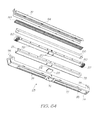
- a pagewidth printhead assembly for an inkjet printer comprising:
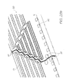
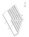
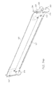
- the integrated circuits abut in an end-to-end arrangement across the length of the ink distribution member.
- the ends of the integrated circuits are shaped to have a straight edge to facilitate a rectangular join between neighbouring integrated circuits.
- the ends of the integrated circuits are shaped to have an angled edge to facilitate a sloping join between neighbouring integrated circuits.
- neighbouring integrated circuits are vertically offset from each other along the length of the ink distribution member.
- the rows of nozzles are arranged in a sloping arrangement across the surface of the integrated circuits.
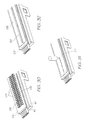
- the angled edge has an angle of 45°.
- the angled edge has a sawtooth profile.
- the nozzles of each of the rows adj acent one end of the integrated circuits are vertically displaced with respect to the remainder of the nozzles to provide a degree of nozzle overlap at the join and to maintain nozzle pitch across the join.
- the vertically displaced nozzles are arranged in a triangular configuration.
- the vertically displaced nozzles are arranged in a trapezoidal configuration.
- the distance of separation between neighbouring integrated circuits is less than 15 microns.
- a pagewidth printhead assembly wherein the inkjet printer comprises:
- a pagewidth printhead assembly wherein the printhead is arranged for use in a print engine of the inkjet printer, the print engine comprising:
- a pagewidth printhead assembly wherein the printhead is arranged for use with a cartridge unit comprising:
- a pagewidth printhead assembly wherein the printhead is arranged for use with a cartridge unit comprising:
- a pagewidth printhead assembly wherein the printhead is arranged for use with a cartridge unit comprising:
- a pagewidth printhead assembly wherein the printhead is arranged for use with a cartridge unit comprising:
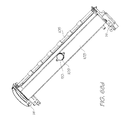
- a pagewidth printhead assembly wherein the body portion has one or more connectors formed thereon for securing the printhead assembly to the one or more ink sources to facilitate ink flow therebetween.
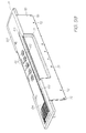
- a pagewidth printhead assembly wherein an electrical connector in electrical communication with the or each integrated circuit extends along the length of the printhead assembly for mating with a corresponding electrical connector of the inkjet printer.
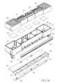
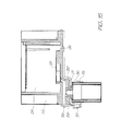
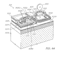
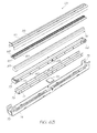
- a pagewidth printhead assembly wherein the body portion has one or more channels formed therein for distributing the ink substantially along the length of the printhead assembly and wherein the ink distribution member is a unitary element having a plurality of conduits formed therethrough, each of the conduits having an inlet which receives ink from one of the channels of the body portion and an outlet which delivers the ink to a predetermined number of nozzles of the one or more integrated circuits.
- a pagewidth printhead assembly wherein the ink distribution member comprises a first layer which directs the ink from the one or more channels of the body portion for delivery to each integrated circuit, and a second layer attached to said first layer for receiving and securing each integrated circuit in a position to receive the ink from the first layer.
- a pagewidth printhead assembly wherein the printhead of the assembly is arranged for use with a capping assembly for capping the printhead, the capping assembly comprising:
- a pagewidth printhead assembly wherein the printhead is arranged for use with a capping assembly for capping the pagewidth printhead of the pagewidth printhead assembly, the capping assembly comprising:
- a pagewidth printhead assembly the printhead being arranged for use with a capping assembly for capping the pagewidth printhead of the pagewidth printhead assembly, the capping assembly comprising:
- a pagewidth printhead assembly the printhead being arranged for use with a capping assembly for capping the pagewidth printhead of the pagewidth printhead assembly, the capping assembly comprising:
- a pagewidth printhead assembly the printhead of the assembly being arranged for use with a cradle unit comprising:
- a pagewidth printhead assembly the printhead of the assembly being arranged for use with a cradle unit comprising:
- a pagewidth printhead assembly the printhead of the assembly being arranged for use with a cradle unit comprising:
- a pagewidth printhead assembly the printhead of the assembly being arranged for use with a cradle unit comprising:
- a pagewidth printhead assembly the printhead of the assembly being arranged for use with a cradle unit comprising:
- a pagewidth printhead assembly the printhead of the assembly being arranged for use with a cradle unit having a body complementary to a removable inkjet cartridge of a type having a pagewidth printhead and an ink supply and a controller for controlling the operation of the printhead to facilitate printing; wherein the cradle unit is arranged for engagement with a cover assembly comprising:
- a pagewidth printhead assembly the printhead of the assembly being arranged for use with a cradle unit having a body complementary to a removable inkjet cartridge of a type having a pagewidth printhead and an ink supply and a controller for controlling the operation of the printhead to facilitate printing; wherein the cradle unit is arranged for engagement with a cover assembly comprising a refill actuator for dispensing ink from an ink refill unit into said refillable ink supply.
- a pagewidth printhead assembly the assembly being arranged in fluid communication with one or more ink storage compartments within a cartridge unit, the cartridge unit being arranged for use with an ink priming system comprising:
- a pagewidth printhead assembly the assembly being arranged in fluid communication with one or more ink storage compartments within a cartridge unit, the cartridge unit being arranged for use with an ink priming system comprising:
- a pagewidth printhead assembly the assembly being arranged for use in a cartridge unit adapted for refilling from a printing fluid refill cartridge that is arranged for use with a printing fluid dispenser comprising:
- a pagewidth printhead assembly the assembly being arranged for use in a printing unit, which is adapted for refilling with a supply of printing fluid by a method comprising the steps of:
- a pagewidth printhead assembly the assembly being arranged for use in a cartridge unit adapted for refilling from a printing fluid refill cartridge having a dispensing assembly comprising:
- a pagewidth printhead assembly the assembly being arranged for use in a print engine adapted for refilling from a printing fluid refill unit, wherein the refilling is controlled by a system comprising:
- a pagewidth printhead assembly the assembly being arranged for use in a print engine adapted for refilling from a printing fluid refill unit comprising an information storage element for storing information on the amount of printing fluid contained in the refill unit and for connecting with an information reader incorporated in the print engine for reading the information stored by the storage element when the refill unit is mounted to the print engine, wherein the information stored by the storage element enables the reader to control the refilling of the print engine with the printing fluid contained in the refill unit.
- a pagewidth printhead assembly the assembly being arranged for use with a printing unit adapted for refilling by a printing fluid refill cartridge wherein the refilling is controlled by a method comprising the steps of :
- a pagewidth printhead assembly the assembly being arranged for use in a printing cartridge having a printing fluid storage device comprising a porous body having a plurality of individual channels arranged in an array to store printing fluid and supply the stored printing fluid to at least one printing fluid ejecting nozzle of a printhead of a printer unit, wherein a first end of each of the channels is in fluid communication with a printing fluid supply to extract printing fluid from the fluid supply for storage therein under capillary action and the stored printing fluid is supplied to the at least one nozzle under capillary action.
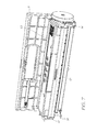
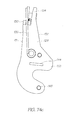
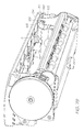
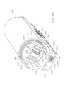
- the present invention resides in a print engine 1 that can be readily incorporated into a body of a printer unit 2 to perform the printing functions of the printer unit.
- the printer unit 2 which incorporates the print engine 1, may be in any form but typically has a media supply region 3 for supporting and supplying media 8 to be printed by the print engine, and a media output or collection region 4 for collecting the printed sheets of media.
- the printer unit 2 may also have a user interface 5 for enabling a user to control the operation of the printer unit, and this user interface 5 may be in the form of an LCD touch screen as shown.
- the printer unit 2 typically has an internal cavity 6 for receiving the print engine 1, and access to the internal cavity may be provided by a lid 7 which is hingedly attached to the body of the printer unit 2.
- the print engine 1 is configured to be positioned and secured within the printer unit 2 such that media 8 located in media supply region 3 can be fed to the print engine 1 for printing and delivered to the collection region 4 for collection following printing.
- the print engine 1 includes media transport means which take the sheets of media 8 from the media supply region 3 and deliver the media past the printhead assembly, where it is printed, into the media output tray 4.
- a picker mechanism 9 is provided with the printer unit 2 to assist in feeding individual streets of media 8 from the media supply 3 to the print engine 1.
- the printer unit 2 is arranged to print documents received from an external source, such as a computer system 702, onto a print media, such as a sheet of paper.
- the printer unit 100 includes means which allow electrical connection between the printer unit 2 and the computer system 702 to receive data which has been pre-processed by the computer system 702.
- the external computer system 702 is programmed to perform various steps involved in printing a document, including receiving the document (step 703), buffering it (step 704) and rasterizing it (step 706), and then compressing it (step 708) for transmission to the printer unit 2.
- the printer unit 2 receives the document from the external computer system 702 in the form of a compressed, multi-layer page image, wherein control electronics provided within the print engine 1 buffers the image (step 710), and then expands the image (step 712) for further processing.
- the expanded contone layer is dithered (step 714) and then the black layer from the expansion step is composited over the dithered contone layer (step 716).
- Coded data may also be rendered (step 718) to form an additional layer, to be printed (if desired) using an infrared ink that is substantially invisible to the human eye.
- the black, dithered contone and infrared layers are combined (step 720) to form a page that is supplied to a printhead for printing (step 722).
- the data associated with the document to be printed is divided into a high-resolution bi-level mask layer for text and line art and a medium-resolution contone color image layer for images or background colors.
- colored text can be supported by the addition of a medium-to-high-resolution contone texture layer for texturing text and line art with color data taken from an image or from flat colors.
- the printing architecture generalises these contone layers by representing them in abstract "image” and “texture” layers which can refer to either image data or flat color data.
- This division of data into layers based on content follows the base mode Mixed Raster Content (MRC) mode as would be understood by a person skilled in the art.
- MRC Mixed Raster Content
- the printing architecture makes compromises in some cases when data to be printed overlap. In particular, in one form all overlaps are reduced to a 3-layer representation in a process (collision resolution) embodying the compromises explicitly.
- data is delivered to the printer unit 2 in the form of a compressed, multi-layer page image with the pre-processing of the image performed by a mainly software-based computer system 702.
- the print engine 1 processes this data using a mainly hardware-based system as is shown in more detail in Figure 4 .
- a distributor 730 Upon receiving the data, a distributor 730 converts the data from a proprietary representation into a hardware-specific representation and ensures that the data is sent to the correct hardware device whilst observing any constraints or requirements on data transmission to these devices.
- the distributor 730 distributes the converted data to an appropriate one of a plurality of pipelines 732.
- the pipelines are identical to each other, and in essence provide decompression, scaling and dot compositing functions to generate a set of printable dot outputs.
- Each pipeline 732 includes a buffer 734 for receiving the data.
- a contone decompressor 736 decompresses the color contone planes, and a mask decompressor decompresses the monotone (text) layer.
- Contone and mask scalers 740 and 742 scale the decompressed contone and mask planes respectively, to take into account the size of the medium onto which the page is to be printed.
- the scaled contone planes are then dithered by ditherer 744.
- a stochastic dispersed-dot dither is used. Unlike a clustered-dot (or amplitude-modulated) dither, a dispersed-dot (or frequency-modulated) dither reproduces high spatial frequencies (i.e. image detail) almost to the limits of the dot resolution, while simultaneously reproducing lower spatial frequencies to their full color depth, when spatially integrated by the eye.
- a stochastic dither matrix is carefully designed to be relatively free of objectionable low-frequency patterns when tiled across the image. As such, its size typically exceeds the minimum size required to support a particular number of intensity levels (e.g. 16 x 16 x 8 bits for 257 intensity levels).
- the dithered planes are then composited in a dot compositor 746 on a dot-by-dot basis to provide dot data suitable for printing.
- This data is forwarded to data distribution and drive electronics 748, which in turn distributes the data to the correct nozzle actuators 750, which in turn cause ink to be ejected from the correct nozzles 752 at the correct time in a manner which will be described in more detail later in the description.
- the components employed within the print engine 1 to process the image for printing depend greatly upon the manner in which data is presented.
- the print engine 1 may employ additional software and/or hardware components to perform more processing within the printer unit 2 thus reducing the reliance upon the computer system 702.
- the print engine 1 may employ fewer software and/or hardware components to perform less processing thus relying upon the computer system 702 to process the image to a higher degree before transmitting the data to the printer unit 2.
- SoPEC Small Office Home Office Printer Engine Chip
- a SoPEC device consists of 3 distinct subsystems: a Central Processing Unit (CPU) subsystem 771, a Dynamic Random Access Memory (DRAM) subsystem 772 and a Print Engine Pipeline (PEP) subsystem 773.
- CPU Central Processing Unit
- DRAM Dynamic Random Access Memory
- PEP Print Engine Pipeline
- the CPU subsystem 771 includes a CPU 775 that controls and configures all aspects of the other subsystems. It provides general support for interfacing and synchronizing all elements of the print engine 1. It also controls the low-speed communication to QA chips (which are described delow).
- the CPU subsystem 771 also contains various peripherals to aid the CPU, such as General Purpose Input Output (GPIO, which includes motor control), an Interrupt Controller Unit (ICU), LSS Master and general timers.
- GPIO General Purpose Input Output
- ICU Interrupt Controller Unit
- LSS Master General Timers.
- the Serial Communications Block (SCB) on the CPU subsystem provides a full speed USB1.1 interface to the host as well as an Inter SoPEC Interface (ISI) to other SoPEC devices (not shown).
- ISI Inter SoPEC Interface
- the DRAM subsystem 772 accepts requests from the CPU, Serial Communications Block (SCB) and blocks within the PEP subsystem.
- the DRAM subsystem 772 and in particular the DRAM Interface Unit (DIU), arbitrates the various requests and determines which request should win access to the DRAM.
- the DIU arbitrates based on configured parameters, to allow sufficient access to DRAM for all requestors.
- the DIU also hides the implementation specifics of the DRAM such as page size, number of banks and refresh rates.
- the Print Engine Pipeline (PEP) subsystem 773 accepts compressed pages from DRAM and renders them to bi-level dots for a given print line destined for a printhead interface (PHI) that communicates directly with the printhead.
- the first stage of the page expansion pipeline is the Contone Decoder Unit (CDU), Lossless Bi-level Decoder (LBD) and, where required, Tag Encoder (TE).
- the CDU expands the JPEG-compressed contone (typically CMYK) layers
- the LBD expands the compressed bi-level layer (typically K)
- the TE encodes any Netpage tags for later rendering (typically in IR or K ink), in the event that the printer unit 2 has Netpage capabilities.
- the output from the first stage is a set of buffers: the Contone FIFO unit (CFU), the Spot FIFO Unit (SFU), and the Tag FIFO Unit (TFU).
- the CFU and SFU buffers are implemented in DRAM.
- the second stage is the Halftone Compositor Unit (HCU), which dithers the contone layer and composites position tags and the bi-level spot layer over the resulting bi-level dithered layer.
- HCU Halftone Compositor Unit
- a number of compositing options can be implemented, depending upon the printhead with which the SoPEC device is used. Up to 6 channels of bi-level data are produced from this stage, although not all channels may be present on the printhead.
- the printhead may be CMY only, with K pushed into the CMY channels and IR ignored.
- any encoded tags may be printed in K if IR ink is not available (or for testing purposes).
- a Dead Nozzle Compensator compensates for dead nozzles in the printhead by color redundancy and error diffusing of dead nozzle data into surrounding dots.
- the resultant bi-level 5 channel dot-data (typically CMYK, Infrared) is buffered and written to a set of line buffers stored in DRAM via a Dotline Writer Unit (DWU).
- CMYK Infrared
- DWU Dotline Writer Unit
- the dot-data is loaded back from DRAM, and passed to the printhead interface via a dot FIFO.
- the dot FIFO accepts data from a Line Loader Unit (LLU) at the system clock rate ( pclk ), while the PrintHead Interface (PHI) removes data from the FIFO and sends it to the printhead at a rate of 2/3 times the system clock rate.
- LLU Line Loader Unit
- PHI PrintHead Interface
- the DRAM is 2.5Mbytes in size, of which about 2Mbytes are available for compressed page store data.
- a compressed page is received in two or more bands, with a number of bands stored in memory.
- a band of the page is consumed by the PEP subsystem 773 for printing, a new band can be downloaded.
- the new band may be for the current page or the next page.
- the embedded USB 1.1 device accepts compressed page data and control commands from the host PC, and facilitates the data transfer to either the DRAM (or to another SoPEC device in multi-SoPEC systems, as described below).
- SoPEC devices can be used in alternative embodiments, and can perform different functions depending upon the particular implementation. For example, in some cases a SoPEC device can be used simply for its onboard DRAM, while another SoPEC device attends to the various decompression and formatting functions described above. This can reduce the chance of buffer under-run, which can happen in the event that the printer commences printing a page prior to all the data for that page being received and the rest of the data is not received in time. Adding an extra SoPEC device for its memory buffering capabilities doubles the amount of data that can be buffered, even if none of the other capabilities of the additional chip are utilized.
- Each SoPEC system can have several quality assurance (QA) devices designed to cooperate with each other to ensure the quality of the printer mechanics, the quality of the ink supply so the printhead nozzles will not be damaged during prints, and the quality of the software to ensure printheads and mechanics are not damaged.
- QA quality assurance
- each printing SoPEC will have an associated printer unit QA, which stores information relating to the printer unit attributes such as maximum print speed.
- the cartridge unit may also contain a QA chip, which stores cartridge information such as the amount of ink remaining, and may also be configured to act as a ROM (effectively as an EEPROM) that stores printhead-specific information such as dead nozzle mapping and printhead characteristics.
- the refill unit may also contain a QA chip, which stores refill ink information such as the type/colour of the ink and the amount of ink present for refilling.
- the CPU in the SoPEC device can optionally load and run program code from a QA Chip that effectively acts as a serial EEPROM. Finally, the CPU in the SoPEC device runs a logical QA chip (ie, a software QA chip).
- Each SoPEC device has two LSS system buses that can communicate with QA devices for system authentication and ink usage accounting.
- a large number of QA devices can be used per bus and their position in the system is unrestricted with the exception that printer QA and ink QA devices should be on separate LSS busses.
- the logical QA communicates with the ink QA to determine remaining ink.
- the reply from the ink QA is authenticated with reference to the printer QA.
- the verification from the printer QA is itself authenticated by the logical QA, thereby indirectly adding an additional authentication level to the reply from the ink QA.
- Data passed between the QA chips is authenticated by way of digital signatures.
- HMAC-SHA1 authentication is used for data
- RSA is used for program code, although other schemes could be used instead.
- the SoPEC device therefore controls the overall operation of the print engine 1 and performs essential data processing tasks as well as synchronising and controlling the operation of the individual components of the print engine 1to facilitate print media handling, as will be discussed below.
- the print engine 1 is shown in detail in Figs. 6 - 8 and consists of two parts: a cartridge unit 10 and a cradle unit 12.
- the cartridge unit 10 is shaped and sized to be received within the cradle unit 12 and secured in position by a cover assembly 11 mounted to the cradle unit.
- the cradle unit 12 is provided with an external body 13 having anchor portions 14 which allow it to be fixed to the printer unit 2 in a desired position and orientation, as discussed above, to facilitate printing.
- the print engine 1 is able to control various aspects associated with printing, including transporting the media past the printhead in a controlled manner as well as the controlled ejection of ink onto the surface of the passing media.
- the print engine 2 may also include electrical contacts which facilitate electrical connection with the user interface 5 of the printer unit 2 to enable control of the print engine 1.
- the cartridge unit 10 is shown in detail in Figs. 9 - 12 .
- the cartridge unit 10 generally consists of a main body 20, a lid assembly 21, a printhead assembly 22 and a capper assembly 23.
- the cartridge unit 10 has facilities for receiving a refill supply of ink to replenish the ink storage when necessary and the cartridge unit itself carries an integral capping assembly 23 for capping the printhead when not in use.
- the main body 20 of the cartridge unit 10 is shown in more detail in Figs 13 - 15 and comprises a moulded plastics body which defines a plurality of ink storage compartments 24 in which the various colours and/or types of ink are stored. Each of the ink storage compartments 24 are separated from one another to prevent mixing of the different inks, as is shown more clearly in Figure 14 , and extend along the length of the main body 20.
- each of the ink storage compartments 24 is provided with a raised portion 26 which surrounds an ink outlet 27, through which the ink flows for supply to the printhead assembly 22.
- the raised portions 26 are typically moulded into the main body 20 and act to separate the outlet 27 from the base 25 of the ink storage compartment 24 to ensure a sufficient flow rate of ink from the compartment 24.
- an air barrier/ink filter 28 made from a fine mesh material is placed over the ink outlet 27, atop of the raised portions 26, thereby leaving a space between the filter and the outlet for receiving ink.
- the air barrier/ink filter 28 is formed such that ink can readily pass through the mesh to the printhead assembly 22 but any air bubbles present in the ink are prevented from passing through.
- the ink storage compartments 24 are provided with an absorbent material 29 such as a foam for storing the ink.
- the absorbent material 29 is shaped to conform to the shape of the ink storage compartment 24 and is fitted within the corresponding compartment to be supported on top of the air barrier/ink filter 28. In this arrangement, the lower surface of the absorbent material 29 is separated from the base 25 of the ink storage compartments via the raised portions 26.
- the absorbent material 29 acts to absorb ink supplied to the compartment 24 such that the ink is suspended internally within.
- the manner in which ink is supplied to the compartment 24 will be discussed in more detail later, however it should be appreciated that the structure of the absorbent material is such that it contains a number of open pores which receive and draw in the ink under capillary action.
- the ink fills the space between the ink filter/air barrier 28 and the outlet 27 thereby forming an ink dam, which is in fluid communication with the ink in the printhead assembly 22 and the ink suspended within the absorbent material 29. Due to the nature of the absorbent material 29 and the fact that the ink is retained therein under capillary action, a back pressure is created which prevents the ink from freely flowing from the compartment 24 and out the nozzles of the printhead assembly 22.
- the absorbent material 29 may be provided as a block or stack of layers made from a polymer material, such as polycarbonate, acrylic, polysulfone, polystyrene, fluoropolymer, cyclic olefin polymer, cyclic olefin copolymer, etc, having the channels 16 formed therein in the form of a micro-capillary array, as shown in Fig. 16 , with each channel having an average diameter of about 10 microns or less.
- a polymer material such as polycarbonate, acrylic, polysulfone, polystyrene, fluoropolymer, cyclic olefin polymer, cyclic olefin copolymer, etc, having the channels 16 formed therein in the form of a micro-capillary array, as shown in Fig. 16 , with each channel having an average diameter of about 10 microns or less.
- the body of the absorbent material 29, in which the micro-capillary array of the channels 16 is formed remains stable and rigid at all times. That is, the rigid walls of the channels remain intact during exposure to the ink whereby particulate matter is not introduced into the ink, unlike the cellular or interlaced arrangement of compressible pores within the conventional foam and sponge materials which contribute to contaminant production.
- the absorbent material 29 having the channels 16 formed as a micro-capillary array therein can be arranged within the individual ink storage compartments 24 as shown in Fig 17 .
- An ink trapping layer 17 is provided between the ink filter/air barrier 28 and the absorbent material 29.
- the trapping layer 17 absorbs the supplied ink in multiple-directions, thus allowing for the ingress of the ink into the longitudinally orientated channels 16, and in this regard merely acts as a means for presenting the ink to the channels 16.
- the trapping layer 17 may be provided as a foam or sponge material with a thickness substantially less than that of the absorbent material 29, since the function of the trapping layer is merely to supply ink to the channels 16 of the absorbent material 29 and not to store the ink.
- the ink drawn into and stored within the channels 16 is able to pass to the nozzles of the printhead assembly 22 via the ink trapping layer 17.
- the use of foam or sponge material in the ink trapping layer 17 may result in some particulate contamination occurring in the ink. However, this may be minimized by providing the layer with a thickness and density which is just sufficient for absorbing the necessary amount of ink for effective absorption into the channels 16. In any event, since the ink is effectively stored only in the absorbent material 29, the contaminant level that may be produced in the ink trapping layer is significantly reduced from the levels produced by the conventional structures.
- a pressed metal chassis 30 is fitted to the underside of the main body via clips 31 formed in the chassis 30 which mate with corresponding clips formed in the main body 20.
- the pressed metal chassis 30 is shaped to conform to the underside of the main body 20 and includes a plurality of holes 32 that extend therethrough which are positioned to correspond with the ink outlets 27 of the ink storage compartments 24 such that there is a passage for ink to pass through the chassis 30.
- the chassis 30 provides additional stability to the cartridge unit 10 and includes an edge 33 that extends downwardly from the main body 20 which defines a contact region where the flex printed circuit board 52 of the printhead assembly 22 contacts with corresponding electrical contacts 128 in the cradle unit 12, in a manner which will be described in more detail later in the description.
- the chassis 30 also has a plurality of elongate recesses 34 formed along its length, through which connecting clips provided on the printhead assembly 22 pass, for connection to the main body 20, as will be described in more detail below.
- a seal moulding 35 is attached to the chassis 30 to complete and seal the ink flow path from the ink storage compartments 24 through the chassis 30.
- the seal moulding 35 is made from an elastomeric material and has a plurality of hollow cylindrical inserts 36 formed along its surface which extend through the holes 32 formed in the chassis 30 and into the ink outlets 27 of each of the ink storage compartments 24, as shown in Fig 15 .
- the distal ends of the hollow cylindrical inserts 36 abut with the main body 20 to seal the ink outlets 27 and ensure ink flow through the seal moulding 35.
- the seal moulding 35 is fixed to the surface of the metal chassis 30 by a lock-fit or a suitable adhesive and acts to provide a substantially planar surface upon which the printhead assembly 22 is attached.
- the planar surface having a plurality of outlet holes 39 provided therein through which ink can flow to the printhead assembly.
- a flex printed circuit board (PCB) backer 37 is attached to the side of the main body 20 via locating studs 38 and extends over the downwardly projecting edge 33 of the chassis 30.
- the flex PCB backer 37 is made from a suitable elastomeric material and provides a backing onto which the flex PCB 52 of the printhead assembly 22 is supported following attachment of the printhead assembly 22 to the main body 20.
- the flex PCB 52 from the printhead assembly 22 is provided with a suitable recess which fits over the locating studs 38 such that the electrical dimpled contacts 53 formed on the flex PCB 52 are positioned over the flex PCB backer 37 and extend outwardly therefrom to contact suitable electrical contacts 128 provided in the cradle unit 12.
- This arrangement provides some degree of flexibility in this contact region such that appropriate electrical contact can be established between the cradle unit 12 and the cartridge unit 10 to allow the transmission of data and power therebetween to control the ink ejecting nozzles of the printhead assembly 22.
- This arrangement also ensures that the forces associated with the contact between the cartridge unit 12 and the cradle unit 10 in this region are carried by the chassis 30 and not transferred to the printhead assembly 22 which could cause damage to the delicate printhead integrated circuits.
- the main body 20 also includes a pair of end supports 40 which extend from the main body 20 in a downward direction with respect to the cartridge unit 10.
- the end supports 40 are arranged such that the seal moulding 35 and the flex PCB backer 37 extend along the main body 20 between the two end supports 40. The purpose of the end supports 40 will be described later in the description.
- the printhead assembly 22 is shown in more detail in Figs. 18 to 21 , and is adapted to be attached to the underside of the main body 20 to receive ink from the outlet holes 39 formed in the planar surface of the seal moulding 35.
- the printhead assembly 22 comprises an upper moulding 42, having features which facilitate connection of the printhead assembly to the main body 20 of the cartridge unit 10. These features are in the form of u-shaped clips 43 that project from the surface of the upper moulding 42.
- the clips 43 pass through the elongate recesses 34 provided in the chassis 30 and become captured by lugs (not shown) formed in the main body 20, thereby securing the printhead assembly 22 to the main body 20.
- the surface of the upper moulding 42 has a plurality of ink inlets 44 which proj ect therefrom.
- the ink inlets 44 are received within the outlet holes 39 of the seal moulding 35, when the printhead assembly 22 is secured to the main body 20, and provide a path for the ink to flow to the printhead integrated circuits for printing.
- the ink inlets 44 are shaped to fit within the outlet holes 39 of the seal moulding 35 and may also be provided with an outer coating that facilitates sealing.
- the upper moulding 42 is made from a liquid crystal polymer (LCP) and is bonded to a lower moulding 45 via an adhesive film 46.
- the lower moulding 45 is also made from an LCP and has a plurality of channels 47 formed along its length. Each of the channels 47 are provided to receive ink from one of the ink storage compartments 24, via an ink inlet 44, and distribute the ink along the length of the printhead assembly 22 for feeding to the ink delivery nozzles 51 of the printhead assembly 22.
- the channels preferably have a width of 1 mm and are separated by walls having a width of 0.75 mm.
- the lower moulding 45 has five channels 47 extending along its length with each of the ink channels 47 receiving ink from one of the corresponding ink inlets 44.
- the adhesive film 46 also acts to seal the individual ink channels 47 and prevent cross channel mixing of the ink when the lower moulding 45 is assembled to the upper moulding 42.
- an ink distribution member 48 is attached to the lower moulding 45 and acts as an interface between the printhead ICs 50 and the ink channels 47 of the lower moulding 45.
- the purpose of the ink distribution member 48 is to provide a flow path for ink to flow from the relatively wide channels 47 to the relatively small and narrow channels 98 formed on the underside of the printhead ICs 50 which feed the ink to the individual ink delivery nozzles 51.
- the ink distribution member 48 functions to perform millimetric-to-micrometric fluid distribution to the nozzles of the printhead ICs 50
- the present invention is related to page-width printing and as such the printhead ICs 50 are arranged to extend horizontally across the width of the passing media to deposit ink droplets thereon to create an image.
- individual printhead ICs 50 are linked together in abutting arrangement across the surface of the ink distribution member 48 of the printhead assembly 22, as shown simply in Fig 22 .
- the length of an individual printhead IC 50 is around 20 - 22 mm and as such in order to print an A4/LTS letter sized page, 11 - 12 individual printhead ICs 50 may be linked together in abutting fashion.
- Other printing sizes may also be possible and as such the number of individual printhead ICs 50 required may vary depending upon the application.
- Each printhead IC 50 has a plurality of individual ink delivery nozzles 51 formed therein, the structure and control of which will be described in more detail later.
- the nozzles 51 within an individual printhead IC 50 are grouped physically to reduce ink supply complexity and wiring complexity, and are also grouped logically to minimize power consumption and to allow a variety of printing speeds.
- each printhead IC 50 is able to print five different colours ( C, M, Y, K and IR) and contains 1280 ink delivery nozzles 51 per colour, with these nozzles being divided into even and odd nozzles (640 each). Even and odd nozzles for each colour are provided on different rows on the printhead IC 50 and are aligned vertically to perform true 1600 dpi printing, meaning that the nozzles 51 are arranged in 10 rows.
- the horizontal distance between two adjacent nozzles 51 on a single row is 31.75 microns, whilst the vertical distance between rows of nozzles is based on the firing order of the nozzles, but rows are typically separated by an exact number of dot lines, plus a fraction of a dot line corresponding to the distance the paper will move between row firing times Also, the spacing of even and odd rows of nozzles for a given colour must be such that they can share an ink channel, as will be described below.
- the manner in which individual printhead ICs 50 are linked together in abutting fashion may be performed in a variety of ways. As shown in Fig. 23 , the simplest way to achieve this linkage of the printhead ICs 50 is to form a rectangular join between adjacent ICs 50. However, due to the nature of this rectangular join, it may result in a gap between adjacent nozzles at the join interface which could produce a vertical stripe down the printed page of media where no ink is deposited, which may be unacceptable in some printing applications.
- the ICs 50 may be provided with a vertical offset, as shown in Fig 25 .
- This offset can be seen by the vertical offset between the longitudinal edges of adjacent ICs 50, and this offset increases with each join along the length of the printhead assembly 22. For example, if the offset was equivalent to 7 lines of nozzles per join, then for 11 ICs joined in this manner, there would be a total of 10 joins and 70 additional nozzle lines. This then results in an increase in the lines of data storage required for the printhead assembly.
- each IC 50 may be placed on a mild slope to achieve a constant number of print lines regardless of the number of joins, as shown in Fig. 26 .
- Fig. 27a and 27b Yet another system for linking the ICs 50 in abutting fashion is shown in Fig. 27a and 27b .
- the ICs 50 are shaped at their ends to link together to form a horizontal line of ICs, with no vertical offset between neighboring ICs.
- a sloping join is provided between the ICs which has a 45 degree angle to the upper and lower chip edges.
- the joining edge is not straight and has a sawtooth profile to facilitate positioning, and the ICs 50 are intended to be spaced about 11 microns apart, measured perpendicular to the joining edge.
- the left most ink delivery nozzles on each row are dropped by 10 line pitches and arranged in a triangle configuration as shown in Fig 27a and Figs.
- This arrangement provides a degree of overlap of nozzles at the join and maintains the pitch of the nozzles to ensure that the drops of ink are delivered consistently along the printing zone. This arrangement also ensures that more silicon is provided at the edge of the IC 50 to ensure sufficient linkage. Control of the operation of the nozzles is performed by the SoPEC device, however compensation for the nozzles is performed in the printhead, or may also be performed by the SoPEC device, depending on the storage requirements. In this regard it will be appreciated that the dropped triangle arrangement of nozzles disposed at one end of the IC 50 provides the minimum on-printhead storage requirements. However where storage requirements are less critical shapes other than a triangle can be used, for example, the dropped rows may take the form of a trapezoid.
- Fig. 28a shows more clearly the upper surface of a portion of the individual ICs.
- bond pads 96 are provided along an edge thereof which provide a means for receiving data and or power to control the operation of the nozzles from the SoPEC of the cradle unit 12.
- Fiducials 97 are also provided on the surface of the ICs to assist in positioning and aligning the ICs 50 with respect to each other.
- the fiducials 97 are in the form of markers that are readily identifiable by appropriate positioning equipment to indicate the true position of the IC 50 with respect to a neighbouring IC 50, and are strategically positioned at the edges of the IC, proximal the join.
- the fiducials 97 align with corresponding fiducials 97 provided on the surface of a neighbouring IC 50 to ensure alignment of the ICs to appropriate limits, as discussed above.
- the underside of a printhead IC 50 is shown in relation to Fig 28c .
- a number of etched channels 98 there are provided a number of etched channels 98, with each channel 98 in communication with a pair of rows of nozzles 51.
- the channels 98 are about 80 microns wide and extend the length of the IC 50 and include silicon walls 99 formed therein, to divide the channels 98 into portions.
- the channels are adapted to receive ink from the ink channels 47 of the lower moulding 45 and distribute the ink to the pair of rows of nozzles 51 to eject that ink of a specific colour or type.
- each portion feeds approximately 128 nozzles and is individually fed a supply of ink.
- Each of the ICs 50 are positioned and secured to the surface of the ink distribution member 48.
- the ink distribution member delivers the ink from the 1 mm wide channels 47 formed in the lower moulding 45 to the 80 micron wide channels 98 formed in the underside of the printhead ICs 50.
- the ink distribution member 48 can be configured in a number of forms.
- the ink distribution member 48 may be in the form of a laminated structure consisting of a number of layers bonded to one another, as described in U.S. Patent No. 6,409,323 and pending US Application No. 2004/0113997 .
- the ink distribution member 48 may be in a two-part form comprising an intermediate layer 172 and an adhesive layer 173, as shown in Fig. 29 .
- the intermediate layer 172 is arranged to fit over the exposed channels 47 of the lower moulding 45 to seal the channels 47 and to form a sealed unit with the lower moulding 45.
- the intermediate layer 172 has a plurality of holes 174 formed therethrough along its length each of which are aligned with the channels 47 and are spaced at regular intervals along the length thereof.
- the holes 174 formed through the intermediate layer 172 which relate to the most central channel 47 of the lower moulding 45 are in the form of small diameter holes equi-spaced at intervals along the length of the intermediate layer 172. Larger diameter holes 174 are provided which correspond to the other channels 47 of the lower moulding 45, which are displaced laterally from the most central channel. These holes 174 are similarly equi-spaced along the length of the intermediate layer and micro conduits 176 are provided which extend from the larger diameter holes to terminate at a central region of the intermediate layer 172, proximal the smaller diameter holes. These conduits 176 distribute the ink from each of the holes 172 to a central region of the intermediate layer to deliver the different types/colours of ink to the channels 98 formed in the underside of the integrated circuits 50.
- the intermediate layer 172 is also made from a liquid crystal polymer (LCP) which is injection moulded to the appropriate shape and configuration.
- LCP liquid crystal polymer
- the intermediate layer 172 is bonded to the lower moulding 45 via a thermal adhesive, such as 3M 816 or Abelflex 5206 or 5205, which is applied between the intermediate layer 172 and the lower moulding 45 and placed in a laminator.
- the bonding film 175 is applied to the surface of the intermediate layer 172.
- the bonding film 175 is in the form of a laminate polymer film which may be a thermoplastic film such as a PET or Polysulphone film, or it may be in the form of a thermoset film, such as those manufactured by AL technologies and Rogers Corporation.
- the bonding film 175 preferably has co-extruded adhesive layers formed on both sides thereof and is laminated onto the upper surface of the intermediate layer 172
- holes are drilled through the bonding layer 175 to coincide with the centrally located small diameter holes 174, and the ends of the conduits 176. This is shown in Fig. 31 . These holes provide a separate flow passage through the bonding layer 175 for each of the different types of inks, which feed directly to the appropriate channel portions 98 formed on the underside of the integrated circuits 50 for supply to the ink delivery nozzles 51 associated with each channel portion 98, as discussed above. Fiducial locating marks 177 are also drilled into the surface of the bonding layer to assist in attaching and positioning the ICs 50 thereon.
- the ICs 50 are placed in a die and heated to 170° C and then pressed into the bonding layer 175 at 40 psi pressure for about 3 seconds. This results in the ICs 50 being thermally bonded to the intermediate layer 172, as shown in Fig 32 .
- the fiducial locating marks 177 formed in the surface of the bonding layer 175 aid in positioning the ICs such that the channels 98 formed in the underside of the ICs 50 correctly align with the holes drilled through the bonding layer 175 to provide a flow path for ink to be fed to the nozzles for printing.
- the ink distribution member 48 is in the form of a two part element containing an intermediate layer 172 which fits over the channels 47 formed in the lower moulding 45, and a bonding layer 175 allowing fluid flow therethrough and which acts to attach the ICs to the surface of the intermediate layer 172.
- the ink distribution member 48 may be in the form of a one-piece element with the ICs being directly attached to its upper surface.
- the conduits are formed within the body of the ink distribution member 48 such that the upper surface of the ink distribution member only has small diameter holes formed centrally therein for delivering the ink to the undersurface of the ICs.
- FIGs 33a - 33c The manner in which this is achieved is shown in Figs 33a - 33c . These Figures merely show the manner in which the ink can be directed from one of the channels 47 of the lower moulding 45, and it will be appreciated that the same approach can be similarly applied to deliver ink from the remainder of the channels 47.
- the underside of the ink distribution member 48 is provided with a plurality of holes or inlets 180 therein, each having a diameter of approximately 1 mm, which corresponds to the width of the channels 47 provided in the lower moulding 45.
- the inlets 180 do not extend through the body of the ink distribution member 48, but rather extend into the member 48 to a depth of about a 3/4 the thickness of the member 48, as shown in the sectioned view of Fig 33c .
- an outlet 182 in the form of a 80 micron wide hole, is provided in the uppermost surface of the ink distribution member 48 which extends into the end wall of the inlet 180 to provide a path for the ink to flow out of the ink distribution member.
- a tunnel 181 is provided from a side wall of the inlet 180 within the ink distribution member 48 which acts to direct the flow of the ink received in the inlet through the body of the ink distribution member 48 to a central position therein.
- An outlet 182 is then formed on an uppermost side of the ink distribution member to provide a path for the ink present in the tunnel 181 to exit the ink distribution member at the desired position along the surface of the ink distribution member.
- the outlets 182 are essentially 80 microns in width, to correspond with the width of the channels 98 provided on the underside of the integrated circuits 50.
- the ink distribution member 48 of this embodiment is made from a photo-structurable glass-ceramic material, such as Forturan glass. These materials, when exposed to specific levels of pulsed UV laser energy density (fluence), have a photo-chemical reaction which creates a density of nanocrystals within the volume thereof, the density of which is directly proportional to the fluence of the exposed laser beam.
- the ink distribution member 48 in order to form the desired inlets 180, outlets 182 and tunnels 181 connecting the inlets and outlets, the ink distribution member 48 is mounted upon a precision XYZ stage for exposure to a focussed laser beam.
- Various tools may be used to control the size and shape of the critically exposed volume of the glass structure to ensure that the desired pattern and shape is created within the ink distribution member. Typical exposure times may vary from 15 minutes to 1 hour.
- the ink distribution member is loaded into an oven for thermal treatment to aid in causing crystallisation of exposed regions of the glass.
- the exposed and thermally treated glass is then loaded into a mild etchant for around 7 minutes to etch the exposed regions, however the etch time may vary dependant upon the thickness of the glass and the depth of the cut.
- the thermal treatment and etching steps may be repeated in order to form the complete ink distribution member as shown in the figures.
- ink present in the channels 47 of the lower moulding 45 is drawn into the ink distribution member 48 via inlets 180 which are positioned over the channels 47 at regular intervals therealong.
- the ink is directed to a central region of the ink distribution member 48 via the above mentioned tunnels 181, where the ink can then exit the ink distribution member 48 via the outlets 182 at a predetermined position which is aligned with the corresponding channels 98 formed in the underside of the ICs 50.
- the ICs 50 are secured to the upper surface of the ink distribution member 48 to receive the ink therefrom, using spun coated adhesive applied to the underside of the IC 50, or by screen printing epoxy on the upper surface of the ink distribution member 48.
- the fiducials provided on the ICs 50 and on the surface of the ink distribution member 48 assist in positioning the ICs 50 such that the channels 98 formed in the underside of the ICs 50 are aligned with the appropriate outlet 182 formed in the upper surface of the member 48 to receive the correct type/colour of ink.
- Figs. 34a and 34b show the manner in which this is arranged to control the delivery of ink from the five channels 47 of the lower moulding 45. These figures provide a top view of the arrangement and for reasons of clarity, the various elements are shown in outline to indicate the manner in which ink flows between the elements.
- Fig 34a is a top view of the arrangement showing the ICs 50 located centrally upon the ink distribution member 48.
- the ink distribution member 48 is in turn secured to the lower moulding 45 such that the inlets 180 align with the respective channels 47 at regular intervals along the length thereof to receive ink from the channels 47 for distribution to the ICs 50.
- the inlets 180 associated with the central channel 47 are in direct fluid communication with an outlet 182, which delivers the ink to the underside of the ICs 50.
- the inlets 180 associated with the other channels 47 include tunnels 181 formed within the ink distribution member 48 which are in fluid communication with associated outlets 182 disposed remote from the inlets 180 to deliver ink to the underside of the ICs 50.
- the outlets 182 are centrally arranged on the upper surface of the ink distribution member in a predetermined pattern, with the position of each outlet defining a point at which ink of a specific colour is delivered to the IC 50.
- Fig 34b is a magnified view of Fig 34a , showing in detail the manner in which the ink is supplied to the underside of the ICs 50.
- the channels 98 formed on the underside of the IC 50 are clearly shown, as are the silicon walls 99 provided along the length of the channels 98, which divide the channels 98 into portions.
- the ICs 50 are positioned on the surface of the ink distribution member such that the outlets 182 align with the channels 98 at the junction of the channel portions, namely at the region where the silicon walls 99 are situated. This then ensures that one outlet 182 supplies ink to two channel portions, allowing a regular spacing of outlets to be achieved along the surface of the ink distribution member 48.
- the ink distribution member 48 is in the form of a on-piece element thereby overcoming the need to provide separate layers and reducing the complexity of the system, as sealing between layers is no longer required.
- a flex PCB 52 is attached along an edge of the ICs 50 so that control signals and power can be supplied to the bond bads 96 of the ICs 50 to effect printing.
- the flex PCB 52 folds around the printhead assembly 22 in an upward direction with respect to the cartridge unit 10, and has a plurality of dimpled contacts 53 provided along its length for receiving power and or data signals from the control circuitry of the cradle unit 12.
- a plurality of holes 54 are also formed along the distal edge of the flex PCB 52 which provide a means for attaching the flex PCB 52 to the locating studs 38 formed on the main body 20, such that the dimpled contacts 53 of the flex PCB 52 extends over the flex PCB backer 37.
- the manner in which the dimpled contacts 53 of the flex PCB 52 contact the power and data contacts 128 of the cradle unit 12 is described later.
- a media shield 55 is attached to the printhead assembly 22 along an edge thereof and acts to protect the printhead ICs 50 from damage which may occur due to contact with the passing media.
- the media shield 55 is attached to the upper moulding 42 upstream of the printhead ICs 50 as shown more clearly in Fig. 21 , via an appropriate clip-lock arrangement or via an adhesive. When attached in this manner, the printhead ICs 50 sit below the surface of the media shield 55, out of the path of the passing media.
- a space 56 is provided between the media shield 55 and the upper 42 and lower 45 moulding which can receive pressurized air from an air compressor or the like. As this space 56 extends along the length of the printhead assembly 22, compressed air can be supplied to the space 56 from either end of the printhead assembly 22 and be evenly distributed along the assembly.
- the inner surface 57 of the media shield 55 is provided with a series of fins 58 which define a plurality of air outlets evenly distributed along the length of the media shield 55 through which the compressed air travels.
- This arrangement therefore provides a stream of air across the printhead ICs 50 in the direction of the media delivery which acts to prevent dust and other particulate matter carried with the media from settling on the surface of the printhead ICs, which could cause blockage and damage to the nozzles.
- FIG. 21 A cross section of the complete printhead assembly 22 is shown in Fig. 21 .
- ink is received from the ink storage compartments 24 via the ink inlets 44 of the upper moulding 42, which feed the ink directly into one of the ink channels 47 of the lower moulding 45.
- the ink is in turn fed from the ink channels 47 to the ink delivery nozzles 51 of the printhead ICs 50 by way of the ink distribution member 48.
- the lower moulding 45 is provided with a plurality of priming inlets 59 at one end thereof.
- Each of the priming inlets 59 communicate directly with one of the channels 47 and provide a means for priming the printhead assembly 22 and the ink storage compartments 24 with ink prior to shipment and use.
- Figs 35 - 40 Various ways in which the priming is achieved will now be described with reference to Figs 35 - 40 .
- Fig. 35 is a simplified cross-sectional representation of an ink storage compartment 24 as described previously.
- Ink is primed into the absorbent material 29 through the ink outlet 27 which links the compartment 24 to the channels 47 of the printhead assembly 22.
- the ink is supplied via the priming inlets 59 along the channels 47 of the lower moulding 45, with each channel 47 in fluid communication with one ink outlet 27 of an ink storage compartment 24 to deliver ink of a specific type/colour to that ink storage compartment 24.
- Priming of the ink storage compartments 24 is typically performed prior to shipment of the cartridge unit 10 and as such, an ink source can be temporarily attached to the priming inlets 59, wherein upon completion of priming, the priming inlets can be capped/sealed.
- priming ink is supplied under pressure to the ink storage compartment 24 via the ink outlets 27.
- the priming ink flows into the space between the ink filter/air barrier 28 and the outlet 27, and is absorbed into the absorbent material 29 through the ink filter/air barrier 28.
- the ink becomes suspended within the absorbent material due to capillary attraction forces.
- the ink is able to be continually drawn into the pores of the absorbent material 29 via capillary action (as shown by arrows B).
- ink present in the channels 47 of the lower moulding 45 is also supplied to the ink delivery nozzles 51 of the integrated circuits 50, via the ink distribution member 48.
- the ink flows to the nozzles 51 to prime the individual nozzles with ink, and due to the capillary action of the absorbent material 29 in the ink storage compartments 24, a sufficient backpressure is established in the ink supply to prevent leakage of the ink out of the nozzles 51.
- the priming operation is ceased before the absorbent material becomes completely saturated and its upper surface becomes wet with ink, so that the necessary backpressure can be maintained.
- This may be controlled by limiting the supply of ink or by more sophisticated methods, such as sensing the level of ink within the body.
- Hydrophobic material may also be used on the surface of the ICs 50 in the vicinity of the nozzles 51 so as to assist in leakage prevention.
- FIG. 35 to 39 An alternative embodiment for configuring the ink storage compartments 24 which provides a means of substantially obviating the need to limit the ink pressure during priming is illustrated in Figs. 35 to 39 .
- a bypass fluid path 185 is provided in fluid communication with the ink outlet 27.
- the bypass fluid path 185 allows the priming ink an additional path into the ink storage compartment 24 where it can be absorbed by the absorbent material 29.
- the priming ink does not only flow through the ink filter air barrier 28 directly into the absorbent material 29, but can also flow into at least a portion of a well region 24a of the compartment 24, as illustrated by arrows C in Fig. 36 .
- the well region 24a is the annular region surrounding the raised portions 26 on the base 25 of the compartments where there is a gap between the base 25 of the compartment 24 and the absorbent material 29. This well region 24a defines a space where the priming ink can be readily delivered via the bypass fluid path 185.
- the path 185 is provided with a bypass valve 186 which is open during initial priming of the cartridge unit 10 and is closed upon completion of the priming operation, as shown in Fig. 37 .
- the bypass valve 186 may be provided by way of a variety of arrangements and may be either manually or automatically controlled.
- the bypass valve 186 may be provided as a manual depression button as illustrated in Figs. 38 and 39 .
- the bypass valve 186 is in the form of a button 187 provided as a flexible portion of the bottom wall of the path 185.
- the button 187 may be made from a rubber material and may be connected to the wall of the path 185 via an annular weakened portion 187a. Initially, and during priming, the button 187 is positioned as shown in Fig. 38 to allow the priming ink to flow through the path 185. Once priming is complete, the path 185 is closed by depressing the button 187 into a circular recessed region 188 of the internal wall of the path 185. In this regard, the button 187 is captured by the lip 189 and retained therein, thereby blocking the bypass valve 186, as shown in Fig. 39 .
- bypass valve structures are possible and encompassed by the present invention.
- a simple alternative to the above may be providing the additional fluid path 185 as a compressible silicon tube or the like.
- the bypass valve 186 may be configured to be irreversibly closed once the priming is completed. On the other hand, if refilling of the storage compartments via the priming inlets of the printhead assembly 22 is desired, a bypass valve capable of being opened and closed without limit may be provided.
- FIG. 40 Another embodiment of the ink storage compartments 24 which provides an alternative or additional arrangement for priming the compartments 24 with ink is illustrated in Fig. 40 .
- a port 190 is provided in at least one of the side walls of each compartment 24 in a position below the upper surface of the absorbent material 29.
- the ports 190 are provided for the insertion of a needle 191 from an external ink source syringe or the like (not shown) which penetrates into the absorbent material 29, and through which the priming ink is supplied into the body.
- the ports 190 are configured so that the needle 191 supplies the priming ink towards the lower portion of the absorbent material 29, shown with arrows D in Fig. 40 , so as to prevent wetting of the uppermost portion of the absorbent material 29, for the reasons discussed above.
- Each port 190 is provided with a valve 192 which allows penetration of the needle 191 and is sealed when the needle is extracted and at other times.
- the valve 192 may incorporate an elastomeric seal.
- the priming ink is delivered directly to the absorbent material 29 and through capillary force is suspended therein for delivery to the nozzles of the printhead assembly 22, as shown with arrow E in Fig. 40 .
- Figure 50 shows an array of ink delivery nozzle arrangements 801 formed on a silicon substrate 8015.
- Each of the nozzle arrangements 801 are identical, however groups of nozzle arrangements 801 are arranged to be fed with different colored inks or fixative.
- the nozzle arrangements are arranged in rows and are staggered with respect to each other, allowing closer spacing of ink dots during printing than would be possible with a single row of nozzles.
- Such an arrangement makes it possible to provide a high density of nozzles, for example, more than 5000 nozzles arrayed in a plurality of staggered rows each having an interspacing of about 32 microns between the nozzles in each row and about 80 microns between the adjacent rows.
- the multiple rows also allow for redundancy (if desired), thereby allowing for a predetermined failure rate per nozzle.
- Each nozzle arrangement 801 is the product of an integrated circuit fabrication technique.
- the nozzle arrangement 801 defines a micro-electromechanical system (MEMS).
- MEMS micro-electromechanical system
- the ink jet printhead integrated circuit 50 includes a silicon wafer substrate 8015 having 0.35 Micron 1 P4M 12 volt CMOS microprocessing electronics is positioned thereon.
- a silicon dioxide (or alternatively glass) layer 8017 is positioned on the substrate 8015.
- the silicon dioxide layer 8017 defines CMOS dielectric layers.
- CMOS top-level metal defines a pair of aligned aluminium electrode contact layers 8030 positioned on the silicon dioxide layer 8017.
- Both the silicon wafer substrate 8015 and the silicon dioxide layer 8017 are etched to define an ink inlet channel 8014 having a generally circular cross section (in plan).
- An aluminium diffusion barrier 8028 of CMOS metal 1, CMOS metal 2/3 and CMOS top level metal is positioned in the silicon dioxide layer 8017 about the ink inlet channel 8014.
- the diffusion barrier 8028 serves to inhibit the diffusion of hydroxyl ions through CMOS oxide layers of the drive electronics layer 8017.
- a passivation layer in the form of a layer of silicon nitride 8031 is positioned over the aluminium contact layers 8030 and the silicon dioxide layer 8017. Each portion of the passivation layer 8031 positioned over the contact layers 8030 has an opening 8032 defined therein to provide access to the contacts 8030.
- the nozzle arrangement 801 includes a nozzle chamber 8029 defined by an annular nozzle wall 8033, which terminates at an upper end in a nozzle roof 8034 and a radially inner nozzle rim 804 that is circular in plan.
- the ink inlet channel 8014 is in fluid communication with the nozzle chamber 8029.
- a moving rim 8010 At a lower end of the nozzle wall, there is disposed a moving rim 8010, that includes a moving seal lip 8040.
- An encircling wall 8038 surrounds the movable nozzle, and includes a stationary seal lip 8039 that, when the nozzle is at rest as shown in Fig. 44 , is adjacent the moving rim 8010.
- a fluidic seal 8011 is formed due to the surface tension of ink trapped between the stationary seal lip 8039 and the moving seal lip 8040. This prevents leakage of ink from the chamber whilst providing a low resistance coupling between the encircling wall 8038 and the nozzle wall 8033.
- a plurality of radially extending recesses 8035 is defined in the roof 8034 about the nozzle rim 804.
- the recesses 8035 serve to contain radial ink flow as a result of ink escaping past the nozzle rim 804.
- the nozzle wall 8033 forms part of a lever arrangement that is mounted to a carrier 8036 having a generally U-shaped profile with a base 8037 attached to the layer 8031 of silicon nitride.
- the lever arrangement also includes a lever arm 8018 that extends from the nozzle walls and incorporates a lateral stiffening beam 8022.
- the lever arm 8018 is attached to a pair of passive beams 806, formed from titanium nitride (TiN) and positioned on either side of the nozzle arrangement, as best shown in Fig. 44 and 49 .
- the other ends of the passive beams 806 are attached to the carrier 8036.
- the lever arm 8018 is also attached to an actuator beam 807, which is formed from TiN. It will be noted that this attachment to the actuator beam is made at a point a small but critical distance higher than the attachments to the passive beam 806.
- the actuator beam 807 is substantially U-shaped in plan, defining a current path between the electrode 809 and an opposite electrode 8041.
- Each of the electrodes 809 and 8041 are electrically connected to respective points in the contact layer 8030.
- the actuator beam is also mechanically anchored to anchor 808.
- the anchor 808 is configured to constrain motion of the actuator beam 807 to the left of Figs. 44 to 46 when the nozzle arrangement is in operation.
- the TiN in the actuator beam 807 is conductive, but has a high enough electrical resistance that it undergoes self-heating when a current is passed between the electrodes 809 and 8041. No current flows through the passive beams 806, so they do not expand.
- the device at rest is filled with ink 8013 that defines a meniscus 803 under the influence of surface tension.
- the ink is retained in the chamber 8029 by the meniscus, and will not generally leak out in the absence of some other physical influence.
- a current is passed between the contacts 809 and 8041, passing through the actuator beam 807.
- the self-heating of the beam 807 due to its resistance causes the beam to expand.
- the dimensions and design of the actuator beam 807 mean that the majority of the expansion in a horizontal direction with respect to Figs. 41 to 43 .
- the expansion is constrained to the left by the anchor 808, so the end of the actuator beam 807 adjacent the lever arm 8018 is impelled to the right.
- the relative horizontal inflexibility of the passive beams 806 prevents them from allowing much horizontal movement the lever arm 8018.
- the relative displacement of the attachment points of the passive beams and actuator beam respectively to the lever arm causes a twisting movement that causes the lever arm 8018 to move generally downwards.
- the movement is effectively a pivoting or hinging motion.
- the absence of a true pivot point means that the rotation is about a pivot region defined by bending of the passive beams 806.
- the downward movement (and slight rotation) of the lever arm 8018 is amplified by the distance of the nozzle wall 8033 from the passive beams 806.
- the downward movement of the nozzle walls and roof causes a pressure increase within the chamber 8029, causing the meniscus to bulge as shown in Fig. 42 .
- the surface tension of the ink means the fluid seal 8011 is stretched by this motion without allowing ink to leak out.
- the drive current is stopped and the actuator beam 807 quickly cools and contracts.
- the contraction causes the lever arm to commence its return to the quiescent position, which in turn causes a reduction in pressure in the chamber 8029.
- the interplay of the momentum of the bulging ink and its inherent surface tension, and the negative pressure caused by the upward movement of the nozzle chamber 8029 causes thinning, and ultimately snapping, of the bulging meniscus to define an ink drop 802 that continues upwards until it contacts adjacent print media.
- meniscus 803 forms the concave shape shown in Fig. 43 .
- Surface tension causes the pressure in the chamber 8029 to remain relatively low until ink has been sucked upwards through the inlet 8014, which returns the nozzle arrangement and the ink to the quiescent situation shown in Fig. 61 .
- the nozzle arrangement 1001 is of a bubble forming heater element actuator type which comprises a nozzle plate 1002 with a nozzle 1003 therein, the nozzle having a nozzle rim 1004, and aperture 1005 extending through the nozzle plate.
- the nozzle plate 1002 is plasma etched from a silicon nitride structure which is deposited, by way of chemical vapor deposition (CVD), over a sacrificial material which is subsequently etched.
- CVD chemical vapor deposition
- the nozzle arrangement includes, with respect to each nozzle 1003, side walls 1006 on which the nozzle plate is supported, a chamber 1007 defined by the walls and the nozzle plate 1002, a multi-layer substrate 1008 and an inlet passage 1009 extending through the multi-layer substrate to the far side (not shown) of the substrate.
- a looped, elongate heater element 1010 is suspended within the chamber 1007, so that the element is in the form of a suspended beam.
- the nozzle arrangement as shown is a microelectromechanical system (MEMS) structure, which is formed by a lithographic process.
- MEMS microelectromechanical system
- ink 1011 from a reservoir enters the chamber 1007 via the inlet passage 1009, so that the chamber fills. Thereafter, the heater element 1010 is heated for somewhat less than 1 micro second, so that the heating is in the form of a thermal pulse. It will be appreciated that the heater element 1010 is in thermal contact with the ink 1011 in the chamber 1007 so that when the element is heated, this causes the generation of vapor bubbles in the ink. Accordingly, the ink 1011 constitutes a bubble forming liquid.
- the bubble 1012 once generated, causes an increase in pressure within the chamber 1007, which in turn causes the ejection of a drop 1016 of the ink 1011 through the nozzle 1003.
- the rim 1004 assists in directing the drop 1016 as it is ejected, so as to minimize the chance of a drop misdirection.
- the increase in pressure within the chamber 1007 not only pushes ink 1011 out through the nozzle 1003, but also pushes some ink back through the inlet passage 1009.
- the inlet passage 1009 is approximately 200 to 300 microns in length, and is only approximately 16 microns in diameter. Hence there is a substantial viscous drag.
- the predominant effect of the pressure rise in the chamber 1007 is to force ink out through the nozzle 1003 as an ejected drop 1016, rather than back through the inlet passage 1009.
- the ink drop 1016 is being ejected is shown during its "necking phase" before the drop breaks off.
- the bubble 1012 has already reached its maximum size and has then begun to collapse towards the point of collapse 1017.
- the collapsing of the bubble 1012 towards the point of collapse 1017 causes some ink 1011 to be drawn from within the nozzle 1003 (from the sides 1018 of the drop), and some to be drawn from the inlet passage 1009, towards the point of collapse. Most of the ink 1011 drawn in this manner is drawn from the nozzle 1003, forming an annular neck 1019 at the base of the drop 16 prior to its breaking off.
- the drop 1016 requires a certain amount of momentum to overcome surface tension forces, in order to break off.
- ink 1011 is drawn from the nozzle 1003 by the collapse of the bubble 1012, the diameter of the neck 1019 reduces thereby reducing the amount of total surface tension holding the drop, so that the momentum of the drop as it is ejected out of the nozzle is sufficient to allow the drop to break off.
- This type typically provides an ink delivery nozzle arrangement having a nozzle chamber containing ink and a thermal bend actuator connected to a paddle positioned within the chamber.
- the thermal actuator device is actuated so as to eject ink from the nozzle chamber.
- the preferred embodiment includes a particular thermal bend actuator which includes a series of tapered portions for providing conductive heating of a conductive trace.
- the actuator is connected to the paddle via an arm received through a slotted wall of the nozzle chamber.
- the actuator arm has a mating shape so as to mate substantially with the surfaces of the slot in the nozzle chamber wall.
- FIGs. 52(a)-(c) there is provided schematic illustrations of the basic operation of a nozzle arrangement of this embodiment.
- a nozzle chamber 501 is provided filled with ink 502 by means of an ink inlet channel 503 which can be etched through a wafer substrate on which the nozzle chamber 501 rests.
- the nozzle chamber 501 further includes an ink ejection port 504 around which an ink meniscus forms.
- a paddle type device 507 which is interconnected to an actuator 508 through a slot in the wall of the nozzle chamber 501.
- the actuator 508 includes a heater means e.g. 509 located adj acent to an end portion of a post 510.
- the post 510 is fixed to a substrate.
- the heater means 509 When it is desired to eject a drop from the nozzle chamber 501, as illustrated in Fig. 52(b) , the heater means 509 is heated so as to undergo thermal expansion.
- a suitable material for the heater elements is a copper nickel alloy which can be formed so as to bend a glass material.
- the heater means 509 is ideally located adjacent the end portion of the post 510 such that the effects of activation are magnified at the paddle end 507 such that small thermal expansions near the post 510 result in large movements of the paddle end.
- the heater means 509 and consequential paddle movement causes a general increase in pressure around the ink meniscus 505 which expands, as illustrated in Fig. 52(b) , in a rapid manner.
- the heater current is pulsed and ink is ejected out of the port 504 in addition to flowing in from the ink channel 503.
- the paddle 507 is deactivated to again return to its quiescent position.
- the deactivation causes a general reflow of the ink into the nozzle chamber.
- the forward momentum of the ink outside the nozzle rim and the corresponding backflow results in a general necking and breaking off of the drop 512 which proceeds to the print media.
- the collapsed meniscus 505 results in a general sucking of ink into the nozzle chamber 502 via the ink flow channel 503.
- the nozzle chamber 501 is refilled such that the position in Fig. 52(a) is again reached and the nozzle chamber is subsequently ready for the ejection of another drop of ink.
- Fig. 53 illustrates a side perspective view of the nozzle arrangement.
- Fig. 54 illustrates sectional view through an array of nozzle arrangement of Fig. 53 . In these figures, the numbering of elements previously introduced has been retained.
- the actuator 508 includes a series of tapered actuator units e.g. 515 which comprise an upper glass portion (amorphous silicon dioxide) 516 formed on top of a titanium nitride layer 517.
- a copper nickel alloy layer hereinafter called cupronickel
- cupronickel a copper nickel alloy layer
- the titanium nitride layer 517 is in a tapered form and, as such, resistive heating takes place near an end portion of the post 510. Adjacent titanium nitride/glass portions 515 are interconnected at a block portion 519 which also provides a mechanical structural support for the actuator 508.
- the heater means 509 ideally includes a plurality of the tapered actuator unit 515 which are elongate and spaced apart such that, upon heating, the bending force exhibited along the axis of the actuator 508 is maximized. Slots are defined between adjacent tapered units 515 and allow for slight differential operation of each actuator 508 with respect to adjacent actuators 508.
- the block portion 519 is interconnected to an arm 520.
- the arm 520 is in turn connected to the paddle 507 inside the nozzle chamber 501 by means of a slot e.g. 522 formed in the side of the nozzle chamber 501.
- the slot 522 is designed generally to mate with the surfaces of the arm 520 so as to minimize opportunities for the outflow of ink around the arm 520.
- the ink is held generally within the nozzle chamber 501 via surface tension effects around the slot 522.
- a conductive current is passed through the titanium nitride layer 517 within the block portion 519 connecting to a lower CMOS layer 506 which provides the necessary power and control circuitry for the nozzle arrangement.
- the conductive current results in heating of the nitride layer 517 adjacent to the post 510 which results in a general upward bending of the arm 20 and consequential ejection of ink out of the nozzle 504.
- the ejected drop is printed on a page in the usual manner for an inkjet printer as previously described.
- An array of nozzle arrangements can be formed so as to create a single printhead.
- Fig. 54 there is illustrated a partly sectioned various array view which comprises multiple ink ejection nozzle arrangements of Figure 73 laid out in interleaved lines so as to form a printhead array.
- different types of arrays can be formulated including full color arrays etc.
- the integrated circuits 50 may be arranged to have between 5000 to 100,000 of the above described ink delivery nozzles arranged along its surface, depending upon the length of the integrated circuits and the desired printing properties required. For example, for narrow media it may be possible to only require 5000 nozzles arranged along the surface of the printhead assembly to achieve a desired printing result, whereas for wider media a minimum of 10,000, 20,000 or 50,000 nozzles may need to be provided along the length of the printhead assembly to achieve the desired printing result. For full colour photo quality images on A4 or US letter sized media at or around 1600dpi, the integrated circuits 50 may have 13824 nozzles per color.
- the integrated circuits 50 may have around 53396 nozzles disposed along the surface thereof. Further, in a case where the printhead assembly 22 is capable of printing 6 printing fluids (C, M, Y, K, IR and a fixative) this may result in 82944 nozzles being provided on the surface of the integrated circuits 50. In all such arrangements, the electronics supporting each nozzle is the same.
- Fig. 55 shows an overview of the integrated circuit 50 and its connections to the SoPEC device (discussed above) provided within the control electronics of the print engine 1.
- integrated circuit 50 includes a nozzle core array 901 containing the repeated logic to fire each nozzle, and nozzle control logic 902 to generate the timing signals to fire the nozzles.
- the nozzle control logic 902 receives data from the SoPEC device via a high-speed link.
- the nozzle control logic 902 is configured to send serial data to the nozzle array core for printing, via a link 907, which may be in the form of an electrical connector. Status and other operational information about the nozzle array core 901 is communicated back to the nozzle control logic 902 via another link 908, which may be also provided on the electrical connector.
- the nozzle array core 901 is shown in more detail in Figs. 56 and 57 .
- the nozzle array core 901 comprises an array of nozzle columns 911.
- the array includes a fire/select shift register 912 and up to 6 color channels, each of which is represented by a corresponding dot shift register 913.
- the fire/select shift register 912 includes forward path fire shift register 930, a reverse path fire shift register 931 and a select shift register 932.
- Each dot shift register 913 includes an odd dot shift register 933 and an even dot shift register 934.
- the odd and even dot shift registers 933 and 934 are connected at one end such that data is clocked through the odd shift register 933 in one direction, then through the even shift register 934 in the reverse direction.
- the output of all but the final even dot shift register is fed to one input of a multiplexer 935.
- This input of the multiplexer is selected by a signal (corescan) during post-production testing.
- the corescan signal selects dot data input Dot[x] supplied to the other input of the multiplexer 935. This causes Dot[x] for each color to be supplied to the respective dot shift registers 913.
- the column N includes 12 data values, comprising an odd data value 936 and an even data value 937 for each of the six dot shift registers.
- Column N also includes an odd fire value 938 from the forward fire shift register 930 and an even fire value 939 from the reverse fire shift register 931, which are supplied as inputs to a multiplexer 940.
- the output of the multiplexer 940 is controlled by the select value 941 in the select shift register 932. When the select value is zero, the odd fire value is output, and when the select value is one, the even fire value is output.
- Each of the odd and even data values 936 and 937 is provided as an input to corresponding odd and even dot latches 942 and 943 respectively.
- Each dot latch and its associated data value form a unit cell, such as unit cell 944.
- a unit cell is shown in more detail in Fig. 58 .
- the dot latch 942 is a D-type flip-flop that accepts the output of the data value 936, which is held by a D-type flip-flop 944 forming an element of the odd dot shift register 933.
- the data input to the flip-flop 944 is provided from the output of a previous element in the odd dot shift register (unless the element under consideration is the first element in the shift register, in which case its input is the Dot[x] value).
- Data is clocked from the output of flip-flop 944 into latch 942 upon receipt of a negative pulse provided on LsyncL.
- the output of latch 942 is provided as one of the inputs to a three-input AND gate 945.
- Other inputs to the AND gate 945 are the Fr signal (from the output of multiplexer 940) and a pulse profile signal Pr.
- the firing time of a nozzle is controlled by the pulse profile signal Pr, and can be, for example, lengthened to take into account a low voltage condition that arises due to low power supply (in a removable power supply embodiment). This is to ensure that a relatively consistent amount of ink is efficiently ejected from each nozzle as it is fired.
- the profile signal Pr is the same for each dot shift register, which provides a balance between complexity, cost and performance.
- the Pr signal can be applied globally (ie, is the same for all nozzles), or can be individually tailored to each unit cell or even to each nozzle.
- the fire enable Fr and pulse profile Pr signals are applied to the AND gate 945, combining to the trigger the nozzle to eject a dot of ink for each latch 942 that contains a logic 1.
- the fire signals Fr are routed on a diagonal, to enable firing of one color in the current column, the next color in the following column, and so on. This averages the current demand by spreading it over 6 columns in time-delayed fashion.
- the dot latches and the latches forming the various shift registers are fully static in this embodiment, and are CMOS-based.
- the design and construction of latches is well known to those skilled in the art of integrated circuit engineering and design, and so will not be described in detail in this document.
- the nozzle speed may be as much as 20 kHz for the printer unit 2 capable of printing at about 60 ppm, and even more for higher speeds.
- the amount of ink than can be ejected by the entire printhead assembly 22 is at least 50 million drops per second.
- the drops of ink are ejected by the nozzles with a maximum drop ejection energy of about 250 nanojoules per drop.
- control electronics must be able to determine whether a nozzle is to eject a drop of ink at an equivalent rate.
- the control electronics must be able to determine whether a nozzle ejects a drop of ink at a rate of at least 50 million determinations per second. This may increase to at least 100 million determinations per second or at least 500 million determinations per second, and in many cases at least 1 billion determinations per second for the higher-speed, higher-quality printing applications.
- the above-described ranges of the number of nozzles provided on the printhead assembly 22 together with the nozzle firing speeds and print speeds results in an area print speed of at least 50 cm 2 per second, and depending on the printing speed, at least 100 cm 2 per second, preferably at least 200 cm 2 per second, and more preferably at least 500 cm 2 per second at the higher-speeds.
- Such an arrangement provides a printer unit 2 that is capable of printing an area of media at speeds not previously attainable with conventional printer units.
- the lid assembly 21 of the cartridge unit 10 is shown in Figures 59 - 61 .
- the lid assembly 21 is arranged to fit over the main body 20, thereby sealing each of the ink storage compartments 24.
- the lid assembly 21 is shaped to conform to the shape of main body 20 and is attached to the main body via ultrasonic welding, or any other suitable method which provides a sealed connection.
- the outer surface 60 of the lid assembly 21 is provided with a number of ink refill ports 61, for receiving ink from a refill unit 200 and for directing the refill ink into one of the ink storage compartments 24 of the main body 20.
- ink refill ports 61 there are five ink refill ports 61 provided, with each of the refill ports being in fluid communication with one of the five ink storage compartments 24 to facilitate refilling of the associated compartments with ink.
- the ink refills ports 61 are in the form of holes extending through the lid assembly 11 and each hole is provided with a valve fitting 62 made from an elastomeric moulding.
- the valve fittings 62 act to seal the ports 61 during non refill periods and provide a means for interacting with an outlet of the ink refill unit 200 to ensure controlled transfer of ink between the ink refill unit 200 and the ink storage compartment 24.
- the valve fittings 62 seal the ink refill ports, and when the ink refill unit 200 is in communication with the ink refill ports, the valve fittings permits transfer of ink from the ink refill unit through the ink refill ports. The manner in which this is achieved is described later in the description.
- the outer surface 60 of the lid assembly 21 also includes a venting arrangement which provides air venting of each ink storage compartment 24.
- the venting arrangement consists of individual vent holes 63 which extend into the individual ink storage compartments 24 and channels 64 which extend from the vent holes 63 to the edge of the lid assembly 21.
- the channels 64 are preferably etched into the outer surface 60 of the lid assembly and assume a tortuous path in the passage from the vent holes 63 to the edge of the lid assembly.
- a film 65 is placed over the outer surface 60 of the lid assembly and includes holes 66 formed therein which fit around the ink refill ports 61.
- the film 65 may be an adhesive film such as a sticker/label or the like which may also have printed thereon instruction information to assist the user in handling the cartridge unit 10.
- the film When applied to the surface of the lid assembly 21, the film sits atop the etched channels 64 formed in the outer surface 60, thereby enclosing the venting passage from the vent hole 63 to the edge of the lid assembly 21 which enables the ink storage compartment to breathe via the tortuous path.
- the underside of the lid assembly 21 is shown in more detail in Figure 60 and includes flow channels 67 extending from the underside of the ink refill ports 61 to direct the refill ink into the appropriate ink storage compartment 24.
- a weld membrane 68 is welded to the underside of the ink refill ports 61 and the flow channels 67 to form sealed delivery passages along which the ink passes en route to each of the ink storage compartments 24.
- the underside of the lid assembly 21, also includes moulded features or ridges 69 which extend into the ink storage compartments 24 when the lid assembly 21 is sealed to the main body 20. These moulded features or ridges 69 ensure that an air gap is formed above the absorbent material 29 for venting via the vent hole 63 to assist the absorbent material 29 to function to absorb the ink and retain the ink suspended therein under capillary action.
- a pair of guide walls 70 extending downwardly from the outer surface 60 of the lid assembly 21 are a pair of guide walls 70.
- the guide walls 70 assist in locating the lid assembly 21 on the main body 20 during assembly.
- the guide walls 70 also have a recessed portion 71 formed therein which acts as a hand grip to assist in handling the cartridge unit during use.
- the guide wall 70 that extends along the face of the main body 20 proximal the printhead assembly 22 also includes a series of holes 72 in a lower edge thereof. These holes 72 are arranged to align with and receive the locating studs 38 provided on the main body 20 onto which the flex PCB backer 37 and the flex PCB 52 of the printhead assembly 22 are attached. In this arrangement, when the lid assembly 21 is fixed to the main body 20, a portion of the flex PCB 52 of the printhead assembly 22 is sandwiched between the guide wall 70 and the flex PCB backer 37, thereby acting to help retain the flex PCB 52 in position.
- the main body 20 of the cartridge unit 10 is provided with downwardly projecting end supports 40.
- the end supports 40 are integral with the main body 20 and are arranged such that the printhead assembly 22 is positioned between the end supports.
- Each of the end supports 40 are configured to receive the capping assembly 23 and as such have retaining projections 73 formed on their surfaces to retain the capping assembly 23 in position.
- the capping assembly 23 is shown in more detail in Figures 62 to 67 , and generally consists of a capper chassis 74 which receives the various components of the capping assembly 23 therein.
- the capper chassis 74 is in the form of an open ended channel having a pair of upwardly extending tongue portions 75 at its ends which are shaped to fit over the end supports 40 of the main body and engage with the retaining projections 73 provided thereon to secure the capper assembly 23 in position.
- the capper chassis 74 essentially retains the parts of the capper assembly 23 therein, and is made from a suitable metal material, having rigidity and resilience, such as a pressed steel plate.
- the base of the capper chassis 74 is shown more clearly in Fig. 64 and includes a centrally located removed portion 76 and spring arms 77 extending from either side of the removed portion 76 towards the tongue portions 75.
- the spring arms 77 are hingedly fixed to the chassis 74 at the region proximal the removed portion, and are biased inwards of the capper chassis.
- the spring arms 77 may be made from the same material as the chassis and formed by removing material from the chassis pressing the arms from the base of the chassis. Whilst the spring arms 77 are shown as being integral with the chassis 74, they may be provided as a separate insert which may be inserted into the open channel of the chassis 74, as would be appreciated by a person skilled in the art.
- a rigid insert 78 is provided to fit within the chassis 74 to provide added rigidity to the capper assembly 23.
- the insert 78 is made from moulded steel and forms an open u-shaped channel.
- a lower capper moulding 79 is located within the insert 78 and retained within the insert via engagement of a number of lugs 80 formed along the sides of the lower capper moulding 79 with corresponding holes 81 provided in the sides of the insert 78.
- the lower capper moulding 79 is made from a suitable plastic material and forms a body having closed ends and an open top. The ends of the lower capper moulding 79 are provided with air vents 82 which provide a means for air to enter the capper assembly and ventilate the capper assembly.
- the base of the lower capper moulding is provided with a pair of centrally located projections 83 which are received within slots 84 formed in the base of the rigid insert 78.
- the projections 83 extend through the rigid insert 78, beyond its outer base surface to define a region for receiving an electromagnetic button 85, which is spot welded to the outer base surface of the rigid insert 78 between the projections 83.
- the purpose of the electromagnetic button 85 will be discussed in more detail later in the description; however it should be appreciated that the electromagnetic button 85 can be made of any material which is capable of experiencing magnetic attraction forces.
- a strip of absorbent media 86 is provided to fit within the lower capping moulding 79, and may be made from any type of material capable of absorbing and retaining ink therein, such as urethane foam or the like.
- the absorbent media 86 is shaped to fit within the lower capper moulding 79 and includes a stepped portion 87 which projects above the lower capper moulding 79 and extends centrally along the length of the absorbent media 86, as is shown more clearly with regard to Figs. 63 and 65 .
- the upper capper moulding 88 is then provided to fit over the lower capper moulding 79 and the absorbent media 86.
- the upper capper moulding 88 has essentially two portions, a lower portion 89 which seals along the edges of the lower capper moulding 79 to retain the absorbent media 86 therein, and an upper portion 90 which essentially conforms to the shape of the stepped portion 87 of the absorbent media 86.
- the lower portion 89 is made from a rubber or plastics material and has an edge portion which sits along the upper edge of the lower capping moulding 79 and which is attached thereto by an ultrasonic weld or any other suitable attachment means.
- the upper portion 90 has an open upper surface and is made from a dual shot elastomeric material.
- the open upper surface is in the form of a rim portion 91 that extends beyond the absorbent media 86 and defines a perimeter seal for sealing the integrated circuits 50 of the printhead assembly 22, as is shown in relation to Fig. 65 .
- the space formed between the upper edge of the rim portion 91 and the absorbent media 86 is the space which seals the integrated circuits 50 of the printhead assembly 22.
- the upper capper moulding 88, absorbent media 86, lower capper moulding 79 and the rigid insert 78 form a unit which is adapted to fit within the capper chassis 74.
- a retainer element 92 is provided which fits over the upper capping moulding 88 and is secured to the chassis 74 as shown in Fig 62 .
- the retainer element 92 is essentially in the form of an open ended channel which fits over the upper capper moulding 88 and encloses the components therein.
- a slot 93 is formed in the upper surface of the retainer element 92 through which the upper portion 90 of the upper capper moulding 88 can protrude and the slot is shaped to conform to the shape of the upper portion 90 of the upper capper moulding 88, as is shown in Fig. 65 .
- the upper surface of the retainer element 92 is curved and acts as a media guide during printing, as will be described in more detail later.
- the retainer element 92 is fixed to the chassis via a snap-fit arrangement whereby lugs 94 formed in the retainer element 92 are received in recesses 95 provided in the chassis 74.
- the rigid insert 78 which contains the lower capper moulding 79, absorbent media 86 and the upper capper moulding 88 therein, is supported on the spring arms 77 and is raised from the base of the chassis 74.
- This state is shown in Figs. 62 and 65 , and in this state the upper portion 90 of the upper capper moulding 88 protrudes through the slot 93 provided in the retainer element 92.
- This state is the capping state, whereby the upper rim portion 91 of the upper capper moulding 88 contacts the printhead assembly 22 and acts as a perimeter seal around the printhead integrated circuits 50, sealing them within the confined space of the capper assembly 23.
- the nozzles 51 of the printhead integrated circuits 50 may fire and spit ink into the absorbent material 86.
- the absorbent material 86 is typically retained in a moist state at all times, such that when the integrated circuits are in the capping state, the nozzles are sealed in a moist environment which prevents ink from drying in the nozzles of the integrated circuits and blocking the nozzles.
- the capper assembly 23 In order to perform printing, the capper assembly 23 must be moved from a capping state to a printing state. This is achieved by causing the rigid insert 78 to act against the spring arms 77 of the chassis 74 and move in a downwards direction, towards the base of the chassis 74. This movement is caused by applying an electromagnetic force in the vicinity of the base of the capper assembly 23, proximal the centrally located removed portion 76. The activation of the electromagnet force attracts the electromagnet button 85 fixed to the underside of the rigid insert 78, thereby causing the rigid insert, which contains the lower capper moulding 79, absorbent media 86 and the upper capper moulding 88 therein, to move in a downward direction with respect to the printhead assembly 22.
- the centrally located removed portion 76 of the base of the chassis 74 allows the electromagnet button 85 to be fully retracted against the spring arms 77 towards the source of the electromagnetic force. This in turn causes the upper rim portion 91 of the upper capping moulding 88 to retract into the retainer element 92 such that it is flush with the outer surface of the retainer element 92 and does not protrude therefrom. It will be appreciated that the retainer element 92 does not move and is fixed in position. Such a state is referred to as the printing state, and in this state there is a gap formed between the retainer element 92 and the printhead assembly 22 through which the media can pass for printing. In the printing state, the retainer element 92 acts as a media guide and the media contacts the retainer element and is supported on the surface of the retainer element as it passes the printhead assembly for printing.
- Figs. 66 and 67 show the cartridge unit 10 in the capping state and the printing state respectively.
- the capping state is the relaxed state of the capper assembly 23 and whenever printing is not occurring the cartridge unit 10 is in the capping state.
- the cartridge unit 10 is packaged and shipped in the capping state.
- an electromagnet which is located in the cradle unit 12 as described later, to cause the upper capper moulding 88 to retract into the retainer element 92.
- the electromagnetic force is removed, and the capper assembly 23 returns to the capping state under action of the spring arms 77, thereby protecting the printhead integrated circuits 50 against prolonged periods of exposure to drying air.
- the cradle unit 12 is shown in relation to Figs 6 - 8 and generally consists of a main body 13 which defines an opening for receiving the cartridge unit 10, and a cover assembly 11 adapted to close the opening to secure the cartridge unit 10 in place within the cradle unit 12.
- the main body 13 of the cradle unit 12 includes a frame structure 101 as shown in Figs. 68a - 68d .
- the frame structure 101 generally comprises two end plates 102 and a base plate 103 connecting each of the end plates 102.
- each of the end plates 102 is provided with anchor portions 14 formed the base thereof to enable the print engine 1 to be secured in position within the printer unit 2.
- a drive roller 104 and an exit roller 105 are mounted between the end plates 102 via mounting bearings 106 and are separated a distance to accommodate the cartridge unit 10 when the print engine 1 is fully assembled.
- the drive roller 104 and the exit roller 105 are each driven by a brushless DC motor 107 which is mounted to one of the end plates 102 and drives each of the drive and exit rollers via a drive mechanism 108, such as a drive belt.
- a brushless DC motor 107 which is mounted to one of the end plates 102 and drives each of the drive and exit rollers via a drive mechanism 108, such as a drive belt.
- An electromagnet assembly 109 is mounted to the underside of the base plate 103 in a central position as shown most clearly in Figs. 68c and 68d .
- the purpose of the electromagnet assembly 109 is to actuate the capper assembly 23 of the cartridge unit 10, as previously discussed.
- a hole 110 is provided in the base plate 103 around the electromagnet assembly 109 to facilitate communication with the electromagnet button 85 on the capper assembly 23.
- a refill solenoid assembly 111 is mounted to the other end plate 102, opposite the DC motor 107, and is provided to operate a refill unit 200 to refill the cartridge unit 10 with refill ink, as will be described later.
- the refill solenoid assembly 111 is positioned such that an actuator arm 112 extends beyond the upper edge of the end plate 102, the purpose of which will become apparent later in the description.
- Cartridge unit guides 113 are also mounted to the interior surfaces of each of the end plates 102.
- the guides are located at the rear of the cradle unit 12 and assist in positioning the cartridge unit 10 within the cradle unit 12 to ensure that removal and replacement of the cartridge unit 10 is a simple process.
- a cartridge unit support member 114 is mounted between the end plates 102 at the front of the cradle unit 12.
- the cartridge unit support member 114 is shown in more detail in Fig. 69 , and is in the form of a shaped plate fixed to the front portion of the cradle unit 12.
- the cartridge unit support member 114 has a pair of clips 115 which fit into recesses 116 formed in the end plates 102 and has further anchor points 117 which enable the cartridge unit support member to be fixed to the end plates 102, via screws or the like, to form a surface upon which the cartridge unit 10 can be received and supported.
- An idle roller assembly 119 is fixed to the cartridge unit support member 114 and includes a plurality of roller wheels 120 which are positioned to contact the surface of the drive roller 104 and rotate therewith.
- the idle roller assembly 119 is shown in Figs. 71a and 71b and comprises a curved multi-sectioned plate 121 with each section of the plate having a pair of roller wheels 120 provided at its distal end.
- Each section of the plate 121 is spring loaded against the surface of the cartridge unit support member 114 via a suitable spring means 122, to allow the roller wheels 120 to move with respect to the surface of the drive roller 104 to accommodate print media therebetween.
- the idle roller assembly 119 is attached to the under-surface of the cartridge unit support member 114 via clips 123 which are received in corresponding slots 124 formed in the cartridge unit support member 114, as is shown in Fig. 72 .
- Such an arrangement ensures that the media that is presented to the print engine 1 from the picker mechanism 9 of the printer unit 2, is gripped between the drive roller 104 and the idle roller assembly 119 for transport past the printhead assembly 22 of the cartridge unit 10 for printing.
- the control electronics for the print engine which controls the operation of the integrated circuits 50 of the printhead assembly 22, as well as the operation of the drive roller 104 and exit roller 105 and other related componentry, is provided on a printed circuit board (PCB) 125 as shown in Figs. 73a and 73b .
- PCB printed circuit board
- one face of the PCB 125 contains the SoPEC devices 126 and related componentry 127 for receiving and distributing the data and power received, as will be discussed later, whilst the other face of the PCB includes rows of electrical contacts 128 along an edge thereof which provides a means for transmitting the power and data signals to the printhead assembly 22 in a manner to be described below.
- the PCB 125 is mounted between two arms 129, with each of the arms having a claw portion 130 to receive the PCB 125 in position, as shown in Figs. 74a - 74c .
- Each arm 129 is configured to have a substantially straight edge 131 and an angled edge 132 having a protrusion 133 formed thereon.
- the PCB 125 is positioned between the arms 129 such that the face of the PCB having the electrical contacts 128 formed along the lower edge thereof extends between the substantially straight edges 131 of the arms 129.
- each of the arms 129 includes an upwardly extending finger portion 134 and a spring element 135 is provided for each of the arms 129, the purpose of the finger portion 134 and the spring element 135 will be discussed in more detail later.
- a support bar 136 is attached to the assembly which acts along the bottom edge of the PCB 125, on the face that contains the SoPEC devices 126 and the related componentry 127.
- This support bar 136 is shown in Figs. 75a - 75b and consists of a curved plate 137 made from a suitable material such as steel which has appropriate strength and rigidity properties.
- the support bar 136 has a contact edge 138 which is arranged to contact the surface of the PCB 125, along its bottom edge opposite the electrical contacts 128.
- the contact edge 138 has a pair of attachment points 139 at its ends which allow the support bar 136 to be secured to the PCB 125 via screws or other suitable attachment means.
- Locating projections 140 are also provided to mate with appropriate locating holes in the PCB 125 to assist in correctly position the support bar 136 in place.
- the contact edge 138 includes an electrical insulator coating 141 along its length which performs the contact between the support bar 136 and the PCB 125. It will be appreciated that the support bar 136 contacts the surface of the PCB 125 along its' lower edge and provides backing support to the electrical contacts 128 when they come into contact with the corresponding dimple contacts 53 provided on the flex PCB 52 of the printhead assembly 22.
- the support bar 136 also includes a relatively straight portion 142 which extends substantially horizontally from the contact edge 138.
- the straight portion 142 includes a pair of tabs 143 that extend longitudinally from its ends to engage with corresponding slots 144 provided in the arms 129 to further secure the support bar 136 in position.
- a plurality of star wheels 145 is also provided along the length of the straight portion 142 in a staggered arrangement.
- the star wheels 145 are secured within slots 146 formed in the straight portion 142 and are provide on spring loaded axles 147 which permits relative movement of the star wheels 145 with respect to the straight portion of the support bar 146.
- the star wheels 145 are provided to contact the surface of the exit roller 105 to assist in gripping and removing the printed media from the print engine 1, as will be discussed below.
- Fig. 76 shows the support bar 136 attached to the PCB 125 and arms 129.
- the arms 129 are attached to a bottom portion of end plates 102 at the pivot point 148 via a screw arrangement as shown in Figs. 77a and 77b .
- the arms 129, and subsequently the PCB 125 and support bar 136 is able to pivot about the pivot point 148 between an open position wherein the contacts 128 on the PCB 125 are remote from the dimpled contacts 53 on the flex PCB 52 of the cartridge unit 22, and a closed position where the contacts 128 on the PCB 125 are in pressing contact with the dimpled contacts 53 on the flex PCB 52 of the cartridge unit 22.
- the star wheels 145 upon attachment of the arms 129 to the end plates 102, the star wheels 145 are in contact with the surface of the exit roller 105, to capture the sheet of media therebetween for removal of the sheet from the print engine 1 to a collection area 4 for collection.
- the cover assembly 11 is attached to the upper portion of the end plates 102 via pivot pins 150 which are received in holes 151 formed in the upper portion of the end plates 102.
- the cover assembly 11 is made from a moulded plastic material and the pivot pins 150 are formed proximal to a rear edge of the cover assembly 11 during the moulding process.
- the pivot pins 150 allow the cover assembly 11 to pivot about the end plates 102 between a closed position, where the cartridge unit 10 is secured within the cradle unit 12, and an open position, where the cartridge unit 10 can be removed from the cradle unit 12 and replaced.
- a latch 152 is provided in a front edge 153 of the cover assembly 11.
- the latch 152 has a flexible clip element 154 which is received within a recess 155 provided in the cartridge unit support member 114 when the cover assembly 11 is in the closed position, as shown in Fig 81 .
- the flexible clip element 154 is spring loaded via a spring element (not shown) such that the clip element 154 can be readily depressed to release engagement between it and the recess 155 provided in the cartridge unit support member 114 so that the cover assembly 11 can be pivoted into an open position, as shown in Fig. 80 .
- the posts 156 are arranged substantially alongside the pivot pins 150, towards the front edge 153 of the cover assembly 11.
- the posts 156 are configured such that they are a greater length than the pivot pins 150 and hence extend inwardly a greater distance, to contact the spring element 135 of the arms 129 which support the PCB 125.
- the act of opening and closing the cover assembly 11 also performs the function of bringing the contacts 128 provided on the surface of the PCB 125, into contact with the corresponding dimpled contacts 53 provided on the flex PCB 52 of the printhead assembly 22.
- the cover assembly 11 and the arms 129 are arranged as shown in Fig. 79 .
- the cover assembly 11 is attached to the end plates 102 such that the posts 156 extend between the upwardly extending finger portion 134 and the spring element 135 at each end thereof.
- the posts 156 act against the upwardly extending finger portion 134 of the arms 129 causing the arms 129, and the PCB 125, to pivot away from contact with the dimpled contacts 53 of the flex PCB 52 of the cartridge unit 22.
- This movement is due to the swing action of the cover assembly 11 when opened which in turn causes the posts 156 to move in an arcuate direction towards the rear of the print engine 1.
- the cover assembly 11 pivots about the pivot pins 150, causing the posts 156 to move in an arcuate direction towards the front of the print engine 1.
- the posts 156 move, they contact the upright portion of the spring element 135, causing the PCB 125 and the arms 129 to pivot forward.
- the spring element 135 has considerable rigidity to transfer the force exerted upon it by the posts 156 into forward movement of the PCB 125 and arms 129 which results in the contacts 128 on the outward lower portion of the PCB 125 to contact the corresponding dimpled contacts 53 provided on the flex PCB 52 of the cartridge unit 10, which is positioned and supported on the flex PCB backer 37.
- the contacts 128 remain in aligned contact with the dimpled contacts 53, ensuring that power and data can be transmitted between the SoPEC devices 126 and the integrated circuits 50 of the printhead assembly 22.
- the cover assembly 11 includes a centrally located docking port 157 in the form of a hole formed through the cover assembly 11.
- the docking port 157 is shaped to enable a refill unit 200 to pass therethrough to dock with the cartridge unit 10 thereby enabling refilling of the cartridge unit 10 with ink, in a manner which will be described below.
- the docking port 157 has a rim portion 158 upon which a portion of the base of the refill unit 200 is received.
- Formed within the rim portion 158 of the docking port 157 is an engagement means 159 which engages with the refill unit 200 to retain the refill unit securely in position to facilitate refilling of the cartridge unit 12.
- a QA chip reader 160 is also formed in the rim 158 of the docking port 157 to mate with a corresponding QA chip provided in the refill unit 200 to ensure integrity of the refill unit.
- the manner in which the engagement means 159 and the QA chip reader 160 functions will be described in more detail later in the description.
- the push rod 162 Projecting into the docking port 157 via a hole 161 formed in the wall of the rim portion 158, as shown in Fig 78c , is a push rod 162.
- the push rod 162 is in the form of an elongate bar member having an end 163 of reduced cross section which extends through the hole 161 in the wall of the rim portion 158; and an end having a foot portion 164, a part of which extends perpendicular to the length of the push rod 162.
- the body of the push rod 162, proximal the foot portion 164, has a slot 165 formed therein which enables the push rod 162 to be secured to the underside of the cover assembly 11 by way of a screw or the like upon which a push clip 166 is secured.
- the push clip 166 allows the push rod 162 to move longitudinally with respect to the push clip 166 but prevents any sideways or downward movement of the push rod 162.
- a retainer 167 is also provided in the underside of the cover assembly 11 proximal the docking port 157 to retain the push rod in position and to prevent any non-longitudinal movement of the push rod 162.
- the pushrod 162 is free to move in a longitudinal direction with respect to its length, such that the end 163 of reduced cross section can enter and be withdrawn from the docking port 157.
- a spring element 168 is provided in the slot 165 formed in the push rod 162 and acts to bias the push rod 162 into position, such that its natural position is to have its end 163 extend into the docking port 157.
- the foot portion 164 of the push rod 162 is shown in more detail in Fig. 83 .
- the part of the foot portion 164 which extends perpendicular to the length of the push rod, has a groove 169 formed therein.
- the surface 170 of the groove is angled towards the end 163 of the push rod, as shown.
- the foot portion 164 is positioned at the side edge of the cover assembly 11 and extends in a downward direction with respect to the cover assembly 11. In this position the actuator arm 112 of the refill solenoid assembly 111 mounted on the cradle unit 12 is orientated such that it is aligned with the groove 169 of the foot portion 164.
- the actuator arm 112 As the actuator arm 112 is raised by the solenoid assembly 111 in a vertical direction, it travels along the surface 170 of the groove 169 thereby causing the push rod 162 to retract such that the end 163 of the push rod 162 no longer extends into the docking port 157. Lowering of the actuator arm 112 by the solenoid assembly 111 results in the push rod 162 returning to its naturally biased position under the action of the spring element 168, whereby the end 163 extends into the docking port 157.
- the manner in which the end 163 of the push rod interacts with the refill assembly 200 will be discussed in more detail below, however it should be appreciated that the the position of the push rod is controlled by the SoPEC device 126 with regard to the state of operation of the printer unit.
- Fig. 47 illustrates one embodiment of an ink refill unit 200.
- the ink refill unit 200 generally comprises a base assembly 202 which houses internal ink refilling components and a lid assembly 204 which fits onto the base assembly 202.
- the base and lid assemblies may be moulded from a plastics material and the base assembly may be moulded as a single piece or in sections (as shown in Fig. 88 ).
- the refill unit 200 contains ink and is intended to be used as a means for refilling the ink storage compartments 24 within the cartridge unit 10.
- the refill unit 200 is configured to dock with the surface of the cartridge unit 10 in order to transfer the ink it contains into the ink storage compartments 24 of the cartridge unit 10.
- the cover assembly 11 of the cradle unit 12 has a docking port 157 formed therein through which the refill unit 200 is able to pass to dock with the upper surface of the print cartridge 10.
- each refill unit 200 is configured with a plurality of outlets 206 located in a bottom section 202a of the base assembly 202 for docking with the cartridge unit.
- the refill unit 200 is arranged with one working outlet 208 for the distribution of the particular coloured ink contained in the refill unit to the ink refill port 61 of the correspondingly coloured ink storage compartment 24 in the cartridge unit 10. That is, if the refill unit 200 contains cyan ink, the working outlet 208 is positioned so as to correspond to the ink refill port 61 of the cyan ink chamber of the cartridge unit 10 when the refill unit is docked with the cartridge unit.
- a clip arrangement 210 is provided on at least one side of the base assembly 202 of the refill unit 200 for securing the refill unit to the print engine during the refilling operation. This ensures reliable and efficient transfer of ink from the refill unit 200 to the cartridge unit as the refill unit 200 is substantially immovable from the print engine until the clip arrangement 210 is disengaged, thereby ensuring a complete seal between the refill unit and the cartridge unit and preventing the possibility of ink spillage or air ingress between the outlet and the ink refill port.
- the clip arrangement 210 is formed as a resilient section of the side wall of the base assembly 202 and is movable with respect the remainder of the side wall so as to engage and disengage with a corresponding engagement means 159 provided in the docking port 157 of the cover assembly 11 of the cradle unit.
- the clip arrangement includes clip portions 212 in the form of projections that project from a resilient arm 214, the arm 214 being depressible to move into and out of a recess 216 about a pivot region 218, the pivot region 218 being a weakened region in the surface of the base assembly 202.
- the clip and engagement means of the refill unit and the cover assembly, respectively, are configured so that in the docked (refilling) position, the outlets 206, and most importantly the working outlet 208, of the refill unit 200 is snugly positioned on the refill ports of the cartridge unit.
- the refill unit 200 can be removed from docking engagement with the cartridge unit, by depressing the resilient arm 214 such that the clip portions 212 disengage with the lip of the engagement means.
- Suitable detail ridges 222 may be provided on the resilient arm 214 to provide grip for a user's finger(s) to manipulate the clip arrangement 210.
- the clip arrangement 210 and corresponding engagement portion 110 may be provided on only one side of the refill unit 200 and cover assembly, or maybe provided on both (opposite) sides.
- the ink is stored in a syringe-type assembly 224.
- the syringe-type assembly 224 is mounted within the base assembly 202 of the refill unit 200 so as to be covered by the lid assembly 204.
- the syringe-type assembly 224 has the necessary capacity to store the amount of ink required for refilling of the ink storage compartments of the cartridge unit.
- the components of the syringe assembly 224 are most clearly seen in Fig. 90 .
- a tank 226 is provided in the syringe assembly 224 for storing the ink within the refill unit 200.
- the tank 226 has at one end an ejection port 228 through which the ink is ejected for distribution and is sealed at the other end by a syringe seal 230.
- the syringe seal 230 is mounted on a plunger 232 which is received within the hollow internal space of the tank 226 to expel the stored ink from the ejection port 228.
- the plunger 232 is arranged to be driven into the hollow internal space of the tank 226 under action of a compression spring 234.
- the compression spring is provided within the plunger 232 and projects from the plunger to contact with the internal end wall of the base assembly 202 (i.e., opposite the internal end wall adjacent the ejection port 228 of the tank 226). In this way, the compression spring 234 applies a constant force to the plunger 232 urging it plunge towards the interior of the tank 226 when the syringe assembly 224 is housed in the base assembly 202.
- the ratchet arrangement comprises an actuator rod 236 which mounts at its upper end and an intermediate position towards its lower end to mounting slots 238 provided on the tank 226.
- the rod 236 has a pawl 240 projecting from one side thereof between the positions mounted through the slots 238.
- the pawl 240 is engageable with a series of grooves providing a ratchet 242 on a side surface of the plunger 232.
- the rod 236 is rotatable about its long axis so as to engage and disengage the pawl 240 with the ratchet 242.
- An actuator spring 244 is provided at the upper end of the rod 236 which acts against the side surface of the plunger 232 so as to bias the pawl 240 into the ratchet 242.
- the engagement of the pawl 240 and the ratchet 242 provides sufficient resistance against the plunging of the plunger 232 into the interior of the tank 226 under action of the compression spring 234.
- the pawl 240 is engaged with the first groove of the ratchet 242, thereby preventing the plunger from substantially entering the interior of the tank 226 and in turn providing maximum ink storage capacity within the tank 226.
- ink In order to commence refilling of the cartridge unit, ink must be ejected from the tank 226 through the ejection port 228. This is achieved through rotation of the rod 236 which disengages the pawl from the first groove. The plunger 232 then enters into the interior of the tank 226 under action of the compression spring, causing ink to be ejected out the ejection port 228.
- the pawl 240 following disengagement with the first groove, engages with the next groove of the ratchet 242 through the return action of the actuator spring 244 against the initial rotation the rod 236. This causes movement of the plunger 232 within the interior of the tank 226 to stop, thereby stopping delivery of ink from the ejection port 228. More ink can be ejected from the tank 226 by repeated rotation of the rod 236 and engagement/disengagement of the pawl 240 with the ratchet 242, thereby providing incremental delivery of ink in controlled amounts. This continues until the pawl engages with the final groove of the ratchet, at which point the ink within the tank 226 has been depleted.
- the rotation of the rod 236 to disengage the pawl 240 is caused by action of an actuator shaft 246 on an arm 248 which projects from the rod.
- the actuator shaft 246 is housed within the base assembly 202, as shown in Fig. 93 , so as to be slidable along its long axis.
- One end of the actuator shaft 246 is slidable to contact the arm 248 of the rod 236 when the syringe assembly 224 is mounted into the base assembly 202 and the other end of the actuator shaft is slidable to be exposed to the outside of the base assembly through a hole 202b formed in one of its end walls.
- the exposed end of the actuator shaft 246 comes into contact with the end of the push rod provided on the underside of the cover assembly, which projects into the docking port of the cover assembly.
- the solenoid assembly can cause the push rod to extend and push the actuator shaft 246 into contact with the arm 248 of the rod 236 so as to disengage the pawl 240 with the ratchet 242, following which the push rod returns to its retracted position. Then, once the pawl 240 re-engages through action of the actuator spring 244, the arm 248 of the rod 236 pushes the actuator shaft 246 back so as to be exposed again for subsequent contact by the push rod.
- the refill cartridge is provided with the ability to perform multiple refilling operations.
- the status of the amount of the ink stored within the refill unit 200 is monitored by a quality assurance (QA) control chip 250 provided in the base assembly 202.
- the QA chip 250 may store information in a memory thereof such as the ink capacity of the tank 226 (e.g., about 50 ml), the amount of ink which will be ejected from the tank with each pawl/ratchet 240/242 shift (e.g., about 6 ml), the colour of the ink stored within the tank and the position of the working outlet 208.
- a sensor or other means is provided connected to the QA chip 250 which senses either the position of the pawl/ratchet or the number of times the rod 236 has been rotated by the actuator shaft 246 or some other mechanism which informs the QA chip 250 of the remaining capacity/number of refills of the refill unit.
- the memory of the QA chip 250 is provided as a rewritable memory.
- the QA chip 250 is provided in an exposed position on the end surface of the base assembly 202, such as in the vicinity of the hole 202b for the actuator shaft 246 (see Fig. 88 ), so as to align and connect with the corresponding QA chip reader provided within the rim of the docking port of the cover assembly.
- the QA chip reader is connected to a QA chip and/or controller of the print engine.
- the QA chip 250 is able to communicate the above-described information to the print engine.
- the controller of the print engine is able to check whether the ink storage compartment of the cartridge unit containing the ink colour/type which matches the refill unit 200 requires refilling by the amount of at least one pawl/ratchet shift. In response to such determinations, the controller controls the solenoid assembly so as to operate the push rod the appropriate number of times to refill the corresponding ink chamber.
- This communication between the refill unit 200 and the print engine ensures that the correct type/colour of ink and the correct amount of ink is refilled into the correct ink storage compartment. Other checks can be performed also, such as correct positioning of the working outlet 208 on the appropriate refill port of the cartridge unit.
- the working outlet 208 of the refill unit comprises a syringe needle 252 which is connected to the ejection port 228 of the tank 226 through a fluid channel 254 provided on the inner side and bottom surfaces of the base assembly 202. Sealing between the ejection port 228 and the fluid channel 254 is provided by an O-ring 256.
- the syringe needle 252 is arranged to penetrate the valve fittings provided within the corresponding ink refill ports so as to allow the flow of ink into the ink storage compartments.
- valve fittings may be provided as an elastomeric seal which seals the ink storage compartments from the surroundings, thus preventing dust and the like entering the chambers and providing an elastically walled channel through which the syringe needle 252 can pass.
- Sealing between the working outlet 208 and the valve fittings is provided by a seal ring 258 which surrounds the syringe needle 252.
- the syringe needle 252 In the refill unit's isolated state, the syringe needle 252 is protected by the seal ring 258 within the working outlet 208 (see Fig. 88 ). Whereas, in the refill position, the syringe needle 252 is exposed to the valve fitting by action of valve's upper surface on the seal ring 258 to push the seal ring into the working outlet 208.
- the seal ring 258 is able to 'ride' up the syringe needle 252 and upon release from the refill position, the seal ring is returned to its protection position via action of a seal spring 260 situated between the seal ring and the inner surface of the fluid channel 254 above the syringe needle.
- the seal spring 260 is held to the seal ring 258 with a support washer 262.
- FIG. 94a to 94c An exemplary refilling operation is illustrated in Fig. 94a to 94c .
- the refill unit 200 is in its refilling position with the syringe needle 252 penetrating the valve fittings of an ink storage compartment of the cartridge unit.
- ink 264 stored within the tank 226 has been primed into the fluid channel 254 and the syringe needle 252.
- the fluid channel 254 may comprise air or other gas at this stage, e.g., before the first refilling operation for the refill unit has been performed. The ink is held within this fluid path without escaping through the syringe needle due to vacuum pressure created in the fluid path.
- a cap may be provided to be either manually or automatically fitted within the working outlet so as to cap the end of the syringe needle.
- a cap additionally provides a means of ensuring that the stored ink does not dry out before the first application and between multiple refill applications.
- Fig. 94b the actuator arm of the solenoid assembly of the cradle unit is operated to extend the push bar into contact with the actuator shaft 246, moving the actuator shaft 246 into contact against the arm 248 of the rod 236.
- the push bar returns to its retracted position of Fig. 94a .
- the pawl 240 is then disengaged from the ratchet groove 242, thus causing the compression spring 234 to depress the plunger 232 into the tank 224 in the direction of arrow A.
- ink 264 is ejected from the ejection port 228 and thus through the syringe needle 252 into the ink storage compartment in the direction of arrow B.
- the above process may be repeated until the ink chamber 122 is deemed refilled by the controller of the printer unit or until the refill unit 200 is depleted of ink.
- the status of the amount of ink in the refill unit 200 can be relayed to a user through the operation of an indicator light 266, such as an LED, provided on the lid assembly 204.
- the indicator light 266 is connected to the QA chip 250 when the lid assembly 204 is fitted to the base assembly 202, and may be operated to illuminate during the refilling operation and cease illumination when this operation is finished and when the refill unit 200 is depleted.
- the indicator light 266 may be capable of multi-coloured illumination, such that different light colours are used to indicate the particular status of the refill unit 200, e.g., a green light during refilling; a red light when the refill unit is depleted.
- Power for the indicator light 266 and the QA chip 250 may be provided via the connection with the QA chip reader.
- a battery may be provided within the refill unit 200 having a power capacity sufficient for operating the unit until the ink is depleted.
- a syringe assembly 268 housed within the refill cartridge 200 is illustrated in Figs. 95 to 99 .
- the syringe assembly 268 is mounted within the base assembly 202 of the refill unit 200 so as to be covered by the lid assembly 204 and has the necessary capacity to store and distribute the amount of ink required for refilling to the print cartridge 102 through the working outlet 208.
- the syringe assembly 268 is provided with the tank 226 for storing the ink within the refill unit 200.
- the tank 226 has at one end the ejection port 228 through which the ink is ejected for distribution and is sealed at the other end by the syringe seal 230.
- the syringe seal 230 is mounted on the plunger 232 which plunges into the hollow internal space of the tank 226 to drive the stored ink out of the ejection port 228.
- the plunger 232 is plunged into the tank 226 through action of a compression spring 270 which is attached at one and about the circumference of the body 232a of the plunger 232.
- the other end of the spring 270 acts against a ring 232b fixed between posts 272 which project from the lower internal surface of the base assembly 202.
- compression spring 270 due to the nature compression spring 270, it acts to constantly bias the plunger 232 towards the interior of the tank 226 when the syringe assembly 268 is housed in the base assembly 202, as did the earlier described embodiment.
- control of the plunging operation is provided by a pawl and ratchet arrangement of the syringe assembly 268.
- the pawl and ratchet arrangement comprises an actuator rod 274 which is mounted via pins 274a, between its upper and lower ends, to mounting slots 276 which project from the lower internal surface of the base assembly 202. In this way, the rod 274 is able to swing or pivot about the mounted pins 274a.
- the rod 274 has a pawl 278 at its upper end which is engageable with a series of teeth of a ratchet 280 provided in a circular arrangement at one end of a feed member 282 (best illustrated in Fig. 98 ).
- the swinging of the rod 274 enables the pawl to engage and disengage with the ratchet.
- An actuator spring 284 is provided between a boss 274b, which projects from the lower end of the rod 274, and an internal surface of the base assembly to bias the pawl into the ratchet.
- the feed member 282 is in the form of a cylindrical wheel and is mounted at either end to the posts 272 via pins 272a which project into axial holes (not shown) in the ends of the feed member 282. In this way, the feed member 282 is able to rotate about its longitudinal axis.
- the feed member 282 further comprises a grooved thread 286 about its circumference at the end opposite the ratchet 280.
- the grooved thread 286 is used to train a rope 288 about the feed member 282. One end of the rope is attached to the end of the grooved thread and the other end of the rope attached to, or through, the plunger body 232a.
- the combination of the rope 288 and grooved thread 286 and the ratchet and pawl arrangement is used to initially retract the plunger 232 from the tank 226 so as to provide a space in which to store the ink.
- the feed member 282 is provided with a gear 290 which is able to mesh with an external motor gear or the like. Action of the motor gear rotates the feed member (in a clockwise direction in the arrangement shown in Fig. 97 ) whilst the pawl is not engaged with the ratchet which causes the rope to be wound about the grooved thread, thus retracting the plunger from the tank 226 against the action of the spring 270.
- the pawl 278 is engaged with the tooth of the ratchet 280 which provides maximum ink storage capacity within the tank 226.
- the rod 274 is swung to disengage the pawl with the tooth of the ratchet. This causes the plunger 232 to advance into the tank 226 a set distance thereby ejecting a measured portion of the stored ink through the ejection port 228. Ejection stops when the pawl 278 engages with the next tooth of the ratchet 280, which occurs through action of the actuator spring 284 swinging the rod 274 into engagement with the ratchet.
- the swinging of the rod 274 to disengage the pawl 278 can be controlled by way of a slider element provided on the underside of the cover assembly 11 contacting the lower surface of the rod opposite the boss 274b.
- the lid assembly can be configured such that an end of the slider element projects into the docking port 157 and through a hole 202c formed in one of the side walls of the base assembly 202 when the refill unit is docked wit the cartridge unit 10.
- the other end of the slider element may be connected to a refill solenoid assembly which is attached to the cradle unit as described previously.
- the slider element can be operated to push the rod 274 so as to disengage the pawl 278 with the ratchet 280. Then, once the pawl re-engages through action of the actuator spring 284, the lower end of the rod 274 is repositioned for subsequent contact by the slider element.
- More ink is refilled from the refill unit 200 through repeated sliding of the slider element. Equally, multiple refill operations using the one refill unit 200 can be performed if any one refill operation does not deplete the ink contained therein. As such, the refill unit is provided with the ability to perform multiple refilling operations.
- the clip arrangement 210 and the arrangement of the syringe needle 252 in the working outlet 208 and the QA chip 250 is the same for the refill cartridge incorporating this alternative syringe assembly 268 as that of the previous embodiment.
- a larger volume of ink can be stored within the tank 226 of the refill unit 200 (e.g., about 50 ml) whilst retaining a similarly size to that in the previous embodiment. This is because, the space occupied by the pawl and ratchet arrangement is minimised whilst retaining a sufficient number of steps for controlled ejection of ink for refilling.
- Figs. 100 to 106 illustrate yet another embodiment of an ink refill unit 400 suitable for use with the print engine of the present invention.
- the ink refill unit 400 generally comprises a body assembly 402, for housing the various internal components necessary for storing and delivering the refill ink, and an end cap assembly 404 which fits onto and caps an end of the body assembly 402.
- the body and cap assemblies may be moulded from a plastics material.
- the refill unit 400 contains ink and is intended to be used as a means for refilling ink storage compartments 24 provided within the cartridge unit 10.
- the refill unit 400 is configured to dock with the uppermost surface 60 of the cartridge unit 10 to transfer the ink contained therein into one or more of the ink storage compartments 24 of the cartridge unit 10 in the manner as discussed previously.
- the refill unit 400 is also arranged with at least one working outlet 408 (see Fig. 102 ) for distributing a particular colour or type of ink contained in the refill unit to the corresponding ink refill port 61 associated with the desired ink storage compartment 24 of the cartridge unit 10. That is, if the refill unit 400 contains cyan ink, the working outlet 408 is positioned so as to correspond to the ink refill port 61 associated with the cyan ink stoage compartment of the cartridge unit 10 when the refill unit is in its refilling position.
- a clip arrangement similar to that of the earlier described embodiment may be provided on the body assembly 402 and within the rim portion 158 of the docking port 157, to ensure reliable and efficient transfer of ink from the refill unit 400 to the cartridge unit 10.
- the body assembly 402 of the ink refill unit 400 has capacity to store a sufficient amount of ink required to refill the ink storage compartments 24 of the cartridge unit 10.
- the internal components of the body assembly 402 are most clearly seen in Figs. 103 to 106 .
- a compressible bellows tank 410 is provided in the body assembly 402 for storing the ink.
- the bellows tank is sealed at one end and is provided with an ejection port 412 at the other end (being the end adjacent the end wall of the body assembly) through which the ink is ejected for distribution.
- the sealed end of the bellows tank 410 abuts a plunger 414 which is arranged to compress the bellows tank against the end wall of the body assembly to expel the stored ink out of the ejection port 412.
- the plunger 414 compresses the bellows tank 410 through action of a gear and thread arrangement.
- the gear and thread arrangement comprises a helical geared thread 416 provided about the circumference of the substantially circular plunger 414 which mates with an elongate drive gear 418 which is mounted within the body assembly 402 and extends along the length thereof, and an internal lead screw thread 420 provided in the substantially cylindrical internal wall of the body assembly (see Fig. 106 ).
- the lead screw thread 420 is provided with a gap along the length of the body assembly 402 in which the drive gear 418 sits and is able to come into contact with the gear teeth in the gear thread 416 of the plunger 414.
- An elongate protruded region 422 of the body assembly 402 is provided to accommodate the drive gear 418 in this position.
- the plunger 414 is able to rotate so as to move along the lead screw thread 420. This movement provides the plunging operation of the plunger against the bellows tank.
- the rotation of the plunger is provided by rotation of the drive gear 418 being imparted to the geared thread 416 of the plunger.
- the drive gear 418 is held within the protruded region 422 by a pin 418a provided on one end of the drive gear which slides into a depression or hole within the internal end wall of the body assembly 402 and a pin 404a provided in a corresponding position on the internal surface of the end cap assembly 404 which slides into a corresponding depression 418b provided on the other end of the drive gear.
- Other arrangements are possible however, so long as the drive gear is free to rotate about its long axis.
- the rotation of the drive gear 418 is driven by a motor gear 124 which meshes with the teeth of the drive gear.
- the motor gear 124 is driven by a motor which may be mounted to the underside of the cover assembly 11 of the cradle unit 12.
- the motor gear 124 is arranged to project from the surface of the cover assembly to engage with the drive gear 418 through a slot 422a in the protruded region 422.
- the motorisation of the gear and thread arrangement may also be provided within the refill unit 400 itself instead of in the cover assembly 11.
- Control of the plunging operation is provided by the controlling the operation of the motor responsible for rotating the motor gear 124, and a suitable gearing ratio may be provided for reasonably fine control of the plunger movement.
- the plunging operation provides controlled release of the ink from the bellows tank 410 through its ejection port 412.
- plunger 414 Upon first use of the refill unit 400, plunger 414 is fully retracted so as to provide full extension of the bellows tank and hence maximum ink storage capacity in the refill unit 400.
- suitably sized bellows tanks can be provided within the same sized refill units 400 for provided different storage amounts, e.g., 30 ml as opposed to 50 ml, depending on application, the colour of the ink, etc.
- the motor may be controlled to rotate the motor gear 124 and the drive gear 418 thereby causing the plunger 414 to compress the bellows tank to eject some of the stored ink through the ejection port 412.
- the amount of ink ejected per rotation of the motor gear 124 can be readily ascertained to provide metered release of ink into the cartridge unit 10 as necessary.
- the plunging is continued until the required amount of ink has been ejected into the ink storage compartments of the cartridge unit 10. For example, in a single-use refill operation, the entire contents of the refill unit 400 would be ejected, however in a multiple-use refill operation, only part of the refill unit's capacity of ink may be required at one time. In such a multiple-use regime, more ink can be ejected from the bellows tank by repeated plunging operations until the ink within the bellows tank has been depleted.
- the ink may be dispensed in a series of preselected amounts, e.g., by a series of preselected numbers of turns of the plunger 414, until the necessary amount of ink has been dispensed, or the plunger 414 may be simply turned until it is determined that the ink chamber has been replenished.
- suitable fluid pressure is retained within the bellows tank 410 at all times. This is achieved by backing-up the plunger 414 by a suitable amount once the refilling operation is complete. This is done by rotating the plunger in the opposite direction so as to allow slight re-expansion of the bellows tank 410.
- the sealed end of the bellows tank is preferably attached to the plunger and the motor provided in the cover assembly 11 is preferably a bi-directional motor.
- the status of the amount of the ink stored within the refill unit 400 is monitored by a QA control chip 424 provided in the body assembly 402.
- the QA chip 424 is provided in an exposed position on the surface of the end cap assembly 404, or alternatively on the end surface of the body assembly 402, so as to align and connect with a QA chip reader 160 provided in the docking port 157 of the cover assembly 11.
- the QA chip reader is in turn connected to the SoPEC devices 126 of the cradle unit 12 to enable control of the overall refill operation.
- the QA chip 424 is used to provide information on the amount of ink (and colour, etc) stored in the refill unit 400 at any instant to the SoPEC devices 126, so that the SoPEC devices can control the motor to rotate the motor gear 124 the appropriate number of times to refill the corresponding ink storage compartment 24.
- a sensor or other means may be connected to the QA chip 424 to sense either the position of the plunger 414 or the number of times the plunger 414 has been rotated by the drive gear 418 which informs the QA chip 424 of the remaining capacity/number of refills of the refill unit 400.
- the working outlet 408 of the refill unit 400 comprises a syringe needle 426 which is connected to the ejection port 412 of the bellows tank 410 through a fluid channel 428 provided on the outer sides of the body assembly 402 (see Fig. 102 ). Sealing between the ejection port 412 and the fluid channel 428 is provided by an O-ring 430.
- the syringe needle 426 is arranged to penetrate the valve fittings 62 provided within the ink refill ports 61 of the cartridge unit 10 so as to allow the flow of ink into the ink storage compartments 24.
- the arrangement and operation of the syringe needle 426 is otherwise the same as in the first embodiment.
- An indicator light (not shown) may be provided on the body assembly 402 of the refill unit 400 connected to the QA chip 424 so as to indicate the status of the amount of ink in the refill unit to a user.
- Power for the indicator light and the QA chip may be provided via the connection to the contact 130 of the print cradle 100.
- a battery may be provided within the refill unit 400 having a power capacity sufficient for operating the unit until the ink is depleted.
Applications Claiming Priority (2)
| Application Number | Priority Date | Filing Date | Title |
|---|---|---|---|
| US10/760,254 US7448734B2 (en) | 2004-01-21 | 2004-01-21 | Inkjet printer cartridge with pagewidth printhead |
| EP04802091A EP1706272B1 (de) | 2004-01-21 | 2004-12-20 | Tintenstrahldruckereinheit mit einer hochgeschwindigkeitsdruckeinrichtung |
Related Parent Applications (2)
| Application Number | Title | Priority Date | Filing Date |
|---|---|---|---|
| EP04802091A Division EP1706272B1 (de) | 2004-01-21 | 2004-12-20 | Tintenstrahldruckereinheit mit einer hochgeschwindigkeitsdruckeinrichtung |
| EP04802091.1 Division | 2004-12-20 |
Publications (3)
| Publication Number | Publication Date |
|---|---|
| EP2527150A2 true EP2527150A2 (de) | 2012-11-28 |
| EP2527150A3 EP2527150A3 (de) | 2013-05-08 |
| EP2527150B1 EP2527150B1 (de) | 2014-02-26 |
Family
ID=34749937
Family Applications (6)
| Application Number | Title | Priority Date | Filing Date |
|---|---|---|---|
| EP12180807.5A Not-in-force EP2527150B1 (de) | 2004-01-21 | 2004-12-20 | Seitenbreiten-druckkopfanordnung mit aneinanderstossenden chips auf einem tintenverteilkörper |
| EP04802092A Not-in-force EP1706274B1 (de) | 2004-01-21 | 2004-12-20 | Patroneneinheit mit einem mit unterdruck beaufschlagten tintenspeicher |
| EP04802086A Withdrawn EP1706268A4 (de) | 2004-01-21 | 2004-12-20 | Hochgeschwindigkeits-digitaldruckereinheit |
| EP04802091A Not-in-force EP1706272B1 (de) | 2004-01-21 | 2004-12-20 | Tintenstrahldruckereinheit mit einer hochgeschwindigkeitsdruckeinrichtung |
| EP04802090A Not-in-force EP1709790B1 (de) | 2004-01-21 | 2004-12-20 | Kombination aus drucker und bildleser in l-förmiger konfiguration |
| EP04802088A Not-in-force EP1706277B1 (de) | 2004-01-21 | 2004-12-20 | Netzwerk-tintenstrahldruckereinheit mit mehreren mediumeingabefächern |
Family Applications After (5)
| Application Number | Title | Priority Date | Filing Date |
|---|---|---|---|
| EP04802092A Not-in-force EP1706274B1 (de) | 2004-01-21 | 2004-12-20 | Patroneneinheit mit einem mit unterdruck beaufschlagten tintenspeicher |
| EP04802086A Withdrawn EP1706268A4 (de) | 2004-01-21 | 2004-12-20 | Hochgeschwindigkeits-digitaldruckereinheit |
| EP04802091A Not-in-force EP1706272B1 (de) | 2004-01-21 | 2004-12-20 | Tintenstrahldruckereinheit mit einer hochgeschwindigkeitsdruckeinrichtung |
| EP04802090A Not-in-force EP1709790B1 (de) | 2004-01-21 | 2004-12-20 | Kombination aus drucker und bildleser in l-förmiger konfiguration |
| EP04802088A Not-in-force EP1706277B1 (de) | 2004-01-21 | 2004-12-20 | Netzwerk-tintenstrahldruckereinheit mit mehreren mediumeingabefächern |
Country Status (10)
| Country | Link |
|---|---|
| US (155) | US7448734B2 (de) |
| EP (6) | EP2527150B1 (de) |
| JP (16) | JP2007518602A (de) |
| KR (11) | KR100973611B1 (de) |
| CN (6) | CN100482475C (de) |
| AT (1) | ATE510696T1 (de) |
| AU (8) | AU2004314467B2 (de) |
| CA (5) | CA2550799C (de) |
| SG (21) | SG149844A1 (de) |
| WO (6) | WO2005070678A1 (de) |
Families Citing this family (291)
| Publication number | Priority date | Publication date | Assignee | Title |
|---|---|---|---|---|
| US6738096B1 (en) * | 1998-07-10 | 2004-05-18 | Silverbrook Research Pty Ltd | Low-cost disposable camera including print media carrying indication of postage paid |
| US6647270B1 (en) * | 1999-09-10 | 2003-11-11 | Richard B. Himmelstein | Vehicletalk |
| US6526658B1 (en) | 2000-05-23 | 2003-03-04 | Silverbrook Research Pty Ltd | Method of manufacture of an ink jet printhead having a moving nozzle with an externally arranged actuator |
| AU2000247314C1 (en) * | 2000-05-24 | 2005-10-06 | Zamtec Limited | Method of manufacture of an ink jet printhead having a moving nozzle with an externally arranged actuator |
| AUPS048502A0 (en) | 2002-02-13 | 2002-03-07 | Silverbrook Research Pty. Ltd. | Methods and systems (ap44) |
| AR049674A1 (es) * | 2003-08-08 | 2006-08-30 | Seiko Epson Corp | Recipiente contenedor de liquido a suministrar a un aparato de consumo de dicho liquido |
| US7367650B2 (en) | 2004-01-21 | 2008-05-06 | Silverbrook Research Pty Ltd | Printhead chip having low aspect ratio ink supply channels |
| US7232208B2 (en) * | 2004-01-21 | 2007-06-19 | Silverbrook Research Pty Ltd | Inkjet printer cartridge refill dispenser with plunge action |
| US7441865B2 (en) * | 2004-01-21 | 2008-10-28 | Silverbrook Research Pty Ltd | Printhead chip having longitudinal ink supply channels |
| US7121655B2 (en) * | 2004-01-21 | 2006-10-17 | Silverbrook Research Pty Ltd | Inkjet printer cartridge refill dispenser |
| US7425050B2 (en) * | 2004-01-21 | 2008-09-16 | Silverbrook Research Pty Ltd | Method for facilitating maintenance of an inkjet printer having a pagewidth printhead |
| US7524016B2 (en) * | 2004-01-21 | 2009-04-28 | Silverbrook Research Pty Ltd | Cartridge unit having negatively pressurized ink storage |
| US20050157125A1 (en) * | 2004-01-21 | 2005-07-21 | Silverbrook Research Pty Ltd | Inkjet printer cartridge with integral shield |
| US7645025B2 (en) | 2004-01-21 | 2010-01-12 | Silverbrook Research Pty Ltd | Inkjet printer cartridge with two printhead integrated circuits |
| US7364264B2 (en) | 2004-01-21 | 2008-04-29 | Silverbrook Research Pty Ltd | Inkjet printer cradle with single drive motor performing multiple functions |
| US7328985B2 (en) * | 2004-01-21 | 2008-02-12 | Silverbrook Research Pty Ltd | Inkjet printer cartridge refill dispenser with security mechanism |
| US7374355B2 (en) | 2004-01-21 | 2008-05-20 | Silverbrook Research Pty Ltd | Inkjet printer cradle for receiving a pagewidth printhead cartridge |
| US7448734B2 (en) * | 2004-01-21 | 2008-11-11 | Silverbrook Research Pty Ltd | Inkjet printer cartridge with pagewidth printhead |
| US7249838B2 (en) * | 2004-01-21 | 2007-07-31 | Silverbrook Research Pty Ltd | Self threading wallpaper printer |
| US7083273B2 (en) | 2004-01-21 | 2006-08-01 | Silverbrook Research Pty Ltd | Inkjet printer cartridge with uniform compressed air distribution |
| US20050157112A1 (en) * | 2004-01-21 | 2005-07-21 | Silverbrook Research Pty Ltd | Inkjet printer cradle with shaped recess for receiving a printer cartridge |
| US7364263B2 (en) * | 2004-01-21 | 2008-04-29 | Silverbrook Research Pty Ltd | Removable inkjet printer cartridge |
| US7360868B2 (en) * | 2004-01-21 | 2008-04-22 | Silverbrook Research Pty Ltd | Inkjet printer cartridge with infrared ink delivery capabilities |
| US7469989B2 (en) | 2004-01-21 | 2008-12-30 | Silverbrook Research Pty Ltd | Printhead chip having longitudinal ink supply channels interrupted by transverse bridges |
| US20050157000A1 (en) * | 2004-01-21 | 2005-07-21 | Silverbrook Research Pty Ltd | Inkjet printer cradle with end data and power contacts |
| US7731327B2 (en) * | 2004-01-21 | 2010-06-08 | Silverbrook Research Pty Ltd | Desktop printer with cartridge incorporating printhead integrated circuit |
| US7201468B2 (en) | 2004-01-21 | 2007-04-10 | Silverbrook Research Pty Ltd | Inkjet printer cartridge with fixative delivery capabilities |
| US7097291B2 (en) * | 2004-01-21 | 2006-08-29 | Silverbrook Research Pty Ltd | Inkjet printer cartridge with ink refill port having multiple ink couplings |
| US7156511B2 (en) * | 2004-01-21 | 2007-01-02 | Silverbrook Research Pty Ltd | Inkjet printer cartridge with integral maintenance station |
| US7303255B2 (en) * | 2004-01-21 | 2007-12-04 | Silverbrook Research Pty Ltd | Inkjet printer cartridge with a compressed air port |
| US20050157128A1 (en) * | 2004-01-21 | 2005-07-21 | Silverbrook Research Pty Ltd | Pagewidth inkjet printer cartridge with end electrical connectors |
| US7198352B2 (en) | 2004-01-21 | 2007-04-03 | Kia Silverbrook | Inkjet printer cradle with cartridge stabilizing mechanism |
| US7367647B2 (en) * | 2004-01-21 | 2008-05-06 | Silverbrook Research Pty Ltd | Pagewidth inkjet printer cartridge with ink delivery member |
| JP4581531B2 (ja) * | 2004-07-27 | 2010-11-17 | ソニー株式会社 | 排紙トレー、給排紙装置、画像形成装置、及び情報表示装置 |
| KR100612450B1 (ko) * | 2004-10-14 | 2006-08-16 | 삼성전자주식회사 | 와이드 어레이 헤드용 잉크 카트리지 |
| AU2005324288B2 (en) * | 2005-01-10 | 2011-02-17 | Memjet Technology Limited | Inkjet printhead production method |
| US7296881B2 (en) * | 2005-01-21 | 2007-11-20 | Hewlett-Packard Development Company, L.P. | Printhead de-priming |
| US7278720B2 (en) * | 2005-01-24 | 2007-10-09 | Hewlett-Packard Develpoment Company, L.P. | Ink cartridge with multiple chambers aligned along an axial length |
| US7468284B2 (en) * | 2005-02-28 | 2008-12-23 | Silverbrook Research Pty Ltd | Method of bonding substrates |
| US7372145B2 (en) * | 2005-02-28 | 2008-05-13 | Silverbrook Research Pty Ltd | Bonded assembly having improved adhesive bond strength |
| US7425052B2 (en) * | 2005-02-28 | 2008-09-16 | Silverbrook Research Pty Ltd | Printhead assembly having improved adhesive bond strength |
| JP4682862B2 (ja) * | 2005-03-31 | 2011-05-11 | セイコーエプソン株式会社 | 液体収容体及びその液体充填方法 |
| KR100694132B1 (ko) * | 2005-06-28 | 2007-03-12 | 삼성전자주식회사 | 잉크 카트리지의 잉크 채널 유닛과 그 제조 방법 |
| JP2007069435A (ja) * | 2005-09-06 | 2007-03-22 | Brother Ind Ltd | 液滴吐出装置 |
| KR100813964B1 (ko) * | 2005-09-22 | 2008-03-14 | 삼성전자주식회사 | 어레이 타입 프린트헤드 및 이를 구비한 잉크젯화상형성장치 |
| US7399057B2 (en) * | 2005-10-11 | 2008-07-15 | Silverbrook Research Pty Ltd | Printhead maintenance station having cylindrical engagement pad |
| US7607755B2 (en) * | 2005-10-11 | 2009-10-27 | Silverbrook Research Pty Ltd | Method of maintaining a printhead using a maintenance roller |
| US7669958B2 (en) * | 2005-10-11 | 2010-03-02 | Silverbrook Research Pty Ltd | Printhead cartridge comprising integral printhead maintenance station with maintenance roller |
| AU2006301900B2 (en) * | 2005-10-11 | 2010-05-27 | Memjet Technology Limited | Printhead maintenance assembly comprising maintenance roller and cleaning mechanism |
| US20070104496A1 (en) * | 2005-11-10 | 2007-05-10 | Xerox Corporation | Illuminated output presence indicator |
| US7448724B2 (en) * | 2005-12-05 | 2008-11-11 | Silverbrook Research Pty Ltd | Method of maintaining a printhead using a maintenance belt |
| US7735955B2 (en) | 2005-12-05 | 2010-06-15 | Silverbrook Research Pty Ltd | Method of assembling printhead capping mechanism |
| US7452055B2 (en) * | 2005-12-05 | 2008-11-18 | Silverbrook Research Pty Ltd | Printing cartridge having self-referencing printhead |
| US7758038B2 (en) * | 2005-12-05 | 2010-07-20 | Silverbrook Research Pty Ltd | Printer having compact media pick-up device |
| US7445311B2 (en) * | 2005-12-05 | 2008-11-04 | Silverbrook Research Pty Ltd | Printhead maintenance station having maintenance belt |
| US7475963B2 (en) * | 2005-12-05 | 2009-01-13 | Silverbrook Research Pty Ltd | Printing cartridge having commonly mounted printhead and capper |
| US7448739B2 (en) | 2005-12-05 | 2008-11-11 | Silverbrook Research Pty Ltd | Constant negative pressure head ink supply arrangement for inkjet printhead |
| US7448735B2 (en) * | 2005-12-05 | 2008-11-11 | Silverbrook Research Pty Ltd | Ink priming arrangement for inkjet printhead |
| US7455383B2 (en) * | 2005-12-05 | 2008-11-25 | Silverbrook Research Pty Ltd | Printhead maintenance station having maintenance belt with belt-cleaning station |
| US7722161B2 (en) * | 2005-12-05 | 2010-05-25 | Silverbrook Research Pty Ltd | Method of locating printhead on printer |
| US7465033B2 (en) * | 2005-12-05 | 2008-12-16 | Silverbrook Research Ptv Ltd | Self-referencing printhead assembly |
| US7681876B2 (en) * | 2005-12-05 | 2010-03-23 | Silverbrook Research Pty Ltd | Printer having disengageably gear driven media pick-up roller |
| US7470002B2 (en) * | 2005-12-05 | 2008-12-30 | Silverbrook Research Ptv Ltd | Printer having self-reference mounted printhead |
| US7632032B2 (en) * | 2005-12-05 | 2009-12-15 | Silverbrook Research Pty Ltd | Method of assembling printer media transport arrangement |
| US7465042B2 (en) * | 2005-12-05 | 2008-12-16 | Silverbrook Research Pty Ltd | Method of priming inkjet printhead |
| WO2007098524A1 (en) * | 2006-03-03 | 2007-09-07 | Silverbrook Research Pty Ltd | Pulse damped fluidic architecture |
| US7837297B2 (en) * | 2006-03-03 | 2010-11-23 | Silverbrook Research Pty Ltd | Printhead with non-priming cavities for pulse damping |
| EP1991422B1 (de) * | 2006-03-03 | 2012-06-27 | Silverbrook Research Pty. Ltd | Impulsgedämpfte fluidarchitektur |
| US7721441B2 (en) * | 2006-03-03 | 2010-05-25 | Silverbrook Research Pty Ltd | Method of fabricating a printhead integrated circuit attachment film |
| GB2436293A (en) * | 2006-03-24 | 2007-09-26 | Galley Geoffrey H | Spinous processes insertion device |
| KR100754212B1 (ko) * | 2006-03-25 | 2007-09-03 | 삼성전자주식회사 | 잉크 세트, 이를 함유한 잉크 카트리지 및 잉크젯 기록장치 |
| JP4725394B2 (ja) * | 2006-03-31 | 2011-07-13 | 富士フイルム株式会社 | インクジェット記録装置 |
| US7992961B2 (en) * | 2006-03-31 | 2011-08-09 | Brother Kogyo Kabushiki Kaisha | Ink-jet head |
| US7726791B2 (en) * | 2006-03-31 | 2010-06-01 | Lexmark International, Inc. | Conduit construction using films |
| JP2007290137A (ja) * | 2006-04-20 | 2007-11-08 | Seiko Epson Corp | 液体カートリッジ及びその製造方法 |
| US20080062445A1 (en) * | 2006-09-11 | 2008-03-13 | Silverbrook Research Pty Ltd | Method of printing photos from a printer |
| US20080062452A1 (en) * | 2006-09-11 | 2008-03-13 | Silverbrook Research Pty Ltd | PictBridge printer with photo-sized display screen |
| US7663784B2 (en) * | 2006-09-11 | 2010-02-16 | Silverbrook Research Pty Ltd | Method of storing and displaying photos on a digital photo frame |
| JP4946751B2 (ja) * | 2006-11-06 | 2012-06-06 | セイコーエプソン株式会社 | 容器ホルダ、液体消費装置及び液体収容容器 |
| PL2080620T3 (pl) * | 2006-11-06 | 2011-10-31 | Seiko Epson Corp | Zbiornik cieczy, uchwyt zbiorników oraz urządzenie zużywające ciecz |
| US8141998B2 (en) * | 2006-11-06 | 2012-03-27 | Seiko Epson Corporation | Liquid container |
| US7568694B2 (en) | 2006-11-27 | 2009-08-04 | Eastman Kodak Company | Printed medium collector |
| EP1939790B1 (de) * | 2006-12-28 | 2009-07-22 | Seiko Epson Corporation | Medienverarbeitungsvorrichtung |
| US20080157405A1 (en) * | 2007-01-03 | 2008-07-03 | International Business Machines Corporation | Chip stack with precision alignment, high yield assembly and thermal conductivity |
| US7605009B2 (en) | 2007-03-12 | 2009-10-20 | Silverbrook Research Pty Ltd | Method of fabrication MEMS integrated circuits |
| JP5214635B2 (ja) * | 2007-03-21 | 2013-06-19 | ザムテック・リミテッド | 流体減衰式プリントヘッド |
| US7758177B2 (en) * | 2007-03-21 | 2010-07-20 | Silverbrook Research Pty Ltd | High flowrate filter for inkjet printhead |
| JP4962092B2 (ja) * | 2007-03-30 | 2012-06-27 | ブラザー工業株式会社 | 画像形成装置 |
| JP4962094B2 (ja) * | 2007-03-30 | 2012-06-27 | ブラザー工業株式会社 | 画像形成装置 |
| JP5056163B2 (ja) * | 2007-05-25 | 2012-10-24 | ブラザー工業株式会社 | インクカートリッジの判定装置及び判定方法 |
| US7866795B2 (en) | 2007-06-15 | 2011-01-11 | Silverbrook Research Pty Ltd | Method of forming connection between electrode and actuator in an inkjet nozzle assembly |
| US7819503B2 (en) * | 2007-06-15 | 2010-10-26 | Silverbrook Research Pty Ltd | Printhead integrated circuit comprising inkjet nozzle assemblies having connector posts |
| US20090009541A1 (en) | 2007-07-02 | 2009-01-08 | Seiko Epson Corporation | Liquid discharging apparatus and method of discharging liquid |
| JP2009029112A (ja) * | 2007-07-02 | 2009-02-12 | Seiko Epson Corp | 液体吐出装置及び液体吐出方法 |
| US8789905B2 (en) | 2007-07-02 | 2014-07-29 | Seiko Epson Corporation | Liquid discharging apparatus and method of discharging liquid |
| US8128210B2 (en) * | 2007-07-20 | 2012-03-06 | Seiko Epson Corporation | Fluid ejecting apparatus and fluid filling method of fluid ejecting apparatus |
| CA2596123A1 (en) | 2007-08-03 | 2009-02-03 | Carlo Fascio | Refillable ink cartridge |
| JP2009051046A (ja) * | 2007-08-24 | 2009-03-12 | Canon Inc | インクジェット記録ヘッド及び気泡除去方法 |
| US7914132B2 (en) * | 2007-10-16 | 2011-03-29 | Silverbrook Research Pty Ltd | Inkjet printer with selectively isolatable pump |
| US7922279B2 (en) * | 2008-01-16 | 2011-04-12 | Silverbrook Research Pty Ltd | Printhead maintenance facility with ink storage and driven vacuum drainage coupling |
| EP2543514B1 (de) * | 2008-01-16 | 2015-05-06 | Memjet Technology Limited | Drucker mit Nullkraftstecker-Druckkopfkartusche |
| EP2237965B1 (de) * | 2008-01-16 | 2012-09-26 | Silverbrook Research Pty. Ltd | Mehrere leitungen aufweisende strömungskupplung mit leckflusssteuerung |
| US7845778B2 (en) * | 2008-01-16 | 2010-12-07 | Silverbrook Research Pty Ltd | Printer with zero insertion force printhead cartridge |
| US20090179967A1 (en) * | 2008-01-16 | 2009-07-16 | Silverbrook Research Pty Ltd | Multiple conduit fluid coupling with leakage flow control |
| US20090233050A1 (en) * | 2008-03-17 | 2009-09-17 | Silverbrook Research Pty Ltd | Fabrication of a printhead integrated circuit attachment film by photopatterning |
| EP2252463A1 (de) * | 2008-03-17 | 2010-11-24 | Silverbrook Research Pty. Ltd | Herstellung einer druckkopf-ic-befestigungsfolie durch photostrukturierung |
| US7845755B2 (en) * | 2008-03-17 | 2010-12-07 | Silverbrook Research Pty Ltd | Printhead integrated circuit attachment film having differentiated adhesive layers |
| JP4692567B2 (ja) * | 2008-03-29 | 2011-06-01 | ブラザー工業株式会社 | 画像形成装置 |
| US7815273B2 (en) * | 2008-04-01 | 2010-10-19 | Hewlett-Packard Development Company, L.P. | Fluid ejection device |
| US8206353B2 (en) * | 2008-04-11 | 2012-06-26 | Medtronic Minimed, Inc. | Reservoir barrier layer systems and methods |
| US8858501B2 (en) * | 2008-04-11 | 2014-10-14 | Medtronic Minimed, Inc. | Reservoir barrier layer systems and methods |
| US9295776B2 (en) * | 2008-04-11 | 2016-03-29 | Medtronic Minimed, Inc. | Reservoir plunger head systems and methods |
| US8293338B2 (en) * | 2008-04-15 | 2012-10-23 | Xerox Corporation | Applying a transparent protective coating to marked media in a print engine |
| US8496320B2 (en) * | 2008-05-08 | 2013-07-30 | Hewlett-Packard Development Company, L.P. | Ink cartridge having a staked vent sealing member |
| US8272704B2 (en) | 2008-05-22 | 2012-09-25 | Zipher Limited | Ink containment system and ink level sensing system for an inkjet cartridge |
| US8091993B2 (en) * | 2008-05-22 | 2012-01-10 | Videojet Technologies Inc. | Ink containment system and ink level sensing system for an inkjet cartridge |
| KR101255579B1 (ko) * | 2008-05-23 | 2013-04-17 | 후지필름 가부시키가이샤 | 유체 배출 모듈 장착 방법 및 장치 |
| CN102036829B (zh) * | 2008-05-23 | 2013-10-30 | 富士胶片株式会社 | 流体液滴喷射装置和用于流体液滴喷射的方法 |
| JP4687745B2 (ja) * | 2008-05-23 | 2011-05-25 | 富士ゼロックス株式会社 | 画像処理装置、画像記録システム及びプログラム |
| JP4814927B2 (ja) | 2008-10-17 | 2011-11-16 | 株式会社沖データ | シート堆積装置及び画像形成装置 |
| US7631864B1 (en) * | 2008-12-17 | 2009-12-15 | Xerox Corporation | Catch tray for document production device |
| US8342391B2 (en) * | 2008-12-18 | 2013-01-01 | Ncr Corporation | Travel kiosk |
| CA2742314C (en) * | 2008-12-19 | 2013-10-22 | Silverbrook Research Pty Ltd | Ink manifold with multiple conduit shut off valve |
| US8025374B2 (en) | 2008-12-19 | 2011-09-27 | Silverbrook Research Pty Ltd | Ink manifold with multiple conduit shut off valve |
| WO2010075507A2 (en) * | 2008-12-23 | 2010-07-01 | Intercat Equipment, Inc. | Material withdrawal apparatus and methods of regulating material inventory in one or more units |
| KR20100081555A (ko) * | 2009-01-06 | 2010-07-15 | 삼성전자주식회사 | 잉크젯 프린터의 노즐 캡핑장치 |
| KR20100081867A (ko) * | 2009-01-07 | 2010-07-15 | 삼성전자주식회사 | 잉크 카트리지와 잉크 순환 시스템 |
| TR201809762T4 (tr) * | 2009-02-27 | 2018-07-23 | Hewlett Packard Development Co | Bir baskı cihazı için akışkan kartuşu. |
| US20100228090A1 (en) * | 2009-03-06 | 2010-09-09 | Ethicon Endo-Surgery, Inc. | Methods and devices for providing access into a body cavity |
| EP2228226B1 (de) * | 2009-03-12 | 2012-06-27 | Fujifilm Corporation | Bilderzeugungsverfahren |
| WO2010134901A1 (en) | 2009-05-17 | 2010-11-25 | Hewlett-Packard Development Company, L.P. | Fluid-ejection printhead die having mixing barrier |
| US8323993B2 (en) * | 2009-07-27 | 2012-12-04 | Zamtec Limited | Method of fabricating inkjet printhead assembly having backside electrical connections |
| US20110026048A1 (en) * | 2009-07-31 | 2011-02-03 | Silverbrook Research Pty Ltd | Printing system with aerosol collection from both sides of media path |
| US9048802B2 (en) | 2009-08-17 | 2015-06-02 | Skyworks Solutions, Inc. | Radio frequency power amplifier with linearizing predistorter |
| WO2011023629A1 (en) * | 2009-08-27 | 2011-03-03 | Sanofi-Aventis Deutschland Gmbh | Injector device |
| US9474540B2 (en) | 2009-10-08 | 2016-10-25 | Ethicon-Endo-Surgery, Inc. | Laparoscopic device with compound angulation |
| US8388096B2 (en) * | 2009-12-17 | 2013-03-05 | Hewlett-Packard Development Company, L.P. | Detecting and removing fibers |
| JP5458922B2 (ja) * | 2010-02-03 | 2014-04-02 | 富士ゼロックス株式会社 | 画像処理装置及びプログラム |
| JP5077381B2 (ja) * | 2010-03-29 | 2012-11-21 | ブラザー工業株式会社 | 液体吐出装置 |
| US8256876B2 (en) * | 2010-03-31 | 2012-09-04 | Eastman Kodak Company | Ink passageways connecting inlet ports and chambers |
| JP5577827B2 (ja) * | 2010-04-28 | 2014-08-27 | ブラザー工業株式会社 | インクジェット記録装置 |
| US8313179B2 (en) | 2010-04-29 | 2012-11-20 | Hewlett-Packard Development Company, L.P. | Liquid delivery for a printhead |
| PT2567257T (pt) | 2010-05-06 | 2021-07-20 | Immunolight Llc | Composição de ligação adesiva e método de utilização |
| US9226760B2 (en) | 2010-05-07 | 2016-01-05 | Ethicon Endo-Surgery, Inc. | Laparoscopic devices with flexible actuation mechanisms |
| US8562592B2 (en) | 2010-05-07 | 2013-10-22 | Ethicon Endo-Surgery, Inc. | Compound angle laparoscopic methods and devices |
| US20110279535A1 (en) | 2010-05-17 | 2011-11-17 | Silverbrook Research Pty Ltd | Maintenance apparatus having rotatable wiper and transfer rollers for printhead |
| US20110279610A1 (en) | 2010-05-17 | 2011-11-17 | Silverbrook Research Pty Ltd | Fluid Container with Air Lock Prevention |
| US8460337B2 (en) | 2010-06-09 | 2013-06-11 | Ethicon Endo-Surgery, Inc. | Selectable handle biasing |
| WO2011156835A1 (en) * | 2010-06-17 | 2011-12-22 | Geneasys Pty Ltd | Test module incorporating spectrometer |
| JP5545058B2 (ja) | 2010-06-17 | 2014-07-09 | ブラザー工業株式会社 | 画像記録装置 |
| US8205965B2 (en) * | 2010-07-20 | 2012-06-26 | Hewlett-Packard Development Company, L.P. | Print bar structure |
| JP5736702B2 (ja) * | 2010-09-21 | 2015-06-17 | セイコーエプソン株式会社 | 記録装置 |
| JP5621495B2 (ja) * | 2010-10-14 | 2014-11-12 | セイコーエプソン株式会社 | プリンター制御装置、印刷システム、プリンターの制御方法及びプログラム |
| BR112013009744A2 (pt) * | 2010-10-21 | 2016-07-19 | Organovo Inc | dispositivo, sistemas e métodos para a fabricação de tecido |
| US8020850B1 (en) * | 2010-10-29 | 2011-09-20 | Lexmark International, Inc. | Removable input tray assembly having a dual function roller for feeding media and separating media in an image forming device |
| US8235376B2 (en) * | 2010-10-29 | 2012-08-07 | Lexmark International, Inc. | Removable input tray assembly having an integrated roller nip for an image forming device |
| US20120127246A1 (en) * | 2010-11-18 | 2012-05-24 | Chi-Chang Liu | Ink cartridge structure |
| USD665842S1 (en) * | 2010-11-19 | 2012-08-21 | Domino Printing Sciences Plc | Printer service module |
| US8894190B2 (en) * | 2010-11-19 | 2014-11-25 | Domino Printing Sciences Plc | Relating to inkjet printers |
| JP2012121168A (ja) * | 2010-12-06 | 2012-06-28 | Canon Inc | 液体吐出ヘッド及びその製造方法 |
| JP5724398B2 (ja) * | 2011-01-14 | 2015-05-27 | セイコーエプソン株式会社 | 容器ユニット、及び、液体噴射システム |
| JP5343994B2 (ja) * | 2011-03-31 | 2013-11-13 | ブラザー工業株式会社 | 記録装置 |
| WO2012166439A1 (en) | 2011-05-27 | 2012-12-06 | Dsa Detection Llc | Multi-dopant permeation tube |
| US8814327B2 (en) | 2011-07-01 | 2014-08-26 | Canon Kabushiki Kaisha | Power supply apparatus and printing apparatus |
| US20130025125A1 (en) * | 2011-07-27 | 2013-01-31 | Petruchik Dwight J | Method of fabricating a layered ceramic substrate |
| US8897629B1 (en) | 2012-01-27 | 2014-11-25 | Scent Sciences Corporation | Scent delivery apparatus |
| JP6045227B2 (ja) * | 2012-07-05 | 2016-12-14 | キヤノン株式会社 | インクジェット記録装置 |
| US8905528B2 (en) * | 2012-07-24 | 2014-12-09 | Eastman Kodak Company | Ink tank with a compliant wick |
| JP6135073B2 (ja) | 2012-09-01 | 2017-05-31 | 株式会社リコー | 画像形成装置 |
| US9421781B2 (en) * | 2012-10-15 | 2016-08-23 | Seiko Epson Corporation | Recording apparatus |
| JP5794221B2 (ja) * | 2012-12-19 | 2015-10-14 | コニカミノルタ株式会社 | 画像形成装置 |
| JP2014151976A (ja) * | 2013-02-05 | 2014-08-25 | Seiko Epson Corp | 媒体搬送装置及び記録装置 |
| JP5692265B2 (ja) * | 2013-03-07 | 2015-04-01 | セイコーエプソン株式会社 | 液体噴射装置、液体供給装置及び液体収容体 |
| US8851617B1 (en) | 2013-03-25 | 2014-10-07 | Hewlett-Packard Development Company, L.P. | Provide printing fluid to printhead |
| US10105901B2 (en) | 2013-09-13 | 2018-10-23 | Microjet Technology Co., Ltd. | Rapid prototyping apparatus with page-width array printing module |
| TWI579151B (zh) * | 2014-12-19 | 2017-04-21 | 研能科技股份有限公司 | 頁寬噴印之快速成型裝置 |
| US9015903B2 (en) * | 2013-09-20 | 2015-04-28 | Hewlett-Packard Development Company, L.P. | Pin connector |
| WO2015047231A1 (en) | 2013-09-25 | 2015-04-02 | Hewlett-Packard Development Company, L.P. | Printhead assembly with one-piece printhead support |
| JP6221566B2 (ja) * | 2013-09-26 | 2017-11-01 | セイコーエプソン株式会社 | 液体収容容器の再生方法、および液体収容容器 |
| EP3071415B1 (de) | 2013-11-19 | 2017-04-26 | Memjet Technology Limited | Druckverfahren für tinte auf basis von pigmenten, tintensatz, tinten und drucker dafür |
| GB2520745A (en) * | 2013-11-29 | 2015-06-03 | Ingegneria Ceramica S R L | An improved support bar for a printhead |
| US9420503B2 (en) | 2014-01-21 | 2016-08-16 | Cisco Technology, Inc. | System and method for seamless mobility in a network environment |
| PL3099500T3 (pl) | 2014-01-31 | 2019-11-29 | Hewlett Packard Development Co | Zasobniki atramentu i sposoby przygotowywania zasobników atramentu |
| CN103832080B (zh) * | 2014-03-20 | 2015-10-28 | 北京美科艺数码科技发展有限公司 | 副墨盒,供墨系统及喷墨打印装置 |
| JP6361861B2 (ja) * | 2014-03-25 | 2018-07-25 | セイコーエプソン株式会社 | 記録装置 |
| JP6187364B2 (ja) | 2014-03-31 | 2017-08-30 | ブラザー工業株式会社 | 印刷装置 |
| CN103862889A (zh) * | 2014-04-04 | 2014-06-18 | 晏石英 | 一种无尘打印系统 |
| US9427048B2 (en) * | 2014-06-09 | 2016-08-30 | Nike, Inc. | Polymeric component with injected, embedded ink and apparatus and method for manufacturing same |
| CN104044373A (zh) * | 2014-06-20 | 2014-09-17 | 张晓玲 | 一种自动报警打印机 |
| DE102014213874A1 (de) * | 2014-07-16 | 2016-01-21 | Siemens Aktiengesellschaft | Prekonzentrator zum Adsorbieren und/oder Desorbieren wenigstens einer Komponente eines Gases |
| US9944079B2 (en) | 2014-07-17 | 2018-04-17 | Hewlett-Packard Development Company, L.P. | Print bar structure |
| USD763331S1 (en) * | 2014-07-25 | 2016-08-09 | Inter-Power Corporation | Billet push rod |
| USD763140S1 (en) * | 2014-07-25 | 2016-08-09 | Inter-Power Corporation | Billet push rod |
| USD761338S1 (en) * | 2014-07-25 | 2016-07-12 | Inter-Power Corporation | Billet push rod |
| WO2016018322A1 (en) | 2014-07-30 | 2016-02-04 | Hewlett-Packard Development Company, L.P. | Printer cap |
| JP6394185B2 (ja) * | 2014-08-28 | 2018-09-26 | セイコーエプソン株式会社 | 印刷装置 |
| US9546292B2 (en) | 2014-11-19 | 2017-01-17 | Memjet Technology Limited | Ink additive combinations for improving printhead lifetime |
| TWI633018B (zh) * | 2014-12-19 | 2018-08-21 | 研能科技股份有限公司 | 頁寬噴印之快速成型裝置 |
| US10449777B2 (en) | 2015-01-29 | 2019-10-22 | Hewlett-Packard Development Company, L.P. | Print system with volume substantially void of liquid |
| US10377556B2 (en) | 2015-02-04 | 2019-08-13 | S.C. Johnson & Son, Inc. | Retaining apparatus |
| WO2016188653A1 (en) * | 2015-05-28 | 2016-12-01 | Sicpa Holding Sa | Ink reservoir with back pressure system |
| USD763332S1 (en) * | 2015-05-31 | 2016-08-09 | Huai Wu | 3D printhead |
| JP2017056629A (ja) * | 2015-09-16 | 2017-03-23 | 船井電機株式会社 | 画像形成装置 |
| WO2017074354A1 (en) | 2015-10-28 | 2017-05-04 | Hewlett-Packard Development Company, L.P. | Printer cartridge with multiple backpressure chambers |
| CN106739525A (zh) * | 2015-11-25 | 2017-05-31 | 周利平 | 新型墨盒 |
| CN106808802A (zh) * | 2015-11-28 | 2017-06-09 | 周利军 | 环保智能外置供墨系统 |
| US9969165B2 (en) | 2016-01-08 | 2018-05-15 | Canon Kabushiki Kaisha | Liquid discharge head and liquid discharge apparatus |
| JP6987498B2 (ja) * | 2016-01-08 | 2022-01-05 | キヤノン株式会社 | 液体吐出用基板、液体吐出ヘッド、および液体吐出装置 |
| US10022979B2 (en) | 2016-01-08 | 2018-07-17 | Canon Kabushiki Kaisha | Liquid ejection head, liquid ejection apparatus, and manufacturing method |
| EP3238676B1 (de) | 2016-04-29 | 2019-01-02 | The Procter and Gamble Company | Saugkern mit profilierter verteilung von absorbierendem material |
| US10576765B2 (en) | 2016-04-29 | 2020-03-03 | Hewlett-Packard Development Company, L.P. | Printer door hinge assembly |
| TWI715755B (zh) * | 2016-05-02 | 2021-01-11 | 愛爾蘭商滿捷特科技公司 | 用於高速列印之單色噴墨列印頭 |
| US10507679B2 (en) | 2016-05-24 | 2019-12-17 | Electronics For Imaging, Inc. | Replication alignment of components for use in inkjet printing applications |
| US10076902B2 (en) | 2016-05-27 | 2018-09-18 | Canon Kabushiki Kaisha | Print element substrate, liquid ejection head, and printing device |
| JP6821331B2 (ja) | 2016-05-30 | 2021-01-27 | キヤノン株式会社 | 記録素子基板、液体吐出ヘッド、及び液体吐出装置 |
| JP6742825B2 (ja) * | 2016-06-06 | 2020-08-19 | キヤノン株式会社 | 制御装置及び制御方法 |
| JP6901246B2 (ja) * | 2016-08-03 | 2021-07-14 | 富士通コンポーネント株式会社 | プリンタ |
| US10857822B2 (en) | 2016-09-09 | 2020-12-08 | Hewlett-Packard Development Company, L.P. | Print engine and accessory mating |
| US10807362B2 (en) | 2016-09-12 | 2020-10-20 | Hewlett-Packard Development Company, L.P. | Printing subassembly |
| CN109689384A (zh) * | 2016-09-12 | 2019-04-26 | 惠普发展公司,有限责任合伙企业 | 具有光源的装置 |
| JP7005232B2 (ja) | 2016-09-27 | 2022-01-21 | キヤノン株式会社 | 記録ヘッド、素子基板、及び記録装置 |
| JP2018054947A (ja) * | 2016-09-29 | 2018-04-05 | 富士ゼロックス株式会社 | 画像形成装置 |
| JP2018054948A (ja) * | 2016-09-29 | 2018-04-05 | 富士ゼロックス株式会社 | 画像形成装置 |
| JP2018054949A (ja) * | 2016-09-29 | 2018-04-05 | 富士ゼロックス株式会社 | 画像形成装置 |
| IT201600098327A1 (it) * | 2016-09-30 | 2018-03-30 | Omso Officina Macchine Per Stampa Su Oggetti Spa | Macchina per la stampa a getto d'inchiostro di oggetti tridimensionali, in particolare di oggetti tubolari |
| JP6891488B2 (ja) * | 2016-12-27 | 2021-06-18 | セイコーエプソン株式会社 | 印刷装置 |
| TW201838829A (zh) | 2017-02-06 | 2018-11-01 | 愛爾蘭商滿捷特科技公司 | 用於全彩頁寬列印的噴墨列印頭 |
| WO2018169641A1 (en) | 2017-03-14 | 2018-09-20 | Illinois Tool Works Inc. | Quick connect assembly for fluid and electrical connections |
| US10933665B2 (en) | 2017-03-30 | 2021-03-02 | Hewlett-Packard Development Company, L.P. | Module to increase medium storage capacity |
| WO2018188806A1 (en) | 2017-04-13 | 2018-10-18 | Memjet Technology Limited | Low toxicity ink formulations with improved printhead lifetime |
| CN107415477A (zh) * | 2017-09-12 | 2017-12-01 | 陆永添 | 一种带喷头清洗保湿机构的高速纺织喷墨机 |
| CN107757131B (zh) * | 2017-09-28 | 2019-06-25 | 北京盛通印刷股份有限公司 | 一种改进的喷墨打印机用墨盒的储墨装置 |
| EP3697621A4 (de) * | 2017-10-20 | 2021-05-05 | Hewlett-Packard Development Company, L.P. | Tintenkartuschenkappen |
| US10696054B2 (en) * | 2017-10-24 | 2020-06-30 | Seiko Epson Corporation | Recording apparatus, liquid storage unit, and medium accommodation unit |
| JP7026486B2 (ja) * | 2017-11-07 | 2022-02-28 | エスアイアイ・プリンテック株式会社 | 液体噴射ヘッドおよび液体噴射記録装置 |
| JP7059591B2 (ja) * | 2017-11-28 | 2022-04-26 | セイコーエプソン株式会社 | 液体噴射装置 |
| KR102024615B1 (ko) * | 2017-12-06 | 2019-09-24 | 세메스 주식회사 | 약액 세정 장치 및 약액 세정 방법 |
| WO2019117937A1 (en) * | 2017-12-15 | 2019-06-20 | Hewlett-Packard Development Company, L.P. | Fluidic ejection controllers with selectively removable ejection boards |
| CN108099412A (zh) * | 2017-12-28 | 2018-06-01 | 南宁远卓新能源科技有限公司 | 防气泡用墨盒 |
| MX2020001166A (es) * | 2018-01-31 | 2020-03-12 | Hewlett Packard Development Co | Predicciones de final de vida de substancia de impresion. |
| CN110126471A (zh) * | 2018-02-08 | 2019-08-16 | 亿码(厦门)标识科技有限公司 | 按压式供墨墨盒 |
| JP7005376B2 (ja) | 2018-02-15 | 2022-01-21 | キヤノン株式会社 | 素子基板、記録ヘッド、及び記録装置 |
| CN111819083B (zh) * | 2018-03-08 | 2022-03-29 | 惠普发展公司,有限责任合伙企业 | 附属装置、伪盒、用于将伪盒插入到打印机中的方法 |
| WO2020018073A1 (en) | 2018-07-17 | 2020-01-23 | Hewlett-Packard Development Company, L.P. | Droplet ejectors with target media |
| WO2019209374A1 (en) | 2018-04-24 | 2019-10-31 | Hewlett-Packard Development Company, L.P. | Sequenced droplet ejection to deliver fluids |
| WO2019209273A1 (en) | 2018-04-24 | 2019-10-31 | Hewlett-Packard Development Company, L.P. | Microfluidic devices |
| WO2020018075A1 (en) * | 2018-07-17 | 2020-01-23 | Hewlett-Packard Development Company, L.P. | Droplet ejectors to mix fluids |
| KR20190124014A (ko) * | 2018-04-25 | 2019-11-04 | 휴렛-팩커드 디벨롭먼트 컴퍼니, 엘.피. | 화성형성장치 이송장치상의 센서 클리닝 |
| US11020966B2 (en) | 2018-04-27 | 2021-06-01 | Canon Kabushiki Kaisha | Liquid ejection head substrate, method of manufacturing liquid ejection head substrate, and liquid ejection head |
| EP3758944B1 (de) | 2018-05-03 | 2023-06-07 | Memjet Technology Limited | Tintenstrahldruckkopf mit verkapselungsmittelrückhaltefunktionen |
| US20210147166A1 (en) * | 2018-05-09 | 2021-05-20 | Hewlett-Packard Development Company, L.P. | Print devices |
| WO2020009699A1 (en) | 2018-07-04 | 2020-01-09 | Hewlett-Packard Development Company, L.P. | Liquid delivery system for an inkjet type dispenser |
| US11535036B2 (en) | 2018-07-13 | 2022-12-27 | Hewlett-Packard Development Company, L.P. | Unattended reservoir refillings |
| JP7065200B2 (ja) * | 2018-07-13 | 2022-05-11 | ヒューレット-パッカード デベロップメント カンパニー エル.ピー. | 印刷液体サプライ |
| WO2020013862A1 (en) | 2018-07-13 | 2020-01-16 | Hewlett-Packard Development Company, L.P. | Print substance reservoirs |
| CN111655495B (zh) * | 2018-07-13 | 2021-12-31 | 惠普发展公司,有限责任合伙企业 | 打印液供给器互连件、打印机及打印液供给器 |
| US11325380B2 (en) | 2018-07-17 | 2022-05-10 | Hewlett-Packard Development Company, L.P. | Droplet ejectors to provide fluids to droplet ejectors |
| TWI657036B (zh) * | 2018-07-18 | 2019-04-21 | 信紘科技股份有限公司 | 自動槽充對接裝置 |
| WO2020018119A1 (en) | 2018-07-20 | 2020-01-23 | Hewlett-Packard Development Company, L.P. | Cleaning print head cap |
| CN112512817B (zh) * | 2018-08-30 | 2022-08-19 | 惠普发展公司,有限责任合伙企业 | 具有柱塞的注射器 |
| WO2020046339A1 (en) | 2018-08-30 | 2020-03-05 | Hewlett-Packard Development Company, L.P. | Contacts for a print particle input recess |
| CN112399919A (zh) * | 2018-08-30 | 2021-02-23 | 惠普发展公司,有限责任合伙企业 | 喷射器主体 |
| US11104150B2 (en) | 2018-08-30 | 2021-08-31 | Hewlett-Packard Development Company, L.P. | Valve housing rotation prevention |
| CN108726215A (zh) * | 2018-09-07 | 2018-11-02 | 天津光电通信技术有限公司 | 一种图像形成装置的打印介质扩容框架及图像形成装置 |
| KR20200052726A (ko) | 2018-11-07 | 2020-05-15 | 휴렛-팩커드 디벨롭먼트 컴퍼니, 엘.피. | 커플러 홀더 기반 토너 로킹 시스템 |
| EP3785082B1 (de) | 2018-11-15 | 2024-01-03 | Hewlett-Packard Development Company, L.P. | Authentifizierung von drucksubstanzmesslehren |
| USD934341S1 (en) | 2018-12-03 | 2021-10-26 | Hewlett-Packard Development Company, L.P. | Ink cartridge |
| WO2020117217A1 (en) * | 2018-12-04 | 2020-06-11 | Hewlett-Packard Development Company, L.P. | Print device functionalities |
| US11919313B2 (en) | 2018-12-04 | 2024-03-05 | Hewlett-Packard Development Company, L.P. | Print device functionalities |
| CN109671040B (zh) * | 2018-12-31 | 2023-05-12 | 珠海智汇网络设备有限公司 | 打印图片数据处理方法、计算机装置及计算机可读存储介质 |
| US20210165346A1 (en) * | 2019-01-24 | 2021-06-03 | Hewlett-Packard Development Company, L.P. | Refill dispenser for refilling developer cartridge |
| WO2020159517A1 (en) | 2019-01-31 | 2020-08-06 | Hewlett-Packard Development Company, L.P. | Fluidic die with surface condition monitoring |
| US11494481B2 (en) * | 2019-05-10 | 2022-11-08 | Canon Kabushiki Kaisha | Authentication apparatus for authenticating authentication target device |
| CN110077119A (zh) * | 2019-05-20 | 2019-08-02 | 黄春燕 | 一种环保型供墨装置 |
| US11718098B2 (en) | 2019-07-08 | 2023-08-08 | Hewlett-Packard Development Company L.P. | Device to supply printing material |
| WO2021006880A1 (en) | 2019-07-09 | 2021-01-14 | Hewlett-Packard Development Company, L.P. | Photoconductor having optical tag |
| US11890877B2 (en) * | 2019-08-30 | 2024-02-06 | Primera Technology, Inc. | Food product platform for food product printer |
| WO2021050063A1 (en) * | 2019-09-11 | 2021-03-18 | Hewlett-Packard Development Company, L.P. | Printers with refillable printing fluid reservoirs |
| US20220193781A1 (en) * | 2019-09-16 | 2022-06-23 | Hewlett-Packard Development Company, L.P. | Circulation paths for fluid dispensing devices |
| US11912034B2 (en) | 2019-10-31 | 2024-02-27 | Hewlett-Packard Development Company, L.P. | Maintenance scheduling |
| WO2021086400A1 (en) * | 2019-11-01 | 2021-05-06 | Hewlett-Packard Development Company, L.P. | Apparatus having electric interconnects |
| JP2021111280A (ja) * | 2020-01-15 | 2021-08-02 | キヤノン株式会社 | 相互認証ペアを形成する方法および認証装置 |
| WO2021216063A1 (en) * | 2020-04-22 | 2021-10-28 | Hewlett-Packard Development Company, L.P. | Fluid ejection apparatus |
| US11090938B1 (en) * | 2020-05-15 | 2021-08-17 | Funai Electric Co., Ltd. | Multi-array ejection head and method of use |
| EP4196350A1 (de) | 2020-08-13 | 2023-06-21 | Memjet Technology Limited | Tintenstrahldruckkopf mit robuster umkapselung von drahtbonden |
| WO2022093233A1 (en) * | 2020-10-29 | 2022-05-05 | Hewlett-Packard Development Company, L.P. | Tray to hold sheet media for printing |
| US20230405998A1 (en) * | 2020-11-20 | 2023-12-21 | Hewlett-Packard Development Company, L.P. | Profile governing servicing maintenance of fluidic printhead nozzles |
| WO2022268427A1 (en) | 2021-06-23 | 2022-12-29 | Memjet Technology Limited | Thermal regulation in long inkjet printhead |
| US11529599B1 (en) | 2021-12-13 | 2022-12-20 | Cana Technology, Inc. | Electromechanical valve sequencing for fluid mixture dispensing devices |
| CN115071289A (zh) * | 2022-06-30 | 2022-09-20 | 珠海恒盛条码设备有限公司 | 一种主体与底座快拆式打印机 |
| CN117262812B (zh) * | 2023-11-21 | 2024-02-09 | 南京爱德印刷有限公司 | 一种特薄字典纸单张机器折页装置 |
Citations (3)
| Publication number | Priority date | Publication date | Assignee | Title |
|---|---|---|---|---|
| US6243113B1 (en) | 1998-03-25 | 2001-06-05 | Silverbrook Research Pty Ltd | Thermally actuated ink jet printing mechanism including a tapered heater element |
| US6409323B1 (en) | 2000-05-23 | 2002-06-25 | Silverbrook Research Pty Ltd | Laminated ink distribution assembly for a printer |
| US20040113997A1 (en) | 2001-03-27 | 2004-06-17 | Silverbrook Research Pty Ltd | Printhead assembly incorporating micromoldings |
Family Cites Families (735)
| Publication number | Priority date | Publication date | Assignee | Title |
|---|---|---|---|---|
| US485435A (en) * | 1892-11-01 | Combined easy | ||
| US270177A (en) * | 1883-01-02 | brooks | ||
| US386898A (en) * | 1888-07-31 | Secondary battery | ||
| US10A (en) * | 1836-08-10 | Gtttlslto andi | ||
| US590669A (en) * | 1897-09-28 | Horse-collar pad | ||
| US620651A (en) * | 1899-03-07 | Dress-guard for bicycles | ||
| US86467A (en) * | 1869-02-02 | Egbert w | ||
| US450148A (en) * | 1891-04-14 | Rotary fan | ||
| US587788A (en) * | 1897-08-10 | Morton | ||
| US656198A (en) * | 1897-03-10 | 1900-08-21 | James R Maccoll | Lappet-loom. |
| US644355A (en) * | 1898-04-02 | 1900-02-27 | George B Haycock | Fountain-cuspidor. |
| US628912A (en) * | 1898-07-29 | 1899-07-18 | George William Bayley | Acetylene-gas lamp. |
| US654398A (en) * | 1899-04-15 | 1900-07-24 | Ernest Hollings | Guncotton-press. |
| US667584A (en) * | 1900-05-01 | 1901-02-05 | Sterling Arc Lamp Company | Electric-arc lamp. |
| US655976A (en) * | 1900-06-16 | 1900-08-14 | Henry S Jacobs | Bait or other net. |
| US1880354A (en) | 1931-07-30 | 1932-10-04 | Herman C Mueller | Fluid gun |
| US3214067A (en) | 1962-09-11 | 1965-10-26 | Thomas R Linington | Fluid dispenser |
| US3270182A (en) * | 1964-03-26 | 1966-08-30 | Hynes Electric Heating Company | High temperature fluid heater |
| GB1051747A (de) | 1964-08-28 | |||
| US3403679A (en) | 1964-12-11 | 1968-10-01 | Secr Defence Brit | Hypodermic injection apparatus with a secondary capsule-collapsing means |
| US3950761A (en) | 1973-01-04 | 1976-04-13 | Casio Computer Co., Ltd. | Ink pressurizing apparatus for an ink jet recorder |
| US3948259A (en) | 1973-03-09 | 1976-04-06 | Population Research Incorporated | Dispensing instrument |
| US3886938A (en) * | 1973-10-23 | 1975-06-03 | Scala Anthony | Power operated fluid infusion device |
| US3868698A (en) * | 1973-10-24 | 1975-02-25 | Mead Corp | Stimulation control apparatus for an ink jet recorder |
| DE2460573A1 (de) | 1974-12-20 | 1976-07-01 | Siemens Ag | Vorrichtung fuer tintenstrahlschreiber zur versorgung von piezoelektrisch betriebenen schreibduesen mit schreibfluessigkeit |
| US4007465A (en) * | 1975-11-17 | 1977-02-08 | International Business Machines Corporation | System for self-cleaning ink jet head |
| DE2607313C3 (de) | 1976-02-23 | 1979-01-25 | Siemens Ag, 1000 Berlin Und 8000 Muenchen | Schutz- und Reinigungsvorrichtung für Schreibköpfe in Tintenschreibeinrichtungen |
| DE2610518C3 (de) | 1976-03-12 | 1983-04-07 | Siemens AG, 1000 Berlin und 8000 München | Tintenvorratsbehälter für Tintenschreibeinrichtungen |
| US4183031A (en) | 1976-06-07 | 1980-01-08 | Silonics, Inc. | Ink supply system |
| JPS54103351A (en) * | 1978-01-31 | 1979-08-14 | Sharp Corp | Fluid feed mechanism |
| JPS54123950A (en) | 1978-03-17 | 1979-09-26 | Matsushita Electric Ind Co Ltd | Ink jet recorder |
| JPS55158975A (en) * | 1979-05-26 | 1980-12-10 | Ricoh Co Ltd | Ink supplying mechanism of ink jet recording device |
| DE3022128C2 (de) * | 1980-06-10 | 1983-12-08 | Mannesmann AG, 4000 Düsseldorf | Druckkopf zum Erzeugen von Druckzeichen nach dem Matrix-Druckverfahren |
| DE3021913A1 (de) | 1980-06-11 | 1981-12-17 | Siemens AG, 1000 Berlin und 8000 München | Schwenkbare tintenabweisblende fuer den screibkopf einer tintenschreibeinrichtung |
| US4342042A (en) | 1980-12-19 | 1982-07-27 | Pitney Bowes Inc. | Ink supply system for an array of ink jet heads |
| US4329698A (en) * | 1980-12-19 | 1982-05-11 | International Business Machines Corporation | Disposable cartridge for ink drop printer |
| US4333456A (en) | 1981-02-09 | 1982-06-08 | Sterling Drug Inc. | Self-aspirating hypodermic syringe and self-aspirating assembly therefor |
| JPS57159658A (en) | 1981-03-27 | 1982-10-01 | Fujitsu Ltd | Ink jet recording head |
| JPS57201682A (en) | 1981-06-08 | 1982-12-10 | Canon Inc | Ink cassette |
| US4415101A (en) * | 1982-01-22 | 1983-11-15 | Shapiro Justin J | Incremental liquid dispensing device |
| NZ203203A (en) | 1982-02-16 | 1985-09-13 | Commw Scient Ind Res Org | Controlled release device:gas diffusion limited |
| US4558326A (en) * | 1982-09-07 | 1985-12-10 | Konishiroku Photo Industry Co., Ltd. | Purging system for ink jet recording apparatus |
| US4500148A (en) * | 1983-01-31 | 1985-02-19 | H. King & Associates, Ltd. | Display and storage unit |
| US4594697A (en) * | 1983-05-25 | 1986-06-10 | Pascouet Adrien P | Pneumatically-operated liquid slug projector apparatus |
| US6247803B1 (en) | 1983-10-13 | 2001-06-19 | Seiko Epson Corporation | Ink jet recording apparatus and method for replenishing ink in the tank cartridge |
| DE3401071A1 (de) | 1984-01-13 | 1985-07-25 | Siemens AG, 1000 Berlin und 8000 München | Vorrichtung zum nachfuellen von tintenbehaeltern in tintenschreibeinrichtungen |
| JPH0626886B2 (ja) * | 1984-01-30 | 1994-04-13 | キヤノン株式会社 | 液体噴射記録装置 |
| JPH0753450B2 (ja) * | 1984-03-31 | 1995-06-07 | キヤノン株式会社 | 液体噴射記録装置 |
| EP0168592B1 (de) * | 1984-05-29 | 1988-08-03 | Siemens Aktiengesellschaft | Gerät zum Abtasten und/oder Bedrucken von Aufzeichnungsträgern |
| US4580148A (en) * | 1985-02-19 | 1986-04-01 | Xerox Corporation | Thermal ink jet printer with droplet ejection by bubble collapse |
| US5202702A (en) * | 1985-04-08 | 1993-04-13 | Canon Kabushiki Kaisha | Ink jet recording apparatus and a method of cleaning a recording head used in the apparatus |
| US4591869A (en) | 1985-04-12 | 1986-05-27 | Eastman Kodak Company | Ink jet printing apparatus and method providing an induced, clean-air region |
| US4719474A (en) | 1985-07-19 | 1988-01-12 | Rudolf Hell Gmbh | Apparatus for imaging text and graphics on photosensitive material |
| US4594597A (en) * | 1985-08-13 | 1986-06-10 | Sanders Associates, Inc. | Thermal printer |
| US4612010A (en) | 1985-08-14 | 1986-09-16 | Hamacher Edward N | Infiltration pump |
| US4694597A (en) * | 1985-10-15 | 1987-09-22 | Kuei Wen Sheu | Electric perpetual calendar |
| EP0257068B1 (de) | 1986-02-25 | 1990-03-07 | Siemens Aktiengesellschaft | Verfahren und vorrichtung zum abdichten und reinigen der tintenaustrittsöffnungen an einem tintenschreibkopf |
| US4832918A (en) | 1986-06-12 | 1989-05-23 | Inpal Co., Ltd. | Rotary ozonizer |
| US4771295B1 (en) * | 1986-07-01 | 1995-08-01 | Hewlett Packard Co | Thermal ink jet pen body construction having improved ink storage and feed capability |
| US4728969A (en) | 1986-07-11 | 1988-03-01 | Tektronix, Inc. | Air assisted ink jet head with single compartment ink chamber |
| US4727378A (en) * | 1986-07-11 | 1988-02-23 | Tektronix, Inc. | Method and apparatus for purging an ink jet head |
| GB2197751A (en) * | 1986-11-24 | 1988-05-25 | Philips Electronic Associated | Variable shaped spot electron beam pattern generator |
| US5019839A (en) * | 1986-12-25 | 1991-05-28 | Canon Kabushiki Kaisha | Recording apparatus having a movable sheet guide member |
| US4727387A (en) * | 1987-06-24 | 1988-02-23 | Blaser Industries, Inc. | Paper-handling mechanism for laser printer |
| DE3855368T2 (de) * | 1987-11-10 | 1997-02-20 | Mita Industrial Co Ltd | Bilderzeugungsgerät |
| US4831389A (en) * | 1987-12-21 | 1989-05-16 | Hewlett-Packard Company | Off board ink supply system and process for operating an ink jet printer |
| CH678169A5 (de) * | 1988-03-07 | 1991-08-15 | Rutishauser Data Ag | |
| JPH01231755A (ja) * | 1988-03-08 | 1989-09-18 | Fuji Xerox Co Ltd | 排出紙枚数検知装置 |
| US4971527A (en) * | 1988-03-30 | 1990-11-20 | Videojet Systems International, Inc. | Regulator valve for an ink marking system |
| DE3814720A1 (de) * | 1988-04-30 | 1989-11-09 | Olympia Aeg | Verfahren zur herstellung einer grundplatte mit durch aetzen hergestellte einarbeitungen fuer einen tintendruckkopf |
| US5182581A (en) * | 1988-07-26 | 1993-01-26 | Canon Kabushiki Kaisha | Ink jet recording unit having an ink tank section containing porous material and a recording head section |
| US5184178A (en) | 1988-09-13 | 1993-02-02 | Canon Kabushiki Kaisha | Image recording apparatus having an interchangeable cartridge |
| JPH02132026A (ja) | 1988-10-20 | 1990-05-21 | Ricoh Co Ltd | 画像形成装置 |
| US6097407A (en) | 1988-11-09 | 2000-08-01 | Canon Kabushiki Kaisha | Package for ink jet head |
| US4992802A (en) | 1988-12-22 | 1991-02-12 | Hewlett-Packard Company | Method and apparatus for extending the environmental operating range of an ink jet print cartridge |
| JP2683126B2 (ja) | 1988-12-28 | 1997-11-26 | キヤノン株式会社 | インクジェット記録装置 |
| JP2575205B2 (ja) * | 1989-01-13 | 1997-01-22 | キヤノン株式会社 | インクタンク |
| US4959667A (en) * | 1989-02-14 | 1990-09-25 | Hewlett-Packard Company | Refillable ink bag |
| US5049898A (en) * | 1989-03-20 | 1991-09-17 | Hewlett-Packard Company | Printhead having memory element |
| US4907019A (en) * | 1989-03-27 | 1990-03-06 | Tektronix, Inc. | Ink jet cartridges and ink cartridge mounting system |
| US5006002A (en) | 1989-04-11 | 1991-04-09 | Clancy Systems International, Inc. | Portable printing apparatus with movable paper feed gate |
| JP2810701B2 (ja) * | 1989-05-31 | 1998-10-15 | キヤノン株式会社 | インクジェット記録ヘッドおよびインクジェット記録装置 |
| US4973993A (en) | 1989-07-11 | 1990-11-27 | Hewlett-Packard Company | Ink-quantity and low ink sensing for ink-jet printers |
| US4967207A (en) * | 1989-07-26 | 1990-10-30 | Hewlett-Packard Company | Ink jet printer with self-regulating refilling system |
| US4968998A (en) * | 1989-07-26 | 1990-11-06 | Hewlett-Packard Company | Refillable ink jet print system |
| US4935750A (en) * | 1989-08-31 | 1990-06-19 | Xerox Corporation | Sealing means for thermal ink jet printheads |
| US5027134A (en) * | 1989-09-01 | 1991-06-25 | Hewlett-Packard Company | Non-clogging cap and service station for ink-jet printheads |
| JP2771278B2 (ja) * | 1989-09-20 | 1998-07-02 | 株式会社日立製作所 | ファクシミリ装置 |
| US4935751A (en) * | 1989-09-21 | 1990-06-19 | Hewlett-Packard Company | Level sensor for ink bag |
| WO1991005667A1 (de) * | 1989-10-13 | 1991-05-02 | Siemens Aktiengesellschaft | Druckeinrichtung |
| US4985710A (en) | 1989-11-29 | 1991-01-15 | Xerox Corporation | Buttable subunits for pagewidth "Roofshooter" printheads |
| CA2019290A1 (en) * | 1990-01-12 | 1991-07-12 | Bruce Cowger | Pressure-sensitive accumulator for ink-jet pens |
| US4978343A (en) * | 1990-01-16 | 1990-12-18 | Dysarz Edward D | Trap in barrel one handed retractable safety syringe |
| CA2034298C (en) * | 1990-01-17 | 1996-04-23 | Shinichi Hirasawa | Liquid jet recording head |
| US5186449A (en) * | 1990-01-23 | 1993-02-16 | Mita Industrial Co., Ltd. | Sheet feeder unit |
| GB2242046B (en) | 1990-02-02 | 1994-06-01 | Canon Kk | Recording method and apparatus |
| JP2752495B2 (ja) | 1990-02-13 | 1998-05-18 | キヤノン株式会社 | インクジェット記録装置 |
| DE69122539T2 (de) * | 1990-02-13 | 1997-03-13 | Canon Kk | Abdeckvorrichtung und eine diese nutzende Tintenstrahlaufzeichnungsvorrichtung |
| US5221935A (en) * | 1990-02-15 | 1993-06-22 | Canon Kabushiki Kaisha | Waste ink receiving cartridge and ink recording apparatus using said cartridge |
| US5717444A (en) | 1990-04-11 | 1998-02-10 | Canon Kabushiki Kaisha | Suction recovery device and ink jet recording apparatus using the device |
| GB9010289D0 (en) | 1990-05-08 | 1990-06-27 | Xaar Ltd | Drop-on-demand printing apparatus and method of manufacture |
| US5051761A (en) | 1990-05-09 | 1991-09-24 | Xerox Corporation | Ink jet printer having a paper handling and maintenance station assembly |
| JPH0427556A (ja) * | 1990-05-23 | 1992-01-30 | Canon Inc | インクジェット記録装置 |
| US5469199A (en) * | 1990-08-16 | 1995-11-21 | Hewlett-Packard Company | Wide inkjet printhead |
| JP2713811B2 (ja) * | 1990-10-03 | 1998-02-16 | キヤノン株式会社 | 記録媒体送給装置および記録装置 |
| US6249481B1 (en) * | 1991-10-15 | 2001-06-19 | Kabushiki Kaisha Toshiba | Semiconductor memory device |
| US5159348A (en) * | 1990-10-29 | 1992-10-27 | Xerox Corporation | Ink jet printing apparatus |
| US5138332A (en) * | 1990-10-29 | 1992-08-11 | Xerox Corporation | Ink jet printing apparatus |
| JP2752793B2 (ja) * | 1990-12-10 | 1998-05-18 | キヤノン株式会社 | インクジェット記録装置および該装置用インクタンクカートリッジ |
| US5233369A (en) | 1990-12-27 | 1993-08-03 | Xerox Corporation | Method and apparatus for supplying ink to an ink jet printer |
| CA2059198C (en) * | 1991-01-11 | 1997-12-16 | Kazuyoshi Takahashi | Ink jet recording apparatus |
| JP2962838B2 (ja) | 1991-01-18 | 1999-10-12 | キヤノン株式会社 | インクジェット記録装置 |
| US6019457A (en) * | 1991-01-30 | 2000-02-01 | Canon Information Systems Research Australia Pty Ltd. | Ink jet print device and print head or print apparatus using the same |
| JP3054208B2 (ja) * | 1991-03-01 | 2000-06-19 | 帝人製機株式会社 | 磁界測定装置 |
| JPH04288261A (ja) | 1991-03-18 | 1992-10-13 | Canon Inc | 記録装置 |
| US5624196A (en) * | 1991-04-16 | 1997-04-29 | Hewlett-Packard Company | Method and apparatus for paper control including kickers |
| US5185614A (en) * | 1991-04-17 | 1993-02-09 | Hewlett-Packard Company | Priming apparatus and process for multi-color ink-jet pens |
| US5191382A (en) * | 1991-04-22 | 1993-03-02 | Canon Kabushiki Kaisha | Image forming system |
| JP2955384B2 (ja) * | 1991-04-26 | 1999-10-04 | キヤノン株式会社 | 画像記録装置 |
| US5160945A (en) | 1991-05-10 | 1992-11-03 | Xerox Corporation | Pagewidth thermal ink jet printhead |
| US6264314B1 (en) | 1991-05-27 | 2001-07-24 | Seiko Epson Corporation | Ink cartridge for ink jet recording apparatus |
| US5192959A (en) | 1991-06-03 | 1993-03-09 | Xerox Corporation | Alignment of pagewidth bars |
| US5748216A (en) * | 1991-06-19 | 1998-05-05 | Hewlett-Packard Company | Inkjet print cartridge having valve connectable to an external ink reservoir for recharging the print cartridge |
| US5359353A (en) | 1991-06-19 | 1994-10-25 | Hewlett-Packard Company | Spring-bag printer ink cartridge with volume indicator |
| US5745137A (en) * | 1992-08-12 | 1998-04-28 | Hewlett-Packard Company | Continuous refill of spring bag reservoir in an ink-jet swath printer/plotter |
| US5793387A (en) * | 1991-06-19 | 1998-08-11 | Hewlett-Packard Company | Method and apparatus for ink-jet ink level detection |
| US5963238A (en) * | 1991-06-19 | 1999-10-05 | Hewlett-Packard Company | Intermittent refilling of print cartridge installed in an inkjet printer |
| US5187498A (en) * | 1991-07-24 | 1993-02-16 | Xerox Corporation | Ink supply container and system |
| US5155497A (en) | 1991-07-30 | 1992-10-13 | Hewlett-Packard Company | Service station for ink-jet printer |
| JP3012043B2 (ja) * | 1991-08-20 | 2000-02-21 | 三田工業株式会社 | オプション装置 |
| JP3351436B2 (ja) | 1991-08-21 | 2002-11-25 | セイコーエプソン株式会社 | 細孔を有する2部材の接着用シ−ト材 |
| JPH0584919A (ja) * | 1991-09-27 | 1993-04-06 | Seiko Epson Corp | インクジエツトヘツド |
| JP3009764B2 (ja) | 1991-10-03 | 2000-02-14 | キヤノン株式会社 | インクジェット記録装置 |
| JP2761685B2 (ja) * | 1991-10-17 | 1998-06-04 | 三菱電機株式会社 | 半導体装置の製造方法 |
| KR940003112B1 (ko) * | 1991-10-25 | 1994-04-13 | 삼성전자 주식회사 | 전자사진방식을 이용한 기기에 사용되는 카세트 |
| US5216442A (en) * | 1991-11-14 | 1993-06-01 | Xerox Corporation | Moving platen architecture for an ink jet printer |
| US5222186A (en) * | 1991-12-06 | 1993-06-22 | Globol Gmbh | Electrical apparatus for vaporizing of active substances |
| US5613952A (en) | 1991-12-23 | 1997-03-25 | Syringe Develpoment Partners | Safety syringe |
| US5477963A (en) * | 1992-01-28 | 1995-12-26 | Seiko Epson Corporation | Ink-jet recording apparatus and ink tank cartridge therefor |
| CN1096943C (zh) | 1992-02-26 | 2002-12-25 | 佳能株式会社 | 喷墨织物印刷方法及其印刷得到的材料 |
| ATE181882T1 (de) | 1992-03-09 | 1999-07-15 | Canon Kk | Mehrfachaufzeichnungsvorrichtung mittels eines monochromdruckers |
| US5406320A (en) * | 1992-03-10 | 1995-04-11 | Scitex Digital Printing, Inc. | Ink replenishment assemblies for ink jet printers |
| US5467118A (en) | 1993-12-21 | 1995-11-14 | Hewlett-Packard Company | Ink cartridge for a hard copy printing or plotting apparatus |
| US5396268A (en) * | 1992-03-27 | 1995-03-07 | Scitex Digital Printing, Inc. | Refill apparatus and method |
| DE69309153T2 (de) * | 1992-06-04 | 1997-10-09 | Tektronix Inc | Auf Abruf arbeitender Tintenstrahldruckkopf mit verbesserter Säuberungsleistung |
| IT1256844B (it) * | 1992-06-08 | 1995-12-21 | Olivetti & Co Spa | Metodo e dispositivo per il riconoscimento della fine-inchiostro in una testina di stampa a getto d'inchiostro. |
| US5294946A (en) * | 1992-06-08 | 1994-03-15 | Signtech Usa, Ltd. | Ink jet printer |
| US5754207A (en) | 1992-08-12 | 1998-05-19 | Hewlett-Packard Company | Volume indicating ink reservoir cartridge system |
| US5450112A (en) * | 1992-12-23 | 1995-09-12 | Hewlett-Packard Company | Laminated film for ink reservoir |
| US5757390A (en) * | 1992-08-12 | 1998-05-26 | Hewlett-Packard Company | Ink volume sensing and replenishing system |
| JPH06125141A (ja) * | 1992-08-25 | 1994-05-06 | Olympus Optical Co Ltd | 半導体量子井戸光学素子 |
| US5455609A (en) | 1992-09-30 | 1995-10-03 | Hewlett-Packard Company | Printhead servicing station for printers |
| US5561450A (en) | 1992-09-30 | 1996-10-01 | Pitney Bowes Inc. | Apparatus for mounting an ink jet cartridge on a support therefor |
| US5359356A (en) | 1992-09-30 | 1994-10-25 | Ecklund Joel E | Collapsible jet-ink container assembly and method |
| US5238044A (en) * | 1992-10-20 | 1993-08-24 | Gilley Paul D | Window treatment support device |
| US5221397A (en) | 1992-11-02 | 1993-06-22 | Xerox Corporation | Fabrication of reading or writing bar arrays assembled from subunits |
| US5404158A (en) | 1992-11-12 | 1995-04-04 | Xerox Corporation | Ink jet printer maintenance system |
| CA2112182C (en) | 1992-12-25 | 2000-06-27 | Masami Ikeda | Detachable ink jet unit and ink jet apparatus |
| US5527871A (en) * | 1992-12-28 | 1996-06-18 | Kabushiki Kaisha Toyota Chuo Kenkyusho | Layered inorganic-organic polymer shaped article thereof and process for producing the same |
| JP3356818B2 (ja) * | 1993-03-09 | 2002-12-16 | 富士ゼロックス株式会社 | インクジェット記録装置のインク供給装置 |
| US5365645A (en) | 1993-03-19 | 1994-11-22 | Compaq Computer Corporation | Methods of fabricating a page wide piezoelectric ink jet printhead assembly |
| JPH06317953A (ja) * | 1993-04-28 | 1994-11-15 | Canon Inc | フレーム構造及び画像形成装置 |
| US5392063A (en) * | 1993-04-30 | 1995-02-21 | Hewlett-Packard Company | Spring cartridge clamp for inkjet printer carriage |
| US5825378A (en) * | 1993-04-30 | 1998-10-20 | Hewlett-Packard Company | Calibration of media advancement to avoid banding in a swath printer |
| US6206514B1 (en) * | 1993-06-29 | 2001-03-27 | Canon Kabushiki Kaisha | Ink tank unit, an ink jet cartridge having said ink tank unit and an ink jet apparatus having said ink jet cartridge |
| JPH0728392A (ja) * | 1993-07-12 | 1995-01-31 | Omron Corp | プログラマブルコントローラ |
| US5891086A (en) | 1993-07-31 | 1999-04-06 | Weston Medical Limited | Needle-less injector |
| JPH0749463A (ja) * | 1993-08-05 | 1995-02-21 | Fuji Xerox Co Ltd | 光偏向器 |
| JP3155667B2 (ja) | 1993-08-10 | 2001-04-16 | キヤノン株式会社 | 記録装置 |
| JP3133906B2 (ja) * | 1993-08-19 | 2001-02-13 | キヤノン株式会社 | インクタンクカートリッジ |
| EP0640482B1 (de) * | 1993-08-23 | 2002-04-10 | Canon Kabushiki Kaisha | Auswechselbare Tintenpatrone |
| US5532825A (en) * | 1993-08-30 | 1996-07-02 | Hewlett-Packard Company | Add-on scanner for existing ink jet printer |
| JP3217610B2 (ja) * | 1993-09-03 | 2001-10-09 | キヤノン株式会社 | インクジェット記録装置および情報処理システム |
| IT1272050B (it) | 1993-11-10 | 1997-06-11 | Olivetti Canon Ind Spa | Dispositivo stampante parallelo con struttura modulare e relativo procedimento di realizzazione. |
| US5696546A (en) * | 1993-11-15 | 1997-12-09 | Xerox Corporation | Ink supply cartridge with ink jet printhead having improved fluid seal therebetween |
| US5619239A (en) | 1993-11-29 | 1997-04-08 | Canon Kabushiki Kaisha | Replaceable ink tank |
| JP3219609B2 (ja) * | 1993-11-29 | 2001-10-15 | キヤノン株式会社 | インク再充填器及びインク再充填方法 |
| US5400573A (en) * | 1993-12-14 | 1995-03-28 | Crystal; Richard G. | Kit and method for opening, refilling and sealing a cartridge |
| JP3298279B2 (ja) * | 1993-12-24 | 2002-07-02 | 株式会社村田製作所 | 誘電体共振器装置、その結合係数調整方法及びその製造装置 |
| US5657065A (en) * | 1994-01-03 | 1997-08-12 | Xerox Corporation | Porous medium for ink delivery systems |
| US5565900A (en) | 1994-02-04 | 1996-10-15 | Hewlett-Packard Company | Unit print head assembly for ink-jet printing |
| US5369017A (en) * | 1994-02-04 | 1994-11-29 | The Scripps Research Institute | Process for solid phase glycopeptide synthesis |
| US5572245A (en) | 1994-03-10 | 1996-11-05 | Hewlett-Packard Company | Protective cover apparatus for an ink-jet pen |
| US5682186A (en) * | 1994-03-10 | 1997-10-28 | Hewlett-Packard Company | Protective capping apparatus for an ink-jet pen |
| US5712668A (en) * | 1994-03-25 | 1998-01-27 | Hewlett-Packard Company | Rotary Multi-ridge capping system for inkjet printheads |
| US5574489A (en) * | 1994-03-30 | 1996-11-12 | Hewlett-Packard Company | Ink cartridge system for ink-jet printer |
| US5515663A (en) | 1994-04-06 | 1996-05-14 | Nu-Kote International, Inc. | Method of refilling ink-jet printer cartridges |
| JPH07311058A (ja) | 1994-05-20 | 1995-11-28 | Citizen Watch Co Ltd | インクカートリッジ |
| US5640644A (en) * | 1994-06-07 | 1997-06-17 | Konica Corporation | Image forming apparatus having toner replenishment device |
| US5581287A (en) | 1994-06-30 | 1996-12-03 | Jetfill, Inc. | Inkjet printer ink cartridge refilling structure |
| US5572244A (en) | 1994-07-27 | 1996-11-05 | Xerox Corporation | Adhesive-free edge butting for printhead elements |
| AU3241795A (en) * | 1994-08-09 | 1996-03-07 | Encad, Inc. | Printer ink cartridge |
| EP1645420B1 (de) | 1994-08-24 | 2008-10-29 | Canon Kabushiki Kaisha | Tintenbehälter für Tintenstrahldrucker |
| US5530463A (en) * | 1994-08-25 | 1996-06-25 | Xerox Corporation | Integral seal for ink jet printheads |
| US5431389A (en) * | 1994-08-26 | 1995-07-11 | Wensink; Gary L. | Hand scanner support and paper guide apparatus |
| US6238042B1 (en) | 1994-09-16 | 2001-05-29 | Seiko Epson Corporation | Ink cartridge for ink jet printer and method of charging ink into said cartridge |
| US5673073A (en) * | 1994-09-29 | 1997-09-30 | Hewlett-Packard Company | Syringe for filling print cartridge and establishing correct back pressure |
| US5587730A (en) | 1994-09-30 | 1996-12-24 | Xerox Corporation | Redundant full width array thermal ink jet printing for improved reliability |
| US5585528A (en) * | 1994-09-30 | 1996-12-17 | Shell Oil Company | Cobalt-catalyzed process for preparing 1,3-propanediol using a lipophilic tertiary amine promoter |
| JP3230948B2 (ja) * | 1994-10-03 | 2001-11-19 | キヤノン株式会社 | 画像形成装置 |
| JPH08174860A (ja) * | 1994-10-26 | 1996-07-09 | Seiko Epson Corp | インクジェットプリンタ用インクカートリッジ |
| US6367918B1 (en) | 1994-10-31 | 2002-04-09 | Hewlett-Packard Company | Unitary latching device for secure positioning of print cartridge during printing, priming and replenishment |
| US5852459A (en) | 1994-10-31 | 1998-12-22 | Hewlett-Packard Company | Printer using print cartridge with internal pressure regulator |
| US5980032A (en) * | 1994-10-31 | 1999-11-09 | Hewlett-Packard Company | Compliant ink interconnect between print cartridge and carriage |
| US5673072A (en) | 1994-10-31 | 1997-09-30 | Hewlett-Packard Company | Method and apparatus for refilling a print cartridge having a spherical stopper |
| EP0710568B1 (de) * | 1994-11-02 | 2000-01-19 | Seiko Epson Corporation | Tintenstrahlaufzeichner und zugehöriger Drucker |
| US6010213A (en) | 1994-11-18 | 2000-01-04 | Seiko Epson Corporation | Ink supply device for use in ink jet printer and ink tank for use in the same device |
| US5575466A (en) * | 1994-11-21 | 1996-11-19 | Unisys Corporation | Document transport with variable pinch-roll force for gap adjust |
| US5585825A (en) | 1994-11-25 | 1996-12-17 | Xerox Corporation | Ink jet printer having temperature sensor for replaceable printheads |
| US5581284A (en) | 1994-11-25 | 1996-12-03 | Xerox Corporation | Method of extending the life of a printbar of a color ink jet printer |
| US5680164A (en) * | 1994-11-29 | 1997-10-21 | Hewlett-Packard Company | Refill method and apparatus for ink cartridge units |
| US5812156A (en) | 1997-01-21 | 1998-09-22 | Hewlett-Packard Company | Apparatus controlled by data from consumable parts with incorporated memory devices |
| US5699091A (en) | 1994-12-22 | 1997-12-16 | Hewlett-Packard Company | Replaceable part with integral memory for usage, calibration and other data |
| JP3417434B2 (ja) | 1995-01-05 | 2003-06-16 | セイコーエプソン株式会社 | インクジェットプリンタ用インクカートリッジ |
| EP0722839A3 (de) * | 1995-01-17 | 1998-01-07 | Hewlett-Packard Company | Tintenstrahldrucker mit grossvolumigem Hilfseingabefach |
| US5742305A (en) * | 1995-01-20 | 1998-04-21 | Hewlett-Packard | PWA inkjet printer element with resident memory |
| JPH08267871A (ja) | 1995-02-03 | 1996-10-15 | Alps Electric Co Ltd | サーマルプリンタ |
| JPH08230260A (ja) * | 1995-03-01 | 1996-09-10 | Seiko Epson Corp | 画像形成装置 |
| JP3324629B2 (ja) | 1995-03-13 | 2002-09-17 | セイコーエプソン株式会社 | インクジェット式印刷ユニットの保管ケース |
| US5631681A (en) * | 1995-03-29 | 1997-05-20 | Hewlett-Packard Company | Ink replenishing system and method for ink-jet printers |
| US5984446A (en) * | 1995-04-12 | 1999-11-16 | Eastman Kodak Company | Color office printer with a high capacity digital page image store |
| US6053598A (en) | 1995-04-13 | 2000-04-25 | Pitney Bowes Inc. | Multiple print head packaging for ink jet printer |
| US6318850B1 (en) | 1995-12-04 | 2001-11-20 | Hewlett-Packard Company | Ink container refurbishment system |
| US5900896A (en) * | 1995-04-27 | 1999-05-04 | Hewlett-Packard Company | Ink cartridge adapters |
| US6322207B1 (en) * | 1995-04-27 | 2001-11-27 | Hewlett-Packard Company | Replaceable pump module for receiving replaceable ink supplies to provide ink to an ink jet printing system |
| US7249831B2 (en) | 1995-04-27 | 2007-07-31 | Hewlett-Packard Development Company, L.P. | Ink container refurbishment system |
| US5877788A (en) * | 1995-05-09 | 1999-03-02 | Moore Business Forms, Inc. | Cleaning fluid apparatus and method for continuous printing ink-jet nozzle |
| US5992985A (en) | 1995-05-31 | 1999-11-30 | Hewlett-Packard Company | Variable pressure control for ink replenishment of on-carriage print cartridge |
| US6168255B1 (en) * | 1995-06-07 | 2001-01-02 | Citizen Watch Co., Ltd. | Ink jet head method of production thereof, and jig for producing ink jet head |
| US5736957A (en) * | 1995-06-30 | 1998-04-07 | The Johns Hopkins University | Delay compensated doppler radar altimeter |
| US5711516A (en) * | 1995-07-05 | 1998-01-27 | Storm Technology Inc. | Sheet feeder having sloping sheet support side for use with detachable image scanner |
| JP3376216B2 (ja) | 1995-07-18 | 2003-02-10 | キヤノン株式会社 | 画像形成装置 |
| JPH0939265A (ja) * | 1995-07-29 | 1997-02-10 | Seiko Epson Corp | プリンタにおけるインクカートリッヂ並びにその識別装置 |
| US5623876A (en) * | 1995-08-23 | 1997-04-29 | Pitney Bowes Inc. | Apparatus and method for positioning a printing mechanism between stations in a mail handling apparatus |
| US5577613A (en) * | 1995-09-06 | 1996-11-26 | Hewlett-Packard Company | Integrated carry handle and accessory interlock system |
| DE69602573T2 (de) * | 1995-10-26 | 1999-09-23 | Hewlett Packard Co | Tintenzurückhaltungsvorrichtung für Tintenstrahlschreiber |
| US6017117A (en) | 1995-10-31 | 2000-01-25 | Hewlett-Packard Company | Printhead with pump driven ink circulation |
| US6135586A (en) | 1995-10-31 | 2000-10-24 | Hewlett-Packard Company | Large area inkjet printhead |
| EP0773109B1 (de) | 1995-11-08 | 2002-10-02 | Canon Kabushiki Kaisha | Farbstoffnachfüllverfahren und -vorrichtung, Tintenbehälter und Tintenstrahlaufzeichnungsgerät mit einer solchen Vorrichtung |
| JP3653833B2 (ja) * | 1995-11-18 | 2005-06-02 | ブラザー工業株式会社 | インクジェットプリンタ |
| US5785308A (en) * | 1995-11-28 | 1998-07-28 | Lexmark International, Inc. | Media pass through configuration for printers |
| US5900895A (en) * | 1995-12-04 | 1999-05-04 | Hewlett-Packard Company | Method for refilling an ink supply for an ink-jet printer |
| US5790146A (en) * | 1995-12-04 | 1998-08-04 | Xerox Corporation | Fluid applicator for maintenance of liquid ink printers |
| DE19545775C2 (de) * | 1995-12-07 | 1999-03-25 | Pelikan Produktions Ag | Flüssigkeitspatrone, insbesondere Tintenpatrone für einen Druckkopf eines Ink-Jet-Printers |
| US5997121A (en) | 1995-12-14 | 1999-12-07 | Xerox Corporation | Sensing system for detecting presence of an ink container and level of ink therein |
| US5676475A (en) * | 1995-12-15 | 1997-10-14 | Encad, Inc. | Smart print carriage incorporating circuitry for processing data |
| KR100200965B1 (ko) * | 1995-12-30 | 1999-06-15 | 윤종용 | 전자사진 방식을 이용한 기기의 보조 급지장치 |
| DE69733176T2 (de) | 1996-02-21 | 2006-02-16 | Seiko Epson Corp. | Tintenkartusche |
| JP3467676B2 (ja) | 1996-03-14 | 2003-11-17 | セイコーエプソン株式会社 | インクジェット記録装置及びインクカートリッジ |
| US5886719A (en) * | 1996-03-14 | 1999-03-23 | Hewlett-Packard Company | Ink valve having a releasable tip for a print cartridge recharge system |
| JP3366522B2 (ja) * | 1996-03-16 | 2003-01-14 | 京セラミタ株式会社 | 画像形成装置の位置決め機構 |
| KR0174704B1 (ko) * | 1996-03-29 | 1999-05-15 | 김광호 | 잉크-젯 프린터의 칼라-잉크 재충전 장치 |
| US5751311A (en) * | 1996-03-29 | 1998-05-12 | Xerox Corporation | Hybrid ink jet printer with alignment of scanning printheads to pagewidth printbar |
| DE19613945C2 (de) | 1996-04-06 | 1999-04-22 | Francotyp Postalia Gmbh | Wiederverwendbarkeitssperre für einen Behälter für die Tintenversorgung |
| FI961649A0 (fi) * | 1996-04-15 | 1996-04-15 | Labsystems Oy | Spaerrpipett |
| JP3450643B2 (ja) * | 1996-04-25 | 2003-09-29 | キヤノン株式会社 | 液体収容容器への液体補充方法、該補充方法を用いる液体吐出記録装置、液体補充容器、液体収容容器およびヘッドカートリッジ |
| KR0174668B1 (ko) * | 1996-05-22 | 1999-05-15 | 김광호 | 잉크젯 프린터의 헤드 카트리지 장치 |
| US5877795A (en) * | 1996-05-24 | 1999-03-02 | Hewlett-Packard Co. | Methods and designs to purge air from ink tubes during initial startup |
| IT1293404B1 (it) | 1996-07-05 | 1999-03-01 | Seiko Epson Corp | Cartuccia di inchiostro e meccanismo di caricamento per tale cartuccia di inchiostro. |
| JPH1024582A (ja) * | 1996-07-12 | 1998-01-27 | Canon Inc | 液体吐出ヘッド並びに該液体吐出ヘッドの回復方法及び製造方法、並びに該液体吐出ヘッドを用いた液体吐出装置 |
| EP0819533A3 (de) | 1996-07-12 | 1998-11-25 | Canon Kabushiki Kaisha | Verfahren zur Standardisierung eines Tintenstrahlaufzeichnungskopfes und Tintenstrahlaufzeichnungskopf zum Erreichen einer solchen Standardisierung, Tintenstrahlaufzeichnungsverfahren, Datenverarbeitungsvorrichtung und Host-Vorrichtung |
| US6290343B1 (en) * | 1996-07-15 | 2001-09-18 | Hewlett-Packard Company | Monitoring and controlling ink pressurization in a modular ink delivery system for an inkjet printer |
| JPH1044418A (ja) * | 1996-07-31 | 1998-02-17 | Canon Inc | インクジェット記録ヘッドおよびそのヘッドを用いたインクジェット記録装置 |
| JP3445097B2 (ja) * | 1996-08-12 | 2003-09-08 | キヤノン株式会社 | プリント装置 |
| JPH10109458A (ja) | 1996-08-14 | 1998-04-28 | Seiko Epson Corp | インクジェット記録装置における記録ヘッドの位置調整機構 |
| JPH1058758A (ja) | 1996-08-20 | 1998-03-03 | Brother Ind Ltd | 走査式プリンタ |
| JPH1063454A (ja) * | 1996-08-21 | 1998-03-06 | Niigata Nippon Denki Software Kk | 印刷処理システム |
| US6347863B1 (en) * | 1996-08-23 | 2002-02-19 | Kenneth Yuen | Ink cap |
| TW330907B (en) | 1996-09-09 | 1998-05-01 | Riso Kagaku Corp | The ink container and ink supplied device for packing ink container |
| JPH1086467A (ja) | 1996-09-10 | 1998-04-07 | Mutoh Ind Ltd | インクジェットプリンタにおける用紙押え装置 |
| FI104222B1 (fi) | 1996-10-03 | 1999-11-30 | Nokia Mobile Phones Ltd | Modulaarinen matkaviestinjärjestelmä |
| US6120132A (en) * | 1996-10-07 | 2000-09-19 | Hewlett-Packard Company | Assembly technique using modular ink delivery components for installation in an inkjet printer |
| US5929883A (en) | 1997-03-03 | 1999-07-27 | Hewlett-Packard Company | Printing system with single on/off control valve for periodic ink replenishment of inkjet printhead |
| US6113229A (en) * | 1996-10-07 | 2000-09-05 | Hewlett-Packard Company | Interchangeable fluid interconnect attachment and interface |
| JPH10134163A (ja) | 1996-11-05 | 1998-05-22 | Pfu Ltd | スキャナ付き装置 |
| KR100211795B1 (ko) * | 1996-11-08 | 1999-08-02 | 윤종용 | 레이저 빔 프린터의 보조 급지 장치용 구동장치 |
| JP3513377B2 (ja) | 1996-12-05 | 2004-03-31 | キヤノン株式会社 | 液体収容容器への液体充填方法、該充填方法を実施するための充填ユニットと該充填方法により製造された液体収容容器、及び液体吐出記録装置 |
| US5788388A (en) * | 1997-01-21 | 1998-08-04 | Hewlett-Packard Company | Ink jet cartridge with ink level detection |
| US5870117A (en) | 1997-01-21 | 1999-02-09 | Xerox Corporation | Liquid ink printer including a camming printhead to enable increased resolution printing |
| US6227638B1 (en) | 1997-01-21 | 2001-05-08 | Hewlett-Packard Company | Electrical refurbishment for ink delivery system |
| US5746528A (en) * | 1997-02-26 | 1998-05-05 | Hewlett-Packard Company | Hard copy apparatus with a print media telescoping tray system |
| US6139135A (en) * | 1997-03-03 | 2000-10-31 | Hewlett-Packard Company | Inkjet printing with replaceable set of ink-related components (printhead/service module/ink supply) for each color of ink |
| DE19710070C2 (de) * | 1997-03-12 | 2000-11-30 | Voith Turbo Kg | Kraftübertragungseinheit |
| US5730537A (en) * | 1997-03-13 | 1998-03-24 | Hewlett-Packard Company | Print media handling and ejection system |
| JP2874687B2 (ja) | 1997-03-27 | 1999-03-24 | 日本電気株式会社 | インクカートリッジおよびインクジェット記録装置 |
| US6045214A (en) * | 1997-03-28 | 2000-04-04 | Lexmark International, Inc. | Ink jet printer nozzle plate having improved flow feature design and method of making nozzle plates |
| EP0874191B1 (de) * | 1997-04-24 | 2002-09-04 | Bridgestone Corporation | Optische Übertragungsröhre, Verfahren zu deren Herstellung und lineares Beleuchtungssystem |
| JP3332795B2 (ja) * | 1997-04-28 | 2002-10-07 | キヤノン株式会社 | インクタンクおよびインクジェットカートリッジ |
| CN2353532Y (zh) | 1997-05-12 | 1999-12-15 | 珠海飞马耗材有限公司 | 注墨装置 |
| JP3382501B2 (ja) * | 1997-05-15 | 2003-03-04 | キヤノン株式会社 | 画像形成装置 |
| US6010210A (en) | 1997-06-04 | 2000-01-04 | Hewlett-Packard Company | Ink container having a multiple function chassis |
| US5949459A (en) | 1997-06-04 | 1999-09-07 | Hewlett-Packard Company | Method and apparatus for securing an ink container |
| US6067906A (en) | 1997-06-10 | 2000-05-30 | Walter Stobb Assoicates, Inc. | Method and apparatus for dispensing ink to a printing press |
| US6092943A (en) * | 1997-06-11 | 2000-07-25 | Brother Kogyo Kabushiki Kaisha | Apparatus and method for measuring printing paper quantity and warning printing part exchange time |
| US6547364B2 (en) * | 1997-07-12 | 2003-04-15 | Silverbrook Research Pty Ltd | Printing cartridge with an integrated circuit device |
| US6238044B1 (en) * | 2000-06-30 | 2001-05-29 | Silverbrook Research Pty Ltd | Print cartridge |
| US6293658B1 (en) | 1997-07-15 | 2001-09-25 | Silverbrook Research Pty Ltd | Printhead ink supply system |
| US6382769B1 (en) | 1997-07-15 | 2002-05-07 | Silverbrook Research Pty Ltd | Method of tab alignment in an integrated circuit type device |
| US6318849B1 (en) | 1997-07-15 | 2001-11-20 | Silverbrook Research Pty Ltd | Fluid supply mechanism for multiple fluids to multiple spaced orifices |
| AUPP398798A0 (en) * | 1998-06-09 | 1998-07-02 | Silverbrook Research Pty Ltd | Image creation method and apparatus (ij43) |
| US6672706B2 (en) | 1997-07-15 | 2004-01-06 | Silverbrook Research Pty Ltd | Wide format pagewidth inkjet printer |
| US6652052B2 (en) | 1997-07-15 | 2003-11-25 | Silverbrook Research Pty Ltd | Processing of images for high volume pagewidth printing |
| US20040246311A1 (en) * | 1997-07-15 | 2004-12-09 | Kia Silverbrook | Inkjet printhead with heater element close to drive circuits |
| US6857724B2 (en) | 1997-07-15 | 2005-02-22 | Silverbrook Research Pty Ltd | Print assembly for a wide format pagewidth printer |
| US6588882B2 (en) * | 1997-07-15 | 2003-07-08 | Silverbrook Research Pty Ltd | Inkjet printheads |
| US6152619A (en) | 1997-07-15 | 2000-11-28 | Silverbrook Research Pty. Ltd. | Portable camera with an ink jet printer and cutting blade |
| US6270182B1 (en) * | 1997-07-15 | 2001-08-07 | Silverbrook Research Pty Ltd | Inkjet print head recapping mechanism |
| US6679584B2 (en) | 1997-07-15 | 2004-01-20 | Silverbrook Research Pty Ltd. | High volume pagewidth printing |
| US7556356B1 (en) * | 1997-07-15 | 2009-07-07 | Silverbrook Research Pty Ltd | Inkjet printhead integrated circuit with ink spread prevention |
| JPH1170720A (ja) * | 1997-08-29 | 1999-03-16 | Seiko Epson Corp | テスト用ドット記録方法および記録装置 |
| JP2001512064A (ja) * | 1997-08-01 | 2001-08-21 | マルコニ データ システムズ インコーポレイテッド | インクジェットプリンタ用自動プライミング・インクシステム |
| EP0899112B1 (de) | 1997-08-20 | 2003-07-23 | Brother Kogyo Kabushiki Kaisha | Tintenstrahldrucker und darin verwendeter Tintenbehälter |
| AUPO888097A0 (en) * | 1997-08-29 | 1997-09-25 | Biotech Australia Pty Limited | Cross-linked particles |
| US6033060A (en) * | 1997-08-29 | 2000-03-07 | Topaz Technologies, Inc. | Multi-channel ink supply pump |
| US6027209A (en) | 1997-09-03 | 2000-02-22 | Hewlett-Packard Company | Ordered storage and/or removal of inkjet cartridges and capping means from a storage container |
| FR2768078B1 (fr) * | 1997-09-10 | 1999-11-26 | Neopost Ind | Station de maintenance pour tete d'impression a jet d'encre de machine a affranchir |
| JPH1178013A (ja) * | 1997-09-12 | 1999-03-23 | Seiko Epson Corp | インクジェット式ライン型記録ヘッド |
| US6158837A (en) * | 1997-09-19 | 2000-12-12 | Xerox Corporation | Printer having print mode for non-qualified marking material |
| US6276787B1 (en) * | 1997-09-26 | 2001-08-21 | Brother Kogyo Kabushiki Kaisha | Ink supplying device |
| US6508546B2 (en) | 1998-10-16 | 2003-01-21 | Silverbrook Research Pty Ltd | Ink supply arrangement for a portable ink jet printer |
| EP0911700B1 (de) * | 1997-10-24 | 2003-07-23 | Oki Data Corporation | Bildaufzeichnungsgerät |
| US6123410A (en) | 1997-10-28 | 2000-09-26 | Hewlett-Packard Company | Scalable wide-array inkjet printhead and method for fabricating same |
| US6350013B1 (en) * | 1997-10-28 | 2002-02-26 | Hewlett-Packard Company | Carrier positioning for wide-array inkjet printhead assembly |
| US6250738B1 (en) * | 1997-10-28 | 2001-06-26 | Hewlett-Packard Company | Inkjet printing apparatus with ink manifold |
| JPH11198495A (ja) * | 1997-11-11 | 1999-07-27 | Brother Ind Ltd | 画像形成装置 |
| US6206506B1 (en) * | 1997-11-17 | 2001-03-27 | Canon Kabushiki Kaisha | Ink jet printer having an ink cleaning mechanism |
| US6128098A (en) * | 1997-11-17 | 2000-10-03 | Canon Kabushiki Kaisha | Control over print head driving parameters |
| US6203139B1 (en) | 1997-12-05 | 2001-03-20 | Hewlett-Packard Company | Carriage random vibration |
| US6113232A (en) | 1997-12-19 | 2000-09-05 | Hewlett-Packard Company | Stationary pen printer |
| US6158848A (en) * | 1997-12-31 | 2000-12-12 | Liu; Win-Yin | Refilling device for ink cartridge of a jet printer |
| JPH11192720A (ja) | 1998-01-05 | 1999-07-21 | Seiko Epson Corp | インクジェット式記録装置、インク充填方法、及びインク補給方法 |
| US6155669A (en) * | 1998-01-08 | 2000-12-05 | Xerox Corporation | Pagewidth ink jet printer including a printbar mounted encoding system |
| US6079819A (en) | 1998-01-08 | 2000-06-27 | Xerox Corporation | Ink jet printhead having a low cross talk ink channel structure |
| US6305793B1 (en) | 1998-01-23 | 2001-10-23 | Hewlett-Packard Company | Diaphragm pump having an integral pressure plate |
| US6481824B1 (en) | 1998-01-30 | 2002-11-19 | Seiko Epson Corporation | Ink jet recording apparatus and recording head cleaning control method thereon |
| KR100307584B1 (ko) * | 1998-02-27 | 2001-12-12 | 윤종용 | 습식전자사진방식인쇄기용잉크공급장치 |
| US6271928B1 (en) | 1998-03-04 | 2001-08-07 | Hewlett-Packard Company | Electrical storage device for a replaceable printing component |
| US6439682B1 (en) * | 1998-03-05 | 2002-08-27 | Seiko Epson Corporation | Printing method, printing apparatus, and recording medium |
| JP4018286B2 (ja) | 1998-03-11 | 2007-12-05 | キヤノン株式会社 | インクジェット記録方法及び装置及び記録システム |
| US6493937B1 (en) | 1998-03-16 | 2002-12-17 | Hewlett-Packard Company | Method of manufacture for ink-jet hard copy apparatus using a modular approach to ink-jet technology |
| EP0956958B1 (de) * | 1998-04-28 | 2004-06-30 | Canon Kabushiki Kaisha | Tintenstrahlaufzeichnungsvorrichtung |
| SG95595A1 (en) * | 1998-05-13 | 2003-04-23 | Seiko Epson Corp | Ink cartridge for ink-jet printing apparatus |
| ES2341675T3 (es) * | 1998-05-18 | 2010-06-24 | Seiko Epson Corporation | Aparato de impresion de chorro de tinta y cartucho de tinta correspondiente. |
| JPH11334051A (ja) | 1998-05-28 | 1999-12-07 | Toshiba Tec Corp | インクジェット記録装置 |
| JPH11342621A (ja) * | 1998-05-29 | 1999-12-14 | Canon Inc | インクジェット記録装置 |
| US6820959B1 (en) * | 1998-06-03 | 2004-11-23 | Lexmark International, In.C | Ink jet cartridge structure |
| US6206511B1 (en) | 1998-06-19 | 2001-03-27 | Lexmark International, Inc. | Multiple-cartridge off-board ink supplies for color ink jet printers |
| US6158850A (en) * | 1998-06-19 | 2000-12-12 | Lexmark International, Inc. | On carrier secondary ink tank with memory and flow control means |
| US6161915A (en) | 1998-06-19 | 2000-12-19 | Lexmark International, Inc | Identification of thermal inkjet printer cartridges |
| US6155664A (en) * | 1998-06-19 | 2000-12-05 | Lexmark International, Inc. | Off-carrier inkjet print supply with memory |
| US5969736A (en) * | 1998-07-14 | 1999-10-19 | Hewlett-Packard Company | Passive pressure regulator for setting the pressure of a liquid to a predetermined pressure differential below a reference pressure |
| US6282769B1 (en) * | 1998-07-15 | 2001-09-04 | Cosma International Inc. | Motor vehicle end module assembly |
| JP3610236B2 (ja) * | 1998-07-30 | 2005-01-12 | キヤノン株式会社 | 記録装置 |
| US6378984B1 (en) * | 1998-07-31 | 2002-04-30 | Hewlett-Packard Company | Reinforcing features in flex circuit to provide improved performance in a thermal inkjet printhead |
| US6454400B1 (en) | 1998-09-01 | 2002-09-24 | Canon Kabushiki Kaisha | Liquid container, cartridge including liquid container, printing apparatus using cartridge and liquid discharge printing apparatus |
| US6488352B1 (en) | 1998-09-03 | 2002-12-03 | Hewlett-Packard Company | Method and apparatus for checking compatibility of a replaceable printing component |
| AU6059699A (en) * | 1998-09-23 | 2000-04-10 | Regents Of The University Of California, The | Synthetic peptides, conjugation reagents and methods |
| US6505924B2 (en) * | 1998-09-30 | 2003-01-14 | Brother Kogyo Kabushiki Kaisha | Ink cartridge |
| US6065826A (en) * | 1998-10-06 | 2000-05-23 | Hewlett-Packard Company | Modular print cartridge receptacle for use in inkjet printing systems |
| US6148172A (en) * | 1998-10-09 | 2000-11-14 | Konica Corporation | Image forming apparatus having means for enhancing accuracy of conveyance of recording sheets |
| EP1038682B1 (de) * | 1998-10-13 | 2005-12-28 | Seiko Epson Corporation | Tintenstrahlaufzeichnungsvorrichtung |
| JP2000118783A (ja) * | 1998-10-16 | 2000-04-25 | Canon Inc | 画像形成装置 |
| US6151041A (en) * | 1998-10-19 | 2000-11-21 | Lexmark International, Inc. | Less restrictive print head cartridge installation in an ink jet printer |
| JP3495926B2 (ja) * | 1998-10-27 | 2004-02-09 | キヤノン株式会社 | 記録装置 |
| MY125897A (en) * | 1998-11-02 | 2006-08-30 | Seiko Epson Corp | Ink cartridge and printer using the same |
| US6136210A (en) * | 1998-11-02 | 2000-10-24 | Xerox Corporation | Photoetching of acoustic lenses for acoustic ink printing |
| US6547368B2 (en) | 1998-11-09 | 2003-04-15 | Silverbrook Research Pty Ltd | Printer including printhead capping mechanism |
| AUPP702498A0 (en) * | 1998-11-09 | 1998-12-03 | Silverbrook Research Pty Ltd | Image creation method and apparatus (ART77) |
| AUPP702698A0 (en) | 1998-11-09 | 1998-12-03 | Silverbrook Research Pty Ltd | Image creation method and apparatus(ART78) |
| AUPP701998A0 (en) | 1998-11-09 | 1998-12-03 | Silverbrook Research Pty Ltd | Image creation method and apparatus (ART74) |
| US6149256A (en) | 1998-11-24 | 2000-11-21 | Eastman Kodak Company | Insertable cartridge for digital camera with ink jet printer |
| JP4314702B2 (ja) * | 1998-11-26 | 2009-08-19 | セイコーエプソン株式会社 | 印刷装置、書込方法およびプリンタ |
| JP2000158748A (ja) | 1998-11-27 | 2000-06-13 | Canon Inc | 画像形成装置 |
| US6400844B1 (en) * | 1998-12-02 | 2002-06-04 | Xerox Corporation | Method and apparatus for segmenting data to create mixed raster content planes |
| US6130684A (en) * | 1998-12-09 | 2000-10-10 | Xerox Corporation | Maintenance station for an ink jet printhead with improved capping and wiping system |
| SG116488A1 (en) * | 1998-12-16 | 2005-11-28 | Silverbrook Res Pty Ltd | Printer transfer roller with internal drive motor. |
| KR100576655B1 (ko) * | 1998-12-16 | 2006-05-04 | 실버브룩 리서치 피티와이 리미티드 | 내부 구동 모터를 가지고 있는 프린터 전사 롤러 |
| US6341845B1 (en) | 2000-08-25 | 2002-01-29 | Hewlett-Packard Company | Electrical connection for wide-array inkjet printhead assembly with hybrid carrier for printhead dies |
| US6428145B1 (en) | 1998-12-17 | 2002-08-06 | Hewlett-Packard Company | Wide-array inkjet printhead assembly with internal electrical routing system |
| EP1013449B1 (de) | 1998-12-24 | 2007-02-14 | Seiko Epson Corporation | Tintensack für Tintenstrahlaufzeichnungsgerät und Packung zum Verpacken eines solchen Sackes |
| US6541872B1 (en) * | 1999-01-11 | 2003-04-01 | Micron Technology, Inc. | Multi-layered adhesive for attaching a semiconductor die to a substrate |
| JP2000211115A (ja) * | 1999-01-20 | 2000-08-02 | Toshiba Tec Corp | インクジェットプリンタ |
| US6172695B1 (en) | 1999-01-25 | 2001-01-09 | Win-Yin Liu | Ink replenishing device for link cartridge of a jet printer |
| JP3592172B2 (ja) * | 1999-01-27 | 2004-11-24 | キヤノン株式会社 | インクジェット記録ヘッドの製造方法、該製法によって製造されたインクジェット記録ヘッド及び該インクジェット記録ヘッドを搭載したインクジェット記録装置 |
| US6241349B1 (en) * | 1999-01-28 | 2001-06-05 | Hewlett-Packard Company | High-durability ink containment unit for use in an ink delivery system |
| JP3455798B2 (ja) | 1999-02-04 | 2003-10-14 | カシオ計算機株式会社 | インクジェット記録装置及びそれに用いるインクカートリッジとインク補充具 |
| US6137508A (en) * | 1999-02-04 | 2000-10-24 | Hewlett-Packard Company | Printhead de-multiplexing and interconnect on carriage mounted flex circuit |
| WO2000047417A1 (fr) | 1999-02-15 | 2000-08-17 | Seiko Epson Corporation | Imprimante a jet d'encre |
| US6349908B1 (en) * | 1999-02-17 | 2002-02-26 | Eagle Electric Manufacturing Co., Inc. | Standoff assembly and method for supporting an electrical component |
| US6364458B2 (en) * | 1999-02-18 | 2002-04-02 | Hewlett-Packard Company | Pivoted printhead handle with recessed rest position |
| US6476928B1 (en) * | 1999-02-19 | 2002-11-05 | Hewlett-Packard Co. | System and method for controlling internal operations of a processor of an inkjet printhead |
| US6183063B1 (en) | 1999-03-04 | 2001-02-06 | Lexmark International, Inc. | Angled printer cartridge |
| US6474776B1 (en) | 1999-03-04 | 2002-11-05 | Encad, Inc. | Ink jet cartridge with two jet plates |
| GB2343415C (en) | 1999-03-09 | 2014-10-22 | Richard Gardiner | An ink jet printer |
| KR100545327B1 (ko) | 1999-03-12 | 2006-01-24 | 메디테크닉 인코퍼레이티드 | 제활된 치아의 치수강을 밀봉하기 위한 장치 |
| AUPP922299A0 (en) * | 1999-03-16 | 1999-04-15 | Silverbrook Research Pty Ltd | An image creation method and apparatus (macro 01) |
| DE60010996T2 (de) * | 1999-03-29 | 2005-06-09 | Seiko Epson Corp. | Verfahren und Vorrichtung zum Befüllen von Tintenpatronen mit Tinte |
| TW522099B (en) | 1999-03-31 | 2003-03-01 | Seiko Epson Corp | Printing system, printing controller, printer, method for controlling printing operations, printing method, ink box, ink provider, and recording medium |
| US6106178A (en) * | 1999-04-12 | 2000-08-22 | Hewlett-Packard Company | Printer and printer paper tray |
| AUPP996099A0 (en) | 1999-04-23 | 1999-05-20 | Silverbrook Research Pty Ltd | A method and apparatus(sprint01) |
| US6293649B1 (en) | 1999-04-30 | 2001-09-25 | Hewlett-Packard Company | Print cartridge latching mechanism for a displaceable print cartridge chute |
| DE19920921B4 (de) * | 1999-05-06 | 2005-03-03 | Artech Gmbh Design + Production In Plastic | Tintenversorgungstank für einen Tintenstrahldruckkopf |
| SG114455A1 (en) * | 1999-05-10 | 2005-09-28 | Kong Keng Wah Trading As Oem S | An ink cartridge refilling system and a method of refilling an ink cartridge |
| AUPQ056099A0 (en) | 1999-05-25 | 1999-06-17 | Silverbrook Research Pty Ltd | A method and apparatus (pprint01) |
| US7038797B1 (en) | 1999-05-25 | 2006-05-02 | Silverbrook Research Pty Ltd | Method and system for delivery of mail |
| US6669385B1 (en) | 1999-05-25 | 2003-12-30 | Silverbrook Research Pty Ltd | Printer having a document transfer device |
| US7173722B1 (en) | 1999-05-25 | 2007-02-06 | Silverbrook Research Pty Ltd | Method and system for printing a photograph |
| CA2310181C (en) | 1999-05-31 | 2004-06-22 | Canon Kabushiki Kaisha | Ink tank, ink-jet cartridge, ink-supplying apparatus, ink-jet printing apparatus and method for supplying ink |
| US6611707B1 (en) | 1999-06-04 | 2003-08-26 | Georgia Tech Research Corporation | Microneedle drug delivery device |
| US6210522B1 (en) * | 1999-06-15 | 2001-04-03 | Lexmark International, Inc. | Adhesive bonding laminates |
| DE10028318B4 (de) * | 1999-06-28 | 2017-02-16 | Heidelberger Druckmaschinen Ag | Verfahren und Vorrichtung zur Reinigung eines Druckkopfes eines Tintenstrahldruckers |
| JP2001198684A (ja) * | 1999-06-30 | 2001-07-24 | Canon Inc | レーザ加工方法、該レーザ加工方法を用いたインクジェット記録ヘッドの製造方法、該製造方法で製造されたインクジェット記録ヘッド |
| JP2001010081A (ja) | 1999-06-30 | 2001-01-16 | Canon Inc | インクジェットカートリッジ、インクジェット装置、およびインクジェットカートリッジの製造方法 |
| CN1565845A (zh) * | 1999-06-30 | 2005-01-19 | 西尔弗布鲁克研究股份有限公司 | 打印头支撑结构和组件 |
| GB9916532D0 (en) * | 1999-07-14 | 1999-09-15 | Videojet Systems Int | A droplet generator for a continuous stream ink jet print head |
| JP3755755B2 (ja) * | 1999-07-14 | 2006-03-15 | セイコーエプソン株式会社 | インクカートリッジおよびこれを用いたインクジェット式記録装置並びに同装置へのインクカートリッジの装着可否判定方法。 |
| JP2001058418A (ja) * | 1999-08-20 | 2001-03-06 | Canon Inc | キャリッジ、およびインクジェット記録装置 |
| JP2001063901A (ja) * | 1999-08-24 | 2001-03-13 | Canon Inc | 画像読み取り装置および画像処理装置 |
| JP2001063058A (ja) | 1999-08-24 | 2001-03-13 | Canon Inc | 記録システム、記録装置、情報処理装置及びそれらの制御方法、コンピュータ可読メモリ |
| US6982969B1 (en) * | 1999-09-28 | 2006-01-03 | Tachyon, Inc. | Method and system for frequency spectrum resource allocation |
| JP2001072309A (ja) * | 1999-09-01 | 2001-03-21 | Fujitsu Ltd | 像形成装置及び媒体排出装置 |
| JP2001071523A (ja) | 1999-09-03 | 2001-03-21 | Canon Inc | プリント装置 |
| KR100358341B1 (ko) | 1999-09-13 | 2002-10-25 | 삼성전자 주식회사 | 마이크로 인젝팅 디바이스용 프린터의 카트리지 종류 판별장치 |
| US6145973A (en) | 1999-09-14 | 2000-11-14 | Wisertek International Corp. | Ink-jet cartridge |
| US6229114B1 (en) * | 1999-09-30 | 2001-05-08 | Xerox Corporation | Precision laser cutting of adhesive members |
| US6658219B1 (en) | 1999-09-30 | 2003-12-02 | Fuji Photo Film Co., Ltd. | Method, device, system and recording medium for detecting improper cartridge, and cartridge |
| JP2001096847A (ja) * | 1999-10-01 | 2001-04-10 | Canon Inc | 印刷装置 |
| EP1785278A1 (de) * | 1999-10-04 | 2007-05-16 | Seiko Epson Corporation | Tintenstrahlaufzeichnungsvorrichtung, Halbleitervorrichtung und Aufzeichnungskopfvorrichtung |
| JP4084511B2 (ja) * | 1999-10-05 | 2008-04-30 | 株式会社沖データ | プリンタ |
| US6155678A (en) | 1999-10-06 | 2000-12-05 | Lexmark International, Inc. | Replaceable ink cartridge for ink jet pen |
| US6577713B1 (en) * | 1999-10-08 | 2003-06-10 | Iquest Technologies, Inc. | Method of creating a telephone data capturing system |
| US6263658B1 (en) * | 1999-10-12 | 2001-07-24 | D&W Jewelry, Inc. | Oval faceted jewelry rope chain |
| AU774025B2 (en) | 1999-10-25 | 2004-06-10 | Silverbrook Research Pty Ltd | Electronically controllable pen with code sensor |
| US6190002B1 (en) | 1999-10-27 | 2001-02-20 | Lexmark International, Inc. | Ink jet pen |
| US6460985B1 (en) | 1999-10-29 | 2002-10-08 | Hewlett-Packard Company | Ink reservoir for an inkjet printer |
| US6494630B2 (en) | 1999-10-31 | 2002-12-17 | Hewlett-Packard Company | Datum structure for compact print cartridge |
| US6213596B1 (en) * | 1999-11-30 | 2001-04-10 | Lexmark International, Inc. | Method and apparatus for reducing entrained air in ink for ink jet cartridges used in ink jet printers |
| WO2001039981A1 (fr) | 1999-12-01 | 2001-06-07 | Sony Corporation | Procede d'activation de la tete d'impression d'une imprimante a jet d'encre, et imprimante a jet d'encre utilisant ce procede |
| US6796645B2 (en) * | 1999-12-06 | 2004-09-28 | Canon Kabushiki Kaisha | Surface reformed fiber body, liquid container using fiber absorber, and method of producing fiber absorber for use in liquid ejection |
| AUPQ455999A0 (en) * | 1999-12-09 | 2000-01-06 | Silverbrook Research Pty Ltd | Memjet four color modular print head packaging |
| JP2001239662A (ja) * | 1999-12-20 | 2001-09-04 | Canon Inc | 画像記録装置 |
| US6644801B2 (en) | 1999-12-27 | 2003-11-11 | Canon Kabushiki Kaisha | Ink jet recording apparatus |
| JP2001187459A (ja) | 1999-12-28 | 2001-07-10 | Fuji Xerox Co Ltd | インクジェット記録装置 |
| WO2001053102A1 (fr) * | 2000-01-20 | 2001-07-26 | Sony Corporation | Procede de commande de tete d'enregistrement, tete d'enregistrement et imprimante a jet d'encre |
| EP1916114A1 (de) | 2000-01-21 | 2008-04-30 | Seiko Epson Corporation | Tintenpatrone und Tintenstrahlaufzeichnungsvorrichtung damit |
| US6612032B1 (en) * | 2000-01-31 | 2003-09-02 | Lexmark International, Inc. | Manufacturing method for ink jet pen |
| US6827432B2 (en) | 2000-01-31 | 2004-12-07 | Hewlett-Packard Development Company, L.P. | Replaceable ink container for an inkjet printing system |
| US6488369B1 (en) * | 2000-01-31 | 2002-12-03 | Hewlett-Packard Company | Ink container configured to establish reliable electrical and fluidic connections to a receiving station |
| JP2001212984A (ja) * | 2000-02-03 | 2001-08-07 | Canon Inc | インクジェット記録装置 |
| JP4124939B2 (ja) | 2000-02-03 | 2008-07-23 | キヤノン株式会社 | インク−被記録媒体一体型のパック |
| US6270117B1 (en) * | 2000-02-11 | 2001-08-07 | Delphi Technologies, Inc. | Deceleration sensor for vehicle air bag |
| CN1280103C (zh) * | 2000-02-16 | 2006-10-18 | 精工爱普生株式会社 | 喷墨打印机用连接组件及喷墨打印机 |
| US6213597B1 (en) * | 2000-02-29 | 2001-04-10 | Win-Yin Liu | Apparatus for ink cartridge of a jet printer |
| AUPQ595700A0 (en) | 2000-03-02 | 2000-03-23 | Silverbrook Research Pty Ltd | Alignment module for printheads |
| US6634746B2 (en) * | 2000-03-02 | 2003-10-21 | Canon Kabushiki Kaisha | Recording apparatus |
| AUPQ595900A0 (en) | 2000-03-02 | 2000-03-23 | Silverbrook Research Pty Ltd | Modular printhead |
| JP4593813B2 (ja) * | 2000-03-16 | 2010-12-08 | キヤノン株式会社 | 画像形成装置のオプション装置および画像形成装置並びに画像形成システム |
| US6250751B1 (en) | 2000-03-28 | 2001-06-26 | Lexmark International, Inc. | Ink jet printer cartridge manufacturing method and apparatus |
| WO2001074593A1 (fr) * | 2000-03-31 | 2001-10-11 | Fujitsu Limited | Tete a jet d'encre |
| US7014286B2 (en) * | 2000-04-11 | 2006-03-21 | Seiko Epson Corporation | Liquid jetting apparatus |
| US6267468B1 (en) * | 2000-04-13 | 2001-07-31 | Hewlett-Packard Company | Printhead substrate having a mixture of single and double sided elongate ink feed channels |
| US6199977B1 (en) * | 2000-04-13 | 2001-03-13 | Lexmark International, Inc. | Cartridge body for ink jet printer |
| US6238039B1 (en) * | 2000-04-17 | 2001-05-29 | Hewlett-Packard Company | Carriage for ink-jet hard copy apparatus |
| PT1280669E (pt) | 2000-05-04 | 2007-06-05 | Trodat Gmbh | Carimbo auto-tintável |
| JP2001322293A (ja) | 2000-05-12 | 2001-11-20 | Sony Corp | インクジェットプリンタ及びそのヘッドカートリッジ |
| US6988840B2 (en) * | 2000-05-23 | 2006-01-24 | Silverbrook Research Pty Ltd | Printhead chassis assembly |
| US6318920B1 (en) * | 2000-05-23 | 2001-11-20 | Silverbrook Research Pty Ltd | Rotating platen member |
| US6652078B2 (en) | 2000-05-23 | 2003-11-25 | Silverbrook Research Pty Ltd | Ink supply arrangement for a printer |
| US6604810B1 (en) | 2000-05-23 | 2003-08-12 | Silverbrook Research Pty Ltd | Printhead capping arrangement |
| US6281912B1 (en) * | 2000-05-23 | 2001-08-28 | Silverbrook Research Pty Ltd | Air supply arrangement for a printer |
| US6488422B1 (en) | 2000-05-23 | 2002-12-03 | Silverbrook Research Pty Ltd | Paper thickness sensor in a printer |
| US6588886B2 (en) | 2000-05-23 | 2003-07-08 | Silverbrook Research Pty Ltd | Nozzle guard for an ink jet printhead |
| IL153036A0 (en) | 2000-05-24 | 2003-06-24 | Silverbrook Res Pty Ltd | Laminated ink distribution assembly for a printer |
| AU774048B2 (en) | 2000-05-24 | 2004-06-17 | Memjet Technology Limited | Rotating platen member |
| US6969144B2 (en) | 2002-11-23 | 2005-11-29 | Silverbrook Research Pty Ltd | Printhead capping mechanism with rotary platen assembly |
| US6851797B2 (en) | 2000-05-29 | 2005-02-08 | Seiko Epson Corporation | Method of filling recording material in recording material container and filling apparatus |
| US6692107B2 (en) * | 2000-06-01 | 2004-02-17 | Lexmark International, Inc. | Ink cartridge body and carrier assembly |
| US6491371B1 (en) * | 2000-06-16 | 2002-12-10 | Xerox Corporation | Ink blotter for an ink jet printer maintenance station providing increased ink carrying capacity |
| US6390615B1 (en) * | 2000-06-19 | 2002-05-21 | Xerox Corporation | Ink tank with securing means and seal |
| TW492114B (en) * | 2000-06-19 | 2002-06-21 | Advantest Corp | Method and apparatus for edge connection between elements of an integrated circuit |
| US6394573B1 (en) * | 2000-06-28 | 2002-05-28 | Silverbrook Research Pty Ltd | Printing with a multi-segment printhead |
| EP1299239B1 (de) | 2000-06-30 | 2007-05-09 | Silverbrook Research Pty. Limited | Farbvorrichtung für eine druckmaschine |
| US6676250B1 (en) | 2000-06-30 | 2004-01-13 | Silverbrook Research Pty Ltd | Ink supply assembly for a print engine |
| US6347864B1 (en) * | 2000-06-30 | 2002-02-19 | Silverbrook Research Pty Ltd | Print engine including an air pump |
| JP4613399B2 (ja) | 2000-07-14 | 2011-01-19 | ソニー株式会社 | カートリッジ管理装置、カートリッジ管理方法、カートリッジ管理機能を有するプログラムを記録したコンピュータ読み取り可能なプログラム格納媒体 |
| US6758934B2 (en) * | 2000-07-17 | 2004-07-06 | Lexmark International, Inc. | Method and apparatus for adhesively securing ink jet pen components using thin film adhesives |
| JP2002036586A (ja) * | 2000-07-25 | 2002-02-05 | Sony Corp | プリンタ及びカートリッジ |
| JP2002103597A (ja) * | 2000-07-25 | 2002-04-09 | Sony Corp | プリンタ及びプリンタヘッド |
| EP1179954A3 (de) * | 2000-07-31 | 2002-04-10 | Texas Instruments Incorporated | Digitales Teilnehmerleitungs-(DSL)-modem mit automatischer Leitungsverbindung |
| GB2354202B (en) * | 2000-08-07 | 2002-09-18 | Dynamic Cassette Int | A printer cartridge kit and method |
| JP2002060117A (ja) | 2000-08-21 | 2002-02-26 | Fuji Photo Film Co Ltd | 壁掛けプリンタ |
| JP2002059558A (ja) * | 2000-08-22 | 2002-02-26 | Sony Corp | ヘッドカートリッジ及びインクジェットプリンタ |
| JP2002067343A (ja) * | 2000-08-30 | 2002-03-05 | Casio Comput Co Ltd | 長尺記録ヘッド |
| US6830646B2 (en) | 2000-08-30 | 2004-12-14 | Lexmark International, Inc. | Radiation curable resin layer |
| US6581799B1 (en) * | 2000-09-08 | 2003-06-24 | Eveready Battery Company, Inc. | Product dispenser |
| JP3593308B2 (ja) | 2000-09-13 | 2004-11-24 | シャープ株式会社 | 画像記録装置 |
| JP2002087602A (ja) * | 2000-09-13 | 2002-03-27 | Sharp Corp | 給紙装置 |
| US6386535B1 (en) * | 2000-09-15 | 2002-05-14 | Silverbrook Research Pty Ltd | Loading mechanism for a modular commercial printer |
| US6612240B1 (en) | 2000-09-15 | 2003-09-02 | Silverbrook Research Pty Ltd | Drying of an image on print media in a modular commercial printer |
| US6640843B2 (en) * | 2000-09-29 | 2003-11-04 | Lee Yong-Soo | Ink refilling apparatus and method for cartridge of ink jet printer |
| JP2002103638A (ja) | 2000-10-02 | 2002-04-09 | Sharp Corp | インクジェットプリンタのラインヘッドクリーニング装置 |
| JP4536897B2 (ja) * | 2000-10-02 | 2010-09-01 | キヤノン株式会社 | 画像形成装置 |
| JP2002103644A (ja) | 2000-10-02 | 2002-04-09 | Ricoh Co Ltd | インクジェット記録装置 |
| JP2002103717A (ja) * | 2000-10-05 | 2002-04-09 | Sharp Corp | 画像形成装置 |
| WO2002028715A1 (en) | 2000-10-06 | 2002-04-11 | Nu-Kote International Inc | Pressurized ink filling method for dual compartment ink-jet cartridge used in ink-jet printer |
| CN100415526C (zh) * | 2000-10-11 | 2008-09-03 | 精工爱普生株式会社 | 墨盒和喷墨打印机 |
| US6485435B1 (en) | 2000-10-18 | 2002-11-26 | The United States Of America As Represented By The Secretary Of The Interior | Fistula device and method for in-vivo evaluation of fish egg development |
| US6302022B1 (en) | 2000-10-20 | 2001-10-16 | Shiny Shih | Ink refillable stamp |
| US6457810B1 (en) * | 2000-10-20 | 2002-10-01 | Silverbrook Research Pty Ltd. | Method of assembly of six color inkjet modular printhead |
| SG103319A1 (en) | 2000-10-20 | 2004-04-29 | Seiko Epson Corp | Ink cartridge for ink jet recording device |
| US6859225B1 (en) | 2000-10-20 | 2005-02-22 | Silverbrook Research Pty Ltd | Method and apparatus for fault tolerant data storage on photographs |
| JP2002127426A (ja) | 2000-10-20 | 2002-05-08 | Sony Corp | プリンタ |
| US6485135B1 (en) * | 2000-10-20 | 2002-11-26 | Silverbrook Research Pty Ltd | Ink feed for six color inkjet modular printhead |
| US7535582B1 (en) | 2000-10-20 | 2009-05-19 | Silverbrook Research Pty Ltd | Digital photographic duplication system with image quality restoration |
| JP3843730B2 (ja) * | 2000-11-13 | 2006-11-08 | ブラザー工業株式会社 | 画像形成装置及び記録媒体供給装置 |
| US6550882B2 (en) | 2000-11-17 | 2003-04-22 | Canon Kabushiki Kaisha | Ink jet printing apparatus |
| TW562750B (en) | 2000-12-05 | 2003-11-21 | Benq Corp | Pressure-compensation device |
| TW528684B (en) | 2000-12-08 | 2003-04-21 | Benq Corp | Pressure regulating device of ink cartridge for an ink-jet printer |
| US20020075350A1 (en) * | 2000-12-15 | 2002-06-20 | Xerox Corporation | Ink jet printer having a cleaning blade cleaner assembly |
| AUPR224300A0 (en) * | 2000-12-21 | 2001-01-25 | Silverbrook Research Pty. Ltd. | An apparatus (mj72) |
| AUPR224200A0 (en) * | 2000-12-21 | 2001-01-25 | Silverbrook Research Pty. Ltd. | An apparatus (ap16) |
| US6644796B2 (en) * | 2000-12-22 | 2003-11-11 | Hewlett-Packard Development Company, L.P. | Fluid interconnect in a replaceable ink reservoir for pigmented ink |
| JP2002254673A (ja) * | 2000-12-25 | 2002-09-11 | Seiko Epson Corp | インクジェット記録装置用インクカートリッジ |
| JP2002192741A (ja) | 2000-12-26 | 2002-07-10 | Fuji Xerox Co Ltd | インクカートリッジ、インクカートリッジへのインク充填方法 |
| TW533135B (en) | 2001-01-08 | 2003-05-21 | Int United Technology Co Ltd | Ink container having pressure regulation device |
| US6717040B1 (en) * | 2001-01-12 | 2004-04-06 | Pioneer Hi-Bred International, Inc. | Inbred maize line PH5W4 |
| US6839155B2 (en) * | 2001-01-16 | 2005-01-04 | Xerox Corporation | Locating edges of a scanned document |
| AUPR256401A0 (en) | 2001-01-17 | 2001-02-08 | Silverbrook Research Pty. Ltd. | An apparatus (AP17) |
| JP2002210940A (ja) | 2001-01-19 | 2002-07-31 | Canon Inc | インクジェット記録方法 |
| US6488368B2 (en) * | 2001-01-26 | 2002-12-03 | Hewlett-Packard Company | Manifold for providing fluid connections between carriage-mounted ink containers and printheads |
| US6523935B2 (en) | 2001-01-30 | 2003-02-25 | Hewlett-Packard Company | Narrow ink jet printhead |
| US6502926B2 (en) * | 2001-01-30 | 2003-01-07 | Lexmark International, Inc. | Ink jet semiconductor chip structure |
| CA2371040A1 (en) * | 2001-02-09 | 2002-08-09 | Nobuyuki Hatasa | Liquid container and recording apparatus |
| JP4095308B2 (ja) | 2001-02-09 | 2008-06-04 | キヤノン株式会社 | カートリッジ、キャリッジ、インクジェット記録装置および記録ヘッド |
| US6695429B2 (en) | 2001-02-12 | 2004-02-24 | Hewlett-Packard Development Company, L.P. | Fluid assisted printhead blotter for an inkjet printer service station |
| JP3386052B2 (ja) * | 2001-02-13 | 2003-03-10 | トヨタ自動車株式会社 | ポンプ装置 |
| US6557976B2 (en) * | 2001-02-14 | 2003-05-06 | Hewlett-Packard Development Company, L.P. | Electrical circuit for wide-array inkjet printhead assembly |
| US6390613B1 (en) | 2001-02-16 | 2002-05-21 | Win-Yin Liu | Ink-refilling device for ink cartridge of a jet printer |
| JP4878081B2 (ja) * | 2001-02-20 | 2012-02-15 | キヤノン株式会社 | 記録装置 |
| US6491376B2 (en) * | 2001-02-22 | 2002-12-10 | Eastman Kodak Company | Continuous ink jet printhead with thin membrane nozzle plate |
| US6974205B2 (en) * | 2001-02-27 | 2005-12-13 | Hewlett-Packard Development Company, L.P. | Printhead employing both slotted and edgefeed fluid delivery to firing resistors |
| US6554398B2 (en) | 2001-03-08 | 2003-04-29 | Agfa-Gevaert | Ink-jet printer equipped for aligning the printheads |
| US6572214B2 (en) | 2001-03-09 | 2003-06-03 | Hewlett-Packard Development Company, L.P. | Inkjet printing systems using filter fluid interconnects for pigmented inks |
| JP2002273878A (ja) | 2001-03-19 | 2002-09-25 | Ricoh Co Ltd | ライン型インクジェットヘッドおよびインクジェット記録装置 |
| US6478415B2 (en) * | 2001-03-21 | 2002-11-12 | Hewlett-Packard Company | Rejuvenation station and printer cartridge therefore |
| US6789876B2 (en) * | 2001-03-21 | 2004-09-14 | Aaron G. Barclay | Co-operating mechanical subassemblies for a scanning carriage, digital wide-format color inkjet print engine |
| AUPR399301A0 (en) * | 2001-03-27 | 2001-04-26 | Silverbrook Research Pty. Ltd. | An apparatus and method(ART106) |
| AUPR399101A0 (en) | 2001-03-27 | 2001-04-26 | Silverbrook Research Pty. Ltd. | An apparatus and method(ART105) |
| US6619776B2 (en) * | 2001-03-30 | 2003-09-16 | Brother Kogyo Kabushiki Kaisha | Image forming device capable of detecting existence of ink and ink cartridge with high accuracy |
| US6666542B2 (en) * | 2001-03-30 | 2003-12-23 | Brother Kogyo Kabushiki Kaisha | Ink cartridge for printer or the like and ink cartridge positioning and locking mechanism |
| JP2002295419A (ja) * | 2001-04-03 | 2002-10-09 | Tateyama Alum Ind Co Ltd | 柱部材の連結具と連結構造 |
| CA2379725C (en) | 2001-04-03 | 2007-06-12 | Seiko Epson Corporation | Ink cartridge |
| US6908179B2 (en) | 2001-04-04 | 2005-06-21 | Eastman Kodak Company | Ink level and negative pressure control in an ink jet printer |
| JP2002302325A (ja) | 2001-04-05 | 2002-10-18 | Canon Inc | 壁掛け式印刷装置 |
| US6364473B1 (en) | 2001-04-06 | 2002-04-02 | Win-Yin Liu | Refilling needle for refilling an ink cartridge |
| KR100526492B1 (ko) * | 2001-04-20 | 2005-11-08 | 세이코 엡슨 가부시키가이샤 | 정비 장치, 정비 방법 및 그것을 이용한 잉크젯 프린터 |
| US6916088B2 (en) * | 2001-04-20 | 2005-07-12 | Hewlett-Packard Development Company, L.P. | Ink container configured to establish reliable fluidic connection to a receiving station |
| KR100389001B1 (ko) | 2001-05-03 | 2003-06-25 | 삼성전자주식회사 | 잉크젯 프린터의 잉크카트리지 착탈장치 |
| JP2003136728A (ja) * | 2001-11-05 | 2003-05-14 | Sony Corp | インクジェットプリントヘッド及びこれを備えたインクジェットプリンタ、並びにインクジェットプリントヘッドの製造方法 |
| US20020171718A1 (en) | 2001-05-18 | 2002-11-21 | Park Sung Joon | Liquid refiller |
| JP2002356026A (ja) | 2001-05-31 | 2002-12-10 | Sharp Corp | インクジェットプリンタ |
| US6386691B1 (en) | 2001-06-05 | 2002-05-14 | Win-Yin Liu | Ink cartridge of a printer facilitating second refilling |
| JP2003072107A (ja) | 2001-06-11 | 2003-03-12 | Canon Inc | 携帯電子装置、携帯印刷装置、携帯電子機器、充電装置及び携帯電子機器システム |
| JP4666818B2 (ja) | 2001-06-15 | 2011-04-06 | キヤノン株式会社 | 記録ヘッド、記録ヘッドカートリッジ及びその記録装置 |
| US6948803B2 (en) * | 2001-06-18 | 2005-09-27 | Canon Kabushiki Kaisha | Ink container, inkjet printing apparatus and ink supplying method |
| JP3581675B2 (ja) * | 2001-06-18 | 2004-10-27 | キヤノン株式会社 | インク貯留容器およびインクジェットプリント装置 |
| JP2002370375A (ja) * | 2001-06-18 | 2002-12-24 | Canon Inc | インクジェットプリント装置、インクタンクおよびインク供給方法 |
| DE60238609D1 (de) * | 2001-06-20 | 2011-01-27 | Sony Corp | Flüssigkeitsablassvorrichtung und flüssigkeitsablassverfahren |
| JP2003001902A (ja) | 2001-06-26 | 2003-01-08 | Sharp Corp | 壁掛けプリンタ |
| TW524754B (en) | 2001-07-24 | 2003-03-21 | Nano Dynamics Inc | Ink supplying cassette having under pressure regulation mechanism |
| US6729714B2 (en) | 2001-07-31 | 2004-05-04 | Hewlett-Packard Development Company, L.P. | Separable key for establishing detachable printer component compatibility with a printer |
| US6481837B1 (en) * | 2001-08-01 | 2002-11-19 | Benjamin Alan Askren | Ink delivery system |
| JP3977097B2 (ja) | 2001-08-01 | 2007-09-19 | キヤノン株式会社 | 液体供給装置および液体吐出記録装置 |
| US6959984B2 (en) * | 2001-08-14 | 2005-11-01 | Canon Kabushiki Kaisha | Liquid container and inkjet cartridge |
| US6505926B1 (en) | 2001-08-16 | 2003-01-14 | Eastman Kodak Company | Ink cartridge with memory chip and method of assembling |
| US6481838B1 (en) * | 2001-09-05 | 2002-11-19 | Hewlett-Packard Company | Ink tube connection to printhead carriage cover |
| JP4741761B2 (ja) | 2001-09-14 | 2011-08-10 | キヤノン株式会社 | インクジェット記録ヘッド、該インクジェット記録ヘッドを用いたインクジェット記録装置、およびインクジェット記録ヘッドの製造方法 |
| JP2003089215A (ja) * | 2001-09-17 | 2003-03-25 | S T Sangyo Kk | インクジェットプリンター用インクカートリッジへのインクの補充方法および装置 |
| US6481829B1 (en) | 2001-09-18 | 2002-11-19 | Lexmark International, Inc. | Manually actuated carrier latch mechanism |
| US6619784B2 (en) | 2001-09-28 | 2003-09-16 | Hewlett-Packard Development Company, L.P. | System and method for reducing service station fluid waste and to improve print throughout with spit strips |
| JP4054555B2 (ja) * | 2001-10-01 | 2008-02-27 | キヤノン株式会社 | 記録装置及びその制御方法及び記録媒体 |
| US6554397B1 (en) * | 2001-10-02 | 2003-04-29 | Hewlett-Packard Company | Pen positioning in page wide array printers |
| ATE326348T1 (de) | 2001-10-05 | 2006-06-15 | Canon Kk | Tintenbehälter, flüssigkeitszufuhrvorrichtung und aufzeichnungsvorrichtung |
| EP1304227B1 (de) * | 2001-10-17 | 2004-06-02 | Seiko Epson Corporation | Transportgerät für fixiertes Material und Flüssigkeitsfixiergerät mit einem solchen Transportgerät |
| US6749292B2 (en) | 2001-10-18 | 2004-06-15 | Hewlett-Packard Development Company, L.P. | Replaceable ink container for an inkjet printing system |
| TW543317B (en) * | 2001-10-19 | 2003-07-21 | Primax Electronics Ltd | Image scanning device with retractable data storage module reading function |
| JP4167436B2 (ja) * | 2002-03-05 | 2008-10-15 | 松下電器産業株式会社 | 記録装置 |
| US20030076391A1 (en) | 2001-10-24 | 2003-04-24 | Wilson John F. | Supply adaptor for an on-axis printer |
| US6585348B2 (en) * | 2001-10-29 | 2003-07-01 | Hewlett-Packard Development Company, L.P. | Inkjet printer cartridge adapted for enhanced cleaning thereof and method of assembling the printer cartridge |
| US6592200B2 (en) * | 2001-10-30 | 2003-07-15 | Hewlett-Packard Development Company, L.P. | Integrated print module and servicing assembly |
| US6595619B2 (en) * | 2001-10-30 | 2003-07-22 | Hewlett-Packard Development Company, L.P. | Printing mechanism service station for a printbar assembly |
| US6682165B2 (en) * | 2001-10-30 | 2004-01-27 | Hewlett-Packard Development Company, L.P. | Wiping fluid spray system for inkjet printhead |
| US6637858B2 (en) * | 2001-10-30 | 2003-10-28 | Hewlett-Packard Development Company, L.P. | Printing mechanism hinged printbar assembly |
| US6648465B2 (en) * | 2001-10-31 | 2003-11-18 | Hewlett-Packard Development Company, L.P. | Heated media deflector |
| FR2831855B1 (fr) | 2001-11-06 | 2004-04-02 | Gemplus Card Int | Agencement d'alimentation en fluide d'une machine comportant des moyens de detrompage |
| JP3815308B2 (ja) * | 2001-11-26 | 2006-08-30 | セイコーエプソン株式会社 | インクジェット記録装置およびインクカートリッジ |
| JP2003163774A (ja) * | 2001-11-27 | 2003-06-06 | Canon Inc | 画像処理装置 |
| KR100433529B1 (ko) * | 2001-12-04 | 2004-05-31 | 삼성전자주식회사 | 압력조절모듈을 구비한 잉크 카트리지 |
| JP2003191488A (ja) * | 2001-12-27 | 2003-07-08 | Canon Inc | 液体収納容器、インクジェットカートリッジおよびインクジェット記録装置 |
| JP2003196774A (ja) | 2001-12-28 | 2003-07-11 | Ricoh Elemex Corp | 計量装置、該計量装置を用いた機器管理システム、該システムの機能を実現するプログラム及び記録媒体 |
| US7149753B2 (en) | 2002-01-11 | 2006-12-12 | Sap Aktiengesellschaft | Providing selective access to tracking information |
| JP2003206064A (ja) | 2002-01-11 | 2003-07-22 | Seiko Epson Corp | プリンタ |
| JP3705208B2 (ja) * | 2002-01-16 | 2005-10-12 | セイコーエプソン株式会社 | インクジェット記録装置の制御方法およびインクジェット記録装置 |
| US7452061B2 (en) | 2002-01-30 | 2008-11-18 | Hewlett-Packard Development Company, L.P. | Method and device for filling a printing-fluid container |
| US6962408B2 (en) * | 2002-01-30 | 2005-11-08 | Hewlett-Packard Development Company, L.P. | Printing-fluid container |
| US6758558B2 (en) | 2002-02-07 | 2004-07-06 | Nanodynamics Inc. | Ink container having a pressure stabilizer module |
| AUPS048102A0 (en) | 2002-02-13 | 2002-03-07 | Silverbrook Research Pty. Ltd. | Methods and systems (ap77) |
| AUPS048602A0 (en) | 2002-02-13 | 2002-03-07 | Silverbrook Research Pty. Ltd. | Methods and systems (ap46) |
| AUPS049202A0 (en) | 2002-02-13 | 2002-03-07 | Silverbrook Research Pty. Ltd. | Methods and systems (ap52) |
| US6679594B2 (en) | 2002-02-16 | 2004-01-20 | Hewlett-Packard Development Company, Lp. | Imaging media cartridge having a reserve chamber |
| JP4147969B2 (ja) | 2002-02-20 | 2008-09-10 | ブラザー工業株式会社 | インクジェットヘッド及びこれを有するインクジェットプリンタ |
| JP3658373B2 (ja) | 2002-02-22 | 2005-06-08 | キヤノン株式会社 | 液体貯蔵容器、インクジェットカートリッジ、および、インクジェット記録装置 |
| US8328350B2 (en) * | 2002-02-28 | 2012-12-11 | Hewlett-Packard Development Company, L.P. | Vertical mount printing device |
| US6622325B1 (en) * | 2002-03-01 | 2003-09-23 | Jesse Garza | Facial fatigue reducing pillow construction |
| JP3889979B2 (ja) * | 2002-03-06 | 2007-03-07 | 株式会社東海理化電機製作所 | コネクタ及びコネクタの固定構造 |
| JP2003334935A (ja) * | 2002-03-15 | 2003-11-25 | Sharp Corp | 記録装置 |
| JP3739716B2 (ja) | 2002-03-22 | 2006-01-25 | シャープ株式会社 | 印字ヘッドメンテナンス機構 |
| US6655793B2 (en) * | 2002-03-26 | 2003-12-02 | Hewlett-Packard Development Company, L.P. | Print cartridge supporting apparatus |
| WO2003084209A1 (en) * | 2002-03-28 | 2003-10-09 | Brother Kogyo Kabushiki Kaisha | Printing device |
| US6857731B2 (en) * | 2002-04-10 | 2005-02-22 | Hewlett-Packard Development Company, Lp. | Ink level indicator and ink cartridge having the same |
| US7083245B2 (en) * | 2002-04-15 | 2006-08-01 | Canon Kabushiki Kaisha | Recording apparatus |
| JP2003312023A (ja) * | 2002-04-19 | 2003-11-06 | Brother Ind Ltd | インクジェット印字ヘッドのクリーニング装置 |
| US6676252B2 (en) * | 2002-04-24 | 2004-01-13 | Hewlett-Packard Development Company, L.P. | Printer ink cartridge and method of assembling same |
| US6637860B1 (en) | 2002-05-13 | 2003-10-28 | Creo Srl | High throughput inkjet printer with provision for spot color printing |
| ITTO20020428A1 (it) | 2002-05-20 | 2003-11-20 | Tecnost Sistemi S P A | Stampante a getto di inchiostro con serbatoio ad alta capacita' e relativo sistema di rifornimento dell'inchiostro. |
| JP2003341023A (ja) * | 2002-05-24 | 2003-12-03 | Seiko Epson Corp | 印刷装置、印刷方法、コンピュータプログラム、及びコンピュータシステム |
| JP3901019B2 (ja) * | 2002-06-04 | 2007-04-04 | ブラザー工業株式会社 | インクカートリッジ |
| US6991331B2 (en) * | 2002-06-25 | 2006-01-31 | Canon Kabushiki Kaisha | Recording apparatus |
| JP2004034336A (ja) * | 2002-06-28 | 2004-02-05 | Fuji Xerox Co Ltd | インク補給装置、サブインクタンク及びインクジェット記録装置 |
| US20050062791A1 (en) * | 2002-07-09 | 2005-03-24 | Yuji Yakura | Image forming device and control method therefor |
| JP4019829B2 (ja) | 2002-07-10 | 2007-12-12 | ソニー株式会社 | 画像形成装置及びその制御方法 |
| US7702419B2 (en) * | 2002-07-16 | 2010-04-20 | Hewlett-Packard Development Company, L.P. | System and method for filling a reservoir |
| US6824129B2 (en) * | 2002-08-19 | 2004-11-30 | Sides, Ii William R. | Printer system for vertical or horizontal mounting |
| JP4284942B2 (ja) | 2002-08-20 | 2009-06-24 | セイコーエプソン株式会社 | 印刷装置、コンピュータプログラム、コンピュータシステム、及び、補正用パターンの製造方法 |
| US6705714B1 (en) | 2002-08-21 | 2004-03-16 | Eastman Kodak Company | Ink cartridge having ink supply bag filled to less than capacity and folded in cartridge housing |
| AU2002336381A1 (en) | 2002-08-26 | 2004-03-11 | Penjet Corporation | Apparatus for needle-less injection with a degassed fluid |
| US6729360B2 (en) | 2002-09-04 | 2004-05-04 | Hewlett-Packard Development Company, L.P. | Ink cartridge refilling station |
| US6715857B2 (en) * | 2002-09-05 | 2004-04-06 | Lexmark International, Inc. | Printhead carrier housing and flexible printed circuit attached to same |
| US6799610B2 (en) * | 2002-09-20 | 2004-10-05 | Kenneth Yuen | Method and apparatus for refilling an ink cartridge |
| JP4338170B2 (ja) * | 2002-09-30 | 2009-10-07 | キヤノン株式会社 | 画像形成装置 |
| JP4193458B2 (ja) | 2002-10-03 | 2008-12-10 | セイコーエプソン株式会社 | 双方向印刷時の記録位置ずれの調整 |
| US6688734B1 (en) | 2002-10-04 | 2004-02-10 | Win-Yin Liu | Pull handle of an ink refill cylinder |
| US6749294B2 (en) | 2002-10-10 | 2004-06-15 | Hewlett-Packard Development Company, L.P. | Keying methods and apparatus for inkjet print cartridges and inkjet printers |
| JP2004142315A (ja) | 2002-10-25 | 2004-05-20 | Canon Inc | インクジェット記録装置 |
| US6869165B2 (en) | 2002-10-30 | 2005-03-22 | Hewlett-Packard Development Company, L.P. | Fluid interconnect for printhead assembly |
| US6764171B2 (en) * | 2002-11-13 | 2004-07-20 | Hewlett-Packard Development Company, L.P. | Pressure regulator, cartridge using the same and method for indicating remaining cartridge content |
| JP4018513B2 (ja) | 2002-11-20 | 2007-12-05 | キヤノン株式会社 | 液体貯留装置 |
| US6719406B1 (en) * | 2002-11-23 | 2004-04-13 | Silverbrook Research Pty Ltd | Ink jet printhead with conformally coated heater |
| US6755509B2 (en) * | 2002-11-23 | 2004-06-29 | Silverbrook Research Pty Ltd | Thermal ink jet printhead with suspended beam heater |
| US6669333B1 (en) | 2002-11-23 | 2003-12-30 | Silverbrook Research Pty Ltd | Stacked heater elements in a thermal ink jet printhead |
| JP3624950B2 (ja) * | 2002-11-26 | 2005-03-02 | セイコーエプソン株式会社 | インクカートリッジ |
| JP3919734B2 (ja) * | 2002-12-06 | 2007-05-30 | 株式会社リコー | インクカートリッジ及びその筺体、画像形成装置 |
| EP1918111B1 (de) * | 2002-12-10 | 2009-05-13 | Seiko Epson Corporation | Tintenpatrone |
| US7044574B2 (en) | 2002-12-30 | 2006-05-16 | Lexmark International, Inc. | Method and apparatus for generating and assigning a cartridge identification number to an imaging cartridge |
| US7382499B2 (en) | 2003-01-08 | 2008-06-03 | Brother Kogyo Kabushiki Kaisha | Media access lamp |
| JP2004216680A (ja) | 2003-01-14 | 2004-08-05 | Konica Minolta Holdings Inc | インクジェット方式の画像形成装置 |
| JP4274412B2 (ja) * | 2003-01-21 | 2009-06-10 | 理想科学工業株式会社 | インク残量算出方法および装置並びにインク容器 |
| US6966639B2 (en) * | 2003-01-28 | 2005-11-22 | Hewlett-Packard Development Company, L.P. | Ink cartridge and air management system for an ink cartridge |
| US6872874B1 (en) * | 2003-01-31 | 2005-03-29 | Pioneer Hi-Bred International, Inc. | Inbred maize line PH890 |
| KR100544459B1 (ko) * | 2003-02-21 | 2006-01-24 | 삼성전자주식회사 | 사무기기의 메인터넌스 자동 수행장치 및 그 방법 |
| US6749298B1 (en) | 2003-02-27 | 2004-06-15 | Hewlett-Packard Development Company, L.P. | Power transmission arrangement |
| JP3770252B2 (ja) * | 2003-02-27 | 2006-04-26 | ソニー株式会社 | 液体吐出装置及び液体吐出方法 |
| US6851787B2 (en) * | 2003-03-06 | 2005-02-08 | Hewlett-Packard Development Company, L.P. | Printer servicing system and method |
| JP2004276374A (ja) * | 2003-03-14 | 2004-10-07 | Fuji Xerox Co Ltd | 記録装置 |
| JP2004284253A (ja) * | 2003-03-24 | 2004-10-14 | Fuji Xerox Co Ltd | インクジェット記録ヘッド及びインクジェット記録装置 |
| JP4218385B2 (ja) * | 2003-03-24 | 2009-02-04 | 富士ゼロックス株式会社 | インクジェット記録ヘッド及びインクジェット記録装置 |
| JP2004314602A (ja) * | 2003-04-04 | 2004-11-11 | Canon Inc | 液体収納容器及びその製造方法 |
| US6869166B2 (en) | 2003-04-09 | 2005-03-22 | Joaquim Brugue | Multi-die fluid ejection apparatus and method |
| US6871028B2 (en) | 2003-04-24 | 2005-03-22 | Hewlett-Packard Development Company, L.P. | Image forming devices, image forming device consumable assemblies and image forming device communication methods |
| US20040223859A1 (en) | 2003-05-09 | 2004-11-11 | Ingersoll-Rand Company | Air compressor assembly |
| US6971740B2 (en) * | 2003-05-13 | 2005-12-06 | Kenneth Yuen | Ink cartridge refill system and method of use |
| US6736488B1 (en) | 2003-05-23 | 2004-05-18 | Hewlett-Packard Development Company, L.P. | Electrical interconnect for printhead assembly |
| US7147314B2 (en) * | 2003-06-18 | 2006-12-12 | Lexmark International, Inc. | Single piece filtration for an ink jet print head |
| JP2005028779A (ja) * | 2003-07-07 | 2005-02-03 | Canon Inc | インクタンクおよびインクタンクホルダー |
| US6981783B2 (en) * | 2003-07-10 | 2006-01-03 | Everspring Industry Co., Ltd. | Burglar alarm light |
| USD528011S1 (en) | 2003-07-18 | 2006-09-12 | Fuji Seal International, Inc. | Flexible pouch |
| US7029091B2 (en) | 2003-08-05 | 2006-04-18 | Hewlett-Packard Development Company, L.P. | Inkjet consumable cartridge with integrated nozzle cap |
| CA105801S (en) | 2003-08-08 | 2005-05-26 | Seiko Epson Corp | Ink pack |
| US6913342B2 (en) | 2003-09-10 | 2005-07-05 | Eastman Kodak Company | Apparatus for securing print cartridge in ink jet printer |
| US6935731B2 (en) | 2003-09-10 | 2005-08-30 | Eastman Kodak Company | Ink jet print system including print cartridge |
| JP2005099289A (ja) * | 2003-09-24 | 2005-04-14 | Fuji Xerox Co Ltd | プリンタ装置 |
| JP4378221B2 (ja) * | 2003-10-08 | 2009-12-02 | キヤノン株式会社 | プロセスカートリッジ及び電子写真画像形成装置 |
| FR2860735B1 (fr) * | 2003-10-10 | 2006-12-22 | Degremont | Buse de detente d'eau pressurisee pour generer des microbules dans une installation de flottation |
| US7025440B2 (en) | 2003-10-15 | 2006-04-11 | Lexmark International, Inc. | Low profile ink jet cartridge assembly |
| US7306320B2 (en) | 2003-11-12 | 2007-12-11 | Silverbrook Research Pty Ltd | High speed digital printer unit |
| US7063402B2 (en) * | 2003-11-24 | 2006-06-20 | Eastman Kodak Company | Flexible lamination for use with primary ink jet components |
| US7029083B2 (en) * | 2003-11-26 | 2006-04-18 | Fuji Xerox Co., Ltd. | Systems and methods for controllably refilling a fluid quantity sensing fluid ejection head |
| US7172272B2 (en) * | 2003-11-26 | 2007-02-06 | Fuji Xerox Co., Ltd. | Systems and methods for vent path leakage prevention |
| US7107836B2 (en) * | 2003-12-19 | 2006-09-19 | Neopost Industrie Sa | Radio frequency tagging for indicia printing and product information |
| US7210771B2 (en) | 2004-01-08 | 2007-05-01 | Eastman Kodak Company | Ink delivery system with print cartridge, container and reservoir apparatus and method |
| US7165833B2 (en) * | 2004-01-08 | 2007-01-23 | Eastman Kodak Company | Ink container installation and alignment feature |
| US7448734B2 (en) * | 2004-01-21 | 2008-11-11 | Silverbrook Research Pty Ltd | Inkjet printer cartridge with pagewidth printhead |
| US7201470B2 (en) | 2004-01-21 | 2007-04-10 | Silverbrook Research Pty Ltd | Inkjet printer cradle with compressed air delivery system |
| US7118192B2 (en) * | 2004-01-21 | 2006-10-10 | Silverbrook Research Pty Ltd | Printhead assembly with support for print engine controller |
| US7258432B2 (en) * | 2004-01-21 | 2007-08-21 | Silverbrook Research Pty Ltd | Inkjet printer cartridge with controlled refill |
| US7083273B2 (en) | 2004-01-21 | 2006-08-01 | Silverbrook Research Pty Ltd | Inkjet printer cartridge with uniform compressed air distribution |
| US7121655B2 (en) | 2004-01-21 | 2006-10-17 | Silverbrook Research Pty Ltd | Inkjet printer cartridge refill dispenser |
| US7165834B2 (en) * | 2004-01-21 | 2007-01-23 | Silverbrook Research Pty Ltd | Printhead module with fixedly attached printhead tiles |
| US7441865B2 (en) * | 2004-01-21 | 2008-10-28 | Silverbrook Research Pty Ltd | Printhead chip having longitudinal ink supply channels |
| US7156511B2 (en) | 2004-01-21 | 2007-01-02 | Silverbrook Research Pty Ltd | Inkjet printer cartridge with integral maintenance station |
| US7287846B2 (en) | 2004-01-21 | 2007-10-30 | Silverbrook Research Pty Ltd | Inkjet printer cartridge with combined blotter |
| US7367647B2 (en) | 2004-01-21 | 2008-05-06 | Silverbrook Research Pty Ltd | Pagewidth inkjet printer cartridge with ink delivery member |
| US7441880B2 (en) | 2004-01-21 | 2008-10-28 | Silverbrook Research Pty Ltd | Common inkjet printer cradle for pagewidth printhead printer cartridge |
| US7731327B2 (en) | 2004-01-21 | 2010-06-08 | Silverbrook Research Pty Ltd | Desktop printer with cartridge incorporating printhead integrated circuit |
| US7645025B2 (en) * | 2004-01-21 | 2010-01-12 | Silverbrook Research Pty Ltd | Inkjet printer cartridge with two printhead integrated circuits |
| US7328985B2 (en) | 2004-01-21 | 2008-02-12 | Silverbrook Research Pty Ltd | Inkjet printer cartridge refill dispenser with security mechanism |
| US7469989B2 (en) | 2004-01-21 | 2008-12-30 | Silverbrook Research Pty Ltd | Printhead chip having longitudinal ink supply channels interrupted by transverse bridges |
| US7097291B2 (en) | 2004-01-21 | 2006-08-29 | Silverbrook Research Pty Ltd | Inkjet printer cartridge with ink refill port having multiple ink couplings |
| US7303251B2 (en) | 2004-01-21 | 2007-12-04 | Silverbrook Research Pty Ltd | Inkjet printer cradle with integrated cartridge engaging mechanism |
| US7364264B2 (en) * | 2004-01-21 | 2008-04-29 | Silverbrook Research Pty Ltd | Inkjet printer cradle with single drive motor performing multiple functions |
| US7374355B2 (en) | 2004-01-21 | 2008-05-20 | Silverbrook Research Pty Ltd | Inkjet printer cradle for receiving a pagewidth printhead cartridge |
| US7303255B2 (en) * | 2004-01-21 | 2007-12-04 | Silverbrook Research Pty Ltd | Inkjet printer cartridge with a compressed air port |
| US7364263B2 (en) | 2004-01-21 | 2008-04-29 | Silverbrook Research Pty Ltd | Removable inkjet printer cartridge |
| US7232208B2 (en) | 2004-01-21 | 2007-06-19 | Silverbrook Research Pty Ltd | Inkjet printer cartridge refill dispenser with plunge action |
| US7198352B2 (en) | 2004-01-21 | 2007-04-03 | Kia Silverbrook | Inkjet printer cradle with cartridge stabilizing mechanism |
| US7111930B2 (en) * | 2004-03-25 | 2006-09-26 | Hewlett-Packard Development Company, L.P. | Fluid supply having a fluid absorbing material |
| US7168798B2 (en) * | 2004-04-26 | 2007-01-30 | Hewlett-Packard Development Company, L.P. | Hybrid ink delivery system |
| US7125184B2 (en) | 2004-06-03 | 2006-10-24 | Lite-On Technology Corp. | Printer with replaceable modules |
| US20060012634A1 (en) * | 2004-07-15 | 2006-01-19 | Squie Roger W | Print cartridge adapter |
| US7284844B2 (en) * | 2004-07-30 | 2007-10-23 | Hewlett-Packard Development Comapny, L.P. | Air-driven delivery assembly |
| AU2005324288B2 (en) * | 2005-01-10 | 2011-02-17 | Memjet Technology Limited | Inkjet printhead production method |
| US7341330B2 (en) | 2005-02-28 | 2008-03-11 | Silverbrook Research Pty Ltd | Substrates adapted for adhesive bonding |
| JP4682862B2 (ja) * | 2005-03-31 | 2011-05-11 | セイコーエプソン株式会社 | 液体収容体及びその液体充填方法 |
| EP1712207B1 (de) * | 2005-04-15 | 2012-05-09 | Eden Spine Europe SA | Bandscheibenprothese |
| KR100657335B1 (ko) | 2005-09-15 | 2006-12-14 | 삼성전자주식회사 | 혼합식 잉크젯 화상형성장치 |
| US7415050B2 (en) * | 2006-09-18 | 2008-08-19 | Biolase Technology, Inc. | Electromagnetic energy distributions for electromagnetically induced mechanical cutting |
| US7976144B2 (en) * | 2006-11-21 | 2011-07-12 | Xerox Corporation | System and method for delivering solid ink sticks to a melting device through a non-linear guide |
| US7547831B1 (en) * | 2006-12-15 | 2009-06-16 | Pioneer Hi-Bred International, Inc. | Inbred maize line PHGJB |
| US7959266B2 (en) * | 2007-03-28 | 2011-06-14 | Xerox Corporation | Self aligned port hole opening process for ink jet print heads |
| US7997069B2 (en) * | 2007-06-26 | 2011-08-16 | GM Global Technology Operations LLC | Ash reduction system using electrically heated particulate matter filter |
| US7802478B2 (en) * | 2007-06-27 | 2010-09-28 | Corning Incorporated | Methods and apparatus for measuring elastic modulus of non-solid ceramic materials by resonance |
| JP2009158151A (ja) * | 2007-12-25 | 2009-07-16 | Sumitomo Wiring Syst Ltd | コネクタ |
| US8189738B2 (en) * | 2008-06-02 | 2012-05-29 | Elekta Ltd. | Methods and systems for guiding clinical radiotherapy setups |
| EP2181963B1 (de) * | 2008-10-06 | 2018-12-12 | Amminex Emissions Technology A/S | Freisetzung von gespeichertem Ammoniak beim Start |
| CN102318278A (zh) | 2009-02-10 | 2012-01-11 | 三菱电机株式会社 | 主站装置以及权限分配方法 |
-
2004
- 2004-01-21 US US10/760,254 patent/US7448734B2/en active Active
- 2004-12-20 SG SG200900286-6A patent/SG149844A1/en unknown
- 2004-12-20 SG SG200900273-4A patent/SG149835A1/en unknown
- 2004-12-20 US US11/014,729 patent/US7490927B2/en active Active
- 2004-12-20 CA CA2550799A patent/CA2550799C/en not_active Expired - Fee Related
- 2004-12-20 US US11/014,743 patent/US7331661B2/en not_active Expired - Fee Related
- 2004-12-20 CA CA2550790A patent/CA2550790C/en not_active Expired - Fee Related
- 2004-12-20 US US11/014,762 patent/US7537309B2/en active Active
- 2004-12-20 US US11/014,721 patent/US7152972B2/en not_active Expired - Lifetime
- 2004-12-20 US US11/014,724 patent/US7311382B2/en active Active
- 2004-12-20 WO PCT/AU2004/001790 patent/WO2005070678A1/en active Application Filing
- 2004-12-20 JP JP2006549771A patent/JP2007518602A/ja active Pending
- 2004-12-20 US US11/014,764 patent/US7621620B2/en not_active Expired - Fee Related
- 2004-12-20 AU AU2004314467A patent/AU2004314467B2/en not_active Ceased
- 2004-12-20 JP JP2006549774A patent/JP2007534519A/ja active Pending
- 2004-12-20 SG SG200900378-1A patent/SG149859A1/en unknown
- 2004-12-20 SG SG200900284-1A patent/SG149842A1/en unknown
- 2004-12-20 US US11/014,733 patent/US7524043B2/en active Active
- 2004-12-20 US US11/014,754 patent/US7300140B2/en not_active Expired - Fee Related
- 2004-12-20 US US11/014,756 patent/US7364257B2/en not_active Expired - Fee Related
- 2004-12-20 US US11/014,751 patent/US7303268B2/en not_active Expired - Fee Related
- 2004-12-20 US US11/014,719 patent/US7393076B2/en not_active Expired - Fee Related
- 2004-12-20 KR KR1020087002339A patent/KR100973611B1/ko active IP Right Grant
- 2004-12-20 CN CNB2004800408284A patent/CN100482475C/zh not_active Expired - Fee Related
- 2004-12-20 US US11/014,713 patent/US7249822B2/en active Active
- 2004-12-20 SG SG200900380-7A patent/SG149861A1/en unknown
- 2004-12-20 SG SG200900277-5A patent/SG149838A1/en unknown
- 2004-12-20 SG SG200900298-1A patent/SG149848A1/en unknown
- 2004-12-20 US US11/014,723 patent/US7360860B2/en not_active Expired - Fee Related
- 2004-12-20 US US11/014,731 patent/US7543808B2/en not_active Expired - Fee Related
- 2004-12-20 JP JP2006549770A patent/JP2007527802A/ja active Pending
- 2004-12-20 CN CNB2004800407794A patent/CN100548691C/zh not_active Expired - Fee Related
- 2004-12-20 WO PCT/AU2004/001785 patent/WO2005070674A1/en active Application Filing
- 2004-12-20 SG SG200900280-9A patent/SG149840A1/en unknown
- 2004-12-20 CN CNB2004800407756A patent/CN100457465C/zh not_active Expired - Fee Related
- 2004-12-20 US US11/014,715 patent/US7270405B2/en not_active Expired - Fee Related
- 2004-12-20 JP JP2006549769A patent/JP2007521988A/ja active Pending
- 2004-12-20 KR KR1020067016603A patent/KR100814171B1/ko active IP Right Grant
- 2004-12-20 KR KR1020067016332A patent/KR20060117353A/ko not_active Application Discontinuation
- 2004-12-20 US US11/014,739 patent/US7331660B2/en not_active Expired - Fee Related
- 2004-12-20 US US11/014,748 patent/US7331663B2/en active Active
- 2004-12-20 JP JP2006549772A patent/JP4634400B2/ja not_active Expired - Fee Related
- 2004-12-20 CA CA2550774A patent/CA2550774C/en not_active Expired - Fee Related
- 2004-12-20 JP JP2006549773A patent/JP2007518603A/ja active Pending
- 2004-12-20 KR KR1020067016330A patent/KR100778960B1/ko active IP Right Grant
- 2004-12-20 US US11/014,768 patent/US7350913B2/en active Active - Reinstated
- 2004-12-20 CN CN2008101851388A patent/CN101450549B/zh not_active Expired - Fee Related
- 2004-12-20 US US11/014,720 patent/US7284816B2/en active Active
- 2004-12-20 KR KR1020087001860A patent/KR101000175B1/ko active IP Right Grant
- 2004-12-20 EP EP12180807.5A patent/EP2527150B1/de not_active Not-in-force
- 2004-12-20 US US11/014,757 patent/US7407262B2/en active Active - Reinstated
- 2004-12-20 US US11/014,740 patent/US7380902B2/en active Active
- 2004-12-20 US US11/014,738 patent/US7416287B2/en not_active Expired - Fee Related
- 2004-12-20 SG SG200900379-9A patent/SG149860A1/en unknown
- 2004-12-20 US US11/014,735 patent/US7470007B2/en not_active Expired - Fee Related
- 2004-12-20 US US11/014,746 patent/US7249833B2/en active Active
- 2004-12-20 US US11/014,759 patent/US7350896B2/en not_active Expired - Fee Related
- 2004-12-20 US US11/014,737 patent/US7488052B2/en active Active
- 2004-12-20 SG SG200900275-9A patent/SG149837A1/en unknown
- 2004-12-20 US US11/014,753 patent/US7284845B2/en not_active Expired - Fee Related
- 2004-12-20 US US11/014,752 patent/US7255430B2/en not_active Expired - Fee Related
- 2004-12-20 US US11/014,718 patent/US7380910B2/en active Active
- 2004-12-20 EP EP04802092A patent/EP1706274B1/de not_active Not-in-force
- 2004-12-20 SG SG200900381-5A patent/SG149862A1/en unknown
- 2004-12-20 US US11/014,766 patent/US7566106B2/en not_active Expired - Fee Related
- 2004-12-20 AU AU2004314468A patent/AU2004314468B2/en not_active Ceased
- 2004-12-20 AU AU2004314613A patent/AU2004314613B2/en not_active Ceased
- 2004-12-20 AU AU2004314465A patent/AU2004314465B2/en not_active Ceased
- 2004-12-20 SG SG200900279-1A patent/SG149839A1/en unknown
- 2004-12-20 CN CNA2004800408180A patent/CN1918895A/zh active Pending
- 2004-12-20 SG SG200900399-7A patent/SG149864A1/en unknown
- 2004-12-20 EP EP04802086A patent/EP1706268A4/de not_active Withdrawn
- 2004-12-20 US US11/014,717 patent/US7431424B2/en not_active Expired - Fee Related
- 2004-12-20 US US11/014,744 patent/US7390080B2/en active Active
- 2004-12-20 SG SG200900389-8A patent/SG149863A1/en unknown
- 2004-12-20 US US11/014,750 patent/US7681967B2/en not_active Expired - Fee Related
- 2004-12-20 US US11/014,755 patent/US7357492B2/en not_active Expired - Fee Related
- 2004-12-20 US US11/014,758 patent/US7429096B2/en not_active Expired - Fee Related
- 2004-12-20 US US11/014,767 patent/US7322671B2/en active Active
- 2004-12-20 EP EP04802091A patent/EP1706272B1/de not_active Not-in-force
- 2004-12-20 EP EP04802090A patent/EP1709790B1/de not_active Not-in-force
- 2004-12-20 SG SG200900272-6A patent/SG149834A1/en unknown
- 2004-12-20 US US11/014,736 patent/US7390075B2/en active Active
- 2004-12-20 SG SG200900274-2A patent/SG149836A1/en unknown
- 2004-12-20 CN CN200480040776A patent/CN100586715C/zh not_active Expired - Fee Related
- 2004-12-20 WO PCT/AU2004/001789 patent/WO2005070677A1/en active Application Filing
- 2004-12-20 US US11/014,726 patent/US7322684B2/en active Active
- 2004-12-20 US US11/014,727 patent/US7686446B2/en not_active Expired - Fee Related
- 2004-12-20 KR KR1020067016331A patent/KR100733490B1/ko active IP Right Grant
- 2004-12-20 KR KR1020067016333A patent/KR20060117354A/ko active Application Filing
- 2004-12-20 US US11/014,761 patent/US7328973B2/en active Active
- 2004-12-20 US US11/014,749 patent/US7588301B2/en not_active Expired - Fee Related
- 2004-12-20 US US11/014,714 patent/US7303252B2/en active Active
- 2004-12-20 KR KR1020067016677A patent/KR20060116851A/ko not_active IP Right Cessation
- 2004-12-20 US US11/014,745 patent/US7322685B2/en not_active Expired - Fee Related
- 2004-12-20 KR KR1020097005894A patent/KR20090036609A/ko not_active Application Discontinuation
- 2004-12-20 US US11/014,716 patent/US7470006B2/en active Active
- 2004-12-20 WO PCT/AU2004/001784 patent/WO2005070673A1/en active Application Filing
- 2004-12-20 US US11/014,728 patent/US7377635B2/en not_active Expired - Fee Related
- 2004-12-20 SG SG200900282-5A patent/SG149841A1/en unknown
- 2004-12-20 US US11/014,732 patent/US7585054B2/en not_active Expired - Fee Related
- 2004-12-20 SG SG200900402-9A patent/SG149865A1/en unknown
- 2004-12-20 WO PCT/AU2004/001786 patent/WO2005070686A1/en active IP Right Grant
- 2004-12-20 US US11/014,741 patent/US7328984B2/en not_active Expired - Fee Related
- 2004-12-20 US US11/014,742 patent/US7347534B2/en active Active
- 2004-12-20 SG SG200900296-5A patent/SG149847A1/en unknown
- 2004-12-20 US US11/014,725 patent/US7384135B2/en active Active
- 2004-12-20 US US11/014,760 patent/US7427121B2/en not_active Expired - Fee Related
- 2004-12-20 US US11/014,763 patent/US7669961B2/en not_active Expired - Fee Related
- 2004-12-20 US US11/014,734 patent/US7399072B2/en not_active Expired - Fee Related
- 2004-12-20 US US11/014,747 patent/US7360861B2/en not_active Expired - Fee Related
- 2004-12-20 CA CA002550817A patent/CA2550817A1/en not_active Abandoned
- 2004-12-20 SG SG200900288-2A patent/SG149845A1/en unknown
- 2004-12-20 AT AT04802092T patent/ATE510696T1/de not_active IP Right Cessation
- 2004-12-20 EP EP04802088A patent/EP1706277B1/de not_active Not-in-force
- 2004-12-20 WO PCT/AU2004/001788 patent/WO2005071937A1/en active Application Filing
- 2004-12-20 AU AU2004314469A patent/AU2004314469B2/en not_active Ceased
- 2004-12-20 CA CA2550813A patent/CA2550813C/en not_active Expired - Fee Related
- 2004-12-20 SG SG200900285-8A patent/SG149843A1/en unknown
- 2004-12-20 KR KR1020087026043A patent/KR20080108569A/ko not_active Application Discontinuation
- 2004-12-20 KR KR1020087001839A patent/KR20080015949A/ko active Application Filing
- 2004-12-20 AU AU2004314466A patent/AU2004314466B2/en not_active Ceased
- 2004-12-20 US US11/014,765 patent/US7357493B2/en not_active Expired - Fee Related
- 2004-12-20 US US11/014,712 patent/US7311381B2/en not_active Expired - Fee Related
-
2006
- 2006-11-06 US US11/592,996 patent/US7513615B2/en not_active Expired - Fee Related
-
2007
- 2007-06-05 US US11/758,640 patent/US7547098B2/en not_active Expired - Fee Related
- 2007-07-09 US US11/775,143 patent/US7703886B2/en active Active
- 2007-07-16 US US11/778,567 patent/US7726789B2/en not_active Expired - Fee Related
- 2007-08-14 US US11/838,877 patent/US7467860B2/en not_active Expired - Fee Related
- 2007-09-10 US US11/852,958 patent/US7914140B2/en not_active Expired - Fee Related
- 2007-09-10 US US11/852,907 patent/US7748828B2/en not_active Expired - Fee Related
- 2007-10-15 US US11/872,038 patent/US7549738B2/en not_active Expired - Fee Related
- 2007-11-22 US US11/944,453 patent/US7753507B2/en not_active Expired - Fee Related
- 2007-11-25 US US11/944,633 patent/US7467861B2/en not_active Expired - Fee Related
- 2007-12-12 US US11/955,065 patent/US7658466B2/en not_active Expired - Fee Related
- 2007-12-12 US US11/955,093 patent/US8079684B2/en not_active Expired - Fee Related
- 2007-12-20 US US11/961,578 patent/US7611223B2/en not_active Expired - Fee Related
-
2008
- 2008-01-03 US US12/003,875 patent/US8109616B2/en not_active Expired - Fee Related
- 2008-01-03 US US12/003,952 patent/US8020976B2/en not_active Expired - Fee Related
- 2008-01-16 US US12/007,817 patent/US7712882B2/en not_active Expired - Fee Related
- 2008-01-16 US US12/007,818 patent/US7771035B2/en not_active Expired - Fee Related
- 2008-01-29 US US12/022,023 patent/US7914136B2/en not_active Expired - Fee Related
- 2008-01-30 US US12/023,000 patent/US7762652B2/en not_active Expired - Fee Related
- 2008-01-30 US US12/023,018 patent/US7686437B2/en not_active Expired - Fee Related
- 2008-02-11 US US12/068,679 patent/US7771031B2/en not_active Expired - Fee Related
- 2008-02-14 US US12/031,582 patent/US7806519B2/en not_active Expired - Fee Related
- 2008-02-19 US US12/071,187 patent/US7658479B2/en not_active Expired - Fee Related
- 2008-03-06 US US12/043,708 patent/US7686439B2/en not_active Expired - Fee Related
- 2008-03-21 US US12/076,664 patent/US7513610B2/en not_active Expired - Fee Related
- 2008-03-21 US US12/076,666 patent/US7819490B2/en not_active Expired - Fee Related
- 2008-03-21 US US12/076,665 patent/US7556359B2/en not_active Expired - Fee Related
- 2008-03-31 US US12/079,897 patent/US7588324B2/en not_active Expired - Fee Related
- 2008-04-04 US US12/062,512 patent/US20080185774A1/en not_active Abandoned
- 2008-05-16 US US12/121,792 patent/US7537315B2/en not_active Expired - Fee Related
- 2008-05-18 US US12/122,711 patent/US7748818B2/en not_active Expired - Fee Related
- 2008-05-18 US US12/122,712 patent/US7658483B2/en not_active Expired - Fee Related
- 2008-05-19 US US12/123,371 patent/US7841707B2/en not_active Expired - Fee Related
- 2008-05-19 US US12/123,403 patent/US7815300B2/en not_active Expired - Fee Related
- 2008-05-19 US US12/123,394 patent/US7780282B2/en not_active Expired - Fee Related
- 2008-06-13 US US12/138,418 patent/US8007087B2/en not_active Expired - Fee Related
- 2008-06-13 US US12/138,420 patent/US7806522B2/en not_active Expired - Fee Related
- 2008-06-13 US US12/138,417 patent/US7677692B2/en not_active Expired - Fee Related
- 2008-06-13 US US12/138,424 patent/US7802879B2/en not_active Expired - Fee Related
- 2008-07-09 US US12/170,431 patent/US8057023B2/en not_active Expired - Fee Related
- 2008-07-22 US US12/177,868 patent/US7699448B2/en not_active Expired - Fee Related
- 2008-07-22 US US12/177,871 patent/US7887169B2/en not_active Expired - Fee Related
- 2008-07-22 US US12/177,864 patent/US7699446B2/en not_active Expired - Fee Related
- 2008-07-22 US US12/177,866 patent/US7699447B2/en not_active Expired - Fee Related
- 2008-08-12 US US12/190,586 patent/US7901043B2/en not_active Expired - Fee Related
- 2008-08-12 US US12/190,561 patent/US7695125B2/en not_active Expired - Fee Related
- 2008-08-20 US US12/194,536 patent/US7837296B2/en not_active Expired - Fee Related
- 2008-09-21 US US12/234,695 patent/US20090009571A1/en not_active Abandoned
- 2008-09-26 AU AU2008229654A patent/AU2008229654B2/en not_active Ceased
- 2008-11-03 US US12/264,126 patent/US7901062B2/en not_active Expired - Fee Related
- 2008-11-04 US US12/264,749 patent/US7661812B2/en not_active Expired - Fee Related
- 2008-11-23 US US12/276,358 patent/US7938530B2/en active Active
- 2008-11-23 US US12/276,404 patent/US7695121B2/en not_active Expired - Fee Related
- 2008-11-23 US US12/276,384 patent/US7857436B2/en not_active Expired - Fee Related
- 2008-11-26 US US12/324,610 patent/US7703885B2/en not_active Expired - Fee Related
- 2008-11-26 US US12/324,573 patent/US7845782B2/en not_active Expired - Fee Related
-
2009
- 2009-03-03 US US12/397,249 patent/US7775642B2/en not_active Expired - Fee Related
- 2009-04-13 US US12/422,879 patent/US7708392B2/en not_active Expired - Fee Related
- 2009-04-30 US US12/433,862 patent/US7942502B2/en not_active Expired - Fee Related
- 2009-05-06 US US12/436,127 patent/US20090213176A1/en not_active Abandoned
- 2009-05-06 US US12/436,124 patent/US7874665B2/en not_active Expired - Fee Related
- 2009-05-31 US US12/475,553 patent/US7946697B2/en not_active Expired - Fee Related
- 2009-05-31 US US12/475,562 patent/US7938518B2/en not_active Expired - Fee Related
- 2009-06-09 US US12/480,686 patent/US7938519B2/en not_active Expired - Fee Related
- 2009-06-28 US US12/493,236 patent/US8007065B2/en not_active Expired - Fee Related
- 2009-07-08 JP JP2009161506A patent/JP4891370B2/ja active Active
- 2009-07-08 JP JP2009161498A patent/JP4922354B2/ja not_active Expired - Fee Related
- 2009-07-08 JP JP2009161502A patent/JP2009262566A/ja active Pending
- 2009-07-08 JP JP2009161664A patent/JP2009262569A/ja active Pending
- 2009-07-08 JP JP2009161505A patent/JP4960994B2/ja active Active
- 2009-08-12 US US12/540,360 patent/US8070266B2/en not_active Expired - Fee Related
- 2009-08-17 US US12/542,691 patent/US7976137B2/en not_active Expired - Fee Related
- 2009-08-17 US US12/542,647 patent/US8240825B2/en not_active Expired - Fee Related
- 2009-08-17 US US12/542,645 patent/US8251499B2/en not_active Expired - Fee Related
- 2009-10-08 JP JP2009234474A patent/JP5302842B2/ja active Active
- 2009-10-08 JP JP2009234475A patent/JP5302843B2/ja active Active
- 2009-10-25 US US12/605,365 patent/US8376533B2/en not_active Expired - Fee Related
- 2009-11-04 US US12/612,660 patent/US20100053273A1/en not_active Abandoned
- 2009-12-29 US US12/649,311 patent/US8007093B2/en not_active Expired - Fee Related
-
2010
- 2010-01-26 US US12/694,036 patent/US8025381B2/en not_active Expired - Fee Related
- 2010-01-28 US US12/696,031 patent/US8002393B2/en not_active Expired - Fee Related
- 2010-01-31 US US12/697,271 patent/US7971978B2/en not_active Expired - Fee Related
- 2010-02-08 US US12/702,103 patent/US8079700B2/en not_active Expired - Fee Related
- 2010-02-24 US US12/711,258 patent/US8366244B2/en not_active Expired - Fee Related
- 2010-03-09 US US12/720,342 patent/US20100165058A1/en not_active Abandoned
- 2010-03-09 US US12/720,590 patent/US8485651B2/en active Active
- 2010-03-09 US US12/720,665 patent/US8042922B2/en not_active Expired - Fee Related
- 2010-03-10 US US12/721,541 patent/US8251501B2/en active Active
- 2010-03-29 US US12/749,252 patent/US8398216B2/en active Active
- 2010-04-09 US US12/757,039 patent/US8047639B2/en not_active Expired - Fee Related
- 2010-04-13 US US12/758,801 patent/US8002394B2/en not_active Expired - Fee Related
- 2010-04-13 US US12/758,800 patent/US8007083B2/en not_active Expired - Fee Related
- 2010-04-22 US US12/765,803 patent/US8348386B2/en active Active
- 2010-04-23 US US12/765,862 patent/US8220900B2/en not_active Expired - Lifetime
- 2010-04-28 US US12/769,533 patent/US8075110B2/en not_active Expired - Fee Related
- 2010-04-29 US US12/770,709 patent/US20100220126A1/en not_active Abandoned
- 2010-05-04 US US12/773,655 patent/US8500259B2/en not_active Expired - Fee Related
- 2010-05-23 US US12/785,475 patent/US20100225714A1/en not_active Abandoned
- 2010-07-01 US US12/829,260 patent/US8235502B2/en active Active
- 2010-07-01 US US12/829,324 patent/US20100271421A1/en not_active Abandoned
- 2010-07-08 US US12/832,923 patent/US20100271427A1/en not_active Abandoned
- 2010-07-13 US US12/835,493 patent/US20100277556A1/en not_active Abandoned
- 2010-09-01 JP JP2010195992A patent/JP2010264770A/ja active Pending
- 2010-10-15 JP JP2010232911A patent/JP2011020456A/ja active Pending
- 2010-11-12 AU AU2010241381A patent/AU2010241381B2/en not_active Ceased
-
2011
- 2011-11-14 US US13/296,197 patent/US20120056941A1/en not_active Abandoned
- 2011-12-19 US US13/330,255 patent/US8439497B2/en not_active Expired - Lifetime
-
2012
- 2012-10-23 JP JP2012233714A patent/JP5648034B2/ja active Active
-
2013
- 2013-02-21 US US13/773,488 patent/US8672450B2/en not_active Expired - Lifetime
-
2014
- 2014-02-14 US US14/180,585 patent/US9044956B2/en not_active Expired - Fee Related
-
2015
- 2015-02-27 US US14/634,226 patent/US20150165800A1/en not_active Abandoned
Patent Citations (3)
| Publication number | Priority date | Publication date | Assignee | Title |
|---|---|---|---|---|
| US6243113B1 (en) | 1998-03-25 | 2001-06-05 | Silverbrook Research Pty Ltd | Thermally actuated ink jet printing mechanism including a tapered heater element |
| US6409323B1 (en) | 2000-05-23 | 2002-06-25 | Silverbrook Research Pty Ltd | Laminated ink distribution assembly for a printer |
| US20040113997A1 (en) | 2001-03-27 | 2004-06-17 | Silverbrook Research Pty Ltd | Printhead assembly incorporating micromoldings |
Also Published As
Similar Documents
| Publication | Publication Date | Title |
|---|---|---|
| US9044956B2 (en) | Pagewidth printhead assembly having ink distribution member |
Legal Events
| Date | Code | Title | Description |
|---|---|---|---|
| PUAI | Public reference made under article 153(3) epc to a published international application that has entered the european phase |
Free format text: ORIGINAL CODE: 0009012 |
|
| AC | Divisional application: reference to earlier application |
Ref document number: 1706272 Country of ref document: EP Kind code of ref document: P |
|
| AK | Designated contracting states |
Kind code of ref document: A2 Designated state(s): AT BE BG CH CY CZ DE DK EE ES FI FR GB GR HU IE IS IT LI LT LU MC NL PL PT RO SE SI SK TR |
|
| PUAL | Search report despatched |
Free format text: ORIGINAL CODE: 0009013 |
|
| AK | Designated contracting states |
Kind code of ref document: A3 Designated state(s): AT BE BG CH CY CZ DE DK EE ES FI FR GB GR HU IE IS IT LI LT LU MC NL PL PT RO SE SI SK TR |
|
| RIC1 | Information provided on ipc code assigned before grant |
Ipc: B41J 2/155 20060101AFI20130402BHEP Ipc: B41J 2/145 20060101ALI20130402BHEP |
|
| 17P | Request for examination filed |
Effective date: 20130815 |
|
| RBV | Designated contracting states (corrected) |
Designated state(s): AT BE BG CH CY CZ DE DK EE ES FI FR GB GR HU IE IS IT LI LT LU MC NL PL PT RO SE SI SK TR |
|
| GRAP | Despatch of communication of intention to grant a patent |
Free format text: ORIGINAL CODE: EPIDOSNIGR1 |
|
| INTG | Intention to grant announced |
Effective date: 20131016 |
|
| GRAP | Despatch of communication of intention to grant a patent |
Free format text: ORIGINAL CODE: EPIDOSNIGR1 |
|
| INTG | Intention to grant announced |
Effective date: 20131127 |
|
| GRAS | Grant fee paid |
Free format text: ORIGINAL CODE: EPIDOSNIGR3 |
|
| GRAA | (expected) grant |
Free format text: ORIGINAL CODE: 0009210 |
|
| RAP1 | Party data changed (applicant data changed or rights of an application transferred) |
Owner name: ZAMTEC LIMITED |
|
| AC | Divisional application: reference to earlier application |
Ref document number: 1706272 Country of ref document: EP Kind code of ref document: P |
|
| AK | Designated contracting states |
Kind code of ref document: B1 Designated state(s): AT BE BG CH CY CZ DE DK EE ES FI FR GB GR HU IE IS IT LI LT LU MC NL PL PT RO SE SI SK TR |
|
| REG | Reference to a national code |
Ref country code: GB Ref legal event code: FG4D |
|
| REG | Reference to a national code |
Ref country code: CH Ref legal event code: EP |
|
| REG | Reference to a national code |
Ref country code: AT Ref legal event code: REF Ref document number: 653327 Country of ref document: AT Kind code of ref document: T Effective date: 20140315 |
|
| REG | Reference to a national code |
Ref country code: NL Ref legal event code: T3 |
|
| REG | Reference to a national code |
Ref country code: IE Ref legal event code: FG4D |
|
| REG | Reference to a national code |
Ref country code: DE Ref legal event code: R096 Ref document number: 602004044489 Country of ref document: DE Effective date: 20140410 |
|
| REG | Reference to a national code |
Ref country code: AT Ref legal event code: MK05 Ref document number: 653327 Country of ref document: AT Kind code of ref document: T Effective date: 20140226 |
|
| REG | Reference to a national code |
Ref country code: LT Ref legal event code: MG4D |
|
| PG25 | Lapsed in a contracting state [announced via postgrant information from national office to epo] |
Ref country code: IS Free format text: LAPSE BECAUSE OF FAILURE TO SUBMIT A TRANSLATION OF THE DESCRIPTION OR TO PAY THE FEE WITHIN THE PRESCRIBED TIME-LIMIT Effective date: 20140626 Ref country code: LT Free format text: LAPSE BECAUSE OF FAILURE TO SUBMIT A TRANSLATION OF THE DESCRIPTION OR TO PAY THE FEE WITHIN THE PRESCRIBED TIME-LIMIT Effective date: 20140226 |
|
| RAP2 | Party data changed (patent owner data changed or rights of a patent transferred) |
Owner name: MEMJET TECHNOLOLGY LIMITED |
|
| PG25 | Lapsed in a contracting state [announced via postgrant information from national office to epo] |
Ref country code: PT Free format text: LAPSE BECAUSE OF FAILURE TO SUBMIT A TRANSLATION OF THE DESCRIPTION OR TO PAY THE FEE WITHIN THE PRESCRIBED TIME-LIMIT Effective date: 20140626 Ref country code: FI Free format text: LAPSE BECAUSE OF FAILURE TO SUBMIT A TRANSLATION OF THE DESCRIPTION OR TO PAY THE FEE WITHIN THE PRESCRIBED TIME-LIMIT Effective date: 20140226 Ref country code: SE Free format text: LAPSE BECAUSE OF FAILURE TO SUBMIT A TRANSLATION OF THE DESCRIPTION OR TO PAY THE FEE WITHIN THE PRESCRIBED TIME-LIMIT Effective date: 20140226 Ref country code: AT Free format text: LAPSE BECAUSE OF FAILURE TO SUBMIT A TRANSLATION OF THE DESCRIPTION OR TO PAY THE FEE WITHIN THE PRESCRIBED TIME-LIMIT Effective date: 20140226 Ref country code: CY Free format text: LAPSE BECAUSE OF FAILURE TO SUBMIT A TRANSLATION OF THE DESCRIPTION OR TO PAY THE FEE WITHIN THE PRESCRIBED TIME-LIMIT Effective date: 20140226 |
|
| RAP2 | Party data changed (patent owner data changed or rights of a patent transferred) |
Owner name: MEMJET TECHNOLOGY LIMITED |
|
| PG25 | Lapsed in a contracting state [announced via postgrant information from national office to epo] |
Ref country code: BE Free format text: LAPSE BECAUSE OF FAILURE TO SUBMIT A TRANSLATION OF THE DESCRIPTION OR TO PAY THE FEE WITHIN THE PRESCRIBED TIME-LIMIT Effective date: 20140226 |
|
| PG25 | Lapsed in a contracting state [announced via postgrant information from national office to epo] |
Ref country code: RO Free format text: LAPSE BECAUSE OF FAILURE TO SUBMIT A TRANSLATION OF THE DESCRIPTION OR TO PAY THE FEE WITHIN THE PRESCRIBED TIME-LIMIT Effective date: 20140226 Ref country code: EE Free format text: LAPSE BECAUSE OF FAILURE TO SUBMIT A TRANSLATION OF THE DESCRIPTION OR TO PAY THE FEE WITHIN THE PRESCRIBED TIME-LIMIT Effective date: 20140226 Ref country code: CZ Free format text: LAPSE BECAUSE OF FAILURE TO SUBMIT A TRANSLATION OF THE DESCRIPTION OR TO PAY THE FEE WITHIN THE PRESCRIBED TIME-LIMIT Effective date: 20140226 Ref country code: DK Free format text: LAPSE BECAUSE OF FAILURE TO SUBMIT A TRANSLATION OF THE DESCRIPTION OR TO PAY THE FEE WITHIN THE PRESCRIBED TIME-LIMIT Effective date: 20140226 |
|
| REG | Reference to a national code |
Ref country code: DE Ref legal event code: R097 Ref document number: 602004044489 Country of ref document: DE Ref country code: DE Ref legal event code: R081 Ref document number: 602004044489 Country of ref document: DE Owner name: MEMJET TECHNOLOGY LIMITED, IE Free format text: FORMER OWNER: ZAMTEC LTD., DUBLIN, IE Effective date: 20141016 |
|
| PG25 | Lapsed in a contracting state [announced via postgrant information from national office to epo] |
Ref country code: ES Free format text: LAPSE BECAUSE OF FAILURE TO SUBMIT A TRANSLATION OF THE DESCRIPTION OR TO PAY THE FEE WITHIN THE PRESCRIBED TIME-LIMIT Effective date: 20140226 Ref country code: SK Free format text: LAPSE BECAUSE OF FAILURE TO SUBMIT A TRANSLATION OF THE DESCRIPTION OR TO PAY THE FEE WITHIN THE PRESCRIBED TIME-LIMIT Effective date: 20140226 Ref country code: PL Free format text: LAPSE BECAUSE OF FAILURE TO SUBMIT A TRANSLATION OF THE DESCRIPTION OR TO PAY THE FEE WITHIN THE PRESCRIBED TIME-LIMIT Effective date: 20140226 |
|
| PLBE | No opposition filed within time limit |
Free format text: ORIGINAL CODE: 0009261 |
|
| STAA | Information on the status of an ep patent application or granted ep patent |
Free format text: STATUS: NO OPPOSITION FILED WITHIN TIME LIMIT |
|
| 26N | No opposition filed |
Effective date: 20141127 |
|
| REG | Reference to a national code |
Ref country code: NL Ref legal event code: TD Effective date: 20150128 |
|
| REG | Reference to a national code |
Ref country code: DE Ref legal event code: R097 Ref document number: 602004044489 Country of ref document: DE Effective date: 20141127 |
|
| PG25 | Lapsed in a contracting state [announced via postgrant information from national office to epo] |
Ref country code: IT Free format text: LAPSE BECAUSE OF FAILURE TO SUBMIT A TRANSLATION OF THE DESCRIPTION OR TO PAY THE FEE WITHIN THE PRESCRIBED TIME-LIMIT Effective date: 20140226 |
|
| PG25 | Lapsed in a contracting state [announced via postgrant information from national office to epo] |
Ref country code: SI Free format text: LAPSE BECAUSE OF FAILURE TO SUBMIT A TRANSLATION OF THE DESCRIPTION OR TO PAY THE FEE WITHIN THE PRESCRIBED TIME-LIMIT Effective date: 20140226 |
|
| PG25 | Lapsed in a contracting state [announced via postgrant information from national office to epo] |
Ref country code: LU Free format text: LAPSE BECAUSE OF FAILURE TO SUBMIT A TRANSLATION OF THE DESCRIPTION OR TO PAY THE FEE WITHIN THE PRESCRIBED TIME-LIMIT Effective date: 20141220 |
|
| REG | Reference to a national code |
Ref country code: CH Ref legal event code: PL |
|
| PG25 | Lapsed in a contracting state [announced via postgrant information from national office to epo] |
Ref country code: LI Free format text: LAPSE BECAUSE OF NON-PAYMENT OF DUE FEES Effective date: 20141231 Ref country code: CH Free format text: LAPSE BECAUSE OF NON-PAYMENT OF DUE FEES Effective date: 20141231 |
|
| REG | Reference to a national code |
Ref country code: FR Ref legal event code: PLFP Year of fee payment: 12 |
|
| PG25 | Lapsed in a contracting state [announced via postgrant information from national office to epo] |
Ref country code: BG Free format text: LAPSE BECAUSE OF FAILURE TO SUBMIT A TRANSLATION OF THE DESCRIPTION OR TO PAY THE FEE WITHIN THE PRESCRIBED TIME-LIMIT Effective date: 20140226 Ref country code: MC Free format text: LAPSE BECAUSE OF FAILURE TO SUBMIT A TRANSLATION OF THE DESCRIPTION OR TO PAY THE FEE WITHIN THE PRESCRIBED TIME-LIMIT Effective date: 20140226 |
|
| PG25 | Lapsed in a contracting state [announced via postgrant information from national office to epo] |
Ref country code: GR Free format text: LAPSE BECAUSE OF FAILURE TO SUBMIT A TRANSLATION OF THE DESCRIPTION OR TO PAY THE FEE WITHIN THE PRESCRIBED TIME-LIMIT Effective date: 20140527 |
|
| PG25 | Lapsed in a contracting state [announced via postgrant information from national office to epo] |
Ref country code: TR Free format text: LAPSE BECAUSE OF FAILURE TO SUBMIT A TRANSLATION OF THE DESCRIPTION OR TO PAY THE FEE WITHIN THE PRESCRIBED TIME-LIMIT Effective date: 20140226 Ref country code: HU Free format text: LAPSE BECAUSE OF FAILURE TO SUBMIT A TRANSLATION OF THE DESCRIPTION OR TO PAY THE FEE WITHIN THE PRESCRIBED TIME-LIMIT; INVALID AB INITIO Effective date: 20041220 |
|
| REG | Reference to a national code |
Ref country code: FR Ref legal event code: PLFP Year of fee payment: 13 |
|
| REG | Reference to a national code |
Ref country code: FR Ref legal event code: PLFP Year of fee payment: 14 |
|
| PGFP | Annual fee paid to national office [announced via postgrant information from national office to epo] |
Ref country code: NL Payment date: 20171226 Year of fee payment: 14 |
|
| PGFP | Annual fee paid to national office [announced via postgrant information from national office to epo] |
Ref country code: IE Payment date: 20171228 Year of fee payment: 14 |
|
| REG | Reference to a national code |
Ref country code: NL Ref legal event code: MM Effective date: 20190101 |
|
| REG | Reference to a national code |
Ref country code: IE Ref legal event code: MM4A |
|
| PG25 | Lapsed in a contracting state [announced via postgrant information from national office to epo] |
Ref country code: NL Free format text: LAPSE BECAUSE OF NON-PAYMENT OF DUE FEES Effective date: 20190101 |
|
| PG25 | Lapsed in a contracting state [announced via postgrant information from national office to epo] |
Ref country code: IE Free format text: LAPSE BECAUSE OF NON-PAYMENT OF DUE FEES Effective date: 20181220 |
|
| PGFP | Annual fee paid to national office [announced via postgrant information from national office to epo] |
Ref country code: GB Payment date: 20211227 Year of fee payment: 18 Ref country code: FR Payment date: 20211227 Year of fee payment: 18 Ref country code: DE Payment date: 20211227 Year of fee payment: 18 |
|
| REG | Reference to a national code |
Ref country code: DE Ref legal event code: R119 Ref document number: 602004044489 Country of ref document: DE |
|
| GBPC | Gb: european patent ceased through non-payment of renewal fee |
Effective date: 20221220 |
|
| PG25 | Lapsed in a contracting state [announced via postgrant information from national office to epo] |
Ref country code: GB Free format text: LAPSE BECAUSE OF NON-PAYMENT OF DUE FEES Effective date: 20221220 Ref country code: DE Free format text: LAPSE BECAUSE OF NON-PAYMENT OF DUE FEES Effective date: 20230701 |
|
| PG25 | Lapsed in a contracting state [announced via postgrant information from national office to epo] |
Ref country code: FR Free format text: LAPSE BECAUSE OF NON-PAYMENT OF DUE FEES Effective date: 20221231 |