EP0899112B1 - Tintenstrahldrucker und darin verwendeter Tintenbehälter - Google Patents
Tintenstrahldrucker und darin verwendeter Tintenbehälter Download PDFInfo
- Publication number
- EP0899112B1 EP0899112B1 EP98306647A EP98306647A EP0899112B1 EP 0899112 B1 EP0899112 B1 EP 0899112B1 EP 98306647 A EP98306647 A EP 98306647A EP 98306647 A EP98306647 A EP 98306647A EP 0899112 B1 EP0899112 B1 EP 0899112B1
- Authority
- EP
- European Patent Office
- Prior art keywords
- ink container
- flexible pack
- ink
- container according
- spring member
- Prior art date
- Legal status (The legal status is an assumption and is not a legal conclusion. Google has not performed a legal analysis and makes no representation as to the accuracy of the status listed.)
- Expired - Lifetime
Links
Images


Classifications
-
- B—PERFORMING OPERATIONS; TRANSPORTING
- B41—PRINTING; LINING MACHINES; TYPEWRITERS; STAMPS
- B41J—TYPEWRITERS; SELECTIVE PRINTING MECHANISMS, i.e. MECHANISMS PRINTING OTHERWISE THAN FROM A FORME; CORRECTION OF TYPOGRAPHICAL ERRORS
- B41J2/00—Typewriters or selective printing mechanisms characterised by the printing or marking process for which they are designed
- B41J2/005—Typewriters or selective printing mechanisms characterised by the printing or marking process for which they are designed characterised by bringing liquid or particles selectively into contact with a printing material
- B41J2/01—Ink jet
- B41J2/17—Ink jet characterised by ink handling
- B41J2/175—Ink supply systems ; Circuit parts therefor
- B41J2/17503—Ink cartridges
- B41J2/17556—Means for regulating the pressure in the cartridge
-
- B—PERFORMING OPERATIONS; TRANSPORTING
- B41—PRINTING; LINING MACHINES; TYPEWRITERS; STAMPS
- B41J—TYPEWRITERS; SELECTIVE PRINTING MECHANISMS, i.e. MECHANISMS PRINTING OTHERWISE THAN FROM A FORME; CORRECTION OF TYPOGRAPHICAL ERRORS
- B41J2/00—Typewriters or selective printing mechanisms characterised by the printing or marking process for which they are designed
- B41J2/005—Typewriters or selective printing mechanisms characterised by the printing or marking process for which they are designed characterised by bringing liquid or particles selectively into contact with a printing material
- B41J2/01—Ink jet
- B41J2/17—Ink jet characterised by ink handling
- B41J2/175—Ink supply systems ; Circuit parts therefor
- B41J2/17503—Ink cartridges
- B41J2/17513—Inner structure
-
- B—PERFORMING OPERATIONS; TRANSPORTING
- B41—PRINTING; LINING MACHINES; TYPEWRITERS; STAMPS
- B41J—TYPEWRITERS; SELECTIVE PRINTING MECHANISMS, i.e. MECHANISMS PRINTING OTHERWISE THAN FROM A FORME; CORRECTION OF TYPOGRAPHICAL ERRORS
- B41J2/00—Typewriters or selective printing mechanisms characterised by the printing or marking process for which they are designed
- B41J2/005—Typewriters or selective printing mechanisms characterised by the printing or marking process for which they are designed characterised by bringing liquid or particles selectively into contact with a printing material
- B41J2/01—Ink jet
- B41J2/17—Ink jet characterised by ink handling
- B41J2/175—Ink supply systems ; Circuit parts therefor
- B41J2/17503—Ink cartridges
- B41J2/1752—Mounting within the printer
- B41J2/17523—Ink connection
-
- B—PERFORMING OPERATIONS; TRANSPORTING
- B41—PRINTING; LINING MACHINES; TYPEWRITERS; STAMPS
- B41J—TYPEWRITERS; SELECTIVE PRINTING MECHANISMS, i.e. MECHANISMS PRINTING OTHERWISE THAN FROM A FORME; CORRECTION OF TYPOGRAPHICAL ERRORS
- B41J2/00—Typewriters or selective printing mechanisms characterised by the printing or marking process for which they are designed
- B41J2/005—Typewriters or selective printing mechanisms characterised by the printing or marking process for which they are designed characterised by bringing liquid or particles selectively into contact with a printing material
- B41J2/01—Ink jet
- B41J2/17—Ink jet characterised by ink handling
- B41J2/175—Ink supply systems ; Circuit parts therefor
- B41J2/17503—Ink cartridges
- B41J2/17553—Outer structure
Definitions
- the present invention relates to an ink jet printer and an ink container used therein for reserving ink.
- An ink jet printer has an ink container for reserving ink that is to be supplied to a printing head.
- Fig. 1 shows an ink container 200 disclosed in Japanese Laid-Open Patent Application No. HEI 6-183023.
- the ink container 200 includes a cartridge case 220 and a flexible pack 210 accommodated in the cartridge case 220.
- the ink container 200 is connected to a printing head (not shown) via a connecting pipe 208. Since the ink container 200 is replaceable, it is necessary to prevent the ink leakage out of the ink container 200 particularly when the ink container 200 is being mounted on the ink jet printer.
- a pair of plate members 201 and 202 are provided in the interior of the flexible pack 210.
- a compression spring 205 is provided between the plate members 201 and 202, which biases the plate members 201 and 202 away from each other. Due to the spring force of the compression spring 205, the capacity of the flexible pack 210 is increased, thereby to causes a negative pressure (that is, a pressure lower than a air pressure) in the flexible pack 210. Thus, the ink leakage out of the ink container 200 is prevented.
- the compression spring 205 and the plate members 201 and 202 are provided in the flexible pack 210, the structure of the conventional ink container 200 is complicated. Particularly, it is difficult to manufacture the flexible pack 210 accommodating the compression spring 205 and the plate members 201 and 202 by mass-oroduction process. Additionally, it is difficult to reduce the manufacturing cost of the ink container.
- EP-A-0 678 390 upon which the precharacterising portion of appended claim 1 is based, describes a collapsible ink cartridge constructed from a plurality of wall panels that are resiliently hinged to adjacent wall panels.
- the wall panels define a cavity for storing ink and are biassed resiliently to expand the cavity.
- an ink container comprising:
- the structure of the ink container is simple. Additionally, it is easy to manufacture the ink container by mass-production process.
- the flexible pack has a certain width and a certain length.
- the biasing arrangement includes a U-shaped joining section located at a center of the flexible pack in a direction of the width, and fixing portions which are fixed to the opposing sheet walls of the flexible pack.
- the fixing portions extend in a direction of the width toward lateral sides of the flexible pack.
- the local spring force of the spring member has a distribution in the direction with the width.
- the center portions of the sheet walls are strongly biased by the spring member (compared with the side portions of the sheet walls) .
- the spring member includes a band extending in a zigzag manner so that the band extends in a direction of the width and in a direction of the length. With this, the above-mentioned distribution in local spring force can be easily obtained.
- the ink container includes an end surface, When the end surface is urged in one direction, at least a part of the biassing arrangement is deformed so as to further increase the capacity of the flexible pack.
- the spring member has curvatures so that a interval of opposing portions of the spring member is the largest at a center portion in said one direction.
- the ink container further includes a connecting pipe which connects the flexible pipe and a printing head.
- the connecting pipe pierces the end surface. Further, a pierced position on the end surface is located between the two sheet walls. With this, the pushing force is easily converted to the bending of the spring member.
- the end surface is a flat surface substantially perpendicular to the two sheet walls, so that the connecting pipe can pierce end surface.
- the end surface has an eye-shape. That is, an interval between the two sheet walls at the end surface is the largest at the center thereof in a direction of the width (of the sheet walls). With this, the peripheral length of the end surface is relatively large. Thus, the increasing capacity of the flexible pack caused by the deformation of the biasing arrangement is larger than the decreasing capacity caused by the inward deformation of the flexible pack.
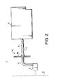
- Fig. 2 is a schematic view showing a main part of an ink jet printer according to the first embodiment.
- the ink jet printer 1 has a printing head 2 which emerges ink droplets to a recording media R.
- the printing head 2 is mounted to a carriage (not shown) that is movable in the direction of the width of the recording media R.
- the carriage (not shown) has a cartridge mounting portion 4 to which an ink cartridge 3 is mounted.
- a connecting pipe 6 is provided to the mounting portion 4, which has a sharpen tip.
- the connecting pipe 6 is connected to the printing head 2 via an intermediate pipe 5.
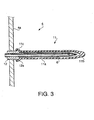
- Fig. 3 is an enlarged view showing the connecting pipe 6.
- the connecting pipe 6 is fixed to a wall 4a of the mounting portion 4 via a bushing 12.
- the connecting pipe 6 is covered by a flexible sheath 11.
- the flexible sheath 11 has an accordion-folded-portion 11a which is extensible in the longitudinal direction of the connecting pipe 6.
- a tail portion 11c of the flexible sheath 11 is hooked on a flange portion 12a of the bushing 12, so that the flexible sheath does not drop out of the bushing 12.
- the connecting pipe 6 When the connecting pipe 6 is inserted into the ink cartridge 3, the connecting pipe 6 pierces and penetrates a tip 11b of the flexible sheath 11.
- the tip 11b of the flexible sheath 11 is thicker than the other portion of the flexible sheath 11. With this, when the connecting pipe 6 (piercing the tip 11b) is removed from the tip 11b, a through-hole formed on the tip 11b is closed due to the elasticity of the tip 11b. It enables a user to repeatedly use the ink cartridge 3.
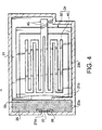
- Fig. 4 is a sectional view of the ink cartridge 3.
- the ink cartridge 3 has a cartridge case 21.
- the cartridge case 21 has an opening 21a which is tightly sealed by a seal 22 made of an elastic material such as a rubber.
- the seal 22 is fixed to the inner side of a wall around the opening 21. The seal 22 is opened when pierced by the connecting pipe 6 (Fig. 3).
- the interior of the cartridge case 21 is divided into two regions 23a and 23b by a partition wall 21b.
- the first region 23a (located behind the opening 21a) is filled with a sponge member 25 in which ink can be impregnated.
- the second region 23b accommodates an ink container 24 detailed below.
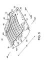
- Fig. 5 is a perspective view of the ink container 24.
- the ink container 24 includes a flexible pack 30 in which ink can be reserved.
- the flexible pack 30 is made of a rectangular sheet. The sheet is folded (bent) into two half sheets so that one of the half sheets lies on the other. Further, three ends of one of the half sheets are attached to opposing three ends of the other by means of heat seal.
- the half sheets of the flexible pack 30 are respectively referred to as an upper sheet wall 31 and a lower sheet walls 32 as shown in Fig. 5.
- the folded end is referred to as a front end 33.
- the (folded) front end 33 forms a plane surface that is substantially perpendicular to the upper and lower sheet walls 31 and 32.
- three sealed ends of the flexible pack 30 are respectively referred to as a left end 34, a rear end 35, and a right end 36 as shown in Fig. 5.
- the ink container 24 further includes a spring member 40 provided to the outer surface of the flexible pack 30.
- the spring member 40 has a plate form and extends over upper and lower sheet walls 31 and 32.
- a bending section of the spring member 40 is defined as a U-shaped joining section 45.
- Opposing portions of the spring member 40 (fixed to the sheet walls 31 and 32) are defined as fixing portions 400 and 410.
- the lower fixing portion 400 is hidden beneath the flexible pack 30 in Fig. 5, the lower fixing portion 410 is constructed in a similar manner to the upper fixing portion 400.
- the U-shaped joining section 45 is located at the center of the flexible pack 30 in the direction of the width W of the flexible pack 30.
- the upper fixing portion 400 has a symmetrical shape with respect to the center of the flexible pack 30 in the direction of the width W.
- the upper fixing portion 400 includes two inner parts 420 (close to the center of the flexible pack 30) and two outer parts 430 (close to the side ends of the flexible pack 30).
- the inner part 420 is ⁇ -shaped and includes (1) a first section 421 which extends frontward (in parallel to the side ends 34 and 36 of the flexible pack 30) to the front end 33 from the U-shaped joining section 45, (2) a second section 422 which extends sideways from the front end of the first section 421, and (3) a third section 423 which extends rearward (in parallel to the side ends 34 and 36 of the flexible pack 30) to the rear end 35 from the side end of the second section 422.
- a connecting section 425 is provided to the rear end of the third section 423, which extends sideways.
- the outer part 430 is ⁇ -shaped and includes (1) a first section 431 which extends frontward to the front end 33 from the side end of the connecting section 425, (2) a second section 432 which extends sideways from the front end of the first section 431, and (3) a third section 433 which extends rearward to the rear end 35 from the side end of the section 432.
- the sections 421, 422, 423, 425, 431, 432 and 433 are attached to the upper sheet wall 31 of the flexible pack 30, by means of an adhesive agent or a double-sided-tape.
- the lower fixing portion 410 is attached to the outer surface of the lower sheet wall 32. Since the structure of the lower fixing portion 410 is the same as the upper fixing portion 400, the detailed description thereof is omitted.
- the spring member 40 is going to deform so that the fixing portions 400 and 410 are move away from each other. With such an arrangement, the spring member 40 biases the sheet walls 31 and 32 of the flexible pack 30 so that the sheet walls 31 and 32 move away from each other.
- the pressure in the flexible pack 30 is negative, the ink leakage out of the ink container 24 is prevented.
- the spring member 40 is provided to the outside of the flexible pack 30, the structure of the ink container 24 is simple. Additionally, it is easy to manufacture the ink container 24 by mass-production process. Further, since the fixing portion 400 and 410 extend throughout the surfaces of the sheet walls 31 and 32, the sheet walls 31 and 32 are effectively biased.
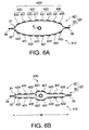
- Figs. 6A and 6B are front views of the ink container 24.
- the local spring force of the spring member 40 has a distribution in the direction of the width W of the flexible pack 30. Particularly, the local spring force of the spring member 40 is strongest at the center of the direction of the width W. Further, the local spring force of the spring member 40 gradually decreases, according to the distance from the center in the direction of the width W. That is, the center portions of the sheet walls 31 and 32 (in the direction of the width W) are strongly biased outward, compared with the side portions of the flexible pack 30.
- the ink pack 30 When ink is fully reserved in the ink pack 30 as shown in Fig. 6A, the ink pack 30 is entirely expanded. As the amount of ink decreases as shown in Fig. 6B, the interval between fixing portions 400 and 410 at the side portions of the flexible pack 30 is rapidly contracted, compared with the center portion of the flexible pack 30. Thus, the capacity of the center portion of the flexible pack 30 is larger than the side portions of the flexible pack 30. Accordingly, the remaining ink may easily gather at the center portion of the flexible pack 30. Since the connecting pipe 6 is inserted into the center portion of the flexible pack 30, ink can be effectively drawn by the connecting pipe 6. With such an arrangement, ink reserved in the flexible pack 30 can be fully used up.
- the sheet walls 31 and 32 are strongly bonded at the side ends 34 and 36 of the flexible pack 30, it promotes the tendency of the interval between the sheet walls 31 and 32 at side portions to decrease. It therefore promotes the gathering of ink at the center portion of the flexible pack 30.
- FIG. 7A when the ink cartridge 3 is not mounted to the mouthing portion 4 of the ink jet printer (not shown), the connecting pipe 6 is not inserted in the ink container 3. In this state, the connecting pipe 6 is covered by the flexible sheath 11. With this, it is prevented that the connecting pipe 6 injures a finger of a user. Further, it is prevented that the connecting pipe 6 6 gets dried, and that dust and debris stick on the connecting pipe 6.
- the sheath 11 When the ink cartridge 3 is mounted to the mounting portion 4, the sheath 11 is pushed by the ink container 3 so that the accordion portion 11a is contracted. With this, the connecting pipe 6 pierces the tip of the sheath 11a. Further, the connecting pipe 6 pierces the seal 22 to be inserted in the ink cartridge 3. The interior of the ink cartridge is given a negative pressure, so that ink stored in the printing head 2 (Fig. 2) is sucked in the ink cartridge 3 through the connecting pipe 6. The sucked ink is impregnated in the sponge 25 provided behind the seal 22. The printing head 2 (Fig. 2) then becomes empty.
- the connecting pipe 6 pierces the front end 33 of the flexible pack 30, so that the tip of the connecting pipe 6 is inserted in the flexible pack 30.
- the printing head 2 (Fig. 2) and the ink container 24 are connected so that ink can be supplied to the printing head 2 from the ink container 24.
- Figs. 8A, 8B and 8C The insertion of the connecting pipe 6 into the flexible pack 30 is detailed with reference to Figs. 8A, 8B and 8C.
- the position where the connecting pipe 6 abuts the front end 33 of the flexible pack 33 is the center of the fixing portions 400 and 410.
- Each of the fixing portions 400 and 410 is urged in a direction substantially parallel to a plane thereof. Further, the front ends of the fixing portions 400 and 410 are minutely shifted toward each other. With this, the fixing portions 400 and 410 are buckled so that the center portions thereof in the longitudinal direction are shifted away from each other.
- Fig. 8C schematically shows the change in the capacity of the flexible pack 30 before and after the abutment of the connecting pipe 6.
- the increasing capacity C1 of the flexible pack 30 caused by the outward deformation of the upper and lower sheet walls 31 and 32 is larger than the decreasing capacity C2 caused by the inward deformation of the front end 33.
- the interval between the fixing portions 400 and 410 is the largest at the center thereof in the longitudinal direction and gradually decreases according to the longitudinal distance from the center. Accordingly, when the connecting pipe 6 pierces the flexible pack 30, the total capacity of the flexible pack 30 increases.
- the decreasing capacity C2' caused by the inward deformation of the rear part of the sheet walls 31 and 32 is small so that the capacity C2' is negligible.
- the front end 33 of the flexible pack 30 has an eye-shape such that the interval between the sheet walls 31 and 32 is the largest at the center in the direction of the width W and gradually decreases according to the distance from the center in the direction of the width W.
- the peripheral length of the front end 33 is relatively large, compared with the area of the front end 33.
- the increasing capacity of the flexible pack 30 caused by the deformation of the upper and lower sheet walls 31 and 32 is larger than the decreasing capacity C2 caused by the inward deformation of the front end 33.
- the total capacity of the flexible pack 30 is increased when the connecting pipe 6 pierces the flexible pack 30, it increases the magnitude of negative pressure in the ink container 24. This is advantageous in preventing the ink leakage out of the flexible pack 30 through a gap around the penetrating connecting pipe 6 and ink leakage through a nozzle of the printing head 2 (Fig. 2).
- the portion to be pierced by the connecting pipe 6 is located between the upper and lower sheet walls 31 and 32, the front edges of the fixing portions 400 and 410 are allowed to move toward each other. With this, the pushing force of the connecting pipe 6 is easily converted to the buckling of the fixing portions 400 and 410 of the spring member 40. Additionally, since the front end 33 has a flat surface which is substantially perpendicular to the fixing portions 400 and 410, and since the connecting pipe 6 is inserted into the center of the flat surface, it is easy to let the connecting pipe 6 pierce the front end 33.
- ink is introduced into the printing head 2 (through the connecting pipe 6) by a suction device provided in the printing head 2.
- the negative pressure in the flexible pack 30 reaches to the printing head 2, so that ink does not unintentionally drop out of the printing head 2 on starting a printing operation of the ink jet printer.
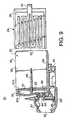
- Fig. 9 is a sectional view of a modification of the first embodiment.
- an ink jet printer 51 has a printing head 52 and a carriage 53 that carries the printing head 52.
- the ink container 24 is directly mounted to a mounting portion 55 of the carriage 53.
- the mounting portion 55 is made of synthetic resin, and includes a floor 58 and a double wall 57 formed on the floor 58.
- the double wall 57 includes first and second walls 57a and 57b and an ink chamber 56 formed between the walls 57a and 57b.
- two side walls 59 and 60 are formed at both side ends of the floor 58.
- the floor 58, the double wall 57 and the side walls 59 and 60 constitute a recess 61 which receives the ink container 24.
- a connecting pipe 62 is provided to the double wall 57, which is arranged to pierce the ink container 24 when the ink container 24 is mounted to the recess 61.
- the connecting pipe 62 extends from the chamber 56 to the recess 61, supported by the second wall 57b via a bushing 63.
- An ink supply hole 64 is formed at the lower part of the chamber 56.
- the printing head 52 is mounted to the ink supply hole 64 via adapters 65 and 66.
- the printing head 52 is covered by cover members 67 and 68.
- the connecting pipe 62 pierces the front end 33 of the ink container 24. With this, the printing head 52 and the ink container 24 are connected with each other via the connecting pipe 62, the chamber 56 and ink supply hole 64. After the ink container 24 is mounted to the recess 61, ink is introduced into the printing head 2 (through the connecting pipe 62, the chamber 56 and ink supply hole 64) by a suction device provided in the printing head 2.
Landscapes
- Ink Jet (AREA)
Claims (18)
- Tintenbehälter (24) mit:dadurch gekennzeichnet, daß die Vorspannanordnung ein Federteil (40) in Plattenform aufweist, das sich über die zwei gegenüberliegenden Blattwände (33, 32) der flexiblen Verpackung (30) erstreckt.einer flexiblen Verpackung (30), in der Tinte aufbewahrt werden kann, wobei die flexible Verpackung (30) zwei Blattwände (31, 32) aufweist, die einander gegenüberliegen; undeiner Vorspannanordnung (40), die die gegenüberliegenden Blattwände (31, 32) voneinander weg vorspannt zum dadurch Vergrößern einer Kapazität der flexiblen Verpackung (30), wodurch ein Unterdruck in der flexiblen Verpackung (30) verursacht wird;
- Tintenbehälter nach Anspruch 1, bei dem die flexible Verpackung (30) eine bestimmte Breite und eine bestimmte Länge aufweist,
wobei das Federteil (40) aufweist:einen U-förmigen Verbindungsabschnitt (45), der an einem Zentrum der flexiblen Verpackung (30) in der Richtung der Breite angeordnet ist; undBefestigungsabschnitte (400, 410), die an den zwei gegenüberliegenden Blattwänden (31, 32) befestigt sind, wobei die Befestigungsabschnitte (400, 410) sich in eine Richtung der Breite zu lateralen Seiten der flexiblen Verpackung (30) erstrecken. - Tintenbehälter nach Anspruch 2, bei dem das Federteil (40) so aufgebaut ist, daß eine lokale Federkraft stärker an einem Zentrum davon in der Breitenrichtung als an einer Seite davon in der Breitenrichtung ist.
- Tintenbehälter nach Anspruch 2 oder 3, wobei das Federteil (40) ein Band (420, 430) aufweist, das sich in einer Zickzack-Weise so erstreckt, daß sich das Band in einer Richtung der Breite und in einer Richtung der Länge erstreckt.
- Tintenbehälter nach einem der vorhergehenden Ansprüche, bei dem, wenn das Federteil (40) in eine Richtung gedrückt wird, gegenüberliegende Abschnitte des Federteiles (40) sich voneinander weg verformen, so daß eine Kapazität der flexiblen Verpakkung vergrößert wird.
- Tintenbehälter nach Anspruch 5, bei dem die flexible Verpackung eine Endoberfläche (33) aufweist, die an einem Ende davon in der einen Richtung gebildet ist.
- Tintenbehälter nach Anspruch 5 oder 6, bei dem das Federteil (40) Krümmungen so aufweist, daß ein Abstand zwischen gegenüberliegenden Abschnitten des Federteiles (40) am größten an Zentrumsabschnitten in der einen Richtung ist.
- Tintenbehälter nach einem der vorhergehenden Ansprüche, bei dem die flexible Verpackung (30) durch Falten eines rechtekkigen Blattes so hergestellt wird, daß eine Hälfte des Blattes auf der anderen liegt, und durch Anbringen gegenüberliegender Enden der Hälften.
- Tintenbehälter nach Anspruch 1, bei dem die flexible Verpackung (30) eine bestimmte Breite und eine bestimmte Länge aufweist; und
bei dem die Vorspannanordnung (40) so aufgebaut ist, daß eine lokale Federkraft stärker an einem Zentrum davon in der Breitenrichtung als an einer Seite davon in der Breitenrichtung ist. - Tintenbehälter nach Anspruch 1, bei dem die flexible Verpackung weiter eine Endoberfläche (33) aufweist; und
wenn die Endoberfläche (33) in eine Richtung gedrückt wird, mindestens ein Teil der Vorspannanordnung (40) so verformt wird, daß weiter die Kapazität der flexiblen Verpackung (30) vergrößert wird. - Tintenbehälter nach Anspruch 10, bei dem eine vergrößerte Kapazität der flexiblen Verpackung (30), die durch die Verformung der Vorspannanordnung (40) verursacht wird, größer als eine abnehmende Kapazität der flexiblen Verpackung (30) ist, die durch die Verformung der Endoberfläche (33) nach innen ist.
- Tintenbehälter nach Anspruch 10 oder 11, bei dem das Federteil (40) Krümmungen so aufweist, daß ein Abstand zwischen gegenüberliegenden Abschnitten des Federteiles (40) am größten an den Zentrumsabschnitten in der einen Richtung ist.
- Tintenbehälter nach Anspruch 10, 11 oder 12, bei dem, wenn gegenüberliegende Abschnitte des Federteiles (40) in die eine Richtung gedrückt werden, die gegenüberliegenden Abschnitte sich voneinander weg verformen.
- Tintenbehälter nach Anspruch 13, bei dem die Endoberfläche (33) eine flache Oberfläche ist, die im wesentlichen senkrecht zu den zwei Blattwänden (31, 32) ist.
- Tintenbehälter nach Anspruch 13 oder 14, bei dem die Blattwände (31, 32) eine bestimmte Breite aufweisen, die senkrecht zu der einen Richtung ist; und
bei dem die Endoberfläche (33) eine Augenform derart aufweist, daß ein Abstand zwischen den zwei Blattwänden (31, 32) an der Endoberfläche (33) am größten an einen Zentrum davon in eine Richtung der Breite ist, wobei der Abstand gemäß dem Abstand von dem Zentrum abnimmt. - Tintenbehälter nach einem der Ansprüche 6 und 10 bis 15, weiter mit einer Verbindungsröhre (6), die die flexible Verpakkung (30) und einen Druckkopf (2) verbindet;
bei dem die Verbindungsröhre (6) die Endoberfläche (33) durchstößt, eine Durchstoßungsposition auf der Endoberfläche (33) zwischen den zwei Blattwänden (31, 32) angeordnet ist. - Tintenstrahldrucker mit:einem Druckkopf (2), der Tintentröpfchen auf ein Aufzeichnungsmedium ausgibt;einem Schlitten, der den Druckkopf (2) trägt;einem Tintenbehälter (24) nach einem der vorhergehenden Ansprüche;einem Anbringungsabschnitt (4), der auf dem Schlitten gebildet ist, an dem der Tintenbehälter (24) angebracht ist; undeiner Verbindungsröhre (6), die an dem Anbringungsabschnitt (4) vorgesehen ist, die in die flexible Verpackung (30) eingeführt wird, wobei die Verbindungsröhre (6) die flexible Verpackung (30) und den Druckkopf (2) verbindet.
- Tintenstrahldrucker nach Anspruch 17, bei dem die Verbindungsröhre (6) die Endoberfläche (33) durchstößt, wobei eine Durchstoßungsposition zwischen den zwei Seitenwänden (31, 32) angeordnet ist.
Priority Applications (1)
| Application Number | Priority Date | Filing Date | Title |
|---|---|---|---|
| EP02022020A EP1279512B1 (de) | 1997-08-20 | 1998-08-19 | Tintenbehälter für Tintenstrahldrucker |
Applications Claiming Priority (6)
| Application Number | Priority Date | Filing Date | Title |
|---|---|---|---|
| JP22380697A JP3887898B2 (ja) | 1997-08-20 | 1997-08-20 | インク容器及びそれを用いたインクジェット記録装置 |
| JP223806/97 | 1997-08-20 | ||
| JP22380697 | 1997-08-20 | ||
| JP225943/97 | 1997-08-22 | ||
| JP22594397 | 1997-08-22 | ||
| JP22594397A JP3915186B2 (ja) | 1997-08-22 | 1997-08-22 | インク容器及びそれを用いたインクジェット記録装置 |
Related Child Applications (1)
| Application Number | Title | Priority Date | Filing Date |
|---|---|---|---|
| EP02022020A Division EP1279512B1 (de) | 1997-08-20 | 1998-08-19 | Tintenbehälter für Tintenstrahldrucker |
Publications (3)
| Publication Number | Publication Date |
|---|---|
| EP0899112A2 EP0899112A2 (de) | 1999-03-03 |
| EP0899112A3 EP0899112A3 (de) | 2000-05-17 |
| EP0899112B1 true EP0899112B1 (de) | 2003-07-23 |
Family
ID=26525696
Family Applications (2)
| Application Number | Title | Priority Date | Filing Date |
|---|---|---|---|
| EP02022020A Expired - Lifetime EP1279512B1 (de) | 1997-08-20 | 1998-08-19 | Tintenbehälter für Tintenstrahldrucker |
| EP98306647A Expired - Lifetime EP0899112B1 (de) | 1997-08-20 | 1998-08-19 | Tintenstrahldrucker und darin verwendeter Tintenbehälter |
Family Applications Before (1)
| Application Number | Title | Priority Date | Filing Date |
|---|---|---|---|
| EP02022020A Expired - Lifetime EP1279512B1 (de) | 1997-08-20 | 1998-08-19 | Tintenbehälter für Tintenstrahldrucker |
Country Status (4)
| Country | Link |
|---|---|
| US (1) | US6227662B1 (de) |
| EP (2) | EP1279512B1 (de) |
| DE (2) | DE69816541T2 (de) |
| HK (1) | HK1049645B (de) |
Families Citing this family (15)
| Publication number | Priority date | Publication date | Assignee | Title |
|---|---|---|---|---|
| JPH11240171A (ja) * | 1997-12-22 | 1999-09-07 | Oki Data Corp | インク貯蔵容器 |
| US6505924B2 (en) | 1998-09-30 | 2003-01-14 | Brother Kogyo Kabushiki Kaisha | Ink cartridge |
| ATE353764T1 (de) * | 1998-12-24 | 2007-03-15 | Seiko Epson Corp | Tintensack für tintenstrahlaufzeichnungsgerät und packung zum verpacken eines solchen sackes |
| US6364474B1 (en) * | 1999-09-10 | 2002-04-02 | Industrial Technology Research Institute | Pressure control device |
| US6464346B2 (en) * | 1999-10-29 | 2002-10-15 | Hewlett-Packard Company | Ink containment and delivery techniques |
| EP1849608B1 (de) * | 2000-01-21 | 2010-04-21 | Seiko Epson Corporation | Tintenpatrone und Tintenstrahldruckvorrichtung mit einer derartigen Tintenpatrone |
| USD451542S1 (en) | 2000-08-09 | 2001-12-04 | Seiko Epson Corporation | Ink pack |
| WO2002058024A1 (fr) * | 2001-01-19 | 2002-07-25 | Fujitsu Limited | Dispositif de protection contre le vol a poche d'encre, et coffre-fort equipe d'un tel dispositif |
| US6959984B2 (en) * | 2001-08-14 | 2005-11-01 | Canon Kabushiki Kaisha | Liquid container and inkjet cartridge |
| JP2004083621A (ja) | 2002-08-22 | 2004-03-18 | Brother Ind Ltd | インクジェット記録用水性インク |
| US7367650B2 (en) | 2004-01-21 | 2008-05-06 | Silverbrook Research Pty Ltd | Printhead chip having low aspect ratio ink supply channels |
| US7524016B2 (en) | 2004-01-21 | 2009-04-28 | Silverbrook Research Pty Ltd | Cartridge unit having negatively pressurized ink storage |
| US7469989B2 (en) | 2004-01-21 | 2008-12-30 | Silverbrook Research Pty Ltd | Printhead chip having longitudinal ink supply channels interrupted by transverse bridges |
| US7448734B2 (en) | 2004-01-21 | 2008-11-11 | Silverbrook Research Pty Ltd | Inkjet printer cartridge with pagewidth printhead |
| JP4806616B2 (ja) * | 2006-09-29 | 2011-11-02 | 富士フイルム株式会社 | インクカートリッジ及びインクジェット記録装置 |
Family Cites Families (13)
| Publication number | Priority date | Publication date | Assignee | Title |
|---|---|---|---|---|
| GB2063175B (en) | 1979-11-06 | 1984-02-15 | Shinshu Seiki Kk | Ink jet printer |
| JPS59204566A (ja) * | 1983-05-09 | 1984-11-19 | Ricoh Co Ltd | オンデマンド型インクジエツトプリンタ−におけるインクカ−トリツジのインク袋 |
| JPS62225352A (ja) * | 1986-03-27 | 1987-10-03 | Nec Corp | インクジエツトプリンタのインク供給機構 |
| JPH023321A (ja) * | 1988-06-17 | 1990-01-08 | Canon Inc | インクカートリッジ |
| US5325119A (en) * | 1992-08-12 | 1994-06-28 | Hewlett-Packard Company | Variable rate spring ink pressure regulator for a thermal ink jet printer |
| CA2093971A1 (en) * | 1992-08-12 | 1994-02-13 | Tofigh Khodapanah | Ink pressure regulator for a thermal ink jet printer |
| US5574490A (en) | 1992-08-12 | 1996-11-12 | Hewlett-Packard Company | Ink jet hard copy apparatus ink cartridge |
| JPH06183023A (ja) * | 1992-12-21 | 1994-07-05 | Canon Inc | インクカートリッジ及びインクジェット記録装置 |
| US5426459A (en) * | 1992-12-22 | 1995-06-20 | Hewlett-Packard Company | Combined filter/aircheck valve for thermal ink-jet pen |
| JPH0752399A (ja) | 1993-08-11 | 1995-02-28 | Canon Inc | インクタンク |
| JP3450916B2 (ja) | 1993-12-21 | 2003-09-29 | ヒューレット・パッカード・カンパニー | プリンタのインク・カートリッジ |
| US5691755A (en) | 1994-04-18 | 1997-11-25 | Hewlett-Packard Company | Collapsible ink cartridge |
| US5751320A (en) * | 1994-09-29 | 1998-05-12 | Hewlett-Packard Company | Ink recharger for inkjet print cartridge having sliding valve connectable to print cartridge |
-
1998
- 1998-08-19 EP EP02022020A patent/EP1279512B1/de not_active Expired - Lifetime
- 1998-08-19 US US09/136,764 patent/US6227662B1/en not_active Expired - Lifetime
- 1998-08-19 DE DE69816541T patent/DE69816541T2/de not_active Expired - Lifetime
- 1998-08-19 EP EP98306647A patent/EP0899112B1/de not_active Expired - Lifetime
- 1998-08-19 DE DE69831883T patent/DE69831883T2/de not_active Expired - Lifetime
-
2003
- 2003-03-10 HK HK03101703.3A patent/HK1049645B/en not_active IP Right Cessation
Also Published As
| Publication number | Publication date |
|---|---|
| EP0899112A2 (de) | 1999-03-03 |
| EP1279512B1 (de) | 2005-10-12 |
| DE69831883D1 (de) | 2005-11-17 |
| HK1049645A1 (en) | 2003-05-23 |
| EP1279512A1 (de) | 2003-01-29 |
| HK1049645B (en) | 2006-01-13 |
| DE69816541T2 (de) | 2004-04-15 |
| EP0899112A3 (de) | 2000-05-17 |
| DE69816541D1 (de) | 2003-08-28 |
| US6227662B1 (en) | 2001-05-08 |
| DE69831883T2 (de) | 2006-07-13 |
Similar Documents
| Publication | Publication Date | Title |
|---|---|---|
| EP0899112B1 (de) | Tintenstrahldrucker und darin verwendeter Tintenbehälter | |
| KR100190414B1 (ko) | 잉크 용기 및 잉크 용기 제조 방법 | |
| US6739707B2 (en) | Ink cartridge | |
| JP3667296B2 (ja) | インクタンク | |
| US6382786B2 (en) | Liquid storing container having improved internal structure, liquid ejection head cartridge using the same container, and liquid ejection recording apparatus | |
| JP2001105617A (ja) | 液体収納容器、該液体収納容器に用いられるキャップ、及びキャップ付き液体収納容器 | |
| JPH06155759A (ja) | インク溜め構造およびプリンタ・インク・カートリッジ | |
| JPH071742A (ja) | サーマルインクジェットペン用の剛性ループケース構造体 | |
| AU713867B2 (en) | Ink cartridge | |
| US5917527A (en) | Ink-jet pen with near net size porous member | |
| US6164770A (en) | Ink cartridge and ink jet printer using the same | |
| EP1519095B1 (de) | Schlauchbefestigungsanordnung und dafür verwendete Befestigungselement | |
| JP6372369B2 (ja) | 液体収容体 | |
| JP3703891B2 (ja) | 多孔性部材を有するインクジェット・ペン | |
| JP3225701B2 (ja) | インクジェット記録ヘッドユニット | |
| EP2567820B1 (de) | Tintenpatrone und Tintenstrahldrucker | |
| JP4258707B2 (ja) | ユニット交換型フィルタ装置 | |
| JP4018556B2 (ja) | インクタンク | |
| JP3887898B2 (ja) | インク容器及びそれを用いたインクジェット記録装置 | |
| CN220883798U (zh) | 一种带头墨盒 | |
| JP3687706B2 (ja) | プリンタおよびインクタンク | |
| JP7806315B2 (ja) | 液体装着体 | |
| JP2000210513A (ja) | ユニット交換型フィルタ装置 | |
| CN117915804A (zh) | 剃须刀刀片架用分配器 | |
| JP3182501B2 (ja) | インクカートリッジ |
Legal Events
| Date | Code | Title | Description |
|---|---|---|---|
| PUAI | Public reference made under article 153(3) epc to a published international application that has entered the european phase |
Free format text: ORIGINAL CODE: 0009012 |
|
| AK | Designated contracting states |
Kind code of ref document: A2 Designated state(s): DE GB SE |
|
| AX | Request for extension of the european patent |
Free format text: AL;LT;LV;MK;RO;SI |
|
| PUAL | Search report despatched |
Free format text: ORIGINAL CODE: 0009013 |
|
| AK | Designated contracting states |
Kind code of ref document: A3 Designated state(s): AT BE CH CY DE DK ES FI FR GB GR IE IT LI LU MC NL PT SE |
|
| AX | Request for extension of the european patent |
Free format text: AL;LT;LV;MK;RO;SI |
|
| 17P | Request for examination filed |
Effective date: 20000915 |
|
| AKX | Designation fees paid |
Free format text: DE GB SE |
|
| 17Q | First examination report despatched |
Effective date: 20010731 |
|
| GRAG | Despatch of communication of intention to grant |
Free format text: ORIGINAL CODE: EPIDOS AGRA |
|
| GRAG | Despatch of communication of intention to grant |
Free format text: ORIGINAL CODE: EPIDOS AGRA |
|
| GRAG | Despatch of communication of intention to grant |
Free format text: ORIGINAL CODE: EPIDOS AGRA |
|
| GRAH | Despatch of communication of intention to grant a patent |
Free format text: ORIGINAL CODE: EPIDOS IGRA |
|
| GRAH | Despatch of communication of intention to grant a patent |
Free format text: ORIGINAL CODE: EPIDOS IGRA |
|
| GRAA | (expected) grant |
Free format text: ORIGINAL CODE: 0009210 |
|
| AK | Designated contracting states |
Designated state(s): DE GB SE |
|
| REG | Reference to a national code |
Ref country code: GB Ref legal event code: FG4D |
|
| REG | Reference to a national code |
Ref country code: SE Ref legal event code: TRGR |
|
| REF | Corresponds to: |
Ref document number: 69816541 Country of ref document: DE Date of ref document: 20030828 Kind code of ref document: P |
|
| PLBE | No opposition filed within time limit |
Free format text: ORIGINAL CODE: 0009261 |
|
| STAA | Information on the status of an ep patent application or granted ep patent |
Free format text: STATUS: NO OPPOSITION FILED WITHIN TIME LIMIT |
|
| 26N | No opposition filed |
Effective date: 20040426 |
|
| PGFP | Annual fee paid to national office [announced via postgrant information from national office to epo] |
Ref country code: GB Payment date: 20170725 Year of fee payment: 20 Ref country code: DE Payment date: 20170825 Year of fee payment: 20 |
|
| PGFP | Annual fee paid to national office [announced via postgrant information from national office to epo] |
Ref country code: SE Payment date: 20170810 Year of fee payment: 20 |
|
| REG | Reference to a national code |
Ref country code: DE Ref legal event code: R071 Ref document number: 69816541 Country of ref document: DE |
|
| REG | Reference to a national code |
Ref country code: GB Ref legal event code: PE20 Expiry date: 20180818 |
|
| REG | Reference to a national code |
Ref country code: SE Ref legal event code: EUG |
|
| PG25 | Lapsed in a contracting state [announced via postgrant information from national office to epo] |
Ref country code: GB Free format text: LAPSE BECAUSE OF EXPIRATION OF PROTECTION Effective date: 20180818 |