EP3096357A1 - Selbstausrichtende kontakte - Google Patents
Selbstausrichtende kontakte Download PDFInfo
- Publication number
- EP3096357A1 EP3096357A1 EP16172290.5A EP16172290A EP3096357A1 EP 3096357 A1 EP3096357 A1 EP 3096357A1 EP 16172290 A EP16172290 A EP 16172290A EP 3096357 A1 EP3096357 A1 EP 3096357A1
- Authority
- EP
- European Patent Office
- Prior art keywords
- layer
- metal
- gate electrode
- spacers
- gate
- Prior art date
- Legal status (The legal status is an assumption and is not a legal conclusion. Google has not performed a legal analysis and makes no representation as to the accuracy of the status listed.)
- Granted
Links
- 125000006850 spacer group Chemical group 0.000 claims abstract description 140
- 239000000758 substrate Substances 0.000 claims abstract description 48
- 238000009792 diffusion process Methods 0.000 claims abstract description 46
- 239000010410 layer Substances 0.000 claims description 425
- 229910052751 metal Inorganic materials 0.000 claims description 236
- 239000002184 metal Substances 0.000 claims description 236
- 229910052581 Si3N4 Inorganic materials 0.000 claims description 36
- HQVNEWCFYHHQES-UHFFFAOYSA-N silicon nitride Chemical compound N12[Si]34N5[Si]62N3[Si]51N64 HQVNEWCFYHHQES-UHFFFAOYSA-N 0.000 claims description 36
- 239000003989 dielectric material Substances 0.000 claims description 29
- 229910052710 silicon Inorganic materials 0.000 claims description 24
- 239000010703 silicon Substances 0.000 claims description 24
- 229910021332 silicide Inorganic materials 0.000 claims description 20
- FVBUAEGBCNSCDD-UHFFFAOYSA-N silicide(4-) Chemical group [Si-4] FVBUAEGBCNSCDD-UHFFFAOYSA-N 0.000 claims description 20
- WFKWXMTUELFFGS-UHFFFAOYSA-N tungsten Chemical compound [W] WFKWXMTUELFFGS-UHFFFAOYSA-N 0.000 claims description 10
- 229910052721 tungsten Inorganic materials 0.000 claims description 10
- 239000010937 tungsten Substances 0.000 claims description 10
- 239000004065 semiconductor Substances 0.000 claims description 9
- 229910052782 aluminium Inorganic materials 0.000 claims description 7
- XAGFODPZIPBFFR-UHFFFAOYSA-N aluminium Chemical compound [Al] XAGFODPZIPBFFR-UHFFFAOYSA-N 0.000 claims description 7
- RTAQQCXQSZGOHL-UHFFFAOYSA-N Titanium Chemical compound [Ti] RTAQQCXQSZGOHL-UHFFFAOYSA-N 0.000 claims description 5
- 229910052719 titanium Inorganic materials 0.000 claims description 5
- 239000010936 titanium Substances 0.000 claims description 5
- 239000011229 interlayer Substances 0.000 claims description 3
- 229910052735 hafnium Inorganic materials 0.000 claims description 2
- VBJZVLUMGGDVMO-UHFFFAOYSA-N hafnium atom Chemical compound [Hf] VBJZVLUMGGDVMO-UHFFFAOYSA-N 0.000 claims description 2
- QVGXLLKOCUKJST-UHFFFAOYSA-N atomic oxygen Chemical compound [O] QVGXLLKOCUKJST-UHFFFAOYSA-N 0.000 claims 1
- 229910021421 monocrystalline silicon Inorganic materials 0.000 claims 1
- 229910052760 oxygen Inorganic materials 0.000 claims 1
- 239000001301 oxygen Substances 0.000 claims 1
- 238000000059 patterning Methods 0.000 abstract description 20
- 238000000034 method Methods 0.000 description 144
- 239000000463 material Substances 0.000 description 96
- 238000005530 etching Methods 0.000 description 43
- XUIMIQQOPSSXEZ-UHFFFAOYSA-N Silicon Chemical compound [Si] XUIMIQQOPSSXEZ-UHFFFAOYSA-N 0.000 description 23
- OKTJSMMVPCPJKN-UHFFFAOYSA-N Carbon Chemical compound [C] OKTJSMMVPCPJKN-UHFFFAOYSA-N 0.000 description 22
- 229910052799 carbon Inorganic materials 0.000 description 22
- 239000012212 insulator Substances 0.000 description 22
- VYPSYNLAJGMNEJ-UHFFFAOYSA-N Silicium dioxide Chemical compound O=[Si]=O VYPSYNLAJGMNEJ-UHFFFAOYSA-N 0.000 description 21
- 238000004519 manufacturing process Methods 0.000 description 21
- 238000005137 deposition process Methods 0.000 description 20
- 238000000151 deposition Methods 0.000 description 19
- IJGRMHOSHXDMSA-UHFFFAOYSA-N Atomic nitrogen Chemical compound N#N IJGRMHOSHXDMSA-UHFFFAOYSA-N 0.000 description 16
- 239000011810 insulating material Substances 0.000 description 14
- 150000004767 nitrides Chemical class 0.000 description 14
- HBMJWWWQQXIZIP-UHFFFAOYSA-N silicon carbide Chemical compound [Si+]#[C-] HBMJWWWQQXIZIP-UHFFFAOYSA-N 0.000 description 14
- 229910010271 silicon carbide Inorganic materials 0.000 description 14
- 229910052814 silicon oxide Inorganic materials 0.000 description 14
- 229910044991 metal oxide Inorganic materials 0.000 description 13
- 150000004706 metal oxides Chemical class 0.000 description 13
- 150000002739 metals Chemical class 0.000 description 13
- TWNQGVIAIRXVLR-UHFFFAOYSA-N oxo(oxoalumanyloxy)alumane Chemical compound O=[Al]O[Al]=O TWNQGVIAIRXVLR-UHFFFAOYSA-N 0.000 description 13
- 230000003071 parasitic effect Effects 0.000 description 12
- 238000001465 metallisation Methods 0.000 description 11
- 238000000206 photolithography Methods 0.000 description 11
- PXHVJJICTQNCMI-UHFFFAOYSA-N Nickel Chemical compound [Ni] PXHVJJICTQNCMI-UHFFFAOYSA-N 0.000 description 10
- KDLHZDBZIXYQEI-UHFFFAOYSA-N Palladium Chemical compound [Pd] KDLHZDBZIXYQEI-UHFFFAOYSA-N 0.000 description 10
- BASFCYQUMIYNBI-UHFFFAOYSA-N platinum Chemical compound [Pt] BASFCYQUMIYNBI-UHFFFAOYSA-N 0.000 description 10
- 229910052580 B4C Inorganic materials 0.000 description 8
- 229910052582 BN Inorganic materials 0.000 description 8
- PZNSFCLAULLKQX-UHFFFAOYSA-N Boron nitride Chemical compound N#B PZNSFCLAULLKQX-UHFFFAOYSA-N 0.000 description 8
- RYGMFSIKBFXOCR-UHFFFAOYSA-N Copper Chemical compound [Cu] RYGMFSIKBFXOCR-UHFFFAOYSA-N 0.000 description 8
- UFHFLCQGNIYNRP-UHFFFAOYSA-N Hydrogen Chemical compound [H][H] UFHFLCQGNIYNRP-UHFFFAOYSA-N 0.000 description 8
- 238000000231 atomic layer deposition Methods 0.000 description 8
- 230000015572 biosynthetic process Effects 0.000 description 8
- INAHAJYZKVIDIZ-UHFFFAOYSA-N boron carbide Chemical compound B12B3B4C32B41 INAHAJYZKVIDIZ-UHFFFAOYSA-N 0.000 description 8
- 238000005229 chemical vapour deposition Methods 0.000 description 8
- 229910052802 copper Inorganic materials 0.000 description 8
- 239000010949 copper Substances 0.000 description 8
- 230000008021 deposition Effects 0.000 description 8
- 229910052739 hydrogen Inorganic materials 0.000 description 8
- 239000001257 hydrogen Substances 0.000 description 8
- 229910052757 nitrogen Inorganic materials 0.000 description 8
- 229910000510 noble metal Inorganic materials 0.000 description 8
- 229920002120 photoresistant polymer Polymers 0.000 description 8
- 239000011295 pitch Substances 0.000 description 8
- 229910017052 cobalt Inorganic materials 0.000 description 6
- 239000010941 cobalt Substances 0.000 description 6
- GUTLYIVDDKVIGB-UHFFFAOYSA-N cobalt atom Chemical compound [Co] GUTLYIVDDKVIGB-UHFFFAOYSA-N 0.000 description 6
- 238000007772 electroless plating Methods 0.000 description 6
- 238000004544 sputter deposition Methods 0.000 description 6
- 230000009977 dual effect Effects 0.000 description 5
- 229910052759 nickel Inorganic materials 0.000 description 5
- 229910052763 palladium Inorganic materials 0.000 description 5
- 238000005240 physical vapour deposition Methods 0.000 description 5
- 229910052697 platinum Inorganic materials 0.000 description 5
- 238000007517 polishing process Methods 0.000 description 5
- 229910021420 polycrystalline silicon Inorganic materials 0.000 description 5
- 229920005591 polysilicon Polymers 0.000 description 5
- 239000000126 substance Substances 0.000 description 5
- 229910052715 tantalum Inorganic materials 0.000 description 5
- GUVRBAGPIYLISA-UHFFFAOYSA-N tantalum atom Chemical compound [Ta] GUVRBAGPIYLISA-UHFFFAOYSA-N 0.000 description 5
- 238000009713 electroplating Methods 0.000 description 4
- BQCADISMDOOEFD-UHFFFAOYSA-N Silver Chemical compound [Ag] BQCADISMDOOEFD-UHFFFAOYSA-N 0.000 description 3
- PCHJSUWPFVWCPO-UHFFFAOYSA-N gold Chemical compound [Au] PCHJSUWPFVWCPO-UHFFFAOYSA-N 0.000 description 3
- 229910052737 gold Inorganic materials 0.000 description 3
- 239000010931 gold Substances 0.000 description 3
- 238000000926 separation method Methods 0.000 description 3
- 235000012239 silicon dioxide Nutrition 0.000 description 3
- 239000000377 silicon dioxide Substances 0.000 description 3
- 229910052709 silver Inorganic materials 0.000 description 3
- 239000004332 silver Substances 0.000 description 3
- ZOXJGFHDIHLPTG-UHFFFAOYSA-N Boron Chemical compound [B] ZOXJGFHDIHLPTG-UHFFFAOYSA-N 0.000 description 2
- 229910000676 Si alloy Inorganic materials 0.000 description 2
- 238000000137 annealing Methods 0.000 description 2
- 229910052785 arsenic Inorganic materials 0.000 description 2
- RQNWIZPPADIBDY-UHFFFAOYSA-N arsenic atom Chemical compound [As] RQNWIZPPADIBDY-UHFFFAOYSA-N 0.000 description 2
- 229910052796 boron Inorganic materials 0.000 description 2
- 230000015556 catabolic process Effects 0.000 description 2
- 239000011248 coating agent Substances 0.000 description 2
- 238000000576 coating method Methods 0.000 description 2
- 239000002019 doping agent Substances 0.000 description 2
- -1 e.g. Inorganic materials 0.000 description 2
- 238000005516 engineering process Methods 0.000 description 2
- 239000011521 glass Substances 0.000 description 2
- BHEPBYXIRTUNPN-UHFFFAOYSA-N hydridophosphorus(.) (triplet) Chemical compound [PH] BHEPBYXIRTUNPN-UHFFFAOYSA-N 0.000 description 2
- 238000009413 insulation Methods 0.000 description 2
- 238000002955 isolation Methods 0.000 description 2
- MRELNEQAGSRDBK-UHFFFAOYSA-N lanthanum(3+);oxygen(2-) Chemical compound [O-2].[O-2].[O-2].[La+3].[La+3] MRELNEQAGSRDBK-UHFFFAOYSA-N 0.000 description 2
- 238000012986 modification Methods 0.000 description 2
- 230000004048 modification Effects 0.000 description 2
- 239000011800 void material Substances 0.000 description 2
- 235000001674 Agaricus brunnescens Nutrition 0.000 description 1
- JBRZTFJDHDCESZ-UHFFFAOYSA-N AsGa Chemical compound [As]#[Ga] JBRZTFJDHDCESZ-UHFFFAOYSA-N 0.000 description 1
- 229910052691 Erbium Inorganic materials 0.000 description 1
- 229910001218 Gallium arsenide Inorganic materials 0.000 description 1
- 229910000673 Indium arsenide Inorganic materials 0.000 description 1
- GPXJNWSHGFTCBW-UHFFFAOYSA-N Indium phosphide Chemical compound [In]#P GPXJNWSHGFTCBW-UHFFFAOYSA-N 0.000 description 1
- ZOKXTWBITQBERF-UHFFFAOYSA-N Molybdenum Chemical compound [Mo] ZOKXTWBITQBERF-UHFFFAOYSA-N 0.000 description 1
- KJTLSVCANCCWHF-UHFFFAOYSA-N Ruthenium Chemical compound [Ru] KJTLSVCANCCWHF-UHFFFAOYSA-N 0.000 description 1
- 229910000577 Silicon-germanium Inorganic materials 0.000 description 1
- GWEVSGVZZGPLCZ-UHFFFAOYSA-N Titan oxide Chemical compound O=[Ti]=O GWEVSGVZZGPLCZ-UHFFFAOYSA-N 0.000 description 1
- NRTOMJZYCJJWKI-UHFFFAOYSA-N Titanium nitride Chemical compound [Ti]#N NRTOMJZYCJJWKI-UHFFFAOYSA-N 0.000 description 1
- 229910052769 Ytterbium Inorganic materials 0.000 description 1
- QCWXUUIWCKQGHC-UHFFFAOYSA-N Zirconium Chemical compound [Zr] QCWXUUIWCKQGHC-UHFFFAOYSA-N 0.000 description 1
- 229910026551 ZrC Inorganic materials 0.000 description 1
- OTCHGXYCWNXDOA-UHFFFAOYSA-N [C].[Zr] Chemical compound [C].[Zr] OTCHGXYCWNXDOA-UHFFFAOYSA-N 0.000 description 1
- XWCMFHPRATWWFO-UHFFFAOYSA-N [O-2].[Ta+5].[Sc+3].[O-2].[O-2].[O-2] Chemical compound [O-2].[Ta+5].[Sc+3].[O-2].[O-2].[O-2] XWCMFHPRATWWFO-UHFFFAOYSA-N 0.000 description 1
- LEVVHYCKPQWKOP-UHFFFAOYSA-N [Si].[Ge] Chemical compound [Si].[Ge] LEVVHYCKPQWKOP-UHFFFAOYSA-N 0.000 description 1
- ILCYGSITMBHYNK-UHFFFAOYSA-N [Si]=O.[Hf] Chemical compound [Si]=O.[Hf] ILCYGSITMBHYNK-UHFFFAOYSA-N 0.000 description 1
- 229910045601 alloy Inorganic materials 0.000 description 1
- 239000000956 alloy Substances 0.000 description 1
- CAVCGVPGBKGDTG-UHFFFAOYSA-N alumanylidynemethyl(alumanylidynemethylalumanylidenemethylidene)alumane Chemical compound [Al]#C[Al]=C=[Al]C#[Al] CAVCGVPGBKGDTG-UHFFFAOYSA-N 0.000 description 1
- 229910052787 antimony Inorganic materials 0.000 description 1
- WATWJIUSRGPENY-UHFFFAOYSA-N antimony atom Chemical compound [Sb] WATWJIUSRGPENY-UHFFFAOYSA-N 0.000 description 1
- VKJLWXGJGDEGSO-UHFFFAOYSA-N barium(2+);oxygen(2-);titanium(4+) Chemical compound [O-2].[O-2].[O-2].[Ti+4].[Ba+2] VKJLWXGJGDEGSO-UHFFFAOYSA-N 0.000 description 1
- 230000007547 defect Effects 0.000 description 1
- 238000006731 degradation reaction Methods 0.000 description 1
- 230000001419 dependent effect Effects 0.000 description 1
- KPUWHANPEXNPJT-UHFFFAOYSA-N disiloxane Chemical class [SiH3]O[SiH3] KPUWHANPEXNPJT-UHFFFAOYSA-N 0.000 description 1
- 238000005108 dry cleaning Methods 0.000 description 1
- UYAHIZSMUZPPFV-UHFFFAOYSA-N erbium Chemical compound [Er] UYAHIZSMUZPPFV-UHFFFAOYSA-N 0.000 description 1
- 230000005669 field effect Effects 0.000 description 1
- 229940104869 fluorosilicate Drugs 0.000 description 1
- VTGARNNDLOTBET-UHFFFAOYSA-N gallium antimonide Chemical compound [Sb]#[Ga] VTGARNNDLOTBET-UHFFFAOYSA-N 0.000 description 1
- 229910052732 germanium Inorganic materials 0.000 description 1
- GNPVGFCGXDBREM-UHFFFAOYSA-N germanium atom Chemical compound [Ge] GNPVGFCGXDBREM-UHFFFAOYSA-N 0.000 description 1
- 229910000449 hafnium oxide Inorganic materials 0.000 description 1
- WIHZLLGSGQNAGK-UHFFFAOYSA-N hafnium(4+);oxygen(2-) Chemical compound [O-2].[O-2].[Hf+4] WIHZLLGSGQNAGK-UHFFFAOYSA-N 0.000 description 1
- WHJFNYXPKGDKBB-UHFFFAOYSA-N hafnium;methane Chemical compound C.[Hf] WHJFNYXPKGDKBB-UHFFFAOYSA-N 0.000 description 1
- 238000011065 in-situ storage Methods 0.000 description 1
- WPYVAWXEWQSOGY-UHFFFAOYSA-N indium antimonide Chemical compound [Sb]#[In] WPYVAWXEWQSOGY-UHFFFAOYSA-N 0.000 description 1
- RPQDHPTXJYYUPQ-UHFFFAOYSA-N indium arsenide Chemical compound [In]#[As] RPQDHPTXJYYUPQ-UHFFFAOYSA-N 0.000 description 1
- JQJCSZOEVBFDKO-UHFFFAOYSA-N lead zinc Chemical compound [Zn].[Pb] JQJCSZOEVBFDKO-UHFFFAOYSA-N 0.000 description 1
- 238000001459 lithography Methods 0.000 description 1
- 150000001247 metal acetylides Chemical class 0.000 description 1
- NFFIWVVINABMKP-UHFFFAOYSA-N methylidynetantalum Chemical compound [Ta]#C NFFIWVVINABMKP-UHFFFAOYSA-N 0.000 description 1
- 239000000203 mixture Substances 0.000 description 1
- 229910052750 molybdenum Inorganic materials 0.000 description 1
- 239000011733 molybdenum Substances 0.000 description 1
- BCCOBQSFUDVTJQ-UHFFFAOYSA-N octafluorocyclobutane Chemical compound FC1(F)C(F)(F)C(F)(F)C1(F)F BCCOBQSFUDVTJQ-UHFFFAOYSA-N 0.000 description 1
- 235000019407 octafluorocyclobutane Nutrition 0.000 description 1
- 230000003287 optical effect Effects 0.000 description 1
- 229920000620 organic polymer Polymers 0.000 description 1
- KJXBRHIPHIVJCS-UHFFFAOYSA-N oxo(oxoalumanyloxy)lanthanum Chemical compound O=[Al]O[La]=O KJXBRHIPHIVJCS-UHFFFAOYSA-N 0.000 description 1
- SIWVEOZUMHYXCS-UHFFFAOYSA-N oxo(oxoyttriooxy)yttrium Chemical compound O=[Y]O[Y]=O SIWVEOZUMHYXCS-UHFFFAOYSA-N 0.000 description 1
- BPUBBGLMJRNUCC-UHFFFAOYSA-N oxygen(2-);tantalum(5+) Chemical compound [O-2].[O-2].[O-2].[O-2].[O-2].[Ta+5].[Ta+5] BPUBBGLMJRNUCC-UHFFFAOYSA-N 0.000 description 1
- RVTZCBVAJQQJTK-UHFFFAOYSA-N oxygen(2-);zirconium(4+) Chemical compound [O-2].[O-2].[Zr+4] RVTZCBVAJQQJTK-UHFFFAOYSA-N 0.000 description 1
- 238000005498 polishing Methods 0.000 description 1
- 229920001343 polytetrafluoroethylene Polymers 0.000 description 1
- 239000004810 polytetrafluoroethylene Substances 0.000 description 1
- 239000011148 porous material Substances 0.000 description 1
- 230000005855 radiation Effects 0.000 description 1
- 229910052707 ruthenium Inorganic materials 0.000 description 1
- 229910001925 ruthenium oxide Inorganic materials 0.000 description 1
- WOCIAKWEIIZHES-UHFFFAOYSA-N ruthenium(iv) oxide Chemical compound O=[Ru]=O WOCIAKWEIIZHES-UHFFFAOYSA-N 0.000 description 1
- VEALVRVVWBQVSL-UHFFFAOYSA-N strontium titanate Chemical compound [Sr+2].[O-][Ti]([O-])=O VEALVRVVWBQVSL-UHFFFAOYSA-N 0.000 description 1
- CZXRMHUWVGPWRM-UHFFFAOYSA-N strontium;barium(2+);oxygen(2-);titanium(4+) Chemical compound [O-2].[O-2].[O-2].[O-2].[Ti+4].[Sr+2].[Ba+2] CZXRMHUWVGPWRM-UHFFFAOYSA-N 0.000 description 1
- 229910003468 tantalcarbide Inorganic materials 0.000 description 1
- MZLGASXMSKOWSE-UHFFFAOYSA-N tantalum nitride Chemical compound [Ta]#N MZLGASXMSKOWSE-UHFFFAOYSA-N 0.000 description 1
- 229910001936 tantalum oxide Inorganic materials 0.000 description 1
- OCGWQDWYSQAFTO-UHFFFAOYSA-N tellanylidenelead Chemical compound [Pb]=[Te] OCGWQDWYSQAFTO-UHFFFAOYSA-N 0.000 description 1
- OGIDPMRJRNCKJF-UHFFFAOYSA-N titanium oxide Inorganic materials [Ti]=O OGIDPMRJRNCKJF-UHFFFAOYSA-N 0.000 description 1
- MTPVUVINMAGMJL-UHFFFAOYSA-N trimethyl(1,1,2,2,2-pentafluoroethyl)silane Chemical compound C[Si](C)(C)C(F)(F)C(F)(F)F MTPVUVINMAGMJL-UHFFFAOYSA-N 0.000 description 1
- NAWDYIZEMPQZHO-UHFFFAOYSA-N ytterbium Chemical compound [Yb] NAWDYIZEMPQZHO-UHFFFAOYSA-N 0.000 description 1
- 229910052727 yttrium Inorganic materials 0.000 description 1
- VWQVUPCCIRVNHF-UHFFFAOYSA-N yttrium atom Chemical compound [Y] VWQVUPCCIRVNHF-UHFFFAOYSA-N 0.000 description 1
- 229910052726 zirconium Inorganic materials 0.000 description 1
- 229910001928 zirconium oxide Inorganic materials 0.000 description 1
- GFQYVLUOOAAOGM-UHFFFAOYSA-N zirconium(iv) silicate Chemical compound [Zr+4].[O-][Si]([O-])([O-])[O-] GFQYVLUOOAAOGM-UHFFFAOYSA-N 0.000 description 1
Images


Classifications
-
- H—ELECTRICITY
- H01—ELECTRIC ELEMENTS
- H01L—SEMICONDUCTOR DEVICES NOT COVERED BY CLASS H10
- H01L21/00—Processes or apparatus adapted for the manufacture or treatment of semiconductor or solid state devices or of parts thereof
- H01L21/70—Manufacture or treatment of devices consisting of a plurality of solid state components formed in or on a common substrate or of parts thereof; Manufacture of integrated circuit devices or of parts thereof
- H01L21/71—Manufacture of specific parts of devices defined in group H01L21/70
- H01L21/768—Applying interconnections to be used for carrying current between separate components within a device comprising conductors and dielectrics
- H01L21/76897—Formation of self-aligned vias or contact plugs, i.e. involving a lithographically uncritical step
-
- H—ELECTRICITY
- H01—ELECTRIC ELEMENTS
- H01L—SEMICONDUCTOR DEVICES NOT COVERED BY CLASS H10
- H01L21/00—Processes or apparatus adapted for the manufacture or treatment of semiconductor or solid state devices or of parts thereof
- H01L21/02—Manufacture or treatment of semiconductor devices or of parts thereof
- H01L21/04—Manufacture or treatment of semiconductor devices or of parts thereof the devices having potential barriers, e.g. a PN junction, depletion layer or carrier concentration layer
- H01L21/18—Manufacture or treatment of semiconductor devices or of parts thereof the devices having potential barriers, e.g. a PN junction, depletion layer or carrier concentration layer the devices having semiconductor bodies comprising elements of Group IV of the Periodic Table or AIIIBV compounds with or without impurities, e.g. doping materials
- H01L21/28—Manufacture of electrodes on semiconductor bodies using processes or apparatus not provided for in groups H01L21/20 - H01L21/268
- H01L21/28008—Making conductor-insulator-semiconductor electrodes
- H01L21/28017—Making conductor-insulator-semiconductor electrodes the insulator being formed after the semiconductor body, the semiconductor being silicon
- H01L21/28026—Making conductor-insulator-semiconductor electrodes the insulator being formed after the semiconductor body, the semiconductor being silicon characterised by the conductor
- H01L21/28123—Lithography-related aspects, e.g. sub-lithography lengths; Isolation-related aspects, e.g. to solve problems arising at the crossing with the side of the device isolation; Planarisation aspects
-
- H—ELECTRICITY
- H01—ELECTRIC ELEMENTS
- H01L—SEMICONDUCTOR DEVICES NOT COVERED BY CLASS H10
- H01L21/00—Processes or apparatus adapted for the manufacture or treatment of semiconductor or solid state devices or of parts thereof
- H01L21/02—Manufacture or treatment of semiconductor devices or of parts thereof
- H01L21/04—Manufacture or treatment of semiconductor devices or of parts thereof the devices having potential barriers, e.g. a PN junction, depletion layer or carrier concentration layer
- H01L21/18—Manufacture or treatment of semiconductor devices or of parts thereof the devices having potential barriers, e.g. a PN junction, depletion layer or carrier concentration layer the devices having semiconductor bodies comprising elements of Group IV of the Periodic Table or AIIIBV compounds with or without impurities, e.g. doping materials
- H01L21/28—Manufacture of electrodes on semiconductor bodies using processes or apparatus not provided for in groups H01L21/20 - H01L21/268
- H01L21/28008—Making conductor-insulator-semiconductor electrodes
- H01L21/28017—Making conductor-insulator-semiconductor electrodes the insulator being formed after the semiconductor body, the semiconductor being silicon
- H01L21/28158—Making the insulator
- H01L21/28229—Making the insulator by deposition of a layer, e.g. metal, metal compound or poysilicon, followed by transformation thereof into an insulating layer
-
- H—ELECTRICITY
- H01—ELECTRIC ELEMENTS
- H01L—SEMICONDUCTOR DEVICES NOT COVERED BY CLASS H10
- H01L21/00—Processes or apparatus adapted for the manufacture or treatment of semiconductor or solid state devices or of parts thereof
- H01L21/02—Manufacture or treatment of semiconductor devices or of parts thereof
- H01L21/04—Manufacture or treatment of semiconductor devices or of parts thereof the devices having potential barriers, e.g. a PN junction, depletion layer or carrier concentration layer
- H01L21/18—Manufacture or treatment of semiconductor devices or of parts thereof the devices having potential barriers, e.g. a PN junction, depletion layer or carrier concentration layer the devices having semiconductor bodies comprising elements of Group IV of the Periodic Table or AIIIBV compounds with or without impurities, e.g. doping materials
- H01L21/28—Manufacture of electrodes on semiconductor bodies using processes or apparatus not provided for in groups H01L21/20 - H01L21/268
- H01L21/28008—Making conductor-insulator-semiconductor electrodes
- H01L21/28255—Making conductor-insulator-semiconductor electrodes the insulator being formed after the semiconductor body, the semiconductor belonging to Group IV and not being elemental silicon, e.g. Ge, SiGe, SiGeC
-
- H—ELECTRICITY
- H01—ELECTRIC ELEMENTS
- H01L—SEMICONDUCTOR DEVICES NOT COVERED BY CLASS H10
- H01L21/00—Processes or apparatus adapted for the manufacture or treatment of semiconductor or solid state devices or of parts thereof
- H01L21/02—Manufacture or treatment of semiconductor devices or of parts thereof
- H01L21/04—Manufacture or treatment of semiconductor devices or of parts thereof the devices having potential barriers, e.g. a PN junction, depletion layer or carrier concentration layer
- H01L21/18—Manufacture or treatment of semiconductor devices or of parts thereof the devices having potential barriers, e.g. a PN junction, depletion layer or carrier concentration layer the devices having semiconductor bodies comprising elements of Group IV of the Periodic Table or AIIIBV compounds with or without impurities, e.g. doping materials
- H01L21/28—Manufacture of electrodes on semiconductor bodies using processes or apparatus not provided for in groups H01L21/20 - H01L21/268
- H01L21/283—Deposition of conductive or insulating materials for electrodes conducting electric current
- H01L21/285—Deposition of conductive or insulating materials for electrodes conducting electric current from a gas or vapour, e.g. condensation
- H01L21/28506—Deposition of conductive or insulating materials for electrodes conducting electric current from a gas or vapour, e.g. condensation of conductive layers
- H01L21/28512—Deposition of conductive or insulating materials for electrodes conducting electric current from a gas or vapour, e.g. condensation of conductive layers on semiconductor bodies comprising elements of Group IV of the Periodic Table
- H01L21/28556—Deposition of conductive or insulating materials for electrodes conducting electric current from a gas or vapour, e.g. condensation of conductive layers on semiconductor bodies comprising elements of Group IV of the Periodic Table by chemical means, e.g. CVD, LPCVD, PECVD, laser CVD
- H01L21/28562—Selective deposition
-
- H—ELECTRICITY
- H01—ELECTRIC ELEMENTS
- H01L—SEMICONDUCTOR DEVICES NOT COVERED BY CLASS H10
- H01L21/00—Processes or apparatus adapted for the manufacture or treatment of semiconductor or solid state devices or of parts thereof
- H01L21/02—Manufacture or treatment of semiconductor devices or of parts thereof
- H01L21/04—Manufacture or treatment of semiconductor devices or of parts thereof the devices having potential barriers, e.g. a PN junction, depletion layer or carrier concentration layer
- H01L21/18—Manufacture or treatment of semiconductor devices or of parts thereof the devices having potential barriers, e.g. a PN junction, depletion layer or carrier concentration layer the devices having semiconductor bodies comprising elements of Group IV of the Periodic Table or AIIIBV compounds with or without impurities, e.g. doping materials
- H01L21/30—Treatment of semiconductor bodies using processes or apparatus not provided for in groups H01L21/20 - H01L21/26
- H01L21/31—Treatment of semiconductor bodies using processes or apparatus not provided for in groups H01L21/20 - H01L21/26 to form insulating layers thereon, e.g. for masking or by using photolithographic techniques; After treatment of these layers; Selection of materials for these layers
- H01L21/3105—After-treatment
- H01L21/311—Etching the insulating layers by chemical or physical means
- H01L21/31105—Etching inorganic layers
-
- H—ELECTRICITY
- H01—ELECTRIC ELEMENTS
- H01L—SEMICONDUCTOR DEVICES NOT COVERED BY CLASS H10
- H01L21/00—Processes or apparatus adapted for the manufacture or treatment of semiconductor or solid state devices or of parts thereof
- H01L21/70—Manufacture or treatment of devices consisting of a plurality of solid state components formed in or on a common substrate or of parts thereof; Manufacture of integrated circuit devices or of parts thereof
- H01L21/71—Manufacture of specific parts of devices defined in group H01L21/70
- H01L21/768—Applying interconnections to be used for carrying current between separate components within a device comprising conductors and dielectrics
- H01L21/76801—Applying interconnections to be used for carrying current between separate components within a device comprising conductors and dielectrics characterised by the formation and the after-treatment of the dielectrics, e.g. smoothing
- H01L21/76802—Applying interconnections to be used for carrying current between separate components within a device comprising conductors and dielectrics characterised by the formation and the after-treatment of the dielectrics, e.g. smoothing by forming openings in dielectrics
-
- H—ELECTRICITY
- H01—ELECTRIC ELEMENTS
- H01L—SEMICONDUCTOR DEVICES NOT COVERED BY CLASS H10
- H01L21/00—Processes or apparatus adapted for the manufacture or treatment of semiconductor or solid state devices or of parts thereof
- H01L21/70—Manufacture or treatment of devices consisting of a plurality of solid state components formed in or on a common substrate or of parts thereof; Manufacture of integrated circuit devices or of parts thereof
- H01L21/71—Manufacture of specific parts of devices defined in group H01L21/70
- H01L21/768—Applying interconnections to be used for carrying current between separate components within a device comprising conductors and dielectrics
- H01L21/76801—Applying interconnections to be used for carrying current between separate components within a device comprising conductors and dielectrics characterised by the formation and the after-treatment of the dielectrics, e.g. smoothing
- H01L21/76829—Applying interconnections to be used for carrying current between separate components within a device comprising conductors and dielectrics characterised by the formation and the after-treatment of the dielectrics, e.g. smoothing characterised by the formation of thin functional dielectric layers, e.g. dielectric etch-stop, barrier, capping or liner layers
- H01L21/76831—Applying interconnections to be used for carrying current between separate components within a device comprising conductors and dielectrics characterised by the formation and the after-treatment of the dielectrics, e.g. smoothing characterised by the formation of thin functional dielectric layers, e.g. dielectric etch-stop, barrier, capping or liner layers in via holes or trenches, e.g. non-conductive sidewall liners
-
- H—ELECTRICITY
- H01—ELECTRIC ELEMENTS
- H01L—SEMICONDUCTOR DEVICES NOT COVERED BY CLASS H10
- H01L21/00—Processes or apparatus adapted for the manufacture or treatment of semiconductor or solid state devices or of parts thereof
- H01L21/70—Manufacture or treatment of devices consisting of a plurality of solid state components formed in or on a common substrate or of parts thereof; Manufacture of integrated circuit devices or of parts thereof
- H01L21/71—Manufacture of specific parts of devices defined in group H01L21/70
- H01L21/768—Applying interconnections to be used for carrying current between separate components within a device comprising conductors and dielectrics
- H01L21/76801—Applying interconnections to be used for carrying current between separate components within a device comprising conductors and dielectrics characterised by the formation and the after-treatment of the dielectrics, e.g. smoothing
- H01L21/76829—Applying interconnections to be used for carrying current between separate components within a device comprising conductors and dielectrics characterised by the formation and the after-treatment of the dielectrics, e.g. smoothing characterised by the formation of thin functional dielectric layers, e.g. dielectric etch-stop, barrier, capping or liner layers
- H01L21/76834—Applying interconnections to be used for carrying current between separate components within a device comprising conductors and dielectrics characterised by the formation and the after-treatment of the dielectrics, e.g. smoothing characterised by the formation of thin functional dielectric layers, e.g. dielectric etch-stop, barrier, capping or liner layers formation of thin insulating films on the sidewalls or on top of conductors
-
- H—ELECTRICITY
- H01—ELECTRIC ELEMENTS
- H01L—SEMICONDUCTOR DEVICES NOT COVERED BY CLASS H10
- H01L21/00—Processes or apparatus adapted for the manufacture or treatment of semiconductor or solid state devices or of parts thereof
- H01L21/70—Manufacture or treatment of devices consisting of a plurality of solid state components formed in or on a common substrate or of parts thereof; Manufacture of integrated circuit devices or of parts thereof
- H01L21/71—Manufacture of specific parts of devices defined in group H01L21/70
- H01L21/768—Applying interconnections to be used for carrying current between separate components within a device comprising conductors and dielectrics
- H01L21/76838—Applying interconnections to be used for carrying current between separate components within a device comprising conductors and dielectrics characterised by the formation and the after-treatment of the conductors
- H01L21/76841—Barrier, adhesion or liner layers
- H01L21/76843—Barrier, adhesion or liner layers formed in openings in a dielectric
- H01L21/76849—Barrier, adhesion or liner layers formed in openings in a dielectric the layer being positioned on top of the main fill metal
-
- H—ELECTRICITY
- H01—ELECTRIC ELEMENTS
- H01L—SEMICONDUCTOR DEVICES NOT COVERED BY CLASS H10
- H01L21/00—Processes or apparatus adapted for the manufacture or treatment of semiconductor or solid state devices or of parts thereof
- H01L21/70—Manufacture or treatment of devices consisting of a plurality of solid state components formed in or on a common substrate or of parts thereof; Manufacture of integrated circuit devices or of parts thereof
- H01L21/71—Manufacture of specific parts of devices defined in group H01L21/70
- H01L21/768—Applying interconnections to be used for carrying current between separate components within a device comprising conductors and dielectrics
- H01L21/76838—Applying interconnections to be used for carrying current between separate components within a device comprising conductors and dielectrics characterised by the formation and the after-treatment of the conductors
- H01L21/76877—Filling of holes, grooves or trenches, e.g. vias, with conductive material
-
- H—ELECTRICITY
- H01—ELECTRIC ELEMENTS
- H01L—SEMICONDUCTOR DEVICES NOT COVERED BY CLASS H10
- H01L21/00—Processes or apparatus adapted for the manufacture or treatment of semiconductor or solid state devices or of parts thereof
- H01L21/70—Manufacture or treatment of devices consisting of a plurality of solid state components formed in or on a common substrate or of parts thereof; Manufacture of integrated circuit devices or of parts thereof
- H01L21/71—Manufacture of specific parts of devices defined in group H01L21/70
- H01L21/768—Applying interconnections to be used for carrying current between separate components within a device comprising conductors and dielectrics
- H01L21/76838—Applying interconnections to be used for carrying current between separate components within a device comprising conductors and dielectrics characterised by the formation and the after-treatment of the conductors
- H01L21/76885—By forming conductive members before deposition of protective insulating material, e.g. pillars, studs
-
- H—ELECTRICITY
- H01—ELECTRIC ELEMENTS
- H01L—SEMICONDUCTOR DEVICES NOT COVERED BY CLASS H10
- H01L23/00—Details of semiconductor or other solid state devices
- H01L23/52—Arrangements for conducting electric current within the device in operation from one component to another, i.e. interconnections, e.g. wires, lead frames
- H01L23/522—Arrangements for conducting electric current within the device in operation from one component to another, i.e. interconnections, e.g. wires, lead frames including external interconnections consisting of a multilayer structure of conductive and insulating layers inseparably formed on the semiconductor body
- H01L23/5226—Via connections in a multilevel interconnection structure
-
- H—ELECTRICITY
- H01—ELECTRIC ELEMENTS
- H01L—SEMICONDUCTOR DEVICES NOT COVERED BY CLASS H10
- H01L23/00—Details of semiconductor or other solid state devices
- H01L23/52—Arrangements for conducting electric current within the device in operation from one component to another, i.e. interconnections, e.g. wires, lead frames
- H01L23/522—Arrangements for conducting electric current within the device in operation from one component to another, i.e. interconnections, e.g. wires, lead frames including external interconnections consisting of a multilayer structure of conductive and insulating layers inseparably formed on the semiconductor body
- H01L23/528—Geometry or layout of the interconnection structure
-
- H—ELECTRICITY
- H01—ELECTRIC ELEMENTS
- H01L—SEMICONDUCTOR DEVICES NOT COVERED BY CLASS H10
- H01L23/00—Details of semiconductor or other solid state devices
- H01L23/52—Arrangements for conducting electric current within the device in operation from one component to another, i.e. interconnections, e.g. wires, lead frames
- H01L23/535—Arrangements for conducting electric current within the device in operation from one component to another, i.e. interconnections, e.g. wires, lead frames including internal interconnections, e.g. cross-under constructions
-
- H—ELECTRICITY
- H01—ELECTRIC ELEMENTS
- H01L—SEMICONDUCTOR DEVICES NOT COVERED BY CLASS H10
- H01L29/00—Semiconductor devices specially adapted for rectifying, amplifying, oscillating or switching and having potential barriers; Capacitors or resistors having potential barriers, e.g. a PN-junction depletion layer or carrier concentration layer; Details of semiconductor bodies or of electrodes thereof ; Multistep manufacturing processes therefor
- H01L29/02—Semiconductor bodies ; Multistep manufacturing processes therefor
- H01L29/06—Semiconductor bodies ; Multistep manufacturing processes therefor characterised by their shape; characterised by the shapes, relative sizes, or dispositions of the semiconductor regions ; characterised by the concentration or distribution of impurities within semiconductor regions
- H01L29/08—Semiconductor bodies ; Multistep manufacturing processes therefor characterised by their shape; characterised by the shapes, relative sizes, or dispositions of the semiconductor regions ; characterised by the concentration or distribution of impurities within semiconductor regions with semiconductor regions connected to an electrode carrying current to be rectified, amplified or switched and such electrode being part of a semiconductor device which comprises three or more electrodes
- H01L29/0843—Source or drain regions of field-effect devices
- H01L29/0847—Source or drain regions of field-effect devices of field-effect transistors with insulated gate
-
- H—ELECTRICITY
- H01—ELECTRIC ELEMENTS
- H01L—SEMICONDUCTOR DEVICES NOT COVERED BY CLASS H10
- H01L29/00—Semiconductor devices specially adapted for rectifying, amplifying, oscillating or switching and having potential barriers; Capacitors or resistors having potential barriers, e.g. a PN-junction depletion layer or carrier concentration layer; Details of semiconductor bodies or of electrodes thereof ; Multistep manufacturing processes therefor
- H01L29/02—Semiconductor bodies ; Multistep manufacturing processes therefor
- H01L29/12—Semiconductor bodies ; Multistep manufacturing processes therefor characterised by the materials of which they are formed
- H01L29/16—Semiconductor bodies ; Multistep manufacturing processes therefor characterised by the materials of which they are formed including, apart from doping materials or other impurities, only elements of Group IV of the Periodic Table
-
- H—ELECTRICITY
- H01—ELECTRIC ELEMENTS
- H01L—SEMICONDUCTOR DEVICES NOT COVERED BY CLASS H10
- H01L29/00—Semiconductor devices specially adapted for rectifying, amplifying, oscillating or switching and having potential barriers; Capacitors or resistors having potential barriers, e.g. a PN-junction depletion layer or carrier concentration layer; Details of semiconductor bodies or of electrodes thereof ; Multistep manufacturing processes therefor
- H01L29/40—Electrodes ; Multistep manufacturing processes therefor
- H01L29/41—Electrodes ; Multistep manufacturing processes therefor characterised by their shape, relative sizes or dispositions
- H01L29/423—Electrodes ; Multistep manufacturing processes therefor characterised by their shape, relative sizes or dispositions not carrying the current to be rectified, amplified or switched
- H01L29/42312—Gate electrodes for field effect devices
- H01L29/42316—Gate electrodes for field effect devices for field-effect transistors
- H01L29/4232—Gate electrodes for field effect devices for field-effect transistors with insulated gate
- H01L29/42364—Gate electrodes for field effect devices for field-effect transistors with insulated gate characterised by the insulating layer, e.g. thickness or uniformity
-
- H—ELECTRICITY
- H01—ELECTRIC ELEMENTS
- H01L—SEMICONDUCTOR DEVICES NOT COVERED BY CLASS H10
- H01L29/00—Semiconductor devices specially adapted for rectifying, amplifying, oscillating or switching and having potential barriers; Capacitors or resistors having potential barriers, e.g. a PN-junction depletion layer or carrier concentration layer; Details of semiconductor bodies or of electrodes thereof ; Multistep manufacturing processes therefor
- H01L29/40—Electrodes ; Multistep manufacturing processes therefor
- H01L29/43—Electrodes ; Multistep manufacturing processes therefor characterised by the materials of which they are formed
- H01L29/45—Ohmic electrodes
- H01L29/456—Ohmic electrodes on silicon
-
- H—ELECTRICITY
- H01—ELECTRIC ELEMENTS
- H01L—SEMICONDUCTOR DEVICES NOT COVERED BY CLASS H10
- H01L29/00—Semiconductor devices specially adapted for rectifying, amplifying, oscillating or switching and having potential barriers; Capacitors or resistors having potential barriers, e.g. a PN-junction depletion layer or carrier concentration layer; Details of semiconductor bodies or of electrodes thereof ; Multistep manufacturing processes therefor
- H01L29/40—Electrodes ; Multistep manufacturing processes therefor
- H01L29/43—Electrodes ; Multistep manufacturing processes therefor characterised by the materials of which they are formed
- H01L29/49—Metal-insulator-semiconductor electrodes, e.g. gates of MOSFET
- H01L29/4966—Metal-insulator-semiconductor electrodes, e.g. gates of MOSFET the conductor material next to the insulator being a composite material, e.g. organic material, TiN, MoSi2
-
- H—ELECTRICITY
- H01—ELECTRIC ELEMENTS
- H01L—SEMICONDUCTOR DEVICES NOT COVERED BY CLASS H10
- H01L29/00—Semiconductor devices specially adapted for rectifying, amplifying, oscillating or switching and having potential barriers; Capacitors or resistors having potential barriers, e.g. a PN-junction depletion layer or carrier concentration layer; Details of semiconductor bodies or of electrodes thereof ; Multistep manufacturing processes therefor
- H01L29/40—Electrodes ; Multistep manufacturing processes therefor
- H01L29/43—Electrodes ; Multistep manufacturing processes therefor characterised by the materials of which they are formed
- H01L29/49—Metal-insulator-semiconductor electrodes, e.g. gates of MOSFET
- H01L29/51—Insulating materials associated therewith
- H01L29/511—Insulating materials associated therewith with a compositional variation, e.g. multilayer structures
- H01L29/512—Insulating materials associated therewith with a compositional variation, e.g. multilayer structures the variation being parallel to the channel plane
-
- H—ELECTRICITY
- H01—ELECTRIC ELEMENTS
- H01L—SEMICONDUCTOR DEVICES NOT COVERED BY CLASS H10
- H01L29/00—Semiconductor devices specially adapted for rectifying, amplifying, oscillating or switching and having potential barriers; Capacitors or resistors having potential barriers, e.g. a PN-junction depletion layer or carrier concentration layer; Details of semiconductor bodies or of electrodes thereof ; Multistep manufacturing processes therefor
- H01L29/40—Electrodes ; Multistep manufacturing processes therefor
- H01L29/43—Electrodes ; Multistep manufacturing processes therefor characterised by the materials of which they are formed
- H01L29/49—Metal-insulator-semiconductor electrodes, e.g. gates of MOSFET
- H01L29/51—Insulating materials associated therewith
- H01L29/517—Insulating materials associated therewith the insulating material comprising a metallic compound, e.g. metal oxide, metal silicate
-
- H—ELECTRICITY
- H01—ELECTRIC ELEMENTS
- H01L—SEMICONDUCTOR DEVICES NOT COVERED BY CLASS H10
- H01L29/00—Semiconductor devices specially adapted for rectifying, amplifying, oscillating or switching and having potential barriers; Capacitors or resistors having potential barriers, e.g. a PN-junction depletion layer or carrier concentration layer; Details of semiconductor bodies or of electrodes thereof ; Multistep manufacturing processes therefor
- H01L29/40—Electrodes ; Multistep manufacturing processes therefor
- H01L29/43—Electrodes ; Multistep manufacturing processes therefor characterised by the materials of which they are formed
- H01L29/49—Metal-insulator-semiconductor electrodes, e.g. gates of MOSFET
- H01L29/51—Insulating materials associated therewith
- H01L29/518—Insulating materials associated therewith the insulating material containing nitrogen, e.g. nitride, oxynitride, nitrogen-doped material
-
- H—ELECTRICITY
- H01—ELECTRIC ELEMENTS
- H01L—SEMICONDUCTOR DEVICES NOT COVERED BY CLASS H10
- H01L29/00—Semiconductor devices specially adapted for rectifying, amplifying, oscillating or switching and having potential barriers; Capacitors or resistors having potential barriers, e.g. a PN-junction depletion layer or carrier concentration layer; Details of semiconductor bodies or of electrodes thereof ; Multistep manufacturing processes therefor
- H01L29/66—Types of semiconductor device ; Multistep manufacturing processes therefor
- H01L29/66007—Multistep manufacturing processes
- H01L29/66075—Multistep manufacturing processes of devices having semiconductor bodies comprising group 14 or group 13/15 materials
- H01L29/66227—Multistep manufacturing processes of devices having semiconductor bodies comprising group 14 or group 13/15 materials the devices being controllable only by the electric current supplied or the electric potential applied, to an electrode which does not carry the current to be rectified, amplified or switched, e.g. three-terminal devices
- H01L29/66409—Unipolar field-effect transistors
- H01L29/66477—Unipolar field-effect transistors with an insulated gate, i.e. MISFET
- H01L29/665—Unipolar field-effect transistors with an insulated gate, i.e. MISFET using self aligned silicidation, i.e. salicide
-
- H—ELECTRICITY
- H01—ELECTRIC ELEMENTS
- H01L—SEMICONDUCTOR DEVICES NOT COVERED BY CLASS H10
- H01L29/00—Semiconductor devices specially adapted for rectifying, amplifying, oscillating or switching and having potential barriers; Capacitors or resistors having potential barriers, e.g. a PN-junction depletion layer or carrier concentration layer; Details of semiconductor bodies or of electrodes thereof ; Multistep manufacturing processes therefor
- H01L29/66—Types of semiconductor device ; Multistep manufacturing processes therefor
- H01L29/66007—Multistep manufacturing processes
- H01L29/66075—Multistep manufacturing processes of devices having semiconductor bodies comprising group 14 or group 13/15 materials
- H01L29/66227—Multistep manufacturing processes of devices having semiconductor bodies comprising group 14 or group 13/15 materials the devices being controllable only by the electric current supplied or the electric potential applied, to an electrode which does not carry the current to be rectified, amplified or switched, e.g. three-terminal devices
- H01L29/66409—Unipolar field-effect transistors
- H01L29/66477—Unipolar field-effect transistors with an insulated gate, i.e. MISFET
- H01L29/6653—Unipolar field-effect transistors with an insulated gate, i.e. MISFET using the removal of at least part of spacer, e.g. disposable spacer
-
- H—ELECTRICITY
- H01—ELECTRIC ELEMENTS
- H01L—SEMICONDUCTOR DEVICES NOT COVERED BY CLASS H10
- H01L29/00—Semiconductor devices specially adapted for rectifying, amplifying, oscillating or switching and having potential barriers; Capacitors or resistors having potential barriers, e.g. a PN-junction depletion layer or carrier concentration layer; Details of semiconductor bodies or of electrodes thereof ; Multistep manufacturing processes therefor
- H01L29/66—Types of semiconductor device ; Multistep manufacturing processes therefor
- H01L29/66007—Multistep manufacturing processes
- H01L29/66075—Multistep manufacturing processes of devices having semiconductor bodies comprising group 14 or group 13/15 materials
- H01L29/66227—Multistep manufacturing processes of devices having semiconductor bodies comprising group 14 or group 13/15 materials the devices being controllable only by the electric current supplied or the electric potential applied, to an electrode which does not carry the current to be rectified, amplified or switched, e.g. three-terminal devices
- H01L29/66409—Unipolar field-effect transistors
- H01L29/66477—Unipolar field-effect transistors with an insulated gate, i.e. MISFET
- H01L29/66545—Unipolar field-effect transistors with an insulated gate, i.e. MISFET using a dummy, i.e. replacement gate in a process wherein at least a part of the final gate is self aligned to the dummy gate
-
- H—ELECTRICITY
- H01—ELECTRIC ELEMENTS
- H01L—SEMICONDUCTOR DEVICES NOT COVERED BY CLASS H10
- H01L29/00—Semiconductor devices specially adapted for rectifying, amplifying, oscillating or switching and having potential barriers; Capacitors or resistors having potential barriers, e.g. a PN-junction depletion layer or carrier concentration layer; Details of semiconductor bodies or of electrodes thereof ; Multistep manufacturing processes therefor
- H01L29/66—Types of semiconductor device ; Multistep manufacturing processes therefor
- H01L29/66007—Multistep manufacturing processes
- H01L29/66075—Multistep manufacturing processes of devices having semiconductor bodies comprising group 14 or group 13/15 materials
- H01L29/66227—Multistep manufacturing processes of devices having semiconductor bodies comprising group 14 or group 13/15 materials the devices being controllable only by the electric current supplied or the electric potential applied, to an electrode which does not carry the current to be rectified, amplified or switched, e.g. three-terminal devices
- H01L29/66409—Unipolar field-effect transistors
- H01L29/66477—Unipolar field-effect transistors with an insulated gate, i.e. MISFET
- H01L29/6656—Unipolar field-effect transistors with an insulated gate, i.e. MISFET using multiple spacer layers, e.g. multiple sidewall spacers
-
- H—ELECTRICITY
- H01—ELECTRIC ELEMENTS
- H01L—SEMICONDUCTOR DEVICES NOT COVERED BY CLASS H10
- H01L29/00—Semiconductor devices specially adapted for rectifying, amplifying, oscillating or switching and having potential barriers; Capacitors or resistors having potential barriers, e.g. a PN-junction depletion layer or carrier concentration layer; Details of semiconductor bodies or of electrodes thereof ; Multistep manufacturing processes therefor
- H01L29/66—Types of semiconductor device ; Multistep manufacturing processes therefor
- H01L29/68—Types of semiconductor device ; Multistep manufacturing processes therefor controllable by only the electric current supplied, or only the electric potential applied, to an electrode which does not carry the current to be rectified, amplified or switched
- H01L29/76—Unipolar devices, e.g. field effect transistors
- H01L29/772—Field effect transistors
- H01L29/78—Field effect transistors with field effect produced by an insulated gate
- H01L29/785—Field effect transistors with field effect produced by an insulated gate having a channel with a horizontal current flow in a vertical sidewall of a semiconductor body, e.g. FinFET, MuGFET
- H01L2029/7858—Field effect transistors with field effect produced by an insulated gate having a channel with a horizontal current flow in a vertical sidewall of a semiconductor body, e.g. FinFET, MuGFET having contacts specially adapted to the FinFET geometry, e.g. wrap-around contacts
-
- H—ELECTRICITY
- H01—ELECTRIC ELEMENTS
- H01L—SEMICONDUCTOR DEVICES NOT COVERED BY CLASS H10
- H01L29/00—Semiconductor devices specially adapted for rectifying, amplifying, oscillating or switching and having potential barriers; Capacitors or resistors having potential barriers, e.g. a PN-junction depletion layer or carrier concentration layer; Details of semiconductor bodies or of electrodes thereof ; Multistep manufacturing processes therefor
- H01L29/40—Electrodes ; Multistep manufacturing processes therefor
- H01L29/43—Electrodes ; Multistep manufacturing processes therefor characterised by the materials of which they are formed
- H01L29/49—Metal-insulator-semiconductor electrodes, e.g. gates of MOSFET
- H01L29/495—Metal-insulator-semiconductor electrodes, e.g. gates of MOSFET the conductor material next to the insulator being a simple metal, e.g. W, Mo
-
- H—ELECTRICITY
- H01—ELECTRIC ELEMENTS
- H01L—SEMICONDUCTOR DEVICES NOT COVERED BY CLASS H10
- H01L2924/00—Indexing scheme for arrangements or methods for connecting or disconnecting semiconductor or solid-state bodies as covered by H01L24/00
- H01L2924/0001—Technical content checked by a classifier
- H01L2924/0002—Not covered by any one of groups H01L24/00, H01L24/00 and H01L2224/00
Definitions
- MOS transistors such as MOS field effect transistors (MOSFET) are used in the manufacture of integrated circuits.
- MOS transistors include several components, such as a gate electrode, gate dielectric layer, spacers, and diffusion regions such as source and drain regions.
- An interlayer dielectric (ILD) is typically formed over the MOS transistor and covers the diffusion regions.
- contact plugs that are typically formed of a metal such as tungsten.
- the contact plugs are fabricated by first patterning the ILD layer to form vias down to the diffusion regions. The patterning process is generally a photolithography process. Next, metal is deposited in the vias to form the contact plugs. A separate contact plug is formed down to the gate electrode using the same or a similar process.
- a contact-to-gate short is a short circuit that occurs when the contact plug is misaligned and comes into electrical contact with the gate electrode.
- One conventional approach to preventing contact-to-gate shorts is by controlling registration and critical dimensions (CDs).
- CDs critical dimensions
- the likelihood of a contact shorting to a gate is very high. This problem becomes more prevalent as transistor gate pitch dimensions are scaled down further because the critical dimensions become much smaller.
- Described herein are systems and methods of reducing the likelihood of contact-to-gate shorts during the fabrication of metal-oxide-semiconductor (MOS) transistors.
- MOS metal-oxide-semiconductor
- various aspects of the illustrative implementations will be described using terms commonly employed by those skilled in the art to convey the substance of their work to others skilled in the art. However, it will be apparent to those skilled in the art that the present invention may be practiced with only some of the described aspects. For purposes of explanation, specific numbers, materials and configurations are set forth in order to provide a thorough understanding of the illustrative implementations.
- FIG. 1A illustrates a substrate 100 and two MOS transistors 101.
- the MOS transistors 101 include gate electrodes 102, gate dielectric layers 104, and spacers 108. Diffusion regions 106 are formed in the substrate 100. Interlayer dielectrics (ILD), such as ILD layers 110a and 1 10b, are deposited in the regions between and around the two MOS transistors 101.
- ILD Interlayer dielectrics
- Figure 1A also illustrates a trench contact 200 that is formed through the ILD layers 1 10a/b down to the diffusion region 106.
- the trench contact 200 is typically formed using a photolithography patterning process followed by a metal deposition process. Photolithography patterning processes and metal deposition processes are well known in the art.
- the photolithography patterning process etches a trench opening through the ILD layers 1 10a/b down to the diffusion region 106.
- the metal deposition process such as electroplating, electroless plating, chemical vapor deposition, physical vapor deposition, sputtering, or atomic layer deposition, fills the trench opening with a metal such as tungsten or copper.
- a metal liner is often deposited prior to the metal, such as a tantalum or tantalum nitride liner.
- a planarization process such as chemical-mechanical polishing (CMP), is used to remove any excess metal and complete the fabrication of the trench contact 200.
- the contact opening may be either a trench shape or a via shape, depending on the patterning process used or the needs of a particular integrated circuit process.
- the implementations of the invention described herein will refer to contact trench openings and trench contacts, but it should be noted that via openings and via contacts (also known as contact plugs or via plugs) can be used instead of contact trench openings and trench contacts in any of these implementations.
- CTG contact-to-gate
- Figure IB illustrates what happens when the trench contact 200 is misaligned.
- the same photolithography processes are used, but as shown, the trench contact 200 is formed at a location that is not completely within the area between the two spacers 108.
- the misalignment causes the trench contact 200 to be in physical contact with one of the gate electrodes 102, thereby creating a contact-to-gate short.
- an insulator-capped gate electrode may be used to minimize the likelihood of contact-to-gate shorts.
- the insulator-cap layer is formed atop the gate electrode 102 and within the spacers 108 of the MOS transistor 101.
- the insulator-cap can consume a significant portion of the volume that exists between the spacers. For instance, the insulator-cap can consume anywhere from 10% to 80% of the volume that exists between the spacers, but will generally consume between 20% and 50% of that volume.
- the gate electrode and gate dielectric layer consume the majority of the remaining volume. Materials that may be used to form the insulator-cap are described below.
- FIG. 2A illustrates an insulator-capped metal gate electrode in accordance with one implementation of the invention.
- a substrate 100 is shown in Figure 2A upon which MOS transistors 101 are formed.
- the substrate 100 may be a crystalline semiconductor substrate formed using a bulk silicon substrate or a silicon-on-insulator substructure.
- the semiconductor substrate may be formed using alternate materials, which may or may not be combined with silicon, that include but are not limited to germanium, indium antimonide, lead telluride, indium arsenide, indium phosphide, gallium arsenide, gallium antimonide, or other Group III-V materials.
- germanium, indium antimonide, lead telluride, indium arsenide, indium phosphide, gallium arsenide, gallium antimonide, or other Group III-V materials Although a few examples of materials from which the substrate may be formed are described here, any material that may serve as a foundation upon which a semiconductor device may be built falls within the spirit and scope of the present invention
- Each MOS transistor 101 can be a planar transistor, as shown in Figure 2A , or can be a nonplanar transistor, such as a double-gate or trigate transistor. Although the implementations described herein illustrate planar transistors, the invention is not limited to planar transistors. Implementations of the invention may also be used on nonplanar transistors, including but not limited to FinFET or trigate transistors.
- Each MOS transistor 101 includes a gate stack formed of three layers: a gate dielectric layer 104, a gate electrode layer 102, and an insulator-cap layer 300.
- the gate dielectric layer 104 may be formed of a material such as silicon dioxide or a high-k material.
- Examples of high-k materials that may be used in the gate dielectric layer 104 include, but are not limited to, hafnium oxide, hafnium silicon oxide, lanthanum oxide, lanthanum aluminum oxide, zirconium oxide, zirconium silicon oxide, tantalum oxide, titanium oxide, barium strontium titanium oxide, barium titanium oxide, strontium titanium oxide, yttrium oxide, aluminum oxide, lead scandium tantalum oxide, and lead zinc niobate.
- the gate dielectric layer 104 may have a thickness between around 1 Angstrom (A) and around 50 A.
- additional processing may be performed on the gate dielectric layer 104, such as an annealing process to improve its quality when a high-k material is used.
- the gate electrode layer 102 is formed on the gate dielectric layer 104 and may consist of at least a P-type workfunction metal or an N-type workfunction metal, depending on whether the transistor is to be a PMOS or an NMOS transistor. In some implementations, the gate electrode layer 102 may consist of two or more metal layers, where at least one metal layer is a workfunction metal layer and at least one metal layer is a fill metal layer.
- metals that may be used for the gate electrode include, but are not limited to, ruthenium, palladium, platinum, cobalt, nickel, and conductive metal oxides, e.g., ruthenium oxide.
- a P-type metal layer will enable the formation of a PMOS gate electrode with a workfunction that is between about 4.9 eV and about 5.2 eV.
- metals that may be used for the gate electrode include, but are not limited to, hafnium, zirconium, titanium, tantalum, aluminum, alloys of these metals, and carbides of these metals such as hafnium carbide, zirconium carbide, titanium carbide, tantalum carbide, and aluminum carbide.
- An N-type metal layer will enable the formation of an NMOS gate electrode with a workfunction that is between about 3.9 eV and about 4.2 eV.
- the insulator-cap layer 300 is formed on the gate electrode layer 102 and may be formed of materials that include, but are not limited to, silicon nitride, silicon oxide, silicon carbide, silicon nitride doped with carbon, silicon oxynitride, other nitride materials, other carbide materials, aluminum oxide, other oxide materials, other metal oxides, boron nitride, boron carbide, and other low-k dielectric materials or low-k dielectric materials doped with one or more of carbon, nitrogen, and hydrogen.
- the insulator-cap layer 300 is described in more detail below.
- a pair of spacers 108 brackets the gate stack.
- the spacers 108 may be formed from a material such as silicon nitride, silicon oxide, silicon carbide, silicon nitride doped with carbon, and silicon oxynitride. Processes for forming spacers are well known in the art and generally include deposition and etching process steps.
- Diffusion regions 106 are formed within the substrate 100 adjacent to the gate stacks of the MOS transistors 101. For each MOS transistor 101, one adjacent diffusion region 106 functions as a source region and the other adjacent diffusion region 106 functions as a drain region.
- the diffusion region 106 may be formed using methods or processes that are well known in the art.
- dopants such as boron, aluminum, antimony, phosphorous, or arsenic may be implanted into the substrate 100 to form the diffusion regions 106.
- the substrate 100 may first be etched to form recesses at the locations of the diffusion regions 106.
- An epitaxial deposition process may then be carried out to fill the recesses with a silicon alloy such as silicon germanium or silicon carbide, thereby forming the diffusion regions 106.
- the epitaxially deposited silicon alloy may be doped in situ with dopants such as boron, arsenic, or phosphorous.
- alternate materials may be deposited into the recesses to form the diffusion regions 106.
- ILD layers 1 lOa/b are deposited over the MOS transistors 101.
- the ILD layers 1 lOa/b may be formed using dielectric materials known for their applicability in integrated circuit structures, such as low-k dielectric materials. Examples of dielectric materials that may be used include, but are not limited to, silicon dioxide (Si02), carbon doped oxide (CDO), silicon nitride, organic polymers such as perfluorocyclobutane or polytetrafluoroethylene, fluorosilicate glass (FSG), and organosilicates such as silsesquioxane, siloxane, or organosilicate glass.
- the ILD layers HOa/b may include pores or other voids to further reduce their dielectric constant.
- Fabrication of a trench contact 200 involves at least a photolithography process and an etching process.
- the photolithography process forms a photoresist hard mask that defines the location of the trench contact 200.
- the process begins by depositing a photoresist material on the ILD layer 110b.
- the deposited photoresist layer is exposed to ultraviolet radiation through a patterned optical mask, wherein the pattern defines the trench contact 200.
- the photoresist layer is then developed to create a photoresist hard mask layer that includes an opening where the trench contact 200 is to be formed.
- photolithography processes are well known in the art and this description is simply a brief overview of a typical photolithography process. Many intermediate steps, such as baking and alignment steps, have been omitted.
- an etching process is carried out.
- the etchant etches portions of the ILD layer 1 lOa/b that are left exposed by openings in the photoresist hard mask, such as the opening for the trench contact 200.
- the etchant therefore etches a trench opening down to the diffusion region 106.
- the etching process used may be a conventional chemical wet etch process or a plasma dry etch process.
- the etching process is carried out for a duration of time, denoted as ETCH, that is sufficient to etch the ILD layer 1 10 all the way down to the diffusion region 106.
- ETCH duration of time
- the insulator-cap layer 300 has a thickness that is sufficient to protect the metal gate electrode 102 from being exposed during fabrication of the trench contact 200 should the contact trench opening be aligned over the insulator-cap layer. Furthermore, the insulator-cap layer 300 has a thickness that is sufficient to electrically isolate the metal gate electrode 102 from the trench contact 200 after the trench contact 200 is formed. In one implementation of the invention, this thickness can range from 5 nm to 50 nm. In another implementation, the height of the insulator-cap layer can account for 20% to 80% of the overall height of the gate stack.
- the etching process used to form the contact trench opening is selective to the insulator-cap layer 300. This means the wet or dry etch chemistry will etch the material of the ILD layer 1 lOa/b but will selectively stop and self align to the insulator-cap layer 300 and the sidewall spacers 108.
- the insulator-cap layer 300 also has a thickness that is sufficient to withstand the etching process for the entirety of TETCH without exposing the underlying metal gate electrode 102. Stated differently, the insulator-cap layer 300 has an initial thickness sufficient to withstand the etching process for a duration of time needed to etch the ILD layer 1 lOa/b all the way down to the diffusion region 106 without any portion of the insulator-cap layer 300 being reduced to a thickness that would permit electrical conductivity between the metal gate electrode 102 and the subsequently formed trench contact 200. After the etching process, the combination of the insulator-cap layer 300 and the spacers 108 electrically isolates the metal gate electrode 102 from the trench contact 200, thereby eliminating CTG shorts.
- the insulator-cap layer 300 of the invention there are several different ways to form the insulator-cap layer 300 of the invention.
- a blanket dielectric layer is initially deposited on a substrate.
- a blanket electrode layer is deposited atop the dielectric layer.
- a blanket insulator layer is formed atop the electrode layer.
- the deposition processes that are used to deposit the dielectric layer, the electrode layer, and the insulator layer are well known in the art and may include, but are not limited to, processes such as electroplating, electroless plating, chemical vapor deposition, atomic layer deposition, physical vapor deposition, and sputtering.
- the three layers are then etched using conventional patterning processes, such as photolithography processes, to form a gate stack consisting of a gate dielectric layer 104, a gate electrode layer 102, and an insulator-cap layer 300. Spacers 108 and diffusion regions 106 are then formed on opposing sides of the gate stack. An ILD layer 1 10a is deposited over the gate stack, the spacers 108, and the diffusion region 1 10. A trench contact 200 may then be formed as described above.
- a blanket dielectric layer and a blanket electrode layer may be deposited and patterned to form a gate stack that consists of the gate dielectric layer 104 and the gate electrode 102.
- a pair of spacers 108 and diffusion regions 106 may be formed on either side of the gate stack.
- an etching process may be carried out to recess the metal gate electrode 102 within the spacers 108, thereby reducing the thickness of the metal gate electrode 102.
- the recessing of the metal gate electrode 102 results in the formation of a trench between the spacers 108 where the bottom surface of the trench corresponds to the top surface of the recessed metal gate electrode 102.
- the metal etch process is followed by an insulator material deposition process that deposits a blanket layer of insulator material and fills the trench between the spacers 108.
- a polishing process such as a chemical mechanical planarization process, is used to polish down the insulator material layer and substantially remove any insulator material that is outside of the spacers 108. The removal of this excess insulator material yields an insulator-cap layer 300 that is substantially contained within the spacers 108.
- a gate-last process such as a replacement metal gate process, is used to form the gate electrode.
- a blanket dielectric layer and a blanket dummy electrode layer may be initially deposited and patterned to form a gate stack that consists of the gate dielectric layer 104 and a dummy gate electrode (not shown).
- the term "dummy" is used to indicate that this layer is sacrificial in nature.
- the materials used in dummy layers may or may not be the same materials that are used in non-dummy layers.
- the dummy electrode layer may consist of polysilicon, which is used in real gate electrodes.
- a pair of spacers 108 and diffusion regions 106 may be formed on either side of the gate stack.
- the dummy gate electrode may be etched out to form a trench between the spacers 108 and atop the gate dielectric layer 104.
- An electrode metal layer may then be deposited to fill the trench.
- the electrode metal layer may be polished down to remove metal outside of the spacers 108 and to confine the electrode metal to the trench between the spacers 108, thereby forming a metal gate electrode 102.
- an etching process is carried out to recess the metal gate electrode 102 within the spacers 108.
- the recessing of the metal gate electrode 102 results in the formation of a trench between the spacers 108.
- An insulator material deposition process fills the trench and a polishing process is used to polish down the insulator material layer and substantially remove any insulator material that is outside of the spacers 108. This yields an insulator-cap layer 300 that is substantially contained within the spacers 108.
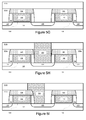
- Figure 2B illustrates a trench contact 200 that is correctly aligned between two MOS transistors having insulator-cap layers 300. In this instance the insulator-cap 300 is not used.
- Figure 2C illustrates a misaligned trench contact 200 formed between two MOS transistors having insulator-cap layers 300. As shown, a portion of the misaligned trench contact 200 is situated directly over the gate electrode 102. Unlike the prior art transistors shown in Figure IB, however, a CTG short is avoided due to the use of the insulator-cap layer 300. The insulator-cap layer 300 electrically isolates the metal gate electrode 102 from the misaligned trench contact 200, allowing the trench contact 200 to be "self-aligned”.
- FIGS 3A to 3C illustrate a slight variation on the transistors of Figure 2A .
- a different implementation of a replacement metal gate process is used to form the transistors.
- a blanket dummy dielectric layer and a blanket dummy electrode layer are deposited on a substrate.
- the dummy electrode layer may consist of polysilicon and the dummy dielectric layer may consist of silicon dioxide, both of which are used in real gate electrodes and real gate dielectric layers.
- These two dummy layers are etched to form a gate stack that consists of a dummy gate dielectric layer and a dummy gate electrode layer.
- Spacers 108 and diffusion regions 106 are then formed on opposing sides of the gate stack.
- An ILD layer 110a is deposited over the gate stack, spacers 108, and diffusion regions 106.
- the ILD layer 1 10a is planarized to expose the dummy electrode layer.
- the dummy electrode layer and the dummy gate dielectric layer are removed using one or more etching processes.
- the removal of the dummy layers produces a trench between the spacers 108.
- the substrate 100 forms a bottom surface of the trench.
- a new high-k gate dielectric layer 104 is deposited into the trench using a chemical vapor deposition process or an atomic layer deposition process.
- the high-k gate dielectric layer 104 is deposited along the bottom and sidewalls of the trench, thereby forming a "U" shaped gate dielectric layer 104, as shown in Figure 3A .
- a metal gate electrode layer 102 is deposited atop the high-k gate dielectric layer 104. Processes for forming the metal gate electrode 102 are well known in the art.
- the final metal gate electrode 102 does not fill the trench in its entirety.
- the metal gate electrode 102 may initially fill the trench in its entirety, but a subsequent etching process may be used to recess the metal gate electrode 102.
- an insulator material deposition process is used to deposit a blanket layer of insulator material that fills the trench between the spacers 108.
- a polishing process such as a chemical mechanical planarization process, is then used to polish down the insulator material layer and remove substantially any insulator material that is outside of the spacers 108. The removal of this excess insulator yields an insulator-cap layer 300 that is substantially confined within the spacers 108. As shown in Figure 3A , the insulator-cap 300 is also confined within the sidewall portions of the gate dielectric layer 104.
- Figure 3B illustrates a trench contact 200 that is correctly aligned between two MOS transistors having insulator-cap layers 300.
- Figure 3C illustrates a misaligned trench contact 200 formed between two MOS transistors having insulator-cap layers 300. Again, a portion of the misaligned trench contact 200 is situated directly over the gate electrode 102. A CTG short is avoided due to the use of the insulator-cap layer 300, which electrically isolates the metal gate electrode 102 from the misaligned trench contact 200.
- FIGs 4A to 4C illustrate a slight variation on the transistors of Figure 3A .
- a replacement gate process is used again to form transistors having a "U" shaped gate dielectric layer 104.
- the gate electrode layer 102 and the gate dielectric layer 104 are initially formed using the same processes detailed above for Figure 3A .
- both the "U" shaped gate dielectric layer 104 and the metal gate electrode 102 are recessed prior to fabrication of the insulator-cap layer 300.
- One or more etching processes may be used to recess both structures.
- the insulator-cap 300 is then formed using the same process described above for Figure 3A and is situated atop both the gate electrode 102 and portions of the gate dielectric layer 104, as shown in Figure 4A.
- Figure 4B illustrates a trench contact 200 that is correctly aligned between two MOS transistors having insulator-cap layers 300.
- Figure 4C illustrates a misaligned trench contact 200 formed between two MOS transistors having insulator-cap layers 300. Again, a portion of the misaligned trench contact 200 is situated directly over the gate electrode 102. A CTG short is avoided due to the use of the insulator-cap layer 300, which electrically isolates the metal gate electrode 102 from the misaligned trench contact 200.
- Figures 5A to 5F illustrate the fabrication of an alternate insulator-cap layer that may be used with a MOS transistor.
- Figure 5A illustrates two MOS transistors that include a dummy gate electrode 500 and a dummy gate dielectric layer 502. Also shown are a pair of spacers 108 that are generally formed of silicon nitride.
- one or multiple etching processes are carried out to partially recess both the dummy gate electrode layer 500 and the spacers 108.
- This dual recess is shown in Figure 5B .
- the etch chemistry used to recess the dummy gate electrode 500 may differ from the etch chemistry used to recess the spacers 108.
- the etching processes used may be wet etches, dry etches, or a combination.
- one or more etching processes are carried out to completely remove the dummy gate electrode 500 as well as the dummy gate dielectric 502.
- Etching processes to completely remove the dummy gate electrode 500 and dummy gate dielectric are well known in the art. Again, these etches may be wet, dry, or a combination.
- the trench 503a is now much deeper and has a cross-section profile that is relatively wide at the top of the trench 503 a and relatively narrow at the bottom of the trench 503a.
- the dummy gate electrode 500 and dummy gate dielectric 502 are removed in their entirety, thereby exposing the top of the substrate 100.
- a gate dielectric layer 104 and a metal gate electrode layer 102 are deposited in the trench 503a.
- a conformal deposition process such as a CVD or an ALD process, is generally used for the deposition of the gate dielectric layer 104, resulting in a conformal dielectric layer 104 that covers the sidewalls and bottom surface of the trench 503a.
- the metal gate electrode layer 102 fills the remainder of the trench 503a.
- the metal gate electrode layer 102 may consist of two or more layers of metal, for instance, a work function metal layer and a fill metal layer.
- the metal gate electrode layer 102 and the gate dielectric layer 104 are recessed as shown in Figure 5E , forming a trench 503b.
- one or more etching processes may be used to recess both the gate electrode layer 102 and the gate dielectric layer 104.
- the etch processes used must be selective to the ILD layer 1 10a.
- the metal gate electrode 102 is recessed until its top surface is even with or below the top surfaces of the spacers 108. Although portions of the metal gate electrode 102 are on top of the spacers 108 in Figure 5D , it is important that no portion of the metal gate electrode 102 remain above the top of the spacers 108 after the recessing of the metal gate 102 in Figure 5E . This is because any portion of the metal gate electrode 102 that remains atop the spacers 108 may end up forming a CTG short with a misaligned trench contact.
- an insulator material deposition process fills the trench 503b and a polishing process is used to polish down the insulator material layer and substantially remove any insulator material that is outside of the trench 503b.
- the insulator-cap layer 504 has the appearance of a mushroom top as it extends laterally above the spacers 108.
- the insulator-cap layer 504 improves contact-to-gate margin by extending over the gate spacer 108.
- the insulator-cap layer 504 may be formed of materials that include, but are not limited to, silicon nitride, silicon oxide, silicon carbide, silicon nitride doped with carbon, silicon oxynitride, other nitride materials, other carbide materials, aluminum oxide, other oxide materials, other metal oxides, and low-k dielectric materials.
- Figure 5G illustrates the deposition of an additional ILD layer 110b that covers the insulator-cap layers 504 and sits atop the first ILD layer 1 10a.
- Figure 5H illustrates a trench contact 200 that has been fabricated down to the diffusion region 106 through the
- Figure 5I illustrates a trench contact 200 that is misaligned. As shown, even though the trench contact 200 is situated on top of the metal gate electrode 102, the insulating-cap layer 504 protects the metal gate electrode 102 and prevents a CTG short from forming by electrically isolating the metal gate electrode 102 from the misaligned trench contact 200.
- the insulating-cap layer 504 addresses the parasitic capacitance issue discussed above in relation to Figure 1A .
- Parasitic capacitance issues are caused by the relatively tight spacing between the trench contact 200 and the diffusion region 106 on one side and the gate electrode 102 on the other side.
- the spacers 108 tend to provide the bulk of the separation between the trench contact 200/diffusion region 106 and the gate electrodes 102, but conventional spacer materials, such as silicon nitride, do little to reduce this parasitic capacitance. Nevertheless, silicon nitride is still used because the etching process that creates a contact trench opening for the trench contact 200 is selective to silicon nitride.
- the laterally extending insulating-cap layer 504 protects the underlying spacers 108 during etching processes used to fabricate the trench contact 200. These etching processes are generally anisotropic processes, therefore, the etch chemistry need only be selective to the insulating-cap layer 504. The insulating-cap layer 504 can then shield the underlying spacers 108. So with an anisotropic process, the use of the insulating-cap layer 504 means the etch chemistry does not necessarily need to be selective to the material used in the spacers 108.
- spacer material This removes any constraints on the choice of spacer material and enables the use of materials that are optimized for capacitance. For instance, materials such as silicon oxynitride (SiON), carbon-doped silicon oxynitride (SiOCN), or low-k dielectric materials may be used in the spacers 108 to reduce issues with parasitic capacitance.
- SiON silicon oxynitride
- SiOCN carbon-doped silicon oxynitride
- low-k dielectric materials may be used in the spacers 108 to reduce issues with parasitic capacitance.
- Figures 6A to 6F illustrate the formation of a stepped metal gate electrode in conjunction with an insulating-cap layer in accordance with an implementation of the invention.
- Figure 6A illustrates two MOS transistors that include a dummy gate electrode 500 and a dummy gate dielectric layer 502.
- Figure 6B one or more etching processes are carried out to completely remove the dummy gate electrode 500 as well as the dummy gate dielectric 502. Etching processes to completely remove the dummy gate electrode 500 and dummy gate dielectric are well known in the art.
- the dummy gate electrode 500 and dummy gate dielectric 502 are removed in their entirety, thereby exposing the top of the substrate 100.
- Figure 6C illustrates the deposition of dual metal gate electrode layers, a conformal metal gate electrode layer 102a and a second metal layer 102b that may or may not be conformal.
- the initial metal gate electrode layer 102a may be deposited using a conformal deposition process such as chemical vapor deposition or atomic layer deposition. Other processes, such as physical vapor deposition or sputtering, may also be used.
- the second metal gate electrode 102b is deposited using a conventional deposition process such as chemical vapor deposition, atomic layer deposition, physical vapor deposition, sputtering, or even processes such as electroplating or electroless plating since a conformal layer is not needed for layer 102b.
- the initial metal gate electrode layer 102a is typically a workfunction metal layer and can be formed using any of the workfunction metals described above.
- the second metal gate electrode layer 102b may be a second workfunction metal layer or it may be a low resistance fill metal layer such as aluminum, tungsten, or copper.
- the metal used in the metal gate electrode 102a has different etch properties than the metal used in the metal gate electrode 102b.
- the dual metal gate electrode layers 102a and 102b are etched and recessed to form trenches 600 in which insulating cap layers may be fabricated.
- the etching process removes a larger portion of metal layer 102a than metal layer 102b.
- a middle portion of the overall metal gate electrode 102 is relatively thicker than the outer edge portions of the overall metal gate electrode 102. Stated differently, a middle portion of the metal gate electrode 102 has a relatively larger height than side portions of the metal gate electrode 102.
- This stepped profile for the metal gate electrode 102 provides advantages as explained below in Figure 6F .
- a single etching process is used that etches the metal gate electrode layer 102a at a faster rate than the metal gate electrode layer 102b.
- the etch chemistry is more selective to the metal gate electrode 102b.
- two etching processes may be used, one for metal layer 102a and another for metal layer 102b. If two etching processes are used, a larger portion of metal layer 102a must be removed relative to metal layer 102b.
- the first of the two etching processes may be selective to the metal layer 102b and the second of the two etching processes may be selective to the metal layer 102a.
- the etching processes used may be wet etch, dry etch, or a combination of both. It will be appreciated by those of ordinary skill in the art that for almost any arbitrary pair of metals used in metal layers 102a and 102b, it is possible to find a wet or dry chemical etch that will differentiate between the two metals.
- an insulator material deposition process fills the trenches 600 and a polishing process is used to polish down the insulator material layer and substantially remove any insulator material that is outside of the trench 600.
- the insulator-cap layer 602 is relatively thick at its outer edges and relatively thin at its middle portion due to the stepped profile of the metal gate electrode 102.
- the insulator-cap layer 602 may be formed of materials that include, but are not limited to, silicon nitride, silicon oxide, silicon carbide, silicon nitride doped with carbon, silicon oxynitride, other nitride materials, other carbide materials, aluminum oxide, other oxide materials, other metal oxides, and low-k dielectric materials.
- Figure 6F illustrates a trench contact 200 that is misaligned.
- the insulating-cap layer 602 protects the metal gate electrode 102 and prevents a CTG short from forming by electrically isolating the metal gate electrode 102 from the misaligned trench contact 200.
- the stepped profile of the metal gate electrode 102 provides at least two advantages. First, the stepped profile causes the thick portion of the insulator-cap layer 602 to be positioned between the metal gate electrode 102 and the trench contact 200, thereby providing strong electrical isolation. Second, the stepped profile allows the middle portion of the metal gate electrode 102 to remain thick, thereby lowering the electrical resistance of the metal gate electrode 102 by increasing its metal content.
- the stepped profile may be optimized by trying to maximize the volume or width of the middle portion of the metal gate electrode 102 while maintaining its electrical isolation from misaligned trench contact 200. In some implementations, this may be done by increasing the size or thickness of the metal gate electrode 102b. In further implementations, this may be done by using more than two metal gate electrode layers to more finely tailor the stepped profile.
- Figures 7A to 7C illustrate the fabrication of a MOS transistor that combines the wide insulator-cap layer 504 of Figure 5F with the stepped profile metal gate electrode 102 of Figures 6D to 6F .
- dual metal gate electrode layers are deposited as shown in Figure 7A .
- One layer is a conformal metal gate electrode layer 102a and the other layer is a second metal layer 102b that may or may not be conformal.
- the initial metal gate electrode layer 102a is typically a workfunction metal layer and the second metal gate electrode layer 102b may be a second workfunction metal layer or it may be a fill metal layer.
- the metal used in the metal gate electrode 102a has different etch properties than the metal used in the metal gate electrode 102b.
- the dual metal gate electrode layers 102a and 102b, as well as the gate dielectric layer 104, are etched and recessed.
- the etch process is selective to the metal gate electrode 102b. This yields a stepped profile for the metal gate electrode 102, as shown in Figure 7B .
- a middle portion of the overall metal gate electrode 102 is relatively thicker than the outer edge portions of the overall metal gate electrode 102.
- insulator-cap layers 700 atop each metal gate electrode 102. This is shown in Figure 7C . Also shown is a misaligned trench contact 200.
- the stepped profile of the metal gate electrode 102 allows the thick portion of the insulator-cap layer 700 to electrically isolate the metal gate electrode 102 from the trench contact 200.
- the stepped profile also allows a middle portion of the metal gate electrode 102 to remain thick, thereby reducing electrical resistance.
- the insulating-cap layer 700 extends over the recessed spacers 108, thereby protecting the spacers during the trench contact 200 etch process and allowing a material to be used in the spacers 108 that is optimized for reducing parasitic capacitance between the trench contact 200 and the metal gate electrode 102.
- Figures 8A to 8F illustrate another implementation of the invention in which contact sidewall spacers are used to reduce CTG shorts and to improve parasitic capacitance issues.
- Figure 8A illustrates a contact trench opening 800 that has been etched through ILD layers 1 10a and 1 10b down to the diffusion region 106. As explained above, photolithography patterning and etching processes are used to form the contact trench opening 800.
- a silicide layer 802 that has been formed at the bottom of the contact trench opening 800.
- a conventional metal deposition process such as a sputtering deposition process or an ALD process, may be used to form a conformal metal layer along at least the bottom of the contact trench opening 800. Often the metal will deposit on the sidewalls of the contact trench opening 800 as well.
- the metal may include one or more of nickel, cobalt, tantalum, titanium, tungsten, platinum, palladium, aluminum, yttrium, erbium, ytterbium, or any other metal that is a good candidate for a silicide.
- An annealing process may then be carried out to cause the metal to react with the diffusion region 106 and form a silicide layer 802. Any unreacted metal may be selectively removed using known processes.
- the silicide layer 802 reduces the electrical resistance between the later formed trench contact 200 and the diffusion region 106.
- Figure 8B illustrates a pair of contact sidewall spacers 804 that are formed along the sidewalls of the contact trench opening 800, in accordance with an implementation of the invention.
- the contact sidewall spacers 804 may be formed using deposition and etching processes similar to the fabrication of gate spacers 108. For instance, a conformal layer of an insulating material may be deposited within the contact trench opening 800, resulting in the insulating material being deposited along the sidewalls and bottom surface of the contact trench opening 800.
- the insulating material may be silicon oxide, silicon nitride, silicon oxynitride (SiON), carbon-doped silicon oxynitride (SiOCN), any other oxide, any other nitride, or any low-k dielectric material.
- an anisotropic etching process is used to remove the insulating material from the bottom of the contact trench opening 800, as well as from other areas such as the surface of the ILD layer 110b. This yields the contact sidewall spacers 804 that are shown in Figure 8B .
- a separate patterning process may be used to form vias down to the metal gate electrodes 102 in order to form gate contacts.
- This separate patterning process will typically involve coating the wafer with a sacrificial photo-definable resist layer, etching the gate contacts, and then removing the photoresist with a wet or dry cleaning process or some combination thereof.
- This separate patterning process is generally carried out after the contact trench opening 800 has been formed, which means first the resist coating and then the wet or dry clean chemistry enters the contact trench opening 800 and can degrade the silicide layer 802.
- the conformal layer of insulating material used to form the spacers 804 is deposited before the patterning process for the gate contacts.
- the conformal layer remains in place to protect the silicide layer 802 until after the gate contacts have been patterned. Then the anisotropic etch described above may be carried out to etch the conformal layer and form the spacers 804.
- the silicide layer 802 is formed prior to fabrication of the contact sidewall spacers 804, which is when the contact trench opening 800 is at its largest width. By forming the silicide layer 802 before forming the contact sidewall spacers 804, a relatively wider silicide layer 802 can be formed to provide better electrical resistance properties, such as lower intrinsic contact resistance. If the contact sidewall spacers 804 are formed first, then less of the diffusion region 106 would be exposed for the silicide fabrication process, yielding a relatively shorter silicide layer.
- a metal deposition process is then carried out to fill the contact trench opening 800 and form the trench contact 200, as shown in Figure 8C .
- the metal deposition process can be any metal deposition process, such as electroplating, electroless plating, chemical vapor deposition, physical vapor deposition, sputtering, or atomic layer deposition.
- the metal used may be any metal that provides suitable contact properties, such as tungsten or copper.
- a metal liner is often deposited prior to the metal, such as a tantalum or tantulum nitride liner.
- a CMP process is used to remove any excess metal and complete the fabrication of the trench contact 200.
- the contact sidewall spacers 804 provide an additional layer of protection between the gate electrodes 102 and the trench contact 200.
- the final trench contact 200 has a relatively narrower width than trench contacts 200 formed using conventional processes, thereby reducing the likelihood of CTG shorts.
- the additional layer of insulation between the gate electrodes 102 and the trench contact 200 reduces parasitic capacitance.
- Figures 8D to 8F illustrate the fabrication of contact sidewall spacers 804 when the contact is misaligned.
- Figure 8D illustrates a misaligned contact trench opening 800 that has been etched through ILD layers 110a and 110b down to the diffusion region 106.
- the insulating-cap layer 300 protects the metal gate electrode 102 from being exposed during this etching process, in accordance with an implementation of the invention.
- a silicide layer 802 that has been formed at the bottom of the contact trench opening 800. Fabrication processes for the silicide layer 802 were provided above.
- Figure 8E illustrates a pair of contact sidewall spacers 804 that are formed along the sidewalls of the contact trench opening 800, in accordance with an implementation of the invention.
- the contact sidewall spacers 804 may be formed by depositing and etching a conformal layer of an insulating material, as explained above.
- a metal deposition process is then carried out to fill the contact trench opening 800 and form the trench contact 200, as shown in Figure 8F .
- the contact sidewall spacers 804 provide an additional layer of protection between the gate electrodes 102 and the trench contact 200.
- the contact sidewall spacers 804 provide more separation between the final trench contact 200 and the metal gate electrodes 102, thereby reducing the likelihood of CTG shorts.
- the additional layer of insulation between the gate electrodes 102 and the trench contact 200 reduces parasitic capacitance.
- Figures 9A to 9D illustrate another process for forming an insulating-cap layer in accordance with an implementation of the invention.
- Figure 9A illustrates two MOS transistors having metal gate electrodes 102 and gate dielectric layer 104.
- the gate electrode layer 102 may include two or more layers (not illustrated), such as a workfunction metal layer and a fill metal layer.
- the gate dielectric layer 104 shown corresponds to a replacement-metal gate process, the following process may also be used with transistors formed using a gate-first approach.
- a metal-cap 900 is formed atop the metal gate electrode 102, as shown in Figure 9A .
- the metal-cap 900 is formed using a selective deposition process.
- Some selective deposition processes include, but are not limited to, electroless plating and chemical vapor deposition.
- Metals that may be selectively deposited include, but are not limited to, cobalt, nickel, platinum, copper, polysilicon, tungsten, palladium, silver, gold, and other noble metals.
- the choice of whether an electroless process or a CVD process is used will depend on the composition of the metal gate electrode 102 and the specific metal that is used in the metal-cap 900.
- cobalt metal can be electrolessly deposited on the copper.
- tungsten or polysilicon can be deposited by CVD on almost any metal that is used in the metal gate electrode 102.
- most metals may be deposited using an electroless process on the noble metal.
- electroless processes require a noble metal for both the substrate metal and the metal to be deposited. Therefore combinations of metals such as cobalt, nickel, copper, platinum, palladium, gold, and silver are possible.
- an ILD layer 902 is blanket deposited over the ILD 110a and the metal-caps 900.
- a CMP process is then used to planaraize both the ILD layer 902 and the metal-caps 900 and cause their top surfaces to be substantially even. This is done to expose the top surface of the metal-caps 900 after the ILD deposition.
- an etching process is used to remove the metal-caps 900 from within the ILD layer 902.
- a wet etch chemistry may be applied to remove the metal-caps 900.
- the etch chemistry that is used must be selective to both the ILD layer 902 and the metal gate electrode 102. This enables the metal-caps 900 to be removed with minimal impact to the ILD layer 902 and the metal gate electrode 102.
- the removal of the metal-caps 900 yields voids 904 within the ILD layer 902.
- an insulating layer such as a silicon nitride layer, may be deposited and planarized to fill in the voids 904, thereby forming self-aligned insulating- cap layers 906.
- This insulating layer is generally deposited as a blanket layer that fills the voids 904 and covers the ILD layer 902.
- a planarization process is then used to remove any excess material that is outside of the voids 904. This confines the insulating material to the voids 904, thereby forming insulating-cap layers 906.
- the insulator-cap layers 906 may be formed of materials that include, but are not limited to, silicon nitride, silicon oxide, silicon carbide, silicon nitride doped with carbon, silicon oxynitride, other nitride materials, other carbide materials, aluminum oxide, other oxide materials, other metal oxides, and low-k dielectric materials. The only constraint is that the material used in the insulator-cap layers 906 be dissimilar to the material used in the ILD layer 902.
- Figures 10A to 10G illustrate a process for forming a self-aligned metal stud atop the trench contact 200 and a pair of insulating spacers that further insulate the metal stud from the metal gate electrodes 102, in accordance with an implementation of the invention.
- Figure 10A illustrates two MOS transistors having metal gate electrodes 102 and gate dielectric layer 104. A trench contact 200 is formed between the two MOS transistors.
- a metal-cap 900 is formed atop the trench contact 200, as shown in Figure 10A .
- the metal-cap 900 is formed using a selective deposition process.
- selective deposition processes include, but are not limited to, electroless plating and chemical vapor deposition.
- the same metals and processes described above for use with the metal gate electrode 102 may also be used here with the trench contact 200.
- the selective deposition process used and the metal used in the metal-cap 900 will depend on the metal that is used in the trench contact 200.
- a selective deposition process is chosen that will deposit metal on only the trench contact 200 and not on the metal gate electrode 102. This can be accomplished by using different types of metals in the trench contact 200 and the metal gate electrode 102. For example, if aluminum is used in the metal gate electrode 102 and a noble metal is used in the trench contact 200, then a selective deposition process can be used to deposit the metal-cap 900 on only the noble metal in the trench contact 200. The same combinations of noble metals described above will work here as well.
- an active metal such as aluminum, tungsten, molybdenum, titanium, tantalum, titanium nitride, or polysilicon
- a noble metal such as cobalt, nickel, copper, platinum, palladium, gold, and silver may be used in the trench contact 200.
- an ILD layer 902 is blanket deposited over the ILD 1 10a and the metal-cap 900.
- a CMP process is then used to planaraize both the ILD layer 902 and the metal-cap 900 and cause their top surfaces to be substantially even. This is done to expose the top surface of the metal-cap 900 after the ILD deposition.
- an etching process is used to remove just the metal-cap 900 from within the ILD layer 902.
- the etch chemistry that is used must be selective to both the ILD layer 902 and the trench contact 200. This enables the metal-cap 900 to be removed with minimal impact to the ILD layer 902 and the trench contact 200.
- the removal of the metal-cap 900 yields a void 904 within the ILD layer 902.
- an insulating layer 906 may be blanket deposited over the ILD layer 902 and within the void 904.
- the insulating layer 906 may be formed of materials that include, but are not limited to, silicon nitride, silicon oxide, silicon carbide, silicon nitride doped with carbon, silicon oxynitride, other nitride materials, other carbide materials, aluminum oxide, other oxide materials, other metal oxides, and low-k dielectric materials, including materials that are the same or similar to the material used in the ILD layer 902.
- an etching process such as an anisotropic etching process is applied to etch down the insulating layer 906 and form spacers 1000. This is shown in Figure 10E .
- the etching process also creates a trench 1002 between the two spacers 1000.
- a metal deposition process is used to deposit a self-aligned metal stud 1004 in the trench 1002 between the spacers 1000 and atop the trench contact 200.
- this metal deposition process may be another selective deposition process, while in other implementations this metal deposition process need not be a selective process.
- an insulating layer may be deposited and planarized to form an ILD layer 1006.
- the top of the metal stud 1004 is also planarized to be even with the ILD layer 1006.
- the self aligned metal stud 1004 is prevented from shorting to the gate by the spacers 1000.
- implementations of the invention are described here that form etch stop structures that are self aligned to the gate, preventing the contact etch from exposing the gate electrode to cause shorting between the gate and contact. A contact to gate short is prevented even in the case of the contact pattern overlaying the gate electrode.
- Implementations of the invention also address problems such as parasitic capacitance between trench contacts and gate electrodes, dielectric breakdown or direct shorts from contact to gate, and degradation of contact silicide during gate contact patterning.
- an insulator-cap layer enables self-aligned contacts, which offer a robust manufacturable process.
- the invention allows initial patterning of wider contacts which is more robust to patterning limitations.
- the wider contacts are also desirable for a silicide-through-contact process flow. Not only does this eliminate a major yield limiter in contact-to-gate shorts, but it also alleviates major constraints for contact patterning and allows for more variability.
- the use of an insulator-cap layer increases the registration window and allows for more critical dimension variability.
- the use of an insulator-cap layer makes the fabrication process for MOS transistors more tolerant to different profiles, different critical dimensions, and over-etching of the ILD during trench contact formation.
- a transistor comprising: a substrate; a pair of spacers on the substrate; a gate dielectric layer on the substrate and between the pair of spacers; a gate electrode layer on the gate dielectric layer and between the pair of spacers; an insulating cap layer on the gate electrode layer and between the pair of spacers; and a pair of diffusion regions adjacent to the pair of spacers.
- a height of the combination of the gate dielectric layer, the gate electrode layer, and the insulating cap layer does not exceed a height of the pair of spacers.
- the gate dielectric layer is formed along the surface of the substrate and along sidewalls of the pair of spacers.
- the insulating cap layer comprises silicon nitride, silicon oxide, silicon carbide, silicon nitride doped with carbon, silicon oxynitride, or aluminum oxide.
- the insulating cap layer comprises a nitride material, a carbide material, an oxide material, a metal oxide material, or a low-k dielectric material.
- the insulating cap layer comprises boron nitride or boron carbide.
- the insulating cap layer comprises a low-k dielectric material doped with one or more of carbon, nitrogen, and hydrogen.
- a method of forming a transistor comprising: forming a gate dielectric layer on a substrate; forming a gate electrode layer on the gate dielectric layer; forming a pair of spacers on opposing sides of the gate dielectric layer and the gate electrode layer; forming a pair of diffusion regions adjacent to the pair of spacers; recessing the gate electrode layer; and forming an insulating cap layer on the recessed gate electrode layer within the pair of spacers.
- the forming of the insulating cap layer comprises: depositing a blanket layer of an insulating material over the recessed gate electrode layer; and planarizing the insulating material layer to form the insulating cap layer.
- the method may further comprise: removing the gate electrode layer and the gate dielectric layer after the diffusion regions have been formed, thereby forming a trench between the pair of spacers; depositing a conformal low-k gate dielectric layer along the sidewalls and bottom surface of the trench between the spacers; and depositing a metal gate electrode layer on the low-k gate dielectric layer before recessing the metal gate electrode.
- the insulating cap layer comprises silicon nitride, silicon oxide, silicon carbide, silicon nitride doped with carbon, silicon oxynitride, or aluminum oxide.
- the insulating cap layer comprises a nitride material, a carbide material, an oxide material, a metal oxide material, or a low-k dielectric material.
- the insulating cap layer comprises boron nitride or boron carbide.
- the insulating cap layer comprises a low-k dielectric material doped with one or more of carbon, nitrogen, and hydrogen.
- a method of forming a transistor comprising: forming a gate stack on a substrate, the gate stack comprising a gate dielectric layer, a gate electrode layer on the gate dielectric layer, and an insulating cap layer on the gate electrode layer; forming a pair of spacers on opposing sides of the gate stack; and forming a pair of diffusion regions adjacent to the pair of spacers.
- the insulating cap layer comprises silicon nitride, silicon oxide, silicon carbide, silicon nitride doped with carbon, silicon oxynitride, or aluminum oxide.
- the insulating cap layer comprises a nitride material, a carbide material, an oxide material, a metal oxide material, or a low-k dielectric material.
- the insulating cap layer comprises boron nitride or boron carbide.
- the insulating cap layer comprises a low-k dielectric material doped with one or more of carbon, nitrogen, and hydrogen.
- a transistor comprising: a substrate; a pair of spacers on the substrate; a gate dielectric layer on the substrate and between the pair of spacers; a gate electrode layer on the gate dielectric layer and between the pair of spacers; an insulating cap layer sited atop the gate electrode layer that extends laterally over the top surfaces of the pair of spacers; and a pair of diffusion regions adjacent to the pair of spacers.
- the gate dielectric layer is formed along the surface of the substrate and along sidewalls of the pair of spacers.
- the insulating cap layer comprises silicon nitride, silicon oxide, silicon carbide, silicon nitride doped with carbon, silicon oxynitride, or aluminum oxide.
- the insulating cap layer comprises a nitride material, a carbide material, an oxide material, a metal oxide material, or a low-k dielectric material.
- the insulating cap layer comprises boron nitride or boron carbide.
- the insulating cap layer comprises a low-k dielectric material doped with one or more of carbon, nitrogen, and hydrogen.
- the pair of spacers comprises silicon oxynitride, carbon-doped silicon oxynitride, or a low-k dielectric material.
- a method of forming a transistor comprising: forming a gate dielectric layer on a substrate; forming a gate electrode layer on the gate dielectric layer; forming a pair of spacers on opposing sides of the gate dielectric layer and the gate electrode layer; forming a pair of diffusion regions adjacent to the pair of spacers; recessing the gate electrode layer; recessing the pair of spacers; and forming an insulating cap layer on the recessed gate electrode layer that extends laterally over the top surfaces of the recessed pair of spacers.
- the method may further comprise: removing the recessed gate electrode layer and the gate dielectric layer after the spacers have been recessed, thereby forming a trench between the recessed pair of spacers; depositing a conformal low-k gate dielectric layer along the sidewalls and bottom surface of the trench between the recessed pair of spacers; depositing a metal gate electrode layer on the low-k gate dielectric layer; and recessing the metal gate electrode so that a height of the recessed metal gate electrode is similar to a height of the recessed pair of spacers before the insulating cap layer is formed.
- the forming of the insulating cap layer comprises: depositing a blanket layer of an insulating material over the recessed gate electrode layer and recessed pair of spacers; and planarizing the insulating material layer to form the insulating cap layer.
- a height of the recessed pair of spacers is substantially the same as a height of the recessed gate electrode.
- the pair of spacers comprises silicon oxynitride (SiON), carbon-doped silicon oxynitride (SiOCN), or a low-k dielectric material.
- a transistor comprising: a substrate; a pair of spacers on the substrate; a gate dielectric layer on the substrate and between the pair of spacers; a gate electrode layer having a stepped profile on the gate dielectric layer, wherein a middle portion of the gate electrode layer has a relatively larger height than side portions of the gate electrode layer; an insulating cap layer on the gate electrode layer and between the pair of spacers; and a pair of diffusion regions adjacent to the pair of spacers.
- the insulating cap layer comprises silicon nitride, silicon oxide, silicon carbide, silicon nitride doped with carbon, silicon oxynitride, or aluminum oxide.
- the insulating cap layer comprises a nitride material, a carbide material, an oxide material, a metal oxide material, or a low-k dielectric material.
- the insulating cap layer comprises boron nitride or boron carbide.
- the insulating cap layer comprises a low-k dielectric material doped with one or more of carbon, nitrogen, and hydrogen.
- the gate electrode comprises two metal layers, wherein a first metal layer comprises the middle portion of the gate electrode having the relatively larger height and a second metal layer comprises the side portions of the gate electrode.
- a method of forming a transistor comprising: forming a gate dielectric layer on a substrate; forming a gate electrode layer on the gate dielectric layer; forming a pair of spacers on opposing sides of the gate dielectric layer and the gate electrode layer; forming a pair of diffusion regions adjacent to the pair of spacers; removing the gate electrode layer and the gate dielectric layer, thereby forming a trench between the pair of spacers; depositing a conformal first metal layer within the trench; depositing a second metal layer on the first metal layer; recessing the first and second metal layers, wherein the first metal layer is recessed to a larger extent than the second metal layer; and forming an insulating cap layer on the recessed first and second metal layers.
- the recessing of the first and second metal layers comprises: applying an etch chemistry to the first and second metal layers that is selective to the second metal layer.
- the recessing of the first and second metal layers comprises: applying a first etch chemistry to recess the first metal layer; and applying a second etch chemistry to recess the second metal layer, wherein the first and second etch chemistries recess the first metal layer to a larger extent than the second metal layer.
- the second etch chemistry also recesses the first metal layer.
- the forming of the insulating cap layer comprises: depositing a blanket layer of an insulating material over the recessed first and second metal layers; and planarizing the insulating material layer to form the insulating cap layer.
- the insulating cap layer comprises silicon nitride, silicon oxide, silicon carbide, silicon nitride doped with carbon, silicon oxynitride, or aluminum oxide.
- the insulating cap layer comprises a nitride material, a carbide material, an oxide material, a metal oxide material, or a low-k dielectric material.
- the insulating cap layer comprises boron nitride or boron carbide.
- the insulating cap layer comprises a low-k dielectric material doped with one or more of carbon, nitrogen, and hydrogen.
- a transistor comprising: a substrate; a pair of spacers on the substrate; a gate dielectric layer on the substrate and between the pair of spacers; a gate electrode layer having a stepped profile on the gate dielectric layer, wherein a middle portion of the gate electrode layer has a relatively larger height than side portions of the gate electrode layer; an insulating cap layer sited atop the gate electrode layer that extends laterally over the top surfaces of the pair of spacers; and a pair of diffusion regions adjacent to the pair of spacers.
- the insulating cap layer comprises silicon nitride, silicon oxide, silicon carbide, silicon nitride doped with carbon, silicon oxynitride, or aluminum oxide.
- the insulating cap layer comprises a nitride material, a carbide material, an oxide material, a metal oxide material, or a low-k dielectric material.
- the insulating cap layer comprises boron nitride or boron carbide.
- the insulating cap layer comprises a low-k dielectric material doped with one or more of carbon, nitrogen, and hydrogen.
- the gate electrode comprises two metal layers, wherein a first metal layer comprises the middle portion of the gate electrode having the relatively larger height and a second metal layer comprises the side portions of the gate electrode.
Landscapes
- Engineering & Computer Science (AREA)
- Microelectronics & Electronic Packaging (AREA)
- Power Engineering (AREA)
- Physics & Mathematics (AREA)
- Condensed Matter Physics & Semiconductors (AREA)
- General Physics & Mathematics (AREA)
- Computer Hardware Design (AREA)
- Ceramic Engineering (AREA)
- Manufacturing & Machinery (AREA)
- Chemical & Material Sciences (AREA)
- Composite Materials (AREA)
- Materials Engineering (AREA)
- Geometry (AREA)
- Inorganic Chemistry (AREA)
- Chemical Kinetics & Catalysis (AREA)
- General Chemical & Material Sciences (AREA)
- Electrodes Of Semiconductors (AREA)
- Insulated Gate Type Field-Effect Transistor (AREA)
- Internal Circuitry In Semiconductor Integrated Circuit Devices (AREA)
Priority Applications (2)
| Application Number | Priority Date | Filing Date | Title |
|---|---|---|---|
| EP19152329.9A EP3506366A1 (de) | 2009-12-30 | 2010-12-07 | Selbstausrichtende kontakte |
| EP22161202.1A EP4033543A1 (de) | 2009-12-30 | 2010-12-07 | Selbstausrichtende kontakte |
Applications Claiming Priority (3)
| Application Number | Priority Date | Filing Date | Title |
|---|---|---|---|
| US12/655,408 US8436404B2 (en) | 2009-12-30 | 2009-12-30 | Self-aligned contacts |
| PCT/US2010/059302 WO2011090571A2 (en) | 2009-12-30 | 2010-12-07 | Self-aligned contacts |
| EP10844169.2A EP2519975B1 (de) | 2009-12-30 | 2010-12-07 | Selbstausrichtende kontakte |
Related Parent Applications (2)
| Application Number | Title | Priority Date | Filing Date |
|---|---|---|---|
| EP10844169.2A Division-Into EP2519975B1 (de) | 2009-12-30 | 2010-12-07 | Selbstausrichtende kontakte |
| EP10844169.2A Division EP2519975B1 (de) | 2009-12-30 | 2010-12-07 | Selbstausrichtende kontakte |
Related Child Applications (4)
| Application Number | Title | Priority Date | Filing Date |
|---|---|---|---|
| EP19152329.9A Division EP3506366A1 (de) | 2009-12-30 | 2010-12-07 | Selbstausrichtende kontakte |
| EP19152329.9A Division-Into EP3506366A1 (de) | 2009-12-30 | 2010-12-07 | Selbstausrichtende kontakte |
| EP22161202.1A Division EP4033543A1 (de) | 2009-12-30 | 2010-12-07 | Selbstausrichtende kontakte |
| EP22161202.1A Division-Into EP4033543A1 (de) | 2009-12-30 | 2010-12-07 | Selbstausrichtende kontakte |
Publications (2)
| Publication Number | Publication Date |
|---|---|
| EP3096357A1 true EP3096357A1 (de) | 2016-11-23 |
| EP3096357B1 EP3096357B1 (de) | 2024-03-13 |
Family
ID=44186364
Family Applications (5)
| Application Number | Title | Priority Date | Filing Date |
|---|---|---|---|
| EP22161202.1A Pending EP4033543A1 (de) | 2009-12-30 | 2010-12-07 | Selbstausrichtende kontakte |
| EP10844169.2A Active EP2519975B1 (de) | 2009-12-30 | 2010-12-07 | Selbstausrichtende kontakte |
| EP17201192.6A Ceased EP3312888A3 (de) | 2009-12-30 | 2010-12-07 | Selbstausrichtende kontakte |
| EP19152329.9A Pending EP3506366A1 (de) | 2009-12-30 | 2010-12-07 | Selbstausrichtende kontakte |
| EP16172290.5A Active EP3096357B1 (de) | 2009-12-30 | 2010-12-07 | Selbstausrichtende kontakte |
Family Applications Before (4)
| Application Number | Title | Priority Date | Filing Date |
|---|---|---|---|
| EP22161202.1A Pending EP4033543A1 (de) | 2009-12-30 | 2010-12-07 | Selbstausrichtende kontakte |
| EP10844169.2A Active EP2519975B1 (de) | 2009-12-30 | 2010-12-07 | Selbstausrichtende kontakte |
| EP17201192.6A Ceased EP3312888A3 (de) | 2009-12-30 | 2010-12-07 | Selbstausrichtende kontakte |
| EP19152329.9A Pending EP3506366A1 (de) | 2009-12-30 | 2010-12-07 | Selbstausrichtende kontakte |
Country Status (8)
| Country | Link |
|---|---|
| US (12) | US8436404B2 (de) |
| EP (5) | EP4033543A1 (de) |
| JP (6) | JP5539538B2 (de) |
| KR (15) | KR102115127B1 (de) |
| CN (2) | CN104795444B (de) |
| HK (1) | HK1173851A1 (de) |
| TW (5) | TWI518904B (de) |
| WO (1) | WO2011090571A2 (de) |
Families Citing this family (247)
| Publication number | Priority date | Publication date | Assignee | Title |
|---|---|---|---|---|
| US8436404B2 (en) | 2009-12-30 | 2013-05-07 | Intel Corporation | Self-aligned contacts |
| US8946828B2 (en) | 2010-02-09 | 2015-02-03 | Taiwan Semiconductor Manufacturing Company, Ltd. | Semiconductor device having elevated structure and method of manufacturing the same |
| KR101675373B1 (ko) * | 2010-03-24 | 2016-11-11 | 삼성전자주식회사 | 반도체 소자 및 그 제조 방법 |
| KR101615654B1 (ko) * | 2010-05-14 | 2016-05-12 | 삼성전자주식회사 | 반도체 소자의 형성방법 |
| US8860107B2 (en) * | 2010-06-03 | 2014-10-14 | International Business Machines Corporation | FinFET-compatible metal-insulator-metal capacitor |
| US8421077B2 (en) * | 2010-06-08 | 2013-04-16 | International Business Machines Corporation | Replacement gate MOSFET with self-aligned diffusion contact |
| JP5569243B2 (ja) * | 2010-08-09 | 2014-08-13 | ソニー株式会社 | 半導体装置及びその製造方法 |
| KR101692309B1 (ko) * | 2010-08-25 | 2017-01-04 | 삼성전자 주식회사 | 반도체 장치의 제조방법 |
| US8592266B2 (en) * | 2010-10-27 | 2013-11-26 | International Business Machines Corporation | Replacement gate MOSFET with a high performance gate electrode |
| US8946006B2 (en) * | 2010-10-28 | 2015-02-03 | International Business Machines Corporation | Replacement gate MOSFET with raised source and drain |
| US8232607B2 (en) * | 2010-11-23 | 2012-07-31 | International Business Machines Corporation | Borderless contact for replacement gate employing selective deposition |
| US8536656B2 (en) * | 2011-01-10 | 2013-09-17 | International Business Machines Corporation | Self-aligned contacts for high k/metal gate process flow |
| DE102011004323B4 (de) * | 2011-02-17 | 2016-02-25 | Globalfoundries Dresden Module One Limited Liability Company & Co. Kg | Halbleiterbauelement mit selbstjustierten Kontaktelementen und Verfahren zu seiner Herstellung |
| CN102779754B (zh) * | 2011-05-12 | 2015-04-08 | 中芯国际集成电路制造(北京)有限公司 | 半导体器件及其制造方法 |
| US8872286B2 (en) * | 2011-08-22 | 2014-10-28 | United Microelectronics Corp. | Metal gate structure and fabrication method thereof |
| US9190261B2 (en) * | 2011-08-25 | 2015-11-17 | Taiwan Semiconductor Manufacturing Company, Ltd. | Layer alignment in FinFET fabrication |
| US8822283B2 (en) | 2011-09-02 | 2014-09-02 | Taiwan Semiconductor Manufacturing Company, Ltd. | Self-aligned insulated film for high-k metal gate device |
| US8877645B2 (en) * | 2011-09-15 | 2014-11-04 | International Business Machines Corporation | Integrated circuit structure having selectively formed metal cap |
| EP2761664A4 (de) * | 2011-09-30 | 2015-06-17 | Intel Corp | Verschliessen von dielektrischen strukturen für transistor-gates |
| US9580776B2 (en) | 2011-09-30 | 2017-02-28 | Intel Corporation | Tungsten gates for non-planar transistors |
| US9177867B2 (en) * | 2011-09-30 | 2015-11-03 | Intel Corporation | Tungsten gates for non-planar transistors |
| US8981435B2 (en) | 2011-10-01 | 2015-03-17 | Intel Corporation | Source/drain contacts for non-planar transistors |
| US8614123B2 (en) * | 2011-11-28 | 2013-12-24 | Globalfoundries Inc. | Method of forming a semiconductor device by using sacrificial gate electrodes and sacrificial self-aligned contact structures |
| US9087915B2 (en) | 2011-12-06 | 2015-07-21 | Intel Corporation | Interlayer dielectric for non-planar transistors |
| CN104011835B (zh) | 2011-12-22 | 2016-10-26 | 英特尔公司 | 栅极对准接触部及其制造方法 |
| US20130175619A1 (en) * | 2012-01-06 | 2013-07-11 | International Business Machines Corporation | Silicon-on-insulator transistor with self-aligned borderless source/drain contacts |
| US8772168B2 (en) * | 2012-01-19 | 2014-07-08 | Globalfoundries Singapore Pte. Ltd. | Formation of the dielectric cap layer for a replacement gate structure |
| US20130187236A1 (en) * | 2012-01-20 | 2013-07-25 | Globalfoundries Inc. | Methods of Forming Replacement Gate Structures for Semiconductor Devices |
| US8927407B2 (en) | 2012-01-20 | 2015-01-06 | Globalfoundries Inc. | Method of forming self-aligned contacts for a semiconductor device |
| US8580628B2 (en) * | 2012-02-02 | 2013-11-12 | GlobalFoundries, Inc. | Integrated circuit contact structure and method |
| KR101853316B1 (ko) * | 2012-03-29 | 2018-04-30 | 삼성전자주식회사 | 반도체 소자 |
| US8946049B2 (en) | 2012-04-11 | 2015-02-03 | International Business Machines Corporation | Replacement gate structures and methods of manufacturing |
| US9111783B2 (en) * | 2012-04-13 | 2015-08-18 | Renesas Electronics Corporation | Semiconductor devices with self-aligned source drain contacts and methods for making the same |
| US8759172B2 (en) * | 2012-04-18 | 2014-06-24 | International Business Machines Corporation | Etch stop layer formation in metal gate process |
| US20130309856A1 (en) * | 2012-05-15 | 2013-11-21 | International Business Machines Corporation | Etch resistant barrier for replacement gate integration |
| US8779515B2 (en) | 2012-05-21 | 2014-07-15 | International Business Machines Corporation | Semiconductor structure containing an aluminum-containing replacement gate electrode |
| US9130023B2 (en) * | 2012-06-05 | 2015-09-08 | Kabushiki Kaisha Toshiba | Isolated insulating gate structure |
| US8679909B2 (en) | 2012-06-08 | 2014-03-25 | Globalfoundries Singapore Pte. Ltd. | Recessing and capping of gate structures with varying metal compositions |
| US8883583B2 (en) * | 2012-06-26 | 2014-11-11 | Taiwan Semiconductor Manufacturing Company, Ltd. | Semiconductor devices, transistors, and methods of manufacture thereof |
| US8937006B2 (en) | 2012-07-30 | 2015-01-20 | Taiwan Semiconductor Manufacturing Company, Ltd. | Method of semiconductor integrated circuit fabrication |
| US9218975B2 (en) * | 2012-08-17 | 2015-12-22 | Globalfoundries Inc. | Methods of forming a replacement gate structure having a gate electrode comprised of a deposited intermetallic compound material |
| US8877621B2 (en) * | 2012-09-05 | 2014-11-04 | Globalfoundries Inc. | Low resistivity gate conductor |
| US8896030B2 (en) | 2012-09-07 | 2014-11-25 | Intel Corporation | Integrated circuits with selective gate electrode recess |
| US8753970B2 (en) * | 2012-09-12 | 2014-06-17 | Globalfoundries Inc. | Methods of forming semiconductor devices with self-aligned contacts and the resulting devices |
| US9034703B2 (en) * | 2012-09-13 | 2015-05-19 | International Business Machines Corporation | Self aligned contact with improved robustness |
| US9461143B2 (en) * | 2012-09-19 | 2016-10-04 | Intel Corporation | Gate contact structure over active gate and method to fabricate same |
| US9299802B2 (en) * | 2012-10-28 | 2016-03-29 | International Business Machines Corporation | Method to improve reliability of high-K metal gate stacks |
| US8765590B2 (en) | 2012-10-31 | 2014-07-01 | International Business Machines Corporation | Insulative cap for borderless self-aligning contact in semiconductor device |
| US8928090B2 (en) | 2012-10-31 | 2015-01-06 | International Business Machines Corporation | Self-aligned contact structure for replacement metal gate |
| US8907427B2 (en) * | 2012-11-05 | 2014-12-09 | Stmicroelectronics, Inc. | Semiconductor device including low-K dielectric cap layer for gate electrodes and related methods |
| US8890262B2 (en) * | 2012-11-29 | 2014-11-18 | Globalfoundries Inc. | Semiconductor device having a metal gate recess |
| US8778789B2 (en) * | 2012-11-30 | 2014-07-15 | GlobalFoundries, Inc. | Methods for fabricating integrated circuits having low resistance metal gate structures |
| US8785283B2 (en) * | 2012-12-05 | 2014-07-22 | United Microelectronics Corp. | Method for forming semiconductor structure having metal connection |
| US8728927B1 (en) * | 2012-12-10 | 2014-05-20 | International Business Machines Corporation | Borderless contacts for semiconductor transistors |
| CN103871857B (zh) * | 2012-12-18 | 2017-09-26 | 中芯国际集成电路制造(上海)有限公司 | 半导体器件的形成方法 |
| US8928048B2 (en) * | 2013-01-17 | 2015-01-06 | Globalfoundries Inc. | Methods of forming semiconductor device with self-aligned contact elements and the resulting device |
| US8946075B2 (en) * | 2013-03-05 | 2015-02-03 | Globalfoundries Inc. | Methods of forming semiconductor device with self-aligned contact elements and the resulting devices |
| US8940633B2 (en) * | 2013-03-05 | 2015-01-27 | Globalfoundries Inc. | Methods of forming semiconductor device with self-aligned contact elements and the resulting devices |
| US8884344B2 (en) | 2013-03-08 | 2014-11-11 | International Business Machines Corporation | Self-aligned contacts for replacement metal gate transistors |
| US9263275B2 (en) * | 2013-03-12 | 2016-02-16 | Taiwan Semiconductor Manufacturing Company, Ltd. | Interface for metal gate integration |
| US9006072B2 (en) * | 2013-03-14 | 2015-04-14 | United Microelectronics Corp. | Method of forming metal silicide layer |
| US8981490B2 (en) * | 2013-03-14 | 2015-03-17 | Texas Instruments Incorporated | Transistor with deep Nwell implanted through the gate |
| TWI581316B (zh) * | 2013-03-15 | 2017-05-01 | 聯華電子股份有限公司 | 形成金屬矽化物層的方法 |
| US20140264640A1 (en) * | 2013-03-18 | 2014-09-18 | Nanya Technology Corp. | Semiconductor device and method for fabricating the same |
| CN104124173A (zh) * | 2013-04-28 | 2014-10-29 | 中芯国际集成电路制造(上海)有限公司 | Mos晶体管的形成方法 |
| CN104143515B (zh) * | 2013-05-09 | 2017-12-01 | 中芯国际集成电路制造(上海)有限公司 | Mos晶体管的形成方法 |
| US20140342553A1 (en) * | 2013-05-14 | 2014-11-20 | United Microelectronics Corp. | Method for Forming Semiconductor Structure Having Opening |
| KR102050779B1 (ko) * | 2013-06-13 | 2019-12-02 | 삼성전자 주식회사 | 반도체 소자 및 이의 제조 방법 |
| KR20150000546A (ko) * | 2013-06-24 | 2015-01-05 | 삼성전자주식회사 | 반도체 소자 및 이의 제조 방법 |
| US20150024584A1 (en) * | 2013-07-17 | 2015-01-22 | Global Foundries, Inc. | Methods for forming integrated circuits with reduced replacement metal gate height variability |
| US9153498B2 (en) * | 2013-07-22 | 2015-10-06 | Globalfoundries Inc. | Methods of forming semiconductor device with self-aligned contact elements and the resulting devices |
| US9257348B2 (en) | 2013-08-06 | 2016-02-09 | Globalfoundries Inc. | Methods of forming replacement gate structures for transistors and the resulting devices |
| US9324709B2 (en) * | 2013-08-19 | 2016-04-26 | Globalfoundries Inc. | Self-aligned gate contact structure |
| US9105497B2 (en) | 2013-09-04 | 2015-08-11 | Globalfoundries Inc. | Methods of forming gate structures for transistor devices for CMOS applications |
| JP6120738B2 (ja) * | 2013-09-17 | 2017-04-26 | ルネサスエレクトロニクス株式会社 | 半導体装置および半導体装置の製造方法 |
| US9564332B2 (en) * | 2013-09-26 | 2017-02-07 | Taiwan Semiconductor Manufacturing Co., Ltd. | Mechanism for forming metal gate structure |
| FR3011382B1 (fr) | 2013-09-27 | 2019-03-29 | Commissariat A L'energie Atomique Et Aux Energies Alternatives | Procede de realisation d'un circuit integre |
| US9018711B1 (en) * | 2013-10-17 | 2015-04-28 | Globalfoundries Inc. | Selective growth of a work-function metal in a replacement metal gate of a semiconductor device |
| US20150111373A1 (en) * | 2013-10-18 | 2015-04-23 | GlobalFoundries, Inc. | Reducing gate height variation in rmg process |
| US9059164B2 (en) | 2013-10-22 | 2015-06-16 | International Business Machines Corporation | Embedded interlevel dielectric barrier layers for replacement metal gate field effect transistors |
| US20150118836A1 (en) * | 2013-10-28 | 2015-04-30 | United Microelectronics Corp. | Method of fabricating semiconductor device |
| US9153483B2 (en) * | 2013-10-30 | 2015-10-06 | Taiwan Semiconductor Manufacturing Company, Ltd. | Method of semiconductor integrated circuit fabrication |
| US10158000B2 (en) * | 2013-11-26 | 2018-12-18 | Taiwan Semiconductor Manufacturing Company Limited | Low-K dielectric sidewall spacer treatment |
| CN104681488B (zh) * | 2013-11-26 | 2018-05-01 | 中芯国际集成电路制造(上海)有限公司 | 晶体管及其形成方法 |
| US9245894B2 (en) | 2013-12-12 | 2016-01-26 | Texas Instruments Incorporated | Self aligned active trench contact |
| US9331072B2 (en) * | 2014-01-28 | 2016-05-03 | Samsung Electronics Co., Ltd. | Integrated circuit devices having air-gap spacers defined by conductive patterns and methods of manufacturing the same |
| US9660035B2 (en) * | 2014-01-29 | 2017-05-23 | International Business Machines Corporation | Semiconductor device including superlattice SiGe/Si fin structure |
| US9093467B1 (en) | 2014-02-04 | 2015-07-28 | Globalfoundries Inc. | Methods of forming gate structures for semiconductor devices using a replacement gate technique and the resulting devices |
| KR20150091895A (ko) * | 2014-02-04 | 2015-08-12 | 에스케이하이닉스 주식회사 | 반도체 장치 및 그 동작방법 |
| US9252243B2 (en) | 2014-02-07 | 2016-02-02 | International Business Machines Corporation | Gate structure integration scheme for fin field effect transistors |
| US20150228546A1 (en) * | 2014-02-11 | 2015-08-13 | United Microelectronics Corp. | Semiconductor device and method of removing spacers on semiconductor device |
| US9524965B2 (en) | 2014-02-12 | 2016-12-20 | Taiwan Semiconductor Manufacturing Co., Ltd. | Gate structures with various widths and method for forming the same |
| US9293557B2 (en) * | 2014-02-20 | 2016-03-22 | International Business Machines Corporation | Low temperature spacer for advanced semiconductor devices |
| US9236437B2 (en) | 2014-02-20 | 2016-01-12 | Globalfoundries Inc. | Method for creating self-aligned transistor contacts |
| US9159822B2 (en) | 2014-02-24 | 2015-10-13 | International Business Machines Corporation | III-V semiconductor device having self-aligned contacts |
| US9231063B2 (en) | 2014-02-24 | 2016-01-05 | International Business Machines Corporation | Boron rich nitride cap for total ionizing dose mitigation in SOI devices |
| US9231067B2 (en) * | 2014-02-26 | 2016-01-05 | Taiwan Semiconductor Manufacturing Co., Ltd. | Semiconductor device and fabricating method thereof |
| US9293576B2 (en) * | 2014-03-05 | 2016-03-22 | International Business Machines Corporation | Semiconductor device with low-k gate cap and self-aligned contact |
| US9257529B2 (en) | 2014-03-11 | 2016-02-09 | Tokyo Electron Limited | Method of forming self-aligned contacts using a replacement metal gate process in a semiconductor device |
| US9324830B2 (en) | 2014-03-27 | 2016-04-26 | International Business Machines Corporation | Self-aligned contact process enabled by low temperature |
| US9711646B2 (en) | 2014-03-31 | 2017-07-18 | United Microelectronics Corp. | Semiconductor structure and manufacturing method for the same |
| US9484205B2 (en) * | 2014-04-07 | 2016-11-01 | International Business Machines Corporation | Semiconductor device having self-aligned gate contacts |
| US9236258B2 (en) * | 2014-04-23 | 2016-01-12 | Globalfoundries Inc. | Methods of forming gate structures for semiconductor devices using a replacement gate technique and the resulting devices |
| US9147748B1 (en) * | 2014-05-01 | 2015-09-29 | Globalfoundries Inc. | Methods of forming replacement spacer structures on semiconductor devices |
| US9608086B2 (en) * | 2014-05-20 | 2017-03-28 | Global Foundries Inc. | Metal gate structure and method of formation |
| US9385235B2 (en) | 2014-05-30 | 2016-07-05 | Taiwan Semiconductor Manufacturing Co., Ltd. | Fin field effect transistor (FinFET) device and method for forming the same |
| US9570319B2 (en) * | 2014-05-30 | 2017-02-14 | Taiwan Semiconductor Manufacturing Company, Ltd. | Method of manufacturing a semiconductor device |
| TWI612563B (zh) | 2014-07-07 | 2018-01-21 | 聯華電子股份有限公司 | 金屬閘極結構與其製作方法 |
| CN105280486B (zh) | 2014-07-23 | 2020-09-22 | 联华电子股份有限公司 | 金属栅极结构的制作方法 |
| KR102276642B1 (ko) | 2014-07-28 | 2021-07-15 | 삼성전자주식회사 | 반도체 장치 및 이의 제조 방법 |
| US10176996B2 (en) * | 2014-08-06 | 2019-01-08 | Globalfoundries Inc. | Replacement metal gate and fabrication process with reduced lithography steps |
| KR102251363B1 (ko) * | 2014-08-08 | 2021-05-14 | 삼성전자주식회사 | 반도체 소자 |
| US9812577B2 (en) | 2014-09-05 | 2017-11-07 | Taiwan Semiconductor Manufacturing Co., Ltd. | Semiconductor structure and fabricating method thereof |
| US10134861B2 (en) | 2014-10-08 | 2018-11-20 | Taiwan Semiconductor Manufacturing Co., Ltd. | Semiconductor device structure and method for forming the same |
| US20160126336A1 (en) * | 2014-10-29 | 2016-05-05 | Globalfoundries Inc. | Method of improved ca/cb contact and device thereof |
| US9876114B2 (en) | 2014-12-30 | 2018-01-23 | Taiwan Semiconductor Manufacturing Company, Ltd. | Structure and method for 3D FinFET metal gate |
| US9391204B1 (en) | 2015-03-12 | 2016-07-12 | International Business Machines Corporation | Asymmetric FET |
| US9892924B2 (en) * | 2015-03-16 | 2018-02-13 | Taiwan Semiconductor Manufacturing Company Ltd | Semiconductor structure and manufacturing method thereof |
| US9698232B2 (en) | 2015-03-18 | 2017-07-04 | Qualcomm Incorporated | Conductive cap for metal-gate transistor |
| US9685532B2 (en) | 2015-03-24 | 2017-06-20 | International Business Machines Corporation | Replacement metal gate structures |
| TWI642188B (zh) * | 2015-03-26 | 2018-11-21 | 聯華電子股份有限公司 | 半導體元件及其製作方法 |
| US9799560B2 (en) | 2015-03-31 | 2017-10-24 | Qualcomm Incorporated | Self-aligned structure |
| TWI650833B (zh) | 2015-04-01 | 2019-02-11 | 聯華電子股份有限公司 | 具有金屬閘極之半導體元件及其製作方法 |
| US9443853B1 (en) | 2015-04-07 | 2016-09-13 | International Business Machines Corporation | Minimizing shorting between FinFET epitaxial regions |
| KR102290538B1 (ko) | 2015-04-16 | 2021-08-19 | 삼성전자주식회사 | 반도체 소자 및 이의 제조 방법 |
| KR102342847B1 (ko) | 2015-04-17 | 2021-12-23 | 삼성전자주식회사 | 반도체 소자 및 그 제조 방법 |
| US9431235B1 (en) * | 2015-04-24 | 2016-08-30 | International Business Machines Corporation | Multilayer dielectric structures with graded composition for nano-scale semiconductor devices |
| US20160322473A1 (en) * | 2015-04-30 | 2016-11-03 | Taiwan Semiconductor Manufacturing Company, Ltd. | Buffer Layer on Gate and Methods of Forming the Same |
| US9941376B2 (en) | 2015-04-30 | 2018-04-10 | Taiwan Semiconductor Manufacturing Company, Ltd. | Metal gate scheme for device and methods of forming |
| US9647091B2 (en) * | 2015-05-01 | 2017-05-09 | International Business Machines Corporation | Annealed metal source drain overlapping the gate |
| US10199230B2 (en) * | 2015-05-01 | 2019-02-05 | Applied Materials, Inc. | Methods for selective deposition of metal silicides via atomic layer deposition cycles |
| US10411113B2 (en) * | 2015-05-22 | 2019-09-10 | Taiwan Semiconductor Manufacturing Co., Ltd. | Structure and formation method of semiconductor device structure |
| US9876074B2 (en) * | 2015-05-22 | 2018-01-23 | International Business Machines Corporation | Structure and process to tuck fin tips self-aligned to gates |
| US10062763B2 (en) | 2015-05-27 | 2018-08-28 | Qualcomm Incorporated | Method and apparatus for selectively forming nitride caps on metal gate |
| US9722043B2 (en) | 2015-06-15 | 2017-08-01 | International Business Machines Corporation | Self-aligned trench silicide process for preventing gate contact to silicide shorts |
| KR102396111B1 (ko) | 2015-06-18 | 2022-05-10 | 삼성전자주식회사 | 반도체 소자 및 그 제조 방법 |
| US10090396B2 (en) * | 2015-07-20 | 2018-10-02 | Taiwan Semiconductor Manufacturing Company, Ltd. | Method for fabricating metal gate devices and resulting structures |
| US9831090B2 (en) * | 2015-08-19 | 2017-11-28 | Taiwan Semiconductor Manufacturing Company, Ltd. | Method and structure for semiconductor device having gate spacer protection layer |
| KR102321373B1 (ko) | 2015-08-19 | 2021-11-02 | 삼성전자주식회사 | 반도체 장치의 제조 방법 |
| CN106531776B (zh) * | 2015-09-11 | 2021-06-29 | 联华电子股份有限公司 | 半导体结构 |
| US9871114B2 (en) | 2015-09-30 | 2018-01-16 | Taiwan Semiconductor Manufacturing Company, Ltd. | Metal gate scheme for device and methods of forming |
| US9768272B2 (en) | 2015-09-30 | 2017-09-19 | International Business Machines Corporation | Replacement gate FinFET process using a sit process to define source/drain regions, gate spacers and a gate cavity |
| US9673101B2 (en) | 2015-09-30 | 2017-06-06 | International Business Machines Corporation | Minimize middle-of-line contact line shorts |
| US9627484B1 (en) | 2015-10-12 | 2017-04-18 | International Business Machines Corporation | Devices with multiple threshold voltages formed on a single wafer using strain in the high-K layer |
| CN106684041B (zh) * | 2015-11-10 | 2020-12-08 | 联华电子股份有限公司 | 半导体元件及其制作方法 |
| US9570450B1 (en) | 2015-11-19 | 2017-02-14 | International Business Machines Corporation | Hybrid logic and SRAM contacts |
| US9660050B1 (en) | 2015-11-25 | 2017-05-23 | International Business Machines Corporation | Replacement low-k spacer |
| US9627510B1 (en) | 2015-12-02 | 2017-04-18 | International Business Machines Corporation | Structure and method for replacement gate integration with self-aligned contacts |
| US20170162444A1 (en) * | 2015-12-02 | 2017-06-08 | International Business Machines Corporation | Contact resistance reduction for advanced technology nodes |
| US9437714B1 (en) | 2015-12-09 | 2016-09-06 | International Business Machines Corporation | Selective gate contact fill metallization |
| US9704971B2 (en) * | 2015-12-09 | 2017-07-11 | Globalfoundries Inc. | Epi facet height uniformity improvement for FDSOI technologies |
| US10867852B2 (en) * | 2015-12-15 | 2020-12-15 | Taiwan Semiconductor Manufacturing Company, Ltd. | Semiconductor device and manufacturing method thereof |
| CN106920771B (zh) * | 2015-12-28 | 2020-03-10 | 中芯国际集成电路制造(北京)有限公司 | 金属栅晶体管源漏区接触塞的制作方法 |
| CN106920750B (zh) * | 2015-12-28 | 2019-11-05 | 中芯国际集成电路制造(上海)有限公司 | 金属栅晶体管源漏区接触塞的制作方法 |
| US9865703B2 (en) * | 2015-12-31 | 2018-01-09 | International Business Machines Corporation | High-K layer chamfering to prevent oxygen ingress in replacement metal gate (RMG) process |
| US9450095B1 (en) * | 2016-02-04 | 2016-09-20 | International Business Machines Corporation | Single spacer for complementary metal oxide semiconductor process flow |
| US9716093B1 (en) * | 2016-03-07 | 2017-07-25 | Taiwan Semiconductor Manufacturing Co., Ltd. | Semiconductor device |
| US9824920B2 (en) * | 2016-04-04 | 2017-11-21 | Globalfoundries Inc. | Methods of forming self-aligned contact structures by work function material layer recessing and the resulting devices |
| CN107275214A (zh) * | 2016-04-08 | 2017-10-20 | 中芯国际集成电路制造(上海)有限公司 | 半导体器件及其形成方法 |
| US10510599B2 (en) * | 2016-04-13 | 2019-12-17 | Taiwan Semiconductor Manufacturing Company Limited | FinFET switch |
| US9793267B1 (en) | 2016-04-22 | 2017-10-17 | United Microelectronics Corp. | Semiconductor device having gate structure with reduced threshold voltage and method for manufacturing the same |
| KR102384818B1 (ko) * | 2016-04-25 | 2022-04-08 | 어플라이드 머티어리얼스, 인코포레이티드 | 수평 게이트 올어라운드 디바이스 나노와이어 에어 갭 스페이서 형성 |
| KR102514620B1 (ko) * | 2016-04-28 | 2023-03-29 | 삼성전자주식회사 | 반도체 소자 및 이의 제조 방법 |
| US9991361B2 (en) * | 2016-05-26 | 2018-06-05 | Globalfoundries Inc. | Methods for performing a gate cut last scheme for FinFET semiconductor devices |
| US9837351B1 (en) | 2016-06-07 | 2017-12-05 | International Business Machines Corporation | Avoiding gate metal via shorting to source or drain contacts |
| US10164032B2 (en) | 2016-06-17 | 2018-12-25 | Taiwan Semiconductor Manufacturing Company, Ltd. | Self-aligned contact and manufacturing method thereof |
| CN109417094B (zh) * | 2016-07-01 | 2022-10-21 | 英特尔公司 | 自-对准栅极边缘三栅极和finFET器件 |
| CN107591366B (zh) * | 2016-07-06 | 2020-06-09 | 中芯国际集成电路制造(上海)有限公司 | 半导体结构及其形成方法 |
| US9847398B1 (en) * | 2016-07-13 | 2017-12-19 | United Microelectronics Corp. | Semiconductor device with gate structure having dielectric layer on one side and contact plug on the other side |
| US9929046B2 (en) * | 2016-07-21 | 2018-03-27 | International Business Machines Corporation | Self-aligned contact cap |
| US9929271B2 (en) | 2016-08-03 | 2018-03-27 | Taiwan Semiconductor Manufacturing Company, Ltd. | Semiconductor device and method |
| CN107785259B (zh) * | 2016-08-24 | 2020-09-15 | 中芯国际集成电路制造(北京)有限公司 | 一种半导体器件及制备方法、电子装置 |
| US9704754B1 (en) * | 2016-09-22 | 2017-07-11 | International Business Machines Corporation | Self-aligned spacer for cut-last transistor fabrication |
| KR20180034798A (ko) * | 2016-09-28 | 2018-04-05 | 삼성전자주식회사 | 유전막 형성 방법 및 반도체 장치의 제조 방법 |
| US9991362B2 (en) * | 2016-09-30 | 2018-06-05 | Taiwan Semiconductor Manufacturing Co., Ltd. | Semiconductor device including tungsten gate and manufacturing method thereof |
| US9704991B1 (en) | 2016-10-31 | 2017-07-11 | International Business Machines Corporation | Gate height and spacer uniformity |
| US9985134B1 (en) | 2016-11-29 | 2018-05-29 | Taiwan Semiconductor Manufacturing Company, Ltd. | FinFETs and methods of forming FinFETs |
| US10522359B2 (en) | 2016-11-29 | 2019-12-31 | Taiwan Semiconductor Manufacturing Company, Ltd. | FinFET device and method of forming |
| US10008416B2 (en) * | 2016-11-30 | 2018-06-26 | Taiwan Semiconductor Manufacturing Co., Ltd. | Forming a protective layer to prevent formation of leakage paths |
| US20180158821A1 (en) * | 2016-12-06 | 2018-06-07 | Globalfoundries Inc. | Gate structures with low resistance |
| US10707316B2 (en) * | 2016-12-09 | 2020-07-07 | Taiwan Semiconductor Manufacturing Co., Ltd. | Structure and formation method of semiconductor device structure with gate structure |
| US10079290B2 (en) | 2016-12-30 | 2018-09-18 | United Microelectronics Corp. | Semiconductor device having asymmetric spacer structures |
| CN110167876B (zh) * | 2017-01-06 | 2022-08-30 | 国立研究开发法人科学技术振兴机构 | 六方晶氮化硼薄膜及其制造方法 |
| US10242918B2 (en) | 2017-02-08 | 2019-03-26 | International Business Machines Corporation | Shallow trench isolation structures and contact patterning |
| US10103237B2 (en) * | 2017-02-28 | 2018-10-16 | International Business Machines Corporation | Inverted MOSFET with scaling advantage |
| US10186456B2 (en) | 2017-04-20 | 2019-01-22 | Taiwan Semiconductor Manufacturing Company, Ltd. | Methods for forming contact plugs with reduced corrosion |
| US10062784B1 (en) * | 2017-04-20 | 2018-08-28 | Taiwan Semiconductor Manufacturing Company, Ltd. | Self-aligned gate hard mask and method forming same |
| US10141225B2 (en) | 2017-04-28 | 2018-11-27 | Taiwan Semiconductor Manufacturing Company, Ltd. | Metal gates of transistors having reduced resistivity |
| TWI729128B (zh) | 2017-05-10 | 2021-06-01 | 聯華電子股份有限公司 | 半導體結構及其製作方法 |
| US10522392B2 (en) * | 2017-05-31 | 2019-12-31 | Taiwan Semiconductor Manufacturing Co., Ltd. | Semiconductor device and method of fabricating the same |
| TWI730119B (zh) | 2017-06-09 | 2021-06-11 | 聯華電子股份有限公司 | 具有金屬閘極之半導體元件之製作方法 |
| US10304735B2 (en) | 2017-06-22 | 2019-05-28 | Globalfoundries Inc. | Mechanically stable cobalt contacts |
| US10181421B1 (en) * | 2017-07-12 | 2019-01-15 | Globalfoundries Inc. | Liner recess for fully aligned via |
| US10186599B1 (en) * | 2017-07-20 | 2019-01-22 | International Business Machines Corporation | Forming self-aligned contact with spacer first |
| CN109411405A (zh) * | 2017-08-17 | 2019-03-01 | 联华电子股份有限公司 | 半导体结构及其制作方法 |
| US10014180B1 (en) | 2017-08-21 | 2018-07-03 | Globalfoundries Inc. | Tungsten gate and method for forming |
| US10804148B2 (en) * | 2017-08-25 | 2020-10-13 | International Business Machines Corporation | Buried contact to provide reduced VFET feature-to-feature tolerance requirements |
| US10763338B2 (en) * | 2017-08-30 | 2020-09-01 | Taiwan Semiconductor Manufacturing Co., Ltd. | Silicide implants |
| US10374058B2 (en) | 2017-09-15 | 2019-08-06 | Taiwan Semiconductor Manufacturing Co., Ltd. | Semiconductor device and method for manufacturing the same |
| US10504782B2 (en) * | 2017-09-29 | 2019-12-10 | Taiwan Semiconductor Manufacturing Company, Ltd. | Fin Field-Effect Transistor device and method of forming the same |
| US10236215B1 (en) * | 2017-10-24 | 2019-03-19 | Globalfoundries Inc. | Methods of forming gate contact structures and cross-coupled contact structures for transistor devices |
| US10651284B2 (en) | 2017-10-24 | 2020-05-12 | Globalfoundries Inc. | Methods of forming gate contact structures and cross-coupled contact structures for transistor devices |
| KR102291538B1 (ko) | 2017-11-10 | 2021-08-18 | 삼성전자주식회사 | 반도체 장치 |
| US10418453B2 (en) * | 2017-11-22 | 2019-09-17 | Taiwan Semiconductor Manufacturing Co., Ltd. | Forming metal contacts on metal gates |
| US11411095B2 (en) | 2017-11-30 | 2022-08-09 | Intel Corporation | Epitaxial source or drain structures for advanced integrated circuit structure fabrication |
| US10403547B2 (en) * | 2017-12-12 | 2019-09-03 | Varian Semiconductor Equipment Associates, Inc. | Structure and method of forming self aligned contacts in semiconductor device |
| CN110246895A (zh) * | 2018-03-09 | 2019-09-17 | 中芯国际集成电路制造(上海)有限公司 | 半导体结构及其形成方法 |
| US10468409B2 (en) * | 2018-03-14 | 2019-11-05 | Taiwan Semiconductor Manufacturing Co., Ltd. | FinFET device with oxidation-resist STI liner structure |
| WO2019190453A1 (en) * | 2018-03-26 | 2019-10-03 | Intel Corporation | Selective etching and controlled atomic layer etching of transition metal oxide films for device fabrication |
| US10249533B1 (en) | 2018-04-12 | 2019-04-02 | International Business Machines Corporation | Method and structure for forming a replacement contact |
| US10665505B2 (en) | 2018-05-22 | 2020-05-26 | International Business Machines Corporation | Self-aligned gate contact isolation |
| US10685872B2 (en) | 2018-05-30 | 2020-06-16 | International Business Machines Corporation | Electrically isolated contacts in an active region of a semiconductor device |
| US10522644B1 (en) | 2018-06-21 | 2019-12-31 | Globalfoundries Inc. | Different upper and lower spacers for contact |
| US11107902B2 (en) * | 2018-06-25 | 2021-08-31 | Taiwan Semiconductor Manufacturing Company, Ltd. | Dielectric spacer to prevent contacting shorting |
| US10818557B2 (en) | 2018-07-03 | 2020-10-27 | Globalfoundries Inc. | Integrated circuit structure to reduce soft-fail incidence and method of forming same |
| US10553486B1 (en) | 2018-07-27 | 2020-02-04 | Globalfoundries Inc. | Field effect transistors with self-aligned metal plugs and methods |
| CN110875396B (zh) * | 2018-08-31 | 2023-08-15 | 力智电子股份有限公司 | 沟槽式栅极金氧半场效晶体管及其制造方法 |
| US11195753B2 (en) * | 2018-09-18 | 2021-12-07 | International Business Machines Corporation | Tiered-profile contact for semiconductor |
| US11195754B2 (en) | 2018-10-09 | 2021-12-07 | International Business Machines Corporation | Transistor with reduced gate resistance and improved process margin of forming self-aligned contact |
| US10892338B2 (en) | 2018-10-24 | 2021-01-12 | Globalfoundries Inc. | Scaled gate contact and source/drain cap |
| US10978571B2 (en) | 2018-10-24 | 2021-04-13 | International Business Machines Corporation | Self-aligned contact with metal-insulator transition materials |
| US10943990B2 (en) | 2018-10-25 | 2021-03-09 | International Business Machines Corporation | Gate contact over active enabled by alternative spacer scheme and claw-shaped cap |
| US11062946B2 (en) * | 2018-11-08 | 2021-07-13 | International Business Machines Corporation | Self-aligned contact on a semiconductor device |
| KR102664157B1 (ko) * | 2018-12-03 | 2024-05-07 | 엘지디스플레이 주식회사 | 투명표시장치 |
| US11152307B2 (en) * | 2018-12-18 | 2021-10-19 | International Business Machines Corporation | Buried local interconnect |
| US10770562B1 (en) | 2019-03-01 | 2020-09-08 | International Business Machines Corporation | Interlayer dielectric replacement techniques with protection for source/drain contacts |
| US10892164B2 (en) | 2019-04-16 | 2021-01-12 | International Business Machines Corporation | Dual hard mask replacement gate |
| US11139306B2 (en) * | 2019-05-28 | 2021-10-05 | Winbond Electronics Corp. | Memory device and method for fabricating the same |
| US10818548B1 (en) * | 2019-05-30 | 2020-10-27 | International Business Machines Corporation | Method and structure for cost effective enhanced self-aligned contacts |
| CN112103249B (zh) * | 2019-06-18 | 2024-03-01 | 中芯国际集成电路制造(上海)有限公司 | 半导体结构及其形成方法 |
| US10832964B1 (en) | 2019-07-15 | 2020-11-10 | International Business Machines Corporatior | Replacement contact formation for gate contact over active region with selective metal growth |
| CN112309861B (zh) * | 2019-07-30 | 2023-10-13 | 中芯国际集成电路制造(上海)有限公司 | 半导体结构及其形成方法、晶体管 |
| KR20210024384A (ko) * | 2019-08-23 | 2021-03-05 | 삼성전자주식회사 | 반도체 소자 및 이의 제조 방법 |
| US11328990B2 (en) * | 2019-09-27 | 2022-05-10 | Taiwan Semiconductor Manufacturing Co., Ltd. | Via structure having a metal hump for low interface resistance |
| US11522083B2 (en) | 2019-10-18 | 2022-12-06 | Taiwan Semiconductor Manufacturing Company, Ltd. | Fin field-effect transistor device and method of forming the same |
| US11264419B2 (en) * | 2019-12-30 | 2022-03-01 | Omnivision Technologies, Inc. | Image sensor with fully depleted silicon on insulator substrate |
| US11302577B2 (en) | 2020-01-17 | 2022-04-12 | Taiwan Semiconductor Manufacturing Company, Ltd. | Self aligned contact scheme |
| KR20210104260A (ko) | 2020-02-17 | 2021-08-25 | 삼성전자주식회사 | 반도체 장치 및 이의 제조 방법 |
| CN113327980B (zh) * | 2020-02-28 | 2023-03-28 | 中芯国际集成电路制造(天津)有限公司 | 半导体结构及其形成方法 |
| US11211462B2 (en) * | 2020-03-05 | 2021-12-28 | International Business Machines Corporation | Using selectively formed cap layers to form self-aligned contacts to source/drain regions |
| DE102020126070A1 (de) * | 2020-03-31 | 2021-09-30 | Taiwan Semiconductor Manufacturing Co., Ltd. | Kontaktbildungsverfahren und entsprechende struktur |
| US11682707B2 (en) | 2020-03-31 | 2023-06-20 | Taiwan Semiconductor Manufacturing Co., Ltd. | Contact formation method and related structure |
| US11508572B2 (en) * | 2020-04-01 | 2022-11-22 | Taiwan Semiconductor Manufacturing Co., Ltd. | Semiconductor device and manufacturing method thereof |
| US11257926B2 (en) | 2020-06-08 | 2022-02-22 | Taiwan Semiconductor Manufacturing Co., Ltd. | Self-aligned contact structures |
| US11264481B2 (en) | 2020-07-01 | 2022-03-01 | International Business Machines Corporation | Self-aligned source and drain contacts |
| TW202236453A (zh) * | 2021-03-10 | 2022-09-16 | 新加坡商發明與合作實驗室有限公司 | 內連線結構及其製造方法 |
| US11935929B2 (en) * | 2021-10-21 | 2024-03-19 | International Business Machines Corporation | High aspect ratio shared contacts |
Citations (5)
| Publication number | Priority date | Publication date | Assignee | Title |
|---|---|---|---|---|
| US5210435A (en) * | 1990-10-12 | 1993-05-11 | Motorola, Inc. | ITLDD transistor having a variable work function |
| DE10056272A1 (de) * | 2000-03-30 | 2001-10-11 | Mitsubishi Electric Corp | Halbleitervorrichtung und Verfahren zu deren Herstellung |
| US20020117726A1 (en) * | 2000-09-26 | 2002-08-29 | Yoshikazu Kasuya | Methods for manufacturing semiconductor devices and semiconductor devices |
| US20060128055A1 (en) * | 2004-12-14 | 2006-06-15 | International Business Machines Corporation | Replacement gate with tera cap |
| US20090275182A1 (en) * | 2008-05-01 | 2009-11-05 | International Business Machines Corporation | Method for fabricating a metal high dielectric constant transistor with reverse-t gate |
Family Cites Families (152)
| Publication number | Priority date | Publication date | Assignee | Title |
|---|---|---|---|---|
| JP3104193B2 (ja) * | 1991-06-28 | 2000-10-30 | ソニー株式会社 | 半導体装置の接続構造形成方法 |
| US5392189A (en) * | 1993-04-02 | 1995-02-21 | Micron Semiconductor, Inc. | Capacitor compatible with high dielectric constant materials having two independent insulative layers and the method for forming same |
| US5381302A (en) * | 1993-04-02 | 1995-01-10 | Micron Semiconductor, Inc. | Capacitor compatible with high dielectric constant materials having a low contact resistance layer and the method for forming same |
| US5385866A (en) * | 1994-06-22 | 1995-01-31 | International Business Machines Corporation | Polish planarizing using oxidized boron nitride as a polish stop |
| JPH0936319A (ja) * | 1995-07-18 | 1997-02-07 | Toshiba Corp | 半導体装置の製造方法 |
| JP3703885B2 (ja) | 1995-09-29 | 2005-10-05 | 株式会社東芝 | 半導体記憶装置とその製造方法 |
| US5792703A (en) | 1996-03-20 | 1998-08-11 | International Business Machines Corporation | Self-aligned contact wiring process for SI devices |
| JP4064496B2 (ja) * | 1996-07-12 | 2008-03-19 | 株式会社東芝 | 半導体装置及びその製造方法 |
| JP3520697B2 (ja) * | 1996-11-07 | 2004-04-19 | 富士通株式会社 | 半導体装置及びその製造方法 |
| JPH10144781A (ja) | 1996-11-12 | 1998-05-29 | Fujitsu Ltd | 半導体装置の製造方法 |
| JP2008153686A (ja) * | 1997-06-30 | 2008-07-03 | Toshiba Corp | 半導体装置の製造方法 |
| JP3232043B2 (ja) | 1997-06-30 | 2001-11-26 | 株式会社東芝 | 半導体装置の製造方法 |
| JP4160167B2 (ja) * | 1997-06-30 | 2008-10-01 | 株式会社東芝 | 半導体装置の製造方法 |
| US6054355A (en) * | 1997-06-30 | 2000-04-25 | Kabushiki Kaisha Toshiba | Method of manufacturing a semiconductor device which includes forming a dummy gate |
| US5807779A (en) * | 1997-07-30 | 1998-09-15 | Taiwan Semiconductor Manufacturing Company Ltd. | Method of making tungsten local interconnect using a silicon nitride capped self-aligned contact process |
| KR100245271B1 (ko) * | 1997-10-01 | 2000-02-15 | 윤종용 | 반도체 장치 및 그의 제조 방법 |
| JPH11135745A (ja) | 1997-10-29 | 1999-05-21 | Toshiba Corp | 半導体装置及びその製造方法 |
| US5907781A (en) | 1998-03-27 | 1999-05-25 | Advanced Micro Devices, Inc. | Process for fabricating an integrated circuit with a self-aligned contact |
| JPH11307473A (ja) * | 1998-04-24 | 1999-11-05 | Sony Corp | 半導体装置およびその製造方法 |
| JP3025478B2 (ja) * | 1998-07-13 | 2000-03-27 | 松下電器産業株式会社 | 半導体装置およびその製造方法 |
| JP3380172B2 (ja) | 1998-07-29 | 2003-02-24 | 松下電器産業株式会社 | 半導体装置の製造方法 |
| US6383951B1 (en) * | 1998-09-03 | 2002-05-07 | Micron Technology, Inc. | Low dielectric constant material for integrated circuit fabrication |
| US6184129B1 (en) * | 1998-09-29 | 2001-02-06 | Texas Instruments Incorporated | Low resistivity poly-silicon gate produced by selective metal growth |
| US20020008257A1 (en) * | 1998-09-30 | 2002-01-24 | John P. Barnak | Mosfet gate electrodes having performance tuned work functions and methods of making same |
| JP3439135B2 (ja) * | 1998-10-05 | 2003-08-25 | 沖電気工業株式会社 | 半導体装置の製造方法及び半導体装置 |
| US6207514B1 (en) * | 1999-01-04 | 2001-03-27 | International Business Machines Corporation | Method for forming borderless gate structures and apparatus formed thereby |
| TW404009B (en) * | 1999-01-27 | 2000-09-01 | United Microelectronics Corp | The method of manufacturing self-aligned contact (SAC) |
| JP2000223703A (ja) * | 1999-01-29 | 2000-08-11 | Toshiba Corp | 半導体装置及びその製造方法 |
| US6235593B1 (en) * | 1999-02-18 | 2001-05-22 | Taiwan Semiconductor Manufacturing Company | Self aligned contact using spacers on the ILD layer sidewalls |
| JP2000243854A (ja) * | 1999-02-22 | 2000-09-08 | Toshiba Corp | 半導体装置及びその製造方法 |
| US6274426B1 (en) * | 1999-02-25 | 2001-08-14 | Taiwan Semiconductor Manufacturing Company | Self-aligned contact process for a crown shaped dynamic random access memory capacitor structure |
| US6348709B1 (en) * | 1999-03-15 | 2002-02-19 | Micron Technology, Inc. | Electrical contact for high dielectric constant capacitors and method for fabricating the same |
| US6573132B1 (en) * | 1999-03-25 | 2003-06-03 | Matsushita Electric Industrial Co., Ltd. | Method for fabricating a semiconductor device having contacts self-aligned with a gate electrode thereof |
| KR100397153B1 (ko) | 1999-07-27 | 2003-09-06 | 한국전기초자 주식회사 | 유리튜브절단용 버너 |
| US6033963A (en) * | 1999-08-30 | 2000-03-07 | Taiwan Semiconductor Manufacturing Company | Method of forming a metal gate for CMOS devices using a replacement gate process |
| US6265319B1 (en) | 1999-09-01 | 2001-07-24 | Taiwan Semiconductor Manufacturing Company | Dual damascene method employing spin-on polymer (SOP) etch stop layer |
| US6294449B1 (en) * | 1999-11-23 | 2001-09-25 | International Business Machines Corporation | Self-aligned contact for closely spaced transistors |
| US7391087B2 (en) * | 1999-12-30 | 2008-06-24 | Intel Corporation | MOS transistor structure and method of fabrication |
| TW506079B (en) * | 2000-02-17 | 2002-10-11 | Koninkl Philips Electronics Nv | A method of manufacturing a semiconductor device |
| KR100350056B1 (ko) | 2000-03-09 | 2002-08-24 | 삼성전자 주식회사 | 다마신 게이트 공정에서 자기정렬콘택패드 형성 방법 |
| US6607950B2 (en) * | 2000-03-30 | 2003-08-19 | Interuniversitair Microelektronic Centrum (Imec) | MIS transistors with a metal gate and high-k dielectric and method of forming |
| JP2001308323A (ja) * | 2000-04-26 | 2001-11-02 | Hitachi Ltd | 半導体装置の製造方法 |
| JP2001345443A (ja) * | 2000-06-01 | 2001-12-14 | Hitachi Ltd | 半導体集積回路装置およびその製造方法 |
| FR2810157B1 (fr) * | 2000-06-09 | 2002-08-16 | Commissariat Energie Atomique | Procede de realisation d'un composant electronique a source, drain et grille auto-allignes, en architecture damascene |
| KR100333372B1 (ko) | 2000-06-21 | 2002-04-19 | 박종섭 | 금속 게이트 모스팻 소자의 제조방법 |
| US6580137B2 (en) * | 2000-08-29 | 2003-06-17 | Boise State University | Damascene double gated transistors and related manufacturing methods |
| US6306713B1 (en) * | 2000-10-10 | 2001-10-23 | Advanced Micro Devices, Inc. | Method for forming self-aligned contacts and local interconnects for salicided gates using a secondary spacer |
| JP2002141420A (ja) | 2000-10-31 | 2002-05-17 | Mitsubishi Electric Corp | 半導体装置及びその製造方法 |
| JP2002198441A (ja) * | 2000-11-16 | 2002-07-12 | Hynix Semiconductor Inc | 半導体素子のデュアル金属ゲート形成方法 |
| JP2002170821A (ja) * | 2000-11-30 | 2002-06-14 | Sony Corp | 膜の形成方法 |
| KR100649821B1 (ko) * | 2000-12-26 | 2006-11-24 | 주식회사 하이닉스반도체 | 반도체소자의 트랜지스터 제조방법 |
| KR100363701B1 (ko) * | 2000-12-29 | 2002-12-05 | 주식회사 하이닉스반도체 | 반도체 소자의 비트 라인 콘택 형성 방법 |
| KR100365414B1 (en) | 2001-04-30 | 2002-12-18 | Hynix Semiconductor Inc | Method for forming ultra-shallow junction using laser annealing process |
| JP2003007850A (ja) * | 2001-06-18 | 2003-01-10 | Matsushita Electric Ind Co Ltd | 半導体装置及びその製造方法 |
| KR100394524B1 (ko) * | 2001-12-21 | 2003-08-14 | 동부전자 주식회사 | 반도체소자의 제조방법 |
| KR100434505B1 (ko) * | 2002-06-19 | 2004-06-05 | 삼성전자주식회사 | 다마신 배선을 이용한 반도체 소자의 제조방법 |
| JP2004071959A (ja) * | 2002-08-08 | 2004-03-04 | Renesas Technology Corp | 半導体装置 |
| US7902029B2 (en) * | 2002-08-12 | 2011-03-08 | Acorn Technologies, Inc. | Process for fabricating a self-aligned deposited source/drain insulated gate field-effect transistor |
| US6624024B1 (en) * | 2002-08-29 | 2003-09-23 | Micron Technology, Inc. | Method and apparatus for a flash memory device comprising a source local interconnect |
| US6909152B2 (en) * | 2002-11-14 | 2005-06-21 | Infineon Technologies, Ag | High density DRAM with reduced peripheral device area and method of manufacture |
| KR20040060335A (ko) * | 2002-12-30 | 2004-07-06 | 주식회사 하이닉스반도체 | 반도체소자의 자기정렬적인 콘택 형성방법 |
| KR100503519B1 (ko) * | 2003-01-22 | 2005-07-22 | 삼성전자주식회사 | 반도체 장치 및 그 제조방법 |
| KR100505062B1 (ko) * | 2003-02-22 | 2005-07-29 | 삼성전자주식회사 | 반도체 소자의 제조방법 |
| US6891192B2 (en) | 2003-08-04 | 2005-05-10 | International Business Machines Corporation | Structure and method of making strained semiconductor CMOS transistors having lattice-mismatched semiconductor regions underlying source and drain regions |
| TWI304633B (en) | 2003-08-25 | 2008-12-21 | Promos Technologies Inc | Semiconductor device and fabricating method thereof |
| KR20050024667A (ko) * | 2003-09-01 | 2005-03-11 | 삼성전자주식회사 | 반도체소자의 버팅컨택 형성방법 |
| US6906360B2 (en) | 2003-09-10 | 2005-06-14 | International Business Machines Corporation | Structure and method of making strained channel CMOS transistors having lattice-mismatched epitaxial extension and source and drain regions |
| US20050085072A1 (en) * | 2003-10-20 | 2005-04-21 | Kim Hyun T. | Formation of self-aligned contact plugs |
| US7056794B2 (en) | 2004-01-09 | 2006-06-06 | International Business Machines Corporation | FET gate structure with metal gate electrode and silicide contact |
| TWI227917B (en) * | 2004-01-29 | 2005-02-11 | Nanya Technology Corp | A word line structure with single-sided partially recessed gate and method for forming the same |
| US7285829B2 (en) * | 2004-03-31 | 2007-10-23 | Intel Corporation | Semiconductor device having a laterally modulated gate workfunction and method of fabrication |
| US7253125B1 (en) * | 2004-04-16 | 2007-08-07 | Novellus Systems, Inc. | Method to improve mechanical strength of low-k dielectric film using modulated UV exposure |
| US7153784B2 (en) | 2004-04-20 | 2006-12-26 | Intel Corporation | Method for making a semiconductor device having a high-k gate dielectric layer and a metal gate electrode |
| US6884715B1 (en) * | 2004-06-04 | 2005-04-26 | International Business Machines Corporation | Method for forming a self-aligned contact with a silicide or damascene conductor and the structure formed thereby |
| US7148548B2 (en) * | 2004-07-20 | 2006-12-12 | Intel Corporation | Semiconductor device with a high-k gate dielectric and a metal gate electrode |
| US7074666B2 (en) * | 2004-07-28 | 2006-07-11 | International Business Machines Corporation | Borderless contact structures |
| US6979622B1 (en) | 2004-08-24 | 2005-12-27 | Freescale Semiconductor, Inc. | Semiconductor transistor having structural elements of differing materials and method of formation |
| US7026689B2 (en) * | 2004-08-27 | 2006-04-11 | Taiwan Semiconductor Manufacturing Company | Metal gate structure for MOS devices |
| US7126199B2 (en) * | 2004-09-27 | 2006-10-24 | Intel Corporation | Multilayer metal gate electrode |
| US7361958B2 (en) * | 2004-09-30 | 2008-04-22 | Intel Corporation | Nonplanar transistors with metal gate electrodes |
| KR100611776B1 (ko) * | 2004-10-06 | 2006-08-10 | 주식회사 하이닉스반도체 | 반도체 소자 제조 방법 |
| US6949768B1 (en) * | 2004-10-18 | 2005-09-27 | International Business Machines Corporation | Planar substrate devices integrated with finfets and method of manufacture |
| US7037774B1 (en) * | 2004-10-21 | 2006-05-02 | Integrated Device Technology, Inc. | Self-aligned contact structure and process for forming self-aligned contact structure |
| US7230296B2 (en) * | 2004-11-08 | 2007-06-12 | International Business Machines Corporation | Self-aligned low-k gate cap |
| KR100719342B1 (ko) | 2005-02-01 | 2007-05-17 | 삼성전자주식회사 | 듀얼 게이트 전극을 갖는 반도체 소자 및 그 형성 방법 |
| KR100585178B1 (ko) * | 2005-02-05 | 2006-05-30 | 삼성전자주식회사 | 금속 게이트 전극을 가지는 FinFET을 포함하는반도체 소자 및 그 제조방법 |
| US7294890B2 (en) * | 2005-03-03 | 2007-11-13 | Agency For Science, Technology And Research | Fully salicided (FUSA) MOSFET structure |
| JP2006253461A (ja) * | 2005-03-11 | 2006-09-21 | Toshiba Corp | 半導体集積回路装置およびその製造方法 |
| US7563701B2 (en) * | 2005-03-31 | 2009-07-21 | Intel Corporation | Self-aligned contacts for transistors |
| US7354854B2 (en) | 2005-05-24 | 2008-04-08 | Texas Instruments Incorporated | Nickel silicide method and structure |
| US7858481B2 (en) * | 2005-06-15 | 2010-12-28 | Intel Corporation | Method for fabricating transistor with thinned channel |
| KR100618908B1 (ko) * | 2005-08-12 | 2006-09-05 | 삼성전자주식회사 | 게이트 저항을 개선한 반도체 소자 및 제조 방법 |
| US20070063277A1 (en) | 2005-09-22 | 2007-03-22 | International Business Machines Corporation | Multiple low and high k gate oxides on single gate for lower miller capacitance and improved drive current |
| JP2007103694A (ja) | 2005-10-05 | 2007-04-19 | Matsushita Electric Ind Co Ltd | 半導体装置及びその製造方法 |
| TWI298175B (en) * | 2005-11-09 | 2008-06-21 | Promos Technologies Inc | Gate structure and fabricating method thereof |
| US7183613B1 (en) | 2005-11-15 | 2007-02-27 | International Business Machines Corporation | Method and structure for enhancing both NMOSFET and PMOSFET performance with a stressed film |
| US20070141798A1 (en) * | 2005-12-20 | 2007-06-21 | Intel Corporation | Silicide layers in contacts for high-k/metal gate transistors |
| JP2007220701A (ja) | 2006-02-14 | 2007-08-30 | Elpida Memory Inc | 半導体装置の製造方法、半導体記憶装置の製造方法 |
| US20070241411A1 (en) * | 2006-04-12 | 2007-10-18 | International Business Machines Corporation | Structures and methods for forming sram cells with self-aligned contacts |
| US20070249156A1 (en) * | 2006-04-20 | 2007-10-25 | Griselda Bonilla | Method for enabling hard mask free integration of ultra low-k materials and structures produced thereby |
| US8193641B2 (en) * | 2006-05-09 | 2012-06-05 | Intel Corporation | Recessed workfunction metal in CMOS transistor gates |
| JP4920310B2 (ja) | 2006-05-30 | 2012-04-18 | 株式会社東芝 | 半導体装置およびその製造方法 |
| US7544594B2 (en) * | 2006-06-28 | 2009-06-09 | Intel Corporation | Method of forming a transistor having gate protection and transistor formed according to the method |
| US7541239B2 (en) * | 2006-06-30 | 2009-06-02 | Intel Corporation | Selective spacer formation on transistors of different classes on the same device |
| WO2008041301A1 (fr) * | 2006-09-29 | 2008-04-10 | Fujitsu Microelectronics Limited | DISPOSITIF SEMI-CONDUCTEUR ET Son procÉDÉ de FABRICATION |
| KR100760926B1 (ko) * | 2006-10-11 | 2007-09-21 | 동부일렉트로닉스 주식회사 | 다중 비트셀을 구현하는 비휘발성 반도체 메모리 장치 및그 제조방법 |
| JP4501965B2 (ja) * | 2006-10-16 | 2010-07-14 | ソニー株式会社 | 半導体装置の製造方法 |
| US8304342B2 (en) * | 2006-10-31 | 2012-11-06 | Texas Instruments Incorporated | Sacrificial CMP etch stop layer |
| JP2008130797A (ja) | 2006-11-21 | 2008-06-05 | Matsushita Electric Ind Co Ltd | 半導体装置及びその製造方法 |
| JP2008130979A (ja) | 2006-11-24 | 2008-06-05 | Takenaka Komuten Co Ltd | 電磁波シールド構造体 |
| US8120114B2 (en) * | 2006-12-27 | 2012-02-21 | Intel Corporation | Transistor having an etch stop layer including a metal compound that is selectively formed over a metal gate |
| US7682891B2 (en) | 2006-12-28 | 2010-03-23 | Intel Corporation | Tunable gate electrode work function material for transistor applications |
| US7432167B2 (en) * | 2007-01-10 | 2008-10-07 | United Microelectronics Corp. | Method of fabricating a strained silicon channel metal oxide semiconductor transistor |
| JP4367523B2 (ja) | 2007-02-06 | 2009-11-18 | ソニー株式会社 | 絶縁ゲート電界効果トランジスタ及びその製造方法 |
| US20080190760A1 (en) * | 2007-02-08 | 2008-08-14 | Applied Materials, Inc. | Resputtered copper seed layer |
| US8129235B2 (en) * | 2007-03-15 | 2012-03-06 | United Microelectronics Corp. | Method of fabricating two-step self-aligned contact |
| US7566651B2 (en) * | 2007-03-28 | 2009-07-28 | International Business Machines Corporation | Low contact resistance metal contact |
| US20080272410A1 (en) * | 2007-05-02 | 2008-11-06 | Chung-Te Lin | Self-Aligned Spacer Contact |
| JP2008282901A (ja) * | 2007-05-09 | 2008-11-20 | Sony Corp | 半導体装置および半導体装置の製造方法 |
| US8450165B2 (en) * | 2007-05-14 | 2013-05-28 | Intel Corporation | Semiconductor device having tipless epitaxial source/drain regions |
| KR101244456B1 (ko) * | 2007-07-10 | 2013-03-18 | 삼성전자주식회사 | 콘택 스페이서를 구비하는 콘택 구조체의 형성 방법 및이를 이용한 반도체 소자의 제조 방법 |
| US7927989B2 (en) * | 2007-07-27 | 2011-04-19 | Freescale Semiconductor, Inc. | Method for forming a transistor having gate dielectric protection and structure |
| DE102007041207B4 (de) * | 2007-08-31 | 2015-05-21 | Globalfoundries Dresden Module One Limited Liability Company & Co. Kg | CMOS-Bauelement mit Gateisolationsschichten mit unterschiedlicher Art und Dicke und Verfahren zur Herstellung |
| US7659171B2 (en) * | 2007-09-05 | 2010-02-09 | International Business Machines Corporation | Methods and structure for forming self-aligned borderless contacts for strain engineered logic devices |
| KR20090025778A (ko) * | 2007-09-07 | 2009-03-11 | 주식회사 하이닉스반도체 | 반도체 소자의 콘택홀 형성 방법 |
| US20090085131A1 (en) | 2007-09-28 | 2009-04-02 | Nec Electronics Corporation | Semiconductor device and manufacturing method thereof |
| US7939889B2 (en) * | 2007-10-16 | 2011-05-10 | Taiwan Semiconductor Manufacturing Company, Ltd. | Reducing resistance in source and drain regions of FinFETs |
| KR20090038972A (ko) * | 2007-10-17 | 2009-04-22 | 삼성전자주식회사 | 콘택홀 형성방법 및 그를 이용한 반도체 메모리소자의제조방법 |
| US20090108359A1 (en) * | 2007-10-31 | 2009-04-30 | Agere Systems Inc. | A semiconductor device and method of manufacture therefor |
| US8354347B2 (en) * | 2007-12-11 | 2013-01-15 | Globalfoundries Singapore Pte. Ltd. | Method of forming high-k dielectric stop layer for contact hole opening |
| JP2009158591A (ja) | 2007-12-25 | 2009-07-16 | Nec Electronics Corp | 半導体装置およびその製造方法 |
| KR101374323B1 (ko) * | 2008-01-07 | 2014-03-17 | 삼성전자주식회사 | 반도체 소자 및 그 제조방법 |
| JP2009231592A (ja) * | 2008-03-24 | 2009-10-08 | Nec Electronics Corp | 半導体装置の製造方法 |
| US7955909B2 (en) * | 2008-03-28 | 2011-06-07 | International Business Machines Corporation | Strained ultra-thin SOI transistor formed by replacement gate |
| US7875519B2 (en) * | 2008-05-21 | 2011-01-25 | Intel Corporation | Metal gate structure and method of manufacturing same |
| US7838913B2 (en) * | 2008-05-28 | 2010-11-23 | International Business Machines Corporation | Hybrid FET incorporating a finFET and a planar FET |
| KR101479997B1 (ko) * | 2008-06-20 | 2015-01-07 | 삼성디스플레이 주식회사 | 액정 표시 장치 및 그 제조 방법 |
| JP2010010218A (ja) | 2008-06-24 | 2010-01-14 | Fujitsu Microelectronics Ltd | 半導体装置とその製造方法 |
| US7902009B2 (en) * | 2008-12-11 | 2011-03-08 | Intel Corporation | Graded high germanium compound films for strained semiconductor devices |
| US8227867B2 (en) * | 2008-12-23 | 2012-07-24 | International Business Machines Corporation | Body contacted hybrid surface semiconductor-on-insulator devices |
| US8202776B2 (en) * | 2009-04-22 | 2012-06-19 | Taiwan Semiconductor Manufacturing Company, Ltd. | Method for protecting a gate structure during contact formation |
| WO2011000020A1 (en) | 2009-06-12 | 2011-01-06 | Sbc Research Pty Ltd | Enhanced method of detection |
| US8530971B2 (en) * | 2009-11-12 | 2013-09-10 | International Business Machines Corporation | Borderless contacts for semiconductor devices |
| US8436404B2 (en) * | 2009-12-30 | 2013-05-07 | Intel Corporation | Self-aligned contacts |
| US8373239B2 (en) * | 2010-06-08 | 2013-02-12 | International Business Machines Corporation | Structure and method for replacement gate MOSFET with self-aligned contact using sacrificial mandrel dielectric |
| US8421077B2 (en) * | 2010-06-08 | 2013-04-16 | International Business Machines Corporation | Replacement gate MOSFET with self-aligned diffusion contact |
| US8232607B2 (en) * | 2010-11-23 | 2012-07-31 | International Business Machines Corporation | Borderless contact for replacement gate employing selective deposition |
| KR20120057818A (ko) * | 2010-11-29 | 2012-06-07 | 삼성전자주식회사 | 반도체 장치 제조 방법 |
| US8637359B2 (en) * | 2011-06-10 | 2014-01-28 | International Business Machines Corporation | Fin-last replacement metal gate FinFET process |
| US20140179093A1 (en) * | 2012-12-20 | 2014-06-26 | GlobalFoundries, Inc. | Gate structure formation processes |
| US9147748B1 (en) * | 2014-05-01 | 2015-09-29 | Globalfoundries Inc. | Methods of forming replacement spacer structures on semiconductor devices |
| US9728505B2 (en) * | 2015-11-16 | 2017-08-08 | Taiwan Semiconductor Manufacturing Company, Ltd. | Methods and structrues of novel contact feature |
-
2009
- 2009-12-30 US US12/655,408 patent/US8436404B2/en active Active
-
2010
- 2010-12-07 KR KR1020197016116A patent/KR102115127B1/ko active IP Right Grant
- 2010-12-07 KR KR1020187036157A patent/KR102033275B1/ko active IP Right Grant
- 2010-12-07 KR KR1020137033304A patent/KR101510034B1/ko active IP Right Grant
- 2010-12-07 KR KR1020167032674A patent/KR101778717B1/ko active IP Right Grant
- 2010-12-07 KR KR1020207013406A patent/KR20200055148A/ko not_active IP Right Cessation
- 2010-12-07 KR KR1020147025871A patent/KR20140119201A/ko active Search and Examination
- 2010-12-07 KR KR1020157016332A patent/KR101625811B1/ko active IP Right Grant
- 2010-12-07 KR KR1020167003449A patent/KR101685886B1/ko active IP Right Grant
- 2010-12-07 EP EP22161202.1A patent/EP4033543A1/de active Pending
- 2010-12-07 EP EP10844169.2A patent/EP2519975B1/de active Active
- 2010-12-07 KR KR1020127016899A patent/KR101459198B1/ko active IP Right Grant
- 2010-12-07 WO PCT/US2010/059302 patent/WO2011090571A2/en active Application Filing
- 2010-12-07 KR KR1020217014516A patent/KR102302712B1/ko active IP Right Grant
- 2010-12-07 CN CN201510084707.XA patent/CN104795444B/zh active Active
- 2010-12-07 KR KR1020207037113A patent/KR102254439B1/ko active IP Right Grant
- 2010-12-07 EP EP17201192.6A patent/EP3312888A3/de not_active Ceased
- 2010-12-07 EP EP19152329.9A patent/EP3506366A1/de active Pending
- 2010-12-07 KR KR1020217029038A patent/KR102432086B1/ko active IP Right Grant
- 2010-12-07 KR KR1020177025380A patent/KR20170105645A/ko active Application Filing
- 2010-12-07 JP JP2012547095A patent/JP5539538B2/ja active Active
- 2010-12-07 KR KR1020187027315A patent/KR101987928B1/ko active IP Right Grant
- 2010-12-07 EP EP16172290.5A patent/EP3096357B1/de active Active
- 2010-12-07 KR KR1020137024989A patent/KR101510032B1/ko active IP Right Grant
- 2010-12-07 CN CN201080054553.5A patent/CN102640291B/zh active Active
- 2010-12-14 TW TW099143705A patent/TWI518904B/zh active
- 2010-12-14 TW TW106134564A patent/TWI641140B/zh active
- 2010-12-14 TW TW104143854A patent/TWI590453B/zh active
- 2010-12-14 TW TW106112596A patent/TWI632680B/zh active
- 2010-12-14 TW TW107127791A patent/TWI666772B/zh active
-
2013
- 2013-01-23 HK HK13100996.9A patent/HK1173851A1/xx unknown
- 2013-03-05 US US13/786,372 patent/US9093513B2/en active Active
-
2014
- 2014-02-06 US US14/174,822 patent/US9054178B2/en active Active
- 2014-04-30 JP JP2014093489A patent/JP6109781B2/ja active Active
-
2015
- 2015-06-04 US US14/731,363 patent/US9466565B2/en active Active
- 2015-11-27 JP JP2015232164A patent/JP2016028462A/ja active Pending
- 2015-12-23 US US14/998,092 patent/US9508821B2/en active Active
-
2016
- 2016-10-20 US US15/299,106 patent/US9892967B2/en active Active
-
2017
- 2017-02-15 JP JP2017025499A patent/JP6306231B2/ja active Active
- 2017-10-06 JP JP2017195735A patent/JP6605554B2/ja active Active
- 2017-11-30 US US15/827,491 patent/US10141226B2/en active Active
-
2018
- 2018-10-16 US US16/162,186 patent/US10629483B2/en active Active
- 2018-11-26 JP JP2018220316A patent/JP6746664B2/ja active Active
-
2020
- 2020-03-16 US US16/819,590 patent/US10930557B2/en active Active
-
2021
- 2021-01-12 US US17/147,423 patent/US11600524B2/en active Active
-
2023
- 2023-01-17 US US18/098,029 patent/US11887891B2/en active Active
- 2023-09-29 US US18/374,976 patent/US20240030067A1/en active Pending
Patent Citations (5)
| Publication number | Priority date | Publication date | Assignee | Title |
|---|---|---|---|---|
| US5210435A (en) * | 1990-10-12 | 1993-05-11 | Motorola, Inc. | ITLDD transistor having a variable work function |
| DE10056272A1 (de) * | 2000-03-30 | 2001-10-11 | Mitsubishi Electric Corp | Halbleitervorrichtung und Verfahren zu deren Herstellung |
| US20020117726A1 (en) * | 2000-09-26 | 2002-08-29 | Yoshikazu Kasuya | Methods for manufacturing semiconductor devices and semiconductor devices |
| US20060128055A1 (en) * | 2004-12-14 | 2006-06-15 | International Business Machines Corporation | Replacement gate with tera cap |
| US20090275182A1 (en) * | 2008-05-01 | 2009-11-05 | International Business Machines Corporation | Method for fabricating a metal high dielectric constant transistor with reverse-t gate |
Also Published As
Similar Documents
| Publication | Publication Date | Title |
|---|---|---|
| US11887891B2 (en) | Self-aligned contacts |
Legal Events
| Date | Code | Title | Description |
|---|---|---|---|
| PUAI | Public reference made under article 153(3) epc to a published international application that has entered the european phase |
Free format text: ORIGINAL CODE: 0009012 |
|
| 17P | Request for examination filed |
Effective date: 20160531 |
|
| AC | Divisional application: reference to earlier application |
Ref document number: 2519975 Country of ref document: EP Kind code of ref document: P |
|
| AK | Designated contracting states |
Kind code of ref document: A1 Designated state(s): AL AT BE BG CH CY CZ DE DK EE ES FI FR GB GR HR HU IE IS IT LI LT LU LV MC MK MT NL NO PL PT RO RS SE SI SK SM TR |
|
| STAA | Information on the status of an ep patent application or granted ep patent |
Free format text: STATUS: EXAMINATION IS IN PROGRESS |
|
| 17Q | First examination report despatched |
Effective date: 20200114 |
|
| STAA | Information on the status of an ep patent application or granted ep patent |
Free format text: STATUS: EXAMINATION IS IN PROGRESS |
|
| STAA | Information on the status of an ep patent application or granted ep patent |
Free format text: STATUS: EXAMINATION IS IN PROGRESS |
|
| RIC1 | Information provided on ipc code assigned before grant |
Ipc: H01L 29/49 20060101ALI20230405BHEP Ipc: H01L 21/768 20060101ALI20230405BHEP Ipc: H01L 29/45 20060101ALI20230405BHEP Ipc: H01L 21/336 20060101ALI20230405BHEP Ipc: H01L 21/28 20060101ALI20230405BHEP Ipc: H01L 29/78 20060101AFI20230405BHEP |
|
| GRAP | Despatch of communication of intention to grant a patent |
Free format text: ORIGINAL CODE: EPIDOSNIGR1 |
|
| STAA | Information on the status of an ep patent application or granted ep patent |
Free format text: STATUS: GRANT OF PATENT IS INTENDED |
|
| INTG | Intention to grant announced |
Effective date: 20231002 |
|
| RIN1 | Information on inventor provided before grant (corrected) |
Inventor name: MACKIEWICZ, RYAN Inventor name: HWANG, JACK Inventor name: KLAUS, JASON W. Inventor name: STEIGERWALD, JOSEPH M. Inventor name: JOSHI, SUBHASH Inventor name: RAHHAL-ORABI, NADIA M. Inventor name: GHANI, TAHIR Inventor name: BOHR, MARK T. |
|
| GRAS | Grant fee paid |
Free format text: ORIGINAL CODE: EPIDOSNIGR3 |
|
| GRAA | (expected) grant |
Free format text: ORIGINAL CODE: 0009210 |
|
| STAA | Information on the status of an ep patent application or granted ep patent |
Free format text: STATUS: THE PATENT HAS BEEN GRANTED |
|
| AC | Divisional application: reference to earlier application |
Ref document number: 2519975 Country of ref document: EP Kind code of ref document: P |
|
| AK | Designated contracting states |
Kind code of ref document: B1 Designated state(s): AL AT BE BG CH CY CZ DE DK EE ES FI FR GB GR HR HU IE IS IT LI LT LU LV MC MK MT NL NO PL PT RO RS SE SI SK SM TR |
|
| REG | Reference to a national code |
Ref country code: GB Ref legal event code: FG4D |
|
| REG | Reference to a national code |
Ref country code: CH Ref legal event code: EP |
|
| P01 | Opt-out of the competence of the unified patent court (upc) registered |
Effective date: 20240224 |
|
| REG | Reference to a national code |
Ref country code: DE Ref legal event code: R096 Ref document number: 602010069296 Country of ref document: DE |
|
| REG | Reference to a national code |
Ref country code: IE Ref legal event code: FG4D |
|
| REG | Reference to a national code |
Ref country code: NL Ref legal event code: FP |