EP3082954B1 - Particle therapy system - Google Patents
Particle therapy system Download PDFInfo
- Publication number
- EP3082954B1 EP3082954B1 EP14830919.8A EP14830919A EP3082954B1 EP 3082954 B1 EP3082954 B1 EP 3082954B1 EP 14830919 A EP14830919 A EP 14830919A EP 3082954 B1 EP3082954 B1 EP 3082954B1
- Authority
- EP
- European Patent Office
- Prior art keywords
- particle
- particle beam
- energy
- irradiation target
- accelerator
- Prior art date
- Legal status (The legal status is an assumption and is not a legal conclusion. Google has not performed a legal analysis and makes no representation as to the accuracy of the status listed.)
- Active
Links
Images


Classifications
-
- A—HUMAN NECESSITIES
- A61—MEDICAL OR VETERINARY SCIENCE; HYGIENE
- A61N—ELECTROTHERAPY; MAGNETOTHERAPY; RADIATION THERAPY; ULTRASOUND THERAPY
- A61N5/00—Radiation therapy
- A61N5/10—X-ray therapy; Gamma-ray therapy; Particle-irradiation therapy
- A61N5/1042—X-ray therapy; Gamma-ray therapy; Particle-irradiation therapy with spatial modulation of the radiation beam within the treatment head
- A61N5/1043—Scanning the radiation beam, e.g. spot scanning or raster scanning
-
- A—HUMAN NECESSITIES
- A61—MEDICAL OR VETERINARY SCIENCE; HYGIENE
- A61N—ELECTROTHERAPY; MAGNETOTHERAPY; RADIATION THERAPY; ULTRASOUND THERAPY
- A61N5/00—Radiation therapy
- A61N5/10—X-ray therapy; Gamma-ray therapy; Particle-irradiation therapy
- A61N5/1042—X-ray therapy; Gamma-ray therapy; Particle-irradiation therapy with spatial modulation of the radiation beam within the treatment head
- A61N5/1045—X-ray therapy; Gamma-ray therapy; Particle-irradiation therapy with spatial modulation of the radiation beam within the treatment head using a multi-leaf collimator, e.g. for intensity modulated radiation therapy or IMRT
-
- A—HUMAN NECESSITIES
- A61—MEDICAL OR VETERINARY SCIENCE; HYGIENE
- A61N—ELECTROTHERAPY; MAGNETOTHERAPY; RADIATION THERAPY; ULTRASOUND THERAPY
- A61N5/00—Radiation therapy
- A61N5/10—X-ray therapy; Gamma-ray therapy; Particle-irradiation therapy
- A61N5/1048—Monitoring, verifying, controlling systems and methods
-
- A—HUMAN NECESSITIES
- A61—MEDICAL OR VETERINARY SCIENCE; HYGIENE
- A61N—ELECTROTHERAPY; MAGNETOTHERAPY; RADIATION THERAPY; ULTRASOUND THERAPY
- A61N5/00—Radiation therapy
- A61N5/10—X-ray therapy; Gamma-ray therapy; Particle-irradiation therapy
- A61N5/1077—Beam delivery systems
-
- A—HUMAN NECESSITIES
- A61—MEDICAL OR VETERINARY SCIENCE; HYGIENE
- A61N—ELECTROTHERAPY; MAGNETOTHERAPY; RADIATION THERAPY; ULTRASOUND THERAPY
- A61N5/00—Radiation therapy
- A61N5/10—X-ray therapy; Gamma-ray therapy; Particle-irradiation therapy
- A61N5/1077—Beam delivery systems
- A61N5/1083—Robot arm beam systems
-
- G—PHYSICS
- G21—NUCLEAR PHYSICS; NUCLEAR ENGINEERING
- G21K—TECHNIQUES FOR HANDLING PARTICLES OR IONISING RADIATION NOT OTHERWISE PROVIDED FOR; IRRADIATION DEVICES; GAMMA RAY OR X-RAY MICROSCOPES
- G21K1/00—Arrangements for handling particles or ionising radiation, e.g. focusing or moderating
- G21K1/02—Arrangements for handling particles or ionising radiation, e.g. focusing or moderating using diaphragms, collimators
- G21K1/04—Arrangements for handling particles or ionising radiation, e.g. focusing or moderating using diaphragms, collimators using variable diaphragms, shutters, choppers
- G21K1/046—Arrangements for handling particles or ionising radiation, e.g. focusing or moderating using diaphragms, collimators using variable diaphragms, shutters, choppers varying the contour of the field, e.g. multileaf collimators
-
- G—PHYSICS
- G21—NUCLEAR PHYSICS; NUCLEAR ENGINEERING
- G21K—TECHNIQUES FOR HANDLING PARTICLES OR IONISING RADIATION NOT OTHERWISE PROVIDED FOR; IRRADIATION DEVICES; GAMMA RAY OR X-RAY MICROSCOPES
- G21K1/00—Arrangements for handling particles or ionising radiation, e.g. focusing or moderating
- G21K1/10—Scattering devices; Absorbing devices; Ionising radiation filters
-
- H—ELECTRICITY
- H05—ELECTRIC TECHNIQUES NOT OTHERWISE PROVIDED FOR
- H05H—PLASMA TECHNIQUE; PRODUCTION OF ACCELERATED ELECTRICALLY-CHARGED PARTICLES OR OF NEUTRONS; PRODUCTION OR ACCELERATION OF NEUTRAL MOLECULAR OR ATOMIC BEAMS
- H05H13/00—Magnetic resonance accelerators; Cyclotrons
- H05H13/02—Synchrocyclotrons, i.e. frequency modulated cyclotrons
-
- A—HUMAN NECESSITIES
- A61—MEDICAL OR VETERINARY SCIENCE; HYGIENE
- A61N—ELECTROTHERAPY; MAGNETOTHERAPY; RADIATION THERAPY; ULTRASOUND THERAPY
- A61N5/00—Radiation therapy
- A61N5/10—X-ray therapy; Gamma-ray therapy; Particle-irradiation therapy
- A61N2005/1085—X-ray therapy; Gamma-ray therapy; Particle-irradiation therapy characterised by the type of particles applied to the patient
- A61N2005/1087—Ions; Protons
-
- A—HUMAN NECESSITIES
- A61—MEDICAL OR VETERINARY SCIENCE; HYGIENE
- A61N—ELECTROTHERAPY; MAGNETOTHERAPY; RADIATION THERAPY; ULTRASOUND THERAPY
- A61N5/00—Radiation therapy
- A61N5/10—X-ray therapy; Gamma-ray therapy; Particle-irradiation therapy
- A61N2005/1092—Details
- A61N2005/1095—Elements inserted into the radiation path within the system, e.g. filters or wedges
-
- A—HUMAN NECESSITIES
- A61—MEDICAL OR VETERINARY SCIENCE; HYGIENE
- A61N—ELECTROTHERAPY; MAGNETOTHERAPY; RADIATION THERAPY; ULTRASOUND THERAPY
- A61N5/00—Radiation therapy
- A61N5/10—X-ray therapy; Gamma-ray therapy; Particle-irradiation therapy
- A61N5/1077—Beam delivery systems
- A61N5/1081—Rotating beam systems with a specific mechanical construction, e.g. gantries
-
- H—ELECTRICITY
- H05—ELECTRIC TECHNIQUES NOT OTHERWISE PROVIDED FOR
- H05H—PLASMA TECHNIQUE; PRODUCTION OF ACCELERATED ELECTRICALLY-CHARGED PARTICLES OR OF NEUTRONS; PRODUCTION OR ACCELERATION OF NEUTRAL MOLECULAR OR ATOMIC BEAMS
- H05H7/00—Details of devices of the types covered by groups H05H9/00, H05H11/00, H05H13/00
- H05H7/001—Arrangements for beam delivery or irradiation
- H05H2007/004—Arrangements for beam delivery or irradiation for modifying beam energy, e.g. spread out Bragg peak devices
-
- H—ELECTRICITY
- H05—ELECTRIC TECHNIQUES NOT OTHERWISE PROVIDED FOR
- H05H—PLASMA TECHNIQUE; PRODUCTION OF ACCELERATED ELECTRICALLY-CHARGED PARTICLES OR OF NEUTRONS; PRODUCTION OR ACCELERATION OF NEUTRAL MOLECULAR OR ATOMIC BEAMS
- H05H7/00—Details of devices of the types covered by groups H05H9/00, H05H11/00, H05H13/00
- H05H7/001—Arrangements for beam delivery or irradiation
- H05H2007/007—Arrangements for beam delivery or irradiation for focusing the beam to irradiation target
-
- H—ELECTRICITY
- H05—ELECTRIC TECHNIQUES NOT OTHERWISE PROVIDED FOR
- H05H—PLASMA TECHNIQUE; PRODUCTION OF ACCELERATED ELECTRICALLY-CHARGED PARTICLES OR OF NEUTRONS; PRODUCTION OR ACCELERATION OF NEUTRAL MOLECULAR OR ATOMIC BEAMS
- H05H7/00—Details of devices of the types covered by groups H05H9/00, H05H11/00, H05H13/00
- H05H7/12—Arrangements for varying final energy of beam
- H05H2007/122—Arrangements for varying final energy of beam by electromagnetic means, e.g. RF cavities
Definitions
- This disclosure relates generally to elements of a particle beam scanning system, such as a collimator and an energy degrader.
- Particle therapy systems use an accelerator to generate a particle beam for treating afflictions, such as tumors.
- particles are accelerated in orbits inside a cavity in the presence of a magnetic field, and are removed from the cavity through an extraction channel.
- a magnetic field regenerator generates a magnetic field bump near the outside of the cavity to distort the pitch and angle of some orbits so that they precess towards, and eventually into, the extraction channel.
- a scanning system is down-beam of the extraction channel.
- “down-beam” means closer to an irradiation target (here, relative to the extraction channel).
- the scanning system moves the beam across at least part of the irradiation target to expose various parts of the irradiation target to the beam.
- the particle beam may be "scanned" over different cross-sections of the tumor.
- the U.S. patent application 2009/096179 A1 discloses a particle therapy system comprising a scanning system and a collimator defining an edge and being controllable to move in two dimensions, wherein the collimator comprises multiple movable fingers configured to intercept the particle beam at an edge of the irradiation target.
- An example particle therapy system comprises a particle accelerator to output a particle beam; and a scanning system for the particle accelerator to scan the particle beam across at least part of an irradiation target.
- the scanning system is configured to scan the particle beam in two dimensions that are at an angle relative to a direction of the particle beam.
- a structure defines an edge. The structure is controllable to move in the two dimensions relative to the irradiation target such that at least part of the structure is between at least part of the particle beam and the irradiation target.
- the structure comprises a material that inhibits transmission of the particle beam.
- the example particle therapy system may include one or more of the following features, either alone or in combination.
- the structure may be rotatable at least in the two dimensions so that the edge can be moved between different parts of the irradiation target and the particle beam.
- the edge may comprise a curve that has a radius that varies on at least one side of the structure.
- the curve may be a French curve.
- the structure may define an aperture and the edge may comprise an edge of the aperture.
- the structure may be movable to track a direction of the particle beam.
- the structure may comprise multiple elements that are adjustable to vary a size of the edge.
- the multiple elements may comprise fingers that are individually movable relative to the irradiation target.
- the structure may be part of a collimator system.
- the structure may comprise a first structure in the collimator system and the edge may comprise a first edge.
- the collimator system may comprise a second structure comprising a second edge. The first edge and the second edge may be controllable to move along different edges of the irradiation target.
- the scanning system may comprise at least one magnet to control movement of the particle beam to scan the particle beam.
- the at least one magnet may be for generating a magnetic field in response to applied current.
- the magnetic field may affect the movement.
- the scanning system may be configured to scan the particle beam more quickly in interior sections of the irradiation target than at edges of the irradiation target.
- the particle beam may be movable within an area of a plane at a location of the structure.
- the structure may have an area that is less than the area of the plane.
- the structure may have an area that is less than half the area of the plane.
- the structure may have an area that is less than a quarter the area of the plane.
- the structure may have an area that is less than an eighth the area of the plane.
- the structure may have an area that is less than ten times a cross-sectional area of the particle beam.
- the scanning system may be configured to scan the particle beam from different incident angles.
- the structure may be controllable to move based on movement of the particle beam as the particle beam is scanned from different incident angles.
- the scanning system may comprise: a magnet to affect a direction of the particle beam to scan the particle beam across at least part of an irradiation target; and a degrader to change an energy of the beam prior to output of the particle beam to the irradiation target, where the degrader is down-beam of the magnet relative to the particle accelerator.
- the particle accelerator may be a variable-energy device.
- the particle accelerator may comprise: a voltage source to provide a radio frequency (RF) voltage to a cavity to accelerate particles from a plasma column, where the cavity has a magnetic field causing particles accelerated from the plasma column to move orbitally within the cavity; an extraction channel to receive the particles accelerated from the plasma column and to output the received particles from the cavity; and a regenerator to provide a magnetic field bump within the cavity to thereby change successive orbits of the particles accelerated from the plasma column so that, eventually, particles output to the extraction channel.
- the magnetic field may be between 4 Tesla (T) and 20T and the magnetic field bump is at most 2 Tesla.
- An example particle therapy system comprises: a particle accelerator to output a particle beam; and a scanning system to receive the particle beam from the particle accelerator and to perform scanning of at least part of an irradiation target with the particle beam.
- the scanning system comprises a structure defining an edge.
- the structure is controllable to move in the two dimensions and to move based on movement of the particle beam so that the edge is between at least part of the particle beam and the irradiation target.
- the structure comprises a material that inhibits transmission of the particle beam.
- the example system also comprises a gantry on which the particle accelerator and the scanning system are mounted. The gantry may be configured to move the particle accelerator and the scanning system around the irradiation target.
- An example particle therapy system comprises: a synchrocyclotron to output a particle beam; a magnet to affect a direction of the particle beam to move the particle beam across a cross-section of an irradiation target; a degrader to change an energy of the particle beam prior to moving the particle beam across the cross-section of the irradiation target, where the degrader is down-beam of the magnet relative to the synchrocyclotron; and one or more processing devices to control movement of the degrader so that the degrader at least partly tracks movement of the particle beam at an irradiation plane.
- the example particle therapy system may include one or more of the following features, either alone or in combination.
- the particle beam may be movable within an area of a plane at a location of the degrader.
- the degrader may have an area that is less than the area of the plane.
- the degrader may comprise multiple pieces, with each piece comprised of beam-energy absorbing material, and with each piece being movable into a path of the particle beam.
- the one or more processing devices may be programmed to receive an energy of the particle beam to apply to the irradiation target, and to move one or more of the pieces of the beam-energy absorbing material into the path of the particle beam so that a resulting energy of the particle beam approximates the energy of the particle beam to apply to the irradiation target.
- the one or more processing devices may be programmed to control movement of the one or more pieces of the beam-energy absorbing material to at least partly track movement of the particle beam.
- the degrader may have an area that is less than half the area of the plane.
- the degrader may have an area that is less than one-quarter the area of the plane.
- the particle beam has a spot size at a location of the degrader; and the degrader may have an area that is less than ten times an area of the spot size.
- the degrader may have an area that is less than twice an area of the spot size.
- the particle therapy system may comprise memory to store a treatment plan.
- the treatment plan may comprise information to define a scanning pattern for the irradiation target.
- the scanning pattern may define movement of the particle beam in the two dimensions and movement of the degrader so that the degrader at least partly tracks movement of the particle beam.
- the synchrocyclotron may comprise: a voltage source to provide a radio frequency (RF) voltage to a cavity to accelerate particles from a plasma column, where the cavity has a magnetic field causing particles accelerated from the plasma column to move orbitally within the cavity; an extraction channel to receive the particles accelerated from the plasma column and to output the received particles from the cavity as part of the particle beam; and a regenerator to provide a magnetic field bump within the cavity to thereby change successive orbits of the particles accelerated from the plasma column so that, eventually, particles output to the extraction channel.
- the magnetic field may be between 4 Tesla (T) and 20T and the magnetic field bump may be at most 2 Tesla, and the synchrocyclotron may be a variable-energy device.
- the magnet and the degrader may be part of a scanning system.
- the particle therapy system may comprise a gantry on which the synchrocyclotron and the scanning system are mounted.
- the gantry may be configured to move the synchrocyclotron and the scanning system around the irradiation target.
- the scanning system may be a raster scanning system, a spot scanning system, or any other type of scanning system
- An example particle therapy system may comprise a particle accelerator to output a particle beam; and a scanning system to receive the particle beam from the synchrocyclotron and to perform scanning of at least part of an irradiation target with the particle beam.
- the scanning system may comprise a degrader to change an energy of the particle beam prior to scanning the at least part of the irradiation target.
- the degrader may be down-beam of the magnet relative to the synchrocyclotron.
- the example particle therapy system may comprise one or more processing devices to control movement of the degrader so that the degrader at least partly tracks movement of the particle beam during; and a gantry on which the particle accelerator and the scanning system are mounted.
- the gantry may be configured to move the synchrocyclotron and the scanning system around the irradiation target.
- the example particle therapy system may include one or more of the following features, either alone or in combination.
- the particle beam may be movable within an area of a plane at a location of the degrader.
- the degrader may have an area that is less than the area of the plane.
- the degrader may comprise multiple pieces, with each piece comprised of beam-energy absorbing material, and with each piece being movable into a path of the particle beam.
- the one or more processing devices may be programmed to receive an energy of the particle beam to apply to the irradiation target, and to move one or more of the pieces of the beam-energy absorbing material into the path of the particle beam so that a resulting energy of the particle beam approximates the energy of the particle beam to apply to the irradiation target.
- the one or more processing devices may be programmed to control movement of the one or more pieces of the beam-energy absorbing material to at least partly track movement of the particle beam.
- the degrader may have an area that is less than half the area of the plane.
- the degrader may have an area that is less than one-quarter the area of the plane.
- the particle beam has a spot size at a location of the degrader, and the degrader may have an area that is less than ten times an area of the spot size.
- the degrader may have an area that is less than twice an area of the spot size.
- the particle accelerator may be a variable-energy synchrocyclotron.
- An example proton therapy system may include the foregoing particle accelerator and scanning system; and a gantry on which the particle accelerator and scanning system are mounted.
- the gantry is rotatable relative to a patient position.
- Protons are output essentially directly from the particle accelerator and through the scanning system to the position of an irradiation target, such as a patient.
- the particle accelerator may be a synchrocyclotron.
- Control of the various systems described herein, or portions thereof, may be implemented via a computer program product that includes instructions that are stored on one or more non-transitory machine-readable storage media, and that are executable on one or more processing devices.
- the systems described herein, or portions thereof, may be implemented as an apparatus, method, or electronic system that may include one or more processing devices and memory to store executable instructions to implement control of the stated functions.
- the example particle therapy system includes a particle accelerator - in this example, a synchrocyclotron - mounted on a gantry.
- the gantry enables the accelerator to be rotated around a patient position, as explained in more detail below.
- the gantry is steel and has two legs mounted for rotation on two respective bearings that lie on opposite sides of a patient.
- the particle accelerator is supported by a steel truss that is long enough to span a treatment area in which the patient lies and that is attached at both ends to the rotating legs of the gantry. As a result of rotation of the gantry around the patient, the particle accelerator also rotates.
- the particle accelerator (e.g., the synchrocyclotron) includes a cryostat that holds one or more superconducting coils, each for conducting a current that generates a magnetic field (B).
- the cryostat uses liquid helium (He) to maintain each coil at superconducting temperatures, e.g., 4° Kelvin (K).
- He liquid helium
- K 4° Kelvin
- Magnetic yokes or smaller magnetic pole pieces are located inside the cryostat, and define a cavity in which particles are accelerated.
- the particle accelerator includes a particle source (e.g., a Penning Ion Gauge - PIG source) to provide a plasma column to the cavity. Hydrogen gas is ionized to produce the plasma column.
- a voltage source provides a radio frequency (RF) voltage to the cavity to accelerate pulses of particles from the plasma column.
- RF radio frequency
- the particle accelerator is a synchrocyclotron. Accordingly, the RF voltage is swept across a range of frequencies to account for relativistic effects on the particles (e.g., increasing particle mass) when accelerating particles from the plasma column.
- the magnetic field produced by running current through a superconducting coil causes particles accelerated from the plasma column to accelerate orbitally within the cavity.
- a particle accelerator other than a synchrocyclotron may be used.
- a cyclotron, a synchrotron, a linear accelerator, and so forth may be substituted for the synchrocyclotron described herein.
- a magnetic field regenerator (“regenerator”) is positioned near the outside of the cavity (e.g., at an interior edge thereof) to adjust the existing magnetic field inside the cavity to thereby change locations (e.g., the pitch and angle) of successive orbits of the particles accelerated from the plasma column so that, eventually, the particles output to an extraction channel that passes through the cryostat.
- the regenerator may increase the magnetic field at a point in the cavity (e.g., it may produce a magnetic field "bump" at an area of the cavity), thereby causing each successive orbit of particles at that point to precess outwardly toward the entry point of the extraction channel until it reaches the extraction channel.
- the extraction channel receives particles accelerated from the plasma column and outputs the received particles from the cavity as a particle beam.
- the superconducting ("main") coils can produce relatively high magnetic fields.
- the magnetic field generated by a main coil may be within a range of 4T to 20T or more.
- a main coil may be used to generate magnetic fields at, or that exceed, one or more of the following magnitudes: 4.0T, 4.1T, 4.2T, 4.3T, 4.4T, 4.5T, 4.6T, 4.7T, 4.8T, 4.9T, 5.0T, 5.1T, 5.2T, 5.3T, 5.4T, 5.5T, 5.6T, 5.7T, 5.8T, 5.9T, 6.0T, 6.1T, 6.2T, 6.3T, 6.4T, 6.5T, 6.6T, 6.7T, 6.8T, 6.9T, 7.0T, 7.1T, 7.2T, 7.3T, 7.4T, 7.5T, 7.6T, 7.7T, 7.8T, 7.9T, 8.0T, 8.1T, 8.2T, 8.3T, 8.4T, 8.5T
- large ferromagnetic magnetic yokes act as a return for stray magnetic field produced by the superconducting coils.
- the superconducting magnet can generate a relatively high magnetic field of, e.g., 4T or more, resulting in considerable stray magnetic fields.
- the relatively large ferromagnetic return yoke 100 are used as a return for the magnetic field generated by superconducting coils.
- a magnetic shield surrounds the yoke. The return yoke and the shield together dissipated stray magnetic field, thereby reducing the possibility that stray magnetic fields will adversely affect the operation of the accelerator.
- the return yoke and shield may be replaced by, or augmented by, an active return system.
- An example active return system includes one or more active return coils that conduct current in a direction opposite to current through the main superconducting coils.
- there is an active return coil for each superconducting coil e.g., two active return coils - one for each superconducting coil (referred to as a "main" coil).
- Each active return coil may also be a superconducting coil that surrounds the outside of a corresponding main superconducting coil.
- each active return may be used to generate a magnetic field of between 2.5T and 12T or more.
- An example of an active return system that may be used is described in U.S. Patent Application No. 13/907,601, filed on May 31, 2013 , the contents of which are incorporated herein by reference.
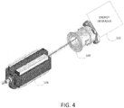
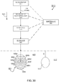
- Fig. 3 at the output of extraction channel 102 of particle accelerator 105 (which may have the configuration shown in Figs. 1 and 2 ), is an example scanning system 106 that may be used to scan the particle beam across at least part of an irradiation target.
- Fig. 4 shows examples of components of the scanning system. These include, but are not limited to, a scanning magnet 108, an ion chamber 109, and an energy degrader 110. Other components that may be incorporated into the scanning system are not shown in Fig. 4 , including, e.g., one or more scatterers for changing beam spot size.
- scanning magnet 108 is controllable in two dimensions (e.g., Cartesian XY dimensions) to direct the particle beam across a part (e.g., a cross-section) of an irradiation target.
- Ion chamber 109 detects the dosage of the beam and feeds-back that information to a control system to adjust beam movement.
- Energy degrader 110 is controllable to move material into, and out of, the path of the particle beam to change the energy of the particle beam and therefore the depth to which the particle beam will penetrate the irradiation target.
- Figs. 5 and 6 shows views of an example scanning magnet 108.
- Scanning magnet 108 includes two coils 111, which control particle beam movement in the X direction, and two coils 112, which control particle beam movement in the Y direction. Control is achieved, in some implementations, by varying current through one or both sets of coils to thereby vary the magnetic field(s) produced thereby. By varying the magnetic field(s) appropriately, the particle beam can be moved in the X and/or Y direction across the irradiation target.
- the scanning magnet is not movable physically relative to the particle accelerator. In other implementations, the scanning magnet may be movable relative to the accelerator (e.g., in addition to the movement provided by the gantry).
- the scanning magnets may be controllable to move the particle beam continuously. In other implementations, the scanning magnets are controllable at intervals or specific times. In some implementations, there may be different scanning magnets to control movement of the beam in the X and/or Y directions. In some implementations, there may be different scanning magnets to control partial movement of the beam in either the X and/or Y direction.
- ion chamber 109 detects dosage applied by the particle beam by detecting the numbers of ion pairs created within a gas caused by incident radiation.
- the numbers of ion pairs correspond to the dosage provided by the particle beam. That information is fed-back to a computer system that controls operation of the particle therapy system.
- the computer system (not shown), which may include memory and one or more processing devices, determines if the dosage detected by ion chamber is the intended dose. If the dosage is not as intended, the computer system may control the accelerator to interrupt production and/or output of the particle beam, and/or control the scanning magnet to prevent output of the particle beam to the irradiation target.
- the computer system may turn the ion source off/on, change the frequency of the RF sweep, activate one or more mechanisms (such as a fast kicker magnet (not shown)) to divert the beam to an absorber material and thereby prevent the beam output, and so forth.
- a fast kicker magnet not shown
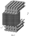
- Fig. 7 shows a range modulator 115, which is an example implementation of energy degrader 110.
- range modulator includes a series of plates 116.
- the plates may be made of one or more of the following example materials: carbon, beryllium or other material of low atomic number. Other materials, however, may be used in place of, or in addition to, these example materials.
- One or more of the plates is movable into, or out of, the beam path to thereby affect the energy of the particle beam and, thus, the depth of penetration of the particle beam within the irradiation target. For example, the more plates that are moved into the path of the particle beam, the more energy that will be absorbed by the plates, and the less energy the particle beam will have. Conversely, the fewer plates that are moved into the path of the particle beam, the less energy that will be absorbed by the plates, and the more energy the particle beam will have. Higher energy particle beams penetrate deeper into the irradiation target than do lower energy particle beams. In this context, “higher” and “lower” are meant as relative terms, and do not have any specific numeric connotations.
- Plates are moved physically into, and out of, the path of the particle beam. For example, as shown in Fig. 8 , a plate 116a moves along the direction of arrow 117 between positions in the path of the particle beam and outside the path of the particle beam.
- the plates are computer-controlled.
- the number of plates that are moved into the path of the particle beam corresponds to the depth at which scanning of an irradiation target is to take place.
- the irradiation target can be divided into cross-sections, each of which corresponds to an irradiation depth.
- One or more plates of the range modulator can be moved into, or out of, the beam path to the irradiation target in order to achieve the appropriate energy to irradiate each of these cross-sections of the irradiation target.
- the range modulator was stationary relative to the particle beam during scanning of a part of (e.g., cross-section of) an irradiation target, except for its plates moving in and out of the path of the particle beam.
- the range modulator of Figs. 7 and 8 may be replaced with a range modulator that, at least some of the time, tracks movement of the particle beam. This type of energy degrader is described in more detail below.
- the particle accelerator may be a variable-energy particle accelerator, such as the example particle accelerator described in U.S. Patent Application No. 13/916,401, filed on June 12, 2013 , the contents of which are incorporated herein by reference.
- a variable-energy particle accelerator there may be less need for an energy degrader of the type described herein, as the energy level of the particle beam may be controlled by the particle accelerator.
- an energy degrader may not be needed.
- an energy degrader may still be used to change beam energy levels.
- a treatment plan is established prior to treating the irradiation target.
- the treatment plan may specify how scanning is to be performed for a particular irradiation target.
- the treatment plan specifies the following information: a type of scanning (e.g., spot scanning or raster scanning); scan locations (e.g., locations of spots to be scanned); magnet current per scan location; dosage-per-spot, spot size; locations (e.g., depths) of irradiation target cross-sections; particle beam energy per cross-section; plates or other types of pieces to move into the beam path for each particle beam energy; and so forth.
- spot scanning involves applying irradiation at discrete spots on an irradiation target and raster scanning involves moving a radiation spot across the radiation target. The concept of spot size therefore applies for both raster and spot scanning.
- the overall treatment plan of an irradiation target includes different treatment plans for different cross-sections of the irradiation target.
- the treatment plans for different cross-sections may contain the same information or different information, such as that provided above.
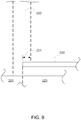
- the scanning system may include a collimator 120 ( Fig. 3 ) to collimate the particle bean, which may include an aperture that is placeable relative to the irradiation target to limit the extent of the particle beam and thereby alter the shape of the spot applied to the irradiation target.
- the collimator may be placed in the beam path down-beam of the energy degrader and before the particle beam hits the irradiation target.
- the collimator may contain an area (e.g., a hole or a transmissive material) through which the particle beam passes and another material (e.g., brass) around the hole that inhibits or prevents passage of the particle beam.
- the collimator may include a structure defining an edge.
- the structure may include a material, such as brass, that inhibits transmission of the particle beam.
- the structure may be controllable to move in two dimensions relative to the irradiation target so that at least part of the structure is between at least part of the particle beam and the irradiation target.
- the structure may be movable in the X and Y directions of a plane that intersects the particle beam and that is parallel, or substantially parallel to, a cross-section of the irradiation target that is being treated.
- a collimator in this manner may be beneficial in that it can be used to customize the cross-sectional shape of the particle beam that reaches the patient, thereby limiting the amount of particle beam that extends beyond the radiation target.
- a structure 220 in a collimator prevents portion 221 of particle beam 222 from reaching a target 224, thereby limiting the beam to the irradiation target and reducing exposure of healthy tissue 225 to radiation.
- the example collimator also provides a defined, or sharp, edge to the particle beam portion that reaches the patient, thereby promoting more precise dose applications.
- Positioning and movement of the collimator may be controlled by a control computer system that controls other features of the particle therapy system described herein.
- the collimator may be controlled in accordance with the treatment plan to track (e.g., follow) motion of the particle beam across at least part of the irradiation target.
- the collimator track is controlled to track all motion of the particle beam relative to the irradiation target.
- the collimator may be controlled to track motion of the particle beam throughout the entirety of the irradiation target, e.g., both at edges of the irradiation target and at interiors of the irradiation target.
- the collimator is controlled to track only some motion of the particle beam relative to the irradiation target.
- the collimator may be controlled to track movement of the particle beam only along the edges of the irradiation target relative to when the particle beam reaches those edges.
- a particle beam may follow a path in an irradiation target 229 shown by arrowed lines 230.
- Collimator 231 may not track motion of the particle beam on the interior 233 of irradiation target 229. But, collimator 231 may track motion of the particle beam along only the edges of the irradiation target (e.g., roughly along arrow 232). For example, each time the particle beam reaches an edge 234 of the irradiation target, the collimator may move, or may have previously moved, to intercept the particle beam at the edge, and thereby limit exposure of surrounding tissue 235 to the beam.
- the collimator moves may depend on the size of the particle beam cross-section (spot) and the speed at which the particle beam scans.
- spot the size of the particle beam cross-section (spot) and the speed at which the particle beam scans.
- the collimator need not track the beam at the interior.
- the movement of a collimator may be controlled in various ways.
- the current through magnet 108 may correspond to the deflection of the particle beam by the magnet and, thus, the location of the particle beam spot on the irradiation target.
- a computer system controlling operation of the scanning system can determine the projected location of the irradiation spot.
- the computer system can control the scanning system, in particular the collimator, to track movement of the irradiation spot along all or part of its motion, as described herein.
- the computer system can control the scanning system, in particular the collimator, so that the collimator arrives at a location before the particle beam spot arrives at that location, as described in more detail below.
- goals of particle beam scanning may include achieving accuracy at the edges of an irradiation target and uniformity of dosage or coverage in the interior of the irradiation target.
- the use of a collimator can help to further these goals by enabling use of a relatively large particle beam spot for scanning.
- a spot size may be considered "large” if it has an area that is within a specified percentage of the area of the irradiation target. This percentage might typically be 2.5%, but values between, e.g., 0.25% and 25%, could also be used. Scanning using a relative large spot size increases the fractional areal coverage of the irradiation target for each beam pulse.
- the larger the size of this spot the less adversely affected the target uniformity will be due to target (patient) motion.
- the collimator reduces the chances that radiation from the large spot will impact tissue (e.g., healthy tissue) outside the radiation target by reducing the lateral penumbra.
- tissue e.g., healthy tissue
- smaller spot sizes were preferred, since they enabled more precise dosage at the edges as compared to a larger spot size. But, compared to a collimated edge, those smaller spot sizes could result in slower treatment times for a given treatment volume, and reduced edge conformality due to reduced edge resolution and increased penumbra.
- the collimator may have any number of different shapes or configurations and may, or may not, include one or more moving parts.
- the collimator is comprised of brass and/or other radiation-blocking material, and has a thickness on the order of several centimeters.
- different collimators may have different compositions and thicknesses.
- the collimator is a structure that has one or more defined edges.
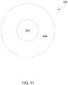
- the collimator may be a structure containing an aperture, or hole.
- Fig. 11 shows an example of this type of collimator 239.
- Collimator 239 may have any appropriate shape, with an aperture therein.
- the edges of the aperture may be used to limit application of the particle beam, as shown in Fig. 9 for example, thereby allowing application of beam 222 to the irradiation target 224 but not to tissue covered by collimator 220 that is otherwise in the beam path.
- the aperture may track (e.g., follow) the particle beam throughout all or part of the scanning operation.
- the aperture may track movement of the particle beam only at edges of the irradiation target or throughout the entire motion of the beam. That is, the collimator itself may move along the edge of the irradiation target to track movement of the particle beam (e.g., so that the location of the collimator coincides with the particle beam when the particle beam reaches the irradiation target edge).
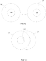
- the collimator may include two or more apertures that are controlled to overlap and thereby achieve a specific size.
- apertures 244 and 245 are part of respective structures 246 and 247. The structures move relative to each other, as shown in Fig. 13 , thereby causing the apertures 244, 245 to overlap and change the size and, in some cases, the shape of resulting hole 248 through which the particle beam is allowed to pass. Shapes other than those shown may be used.
- the collimator may track the movement of the particle beam during the particle beam's motion in the interior of the irradiation target.
- the aperture may have a diameter that is less than the diameter of the particle beam spot.
- the aperture of the collimator may vary in size and/or shape.
- the collimator may have one or more moving parts to vary the size and shape of the aperture (e.g., to reduce its diameter, surface area, or the like).
- the collimator may be a structure having one or more straight edges.
- the collimator may include square, rectangular, or substantially linear structures, each having at least one edge that can be placed in the path of the particle beam.
- the collimator may have a multi-leaf structure, as in Fig. 14 .
- collimator 250 tracks movement along the edge of irradiation target 251.
- Fingers 252 move up or down, or towards or away from the irradiation target, in order to achieve an edge shape 253 that substantially matches the edge shape of the irradiation target and that blocks the particle beam from reaching healthy tissue (or tissue that should not be irradiated).
- each finger can be moved up or down, or extended and retracted, or a combination of such movements to substantially match the edge shape.
- Collimator 250 itself may move along the edge of the irradiation target 251 (e.g., roughly in the direction of arrow 255) to track movement of the particle beam (e.g., so that the location of the collimator coincides with the particle beam when the particle beam reaches the irradiation target edge). In some implementations, collimator 250 may, or may not, move into the interior of the irradiation target during scanning operations.
- irradiation field may be defined by a plane, which is at an angle to the beam, and which defines the maximum extent that a particle beam can move in the X and Y directions relative to the irradiation target.
- the collimator moves relative to (e.g., tracks or moves along the edge of) the irradiation target, and need only provide a defined edge at the point of the irradiation target where and when the spot hits that point.
- the multi-leaf collimator (in addition to being only a single set of fingers) may be made considerably smaller than its conventional counterparts.
- the multi-leaf collimators described herein may include ten or less (e.g., two, three, four, five, six, seven, eight or nine) fingers (or more, if desired).
- collimator 260 may be rectangular in shape, and move along the edge of irradiation target 261. Collimator 260 may move along the edge of the irradiation target to track movement of the particle beam (e.g., so that the location of the collimator coincides with the particle beam when the particle beam reaches the irradiation target edge). During motion along the edge of the irradiation target, collimator 260 may also rotate in two or three dimensions, e.g., in the XY dimensions of arrow 262 and also in the Z dimension. This rotation allows at least a portion of an edge of collimator 260 to match the edge of the irradiation target relative closely.
- collimator 260 may be appropriately positioned so that, when the particle beam reaches the edge of the irradiation target, the collimator blocks the tissue extending beyond the edge.
- the collimator provides a defined radiation edge relative to the irradiation target and protects adjacent tissue from the particle beam. Movement of the collimator to the appropriate point on the edge of the irradiation target may coincide with movement of the particle beam or precede movement of the particle beam.
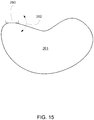
- the collimator may include a single structure with one or more straight edges, as shown in Fig. 15 .
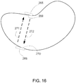
- the collimator may include two or more such structures at different (e.g., opposing) edges of the irradiation target, as shown in Fig. 16 .
- the collimator includes two structures 265, 266.
- Each of structures 265 and 266 tracks movement of the particle beam. That is, structure 265 moves so that the location of structure 265 coincides with the particle beam when the particle beam reaches edge 269 of the irradiation target, and structure 266 moves so that the location of structure 266 coincides with the particle beam when the particle beam reaches edge 270 of the irradiation target.
- Movement of each structure to the appropriate point on the edge of the irradiation target may coincide with movement of the particle beam or precede movement of the particle beam.
- structure 266 can be moved as the spot is scanned in the direction of arrow 271, so that structure 266 is in the appropriate location when the spot returns to edge 270; and structure 265 can be moved as the spot is scanned in the direction of arrow 272, so that structure 265 is in the appropriate location when the spot returns to edge 269.
- Structures 265 and 266 may move at the same times, at different times, or there may be overlap in the times of their movement. An arrangement of this type enables the particle beam to be moved from edge to edge of the irradiation target, with the collimator enabling a defined irradiation field at both edges.
- the collimator may include more than two (e.g., three, four, etc.) structures of the type and operation shown in Fig. 16 .
- the two or more structures that make up the collimator may be structures that include holes, such as that shown in Fig. 11 . The operation of the two-structure collimator is otherwise as described above.
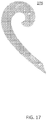
- the collimator need not have a straight edge, but rather its edge(s) may be curved, as shown in Fig. 17 .
- a collimator may include only one such structure or two or more such structures.
- the two or more structures that make up the collimator may be structures that include curved edges.
- two structures of the type shown in Fig. 17 may replace the two structures of Fig. 16 .
- the operation of the two-structure collimator is otherwise as described above.
- the collimator may be a structure having a curved shape having a radius of curvature that varies continuously along its edge, thereby enabling at least part of the edge to closely match the edge of an irradiation target, either directly or by rotating the edge at an appropriate angle.
- collimator 275 is a French curve that can be moved to track the beam, either partly or fully, and that can be rotated in two or three dimensions relative to the irradiation target to control application of the particle beam. Any appropriately curved structure may be include in the collimator.
- collimator 275 may only move along the edge of the irradiation target to track movement of the particle beam (e.g., so that the location of the collimator coincides with the particle beam when the particle beam reaches the irradiation target edge).
- the collimator may, or may not, track movement of the particle beam at the interior of the irradiation target.
- a collimator may include only one structure of the type shown in Fig. 17 or the collimator may include two or more such structures.
- two structures of the type shown in Fig. 17 may replace the two structures of Fig. 16 .
- the operation of the two-structure collimator is otherwise as described above.
- the treatment planning system may be designed so that the scanning speed (e.g., the rate at which the particle beam spot traverses the irradiation target) is different in the interior of the irradiation target than at the edges of the irradiation target.
- the scanning speed may be faster at the interior of the irradiation target than at the edges of the irradiation target.
- This arrangement allows for higher precision scanning at the edges of the irradiation target than at the interior of the irradiation target.
- This type of variable-speed scanning may be implemented using any appropriate type of collimator, including those described herein, or this type of variable-speed scanning may be implemented without using any collimator. In either case, the slower speed at the irradiation target edge may enable more precise scanning there, which may reduce the chances that the particle beam will impact outside the irradiation target.
- the collimator described herein may be used in an intensity-modulated proton therapy process.
- the proton beam is projected at the radiation target from different directions so that a percentage of the overall dose is delivered from each direction.
- Fig. 18 shows a particle beam 280 applied to the irradiation target 281 from three different angles. In this example, 1/3 of the total dose may be applied from one angle; 1/3 of the total dose may be applied from another angle; and 1/3 of the total dose may be applied from yet another angle.
- the particle beam may be scanned at angle 282 relative to horizontal 285 to apply 1/3 of the dose; the particle beam may be scanned at angle 283 to apply 1/3 of the dose; and the particle beam may be scanned at angle 284 to apply 1/3 of the dose.
- the amount of radiation applied to surrounding tissue 287 is spread out at the appropriate angles, thereby reducing the chances that surrounding tissue will be exposed to harmful amounts of radiation. Any appropriate number of angles and appropriate dosage per angle may be employed.
- Irradiation targets such as tumors
- different beam collimation is typically required for the different angles of application of the particle beam.
- the example collimators described herein can be positioned at the appropriate locations along the irradiation target's edge (as described above) to provide appropriate collimation given the angle of irradiation.
- the example collimators can track motion of the particle beam, either only at the irradiation target's edge or throughout some portion (e.g., all) of the motion of the particle beam at all angles of application.
- the example collimators described herein prevent transmission of the particle beam to surrounding tissue by blocking the particle beam. In some implementations, the example collimators may enable partial transmission of the particle beam, thereby resulting in application of lower-levels of radiation to the surrounding tissue than to the irradiation target. Any of the example collimators described herein may be produced in this manner.
- the example collimators described herein may be mounted to one or more computer-controlled robotic arms or other structures to control their movement relative to the irradiation target.
- a collimator may be mounted to the scanning system itself as well.
- the collimator is mounted closest to the patent relative to other elements of the particle beam scanning system (e.g., down-beam of other elements of the scanning system).
- the collimator includes more than one piece (e.g., Fig. 16 )
- a single robotic arm may be configured to control the different pieces of the collimator independently or to control a combination of pre-assembled pieces.
- the energy degrader may also configured to track motion of the particle beam.
- the energy degrader may include multiple plates that are movable into the path of the particle beam to control the amount of energy in the beam and thereby control the depth to which the particle beam penetrates the irradiation target. In this way, the energy degrader is used to perform depth (the direction of the particle beam or Z-direction) scanning in the irradiation target.
- each plate absorbs an amount of energy in the particle beam. Accordingly, the more plates that are placed in front of the particle beam, the less energy the beam has, and the less deep the beam will penetrate into the irradiation target.
- each plate has about the same thickness, and therefore absorbs about the same amount of beam energy.
- different plates may have different thicknesses, with the thickness of a plate corresponding to the amount of energy that the plate absorbs.
- the plates each have a surface area that is about the size of the irradiation field.
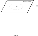
- the irradiation field may be defined by a plane that defines the maximum extent that a particle beam can move in the X and Y directions relative to the irradiation target.
- Fig. 19 shows an irradiation field 290 in front of an irradiation target 291. Due to physical system limitations, a particle beam is movable across, but not beyond, the plane defining the irradiation field.
- the plates in the energy degrader each have a surface are that is at least as big as, and in some cases that exceeds, the size of the irradiation field.
- This configuration can result in plates that are large (e.g., possibly a square meter or square meters), and thus that can be heavy and relative slow to move. Slow movement of the plates can result in slower treatment.
- the energy degraders may be smaller than the size of the irradiation field, and track at least part of the motion of the particle beam. As a result, the energy degrader may be lighter, which can reduce the amount of time that it takes to position the energy degrader plates in the path of the particle beam and thus reduce the treatment time.
- the energy degrader may track the particle beam in two directions (e.g., XY) or in three directions (e.g., XYZ). That is, the energy degrader may move in a plane perpendicular to the particle beam, or the energy degrader may move in a plane perpendicular to the particle beam and along a longitudinal direction of the particle beam.
- any of the collimators described herein may also move in a plane perpendicular to the particle beam, or any of the collimators described herein may also move in a plane perpendicular to the particle beam and along a longitudinal direction of the particle beam. Movement of the collimator(s) and energy degrader(s) may be independent or coordinated.
- an energy degrader may be comprised of multiple pieces, which may be plates or other structures constructed to absorb particle beam energy during treatment. Each piece may have the same area (XY) and thickness (Z) or different pieces may have different areas and thicknesses.
- two or more pieces 294 having the same or different thicknesses may be placed in front an irradiation target 295 in the particle beam 293 path to achieve a particular amount of energy absorption.
- a single piece having a specified thickness may be placed in front of the beam to achieve a particular amount of energy absorption. For example, if a particular energy absorption is needed, the control computer may select a piece with the appropriate thickness to achieve that absorption.
- those pieces may be assembled prior to placement or assembled dynamically during placement.
- the control computer may select two pieces, arrange them, and then move the combination of the two pieces into the beam path.
- the control computer may select two pieces and then move the combination of the two pieces into the beam path simultaneously but not in combination (e.g., each may be moved with a separate robotic arm).
- the energy degrader may track movement of the particle beam across at least part of the irradiation field so as to achieve appropriate energy absorption, and thus beam depth penetration, at various points on the irradiation target.
- the treatment plan may dictate where the energy degrader needs to be at any particular time during treatment, and feedback from the ionization chamber may be used for positioning and position correction, if necessary.
- the precision with which the energy degrader needs to track the particle beam is based on the size of the degrader and the spot size of the particle beam at the point where the particle beam intersects the energy degrader.
- motion of particle beam 304 from location 302 to location 303 would also require energy degrader 299 to move in the direction of arrow 305 to remain in the beam path, since the areas of the spot and the degrader are relatively close in size.
- motion of the particle beam may be dictated by the treatment plan and detected through use of the ionization chamber and feedback to the control computer. This information may also be used to control movement of the energy degrader.
- the moveable energy degrader may be considerably larger than the particle beam spot.
- the energy degrader need not track motion of the particle beam as closely in order to ensure that the energy degrader is in front of the particle beam at appropriate times during treatment.
- the energy degrader need not move at all in some cases where the particle beam moves. That is, for some motion of the particle beam, the energy degrader may remain stationary, but for other motion of the particle beam, the energy degrader also moves to intercept the particle beam.
- Fig. 22 shows a case where the energy degrader 310 is considerably larger than particle beam spot 311 at the point where the particle beam intersects the energy degrader.
- the energy degrader As the particle beam spot moves from point 314a to point 314b, the energy degrader remains in the beam path even though the energy degrader has not moved.
- the control computer system knowing the size of the degrader and the two spot positions, does not move the energy degrader in this case. Accordingly, in this case, the energy degrader need not track movement of the particle beam spot.
- the energy degrader (or piece(s) thereof) will move to track and intercept the beam so as to remain in the beam path. Accordingly, the size of the energy degrader relative to the beam spot is a factor in determining when, and by how much, the energy degrader is required to move during scanning.
- the energy degrader may include multiple parts or pieces.
- one part or piece may be used to track movement of the particle beam across part of an irradiation target (e.g., irradiation applied from the top of the irradiation target) and another part or piece may be used to track movement of the particle beam across another part of an irradiation target (e.g., irradiation applied from the bottom of the target).
- the energy degrader may have any shape, e.g., square, rectangular, circular, oval, irregular, regular, polygonal, spherical, cubical, tetrahedral, and so forth.
- the energy degrader (or pieces thereof) may have any appropriate size.
- the energy degrader (or pieces thereof) may have a surface area this less than the area of the irradiation field, that is less than 3/4 the area of the irradiation field, that is less than 1/2 the area of the irradiation field, that is less than 1/3 the area of the irradiation field, that is less than 1/4 the area of the irradiation field, that is less than 1/5 the area of the irradiation field, or so forth.
- the energy degrader may have a surface area that is less than twenty times the area of the particle beam spot at the irradiation field, that is less than fifteen times the area of the particle beam spot at the irradiation field, that is less than ten times the area of the particle beam spot at the irradiation field, that is less than nine times the area of the particle beam spot at the irradiation field, that is less than eight times the area of the particle beam spot at the irradiation field, that is less than seven times the area of the particle beam spot at the irradiation field, that is less than six times the area of the particle beam spot at the irradiation field, that is less than five times the area of the particle beam spot at the irradiation field, that is less than four times the area of the particle beam spot at the irradiation field, that is less than three times the area of the particle beam spot at the irradiation field, or that is less than two times the area of the particle beam spot at the irradiation field
- the energy degrader (or pieces thereof) may have a surface area that is a multiple of the spot size, e.g., two times the spot size, three times the spot size, five times the spot size, ten times the spot size, and so forth.
- each piece e.g., layer of multiple layers
- different pieces may have different sizes, shapes thicknesses and compositions.
- the movement of the example energy degraders described herein may be controlled in various ways.
- the current through magnet 108 may correspond to the deflection of the particle beam by the magnet and, thus, the location of the particle beam spot on the irradiation target.
- a computer system controlling operation of the scanning system can determine the projected location of the irradiation spot.
- the computer system can control the energy degrader, to track (if necessary) movement of the irradiation spot along all or part of its motion, as described herein.
- the example movable energy degraders described herein may be mounted to one or more computer-controlled robotic arms or other structures that also contain elements of the scanning system to control movement relative to the irradiation target.
- the energy degrader includes more than one piece (e.g., multiple pieces or plates)
- a single robotic arm may be configured to control the different pieces independently.
- Different cross-sections of the irradiation target may be scanned according to different treatment plans.
- an energy degrader is used to control the scanning depth.
- the particle beam may be interrupted or redirected during configuration of the energy degrader. In other implementations, this need not be the case.
- Described herein are examples of treating cross-sections of an irradiation target. These may be cross-sections that are roughly perpendicular to the direction of the particle beam. However, the concepts described herein are equally applicable to treating other portions of an irradiation target that are not cross-sections perpendicular to the direction of the particle beam.
- an irradiation target may be segmented into spherical, cubical or other shaped volumes, and those volumes may be treated using the example processes, systems, and/or devices described herein.
- the processes described herein may be used with a single particle accelerator, and any two or more of the features thereof described herein may be used with the single particle accelerator.
- the particle accelerator may be used in any type of medical or non-medical application.
- An example of a particle therapy system that may be used is provided below.
- the concepts described herein may be used in other systems not specifically described.
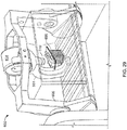
- an example implementation of a charged particle radiation therapy system 400 includes a beam-producing particle accelerator 402 having a weight and size small enough to permit it to be mounted on a rotating gantry 404 with its output directed straight (that is, essentially directly) from the accelerator housing toward a patient 406.
- Particle accelerator 402 also includes a scanning system of a type described herein (e.g., Figs. 3 to 22 ).
- the steel gantry has two legs 408, 410 mounted for rotation on two respective bearings 412, 414 that lie on opposite sides of the patient.
- the accelerator is supported by a steel truss 416 that is long enough to span a treatment area 418 in which the patient lies (e.g., twice as long as a tall person, to permit the person to be rotated fully within the space with any desired target area of the patient remaining in the line of the beam) and is attached stably at both ends to the rotating legs of the gantry.
- the rotation of the gantry is limited to a range 420 of less than 360 degrees, e.g., about 180 degrees, to permit a floor 422 to extend from a wall of the vault 424 that houses the therapy system into the patient treatment area.
- the limited rotation range of the gantry also reduces the required thickness of some of the walls (which are not directly aligned with the beam, e.g., wall 430), which provide radiation shielding of people outside the treatment area.
- a range of 180 degrees of gantry rotation is enough to cover all treatment approach angles, but providing a larger range of travel can be useful.
- the range of rotation may be between 180 and 330 degrees and still provide clearance for the therapy floor space. In other implementations, rotation is not limited as described above.
- the horizontal rotational axis 432 of the gantry is located nominally one meter above the floor where the patient and therapist interact with the therapy system. This floor is positioned about 3 meters above the bottom floor of the therapy system shielded vault.
- the accelerator can swing under the raised floor for delivery of treatment beams from below the rotational axis.
- the patient couch moves and rotates in a substantially horizontal plane parallel to the rotational axis of the gantry.
- the couch can rotate through a range 434 of about 270 degrees in the horizontal plane with this configuration. This combination of gantry and patient rotational ranges and degrees of freedom allow the therapist to select virtually any approach angle for the beam. If needed, the patient can be placed on the couch in the opposite orientation and then all possible angles can be used.
- the accelerator uses a synchrocyclotron configuration having a high magnetic field superconducting electromagnetic structure. Because the bend radius of a charged particle of a given kinetic energy is reduced in direct proportion to an increase in the magnetic field applied to it, the high magnetic field superconducting magnetic structure permits the accelerator to be made smaller and lighter.
- the synchrocyclotron uses a magnetic field that is uniform in rotation angle and falls off in strength with increasing radius. Such a field shape can be achieved regardless of the magnitude of the magnetic field, so in theory there is no upper limit to the magnetic field strength (and therefore the resulting particle energy at a fixed radius) that can be used in a synchrocyclotron.
- the synchrocyclotron is supported on the gantry so that the beam is generated directly in line with the patient.
- the gantry permits rotation of the synchrocyclotron about a horizontal rotational axis that contains a point (isocenter 440) within, or near, the patient.
- the split truss that is parallel to the rotational axis, supports the synchrocyclotron on both sides.
- a patient support area can be accommodated in a wide area around the isocenter. Because the floor can be extended broadly around the isocenter, a patient support table can be positioned to move relative to and to rotate about a vertical axis 442 through the isocenter so that, by a combination of gantry rotation and table motion and rotation, any angle of beam direction into any part of the patient can be achieved.
- the two gantry arms are separated by more than twice the height of a tall patient, allowing the couch with patient to rotate and translate in a horizontal plane above the raised floor.
- Limiting the gantry rotation angle allows for a reduction in the thickness of at least one of the walls surrounding the treatment room. Thick walls, typically constructed of concrete, provide radiation protection to individuals outside the treatment room. A wall downstream of a stopping proton beam may be about twice as thick as a wall at the opposite end of the room to provide an equivalent level of protection. Limiting the range of gantry rotation enables the treatment room to be sited below earth grade on three sides, while allowing an occupied area adjacent to the thinnest wall reducing the cost of constructing the treatment room.
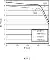
- the superconducting synchrocyclotron 402 operates with a peak magnetic field in a pole gap of the synchrocyclotron of 8.8 Tesla.
- the synchrocyclotron produces a beam of protons having an energy of 250 MeV.
- the synchrocyclotron is a variable-energy machine, and is capable of outputting proton beams having different energies.
- the synchrocyclotron may produce a beam having a fixed energy.
- the field strength could be in the range of 4T to 20T and the proton energy could be in the range of 150 to 300 MeV.
- the radiation therapy system described in this example is used for proton radiation therapy, but the same principles and details can be applied in analogous systems for use in heavy ion (ion) treatment systems.
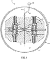
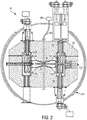
- an example synchrocyclotron 10 (e.g., 402 in Fig. 23 ) includes a magnet system 122 that contains a particle source 190, a radiofrequency drive system 191, and a beam extraction system 318.
- the magnetic field established by the magnet system has a shape appropriate to maintain focus of a contained proton beam using a combination of a split pair of annular superconducting coils 140, 142 and a pair of shaped ferromagnetic (e.g., low carbon steel) pole faces 144, 146.
- the two superconducting magnet coils are centered on a common axis 147 and are spaced apart along the axis.
- the coils may be formed by of Nb 3 Sn-based superconducting 0.8 mm diameter strands (that initially comprise a niobiumtin core surrounded by a copper sheath) deployed in a twisted cable-in-channel conductor geometry. After seven individual strands are cabled together, they are heated to cause a reaction that forms the final (brittle) superconducting material of the wire.
- the wires are soldered into the copper channel (outer dimensions 3.18 x 2.54 mm and inner dimensions 2.08 x 2.08 mm) and covered with insulation (in this example, a woven fiberglass material).
- the copper channel containing the wires is then wound in a coil having a rectangular cross-section.
- the wound coil is then vacuum impregnated with an epoxy compound.
- the finished coils are mounted on an annular stainless steel reverse bobbin. Heater blankets may be placed at intervals in the layers of the windings to protect the assembly in the event of a magnet quench.
- the entire coil can then be covered with copper sheets to provide thermal conductivity and mechanical stability and then contained in an additional layer of epoxy.
- the precompression of the coil can be provided by heating the stainless steel reverse bobbin and fitting the coils within the reverse bobbin.
- the reverse bobbin inner diameter is chosen so that when the entire mass is cooled to 4 K, the reverse bobbin stays in contact with the coil and provides some compression. Heating the stainless steel reverse bobbin to approximately 50 degrees C and fitting coils at a temperature of 100 degrees Kelvin can achieve this.
- the geometry of the coil is maintained by mounting the coils in a "reverse" rectangular bobbin to exert a restorative force that works against the distorting force produced when the coils are energized.
- coil position is maintained relative to corresponding magnet pole pieces and the cryostat using a set of warm-to-cold support straps 402, 404, 406. Supporting the cold mass with thin straps reduces the heat leakage imparted to the cold mass by the rigid support system.
- the straps are arranged to withstand the varying gravitational force on the coil as the magnet rotates on board the gantry.
- Each warm-to-cold support may include one S2 fiberglass link and one carbon fiber link.
- the carbon fiber link is supported across pins between the warm yoke and an intermediate temperature (50 - 70 K), and the S2 fiberglass link 408 is supported across the intermediate temperature pin and a pin attached to the cold mass.
- Each pin may be made of high strength stainless steel.
- the field strength profile as a function of radius is determined largely by choice of coil geometry and pole face shape; the pole faces 144, 146 of the permeable yoke material can be contoured to fine tune the shape of the magnetic field to ensure that the particle beam remains focused during acceleration.
- the superconducting coils are maintained at temperatures near absolute zero (e.g., about 4 degrees Kelvin) by enclosing the coil assembly (the coils and the bobbin) inside an evacuated annular aluminum or stainless steel cryostatic chamber 170 (the cryostat) that provides a free space around the coil structure, except at a limited set of support points 171, 173.
- the outer wall of the cryostat may be made of low carbon steel to provide an additional return flux path for the magnetic field.
- the temperature near absolute zero is achieved and maintained using one single-stage Gifford-McMahon cryo-cooler and three two-stage Gifford McMahon cryo-coolers. Each two stage cryo-cooler has a second stage cold end attached to a condenser that recondenses Helium vapor into liquid Helium.
- the temperature near absolute zero is achieved and maintained using a cooling channel (not shown) containing liquid helium, which is formed inside a superconducting coil support structure (e.g., the reverse bobbin), and which contains a thermal connection between the liquid helium in the channel and the corresponding superconducting coil.
- a liquid helium cooling system of the type described above, and that may be used is described in U.S. Patent Application No. 13/148,000 (Begg et al. ).
- the coil assembly and cryostatic chambers are mounted within and fully enclosed by two halves 181, 183 of a pillbox-shaped magnet yoke 100.
- the yoke 100 provides a path for the return magnetic field flux 184 and magnetically shields the volume 186 between the pole faces 144, 146 to prevent external magnetic influences from perturbing the shape of the magnetic field within that volume.
- the yoke also serves to decrease the stray magnetic field in the vicinity of the accelerator.
- the coil assembly and cryostatic chambers are mounted within and fully enclosed by a non-magnetic enclosure, and the path for return magnetic field flux is implemented using an active return system, an example of which is described above.
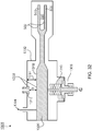
- the synchrocyclotron includes a particle source 190 of a Penning ion gauge geometry located near the geometric center 192 of the magnet structure 182.
- the particle source may be as described below, or the particle source may be of the type described in U.S. Patent Application No. 11/948,662 incorporated herein by reference.
- Particle source 190 is fed from a supply 399 of hydrogen through a gas line 393 and tube 394 that delivers gaseous hydrogen.
- Electric cables 294 carry an electric current from a current source to stimulate electron discharge from cathodes 392, 390 that are aligned with the magnetic field 400.
- the discharged electrons ionize the gas exiting through a small hole from tube 394 to create a supply of positive ions (protons) for acceleration by one semicircular (dee-shaped) radio-frequency plate that spans half of the space enclosed by the magnet structure and one dummy dee plate.
- one semicircular (dee-shaped) radio-frequency plate that spans half of the space enclosed by the magnet structure and one dummy dee plate.
- all (or a substantial part, e.g., a majority) of the tube containing plasma is removed at the acceleration region.
- the dee plate 500 is a hollow metal structure that has two semicircular surfaces 503, 505 that enclose a space 507 in which the protons are accelerated during half of their rotation around the space enclosed by the magnet structure.
- a duct 509 opening into the space 507 extends through the enclosure (e.g., the yoke or pole piece(s)) to an external location from which a vacuum pump can be attached to evacuate the space 507 and the rest of the space within a vacuum chamber in which the acceleration takes place.
- the dummy dee 502 comprises a rectangular metal ring that is spaced near to the exposed rim of the dee plate. The dummy dee is grounded to the vacuum chamber and magnet yoke.
- the dee plate 500 is driven by a radio-frequency signal that is applied at the end of a radio-frequency transmission line to impart an electric field in the space 507.
- the radio frequency electric field is made to vary in time as the accelerated particle beam increases in distance from the geometric center.
- the radio frequency electric field may be controlled in the manner described in U.S. Patent Application No. 11/948,359 , entitled “Matching A Resonant Frequency Of A Resonant Cavity To A Frequency Of An Input Voltage", the contents of which are incorporated herein by reference.
- a large voltage difference may be applied across the radio frequency plates.
- 20,000 Volts is applied across the radio frequency plates. In some versions from 8,000 to 20,000 Volts may be applied across the radio frequency plates.
- the magnet structure is arranged to reduce the capacitance between the radio frequency plates and ground. This may be done by forming holes with sufficient clearance from the radio frequency structures through the outer yoke and the cryostat housing and making sufficient space between the magnet pole faces.
- the high voltage alternating potential that drives the dee plate has a frequency that is swept downward during the accelerating cycle to account for the increasing relativistic mass of the protons and the decreasing magnetic field.
- the dummy dee does not require a hollow semi-cylindrical structure as it is at ground potential along with the vacuum chamber walls.
- Other plate arrangements could be used such as more than one pair of accelerating electrodes driven with different electrical phases or multiples of the fundamental frequency.
- the RF structure can be tuned to keep the Q high during the required frequency sweep by using, for example, a rotating capacitor having intermeshing rotating and stationary blades. During each meshing of the blades, the capacitance increases, thus lowering the resonant frequency of the RF structure.
- the blades can be shaped to create a precise frequency sweep required.
- a drive motor for the rotating condenser can be phase locked to the RF generator for precise control. One bunch of particles may be accelerated during each meshing of the blades of the rotating condenser.
- the vacuum chamber in which the acceleration occurs is a generally cylindrical container that is thinner in the center and thicker at the rim.
- the vacuum chamber encloses the RF plates and the particle source and is evacuated by a vacuum pump. Maintaining a high vacuum reduces the chances that accelerating ions are not lost to collisions with gas molecules and enables the RF voltage to be kept at a higher level without arcing to ground.
- Protons traverse a generally spiral orbital path beginning at the particle source. In half of each loop of the spiral path, the protons gain energy as they pass through the RF electric field. As the protons gain energy, the radius of the central orbit of each successive loop of their spiral path is larger than the prior loop until the loop radius reaches the maximum radius of the pole face. At that location a magnetic and electric field perturbation directs protons into an area where the magnetic field rapidly decreases, and the protons depart the area of the high magnetic field and are directed through an evacuated tube, referred to herein as the extraction channel, to exit the synchrocyclotron.
- a magnetic regenerator may be used to change the magnetic field perturbation to direct the protons.
- the protons exiting will tend to disperse as they enter an area of markedly decreased magnetic field that exists in the room around the synchrocyclotron.
- Beam shaping elements 507, 509 in the extraction channel 138 redirect the protons so that they stay in a straight beam of limited spatial extent.
- Beam formation system 525 may include a scanning system of the type described herein. Beam formation system 525 may be used in conjunction with an inner gantry that controls application of the beam.
- Stray magnetic fields exiting from the synchrocyclotron may be limited by both a magnet yoke (which also serves as a shield) and a separate magnetic shield 514 (e.g., Fig. 1 ).
- the separate magnetic shield includes of a layer 517 of ferromagnetic material (e.g., steel or iron) that encloses the pillbox yoke, separated by a space 516.
- This configuration that includes a sandwich of a yoke, a space, and a shield achieves adequate shielding for a given leakage magnetic field at lower weight.
- an active return system may be used in place of, or to augment, the operation of the magnetic yoke and shield.
- the gantry allows the synchrocyclotron to be rotated about a horizontal rotational axis 432.
- the truss structure 416 has two generally parallel spans 480, 482.
- the synchrocyclotron is cradled between the spans about midway between the legs.
- the gantry is balanced for rotation about the bearings using counterweights 622, 624 mounted on ends of the legs opposite the truss.
- the gantry is driven to rotate by an electric motor mounted to one or both of the gantry legs and connected to the bearing housings by drive gears.
- the rotational position of the gantry is derived from signals provided by shaft angle encoders incorporated into the gantry drive motors and the drive gears.
- the beam formation system 525 acts on the ion beam to give it properties suitable for patient treatment.
- the beam may be spread and its depth of penetration varied to provide uniform radiation across a given target volume.
- the beam formation system may include active scanning elements as described herein.
- synchrocyclotron control electronics may include, e.g., one or more processing devices executing instructions from memory to effect control.
- a beam-producing particle accelerator in this case synchrocyclotron 604 (which may include any and all features described herein), may be mounted on rotating gantry 605.
- Rotating gantry 605 is of the type described herein, and can angularly rotate around patient support 606. This feature enables synchrocyclotron 604 to provide a particle beam essentially directly to the patient from various angles. For example, as in Fig. 29 , if synchrocyclotron 604 is above patient support 606, the particle beam may be directed downwards toward the patient. Alternatively, if synchrocyclotron 604 is below patient support 606, the particle beam may be directed upwards toward the patient.
- a routing mechanism in this context, is different from a shaping or sizing mechanism in that a shaping or sizing mechanism does not re-route the beam, but rather sizes and/or shapes the beam while maintaining the same general trajectory of the beam.
- the synchrocyclotron may be a variable-energy device, such as that described in U.S. Patent Application No. 13/916,401, filed on June 12, 2013 .
- the particle accelerator used in the example particle therapy systems and example scanning systems described herein may be a variable-energy particle accelerator, an example of which is described below
- an example treatment system 910 includes an accelerator 912, e.g., a synchrocyclotron, from which a particle (e.g., proton) beam 914 having a variable energy is extracted to irradiate a target volume 924 of a body 922.
- an accelerator 912 e.g., a synchrocyclotron
- one or more additional devices such as a scanning unit 916 or a scattering unit 916, one or more monitoring units 918, and an energy degrader 920, are placed along the irradiation direction 928.
- the devices intercept the cross-section of the extracted beam 914 and alter one or more properties of the extracted beam for the treatment.
- a target volume to be irradiated (an irradiation target) by a particle beam for treatment typically has a three-dimensional configuration.
- the target volume is divided into layers along the irradiation direction of the particle beam so that the irradiation can be done on a layer-by-layer basis.
- the penetration depth (or which layer the beam reaches) within the target volume is largely determined by the energy of the particle beam.
- a particle beam of a given energy does not reach substantially beyond a corresponding penetration depth for that energy.
- the energy of the particle beam is changed.
- the target volume 924 is divided into nine layers 926a-926i along the irradiation direction 928.
- the irradiation starts from the deepest layer 926i, one layer at a time, gradually to the shallower layers and finishes with the shallowest layer 926a.
- the energy of the particle beam 914 is controlled to be at a level to allow the particle beam to stop at a desired layer, e.g., the layer 926d, without substantially penetrating further into the body or the target volume, e.g., the layers 926e-926i or deeper into the body.
- the desired energy of the particle beam 914 decreases as the treatment layer becomes shallower relative to the particle acceleration.
- the beam energy difference for treating adjacent layers of the target volume 924 is about 3 MeV to about 100 MeV, e.g., about 10 MeV to about 80 MeV, although other differences may also be possible, depending on, e.g., the thickness of the layers and the properties of the beam.
- the energy variation for treating different layers of the target volume 924 can be performed at the accelerator 912 (e.g., the accelerator can vary the energy) so that, in some implementations, no additional energy variation is required after the particle beam is extracted from the accelerator 912. So, the optional energy degrader 920 in the treatment system 10 may be eliminated from the system.
- the accelerator 912 can output particle beams having an energy that varies between about 100 MeV and about 300 MeV, e.g., between about 115 MeV and about 250 MeV.
- the variation can be continuous or non-continuous, e.g., one step at a time.
- the variation, continuous or non-continuous can take place at a relatively high rate, e.g., up to about 50 MeV per second or up to about 20 MeV per second.
- Non-continuous variation can take place one step at a time with a step size of about 10 MeV to about 90 MeV.
- the accelerator 912 can vary the energy of the particle beam for irradiating a next layer, e.g., within several seconds or within less than one second.
- the treatment of the target volume 924 can be continued without substantial interruption or even without any interruption.
- the step size of the non-continuous energy variation is selected to correspond to the energy difference needed for irradiating two adjacent layers of the target volume 924.
- the step size can be the same as, or a fraction of, the energy difference.
- the accelerator 912 and the degrader 920 collectively vary the energy of the beam 914.
- the accelerator 912 provides a coarse adjustment and the degrader 920 provides a fine adjustment or vice versa.
- the accelerator 912 can output the particle beam that varies energy with a variation step of about 10-80 MeV, and the degrader 920 adjusts (e.g., reduces) the energy of the beam at a variation step of about 2-10 MeV.
- the reduced use (or absence) of the energy degrader may help to maintain properties and quality of the output beam from the accelerator, e.g., beam intensity.
- the control of the particle beam can be performed at the accelerator. Side effects, e.g., from neutrons generated when the particle beam passes the degrader 920 can be reduced or eliminated.
- the energy of the particle beam 914 may be adjusted to treat another target volume 930 in another body or body part 922' after completing treatment in target volume 924.
- the target volumes 924, 930 may be in the same body (or patient), or in different patients. It is possible that the depth D of the target volume 930 from a surface of body 922' is different from that of the target volume 924.
- the degrader 912 may only reduce the beam energy and not increase the beam energy.
- the beam energy required for treating target volume 930 is greater than the beam energy required to treat target volume 924.
- the accelerator 912 may increase the output beam energy after treating the target volume 924 and before treating the target volume 930.
- the beam energy required for treating target volume 930 is less than the beam energy required to treat target volume 924.
- the degrader 920 can reduce the energy, the accelerator 912 can be adjusted to output a lower beam energy to reduce or eliminate the use of the degrader 920.
- the division of the target volumes 924, 930 into layers can be different or the same.
- the target volume 930 can be treated similarly on a layer by layer basis to the treatment of the target volume 924.
- the treatment of the different target volumes 924, 930 on the same patient may be substantially continuous, e.g., with the stop time between the two volumes being no longer than about 30 minutes or less, e.g., 25 minutes or less, 20 minutes or less, 15 minutes or less, 10 minutes or less, 5 minutes or less, or 1 minute or less.
- the accelerator 912 can be mounted on a movable gantry and the movement of the gantry can move the accelerator to aim at different target volumes. In some situations, the accelerator 912 can complete the energy adjustment of the output beam 914 during the time the treatment system makes adjustment (such as moving the gantry) after completing the treatment of the target volume 924 and before starting treating the target volume 930.
- the treatment can begin with the adjusted, desired beam energy. Beam energy adjustment for different patients can also be completed relatively efficiently. In some examples, all adjustments, including increasing/reducing beam energy and/or moving the gantry are done within about 30 minutes, e.g., within about 25 minutes, within about 20 minutes, within about 15 minutes, within about 10 minutes or within about 5 minutes.
- an irradiation dose may be applied by moving the beam across the two-dimensional surface of the layer (which is sometimes called scanning beam) using a scanning unit 916.
- the layer can be irradiated by passing the extracted beam through one or more scatterers of the scattering unit 16 (which is sometimes called scattering beam).
- Beam properties can be selected before a treatment or can be adjusted during the treatment by controlling the accelerator 912 and/or other devices, such as the scanning unit/scatterer(s) 916, the degrader 920, and others not shown in the figures.
- system 910 includes a controller 932, such as a computer, in communication with one or more devices in the system. Control can be based on results of the monitoring performed by the one or more monitors 918, e.g., monitoring of the beam intensity, dose, beam location in the target volume, etc.
- the monitors 918 are shown to be between the device 916 and the degrader 920, one or more monitors can be placed at other appropriate locations along the beam irradiation path.
- Controller 932 can also store a treatment plan for one or more target volumes (for the same patient and/or different patients).
- the treatment plan can be determined before the treatment starts and can include parameters, such as the shape of the target volume, the number of irradiation layers, the irradiation dose for each layer, the number of times each layer is irradiated, etc.
- the adjustment of a beam property within the system 910 can be performed based on the treatment plan. Additional adjustment can be made during the treatment, e.g., when deviation from the treatment plan is detected.
- the accelerator 912 is configured to vary the energy of the output particle beam by varying the magnetic field in which the particle beam is accelerated.
- one or more sets of coils receives variable electrical current to produce a variable magnetic field in the cavity.
- one set of coils receives a fixed electrical current, while one or more other sets of coils receives a variable current so that the total current received by the coil sets varies.
- all sets of coils are superconducting.
- some sets of coils, such as the set for the fixed electrical current are superconducting, while other sets of coils, such as the one or more sets for the variable current, are non-superconducting.
- all sets of coils are non-superconducting.
- the magnitude of the magnetic field is scalable with the magnitude of the electrical current. Adjusting the total electric current of the coils in a predetermined range can generate a magnetic field that varies in a corresponding, predetermined range. In some examples, a continuous adjustment of the electrical current can lead to a continuous variation of the magnetic field and a continuous variation of the output beam energy. Alternatively, when the electrical current applied to the coils is adjusted in a non-continuous, step-wise manner, the magnetic field and the output beam energy also varies accordingly in a non-continuous (step-wise) manner. The scaling of the magnetic field to the current can allow the variation of the beam energy to be carried out relatively precisely, although sometimes minor adjustment other than the input current may be performed.
- the accelerator 912 is configured to apply RF voltages that sweep over different ranges of frequencies, with each range corresponding to a different output beam energy. For example, if the accelerator 912 is configured to produce three different output beam energies, the RF voltage is capable of sweeping over three different ranges of frequencies. In another example, corresponding to continuous beam energy variations, the RF voltage sweeps over frequency ranges that continuously change. The different frequency ranges may have different lower frequency and/or upper frequency boundaries.
- the extraction channel may be configured to accommodate the range of different energies produced by the variable-energy particle accelerator.
- the extraction channel may be large enough to support the highest and lowest energies produced by the particle accelerator. That is, the extraction channel may be sized or otherwise configured to receive and to transmit particles within that range of energies.
- Particle beams having different energies can be extracted from the accelerator 912 without altering the features of the regenerator that is used for extracting particle beams having a single energy.
- the regenerator can be moved to disturb (e.g., change) different particle orbits in the manner described above and/or iron rods (magnetic shims) can be added or removed to change the magnetic field bump provided by the regenerator.
- different particle energies will typically be at different particle orbits within the cavity.
- movement of the regenerator is performed in real-time to match real-time changes in the particle beam energy output by the accelerator.
- particle energy is adjusted on a per-treatment basis, and movement of the regenerator (and/or addition/removal of magnetic shims) is performed in advance of the treatment.
- movement of the regenerator (and/or addition/removal of magnetic shims) may be computer controlled.
- a computer may control one or more motors that effect movement of the regenerator and/or magnetic shims.
- the regenerator is implemented using one or more magnetic shims that are controllable to move to the appropriate location(s).
- table 1 shows three example energy levels at which example accelerator 912 can output particle beams.
- the corresponding parameters for producing the three energy levels are also listed.
- the magnet current refers to the total electrical current applied to the one or more coil sets in the accelerator 912; the maximum and minimum frequencies define the ranges in which the RF voltage sweeps; and "r" is the radial distance of a location to a center of the cavity in which the particles are accelerated. Table 1. Examples of beam energies and respective parameters.
- the accelerator can be a synchrocyclotron and the particles may be protons.
- the particles may be output as pulsed beams.
- the energy of the beam output from the particle accelerator can be varied during the treatment of one target volume in a patient, or between treatments of different target volumes of the same patient or different patients.
- settings of the accelerator are changed to vary the beam energy when no beam (or particles) is output from the accelerator.
- the energy variation can be continuous or non-continuous over a desired range.
- the particle accelerator (e.g., synchrocyclotron 502), which may be a variable-energy particle accelerator like accelerator 912 described above, may be configured to output particle beams that have a variable energy.
- the range of the variable energy can have an upper boundary that is about 200 MeV to about 300 MeV or higher, e.g., 200 MeV, about 205 MeV, about 210 MeV, about 215 MeV, about 220 MeV, about 225 MeV, about 230 MeV, about 235 MeV, about 240 MeV, about 245 MeV, about 250 MeV, about 255 MeV, about 260 MeV, about 265 MeV, about 270 MeV, about 275 MeV, about 280 MeV, about 285 MeV, about 290 MeV, about 295 MeV, or about 300 MeV or higher.
- the range can also have a lower boundary that is about 100 MeV or lower to about 200 MeV, e.g., about 100 MeV or lower, about 105 MeV, about 110 MeV, about 115 MeV, about 120 MeV, about 125 MeV, about 130 MeV, about 135 MeV, about 140 MeV, about 145 MeV, about 150 MeV, about 155 MeV, about 160 MeV, about 165 MeV, about 170 MeV, about 175 MeV, about 180 MeV, about 185 MeV, about 190 MeV, about 195 MeV, about 200 MeV.
- a lower boundary that is about 100 MeV or lower to about 200 MeV, e.g., about 100 MeV or lower, about 105 MeV, about 110 MeV, about 115 MeV, about 120 MeV, about 125 MeV, about 130 MeV, about 135 MeV, about 140 MeV, about 145 MeV, about 150 MeV, about 155 MeV, about 160 MeV, about 165 MeV, about
- the variation is non-continuous and the variation step can have a size of about 10 MeV or lower, about 15 MeV, about 20 MeV, about 25 MeV, about 30 MeV, about 35 MeV, about 40 MeV, about 45 MeV, about 50 MeV, about 55 MeV, about 60 MeV, about 65 MeV, about 70 MeV, about 75 MeV, or about 80 MeV or higher.
- Varying the energy by one step size can take no more than 30 minutes, e.g., about 25 minutes or less, about 20 minutes or less, about 15 minutes or less, about 10 minutes or less, about 5 minutes or less, about 1 minute or less, or about 30 seconds or less.
- the variation is continuous and the accelerator can adjust the energy of the particle beam at a relatively high rate, e.g., up to about 50 MeV per second, up to about 45 MeV per second, up to about 40 MeV per second, up to about 35 MeV per second, up to about 30 MeV per second, up to about 25 MeV per second, up to about 20 MeV per second, up to about 15 MeV per second, or up to about 10 MeV per second.
- the accelerator can be configured to adjust the particle energy both continuously and non-continuously.
- a combination of the continuous and non-continuous variation can be used in a treatment of one target volume or in treatments of different target volumes. Flexible treatment planning and flexible treatment can be achieved.
- a particle accelerator that outputs a particle beam having a variable energy can provide accuracy in irradiation treatment and reduce the number of additional devices (other than the accelerator) used for the treatment. For example, the use of degraders for changing the energy of an output particle beam may be reduced or eliminated for all or part of the treatment.
- the properties of the particle beam, such as intensity, focus, etc. can be controlled at the particle accelerator and the particle beam can reach the target volume without substantial disturbance from the additional devices.
- the relatively high variation rate of the beam energy can reduce treatment time and allow for efficient use of the treatment system.
- the accelerator such as the synchrocyclotron 502 of Fig. 1 , accelerates particles or particle beams to variable energy levels by varying the magnetic field in the accelerator, which can be achieved by varying the electrical current applied to coils for generating the magnetic field.
- an example synchrocyclotron e.g., 502 in Fig. 1
- Fig. 33 shows an example of a magnet system that may be used in a variable-energy accelerator.
- the magnetic field established by the magnet system 1012 can vary by about 5% to about 35 % of a maximum value of the magnetic field that two sets of coils 40a and 40b, and 42a and 42b are capable of generating.
- the magnetic field established by the magnet system has a shape appropriate to maintain focus of a contained proton beam using a combination of the two sets of coils and a pair of shaped ferromagnetic (e.g., low carbon steel) structures, examples of which are provided above.
- Each set of coils may be a split pair of annular coils to receive electrical current.
- both sets of coils are superconducting.
- only one set of the coils is superconducting and the other set is non-superconducting or normal conducting (also discussed further below). It is also possible that both sets of coils are non-superconducting.
- Suitable superconducting materials for use in the coils include niobium-3 tin (Nb3Sn) and/or niobium-titanium.
- Other normal conducting materials can include copper. Examples of the coil set constructions are described further below.
- the two sets of coils can be electrically connected serially or in parallel.
- the total electrical current received by the two sets of coils can include about 2 million ampere turns to about 10 million ampere turns, e.g., about 2.5 to about 7.5 million ampere turns or about 3.75 million ampere turns to about 5 million ampere turns.
- one set of coils is configured to receive a fixed (or constant) portion of the total variable electrical current, while the other set of coils is configured to receive a variable portion of the total electrical current.
- the total electrical current of the two coil sets varies with the variation of the current in one coil set. In other situations, the electrical current applied to both sets of coils can vary.
- the variable total current in the two sets of coils can generate a magnetic field having a variable magnitude, which in turn varies the acceleration pathways of the particles and produces particles having variable energies.
- the magnitude of the magnetic field generated by the coil(s) is scalable to the magnitude of the total electrical current applied to the coil(s). Based on the scalability, in some implementations, linear variation of the magnetic field strength can be achieved by linearly changing the total current of the coil sets. The total current can be adjusted at a relatively high rate that leads to a relatively high-rate adjustment of the magnetic field and the beam energy.
- the ratio between values of the current and the magnetic field at the geometric center of the coil rings is: 1990:8.7 (approximately 228.7:1); 1920:8.4 (approximately 228.6:1); 1760:7.9 (approximately 222.8:1). Accordingly, adjusting the magnitude of the total current applied to a superconducting coil(s) can proportionally (based on the ratio) adjust the magnitude of the magnetic field.
- the scalability of the magnetic field to the total electrical current in the example of Table 1 is also shown in the plot of Fig. 31 , where BZ is the magnetic field along the Z direction; and R is the radial distance measured from a geometric center of the coil rings along a direction perpendicular to the Z direction.
- the magnetic field has the highest value at the geometric center, and decreases as the distance R increases.
- the curves 1035, 1037 represent the magnetic field generated by the same coil sets receiving different total electrical current: 1760 Amperes and 1990 Amperes, respectively.
- the corresponding energies of the extracted particles are 211 MeV and 250 MeV, respectively.
- the two curves 1035, 1037 have substantially the same shape and the different parts of the curves 1035, 1037 are substantially parallel. As a result, either the curve 1035 or the curve 1037 can be linearly shifted to substantially match the other curve, indicating that the magnetic field is scalable to the total electrical current applied to the coil sets.
- the scalability of the magnetic field to the total electrical current may not be perfect.
- the ratio between the magnetic field and the current calculated based on the example shown in table 1 is not constant.
- the linear shift of one curve may not perfectly match the other curve.
- the total current is applied to the coil sets under the assumption of perfect scalability.
- the target magnetic field (under the assumption of perfect scalability) can be generated by additionally altering the features, e.g., geometry, of the coils to counteract the imperfection in the scalability.
- ferromagnetic (e.g., iron) rods can be inserted or removed from one or both of the magnetic structures (e.g., yokes, pole pieces, and the like).
- the features of the coils can be altered at a relatively high rate so that the rate of the magnetic field adjustment is not substantially affected as compared to the situation in which the scalability is perfect and only the electrical current needs to be adjusted.
- the rods can be added or removed at the time scale of seconds or minutes, e.g., within 5 minutes, within 1 minute, less than 30 seconds, or less than 1 second.
- settings of the accelerator such as the current applied to the coil sets, can be chosen based on the substantial scalability of the magnetic field to the total electrical current in the coil sets.
- the coil set 42a, 42b can be configured to receive a fixed electrical current corresponding to a lower boundary of a desired range of the magnetic field.
- the fixed electrical current is 1760 Amperes.
- the coil set 40a, 40b can be configured to receive a variable electrical current having an upper boundary corresponding to a difference between an upper boundary and a lower boundary of the desired range of the magnetic field.
- the coil set 40a, 40b is configured to receive electrical current that varies between 0 Ampere and 230 Amperes.
- the coil set 42a, 42b can be configured to receive a fixed electrical current corresponding to an upper boundary of a desired range of the magnetic field.
- the fixed current is 1990 Amperes.
- the coil set 40a, 40b can be configured to receive a variable electrical current having an upper boundary corresponding to a difference between a lower boundary and an upper boundary of the desired range of the magnetic field.
- the coil set 40a, 40b is configured to receive electrical current that varies between -230 Ampere and 0 Ampere.
- the total variable magnetic field generated by the variable total current for accelerating the particles can have a maximum magnitude greater than 4 Tesla, e.g., greater than 5 Tesla, greater than 6 Tesla, greater than 7 Tesla, greater than 8 Tesla, greater than 9 Tesla, or greater than 10 Tesla, and up to about 20 Tesla or higher, e.g., up to about 18 Tesla, up to about 15 Tesla, or up to about 12 Tesla.
- variation of the total current in the coil sets can vary the magnetic field by about 0.2 Tesla to about 4.2 Tesla or more, e.g., about 0.2 Tesla to about 1.4 Tesla or about 0.6 Tesla to about 4.2 Tesla.
- the amount of variation of the magnetic field can be proportional to the maximum magnitude.
- Fig. 32 shows an example RF structure for sweeping the voltage on the dee plate 500 over an RF frequency range for each energy level of the particle beam, and for varying the frequency range when the particle beam energy is varied.
- the semicircular surfaces 503, 505 of the dee plate 500 are connected to an inner conductor 1300 and housed in an outer conductor 1302.
- the high voltage is applied to the dee plate 500 from a power source (not shown, e.g., an oscillating voltage input) through a power coupling device 1304 that couples the power source to the inner conductor.
- the coupling device 1304 is positioned on the inner conductor 1300 to provide power transfer from the power source to the dee plate 500.
- the dee plate 500 is coupled to variable reactive elements 1306, 1308 to perform the RF frequency sweep for each particle energy level, and to change the RF frequency range for different particle energy levels.
- the variable reactive element 1306 can be a rotating capacitor that has multiple blades 1310 rotatable by a motor (not shown). By meshing or unmeshing the blades 1310 during each cycle of RF sweeping, the capacitance of the RF structure changes, which in turn changes the resonant frequency of the RF structure. In some implementations, during each quarter cycle of the motor, the blades 1310 mesh with the each other. The capacitance of the RF structure increases and the resonant frequency decreases. The process reverses as the blades 1310 unmesh. As a result, the power required to generate the high voltage applied to the dee plate 103 and necessary to accelerate the beam can be reduced by a large factor. In some implementations, the shape of the blades 1310 is machined to form the required dependence of resonant frequency on time.
- the RF frequency generation is synchronized with the blade rotation by sensing the phase of the RF voltage in the resonator, keeping the alternating voltage on the dee plates close to the resonant frequency of the RF cavity. (The dummy dee is grounded and is not shown in Fig. 32 ).
- the variable reactive element 1308 can be a capacitor formed by a plate 1312 and a surface 1316 of the inner conductor 1300.
- the plate 1312 is movable along a direction 1314 towards or away from the surface 1316.
- the capacitance of the capacitor changes as the distance D between the plate 1312 and the surface 1316 changes. For each frequency range to be swept for one particle energy, the distance D is at a set value, and to change the frequency range, the plate 1312 is moved corresponding to the change in the energy of the output beam.
- the inner and outer conductors 1300, 1302 are formed of a metallic material, such as copper, aluminum, or silver.
- the blades 1310 and the plate 1312 can also be formed of the same or different metallic materials as the conductors 1300, 1302.
- the coupling device 1304 can be an electrical conductor.
- the variable reactive elements 1306, 1308 can have other forms and can couple to the dee plate 100 in other ways to perform the RF frequency sweep and the frequency range alteration.
- a single variable reactive element can be configured to perform the functions of both the variable reactive elements 1306, 1308. In other implementations, more than two variable reactive elements can be used.
- the control of the gantry, the patient support, the active beam shaping elements, and the synchrocyclotron to perform a therapy session is achieved by appropriate therapy control electronics (not shown).
- Control of the particle therapy system described herein and its various features may be implemented using hardware or a combination of hardware and software.
- a system like the ones described herein may include various controllers and/or processing devices located at various points.
- a central computer may coordinate operation among the various controllers or processing devices.
- the central computer, controllers, and processing devices may execute various software routines to effect control and coordination of testing and calibration.
- System operation can be controlled, at least in part, using one or more computer program products, e.g., one or more computer program tangibly embodied in one or more non-transitory machine-readable media, for execution by, or to control the operation of, one or more data processing apparatus, e.g., a programmable processor, a computer, multiple computers, and/or programmable logic components.
- one or more data processing apparatus e.g., a programmable processor, a computer, multiple computers, and/or programmable logic components.
- a computer program can be written in any form of programming language, including compiled or interpreted languages, and it can be deployed in any form, including as a stand-alone program or as a module, component, subroutine, or other unit suitable for use in a computing environment.
- a computer program can be deployed to be executed on one computer or on multiple computers at one site or distributed across multiple sites and interconnected by a network.
- Actions associated with implementing all or part of the operations of the particle therapy system described herein can be performed by one or more programmable processors executing one or more computer programs to perform the functions described herein. All or part of the operations can be implemented using special purpose logic circuitry, e.g., an FPGA (field programmable gate array) and/or an ASIC (application-specific integrated circuit).
- FPGA field programmable gate array
- ASIC application-specific integrated circuit
- processors suitable for the execution of a computer program include, by way of example, both general and special purpose microprocessors, and any one or more processors of any kind of digital computer.
- a processor will receive instructions and data from a read-only storage area or a random access storage area or both.
- Elements of a computer include one or more processors for executing instructions and one or more storage area devices for storing instructions and data.
- a computer will also include, or be operatively coupled to receive data from, or transfer data to, or both, one or more machine-readable storage media, such as mass PCBs for storing data, e.g., magnetic, magneto-optical disks, or optical disks.
- Non-transitory machine-readable storage media suitable for embodying computer program instructions and data include all forms of non-volatile storage area, including by way of example, semiconductor storage area devices, e.g., EPROM, EEPROM, and flash storage area devices; magnetic disks, e.g., internal hard disks or removable disks; magneto-optical disks; and CD-ROM and DVD-ROM disks.
- semiconductor storage area devices e.g., EPROM, EEPROM, and flash storage area devices
- magnetic disks e.g., internal hard disks or removable disks
- magneto-optical disks e.g., CD-ROM and DVD-ROM disks.
- connection may imply a direct physical connection or a connection that includes intervening components but that nevertheless allows electrical signals to flow between connected components.
- connection involving electrical circuitry mentioned herein, unless stated otherwise, is an electrical connection and not necessarily a direct physical connection regardless of whether the word "electrical” is used to modify "connection”.
- any two more of the foregoing implementations may be used in an appropriate combination in an appropriate particle accelerator (e.g., a synchrocyclotron).
- an appropriate particle accelerator e.g., a synchrocyclotron
- individual features of any two more of the foregoing implementations may be used in an appropriate combination.
- the example implementations described herein are not limited to use with a particle therapy system or to use with the example particle therapy systems described herein. Rather, the example implementations can be used in any appropriate system that directs accelerated particles to an output.
- Provisional Application entitled “MAGNETIC FIELD REGENERATOR” (Application No. 61/707,590 ), the U.S. Provisional Application entitled “FOCUSING A PARTICLE BEAM” (Application No. 61/707,704 ), the U.S. Provisional Application entitled “CONTROLLING PARTICLE THERAPY (Application No. 61/707,624 ), and the U.S. Provisional Application entitled “CONTROL SYSTEM FOR A PARTICLE ACCELERATOR” (Application No. 61/707,645 ).
- Provisional Application entitled “MAGNETIC FIELD REGENERATOR” (Application No. 61/707,590 ), the U.S. Provisional Application entitled “FOCUSING A PARTICLE BEAM” (Application No. 61/707,704 ), the U.S. Provisional Application entitled “CONTROLLING PARTICLE THERAPY (Application No. 61/707,624 ), and the U.S. Provisional Application entitled “CONTROL SYSTEM FOR A PARTICLE ACCELERATOR” (Application No. 61/707,645 ), U.S. Patent No. 7,728,311 which issued on June 1, 2010 , U.S. Patent Application No.
Applications Claiming Priority (2)
| Application Number | Priority Date | Filing Date | Title |
|---|---|---|---|
| US14/137,854 US9962560B2 (en) | 2013-12-20 | 2013-12-20 | Collimator and energy degrader |
| PCT/US2014/071448 WO2015095678A2 (en) | 2013-12-20 | 2014-12-19 | Collimator and energy degrader |
Publications (2)
| Publication Number | Publication Date |
|---|---|
| EP3082954A2 EP3082954A2 (en) | 2016-10-26 |
| EP3082954B1 true EP3082954B1 (en) | 2018-11-07 |
Family
ID=52424103
Family Applications (1)
| Application Number | Title | Priority Date | Filing Date |
|---|---|---|---|
| EP14830919.8A Active EP3082954B1 (en) | 2013-12-20 | 2014-12-19 | Particle therapy system |
Country Status (6)
| Country | Link |
|---|---|
| US (3) | US9962560B2 (ja) |
| EP (1) | EP3082954B1 (ja) |
| JP (2) | JP6341521B2 (ja) |
| CN (2) | CN105848715B (ja) |
| ES (1) | ES2713656T3 (ja) |
| WO (1) | WO2015095678A2 (ja) |
Families Citing this family (29)
| Publication number | Priority date | Publication date | Assignee | Title |
|---|---|---|---|---|
| EP2389980A3 (en) * | 2005-11-18 | 2012-03-14 | Still River Systems, Inc. | Charged particle radiation therapy |
| CN105359223B (zh) * | 2013-07-05 | 2018-05-08 | 爱荷华大学研究基金会 | 用于离子疗法的动态修整点扫描的方法和系统 |
| CN110237447B (zh) | 2013-09-27 | 2021-11-02 | 梅维昂医疗系统股份有限公司 | 粒子治疗系统 |
| US9962560B2 (en) | 2013-12-20 | 2018-05-08 | Mevion Medical Systems, Inc. | Collimator and energy degrader |
| US10675487B2 (en) | 2013-12-20 | 2020-06-09 | Mevion Medical Systems, Inc. | Energy degrader enabling high-speed energy switching |
| US9661736B2 (en) | 2014-02-20 | 2017-05-23 | Mevion Medical Systems, Inc. | Scanning system for a particle therapy system |
| DE102014003536A1 (de) * | 2014-03-13 | 2015-09-17 | Forschungszentrum Jülich GmbH Fachbereich Patente | Supraleitender Magnetfeldstabilisator |
| US10220222B2 (en) * | 2014-07-16 | 2019-03-05 | Uab Research Foundation | Systems and methods for providing radiotherapy treatment |
| JP6568689B2 (ja) * | 2015-01-28 | 2019-08-28 | 株式会社日立製作所 | 粒子線治療システムおよび粒子線治療システムの制御方法 |
| US10786689B2 (en) * | 2015-11-10 | 2020-09-29 | Mevion Medical Systems, Inc. | Adaptive aperture |
| US9894747B2 (en) * | 2016-01-14 | 2018-02-13 | General Electric Company | Radio-frequency electrode and cyclotron configured to reduce radiation exposure |
| EP3906968A1 (en) * | 2016-07-08 | 2021-11-10 | Mevion Medical Systems, Inc. | Treatment planning |
| CN114699656A (zh) * | 2017-01-05 | 2022-07-05 | 梅维昂医疗系统股份有限公司 | 高速能量切换 |
| US11103730B2 (en) | 2017-02-23 | 2021-08-31 | Mevion Medical Systems, Inc. | Automated treatment in particle therapy |
| CN106961780B (zh) * | 2017-04-27 | 2019-04-05 | 中国科学技术大学 | 一种粒子注入系统及环形粒子加速器 |
| WO2018211576A1 (ja) * | 2017-05-16 | 2018-11-22 | 株式会社日立製作所 | 粒子線照射装置 |
| EP3645111A1 (en) | 2017-06-30 | 2020-05-06 | Mevion Medical Systems, Inc. | Configurable collimator controlled using linear motors |
| EP3421088A1 (en) * | 2017-06-30 | 2019-01-02 | RaySearch Laboratories AB | Determining a distribution of spots of varying sizes for ion beam therapy based on user configuration |
| CN117130035A (zh) * | 2017-08-18 | 2023-11-28 | 南京中硼联康医疗科技有限公司 | 生物剂量计及具有其的中子捕获治疗系统 |
| SG11202007169RA (en) * | 2017-10-02 | 2020-08-28 | Rayton Solar Inc | Systems and processes for producing relatively uniform transverse irradiation fields of charged-particle beams |
| SE542451C2 (en) * | 2018-03-12 | 2020-05-05 | Ph Kleven As | PARTICLE BEAM GUIDING SYSTEM AND RELATED RADIOTHERAPY SYSTEM |
| CN109104809A (zh) * | 2018-08-22 | 2018-12-28 | 西北核技术研究所 | 一种用于加速器终端实验站的降能器及降能方法 |
| CN109173083B (zh) * | 2018-09-13 | 2023-09-15 | 国科中子医疗科技有限公司 | 一种中子俘获治疗系统 |
| WO2020185543A1 (en) * | 2019-03-08 | 2020-09-17 | Mevion Medical Systems, Inc. | Collimator and energy degrader for a particle therapy system |
| CN110708857A (zh) * | 2019-11-09 | 2020-01-17 | 中国原子能科学研究院 | 一种准直圆孔大小可改变的粒子加速器水冷束流准直器 |
| CN110944445B (zh) * | 2019-11-28 | 2020-11-10 | 中国原子能科学研究院 | 一种用于中能超导回旋加速器束流对中调节方法 |
| US20210195726A1 (en) * | 2019-12-12 | 2021-06-24 | James Andrew Leskosek | Linear accelerator using a stacked array of cyclotrons |
| JP6830290B1 (ja) * | 2020-09-03 | 2021-02-17 | 株式会社ビードットメディカル | 荷電粒子ビーム照射装置 |
| CN116056305B (zh) * | 2023-02-01 | 2023-08-25 | 中国科学院近代物理研究所 | 束流损失控制装置及注入静电偏转板 |
Family Cites Families (870)
| Publication number | Priority date | Publication date | Assignee | Title |
|---|---|---|---|---|
| US463291A (en) | 1891-11-17 | Air-escape for radiators | ||
| US773508A (en) | 1904-02-05 | 1904-10-25 | Westinghouse Electric & Mfg Co | Process of regulating voltage. |
| US2280606A (en) | 1940-01-26 | 1942-04-21 | Rca Corp | Electronic reactance circuits |
| US2615129A (en) | 1947-05-16 | 1952-10-21 | Edwin M Mcmillan | Synchro-cyclotron |
| US2492324A (en) | 1947-12-24 | 1949-12-27 | Collins Radio Co | Cyclotron oscillator system |
| US2616042A (en) | 1950-05-17 | 1952-10-28 | Weeks Robert Ray | Stabilizer arrangement for cyclotrons and the like |
| US2659000A (en) | 1951-04-27 | 1953-11-10 | Collins Radio Co | Variable frequency cyclotron |
| US2701304A (en) | 1951-05-31 | 1955-02-01 | Gen Electric | Cyclotron |
| US2789222A (en) | 1954-07-21 | 1957-04-16 | Marvin D Martin | Frequency modulation system |
| US2958327A (en) | 1957-03-29 | 1960-11-01 | Gladys W Geissmann | Foundation garment |
| NL235411A (ja) * | 1959-01-23 | |||
| US3360647A (en) | 1964-09-14 | 1967-12-26 | Varian Associates | Electron accelerator with specific deflecting magnet structure and x-ray target |
| GB957342A (en) | 1960-08-01 | 1964-05-06 | Varian Associates | Apparatus for directing ionising radiation in the form of or produced by beams from particle accelerators |
| US3175131A (en) | 1961-02-08 | 1965-03-23 | Richard J Burleigh | Magnet construction for a variable energy cyclotron |
| US3432721A (en) | 1966-01-17 | 1969-03-11 | Gen Electric | Beam plasma high frequency wave generating system |
| JPS4323267Y1 (ja) | 1966-10-11 | 1968-10-01 | ||
| NL7007871A (ja) | 1970-05-29 | 1971-12-01 | ||
| US3679899A (en) | 1971-04-16 | 1972-07-25 | Nasa | Nondispersive gas analyzing method and apparatus wherein radiation is serially passed through a reference and unknown gas |
| US3757118A (en) | 1972-02-22 | 1973-09-04 | Ca Atomic Energy Ltd | Electron beam therapy unit |
| JPS5036158Y2 (ja) | 1972-03-09 | 1975-10-21 | ||
| CA966893A (en) | 1973-06-19 | 1975-04-29 | Her Majesty In Right Of Canada As Represented By Atomic Energy Of Canada Limited | Superconducting cyclotron |
| US4047068A (en) | 1973-11-26 | 1977-09-06 | Kreidl Chemico Physical K.G. | Synchronous plasma packet accelerator |
| US3992625A (en) | 1973-12-27 | 1976-11-16 | Jersey Nuclear-Avco Isotopes, Inc. | Method and apparatus for extracting ions from a partially ionized plasma using a magnetic field gradient |
| US3886367A (en) | 1974-01-18 | 1975-05-27 | Us Energy | Ion-beam mask for cancer patient therapy |
| US3958327A (en) | 1974-05-01 | 1976-05-25 | Airco, Inc. | Stabilized high-field superconductor |
| US4129784A (en) | 1974-06-14 | 1978-12-12 | Siemens Aktiengesellschaft | Gamma camera |
| US3925676A (en) | 1974-07-31 | 1975-12-09 | Ca Atomic Energy Ltd | Superconducting cyclotron neutron source for therapy |
| US3955089A (en) | 1974-10-21 | 1976-05-04 | Varian Associates | Automatic steering of a high velocity beam of charged particles |
| US4230129A (en) | 1975-07-11 | 1980-10-28 | Leveen Harry H | Radio frequency, electromagnetic radiation device having orbital mount |
| ZA757266B (en) | 1975-11-19 | 1977-09-28 | W Rautenbach | Cyclotron and neutron therapy installation incorporating such a cyclotron |
| SU569635A1 (ru) | 1976-03-01 | 1977-08-25 | Предприятие П/Я М-5649 | Магнитный сплав |
| US4038622A (en) | 1976-04-13 | 1977-07-26 | The United States Of America As Represented By The United States Energy Research And Development Administration | Superconducting dipole electromagnet |
| US4112306A (en) | 1976-12-06 | 1978-09-05 | Varian Associates, Inc. | Neutron irradiation therapy machine |
| DE2759073C3 (de) | 1977-12-30 | 1981-10-22 | Siemens AG, 1000 Berlin und 8000 München | Elektronentubus |
| GB2015821B (en) | 1978-02-28 | 1982-03-31 | Radiation Dynamics Ltd | Racetrack linear accelerators |
| US4197510A (en) | 1978-06-23 | 1980-04-08 | The United States Of America As Represented By The Secretary Of The Navy | Isochronous cyclotron |
| JPS5924520B2 (ja) | 1979-03-07 | 1984-06-09 | 理化学研究所 | 等時性サイクロトロンの磁極の構造とそれの使用方法 |
| FR2458201A1 (fr) | 1979-05-31 | 1980-12-26 | Cgr Mev | Systeme resonnant micro-onde a double frequence de resonance et cyclotron muni d'un tel systeme |
| DE2926873A1 (de) | 1979-07-03 | 1981-01-22 | Siemens Ag | Strahlentherapiegeraet mit zwei lichtvisieren |
| US4293772A (en) | 1980-03-31 | 1981-10-06 | Siemens Medical Laboratories, Inc. | Wobbling device for a charged particle accelerator |
| US4342060A (en) | 1980-05-22 | 1982-07-27 | Siemens Medical Laboratories, Inc. | Energy interlock system for a linear accelerator |
| US4336505A (en) | 1980-07-14 | 1982-06-22 | John Fluke Mfg. Co., Inc. | Controlled frequency signal source apparatus including a feedback path for the reduction of phase noise |
| JPS57162527A (en) | 1981-03-31 | 1982-10-06 | Fujitsu Ltd | Setting device for preset voltage of frequency synthesizer |
| US4425506A (en) | 1981-11-19 | 1984-01-10 | Varian Associates, Inc. | Stepped gap achromatic bending magnet |
| DE3148100A1 (de) | 1981-12-04 | 1983-06-09 | Uwe Hanno Dr. 8050 Freising Trinks | "synchrotron-roentgenstrahlungsquelle" |
| JPS58141000A (ja) | 1982-02-16 | 1983-08-20 | 住友重機械工業株式会社 | サイクロトロン |
| US4507616A (en) | 1982-03-08 | 1985-03-26 | Board Of Trustees Operating Michigan State University | Rotatable superconducting cyclotron adapted for medical use |
| US4490616A (en) | 1982-09-30 | 1984-12-25 | Cipollina John J | Cephalometric shield |
| JPS5964069A (ja) | 1982-10-04 | 1984-04-11 | バリアン・アソシエイツ・インコ−ポレイテツド | 電子アーク治療用視準装置のための遮蔽物保持装置 |
| US4507614A (en) | 1983-03-21 | 1985-03-26 | The United States Of America As Represented By The United States Department Of Energy | Electrostatic wire for stabilizing a charged particle beam |
| US4736173A (en) | 1983-06-30 | 1988-04-05 | Hughes Aircraft Company | Thermally-compensated microwave resonator utilizing current-null segmentation |
| JPS6076717A (ja) | 1983-10-03 | 1985-05-01 | Olympus Optical Co Ltd | 内視鏡装置 |
| SE462013B (sv) | 1984-01-26 | 1990-04-30 | Kjell Olov Torgny Lindstroem | Behandlingsbord foer radioterapi av patienter |
| FR2560421B1 (fr) | 1984-02-28 | 1988-06-17 | Commissariat Energie Atomique | Dispositif de refroidissement de bobinages supraconducteurs |
| US4865284A (en) | 1984-03-13 | 1989-09-12 | Siemens Gammasonics, Inc. | Collimator storage device in particular a collimator cart |
| US4641104A (en) | 1984-04-26 | 1987-02-03 | Board Of Trustees Operating Michigan State University | Superconducting medical cyclotron |
| GB8421867D0 (en) | 1984-08-29 | 1984-10-03 | Oxford Instr Ltd | Devices for accelerating electrons |
| US4651007A (en) | 1984-09-13 | 1987-03-17 | Technicare Corporation | Medical diagnostic mechanical positioner |
| JPS6180800A (ja) | 1984-09-28 | 1986-04-24 | 株式会社日立製作所 | 放射光照射装置 |
| US4641057A (en) | 1985-01-23 | 1987-02-03 | Board Of Trustees Operating Michigan State University | Superconducting synchrocyclotron |
| DE3506562A1 (de) | 1985-02-25 | 1986-08-28 | Siemens AG, 1000 Berlin und 8000 München | Magnetfeldeinrichtung fuer eine teilchenbeschleuniger-anlage |
| EP0193837B1 (de) | 1985-03-08 | 1990-05-02 | Siemens Aktiengesellschaft | Magnetfelderzeugende Einrichtung für eine Teilchenbeschleuniger-Anlage |
| NL8500748A (nl) | 1985-03-15 | 1986-10-01 | Philips Nv | Collimator wisselsysteem. |
| DE3511282C1 (de) | 1985-03-28 | 1986-08-21 | Brown, Boveri & Cie Ag, 6800 Mannheim | Supraleitendes Magnetsystem fuer Teilchenbeschleuniger einer Synchrotron-Strahlungsquelle |
| JPS61225798A (ja) | 1985-03-29 | 1986-10-07 | 三菱電機株式会社 | プラズマ発生装置 |
| US4705955A (en) | 1985-04-02 | 1987-11-10 | Curt Mileikowsky | Radiation therapy for cancer patients |
| US4633125A (en) | 1985-05-09 | 1986-12-30 | Board Of Trustees Operating Michigan State University | Vented 360 degree rotatable vessel for containing liquids |
| LU85895A1 (fr) | 1985-05-10 | 1986-12-05 | Univ Louvain | Cyclotron |
| US4628523A (en) | 1985-05-13 | 1986-12-09 | B.V. Optische Industrie De Oude Delft | Direction control for radiographic therapy apparatus |
| GB8512804D0 (en) | 1985-05-21 | 1985-06-26 | Oxford Instr Ltd | Cyclotrons |
| EP0208163B1 (de) | 1985-06-24 | 1989-01-04 | Siemens Aktiengesellschaft | Magnetfeldeinrichtung für eine Anlage zur Beschleunigung und/oder Speicherung elektrisch geladener Teilchen |
| US4726046A (en) | 1985-11-05 | 1988-02-16 | Varian Associates, Inc. | X-ray and electron radiotherapy clinical treatment machine |
| JPS62150804A (ja) | 1985-12-25 | 1987-07-04 | Sumitomo Electric Ind Ltd | シンクロトロン軌道放射システムの荷電粒子偏向装置 |
| JPS62186500A (ja) | 1986-02-12 | 1987-08-14 | 三菱電機株式会社 | 荷電ビ−ム装置 |
| DE3704442A1 (de) | 1986-02-12 | 1987-08-13 | Mitsubishi Electric Corp | Ladungstraegerstrahlvorrichtung |
| US4783634A (en) | 1986-02-27 | 1988-11-08 | Mitsubishi Denki Kabushiki Kaisha | Superconducting synchrotron orbital radiation apparatus |
| US4739173A (en) | 1986-04-11 | 1988-04-19 | Board Of Trustees Operating Michigan State University | Collimator apparatus and method |
| US4754147A (en) | 1986-04-11 | 1988-06-28 | Michigan State University | Variable radiation collimator |
| DE3616141A1 (de) | 1986-05-14 | 1987-11-19 | Siemens Ag | Konturenkollimator fuer die strahlentherapie |
| US4763483A (en) | 1986-07-17 | 1988-08-16 | Helix Technology Corporation | Cryopump and method of starting the cryopump |
| US4868843A (en) | 1986-09-10 | 1989-09-19 | Varian Associates, Inc. | Multileaf collimator and compensator for radiotherapy machines |
| JPS6371213A (ja) | 1986-09-12 | 1988-03-31 | 日本発条株式会社 | サイサポ−ト装置 |
| US4736106A (en) | 1986-10-08 | 1988-04-05 | Michigan State University | Method and apparatus for uniform charged particle irradiation of a surface |
| US4808941A (en) | 1986-10-29 | 1989-02-28 | Siemens Aktiengesellschaft | Synchrotron with radiation absorber |
| JP2670670B2 (ja) | 1986-12-12 | 1997-10-29 | 日鉱金属 株式会社 | 高力高導電性銅合金 |
| GB8701363D0 (en) | 1987-01-22 | 1987-02-25 | Oxford Instr Ltd | Magnetic field generating assembly |
| DE3786158D1 (de) | 1987-01-28 | 1993-07-15 | Siemens Ag | Magneteinrichtung mit gekruemmten spulenwicklungen. |
| EP0277521B1 (de) | 1987-01-28 | 1991-11-06 | Siemens Aktiengesellschaft | Synchrotronstrahlungsquelle mit einer Fixierung ihrer gekrümmten Spulenwicklungen |
| DE3705294A1 (de) | 1987-02-19 | 1988-09-01 | Kernforschungsz Karlsruhe | Magnetisches ablenksystem fuer geladene teilchen |
| JPS63218200A (ja) | 1987-03-05 | 1988-09-12 | Furukawa Electric Co Ltd:The | 超伝導sor発生装置 |
| JPS63226899A (ja) | 1987-03-16 | 1988-09-21 | Ishikawajima Harima Heavy Ind Co Ltd | 超電導ウイグラ− |
| US4767930A (en) | 1987-03-31 | 1988-08-30 | Siemens Medical Laboratories, Inc. | Method and apparatus for enlarging a charged particle beam |
| US4812658A (en) | 1987-07-23 | 1989-03-14 | President And Fellows Of Harvard College | Beam Redirecting |
| JPS6435838A (en) | 1987-07-31 | 1989-02-06 | Jeol Ltd | Charged particle beam device |
| DE3828639C2 (de) | 1987-08-24 | 1994-08-18 | Mitsubishi Electric Corp | Strahlentherapiegerät |
| JP2667832B2 (ja) | 1987-09-11 | 1997-10-27 | 株式会社日立製作所 | 偏向マグネット |
| JPS6489621A (en) | 1987-09-30 | 1989-04-04 | Nec Corp | Frequency synthesizer |
| GB8725459D0 (en) | 1987-10-30 | 1987-12-02 | Nat Research Dev Corpn | Generating particle beams |
| US4945478A (en) | 1987-11-06 | 1990-07-31 | Center For Innovative Technology | Noninvasive medical imaging system and method for the identification and 3-D display of atherosclerosis and the like |
| JPH01128252A (ja) | 1987-11-12 | 1989-05-19 | Matsushita Electric Ind Co Ltd | ヘッド切替え信号作成回路 |
| WO1989005171A2 (en) | 1987-12-03 | 1989-06-15 | University Of Florida | Apparatus for stereotactic radiosurgery |
| US4896206A (en) | 1987-12-14 | 1990-01-23 | Electro Science Industries, Inc. | Video detection system |
| US4870287A (en) | 1988-03-03 | 1989-09-26 | Loma Linda University Medical Center | Multi-station proton beam therapy system |
| US4845371A (en) | 1988-03-29 | 1989-07-04 | Siemens Medical Laboratories, Inc. | Apparatus for generating and transporting a charged particle beam |
| US4917344A (en) | 1988-04-07 | 1990-04-17 | Loma Linda University Medical Center | Roller-supported, modular, isocentric gantry and method of assembly |
| JP2645314B2 (ja) | 1988-04-28 | 1997-08-25 | 清水建設株式会社 | 磁気遮蔽器 |
| US4905267A (en) | 1988-04-29 | 1990-02-27 | Loma Linda University Medical Center | Method of assembly and whole body, patient positioning and repositioning support for use in radiation beam therapy systems |
| US5006759A (en) | 1988-05-09 | 1991-04-09 | Siemens Medical Laboratories, Inc. | Two piece apparatus for accelerating and transporting a charged particle beam |
| JPH079839B2 (ja) | 1988-05-30 | 1995-02-01 | 株式会社島津製作所 | 高周波多重極線型加速器 |
| JPH078300B2 (ja) | 1988-06-21 | 1995-02-01 | 三菱電機株式会社 | 荷電粒子ビームの照射装置 |
| GB2223350B (en) | 1988-08-26 | 1992-12-23 | Mitsubishi Electric Corp | Device for accelerating and storing charged particles |
| GB8820628D0 (en) | 1988-09-01 | 1988-10-26 | Amersham Int Plc | Proton source |
| US4880985A (en) | 1988-10-05 | 1989-11-14 | Douglas Jones | Detached collimator apparatus for radiation therapy |
| DE58907575D1 (de) | 1988-11-29 | 1994-06-01 | Varian International Ag Zug | Strahlentherapiegerät. |
| DE4000666C2 (de) | 1989-01-12 | 1996-10-17 | Mitsubishi Electric Corp | Elektromagnetanordnung für einen Teilchenbeschleuniger |
| JPH0834130B2 (ja) | 1989-03-15 | 1996-03-29 | 株式会社日立製作所 | シンクロトロン放射光発生装置 |
| US5017789A (en) | 1989-03-31 | 1991-05-21 | Loma Linda University Medical Center | Raster scan control system for a charged-particle beam |
| US5117829A (en) | 1989-03-31 | 1992-06-02 | Loma Linda University Medical Center | Patient alignment system and procedure for radiation treatment |
| US5010562A (en) | 1989-08-31 | 1991-04-23 | Siemens Medical Laboratories, Inc. | Apparatus and method for inhibiting the generation of excessive radiation |
| US5046078A (en) | 1989-08-31 | 1991-09-03 | Siemens Medical Laboratories, Inc. | Apparatus and method for inhibiting the generation of excessive radiation |
| JP2896188B2 (ja) | 1990-03-27 | 1999-05-31 | 三菱電機株式会社 | 荷電粒子装置用偏向電磁石 |
| US5072123A (en) | 1990-05-03 | 1991-12-10 | Varian Associates, Inc. | Method of measuring total ionization current in a segmented ionization chamber |
| JPH0763512B2 (ja) | 1990-07-09 | 1995-07-12 | 三菱電機株式会社 | 放射線照射野限定装置 |
| JPH06501334A (ja) | 1990-08-06 | 1994-02-10 | シーメンス アクチエンゲゼルシヤフト | シンクロトロン放射源 |
| JPH0494198A (ja) | 1990-08-09 | 1992-03-26 | Nippon Steel Corp | 電磁気シールド用材料 |
| JP2896217B2 (ja) | 1990-09-21 | 1999-05-31 | キヤノン株式会社 | 記録装置 |
| JP2529492B2 (ja) | 1990-08-31 | 1996-08-28 | 三菱電機株式会社 | 荷電粒子偏向電磁石用コイルおよびその製造方法 |
| JP3215409B2 (ja) | 1990-09-19 | 2001-10-09 | セイコーインスツルメンツ株式会社 | 光弁装置 |
| JP2786330B2 (ja) | 1990-11-30 | 1998-08-13 | 株式会社日立製作所 | 超電導マグネットコイル、及び該マグネットコイルに用いる硬化性樹脂組成物 |
| DE4101094C1 (en) | 1991-01-16 | 1992-05-27 | Kernforschungszentrum Karlsruhe Gmbh, 7500 Karlsruhe, De | Superconducting micro-undulator for particle accelerator synchrotron source - has superconductor which produces strong magnetic field along track and allows intensity and wavelength of radiation to be varied by conrolling current |
| IT1244689B (it) | 1991-01-25 | 1994-08-08 | Getters Spa | Dispositivo per eliminare l'idrogeno da una camera a vuoto, a temperature criogeniche,specialmente in acceleratori di particelle ad alta energia |
| JPH04258781A (ja) | 1991-02-14 | 1992-09-14 | Toshiba Corp | ガンマカメラ |
| JPH04273409A (ja) | 1991-02-28 | 1992-09-29 | Hitachi Ltd | 超電導マグネツト装置及び該超電導マグネツト装置を使用した粒子加速器 |
| DE69226553T2 (de) | 1991-03-13 | 1998-12-24 | Fujitsu Ltd | Vorrichtung und Verfahren zur Belichtung mittels Ladungsträgerstrahlen |
| JP2574711B2 (ja) | 1991-04-22 | 1997-01-22 | 富士写真フイルム株式会社 | トリメチン色素の製造方法 |
| JPH04337300A (ja) | 1991-05-15 | 1992-11-25 | Res Dev Corp Of Japan | 超電導偏向マグネット |
| JPH05154210A (ja) | 1991-12-06 | 1993-06-22 | Mitsubishi Electric Corp | 放射線治療装置 |
| US5148032A (en) | 1991-06-28 | 1992-09-15 | Siemens Medical Laboratories, Inc. | Radiation emitting device with moveable aperture plate |
| US5191706A (en) | 1991-07-15 | 1993-03-09 | Delmarva Sash & Door Company Of Maryland, Inc. | Machine and method for attaching casing to a structural frame assembly |
| WO1993002537A1 (en) | 1991-07-16 | 1993-02-04 | Sergei Nikolaevich Lapitsky | Superconducting electromagnet for charged-particle accelerator |
| FR2679509B1 (fr) | 1991-07-26 | 1993-11-05 | Lebre Charles | Dispositif de serrage automatique, sur le mat d'un diable a fut, de l'element de prise en suspension du fut. |
| US5166531A (en) | 1991-08-05 | 1992-11-24 | Varian Associates, Inc. | Leaf-end configuration for multileaf collimator |
| JP3125805B2 (ja) | 1991-10-16 | 2001-01-22 | 株式会社日立製作所 | 円形加速器 |
| US5240218A (en) | 1991-10-23 | 1993-08-31 | Loma Linda University Medical Center | Retractable support assembly |
| BE1005530A4 (fr) | 1991-11-22 | 1993-09-28 | Ion Beam Applic Sa | Cyclotron isochrone |
| US5374913A (en) | 1991-12-13 | 1994-12-20 | Houston Advanced Research Center | Twin-bore flux pipe dipole magnet |
| US5260581A (en) | 1992-03-04 | 1993-11-09 | Loma Linda University Medical Center | Method of treatment room selection verification in a radiation beam therapy system |
| US5382914A (en) | 1992-05-05 | 1995-01-17 | Accsys Technology, Inc. | Proton-beam therapy linac |
| JPH05341352A (ja) | 1992-06-08 | 1993-12-24 | Minolta Camera Co Ltd | カメラ及び交換レンズのバヨネットマウント用キャップ |
| JPH0636893A (ja) | 1992-06-11 | 1994-02-10 | Ishikawajima Harima Heavy Ind Co Ltd | 粒子加速器 |
| US5336891A (en) | 1992-06-16 | 1994-08-09 | Arch Development Corporation | Aberration free lens system for electron microscope |
| JP2824363B2 (ja) | 1992-07-15 | 1998-11-11 | 三菱電機株式会社 | ビーム供給装置 |
| US5401973A (en) | 1992-12-04 | 1995-03-28 | Atomic Energy Of Canada Limited | Industrial material processing electron linear accelerator |
| JP3121157B2 (ja) | 1992-12-15 | 2000-12-25 | 株式会社日立メディコ | マイクロトロン電子加速器 |
| JPH06233831A (ja) | 1993-02-10 | 1994-08-23 | Hitachi Medical Corp | 定位的放射線治療装置 |
| US5440133A (en) | 1993-07-02 | 1995-08-08 | Loma Linda University Medical Center | Charged particle beam scattering system |
| US5464411A (en) | 1993-11-02 | 1995-11-07 | Loma Linda University Medical Center | Vacuum-assisted fixation apparatus |
| US5549616A (en) | 1993-11-02 | 1996-08-27 | Loma Linda University Medical Center | Vacuum-assisted stereotactic fixation system with patient-activated switch |
| US5463291A (en) | 1993-12-23 | 1995-10-31 | Carroll; Lewis | Cyclotron and associated magnet coil and coil fabricating process |
| JPH07191199A (ja) | 1993-12-27 | 1995-07-28 | Fujitsu Ltd | 荷電粒子ビーム露光システム及び露光方法 |
| JPH07260939A (ja) | 1994-03-17 | 1995-10-13 | Hitachi Medical Corp | シンチレーションカメラのコリメータ交換台車 |
| JP3307059B2 (ja) | 1994-03-17 | 2002-07-24 | 株式会社日立製作所 | 加速器及び医療用装置並びに出射方法 |
| JPH07263196A (ja) | 1994-03-18 | 1995-10-13 | Toshiba Corp | 高周波加速空洞 |
| US5748703A (en) * | 1994-03-22 | 1998-05-05 | Cosman; Eric R. | Dynamic collimator for a linear accelerator |
| DE4411171A1 (de) | 1994-03-30 | 1995-10-05 | Siemens Ag | Vorrichtung zur Bereitstellung eines Strahls aus geladenen Teilchen, der eine Achse auf einer diese schneidenden Zielgeraden anfliegt, sowie ihre Verwendung |
| KR970705920A (ko) | 1994-08-19 | 1997-10-09 | 안소니 제이. 롤린스 | 중(重)동위원소 생산용 초전도성 사이클로트론 및 타겟(superconducting cyclotron and target for use in the production of heavy isotopes) |
| IT1281184B1 (it) | 1994-09-19 | 1998-02-17 | Giorgio Trozzi Amministratore | Apparecchiatura per la radioterapia intraoperatoria mediante acceleratori lineari utilizzabili direttamente in sala operatoria |
| EP0709618B1 (en) | 1994-10-27 | 2002-10-09 | General Electric Company | Ceramic superconducting lead |
| US5633747A (en) | 1994-12-21 | 1997-05-27 | Tencor Instruments | Variable spot-size scanning apparatus |
| JP3629054B2 (ja) | 1994-12-22 | 2005-03-16 | 北海製罐株式会社 | 溶接缶サイドシームの外面補正塗装方法 |
| US5511549A (en) | 1995-02-13 | 1996-04-30 | Loma Linda Medical Center | Normalizing and calibrating therapeutic radiation delivery systems |
| US5585642A (en) | 1995-02-15 | 1996-12-17 | Loma Linda University Medical Center | Beamline control and security system for a radiation treatment facility |
| US5510357A (en) | 1995-02-28 | 1996-04-23 | Eli Lilly And Company | Benzothiophene compounds as anti-estrogenic agents |
| JP3023533B2 (ja) | 1995-03-23 | 2000-03-21 | 住友重機械工業株式会社 | サイクロトロン |
| ATE226842T1 (de) | 1995-04-18 | 2002-11-15 | Univ Loma Linda Med | System für mehrfachpartikel-therapie |
| US5668371A (en) | 1995-06-06 | 1997-09-16 | Wisconsin Alumni Research Foundation | Method and apparatus for proton therapy |
| US5591983A (en) | 1995-06-30 | 1997-01-07 | Siemens Medical Systems, Inc. | Multiple layer multileaf collimator |
| BE1009669A3 (fr) | 1995-10-06 | 1997-06-03 | Ion Beam Applic Sa | Methode d'extraction de particules chargees hors d'un cyclotron isochrone et dispositif appliquant cette methode. |
| GB9520564D0 (en) | 1995-10-07 | 1995-12-13 | Philips Electronics Nv | Apparatus for treating a patient |
| JPH09162585A (ja) | 1995-12-05 | 1997-06-20 | Kanazawa Kogyo Univ | 磁気シールドルーム及びその組立方法 |
| JP3472657B2 (ja) | 1996-01-18 | 2003-12-02 | 三菱電機株式会社 | 粒子線照射装置 |
| JP3121265B2 (ja) | 1996-05-07 | 2000-12-25 | 株式会社日立製作所 | 放射線遮蔽体 |
| US5811944A (en) | 1996-06-25 | 1998-09-22 | The United States Of America As Represented By The Department Of Energy | Enhanced dielectric-wall linear accelerator |
| US5821705A (en) | 1996-06-25 | 1998-10-13 | The United States Of America As Represented By The United States Department Of Energy | Dielectric-wall linear accelerator with a high voltage fast rise time switch that includes a pair of electrodes between which are laminated alternating layers of isolated conductors and insulators |
| US5726448A (en) | 1996-08-09 | 1998-03-10 | California Institute Of Technology | Rotating field mass and velocity analyzer |
| DE69737270T2 (de) | 1996-08-30 | 2008-03-06 | Hitachi, Ltd. | Vorrichtung zum Bestrahlen mit geladenen Teilchen |
| JPH1071213A (ja) | 1996-08-30 | 1998-03-17 | Hitachi Ltd | 陽子線治療システム |
| US5851182A (en) | 1996-09-11 | 1998-12-22 | Sahadevan; Velayudhan | Megavoltage radiation therapy machine combined to diagnostic imaging devices for cost efficient conventional and 3D conformal radiation therapy with on-line Isodose port and diagnostic radiology |
| US5727554A (en) | 1996-09-19 | 1998-03-17 | University Of Pittsburgh Of The Commonwealth System Of Higher Education | Apparatus responsive to movement of a patient during treatment/diagnosis |
| US5764723A (en) | 1996-10-16 | 1998-06-09 | The Trustees Of Columbia University In The City Of New York | Apparatus and method to gate a source for radiation therapy |
| US5672878A (en) | 1996-10-24 | 1997-09-30 | Siemens Medical Systems Inc. | Ionization chamber having off-passageway measuring electrodes |
| US5778047A (en) | 1996-10-24 | 1998-07-07 | Varian Associates, Inc. | Radiotherapy couch top |
| US5920601A (en) | 1996-10-25 | 1999-07-06 | Lockheed Martin Idaho Technologies Company | System and method for delivery of neutron beams for medical therapy |
| US5825845A (en) | 1996-10-28 | 1998-10-20 | Loma Linda University Medical Center | Proton beam digital imaging system |
| US5784431A (en) | 1996-10-29 | 1998-07-21 | University Of Pittsburgh Of The Commonwealth System Of Higher Education | Apparatus for matching X-ray images with reference images |
| JP3841898B2 (ja) | 1996-11-21 | 2006-11-08 | 三菱電機株式会社 | 深部線量測定装置 |
| EP0897731A4 (en) | 1996-11-26 | 2003-07-30 | Mitsubishi Electric Corp | METHOD FOR CHANGING THE POWER DISTRIBUTION |
| JP3246364B2 (ja) | 1996-12-03 | 2002-01-15 | 株式会社日立製作所 | シンクロトロン型加速器及びそれを用いた医療用装置 |
| JP3178381B2 (ja) | 1997-02-07 | 2001-06-18 | 株式会社日立製作所 | 荷電粒子照射装置 |
| JPH1119235A (ja) | 1997-07-03 | 1999-01-26 | Hitachi Ltd | 荷電粒子ビーム照射装置および荷電粒子ビーム照射方法 |
| EP0864337A3 (en) | 1997-03-15 | 1999-03-10 | Shenzhen OUR International Technology & Science Co., Ltd. | Three-dimensional irradiation technique with charged particles of Bragg peak properties and its device |
| JPH1128252A (ja) | 1997-07-11 | 1999-02-02 | Mitsubishi Electric Corp | 照射野の形成方法及び形成装置 |
| US5841237A (en) | 1997-07-14 | 1998-11-24 | Lockheed Martin Energy Research Corporation | Production of large resonant plasma volumes in microwave electron cyclotron resonance ion sources |
| BE1012534A3 (fr) | 1997-08-04 | 2000-12-05 | Sumitomo Heavy Industries | Systeme de lit pour therapie par irradiation. |
| US5846043A (en) | 1997-08-05 | 1998-12-08 | Spath; John J. | Cart and caddie system for storing and delivering water bottles |
| JP3532739B2 (ja) | 1997-08-07 | 2004-05-31 | 住友重機械工業株式会社 | 放射線の照射野形成部材固定装置 |
| US5963615A (en) | 1997-08-08 | 1999-10-05 | Siemens Medical Systems, Inc. | Rotational flatness improvement |
| JP3519248B2 (ja) | 1997-08-08 | 2004-04-12 | 住友重機械工業株式会社 | 放射線治療用回転照射室 |
| JP3203211B2 (ja) | 1997-08-11 | 2001-08-27 | 住友重機械工業株式会社 | 水ファントム型線量分布測定装置及び放射線治療装置 |
| JPH11102800A (ja) | 1997-09-29 | 1999-04-13 | Toshiba Corp | 超電導高周波加速空胴および粒子加速器 |
| WO1999018579A2 (en) | 1997-10-06 | 1999-04-15 | Koninklijke Philips Electronics N.V. | X-ray examination apparatus including x-ray filter and collimator |
| JP3577201B2 (ja) * | 1997-10-20 | 2004-10-13 | 三菱電機株式会社 | 荷電粒子線照射装置、荷電粒子線回転照射装置、および荷電粒子線照射方法 |
| JPH11142600A (ja) | 1997-11-12 | 1999-05-28 | Mitsubishi Electric Corp | 荷電粒子線照射装置及び照射方法 |
| JP3528583B2 (ja) | 1997-12-25 | 2004-05-17 | 三菱電機株式会社 | 荷電粒子ビーム照射装置および磁界発生装置 |
| US6118848A (en) | 1998-01-14 | 2000-09-12 | Reiffel; Leonard | System to stabilize an irradiated internal target |
| AUPP156698A0 (en) | 1998-01-30 | 1998-02-19 | Pacific Solar Pty Limited | New method for hydrogen passivation |
| JPH11243295A (ja) | 1998-02-26 | 1999-09-07 | Shimizu Corp | 磁気シールド方法及び磁気シールド構造 |
| JPH11253563A (ja) | 1998-03-10 | 1999-09-21 | Hitachi Ltd | 荷電粒子ビーム照射方法及び装置 |
| JP3053389B1 (ja) | 1998-12-03 | 2000-06-19 | 三菱電機株式会社 | 動体追跡照射装置 |
| GB2361523B (en) | 1998-03-31 | 2002-05-01 | Toshiba Kk | Superconducting magnet apparatus |
| JPH11329945A (ja) | 1998-05-08 | 1999-11-30 | Nikon Corp | 荷電粒子ビーム転写方法及び荷電粒子ビーム転写装置 |
| JP2000070389A (ja) | 1998-08-27 | 2000-03-07 | Mitsubishi Electric Corp | 照射線量値計算装置、照射線量値計算方法および記録媒体 |
| DE69841746D1 (de) | 1998-09-11 | 2010-08-12 | Gsi Helmholtzzentrum Schwerionenforschung Gmbh | Ionenstrahl-Therapieanlage und Verfahren zum Betrieb der Anlage |
| SE513192C2 (sv) | 1998-09-29 | 2000-07-24 | Gems Pet Systems Ab | Förfarande och system för HF-styrning |
| US6369585B2 (en) | 1998-10-02 | 2002-04-09 | Siemens Medical Solutions Usa, Inc. | System and method for tuning a resonant structure |
| US6279579B1 (en) | 1998-10-23 | 2001-08-28 | Varian Medical Systems, Inc. | Method and system for positioning patients for medical treatment procedures |
| US6621889B1 (en) | 1998-10-23 | 2003-09-16 | Varian Medical Systems, Inc. | Method and system for predictive physiological gating of radiation therapy |
| US6241671B1 (en) | 1998-11-03 | 2001-06-05 | Stereotaxis, Inc. | Open field system for magnetic surgery |
| US6441569B1 (en) | 1998-12-09 | 2002-08-27 | Edward F. Janzow | Particle accelerator for inducing contained particle collisions |
| BE1012358A5 (fr) * | 1998-12-21 | 2000-10-03 | Ion Beam Applic Sa | Procede de variation de l'energie d'un faisceau de particules extraites d'un accelerateur et dispositif a cet effet. |
| BE1012371A5 (fr) | 1998-12-24 | 2000-10-03 | Ion Beam Applic Sa | Procede de traitement d'un faisceau de protons et dispositif appliquant ce procede. |
| JP2000237335A (ja) | 1999-02-17 | 2000-09-05 | Mitsubishi Electric Corp | 放射線治療方法及びそのシステム |
| JP3464406B2 (ja) | 1999-02-18 | 2003-11-10 | 高エネルギー加速器研究機構長 | サイクロトロン用内部負イオン源 |
| DE19907098A1 (de) * | 1999-02-19 | 2000-08-24 | Schwerionenforsch Gmbh | Ionenstrahl-Abtastsystem und Verfahren zum Betrieb des Systems |
| DE19907205A1 (de) | 1999-02-19 | 2000-08-31 | Schwerionenforsch Gmbh | Verfahren zum Betreiben eines Ionenstrahl-Therapiesystems unter Überwachung der Strahlposition |
| DE19907097A1 (de) | 1999-02-19 | 2000-08-31 | Schwerionenforsch Gmbh | Verfahren zum Betreiben eines Ionenstrahl-Therapiesystems unter Überwachung der Bestrahlungsdosisverteilung |
| DE19907138A1 (de) | 1999-02-19 | 2000-08-31 | Schwerionenforsch Gmbh | Verfahren zur Überprüfung der Strahlerzeugungsmittel und der Strahlbeschleunigungsmittel eines Ionenstrahl-Therapiesystems |
| DE19907065A1 (de) | 1999-02-19 | 2000-08-31 | Schwerionenforsch Gmbh | Verfahren zur Überprüfung eines Isozentrums und einer Patientenpositionierungseinrichtung eines Ionenstrahl-Therapiesystems |
| DE19907774A1 (de) | 1999-02-19 | 2000-08-31 | Schwerionenforsch Gmbh | Verfahren zum Verifizieren der berechneten Bestrahlungsdosis eines Ionenstrahl-Therapiesystems |
| DE19907121A1 (de) | 1999-02-19 | 2000-08-31 | Schwerionenforsch Gmbh | Verfahren zur Überprüfung der Strahlführung eines Ionenstrahl-Therapiesystems |
| US6144875A (en) | 1999-03-16 | 2000-11-07 | Accuray Incorporated | Apparatus and method for compensating for respiratory and patient motion during treatment |
| US6501981B1 (en) | 1999-03-16 | 2002-12-31 | Accuray, Inc. | Apparatus and method for compensating for respiratory and patient motions during treatment |
| EP1041579A1 (en) | 1999-04-01 | 2000-10-04 | GSI Gesellschaft für Schwerionenforschung mbH | Gantry with an ion-optical system |
| CA2365838C (en) | 1999-04-07 | 2011-01-18 | Loma Linda University Medical Center | Patient motion monitoring system for proton therapy |
| JP2000294399A (ja) | 1999-04-12 | 2000-10-20 | Toshiba Corp | 超電導高周波加速空胴及び粒子加速器 |
| US6433494B1 (en) | 1999-04-22 | 2002-08-13 | Victor V. Kulish | Inductional undulative EH-accelerator |
| US6459769B1 (en) | 1999-05-03 | 2002-10-01 | Sherwood Services Ag | Movable miniature multi-leaf collimator |
| JP3530072B2 (ja) | 1999-05-13 | 2004-05-24 | 三菱電機株式会社 | 放射線治療用の放射線照射装置の制御装置 |
| SE9902163D0 (sv) | 1999-06-09 | 1999-06-09 | Scanditronix Medical Ab | Stable rotable radiation gantry |
| JP2001006900A (ja) | 1999-06-18 | 2001-01-12 | Toshiba Corp | 放射光発生装置 |
| US6814694B1 (en) | 1999-06-25 | 2004-11-09 | Paul Scherrer Institut | Device for carrying out proton therapy |
| JP2001009050A (ja) | 1999-06-29 | 2001-01-16 | Hitachi Medical Corp | 放射線治療装置 |
| EP1069809A1 (en) | 1999-07-13 | 2001-01-17 | Ion Beam Applications S.A. | Isochronous cyclotron and method of extraction of charged particles from such cyclotron |
| JP2001029490A (ja) | 1999-07-19 | 2001-02-06 | Hitachi Ltd | 混合照射評価支援システム |
| NL1012677C2 (nl) | 1999-07-22 | 2001-01-23 | William Van Der Burg | Inrichting en werkwijze voor het plaatsen van een informatiedrager. |
| US6380545B1 (en) | 1999-08-30 | 2002-04-30 | Southeastern Universities Research Association, Inc. | Uniform raster pattern generating system |
| US7811981B2 (en) | 1999-08-30 | 2010-10-12 | Yissum Research Development Company Of The Hebrew University Of Jerusalem | Methods of and compositions for inhibiting the proliferation of mammalian cells |
| US6420917B1 (en) | 1999-10-01 | 2002-07-16 | Ericsson Inc. | PLL loop filter with switched-capacitor resistor |
| US6713773B1 (en) | 1999-10-07 | 2004-03-30 | Mitec, Inc. | Irradiation system and method |
| JP4185637B2 (ja) | 1999-11-01 | 2008-11-26 | 株式会社神鋼エンジニアリング&メンテナンス | 粒子線治療用回転照射室 |
| US6803585B2 (en) | 2000-01-03 | 2004-10-12 | Yuri Glukhoy | Electron-cyclotron resonance type ion beam source for ion implanter |
| US6366021B1 (en) | 2000-01-06 | 2002-04-02 | Varian Medical Systems, Inc. | Standing wave particle beam accelerator with switchable beam energy |
| JP4203208B2 (ja) | 2000-03-28 | 2008-12-24 | 住友重機械工業株式会社 | 放射線のエネルギ分布調整機構、並びに、これを用いた放射線の照射装置 |
| WO2001076021A2 (en) * | 2000-03-31 | 2001-10-11 | University Of Maryland, Baltimore | Helical electron beam generating device and method of use |
| US6498444B1 (en) | 2000-04-10 | 2002-12-24 | Siemens Medical Solutions Usa, Inc. | Computer-aided tuning of charged particle accelerators |
| US6787771B2 (en) | 2000-04-27 | 2004-09-07 | Loma Linda University | Nanodosimeter based on single ion detection |
| JP2001346893A (ja) | 2000-06-06 | 2001-12-18 | Ishikawajima Harima Heavy Ind Co Ltd | 放射線治療装置 |
| DE10031074A1 (de) | 2000-06-30 | 2002-01-31 | Schwerionenforsch Gmbh | Vorrichtung zur Bestrahlung eines Tumorgewebes |
| US6630675B2 (en) | 2000-07-26 | 2003-10-07 | Siemens Medical Solutions Usa, Inc. | X-ray scintillator compositions for X-ray imaging applications |
| JP3705091B2 (ja) | 2000-07-27 | 2005-10-12 | 株式会社日立製作所 | 医療用加速器システム及びその運転方法 |
| US6914396B1 (en) | 2000-07-31 | 2005-07-05 | Yale University | Multi-stage cavity cyclotron resonance accelerator |
| US6813336B1 (en) * | 2000-08-17 | 2004-11-02 | Siemens Medical Solutions Usa, Inc. | High definition conformal arc radiation therapy with a multi-leaf collimator |
| US6757355B1 (en) * | 2000-08-17 | 2004-06-29 | Siemens Medical Solutions Usa, Inc. | High definition radiation treatment with an intensity modulating multi-leaf collimator |
| US7041479B2 (en) | 2000-09-06 | 2006-05-09 | The Board Of Trustess Of The Leland Stanford Junior University | Enhanced in vitro synthesis of active proteins containing disulfide bonds |
| AU1123202A (en) | 2000-09-15 | 2002-03-26 | Sloan Kettering Inst Cancer | Targeted alpha particle therapy using actinium-225 conjugates |
| WO2002024278A1 (en) | 2000-09-22 | 2002-03-28 | Numerix Llc | Improved radiation therapy treatment method |
| CA2325362A1 (en) | 2000-11-08 | 2002-05-08 | Kirk Flippo | Method and apparatus for high-energy generation and for inducing nuclear reactions |
| US8039261B2 (en) | 2000-11-17 | 2011-10-18 | Vascular Biogenics Ltd. | Promoters exhibiting endothelial cell specificity and methods of using same for regulation of angiogenesis |
| US8071740B2 (en) | 2000-11-17 | 2011-12-06 | Vascular Biogenics Ltd. | Promoters exhibiting endothelial cell specificity and methods of using same for regulation of angiogenesis |
| JP3633475B2 (ja) | 2000-11-27 | 2005-03-30 | 鹿島建設株式会社 | すだれ型磁気シールド方法及びパネル並びに磁気暗室 |
| EP1352399A4 (en) | 2000-12-08 | 2007-12-12 | Univ Loma Linda Med | PROTON BEAM THERAPY SYSTEM CONTROL |
| US6492922B1 (en) | 2000-12-14 | 2002-12-10 | Xilinx Inc. | Anti-aliasing filter with automatic cutoff frequency adaptation |
| JP2002210028A (ja) | 2001-01-23 | 2002-07-30 | Mitsubishi Electric Corp | 放射線照射システム及び放射線照射方法 |
| JP3779878B2 (ja) | 2001-01-30 | 2006-05-31 | 株式会社日立製作所 | マルチリーフコリメータ |
| US6407505B1 (en) | 2001-02-01 | 2002-06-18 | Siemens Medical Solutions Usa, Inc. | Variable energy linear accelerator |
| DE60226124T2 (de) | 2001-02-05 | 2009-05-28 | Gesellschaft für Schwerionenforschung mbH | Vorrichtung zur vorbeschleunigung von ionenstrahlen zur verwendung in einem schwerionenstrahlanwendungssystem |
| US6693283B2 (en) | 2001-02-06 | 2004-02-17 | Gesellschaft Fuer Schwerionenforschung Mbh | Beam scanning system for a heavy ion gantry |
| US6493424B2 (en) | 2001-03-05 | 2002-12-10 | Siemens Medical Solutions Usa, Inc. | Multi-mode operation of a standing wave linear accelerator |
| JP4115675B2 (ja) | 2001-03-14 | 2008-07-09 | 三菱電機株式会社 | 強度変調療法用吸収線量測定装置 |
| US6646383B2 (en) | 2001-03-15 | 2003-11-11 | Siemens Medical Solutions Usa, Inc. | Monolithic structure with asymmetric coupling |
| US6465957B1 (en) | 2001-05-25 | 2002-10-15 | Siemens Medical Solutions Usa, Inc. | Standing wave linear accelerator with integral prebunching section |
| EP1265462A1 (fr) | 2001-06-08 | 2002-12-11 | Ion Beam Applications S.A. | Dispositif et méthode de régulation de l'intensité d'un faisceau extrait d'un accélérateur de particules |
| US6853703B2 (en) | 2001-07-20 | 2005-02-08 | Siemens Medical Solutions Usa, Inc. | Automated delivery of treatment fields |
| US6986739B2 (en) | 2001-08-23 | 2006-01-17 | Sciperio, Inc. | Architecture tool and methods of use |
| JP2003086400A (ja) | 2001-09-11 | 2003-03-20 | Hitachi Ltd | 加速器システム及び医療用加速器施設 |
| US6907105B2 (en) * | 2001-09-25 | 2005-06-14 | Bc Cancer Agency | Methods and apparatus for planning and delivering intensity modulated radiation fields with a rotating multileaf collimator |
| AU2002353904B2 (en) | 2001-10-30 | 2005-07-07 | Loma Linda University Medical Center | Method and device for delivering radiotherapy |
| US6519316B1 (en) | 2001-11-02 | 2003-02-11 | Siemens Medical Solutions Usa, Inc.. | Integrated control of portal imaging device |
| US6777689B2 (en) | 2001-11-16 | 2004-08-17 | Ion Beam Application, S.A. | Article irradiation system shielding |
| US7221733B1 (en) | 2002-01-02 | 2007-05-22 | Varian Medical Systems Technologies, Inc. | Method and apparatus for irradiating a target |
| US6593696B2 (en) | 2002-01-04 | 2003-07-15 | Siemens Medical Solutions Usa, Inc. | Low dark current linear accelerator |
| DE10205949B4 (de) | 2002-02-12 | 2013-04-25 | Gsi Helmholtzzentrum Für Schwerionenforschung Gmbh | Verfahren und Vorrichtung zum Steuern einer nach dem Rasterscanverfahren arbeitenden Bestrahlungseinrichtung für schwere Ionen oder Protonen mit Strahlextraktion |
| JP4146648B2 (ja) | 2002-02-14 | 2008-09-10 | 三菱電機株式会社 | 吸収線量分布測定装置 |
| JP3691020B2 (ja) | 2002-02-28 | 2005-08-31 | 株式会社日立製作所 | 医療用荷電粒子照射装置 |
| JP4072359B2 (ja) | 2002-02-28 | 2008-04-09 | 株式会社日立製作所 | 荷電粒子ビーム照射装置 |
| CN1622843B (zh) | 2002-03-12 | 2010-05-26 | 德国癌症研究公共权益基金会 | 用于执行和验证治疗的装置以及所属的控制器计算机 |
| JP3801938B2 (ja) | 2002-03-26 | 2006-07-26 | 株式会社日立製作所 | 粒子線治療システム及び荷電粒子ビーム軌道の調整方法 |
| EP1358908A1 (en) | 2002-05-03 | 2003-11-05 | Ion Beam Applications S.A. | Device for irradiation therapy with charged particles |
| DE10221180A1 (de) | 2002-05-13 | 2003-12-24 | Siemens Ag | Patientenlagerungsvorrichtung für eine Strahlentherapie |
| US6735277B2 (en) | 2002-05-23 | 2004-05-11 | Koninklijke Philips Electronics N.V. | Inverse planning for intensity-modulated radiotherapy |
| WO2003101538A1 (en) | 2002-05-31 | 2003-12-11 | Ion Beam Applications S.A. | Apparatus for irradiating a target volume |
| US6777700B2 (en) | 2002-06-12 | 2004-08-17 | Hitachi, Ltd. | Particle beam irradiation system and method of adjusting irradiation apparatus |
| JP2004031115A (ja) | 2002-06-26 | 2004-01-29 | Matsushita Electric Ind Co Ltd | サイクロトロンで加速するビームの位相幅制限方法および位相幅制限装置 |
| US6865254B2 (en) | 2002-07-02 | 2005-03-08 | Pencilbeam Technologies Ab | Radiation system with inner and outer gantry parts |
| US7162005B2 (en) | 2002-07-19 | 2007-01-09 | Varian Medical Systems Technologies, Inc. | Radiation sources and compact radiation scanning systems |
| US7103137B2 (en) | 2002-07-24 | 2006-09-05 | Varian Medical Systems Technology, Inc. | Radiation scanning of objects for contraband |
| DE10241178B4 (de) | 2002-09-05 | 2007-03-29 | Mt Aerospace Ag | Isokinetische Gantry-Anordnung zur isozentrischen Führung eines Teilchenstrahls und Verfahren zu deren Auslegung |
| WO2004026401A1 (de) | 2002-09-18 | 2004-04-01 | Paul Scherrer Institut | Anordnung zur durchführung einer protonentherapie |
| JP3748426B2 (ja) | 2002-09-30 | 2006-02-22 | 株式会社日立製作所 | 医療用粒子線照射装置 |
| JP3961925B2 (ja) | 2002-10-17 | 2007-08-22 | 三菱電機株式会社 | ビーム加速装置 |
| US6853142B2 (en) | 2002-11-04 | 2005-02-08 | Zond, Inc. | Methods and apparatus for generating high-density plasma |
| WO2004049770A1 (fr) | 2002-11-25 | 2004-06-10 | Ion Beam Applications S.A. | Cyclotron ameliore |
| EP1429345A1 (fr) | 2002-12-10 | 2004-06-16 | Ion Beam Applications S.A. | Dispositif et procédé de production de radio-isotopes |
| DE10261099B4 (de) | 2002-12-20 | 2005-12-08 | Siemens Ag | Ionenstrahlanlage |
| MXPA05007215A (es) | 2003-01-02 | 2005-09-12 | Univ Loma Linda Med | Sistema para administracion de configuracion y recuperacion para sistema de terapia con haz de protones. |
| EP1439566B1 (en) | 2003-01-17 | 2019-08-28 | ICT, Integrated Circuit Testing Gesellschaft für Halbleiterprüftechnik mbH | Charged particle beam apparatus and method for operating the same |
| US7814937B2 (en) | 2005-10-26 | 2010-10-19 | University Of Southern California | Deployable contour crafting |
| JP4186636B2 (ja) | 2003-01-30 | 2008-11-26 | 株式会社日立製作所 | 超電導磁石 |
| WO2004073364A1 (ja) | 2003-02-17 | 2004-08-26 | Mitsubishi Denki Kabushiki Kaisha | 荷電粒子加速器 |
| JP3748433B2 (ja) | 2003-03-05 | 2006-02-22 | 株式会社日立製作所 | ベッド位置決め装置及びその位置決め方法 |
| JP3859605B2 (ja) | 2003-03-07 | 2006-12-20 | 株式会社日立製作所 | 粒子線治療システム及び粒子線出射方法 |
| WO2004084603A1 (ja) | 2003-03-17 | 2004-09-30 | Kajima Corporation | 開放型磁気シールド構造及びその磁性体フレーム |
| US6853705B2 (en) * | 2003-03-28 | 2005-02-08 | The University Of North Carolina At Chapel Hill | Residual map segmentation method for multi-leaf collimator-intensity modulated radiotherapy |
| JP3655292B2 (ja) | 2003-04-14 | 2005-06-02 | 株式会社日立製作所 | 粒子線照射装置及び荷電粒子ビーム照射装置の調整方法 |
| JP2004321408A (ja) | 2003-04-23 | 2004-11-18 | Mitsubishi Electric Corp | 放射線照射装置および放射線照射方法 |
| DE602004007647T2 (de) | 2003-05-13 | 2008-02-14 | Ion Beam Applications S.A. | Verfahren und system zur automatischen strahlzuweisung in einer teilchenstrahlentherapieanlage mit mehreren räumen |
| EP1736205B1 (en) | 2003-05-13 | 2008-10-22 | Hitachi, Ltd. | Particle beam irradiation apparatus and treatment planning unit |
| WO2004109717A2 (en) | 2003-06-02 | 2004-12-16 | Fox Chase Cancer Center | High energy polyenergetic ion beam systems |
| JP2005027681A (ja) | 2003-07-07 | 2005-02-03 | Hitachi Ltd | 荷電粒子治療装置及び荷電粒子治療システム |
| GB2403884B (en) * | 2003-07-08 | 2006-03-01 | Elekta Ab | Multi-leaf collimator |
| US7038403B2 (en) | 2003-07-31 | 2006-05-02 | Ge Medical Technology Services, Inc. | Method and apparatus for maintaining alignment of a cyclotron dee |
| WO2005018734A2 (en) | 2003-08-12 | 2005-03-03 | Loma Linda University Medical Center | Patient positioning system for radiation therapy system |
| CA2967536C (en) | 2003-08-12 | 2020-08-25 | Vision Rt Limited | Patient positioning system for radiation therapy system |
| JP3685194B2 (ja) | 2003-09-10 | 2005-08-17 | 株式会社日立製作所 | 粒子線治療装置,レンジモジュレーション回転装置及びレンジモジュレーション回転装置の取り付け方法 |
| US20050058245A1 (en) | 2003-09-11 | 2005-03-17 | Moshe Ein-Gal | Intensity-modulated radiation therapy with a multilayer multileaf collimator |
| US20050079235A1 (en) | 2003-10-09 | 2005-04-14 | Eggert Stockfleth | Use of a polyphenol for the treatment of actinic keratosis |
| ZA200602544B (en) | 2003-10-09 | 2007-06-27 | Medigene Ag | The use of a polyphenol for the treatment of a cancerous or pre-cancerous lesion of the skin |
| US7557361B2 (en) | 2003-10-16 | 2009-07-07 | Alis Corporation | Ion sources, systems and methods |
| US7557358B2 (en) | 2003-10-16 | 2009-07-07 | Alis Corporation | Ion sources, systems and methods |
| US7557360B2 (en) | 2003-10-16 | 2009-07-07 | Alis Corporation | Ion sources, systems and methods |
| US7557359B2 (en) | 2003-10-16 | 2009-07-07 | Alis Corporation | Ion sources, systems and methods |
| US7786452B2 (en) | 2003-10-16 | 2010-08-31 | Alis Corporation | Ion sources, systems and methods |
| US7554096B2 (en) | 2003-10-16 | 2009-06-30 | Alis Corporation | Ion sources, systems and methods |
| US7554097B2 (en) | 2003-10-16 | 2009-06-30 | Alis Corporation | Ion sources, systems and methods |
| US7786451B2 (en) | 2003-10-16 | 2010-08-31 | Alis Corporation | Ion sources, systems and methods |
| US7154991B2 (en) | 2003-10-17 | 2006-12-26 | Accuray, Inc. | Patient positioning assembly for therapeutic radiation system |
| CN1537657A (zh) | 2003-10-22 | 2004-10-20 | 高春平 | 手术中放射治疗装置 |
| US7295648B2 (en) | 2003-10-23 | 2007-11-13 | Elektra Ab (Publ) | Method and apparatus for treatment by ionizing radiation |
| JP4114590B2 (ja) | 2003-10-24 | 2008-07-09 | 株式会社日立製作所 | 粒子線治療装置 |
| JP3912364B2 (ja) | 2003-11-07 | 2007-05-09 | 株式会社日立製作所 | 粒子線治療装置 |
| JP2007531556A (ja) | 2003-12-02 | 2007-11-08 | フォックス・チェイス・キャンサー・センター | 放射線治療用のレーザー加速陽子を変調する方法 |
| DE602004011560T2 (de) | 2003-12-02 | 2009-02-05 | Radinova Ab | Mehrzimmer-strahlungsbehandlungssystem |
| US20080164416A1 (en) | 2003-12-04 | 2008-07-10 | Paul Scherrer Institut | Inorganic Scintillating Mixture and a Sensor Assembly For Charged Particle Dosimetry |
| JP3643371B1 (ja) | 2003-12-10 | 2005-04-27 | 株式会社日立製作所 | 粒子線照射装置及び照射野形成装置の調整方法 |
| JP4443917B2 (ja) | 2003-12-26 | 2010-03-31 | 株式会社日立製作所 | 粒子線治療装置 |
| US20060127879A1 (en) | 2003-12-31 | 2006-06-15 | Fuccione Anthony S | Electrodynamic profiling of genomic response in the cell |
| US7173385B2 (en) | 2004-01-15 | 2007-02-06 | The Regents Of The University Of California | Compact accelerator |
| US7710051B2 (en) | 2004-01-15 | 2010-05-04 | Lawrence Livermore National Security, Llc | Compact accelerator for medical therapy |
| CA2556934C (en) | 2004-02-20 | 2018-05-22 | James F. Dempsey | System for delivering conformal radiation therapy while simultaneously imaging soft tissue |
| CN1696652A (zh) | 2004-02-23 | 2005-11-16 | 塞威公司 | 带电粒子束装置探针操作 |
| WO2005092195A1 (ja) * | 2004-03-29 | 2005-10-06 | National Institute Of Radiological Sciences | ヒール効果補正フィルタ、x線照射装置、x線ct装置及びx線ct撮像方法 |
| EP1584353A1 (en) | 2004-04-05 | 2005-10-12 | Paul Scherrer Institut | A system for delivery of proton therapy |
| US8160205B2 (en) | 2004-04-06 | 2012-04-17 | Accuray Incorporated | Robotic arm for patient positioning assembly |
| US7860550B2 (en) | 2004-04-06 | 2010-12-28 | Accuray, Inc. | Patient positioning assembly |
| JP4257741B2 (ja) | 2004-04-19 | 2009-04-22 | 三菱電機株式会社 | 荷電粒子ビーム加速器、荷電粒子ビーム加速器を用いた粒子線照射医療システムおよび、粒子線照射医療システムの運転方法 |
| US20050259779A1 (en) | 2004-05-18 | 2005-11-24 | Siemens Aktiengesellschaft | Biomolecular contrast agents for therapy optimization in radiation therapy with proton or ion beams |
| DE102004027071A1 (de) | 2004-05-19 | 2006-01-05 | Gesellschaft für Schwerionenforschung mbH | Strahlzuteilungsvorrichtung und Strahlzuteilungsverfahren für medizinische Teilchenbeschleuniger |
| DE102004028035A1 (de) | 2004-06-09 | 2005-12-29 | Gesellschaft für Schwerionenforschung mbH | Vorrichtung und Verfahren zur Kompensation von Bewegungen eines Zielvolumens während einer Ionenstrahl-Bestrahlung |
| DE202004009421U1 (de) | 2004-06-16 | 2005-11-03 | Gesellschaft für Schwerionenforschung mbH | Teilchenbeschleuniger für die Strahlentherapie mit Ionenstrahlen |
| US20070031337A1 (en) | 2004-06-22 | 2007-02-08 | Reinhard Schulte | Nanoparticle enhanced proton computed tomography and proton therapy |
| US7073508B2 (en) | 2004-06-25 | 2006-07-11 | Loma Linda University Medical Center | Method and device for registration and immobilization |
| US7135678B2 (en) | 2004-07-09 | 2006-11-14 | Credence Systems Corporation | Charged particle guide |
| US7208748B2 (en) | 2004-07-21 | 2007-04-24 | Still River Systems, Inc. | Programmable particle scatterer for radiation therapy beam formation |
| EP1790203B1 (en) | 2004-07-21 | 2015-12-30 | Mevion Medical Systems, Inc. | A programmable radio frequency waveform generator for a synchrocyclotron |
| JP4104008B2 (ja) | 2004-07-21 | 2008-06-18 | 独立行政法人放射線医学総合研究所 | 螺旋軌道型荷電粒子加速器及びその加速方法 |
| US6965116B1 (en) | 2004-07-23 | 2005-11-15 | Applied Materials, Inc. | Method of determining dose uniformity of a scanning ion implanter |
| JP4489529B2 (ja) | 2004-07-28 | 2010-06-23 | 株式会社日立製作所 | 粒子線治療システム及び粒子線治療システムの制御システム |
| GB2418061B (en) | 2004-09-03 | 2006-10-18 | Zeiss Carl Smt Ltd | Scanning particle beam instrument |
| JP2006081800A (ja) * | 2004-09-17 | 2006-03-30 | Yukimasa Aoki | 多段マルチリーフコリメータ及び放射線治療装置 |
| WO2006034207A2 (en) | 2004-09-17 | 2006-03-30 | Vanderbilt University | Use of gsk3 inhibitors in combination with radiation therapies |
| US8039240B2 (en) | 2004-09-29 | 2011-10-18 | Yissum Reseach Development Company Of The Hebrew University Of Jerusalem | Recombinant human T2 RNase and uses thereof |
| DE102004048212B4 (de) | 2004-09-30 | 2007-02-01 | Siemens Ag | Strahlentherapieanlage mit Bildgebungsvorrichtung |
| JP2006128087A (ja) | 2004-09-30 | 2006-05-18 | Hitachi Ltd | 荷電粒子ビーム出射装置及び荷電粒子ビーム出射方法 |
| JP3806723B2 (ja) | 2004-11-16 | 2006-08-09 | 株式会社日立製作所 | 粒子線照射システム |
| DE102004057726B4 (de) | 2004-11-30 | 2010-03-18 | Siemens Ag | Medizinische Untersuchungs- und Behandlungseinrichtung |
| CN100561332C (zh) | 2004-12-09 | 2009-11-18 | Ge医疗系统环球技术有限公司 | X射线辐照器和x射线成像设备 |
| US7122966B2 (en) | 2004-12-16 | 2006-10-17 | General Electric Company | Ion source apparatus and method |
| WO2007061426A2 (en) | 2004-12-22 | 2007-05-31 | Fox Chase Cancer Center | Laser-accelerated proton therapy units and superconducting eletromagnetig systems for same |
| US7997553B2 (en) | 2005-01-14 | 2011-08-16 | Indiana University Research & Technology Corporati | Automatic retractable floor system for a rotating gantry |
| US7193227B2 (en) | 2005-01-24 | 2007-03-20 | Hitachi, Ltd. | Ion beam therapy system and its couch positioning method |
| US7468506B2 (en) | 2005-01-26 | 2008-12-23 | Applied Materials, Israel, Ltd. | Spot grid array scanning system |
| JP4679567B2 (ja) | 2005-02-04 | 2011-04-27 | 三菱電機株式会社 | 粒子線照射装置 |
| DE112005002171B4 (de) | 2005-02-04 | 2009-11-12 | Mitsubishi Denki K.K. | Teilchenstrahl-Bestrahlungsverfahren und dafür verwendete Teilchenstrahl-Bestrahlungsvorrichtung |
| GB2422958B (en) | 2005-02-04 | 2008-07-09 | Siemens Magnet Technology Ltd | Quench protection circuit for a superconducting magnet |
| JP4219905B2 (ja) | 2005-02-25 | 2009-02-04 | 株式会社日立製作所 | 放射線治療装置の回転ガントリー |
| DE602005027128D1 (de) | 2005-03-09 | 2011-05-05 | Scherrer Inst Paul | System zur gleichzeitigen aufnahme von weitfeld-bev (beam-eye-view) röntgenbildern und verabreichung einer protonentherapie |
| JP4363344B2 (ja) | 2005-03-15 | 2009-11-11 | 三菱電機株式会社 | 粒子線加速器 |
| JP4158931B2 (ja) | 2005-04-13 | 2008-10-01 | 三菱電機株式会社 | 粒子線治療装置 |
| JP4751635B2 (ja) | 2005-04-13 | 2011-08-17 | 株式会社日立ハイテクノロジーズ | 磁界重畳型電子銃 |
| US7420182B2 (en) | 2005-04-27 | 2008-09-02 | Busek Company | Combined radio frequency and hall effect ion source and plasma accelerator system |
| US7014361B1 (en) | 2005-05-11 | 2006-03-21 | Moshe Ein-Gal | Adaptive rotator for gantry |
| WO2006126075A2 (en) | 2005-05-27 | 2006-11-30 | Ion Beam Applications, S.A. | Device and method for quality assurance and online verification of radiation therapy |
| JP4115468B2 (ja) * | 2005-06-10 | 2008-07-09 | 三菱電機株式会社 | 粒子線治療装置 |
| US7575242B2 (en) | 2005-06-16 | 2009-08-18 | Siemens Medical Solutions Usa, Inc. | Collimator change cart |
| GB2427478B (en) | 2005-06-22 | 2008-02-20 | Siemens Magnet Technology Ltd | Particle radiation therapy equipment and method for simultaneous application of magnetic resonance imaging and particle radiation |
| US7436932B2 (en) | 2005-06-24 | 2008-10-14 | Varian Medical Systems Technologies, Inc. | X-ray radiation sources with low neutron emissions for radiation scanning |
| JP3882843B2 (ja) | 2005-06-30 | 2007-02-21 | 株式会社日立製作所 | 回転照射装置 |
| CA2614773C (en) | 2005-07-13 | 2014-10-07 | Crown Equipment Corporation | Pallet clamping device |
| WO2007014108A2 (en) | 2005-07-22 | 2007-02-01 | Tomotherapy Incorporated | Method and system for evaluating quality assurance criteria in delivery of a treament plan |
| WO2007014105A2 (en) | 2005-07-22 | 2007-02-01 | Tomotherapy Incorporated | Method and system for adapting a radiation therapy treatment plan based on a biological model |
| WO2007014094A2 (en) | 2005-07-22 | 2007-02-01 | Tomotherapy Incorporated | Method of and system for predicting dose delivery |
| EP1907984A4 (en) | 2005-07-22 | 2009-10-21 | Tomotherapy Inc | METHOD AND SYSTEM FOR DATA PROCESSING IN THE CONTEXT OF A RADIATION THERAPY TREATMENT PLAN |
| KR20080039920A (ko) | 2005-07-22 | 2008-05-07 | 토모테라피 인코포레이티드 | 방사선 치료 시스템에 의해 부여되는 선량을 평가하는시스템 및 방법 |
| CN101268474A (zh) | 2005-07-22 | 2008-09-17 | 断层放疗公司 | 用于估算实施剂量的方法和系统 |
| CA2616299A1 (en) | 2005-07-22 | 2007-02-01 | Tomotherapy Incorporated | Method of placing constraints on a deformation map and system for implementing same |
| JP2009514559A (ja) | 2005-07-22 | 2009-04-09 | トモセラピー・インコーポレーテッド | 線量体積ヒストグラムを用いて輪郭構造を生成するシステムおよび方法 |
| US7880154B2 (en) | 2005-07-25 | 2011-02-01 | Karl Otto | Methods and apparatus for the planning and delivery of radiation treatments |
| DE102005034912B4 (de) | 2005-07-26 | 2007-10-04 | Siemens Ag | Partikeltherapieanlage, Verfahren zum Bestimmen von Steuerparametern einer derartigen Therapieanlage, Strahlentherapieplanungsvorrichtung und Bestrahlungsverfahren |
| DE102006033501A1 (de) | 2005-08-05 | 2007-02-15 | Siemens Ag | Gantry-System für eine Partikeltherapieanlage |
| EP1752992A1 (de) | 2005-08-12 | 2007-02-14 | Siemens Aktiengesellschaft | Vorrichtung zur Anpassung mindestens eines Partikelstrahlparameters eines Partikelstrahls einer Partikelbeschleunigeranlage und Partikelbeschleunigeranlage mit einer derartigen Vorrichtung |
| DE102005038242B3 (de) | 2005-08-12 | 2007-04-12 | Siemens Ag | Vorrichtung zur Aufweitung einer Partikelenergieverteilung eines Partikelstrahls einer Partikeltherapieanlage, Strahlüberwachungs- und Strahlanpassungseinheit und Verfahren |
| WO2007022374A2 (en) | 2005-08-18 | 2007-02-22 | The University Of Iowa Research Foundation | Assessing response to anti-cd20 therapy by genotyping c1q components |
| DE102005041122B3 (de) | 2005-08-30 | 2007-05-31 | Siemens Ag | Gantry-System für eine Partikeltherapieanlage, Partikeltherapieanlage und Bestrahlungsverfahren für eine Partikeltherapieanlage mit einem derartigen Gantry-System |
| US20070061937A1 (en) | 2005-09-06 | 2007-03-22 | Curle Dennis W | Method and apparatus for aerodynamic hat brim and hat |
| JP5245193B2 (ja) | 2005-09-07 | 2013-07-24 | 株式会社日立製作所 | 荷電粒子ビーム照射システム及び荷電粒子ビーム出射方法 |
| DE102005044409B4 (de) | 2005-09-16 | 2007-11-29 | Siemens Ag | Partikeltherapieanlage und Verfahren zur Ausbildung eines Strahlpfads für einen Bestrahlungsvorgang in einer Partikeltherapieanlage |
| EP1764132A1 (de) | 2005-09-16 | 2007-03-21 | Siemens Aktiengesellschaft | Verfahren und Vorrichtung zur Einstellung eines Strahlpfades einer Partikeltherapieanlage |
| DE102005044408B4 (de) | 2005-09-16 | 2008-03-27 | Siemens Ag | Partikeltherapieanlage, Verfahren und Vorrichtung zur Anforderung eines Partikelstrahls |
| DE102005044407A1 (de) | 2005-09-16 | 2007-03-22 | Siemens Ag | Verfahren zur artefaktreduzierten radiologischen 3D-Bildgebung, Medizinische Bildgebungsvorrichtung und Verfahren zur Erstellung eines Therapieplans |
| WO2007035775A2 (en) | 2005-09-19 | 2007-03-29 | Feng Ma | Imaging system and method utilizing primary radiation |
| US7295649B2 (en) | 2005-10-13 | 2007-11-13 | Varian Medical Systems Technologies, Inc. | Radiation therapy system and method of using the same |
| US7658901B2 (en) | 2005-10-14 | 2010-02-09 | The Trustees Of Princeton University | Thermally exfoliated graphite oxide |
| JP5376951B2 (ja) | 2005-10-24 | 2013-12-25 | ローレンス リヴァーモア ナショナル セキュリティ,エルエルシー | 光学的に開始されるシリコンカーバイド高電圧スイッチ |
| WO2007051313A1 (en) | 2005-11-07 | 2007-05-10 | Fibics Incorporated | Methods for performing circuit edit operations with low landing energy electron beams |
| DE102005053719B3 (de) | 2005-11-10 | 2007-07-05 | Siemens Ag | Partikeltherapieanlage, Therapieplan und Bestrahlungsverfahren für eine derartige Partikeltherapieanlage |
| DE102005053971B4 (de) | 2005-11-11 | 2009-08-27 | Siemens Ag | Partikeltherapieanlage mit einem Fluoroskopiesystem zur kontinuierlichen Gewinnung von Durchleuchtungsbilddaten |
| EP1785161A1 (de) | 2005-11-11 | 2007-05-16 | Siemens Aktiengesellschaft | Behandlungsraum einer Partikeltherapieanlage, Therapieplan, Verfahren zur Erstellung eines Therapieplans und Bestrahlungsverfahren |
| ITCO20050028A1 (it) | 2005-11-11 | 2007-05-12 | Fond Per Adroterapia Oncologica | Complesso di acceleratori di protoni in particolare per uso medicale |
| CN101375644A (zh) | 2005-11-14 | 2009-02-25 | 劳伦斯利弗莫尔国家安全有限公司 | 铸造的电介质复合材料线性加速器 |
| EP2389980A3 (en) | 2005-11-18 | 2012-03-14 | Still River Systems, Inc. | Charged particle radiation therapy |
| US7459899B2 (en) | 2005-11-21 | 2008-12-02 | Thermo Fisher Scientific Inc. | Inductively-coupled RF power source |
| EP1795229A1 (en) | 2005-12-12 | 2007-06-13 | Ion Beam Applications S.A. | Device and method for positioning a patient in a radiation therapy apparatus |
| DE102005063220A1 (de) | 2005-12-22 | 2007-06-28 | GSI Gesellschaft für Schwerionenforschung mbH | Vorrichtung zum Bestrahlen von Tumorgewebe eines Patienten mit einem Teilchenstrahl |
| WO2007077617A2 (ja) | 2005-12-28 | 2007-07-12 | Takashi Suzuki | 二元力学に基づき設計された装置及びその設計方法 |
| US8633160B2 (en) | 2005-12-30 | 2014-01-21 | Nono Inc. | Small molecule inhibitors of PDZ interactions |
| WO2007130164A2 (en) * | 2006-01-19 | 2007-11-15 | Massachusetts Institute Of Technology | High-field superconducting synchrocyclotron |
| US7656258B1 (en) | 2006-01-19 | 2010-02-02 | Massachusetts Institute Of Technology | Magnet structure for particle acceleration |
| DE102006002908B3 (de) | 2006-01-20 | 2007-08-23 | Siemens Ag | Partikeltherapie-Anlage mit drehbarer Gantry und verfahrbaren Bodensegmenten |
| US7432516B2 (en) | 2006-01-24 | 2008-10-07 | Brookhaven Science Associates, Llc | Rapid cycling medical synchrotron and beam delivery system |
| JP4703421B2 (ja) | 2006-02-02 | 2011-06-15 | 株式会社東芝 | マルチリーフコリメータ及びこれを備えた放射線治療装置 |
| EP1818078A1 (en) | 2006-02-09 | 2007-08-15 | DKFZ Deutsches Krebsforschungszentrum | Inverse treatment planning method |
| JP4696965B2 (ja) | 2006-02-24 | 2011-06-08 | 株式会社日立製作所 | 荷電粒子ビーム照射システム及び荷電粒子ビーム出射方法 |
| JP4310319B2 (ja) | 2006-03-10 | 2009-08-05 | 三菱重工業株式会社 | 放射線治療装置制御装置および放射線照射方法 |
| DE102006011828A1 (de) | 2006-03-13 | 2007-09-20 | Gesellschaft für Schwerionenforschung mbH | Bestrahlungsverifikationsvorrichtung für Strahlentherapieanlagen und Verfahren zur Handhabung derselben |
| DE102006012680B3 (de) | 2006-03-20 | 2007-08-02 | Siemens Ag | Partikeltherapie-Anlage und Verfahren zum Ausgleichen einer axialen Abweichung in der Position eines Partikelstrahls einer Partikeltherapie-Anlage |
| JP4644617B2 (ja) | 2006-03-23 | 2011-03-02 | 株式会社日立ハイテクノロジーズ | 荷電粒子線装置 |
| JP4730167B2 (ja) | 2006-03-29 | 2011-07-20 | 株式会社日立製作所 | 粒子線照射システム |
| US7507975B2 (en) | 2006-04-21 | 2009-03-24 | Varian Medical Systems, Inc. | System and method for high resolution radiation field shaping |
| US20080031414A1 (en) | 2006-04-27 | 2008-02-07 | Qfix Systems, Llc | Method for Creating 3D Coordinate Systems in Image Space for Device and Patient Table Location and Verification |
| US7582886B2 (en) | 2006-05-12 | 2009-09-01 | Brookhaven Science Associates, Llc | Gantry for medical particle therapy facility |
| US8426833B2 (en) | 2006-05-12 | 2013-04-23 | Brookhaven Science Associates, Llc | Gantry for medical particle therapy facility |
| US8173981B2 (en) | 2006-05-12 | 2012-05-08 | Brookhaven Science Associates, Llc | Gantry for medical particle therapy facility |
| US8657354B2 (en) | 2006-05-19 | 2014-02-25 | Breya, Llc. | Mobile radiation therapy |
| US7530616B2 (en) | 2006-05-19 | 2009-05-12 | Breya, Llc. | Mobile radiation therapy |
| JP2007307223A (ja) | 2006-05-19 | 2007-11-29 | Mitsubishi Electric Corp | 粒子線照射装置 |
| US8459714B2 (en) | 2006-05-19 | 2013-06-11 | Breya, Llc. | Mobile radiation therapy |
| US7466085B2 (en) | 2007-04-17 | 2008-12-16 | Advanced Biomarker Technologies, Llc | Cyclotron having permanent magnets |
| US7476883B2 (en) | 2006-05-26 | 2009-01-13 | Advanced Biomarker Technologies, Llc | Biomarker generator system |
| US7817836B2 (en) | 2006-06-05 | 2010-10-19 | Varian Medical Systems, Inc. | Methods for volumetric contouring with expert guidance |
| US7402823B2 (en) | 2006-06-05 | 2008-07-22 | Varian Medical Systems Technologies, Inc. | Particle beam system including exchangeable particle beam nozzle |
| DE102006026212B3 (de) | 2006-06-06 | 2008-02-21 | Mt Mechatronics Gmbh | Partikeltherapie-Anlage mit mindestens einer beweglichen Bodenplatte |
| JP5116996B2 (ja) | 2006-06-20 | 2013-01-09 | キヤノン株式会社 | 荷電粒子線描画方法、露光装置、及びデバイス製造方法 |
| RU2009101646A (ru) | 2006-06-22 | 2010-07-27 | Сирион Терапьютикс, Инк. (Us) | Способы лечения офтальмологического патологического состояния глаза млекопитающего |
| US7990524B2 (en) | 2006-06-30 | 2011-08-02 | The University Of Chicago | Stochastic scanning apparatus using multiphoton multifocal source |
| JP4206414B2 (ja) | 2006-07-07 | 2009-01-14 | 株式会社日立製作所 | 荷電粒子ビーム出射装置及び荷電粒子ビーム出射方法 |
| CN101610811A (zh) | 2006-07-28 | 2009-12-23 | 断层放疗公司 | 用于校准放射治疗处理系统的方法和设备 |
| US20090080602A1 (en) | 2006-08-03 | 2009-03-26 | Kenneth Brooks | Dedicated breast radiation imaging/therapy system |
| JP4881677B2 (ja) | 2006-08-31 | 2012-02-22 | 株式会社日立ハイテクノロジーズ | 荷電粒子線走査方法及び荷電粒子線装置 |
| JP4872540B2 (ja) | 2006-08-31 | 2012-02-08 | 株式会社日立製作所 | 回転照射治療装置 |
| US7701677B2 (en) | 2006-09-07 | 2010-04-20 | Massachusetts Institute Of Technology | Inductive quench for magnet protection |
| JP4365844B2 (ja) | 2006-09-08 | 2009-11-18 | 三菱電機株式会社 | 荷電粒子線の線量分布測定装置 |
| DE102006042572A1 (de) | 2006-09-11 | 2008-03-27 | Siemens Ag | Bildgebende medizinische Einheit |
| DE102006042726A1 (de) | 2006-09-12 | 2008-03-27 | Siemens Ag | Lamellenkollimator |
| US7950587B2 (en) | 2006-09-22 | 2011-05-31 | The Board of Regents of the Nevada System of Higher Education on behalf of the University of Reno, Nevada | Devices and methods for storing data |
| DE102006046193B3 (de) | 2006-09-29 | 2008-05-08 | Siemens Ag | Partikeltherapieanlage für die Partikeltherapie eines einer Bewegung ausgesetzten Zielvolumens |
| US8069675B2 (en) | 2006-10-10 | 2011-12-06 | Massachusetts Institute Of Technology | Cryogenic vacuum break thermal coupler |
| DE102006048426B3 (de) | 2006-10-12 | 2008-05-21 | Siemens Ag | Verfahren zur Bestimmung der Reichweite von Strahlung |
| US7469035B2 (en) * | 2006-12-11 | 2008-12-23 | The Board Of Trustees Of The Leland Stanford Junior University | Method to track three-dimensional target motion with a dynamical multi-leaf collimator |
| US7609810B2 (en) * | 2006-12-14 | 2009-10-27 | Byong Yong Yi | Treatment-speed regulated tumor-tracking |
| US7826593B2 (en) | 2006-12-19 | 2010-11-02 | C-Rad Innovation Ab | Collimator |
| DE202006019307U1 (de) | 2006-12-21 | 2008-04-24 | Accel Instruments Gmbh | Bestrahlungsvorrichtung |
| US8405056B2 (en) | 2006-12-28 | 2013-03-26 | Fondazione per Adroterapia Oncologica—TERA | Ion acceleration system for medical and/or other applications |
| JP4655046B2 (ja) | 2007-01-10 | 2011-03-23 | 三菱電機株式会社 | 線形イオン加速器 |
| DE102007003878B4 (de) | 2007-01-25 | 2008-10-02 | Siemens Ag | Partikeltherapie-Anlage mit beweglichem Bodensegment |
| FR2911843B1 (fr) | 2007-01-30 | 2009-04-10 | Peugeot Citroen Automobiles Sa | Systeme de chariots pour le transport et la manipulation de bacs destines a l'approvisionnement en pieces d'une ligne de montage de vehicules |
| WO2008096285A2 (en) | 2007-02-07 | 2008-08-14 | Koninklijke Philips Electronics, N.V. | Motion estimation in treatment planning |
| US7386099B1 (en) | 2007-02-12 | 2008-06-10 | Brainlab Ag | Leave collimator for radiation therapy |
| JP4228018B2 (ja) | 2007-02-16 | 2009-02-25 | 三菱重工業株式会社 | 医療装置 |
| JP4936924B2 (ja) | 2007-02-20 | 2012-05-23 | 稔 植松 | 粒子線照射システム |
| JP2008229324A (ja) | 2007-02-23 | 2008-10-02 | Toshiba Corp | 放射線治療装置 |
| US7858592B2 (en) | 2007-02-26 | 2010-12-28 | The Board Of Regents Of The University Of Texas System | Interfering RNAs against the promoter region of P53 |
| EP2114529B1 (en) | 2007-02-27 | 2011-06-08 | Wisconsin Alumni Research Foundation | Heavy ion radiation therapy system with stair-step modulation |
| WO2008106484A1 (en) | 2007-02-27 | 2008-09-04 | Wisconsin Alumni Research Foundation | Ion radiation therapy system with rocking gantry motion |
| US7977648B2 (en) | 2007-02-27 | 2011-07-12 | Wisconsin Alumni Research Foundation | Scanning aperture ion beam modulator |
| US7977657B2 (en) | 2007-02-27 | 2011-07-12 | Wisconsin Alumni Research Foundation | Ion radiation therapy system with distal gradient tracking |
| US7763873B2 (en) | 2007-02-27 | 2010-07-27 | Wisconsin Alumni Research Foundation | Ion radiation therapy system with variable beam resolution |
| US7397901B1 (en) | 2007-02-28 | 2008-07-08 | Varian Medical Systems Technologies, Inc. | Multi-leaf collimator with leaves formed of different materials |
| DE102007011154A1 (de) | 2007-03-07 | 2008-09-11 | Siemens Ag | Phantom und Verfahren für die Qualitätsüberprüfung einer medizintechnischen Anlage sowie Partikeltherapieanlage |
| DE102007011153A1 (de) | 2007-03-07 | 2008-09-11 | Siemens Ag | Halterungsvorrichtung für Phantome und Verfahren für die Qualitätsüberprüfung einer Strahlentherapieanlage sowie Strahlentherapieanlage |
| DE102007011399A1 (de) | 2007-03-08 | 2008-09-11 | Siemens Ag | Partikeltherapie-Anlage |
| US7778488B2 (en) | 2007-03-23 | 2010-08-17 | Varian Medical Systems International Ag | Image deformation using multiple image regions |
| US7453076B2 (en) | 2007-03-23 | 2008-11-18 | Nanolife Sciences, Inc. | Bi-polar treatment facility for treating target cells with both positive and negative ions |
| US8041006B2 (en) | 2007-04-11 | 2011-10-18 | The Invention Science Fund I Llc | Aspects of compton scattered X-ray visualization, imaging, or information providing |
| DE102007020600A1 (de) | 2007-05-02 | 2008-11-13 | Siemens Ag | Verfahren zur Kalibrierung eines Positronen-Emissions-Tomographen einer Strahlentherapievorrichtung sowie Strahlentherapievorrichtung |
| DE102007020599A1 (de) | 2007-05-02 | 2008-11-06 | Siemens Ag | Partikeltherapieanlage |
| DE102007021033B3 (de) | 2007-05-04 | 2009-03-05 | Siemens Ag | Strahlführungsmagnet zur Ablenkung eines Strahls elektrisch geladener Teilchen längs einer gekrümmten Teilchenbahn und Bestrahlungsanlage mit einem solchen Magneten |
| JP2008279159A (ja) | 2007-05-14 | 2008-11-20 | Hitachi Ltd | 粒子線照射装置及び粒子線照射方法 |
| US7668291B2 (en) | 2007-05-18 | 2010-02-23 | Varian Medical Systems International Ag | Leaf sequencing |
| JP5004659B2 (ja) | 2007-05-22 | 2012-08-22 | 株式会社日立ハイテクノロジーズ | 荷電粒子線装置 |
| WO2008141667A1 (en) * | 2007-05-24 | 2008-11-27 | Elekta Ab (Publ) | Collimation apparatus for radiotherapy |
| DE102007026114A1 (de) | 2007-06-05 | 2008-12-11 | Siemens Ag | Positioniervorrichtung und Verfahren zum Positionieren einer Last sowie medizinische Diagnostik- und/oder Therapieanlage |
| DE102007029192B3 (de) | 2007-06-25 | 2009-01-29 | Siemens Ag | Gantry mit Ausweichraum für eine Partikeltherapie-Anlage |
| US7947969B2 (en) | 2007-06-27 | 2011-05-24 | Mitsubishi Electric Corporation | Stacked conformation radiotherapy system and particle beam therapy apparatus employing the same |
| DE102007036035A1 (de) | 2007-08-01 | 2009-02-05 | Siemens Ag | Steuervorrichtung zur Steuerung eines Bestrahlungsvorgangs, Partikeltherapieanlage sowie Verfahren zur Bestrahlung eines Zielvolumens |
| US7770231B2 (en) | 2007-08-02 | 2010-08-03 | Veeco Instruments, Inc. | Fast-scanning SPM and method of operating same |
| DE102007037896A1 (de) | 2007-08-10 | 2009-02-26 | Enocean Gmbh | System mit Anwesenheitsmelder, Verfahren mit Anwesenheitsmelder, Anwesenheitsmelder, Funkempfänger |
| GB2451708B (en) | 2007-08-10 | 2011-07-13 | Tesla Engineering Ltd | Cooling methods |
| JP4339904B2 (ja) | 2007-08-17 | 2009-10-07 | 株式会社日立製作所 | 粒子線治療システム |
| EP2185075A4 (en) | 2007-09-04 | 2011-05-18 | Tomotherapy Inc | PATIENT SUPPORT DEVICE |
| DE102007042336A1 (de) | 2007-09-06 | 2009-03-12 | Siemens Ag | Partikeltherapieanlage |
| DE102007042340C5 (de) | 2007-09-06 | 2011-09-22 | Mt Mechatronics Gmbh | Partikeltherapie-Anlage mit verfahrbarem C-Bogen |
| DE102007042337A1 (de) | 2007-09-06 | 2009-03-12 | Siemens Ag | Steuerungsvorrichtung und Verfahren zur Steuerung einer medizinische Diagnostik- und/oder Therapieanlage sowie medizinische Diagnostik- und/oder Therapieanlage |
| US7848488B2 (en) | 2007-09-10 | 2010-12-07 | Varian Medical Systems, Inc. | Radiation systems having tiltable gantry |
| US8436323B2 (en) | 2007-09-12 | 2013-05-07 | Kabushiki Kaisha Toshiba | Particle beam irradiation apparatus and particle beam irradiation method |
| DE102007044630A1 (de) | 2007-09-19 | 2009-04-02 | Siemens Ag | Anlage sowie Verfahren zum Betreiben einer Anlage |
| US7582866B2 (en) | 2007-10-03 | 2009-09-01 | Shimadzu Corporation | Ion trap mass spectrometry |
| US8003964B2 (en) | 2007-10-11 | 2011-08-23 | Still River Systems Incorporated | Applying a particle beam to a patient |
| FR2922372B1 (fr) | 2007-10-15 | 2010-07-30 | Imagine Optic | Procede et dispositif pour proteger un equipement laser de puissance, et systeme optique a laser de puissance mettant en oeuvre un tel dispositif |
| DE102007050035B4 (de) | 2007-10-17 | 2015-10-08 | Siemens Aktiengesellschaft | Vorrichtung und Verfahren zur Ablenkung eines Strahls elektrisch geladener Teilchen auf eine gekrümmte Teilchenbahn |
| DE102007050168B3 (de) | 2007-10-19 | 2009-04-30 | Siemens Ag | Gantry, Partikeltherapieanlage sowie Verfahren zum Betreiben einer Gantry mit beweglichem Stellelement |
| EP2225001B1 (en) * | 2007-10-30 | 2013-06-19 | Elekta AB (PUBL) | Radiotherapy apparatus |
| US8016336B2 (en) | 2007-11-07 | 2011-09-13 | Samuel Messinger | Mobile radiation therapy |
| US8581523B2 (en) | 2007-11-30 | 2013-11-12 | Mevion Medical Systems, Inc. | Interrupted particle source |
| US8933650B2 (en) | 2007-11-30 | 2015-01-13 | Mevion Medical Systems, Inc. | Matching a resonant frequency of a resonant cavity to a frequency of an input voltage |
| TWI448313B (zh) | 2007-11-30 | 2014-08-11 | Mevion Medical Systems Inc | 具有一內部起重機龍門架之系統 |
| EP2227295B1 (en) | 2007-11-30 | 2011-05-11 | Still River Systems, Inc. | Inner gantry |
| US7784124B2 (en) | 2007-12-10 | 2010-08-31 | Kci Licensing, Inc. | System and method to occlude patient entrapment zones |
| US8085899B2 (en) | 2007-12-12 | 2011-12-27 | Varian Medical Systems International Ag | Treatment planning system and method for radiotherapy |
| US8304750B2 (en) | 2007-12-17 | 2012-11-06 | Carl Zeiss Nts Gmbh | Scanning charged particle beams |
| AU2008352940B2 (en) | 2007-12-19 | 2014-06-05 | Singulex, Inc. | Scanning analyzer for single molecule detection and methods of use |
| JP5074915B2 (ja) | 2007-12-21 | 2012-11-14 | 株式会社日立製作所 | 荷電粒子ビーム照射システム |
| DE102008005069B4 (de) | 2008-01-18 | 2017-06-08 | Siemens Healthcare Gmbh | Positioniervorrichtung zum Positionieren eines Patienten, Partikeltherapieanlage sowie Verfahren zum Betreiben einer Positioniervorrichtung |
| WO2009097351A2 (en) | 2008-01-28 | 2009-08-06 | The Board Of Regents Of The University Of Texas System | TAK1-D MEDIATED INDUCTION OF CELL DEATH IN HUMAN CANCER CELLS BY SPECIFIC SEQUENCE SHORT DOUBLE STRANDED RNAs |
| CN101951853B (zh) | 2008-02-22 | 2013-01-23 | 洛马林达大学医学中心 | 用于在3d成像系统内将空间失真特征化的系统和方法 |
| DE102008011015A1 (de) | 2008-02-25 | 2009-09-03 | Siemens Aktiengesellschaft | Partikeltherapieanlage |
| EP2282672A4 (en) | 2008-02-29 | 2013-03-20 | Univ Michigan | SYSTEMS AND METHOD FOR ILLUSTRATING TISSUE CHANGES |
| CN201161068Y (zh) * | 2008-02-29 | 2008-12-10 | 中国科学院近代物理研究所 | 改变离子束三维适形调强治疗中展宽Bragg峰宽度的装置 |
| DE102008014406A1 (de) | 2008-03-14 | 2009-09-24 | Siemens Aktiengesellschaft | Partikeltherapieanlage und Verfahren zur Modulation eines in einem Beschleuniger erzeugten Partikelstrahls |
| US7919765B2 (en) | 2008-03-20 | 2011-04-05 | Varian Medical Systems Particle Therapy Gmbh | Non-continuous particle beam irradiation method and apparatus |
| JP5143606B2 (ja) | 2008-03-28 | 2013-02-13 | 住友重機械工業株式会社 | 荷電粒子線照射装置 |
| JP5107113B2 (ja) * | 2008-03-28 | 2012-12-26 | 住友重機械工業株式会社 | 荷電粒子線照射装置 |
| DE102008018417A1 (de) | 2008-04-10 | 2009-10-29 | Siemens Aktiengesellschaft | Verfahren und Vorrichtung zum Erstellen eines Bestrahlungsplans |
| JP4719241B2 (ja) | 2008-04-15 | 2011-07-06 | 三菱電機株式会社 | 円形加速器 |
| WO2009129816A1 (en) * | 2008-04-21 | 2009-10-29 | Elekta Ab (Publ) | Improvements in or relating to multi-leaf collimators |
| US7759642B2 (en) | 2008-04-30 | 2010-07-20 | Applied Materials Israel, Ltd. | Pattern invariant focusing of a charged particle beam |
| US8291717B2 (en) | 2008-05-02 | 2012-10-23 | Massachusetts Institute Of Technology | Cryogenic vacuum break thermal coupler with cross-axial actuation |
| US7903781B2 (en) | 2008-05-02 | 2011-03-08 | L-3 Communications Security And Detection Systems, Inc. | Determination of heavy particle stopping power |
| EP2116277A1 (en) | 2008-05-06 | 2009-11-11 | Ion Beam Applications S.A. | Device and method for particle therapy monitoring and verification |
| JP4691574B2 (ja) | 2008-05-14 | 2011-06-01 | 株式会社日立製作所 | 荷電粒子ビーム出射装置及び荷電粒子ビーム出射方法 |
| US9095040B2 (en) | 2008-05-22 | 2015-07-28 | Vladimir Balakin | Charged particle beam acceleration and extraction method and apparatus used in conjunction with a charged particle cancer therapy system |
| US7943913B2 (en) | 2008-05-22 | 2011-05-17 | Vladimir Balakin | Negative ion source method and apparatus used in conjunction with a charged particle cancer therapy system |
| US8198607B2 (en) | 2008-05-22 | 2012-06-12 | Vladimir Balakin | Tandem accelerator method and apparatus used in conjunction with a charged particle cancer therapy system |
| US8688197B2 (en) | 2008-05-22 | 2014-04-01 | Vladimir Yegorovich Balakin | Charged particle cancer therapy patient positioning method and apparatus |
| US10137316B2 (en) | 2008-05-22 | 2018-11-27 | Vladimir Balakin | Charged particle treatment, rapid patient positioning apparatus and method of use thereof |
| US9498649B2 (en) | 2008-05-22 | 2016-11-22 | Vladimir Balakin | Charged particle cancer therapy patient constraint apparatus and method of use thereof |
| US8129699B2 (en) | 2008-05-22 | 2012-03-06 | Vladimir Balakin | Multi-field charged particle cancer therapy method and apparatus coordinated with patient respiration |
| US8436327B2 (en) | 2008-05-22 | 2013-05-07 | Vladimir Balakin | Multi-field charged particle cancer therapy method and apparatus |
| US7939809B2 (en) | 2008-05-22 | 2011-05-10 | Vladimir Balakin | Charged particle beam extraction method and apparatus used in conjunction with a charged particle cancer therapy system |
| US8188688B2 (en) | 2008-05-22 | 2012-05-29 | Vladimir Balakin | Magnetic field control method and apparatus used in conjunction with a charged particle cancer therapy system |
| US8519365B2 (en) | 2008-05-22 | 2013-08-27 | Vladimir Balakin | Charged particle cancer therapy imaging method and apparatus |
| US8373146B2 (en) | 2008-05-22 | 2013-02-12 | Vladimir Balakin | RF accelerator method and apparatus used in conjunction with a charged particle cancer therapy system |
| US8309941B2 (en) | 2008-05-22 | 2012-11-13 | Vladimir Balakin | Charged particle cancer therapy and patient breath monitoring method and apparatus |
| US8373145B2 (en) | 2008-05-22 | 2013-02-12 | Vladimir Balakin | Charged particle cancer therapy system magnet control method and apparatus |
| US7940894B2 (en) | 2008-05-22 | 2011-05-10 | Vladimir Balakin | Elongated lifetime X-ray method and apparatus used in conjunction with a charged particle cancer therapy system |
| US8896239B2 (en) | 2008-05-22 | 2014-11-25 | Vladimir Yegorovich Balakin | Charged particle beam injection method and apparatus used in conjunction with a charged particle cancer therapy system |
| US9044600B2 (en) | 2008-05-22 | 2015-06-02 | Vladimir Balakin | Proton tomography apparatus and method of operation therefor |
| US8288742B2 (en) | 2008-05-22 | 2012-10-16 | Vladimir Balakin | Charged particle cancer therapy patient positioning method and apparatus |
| US8045679B2 (en) | 2008-05-22 | 2011-10-25 | Vladimir Balakin | Charged particle cancer therapy X-ray method and apparatus |
| US8975600B2 (en) | 2008-05-22 | 2015-03-10 | Vladimir Balakin | Treatment delivery control system and method of operation thereof |
| US9058910B2 (en) | 2008-05-22 | 2015-06-16 | Vladimir Yegorovich Balakin | Charged particle beam acceleration method and apparatus as part of a charged particle cancer therapy system |
| MX2010012714A (es) | 2008-05-22 | 2011-06-01 | Vladimir Yegorovich Balakin | Metodo y aparato de control de la trayectoria de haces para la terapia contra el cancer mediante particulas cargadas. |
| US8718231B2 (en) | 2008-05-22 | 2014-05-06 | Vladimir Balakin | X-ray tomography method and apparatus used in conjunction with a charged particle cancer therapy system |
| US8374314B2 (en) | 2008-05-22 | 2013-02-12 | Vladimir Balakin | Synchronized X-ray / breathing method and apparatus used in conjunction with a charged particle cancer therapy system |
| US8178859B2 (en) | 2008-05-22 | 2012-05-15 | Vladimir Balakin | Proton beam positioning verification method and apparatus used in conjunction with a charged particle cancer therapy system |
| US8642978B2 (en) | 2008-05-22 | 2014-02-04 | Vladimir Balakin | Charged particle cancer therapy dose distribution method and apparatus |
| US9737734B2 (en) | 2008-05-22 | 2017-08-22 | Susan L. Michaud | Charged particle translation slide control apparatus and method of use thereof |
| US8907309B2 (en) | 2009-04-17 | 2014-12-09 | Stephen L. Spotts | Treatment delivery control system and method of operation thereof |
| US8368038B2 (en) | 2008-05-22 | 2013-02-05 | Vladimir Balakin | Method and apparatus for intensity control of a charged particle beam extracted from a synchrotron |
| US20090314960A1 (en) | 2008-05-22 | 2009-12-24 | Vladimir Balakin | Patient positioning method and apparatus used in conjunction with a charged particle cancer therapy system |
| US8399866B2 (en) | 2008-05-22 | 2013-03-19 | Vladimir Balakin | Charged particle extraction apparatus and method of use thereof |
| US9579525B2 (en) | 2008-05-22 | 2017-02-28 | Vladimir Balakin | Multi-axis charged particle cancer therapy method and apparatus |
| US8598543B2 (en) | 2008-05-22 | 2013-12-03 | Vladimir Balakin | Multi-axis/multi-field charged particle cancer therapy method and apparatus |
| US8089054B2 (en) | 2008-05-22 | 2012-01-03 | Vladimir Balakin | Charged particle beam acceleration and extraction method and apparatus used in conjunction with a charged particle cancer therapy system |
| US9737733B2 (en) | 2008-05-22 | 2017-08-22 | W. Davis Lee | Charged particle state determination apparatus and method of use thereof |
| WO2009142546A2 (en) | 2008-05-22 | 2009-11-26 | Vladimir Yegorovich Balakin | Multi-field charged particle cancer therapy method and apparatus |
| US8129694B2 (en) | 2008-05-22 | 2012-03-06 | Vladimir Balakin | Negative ion beam source vacuum method and apparatus used in conjunction with a charged particle cancer therapy system |
| US10213626B2 (en) | 2010-04-16 | 2019-02-26 | Vladimir Balakin | Treatment delivery control system and method of operation thereof |
| US7953205B2 (en) | 2008-05-22 | 2011-05-31 | Vladimir Balakin | Synchronized X-ray / breathing method and apparatus used in conjunction with a charged particle cancer therapy system |
| US8378321B2 (en) | 2008-05-22 | 2013-02-19 | Vladimir Balakin | Charged particle cancer therapy and patient positioning method and apparatus |
| EP2283713B1 (en) | 2008-05-22 | 2018-03-28 | Vladimir Yegorovich Balakin | Multi-axis charged particle cancer therapy apparatus |
| US9056199B2 (en) | 2008-05-22 | 2015-06-16 | Vladimir Balakin | Charged particle treatment, rapid patient positioning apparatus and method of use thereof |
| US8710462B2 (en) | 2008-05-22 | 2014-04-29 | Vladimir Balakin | Charged particle cancer therapy beam path control method and apparatus |
| US8144832B2 (en) | 2008-05-22 | 2012-03-27 | Vladimir Balakin | X-ray tomography method and apparatus used in conjunction with a charged particle cancer therapy system |
| US8378311B2 (en) | 2008-05-22 | 2013-02-19 | Vladimir Balakin | Synchrotron power cycling apparatus and method of use thereof |
| US8487278B2 (en) | 2008-05-22 | 2013-07-16 | Vladimir Yegorovich Balakin | X-ray method and apparatus used in conjunction with a charged particle cancer therapy system |
| US8969834B2 (en) | 2008-05-22 | 2015-03-03 | Vladimir Balakin | Charged particle therapy patient constraint apparatus and method of use thereof |
| US8373143B2 (en) | 2008-05-22 | 2013-02-12 | Vladimir Balakin | Patient immobilization and repositioning method and apparatus used in conjunction with charged particle cancer therapy |
| US8093564B2 (en) | 2008-05-22 | 2012-01-10 | Vladimir Balakin | Ion beam focusing lens method and apparatus used in conjunction with a charged particle cancer therapy system |
| US8569717B2 (en) | 2008-05-22 | 2013-10-29 | Vladimir Balakin | Intensity modulated three-dimensional radiation scanning method and apparatus |
| US8624528B2 (en) | 2008-05-22 | 2014-01-07 | Vladimir Balakin | Method and apparatus coordinating synchrotron acceleration periods with patient respiration periods |
| US7834336B2 (en) | 2008-05-28 | 2010-11-16 | Varian Medical Systems, Inc. | Treatment of patient tumors by charged particle therapy |
| US7987053B2 (en) | 2008-05-30 | 2011-07-26 | Varian Medical Systems International Ag | Monitor units calculation method for proton fields |
| DE102008028510B3 (de) | 2008-06-16 | 2009-12-03 | Siemens Aktiengesellschaft | Partikeltherapieanlage, Verfahren zum Bau einer Partikeltherapieanlage sowie Verfahren zur Nachrüstung einer Partikeltherapieanlage |
| US7801270B2 (en) | 2008-06-19 | 2010-09-21 | Varian Medical Systems International Ag | Treatment plan optimization method for radiation therapy |
| US9612308B2 (en) | 2008-06-20 | 2017-04-04 | Weinberg Medical Physics Inc | Ultra-fast magnetic field for electron paramagnetic resonance imaging used in monitoring dose from proton or hadron therapy |
| DE102008029609A1 (de) | 2008-06-23 | 2009-12-31 | Siemens Aktiengesellschaft | Vorrichtung und Verfahren zur Vermessung eines Strahlflecks eines Partikelstrahls sowie Anlage zur Erzeugung eines Partikelstrahls |
| US8227768B2 (en) | 2008-06-25 | 2012-07-24 | Axcelis Technologies, Inc. | Low-inertia multi-axis multi-directional mechanically scanned ion implantation system |
| DE102008030699A1 (de) | 2008-06-27 | 2009-12-31 | Siemens Aktiengesellschaft | Verfahren zur Energieüberprüfung eines Partikelstrahls, Vorrichtung zur Energieüberprüfung sowie Anlage hiermit |
| US7809107B2 (en) | 2008-06-30 | 2010-10-05 | Varian Medical Systems International Ag | Method for controlling modulation strength in radiation therapy |
| EP2140913A1 (en) | 2008-07-03 | 2010-01-06 | Ion Beam Applications S.A. | Device and method for particle therapy verification |
| US8625739B2 (en) | 2008-07-14 | 2014-01-07 | Vladimir Balakin | Charged particle cancer therapy x-ray method and apparatus |
| US8627822B2 (en) | 2008-07-14 | 2014-01-14 | Vladimir Balakin | Semi-vertical positioning method and apparatus used in conjunction with a charged particle cancer therapy system |
| US8229072B2 (en) | 2008-07-14 | 2012-07-24 | Vladimir Balakin | Elongated lifetime X-ray method and apparatus used in conjunction with a charged particle cancer therapy system |
| JP4691587B2 (ja) | 2008-08-06 | 2011-06-01 | 三菱重工業株式会社 | 放射線治療装置および放射線照射方法 |
| US20110124976A1 (en) | 2008-08-15 | 2011-05-26 | Koninklijke Philips Electronics N.V. | Model enhanced imaging |
| US7796731B2 (en) * | 2008-08-22 | 2010-09-14 | Varian Medical Systems International Ag | Leaf sequencing algorithm for moving targets |
| US8330132B2 (en) | 2008-08-27 | 2012-12-11 | Varian Medical Systems, Inc. | Energy modulator for modulating an energy of a particle beam |
| US7835494B2 (en) | 2008-08-28 | 2010-11-16 | Varian Medical Systems International Ag | Trajectory optimization method |
| US7817778B2 (en) | 2008-08-29 | 2010-10-19 | Varian Medical Systems International Ag | Interactive treatment plan optimization for radiation therapy |
| DE102008051476A1 (de) * | 2008-10-13 | 2010-04-29 | Gsi Helmholtzzentrum Für Schwerionenforschung Gmbh | Vorrichtung und Verfahren zur Bestimmung von Steuerparametern für eine Bestrahlungsanlage, Bestrahlungsanlage und Bestrahlungsverfahren |
| JP5430115B2 (ja) | 2008-10-15 | 2014-02-26 | 三菱電機株式会社 | 荷電粒子線ビームのスキャニング照射装置 |
| WO2010047378A1 (ja) | 2008-10-24 | 2010-04-29 | 株式会社 日立ハイテクノロジーズ | 荷電粒子線装置 |
| US7609811B1 (en) | 2008-11-07 | 2009-10-27 | Varian Medical Systems International Ag | Method for minimizing the tongue and groove effect in intensity modulated radiation delivery |
| EP2359162A1 (en) | 2008-11-21 | 2011-08-24 | Siemens A/S | Radiation detector with doped optical guides |
| US8525419B2 (en) | 2008-11-25 | 2013-09-03 | Oregon Physics, Llc | High voltage isolation and cooling for an inductively coupled plasma ion source |
| US8350234B2 (en) | 2008-12-24 | 2013-01-08 | Mitsubishi Electric Corporation | Particle beam therapy system |
| JP5762975B2 (ja) | 2008-12-31 | 2015-08-12 | イオン・ビーム・アプリケーションズ・エス・アー | ガントリー転がりフロア |
| US7839973B2 (en) | 2009-01-14 | 2010-11-23 | Varian Medical Systems International Ag | Treatment planning using modulability and visibility factors |
| WO2010082451A1 (ja) | 2009-01-15 | 2010-07-22 | 株式会社日立ハイテクノロジーズ | 荷電粒子線応用装置 |
| US8632448B1 (en) | 2009-02-05 | 2014-01-21 | Loma Linda University Medical Center | Proton scattering analysis system |
| GB2467595B (en) | 2009-02-09 | 2011-08-24 | Tesla Engineering Ltd | Cooling systems and methods |
| US7835502B2 (en) | 2009-02-11 | 2010-11-16 | Tomotherapy Incorporated | Target pedestal assembly and method of preserving the target |
| US7986768B2 (en) | 2009-02-19 | 2011-07-26 | Varian Medical Systems International Ag | Apparatus and method to facilitate generating a treatment plan for irradiating a patient's treatment volume |
| US8053745B2 (en) | 2009-02-24 | 2011-11-08 | Moore John F | Device and method for administering particle beam therapy |
| EP2223719A1 (en) | 2009-02-27 | 2010-09-01 | Koninklijke Philips Electronics N.V. | Therapeutic apparatus for treating a subject using magnetic nanoparticles |
| EP2403599A4 (en) | 2009-03-04 | 2017-11-22 | Zakrytoe Aktsionernoe Obshchestvo Protom | Multi-field charged particle cancer therapy method and apparatus |
| US8063381B2 (en) | 2009-03-13 | 2011-11-22 | Brookhaven Science Associates, Llc | Achromatic and uncoupled medical gantry |
| EP2229981A1 (en) | 2009-03-17 | 2010-09-22 | Paul Scherrer Institut | A method for evaluating radiation model data in particle beam radiation applications |
| DE102009017440A1 (de) | 2009-04-15 | 2010-10-28 | Siemens Aktiengesellschaft | Anordnung zur Aufweitung der Partikelenergieverteilung eines Partikelstrahls, Partikeltherapieanlage sowie Verfahren zur Aufweitung der Partikelenergieverteilung eines Partikelstrahls |
| DE102009021024A1 (de) | 2009-05-13 | 2010-11-18 | Siemens Aktiengesellschaft | Verfahren zum Erstellen eines Therapieplans für eine Partikeltherapie sowie Filtervorrichtung für eine Partikeltherapieanlage |
| JP4499829B1 (ja) | 2009-06-09 | 2010-07-07 | 三菱電機株式会社 | 粒子線治療装置および粒子線治療装置の調整方法 |
| EP2446718B1 (en) | 2009-06-24 | 2018-03-28 | Ion Beam Applications S.A. | Device for particle beam production |
| US7934869B2 (en) | 2009-06-30 | 2011-05-03 | Mitsubishi Electric Research Labs, Inc. | Positioning an object based on aligned images of the object |
| US9029760B2 (en) | 2009-07-07 | 2015-05-12 | Board Of Regents, The University Of Texas System | Liquid scintillator for 3D dosimetry for radiotherapy modalities |
| DE102009032275A1 (de) | 2009-07-08 | 2011-01-13 | Siemens Aktiengesellschaft | Beschleunigeranlage und Verfahren zur Einstellung einer Partikelenergie |
| US20110009736A1 (en) | 2009-07-09 | 2011-01-13 | Maltz Jonathan S | Localization Using Non-Metallic Implantable Fiducial Markers |
| WO2011005329A2 (en) * | 2009-07-09 | 2011-01-13 | The Board Of Trustees Of The Leland Stanford Junior University | Method and system for real-time dmlc-based target tracking with optimal motion compensating leaf adaptation |
| US8558461B2 (en) | 2009-07-20 | 2013-10-15 | The Board Of Trustees Of The Leland Stanford Junior University | Method and apparatus for inductive amplification of ion beam energy |
| US8859264B2 (en) | 2009-07-29 | 2014-10-14 | Gsi Helmholtzzentrum Fuer Schwerionenforschung Gmbh | Phantom for the experimental in-vitro validation of radiation procedures under the influence of motion, taking into account the biological effective dose |
| WO2011022316A1 (en) | 2009-08-20 | 2011-02-24 | The Regents Of The University Of Colorado, A Body Corporate | Mirnas dysregulated in triple-negative breast cancer |
| US8462912B2 (en) | 2009-08-31 | 2013-06-11 | Analogic Corporation | Computed tomography examination and particle therapy treatment |
| US7894574B1 (en) | 2009-09-22 | 2011-02-22 | Varian Medical Systems International Ag | Apparatus and method pertaining to dynamic use of a radiation therapy collimator |
| US8009803B2 (en) | 2009-09-28 | 2011-08-30 | Varian Medical Systems International Ag | Treatment plan optimization method for radiosurgery |
| DK2308561T3 (da) | 2009-09-28 | 2011-10-03 | Ion Beam Applic | Kompakt gantry til partikelterapi |
| DE102009043283B4 (de) | 2009-09-29 | 2013-07-04 | Gsi Helmholtzzentrum Für Schwerionenforschung Gmbh | Verfahren und Vorrichtung zur Überprüfung einer Bestrahlungsanlage sowie Bestrahlungsanlage |
| US8090074B2 (en) | 2009-10-02 | 2012-01-03 | Varian Medical Systems International Ag | Systems and methods for obtaining reconstructed images during a treatment session |
| WO2011042819A1 (en) * | 2009-10-06 | 2011-04-14 | Koninklijke Philips Electronics, N.V. | Combination of vmat and standard imrt |
| US8009804B2 (en) | 2009-10-20 | 2011-08-30 | Varian Medical Systems International Ag | Dose calculation method for multiple fields |
| US8382943B2 (en) | 2009-10-23 | 2013-02-26 | William George Clark | Method and apparatus for the selective separation of two layers of material using an ultrashort pulse source of electromagnetic radiation |
| JP5748153B2 (ja) | 2009-10-23 | 2015-07-15 | イオンビーム アプリケーションズ, エス.エー. | 粒子線治療で使用するビーム分析器を備えるガントリ |
| WO2011053960A1 (en) | 2009-11-02 | 2011-05-05 | Procure Treatment Centers, Inc. | Compact isocentric gantry |
| WO2011060133A1 (en) | 2009-11-12 | 2011-05-19 | Oncology Tech Llc | Beam modifying devices for use with particle beam therapy systems |
| EP2341145A1 (en) | 2009-12-30 | 2011-07-06 | febit holding GmbH | miRNA fingerprint in the diagnosis of diseases |
| CA2786377C (en) | 2010-01-05 | 2018-02-27 | Vascular Biogenics Ltd. | Compositions and methods for treating malignant gliomas employing viral vectors encoding a fas-chimera |
| EP2343103A1 (en) | 2010-01-12 | 2011-07-13 | Koninklijke Philips Electronics N.V. | Therapeutic apparatus |
| WO2011091104A1 (en) | 2010-01-25 | 2011-07-28 | Wisconsin Alumni Research Foundation | Method for biological modulation of radiation therapy |
| JP5683113B2 (ja) | 2010-01-26 | 2015-03-11 | 株式会社日立製作所 | 放射線計測装置及び放射線計測装置の放射線計測方法 |
| JP4532606B1 (ja) | 2010-01-28 | 2010-08-25 | 三菱電機株式会社 | 粒子線治療装置 |
| WO2011095900A1 (en) | 2010-02-05 | 2011-08-11 | Koninklijke Philips Electronics N.V. | Treatment plan creation workflow tracking |
| JP5417644B2 (ja) | 2010-02-10 | 2014-02-19 | 株式会社東芝 | 粒子線ビーム照射装置及びその制御方法 |
| JP5463509B2 (ja) | 2010-02-10 | 2014-04-09 | 株式会社東芝 | 粒子線ビーム照射装置及びその制御方法 |
| JP5726910B2 (ja) | 2010-02-12 | 2015-06-03 | ローマ リンダ ユニヴァーシティ メディカル センター | 陽子コンピュータ断層撮影のためのシステム及び方法 |
| DE102010008014A1 (de) | 2010-02-15 | 2011-08-18 | Siemens Aktiengesellschaft, 80333 | Führungssystem für medizinische Anlagen, medizinische Anlage, fahrbare Transportvorrichtung sowie Verfahren |
| US8207656B2 (en) | 2010-02-26 | 2012-06-26 | Heidi Baumgartner | B-K electrode for fixed-frequency particle accelerators |
| JP2011182987A (ja) | 2010-03-09 | 2011-09-22 | Sumitomo Heavy Ind Ltd | 加速粒子照射設備 |
| EP2365514B1 (en) | 2010-03-10 | 2015-08-26 | ICT Integrated Circuit Testing Gesellschaft für Halbleiterprüftechnik mbH | Twin beam charged particle column and method of operating thereof |
| US20110238440A1 (en) | 2010-03-29 | 2011-09-29 | Leuschner Mark B | Intelligent Particle Beam Allocation System and Related Method for Treatment in Multi-Room Medical Centers |
| EP2552545B1 (en) | 2010-03-31 | 2015-02-25 | Ion Beam Applications | Charged particle irradiation device and method of tuning the same |
| JP5646312B2 (ja) | 2010-04-02 | 2014-12-24 | 三菱電機株式会社 | 粒子線照射装置及び粒子線治療装置 |
| DE102010014002A1 (de) | 2010-04-07 | 2011-10-13 | Siemens Aktiengesellschaft | Verfahren zum Betreiben einer Partikeltherapieanlage |
| US10086214B2 (en) | 2010-04-16 | 2018-10-02 | Vladimir Balakin | Integrated tomography—cancer treatment apparatus and method of use thereof |
| US20110284757A1 (en) | 2010-05-11 | 2011-11-24 | Hampton University | Apparatus, method and system for measuring prompt gamma and other beam-induced radiation during hadron therapy treatments for dose and range verification purposes using ionization radiation detection |
| JP5606793B2 (ja) | 2010-05-26 | 2014-10-15 | 住友重機械工業株式会社 | 加速器及びサイクロトロン |
| WO2011148486A1 (ja) | 2010-05-27 | 2011-12-01 | 三菱電機株式会社 | 粒子線照射システムおよび粒子線照射システムの制御方法 |
| US8916838B2 (en) | 2010-06-07 | 2014-12-23 | Ion Beam Applications Sa | Device and method for particle beam delivery |
| US9155908B2 (en) | 2010-06-11 | 2015-10-13 | Koninklijke Philips N.V. | Simultaneous multi-modality inverse optimization for radiotherapy treatment planning |
| JP5722559B2 (ja) | 2010-06-30 | 2015-05-20 | 株式会社日立製作所 | 治療計画装置 |
| CN102905761B (zh) * | 2010-07-15 | 2013-12-18 | 三菱电机株式会社 | 粒子射线照射装置及具备该装置的粒子射线治疗装置 |
| JPWO2012014705A1 (ja) | 2010-07-28 | 2013-09-12 | 住友重機械工業株式会社 | 荷電粒子線照射装置 |
| EP2605828B1 (en) | 2010-08-17 | 2018-04-18 | Board Of Regents, The University Of Texas System | Automated treatment planning for radiation therapy |
| CN103068441B (zh) | 2010-08-17 | 2015-07-15 | 三菱电机株式会社 | 多叶准直器、粒子射线治疗装置以及治疗计划装置 |
| US8416918B2 (en) | 2010-08-20 | 2013-04-09 | Varian Medical Systems International Ag | Apparatus and method pertaining to radiation-treatment planning optimization |
| US8637841B2 (en) * | 2010-08-23 | 2014-01-28 | Varian Medical Systems, Inc. | Multi level multileaf collimators |
| US9324468B2 (en) | 2010-08-23 | 2016-04-26 | Varian Medical Systems, Inc. | Multileaf collimators with transverse motion |
| JP5670126B2 (ja) | 2010-08-26 | 2015-02-18 | 住友重機械工業株式会社 | 荷電粒子線照射装置、荷電粒子線照射方法及び荷電粒子線照射プログラム |
| US8445872B2 (en) | 2010-09-03 | 2013-05-21 | Varian Medical Systems Particle Therapy Gmbh | System and method for layer-wise proton beam current variation |
| BR112013006044B1 (pt) | 2010-09-24 | 2022-03-29 | University Of Florida Research Foundation, Inc | Composição terapêutica para administração enteral compreendendo como aminoácidos livres, serina e valina, bem como embalagem contendo a dita composição |
| US8472583B2 (en) | 2010-09-29 | 2013-06-25 | Varian Medical Systems, Inc. | Radiation scanning of objects for contraband |
| EP2489407A1 (en) | 2011-02-15 | 2012-08-22 | Koninklijke Philips Electronics N.V. | Therapeutic apparatus for heating a subject |
| WO2012055890A1 (en) | 2010-10-26 | 2012-05-03 | Ion Beam Applications S.A. | Magnetic structure for circular ion accelerator |
| WO2012056397A1 (en) | 2010-10-26 | 2012-05-03 | Koninklijke Philips Electronics N.V. | Therapeutic apparatus, computer-implemented method, and computer program product for controlling the focus of radiation into a moving target zone |
| JP5535879B2 (ja) | 2010-11-11 | 2014-07-02 | 住友重機械工業株式会社 | 荷電粒子線照射装置、荷電粒子線照射方法、及び輸送ラインの着脱方法。 |
| JP5124046B2 (ja) | 2010-11-16 | 2013-01-23 | 三菱電機株式会社 | ボーラス、ボーラスの製造方法、粒子線治療装置、および治療計画装置 |
| US8525447B2 (en) | 2010-11-22 | 2013-09-03 | Massachusetts Institute Of Technology | Compact cold, weak-focusing, superconducting cyclotron |
| CN103370729B (zh) | 2010-12-15 | 2020-02-07 | 皇家飞利浦电子股份有限公司 | 用于图像处理的系统和方法 |
| EP2660825B1 (en) | 2010-12-27 | 2015-04-01 | Sumitomo Heavy Industries, Ltd. | Energy degrader and charged-particle irradiation system provided with same |
| JP5726541B2 (ja) | 2011-01-18 | 2015-06-03 | 住友重機械工業株式会社 | エネルギーデグレーダ、及びそれを備えた荷電粒子照射システム |
| EP2668832B1 (en) | 2011-01-28 | 2015-03-11 | Ion Beam Applications | Synchrocyclotron comprising a variable rotating capacitor |
| NO2977083T3 (ja) | 2011-02-04 | 2018-05-26 | ||
| WO2012109540A1 (en) | 2011-02-10 | 2012-08-16 | Fox Chase Cancer Center | Methods for inducing epithelial cancer cell senescence |
| JP5508553B2 (ja) | 2011-02-17 | 2014-06-04 | 三菱電機株式会社 | 粒子線治療装置 |
| JP5484629B2 (ja) | 2011-02-23 | 2014-05-07 | 三菱電機株式会社 | 粒子線治療装置 |
| JP5665721B2 (ja) | 2011-02-28 | 2015-02-04 | 三菱電機株式会社 | 円形加速器および円形加速器の運転方法 |
| US8565377B2 (en) | 2011-03-07 | 2013-10-22 | Dalhousie University | Methods and apparatus for imaging in conjunction with radiotherapy |
| EP2686068B1 (en) | 2011-03-15 | 2018-05-16 | Koninklijke Philips N.V. | Studying dosimetric impact of motion to generate adaptive patient-specific margins in ebrt planning |
| DE102011005739A1 (de) | 2011-03-17 | 2012-09-20 | Siemens Aktiengesellschaft | Verfahren und Vorrichtung zur Bestimmung eines Bestrahlungsplans |
| US8575579B2 (en) | 2011-03-30 | 2013-11-05 | Indiana University Research and Technololgy Corporation | Multi-leaf collimator for proton beam therapy |
| US8519370B2 (en) | 2011-04-11 | 2013-08-27 | Elekta Ab (Publ) | Modifying radiation beam shapes |
| JP5637055B2 (ja) | 2011-04-18 | 2014-12-10 | 株式会社日立製作所 | 粒子線治療計画装置および粒子線治療装置 |
| CN102743822B (zh) | 2011-04-19 | 2015-02-25 | 株式会社日立制作所 | 同步加速器及使用了该同步加速器的粒子线治疗装置 |
| JP5638457B2 (ja) | 2011-05-09 | 2014-12-10 | 住友重機械工業株式会社 | シンクロサイクロトロン及びそれを備えた荷電粒子線照射装置 |
| JP5710374B2 (ja) | 2011-05-11 | 2015-04-30 | 住友重機械工業株式会社 | 荷電粒子線照射装置 |
| EP2524718A1 (en) | 2011-05-17 | 2012-11-21 | Deutsches Krebsforschungszentrum | Leaf module for a multi-leaf collimator and multi-leaf collimator |
| US8653314B2 (en) | 2011-05-22 | 2014-02-18 | Fina Technology, Inc. | Method for providing a co-feed in the coupling of toluene with a carbon source |
| US8963112B1 (en) | 2011-05-25 | 2015-02-24 | Vladimir Balakin | Charged particle cancer therapy patient positioning method and apparatus |
| JP5726644B2 (ja) | 2011-06-06 | 2015-06-03 | 住友重機械工業株式会社 | エネルギーデグレーダ、及びそれを備えた荷電粒子線照射システム |
| EP2532385B1 (fr) | 2011-06-09 | 2015-04-22 | Ion Beam Applications S.A. | Dispositif de blindage pour unité d'irradiation |
| EP2724172A2 (en) | 2011-06-27 | 2014-04-30 | Koninklijke Philips N.V. | Bone mri using an ultrashort echo time pulse sequence with fid and multiple gradient echo acquisition and water-fat separation processing |
| JP5615766B2 (ja) | 2011-06-28 | 2014-10-29 | 住友重機械工業株式会社 | 荷電粒子線照射装置 |
| US20140113388A1 (en) | 2011-06-30 | 2014-04-24 | Koninklijke Philips N.V. | Treatment planning based on polypeptide radiotoxicity serum markers |
| US8558485B2 (en) | 2011-07-07 | 2013-10-15 | Ionetix Corporation | Compact, cold, superconducting isochronous cyclotron |
| WO2013024380A1 (en) | 2011-08-16 | 2013-02-21 | Koninklijke Philips Electronics N.V. | Method to estimate interfractional and intrafractional organ motion for adaptive external beam radiotherapy |
| US8378312B1 (en) | 2011-08-19 | 2013-02-19 | Pyramid Technical Consultants, Inc. | System, apparatus and method for deflecting a particle beam |
| US9199094B2 (en) | 2011-08-31 | 2015-12-01 | Hitachi, Ltd. | Charged particle beam irradiation system and operating method of charged particle beam irradiation system |
| US9645255B2 (en) | 2011-09-21 | 2017-05-09 | Varian Medical Systems Particle Therapy Gmbh | Method for efficient daily constancy check or calibration of proton therapy system |
| US9297912B2 (en) | 2011-09-21 | 2016-03-29 | CERN—European Organization for Nuclear Resesarch | Single layer 3D tracking semiconductor detector |
| US10493300B2 (en) | 2011-09-30 | 2019-12-03 | Varian Medical Systems, Inc. | Proton therapy beam-sharing panel display and controls |
| US9061143B2 (en) | 2011-10-14 | 2015-06-23 | Sumitomo Heavy Industries, Ltd. | Charged particle beam irradiation system and charged particle beam irradiation planning method |
| US8897857B2 (en) | 2011-10-31 | 2014-11-25 | Wisconsin Alumni Research Foundation | Method and apparatus for generating proton therapy treatment planning images |
| EP2782642B1 (en) | 2011-11-23 | 2016-03-16 | Brainlab AG | Method and device for radiation therapy treatment of multiple targets |
| JP6009577B2 (ja) | 2011-11-29 | 2016-10-19 | イオン ビーム アプリケーションズIon Beam Applications | Rf装置及びrf装置を備えるシンクロサイクロトロン |
| US10265543B2 (en) | 2011-11-30 | 2019-04-23 | Koninklijke Philips N.V. | Beam segment-level dose computation and temporal motion tracking for adaptive treatment planning |
| US8644571B1 (en) | 2011-12-06 | 2014-02-04 | Loma Linda University Medical Center | Intensity-modulated proton therapy |
| DE102011088160B3 (de) | 2011-12-09 | 2013-05-16 | Siemens Aktiengesellschaft | Bestrahlungsplanungverfahren und Bestrahlungsplanungsvorrichtung für die Partikeltherapie |
| DE102011089235A1 (de) * | 2011-12-20 | 2012-08-09 | Siemens Aktiengesellschaft | Konturkollimator mit Irisblenden und zugehöriges Verfahren |
| DE102011089748A1 (de) * | 2011-12-23 | 2013-07-25 | Siemens Aktiengesellschaft | Verfahren zur Nachführung eines Strahls für die Bestrahlung eines bewegten Zielvolumens und Strahlentherapiegerät |
| CN103826698B (zh) | 2011-12-28 | 2017-05-03 | 住友重机械工业株式会社 | 带电粒子束照射装置 |
| JP2015505326A (ja) | 2012-01-18 | 2015-02-19 | ニューメディシンズ,インコーポレーテッド | 放射線防護及び放射線誘発性毒性緩和のためのil−12 |
| JP5844169B2 (ja) | 2012-01-31 | 2016-01-13 | 住友重機械工業株式会社 | シンクロサイクロトロン |
| WO2013113913A1 (en) | 2012-02-03 | 2013-08-08 | Ion Beam Applications S.A. | Magnet structure for an isochronous superconducting compact cyclotron |
| CN103974745B (zh) | 2012-02-06 | 2016-08-24 | 住友重机械工业株式会社 | 粒子束照射装置 |
| WO2013119612A1 (en) | 2012-02-07 | 2013-08-15 | Board Of Trustees Of Michigan State University | Electron microscope |
| US8948341B2 (en) | 2012-02-12 | 2015-02-03 | Christopher V. Beckman | Radiation therapy techniques using targeted wave superposition, magnetic field direction and real-time sensory feedback |
| US9381379B2 (en) | 2012-02-12 | 2016-07-05 | Christopher V. Beckman | Radiation therapy techniques using targeted wave superposition, magnetic field direction and real-time sensory feedback |
| US9254396B2 (en) | 2012-02-16 | 2016-02-09 | Rhode Island Hospital | Advanced radiotherapy treatment planning optimization |
| WO2013124975A1 (ja) * | 2012-02-22 | 2013-08-29 | 三菱電機株式会社 | レンジシフタおよび粒子線治療装置 |
| JP5791546B2 (ja) | 2012-02-29 | 2015-10-07 | 株式会社日立製作所 | 放射線計測装置の較正方法及び粒子線治療装置 |
| CN104246961B (zh) | 2012-03-03 | 2017-05-17 | 小利兰·斯坦福大学托管委员会 | 多向非常高电子能量放射治疗系统 |
| EP2637181B1 (en) | 2012-03-06 | 2018-05-02 | Tesla Engineering Limited | Multi orientation cryostats |
| US20130237822A1 (en) | 2012-03-07 | 2013-09-12 | Patrick Gross | Combined radiotherapy ultrasound device |
| US8581525B2 (en) | 2012-03-23 | 2013-11-12 | Massachusetts Institute Of Technology | Compensated precessional beam extraction for cyclotrons |
| JP5630666B2 (ja) * | 2012-03-30 | 2014-11-26 | 住友重機械工業株式会社 | 中性子捕捉療法用コリメータ及び中性子捕捉療法装置 |
| EP2647407A1 (en) | 2012-04-03 | 2013-10-09 | Paul Scherrer Institut | A system for the delivery of proton therapy by pencil beam scanning of a predeterminable volume within a patient |
| JP5868249B2 (ja) | 2012-04-10 | 2016-02-24 | 株式会社日立製作所 | 粒子線治療システム |
| WO2013167733A1 (en) * | 2012-05-09 | 2013-11-14 | Ion Beam Applications S.A. | Method for compensating the deviation of a hadron beam produced by a hadron-therapy installation |
| JP6022045B2 (ja) | 2012-05-31 | 2016-11-09 | シーメンス アクチエンゲゼルシヤフトSiemens Aktiengesellschaft | 荷電粒子ビームをパケット化する方法及び装置 |
| EP2679277A1 (en) | 2012-06-28 | 2014-01-01 | Ion Beam Applications | Apparatus and method for conformal particle radiation therapy of a moving target |
| JP5917322B2 (ja) | 2012-07-12 | 2016-05-11 | 住友重機械工業株式会社 | 荷電粒子線照射装置 |
| JP5886155B2 (ja) | 2012-07-13 | 2016-03-16 | 住友重機械工業株式会社 | 荷電粒子線治療計画装置 |
| US8975836B2 (en) | 2012-07-27 | 2015-03-10 | Massachusetts Institute Of Technology | Ultra-light, magnetically shielded, high-current, compact cyclotron |
| US9603235B2 (en) | 2012-07-27 | 2017-03-21 | Massachusetts Institute Of Technology | Phase-lock loop synchronization between beam orbit and RF drive in synchrocyclotrons |
| WO2014018976A1 (en) | 2012-07-27 | 2014-01-30 | H. Lee Moffitt Cancer Center And Research Institute, Inc. | Multi-spectral fluorescence for in-vivo determination of proton energy and range in proton therapy |
| EP2692392B1 (en) | 2012-07-30 | 2019-05-01 | Hitachi, Ltd. | Treatment planning system |
| JP2014038738A (ja) | 2012-08-13 | 2014-02-27 | Sumitomo Heavy Ind Ltd | サイクロトロン |
| US20140066755A1 (en) | 2012-08-29 | 2014-03-06 | ProNova Solutions, LLC | Simultaneous Imaging and Particle Therapy Treatment system and Method |
| US9655223B2 (en) | 2012-09-14 | 2017-05-16 | Oregon Physics, Llc | RF system, magnetic filter, and high voltage isolation for an inductively coupled plasma ion source |
| EP2901822B1 (en) | 2012-09-28 | 2020-04-08 | Mevion Medical Systems, Inc. | Focusing a particle beam |
| EP2901821B1 (en) | 2012-09-28 | 2020-07-08 | Mevion Medical Systems, Inc. | Magnetic field regenerator |
| ES2739830T3 (es) | 2012-09-28 | 2020-02-04 | Mevion Medical Systems Inc | Ajuste de energía de un haz de partículas |
| WO2014052721A1 (en) | 2012-09-28 | 2014-04-03 | Mevion Medical Systems, Inc. | Control system for a particle accelerator |
| TW201424467A (zh) | 2012-09-28 | 2014-06-16 | Mevion Medical Systems Inc | 一粒子束之強度控制 |
| WO2014052734A1 (en) | 2012-09-28 | 2014-04-03 | Mevion Medical Systems, Inc. | Controlling particle therapy |
| JP6523957B2 (ja) | 2012-09-28 | 2019-06-05 | メビオン・メディカル・システムズ・インコーポレーテッド | 磁場を変更するための磁性シム |
| CN104813747B (zh) | 2012-09-28 | 2018-02-02 | 梅维昂医疗系统股份有限公司 | 使用磁场颤振聚焦粒子束 |
| GB201217782D0 (en) | 2012-10-04 | 2012-11-14 | Tesla Engineering Ltd | Magnet apparatus |
| US20140107390A1 (en) | 2012-10-12 | 2014-04-17 | Elekta Ab (Publ) | Implementation and experimental results of real-time 4d tumor tracking using multi-leaf collimator (mlc), and/or mlc-carriage (mlc-bank), and/or treatment table (couch) |
| WO2014066286A1 (en) | 2012-10-22 | 2014-05-01 | ProNova Solutions, LLC | Proton treatment location projection system |
| US8975602B2 (en) | 2012-10-26 | 2015-03-10 | ProNova Solutions, LLC | Active floor for proton therapy |
| GB2507585B (en) | 2012-11-06 | 2015-04-22 | Siemens Plc | MRI magnet for radiation and particle therapy |
| BE1021525B1 (nl) | 2012-12-10 | 2015-12-08 | Orfit Industries | Profiel voor het bevestigen van een immobiliseringsmasker |
| JP5954826B2 (ja) | 2012-12-25 | 2016-07-20 | 株式会社日立製作所 | 粒子線治療装置 |
| WO2014102756A2 (en) | 2012-12-31 | 2014-07-03 | Perseus-Biomed Inc. | Cath lab system for aiming ultrasound energy |
| JP6066478B2 (ja) | 2013-01-29 | 2017-01-25 | 株式会社日立製作所 | 粒子線治療システム |
| EP2959944A4 (en) | 2013-02-22 | 2016-08-31 | Mitsubishi Electric Corp | BEAM TREATMENT DEVICE OF PARTICLES |
| JP5662503B2 (ja) | 2013-03-07 | 2015-01-28 | メビオン・メディカル・システムズ・インコーポレーテッド | インナーガントリー |
| US9012866B2 (en) | 2013-03-15 | 2015-04-21 | Varian Medical Systems, Inc. | Compact proton therapy system with energy selection onboard a rotatable gantry |
| EP2976771B1 (en) | 2013-03-22 | 2017-05-10 | Deutsches Krebsforschungszentrum | Contour collimator for radiotherapy |
| US20140308202A1 (en) | 2013-04-12 | 2014-10-16 | Vanderbilt University | Nf-kb gene signature predicts prostate and breast cancer progression |
| US9545527B2 (en) | 2013-05-01 | 2017-01-17 | Purdue Research Foundation | System design and method for verifying 3D dosimetric imaging of charged particles in media |
| US9409039B2 (en) | 2013-05-21 | 2016-08-09 | Varian Medical Systems International Ag | Systems and methods for automatic creation of dose prediction models and therapy treatment plans as a cloud service |
| US8791656B1 (en) | 2013-05-31 | 2014-07-29 | Mevion Medical Systems, Inc. | Active return system |
| EP2811813B1 (en) | 2013-06-04 | 2016-01-06 | Ion Beam Applications | Methods for adjusting the position of a main coil in a cyclotron |
| EP3006084B1 (en) | 2013-06-06 | 2018-11-14 | Mitsubishi Electric Corporation | Particle therapy device and method for setting dose calibration factor |
| US9730308B2 (en) | 2013-06-12 | 2017-08-08 | Mevion Medical Systems, Inc. | Particle accelerator that produces charged particles having variable energies |
| CN105359223B (zh) | 2013-07-05 | 2018-05-08 | 爱荷华大学研究基金会 | 用于离子疗法的动态修整点扫描的方法和系统 |
| EP2825000B8 (en) | 2013-07-10 | 2016-05-25 | Adam S.A. | Self-shielded vertical proton linear accelerator for proton-therapy |
| KR101486152B1 (ko) | 2013-07-25 | 2015-01-26 | 가톨릭대학교 산학협력단 | 유동픽셀 양성자 치료용 콜리메이터 |
| WO2015019215A1 (en) | 2013-08-06 | 2015-02-12 | Koninklijke Philips N.V. | Method and system for automatic estimation of utility of adaptive radiation therapy re-planning |
| US10471279B2 (en) | 2013-08-06 | 2019-11-12 | The Trustees Of The University Of Pennsylvania | Proton dose imaging method and apparatus |
| US20150080634A1 (en) | 2013-09-19 | 2015-03-19 | ProNova Solutions, LLC | Tracking external markers to internal bodily structures |
| EP3047500B1 (en) | 2013-09-19 | 2019-04-03 | Pronova Solutions LLC | Systems of controlling a proton beam of a proton treatment system |
| US20150087960A1 (en) | 2013-09-20 | 2015-03-26 | ProNova Solutions, LLC | Positron emission tomography guided proton therapy |
| US9364688B2 (en) | 2013-09-20 | 2016-06-14 | Ion Beam Applications, S.A. | Method and apparatus for monitoring the range of a particle beam |
| CN105792892A (zh) | 2013-09-20 | 2016-07-20 | 普罗诺瓦解决方案有限责任公司 | 用于质子疗法的治疗影院系统 |
| US9731149B2 (en) | 2013-09-22 | 2017-08-15 | Pyramid Technical Consultants Inc. | Method and apparatus for measuring, verifying, and displaying progress of dose delivery in scanned beam particle therapy |
| CN110237447B (zh) | 2013-09-27 | 2021-11-02 | 梅维昂医疗系统股份有限公司 | 粒子治疗系统 |
| EP2853292B1 (en) | 2013-09-30 | 2019-07-31 | Ion Beam Applications S.A. | Charged hadron beam delivery |
| WO2015044416A1 (en) | 2013-09-30 | 2015-04-02 | Galderma S.A. | Prostate cancer treatment |
| JP6292813B2 (ja) | 2013-10-04 | 2018-03-14 | 株式会社日立製作所 | 放射線計測装置とそれを備えた粒子線治療装置ならびに粒子線の線量分布演算方法 |
| US10307616B2 (en) | 2013-10-17 | 2019-06-04 | Koninklijke Philips, N.V. | Medical apparatus with a radiation therapy device and a radiation detection system |
| US9089696B2 (en) | 2013-11-07 | 2015-07-28 | Varian Medical Systems International Ag | Time-resolved pre-treatment portal dosimetry systems, devices, and methods |
| US10099070B2 (en) | 2013-11-08 | 2018-10-16 | Koninklijke Philips N.V. | Medical apparatus for radiotherapy and ultrasound heating |
| US9962560B2 (en) | 2013-12-20 | 2018-05-08 | Mevion Medical Systems, Inc. | Collimator and energy degrader |
| US10675487B2 (en) | 2013-12-20 | 2020-06-09 | Mevion Medical Systems, Inc. | Energy degrader enabling high-speed energy switching |
| US20160325118A1 (en) | 2014-01-16 | 2016-11-10 | Mitsubishi Heavy Industries, Ltd. | Multi-leaf collimator and radiation therapy device |
| US9661736B2 (en) | 2014-02-20 | 2017-05-23 | Mevion Medical Systems, Inc. | Scanning system for a particle therapy system |
| JP6017486B2 (ja) | 2014-03-20 | 2016-11-02 | 住友重機械工業株式会社 | 荷電粒子線治療装置、及び荷電粒子線の飛程調整方法 |
| US9931521B2 (en) * | 2014-03-25 | 2018-04-03 | Varian Medical Systems, Inc. | Multi level multileaf collimator leaf tip shape effects and penumbra optimization |
| EP2942081B1 (en) | 2014-05-09 | 2019-11-06 | Ion Beam Applications S.A. | An apparatus for particle therapy verification comprising a collimator with multiple openings |
| US9999788B2 (en) | 2014-06-05 | 2018-06-19 | International Business Machines Corporation | Fast and accurate proton therapy dose calculations |
| US20160000387A1 (en) | 2014-07-02 | 2016-01-07 | Indiana University Research And Technology Corp. | Body support with anatomical aperture |
| US10369381B2 (en) | 2014-09-02 | 2019-08-06 | Mayo Foundation For Medical Education And Research | System and method for robust intensity-modulated proton therapy planning |
| US20160067316A1 (en) | 2014-09-10 | 2016-03-10 | Board Of Supervisors Of Louisiana State University And Agricultural And Mechanical College | Selective Sensitization of Cancer Cells to, and Selective Protection of Non-Cancer Cells from Genotoxic Therapies |
| US9468608B2 (en) | 2014-10-24 | 2016-10-18 | Institute Of Nuclear Energy Research | Preparation method of radiation sensitive copolymer carrier for coating radiated nanoparticles and chemotherapy drugs |
| EP3035776B1 (en) | 2014-12-16 | 2017-02-15 | Ion Beam Applications S.A. | Energy degrader |
| US10342997B2 (en) | 2014-12-17 | 2019-07-09 | Varian Medical Systems, Inc. | Dynamic beam's eye view of proton therapy irradiation shown in anatomical context |
| KR102412851B1 (ko) | 2015-03-30 | 2022-06-28 | 한국전자통신연구원 | 하전입자 생성용 일체형 타겟 구조체 및 이를 이용한 의료기구의 구동방법 |
| US10569104B2 (en) | 2015-04-09 | 2020-02-25 | The General Hospital Corporation | System and method for quantitative mapping of radioactivity production rate during proton therapy |
| US10786689B2 (en) | 2015-11-10 | 2020-09-29 | Mevion Medical Systems, Inc. | Adaptive aperture |
| US9999787B1 (en) * | 2017-03-08 | 2018-06-19 | Varian Medical Systems International Ag. | Beam limiting device for intensity modulated proton therapy |
-
2013
- 2013-12-20 US US14/137,854 patent/US9962560B2/en active Active
-
2014
- 2014-12-19 CN CN201480070002.6A patent/CN105848715B/zh active Active
- 2014-12-19 EP EP14830919.8A patent/EP3082954B1/en active Active
- 2014-12-19 JP JP2016541203A patent/JP6341521B2/ja active Active
- 2014-12-19 ES ES14830919T patent/ES2713656T3/es active Active
- 2014-12-19 CN CN201910836310.XA patent/CN110548229B/zh active Active
- 2014-12-19 WO PCT/US2014/071448 patent/WO2015095678A2/en active Application Filing
-
2017
- 2017-02-22 US US15/438,854 patent/US20170157424A1/en active Pending
- 2017-02-22 US US15/438,863 patent/US20170157425A1/en active Pending
-
2018
- 2018-05-08 JP JP2018089790A patent/JP6768737B2/ja active Active
Non-Patent Citations (1)
| Title |
|---|
| None * |
Also Published As
| Publication number | Publication date |
|---|---|
| CN110548229B (zh) | 2022-04-19 |
| JP2017501799A (ja) | 2017-01-19 |
| US20150174429A1 (en) | 2015-06-25 |
| CN110548229A (zh) | 2019-12-10 |
| US20170157425A1 (en) | 2017-06-08 |
| JP6768737B2 (ja) | 2020-10-14 |
| EP3082954A2 (en) | 2016-10-26 |
| CN105848715A (zh) | 2016-08-10 |
| US20170157424A1 (en) | 2017-06-08 |
| JP6341521B2 (ja) | 2018-06-13 |
| CN105848715B (zh) | 2019-09-27 |
| JP2018122156A (ja) | 2018-08-09 |
| WO2015095678A3 (en) | 2015-09-17 |
| ES2713656T3 (es) | 2019-05-23 |
| WO2015095678A2 (en) | 2015-06-25 |
| US9962560B2 (en) | 2018-05-08 |
Similar Documents
| Publication | Publication Date | Title |
|---|---|---|
| EP3082954B1 (en) | Particle therapy system | |
| US11786754B2 (en) | Adaptive aperture | |
| US10456591B2 (en) | Particle beam scanning | |
| US11717700B2 (en) | Scanning system | |
| US20200368556A1 (en) | High-speed energy switching | |
| EP2900325B1 (en) | Adjusting energy of a particle beam | |
| EP3565633B1 (en) | High-speed energy switching |
Legal Events
| Date | Code | Title | Description |
|---|---|---|---|
| PUAI | Public reference made under article 153(3) epc to a published international application that has entered the european phase |
Free format text: ORIGINAL CODE: 0009012 |
|
| 17P | Request for examination filed |
Effective date: 20160720 |
|
| AK | Designated contracting states |
Kind code of ref document: A2 Designated state(s): AL AT BE BG CH CY CZ DE DK EE ES FI FR GB GR HR HU IE IS IT LI LT LU LV MC MK MT NL NO PL PT RO RS SE SI SK SM TR |
|
| AX | Request for extension of the european patent |
Extension state: BA ME |
|
| DAX | Request for extension of the european patent (deleted) | ||
| STAA | Information on the status of an ep patent application or granted ep patent |
Free format text: STATUS: EXAMINATION IS IN PROGRESS |
|
| 17Q | First examination report despatched |
Effective date: 20170512 |
|
| REG | Reference to a national code |
Ref country code: HK Ref legal event code: DE Ref document number: 1227345 Country of ref document: HK |
|
| RIN1 | Information on inventor provided before grant (corrected) |
Inventor name: ZWART, GERRIT TOWNSEND Inventor name: COOLEY, JAMES Inventor name: JONES, MARK R. |
|
| GRAP | Despatch of communication of intention to grant a patent |
Free format text: ORIGINAL CODE: EPIDOSNIGR1 |
|
| STAA | Information on the status of an ep patent application or granted ep patent |
Free format text: STATUS: GRANT OF PATENT IS INTENDED |
|
| INTG | Intention to grant announced |
Effective date: 20180502 |
|
| RIN1 | Information on inventor provided before grant (corrected) |
Inventor name: ZWART, GERRIT TOWNSEND Inventor name: JONES, MARK R. Inventor name: COOLEY, JAMES |
|
| GRAJ | Information related to disapproval of communication of intention to grant by the applicant or resumption of examination proceedings by the epo deleted |
Free format text: ORIGINAL CODE: EPIDOSDIGR1 |
|
| STAA | Information on the status of an ep patent application or granted ep patent |
Free format text: STATUS: EXAMINATION IS IN PROGRESS |
|
| GRAR | Information related to intention to grant a patent recorded |
Free format text: ORIGINAL CODE: EPIDOSNIGR71 |
|
| GRAS | Grant fee paid |
Free format text: ORIGINAL CODE: EPIDOSNIGR3 |
|
| STAA | Information on the status of an ep patent application or granted ep patent |
Free format text: STATUS: GRANT OF PATENT IS INTENDED |
|
| GRAA | (expected) grant |
Free format text: ORIGINAL CODE: 0009210 |
|
| STAA | Information on the status of an ep patent application or granted ep patent |
Free format text: STATUS: THE PATENT HAS BEEN GRANTED |
|
| INTC | Intention to grant announced (deleted) | ||
| INTG | Intention to grant announced |
Effective date: 20180927 |
|
| RIN1 | Information on inventor provided before grant (corrected) |
Inventor name: COOLEY, JAMES Inventor name: JONES, MARK R. Inventor name: ZWART, GERRIT TOWNSEND |
|
| AK | Designated contracting states |
Kind code of ref document: B1 Designated state(s): AL AT BE BG CH CY CZ DE DK EE ES FI FR GB GR HR HU IE IS IT LI LT LU LV MC MK MT NL NO PL PT RO RS SE SI SK SM TR |
|
| REG | Reference to a national code |
Ref country code: GB Ref legal event code: FG4D |
|
| REG | Reference to a national code |
Ref country code: CH Ref legal event code: EP Ref country code: AT Ref legal event code: REF Ref document number: 1061370 Country of ref document: AT Kind code of ref document: T Effective date: 20181115 |
|
| REG | Reference to a national code |
Ref country code: DE Ref legal event code: R096 Ref document number: 602014035719 Country of ref document: DE |
|
| REG | Reference to a national code |
Ref country code: IE Ref legal event code: FG4D |
|
| REG | Reference to a national code |
Ref country code: NL Ref legal event code: FP |
|
| REG | Reference to a national code |
Ref country code: LT Ref legal event code: MG4D |
|
| REG | Reference to a national code |
Ref country code: AT Ref legal event code: MK05 Ref document number: 1061370 Country of ref document: AT Kind code of ref document: T Effective date: 20181107 |
|
| PG25 | Lapsed in a contracting state [announced via postgrant information from national office to epo] |
Ref country code: FI Free format text: LAPSE BECAUSE OF FAILURE TO SUBMIT A TRANSLATION OF THE DESCRIPTION OR TO PAY THE FEE WITHIN THE PRESCRIBED TIME-LIMIT Effective date: 20181107 Ref country code: LV Free format text: LAPSE BECAUSE OF FAILURE TO SUBMIT A TRANSLATION OF THE DESCRIPTION OR TO PAY THE FEE WITHIN THE PRESCRIBED TIME-LIMIT Effective date: 20181107 Ref country code: HR Free format text: LAPSE BECAUSE OF FAILURE TO SUBMIT A TRANSLATION OF THE DESCRIPTION OR TO PAY THE FEE WITHIN THE PRESCRIBED TIME-LIMIT Effective date: 20181107 Ref country code: AT Free format text: LAPSE BECAUSE OF FAILURE TO SUBMIT A TRANSLATION OF THE DESCRIPTION OR TO PAY THE FEE WITHIN THE PRESCRIBED TIME-LIMIT Effective date: 20181107 Ref country code: LT Free format text: LAPSE BECAUSE OF FAILURE TO SUBMIT A TRANSLATION OF THE DESCRIPTION OR TO PAY THE FEE WITHIN THE PRESCRIBED TIME-LIMIT Effective date: 20181107 Ref country code: BG Free format text: LAPSE BECAUSE OF FAILURE TO SUBMIT A TRANSLATION OF THE DESCRIPTION OR TO PAY THE FEE WITHIN THE PRESCRIBED TIME-LIMIT Effective date: 20190207 Ref country code: IS Free format text: LAPSE BECAUSE OF FAILURE TO SUBMIT A TRANSLATION OF THE DESCRIPTION OR TO PAY THE FEE WITHIN THE PRESCRIBED TIME-LIMIT Effective date: 20190307 Ref country code: NO Free format text: LAPSE BECAUSE OF FAILURE TO SUBMIT A TRANSLATION OF THE DESCRIPTION OR TO PAY THE FEE WITHIN THE PRESCRIBED TIME-LIMIT Effective date: 20190207 |
|
| REG | Reference to a national code |
Ref country code: ES Ref legal event code: FG2A Ref document number: 2713656 Country of ref document: ES Kind code of ref document: T3 Effective date: 20190523 |
|
| PG25 | Lapsed in a contracting state [announced via postgrant information from national office to epo] |
Ref country code: AL Free format text: LAPSE BECAUSE OF FAILURE TO SUBMIT A TRANSLATION OF THE DESCRIPTION OR TO PAY THE FEE WITHIN THE PRESCRIBED TIME-LIMIT Effective date: 20181107 Ref country code: PT Free format text: LAPSE BECAUSE OF FAILURE TO SUBMIT A TRANSLATION OF THE DESCRIPTION OR TO PAY THE FEE WITHIN THE PRESCRIBED TIME-LIMIT Effective date: 20190307 Ref country code: GR Free format text: LAPSE BECAUSE OF FAILURE TO SUBMIT A TRANSLATION OF THE DESCRIPTION OR TO PAY THE FEE WITHIN THE PRESCRIBED TIME-LIMIT Effective date: 20190208 Ref country code: RS Free format text: LAPSE BECAUSE OF FAILURE TO SUBMIT A TRANSLATION OF THE DESCRIPTION OR TO PAY THE FEE WITHIN THE PRESCRIBED TIME-LIMIT Effective date: 20181107 Ref country code: SE Free format text: LAPSE BECAUSE OF FAILURE TO SUBMIT A TRANSLATION OF THE DESCRIPTION OR TO PAY THE FEE WITHIN THE PRESCRIBED TIME-LIMIT Effective date: 20181107 |
|
| PG25 | Lapsed in a contracting state [announced via postgrant information from national office to epo] |
Ref country code: CZ Free format text: LAPSE BECAUSE OF FAILURE TO SUBMIT A TRANSLATION OF THE DESCRIPTION OR TO PAY THE FEE WITHIN THE PRESCRIBED TIME-LIMIT Effective date: 20181107 Ref country code: PL Free format text: LAPSE BECAUSE OF FAILURE TO SUBMIT A TRANSLATION OF THE DESCRIPTION OR TO PAY THE FEE WITHIN THE PRESCRIBED TIME-LIMIT Effective date: 20181107 Ref country code: DK Free format text: LAPSE BECAUSE OF FAILURE TO SUBMIT A TRANSLATION OF THE DESCRIPTION OR TO PAY THE FEE WITHIN THE PRESCRIBED TIME-LIMIT Effective date: 20181107 |
|
| REG | Reference to a national code |
Ref country code: DE Ref legal event code: R097 Ref document number: 602014035719 Country of ref document: DE |
|
| PG25 | Lapsed in a contracting state [announced via postgrant information from national office to epo] |
Ref country code: EE Free format text: LAPSE BECAUSE OF FAILURE TO SUBMIT A TRANSLATION OF THE DESCRIPTION OR TO PAY THE FEE WITHIN THE PRESCRIBED TIME-LIMIT Effective date: 20181107 Ref country code: SM Free format text: LAPSE BECAUSE OF FAILURE TO SUBMIT A TRANSLATION OF THE DESCRIPTION OR TO PAY THE FEE WITHIN THE PRESCRIBED TIME-LIMIT Effective date: 20181107 Ref country code: LU Free format text: LAPSE BECAUSE OF NON-PAYMENT OF DUE FEES Effective date: 20181219 Ref country code: SK Free format text: LAPSE BECAUSE OF FAILURE TO SUBMIT A TRANSLATION OF THE DESCRIPTION OR TO PAY THE FEE WITHIN THE PRESCRIBED TIME-LIMIT Effective date: 20181107 Ref country code: MC Free format text: LAPSE BECAUSE OF FAILURE TO SUBMIT A TRANSLATION OF THE DESCRIPTION OR TO PAY THE FEE WITHIN THE PRESCRIBED TIME-LIMIT Effective date: 20181107 Ref country code: RO Free format text: LAPSE BECAUSE OF FAILURE TO SUBMIT A TRANSLATION OF THE DESCRIPTION OR TO PAY THE FEE WITHIN THE PRESCRIBED TIME-LIMIT Effective date: 20181107 |
|
| PLBE | No opposition filed within time limit |
Free format text: ORIGINAL CODE: 0009261 |
|
| STAA | Information on the status of an ep patent application or granted ep patent |
Free format text: STATUS: NO OPPOSITION FILED WITHIN TIME LIMIT |
|
| REG | Reference to a national code |
Ref country code: IE Ref legal event code: MM4A |
|
| 26N | No opposition filed |
Effective date: 20190808 |
|
| PG25 | Lapsed in a contracting state [announced via postgrant information from national office to epo] |
Ref country code: IE Free format text: LAPSE BECAUSE OF NON-PAYMENT OF DUE FEES Effective date: 20181219 Ref country code: SI Free format text: LAPSE BECAUSE OF FAILURE TO SUBMIT A TRANSLATION OF THE DESCRIPTION OR TO PAY THE FEE WITHIN THE PRESCRIBED TIME-LIMIT Effective date: 20181107 |
|
| PG25 | Lapsed in a contracting state [announced via postgrant information from national office to epo] |
Ref country code: MT Free format text: LAPSE BECAUSE OF NON-PAYMENT OF DUE FEES Effective date: 20181219 |
|
| PGFP | Annual fee paid to national office [announced via postgrant information from national office to epo] |
Ref country code: IT Payment date: 20191219 Year of fee payment: 6 |
|
| PG25 | Lapsed in a contracting state [announced via postgrant information from national office to epo] |
Ref country code: TR Free format text: LAPSE BECAUSE OF FAILURE TO SUBMIT A TRANSLATION OF THE DESCRIPTION OR TO PAY THE FEE WITHIN THE PRESCRIBED TIME-LIMIT Effective date: 20181107 |
|
| PGFP | Annual fee paid to national office [announced via postgrant information from national office to epo] |
Ref country code: ES Payment date: 20200102 Year of fee payment: 6 |
|
| PG25 | Lapsed in a contracting state [announced via postgrant information from national office to epo] |
Ref country code: HU Free format text: LAPSE BECAUSE OF FAILURE TO SUBMIT A TRANSLATION OF THE DESCRIPTION OR TO PAY THE FEE WITHIN THE PRESCRIBED TIME-LIMIT; INVALID AB INITIO Effective date: 20141219 Ref country code: CY Free format text: LAPSE BECAUSE OF FAILURE TO SUBMIT A TRANSLATION OF THE DESCRIPTION OR TO PAY THE FEE WITHIN THE PRESCRIBED TIME-LIMIT Effective date: 20181107 Ref country code: MK Free format text: LAPSE BECAUSE OF NON-PAYMENT OF DUE FEES Effective date: 20181107 |
|
| PGFP | Annual fee paid to national office [announced via postgrant information from national office to epo] |
Ref country code: GB Payment date: 20201228 Year of fee payment: 7 Ref country code: FR Payment date: 20201227 Year of fee payment: 7 |
|
| PGFP | Annual fee paid to national office [announced via postgrant information from national office to epo] |
Ref country code: CH Payment date: 20210106 Year of fee payment: 7 |
|
| PG25 | Lapsed in a contracting state [announced via postgrant information from national office to epo] |
Ref country code: IT Free format text: LAPSE BECAUSE OF NON-PAYMENT OF DUE FEES Effective date: 20201219 |
|
| REG | Reference to a national code |
Ref country code: ES Ref legal event code: FD2A Effective date: 20220222 |
|
| PG25 | Lapsed in a contracting state [announced via postgrant information from national office to epo] |
Ref country code: ES Free format text: LAPSE BECAUSE OF NON-PAYMENT OF DUE FEES Effective date: 20201220 |
|
| PGFP | Annual fee paid to national office [announced via postgrant information from national office to epo] |
Ref country code: NL Payment date: 20220224 Year of fee payment: 8 |
|
| REG | Reference to a national code |
Ref country code: CH Ref legal event code: PL |
|
| GBPC | Gb: european patent ceased through non-payment of renewal fee |
Effective date: 20211219 |
|
| PG25 | Lapsed in a contracting state [announced via postgrant information from national office to epo] |
Ref country code: GB Free format text: LAPSE BECAUSE OF NON-PAYMENT OF DUE FEES Effective date: 20211219 |
|
| PG25 | Lapsed in a contracting state [announced via postgrant information from national office to epo] |
Ref country code: FR Free format text: LAPSE BECAUSE OF NON-PAYMENT OF DUE FEES Effective date: 20211231 |
|
| PG25 | Lapsed in a contracting state [announced via postgrant information from national office to epo] |
Ref country code: LI Free format text: LAPSE BECAUSE OF NON-PAYMENT OF DUE FEES Effective date: 20211231 Ref country code: CH Free format text: LAPSE BECAUSE OF NON-PAYMENT OF DUE FEES Effective date: 20211231 |
|
| PGFP | Annual fee paid to national office [announced via postgrant information from national office to epo] |
Ref country code: BE Payment date: 20221227 Year of fee payment: 9 |
|
| PGFP | Annual fee paid to national office [announced via postgrant information from national office to epo] |
Ref country code: DE Payment date: 20221228 Year of fee payment: 9 |
|
| REG | Reference to a national code |
Ref country code: NL Ref legal event code: MM Effective date: 20230101 |
|
| P01 | Opt-out of the competence of the unified patent court (upc) registered |
Effective date: 20230630 |
|
| PG25 | Lapsed in a contracting state [announced via postgrant information from national office to epo] |
Ref country code: NL Free format text: LAPSE BECAUSE OF NON-PAYMENT OF DUE FEES Effective date: 20230101 |