EP1069809A1 - Isochronous cyclotron and method of extraction of charged particles from such cyclotron - Google Patents
Isochronous cyclotron and method of extraction of charged particles from such cyclotron Download PDFInfo
- Publication number
- EP1069809A1 EP1069809A1 EP99870156A EP99870156A EP1069809A1 EP 1069809 A1 EP1069809 A1 EP 1069809A1 EP 99870156 A EP99870156 A EP 99870156A EP 99870156 A EP99870156 A EP 99870156A EP 1069809 A1 EP1069809 A1 EP 1069809A1
- Authority
- EP
- European Patent Office
- Prior art keywords
- sectors
- cyclotron
- hill
- orbit
- magnetic field
- Prior art date
- Legal status (The legal status is an assumption and is not a legal conclusion. Google has not performed a legal analysis and makes no representation as to the accuracy of the status listed.)
- Withdrawn
Links
- 238000000605 extraction Methods 0.000 title claims description 42
- 239000002245 particle Substances 0.000 title claims description 36
- 230000005291 magnetic effect Effects 0.000 claims abstract description 69
- 238000000926 separation method Methods 0.000 claims description 12
- 230000003094 perturbing effect Effects 0.000 claims description 4
- 238000000034 method Methods 0.000 description 20
- 150000002500 ions Chemical class 0.000 description 9
- 238000013461 design Methods 0.000 description 6
- 230000009467 reduction Effects 0.000 description 6
- 230000009471 action Effects 0.000 description 5
- 230000001133 acceleration Effects 0.000 description 4
- 230000001427 coherent effect Effects 0.000 description 4
- 238000004519 manufacturing process Methods 0.000 description 4
- 230000007246 mechanism Effects 0.000 description 4
- 230000003287 optical effect Effects 0.000 description 4
- 230000010355 oscillation Effects 0.000 description 4
- 230000008901 benefit Effects 0.000 description 3
- 238000001816 cooling Methods 0.000 description 3
- 239000000498 cooling water Substances 0.000 description 3
- 238000002347 injection Methods 0.000 description 3
- 239000007924 injection Substances 0.000 description 3
- 230000008569 process Effects 0.000 description 3
- XEEYBQQBJWHFJM-UHFFFAOYSA-N Iron Chemical compound [Fe] XEEYBQQBJWHFJM-UHFFFAOYSA-N 0.000 description 2
- 239000004411 aluminium Substances 0.000 description 2
- XAGFODPZIPBFFR-UHFFFAOYSA-N aluminium Chemical compound [Al] XAGFODPZIPBFFR-UHFFFAOYSA-N 0.000 description 2
- 229910052782 aluminium Inorganic materials 0.000 description 2
- 230000003190 augmentative effect Effects 0.000 description 2
- 230000005684 electric field Effects 0.000 description 2
- 230000004907 flux Effects 0.000 description 2
- 238000010438 heat treatment Methods 0.000 description 2
- XLYOFNOQVPJJNP-UHFFFAOYSA-N water Substances O XLYOFNOQVPJJNP-UHFFFAOYSA-N 0.000 description 2
- 230000008859 change Effects 0.000 description 1
- 239000004035 construction material Substances 0.000 description 1
- 238000012937 correction Methods 0.000 description 1
- 230000000694 effects Effects 0.000 description 1
- 230000005686 electrostatic field Effects 0.000 description 1
- 239000003302 ferromagnetic material Substances 0.000 description 1
- 239000011888 foil Substances 0.000 description 1
- 239000004615 ingredient Substances 0.000 description 1
- 229910052742 iron Inorganic materials 0.000 description 1
- 239000000463 material Substances 0.000 description 1
- 238000002661 proton therapy Methods 0.000 description 1
- 230000005855 radiation Effects 0.000 description 1
- 238000011160 research Methods 0.000 description 1
- 238000012552 review Methods 0.000 description 1
- 239000007787 solid Substances 0.000 description 1
- 238000011144 upstream manufacturing Methods 0.000 description 1
Images


Classifications
-
- H—ELECTRICITY
- H05—ELECTRIC TECHNIQUES NOT OTHERWISE PROVIDED FOR
- H05H—PLASMA TECHNIQUE; PRODUCTION OF ACCELERATED ELECTRICALLY-CHARGED PARTICLES OR OF NEUTRONS; PRODUCTION OR ACCELERATION OF NEUTRAL MOLECULAR OR ATOMIC BEAMS
- H05H13/00—Magnetic resonance accelerators; Cyclotrons
-
- H—ELECTRICITY
- H05—ELECTRIC TECHNIQUES NOT OTHERWISE PROVIDED FOR
- H05H—PLASMA TECHNIQUE; PRODUCTION OF ACCELERATED ELECTRICALLY-CHARGED PARTICLES OR OF NEUTRONS; PRODUCTION OR ACCELERATION OF NEUTRAL MOLECULAR OR ATOMIC BEAMS
- H05H7/00—Details of devices of the types covered by groups H05H9/00, H05H11/00, H05H13/00
- H05H7/10—Arrangements for ejecting particles from orbits
Definitions
- the present invention is related to an isochronous cyclotron that can be a compact isochronous cyclotron as well as a separate sector cyclotron.
- the present invention applies both to superconducting and non-super-conducting cyclotrons.
- the present invention is also related to a new method to extract charged particles from an isochronous sector-focused cyclotron.
- a cyclotron is a circular particle accelerator which is used to accelerate positive or negative ions up to energies of a few MeV or more. Cyclotrons can be used for medical applications (production of radioisotopes or for proton therapy) but also for industrial applications, as injector into another accelerator, or for fundamental research.
- a cyclotron consists of several sub-systems of which the most important are mainly the magnetic circuit, the RF acceleration system, the vacuum system, the injection system and the extraction system.
- This magnetic field guides the accelerated particles from the centre of the machine towards the outer radius of the machine in such a way that the orbits of the particles describe a spiral.
- the magnetic field was created in a vertical gap between two cylindrically shaped poles by two solenoid coils wound around these poles.
- these poles no longer consist of one solid cylinder, but are divided into sectors such that the circulating beam alternately experiences a high magnetic field created in a hill sector where the gap between the poles is small, followed by a lower magnetic field in a valley sector where the gap between the poles is large.
- This azimuthal magnetic field variation when properly designed, provides radial as well as vertical focusing and at the same time allows the particle revolution frequency to be constant throughout the machine.
- isochronous cyclotrons Two types exist: the first type is the compact cyclotron where the magnetic field is created by one set of circular coils wound around the total pole; the second type is the separate sector cyclotron where each sector is provided with its own set of coils.
- Document EP-A-0222786 describes a compact sector-focused isochronous cyclotron, called “deep-valley cyclotron", which has a very low electrical power consumption in the coils. This is achieved by a specific magnetic structure having a strongly reduced pole gap in the hill sectors and a very large pole gap in the valley sectors, combined with one circular shaped return yoke placed around the coils which serves to close the magnetic circuit.
- Document WO93/10651 describes a compact sector-focused isochronous cyclotron having the special feature of an elliptically or quasi-elliptically shaped pole gap in the hill sectors which tends to close towards the outer radius of the hill sector and which allows to accelerate the particles very close to the outer radius of the hill sector without losing the focusing action and the isochronism of the magnetic field. This will facilitate the extraction of the beam as is pointed out later.
- the second main sub-system of a cyclotron is the RF accelerating system which consists of resonating radio-frequency cavities which are terminated by the accelerating electrodes, usually called the "dees".
- the RF system creates an alternating voltage of several tenths of kilovolts on the dees at a frequency which is equal to the revolution frequency of the particle or a higher harmonic thereof. This alternating voltage is used to accelerate the particle when it is spiralling outwards to the edge of the pole.
- Another main advantage of the deep-valley cyclotron is that the RF-cavities and dees can be placed in the valleys, allowing for a very compact design of the cyclotron.
- the third main sub-system of a cyclotron is the vacuum system.
- the purpose of the vacuum system is to evacuate the air in the gap where the particles are moving in order to avoid too much scattering of the accelerating particles by the rest-gas in the vacuum tank and also to prevent electrical sparks and discharges created by the RF system.
- the fourth sub-system is the injection system which consists basically of an ion source in which the charged particles are created before starting the accelerating process.
- the ion source can be mounted internally in the centre of the cyclotron or it can be installed outside of the machine. In the latter case the injection system also includes the means to guide the particles from the ion source to the centre of the cyclotron where they start the acceleration process.
- the particles When the particles have completed the acceleration and have reached the outer radius of the pole sectors they can be extracted from the machine, or they can be used in the machine itself. In the latter case an isotope production target is mounted in the vacuum chamber.
- the main disadvantage of this is however, that the particles partly scatter away from the target and then become lost in an uncontrolled manner all over the vacuum tank. This may cause a strong radio-activation of the machine.
- the beam extraction is considered as one of the most difficult processes in generating a cyclotron beam. It basically consists in bringing the beam in a controlled manner from the acceleration region to an outer radius where the magnetic field is low enough so that the beam can freely exit the machine.
- the common method is to use an electrostatic deflector which produces on outward electric field which pulls the particles out of the confining influence of the magnetic field.
- a very thin electrode called septum is placed between the last internal orbit in the machine and the orbit that will be extracted.
- this septum always intercepts a certain fraction of the beam and therefore this extraction method has two main drawbacks. The first one is that the extraction efficiency is limited, thereby limiting the maximum beam intensity that can be extracted due to thermal heating of the septum by the intercepted beam. The second is that interception of particles by the septum contributes strongly to the radio-activation of the cyclotron.
- Document EP-0853867 describes a method for extraction from a cyclotron in which the ratio between the pole gap in the hill sector near the maximum radius and the radial gain per turn of the particles at the same radius is lower than 20 and in which the pole gap in the hill sector has an elliptical or quasi-elliptical shape with a tendency to close at the maximum radius of the hill sector and in which at least one of the hill sectors has a geometrical shape or a magnetic field which is essentially asymmetric as compared to the other hill sectors.
- the present invention relies among others on this narrow quasi-elliptical pole gap and the asymmetry of at least one sector and at the same time outlines the kind of asymmetries that can be applied to obtain the auto-extraction of the beam.
- the aim of the present invention is to propose a new method for extraction of charged particles from a cyclotron without using a stripping mechanism or an electrostatic deflector as it has been described above.
- An additional aim is to obtain in this way an isochronous cyclotron who is more simple in concept and also more economical than those which are presently available.
- Another additional aim is to increase the extraction efficiency and the maximum extracted beam intensity especially for positively charged particles.
- the present invention is related to a superconducting or non-superconducting isochronous sector-focused cyclotron, comprising an electromagnet with an upper pole and a lower pole that constitutes the magnetic circuit, the poles being made of at least three pairs of sectors called “hills” where the vertical gap between said sectors is small, these hill-sectors being separated by sector-formed spaces called “valleys” where the vertical gap is large, said cyclotron being energised by at least one pair of main coils, characterised in that at least one pair of upper and lower hills is significantly longer than the remaining pair(s) of hill sectors in order to have at least one pair of extended hill sectors and at least one pair of non-extended hill sectors and in that a groove or a "plateau” which follows the shape of the extracted orbit is present in said pair of extended hill sectors in order to produce a dip in the magnetic field.
- the radial width of the groove is limited to a few centimetres, preferably of the order of 2 cm, such that it is completely located on the extended hill sector.
- the outer border of the groove may also be moved beyond the radial extremity of the extended hill sector, in which case a kind of "plateau” is formed which is however still characterised by the stepwise increase of the vertical hill gap and the related sudden decrease of the magnetic field near the inner border of the "plateau".
- the vertical gap in the non-extended hill sectors as well as the vertical gap in the extended hill sectors has essentially an elliptical profile which tends to close towards the median plane at the radial extremity of the hill sectors.
- At least one set of harmonic coils is placed in the vertical hill gap, said coils having essentially the shape of the local orbit at that place. Said coils serving to add a first harmonic field component to the existing magnetic field and to increase the turn separation at the entrance of the groove.
- the vertical hill gap profiles onto azymuthally opposite hill sectors is deformed such that one profile shows a profound bump on the last turn of the orbit and the other profile shows a profound dip on the last turn of the orbit. Said deformation serves to add a first harmonic field component to the existing magnetic field and to increase the turn separation at the entrance of the groove.
- a gradient corrector will be present at the exit of the groove.
- Such gradient corrector comprises unshielded permanent magnets and shows a completely open vertical gap as well as small compensating permanent magnets in order to minimise the perturbing magnetic field at the internal orbit.
- a lost beam stop is provided behind the exit of the gradient corrector at an azimuth where there is a significant turn separation between the extracted beam and the last turn of the orbit. Said beam stop is placed such that it intercepts the bad parts of the internal beam as well as the extracted beam.
- the present invention is also related to a method for the extraction of a charged particle beam from a isochronous sector-focused cyclotron as described hereabove, wherein a sharp dip in the magnetic field on the last turn of the orbit will be used in order to extract the beam of particles without the help of an electrostatic deflector or a stripper mechanism.
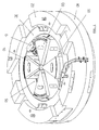
- Figure 1 is representing a 3-dimensional view of the lower half of a magnetic circuit for a compact sector-focused cyclotron according to a preferred embodiment of the present invention.
- Figure 2 is representing a vertical cross-section of the magnetic circuit as represented in Fig. 1.
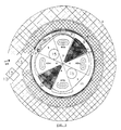
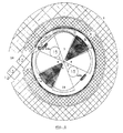
- Figure 3 is representing a view in the median plane of a compact sector-focused cyclotron according to the present invention according to a first preferred embodiment.
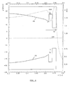
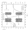
- Figure 4 is representing a vertical cross section of the extended hill sector for one first preferred embodiment of the present invention.
- Figure 5 is representing a vertical cross section of the extended hill sectors for an alternative preferred embodiment of the present invention.
- Figures 6a and 6b are representing the hill gap profiles in opposite sectors for a compact sector-focused cyclotron according to another preferred embodiment of the present invention.
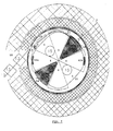
- Figure 7 is representing a view in the median plane for a compact sector-focused cyclotron as having the hill gap as represented in Figs. 6a and 6b.
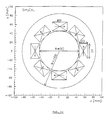
- Figure 8 is representing a view in the median plane of a compact sector-focused cyclotron as a third preferred embodiment of the present invention.
- Figure 9 is representing the schematic vertical cross-section through the gradient corrector showing the configuration of the permanent magnets and the shape of the magnetic field.
- Figure 10 is representing horizontal and vertical cross section through the lost beam dump explaining the cooling mechanism.
- Figure 11 is representing the vertical cross section through the permanent magnet quadrupoles placed in the exit port of the return yoke.
- the present invention concerns a new method for the extraction of charged particles from a compact isochronous sector-focused cyclotron.
- the most important sub-system of the cyclotron is the magnetic circuit, created by an electromagnet as represented by the Figs. 1 and 2, that consists of the following main elements:
- the extraction method is characterised by the fact that there is no electrostatic deflector or stripper mechanism installed in the cyclotron.
- the extraction method is further characterised by the fact that the vertical gaps in the hill sectors have a quasi-elliptical profile (20) that narrows towards the radial extremity of the hill sectors.
- the extraction method is further characterised by the fact that at least one pair of the hill sectors (3) of the cyclotron is significantly longer (about a few centimetres and preferably around 4.0 cm) than the other pair of hill sectors (4).
- the beam In a cyclotron, the beam is confined within the region of the magnetic field by a force, called the Lorentz force. This force is proportional to the magnitude of the magnetic field and also proportional to the velocity of the particle. It is directed perpendicular to both the direction of the magnetic field and the direction of the particle orbit and points approximately towards the centre of the cyclotron.
- a common way to obtain this sudden reduction of the Lorentz force is, to install an electrostatic deflector.
- an electrostatic field is created between a very thin inner septum and an outer electrode.
- This deflector produces an outwardly directed electrical force that counteracts the Lorentz force.
- the septum placed between the last internal orbit and the extracted orbit, is electrically at ground potential so that there is almost no perturbation of the internal orbit.
- the main disadvantage of using the electrostatic deflector is that the septum intercepts a certain fraction of the beam. Due to this it becomes radio-activated and also heats up and therefore limits the maximum extraction efficiency and beam intensity.
- Fig. 3 showing the median plane view of the cyclotron.
- a compact deep valley cyclotron similar to the one described in the document EP-A-0222786 will be the preferred cyclotron for implementing the present invention. Therefore such a cyclotron with 4-fold symmetry consisting in four hill sectors (3, 4) and four valley sectors (5) has been taken as an example. However, similar embodiments with 3-fold symmetry or higher than 4-fold symmetry are also possible.
- Fig. 3 such as the hill and valley sectors, the vacuum chamber (9), the circular coils (6), the return yoke (2) and the accelerating electrodes (14). Also shown is the last full turn (11) in the cyclotron and the extracted beam (12).
- the profile of the vertical gap in the hill sector near the outer radius of the pole has an elliptical or quasi-elliptical (20) shape with a tendency to close towards the maximum pole radius.
- a profile allows to accelerate the particles very close to the outer radius of the hill sector without losing the focusing action and the isochronism of the magnetic field and also to create a magnetic field which shows a very steep fall-off just beyond the radius of the pole.
- the magnetic force which is acting on the extracted orbit is substantially lower than the same force acting on the last internal orbit.
- At least one pair of the hill sectors (3) in the cyclotron is significantly longer than the other pairs of hill sectors (4).
- This extension of at least one pair of hill sectors gives an extension of the magnetic field map on this sector which can be shaped to optimise the extraction process and the optical properties of the extracted beam.
- a groove (7) is machined which follows the shape of the extracted beam (12) on this sector and which, in combination with the small gap in the hill sector and the quasi-elliptical gap profile (20) as described above, produces the required sudden reduction in the magnetic field and in the Lorentz force.
- the effect of this groove (7) is comparable to that of the electrostatic deflector and one could say that it replaces the electrostatic deflector.
- the groove produces a sharp dip in the magnetic field in the sense that, as a function of radius, the field is sharply falling to a minimum but then rises again to more or less the same initial value.
- Fig. 4 The geometry of the groove is illustrated in Fig. 4, together with the quasi-elliptical shape of the gap in the hill sector. This figure also shows the magnetic field shape and especially the sharp dip (200) in the field as produced by the groove (7).
- the outer border of the groove may also be moved beyond the radial extremity of the extended hill sector, in which case a kind of "plateau " (7') is formed which is however still characterised by the stepwise increase of the vertical hill gap and the related sudden decrease of the magnetic field (not represented) near the inner border of the "plateau” (7').
- the density distribution of the beam in the cyclotron is a continuous profile showing a maximum on the centroid of a turn and a non-zero minimum in between two turns.
- the particles situated at this minimum may give rise to beam losses in the extraction process.
- This beam loss can be substantially reduced by augmenting the turn separation between the last internal orbit in the machine and the extracted orbit at the azimuth where the groove is located. Besides the sudden reduction of the Lorentz force, this is the second crucial ingredient for an efficient extraction of the beam.
- a first harmonic Fourier component in the cyclotron magnetic field upstream of the extraction radius.
- a first harmonic field component is characterised by the fact that its magnetic field behaves like a sine-function or cosine-function of the azimuthal angle with a period of 360 degrees. With a proper choice of the amplitude and the azimuthal phase of such a first harmonic field component, a coherent oscillation of the beam is produced which results in the increased turn separation at the desired location in the cyclotron.
- the method for increasing the turn separation is characterised by the use of small harmonic correction coils (40a and 40b) at a lower radius in the machine.
- a possible configuration represented in Fig. 3 is to install in one hill gap an upper and lower coil (40a) which produce a positive field component and on the opposite sector a same pair of coils which produce a negative field component.
- the amplitude of the coherent oscillation can be varied but the phase is fixed.
- the beam still has to make several tuns between the radius of the harmonic coils and the extraction radius, and then an adjustment of only the amplitude of the coherent oscillation is not sufficient.
- a more flexible configuration is, where a second set of coils is installed at an azimuthal angle of 90 degrees with respect to the first set. With such a configuration the amplitude as well as the phase of the coherent oscillation can be varied.
- Other configurations are possible, where instead of four pairs of harmonic coils three pairs are used which are mounted azimuthally 120 degrees apart. This would be a preferred configuration for a cyclotron with 3-fold symmetry.
- the method for increasing the turn separation is characterised by modifying the profile of the hill gap of the two sectors which are located at azimuths of +90 degrees and -90 degrees with respect to the extended hill sector in such a way that in one sector the gap profile contains a bump and thus closes rapidly and then opens again and on the opposite sector the gap profiles contain a dip and thus rapidly opens and then closes again.
- Both hill gap profiles are illustrated in Figs. 6a and 6b.
- This extraction scheme is an alternative for the previous method and is illustrated in Fig. 7.
- the reference (42a) shows the required approximate position of the bump
- the reference (42b) the required approximate position of the dip.
- This configuration produces a strong first harmonic component of which the azimuthal phase is 90 degrees with respect to the azimuth where the groove is located.
- the radial profile and the radial location of this first harmonic on the hill sector is such that the last turn in the machine is strongly influenced by this perturbation and the last minus one turn is not influenced. This requires a sudden change in magnetic field profile which again is only possible when the vertical gap in the hill sector is small enough as has been claimed before.
- the method for increasing the turn separation is characterised by placing permanent magnets (44a and 44b) in two opposite valleys such that in one valley a positive vertical field component is produced and in the opposite valley a negative vertical field component.
- the permanent magnets should be located at azimuths of approximately +90 degrees and -90 degrees with respect to the azimuth of the entrance of the groove and at a radius such that the last turn in the machine is influenced by their magnetic field and the last minus one turn is not influenced.
- the design of this gradient corrector has the following characteristics:
- Fig. 9 shows a schematic vertical cross section through the gradient corrector.
- the radial position of the extracted beam as well as the internal beam is indicated in this figure.
- the required negative gradient of the magnetic field is basically obtained with the four larger permanent magnets (250) having the indicated polarity.
- two additional smaller permanent magnets (300) are placed which serve to compensate the magnitude of the perturbing magnetic field at the position of the internal beam.
- the shape of the magnetic field obtained in this way is indicated in Fig. 9 by the solid line.
- the magnetic field is given that would be obtained without this compensation (dashed line).
- FIG. 9 A similar design as illustrated in Fig. 9 can be used for the references (44a) and (44b) in Fig. 8 related to the extraction scheme where the first harmonic field component is produced by permanent magnets placed in the valleys.
- the fast rise of the magnetic field at the inner radius side of the device which also is realised with the small compensating permanent magnets.
- such a sharp rise is required in order to achieve that the last turn is strongly influenced by the first harmonic field component but the last minus one turn is not.
- the lost beam stop (8) in the several embodiments represented in Figs. 3, 7 and 8.
- the purpose of this beam stop is, to intercept the small fraction of the beam which is not properly extracted and which would otherwise radio-activate or damage unwanted parts of the cyclotron.
- the beam loss on this beam stop is comparable with the beam loss on the septum as occurs in the conventional extraction method using the electrostatic deflector.
- the main advantage of the suggested extraction methods is that this beam stop can be installed at a place where the turn separation between the internal beam and the separated beam is already in the order of 10 cm. Due to this, the beam density of the lost beam is substantially reduced and water-cooling is much easier and more efficient. The problem of thermal heating is therefore much less than that of the septum.
- the design and the construction material of the beam stop can be optimally chosen in order to dissipate almost all of the heat in the cooling water and to minimise the production of neutron radiation.
- this choice is not free because of the presence of high electrical fields.
- the use of the lost beam stop will allow to extract much higher intensities than can be obtained via the conventional extraction with an electrostatic deflector.
- Fig. 10 illustrates the proposed design of the lost beam stop (8). It is designed such that it intercepts the tail on the inner side of the extracted beam (12) but also the tail on the outer side of the internal beam (11). In this way, by properly positioning the beam stop, all the low quality parts of the beam can be efficiently removed.
- the cooling water By applying a high input pressure, the cooling water is forced with a high velocity into the narrow channel. This high velocity substantially augments the cooling efficiency.
- the cooling water is contained by the thin aluminium wall. Most of the heat is therefore dissipated in the water. The production of neutrons in aluminium as well as in water is low.
- the beam leaves the cyclotron via an exit port (17) in the vacuum chamber and via an exit port (18) in the return yoke (2).
- this exit port a quadrupole doublet (13) is placed in order to focus the beam horizontally as well as vertically.
- the quadrupoles are made of unshielded permanent magnets (400).
- shielding is not required because of the low external magnetic field in the exit port.
- Fig. 11 shows a vertical cross section through the quadrupole.
- the polarity of the permanent magnets (400) is indicated by the arrows.
- the dimensions of the permanent magnets are optimised in order to minimise the non-linear contributions in the field over the full bore of the quadrupole.
Landscapes
- Physics & Mathematics (AREA)
- Engineering & Computer Science (AREA)
- Plasma & Fusion (AREA)
- Spectroscopy & Molecular Physics (AREA)
- Particle Accelerators (AREA)
- Physical Or Chemical Processes And Apparatus (AREA)
- Organic Low-Molecular-Weight Compounds And Preparation Thereof (AREA)
Abstract
The present invention is related to a
superconducting or non-superconducting isochronous sector-focused
cyclotron, comprising an electromagnet with an
upper pole and a lower pole that constitute the magnetic
circuit, the poles being made of at least three pairs of
sectors (3, 4) called "hills" where the vertical gap
between said sectors is small, these hill-sectors being
separated by sector-formed spaces called "valleys" (5)
where the vertical gap is large, said cyclotron being
energised by at least one pair of main coils (6),
characterised in that at least one pair of upper and lower
hills is significantly longer than the remaining pairs of
hill sectors in order to have at least one pair of extended
hill sectors (3) and at least one pair of non-extended hill
sectors (4) in that a groove (7) or a "plateau" (7') which
follows the shape of the extracted orbit is present in said
pair of extended hill sectors (3) in order to produce a dip
(200) in the magnetic field.
Description
- The present invention is related to an isochronous cyclotron that can be a compact isochronous cyclotron as well as a separate sector cyclotron.
- The present invention applies both to superconducting and non-super-conducting cyclotrons.
- The present invention is also related to a new method to extract charged particles from an isochronous sector-focused cyclotron.
- A cyclotron is a circular particle accelerator which is used to accelerate positive or negative ions up to energies of a few MeV or more. Cyclotrons can be used for medical applications (production of radioisotopes or for proton therapy) but also for industrial applications, as injector into another accelerator, or for fundamental research.
- A cyclotron consists of several sub-systems of which the most important are mainly the magnetic circuit, the RF acceleration system, the vacuum system, the injection system and the extraction system.
- The most important is the magnetic circuit by which a magnetic field is created. This magnetic field guides the accelerated particles from the centre of the machine towards the outer radius of the machine in such a way that the orbits of the particles describe a spiral. In the earliest cyclotrons the magnetic field was created in a vertical gap between two cylindrically shaped poles by two solenoid coils wound around these poles. In more recent isochronous cyclotrons these poles no longer consist of one solid cylinder, but are divided into sectors such that the circulating beam alternately experiences a high magnetic field created in a hill sector where the gap between the poles is small, followed by a lower magnetic field in a valley sector where the gap between the poles is large. This azimuthal magnetic field variation, when properly designed, provides radial as well as vertical focusing and at the same time allows the particle revolution frequency to be constant throughout the machine.
- Two types of isochronous cyclotrons exist: the first type is the compact cyclotron where the magnetic field is created by one set of circular coils wound around the total pole; the second type is the separate sector cyclotron where each sector is provided with its own set of coils.
- Document EP-A-0222786 describes a compact sector-focused isochronous cyclotron, called "deep-valley cyclotron", which has a very low electrical power consumption in the coils. This is achieved by a specific magnetic structure having a strongly reduced pole gap in the hill sectors and a very large pole gap in the valley sectors, combined with one circular shaped return yoke placed around the coils which serves to close the magnetic circuit.
- Document WO93/10651 describes a compact sector-focused isochronous cyclotron having the special feature of an elliptically or quasi-elliptically shaped pole gap in the hill sectors which tends to close towards the outer radius of the hill sector and which allows to accelerate the particles very close to the outer radius of the hill sector without losing the focusing action and the isochronism of the magnetic field. This will facilitate the extraction of the beam as is pointed out later.
- The second main sub-system of a cyclotron is the RF accelerating system which consists of resonating radio-frequency cavities which are terminated by the accelerating electrodes, usually called the "dees". The RF system creates an alternating voltage of several tenths of kilovolts on the dees at a frequency which is equal to the revolution frequency of the particle or a higher harmonic thereof. This alternating voltage is used to accelerate the particle when it is spiralling outwards to the edge of the pole. Another main advantage of the deep-valley cyclotron is that the RF-cavities and dees can be placed in the valleys, allowing for a very compact design of the cyclotron.
- The third main sub-system of a cyclotron is the vacuum system. The purpose of the vacuum system is to evacuate the air in the gap where the particles are moving in order to avoid too much scattering of the accelerating particles by the rest-gas in the vacuum tank and also to prevent electrical sparks and discharges created by the RF system.
- The fourth sub-system is the injection system which consists basically of an ion source in which the charged particles are created before starting the accelerating process. The ion source can be mounted internally in the centre of the cyclotron or it can be installed outside of the machine. In the latter case the injection system also includes the means to guide the particles from the ion source to the centre of the cyclotron where they start the acceleration process.
- When the particles have completed the acceleration and have reached the outer radius of the pole sectors they can be extracted from the machine, or they can be used in the machine itself. In the latter case an isotope production target is mounted in the vacuum chamber. The main disadvantage of this is however, that the particles partly scatter away from the target and then become lost in an uncontrolled manner all over the vacuum tank. This may cause a strong radio-activation of the machine.
- In many applications it is wished to bring the beam outside of the machine and guide it to a target where it can be used. In this case an extraction system is installed near the outer radius in the machine. The beam extraction is considered as one of the most difficult processes in generating a cyclotron beam. It basically consists in bringing the beam in a controlled manner from the acceleration region to an outer radius where the magnetic field is low enough so that the beam can freely exit the machine.
- For extracting positively charged particles the common method is to use an electrostatic deflector which produces on outward electric field which pulls the particles out of the confining influence of the magnetic field. To achieve this action, a very thin electrode called septum is placed between the last internal orbit in the machine and the orbit that will be extracted. However, this septum always intercepts a certain fraction of the beam and therefore this extraction method has two main drawbacks. The first one is that the extraction efficiency is limited, thereby limiting the maximum beam intensity that can be extracted due to thermal heating of the septum by the intercepted beam. The second is that interception of particles by the septum contributes strongly to the radio-activation of the cyclotron.
- Another well known extraction method concerns negatively charged particles. Here the extraction is obtained by passing the beam through a thin foil wherein the negative ions are stripped from their electrons and are converted into positive ions. This technique allows for an extraction efficiency close to 100% and furthermore an extraction system which is considerably simpler then the previous one. However, also here there is a main disadvantage caused by the fact that the negative ions are not very stable and therefore easily get lost by collisions with the rest gas in the vacuum tank or by too large magnetic forces acting on the ion. This beam loss again causes unwanted radio-activation of the cyclotron. Furthermore, cyclotrons accelerating positive ions allow to produce higher beam intensities with a higher reliability of the accelerator and at the same time allow a strong reduction in size and weight of the machine.
- Also known from the publication "The Review of Scientific Instruments, 27 (1956), No. 7" and from the publication "Nuclear Instruments and
Methods 18, 19 (1962), pp. 41-45e by J. Reginald Richardson, is a claim of a method where the beam could be extracted from the cyclotron without the use of an extraction system. The conditions needed for this auto-extraction are certain resonance conditions of the particle orbits in the magnetic field. However, this method will be difficult to realise and also would give such a bad extracted optical beam quality that in practice it will never be applied. - Also known is the document US-A-3024379 which reports on a cyclotron system in which the magnetic field is essentially independent on the azimuthal angle. This means that this is a non-isochronous cyclotron. It should be noted that the cyclotron described here includes means for extraction of the beam that consists of "regenerators" and "compressors" which allow, by perturbing the magnetic field, an extraction of the beam.
- Document EP-0853867 describes a method for extraction from a cyclotron in which the ratio between the pole gap in the hill sector near the maximum radius and the radial gain per turn of the particles at the same radius is lower than 20 and in which the pole gap in the hill sector has an elliptical or quasi-elliptical shape with a tendency to close at the maximum radius of the hill sector and in which at least one of the hill sectors has a geometrical shape or a magnetic field which is essentially asymmetric as compared to the other hill sectors. The present invention relies among others on this narrow quasi-elliptical pole gap and the asymmetry of at least one sector and at the same time outlines the kind of asymmetries that can be applied to obtain the auto-extraction of the beam.
- The aim of the present invention is to propose a new method for extraction of charged particles from a cyclotron without using a stripping mechanism or an electrostatic deflector as it has been described above.
- An additional aim is to obtain in this way an isochronous cyclotron who is more simple in concept and also more economical than those which are presently available.
- Another additional aim is to increase the extraction efficiency and the maximum extracted beam intensity especially for positively charged particles.
- The present invention is related to a superconducting or non-superconducting isochronous sector-focused cyclotron, comprising an electromagnet with an upper pole and a lower pole that constitutes the magnetic circuit, the poles being made of at least three pairs of sectors called "hills" where the vertical gap between said sectors is small, these hill-sectors being separated by sector-formed spaces called "valleys" where the vertical gap is large, said cyclotron being energised by at least one pair of main coils, characterised in that at least one pair of upper and lower hills is significantly longer than the remaining pair(s) of hill sectors in order to have at least one pair of extended hill sectors and at least one pair of non-extended hill sectors and in that a groove or a "plateau" which follows the shape of the extracted orbit is present in said pair of extended hill sectors in order to produce a dip in the magnetic field.
- According to one preferred embodiment, the radial width of the groove is limited to a few centimetres, preferably of the order of 2 cm, such that it is completely located on the extended hill sector.
- According to an alternative embodiment, the outer border of the groove may also be moved beyond the radial extremity of the extended hill sector, in which case a kind of "plateau" is formed which is however still characterised by the stepwise increase of the vertical hill gap and the related sudden decrease of the magnetic field near the inner border of the "plateau".
- Preferably, the vertical gap in the non-extended hill sectors as well as the vertical gap in the extended hill sectors has essentially an elliptical profile which tends to close towards the median plane at the radial extremity of the hill sectors.
- According to one preferred embodiment, at least one set of harmonic coils is placed in the vertical hill gap, said coils having essentially the shape of the local orbit at that place. Said coils serving to add a first harmonic field component to the existing magnetic field and to increase the turn separation at the entrance of the groove.
- According to another preferred embodiment, the vertical hill gap profiles onto azymuthally opposite hill sectors is deformed such that one profile shows a profound bump on the last turn of the orbit and the other profile shows a profound dip on the last turn of the orbit. Said deformation serves to add a first harmonic field component to the existing magnetic field and to increase the turn separation at the entrance of the groove.
- According to a third preferred embodiment, an arrangement of permanent magnets is placed in two opposite valleys such that in one valley a sharp magnetic field bump is created on the last turn of the orbit and in the opposite valley a magnetic field dip is created on the last turn of the orbit. Said arrangement serves to add a first harmonic field component to the existing magnetic field and to increase the turn separation at the entrance of the groove.
- Preferably, a gradient corrector will be present at the exit of the groove. Such gradient corrector comprises unshielded permanent magnets and shows a completely open vertical gap as well as small compensating permanent magnets in order to minimise the perturbing magnetic field at the internal orbit.
- Advantageously, a lost beam stop is provided behind the exit of the gradient corrector at an azimuth where there is a significant turn separation between the extracted beam and the last turn of the orbit. Said beam stop is placed such that it intercepts the bad parts of the internal beam as well as the extracted beam.
- Preferably, in the return yoke, a pair of horizontally and vertically focusing quadrupoles is placed after the vacuum exit port which are made of unshielded permanent magnets.
- The present invention is also related to a method for the extraction of a charged particle beam from a isochronous sector-focused cyclotron as described hereabove, wherein a sharp dip in the magnetic field on the last turn of the orbit will be used in order to extract the beam of particles without the help of an electrostatic deflector or a stripper mechanism.
- Figure 1 is representing a 3-dimensional view of the lower half of a magnetic circuit for a compact sector-focused cyclotron according to a preferred embodiment of the present invention.
- Figure 2 is representing a vertical cross-section of the magnetic circuit as represented in Fig. 1.
- Figure 3 is representing a view in the median plane of a compact sector-focused cyclotron according to the present invention according to a first preferred embodiment.
- Figure 4 is representing a vertical cross section of the extended hill sector for one first preferred embodiment of the present invention.
- Figure 5 is representing a vertical cross section of the extended hill sectors for an alternative preferred embodiment of the present invention.
- Figures 6a and 6b are representing the hill gap profiles in opposite sectors for a compact sector-focused cyclotron according to another preferred embodiment of the present invention.
- Figure 7 is representing a view in the median plane for a compact sector-focused cyclotron as having the hill gap as represented in Figs. 6a and 6b.
- Figure 8 is representing a view in the median plane of a compact sector-focused cyclotron as a third preferred embodiment of the present invention.
- Figure 9 is representing the schematic vertical cross-section through the gradient corrector showing the configuration of the permanent magnets and the shape of the magnetic field.
- Figure 10 is representing horizontal and vertical cross section through the lost beam dump explaining the cooling mechanism.
- Figure 11 is representing the vertical cross section through the permanent magnet quadrupoles placed in the exit port of the return yoke.
- The present invention concerns a new method for the extraction of charged particles from a compact isochronous sector-focused cyclotron. The most important sub-system of the cyclotron is the magnetic circuit, created by an electromagnet as represented by the Figs. 1 and 2, that consists of the following main elements:
- two base plates (1) and the flux return (2) which connect together and form a rigid structure called the yoke;
- at least 3 upper and 3 lower hill sectors, and preferably 4 upper and 4 lower hill sectors (3,4) as represented in Figs. 1 and 2, which are located symmetrically with respect to the symmetry plane called the median plane (100) and having a vertical gap in the centre of about 36 mm and a vertical gap of about 15 mm at the extraction region;
- between each two hill sectors there is sector where the vertical gap is substantially larger than the hill gap and which is called the valley sector (5), with a vertical gap of about 670 mm;
- two circular coils (6) which are positioned in between the hill sectors and the flux returns (2).
- The extraction method is characterised by the fact that there is no electrostatic deflector or stripper mechanism installed in the cyclotron. The extraction method is further characterised by the fact that the vertical gaps in the hill sectors have a quasi-elliptical profile (20) that narrows towards the radial extremity of the hill sectors. The extraction method is further characterised by the fact that at least one pair of the hill sectors (3) of the cyclotron is significantly longer (about a few centimetres and preferably around 4.0 cm) than the other pair of hill sectors (4).
- In a cyclotron, the beam is confined within the region of the magnetic field by a force, called the Lorentz force. This force is proportional to the magnitude of the magnetic field and also proportional to the velocity of the particle. It is directed perpendicular to both the direction of the magnetic field and the direction of the particle orbit and points approximately towards the centre of the cyclotron.
- When the particle has reached the radial edge of the pole, extraction can be obtained, if the force acting on the particle is suddenly substantially reduced, so that it is no longer big enough to keep the particle in the confining region of the magnetic field. An essential point here is that this reduction of this force must be realised over a small radial distance so that the last internal orbit is not disturbed.
- A common way to obtain this sudden reduction of the Lorentz force is, to install an electrostatic deflector. In this device an electrostatic field is created between a very thin inner septum and an outer electrode. This deflector produces an outwardly directed electrical force that counteracts the Lorentz force. The septum, placed between the last internal orbit and the extracted orbit, is electrically at ground potential so that there is almost no perturbation of the internal orbit. However, the main disadvantage of using the electrostatic deflector is that the septum intercepts a certain fraction of the beam. Due to this it becomes radio-activated and also heats up and therefore limits the maximum extraction efficiency and beam intensity.
- The proposed extraction scheme of the present invention is illustrated in Fig. 3 showing the median plane view of the cyclotron. A compact deep valley cyclotron similar to the one described in the document EP-A-0222786 will be the preferred cyclotron for implementing the present invention. Therefore such a cyclotron with 4-fold symmetry consisting in four hill sectors (3, 4) and four valley sectors (5) has been taken as an example. However, similar embodiments with 3-fold symmetry or higher than 4-fold symmetry are also possible. Several items as discussed before are shown in Fig. 3, such as the hill and valley sectors, the vacuum chamber (9), the circular coils (6), the return yoke (2) and the accelerating electrodes (14). Also shown is the last full turn (11) in the cyclotron and the extracted beam (12).
- One important feature of the present invention is, that the required sudden reduction of the Lorentz force is created by a fast decrease of the magnetic field near the edge of the pole. In order to realise a fast enough drop in the magnetic field, the vertical gap between the poles in the hill sector must be small. Preferably, the ratio between the vertical gap in the hill sector near the maximum radius and the radial gain per turn of the particles at this radius should be less than about 20.
- Advantageously, the profile of the vertical gap in the hill sector near the outer radius of the pole has an elliptical or quasi-elliptical (20) shape with a tendency to close towards the maximum pole radius. Such a profile allows to accelerate the particles very close to the outer radius of the hill sector without losing the focusing action and the isochronism of the magnetic field and also to create a magnetic field which shows a very steep fall-off just beyond the radius of the pole. As a consequence, the magnetic force which is acting on the extracted orbit is substantially lower than the same force acting on the last internal orbit.
- Another new important feature of the present invention is that at least one pair of the hill sectors (3) in the cyclotron is significantly longer than the other pairs of hill sectors (4). This extension of at least one pair of hill sectors gives an extension of the magnetic field map on this sector which can be shaped to optimise the extraction process and the optical properties of the extracted beam.
- Another new important feature of the present invention is that in the above described extension of the hill sector, a groove (7) is machined which follows the shape of the extracted beam (12) on this sector and which, in combination with the small gap in the hill sector and the quasi-elliptical gap profile (20) as described above, produces the required sudden reduction in the magnetic field and in the Lorentz force. The effect of this groove (7) is comparable to that of the electrostatic deflector and one could say that it replaces the electrostatic deflector. In fact the groove produces a sharp dip in the magnetic field in the sense that, as a function of radius, the field is sharply falling to a minimum but then rises again to more or less the same initial value. This is important because it prevents that the quality of the extracted beam gets destroyed due to the well-known horizontally defocusing action of a falling magnetic field shape. The geometry of the groove is illustrated in Fig. 4, together with the quasi-elliptical shape of the gap in the hill sector. This figure also shows the magnetic field shape and especially the sharp dip (200) in the field as produced by the groove (7).
- According to another preferred embodiment, more precisely described in Fig. 5, the outer border of the groove may also be moved beyond the radial extremity of the extended hill sector, in which case a kind of "plateau " (7') is formed which is however still characterised by the stepwise increase of the vertical hill gap and the related sudden decrease of the magnetic field (not represented) near the inner border of the "plateau" (7').
- It should be noted that the density distribution of the beam in the cyclotron is a continuous profile showing a maximum on the centroid of a turn and a non-zero minimum in between two turns. The particles situated at this minimum may give rise to beam losses in the extraction process. This beam loss can be substantially reduced by augmenting the turn separation between the last internal orbit in the machine and the extracted orbit at the azimuth where the groove is located. Besides the sudden reduction of the Lorentz force, this is the second crucial ingredient for an efficient extraction of the beam.
- According to the present invention, three independent methods are proposed for augmenting the turn separation near the extraction radius. All these three methods rely on the creation of a first harmonic Fourier component in the cyclotron magnetic field upstream of the extraction radius. A first harmonic field component is characterised by the fact that its magnetic field behaves like a sine-function or cosine-function of the azimuthal angle with a period of 360 degrees. With a proper choice of the amplitude and the azimuthal phase of such a first harmonic field component, a coherent oscillation of the beam is produced which results in the increased turn separation at the desired location in the cyclotron.
- According to a first preferred embodiment, the method for increasing the turn separation is characterised by the use of small harmonic correction coils (40a and 40b) at a lower radius in the machine. A possible configuration represented in Fig. 3 is to install in one hill gap an upper and lower coil (40a) which produce a positive field component and on the opposite sector a same pair of coils which produce a negative field component. With such a first set of harmonic coils the amplitude of the coherent oscillation can be varied but the phase is fixed. However, for this first preferred embodiment, the beam still has to make several tuns between the radius of the harmonic coils and the extraction radius, and then an adjustment of only the amplitude of the coherent oscillation is not sufficient. A more flexible configuration is, where a second set of coils is installed at an azimuthal angle of 90 degrees with respect to the first set. With such a configuration the amplitude as well as the phase of the coherent oscillation can be varied. Other configurations are possible, where instead of four pairs of harmonic coils three pairs are used which are mounted azimuthally 120 degrees apart. This would be a preferred configuration for a cyclotron with 3-fold symmetry.
- According to a second preferred embodiment, the method for increasing the turn separation is characterised by modifying the profile of the hill gap of the two sectors which are located at azimuths of +90 degrees and -90 degrees with respect to the extended hill sector in such a way that in one sector the gap profile contains a bump and thus closes rapidly and then opens again and on the opposite sector the gap profiles contain a dip and thus rapidly opens and then closes again. Both hill gap profiles are illustrated in Figs. 6a and 6b. This extraction scheme is an alternative for the previous method and is illustrated in Fig. 7. Here the reference (42a) shows the required approximate position of the bump and the reference (42b) the required approximate position of the dip. This configuration produces a strong first harmonic component of which the azimuthal phase is 90 degrees with respect to the azimuth where the groove is located. In this method, there is only one turn between the radius of the first harmonic and the extraction radius, and therefore a possibility for adjusting the phase of the first harmonic is not needed. Ideally the radial profile and the radial location of this first harmonic on the hill sector is such that the last turn in the machine is strongly influenced by this perturbation and the last minus one turn is not influenced. This requires a sudden change in magnetic field profile which again is only possible when the vertical gap in the hill sector is small enough as has been claimed before.
- According to a third preferred embodiment represented in Fig. 8, the method for increasing the turn separation is characterised by placing permanent magnets (44a and 44b) in two opposite valleys such that in one valley a positive vertical field component is produced and in the opposite valley a negative vertical field component. As far as the beam optical behaviour is concerned, this method is equivalent to the previous method. The permanent magnets should be located at azimuths of approximately +90 degrees and -90 degrees with respect to the azimuth of the entrance of the groove and at a radius such that the last turn in the machine is influenced by their magnetic field and the last minus one turn is not influenced. This method takes advantage of the fact that in the valley sectors the magnetic field level is low enough to allow the use of permanent magnet materials without having the complication of possible de-magnetisation of these magnets. Also here a sharp gradient in the radial profile of the first harmonic component is required. This can be obtained by a special configuration of the permanent magnets as will be discussed later. This extraction scheme, which is an alternative for the previous two methods, it illustrated in Fig. 8. Here, the references (44a) and (44b) indicate the approximate location in the cyclotron of the permanent magnets that produce the required first harmonic field component.
- When the extracted beam exits from the extended hill sector it is horizontally diverging due to the optical influence of the magnetic field shape produced by the groove. In order to re-focus the beam, a gradient corrector is installed in the valley at the exit of the groove. In the drawings, this gradient corrector is denoted by reference (10).
- Preferably, the design of this gradient corrector has the following characteristics:
- it is designed of permanent magnets and does not use iron or other soft ferro-magnetic material to shield the permanent magnets; this is possible because of the relative low external magnetic field in the valley,
- there is almost no perturbation of the internal orbits in the cyclotron,
- there is a completely open vertical gap and therefore no unwanted interception of a part of the beam by obstacles in the median plane.
- Fig. 9 shows a schematic vertical cross section through the gradient corrector. The radial position of the extracted beam as well as the internal beam is indicated in this figure. The required negative gradient of the magnetic field is basically obtained with the four larger permanent magnets (250) having the indicated polarity. However, on the inner side two additional smaller permanent magnets (300) are placed which serve to compensate the magnitude of the perturbing magnetic field at the position of the internal beam. The shape of the magnetic field obtained in this way is indicated in Fig. 9 by the solid line. As a comparison also the magnetic field is given that would be obtained without this compensation (dashed line).
- A similar design as illustrated in Fig. 9 can be used for the references (44a) and (44b) in Fig. 8 related to the extraction scheme where the first harmonic field component is produced by permanent magnets placed in the valleys. However, in this case it is not the focusing action which is exploited but the fast rise of the magnetic field at the inner radius side of the device which also is realised with the small compensating permanent magnets. As has already been mentioned before, such a sharp rise is required in order to achieve that the last turn is strongly influenced by the first harmonic field component but the last minus one turn is not.
- Advantageously, one can suggest the use of the lost beam stop (8) in the several embodiments represented in Figs. 3, 7 and 8. The purpose of this beam stop is, to intercept the small fraction of the beam which is not properly extracted and which would otherwise radio-activate or damage unwanted parts of the cyclotron. The beam loss on this beam stop is comparable with the beam loss on the septum as occurs in the conventional extraction method using the electrostatic deflector. However, the main advantage of the suggested extraction methods is that this beam stop can be installed at a place where the turn separation between the internal beam and the separated beam is already in the order of 10 cm. Due to this, the beam density of the lost beam is substantially reduced and water-cooling is much easier and more efficient. The problem of thermal heating is therefore much less than that of the septum. Furthermore, the design and the construction material of the beam stop can be optimally chosen in order to dissipate almost all of the heat in the cooling water and to minimise the production of neutron radiation. In the case of an electrostatic deflector, this choice is not free because of the presence of high electrical fields. The use of the lost beam stop will allow to extract much higher intensities than can be obtained via the conventional extraction with an electrostatic deflector. Fig. 10 illustrates the proposed design of the lost beam stop (8). It is designed such that it intercepts the tail on the inner side of the extracted beam (12) but also the tail on the outer side of the internal beam (11). In this way, by properly positioning the beam stop, all the low quality parts of the beam can be efficiently removed. By applying a high input pressure, the cooling water is forced with a high velocity into the narrow channel. This high velocity substantially augments the cooling efficiency. The cooling water is contained by the thin aluminium wall. Most of the heat is therefore dissipated in the water. The production of neutrons in aluminium as well as in water is low.
- After passing the gradient corrector (10), the beam leaves the cyclotron via an exit port (17) in the vacuum chamber and via an exit port (18) in the return yoke (2). In this exit port a quadrupole doublet (13) is placed in order to focus the beam horizontally as well as vertically. In order to allow a compact design, the quadrupoles are made of unshielded permanent magnets (400). Here again shielding is not required because of the low external magnetic field in the exit port. Fig. 11 shows a vertical cross section through the quadrupole. The polarity of the permanent magnets (400) is indicated by the arrows. The dimensions of the permanent magnets are optimised in order to minimise the non-linear contributions in the field over the full bore of the quadrupole.
Claims (13)
- Superconducting or non-superconducting isochronous sector-focused cyclotron, comprising an electromagnet with an upper pole and a lower pole that constitute the magnetic circuit, the poles being made of at least three pairs of sectors (3, 4) called "hills" where the vertical gap between said sectors is small, these hill-sectors being separated by sector-formed spaces called "valleys" (5) where the vertical gap is large, said cyclotron being energised by at least one pair of main coils (6), characterised in that at least one pair of upper and lower hills is significantly longer than the remaining pairs of hill sectors in order to have at least one pair of extended hill sectors (3) and at least one pair of non-extended hill sectors (4) in that a groove (7) or a "plateau" (7') which follows the shape of the extracted orbit is present in said pair of extended hill sectors (3) in order to produce a dip (200) in the magnetic field.
- Cyclotron according to claim 1, wherein the two extended hill sectors (3) are longer of a few centimetres, preferably of between 2 and 10 centimetres, compared to the non-extended hill sectors (4).
- Cyclotron according to claim 1 or 2, wherein the groove is limited to a few centimetres such that it is completely located on the extended hill sectors.
- Cyclotron according to claim 1 or 2, wherein a "plateau" (7') is formed by moving the outer border of the groove beyond the radial extremity of the extended hill sector (3).
- Cyclotron according to any one of the preceding claims, characterised in that the vertical gap in the non-extended hill sectors (4) as well as the vertical gap in the extended hill sectors (3) has essentially an elliptical profile (20) which tends to close towards the median plane (100) at the radial extremity of the hill sectors.
- Cyclotron according to any one of the preceding claims, characterised in that at least one set of harmonic coils (40a and 40b) are placed in the vertical hill gap, said coils having essentially the shape of the local orbit at that place.
- Cyclotron according to any one of the claims 1 to 5, characterised in that the vertical hill gap profile onto opposite hill sectors is deformed such that one profile shows a profound bump (42a) on the last turn (11) of the orbit and the other profile shows a profound dip (42b) on the last turn (11) of the orbit.
- Cyclotron according to any one of the claims 1 to 5, characterised in that an arrangement of permanent magnets (44a and 44b) is placed in two opposite valleys such that in one valley a sharp magnetic field bump is created on the last turn (11) of the orbit and in the opposite valley a magnetic field dip is created on the last turn (11) of the orbit.
- Cyclotron according to any one of the preceding claims, wherein a gradient corrector (10) is present as the exit of the groove (7).
- Cyclotron according to claim 9, characterised in that the gradient corrector (10) comprises unshielded permanent magnets (250) and shows a completely open vertical gap and small compensating permanent magnets (300) in order to minimise the perturbing magnetic field at the internal orbit.
- Cyclotron according to any one of the preceding claims, characterised in that a lost beam stop (8) is placed behind the exit of the gradient corrector (10) at an azimuth where there is a significant turn separation between the extracted beam (12) and the last turn (11) of the orbit.
- Cyclotron according to any one of the preceding claims, characterised in that in the return yoke (2) a pair of horizontally and vertically focusing quadrupoles (13) is placed after the vacuum exit port (17) which are made of unshielded permanent magnets (400).
- Method for the extraction of a charged particles beam from an isochronous sector-focused cyclotron as described in any one of the preceding claims in which a sharp dip (200) in the magnetic field on the last turn (11) of the orbit is used to extract the beam of particles.
Priority Applications (9)
| Application Number | Priority Date | Filing Date | Title |
|---|---|---|---|
| EP99870156A EP1069809A1 (en) | 1999-07-13 | 1999-07-13 | Isochronous cyclotron and method of extraction of charged particles from such cyclotron |
| US10/031,027 US6683426B1 (en) | 1999-07-13 | 2000-03-31 | Isochronous cyclotron and method of extraction of charged particles from such cyclotron |
| JP2001510280A JP4713799B2 (en) | 1999-07-13 | 2000-03-31 | Isochronous sector-focused cyclotron and method for extracting charged particles from the cyclotron |
| EP00913976A EP1195078B1 (en) | 1999-07-13 | 2000-03-31 | Isochronous cyclotron and its use for extraction of charged particles |
| AU35457/00A AU3545700A (en) | 1999-07-13 | 2000-03-31 | Isochronous cyclotron and method of extraction of charged particles from such cyclotron |
| AT00913976T ATE298497T1 (en) | 1999-07-13 | 2000-03-31 | ISOCHRONIC CYCLOTRON AND USE THEREOF FOR EXTRACTING CHARGED PARTICLES |
| DE60020969T DE60020969T2 (en) | 1999-07-13 | 2000-03-31 | ISOCHRONOUS CYCLOTRON AND ITS USE IN EXTRACTING LOADED PARTICLES |
| PCT/BE2000/000028 WO2001005199A1 (en) | 1999-07-13 | 2000-03-31 | Isochronous cyclotron and method of extraction of charged particles from such cyclotron |
| CA002373763A CA2373763C (en) | 1999-07-13 | 2000-03-31 | Isochronous cyclotron and method of extraction of charged particles from such cyclotron |
Applications Claiming Priority (1)
| Application Number | Priority Date | Filing Date | Title |
|---|---|---|---|
| EP99870156A EP1069809A1 (en) | 1999-07-13 | 1999-07-13 | Isochronous cyclotron and method of extraction of charged particles from such cyclotron |
Publications (1)
| Publication Number | Publication Date |
|---|---|
| EP1069809A1 true EP1069809A1 (en) | 2001-01-17 |
Family
ID=8243873
Family Applications (2)
| Application Number | Title | Priority Date | Filing Date |
|---|---|---|---|
| EP99870156A Withdrawn EP1069809A1 (en) | 1999-07-13 | 1999-07-13 | Isochronous cyclotron and method of extraction of charged particles from such cyclotron |
| EP00913976A Expired - Lifetime EP1195078B1 (en) | 1999-07-13 | 2000-03-31 | Isochronous cyclotron and its use for extraction of charged particles |
Family Applications After (1)
| Application Number | Title | Priority Date | Filing Date |
|---|---|---|---|
| EP00913976A Expired - Lifetime EP1195078B1 (en) | 1999-07-13 | 2000-03-31 | Isochronous cyclotron and its use for extraction of charged particles |
Country Status (8)
| Country | Link |
|---|---|
| US (1) | US6683426B1 (en) |
| EP (2) | EP1069809A1 (en) |
| JP (1) | JP4713799B2 (en) |
| AT (1) | ATE298497T1 (en) |
| AU (1) | AU3545700A (en) |
| CA (1) | CA2373763C (en) |
| DE (1) | DE60020969T2 (en) |
| WO (1) | WO2001005199A1 (en) |
Cited By (39)
| Publication number | Priority date | Publication date | Assignee | Title |
|---|---|---|---|---|
| WO2004049770A1 (en) * | 2002-11-25 | 2004-06-10 | Ion Beam Applications S.A. | Cyclotron |
| US7728311B2 (en) | 2005-11-18 | 2010-06-01 | Still River Systems Incorporated | Charged particle radiation therapy |
| US8003964B2 (en) | 2007-10-11 | 2011-08-23 | Still River Systems Incorporated | Applying a particle beam to a patient |
| WO2012071142A3 (en) * | 2010-11-22 | 2012-07-26 | Massachusetts Institute Of Technology | Compact, cold, weak-focusing, superconducting cyclotron |
| WO2013113913A1 (en) * | 2012-02-03 | 2013-08-08 | Ion Beam Applications S.A. | Magnet structure for an isochronous superconducting compact cyclotron |
| WO2013142409A1 (en) * | 2012-03-23 | 2013-09-26 | Massachusetts Institute Of Technology | Compensated precessional beam extraction for cyclotrons |
| US8581523B2 (en) | 2007-11-30 | 2013-11-12 | Mevion Medical Systems, Inc. | Interrupted particle source |
| FR2997603A1 (en) * | 2012-10-29 | 2014-05-02 | Aima Dev | CYCLOTRON |
| US8791656B1 (en) | 2013-05-31 | 2014-07-29 | Mevion Medical Systems, Inc. | Active return system |
| US8927950B2 (en) | 2012-09-28 | 2015-01-06 | Mevion Medical Systems, Inc. | Focusing a particle beam |
| US8933650B2 (en) | 2007-11-30 | 2015-01-13 | Mevion Medical Systems, Inc. | Matching a resonant frequency of a resonant cavity to a frequency of an input voltage |
| US8952634B2 (en) | 2004-07-21 | 2015-02-10 | Mevion Medical Systems, Inc. | Programmable radio frequency waveform generator for a synchrocyclotron |
| US9155186B2 (en) | 2012-09-28 | 2015-10-06 | Mevion Medical Systems, Inc. | Focusing a particle beam using magnetic field flutter |
| US9185789B2 (en) | 2012-09-28 | 2015-11-10 | Mevion Medical Systems, Inc. | Magnetic shims to alter magnetic fields |
| US9301384B2 (en) | 2012-09-28 | 2016-03-29 | Mevion Medical Systems, Inc. | Adjusting energy of a particle beam |
| EP3024306A1 (en) * | 2014-11-19 | 2016-05-25 | Ion Beam Applications S.A. | High current cyclotron |
| CN106132065A (en) * | 2016-07-29 | 2016-11-16 | 中国原子能科学研究院 | 230MeV superconducting cyclotron avoids the field structure of draw-out area harmful resonance |
| US9545528B2 (en) | 2012-09-28 | 2017-01-17 | Mevion Medical Systems, Inc. | Controlling particle therapy |
| US9622335B2 (en) | 2012-09-28 | 2017-04-11 | Mevion Medical Systems, Inc. | Magnetic field regenerator |
| US9661736B2 (en) | 2014-02-20 | 2017-05-23 | Mevion Medical Systems, Inc. | Scanning system for a particle therapy system |
| US9681531B2 (en) | 2012-09-28 | 2017-06-13 | Mevion Medical Systems, Inc. | Control system for a particle accelerator |
| US9723705B2 (en) | 2012-09-28 | 2017-08-01 | Mevion Medical Systems, Inc. | Controlling intensity of a particle beam |
| US9730308B2 (en) | 2013-06-12 | 2017-08-08 | Mevion Medical Systems, Inc. | Particle accelerator that produces charged particles having variable energies |
| EP3244708A1 (en) * | 2016-05-13 | 2017-11-15 | Ion Beam Applications S.A. | Peripheral hill sector design for cyclotron |
| EP3244709A1 (en) * | 2016-05-13 | 2017-11-15 | Ion Beam Applications S.A. | Gradient corrector for cyclotron |
| RU2641658C2 (en) * | 2016-06-15 | 2018-01-19 | Объединенный Институт Ядерных Исследований | Method for slow beam output of charged particles |
| US9950194B2 (en) | 2014-09-09 | 2018-04-24 | Mevion Medical Systems, Inc. | Patient positioning system |
| US9961757B2 (en) | 2016-05-13 | 2018-05-01 | Ion Beam Applications S.A. | Peripheral hill sector design for cyclotron |
| US9962560B2 (en) | 2013-12-20 | 2018-05-08 | Mevion Medical Systems, Inc. | Collimator and energy degrader |
| US10254739B2 (en) | 2012-09-28 | 2019-04-09 | Mevion Medical Systems, Inc. | Coil positioning system |
| US10258810B2 (en) | 2013-09-27 | 2019-04-16 | Mevion Medical Systems, Inc. | Particle beam scanning |
| CN109792835A (en) * | 2016-10-06 | 2019-05-21 | 住友重机械工业株式会社 | Particle accelerator |
| US10646728B2 (en) | 2015-11-10 | 2020-05-12 | Mevion Medical Systems, Inc. | Adaptive aperture |
| US10653892B2 (en) | 2017-06-30 | 2020-05-19 | Mevion Medical Systems, Inc. | Configurable collimator controlled using linear motors |
| US10675487B2 (en) | 2013-12-20 | 2020-06-09 | Mevion Medical Systems, Inc. | Energy degrader enabling high-speed energy switching |
| US10925147B2 (en) | 2016-07-08 | 2021-02-16 | Mevion Medical Systems, Inc. | Treatment planning |
| US11103730B2 (en) | 2017-02-23 | 2021-08-31 | Mevion Medical Systems, Inc. | Automated treatment in particle therapy |
| US11291861B2 (en) | 2019-03-08 | 2022-04-05 | Mevion Medical Systems, Inc. | Delivery of radiation by column and generating a treatment plan therefor |
| RU2860878C1 (en) * | 2024-12-03 | 2026-04-24 | Федеральное государственное бюджетное учреждение "Институт физики высоких энергий имени А.А. Логунова Национального исследовательского центра "Курчатовский институт" (НИЦ "Курчатовский институт" - ИФВЭ) | Method for stochastic slow extraction of accelerated beam from synchrophasotron |
Families Citing this family (143)
| Publication number | Priority date | Publication date | Assignee | Title |
|---|---|---|---|---|
| JP4560183B2 (en) * | 2000-07-13 | 2010-10-13 | 住友重機械工業株式会社 | Cyclotron beam blocking device and beam monitoring device |
| JP4104008B2 (en) * | 2004-07-21 | 2008-06-18 | 独立行政法人放射線医学総合研究所 | Spiral orbit type charged particle accelerator and acceleration method thereof |
| US9077022B2 (en) * | 2004-10-29 | 2015-07-07 | Medtronic, Inc. | Lithium-ion battery |
| US7315140B2 (en) * | 2005-01-27 | 2008-01-01 | Matsushita Electric Industrial Co., Ltd. | Cyclotron with beam phase selector |
| JP5481070B2 (en) | 2006-01-19 | 2014-04-23 | マサチューセッツ インスティテュート オブ テクノロジー | Magnetic field generation method for particle acceleration, magnet structure, and manufacturing method thereof |
| US7656258B1 (en) | 2006-01-19 | 2010-02-02 | Massachusetts Institute Of Technology | Magnet structure for particle acceleration |
| US7884340B2 (en) * | 2006-05-26 | 2011-02-08 | Advanced Biomarker Technologies, Llc | Low-volume biomarker generator |
| US7466085B2 (en) * | 2007-04-17 | 2008-12-16 | Advanced Biomarker Technologies, Llc | Cyclotron having permanent magnets |
| GB0714778D0 (en) * | 2007-07-31 | 2007-09-12 | Macdonald Bradley Christopher | Method and apparatus for the acceleration and manipulation of charged particles |
| DE102007046739A1 (en) * | 2007-09-28 | 2009-07-23 | Forschungszentrum Jülich GmbH | Chopper for a particle beam |
| US9910166B2 (en) | 2008-05-22 | 2018-03-06 | Stephen L. Spotts | Redundant charged particle state determination apparatus and method of use thereof |
| US10548551B2 (en) | 2008-05-22 | 2020-02-04 | W. Davis Lee | Depth resolved scintillation detector array imaging apparatus and method of use thereof |
| US8624528B2 (en) * | 2008-05-22 | 2014-01-07 | Vladimir Balakin | Method and apparatus coordinating synchrotron acceleration periods with patient respiration periods |
| US9682254B2 (en) | 2008-05-22 | 2017-06-20 | Vladimir Balakin | Cancer surface searing apparatus and method of use thereof |
| US8975600B2 (en) | 2008-05-22 | 2015-03-10 | Vladimir Balakin | Treatment delivery control system and method of operation thereof |
| WO2009142545A2 (en) | 2008-05-22 | 2009-11-26 | Vladimir Yegorovich Balakin | Charged particle cancer therapy patient positioning method and apparatus |
| US10092776B2 (en) | 2008-05-22 | 2018-10-09 | Susan L. Michaud | Integrated translation/rotation charged particle imaging/treatment apparatus and method of use thereof |
| US8399866B2 (en) | 2008-05-22 | 2013-03-19 | Vladimir Balakin | Charged particle extraction apparatus and method of use thereof |
| US9095040B2 (en) | 2008-05-22 | 2015-07-28 | Vladimir Balakin | Charged particle beam acceleration and extraction method and apparatus used in conjunction with a charged particle cancer therapy system |
| US9616252B2 (en) | 2008-05-22 | 2017-04-11 | Vladimir Balakin | Multi-field cancer therapy apparatus and method of use thereof |
| US9177751B2 (en) | 2008-05-22 | 2015-11-03 | Vladimir Balakin | Carbon ion beam injector apparatus and method of use thereof |
| US8436327B2 (en) * | 2008-05-22 | 2013-05-07 | Vladimir Balakin | Multi-field charged particle cancer therapy method and apparatus |
| WO2009142548A2 (en) * | 2008-05-22 | 2009-11-26 | Vladimir Yegorovich Balakin | X-ray method and apparatus used in conjunction with a charged particle cancer therapy system |
| US8373145B2 (en) * | 2008-05-22 | 2013-02-12 | Vladimir Balakin | Charged particle cancer therapy system magnet control method and apparatus |
| US8198607B2 (en) * | 2008-05-22 | 2012-06-12 | Vladimir Balakin | Tandem accelerator method and apparatus used in conjunction with a charged particle cancer therapy system |
| US8766217B2 (en) * | 2008-05-22 | 2014-07-01 | Vladimir Yegorovich Balakin | Multi-field charged particle cancer therapy method and apparatus |
| US8129699B2 (en) * | 2008-05-22 | 2012-03-06 | Vladimir Balakin | Multi-field charged particle cancer therapy method and apparatus coordinated with patient respiration |
| US8598543B2 (en) * | 2008-05-22 | 2013-12-03 | Vladimir Balakin | Multi-axis/multi-field charged particle cancer therapy method and apparatus |
| EP2283713B1 (en) * | 2008-05-22 | 2018-03-28 | Vladimir Yegorovich Balakin | Multi-axis charged particle cancer therapy apparatus |
| US8907309B2 (en) | 2009-04-17 | 2014-12-09 | Stephen L. Spotts | Treatment delivery control system and method of operation thereof |
| US8841866B2 (en) | 2008-05-22 | 2014-09-23 | Vladimir Yegorovich Balakin | Charged particle beam extraction method and apparatus used in conjunction with a charged particle cancer therapy system |
| US9168392B1 (en) | 2008-05-22 | 2015-10-27 | Vladimir Balakin | Charged particle cancer therapy system X-ray apparatus and method of use thereof |
| US8188688B2 (en) | 2008-05-22 | 2012-05-29 | Vladimir Balakin | Magnetic field control method and apparatus used in conjunction with a charged particle cancer therapy system |
| US9579525B2 (en) | 2008-05-22 | 2017-02-28 | Vladimir Balakin | Multi-axis charged particle cancer therapy method and apparatus |
| US8374314B2 (en) | 2008-05-22 | 2013-02-12 | Vladimir Balakin | Synchronized X-ray / breathing method and apparatus used in conjunction with a charged particle cancer therapy system |
| US20090314960A1 (en) * | 2008-05-22 | 2009-12-24 | Vladimir Balakin | Patient positioning method and apparatus used in conjunction with a charged particle cancer therapy system |
| US8129694B2 (en) * | 2008-05-22 | 2012-03-06 | Vladimir Balakin | Negative ion beam source vacuum method and apparatus used in conjunction with a charged particle cancer therapy system |
| US7939809B2 (en) * | 2008-05-22 | 2011-05-10 | Vladimir Balakin | Charged particle beam extraction method and apparatus used in conjunction with a charged particle cancer therapy system |
| US9782140B2 (en) | 2008-05-22 | 2017-10-10 | Susan L. Michaud | Hybrid charged particle / X-ray-imaging / treatment apparatus and method of use thereof |
| US9044600B2 (en) * | 2008-05-22 | 2015-06-02 | Vladimir Balakin | Proton tomography apparatus and method of operation therefor |
| US8089054B2 (en) | 2008-05-22 | 2012-01-03 | Vladimir Balakin | Charged particle beam acceleration and extraction method and apparatus used in conjunction with a charged particle cancer therapy system |
| US9737734B2 (en) | 2008-05-22 | 2017-08-22 | Susan L. Michaud | Charged particle translation slide control apparatus and method of use thereof |
| US8896239B2 (en) * | 2008-05-22 | 2014-11-25 | Vladimir Yegorovich Balakin | Charged particle beam injection method and apparatus used in conjunction with a charged particle cancer therapy system |
| US8710462B2 (en) * | 2008-05-22 | 2014-04-29 | Vladimir Balakin | Charged particle cancer therapy beam path control method and apparatus |
| US10029122B2 (en) | 2008-05-22 | 2018-07-24 | Susan L. Michaud | Charged particle—patient motion control system apparatus and method of use thereof |
| US8373143B2 (en) * | 2008-05-22 | 2013-02-12 | Vladimir Balakin | Patient immobilization and repositioning method and apparatus used in conjunction with charged particle cancer therapy |
| WO2009142547A2 (en) * | 2008-05-22 | 2009-11-26 | Vladimir Yegorovich Balakin | Charged particle beam acceleration method and apparatus as part of a charged particle cancer therapy system |
| US8378311B2 (en) | 2008-05-22 | 2013-02-19 | Vladimir Balakin | Synchrotron power cycling apparatus and method of use thereof |
| US8569717B2 (en) * | 2008-05-22 | 2013-10-29 | Vladimir Balakin | Intensity modulated three-dimensional radiation scanning method and apparatus |
| US8144832B2 (en) * | 2008-05-22 | 2012-03-27 | Vladimir Balakin | X-ray tomography method and apparatus used in conjunction with a charged particle cancer therapy system |
| US9498649B2 (en) | 2008-05-22 | 2016-11-22 | Vladimir Balakin | Charged particle cancer therapy patient constraint apparatus and method of use thereof |
| US8642978B2 (en) * | 2008-05-22 | 2014-02-04 | Vladimir Balakin | Charged particle cancer therapy dose distribution method and apparatus |
| US9981147B2 (en) | 2008-05-22 | 2018-05-29 | W. Davis Lee | Ion beam extraction apparatus and method of use thereof |
| US8637833B2 (en) | 2008-05-22 | 2014-01-28 | Vladimir Balakin | Synchrotron power supply apparatus and method of use thereof |
| US8969834B2 (en) | 2008-05-22 | 2015-03-03 | Vladimir Balakin | Charged particle therapy patient constraint apparatus and method of use thereof |
| US8368038B2 (en) | 2008-05-22 | 2013-02-05 | Vladimir Balakin | Method and apparatus for intensity control of a charged particle beam extracted from a synchrotron |
| CA2725493C (en) * | 2008-05-22 | 2015-08-18 | Vladimir Yegorovich Balakin | Charged particle cancer therapy beam path control method and apparatus |
| US9974978B2 (en) | 2008-05-22 | 2018-05-22 | W. Davis Lee | Scintillation array apparatus and method of use thereof |
| US9737272B2 (en) | 2008-05-22 | 2017-08-22 | W. Davis Lee | Charged particle cancer therapy beam state determination apparatus and method of use thereof |
| US8519365B2 (en) * | 2008-05-22 | 2013-08-27 | Vladimir Balakin | Charged particle cancer therapy imaging method and apparatus |
| US9155911B1 (en) | 2008-05-22 | 2015-10-13 | Vladimir Balakin | Ion source method and apparatus used in conjunction with a charged particle cancer therapy system |
| US8093564B2 (en) | 2008-05-22 | 2012-01-10 | Vladimir Balakin | Ion beam focusing lens method and apparatus used in conjunction with a charged particle cancer therapy system |
| US8718231B2 (en) | 2008-05-22 | 2014-05-06 | Vladimir Balakin | X-ray tomography method and apparatus used in conjunction with a charged particle cancer therapy system |
| US9744380B2 (en) | 2008-05-22 | 2017-08-29 | Susan L. Michaud | Patient specific beam control assembly of a cancer therapy apparatus and method of use thereof |
| US10143854B2 (en) | 2008-05-22 | 2018-12-04 | Susan L. Michaud | Dual rotation charged particle imaging / treatment apparatus and method of use thereof |
| US9937362B2 (en) | 2008-05-22 | 2018-04-10 | W. Davis Lee | Dynamic energy control of a charged particle imaging/treatment apparatus and method of use thereof |
| US10684380B2 (en) | 2008-05-22 | 2020-06-16 | W. Davis Lee | Multiple scintillation detector array imaging apparatus and method of use thereof |
| US8178859B2 (en) | 2008-05-22 | 2012-05-15 | Vladimir Balakin | Proton beam positioning verification method and apparatus used in conjunction with a charged particle cancer therapy system |
| US10070831B2 (en) | 2008-05-22 | 2018-09-11 | James P. Bennett | Integrated cancer therapy—imaging apparatus and method of use thereof |
| US8373146B2 (en) * | 2008-05-22 | 2013-02-12 | Vladimir Balakin | RF accelerator method and apparatus used in conjunction with a charged particle cancer therapy system |
| US8378321B2 (en) * | 2008-05-22 | 2013-02-19 | Vladimir Balakin | Charged particle cancer therapy and patient positioning method and apparatus |
| US9056199B2 (en) | 2008-05-22 | 2015-06-16 | Vladimir Balakin | Charged particle treatment, rapid patient positioning apparatus and method of use thereof |
| US8309941B2 (en) | 2008-05-22 | 2012-11-13 | Vladimir Balakin | Charged particle cancer therapy and patient breath monitoring method and apparatus |
| US9737733B2 (en) | 2008-05-22 | 2017-08-22 | W. Davis Lee | Charged particle state determination apparatus and method of use thereof |
| US9855444B2 (en) | 2008-05-22 | 2018-01-02 | Scott Penfold | X-ray detector for proton transit detection apparatus and method of use thereof |
| US8288742B2 (en) * | 2008-05-22 | 2012-10-16 | Vladimir Balakin | Charged particle cancer therapy patient positioning method and apparatus |
| RU2373673C1 (en) * | 2008-06-09 | 2009-11-20 | Федеральное государственное унитарное предприятие "Научно-исследовательский институт электрофизической аппаратуры им. Д.В. Ефремова" | Isochronous cyclotron for accelerating several types of charged particles |
| US8625739B2 (en) | 2008-07-14 | 2014-01-07 | Vladimir Balakin | Charged particle cancer therapy x-ray method and apparatus |
| US8229072B2 (en) * | 2008-07-14 | 2012-07-24 | Vladimir Balakin | Elongated lifetime X-ray method and apparatus used in conjunction with a charged particle cancer therapy system |
| US8627822B2 (en) * | 2008-07-14 | 2014-01-14 | Vladimir Balakin | Semi-vertical positioning method and apparatus used in conjunction with a charged particle cancer therapy system |
| FR2934456A1 (en) * | 2008-07-23 | 2010-01-29 | Georges Lochak | MAGNETIC MONOPOLY ACCELERATOR. |
| BRPI0924903B8 (en) | 2009-03-04 | 2021-06-22 | Zakrytoe Aktsionernoe Obshchestvo Protom | apparatus for generating a negative ion beam for use in charged particle radiation therapy and method for generating a negative ion beam for use with charged particle radiation therapy |
| US8106570B2 (en) * | 2009-05-05 | 2012-01-31 | General Electric Company | Isotope production system and cyclotron having reduced magnetic stray fields |
| US8153997B2 (en) * | 2009-05-05 | 2012-04-10 | General Electric Company | Isotope production system and cyclotron |
| US8374306B2 (en) | 2009-06-26 | 2013-02-12 | General Electric Company | Isotope production system with separated shielding |
| US8427925B2 (en) | 2010-02-23 | 2013-04-23 | Seagate Technology Llc | HAMR NFT materials with improved thermal stability |
| US9224416B2 (en) | 2012-04-24 | 2015-12-29 | Seagate Technology Llc | Near field transducers including nitride materials |
| US9251837B2 (en) | 2012-04-25 | 2016-02-02 | Seagate Technology Llc | HAMR NFT materials with improved thermal stability |
| KR101378384B1 (en) * | 2010-02-26 | 2014-03-26 | 성균관대학교산학협력단 | Cyclotron |
| US10188877B2 (en) | 2010-04-16 | 2019-01-29 | W. Davis Lee | Fiducial marker/cancer imaging and treatment apparatus and method of use thereof |
| US11648420B2 (en) | 2010-04-16 | 2023-05-16 | Vladimir Balakin | Imaging assisted integrated tomography—cancer treatment apparatus and method of use thereof |
| US10625097B2 (en) | 2010-04-16 | 2020-04-21 | Jillian Reno | Semi-automated cancer therapy treatment apparatus and method of use thereof |
| US9737731B2 (en) | 2010-04-16 | 2017-08-22 | Vladimir Balakin | Synchrotron energy control apparatus and method of use thereof |
| US10589128B2 (en) | 2010-04-16 | 2020-03-17 | Susan L. Michaud | Treatment beam path verification in a cancer therapy apparatus and method of use thereof |
| US10518109B2 (en) | 2010-04-16 | 2019-12-31 | Jillian Reno | Transformable charged particle beam path cancer therapy apparatus and method of use thereof |
| US10555710B2 (en) | 2010-04-16 | 2020-02-11 | James P. Bennett | Simultaneous multi-axes imaging apparatus and method of use thereof |
| US10086214B2 (en) | 2010-04-16 | 2018-10-02 | Vladimir Balakin | Integrated tomography—cancer treatment apparatus and method of use thereof |
| US10349906B2 (en) | 2010-04-16 | 2019-07-16 | James P. Bennett | Multiplexed proton tomography imaging apparatus and method of use thereof |
| US10179250B2 (en) | 2010-04-16 | 2019-01-15 | Nick Ruebel | Auto-updated and implemented radiation treatment plan apparatus and method of use thereof |
| US10376717B2 (en) | 2010-04-16 | 2019-08-13 | James P. Bennett | Intervening object compensating automated radiation treatment plan development apparatus and method of use thereof |
| US10751551B2 (en) | 2010-04-16 | 2020-08-25 | James P. Bennett | Integrated imaging-cancer treatment apparatus and method of use thereof |
| US10556126B2 (en) | 2010-04-16 | 2020-02-11 | Mark R. Amato | Automated radiation treatment plan development apparatus and method of use thereof |
| US10638988B2 (en) | 2010-04-16 | 2020-05-05 | Scott Penfold | Simultaneous/single patient position X-ray and proton imaging apparatus and method of use thereof |
| US9336916B2 (en) | 2010-05-14 | 2016-05-10 | Tcnet, Llc | Tc-99m produced by proton irradiation of a fluid target system |
| US8963112B1 (en) | 2011-05-25 | 2015-02-24 | Vladimir Balakin | Charged particle cancer therapy patient positioning method and apparatus |
| US9269467B2 (en) | 2011-06-02 | 2016-02-23 | Nigel Raymond Stevenson | General radioisotope production method employing PET-style target systems |
| US8558485B2 (en) * | 2011-07-07 | 2013-10-15 | Ionetix Corporation | Compact, cold, superconducting isochronous cyclotron |
| JP2014038738A (en) * | 2012-08-13 | 2014-02-27 | Sumitomo Heavy Ind Ltd | Cyclotron |
| US8933651B2 (en) | 2012-11-16 | 2015-01-13 | Vladimir Balakin | Charged particle accelerator magnet apparatus and method of use thereof |
| JP6138466B2 (en) * | 2012-12-03 | 2017-05-31 | 住友重機械工業株式会社 | cyclotron |
| US8830800B1 (en) | 2013-06-21 | 2014-09-09 | Seagate Technology Llc | Magnetic devices including film structures |
| US9280989B2 (en) | 2013-06-21 | 2016-03-08 | Seagate Technology Llc | Magnetic devices including near field transducer |
| US9502070B2 (en) | 2013-06-24 | 2016-11-22 | Seagate Technology Llc | Materials for near field transducers, near field tranducers containing same, and methods of forming |
| US9058824B2 (en) | 2013-06-24 | 2015-06-16 | Seagate Technology Llc | Devices including a gas barrier layer |
| US8976634B2 (en) | 2013-06-24 | 2015-03-10 | Seagate Technology Llc | Devices including at least one intermixing layer |
| US9245573B2 (en) | 2013-06-24 | 2016-01-26 | Seagate Technology Llc | Methods of forming materials for at least a portion of a NFT and NFTs formed using the same |
| KR101468080B1 (en) * | 2013-08-21 | 2014-12-05 | 성균관대학교산학협력단 | Electromagnetic system for cyclotron |
| US9697856B2 (en) | 2013-12-06 | 2017-07-04 | Seagate Techology LLC | Methods of forming near field transducers and near field transducers formed thereby |
| US9570098B2 (en) | 2013-12-06 | 2017-02-14 | Seagate Technology Llc | Methods of forming near field transducers and near field transducers formed thereby |
| DE102014003536A1 (en) * | 2014-03-13 | 2015-09-17 | Forschungszentrum Jülich GmbH Fachbereich Patente | Superconducting magnetic field stabilizer |
| US9305572B2 (en) | 2014-05-01 | 2016-04-05 | Seagate Technology Llc | Methods of forming portions of near field transducers (NFTS) and articles formed thereby |
| KR101591420B1 (en) * | 2014-09-01 | 2016-02-03 | 성균관대학교산학협력단 | Electromagnetic system for cyclotron |
| KR101591422B1 (en) * | 2014-09-01 | 2016-02-03 | 성균관대학교산학협력단 | Electromagnetic system for cyclotron and methode for providing Electromagnetic system for cyclotron |
| KR101539029B1 (en) * | 2014-09-01 | 2015-07-24 | 성균관대학교산학협력단 | Methode for providing Electromagnetic system for cyclotron |
| US9552833B2 (en) | 2014-11-11 | 2017-01-24 | Seagate Technology Llc | Devices including a multilayer gas barrier layer |
| US9822444B2 (en) | 2014-11-11 | 2017-11-21 | Seagate Technology Llc | Near-field transducer having secondary atom higher concentration at bottom of the peg |
| US9620150B2 (en) | 2014-11-11 | 2017-04-11 | Seagate Technology Llc | Devices including an amorphous gas barrier layer |
| US10510364B2 (en) | 2014-11-12 | 2019-12-17 | Seagate Technology Llc | Devices including a near field transducer (NFT) with nanoparticles |
| US20160275972A1 (en) | 2015-03-22 | 2016-09-22 | Seagate Technology Llc | Devices including metal layer |
| JP6441508B2 (en) * | 2015-05-26 | 2018-12-19 | アンタヤ サイエンス アンド テクノロジーAntaya Science & Technology | Isochronous cyclotron with superconducting flutter coil and non-magnetic reinforcement |
| US9672848B2 (en) | 2015-05-28 | 2017-06-06 | Seagate Technology Llc | Multipiece near field transducers (NFTS) |
| WO2016191666A1 (en) | 2015-05-28 | 2016-12-01 | Seagate Technology Llc | Near field transducers (nfts) including barrier layer and methods of forming |
| US9852748B1 (en) | 2015-12-08 | 2017-12-26 | Seagate Technology Llc | Devices including a NFT having at least one amorphous alloy layer |
| US9907981B2 (en) | 2016-03-07 | 2018-03-06 | Susan L. Michaud | Charged particle translation slide control apparatus and method of use thereof |
| US10037863B2 (en) | 2016-05-27 | 2018-07-31 | Mark R. Amato | Continuous ion beam kinetic energy dissipater apparatus and method of use thereof |
| JP6739393B2 (en) * | 2017-04-18 | 2020-08-12 | 株式会社日立製作所 | Particle beam accelerator and particle beam therapy system |
| CN107347227B (en) * | 2017-08-22 | 2018-06-29 | 合肥中科离子医学技术装备有限公司 | A kind of adjustable piston-type magnet arrangement in isochronous cyclotron center |
| EP3496516B1 (en) * | 2017-12-11 | 2020-02-19 | Ion Beam Applications S.A. | Superconductor cyclotron regenerator |
| EP3876679B1 (en) * | 2020-03-06 | 2022-07-20 | Ion Beam Applications | Synchrocyclotron for extracting beams of various energies and related method |
| CN114828381B (en) * | 2022-05-20 | 2024-10-18 | 中国原子能科学研究院 | A magnetic field structure for high power accelerator extraction area |
| TWI895780B (en) * | 2022-10-06 | 2025-09-01 | 禾榮科技股份有限公司 | Superconducting electromagnet component and isochronous cyclotron including the same |
| CN115604902A (en) * | 2022-10-20 | 2023-01-13 | 四川玖谊源粒子科技有限公司(Cn) | Self-extraction cyclotron |
| CN116981152B (en) * | 2023-08-30 | 2024-02-23 | 中国原子能科学研究院 | A desktop cyclotron system |
Citations (5)
| Publication number | Priority date | Publication date | Assignee | Title |
|---|---|---|---|---|
| US2812463A (en) * | 1951-10-05 | 1957-11-05 | Lee C Teng | Magnetic regenerative deflector for cyclotrons |
| DE1815748A1 (en) * | 1968-12-19 | 1970-07-16 | Licentia Gmbh | Charged particle beam extraction from a cyclotron |
| FR2320680A1 (en) * | 1975-08-08 | 1977-03-04 | Cgr Mev | DEVICE FOR MAGNETIC CORRECTION OF THE TRAJECTORIES OF A BEAM OF ACCELERATED PARTICLES EMERGING FROM A CYCLOTRON |
| FR2544580A1 (en) * | 1983-04-12 | 1984-10-19 | Cgr Mev | CYCLOTRON WITH FOCUSING SYSTEM-DEFOCUSING |
| WO1997014279A1 (en) * | 1995-10-06 | 1997-04-17 | Ion Beam Applications S.A. | Method for sweeping charged particles out of an isochronous cyclotron, and device therefor |
Family Cites Families (9)
| Publication number | Priority date | Publication date | Assignee | Title |
|---|---|---|---|---|
| NL235411A (en) | 1959-01-23 | |||
| US3582700A (en) * | 1968-11-12 | 1971-06-01 | Cyclotron Beam Ertraction Syst | Cyclotron beam extraction system |
| CA966893A (en) * | 1973-06-19 | 1975-04-29 | Her Majesty In Right Of Canada As Represented By Atomic Energy Of Canada Limited | Superconducting cyclotron |
| US3925676A (en) * | 1974-07-31 | 1975-12-09 | Ca Atomic Energy Ltd | Superconducting cyclotron neutron source for therapy |
| LU85895A1 (en) * | 1985-05-10 | 1986-12-05 | Univ Louvain | CYCLOTRON |
| GB8512804D0 (en) * | 1985-05-21 | 1985-06-26 | Oxford Instr Ltd | Cyclotrons |
| JPS6251200A (en) * | 1985-08-28 | 1987-03-05 | 株式会社日本製鋼所 | Magnetic electrode structure of cyclotron having isochronismmagnetic field distribution |
| GB8820628D0 (en) * | 1988-09-01 | 1988-10-26 | Amersham Int Plc | Proton source |
| BE1005530A4 (en) | 1991-11-22 | 1993-09-28 | Ion Beam Applic Sa | Cyclotron isochronous |
-
1999
- 1999-07-13 EP EP99870156A patent/EP1069809A1/en not_active Withdrawn
-
2000
- 2000-03-31 DE DE60020969T patent/DE60020969T2/en not_active Expired - Lifetime
- 2000-03-31 WO PCT/BE2000/000028 patent/WO2001005199A1/en not_active Ceased
- 2000-03-31 CA CA002373763A patent/CA2373763C/en not_active Expired - Fee Related
- 2000-03-31 AU AU35457/00A patent/AU3545700A/en not_active Abandoned
- 2000-03-31 US US10/031,027 patent/US6683426B1/en not_active Expired - Fee Related
- 2000-03-31 EP EP00913976A patent/EP1195078B1/en not_active Expired - Lifetime
- 2000-03-31 JP JP2001510280A patent/JP4713799B2/en not_active Expired - Fee Related
- 2000-03-31 AT AT00913976T patent/ATE298497T1/en not_active IP Right Cessation
Patent Citations (5)
| Publication number | Priority date | Publication date | Assignee | Title |
|---|---|---|---|---|
| US2812463A (en) * | 1951-10-05 | 1957-11-05 | Lee C Teng | Magnetic regenerative deflector for cyclotrons |
| DE1815748A1 (en) * | 1968-12-19 | 1970-07-16 | Licentia Gmbh | Charged particle beam extraction from a cyclotron |
| FR2320680A1 (en) * | 1975-08-08 | 1977-03-04 | Cgr Mev | DEVICE FOR MAGNETIC CORRECTION OF THE TRAJECTORIES OF A BEAM OF ACCELERATED PARTICLES EMERGING FROM A CYCLOTRON |
| FR2544580A1 (en) * | 1983-04-12 | 1984-10-19 | Cgr Mev | CYCLOTRON WITH FOCUSING SYSTEM-DEFOCUSING |
| WO1997014279A1 (en) * | 1995-10-06 | 1997-04-17 | Ion Beam Applications S.A. | Method for sweeping charged particles out of an isochronous cyclotron, and device therefor |
Non-Patent Citations (2)
| Title |
|---|
| DUVAL M ET AL: "New compact cyclotron design for SPIRAL", PROCEEDINGS 14TH INTERNATIONAL CONFERENCE ON MAGNET TECHNOLOGY, TAMPERE, FINLAND, 11-16 JUNE 1995, vol. 32, no. 4, pt.1, IEEE Transactions on Magnetics, July 1996, IEEE, USA, pages 2194 - 2196, XP002122226, ISSN: 0018-9464 * |
| ZELLER A F ET AL: "An adjustable permanent magnet focussing system for heavy ion beams", TENTH INTERNATIONAL CONFERENCE ON MAGNET TECHNOLOGY (MT-10), BOSTON, MA, USA, 21-25 SEPT. 1987, vol. 24, no. 2, pt.1, IEEE Transactions on Magnetics, March 1988, USA, pages 990 - 993, XP002122227, ISSN: 0018-9464 * |
Cited By (74)
| Publication number | Priority date | Publication date | Assignee | Title |
|---|---|---|---|---|
| US7446490B2 (en) | 2002-11-25 | 2008-11-04 | Ion Beam Appliances S.A. | Cyclotron |
| WO2004049770A1 (en) * | 2002-11-25 | 2004-06-10 | Ion Beam Applications S.A. | Cyclotron |
| US8952634B2 (en) | 2004-07-21 | 2015-02-10 | Mevion Medical Systems, Inc. | Programmable radio frequency waveform generator for a synchrocyclotron |
| USRE48047E1 (en) | 2004-07-21 | 2020-06-09 | Mevion Medical Systems, Inc. | Programmable radio frequency waveform generator for a synchrocyclotron |
| US10279199B2 (en) | 2005-11-18 | 2019-05-07 | Mevion Medical Systems, Inc. | Inner gantry |
| US7728311B2 (en) | 2005-11-18 | 2010-06-01 | Still River Systems Incorporated | Charged particle radiation therapy |
| US9452301B2 (en) | 2005-11-18 | 2016-09-27 | Mevion Medical Systems, Inc. | Inner gantry |
| US10722735B2 (en) | 2005-11-18 | 2020-07-28 | Mevion Medical Systems, Inc. | Inner gantry |
| US8344340B2 (en) | 2005-11-18 | 2013-01-01 | Mevion Medical Systems, Inc. | Inner gantry |
| US8916843B2 (en) | 2005-11-18 | 2014-12-23 | Mevion Medical Systems, Inc. | Inner gantry |
| US8907311B2 (en) | 2005-11-18 | 2014-12-09 | Mevion Medical Systems, Inc. | Charged particle radiation therapy |
| US9925395B2 (en) | 2005-11-18 | 2018-03-27 | Mevion Medical Systems, Inc. | Inner gantry |
| US8941083B2 (en) | 2007-10-11 | 2015-01-27 | Mevion Medical Systems, Inc. | Applying a particle beam to a patient |
| US8003964B2 (en) | 2007-10-11 | 2011-08-23 | Still River Systems Incorporated | Applying a particle beam to a patient |
| US8581523B2 (en) | 2007-11-30 | 2013-11-12 | Mevion Medical Systems, Inc. | Interrupted particle source |
| US8933650B2 (en) | 2007-11-30 | 2015-01-13 | Mevion Medical Systems, Inc. | Matching a resonant frequency of a resonant cavity to a frequency of an input voltage |
| USRE48317E1 (en) | 2007-11-30 | 2020-11-17 | Mevion Medical Systems, Inc. | Interrupted particle source |
| US8970137B2 (en) | 2007-11-30 | 2015-03-03 | Mevion Medical Systems, Inc. | Interrupted particle source |
| US8525447B2 (en) | 2010-11-22 | 2013-09-03 | Massachusetts Institute Of Technology | Compact cold, weak-focusing, superconducting cyclotron |
| WO2012071142A3 (en) * | 2010-11-22 | 2012-07-26 | Massachusetts Institute Of Technology | Compact, cold, weak-focusing, superconducting cyclotron |
| WO2013113913A1 (en) * | 2012-02-03 | 2013-08-08 | Ion Beam Applications S.A. | Magnet structure for an isochronous superconducting compact cyclotron |
| US9093209B2 (en) | 2012-02-03 | 2015-07-28 | Ion Beam Applications S.A. | Magnet structure for an isochronous superconducting compact cyclotron |
| US8581525B2 (en) | 2012-03-23 | 2013-11-12 | Massachusetts Institute Of Technology | Compensated precessional beam extraction for cyclotrons |
| WO2013142409A1 (en) * | 2012-03-23 | 2013-09-26 | Massachusetts Institute Of Technology | Compensated precessional beam extraction for cyclotrons |
| US9723705B2 (en) | 2012-09-28 | 2017-08-01 | Mevion Medical Systems, Inc. | Controlling intensity of a particle beam |
| US10368429B2 (en) | 2012-09-28 | 2019-07-30 | Mevion Medical Systems, Inc. | Magnetic field regenerator |
| US9185789B2 (en) | 2012-09-28 | 2015-11-10 | Mevion Medical Systems, Inc. | Magnetic shims to alter magnetic fields |
| US9155186B2 (en) | 2012-09-28 | 2015-10-06 | Mevion Medical Systems, Inc. | Focusing a particle beam using magnetic field flutter |
| US9545528B2 (en) | 2012-09-28 | 2017-01-17 | Mevion Medical Systems, Inc. | Controlling particle therapy |
| US9622335B2 (en) | 2012-09-28 | 2017-04-11 | Mevion Medical Systems, Inc. | Magnetic field regenerator |
| CN108770178A (en) * | 2012-09-28 | 2018-11-06 | 梅维昂医疗系统股份有限公司 | magnetic field regenerator |
| US9681531B2 (en) | 2012-09-28 | 2017-06-13 | Mevion Medical Systems, Inc. | Control system for a particle accelerator |
| US9706636B2 (en) | 2012-09-28 | 2017-07-11 | Mevion Medical Systems, Inc. | Adjusting energy of a particle beam |
| US10155124B2 (en) | 2012-09-28 | 2018-12-18 | Mevion Medical Systems, Inc. | Controlling particle therapy |
| US10254739B2 (en) | 2012-09-28 | 2019-04-09 | Mevion Medical Systems, Inc. | Coil positioning system |
| US8927950B2 (en) | 2012-09-28 | 2015-01-06 | Mevion Medical Systems, Inc. | Focusing a particle beam |
| US9301384B2 (en) | 2012-09-28 | 2016-03-29 | Mevion Medical Systems, Inc. | Adjusting energy of a particle beam |
| FR2997603A1 (en) * | 2012-10-29 | 2014-05-02 | Aima Dev | CYCLOTRON |
| WO2014068477A1 (en) * | 2012-10-29 | 2014-05-08 | Aima Developpement | Cyclotron |
| US8791656B1 (en) | 2013-05-31 | 2014-07-29 | Mevion Medical Systems, Inc. | Active return system |
| US9730308B2 (en) | 2013-06-12 | 2017-08-08 | Mevion Medical Systems, Inc. | Particle accelerator that produces charged particles having variable energies |
| US10456591B2 (en) | 2013-09-27 | 2019-10-29 | Mevion Medical Systems, Inc. | Particle beam scanning |
| US10258810B2 (en) | 2013-09-27 | 2019-04-16 | Mevion Medical Systems, Inc. | Particle beam scanning |
| US9962560B2 (en) | 2013-12-20 | 2018-05-08 | Mevion Medical Systems, Inc. | Collimator and energy degrader |
| US10675487B2 (en) | 2013-12-20 | 2020-06-09 | Mevion Medical Systems, Inc. | Energy degrader enabling high-speed energy switching |
| US10434331B2 (en) | 2014-02-20 | 2019-10-08 | Mevion Medical Systems, Inc. | Scanning system |
| US11717700B2 (en) | 2014-02-20 | 2023-08-08 | Mevion Medical Systems, Inc. | Scanning system |
| US9661736B2 (en) | 2014-02-20 | 2017-05-23 | Mevion Medical Systems, Inc. | Scanning system for a particle therapy system |
| US9950194B2 (en) | 2014-09-09 | 2018-04-24 | Mevion Medical Systems, Inc. | Patient positioning system |
| US9848487B2 (en) | 2014-11-19 | 2017-12-19 | Ion Beam Applications S.A. | High current cyclotron |
| EP3024306A1 (en) * | 2014-11-19 | 2016-05-25 | Ion Beam Applications S.A. | High current cyclotron |
| US10646728B2 (en) | 2015-11-10 | 2020-05-12 | Mevion Medical Systems, Inc. | Adaptive aperture |
| US11786754B2 (en) | 2015-11-10 | 2023-10-17 | Mevion Medical Systems, Inc. | Adaptive aperture |
| US11213697B2 (en) | 2015-11-10 | 2022-01-04 | Mevion Medical Systems, Inc. | Adaptive aperture |
| US10786689B2 (en) | 2015-11-10 | 2020-09-29 | Mevion Medical Systems, Inc. | Adaptive aperture |
| CN107371316A (en) * | 2016-05-13 | 2017-11-21 | 离子束应用股份有限公司 | Gradient corrector for cyclotron |
| CN107371316B (en) * | 2016-05-13 | 2019-08-27 | 离子束应用股份有限公司 | Gradient corrector for cyclotron |
| EP3244708A1 (en) * | 2016-05-13 | 2017-11-15 | Ion Beam Applications S.A. | Peripheral hill sector design for cyclotron |
| EP3244709A1 (en) * | 2016-05-13 | 2017-11-15 | Ion Beam Applications S.A. | Gradient corrector for cyclotron |
| US10278277B2 (en) | 2016-05-13 | 2019-04-30 | Ion Beam Applications S.A. | Gradient corrector for cyclotron |
| US9961757B2 (en) | 2016-05-13 | 2018-05-01 | Ion Beam Applications S.A. | Peripheral hill sector design for cyclotron |
| RU2641658C2 (en) * | 2016-06-15 | 2018-01-19 | Объединенный Институт Ядерных Исследований | Method for slow beam output of charged particles |
| US10925147B2 (en) | 2016-07-08 | 2021-02-16 | Mevion Medical Systems, Inc. | Treatment planning |
| US12150235B2 (en) | 2016-07-08 | 2024-11-19 | Mevion Medical Systems, Inc. | Treatment planning |
| CN106132065A (en) * | 2016-07-29 | 2016-11-16 | 中国原子能科学研究院 | 230MeV superconducting cyclotron avoids the field structure of draw-out area harmful resonance |
| CN109792835A (en) * | 2016-10-06 | 2019-05-21 | 住友重机械工业株式会社 | Particle accelerator |
| US11103730B2 (en) | 2017-02-23 | 2021-08-31 | Mevion Medical Systems, Inc. | Automated treatment in particle therapy |
| US10653892B2 (en) | 2017-06-30 | 2020-05-19 | Mevion Medical Systems, Inc. | Configurable collimator controlled using linear motors |
| US11291861B2 (en) | 2019-03-08 | 2022-04-05 | Mevion Medical Systems, Inc. | Delivery of radiation by column and generating a treatment plan therefor |
| US11311746B2 (en) | 2019-03-08 | 2022-04-26 | Mevion Medical Systems, Inc. | Collimator and energy degrader for a particle therapy system |
| US11717703B2 (en) | 2019-03-08 | 2023-08-08 | Mevion Medical Systems, Inc. | Delivery of radiation by column and generating a treatment plan therefor |
| US12161885B2 (en) | 2019-03-08 | 2024-12-10 | Mevion Medical Systems, Inc. | Delivery of radiation by column and generating a treatment plan therefor |
| US12168147B2 (en) | 2019-03-08 | 2024-12-17 | Mevion Medical Systems, Inc. | Collimator and energy degrader for a particle therapy system |
| RU2860878C1 (en) * | 2024-12-03 | 2026-04-24 | Федеральное государственное бюджетное учреждение "Институт физики высоких энергий имени А.А. Логунова Национального исследовательского центра "Курчатовский институт" (НИЦ "Курчатовский институт" - ИФВЭ) | Method for stochastic slow extraction of accelerated beam from synchrophasotron |
Also Published As
| Publication number | Publication date |
|---|---|
| AU3545700A (en) | 2001-01-30 |
| WO2001005199A1 (en) | 2001-01-18 |
| DE60020969D1 (en) | 2005-07-28 |
| EP1195078B1 (en) | 2005-06-22 |
| CA2373763C (en) | 2008-05-27 |
| ATE298497T1 (en) | 2005-07-15 |
| DE60020969T2 (en) | 2006-05-24 |
| CA2373763A1 (en) | 2001-01-18 |
| EP1195078A1 (en) | 2002-04-10 |
| US6683426B1 (en) | 2004-01-27 |
| JP2003504628A (en) | 2003-02-04 |
| JP4713799B2 (en) | 2011-06-29 |
Similar Documents
| Publication | Publication Date | Title |
|---|---|---|
| EP1195078B1 (en) | Isochronous cyclotron and its use for extraction of charged particles | |
| US6057655A (en) | Method for sweeping charged particles out of an isochronous cyclotron, and device therefor | |
| CN106163073B (en) | A kind of line outbound course of middle energy superconduction bevatron | |
| US5521469A (en) | Compact isochronal cyclotron | |
| US7466085B2 (en) | Cyclotron having permanent magnets | |
| JP4653489B2 (en) | Cyclotron and how to use it | |
| JPH10233299A (en) | Charged particle beam expander | |
| US6445146B1 (en) | Method of reducing axial beam focusing | |
| WO2020257652A1 (en) | Compact rare-earth superconducting cyclotron | |
| US3883761A (en) | Electrostatic extraction method and apparatus for cyclotrons | |
| Kleeven | Injection and extraction for cyclotrons | |
| US3624527A (en) | Magnetically self-shaping septum for beam deflection | |
| Seidel | Injection and extraction in cyclotrons | |
| Bryzgunov et al. | Efficiency improvement of an electron collector intended for electron cooling systems using a Wien filter | |
| CN117042278A (en) | Medical miniaturized ion accelerator | |
| US3323088A (en) | Charged particle extracting magnet for an accelerator | |
| Kleeven et al. | The IBA self-extracting cyclotron project | |
| CA2227228C (en) | Method for sweeping charged particles out of an isochronous cyclotron, and device therefor | |
| WO2017208774A1 (en) | Accelerator and particle beam irradiation apparatus | |
| Naik et al. | Design of a “two-ion source” Charge Breeder using ECR ion source in two frequency mode | |
| JPWO2018042539A1 (en) | Circular accelerator | |
| WO2024127698A1 (en) | Accelerator electromagnet, accelerator, and particle beam therapy system | |
| Jongen et al. | High-intensity cyclotrons for radioisotope production and accelerator driven systems | |
| Johnson | A self-focusing mercury jet target | |
| Khoe et al. | A Decade of Progress in Cyclotrons--Frequency-Modulated and Isochronous |
Legal Events
| Date | Code | Title | Description |
|---|---|---|---|
| PUAI | Public reference made under article 153(3) epc to a published international application that has entered the european phase |
Free format text: ORIGINAL CODE: 0009012 |
|
| AK | Designated contracting states |
Kind code of ref document: A1 Designated state(s): AT BE CH CY DE DK ES FI FR GB GR IE IT LI LU MC NL PT SE |
|
| AX | Request for extension of the european patent |
Free format text: AL;LT;LV;MK;RO;SI |
|
| AKX | Designation fees paid | ||
| REG | Reference to a national code |
Ref country code: DE Ref legal event code: 8566 |
|
| STAA | Information on the status of an ep patent application or granted ep patent |
Free format text: STATUS: THE APPLICATION IS DEEMED TO BE WITHDRAWN |
|
| 18D | Application deemed to be withdrawn |
Effective date: 20010718 |