EP2463150B2 - Contrôle de phares pour empêcher l'éblouissement - Google Patents
Contrôle de phares pour empêcher l'éblouissement Download PDFInfo
- Publication number
- EP2463150B2 EP2463150B2 EP12001598.7A EP12001598A EP2463150B2 EP 2463150 B2 EP2463150 B2 EP 2463150B2 EP 12001598 A EP12001598 A EP 12001598A EP 2463150 B2 EP2463150 B2 EP 2463150B2
- Authority
- EP
- European Patent Office
- Prior art keywords
- vehicle
- light
- headlamps
- headlamp
- road
- Prior art date
- Legal status (The legal status is an assumption and is not a legal conclusion. Google has not performed a legal analysis and makes no representation as to the accuracy of the status listed.)
- Expired - Lifetime
Links
Images


Classifications
-
- B—PERFORMING OPERATIONS; TRANSPORTING
- B60—VEHICLES IN GENERAL
- B60Q—ARRANGEMENT OF SIGNALLING OR LIGHTING DEVICES, THE MOUNTING OR SUPPORTING THEREOF OR CIRCUITS THEREFOR, FOR VEHICLES IN GENERAL
- B60Q1/00—Arrangement of optical signalling or lighting devices, the mounting or supporting thereof or circuits therefor
- B60Q1/02—Arrangement of optical signalling or lighting devices, the mounting or supporting thereof or circuits therefor the devices being primarily intended to illuminate the way ahead or to illuminate other areas of way or environments
- B60Q1/04—Arrangement of optical signalling or lighting devices, the mounting or supporting thereof or circuits therefor the devices being primarily intended to illuminate the way ahead or to illuminate other areas of way or environments the devices being headlights
- B60Q1/06—Arrangement of optical signalling or lighting devices, the mounting or supporting thereof or circuits therefor the devices being primarily intended to illuminate the way ahead or to illuminate other areas of way or environments the devices being headlights adjustable, e.g. remotely-controlled from inside vehicle
- B60Q1/08—Arrangement of optical signalling or lighting devices, the mounting or supporting thereof or circuits therefor the devices being primarily intended to illuminate the way ahead or to illuminate other areas of way or environments the devices being headlights adjustable, e.g. remotely-controlled from inside vehicle automatically
- B60Q1/085—Arrangement of optical signalling or lighting devices, the mounting or supporting thereof or circuits therefor the devices being primarily intended to illuminate the way ahead or to illuminate other areas of way or environments the devices being headlights adjustable, e.g. remotely-controlled from inside vehicle automatically due to special conditions, e.g. adverse weather, type of road, badly illuminated road signs or potential dangers
-
- B—PERFORMING OPERATIONS; TRANSPORTING
- B60—VEHICLES IN GENERAL
- B60Q—ARRANGEMENT OF SIGNALLING OR LIGHTING DEVICES, THE MOUNTING OR SUPPORTING THEREOF OR CIRCUITS THEREFOR, FOR VEHICLES IN GENERAL
- B60Q1/00—Arrangement of optical signalling or lighting devices, the mounting or supporting thereof or circuits therefor
- B60Q1/02—Arrangement of optical signalling or lighting devices, the mounting or supporting thereof or circuits therefor the devices being primarily intended to illuminate the way ahead or to illuminate other areas of way or environments
- B60Q1/04—Arrangement of optical signalling or lighting devices, the mounting or supporting thereof or circuits therefor the devices being primarily intended to illuminate the way ahead or to illuminate other areas of way or environments the devices being headlights
- B60Q1/18—Arrangement of optical signalling or lighting devices, the mounting or supporting thereof or circuits therefor the devices being primarily intended to illuminate the way ahead or to illuminate other areas of way or environments the devices being headlights being additional front lights
-
- B—PERFORMING OPERATIONS; TRANSPORTING
- B60—VEHICLES IN GENERAL
- B60Q—ARRANGEMENT OF SIGNALLING OR LIGHTING DEVICES, THE MOUNTING OR SUPPORTING THEREOF OR CIRCUITS THEREFOR, FOR VEHICLES IN GENERAL
- B60Q1/00—Arrangement of optical signalling or lighting devices, the mounting or supporting thereof or circuits therefor
- B60Q1/02—Arrangement of optical signalling or lighting devices, the mounting or supporting thereof or circuits therefor the devices being primarily intended to illuminate the way ahead or to illuminate other areas of way or environments
- B60Q1/04—Arrangement of optical signalling or lighting devices, the mounting or supporting thereof or circuits therefor the devices being primarily intended to illuminate the way ahead or to illuminate other areas of way or environments the devices being headlights
- B60Q1/06—Arrangement of optical signalling or lighting devices, the mounting or supporting thereof or circuits therefor the devices being primarily intended to illuminate the way ahead or to illuminate other areas of way or environments the devices being headlights adjustable, e.g. remotely-controlled from inside vehicle
- B60Q1/08—Arrangement of optical signalling or lighting devices, the mounting or supporting thereof or circuits therefor the devices being primarily intended to illuminate the way ahead or to illuminate other areas of way or environments the devices being headlights adjustable, e.g. remotely-controlled from inside vehicle automatically
- B60Q1/10—Arrangement of optical signalling or lighting devices, the mounting or supporting thereof or circuits therefor the devices being primarily intended to illuminate the way ahead or to illuminate other areas of way or environments the devices being headlights adjustable, e.g. remotely-controlled from inside vehicle automatically due to vehicle inclination, e.g. due to load distribution
-
- F—MECHANICAL ENGINEERING; LIGHTING; HEATING; WEAPONS; BLASTING
- F21—LIGHTING
- F21S—NON-PORTABLE LIGHTING DEVICES; SYSTEMS THEREOF; VEHICLE LIGHTING DEVICES SPECIALLY ADAPTED FOR VEHICLE EXTERIORS
- F21S41/00—Illuminating devices specially adapted for vehicle exteriors, e.g. headlamps
- F21S41/10—Illuminating devices specially adapted for vehicle exteriors, e.g. headlamps characterised by the light source
- F21S41/14—Illuminating devices specially adapted for vehicle exteriors, e.g. headlamps characterised by the light source characterised by the type of light source
- F21S41/141—Light emitting diodes [LED]
- F21S41/147—Light emitting diodes [LED] the main emission direction of the LED being angled to the optical axis of the illuminating device
- F21S41/148—Light emitting diodes [LED] the main emission direction of the LED being angled to the optical axis of the illuminating device the main emission direction of the LED being perpendicular to the optical axis
-
- F—MECHANICAL ENGINEERING; LIGHTING; HEATING; WEAPONS; BLASTING
- F21—LIGHTING
- F21S—NON-PORTABLE LIGHTING DEVICES; SYSTEMS THEREOF; VEHICLE LIGHTING DEVICES SPECIALLY ADAPTED FOR VEHICLE EXTERIORS
- F21S41/00—Illuminating devices specially adapted for vehicle exteriors, e.g. headlamps
- F21S41/10—Illuminating devices specially adapted for vehicle exteriors, e.g. headlamps characterised by the light source
- F21S41/14—Illuminating devices specially adapted for vehicle exteriors, e.g. headlamps characterised by the light source characterised by the type of light source
- F21S41/141—Light emitting diodes [LED]
- F21S41/151—Light emitting diodes [LED] arranged in one or more lines
- F21S41/153—Light emitting diodes [LED] arranged in one or more lines arranged in a matrix
-
- F—MECHANICAL ENGINEERING; LIGHTING; HEATING; WEAPONS; BLASTING
- F21—LIGHTING
- F21S—NON-PORTABLE LIGHTING DEVICES; SYSTEMS THEREOF; VEHICLE LIGHTING DEVICES SPECIALLY ADAPTED FOR VEHICLE EXTERIORS
- F21S41/00—Illuminating devices specially adapted for vehicle exteriors, e.g. headlamps
- F21S41/10—Illuminating devices specially adapted for vehicle exteriors, e.g. headlamps characterised by the light source
- F21S41/14—Illuminating devices specially adapted for vehicle exteriors, e.g. headlamps characterised by the light source characterised by the type of light source
- F21S41/162—Incandescent light sources, e.g. filament or halogen lamps
-
- F—MECHANICAL ENGINEERING; LIGHTING; HEATING; WEAPONS; BLASTING
- F21—LIGHTING
- F21S—NON-PORTABLE LIGHTING DEVICES; SYSTEMS THEREOF; VEHICLE LIGHTING DEVICES SPECIALLY ADAPTED FOR VEHICLE EXTERIORS
- F21S41/00—Illuminating devices specially adapted for vehicle exteriors, e.g. headlamps
- F21S41/20—Illuminating devices specially adapted for vehicle exteriors, e.g. headlamps characterised by refractors, transparent cover plates, light guides or filters
- F21S41/25—Projection lenses
-
- F—MECHANICAL ENGINEERING; LIGHTING; HEATING; WEAPONS; BLASTING
- F21—LIGHTING
- F21S—NON-PORTABLE LIGHTING DEVICES; SYSTEMS THEREOF; VEHICLE LIGHTING DEVICES SPECIALLY ADAPTED FOR VEHICLE EXTERIORS
- F21S41/00—Illuminating devices specially adapted for vehicle exteriors, e.g. headlamps
- F21S41/20—Illuminating devices specially adapted for vehicle exteriors, e.g. headlamps characterised by refractors, transparent cover plates, light guides or filters
- F21S41/285—Refractors, transparent cover plates, light guides or filters not provided in groups F21S41/24-F21S41/28
-
- F—MECHANICAL ENGINEERING; LIGHTING; HEATING; WEAPONS; BLASTING
- F21—LIGHTING
- F21S—NON-PORTABLE LIGHTING DEVICES; SYSTEMS THEREOF; VEHICLE LIGHTING DEVICES SPECIALLY ADAPTED FOR VEHICLE EXTERIORS
- F21S41/00—Illuminating devices specially adapted for vehicle exteriors, e.g. headlamps
- F21S41/30—Illuminating devices specially adapted for vehicle exteriors, e.g. headlamps characterised by reflectors
- F21S41/32—Optical layout thereof
- F21S41/321—Optical layout thereof the reflector being a surface of revolution or a planar surface, e.g. truncated
-
- F—MECHANICAL ENGINEERING; LIGHTING; HEATING; WEAPONS; BLASTING
- F21—LIGHTING
- F21S—NON-PORTABLE LIGHTING DEVICES; SYSTEMS THEREOF; VEHICLE LIGHTING DEVICES SPECIALLY ADAPTED FOR VEHICLE EXTERIORS
- F21S41/00—Illuminating devices specially adapted for vehicle exteriors, e.g. headlamps
- F21S41/40—Illuminating devices specially adapted for vehicle exteriors, e.g. headlamps characterised by screens, non-reflecting members, light-shielding members or fixed shades
- F21S41/47—Attachment thereof
-
- F—MECHANICAL ENGINEERING; LIGHTING; HEATING; WEAPONS; BLASTING
- F21—LIGHTING
- F21S—NON-PORTABLE LIGHTING DEVICES; SYSTEMS THEREOF; VEHICLE LIGHTING DEVICES SPECIALLY ADAPTED FOR VEHICLE EXTERIORS
- F21S41/00—Illuminating devices specially adapted for vehicle exteriors, e.g. headlamps
- F21S41/60—Illuminating devices specially adapted for vehicle exteriors, e.g. headlamps characterised by a variable light distribution
- F21S41/62—Illuminating devices specially adapted for vehicle exteriors, e.g. headlamps characterised by a variable light distribution for adaptation between right-hand and left-hand traffic
-
- F—MECHANICAL ENGINEERING; LIGHTING; HEATING; WEAPONS; BLASTING
- F21—LIGHTING
- F21S—NON-PORTABLE LIGHTING DEVICES; SYSTEMS THEREOF; VEHICLE LIGHTING DEVICES SPECIALLY ADAPTED FOR VEHICLE EXTERIORS
- F21S41/00—Illuminating devices specially adapted for vehicle exteriors, e.g. headlamps
- F21S41/60—Illuminating devices specially adapted for vehicle exteriors, e.g. headlamps characterised by a variable light distribution
- F21S41/63—Illuminating devices specially adapted for vehicle exteriors, e.g. headlamps characterised by a variable light distribution by acting on refractors, filters or transparent cover plates
- F21S41/64—Illuminating devices specially adapted for vehicle exteriors, e.g. headlamps characterised by a variable light distribution by acting on refractors, filters or transparent cover plates by changing their light transmissivity, e.g. by liquid crystal or electrochromic devices
- F21S41/645—Illuminating devices specially adapted for vehicle exteriors, e.g. headlamps characterised by a variable light distribution by acting on refractors, filters or transparent cover plates by changing their light transmissivity, e.g. by liquid crystal or electrochromic devices by electro-optic means, e.g. liquid crystal or electrochromic devices
-
- F—MECHANICAL ENGINEERING; LIGHTING; HEATING; WEAPONS; BLASTING
- F21—LIGHTING
- F21S—NON-PORTABLE LIGHTING DEVICES; SYSTEMS THEREOF; VEHICLE LIGHTING DEVICES SPECIALLY ADAPTED FOR VEHICLE EXTERIORS
- F21S41/00—Illuminating devices specially adapted for vehicle exteriors, e.g. headlamps
- F21S41/60—Illuminating devices specially adapted for vehicle exteriors, e.g. headlamps characterised by a variable light distribution
- F21S41/67—Illuminating devices specially adapted for vehicle exteriors, e.g. headlamps characterised by a variable light distribution by acting on reflectors
- F21S41/675—Illuminating devices specially adapted for vehicle exteriors, e.g. headlamps characterised by a variable light distribution by acting on reflectors by moving reflectors
-
- F—MECHANICAL ENGINEERING; LIGHTING; HEATING; WEAPONS; BLASTING
- F21—LIGHTING
- F21S—NON-PORTABLE LIGHTING DEVICES; SYSTEMS THEREOF; VEHICLE LIGHTING DEVICES SPECIALLY ADAPTED FOR VEHICLE EXTERIORS
- F21S41/00—Illuminating devices specially adapted for vehicle exteriors, e.g. headlamps
- F21S41/60—Illuminating devices specially adapted for vehicle exteriors, e.g. headlamps characterised by a variable light distribution
- F21S41/68—Illuminating devices specially adapted for vehicle exteriors, e.g. headlamps characterised by a variable light distribution by acting on screens
- F21S41/683—Illuminating devices specially adapted for vehicle exteriors, e.g. headlamps characterised by a variable light distribution by acting on screens by moving screens
- F21S41/686—Blades, i.e. screens moving in a vertical plane
-
- F—MECHANICAL ENGINEERING; LIGHTING; HEATING; WEAPONS; BLASTING
- F21—LIGHTING
- F21S—NON-PORTABLE LIGHTING DEVICES; SYSTEMS THEREOF; VEHICLE LIGHTING DEVICES SPECIALLY ADAPTED FOR VEHICLE EXTERIORS
- F21S41/00—Illuminating devices specially adapted for vehicle exteriors, e.g. headlamps
- F21S41/60—Illuminating devices specially adapted for vehicle exteriors, e.g. headlamps characterised by a variable light distribution
- F21S41/68—Illuminating devices specially adapted for vehicle exteriors, e.g. headlamps characterised by a variable light distribution by acting on screens
- F21S41/683—Illuminating devices specially adapted for vehicle exteriors, e.g. headlamps characterised by a variable light distribution by acting on screens by moving screens
- F21S41/692—Shields, i.e. screens not creating an image meant to be projected
-
- F—MECHANICAL ENGINEERING; LIGHTING; HEATING; WEAPONS; BLASTING
- F21—LIGHTING
- F21S—NON-PORTABLE LIGHTING DEVICES; SYSTEMS THEREOF; VEHICLE LIGHTING DEVICES SPECIALLY ADAPTED FOR VEHICLE EXTERIORS
- F21S41/00—Illuminating devices specially adapted for vehicle exteriors, e.g. headlamps
- F21S41/60—Illuminating devices specially adapted for vehicle exteriors, e.g. headlamps characterised by a variable light distribution
- F21S41/68—Illuminating devices specially adapted for vehicle exteriors, e.g. headlamps characterised by a variable light distribution by acting on screens
- F21S41/683—Illuminating devices specially adapted for vehicle exteriors, e.g. headlamps characterised by a variable light distribution by acting on screens by moving screens
- F21S41/698—Shaft-shaped screens rotating along its longitudinal axis
-
- F—MECHANICAL ENGINEERING; LIGHTING; HEATING; WEAPONS; BLASTING
- F21—LIGHTING
- F21V—FUNCTIONAL FEATURES OR DETAILS OF LIGHTING DEVICES OR SYSTEMS THEREOF; STRUCTURAL COMBINATIONS OF LIGHTING DEVICES WITH OTHER ARTICLES, NOT OTHERWISE PROVIDED FOR
- F21V14/00—Controlling the distribution of the light emitted by adjustment of elements
-
- F—MECHANICAL ENGINEERING; LIGHTING; HEATING; WEAPONS; BLASTING
- F21—LIGHTING
- F21V—FUNCTIONAL FEATURES OR DETAILS OF LIGHTING DEVICES OR SYSTEMS THEREOF; STRUCTURAL COMBINATIONS OF LIGHTING DEVICES WITH OTHER ARTICLES, NOT OTHERWISE PROVIDED FOR
- F21V9/00—Elements for modifying spectral properties, polarisation or intensity of the light emitted, e.g. filters
- F21V9/40—Elements for modifying spectral properties, polarisation or intensity of the light emitted, e.g. filters with provision for controlling spectral properties, e.g. colour, or intensity
-
- B—PERFORMING OPERATIONS; TRANSPORTING
- B60—VEHICLES IN GENERAL
- B60Q—ARRANGEMENT OF SIGNALLING OR LIGHTING DEVICES, THE MOUNTING OR SUPPORTING THEREOF OR CIRCUITS THEREFOR, FOR VEHICLES IN GENERAL
- B60Q2300/00—Indexing codes for automatically adjustable headlamps or automatically dimmable headlamps
- B60Q2300/05—Special features for controlling or switching of the light beam
- B60Q2300/054—Variable non-standard intensity, i.e. emission of various beam intensities different from standard intensities, e.g. continuous or stepped transitions of intensity
-
- B—PERFORMING OPERATIONS; TRANSPORTING
- B60—VEHICLES IN GENERAL
- B60Q—ARRANGEMENT OF SIGNALLING OR LIGHTING DEVICES, THE MOUNTING OR SUPPORTING THEREOF OR CIRCUITS THEREFOR, FOR VEHICLES IN GENERAL
- B60Q2300/00—Indexing codes for automatically adjustable headlamps or automatically dimmable headlamps
- B60Q2300/05—Special features for controlling or switching of the light beam
- B60Q2300/056—Special anti-blinding beams, e.g. a standard beam is chopped or moved in order not to blind
-
- B—PERFORMING OPERATIONS; TRANSPORTING
- B60—VEHICLES IN GENERAL
- B60Q—ARRANGEMENT OF SIGNALLING OR LIGHTING DEVICES, THE MOUNTING OR SUPPORTING THEREOF OR CIRCUITS THEREFOR, FOR VEHICLES IN GENERAL
- B60Q2300/00—Indexing codes for automatically adjustable headlamps or automatically dimmable headlamps
- B60Q2300/10—Indexing codes relating to particular vehicle conditions
- B60Q2300/11—Linear movements of the vehicle
- B60Q2300/112—Vehicle speed
-
- B—PERFORMING OPERATIONS; TRANSPORTING
- B60—VEHICLES IN GENERAL
- B60Q—ARRANGEMENT OF SIGNALLING OR LIGHTING DEVICES, THE MOUNTING OR SUPPORTING THEREOF OR CIRCUITS THEREFOR, FOR VEHICLES IN GENERAL
- B60Q2300/00—Indexing codes for automatically adjustable headlamps or automatically dimmable headlamps
- B60Q2300/10—Indexing codes relating to particular vehicle conditions
- B60Q2300/11—Linear movements of the vehicle
- B60Q2300/114—Vehicle acceleration or deceleration
-
- B—PERFORMING OPERATIONS; TRANSPORTING
- B60—VEHICLES IN GENERAL
- B60Q—ARRANGEMENT OF SIGNALLING OR LIGHTING DEVICES, THE MOUNTING OR SUPPORTING THEREOF OR CIRCUITS THEREFOR, FOR VEHICLES IN GENERAL
- B60Q2300/00—Indexing codes for automatically adjustable headlamps or automatically dimmable headlamps
- B60Q2300/10—Indexing codes relating to particular vehicle conditions
- B60Q2300/12—Steering parameters
- B60Q2300/122—Steering angle
-
- B—PERFORMING OPERATIONS; TRANSPORTING
- B60—VEHICLES IN GENERAL
- B60Q—ARRANGEMENT OF SIGNALLING OR LIGHTING DEVICES, THE MOUNTING OR SUPPORTING THEREOF OR CIRCUITS THEREFOR, FOR VEHICLES IN GENERAL
- B60Q2300/00—Indexing codes for automatically adjustable headlamps or automatically dimmable headlamps
- B60Q2300/10—Indexing codes relating to particular vehicle conditions
- B60Q2300/13—Attitude of the vehicle body
- B60Q2300/132—Pitch
-
- B—PERFORMING OPERATIONS; TRANSPORTING
- B60—VEHICLES IN GENERAL
- B60Q—ARRANGEMENT OF SIGNALLING OR LIGHTING DEVICES, THE MOUNTING OR SUPPORTING THEREOF OR CIRCUITS THEREFOR, FOR VEHICLES IN GENERAL
- B60Q2300/00—Indexing codes for automatically adjustable headlamps or automatically dimmable headlamps
- B60Q2300/20—Indexing codes relating to the driver or the passengers
- B60Q2300/21—Manual control
-
- B—PERFORMING OPERATIONS; TRANSPORTING
- B60—VEHICLES IN GENERAL
- B60Q—ARRANGEMENT OF SIGNALLING OR LIGHTING DEVICES, THE MOUNTING OR SUPPORTING THEREOF OR CIRCUITS THEREFOR, FOR VEHICLES IN GENERAL
- B60Q2300/00—Indexing codes for automatically adjustable headlamps or automatically dimmable headlamps
- B60Q2300/30—Indexing codes relating to the vehicle environment
- B60Q2300/31—Atmospheric conditions
- B60Q2300/312—Adverse weather
-
- B—PERFORMING OPERATIONS; TRANSPORTING
- B60—VEHICLES IN GENERAL
- B60Q—ARRANGEMENT OF SIGNALLING OR LIGHTING DEVICES, THE MOUNTING OR SUPPORTING THEREOF OR CIRCUITS THEREFOR, FOR VEHICLES IN GENERAL
- B60Q2300/00—Indexing codes for automatically adjustable headlamps or automatically dimmable headlamps
- B60Q2300/30—Indexing codes relating to the vehicle environment
- B60Q2300/31—Atmospheric conditions
- B60Q2300/314—Ambient light
-
- B—PERFORMING OPERATIONS; TRANSPORTING
- B60—VEHICLES IN GENERAL
- B60Q—ARRANGEMENT OF SIGNALLING OR LIGHTING DEVICES, THE MOUNTING OR SUPPORTING THEREOF OR CIRCUITS THEREFOR, FOR VEHICLES IN GENERAL
- B60Q2300/00—Indexing codes for automatically adjustable headlamps or automatically dimmable headlamps
- B60Q2300/30—Indexing codes relating to the vehicle environment
- B60Q2300/32—Road surface or travel path
- B60Q2300/322—Road curvature
-
- B—PERFORMING OPERATIONS; TRANSPORTING
- B60—VEHICLES IN GENERAL
- B60Q—ARRANGEMENT OF SIGNALLING OR LIGHTING DEVICES, THE MOUNTING OR SUPPORTING THEREOF OR CIRCUITS THEREFOR, FOR VEHICLES IN GENERAL
- B60Q2300/00—Indexing codes for automatically adjustable headlamps or automatically dimmable headlamps
- B60Q2300/30—Indexing codes relating to the vehicle environment
- B60Q2300/33—Driving situation
- B60Q2300/331—Driving situation characterised by the driving side, e.g. on the left or right hand side
-
- B—PERFORMING OPERATIONS; TRANSPORTING
- B60—VEHICLES IN GENERAL
- B60Q—ARRANGEMENT OF SIGNALLING OR LIGHTING DEVICES, THE MOUNTING OR SUPPORTING THEREOF OR CIRCUITS THEREFOR, FOR VEHICLES IN GENERAL
- B60Q2300/00—Indexing codes for automatically adjustable headlamps or automatically dimmable headlamps
- B60Q2300/30—Indexing codes relating to the vehicle environment
- B60Q2300/33—Driving situation
- B60Q2300/332—Driving situation on city roads
- B60Q2300/3321—Detection of streetlights
-
- B—PERFORMING OPERATIONS; TRANSPORTING
- B60—VEHICLES IN GENERAL
- B60Q—ARRANGEMENT OF SIGNALLING OR LIGHTING DEVICES, THE MOUNTING OR SUPPORTING THEREOF OR CIRCUITS THEREFOR, FOR VEHICLES IN GENERAL
- B60Q2300/00—Indexing codes for automatically adjustable headlamps or automatically dimmable headlamps
- B60Q2300/30—Indexing codes relating to the vehicle environment
- B60Q2300/33—Driving situation
- B60Q2300/334—Driving situation on motorways
-
- B—PERFORMING OPERATIONS; TRANSPORTING
- B60—VEHICLES IN GENERAL
- B60Q—ARRANGEMENT OF SIGNALLING OR LIGHTING DEVICES, THE MOUNTING OR SUPPORTING THEREOF OR CIRCUITS THEREFOR, FOR VEHICLES IN GENERAL
- B60Q2300/00—Indexing codes for automatically adjustable headlamps or automatically dimmable headlamps
- B60Q2300/40—Indexing codes relating to other road users or special conditions
- B60Q2300/41—Indexing codes relating to other road users or special conditions preceding vehicle
-
- B—PERFORMING OPERATIONS; TRANSPORTING
- B60—VEHICLES IN GENERAL
- B60Q—ARRANGEMENT OF SIGNALLING OR LIGHTING DEVICES, THE MOUNTING OR SUPPORTING THEREOF OR CIRCUITS THEREFOR, FOR VEHICLES IN GENERAL
- B60Q2300/00—Indexing codes for automatically adjustable headlamps or automatically dimmable headlamps
- B60Q2300/40—Indexing codes relating to other road users or special conditions
- B60Q2300/42—Indexing codes relating to other road users or special conditions oncoming vehicle
-
- F—MECHANICAL ENGINEERING; LIGHTING; HEATING; WEAPONS; BLASTING
- F21—LIGHTING
- F21S—NON-PORTABLE LIGHTING DEVICES; SYSTEMS THEREOF; VEHICLE LIGHTING DEVICES SPECIALLY ADAPTED FOR VEHICLE EXTERIORS
- F21S41/00—Illuminating devices specially adapted for vehicle exteriors, e.g. headlamps
-
- F—MECHANICAL ENGINEERING; LIGHTING; HEATING; WEAPONS; BLASTING
- F21—LIGHTING
- F21S—NON-PORTABLE LIGHTING DEVICES; SYSTEMS THEREOF; VEHICLE LIGHTING DEVICES SPECIALLY ADAPTED FOR VEHICLE EXTERIORS
- F21S41/00—Illuminating devices specially adapted for vehicle exteriors, e.g. headlamps
- F21S41/10—Illuminating devices specially adapted for vehicle exteriors, e.g. headlamps characterised by the light source
- F21S41/12—Illuminating devices specially adapted for vehicle exteriors, e.g. headlamps characterised by the light source characterised by the type of emitted light
- F21S41/13—Ultraviolet light; Infrared light
-
- F—MECHANICAL ENGINEERING; LIGHTING; HEATING; WEAPONS; BLASTING
- F21—LIGHTING
- F21S—NON-PORTABLE LIGHTING DEVICES; SYSTEMS THEREOF; VEHICLE LIGHTING DEVICES SPECIALLY ADAPTED FOR VEHICLE EXTERIORS
- F21S41/00—Illuminating devices specially adapted for vehicle exteriors, e.g. headlamps
- F21S41/10—Illuminating devices specially adapted for vehicle exteriors, e.g. headlamps characterised by the light source
- F21S41/14—Illuminating devices specially adapted for vehicle exteriors, e.g. headlamps characterised by the light source characterised by the type of light source
- F21S41/141—Light emitting diodes [LED]
- F21S41/143—Light emitting diodes [LED] the main emission direction of the LED being parallel to the optical axis of the illuminating device
-
- F—MECHANICAL ENGINEERING; LIGHTING; HEATING; WEAPONS; BLASTING
- F21—LIGHTING
- F21S—NON-PORTABLE LIGHTING DEVICES; SYSTEMS THEREOF; VEHICLE LIGHTING DEVICES SPECIALLY ADAPTED FOR VEHICLE EXTERIORS
- F21S41/00—Illuminating devices specially adapted for vehicle exteriors, e.g. headlamps
- F21S41/10—Illuminating devices specially adapted for vehicle exteriors, e.g. headlamps characterised by the light source
- F21S41/14—Illuminating devices specially adapted for vehicle exteriors, e.g. headlamps characterised by the light source characterised by the type of light source
- F21S41/141—Light emitting diodes [LED]
- F21S41/151—Light emitting diodes [LED] arranged in one or more lines
-
- F—MECHANICAL ENGINEERING; LIGHTING; HEATING; WEAPONS; BLASTING
- F21—LIGHTING
- F21S—NON-PORTABLE LIGHTING DEVICES; SYSTEMS THEREOF; VEHICLE LIGHTING DEVICES SPECIALLY ADAPTED FOR VEHICLE EXTERIORS
- F21S41/00—Illuminating devices specially adapted for vehicle exteriors, e.g. headlamps
- F21S41/10—Illuminating devices specially adapted for vehicle exteriors, e.g. headlamps characterised by the light source
- F21S41/14—Illuminating devices specially adapted for vehicle exteriors, e.g. headlamps characterised by the light source characterised by the type of light source
- F21S41/17—Discharge light sources
- F21S41/172—High-intensity discharge light sources
-
- F—MECHANICAL ENGINEERING; LIGHTING; HEATING; WEAPONS; BLASTING
- F21—LIGHTING
- F21S—NON-PORTABLE LIGHTING DEVICES; SYSTEMS THEREOF; VEHICLE LIGHTING DEVICES SPECIALLY ADAPTED FOR VEHICLE EXTERIORS
- F21S41/00—Illuminating devices specially adapted for vehicle exteriors, e.g. headlamps
- F21S41/40—Illuminating devices specially adapted for vehicle exteriors, e.g. headlamps characterised by screens, non-reflecting members, light-shielding members or fixed shades
- F21S41/43—Illuminating devices specially adapted for vehicle exteriors, e.g. headlamps characterised by screens, non-reflecting members, light-shielding members or fixed shades characterised by the shape thereof
-
- F—MECHANICAL ENGINEERING; LIGHTING; HEATING; WEAPONS; BLASTING
- F21—LIGHTING
- F21W—INDEXING SCHEME ASSOCIATED WITH SUBCLASSES F21K, F21L, F21S and F21V, RELATING TO USES OR APPLICATIONS OF LIGHTING DEVICES OR SYSTEMS
- F21W2102/00—Exterior vehicle lighting devices for illuminating purposes
- F21W2102/10—Arrangement or contour of the emitted light
- F21W2102/13—Arrangement or contour of the emitted light for high-beam region or low-beam region
- F21W2102/135—Arrangement or contour of the emitted light for high-beam region or low-beam region the light having cut-off lines, i.e. clear borderlines between emitted regions and dark regions
-
- F—MECHANICAL ENGINEERING; LIGHTING; HEATING; WEAPONS; BLASTING
- F21—LIGHTING
- F21Y—INDEXING SCHEME ASSOCIATED WITH SUBCLASSES F21K, F21L, F21S and F21V, RELATING TO THE FORM OR THE KIND OF THE LIGHT SOURCES OR OF THE COLOUR OF THE LIGHT EMITTED
- F21Y2115/00—Light-generating elements of semiconductor light sources
- F21Y2115/10—Light-emitting diodes [LED]
Definitions
- the present invention is generally directed to controlling exterior vehicle lights of a motor vehicle and, more specifically, to controlling exterior vehicle lights of a motor vehicle so as to reduce glare to occupants of other motor vehicles and/or pedestrians, as well as providing optimal lighting for various roads/environmental conditions.
- Document WO 01/70538 A2 discloses a system and method of automatically controlling exterior vehicle lights including an image sensor and a controller to generate control signals.
- the control signals are derived based on information obtained from the image sensor as well as other detected parameters pertaining to the detected light source(s), the vehicle having the control system, and the ambient environment.
- the control circuit may simply turn certain exterior lights on or off, or change the brightness, aim, focus, etc. to produce various beam patterns that maximize the illuminated area in front of the vehicle without causing excessive glare in the eyes of other drivers.
- Document WO 00/17009 A1 discloses a system for automatically controlling continuously variable headlamps on a controlled vehicle which includes an imaging system capable of determining lateral and elevational locations of headlamps from oncoming vehicles and tail lamps from leading vehicles.
- the system also includes a control unit that can acquire an image from in front of the controlled vehicle.
- the image covers a glare area including points at which drivers of oncoming and leading vehicles would perceive the headlamps to cause excessive glare.
- the image is processed to determine if at least one oncoming or leading vehicle is within the glare area. If at least one vehicle is within the glare area, the headlamp illumination range is reduced. Otherwise, the headlamp illumination range is set to full illumination range.
- An example is directed to a system for controlling at least one exterior vehicle light of a controlled vehicle and includes an array of sensors and a control unit.
- the array of sensors is capable of detecting light levels in front of the controlled vehicle.
- the control unit is in communication with the array of sensors and the at least one exterior vehicle light and determines an approximate distance and an angle from the at least one exterior vehicle light of the controlled vehicle to a leading vehicle.
- the control unit is also operable to control operation of the at least one exterior vehicle light as a function of the distance and angle, based on output from the array of sensors, and prevent the at least one exterior vehicle light from providing disruptive glare to a driver of the leading vehicle.
- an illumination control system for controlling at least one exterior vehicle light of a controlled vehicle includes an array of sensors and a control unit.
- the array of sensors generates electrical signals that are provided to the control unit, which is in communication with the at least one exterior vehicle light.
- the control unit is operable to acquire and process electrical signals received from the array of sensors to determine an illumination gradient associated with the at least one exterior vehicle light on a road surface.
- the control unit compares a sensed illumination range, which is based on the illumination gradient, to a desired illumination range and is operable to control the at least one exterior vehicle light to achieve a desired illumination range.
- an illumination control system for controlling at least one exterior vehicle light of a controlled vehicle includes a discrete light sensor and a control unit.
- the discrete light sensor generates electrical signals, which are provided to the control unit, which is in communication with the at least one exterior vehicle light.
- the control unit is operable to acquire and process electrical signals from the discrete light sensor to determine when the at least one exterior vehicle light should transition to a town lighting mode.
- the discrete light sensor provides an indication of an AC component present in ambient light and the control unit causes the at least one exterior vehicle light to transition to the town lighting mode when the AC component exceeds a predetermined AC component threshold.
- an illumination control system for controlling the at least one exterior vehicle light of a controlled vehicle includes an imaging system and a control unit.
- the imaging system obtains an image to a front of the controlled vehicle and includes an array of sensors, which each generate electrical signals that represent a light level sensed by the sensor.
- the control unit is in communication with the at least one exterior vehicle light and is operable to acquire electrical signals received from the array of sensors and to separately process the electrical signals.
- the control unit is operable to examine a position and brightness of an on-coming vehicle headlamp over time, as indicated by the electrical signals provided by the array of sensors, to determine when a median width is appropriate for the activation of a motorway lighting mode and causes the at least one exterior vehicle light to transition to the motorway lighting mode responsive to the determined median width.
- an illumination control system for controlling at least one exterior vehicle light of a controlled vehicle includes an imaging system, a spatially controlled variable attenuating filter and a control unit.
- the imaging system obtains an image to a front of the controlled vehicle and includes an array of sensors that each generate electrical signals representing a light level sensed by the sensor.
- the filter is positioned approximate the at least one exterior vehicle light and the control unit is in communication with the at least one exterior vehicle light and the filter.
- the control unit is operable to acquire electrical signals received from the array of sensors and to process the electrical signals and control the filter to vary an illumination range of the at least one exterior vehicle light in response to the electrical signals and to control the filter to distinguish between vehicular and non-vehicular light sources.
- an illumination control system for controlling at least one exterior vehicle light of a controlled vehicle includes an imaging system, a spatially controlled reflector and a control unit.
- the imaging system obtains an image to a front of the controlled vehicle and includes an array of sensors that each generate electrical signals representing a light level sensed by the sensor.
- the reflector is positioned approximate the at least one exterior vehicle light and the control unit is in communication with the at least one exterior vehicle light and the reflector.
- the control unit is operable to acquire electrical signals received from the array of sensors and to process the electrical signals and control the reflector to vary an illumination range of the at least one exterior vehicle light in response to the electrical signals and to control the reflector to distinguish between vehicular and non-vehicular light sources.
- a system for controlling at least one headlamp of a controlled vehicle includes an array of sensors and a control unit.
- the array of sensors is capable of detecting light levels in front of the controlled vehicle and the control unit is in communication with the array of sensors and the at least one headlamp.
- the headlamp has a high color temperature and the control unit receives data representing the light levels detected by the array of sensors to identify potential light sources and distinguish light that is emitted from the headlamp and reflected by an object from other potential light sources.
- the control unit is also operable to control operation of the at least one headlamp as a function of the light levels output from the array of sensors.
- a controllable headlamp includes at least one light source and a spatially controlled variable attenuating filter positioned approximate the at least one light source.
- the filter is controlled to provide a variable illumination range for the at least one light source and is controlled to distinguish between vehicular and non-vehicular light sources.
- a controllable headlamp includes at least one light source and a spatially controlled reflector positioned approximate the at least one light source.
- the reflector is controlled to provide a variable illumination range for the at least one light source and is controlled to distinguish between vehicular and non-vehicular light sources.
- the present application is directed to a system for controlling at least one exterior vehicle light (e.g., low-beam headlamps, high-beam headlamps, tail lamps, fog lamps, etc.) of a controlled vehicle and includes an array of sensors and a control unit.
- the control unit is in communication with the array of sensors and the at least one exterior vehicle light and is capable of determining a distance and an angle from the at least one exterior vehicle light of the controlled vehicle to a leading vehicle.
- the control unit is operable to control operation of the at least one exterior vehicle light as a function of the distance and angle, based on the output from the array of sensors, and prevent the at least one exterior vehicle light from providing disruptive glare to a driver of the leading vehicle.
- an illumination control system for controlling the at least one exterior vehicle light of a controlled vehicle includes an array of sensors and a control unit.
- the control unit is operable to acquire and process electrical signals received from the array of sensors to determine an illumination gradient associated with the at least one exterior vehicle light on a road surface.
- the control unit compares a sensed illumination range, which is based on the illumination gradient, to a desired illumination range and is operable to control the at least one exterior vehicle light to achieve a desired illumination range.
- an illumination control system for controlling the at least one exterior vehicle light of a controlled vehicle includes a discrete light sensor and a control unit.
- the control unit is operable to acquire and process electrical signals from the discrete light sensor, which provides an indication of an AC component present in ambient light.
- the control unit causes the at least one exterior vehicle light to transition to the town lighting mode when the AC component exceeds a predetermined AC component threshold.
- an illumination control system for controlling the at least one exterior vehicle light of a controlled vehicle includes an imaging system and a control unit.
- the imaging system obtains an image to a front of the controlled vehicle and includes an array of sensors which each generate electrical signals that represent a light level sensed by the sensor.
- the control unit is operable to examine a position and brightness of an on-coming vehicle headlamp over time, as indicated by the electrical signals provided by the array of sensors, to determine when a median width is appropriate for the activation of a motorway lighting mode.
- a control system 40 for continuously variable headlamps includes imaging system 42, control unit 44 and at least one continuously variable headlamp system 46.
- the control unit 44 may take various forms, such as a microprocessor including a memory subsystem with an application appropriate amount of volatile and non-volatile memory, an application specific integrated circuit (ASIC) or a programmable logic device (PLD).
- the imaging system 42 includes vehicle imaging lens system 48 operative to focus light 50 from a region generally in front of a controlled vehicle onto image array sensor 52.
- the imaging system 42 is capable of determining lateral and elevational locations of headlamps from on-coming vehicles and tail lamps of leading vehicles.
- the vehicle imaging lens system 48 may include two lens systems, one lens system having a red filter and one lens system having a cyan filter, which permits the image array sensor 52 to simultaneously view a red image and a cyan image of the same region in front of the controlled vehicle and thereby discriminate between tail lamps and headlamps.
- the image array sensor 52 may include an array of pixel sensors.
- the imaging system 42 may include an ambient light lens system 54 operable to gather light 56 over a wide range of elevational angles for viewing by a portion of the image array sensor 52.
- the light 50 focused through the vehicle imaging lens system 48, may be used to determine ambient light levels.
- a light sensor completely separate from the imaging system 42 may be used to determine ambient light levels.
- the imaging system 42 is incorporated into an interior rearview mirror mount. In this case, the imaging system 42 may be aimed through a portion of the windshield of the controlled vehicle that is cleaned by at least one windshield wiper.
- the control unit 44 accepts pixel gray scale levels 58 and generates image sensor control signals 60 and headlamp illumination control signals 62.
- the control unit 44 includes an imaging array control and analog-to-digital converter (ADC) 64 and a processor 66.
- the processor 66 receives digitized image data from and sends control information to the imaging array control and ADC 64, via serial link 68.
- the control system 40 may include vehicle pitch sensors 70, to detect the pitch angle of a controlled vehicle relative to the road surface. Typically, two of the vehicle pitch sensors 70 are desired. Each of the sensors 70 are mounted on the chassis of the controlled vehicle, near the front or rear axle, and a sensor element is fixed to the axle. As the axle moves relative to the chassis, the sensor 70 measures either rotational or linear displacement. To provide additional information, the control unit 44 may also be connected to a vehicle speed sensor 72, one or more moisture sensors 74 and may also be connected to a GPS receiver, a compass transducer and/or a steering wheel angle sensor.
- Precipitation such as fog, rain or snow may cause excessive light from headlamps 22 to be reflected back to the driver of the controlled vehicle. Precipitation may also decrease the range at which on-coming vehicles and leading vehicles may be detected. Input from the moisture sensor 74 may therefore be used to decrease the full range of illumination.
- a headlamp controller 76 controls at least one of the continuously variable headlamps 22.
- each of the headlamp controllers 76 accepts the headlamp illumination control signals 62, from control unit 44, and affects the headlamps 22 accordingly to modify an illumination range of light 78 leaving headlamp 22.
- the headlamp controller 76 may vary the intensity of the light 78 leaving the headlamp 22, may vary the direction of the light 78 leaving the headlamp 22, or both.
- the control unit 44 may acquire an image covering a glare area, which includes points at which a driver of an on-coming vehicle or leading vehicle would perceive the headlamps 22 to cause excessive glare.
- the control unit 44 processes the image to determine if at least one vehicle is within the glare area. If at least one vehicle is within the glare area, the control unit 44 changes the illumination range. Otherwise, the headlamps 22 are set to a full illumination range.
- the changes to illumination range and setting the headlamps 22 to a full illumination range typically occur gradually as sharp transitions in the illumination range may startle the driver of the controlled vehicle, since the driver may not be aware of the precise switching time.
- a transition time of between one and two seconds is desired for returning to full illumination range from dimmed illumination range, corresponding to low-beam headlamps.
- Such soft transitions in illumination range also allow the control system 40 to recover from a false detection of an on-coming vehicle or leading vehicle. Since image acquisition time is approximately 30 ms, correction may occur without the driver of the controlled vehicle noticing any change.
- reducing illumination range may be accomplished by decreasing the intensity of high-beam headlamps 22 while increasing the intensity of low-beam headlamps 22.
- low-beam headlamps can be left on continuously for ambient light levels below a certain threshold.
- the aim of headlamp 22 may be moved away from the direction of an on-coming vehicle when the illumination range is reduced or changed. This allows the driver of the controlled vehicle to better see the edge of the road, road signs, pedestrians, animals and the like that may be on the curb side of the controlled vehicle.
- the control unit 44 may determine if any leading vehicle is in a curb lane on the opposite side of the controlled vehicle from on-coming traffic. If a leading vehicle is not in the curb lane, reducing the illumination range may include aiming headlamps 22 away from the direction of on-coming traffic. If a leading vehicle is detected in a curb lane, the illumination range may be reduced without changing the horizontal aim of headlamps 22.
- Fig. 1B depicts a leading vehicle 102 that is being followed by a trailing vehicle (not shown) at a distance of about 15 meters, with respect to low-beam headlamps of the trailing vehicle and an internal rearview mirror of the leading vehicle.
- the illumination at the leading vehicle's interior rearview mirror located about 1.2 meters above the road, is determined by: computing the horizontal and vertical angle to each of the headlamps (assuming a headlamp separation of about 1.12 m), determining the intensity of the headlamps at that angle and dividing the determined intensity by the distance squared.
- Information on the average position of automotive rearview mirrors can be obtained from a paper entitled " Field of View in Passenger Car Mirrors," by M. Reed, M. Lehto and M. Flannagan (published by the University of Michigan Transportation Research Institute [UMTRI-2000-23 ]).
- Information on the intensity of average low-beam headlamps can be obtained from a paper entitled " High-Beam and Low-Beam Headlighting Patterns in the U.S. and Europe at the Turn of the Millennium," by B. Schoettle, M. Sivak and M. Flannagan (published by UMTRI [UMTRI 2001-19 ]).
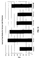
- Fig. 2 is a graph that depicts the illumination (as a function of mounting height of the trailing vehicle's low-beam headlamps) on a surface at the rearview mirror position of a leading vehicle, assuming no obstructions and based on the information set forth above.
- the graph of Fig. 2 illustrates the low-beam headlamp mounting height over the legal range, specified in FMVSS 108, of 0.56 meters to 1.37 meters.
- a typical passenger car may have headlamps mounted at about 0.62 meters.
- the glare on the rearview mirror of the leading vehicle is about 2.4 lux.
- the glare on the rearview mirror of the leading vehicle increases to 5.8 lux.
- FIG. 3 depicts three curves of road illumination as a function of distance for: a passenger car with low-beam headlamps mounted at 0.62 meters, a truck or SUV with low-beam headlamps mounted at 1 meter and a truck or SUV with low-beam headlamps mounted at 1 meter and aimed downward an additional 1.4 degrees.
- the downward aim reduces the visibility distance of the low-beam headlamps significantly.
- simply aiming the headlamps down is generally unacceptable during normal driving conditions, when no leading vehicle is present.
- SAE Society of Automotive Engineers
- Systems to vary the aim of headlamps are currently commercially available on many production vehicles. These systems typically use sensors in the axles of a vehicle to detect changes in road pitch and vary the aim of the headlamps to insure a constant visibility distance.
- Other systems provide motors for adjustment of the aim of the headlamps, but rely on the driver to manually adjust the aim of the headlamps through a manual adjustment knob located in the vehicle. Although such systems were not designed or used in conjunction with a means to detect a leading vehicle to automatically reduce the angle of the headlamps, when such vehicles are detected, such systems can be used for this purpose.
- Such a leading vehicle detection means may include a camera (i.e., an array of sensors) and an image processing system as is described in U.S. Patent No. 6,281,632 entitled “CONTINUOUSLY VARIABLE HEADLAMP CONTROL,” issued August 28, 2001, to Joseph S. Stam et al., and PCT Application No. PCT/US01/08912 , entitled “SYSTEM FOR CONTROLLING EXTERIOR VEHICLE LIGHTS,” published September 27, 2001 ( WO 01/70538 ).
- Such systems are capable of detecting the tail lamps of leading vehicles and may determine the approximate distance to a leading vehicle by the brightness of the tail lamps in an image or by the separation distance between the two tail lamps of the leading vehicle. Since tail lamps are typically mounted below the rear window of most vehicles, the tail lamps' position in the image can also be used to determine if excess glare is likely to be projected into the rearview mirror of the leading vehicle.
- Fig. 4 depicts a leading vehicle 402 (with tail lamps located 1 meter above the road) whose rearview mirror is 15 meters ahead of low-beam headlamps of a trailing vehicle (not shown).
- the angle between the tail lamps of the leading vehicle and the camera of the trailing vehicle can be determined from the position of the tail lamps in the image. It should be appreciated that the difference in mounting height between a camera mounted within a vehicle and low-beam headlamps of the vehicle is fixed and, therefore, can be known for any given vehicle.
- the distance to the leading vehicle can be determined in a number of ways. For example, the distance to the leading vehicle can be estimated by the brightness of the tail lamps of the leading vehicle in the image.
- the distance between the two tail lamps can be used to estimate the distance to the leading vehicle.
- brightness can be used to estimate the distance between the trailing and leading vehicles.
- other devices for determining distance such as a radar, laser or ultrasonic sensors, may be used.
- Such systems are already incorporated in many production vehicles for use in conjunction with, for example, parking aids and adaptive cruise control systems. For an example of one such system see U.S. Patent No. 6,403,942 , entitled "AUTOMATIC HEADLAMP CONTROL SYSTEM UTILIZING RADAR AND AN OPTICAL SENSOR.”
- the angle between the controlled vehicle's headlamps and the leading vehicle can be determined.
- a detailed method for analyzing an image to determine the location of light sources within an image is set forth in PCT Application No. PCT/US01/08912 . Then, if the trailing vehicle is close enough to the leading vehicle for glare to disrupt the driver of the leading vehicle, the aim of the headlamps can be set downward to a level which does not cause disruptive glare (alternatively, or in addition, the intensity of the headlamps may be adjusted).
- the headlamps of the trailing vehicle can be aimed normally for proper road illumination.
- Modifications to the above discussed may include a variety of methods for reducing the intensity of light directed towards the detected light source. These methods include, but are not limited to: modifying the horizontal direction aim of the headlamps, modifying the vertical direction aim of the headlamps, modifying the intensity of the headlamps, enabling or disabling one of a plurality of exterior lights and selectively blocking or attenuating light from the exterior lights in the direction of the detected light source.
- Low-beam headlamps which are designed to prevent glare to on-coming drivers, are typically aimed 1.5 degrees downward and about 1.5 degrees right, with a sharp reduction in intensity above the peak.
- variations in the road and in vehicle loading can regularly cause the peak of these headlamps to shine directly into the eyes of an on-coming driver. This problem becomes much more severe with new technology headlamps, such as high-intensity discharge (HID) headlamps, and, as a result, various groups have attempted to design systems that perform active leveling of these brighter headlamps.
- HID high-intensity discharge
- Prior automatic headlamp leveling systems are improved by sensing the actual beam pattern, provided by, for example, the low-beam headlamps, on the road separately, or in combination with the sensing of the vehicle's pitch.
- the desired illumination range may be constant or may be a function of the current vehicle speed, ambient light level, weather conditions (rain/fog/snow), the presence or absence of other vehicles, the type of roadway or other vehicle and/or environmental conditions. For example, a driver of a vehicle traveling at a high rate of speed may benefit from a longer illumination range, while drivers traveling in fog may benefit from headlamps aimed lower.
- road reflectance is generally variable, it is not normally sufficient to look only at the illumination on the road to determine the illumination range. Rather, it is generally useful to look at the light level gradient with increasing distance on the road surface.
- road illumination decreases as the distance from the vehicle increases.
- the current aim of the headlamps can be determined and adjusted to provide a desired illumination range.
- a vertical linear array of photosensors can be used to image road illumination and, thus, provide the road illumination gradient.
- reflections from lane markings are used to indicate when a road bend is ahead of the controlled vehicle such that a direction of the headlamps of the controlled vehicle is controlled to bend with the road.
- Adaptive front lighting systems are a new generation of forward lighting systems, which contain a variety of technologies for improving a vehicle's forward illumination.
- AFS lighting systems may include, for example, the following illumination modes:
- the goal of a typical AFS lighting system is to provide automatic selection of the different lighting modes. For example, rain sensing or fog sensing can be used to activate bad weather lights and steering wheel angle can be used to activate bending lights.
- the activation of the other illumination modes is not as straight forward. That is, activation of motorway lighting modes and town lighting modes requires a knowledge of the environment. Vehicle speed can be used to activate town lighting; however, it is possible that the illumination range may be unnecessarily reduced when traveling at a low speed out of town. Also, ambient light level may be a useful indication of traveling in a town.
- 09/800,460 entitled "SYSTEM FOR CONTROLLING EXTERIOR LIGHTS," a vehicle including a global positioning system (GPS) with a map database indicating the types of roads on which a vehicle is traveling may be used to determine a proper mode of lighting.
- GPS global positioning system
- map data may not be available for all areas of the world.
- inaccuracies in GPS systems may occasionally cause such a system to incorrectly identify the road on which a vehicle is traveling.
- a town is detected through the use of an optical sensor.
- a discrete light sensor such as that described in PCT Application No. PCT/US00/00677 , entitled “PHOTODIODE LIGHT SENSOR,” by Robert H. Nixon et al. and published July 27, 2000 ( WO 00/43741 ) may be utilized.
- This sensor may be used to measure the ambient light and also measure the 120 Hz (or 100 Hz in Europe) intensity ripple component, produced by discharge street lighting powered by a 60 Hz AC source, by obtaining several light level measurements during different phases of the intensity ripple. If there is a significant AC component in the ambient light level and the vehicle speed is low (for example, less than 30 mph) it is likely that the vehicle is traveling in a town with significant municipal lighting and town lighting can be activated.
- town driving conditions can be accurately determined.
- the magnitude of the AC component may be used in combination with the ambient light level and the vehicle's speed to make a proper determination of the use of town lighting. For example, if the ambient light level is sufficient such that there would not be a significant safety risk from the reduced illumination range, the speed of the vehicle is indicative of driving in a town (e.g., below about 30 mph) and there is a significant AC component in the ambient lighting, town lighting may be activated.
- the transition from normal low-beam lighting to town lighting may be continuous with the illumination range being a continuous function of ambient lighting and vehicle speed so as to produce a sufficient illumination range for given conditions.
- a sensor array such as an image sensor, may be used to identify street lamps and activate town lighting if the number of streetlamps detected in a period of time exceeds a threshold (along with consideration of the vehicle's speed and ambient lighting).
- the light sensor may be provided in various places throughout a motor vehicle, e.g., provided in a rearview mirror housing. Further, such a light sensor may also be used for various other functions (e.g., sun load), such as those set forth in U.S. Patent No. 6,379,013 , entitled “VEHICLE EQUIPMENT CONTROL WITH SEMICONDUCTOR LIGHT SENSORS.”
- Motorway conditions can be also be determined by using an image sensor to detect the lane separation or median of a motorway. This can be accomplished by directly looking at the angular movement of the headlamps of on-coming vehicles in several subsequent images. The detection of the movement of an object in a series of images is further described in U.S. Patent Application Serial No. 09/799,310 entitled "IMAGE PROCESSING SYSTEM TO CONTROL VEHICLE HEADLAMPS OR OTHER VEHICLE EQUIPMENT,” filed March 5, 2001, to Joseph S. Stam et al. Fig.
- FIG. 5 illustrates three curves, which represent different motorway median widths, and how the position of an on-coming headlamp in an image varies as a function of the distance between two vehicles that are traveling in different directions are converging.
- Fig. 6A schematically illustrates an exemplary high-performance headlamp, commonly referred to as a projector headlamp, which is utilized in conjunction with a mask 603.
- a bulb 602 is placed in front of a reflector 601.
- the bulb 602 may be of a conventional incandescent (e.g., tungsten-halogen) type, high-intensity discharge (HID) type or other suitable bulb type, or may be the output from a remote light source as is described further below.
- a lens 604 directs light from the bulb 602 and reflected by the reflector 601 down the road.
- the mask 603 establishes a cutoff point to prevent light above the horizon 605 from being directed down the road.
- the mask 603 absorbs or reflects light rays, such as light ray 607, which would cause glare to another vehicle.
- the mask 603, typically, has a shape, such as that shown in Fig. 6B , which contains a step allowing a slightly higher cutoff point to the right of the vehicle.
- a modification to this type of lamp construction includes a solenoid to control the mask 603.
- the mask 603 can be removed from the position in front of the bulb 602.
- rays such as the ray 607
- the lamp with mask 603 removed can function as a high-beam headlamp.
- the mask 603 may also be controlled by a motor to move vertically relative to the bulb 602, lens 604 and reflector 601, as shown in Fig. 6C .
- a motor to move vertically relative to the bulb 602, lens 604 and reflector 601, as shown in Fig. 6C .
- the cutoff angle is raised and the illumination range is extended.
- the cutoff angle is lowered and illumination range is reduced.
- the movement of the mask 603 can be used to establish different lighting functions, such as town or motorway lighting, or to increase the illumination range gradually with increased speed. Additionally, the movement of the mask 603 can also be used to establish the vertical aim of the headlamp and therefore compensate for vehicle pitch variations as described herein above. This method of aiming the headlamp is advantageous because only the relatively small mask 603 requires movement, rather than the entire lamp set which is moved in some auto-leveling systems today.
- the mask 603 is replaced with a spatially controlled variable attenuating filter.
- This filter can be formed as an electrochromic variable transmission window, which has the capability to selectively darken various regions of the window.
- This window may contain a liquid or solid state (e.g., tungsten oxide) electrochromic material that is capable of withstanding the high temperatures achieved in close proximity to the bulb.
- this window may be a liquid crystal device (LCD), a suspended particle device or other electrically, chemically or mechanically variable transmission device.
- LCD liquid crystal device
- a suitable electrochromic device is disclosed in U.S. Patent No. 6,020,987 entitled "ELECTROCHROMIC MEDIUM CAPABLE OF PRODUCING A PRE-SELECTED COLOR.”
- variable transmission device 700 An example of such a variable transmission device 700 is shown in Figs. 7A and 7B .
- the device 700 is constructed using two pieces of glass with electrochromic material contained between.
- a transparent conductive electrode such as indium tin oxide (ITO)
- ITO indium tin oxide
- these regions are horizontal strips 701, which may optionally contain a slight step.
- the window 700 may contain several independently controlled blocks 702 as shown in Fig. 7B .
- distinct beam patterns may be achieved in various manners, e.g., changing the intensity or one or more light sources, changing the aiming direction of one or more light sources, changing the distribution of light provided by one or more light sources and/or activating multiple light sources in combination.
- mask 603 may be constructed as a spatially controlled reflector.
- a reflector may be a reversible electro-chemical reflector, such as that described in U.S. Patent Nos. 5,903,382 ; 5,923,456 ; 6,166,847 ; 6,111,685 and 6,301,039 .
- a reflective metal is selectively plated and de-plated on a surface to switch between a reflective and transmissive state.
- a metal-hydride switchable mirror available from Phillips electronics, may also be used to provide a spatially controlled reflector.
- the spatially controlled reflector may be formed as a single contiguous reflector, allowing for a switch from high to low-beam or may be patterned, such as in Figs. 7A and 7B , to allow activation of individual segments of the mirror and, thus, provide spatial control of the transmitted beam.
- the use of a spatially controlled mirror provides the advantage that a reflective device reflects light rays 607 back into reflector 601 and, thus, these rays are conserved, rather than absorbed and, as such, are available to be projected in other areas of the beam. This provides a headlamp with improved efficiency, as compared to headlamps that absorb light rays to provide a desired illumination pattern. Additionally, by reflecting light rays, rather than absorbing the light rays, the mask may not become as hot and, thus, the headlamp becomes potentially more robust.
- a spatially controlled reflector may be used to construct a headlamp in accordance with Fig. 9 .
- a bulb 901 and reflector 902 form a light source, which projects incident rays 906 onto a spatially controlled reflector 903.
- the light source may be any type of light source suitable for automotive use, such as a halogen source, a high-intensity discharge (HID) source or a light emitting diode (LED) source.
- Incident rays 906 may also come from a remote light source through a fiber bundle or light pipe.
- the spatially controlled reflector 903 contains a plurality of switchable mirrors 905, which can be turned on and which reflect incident rays 906 (as reflected rays 907), which are then projected by lens 904 down the road.
- the incident rays 906 When turned off, the incident rays 906 are reflected away from the lens 904, transmitted through the reflector 903 or absorbed and, thus, not projected by the lens 904. Alternatively, the rays may be redirected to increase the illumination of other portions of a headlamp beam.
- the spatially controlled reflector may be, for example, a custom designed digital micro-mirror device (DMD) available from Texas Instruments.
- DMDs are micromachined arrays of tiny mirrors which can be switched between two angles and are currently widely used for video projectors.
- the application of a DMD to produce a spatially configurable headlamp is analogous to that of a video projector.
- high resolution, variable color and video frame rates that are necessary for video projectors are not necessary in a headlamp that utilizes a DMD.
- a control system for a headlamp can be simpler than a control system for a video projector.
- the spatially controlled reflector may be constructed as a reversible electro-chemical reflector or a metal-hydride switchable mirror as described above.
- a solid mirror with a patterned attenuating filter such as an electrochromic filter or LCD placed in front of the mirror may be used to provide the same function.
- controllable reflectors and/or attenuators may be used to select a beam pattern, based upon one or more driving conditions, at which point a control unit (based upon input received from a sensor array) may cause the reflector and/or attenuator to redirect or inhibit light that would cause glare to a sensed object.
- systems implementing a control unit in conjunction with a sensor array are configurable to distinguish between reflected light and light from another light source, through manipulation of a light source or sources of a controlled vehicle headlamp.
- the light source(s) of the headlamp embodiments of Figs. 8 and 9 can be cycled such that reflected light can be distinguished from light from another light source.
- the embodiment of Figs. 7A-7B may also be cycled to distinguish reflected light from light from another light source.
- the headlamp of Fig. 9 generally functions in a similar manner as the previously described headlamps.
- the lamp can provide a basic low-beam function and/or provide high-beams, bending lamps, motorway lighting, bad weather lighting or any intermediate state.
- mirrors when used with a camera to detect the direction to other vehicles, mirrors can be turned off to prevent light rays in that direction from being projected and, thus, glaring the other vehicle.
- the mirrors may be controlled such that reflected light, e.g., a non-vehicular light source can be distinguished from light provided by another light source, e.g., a vehicular light source.
- FIG. 8 Yet another headlamp configuration is described with reference to Fig. 8 .
- the reflector 601, bulb 602, and mask 603 are replaced by a high-intensity LED array 801, which is placed approximately in the focal plane of the lens 604.
- High intensity LED arrays suitable for use as automotive headlamps are described in PCT application PCT/US01/08912 , and in U.S. Patent Application 09/835,238 to Roberts et al., filed April 13, 2001 . These arrays may produce white light illumination through a binary-complementary combination of amber and blue-green LED emitters.
- LEDs 802 or groups of LEDs 802 in the LED array 801 are configured to be independently, and optionally variably, energized by electronic control unit.
- the light from LEDs 802 (or groups of closely spaced LEDs) is projected to a particular region in front of the lamp by the lens 604.
- a desired beam pattern can be achieved in a fashion similar to that achieved by selectively darkening various blocks 702 as described with respect to Fig. 7B .
- all LEDs below a cutoff point may be energized to produce a desired illumination range.
- LEDs which project light in the direction of the identified vehicle may be shut off or reduced in intensity to prevent glare to the vehicle. All other LEDs may remain lit to provide illumination in regions where no vehicles are present.
- a portion of the LEDs can be dimmed or turned off to distinguish on-coming vehicles from other light sources, such as reflectors.
- the above described headlamps provide a controllable and reconfigurable beam pattern. These headlamps may be used with the methods described above to provide a fully automatic vehicle forward light system, which can provide numerous functions, including: low-beams, high-beams, motorway lighting, town lighting, bad weather lighting, bending lamps, auto leveling and anti-glare control to prevent glare to on-coming or preceding drivers. These particular lighting modes are only exemplary and control may switch between discrete modes or may be continuous.
- a variety of sensors may provide input to a control system to determine the appropriate beam pattern for the given driving conditions.
- These sensors may include, for example, a camera, ambient light sensor, speed sensor, steering wheel angle sensor, temperature sensor, compass, a navigation system (e.g., a land-based (such as Loran) or satellite-based (such as GPS), pitch sensors and various user input switches.
- a driver input may be provided for setting various preferences, such as the thresholds for switching between various beam patterns, the brightness of the lamps, the sharpness of beam cutoffs, the color of the lamps, the degree of bending, etc.
- a GPS, user input or factory setting may be provided to indicate the location of the vehicle to ensure compliance with various laws. Thus, identical lamp assemblies may be used in various countries with a simple selection of location.
- control methods described herein may be utilized with the lamps described here in or with other lamp types. Similarly, the lamps described herein may be controlled by a variety of methods. Finally, the lamps described herein may be used alone, in any number or configuration, or in conjunction with standard lamps, fixed bending lamps, fog lamps, foul weather lamps or other types of lamps. The control methods may control both the configurable lamps and any other type of lamp.
- Various external vehicle lights are used, such as high-intensity discharge (HID) headlamps, tungsten-halogen and blue-enhanced halogen headlamps, to provide greater ability to distinguish reflections from various roadside reflectors and signs from headlamps of on-coming vehicles and tail lamps of leading vehicles. Additionally, specific spectral filter material may be employed in combination with the external vehicle lights to produce desired results.
- HID high-intensity discharge
- tungsten-halogen and blue-enhanced halogen headlamps to provide greater ability to distinguish reflections from various roadside reflectors and signs from headlamps of on-coming vehicles and tail lamps of leading vehicles.
- specific spectral filter material may be employed in combination with the external vehicle lights to produce desired results.
- Fig. 10 depicts plots of the spectral content of different types of vehicular related light sources and Fig. 11 depicts plots of the spectral reflectance of various colored signs.
- Fig. 12 depicts plots of the percent transmission of red and infrared spectral filters used in one embodiment of the present invention and
- Fig. 13 depicts a plot of the quantum efficiency of an optical system in accordance with an embodiment of the present invention. Numerical data depicted by the plots of Figs. 10-13 is utilized, as described in further detail below, to categorize various light sources.
- the brightness of a given detected light source can be estimated by multiplying the spectral output of the source, as shown in Fig. 10 , by the infrared spectral filter transmission factor, as shown in Fig. 12 , multiplied by the spectral response of the pixel array, as shown in Fig. 13 .
- this value is further multiplied by the transmission factor of the red spectral filter.
- the brightness of detected reflections from road signs can be estimated by multiplying the controlled vehicle's headlamp spectral output, as shown in Fig. 10 , by the spectral reflectance factor of the sign, as shown in Fig. 11 , the infrared spectral filter transmission factor, as shown in Fig. 12 , and the spectral response of the optical system, as shown in Fig. 13 .
- the preceding result is then multiplied by the red spectral filter transmission factor, as shown in Fig. 12 .
- the ratio in brightness between the object projected onto the red filtered pixels in relation to the object projected onto the non-red filtered pixels can be used to determine the relative redness of an object. This ratio can then be utilized to determine if the object is a tail lamp or a headlamp.
- Fig. 14 depicts the computed ratios of the brightness of objects projected onto red filtered pixels relative to those same objects projected onto the non-filtered pixels. As is shown in Fig. 14 , tail lamps have a much higher red-to-clear ratio than headlamps, or most other objects.
- HIR halogen-infrared
- HIR bulbs have the advantage of emitting less red light as a percentage of their total output, as shown in Fig. 10 .
- the image of signs reflecting light will have a lower brightness on red filtered pixels than on non-red filtered pixels.
- Other light sources which emit less red light in proportion to the total amount of light, may be advantageously used to minimize the false detection of road signs and reflections off of other objects; HID high-beam lights and LED headlamps are examples of such sources.
- white light sources such as headlamps
- Light sources with a high color temperature have a more bluish hue and are, misleadingly, typically called “cool-white light” sources.
- Light sources with a more yellow or orangish hue have a lower color temperature and are, also misleadingly, called “warm white light” sources.
- Higher color temperature light sources have a relatively higher proportion of short wavelength visible light to long wavelength visible light.
- One can benefit from the use of higher color temperature headlamps due to the reduced proportion of red light that will be reflected by signs or other objects that could potentially be detected.
- Correlated color temperature for non-perfect Planckian sources can be estimated by computing the color coordinates of the light source and finding the nearest temperature value on the Planckian locus. Calculation of color coordinates is well known in the art.
- the text entitled MEASURING COLOUR, second edition, by R. W. G. Hunt is one source for known teachings in the calculation of color coordinates.
- HID high-intensity discharge
- Fig. 15A schematically illustrates a headlamp 1500, which includes a rotatable mask 1503 and a bulb 1502 that is positioned in front of a reflector 1501.
- the bulb 1502 may be of a conventional incandescent (e.g., tungsten-halogen) type, high-intensity discharge (HID) type or other suitable bulb type, or may be the output from a remote light source as is described above.
- a lens 1504 directs light from the bulb 1502 and reflected by the reflector 1501 down the road.
- the mask 1503 establishes a cutoff point to prevent light vertically above the horizon 1505 from being directed down the road.
- the mask 1503 absorbs or reflects light rays, such as light ray 1507, which may cause glare to another vehicle and allows an illumination pattern provided by the headlamp 1500 to be changed.
- the mask 1503 may have a number of different shapes, such as the oval shown in Fig. 15B , and may be implemented as an irregular cylinder that is coupled to a motor M, e.g., a stepper-motor, off-center so as to achieve a variable illumination pattern as the mask 1503 is rotated, i.e., the mask 1503 changes how much light is blocked as it is rotated. In this manner, the mask 1503 can provide an oblong profile in the vertical direction, when the mask 1503 is implemented as an oval cylinder.
- a motor M e.g., a stepper-motor
- a control unit receives electrical signals from a sensor array and controls the rotated position of the mask 1503, by sending control signals to the motor M, to achieve a desired illumination pattern.
- a homing or feedback technique may be employed to assure that the mask 1503 is in a known position and, thus, able to provide a desired illumination pattern.
- the rotation of the mask 1503 can be used to establish a vertical aim of the headlamp 1500, vehicle pitch variation compensation, as described herein above, can also be achieved. This technique of aiming a headlamp is advantageous as only the relatively small mask 1503 requires movement, rather than the entire lamp set which is moved in some commercially available auto-leveling systems.
- Fig. 16A schematically illustrates a headlamp 1600, which includes a rotatable mask 1603 that includes a plurality of profiles, according to another embodiment of the present invention. These profiles allow an illumination pattern to be controlled in both horizontal and vertical directions.
- the headlamp 1600 includes a bulb 1602 that is placed in front of a reflector 1601.
- the bulb 1602 may be of a conventional incandescent (e.g., tungsten-halogen) type, high-intensity discharge (HID) type or other suitable bulb type, or may be the output from a remote light source as is described above.
- a lens 1604 directs light from the bulb 1602 and reflected by the reflector 1601 down the road.
- the mask 1603 establishes a cutoff point to prevent light above the horizon 1605 from being directed down the road.
- the mask 1603 absorbs or reflects light rays, such as light ray 1607, which would cause glare to another vehicle.
- Light rays, such as light ray 1606, which project below the cutoff point, pass through the lens 1604 as they are not blocked by the mask 1603.
- the mask 1603 may simultaneously have a number of different incorporated profiles, such as the profiles shown in Figs. 16B and 16C , and is coupled to a motor M, e.g. a stepper-motor, at an end so as to achieve a variable illumination pattern as the mask 1603 is rotated to select a desired profile. For example, by providing different horizontal profiles one can effect where light is aimed, e.g., left or right, and/or change the width of a light beam. Similar to the headlamp 1500, the headlamp 1600 may function with a control unit that receives electrical signals from a sensor array and controls the rotated position of the mask 1603, by sending control signals to the motor M, to achieve a desired illumination pattern. It should be appreciated that a homing or feedback technique may also be employed to assure that the mask 1603 is in a known position and, thus, able to provide a desired illumination pattern.
- a homing or feedback technique may also be employed to assure that the mask 1603 is in a known position and, thus, able to
- the rotation of the mask 1603 can also be used to establish different lighting functions, such as town or motorway lighting, or to increase the illumination range gradually with increased speed. Additionally, the rotation of the mask 1603 can also be used to establish both vertical and horizontal aim of the headlamp and therefore also compensate for vehicle pitch variations, as described herein above. This method of aiming the headlamp is also advantageous due to the fact that only the relatively small mask 1603 requires rotation.
Claims (9)
- Système de commande (40) pour commander au moins un feu de véhicule extérieur (22) d'un véhicule à moteur commandé, le système comprenant :un module de commande (44) en communication avec l'au moins un feu de véhicule extérieur, le module de commande (44) pouvant être opéré pour :recevoir une image d'un champ de vision avant du véhicule à moteur d'un capteur d'image ; etanalyser l'image reçue pour détecter des réflexions de marquages de voie pour détecter lorsqu'un virage est devant le véhicule à moteur ;dans lequel une direction de l'au moins un feu de véhicule extérieur (22) du véhicule à moteur commandé est commandée pour se courber avec la route,dans lequel le module de commande (44) peut en outre être opéré pour :regarder un gradient d'éclairement sur la route avec une distance croissante sur la surface routière ;comparer une plage d'éclairement réelle à une plage d'éclairement souhaitée ; etcompenser la variance en ajustant la cible de l'au moins un feu de véhicule extérieur (22).
- Système de commande (40) selon la revendication 1, dans lequel la plage d'éclairement souhaitée est constante.
- Système de commande (40) selon la revendication 1, dans lequel la plage d'éclairement souhaitée est une fonction de conditions du véhicule et/ou environnementales.
- Système de commande (40) selon l'une quelconque des revendications 1 à 3, dans lequel le module de commande (44) peut en outre être opéré pour :analyser l'image reçue en regardant une bande verticale de pixels correspondant à un angle horizontal particulier et une plage d'angles verticaux ;comparer le changement de luminosité en travers de la bande à une courbe appropriée en fonction d'une hauteur de montage de l'au moins un feu de véhicule extérieur (22) ; etdéterminer la cible de l'au moins un feu de véhicule extérieur (22).
- Système de commande (40) selon l'une quelconque des revendications 1 à 3, comprenant en outre un réseau linéaire vertical de capteurs optiques.
- Procédé de commande du feu avant (22) d'un véhicule à moteur, comprenant les étapes consistant à :recevoir une image d'un champ de vision avant du véhicule à moteur d'un capteur d'image ; etanalyser l'image reçue pour détecter des réflexions de marquages de voie pour détecter lorsqu'un virage est devant le véhicule à moteur ;dans lequel une direction de l'au moins un feu de véhicule extérieur (22) du véhicule à moteur commandé est commandée pour se courber avec la route,comprenant en outre les étapes consistant à :regarder un gradient d'éclairement sur la route avec une distance croissante sur la surface routière ;comparer une plage d'éclairement réelle à une plage d'éclairement souhaitée ; etcompenser la variance en ajustant la cible de l'au moins un feu de véhicule extérieur (22).
- Procédé selon la revendication 6, dans lequel la plage d'éclairement souhaitée est constante.
- Procédé selon la revendication 6, dans lequel la plage d'éclairement souhaitée est une fonction de conditions du véhicule et/ou environnementales.
- Procédé selon l'une quelconque des revendications 6 à 8, comprenant en outre les étapes consistant à :analyser l'image reçue en regardant une bande verticale de pixels correspondant à un angle horizontal particulier et une plage d'angles verticaux ;comparer le changement de luminosité en travers de la bande à une courbe appropriée en fonction d'une hauteur de montage de l'au moins un feu de véhicule extérieur (22) ; etdéterminer la cible de l'au moins un feu de véhicule extérieur (22).
Applications Claiming Priority (4)
| Application Number | Priority Date | Filing Date | Title |
|---|---|---|---|
| US33976201P | 2001-12-10 | 2001-12-10 | |
| US10/235,476 US6861809B2 (en) | 1998-09-18 | 2002-09-05 | Headlamp control to prevent glare |
| PCT/US2002/039365 WO2003053737A1 (fr) | 2001-12-10 | 2002-12-09 | Commande de phare avant pour eviter l'eblouissement |
| EP02786988.2A EP1451038B1 (fr) | 2001-12-10 | 2002-12-09 | Commande de phare avant pour eviter l'eblouissement |
Related Parent Applications (3)
| Application Number | Title | Priority Date | Filing Date |
|---|---|---|---|
| EP02786988.2A Division-Into EP1451038B1 (fr) | 2001-12-10 | 2002-12-09 | Commande de phare avant pour eviter l'eblouissement |
| EP02786988.2A Division EP1451038B1 (fr) | 2001-12-10 | 2002-12-09 | Commande de phare avant pour eviter l'eblouissement |
| EP02786988.2 Division | 2002-12-09 |
Publications (3)
| Publication Number | Publication Date |
|---|---|
| EP2463150A1 EP2463150A1 (fr) | 2012-06-13 |
| EP2463150B1 EP2463150B1 (fr) | 2018-07-25 |
| EP2463150B2 true EP2463150B2 (fr) | 2022-04-13 |
Family
ID=26928937
Family Applications (3)
| Application Number | Title | Priority Date | Filing Date |
|---|---|---|---|
| EP02786988.2A Expired - Lifetime EP1451038B1 (fr) | 2001-12-10 | 2002-12-09 | Commande de phare avant pour eviter l'eblouissement |
| EP12001598.7A Expired - Lifetime EP2463150B2 (fr) | 2001-12-10 | 2002-12-09 | Contrôle de phares pour empêcher l'éblouissement |
| EP12001596.1A Expired - Lifetime EP2463149B1 (fr) | 2001-12-10 | 2002-12-09 | Dipositif de contrôle de phare destiné à empêcher l' éblouissement. |
Family Applications Before (1)
| Application Number | Title | Priority Date | Filing Date |
|---|---|---|---|
| EP02786988.2A Expired - Lifetime EP1451038B1 (fr) | 2001-12-10 | 2002-12-09 | Commande de phare avant pour eviter l'eblouissement |
Family Applications After (1)
| Application Number | Title | Priority Date | Filing Date |
|---|---|---|---|
| EP12001596.1A Expired - Lifetime EP2463149B1 (fr) | 2001-12-10 | 2002-12-09 | Dipositif de contrôle de phare destiné à empêcher l' éblouissement. |
Country Status (9)
| Country | Link |
|---|---|
| US (2) | US6861809B2 (fr) |
| EP (3) | EP1451038B1 (fr) |
| JP (2) | JP2005512875A (fr) |
| KR (1) | KR100796698B1 (fr) |
| CN (1) | CN100387461C (fr) |
| AU (1) | AU2002351338A1 (fr) |
| CA (1) | CA2465782C (fr) |
| MX (1) | MXPA04005569A (fr) |
| WO (1) | WO2003053737A1 (fr) |
Families Citing this family (274)
| Publication number | Priority date | Publication date | Assignee | Title |
|---|---|---|---|---|
| US6822563B2 (en) | 1997-09-22 | 2004-11-23 | Donnelly Corporation | Vehicle imaging system with accessory control |
| US5877897A (en) | 1993-02-26 | 1999-03-02 | Donnelly Corporation | Automatic rearview mirror, vehicle lighting control and vehicle interior monitoring system using a photosensor array |
| US6891563B2 (en) | 1996-05-22 | 2005-05-10 | Donnelly Corporation | Vehicular vision system |
| US7655894B2 (en) | 1996-03-25 | 2010-02-02 | Donnelly Corporation | Vehicular image sensing system |
| US7029151B2 (en) * | 2001-05-25 | 2006-04-18 | Illume L.L.C. | Lamp masking method and apparatus |
| US7036966B2 (en) * | 2001-05-25 | 2006-05-02 | Illume, Inc. | Lamp masking method and apparatus |
| US20030137849A1 (en) * | 2002-01-22 | 2003-07-24 | Alden Ray M. | Segmented distribution headlight system, method, and apparatus |
| EP1504276B1 (fr) | 2002-05-03 | 2012-08-08 | Donnelly Corporation | Systeme de detection d'objets pour vehicule |
| US11208029B2 (en) | 2002-07-12 | 2021-12-28 | Yechezkal Evan Spero | Adaptive headlight system |
| ATE386951T1 (de) * | 2002-08-05 | 2008-03-15 | Elbit Systems Ltd | Nachtsichtabbildungssystem und -verfahren zur montage in einem fahrzeug |
| MXPA05001880A (es) | 2002-08-21 | 2005-06-03 | Gentex Corp | Metodos de adquisicion y procesamiento de imagen para control automatico de iluminacion exterior vehicular. |
| JP2004175252A (ja) * | 2002-11-28 | 2004-06-24 | Tokai Rika Co Ltd | 車両用点灯制御装置 |
| DE10315741A1 (de) * | 2003-04-04 | 2004-11-04 | Daimlerchrysler Ag | Vorrichtung zur Verbesserung der Sicht in einem Kraftfahrzeug |
| JP4979376B2 (ja) | 2003-05-06 | 2012-07-18 | ジェンテックス コーポレイション | 車両用バックミラー要素及びこれらの要素を組み込むアセンブリ |
| CN1910823A (zh) | 2003-05-19 | 2007-02-07 | 金泰克斯公司 | 包含免提电话部件的后视镜组件 |
| DE10330215A1 (de) * | 2003-07-03 | 2005-01-20 | Hella Kgaa Hueck & Co. | Scheinwerfer für Fahrzeuge |
| KR20050006913A (ko) * | 2003-07-10 | 2005-01-17 | 현대자동차주식회사 | 차량의 안개 검지 시스템 및 그 방법 |
| DE10335189A1 (de) * | 2003-07-30 | 2005-03-03 | Daimlerchrysler Ag | Vorrichtung zur Sichtverbesserung bei Kraftfahrzeugen |
| DE10355747B4 (de) * | 2003-08-28 | 2014-10-09 | Automotive Lighting Reutlingen Gmbh | Kraftfahrzeugscheinwerfer zur Erzeugung unterschiedlicher Leuchtfunktionen |
| CA2554955C (fr) * | 2004-02-04 | 2010-09-14 | Elbit Systems Ltd. | Synchronisation d'image |
| DE102004006133B4 (de) * | 2004-02-07 | 2006-11-23 | Bayerische Motoren Werke Ag | Vorrichtung zur Leuchtweitenregulierung eines Kraftfahrzeugs |
| US7526103B2 (en) | 2004-04-15 | 2009-04-28 | Donnelly Corporation | Imaging system for vehicle |
| JP4252938B2 (ja) * | 2004-07-07 | 2009-04-08 | 株式会社デンソー | 車両の車室照明装置 |
| US7881496B2 (en) | 2004-09-30 | 2011-02-01 | Donnelly Corporation | Vision system for vehicle |
| CA2585982C (fr) | 2004-11-18 | 2012-07-10 | Gentex Corporation | Systeme ameliore d'acquisition et de traitement d'images pour la commande d'equipements de vehicules |
| DE102005008850B4 (de) | 2005-02-26 | 2022-10-06 | Kostal Automobil Elektrik Gmbh & Co. Kg | Vorrichtung zum automatischen Ein- und Ausschalten von Beleuchtungseinrichtungen eines Kraftfahrzeugs |
| DE102005014953A1 (de) * | 2005-04-01 | 2006-10-05 | Audi Ag | Kraftfahrzeug mit einer Beleuchtungseinrichtung mit veränderbarem Ausleuchtvolumen |
| JP4497026B2 (ja) * | 2005-05-24 | 2010-07-07 | 日産自動車株式会社 | 車両用前照灯制御装置 |
| FR2887394B1 (fr) * | 2005-06-17 | 2015-04-17 | Valeo Vision | Procede et dispositif de gestion de ballast notamment pour projecteur de vehicule automobile |
| DE102006016073A1 (de) * | 2005-08-24 | 2007-03-22 | Dr.Ing.H.C. F. Porsche Ag | Verfahren zur Steuerung der Leuchtweite eines Kraftfahrzeuges |
| DE102005041991A1 (de) * | 2005-09-05 | 2007-03-15 | Robert Bosch Gmbh | Verfahren und Vorrichtung zum Steuern eines Scheinwerfers |
| US20070052555A1 (en) * | 2005-09-08 | 2007-03-08 | Visteon Global Technologies, Inc. | Predictive adaptive front lighting integrated system |
| US7417221B2 (en) * | 2005-09-08 | 2008-08-26 | Gentex Corporation | Automotive vehicle image sensor |
| FR2891511B1 (fr) * | 2005-09-30 | 2008-01-04 | Valeo Vision Sa | Systeme d'adaptation de l'eclairage d'un vehicule en fonction d'une situation de route et procede mis en oeuvre par ce systeme. |
| FR2892360B1 (fr) * | 2005-10-25 | 2009-05-15 | Valeo Vision Sa | Procede de controle d'une operation de commutation de faisceaux lumineux. |
| FR2892361B1 (fr) * | 2005-10-25 | 2009-05-15 | Valeo Vision Sa | Procede de commutation de faisceaux lumineux. |
| EP1991905B1 (fr) | 2006-03-09 | 2011-05-11 | Gentex Corporation | Ensemble retroviseur de vehicule comportant un afficheur haute densite |
| CN101411178B (zh) * | 2006-03-28 | 2011-10-05 | 京瓷株式会社 | 暗视装置 |
| JP2007276704A (ja) * | 2006-04-10 | 2007-10-25 | Denso Corp | 照明制御システム |
| JP4466607B2 (ja) * | 2006-05-09 | 2010-05-26 | 株式会社デンソー | 車両用灯火管理システムおよび車両用灯火管理装置 |
| TWI302879B (en) | 2006-05-12 | 2008-11-11 | Univ Nat Chiao Tung | Real-time nighttime vehicle detection and recognition system based on computer vision |
| US7604383B2 (en) * | 2006-06-29 | 2009-10-20 | Magna International | Reconfigurable headlamp and a control system for reconfiguring a vehicle lighting system |
| JP4853160B2 (ja) * | 2006-08-02 | 2012-01-11 | 株式会社デンソー | 車両検出装置及びヘッドランプ制御装置 |
| US7972045B2 (en) | 2006-08-11 | 2011-07-05 | Donnelly Corporation | Automatic headlamp control system |
| JP4609398B2 (ja) * | 2006-08-23 | 2011-01-12 | カシオ計算機株式会社 | 撮像装置及びプログラム |
| US8410402B2 (en) * | 2006-08-28 | 2013-04-02 | Dialight Corporation | Method and apparatus for using light emitting diodes for removing moisture |
| WO2008025436A1 (fr) * | 2006-08-29 | 2008-03-06 | Daimler Ag | Procédé et dispositif permettant d'éviter l'éblouissement d'autres usagers de la route |
| JP4697101B2 (ja) * | 2006-09-07 | 2011-06-08 | 株式会社デンソー | 車両検出装置、およびライト制御装置 |
| JP4484856B2 (ja) * | 2006-10-06 | 2010-06-16 | 日立オートモティブシステムズ株式会社 | 自動車用ヘッドライト制御装置 |
| JP4240110B2 (ja) * | 2006-10-31 | 2009-03-18 | トヨタ自動車株式会社 | 車両用照明装置、車両用照明制御方法、及び車両用照明制御プログラム |
| KR100836402B1 (ko) * | 2006-11-02 | 2008-06-09 | 현대자동차주식회사 | 차량에서의 하이빔 제어 장치 및 방법 |
| TW200821555A (en) | 2006-11-10 | 2008-05-16 | Macroblock Inc | Illuminating apparatus and brightness switching device thereof |
| FR2908705B1 (fr) | 2006-11-17 | 2009-07-17 | Valeo Vision Sa | Procede d'adaptation automatique d'un faisceau lumineux de dispositif projecteur. |
| JP4349414B2 (ja) * | 2006-12-15 | 2009-10-21 | トヨタ自動車株式会社 | 車両用照明装置 |
| JP4914234B2 (ja) * | 2007-01-31 | 2012-04-11 | 富士重工業株式会社 | 先行車両検出装置 |
| JP2008189276A (ja) * | 2007-02-08 | 2008-08-21 | Koito Mfg Co Ltd | 車両用ランプシステム |
| JP4508202B2 (ja) | 2007-02-14 | 2010-07-21 | 株式会社デンソー | 車両間情報伝達システム |
| JP4305548B2 (ja) * | 2007-03-01 | 2009-07-29 | 株式会社デンソー | ライト制御装置 |
| FR2915719B1 (fr) * | 2007-05-04 | 2015-05-15 | Valeo Vision | Procede de commande de l'orientation des projecteurs de vehicule |
| DE102007036697A1 (de) * | 2007-08-03 | 2009-02-05 | Lear Corp., Southfield | Optische Streuung eines Lichtstrahls |
| EP2026097A1 (fr) * | 2007-08-08 | 2009-02-18 | Harman Becker Automotive Systems GmbH | Système d'illumination pour véhicule |
| US20090052200A1 (en) * | 2007-08-22 | 2009-02-26 | Thomas Tessnow | Single source visible and IR vehicle headlamp |
| DE102007040042B4 (de) | 2007-08-24 | 2019-02-21 | HELLA GmbH & Co. KGaA | System zum Erzeugen eines Lichtbündels im Vorfeld eines Kraftfahrzeuges |
| JP4466701B2 (ja) * | 2007-09-10 | 2010-05-26 | 株式会社デンソー | ライト制御装置 |
| JP4458141B2 (ja) * | 2007-09-27 | 2010-04-28 | 株式会社デンソー | ライト制御装置 |
| JP5003398B2 (ja) * | 2007-10-10 | 2012-08-15 | 株式会社豊田中央研究所 | 照明装置 |
| DE102007048717A1 (de) * | 2007-10-11 | 2009-04-16 | GM Global Technology Operations, Inc., Detroit | Vorrichtung und Verfahren zum Reduzieren der Lichtblendung eines Fahrers eines Kraftfahrzeugs |
| TWI387241B (zh) * | 2007-11-22 | 2013-02-21 | Innovative Sonic Ltd | 提升無線資源控制程序重啟效率的方法及其通訊裝置 |
| JP2009132230A (ja) * | 2007-11-29 | 2009-06-18 | Omron Corp | 前照灯配光制御装置 |
| JP4613970B2 (ja) * | 2008-03-12 | 2011-01-19 | トヨタ自動車株式会社 | 車両用照明装置 |
| DE102008025458B4 (de) | 2008-05-28 | 2020-03-12 | HELLA GmbH & Co. KGaA | Verfahren und Vorrichtung zur Kalibrierung einer durch einen Frontscheinwerfer eines Fahrzeugs erzeugten horizontalen Hell-Dunkel-Grenze |
| DE102008031159A1 (de) | 2008-07-03 | 2010-01-07 | Adc Automotive Distance Control Systems Gmbh | Verfahren zur Dejustageerkennung eines Fahrzeugscheinwerfers mit einer Kamera |
| DE102008041355A1 (de) * | 2008-08-19 | 2010-02-25 | Robert Bosch Gmbh | Verkehrssituationsangepasste Licht-Energiesparfunktion |
| JP5138517B2 (ja) * | 2008-09-08 | 2013-02-06 | 株式会社小糸製作所 | 車両用前照灯、車両用前照灯の制御方法 |
| KR101014105B1 (ko) * | 2008-11-20 | 2011-02-14 | 주식회사 현대오토넷 | 차량용 헤드램프 제어 장치 |
| JP5051468B2 (ja) * | 2008-12-25 | 2012-10-17 | トヨタ自動車株式会社 | センサ校正装置、及び、センサ校正方法 |
| DE102008063328A1 (de) * | 2008-12-30 | 2010-07-01 | Hella Kgaa Hueck & Co. | Verfahren und Vorrichtung zum Ermitteln einer Änderung des Nickwinkels einer Kamera eines Fahrzeugs |
| US8935055B2 (en) * | 2009-01-23 | 2015-01-13 | Robert Bosch Gmbh | Method and apparatus for vehicle with adaptive lighting system |
| US20100265100A1 (en) * | 2009-04-20 | 2010-10-21 | Lsi Industries, Inc. | Systems and methods for intelligent lighting |
| DE102009024352A1 (de) * | 2009-06-09 | 2010-12-16 | Automotive Lighting Reutlingen Gmbh | Verfahren zum Betreiben einer Beleuchtungseinrichtung |
| DE102011081380A1 (de) | 2011-08-23 | 2013-02-28 | Robert Bosch Gmbh | Verfahren zur Steuerung einer Lichtaussendung eines Scheinwerfers eines Fahrzeugs |
| DE102009028344A1 (de) | 2009-08-07 | 2011-02-10 | Robert Bosch Gmbh | Verfahren und Vorrichtung zur abstandsbasierten Entprellung von Lichtcharakteristikwechseln |
| CN102470793B (zh) * | 2009-08-07 | 2016-08-24 | 罗伯特·博世有限公司 | 用于光特征变化的基于间距的去抖动的方法和装置 |
| DE102009028342A1 (de) | 2009-08-07 | 2011-02-17 | Robert Bosch Gmbh | Verfahren und Vorrichtung zur Aktivierung des Stadtlichts eines Fahrzeugs, abhängig von der Erkennung einer beleuchteten Gegend innerorts mittels einer Kamera |
| JP2011081967A (ja) * | 2009-10-05 | 2011-04-21 | Koito Mfg Co Ltd | 車両用前照灯 |
| EP2491297B8 (fr) * | 2009-10-22 | 2017-04-19 | Premium Electronic Co., Limited | Système de signalisation avec un rapport de contraste amélioré |
| US8970111B2 (en) * | 2010-03-02 | 2015-03-03 | Evolved Aircraft Systems, L.L.C. | Method and apparatus for automatically controlling airborne vehicle lighting systems |
| KR101172954B1 (ko) | 2009-12-23 | 2012-08-09 | 동의과학대학 산학협력단 | 차량등 자동제어 장치 및 방법 |
| DE102010010909A1 (de) * | 2010-03-10 | 2011-09-15 | Daimler Ag | Verfahren zum Justieren und/oder Kalibrieren einer optischen Einheit eines Fahrzeugs |
| KR101044359B1 (ko) * | 2010-05-20 | 2011-06-29 | 주식회사 와이즈오토모티브 | 차량의 데이터 통신 장치 |
| US9056584B2 (en) | 2010-07-08 | 2015-06-16 | Gentex Corporation | Rearview assembly for a vehicle |
| DE102010033351A1 (de) * | 2010-08-04 | 2012-02-09 | Audi Ag | Verfahren zur Kalibrierung eines wenigstens einen Scheinwerfer eines Kraftfahrzeugs ansteuernden Fahrzeugsystems |
| US8536997B2 (en) | 2010-08-12 | 2013-09-17 | General Electric Company | Vehicle lighting control apparatus and method |
| JP5348100B2 (ja) * | 2010-09-17 | 2013-11-20 | トヨタ自動車株式会社 | 前照灯装置、輝度制御方法 |
| US8905609B2 (en) | 2010-09-30 | 2014-12-09 | Osram Sylvania Inc. | Lighting system with shutter, reflector, primary light engine and a secondary light engine coupled to shutter |
| KR101232308B1 (ko) * | 2010-11-25 | 2013-02-13 | 에스엘 주식회사 | 헤드램프 제어장치 및 제어방법 |
| CH704278A1 (de) * | 2010-12-28 | 2012-06-29 | Regent Beleuchtungskoerper Ag | Leuchte. |
| US8433479B2 (en) * | 2011-02-09 | 2013-04-30 | Ford Global Technologies, Llc | Adaptive front-lighting system with fuzzy logic control |
| US8814373B2 (en) | 2011-02-28 | 2014-08-26 | Gentex Corporation | Rearview device support assembly |
| WO2012118749A1 (fr) | 2011-02-28 | 2012-09-07 | Gentex Corporation | Ensemble de support de rétroviseur |
| EP2495127B1 (fr) * | 2011-03-01 | 2014-07-30 | Autoliv Development AB | Système d'assistance au conducteur et procédé pour véhicule à moteur |
| DE102011006570A1 (de) * | 2011-03-31 | 2012-10-04 | Robert Bosch Gmbh | Verfahren und Steuergerät zum Übertragen von Daten über eine aktuelle Fahrzeugumgebung an ein Scheinwerfersteuergerät eines Fahrzeugs |
| DE102011006554A1 (de) * | 2011-03-31 | 2012-10-04 | Robert Bosch Gmbh | Verfahren und Vorrichtung zur Bereitstellung eines Signals für eine Lichtsteuerungseinheit |
| KR101356151B1 (ko) * | 2011-05-23 | 2014-01-24 | 에스엘 주식회사 | 차량용 헤드램프 및 그 제어 방법 |
| KR101344423B1 (ko) | 2011-06-08 | 2013-12-23 | 에스엘 주식회사 | 차량용 헤드램프 제어 장치 및 방법 |
| KR20120136720A (ko) * | 2011-06-09 | 2012-12-20 | 현대자동차주식회사 | 차량 전조등의 빔 패턴 제어 시스템 및 그 방법 |
| JP5758724B2 (ja) * | 2011-07-07 | 2015-08-05 | 株式会社小糸製作所 | 車輌用前照灯 |
| JP5454523B2 (ja) * | 2011-07-13 | 2014-03-26 | トヨタ自動車株式会社 | 車両配光制御装置 |
| DE102011108384A1 (de) * | 2011-07-22 | 2013-01-24 | Audi Ag | Scheinwerfer für ein Kraftfahrzeug |
| ES2401500B1 (es) * | 2011-09-23 | 2014-08-22 | Vanos, S.A. | Dispositivo y sistema luminoso. |
| KR101253475B1 (ko) * | 2011-09-29 | 2013-04-11 | 주식회사 만도 | 차량의 램프 제어 장치 및 방법 |
| US8801252B2 (en) * | 2011-10-28 | 2014-08-12 | Hyundai America Technical Center, Inc. | Multi-functional projector lamp shield and multi-functional projector embodying such a shield |
| DE102011055606A1 (de) * | 2011-11-22 | 2013-05-23 | Hella Kgaa Hueck & Co. | Verfahren und Steuergerät zum Steuern von Hauptscheinwerfern mit einstellbarer vertikaler Hell-Dunkel-Grenze zum Entblenden von Objekten |
| DE102012200040A1 (de) * | 2012-01-03 | 2013-07-04 | Robert Bosch Gmbh | Verfahren und Steuergerät zum Anpassen einer oberen Scheinwerferstrahlgrenze eines Scheinwerferkegels |
| US9316347B2 (en) | 2012-01-24 | 2016-04-19 | Gentex Corporation | Rearview assembly with interchangeable rearward viewing device |
| US10457209B2 (en) | 2012-02-22 | 2019-10-29 | Magna Electronics Inc. | Vehicle vision system with multi-paned view |
| US9319637B2 (en) | 2012-03-27 | 2016-04-19 | Magna Electronics Inc. | Vehicle vision system with lens pollution detection |
| FR2988807A1 (fr) * | 2012-03-30 | 2013-10-04 | Peugeot Citroen Automobiles Sa | Module optique avec cache mobile pour projecteur de vehicule |
| US8879139B2 (en) | 2012-04-24 | 2014-11-04 | Gentex Corporation | Display mirror assembly |
| KR101273448B1 (ko) * | 2012-05-29 | 2013-06-11 | 한국건설기술연구원 | 자동 휘도 조절 시스템 |
| US8983135B2 (en) * | 2012-06-01 | 2015-03-17 | Gentex Corporation | System and method for controlling vehicle equipment responsive to a multi-stage village detection |
| WO2013188523A1 (fr) | 2012-06-12 | 2013-12-19 | Gentex Corporation | Système de formation d'image de véhicule fournissant une indication de stabilité d'orientation à étages multiples |
| CN102745124A (zh) * | 2012-07-11 | 2012-10-24 | 孙伟 | 一种防止车辆前照灯眩目的装置和方法 |
| CN104335684B (zh) * | 2012-07-17 | 2017-02-22 | 皇家飞利浦有限公司 | 用于沿或逆交通方向选择性地发射光的照明装置和控制该照明装置的方法 |
| CN104583012B (zh) | 2012-08-02 | 2018-01-05 | 金泰克斯公司 | 用于响应于对小型卡车的检测来控制外部车辆灯的系统和方法 |
| US9511708B2 (en) | 2012-08-16 | 2016-12-06 | Gentex Corporation | Method and system for imaging an external scene by employing a custom image sensor |
| WO2014032042A1 (fr) | 2012-08-24 | 2014-02-27 | Gentex Corporation | Ensemble de rétroviseur spécifiquement formé |
| US9199574B2 (en) | 2012-09-11 | 2015-12-01 | Gentex Corporation | System and method for detecting a blocked imager |
| JP5948194B2 (ja) * | 2012-09-13 | 2016-07-06 | 株式会社小糸製作所 | 車両用灯具の制御方法および車両用灯具 |
| KR102023525B1 (ko) * | 2012-09-27 | 2019-09-20 | 엘지이노텍 주식회사 | 헤드 라이트 장치 및 이의 제어 방법 |
| US9707896B2 (en) | 2012-10-15 | 2017-07-18 | Magna Electronics Inc. | Vehicle camera lens dirt protection via air flow |
| US9398270B2 (en) | 2012-12-04 | 2016-07-19 | Gentex Corporation | Imaging system and method for detecting a bright city condition |
| US9327648B2 (en) | 2013-01-04 | 2016-05-03 | Gentex Corporation | Rearview assembly with exposed carrier plate |
| WO2014110124A1 (fr) | 2013-01-09 | 2014-07-17 | Gentex Corporation | Applique imprimée et son procédé |
| CN104938033B (zh) | 2013-01-25 | 2017-08-08 | 飞利浦灯具控股公司 | 照明设备和照明系统 |
| US9445057B2 (en) | 2013-02-20 | 2016-09-13 | Magna Electronics Inc. | Vehicle vision system with dirt detection |
| WO2014133868A1 (fr) | 2013-03-01 | 2014-09-04 | Gentex Corporation | Système d'imagerie de véhicule et procédé de classement d'objets au moyen d'une analyse de mouvement relatif |
| CN103192759B (zh) * | 2013-04-22 | 2016-02-03 | 长安大学 | 一种夜间会车用的面阵led车灯控制系统及其控制方法 |
| JP6214202B2 (ja) * | 2013-05-07 | 2017-10-18 | 株式会社小糸製作所 | 灯具ユニットおよび光偏向装置 |
| KR101478073B1 (ko) | 2013-08-07 | 2015-01-02 | 주식회사 만도 | 차량용 램프 제어 장치 및 그 램프 제어 방법 |
| KR101738995B1 (ko) | 2013-08-19 | 2017-05-23 | 젠텍스 코포레이션 | 에고 모션 검출을 구비한 촬상 시스템 및 방법 |
| WO2015026810A1 (fr) | 2013-08-19 | 2015-02-26 | Gentex Corporation | Système d'imagerie de véhicule et procédé permettant de faire la distinction entre des objets réfléchissants et des lumières d'un autre véhicule |
| KR101848451B1 (ko) | 2013-08-19 | 2018-04-12 | 젠텍스 코포레이션 | 차량 후미등과 점멸 적색 정지등을 구별하기 위한 차량 촬상 시스템 및 방법 |
| US9514373B2 (en) | 2013-08-28 | 2016-12-06 | Gentex Corporation | Imaging system and method for fog detection |
| WO2015034773A1 (fr) | 2013-09-04 | 2015-03-12 | Gentex Corporation | Ensemble rétroviseur de véhicule pour afficher des images |
| CN105555612B (zh) | 2013-09-24 | 2018-06-01 | 金泰克斯公司 | 显示镜组件 |
| EP3052341B1 (fr) | 2013-10-01 | 2021-12-01 | Gentex Corporation | Système et procédé permettant de commander les feux de véhicule extérieurs sur autoroutes |
| DE102013016761A1 (de) * | 2013-10-10 | 2015-04-16 | GM Global Technology Operations LLC (n. d. Gesetzen des Staates Delaware) | Verfahren zum Betrieb von Scheinwerfern eines Kraftfahrzeugs, Scheinwerfersystem sowie Kraftfahrzeug |
| KR101511853B1 (ko) | 2013-10-14 | 2015-04-13 | 영남대학교 산학협력단 | 단일 다중 노출 카메라를 이용한 야간 전방 차량 검출 및 위치 측정 시스템 및 방법 |
| CN105705353B (zh) | 2013-11-15 | 2018-05-01 | 金泰克斯公司 | 包括对颜色衰减进行动态补偿的成像系统 |
| TWI555654B (zh) * | 2013-11-20 | 2016-11-01 | 吳長洲 | 頭燈控制系統 |
| KR101565344B1 (ko) | 2013-12-13 | 2015-11-03 | 현대자동차주식회사 | 차량 연동 단말기 조명 제어 시스템 및 제어 방법 |
| KR101637342B1 (ko) | 2013-12-19 | 2016-07-07 | 에스엘 주식회사 | 차량용 램프 |
| EP3083330B1 (fr) | 2013-12-20 | 2018-04-04 | Gentex Corporation | Commande de feux de véhicule extérieurs |
| US9511715B2 (en) | 2014-01-31 | 2016-12-06 | Gentex Corporation | Backlighting assembly for display for reducing cross-hatching |
| KR20150098189A (ko) * | 2014-02-17 | 2015-08-27 | 이정용 | 자동차 전조등 조사각도 자동 조절장치 |
| US10705332B2 (en) | 2014-03-21 | 2020-07-07 | Gentex Corporation | Tri-modal display mirror assembly |
| US9834146B2 (en) | 2014-04-01 | 2017-12-05 | Gentex Corporation | Automatic display mirror assembly |
| KR101627569B1 (ko) | 2014-05-23 | 2016-06-07 | 에스엘 주식회사 | 차량용 램프 |
| RU2695009C2 (ru) * | 2014-05-28 | 2019-07-18 | Найс С.Р.Л. | Устройство для транспортных средств, позволяющее автоматизировать работу фар дальнего света, в комплекте с электронным блоком для снижения оптических искажений |
| CN104057872B (zh) * | 2014-06-08 | 2015-06-17 | 来安县新元机电设备设计有限公司 | 一种汽车前置灯光控制方法及系统 |
| JP6166225B2 (ja) * | 2014-06-10 | 2017-07-19 | トヨタ自動車株式会社 | 車両用前照灯制御装置 |
| KR101618557B1 (ko) | 2014-07-24 | 2016-05-18 | 에스엘 주식회사 | 차량용 램프 및 그 제어 방법 |
| DE102014217366A1 (de) * | 2014-09-01 | 2016-03-03 | Robert Bosch Gmbh | Verfahren und Vorrichtung zum Anpassen einer Helligkeit eines Scheinwerfers für ein Fahrzeug |
| WO2016044746A1 (fr) | 2014-09-19 | 2016-03-24 | Gentex Corporation | Ensemble rétroviseur |
| CN105590578A (zh) * | 2014-10-20 | 2016-05-18 | 深圳富泰宏精密工业有限公司 | 自动开启蓝光滤波器护眼系统及方法 |
| WO2016073848A1 (fr) | 2014-11-07 | 2016-05-12 | Gentex Corporation | Actionneur de miroir d'affichage plein écran |
| WO2016077583A1 (fr) | 2014-11-13 | 2016-05-19 | Gentex Corporation | Système de rétroviseur avec un dispositif d'affichage |
| FR3029144B1 (fr) * | 2014-11-27 | 2016-12-09 | Valeo Vision | Systeme d'aide a la conduite d'un vehicule pour la reduction de contraste lumineux |
| WO2016090126A2 (fr) | 2014-12-03 | 2016-06-09 | Gentex Corporation | Ensemble miroir d'affichage |
| USD746744S1 (en) | 2014-12-05 | 2016-01-05 | Gentex Corporation | Rearview device |
| KR102252468B1 (ko) | 2014-12-19 | 2021-05-18 | 에스엘 주식회사 | 차량용 램프 및 그 제어 방법 |
| KR20160074904A (ko) | 2014-12-19 | 2016-06-29 | 에스엘 주식회사 | 차량용 램프 및 그 제어 방법 |
| KR20160074903A (ko) | 2014-12-19 | 2016-06-29 | 에스엘 주식회사 | 차량용 램프 및 그 제어 방법 |
| KR102289747B1 (ko) | 2014-12-19 | 2021-08-13 | 에스엘 주식회사 | 차량용 램프 제어 장치 및 방법 |
| US9744907B2 (en) | 2014-12-29 | 2017-08-29 | Gentex Corporation | Vehicle vision system having adjustable displayed field of view |
| US9720278B2 (en) | 2015-01-22 | 2017-08-01 | Gentex Corporation | Low cost optical film stack |
| JP6495021B2 (ja) * | 2015-01-22 | 2019-04-03 | スタンレー電気株式会社 | 車両用灯具 |
| JP6517519B2 (ja) * | 2015-01-26 | 2019-05-22 | 株式会社小糸製作所 | 車両検出装置 |
| KR20160112429A (ko) | 2015-03-19 | 2016-09-28 | 에스엘 주식회사 | 차량용 램프 |
| JP6751707B2 (ja) * | 2015-03-26 | 2020-09-09 | 株式会社小糸製作所 | 車両用灯具 |
| US11230225B1 (en) * | 2015-04-06 | 2022-01-25 | Apple Inc. | Exterior lighting |
| US9995854B2 (en) | 2015-04-20 | 2018-06-12 | Gentex Corporation | Rearview assembly with applique |
| EP3297870B1 (fr) | 2015-05-18 | 2020-02-05 | Gentex Corporation | Dispositif de rétroviseur plein affichage |
| KR102135427B1 (ko) | 2015-06-22 | 2020-07-17 | 젠텍스 코포레이션 | 진폭-변조된 광의 깜박임을 보정하기 위해 스트리밍된 비디오 이미지를 처리하는 시스템 및 방법 |
| DE102015214332A1 (de) * | 2015-07-29 | 2017-02-02 | Conti Temic Microelectronic Gmbh | Lichtdiagnose mittels eines kamerasystems eines fahrzeugs |
| EP3344919B1 (fr) * | 2015-09-01 | 2019-10-09 | Lumileds Holding B.V. | Système d'éclairage et procédé d'éclairage |
| KR102394952B1 (ko) | 2015-09-02 | 2022-05-09 | 주식회사 에스엘라이팅 | 차량용 램프, 그리고 이에 적용되는 제어 방법 |
| KR20170027392A (ko) | 2015-09-02 | 2017-03-10 | 주식회사 에스엘라이팅 | 차량용 램프, 그리고 이에 적용되는 제어 방법 |
| FR3041073B1 (fr) * | 2015-09-15 | 2020-01-31 | Valeo Vision | Dispositif de projection de faisceau lumineux a ecran digital et projecteur muni d’un tel dispositif |
| USD797627S1 (en) | 2015-10-30 | 2017-09-19 | Gentex Corporation | Rearview mirror device |
| USD798207S1 (en) | 2015-10-30 | 2017-09-26 | Gentex Corporation | Rearview mirror assembly |
| US9994156B2 (en) | 2015-10-30 | 2018-06-12 | Gentex Corporation | Rearview device |
| EP3368374B1 (fr) | 2015-10-30 | 2023-12-27 | Gentex Corporation | Manette à bascule |
| USD800618S1 (en) | 2015-11-02 | 2017-10-24 | Gentex Corporation | Toggle paddle for a rear view device |
| JP6350555B2 (ja) * | 2016-02-10 | 2018-07-04 | トヨタ自動車株式会社 | 車両用ヘッドランプ配光制御装置及び方法 |
| US9651390B1 (en) * | 2016-02-25 | 2017-05-16 | Here Global B.V. | Mapping road illumination |
| CN107128239A (zh) * | 2016-02-29 | 2017-09-05 | 长城汽车股份有限公司 | 车辆、车辆的照明系统及其控制方法 |
| CN107128242A (zh) * | 2016-02-29 | 2017-09-05 | 长城汽车股份有限公司 | 车辆、车辆的照明系统及其控制方法 |
| CN107226026A (zh) * | 2016-03-23 | 2017-10-03 | 常州星宇车灯股份有限公司 | 基于dsp的近红外ccd夜视辅助照明系统 |
| USD845851S1 (en) | 2016-03-31 | 2019-04-16 | Gentex Corporation | Rearview device |
| USD817238S1 (en) | 2016-04-29 | 2018-05-08 | Gentex Corporation | Rearview device |
| CN105946710A (zh) * | 2016-04-29 | 2016-09-21 | 孙继勇 | 行车辅助装置 |
| CA3024860A1 (fr) * | 2016-05-21 | 2017-11-30 | JST Performance, LLC | Procede et appareil pour equipements d'eclairage de vehicule |
| US10025138B2 (en) | 2016-06-06 | 2018-07-17 | Gentex Corporation | Illuminating display with light gathering structure |
| DE102016009459A1 (de) * | 2016-08-03 | 2018-02-08 | Daimler Ag | Verfahren zur Bestimmung von Steuerparametern für Lichtquellen eines Fahrzeugscheinwerfers |
| WO2018031466A1 (fr) | 2016-08-08 | 2018-02-15 | Gentex Corporation | Système et procédé de traitement de données vidéo permettant la détection et l'élimination de sources de lumière scintillantes par le biais d'une commande d'exposition dynamique |
| CN109690347A (zh) * | 2016-09-15 | 2019-04-26 | 株式会社小糸制作所 | 传感器系统 |
| DE102016120222A1 (de) * | 2016-10-24 | 2018-04-26 | HELLA GmbH & Co. KGaA | Beleuchtungsvorrichtung für ein Fahrzeug sowie Verfahren zur Einstellung der Leuchtweite eines Scheinwerfers eines Fahrzeugs |
| CN106740427B (zh) * | 2016-12-05 | 2020-09-18 | 车音智能科技有限公司 | 车辆灯光控制提醒方法及装置 |
| USD809984S1 (en) | 2016-12-07 | 2018-02-13 | Gentex Corporation | Rearview assembly |
| USD854473S1 (en) | 2016-12-16 | 2019-07-23 | Gentex Corporation | Rearview assembly |
| JP2020505802A (ja) | 2016-12-30 | 2020-02-20 | ジェンテックス コーポレイション | オンデマンドスポッタービューを備えた全画面表示ミラー |
| EP3574447B1 (fr) | 2017-01-27 | 2023-10-11 | Gentex Corporation | Compensation d'image pour inclinaison de moto |
| WO2018170353A1 (fr) | 2017-03-17 | 2018-09-20 | Gentex Corporation | Système de caméra arrière à double affichage |
| FR3064223B1 (fr) * | 2017-03-21 | 2022-08-12 | Valeo Vision | Module d'emission lumineuse ameliore pour vehicule automobile |
| FR3065818B1 (fr) * | 2017-04-28 | 2019-04-26 | Valeo Vision | Module lumineux pour un vehicule automobile configure pour projeter un faisceau lumineux formant une image pixelisee |
| KR102202125B1 (ko) * | 2017-06-02 | 2021-01-13 | 현대모비스 주식회사 | 조향 정보를 이용한 배광 제어 장치 및 방법 |
| US10171943B1 (en) | 2017-06-12 | 2019-01-01 | Qualcomm Incorporated | System and method for utilizing an array of mobile devices for imaging and user equipment positioning |
| EP3647115B1 (fr) * | 2017-06-27 | 2023-03-22 | Koito Manufacturing Co., Ltd. | Système de phare de véhicule, et procédé de commande de phare de véhicule |
| AT519885B1 (de) * | 2017-07-03 | 2018-11-15 | Zkw Group Gmbh | Verfahren zur erzeugung einer variablen fernlicht-lichtverteilung und vorrichtung |
| CN109398220A (zh) * | 2017-08-18 | 2019-03-01 | 深圳市绎立锐光科技开发有限公司 | 车前大灯调节装置及系统 |
| KR20190033850A (ko) | 2017-09-22 | 2019-04-01 | 에스엘 주식회사 | 차량용 램프 |
| KR101968093B1 (ko) | 2017-09-22 | 2019-04-11 | 에스엘 주식회사 | 차량용 램프 |
| KR101968094B1 (ko) | 2017-09-22 | 2019-04-11 | 에스엘 주식회사 | 차량용 램프 |
| KR20190033854A (ko) | 2017-09-22 | 2019-04-01 | 에스엘 주식회사 | 차량용 램프 |
| AT519863B1 (de) * | 2017-09-27 | 2018-11-15 | Zkw Group Gmbh | Kraftfahrzeubeleuchtungsvorrichtung mit unterteilte Mikro-Eintrittsoptiken aufweisenden Mikrooptik-Systemen |
| EP3710745A1 (fr) | 2017-11-15 | 2020-09-23 | Lumileds Holding B.V. | Système d'éclairage doté d'un élément réflecteur à commande spatiale |
| KR102397537B1 (ko) | 2017-11-17 | 2022-05-13 | 에스엘 주식회사 | 차량용 램프 |
| KR101982503B1 (ko) | 2017-11-17 | 2019-05-28 | 에스엘 주식회사 | 차량용 램프 |
| KR102435180B1 (ko) | 2017-11-29 | 2022-08-23 | 에스엘 주식회사 | 차량용 램프 |
| KR102409841B1 (ko) | 2017-11-29 | 2022-06-16 | 에스엘 주식회사 | 차량용 램프 |
| DE212018000369U1 (de) | 2017-12-01 | 2020-08-14 | Gentex Corporation | System zur Identifizierung eines Fahrzeugbetriebsmodus |
| CN108045301A (zh) * | 2017-12-06 | 2018-05-18 | 广东雷腾智能光电有限公司 | 一种点阵式激光大灯防眩光控制系统及控制方法 |
| DE102017129946A1 (de) * | 2017-12-14 | 2019-06-19 | HELLA GmbH & Co. KGaA | Verfahren zur Erfassung von Fehleinstellungen der Hell-Dunkel-Grenze eines Scheinwerfers |
| KR101987289B1 (ko) | 2017-12-29 | 2019-06-11 | 에스엘 주식회사 | 차량용 램프 |
| DE102018200025A1 (de) * | 2018-01-02 | 2019-07-04 | Ford Global Technologies, Llc | Fahrzeugbeleuchtung |
| WO2019150391A1 (fr) * | 2018-02-02 | 2019-08-08 | Varroc Engineering Private Limited | Ensemble phare d'automobile |
| US11148582B2 (en) | 2018-02-02 | 2021-10-19 | Varroc Engineering Limited | Automobile headlight assembly |
| KR102014874B1 (ko) | 2018-02-27 | 2019-08-27 | 에스엘 주식회사 | 차량용 램프 |
| JP7110650B2 (ja) * | 2018-03-22 | 2022-08-02 | マツダ株式会社 | 車両用前照灯のスイッチ装置 |
| JP7184539B2 (ja) * | 2018-05-24 | 2022-12-06 | スタンレー電気株式会社 | 点灯制御装置、車両用灯具、および点灯制御方法 |
| US11034286B2 (en) * | 2018-09-10 | 2021-06-15 | Lumileds Holding B.V. | Adaptive headlamp system for vehicles |
| KR102091488B1 (ko) | 2018-09-21 | 2020-03-20 | 에스엘 주식회사 | 차량용 램프 |
| KR102160529B1 (ko) | 2018-09-21 | 2020-09-28 | 에스엘 주식회사 | 차량용 램프 |
| KR102619772B1 (ko) | 2018-10-31 | 2024-01-02 | 에스엘 주식회사 | 차량용 램프 |
| KR20200048900A (ko) | 2018-10-31 | 2020-05-08 | 에스엘 주식회사 | 차량용 램프 |
| CN109606081A (zh) * | 2018-11-09 | 2019-04-12 | 广东工业大学 | 一种智能车灯玻璃控制系统及其控制系统 |
| KR20200073026A (ko) | 2018-12-13 | 2020-06-23 | 에스엘 주식회사 | 차량용 램프 |
| KR20200079742A (ko) | 2018-12-26 | 2020-07-06 | 에스엘 주식회사 | 차량용 램프 |
| KR102543458B1 (ko) | 2018-12-26 | 2023-06-14 | 에스엘 주식회사 | 차량용 램프 |
| JP7056835B2 (ja) * | 2019-01-17 | 2022-04-19 | トヨタ自動車株式会社 | 車両用前照灯装置 |
| CN110285947B (zh) * | 2019-02-20 | 2020-11-27 | 北京工业大学 | 一种隧道照明的交通安全眩光的测算方法 |
| CN109760582B (zh) * | 2019-03-23 | 2020-06-19 | 吉林大学 | 一种基于车联网的会车防眩目车灯自动控制方法 |
| CN110107859A (zh) * | 2019-05-09 | 2019-08-09 | 张若晨 | 一种智能安全大灯的视觉控制系统、方法及汽车 |
| WO2020257606A1 (fr) | 2019-06-21 | 2020-12-24 | Flex-N-Gate Advanced Productdevelopment, Llc | Ensemble lampe à miroir commutable segmenté |
| US11198386B2 (en) * | 2019-07-08 | 2021-12-14 | Lear Corporation | System and method for controlling operation of headlights in a host vehicle |
| KR20210037239A (ko) | 2019-09-27 | 2021-04-06 | 에스엘 주식회사 | 차량용 램프 |
| EP3833161B1 (fr) * | 2019-12-06 | 2024-03-20 | ZKW Group GmbH | Dispositif d'éclairage pour un phare de véhicule automobile |
| CN110979158A (zh) * | 2019-12-23 | 2020-04-10 | 北京海纳川汽车部件股份有限公司 | 车辆及其车灯的控制方法与装置 |
| KR20210107344A (ko) | 2020-02-24 | 2021-09-01 | 에스엘 주식회사 | 차량용 램프 |
| US11485197B2 (en) | 2020-03-13 | 2022-11-01 | Lear Corporation | System and method for providing an air quality alert to an occupant of a host vehicle |
| JP2021154949A (ja) * | 2020-03-27 | 2021-10-07 | 本田技研工業株式会社 | 車両におけるコミュニケーション支援装置 |
| KR20210121461A (ko) | 2020-03-30 | 2021-10-08 | 에스엘 주식회사 | 차량용 시그널 램프 |
| CN111372363A (zh) * | 2020-04-09 | 2020-07-03 | 珠海格力电器股份有限公司 | 灯具的控制方法、设备、存储介质和灯具 |
| WO2022026594A1 (fr) * | 2020-07-30 | 2022-02-03 | Tesla, Inc. | Phare universel |
| US11315429B1 (en) | 2020-10-27 | 2022-04-26 | Lear Corporation | System and method for providing an alert to a driver of a host vehicle |
| KR102489327B1 (ko) * | 2020-12-10 | 2023-01-16 | 박석동 | Lcd 패턴판을 가지는 전조등 유닛 |
| CN112776706A (zh) * | 2020-12-24 | 2021-05-11 | 广州小鹏自动驾驶科技有限公司 | 一种车辆大灯控制方法和装置 |
| KR102487435B1 (ko) | 2021-01-11 | 2023-01-10 | 한국기술교육대학교 산학협력단 | 가변초점렌즈를 구비하는 차량의 전조등 |
| KR20220124431A (ko) | 2021-03-03 | 2022-09-14 | 에스엘 주식회사 | 차량용 램프 |
| JP7221319B2 (ja) | 2021-03-03 | 2023-02-13 | 本田技研工業株式会社 | ヘッドライト制御システム |
| CN113263976B (zh) * | 2021-06-22 | 2023-06-27 | Oppo广东移动通信有限公司 | 车辆灯光控制方法、装置、车辆终端以及服务器 |
| DE102021116809A1 (de) | 2021-06-30 | 2023-01-05 | Bayerische Motoren Werke Aktiengesellschaft | Kraftfahrzeug mit einer Projektionseinheit und Verfahren zum Betreiben eines Kraftfahrzeugs |
Citations (4)
| Publication number | Priority date | Publication date | Assignee | Title |
|---|---|---|---|---|
| US5562336A (en) † | 1995-02-07 | 1996-10-08 | Honda Giken Kogyo Kabushiki Kaisha | Head lamp device for vehicle |
| EP0869031A2 (fr) † | 1997-04-04 | 1998-10-07 | Robert Bosch Gmbh | Dispositif de commande du faisceau d'éclairage et/ou de la direction du fasiceau |
| GB2337578A (en) † | 1998-05-18 | 1999-11-24 | Koito Mfg Co Ltd | A vehicle lamp system using environment detection means |
| FR2799703A1 (fr) † | 1999-10-15 | 2001-04-20 | Koito Mfg Co Ltd | Appareil d'eclairage en fonction des conditions de conduite d'un vehicule |
Family Cites Families (130)
| Publication number | Priority date | Publication date | Assignee | Title |
|---|---|---|---|---|
| US2131888A (en) | 1933-11-06 | 1938-10-04 | Floyd M Harris | Automobile lighting system |
| US2632040A (en) | 1952-05-01 | 1953-03-17 | Rabinow Jacob | Automatic headlight dimmer |
| US2827594A (en) | 1954-09-02 | 1958-03-18 | Rabinow Jacob | Color discriminating headlight dimmer |
| US3179845A (en) | 1961-05-01 | 1965-04-20 | Kulwiec Chester | Headlight illumination and signaling system for motor vehicles |
| US3581276A (en) | 1968-03-22 | 1971-05-25 | Essex International Inc | Vehicle light control and warning indicator system |
| US3663819A (en) | 1969-07-23 | 1972-05-16 | Lucas Industries Ltd | Road vehicle lighting system in which same shutter obscures photocell when system is operative and when it is not energized |
| JPS5844228B2 (ja) | 1976-07-08 | 1983-10-01 | トヨタ自動車株式会社 | 車両用障害物検出レ−ダ |
| US4139801A (en) | 1977-01-26 | 1979-02-13 | Linares Raul F | Automatic automobile light control system |
| US4258979A (en) | 1978-12-08 | 1981-03-31 | Mahin William E | Rear view mirror assembly |
| US4236099A (en) | 1979-03-05 | 1980-11-25 | Irving Rosenblum | Automatic headlight system |
| US4376909A (en) | 1979-04-13 | 1983-03-15 | Honda Giken Kogyo Kabushiki Kaisha | Automatic light control for automotive vehicles |
| US4286308A (en) | 1979-09-04 | 1981-08-25 | Polaroid Corporation | Apparatus and method for reducing headlight glare |
| FR2492748A2 (fr) | 1979-11-07 | 1982-04-30 | Massoni Francois | Dispositif de commande automatique de l'allumage et de l'extinction des feux d'un vehicule |
| US5845000A (en) | 1992-05-05 | 1998-12-01 | Automotive Technologies International, Inc. | Optical identification and monitoring system using pattern recognition for use with vehicles |
| US6507779B2 (en) * | 1995-06-07 | 2003-01-14 | Automotive Technologies International, Inc. | Vehicle rear seat monitor |
| US6442465B2 (en) * | 1992-05-05 | 2002-08-27 | Automotive Technologies International, Inc. | Vehicular component control systems and methods |
| US4479173A (en) | 1983-04-21 | 1984-10-23 | Rumpakis George E | Lighted instrument assembly |
| US4692798A (en) | 1984-01-09 | 1987-09-08 | Nissan Motor Company, Limited | Apparatus and process for improving visibility of object within visual field |
| US4599544A (en) | 1984-05-24 | 1986-07-08 | General Motors Corporation | Vehicle headlamp beam control |
| JPS60256076A (ja) | 1984-06-01 | 1985-12-17 | Nissan Motor Co Ltd | 先行車検出装置 |
| US4645975A (en) | 1984-09-04 | 1987-02-24 | Ford Motor Company | Composite light pickup device |
| US4891559A (en) * | 1985-06-13 | 1990-01-02 | Nippondenso Soken, Inc. | Apparatus for controlling a headlight of a vehicle |
| US4665321A (en) | 1985-08-14 | 1987-05-12 | Kwangling Chang | Automatic control system for automobile lights |
| JPH0655581B2 (ja) * | 1985-12-05 | 1994-07-27 | 日本電装株式会社 | 車両のヘッドライト制御装置 |
| DE3601388A1 (de) | 1986-01-18 | 1987-07-23 | Bosch Gmbh Robert | Scheinwerferanlage fuer fahrzeuge, insbesondere fuer kraftfahrzeuge |
| US4727290A (en) | 1987-05-29 | 1988-02-23 | General Motors Corporation | Automatic vehicle headlamp dimming control |
| JPS6416442U (fr) * | 1987-07-21 | 1989-01-26 | ||
| JPH01158579A (ja) | 1987-09-09 | 1989-06-21 | Aisin Seiki Co Ltd | 像認識装置 |
| US4862037A (en) | 1987-12-24 | 1989-08-29 | Ford Motor Company | Automatic headlamp dimming system |
| US4930742A (en) | 1988-03-25 | 1990-06-05 | Donnelly Corporation | Rearview mirror and accessory mount for vehicles |
| JPH01278848A (ja) | 1988-05-02 | 1989-11-09 | Nissan Motor Co Ltd | 車両用前照灯装置 |
| CA1329263C (fr) | 1989-03-01 | 1994-05-03 | Mark Krichever | Lecteur de codes a barres |
| US4934273A (en) | 1989-06-20 | 1990-06-19 | Spectra Diode Laboratories, Inc. | Laser flare |
| US5355146A (en) | 1990-03-05 | 1994-10-11 | Bmc Micro-Industries Ltd. | Multi-directional hand scanner and mouse |
| US5072154A (en) | 1990-03-13 | 1991-12-10 | Chen Min Hsiung | Automatic luminosity control device for car and motor bicycle headlamps |
| JP2920653B2 (ja) | 1990-03-15 | 1999-07-19 | アイシン精機株式会社 | 車載撮像装置 |
| JP3043469B2 (ja) | 1990-07-05 | 2000-05-22 | キヤノン株式会社 | 大容量カラーレーザプリントシステム |
| US5166681A (en) | 1990-07-30 | 1992-11-24 | Bottesch H Werner | Passive vehicle presence detection system |
| US5036437A (en) | 1990-09-04 | 1991-07-30 | Lectron Products, Inc. | Vehicle lamp control sensor |
| US5905457A (en) | 1990-10-11 | 1999-05-18 | Rashid; Charles | Vehicle radar safety apparatus |
| US5124549A (en) | 1990-10-15 | 1992-06-23 | Lectron Products, Inc. | Automatic headlamp dimmer with optical baffle |
| US5086253A (en) | 1990-10-15 | 1992-02-04 | Lawler Louis N | Automatic headlight dimmer apparatus |
| US5187383A (en) | 1990-11-06 | 1993-02-16 | Alfonse Taccetta | Headlight actuator associated with windsheild wiper actuation having delay circuits and daylight detection |
| US5451822A (en) * | 1991-03-15 | 1995-09-19 | Gentex Corporation | Electronic control system |
| US5182502A (en) | 1991-05-06 | 1993-01-26 | Lectron Products, Inc. | Automatic headlamp dimmer |
| US5416318A (en) | 1991-10-03 | 1995-05-16 | Hegyi; Dennis J. | Combined headlamp and climate control sensor having a light diffuser and a light modulator |
| US5235178A (en) | 1991-10-03 | 1993-08-10 | Hegyi Dennis J | Light sensor with diffuser and eye-like response |
| US5402170A (en) | 1991-12-11 | 1995-03-28 | Eastman Kodak Company | Hand-manipulated electronic camera tethered to a personal computer |
| US5835613A (en) | 1992-05-05 | 1998-11-10 | Automotive Technologies International, Inc. | Optical identification and monitoring system using pattern recognition for use with vehicles |
| GB2267341B (en) * | 1992-05-27 | 1996-02-21 | Koito Mfg Co Ltd | Glare sensor for a vehicle |
| JP2783079B2 (ja) | 1992-08-28 | 1998-08-06 | トヨタ自動車株式会社 | ヘッドランプの配光制御装置 |
| JP3158707B2 (ja) | 1992-09-09 | 2001-04-23 | 株式会社デンソー | 車両用光レーダ装置 |
| US5475441A (en) | 1992-12-10 | 1995-12-12 | Eastman Kodak Company | Electronic camera with memory card interface to a computer |
| US5347261A (en) | 1993-01-21 | 1994-09-13 | Robert Adell | "Hands free" vehicle bright light signal system |
| JPH06286521A (ja) | 1993-02-10 | 1994-10-11 | Ford Motor Co | 自動車のヘッドライトをロービームに自動的に切り換える方法及び装置 |
| US5298732A (en) | 1993-02-18 | 1994-03-29 | Emee, Inc. | Automatic visor for continuously repositioning a shading object to shade a designated location from a direct radiation source |
| US5796094A (en) | 1993-02-26 | 1998-08-18 | Donnelly Corporation | Vehicle headlight control using imaging sensor |
| US5877897A (en) | 1993-02-26 | 1999-03-02 | Donnelly Corporation | Automatic rearview mirror, vehicle lighting control and vehicle interior monitoring system using a photosensor array |
| US6396397B1 (en) | 1993-02-26 | 2002-05-28 | Donnelly Corporation | Vehicle imaging system with stereo imaging |
| US5550677A (en) | 1993-02-26 | 1996-08-27 | Donnelly Corporation | Automatic rearview mirror system using a photosensor array |
| US5347459A (en) | 1993-03-17 | 1994-09-13 | National Research Council Of Canada | Real time collision detection |
| US5452004A (en) | 1993-06-17 | 1995-09-19 | Litton Systems, Inc. | Focal plane array imaging device with random access architecture |
| JP2862766B2 (ja) * | 1993-08-03 | 1999-03-03 | 株式会社小糸製作所 | 自動車用ヘッドランプの配光制御装置 |
| US5434407A (en) | 1993-08-23 | 1995-07-18 | Gentex Corporation | Automatic rearview mirror incorporating light pipe |
| JP2777052B2 (ja) | 1993-10-13 | 1998-07-16 | 株式会社小糸製作所 | 自動車用ヘッドランプ |
| JP3106045B2 (ja) | 1993-11-25 | 2000-11-06 | 株式会社デンソー | レーダ装置 |
| US5379104A (en) | 1994-01-04 | 1995-01-03 | Chuo Electronic Measurement Co., Ltd. | Method of, and apparatus for, detecting optical axis of headlamp |
| US5471515A (en) | 1994-01-28 | 1995-11-28 | California Institute Of Technology | Active pixel sensor with intra-pixel charge transfer |
| US5841126A (en) | 1994-01-28 | 1998-11-24 | California Institute Of Technology | CMOS active pixel sensor type imaging system on a chip |
| JP3189560B2 (ja) | 1994-03-25 | 2001-07-16 | 株式会社デンソー | 車間距離検知装置および車間距離警報装置 |
| US5666028A (en) | 1994-04-06 | 1997-09-09 | Gentex Corporation | Automobile headlamp and running light control system |
| US5537003A (en) | 1994-04-08 | 1996-07-16 | Gentex Corporation | Control system for automotive vehicle headlamps and other vehicle equipment |
| US5483346A (en) | 1994-04-11 | 1996-01-09 | Butzer; Dane C. | Polarization based optical sensor utilizing total internal reflection |
| JP3401913B2 (ja) | 1994-05-26 | 2003-04-28 | 株式会社デンソー | 車両用障害物認識装置 |
| SE516317C2 (sv) | 1994-06-07 | 2001-12-17 | Saabtech Electronics Ab | Förfarande för att bestämma körfältet för ett framförvarande fordon |
| US5812321A (en) | 1994-07-19 | 1998-09-22 | Donnelly Corporation | Automatic sensitivity adjustment for electro-optic mirror and headlight activation control |
| EP0693397B1 (fr) | 1994-07-19 | 2002-09-11 | Donnelly Corporation | Système de rétroviseur automatique à allumage automatique des phares |
| US5481268A (en) | 1994-07-20 | 1996-01-02 | Rockwell International Corporation | Doppler radar system for automotive vehicles |
| US5587929A (en) | 1994-09-02 | 1996-12-24 | Caterpillar Inc. | System and method for tracking objects using a detection system |
| US5621460A (en) | 1994-10-11 | 1997-04-15 | Lockheed Martin Corporation | Optical differentiation between plants and background utilizing a single CCD camera |
| US5508592A (en) | 1994-12-21 | 1996-04-16 | Osram Sylvania Inc. | Method for deflecting the arc of an electrodeless hid lamp |
| US5614788A (en) | 1995-01-31 | 1997-03-25 | Autosmart Light Switches, Inc. | Automated ambient condition responsive daytime running light system |
| JP3470453B2 (ja) | 1995-04-06 | 2003-11-25 | 株式会社デンソー | 車間距離制御装置 |
| US5554912A (en) | 1995-05-15 | 1996-09-10 | Delco Electronics Corporation | Adaptive instrument display brightness control system |
| US5751832A (en) | 1996-09-04 | 1998-05-12 | Progressive Tool & Industries Co. | Headlight aiming apparatus |
| US5592146A (en) | 1995-11-06 | 1997-01-07 | Kover, Jr.; Joseph | Programmable vehicle light controller |
| JPH09178848A (ja) | 1995-12-25 | 1997-07-11 | Denso Corp | 車両用障害物認識装置 |
| DE19603529A1 (de) | 1996-02-01 | 1997-08-07 | Bosch Gmbh Robert | Fernlichtscheinwerfer für Fahrzeuge |
| US5912534A (en) | 1996-03-18 | 1999-06-15 | Autosmart Light Switches, Inc. | Double relay light switching system for providing daytime running lights for vehicles |
| US5867214A (en) | 1996-04-11 | 1999-02-02 | Apple Computer, Inc. | Apparatus and method for increasing a digital camera image capture rate by delaying image processing |
| US5736816A (en) | 1996-06-24 | 1998-04-07 | Strenke; Leroy M. | Automatic on-off vehicle headlight system |
| US6144158A (en) | 1996-11-07 | 2000-11-07 | Sensci Corporation | Adaptive/anti-blinding headlights |
| US5811888A (en) | 1996-11-12 | 1998-09-22 | Hsieh; Cheng-Tien | Automatic vehicle power and headlight controlling device with detecting function of a generator and delayed effect |
| US6130421A (en) * | 1998-06-09 | 2000-10-10 | Gentex Corporation | Imaging system for vehicle headlamp control |
| US5990469A (en) * | 1997-04-02 | 1999-11-23 | Gentex Corporation | Control circuit for image array sensors |
| US6020987A (en) | 1997-04-02 | 2000-02-01 | Gentex Corporation | Electrochromic medium capable of producing a pre-selected color |
| US5837994C1 (en) * | 1997-04-02 | 2001-10-16 | Gentex Corp | Control system to automatically dim vehicle head lamps |
| US5923027A (en) | 1997-09-16 | 1999-07-13 | Gentex Corporation | Moisture sensor and windshield fog detector using an image sensor |
| US6356376B1 (en) | 1997-04-02 | 2002-03-12 | Gentex Corporation | Electrochromic rearview mirror incorporating a third surface metal reflector and a display/signal light |
| US6049171A (en) * | 1998-09-18 | 2000-04-11 | Gentex Corporation | Continuously variable headlamp control |
| US6587573B1 (en) | 2000-03-20 | 2003-07-01 | Gentex Corporation | System for controlling exterior vehicle lights |
| US5781105A (en) | 1997-04-09 | 1998-07-14 | Ford Motor Company | Light management system for a vehicle |
| JPH1128971A (ja) * | 1997-07-11 | 1999-02-02 | Nissan Motor Co Ltd | 車両用前照灯装置 |
| JP3684776B2 (ja) | 1997-07-23 | 2005-08-17 | 株式会社デンソー | 車両用障害物認識装置 |
| US5923456A (en) | 1997-12-19 | 1999-07-13 | Rockwell International Corporation | Reversible electrochemical mirror |
| US6111685A (en) | 1997-12-19 | 2000-08-29 | Rockwell Science Center, Llc | Reversible electrochemical mirror (REM) with improved electrolytic solution |
| US5903382A (en) | 1997-12-19 | 1999-05-11 | Rockwell International Corporation | Electrodeposition cell with high light transmission |
| US6008486A (en) | 1997-12-31 | 1999-12-28 | Gentex Corporation | Wide dynamic range optical sensor |
| JP3829460B2 (ja) * | 1998-02-19 | 2006-10-04 | 三菱自動車工業株式会社 | 自動車用ヘッドライトの配光制御装置 |
| US6329925B1 (en) | 1999-11-24 | 2001-12-11 | Donnelly Corporation | Rearview mirror assembly with added feature modular display |
| AU1110200A (en) * | 1998-10-12 | 2000-05-01 | Control Devices, Inc. | Ambient light sensor |
| JP2000211423A (ja) * | 1999-01-22 | 2000-08-02 | Koito Mfg Co Ltd | 車輌用灯具の照射方向制御装置 |
| US6359274B1 (en) | 1999-01-25 | 2002-03-19 | Gentex Corporation | Photodiode light sensor |
| JP2003524545A (ja) * | 1999-01-25 | 2003-08-19 | ジェンテクス・コーポレーション | 半導体光センサを用いる車両装置制御 |
| US6184781B1 (en) | 1999-02-02 | 2001-02-06 | Intel Corporation | Rear looking vision system |
| US6166698A (en) | 1999-02-16 | 2000-12-26 | Gentex Corporation | Rearview mirror with integrated microwave receiver |
| JP4171127B2 (ja) * | 1999-03-01 | 2008-10-22 | スタンレー電気株式会社 | 自動車用ヘッドランプ装置 |
| US6023229A (en) | 1999-03-02 | 2000-02-08 | Gentex Corp | Rearview mirror with internally-mounted compass sensor |
| US6102546A (en) | 1999-04-01 | 2000-08-15 | Gentex Corporation | Rearview mirror bezel having reduced apparent size |
| JP4093515B2 (ja) | 1999-05-12 | 2008-06-04 | 本田技研工業株式会社 | 前後輪駆動車両 |
| US6465962B1 (en) * | 1999-10-25 | 2002-10-15 | Sam Fu | Vehicle auxiliary lamps installation kit |
| US6403942B1 (en) * | 2000-03-20 | 2002-06-11 | Gentex Corporation | Automatic headlamp control system utilizing radar and an optical sensor |
| JP2001325816A (ja) * | 2000-05-15 | 2001-11-22 | Koito Mfg Co Ltd | 車両用前照灯 |
| JP2001325817A (ja) * | 2000-05-15 | 2001-11-22 | Koito Mfg Co Ltd | 車両用前照灯 |
| US6301039B1 (en) | 2000-09-13 | 2001-10-09 | Rockwell Technologies, Llc | Reversible electrochemical mirror (REM) state monitoring |
| US6902307B2 (en) * | 2001-05-25 | 2005-06-07 | Illume, L.L.C. | Taillight apparatus and method of making |
| US6550943B2 (en) * | 2001-05-25 | 2003-04-22 | Illume, L.L.C. | Lamp masking method and apparatus |
| US6558026B2 (en) * | 2001-05-25 | 2003-05-06 | Illume, L.L.C. | Lamp masking method and apparatus |
| US7036966B2 (en) * | 2001-05-25 | 2006-05-02 | Illume, Inc. | Lamp masking method and apparatus |
| US6617564B2 (en) * | 2001-10-04 | 2003-09-09 | Gentex Corporation | Moisture sensor utilizing stereo imaging with an image sensor |
-
2002
- 2002-09-05 US US10/235,476 patent/US6861809B2/en not_active Expired - Lifetime
- 2002-12-09 MX MXPA04005569A patent/MXPA04005569A/es active IP Right Grant
- 2002-12-09 AU AU2002351338A patent/AU2002351338A1/en not_active Abandoned
- 2002-12-09 EP EP02786988.2A patent/EP1451038B1/fr not_active Expired - Lifetime
- 2002-12-09 EP EP12001598.7A patent/EP2463150B2/fr not_active Expired - Lifetime
- 2002-12-09 JP JP2003554475A patent/JP2005512875A/ja active Pending
- 2002-12-09 CN CNB028245725A patent/CN100387461C/zh not_active Expired - Lifetime
- 2002-12-09 EP EP12001596.1A patent/EP2463149B1/fr not_active Expired - Lifetime
- 2002-12-09 KR KR1020047008639A patent/KR100796698B1/ko active IP Right Grant
- 2002-12-09 CA CA2465782A patent/CA2465782C/fr not_active Expired - Lifetime
- 2002-12-09 WO PCT/US2002/039365 patent/WO2003053737A1/fr active Application Filing
-
2004
- 2004-11-19 US US10/993,765 patent/US20050073853A1/en not_active Abandoned
-
2008
- 2008-08-12 JP JP2008207913A patent/JP5023296B2/ja not_active Expired - Lifetime
Patent Citations (4)
| Publication number | Priority date | Publication date | Assignee | Title |
|---|---|---|---|---|
| US5562336A (en) † | 1995-02-07 | 1996-10-08 | Honda Giken Kogyo Kabushiki Kaisha | Head lamp device for vehicle |
| EP0869031A2 (fr) † | 1997-04-04 | 1998-10-07 | Robert Bosch Gmbh | Dispositif de commande du faisceau d'éclairage et/ou de la direction du fasiceau |
| GB2337578A (en) † | 1998-05-18 | 1999-11-24 | Koito Mfg Co Ltd | A vehicle lamp system using environment detection means |
| FR2799703A1 (fr) † | 1999-10-15 | 2001-04-20 | Koito Mfg Co Ltd | Appareil d'eclairage en fonction des conditions de conduite d'un vehicule |
Also Published As
| Publication number | Publication date |
|---|---|
| US20030107323A1 (en) | 2003-06-12 |
| EP1451038A1 (fr) | 2004-09-01 |
| KR100796698B1 (ko) | 2008-01-21 |
| CN100387461C (zh) | 2008-05-14 |
| EP1451038B1 (fr) | 2015-09-16 |
| US20050073853A1 (en) | 2005-04-07 |
| EP1451038A4 (fr) | 2009-11-25 |
| AU2002351338A1 (en) | 2003-07-09 |
| KR20040073458A (ko) | 2004-08-19 |
| EP2463150B1 (fr) | 2018-07-25 |
| US6861809B2 (en) | 2005-03-01 |
| EP2463149A1 (fr) | 2012-06-13 |
| EP2463150A1 (fr) | 2012-06-13 |
| JP2009007001A (ja) | 2009-01-15 |
| CA2465782A1 (fr) | 2003-07-03 |
| JP2005512875A (ja) | 2005-05-12 |
| MXPA04005569A (es) | 2004-12-06 |
| CA2465782C (fr) | 2011-09-20 |
| EP2463149B1 (fr) | 2015-04-01 |
| CN1602260A (zh) | 2005-03-30 |
| WO2003053737A1 (fr) | 2003-07-03 |
| JP5023296B2 (ja) | 2012-09-12 |
Similar Documents
| Publication | Publication Date | Title |
|---|---|---|
| EP2463150B2 (fr) | Contrôle de phares pour empêcher l'éblouissement | |
| US7364333B2 (en) | Vehicle headlight system with variable beam shape | |
| US9050928B2 (en) | Headlamp device and luminance control method therefor | |
| US6254259B1 (en) | Vehicle Lamp System | |
| US6969183B2 (en) | Digital lighting apparatus for vehicle, controller for digital lighting apparatus, and control program for digital lighting apparatus | |
| EP2420408B1 (fr) | Système de commande des lumières exterieures d'un véhicule | |
| US7653215B2 (en) | System for controlling exterior vehicle lights | |
| KR101195110B1 (ko) | 헤드램프 조립체 및 이의 제어방법 | |
| KR20050113608A (ko) | 자동 차량 외부광 제어 장치 | |
| US20090167188A1 (en) | Method and device for controlling the light functions in front headlamps for road vehicles | |
| EP2399777A2 (fr) | Dispositif de commande, phare de véhicule et système de phare de véhicule | |
| KR20130055406A (ko) | 차량의 헤드 램프 제어 장치 및 방법 | |
| WO2020064008A1 (fr) | Procédé et système de commande anti-éblouissement d'un véhicule, et véhicule | |
| JPH07144577A (ja) | 車両用前照灯装置 | |
| US11161450B2 (en) | Autonomous headlight control based on elevation profile | |
| KR101708957B1 (ko) | 전조등 제어 방법 및 이러한 방법을 수행하는 장치 | |
| JP2009101926A (ja) | 車両用照明装置、照明制御方法 | |
| CN112140983A (zh) | 控制明暗截止线的方法、车灯和车辆 | |
| KR20000021771A (ko) | 자동차 헤드램프의 수평 유지장치 및 그 구동방법 |
Legal Events
| Date | Code | Title | Description |
|---|---|---|---|
| PUAI | Public reference made under article 153(3) epc to a published international application that has entered the european phase |
Free format text: ORIGINAL CODE: 0009012 |
|
| AC | Divisional application: reference to earlier application |
Ref document number: 1451038 Country of ref document: EP Kind code of ref document: P |
|
| AK | Designated contracting states |
Kind code of ref document: A1 Designated state(s): AT BE BG CH CY CZ DE DK EE ES FI FR GB GR IE IT LI LU MC NL PT SE SI SK TR |
|
| RIN1 | Information on inventor provided before grant (corrected) |
Inventor name: STAM, JOSEPH S. |
|
| 17P | Request for examination filed |
Effective date: 20121213 |
|
| 17Q | First examination report despatched |
Effective date: 20130219 |
|
| STAA | Information on the status of an ep patent application or granted ep patent |
Free format text: STATUS: EXAMINATION IS IN PROGRESS |
|
| GRAP | Despatch of communication of intention to grant a patent |
Free format text: ORIGINAL CODE: EPIDOSNIGR1 |
|
| STAA | Information on the status of an ep patent application or granted ep patent |
Free format text: STATUS: GRANT OF PATENT IS INTENDED |
|
| INTG | Intention to grant announced |
Effective date: 20180214 |
|
| RIN1 | Information on inventor provided before grant (corrected) |
Inventor name: STAM, JOSEPH S. |
|
| GRAS | Grant fee paid |
Free format text: ORIGINAL CODE: EPIDOSNIGR3 |
|
| GRAA | (expected) grant |
Free format text: ORIGINAL CODE: 0009210 |
|
| STAA | Information on the status of an ep patent application or granted ep patent |
Free format text: STATUS: THE PATENT HAS BEEN GRANTED |
|
| AC | Divisional application: reference to earlier application |
Ref document number: 1451038 Country of ref document: EP Kind code of ref document: P |
|
| AK | Designated contracting states |
Kind code of ref document: B1 Designated state(s): AT BE BG CH CY CZ DE DK EE ES FI FR GB GR IE IT LI LU MC NL PT SE SI SK TR |
|
| REG | Reference to a national code |
Ref country code: GB Ref legal event code: FG4D |
|
| REG | Reference to a national code |
Ref country code: CH Ref legal event code: EP |
|
| REG | Reference to a national code |
Ref country code: AT Ref legal event code: REF Ref document number: 1021384 Country of ref document: AT Kind code of ref document: T Effective date: 20180815 |
|
| REG | Reference to a national code |
Ref country code: IE Ref legal event code: FG4D |
|
| REG | Reference to a national code |
Ref country code: DE Ref legal event code: R096 Ref document number: 60249539 Country of ref document: DE |
|
| REG | Reference to a national code |
Ref country code: NL Ref legal event code: MP Effective date: 20180725 |
|
| PG25 | Lapsed in a contracting state [announced via postgrant information from national office to epo] |
Ref country code: NL Free format text: LAPSE BECAUSE OF FAILURE TO SUBMIT A TRANSLATION OF THE DESCRIPTION OR TO PAY THE FEE WITHIN THE PRESCRIBED TIME-LIMIT Effective date: 20180725 |
|
| REG | Reference to a national code |
Ref country code: AT Ref legal event code: MK05 Ref document number: 1021384 Country of ref document: AT Kind code of ref document: T Effective date: 20180725 |
|
| PG25 | Lapsed in a contracting state [announced via postgrant information from national office to epo] |
Ref country code: BG Free format text: LAPSE BECAUSE OF FAILURE TO SUBMIT A TRANSLATION OF THE DESCRIPTION OR TO PAY THE FEE WITHIN THE PRESCRIBED TIME-LIMIT Effective date: 20181025 Ref country code: GR Free format text: LAPSE BECAUSE OF FAILURE TO SUBMIT A TRANSLATION OF THE DESCRIPTION OR TO PAY THE FEE WITHIN THE PRESCRIBED TIME-LIMIT Effective date: 20181026 Ref country code: SE Free format text: LAPSE BECAUSE OF FAILURE TO SUBMIT A TRANSLATION OF THE DESCRIPTION OR TO PAY THE FEE WITHIN THE PRESCRIBED TIME-LIMIT Effective date: 20180725 Ref country code: AT Free format text: LAPSE BECAUSE OF FAILURE TO SUBMIT A TRANSLATION OF THE DESCRIPTION OR TO PAY THE FEE WITHIN THE PRESCRIBED TIME-LIMIT Effective date: 20180725 Ref country code: FI Free format text: LAPSE BECAUSE OF FAILURE TO SUBMIT A TRANSLATION OF THE DESCRIPTION OR TO PAY THE FEE WITHIN THE PRESCRIBED TIME-LIMIT Effective date: 20180725 |
|
| PG25 | Lapsed in a contracting state [announced via postgrant information from national office to epo] |
Ref country code: ES Free format text: LAPSE BECAUSE OF FAILURE TO SUBMIT A TRANSLATION OF THE DESCRIPTION OR TO PAY THE FEE WITHIN THE PRESCRIBED TIME-LIMIT Effective date: 20180725 |
|
| REG | Reference to a national code |
Ref country code: DE Ref legal event code: R026 Ref document number: 60249539 Country of ref document: DE |
|
| PG25 | Lapsed in a contracting state [announced via postgrant information from national office to epo] |
Ref country code: EE Free format text: LAPSE BECAUSE OF FAILURE TO SUBMIT A TRANSLATION OF THE DESCRIPTION OR TO PAY THE FEE WITHIN THE PRESCRIBED TIME-LIMIT Effective date: 20180725 Ref country code: IT Free format text: LAPSE BECAUSE OF FAILURE TO SUBMIT A TRANSLATION OF THE DESCRIPTION OR TO PAY THE FEE WITHIN THE PRESCRIBED TIME-LIMIT Effective date: 20180725 Ref country code: CZ Free format text: LAPSE BECAUSE OF FAILURE TO SUBMIT A TRANSLATION OF THE DESCRIPTION OR TO PAY THE FEE WITHIN THE PRESCRIBED TIME-LIMIT Effective date: 20180725 |
|
| PLBI | Opposition filed |
Free format text: ORIGINAL CODE: 0009260 |
|
| PG25 | Lapsed in a contracting state [announced via postgrant information from national office to epo] |
Ref country code: SK Free format text: LAPSE BECAUSE OF FAILURE TO SUBMIT A TRANSLATION OF THE DESCRIPTION OR TO PAY THE FEE WITHIN THE PRESCRIBED TIME-LIMIT Effective date: 20180725 Ref country code: DK Free format text: LAPSE BECAUSE OF FAILURE TO SUBMIT A TRANSLATION OF THE DESCRIPTION OR TO PAY THE FEE WITHIN THE PRESCRIBED TIME-LIMIT Effective date: 20180725 |
|
| 26 | Opposition filed |
Opponent name: VALEO VISION Effective date: 20190425 |
|
| REG | Reference to a national code |
Ref country code: CH Ref legal event code: PL |
|
| PLAX | Notice of opposition and request to file observation + time limit sent |
Free format text: ORIGINAL CODE: EPIDOSNOBS2 |
|
| PLAN | Information deleted related to communication of a notice of opposition and request to file observations + time limit |
Free format text: ORIGINAL CODE: EPIDOSDOBS2 |
|
| PLAX | Notice of opposition and request to file observation + time limit sent |
Free format text: ORIGINAL CODE: EPIDOSNOBS2 |
|
| PG25 | Lapsed in a contracting state [announced via postgrant information from national office to epo] |
Ref country code: LU Free format text: LAPSE BECAUSE OF NON-PAYMENT OF DUE FEES Effective date: 20181209 Ref country code: MC Free format text: LAPSE BECAUSE OF FAILURE TO SUBMIT A TRANSLATION OF THE DESCRIPTION OR TO PAY THE FEE WITHIN THE PRESCRIBED TIME-LIMIT Effective date: 20180725 Ref country code: SI Free format text: LAPSE BECAUSE OF FAILURE TO SUBMIT A TRANSLATION OF THE DESCRIPTION OR TO PAY THE FEE WITHIN THE PRESCRIBED TIME-LIMIT Effective date: 20180725 |
|
| REG | Reference to a national code |
Ref country code: IE Ref legal event code: MM4A |
|
| REG | Reference to a national code |
Ref country code: BE Ref legal event code: MM Effective date: 20181231 |
|
| PG25 | Lapsed in a contracting state [announced via postgrant information from national office to epo] |
Ref country code: IE Free format text: LAPSE BECAUSE OF NON-PAYMENT OF DUE FEES Effective date: 20181209 |
|
| PG25 | Lapsed in a contracting state [announced via postgrant information from national office to epo] |
Ref country code: BE Free format text: LAPSE BECAUSE OF NON-PAYMENT OF DUE FEES Effective date: 20181231 |
|
| PLBB | Reply of patent proprietor to notice(s) of opposition received |
Free format text: ORIGINAL CODE: EPIDOSNOBS3 |
|
| PG25 | Lapsed in a contracting state [announced via postgrant information from national office to epo] |
Ref country code: LI Free format text: LAPSE BECAUSE OF NON-PAYMENT OF DUE FEES Effective date: 20181231 Ref country code: CH Free format text: LAPSE BECAUSE OF NON-PAYMENT OF DUE FEES Effective date: 20181231 |
|
| PG25 | Lapsed in a contracting state [announced via postgrant information from national office to epo] |
Ref country code: TR Free format text: LAPSE BECAUSE OF FAILURE TO SUBMIT A TRANSLATION OF THE DESCRIPTION OR TO PAY THE FEE WITHIN THE PRESCRIBED TIME-LIMIT Effective date: 20180725 |
|
| PG25 | Lapsed in a contracting state [announced via postgrant information from national office to epo] |
Ref country code: PT Free format text: LAPSE BECAUSE OF FAILURE TO SUBMIT A TRANSLATION OF THE DESCRIPTION OR TO PAY THE FEE WITHIN THE PRESCRIBED TIME-LIMIT Effective date: 20180725 |
|
| PG25 | Lapsed in a contracting state [announced via postgrant information from national office to epo] |
Ref country code: CY Free format text: LAPSE BECAUSE OF FAILURE TO SUBMIT A TRANSLATION OF THE DESCRIPTION OR TO PAY THE FEE WITHIN THE PRESCRIBED TIME-LIMIT Effective date: 20180725 |
|
| REG | Reference to a national code |
Ref country code: CH Ref legal event code: PK Free format text: BERICHTIGUNGEN |
|
| RIC2 | Information provided on ipc code assigned after grant |
Ipc: F21V 14/00 20180101ALI20210805BHEP Ipc: B60Q 1/18 20060101ALI20210805BHEP Ipc: B60Q 1/10 20060101ALI20210805BHEP Ipc: B60Q 1/08 20060101ALI20210805BHEP Ipc: B60Q 1/06 20060101ALI20210805BHEP Ipc: B60Q 1/14 20060101AFI20210805BHEP |
|
| PGFP | Annual fee paid to national office [announced via postgrant information from national office to epo] |
Ref country code: DE Payment date: 20211117 Year of fee payment: 20 Ref country code: FR Payment date: 20211117 Year of fee payment: 20 Ref country code: GB Payment date: 20211118 Year of fee payment: 20 |
|
| PUAH | Patent maintained in amended form |
Free format text: ORIGINAL CODE: 0009272 |
|
| STAA | Information on the status of an ep patent application or granted ep patent |
Free format text: STATUS: PATENT MAINTAINED AS AMENDED |
|
| 27A | Patent maintained in amended form |
Effective date: 20220413 |
|
| AK | Designated contracting states |
Kind code of ref document: B2 Designated state(s): AT BE BG CH CY CZ DE DK EE ES FI FR GB GR IE IT LI LU MC NL PT SE SI SK TR |
|
| REG | Reference to a national code |
Ref country code: DE Ref legal event code: R102 Ref document number: 60249539 Country of ref document: DE |
|
| REG | Reference to a national code |
Ref country code: DE Ref legal event code: R071 Ref document number: 60249539 Country of ref document: DE |
|
| REG | Reference to a national code |
Ref country code: GB Ref legal event code: PE20 Expiry date: 20221208 |
|
| PG25 | Lapsed in a contracting state [announced via postgrant information from national office to epo] |
Ref country code: GB Free format text: LAPSE BECAUSE OF EXPIRATION OF PROTECTION Effective date: 20221208 |