EP4350864A2 - Batteriepack, fahrzeug und energiespeichervorrichtung - Google Patents
Batteriepack, fahrzeug und energiespeichervorrichtung Download PDFInfo
- Publication number
- EP4350864A2 EP4350864A2 EP24159357.3A EP24159357A EP4350864A2 EP 4350864 A2 EP4350864 A2 EP 4350864A2 EP 24159357 A EP24159357 A EP 24159357A EP 4350864 A2 EP4350864 A2 EP 4350864A2
- Authority
- EP
- European Patent Office
- Prior art keywords
- cell
- battery pack
- cells
- side beam
- dimension
- Prior art date
- Legal status (The legal status is an assumption and is not a legal conclusion. Google has not performed a legal analysis and makes no representation as to the accuracy of the status listed.)
- Pending
Links
- 238000004146 energy storage Methods 0.000 title claims description 12
- 210000004027 cell Anatomy 0.000 claims abstract description 1299
- 210000005056 cell body Anatomy 0.000 claims abstract description 99
- 238000007789 sealing Methods 0.000 claims description 44
- 229910052751 metal Inorganic materials 0.000 claims description 4
- 239000002184 metal Substances 0.000 claims description 4
- 238000003491 array Methods 0.000 description 74
- 230000017525 heat dissipation Effects 0.000 description 47
- 238000005192 partition Methods 0.000 description 39
- 230000002829 reductive effect Effects 0.000 description 36
- 230000000052 comparative effect Effects 0.000 description 23
- 238000000034 method Methods 0.000 description 23
- 238000010586 diagram Methods 0.000 description 21
- 230000008569 process Effects 0.000 description 19
- 238000004519 manufacturing process Methods 0.000 description 18
- 230000000694 effects Effects 0.000 description 15
- 230000003014 reinforcing effect Effects 0.000 description 15
- 238000009826 distribution Methods 0.000 description 13
- 239000002131 composite material Substances 0.000 description 12
- 238000002474 experimental method Methods 0.000 description 12
- 239000004033 plastic Substances 0.000 description 12
- 239000000463 material Substances 0.000 description 11
- 239000000243 solution Substances 0.000 description 11
- 210000004460 N cell Anatomy 0.000 description 10
- 238000013461 design Methods 0.000 description 8
- 238000009413 insulation Methods 0.000 description 8
- 238000004026 adhesive bonding Methods 0.000 description 7
- 238000004891 communication Methods 0.000 description 7
- 230000000670 limiting effect Effects 0.000 description 6
- 230000036961 partial effect Effects 0.000 description 6
- 238000004321 preservation Methods 0.000 description 6
- 238000003825 pressing Methods 0.000 description 6
- XLYOFNOQVPJJNP-UHFFFAOYSA-N water Substances O XLYOFNOQVPJJNP-UHFFFAOYSA-N 0.000 description 6
- 229910052782 aluminium Inorganic materials 0.000 description 5
- XAGFODPZIPBFFR-UHFFFAOYSA-N aluminium Chemical compound [Al] XAGFODPZIPBFFR-UHFFFAOYSA-N 0.000 description 5
- 230000007547 defect Effects 0.000 description 5
- 230000006872 improvement Effects 0.000 description 5
- 239000000779 smoke Substances 0.000 description 5
- 238000003466 welding Methods 0.000 description 5
- 229910000831 Steel Inorganic materials 0.000 description 4
- 238000011161 development Methods 0.000 description 4
- 239000010959 steel Substances 0.000 description 4
- 230000002411 adverse Effects 0.000 description 3
- 239000000110 cooling liquid Substances 0.000 description 3
- 238000006073 displacement reaction Methods 0.000 description 3
- 239000000428 dust Substances 0.000 description 3
- 230000001788 irregular Effects 0.000 description 3
- 239000007769 metal material Substances 0.000 description 3
- 239000002937 thermal insulation foam Substances 0.000 description 3
- 229920000742 Cotton Polymers 0.000 description 2
- 230000002708 enhancing effect Effects 0.000 description 2
- 238000004880 explosion Methods 0.000 description 2
- 238000002347 injection Methods 0.000 description 2
- 239000007924 injection Substances 0.000 description 2
- 239000007788 liquid Substances 0.000 description 2
- 238000000691 measurement method Methods 0.000 description 2
- 238000012546 transfer Methods 0.000 description 2
- RYGMFSIKBFXOCR-UHFFFAOYSA-N Copper Chemical compound [Cu] RYGMFSIKBFXOCR-UHFFFAOYSA-N 0.000 description 1
- 230000005540 biological transmission Effects 0.000 description 1
- 230000003139 buffering effect Effects 0.000 description 1
- 238000004364 calculation method Methods 0.000 description 1
- 230000008859 change Effects 0.000 description 1
- 238000001816 cooling Methods 0.000 description 1
- 229910052802 copper Inorganic materials 0.000 description 1
- 239000010949 copper Substances 0.000 description 1
- 230000003247 decreasing effect Effects 0.000 description 1
- 238000011549 displacement method Methods 0.000 description 1
- 238000005516 engineering process Methods 0.000 description 1
- GELKBWJHTRAYNV-UHFFFAOYSA-K lithium iron phosphate Chemical compound [Li+].[Fe+2].[O-]P([O-])([O-])=O GELKBWJHTRAYNV-UHFFFAOYSA-K 0.000 description 1
- 238000012986 modification Methods 0.000 description 1
- 230000004048 modification Effects 0.000 description 1
- 238000012545 processing Methods 0.000 description 1
Images


Classifications
-
- H—ELECTRICITY
- H01—ELECTRIC ELEMENTS
- H01M—PROCESSES OR MEANS, e.g. BATTERIES, FOR THE DIRECT CONVERSION OF CHEMICAL ENERGY INTO ELECTRICAL ENERGY
- H01M10/00—Secondary cells; Manufacture thereof
- H01M10/60—Heating or cooling; Temperature control
- H01M10/61—Types of temperature control
- H01M10/613—Cooling or keeping cold
-
- H—ELECTRICITY
- H01—ELECTRIC ELEMENTS
- H01M—PROCESSES OR MEANS, e.g. BATTERIES, FOR THE DIRECT CONVERSION OF CHEMICAL ENERGY INTO ELECTRICAL ENERGY
- H01M50/00—Constructional details or processes of manufacture of the non-active parts of electrochemical cells other than fuel cells, e.g. hybrid cells
- H01M50/20—Mountings; Secondary casings or frames; Racks, modules or packs; Suspension devices; Shock absorbers; Transport or carrying devices; Holders
- H01M50/204—Racks, modules or packs for multiple batteries or multiple cells
- H01M50/207—Racks, modules or packs for multiple batteries or multiple cells characterised by their shape
- H01M50/209—Racks, modules or packs for multiple batteries or multiple cells characterised by their shape adapted for prismatic or rectangular cells
-
- H—ELECTRICITY
- H01—ELECTRIC ELEMENTS
- H01M—PROCESSES OR MEANS, e.g. BATTERIES, FOR THE DIRECT CONVERSION OF CHEMICAL ENERGY INTO ELECTRICAL ENERGY
- H01M50/00—Constructional details or processes of manufacture of the non-active parts of electrochemical cells other than fuel cells, e.g. hybrid cells
- H01M50/20—Mountings; Secondary casings or frames; Racks, modules or packs; Suspension devices; Shock absorbers; Transport or carrying devices; Holders
- H01M50/233—Mountings; Secondary casings or frames; Racks, modules or packs; Suspension devices; Shock absorbers; Transport or carrying devices; Holders characterised by physical properties of casings or racks, e.g. dimensions
-
- B—PERFORMING OPERATIONS; TRANSPORTING
- B60—VEHICLES IN GENERAL
- B60K—ARRANGEMENT OR MOUNTING OF PROPULSION UNITS OR OF TRANSMISSIONS IN VEHICLES; ARRANGEMENT OR MOUNTING OF PLURAL DIVERSE PRIME-MOVERS IN VEHICLES; AUXILIARY DRIVES FOR VEHICLES; INSTRUMENTATION OR DASHBOARDS FOR VEHICLES; ARRANGEMENTS IN CONNECTION WITH COOLING, AIR INTAKE, GAS EXHAUST OR FUEL SUPPLY OF PROPULSION UNITS IN VEHICLES
- B60K1/00—Arrangement or mounting of electrical propulsion units
- B60K1/04—Arrangement or mounting of electrical propulsion units of the electric storage means for propulsion
-
- B—PERFORMING OPERATIONS; TRANSPORTING
- B60—VEHICLES IN GENERAL
- B60L—PROPULSION OF ELECTRICALLY-PROPELLED VEHICLES; SUPPLYING ELECTRIC POWER FOR AUXILIARY EQUIPMENT OF ELECTRICALLY-PROPELLED VEHICLES; ELECTRODYNAMIC BRAKE SYSTEMS FOR VEHICLES IN GENERAL; MAGNETIC SUSPENSION OR LEVITATION FOR VEHICLES; MONITORING OPERATING VARIABLES OF ELECTRICALLY-PROPELLED VEHICLES; ELECTRIC SAFETY DEVICES FOR ELECTRICALLY-PROPELLED VEHICLES
- B60L50/00—Electric propulsion with power supplied within the vehicle
- B60L50/50—Electric propulsion with power supplied within the vehicle using propulsion power supplied by batteries or fuel cells
- B60L50/60—Electric propulsion with power supplied within the vehicle using propulsion power supplied by batteries or fuel cells using power supplied by batteries
- B60L50/64—Constructional details of batteries specially adapted for electric vehicles
-
- B—PERFORMING OPERATIONS; TRANSPORTING
- B60—VEHICLES IN GENERAL
- B60L—PROPULSION OF ELECTRICALLY-PROPELLED VEHICLES; SUPPLYING ELECTRIC POWER FOR AUXILIARY EQUIPMENT OF ELECTRICALLY-PROPELLED VEHICLES; ELECTRODYNAMIC BRAKE SYSTEMS FOR VEHICLES IN GENERAL; MAGNETIC SUSPENSION OR LEVITATION FOR VEHICLES; MONITORING OPERATING VARIABLES OF ELECTRICALLY-PROPELLED VEHICLES; ELECTRIC SAFETY DEVICES FOR ELECTRICALLY-PROPELLED VEHICLES
- B60L50/00—Electric propulsion with power supplied within the vehicle
- B60L50/50—Electric propulsion with power supplied within the vehicle using propulsion power supplied by batteries or fuel cells
- B60L50/60—Electric propulsion with power supplied within the vehicle using propulsion power supplied by batteries or fuel cells using power supplied by batteries
- B60L50/66—Arrangements of batteries
-
- H—ELECTRICITY
- H01—ELECTRIC ELEMENTS
- H01M—PROCESSES OR MEANS, e.g. BATTERIES, FOR THE DIRECT CONVERSION OF CHEMICAL ENERGY INTO ELECTRICAL ENERGY
- H01M10/00—Secondary cells; Manufacture thereof
- H01M10/05—Accumulators with non-aqueous electrolyte
- H01M10/052—Li-accumulators
-
- H—ELECTRICITY
- H01—ELECTRIC ELEMENTS
- H01M—PROCESSES OR MEANS, e.g. BATTERIES, FOR THE DIRECT CONVERSION OF CHEMICAL ENERGY INTO ELECTRICAL ENERGY
- H01M10/00—Secondary cells; Manufacture thereof
- H01M10/42—Methods or arrangements for servicing or maintenance of secondary cells or secondary half-cells
- H01M10/425—Structural combination with electronic components, e.g. electronic circuits integrated to the outside of the casing
-
- H—ELECTRICITY
- H01—ELECTRIC ELEMENTS
- H01M—PROCESSES OR MEANS, e.g. BATTERIES, FOR THE DIRECT CONVERSION OF CHEMICAL ENERGY INTO ELECTRICAL ENERGY
- H01M10/00—Secondary cells; Manufacture thereof
- H01M10/60—Heating or cooling; Temperature control
- H01M10/62—Heating or cooling; Temperature control specially adapted for specific applications
- H01M10/625—Vehicles
-
- H—ELECTRICITY
- H01—ELECTRIC ELEMENTS
- H01M—PROCESSES OR MEANS, e.g. BATTERIES, FOR THE DIRECT CONVERSION OF CHEMICAL ENERGY INTO ELECTRICAL ENERGY
- H01M10/00—Secondary cells; Manufacture thereof
- H01M10/60—Heating or cooling; Temperature control
- H01M10/64—Heating or cooling; Temperature control characterised by the shape of the cells
- H01M10/647—Prismatic or flat cells, e.g. pouch cells
-
- H—ELECTRICITY
- H01—ELECTRIC ELEMENTS
- H01M—PROCESSES OR MEANS, e.g. BATTERIES, FOR THE DIRECT CONVERSION OF CHEMICAL ENERGY INTO ELECTRICAL ENERGY
- H01M10/00—Secondary cells; Manufacture thereof
- H01M10/60—Heating or cooling; Temperature control
- H01M10/65—Means for temperature control structurally associated with the cells
- H01M10/655—Solid structures for heat exchange or heat conduction
- H01M10/6551—Surfaces specially adapted for heat dissipation or radiation, e.g. fins or coatings
-
- H—ELECTRICITY
- H01—ELECTRIC ELEMENTS
- H01M—PROCESSES OR MEANS, e.g. BATTERIES, FOR THE DIRECT CONVERSION OF CHEMICAL ENERGY INTO ELECTRICAL ENERGY
- H01M10/00—Secondary cells; Manufacture thereof
- H01M10/60—Heating or cooling; Temperature control
- H01M10/65—Means for temperature control structurally associated with the cells
- H01M10/655—Solid structures for heat exchange or heat conduction
- H01M10/6554—Rods or plates
-
- H—ELECTRICITY
- H01—ELECTRIC ELEMENTS
- H01M—PROCESSES OR MEANS, e.g. BATTERIES, FOR THE DIRECT CONVERSION OF CHEMICAL ENERGY INTO ELECTRICAL ENERGY
- H01M10/00—Secondary cells; Manufacture thereof
- H01M10/60—Heating or cooling; Temperature control
- H01M10/65—Means for temperature control structurally associated with the cells
- H01M10/655—Solid structures for heat exchange or heat conduction
- H01M10/6556—Solid parts with flow channel passages or pipes for heat exchange
-
- H—ELECTRICITY
- H01—ELECTRIC ELEMENTS
- H01M—PROCESSES OR MEANS, e.g. BATTERIES, FOR THE DIRECT CONVERSION OF CHEMICAL ENERGY INTO ELECTRICAL ENERGY
- H01M10/00—Secondary cells; Manufacture thereof
- H01M10/60—Heating or cooling; Temperature control
- H01M10/65—Means for temperature control structurally associated with the cells
- H01M10/656—Means for temperature control structurally associated with the cells characterised by the type of heat-exchange fluid
- H01M10/6567—Liquids
- H01M10/6568—Liquids characterised by flow circuits, e.g. loops, located externally to the cells or cell casings
-
- H—ELECTRICITY
- H01—ELECTRIC ELEMENTS
- H01M—PROCESSES OR MEANS, e.g. BATTERIES, FOR THE DIRECT CONVERSION OF CHEMICAL ENERGY INTO ELECTRICAL ENERGY
- H01M50/00—Constructional details or processes of manufacture of the non-active parts of electrochemical cells other than fuel cells, e.g. hybrid cells
- H01M50/10—Primary casings, jackets or wrappings of a single cell or a single battery
- H01M50/102—Primary casings, jackets or wrappings of a single cell or a single battery characterised by their shape or physical structure
- H01M50/103—Primary casings, jackets or wrappings of a single cell or a single battery characterised by their shape or physical structure prismatic or rectangular
-
- H—ELECTRICITY
- H01—ELECTRIC ELEMENTS
- H01M—PROCESSES OR MEANS, e.g. BATTERIES, FOR THE DIRECT CONVERSION OF CHEMICAL ENERGY INTO ELECTRICAL ENERGY
- H01M50/00—Constructional details or processes of manufacture of the non-active parts of electrochemical cells other than fuel cells, e.g. hybrid cells
- H01M50/10—Primary casings, jackets or wrappings of a single cell or a single battery
- H01M50/116—Primary casings, jackets or wrappings of a single cell or a single battery characterised by the material
- H01M50/117—Inorganic material
- H01M50/119—Metals
-
- H—ELECTRICITY
- H01—ELECTRIC ELEMENTS
- H01M—PROCESSES OR MEANS, e.g. BATTERIES, FOR THE DIRECT CONVERSION OF CHEMICAL ENERGY INTO ELECTRICAL ENERGY
- H01M50/00—Constructional details or processes of manufacture of the non-active parts of electrochemical cells other than fuel cells, e.g. hybrid cells
- H01M50/10—Primary casings, jackets or wrappings of a single cell or a single battery
- H01M50/131—Primary casings, jackets or wrappings of a single cell or a single battery characterised by physical properties, e.g. gas-permeability or size
-
- H—ELECTRICITY
- H01—ELECTRIC ELEMENTS
- H01M—PROCESSES OR MEANS, e.g. BATTERIES, FOR THE DIRECT CONVERSION OF CHEMICAL ENERGY INTO ELECTRICAL ENERGY
- H01M50/00—Constructional details or processes of manufacture of the non-active parts of electrochemical cells other than fuel cells, e.g. hybrid cells
- H01M50/20—Mountings; Secondary casings or frames; Racks, modules or packs; Suspension devices; Shock absorbers; Transport or carrying devices; Holders
- H01M50/218—Mountings; Secondary casings or frames; Racks, modules or packs; Suspension devices; Shock absorbers; Transport or carrying devices; Holders characterised by the material
- H01M50/22—Mountings; Secondary casings or frames; Racks, modules or packs; Suspension devices; Shock absorbers; Transport or carrying devices; Holders characterised by the material of the casings or racks
- H01M50/222—Inorganic material
- H01M50/224—Metals
-
- H—ELECTRICITY
- H01—ELECTRIC ELEMENTS
- H01M—PROCESSES OR MEANS, e.g. BATTERIES, FOR THE DIRECT CONVERSION OF CHEMICAL ENERGY INTO ELECTRICAL ENERGY
- H01M50/00—Constructional details or processes of manufacture of the non-active parts of electrochemical cells other than fuel cells, e.g. hybrid cells
- H01M50/20—Mountings; Secondary casings or frames; Racks, modules or packs; Suspension devices; Shock absorbers; Transport or carrying devices; Holders
- H01M50/244—Secondary casings; Racks; Suspension devices; Carrying devices; Holders characterised by their mounting method
-
- H—ELECTRICITY
- H01—ELECTRIC ELEMENTS
- H01M—PROCESSES OR MEANS, e.g. BATTERIES, FOR THE DIRECT CONVERSION OF CHEMICAL ENERGY INTO ELECTRICAL ENERGY
- H01M50/00—Constructional details or processes of manufacture of the non-active parts of electrochemical cells other than fuel cells, e.g. hybrid cells
- H01M50/20—Mountings; Secondary casings or frames; Racks, modules or packs; Suspension devices; Shock absorbers; Transport or carrying devices; Holders
- H01M50/249—Mountings; Secondary casings or frames; Racks, modules or packs; Suspension devices; Shock absorbers; Transport or carrying devices; Holders specially adapted for aircraft or vehicles, e.g. cars or trains
-
- H—ELECTRICITY
- H01—ELECTRIC ELEMENTS
- H01M—PROCESSES OR MEANS, e.g. BATTERIES, FOR THE DIRECT CONVERSION OF CHEMICAL ENERGY INTO ELECTRICAL ENERGY
- H01M50/00—Constructional details or processes of manufacture of the non-active parts of electrochemical cells other than fuel cells, e.g. hybrid cells
- H01M50/20—Mountings; Secondary casings or frames; Racks, modules or packs; Suspension devices; Shock absorbers; Transport or carrying devices; Holders
- H01M50/251—Mountings; Secondary casings or frames; Racks, modules or packs; Suspension devices; Shock absorbers; Transport or carrying devices; Holders specially adapted for stationary devices, e.g. power plant buffering or backup power supplies
-
- H—ELECTRICITY
- H01—ELECTRIC ELEMENTS
- H01M—PROCESSES OR MEANS, e.g. BATTERIES, FOR THE DIRECT CONVERSION OF CHEMICAL ENERGY INTO ELECTRICAL ENERGY
- H01M50/00—Constructional details or processes of manufacture of the non-active parts of electrochemical cells other than fuel cells, e.g. hybrid cells
- H01M50/20—Mountings; Secondary casings or frames; Racks, modules or packs; Suspension devices; Shock absorbers; Transport or carrying devices; Holders
- H01M50/271—Lids or covers for the racks or secondary casings
-
- H—ELECTRICITY
- H01—ELECTRIC ELEMENTS
- H01M—PROCESSES OR MEANS, e.g. BATTERIES, FOR THE DIRECT CONVERSION OF CHEMICAL ENERGY INTO ELECTRICAL ENERGY
- H01M50/00—Constructional details or processes of manufacture of the non-active parts of electrochemical cells other than fuel cells, e.g. hybrid cells
- H01M50/30—Arrangements for facilitating escape of gases
- H01M50/317—Re-sealable arrangements
-
- H—ELECTRICITY
- H01—ELECTRIC ELEMENTS
- H01M—PROCESSES OR MEANS, e.g. BATTERIES, FOR THE DIRECT CONVERSION OF CHEMICAL ENERGY INTO ELECTRICAL ENERGY
- H01M50/00—Constructional details or processes of manufacture of the non-active parts of electrochemical cells other than fuel cells, e.g. hybrid cells
- H01M50/30—Arrangements for facilitating escape of gases
- H01M50/342—Non-re-sealable arrangements
- H01M50/3425—Non-re-sealable arrangements in the form of rupturable membranes or weakened parts, e.g. pierced with the aid of a sharp member
-
- H—ELECTRICITY
- H01—ELECTRIC ELEMENTS
- H01M—PROCESSES OR MEANS, e.g. BATTERIES, FOR THE DIRECT CONVERSION OF CHEMICAL ENERGY INTO ELECTRICAL ENERGY
- H01M50/00—Constructional details or processes of manufacture of the non-active parts of electrochemical cells other than fuel cells, e.g. hybrid cells
- H01M50/30—Arrangements for facilitating escape of gases
- H01M50/35—Gas exhaust passages comprising elongated, tortuous or labyrinth-shaped exhaust passages
- H01M50/367—Internal gas exhaust passages forming part of the battery cover or case; Double cover vent systems
-
- H—ELECTRICITY
- H01—ELECTRIC ELEMENTS
- H01M—PROCESSES OR MEANS, e.g. BATTERIES, FOR THE DIRECT CONVERSION OF CHEMICAL ENERGY INTO ELECTRICAL ENERGY
- H01M50/00—Constructional details or processes of manufacture of the non-active parts of electrochemical cells other than fuel cells, e.g. hybrid cells
- H01M50/30—Arrangements for facilitating escape of gases
- H01M50/383—Flame arresting or ignition-preventing means
-
- H—ELECTRICITY
- H01—ELECTRIC ELEMENTS
- H01M—PROCESSES OR MEANS, e.g. BATTERIES, FOR THE DIRECT CONVERSION OF CHEMICAL ENERGY INTO ELECTRICAL ENERGY
- H01M50/00—Constructional details or processes of manufacture of the non-active parts of electrochemical cells other than fuel cells, e.g. hybrid cells
- H01M50/50—Current conducting connections for cells or batteries
- H01M50/531—Electrode connections inside a battery casing
-
- H—ELECTRICITY
- H01—ELECTRIC ELEMENTS
- H01M—PROCESSES OR MEANS, e.g. BATTERIES, FOR THE DIRECT CONVERSION OF CHEMICAL ENERGY INTO ELECTRICAL ENERGY
- H01M50/00—Constructional details or processes of manufacture of the non-active parts of electrochemical cells other than fuel cells, e.g. hybrid cells
- H01M50/50—Current conducting connections for cells or batteries
- H01M50/543—Terminals
-
- B—PERFORMING OPERATIONS; TRANSPORTING
- B60—VEHICLES IN GENERAL
- B60K—ARRANGEMENT OR MOUNTING OF PROPULSION UNITS OR OF TRANSMISSIONS IN VEHICLES; ARRANGEMENT OR MOUNTING OF PLURAL DIVERSE PRIME-MOVERS IN VEHICLES; AUXILIARY DRIVES FOR VEHICLES; INSTRUMENTATION OR DASHBOARDS FOR VEHICLES; ARRANGEMENTS IN CONNECTION WITH COOLING, AIR INTAKE, GAS EXHAUST OR FUEL SUPPLY OF PROPULSION UNITS IN VEHICLES
- B60K1/00—Arrangement or mounting of electrical propulsion units
- B60K1/04—Arrangement or mounting of electrical propulsion units of the electric storage means for propulsion
- B60K2001/0405—Arrangement or mounting of electrical propulsion units of the electric storage means for propulsion characterised by their position
- B60K2001/0438—Arrangement under the floor
-
- B—PERFORMING OPERATIONS; TRANSPORTING
- B60—VEHICLES IN GENERAL
- B60L—PROPULSION OF ELECTRICALLY-PROPELLED VEHICLES; SUPPLYING ELECTRIC POWER FOR AUXILIARY EQUIPMENT OF ELECTRICALLY-PROPELLED VEHICLES; ELECTRODYNAMIC BRAKE SYSTEMS FOR VEHICLES IN GENERAL; MAGNETIC SUSPENSION OR LEVITATION FOR VEHICLES; MONITORING OPERATING VARIABLES OF ELECTRICALLY-PROPELLED VEHICLES; ELECTRIC SAFETY DEVICES FOR ELECTRICALLY-PROPELLED VEHICLES
- B60L58/00—Methods or circuit arrangements for monitoring or controlling batteries or fuel cells, specially adapted for electric vehicles
- B60L58/10—Methods or circuit arrangements for monitoring or controlling batteries or fuel cells, specially adapted for electric vehicles for monitoring or controlling batteries
- B60L58/24—Methods or circuit arrangements for monitoring or controlling batteries or fuel cells, specially adapted for electric vehicles for monitoring or controlling batteries for controlling the temperature of batteries
- B60L58/26—Methods or circuit arrangements for monitoring or controlling batteries or fuel cells, specially adapted for electric vehicles for monitoring or controlling batteries for controlling the temperature of batteries by cooling
-
- H—ELECTRICITY
- H01—ELECTRIC ELEMENTS
- H01M—PROCESSES OR MEANS, e.g. BATTERIES, FOR THE DIRECT CONVERSION OF CHEMICAL ENERGY INTO ELECTRICAL ENERGY
- H01M10/00—Secondary cells; Manufacture thereof
- H01M10/60—Heating or cooling; Temperature control
- H01M10/65—Means for temperature control structurally associated with the cells
- H01M10/656—Means for temperature control structurally associated with the cells characterised by the type of heat-exchange fluid
- H01M10/6569—Fluids undergoing a liquid-gas phase change or transition, e.g. evaporation or condensation
-
- H—ELECTRICITY
- H01—ELECTRIC ELEMENTS
- H01M—PROCESSES OR MEANS, e.g. BATTERIES, FOR THE DIRECT CONVERSION OF CHEMICAL ENERGY INTO ELECTRICAL ENERGY
- H01M10/00—Secondary cells; Manufacture thereof
- H01M10/42—Methods or arrangements for servicing or maintenance of secondary cells or secondary half-cells
- H01M10/425—Structural combination with electronic components, e.g. electronic circuits integrated to the outside of the casing
- H01M2010/4271—Battery management systems including electronic circuits, e.g. control of current or voltage to keep battery in healthy state, cell balancing
-
- H—ELECTRICITY
- H01—ELECTRIC ELEMENTS
- H01M—PROCESSES OR MEANS, e.g. BATTERIES, FOR THE DIRECT CONVERSION OF CHEMICAL ENERGY INTO ELECTRICAL ENERGY
- H01M2220/00—Batteries for particular applications
- H01M2220/20—Batteries in motive systems, e.g. vehicle, ship, plane
-
- Y—GENERAL TAGGING OF NEW TECHNOLOGICAL DEVELOPMENTS; GENERAL TAGGING OF CROSS-SECTIONAL TECHNOLOGIES SPANNING OVER SEVERAL SECTIONS OF THE IPC; TECHNICAL SUBJECTS COVERED BY FORMER USPC CROSS-REFERENCE ART COLLECTIONS [XRACs] AND DIGESTS
- Y02—TECHNOLOGIES OR APPLICATIONS FOR MITIGATION OR ADAPTATION AGAINST CLIMATE CHANGE
- Y02E—REDUCTION OF GREENHOUSE GAS [GHG] EMISSIONS, RELATED TO ENERGY GENERATION, TRANSMISSION OR DISTRIBUTION
- Y02E60/00—Enabling technologies; Technologies with a potential or indirect contribution to GHG emissions mitigation
- Y02E60/10—Energy storage using batteries
Definitions
- This application relates to the field of vehicle manufacturing technologies, and specifically to a battery pack, a vehicle including the battery pack, and an energy storage device including the battery pack.
- Battery packs applied to electric vehicles in the related art mainly include a battery pack housing and a plurality of battery modules mounted in the battery pack housing. Each of the battery modules is formed by a plurality of cells assembled together.
- a battery pack includes a battery pack housing, a plurality of transverse beams 500 and a plurality of longitudinal beams 600, a plurality of transverse beams 500 and a plurality of longitudinal beams 600 divide the battery pack housing into a plurality of mounting regions for battery modules 400.
- the battery modules 400 are fixed on the transverse beams 500 or the longitudinal beams 600 by screws or other means.
- Each of the battery modules 400 includes a plurality of cells arranged in sequence. A plurality of cells are arranged to form a cell array. At least one of end plates and side plates are disposed outside the cell array. Usually, both end plates and side plates are disposed. The end plates and the side plates are fixed to define a space for accommodating the cell array.
- the end plates and the side plates are connected by screws, by welding, or by other connecting members such as a pull rod, so as to fix the cell array.
- the battery modules 400 are fixed on the transverse beams 500 and the longitudinal beams 600 by screws, space is wasted, and the use of screws or other connecting members increases the weight, and the energy density is reduced.
- the battery module 400 are designed with the end plates and the side plates which all have a certain thickness and height, space inside the battery pack is wasted, leading to low utilization of the volume of the battery pack.
- the ratio of the sum of the volumes of cells in the battery pack to the volume of the battery pack is about 50%, or even lower than 40%.
- the end plates and the side plates of the battery module 400 and the connection and mounting manners inside the battery pack reduce the utilization of the space inside the battery pack.
- the ratio of the sum of the volumes of cells to the volume of the battery pack is too low, and the energy density of the battery pack cannot meet the requirements, and it gradually becomes an important factor hindering the development of electric vehicles.
- a complicated assembly process is required, and complex assembly procedures need to be performed.
- cells need to be assembled to form a battery module, and then the battery module needs to be mounted in the battery pack housing, leading to increased labor and material costs.
- multiple assembly procedures required in the assembly process of the battery pack lead to an increase in defect rate and an increase in the possibility of loosening and unstable mounting of the battery pack, adversely affecting the quality of the battery pack and reducing the stability and reliability of the battery pack.
- an objective of the present disclosure is to provide a battery pack, which has the advantages of high space utilization, high energy density, long battery life, and low costs.
- this application provides a battery pack, including a cell array and a support member, where the cell array includes a plurality of cells, the cell has a first dimension, and the first dimension is a maximum spacing between two imaginary parallel planes sandwiching the cell; and at least one of the cells meets 600mm ⁇ first dimension ⁇ 2500 mm and includes a casing and a core located inside the casing, a supporting region is formed on the casing, and the cell is connected to the support member through the supporting region and is supported on the support member
- This application provides a battery pack, including a cell array and a support member, where the cell array includes a plurality of cells, the cell has a dimension A, the dimension A is a length of a minimum enclosing rectangle of the cell, at least one of the cells meets 600 mm ⁇ dimension A ⁇ 2500 mm and includes a casing and a core located inside the casing, a supporting region is formed on the casing, and the cell is connected to the support member through the supporting region and is supported on the support member
- a battery pack including a cell array and a support member, where the cell array includes a plurality of cells, at least one of the cells includes a cell body and electrode terminals extending out of the cell body and configured to output a current inside the cell body, the cell body is substantially a cuboid, the cell body has a length L, 600 mm ⁇ L ⁇ 2500 mm, the at least one cell includes a casing and a core located inside the casing, a supporting region is formed on the casing, and the cell is connected to the support member through the supporting region and is supported on the support member
- the fabrication process of the battery pack is simplified, the assembly complexity of the cell is reduced, and the production costs are reduced; on the other hand, the weight of the entire battery pack is reduced, thereby achieving a lightweight battery pack.
- the battery life of the electric vehicle can also be improved, and the weight of the electric vehicle can be reduced.
- the cell has a hard shell and a long cell dimension, so that the cell itself can serve as a transverse beam or longitudinal beam to enhance the structural strength of the battery pack.
- the cell can be supported by the support member, that is, the cell itself can be directly used to replace the reinforcing structure to ensure the structural strength of the battery pack, thereby ensuring that the battery pack does not easily deform under an external force.
- This application further provides a vehicle, including the above-mentioned battery pack.
- This application further provides an energy storage device, including the above-mentioned battery pack.
- the vehicle, the energy storage device, and the above-mentioned battery pack have the same advantages over the related art, and the details will not be repeated herein.
- a battery pack 200 including a cell array 3 and a support member 4.
- the cell array 3 includes a plurality of cells 100, the cell 100 has a first dimension, and the first dimension is a maximum spacing between two imaginary parallel planes sandwiching the cell 100. At least one of the cells 100 meets: 600 mm ⁇ first dimension ⁇ 2500 mm.
- each set of planes includes two parallel planes spaced apart from each other.
- the two parallel planes in each set together can imaginarily sandwich two opposite sides of the cell 100.
- a distance exists between the two parallel planes in each set, and the first dimension is a maximum value of such distances.
- the first dimension may be defined with reference to Feret diameter.
- the Feret diameter is a measure of an object dimension along a specified direction.
- the measurement method is defined as the distance between the two parallel planes restricting the object perpendicular to the specified direction.
- the cell 100 may be of various shapes, for example, may be of a regular geometry or of an irregular geometry.
- the cell may be square, round, polygonal, triangular, or of any other shape.
- the cell is a special-shaped cell. It may be understood that the shape of the cell is not limited in this application.
- the first dimension may be construed as follows: there are multiple pairs of parallel planes tangent to the contour edge of the cell 100, and when a spacing between one pair of parallel planes is greater than spacings between the other pairs of parallel planes, the largest spacing may be defined as the first dimension.
- the cell 100 includes a casing and a core located inside the casing.
- a supporting region is formed on the casing, and the cell 100 is connected to the support member through the supporting region and is supported on the support member.
- the battery pack 200 of this application at least has the following improvements:
- the support strength of the housing may be increased by making improvements in terms of the forming process and the structural design, and the length-width ratio of the housing is controlled in a predetermined range.
- the internal resistance of the cell may be reduced by means such as optimizing the current collection path.
- the liquid injection process may also be improved to solve the problem of long liquid injection time caused by long cell dimension.
- the casing may include a casing body and a cover plate sealing the casing body.
- the casing body is made of aluminum or steel.
- the casing body may be a polyhedron having an opening.
- the cover plate is correspondingly configured to close the opening.
- the number of openings may be one or more, and correspondingly, the number of cover plates may also be one or more.
- the supporting region may be a partial region of an outer surface of the casing body or the cover plate, or may be any combination of an outer surface of the casing body, an outer surface of the cover plate, a partial region of an outer surface of the casing body, and a partial region of an outer surface of the cover plate, as long as the supporting region can be connected to the support member 4.
- the supporting region may be disposed at two ends of the cell 100 along the first dimension, so that the the cell 100 may be supported by the support member 4 along the first dimension.
- the first dimension of the cell 100 may be designed to be 600 mm-2500 mm. Because the cell 100 is long enough, the cell 100 can be directly supported by the support member 4. By forming a plurality of cells 100 into a module, the cells 100 themselves can provide a supporting function, and replace the reinforcing structure to ensure the structural strength of the battery pack 200.
- transverse beams 500 and/or longitudinal beams 600 in the battery pack 200 can be reduced, or even the use of transverse beams 500 and/or longitudinal beams 600 in the battery pack 200 can be avoided, so that the space occupied by transverse beams 500 and/or longitudinal beams 600 in the battery pack 200 can be reduced, thereby improving the utilization of the space inside the battery pack 200, and allowing as many cells 100 as possible to be disposed in the battery pack 200.
- the capacity, the voltage, and the battery life of the entire battery pack can be improved.
- such a design can improve the space utilization from about 40% to 60% or even higher, for example, 80%.
- the cell 100 is designed as a pouch cell, that is, the housing of the cell is an aluminum-plastic composite film and the aluminum-plastic composite film is used to support the cell, the aluminum-plastic composite film of the cell may be worn out, and the pouch cell in the battery pack is prone to displacement, which accelerates the wear of the cell.
- the cell 100 fails, resulting in a short battery life of the battery pack.
- the heat dissipation performance of the pouch cell is poor, and after the pouch cells are designed into the dimension described in this application and arranged in the battery pack, the heat dissipation performance of the entire pouch cell is poor.
- the cell 100 includes a casing, a cover plate, and a core located inside a space formed by the casing and the cover plate.
- the cell is a hard-case cell.
- a supporting region is formed on the casing and/or the cover plate, and the support member 4 is connected to the supporting region to support the cell.
- the support member 4 is connected to the supporting region may be that the support member 4 is in direct contact with the supporting region, or may be that the support member 4 is in indirect contact or connection with the supporting region through another component, which may be set depending on usage scenarios and is not limited in this application.
- the fabrication process of the battery pack 200 is simplified, the assembly complexity of the cell 100 is reduced, and the production costs are reduced; on the other hand, the weight of the entire battery pack 200 is reduced, thereby achieving a lightweight battery pack.
- the battery life of the electric vehicle can also be improved, and the weight of the electric vehicle can be reduced.
- the first dimension meets 600 mm ⁇ first dimension ⁇ 1500 mm. In some embodiments of the present disclosure, the first dimension meets 600 mm ⁇ first dimension ⁇ 000 mm.
- the cell 100 having such a length is long enough to be supported by the support member 4, and the cell 100 having such a length is not too long. When used in the battery pack 200, the rigidity of the cell 100 is large enough.
- the specific form of the battery pack is not particularly limited. as long as the battery pack includes the support member 4, the cell array 3 is located on the support member 4, and the cells 100 are supported on the support member 4.
- the specific structure of the support member 4 is not limited in this application, as long as the cells 100 can be supported on the support member 4.
- the specific structure of the support member 4 will be described below.
- the cells 100 are supported on the support member 4.
- the cells 100 may be directly supported on the support member 4, that is, respectively disposed on the support member 4, or fixed on the support member 4.
- the specific fixing manner will be described in detail below.
- the specific supporting and fixing manners are not limited in this application.
- the support member 4 is used for supporting the cell array 3.
- the support member 4 is usually of a rigid structure.
- the support member 4 may be an independently fabricated tray or a rigid supporting structure formed on the chassis of the vehicle, and can be easily mounted on the vehicle or another apparatus.
- the cells 100 may support itself through the connection between the local supporting region and the support member 4.
- the entire side where the supporting region of the cell 100 is located may be in contact with the vehicle chassis.
- the above inventive concept of this application may be achieved by locally reinforcing the part of the vehicle chassis corresponding to the supporting region, and the region of the vehicle chassis corresponding to the non-supporting region of the cell 100 may be weakened, or even partially removed.
- the metal housing of the cell 100 When the housing of the cell 100 is made of a metal material, the metal housing of the cell 100 has a better heat-conducting property, so that the heat dissipation efficiency of the cell 100 can be improved, thereby improving the heat dissipation effect.
- the cell 100 has a second dimension.
- the cell has a second dimension, which is a minimum spacing between two imaginary parallel planes sandwiching the cell, a normal of the two parallel planes corresponding to the second dimension is a P direction, and a plurality of cells are arranged along the P direction of the at least one cell.
- each set of parallel planes includes two parallel planes, the two parallel planes in each set can imaginarily sandwich the cell 100, a distance exists between the two parallel planes in each set, and the second dimension is a minimum value of such distances.
- the second dimension may be defined with reference to Feret diameter.
- the Feret diameter is a measure of an object dimension along a specified direction.
- the measurement method is defined as the distance between the two parallel planes restricting the object perpendicular to the specified direction.
- the second dimension may be construed as follows: there are multiple pairs of parallel planes tangent to the contour edge of the cell 100, and when a spacing between one pair of parallel planes is less than spacings between the other pairs of parallel planes, the smallest spacing may be defined as the second dimension.
- a normal of the two parallel planes corresponding to the second dimension is a P direction, and a plurality of cells are arranged along the P direction of any cell in the cell array 3.
- At least one of the cells meets: 23 ⁇ first dimension/second dimension ⁇ 208.
- the cell 100 has a volume V, and The cell body of at least one of the cells 100 meets: 0.0005 mm -2 ⁇ L/V ⁇ 0.002 mm -2 .
- the volume V of the cell may be obtained by the water displacement method: that is, the cell is put into a container which is full of water, and the volume of water displaced from the container is equal to the volume of the cell. It is found through a large number of experiments that when the cell 100 meets the above limitations, the cross-section of the cell 100 is small, and the cell 100 has a good heat dissipation effect, so that the temperature difference between the inside and outside of the cell 100 is small.
- a ratio of the surface area S to the volume V of the cell body of the cell 100 is 0.1 mm -1 ⁇ S/V ⁇ 0.35 mm -1 . This ratio may be achieved by the above long and thin cell 100 or through dimension adjustment. By controlling the ratio of the surface area S to the volume V of the cell 100, a sufficient heat dissipation area is provided while ensuring that the length of the cell 100 extends along the Y direction, thereby ensuring the heat dissipation effect of the cell 100.
- the surface area of the cell is the sum of the areas of all surfaces of the cell.
- the at least one cell 100 has a first end and a second end along the first dimension, at least one of the first end and the second end has an electrode terminal configured to output a current inside the cell 100, and electrode terminals of cells 100 are electrically connected to each other through a connecting member.
- the "first end” and the “second end” of the cell 100 are used for describing the orientation of the cell 100, and are not intended to limit or describe the specific structure of the cell 100.
- the “first end” and the “second end” of the cell 100 are not intended to limit or describe positive and negative electrodes of the cell 100.
- a first electrode terminal 101 of the cell 100 extends out from the first end of the cell 100
- a second electrode terminal 102 of the cell 100 extends out from the second end of the cell 100.
- the first dimension direction of the cell 100 may be the direction of a current inside the cell 100, that is, the current direction inside the cell 100 is the first dimension direction.
- the cell 100 has a larger effective heat dissipation area and a higher heat dissipation efficiency.
- the first electrode terminal 101 is a positive electrode of the cell 100
- the second electrode terminal 102 is a negative electrode of the cell 100; or the first electrode terminal 101 is the negative electrode of the cell 100, and the second electrode terminal 102 is the positive electrode of the cell 100.
- Electrode terminals of cells 100 are connected in series or in parallel to each other through a connecting member.
- the battery pack further includes two side plate components disposed opposite to each other on two sides of the cell array 3 and configured to sandwich the cell array 3.
- the side plate components sandwiching the cell array 3 provide a function of limiting expansive deformation of the plurality of cells 100, thereby ensuring starting of an explosion-proof valve 103 and a current interrupt device (CID).
- the side plate components may be a third side beam 203 and a fourth side beam 204; in some other embodiments, as shown in FIG. 12 , the side plate components may be a first side plate 209 and a second side plate 210.
- the normal of the two parallel planes corresponding to the first dimension is a Q direction
- the battery pack includes a tray for use with a vehicle
- the tray includes a first side beam 201 and a second side beam 202 disposed opposite to each other along the Q direction
- the support member 4 is the first side beam 201 and the second side beam 202
- two ends of the cell 100 are respectively supported by the first side beam 201 and the second side beam 202.
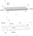
- the support member 4 is a plurality of bottom beams, and the bottom beams are located below the cell array 3.
- the bottom beams are used for supporting the cell array 3.
- Upper surfaces of the bottom beams may be planes so as to support the cell array 3 in a surface-to-surface manner.
- the bottom beam has a rectangular cross-section.
- There may be a plurality of bottom beams, and the plurality of bottom beams may be disposed in parallel at intervals or disposed crossing each other.
- the cell array 3 may be fixed to the bottom beams by means such as gluing or threaded connecting members, the battery pack further includes a sealing cover, and the sealing cover and the bottom beams form an accommodating cavity for accommodating the cell array 3.
- the sealing cover is used for preventing intrusion of dust, water, and the like.
- the normal of the two parallel planes corresponding to the first dimension is the Q direction
- the bottom beams include a first beam 501 and a second beam 502 located on and intersecting the first beam 501, an angle between an extension direction of the first beam 501 and the Q direction is 60-90°, and the cell 100 is supported by the first beam 501.
- the first beam 501 is perpendicularly connected to the second beam 502.
- the connection between the first beam 501 and the second beam 502 may be achieved by means such as, but not limited to, a threaded connecting member or welding.
- the first beam 501 and the second beam 502 may both be straight beams.
- the two second beams 502 are respectively located at two ends of the first beam 501 and are respectively perpendicular to the first beam 501, and the cell 100 is supported by the first beam 501.
- the second beam 502 protrudes upward (Z direction) relative to the first beam 501, for example, a lower surface of the second beam 502 may be connected to an upper surface of the first beam 501.
- the outermost two cells 100 may respectively lean against side surfaces of two second beams 502 which face toward each other.
- a center of the cell 100 is located on the first beam 501.
- a length direction of the cell 100 is perpendicular to a length direction of the first beam 501.
- the supporting of the cell 100 by using a single beam can be achieved.
- the normal of the two parallel planes corresponding to the first dimension is the Q direction
- the bottom beams may be a plurality of rectangular beams parallel to and spaced apart from each other
- an angle between an extension direction of the rectangular beam and the Q direction is 60-90°
- the cell 100 is supported by the rectangular beam.
- the rectangular beam may be evenly distributed along the Q direction
- the extension direction of the rectangular beam is perpendicular to the Y direction
- the cell 100 is located on the evenly distributed rectangular beam.
- the shape of the bottom beam includes, but is not limited to, straight and rectangular, and may also be triangular, trapezoidal, or any other special shape.
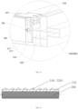
- the support member 4 is a vehicle chassis, and the cell array 3 is located on the vehicle chassis.
- the battery pack 200 may be directly formed on an electric vehicle.
- the battery pack 200 is an apparatus configured for mounting the cell 100 and formed at any suitable position on the electric vehicle.
- the battery pack 200 may be directly formed on the chassis of the electric vehicle.
- the vehicle chassis is provided with a cavity 300 recessed downward, to facilitate the assembly of the cell 100.
- the cavity 300 may include a first side wall 301 and a second side wall 302 disposed opposite to each other.
- the first side wall 301 may extend downward from the chassis of the electric vehicle to obtain an extension portion of the first side wall 301
- the second side wall 302 may extend downward from the chassis of the electric vehicle to obtain an extension portion of the first side wall 302.
- the first end of the cell 100 may be supported by the extension portion of the first side wall 301
- the second end of the cell 100 may be supported by the extension portion of the second side wall 302. Accordingly, this application further provides an electric vehicle allowing for arranging cells 100 according to the above technical solution, where a cavity 300 having the same features as a separate tray for use with a vehicle is formed on the electric vehicle, thus forming the battery pack 200 provided by this application.
- the normal of the two parallel planes corresponding to the first dimension is the Q direction
- a cell placement region is formed in the battery pack 200
- the cell array 3 is located in the cell placement region
- the battery pack 200 includes one cell array 3
- the cells 100 extend from one side of the cell placement region to the other side of the cell placement region along the Q direction.
- the battery pack accommodates only one cell in the Q direction.
- the cell has a second dimension, which is a minimum spacing between two imaginary parallel planes sandwiching the cell, a normal of the two parallel planes corresponding to the second dimension is a P direction, and a cell placement region is formed in the battery pack 200, the cell array 3 is located in the cell placement region, N cell arrays 3 along the P direction and M cell arrays 3 along the Q direction are disposed in the cell placement region, the cell arrays 3 are electrically connected to each other through connecting members between electrode terminals of cells, N is greater than or equal to 1, and M is greater than or equal to 1.
- An electrode terminal of the last cell of the (N-1) th cell array 3 is connected to an electrode terminal of the first cell of the N th cell array 3 through a connecting member, and N is greater than or equal to 1.
- a plurality of cell arrays 3 may be disposed along the arrangement direction of the cells 100, that is, the battery pack 200 is provided therein with multiple columns of cell arrays 3.
- the first partition plate 700 divides the shown cell array 3 along the P direction of the battery pack 200 into two cell arrays 3.
- the last cell 100 of one cell array 3 is connected to the first cell of the other cell array 3 through a connecting member.
- a cell placement region is formed in the battery pack, the cell array 3 is located in the cell placement region, M cell arrays 3 along the Q direction are disposed in the cell placement region, the cell arrays 3 are electrically connected to each other through connecting members between electrode terminals of cells, and M is greater than or equal to 1.
- An electrode terminal of the last cell of the (M-1) th cell array 3 is connected to an electrode terminal of the first cell of the M th cell array 3 through a connecting member, and M is greater than or equal to 1.
- a plurality of cells 100 may be accommodated, that is, the battery pack 200 is provided therein with multiple rows of cell arrays 3.
- the second partition plate 800 divides the cell array 3 along the Q direction of the battery pack 2000 into two cell arrays 3.
- the last cell 100 of one cell array 3 is connected to the first cell of the other cell array 3 through a connecting member.
- a cell placement region is formed in the battery pack, the cell array 3 is located in the cell placement region, N cell arrays 3 along the P direction and M cell arrays 3 along the Q direction are disposed in the cell placement region, the cell arrays 3 are electrically connected to each other through connecting members between electrode terminals of cells, N is greater than or equal to 1, and M is greater than or equal to 1.
- the cell placement region is divided into a plurality of battery placement subregions, and in the extension direction of the cell 100, i.e., the Q direction, a plurality of cells 100 may be accommodated. That is, the battery pack 200 is provided therein with multiple rows and multiple columns of cell arrays 3.
- a first partition plate 700 and a second partition plate 800 are disposed in the battery pack 200, and the first partition plate 700 and the second partition plate 800 divide a plurality of cells into two rows and two columns of cell arrays 3. Any two of the cell arrays 3 are connected to each other through connecting members between electrode terminals.
- first partition plate 700 and the second partition plate 800 may be reinforcing ribs, or may be heat insulation foam or other mechanical member, which is not limited in this application.
- the quantity of cells 100 in the cell array 3 is not particularly limited in this application, and depending on different vehicle types and different power requirements, different numbers of cells 100 may be arranged. In some specific examples of this application, the quantity of cells in the cell array 3 is 60-200. In some other specific examples of this application, the quantity of cells in the cell array 3 is 80-150.
- the quantity of cells 100 in the cell array of this application is not limited, and for example, may be 2.
- the battery pack of this application may include one cell array described above, or may include a plurality of cell arrays.
- the cell arrays may be the same or different.
- the battery pack may include other types of cells, for example, smaller cells disposed according to the space inside the battery pack, and the specific placement of such other types of cells is not limited by the cell array of the present invention.
- a battery pack 200 including a cell array 3 and a support member 4.
- the cell array 3 includes a plurality of cells 100, the cell 100 has a dimension A, and the dimension A is a length of a minimum enclosing rectangle of the cell 100. At least one of the cells 100 meets: 600 mm ⁇ dimension A ⁇ 2500 mm.
- the minimum enclosing rectangle may be construed as follows: for the cell 100, assuming there is a cuboid housing and inner walls of six sides of the cuboid housing abut against the outer contour of the cell, the housing of the cuboid housing is the minimum enclosing rectangle.
- the dimension A is a length of the minimum enclosing rectangle.
- the cell 100 may be of various shapes, for example, may be of a regular geometry or of an irregular geometry.
- the cell may be square, round, polygonal, triangular, or of any other shape.
- the cell is a special-shaped cell. It may be understood that the shape of the cell is not limited in this application.
- the cell 100 includes a casing and a core located inside the casing.
- a supporting region is formed on the casing, and
- the support member 4 is connected to the supporting region to support the cell 100.
- the casing may include a casing body and a cover plate sealing the casing body.
- the casing body is made of aluminum or steel.
- the supporting region may be an outer surface of the casing body or the cover plate, or may be a partial region of an outer surface of the casing body or the cover plate, or may be any combination of an outer surface of the casing body, an outer surface of the cover plate, a partial region of an outer surface of the casing body, and a partial region of an outer surface of the cover plate, as long as the supporting region can be connected to the support member 4 to support the cell 100.
- the supporting region may be disposed at two ends of the cell 100 along the dimension A, so that the the cell 100 may be supported by the support member 4 along the dimension A.
- the dimension A of the cell 100 may be designed to be 600 mm-2500 mm. Because the cell 100 is long enough, the cell 100 can be directly supported by the support member 4. By forming a plurality of cells 100 into a module, the cells 100 themselves can provide a supporting function, and replace the reinforcing structure to ensure the structural strength of the battery pack 200.
- transverse beams 500 and/or longitudinal beams 600 in the battery pack 200 can be reduced, or even the use of transverse beams 500 and/or longitudinal beams 600 in the battery pack 200 can be avoided, so that the space occupied by transverse beams 500 and/or longitudinal beams 600 in the battery pack 200 can be reduced, thereby improving the utilization of the space inside the battery pack 200, and allowing as many cells 100 as possible to be disposed in the battery pack 200.
- the capacity, the voltage, and the battery life of the entire battery pack can be improved.
- such a design can improve the space utilization from about 40% to 60% or even higher, for example, 80%.
- the cell 100 is designed as a pouch cell, that is, the housing of the cell is an aluminum-plastic composite film and the aluminum-plastic composite film is used to support the cell, the aluminum-plastic composite film of the cell may be worn out, and the pouch cell in the battery pack is prone to displacement, which accelerates the wear of the cell.
- the cell 100 fails, resulting in a short battery life of the battery pack.
- the heat dissipation performance of the pouch cell is poor, and after the pouch cells are designed into the dimension described in this application and arranged in the battery pack, the heat dissipation performance of the entire pouch cell is poor.
- the cell 100 includes a casing, a cover plate, and a core located inside a space formed by the casing and the cover plate.
- the cell is a hard-case cell.
- a supporting region is formed on the casing and/or the cover plate, and the support member 4 is connected to the supporting region to support the cell.
- the support member 4 is connected to the supporting region may be that the support member 4 is in direct contact with the supporting region, or may be that the support member 4 is in indirect contact or connection with the supporting region through another component, which may be set depending on usage scenarios and is not limited in this application.
- the fabrication process of the battery pack 200 is simplified, the assembly complexity of the cell 100 is reduced, and the production costs are reduced; In another case, the weight of the entire battery pack 200 is reduced, thereby achieving a lightweight battery pack.
- the battery life of the electric vehicle can also be improved, and the weight of the electric vehicle can be reduced.
- 600 mm ⁇ dimension A ⁇ 1500 mm for example, 600 mm ⁇ dimension A ⁇ 1000 mm.
- the cell 100 having such a length is long enough to be supported by the support member 4, and the cell 100 having such a length is not too long.
- the rigidity of the cell 100 is large enough.
- the specific form of the battery pack is not particularly limited, as long as the battery pack includes the support member 4, the cell array 3 is located on the support member 4, the cells 100 are supported by the support member 4.
- the specific structure of the support member 4 is not limited in this application, as long as the cells 100 can be supported by the support member 4.
- the specific structure of the support member 4 will be described below.
- the cells 100 are supported by the support member 4.
- the cells 100 may be directly supported by the support member 4, that is, respectively disposed on the support member 4, or fixed on the support member 4.
- the specific fixing manner will be described in detail below.
- the specific supporting and fixing manners are not limited in this application.
- the support member 4 is used for supporting the cell array 3.
- the support member 4 is usually of a rigid structure.
- the support member 4 may be an independently fabricated tray or a rigid supporting structure formed on the chassis of the vehicle, and can be easily mounted on the vehicle or another apparatus.
- the metal housing of the cell 100 When the housing of the cell 100 is made of a metal material, the metal housing of the cell 100 has a better heat-conducting property, so that the heat dissipation efficiency of the cell 100 can be improved, thereby improving the heat dissipation effect.
- the plurality of cells are arranged along a direction K, and the direction K is a width direction of a minimum enclosing rectangle of the at least one cell in the cell array 3.
- the cell 100 has a dimension B, the cell has a dimension B, which is a width of a minimum enclosing rectangle of the cell, the normal of the two parallel planes corresponding to the dimension B is the direction K, and a plurality of cells are arranged along the K direction of the at least one cell.
- At least one of the cells meets: 10 ⁇ dimension A/dimension B ⁇ 208. In some embodiments, at least one of the cells meets: 23 ⁇ dimension A/dimension B ⁇ 208. In an embodiment of this application, 50 ⁇ dimension A/dimension B ⁇ 70. It is found through a large number of experiments that for the cell 100 that meets the above dimension requirement, the cell 100 can have a small thickness along the dimension B while providing rigidity that meets the supporting requirement, so that the cell 100 has a high heat dissipation capability.
- the plurality of cells 100 are arranged along a direction K, and the direction K is a height direction of a minimum enclosing rectangle of the at least one cell 100 in the cell array 3.
- the cell 100 has a dimension C, which is a height of a minimum enclosing rectangle of the cell 100.
- At least one of the cells 100 meets: 10 ⁇ dimension A/dimension C ⁇ 208, for example, 23 ⁇ dimension A/dimension C ⁇ 208, for example, 50 ⁇ dimension A/dimension C ⁇ 70. It is found through a large number of experiments that for the cell 100 that meets the above dimension requirement, the cell 100 can have a small thickness along the dimension C while providing rigidity that meets the supporting requirement, so that the cell 100 has a high heat dissipation capability.
- the battery pack 200 further includes two side plate components disposed opposite to each other on two sides of the cell array 3 and configured to sandwich the cell array 3.
- the side plate components sandwiching the cell array 3 provide a function of limiting expansive deformation of the plurality of cells 100, thereby ensuring starting of an explosion-proof valve 103 and a current interrupt device (CID).
- the side plate components may be a third side beam 203 and a fourth side beam 204;
- the side plate components may be a first side plate 209 and a second side plate 210.
- the battery pack 200 includes a tray for use with a vehicle, the tray includes a first side beam 201 and a second side beam 202 disposed opposite to each other along a length direction of a minimum enclosing rectangle of the cell 100, the support member 4 is the first side beam 201 and the second side beam 202, and two ends of the cell 100 are respectively supported by the first side beam 201 and the second side beam 202.
- the support member 4 is a plurality of bottom beams, and the bottom beams are located below the cell array 3.
- the bottom beams are used for supporting the cell array 3.
- Upper surfaces of the bottom beams may be planes so as to support the cell array 3 in a surface-to-surface manner.
- the bottom beam has a rectangular cross-section.
- There may be a plurality of bottom beams, and the plurality of bottom beams may be disposed in parallel at intervals or disposed crossing each other.
- the cell array 3 may be fixed to the bottom beams by means such as gluing or threaded connecting members, the battery pack further includes a sealing cover, and the sealing cover and the bottom beams form an accommodating cavity for accommodating the cell array 3.
- the sealing cover is used for preventing intrusion of dust, water, and the like.
- the bottom beams include a first beam 501 and a second beam 502 located on and intersecting the first beam 501, an angle between an extension direction of the first beam 501 and the length direction of the minimum enclosing rectangle of the cell is 60-90°, and the cell 100 is supported by the first beam 501.
- the first beam 501 is perpendicularly connected to the second beam 502.
- the connection between the first beam 501 and the second beam 502 may be achieved by means such as, but not limited to, a threaded connecting member or welding.
- the first beam 501 and the second beam 502 may both be straight beams.
- the two second beams 502 are respectively located at two ends of the first beam 501 and are respectively perpendicular to the first beam 501, and the cell 100 is supported by the first beam 501.
- the second beam 502 protrudes upward (Z direction) relative to the first beam 501, for example, a lower surface of the second beam 502 may be connected to an upper surface of the first beam 501.
- the outermost two cells 100 may respectively lean against side surfaces of two second beams 502 which face toward each other.
- a center of the cell 100 is located on the first beam 501.
- a length direction of the cell 100 is perpendicular to a length direction of the first beam 501.
- the supporting of the cell 100 by using a single beam can be achieved.
- the shape of the bottom beam includes, but not limited to, straight and rectangular, and may also be triangular, trapezoidal, or any other special shape.
- the support member 4 is a vehicle chassis, and the cell array 3 is located on the vehicle chassis.
- the battery pack 200 may be directly formed on an electric vehicle.
- the battery pack 200 is an apparatus configured for mounting the cell 100 and formed at any suitable position on the electric vehicle. for example, the battery pack 200 may be directly formed on the chassis of the electric vehicle.
- the vehicle chassis is provided with a cavity 300 recessed downward, to facilitate the assembly of the cell 100.
- the cavity 300 may include a first side wall 301 and a second side wall 302 disposed opposite to each other.
- the first side wall 301 may extend downward from the chassis of the electric vehicle to obtain an extension portion of the first side wall 301
- the second side wall 302 may extend downward from the chassis of the electric vehicle to obtain an extension portion of the first side wall 302.
- the first end of the cell 100 may be supported by the extension portion of the first side wall 301
- the second end of the cell 100 may be supported by the extension portion of the second side wall 302. Accordingly, this application further provides an electric vehicle allowing for arranging cells 100 according to the above technical solution, where a cavity 300 having the same features as a separate tray for use with a vehicle is formed on the electric vehicle, thus forming the battery pack 200 provided by this application.
- a cell placement region is formed in the battery pack 200, the cell array 3 is located in the cell placement region, the battery pack 200 includes one cell array 3, and the cells extend from one side of the cell placement region to the other side of the cell placement region along a length direction of a minimum enclosing rectangle of the cell 100.
- the battery pack 200 accommodates only one cell in the length direction of the minimum enclosing rectangle of the cell 100.
- a cell placement region is formed in the battery pack 200, the cell array 3 is located in the cell placement region, N cell arrays 3 along a width direction of the minimum enclosing rectangle of the cell are disposed in the cell placement region, the cell arrays 3 are electrically connected to each other through connecting members between electrode terminals of cells, and N is greater than or equal to 1.
- M cell arrays 3 along a length direction of the minimum enclosing rectangle of the cell are disposed in the cell placement region, the cell arrays 3 are electrically connected to each other through connecting members between electrode terminals of cells, and M is greater than or equal to 1.
- the first partition plate 700 divides the shown cell array 3 along the K direction of the battery pack 200 into two cell arrays 3.
- the last cell 100 of one cell array 3 is connected to the first cell of the other cell array 3 through a connecting member.
- a cell placement region is formed in the battery pack, the cell array 3 is located in the cell placement region, M cell arrays 3 along the Q direction are disposed in the cell placement region, the cell arrays 3 are electrically connected to each other through connecting members between electrode terminals of cells, and M is greater than or equal to 1.
- An electrode terminal of the last cell of the (M-1) th cell array 3 is connected to an electrode terminal of the first cell of the M th cell array 3 through a connecting member, and M is greater than or equal to 1.
- a plurality of cells 100 may be accommodated. That is, the battery pack 200 is provided therein with multiple rows of cell arrays 3.
- the second partition plate 800 divides the cell array 3 along the Q direction of the battery pack 2000 into two cell arrays 3.
- the last cell 100 of one cell array 3 is connected to the first cell of the other cell array 3 through a connecting member.
- a cell placement region is formed in the battery pack, the cell array 3 is located in the cell placement region, N cell arrays 3 along the K direction and M cell arrays 3 along the Q direction are disposed in the cell placement region, the cell arrays 3 are electrically connected to each other through connecting members between electrode terminals of cells, N is greater than or equal to 1, and M is greater than or equal to 1.
- the cell placement region is divided into a plurality of battery placement subregions, and in the extension direction of the cell 100, i.e., the Q direction, a plurality of cells 100 may be accommodated. That is, the battery pack 200 is provided therein with multiple rows and multiple columns of cell arrays 3.
- a first partition plate 700 and a second partition plate 800 are disposed in the battery pack 200, and the first partition plate 700 and the second partition plate 800 divide a plurality of cells into two rows and two columns of cell arrays 3. Any two of the cell arrays 3 are connected to each other through connecting members between electrode terminals.
- the first partition plate 700 and the second partition plate 800 may be reinforcing ribs, or may be heat insulation foam or other mechanical member, which is not limited in this application.
- a cell placement region is formed in the battery pack, the cell array 3 is located in the cell placement region, J cell arrays 3 along a height direction of the minimum enclosing rectangle of the cell are disposed in the cell placement region, the cell arrays 3 are electrically connected to each other through connecting members between electrode terminals of cells, and J is greater than or equal to 1.
- the quantity of cells 100 in the cell array 3 is not particularly limited in this application, and depending on different vehicle types and different power requirements, different numbers of cells 100 may be arranged. In some specific examples of this application, the quantity of cells in the cell array 3 is 60-200. In some other specific examples of this application, the quantity of cells in the cell array 3 is 80-150.
- a battery pack 200 including a cell array 3 and a support member 4.
- the cell array 3 includes a plurality of cells 100, At least one of the cells 100 includes a cell body and electrode terminals extending out of the cell body and configured to output a current inside the cell body, the cell body is substantially a cuboid, the cell body has a length L, and 600 mm ⁇ L ⁇ 2500 mm.
- the cell 100 includes a casing and a core located inside the casing. A supporting region is formed on the casing, and The support member 4 is connected to the supporting region to support the cell 100.
- the cell body is substantially a cuboid may be construed as that the cell body may be cuboid or cubic, or may be partially special-shaped but basically cuboid or cubic, or may be largely of a cuboid or cubic shape having a notch, a bump, a chamfer, an arc portion, or a bent portion.
- transverse beams 500 and/or longitudinal beams 600 need to be disposed in the battery pack 200 (as shown in FIG. 1 ), to facilitate the assembly of the cell 100.
- the battery module is fixed to the neighboring transverse beam 500 and/or longitudinal beam 600 through a fastener.
- transverse beams 500 and/or longitudinal beams 600 are disposed in the battery pack, the transverse beams 500 and/or longitudinal beams 600 occupy a large part of the space for accommodating cells in the battery pack 200, leading to low utilization of the volume of the battery pack.
- the volume utilization of the battery pack 200 is about 40% or even lower In other words, in the related art, only about 40% of the space inside the battery pack 200 can be used for mounting cells. As a result, the quantity of cells 100 that the battery pack 200 can accommodate is limited, the capacity and the voltage of the entire battery pack are restricted, and the battery life of the battery pack is short.
- the length L of the cell body of the cell 100 may be designed to be 600 mm-2500 mm. Because the cell body of the cell 100 is long enough, the cell body itself can provide a supporting function, and replace the reinforcing structure to ensure the structural strength of the battery pack 200. In this way, the use of transverse beams 500 and/or longitudinal beams 600 in the battery pack 200 can be reduced, or even the use of transverse beams 500 and/or longitudinal beams 600 in the battery pack 200 can be avoided, so that the space occupied by transverse beams 500 and/or longitudinal beams 600 in the battery pack 200 can be reduced, thereby improving the utilization of the space inside the battery pack 200, and allowing as many cells 100 as possible to be disposed in the battery pack 200.
- the capacity, the voltage, and the battery life of the entire battery pack can be improved.
- such a design can improve the space utilization from about 40% to 60% or even higher, for example, 80%.
- the cell 100 is designed as a pouch cell, that is, the housing of the cell is an aluminum-plastic composite film and the aluminum-plastic composite film is used to support the cell, the aluminum-plastic composite film of the cell may be worn out, and the pouch cell in the battery pack is prone to displacement, which accelerates the wear of the cell.
- the cell 100 fails, resulting in a short battery life of the battery pack.
- the cell 100 includes a casing, a cover plate, and a core located inside a space formed by the casing and the cover plate.
- the cell is a hard-case cell.
- the length L of the cell is 600 mm-2500 mm
- a supporting region is formed on the casing and/or the cover plate, and the support member 4 is connected to the supporting region to support the cell.
- the support member 4 is connected to the supporting region may be that the support member 4 is in direct contact with the supporting region, or may be that the support member 4 is in indirect contact or connection with the supporting region through another component, which may be set depending on usage scenarios and is not limited in this application.
- the fabrication process of the battery pack 200 is simplified, the assembly complexity of the cell 100 is reduced, and the production costs are reduced; In another case, the weight of the entire battery pack 200 is reduced, thereby achieving a lightweight battery pack.
- the battery life of the electric vehicle can also be improved, and the weight of the electric vehicle can be reduced.
- the specific form of the battery pack is not particularly limited, as long as the battery pack includes the support member 4, the cell array 3 is located on the support member 4, the cells 100 are supported by the support member 4.
- the specific structure of the support member 4 is not limited in this application, as long as the cells 100 can be supported by the support member 4.
- the specific structure of the support member 4 will be described below.
- the cells 100 are supported by the support member 4.
- the cells 100 may be directly supported by the support member 4, that is, respectively disposed on the support member 4, or fixed on the support member 4.
- the specific fixing manner will be described in detail below.
- the specific supporting and fixing manners are not limited in this application.
- the support member 4 is used for supporting the cell array 3.
- the support member 4 is usually of a rigid structure.
- the support member 4 may be an independently fabricated tray or a rigid supporting structure formed on the chassis of the vehicle.
- the support member 4 is used for maintaining the complete appearance of the battery pack, and can be easily mounted on the vehicle or another apparatus.
- the cell body of the cell 100 because the length L of the cell body of the cell 100 is long, the cell body itself can provide a supporting function, so that the use of transverse beams and/or longitudinal beams in the battery pack to enhance the structural strength can be reduced, thereby improving the utilization of the space inside the battery pack, and allowing more cells to be disposed in the battery pack.
- the cell body of the cell 100 has three directions perpendicular to each other, namely, X direction, Y direction, and Z direction. Every two of the X direction, the Y direction, the Z direction are perpendicular to each other.
- the X direction is the arrangement direction of the cell 100
- the Y direction is the length direction of the cell 100
- the Z direction is the height direction of the cell 100.
- the length direction of the battery pack 200 may be parallel to a longitudinal direction of a vehicle 1
- the width direction of the battery pack 200 may be parallel to a transverse direction of the vehicle 1
- the Y direction may be parallel to the transverse direction of the vehicle 1
- the X direction may be parallel to the longitudinal direction of the vehicle 1
- the Z direction may be parallel to a vertical direction of the vehicle 1.
- the length direction of the battery pack 200 may be parallel to a longitudinal direction of a vehicle 1
- the width direction of the battery pack 200 may be parallel to a transverse direction of the vehicle 1
- the Y direction may be parallel to the longitudinal direction of the vehicle 1
- the X direction may be parallel to the transverse direction of the vehicle 1
- the Z direction may be parallel to a vertical direction of the vehicle 1.
- the X direction, the Y direction, and the Z direction may also correspond to the actual directions of the vehicle in other relationship, and the actual correspondence depends on the mounting direction of the battery pack 200.
- a vehicle traveling direction is the longitudinal direction of the vehicle; a direction perpendicular to and coplanar with the vehicle traveling direction is the transverse direction of the vehicle, which is generally a horizontal direction; and an up-down direction is the vertical direction of the vehicle, which is generally an upright direction.
- the cells 100 may be arranged in sequence along the X direction, and the quantity of cells may not be limited. With such an arrangement, as the quantity of cells arranged in the battery pack increases, the heat dissipation performance of the entire battery pack degrades.
- L/H or LID is limited, so that the thickness along the X direction and the height along the Z direction are relatively small, and the surface area of a single cell is greater than the surface area of a cell in the related art In this way, the heat dissipation area of the cell can be increased, to improve the heat dissipation efficiency of the cell, thereby improving the safety performance of the entire battery pack, to make the battery pack safer and more reliable.
- the metal housing of the cell 100 has a better heat-conducting property, so that the heat dissipation efficiency of the cell 100 can be improved, thereby improving the heat dissipation effect.
- the plurality of cells 100 may be arranged in the cell array 3 in various manners.
- the cell body has a length L, a thickness D, and a height H, a thickness direction thereof being an X direction, a length direction thereof being a Y direction, and a height direction thereof being a Z direction.
- the plurality of cells 100 may be arranged at intervals or arranged closely along the X direction. As shown in FIG. 2 , in this implementation, the cells are arranged closely along the X direction, so as to make full use of the space.
- the plurality of cells 100 are arranged along the X direction of at least one cell in the cell array 3, and the X direction is a thickness direction of any cell 100 in the cell array 3.
- the cell body has a thickness D, and at least one of the cells 100 meets: 10 ⁇ L/D ⁇ 208, for example, 23 ⁇ L/D ⁇ 208, for example, 50 ⁇ L/D ⁇ 70. It is found through a large number of experiments that for the cell 100 that meets the above dimension requirement, the cell 100 can have a small thickness in the X direction while providing rigidity that meets the supporting requirement, so that the cell 100 has a high heat dissipation capability.
- the plurality of cells 100 are arranged along the Z direction of at least one cell in the cell array 3, and the Z direction is a height direction of any cell 100 in the cell array 3.
- the cell body has a height H, and at least one of the cells 100 meets: 10 ⁇ L/H ⁇ 208, for example, 23 ⁇ L/H ⁇ 208. In some embodiments, 50 ⁇ L/H ⁇ 70. It is found through a large number of experiments that for the cell 100 that meets the above dimension requirement, the cell body can have a small thickness in the Z direction while providing rigidity that meets the supporting requirement, so that the cell body has a high heat dissipation capability.
- an array with flush ends maybe formed, or the cells may form an angle with the X direction or the Z direction, that is, may be obliquely arranged.
- the arrangement directions of the plurality of cells 100 may be the same, or may be partially different or completely different, as long as each cell is distributed along a predetermined direction.
- 600 mm ⁇ L ⁇ 1500 mm for example, 600 mm ⁇ L ⁇ 1000 mm.
- the cell 100 having such a length is long, and when used in the battery pack 200, only a single cell 100 needs to be disposed along the first direction.
- the cell body of the cell 100 has a volume V, and at least one of the cells 100 meets: 0.0005 mm -2 ⁇ L/V ⁇ 0.002 mm -2 . It is found through a large number of experiments that when the cell 100 meets the above limitations, the cross-section of the cell body is small, and the cell body has a good heat dissipation effect, so that the temperature difference between the inside and outside of the cell body is small.
- a ratio of the surface area S to the volume V of the cell body of the cell 100 is 0.1 mm -1 ⁇ S/V ⁇ 0.35 mm -1 . This ratio may be achieved by the above long and thin cell 100, or through dimension adjustment. By controlling the ratio of the surface area S to the volume V of the cell 100, a sufficient heat dissipation area is provided while ensuring that the length of the cell body extends along the Y direction, thereby ensuring the heat dissipation effect of the cell 100.
- the cell body has a volume V, and a relationship between the height H of the cell body and the volume V of the corresponding cell body is 0.0001 mm -2 ⁇ H/V ⁇ 0.00015 mm -2 .
- the cell body has a length L, a thickness D, and a height H, a thickness direction thereof being an X direction, a length direction thereof being a Y direction, and a height direction thereof being a Z direction; and the height H of the cell body is greater than or equal to the thickness D of the cell body, at least one of the cells meets: 23 ⁇ L/D ⁇ 208, and 4 ⁇ L/H ⁇ 21, and the plurality of cells are arranged along the X direction of at least one cell in the cell array 3. In solutions of some embodiments, at least one of the cells meets: 9 ⁇ L/H ⁇ 13.
- the cell body can have a small thickness in the X direction while providing rigidity that meets the supporting requirement, so that the cell body has a high heat dissipation capability, and the cells 100 can be conveniently arranged closely in the X direction.
- the at least one cell 100 has a first end and a second end along the Y direction, at least one of the first end and the second end has an electrode terminal configured to output a current inside the cell, and electrode terminals of cells 100 are electrically connected to each other through a connecting member.
- first end and the “second end” of the cell 100 are used for describing the orientation of the cell 100, and are not intended to limit or describe the specific structure of the cell 100.
- first end and the “second end” of the cell 100 are not intended to limit or describe positive and negative electrodes of the cell 100.
- a first electrode terminal 101 of the cell 100 extends out from the first end of the cell 100 facing toward the Y direction
- a second electrode terminal 102 of the cell 100 extends out from the second end of the cell 100 facing toward the Y direction.
- the length direction of the cell 100 may be the direction of a current inside the cell 100, that is, the current direction inside the cell 100 is the Y direction.
- the cell 100 has a larger effective heat dissipation area and a higher heat dissipation efficiency.
- the first electrode terminal 101 is a positive electrode of the cell 100
- the second electrode terminal 102 is a negative electrode of the cell 100; or the first electrode terminal 101 is the negative electrode of the cell 100, and the second electrode terminal 102 is the positive electrode of the cell 100.
- Electrode terminals of cells 100 are connected in series or in parallel to each other through a connecting member.
- the thickness directions of at least a part of the cells 100 extend along the X direction, that is, a plurality of cells are arranged along the thickness direction of the cell.
- the cell array 3 includes a plurality of cells 100 arranged in sequence along the X direction, and the cell 100 has a length extending along the Y direction and a height extending along the Z direction.
- a plurality of cells 100 are arranged along the thickness direction, and extend along the length direction, thereby making full use of the space inside the battery pack, and allowing more cells to be disposed.
- the cell 100 has a first end and a second end along the length direction, the first end and/or the second end has an electrode terminal configured to output a current inside the cell, and electrode terminals of cells are connected to each other through a connecting member.
- first end and the “second end” of the cell 100 are used for describing the orientation of the cell 100, and are not intended to limit or describe the specific structure of the cell 100.
- first end and the “second end” of the cell 100 are not intended to limit or describe positive and negative electrodes of the cell 100.
- a first electrode terminal 101 of the cell 100 extends out from the first end of the cell 100 along the length direction
- a second electrode terminal 102 of the cell 100 extends out from the second end of the cell 100 along the length direction.
- the length direction of the cell 100 may be the direction of a current inside the cell 100, that is, the current direction inside the cell 100 is the Y direction.
- the cell 100 has a larger effective heat dissipation area and a higher heat dissipation efficiency.
- the first electrode terminal 101 is a positive electrode of the cell 100
- the second electrode terminal 102 is a negative electrode of the cell 100; or the first electrode terminal 101 is the negative electrode of the cell 100, and the second electrode terminal 102 is the positive electrode of the cell 100.
- Electrode terminals of cells 100 are connected in series or in parallel to each other through a connecting member.
- the ratio of the length L and the thickness D of the cell body of the at least one cell 100 meets 23 ⁇ L/D ⁇ 208. Under this ratio, a moderately long, and thin cell 100 can be obtained, and while ensuring that the length of the cell 100 extends along the first direction, a suitable resistance, a large heat dissipation area, and high heat dissipation efficiency can be maintained, providing good adaptability for various vehicle types.
- the ratio of the length L and the thickness D of the cell body of the at least one cell 100 meets 50 ⁇ L/D ⁇ 70. Under this ratio, a moderately long cell 100 can be obtained, and the rigidity of the cell 100 is large enough, thereby facilitating the processing, transportation, and assembly.
- the cell 100 is mounted in the battery pack housing, because the cell 100 has high rigidity, the cell 100 itself can be used as reinforcing beams.
- a suitable resistance, a large heat dissipation area, and high heat dissipation efficiency can be maintained, providing good adaptability for various vehicle types.
- the battery pack 200 in the X direction, further includes two side plate components disposed opposite to each other on two sides of the cell array 3 and configured to sandwich the cell array 3.
- the side plate components sandwiching the cell array 3 provide a function of limiting expansive deformation of the plurality of cells 100, thereby ensuring starting of an explosion-proof valve 103 and a current interrupt device (CID).
- the side plate components may be a third side beam 203 and a fourth side beam 204.
- the side plate components may be a first side plate 209 and a second side plate 210.
- the battery pack provided by this application further includes a sealing cover 220.
- the sealing cover 220 and the support member 4 form an accommodating cavity for accommodating the cell array 3.
- the sealing cover 220 and the support member 4 define the accommodating cavity for accommodating cells, and the sealing cover 220 provides a waterproof moisture-proof function.
- the battery pack 200 includes a tray for use with a vehicle.
- the tray is a separately fabricated tray for accommodating and mounting cells 100 therein. As shown in FIG. 16 , FIG. 18, and FIG. 19 , after the cell 100 is mounted in the tray, the tray may be mounted on the vehicle body through a fastener, for example, may be suspended on the chassis of an electric vehicle.
- the tray includes a first side beam 201 and a second side beam 202 disposed opposite to each other along the Y direction, the support member 4 is the first side beam 201 and the second side beam 202, the first end of the cell 100 is supported by the first side beam 201, and the second end of the cell 100 is supported by the second side beam 202.
- the specific structure of the first side beam 201 and the second side beam 202 are not limited, the first side beam 201 and the second side beam 202 are disposed opposite to each other, and the first side beam 201 and the second side beam 202 may be parallel to each other or may form an angle, and may be of a straight or curved structure.
- the first side beam 201 may be rectangular, cylindrical, or polygonal, which is not particularly limited in this application.
- the first side beam 201 and the second side beam 202 are disposed opposite to each other along the Y direction, the plurality of cells 100 are disposed between the first side beam 201 and the second side beam 202, and two ends of the cell 100 are respectively supported by the first side beam 201 and the second side beam 202.
- the first end of each cell 100 is supported by the first side beam 201
- the second end of each cell 100 is supported by the second side beam 202.
- each of the cells 100 extends between the first side beam 201 and the second side beam 202, and the plurality of cells 100 are arranged along the length direction of the first side beam 201 and the second side beam 202, that is, arranged along the X direction.
- the first end and the second end of the cell 100 are respectively supported by the first side beam 201 and the second side beam 202.
- the cell 100 may be directly supported by the first side beam 201 and the second side beam 202, that is, respectively placed on the first side beam 201 and the second side beam 202; or may be fixed on the first side beam 201 and the second side beam 202.
- the specific fixing manner will be described in detail below. The specific supporting and fixing manners are not limited in this application.
- the first end of each cell 100 may be directly or indirectly supported by the first side beam 201, and the second end of each cell 100 may be directly or indirectly supported by the second side beam 202.
- the term “directly” means that the first end of the cell 100 is in direct contact fit with the first side beam 201, and the second end of the cell 100 is in direct contact fit with the second side beam 202.
- the term “indirectly” means that for example, in some embodiments, the first end of the cell 100 is supported by the first side beam 201 through a first end plate 207, and the second end of the cell 100 is supported by the second side beam 202 through a second end plate 208.
- the cell 100 may be perpendicular to the first side beam 201 and/or the second side beam 202, or may form a sharp or obtuse angle with the first side beam 201 and/or the second side beam 202.
- the first side beam 201, the second side beam 202, and the cell 100 may constitute a rectangular, square or rhomboid, fan-shaped or other structure; when the first side beam 201 and the second side beam 202 form an angle, the first side beam 201, the second side beam 202, and the cell 100 may constitute a trapezoid, triangular or other structure.
- the angle between the first side beam 201 and the second side beam 202 and the angles between the cell 100 and the first side beam 201 and the second side beam 202 are not limited in this application.
- the first side beam 201 and the second side beam 202 are located on two opposite sides of the tray along the Y direction, which means that as shown in FIG. 2 , the first side beam 201 and the second side beam 202 are located on the outermost sides of the tray along the Y direction, and the first side beam 201 and the second side beam 202 are the outermost side edges of the tray.
- first end and the “second end” of the cell 100 mentioned above are used for describing the orientation of the cell 100, and are not intended to limit or describe the specific structure of the cell 100.
- first end and the “second end” of the cell 100 are not intended to limit or describe positive and negative electrodes of the cell 100.
- the end of the cell 100 supported by the first side beam 201 is the first end
- the end of the cell 100 supported by the second side beam 202 is the second end.
- the vehicle body has a large width of for example 1.2 m-2 m and a large length of for example 2 m-5 m, and different vehicle types correspond to different vehicle body widths and lengths.
- a larger vehicle body width and length requires the tray disposed at the bottom of the vehicle to have a larger overall dimension.
- a large tray dimension results in that in the related art, in addition to the side beams disposed at the side edges of the tray, transverse beams also need to be disposed inside the tray, in order to provide a sufficient supporting force and structural strength for cells disposed therein. After transverse beams are disposed in the tray, part of the load and internal space of the tray are occupied by the transverse beams; as a result, the space inside the tray cannot be effectively used.
- transverse beams due to the existence of transverse beams, to allow for the mounting of transverse beams, a plurality of battery modules need to be disposed inside the tray along the width and length directions, which requires a complex mounting process involving a large quantity of mechanical members for mounting.
- the module layout and cell layout methods in the related art cannot provide a sufficient structural strength for the battery module, and the tray cannot provide a sufficient bearing capacity.
- the cell 100 when the length L of the cell is 600 mm-1500 mm, two ends of the cell 100 are respectively supported by the first side beam 201 and the second side beam 202, so as to distribute the weight of the cell to the side beams on two sides of the tray. While avoiding the use of transverse beams, the bearing capacity of the tray is effectively improved. In addition, the cell 100 itself can provide a supporting function.
- the first side beam 201 and the second side beam 202 respectively include inner wall surfaces matching two end faces of the cell 100.
- An insulating plate is sandwiched between the inner wall surface of the first side beam 201 and the first end of the cell 100, that is, the insulating plate is located between the cell 100 and the inner wall surface of the first side beam 201.
- An insulating plate is sandwiched between the inner wall surface of the second side beam 202 and the second end of the cell 100, that is, the insulating plate is located between the cell 100 and the inner wall surface of the second side beam 202.
- the specific structure of the insulating plate is not limited, as long as it can provide functions of fixing the cell array 3 and preventing expansion.
- the insulating plate may be a first end plate 207 and a second end plate 208 described below.
- the tray includes a bottom plate, the first side beam 201 and the second side beam 202 are disposed opposite to each other at two ends of the bottom plate along the Y direction, and the cell 100 is spaced apart from the bottom plate.
- the bearing load of the bottom plate for the cell 100 can be reduced, and most of the weight of the cell 100 can be borne by the first side beam and the second side beam, so that the load bearing requirements on the bottom plate are lowered, thereby simplifying the manufacturing process of the bottom plate and reducing the production costs.
- a thermal insulation layer 217 is disposed between the bottom of the cell array 3 formed by arranging a plurality of cells 100 and the bottom plate of the tray, so as to prevent the heat transfer between the cell 100 and the outside, thereby achieving a heat preservation function for the cell 100, and preventing thermal interference between the environment outside the battery pack 200 and the cell 100 inside the battery pack 200.
- the thermal insulation layer 217 may be made of a material having heat insulation and heat preservation functions, for example, made of heat preservation cotton.
- the first side beam 201 is provided with a first support plate 213, and the second side beam 202 is provided with a second support plate 214.
- a side of the first support plate 213 facing toward the sealing cover 220 is provided with a first supporting surface, and a side of the second support plate 214 facing toward the sealing cover 220 is provided with a second supporting surface.
- the first end of each cell 100 is supported by the first supporting surface of the first support plate 213, and the second end of each cell 100 is supported by the second supporting surface of the second support plate 214.
- a side of the first support plate 213 facing away from the sealing cover 220 is provided with a first mounting surface
- a side of the second support plate 214 facing away from the sealing cover 220 is provided with a second mounting surface.
- the bottom plate of the tray is mounted on the first mounting surface and the second mounting surface, the first support plate 213 may protrude inward from the bottom of the first side beam 201, and the second support plate 214 may protrude inward from the bottom of the second side beam 202.
- the structure of the battery pack 200 provided by this application can be simplified, and the weight of the battery pack 200 can be reduced.
- Insulating plates may be disposed on the first support plate 213 and the second support plate 214. The insulating plates are located between the cell 100 and the first support plate 213 and the second support plate 214.
- first side beam 201, the second side beam 202, and the bottom plate are not particularly limited, and they may be integrally formed or may be welded together.
- the inner wall surface of the first side beam 201 facing toward the cell 100 has a first connecting surface 215, and a distance from the first connecting surface 215 to the sealing cover 220 is less than a distance from the first supporting surface to the sealing cover 220;
- the inner wall surface of the second side beam 202 facing toward the cell 100 has a second connecting surface 216, and a distance from the second connecting surface 216 to the sealing cover 220 is less than a distance from the second supporting surface to the sealing cover 220; and the two ends of the cell 100 are respectively in contact with the first connecting surface and the second connecting surface.
- the first side beam 201 is further provided with a first connecting surface 215, and the second side beam 202 is further provided with a second connecting surface 216.
- the first end of each cell 100 is fixed on the first connecting surface 215, and the second end of each cell 100 is fixed on the second connecting surface 216.
- the first connecting surface 215 may be a third support plate disposed on the first side beam 201, and the third support plate is located above the first support plate 213.
- the second connecting surface 216 may be a fourth support plate disposed on the second side beam 202, and the fourth support plate is located above the second support plate 214.
- the first end and the second end of the cell may be fixed to the first connecting surface 215 and the second connecting surface 216 through fasteners, or welded on the first connecting surface 215 and the second connecting surface 216.
- the inner wall surface of the first side beam 201 facing toward the cell 100 has a step structure including at least two steps, and sides of two steps facing toward the sealing cover 220 respectively form the first connecting surface 215 and the first supporting surface; and the inner wall surface of the second side beam 202 facing toward the cell 100 has a step structure including at least two steps, and sides of two steps facing toward the sealing cover 220 respectively form the second connecting surface 216 and the second supporting surface.
- a first end plate 207 is disposed at an end of a cell 100 adjacent to the first side beam 201 facing toward the first side beam 201; in at least a part of the plurality of cells 100, a second end plate 208 is disposed at an end of a cell 100 adjacent to the second side beam 202 facing toward the second side beam 202.
- the first end of the at least one cell 100 is connected to the first connecting surface 215 through the first end plate 207, and the second end of the at least one cell 100 is connected to the second connecting surface 216 through the second end plate 208.
- only one cell is supported by the first side beam 201 through the first end plate, and at least one cell 100 is supported by the second side beam 202 through the second end plate 208.
- the first end plate 207, the second end plate 208, and at least a part of the plurality of cells 100 form a battery module.
- the battery module is supported between the first side beam 201 and the second side beam 202 through the first end plate 207 and the second end plate 208.
- first end plates 207 there may be a plurality of first end plates 207, there may be a plurality of second end plates 208, and the plurality of first end plates 207, the plurality of second end plates 208, and the cells 100 form a plurality of battery modules.
- Each of the battery modules is supported between the first side beam 201 and the second side beam 202 through the corresponding first end plate 207 and second end plate 208.
- Each of the battery modules extends between the first side beam 201 and the second side beam 202, and the plurality of battery modules are arranged along the length direction of the first side beam 201 and the second side beam 202.
- the quantity of first end plates 207 and the quantity of second end plates 208 that is, the quantity of battery modules is not limited.
- the first end plate 207 includes an end plate body 231 disposed opposite to an end face of the cell 100 and a first connecting plate 232 connected to the end plate body 231 and protruding toward the first side beam 201
- the second end plate 208 includes an end plate body 231 disposed opposite to an end face of the cell 100 and a first connecting plate 232 connected to the end plate body 231 and protruding toward the second side beam 202
- the first connecting plate 232 of the first end plate 207 is connected to the first connecting surface 215
- the first connecting plate 232 of the second end plate 208 is connected to the second connecting surface 216.
- the specific connection form is not limited herein.
- an explosion-proof valve 103 is disposed at the first end of the cell 100 facing toward the first side beam 201, the first side beam 201 is provided therein with an exhaust passage 222, an exhaust vent 221 is provided at a position on the first side beam 201 corresponding to the explosion-proof valve 103, the exhaust vent 221 is in communication with the exhaust passage 222, and the battery pack 200 is provided with an exhaust outlet in communication with the exhaust passages 222.
- An explosion-proof valve 103 is disposed at the second end of the cell 100 facing toward the second side beam 202, the second side beam 202 is provided therein with an exhaust passage 222, an exhaust vent 221 is provided at a position on the second side beam 202 corresponding to the explosion-proof valve 103, the exhaust vent 221 is in communication with the exhaust passage 222, and the battery pack 200 is provided with an exhaust outlet in communication with the exhaust passages 222.
- the exhaust vent 221 may be formed on the first end plate 207 and the first side beam 201, and/or on the second end plate 208 and the second side beam 202.
- the explosion-proof valve is opened, so that a flame, smoke or gas inside the cell will be discharged through the explosion-proof valve.
- the flame, smoke or gas accumulates inside the battery pack, and if not discharged in time, will cause secondary damage to the cell.
- the explosion-proof valve 103 is opened when the gas pressure inside the cell 100 increases, and the flame, smoke or gas inside the cell will directly enter the exhaust passages 222 inside the first side beam 201 and/or the second side beam 202 through the gas inlet 221, and will be discharged out of the first side beam 201 and the second side beam 202 through the exhaust vent, for example, discharged into the atmosphere through the exhaust vent. In this way, the flame, smoke or gas will not accumulate inside the battery pack 200, thereby preventing the the flame, smoke or gas from causing secondary damage to the cell 100.
- a management accommodating cavity for accommodating battery management components and power distribution components is defined between the first connecting surface 215, the second connecting surface 216, and the sealing cover 220. In this way, the space occupied by battery management components and power distribution components can be reduced, so that more cells can be disposed in the battery pack, thereby improving the space utilization, and improving the volume energy density and the battery life.
- the cell 100 is spaced apart from the bottom plate of the tray. Because the bottom plate of the tray does not receive any force, the manufacturing process of the bottom plate can be simplified, thereby reducing the manufacturing costs.
- a thermal insulation layer is disposed between the cell 100 and the bottom plate of the tray, to prevent heat transfer between the cell 100 and the outside, thereby achieving a heat preservation function for the cell 100, and preventing thermal interference between the environment outside the battery pack 200 and the cell 100 inside the battery pack 200.
- the thermal insulation layer may be made of a material having heat insulation and heat preservation functions, for example, made of heat preservation cotton.
- the battery pack 200 further includes a third side beam 203 and a fourth side beam 204 disposed opposite to each other along the X direction, and the plurality of cells 100 are arranged between the third side beam 203 and the fourth side beam 204 along the X direction.
- the first side beam 201 and the second side beam 202 are perpendicular to and connected to the third side beam 203 and the fourth side beam 204, so that the battery pack 200 forms a rectangle or square.
- first side beam 201 and the second side beam 202 may be parallel to each other, and the third side beam 203 and the fourth side beam 204 may form an angle with the first side beam 201 and the side beam 202, so that the battery pack 200 forms a trapezoid, rhomboid, or the like.
- the specific shape of the battery pack 200 formed by the first side beam 201, the second side beam 202, the third side beam 203, and the fourth side beam 204 is not limited in this application.
- the third side beam 203 and the fourth side beam 204 provide a pressing force to the cell array 3.
- the third side beam 203 applies an acting force, which is toward the fourth side beam 204, on the cell 100 disposed adjacent to the third side beam 203
- the third side beam 204 applies an acting force, which is toward the third side beam 203, on the cell 100 disposed adjacent to the fourth side beam 204, so that the plurality of cells 100 can be closely arranged between the third side beam 203 and the fourth side beam 204 along the X direction, and the plurality of cells 100 can closely fit each other.
- the third side beam 203 and the fourth side beam 204 may limit the plurality of cells 100 in the X direction, and especially when the cell 100 undergoes slight expansion, may provide a buffering function and an inward pressure for the cell 100, to prevent the cell 100 from excessive expansion and deformation.
- the third side beam 203 and the fourth side beam 204 can effectively limit the expansion of the cell 100, so that when the cell 100 fails and expands, the gas pressure inside the cell is sufficient to break through the explosion-proof valve 103 or a flip sheet inside the CID, to short circuit the cell 100, thereby ensuring the safety of the cell 100, and preventing explosion of the cell 100.
- a first elastic apparatus 205 may be disposed between the third side beam 203 and the cell 100 adjacent to the third side beam 203, and/or a second elastic apparatus 206 may be disposed between the fourth side beam 204 and the cell 100 adjacent to the fourth side beam 204.
- the first elastic apparatus 205 may be mounted on the third side beam 203
- the second elastic apparatus 206 may be mounted on the fourth side beam 204
- the plurality of cells 100 are closely arranged through the first elastic apparatus 205 and the second elastic apparatus 206.
- he quantity of cells 100 arranged between the third side beam 203 and the fourth side beam 204 can be adjusted by changing the mounting distances from the first elastic apparatus 205 and the second elastic apparatus 206 to the third side beam 203 and the fourth side beam 204 without changing the spacing between the third side beam 203 and the fourth side beam 204.
- the third side beam 203 is further provided with a third connecting surface 236, and the fourth side beam 204 is further provided with a fourth connecting surface 235.
- a first side of each cell 100 is fixed on the third connecting surface 236, and a second side of each cell 100 is fixed on the fourth connecting surface 235.
- a first side plate 209 is disposed at an end of a cell 100 adjacent to the third side beam 203 facing toward the third side beam 203; in at least a part of the plurality of cells 100, a second side plate 210 is disposed at an end of a cell 100 adjacent to the fourth side beam 204 facing toward the fourth side beam 204.
- the first side of the at least one cell 100 is connected to the third connecting surface 236 through the first side plate 209, and the second side of the at least one cell 100 is connected to the fourth connecting surface 235 through the second side plate 210.
- at least one cell is supported by the fourth side beam 204 through the first side plate 209
- at least one cell 100 is supported by the fourth side beam 204 through the second side plate 210.
- the first side plate 209, the second side plate 210, and at least a part of the plurality of cells 100 form a battery module.
- the battery module is supported between the third side beam 203 and the fourth side beam 204 through the first side plate 209 and the second side plate 210.
- Each of the battery modules is supported between the third side beam 203 and the fourth side beam 204 through the corresponding first side plate 209 and second side plate 210.
- Each of the battery modules is arranged between the third side beam 203 and the fourth side beam 204.
- the quantity of first side plates 209 and the quantity of second side plates 210 that is, the quantity of battery modules is not limited.
- the first side plate 209 includes a side plate body 234 disposed opposite to an end face of the cell 100 and a second connecting plate 233 connected to the side plate body 234 and protruding toward the third side beam 203
- the second side plate 210 includes a side plate body 234 disposed opposite to an end face of the cell 100 and a second connecting plate 233 connected to the side plate body 234 and protruding toward the fourth side beam 204
- the second connecting plate 233 corresponding to the first side plate 209 is connected to the third connecting surface 236, and the second connecting plate 233 of the second side plate 210 is connected to the fourth connecting surface 235.
- the specific connection form is not limited herein.
- At least a part of the cells 100 are supported between the first side beam 201 and the second side beam 202 through a second panel 211, and the second panel 211 and at least a part of the cells 100 form a battery module.
- the second panel 211 is disposed below at least a part of the plurality of cells 100, and each cell 100 is supported between the first side beam 201 and the second side beam 202 through the second panel 211; and the second panel 211 and at least a part of the plurality of cells 100 form a battery module.
- the plurality of cells 100 are supported between the first side beam 201 and the second side beam 202 through the second panel 211, thereby simplifying the structure of the battery module, and achieving a lightweight battery pack.
- the first end plate 207 and the second end plate 208, or the second panel 211 may be supported by the first side beam 201 and the second side beam 202 in various manners, which are not limited in this application.
- the first end plate 207 and the second end plate 208, or the second panel 211 may be detachably fastened on the first side beam 201 and the second side beam 202 through fasteners; or fixed to the first side beam 201 and the second side beam 202 by welding; or connected to the first side beam 201 and the second side beam 202 by gluing; or directly placed on the first side beam 201 and the second side beam 202, and supported by the first side beam 201 and the second side beam 202.
- the battery pack 200 includes: a first panel 212 and a second panel 211, where the first panel 212 and the second panel 211 are respectively connected to upper surfaces and lower surfaces of at least a part of the cells 100; a first end plate 207 and a second end plate 208, where the first end plate 207 and the second end plate 208 are respectively provided on two end faces of at least a part of the cells 100; and a first side plate 209 and a second side plate 210, where the first side plate 209 and the second side plate 210 are respectively disposed on outer side surfaces of the outermost two cells 100.
- the first end plate 207, the second end plate 208, the first side plate 209, and the second side plate 210 are all connected to the first panel 212 and the second panel 211.
- the inner wall surface of the first side beam 201 facing toward the cell 100 has a first supporting surface and a first connecting surface 215, and the inner wall surface of the second side beam 202 facing toward the cell 100 has a second supporting surface and a second connecting surface 216.
- the first end of the cell 100 is supported by the first supporting surface, and the second end of the cell 100 is supported by the second supporting surface.
- the first end plate 207 is connected to the first connecting surface 215, and the second end plate 208 is connected to the second connecting surface 216.
- An inner wall surface of the third side beam 203 facing toward the cell 100 has a third connecting surface 236, and an inner wall surface of the fourth side beam facing toward the cell has a fourth connecting surface 235.
- the first side plate 209 is connected to the third connecting surface 236, and the second side plate 210 is connected to the fourth connecting surface 235.
- the first end plate 207, the second end plate 208, the first side plate 209, the second side plate 210, the first panel 212, and the second panel 211 jointly define a closed accommodating space for accommodating the plurality of cells 100.
- the first end plate 207, the second end plate 208, the first side plate 209, the second side plate 210, the first panel 212, and the second panel 211 can control the impact of the failure of the cell 100 to be within a certain range, so as to prevent the explosion of the cell 100 from affecting components nearby.
- the first side plate 209 may be the first elastic apparatus 205 mentioned above, and the second side plate 210 may be the second elastic apparatus 206 mentioned above, so that the first side plate 209 and the second side plate 210 provide a function of limiting expansive deformation of the plurality of cells 100, thereby ensuring starting of the explosion-proof valve 103 and/or the current interrupt device (CID).
- CID current interrupt device
- a heat-conducting plate 218 may be disposed between the first panel 212 and the cell 100, to facilitate heat dissipation of the cell 100, and ensure that the temperature difference between the plurality of cells 100 is not too large.
- the heat-conducting plate 218 may be made of a material having a good heat-conducting property.
- the heat-conducting plate 218 may be made of a material having a high coefficient of thermal conductivity, such as copper or aluminum.
- the length direction of the cell 100 may be used as the width direction of the vehicle, that is, a left-right direction of the vehicle.
- the support member 4 is a plurality of bottom beams, and the bottom beams are located below the cell array 3.
- the bottom beams are used for supporting the cell array 3.
- Upper surfaces of the bottom beams may be planes so as to support the cell array 3 in a surface-to-surface manner.
- the bottom beam has a rectangular cross-section.
- There may be a plurality of bottom beams, and the plurality of bottom beams may be disposed in parallel at intervals or disposed crossing each other.
- the cell array 3 may be fixed to the bottom beams by means such as gluing or threaded connecting members, the battery pack further includes a sealing cover, and the sealing cover and the bottom beams form an accommodating cavity for accommodating the cell array 3.
- the sealing cover is used for preventing intrusion of dust, water, and the like.
- the bottom beams include a first beam 501 and a second beam 502 located on and intersecting the first beam 501, an angle between an extension direction of the first beam 501 and the Y direction is 60-90°, and the cell 100 is supported by the first beam 501.
- the first beam 501 is perpendicularly connected to the second beam 502.
- the connection between the first beam 501 and the second beam 502 may be achieved by means such as, but not limited to, a threaded connecting member or welding.
- the first beam 501 and the second beam 502 may both be straight beams.
- the two second beams 502 are respectively located at two ends of the first beam 501 and are respectively perpendicular to the first beam 501, and the cell 100 is supported by the first beam 501.
- the second beam 502 protrudes upward (Z direction) relative to the first beam 501, for example, a lower surface of the second beam 502 may be connected to an upper surface of the first beam 501.
- the outermost two cells 100 may respectively lean against side surfaces of two second beams 502 which face toward each other.
- a center of the cell 100 is located on the first beam 501.
- a length direction of the cell 100 is perpendicular to a length direction of the first beam 501.
- the supporting of the cell 100 by using a single beam can be achieved.
- the bottom beams may be a plurality of rectangular beams parallel to and spaced apart from each other, an angle between an extension direction of the rectangular beam and the Y direction is 60-90°, and the cell 100 is supported by the rectangular beam.
- the rectangular beam may be evenly distributed along the Y direction, the extension direction of the rectangular beam is perpendicular to the Y direction, and the cell 100 is located on the evenly distributed rectangular beam.
- the shape of the bottom beam includes, but is not limited to, straight and rectangular, and may also be triangular, trapezoidal, or any other special shape.
- the support member 4 is a vehicle chassis, and the cell array 3 is located on the vehicle chassis.
- the battery pack 200 may be directly formed on an electric vehicle.
- the battery pack 200 is an apparatus configured for mounting the cell 100 and formed at any suitable position on the electric vehicle.
- the battery pack 200 may be directly formed on the chassis of the electric vehicle.
- the vehicle chassis is provided with a cavity 300 recessed downward, to facilitate the assembly of the cell 100.
- the cavity 300 may include a first side wall 301 and a second side wall 302 disposed opposite to each other.
- the first side wall 301 may extend downward from the chassis of the electric vehicle to obtain an extension portion of the first side wall 301
- the second side wall 302 may extend downward from the chassis of the electric vehicle to obtain an extension portion of the first side wall 302.
- the first end of the cell 100 may be supported by the extension portion of the first side wall 301
- the second end of the cell 100 may be supported by the extension portion of the second side wall 302. Accordingly, this application further provides an electric vehicle allowing for arranging cells 100 according to the above technical solution, where a cavity 300 having the same features as a separate tray for use with a vehicle is formed on the electric vehicle, thus forming the battery pack 200 provided by this application.
- the extension portion of the first side wall 301 and the extension portion of the second side wall 302 form a bottom 305 of the cavity 300.
- the extension portion of the first side wall 301 is connected to the extension portion of the second side wall 302, so that the cavity 300 is formed into a cavity 300 having a U-shaped groove recessed downward, and the cell 100 may be supported by th bottom 305 of the cavity 300.
- the extension portion of the first side wall 301 may be spaced apart from the extension portion of the second side wall 302 by a distance.
- a cell placement region is formed in the battery pack 200, the cell array 3 is located in the cell placement region, and the battery pack 200 includes one cell array 3.
- no reinforcing rib needs to be disposed in the battery pack, and the cells 100 connected function as reinforcing ribs, so that the structure of the battery pack 200 is greatly simplified, and the space occupied by reinforcing ribs and the space occupied by the mounting structure of the cell 100 are reduced, thereby improving the space utilization to improve the battery life.
- the battery pack accommodates only one cell 100 in the Y direction.
- the battery pack 200 does not allow two or more cells 100 to be arranged in this direction. That the battery pack accommodates only one cell 100 means that in the Y direction of the battery pack 200, only one cell 100 can be disposed.
- the cell 100 is perpendicular to the first side beam 201 and the second side beam 202, a distance between the first end and the second end of the cell 100 is L1, and a distance between an inner surface of the first side beam 201 and an inner surface of the second side beam 202 is L2, where a ratio of L1 to L2 meets L1/L2 ⁇ 50%.
- only one cell 100 is arranged between the first side beam 201 and the second side beam 202.
- the purpose of using the cell 100 as a transverse beam or longitudinal beam is achieved.
- the cell 100 itself can serve as a transverse beam or longitudinal beam to enhance the structural strength of the battery pack 200.
- the ratio of L1 to L2 may meet 80% ⁇ L1/L2 ⁇ 97%, so that the first end and the second end of the cell 100 are as close as possible to the first side beam 201 and the second side beam 202 or even abut against the first side beam 201 and the second side beam 202.
- the distribution and transmission of force can be achieved by using the structure of the cell 100 itself, thereby ensuring that the cell 100 can serve as a transverse beam or longitudinal beam to enhance the structural strength of the battery pack 200, and ensuring that the battery pack 200 has sufficient strength against deformation under an external force.
- the embodiments of this application are not limited to the case where no reinforcing rib is disposed. Therefore, there may be a plurality of cell arrays 3.
- a cell placement region is formed in the battery pack 200, the cell array 3 is located in the cell placement region, N cell arrays 3 along the X direction and M cell arrays 3 along the Y direction are disposed in the cell placement region, the cell arrays 3 are electrically connected to each other through connecting members between electrode terminals of cells, N is greater than or equal to 1, and M is greater than or equal to 1.
- An electrode terminal of the last cell of the (N-1) th cell array 3 is connected to an electrode terminal of the first cell of the N th cell array 3 through a connecting member, and N is greater than or equal to 1.
- a plurality of cell arrays 3 may be disposed along the arrangement direction of the cells 100, that is, the battery pack 200 is provided therein with multiple columns of cell arrays 3.
- the first partition plate 700 divides the shown cell array 3 along the X direction of the battery pack 200 into two cell arrays 3.
- the last cell 100 of one cell array 3 is connected to the first cell of the other cell array 3 through a connecting member.
- a cell placement region is formed in the battery pack, the cell array 3 is located in the cell placement region, M cell arrays 3 along the Y direction are disposed in the cell placement region, the cell arrays 3 are electrically connected to each other through connecting members between electrode terminals of cells, and M is greater than or equal to 1.
- An electrode terminal of the last cell of the (M-1) th cell array 3 is connected to an electrode terminal of the first cell of the M th cell array 3 through a connecting member, and M is greater than or equal to 1.
- a plurality of cells 100 may be accommodated. That is, the battery pack 200 is provided therein with multiple rows of cell arrays 3.
- the second partition plate 800 divides the cell array 3 along the Y direction of the battery pack 2000 into two cell arrays 3.
- the last cell 100 of one cell array 3 is connected to the first cell of the other cell array 3 through a connecting member.
- a cell placement region is formed in the battery pack, the cell array 3 is located in the cell placement region, N cell arrays 3 along the X direction and M cell arrays 3 along the Y direction are disposed in the cell placement region, the cell arrays 3 are electrically connected to each other through connecting members between electrode terminals of cells, N is greater than or equal to 1, and M is greater than or equal to 1.
- the cell placement region is divided into a plurality of battery placement subregions, and in the extension direction of the cell 100, i.e., the Y direction, a plurality of cells 100 may be accommodated. That is, the battery pack 200 is provided therein with multiple rows and multiple columns of cell arrays 3.
- a first partition plate 700 and a second partition plate 800 are disposed in the battery pack 200, and the first partition plate 700 and the second partition plate 800 divide a plurality of cells into two rows and two columns of cell arrays 3. Any two of the cell arrays 3 are connected to each other through connecting members between electrode terminals.
- first partition plate 700 and the second partition plate 800 may be reinforcing ribs, or may be heat insulation foam or other mechanical member, which is not limited in this application.
- the quantity of cells 100 in the cell array 3 is not particularly limited in this application, and depending on different vehicle types and different power requirements, different numbers of cells 100 may be arranged. In some specific examples of this application, the quantity of cells in the cell array 3 is 60-200. In some other specific examples of this application, the quantity of cells in the cell array 3 is 80-150.
- the cells in the cell array 3 are connected by gluing.
- space can be saved, and the use of other mechanical members is reduced, thereby achieving a lightweight design, and improving the energy density and the production efficiency.
- the first panel 212 is a heat exchange plate 219 provided therein with a cooling structure, and a cooling liquid is provided inside the heat exchange plate 219, so as to lower the temperature of the cell 100 by using the cooling liquid, making the cell 100 remain at a suitable operating temperature. Because the heat-conducting plate 218 is disposed between the heat exchange plate 219 and the cell 100, the temperature differences between various positions on the heat exchange plate 219 can be balanced by means of the heat-conducting plate 218 when the cooling liquid is used to cool the cell 100, thereby controlling the temperature difference between the plurality of cells 100 to be within 1°C.
- the cell 100 may be of any suitable structure and shape.
- the cell body of the cell 100 is a prismatic cell having a square-shaped structure and has a length, a thickness, and a height in a range of the length to the thickness, each cell 100 is placed on its side, a length direction of the cell body of each cell 100 is a Y direction, a thickness direction thereof is an X direction, a height direction thereof is a Z direction, and neighboring two cells 100 are arranged in a large surface-to-large surface manner.
- the square shape has a length L in the length direction, a thickness D in the thickness direction perpendicular to the length direction, and a height H in the height direction.
- the height H is in a range of the length L to the thickness D.
- the cell 100 has large surfaces, narrow surfaces, and end faces. A long side of the large surface has the length L, and a short side of the large surface has the height H. A long side of the narrow surface has the length L, and a short side of the narrow surface has the thickness D. A long side of the end face has the height H, and a short side of the end face has the thickness D. That each cell 100 is placed on its side means that and two end faces of the cell 100 respectively face toward the first side beam 201 and the second side beam 202. The large surfaces of neighboring two cells 100 are opposite to each other, so that the cells 100 can be used in place of transverse beams, and provide a better effect and a higher strength.
- the cell 100 may be a cylindrical cell.
- the ratio of the length L and the thickness D of the cell body of the cell 100 meets 23 ⁇ L/D ⁇ 208. Under this ratio, a long and thin cell 100 can be obtained. In this way, while ensuring that the length of the cell 100 extends along the Y direction, a suitable resistance, a large heat dissipation area, and high heat dissipation efficiency can be maintained, providing good adaptability for various vehicle types.
- the ratio of the length L and the height H of the cell body of the cell 100 meets 4 ⁇ L/D ⁇ 21. In some embodiments, 9 ⁇ L/H ⁇ 13. This ratio may be achieved by the above long and thin cell 100 or through dimension adjustment. By controlling the ratio of the length L and the height H of the cell body of the cell 100, a sufficient heat dissipation area is provided while ensuring that the length of the cell 100 extends along the Y direction, thereby ensuring the heat dissipation effect of the cell 100.
- the two ends of the cell cannot be directly supported by the side beams.
- a plurality of cells need to be arranged to form a cell array 3.
- End plates and/or side plates are disposed outside the cell array 3.
- both end plates and side plates are disposed.
- the end plates and the side plates are fixed to define a space for accommodating the cell array 3.
- a battery module is formed.
- the battery module is mounted in the battery pack, and at least one of transverse beams and longitudinal beams further needs to be disposed in the battery pack to facilitate the mounting of the battery module.
- the dimension L of the cell is large, and the cell is a hard-case cell that can provide a supporting function by itself; therefore, in the process of assembling cells into a battery pack, first, a single cell 100 may be directly placed on its side into the tray, with the first end of the cell 100 being supported by the first side beam 201, and the other end of the cell 100 being supported by the second side beam 200. Then, other cells 100 are placed in sequence along the X direction of the battery pack to form a cell array 3, and then the fixing of the cell array 3 and the mounting of battery management components and power distribution components are implemented by using fasteners.
- the entire assembly process is relatively simple, it is not necessary to assemble cells into a battery module first and then mount the battery module into the battery pack, but instead, the cell array 3 can be directly formed in the battery pack, thereby reducing the labor and material costs, lowering the defect rate, and improving the stability and reliability of the battery pack.
- a second objective of this application is to provide a vehicle 1, including the above-mentioned battery pack 200.
- the vehicle 1 may include a commercial vehicle, a special vehicle, an electric bicycle, an electric motorcycle, an electric scooter, or any other electric vehicle that requires the use of a battery pack to provide electric energy to drive it.
- the battery pack 200 is disposed at a bottom of the electric vehicle, and the support member 4 is fixedly connected to a chassis of the vehicle 1. Because there is a large mounting space at the chassis of the electric vehicle, disposing the battery pack 200 at the chassis of the electric vehicle can increase the quantity of cells 100 as much as possible, thereby improving the battery life of the electric vehicle.
- the vehicle includes a battery pack disposed at a bottom of the vehicle, and the battery pack is fixedly connected to a chassis of the vehicle.
- the Q direction, or the length direction of the minimum enclosing rectangle of the cell, or the Y direction is a width direction of a vehicle body of the vehicle, that is, a left-right direction of the vehicle.
- the P direction, or the width direction of the minimum enclosing rectangle of the cell, or the Y direction is a length direction of the vehicle body of the vehicle, that is, a front-rear direction of the vehicle.
- the vehicle may include a plurality of battery packs disposed at the bottom of the vehicle. The shapes and dimensions of the plurality of battery packs may be the same or may be different. Each battery pack may be adjusted depending on the shape and dimension of the chassis of the vehicle.
- the plurality of battery packs are arranged along the length direction of the vehicle body, that is, the front-rear direction.
- a ratio of a width L3 of the battery pack 200 in the Q direction, or the length direction of the minimum enclosing rectangle of the cell, or the Y direction to a vehicle body width W meets: 50% ⁇ L3/W ⁇ 80%.
- only one battery pack 200 may be disposed along the width direction of the vehicle body, and when there are a plurality of battery packs 200, the plurality of battery packs 200 are arranged along the length direction of the vehicle body.
- the vehicle body width is 600 mm-2000 mm, for example, 600 mm, 1600 mm, 1800 mm, or 2000 mm
- the vehicle body length is 500 mm-5000 mm.
- For a passenger vehicle its width is generally 600 mm-1800 mm, and the vehicle body length is 600 mm-4000 mm.
- a ratio of a dimension L' of the cell 100 in the Q direction, or the length direction of the minimum enclosing rectangle of the cell, or the Y direction to the vehicle body width W meets: 46% ⁇ L'/W ⁇ 76%.
- the ratio of the dimension L' of the cell 100 in the Y direction to the vehicle body width W meets 46% ⁇ L'/W ⁇ 76%.
- only one cell 100 may be disposed along the width direction of the vehicle body.
- a plurality of battery modules or a plurality of cells may be disposed in the length direction.
- the dimension of the cell 100 in the Y direction is 600 mm-1500 mm.
- the length of the cell As a result, if the length of the cell is increased, the thickness or width of the cell will be decreased.
- the surface area of the entire cell needs to be ensured in order to improve the heat dissipation effect, and in view of this, the length of the cell cannot be increased by reducing the width (height) of the cell.
- the utilization of the space in height is also limited. To minimize the impact, usually the width (height) of the cell is not adjusted. Therefore, the surface area of the cell can be changed only by changing the length of the cell in the first direction and the thickness of the cell in the second direction. Therefore, it is probable to increase the length by reducing the thickness.
- This application further provides an energy storage device 2.
- the energy storage device 2 of this application includes the battery pack 200 according to any one of the foregoing embodiments.
- the energy storage device 2 of this application may be applied to a backup power supply for family use, a backup power supply for commercial use, an outdoor power supply, peak-shaving energy storage equipment for a power station, a power supply for various vehicles, and the like.
- the following embodiments and comparative examples all take a lithium iron phosphate battery as an example.
- the total volume of the battery pack 200 is 213 L, where the volume occupied by the battery pack housing and the battery management system and other power distribution modules therein is 82.54 L in total, and the remaining volume of the battery pack 200 that can be actually used for accommodating the cells 100 and/or the first partition plate and the second partition plate is 130.46 L.
- two transverse beams 500 and one longitudinal beam 600 are disposed inside the battery pack housing.
- the two transverse beams 500 and the longitudinal beam 600 divide cells 100 into six battery modules 400.
- the length direction of the cell 100 is arranged along the width direction of the battery pack 200, and a plurality of cells 100 are arranged along the length direction of the battery pack 200.
- the battery pack housing accommodates one cell 100.
- the cell 100 extends from one side to the other side of the battery pack housing along the width direction of the battery pack 200.
- a first partition plate 700 is disposed in the battery pack housing, and no second partition plate 800 is disposed.
- the first partition plate 700 extends along the width direction of the battery pack 200.
- a plurality of cells 100 are arranged along the length direction of the battery pack 200 to form a cell array 400.
- the first partition plate 700 divides the cell array 400 along the length direction of the battery pack 200 into two parts.
- the first side beam 201 and the second side beam 202 of the battery pack housing that are located at two sides of the battery pack 200 in the width direction provide a supporting force for the cell 100.
- the third side beam 203 and the fourth side beam 204 of the battery pack housing that are located at two ends of the battery pack 200 in the length direction provide an inward pressing force for adjacent cells 100.
- the battery pack housing contains one layer of cell array 400 along the height direction of the battery pack 200.
- the length direction of the cell 100 is arranged along the width direction of the battery pack 200, and a plurality of cells 100 are arranged along the length direction of the battery pack 200.
- the battery pack housing accommodates one cell 100.
- the cell 100 extends from one side to the other side of the battery pack housing along the width direction of the battery pack 200.
- no first partition plate 700 or second partition plate 800 is disposed in the battery pack housing.
- the first side beam 201 and the second side beam 202 of the battery pack housing that are located at two sides of the battery pack 200 in the width direction provide a supporting force for the cell 100.
- the third side beam 203 and the fourth side beam 204 of the battery pack housing that are located at two ends of the battery pack 200 in the length direction provide an inward pressing force for adjacent cells 100.
- the battery pack housing contains two layers of cell arrays 400 along the height direction of the battery pack 200.
- the battery pack 200 according to the embodiments of this application, by designing the arrangement, dimension parameters and other factors of the cells 100, the grouping efficiency can overcome the limitations of existing battery packs 200, thereby achieving a higher energy density.
- the total volume of the battery pack 200 is 310 L, where the volume occupied by the battery pack housing and the battery management system and other power distribution modules therein is 90 L in total, and the remaining volume of the battery pack that can be actually used for accommodating the cells 100 and/or the first partition plate and the second partition plate is 220 L.
- the length direction of the cell 100 is arranged along the length direction of the battery pack 200, and a plurality of cells 100 are arranged along the width direction of the battery pack 200.
- the battery pack housing accommodates one cell 100.
- the cell 100 extends from one side to the other side of the battery pack housing along the length direction of the battery pack 200.
- a second partition plate 800 is disposed in the battery pack housing, and no transverse beam 500 is disposed.
- the second partition plate 800 extends along the length direction of the battery pack 200.
- a plurality of cells 100 are arranged along the width direction of the battery pack 200 to form a cell array 400.
- the second partition plate 800 divides the cell array 400 along the width direction of the battery pack 200 into two parts.
- the third side beam 203 and the fourth side beam 204 of the battery pack housing that are located at two ends of the battery pack 200 in the length direction provide a supporting force for the cell 100.
- the first side beam 201 and the second side beam 202 of the battery pack housing that are located at two sides of the battery pack 200 in the width direction provide an inward pressing force for adjacent cells 100.
- the battery pack housing contains two layers of cell arrays 400 along the height direction of the battery pack 200.
- the length direction of the cell 100 is arranged along the length direction of the battery pack 200, and a plurality of cells 100 are arranged along the width direction of the battery pack 200.
- the battery pack housing accommodates one cell 100.
- the cell 100 extends from one side to the other side of the battery pack housing along the length direction of the battery pack 200.
- the third side beam 203 and the fourth side beam 204 of the battery pack housing that are located at two ends of the battery pack 200 in the length direction provide a supporting force for the cell 100.
- the first side beam 201 and the second side beam 202 of the battery pack housing that are located at two sides of the battery pack 200 in the width direction provide an inward pressing force for adjacent cells 100.
- the battery pack housing contains two layers of cell arrays 400 along the height direction of the battery pack 200.
- the total volume of the battery pack 200 is 414 L, where the volume occupied by the battery pack housing and the battery management system and other power distribution modules therein is 102 L in total, and the remaining volume of the battery pack that can be actually used for accommodating the cells 100 is 312 L.
- the arrangement manner of cells in the battery pack is the same as that in Embodiment 4.
- the total volume of the battery pack 200 is 508 L, where the volume occupied by the battery pack housing and the battery management system and other power distribution modules therein is 119 L in total, and the remaining volume of the battery pack that can be actually used for accommodating the cells 100 is 389 L.
- the arrangement manner of cells in the battery pack is the same as that in Embodiment 4.
- Embodiments 1-6 and Comparative Examples 1-2 are as shown in Table 1.
- Table 1 Experiment Compara tive example 1 Embodi ment 1 Embodi ment 2 Compara tive example 2 Embodi ment 3 Embodi ment 4 Compara tive example 3 Embodi ment 5 Embodi ment 6
- the cell in Comparative Example 4 and Embodiments 7-10 is fast-charged at a rate of 2C, and in the fast-charging process, the temperature rise of the cell is measured.
- Table 2 below records the selection of parameters including the length, width, thickness, volume, surface area, and energy of the cell in each embodiment and comparative example, and also records specific temperature rises.
- Embodiment 10 Cell body length (mm) 173 905 1280 700 600 1500 Cell body width (mm) 113.9 113.9 109 109 150 105 Cell body thickness (mm) 50 9.6 7 12.5 14.5 13.5 Cell body volume (mm) 985235 989563.2 976640 953750 1305000 2126250 Cell body surface area (mm) 58146.02 223535 296960 170100 197400 355500 Cell body length/cell body width 1.52 7.95 11.74 6.422018349 4 14.28571429 Cell body length/cell body thickness 3.46 94.2708333 182.8571429 56 41.37931034 111.1111111 Cell body length/cell body volume (mm-2) 0.000176 0.00091455 0.001310616 0.000733945 0.00045977 0.000705467 Cell body width/cell body volume (mm-2) 0.000116 0.0001151 0.000111607 0.000114286 0.000114943
Applications Claiming Priority (8)
| Application Number | Priority Date | Filing Date | Title |
|---|---|---|---|
| CN201910021248 | 2019-01-09 | ||
| CN201910021246 | 2019-01-09 | ||
| CN201910021244 | 2019-01-09 | ||
| CN201910021247 | 2019-01-09 | ||
| CN201910020967 | 2019-01-09 | ||
| CN201910020925 | 2019-01-09 | ||
| EP19909473.1A EP3783688A4 (de) | 2019-01-09 | 2019-06-21 | Batteriepack, fahrzeug und energiespeichervorrichtung |
| PCT/CN2019/092391 WO2020143175A1 (zh) | 2019-01-09 | 2019-06-21 | 电池包、车辆和储能装置 |
Related Parent Applications (1)
| Application Number | Title | Priority Date | Filing Date |
|---|---|---|---|
| EP19909473.1A Division EP3783688A4 (de) | 2019-01-09 | 2019-06-21 | Batteriepack, fahrzeug und energiespeichervorrichtung |
Publications (1)
| Publication Number | Publication Date |
|---|---|
| EP4350864A2 true EP4350864A2 (de) | 2024-04-10 |
Family
ID=67626469
Family Applications (22)
| Application Number | Title | Priority Date | Filing Date |
|---|---|---|---|
| EP19909472.3A Pending EP3907776A4 (de) | 2019-01-09 | 2019-06-21 | Batteriepack und elektrisches fahrzeug |
| EP23220492.5A Pending EP4343941A2 (de) | 2019-01-09 | 2019-06-21 | Batteriepack und elektrofahrzeug |
| EP19909561.3A Pending EP3907778A4 (de) | 2019-01-09 | 2019-06-21 | Batteriepack, fahrzeug und energiespeichervorrichtung |
| EP19908498.9A Pending EP3907846A4 (de) | 2019-01-09 | 2019-06-21 | Leistungsbatteriepack und elektrofahrzeug |
| EP24159357.3A Pending EP4350864A2 (de) | 2019-01-09 | 2019-06-21 | Batteriepack, fahrzeug und energiespeichervorrichtung |
| EP23220620.1A Pending EP4343942A2 (de) | 2019-01-09 | 2019-06-21 | Batteriepack und elektrofahrzeug |
| EP19909473.1A Pending EP3783688A4 (de) | 2019-01-09 | 2019-06-21 | Batteriepack, fahrzeug und energiespeichervorrichtung |
| EP19908883.2A Active EP3907774B1 (de) | 2019-01-09 | 2019-06-21 | Einzelzelle, batteriepack und elektrisches fahrzeug |
| EP24167374.8A Pending EP4369496A2 (de) | 2019-01-09 | 2019-06-21 | Zelle für ein batteriepack, batteriepack und elektrofahrzeug |
| EP19909474.9A Pending EP3907777A4 (de) | 2019-01-09 | 2019-06-21 | Leistungsbatteriepack und elektrofahrzeug |
| EP23220823.1A Pending EP4329056A2 (de) | 2019-01-09 | 2019-06-21 | Leistungsbatteriepack und elektrofahrzeug |
| EP24167373.0A Pending EP4369495A2 (de) | 2019-01-09 | 2019-06-21 | Zelle für ein batteriepack, batteriepack und elektrofahrzeug |
| EP23220825.6A Pending EP4329058A2 (de) | 2019-01-09 | 2019-06-21 | Leistungsbatteriepack und elektrofahrzeug |
| EP24167368.0A Pending EP4369491A2 (de) | 2019-01-09 | 2019-06-21 | Batteriepack und elektrisches fahrzeug |
| EP24167369.8A Pending EP4369492A2 (de) | 2019-01-09 | 2019-06-21 | Batteriepack und elektrisches fahrzeug |
| EP24167375.5A Pending EP4369497A2 (de) | 2019-01-09 | 2019-06-21 | Batteriepack und elektrisches fahrzeug |
| EP24167371.4A Pending EP4369494A2 (de) | 2019-01-09 | 2019-06-21 | Zelle für ein batteriepack, batteriepack und elektrofahrzeug |
| EP24167370.6A Pending EP4369493A2 (de) | 2019-01-09 | 2019-06-21 | Batteriepack und elektrisches fahrzeug |
| EP23220826.4A Pending EP4329067A2 (de) | 2019-01-09 | 2019-06-21 | Batteriepack, fahrzeug und energiespeichervorrichtung |
| EP19908966.5A Pending EP3907775A4 (de) | 2019-01-09 | 2019-06-21 | Leistungsbatteriepack und elektrofahrzeug |
| EP23220824.9A Pending EP4329057A2 (de) | 2019-01-09 | 2019-06-21 | Leistungsbatteriepack und elektrofahrzeug |
| EP19908886.5A Active EP3782837B1 (de) | 2019-01-09 | 2019-06-21 | Batteriepack, fahrzeug und energiespeichervorrichtung |
Family Applications Before (4)
| Application Number | Title | Priority Date | Filing Date |
|---|---|---|---|
| EP19909472.3A Pending EP3907776A4 (de) | 2019-01-09 | 2019-06-21 | Batteriepack und elektrisches fahrzeug |
| EP23220492.5A Pending EP4343941A2 (de) | 2019-01-09 | 2019-06-21 | Batteriepack und elektrofahrzeug |
| EP19909561.3A Pending EP3907778A4 (de) | 2019-01-09 | 2019-06-21 | Batteriepack, fahrzeug und energiespeichervorrichtung |
| EP19908498.9A Pending EP3907846A4 (de) | 2019-01-09 | 2019-06-21 | Leistungsbatteriepack und elektrofahrzeug |
Family Applications After (17)
| Application Number | Title | Priority Date | Filing Date |
|---|---|---|---|
| EP23220620.1A Pending EP4343942A2 (de) | 2019-01-09 | 2019-06-21 | Batteriepack und elektrofahrzeug |
| EP19909473.1A Pending EP3783688A4 (de) | 2019-01-09 | 2019-06-21 | Batteriepack, fahrzeug und energiespeichervorrichtung |
| EP19908883.2A Active EP3907774B1 (de) | 2019-01-09 | 2019-06-21 | Einzelzelle, batteriepack und elektrisches fahrzeug |
| EP24167374.8A Pending EP4369496A2 (de) | 2019-01-09 | 2019-06-21 | Zelle für ein batteriepack, batteriepack und elektrofahrzeug |
| EP19909474.9A Pending EP3907777A4 (de) | 2019-01-09 | 2019-06-21 | Leistungsbatteriepack und elektrofahrzeug |
| EP23220823.1A Pending EP4329056A2 (de) | 2019-01-09 | 2019-06-21 | Leistungsbatteriepack und elektrofahrzeug |
| EP24167373.0A Pending EP4369495A2 (de) | 2019-01-09 | 2019-06-21 | Zelle für ein batteriepack, batteriepack und elektrofahrzeug |
| EP23220825.6A Pending EP4329058A2 (de) | 2019-01-09 | 2019-06-21 | Leistungsbatteriepack und elektrofahrzeug |
| EP24167368.0A Pending EP4369491A2 (de) | 2019-01-09 | 2019-06-21 | Batteriepack und elektrisches fahrzeug |
| EP24167369.8A Pending EP4369492A2 (de) | 2019-01-09 | 2019-06-21 | Batteriepack und elektrisches fahrzeug |
| EP24167375.5A Pending EP4369497A2 (de) | 2019-01-09 | 2019-06-21 | Batteriepack und elektrisches fahrzeug |
| EP24167371.4A Pending EP4369494A2 (de) | 2019-01-09 | 2019-06-21 | Zelle für ein batteriepack, batteriepack und elektrofahrzeug |
| EP24167370.6A Pending EP4369493A2 (de) | 2019-01-09 | 2019-06-21 | Batteriepack und elektrisches fahrzeug |
| EP23220826.4A Pending EP4329067A2 (de) | 2019-01-09 | 2019-06-21 | Batteriepack, fahrzeug und energiespeichervorrichtung |
| EP19908966.5A Pending EP3907775A4 (de) | 2019-01-09 | 2019-06-21 | Leistungsbatteriepack und elektrofahrzeug |
| EP23220824.9A Pending EP4329057A2 (de) | 2019-01-09 | 2019-06-21 | Leistungsbatteriepack und elektrofahrzeug |
| EP19908886.5A Active EP3782837B1 (de) | 2019-01-09 | 2019-06-21 | Batteriepack, fahrzeug und energiespeichervorrichtung |
Country Status (10)
| Country | Link |
|---|---|
| US (10) | US11955651B2 (de) |
| EP (22) | EP3907776A4 (de) |
| JP (19) | JP7319376B2 (de) |
| KR (12) | KR20210110374A (de) |
| CN (43) | CN210403800U (de) |
| ES (1) | ES2939728T3 (de) |
| HU (2) | HUE060771T2 (de) |
| PT (1) | PT3782837T (de) |
| TW (2) | TWI755643B (de) |
| WO (8) | WO2020143172A1 (de) |
Families Citing this family (106)
| Publication number | Priority date | Publication date | Assignee | Title |
|---|---|---|---|---|
| WO2019021979A1 (ja) * | 2017-07-27 | 2019-01-31 | 三洋電機株式会社 | 電池パック及びその製造方法 |
| CN110417266A (zh) | 2018-04-26 | 2019-11-05 | 比亚迪股份有限公司 | Dcdc变换器、车载充电机和电动车辆 |
| JP7319376B2 (ja) * | 2019-01-09 | 2023-08-01 | ビーワイディー カンパニー リミテッド | 電池パック及び電気自動車 |
| EP3937295A4 (de) * | 2019-03-05 | 2023-07-19 | Aiways Automobile Co., Ltd | Batteriepack |
| CN110190216B (zh) * | 2019-03-08 | 2020-06-19 | 比亚迪股份有限公司 | 动力电池包、储能装置以及电动车 |
| CN112582743B (zh) * | 2019-09-27 | 2022-08-09 | 比亚迪股份有限公司 | 托盘、电池包及车辆 |
| JP7100005B2 (ja) * | 2019-10-03 | 2022-07-12 | 本田技研工業株式会社 | 車両下部構造 |
| CN110854325B (zh) * | 2019-11-13 | 2022-10-25 | 北京海纳川汽车部件股份有限公司 | 电动车的电池组件以及电动车 |
| CN115513583A (zh) * | 2019-11-19 | 2022-12-23 | 宁德时代新能源科技股份有限公司 | 电池包和车辆 |
| CN110854330A (zh) * | 2019-11-27 | 2020-02-28 | 华霆(合肥)动力技术有限公司 | 排气定位工装、电池模组和电池包 |
| CN112874285A (zh) * | 2019-11-29 | 2021-06-01 | 比亚迪股份有限公司 | 电池包和电动车 |
| CN113036256B (zh) * | 2019-12-05 | 2022-11-11 | 比亚迪股份有限公司 | 电池包及电动车 |
| CN113335080A (zh) * | 2020-02-18 | 2021-09-03 | 比亚迪股份有限公司 | 电池包及车辆 |
| CN117525757A (zh) * | 2020-02-28 | 2024-02-06 | 比亚迪股份有限公司 | 电池包及电动车 |
| KR20210127320A (ko) * | 2020-04-14 | 2021-10-22 | 주식회사 엘지에너지솔루션 | 전지 팩 및 이를 포함하는 디바이스 |
| CN111613745B (zh) * | 2020-04-16 | 2022-11-08 | 宁波吉利汽车研究开发有限公司 | 动力电池包及车辆 |
| CN111599957A (zh) * | 2020-04-27 | 2020-08-28 | 威睿电动汽车技术(宁波)有限公司 | 一种电池模组及电池包 |
| KR20210134164A (ko) * | 2020-04-29 | 2021-11-09 | 주식회사 엘지에너지솔루션 | 배터리 팩, 그것을 포함하는 전자 디바이스, 및 자동차 |
| KR20210133537A (ko) * | 2020-04-29 | 2021-11-08 | 주식회사 엘지에너지솔루션 | 전지팩 및 이를 포함하는 디바이스 |
| KR20210134165A (ko) * | 2020-04-29 | 2021-11-09 | 주식회사 엘지에너지솔루션 | 개선된 고정 구조 및 가스 배출 구조를 갖는 배터리 팩, 그리고 이를 포함하는 전자 디바이스 및 자동차 |
| KR20210133536A (ko) * | 2020-04-29 | 2021-11-08 | 주식회사 엘지에너지솔루션 | 전지팩 및 이를 포함하는 디바이스 |
| KR20210133539A (ko) * | 2020-04-29 | 2021-11-08 | 주식회사 엘지에너지솔루션 | 전지 모듈 및 이를 포함하는 전지팩 |
| CN113594612A (zh) * | 2020-04-30 | 2021-11-02 | 蜂巢能源科技有限公司 | 用于车辆的电池模组以及具有其的车辆 |
| CN113594614B (zh) * | 2020-04-30 | 2023-06-20 | 蜂巢能源科技有限公司 | 用于车辆的电池模组以及具有其的车辆 |
| CN113594616B (zh) * | 2020-04-30 | 2023-05-23 | 蜂巢能源科技有限公司 | 用于车辆的电池模组以及车辆 |
| CN113594610B (zh) * | 2020-04-30 | 2024-02-23 | 蜂巢能源科技有限公司 | 用于车辆的电池模组以及车辆 |
| CN113782890B (zh) * | 2020-05-22 | 2024-05-07 | 比亚迪股份有限公司 | 一种电池包及电动车 |
| CN113782899B (zh) * | 2020-05-22 | 2024-05-07 | 比亚迪股份有限公司 | 一种电池包外壳、电池包及电动车 |
| CN113782904B (zh) * | 2020-05-22 | 2023-04-07 | 比亚迪股份有限公司 | 一种电池包及电动车 |
| CN113809479B (zh) * | 2020-05-27 | 2023-02-10 | 比亚迪股份有限公司 | 电池包以及车辆 |
| CN113809461B (zh) * | 2020-05-28 | 2022-12-09 | 比亚迪股份有限公司 | 电池包壳体、电池包及车辆 |
| CN111584787A (zh) * | 2020-06-08 | 2020-08-25 | 王文阁 | 一种直角瓦棱形刀片电池 |
| CN112332032B (zh) | 2020-06-23 | 2024-02-23 | 宁德时代新能源科技股份有限公司 | 电池组以及使用电池组作为电源的装置 |
| CN111923750B (zh) * | 2020-07-29 | 2023-05-23 | 中国第一汽车股份有限公司 | 一种动力锂电池系统 |
| CN111900302A (zh) * | 2020-08-21 | 2020-11-06 | 常州瑞德丰精密技术有限公司 | 组合动力电池及电动车 |
| KR20220032933A (ko) * | 2020-09-08 | 2022-03-15 | 주식회사 엘지에너지솔루션 | 전지 팩 내부를 관통하는 보강 폴을 포함하는 전지 팩 및 이를 포함하는 자동차 |
| CN114204156A (zh) * | 2020-09-17 | 2022-03-18 | 奥动新能源汽车科技有限公司 | 用于竖直挂接于电动汽车的换电电池包及电动汽车 |
| US11584238B2 (en) * | 2020-09-22 | 2023-02-21 | Ford Global Technologies, Llc | Passive structural stopper bracket |
| CN114361683B (zh) * | 2020-09-27 | 2024-01-09 | 比亚迪股份有限公司 | 一种电池托盘及具有其的电池组件 |
| JP7229978B2 (ja) | 2020-09-30 | 2023-02-28 | 本田技研工業株式会社 | 車両 |
| EP4016714B1 (de) | 2020-10-19 | 2023-07-26 | Jiangsu Contemporary Amperex Technology Limited | Gehäusekörper für batterie, batterie und elektrische vorrichtung |
| JP7457870B2 (ja) | 2020-10-19 | 2024-03-28 | ジアンス・コンテンポラリー・アンプレックス・テクノロジー・リミテッド | 電池用筐体、電池、電力消費装置、電池の製造方法及びその装置 |
| CN112290143B (zh) * | 2020-10-21 | 2022-10-28 | 孚能科技(赣州)股份有限公司 | 动力电池及车辆 |
| CN213692271U (zh) | 2020-11-20 | 2021-07-13 | 宁德时代新能源科技股份有限公司 | 电池单体、电池及用电装置 |
| CN112490579A (zh) * | 2020-12-16 | 2021-03-12 | 广东和胜新能源汽车配件有限公司 | 电池箱体 |
| JP7186760B2 (ja) * | 2020-12-21 | 2022-12-09 | プライムプラネットエナジー&ソリューションズ株式会社 | 蓄電モジュール |
| KR20220091958A (ko) * | 2020-12-24 | 2022-07-01 | 에스케이온 주식회사 | 파우치형 배터리셀 및 이를 포함하는 배터리 팩 |
| CN112701408B (zh) * | 2020-12-25 | 2022-12-09 | 孚能科技(赣州)股份有限公司 | 箱体底盘的底板结构、箱体底盘、电池包和汽车 |
| CN112701410B (zh) * | 2020-12-29 | 2022-08-19 | 长城汽车股份有限公司 | 电池包以及具有其的车辆 |
| CN112701394B (zh) * | 2020-12-29 | 2022-09-09 | 长城汽车股份有限公司 | 用于车辆的电池包以及车辆 |
| CN113067038B (zh) * | 2021-01-04 | 2022-11-01 | 苏州清陶新能源科技有限公司 | 一种电池包、车辆及储能装置 |
| CN113054301A (zh) * | 2021-03-11 | 2021-06-29 | 广州小鹏汽车科技有限公司 | 动力电池包及电动汽车 |
| FR3120578A1 (fr) * | 2021-03-12 | 2022-09-16 | Psa Automobiles Sa | Support d’un chargeur de batterie électrique d’un véhicule automobile |
| EP4308398A1 (de) * | 2021-03-18 | 2024-01-24 | Grouper Acquistition Company, LLC | Fahrzeugbatteriefach und verfahren zur herstellung davon |
| CN112864510B (zh) * | 2021-04-23 | 2021-08-03 | 苏州清陶新能源科技有限公司 | 一种软包电池包 |
| CN115249862A (zh) * | 2021-04-26 | 2022-10-28 | 北京航空航天大学 | 用于车辆的动力电池防护系统、动力电池总成和车辆 |
| CN115347293A (zh) * | 2021-05-14 | 2022-11-15 | 中创新航科技股份有限公司 | 电池包及车辆 |
| CN115377597B (zh) * | 2021-05-17 | 2023-12-05 | 华晨宝马汽车有限公司 | 无框架的电池组及其制造方法 |
| KR20220156319A (ko) * | 2021-05-18 | 2022-11-25 | 남도금형(주) | 전기자동차용 배터리 케이스 |
| CN113232526B (zh) * | 2021-05-24 | 2023-04-07 | 上海兰钧新能源科技有限公司 | 电池包和汽车 |
| KR20220163202A (ko) * | 2021-06-02 | 2022-12-09 | 주식회사 엘지에너지솔루션 | 배터리 팩, 및 그것을 포함하는 자동차 |
| CN115458857A (zh) * | 2021-06-09 | 2022-12-09 | 太普动力新能源(常熟)股份有限公司 | 电池模块 |
| EP4120439A1 (de) * | 2021-07-16 | 2023-01-18 | Volvo Car Corporation | Strukturbatterie mit kühlkanälen |
| FR3125638A1 (fr) * | 2021-07-20 | 2023-01-27 | Manitou Bf | Ensemble de batteries pour un engin de travail |
| CN113629315B (zh) * | 2021-07-23 | 2023-01-03 | 上汽通用汽车有限公司 | 一种电池包底盘及电池包 |
| CN113451698A (zh) * | 2021-07-23 | 2021-09-28 | 湖北亿纬动力有限公司 | 一种ctp电池包及汽车 |
| US20230033505A1 (en) * | 2021-07-28 | 2023-02-02 | Rivian Ip Holdings, Llc | Battery module thermal isolation |
| EP4152512A4 (de) | 2021-07-30 | 2023-11-08 | Contemporary Amperex Technology Co., Limited | Batterie, elektrische vorrichtung und verfahren zur herstellung einer batterie |
| CN113566602A (zh) * | 2021-07-30 | 2021-10-29 | 浙江银轮新能源热管理系统有限公司 | 换热器、电池系统及车辆 |
| CN113601451A (zh) * | 2021-07-30 | 2021-11-05 | 国网浙江电动汽车服务有限公司 | 一种用于拼合动力电池电芯的夹具 |
| CN113659279B (zh) * | 2021-08-13 | 2023-05-12 | 蜂巢能源科技股份有限公司 | 用于电池包的防爆装置和电池包 |
| CN113675456A (zh) * | 2021-08-20 | 2021-11-19 | 夏秀明 | 一种动力型锂离子电池单体、动力电池包和电动车 |
| KR20230040668A (ko) * | 2021-09-16 | 2023-03-23 | 주식회사 엘지에너지솔루션 | 전지 팩 및 이를 포함하는 디바이스 |
| CN113937393A (zh) * | 2021-10-13 | 2022-01-14 | 天能帅福得能源股份有限公司 | 一种改善圆柱型锂离子电池散热的方法 |
| EP4354598A1 (de) * | 2021-11-03 | 2024-04-17 | Contemporary Amperex Technology Co., Limited | Batteriezelle und herstellungsverfahren und herstellungssystem dafür sowie batterie und elektrische vorrichtung |
| CN113879341B (zh) * | 2021-11-22 | 2023-01-20 | 中车青岛四方机车车辆股份有限公司 | 双动力轨道车辆 |
| CN114156581B (zh) * | 2021-11-30 | 2022-12-02 | 深圳品驾智能科技有限公司 | 一种动力电池的保护外壳 |
| CN114421086A (zh) * | 2021-12-29 | 2022-04-29 | 杰锋汽车动力系统股份有限公司 | 一种汽车动力锂离子电池模组结构 |
| WO2023146083A1 (ko) * | 2022-01-26 | 2023-08-03 | 주식회사 엘지에너지솔루션 | 배터리팩 및 이를 구비한 자동차 |
| CN217158423U (zh) * | 2022-02-11 | 2022-08-09 | 湖北亿纬动力有限公司 | 一种电芯模组、动力电池及电动车辆 |
| KR20230134377A (ko) * | 2022-03-14 | 2023-09-21 | 에스케이온 주식회사 | 배터리 팩 |
| TWI800312B (zh) * | 2022-03-18 | 2023-04-21 | 和緯車輛技術股份有限公司 | 增加電池組散熱功效的底盤車架 |
| CN115214777B (zh) * | 2022-03-31 | 2023-11-24 | 长城汽车股份有限公司 | 车辆底盘结构及车辆 |
| CN114665177A (zh) * | 2022-04-02 | 2022-06-24 | 合肥国轩高科动力能源有限公司 | 一种无模组电池系统 |
| CN114678652B (zh) * | 2022-04-08 | 2024-03-19 | 欣旺达动力科技股份有限公司 | 单体电池及电池包 |
| WO2023220884A1 (zh) * | 2022-05-16 | 2023-11-23 | 宁德时代新能源科技股份有限公司 | 电池及用电装置 |
| KR20230167969A (ko) * | 2022-06-03 | 2023-12-12 | 주식회사 엘지에너지솔루션 | 배터리 팩 |
| CN114883658B (zh) * | 2022-06-09 | 2023-09-26 | 江苏正力新能电池技术有限公司 | 一种可充电电池及可充电电池模组 |
| CN115123388B (zh) * | 2022-06-30 | 2023-05-16 | 东风汽车集团股份有限公司 | 一种车架电池包的分层式模块化集成结构 |
| WO2024000502A1 (zh) * | 2022-06-30 | 2024-01-04 | 宁德时代新能源科技股份有限公司 | 电池及用电设备 |
| EP4300667A1 (de) | 2022-07-01 | 2024-01-03 | Speira GmbH | Batteriezellgehäuse und verfahren zur herstellung |
| WO2024015392A1 (en) * | 2022-07-12 | 2024-01-18 | Paccar Inc | Battery pack enclosures for modular and scalable battery packs |
| CN117438712A (zh) * | 2022-07-15 | 2024-01-23 | 比亚迪股份有限公司 | 储能电池柜和具有其的储能系统 |
| CN115249866B (zh) * | 2022-07-19 | 2024-04-12 | 集瑞联合重工有限公司 | 电池包安装结构、车架组件及车辆 |
| JP2024014815A (ja) * | 2022-07-22 | 2024-02-01 | ミルウォーキー エレクトリック ツール コーポレイション | 向上したエネルギー密度を有する充電式バッテリーパック |
| CN115275488A (zh) * | 2022-08-24 | 2022-11-01 | 浙江凌骁能源科技有限公司 | 电池包下箱体 |
| US11949080B2 (en) | 2022-09-06 | 2024-04-02 | Harbinger Motors Inc. | Battery packs with safety features and methods of installing such packs on truck frames |
| US11961987B2 (en) | 2022-09-06 | 2024-04-16 | Harbinger Motors Inc. | Battery modules with casted module enclosures and methods of fabricating thereof |
| WO2024077626A1 (zh) * | 2022-10-14 | 2024-04-18 | 宁德时代新能源科技股份有限公司 | 电池及用电设备 |
| WO2024077605A1 (zh) * | 2022-10-14 | 2024-04-18 | 宁德时代新能源科技股份有限公司 | 电池和用电装置 |
| CN115498348B (zh) * | 2022-11-18 | 2023-03-14 | 中创新航科技股份有限公司 | 电池包的装配方法及装配设备、电池包 |
| CN116454526B (zh) * | 2023-06-14 | 2023-08-29 | 深圳海辰储能控制技术有限公司 | 储能装置、用电系统及储能系统 |
| CN116454515B (zh) * | 2023-06-15 | 2023-09-19 | 中创新航科技集团股份有限公司 | 电池包 |
| CN117525542A (zh) * | 2023-07-28 | 2024-02-06 | 宁德时代新能源科技股份有限公司 | 电池单体、电池和用电装置 |
| CN117199644B (zh) * | 2023-11-03 | 2024-04-05 | 宁德时代新能源科技股份有限公司 | 电池单体、电池以及用电装置 |
| CN117308863B (zh) * | 2023-11-22 | 2024-04-12 | 宁德时代新能源科技股份有限公司 | 电池包的碰撞损害检测方法、装置、电子设备及存储介质 |
Family Cites Families (402)
| Publication number | Priority date | Publication date | Assignee | Title |
|---|---|---|---|---|
| JPH02138858A (ja) | 1988-03-01 | 1990-05-28 | Ricoh Co Ltd | ガス検出装置 |
| JPH02138858U (de) * | 1989-04-26 | 1990-11-20 | ||
| JP3157226B2 (ja) * | 1991-11-25 | 2001-04-16 | 三洋電機株式会社 | アルカリ蓄電池 |
| JPH05193366A (ja) * | 1992-01-22 | 1993-08-03 | Honda Motor Co Ltd | 電気自動車用バッテリの固定構造 |
| US5419983A (en) | 1993-07-20 | 1995-05-30 | Matsushita Electric Industrial Co., Ltd. | Lead acid battery |
| JPH07186734A (ja) | 1993-12-27 | 1995-07-25 | Honda Motor Co Ltd | 電動車両のバッテリボックス構造 |
| JP3388624B2 (ja) * | 1994-03-01 | 2003-03-24 | 本田技研工業株式会社 | 電動車両のバッテリ冷却装置 |
| DE4407156C1 (de) | 1994-03-04 | 1995-06-08 | Deutsche Automobilgesellsch | Batteriekasten |
| US5620057A (en) | 1994-12-19 | 1997-04-15 | General Motors Corporation | Electric vehicle battery enclosure |
| JPH08250151A (ja) * | 1995-03-14 | 1996-09-27 | Matsushita Electric Ind Co Ltd | 密閉形アルカリ蓄電池の単位電池 |
| JPH09274899A (ja) | 1996-04-03 | 1997-10-21 | Daihatsu Motor Co Ltd | 電気自動車のバッテリ取付装置 |
| JP3428336B2 (ja) * | 1996-12-26 | 2003-07-22 | 松下電器産業株式会社 | 角形密閉式蓄電池 |
| TW364221B (en) | 1998-03-24 | 1999-07-11 | Electric Fuel Ltd | Cell for a metal-air battery |
| JP3485162B2 (ja) | 1998-10-09 | 2004-01-13 | 矢崎総業株式会社 | バッテリ用接続プレートおよびその製造方法 |
| FR2790870B1 (fr) * | 1999-03-11 | 2001-06-01 | Oldham France Sa | Coffre pour ensemble de batteries d'accumulateurs electriques |
| JP3498636B2 (ja) | 1999-06-09 | 2004-02-16 | 日産自動車株式会社 | 電気自動車のバッテリ取付構造 |
| JP2001313009A (ja) | 2000-02-24 | 2001-11-09 | Sanyo Electric Co Ltd | 対流促進膜付き密閉電池 |
| JP4114030B2 (ja) | 2000-03-13 | 2008-07-09 | 大阪瓦斯株式会社 | 電池モジュール及び扁平形状電池 |
| CN1193443C (zh) * | 2000-09-29 | 2005-03-16 | Lg化学株式会社 | 二次电池的安全板 |
| JP2002246068A (ja) * | 2001-02-15 | 2002-08-30 | Osaka Gas Co Ltd | 非水系二次電池 |
| JP2002298827A (ja) * | 2001-03-28 | 2002-10-11 | Osaka Gas Co Ltd | 非水系二次電池 |
| JP2003007345A (ja) | 2001-04-16 | 2003-01-10 | Mitsubishi Chemicals Corp | リチウム二次電池 |
| WO2002086993A1 (fr) * | 2001-04-20 | 2002-10-31 | Yuasa Corporation | Matiere active anodique et son procede de production, anode pour pile secondaire a electrolyte non aqueux et pile secondaire a electrolyte non aqueux |
| US6808842B2 (en) | 2002-02-08 | 2004-10-26 | Microsoft Corporation | Battery pack |
| US6780539B2 (en) * | 2002-02-21 | 2004-08-24 | The Gillette Company | Alkaline battery with flat housing |
| JP4242665B2 (ja) * | 2002-05-13 | 2009-03-25 | パナソニック株式会社 | 組電池の冷却装置及び二次電池 |
| JP3711962B2 (ja) * | 2002-06-28 | 2005-11-02 | 日産自動車株式会社 | 薄型電池 |
| JP3729164B2 (ja) * | 2002-08-05 | 2005-12-21 | 日産自動車株式会社 | 自動車用電池 |
| KR20040017094A (ko) * | 2002-08-20 | 2004-02-26 | 삼성에스디아이 주식회사 | 안전변을 구비한 파우치형 이차전지 |
| JP4170714B2 (ja) | 2002-09-20 | 2008-10-22 | 松下電器産業株式会社 | 組電池 |
| JP2004296110A (ja) * | 2003-03-25 | 2004-10-21 | Osaka Gas Co Ltd | 非水系二次電池 |
| DE10328209A1 (de) * | 2003-06-24 | 2005-01-13 | Conti Temic Microelectronic Gmbh | Bordnetz eines Kraftfahrzeugs |
| KR100580972B1 (ko) * | 2004-01-07 | 2006-05-17 | 주식회사 엘지화학 | 전지 |
| JP5040056B2 (ja) * | 2004-02-17 | 2012-10-03 | パナソニック株式会社 | 略長円形状電池 |
| JP2005285633A (ja) * | 2004-03-30 | 2005-10-13 | Osaka Gas Co Ltd | 非水系二次電池及びその充電方法 |
| JP2006107995A (ja) * | 2004-10-07 | 2006-04-20 | Aoi Electronics Co Ltd | 放熱性及び安全性に優れた大容量二次電池 |
| JP5220588B2 (ja) * | 2005-05-02 | 2013-06-26 | エルジー・ケム・リミテッド | 安全性が向上した中型又は大型の改良バッテリーパック |
| JP2007027011A (ja) | 2005-07-20 | 2007-02-01 | Sanyo Electric Co Ltd | 電源装置 |
| JP4211769B2 (ja) | 2005-08-19 | 2009-01-21 | 日産自動車株式会社 | 自動車用電池 |
| JP2007134178A (ja) | 2005-11-10 | 2007-05-31 | Toyota Motor Corp | チューブ型燃料電池モジュール |
| CN100479251C (zh) | 2006-03-12 | 2009-04-15 | 中国科学技术大学 | 一种平板型电极支撑固体氧化物燃料电池 |
| CN100483792C (zh) | 2006-05-26 | 2009-04-29 | 比亚迪股份有限公司 | 电动汽车的电池组件 |
| JP5378670B2 (ja) | 2006-10-13 | 2013-12-25 | パナソニック株式会社 | 電池パック |
| JP4420018B2 (ja) * | 2006-12-28 | 2010-02-24 | 三菱自動車工業株式会社 | 電気自動車のバッテリ搭載構造 |
| CN201044247Y (zh) * | 2007-01-08 | 2008-04-02 | 罗杰 | 一种加长型车用电池 |
| TWM319637U (en) | 2007-01-08 | 2007-09-21 | Shr-Shiung Shie | Electromagnetic insulation card |
| JP2008171628A (ja) | 2007-01-10 | 2008-07-24 | Furukawa Sky Kk | 電池ケースの放熱用仕切り板 |
| TW200840170A (en) | 2007-03-30 | 2008-10-01 | Amita Technologies Inc | Power disconnection safety structure for preventing soft-shell lithium-ion battery overcharging |
| EP3121866B1 (de) | 2007-03-30 | 2023-05-17 | Sony Group Corporation | Batteriepack |
| CN101647137B (zh) | 2007-04-02 | 2012-07-18 | 石井见敏 | 蓄电池、蓄电池收纳装置、蓄电池充电装置以及蓄电池的使用量结算装置 |
| KR101141057B1 (ko) * | 2007-06-28 | 2012-05-03 | 주식회사 엘지화학 | 중대형 전지팩 |
| JP5295664B2 (ja) * | 2007-07-12 | 2013-09-18 | 株式会社東芝 | 非水電解質電池用電極および非水電解質電池 |
| JP5164470B2 (ja) * | 2007-08-07 | 2013-03-21 | 三洋電機株式会社 | パック電池 |
| CN100495280C (zh) * | 2007-11-01 | 2009-06-03 | 上海交通大学 | 动力锂电池组温度控制装置 |
| CN201146206Y (zh) * | 2008-01-21 | 2008-11-05 | 浙江超威电源有限公司 | 一种电动车用电池 |
| US8920968B2 (en) * | 2008-03-14 | 2014-12-30 | Nec Corporation | Overlaying member and film-covered electrical device |
| JP5331517B2 (ja) | 2008-04-14 | 2013-10-30 | 日産自動車株式会社 | 組電池、および組電池を搭載した車両 |
| US8012407B2 (en) | 2008-07-08 | 2011-09-06 | Siemens Industry, Inc. | Power clamping for water boxes |
| JP4659861B2 (ja) * | 2008-07-09 | 2011-03-30 | シャープ株式会社 | 扁平型二次電池およびその製造方法 |
| CN101521294B (zh) * | 2008-10-10 | 2011-05-18 | 比亚迪股份有限公司 | 一种电动汽车用动力电池 |
| CN201387916Y (zh) * | 2009-02-27 | 2010-01-20 | 天津力神电池股份有限公司 | 大尺寸聚合物电池正反面贴保护胶带工装 |
| CN102356505B (zh) | 2009-04-01 | 2015-05-20 | 株式会社Lg化学 | 具有优良散热特性的电池模块和中型到大型电池组 |
| JP2012523087A (ja) * | 2009-04-01 | 2012-09-27 | エルジー・ケム・リミテッド | モジュールの設計構造に柔軟性を有するバッテリーモジュール、並びにそのバッテリーモジュールを含む中型および大型のバッテリーパック |
| US8268469B2 (en) * | 2009-04-22 | 2012-09-18 | Tesla Motors, Inc. | Battery pack gas exhaust system |
| US10476051B2 (en) * | 2009-04-22 | 2019-11-12 | Tesla, Inc. | Battery pack base plate heat exchanger |
| CN101877413B (zh) * | 2009-04-30 | 2013-10-30 | 比亚迪股份有限公司 | 一种单体电池及包含该单体电池的动力电池组 |
| JP5392951B2 (ja) * | 2009-06-18 | 2014-01-22 | 古河電池株式会社 | 二次電池 |
| CN201682023U (zh) * | 2009-06-26 | 2010-12-22 | 比亚迪股份有限公司 | 一种锂离子电池 |
| CN101604763B (zh) * | 2009-07-07 | 2012-07-04 | 广东国光电子有限公司 | 一种窄型锂离子电池及其制造工艺 |
| JP5466906B2 (ja) | 2009-09-18 | 2014-04-09 | パナソニック株式会社 | 電池モジュール |
| FR2951029A1 (fr) * | 2009-10-01 | 2011-04-08 | Peugeot Citroen Automobiles Sa | Module et unite de stockage d'energie electrique plat pour coffre a bagage de vehicule et procede de mise en place |
| JP5560342B2 (ja) | 2009-10-13 | 2014-07-23 | エルジー・ケム・リミテッド | 優れた構造安定性を有する電池モジュール |
| KR101182427B1 (ko) | 2009-12-21 | 2012-09-12 | 에스비리모티브 주식회사 | 배터리 팩 및 이를 구비하는 자동차 |
| CN201766132U (zh) * | 2010-02-11 | 2011-03-16 | 北京神州巨电新能源技术开发有限公司 | 大容量聚合物锂离子电池结构 |
| JP2011210619A (ja) * | 2010-03-30 | 2011-10-20 | Sanyo Electric Co Ltd | 組電池 |
| US9515355B2 (en) | 2010-03-31 | 2016-12-06 | Toyota Jidosha Kabushiki Kaisha | Method for sorting used secondary battery, rebuilt battery pack, vehicle and battery operated device incorporating same, and method for manufacturing rebuilt battery pack |
| CN203351708U (zh) * | 2010-05-21 | 2013-12-18 | 格拉弗技术国际控股有限公司 | 电池组 |
| DE102011102019B4 (de) * | 2010-06-02 | 2014-05-28 | Mazda Motor Corporation | Batteriemontagestruktur für ein Elektromotorfahrzeug |
| JP5384432B2 (ja) | 2010-06-04 | 2014-01-08 | 株式会社神戸製鋼所 | 自動車のバッテリートレイ |
| US9083062B2 (en) * | 2010-08-02 | 2015-07-14 | Envia Systems, Inc. | Battery packs for vehicles and high capacity pouch secondary batteries for incorporation into compact battery packs |
| CN101944638B (zh) * | 2010-09-08 | 2013-06-12 | 奇瑞汽车股份有限公司 | 一种电动汽车用锂离子电池组的制造方法 |
| US9843027B1 (en) | 2010-09-14 | 2017-12-12 | Enovix Corporation | Battery cell having package anode plate in contact with a plurality of dies |
| JP5558283B2 (ja) | 2010-09-14 | 2014-07-23 | 本田技研工業株式会社 | 電池モジュール |
| WO2012039013A1 (ja) * | 2010-09-20 | 2012-03-29 | トヨタ自動車株式会社 | 二次電池用組付パレット及び二次電池の製造方法 |
| JP5610309B2 (ja) * | 2010-09-30 | 2014-10-22 | 株式会社Gsユアサ | 単電池、電池モジュール及び組電池 |
| KR101191660B1 (ko) | 2010-11-08 | 2012-10-17 | 에스비리모티브 주식회사 | 전지 모듈 |
| JP2012119138A (ja) | 2010-11-30 | 2012-06-21 | Panasonic Corp | 電池モジュール |
| KR20120102694A (ko) | 2010-11-30 | 2012-09-18 | 파나소닉 주식회사 | 전지블록, 전지모듈 및 전지 팩 배치구조 |
| US20120288738A1 (en) | 2010-12-13 | 2012-11-15 | Shunsuke Yasui | Battery pack |
| KR101220768B1 (ko) | 2010-12-28 | 2013-01-21 | 주식회사 포스코 | 전기 자동차용 언더 바디 |
| CN102683907B (zh) * | 2011-01-24 | 2015-01-07 | 冯国安 | 用于电池单元之间的电气连接的夹子系统 |
| DE102011000693B4 (de) | 2011-02-14 | 2021-03-04 | Dr. Ing. H.C. F. Porsche Aktiengesellschaft | Elektrischer Energiespeicher eines Kraftfahrzeugs |
| JP2012209248A (ja) | 2011-03-11 | 2012-10-25 | Nissan Motor Co Ltd | 車載用バッテリ |
| US20140017542A1 (en) | 2011-03-31 | 2014-01-16 | Nec Energy Devices, Ltd. | Battery pack and electric bicycle |
| WO2012140727A1 (ja) | 2011-04-12 | 2012-10-18 | 日立ビークルエナジー株式会社 | 二次電池モジュール |
| CN202034426U (zh) | 2011-04-27 | 2011-11-09 | 湖北骆驼蓄电池研究院有限公司 | 卷绕式蓄电池排气壳体 |
| JP5803259B2 (ja) * | 2011-05-17 | 2015-11-04 | 日産自動車株式会社 | 電気自動車のバッテリパック構造 |
| JP5784978B2 (ja) * | 2011-05-17 | 2015-09-24 | 日立オートモティブシステムズ株式会社 | 非水電解質電池 |
| JP5853417B2 (ja) * | 2011-05-17 | 2016-02-09 | 日産自動車株式会社 | 電気自動車のバッテリパック構造 |
| CN202332978U (zh) | 2011-05-25 | 2012-07-11 | 天津科斯特汽车技术有限责任公司 | 电动汽车用动力电池包壳体 |
| JP5513445B2 (ja) * | 2011-06-08 | 2014-06-04 | 本田技研工業株式会社 | 車両用電源装置 |
| CN202217748U (zh) * | 2011-07-05 | 2012-05-09 | 惠州比亚迪电池有限公司 | 一种电池散热装置及电池组 |
| DE102011079037A1 (de) | 2011-07-12 | 2013-01-17 | Sb Limotive Company Ltd. | Batteriezellenmodul, Verfahren zum Betreiben eines Batteriezellenmoduls sowie Batterie und Kraftfahrzeug |
| CN202178305U (zh) * | 2011-07-19 | 2012-03-28 | 惠州比亚迪电池有限公司 | 一种电动汽车电源模块 |
| CN102956934B (zh) | 2011-08-17 | 2015-05-13 | 比亚迪股份有限公司 | 一种电池模组 |
| DE102011111229A1 (de) | 2011-08-20 | 2013-02-21 | GEDIA Gebrüder Dingerkus GmbH | Batterieeinhausung für Elektro- und Hybridfahrzeuge |
| KR101292984B1 (ko) | 2011-08-22 | 2013-08-02 | 로베르트 보쉬 게엠베하 | 배터리 모듈 |
| WO2013031614A1 (ja) | 2011-08-26 | 2013-03-07 | 三洋電機株式会社 | 電源装置及びこれを備える車両並びに蓄電装置 |
| CN202210539U (zh) * | 2011-08-31 | 2012-05-02 | 重庆长安汽车股份有限公司 | 一种动力电池包支承固定结构 |
| KR101272524B1 (ko) * | 2011-09-20 | 2013-06-11 | 현대자동차주식회사 | 배터리 셀용 방열판 및 이를 갖는 배터리 모듈 |
| JP5533828B2 (ja) * | 2011-09-21 | 2014-06-25 | 株式会社Gsユアサ | 電池 |
| CN202268412U (zh) | 2011-09-28 | 2012-06-06 | 上海比亚迪有限公司 | 一种车用动力电池包 |
| CN202268403U (zh) | 2011-09-29 | 2012-06-06 | 深圳市沃特玛电池有限公司 | 电池箱 |
| US9614208B2 (en) | 2011-10-10 | 2017-04-04 | Samsung Sdi Co., Ltd. | Battery pack with degassing cover and plate thereon |
| WO2013069308A1 (ja) | 2011-11-11 | 2013-05-16 | パナソニック株式会社 | 電池パック |
| JP5692019B2 (ja) * | 2011-11-22 | 2015-04-01 | トヨタ自動車株式会社 | サービスホールカバー取付構造、及びこれを備えた車両用電池搭載構造 |
| JP5720544B2 (ja) | 2011-11-23 | 2015-05-20 | 株式会社デンソー | 電池ユニット |
| CN202373642U (zh) | 2011-12-02 | 2012-08-08 | 苏州冠硕新能源有限公司 | 一种锂电池 |
| KR101328010B1 (ko) | 2011-12-28 | 2013-11-13 | 주식회사 피엠그로우 | 전기 자동차용 배터리 케이스 |
| WO2013098982A1 (ja) * | 2011-12-28 | 2013-07-04 | 日立ビークルエナジー株式会社 | 電池モジュール、電池ブロック、及び、電池パック |
| KR101488411B1 (ko) * | 2012-01-02 | 2015-02-03 | 주식회사 엘지화학 | 연결부재, 측면 지지부재 및 하단 지지부재를 포함하는 전지팩 |
| KR101447057B1 (ko) * | 2012-01-26 | 2014-10-07 | 주식회사 엘지화학 | 전지셀의 장착 및 방열을 위한 방열 지지부재를 포함하는 전지모듈 |
| JP5880086B2 (ja) * | 2012-01-31 | 2016-03-08 | 三菱自動車工業株式会社 | 電池容器 |
| WO2013129732A1 (ko) | 2012-02-28 | 2013-09-06 | 세방전지(주) | 연결장치가 구비된 리튬전지 |
| US8652672B2 (en) * | 2012-03-15 | 2014-02-18 | Aquion Energy, Inc. | Large format electrochemical energy storage device housing and module |
| JP2013211197A (ja) * | 2012-03-30 | 2013-10-10 | Primearth Ev Energy Co Ltd | 電池モジュール及び組電池 |
| CN104247201B (zh) * | 2012-04-26 | 2019-01-11 | 积水化学工业株式会社 | 蓄电系统、以及盒 |
| JP2015519691A (ja) * | 2012-05-07 | 2015-07-09 | エルジー ケム. エルティーディ. | 非定型構造の電池パック |
| US8592063B1 (en) * | 2012-05-29 | 2013-11-26 | Vecture, Inc. | Battery pack pressure valve |
| KR101947831B1 (ko) | 2012-06-14 | 2019-02-13 | 현대자동차주식회사 | 차량용 고전압 배터리팩 |
| JP2014022277A (ja) * | 2012-07-20 | 2014-02-03 | Primearth Ev Energy Co Ltd | 電池パックの支持構造及び電池パック |
| JP6015190B2 (ja) | 2012-07-23 | 2016-10-26 | 三菱自動車工業株式会社 | バッテリボックス |
| KR101392778B1 (ko) * | 2012-07-23 | 2014-05-08 | 임기정 | 생두를 커피로 자동 생산하여 소비자에게 전달하는 커피메이트시스템의 상품을 이송시키기 위한 이송수단 |
| CN202712297U (zh) | 2012-07-24 | 2013-01-30 | 上海电巴新能源科技有限公司 | 一种车载动力电池箱 |
| JP6136168B2 (ja) | 2012-09-28 | 2017-05-31 | 株式会社Gsユアサ | 組電池 |
| JP6070046B2 (ja) | 2012-10-16 | 2017-02-01 | トヨタ自動車株式会社 | 車両用電池搭載構造 |
| JP5939307B2 (ja) | 2012-10-25 | 2016-06-22 | 日産自動車株式会社 | 電池モジュールのガス排出構造 |
| KR101934396B1 (ko) * | 2012-10-30 | 2019-01-02 | 삼성에스디아이 주식회사 | 배터리 조립체 |
| KR101441210B1 (ko) * | 2012-12-27 | 2014-09-17 | 에이치엘그린파워 주식회사 | 배터리 셀의 확장 및 변경이 용이한 배터리 모듈 |
| KR101669118B1 (ko) | 2013-01-03 | 2016-10-25 | 삼성에스디아이 주식회사 | 배터리 팩 |
| CN103928642A (zh) * | 2013-01-16 | 2014-07-16 | 微宏动力系统(湖州)有限公司 | 软包电池支架 |
| CN203150637U (zh) | 2013-01-24 | 2013-08-21 | 东风汽车公司 | 纯电动汽车动力电池单体成组结构 |
| JP6199369B2 (ja) | 2013-02-14 | 2017-09-20 | 三洋電機株式会社 | 電池モジュール |
| JP2014164795A (ja) | 2013-02-21 | 2014-09-08 | Nissan Motor Co Ltd | バッテリユニット |
| WO2014162963A1 (ja) * | 2013-04-03 | 2014-10-09 | Necエナジーデバイス株式会社 | 電池モジュール |
| US20140357757A1 (en) | 2013-05-30 | 2014-12-04 | Sabic Global Technologies B.V. | Poly(phenylene ether) composition and article |
| JP6174381B2 (ja) | 2013-06-06 | 2017-08-02 | 日立オートモティブシステムズ株式会社 | 蓄電ブロックおよび蓄電モジュール |
| JP2015022915A (ja) * | 2013-07-19 | 2015-02-02 | 住友電気工業株式会社 | 二次電池パック及びこれを備えた移動体 |
| US9748548B2 (en) * | 2013-07-30 | 2017-08-29 | Johnson Controls Technology Company | Pouch frame with integral circuitry for battery module |
| JP2015057759A (ja) | 2013-08-09 | 2015-03-26 | 住友電気工業株式会社 | 電池モジュール、電池モジュールユニットおよび電池パック |
| JP6158006B2 (ja) * | 2013-09-17 | 2017-07-05 | 株式会社東芝 | 音声処理装置、方法、及びプログラム |
| KR101699855B1 (ko) | 2013-09-30 | 2017-01-25 | 주식회사 엘지화학 | 전기 절연성 부재를 포함하는 전지팩 |
| JP6256846B2 (ja) | 2013-10-31 | 2018-01-10 | パナソニックIpマネジメント株式会社 | 電池モジュール |
| CN203600973U (zh) | 2013-11-15 | 2014-05-21 | 上汽通用五菱汽车股份有限公司 | 一种车用动力电池系统的布置结构 |
| CN203760534U (zh) | 2013-11-20 | 2014-08-06 | 北京科易动力科技有限公司 | 一种电池模块 |
| JP2015118799A (ja) | 2013-12-18 | 2015-06-25 | 古河電池株式会社 | 蓄電池収納箱 |
| CN104795527B (zh) | 2014-01-21 | 2018-07-17 | 微宏动力系统(湖州)有限公司 | 电池模块 |
| CN103779613B (zh) * | 2014-02-19 | 2016-01-20 | 广州丰江电池新技术股份有限公司 | 超薄锂离子电池化成系统、化成方法及制作的电池 |
| CN103824984B (zh) | 2014-03-10 | 2016-05-18 | 江西博能上饶客车有限公司 | 用于新能源汽车的快换锂电池箱总成 |
| DE102014207403A1 (de) | 2014-04-17 | 2015-10-22 | Robert Bosch Gmbh | Batterieeinheit mit einer Aufnahmeeinrichtung und einer Mehrzahl von elektrochemischen Zellen sowie Batteriemodul mit einer Mehrzahl von solchen Batterieeinheiten |
| CN105024022B (zh) * | 2014-04-30 | 2017-12-26 | 湖南大学 | 一种层式软包锂离子电池模块及其电池组 |
| JP2017123212A (ja) | 2014-05-14 | 2017-07-13 | 三洋電機株式会社 | 電池パックおよび電子機器 |
| EP3188281B1 (de) | 2014-06-03 | 2023-11-01 | Samsung SDI Co., Ltd. | Batteriefach |
| CN203983373U (zh) | 2014-07-16 | 2014-12-03 | 中航锂电(洛阳)有限公司 | 电池保护装置及使用该电池保护装置的电池模块 |
| CN204029891U (zh) * | 2014-07-25 | 2014-12-17 | 北汽福田汽车股份有限公司 | 电池模组 |
| JP6441125B2 (ja) * | 2014-07-31 | 2018-12-19 | 株式会社東芝 | 非水電解質電池及び電池パック |
| DE102014216407A1 (de) * | 2014-08-19 | 2016-02-25 | Robert Bosch Gmbh | Aufnahme für ein Batteriemodul und Batteriemodul aufweisend eine derartige Aufnahme |
| US9893390B2 (en) | 2014-08-27 | 2018-02-13 | Duracell U.S. Operations, Inc. | Battery pack including an indicator circuit |
| CN105489828B (zh) | 2014-09-15 | 2019-11-05 | 比亚迪股份有限公司 | 动力电池模组和具有其的动力电池包 |
| US20160093843A1 (en) | 2014-09-26 | 2016-03-31 | Powertree Services, Inc. | Systems and methods for a modular battery pack |
| US20160093854A1 (en) | 2014-09-26 | 2016-03-31 | Johnson Controls Technology Company | Prismatic battery cell energy density for a lithium ion battery module |
| CN204189846U (zh) | 2014-09-30 | 2015-03-04 | 比亚迪股份有限公司 | 一种动力电池模组 |
| CN204130608U (zh) | 2014-10-23 | 2015-01-28 | 北汽福田汽车股份有限公司 | 一种新型电池箱结构 |
| US20160133889A1 (en) | 2014-11-07 | 2016-05-12 | Cheng Uei Precision Industry Co., Ltd. | Battery holder |
| CN104319360B (zh) | 2014-11-11 | 2017-01-25 | 东莞新能源科技有限公司 | 锂离子电池和电池包 |
| KR20160059166A (ko) * | 2014-11-18 | 2016-05-26 | 삼성에스디아이 주식회사 | 배터리 팩 |
| JP6330634B2 (ja) * | 2014-11-26 | 2018-05-30 | 株式会社オートネットワーク技術研究所 | 蓄電モジュール |
| DE102014117547B4 (de) * | 2014-11-28 | 2016-08-04 | Technische Universität München | Gehäuse für einen Zellstapel einer Batterie und Verfahren zur Herstellung eines solchen |
| CN104617244B (zh) * | 2014-12-05 | 2017-02-22 | 超威电源有限公司 | 电动车蓄电池抗震防撞结构 |
| US9868361B2 (en) * | 2014-12-11 | 2018-01-16 | Ford Global Technologies, Llc | Battery impact absorbing system |
| KR101806415B1 (ko) * | 2014-12-19 | 2017-12-07 | 주식회사 엘지화학 | 냉각효율이 향상된 이차전지 셀 및 이를 포함하는 모듈형 전지 |
| KR101792820B1 (ko) * | 2014-12-22 | 2017-11-01 | 주식회사 엘지화학 | 파단 유도부가 형성된 단자 접속부재 및 댐핑부재를 포함하는 전지팩 |
| JP6184938B2 (ja) * | 2014-12-25 | 2017-08-23 | 本田技研工業株式会社 | 蓄電モジュールが搭載される電動車両 |
| CN104576999A (zh) * | 2015-01-14 | 2015-04-29 | 重庆长安汽车股份有限公司 | 电动汽车及动力电池包 |
| CN204348866U (zh) * | 2015-01-26 | 2015-05-20 | 盐城师范学院 | 一种高比能量锂离子电池包的散热结构 |
| US9283837B1 (en) * | 2015-01-28 | 2016-03-15 | Atieva, Inc. | Compliantly mounted motor assembly utilizing dual levels of vibration isolation |
| KR20160094235A (ko) | 2015-01-30 | 2016-08-09 | 삼성에스디아이 주식회사 | 전력저장장치 |
| US9662997B2 (en) * | 2015-02-11 | 2017-05-30 | Ford Global Technologies, Llc | Method and apparatus for attaching a crushable carbon fiber reinforced polymer structure to the outer surface of a battery enclosure |
| US11309604B2 (en) | 2015-04-13 | 2022-04-19 | Cps Technology Holdings Llc | Thermal epoxy and positioning of electrochemical cells |
| CN107534113B (zh) * | 2015-04-28 | 2021-09-07 | 三洋电机株式会社 | 电源装置及具有该电源装置的车辆 |
| CN204614833U (zh) * | 2015-05-11 | 2015-09-02 | 宁德时代新能源科技有限公司 | 电池模组及动力电池系统 |
| CN204577542U (zh) | 2015-05-14 | 2015-08-19 | 中国科学院宁波材料技术与工程研究所 | 金属空气电池堆及其电池单体 |
| CN204668376U (zh) | 2015-05-20 | 2015-09-23 | 微宏动力系统(湖州)有限公司 | 电池组系统 |
| CN204651372U (zh) | 2015-06-05 | 2015-09-16 | 宁德时代新能源科技有限公司 | 用于电池模组的上盖组件 |
| WO2016208687A1 (ja) | 2015-06-23 | 2016-12-29 | ヤマハ発動機株式会社 | 磁歪式センサ、磁性構造体およびその製造方法、ならびに、磁歪式センサを備えたモータ駆動ユニットおよび電動アシスト付き自転車 |
| CN204809680U (zh) | 2015-06-26 | 2015-11-25 | 枣庄市航宇电力电器设备制造有限公司 | 一种箱式变电站箱体 |
| CN204732461U (zh) | 2015-07-01 | 2015-10-28 | 深圳市慧通天下科技股份有限公司 | 防爆电池箱 |
| CN204885223U (zh) | 2015-07-18 | 2015-12-16 | 新余市晟源科技有限公司 | 一种锂电池防爆外壳 |
| CN105024112B (zh) | 2015-07-28 | 2017-09-26 | 合肥献芝新能源有限公司 | 圆形带密封圈无极耳锌空电池 |
| CN204857906U (zh) | 2015-07-28 | 2015-12-09 | 合肥献芝新能源有限公司 | 圆形带密封圈无锌极耳锌空电池 |
| JP6606907B2 (ja) | 2015-07-30 | 2019-11-20 | 株式会社Gsユアサ | 蓄電装置 |
| KR102036666B1 (ko) * | 2015-08-24 | 2019-10-28 | 주식회사 엘지화학 | 라멜라 구조 전극 및 이를 포함하는 이차 전지 |
| CN204991802U (zh) * | 2015-08-31 | 2016-01-20 | 天津森丰科技有限公司 | 一种电动车电池盒 |
| JP2017054683A (ja) | 2015-09-09 | 2017-03-16 | プライムアースEvエナジー株式会社 | 電池モジュール |
| CN106558659B (zh) * | 2015-09-24 | 2019-07-26 | 比亚迪股份有限公司 | 电池包和具有该电池包的车辆 |
| CN105244462B (zh) | 2015-09-25 | 2017-10-17 | 中国科学院广州能源研究所 | 电动汽车动力电池组的热管理系统 |
| DE102015218727A1 (de) * | 2015-09-29 | 2017-03-30 | Robert Bosch Gmbh | Batteriemodul und Batteriepack |
| CN205016591U (zh) * | 2015-09-29 | 2016-02-03 | 比亚迪股份有限公司 | 一种电池包体及其汽车 |
| JP6118381B2 (ja) | 2015-09-30 | 2017-04-19 | 富士重工業株式会社 | 車載用バッテリー |
| JP6350480B2 (ja) * | 2015-10-05 | 2018-07-04 | トヨタ自動車株式会社 | 密閉型電池 |
| KR102030726B1 (ko) | 2015-10-15 | 2019-10-10 | 주식회사 엘지화학 | 배터리 팩 |
| KR102127273B1 (ko) | 2015-11-05 | 2020-06-26 | 주식회사 엘지화학 | 보강 지지부재를 포함하고 있는 전지팩 |
| US10497985B2 (en) | 2015-11-06 | 2019-12-03 | Sanyo Electric Co., Ltd. | Electrode plate for power storage devices and power storage device |
| KR102032504B1 (ko) | 2015-11-06 | 2019-11-08 | 주식회사 엘지화학 | 내충격성이 향상된 배터리 모듈 |
| CN205159465U (zh) | 2015-11-24 | 2016-04-13 | 国联汽车动力电池研究院有限责任公司 | 一种恒温动力电池模块 |
| JP6646427B2 (ja) | 2015-12-15 | 2020-02-14 | 豊田鉄工株式会社 | 電池ケース |
| CN205282524U (zh) * | 2015-12-16 | 2016-06-01 | 比亚迪股份有限公司 | 托盘、动力电池包及电动车 |
| CN205282525U (zh) | 2015-12-16 | 2016-06-01 | 惠州比亚迪电池有限公司 | 托盘、动力电池包及电动车 |
| CN106257714A (zh) | 2015-12-21 | 2016-12-28 | 上海卡耐新能源有限公司 | 一种新体系锂离子电池及其制备方法 |
| KR101916720B1 (ko) | 2016-01-05 | 2018-11-08 | 엘지전자 주식회사 | 배터리 모듈 및 그 제조방법, 배터리 모듈을 이용한 전기 자동차 |
| WO2017117720A1 (zh) * | 2016-01-05 | 2017-07-13 | 宁德时代新能源科技股份有限公司 | 电池模组及电池包 |
| JP6115659B2 (ja) * | 2016-01-27 | 2017-04-19 | 三菱自動車工業株式会社 | 電池容器 |
| KR102061872B1 (ko) | 2016-01-28 | 2020-01-02 | 주식회사 엘지화학 | 이차전지 팩 케이스 및 이를 포함하는 이차전지 팩 |
| CN205488247U (zh) * | 2016-01-31 | 2016-08-17 | 谢振华 | 一种锂电池的防爆阀结构 |
| US10017037B2 (en) * | 2016-02-09 | 2018-07-10 | Nio Usa, Inc. | Vehicle having a battery pack directly attached to the cross rails of a frame structure |
| CN205429111U (zh) * | 2016-02-22 | 2016-08-03 | 迪吉亚节能科技股份有限公司 | 锂电池导热模块 |
| CN205621793U (zh) | 2016-02-25 | 2016-10-05 | 比亚迪股份有限公司 | 一种电池模组、包含该电池模组的动力电池及电动汽车 |
| WO2017143752A1 (zh) * | 2016-02-25 | 2017-08-31 | 比亚迪股份有限公司 | 单体电池、电池模组、动力电池及电动汽车 |
| CN107123776B (zh) * | 2016-02-25 | 2019-11-08 | 比亚迪股份有限公司 | 单体电池、电池模组、动力电池及电动汽车 |
| CN107123769B (zh) | 2016-02-25 | 2019-09-13 | 比亚迪股份有限公司 | 单体电池、电池模组、电池包及电动汽车 |
| KR102072764B1 (ko) * | 2016-03-03 | 2020-02-03 | 주식회사 엘지화학 | 배터리 모듈 및 이를 포함하는 배터리 팩, 자동차 |
| KR102034208B1 (ko) | 2016-03-03 | 2019-10-18 | 주식회사 엘지화학 | 배터리 모듈, 이러한 배터리 모듈을 포함하는 배터리 팩 및 이러한 배터리 팩을 포함하는 자동차 |
| KR101805546B1 (ko) | 2016-03-08 | 2017-12-07 | 삼성에스디아이 주식회사 | 절곡부를 갖춘 연결 탭을 포함하는 전지 팩 |
| DE102016203818A1 (de) * | 2016-03-09 | 2017-09-14 | Robert Bosch Gmbh | Batteriepack |
| CN205645921U (zh) * | 2016-04-08 | 2016-10-12 | 比亚迪股份有限公司 | 电池包箱体和具有其的车辆 |
| CN105845860B (zh) | 2016-04-13 | 2018-05-08 | 王建标 | 用于电动汽车的蓄电池 |
| JP6520808B2 (ja) | 2016-04-21 | 2019-05-29 | トヨタ自動車株式会社 | 車両のバッテリ搭載構造 |
| JP6512162B2 (ja) * | 2016-04-21 | 2019-05-15 | トヨタ自動車株式会社 | 車両のバッテリ搭載構造 |
| JP6840934B2 (ja) | 2016-04-25 | 2021-03-10 | トヨタ自動車株式会社 | 車両のバッテリ搭載構造 |
| JP6614012B2 (ja) * | 2016-04-26 | 2019-12-04 | トヨタ自動車株式会社 | 車両のバッテリ搭載構造 |
| JP2017197093A (ja) | 2016-04-28 | 2017-11-02 | トヨタ自動車株式会社 | 車両のバッテリ搭載構造 |
| CN109478690B (zh) | 2016-05-13 | 2022-08-23 | 艾诺维克斯公司 | 三维电池的尺寸约束 |
| CN107394063B (zh) * | 2016-05-16 | 2023-06-06 | 宁德时代新能源科技股份有限公司 | 二次电池 |
| CN105762316A (zh) | 2016-05-20 | 2016-07-13 | 宁德时代新能源科技股份有限公司 | 一种电池箱 |
| CN107437594B (zh) | 2016-05-27 | 2020-03-10 | 宁德时代新能源科技股份有限公司 | 电池包 |
| JP2017228391A (ja) * | 2016-06-21 | 2017-12-28 | 本田技研工業株式会社 | 角型電池の製造方法、車両の製造方法、角型電池の設計支援方法、角型電池及び車両 |
| WO2017221536A1 (ja) | 2016-06-21 | 2017-12-28 | Necエナジーデバイス株式会社 | 枠部材及び枠部材を用いた電池パック |
| US11139521B2 (en) | 2016-07-07 | 2021-10-05 | Samsung Sdi Co., Ltd. | Battery submodule carrier, battery submodule, battery system and vehicle |
| US10062876B2 (en) | 2016-07-07 | 2018-08-28 | Samsung Sdi Co., Ltd. | Battery module carrier, battery module, and vehicle with a battery system |
| US11075423B2 (en) * | 2016-07-07 | 2021-07-27 | Samsung Sdi Co., Ltd. | Battery submodule carrier, battery submodule, battery system and vehicle |
| KR20180006150A (ko) | 2016-07-08 | 2018-01-17 | 주식회사 엘지화학 | 안전성이 개선된 셀 모듈 어셈블리 및 이를 위한 팩 구조물 |
| US10367221B2 (en) * | 2016-07-14 | 2019-07-30 | The Curators Of The University Of Missouri | Distributed energy storage system |
| CN205900638U (zh) | 2016-07-21 | 2017-01-18 | 北京新能源汽车股份有限公司 | 动力电池和具有其的汽车 |
| CN205900631U (zh) * | 2016-07-21 | 2017-01-18 | 北京新能源汽车股份有限公司 | 动力电池和具有其的汽车 |
| CN205900633U (zh) * | 2016-07-21 | 2017-01-18 | 北京新能源汽车股份有限公司 | 动力电池和具有其的汽车 |
| CN106098993B (zh) * | 2016-07-26 | 2018-08-07 | 广东松湖动力技术有限公司 | 一种电池箱 |
| JP6615714B2 (ja) | 2016-07-29 | 2019-12-04 | 本田技研工業株式会社 | 電気自動車用のバッテリパック |
| CN106058111B (zh) * | 2016-08-12 | 2018-09-11 | 辽宁比科新能源股份有限公司 | 一种热均衡锂离子电池包 |
| CN107768560A (zh) | 2016-08-16 | 2018-03-06 | 原道电子股份有限公司 | 具有导流隔板结构的电池模块 |
| CN205960060U (zh) | 2016-08-16 | 2017-02-15 | 原道电子股份有限公司 | 具有导流隔板结构的电池模块 |
| KR102119183B1 (ko) | 2016-08-18 | 2020-06-04 | 주식회사 엘지화학 | 배터리 모듈 |
| CN107785511B (zh) * | 2016-08-30 | 2019-11-22 | 比亚迪股份有限公司 | 电池模组、动力电池包及汽车 |
| CN106182714B (zh) * | 2016-08-31 | 2019-04-30 | 南通鼎鑫电池有限公司 | 一种大容量聚合物锂电池的冲坑磨具 |
| CN106299166B (zh) | 2016-09-20 | 2020-02-11 | 宁德时代新能源科技股份有限公司 | 电池包 |
| CN107845742A (zh) * | 2016-09-21 | 2018-03-27 | 宁德时代新能源科技股份有限公司 | 动力电池及其电池模组 |
| CN205992578U (zh) * | 2016-09-21 | 2017-03-01 | 宁波利维能储能系统有限公司 | 兼具加热与散热功能的电池包 |
| CN106992273B (zh) | 2016-09-21 | 2018-09-11 | 比亚迪股份有限公司 | 动力电池包 |
| CN206040913U (zh) * | 2016-09-29 | 2017-03-22 | 宁德时代新能源科技股份有限公司 | 电池模组 |
| CN107887536B (zh) * | 2016-09-30 | 2021-08-20 | 蜂巢能源科技有限公司 | 电池包 |
| CN206134803U (zh) * | 2016-10-17 | 2017-04-26 | 宁德时代新能源科技股份有限公司 | 二次电芯 |
| EP3530324A4 (de) * | 2016-10-18 | 2020-06-10 | Hitachi, Ltd. | Speicherbatterievorrichtung für elektroschienenfahrzeug mit akku sowie elektroschienenfahrzeug mit akku |
| CN206259400U (zh) | 2016-10-18 | 2017-06-16 | 南京金邦动力科技有限公司 | 一种汽车锂电池组 |
| CN206364073U (zh) * | 2016-10-25 | 2017-07-28 | 微宏动力系统(湖州)有限公司 | 方壳电池 |
| JP6680181B2 (ja) * | 2016-10-26 | 2020-04-15 | 株式会社デンソー | 電池パック |
| CN206134820U (zh) | 2016-11-02 | 2017-04-26 | 天能电池集团(安徽)有限公司 | 铅酸蓄电池阶梯结构板栅 |
| JP6629710B2 (ja) | 2016-11-08 | 2020-01-15 | トヨタ自動車株式会社 | 組電池 |
| CN106450089B (zh) * | 2016-11-09 | 2023-02-28 | 安徽天鑫能源科技有限公司 | 一种无模组化电池包结构 |
| CN108075063B (zh) | 2016-11-09 | 2021-06-29 | Cps科技控股有限公司 | 具有排气通道的电池包 |
| CN206225503U (zh) * | 2016-11-09 | 2017-06-06 | 宝沃汽车(中国)有限公司 | 电池、具有所述电池的电池组及具有所述电池组的电池包 |
| CN106486625B (zh) * | 2016-11-11 | 2019-06-04 | 宁德时代新能源科技股份有限公司 | 电池包 |
| CN206349418U (zh) * | 2016-11-18 | 2017-07-21 | 比亚迪股份有限公司 | 电池包 |
| CN108075065A (zh) | 2016-11-18 | 2018-05-25 | 比亚迪股份有限公司 | 电池包 |
| DE102016223220A1 (de) | 2016-11-23 | 2018-05-24 | Volkswagen Aktiengesellschaft | Batteriegehäuse für ein Fahrzeug |
| CN106627081A (zh) | 2016-11-24 | 2017-05-10 | 深圳市沃特玛电池有限公司 | 一种电动汽车底盘 |
| JP6693394B2 (ja) * | 2016-11-24 | 2020-05-13 | トヨタ自動車株式会社 | 車載電池パック |
| CN206322750U (zh) * | 2016-11-30 | 2017-07-11 | 惠州比亚迪实业有限公司 | 一种电池托盘及电池包 |
| HUE052484T2 (hu) | 2016-12-05 | 2021-04-28 | Samsung Sdi Co Ltd | Akkumulátortelep rendszer, amely magában foglal eltávolítható akkumulátor alkotórész hordozókat |
| US11349164B2 (en) * | 2016-12-19 | 2022-05-31 | Dana Canada Corporation | Battery cooler support architecture |
| JP6555244B2 (ja) | 2016-12-19 | 2019-08-07 | トヨタ自動車株式会社 | 車両 |
| CN106684287A (zh) | 2016-12-20 | 2017-05-17 | 常州普莱德新能源电池科技有限公司 | 电池模组 |
| JP6717189B2 (ja) | 2016-12-22 | 2020-07-01 | トヨタ自動車株式会社 | 蓄電装置 |
| CN206532801U (zh) | 2016-12-22 | 2017-09-29 | 惠州比亚迪实业有限公司 | 一种电池托盘及电池包 |
| CN206374545U (zh) | 2016-12-23 | 2017-08-04 | 比亚迪股份有限公司 | 电动车顶围电池包组件和具有其的电动车 |
| CN110088937B (zh) | 2016-12-27 | 2022-04-08 | 松下知识产权经营株式会社 | 电池模块 |
| WO2018125641A1 (en) | 2016-12-28 | 2018-07-05 | Nanotek Instruments, Inc. | Flexible and shape-conformal rope-shape alkali metal batteries |
| JP6798310B2 (ja) | 2016-12-28 | 2020-12-09 | 日産自動車株式会社 | 車両搭載用の電池パック |
| CN107425159A (zh) * | 2017-01-04 | 2017-12-01 | 上海蓝诺新能源技术有限公司 | 软包电池模组 |
| EP3345779B1 (de) * | 2017-01-05 | 2021-05-26 | Samsung SDI Co., Ltd. | Fahrzeugkarosserieteil und fahrzeug mit integriertem batteriesystem |
| CN106654103B (zh) * | 2017-01-20 | 2019-10-22 | 宁德时代新能源科技股份有限公司 | 电池模组端板及电池模组 |
| CN106654114A (zh) | 2017-01-22 | 2017-05-10 | 北京新能源汽车股份有限公司 | 一种动力电池结构及汽车 |
| DE102017102699B4 (de) * | 2017-02-10 | 2021-01-28 | Benteler Automobiltechnik Gmbh | Batterieträger mit verbesserten Crasheigenschaften |
| CN206595314U (zh) | 2017-02-21 | 2017-10-27 | 广州小鹏汽车科技有限公司 | 一种电动汽车电池包泄压防爆结构 |
| CN107256932B (zh) | 2017-02-23 | 2023-06-23 | 吴华锋 | 一种电动汽车供电组件 |
| CN206490118U (zh) * | 2017-02-27 | 2017-09-12 | 宁德时代新能源科技股份有限公司 | 一种动力电池模组 |
| DE102017104359A1 (de) | 2017-03-02 | 2018-09-06 | Kirchhoff Automotive Deutschland Gmbh | Batteriegehäuse sowie Verfahren zum Herstellen eines solchen |
| DE102017204412A1 (de) * | 2017-03-16 | 2018-09-20 | Audi Ag | Batterie für ein Kraftfahrzeug und Kraftfahrzeug |
| JP6796188B2 (ja) * | 2017-03-21 | 2020-12-02 | 日本碍子株式会社 | フレーム構造体組立キット、電池モジュール、及び電池モジュールの製造方法 |
| CN206584990U (zh) * | 2017-03-28 | 2017-10-24 | 长城汽车股份有限公司 | 电池包用侧板结构、电池包壳体、电池包和车辆 |
| CN206679475U (zh) * | 2017-04-01 | 2017-11-28 | 比亚迪股份有限公司 | 电池托盘和车辆 |
| DE202017101961U1 (de) * | 2017-04-03 | 2018-07-04 | Hofer Mechatronik Gmbh | Traktionsakkumulator, insbesondere länglicher Bauart mit benachbart angeordneten Lithium-Ionen-Sekundärzellen |
| EP3780145A3 (de) * | 2017-04-03 | 2021-11-17 | hofer powertrain innovation GmbH | Traktionsakkumulator für ein kraftfahrzeug, insbesondere mit benachbart angeordneten lithium-ionen-sekundärzellen, und verfahren zur herstellung des traktionsakkumulators |
| KR102172517B1 (ko) * | 2017-04-04 | 2020-10-30 | 주식회사 엘지화학 | 크래쉬 빔 구조를 갖는 배터리 팩 |
| JP6845984B2 (ja) * | 2017-04-11 | 2021-03-24 | トヨタ車体株式会社 | 車両用バッテリートレイ |
| WO2018198895A1 (ja) | 2017-04-24 | 2018-11-01 | 株式会社村田製作所 | 二次電池、電池パック、電動車両、電力貯蔵システム、電動工具および電子機器 |
| CN206849954U (zh) * | 2017-04-26 | 2018-01-05 | 微宏动力系统(湖州)有限公司 | 电池模组 |
| CN206864505U (zh) | 2017-04-27 | 2018-01-09 | 浙江壹舸能源有限公司 | 电动车锂电池模组 |
| CN108878698B (zh) * | 2017-05-09 | 2021-08-13 | 华为技术有限公司 | 电池包、电池储能系统和电动汽车 |
| US11211656B2 (en) | 2017-05-16 | 2021-12-28 | Shape Corp. | Vehicle battery tray with integrated battery retention and support feature |
| US10483510B2 (en) * | 2017-05-16 | 2019-11-19 | Shape Corp. | Polarized battery tray for a vehicle |
| CN107275710A (zh) | 2017-05-18 | 2017-10-20 | 苏州鲁卡斯金属科技有限公司 | 电池包导热散热装置 |
| CN108933296B (zh) | 2017-05-25 | 2020-11-24 | 宁德时代新能源科技股份有限公司 | 锂离子电池包 |
| US10319978B2 (en) | 2017-05-25 | 2019-06-11 | GM Global Technology Operations LLC | Multi-tabbed electrodes having high aspect ratios and batteries incorporating the same |
| CN108933203A (zh) | 2017-05-25 | 2018-12-04 | 宁德时代新能源科技股份有限公司 | 电池包 |
| JP7359527B2 (ja) * | 2017-05-31 | 2023-10-11 | トヨタ自動車株式会社 | 電池搭載構造 |
| JP2018206495A (ja) | 2017-05-31 | 2018-12-27 | 株式会社日立製作所 | 二次電池モジュール |
| DE102017209342A1 (de) * | 2017-06-01 | 2018-12-06 | Volkswagen Aktiengesellschaft | Unterschale für ein Batteriegehäuse einer Traktionsbatterie und Traktionsbatterie |
| CN207097887U (zh) | 2017-06-06 | 2018-03-13 | 北京新能源汽车股份有限公司 | 电池壳体及其底板组件 |
| KR102165328B1 (ko) * | 2017-06-22 | 2020-10-13 | 주식회사 엘지화학 | 배터리 팩 |
| CN206893769U (zh) | 2017-06-28 | 2018-01-16 | 上海杰士鼎虎动力有限公司 | 一种冷库叉车电池 |
| WO2019001357A1 (zh) | 2017-06-30 | 2019-01-03 | 比亚迪股份有限公司 | 电池托盘、电池包总成以及具有它的车辆 |
| CN107248557A (zh) | 2017-07-03 | 2017-10-13 | 江苏银基烯碳能源科技有限公司 | 一种电池箱 |
| CN107195829A (zh) * | 2017-07-05 | 2017-09-22 | 江西优特汽车技术有限公司 | 新能源汽车的动力电池 |
| CN107394279A (zh) * | 2017-07-28 | 2017-11-24 | 深圳市博澳能源技术开发有限公司 | 单体大容量聚合物锂离子电池的封装方法 |
| CN107437606A (zh) * | 2017-07-28 | 2017-12-05 | 深圳市博澳能源技术开发有限公司 | 一种单体大容量聚合物锂离子电池的注液方法 |
| CN207967197U (zh) * | 2017-07-28 | 2018-10-12 | 深圳市博澳能源技术开发有限公司 | 单体超大容量的聚合物锂离子电池 |
| CN107293809A (zh) | 2017-08-01 | 2017-10-24 | 珠海格力电器股份有限公司 | 一种软包锂离子电池及其制造方法 |
| US20190044114A1 (en) | 2017-08-04 | 2019-02-07 | Peter J. DeMar | Battery removal, insertion and replacement |
| CN107644962B (zh) * | 2017-08-11 | 2024-02-02 | 长沙先度科技有限公司 | 一种电池包箱体与单体锂电池的连接结构 |
| CN207233816U (zh) | 2017-08-11 | 2018-04-13 | 深圳市沃特玛电池有限公司 | 一种电池包 |
| CN207183353U (zh) | 2017-08-11 | 2018-04-03 | 湖南小步科技有限公司 | 一种电池包箱体与单体锂电池的连接结构 |
| CN107611296A (zh) * | 2017-08-11 | 2018-01-19 | 湖南小步科技有限公司 | 一种电动汽车用锂电池包 |
| WO2019055658A2 (en) * | 2017-09-13 | 2019-03-21 | Shape Corp. | VEHICLE BATTERY TRAY WITH TUBULAR PERIPHERAL WALL |
| CN207398218U (zh) | 2017-09-21 | 2018-05-22 | 宁德时代新能源科技股份有限公司 | 电池模组 |
| CN207664083U (zh) | 2017-09-25 | 2018-07-27 | 安徽鹭江电子工业制造有限公司 | 一种多规格电池托盘 |
| CN207425959U (zh) | 2017-09-29 | 2018-05-29 | 东软集团股份有限公司 | 一种电池包壳体及其内部安装组件 |
| CN207233915U (zh) * | 2017-09-29 | 2018-04-13 | 成都雅骏新能源汽车科技股份有限公司 | 一种水冷散热的电池箱体结构 |
| CN207818836U (zh) | 2017-09-30 | 2018-09-04 | 比亚迪股份有限公司 | 电池模组、导热件以及电池包 |
| CN207398226U (zh) * | 2017-10-17 | 2018-05-22 | 宁德时代新能源科技股份有限公司 | 电池模组 |
| CN207705320U (zh) | 2017-10-17 | 2018-08-07 | 蔚来汽车有限公司 | 电池模组以及动力电池 |
| CN207868256U (zh) | 2017-10-26 | 2018-09-14 | 苏州宇量电池有限公司 | 一种具有防爆阀的快速排压锂电池 |
| CN107946506B (zh) | 2017-10-27 | 2022-07-29 | 天津市捷威动力工业有限公司 | 一种新的动力电池模组结构 |
| CN107833996A (zh) | 2017-10-30 | 2018-03-23 | 北京普莱德新能源电池科技有限公司 | 一种可承载双层电池模组的单层电池箱 |
| CN207381449U (zh) | 2017-10-31 | 2018-05-18 | 宁德时代新能源科技股份有限公司 | 电池箱体及电池包 |
| CN207441810U (zh) * | 2017-11-15 | 2018-06-01 | 宁德时代新能源科技股份有限公司 | 电池模组及电池包 |
| CN207559010U (zh) | 2017-11-16 | 2018-06-29 | 东莞市迈泰热传科技有限公司 | 一种新能源电池托盘水冷一体式箱体结构 |
| CN207459036U (zh) | 2017-11-24 | 2018-06-05 | 天台县银兴机械铸造有限公司 | 电动汽车用电池托盘 |
| CN107946692A (zh) | 2017-11-27 | 2018-04-20 | 安徽欧鹏巴赫新能源科技有限公司 | 用于电池模组的散热结构 |
| CN207474601U (zh) | 2017-11-28 | 2018-06-08 | 福建荣华科技有限公司 | 锂离子电池及电池模组 |
| CN207530003U (zh) | 2017-11-28 | 2018-06-22 | 苏州奥杰汽车技术股份有限公司 | 一种动力电池包快速拆装结构及一种电动汽车 |
| CN207781669U (zh) * | 2017-11-29 | 2018-08-28 | 长城汽车股份有限公司 | 用于车辆的电池包及具有其的车辆 |
| CN108011069A (zh) | 2017-12-01 | 2018-05-08 | 衢州职业技术学院 | 动力电池以及动力电池的热管理系统 |
| CN207781672U (zh) | 2017-12-05 | 2018-08-28 | 银隆新能源股份有限公司 | 电池箱、电池组件及汽车 |
| CN108155311B (zh) * | 2017-12-06 | 2021-03-05 | 国联汽车动力电池研究院有限责任公司 | 一种锂离子动力电池液冷模组 |
| CN207818670U (zh) * | 2017-12-21 | 2018-09-04 | 宁德时代新能源科技股份有限公司 | 电池模组 |
| CN207558892U (zh) * | 2017-12-25 | 2018-06-29 | 宁德时代新能源科技股份有限公司 | 电池模组及电池包 |
| CN207818679U (zh) | 2017-12-28 | 2018-09-04 | 宁德时代新能源科技股份有限公司 | 电池模组 |
| CN207743264U (zh) | 2018-01-06 | 2018-08-17 | 江西安驰新能源科技有限公司 | 一种用于电动乘用车的电池模组 |
| CN107978800A (zh) * | 2018-01-15 | 2018-05-01 | 华动智慧信息技术(深圳)有限公司 | 把单体电池实现高压的方法和制备及其电池组制法 |
| CN208014765U (zh) * | 2018-01-29 | 2018-10-26 | 合肥国轩高科动力能源有限公司 | 一种具有高能量密度的电池包装置 |
| CN207818697U (zh) * | 2018-01-29 | 2018-09-04 | 宁德时代新能源科技股份有限公司 | 电池及电池模组 |
| CN207967093U (zh) * | 2018-01-31 | 2018-10-12 | 北京智行鸿远汽车有限公司 | 一种风冷电池包系统 |
| CN207993982U (zh) * | 2018-02-01 | 2018-10-19 | 林悦忠 | 一种新型锂电池 |
| CN207743294U (zh) | 2018-02-05 | 2018-08-17 | 宁德时代新能源科技股份有限公司 | 电池包 |
| CN207800740U (zh) * | 2018-02-07 | 2018-08-31 | 宁德时代新能源科技股份有限公司 | 电池模组 |
| CN207938676U (zh) * | 2018-02-09 | 2018-10-02 | 比亚迪股份有限公司 | 电池托盘及电池包 |
| CN108389986B (zh) | 2018-02-11 | 2021-01-22 | 长乐致远技术开发有限公司 | 新能源汽车电池密封箱 |
| CN108417747A (zh) | 2018-02-28 | 2018-08-17 | 奇瑞汽车股份有限公司 | 电池包安装螺栓保护装置及具有其的电动汽车 |
| CN208014778U (zh) | 2018-03-30 | 2018-10-26 | 宁德时代新能源科技股份有限公司 | 电池箱体以及电池箱 |
| CN207967121U (zh) | 2018-03-30 | 2018-10-12 | 宁德时代新能源科技股份有限公司 | 电池模组 |
| CN207967123U (zh) | 2018-03-30 | 2018-10-12 | 宁德时代新能源科技股份有限公司 | 固定压板以及电池箱 |
| CN208256735U (zh) * | 2018-04-19 | 2018-12-18 | 南京卡耐新能源技术发展有限公司 | 一种vda标准尺寸的软包锂离子电池 |
| CN108777268A (zh) * | 2018-04-19 | 2018-11-09 | 芜湖天量电池系统有限公司 | 一种新型动力电池包结构及其组装工艺 |
| CN208189676U (zh) | 2018-04-27 | 2018-12-04 | 比亚迪股份有限公司 | 动力电池托盘及车辆 |
| CN208336298U (zh) | 2018-05-03 | 2019-01-04 | 大陆汽车投资(上海)有限公司 | 用于电动汽车的电池箱及具有该电池箱的电动汽车 |
| CN108749548B (zh) | 2018-05-14 | 2022-04-29 | 奇瑞汽车股份有限公司 | 一种新能源汽车电池包总成及新能源汽车 |
| CN108493384A (zh) * | 2018-05-29 | 2018-09-04 | 北斗航天汽车(北京)有限公司 | 方型锂离子电池模组、电池包、电动汽车 |
| CN208256768U (zh) | 2018-05-31 | 2018-12-18 | 上海科泰电源股份有限公司 | 一种抽屉式双层电池箱 |
| CN108550747B (zh) * | 2018-06-05 | 2023-12-01 | 安徽艾伊德动力科技有限公司 | 一种新型动力电池梯次利用pack |
| CN208256770U (zh) * | 2018-06-08 | 2018-12-18 | 宁德时代新能源科技股份有限公司 | 电池模组 |
| CN108598354A (zh) | 2018-06-13 | 2018-09-28 | 东莞塔菲尔新能源科技有限公司 | 一种多极耳电芯、多端子电池、电池模组及其制备方法 |
| CN109103371A (zh) * | 2018-07-13 | 2018-12-28 | 湖北锂诺新能源科技有限公司 | 一种电池包安装总成 |
| CN108717961A (zh) | 2018-07-27 | 2018-10-30 | 广东亚太轻量化技术研究有限公司 | 一种新能源电动汽车的电池盒下盒体 |
| CN208722952U (zh) * | 2018-08-15 | 2019-04-09 | 北京普莱德新能源电池科技有限公司 | 一种拼焊式铝合金模组托盘及电池包 |
| CN109148771B (zh) * | 2018-08-23 | 2021-07-23 | 北京新能源汽车股份有限公司 | 电池包 |
| EP3840972A4 (de) * | 2018-08-24 | 2022-05-11 | Hexagon Purus North America Holdings Inc. | Batteriesystem für schwerlastfahrzeuge |
| CN109346637B (zh) | 2018-10-15 | 2021-10-22 | 杭州技师学院 | 燃油汽车蓄电池壳体 |
| KR20200046333A (ko) * | 2018-10-24 | 2020-05-07 | 현대자동차주식회사 | 파우치 타입 배터리 셀 |
| DE102018127368A1 (de) | 2018-11-02 | 2020-05-07 | Benteler Automobiltechnik Gmbh | Schweller und Fahrzeugrahmen einer Fahrzeugkarosserie und Verfahren zur Herstellung eines Schwellers |
| CN110190211B (zh) | 2018-12-29 | 2020-03-31 | 比亚迪股份有限公司 | 电池托盘、动力电池包及车辆 |
| CN110190212B (zh) | 2018-12-29 | 2020-02-04 | 比亚迪股份有限公司 | 动力电池包及车辆 |
| CN111384335A (zh) | 2018-12-30 | 2020-07-07 | 宁德时代新能源科技股份有限公司 | 一种电池包及车辆 |
| JP7319376B2 (ja) * | 2019-01-09 | 2023-08-01 | ビーワイディー カンパニー リミテッド | 電池パック及び電気自動車 |
-
2019
- 2019-06-21 JP JP2021540055A patent/JP7319376B2/ja active Active
- 2019-06-21 CN CN201920971038.1U patent/CN210403800U/zh active Active
- 2019-06-21 CN CN201910544171.3A patent/CN111430600B/zh active Active
- 2019-06-21 WO PCT/CN2019/092351 patent/WO2020143172A1/zh unknown
- 2019-06-21 CN CN201910544144.6A patent/CN111430596B/zh active Active
- 2019-06-21 CN CN201910542795.1A patent/CN110165113B/zh active Active
- 2019-06-21 EP EP19909472.3A patent/EP3907776A4/de active Pending
- 2019-06-21 US US17/421,875 patent/US11955651B2/en active Active
- 2019-06-21 CN CN202210554644.XA patent/CN114824630B/zh active Active
- 2019-06-21 KR KR1020217024695A patent/KR20210110374A/ko not_active Application Discontinuation
- 2019-06-21 EP EP23220492.5A patent/EP4343941A2/de active Pending
- 2019-06-21 EP EP19909561.3A patent/EP3907778A4/de active Pending
- 2019-06-21 CN CN202210555862.5A patent/CN115020886B/zh active Active
- 2019-06-21 KR KR1020207034841A patent/KR102483099B1/ko active IP Right Grant
- 2019-06-21 CN CN202210555886.0A patent/CN114824631B/zh active Active
- 2019-06-21 KR KR1020247011026A patent/KR20240051270A/ko active Application Filing
- 2019-06-21 EP EP19908498.9A patent/EP3907846A4/de active Pending
- 2019-06-21 KR KR1020237040884A patent/KR20230165881A/ko not_active Application Discontinuation
- 2019-06-21 CN CN202111434668.3A patent/CN114597565B/zh active Active
- 2019-06-21 CN CN202210017903.5A patent/CN114256553B/zh active Active
- 2019-06-21 CN CN202210017491.5A patent/CN114256551B/zh active Active
- 2019-06-21 HU HUE19908886A patent/HUE060771T2/hu unknown
- 2019-06-21 JP JP2021540122A patent/JP7311611B2/ja active Active
- 2019-06-21 CN CN201920959960.9U patent/CN210403799U/zh active Active
- 2019-06-21 WO PCT/CN2019/092393 patent/WO2020143177A1/zh unknown
- 2019-06-21 EP EP24159357.3A patent/EP4350864A2/de active Pending
- 2019-06-21 JP JP2021540126A patent/JP2022517007A/ja active Pending
- 2019-06-21 JP JP2021540123A patent/JP2022517006A/ja active Pending
- 2019-06-21 WO PCT/CN2019/092389 patent/WO2020143173A1/zh unknown
- 2019-06-21 KR KR1020217024516A patent/KR20210109025A/ko not_active Application Discontinuation
- 2019-06-21 CN CN201910544161.XA patent/CN111430598B/zh active Active
- 2019-06-21 EP EP23220620.1A patent/EP4343942A2/de active Pending
- 2019-06-21 EP EP19909473.1A patent/EP3783688A4/de active Pending
- 2019-06-21 CN CN202210017931.7A patent/CN114256546A/zh active Pending
- 2019-06-21 CN CN201910544940.XA patent/CN111430601B/zh active Active
- 2019-06-21 ES ES19908883T patent/ES2939728T3/es active Active
- 2019-06-21 EP EP19908883.2A patent/EP3907774B1/de active Active
- 2019-06-21 CN CN202210018001.3A patent/CN114256555B/zh active Active
- 2019-06-21 US US17/422,124 patent/US20220126705A1/en active Pending
- 2019-06-21 CN CN201920948604.7U patent/CN210403796U/zh active Active
- 2019-06-21 EP EP24167374.8A patent/EP4369496A2/de active Pending
- 2019-06-21 JP JP2021510152A patent/JP7114799B2/ja active Active
- 2019-06-21 CN CN201910544377.6A patent/CN110165117B/zh active Active
- 2019-06-21 EP EP19909474.9A patent/EP3907777A4/de active Pending
- 2019-06-21 CN CN202210555873.3A patent/CN115020887B/zh active Active
- 2019-06-21 EP EP23220823.1A patent/EP4329056A2/de active Pending
- 2019-06-21 CN CN202210017973.0A patent/CN114256554B/zh active Active
- 2019-06-21 EP EP24167373.0A patent/EP4369495A2/de active Pending
- 2019-06-21 EP EP23220825.6A patent/EP4329058A2/de active Pending
- 2019-06-21 KR KR1020207031240A patent/KR102478780B1/ko active IP Right Grant
- 2019-06-21 US US17/422,084 patent/US20220102787A1/en active Pending
- 2019-06-21 KR KR1020247010761A patent/KR20240046642A/ko active Application Filing
- 2019-06-21 CN CN201920948746.3U patent/CN210403797U/zh active Active
- 2019-06-21 EP EP24167368.0A patent/EP4369491A2/de active Pending
- 2019-06-21 CN CN201910544947.1A patent/CN110379963B/zh active Active
- 2019-06-21 EP EP24167369.8A patent/EP4369492A2/de active Pending
- 2019-06-21 CN CN202210017612.6A patent/CN114256552A/zh active Pending
- 2019-06-21 CN CN201910544975.3A patent/CN111430603B/zh active Active
- 2019-06-21 KR KR1020217024182A patent/KR20210109018A/ko active IP Right Grant
- 2019-06-21 KR KR1020217024443A patent/KR20210110683A/ko active IP Right Grant
- 2019-06-21 CN CN201910542986.8A patent/CN110165114B/zh active Active
- 2019-06-21 CN CN201920971074.8U patent/CN210167401U/zh active Active
- 2019-06-21 CN CN201910544020.8A patent/CN110165116B/zh active Active
- 2019-06-21 CN CN202210244581.8A patent/CN114512759B/zh active Active
- 2019-06-21 CN CN201920942022.8U patent/CN209389112U/zh active Active
- 2019-06-21 US US17/421,883 patent/US20220123404A1/en active Pending
- 2019-06-21 EP EP24167375.5A patent/EP4369497A2/de active Pending
- 2019-06-21 PT PT199088865T patent/PT3782837T/pt unknown
- 2019-06-21 JP JP2021540056A patent/JP2022517214A/ja active Pending
- 2019-06-21 CN CN201910544169.6A patent/CN111430599B/zh active Active
- 2019-06-21 WO PCT/CN2019/092392 patent/WO2020143176A1/zh unknown
- 2019-06-21 CN CN202210244592.6A patent/CN114512760B/zh active Active
- 2019-06-21 CN CN202111434651.8A patent/CN114597564A/zh active Pending
- 2019-06-21 CN CN201920942021.3U patent/CN209389111U/zh active Active
- 2019-06-21 EP EP24167371.4A patent/EP4369494A2/de active Pending
- 2019-06-21 US US17/421,895 patent/US20220118841A1/en active Pending
- 2019-06-21 US US17/049,732 patent/US20210249725A1/en not_active Abandoned
- 2019-06-21 CN CN201910544950.3A patent/CN111430602B/zh active Active
- 2019-06-21 CN CN201910542987.2A patent/CN110165115B/zh active Active
- 2019-06-21 KR KR1020217024749A patent/KR102654288B1/ko active IP Right Grant
- 2019-06-21 JP JP2021540054A patent/JP7410155B2/ja active Active
- 2019-06-21 CN CN202210017985.3A patent/CN114221082B/zh active Active
- 2019-06-21 EP EP24167370.6A patent/EP4369493A2/de active Pending
- 2019-06-21 CN CN202210017475.6A patent/CN114221072B/zh active Active
- 2019-06-21 US US17/048,947 patent/US11183729B2/en active Active
- 2019-06-21 KR KR1020227045293A patent/KR102609117B1/ko active IP Right Grant
- 2019-06-21 CN CN201910544153.5A patent/CN111430597B/zh active Active
- 2019-06-21 WO PCT/CN2019/092390 patent/WO2020143174A1/zh unknown
- 2019-06-21 EP EP23220826.4A patent/EP4329067A2/de active Pending
- 2019-06-21 CN CN201920959858.9U patent/CN210403798U/zh active Active
- 2019-06-21 CN CN202210244489.1A patent/CN114512758B/zh active Active
- 2019-06-21 WO PCT/CN2019/092349 patent/WO2020143171A1/zh unknown
- 2019-06-21 CN CN201920948382.9U patent/CN210403795U/zh active Active
- 2019-06-21 CN CN201910544929.3A patent/CN110165118B/zh active Active
- 2019-06-21 EP EP19908966.5A patent/EP3907775A4/de active Pending
- 2019-06-21 EP EP23220824.9A patent/EP4329057A2/de active Pending
- 2019-06-21 WO PCT/CN2019/092391 patent/WO2020143175A1/zh unknown
- 2019-06-21 JP JP2021513978A patent/JP7197689B2/ja active Active
- 2019-06-21 CN CN202210555872.9A patent/CN115020893B/zh active Active
- 2019-06-21 US US17/422,130 patent/US20220126666A1/en active Pending
- 2019-06-21 WO PCT/CN2019/092394 patent/WO2020143178A1/zh unknown
- 2019-06-21 EP EP19908886.5A patent/EP3782837B1/de active Active
- 2019-06-21 HU HUE19908883A patent/HUE061756T2/hu unknown
- 2019-06-21 KR KR1020217024694A patent/KR20210109028A/ko not_active Application Discontinuation
- 2019-06-21 CN CN202210017488.3A patent/CN114256550B/zh active Active
- 2019-10-30 TW TW108139354A patent/TWI755643B/zh active
- 2019-10-30 TW TW108139355A patent/TWI753316B/zh active
-
2022
- 2022-07-27 JP JP2022119156A patent/JP7371179B2/ja active Active
-
2023
- 2023-05-17 JP JP2023081780A patent/JP2023116467A/ja active Pending
- 2023-06-30 JP JP2023108900A patent/JP2023134546A/ja active Pending
- 2023-07-07 US US18/348,698 patent/US20230352783A1/en active Pending
- 2023-07-20 JP JP2023117989A patent/JP2023156319A/ja active Pending
- 2023-08-04 JP JP2023127425A patent/JP2023162215A/ja active Pending
- 2023-09-07 JP JP2023144986A patent/JP2023182588A/ja active Pending
- 2023-10-18 JP JP2023179209A patent/JP2024012331A/ja active Pending
- 2023-12-25 JP JP2023217584A patent/JP2024038070A/ja active Pending
- 2023-12-27 JP JP2023222047A patent/JP2024050560A/ja active Pending
- 2023-12-27 JP JP2023222043A patent/JP2024050558A/ja active Pending
- 2023-12-27 JP JP2023222044A patent/JP2024050559A/ja active Pending
- 2023-12-28 US US18/398,950 patent/US20240128565A1/en active Pending
Also Published As
Similar Documents
| Publication | Publication Date | Title |
|---|---|---|
| US20230352783A1 (en) | Battery pack, vehicle, and energy storage device | |
| US20150270589A1 (en) | Battery block and battery module having same | |
| US20140370363A1 (en) | Energy storage apparatus | |
| JP2001196103A (ja) | 組電池の冷却構造 | |
| EP3933955A1 (de) | Akkupack, energiespeichervorrichtung und elektrisches fahrzeug | |
| CN219917301U (zh) | 电芯模块及电池组 | |
| EP4246665A1 (de) | Batteriepack |
Legal Events
| Date | Code | Title | Description |
|---|---|---|---|
| PUAI | Public reference made under article 153(3) epc to a published international application that has entered the european phase |
Free format text: ORIGINAL CODE: 0009012 |
|
| STAA | Information on the status of an ep patent application or granted ep patent |
Free format text: STATUS: THE APPLICATION HAS BEEN PUBLISHED |
|
| AC | Divisional application: reference to earlier application |
Ref document number: 3783688 Country of ref document: EP Kind code of ref document: P |
|
| AK | Designated contracting states |
Kind code of ref document: A2 Designated state(s): AL AT BE BG CH CY CZ DE DK EE ES FI FR GB GR HR HU IE IS IT LI LT LU LV MC MK MT NL NO PL PT RO RS SE SI SK SM TR |