EP3387345B1 - Verfahren und vorrichtung zur herstellung einer struktur mit vakuumisolation - Google Patents
Verfahren und vorrichtung zur herstellung einer struktur mit vakuumisolation Download PDFInfo
- Publication number
- EP3387345B1 EP3387345B1 EP16873572.8A EP16873572A EP3387345B1 EP 3387345 B1 EP3387345 B1 EP 3387345B1 EP 16873572 A EP16873572 A EP 16873572A EP 3387345 B1 EP3387345 B1 EP 3387345B1
- Authority
- EP
- European Patent Office
- Prior art keywords
- insulation
- insulated structure
- operable
- insulating
- pressing mechanism
- Prior art date
- Legal status (The legal status is an assumption and is not a legal conclusion. Google has not performed a legal analysis and makes no representation as to the accuracy of the status listed.)
- Active
Links
Images


Classifications
-
- F—MECHANICAL ENGINEERING; LIGHTING; HEATING; WEAPONS; BLASTING
- F25—REFRIGERATION OR COOLING; COMBINED HEATING AND REFRIGERATION SYSTEMS; HEAT PUMP SYSTEMS; MANUFACTURE OR STORAGE OF ICE; LIQUEFACTION SOLIDIFICATION OF GASES
- F25D—REFRIGERATORS; COLD ROOMS; ICE-BOXES; COOLING OR FREEZING APPARATUS NOT OTHERWISE PROVIDED FOR
- F25D23/00—General constructional features
- F25D23/06—Walls
- F25D23/062—Walls defining a cabinet
-
- B—PERFORMING OPERATIONS; TRANSPORTING
- B29—WORKING OF PLASTICS; WORKING OF SUBSTANCES IN A PLASTIC STATE IN GENERAL
- B29K—INDEXING SCHEME ASSOCIATED WITH SUBCLASSES B29B, B29C OR B29D, RELATING TO MOULDING MATERIALS OR TO MATERIALS FOR MOULDS, REINFORCEMENTS, FILLERS OR PREFORMED PARTS, e.g. INSERTS
- B29K2105/00—Condition, form or state of moulded material or of the material to be shaped
- B29K2105/25—Solid
- B29K2105/251—Particles, powder or granules
-
- B—PERFORMING OPERATIONS; TRANSPORTING
- B29—WORKING OF PLASTICS; WORKING OF SUBSTANCES IN A PLASTIC STATE IN GENERAL
- B29K—INDEXING SCHEME ASSOCIATED WITH SUBCLASSES B29B, B29C OR B29D, RELATING TO MOULDING MATERIALS OR TO MATERIALS FOR MOULDS, REINFORCEMENTS, FILLERS OR PREFORMED PARTS, e.g. INSERTS
- B29K2995/00—Properties of moulding materials, reinforcements, fillers, preformed parts or moulds
- B29K2995/0012—Properties of moulding materials, reinforcements, fillers, preformed parts or moulds having particular thermal properties
- B29K2995/0015—Insulating
-
- F—MECHANICAL ENGINEERING; LIGHTING; HEATING; WEAPONS; BLASTING
- F25—REFRIGERATION OR COOLING; COMBINED HEATING AND REFRIGERATION SYSTEMS; HEAT PUMP SYSTEMS; MANUFACTURE OR STORAGE OF ICE; LIQUEFACTION SOLIDIFICATION OF GASES
- F25D—REFRIGERATORS; COLD ROOMS; ICE-BOXES; COOLING OR FREEZING APPARATUS NOT OTHERWISE PROVIDED FOR
- F25D2201/00—Insulation
- F25D2201/10—Insulation with respect to heat
- F25D2201/12—Insulation with respect to heat using an insulating packing material
- F25D2201/122—Insulation with respect to heat using an insulating packing material of loose fill type
-
- F—MECHANICAL ENGINEERING; LIGHTING; HEATING; WEAPONS; BLASTING
- F25—REFRIGERATION OR COOLING; COMBINED HEATING AND REFRIGERATION SYSTEMS; HEAT PUMP SYSTEMS; MANUFACTURE OR STORAGE OF ICE; LIQUEFACTION SOLIDIFICATION OF GASES
- F25D—REFRIGERATORS; COLD ROOMS; ICE-BOXES; COOLING OR FREEZING APPARATUS NOT OTHERWISE PROVIDED FOR
- F25D2201/00—Insulation
- F25D2201/10—Insulation with respect to heat
- F25D2201/12—Insulation with respect to heat using an insulating packing material
- F25D2201/124—Insulation with respect to heat using an insulating packing material of fibrous type
-
- F—MECHANICAL ENGINEERING; LIGHTING; HEATING; WEAPONS; BLASTING
- F25—REFRIGERATION OR COOLING; COMBINED HEATING AND REFRIGERATION SYSTEMS; HEAT PUMP SYSTEMS; MANUFACTURE OR STORAGE OF ICE; LIQUEFACTION SOLIDIFICATION OF GASES
- F25D—REFRIGERATORS; COLD ROOMS; ICE-BOXES; COOLING OR FREEZING APPARATUS NOT OTHERWISE PROVIDED FOR
- F25D2201/00—Insulation
- F25D2201/10—Insulation with respect to heat
- F25D2201/14—Insulation with respect to heat using subatmospheric pressure
-
- Y—GENERAL TAGGING OF NEW TECHNOLOGICAL DEVELOPMENTS; GENERAL TAGGING OF CROSS-SECTIONAL TECHNOLOGIES SPANNING OVER SEVERAL SECTIONS OF THE IPC; TECHNICAL SUBJECTS COVERED BY FORMER USPC CROSS-REFERENCE ART COLLECTIONS [XRACs] AND DIGESTS
- Y02—TECHNOLOGIES OR APPLICATIONS FOR MITIGATION OR ADAPTATION AGAINST CLIMATE CHANGE
- Y02B—CLIMATE CHANGE MITIGATION TECHNOLOGIES RELATED TO BUILDINGS, e.g. HOUSING, HOUSE APPLIANCES OR RELATED END-USER APPLICATIONS
- Y02B40/00—Technologies aiming at improving the efficiency of home appliances, e.g. induction cooking or efficient technologies for refrigerators, freezers or dish washers
Definitions
- the device is in the field of mechanisms for forming vacuum insulated structures.
- the device includes a pressing mechanism incorporated within an insulation delivery system for simultaneously delivering and pressing insulative material.
- Document US5,509,248 discloses a method for filling and packing insulating powder in the walls of a cabinet body, wherein powder is filled into the cabinet body by being blown by gaseous medium of a first pressure and then packed by gaseous medium of a second pressure, the gaseous medium during the filling and the packing being evacuated via a filter element arranged at the free edges of the cabinet body.
- an insulation delivery apparatus for forming an insulated appliance structure includes an insulated structure having an outer wrapper and an inner liner that cooperate to define an interior cavity.
- a hopper has a storage bin and a delivery mechanism, wherein the delivery mechanism selectively delivers an insulating medium from the storage bin, through an insulation conduit and into the interior cavity, wherein the delivery mechanism is operable between an idle state and a delivery state.
- a pressing mechanism is coupled with the insulation conduit, wherein the pressing mechanism is in selective engagement with the insulated structure, wherein the pressing mechanism is operable between a rest state and a compressing state.
- An inner support is in selective engagement with an outer surface of the inner liner and an operable outer support in selective engagement with a portion of an exterior surface of the outer wrapper, wherein the inner support and the operable outer support provides structural support to the insulated structure when the pressing mechanism is in the compressing state.
- a back panel (70) of the insulated structure (12) is selectively engaged with the operable portion (60) of the insulation conduit (34) and the pressing mechanism (40) operates the back panel (70) and the operable portion (60) of the insulation conduit (34) relative to the insulated structure (12) and the storage bin (28).
- a method for forming a vacuum insulated structure includes disposing an insulation material into a hopper having a storage bin and a delivery mechanism, wherein a pressing mechanism is in communication with the hopper.
- An insulated structure is positioned on an inner support, wherein the insulated structure includes an inner liner and an outer wrapper that define an insulating cavity.
- Portions of an operable outer support are positioned against an exterior surface of the insulated structure, wherein the inner support and the operable outer support locate the insulated structure such that the delivery mechanism is in communication with the insulating cavity.
- the delivery mechanism is operated to dispose the insulation material within the insulating cavity of the insulated structure.
- the pressing mechanism is operated during operation of the delivery mechanism to compress the insulation material disposed within the insulating cavity to define a target density, wherein a back panel of the insulated structure is engaged with the pressing mechanism.
- the inner support and the operable outer support substantially limit outward deflection of the outer wrapper and inner liner during operation of the pressing mechanism.
- the back panel is sealed to the remainder of the insulated structure to define a hermetic seal. Gas is expressed from the interior cavity to define a vacuum insulated structure and portions of the operable outer support are moved away from the vacuum insulated structure. The vacuum insulated structure is removed from the inner support.
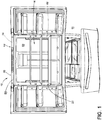
- the terms "upper,” “lower,” “right,” “left,” “rear,” “front,” “vertical,” “horizontal,” and derivatives thereof shall relate to the device as oriented in FIG. 1 .
- the device may assume various alternative orientations and step sequences, except where expressly specified to the contrary.
- the specific devices and processes illustrated in the attached drawings, and described in the following specification are simply exemplary embodiments of the inventive concepts defined in the appended claims. Hence, specific dimensions and other physical characteristics relating to the embodiments disclosed herein are not to be considered as limiting, unless the claims expressly state otherwise.
- reference numeral 10 generally refers to an appliance that includes a vacuum-type and/or compressed insulated structure 12 disposed therein for substantially limiting thermal transfer from an internal compartment 14 of the appliance 10 to external areas 16 of the appliance 10.
- an appliance 10 can include an insulated structure 12 formed using an insulation delivery apparatus 18.
- the insulated structure 12 for the appliance 10 includes an outer wrapper 20 and an inner liner 22 that cooperate to define an interior cavity 24.
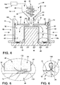
- the insulation delivery apparatus 18 includes a hopper 26 having a storage bin 28 and a delivery mechanism 30.
- the delivery mechanism 30 selectively delivers an insulating medium 32 from the storage bin 28, through an insulation conduit 34, and into the interior cavity 24.
- the delivery mechanism 30 is operable between an idle state 36 and a delivery state 38, the idle state 36 being defined by the delivery mechanism 30 being substantially deactivated and the movement of the insulating medium 32 from the storage bin 28 and into the interior cavity 24 diminished or fully stopped.
- the delivery state 38 of the delivery mechanism 30 is defined by the operation of the delivery mechanism 30 for transporting the insulating medium 32 from the storage bin 28 and into the interior cavity 24 of the insulated structure 12.
- a pressing mechanism 40 is coupled with the insulation conduit 34 connected with the hopper 26. The pressing mechanism 40 is in selective engagement with the insulated structure 12.
- the pressing mechanism 40 is operable between a rest state 42, where the pressing mechanism 40 is positioned above the insulated structure 12, and a compressing state 44, wherein the pressing mechanism 40 is moved downward toward the insulated structure 12 to engage the interior cavity 24 of the insulated structure 12.
- the pressing mechanism 40 is adapted to compress the insulating medium 32 to be densified within the interior cavity 24 of the insulated structure 12.
- the insulation delivery apparatus 18 can include an inner support 46 that is attached to a base structure 48, where the inner support 46 selectively engages an outer surface 50 of the inner liner 22.
- the inner liner 22 of the insulated structure 12 is placed over the inner support 46 such that the inner liner 22 and, in turn, the insulated structure 12, can rest upon the inner support 46 to position the insulated structure 12 relative to the insulation delivery apparatus 18.
- the insulation delivery apparatus 18 also includes an operable outer support 52 that is in selective engagement with a portion of an exterior surface 54 of the outer wrapper 20. The engagement between the operable outer support 52 and the exterior surface 54 of the outer wrapper 20 serves to further secure the insulated structure 12 within the insulation delivery apparatus 18 and relative to the hopper 26.
- the inner support 46 and the operable outer support 52 also provide structural support and buttressing support to the insulated structure 12 as the pressing mechanism 40 is operated in the compressing state 44.
- the insulation conduit 34 includes an operable portion 60 that is in communication with the pressing mechanism 40.
- the operable portion 60 is adapted to be at least vertically flexible, displaceable or otherwise operable relative to the storage bin 28. It is further contemplated that the operable portion 60 can be movable in lateral, rotational and other directions in addition to being vertically operable relative to the storage bin 28.
- the operable portion 60 of the insulation conduit 34 allows for the delivery mechanism 30 to transfer the insulating medium 32 from the storage bin 28, through the insulation conduit 34 and into the interior cavity 24 as the pressing mechanism 40 moves in the compressing state 44. In this manner, at least a portion of the insulation conduit 34, proximate the operable portion 60, can extend through a portion of the pressing mechanism 40.
- the pressing mechanism 40 can define a conduit aperture 62 through which the operable portion 60 of the insulation conduit 34 can deliver the insulating medium 32 through the pressing mechanism 40 and into the interior cavity 24 of the insulated structure 12.
- the pressing mechanism 40 can include a shape that corresponds to various shapes of insulated structure 12. In this manner, the pressing mechanism 40 can be shaped to extend into the various walls of the insulated structure 12.
- the pressing mechanism 40 can also be shaped to correspond to the shape of the back panel 70 of the insulated structure 12. Combinations of these shapes can be used in a pattern to compress the insulating medium 32 at various stages of the operation of the delivery apparatus 18.
- These various shapes of the pressing mechanism 40 can serve to substantially prevent the insulating medium 32 from sticking or otherwise adhering to the surfaces that define the interior cavity 24.
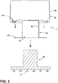
- a back panel 70 for the insulated structure 12 is selectively engaged with the operable portion 60 of the insulation conduit 34.
- the pressing mechanism 40 operates the back panel 70 and the operable portion 60 of the insulation conduit 34 relative to the back panel 70.
- the pressing mechanism 40 positions the back panel 70 relative to the insulated structure 12 and the interior cavity 24, such that the size of the insulated structure 12 can be set through the operation of the pressing mechanism 40.
- a sealing apparatus (not shown) of the insulation delivery apparatus 18 can be selectively operated to form a seal 72 between the back panel 70 and at least one of the outer wrapper 20 and the inner liner 22.
- the sealing apparatus can be in the form of a crimping device, welding device, adhesive dispensing device, fastening device, combinations thereof, and other similar devices that can provide a seal 72 between the back panel 70 and the remainder of the insulated structure 12. It is contemplated that the sealing apparatus can provide a hermetic seal 72 between the back panel 70 and the insulated structure 12 at at least one of the outer wrapper 20 and inner liner 22 of the insulated structure 12.
- the amount of the insulating medium 32 being disposed within the interior cavity 24 is monitored.
- the position of the back panel 70 relative to the insulated structure 12 is also monitored.
- the amount of insulating medium 32 and the current volume 80 of the interior cavity 24 can be known values such that the density of the insulating medium 32 disposed within the interior cavity 24 can be calculated during operation of the dispensing mechanism and pressing mechanism 40.
- the insulating medium 32 can be compressed to define a target density 82 to be defined within the insulated structure 12.
- the target density 82 can be a value that is determined during the design of the appliance 10.
- the target density 82 can be determined based upon several factors that can include, but are not limited to, the size of the appliance 10, the thickness of the insulated structure 12, the type of insulating medium 32, the function of the appliance 10, combinations thereof, and other similar factors that can bear on the cost, dimensional parameters, and performance of the appliance 10.
- the delivery mechanism 30 for the insulation delivery apparatus 18 includes an auger 90 that is disposed within the hopper 26. Operation of the auger 90 can cause a helical member to move the insulating medium 32 from the storage bin 28 and into the insulation conduit 34. As additional insulating medium 32 is compressed to achieve the target density 82, the auger 90 continues to operate in the delivery state 38 to provide additional insulating medium 32 to be disposed within the interior cavity 24 of the insulated structure 12. Once the appropriate amount of the insulating medium 32 is provided, the hopper 26 can be placed in the idle state 36, such that the auger 90 is slowed or stopped and no additional insulation, or substantially no additional insulation is provided into the interior cavity 24 of the insulated structure 12.
- the delivery mechanism 30 can include various alternate, or additional mechanisms, which mechanisms can include, but are not limited to, conveyors, blowers, suction devices, gravity fed mechanisms, and other similar delivery mechanisms 30 for disposing the insulating medium 32 within the interior cavity 24 of the insulated structure 12. It is also contemplated that combinations of these delivery mechanisms 30 can be used simultaneously, sequentially, or in a predetermined pattern in order to provide the appropriate amount of insulating medium 32 into the interior cavity 24 of the insulated structure 12 to achieve the target density 82.
- a suction mechanism including a vacuum pump 100 and a gas outlet valve 102 can be placed in communication with the interior cavity 24.
- the gas outlet valve 102 can be disposed in a portion of the insulated structure 12, in one or both of the outer wrapper 20 and the inner liner 22. It is contemplated that more than one gas outlet valve 102 can be disposed in the insulated structure 12 for expressing gas 104 from various portions of the interior cavity 24 of the insulated structure 12.
- the vacuum pump 100 can be used after the insulated structure 12 is hermetically sealed to express gas 104, such as air, from the interior cavity 24, where such an expression of gas 104 can cause an additional compression of the insulating medium 32.
- gas 104 such as air
- This additional compression of the insulating medium 32 through the expression of gas 104 can result in finite changes in the density of the insulating medium 32 to arrive at the target density 82 desired for the particular design of the appliance 10.
- the gas outlet valve 102 can be incorporated to work in conjunction with the delivery mechanism 30 to deliver the insulating medium 32 into the interior cavity 24. In this manner, gas 104 can be expressed and the expression of gas 104 also results in the insulating medium 32 being drawn toward the gas outlet valve 102.
- the expression of the gas 104 can result in the dispersion of the insulating medium 32 throughout the interior cavity 24.
- the gas outlet valve 102 can include a filter that allows for gas 104 to pass through the gas outlet valve 102, but substantially prevents the insulating medium 32 from passing therethrough.
- Additional compression of the insulating medium 32 can also be achieved through use of a vibrating mechanism placed in communication with the interior cavity 24.
- a vibrating mechanism can be an external vibrating table positioned against the outer wrapper 20 and/or the inner liner 22.
- the vibrating mechanism can also be a portable vibrating wand that can be disposed within the interior cavity 24.
- the vibrating mechanism can be part of the pressing mechanism 40, wherein the pressing mechanism 40 operates to compress and also vibrate the insulating medium 32 to further compact the insulating medium 32 in the interior cavity 24.
- a gas inlet valve 110 can be attached to a gas injector 112 that can be used in conjunction with the gas outlet valve 102 attached to the vacuum pump 100.
- the gas injector 112 can inject an insulating gas 114 to replace the expressed gas 104 to provide additional insulating characteristics to the insulating medium 32.
- insulating gasses 114 can include, but are not limited to, argon, neon, carbon dioxide, xenon, combinations thereof, and other similar insulating gasses 114.
- the locations and number of gas outlet valves 102, gas inlet valves 110 and other access apertures for injecting or expressing material from the interior cavity 24 can vary depending on the particular design and/or the desired performance of the insulation system of the appliance 10.
- an additive delivery mechanism 120 can be included within the insulation delivery apparatus 18.
- the additive delivery mechanism 120 can be used to combine insulating material additives 122 into the insulating medium 32 to modify the insulating characteristics of the insulating medium 32.
- the additive delivery mechanism 120 can be positioned proximate the hopper 26 such that the additives 122 are combined with the insulating medium 32 as the insulating medium 32 is disposed within the storage bin 28 of the hopper 26.
- the additive delivery mechanism 120 can be defined with the delivery mechanism 30 itself, such that the delivery mechanism 30 also acts as a mixing apparatus for combining the one or more additives 122 with the insulating medium 32 such that both can be disposed within the interior cavity 24 of the insulated structure 12 simultaneously. It is further contemplated that the additive delivery mechanism 120 can include a separate mechanism that can be separately operated to provide the various additives 122 directly into the insulated structure 12 at a separate location from the insulating medium 32.
- the one or more additives 122 that can be included and combined with the insulating medium 32 can include, but are not limited to, insulating glass spheres, insulating gas 114, additional powder-based insulation, granular insulation, glass fibers, combinations thereof, and other similar insulating additives 122.
- These additives 122 can be combined with the insulating medium 32, where the insulating medium 32 can include various components that can include, but are not limited to, various forms of silica, aerogel, one or more opacifiers, glass fiber, and insulating glass spheres.
- the glass spheres can take the form of solid or hollow glass spheres and can be of varying sizes including microspheres, nanospheres, and spheres of different sizes. It is further contemplated that the microspheres can include a hollow cavity, or a hollow cavity that includes an at least partial vacuum defined therein.
- the inner liner 22 of the insulated structure 12 can define an internal compartment 14, such as a refrigerating or freezing compartment of a refrigerator, a heating cavity of an oven, a washing cavity of a dishwasher or laundry appliance, or other similar interior cavity 24 of various appliances and fixtures.
- the inner support 46 is configured to be in selective engagement with an outer surface 50 of the inner compartment. In this manner, the outer surface 50 of the inner compartment at least partially surrounds the inner support 46 such that the inner support 46 prevents lateral movement of at least the inner liner 22 of the insulated structure 12.
- the inner liner 22 and outer wrapper 20 can be separate components that can be attached to one another while the inner liner 22 is disposed on the inner support 46.
- an edge 130 of the inner liner 22, or an edge 130 of the outer wrapper 20 can include a folded sealing member 132 that engages the other component of the insulated structure 12.
- the outer wrapper 20 can include the folded sealing member 132 such that the folded sealing member 132 of the outer wrapper 20 engages the opposing surfaces of the edge 130 of the inner liner 22, such that the outer wrapper 20 can be engaged with and form a seal 72 with the inner liner 22 on both sides.
- a sealing apparatus can be included within the insulation delivery apparatus 18 for sealing the connection between the outer wrapper 20 and the inner liner 22 to provide a hermetic seal 72 between these components.
- the engagement between the back panel 70 and the remainder of the insulated structure 12 can include a similar folded sealing member 132 of at least one of the edges 130 of the insulated structure 12 and/or the back panel 70.
- the back panel 70 can include the folded sealing member 132 that extends over an edge 130 of the insulated structure 12 such that the folded sealing member 132 of the back panel 70 engages both sides of the edge 130 of the insulated structure 12 at either the outer wrapper 20 or the inner liner 22. In this manner, both sides of the folded sealing member 132 of the back panel 70 can be sealed against the insulated structure 12 to define the hermetic seal 72 between the back panel 70 and the insulated structure 12.
- the various sealing mechanisms that can define the hermetic seal 72 between the various components of the insulated structure 12 can include, but are not limited to, welds, adhesives, fasteners, crimping engagements, combinations thereof, and other similar sealing engagements.
- the various components of the insulated structure 12 can be made of various rigid materials that can include, but are not limited to, metals, plastics, combinations thereof, and other similar materials.
- the various components of the insulated structure 12 will be made of the same material, such as the inner liner 22, outer wrapper 20, and back panel 70, all being made of metal. It is also contemplated that these components can be made of different materials, although the methods for sealing different materials of the insulated structure 12 can require different types of sealing mechanisms and operations to define the hermetic seal 72 between the various components of the insulated structure 12.
- the operable outer support 52 can be selectively moved between a load position 140 and a fill position 142.
- the load position 140 can be defined by a position of the operable outer support 52 where the inner liner 22 and outer wrapper 20 can be disposed over the inner support 46 without interference from the operable outer support 52.
- the load position 140 is defined by the operable outer support 52 being moved away from the inner support 46 such that the operable outer support 52 is free of engagement with the outer wrapper 20.
- the operable outer support 52 can be moved to the fill position 142, wherein the operable outer support 52 is placed in engagement with the exterior surface 54 of the outer wrapper 20.
- the inner support 46 and the operable outer support 52 buttress the inner liner 22 and outer wrapper 20 to prevent outward deflection of the insulated structure 12 during operation of the delivery mechanism 30 and pressing mechanism 40.
- the delivery mechanism 30 and pressing mechanism 40 operates to increase the amount of insulating medium 32 and also increase the density of the insulating medium 32, these operations will tend to cause the insulated structure 12 to deflect outward as the density of the insulating medium 32 increases.
- the positioning of the inner support 46 and the operable outer support 52 serve to counteract this tendency to deflect such that the insulated structure 12 maintains its desired shape during operation of the insulation delivery apparatus 18.
- the operable outer support 52 is moved back to the load position 140 such that the completed insulated structure 12 can be removed from the inner support 46, and components of another insulated structure 12 can be placed over the inner support 46 to begin the process again.
- each insulated structure 12 placed upon the insulation delivery apparatus 18 different parameters can be set for each insulated structure 12. Accordingly, various components of the insulation delivery apparatus 18 can be modified to accommodate a variety of designs for various vacuum insulated structures 12.
- the inner support 46 can be modified in size to accommodate different sizes of insulated structures 12.
- the amount of insulating medium 32 can also be modified and the amount of compressive force applied to the insulating medium 32 can be modified for each insulated structure 12 such that insulated structures 12 having various design parameters can be manufactured on the same insulation delivery apparatus 18.
- each insulation delivery apparatus 18 can be programmed to manufacture a single type of insulated structure 12 having a predetermined set of parameters that are achieved during each operation of the insulation delivery apparatus 18.
- a method 400 for forming a vacuum insulated structure 12.
- an insulation material is disposed into a hopper 26 having a storage bin 28 and delivery mechanism 30 (step 402).
- a pressing mechanism 40 is placed in communication with the hopper 26, where the pressing mechanism 40 and delivery mechanism 30 can be operated either simultaneously, sequentially, or in varying operational parameters.
- an insulated structure 12 is also positioned on an inner support 46 (step 404).
- the insulated structure 12 includes an inner liner 22 and an outer wrapper 20 that define an insulated interior cavity 24 defined therebetween.
- the insulated structure 12 includes an inner liner 22 and an outer wrapper 20, such structure can typically define a cabinet for an appliance 10. It is also contemplated, as will be described more fully below, that the insulated structure 12 can be a panel member used to form a vacuum insulated panel that can be placed within an appliance 10.
- an operable outer support 52 can be positioned against an exterior surface 54 of the insulated structure 12 (step 406).
- the inner support 46 and the operable outer support 52 serve to locate the insulated structure 12 such that the delivery mechanism 30 is in communication with the insulating interior cavity 24 of the insulated structure 12.
- the delivery mechanism 30 is operated to dispose the material of the insulating medium 32 within the insulation interior cavity 24 of the insulated structure 12 (step 408).
- the pressing mechanism 40 can also be operated during operation of the delivery mechanism 30 to compress the insulating medium 32 disposed within the insulated interior cavity 24 to define or substantially define the target density 82 of the insulating medium 32 (step 410).
- the back panel 70 of the insulated structure 12 can be engaged with the pressing mechanism 40.
- the inner support 46 and the operable outer support 52 substantially limit outward deflection of the outer wrapper 20 and inner liner 22 during operation of the pressing mechanism 40 and the delivery mechanism 30.
- the back panel 70 is sealed to the remainder of the insulated structure 12 to define a hermetic seal 72 (step 412).
- Gas 104 is then expressed from the interior cavity 24 to define a vacuum-type insulated structure 12 (step 414).
- portions of the operable outer support 52 are moved away from the vacuum-type insulated structure 12 and the vacuum-type insulated structure 12 are removed from the inner support 46 (step 416).
- the operable outer support 52 can include support components 150 that can be moved in varying directions toward and away from the inner support 46 to define the load position 140 and the fill position 142.
- Such movements of the support components 150 of the operable outer support 52 can include lateral movements, vertical movements, rotating movements, combinations thereof, and other similar movements that can place the support components 150 of the operable outer support 52 proximate to and distal from the inner support 46, and, accordingly, into and out of engagement with the insulated structure 12.
- an insulating medium 32 is disposed into a hopper 26 having a storage bin 28 and delivery mechanism 30 (step 602).
- a pressing mechanism 40 can be placed in communication with the hopper 26. It is contemplated that the pressing mechanism 40 can be directly attached to hopper 26 via the operable portion 60 of the insulation conduit 34. It is also contemplated that the pressing mechanism 40 can be a separate apparatus that operates in conjunction with the hopper 26, but is not directly attached thereto.
- the pressing mechanism 40 can be disposed adjacent one of the insulated structure 12 and the delivery mechanism 30 can be disposed proximate another separate wall of the insulated structure 12.
- the insulated structure 12 can be positioned proximate an operable outer support 52, wherein the insulated structure 12 includes an insulating interior cavity 24 (step 604).
- the insulated structure 12 can take the form of the structure of an appliance 10, or can take the form of a panel member that will be made into a vacuum insulated panel for installation, as a separate insulation unit, within the appliance 10. Portions of the operable outer support 52 can then be positioned against an exterior surface 54 of the insulated structure 12 (step 606).
- the operable outer support 52 can locate the insulated structure 12 such that the delivery mechanism 30 is in communication with the insulating interior cavity 24. Once the insulated structure 12 is positioned, the delivery mechanism 30 can operate to dispose the insulating medium 32 within the insulating interior cavity 24 of the insulated structure 12 (step 608). The pressing mechanism 40 can then be operated to compress the material of the insulating medium 32 disposed within the insulating interior cavity 24 to define the target density 82 (step 610). It is contemplated that the pressing mechanism 40 can be operated during operation of the delivery mechanism 30 in a substantially simultaneous fashion, a sequential fashion, or according to a predetermined operational pattern of simultaneous/sequential or independent steps of the delivery mechanism 30 and the pressing mechanism 40.
- the operable outer support 52 substantially limits outward deflection of the outer wrapper 20 during operation of the pressing mechanism 40.
- the insulated structure 12 can then be sealed with the insulating medium 32 disposed therein to define a hermetic seal 72 (step 612).
- the insulating medium 32 can be at the target density 82, or at a density substantially similar to the target density 82 where further compressive or expansive operations may take place to place the insulating medium 32 at the target density 82.
- gas 104 can be expressed from the interior cavity 24 to define the vacuum-type insulated structure 12 (step 614).
- portions of the operable outer support 52 can be moved away from the vacuum-type insulated structure 12 (step 616).
- the vacuum-type insulated structure 12 in the form of a vacuum insulated cabinet or vacuum insulated panel, can be removed and components of another insulated structure 12 can be disposed proximate the operable outer support 52.
- the operation of the insulation delivery apparatus 18 can be used to fine-tune the density of the insulating medium 32 disposed within the insulated structure 12 to provide a substantially accurate density of the insulating medium 32 at a target density 82.
- the various operations of the delivery mechanism 30, pressing mechanism 40, additive delivery mechanism 120, vacuum pump 100 and gas injector 112 can be used separately or in various combinations to achieve a substantially accurate target density 82 of the insulating medium 32 disposed within the insulated structure 12 of the appliance 10.
- the term "coupled” in all of its forms, couple, coupling, coupled, etc. generally means the joining of two components (electrical or mechanical) directly or indirectly to one another. Such joining may be stationary in nature or movable in nature. Such joining may be achieved with the two components (electrical or mechanical) and any additional intermediate members being integrally formed as a single unitary body with one another or with the two components. Such joining may be permanent in nature or may be removable or releasable in nature unless otherwise stated.
- elements shown as integrally formed may be constructed of multiple parts or elements shown as multiple parts may be integrally formed, the operation of the interfaces may be reversed or otherwise varied, the length or width of the structures and/or members or connector or other elements of the system may be varied, the nature or number of adjustment positions provided between the elements may be varied.
- the elements and/or assemblies of the system may be constructed from any of a wide variety of materials that provide sufficient strength or durability, in any of a wide variety of colors, textures, and combinations. Accordingly, all such modifications are intended to be included within the scope of the present invention as defined in the appended claims. Other substitutions, modifications, changes, and omissions may be made in the design, operating conditions, and arrangement of the desired and other exemplary embodiments without departing from the scope of the present invention as defined in the appended claims.
Landscapes
- Engineering & Computer Science (AREA)
- Chemical & Material Sciences (AREA)
- Combustion & Propulsion (AREA)
- Physics & Mathematics (AREA)
- Mechanical Engineering (AREA)
- Thermal Sciences (AREA)
- General Engineering & Computer Science (AREA)
- Thermal Insulation (AREA)
Claims (14)
- Isolierungsabgabeeinrichtung (18) zum Bilden einer isolierten Gerätestruktur, die Isolierungsabgabeeinrichtung (18) umfassend:eine isolierte Struktur (12), die eine Außenumhüllung (20) und eine Innenauskleidung (22) aufweist, die zum Definieren eines Innenhohlraums (24) zusammenwirken;einen Speicherbehälter (28) in Verbindung mit einem Abgabemechanismus (30), wobei der Abgabemechanismus (30) selektiv ein Isoliermedium (32) aus dem Speicherbehälter (28), durch eine Isolierungsleitung (34) und in den Innenhohlraum (24) abgibt, wobei der Abgabemechanismus (30) zwischen einem Ruhezustand (36) und einem Abgabezustand (38) betätigbar ist;einen Pressmechanismus (40), der mit der Isolierungsleitung (34) gekoppelt ist, wobei der Pressmechanismus (40) in selektivem Eingriff mit der isolierten Struktur (12) ist, wobei der Pressmechanismus (40) zwischen einem Ruhezustand (42) und einem Verdichtungszustand (44) betätigbar ist, wobei die Isolierungsleitung (34) einen betätigbaren Abschnitt (60) einschließt, der in Verbindung mit dem Pressmechanismus (40) steht;eine Innenstütze (46) in selektivem Eingriff mit einer Außenoberfläche (50) der Innenauskleidung (22) undeine betätigbare Außenstütze (52) in selektivem Eingriff mit einem Abschnitt einer Außenoberfläche (54) der Außenumhüllung (20), wobei die Innenstütze (46) und die betätigbare Außenstütze (52) eine Stützstruktur für die isolierte Struktur (12) bereitstellt, wenn der Pressmechanismus (40) im Verdichtungszustand (44) ist,dadurch gekennzeichnet, dasseine Rückwand (70) der isolierten Struktur (12) mit dem betätigbaren Abschnitt (60) der Isolierungsleitung (34) selektiv in Eingriff ist undder Pressmechanismus (40) die Rückwand (70) und den betätigbaren Abschnitt (60) der Isolierungsleitung (34) bezogen auf die isolierte Struktur (12) und den Speicherbehälter (28) betätigt.
- Isolierungsabgabeeinrichtung (18) nach Anspruch 1, wobei der betätigbare Abschnitt (60) bezogen auf den Speicherbehälter (28) mindestens vertikal betätigbar ist.
- Isolierungsabgabeeinrichtung (18) nach Anspruch 1 oder Anspruch 2, wobei der Abgabemechanismus (30) eine Förderschnecke (90) einschließt.
- Isolierungsabgabeeinrichtung (18) nach einem oder mehreren der Ansprüche 1-3, wobei die Innenauskleidung (22) einen Innenraum definiert und wobei die Innenstütze (46) in selektivem Eingriff mit einer Außenoberfläche (50) des Innenraums ist.
- Isolierungsabgabeeinrichtung (18) nach einem oder mehreren der Ansprüche 1-4, wobei die betätigbare Außenstütze (52) zwischen einer Ladeposition (140) und einer Füllposition (142) selektiv betätigbar ist.
- Isolierungsabgabeeinrichtung (18) nach Anspruch 5, wobei die Ladeposition (140) dadurch definiert ist, dass die betätigbare Außenstütze (52) nicht in Eingriff mit der Außenumhüllung (20) ist, und wobei die Füllposition (142) dadurch definiert ist, dass die betätigbare Außenstütze (52) in Eingriff mit der Außenoberfläche (54) der Außenumhüllung (20) ist.
- Isolierungsabgabeeinrichtung (18) nach Anspruch 1, wobei eine Dichtungseinrichtung zum Bilden einer Dichtung (72) zwischen der Rückwand (70) und einem von der Außenumhüllung (20) und der Innenauskleidung (22) selektiv betätigt wird.
- Isolierungsabgabeeinrichtung (18) nach einem oder mehreren der Ansprüche 1-7, weiter umfassend:
eine Vakuumpumpe (100) in Verbindung mit dem Innenhohlraum (24) über mindestens ein Gasventil, das in einem Abschnitt der isolierten Struktur (12) angeordnet ist. - Isolierungsabgabeeinrichtung (18) nach einem oder mehreren der Ansprüche 1-8, wobei das Isoliermedium (32) mindestens eines von Kieselsäure, Aerogel, Trübungsmittel, Glasfaser und Isolierkugeln einschließt.
- Isolierungsabgabeeinrichtung (18) nach einem oder mehreren der Ansprüche 1-9, weiter umfassend:
einen Zusatzstoffabgabemechanismus (120), wobei Zusatzstoffe (122) dem Isoliermedium (32) zur Anordnung innerhalb des Innenhohlraums (24) zugegeben werden, wobei die Zusatzstoffe (122) mindestens eines von Isolierglaskugeln und Isoliergas (114) einschließen. - Isolierungsabgabeeinrichtung (18) nach Anspruch 1-10, wobei der Speicherbehälter (28) und der Abgabemechanismus (30) innerhalb eines Trichters (26) enthalten sind, der mindestens das Isoliermedium (32) aufnimmt, und wobei sich die Isolierungsleitung (34) von dem Trichter (26) und in den Innenhohlraum (24) erstreckt.
- Verfahren (400) zum Bilden einer vakuumisolierten Struktur (12), wobei das Verfahren (400) die Schritte umfasst:Anordnen eines Isolierungsmaterials (32) in einen Trichter (26), der einen Speicherbehälter (28) und einen Abgabemechanismus (30) aufweist, wobei ein Pressmechanismus (40) in Verbindung mit dem Trichter (26) steht;Positionieren einer isolierten Struktur (12) an einer Innenstütze (46), wobei die isolierte Struktur (12) eine Innenauskleidung (22) und eine Außenumhüllung (20) einschließt, die einen Isolierhohlraum (24) definieren;Positionieren von Abschnitten einer betätigbaren Außenstütze (52) gegen eine Außenoberfläche (54) der isolierten Struktur (12), wobei die Innenstütze (46) und die betätigbare Außenstütze (52) die isolierte Struktur (12) derart anordnet, dass der Abgabemechanismus (30) in Verbindung mit dem Isolierhohlraum (24) steht;Betätigen des Abgabemechanismus (30) zum Anordnen des Isolierungsmaterials (32) innerhalb des Isolierhohlraums (24) der isolierten Struktur (12);Betätigen des Pressmechanismus (40) während der Betätigung des Abgabemechanismus (30) zum Verdichten des Isolierungsmaterials (32), das innerhalb des Isolierhohlraums (24) angeordnet ist, zum Definieren einer Solldichte, wobei eine Rückwand (70) der isolierten Struktur (12) mit dem Pressmechanismus (40) in Eingriff ist, wobei die Innenstütze (46) und die betätigbare Außenstütze (52) im Wesentlichen eine Biegung nach außen der Außenumhüllung (20) und der Innenauskleidung (22) während der Betätigung des Pressmechanismus (40) begrenzen;Abdichten der Rückwand (70) an einem Rest der isolierten Struktur (12) zum Definieren einer hermetischen Dichtung (72);Herausdrücken von Gas aus dem Innenhohlraum (24) zum Definieren einer vakuumisolierten Struktur (12) undBewegen der Abschnitte der betätigbaren Außenstütze (52) weg von der vakuumisolierten Struktur (12) und Entfernen der vakuumisolierten Struktur (12) von der Innenstütze (46),wobei der Abgabemechanismus (30) eine Förderschnecke (90) ist,wobei der Trichter (26) eine Isolierungsleitung (34) einschließt, durch die das Isolierungsmaterial (32) von dem Speicherbehälter (28) an den Isolierhohlraum (24) abgegeben wird,wobei sich die Isolierungsleitung (34) durch einen Abschnitt des Pressmechanismus (40) zum Abgeben des Isolierungsmaterials (32) von dem Speicherbehälter (28) an den Isolierhohlraum (24) erstreckt,wobei die Isolierungsleitung (34) einen betätigbaren Abschnitt (60) in Eingriff mit dem Pressmechanismus (40) einschließt undwobei der betätigbare Abschnitt (60) der Isolierungsleitung (34) zum im Wesentlichen Folgen der Bewegung des Pressmechanismus (40) wirkt.
- Verfahren (400) nach Anspruch 12, weiter umfassend den Schritt:
Anordnen von mindestens einem Zusatzstoff (122) an dem Isolierungsmaterial (32) zur Anordnung innerhalb des Isolierhohlraums (24) der isolierten Struktur (12), wobei der mindestens eine Zusatzstoff (122) mindestens eines von Isolierglaskugeln und Isoliergas (114) einschließt. - Verfahren (400) nach Anspruch 12 oder Anspruch 13, wobei das Isolierungsmaterial (32) mindestens eines von einer Isolierung auf Pulverbasis, einer granularen Isolierung, einem Trübungsmittel, Glasfaser, Isolierglaskugeln und Aerogel einschließt.
Applications Claiming Priority (2)
| Application Number | Priority Date | Filing Date | Title |
|---|---|---|---|
| US14/961,945 US10222116B2 (en) | 2015-12-08 | 2015-12-08 | Method and apparatus for forming a vacuum insulated structure for an appliance having a pressing mechanism incorporated within an insulation delivery system |
| PCT/US2016/062804 WO2017099975A1 (en) | 2015-12-08 | 2016-11-18 | Method and apparatus for making structure with vacuum insulation |
Publications (3)
| Publication Number | Publication Date |
|---|---|
| EP3387345A1 EP3387345A1 (de) | 2018-10-17 |
| EP3387345A4 EP3387345A4 (de) | 2019-08-21 |
| EP3387345B1 true EP3387345B1 (de) | 2021-01-13 |
Family
ID=58799719
Family Applications (1)
| Application Number | Title | Priority Date | Filing Date |
|---|---|---|---|
| EP16873572.8A Active EP3387345B1 (de) | 2015-12-08 | 2016-11-18 | Verfahren und vorrichtung zur herstellung einer struktur mit vakuumisolation |
Country Status (3)
| Country | Link |
|---|---|
| US (1) | US10222116B2 (de) |
| EP (1) | EP3387345B1 (de) |
| WO (1) | WO2017099975A1 (de) |
Families Citing this family (4)
| Publication number | Priority date | Publication date | Assignee | Title |
|---|---|---|---|---|
| US12508751B2 (en) | 2015-12-08 | 2025-12-30 | Whirlpool Corporation | Insulation compaction device and method for forming an insulated structure for an appliance |
| EP3615872B1 (de) * | 2017-04-28 | 2023-04-19 | Whirlpool Corporation | Strukturschrank für ein gerät |
| CN114674111B (zh) * | 2017-10-26 | 2024-08-20 | 惠而浦公司 | 用于提高真空绝缘结构中粉末绝缘材料的包装效率的真空辅助加热螺旋进料器 |
| EP3847405B1 (de) * | 2018-09-05 | 2024-07-24 | Whirlpool Corporation | Verfahren zum hinzufügen eines vakuumisolationsmaterials in eine vakuumisolierte kühlschrankstruktur und entsprechende vakuumisolierte kühlschrankstruktur |
Family Cites Families (543)
| Publication number | Priority date | Publication date | Assignee | Title |
|---|---|---|---|---|
| US3125388A (en) | 1964-03-17 | Floor-loading cabinet construction | ||
| CA626838A (en) | 1961-09-05 | Whirlpool Corporation | Heat insulating panels | |
| US948541A (en) | 1908-03-23 | 1910-02-08 | Clyde J Coleman | Heat-insulating wall. |
| US1275511A (en) | 1918-02-23 | 1918-08-13 | James Welch | Refrigerator. |
| US1921576A (en) | 1931-03-05 | 1933-08-08 | Copeland Products Inc | Refrigerating apparatus |
| US1849369A (en) | 1931-03-16 | 1932-03-15 | Durowood Ind Inc | Heat insulating material |
| US2108212A (en) | 1934-08-01 | 1938-02-15 | Shellwood Johnson Company | Metal-walled vacuum chamber or container |
| US2164143A (en) | 1934-11-10 | 1939-06-27 | Termisk Isolation Ab | Insulation |
| US2128336A (en) | 1936-03-25 | 1938-08-30 | Torstensson Sture Folke | Insulation |
| US2191659A (en) | 1936-06-03 | 1940-02-27 | Siemens Ag | Cold producing plant |
| US2318744A (en) | 1939-11-30 | 1943-05-11 | Johns Manville | Method of insulating |
| US2356827A (en) | 1941-04-26 | 1944-08-29 | Johns Manville | Method and apparatus for insulating structures |
| US2439603A (en) | 1943-03-02 | 1948-04-13 | Wood Conversion Co | Insulating confined spaces |
| US2439602A (en) | 1943-03-02 | 1948-04-13 | Wood Conversion Co | Insulating confined spaces |
| US2381454A (en) * | 1943-03-25 | 1945-08-07 | American Can Co | Machine for filling products into containers |
| US2538780A (en) | 1945-02-22 | 1951-01-23 | Frederick E Hazard | Refrigerating device for package goods |
| US2559356A (en) | 1945-04-28 | 1951-07-03 | Johns Manville | Method and apparatus for insulating refrigerators and the like |
| US2432042A (en) | 1945-10-15 | 1947-12-02 | Seeger Refrigerator Co | Refrigerator cabinet construction having means to restrict moisture in the walls of the cabinet |
| US2451884A (en) | 1947-08-16 | 1948-10-19 | Otto E Stelzer | Bar mounting fixture |
| US2768046A (en) | 1952-07-09 | 1956-10-23 | Gen Electric | Insulating structures |
| US2729863A (en) | 1952-12-11 | 1956-01-10 | Gen Electric | Insulated cabinet |
| US2817123A (en) | 1955-03-24 | 1957-12-24 | Gen Motors Corp | Refrigerating apparatus |
| US2942438A (en) | 1955-11-23 | 1960-06-28 | Gen Motors Corp | Refrigerator |
| US2985075A (en) | 1956-02-20 | 1961-05-23 | Knutsson-Hall Folke Knut | Method of manufacturing boxes of cardboard |
| DE1150190B (de) | 1957-12-23 | 1963-06-12 | Erich C Cussler | Vorrichtung zum Herstellen eines doppelwandigen Kuehlschrankgehaeuses |
| GB837929A (en) | 1958-03-07 | 1960-06-15 | Whirlpool Co | Heat insulating panels |
| US3086830A (en) | 1960-06-09 | 1963-04-23 | Malia John Peter | Compartmentalized refrigerator |
| US3137900A (en) | 1961-08-01 | 1964-06-23 | Gen Electric | Insulated wall and method of manufacture |
| US3258883A (en) | 1962-09-25 | 1966-07-05 | North American Aviation Inc | Rigidized evacuated structure |
| US3218111A (en) | 1964-01-27 | 1965-11-16 | Gen Motors Corp | Refrigerating apparatus |
| US3408316A (en) | 1964-02-13 | 1968-10-29 | Phillip Carey Corp | Preformed thermal insulation material and binder for molding same |
| US3338451A (en) | 1964-02-20 | 1967-08-29 | Gen Motors Corp | Refrigerating apparatus |
| US3358059A (en) | 1964-04-20 | 1967-12-12 | Dow Chemical Co | Method of filling enclosures with low density particulated material |
| US3353301A (en) | 1965-02-08 | 1967-11-21 | Glenco Refrigeration Corp | Thermal breaker strip |
| US3471416A (en) | 1965-07-06 | 1969-10-07 | Wyandotte Chemicals Corp | Low density foam system for refrigeration use |
| US3353321A (en) | 1965-09-15 | 1967-11-21 | Star Metal Corp | Thermal breaker strip |
| US3290893A (en) | 1965-09-29 | 1966-12-13 | Gen Electric | Household refrigerator |
| US3379481A (en) | 1965-10-20 | 1968-04-23 | Jessie M. Fisher | Cover for external air conditioning apparatus |
| US3513875A (en) | 1968-03-14 | 1970-05-26 | Illinois Tool Works | Closure device |
| US3688384A (en) | 1969-09-09 | 1972-09-05 | Mitsubishi Rayon Co | Method of producing a synthetic resin box with double wall structure |
| US3634971A (en) | 1969-12-01 | 1972-01-18 | Gen Motors Corp | All plastic refrigerator door with integral bump stop handle |
| US3635536A (en) | 1970-01-14 | 1972-01-18 | Westinghouse Electric Corp | Portable refrigerator utilizing a living hinge |
| US3632012A (en) | 1970-01-20 | 1972-01-04 | Philips Corp | Refrigerator cabinets |
| US3633783A (en) | 1970-01-21 | 1972-01-11 | Westinghouse Electric Corp | Refrigeration apparatus cabinet construction |
| US3597850A (en) | 1970-03-11 | 1971-08-10 | Nat Service Ind Inc | Continuous vacuum drier |
| JPS4828353B1 (de) | 1970-07-29 | 1973-08-31 | ||
| US3670521A (en) | 1970-11-17 | 1972-06-20 | Gen Electric | Side-by-side refrigerator |
| GB1437001A (en) | 1972-08-21 | 1976-05-26 | Sidaplax | Laminates |
| SU476407A1 (ru) | 1973-04-02 | 1975-07-05 | Трест "Киевподземдорстрой"-1 Главкиевгорстрой | Установка дл нанесени на трубу теплоизол ции из жестких масс типа легкого бетона |
| US3868829A (en) | 1973-11-30 | 1975-03-04 | Gen Motors Corp | Insulation divider for refrigerator cabinet |
| US4043624A (en) | 1974-01-14 | 1977-08-23 | Whirlpool Corporation | Refrigeration apparatus wall structure |
| US3875683A (en) | 1974-05-17 | 1975-04-08 | Whitlock Inc | Integral heater plenum drying hoppers |
| US3935787A (en) | 1974-06-19 | 1976-02-03 | Illinois Tool Works Inc. | Door handle anchor |
| SU547614A1 (ru) | 1974-09-16 | 1977-02-25 | Минский Завод Холодильников | Способ изготовлени теплоизолированной камеры |
| JPS5926376B2 (ja) | 1974-11-15 | 1984-06-27 | 住友金属工業株式会社 | 中空二重管の曲げ加工法 |
| US4005919A (en) | 1974-12-23 | 1977-02-01 | Monsanto Company | Refrigerator construction |
| CA1046571A (en) | 1975-06-13 | 1979-01-16 | Canadian General Electric Company Limited | Foam insulated side-by-side refrigerator |
| US4050145A (en) | 1975-08-04 | 1977-09-27 | Whirlpool Corporation | Method of making refrigeration apparatus enclosure structure |
| US4006947A (en) | 1975-11-07 | 1977-02-08 | Whirlpool Corporation | Liner and insulation structure for refrigeration apparatus |
| US4242241A (en) | 1977-10-31 | 1980-12-30 | The Celotex Corporation | Method for making a slurry containing particulate matter and fibers for a preformed insulation product |
| SU648780A1 (ru) | 1977-11-17 | 1979-02-25 | Предприятие П/Я Р-6601 | Уплотнение разъемного соединени |
| JPS57140642A (en) | 1978-08-28 | 1982-08-31 | Torobin Leonard B | Minute sphere of hollow inorganic film forming material |
| US5212143A (en) | 1978-08-28 | 1993-05-18 | Torobin Leonard B | Hollow porous microspheres made from dispersed particle compositions |
| US4671909A (en) | 1978-09-21 | 1987-06-09 | Torobin Leonard B | Method for making hollow porous microspheres |
| US4777154A (en) | 1978-08-28 | 1988-10-11 | Torobin Leonard B | Hollow microspheres made from dispersed particle compositions and their production |
| US4170391A (en) | 1978-09-21 | 1979-10-09 | General Electric Company | Refrigerator cabinet construction |
| US4260876A (en) | 1978-12-11 | 1981-04-07 | Anthony's Manufacturing Company, Inc. | Dew point differential power controller |
| DE2911416A1 (de) | 1979-03-23 | 1980-09-25 | Erno Raumfahrttechnik Gmbh | Element zur waermeisolation |
| US4303732A (en) | 1979-07-20 | 1981-12-01 | Torobin Leonard B | Hollow microspheres |
| US4303730A (en) | 1979-07-20 | 1981-12-01 | Torobin Leonard B | Hollow microspheres |
| US4332429A (en) | 1979-12-03 | 1982-06-01 | General Electric Company | Household refrigerator and method of construction |
| US4325734A (en) | 1980-03-27 | 1982-04-20 | Mcgraw-Edison Company | Method and apparatus for forming compact bodies from conductive and non-conductive powders |
| US4330310A (en) | 1980-08-22 | 1982-05-18 | Whirlpool Corporation | Plastic mullion rail assembly for refrigerator |
| US4396362A (en) | 1980-10-31 | 1983-08-02 | Union Carbide Corporation | Cryogenic reciprocating pump |
| US4805293A (en) | 1981-09-03 | 1989-02-21 | Whirlpool Corporation | Insulated cabinet manufacture |
| US4745015A (en) | 1981-09-30 | 1988-05-17 | The Dow Chemical Company | Thermal insulating panel |
| JPS59191588A (ja) | 1983-04-14 | 1984-10-30 | Kawasaki Steel Corp | 溶接工作物の変形防止方法 |
| US4492368A (en) | 1983-07-13 | 1985-01-08 | General Electric Company | Force applying apparatus |
| DE3346671C1 (de) | 1983-12-23 | 1985-07-04 | Karl 7531 Neuhausen Lenhardt | Verfahren zum Formen der Ecken von Abstandhalterrahmen fuer randverklebte Isolierglasscheiben |
| US4529368A (en) | 1983-12-27 | 1985-07-16 | E. I. Du Pont De Nemours & Company | Apparatus for quenching melt-spun filaments |
| US4671985A (en) | 1984-11-05 | 1987-06-09 | Swiss Aluminium Ltd. | Thin, deformable composite laminate |
| SU1307186A1 (ru) | 1985-11-15 | 1987-04-30 | Производственное Объединение По Выпуску Бытовых Холодильников,Г.Минск | Способ изготовлени шкафа холодильника |
| US4865875A (en) | 1986-02-28 | 1989-09-12 | Digital Equipment Corporation | Micro-electronics devices and methods of manufacturing same |
| US4781968A (en) | 1986-02-28 | 1988-11-01 | Digital Equipment Corporation | Micro-electronics devices and methods of manufacturing same |
| US4681788A (en) | 1986-07-31 | 1987-07-21 | General Electric Company | Insulation formed of precipitated silica and fly ash |
| IT1201782B (it) | 1986-09-18 | 1989-02-02 | Zanussi Zeltron Inst | Procedimento per al fabbricazione di apparecchi frigoriferi |
| US4870735A (en) | 1987-07-31 | 1989-10-03 | White Consolidated Industries, Inc. | Refrigeration cabinet construction |
| US4771532A (en) | 1988-01-27 | 1988-09-20 | General Electric Company | Method of assembling a refrigerator |
| US5157893A (en) | 1988-04-15 | 1992-10-27 | Midwest Research Institute | Compact vacuum insulation |
| US5813454A (en) | 1988-04-15 | 1998-09-29 | Varitec Thermal, L.L.C. | Variably insulating portable heater/cooler |
| US5477676A (en) | 1988-04-15 | 1995-12-26 | Midwest Research Institute | Method and apparatus for thermal management of vehicle exhaust systems |
| US5318108A (en) | 1988-04-15 | 1994-06-07 | Midwest Research Institute | Gas-controlled dynamic vacuum insulation with gas gate |
| US5175975A (en) | 1988-04-15 | 1993-01-05 | Midwest Research Institute | Compact vacuum insulation |
| US5643485A (en) | 1988-04-15 | 1997-07-01 | Midwest Research Institute | Cooking utensil with improved heat retention |
| US4917841A (en) | 1988-10-07 | 1990-04-17 | General Electric Company | Method of making a refrigerator cabinet liner having non-crinkled corners |
| US5033636A (en) | 1988-10-07 | 1991-07-23 | General Electric Company | Refrigerator cabinet liner having non-crinkled corners |
| US4914341A (en) | 1989-03-23 | 1990-04-03 | White Consolidated Industries, Inc. | Refrigerator cabinet construction |
| US5007226A (en) | 1989-05-01 | 1991-04-16 | Soltech, Inc. | Insulated refrigerator door construction |
| JPH0313779A (ja) | 1989-06-12 | 1991-01-22 | Matsushita Refrig Co Ltd | 断熱箱体 |
| US5018328A (en) | 1989-12-18 | 1991-05-28 | Whirlpool Corporation | Multi-compartment vacuum insulation panels |
| US5082335A (en) | 1989-12-18 | 1992-01-21 | Whirlpool Corporation | Vacuum insulation system for insulating refrigeration cabinets |
| US5084320A (en) | 1990-01-22 | 1992-01-28 | Barito Robert W | Evacuated thermal insulation |
| SE468227B (sv) | 1990-03-14 | 1992-11-23 | Electrolux Ab | Doerr vikt av plaat |
| US5066437A (en) | 1990-03-19 | 1991-11-19 | Barito Robert W | Method for insulating thermal devices |
| US5227245A (en) | 1990-04-04 | 1993-07-13 | The Dow Chemical Company | Barrier films for preventing solvent attack on plastic resins |
| US5094899A (en) | 1990-09-06 | 1992-03-10 | Owens-Corning Fiberglas Corporation | High r super insulation panel |
| US5252408A (en) | 1990-09-24 | 1993-10-12 | Aladdin Industries, Inc. | Vacuum insulated panel and method of forming a vacuum insulated panel |
| US5500305A (en) | 1990-09-24 | 1996-03-19 | Aladdin Industries, Inc. | Vacuum insulated panel and method of making a vacuum insulated panel |
| IT1243736B (it) | 1990-10-12 | 1994-06-21 | Sviluppo Settori Impiego Srl | Procedimento per la preparazione di corpi formati termoisolante e/o strutturali e prodotti cosi' ottenuti. |
| JP2966503B2 (ja) | 1990-10-26 | 1999-10-25 | 三洋電機株式会社 | 真空断熱部材とその製造方法 |
| US5168674A (en) | 1990-11-29 | 1992-12-08 | Molthen Robert M | Vacuum constructed panels |
| US5171346A (en) | 1991-01-22 | 1992-12-15 | Aktiebolaget Electrolux | Method of forming a composite thermal insulating material |
| US5219665A (en) | 1991-01-30 | 1993-06-15 | E. I. Du Pont De Nemours And Company | Fabricated articles with improved resistance to hydrohalocarbons |
| DE4110292C2 (de) | 1991-03-28 | 1998-01-22 | Miele & Cie | Haushaltgerät, wie Geschirrspülmaschine, Kühlschrank oder Gefriertruhe, mit einem Außengehäusemantel und innenliegendem Spülbehälter oder Kühlraum |
| JP2774388B2 (ja) | 1991-04-09 | 1998-07-09 | シャープ株式会社 | 真空断熱パネル |
| US5118174A (en) | 1991-05-17 | 1992-06-02 | Whirlpool Corporation | Method to prevent chemical (HCFC) attack of plastic foodliner from foam insulation chemicals |
| US5221136A (en) | 1991-09-12 | 1993-06-22 | Basf Corporation | Refrigerator liner structures |
| US5263773A (en) | 1991-11-14 | 1993-11-23 | White Consolidated Industries, Inc. | Cabinet structure and method of producing same |
| US5273801A (en) | 1991-12-31 | 1993-12-28 | Whirlpool Corporation | Thermoformed vacuum insulation container |
| RU2061925C1 (ru) | 1992-02-18 | 1996-06-10 | Алексей Митрофанович Бобришов | Тепловая изоляция |
| US5231811A (en) | 1992-03-16 | 1993-08-03 | Chicago Bridge & Iron Technical Services Company | Storage structures with layered thermal finish covering |
| US5248196A (en) | 1992-07-17 | 1993-09-28 | Whirlpool Corporation | Insulated wiring harness for domestic refrigerator |
| US5375428A (en) | 1992-08-14 | 1994-12-27 | Whirlpool Corporation | Control algorithm for dual temperature evaporator system |
| US5251455A (en) | 1992-08-14 | 1993-10-12 | Whirlpool Corporation | Energy efficient insulation system for refrigerator/freezer |
| US5652039A (en) | 1992-10-23 | 1997-07-29 | Tremain; Stephen R. | Sandwich panel for angular forming |
| US5507999A (en) | 1992-10-27 | 1996-04-16 | The Geon Company | Process for thermoforming plastic doors |
| JPH06159922A (ja) | 1992-11-26 | 1994-06-07 | Sanyo Electric Co Ltd | 断熱箱体及びその製造方法 |
| US5359795A (en) | 1993-03-02 | 1994-11-01 | White Consolidated Industries, Inc. | Refrigerator door construction |
| US5353868A (en) | 1993-04-19 | 1994-10-11 | Abbott Roy W | Integral tube and strip fin heat exchanger circuit |
| JPH071479A (ja) | 1993-06-18 | 1995-01-06 | Asahi Glass Co Ltd | 断熱性構造体の製造法 |
| SE501701C2 (sv) | 1993-09-29 | 1995-04-24 | Electrolux Ab | Sätt att fylla och packa isoleringspulver i väggarna hos en skåpkropp |
| US6164739A (en) | 1993-10-18 | 2000-12-26 | The Dow Chemical Company | Multilayer protective film |
| RU2081858C1 (ru) | 1993-10-21 | 1997-06-20 | Акционерное общество закрытого типа "Русстек" | Способ получения стеклянных микрошариков |
| US5866228A (en) | 1993-11-22 | 1999-02-02 | Mitsubishi Chemical Corporation | Vacuum heat-insulator |
| JPH07167377A (ja) | 1993-12-14 | 1995-07-04 | Sharp Corp | 真空断熱材 |
| SE505193C2 (sv) | 1993-12-22 | 1997-07-14 | Electrolux Ab | Låda utgörande vakuumisolerade väggar hos ett kyl- eller frysskåp |
| WO1995021361A1 (en) | 1994-02-03 | 1995-08-10 | Nippon Sanso Corporation | Cold/hot/storage and method of production thereof |
| FI1349U1 (fi) | 1994-02-21 | 1994-05-20 | Jarmo Sjoeholm | Profilkonstruktion |
| DE4409091A1 (de) | 1994-03-17 | 1995-09-21 | Licentia Gmbh | Kühlgerät mit vakuumisolierten Wänden |
| JPH07269779A (ja) | 1994-03-28 | 1995-10-20 | Toshiba Corp | 断熱筐体及び真空断熱パネルの製造方法 |
| RU2077411C1 (ru) | 1994-05-04 | 1997-04-20 | Самарский государственный технический университет | Способ получения изделий из порошковых материалов |
| JP3438948B2 (ja) | 1994-06-27 | 2003-08-18 | 株式会社日立製作所 | 冷蔵庫 |
| US5827385A (en) | 1994-07-15 | 1998-10-27 | Vacupanel, Inc. | Method of producing an evacuated insulated container |
| US6221456B1 (en) | 1994-07-26 | 2001-04-24 | Louis August Pogorski | Thermal insulation |
| CA2155056C (en) | 1994-08-08 | 2007-03-06 | John R. Revlett | Refrigeration appliance door with reinforcement sheet |
| US5533311A (en) | 1994-09-30 | 1996-07-09 | Maytag Corporation | Thermoformed plastic refrigerator door |
| DE4439328A1 (de) | 1994-11-04 | 1996-05-09 | Bayer Ag | Wärmeisolierender Körper |
| US5532034A (en) | 1994-12-06 | 1996-07-02 | Whirlpool Corporation | Getter system for vacuum insulation panel |
| US5834126A (en) | 1994-12-30 | 1998-11-10 | Basf Corporation | Barrier layer for use in refrigerator cabinets |
| GB9500497D0 (en) | 1995-01-11 | 1995-03-01 | Tioxide Group Services Ltd | Gloss emulsion paints |
| KR0184681B1 (ko) | 1995-01-24 | 1999-05-15 | 구보타 다다시 | 탄산가스 흡착제를 가지는 발포 단열재와 그 발포 단열재의 제조방법 |
| US5640828A (en) | 1995-02-15 | 1997-06-24 | Weather Shield Mfg., Inc. | Spacer for an insulated window panel assembly |
| CN1076460C (zh) | 1995-04-13 | 2001-12-19 | 亨茨曼Ici化学品有限公司 | 非平面抽空绝缘板,其制造方法及应用 |
| JPH08303686A (ja) | 1995-04-28 | 1996-11-22 | Mitsubishi Chem Corp | 真空断熱パネルおよびその製造方法 |
| JPH08300052A (ja) | 1995-04-28 | 1996-11-19 | Showa Alum Corp | 中空材の曲げ加工方法、中空材及び中空材の両端部蓋装置 |
| US5600966A (en) | 1995-05-19 | 1997-02-11 | Forma Scientific, Inc. | Ultra low temperature split door freezer |
| DE19520020A1 (de) | 1995-05-31 | 1996-12-05 | Bosch Siemens Hausgeraete | Wärmeisolierendes Gehäuse |
| US5632543A (en) | 1995-06-07 | 1997-05-27 | Owens-Corning Fiberglas Technology Inc. | Appliance cabinet construction |
| JPH0952955A (ja) | 1995-08-11 | 1997-02-25 | Daikin Ind Ltd | 変性ポリテトラフルオロエチレン粒状粉末の製法 |
| DE19537714A1 (de) | 1995-10-10 | 1997-04-17 | Inst Neue Mat Gemein Gmbh | Verfahren zur Herstellung eines leitfähigen Sinterkörpers auf der Basis von Siliciumcarbid |
| RU2162031C2 (ru) | 1995-12-11 | 2001-01-20 | Хантсман Ай Си Ай Кемикалз Ллс | Теплоизолирующее устройство |
| JPH09166271A (ja) | 1995-12-15 | 1997-06-24 | Fujimori Kogyo Kk | 断熱壁面に対する真空断熱パネルの取付け構造及び真空断熱パネル |
| WO1997030782A1 (fr) | 1996-02-20 | 1997-08-28 | Mikuni Corporation | Procede de production de materiau granulaire |
| DE19607963C1 (de) | 1996-03-01 | 1997-05-22 | Carsten Klatt | Dämmstoff aus Reishülsen zur Herstellung einer Dämmstoffschüttung, Verfahren zur Herstellung desselben sowie Verfahren zur Herstellung einer Dämmstoffschüttung aus demselben |
| EP0912329A4 (de) | 1996-07-08 | 2001-03-07 | Oceaneering Int Inc | Isolierplatte |
| DE29613093U1 (de) | 1996-07-29 | 1997-11-27 | Bayer Ag, 51373 Leverkusen | Fixiertes Vakuumisolierpaneel sowie ein dieses fixierte Vakuumisolierpaneel enthaltendes Kühlmöbelelement |
| JP3792801B2 (ja) | 1996-10-07 | 2006-07-05 | 松下冷機株式会社 | 真空断熱体 |
| JPH10113983A (ja) | 1996-10-15 | 1998-05-06 | Toshiba Corp | 断熱箱体の内箱の製造方法 |
| US5868890A (en) | 1996-11-22 | 1999-02-09 | Eften, Inc. | Process for bonding a cover to a substrate |
| US5900299A (en) | 1996-12-23 | 1999-05-04 | Wynne; Nicholas | Vacuum insulated panel and container and method of production |
| US6106449A (en) | 1996-12-23 | 2000-08-22 | Vacupanel, Inc. | Vacuum insulated panel and container and method of production |
| US5934085A (en) | 1997-02-24 | 1999-08-10 | Matsushita Electric Industrial Co., Ltd. | Thermal insulator cabinet and method for producing the same |
| JPH10300330A (ja) | 1997-04-25 | 1998-11-13 | Sanyo Electric Co Ltd | 低温貯蔵庫 |
| JP3939497B2 (ja) | 1997-09-19 | 2007-07-04 | マグアイア、プロダクツ、インコーポレーテッド | 低圧乾燥器 |
| US5924295A (en) | 1997-10-07 | 1999-07-20 | Samsung Electronics Co., Ltd. | Method and apparatus for controlling initial operation of refrigerator |
| DE19745860A1 (de) | 1997-10-16 | 1999-06-17 | Bosch Siemens Hausgeraete | Wärmeisolierende Wandung |
| DE19745827A1 (de) | 1997-10-16 | 1999-05-06 | Bosch Siemens Hausgeraete | Wärmeisolierende Wandung |
| DE19745825A1 (de) | 1997-10-16 | 1999-04-22 | Bosch Siemens Hausgeraete | Wärmeisolierende Wandung |
| JPH11159693A (ja) | 1997-11-28 | 1999-06-15 | Mitsubishi Electric Corp | 真空断熱パネル及びその製造方法並びにそれを用いた断熱箱体 |
| JP3968612B2 (ja) | 1998-01-27 | 2007-08-29 | 三菱電機株式会社 | 全真空断熱箱体及びその全真空断熱箱体を用いた冷蔵庫並びにその全真空断熱箱体の製造方法及び解体方法 |
| SE511472C2 (sv) | 1998-02-12 | 1999-10-04 | Electrolux Ab | Vakuumisolerat kyl- eller frysskåp |
| AU3344199A (en) | 1998-04-17 | 1999-11-08 | Toyo Seikan Kaisha Ltd. | Method and device for manufacturing positive pressure packaging body |
| JPH11311395A (ja) | 1998-04-24 | 1999-11-09 | Matsushita Refrig Co Ltd | 真空断熱体、断熱箱体、断熱パネル、及び真空断熱体の製造方法 |
| DE19818890A1 (de) | 1998-04-28 | 1999-11-04 | Bayer Ag | Kontinuierliches Verfahren zur Herstellung eines Kühlschranks |
| RU2132522C1 (ru) | 1998-05-26 | 1999-06-27 | Краснодарский научно-исследовательский институт хранения и переработки сельскохозяйственной продукции | Устройство для хранения биологических объектов |
| JPH11336990A (ja) | 1998-05-27 | 1999-12-07 | Matsushita Refrig Co Ltd | 真空断熱体、断熱箱体、及び断熱パネル |
| US6244458B1 (en) | 1998-07-09 | 2001-06-12 | Thermo Solutions, Inc. | Thermally insulated container |
| US6109712A (en) | 1998-07-16 | 2000-08-29 | Maytag Corporation | Integrated vacuum panel insulation for thermal cabinet structures |
| US5966963A (en) | 1998-07-30 | 1999-10-19 | Kovalaske; Kenneth A. | Refrigerator with a third door |
| US6460955B1 (en) | 1998-09-09 | 2002-10-08 | Fisher & Paykel Limited | Cabinet, parts thereof and associated methods |
| US6094922A (en) | 1998-09-09 | 2000-08-01 | Ziegler; Alex R. | Vacuum-insulated refrigerant line for allowing a vaccum chamber system with water-vapor cryocoil compressor to be locatable outside cleanroom |
| JP3137946B2 (ja) | 1998-09-22 | 2001-02-26 | 明星工業株式会社 | 断熱パネル及びその製造方法 |
| US6132837A (en) | 1998-09-30 | 2000-10-17 | Cabot Corporation | Vacuum insulation panel and method of preparing the same |
| JP2000117334A (ja) | 1998-10-20 | 2000-04-25 | Toyota Motor Corp | 押出し材の曲げ加工方法 |
| JP3773675B2 (ja) | 1998-10-28 | 2006-05-10 | 株式会社松井製作所 | 粉粒体材料の真空式自動連続除湿乾燥装置 |
| CA2257703C (en) | 1999-01-04 | 2002-10-08 | Nedo Banicevic | Refrigerator evaporator housing |
| US6390378B1 (en) | 1999-02-02 | 2002-05-21 | Ca Global Express, Llc | Centralized humidification controlled container system for transporting and holding perishable goods |
| DE19907182A1 (de) | 1999-02-19 | 2000-08-24 | Bsh Bosch Siemens Hausgeraete | Wärmeisolierende Wand |
| US6260377B1 (en) | 1999-03-05 | 2001-07-17 | Sanyo Electric Co., Ltd. | Refrigerating apparatus |
| US6629429B1 (en) | 1999-03-12 | 2003-10-07 | Matsushita Refrigeration Company | Refrigerator |
| DE19914105A1 (de) | 1999-03-23 | 2000-09-28 | Wolfgang Reimann | Wärmedämmplatte mit verbesserter Wärmedämmung |
| DE19915456A1 (de) | 1999-04-01 | 2000-10-05 | Bsh Bosch Siemens Hausgeraete | Wärmeisolierende Wandung |
| DE19915311A1 (de) | 1999-04-03 | 2000-10-05 | Bayer Ag | Vakuum Isolier Paneele |
| DE60036572T2 (de) | 1999-04-12 | 2008-10-23 | Isuzu Motors Ltd. | Wärmedämmendes Mauerelement und Verfahren zu dessen Herstellung |
| RU2162576C2 (ru) | 1999-04-15 | 2001-01-27 | Государственная академия сферы быта и услуг | Устройство холодильного агрегата бытового компрессионного холодильника |
| UA72518C2 (uk) | 1999-06-04 | 2005-03-15 | Лусайт Інтернешнл Юк Лімітед | Полімерний матеріал, стійкий до впливу атмосферних факторів, спосіб його одержання та застосування |
| DE19931170A1 (de) | 1999-07-06 | 2001-01-11 | Bsh Bosch Siemens Hausgeraete | Wärmeisolierende Wandung wie ein Kühlgeräte-Gehäuse oder eine Kältegerätetür |
| US6220473B1 (en) | 1999-07-14 | 2001-04-24 | Thermo Solutions, Inc. | Collapsible vacuum panel container |
| US6406449B1 (en) | 1999-07-26 | 2002-06-18 | Richard A. Young | Vest having arm sling |
| JP3584793B2 (ja) | 1999-08-02 | 2004-11-04 | 株式会社デンソー | 吸着剤の造粒方法 |
| KR100554287B1 (ko) | 1999-08-26 | 2006-02-24 | 삼성전자주식회사 | 병립형 냉장고의 중간격벽 커버장치 |
| US6294595B1 (en) | 1999-08-30 | 2001-09-25 | Nexpress Solutions Llc | Polymeric powders and method of preparation |
| JP3464949B2 (ja) | 1999-09-21 | 2003-11-10 | 株式会社東芝 | 冷蔵庫 |
| DE19948361A1 (de) | 1999-10-07 | 2001-04-12 | Bsh Bosch Siemens Hausgeraete | Kältegerät |
| JP2001116437A (ja) | 1999-10-20 | 2001-04-27 | Hitachi Ltd | 冷蔵庫の真空断熱扉 |
| DE19957806A1 (de) | 1999-12-01 | 2001-06-07 | Bsh Bosch Siemens Hausgeraete | Wärmeisolierende Wandung |
| JP3478771B2 (ja) | 1999-12-10 | 2003-12-15 | 松下冷機株式会社 | 冷蔵庫 |
| JP3781598B2 (ja) | 1999-12-28 | 2006-05-31 | 日清紡績株式会社 | 真空断熱材の変形方法、真空断熱材の固定方法、冷凍・冷蔵容器及び断熱箱体 |
| AU781858B2 (en) | 1999-12-28 | 2005-06-16 | Lg Electronics Inc. | Door handle installation structure of refrigerator |
| IT1316769B1 (it) | 2000-02-18 | 2003-05-12 | Getters Spa | Pannello evacuato per isolamento termico con ridotta conduzione dicalore ai bordi |
| JP3478780B2 (ja) | 2000-05-25 | 2003-12-15 | 松下冷機株式会社 | 真空断熱材、及び真空断熱材を用いた冷蔵庫 |
| TW470837B (en) | 2000-04-21 | 2002-01-01 | Matsushita Refrigeration | Vacuum heat insulator |
| CN1308639C (zh) | 2000-04-21 | 2007-04-04 | 松下冷机株式会社 | 冰箱 |
| EP1160212A1 (de) | 2000-05-31 | 2001-12-05 | Asahi Glass Co., Ltd. | Glas Mikrohohlkugeln und Verfahren zu ihrer Herstellung |
| JP2001343176A (ja) | 2000-06-02 | 2001-12-14 | Purotekku Denshi Kogyo:Kk | 真空断熱型保冷装置及び真空断熱型保冷方法 |
| TW539614B (en) | 2000-06-06 | 2003-07-01 | Matsushita Electric Works Ltd | Laminate |
| US7234247B2 (en) | 2000-06-16 | 2007-06-26 | Maguire Stephen B | Low pressure dryer |
| WO2002000418A1 (en) | 2000-06-27 | 2002-01-03 | Graham Packaging Company, L.P. | Preform and method for manufacturing a multi-layer, blown finish container |
| IT1318100B1 (it) | 2000-06-30 | 2003-07-23 | Getters Spa | Pannello evacuato per isolamento termico di un corpo avente superficinon piane |
| GB0019596D0 (en) | 2000-08-09 | 2000-09-27 | Foster Refrigerator Uk Ltd | Refrigeration cabinet |
| RU2166158C1 (ru) | 2000-08-25 | 2001-04-27 | Выгодин Вячеслав Александрович | Холодильник для пищевых продуктов |
| JP2002068853A (ja) | 2000-08-28 | 2002-03-08 | Tokai Kogyo Kk | 軽量断熱体およびその製造方法 |
| EP1401731A2 (de) | 2000-11-29 | 2004-03-31 | American Aerogel Corporation | Isolierbarrieren und verfahren zu deren herstellung |
| WO2002052208A1 (en) | 2000-12-22 | 2002-07-04 | Arçelik A.S. | An insulated unit |
| KR100362612B1 (ko) | 2001-01-05 | 2002-11-29 | 삼성전자 주식회사 | 냉장고 |
| US6415623B1 (en) | 2001-01-05 | 2002-07-09 | Cold Sell Systems, Llc | Point of sale product chiller |
| EP1364703A4 (de) | 2001-01-30 | 2008-02-06 | Honda Motor Co Ltd | "aktive struktur, vorrichtung zur aktivierung eines stoffes und verfahren zur aktivierung eines stoffes" |
| CA2338807C (en) | 2001-02-27 | 2004-07-06 | Camco Inc. | Refrigerator mullion |
| JP4028688B2 (ja) | 2001-03-21 | 2007-12-26 | 株式会社東芝 | 冷蔵庫 |
| WO2002081833A1 (en) | 2001-04-06 | 2002-10-17 | Dow Global Technologies Inc. | Shapeable vacuum insulation panel containing a single core component |
| KR100376167B1 (ko) | 2001-04-18 | 2003-03-15 | 삼성전자주식회사 | 냉온장고 |
| DE10126843A1 (de) | 2001-06-01 | 2002-12-05 | Bsh Bosch Siemens Hausgeraete | Korpus für ein Kältegerät |
| DE60233941D1 (de) | 2001-06-04 | 2009-11-19 | Panasonic Corp | Isolierter kastenförmiger körper, kühlvorrichtung mit dem kastenförmigen körper und verfahren zum recycling von materialien für den isolierten kastenförmigen körper |
| ITMI20011868A1 (it) | 2001-09-06 | 2003-03-06 | Whirlpool Co | Apparecchio refrigerante con isolamento sottovuoto |
| US20030056334A1 (en) | 2001-09-24 | 2003-03-27 | Burl Finkelstein | Pull handle |
| US6773082B2 (en) | 2002-01-28 | 2004-08-10 | Daewoo Electronics Corp. | Refrigerator using EPS insulating material |
| DE10208066A1 (de) | 2002-02-25 | 2003-09-04 | Bsh Bosch Siemens Hausgeraete | Innenteil für ein Kältegerät |
| US6858280B2 (en) | 2002-02-26 | 2005-02-22 | Technology Applications, Inc. | Microsphere insulation systems |
| JP4121874B2 (ja) | 2002-03-13 | 2008-07-23 | 日世株式会社 | 生分解性成形物の製造方法およびそれに用いる成形型 |
| US7278279B2 (en) | 2002-03-13 | 2007-10-09 | Matsushita Refrigeration Co. | Refrigerator |
| WO2003083388A1 (fr) | 2002-03-29 | 2003-10-09 | Kabushiki Kaisha Toshiba | Refrigerateur |
| US7296432B2 (en) | 2002-04-05 | 2007-11-20 | Dometic Gmbh | Refrigerator housing |
| GB0209067D0 (en) | 2002-04-20 | 2002-05-29 | Microtherm Int Ltd | Flexible vacuum insulation panel and method of manufacture |
| KR100887575B1 (ko) | 2002-04-22 | 2009-03-09 | 엘지전자 주식회사 | 이중도어를 구비한 냉장고 |
| EP1505359A4 (de) | 2002-04-22 | 2006-08-30 | Matsushita Refrigeration | Kühlschrank |
| CA2383905C (en) | 2002-04-29 | 2007-06-26 | Camco Inc. | Refrigerator cabinet refrigerant tube assembly |
| KR100819085B1 (ko) | 2002-06-24 | 2008-04-02 | 삼성전자주식회사 | 냉장고 |
| US6716501B2 (en) | 2002-07-18 | 2004-04-06 | Avery Dennison Corporation | Multilayered film |
| AU2003256244A1 (en) | 2002-07-19 | 2004-02-09 | Arcelik A.S. | An insulated unit and a manufacturing method thereof |
| DE10248510A1 (de) | 2002-10-17 | 2004-04-29 | BSH Bosch und Siemens Hausgeräte GmbH | Kältegerät mit einem evakuierbaren Lagerfach |
| BR0205050A (pt) | 2002-11-25 | 2004-06-29 | Multibras Eletrodomesticos Sa | Sistema de alimentação elétrica para porta de refrigeradores e freezers |
| JP3559035B2 (ja) | 2002-12-05 | 2004-08-25 | 松下冷機株式会社 | 真空断熱材およびその製造方法、並びに真空断熱材を使用した防寒具およびパーソナルコンピューター |
| JP2004198066A (ja) | 2002-12-20 | 2004-07-15 | Matsui Mfg Co | 粉粒体材料の乾燥貯留装置及び粉粒体材料の供給システム |
| DE10302797B4 (de) | 2003-01-24 | 2025-05-28 | BSH Hausgeräte GmbH | Tür für ein Kältegerät und Kältegerät, umfassend eine Tür |
| KR100523035B1 (ko) | 2003-01-24 | 2005-10-24 | 삼성전자주식회사 | 냉장고용 일체형 흡입배관세트와 냉장고 |
| RU2234645C1 (ru) | 2003-01-27 | 2004-08-20 | Южно-Российский государственный университет экономики и сервиса | Бытовой компрессионный холодильник |
| US6997530B2 (en) | 2003-03-12 | 2006-02-14 | Maytag Corporation | Fastening system for appliance cabinet assembly |
| US20040180176A1 (en) | 2003-03-14 | 2004-09-16 | Rusek Stanley J. | Vaccum insulation article |
| JP2004303695A (ja) | 2003-04-01 | 2004-10-28 | Toshiba Corp | 高温体収納装置 |
| JP2004308691A (ja) | 2003-04-02 | 2004-11-04 | Nisshinbo Ind Inc | 真空断熱材及びその製造方法 |
| KR100750456B1 (ko) | 2003-04-18 | 2007-08-22 | 마쯔시다덴기산교 가부시키가이샤 | 진공 단열재와 이를 사용한 기기 |
| US20040226141A1 (en) | 2003-05-13 | 2004-11-18 | Manitowoc Foodservice Companies, Inc. | Reversible door handle |
| FR2857393B1 (fr) | 2003-07-09 | 2005-10-07 | Gerard Noale | Dispositif coupe-feu pour la protection de parois ou de structures |
| JP4111096B2 (ja) | 2003-08-05 | 2008-07-02 | 三菱電機株式会社 | 冷蔵庫 |
| JP2005069596A (ja) | 2003-08-26 | 2005-03-17 | Toshiba Corp | 冷蔵庫 |
| US7008032B2 (en) | 2003-08-29 | 2006-03-07 | Maytag Corporation | Refrigerator incorporating french doors with rotating mullion bar |
| GB0322358D0 (en) | 2003-09-24 | 2003-10-22 | Bioprogress Technology Ltd | Improvements in powder compaction and enrobing |
| JP2005098637A (ja) | 2003-09-26 | 2005-04-14 | Hitachi Home & Life Solutions Inc | 冷蔵庫並びに真空断熱材及びその製造方法 |
| AU2004214520B2 (en) | 2003-09-29 | 2009-08-06 | Lg Electronics Inc. | Handle assembly for refrigerator |
| JP2005114015A (ja) | 2003-10-07 | 2005-04-28 | Matsushita Electric Ind Co Ltd | 真空断熱材とこれを用いた冷蔵庫、保温保冷容器、給湯器及び炊飯器断熱箱体 |
| DE10355137A1 (de) | 2003-11-26 | 2005-06-23 | BSH Bosch und Siemens Hausgeräte GmbH | Kältegerätegehäuse |
| JP2005164193A (ja) | 2003-12-05 | 2005-06-23 | Matsushita Electric Ind Co Ltd | 冷蔵庫 |
| DE10360908A1 (de) | 2003-12-23 | 2005-07-21 | BSH Bosch und Siemens Hausgeräte GmbH | Einbau-Kältegerät |
| KR101010793B1 (ko) | 2004-02-11 | 2011-01-25 | 엘지전자 주식회사 | 냉장고 본체 및 그 제조방법 |
| JP2005256849A (ja) | 2004-03-08 | 2005-09-22 | Sanyo Electric Co Ltd | 真空断熱材 |
| KR101014199B1 (ko) | 2004-03-26 | 2011-02-14 | 주식회사 대우일렉트로닉스 | 냉장고 도어 핸들 조립구조 |
| DE102004014926A1 (de) | 2004-03-26 | 2005-10-13 | BSH Bosch und Siemens Hausgeräte GmbH | Kältegerät mit zwei Lagerfächern |
| US20050229614A1 (en) | 2004-04-02 | 2005-10-20 | Altech Controls, Inc. | Anti-sweat heater control system and method |
| ITMI20040737A1 (it) | 2004-04-14 | 2004-07-14 | Whirlpool Co | Apparecchio frigorifero e-o congelatore modulare |
| DE102004026443B3 (de) | 2004-05-29 | 2006-02-02 | Stefanie Heller | Isolierende Granulate für Anwendungen im Hochtemperaturbereich |
| DE102004026433A1 (de) | 2004-05-29 | 2005-12-22 | Schott Ag | Nanoglaspulver und deren Verwendung |
| US7762634B2 (en) | 2004-06-03 | 2010-07-27 | Panasonic Corporation | Vacuum heat insulation material and cold reserving apparatus with the same |
| JP4183657B2 (ja) | 2004-06-04 | 2008-11-19 | 日立アプライアンス株式会社 | 冷蔵庫 |
| WO2006011116A1 (en) | 2004-07-22 | 2006-02-02 | Arcelik Anonim Sirketi | A cooling device |
| US20060028105A1 (en) | 2004-08-05 | 2006-02-09 | Rasche Kenneth J | Formed door for refrigerators |
| KR100555804B1 (ko) | 2004-08-11 | 2006-03-03 | 엘지전자 주식회사 | 냉장고용 도어핸들 |
| JP2006077792A (ja) | 2004-09-07 | 2006-03-23 | Matsushita Electric Ind Co Ltd | 真空断熱材 |
| SE0402261D0 (sv) | 2004-09-17 | 2004-09-17 | Electrolux Home Prod Corp | Capacitive Sensor System |
| US8353177B2 (en) | 2004-09-27 | 2013-01-15 | Whirlpool Corporation | Apparatus and method for dispensing ice from a bottom mount refrigerator |
| JP4670302B2 (ja) * | 2004-10-06 | 2011-04-13 | 株式会社スリーボンド | 材料圧送装置 |
| JP4576195B2 (ja) | 2004-10-12 | 2010-11-04 | 日立アプライアンス株式会社 | 真空断熱材、及び真空断熱材を用いた冷蔵庫、並びに真空断熱材の製造方法。 |
| JP4215701B2 (ja) | 2004-10-12 | 2009-01-28 | 日立アプライアンス株式会社 | 冷蔵庫 |
| DE102004052623A1 (de) | 2004-10-29 | 2006-05-11 | BSH Bosch und Siemens Hausgeräte GmbH | Kältegerät |
| DE102004052622A1 (de) | 2004-10-29 | 2006-06-08 | BSH Bosch und Siemens Hausgeräte GmbH | Modulares Kältegerät |
| JP4303674B2 (ja) | 2004-12-02 | 2009-07-29 | 株式会社ルネッサンス・エナジー・インベストメント | 断熱用ブロック及び低温貯蔵庫 |
| JP4649969B2 (ja) | 2004-12-07 | 2011-03-16 | 凸版印刷株式会社 | 真空断熱材 |
| FR2878936A1 (fr) | 2004-12-08 | 2006-06-09 | Saipem S A Sa | Procede d'isolation thermique de conduites coaxiales par un materiau isolant particulaire |
| KR100620025B1 (ko) | 2004-12-18 | 2006-09-08 | 엘지전자 주식회사 | 미세중공구체를 이용한 냉장고 캐비넷의 단열 구조 |
| US7732032B2 (en) | 2004-12-30 | 2010-06-08 | United States Gypsum Company | Lightweight, fiber-reinforced cementitious panels |
| JP2006200685A (ja) | 2005-01-24 | 2006-08-03 | Toshiba Corp | 断熱構造体およびその解体方法 |
| US7207181B2 (en) | 2005-03-01 | 2007-04-24 | Bradley W. Geuke | Refrigeration unit condensation prevention |
| ITVA20050025A1 (it) | 2005-04-15 | 2006-10-16 | Whirlpool Co | Procedimento per la produzione di materiali polimerici espansi e materiale polimerico espanso ottenuto mediante tale procedimento |
| DE102005021608A1 (de) | 2005-05-10 | 2006-11-23 | BSH Bosch und Siemens Hausgeräte GmbH | Mehrteiliges Haushaltsgerät |
| EP1724095B1 (de) | 2005-05-10 | 2008-08-20 | Whirlpool Corporation | Verfahren zum Herstellen eines Gerätegehäuses |
| US7284390B2 (en) | 2005-05-18 | 2007-10-23 | Whirlpool Corporation | Refrigerator with intermediate temperature icemaking compartment |
| JP4215745B2 (ja) | 2005-05-20 | 2009-01-28 | 日立アプライアンス株式会社 | 真空断熱材、真空断熱材を用いた冷蔵庫及び真空断熱材の製造方法 |
| JP4101252B2 (ja) | 2005-05-31 | 2008-06-18 | 三洋電機株式会社 | 冷蔵庫 |
| KR100633027B1 (ko) | 2005-07-04 | 2006-10-11 | 삼성광주전자 주식회사 | 냉장고의 내상 및 냉장고의 내상 성형용 금형 |
| BRPI0502706B1 (pt) | 2005-07-12 | 2015-12-15 | Multibrás S A Eletrodomésticos | arranjo de insuflamento de ar em um refrigerador combinado |
| US7343757B2 (en) | 2005-08-11 | 2008-03-18 | Whirlpool Corporation | Integrated center rail dispenser |
| EP1934540B1 (de) | 2005-09-07 | 2016-08-10 | LG Electronics, Inc. | Türgriff für einen kühlschrank |
| DE102005045726A1 (de) | 2005-09-23 | 2007-04-05 | Va-Q-Tec Ag | Verfahren zur Herstellung eines folienumhüllten Vakuumdämmkörpers |
| DE102005057144A1 (de) | 2005-11-30 | 2007-06-06 | BSH Bosch und Siemens Hausgeräte GmbH | Verbindungssystem zur Verbindung eines Einbaugeräts mit einem Möbel sowie Möbelanordnung |
| DE102005057160A1 (de) | 2005-11-30 | 2007-05-31 | BSH Bosch und Siemens Hausgeräte GmbH | Gehäuse für ein Haushaltsgerät |
| DE102005057150A1 (de) | 2005-11-30 | 2007-06-06 | BSH Bosch und Siemens Hausgeräte GmbH | Kühl- bzw. Gefrierschrank mit Verstärkungsrahmen |
| ATE509891T1 (de) | 2005-12-20 | 2011-06-15 | Evonik Degussa Gmbh | Pyrogen hergestelltes siliciumdioxid |
| KR20070065743A (ko) | 2005-12-20 | 2007-06-25 | 주식회사 대우일렉트로닉스 | 냉장고의 도어핸들 고정구조 |
| US7475562B2 (en) | 2005-12-29 | 2009-01-13 | Maytag Corporation | Ice storage drawer for a bottom mount refrigerator |
| EP1813574A1 (de) | 2006-01-25 | 2007-08-01 | Degussa GmbH | Zu Schülpen kompaktiertes pyrogen hergestelltes Siliciumdioxid |
| JP4779684B2 (ja) | 2006-02-09 | 2011-09-28 | パナソニック株式会社 | 真空断熱箱体 |
| EP1994342B1 (de) | 2006-02-24 | 2019-01-16 | Carrier Corporation | Verbundtüren für eine transportkühleinheit |
| JP4671895B2 (ja) | 2006-03-28 | 2011-04-20 | 日立アプライアンス株式会社 | 断熱パネル、断熱箱体及び断熱パネルの製造方法 |
| DE102006018426A1 (de) | 2006-04-20 | 2007-10-25 | BSH Bosch und Siemens Hausgeräte GmbH | Mehrteiliges Haushaltsgerät |
| EP2024696B1 (de) | 2006-05-31 | 2009-10-21 | Arçelik A.S. | Kühlvorrichtung |
| EP2035738B1 (de) | 2006-06-22 | 2014-05-07 | Basf Se | Wärmedämmelemente |
| GB0612803D0 (en) | 2006-06-28 | 2006-08-09 | Lucite Int Uk Ltd | Polymeric composition |
| US7793388B2 (en) | 2006-07-13 | 2010-09-14 | Maytag Corporation | Handle assembly for a domestic appliance |
| US7861538B2 (en) | 2006-07-26 | 2011-01-04 | The Aerospace Corporation | Thermoelectric-based refrigerator apparatuses |
| DE102006039621A1 (de) | 2006-08-24 | 2008-02-28 | Porextherm-Dämmstoffe Gmbh | Vakuumisolationspaneel mit Durchführung |
| JP4828353B2 (ja) | 2006-08-24 | 2011-11-30 | 日立オートモティブシステムズ株式会社 | ステアリング装置 |
| JP4545126B2 (ja) | 2006-09-04 | 2010-09-15 | シャープ株式会社 | 真空断熱パネル及びそれを用いた冷蔵庫 |
| WO2008065453A1 (en) | 2006-12-01 | 2008-06-05 | Innovia Films Limited | Film |
| CN1970185A (zh) | 2006-12-05 | 2007-05-30 | 成都飞机工业(集团)有限责任公司 | 中空铝合金挤压型材的弯曲成形方法 |
| RU2349618C2 (ru) | 2006-12-13 | 2009-03-20 | Виталий Степанович Беляев | Покрытие, наполненное полыми микросферами, предотвращающее обледенение поверхностей различных изделий |
| US7614244B2 (en) | 2006-12-21 | 2009-11-10 | General Electric Company | Ice producing apparatus and method |
| DE102006061085A1 (de) | 2006-12-22 | 2008-06-26 | BSH Bosch und Siemens Hausgeräte GmbH | Kältegerät |
| JP4897473B2 (ja) | 2006-12-26 | 2012-03-14 | 倉敷紡績株式会社 | 真空断熱材 |
| US8739568B2 (en) | 2008-03-12 | 2014-06-03 | Whirlpool Corporation | Appliance feature module enabled by energy or materials sourced from the host appliance |
| US8117865B2 (en) | 2008-03-12 | 2012-02-21 | Whirlpool Corporation | Refrigerator with module receiving conduits |
| US8453476B2 (en) | 2009-05-21 | 2013-06-04 | Whirlpool Corporation | Refrigerator module mounting system |
| US8299656B2 (en) | 2008-03-12 | 2012-10-30 | Whirlpool Corporation | Feature module connection system |
| KR20080065434A (ko) | 2007-01-09 | 2008-07-14 | 엘지전자 주식회사 | 냉장고용 도어핸들 |
| WO2008118536A2 (en) | 2007-02-02 | 2008-10-02 | The Regents Of The University Of California | Method for producing active glass nanoparticles by laser ablation |
| JP2008190815A (ja) | 2007-02-07 | 2008-08-21 | Sharp Corp | 冷却庫 |
| DE102007016846A1 (de) | 2007-04-10 | 2008-10-16 | BSH Bosch und Siemens Hausgeräte GmbH | Verfahren zum Herstellen eines Kältegeräts |
| CN101742945B (zh) | 2007-05-18 | 2012-11-14 | 梅特罗工业有限公司 | 用于环境控制柜的模块化隔热系统 |
| DE102007024365A1 (de) | 2007-05-22 | 2008-11-27 | Evonik Degussa Gmbh | Pyrogen hergestellte silanisierte und vermahlene Kieselsäure |
| KR101386469B1 (ko) | 2007-05-25 | 2014-04-21 | 엘지전자 주식회사 | 냉장고 |
| US7794805B2 (en) | 2007-06-29 | 2010-09-14 | Schlumberger Technology Corporation | Thermal insulation barriers |
| KR101401690B1 (ko) | 2007-07-05 | 2014-05-29 | 엘지전자 주식회사 | 냉장고 도어핸들 장착구조 |
| KR20090006389A (ko) | 2007-07-11 | 2009-01-15 | 엘지전자 주식회사 | 냉장고 |
| DE102007034298A1 (de) | 2007-07-24 | 2009-01-29 | BSH Bosch und Siemens Hausgeräte GmbH | Kältegerät mit Vakuumisolation |
| US20090032541A1 (en) | 2007-08-02 | 2009-02-05 | Lancer Partnership, Ltd. | Method and apparatus for a product dispenser with increased insulative properties |
| KR100876689B1 (ko) | 2007-08-27 | 2008-12-31 | 엘지전자 주식회사 | 냉장고 및 냉장고 도어 |
| JP2009063064A (ja) | 2007-09-06 | 2009-03-26 | Hitachi Appliances Inc | 真空断熱材及びこれを用いた冷蔵庫 |
| US7703824B2 (en) | 2007-12-03 | 2010-04-27 | International Truck Intellectual Property Company, Llc | In-cab refrigerator mounting and method |
| US20090179541A1 (en) | 2007-12-12 | 2009-07-16 | Nanopore, Inc. | Vacuum insulation panel with smooth surface method for making and applications of same |
| JP2009162402A (ja) | 2007-12-28 | 2009-07-23 | Sharp Corp | 冷蔵庫 |
| US8166872B2 (en) | 2008-03-12 | 2012-05-01 | Whirlpool Corporation | Modified atmosphere for food preservation |
| JP4973552B2 (ja) | 2008-03-14 | 2012-07-11 | クラウスマッファイ テヒノロギース ゲゼルシャフト ミット ベシュレンクテル ハフツング | 金型内成形品被覆用金型及び金型内成形品被覆成形方法 |
| WO2009131933A2 (en) | 2008-04-21 | 2009-10-29 | Dow Global Technologies Inc. | Units insulated with foams and having flexible outer skins |
| DE102008026529A1 (de) | 2008-06-03 | 2009-12-10 | BSH Bosch und Siemens Hausgeräte GmbH | Haushaltsgerät, insbesondere Kältegerät |
| DE102008026528A1 (de) | 2008-06-03 | 2009-12-10 | BSH Bosch und Siemens Hausgeräte GmbH | Haushaltsgerät, insbesondere Kältegerät, sowie Verfahren zum Herstellen eines Verbundkörpers und Vorschäumform zur Durchführung des Verfahrens |
| JP2010017437A (ja) | 2008-07-14 | 2010-01-28 | Panasonic Corp | ランチジャー |
| JPWO2010007783A1 (ja) | 2008-07-17 | 2012-01-05 | パナソニック株式会社 | 断熱体、断熱箱体、断熱扉及び冷凍冷蔵庫 |
| DE102008041488A1 (de) | 2008-08-22 | 2010-02-25 | BSH Bosch und Siemens Hausgeräte GmbH | Haushaltsgerät für den Einbau in einem Möbelrahmen |
| EP2159524B1 (de) | 2008-08-27 | 2010-12-01 | Panasonic Corporation | Kühlanlage |
| JP5333038B2 (ja) | 2008-09-10 | 2013-11-06 | パナソニック株式会社 | 真空断熱材とその製造方法 |
| JP2010071565A (ja) | 2008-09-19 | 2010-04-02 | Hitachi Appliances Inc | 冷蔵庫 |
| DE102008042814A1 (de) | 2008-10-14 | 2010-04-15 | BSH Bosch und Siemens Hausgeräte GmbH | Kältegerät, insbesondere Haushaltskältegerät, sowie Kältegerät-Modulanordnung |
| BRPI0804334A2 (pt) | 2008-10-14 | 2010-07-13 | Whirlpool Sa | módulo de refrigeração para aparelho refrigerador de ventilação forçada e aparelho refrigerador |
| JP5500814B2 (ja) | 2008-10-30 | 2014-05-21 | 株式会社クボタ | 自動販売機の断熱構造 |
| DE102008044385A1 (de) | 2008-12-05 | 2010-06-10 | BSH Bosch und Siemens Hausgeräte GmbH | Griffhalter, Hausgerät und Verfahren zum Befestigen eines Türgriffes |
| DE102008054590A1 (de) | 2008-12-12 | 2010-06-17 | BSH Bosch und Siemens Hausgeräte GmbH | Kältegerät mit einer Eis- und/oder Flüssigkeitsausgabevorrichtung |
| RU2422598C2 (ru) | 2008-12-16 | 2011-06-27 | Общество с ограниченной ответственностью "Краспан" | Огнестойкая композитная панель |
| JP2010145002A (ja) | 2008-12-18 | 2010-07-01 | Sharp Corp | 冷蔵庫の断熱箱体およびその製造方法 |
| EP2500617A1 (de) | 2008-12-26 | 2012-09-19 | Mitsubishi Electric Corporation | Vakuumwärmeisolationsmaterial, Wärmeisolationsbox mit Vakuumwärmeisolationsmaterial, Kühlschrank, Kühl-/Klimaanlage, Wassererhitzer/Geräte und Herstellungsverfahren von Vakuumwärmeisolationsmaterial |
| RU2414288C2 (ru) | 2009-01-21 | 2011-03-20 | Владимир Александрович Алабушев | Устройство для смешения порошков |
| CN102317721A (zh) | 2009-02-12 | 2012-01-11 | 松下电器产业株式会社 | 冰箱 |
| IT1393100B1 (it) | 2009-02-20 | 2012-04-11 | Crios S P A Ora Cannon Ergos S P A | Metodo e apparecchiatura per la schiumatura sottovuoto di armadi frigoriferi. |
| US9217599B2 (en) | 2009-02-28 | 2015-12-22 | Electrolux Home Products, Inc. | Water introduction into fresh-food icemaker |
| JP5236550B2 (ja) | 2009-03-30 | 2013-07-17 | 三菱電機株式会社 | 真空断熱材とその製造方法、及びこの真空断熱材を備えた断熱箱 |
| JP2010236770A (ja) | 2009-03-31 | 2010-10-21 | Panasonic Corp | 断熱箱体、及び冷凍冷蔵庫 |
| CN102405128B (zh) | 2009-04-21 | 2015-01-21 | 株式会社松井制作所 | 塑料成形材料的减压干燥装置 |
| DE102009002800A1 (de) | 2009-05-04 | 2010-11-18 | BSH Bosch und Siemens Hausgeräte GmbH | Haushaltskältegerät und wärmeisolierende Wandung eines Haushaltskältegerätes |
| US8382219B2 (en) | 2009-05-11 | 2013-02-26 | Sub-Zero, Inc. | Installation system and door positioning device for appliances |
| US20100287974A1 (en) | 2009-05-15 | 2010-11-18 | Whirlpool Corporation | Insulation panels applied to or as a feature module |
| JP2010276309A (ja) | 2009-05-29 | 2010-12-09 | Hitachi Appliances Inc | 断熱箱体及びこれを備えた冷蔵庫 |
| JP2011002033A (ja) | 2009-06-18 | 2011-01-06 | Hitachi Appliances Inc | 真空断熱材およびこれを用いた断熱箱体並びに冷蔵庫 |
| CN102472559B (zh) | 2009-07-07 | 2014-07-30 | 阿塞里克股份有限公司 | 包含塑料内衬的冰箱 |
| US8511109B2 (en) | 2009-07-15 | 2013-08-20 | Whirlpool Corporation | High efficiency refrigerator |
| KR101302757B1 (ko) | 2009-07-28 | 2013-09-02 | 엘지전자 주식회사 | 냉장고 |
| KR20110015322A (ko) | 2009-08-07 | 2011-02-15 | 엘지전자 주식회사 | 진공단열재, 진공단열재를 구비한 냉장고 및 진공단열재의 제조방법 |
| KR20110015323A (ko) | 2009-08-07 | 2011-02-15 | 엘지전자 주식회사 | 진공단열재, 진공단열재를 구비한 냉장고 및 진공단열재의 제조방법 |
| US9103482B2 (en) | 2009-10-19 | 2015-08-11 | Mitsubishi Electric Corporation | Vacuum heat insulating material, heat insulating box, refrigerator, refrigerating/air-conditioning apparatus, water heater, appliance, and manufacturing method of vacuum heat insulating material |
| US7908873B1 (en) | 2009-10-21 | 2011-03-22 | Whirlpool Corporation | Minimized insulation thickness between high and low sides of cooling module set utilizing gas filled insulation panels |
| US20110095669A1 (en) | 2009-10-22 | 2011-04-28 | Moon William T | Refrigerator vacuum insulation application |
| CN201680116U (zh) | 2009-10-27 | 2010-12-22 | 滁州银兴电气有限公司 | 一种低成本可集成型真空绝热板 |
| JP5513855B2 (ja) | 2009-11-11 | 2014-06-04 | 株式会社東芝 | 冷蔵庫 |
| DE102009046810A1 (de) | 2009-11-18 | 2011-05-19 | Wacker Chemie Ag | Polymermodifizierte Wärmedämmformkörper |
| US8943770B2 (en) | 2009-11-20 | 2015-02-03 | Electrolux Home Products Pty Limited | Insulated panel and method of assembly |
| EP2504290B1 (de) | 2009-11-25 | 2018-04-25 | Cabot Corporation | Verfahren zur herstellung von aerogelverbundstoffen |
| EP3537076B1 (de) | 2009-12-22 | 2021-08-11 | LG Electronics Inc. | Kühlschrank |
| US20110146335A1 (en) | 2009-12-22 | 2011-06-23 | Lg Electronics Inc. | Refrigerator |
| WO2011081498A2 (en) | 2009-12-31 | 2011-07-07 | Lg Electronics Inc. | Refrigerator |
| CN102116554A (zh) | 2010-01-04 | 2011-07-06 | Lg电子株式会社 | 电冰箱 |
| US8299545B2 (en) | 2010-01-28 | 2012-10-30 | International Business Machines Corporation | Method and structure to improve body effect and junction capacitance |
| AU2011210122B2 (en) | 2010-02-01 | 2013-06-06 | Lg Electronics Inc. | Refrigerator |
| US7930892B1 (en) | 2010-02-26 | 2011-04-26 | Whirlpool Corporation | Refrigerator with continuous vacuum insulation |
| KR101267733B1 (ko) | 2010-03-04 | 2013-05-24 | (주)엘지하우시스 | 그루브 타입 진공 단열재 및 그 제조 방법 |
| JP2011196644A (ja) | 2010-03-23 | 2011-10-06 | Panasonic Corp | 断熱箱体、及び断熱箱体の製造方法、及び冷凍冷蔵庫 |
| JP5459068B2 (ja) * | 2010-05-24 | 2014-04-02 | 株式会社スリーボンド | 材料圧送装置 |
| MX337697B (es) | 2010-06-22 | 2016-03-14 | Lg Electronics Inc | Refrigerador y metodo de fabricacion del mismo. |
| DE102010024951A1 (de) | 2010-06-24 | 2011-12-29 | Va-Q-Tec Ag | Vakuumdämmkörper mit Oberflächenstruktur |
| KR20120006699A (ko) | 2010-07-13 | 2012-01-19 | 삼성전자주식회사 | 냉장고 |
| KR101279000B1 (ko) | 2010-07-14 | 2013-07-02 | 이준석 | 진공판넬단열재를 이용한 텐트 제조방법 및 텐트 |
| JP5608457B2 (ja) | 2010-07-22 | 2014-10-15 | 日立アプライアンス株式会社 | 真空断熱材及びこれを用いた冷蔵庫 |
| CN201748744U (zh) | 2010-07-27 | 2011-02-16 | 河南新飞电器有限公司 | 一种冰箱门 |
| US20140190978A1 (en) | 2010-07-27 | 2014-07-10 | Honeywell International Inc. | Devices for maintaining food products at low temperature |
| KR101286342B1 (ko) | 2010-08-17 | 2013-07-15 | (주)엘지하우시스 | 진공단열재용 복합심재, 그 제조방법 및 이를 이용한 진공단열재 |
| CA2808767C (en) | 2010-08-18 | 2015-08-04 | Xinyu Hu | Powder particle shaping device and method |
| US8434317B2 (en) | 2010-08-19 | 2013-05-07 | General Electric Company | Anti-sweat heater demand supply module using temperature and humidity control |
| WO2012026715A2 (en) | 2010-08-23 | 2012-03-01 | Lg Electronics Inc. | Vacuum insulation material |
| DE102010040362A1 (de) | 2010-09-07 | 2012-03-08 | BSH Bosch und Siemens Hausgeräte GmbH | Gehäuse für ein Kältegerät |
| JP2012063029A (ja) | 2010-09-14 | 2012-03-29 | Hitachi Appliances Inc | 真空断熱材及びそれを用いた冷蔵庫 |
| KR20120033165A (ko) | 2010-09-29 | 2012-04-06 | 엘지전자 주식회사 | 냉장고용 진공단열재 및 이를 구비한 냉장고 캐비넷의 단열구조 |
| WO2012044001A2 (en) | 2010-10-01 | 2012-04-05 | Lg Electronics Inc. | Vacuum insulation panel, refrigerator with vacuum insulation panel and manufacturing method for vacuum insulation panel |
| KR101714570B1 (ko) | 2010-11-02 | 2017-03-09 | 엘지전자 주식회사 | 진공 단열재를 갖는 냉장고 |
| US8491070B2 (en) | 2010-10-04 | 2013-07-23 | General Electric Company | Refrigerator door pocket hinge assembly |
| JP5743483B2 (ja) | 2010-10-20 | 2015-07-01 | 株式会社東芝 | 断熱キャビネット |
| KR101227516B1 (ko) | 2010-10-28 | 2013-01-31 | 엘지전자 주식회사 | 진공공간부를 구비하는 냉장고 |
| KR101898487B1 (ko) | 2010-10-28 | 2018-10-04 | 엘지전자 주식회사 | 진공공간부를 구비하는 냉장고 |
| KR101404239B1 (ko) | 2010-11-12 | 2014-06-05 | (주)엘지하우시스 | 다층 박막 진공단열재 |
| JP4981165B2 (ja) | 2010-12-21 | 2012-07-18 | 義和 青木 | 二重収納扉付き冷蔵庫 |
| DE102011015715A1 (de) | 2010-12-22 | 2012-06-28 | Hw Verwaltungs Gmbh | Wandaufbau für thermisch isolierte Behälter |
| JP2012163258A (ja) | 2011-02-07 | 2012-08-30 | Mitsubishi Electric Corp | 貯湯式給湯装置 |
| CN103402754A (zh) | 2011-03-04 | 2013-11-20 | 巴斯夫欧洲公司 | 复合元件 |
| JP2012189114A (ja) | 2011-03-09 | 2012-10-04 | Sekisui Plastics Co Ltd | 真空断熱材の製造方法 |
| US20120237715A1 (en) | 2011-03-17 | 2012-09-20 | Xerox Corporation | Bending preformed vacuum insulation panel |
| KR20120106098A (ko) | 2011-03-17 | 2012-09-26 | 삼성전자주식회사 | 냉장고 |
| CN103459009B (zh) | 2011-03-31 | 2016-06-22 | 国立大学法人丰桥技术科学大学 | 复合粒子制造装置及复合粒子的制造方法 |
| US20120279247A1 (en) | 2011-05-03 | 2012-11-08 | General Electric Company | Fresh food compartment ice box door |
| DE102011075390A1 (de) | 2011-05-06 | 2012-11-08 | BSH Bosch und Siemens Hausgeräte GmbH | Kältegerät, insbesondere Haushaltskältegerät |
| US20120285971A1 (en) | 2011-05-09 | 2012-11-15 | General Electric Company | Integrated vacuum insulation panel |
| KR101091807B1 (ko) | 2011-05-18 | 2011-12-13 | 한국지질자원연구원 | 유전율 센서를 이용한 암석 및 단층점토의 유전율 측정장치 |
| JP5558415B2 (ja) | 2011-05-24 | 2014-07-23 | 三菱電機株式会社 | 冷蔵庫 |
| US8881398B2 (en) | 2011-05-26 | 2014-11-11 | General Electric Company | Method and apparatus for insulating a refrigeration appliance |
| JP2013002484A (ja) | 2011-06-14 | 2013-01-07 | Hitachi Appliances Inc | 真空断熱材及びそれを用いた冷蔵庫 |
| DE102011051178A1 (de) | 2011-06-19 | 2012-12-20 | Viktor Schatz | Dämmstoff |
| CN102296714B (zh) | 2011-07-11 | 2012-05-30 | 潍坊三强集团有限公司 | 利用膨胀玻化微珠生产真空绝热墙体保温板的生产方法 |
| KR101857654B1 (ko) | 2011-07-14 | 2018-05-15 | 엘지전자 주식회사 | 냉장고 |
| EP4209737A1 (de) | 2011-08-05 | 2023-07-12 | LG Electronics Inc. | Kühlschrank mit innentür |
| US8528284B2 (en) | 2011-08-11 | 2013-09-10 | Mark A. Aspenson | Thermal energy venting system |
| JP5689387B2 (ja) | 2011-08-30 | 2015-03-25 | 日立アプライアンス株式会社 | 冷蔵庫及びその製造方法 |
| KR101360474B1 (ko) | 2011-08-31 | 2014-02-11 | (주)엘지하우시스 | 복합 게터제를 포함하는 진공 단열재 |
| DE102011083017A1 (de) | 2011-09-20 | 2013-03-21 | Evonik Industries Ag | Verbundwerkstoffe umfassend eine offenzellige Polymermatrix und darin eingebettete Granulate |
| DE102011083011A1 (de) | 2011-09-20 | 2013-03-21 | Evonik Goldschmidt Gmbh | Verbundwerkstoffe umfassend eine Polymermatrix und darin eingebetteteGranulate |
| FR2980963B1 (fr) | 2011-10-07 | 2014-10-31 | Andre Renard | Amelioration aux appareils refrigeres d'exposition de produits |
| JP2013088036A (ja) | 2011-10-19 | 2013-05-13 | Hitachi Appliances Inc | 断熱箱体、冷蔵庫及び貯湯式給湯器 |
| CN103072321A (zh) | 2011-10-25 | 2013-05-01 | 福建赛特新材股份有限公司 | 一种真空绝热板用芯材、其制备方法及其用途 |
| JP5860685B2 (ja) | 2011-12-06 | 2016-02-16 | 株式会社東芝 | 断熱キャビネット |
| DE102011089783A1 (de) | 2011-12-23 | 2013-06-27 | Bayer Materialscience Aktiengesellschaft | Niedrigviskose reaktive Polyurethan-Zusammensetzungen |
| SG11201404580QA (en) | 2012-02-01 | 2014-10-30 | 3M Innovative Properties Co | Nanostructured materials and methods of making the same |
| KR20140124805A (ko) | 2012-02-01 | 2014-10-27 | 쓰리엠 이노베이티브 프로퍼티즈 캄파니 | 나노구조화된 재료 및 그 제조 방법 |
| CN107218764A (zh) | 2012-03-16 | 2017-09-29 | 三星电子株式会社 | 冰箱 |
| JP6081069B2 (ja) | 2012-03-21 | 2017-02-15 | 東芝ライフスタイル株式会社 | 冷蔵庫 |
| JP6108180B2 (ja) | 2012-03-23 | 2017-04-05 | パナソニックIpマネジメント株式会社 | 真空断熱材およびこれを用いた断熱筐体 |
| US9221210B2 (en) | 2012-04-11 | 2015-12-29 | Whirlpool Corporation | Method to create vacuum insulated cabinets for refrigerators |
| US9182158B2 (en) | 2013-03-15 | 2015-11-10 | Whirlpool Corporation | Dual cooling systems to minimize off-cycle migration loss in refrigerators with a vacuum insulated structure |
| US8944541B2 (en) | 2012-04-02 | 2015-02-03 | Whirlpool Corporation | Vacuum panel cabinet structure for a refrigerator |
| US20130257257A1 (en) | 2012-04-02 | 2013-10-03 | Whirlpool Corporation | Method to create vacuum insulated cabinets for refrigerators |
| KR101519876B1 (ko) | 2012-04-27 | 2015-05-14 | 삼성전자 주식회사 | 냉장고 및 냉장고의 핸들 조립방법 |
| KR101410459B1 (ko) | 2012-05-02 | 2014-06-27 | 삼성전자주식회사 | 냉장고 및 그 도어의 제조 방법 |
| US8739567B2 (en) | 2012-06-08 | 2014-06-03 | General Electric Company | Dual evaporator refrigeration system using zeotropic refrigerant mixture |
| CN102717578B (zh) | 2012-06-08 | 2015-03-04 | 青岛科瑞新型环保材料有限公司 | 一种利用膨胀珍珠岩生产真空绝热板的方法 |
| CN102720277A (zh) | 2012-06-08 | 2012-10-10 | 青岛科瑞新型环保材料有限公司 | 利用膨胀玻化微珠生产真空绝热墙体保温板的生产方法 |
| KR102001145B1 (ko) | 2012-06-12 | 2019-10-21 | 엘지전자 주식회사 | 냉장고용 도어, 도어의 제조방법, 금속 용기 및 그의 제조방법, 금속 판재의 가공방법, 금속 판재의 가공 장치 |
| FR2991698B1 (fr) | 2012-06-12 | 2014-07-04 | Electricite De France | Panneau isolant thermique |
| CN104583663B (zh) | 2012-08-23 | 2016-10-26 | 旭硝子株式会社 | 真空隔热材料的制造方法以及真空隔热材料 |
| JP6081108B2 (ja) | 2012-09-06 | 2017-02-15 | 東芝ライフスタイル株式会社 | 冷蔵庫 |
| KR102025173B1 (ko) | 2012-11-09 | 2019-09-26 | 삼성전자주식회사 | 냉장고 |
| CN202973713U (zh) | 2012-11-26 | 2013-06-05 | 合肥美的荣事达电冰箱有限公司 | 冰箱及用于冰箱的温控磁敏开关组件 |
| DE102012223541A1 (de) | 2012-12-18 | 2014-06-18 | BSH Bosch und Siemens Hausgeräte GmbH | Vakuumisolationselement für ein Haushaltskältegerät mit einem Loch in der Hülle sowie Haushaltskältegerät mit einem Vakuumisolationselement |
| DE102012223536A1 (de) | 2012-12-18 | 2014-06-18 | BSH Bosch und Siemens Hausgeräte GmbH | Trägerrahmen für einen Isolationskörper mit einer Dichtung an der Innenwand sowie Haushaltskältegerät |
| DE102012223538A1 (de) | 2012-12-18 | 2014-06-18 | BSH Bosch und Siemens Hausgeräte GmbH | Wandung für ein Haushaltskältegerät mit einem einstückigen Trägerrahmen für einen Isolationskörper sowie Haushaltskältegerät |
| US9726438B2 (en) | 2013-01-14 | 2017-08-08 | Nanopore Incorporated | Production of thermal insulation products |
| US20140216706A1 (en) | 2013-02-05 | 2014-08-07 | General Electric Company | Humidity control sensor for a refrigerator |
| DE102013005585A1 (de) | 2013-02-07 | 2014-08-07 | Liebherr-Hausgeräte Lienz Gmbh | Vakuumdämmkörper |
| KR101860718B1 (ko) | 2013-02-21 | 2018-05-24 | 삼성전자주식회사 | 이중 도어를 갖는 냉장고 |
| KR20140104640A (ko) | 2013-02-21 | 2014-08-29 | 삼성전자주식회사 | 이중 도어를 갖는 냉장고 |
| US20150027628A1 (en) | 2013-03-08 | 2015-01-29 | Whirlpool Corporation | Method of encapsulating a projection and making an evacuated cabinet |
| US9140480B2 (en) | 2013-03-15 | 2015-09-22 | Whirlpool Corporation | Active insulation hybrid dual evaporator with rotating fan |
| KR102004470B1 (ko) | 2013-04-01 | 2019-10-17 | 엘지전자 주식회사 | 냉장고 |
| KR101728196B1 (ko) | 2013-04-26 | 2017-04-18 | 엘지전자 주식회사 | 냉장고 |
| DE102013104712A1 (de) | 2013-05-07 | 2014-11-13 | Saint-Gobain Isover | Verfahren zur Herstellung von Vakuum-Isolations-Paneelen |
| CN203331442U (zh) | 2013-05-16 | 2013-12-11 | 常州市鼎亨机电设备有限公司 | 新型粉末压制装置 |
| GB201309061D0 (en) | 2013-05-17 | 2013-07-03 | Dow Corning | Insulation panels |
| KR20140137108A (ko) | 2013-05-22 | 2014-12-02 | 엘지전자 주식회사 | 냉장고 및 이의 제조방법 |
| ES2628930T3 (es) | 2013-07-11 | 2017-08-04 | Anthony International | Dispositivo de almacenamiento de temperatura controlada con una puerta de expositor y un mainel pivotante |
| JP6092027B2 (ja) | 2013-07-12 | 2017-03-08 | 東芝ライフスタイル株式会社 | 冷蔵庫 |
| CN203572131U (zh) | 2013-07-31 | 2014-04-30 | 博西华电器(江苏)有限公司 | 冰箱 |
| DE102013016774A1 (de) | 2013-07-31 | 2015-02-05 | Liebherr-Hausgeräte Lienz Gmbh | Vakuumdämmkörper |
| KR102118047B1 (ko) | 2013-09-09 | 2020-06-02 | 엘지전자 주식회사 | 냉장고 |
| KR102218309B1 (ko) | 2013-11-18 | 2021-02-22 | 삼성전자주식회사 | 냉장고 |
| FR3014013B1 (fr) | 2013-11-29 | 2016-11-04 | Euro-Shelter | Procede de fabrication d'une piece en materiau sandwich et piece realisee suivant un tel procede |
| KR102216445B1 (ko) | 2013-12-06 | 2021-02-17 | 삼성전자주식회사 | 냉장고 |
| EP3608614B1 (de) | 2013-12-23 | 2022-10-19 | Lg Electronics Inc. | Kühlschrank |
| KR20150075895A (ko) | 2013-12-26 | 2015-07-06 | 동부대우전자 주식회사 | 냉장고 이슬 맺힘 방지용 냉장고 및 그 제어 방법 |
| KR101647758B1 (ko) | 2014-01-28 | 2016-08-12 | (주)에코메이텍 | 조립식 패널 및 간격 유지구의 고정위치 산출방법 |
| US20150224685A1 (en) | 2014-02-13 | 2015-08-13 | Caterpillar Inc. | System and method for manufacturing an article |
| KR101622228B1 (ko) | 2014-02-21 | 2016-05-18 | 엘지전자 주식회사 | 냉장고 |
| US9689604B2 (en) | 2014-02-24 | 2017-06-27 | Whirlpool Corporation | Multi-section core vacuum insulation panels with hybrid barrier film envelope |
| RU142892U1 (ru) | 2014-02-28 | 2014-07-10 | Общество С Ограниченной Ответственностью "Смит-Ярцево" | Теплоизолированная труба и отдельный участок трубопровода с гидрозащитой по наружной поверхности и по торцам |
| KR102228916B1 (ko) | 2014-03-11 | 2021-03-17 | 삼성전자주식회사 | 냉장고 |
| US9605891B2 (en) | 2014-03-11 | 2017-03-28 | Samsung Electronics Co., Ltd. | Refrigerator |
| US10655904B2 (en) | 2014-04-04 | 2020-05-19 | Hussmann Corporation | Merchandiser including frame heaters |
| EP2975345B1 (de) | 2014-07-16 | 2019-01-02 | LG Electronics Inc. | Kühlschranktür und herstellungsverfahren dafür |
| US20160084567A1 (en) | 2014-09-22 | 2016-03-24 | General Electric Company | Anchor assemblies and mounting kits for connecting door handles to doors of refrigerator appliances |
| DE102015008157A1 (de) | 2014-11-27 | 2016-06-02 | Liebherr-Hausgeräte Lienz Gmbh | Vakuumdämmkörper |
| KR20160084020A (ko) | 2015-01-05 | 2016-07-13 | 삼성전자주식회사 | 냉장고 및 냉장고의 디스플레이 유닛 |
| JP6142884B2 (ja) | 2015-02-16 | 2017-06-07 | トヨタ自動車株式会社 | 非水電解質二次電池の製造方法 |
| US20160258671A1 (en) | 2015-03-02 | 2016-09-08 | Whirlpool Corporation | Gas barrier for vacuum insulation |
| US9976794B2 (en) | 2015-04-06 | 2018-05-22 | Electrolux Home Products, Inc. | Chest with access doors |
| CN104816478B (zh) | 2015-05-12 | 2017-07-04 | 北京化工大学 | 一种利用超临界二氧化碳作为溶剂的3d打印装置及方法 |
| US20160348957A1 (en) | 2015-05-28 | 2016-12-01 | General Electric Company | Refrigerator appliances and mullions therefor |
| CN204963379U (zh) | 2015-07-23 | 2016-01-13 | 合肥美的电冰箱有限公司 | 铰链盖及冰箱 |
| CN105115221B (zh) | 2015-07-23 | 2018-09-04 | 合肥美的电冰箱有限公司 | 铰链盖及冰箱 |
| JP2017040432A (ja) | 2015-08-20 | 2017-02-23 | パナソニックIpマネジメント株式会社 | 冷蔵庫 |
| CA179067S (en) | 2015-09-03 | 2018-01-22 | Arcelik As | Cooking oven |
| US11052579B2 (en) | 2015-12-08 | 2021-07-06 | Whirlpool Corporation | Method for preparing a densified insulation material for use in appliance insulated structure |
| KR102391409B1 (ko) | 2015-12-17 | 2022-04-27 | 엘지전자 주식회사 | 냉장고 |
| US10018406B2 (en) | 2015-12-28 | 2018-07-10 | Whirlpool Corporation | Multi-layer gas barrier materials for vacuum insulated structure |
| KR101829352B1 (ko) | 2016-01-05 | 2018-03-29 | 엘지전자 주식회사 | 냉장고 |
-
2015
- 2015-12-08 US US14/961,945 patent/US10222116B2/en active Active
-
2016
- 2016-11-18 WO PCT/US2016/062804 patent/WO2017099975A1/en not_active Ceased
- 2016-11-18 EP EP16873572.8A patent/EP3387345B1/de active Active
Non-Patent Citations (1)
| Title |
|---|
| None * |
Also Published As
| Publication number | Publication date |
|---|---|
| EP3387345A1 (de) | 2018-10-17 |
| US10222116B2 (en) | 2019-03-05 |
| WO2017099975A1 (en) | 2017-06-15 |
| EP3387345A4 (de) | 2019-08-21 |
| US20170159997A1 (en) | 2017-06-08 |
Similar Documents
| Publication | Publication Date | Title |
|---|---|---|
| EP3387345B1 (de) | Verfahren und vorrichtung zur herstellung einer struktur mit vakuumisolation | |
| US11691318B2 (en) | Method for preparing a densified insulation material for use in appliance insulated structure | |
| US20240230211A1 (en) | Double cabinet vacuum insulated refrigerator with a structural foamed mullion | |
| US10907886B2 (en) | Methods for dispensing and compacting insulation materials into a vacuum sealed structure | |
| US20230258392A1 (en) | Filling ports for insulated structures incorporated within an appliance | |
| EP3387343B1 (de) | Isolationsverdichtungsvorrichtung und verfahren zur ausbildung einer isolierten struktur für ein gerät | |
| EP3516285B1 (de) | Gerät mit einer vakuumisolierten struktur | |
| EP4166876A1 (de) | Isolationsmaterialien für eine vakuumisolierte struktur und herstellungsverfahren | |
| US10648609B2 (en) | Structural insulating component for a multi-layer insulation system of a vacuum insulated structure | |
| US20240401870A1 (en) | Connector assembly for vacuum insulated structures | |
| US12508751B2 (en) | Insulation compaction device and method for forming an insulated structure for an appliance | |
| EP4464960A2 (de) | Verfahren zur herstellung eines isolierungselements für eine vakuumisolierte struktur |
Legal Events
| Date | Code | Title | Description |
|---|---|---|---|
| STAA | Information on the status of an ep patent application or granted ep patent |
Free format text: STATUS: THE INTERNATIONAL PUBLICATION HAS BEEN MADE |
|
| PUAI | Public reference made under article 153(3) epc to a published international application that has entered the european phase |
Free format text: ORIGINAL CODE: 0009012 |
|
| STAA | Information on the status of an ep patent application or granted ep patent |
Free format text: STATUS: REQUEST FOR EXAMINATION WAS MADE |
|
| 17P | Request for examination filed |
Effective date: 20180430 |
|
| AK | Designated contracting states |
Kind code of ref document: A1 Designated state(s): AL AT BE BG CH CY CZ DE DK EE ES FI FR GB GR HR HU IE IS IT LI LT LU LV MC MK MT NL NO PL PT RO RS SE SI SK SM TR |
|
| AX | Request for extension of the european patent |
Extension state: BA ME |
|
| DAV | Request for validation of the european patent (deleted) | ||
| DAX | Request for extension of the european patent (deleted) | ||
| A4 | Supplementary search report drawn up and despatched |
Effective date: 20190723 |
|
| RIC1 | Information provided on ipc code assigned before grant |
Ipc: F16L 59/065 20060101ALI20190717BHEP Ipc: F25D 23/06 20060101AFI20190717BHEP Ipc: B29K 105/00 20060101ALN20190717BHEP Ipc: F16L 59/04 20060101ALI20190717BHEP |
|
| GRAP | Despatch of communication of intention to grant a patent |
Free format text: ORIGINAL CODE: EPIDOSNIGR1 |
|
| STAA | Information on the status of an ep patent application or granted ep patent |
Free format text: STATUS: GRANT OF PATENT IS INTENDED |
|
| RIC1 | Information provided on ipc code assigned before grant |
Ipc: F25D 23/06 20060101AFI20200911BHEP Ipc: F16L 59/04 20060101ALI20200911BHEP Ipc: B29K 105/00 20060101ALN20200911BHEP Ipc: F16L 59/065 20060101ALI20200911BHEP |
|
| RIC1 | Information provided on ipc code assigned before grant |
Ipc: F25D 23/06 20060101AFI20200929BHEP Ipc: B29K 105/00 20060101ALN20200929BHEP Ipc: F16L 59/065 20060101ALI20200929BHEP Ipc: F16L 59/04 20060101ALI20200929BHEP |
|
| RIC1 | Information provided on ipc code assigned before grant |
Ipc: B29K 105/00 20060101ALN20201008BHEP Ipc: F16L 59/065 20060101ALI20201008BHEP Ipc: F16L 59/04 20060101ALI20201008BHEP Ipc: F25D 23/06 20060101AFI20201008BHEP |
|
| INTG | Intention to grant announced |
Effective date: 20201021 |
|
| GRAS | Grant fee paid |
Free format text: ORIGINAL CODE: EPIDOSNIGR3 |
|
| GRAA | (expected) grant |
Free format text: ORIGINAL CODE: 0009210 |
|
| STAA | Information on the status of an ep patent application or granted ep patent |
Free format text: STATUS: THE PATENT HAS BEEN GRANTED |
|
| AK | Designated contracting states |
Kind code of ref document: B1 Designated state(s): AL AT BE BG CH CY CZ DE DK EE ES FI FR GB GR HR HU IE IS IT LI LT LU LV MC MK MT NL NO PL PT RO RS SE SI SK SM TR |
|
| REG | Reference to a national code |
Ref country code: GB Ref legal event code: FG4D |
|
| REG | Reference to a national code |
Ref country code: CH Ref legal event code: EP |
|
| REG | Reference to a national code |
Ref country code: DE Ref legal event code: R096 Ref document number: 602016051529 Country of ref document: DE |
|
| REG | Reference to a national code |
Ref country code: IE Ref legal event code: FG4D |
|
| REG | Reference to a national code |
Ref country code: AT Ref legal event code: REF Ref document number: 1354884 Country of ref document: AT Kind code of ref document: T Effective date: 20210215 |
|
| REG | Reference to a national code |
Ref country code: AT Ref legal event code: MK05 Ref document number: 1354884 Country of ref document: AT Kind code of ref document: T Effective date: 20210113 |
|
| REG | Reference to a national code |
Ref country code: NL Ref legal event code: MP Effective date: 20210113 |
|
| REG | Reference to a national code |
Ref country code: LT Ref legal event code: MG9D |
|
| PG25 | Lapsed in a contracting state [announced via postgrant information from national office to epo] |
Ref country code: PT Free format text: LAPSE BECAUSE OF FAILURE TO SUBMIT A TRANSLATION OF THE DESCRIPTION OR TO PAY THE FEE WITHIN THE PRESCRIBED TIME-LIMIT Effective date: 20210513 Ref country code: NO Free format text: LAPSE BECAUSE OF FAILURE TO SUBMIT A TRANSLATION OF THE DESCRIPTION OR TO PAY THE FEE WITHIN THE PRESCRIBED TIME-LIMIT Effective date: 20210413 Ref country code: FI Free format text: LAPSE BECAUSE OF FAILURE TO SUBMIT A TRANSLATION OF THE DESCRIPTION OR TO PAY THE FEE WITHIN THE PRESCRIBED TIME-LIMIT Effective date: 20210113 Ref country code: HR Free format text: LAPSE BECAUSE OF FAILURE TO SUBMIT A TRANSLATION OF THE DESCRIPTION OR TO PAY THE FEE WITHIN THE PRESCRIBED TIME-LIMIT Effective date: 20210113 Ref country code: GR Free format text: LAPSE BECAUSE OF FAILURE TO SUBMIT A TRANSLATION OF THE DESCRIPTION OR TO PAY THE FEE WITHIN THE PRESCRIBED TIME-LIMIT Effective date: 20210414 Ref country code: LT Free format text: LAPSE BECAUSE OF FAILURE TO SUBMIT A TRANSLATION OF THE DESCRIPTION OR TO PAY THE FEE WITHIN THE PRESCRIBED TIME-LIMIT Effective date: 20210113 Ref country code: BG Free format text: LAPSE BECAUSE OF FAILURE TO SUBMIT A TRANSLATION OF THE DESCRIPTION OR TO PAY THE FEE WITHIN THE PRESCRIBED TIME-LIMIT Effective date: 20210413 |
|
| PG25 | Lapsed in a contracting state [announced via postgrant information from national office to epo] |
Ref country code: AT Free format text: LAPSE BECAUSE OF FAILURE TO SUBMIT A TRANSLATION OF THE DESCRIPTION OR TO PAY THE FEE WITHIN THE PRESCRIBED TIME-LIMIT Effective date: 20210113 Ref country code: PL Free format text: LAPSE BECAUSE OF FAILURE TO SUBMIT A TRANSLATION OF THE DESCRIPTION OR TO PAY THE FEE WITHIN THE PRESCRIBED TIME-LIMIT Effective date: 20210113 Ref country code: LV Free format text: LAPSE BECAUSE OF FAILURE TO SUBMIT A TRANSLATION OF THE DESCRIPTION OR TO PAY THE FEE WITHIN THE PRESCRIBED TIME-LIMIT Effective date: 20210113 Ref country code: RS Free format text: LAPSE BECAUSE OF FAILURE TO SUBMIT A TRANSLATION OF THE DESCRIPTION OR TO PAY THE FEE WITHIN THE PRESCRIBED TIME-LIMIT Effective date: 20210113 Ref country code: SE Free format text: LAPSE BECAUSE OF FAILURE TO SUBMIT A TRANSLATION OF THE DESCRIPTION OR TO PAY THE FEE WITHIN THE PRESCRIBED TIME-LIMIT Effective date: 20210113 |
|
| PG25 | Lapsed in a contracting state [announced via postgrant information from national office to epo] |
Ref country code: IS Free format text: LAPSE BECAUSE OF FAILURE TO SUBMIT A TRANSLATION OF THE DESCRIPTION OR TO PAY THE FEE WITHIN THE PRESCRIBED TIME-LIMIT Effective date: 20210513 |
|
| REG | Reference to a national code |
Ref country code: DE Ref legal event code: R097 Ref document number: 602016051529 Country of ref document: DE |
|
| PG25 | Lapsed in a contracting state [announced via postgrant information from national office to epo] |
Ref country code: EE Free format text: LAPSE BECAUSE OF FAILURE TO SUBMIT A TRANSLATION OF THE DESCRIPTION OR TO PAY THE FEE WITHIN THE PRESCRIBED TIME-LIMIT Effective date: 20210113 Ref country code: CZ Free format text: LAPSE BECAUSE OF FAILURE TO SUBMIT A TRANSLATION OF THE DESCRIPTION OR TO PAY THE FEE WITHIN THE PRESCRIBED TIME-LIMIT Effective date: 20210113 Ref country code: SM Free format text: LAPSE BECAUSE OF FAILURE TO SUBMIT A TRANSLATION OF THE DESCRIPTION OR TO PAY THE FEE WITHIN THE PRESCRIBED TIME-LIMIT Effective date: 20210113 |
|
| PLBE | No opposition filed within time limit |
Free format text: ORIGINAL CODE: 0009261 |
|
| STAA | Information on the status of an ep patent application or granted ep patent |
Free format text: STATUS: NO OPPOSITION FILED WITHIN TIME LIMIT |
|
| PG25 | Lapsed in a contracting state [announced via postgrant information from national office to epo] |
Ref country code: DK Free format text: LAPSE BECAUSE OF FAILURE TO SUBMIT A TRANSLATION OF THE DESCRIPTION OR TO PAY THE FEE WITHIN THE PRESCRIBED TIME-LIMIT Effective date: 20210113 Ref country code: SK Free format text: LAPSE BECAUSE OF FAILURE TO SUBMIT A TRANSLATION OF THE DESCRIPTION OR TO PAY THE FEE WITHIN THE PRESCRIBED TIME-LIMIT Effective date: 20210113 Ref country code: RO Free format text: LAPSE BECAUSE OF FAILURE TO SUBMIT A TRANSLATION OF THE DESCRIPTION OR TO PAY THE FEE WITHIN THE PRESCRIBED TIME-LIMIT Effective date: 20210113 |
|
| 26N | No opposition filed |
Effective date: 20211014 |
|
| PG25 | Lapsed in a contracting state [announced via postgrant information from national office to epo] |
Ref country code: ES Free format text: LAPSE BECAUSE OF FAILURE TO SUBMIT A TRANSLATION OF THE DESCRIPTION OR TO PAY THE FEE WITHIN THE PRESCRIBED TIME-LIMIT Effective date: 20210113 Ref country code: AL Free format text: LAPSE BECAUSE OF FAILURE TO SUBMIT A TRANSLATION OF THE DESCRIPTION OR TO PAY THE FEE WITHIN THE PRESCRIBED TIME-LIMIT Effective date: 20210113 |
|
| PG25 | Lapsed in a contracting state [announced via postgrant information from national office to epo] |
Ref country code: SI Free format text: LAPSE BECAUSE OF FAILURE TO SUBMIT A TRANSLATION OF THE DESCRIPTION OR TO PAY THE FEE WITHIN THE PRESCRIBED TIME-LIMIT Effective date: 20210113 |
|
| PG25 | Lapsed in a contracting state [announced via postgrant information from national office to epo] |
Ref country code: IS Free format text: LAPSE BECAUSE OF FAILURE TO SUBMIT A TRANSLATION OF THE DESCRIPTION OR TO PAY THE FEE WITHIN THE PRESCRIBED TIME-LIMIT Effective date: 20210513 |
|
| PG25 | Lapsed in a contracting state [announced via postgrant information from national office to epo] |
Ref country code: MC Free format text: LAPSE BECAUSE OF FAILURE TO SUBMIT A TRANSLATION OF THE DESCRIPTION OR TO PAY THE FEE WITHIN THE PRESCRIBED TIME-LIMIT Effective date: 20210113 |
|
| REG | Reference to a national code |
Ref country code: CH Ref legal event code: PL |
|
| PG25 | Lapsed in a contracting state [announced via postgrant information from national office to epo] |
Ref country code: LU Free format text: LAPSE BECAUSE OF NON-PAYMENT OF DUE FEES Effective date: 20211118 Ref country code: BE Free format text: LAPSE BECAUSE OF NON-PAYMENT OF DUE FEES Effective date: 20211130 |
|
| REG | Reference to a national code |
Ref country code: BE Ref legal event code: MM Effective date: 20211130 |
|
| PG25 | Lapsed in a contracting state [announced via postgrant information from national office to epo] |
Ref country code: LI Free format text: LAPSE BECAUSE OF NON-PAYMENT OF DUE FEES Effective date: 20211130 Ref country code: CH Free format text: LAPSE BECAUSE OF NON-PAYMENT OF DUE FEES Effective date: 20211130 |
|
| PG25 | Lapsed in a contracting state [announced via postgrant information from national office to epo] |
Ref country code: IE Free format text: LAPSE BECAUSE OF NON-PAYMENT OF DUE FEES Effective date: 20211118 |
|
| PG25 | Lapsed in a contracting state [announced via postgrant information from national office to epo] |
Ref country code: HU Free format text: LAPSE BECAUSE OF FAILURE TO SUBMIT A TRANSLATION OF THE DESCRIPTION OR TO PAY THE FEE WITHIN THE PRESCRIBED TIME-LIMIT; INVALID AB INITIO Effective date: 20161118 |
|
| P01 | Opt-out of the competence of the unified patent court (upc) registered |
Effective date: 20230522 |
|
| PG25 | Lapsed in a contracting state [announced via postgrant information from national office to epo] |
Ref country code: NL Free format text: LAPSE BECAUSE OF NON-PAYMENT OF DUE FEES Effective date: 20210113 Ref country code: CY Free format text: LAPSE BECAUSE OF FAILURE TO SUBMIT A TRANSLATION OF THE DESCRIPTION OR TO PAY THE FEE WITHIN THE PRESCRIBED TIME-LIMIT Effective date: 20210113 |
|
| PGFP | Annual fee paid to national office [announced via postgrant information from national office to epo] |
Ref country code: IT Payment date: 20231124 Year of fee payment: 8 |
|
| PG25 | Lapsed in a contracting state [announced via postgrant information from national office to epo] |
Ref country code: MK Free format text: LAPSE BECAUSE OF FAILURE TO SUBMIT A TRANSLATION OF THE DESCRIPTION OR TO PAY THE FEE WITHIN THE PRESCRIBED TIME-LIMIT Effective date: 20210113 |
|
| PG25 | Lapsed in a contracting state [announced via postgrant information from national office to epo] |
Ref country code: MT Free format text: LAPSE BECAUSE OF FAILURE TO SUBMIT A TRANSLATION OF THE DESCRIPTION OR TO PAY THE FEE WITHIN THE PRESCRIBED TIME-LIMIT Effective date: 20210113 |
|
| PGFP | Annual fee paid to national office [announced via postgrant information from national office to epo] |
Ref country code: DE Payment date: 20241128 Year of fee payment: 9 |
|
| PGFP | Annual fee paid to national office [announced via postgrant information from national office to epo] |
Ref country code: GB Payment date: 20241126 Year of fee payment: 9 |
|
| PGFP | Annual fee paid to national office [announced via postgrant information from national office to epo] |
Ref country code: FR Payment date: 20241126 Year of fee payment: 9 |
|
| PG25 | Lapsed in a contracting state [announced via postgrant information from national office to epo] |
Ref country code: IT Free format text: LAPSE BECAUSE OF NON-PAYMENT OF DUE FEES Effective date: 20241118 |
|
| PG25 | Lapsed in a contracting state [announced via postgrant information from national office to epo] |
Ref country code: TR Free format text: LAPSE BECAUSE OF FAILURE TO SUBMIT A TRANSLATION OF THE DESCRIPTION OR TO PAY THE FEE WITHIN THE PRESCRIBED TIME-LIMIT Effective date: 20210113 |