EP1748723B1 - Apparatus and method for facilitating treatment of tissue via improved delivery of energy based and non-energy based modalities - Google Patents
Apparatus and method for facilitating treatment of tissue via improved delivery of energy based and non-energy based modalities Download PDFInfo
- Publication number
- EP1748723B1 EP1748723B1 EP05712548.6A EP05712548A EP1748723B1 EP 1748723 B1 EP1748723 B1 EP 1748723B1 EP 05712548 A EP05712548 A EP 05712548A EP 1748723 B1 EP1748723 B1 EP 1748723B1
- Authority
- EP
- European Patent Office
- Prior art keywords
- endoscope
- treatment
- steerable
- ablation
- endoscopic device
- Prior art date
- Legal status (The legal status is an assumption and is not a legal conclusion. Google has not performed a legal analysis and makes no representation as to the accuracy of the status listed.)
- Active
Links
- 238000011282 treatment Methods 0.000 title claims description 165
- 238000000034 method Methods 0.000 title description 76
- 238000002679 ablation Methods 0.000 claims description 110
- 230000000694 effects Effects 0.000 claims description 22
- 238000003384 imaging method Methods 0.000 claims description 21
- 210000000056 organ Anatomy 0.000 claims description 21
- 238000001514 detection method Methods 0.000 claims description 14
- 230000000747 cardiac effect Effects 0.000 claims description 11
- 208000037265 diseases, disorders, signs and symptoms Diseases 0.000 claims description 10
- 210000000115 thoracic cavity Anatomy 0.000 claims description 6
- 238000004891 communication Methods 0.000 claims description 5
- 208000035475 disorder Diseases 0.000 claims description 5
- 239000000853 adhesive Substances 0.000 claims description 4
- 230000001070 adhesive effect Effects 0.000 claims description 4
- 201000010099 disease Diseases 0.000 claims description 3
- 230000001766 physiological effect Effects 0.000 claims description 2
- 208000014001 urinary system disease Diseases 0.000 claims 1
- 210000001519 tissue Anatomy 0.000 description 62
- 230000033001 locomotion Effects 0.000 description 35
- 238000013507 mapping Methods 0.000 description 19
- 230000037361 pathway Effects 0.000 description 17
- 208000003734 Supraventricular Tachycardia Diseases 0.000 description 15
- 238000001356 surgical procedure Methods 0.000 description 14
- 238000010317 ablation therapy Methods 0.000 description 13
- 210000001147 pulmonary artery Anatomy 0.000 description 13
- 210000003492 pulmonary vein Anatomy 0.000 description 12
- 210000004556 brain Anatomy 0.000 description 11
- 206010003658 Atrial Fibrillation Diseases 0.000 description 10
- 238000011298 ablation treatment Methods 0.000 description 10
- 238000005259 measurement Methods 0.000 description 9
- 210000005003 heart tissue Anatomy 0.000 description 8
- 238000002324 minimally invasive surgery Methods 0.000 description 8
- 210000003484 anatomy Anatomy 0.000 description 7
- 229910001285 shape-memory alloy Inorganic materials 0.000 description 7
- 238000002560 therapeutic procedure Methods 0.000 description 7
- 238000003491 array Methods 0.000 description 6
- 210000005013 brain tissue Anatomy 0.000 description 6
- 238000003780 insertion Methods 0.000 description 6
- 230000037431 insertion Effects 0.000 description 6
- 210000004185 liver Anatomy 0.000 description 6
- 239000000463 material Substances 0.000 description 6
- 210000003200 peritoneal cavity Anatomy 0.000 description 6
- 210000005245 right atrium Anatomy 0.000 description 6
- 230000002861 ventricular Effects 0.000 description 6
- 230000006378 damage Effects 0.000 description 5
- 238000005286 illumination Methods 0.000 description 5
- 210000004072 lung Anatomy 0.000 description 5
- 210000004115 mitral valve Anatomy 0.000 description 5
- 238000000926 separation method Methods 0.000 description 5
- 206010047302 ventricular tachycardia Diseases 0.000 description 5
- 230000000007 visual effect Effects 0.000 description 5
- 239000000956 alloy Substances 0.000 description 4
- 210000003157 atrial septum Anatomy 0.000 description 4
- 230000005540 biological transmission Effects 0.000 description 4
- 210000002837 heart atrium Anatomy 0.000 description 4
- 210000005246 left atrium Anatomy 0.000 description 4
- 230000003902 lesion Effects 0.000 description 4
- 210000003625 skull Anatomy 0.000 description 4
- 230000008859 change Effects 0.000 description 3
- 238000002591 computed tomography Methods 0.000 description 3
- 230000009977 dual effect Effects 0.000 description 3
- 238000002001 electrophysiology Methods 0.000 description 3
- 230000007831 electrophysiology Effects 0.000 description 3
- 239000000835 fiber Substances 0.000 description 3
- 230000006870 function Effects 0.000 description 3
- 230000003993 interaction Effects 0.000 description 3
- 230000003601 intercostal effect Effects 0.000 description 3
- 230000000926 neurological effect Effects 0.000 description 3
- 210000002620 vena cava superior Anatomy 0.000 description 3
- 206010059491 Intracranial haematoma Diseases 0.000 description 2
- 230000004913 activation Effects 0.000 description 2
- 210000000436 anus Anatomy 0.000 description 2
- 210000000709 aorta Anatomy 0.000 description 2
- 238000013459 approach Methods 0.000 description 2
- 230000015572 biosynthetic process Effects 0.000 description 2
- 210000000988 bone and bone Anatomy 0.000 description 2
- 210000001175 cerebrospinal fluid Anatomy 0.000 description 2
- 238000007428 craniotomy Methods 0.000 description 2
- 238000005516 engineering process Methods 0.000 description 2
- 210000001035 gastrointestinal tract Anatomy 0.000 description 2
- 208000014674 injury Diseases 0.000 description 2
- 230000002262 irrigation Effects 0.000 description 2
- 238000003973 irrigation Methods 0.000 description 2
- 230000003446 memory effect Effects 0.000 description 2
- 230000007935 neutral effect Effects 0.000 description 2
- 238000005457 optimization Methods 0.000 description 2
- 230000000399 orthopedic effect Effects 0.000 description 2
- 210000003516 pericardium Anatomy 0.000 description 2
- 238000012545 processing Methods 0.000 description 2
- 230000000644 propagated effect Effects 0.000 description 2
- 230000001902 propagating effect Effects 0.000 description 2
- 230000002685 pulmonary effect Effects 0.000 description 2
- 238000007674 radiofrequency ablation Methods 0.000 description 2
- 239000000523 sample Substances 0.000 description 2
- 230000002459 sustained effect Effects 0.000 description 2
- 230000001225 therapeutic effect Effects 0.000 description 2
- 230000008733 trauma Effects 0.000 description 2
- 210000005166 vasculature Anatomy 0.000 description 2
- 210000001631 vena cava inferior Anatomy 0.000 description 2
- 206010002091 Anaesthesia Diseases 0.000 description 1
- 208000024172 Cardiovascular disease Diseases 0.000 description 1
- 241001269524 Dura Species 0.000 description 1
- 206010014561 Emphysema Diseases 0.000 description 1
- 208000034693 Laceration Diseases 0.000 description 1
- 206010028980 Neoplasm Diseases 0.000 description 1
- 230000037005 anaesthesia Effects 0.000 description 1
- 238000004458 analytical method Methods 0.000 description 1
- 206010003119 arrhythmia Diseases 0.000 description 1
- 230000006793 arrhythmia Effects 0.000 description 1
- 238000013528 artificial neural network Methods 0.000 description 1
- 238000010009 beating Methods 0.000 description 1
- 230000008901 benefit Effects 0.000 description 1
- 238000001574 biopsy Methods 0.000 description 1
- 210000004369 blood Anatomy 0.000 description 1
- 239000008280 blood Substances 0.000 description 1
- 230000036760 body temperature Effects 0.000 description 1
- 238000013276 bronchoscopy Methods 0.000 description 1
- 238000013153 catheter ablation Methods 0.000 description 1
- 210000000038 chest Anatomy 0.000 description 1
- NEHMKBQYUWJMIP-UHFFFAOYSA-N chloromethane Chemical compound ClC NEHMKBQYUWJMIP-UHFFFAOYSA-N 0.000 description 1
- 238000002052 colonoscopy Methods 0.000 description 1
- 150000001875 compounds Chemical class 0.000 description 1
- 238000001816 cooling Methods 0.000 description 1
- 238000012937 correction Methods 0.000 description 1
- 230000001419 dependent effect Effects 0.000 description 1
- 238000011161 development Methods 0.000 description 1
- 238000002059 diagnostic imaging Methods 0.000 description 1
- 238000002405 diagnostic procedure Methods 0.000 description 1
- 238000006073 displacement reaction Methods 0.000 description 1
- 230000002526 effect on cardiovascular system Effects 0.000 description 1
- 238000001839 endoscopy Methods 0.000 description 1
- 210000003238 esophagus Anatomy 0.000 description 1
- 238000002594 fluoroscopy Methods 0.000 description 1
- 239000000499 gel Substances 0.000 description 1
- 239000003292 glue Substances 0.000 description 1
- 230000006872 improvement Effects 0.000 description 1
- 238000007689 inspection Methods 0.000 description 1
- 238000013152 interventional procedure Methods 0.000 description 1
- 230000000302 ischemic effect Effects 0.000 description 1
- 210000003734 kidney Anatomy 0.000 description 1
- 238000002357 laparoscopic surgery Methods 0.000 description 1
- 210000005240 left ventricle Anatomy 0.000 description 1
- 230000004807 localization Effects 0.000 description 1
- 238000002595 magnetic resonance imaging Methods 0.000 description 1
- 230000007246 mechanism Effects 0.000 description 1
- 210000002418 meninge Anatomy 0.000 description 1
- 238000012978 minimally invasive surgical procedure Methods 0.000 description 1
- 229910001000 nickel titanium Inorganic materials 0.000 description 1
- HLXZNVUGXRDIFK-UHFFFAOYSA-N nickel titanium Chemical compound [Ti].[Ti].[Ti].[Ti].[Ti].[Ti].[Ti].[Ti].[Ti].[Ti].[Ti].[Ni].[Ni].[Ni].[Ni].[Ni].[Ni].[Ni].[Ni].[Ni].[Ni].[Ni].[Ni].[Ni].[Ni] HLXZNVUGXRDIFK-UHFFFAOYSA-N 0.000 description 1
- 230000003287 optical effect Effects 0.000 description 1
- 230000002250 progressing effect Effects 0.000 description 1
- 230000005855 radiation Effects 0.000 description 1
- 238000011084 recovery Methods 0.000 description 1
- 238000002310 reflectometry Methods 0.000 description 1
- 210000005241 right ventricle Anatomy 0.000 description 1
- 210000004872 soft tissue Anatomy 0.000 description 1
- 210000001562 sternum Anatomy 0.000 description 1
- 210000002784 stomach Anatomy 0.000 description 1
- 210000002330 subarachnoid space Anatomy 0.000 description 1
- 230000000451 tissue damage Effects 0.000 description 1
- 231100000827 tissue damage Toxicity 0.000 description 1
- 210000000591 tricuspid valve Anatomy 0.000 description 1
- 238000002604 ultrasonography Methods 0.000 description 1
- 210000001835 viscera Anatomy 0.000 description 1
- 238000012800 visualization Methods 0.000 description 1
Images


Classifications
-
- A—HUMAN NECESSITIES
- A61—MEDICAL OR VETERINARY SCIENCE; HYGIENE
- A61B—DIAGNOSIS; SURGERY; IDENTIFICATION
- A61B1/00—Instruments for performing medical examinations of the interior of cavities or tubes of the body by visual or photographical inspection, e.g. endoscopes; Illuminating arrangements therefor
- A61B1/005—Flexible endoscopes
- A61B1/0051—Flexible endoscopes with controlled bending of insertion part
- A61B1/0055—Constructional details of insertion parts, e.g. vertebral elements
-
- A—HUMAN NECESSITIES
- A61—MEDICAL OR VETERINARY SCIENCE; HYGIENE
- A61B—DIAGNOSIS; SURGERY; IDENTIFICATION
- A61B1/00—Instruments for performing medical examinations of the interior of cavities or tubes of the body by visual or photographical inspection, e.g. endoscopes; Illuminating arrangements therefor
- A61B1/005—Flexible endoscopes
- A61B1/0051—Flexible endoscopes with controlled bending of insertion part
- A61B1/0052—Constructional details of control elements, e.g. handles
- A61B1/0053—Constructional details of control elements, e.g. handles using distributed actuators, e.g. artificial muscles
-
- A—HUMAN NECESSITIES
- A61—MEDICAL OR VETERINARY SCIENCE; HYGIENE
- A61B—DIAGNOSIS; SURGERY; IDENTIFICATION
- A61B1/00—Instruments for performing medical examinations of the interior of cavities or tubes of the body by visual or photographical inspection, e.g. endoscopes; Illuminating arrangements therefor
- A61B1/005—Flexible endoscopes
- A61B1/0058—Flexible endoscopes using shape-memory elements
-
- A—HUMAN NECESSITIES
- A61—MEDICAL OR VETERINARY SCIENCE; HYGIENE
- A61B—DIAGNOSIS; SURGERY; IDENTIFICATION
- A61B1/00—Instruments for performing medical examinations of the interior of cavities or tubes of the body by visual or photographical inspection, e.g. endoscopes; Illuminating arrangements therefor
- A61B1/012—Instruments for performing medical examinations of the interior of cavities or tubes of the body by visual or photographical inspection, e.g. endoscopes; Illuminating arrangements therefor characterised by internal passages or accessories therefor
- A61B1/0125—Endoscope within endoscope
-
- A—HUMAN NECESSITIES
- A61—MEDICAL OR VETERINARY SCIENCE; HYGIENE
- A61B—DIAGNOSIS; SURGERY; IDENTIFICATION
- A61B1/00—Instruments for performing medical examinations of the interior of cavities or tubes of the body by visual or photographical inspection, e.g. endoscopes; Illuminating arrangements therefor
- A61B1/012—Instruments for performing medical examinations of the interior of cavities or tubes of the body by visual or photographical inspection, e.g. endoscopes; Illuminating arrangements therefor characterised by internal passages or accessories therefor
- A61B1/018—Instruments for performing medical examinations of the interior of cavities or tubes of the body by visual or photographical inspection, e.g. endoscopes; Illuminating arrangements therefor characterised by internal passages or accessories therefor for receiving instruments
-
- A—HUMAN NECESSITIES
- A61—MEDICAL OR VETERINARY SCIENCE; HYGIENE
- A61B—DIAGNOSIS; SURGERY; IDENTIFICATION
- A61B1/00—Instruments for performing medical examinations of the interior of cavities or tubes of the body by visual or photographical inspection, e.g. endoscopes; Illuminating arrangements therefor
- A61B1/04—Instruments for performing medical examinations of the interior of cavities or tubes of the body by visual or photographical inspection, e.g. endoscopes; Illuminating arrangements therefor combined with photographic or television appliances
- A61B1/05—Instruments for performing medical examinations of the interior of cavities or tubes of the body by visual or photographical inspection, e.g. endoscopes; Illuminating arrangements therefor combined with photographic or television appliances characterised by the image sensor, e.g. camera, being in the distal end portion
-
- A—HUMAN NECESSITIES
- A61—MEDICAL OR VETERINARY SCIENCE; HYGIENE
- A61B—DIAGNOSIS; SURGERY; IDENTIFICATION
- A61B1/00—Instruments for performing medical examinations of the interior of cavities or tubes of the body by visual or photographical inspection, e.g. endoscopes; Illuminating arrangements therefor
- A61B1/31—Instruments for performing medical examinations of the interior of cavities or tubes of the body by visual or photographical inspection, e.g. endoscopes; Illuminating arrangements therefor for the rectum, e.g. proctoscopes, sigmoidoscopes, colonoscopes
-
- A—HUMAN NECESSITIES
- A61—MEDICAL OR VETERINARY SCIENCE; HYGIENE
- A61B—DIAGNOSIS; SURGERY; IDENTIFICATION
- A61B18/00—Surgical instruments, devices or methods for transferring non-mechanical forms of energy to or from the body
- A61B18/04—Surgical instruments, devices or methods for transferring non-mechanical forms of energy to or from the body by heating
- A61B18/12—Surgical instruments, devices or methods for transferring non-mechanical forms of energy to or from the body by heating by passing a current through the tissue to be heated, e.g. high-frequency current
- A61B18/14—Probes or electrodes therefor
- A61B18/1492—Probes or electrodes therefor having a flexible, catheter-like structure, e.g. for heart ablation
-
- G—PHYSICS
- G02—OPTICS
- G02B—OPTICAL ELEMENTS, SYSTEMS OR APPARATUS
- G02B23/00—Telescopes, e.g. binoculars; Periscopes; Instruments for viewing the inside of hollow bodies; Viewfinders; Optical aiming or sighting devices
- G02B23/24—Instruments or systems for viewing the inside of hollow bodies, e.g. fibrescopes
- G02B23/2407—Optical details
- G02B23/2461—Illumination
- G02B23/2469—Illumination using optical fibres
-
- G—PHYSICS
- G02—OPTICS
- G02B—OPTICAL ELEMENTS, SYSTEMS OR APPARATUS
- G02B23/00—Telescopes, e.g. binoculars; Periscopes; Instruments for viewing the inside of hollow bodies; Viewfinders; Optical aiming or sighting devices
- G02B23/24—Instruments or systems for viewing the inside of hollow bodies, e.g. fibrescopes
- G02B23/2476—Non-optical details, e.g. housings, mountings, supports
- G02B23/2484—Arrangements in relation to a camera or imaging device
-
- A—HUMAN NECESSITIES
- A61—MEDICAL OR VETERINARY SCIENCE; HYGIENE
- A61B—DIAGNOSIS; SURGERY; IDENTIFICATION
- A61B1/00—Instruments for performing medical examinations of the interior of cavities or tubes of the body by visual or photographical inspection, e.g. endoscopes; Illuminating arrangements therefor
- A61B1/005—Flexible endoscopes
- A61B1/0051—Flexible endoscopes with controlled bending of insertion part
- A61B1/0052—Constructional details of control elements, e.g. handles
-
- A—HUMAN NECESSITIES
- A61—MEDICAL OR VETERINARY SCIENCE; HYGIENE
- A61B—DIAGNOSIS; SURGERY; IDENTIFICATION
- A61B18/00—Surgical instruments, devices or methods for transferring non-mechanical forms of energy to or from the body
- A61B18/02—Surgical instruments, devices or methods for transferring non-mechanical forms of energy to or from the body by cooling, e.g. cryogenic techniques
-
- A—HUMAN NECESSITIES
- A61—MEDICAL OR VETERINARY SCIENCE; HYGIENE
- A61B—DIAGNOSIS; SURGERY; IDENTIFICATION
- A61B17/00—Surgical instruments, devices or methods, e.g. tourniquets
- A61B17/00234—Surgical instruments, devices or methods, e.g. tourniquets for minimally invasive surgery
- A61B2017/00292—Surgical instruments, devices or methods, e.g. tourniquets for minimally invasive surgery mounted on or guided by flexible, e.g. catheter-like, means
- A61B2017/00296—Surgical instruments, devices or methods, e.g. tourniquets for minimally invasive surgery mounted on or guided by flexible, e.g. catheter-like, means mounted on an endoscope
-
- A—HUMAN NECESSITIES
- A61—MEDICAL OR VETERINARY SCIENCE; HYGIENE
- A61B—DIAGNOSIS; SURGERY; IDENTIFICATION
- A61B17/00—Surgical instruments, devices or methods, e.g. tourniquets
- A61B17/00234—Surgical instruments, devices or methods, e.g. tourniquets for minimally invasive surgery
- A61B2017/00292—Surgical instruments, devices or methods, e.g. tourniquets for minimally invasive surgery mounted on or guided by flexible, e.g. catheter-like, means
- A61B2017/003—Steerable
-
- A—HUMAN NECESSITIES
- A61—MEDICAL OR VETERINARY SCIENCE; HYGIENE
- A61B—DIAGNOSIS; SURGERY; IDENTIFICATION
- A61B18/00—Surgical instruments, devices or methods for transferring non-mechanical forms of energy to or from the body
- A61B2018/00315—Surgical instruments, devices or methods for transferring non-mechanical forms of energy to or from the body for treatment of particular body parts
- A61B2018/00345—Vascular system
- A61B2018/00351—Heart
-
- A—HUMAN NECESSITIES
- A61—MEDICAL OR VETERINARY SCIENCE; HYGIENE
- A61B—DIAGNOSIS; SURGERY; IDENTIFICATION
- A61B18/00—Surgical instruments, devices or methods for transferring non-mechanical forms of energy to or from the body
- A61B2018/00315—Surgical instruments, devices or methods for transferring non-mechanical forms of energy to or from the body for treatment of particular body parts
- A61B2018/00434—Neural system
- A61B2018/00446—Brain
-
- A—HUMAN NECESSITIES
- A61—MEDICAL OR VETERINARY SCIENCE; HYGIENE
- A61B—DIAGNOSIS; SURGERY; IDENTIFICATION
- A61B18/00—Surgical instruments, devices or methods for transferring non-mechanical forms of energy to or from the body
- A61B18/02—Surgical instruments, devices or methods for transferring non-mechanical forms of energy to or from the body by cooling, e.g. cryogenic techniques
- A61B2018/0212—Surgical instruments, devices or methods for transferring non-mechanical forms of energy to or from the body by cooling, e.g. cryogenic techniques using an instrument inserted into a body lumen, e.g. catheter
-
- A—HUMAN NECESSITIES
- A61—MEDICAL OR VETERINARY SCIENCE; HYGIENE
- A61B—DIAGNOSIS; SURGERY; IDENTIFICATION
- A61B34/00—Computer-aided surgery; Manipulators or robots specially adapted for use in surgery
- A61B34/30—Surgical robots
- A61B2034/301—Surgical robots for introducing or steering flexible instruments inserted into the body, e.g. catheters or endoscopes
Definitions
- the present invention relates generally to endoscopes and endoscopic medical procedures. More particularly, it relates to apparatus for accessing and treating regions within the body which are difficult to reach through conventional surgical devices and procedures.
- Minimally invasive surgery is an alternative surgical procedure in which small incisions are made in the patient's body to provide access for various surgical devices for viewing and operating inside the patient.
- Laparoscopes are typically used for accessing and performing operations within the body through these small incisions using specially designed surgical instruments. These instruments generally have handles which are manipulatable from outside of the patient's body by the surgeon to control the operation of the instrument typically through an elongated tubular section which fits through a tube, introducer, or trocar device entering the patient's body.
- Flexible endoscopic devices are also available for use in minimally invasive surgical procedures in providing access to regions within the body.
- Flexible endoscopes are typically used for a variety of different diagnostic and interventional procedures, including colonoscopy, bronchoscopy, thoracoscopy, laparoscopy and video endoscopy.
- a flexible endoscope may typically include a fiberoptic imaging bundle or a miniature camera located at the instrument's tip, illumination fibers, one or two instrument channels that may also be used for insufflation or irrigation, air and water channels, and vacuum channels.
- considerable manipulation of the endoscope is often necessary to advance the device through the body, making use of conventional devices more difficult and time consuming and adding to the potential for complications.
- Steerable flexible endoscopes have been devised to facilitate selection of the correct path though regions of the body.
- the device is typically inserted farther into the body, it generally becomes more difficult to advance.
- friction and slack in the endoscope typically builds up at each turn, making it more difficult to advance and withdraw the device.
- Another problem which may arise, for example, in colonoscopic procedures is the formation of loops in the long and narrow tube of the colonoscope. Such loops may arise when the scope encounters an obstacle, gets stuck in a narrow passage, or takes on a shape that incorporates compound curves. Rather progressing, the scope forms loops within the patient.
- excess force may be exerted, damaging delicate tissue in the patient's body. The physician may proceed with the attempted insertion of the endoscope without realizing there is a problem.
- a visual imaging device Through a visual imaging device the user can observe images transmitted from the distal end of the endoscope. From these images and from knowledge of the path the endoscope has followed, the user can ordinarily determine the position of the endoscope. However, it is difficult to determine the endoscope position within a patient's body with any great degree of accuracy.
- US 5 018 509 A discloses an endoscope insertion controlling apparatus.
- the apparatus includes a region extracting apparatus for extracting a plurality of regions corresponding to brightness from an endoscope image, for example, by setting a plurality of threshold levels of brightness and a judging apparatus for determining endoscope inserting conditions such as an inserting direction and progress speed based on an arrangement of the respective regions extracted by the region extracting apparatus.
- An endoscope inserting direction detecting apparatus includes a light receiving apparatus for receiving light from a visual field narrower than an ordinary observing field of the endoscope, a scanning apparatus for scanning the visual field of the light receiving apparatus and a judging apparatus for determining an endoscope inserting direction based on the received light amount by the light receiving apparatus in the respective visual field directions obtained by scanning the visual field of the light receiving apparatus by the scanning apparatus.
- US 5 269 289 A discloses a cavity insert device.
- the device comprises an insert section capable of being inserted into tracts and cavities, a detection circuit for detecting conditions of components making up the device, such as an observation device formed at the distal end side of the insert section, and a fuzzy inference section for synthetically determining a plurality of information signals outputted from the detection circuit and producing control signals to control the components.
- the fuzzy inference section employs inference rules which are empirically considered to be desirable, and control is made by the control signals obtained with the fuzzy inference. The device is thus operated in a nearly optimum state.
- US 6 068 629 A discloses a steerable electrophysiology catheter which includes a shaft having a distal ablation segment with one or more electrodes coupled to a source of electrical energy by a connector extending through the shaft.
- the distal ablation segment of the shaft is movable between a collapsed configuration sized for percutaneous introduction into the patient and/or endoluminal delivery to the target site and an expanded configuration, in which the distal ablation segment forms a substantially continuous surface transverse to the shaft axis for engaging the heart tissue and creating a linear lesion thereon.
- the catheter includes one or more force element(s) positioned to apply an axial force between the distal and proximal ends of the ablation segment.
- the force element(s) provide a sufficiently uniform force against the distal ablation segment to establish continuous contact pressure between the electrodes and the patient's heart tissue. This contact pressure allows the surgeon to engage the entire length of the distal ablation segment against the heart tissue to provide a relatively long linear lesion on this tissue.
- US 5 347 987 A discloses a self-guiding, self-centering endoscope system.
- the system provides for the advance of a head of the endoscope through the lumen of an internal organ with minimal discomfort to the patient in which use of anesthesia is substantially eliminated.
- the guiding system is implemented through an algorithm controlled computer processing of 136 coordinate sectors of an electronic mask applied to a video output of the endoscope camera. This output is digitized by a video processing unit and fed into a computer module in which the algorithm compares derived gray scale values of the sectors with a pre-set gray scale parameter to differentiate between levels of varying reflectivity within and upon the walls of the lumen to, thereby, ascertain the best path for the head of the endoscope.
- X- and Y-axis servo-amplifiers and motors a real time correction of the position of the endoscope head is obtained relative to the center of the lumen.
- US 2003/045778 A1 is considered to represent the most relevant prior art and discloses a system for inserting an apparatus into a body cavity.
- An elongate body has a proximal end and a selectively steerable distal end, the elongate body comprising a plurality of segments. At least two tensioning members are attached to each of at least a majority of segments for actuating the segments. When the distal end assumes a selected curve, the selected curve is propagated along the elongate body by the tensioning members selectively actuating the segments.
- a control unit is in communication with each of the segments for selectively controlling each tensioning member to alter the relative position of the segments when the selected curve is propagated along the elongate body.
- An imaging system transmits an image from the distal end to the proximal end of the elongated body and comprises a fiberoptic imaging bundle extending from the distal end to the proximal end of the elongate body.
- Endoscopic devices may be particularly useful in treating various regions within the body.
- Such endoscopes may include a steerable distal portion and an automatically controlled proximal portion which may be controlled by a physician or surgeon to facilitate steering the device while the proximal portion may be automatically controlled by, e.g., a controller or computer.
- the steerable endoscope may be advanced within the body of a patient, e.g., via any one of the natural orifices into the body such as through the anus.
- the device may be introduced percutaneously through a small incision into the body.
- the endoscopic device may be advanced and maneuvered to avoid obstructing anatomical features such as organs, bones, etc., without impinging upon the anatomy of the patient.
- Examples of such devices are described in detail in the following patents and co-pending applications: U.S. Pat. No. 6,468,203 ; U.S. Pat. No. 6,610,007 ; U.S. Pat. App. No. 10/087,100 filed March 1,2002 ; U.S. Pat. App. No. 10/139,289 filed May 2, 2002 , U.S. Pat. App; No. 10/229,577 filed August 27, 2002 ; U.S. Pat. App. No. 10/229,814 filed August 27, 2002 , and U.S. Pat, App. No. 10/306,580 filed November 27, 2002 .
- one method of treating an obstructed region of tissue within a body may generally comprise advancing an elongate device into the body through an opening, the elongate device having a proximal portion and a selectively steerable distal portion and the elongate device having a plurality of segments, selectively steering the distal portion to assume a selected curve along a desired path within the body which avoids contact with tissue (or does not require displacement of adjacent tissue along the desired path or avoids applying excess force to the adjacent tissue), and further advancing the elongate device through the body and towards the region of tissue to be treated while controlling the proximal portion of the device to assume the selected curve of the distal portion.
- the endoscopic device may be utilized for neurological surgical applications. Because the endoscopic device is unconstrained by "straight-line" requirements for accessing regions of the brain which are conventionally difficult to reach and/or because the device avoids forming loops when advanced, the endoscope may be accurately advanced and positioned within the cranium by steering the device around the brain with minimal or no trauma to healthy brain tissue. The endoscope may also be advanced through the tissue as necessary to access treatment areas embedded deep within the tissue through pathways which may minimize any damage to healthy adjacent tissue.
- the endoscopic device may allow access to sensitive regions over or within the brain, minimally invasive surgery may be performed where conventional surgery would normally require removal of portions of the skull, for instance, in craniotomy procedures or treatment of intracranial hematomas, etc.
- access through the nasal passages or other natural cranial orifices may be facilitated.
- Another area of treatment in which the endoscopic device may be utilized may include use for coronary procedures, e.g., treatment of the mitral valve, tissue ablation for the treatment of atrial fibrillation, placement, removal, or adjustment of pacing leads, etc.
- the endoscopic device may be introduced within the heart via the superior vena cava and advanced through the right atrium. Once the endoscope is within the right atrium, the distal portion may be steered through the atrial septum and into the left atrium where the distal portion of the device may be positioned adjacent to the tissue to be treated, in this example, the mural valve.
- various tools or devices e.g., scalpels, graspers, etc., may be delivered through one or several working channel within the device to effect the treatment.
- various thoracoscopy procedures may be accomplished in a minimally invasive procedure, e.g., percutaneously.
- the endoscope may be advanced into the patient via an introducer or port, which may also be configured as a datum for establishing a fixed point of reference for the endoscope during the procedure.
- the port or datum may be in electrical communication with a computer or processor used for determining and/or maintaining the position of the device within the patient.
- the endoscope may be advanced into the body of the patient through an incision made, e.g., in the intercostal space between the ribs.
- the endoscope may then be advanced into the thoracic cavity and maneuvered to regions within the body such as the posterior region of the heart which are normally inaccessible for conventional laparoscopic procedures due to a lack of straight-line access.
- Described herein after is a method for facilitating a treatment within a body including inserting an endoscope having a steerable distal end and a controllable proximate end, the controllable proximate end being controlled to follow the steerable distal end.
- the endoscope is maneuvered into a position within the body to facilitate a treatment of a body portion.
- a treatment is performed on the body portion.
- the body portion could be, for example, in the thoracic cavity, the skull, or the peritoneal cavity.
- a system for facilitating a treatment of the heart having a system for indicating the location of an errant condition of the heart.
- a controller system utilizing information generated by the system for indicating to assist in the articulation of a steerable endoscope having a steerable distal end and a controllable proximate end to follow the steerable distal end into a position to facilitate a treatment of the errant condition of the heart.
- a treatment device provided by the steerable endoscope to perform a treatment of the errant condition of the heart.
- an apparatus for performing a cardiac ablation therapy having a steerable endoscope having a steerable distal end and a controllable proximate end configured to automatically follow the configuration of the steerable distal end.
- An ablation therapy device adapted to be deployed by the steerable endoscope.
- a fastener that fixes the position of the ablation therapy device.
- a method of performing a treatment within the body by advancing a steerable distal end of an endoscope along a pathway into a treatment position to facilitate a treatment within a body.
- the proximate end of the endoscope is controlled to follow the pathway of the steerable distal end of the endoscope.
- a treatment element is provided to the treatment position.
- the pair of endoscopes may be arranged such that one endoscope is within the other endoscope or, alternatively, where one endoscope is adjacent the other endoscope.
- One steerable endoscope may be maneuvered into a desired position within the body to facilitate treatment and then fixed into that position.
- the second endoscope may be maneuvered to perform the therapy or facilitate a treatment utilizing the fixed position within the body provided by the first endoscope. This procedure may be useful in conditions of movement, such as beating heart treatments where the first endoscope may be used as a fixed treatment point for utilizing the second endoscope.
- the endoscope device may also be utilized for procedures within the peritoneal cavity. Potential applications may include minimally invasive surgery for urologic, bariatric, and liver surgery. Moreover, minimally invasive access may be achieved for treatments in spinal or orthopedic surgery as well.
- the endoscope may be introduced into the patient through an incision via a port, which may also function as a datum.
- the distal portion may be steered to avoid various organs while being advanced to a tissue region to be treated, e.g., the liver.
- the distal portion of the endoscope may accordingly be steered while the proximal portion may be automatically controlled to follow a path defined by the distal portion which minimizes contact with the surrounding and adjacent tissue and organs.
- one or more laparoscopes may optionally be used in combination with the endoscope to assist with the surgical procedure.
- Endoscopic devices which are particularly useful may include various endoscopes having a steerable distal portion and an automatically controlled proximal portion.
- the steerable distal portion may be controlled by a physician or surgeon to facilitate steering the device while the proximal portion may be automatically controlled by, e.g., a controller or computer.
- the steerable endoscope may be advanced within the body of the patient through a number of different methods. For instance, the endoscope may be introduced via any one of the natural orifices into the body such as through the anus. Alternatively, the device may be introduced percutaneously through a small incision into the body. Once the endoscopic device has been introduced into the body, it may be advanced and maneuvered, as described below, to avoid obstructing anatomical features such as organs, bones, etc., without impinging upon the anatomy of the patient.
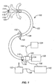
- Fig. 1 illustrates one variation of a steerable endoscope 100 which may be utilized for accessing various regions within the body without impinging upon the anatomy of the patient.
- the endoscope 100 generally has an elongate body 102 with a manually or selectively steerable distal portion 104 and an automatically controlled proximal portion 106.
- the selectively steerable distal portion 104 may be selectively steered or bent up to a full 180° bend in any direction, as shown by the dashed lines.
- a fiberoptic imaging bundle 112 and one or more illumination fibers 114 may optionally be extended through the body 102 from the proximal end 110 to the distal end 108.
- the endoscope 100 may be configured as a video endoscope with a miniaturized video camera, such as a CCD or CMOS camera, positioned at the distal end 108 of the endoscope body 102.
- the images from the video camera may be transmitted to a video monitor by a transmission cable or by wireless transmission.
- the body 102 of the endoscope 100 may also include at least one or two instrument channels 116, 118 that may be used to provide access through the endoscope for any number of tools. Channels 116 , 118 may also be used for various other purposes, e.g., insufflation or irrigation.
- the elongate body 102 of the endoscope 100 is highly flexible so that it is able to bend around small diameter curves without buckling or kinking.
- the elongate body 102 of the endoscope 100 may range in length typically from, e.g., 135 to 185 cm, and 12 to 13 mm in diameter.
- the device may be modified in size to be smaller in diameter.
- the endoscope 100 may also be modified in length to be longer or shorter, depending upon the desired application.
- a handle 120 is attachable to the proximal end 110 of the elongate body 102.
- the handle 120 may include an ocular 124 connected to the fiberoptic imaging bundle 112 for direct viewing and/or for connection to a video camera 126.
- the handle 120 may also be connected to an illumination source 128 via an illumination cable 134 that may connected to or continuous with the illumination fibers 114.
- An optional first luer lock fitting 130 and an optional second luer lock fitting 132 which may be in communication with instrument channels 116, 118, respectively, may also be located on or near the handle 120.
- the handle 120 may be connected to an electronic motion controller 140 by way of a controller cable 136.
- a steering control 122 may be connected to the electronic motion controller 140 by way of a second cable 138.
- the steering control 122 may be configured to allow the physician or surgeon to selectively steer or bend the selectively steerable distal portion 104 of the elongate body 102 in the desired direction.
- the steering control 122 may be a joystick controller as shown, or other known steering control mechanism.
- the steering may be effected manually, e.g. by the use of cables, hydraulics, or pneumatics, or any other known mechanical apparatus for controlling the distal portion of the elongate body.
- the electronic motion controller 140 may be used to control the motion of the automatically controlled proximal portion 106 of the elongate body 102 and may be implemented using a motion control program running on a microcomputer or through an application-specific motion controller. Alternatively, the electronic motion controller 140 may be implemented using a neural network controller.
- An axial motion transducer 150 may be provided to measure the axial motion of the elongate body 102 as it is advanced and withdrawn.
- the axial motion transducer 150 can be made in many configurations, some of which are described below.
- the axial motion transducer 150 is configured as a ring 152, for illustrative purposes only, that surrounds the elongate body 102 of the endoscope 100.
- the axial motion transducer 150 may be attached to a fixed point of reference, such as the surgical table or the insertion point for the endoscope 100 on the patient's body, as described below.
- the axial motion transducer 150 may use optical, electronic, magnetic, mechanical, etc., methods to determine the axial position of the endoscope body 102.
- the motion transducer may be configured to simultaneously measure and communicate rotational motion of the endoscope, so that this additional data may be used in the control of the instrument's motion.
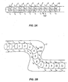
- Fig. 2A shows a wire frame model of a section of the body 102 of the endoscope 100 in a neutral or straight position. Most of the internal structure of the endoscope body 102 has been eliminated in this drawing for the sake of clarity.
- the endoscope body 102 is divided up into sections 1, 2, 3 ... 10, etc.
- the geometry of each section is defined by four length measurements along the a, b, c and d axes.
- the geometry of section 1 may be defined by the four length measurements 1 1a , 1 1b , 1 1c , 1 1d
- the geometry of section 2 may be defined by the four length measurements 1 2a , 1 2b , 1 2c , 1 2d , etc.
- the geometry of each section may be altered using the linear actuators to change the four length measurements along the a, b, c and d axes.
- the measurements 1 1a , 1 2a , 1 3a ....1 10a can be shortened and the measurements 1 1b , 1 2b , 1 3b ....1 10b can be lengthened an equal amount.
- the amount by which these measurements are changed determines the radius of the resultant curve.
- the a, b, c and d axis measurements of each section may be automatically controlled by the electronic motion controller 140.
- Fig. 2B the endoscope body 102 has been maneuvered through the curve C with the benefit of the selectively steerable distal portion 104 and now the automatically controlled proximal portion 106 resides in the curve C.
- sections 3-7 are in the S-shaped curved section, 1 3a ⁇ 1 3b , 1 4a ⁇ 1 4b and 1 5a ⁇ 1 5b , but 1 6a > 1 6b , 1 7a > 1 7b and 1 8a > 1 8b .
- section 1 moves into the position marked 1'
- section 2 moves into the position previously occupied by section 1
- section 3 moves into the position previously occupied by section 2; etc.
- the axial motion transducer 150 produces a signal indicative of the axial position of the endoscope body 102 with respect to a fixed point of reference and sends the signal to the electronic motion controller 140.
- each time the endoscope body 102 advances one unit each section in the automatically controlled proximal portion 106 is signaled to assume the shape of the section that previously occupied the space that it is now in.
- each section in the automatically controlled proximal portion 106 is signaled to assume the shape of the section that previously occupied the space that it is now in.
- the S-shaped curve propagates distally along the length of the automatically controlled proximal portion 106 of the endoscope body 102, and the S-shaped curve appears to be fixed in space, as the endoscope body 102 withdraws proximally.
- the axial motion transducer 150 may be used to detect the change in position and the electronic motion controller 140 may be used to propagate the selected curves proximally or distally along the automatically controlled proximal portion 106 of the endoscope body 102 to maintain the curves in a spatially fixed position.
- a rotational motion transducer (separate from or integrated within transducer 150 ) may be used to detect the change in position and the electronic motion controller may be similarly used to adjust the shape of the endoscope body 102 to maintain the curves in a spatially fixed position. This allows the endoscope body 102 to move through tortuous curves without putting unnecessary force on the wall of the curve C.
- the endoscopic device may be utilized for neurological surgical applications. Because the endoscopic device is unconstrained by "straight-line" requirements for accessing regions of the brain which are conventionally difficult to reach, the endoscope may be advanced and positioned within the cranium by steering the device around the brain with minimal or no trauma to healthy brain tissue. The endoscope may also be advanced through the tissue as necessary to access treatment areas embedded deep within the tissue through pathways which may minimize any damage to healthy adjacent tissue.
- the endoscopic device may allow access to sensitive regions over or within the brain, minimally invasive surgery may be performed where conventional surgery would normally require removal of portions of the skull, for instance, in craniotomy procedures or treatment of intracranial hematomas, etc.
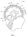
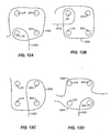
- Fig. 3 shows a cross-sectional side view of head 202 of patient 200.
- the brain 206 may be seen within the cranial cavity 210 of cranium 204.
- the endoscopic device 212 is an embodiment of a steerable endoscope of the present invention that has been sized, shaped and configured for accessing the interior of the cranial cavity and external and internal regions of the brain. The movement, position, tracking and control of the endoscopic device 212 is performed by a user alone or in cooperation with any or all of imaging systems, position and location systems, and surgical planning methods and techniques.
- the endoscopic device 212 may be introduced into the cranial cavity 210 from an easily accessible insertion site 222, e.g., a perforation within the skull.
- the endoscope 212 may be then advanced through the insertion site 222 by controlling the steerable distal portion 214 to avoid brain tissue.
- the automatically controlled proximal portion 216 may attain the shape defined by the steerable distal portion 214 to avoid contact with brain tissue 206.
- the endoscope 212 may be further advanced through the cranial cavity 210 and within the cerebrospinal fluid so that the device is advanced above or within the layers of the meninges, e.g., within the subarachnoid space. In either case, the endoscope 212 may be steered along a path which avoids or minimizes contact or pressure against the brain tissue 206. As the controlled proximal portion 216 is advanced distally and attains the shape defined by the distal portion 214, the proximal portion 216 likewise may be controlled to automatically avoid or minimize contact or pressure against the brain tissue 206. Once the distal portion 216 is advanced to the desired treatment region 208, various tools 220 may be introduced through the instrument channel 218 to enable treatment of the region 208. Any number of treatments or procedures may accordingly be effected, e.g., tumor biopsy and/or removal, shunt placement, lead placement, device placement, drainage of excess cerebrospinal fluid or blood, etc.
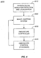
- Fig. 4 shows the interaction of several components to provide a method of positioning a steerable endoscope system to facilitate treatment.
- the movement, position, tracking and control of endoscopic devices is performed by a user alone or in cooperation with any or all of imaging systems, position and location systems, and surgical planning methods and techniques.
- the system schematic 4000 illustrates one embodiment of an integrated detection, mapping and control system for positioning and controlling a steerable, controllable endoscope of the present invention.
- a suitable device, element or system is used to detect and localize a physiological indication (4010).
- a physiological indication could be any perceptible indicia of a condition for which treatment may be facilitated.
- physiological indicators include electrophysiology data or electrical signals from the heart. This system would be capable of identifying or performing analysis of monitored data to identify or determine the location of errant activity.
- An image/mapping system includes any imaging modality that may provide position, location, tissue type, disease state, or any other information that facilitates correlating the physiological activity to a identifiable and/or localizable position within the anatomy or within a frame of reference.
- imaging technologies such as x-ray, fluoroscopy, computed tomography (CT), three dimensional CAT scan, magnetic resonance imaging (MRI), and magnetic field locating systems.
- Examples of image/mapping systems specifically suited for the treatment of cardiovascular disorders include electrocardiogram detection systems, cardiac electrophysiology mapping systems, endocardial mapping systems, or other systems and methods that provide the ability acquire, visualize, interpret and act on cardiac electrophysiological data.
- An example of such a system is described in US Patent 5,848,972 entitled, "Method for Endocardial Activation Mapping Using a Multi-Electrode Catheter” the entirety of which is incorporated herein by reference. Additional examples are described in US Patent 5,487,385 ; US Patent 5,848,972 ; and US Patent 5,645,064 .
- Integrated mapping, detection and/or ablation probes and devices may also be delivered using the steerable endoscope.
- Additional other systems may provide mapping, display or position information of a local isochronal activation map of the heart along with the relative position of the endoscope and direction information or movement commands to position the endoscope (or components, elements or systems onboard the endoscope) to provide treatment to the source of the arrhythmia.
- the endoscope controller (4030). This step indicates the ability of the endoscope controller to respond to the indication, position, image, mapping and other data and utilize that data for altering the scope configuration, position, orientation or other relational information indicative of the scope controller responding to the information provided.
- the endoscope is configured to provide of facilitate providing components, elements or systems to facilitate a treatment of the physiological indication being monitored.
- the controller utilizes the data provided to position the steerable, controllable endoscope into a position related to the location or site that exhibits the errant activity. The proximity of the endoscope to the location or site of the errant activity will vary depending upon, for example, the treatment being implemented, the element, component or system being used to facilitate treatment.
- the position of the endoscope is supplied back into the image or mapping system as a form of feedback to better assist in guiding the endoscope into the desired position to facilitate treatment (4040).
- the system 4000 may include an overall mapping system that provides medically significant data that facilitates a treatment.
- This overall mapping or imaging system may include mapping or imaging an area of monitored activity.
- the area of monitored activity includes not only the portion of the body important to the treatment but also imaging information of those other parts of the body not impacted by the treatment but are instead the likely pathway(s) of the steerable, controllable endoscope to reach the area where the treatment will be facilitated.
- some embodiments of the system may include the ability to detect, localize or otherwise indicate the position of the treatment area or area of errant activity or conditions subject to treatment. These indications may then be utilized to augment the guidance of the steerable, controllable endoscope into the desired position to facilitate treatment.
- other medical imaging and tracking systems may be utilized to provide tracking, guidance and position feedback information to the control of the steerable endoscope.
- An exemplary system is described by Dumoulin et al. in US Patent 5,377,678 .
- steps are only representative of one embodiment of how physiological indications, and position information may be utilized to improve the guidance system and controls used by steerable endoscopes to ensure the placement of the endoscope to facilitate treatment. It is to be appreciated that the steps were utilized for clarity and ease of discussion. The methods of embodiments are not so limited. For example, a single system could be used as an integrated indication, imaging, endoscope controller that receives endoscope position feedback in real time. In an alternative example, the physiological indication and image/mapping functions may be combined into a single unit. As such, while the above steps have been described as happening only once or in a serial fashion, it is to be appreciated that the steps may be conducted in as different order or multiple times.
- Other physiological indication detection and localization systems may be used and will correspond to an appropriate system useful in the treatment being performed.
- alternative image and mapping systems may also be employed and may also be selected depending upon the treatment being facilitated through the use of a steerable controllable endoscope.
- the system may also control the movement of the endoscope automatically based on inputs from the user, pre-surgical planning data, or other indications of desired pathways or pathways to avoid.
- a user may input additional guidance or control information into the system for furthering the guidance or desired placement of the endoscope.
- Another area of treatment in which the endoscopic device may be utilized may include use for coronary procedures, e.g., treatment of the mitral valve, performing or facilitating treatment of supraventricular tachycardia, including, for example, tissue ablation for the treatment of atrial fibrillation, treatment of ventricular tachycardia alone or in combination with treatment of supraventricular tachycardia, treatments for the placement, repositioning or removal of device leads, etc.
- Atrial fibrillation is typically sustained by the presence of multiple electrical reentrant wavelets propagating simultaneously in the atria of the heart.
- Surgical and catheter-based techniques typically place segmented or continuous lesions near and around the pulmonary veins as one way to re-synchronize the atria.
- Embodiments of the present invention may be utilized to facilitate ablation therapies, ablation elements and devices that employ one or a combination of energy modalities, such as, for example, cryogenic energy, hydraulic energy, laser energy, magnetic energy, mechanical energy, microwave energy, radiation energy, radio-frequency energy, thermal energy, and ultrasonic energy.
- energy modalities such as, for example, cryogenic energy, hydraulic energy, laser energy, magnetic energy, mechanical energy, microwave energy, radiation energy, radio-frequency energy, thermal energy, and ultrasonic energy.
- Microwave ablation systems may include, for example, those based on AFx microwave surgical ablation systems such as the AFx Flex 4 or the like. AFx is currently owned by Guidant Corp.
- Cryogenic ablation systems may include, for example, systems available from Cryocath Technologies such as the "SurgiFrost,” “Frostbyte” or “Artic Circler” systems and the like. Ultrsound based surgical probes may be, for example, based upon the ultrasound ablation systems produced by EpiCor Medical or the like. A large number of commercially available ablation systems are available to illustrate the wide variety of ablation systems , techniques and modalities that may be delivered or utilized by embodiments of the steerable endoscopic systems.
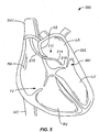
- a cross-sectional anterior view of heart 302 may be seen in coronary procedure 300 for treatment of the mitral valve MV located between the left atrium LA and the left ventricle LV.
- the endoscopic device 212 is shown in this treatment variation as being introduced within the heart 302 via the superior vena cava SVC and advanced through the right atrium RA. Also shown is the right ventricle RV below the tricuspid valve TV and inferior vena cava IVC.
- the endoscope 212 may be sized accordingly to be delivered intravascularly. Once the endoscopic device 212 is within the right atrium RA, the distal portion 214 may be steered towards the atrial septum AS which separates the left atrium LA and right atrium RA.
- a cutting tool deliverable through the device 212 may be used to perforate the atrial septum AS to allow passage of the endoscopic device 212 into the left atrium LA.
- the distal portion 214 may then be steered and positioned adjacent the mitral valve MV while the proximal portion 216 is automatically controlled to minimize any pressure which may be exerted by the device 212 against the tissue of the heart 302.
- various tools or devices may be delivered through the channel 218 to effect the treatment.
- the endoscope 212 may simply be withdrawn proximally in the same manner while minimizing any contact pressure against the tissue.
- FIG. 6 shows an example of a thoracoscopy procedure 400 which may be performed percutaneously.
- the endoscope 212 may be advanced into the patient 402 via an introducer or port 412, which may also be configured as a datum for establishing a fixed point of reference for the endoscope 212 during the procedure.
- the port or datum 412 may be in electrical communication via electrical lines 418 with a computer or processor 416 which may be used for determining and/or maintaining the position of the device 212 within the patient 402.
- the endoscope 212 may be advanced into the body of the patient 402 through an incision 414 made, e.g., in the intercostal space between the ribs 404. The endoscope 212 may then be advanced into the thoracic cavity and maneuvered to regions within the body such as the posterior region of the heart 408 which are normally inaccessible for conventional laparoscopic procedures due to a lack of straight-line access.
- the endoscopic device 212 is shown having been inserted through port or datum 412 and advanced posteriorly of heart 408 behind sternum 406.
- the lungs are not shown for the sake of clarity; however, the endoscope 212 may be steered and advanced around the lungs in a manner described above so as to avoid contact or to minimize contact with the lung tissue or any other organs or structures which may be obstructing a straight-line path.
- the endoscopic device 212 is capable of reaching regions within the body, without damaging surrounding tissue, which is normally inaccessible via conventional laparoscopic procedures.
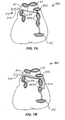
- Figs. 7A to 7D show an example of the endoscopic device advanced about the posterior region of a heart to facilitate treatment of a supraventricular tachycardia.
- a supraventricular tachycardia is atrial fibrillation.
- Another procedure 500 is shown in Figs. 7A to 7D , which illustrate how the endoscopic device may be utilized for the treatment of atrial fibrillation.
- the figures show a posterior view of the heart with the aorta AA and pulmonary trunk PT as anatomical landmarks.
- Atrial fibrillation is typically sustained by the presence of multiple electrical reentrant wavelets propagating simultaneously in the atria of the heart.
- Surgical and catheter-based techniques typically place segmented or continuous lesions near and around the pulmonary veins as one way to re-synchronize the atria.
- the endoscopic device 212 may be utilized by advancing the device 212 into the thoracic cavity, as described above or through various other channels, and steered towards the posterior region of the heart.
- the steerable distal portion 214 may be advanced as shown in Fig. 7A such that the endoscope 212 approaches above the left pulmonary veins LPV.
- the distal portion 214 may be steered around the right pulmonary veins RPV while the endoscope 212 is advanced distally.
- the automatically controllable proximal portion 216 may thus assume the shape defined by the distal portion 214 in traversing around the pulmonary vessels. As shown in Fig.
- the distal portion 214 is steered around the left pulmonary vessels LPV while the proximal portion has assumed the curved path traversed by the device around the right pulmonary vessels RPV.
- the device 212 may be fully advanced entirely around the pulmonary vessels such that the distal portion 214 and proximal portion 216 are in intimate contact against the heart tissue while maintaining its configuration. The tissue which is in contact against the device 212 may then be ablated by one or several electrodes located along the length of the distal and/or proximal portions 214, 216, as described in further detail below.
- an ablation device such as a catheter or other energy source, may be delivered through one or more working channels in or on the endoscope, and left in place as desired.
- This ablation device may then be used to deliver ablative energy in various forms, e.g., RF, microwave, cryogenic cooling, etc as described herein or known to those of ordinary skill in the art.
- the device may be held fixedly in the desired location by various methods, e.g., vacuum, magnetically, temporary adhesives, sutures, or any other methods of attaching or approximating the device and tissue.
- Figs. 8A to 8D show an example of a procedure 600 wherein a steerable endoscopic device is advanced about the posterior region of a heart and then retracted to deploy a device to facilitate treatment of a supraventricular tachycardia.
- the steerable endoscopic device 800 is capable of reaching regions within the body as described above and as an improvement over laparoscopic procedures.
- the figures show a posterior view of the heart with the aorta AA and pulmonary trunk PT as anatomical landmarks.
- Fig. 8A illustrates an endoscopic device 800 having a steerable, controllable distal end 805 and a controllable proximal end 810.
- Fig. 8A illustrates an endoscopic device 800 having a steerable, controllable distal end 805 and a controllable proximal end 810.
- Fig. 8A also illustrates the ablation device 815 distal end is attached to the heart using any of the attachment methods described in this application or known to those of ordinary skill in the art.
- the steerable endoscope 800 is withdrawn proximally along the pathway leaving behind the ablation device 815.
- the ablation device 815 is completely deployed about the pulmonary veins in the desired deployment pathway created by the steerable endoscope 800.
- the endoscope 800 may be withdrawn during the treatment that utilizes the ablation device 815.
- the endoscope 800 may be utilized to visually inspect the position and orientation of each ablation element distributed along the ablation device 815 in those embodiments where the ablation device 815 comprises a plurality of ablation elements. In this illustrated embodiment, the ablation device 815 has been illustrated as a single ablation element for ease of illustration.
- the endoscope may also be utilized to ensure the ablation device 815 has been properly deployed into the desired position to facilitate treatment.
- the endoscope may be utilized to visually inspect any fasteners or other adhesives or affixing means used to maintain the position of the ablation device 815 relative to the pulmonary veins.
- Fig. 9 shows an embodiment of a treatment device having a plurality of fasteners to facilitate contact between the treatment device and the surrounding tissue.
- An endoscopic device 900 has a controllable, steerable end 905 positioned to deploy or facilitate the deployment of an ablation device 915.
- the ablation device 915 has a plurality of ablation elements 920.
- the ablation device 915 also has a plurality of fasteners 925 to increase the contact between the ablation device 915 and the surrounding tissue, organ or body portion to facilitate ablation therapy. Note the position of the fasteners 925 relative to the ablation elements 920 to provide maximum contact between and to ensure the location of the ablation elements 920 relative to the surrounding tissue.
- the fasteners 925 may be in other positions and may also be of other configurations and type described elsewhere in this application and/or as known to those of ordinary skill in the art.
- the fasteners 925 could be configured such that as the steerable tip 905 is withdrawn proximally, the fastener 925 engages the surrounding tissue to secure the position of the ablation device 915. Once the ablation device 915 is positioned, the ablation treatment proceeds as desired. When the ablation treatment is complete, the steerable endoscope 900 is advances proximally from the distal end of the ablation device 915. As the steerable endoscope tip 905 advances distally past a fastener 925, the fastener 925 along with the ablation device 915 are withdrawn into the steerable endoscope 900. It is to be appreciated that any of a wide variety of fasteners may be utilized to engage with the surrounding tissue.
- the fasteners 925 could be formed from superelastic or shape memory alloy material.
- the properties of the shape memory alloy material could be selected such that the thermal energy of the body temperature is used to engage the fastener with the surrounding tissue.
- the shape memory alloy fasteners could be selectively actuated to release the shape memory effect to engage with the surrounding tissue. Engagement with the tissue includes fasteners that do not break the surface of the tissue as well as fasteners that do break the surface of the tissue. While some fasteners may disengage from the surrounding tissue through the movement of the steerable endoscope, it is to be appreciated that a tool or element may be present on or in the distal end of the endoscope 900 to facilitate the disengagement of the fastener from the surrounding tissue.
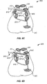
- Figs. 10A and 10B show additional examples of the endoscopic device advanced about the posterior region of a heart to facilitate treatment of a supraventricular tachycardia ( Fig. 10A ) and a combination of supraventricular and ventricular tachycardia ( Fig. 10B ).
- Fig. 10A shows another variation 600 of treating atrial fibrillation where the device may be steered and configured to loop in a continuous manner about the pulmonary vessels in a first encirclement 602 over the left pulmonary vessels LPV and a second encirclement 604 over the right pulmonary vessels RPV.
- the encircled portions 602, 604 of the endoscope 212 may be activated to ablate the heart tissue only around the pulmonary vessels LPV, RPV or alternatively, it may be activated to ablate the heart tissue along the entire length of both distal portion 214 and proximal portion 216. Moreover, a variety of ablation devices may be delivered to the desired areas, as described above.
- Fig. 10B shows another variation 650 of treating atrial fibrillation where the device may be steered and configured to loop in a continuous manner about the pulmonary vessels in a first encirclement 602 over the left pulmonary vessels LPV and a second encirclement 652 over the right pulmonary vessels RPV and then across a portion of the ventricle (654).
- the encircled portions 602, 652, 654 of the endoscope 212 may be activated to ablate the heart tissue around the pulmonary vessels LPV, RPV and the ventricular portion adjacent 654. Alternatively, it may be activated to ablate the heart tissue along the entire length of both distal portion 214 and proximal portion 216.
- a variety of ablation devices may be delivered to the desired areas, as described above.
- Fig. 11 shows yet another example of a treatment for atrial fibrillation using the endoscopic device.
- Fig. 11 shows yet another variation 700 in which the endoscope 216 may be advanced and steered to contact the portions of tissue posteriorly adjacent to the pulmonary vessels LPV, RPV such that an encircled region is formed 702.
- embodiments of the steerable endoscope may be positioned about a portion of the coronary vasculature or other coronary landmarks to facilitate treatments of the heart.
- the endoscope 216 has been maneuvered using the techniques described herein into a position interior and adjacent the pulmonary veins and extended towards the inferior vena cava.
- the extreme configurability and controllability of the space and position of steerable endoscopes enable placement of therapeutic devices, elements and systems about the heart and elsewhere within the body to facilitate treatment.
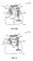
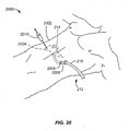
- Figs. 12A and 12D illustrate additional alternative embodiments of steerable endoscopic devices advanced about the posterior region of a heart to facilitate treatment of a supraventricular tachycardia and/or combinations of supraventricular and ventricular tachycardia.
- the left pulmonary veins (LPV) and right pulmonary veins (RPV) are used as landmarks for purposes of illustration and discussion and not limitation.
- Figure 12A illustrates an endoscopic device 1200 positioned about both the LPV and RPV and encircling one of the LPV and then proceeding anteriorly across a ventricular portion of the heart 1205.
- Figure 12B illustrates an endoscopic device 1200 positioned about both the LPV and RPV and encircling one of the LPV and then proceeding laterally across a ventricular portion of the heart 1210.
- Figure 12C illustrates an endoscopic device 1200 positioned about both the RPV, partially encircling the LPV and then proceeding anteriorly across a ventricular portion of the heart 1205.
- Fig. 12D illustrates an embodiment where two endoscopic devices 1250 and 1260 are utilized to facilitate an ablation therapy.
- the first steerable endoscopic device 1250 is positioned laterally across the heart and partially encircling a LPV and a RPV.
- the second endoscopic device 1260 is positioned adjacent a LPV, encircling a RPV and then proceeding anteriorly across a ventricular surface of the heart 1205. It is to be appreciated that the first steerable endoscope 1250 may be used to facilitate a first ablation therapy at the same time, subsequent to or in a sequence with a second ablation therapy facilitated by the second steerable endoscope 1260. As these illustrative embodiments demonstrate, the steerable endoscopes may be deployed in a wide variety of circumstances to facilitate an ablation therapy.
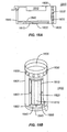
- Fig. 13 shows an embodiment of a dual, steerable endoscope 1300 utilized to facilitate treatment of the heart.
- the dual steerable endoscope 1300 includes a first steerable endoscope 1305 and a second steerable endoscope 1310 disposed within the first steerable endoscope 1305.
- both endoscopes 1305, 1310 are articulated to an initial condition (I).
- the second endoscope 1310 proceeds along the pathway (a) through (i) to encircle the LPV, RPV and then proceed across a ventricular portion of the heart.
- the second endoscope 1310 may proceed along the pathway under control of a user.
- the second endoscope 1310 may proceed along the pathway by automatically deploying based upon any or a combination of pre-surgical planning imagery, real time imagery, mapping system receiving inputs from a detection or tracking system.
- the second endoscope 1310 proceeds using a combination of automatic controls and user input.
- first and second steerable endoscopes may be utilized to access portions of the neurovasculature, and other regions by maintaining the size of the second steerable endoscope to be much less than the size of the first endoscope.
- the first endoscope may positioned in a first position, affixed in that position to act as a stable platform and/or datum for the second steerable endoscope. From that stable base, the second endoscope may be deployed to facilitate treatments.
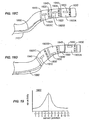
- Figs. 14A to 14C shows side and end views, respectively, of various electrode configurations on the endoscope for tissue ablation treatment.
- the endoscope 900 may be configured with a number of elements, devices or systems to facilitate treatment.
- a steerable endoscope may have a plurality of electrodes disposed along its outer surface to facilitate the tissue ablation along the length, or selected regions of length, of the endoscope, as shown as described herein.
- the figure shows the steerable distal portion 904 and part of the automatically controllable proximal portion 902 as one example of electrode placement over the endoscope 900.
- one or any number of electrodes 906 may be circumferentially positioned, e.g., ring-shaped, along the length of endoscope 900 at intervals.
- the electrodes 906 are shown positioned at uniform intervals in this variation; however, they may be configured in any random, arbitrary, or specified locations over the outer surface of the endoscope 900.
- Each of the electrodes 906 may be electrically connected via corresponding wires 908 to a power supply and/or controller.
- all the electrodes 906 may be configured to operate simultaneously or to operate only selected electrodes 906 which may be in contact with tissue.
- various ablation devices may be delivered to the desired areas, again as described above.
- Fig. 14B shows another variation in endoscope 910 in which electrodes 916 may be configured to extend longitudinally over the proximal portion 912 and/or distal portion 914.
- the electrodes may be configured to extend in a continuous strip along the endoscope length or the electrodes 916 may be alternatively configured to extend in a segmented manner longitudinally over the endoscope 910, as shown. Having segmented electrodes 916 may allow for selected electrodes to be activated during tissue ablation.
- Fig.14B shows a single line of electrodes 916 for illustration purposes, multiple lines of electrodes may be positioned over the outer surface of the device, as shown in the example of Fig. 14C , which illustrates multiple lines of electrodes 918 spaced uniformly around the circumference of the endoscope surface.
- a treatment device may be advantageous to increase the degree of contact or ensure the position between the treatment tool, element, or device and the tissue, organ or portion of the body receiving the treatment.
- means for increasing contact or affixing the position of a treatment device include: biocompatible adhesives, glues and gels either alone or in combination with staples, suction, wires, barbed and barb-less hooks or hook shaped to loop around specific anatomy.
- a hook shaped to loop around specific anatomy includes J-shaped hooks to loop, at least partially, about the coronary vasculature.
- a J-shaped hook may be shaped and configured to at least partially encircle a pulmonary vein.
- wires, staples or other fastening components may be formed from shape memory alloy material such as, nitinol or other suitable, biocompatible shape memory alloy material.
- shape memory alloy fastener could be held in a first or stowed condition while navigating to the site prior to facilitating treatment. Once the treatment device is positioned, the shape memory alloy fastener could be activated and use the shape memory effect to affix the treatment device into the desired position.
- a steerable endoscope having a magnetic portion could be deployed about the tissue, organ or region of the body to facilitate treatment. Thereafter, the steerable endoscope could be used as a guide for the placement of an ablation system. Permanent magnets or electromagnets could be used to magnetically couple the ablation system in a desired position adjacent the steerable endoscope. Once the treatment was completed, the magnetic field is broken and the ablation system and steerable endoscope withdrawn, could be deployed in proximity to the steerable endoscope and a
- the steerable endoscope itself may be looped around the organ, tissue or portion of the body to undergo treatment and then secured to itself in order to facilitate treatment.
- the distal end of the endoscope could be anchored with a dissolvable suture or other dissolvable biodegradable fastener that remains in place after the ablation treatment is completed and is then absorbed into the tissue or dissolves.
- an array of needles may be configured along the length or a portion of the length of the ablation device or steerable endoscope or both.
- an array of conductive needles are arranged to improve contact between an RF ablation based delivery system and the tissue undergoing treatment.
- other suitable elements may be employed to improve the effectiveness of other ablation modalities. It is to be appreciated therefore that while needle arrays are described as increasing the effectiveness of the delivery of RF ablation energy, other elements and configurations may be used to increase the effectiveness of other ablation therapy modalities. Alternatively, for non-energy based ablation, such as ablation techniques that use lacerations of the tissue, then the elements could be any suitable device for cutting or otherwise altering the tissue to achieve a therapeutic affect.
- Figs. 15A and 15B show an embodiment of a needle array in a retracted ( Fig. 15A ) and a deployed ( Fig. 15B ) configuration.
- a portion of a steerable endoscope or ablation element 1500 is shown in cross section.
- Ablation needles 1505, 1510 are attached to backing plate 1515.
- the needles are maintained in the stowed configuration ( Fig. 15A ) with the backing plate retracted to reduce the risk of inadvertent tissue damage as the steerable endoscope or ablation system is advanced to the treatment site.
- the needles 1505, 1510 remain below the steerable endoscope or ablation element exterior surface 1502.
- the backing plate 1515 is advanced to the deployed condition ( Fig.
- the needles 1505, 1510 protrude beyond the steerable endoscope or ablation element exterior surface 1502.
- the needles 1505, 1510 would make suitable contact with the surrounding tissue, organ or body portion to facilitate treatment.
- the backing plate may be moved between the retracted and deployed configuration utilizing any of a number of techniques.
- techniques and methods include, mechanical drives, hydraulics, motors, actuators, permanent magnets, electromagnets, spring loaded actuators, vacuum, or other conventional actuation means.
- the actuation means could be any suitable actuation force capable of displacing the backing plate 1515 to urge a portion or all of a needle array from a retracted position into a deployed position and hence into suitable contact with the organ, tissue or body portion to receive treatment.
- the backing plate 1515 could be continuously biased outwardly, here, outwardly indicates a position where the needles would move into a deployed configuration.
- the ablation element or steerable endoscope having the needle array could be covered with a moveable sheath. Once the ablation element or moveable endoscope is in the desired position, the sheath is retracted releasing the backing plate bias and allowing the needles to move into a deployed configuration.
- the illustrated embodiment illustrates a pair of needles in cross section.
- the additional needles may be, for example, arrayed in a regular continuous pattern as in Fig. 16 .
- a single needle or array on continuous, discontinuous or random arrangement of needles may be used.
- more than teo needles may be used.
- the illustrated needles 1505, 1510 have a separation angle ⁇ 1 The separation angle may vary from 0 to 180 degrees in one embodiment, from 0 to 70 degrees in another embodiment or from 0 - 30 degrees in yet another embodiment depending upon application.
- the needles may have a regular separation angle meaning that the needles are at regular angular intervals.
- the needles in a multiple needle configuration may be placed in non-regular or variable separation angles.
- the spacing between needles may also be continuous or variable.
- the needles may be arranged into a single continuous segment with uniform spacing. Such a uniform array of needles is illustrated in Fig. 16 .
- the ablation element or steerable endoscope section configured for ablation 1600 is shown in Fig. 16 .
- Needles 1610 are shown in a single segment or grouping of needles 1605.
- Fig. 17 shows an embodiment of a needle array segment 1700 having three sections (1705, 1710 and 1715) showing a variety of needle spacing configurations.
- the needle array segment 1700 illustrates how a nearly limitless variety of spacing configurations may be combined to obtain a desired needle array configuration to facilitate an ablation treatment.
- Section 1705 includes an upper array of needles 1726, 1728 and 1730 aligned in a continuous uniform fashion above a lower array of needles 1720, 1722 and 1724. This configuration is similar to section 1600 in Figure 16 .
- the upper array of section 1710 has evenly spaced needles 1732, 1734 and 1736.
- the lower array of needles have only one needle aligned to the upper array. Needle 1738 is aligned with needle 1732.
- a plurality of needles (1740, 1741 and 1742) are spaced across from upper array needle 1734.
- the section 1710 illustrates how there may be needle to needle correspondence (1732, 1738), no correspondence (1736) or one to many correspondence (1734, 1740, 1741, 1742) between the needles in the upper and lower arrays of a section.
- Section 1715 further illustrates the configurabilty of the needle arrangements.
- Both the upper needles 1750, 1752, 1754 1756 and lower needles 1766, 1768, 1770, 1771, 1772, 1773 illustrate variable spacing.
- section 1715 illustrates a middle array having upper needles 1758, 1760 spaced apart from lower needles 1762, 1764.
- the upper and lower needles are aligned but that need not be the case in all embodiments.
- the middle array is illustrated without alignment to the upper array and the lower array. This need not be the case in all embodiments.
- the middle array may be aligned with all or part of either a lower or an upper array.
- a needle pattern within a section could be predetermined and selected to facilitate a desired ablation treatment.
- the type, number, amount and ablation pattern could be predetermined and an appropriate combination of segments, sections and needles arrays could be loaded into a steerable endoscope or otherwise delivered utilizing a steerable endoscope to facilitate treatment.
- Fig. 18A and 18B show a side and isometric view of an embodiment of a tunable treatment device of the present invention.
- the tunable treatment device 1800 includes an ablation element 1810 within a housing 1805.
- the housing 1805 also includes an opening 1815 that allows the energy generated by the ablation element 1810 to pass outside of the housing.
- the opening 1815 is fitted with a cover 1820 that forms a seal between the environment the tunable treatment device 1800 is positioned in and the interior of the housing 1805.
- the housing 1805 is made of a first material and the cover 1820 is made of a second material. With respect to the energy generated or provided by the ablation element 1810, the first material transmits less of the energy generated by the ablation element 1810 than the second material.
- the first material acts as a shield separating the ablation energy generated by the ablation element and the surrounding environment.
- the second material acts as a transmission window or opening in an otherwise shielded housing.
- the transmission window or opening thus allows energy provided by the ablation element to be selectively passed via the opening into the tissue, organ or environment positioned adjacent the cover 1820.
- the tunable ablation delivery device 1800 is also provided with a detector 1830 for detecting a physiological indication useful in administering the ablation therapy.
- the detector 1830 may comprise a plurality of detection elements arrayed about the housing 1805.
- the detector 1830 includes a plurality of detection elements 1835.
- the detection elements 1835 are arranged at regular intervals about the perimeter of the housing 1805. A reading may be obtained from each element and then analyzed to determine which element or elements obtained the best reading for the physiological parameter being measured. Once that determination is made, the tunable ablation device 1800 may then be oriented to place the opening 1815 into position to facilitate ablation treatment.
- the tunable ablation delivery device 1800 may be modified to facilitate an ablation treatment on the pericardium of the heart.
- the detection elements 1835 may be elements capable of detecting electrophysiological (EP) activity.
- the detection elements 1835 could detect electrophysiological (EP) activity by detecting ECG activity.
- An example of the readings and/or signal strength obtained by each detector 1835 is illustrated in Figure 19.
- Fig. 19 shows a graph illustrating a technique to optimize placement of a tunable ablation device to facilitate therapy. Using conventional software, hardware and optimization techniques, the detection elements 1835 may be used to localize the position, relative to the housing 1805, where the desired amount of physiological indication occurs. In the graph 1900 the desired activity is the peak EP activity.
- the peak EP activity occurs in proximity to sensor position 5.
- This information can then be used by the control system that articulates, rotates, translates or otherwise positions the tunable ablation element 1800 to position the tunable ablation element 1800 into a position that facilitates an ablation treatment in the vicinity of sensor 5.
- the tunable ablation device 1800 would be rotated under the control of a control system having the relative position and orientation of the plurality of elements 1835 and the opening 1815 and ablation element 1810.
- the tunable ablation device 1800 would be rotated under the control of a control system using for example, the engagement element 1845, to align the opening 1815 and/or cover 1820 into the orientation of sensor 5.
- FIG. 18C An example of how a plurality of tunable ablation elements may be advantageously deployed to increase the effectiveness of an ablation therapy will now be described with reference to Figures 18C and 18D .
- Three tunable ablation elements 1800A, 1800B and 1800C are positioned within a steerable endoscope 212 of the present invention.
- the three ablation elements have reached the deployment point for ablation element 1800A.
- the windows 1820 are aligned.
- the detectors 1830 on ablation element 1800A are used to improve the effectiveness of the ablation element within the tunable ablation element 1800A by indicating a desired position for applying the ablation therapy. As shown in Fig.
- the determined position of the element 1800A is when the window 1820 rotated into a slightly upward position from the initial position. Additionally, the mechanical linkage 1845 has been disengaged so that the control cable/component 1880 no longer rotates the element 1800A. In addition, the fixation elements for element 1800A have been omitted for clarity but have engaged to fix the position of element 1800A.
- Figure 18D also illustrates how the controller cable/component 1880 has utilized the detector 1830 onboard element 1800B to optimize the position of the window 1820. Note that the window 1820 for element 1800B is rotated downward. At this point, the fixation elements for element 1800B are engaged to fix the position of the element 1800B.
- the detector for detecting a physiological indication could also be a single detector.
- the single detector could be actuated to move about the surface of the tunable ablation delivery device 1800 measuring the indication. The obtained measurements could then be used to assist in positioning the ablation element 1810 and opening 1815 to facilitate treatment.
- the single detector could move about the perimeter of the tunable ablation device and provide strength of indication relative to position information similar to Figure 19 .
- a securing member 1840 is also provided to hold the tunable ablation device 1800 in the desired position during the readings from the indicator elements 1835, or after rotation of the ablation device into the desired position for facilitating treatment.
- the securing member 1840 may be a vacuum manifold 1855 having a plurality of suction ports 1860.
- the securing means is releasable from the surrounding tissue, organ or region of interest to facilitate movement to align the ablation element for treatment or for easy removal once the treatment is complete.
- the endoscope device may also be utilized for procedures within the peritoneal cavity. Potential applications may include minimally invasive surgery for urologic, bariatric, and liver surgery. Moreover, minimally invasive access may be achieved for treatments in spinal or orthopedic surgery as well.
- Fig. 20 shows an example of a procedure 2000 within the peritoneal cavity which may be performed with the endoscopic device.
- Fig. 20 shows an example of a procedure 2000 within the peritoneal cavity using the endoscopic device 212.
- the endoscope 212 may be introduced into patient 2002 through an incision 2008 via a port, which may also function as a datum 2006, as described above.
- the distal portion 214 may be steered to avoid various organs while being 2004.
- the distal portion 214 of the endoscope 212 may accordingly be steered while the proximal portion 216 may be automatically controlled to follow a path defined by the distal portion 214 which minimizes contact with the surrounding and adjacent tissue and organs.
- One or more laparoscopes 2010 may optionally be used in combination with the endoscope 212 to assist with the surgical procedure.
- various tools or treatment devices may be advanced through the endoscope 212 from the proximal end to effect the desired treatment.
- this example shows treatment of the liver 2004 using the endoscope 212, this is intended to be illustrative of other organs or procedures that may be effectively treated utilizing embodiments of the endoscope 212.
- steerable endoscopic may advantageously utilized to facilitate a wide variety of procedures.
- the ablation element, device or system may be part of the segmented steerable endoscope, deployed within a working channel or other passage created by the steerable endoscope, or a combination of fixed and moveable treatment elements, device or systems.
- steerable endoscopes may, in one embodiment, facilitate treatment by deploying an ablation element, device or system affixed to the endoscope to a treatment location in a treatment position. The endoscope remains in place during the treatment and, when complete, retracts from the treatment position.
- the steerable endoscope is utilized to deploy and/or inspect the placement of a treatment device, is then withdrawn while the treatment proceeds. Thereafter, the steerable endoscope retrieves the treatment device.
- the steerable endoscope may be inserted into a treatment area into a desired treatment pathway. Next, the steerable endoscope is retracted to leave the treatment device in place along the desired treatment pathway. The steerable endoscope may remain in place for visualization of the treatment as it proceeds, monitor a physiological indication or otherwise support the treatment. Alternatively, the steerable endoscope may withdraw from the treatment area or completely from the body.
- the steerable endoscope may be advanced along the treatment device to remove/store the treatment device as the endoscope proceeds distally along the treatment device. Once the treatment device has been collected into the endoscope, the endoscope is withdrawn. Accordingly, there have been shown various ways to position a treatment element, device or system within a body, affix or otherwise maintain the position of the treatment device relative to the area or areas of treatment to increase the effectiveness of the treatment or therapy being performed.
- various imaging and control systems may be used to facilitate control of the steerable endoscope.
- the steerable endoscope may proceed along and envelope a deployed treatment device utilizing a recorded pathway to retrace steps used to place the treatment device.
- the steerable endoscope may also track a way point set to indicate the next fastener where the fastener is in a preprogrammed position, in an position identifiable using an imaging system or the fastener is other wise configured for easy identification, such as through use of an RFID, for example.
- the steerable endoscope may also use an imaging system for guidance in recovering a treatment device.
- the steerable endoscope may also utilize fly by wire techniques to fly by wire using the treatment device as the wire.
- the treatment device could be automatically withdrawn into the steerable endoscope using mapping, imaging or other system controls to retrace track or otherwise dislodge or disengage the treatment device from the internal position to perform a treatment.
- Embodiments may also include tools, devices or systems to pierce, lacerate, cut, puncture, or otherwise provide a passage or controlled perforation of tissue to allow access of the steerable, guided endoscope into the region of interest.
- a neurological application for accessing the brain such as device would be suited for creating a suitable opening in the dura for example.
- a cardiovascular application for accessing the heart such as device would be suited for creating a suitable opening in the pericardium for example.
- the tools, devices or systems to pierce, lacerate, cut, puncture, or otherwise provide a passage or controlled perforation to enable passage of the endoscope may be disposed permanently on the distal end of the scope.
- the tools, devices or systems may be mounted on the distal end of the endoscope but be positionable between a retracted and extended position to help minimize the risk of inadvertent damage while the endoscope is moving within the body to the region of interest.
- the tools, devices or systems may be provided conventionally via a working channel in the endoscope. Examples of the tools, devices or systems include scissors, electrocaulitry devices and systems, small snips, shaped blades and shaped tips.
- embodiments have been shown and described as dispensing treatment within the brain, cranial interior, the interior of the heart, the exterior of the heart, it is to be appreciated that embodiments of the methods and apparatus may be used in other applications as well.
- embodiments may be used to facilitate treatment of disorders of other organs and portions of the body, for example, the stomach, the gastrointestinal tract, the esophagus, the bladder, the liver, the kidneys and the lungs.
- embodiments may be used to facilitate treatment of localized disorders within the body, portions of the body or a disorder of a physiological system.
- the applications of the devices and methods discussed above are not limited to regions of the body but may include any number of further treatment applications. Other treatment sites may include other areas or regions of the body. Additionally, the embodiments described above may be used in other industrial and commercial environments such as exploratory procedures on piping systems, ducts, internal inspection of mechanical systems including automotive, aeronautical, aerospace, and marine systems and equipment, etc.
Landscapes
- Health & Medical Sciences (AREA)
- Life Sciences & Earth Sciences (AREA)
- Surgery (AREA)
- Physics & Mathematics (AREA)
- Engineering & Computer Science (AREA)
- Optics & Photonics (AREA)
- Veterinary Medicine (AREA)
- Public Health (AREA)
- Nuclear Medicine, Radiotherapy & Molecular Imaging (AREA)
- General Health & Medical Sciences (AREA)
- Biomedical Technology (AREA)
- Heart & Thoracic Surgery (AREA)
- Medical Informatics (AREA)
- Molecular Biology (AREA)
- Animal Behavior & Ethology (AREA)
- Radiology & Medical Imaging (AREA)
- Pathology (AREA)
- Biophysics (AREA)
- Astronomy & Astrophysics (AREA)
- General Physics & Mathematics (AREA)
- Cardiology (AREA)
- Plasma & Fusion (AREA)
- Otolaryngology (AREA)
- Multimedia (AREA)
- Endoscopes (AREA)
- Surgical Instruments (AREA)
- Instruments For Viewing The Inside Of Hollow Bodies (AREA)
- Electrotherapy Devices (AREA)
Applications Claiming Priority (3)
| Application Number | Priority Date | Filing Date | Title |
|---|---|---|---|
| US10/767,109 US20050165276A1 (en) | 2004-01-28 | 2004-01-28 | Methods and apparatus for accessing and treating regions of the body |
| US10/850,360 US8517923B2 (en) | 2000-04-03 | 2004-05-19 | Apparatus and methods for facilitating treatment of tissue via improved delivery of energy based and non-energy based modalities |
| PCT/US2005/003140 WO2005072445A2 (en) | 2004-01-28 | 2005-01-28 | Apparatus and method for facilitating treatment of tissue via improved delivery of energy based and non-energy based modalities |
Publications (3)
| Publication Number | Publication Date |
|---|---|
| EP1748723A2 EP1748723A2 (en) | 2007-02-07 |
| EP1748723A4 EP1748723A4 (en) | 2012-08-08 |
| EP1748723B1 true EP1748723B1 (en) | 2020-07-08 |
Family
ID=34830626
Family Applications (1)
| Application Number | Title | Priority Date | Filing Date |
|---|---|---|---|
| EP05712548.6A Active EP1748723B1 (en) | 2004-01-28 | 2005-01-28 | Apparatus and method for facilitating treatment of tissue via improved delivery of energy based and non-energy based modalities |
Country Status (5)
| Country | Link |
|---|---|
| US (4) | US8517923B2 (ja) |
| EP (1) | EP1748723B1 (ja) |
| JP (3) | JP5216986B2 (ja) |
| CA (1) | CA2554714A1 (ja) |
| WO (1) | WO2005072445A2 (ja) |
Families Citing this family (112)
| Publication number | Priority date | Publication date | Assignee | Title |
|---|---|---|---|---|
| US7416554B2 (en) | 2002-12-11 | 2008-08-26 | Usgi Medical Inc | Apparatus and methods for forming and securing gastrointestinal tissue folds |
| US7955340B2 (en) * | 1999-06-25 | 2011-06-07 | Usgi Medical, Inc. | Apparatus and methods for forming and securing gastrointestinal tissue folds |
| US7637905B2 (en) * | 2003-01-15 | 2009-12-29 | Usgi Medical, Inc. | Endoluminal tool deployment system |
| US20040122456A1 (en) * | 2002-12-11 | 2004-06-24 | Saadat Vahid C. | Methods and apparatus for gastric reduction |
| US8517923B2 (en) | 2000-04-03 | 2013-08-27 | Intuitive Surgical Operations, Inc. | Apparatus and methods for facilitating treatment of tissue via improved delivery of energy based and non-energy based modalities |
| US6984203B2 (en) * | 2000-04-03 | 2006-01-10 | Neoguide Systems, Inc. | Endoscope with adjacently positioned guiding apparatus |
| US6610007B2 (en) | 2000-04-03 | 2003-08-26 | Neoguide Systems, Inc. | Steerable segmented endoscope and method of insertion |
| US6837846B2 (en) * | 2000-04-03 | 2005-01-04 | Neo Guide Systems, Inc. | Endoscope having a guide tube |
| US6858005B2 (en) * | 2000-04-03 | 2005-02-22 | Neo Guide Systems, Inc. | Tendon-driven endoscope and methods of insertion |
| US8888688B2 (en) | 2000-04-03 | 2014-11-18 | Intuitive Surgical Operations, Inc. | Connector device for a controllable instrument |
| US6468203B2 (en) | 2000-04-03 | 2002-10-22 | Neoguide Systems, Inc. | Steerable endoscope and improved method of insertion |
| US20050085693A1 (en) * | 2000-04-03 | 2005-04-21 | Amir Belson | Activated polymer articulated instruments and methods of insertion |
| US7740623B2 (en) * | 2001-01-13 | 2010-06-22 | Medtronic, Inc. | Devices and methods for interstitial injection of biologic agents into tissue |
| US7628780B2 (en) * | 2001-01-13 | 2009-12-08 | Medtronic, Inc. | Devices and methods for interstitial injection of biologic agents into tissue |
| US20040138621A1 (en) | 2003-01-14 | 2004-07-15 | Jahns Scott E. | Devices and methods for interstitial injection of biologic agents into tissue |
| CN1617687A (zh) * | 2002-01-09 | 2005-05-18 | 新引导系统公司 | 对结肠进行分光镜检查的设备和方法 |
| CN1764416A (zh) | 2002-01-09 | 2006-04-26 | 新引导系统公司 | 用于内窥镜结肠切除术的设备和方法 |
| US7942884B2 (en) * | 2002-12-11 | 2011-05-17 | Usgi Medical, Inc. | Methods for reduction of a gastric lumen |
| US7942898B2 (en) * | 2002-12-11 | 2011-05-17 | Usgi Medical, Inc. | Delivery systems and methods for gastric reduction |
| US20040186349A1 (en) * | 2002-12-24 | 2004-09-23 | Usgi Medical Corp. | Apparatus and methods for achieving endoluminal access |
| WO2004060040A2 (en) * | 2002-12-30 | 2004-07-22 | Fannie Mae | System and method for processing data pertaining to financial assets |
| US20040186350A1 (en) * | 2003-01-13 | 2004-09-23 | Usgi Medical Corp. | Apparatus and methods for guiding an endoscope via a rigidizable wire guide |
| US20040249367A1 (en) * | 2003-01-15 | 2004-12-09 | Usgi Medical Corp. | Endoluminal tool deployment system |
| US8882657B2 (en) | 2003-03-07 | 2014-11-11 | Intuitive Surgical Operations, Inc. | Instrument having radio frequency identification systems and methods for use |
| JP4540328B2 (ja) * | 2003-11-19 | 2010-09-08 | カール事務器株式会社 | 多機能孔明け装置 |
| US20050272977A1 (en) * | 2004-04-14 | 2005-12-08 | Usgi Medical Inc. | Methods and apparatus for performing endoluminal procedures |
| US8562516B2 (en) | 2004-04-14 | 2013-10-22 | Usgi Medical Inc. | Methods and apparatus for obtaining endoluminal access |
| US8512229B2 (en) * | 2004-04-14 | 2013-08-20 | Usgi Medical Inc. | Method and apparatus for obtaining endoluminal access |
| US8277373B2 (en) | 2004-04-14 | 2012-10-02 | Usgi Medical, Inc. | Methods and apparaus for off-axis visualization |
| US20050251091A1 (en) * | 2004-05-10 | 2005-11-10 | Usgi Medical Inc. | Apparatus and methods for transgastric tissue manipulation |
| US7837615B2 (en) * | 2004-05-10 | 2010-11-23 | Usgi Medical, Inc. | Shape lockable apparatus and method for advancing an instrument through unsupported anatomy |
| US9463012B2 (en) | 2004-10-26 | 2016-10-11 | P Tech, Llc | Apparatus for guiding and positioning an implant |
| US9125639B2 (en) * | 2004-11-23 | 2015-09-08 | Pneumrx, Inc. | Steerable device for accessing a target site and methods |
| US20060235458A1 (en) * | 2005-04-15 | 2006-10-19 | Amir Belson | Instruments having an external working channel |
| US7740627B2 (en) * | 2005-04-29 | 2010-06-22 | Medtronic Cryocath Lp | Surgical method and apparatus for treating atrial fibrillation |
| US7794455B2 (en) * | 2005-04-29 | 2010-09-14 | Medtronic Cryocath Lp | Wide area ablation of myocardial tissue |
| WO2007033379A2 (en) * | 2005-09-14 | 2007-03-22 | Neoguide Systems, Inc. | Methods and apparatus for performing transluminal and other procedures |
| US8721597B2 (en) * | 2006-11-09 | 2014-05-13 | Ncontact Surgical, Inc. | Diaphragm entry for posterior surgical access |
| US9561044B2 (en) * | 2005-10-12 | 2017-02-07 | Atricure, Inc. | Diaphragm entry for posterior surgical access |
| US8211011B2 (en) | 2006-11-09 | 2012-07-03 | Ncontact Surgical, Inc. | Diaphragm entry for posterior surgical access |
| US9808280B2 (en) * | 2005-10-12 | 2017-11-07 | Atricure, Inc. | Diaphragm entry for posterior surgical access |
| US20070161857A1 (en) | 2005-11-22 | 2007-07-12 | Neoguide Systems, Inc. | Method of determining the shape of a bendable instrument |
| US8083879B2 (en) * | 2005-11-23 | 2011-12-27 | Intuitive Surgical Operations, Inc. | Non-metallic, multi-strand control cable for steerable instruments |
| US8726909B2 (en) * | 2006-01-27 | 2014-05-20 | Usgi Medical, Inc. | Methods and apparatus for revision of obesity procedures |
| US8568299B2 (en) * | 2006-05-19 | 2013-10-29 | Intuitive Surgical Operations, Inc. | Methods and apparatus for displaying three-dimensional orientation of a steerable distal tip of an endoscope |
| US9242073B2 (en) * | 2006-08-18 | 2016-01-26 | Boston Scientific Scimed, Inc. | Electrically actuated annelid |
| US10166070B2 (en) * | 2007-01-02 | 2019-01-01 | Baylis Medical Company Inc. | Electrosurgical pericardial puncture |
| US20090209849A1 (en) * | 2007-05-02 | 2009-08-20 | Philip Stephen Rowe | Medical Device Placement and Monitoring System Utilizing Radio Frequency Identification |
| WO2009009443A1 (en) * | 2007-07-06 | 2009-01-15 | Barrx Medical, Inc. | Method and apparatus for gastrointestinal tract ablation to achieve loss of persistent and/or recurrent excess body weight following a weight-loss operation |
| US9220398B2 (en) | 2007-10-11 | 2015-12-29 | Intuitive Surgical Operations, Inc. | System for managing Bowden cables in articulating instruments |
| US20200352647A1 (en) * | 2007-12-27 | 2020-11-12 | Baylis Medical Company Inc. | Electrosurgical Pericardial Puncture |
| US8182418B2 (en) * | 2008-02-25 | 2012-05-22 | Intuitive Surgical Operations, Inc. | Systems and methods for articulating an elongate body |
| US8771170B2 (en) | 2008-08-01 | 2014-07-08 | Microaccess, Inc. | Methods and apparatus for transesophageal microaccess surgery |
| JP5580540B2 (ja) * | 2009-03-02 | 2014-08-27 | オリンパス株式会社 | ガイドデバイス |
| JP5476564B2 (ja) * | 2009-04-16 | 2014-04-23 | 国立大学法人 東京大学 | 医用電極器具 |
| US8926602B2 (en) | 2010-01-28 | 2015-01-06 | Medtronic Cryocath Lp | Triple balloon catheter |
| CA2813592C (en) * | 2010-10-05 | 2019-12-03 | Emory University | Devices, systems, and methods for improving access to cardiac and vascular chambers |
| WO2012114333A1 (en) | 2011-02-24 | 2012-08-30 | Ilan Ben Oren | Hybrid catheter for vascular intervention |
| CA2838637C (en) | 2011-06-10 | 2020-11-17 | Board Of Regents Of The University Of Nebraska | Methods, systems, and devices relating to surgical end effectors |
| US11304746B2 (en) | 2011-06-14 | 2022-04-19 | Aerin Medical Inc. | Method of treating airway tissue to reduce mucus secretion |
| US10722282B2 (en) | 2011-06-14 | 2020-07-28 | Aerin Medical, Inc. | Methods and devices to treat nasal airways |
| US11033318B2 (en) | 2011-06-14 | 2021-06-15 | Aerin Medical, Inc. | Methods and devices to treat nasal airways |
| US11241271B2 (en) | 2011-06-14 | 2022-02-08 | Aerin Medical Inc. | Methods of treating nasal airways |
| US9415194B2 (en) | 2011-06-14 | 2016-08-16 | Aerin Medical Inc. | Post nasal drip treatment |
| US10456185B2 (en) | 2011-06-14 | 2019-10-29 | Aerin Medical, Inc. | Methods and devices to treat nasal airways |
| CN103747754B (zh) | 2011-06-14 | 2016-07-06 | 艾琳医药股份有限公司 | 用于治疗鼻气道的装置 |
| US9387031B2 (en) | 2011-07-29 | 2016-07-12 | Medtronic Ablation Frontiers Llc | Mesh-overlayed ablation and mapping device |
| US9265514B2 (en) | 2012-04-17 | 2016-02-23 | Miteas Ltd. | Manipulator for grasping tissue |
| US9113911B2 (en) | 2012-09-06 | 2015-08-25 | Medtronic Ablation Frontiers Llc | Ablation device and method for electroporating tissue cells |
| JP2015534845A (ja) * | 2012-10-17 | 2015-12-07 | ウースター・ポリテクニック・インスティテュートWorcester Polytechnic Institute | 非対称チップニードルの挿入経路の劣駆動制御のためのシステム及び方法 |
| EP2931123B1 (en) * | 2012-12-17 | 2022-09-21 | Koninklijke Philips N.V. | Ultrasound tracking imaging device with local view and stationary overall view |
| US20140188440A1 (en) | 2012-12-31 | 2014-07-03 | Intuitive Surgical Operations, Inc. | Systems And Methods For Interventional Procedure Planning |
| WO2015048806A2 (en) | 2013-09-30 | 2015-04-02 | Nidus Medical, Llc | Apparatus and methods for treating rhinitis |
| WO2015077584A2 (en) | 2013-11-22 | 2015-05-28 | Massachusetts Institute Of Technology | Steering techniques for surgical instruments |
| US20150245868A1 (en) * | 2014-02-28 | 2015-09-03 | Tenjin LLC | Bendable and rebendable endoscopic electrosurgical device |
| JP6234332B2 (ja) * | 2014-06-25 | 2017-11-22 | オリンパス株式会社 | 内視鏡装置、作動方法、及び作動プログラム |
| US9763743B2 (en) | 2014-07-25 | 2017-09-19 | Arrinex, Inc. | Apparatus and method for treating rhinitis |
| KR20170093112A (ko) * | 2014-09-29 | 2017-08-14 | 클리어마인드 바이오메디컬 인코포레이티드 | 수술 도구 |
| WO2016076964A2 (en) * | 2014-09-30 | 2016-05-19 | Massachusetts Institute Of Technology | Instruments for minimally invasive surgical procedures |
| US9867656B2 (en) | 2014-11-17 | 2018-01-16 | Covidien Lp | Multi-function surgical instruments |
| EP3344113B1 (en) * | 2015-09-03 | 2023-01-18 | Neptune Medical Inc. | Device for endoscopic advancement through the small intestine |
| US10143526B2 (en) * | 2015-11-30 | 2018-12-04 | Auris Health, Inc. | Robot-assisted driving systems and methods |
| CN108882957B (zh) * | 2016-02-10 | 2022-09-16 | 埃米尔·贝尔森 | 个性化的心房颤动消融 |
| WO2017139609A1 (en) | 2016-02-12 | 2017-08-17 | Aerin Medical, Inc. | Hyaline cartilage shaping |
| WO2017152061A1 (en) | 2016-03-04 | 2017-09-08 | Aerin Medical, Inc. | Eustachian tube modification |
| US11684420B2 (en) | 2016-05-05 | 2023-06-27 | Eximo Medical Ltd. | Apparatus and methods for resecting and/or ablating an undesired tissue |
| CN114886484A (zh) * | 2016-06-30 | 2022-08-12 | 直观外科手术操作公司 | 可转向细长装置的系统和方法 |
| US11122971B2 (en) | 2016-08-18 | 2021-09-21 | Neptune Medical Inc. | Device and method for enhanced visualization of the small intestine |
| US10441783B2 (en) * | 2016-08-19 | 2019-10-15 | Pacesetter, Inc. | Medical tool employing a warning mechanism notifying that a rotational limit has been reached |
| EP3558179A1 (en) | 2016-12-22 | 2019-10-30 | Aerin Medical, Inc. | Soft palate treatment |
| US11806071B2 (en) | 2016-12-22 | 2023-11-07 | Aerin Medical Inc. | Soft palate treatment |
| CA3061352A1 (en) | 2017-04-28 | 2018-11-01 | Arrinex, Inc. | Systems and methods for locating blood vessels in the treatment of rhinitis |
| USD880694S1 (en) | 2017-05-01 | 2020-04-07 | Aerin Medical, Inc. | Nasal airway medical instrument |
| US11096738B2 (en) | 2017-05-05 | 2021-08-24 | Aerin Medical, Inc. | Treatment of spinal tissue |
| WO2019012602A1 (ja) | 2017-07-11 | 2019-01-17 | オリンパス株式会社 | 内視鏡システム、画像診断システム |
| US11648047B2 (en) | 2017-10-06 | 2023-05-16 | Vive Scientific, Llc | System and method to treat obstructive sleep apnea |
| US11596477B2 (en) | 2017-11-20 | 2023-03-07 | Covidien Lp | Systems and methods for generating energy delivery heat maps |
| CN110384474B (zh) * | 2018-04-23 | 2022-03-08 | 克力迈生医股份有限公司 | 颅内内窥镜及其使用方法 |
| US20190365487A1 (en) * | 2018-06-04 | 2019-12-05 | Epica International, Inc. | Articulated apparatus for surgery |
| CA3106275A1 (en) | 2018-07-19 | 2020-01-23 | Neptune Medical Inc. | Dynamically rigidizing composite medical structures |
| USD902412S1 (en) | 2018-10-31 | 2020-11-17 | Aerin Medical, Inc. | Electrosurgery console |
| USD881904S1 (en) | 2018-10-31 | 2020-04-21 | Aerin Medical Inc. | Display screen with animated graphical user interface |
| EP3677186A1 (en) | 2019-01-03 | 2020-07-08 | Siemens Healthcare GmbH | Medical imaging device, system, and method for generating a motion-compensated image, and corresponding storage medium |
| US20200305969A1 (en) * | 2019-03-29 | 2020-10-01 | Acclarent, Inc. | System and Method for Treating Epistaxis |
| US11793392B2 (en) | 2019-04-17 | 2023-10-24 | Neptune Medical Inc. | External working channels |
| WO2020257533A1 (en) * | 2019-06-19 | 2020-12-24 | Neotract, Inc. | Devices and methods for targeting implant deployment in tissue |
| JP2023520780A (ja) | 2020-03-30 | 2023-05-19 | ネプチューン メディカル インク. | 装置硬化のための層状壁 |
| CN115697173A (zh) * | 2020-05-26 | 2023-02-03 | 捷锐士阿希迈公司(以奥林巴斯美国外科技术名义) | 具有可变柔性的内窥镜 |
| AU2021291294A1 (en) | 2020-06-19 | 2023-02-02 | Remedy Robotics, Inc. | Systems and methods for guidance of intraluminal devices within the vasculature |
| AU2022305235A1 (en) | 2021-07-01 | 2024-01-18 | Remedy Robotics, Inc. | Vision-based position and orientation determination for endovascular tools |
| US11707332B2 (en) | 2021-07-01 | 2023-07-25 | Remedy Robotics, Inc. | Image space control for endovascular tools |
| US20230346204A1 (en) | 2022-04-27 | 2023-11-02 | Neptune Medical Inc. | Endoscope sheath apparatuses |
Citations (1)
| Publication number | Priority date | Publication date | Assignee | Title |
|---|---|---|---|---|
| US20030045778A1 (en) * | 2000-04-03 | 2003-03-06 | Ohline Robert M. | Tendon-driven endoscope and methods of insertion |
Family Cites Families (580)
| Publication number | Priority date | Publication date | Assignee | Title |
|---|---|---|---|---|
| US616672A (en) | 1898-12-27 | kelling | ||
| US1590919A (en) | 1926-06-29 | of brooklyn | ||
| US2241576A (en) | 1940-03-20 | 1941-05-13 | Charles L Barton | Figure toy |
| US2510198A (en) | 1947-10-17 | 1950-06-06 | Earl B Tesmer | Flexible positioner |
| US2533494A (en) | 1949-02-18 | 1950-12-12 | Jr Iverson O Mitchell | Adjustable article support |
| US2767705A (en) | 1954-10-08 | 1956-10-23 | Technical Oil Tool Corp | Sigmoidoscope with suction attachment for immobilizing adjacent tissue |
| US3060972A (en) | 1957-08-22 | 1962-10-30 | Bausch & Lomb | Flexible tube structures |
| NL106631C (nl) | 1960-02-04 | 1963-11-15 | Pieter Johannes Meijs | Ondersteunings- en vastzetinrichting, in het bijzonder voor een meetklok |
| US3071161A (en) * | 1960-05-16 | 1963-01-01 | Bausch & Lomb | Bidirectionally flexible segmented tube |
| US3190286A (en) | 1961-10-31 | 1965-06-22 | Bausch & Lomb | Flexible viewing probe for endoscopic use |
| GB983560A (en) * | 1962-09-18 | 1965-02-17 | Polymathic Engineering Company | Supporting stand for instruments, tools and the like |
| US3162214A (en) | 1963-01-16 | 1964-12-22 | American Optical Corp | Flexible tubular structures |
| US3266059A (en) | 1963-06-19 | 1966-08-16 | North American Aviation Inc | Prestressed flexible joint for mechanical arms and the like |
| US3430662A (en) * | 1964-09-21 | 1969-03-04 | Stephen Guarnaschelli | Flexible segmented tube |
| JPS4712705Y1 (ja) | 1967-04-20 | 1972-05-10 | ||
| US3610231A (en) | 1967-07-21 | 1971-10-05 | Olympus Optical Co | Endoscope |
| US3546961A (en) | 1967-12-22 | 1970-12-15 | Gen Electric | Variable flexibility tether |
| US3497083A (en) * | 1968-05-10 | 1970-02-24 | Us Navy | Tensor arm manipulator |
| JPS4831554B1 (ja) * | 1968-12-24 | 1973-09-29 | ||
| US3625084A (en) | 1970-09-21 | 1971-12-07 | Nasa | Flexible/rigidifiable cable assembly |
| US3739770A (en) | 1970-10-09 | 1973-06-19 | Olympus Optical Co | Bendable tube of an endoscope |
| US3946727A (en) * | 1971-06-15 | 1976-03-30 | Olympus Optical Co., Ltd. | Flexible tube assembly for an endoscope |
| US3773034A (en) | 1971-11-24 | 1973-11-20 | Itt Research Institute | Steerable catheter |
| US3871358A (en) * | 1972-08-04 | 1975-03-18 | Olympus Optical Co | Guiding tube for the insertion of an admissible medical implement into a human body |
| US3780740A (en) | 1972-11-01 | 1973-12-25 | J Rhea | Intubation device and method of advancing a tube past the pylorus |
| JPS506192A (ja) | 1973-05-18 | 1975-01-22 | ||
| US3897775A (en) | 1973-09-07 | 1975-08-05 | Olympus Optical Co | Endoscope with facile bending operation |
| US3858578A (en) * | 1974-01-21 | 1975-01-07 | Pravel Wilson & Matthews | Surgical retaining device |
| US3990434A (en) | 1975-02-18 | 1976-11-09 | The United States Of America As Represented By The Department Of Health, Education And Welfare | Reversible intravasal occlusive device |
| US4054128A (en) | 1976-09-28 | 1977-10-18 | Universite De Sherbrooke | Device for carrying observation and/or manipulation instruments |
| DE2657255A1 (de) | 1976-12-17 | 1978-06-29 | P H Dr Schomacher | Vorrichtung zum schliessen von durchtrennten koerpergefaessen |
| JPS5940002Y2 (ja) | 1976-12-28 | 1984-11-12 | 株式会社メドス研究所 | 内視鏡における彎曲装置 |
| US4176662A (en) | 1977-06-17 | 1979-12-04 | The United States Of America As Represented By The Administrator Of The National Aeronautics And Space Administration | Apparatus for endoscopic examination |
| DE2818437C2 (de) | 1978-04-27 | 1983-07-07 | J.M. Voith Gmbh, 7920 Heidenheim | Steinwalze |
| DE2823025C2 (de) | 1978-05-26 | 1986-02-06 | Rolf 2300 Quarnbek Emeis | Vorrichtung zum Transport eines Instrumentes (Coloskopes) zur Dickdarmdiagnostik und/oder -therapie |
| JPS5754724Y2 (ja) | 1978-10-03 | 1982-11-26 | ||
| SU871786A1 (ru) | 1978-12-04 | 1981-10-15 | Сктб Средств Неразрушающего Контроля | Трубка дл эндоскопии |
| JPS5586435A (en) | 1978-12-22 | 1980-06-30 | Olympus Optical Co | Endoscope |
| JPS5586436A (en) | 1978-12-22 | 1980-06-30 | Olympus Optical Co | Endoscope |
| US4494417A (en) * | 1979-03-16 | 1985-01-22 | Robotgruppen Hb | Flexible arm, particularly a robot arm |
| SE419421B (sv) | 1979-03-16 | 1981-08-03 | Ove Larson | Bojlig arm i synnerhet robotarm |
| JPS6041203Y2 (ja) * | 1979-04-03 | 1985-12-14 | 富士写真光機株式会社 | 内視鏡の彎曲管部 |
| JPS606652B2 (ja) | 1979-11-16 | 1985-02-19 | オリンパス光学工業株式会社 | 内視鏡用可撓管 |
| US4366810A (en) * | 1980-08-28 | 1983-01-04 | Slanetz Jr Charles A | Tactile control device for a remote sensing device |
| US4483326A (en) | 1981-04-21 | 1984-11-20 | Kabushiki Kaisha Medos Kenkyusho | Curvature control mechanism in endoscopes |
| US4418688A (en) | 1981-07-06 | 1983-12-06 | Laserscope, Inc. | Microcatheter having directable laser and expandable walls |
| EP0077526B1 (en) * | 1981-10-15 | 1987-09-16 | Olympus Optical Co., Ltd. | Endoscope system with an electric bending mechanism |
| DE3278275D1 (en) | 1981-10-22 | 1988-05-05 | Olympus Optical Co | Endoscope apparatus with motor-driven bending mechanism |
| JPS5878639A (ja) * | 1981-11-04 | 1983-05-12 | オリンパス光学工業株式会社 | 内視鏡 |
| US4601283A (en) | 1981-12-07 | 1986-07-22 | Machida Endoscope Co., Ltd. | Endoscope with a memory shape alloy to control tube bending |
| US4489826A (en) | 1982-02-05 | 1984-12-25 | Philip Dubson | Adjustable apparatus |
| US4517652A (en) | 1982-03-05 | 1985-05-14 | Texas Instruments Incorporated | Hand-held manipulator application module |
| JPS5953188A (ja) * | 1982-09-22 | 1984-03-27 | 株式会社日立製作所 | 多関節マニピユレ−タ |
| US4643184A (en) * | 1982-09-29 | 1987-02-17 | Mobin Uddin Kazi | Embolus trap |
| US4551061A (en) | 1983-04-18 | 1985-11-05 | Olenick Ralph W | Flexible, extensible robot arm |
| GB2145691B (en) | 1983-08-29 | 1987-06-03 | Toshiba Kk | Extendible and contractable arms |
| US4534339A (en) | 1983-10-17 | 1985-08-13 | Warner-Lambert Technologies, Inc. | Endoscope |
| US4543090A (en) | 1983-10-31 | 1985-09-24 | Mccoy William C | Steerable and aimable catheter |
| US4601705A (en) | 1983-10-31 | 1986-07-22 | Mccoy William C | Steerable and aimable catheter |
| US5090956A (en) | 1983-10-31 | 1992-02-25 | Catheter Research, Inc. | Catheter with memory element-controlled steering |
| JPS60179713A (ja) | 1984-02-28 | 1985-09-13 | Olympus Optical Co Ltd | 内視鏡装置 |
| JPS60176417U (ja) | 1984-05-02 | 1985-11-22 | 株式会社 町田製作所 | 内視鏡挿入用の案内管 |
| GB8413058D0 (en) | 1984-05-22 | 1984-06-27 | Minvade Ltd | Endoscopes |
| JPS60187737U (ja) | 1984-05-23 | 1985-12-12 | オリンパス光学工業株式会社 | 留置チユ−ブガイド装置 |
| US4651718A (en) * | 1984-06-29 | 1987-03-24 | Warner-Lambert Technologies Inc. | Vertebra for articulatable shaft |
| DE3426024A1 (de) * | 1984-07-14 | 1986-01-16 | Robert 5442 Mendig Merkt | Bausatz zum herstellen einer montagelehre fuer rohrleitungen, insbesondere rohrleitungen fuer hydraulische oder pneumatische schalt- bzw. arbeitskreise |
| US4754909A (en) | 1984-08-09 | 1988-07-05 | Barker John M | Flexible stapler |
| US4577621A (en) * | 1984-12-03 | 1986-03-25 | Patel Jayendrakumar I | Endoscope having novel proximate and distal portions |
| US4646722A (en) * | 1984-12-10 | 1987-03-03 | Opielab, Inc. | Protective endoscope sheath and method of installing same |
| DE3447642C1 (de) * | 1984-12-28 | 1986-09-18 | Bernhard M. Dr. 5600 Wuppertal Cramer | Lenkbarer Fuehrungsdraht fuer Katheter |
| SU1256955A1 (ru) | 1985-01-17 | 1986-09-15 | Всесоюзный Проектно-Технологический Институт Тяжелого Машиностроения | Манипул тор |
| JPH0762737B2 (ja) | 1985-03-08 | 1995-07-05 | オリンパス光学工業株式会社 | 内視鏡装置 |
| JPH055529Y2 (ja) * | 1985-03-25 | 1993-02-15 | ||
| US4624243A (en) | 1985-04-08 | 1986-11-25 | American Hospital Supply Corp. | Endoscope having a reusable eyepiece and a disposable distal section |
| US4601713A (en) | 1985-06-11 | 1986-07-22 | Genus Catheter Technologies, Inc. | Variable diameter catheter |
| US4683773A (en) | 1985-06-27 | 1987-08-04 | Gary Diamond | Robotic device |
| SU1301701A1 (ru) | 1985-11-04 | 1987-04-07 | Государственный Научно-Исследовательский Институт Машиноведения Им.А.А.Благонравова | Исполнительное устройство промышленного робота |
| JPS62113125A (ja) | 1985-11-13 | 1987-05-25 | Olympus Optical Co Ltd | 内視鏡 |
| US4696544A (en) | 1985-11-18 | 1987-09-29 | Olympus Corporation | Fiberscopic device for inspection of internal sections of construction, and method for using same |
| JPS62139626A (ja) | 1985-12-13 | 1987-06-23 | オリンパス光学工業株式会社 | 内視鏡用可撓管 |
| DE3704247A1 (de) | 1986-02-14 | 1987-08-20 | Olympus Optical Co | Endoskopeinfuehrunterstuetzungseinrichtung |
| JPS62192134A (ja) * | 1986-02-17 | 1987-08-22 | オリンパス光学工業株式会社 | 内視鏡装置用湾曲部装置 |
| US4686963A (en) | 1986-03-05 | 1987-08-18 | Circon Corporation | Torsion resistant vertebrated probe of simple construction |
| US4799474A (en) * | 1986-03-13 | 1989-01-24 | Olympus Optical Co., Ltd. | Medical tube to be inserted in body cavity |
| US4672961A (en) * | 1986-05-19 | 1987-06-16 | Davies David H | Retrolasing catheter and method |
| DE3734979A1 (de) * | 1986-10-16 | 1988-04-28 | Olympus Optical Co | Endoskop |
| US4917114A (en) * | 1986-10-17 | 1990-04-17 | United States Surgical Corporation | Surgical fastener and surgical stapling apparatus |
| US4790624A (en) | 1986-10-31 | 1988-12-13 | Identechs Corporation | Method and apparatus for spatially orienting movable members using shape memory effect alloy actuator |
| US4753223A (en) | 1986-11-07 | 1988-06-28 | Bremer Paul W | System for controlling shape and direction of a catheter, cannula, electrode, endoscope or similar article |
| JPS63123011A (ja) | 1986-11-12 | 1988-05-26 | Olympus Optical Co Ltd | 内視鏡 |
| US4895431A (en) * | 1986-11-13 | 1990-01-23 | Olympus Optical Co., Ltd. | Method of processing endoscopic images |
| JPS63136014A (ja) | 1986-11-28 | 1988-06-08 | Res Dev Corp Of Japan | 可撓管の能動屈曲装置 |
| US4793326A (en) | 1986-12-08 | 1988-12-27 | Olympus Optical Co., Ltd. | Endoscope having insertion end guide means |
| FR2610236B1 (fr) | 1987-02-04 | 1991-07-12 | Logabex | Robot redondant de type modulaire |
| US4832473A (en) | 1987-02-06 | 1989-05-23 | Olympus Optical Co., Ltd. | Endoscope with elastic actuator comprising a synthetic rubber tube with only radial expansion controlled by a mesh-like tube |
| EP0549569B1 (en) * | 1987-02-09 | 1995-01-25 | Sumitomo Electric Industries Limited | Mechanism for bending elongated body |
| JPS63136014U (ja) | 1987-02-25 | 1988-09-07 | ||
| DE3707787A1 (de) | 1987-03-11 | 1988-09-22 | Patrik Dr Med Gruendler | Endoskop |
| US4846573A (en) | 1987-04-10 | 1989-07-11 | Identechs Corporation | Shape memory effect alloy pull wire articulator for borescopes |
| JPS63272322A (ja) | 1987-05-01 | 1988-11-09 | Olympus Optical Co Ltd | 内視鏡先端部の湾曲量検出装置 |
| US4807593A (en) * | 1987-05-08 | 1989-02-28 | Olympus Optical Co. Ltd. | Endoscope guide tube |
| US4884557A (en) | 1987-05-15 | 1989-12-05 | Olympus Optical Co., Ltd. | Endoscope for automatically adjusting an angle with a shape memory alloy |
| US4796607A (en) * | 1987-07-28 | 1989-01-10 | Welch Allyn, Inc. | Endoscope steering section |
| IT1235460B (it) | 1987-07-31 | 1992-07-30 | Confida Spa | Endoscopio flessibile. |
| US4787369A (en) | 1987-08-14 | 1988-11-29 | Welch Allyn, Inc. | Force relieving, force limiting self-adjusting steering for borescope or endoscope |
| US4890602A (en) * | 1987-11-25 | 1990-01-02 | Hake Lawrence W | Endoscope construction with means for controlling rigidity and curvature of flexible endoscope tube |
| JPH01152413A (ja) | 1987-12-09 | 1989-06-14 | Olympus Optical Co Ltd | 内視鏡用ガイドチューブ |
| JPH01153292A (ja) | 1987-12-10 | 1989-06-15 | Komatsu Ltd | 可撓腕ロボットのオーバーラン検出装置 |
| US4815450A (en) * | 1988-02-01 | 1989-03-28 | Patel Jayendra I | Endoscope having variable flexibility |
| JPH01229220A (ja) | 1988-03-09 | 1989-09-12 | Olympus Optical Co Ltd | 内視鏡用ガイドチューブ |
| US4930494A (en) | 1988-03-09 | 1990-06-05 | Olympus Optical Co., Ltd. | Apparatus for bending an insertion section of an endoscope using a shape memory alloy |
| JP2619912B2 (ja) | 1988-04-13 | 1997-06-11 | オリンパス光学工業株式会社 | 形状記憶アクチュエータ |
| US4834068A (en) | 1988-03-18 | 1989-05-30 | Gottesman James E | Barrier shield method and apparatus for optical-medical devices |
| US5372138A (en) * | 1988-03-21 | 1994-12-13 | Boston Scientific Corporation | Acousting imaging catheters and the like |
| JPH01244732A (ja) | 1988-03-28 | 1989-09-29 | Asahi Optical Co Ltd | シース付内視鏡 |
| US4987314A (en) * | 1988-04-21 | 1991-01-22 | Olympus Optical Co., Ltd. | Actuator apparatus utilizing a shape-memory alloy |
| US5005558A (en) * | 1988-05-16 | 1991-04-09 | Kabushiki Kaisha Toshiba | Endoscope |
| ATE119451T1 (de) | 1988-05-19 | 1995-03-15 | Eric Frank Rhys Edwards | Bewegungsantriebsvorrichtungen. |
| US4873990A (en) | 1988-09-23 | 1989-10-17 | The United States Of America As Represented By The Administrator Of The National Aeronautics And Space Administration | Circumferential pressure probe |
| GB2226245A (en) | 1988-11-18 | 1990-06-27 | Alan Crockard | Endoscope, remote actuator and aneurysm clip applicator. |
| EP0382974A1 (en) | 1989-01-23 | 1990-08-22 | C.R. Bard, Inc. | Braided guide wire and method for the use thereof |
| US5083549A (en) | 1989-02-06 | 1992-01-28 | Candela Laser Corporation | Endoscope with tapered shaft |
| US4977886A (en) | 1989-02-08 | 1990-12-18 | Olympus Optical Co., Ltd. | Position controlling apparatus |
| US5018509A (en) | 1989-02-21 | 1991-05-28 | Olympus Optical Co., Ltd. | Endoscope insertion controlling apparatus |
| JP2981556B2 (ja) | 1989-02-28 | 1999-11-22 | 旭光学工業株式会社 | 内視鏡の先端部 |
| JPH02246986A (ja) | 1989-03-20 | 1990-10-02 | Olympus Optical Co Ltd | 生体内案内具 |
| US4919112B1 (en) * | 1989-04-07 | 1993-12-28 | Low-cost semi-disposable endoscope | |
| US5421337A (en) | 1989-04-14 | 1995-06-06 | Massachusetts Institute Of Technology | Spectral diagnosis of diseased tissue |
| JPH0651018B2 (ja) | 1989-05-02 | 1994-07-06 | 株式会社東芝 | 内視鏡 |
| JP2778739B2 (ja) | 1989-05-10 | 1998-07-23 | オリンパス光学工業株式会社 | 計測用内視鏡装置 |
| JPH03109021A (ja) | 1989-05-19 | 1991-05-09 | Olympus Optical Co Ltd | 湾曲装置 |
| JP2750153B2 (ja) | 1989-05-31 | 1998-05-13 | オリンパス光学工業株式会社 | 内視鏡 |
| US5014709A (en) | 1989-06-13 | 1991-05-14 | Biologic Systems Corp. | Method and apparatus for high resolution holographic imaging of biological tissue |
| US5207695A (en) | 1989-06-19 | 1993-05-04 | Trout Iii Hugh H | Aortic graft, implantation device, and method for repairing aortic aneurysm |
| DE3921233A1 (de) | 1989-06-28 | 1991-02-14 | Storz Karl Gmbh & Co | Endoskop mit einer am distalen ende angeordneten videoeinrichtung |
| JP2886588B2 (ja) | 1989-07-11 | 1999-04-26 | 日本碍子株式会社 | 圧電/電歪アクチュエータ |
| JPH0716478B2 (ja) | 1989-07-12 | 1995-03-01 | 富士写真光機株式会社 | 内視鏡のアングル機構 |
| US5005559A (en) * | 1989-07-27 | 1991-04-09 | Massachusetts Institute Of Technology | Video-graphic arthroscopy system |
| DE3925484A1 (de) | 1989-08-01 | 1991-02-07 | Bob Konstantin | Vorrichtung zum einfuehren eines medizinischen endoskops in einen koerperkanal |
| US5060632A (en) | 1989-09-05 | 1991-10-29 | Olympus Optical Co., Ltd. | Endoscope apparatus |
| JPH042322A (ja) | 1990-04-20 | 1992-01-07 | Olympus Optical Co Ltd | 内視鏡装置 |
| US5681260A (en) * | 1989-09-22 | 1997-10-28 | Olympus Optical Co., Ltd. | Guiding apparatus for guiding an insertable body within an inspected object |
| US4957486A (en) | 1989-10-02 | 1990-09-18 | Davis Emsley A | Rectal-stomal insert apparatus and method |
| US4949927A (en) | 1989-10-17 | 1990-08-21 | John Madocks | Articulable column |
| DE3935256C1 (ja) | 1989-10-23 | 1991-01-03 | Bauerfeind, Peter, Dr., 8264 Waldkraiburg, De | |
| JPH03136630A (ja) | 1989-10-24 | 1991-06-11 | Olympus Optical Co Ltd | 内視鏡案内管 |
| JPH03139325A (ja) | 1989-10-24 | 1991-06-13 | Olympus Optical Co Ltd | 内視鏡用湾曲能動体 |
| US5257617A (en) | 1989-12-25 | 1993-11-02 | Asahi Kogaku Kogyo Kabushiki Kaisha | Sheathed endoscope and sheath therefor |
| JPH03218723A (ja) | 1990-01-24 | 1991-09-26 | Toshiba Corp | 内視鏡 |
| DE4102211A1 (de) | 1990-01-26 | 1991-08-01 | Asahi Optical Co Ltd | Kruemmungseinrichtung fuer ein endoskop |
| US5025778A (en) | 1990-03-26 | 1991-06-25 | Opielab, Inc. | Endoscope with potential channels and method of using the same |
| US5253647A (en) | 1990-04-13 | 1993-10-19 | Olympus Optical Co., Ltd. | Insertion position and orientation state pickup for endoscope |
| US5059158A (en) | 1990-05-08 | 1991-10-22 | E.B.T., Inc. | Electronic transmission control system for a bicycle |
| US5431645A (en) | 1990-05-10 | 1995-07-11 | Symbiosis Corporation | Remotely activated endoscopic tools such as endoscopic biopsy forceps |
| JP2987452B2 (ja) | 1990-05-17 | 1999-12-06 | オリンパス光学工業株式会社 | 内視鏡 |
| US5092901A (en) * | 1990-06-06 | 1992-03-03 | The Royal Institution For The Advancement Of Learning (Mcgill University) | Shape memory alloy fibers having rapid twitch response |
| US5203319A (en) | 1990-06-18 | 1993-04-20 | Welch Allyn, Inc. | Fluid controlled biased bending neck |
| JPH0454970A (ja) | 1990-06-25 | 1992-02-21 | Olympus Optical Co Ltd | 医療用処置具 |
| JPH04122233A (ja) | 1990-09-11 | 1992-04-22 | Toshiba Corp | 内視鏡 |
| US5125395A (en) | 1990-09-12 | 1992-06-30 | Adair Edwin Lloyd | Deflectable sheath for optical catheter |
| JP3029657B2 (ja) * | 1990-09-28 | 2000-04-04 | カヤバ工業株式会社 | 位置検出装置 |
| GB9023394D0 (en) | 1990-10-26 | 1990-12-05 | Gore W L & Ass Uk | Segmented flexible housing |
| JPH03170125A (ja) | 1990-11-02 | 1991-07-23 | Olympus Optical Co Ltd | 内視鏡 |
| JP2598568B2 (ja) | 1990-11-20 | 1997-04-09 | オリンパス光学工業株式会社 | 電子内視鏡装置 |
| JP3136630B2 (ja) | 1991-03-05 | 2001-02-19 | 株式会社日立製作所 | 核磁気共鳴装置 |
| JP3012341B2 (ja) | 1990-12-25 | 2000-02-21 | オリンパス光学工業株式会社 | 内視鏡装置 |
| US5531664A (en) | 1990-12-26 | 1996-07-02 | Olympus Optical Co., Ltd. | Bending actuator having a coil sheath with a fixed distal end and a free proximal end |
| US5228429A (en) | 1991-01-14 | 1993-07-20 | Tadashi Hatano | Position measuring device for endoscope |
| US5250058A (en) | 1991-01-17 | 1993-10-05 | Ethicon, Inc. | Absorbable anastomosic fastener means |
| US5188111A (en) * | 1991-01-18 | 1993-02-23 | Catheter Research, Inc. | Device for seeking an area of interest within a body |
| US5400769A (en) * | 1991-02-18 | 1995-03-28 | Olympus Optical Co., Ltd. | Electrically bendable endoscope apparatus having controlled fixed bending speed |
| JPH074075B2 (ja) | 1991-02-28 | 1995-01-18 | 工業技術院長 | アクチュエータ素子 |
| US5217453A (en) | 1991-03-18 | 1993-06-08 | Wilk Peter J | Automated surgical system and apparatus |
| AU1924192A (en) * | 1991-03-21 | 1992-10-21 | Thomas R. Winston | Catheter for laser treatment of atherosclerotic plaque and other tissue abnormalities |
| JP3063784B2 (ja) | 1991-03-26 | 2000-07-12 | オリンパス光学工業株式会社 | 内視鏡装置 |
| US5347987A (en) * | 1991-04-08 | 1994-09-20 | Feldstein David A | Self-centering endoscope system |
| JP3065702B2 (ja) | 1991-04-23 | 2000-07-17 | オリンパス光学工業株式会社 | 内視鏡システム |
| US6485413B1 (en) | 1991-04-29 | 2002-11-26 | The General Hospital Corporation | Methods and apparatus for forward-directed optical scanning instruments |
| US5251611A (en) | 1991-05-07 | 1993-10-12 | Zehel Wendell E | Method and apparatus for conducting exploratory procedures |
| CA2042075C (en) * | 1991-05-08 | 2001-01-23 | Branko Palcic | Endoscopic imaging system |
| US5127393A (en) | 1991-05-28 | 1992-07-07 | Medilase, Inc. | Flexible endoscope with rigid introducer |
| US5239982A (en) | 1991-06-07 | 1993-08-31 | Baxter International Inc. | Catheter depth gauge and method of use |
| US5503616A (en) | 1991-06-10 | 1996-04-02 | Endomedical Technologies, Inc. | Collapsible access channel system |
| US5159446A (en) | 1991-06-21 | 1992-10-27 | Olympus Optical Co., Ltd. | Electronic endoscope system provided with a separate camera controlling unit and motor controlling unit |
| JPH051999A (ja) | 1991-06-25 | 1993-01-08 | Kawasaki Steel Corp | 集合組織の測定方法及び装置 |
| US5769792A (en) | 1991-07-03 | 1998-06-23 | Xillix Technologies Corp. | Endoscopic imaging system for diseased tissue |
| WO1993000868A1 (en) | 1991-07-04 | 1993-01-21 | Earl Ronald Owen | Tubular surgical implant |
| JPH0511196A (ja) | 1991-07-08 | 1993-01-19 | Olympus Optical Co Ltd | 内視鏡用視野方向変換光学系 |
| JPH0523291A (ja) | 1991-07-24 | 1993-02-02 | Machida Endscope Co Ltd | 内視鏡の湾曲管 |
| JP2735747B2 (ja) * | 1991-09-03 | 1998-04-02 | ゼネラル・エレクトリック・カンパニイ | 追跡及びイメージング・システム |
| JPH05184526A (ja) | 1991-09-17 | 1993-07-27 | Olympus Optical Co Ltd | 可撓管の湾曲機構 |
| JPH05184531A (ja) | 1991-09-17 | 1993-07-27 | Olympus Optical Co Ltd | 医療用チューブ |
| JPH05177002A (ja) | 1991-09-17 | 1993-07-20 | Olympus Optical Co Ltd | メカノケミカル式アクチュエータ及び医療用チューブ |
| US5343874A (en) | 1991-09-27 | 1994-09-06 | Applied Medical Technology, Inc. | Tract measuring device |
| US5370108A (en) | 1991-10-02 | 1994-12-06 | Asahi Kogaku Kogyo Kabushiki Kaisha | Endoscope |
| JPH05111458A (ja) | 1991-10-21 | 1993-05-07 | Asahi Optical Co Ltd | 内視鏡の信号ケーブルの被覆構造 |
| JP3149219B2 (ja) * | 1991-10-15 | 2001-03-26 | 旭光学工業株式会社 | 内視鏡の湾曲部の被覆構造 |
| US5197649A (en) | 1991-10-29 | 1993-03-30 | The Trustees Of Columbia University In The City Of New York | Gastrointestinal endoscoptic stapler |
| US5486182A (en) | 1991-11-05 | 1996-01-23 | Wilk & Nakao Medical Technology Inc. | Polyp retrieval assembly with separable web member |
| JP3131871B2 (ja) | 1991-11-05 | 2001-02-05 | セイコーエプソン株式会社 | マイクロロボット |
| US5271381A (en) | 1991-11-18 | 1993-12-21 | Vision Sciences, Inc. | Vertebrae for a bending section of an endoscope |
| JP3004830B2 (ja) | 1991-12-09 | 2000-01-31 | 松下電器産業株式会社 | 半導体集積回路の評価装置及び評価方法 |
| US5217001A (en) | 1991-12-09 | 1993-06-08 | Nakao Naomi L | Endoscope sheath and related method |
| US5469840A (en) | 1991-12-10 | 1995-11-28 | Olympus Optical, Ltd. | Electromotive warping type endoscope with velocity control |
| US6808520B1 (en) | 1991-12-13 | 2004-10-26 | Endovascular Technologies, Inc. | Dual valve, flexible expandable sheath and method |
| ES2048086B1 (es) | 1992-01-17 | 1994-10-01 | Univ Pais Vasco | Dispositivos laminares que emplean polimeros conductores capaces de provocar movimientos mecanicos. |
| US5699796A (en) * | 1993-01-29 | 1997-12-23 | Cardima, Inc. | High resolution intravascular signal detection |
| WO1993015648A1 (en) | 1992-02-07 | 1993-08-19 | Wilk Peter J | Endoscope with disposable insertion member |
| US5348259A (en) | 1992-02-10 | 1994-09-20 | Massachusetts Institute Of Technology | Flexible, articulable column |
| US5658238A (en) | 1992-02-25 | 1997-08-19 | Olympus Optical Co., Ltd. | Endoscope apparatus capable of being switched to a mode in which a curvature operating lever is returned and to a mode in which the curvature operating lever is not returned |
| US5234448A (en) | 1992-02-28 | 1993-08-10 | Shadyside Hospital | Method and apparatus for connecting and closing severed blood vessels |
| US5279559A (en) | 1992-03-06 | 1994-01-18 | Aai Corporation | Remote steering system for medical catheter |
| US5624380A (en) | 1992-03-12 | 1997-04-29 | Olympus Optical Co., Ltd. | Multi-degree of freedom manipulator |
| US5425738A (en) | 1992-04-08 | 1995-06-20 | American Cyanamid Company | Endoscopic anastomosis ring insertion device and method of use thereof |
| US5396879A (en) | 1992-04-09 | 1995-03-14 | Wilk; Peter J. | Elongate medical instrument with distal end orientation control |
| US5602449A (en) * | 1992-04-13 | 1997-02-11 | Smith & Nephew Endoscopy, Inc. | Motor controlled surgical system and method having positional control |
| JPH05305073A (ja) | 1992-05-01 | 1993-11-19 | Olympus Optical Co Ltd | 挿入具の位置検出表示装置 |
| US6096289A (en) | 1992-05-06 | 2000-08-01 | Immunomedics, Inc. | Intraoperative, intravascular, and endoscopic tumor and lesion detection, biopsy and therapy |
| US5324284A (en) | 1992-06-05 | 1994-06-28 | Cardiac Pathways, Inc. | Endocardial mapping and ablation system utilizing a separately controlled ablation catheter and method |
| US5325845A (en) | 1992-06-08 | 1994-07-05 | Adair Edwin Lloyd | Steerable sheath for use with selected removable optical catheter |
| US5250167A (en) | 1992-06-22 | 1993-10-05 | The United States Of America As Represented By The United States Department Of Energy | Electrically controlled polymeric gel actuators |
| JPH067287A (ja) | 1992-06-25 | 1994-01-18 | Toshiba Corp | 内視鏡装置 |
| US5482029A (en) * | 1992-06-26 | 1996-01-09 | Kabushiki Kaisha Toshiba | Variable flexibility endoscope system |
| US5297443A (en) * | 1992-07-07 | 1994-03-29 | Wentz John D | Flexible positioning appendage |
| US5720718A (en) * | 1992-08-12 | 1998-02-24 | Vidamed, Inc. | Medical probe apparatus with enhanced RF, resistance heating, and microwave ablation capabilities |
| JPH0670940A (ja) | 1992-08-27 | 1994-03-15 | Olympus Optical Co Ltd | 不整脈治療装置 |
| CA2143639C (en) * | 1992-09-01 | 2004-07-20 | Edwin L. Adair | Sterilizable endoscope with separable disposable tube assembly |
| US5402768A (en) * | 1992-09-01 | 1995-04-04 | Adair; Edwin L. | Endoscope with reusable core and disposable sheath with passageways |
| US5772597A (en) | 1992-09-14 | 1998-06-30 | Sextant Medical Corporation | Surgical tool end effector |
| US5662587A (en) | 1992-09-16 | 1997-09-02 | Cedars Sinai Medical Center | Robotic endoscopy |
| US5337732A (en) | 1992-09-16 | 1994-08-16 | Cedars-Sinai Medical Center | Robotic endoscopy |
| US5279610A (en) * | 1992-11-06 | 1994-01-18 | Cook Incorporated | Oroesophageal, instrument introducer assembly and method of use |
| US5383467A (en) * | 1992-11-18 | 1995-01-24 | Spectrascience, Inc. | Guidewire catheter and apparatus for diagnostic imaging |
| EP0669820B1 (en) | 1992-11-18 | 1997-04-16 | Spectrascience, Inc. | Apparatus for diagnostic imaging |
| US5383852A (en) * | 1992-12-04 | 1995-01-24 | C. R. Bard, Inc. | Catheter with independent proximal and distal control |
| DE4244990C2 (de) | 1992-12-15 | 2002-03-14 | Stm Medtech Starnberg | Vorrichtung zum Bewegen eines Endoskopschafts längs eines kanalartigen Hohlraums |
| US5460168A (en) | 1992-12-25 | 1995-10-24 | Olympus Optical Co., Ltd. | Endoscope cover assembly and cover-system endoscope |
| ES2062930B1 (es) | 1992-12-28 | 1995-06-16 | Univ Pais Vasco | Musculos artificiales formados por multicapas: polimeros conductores-polimeros no conductores. |
| US5653690A (en) | 1992-12-30 | 1997-08-05 | Medtronic, Inc. | Catheter having a balloon with retention enhancement |
| JP3322356B2 (ja) | 1993-01-29 | 2002-09-09 | オリンパス光学工業株式会社 | 可撓管 |
| US5405337A (en) | 1993-02-24 | 1995-04-11 | The Board Of Trustees Of The Leland Stanford Junior University | Spatially distributed SMA actuator film providing unrestricted movement in three dimensional space |
| US5460166A (en) | 1993-03-11 | 1995-10-24 | Olympus Optical, Ltd. | Endoscope of an endoscope cover system wherein, at the time of the maximum curvature, a fluid tube path will be curved as twisted so as to move to the side on which the radius of curvature will become larger |
| US5551945A (en) | 1993-03-16 | 1996-09-03 | Olympus Optical Co., Ltd. | Endoscope system including endoscope and protection cover |
| JP3250759B2 (ja) | 1993-04-02 | 2002-01-28 | オリンパス光学工業株式会社 | 可撓性管状挿入具の湾曲装置 |
| JP3362906B2 (ja) | 1993-04-07 | 2003-01-07 | オリンパス光学工業株式会社 | 体腔内位置検知装置 |
| US5413108A (en) | 1993-04-21 | 1995-05-09 | The Research Foundation Of City College Of New York | Method and apparatus for mapping a tissue sample for and distinguishing different regions thereof based on luminescence measurements of cancer-indicative native fluorophor |
| US5693082A (en) * | 1993-05-14 | 1997-12-02 | Fidus Medical Technology Corporation | Tunable microwave ablation catheter system and method |
| US5507717A (en) * | 1993-05-24 | 1996-04-16 | Olympus Optical Co., Ltd. | Device for bending the insertion section of an endoscope |
| US5487757A (en) * | 1993-07-20 | 1996-01-30 | Medtronic Cardiorhythm | Multicurve deflectable catheter |
| US5556370A (en) | 1993-07-28 | 1996-09-17 | The Board Of Trustees Of The Leland Stanford Junior University | Electrically activated multi-jointed manipulator |
| US5415633A (en) | 1993-07-28 | 1995-05-16 | Active Control Experts, Inc. | Remotely steered catheterization device |
| EP0740522B1 (de) | 1993-08-30 | 2000-03-08 | STM Medizintechnik Starnberg GmbH | Piezoelektrisches Linear-Antriebselement |
| JPH0788788A (ja) | 1993-09-20 | 1995-04-04 | Olympus Optical Co Ltd | 能動湾曲形管状マニピュレータ |
| US5651785A (en) | 1993-09-20 | 1997-07-29 | Abela Laser Systems, Inc. | Optical fiber catheter and method |
| US5389222A (en) * | 1993-09-21 | 1995-02-14 | The United States Of America As Represented By The United States Department Of Energy | Spring-loaded polymeric gel actuators |
| US5577992A (en) | 1993-10-05 | 1996-11-26 | Asahi Kogaku Kogyo Kabushiki Kaisha | Bendable portion of endoscope |
| US5558091A (en) | 1993-10-06 | 1996-09-24 | Biosense, Inc. | Magnetic determination of position and orientation |
| US6059718A (en) | 1993-10-18 | 2000-05-09 | Olympus Optical Co., Ltd. | Endoscope form detecting apparatus in which coil is fixedly mounted by insulating member so that form is not deformed within endoscope |
| JP3273676B2 (ja) | 1993-10-22 | 2002-04-08 | オリンパス光学工業株式会社 | 二段湾曲内視鏡 |
| JPH07120684A (ja) | 1993-10-25 | 1995-05-12 | Olympus Optical Co Ltd | 多関節可撓管 |
| JP3411655B2 (ja) | 1994-03-15 | 2003-06-03 | ペンタックス株式会社 | 内視鏡の先端部 |
| US5402793A (en) | 1993-11-19 | 1995-04-04 | Advanced Technology Laboratories, Inc. | Ultrasonic transesophageal probe for the imaging and diagnosis of multiple scan planes |
| US5487385A (en) * | 1993-12-03 | 1996-01-30 | Avitall; Boaz | Atrial mapping and ablation catheter system |
| JP3170125B2 (ja) | 1993-12-22 | 2001-05-28 | セイコーエプソン株式会社 | 文字ドットデータの圧縮方法およびその装置 |
| US5451221A (en) | 1993-12-27 | 1995-09-19 | Cynosure, Inc. | Endoscopic light delivery system |
| US5449206A (en) * | 1994-01-04 | 1995-09-12 | Lockwood Products, Inc. | Ball and socket joint with internal stop |
| US6099524A (en) * | 1994-01-28 | 2000-08-08 | Cardiac Pacemakers, Inc. | Electrophysiological mapping and ablation catheter and method |
| US5911715A (en) | 1994-02-14 | 1999-06-15 | Scimed Life Systems, Inc. | Guide catheter having selected flexural modulus segments |
| US5860581A (en) * | 1994-03-24 | 1999-01-19 | United States Surgical Corporation | Anvil for circular stapler |
| US5556700A (en) | 1994-03-25 | 1996-09-17 | Trustees Of The University Of Pennsylvania | Conductive polyaniline laminates |
| US5590660A (en) | 1994-03-28 | 1997-01-07 | Xillix Technologies Corp. | Apparatus and method for imaging diseased tissue using integrated autofluorescence |
| US5429118A (en) | 1994-04-07 | 1995-07-04 | Cook (Canada) Incorporated | Disposable medical scope sheath |
| US5662585A (en) | 1994-05-05 | 1997-09-02 | Imagyn Medical, Inc. | Endoscope with protruding member and method of utilizing the same |
| US5842973A (en) | 1994-05-17 | 1998-12-01 | Bullard; James Roger | Nasal intubation apparatus |
| JPH0866351A (ja) | 1994-06-21 | 1996-03-12 | Gunji Haga | ロボット内視鏡 |
| US5558665A (en) | 1994-06-24 | 1996-09-24 | Archimedes Surgical, Inc. | Surgical instrument and method for intraluminal retraction of an anatomic structure |
| US5530757A (en) | 1994-06-28 | 1996-06-25 | International Business Machines Corporation | Distributed fingerprints for information integrity verification |
| JPH0810336A (ja) | 1994-06-30 | 1996-01-16 | Agency Of Ind Science & Technol | 医療用チューブ |
| JP3213481B2 (ja) | 1994-07-07 | 2001-10-02 | トヨタ自動車株式会社 | 自動車内装用ポリプロピレン樹脂組成物 |
| US5624381A (en) | 1994-08-09 | 1997-04-29 | Kieturakis; Maciej J. | Surgical instrument and method for retraction of an anatomic structure defining an interior lumen |
| DE69514238T2 (de) | 1994-08-19 | 2000-05-11 | Biosense Inc | Medizinisches diagnose-, behandlungs- und darstellungssystem |
| US5492131A (en) | 1994-09-06 | 1996-02-20 | Guided Medical Systems, Inc. | Servo-catheter |
| US5647840A (en) * | 1994-09-14 | 1997-07-15 | Circon Corporation | Endoscope having a distally heated distal lens |
| US5606975A (en) | 1994-09-19 | 1997-03-04 | The Board Of Trustees Of The Leland Stanford Junior University | Forward viewing ultrasonic imaging catheter |
| US5765561A (en) | 1994-10-07 | 1998-06-16 | Medical Media Systems | Video-based surgical targeting system |
| AU3950595A (en) | 1994-10-07 | 1996-05-06 | St. Louis University | Surgical navigation systems including reference and localization frames |
| US5645520A (en) | 1994-10-12 | 1997-07-08 | Computer Motion, Inc. | Shape memory alloy actuated rod for endoscopic instruments |
| US5522788A (en) | 1994-10-26 | 1996-06-04 | Kuzmak; Lubomyr I. | Finger-like laparoscopic blunt dissector device |
| US5535759A (en) | 1994-11-02 | 1996-07-16 | Wilk; Peter J. | Endoscopic method of cleaning and operating on a site within a patient |
| US5868760A (en) | 1994-12-07 | 1999-02-09 | Mcguckin, Jr.; James F. | Method and apparatus for endolumenally resectioning tissue |
| US6690963B2 (en) | 1995-01-24 | 2004-02-10 | Biosense, Inc. | System for determining the location and orientation of an invasive medical instrument |
| US5728044A (en) * | 1995-03-10 | 1998-03-17 | Shan; Yansong | Sensor device for spacial imaging of endoscopes |
| DE19510962C2 (de) | 1995-03-25 | 1998-02-05 | Winter & Ibe Olympus | Medizinisch-endoskopisches Gerät mit superelastischem Element |
| FR2732225A1 (fr) | 1995-03-27 | 1996-10-04 | Mazars Paul | Catheter a deformation pilotee |
| JP3139325B2 (ja) | 1995-03-30 | 2001-02-26 | 日本鋼管株式会社 | レーザ溶接性に優れたZn−Ni系合金めっき鋼板 |
| JPH08322783A (ja) | 1995-03-30 | 1996-12-10 | Gunji Haga | 大腸用のロボット内視鏡 |
| JP3543027B2 (ja) | 1995-04-10 | 2004-07-14 | オリンパス株式会社 | プローブ用湾曲シース |
| US5620408A (en) | 1995-04-14 | 1997-04-15 | Vennes; Jack A. | Endoscopic over-tube |
| US5771902A (en) | 1995-09-25 | 1998-06-30 | Regents Of The University Of California | Micromachined actuators/sensors for intratubular positioning/steering |
| JPH08322786A (ja) | 1995-05-30 | 1996-12-10 | Toshiba Medical Eng Co Ltd | 生体内診断治療装置 |
| US5667476A (en) | 1995-06-05 | 1997-09-16 | Vision-Sciences, Inc. | Endoscope articulation system to reduce effort during articulation of an endoscope |
| US6210337B1 (en) | 1995-06-07 | 2001-04-03 | Atl Ultrasound Inc. | Ultrasonic endoscopic probe |
| US5759151A (en) | 1995-06-07 | 1998-06-02 | Carnegie Mellon University | Flexible steerable device for conducting exploratory procedures |
| US5752912A (en) | 1995-06-26 | 1998-05-19 | Asahi Kogaku Kogyo Kabushiki Kaisha | Manipulator for flexible portion of an endoscope |
| US5662621A (en) | 1995-07-06 | 1997-09-02 | Scimed Life Systems, Inc. | Guide catheter with shape memory retention |
| JPH0928662A (ja) | 1995-07-17 | 1997-02-04 | Olympus Optical Co Ltd | 内視鏡形状検出装置 |
| US5776050A (en) * | 1995-07-24 | 1998-07-07 | Medical Media Systems | Anatomical visualization system |
| US6428470B1 (en) | 1995-09-15 | 2002-08-06 | Pinotage, Llc | Imaging system and components thereof |
| US5848972A (en) * | 1995-09-15 | 1998-12-15 | Children's Medical Center Corporation | Method for endocardial activation mapping using a multi-electrode catheter |
| GB9519194D0 (en) | 1995-09-20 | 1995-11-22 | Univ Wales Medicine | Anorectal angle measurement |
| US5810717A (en) | 1995-09-22 | 1998-09-22 | Mitsubishi Cable Industries, Ltd. | Bending mechanism and stereoscope using same |
| DE19535179A1 (de) | 1995-09-22 | 1997-03-27 | Wolf Gmbh Richard | Abwinkelbares Rohr und Verfahren zu seiner Herstellung |
| US5810715A (en) | 1995-09-29 | 1998-09-22 | Olympus Optical Co., Ltd. | Endoscope provided with function of being locked to flexibility of insertion part which is set by flexibility modifying operation member |
| WO1997013471A1 (en) | 1995-10-13 | 1997-04-17 | Transvascular, Inc. | A device, system and method for interstitial transvascular intervention |
| US5651769A (en) | 1995-10-16 | 1997-07-29 | The Beth Israel Hospital Association | Method for retrieving pancreatic juice utilizing and endoscopically wire-guided catheter |
| US5704898A (en) | 1995-11-17 | 1998-01-06 | Circon Corporation | Articulation mechanism for an endoscope |
| IL124822A (en) | 1995-12-11 | 2000-12-06 | Primordial L L C | Construction system |
| JP3221824B2 (ja) * | 1995-12-19 | 2001-10-22 | 富士写真光機株式会社 | 湾曲部保護機構を備えた内視鏡 |
| US5749828A (en) | 1995-12-22 | 1998-05-12 | Hewlett-Packard Company | Bending neck for use with invasive medical devices |
| IT1277690B1 (it) | 1995-12-22 | 1997-11-11 | Bieffe Medital Spa | Sistema di sostegno ed attuazione a vertebre in particolare per strumenti chirurgici e diagnostici |
| IL125259A (en) | 1996-01-08 | 2002-12-01 | Biosense Inc | Device for stimulating the heart muscle through the blood vessels |
| US5989230A (en) | 1996-01-11 | 1999-11-23 | Essex Technology, Inc. | Rotate to advance catheterization system |
| US6109852A (en) | 1996-01-18 | 2000-08-29 | University Of New Mexico | Soft actuators and artificial muscles |
| US5827265A (en) | 1996-02-07 | 1998-10-27 | Regents Of The University Of California | Intraluminal tissue welding for anastomosis |
| US5810776A (en) | 1996-02-13 | 1998-09-22 | Imagyn Medical, Inc. | Method and apparatus for performing laparoscopy |
| CA2246341C (en) * | 1996-02-15 | 2007-05-01 | Biosense, Inc. | Precise position determination of endoscopes |
| CA2246287C (en) | 1996-02-15 | 2006-10-24 | Biosense, Inc. | Medical procedures and apparatus using intrabody probes |
| IL125756A (en) | 1996-02-15 | 2003-05-29 | Biosense Inc | Catheter for use in surgery |
| DE69733604T2 (de) | 1996-02-15 | 2006-05-11 | Biosense Webster, Inc., Diamond Bar | Bewegliche empfangs- und sendespulen für ein ortsbestimmungssystem |
| EP0910299B1 (en) | 1996-02-15 | 2003-02-12 | Biosense, Inc. | Method for configuring and operating a probe |
| US5647368A (en) | 1996-02-28 | 1997-07-15 | Xillix Technologies Corp. | Imaging system for detecting diseased tissue using native fluorsecence in the gastrointestinal and respiratory tract |
| US5813976A (en) | 1996-04-02 | 1998-09-29 | Filipi; Charles J. | Stabilizing instrumentation for the performing of endoscopic surgical procedures |
| US5762613A (en) | 1996-05-07 | 1998-06-09 | Spectrascience, Inc. | Optical biopsy forceps |
| US5746694A (en) | 1996-05-16 | 1998-05-05 | Wilk; Peter J. | Endoscope biopsy channel liner and associated method |
| GB9610765D0 (en) | 1996-05-23 | 1996-07-31 | Axon Anthony T R | Improvements in or relating to endoscopes |
| US5773835A (en) | 1996-06-07 | 1998-06-30 | Rare Earth Medical, Inc. | Fiber optic spectroscopy |
| US5800421A (en) | 1996-06-12 | 1998-09-01 | Lemelson; Jerome H. | Medical devices using electrosensitive gels |
| US6119913A (en) | 1996-06-14 | 2000-09-19 | Boston Scientific Corporation | Endoscopic stapler |
| DE19626433A1 (de) | 1996-06-19 | 1998-01-15 | Jan Henrik Dr Wilkens | Endoskopkopf |
| US5882346A (en) * | 1996-07-15 | 1999-03-16 | Cardiac Pathways Corporation | Shapable catheter using exchangeable core and method of use |
| US6016440A (en) * | 1996-07-29 | 2000-01-18 | Bruker Analytik Gmbh | Device for infrared (IR) spectroscopic investigations of internal surfaces of a body |
| US5902254A (en) | 1996-07-29 | 1999-05-11 | The Nemours Foundation | Cathether guidewire |
| US5685822A (en) * | 1996-08-08 | 1997-11-11 | Vision-Sciences, Inc. | Endoscope with sheath retaining device |
| US5993447A (en) | 1996-08-16 | 1999-11-30 | United States Surgical | Apparatus for thermal treatment of tissue |
| US7018331B2 (en) * | 1996-08-26 | 2006-03-28 | Stryker Corporation | Endoscope assembly useful with a scope-sensing light cable |
| AU723302B2 (en) | 1996-08-27 | 2000-08-24 | Conmed Endoscopic Technologies, Inc. | Torquable, low mass medical guidewire |
| US6096009A (en) | 1996-09-13 | 2000-08-01 | Boston Scientific Corporation | Guidewire and catheter locking device and method |
| US5971767A (en) * | 1996-09-16 | 1999-10-26 | The Research Foundation Of State University Of New York | System and method for performing a three-dimensional virtual examination |
| GB9619470D0 (en) | 1996-09-18 | 1996-10-30 | Univ London | Imaging apparatus |
| JP3109021B2 (ja) | 1996-09-24 | 2000-11-13 | 株式会社小糸製作所 | 車輌用灯具 |
| US6464697B1 (en) * | 1998-02-19 | 2002-10-15 | Curon Medical, Inc. | Stomach and adjoining tissue regions in the esophagus |
| US6840936B2 (en) | 1996-10-22 | 2005-01-11 | Epicor Medical, Inc. | Methods and devices for ablation |
| IT1285533B1 (it) | 1996-10-22 | 1998-06-08 | Scuola Superiore Di Studi Universitari E Di Perfezionamento Sant Anna | Robot endoscopico |
| US5912147A (en) | 1996-10-22 | 1999-06-15 | Health Research, Inc. | Rapid means of quantitating genomic instability |
| US6058323A (en) | 1996-11-05 | 2000-05-02 | Lemelson; Jerome | System and method for treating select tissue in a living being |
| US5941908A (en) | 1997-04-23 | 1999-08-24 | Vascular Science, Inc. | Artificial medical graft with a releasable retainer |
| US6036702A (en) | 1997-04-23 | 2000-03-14 | Vascular Science Inc. | Medical grafting connectors and fasteners |
| US5810716A (en) | 1996-11-15 | 1998-09-22 | The United States Of America As Represented By The Secretary Of The Navy | Articulated manipulator for minimally invasive surgery (AMMIS) |
| US6371907B1 (en) | 1996-11-18 | 2002-04-16 | Olympus Optical Co., Ltd. | Endoscope apparatus driving manipulation wires with drive motor in drum portion |
| DE19748795B4 (de) * | 1996-11-18 | 2006-08-17 | Olympus Corporation | Endoskop |
| EP0981393B1 (en) * | 1996-11-21 | 2008-07-09 | Boston Scientific Limited | Device for mucosal ablation using light |
| GB9624486D0 (en) | 1996-11-26 | 1997-01-15 | Univ Bristol | Control means |
| US5968052A (en) | 1996-11-27 | 1999-10-19 | Scimed Life Systems Inc. | Pull back stent delivery system with pistol grip retraction handle |
| JP3615890B2 (ja) | 1996-12-04 | 2005-02-02 | フジノン株式会社 | 電子内視鏡装置 |
| US5779624A (en) | 1996-12-05 | 1998-07-14 | Boston Scientific Corporation | Sigmoid splint device for endoscopy |
| US5885208A (en) * | 1996-12-24 | 1999-03-23 | Olympus Optical Co., Ltd. | Endoscope system |
| ATE261700T1 (de) | 1997-01-03 | 2004-04-15 | Biosense Inc | Katheter mit anpassbarer form |
| US5916213A (en) | 1997-02-04 | 1999-06-29 | Medtronic, Inc. | Systems and methods for tissue mapping and ablation |
| US6809462B2 (en) | 2000-04-05 | 2004-10-26 | Sri International | Electroactive polymer sensors |
| US5928136A (en) | 1997-02-13 | 1999-07-27 | Karl Storz Gmbh & Co. | Articulated vertebra for endoscopes and method to make it |
| US5855565A (en) | 1997-02-21 | 1999-01-05 | Bar-Cohen; Yaniv | Cardiovascular mechanically expanding catheter |
| US5893369A (en) | 1997-02-24 | 1999-04-13 | Lemole; Gerald M. | Procedure for bypassing an occlusion in a blood vessel |
| EP0971624A1 (en) * | 1997-03-13 | 2000-01-19 | Biomax Technologies, Inc. | Methods and apparatus for detecting the rejection of transplanted tissue |
| US5857962A (en) | 1997-03-13 | 1999-01-12 | Circon Corporation | Resectoscope with curved electrode channel and resiliently deflectable electrode section |
| US5876373A (en) * | 1997-04-04 | 1999-03-02 | Eclipse Surgical Technologies, Inc. | Steerable catheter |
| JPH10337274A (ja) | 1997-04-09 | 1998-12-22 | Olympus Optical Co Ltd | 内視鏡分光装置 |
| US6656110B1 (en) | 1997-04-16 | 2003-12-02 | Karl Storz Gmbh & Co. Kg | Endoscopic system |
| JP4002322B2 (ja) | 1997-04-25 | 2007-10-31 | 東芝エレベータ株式会社 | 車いす用踏段付エスカレータ |
| US5921915A (en) | 1997-04-30 | 1999-07-13 | C.R. Bard, Inc. | Directional surgical device for use with endoscope, gastroscope, colonoscope or the like |
| US5908381A (en) | 1997-04-30 | 1999-06-01 | C. R. Bard Inc. | Directional surgical device for use with endoscope, gastroscope, colonoscope or the like |
| US5879297A (en) | 1997-05-08 | 1999-03-09 | Lucent Medical Systems, Inc. | System and method to determine the location and orientation of an indwelling medical device |
| US5873817A (en) | 1997-05-12 | 1999-02-23 | Circon Corporation | Endoscope with resilient deflectable section |
| JP3477570B2 (ja) | 1997-06-02 | 2003-12-10 | 正喜 江刺 | 能動導管とその製造方法 |
| US6149581A (en) | 1997-06-12 | 2000-11-21 | Klingenstein; Ralph James | Device and method for access to the colon and small bowel of a patient |
| GB9713680D0 (en) | 1997-06-27 | 1997-09-03 | Keymed Medicals & Ind Equip | Improvements in or relating to optical scopes with measuring systems |
| DE19729499A1 (de) | 1997-07-10 | 1999-01-14 | Friedrich Schiller Uni Jena Bu | Vorrichtung zum Erleichtern der Vorschubbewegung von flexiblen Endoskopen |
| JP3723327B2 (ja) | 1997-07-25 | 2005-12-07 | 田淵 和久 | 内外診兼用診療台 |
| US5921926A (en) | 1997-07-28 | 1999-07-13 | University Of Central Florida | Three dimensional optical imaging colposcopy |
| JPH1152413A (ja) | 1997-07-30 | 1999-02-26 | Matsushita Electric Ind Co Ltd | 液晶表示素子及びその製造方法 |
| JPH1156754A (ja) | 1997-08-18 | 1999-03-02 | Asahi Optical Co Ltd | 内視鏡の操作部 |
| US5916147A (en) | 1997-09-22 | 1999-06-29 | Boury; Harb N. | Selectively manipulable catheter |
| US6685726B2 (en) | 1997-09-26 | 2004-02-03 | Cryolife, Inc. | Sutureless anastomotic technique using a bioadhesive and device therefor |
| CA2305525C (en) | 1997-10-10 | 2008-12-02 | Scimed Life Systems, Inc. | Soft tissue coagulation probe |
| US6147480A (en) | 1997-10-23 | 2000-11-14 | Biosense, Inc. | Detection of metal disturbance |
| NL1007349C2 (nl) | 1997-10-24 | 1999-04-27 | Suyker Wilhelmus Joseph Leonardus | Systeem voor het mechanisch vervaardigen van anastomoses tussen holle structuren; alsmede inrichting en applicator voor gebruik daarbij. |
| JP3231707B2 (ja) * | 1997-10-28 | 2001-11-26 | 譲 土井 | 内視鏡用測長具 |
| IL122111A (en) | 1997-11-04 | 2004-06-01 | Sightline Techn Ltd | Rectoscope video |
| US6056743A (en) | 1997-11-04 | 2000-05-02 | Scimed Life Systems, Inc. | Percutaneous myocardial revascularization device and method |
| GB2331807B (en) * | 1997-11-15 | 2002-05-29 | Roke Manor Research | Catheter tracking system |
| US6348058B1 (en) * | 1997-12-12 | 2002-02-19 | Surgical Navigation Technologies, Inc. | Image guided spinal surgery guide, system, and method for use thereof |
| US5989182A (en) | 1997-12-19 | 1999-11-23 | Vista Medical Technologies, Inc. | Device-steering shaft assembly and endoscope |
| WO1999033392A1 (de) | 1997-12-29 | 1999-07-08 | Falko Skrabal | Verformbare sonde mit automatischer detektion der sondenlage |
| ATE391451T1 (de) * | 1998-01-26 | 2008-04-15 | Massachusetts Inst Technology | Endoskop zur erfassung von fluoreszenzbilder |
| US6129667A (en) | 1998-02-02 | 2000-10-10 | General Electric Company | Luminal diagnostics employing spectral analysis |
| JP2002502626A (ja) | 1998-02-10 | 2002-01-29 | アーテミス・メディカル・インコーポレイテッド | 補足装置およびその使用方法 |
| CA2321049A1 (en) | 1998-02-23 | 1999-08-26 | Algotec Systems Ltd. | Automatic path planning system and method |
| US6949106B2 (en) * | 1998-02-24 | 2005-09-27 | Endovia Medical, Inc. | Surgical instrument |
| US7297142B2 (en) | 1998-02-24 | 2007-11-20 | Hansen Medical, Inc. | Interchangeable surgical instrument |
| US20020138082A1 (en) | 1998-02-24 | 2002-09-26 | Brock David L. | Surgical instrument |
| EP0938871A3 (en) | 1998-02-27 | 2001-03-07 | ECLIPSE SURGICAL TECHNOLOGIES, Inc. | Surgical apparatus |
| US6312429B1 (en) | 1998-09-01 | 2001-11-06 | Senorx, Inc. | Electrosurgical lesion location device |
| US6174291B1 (en) * | 1998-03-09 | 2001-01-16 | Spectrascience, Inc. | Optical biopsy system and methods for tissue diagnosis |
| US6066102A (en) | 1998-03-09 | 2000-05-23 | Spectrascience, Inc. | Optical biopsy forceps system and method of diagnosing tissue |
| DE19815598B4 (de) | 1998-04-07 | 2007-01-18 | Stm Medizintechnik Starnberg Gmbh | Flexibles Zugangsrohr mit Stülpschlauchsystem |
| US6249076B1 (en) | 1998-04-14 | 2001-06-19 | Massachusetts Institute Of Technology | Conducting polymer actuator |
| JPH11299725A (ja) | 1998-04-21 | 1999-11-02 | Olympus Optical Co Ltd | 内視鏡用フード |
| US6106510A (en) | 1998-05-28 | 2000-08-22 | Medtronic, Inc. | Extruded guide catheter shaft with bump extrusion soft distal segment |
| JPH11342106A (ja) | 1998-06-03 | 1999-12-14 | Masazumi Takada | 自走式大腸内視鏡 |
| US6616600B2 (en) | 1998-06-11 | 2003-09-09 | Fritz Pauker | Endoscope shaft |
| US6066132A (en) | 1998-06-30 | 2000-05-23 | Ethicon, Inc. | Articulating endometrial ablation device |
| US6352503B1 (en) * | 1998-07-17 | 2002-03-05 | Olympus Optical Co., Ltd. | Endoscopic surgery apparatus |
| US6117296A (en) | 1998-07-21 | 2000-09-12 | Thomson; Timothy | Electrically controlled contractile polymer composite |
| EP1100373B1 (en) | 1998-08-02 | 2008-09-03 | Super Dimension Ltd. | Intrabody navigation system for medical applications |
| JP3514979B2 (ja) | 1998-08-06 | 2004-04-05 | オリンパス株式会社 | 内視鏡装置 |
| WO2000010466A1 (en) | 1998-08-17 | 2000-03-02 | Coroneo Inc. | Pericardium retraction device for positioning a beating heart |
| US6511417B1 (en) * | 1998-09-03 | 2003-01-28 | Olympus Optical Co., Ltd. | System for detecting the shape of an endoscope using source coils and sense coils |
| DE19840986A1 (de) * | 1998-09-08 | 2000-03-09 | Etm Endoskopische Technik Gmbh | Schnellverschluss für ein Endoskop |
| US6432041B1 (en) | 1998-09-09 | 2002-08-13 | Olympus Optical Co., Ltd. | Endoscope shape detecting apparatus wherein form detecting processing is controlled according to connection state of magnetic field generating means |
| US6185448B1 (en) * | 1998-09-29 | 2001-02-06 | Simcha Borovsky | Apparatus and method for locating and mapping a catheter in intracardiac operations |
| US6544215B1 (en) | 1998-10-02 | 2003-04-08 | Scimed Life Systems, Inc. | Steerable device for introducing diagnostic and therapeutic apparatus into the body |
| US6245062B1 (en) * | 1998-10-23 | 2001-06-12 | Afx, Inc. | Directional reflector shield assembly for a microwave ablation instrument |
| US6178346B1 (en) * | 1998-10-23 | 2001-01-23 | David C. Amundson | Infrared endoscopic imaging in a liquid with suspended particles: method and apparatus |
| WO2000027462A1 (fr) | 1998-11-06 | 2000-05-18 | The Furukawa Electric Co., Ltd. | FIL-GUIDE MEDICAL DU TYPE NiTi ET PROCEDE DE PRODUCTION |
| US6174280B1 (en) * | 1998-11-19 | 2001-01-16 | Vision Sciences, Inc. | Sheath for protecting and altering the bending characteristics of a flexible endoscope |
| US6468265B1 (en) | 1998-11-20 | 2002-10-22 | Intuitive Surgical, Inc. | Performing cardiac surgery without cardioplegia |
| JP2002531164A (ja) | 1998-11-23 | 2002-09-24 | シー・アール・バード・インコーポレーテッド | 心臓内把持カテーテル |
| JP3448228B2 (ja) | 1998-11-30 | 2003-09-22 | 富士写真光機株式会社 | 内視鏡挿入ガイド管 |
| AU1405400A (en) * | 1998-12-01 | 2000-06-19 | Atropos Limited | A medical device comprising an evertable sleeve |
| US6162171A (en) | 1998-12-07 | 2000-12-19 | Wan Sing Ng | Robotic endoscope and an autonomous pipe robot for performing endoscopic procedures |
| US7125403B2 (en) | 1998-12-08 | 2006-10-24 | Intuitive Surgical | In vivo accessories for minimally invasive robotic surgery |
| JP2000193893A (ja) | 1998-12-28 | 2000-07-14 | Suzuki Motor Corp | 検査用挿入管の屈曲装置 |
| US6293908B1 (en) | 1999-02-12 | 2001-09-25 | Fuji Photo Optical Co., Ltd. | Mouthpiece and insertion assisting device for endoscope |
| US6203494B1 (en) * | 1999-03-02 | 2001-03-20 | Olympus Optical Co., Ltd. | Endoscope capable of varying hardness of flexible part of insertion unit thereof |
| US6179776B1 (en) | 1999-03-12 | 2001-01-30 | Scimed Life Systems, Inc. | Controllable endoscopic sheath apparatus and related method of use |
| JP2000279367A (ja) | 1999-03-31 | 2000-10-10 | Olympus Optical Co Ltd | 内視鏡装置 |
| US6569084B1 (en) | 1999-03-31 | 2003-05-27 | Olympus Optical Co., Ltd. | Endoscope holder and endoscope device |
| US6902528B1 (en) | 1999-04-14 | 2005-06-07 | Stereotaxis, Inc. | Method and apparatus for magnetically controlling endoscopes in body lumens and cavities |
| US6569173B1 (en) | 1999-12-14 | 2003-05-27 | Integrated Vascular Interventional Technologies, L.C. | Compression plate anastomosis apparatus |
| US6459481B1 (en) | 1999-05-06 | 2002-10-01 | David F. Schaack | Simple system for endoscopic non-contact three-dimentional measurement |
| ATE332108T1 (de) | 1999-05-10 | 2006-07-15 | Hansen Medical Inc | Chirurgisches instrument |
| US6482149B1 (en) | 1999-05-12 | 2002-11-19 | Fuji Photo Optical Co., Ltd. | Curved part of endoscope |
| DE19922363A1 (de) | 1999-05-14 | 2000-11-23 | Rexroth Star Gmbh | Einrichtung zur Ermittlung der Relativposition zweier relativ zueinander beweglicher Körper und Verfahren zur Herstellung einer solchen Einrichtung |
| US6233476B1 (en) | 1999-05-18 | 2001-05-15 | Mediguide Ltd. | Medical positioning system |
| DK1185200T3 (da) | 1999-06-05 | 2008-04-07 | Wilson Cook Medical Inc | Kendetegn til en endoskopisk, medicinsk anordning |
| JP3490932B2 (ja) | 1999-06-07 | 2004-01-26 | ペンタックス株式会社 | 飲み込み型内視鏡装置 |
| JP3490933B2 (ja) | 1999-06-07 | 2004-01-26 | ペンタックス株式会社 | 飲み込み型内視鏡装置 |
| US6664718B2 (en) | 2000-02-09 | 2003-12-16 | Sri International | Monolithic electroactive polymers |
| JP3565099B2 (ja) | 1999-08-02 | 2004-09-15 | 富士写真光機株式会社 | 内視鏡の流体供給装置 |
| JP3365981B2 (ja) | 1999-08-05 | 2003-01-14 | オリンパス光学工業株式会社 | 内視鏡形状検出装置 |
| US20030187460A1 (en) * | 1999-08-10 | 2003-10-02 | Chin Albert K. | Methods and apparatus for endoscopic cardiac surgery |
| JP2001096478A (ja) | 1999-09-27 | 2001-04-10 | Ueda Seni Kagaku Shinkokai | 索状形屈曲機構および、索状形屈曲機構を備えたマニピュレータ、屈曲形液体内推進体、内視鏡 |
| JP4454078B2 (ja) | 1999-10-08 | 2010-04-21 | 株式会社町田製作所 | 内視鏡の湾曲管およびその製造方法 |
| GB9927358D0 (en) | 1999-11-19 | 2000-01-19 | Marconi Electronic Syst Ltd | Endoscope suitable for magnetic resonance imaging |
| US6533752B1 (en) | 2000-01-05 | 2003-03-18 | Thomas C Waram | Variable shape guide apparatus |
| US6517477B1 (en) * | 2000-01-27 | 2003-02-11 | Scimed Life Systems, Inc. | Catheter introducer system for exploration of body cavities |
| JP3765218B2 (ja) * | 2000-02-03 | 2006-04-12 | フジノン株式会社 | 内視鏡の操作ワイヤガイド装置 |
| US6911764B2 (en) | 2000-02-09 | 2005-06-28 | Sri International | Energy efficient electroactive polymers and electroactive polymer devices |
| US7993368B2 (en) | 2003-03-13 | 2011-08-09 | C.R. Bard, Inc. | Suture clips, delivery devices and methods |
| US6464693B1 (en) * | 2000-03-06 | 2002-10-15 | Plc Medical Systems, Inc. | Myocardial revascularization |
| US6817973B2 (en) | 2000-03-16 | 2004-11-16 | Immersion Medical, Inc. | Apparatus for controlling force for manipulation of medical instruments |
| IL138632A (en) | 2000-09-21 | 2008-06-05 | Minelu Zonnenschein | A multi-eyed endoscope |
| IL141665A (en) | 2001-02-26 | 2007-02-11 | Minelu Zonnenschein | Determination of position using ultrasound |
| IL139788A (en) | 2000-11-20 | 2006-10-05 | Minelu Zonnenschein | Stapler for endoscopes |
| AU3952501A (en) | 2000-03-16 | 2001-09-24 | Medigus Ltd | Fundoplication apparatus and method |
| EP1267702A1 (en) | 2000-03-23 | 2003-01-02 | Atropos Limited | An insertion device for an endoscope |
| US6428203B1 (en) | 2000-03-23 | 2002-08-06 | Ta Instruments, Inc. | Power compensation differential scanning calorimeter |
| JP2003528688A (ja) * | 2000-03-30 | 2003-09-30 | シビヨン, インコーポレイテッド | 内視鏡を較正するための装置および方法 |
| US20050085693A1 (en) | 2000-04-03 | 2005-04-21 | Amir Belson | Activated polymer articulated instruments and methods of insertion |
| US8517923B2 (en) | 2000-04-03 | 2013-08-27 | Intuitive Surgical Operations, Inc. | Apparatus and methods for facilitating treatment of tissue via improved delivery of energy based and non-energy based modalities |
| US6837846B2 (en) | 2000-04-03 | 2005-01-04 | Neo Guide Systems, Inc. | Endoscope having a guide tube |
| US6984203B2 (en) * | 2000-04-03 | 2006-01-10 | Neoguide Systems, Inc. | Endoscope with adjacently positioned guiding apparatus |
| US20050165276A1 (en) | 2004-01-28 | 2005-07-28 | Amir Belson | Methods and apparatus for accessing and treating regions of the body |
| US8888688B2 (en) | 2000-04-03 | 2014-11-18 | Intuitive Surgical Operations, Inc. | Connector device for a controllable instrument |
| US6800056B2 (en) | 2000-04-03 | 2004-10-05 | Neoguide Systems, Inc. | Endoscope with guiding apparatus |
| US6974411B2 (en) | 2000-04-03 | 2005-12-13 | Neoguide Systems, Inc. | Endoscope with single step guiding apparatus |
| US6610007B2 (en) | 2000-04-03 | 2003-08-26 | Neoguide Systems, Inc. | Steerable segmented endoscope and method of insertion |
| US6468203B2 (en) | 2000-04-03 | 2002-10-22 | Neoguide Systems, Inc. | Steerable endoscope and improved method of insertion |
| JP4962750B2 (ja) | 2000-04-21 | 2012-06-27 | ユニベルシテ ピエール エ マリー キュリー(パリ シジェム) | 特に内視鏡検査及び/又は低侵襲手術用器具のための湾曲変形装置 |
| FR2807960B1 (fr) | 2000-04-21 | 2002-07-26 | Univ Paris Curie | Dispositif de positionnement, d'exploration et/ou d'intervention notamment dans le domaine de l'endoscopie et/ou de la chirurgie mini-invasive |
| US6309346B1 (en) | 2000-06-29 | 2001-10-30 | Ashkan Farhadi | Creeping colonoscope |
| US6871084B1 (en) * | 2000-07-03 | 2005-03-22 | Srico, Inc. | High-impedance optical electrode |
| JP2002017746A (ja) * | 2000-07-03 | 2002-01-22 | Terumo Corp | レーザ照射装置 |
| US6544257B2 (en) | 2000-07-03 | 2003-04-08 | Olympus Optical Co., Ltd. | Thermal treatment apparatus |
| JP4083398B2 (ja) * | 2000-07-03 | 2008-04-30 | オリンパス株式会社 | 加熱治療装置 |
| KR20030020361A (ko) | 2000-07-13 | 2003-03-08 | 윌슨-쿡 메디컬, 인크. | 의료기기용 표적 시스템 |
| EP1174076A3 (de) | 2000-07-18 | 2002-10-16 | BIOTRONIK Mess- und Therapiegeräte GmbH & Co Ingenieurbüro Berlin | Vorrichtung zur automatischen Durchführung von diagnostischen und/oder therapeutischen Aktionen in Körperhöhlungen |
| JP3574844B2 (ja) | 2000-07-19 | 2004-10-06 | 大阪大学長 | 銅塩と窒素含有化合物からなる銅系触媒の存在下アルデヒドを用いて化合物を酸化する方法 |
| WO2002007611A2 (en) | 2000-07-21 | 2002-01-31 | Atropos Limited | A surgical instrument |
| EP1303222A1 (en) | 2000-07-21 | 2003-04-23 | Atropos Limited | A cannula |
| JP2002078674A (ja) | 2000-09-08 | 2002-03-19 | Fuji Photo Optical Co Ltd | 内視鏡の湾曲部構造 |
| AU2001292836A1 (en) * | 2000-09-23 | 2002-04-02 | The Board Of Trustees Of The Leland Stanford Junior University | Endoscopic targeting method and system |
| US6423014B1 (en) | 2000-09-29 | 2002-07-23 | University Of Vermont | Therapeutic and diagnostic needling device and method |
| JP2002177198A (ja) * | 2000-10-02 | 2002-06-25 | Olympus Optical Co Ltd | 内視鏡 |
| JP2002177201A (ja) | 2000-10-02 | 2002-06-25 | Olympus Optical Co Ltd | 内視鏡 |
| US6640120B1 (en) * | 2000-10-05 | 2003-10-28 | Scimed Life Systems, Inc. | Probe assembly for mapping and ablating pulmonary vein tissue and method of using same |
| US6461294B1 (en) | 2000-10-30 | 2002-10-08 | Vision Sciences, Inc. | Inflatable member for an endoscope sheath |
| US6514237B1 (en) | 2000-11-06 | 2003-02-04 | Cordis Corporation | Controllable intralumen medical device |
| US6569085B2 (en) | 2001-08-16 | 2003-05-27 | Syntheon, Llc | Methods and apparatus for delivering a medical instrument over an endoscope while the endoscope is in a body lumen |
| US6503259B2 (en) | 2000-12-27 | 2003-01-07 | Ethicon, Inc. | Expandable anastomotic device |
| US20030163128A1 (en) * | 2000-12-29 | 2003-08-28 | Afx, Inc. | Tissue ablation system with a sliding ablating device and method |
| JP2002264048A (ja) | 2001-03-08 | 2002-09-18 | Hitachi Ltd | 被牽引機構の位置決め制御装置 |
| US6793621B2 (en) | 2001-03-08 | 2004-09-21 | Atropos Limited | Colonic overtube |
| WO2002069841A2 (en) | 2001-03-08 | 2002-09-12 | Atropos Limited | Inserting device for colonoscopes |
| US20050203339A1 (en) | 2001-03-08 | 2005-09-15 | Atropos Limited | Colonic overtube |
| WO2002089692A1 (fr) | 2001-05-04 | 2002-11-14 | Areall | Procede et dispositif pour guider le deplacement d'au moins un point de reference par rapport a un corps |
| JP3720727B2 (ja) | 2001-05-07 | 2005-11-30 | オリンパス株式会社 | 内視鏡形状検出装置 |
| US6846286B2 (en) | 2001-05-22 | 2005-01-25 | Pentax Corporation | Endoscope system |
| FR2825013B1 (fr) | 2001-05-28 | 2004-01-09 | Univ Paris Curie | Structure tubulaire active orientable et endoscope forme a partir d'une telle structure |
| US20030065373A1 (en) | 2001-10-02 | 2003-04-03 | Lovett Eric G. | Medical device having rheometric materials and method therefor |
| US6835173B2 (en) | 2001-10-05 | 2004-12-28 | Scimed Life Systems, Inc. | Robotic endoscope |
| EP1443851A1 (en) | 2001-10-18 | 2004-08-11 | Atropos Limited | A device to aid advancement of a colonoscope |
| KR100396558B1 (ko) | 2001-10-25 | 2003-09-02 | 삼성전자주식회사 | 적응 움직임 보상형 프레임 및/또는 레이트 변환 장치 및그 방법 |
| JP2003135381A (ja) | 2001-10-31 | 2003-05-13 | Machida Endscope Co Ltd | 湾曲管及びその製造方法 |
| US20050014995A1 (en) | 2001-11-09 | 2005-01-20 | David Amundson | Direct, real-time imaging guidance of cardiac catheterization |
| US6960161B2 (en) | 2001-12-28 | 2005-11-01 | Karl Storz Imaging Inc. | Unified electrical and illumination cable for endoscopic video imaging system |
| US7493156B2 (en) | 2002-01-07 | 2009-02-17 | Cardiac Pacemakers, Inc. | Steerable guide catheter with pre-shaped rotatable shaft |
| CN1764416A (zh) | 2002-01-09 | 2006-04-26 | 新引导系统公司 | 用于内窥镜结肠切除术的设备和方法 |
| CN1617687A (zh) | 2002-01-09 | 2005-05-18 | 新引导系统公司 | 对结肠进行分光镜检查的设备和方法 |
| US7277833B2 (en) | 2002-02-06 | 2007-10-02 | Siemens Corporate Research, Inc. | Modeling of the workspace and active pending behavior of an endscope using filter functions |
| JP2005518855A (ja) | 2002-03-06 | 2005-06-30 | アトロポス・リミテッド | こわさを変更できる操縦可能な結腸内視鏡プローブ |
| US7233820B2 (en) | 2002-04-17 | 2007-06-19 | Superdimension Ltd. | Endoscope structures and techniques for navigating to a target in branched structure |
| US7250027B2 (en) * | 2002-05-30 | 2007-07-31 | Karl Storz Endovision, Inc. | Articulating vertebrae with asymmetrical and variable radius of curvature |
| EP1513440A2 (en) | 2002-05-30 | 2005-03-16 | The Board of Trustees of The Leland Stanford Junior University | Apparatus and method for coronary sinus access |
| JP4054970B2 (ja) | 2002-05-31 | 2008-03-05 | ブリヂストンスポーツ株式会社 | ゴルフボール |
| US6837847B2 (en) | 2002-06-13 | 2005-01-04 | Usgi Medical, Inc. | Shape lockable apparatus and method for advancing an instrument through unsupported anatomy |
| US20050137454A1 (en) | 2002-06-13 | 2005-06-23 | Usgi Medical Corp. | Shape lockable apparatus and method for advancing an instrument through unsupported anatomy |
| US7041052B2 (en) | 2002-06-13 | 2006-05-09 | Usgi Medical Inc. | Shape lockable apparatus and method for advancing an instrument through unsupported anatomy |
| US6715552B2 (en) * | 2002-06-20 | 2004-04-06 | Halliburton Energy Services, Inc. | Well cementing methods and compositions |
| US6679836B2 (en) | 2002-06-21 | 2004-01-20 | Scimed Life Systems, Inc. | Universal programmable guide catheter |
| WO2004006980A2 (en) | 2002-07-11 | 2004-01-22 | Sightline Technologies Ltd. | Piston-actuated endoscopic steering system |
| US7442192B2 (en) * | 2002-07-14 | 2008-10-28 | Knowlton Edward W | Method and apparatus for surgical dissection |
| US7331967B2 (en) | 2002-09-09 | 2008-02-19 | Hansen Medical, Inc. | Surgical instrument coupling mechanism |
| GB0222265D0 (en) | 2002-09-25 | 2002-10-30 | Imp College Innovations Ltd | Control of robotic manipulation |
| US20040186350A1 (en) | 2003-01-13 | 2004-09-23 | Usgi Medical Corp. | Apparatus and methods for guiding an endoscope via a rigidizable wire guide |
| JP4481247B2 (ja) | 2003-02-11 | 2010-06-16 | オリンパス株式会社 | オーバーチューブおよびオーバーチューブの製造方法 |
| US20040176683A1 (en) | 2003-03-07 | 2004-09-09 | Katherine Whitin | Method and apparatus for tracking insertion depth |
| US8882657B2 (en) | 2003-03-07 | 2014-11-11 | Intuitive Surgical Operations, Inc. | Instrument having radio frequency identification systems and methods for use |
| US8187288B2 (en) | 2003-03-10 | 2012-05-29 | Boston Scientific Scimed, Inc. | Re-shapeable medical device |
| US7285088B2 (en) | 2003-05-13 | 2007-10-23 | Olympus Corporation | Endoscope apparatus |
| US7431694B2 (en) | 2003-05-16 | 2008-10-07 | Ethicon Endo-Surgery, Inc. | Method of guiding medical devices |
| CN1870930A (zh) | 2003-08-20 | 2006-11-29 | 新引导系统公司 | 活化聚合物关节连接的器械及插入方法 |
| DE10339201B4 (de) | 2003-08-22 | 2005-07-21 | Hohmann, Jörg | Doppelmutter zum kontrollierten Spannen eines Bauteils mittels Schraubenverbindung |
| US7134993B2 (en) | 2004-01-29 | 2006-11-14 | Ge Inspection Technologies, Lp | Method and apparatus for improving the operation of a remote viewing device by changing the calibration settings of its articulation servos |
| US20070142749A1 (en) | 2004-03-04 | 2007-06-21 | Oussama Khatib | Apparatus for medical and/or simulation procedures |
| US7837615B2 (en) | 2004-05-10 | 2010-11-23 | Usgi Medical, Inc. | Shape lockable apparatus and method for advancing an instrument through unsupported anatomy |
| JP2006068393A (ja) | 2004-09-03 | 2006-03-16 | Olympus Corp | 内視鏡 |
| US20060235458A1 (en) | 2005-04-15 | 2006-10-19 | Amir Belson | Instruments having an external working channel |
| JP2008543590A (ja) | 2005-06-21 | 2008-12-04 | オリヴァー クリスペン ロバティックス リミテッド | 複数の関節要素からなるロボットアームおよびアーム形状を特定するための手段 |
| WO2007033379A2 (en) | 2005-09-14 | 2007-03-22 | Neoguide Systems, Inc. | Methods and apparatus for performing transluminal and other procedures |
| US20070161857A1 (en) | 2005-11-22 | 2007-07-12 | Neoguide Systems, Inc. | Method of determining the shape of a bendable instrument |
| US8083879B2 (en) | 2005-11-23 | 2011-12-27 | Intuitive Surgical Operations, Inc. | Non-metallic, multi-strand control cable for steerable instruments |
| US8568299B2 (en) | 2006-05-19 | 2013-10-29 | Intuitive Surgical Operations, Inc. | Methods and apparatus for displaying three-dimensional orientation of a steerable distal tip of an endoscope |
| DE502007001444D1 (de) | 2007-04-04 | 2009-10-15 | Applied Materials Inc | Vorrichtung und Verfahren zur Beschichtung eines Kunststoffsubstrates |
| JP5184531B2 (ja) | 2007-07-31 | 2013-04-17 | 株式会社ミクニ | 多連スロットル装置 |
| JP3136630U (ja) | 2007-08-22 | 2007-11-01 | ▲たい▼港科技股▲ふん▼有限公司 | ホタルを飼育する観察ケース |
| US9220398B2 (en) | 2007-10-11 | 2015-12-29 | Intuitive Surgical Operations, Inc. | System for managing Bowden cables in articulating instruments |
| US8182418B2 (en) | 2008-02-25 | 2012-05-22 | Intuitive Surgical Operations, Inc. | Systems and methods for articulating an elongate body |
| JP5011196B2 (ja) | 2008-04-14 | 2012-08-29 | 株式会社東芝 | 半導体装置およびその製造方法 |
| JP5305073B2 (ja) | 2008-07-16 | 2013-10-02 | 富士ゼロックス株式会社 | 印刷システム、画像形成装置、後処理装置、画像形成プログラム及び後処理プログラム |
| JP5177002B2 (ja) | 2009-02-18 | 2013-04-03 | 株式会社セガ | 情報処理装置の防塵カバー、情報処理装置、及び防塵構造 |
| JP5111458B2 (ja) | 2009-07-24 | 2013-01-09 | 帝人化成株式会社 | 芳香族ポリカーボネート樹脂組成物の真珠光沢を低減させる方法 |
| JP5001999B2 (ja) | 2009-12-16 | 2012-08-15 | 三菱重工業株式会社 | 風力発電装置 |
| CN106456256B (zh) | 2014-05-13 | 2019-03-26 | 柯惠Lp公司 | 机器人手术系统和器械驱动单元 |
| EP3193767B1 (en) | 2014-09-15 | 2022-04-20 | Covidien LP | Robotically controlling surgical assemblies |
| EP3294184B1 (en) | 2015-05-11 | 2023-07-12 | Covidien LP | Coupling instrument drive unit and robotic surgical instrument |
| JP6007287B1 (ja) | 2015-05-14 | 2016-10-12 | 西芝電機株式会社 | 発電機付エンジン駆動ポンプ |
| EP3310288A4 (en) | 2015-06-19 | 2019-03-06 | Covidien LP | CONTROL OF ROBOTIC SURGICAL INSTRUMENTS WITH BIDIRECTIONAL COUPLING |
| US10828115B2 (en) | 2015-07-23 | 2020-11-10 | Sri International | Robotic arm and robotic surgical system |
| JP7088788B2 (ja) | 2018-08-31 | 2022-06-21 | 旭有機材株式会社 | ポリウレタンフォーム用薬液組成物 |
| KR102222105B1 (ko) | 2019-07-31 | 2021-03-03 | 덕산하이메탈(주) | 도전입자, 도전재료 및 접속 구조체 |
-
2004
- 2004-05-19 US US10/850,360 patent/US8517923B2/en not_active Expired - Lifetime
-
2005
- 2005-01-28 CA CA002554714A patent/CA2554714A1/en not_active Abandoned
- 2005-01-28 JP JP2006551580A patent/JP5216986B2/ja active Active
- 2005-01-28 WO PCT/US2005/003140 patent/WO2005072445A2/en active Application Filing
- 2005-01-28 EP EP05712548.6A patent/EP1748723B1/en active Active
-
2013
- 2013-08-08 US US13/962,264 patent/US9427282B2/en not_active Expired - Lifetime
-
2014
- 2014-12-09 JP JP2014249104A patent/JP2015083157A/ja active Pending
-
2016
- 2016-08-05 US US15/229,177 patent/US10327625B2/en not_active Expired - Fee Related
- 2016-11-17 JP JP2016224175A patent/JP6302035B2/ja active Active
-
2019
- 2019-06-17 US US16/443,070 patent/US11026564B2/en not_active Expired - Lifetime
Patent Citations (1)
| Publication number | Priority date | Publication date | Assignee | Title |
|---|---|---|---|---|
| US20030045778A1 (en) * | 2000-04-03 | 2003-03-06 | Ohline Robert M. | Tendon-driven endoscope and methods of insertion |
Also Published As
| Publication number | Publication date |
|---|---|
| US11026564B2 (en) | 2021-06-08 |
| US10327625B2 (en) | 2019-06-25 |
| US20170027419A1 (en) | 2017-02-02 |
| JP2017080422A (ja) | 2017-05-18 |
| EP1748723A2 (en) | 2007-02-07 |
| JP5216986B2 (ja) | 2013-06-19 |
| WO2005072445A3 (en) | 2009-03-26 |
| WO2005072445A2 (en) | 2005-08-11 |
| EP1748723A4 (en) | 2012-08-08 |
| US9427282B2 (en) | 2016-08-30 |
| US20050020901A1 (en) | 2005-01-27 |
| US20140046324A1 (en) | 2014-02-13 |
| CA2554714A1 (en) | 2005-08-11 |
| US8517923B2 (en) | 2013-08-27 |
| US20190365205A1 (en) | 2019-12-05 |
| JP2007526801A (ja) | 2007-09-20 |
| JP6302035B2 (ja) | 2018-03-28 |
| JP2015083157A (ja) | 2015-04-30 |
Similar Documents
| Publication | Publication Date | Title |
|---|---|---|
| US11026564B2 (en) | Apparatus and methods for facilitating treatment of tissue via improved delivery of energy based and non-energy based modalities | |
| JP2012024595A (ja) | エネルギー利用モダリティ及び非エネルギー利用モダリティの改良適用による、組織治療の円滑化のための装置及び方法 | |
| US11678788B2 (en) | Systems and methods for use of a variable stiffness flexible elongate device | |
| US6332089B1 (en) | Medical procedures and apparatus using intrabody probes | |
| US20190307331A1 (en) | Electrophysiology mapping and visualization system | |
| US20070135803A1 (en) | Methods and apparatus for performing transluminal and other procedures | |
| US20090062602A1 (en) | Apparatus for robotic instrument having variable flexibility and torque transmission | |
| US20230071306A1 (en) | Systems and methods for delivering targeted therapy | |
| US20230075988A1 (en) | Uterine manipulator control with presentation of critical structures | |
| US20230073575A1 (en) | Laparoscopic view direct motion control of mirrored endoluminal device | |
| US11957382B2 (en) | Robotically controlled uterine manipulator with articulation | |
| US20240024047A1 (en) | Systems for retracting and adjusting elongate flexible devices and associated methods | |
| US20230073783A1 (en) | Robotically controlled uterine manipulator with sensing | |
| US20240156518A1 (en) | Medical systems for ablation or electroporation including a removable electrically conductive stylet and methods of use |
Legal Events
| Date | Code | Title | Description |
|---|---|---|---|
| PUAI | Public reference made under article 153(3) epc to a published international application that has entered the european phase |
Free format text: ORIGINAL CODE: 0009012 |
|
| 17P | Request for examination filed |
Effective date: 20060811 |
|
| AK | Designated contracting states |
Kind code of ref document: A2 Designated state(s): AT BE BG CH CY CZ DE DK EE ES FI FR GB GR HU IE IS IT LI LT LU MC NL PL PT RO SE SI SK TR |
|
| AX | Request for extension of the european patent |
Extension state: AL BA HR LV MK YU |
|
| DAX | Request for extension of the european patent (deleted) | ||
| RIN1 | Information on inventor provided before grant (corrected) |
Inventor name: OHLINE, MATT Inventor name: BELSON, AMIR |
|
| RAP1 | Party data changed (applicant data changed or rights of an application transferred) |
Owner name: NEOGUIDE SYSTEMS, INC. |
|
| PUAK | Availability of information related to the publication of the international search report |
Free format text: ORIGINAL CODE: 0009015 |
|
| RIC1 | Information provided on ipc code assigned before grant |
Ipc: A61B 1/06 20060101AFI20090407BHEP |
|
| RAP1 | Party data changed (applicant data changed or rights of an application transferred) |
Owner name: INTUITIVE SURGICAL, INC. |
|
| RAP1 | Party data changed (applicant data changed or rights of an application transferred) |
Owner name: INTUITIVE SURGICAL OPERATIONS, INC. |
|
| A4 | Supplementary search report drawn up and despatched |
Effective date: 20120706 |
|
| RIC1 | Information provided on ipc code assigned before grant |
Ipc: A61B 1/06 20060101AFI20120702BHEP |
|
| 17Q | First examination report despatched |
Effective date: 20121128 |
|
| RAP1 | Party data changed (applicant data changed or rights of an application transferred) |
Owner name: INTUITIVE SURGICAL OPERATIONS, INC. |
|
| STAA | Information on the status of an ep patent application or granted ep patent |
Free format text: STATUS: EXAMINATION IS IN PROGRESS |
|
| GRAP | Despatch of communication of intention to grant a patent |
Free format text: ORIGINAL CODE: EPIDOSNIGR1 |
|
| STAA | Information on the status of an ep patent application or granted ep patent |
Free format text: STATUS: GRANT OF PATENT IS INTENDED |
|
| INTG | Intention to grant announced |
Effective date: 20200212 |
|
| GRAS | Grant fee paid |
Free format text: ORIGINAL CODE: EPIDOSNIGR3 |
|
| GRAA | (expected) grant |
Free format text: ORIGINAL CODE: 0009210 |
|
| STAA | Information on the status of an ep patent application or granted ep patent |
Free format text: STATUS: THE PATENT HAS BEEN GRANTED |
|
| REG | Reference to a national code |
Ref country code: DE Ref legal event code: R081 Ref document number: 602005056902 Country of ref document: DE Owner name: INTUITIVE SURGICAL OPERATIONS, INC., SUNNYVALE, US Free format text: FORMER OWNER: NEOGUIDE SYSTEMS, INC., LOS GATOS, CALIF., US |
|
| AK | Designated contracting states |
Kind code of ref document: B1 Designated state(s): AT BE BG CH CY CZ DE DK EE ES FI FR GB GR HU IE IS IT LI LT LU MC NL PL PT RO SE SI SK TR |
|
| REG | Reference to a national code |
Ref country code: GB Ref legal event code: FG4D |
|
| REG | Reference to a national code |
Ref country code: AT Ref legal event code: REF Ref document number: 1287561 Country of ref document: AT Kind code of ref document: T Effective date: 20200715 Ref country code: CH Ref legal event code: EP |
|
| REG | Reference to a national code |
Ref country code: DE Ref legal event code: R096 Ref document number: 602005056902 Country of ref document: DE |
|
| REG | Reference to a national code |
Ref country code: IE Ref legal event code: FG4D |
|
| REG | Reference to a national code |
Ref country code: LT Ref legal event code: MG4D |
|
| REG | Reference to a national code |
Ref country code: AT Ref legal event code: MK05 Ref document number: 1287561 Country of ref document: AT Kind code of ref document: T Effective date: 20200708 |
|
| REG | Reference to a national code |
Ref country code: NL Ref legal event code: MP Effective date: 20200708 |
|
| PG25 | Lapsed in a contracting state [announced via postgrant information from national office to epo] |
Ref country code: AT Free format text: LAPSE BECAUSE OF FAILURE TO SUBMIT A TRANSLATION OF THE DESCRIPTION OR TO PAY THE FEE WITHIN THE PRESCRIBED TIME-LIMIT Effective date: 20200708 Ref country code: BG Free format text: LAPSE BECAUSE OF FAILURE TO SUBMIT A TRANSLATION OF THE DESCRIPTION OR TO PAY THE FEE WITHIN THE PRESCRIBED TIME-LIMIT Effective date: 20201008 Ref country code: GR Free format text: LAPSE BECAUSE OF FAILURE TO SUBMIT A TRANSLATION OF THE DESCRIPTION OR TO PAY THE FEE WITHIN THE PRESCRIBED TIME-LIMIT Effective date: 20201009 Ref country code: ES Free format text: LAPSE BECAUSE OF FAILURE TO SUBMIT A TRANSLATION OF THE DESCRIPTION OR TO PAY THE FEE WITHIN THE PRESCRIBED TIME-LIMIT Effective date: 20200708 Ref country code: SE Free format text: LAPSE BECAUSE OF FAILURE TO SUBMIT A TRANSLATION OF THE DESCRIPTION OR TO PAY THE FEE WITHIN THE PRESCRIBED TIME-LIMIT Effective date: 20200708 Ref country code: FI Free format text: LAPSE BECAUSE OF FAILURE TO SUBMIT A TRANSLATION OF THE DESCRIPTION OR TO PAY THE FEE WITHIN THE PRESCRIBED TIME-LIMIT Effective date: 20200708 Ref country code: PT Free format text: LAPSE BECAUSE OF FAILURE TO SUBMIT A TRANSLATION OF THE DESCRIPTION OR TO PAY THE FEE WITHIN THE PRESCRIBED TIME-LIMIT Effective date: 20201109 Ref country code: LT Free format text: LAPSE BECAUSE OF FAILURE TO SUBMIT A TRANSLATION OF THE DESCRIPTION OR TO PAY THE FEE WITHIN THE PRESCRIBED TIME-LIMIT Effective date: 20200708 |
|
| PG25 | Lapsed in a contracting state [announced via postgrant information from national office to epo] |
Ref country code: IS Free format text: LAPSE BECAUSE OF FAILURE TO SUBMIT A TRANSLATION OF THE DESCRIPTION OR TO PAY THE FEE WITHIN THE PRESCRIBED TIME-LIMIT Effective date: 20201108 Ref country code: PL Free format text: LAPSE BECAUSE OF FAILURE TO SUBMIT A TRANSLATION OF THE DESCRIPTION OR TO PAY THE FEE WITHIN THE PRESCRIBED TIME-LIMIT Effective date: 20200708 |
|
| PG25 | Lapsed in a contracting state [announced via postgrant information from national office to epo] |
Ref country code: NL Free format text: LAPSE BECAUSE OF FAILURE TO SUBMIT A TRANSLATION OF THE DESCRIPTION OR TO PAY THE FEE WITHIN THE PRESCRIBED TIME-LIMIT Effective date: 20200708 |
|
| REG | Reference to a national code |
Ref country code: DE Ref legal event code: R097 Ref document number: 602005056902 Country of ref document: DE |
|
| PG25 | Lapsed in a contracting state [announced via postgrant information from national office to epo] |
Ref country code: RO Free format text: LAPSE BECAUSE OF FAILURE TO SUBMIT A TRANSLATION OF THE DESCRIPTION OR TO PAY THE FEE WITHIN THE PRESCRIBED TIME-LIMIT Effective date: 20200708 Ref country code: IT Free format text: LAPSE BECAUSE OF FAILURE TO SUBMIT A TRANSLATION OF THE DESCRIPTION OR TO PAY THE FEE WITHIN THE PRESCRIBED TIME-LIMIT Effective date: 20200708 Ref country code: DK Free format text: LAPSE BECAUSE OF FAILURE TO SUBMIT A TRANSLATION OF THE DESCRIPTION OR TO PAY THE FEE WITHIN THE PRESCRIBED TIME-LIMIT Effective date: 20200708 Ref country code: CZ Free format text: LAPSE BECAUSE OF FAILURE TO SUBMIT A TRANSLATION OF THE DESCRIPTION OR TO PAY THE FEE WITHIN THE PRESCRIBED TIME-LIMIT Effective date: 20200708 Ref country code: EE Free format text: LAPSE BECAUSE OF FAILURE TO SUBMIT A TRANSLATION OF THE DESCRIPTION OR TO PAY THE FEE WITHIN THE PRESCRIBED TIME-LIMIT Effective date: 20200708 |
|
| PLBE | No opposition filed within time limit |
Free format text: ORIGINAL CODE: 0009261 |
|
| STAA | Information on the status of an ep patent application or granted ep patent |
Free format text: STATUS: NO OPPOSITION FILED WITHIN TIME LIMIT |
|
| 26N | No opposition filed |
Effective date: 20210409 |
|
| PG25 | Lapsed in a contracting state [announced via postgrant information from national office to epo] |
Ref country code: SK Free format text: LAPSE BECAUSE OF FAILURE TO SUBMIT A TRANSLATION OF THE DESCRIPTION OR TO PAY THE FEE WITHIN THE PRESCRIBED TIME-LIMIT Effective date: 20200708 |
|
| PG25 | Lapsed in a contracting state [announced via postgrant information from national office to epo] |
Ref country code: SI Free format text: LAPSE BECAUSE OF FAILURE TO SUBMIT A TRANSLATION OF THE DESCRIPTION OR TO PAY THE FEE WITHIN THE PRESCRIBED TIME-LIMIT Effective date: 20200708 Ref country code: MC Free format text: LAPSE BECAUSE OF FAILURE TO SUBMIT A TRANSLATION OF THE DESCRIPTION OR TO PAY THE FEE WITHIN THE PRESCRIBED TIME-LIMIT Effective date: 20200708 |
|
| REG | Reference to a national code |
Ref country code: CH Ref legal event code: PL |
|
| GBPC | Gb: european patent ceased through non-payment of renewal fee |
Effective date: 20210128 |
|
| PG25 | Lapsed in a contracting state [announced via postgrant information from national office to epo] |
Ref country code: LU Free format text: LAPSE BECAUSE OF NON-PAYMENT OF DUE FEES Effective date: 20210128 |
|
| REG | Reference to a national code |
Ref country code: BE Ref legal event code: MM Effective date: 20210131 |
|
| PG25 | Lapsed in a contracting state [announced via postgrant information from national office to epo] |
Ref country code: FR Free format text: LAPSE BECAUSE OF NON-PAYMENT OF DUE FEES Effective date: 20210131 |
|
| PG25 | Lapsed in a contracting state [announced via postgrant information from national office to epo] |
Ref country code: LI Free format text: LAPSE BECAUSE OF NON-PAYMENT OF DUE FEES Effective date: 20210131 Ref country code: GB Free format text: LAPSE BECAUSE OF NON-PAYMENT OF DUE FEES Effective date: 20210128 Ref country code: CH Free format text: LAPSE BECAUSE OF NON-PAYMENT OF DUE FEES Effective date: 20210131 |
|
| PG25 | Lapsed in a contracting state [announced via postgrant information from national office to epo] |
Ref country code: IE Free format text: LAPSE BECAUSE OF NON-PAYMENT OF DUE FEES Effective date: 20210128 |
|
| PG25 | Lapsed in a contracting state [announced via postgrant information from national office to epo] |
Ref country code: IS Free format text: LAPSE BECAUSE OF FAILURE TO SUBMIT A TRANSLATION OF THE DESCRIPTION OR TO PAY THE FEE WITHIN THE PRESCRIBED TIME-LIMIT Effective date: 20201108 |
|
| PG25 | Lapsed in a contracting state [announced via postgrant information from national office to epo] |
Ref country code: BE Free format text: LAPSE BECAUSE OF NON-PAYMENT OF DUE FEES Effective date: 20210131 |
|
| PG25 | Lapsed in a contracting state [announced via postgrant information from national office to epo] |
Ref country code: HU Free format text: LAPSE BECAUSE OF FAILURE TO SUBMIT A TRANSLATION OF THE DESCRIPTION OR TO PAY THE FEE WITHIN THE PRESCRIBED TIME-LIMIT; INVALID AB INITIO Effective date: 20050128 Ref country code: CY Free format text: LAPSE BECAUSE OF FAILURE TO SUBMIT A TRANSLATION OF THE DESCRIPTION OR TO PAY THE FEE WITHIN THE PRESCRIBED TIME-LIMIT Effective date: 20200708 |
|
| P01 | Opt-out of the competence of the unified patent court (upc) registered |
Effective date: 20230330 |
|
| PGFP | Annual fee paid to national office [announced via postgrant information from national office to epo] |
Ref country code: DE Payment date: 20240129 Year of fee payment: 20 |