US11707332B2 - Image space control for endovascular tools - Google Patents

Image space control for endovascular tools Download PDF

Info

Publication number
US11707332B2
US11707332B2 US17/819,101 US202217819101A US11707332B2 US 11707332 B2 US11707332 B2 US 11707332B2 US 202217819101 A US202217819101 A US 202217819101A US 11707332 B2 US11707332 B2 US 11707332B2
Authority
US
United States
Prior art keywords
medical instrument
medical
catheter
plane
medical image
Prior art date
Legal status (The legal status is an assumption and is not a legal conclusion. Google has not performed a legal analysis and makes no representation as to the accuracy of the status listed.)
Active
Application number
US17/819,101
Other versions
US20230000566A1 (en
Inventor
David James Bell
Jake Anthony Sganga
Gregory Kahn
Current Assignee (The listed assignees may be inaccurate. Google has not performed a legal analysis and makes no representation or warranty as to the accuracy of the list.)
Remedy Robotics Inc
Original Assignee
Remedy Robotics Inc
Priority date (The priority date is an assumption and is not a legal conclusion. Google has not performed a legal analysis and makes no representation as to the accuracy of the date listed.)
Filing date
Publication date
Priority claimed from US17/810,102 external-priority patent/US11690683B2/en
Application filed by Remedy Robotics Inc filed Critical Remedy Robotics Inc
Priority to US17/819,101 priority Critical patent/US11707332B2/en
Publication of US20230000566A1 publication Critical patent/US20230000566A1/en
Assigned to Remedy Robotics, Inc. reassignment Remedy Robotics, Inc. ASSIGNMENT OF ASSIGNORS INTEREST (SEE DOCUMENT FOR DETAILS). Assignors: BELL, DAVID JAMES, KAHN, GREGORY, SGANGA, JAKE ANTHONY
Priority to US18/352,491 priority patent/US20240000517A1/en
Application granted granted Critical
Publication of US11707332B2 publication Critical patent/US11707332B2/en
Active legal-status Critical Current
Anticipated expiration legal-status Critical

Links

Images

Classifications

    • AHUMAN NECESSITIES
    • A61MEDICAL OR VETERINARY SCIENCE; HYGIENE
    • A61BDIAGNOSIS; SURGERY; IDENTIFICATION
    • A61B90/00Instruments, implements or accessories specially adapted for surgery or diagnosis and not covered by any of the groups A61B1/00 - A61B50/00, e.g. for luxation treatment or for protecting wound edges
    • A61B90/36Image-producing devices or illumination devices not otherwise provided for
    • A61B90/37Surgical systems with images on a monitor during operation
    • AHUMAN NECESSITIES
    • A61MEDICAL OR VETERINARY SCIENCE; HYGIENE
    • A61BDIAGNOSIS; SURGERY; IDENTIFICATION
    • A61B34/00Computer-aided surgery; Manipulators or robots specially adapted for use in surgery
    • A61B34/20Surgical navigation systems; Devices for tracking or guiding surgical instruments, e.g. for frameless stereotaxis
    • AHUMAN NECESSITIES
    • A61MEDICAL OR VETERINARY SCIENCE; HYGIENE
    • A61BDIAGNOSIS; SURGERY; IDENTIFICATION
    • A61B34/00Computer-aided surgery; Manipulators or robots specially adapted for use in surgery
    • A61B34/30Surgical robots
    • AHUMAN NECESSITIES
    • A61MEDICAL OR VETERINARY SCIENCE; HYGIENE
    • A61BDIAGNOSIS; SURGERY; IDENTIFICATION
    • A61B34/00Computer-aided surgery; Manipulators or robots specially adapted for use in surgery
    • A61B34/70Manipulators specially adapted for use in surgery
    • A61B34/71Manipulators operated by drive cable mechanisms
    • GPHYSICS
    • G06COMPUTING; CALCULATING OR COUNTING
    • G06TIMAGE DATA PROCESSING OR GENERATION, IN GENERAL
    • G06T7/00Image analysis
    • G06T7/70Determining position or orientation of objects or cameras
    • G06T7/73Determining position or orientation of objects or cameras using feature-based methods
    • G06T7/74Determining position or orientation of objects or cameras using feature-based methods involving reference images or patches
    • AHUMAN NECESSITIES
    • A61MEDICAL OR VETERINARY SCIENCE; HYGIENE
    • A61BDIAGNOSIS; SURGERY; IDENTIFICATION
    • A61B17/00Surgical instruments, devices or methods, e.g. tourniquets
    • A61B17/00234Surgical instruments, devices or methods, e.g. tourniquets for minimally invasive surgery
    • A61B2017/00292Surgical instruments, devices or methods, e.g. tourniquets for minimally invasive surgery mounted on or guided by flexible, e.g. catheter-like, means
    • AHUMAN NECESSITIES
    • A61MEDICAL OR VETERINARY SCIENCE; HYGIENE
    • A61BDIAGNOSIS; SURGERY; IDENTIFICATION
    • A61B34/00Computer-aided surgery; Manipulators or robots specially adapted for use in surgery
    • A61B34/10Computer-aided planning, simulation or modelling of surgical operations
    • A61B2034/101Computer-aided simulation of surgical operations
    • A61B2034/105Modelling of the patient, e.g. for ligaments or bones
    • AHUMAN NECESSITIES
    • A61MEDICAL OR VETERINARY SCIENCE; HYGIENE
    • A61BDIAGNOSIS; SURGERY; IDENTIFICATION
    • A61B34/00Computer-aided surgery; Manipulators or robots specially adapted for use in surgery
    • A61B34/20Surgical navigation systems; Devices for tracking or guiding surgical instruments, e.g. for frameless stereotaxis
    • A61B2034/2046Tracking techniques
    • A61B2034/2065Tracking using image or pattern recognition
    • AHUMAN NECESSITIES
    • A61MEDICAL OR VETERINARY SCIENCE; HYGIENE
    • A61BDIAGNOSIS; SURGERY; IDENTIFICATION
    • A61B34/00Computer-aided surgery; Manipulators or robots specially adapted for use in surgery
    • A61B34/30Surgical robots
    • A61B2034/301Surgical robots for introducing or steering flexible instruments inserted into the body, e.g. catheters or endoscopes
    • AHUMAN NECESSITIES
    • A61MEDICAL OR VETERINARY SCIENCE; HYGIENE
    • A61BDIAGNOSIS; SURGERY; IDENTIFICATION
    • A61B90/00Instruments, implements or accessories specially adapted for surgery or diagnosis and not covered by any of the groups A61B1/00 - A61B50/00, e.g. for luxation treatment or for protecting wound edges
    • A61B90/06Measuring instruments not otherwise provided for
    • A61B2090/067Measuring instruments not otherwise provided for for measuring angles
    • AHUMAN NECESSITIES
    • A61MEDICAL OR VETERINARY SCIENCE; HYGIENE
    • A61BDIAGNOSIS; SURGERY; IDENTIFICATION
    • A61B90/00Instruments, implements or accessories specially adapted for surgery or diagnosis and not covered by any of the groups A61B1/00 - A61B50/00, e.g. for luxation treatment or for protecting wound edges
    • A61B90/36Image-producing devices or illumination devices not otherwise provided for
    • A61B90/37Surgical systems with images on a monitor during operation
    • A61B2090/376Surgical systems with images on a monitor during operation using X-rays, e.g. fluoroscopy
    • AHUMAN NECESSITIES
    • A61MEDICAL OR VETERINARY SCIENCE; HYGIENE
    • A61BDIAGNOSIS; SURGERY; IDENTIFICATION
    • A61B90/00Instruments, implements or accessories specially adapted for surgery or diagnosis and not covered by any of the groups A61B1/00 - A61B50/00, e.g. for luxation treatment or for protecting wound edges
    • A61B90/39Markers, e.g. radio-opaque or breast lesions markers
    • A61B2090/3966Radiopaque markers visible in an X-ray image
    • AHUMAN NECESSITIES
    • A61MEDICAL OR VETERINARY SCIENCE; HYGIENE
    • A61BDIAGNOSIS; SURGERY; IDENTIFICATION
    • A61B34/00Computer-aided surgery; Manipulators or robots specially adapted for use in surgery
    • A61B34/25User interfaces for surgical systems
    • GPHYSICS
    • G06COMPUTING; CALCULATING OR COUNTING
    • G06TIMAGE DATA PROCESSING OR GENERATION, IN GENERAL
    • G06T2207/00Indexing scheme for image analysis or image enhancement
    • G06T2207/10Image acquisition modality
    • G06T2207/10116X-ray image
    • GPHYSICS
    • G06COMPUTING; CALCULATING OR COUNTING
    • G06TIMAGE DATA PROCESSING OR GENERATION, IN GENERAL
    • G06T2207/00Indexing scheme for image analysis or image enhancement
    • G06T2207/20Special algorithmic details
    • G06T2207/20092Interactive image processing based on input by user
    • GPHYSICS
    • G06COMPUTING; CALCULATING OR COUNTING
    • G06TIMAGE DATA PROCESSING OR GENERATION, IN GENERAL
    • G06T2207/00Indexing scheme for image analysis or image enhancement
    • G06T2207/30Subject of image; Context of image processing
    • G06T2207/30004Biomedical image processing
    • G06T2207/30021Catheter; Guide wire
    • GPHYSICS
    • G06COMPUTING; CALCULATING OR COUNTING
    • G06TIMAGE DATA PROCESSING OR GENERATION, IN GENERAL
    • G06T2207/00Indexing scheme for image analysis or image enhancement
    • G06T2207/30Subject of image; Context of image processing
    • G06T2207/30004Biomedical image processing
    • G06T2207/30101Blood vessel; Artery; Vein; Vascular
    • GPHYSICS
    • G06COMPUTING; CALCULATING OR COUNTING
    • G06TIMAGE DATA PROCESSING OR GENERATION, IN GENERAL
    • G06T2207/00Indexing scheme for image analysis or image enhancement
    • G06T2207/30Subject of image; Context of image processing
    • G06T2207/30204Marker

Definitions

  • the present application is directed to control systems for endovascular and other intraluminal tools or medical instruments, such as catheters.
  • the devices, systems, and methods described herein can be included in or used in conjunction with robotic medical systems configured to facilitate control and operation of the medical instrument.
  • Endovascular medical procedures are common.
  • a tool or medical instrument that is generally configured as a long, thin, flexible body is inserted into and navigated through a lumen or other cavity of the body.
  • the tools or medical instruments are articulable or controllable, for example, using one or more pull wires, to allow an operator to navigate the tool or medical instrument within the body. Such navigation is often accomplished through deflection (for example, bending) of the distal tip of the tool or medical instrument.
  • Some tools or medical instruments are configured for manual control, for example, using knobs or levers mounted on a proximally located handle of the tool or medical instrument.
  • the tools or medical instruments can be configured for robotic control, for example, control by a robotic medical system.
  • an operator can use the robotic medical system (for example, a controller, user interface, and/or the like) to robotically control the tool or medical instrument.
  • control inputs are provided with respect to a plane of a two-dimensional medical image such as an X-ray.
  • control inputs can be provided to adjust a heading of an instrument within the plane of the medical image, adjust an incline of the instrument into or out of the plane of the medical image, and/or to insert or retract the medical instrument.
  • Providing a control scheme in which control inputs are provided by a user with respect to the plane of the medical image can advantageously facilitate intuitive and natural control of the instrument.
  • image space control because control inputs are provided with respect to the plane of a two-dimensional medical image.
  • Articulating the instrument either to adjust the heading of the instrument within the two-dimensional plane of the medical image or to adjust the incline of the instrument into or out of the plane of the medical image, typically requires an accurate understanding of the current roll angle of the instrument about its longitudinal axis.
  • the control scheme described herein allows for determination or estimation of the current roll angle of the instrument based on an appearance of one or more radio-opaque fiducials that are included on the medical instrument, and which are visible within the medical image.
  • computer vision can be used to analyze a two-dimensional medical image to determine the position and/or orientation (including, in some examples, current roll) of a catheter based on radio-opaque markers that are included on the catheter.
  • five degrees of freedom for the catheter can be determined: two positional degrees of freedom (e.g., x and y position) and three degrees of freedom relating to orientation (e.g., heading, incline, and roll).
  • two positional degrees of freedom e.g., x and y position
  • three degrees of freedom relating to orientation e.g., heading, incline, and roll.
  • Various example configurations for the radio-opaque markers are disclosed. The use of other configurations for the radio-opaque markers is also possible, and this disclosure should not be limited to only the disclosed configurations.
  • position and orientation can be determined using minimally sophisticated medical imaging (e.g., single plane X-ray). Suitable medical imaging devices are widely available, allowing the devices, systems, and methods described herein to be widely available. Additionally, position and orientation can be determined without the additional hardware that is often required by other systems. For example, existing systems often determine position and orientation using electromagnetic sensors and electromagnetic field generators. Such systems are cumbersome and relatively inaccurate, requiring precise registrations with other forms of data (e.g., medical imaging data, computer models, robotic movement data, etc.) in order to be useful. With the principals described herein, the need for such systems can be avoided.
  • medical imaging e.g., single plane X-ray
  • Suitable medical imaging devices are widely available, allowing the devices, systems, and methods described herein to be widely available.
  • position and orientation can be determined without the additional hardware that is often required by other systems.
  • existing systems often determine position and orientation using electromagnetic sensors and electromagnetic field generators. Such systems are cumbersome and relatively inaccurate, requiring precise registrations with other forms of
  • the devices, systems, and methods of the present application can allow for safer and more precise control of a catheter. This can, in turn, facilitate remote or autonomous control of the catheter. Additionally, the control schemes described herein can facilitate natural and intuitive control of an instrument, allowing the user to provide inputs with respect to the plane of the medical image that the user is currently viewing, and in some cases, without requiring the user to actively consider the current roll of the instrument.
  • a computer-implemented system comprises at least one processor and at least one electronic storage medium, the electronic storage medium storing instructions configured to cause the at least one processor to: receive, from a medical imaging device, a two-dimensional medical image including a view of at least a distal portion of a medical instrument, the distal portion of the medical instrument including one or more fiducials positioned thereon, the one or more fiducials being radio-opaque and visible in the medical image; detect, within the medical image, a two-dimensional appearance of the one or more fiducials; and based on the two-dimensional appearance of the one or more fiducials, determine at least one of: a roll angle of the distal portion of the medical instrument, and an incline of the distal portion of the medical instrument.
  • the system may include one or more of the following features in any combination: (a) wherein the at least one processor is configured to detect the two-dimensional appearance of the one or more fiducials based on a computer vision algorithm; (b) the at least one processor is configured to detect the two-dimensional appearance of the one or more fiducials using a neural network; (c) wherein the at least one processor is further configured to determine both of the roll angle of the distal portion of the medical instrument and the incline of the distal portion of the medical instrument; (d) wherein the at least one processor is further configured to determine the incline with respect to an image plane of the two-dimensional medical image; (e) wherein the one or more fiducials are configured such that the two-dimensional appearance of the fiducials within the medical image is visually distinguishable for different roll angles and different inclines of the medical instrument; (f) wherein the one or more fiducials are configured such that the two-dimensional appearance of the fiducials within the medical image is visually distinguishable for different roll angles and different in
  • a method in another aspect, includes: receiving, from a medical imaging device, a two-dimensional medical image including a view of at least a distal portion of a medical instrument, the distal portion of the medical instrument including one or more fiducials positioned thereon, the one or more fiducials being radio-opaque and visible in the medical image; detecting, within the medical image, a two-dimensional appearance of the one or more fiducials; and based on the two-dimensional appearance of the one or more fiducials, determining at least one of: a roll angle of the distal portion of the medical instrument, and an incline of the distal portion of the medical instrument.
  • the method may include one or more of the following features in any combination: (a) wherein detecting the two-dimensional appearance of the one or more fiducials is based on a computer vision algorithm; (b) detecting the two-dimensional appearance of the one or more fiducials using a neural network; (c) determining both of the roll angle of the distal portion of the medical instrument and the incline of the distal portion of the medical instrument; (d) determining the incline with respect to an image plane of the two-dimensional medical image; (r) wherein the one or more fiducials are configured such that the two-dimensional appearance of the fiducials within the medical image is visually distinguishable for different roll angles and different inclines of the medical instrument; (f) wherein the one or more fiducials are configured such that the two-dimensional appearance of the fiducials within the medical image is visually distinguishable for different roll angles and different inclines of the medical instrument for incremental changes of less than 5 degrees, less than 10 degrees, less than 15 degrees, less than 20 degrees, less than 25
  • a computer-implemented system includes at least one processor and at least one electronic storage medium storing instructions configured to cause the at least one processor to: display, on a graphical user interface, a two-dimensional medical image including a view of at least a distal end of a medical instrument, the distal end including one or more fiducials positioned thereon and that are visible in the medical image; determine, based on the one or more fiducials in the medical image, a roll estimate of a current roll angle of the medical instrument; receive a user input from a user input device, the user input comprising at least one of: a heading command to change a heading of the medical instrument within a plane of the medical image, or an incline command to change an incline of the medical instrument into or out of the plane of the medical image; based on the roll estimate and the user input, generate one or more motor commands configured to cause a robotic system coupled to the medical instrument to move the robotic medical instrument according to the user input; and cause the robotic medical system to move
  • the system may include one or more of the following features in any combination: (a) wherein the one or more motor commands comprise pullwire commands configured to actuate one or more pullwires of the medical instrument; (b) wherein the roll estimate is determined based on a two-dimensional appearance of the one or more fiducials in the medical image; (c) wherein the at least one processor is configured to determine the roll estimate based on a computer vision analysis of the one or more fiducials in the medical image; (d) wherein the processor is further configured to display, on the graphical user interface, a plurality of sample images, each sample image comprising a shape corresponding to a sample two-dimensional projection of the one or more fiducials onto a plane at a different roll angle, and receive a sample selection on the user input device, wherein the sample selection comprises an indication of a sample image that most closely corresponds to the two-dimensional appearance of the one or more fiducials in the medical image, wherein the roll estimate is determined based on the sample selection; (e) wherein the
  • a method which includes: displaying, on a graphical user interface, a two-dimensional medical image including a view of at least a distal end of a medical instrument, the distal end including one or more fiducials positioned thereon and that are visible in the medical image; determining, based on the one or more fiducials in the medical image, a roll estimate of a current roll angle of the medical instrument; receiving a user input from a user input device, the user input comprising at least one of: a heading command to change a heading of the medical instrument within a plane of the medical image, or an incline command to change an incline of the medical instrument into or out of the plane of the medical image; based on the roll estimate and the user input, generating one or more motor commands configured to cause a robotic system coupled to the medical instrument to move the robotic medical instrument according to the user input; and cause the robotic medical system to move the robotic medical system based on the one or more motor commands.
  • the method may include one or more of the following features in any combination: (a) wherein the one or more motor commands comprise pullwire commands configured to actuate one or more pullwires of the medical instrument; (b) wherein the roll estimate is determined based on a two-dimensional appearance of the one or more fiducials in the medical image; (c) wherein determining the roll estimate is based on a computer vision analysis of the one or more fiducials in the medical image; (d) displaying, on the graphical user interface, a plurality of sample images, each sample image comprising a shape corresponding to a sample two-dimensional projection of the one or more fiducials onto a plane at a different roll angle, and receiving a sample selection on the user input device, wherein the sample selection comprises an indication of a sample image that most closely corresponds to the two-dimensional appearance of the one or more fiducials in the medical image, wherein the roll estimate is determined based on the sample selection; (e) wherein the heading command to change the heading of the medical instrument comprises an indication
  • FIGS. 1 A- 1 D illustrate an example coordinate system for three-dimensional image pose estimation.
  • FIG. 2 A illustrates a side view of a distal end of an embodiment of an endovascular catheter.
  • FIG. 2 B is a fluoroscopic image illustrating an endovascular catheter, such as that shown in FIG. 2 A , navigating through a vascular network of a patient, according to an embodiment.
  • FIGS. 3 A- 3 F illustrate an embodiment of a marker on a distal end of a catheter at different orientations, according to an example.
  • FIG. 4 illustrates an example model of a vascular network of a patient.
  • FIG. 5 A is an example fluoroscopic image of a catheter navigating through the vasculature.
  • FIG. 5 B is another example fluoroscopic image of a catheter navigating through the vasculature.
  • FIGS. 6 A- 6 F illustrate determination of out-of-plane angle based on detection of a shape of the marker within a medical image, according to some examples.
  • FIGS. 7 A- 7 C illustrate an example of a semicircular marker for a catheter configured to allow for, among other things, determination of the sign of the incline of the catheter.
  • FIG. 7 D illustrates an additional example of a catheter including different marker types that can be configured to allow for, among other things, determination of the sign of the incline of the catheter.
  • FIGS. 8 A- 8 B illustrate example fluoroscopic images of a catheter including an example of a non-circumferential ring configured to allow for determination of, among other things, both the sign and magnitude of the incline of the catheter.
  • FIG. 8 C illustrates example two-dimensional appearances of radio-opaque markers at various heading and roll positions.
  • FIG. 9 A illustrates examples of projections of three-dimensional generated catheters onto real world two-dimensional X-ray images, according to some examples.
  • FIGS. 9 B- 9 C illustrate an example prediction of a trained deep neural network for predicting a position of a body of a catheter body, according to an example.
  • FIG. 9 D illustrates an example determination of a centerline of a catheter.
  • FIG. 9 E illustrates an example determination of a position and heading of a catheter.
  • FIG. 10 is a block diagram of an embodiment of a computer system configured to implement features described herein.
  • FIGS. 11 A and 11 B are side and top views of an embodiment of a catheter that includes markers configured to allow for determination of, among other things, a catheter roll angle.
  • FIGS. 12 A- 12 D show the catheter and markers at various roll positions.
  • FIGS. 13 A and 13 B are perspective and side views of another embodiment of a catheter that includes markers configured to allow for determination of a catheter roll angle.
  • FIGS. 14 A and 14 B are perspective and top views of another embodiment of a catheter that includes markers configured to allow for determination of a catheter roll angle.
  • FIGS. 15 A- 15 H illustrate determination of roll angle based on detection of a phase of a sinusoid of a helical fiducial within a medical image, according to some examples.
  • FIG. 16 A is a perspective view of another embodiment of a catheter that includes a radio-opaque one and one quarter roll helix fiducial configured to allow for determination of a catheter roll angle.
  • FIGS. 16 B- 16 E show fluoroscopic images of a catheter for determination of a catheter roll angle, according to some examples.
  • FIG. 16 F illustrates the two-dimensional appearance of a radio-opaque marker at different roll positions.
  • FIGS. 17 A- 17 B illustrate an embodiment of a catheter that includes radio opaque braids can be used to determine roll, according to some examples.
  • FIGS. 18 A- 18 B illustrate another embodiment of a catheter where radio opaque markers or fiducials can be used to detect planarity.
  • FIG. 19 illustrates another embodiment of a catheter that includes markers can be used to determine whether the catheter is angled into or out of the image plane, according to some examples.
  • FIGS. 20 A- 20 D illustrate an embodiment of a graphical user interface for providing image space control of a medical instrument.
  • FIGS. 21 A- 21 B illustrate two example embodiments for roll estimate determination.
  • FIGS. 22 A- 22 B illustrate an embodiment of a user input device for providing image space control of a medical instrument.
  • FIG. 23 illustrates another embodiment of a user input device for providing image space control of a medical instrument.
  • FIG. 24 is a flowchart depicting an example user space control method.
  • This application describes devices, systems, and methods for detecting or determining the position and/or orientation of endovascular or other intraluminal tools or medical instruments, such as catheters.
  • the term “pose” is used herein to refer to the position and orientation of a catheter.
  • determination of pose can be made based on a two-dimensional medical image, such as a single plane X-ray image, and one or more radio-opaque markers included on a catheter.
  • Computer vision models can be employed to detect the radio-opaque markers in the two-dimensional medical image and to determine the pose of the catheter therefrom.
  • the pose can be defined by five degrees of freedom for the catheter.
  • the five degrees of freedom can include two positional degrees of freedom (e.g., x and y position) and three degrees of freedom relating to orientation (e.g., heading, incline, and roll).
  • the pose can comprise greater (e.g., six) or fewer (e.g., four or fewer) degrees of freedom.
  • the pose of an instrument can be defined in many different ways. While this application primarily describes examples of pose in terms of x, y, and z for position, and heading, incline, and roll for orientation, other methods for describing or defining the pose (e.g., alternative coordinate systems, alternative naming conventions, etc.) are possible, and the principles of this application extend to all methods for defining pose. Further, in some embodiments, the methods and systems of this application may be used to determine one, more than one, or all elements of pose.
  • This application also describes devices, systems, and methods for controlling endovascular or other intraluminal tools or medical instruments, such as catheters, wherein control inputs are provided with respect to a plane of a two-dimensional medical image.
  • control inputs are provided with respect to a plane of a two-dimensional medical image.
  • a user can provide control inputs to change a heading of an instrument within the plane of the medical image and/or to change an incline of the instrument into or out of the plane of the medical image.
  • a computer system can determine appropriate motor commands to cause the desired movement/articulation of the instrument based on the control inputs and an estimate of a current roll of the instrument.
  • the estimate of the current roll of the instrument can be determined based on an appearance of one or more radio-opaque markers or fiducials that are included on a distal end of the image and which are visible within the medical image. In some instances, the estimate of current roll is determined by the system based on a computer vision analysis of the medical image. In some instances, the estimate of the current roll is determined and input by the user based on a user-identified appearance of the fiducials.
  • control system is referred to herein as “image space control” because control inputs are provided with respect to the plane of the image (e.g., adjust heading within the plane or adjust inclination into or out of the plane).
  • This type of control system is intuitive as the user may provide such inputs while viewing the medical image. That is, the user can provide control inputs relative to the current appearance of the instrument within a medical image and without, in some embodiments, needed to specifically understand which pull wires of the instrument need to be actuated to achieve a desired motion.
  • the principals described herein can be applicable to robotic medical procedures, for example, where the catheter is robotically controlled by a robotic medical system that is configured to insert, retract, roll, and/or articulate the catheter based on inputs received from a physician or in an autonomous or semi-autonomous manner. In some instances the principals of this disclosure may also be applicable to manually controlled catheters.
  • the medical instrument or tool is an endovascular catheter configured to navigate within the vasculature of the patient.
  • the medical instrument or tool is an endovascular catheter configured to navigate within the vasculature of the patient.
  • an endovascular catheter or catheter may also be applied to other endoluminal, endoscopic, and/or laparoscopic tools or the like. Additionally, it should be realized that while this application provides several example configurations for tools or medical instruments that include specific configurations of radio-opaque markers, other configurations of radio-opaque markers can also be used.
  • FIG. 2 B provides an example X-ray image of a catheter 100 navigating through an aortic arch of a patient. From FIG. 2 B alone, however, a person would have difficulty understanding the exact pose of the catheter 100 . For example, does the catheter 100 lie completely within the plane of the image, or is it inclined into or out of the plane of the image? Highly skilled physicians may be able to make educated guesses with respect to these questions based on their understanding of human anatomy. Still, however, uncertainty exists, which increases the risk of damage to the patient during a medical procedure.
  • catheters include pullwires that can be actuated (e.g., tensioned or pulled) to cause deflection of a distal tip of the catheter. See, for example, the catheter 100 of FIG. 2 A described below.
  • catheters include four pullwires, each configured to cause deflection of the catheter in one of four cardinal directions.
  • one pullwire can be associated with deflecting the tip of the catheter up, one pullwire can be associated with deflecting the tip down, one pullwire can be associated with deflecting the tip right, and one pullwire can be associated with deflecting the tip down.
  • one pullwire to actuate to cause a given deflection requires an understanding of the current roll position of the catheter. For example, if the distal tip of the catheter is rolled by 90 degrees, actuating the pullwire generally associated with an upward deflection of the tip would instead cause the catheter to articulate (possibly unexpectedly) to the right or left. Unintended articulation can frustrate navigation and cause injury to a patient.
  • the distal tip of a catheter often rolls (in unexpected ways) as the catheter is navigated through complex anatomy, such as through a vascular network of a patient, even if roll inputs are not provided at the proximal (e.g., external) end of the catheter.
  • the systems, methods, and devices provide for accurate determination of the pose of a catheter (including its roll) based on detection of radio-opaque fiducials included on the catheter.
  • detection of the radio-opaque fiducials is achieved using computer vision analysis of a two-dimensional medical image of the catheter.
  • the methods and systems described herein can also be used with biplane imaging systems to determine six degree of freedom pose estimates of the catheter. In such cases, determination of incline may (in some instances) be determined from the biplane images, while roll angle can be determined based on computer vision analysis of the radio-opaque fiducials included on the catheter.
  • FIGS. 1 A- 1 D illustrate an example coordinate system for three-dimensional image pose estimation or determination.
  • the term “pose” is used herein to refer to the different combinations of positions and/or orientations of an endovascular tool, intraluminal tool, medical instrument and/or the like.
  • Position can refer to, for example, an x, y, and z position (for example, a location within three-dimensional space).
  • position can refer to the x and y position within the two-dimensional image plane of a medical image, such as an X-ray.
  • Orientation can be represented in many different ways.
  • orientation is referred to using three Euler angles: (1) heading, which can be a measure of angulation or articulation about the z-axis and/or where the device is pointing in the image plane; (2) incline, which can be a measure of rotation about the x-axis and/or where the device is pointing out of the image plane (e.g., pitch); and (3) roll which can be a measure of rotation about the longitudinal or central axis of the catheter.
  • heading which can be a measure of angulation or articulation about the z-axis and/or where the device is pointing in the image plane
  • incline which can be a measure of rotation about the x-axis and/or where the device is pointing out of the image plane (e.g., pitch)
  • roll which can be a measure of rotation about the longitudinal or central axis of the catheter.
  • FIGS. 1 A- 1 D provide additional illustrations.
  • FIG. 1 A represents two-dimensional position within the x-y plane of the medical image.
  • FIG. 1 B illustrates the heading angle, measured about the z-axis, which generally corresponds to the apparent heading or direction of the catheter within the x-y plane of the image.
  • FIG. 1 C illustrates the incline angle, measured about the x-axis, which generally corresponds to a measurement of the angle into or out of the plane of the image.
  • FIG. 1 D illustrates the roll of the catheter, measured about the catheter's longitudinal or central axis.
  • the methods and systems described herein are also applicable to determination of one, more than one, or all elements of pose, regardless of the manner in which pose is defined (e.g., regardless of coordinate system, nomenclature, etc.).
  • the use of computer vision algorithms and unique radio-opaque markings or fiducials can be included on the catheter that may be used to quantitatively estimate the endovascular tool's five-dimensional pose (for example, two-dimensional position (e.g., see FIG. 1 A ), as well as its heading (e.g., FIG. 1 B ), incline (e.g., FIG. 1 C ), and roll (e.g., FIG. 1 D ).
  • five-dimensional pose for example, two-dimensional position (e.g., see FIG. 1 A ), as well as its heading (e.g., FIG. 1 B ), incline (e.g., FIG. 1 C ), and roll (e.g., FIG. 1 D ).
  • radio-opaque markings can preserve the readily visible dimensions, for example, the position of the endovascular tool on the image plane (the x and y position) and the direction the endovascular tool points in the image plane (the heading), and further, the use of unique radio-opaque markings can further allow the sign of the incline dimension, the degree of incline dimension, and the roll to be quantitatively estimated or determined. While many different radio-opaque materials may be used, in some embodiments, it may be preferable to use platinum, tungsten, and/or gold because of their superior X-ray attenuation properties. In some embodiments, the radio-opaque material may be a piece of wire, metal, radio-opaque ink and/or the like that is place within a layer of the catheter or other tool. Examples are provided below.
  • FIG. 2 A illustrates a distal end of an embodiment of an endovascular catheter 100 .
  • the catheter 100 includes a long, thin, and flexible body 101 that extends to a distal end 103 .
  • the body 101 can be configured to be navigated through the patient's vasculature.
  • a channel may be formed through the body 101 such that other tools or instruments can be passed through the catheter 100 and gain access to the patient's anatomy through an opening that can be included on the distal end 103 of the catheter.
  • one or more tools can be integrated directly into the catheter 100 itself.
  • the catheter 100 or a distal portion thereof can be configured to be articulable or deflectable.
  • the catheter 100 includes one or more pull wires 105 that extend on, in, or through the body 101 and attach at or near the distal end 103 . Actuation (e.g., pulling or shortening) the pull wires 105 at or near their proximal end can be configured to cause a distal portion of the catheter 100 to deflect or articulate.
  • the catheter 100 can be configured for one-way, two-way, three-way, or four-way deflection, although other configurations providing different degrees of articulation or deflection are also possible.
  • the catheter 100 can be configured such that control thereof (e.g., control of the deflection of the distal portion of the catheter 100 ) can be accomplished manually or robotically.
  • control thereof e.g., control of the deflection of the distal portion of the catheter 100
  • the body 101 and pull wires 105 extend proximally to a handle located on a proximal end of the catheter 100 (not shown).
  • the handle can be configured to by operated by hand (e.g., manually) to actuate the pull wires 105 .
  • the handle can include one or more manual inputs such as levers, buttons, dials and/or the like that allow a user to manually actuate the pull wires 105 to cause deflection of the distal portion of the catheter 100 .
  • the body 101 and pull wires 105 extend proximally to a base located on a proximal end of the catheter 100 (not shown).
  • the base can be configured to connect to and be operated by a robotic medical system to actuate the pull wires 105 .
  • the base can include one or more robotic inputs configured to engage with robotic outputs or actuators on the robotic medical system. In some embodiments, other methods and configurations for manual and robotic control may be used.
  • FIG. 2 A also illustrates that, in some embodiments, the catheter 100 can include a marker (or fiducial) 107 .
  • the marker 107 is positioned at the distal end 103 of the catheter 100 .
  • the marker 107 can be configured to facilitate identification of the distal end 103 of the catheter 100 in a medical image captured during a medical procedure.
  • the marker 107 can be radio-opaque so as to be readily identifiable within a fluoroscopic image.
  • the marker 107 comprises a radio-opaque ring positioned on the distal end 103 of the catheter 100 .
  • the marker 107 comprises a radio-opaque material
  • it can be more easily identified within, for example, a fluoroscopic image such as an X-ray. Identification of the distal end 103 within a medical image during a procedure can greatly facilitate navigation and control of the catheter 100 .
  • FIG. 2 B provides an example medical image of a catheter 100 , such as the catheter 100 of FIG. 2 A , navigating within the vasculature of the patient.
  • the image of FIG. 2 B is a fluoroscopic X-ray image.
  • both blood vessels 109 of the patient's vasculature, as well as the catheter 100 itself, are visible in the image.
  • the marker 107 included at the distal end 103 of the catheter 100 helps a user (or a computer-vision algorithm) viewing the image to identify the distal end 103 of the catheter 100 . Because the marker 107 comprises a radio-opaque material, it shows up well within the image.
  • a physician or other operator attempts to guide the distal end 103 of the catheter 100 to a specific location, such as, for example a treatment site.
  • a specific location such as, for example a treatment site.
  • a mechanical thrombectomy is a mechanical thrombectomy.
  • a large vessel occlusion (LVO) stroke occurs when a blood clot lodges in at least one of the internal carotid, proximal middle cerebral artery, proximal anterior cerebral artery, basilar artery, or vertebral artery.
  • LVO large vessel occlusion
  • Such a clot can partially or completely occlude downstream blood supply to brain tissue resulting in neuronal infarction and subsequent neurological impairment or death.
  • a physician gains access to the patient's vasculature and inserts a catheter, such as catheter 100 .
  • the catheter 100 is guided to the obstruction using, for example, one or more medical images similar to the one shown in FIG. 2 B .
  • tools are passed through the working channel of the catheter 100 to remove the obstruction.
  • FIG. 2 B for example, one can relatively easily understand the shape of the catheter 100 within the plane of the two-dimensional of the image.
  • the shape of the catheter 100 out of the plane of the image e.g., the incline of the catheter
  • this application offers new devices, systems, and methods for determining an out of the plane angle of the distal end 103 of the catheter 100 . Increasing a physician's understanding of the out of the plane angle of the distal end 103 of the catheter 100 can greatly facilitate navigation and improve the experience of driving or controlling the catheter 100 .
  • the catheter 100 may include an articulable portion that is actuated via pull wires.
  • the catheter 100 may move unexpectedly to the left if the catheter 100 is rolled 180 degrees such that the right most pull wire 105 is positioned on the left side of the catheter 100 .
  • the physician may estimate the roll position of the catheter 100 based on the roll position of the proximal end of the catheter 100 .
  • the roll position at the proximal end of the catheter 100 may not (and often does not) directly correspond to the roll position at the distal end 103 of the catheter 100 .
  • the roll position at the distal portion of the catheter 100 may not (and often does not) directly correspond to the roll position at the distal end 103 of the catheter 100 .
  • a catheter 100 can include a marker 107 (or a plurality of markers) positioned on the distal end 103 thereof.
  • the marker 107 comprises a ring positioned on the distal end 103 .
  • the marker 107 can be radio-opaque such that it can be easily identifiable within a medical image, such as, for example, the medical image shown in FIG. 2 B .
  • the shape of the marker(s) 107 within the two-dimensional image can be analyzed to determine the out of the plane angle or incline of the catheter 100 .
  • the two-dimensional projection of the three-dimensional shape of the marker 107 can be analyzed to determine the out of the plane angle of the catheter 100 .
  • the term “incline,” as referred to herein, can refer to the degree of angulation of the catheter towards or away from the X-ray source (e.g., into or out of the imaging plane), for example, as shown in FIG. 1 C .
  • a positive degree of angulation indicates that the catheter is angled towards the X-ray emitter, with a maximum incline of +90-degrees.
  • a negative degree of angulation indicates that the catheter is angled away from the X-ray emitter, with a maximum incline of ⁇ 90-degrees.
  • the ring-shaped marker 107 presents or appears as a rectangle having a straight edge at the distal most tip within the two-dimensional plane of FIG. 2 A .
  • the distal portion of the catheter 100 lies in the plane of the FIG. 2 A (e.g., in the illustrated orientation, the catheter 100 is not curving into or out of the plane of FIG. 2 A ).
  • FIGS. 3 A- 3 F illustrate the marker 107 in different orientations.
  • the distal most end of the marker 107 is illustrated with a double line.
  • the marker 107 comprises a ring shape that can be positioned on the end of a catheter, such as the catheter 100 of FIG. 2 A .
  • the marker 107 is generally pointed up and to the left.
  • the distal end of the marker 107 presents as an ellipse within the plane of FIG. 3 A .
  • FIG. 3 F Because the entire ellipse is visible, it can be determined that the marker 107 is pointed out of the plane of the page. In contrast, consider FIG. 3 F . In FIG. 3 F , within the plane of the page, one can see that the marker 107 is pointed straight up. Considering the distal edge of the marker 107 , one can only see half of the ellipse (the other half being blocked from view). From this, it can be determined the marker 107 of FIG. 3 F is angled into the page.
  • FIG. 3 B presents a similar example to FIG. 3 F , except, as shown in FIG. 3 B , the entire ellipse is visible. From this it can be determined that the marker is angled out of the plane of FIG. 3 B .
  • FIG. 3 C presents an example where the marker 107 is pointed up and to the right within the plane of FIG. 3 C and angled slightly out of the page based on the shape of the ellipse.
  • FIG. 3 D illustrates another example where the marker 107 is angled out of the plane of the page. Comparing FIGS. 3 B and 3 D , one can see that the length of the minor axis of the ellipse is shorter in FIG. 3 D as compared to FIG. 3 B . This indicates that the degree of the angle out of the page in FIG. 3 D is less than the degree of the angle out of the page of FIG. 3 B .
  • FIG. 3 E illustrates an example similar to FIG. 2 A , in which the marker is pointed upwards, within the plane of the page. At this orientation, the minor axis has decreased to zero, indicating that the marker 107 is pointed upwards within the plane of the page.
  • the marker 107 can analyze the two-dimensional shape created by the ring or circled-shaped marker 107 within a two-dimensional imaging plane to determine the orientation of the marker 107 into and out of the page.
  • Other shapes for marker 107 are possible.
  • the marker 107 need not always comprise a ring shape.
  • a computer system such as or which can include a computer vision system, can be used to (1) detect the shape (e.g., the visible, ellipse, circle, curve, or line) created by the distal end of the ring-shaped marker 107 within the two-dimensional image, and (2) extract or determine the out of the plane angle of the marker 107 or the tool incline from the detected shape.
  • the computer system may utilize artificial intelligence or machine learning to perform such functionality.
  • a neural network can be trained to detect the shape created by the distal end of the ring-shaped marker 107 within the two-dimensional image, and extract or determine the out of the plane angle of the marker 107 from the detected shape.
  • computer vision can be used to define the orientation of the tool along the z-axis.
  • the out of the plane angle of the catheter 100 can be important in improving and/or facilitating navigation through a luminal network, such as the vasculature.
  • the vasculature of a patient will not lie within a single plane. This is apparent considering the model example vasculature provided in FIG. 4 .
  • the arch of the aorta does move slightly from left to right, but it moves or arches predominately from front to back.
  • a tool navigating through the arch of the aorta will be moving significantly out of the plane of the imaging device.
  • the angle of the catheter 100 out of the page can be determined as described above.
  • FIGS. 5 A and 5 B provide additional example medical images of a catheter, such as the catheter 100 of FIG. 2 A , navigating through vasculature. These figures illustrate how the catheter 100 moves at an angle into and out of the plane of the medical image based on the portion of the anatomy through which the catheter 100 passes.
  • FIG. 5 A which illustrates the catheter 100 navigating through a portion of the carotid artery
  • the distal end 103 of the catheter 100 lies generally within the plane of the medical image, and thus the distal end 103 of the marker 107 does not form an ellipse.
  • FIG. 5 B illustrates the catheter 100 navigating through a portion of the aortic arch. As shown, the distal end 103 of the marker 107 does forms an ellipse which indicates that the catheter 100 is moving with at an angle that is moving out of the plane of FIG. 5 B .
  • FIGS. 6 A- 6 F provide additional examples of detecting the shape (e.g., the visible, ellipse, circle, curve, or line) created by the distal end of the ring-shaped marker 107 within the two-dimensional image and extracting or determining the out of the plane angle of the marker 107 from the detected shape.
  • FIGS. 6 A- 6 C illustrate three example images
  • FIGS. 6 D- 6 F illustrate the same images with the shape of the ring-shaped marker 107 that has been detected and highlighted.
  • a degree of angulation may be presumed for each vessel through which the catheter 100 passes, for example, based on the general or average angulation of that vessel across the population.
  • the angulation of a vessel can be determined based on a CT scan.
  • an additional medical image at a different orientation than the first medical image e.g., a lateral angiographic view
  • the medical imager can be moved so as to gain an understanding of the out of the plane angulation.
  • the magnitude of the incline of endovascular and other intraluminal tools can, in some embodiments, be determined by analysis of the elliptical shape of the tool mouth (or a marker, such a ring-shaped marker, included thereon).
  • the sign of the degree of angulation is not always readily identifiable solely from analysis of the marker 107 because the elliptical shape may look the same when imaged in two dimensions for both positive angulation and negative angulations of the same degree of incline.
  • an additional method may be desired.
  • FIG. 7 A illustrates one method for determining the sign of the incline of catheter 100
  • catheter 100 can include a semicircular marker 110 positioned on the distal end 103 thereof.
  • the semicircular marker 110 can be radio-opaque such that it can easily be identifiable within a medical image.
  • the semicircular marker 110 extends around one half of the distal end 103 of the catheter 100 .
  • other portions can be used (e.g., 1 ⁇ 4, etc.).
  • additional fiducials such as helical fiducial 111 may also be used.
  • the position of the marker 110 within the two-dimensional image can be analyzed to determine the sign of the incline of the catheter 100 .
  • the sign of the incline of catheter 100 can be determined by whether the semicircular marker 110 appears to be above or below the distal end 103 in the two-dimensional image.
  • FIGS. 7 B- 7 C illustrate the appearance of the marker 110 on a catheter tip on an X-ray at different inclines.
  • the catheter itself is not shown in these figures.
  • the semicircular marker 110 in combination with helical fiducial 111 will produce a different appearance in the two-dimensional image when inclined at the same angle, but at different signed inclines (e.g., whether into or out of the plane of the image).
  • the magnitude of the incline could be determined to be 45-degrees using a method such as the ring-shaped marker method described above.
  • the semicircular marker 110 in combination with helical fiducial 111 could then be used to determine the signed incline.
  • the catheter tip is inclined at negative 45-degrees
  • FIG. 7 C the catheter tip is inclined at positive 45-degrees.
  • a computer system such as a computer vision system, can be used to (1) detect the position of the semicircular marker 110 in combination with helical fiducial 111 within the two-dimensional image, and (2) extract or determine the sign of the tool incline from the detected position.
  • the computer system may utilize artificial intelligence or machine learning to perform such functionality.
  • a neural network can be trained to detect the position of the semicircular marker 110 in combination with helical fiducial 111 within the two-dimensional image, and extract or determine the sign of the tool incline from the detected position.
  • the machine learning algorithm does not hardcode the aforementioned approach. Instead, the machine learning algorithm trains a deep neural network to directly predict the incline angle from the input of the X-ray image.
  • FIG. 7 D illustrates an additional example of a catheter 100 including a helical marker 111 and additional markers 114 .
  • the additional markers 114 include a semi-circular portion that extends partially around the radius of the catheter 100 and a tail portion that extends along longitudinally along the catheter.
  • FIGS. 8 A- 8 B illustrate provide an additional example of determination of the sign and magnitude of incline of catheter 100 , where the catheter 100 can include one or more non-circumferential rings 113 .
  • the non-circumferential rings are semi-circular, extending part way around the catheter 100 .
  • the non-circumferential rings 113 can be radio-opaque such that it can easily be identifiable within a medical image. The appearance of the non-circumferential rings 113 can be analyzed to determine the sign and magnitude of the incline of the catheter 100 .
  • the sign and magnitude of the incline of catheter 100 can be determined by the unique appearance of the non-circumferential rings 113 in the two-dimensional image at varying degrees of incline, both positive and negative.
  • non-circumferential rings 113 are arranged in an asymmetrical design. That is, in some embodiments, the non-circumferential rings 113 are each positioned at a different rotational position around the catheter 100 . In the illustrated embodiments, the non-circumferential rings are positioned at 90-degree offsets. In some embodiments, non-circumferential rings 113 are multiple ellipses offset from each other.
  • FIG. 8 C illustrates how an example arrangement of non-circumferential rings 113 positioned on a distal end of a catheter may provide a unique appearance at different inclination and roll angles. Images are provided at positive, neutral (i.e., zero), and negative inclinations, as well as at different roll positions provided in 30-degree increments. As shown, each of the 36 different illustrated positions provides a unique appearance. By detected, for example, using computer vision, this appearance within a medical image, the incline (including its sign) and the roll of the catheter can be determined. While FIG. 8 C illustrates how the radio-opaque markers provide different two-dimensional appearances for different roll positions at 30-degree increments and for different positive, neutral (zero), and negative inclines, the illustrated increments are not intended to be limiting.
  • the radio-opaque markers provide unique or visually distinguishable two-dimensional appearances at all different roll or incline positions. In some embodiments, the radio-opaque markers provide unique or visually distinguishable two-dimensional appearances at different roll or incline positions within increments of about, at least, or at most 1 degree, 2 degrees, 3 degrees, 4 degrees, 5 degrees, 7.5 degrees, 10 degrees, 12.5 degrees, 15 degrees, 17.5 degrees, 20 degrees, 25 degrees, 30 degrees, or 40 degrees.
  • the radio-opaque markers are configured with a three-dimensional shape that, when viewed within the two-dimensional plane of a two-dimensional medical imaging device, provides a unique or visually distinguishable appearance that can be distinguished at the different incremental roll or incline angles listed above.
  • the above listed increments can be considered minimum resolutions for the system or the minimum change in roll or incline that is detectable by the system.
  • FIG. 9 A illustrates examples of projections of three-dimensional generated catheters onto real world two-dimensional X-ray images.
  • FIGS. 9 B- 9 C illustrate an example prediction of the trained deep neural network for predicting where the catheter body is.
  • position can refer to translation of endovascular and/or other intraluminal tools along the x, y, and z directions.
  • only the two-dimensional (x and y) position is used instead of determining the three-dimensional position of the instrument (z, y, and z). This can be because estimating the z position (i.e., depth) may require calibrating the X-ray camera to obtain determine intrinsic parameters thereof. While this is feasible, it would likely (1) add a burdensome pre-operative image calibration step, (2) may not help that much because motion planning is primarily done in two-dimensions, and (3) we the C-arm can be rotated to obtain a Z position estimate.
  • the system may be configured to predict where the full tool body is, and then from this tool body we the two-dimensional tip location can be extracted. This approach may be beneficial because the tool body provides a very strong training signal for learning deep neural network segmentation models. That is, in some instances, it may be easier for a neural network of computer vision algorithm to detect the body of a catheter and then extract the location of the tip from there. In some embodiments, catheter kinematics are further used refine this estimate.
  • a deep neural network can be used to estimate the two-dimensional centerline position of the catheter based on one or more images of the catheter navigating within the body.
  • FIG. 9 D illustrates an example, in which the neural network has identified the catheter within the image, superimposed its estimated centerline onto the image, and highlighted the catheter. Once the centerline of the catheter has been identified within the image, the two-dimensional position can be directly extracted by computing the most distal position along the centerline. Similarly, the heading of the catheter can also be directly extracted from the body estimate by computing the vector of the tip of the body line.
  • FIG. 9 E illustrates an example in which the distal tip position and heading angle have been determined and the image has been updated to include a highlight identifying the position and an arrow indicating the heading.
  • a machine learning algorithm for estimating the position of a catheter and/or other tool may use the following approach.
  • the image generation procedure is modified by drawing the catheter on top of tangible X-ray images (e.g., as shown in FIG. 9 B ).
  • This process may have the advantage of training the deep neural network with realistic noise and occlusions that would be seen in actual X-rays, making the system robust to real world conditions.
  • the two-dimensional x and y position is estimated.
  • radio-opaque markings may be added to the tool body, such as, for example, a full-length helix, to assist with the identification.
  • the three-dimensional x, y, and z position may be estimated instead.
  • estimation of the Z position may require calibration of the X-ray camera to obtain its camera intrinsic, which requires an additional step of a pre-operation image calibration.
  • the two-dimensional position estimation will be preferable so the pre-operation image calibration step does not need to be completed and because the z position may not be necessary because motion planning is primarily conducted in two-dimensions. Further, a z position estimate can be obtained by rotating the C-arm.
  • the two-dimensional x and y position of the full tool body may be predicted. Thereafter, the two-dimensional x and y position location of the tool tip (such as, for example, the distal end 103 of catheter 100 ) can be determined.
  • This approach may be used because the tool body provides a very strong training signal for learning deep neural network segmentation models.
  • catheter kinematics may be used to further refine the position estimate.
  • heading can refer to a measure of angulation or articulation about the z-axis and/or where the device is pointing in the image plane.
  • the deep neural network prediction of the catheter body position may be used. Based on the prediction of the two-dimensional x and y position of the catheter tip, a second position located on the catheter body may be determined. The second position may be an infinitesimal distance from the tool tip in a direction along the catheter body. The heading angle of the catheter may then be calculated using trigonometry based on the x and y position of the tool tip and the second position along the catheter body.
  • radio-opaque markers can be placed at the distal tip 103 of a catheter 100 to improve the visibility of the catheter 100 in a medical image (see FIGS. 2 A and 2 B ). In some embodiments, these markers are symmetric about the tools axis and thus do not provide any information related to the roll angle of the catheter. As described in this section, the degree of rotation of a tool about its centerline may be informed by the addition of radio-opaque rotation fiducials. Numerous configurations of radio-opaque rotation fiducials can be utilized to determine the degree of tool rotation, provided the configurations result in a unique X-ray appearance of the tool at differing degrees of rotation.
  • markers 108 that are rotationally asymmetric can be utilized on the catheter 100 and configured to provide information from which the roll angle of the catheter 100 can be determined.
  • a computer vision algorithm can be used to detect and analyze the positions of the markers 108 to determine the rotation or roll of the catheter 100 about its longitudinal axis. As described above, the rotation of the catheter 100 determines how an actuation of a given pull wire will move the catheter 100 .
  • an accurate understanding of the roll angle of the catheter 100 can be important for successful navigation of the catheter 100 through the vasculature.
  • FIGS. 11 A and 11 B illustrate side and top views respectively of a distal portion of a catheter 100 that has been configured with markers 108 from which the roll angle of the catheter 100 can be determined.
  • the catheter 100 includes markers 108 A- 108 D configured as radio-opaque fiducials (e.g., dots) placed at different distances from the distal tip 103 , at differing angles/arcs from the center of the tool.
  • radio-opaque fiducials e.g., dots
  • the markers may be other radio-opaque fiducials, such as, for example squares, circles, diamonds, and/or the like.
  • a first marker 108 A is positioned a first distance 2D (twice the diameter of the tool) from the distal tip 103 and at a 45-degree rotational offset with respect to a first pull wire 105 .
  • a second marker 108 B is positioned an additional distance 2D from the distal tip 103 (4D) and at a 135-degree rotational offset with respect to the first pull wire 105 .
  • a third marker 108 C is positioned an additional distance 2D from the distal tip 103 (6D) and at a 225-degree rotational offset with respect to the first pull wire 105 .
  • a fourth marker 108 D is positioned an additional distance 2D from the distal tip 103 (8D) and at a 315-degree rotational offset with respect to the first pull wire 105 .
  • the rotational offset of first marker 108 A from the first pull wire may be, for example, 0-degrees, 5-degrees, 10-degrees, 15-degrees, 20-degrees, 25-degrees, 30-degrees, 35-degrees, 40-degrees, 45-degrees, 50-degrees, 55-degrees, 60-degrees, 65-degrees, 70-degrees, 75-degrees, 80-degrees, 85-degrees, 90-degrees, and/or the like, with the second marker 108 B, third marker 108 C, and fourth marker 108 D being an additional 90-degrees, 180 degrees, and 270-degrees respectively rotationally offset from first marker 108 A.
  • the distance 2D is approximately 5 mm.
  • each marker 108 is positioned at a longitudinal distance that is twice the diameter D of the catheter 100 below the marker 108 above it (or below the distal tip 103 for the first marker). This need not be the case in all embodiments, and other spacings are possible. In the illustrated example, each marker 108 is positioned at 90-degree offsets and between the adjacent pull wires 105 . Again, this need not be the case in all embodiments and other spacings are possible. Further, in FIG. 6 A , the catheter 100 is illustrated as transparent, allowing all four markers 108 to be visible. It should be appreciated, however, that in the illustrated example, markers 108 A and 108 D are on the back side of the catheter 100 (the side facing away relative to the orientation of the image) and thus would not be visible if the catheter were not illustrated as transparent.
  • FIGS. 12 A- 12 D provide various examples of the catheter 100 at different orientations. In each of FIGS. 12 A- 12 D , both a model of the catheter and a corresponding image of the catheter are shown. FIGS. 12 A- 12 D illustrate that for each roll position, the appearance of the markers 108 A- 108 D is different, thus allowing for roll determination.
  • determining roll from the markers 108 A- 108 D can be accomplished as follows: (1) the locations of the markers 108 A- 108 D within an image can be determined, in some embodiments, this is accomplished through computer vision or a neural network that has been trained to identify the markers 108 A- 108 D; (2) the centerline of the catheter 100 can be determined using, for example, computer vision or a neural network; (3) the distance (with appropriate sign, positive or negative) between each of the markers 108 A- 108 D and the centerline can be determined; (4) the signed distance between the markers and the centerline can be used to determine the roll angle using geometry principles.
  • markers 108 A- 108 D can be advantageous for various reasons. For example, because each marker 108 A- 108 D is placed at a different distance from the distal tip 103 , they can each be uniquely identified by that distance. This can allow the machine learning model and/or loss to be much more robust and/or generalizable. Use of four markers 108 A- 108 D may also prevent against or eliminate angle aliasing, for example, allowing for full determination of roll between 0 and 360 degrees.
  • markers 108 A- 108 D are equidistantly spaced along the longitudinal axis, the markers 108 A- 108 D can be analyzed to determine out-of-of plane rotations. Further, use of four markers 108 A- 108 D can allow for determination of the centerline of the catheter 100 . Use of markers 108 A- 108 D and four pull wires 105 can also facilitate control and verification.
  • increasing the axial distance between the markers 108 A- 108 D can increase the signal to noise ratio, for example, allowing the markers 108 A- 108 D to be more easily identified within the medical image.
  • more than four markers may be used to determine the roll of the catheter 100 . In some embodiments, less than four markers may be used to determine the roll of the catheter 100 .
  • FIGS. 13 A and 13 B illustrate another embodiment of markers 115 that can be used to determine roll angle of a catheter 100 .
  • FIG. 13 A is a perspective view of a distal end of a catheter 100 including markers thereon.
  • FIG. 13 B is a side view of the markers 115 .
  • multiple ring-shaped markers 115 are included.
  • Each ring-shaped marker 115 can include a through hole formed therethrough. When the ring 115 is rotated such that the holes align, there will be a visible gap in the ring. When the ring 115 is rotated such that the holes do not align, the ring will appear solid. This distinction may be detectable through a centroid detection algorithm or a computer vision algorithm trained for this type of device. In other embodiments, the hole need not be circular, the hole may be, for example, any polygonal shape.
  • multiple rings 115 may be stacked at set rotations, such that the rotation of the tool can be determined by identifying which of the rings 115 presents a visible gap.
  • radio-opaque sleeves or other features can be coupled to the pull wires.
  • a computer vision algorithm can be configured to either detect the features at opposite sides of the catheter or to detect when the features overlap. In either case, these features would allow the computer vision system to assess if the tool is oriented with each pull wire in plane.
  • FIGS. 14 A and 14 B illustrate another embodiment of catheter 100 that includes the use of two markers 117 and 119 of different lengths oriented at 90 degrees with respect to each other. Because the markers 117 and 119 are of different length, the relative position of the markers 117 to marker 119 can be determined, allowing roll angle to be reliably computed using only two markers.
  • FIGS. 15 A- 15 H illustrate another embodiment of a configuration that may be used to determine the roll of the catheter 100 .
  • a radio-opaque helix fiducial 121 is coupled to catheter 100 .
  • the radio-opaque helix fiducial 121 is approximately sinusoidal such that the phase of the sinusoid can be used to determine the degree of roll.
  • the phase of the sinusoid may be determined by the location of the radio-opaque helix fiducial 121 closest to the distal end of the catheter 100 and by the location of the radio-opaque helix fiducial 121 furthest from the distal end of the catheter 100 , near the base of the cylindrical band.
  • the machine learning algorithm does not hardcode the phase determination. Instead, the machine learning algorithm trains a deep neural network to directly predict the roll angle form the input X-ray image.
  • FIGS. 15 A- 15 H illustrate X-ray images of catheter 100 at different degrees of roll and different degrees of incline.
  • FIG. 16 A illustrates another embodiment of a configuration that may be used to determine the roll of the catheter 100 .
  • a radio-opaque one and one quarter roll helix fiducial 123 is coupled to catheter 100 , where the helix is made slightly longer than one complete revolution, such that the roll helix fiducial 123 is approximately 1.25 times the articulation length.
  • the degree of roll of catheter 100 can be determined because the roll helix 123 takes on a different appearance depending on the degree of roll.
  • the roll helix fiducial can comprise other lengths greater than or less than one and one quarters. For example, as shown in FIGS.
  • the roll helix 123 takes on a distinct appearance.
  • the articulation length is approximately two centimeters.
  • the embodiments illustrated in FIGS. 16 A- 16 E also include examples of the non-circumferential markers discussed above.
  • FIG. 16 F illustrates the two-dimensional appearance (e.g., as within the plane of medial image) of the helical fiducial 123 of FIG. 16 A and different roll positions in 30-degree increments. As shown, each roll position provides a unique appearance which can be used to determine roll, for example, by a computer vision, neural network, or machine learning system. While FIG. 16 F illustrates how the radio-opaque markers provide different two-dimensional appearances for different roll positions at 30-degree increments, the illustrated increments are not intended to be limiting.
  • the radio-opaque markers provide unique or visually distinguishable two-dimensional appearances at all different roll positions. In some embodiments, the radio-opaque markers provide unique or visually distinguishable two-dimensional appearances at different roll positions within increments of about, at least, or at most 1 degree, 2 degrees, 3 degrees, 4 degrees, 5 degrees, 7.5 degrees, 10 degrees, 12.5 degrees, 15 degrees, 17.5 degrees, 20 degrees, 25 degrees, 30 degrees, or 40 degrees. The above listed increments can be considered minimum resolutions for the system or the minimum change in roll that is detectable by the system.
  • the roll angle determined based on the markers of any of these embodiments can be used by a motion planning algorithm to determine how it will move the catheter.
  • the algorithm can be configured to rotate the catheter until the radio-opaque identifiers aligns with the imaging plane.
  • the algorithm can measure the rotation of the tool using the radio-opaque identifiers and update which pull wires it uses to execute a maneuver.
  • FIGS. 17 A and 17 B illustrate an embodiment where radio opaque braids 125 can be used to determine roll.
  • the way in which the radio opaque braids 125 are wound around the catheter 100 may be used to detect out-of-plane deflection.
  • FIGS. 18 A and 18 B illustrate that radio opaque markers or fiducials 127 can be used to detect planarity.
  • the distance observed in a single plane can be used to provide information regarding a tool's degree of out-of-plane deflection.
  • the shorter distance between the two fiducials 127 indicates bending out of plane, whereas the longer distance indicates the tool is more planar.
  • FIG. 19 by adding markers on opposite sides of the catheter that can be distinguished from one another, one can determine whether the catheter is angled into or out of the image plane.
  • a double dot 131 is shown on one side and a single dot 133 on the other side.
  • the first image is a side view
  • the second shows the device head on (from x-ray view).
  • the double dot 131 above the single dot 133 .
  • the single dot 133 is above the double dot 131 .
  • One may need to know the roll of the device to use this information for example, to know which one is in front and which one is behind).
  • markers With at least two pairs of front/back markers 90 degrees apart and the roll is known, one could determine this deflection for any roll value.
  • alternative markers could be used, such as shapes, for example circles, squares, donuts, lines, and or the like.
  • markers such as a solid ring and/or a partial ring(s) and/or the like may be used.
  • Unexpected motion of the distal end of a catheter can jeopardize the safety of endovascular or other procedures.
  • the term “unexpected motion,” as referred to herein, describes any movement or behavior of the distal end of a catheter that is not predicted based on the movement and/or control of the proximal end of the catheter.
  • An example of unexpected motion may be a poor torque response where an unexpected roll motion occurs at the distal end of a catheter.
  • the unexpected roll motion may occur when the rotation at the distal end of the catheter does not correlate to the rotation at the proximal end. For example, sometimes when the proximal end of the catheter is rotating, the distal end of the catheter may be rotating at a slower rate or may not be rotating at all.
  • the proximal end of the catheter continues to rotate and the distal end rotates at a slower rate or does not rotate at all, torque builds up in the catheter. If the proximal end of the catheter continues to rotate, eventually the torque in the catheter may cause the distal end of the catheter to rotate very quickly to catch up with the rotation imposed on the proximal end of the catheter and the quick rotation may be characterized as unexpected motion which could cause harm to the patient. For example, the unexpected motion at the distal end could cause damage to or a tear in a vessel wall.
  • the degree of rotation of the distal end of a tool about its centerline may be informed by the addition of radio-opaque rotation fiducials.
  • unexpected motion at the distal end of a catheter may be prevented by tracking and comparing the rotation rate and roll of the distal and proximal ends of a catheter.
  • the comparison may be performed at discrete steps. In some embodiments, the comparison may be performed continuously.
  • rotation at the proximal end of a catheter may be prevented when there is a difference of more than a specific number of degrees of rotation between the proximal and distal ends of the catheter. By preventing further rotation after the difference in rotation is calculated at a specific amount, the system may prevent unexpected motion (for example, snapping and/or whipping of the distal end) to increase the safety of the procedure.
  • a computer vision system may be used to identify the fiducials to model how far the distal catheter tip has rotated in relation to how far the motors controlling rotation at the proximal end of the catheter have moved.
  • this method may be paired with other safety information such as, for example, force detection and/or the like.
  • a similar method may be applied to detect discrepancies in expected advancement and retraction of the catheter as compared to actual advancement and retraction of the catheter. Use of this method may be used to identify potential obstructions to catheter motion. For example, using the methods described herein to determine the actual position a catheter tip can be compared to the expected position of a catheter tip based on how the catheter was controlled.
  • the automated identification of a tool, tool tip and/or tool orientation may be used to control movement of a decoupled imaging source to maintain optimal viewing.
  • movement of an angiography system could be precisely controlled and/or centered on the tool in question without manual manipulation.
  • movement of a camera could be precisely controlled and/or centered on the tool in question without manual manipulation. Being able to maintain optimal viewing in this manner may have the advantage of significantly better imaging for the surgeon.
  • automated tool tracking may improve the speed and efficiency of procedures, for example, the procedure would be faster and more efficient because the surgeon does not have to put down the tools and move the camera intermittently.
  • automated tool tracking may reduce the number of personal required in the operation room because no one needs to control the camera.
  • Automated tool tracking may be most useful for interventional and/or surgical applications where the source of input imaging is decoupled from the navigating and/or interventional tool.
  • an assistant In these procedures, generally an assistant must manually track the surgeon's tools which may result in both lag and imprecision.
  • the automated tool tracking system may be used to maintain the tool tip halfway across and one third up the image screen for the entire procedure instead of the current method of having the physician put down the tools and manually readjust the screen to focus on the tool.
  • the automated tool tracking system may be used to enable an external camera source to be automatically adjusted to maintain the tools in the center of the image, thus improving the focus and positioning of the camera.
  • the various technologies disclosed herein related to determination of position and/or orientation determination can be used to facilitate the treatment of various diseases and other conditions where a robotic or manual device is advanced through an intraluminal (e.g., intravascular) network of a subject to reach the site of intravascular pathology (e.g., thrombosis, embolus, occlusion, aneurysm, rupture, bleeding, dissection, etc.).
  • intraluminal e.g., intravascular
  • the systems, devices, and methods described herein can be used to facilitate one or more endovascular purposes, surgeries, and/or treatments.
  • the systems, processes, and methods described herein can be used for one or more of removal of intravascular blockage/reestablishment of perfusion; treatment of vessel wall injury (aneurysm and/or dissection); treatment of bleeding: aneurysm rupture/trauma; and/or the like.
  • the systems, devices, and methods described herein can be used to treat vascular trauma.
  • the systems, devices, and methods described herein can be used to facilitate neurovascular applications and/or treatments, such as for example to treat subarachnoid hemorrhage, aneurysm, arteriovenous malformation, and/or the like.
  • the systems, devices, and methods described herein can be used for cardiovascular applications and/or treatments, such as for example to treat myocardial infarction, coronary artery disease, pacemaker insertion, and/or the like.
  • the systems, devices, and methods described herein can be used for aortic applications and/or treatments, such as for example to treat aortic dissection, aortic aneurysm, and/or the like.
  • the systems, devices, and methods described herein can be used for peripheral emboli applications and/or treatments. In some embodiments, the systems, devices, and methods described herein can be used for vascular trauma applications and/or treatments. In some embodiments, the systems, devices, and methods described herein can be used for venous applications and/or treatments.
  • This section describes devices, systems, and methods for controlling medical instruments, such as catheters, wherein user inputs are provided with respect to a plane of a two-dimensional medical image.
  • a user such as a physician that is controlling a robotic medical instrument or a medical instrument that is coupled to a robotic system, can provide user inputs to change a heading of the instrument within the plane of the medical image (e.g., as shown in FIG. 1 B ) and/or to change an incline of the instrument into or out of the plane of the medical image (e.g., as shown in FIG. 1 C ).
  • This type of control system can be referred to herein as “image space control” because the user inputs are provided with respect to the plane of the image (e.g., adjusting the heading within the plane or adjusting the inclination into or out of the plane).
  • This type of control system is intuitive as the user may provide such inputs while viewing the medical image which includes at least a representation of a distal portion of the instrument. That is, the user can provide control inputs relative to the current appearance of the instrument within a medical image.
  • many articulable medical instruments or catheters use one or more pull wires to control articulation (bending or deflection) of a distal tip of the instrument.
  • some catheters include four pullwires, each configured to cause deflection of the catheter in one of four directions: one pullwire can be associated with deflecting the tip of the catheter up, one pullwire can be associated with deflecting the tip down, one pullwire can be associated with deflecting the tip right, and one pullwire can be associated with deflecting the tip down.
  • knowing which pullwire to actuate to cause a given deflection requires an understanding of the current roll position of the catheter. If the distal tip of the catheter is rolled by 90 degrees, actuating the pullwire generally associated with an upward deflection of the tip would instead cause the catheter to articulate (possibly unexpectedly) to the right or left.
  • a computer system can determine appropriate motor commands to cause the desired movement/articulation of the instrument based on user provided control inputs and an estimate of a current roll of the instrument.
  • the estimate of the current roll of the instrument can be determined based on an appearance of one or more radio-opaque markers or fiducials that are included on a distal end of the image and which are visible within the medical image.
  • the estimate of current roll is determined by the system based on a computer vision analysis of the medical image.
  • the estimate of the current roll is determined and input by the user based on a user-identified appearance of the fiducials.
  • the user can provide natural and intuitive inputs with respect to the current position and orientation of the instrument within a medical image, and the system can determine appropriate motor commands (e.g., commands for actuating one or more of the pullwires of the instrument) to cause the desired motion.
  • this can allow the user to control the catheter in one or more of the following three directions: forward and back (insertion), left and right (heading), and/or into and out of the image (incline). These directions move with respect the plane of the image regardless of how the X-ray is moved or how the catheter is rolled in the body.
  • This control mode is intuitive and provides a large advancement over the current standard of care, which requires the user to frequently guess and check which way the catheter will move on screen. Using these controls, the user can easily access tricky vessels and ensure safe navigation of the instrument through the vessels in an atraumatic fashion.
  • a user may provide user inputs in various ways.
  • the user can specify desired targets for insertion, heading, and/or incline.
  • the system can determine the appropriate motor commands for causing the instrument to move from its current position and orientation to the desired position and orientation.
  • Providing such absolute targets e.g., desired targets for insertion, heading, and/or incline
  • a user may provide user inputs that are indicated relative to the current position or orientation of the instrument. For example, a user can specify that the instrument adjust its heading to the right relative to the current heading of the instrument, While such a system may be less tolerant to high latency and communication lag, it still allows user to navigate in a simple and intuitive manner.
  • the roll estimate is determined automatically the system based on the appearance of one or more fiducials on the instrument in the image.
  • the roll estimate may be determined with assistance from the user. For example, the user may select or provide a roll estimate by comparing the current appearance of the one or more fiducials in the image to one or more sample images representative of the appearance of the one or more fiducials at different roll angles.
  • image space control Another advantage to image space control is that it continues to function even if the imaging device, for example, a C-arm of an X-ray machine, is moved. This is because control inputs are provided with respect to the plane of the image. If the imaging device is moved, the plane will move also, and control inputs will be provided with respect to the moved plane.
  • the imaging device for example, a C-arm of an X-ray machine
  • FIGS. 20 A- 20 D illustrate an embodiment of a graphical user interface 200 for providing image space control of a medical instrument.
  • the graphical user interface is configured to display a two-dimensional medical image 202 , such as an X-ray.
  • the medical image 202 includes a view of a distal end of a medical instrument, such as a catheter 204 .
  • the catheter 204 includes one or more fiducials 206 positioned thereon.
  • the fiducials 206 are visible within the medical image 202 .
  • the fiducials 206 can be configured as described above in order to allow for vision-based determination of the position and orientation (including roll) of the medical instrument.
  • at least one fiducial 206 can be configured such that it provides unique two-dimensional appearances associated with different roll angles for the catheter 204 , for example, as described above with reference to FIG. 16 F .
  • the graphical user interface 200 may also include a user input device 208 .
  • the user input device 208 is configured to receive user inputs from a user that are provided with respect to the two-dimensional medical image 202 .
  • the user input device 208 includes features for allowing a user to input insert commands (e.g., to advance or retract the instrument 204 ), heading commands (e.g., to alter the heading of the medical instrument 204 within the plane of the medical image 202 , for example, to the right or left of the instrument's current heading), and incline commands (e.g., to alter the incline of the medical instrument 204 into or out of the plane of the medical image 202 .
  • the user input device 208 may include other options as well.
  • the user input device 208 includes options to inject contrast, confirm an entered movement, and to relax the catheter.
  • the user input device 208 is illustrated as a component of the graphical user interface 200 , this need not be the case in all embodiments.
  • the user input device 208 can comprise a handheld control.
  • the user input device 208 allows the user to provide user inputs for controlling the instrument 204 with respect to the current configuration of instrument as shown in the two-dimensional medical image 202 .
  • the user may input a desired heading for the medical instrument via the heading input of the user input device.
  • the user can input a desired heading by selecting a target point on the wheel.
  • the desired heading is shown at about 355 degrees with a highlighted circle.
  • the current heading is also shown on the wheel at about 270 degrees as a lighter circle.
  • the user may also select a desired inclination using the incline slider, if desired.
  • the robotic system can determine appropriate motor commands to cause the instrument 204 to move to the desired heading and incline.
  • FIG. 20 C shows the instrument 204 after movement.
  • FIG. 20 D illustrates that, by using the insert arrows of the user input device 208 the user can command forward and backward motion of the instrument 208 .
  • the graphical user interface 200 and user input device 208 of FIGS. 20 A- 20 D provide only one example of how these features may be configured. Additional examples are discussed below with reference to FIGS. 22 A- 23 , and further embodiments will be apparent to those of ordinary skill in the art upon consideration of this disclosure.
  • the system determines the roll of the instrument automatically, for example, using computer vision analysis of the appearance of one or more of the fiducials in the image as discussed above.
  • the system may determine the roll of the instrument based upon a user input.
  • FIGS. 21 A- 21 B illustrate two example embodiments for roll estimate determination.
  • the user is presented with both the medical image and a plurality of sample images.
  • Each of the sample images illustrates the appearance of a fiducial at a specified roll value (e.g., similar to FIG. 16 F ).
  • the user is prompted to select which images most closely corresponds to the appearance of the fiducial in the medical image.
  • the accuracy of the roll estimate can be improved.
  • the sample images are presented to the user in a series of steps (e.g., a first set of images at roll increments of 30 degrees, a second set of images at roll increments of 5 degrees, and a third set of images at roll increments of 1 degree).
  • FIG. 21 B provides an alternative embodiment, wherein a user is asked to adjust a position of a slider (or provide another input) that causes a sample image that includes a representation of the fiducial at a given roll angle to change. The position of the slide is adjusted until the sample images corresponds to the appearance of the fiducial in the image.
  • this information can be used in conjunction with the user inputs of heading, incline, and/or insertion to provide appropriate motor commands.
  • FIGS. 22 A- 22 B illustrate an embodiment of a user input device for providing image space control of a medical instrument.
  • the user input device is similar to that which is shown in FIGS. 20 A- 20 D .
  • the user input device is configured to provide absolute or target-based inputs for heading and incline. That is, using the wheel for heading and the slider for incline, the user can select desired angles. By selecting confirm move, the system can determine the appropriate motor commands and cause movement of the instrument until the specified angles are reached. In some embodiments, the system only moves while the user holds down the confirm move button, although this need not be the case in all embodiments.
  • the mechanisms for providing absolute or target-based inputs for heading and incline should not be limited to only the wheel and slider shown. Other mechanisms are possible.
  • insert and retract commands can be provided using the appropriate arrows.
  • insert commands can be provided in an absolute or target-based manner. For example, a user can specify a desired insertion or retraction (e.g., in terms of millimeters, pixels, etc.) and the system can generate motor commands configured to cause movement to the target.
  • FIG. 23 illustrates another embodiment of a user input device for providing image space control of a medical instrument.
  • arrows are provided for each of insert, heading, and incline in order to provide relative control. Pressing any of the arrows can cause motion in the indicated direction (e.g., insert or retract; alter heading in the plane of the image; or alter incline into or out of the plane of direction) relative to the current position and/or heading of the instrument,
  • FIG. 24 is a flowchart depicting an example user space control method 300 .
  • the method 300 begins at block 302 at which the system displays a medical image to the user.
  • the medical image can be displayed, for example, on a graphical user interface.
  • the medical image can be a two-dimensional medical image, such as an X-ray.
  • the medical image can include a view of at least a distal end of a medical instrument as well as one or more fiducials positioned on the instrument.
  • a roll estimate for the instrument is determined based on the medical image.
  • the roll estimate is determined based on a two-dimensional appearance of the one or more fiducials in the medical image.
  • the roll estimate is determined based on a computer vision analysis of the one or more fiducials in the medical image.
  • the roll estimate is determined based on a user input, for example, as described with reference to FIGS. 21 A and 21 B . For example, the user may select which of a plurality of sample images, each corresponding to a different roll angle, most closely corresponds to the appearance of the fiducial in the medical image.
  • a user input can be received from a user input device.
  • the user input can comprise at least one of a heading command to change a heading of the medical instrument within a plane of the medical image, or an incline command to change an incline of the medical instrument into or out of the plane of the medical image.
  • the user input comprises an insert or retract command.
  • the user inputs can be provided relative to the current position of the instrument or as absolute or desired targets.
  • the method 300 determines one or more motor commands configured to cause a robotic system coupled to the medical instrument to move the robotic medical instrument according to the user input.
  • the motor commands comprise pullwire commands configured to actuate one or more pullwires of the medical instrument.
  • the motor commands are transmitted to a robotic system that moves the instrument according to the commands.
  • the systems, processes, and methods described herein are implemented using a computing system, such as the one illustrated in FIG. 10 .
  • the example computer system 1002 is in communication with one or more computing systems 1020 and/or one or more data sources 1022 via one or more networks 1018 . While FIG. 10 illustrates an embodiment of a computing system 1002 , it is recognized that the functionality provided for in the components and modules of computer system 1002 can be combined into fewer components and modules, or further separated into additional components and modules.
  • the computer system 1002 can comprise a pose determination module 1014 that carries out the functions, methods, acts, and/or processes described herein.
  • the module 1014 is executed on the computer system 1002 by a central processing unit 1006 discussed further below.
  • module refers to logic embodied in hardware or firmware or to a collection of software instructions, having entry and exit points. Modules are written in a program language, such as JAVA, C, C++, and/or the like. Software modules can be compiled or linked into an executable program, installed in a dynamic link library, or can be written in an interpreted language such as BASIC, PERL, LAU, PHP, or Python and/or any such languages. Software modules can be called from other modules or from themselves, and/or can be invoked in response to detected events or interruptions. Modules implemented in hardware include connected logic units such as gates and flip-flops, and/or can include programmable units, such as programmable gate arrays and/or processors.
  • the modules described herein refer to logical modules that can be combined with other modules or divided into sub-modules despite their physical organization or storage.
  • the modules are executed by one or more computing systems and can be stored on or within any suitable computer readable medium, or implemented in-whole or in-part within special designed hardware or firmware. Not all calculations, analysis, and/or optimization require the use of computer systems, though any of the above-described methods, calculations, processes, or analyses can be facilitated through the use of computers. Further, in some embodiments, process blocks described herein can be altered, rearranged, combined, and/or omitted.
  • the computer system 1002 includes one or more processing units (CPU) 1006 , which can comprise a microprocessor.
  • the computer system 1002 further includes a physical memory 1010 , such as random access memory (RAM) for temporary storage of information, a read only memory (ROM) for permanent storage of information, and a mass storage device 1004 , such as a backing store, hard drive, rotating magnetic disks, solid state disks (SSD), flash memory, phase-change memory (PCM), 3D XPoint memory, diskette, or optical media storage device.
  • the mass storage device can be implemented in an array of servers.
  • the components of the computer system 1002 are connected to the computer using a standards-based bus system.
  • the bus system can be implemented using various protocols, such as Peripheral Component Interconnect (PCI), Micro Channel, SCSI, Industrial Standard Architecture (ISA) and Extended ISA (EISA) architectures.
  • PCI Peripheral Component Interconnect
  • ISA Industrial Standard Architecture
  • EISA Extended ISA
  • the computer system 1002 includes one or more input/output (I/O) devices and interfaces 1012 , such as a keyboard, mouse, touch pad, and printer.
  • the I/O devices and interfaces 1012 can include one or more display devices, such as a monitor, which allows the visual presentation of data to a user. More particularly, a display device provides for the presentation of GUIs as application software data, and multi-media presentations, for example.
  • the I/O devices and interfaces 1012 can also provide a communications interface to various external devices.
  • the computer system 1002 can comprise one or more multi-media devices 1008 , such as speakers, video cards, graphics accelerators, and microphones, for example.
  • the computer system 1002 can run on a variety of computing devices, such as a server, a Windows server, a Structure Query Language server, a Unix Server, a personal computer, a laptop computer, and so forth. In other embodiments, the computer system 1002 can run on a cluster computer system, a mainframe computer system and/or other computing system suitable for controlling and/or communicating with large databases, performing high volume transaction processing, and generating reports from large databases.
  • the computing system 1002 is generally controlled and coordinated by an operating system software, such as z/OS, Windows, Linux, UNIX, BSD, PHP, SunOS, Solaris, MacOS, ICloud services or other compatible operating systems, including proprietary operating systems. Operating systems control and schedule computer processes for execution, perform memory management, provide file system, networking, and I/O services, and provide a user interface, such as a graphical user interface (GUI), among other things.
  • GUI graphical user interface
  • the computer system 1002 illustrated in FIG. 10 is coupled to a network 1018 , such as a LAN, WAN, or the Internet via a communication link 1016 (wired, wireless, or a combination thereof).
  • Network 1018 communicates with various computing devices and/or other electronic devices.
  • Network 1018 is communicating with one or more computing systems 1020 and one or more data sources 1022 .
  • the pose determination module 1014 can access or can be accessed by computing systems 1020 and/or data sources 1022 through a web-enabled user access point. Connections can be a direct physical connection, a virtual connection, and other connection type.
  • the web-enabled user access point can comprise a browser module that uses text, graphics, audio, video, and other media to present data and to allow interaction with data via the network 1018 .
  • the output module can be implemented as a combination of an all-points addressable display such as a cathode ray tube (CRT), a liquid crystal display (LCD), a plasma display, or other types and/or combinations of displays.
  • the output module can be implemented to communicate with input devices 1012 and they also include software with the appropriate interfaces which allow a user to access data through the use of stylized screen elements, such as menus, windows, dialogue boxes, tool bars, and controls (for example, radio buttons, check boxes, sliding scales, and so forth).
  • the output module can communicate with a set of input and output devices to receive signals from the user.
  • the computing system 1002 can include one or more internal and/or external data sources (for example, data sources 1022 ).
  • data sources 1022 can be implemented using a relational database, such as DB2, Sybase, Oracle, CodeBase, and Microsoft® SQL Server as well as other types of databases such as a flat-file database, an entity relationship database, and object-oriented database, and/or a record-based database.
  • relational database such as DB2, Sybase, Oracle, CodeBase, and Microsoft® SQL Server
  • other types of databases such as a flat-file database, an entity relationship database, and object-oriented database, and/or a record-based database.
  • the computer system 1002 can also access one or more databases 1022 .
  • the databases 1022 can be stored in a database or data repository.
  • the computer system 1002 can access the one or more databases 1022 through a network 1018 or can directly access the database or data repository through I/O devices and interfaces 1012 .
  • the data repository storing the one or more databases 1022 can reside within the computer system 1002 .
  • a Uniform Resource Locator can include a web address and/or a reference to a web resource that is stored on a database and/or a server.
  • the URL can specify the location of the resource on a computer and/or a computer network.
  • the URL can include a mechanism to retrieve the network resource.
  • the source of the network resource can receive a URL, identify the location of the web resource, and transmit the web resource back to the requestor.
  • a URL can be converted to an IP address, and a Doman Name System (DNS) can look up the URL and its corresponding IP address.
  • DNS Doman Name System
  • URLs can be references to web pages, file transfers, emails, database accesses, and other applications.
  • the URLs can include a sequence of characters that identify a path, domain name, a file extension, a host name, a query, a fragment, scheme, a protocol identifier, a port number, a username, a password, a flag, an object, a resource name and/or the like.
  • the systems disclosed herein can generate, receive, transmit, apply, parse, serialize, render, and/or perform an action on a URL.
  • a cookie also referred to as an HTTP cookie, a web cookie, an internet cookie, and a browser cookie, can include data sent from a website and/or stored on a user's computer. This data can be stored by a user's web browser while the user is browsing.
  • the cookies can include useful information for websites to remember prior browsing information, such as a shopping cart on an online store, clicking of buttons, login information, and/or records of web pages or network resources visited in the past. Cookies can also include information that the user enters, such as names, addresses, passwords, credit card information, etc. Cookies can also perform computer functions. For example, authentication cookies can be used by applications (for example, a web browser) to identify whether the user is already logged in (for example, to a web site).
  • the cookie data can be encrypted to provide security for the consumer.
  • Tracking cookies can be used to compile historical browsing histories of individuals.
  • Systems disclosed herein can generate and use cookies to access data of an individual.
  • Systems can also generate and use JSON web tokens to store authenticity information, HTTP authentication as authentication protocols, IP addresses to track session or identity information, URLs, and the like.
  • actions such as “advancing a catheter or microcatheter” or “advancing one portion of the device (e.g., linearly) relative to another portion of the device to rotate the distal end of the device” include instructing “advancing a catheter” or “instructing advancing one portion of the device,” respectively.
  • the ranges disclosed herein also encompass any and all overlap, sub-ranges, and combinations thereof.
  • Language such as “up to,” “at least,” “greater than,” “less than,” “between,” and the like includes the number recited. Numbers preceded by a term such as “about” or “approximately” include the recited numbers. For example, “about 10 mm” includes “10 mm.”
  • Terms or phrases preceded by a term such as “substantially” include the recited term or phrase. For example, “substantially parallel” includes “parallel.”

Abstract

Systems and methods for image space control of a medical instrument are provided. In one example, a system is configured to display a two-dimensional medical image including a view of at least a distal end of an instrument. The system can determine, based on one or more fiducials on the instrument, a roll estimate of the instrument. The system further can receive a user input comprising a heading command to change a heading of the instrument within a plane of the medical image, or an incline command to change an incline of the instrument into or out of the plane of the medical image. Based on the roll estimate and the user input, the system can generate one or more motor commands configured to cause a robotic system coupled to the medical instrument to move the robotic medical instrument.

Description

PRIORITY APPLICATIONS
This application is a continuation in part of U.S. application Ser. No. 17/810,102, filed Jun. 30, 2022, which claims priority to U.S. Provisional Application No. 63/202,963, filed Jul. 1, 2021, and to U.S. Provisional Application No. 63/264,531, filed Nov. 24, 2021, each of which are incorporated herein by reference. Any and all applications for which a foreign or domestic priority claim is identified in the Application Data Sheet as filed with the present application are hereby incorporated by reference under 37 CFR 1.57.
BACKGROUND Field
The present application is directed to control systems for endovascular and other intraluminal tools or medical instruments, such as catheters. In some embodiments, the devices, systems, and methods described herein can be included in or used in conjunction with robotic medical systems configured to facilitate control and operation of the medical instrument.
Description
Endovascular medical procedures are common. During an endovascular procedure, a tool or medical instrument that is generally configured as a long, thin, flexible body is inserted into and navigated through a lumen or other cavity of the body.
In some instances, the tools or medical instruments are articulable or controllable, for example, using one or more pull wires, to allow an operator to navigate the tool or medical instrument within the body. Such navigation is often accomplished through deflection (for example, bending) of the distal tip of the tool or medical instrument.
Some tools or medical instruments are configured for manual control, for example, using knobs or levers mounted on a proximally located handle of the tool or medical instrument. In other instances, the tools or medical instruments can be configured for robotic control, for example, control by a robotic medical system. In some embodiments, an operator can use the robotic medical system (for example, a controller, user interface, and/or the like) to robotically control the tool or medical instrument.
SUMMARY
This application describes devices, systems, and methods for controlling endovascular or other intraluminal tools during a medical procedure. In some embodiments, control inputs are provided with respect to a plane of a two-dimensional medical image such as an X-ray. For example, control inputs can be provided to adjust a heading of an instrument within the plane of the medical image, adjust an incline of the instrument into or out of the plane of the medical image, and/or to insert or retract the medical instrument. Providing a control scheme in which control inputs are provided by a user with respect to the plane of the medical image can advantageously facilitate intuitive and natural control of the instrument. In some instances, such a control scheme is referred to herein as “image space control” because control inputs are provided with respect to the plane of a two-dimensional medical image.
Articulating the instrument, either to adjust the heading of the instrument within the two-dimensional plane of the medical image or to adjust the incline of the instrument into or out of the plane of the medical image, typically requires an accurate understanding of the current roll angle of the instrument about its longitudinal axis. During a medical procedure it can be difficult for a human user controlling the instrument to keep track of or understand the current roll of the instrument, especially as the instrument is navigated through generally tortuous paths, such as luminal networks of the body. In some embodiments, the control scheme described herein allows for determination or estimation of the current roll angle of the instrument based on an appearance of one or more radio-opaque fiducials that are included on the medical instrument, and which are visible within the medical image.
For example, computer vision can be used to analyze a two-dimensional medical image to determine the position and/or orientation (including, in some examples, current roll) of a catheter based on radio-opaque markers that are included on the catheter. In some instances, five degrees of freedom for the catheter can be determined: two positional degrees of freedom (e.g., x and y position) and three degrees of freedom relating to orientation (e.g., heading, incline, and roll). Various example configurations for the radio-opaque markers are disclosed. The use of other configurations for the radio-opaque markers is also possible, and this disclosure should not be limited to only the disclosed configurations.
The devices, systems, and methods described herein can provide several notable advantages over existing technologies. For example, position and orientation can be determined using minimally sophisticated medical imaging (e.g., single plane X-ray). Suitable medical imaging devices are widely available, allowing the devices, systems, and methods described herein to be widely available. Additionally, position and orientation can be determined without the additional hardware that is often required by other systems. For example, existing systems often determine position and orientation using electromagnetic sensors and electromagnetic field generators. Such systems are cumbersome and relatively inaccurate, requiring precise registrations with other forms of data (e.g., medical imaging data, computer models, robotic movement data, etc.) in order to be useful. With the principals described herein, the need for such systems can be avoided. Finally, the devices, systems, and methods of the present application can allow for safer and more precise control of a catheter. This can, in turn, facilitate remote or autonomous control of the catheter. Additionally, the control schemes described herein can facilitate natural and intuitive control of an instrument, allowing the user to provide inputs with respect to the plane of the medical image that the user is currently viewing, and in some cases, without requiring the user to actively consider the current roll of the instrument. These and other benefits and advantages of the application will become more apparent after considering the disclosure and drawings in the Detailed Description section below.
In a first aspect, a computer-implemented system comprises at least one processor and at least one electronic storage medium, the electronic storage medium storing instructions configured to cause the at least one processor to: receive, from a medical imaging device, a two-dimensional medical image including a view of at least a distal portion of a medical instrument, the distal portion of the medical instrument including one or more fiducials positioned thereon, the one or more fiducials being radio-opaque and visible in the medical image; detect, within the medical image, a two-dimensional appearance of the one or more fiducials; and based on the two-dimensional appearance of the one or more fiducials, determine at least one of: a roll angle of the distal portion of the medical instrument, and an incline of the distal portion of the medical instrument.
The system may include one or more of the following features in any combination: (a) wherein the at least one processor is configured to detect the two-dimensional appearance of the one or more fiducials based on a computer vision algorithm; (b) the at least one processor is configured to detect the two-dimensional appearance of the one or more fiducials using a neural network; (c) wherein the at least one processor is further configured to determine both of the roll angle of the distal portion of the medical instrument and the incline of the distal portion of the medical instrument; (d) wherein the at least one processor is further configured to determine the incline with respect to an image plane of the two-dimensional medical image; (e) wherein the one or more fiducials are configured such that the two-dimensional appearance of the fiducials within the medical image is visually distinguishable for different roll angles and different inclines of the medical instrument; (f) wherein the one or more fiducials are configured such that the two-dimensional appearance of the fiducials within the medical image is visually distinguishable for different roll angles and different inclines of the medical instrument for incremental changes of less than 5 degrees, less than 10 degrees, less than 15 degrees, less than 20 degrees, less than 25 degrees, less than 30 degrees, less than 35 degrees, or less than 40 degrees; (g) wherein the one or more fiducials are configured such that the two-dimensional appearance of the fiducials within the medical image is visually distinguishable for different roll angles and different inclines of the medical instrument for incremental changes of about 5 degrees, about 10 degrees, about 15 degrees, about 20 degrees, about 25 degrees, about 30 degrees, about 35 degrees, or about 40 degrees; (h) wherein the at least one processor is further configured to detect, within the medical image, a distal tip of the medical instrument, and based on the detected distal tip of the medical instrument, determine a two-dimensional position of the distal tip of the medical instrument within a plane of the two-dimensional medical image; (i) wherein detecting the distal tip of the medical instrument comprises determining, based on the medical image, a centerline of the distal portion of the medical instrument, and determining an endpoint for the centerline; (j) wherein the at least one processor is further configured to detect, within the medical image, a portion of the medical instrument, and based on the detected distal portion of the medical instrument, determine a heading of the medical instrument within a plane of the two-dimensional medical image; (k) wherein determining the heading of the medical instrument comprises determining, based on the medical image, a centerline of the distal portion of the medical instrument, and determining an endpoint for the centerline, and determining a vector extending from the endpoint, the vector being colinear with a distal portion of the centerline; (l) wherein the medical instrument comprises an endoluminal medical instrument; (m) wherein the medical instrument comprises a catheter; (n) wherein the medical imaging device comprises an X-ray device; (o) wherein the processor is further configured to determine one or more motor controls configured to cause articulation of the distal portion of the medical instrument, wherein the one or more motor controls are determined at least in part based on the determined roll angle or the determined incline, and transmit the one or more motor controls to a robotic system coupled with the medical instrument, whereby the robotic system causes articulation of the medical instrument based on the one or more motor controls; (p) wherein the processor is further configured to determine the one or more motor controls based on a user input; (q) wherein the processor is further configured to cause the determined roll angle or the determined incline to be displayed on a user display; (r) the processor is further configured to cause the two-dimensional medical image to be displayed on the user display; and/or other features as described throughout this application.
In another aspect, a method includes: receiving, from a medical imaging device, a two-dimensional medical image including a view of at least a distal portion of a medical instrument, the distal portion of the medical instrument including one or more fiducials positioned thereon, the one or more fiducials being radio-opaque and visible in the medical image; detecting, within the medical image, a two-dimensional appearance of the one or more fiducials; and based on the two-dimensional appearance of the one or more fiducials, determining at least one of: a roll angle of the distal portion of the medical instrument, and an incline of the distal portion of the medical instrument.
The method may include one or more of the following features in any combination: (a) wherein detecting the two-dimensional appearance of the one or more fiducials is based on a computer vision algorithm; (b) detecting the two-dimensional appearance of the one or more fiducials using a neural network; (c) determining both of the roll angle of the distal portion of the medical instrument and the incline of the distal portion of the medical instrument; (d) determining the incline with respect to an image plane of the two-dimensional medical image; (r) wherein the one or more fiducials are configured such that the two-dimensional appearance of the fiducials within the medical image is visually distinguishable for different roll angles and different inclines of the medical instrument; (f) wherein the one or more fiducials are configured such that the two-dimensional appearance of the fiducials within the medical image is visually distinguishable for different roll angles and different inclines of the medical instrument for incremental changes of less than 5 degrees, less than 10 degrees, less than 15 degrees, less than 20 degrees, less than 25 degrees, less than 30 degrees, less than 35 degrees, or less than 40 degrees; (g) wherein the one or more fiducials are configured such that the two-dimensional appearance of the fiducials within the medical image is visually distinguishable for different roll angles and different inclines of the medical instrument for incremental changes of about 5 degrees, about 10 degrees, about 15 degrees, about 20 degrees, about 25 degrees, about 30 degrees, about 35 degrees, or about 40 degrees; (h) detecting, within the medical image, a distal tip of the medical instrument, and based on the detected distal tip of the medical instrument, determining a two-dimensional position of the distal tip of the medical instrument within a plane of the two-dimensional medical image; (i) wherein detecting the distal tip of the medical instrument comprises determining, based on the medical image, a centerline of the distal portion of the medical instrument, and determining an endpoint for the centerline; (j) detecting, within the medical image, a portion of the medical instrument, and based on the detected distal portion of the medical instrument, determine a heading of the medical instrument within a plane of the two-dimensional medical image; (k) wherein determining the heading of the medical instrument comprises determining, based on the medical image, a centerline of the distal portion of the medical instrument, and determining an endpoint for the centerline, and determining a vector extending from the endpoint, the vector being colinear with a distal portion of the centerline; (l) wherein the medical instrument comprises an endoluminal medical instrument; (m) wherein the medical instrument comprises a catheter; (n) wherein the medical imaging device comprises an X-ray device; (o) determining one or more motor controls configured to cause articulation of the distal portion of the medical instrument, wherein the one or more motor controls are determined at least in part based on the determined roll angle or the determined incline, and transmitting the one or more motor controls to a robotic system coupled with the medical instrument, whereby the robotic system causes articulation of the medical instrument based on the one or more motor controls; (p) determining the one or more motor controls based on a user input; (q) causing the determined roll angle or the determined incline to be displayed on a user display; (r) causing the two-dimensional medical image to be displayed on the user display; and/or other features as described throughout this application.
In another aspect, a computer-implemented system is disclosed. The system includes at least one processor and at least one electronic storage medium storing instructions configured to cause the at least one processor to: display, on a graphical user interface, a two-dimensional medical image including a view of at least a distal end of a medical instrument, the distal end including one or more fiducials positioned thereon and that are visible in the medical image; determine, based on the one or more fiducials in the medical image, a roll estimate of a current roll angle of the medical instrument; receive a user input from a user input device, the user input comprising at least one of: a heading command to change a heading of the medical instrument within a plane of the medical image, or an incline command to change an incline of the medical instrument into or out of the plane of the medical image; based on the roll estimate and the user input, generate one or more motor commands configured to cause a robotic system coupled to the medical instrument to move the robotic medical instrument according to the user input; and cause the robotic medical system to move the robotic medical system based on the one or more motor commands.
The system may include one or more of the following features in any combination: (a) wherein the one or more motor commands comprise pullwire commands configured to actuate one or more pullwires of the medical instrument; (b) wherein the roll estimate is determined based on a two-dimensional appearance of the one or more fiducials in the medical image; (c) wherein the at least one processor is configured to determine the roll estimate based on a computer vision analysis of the one or more fiducials in the medical image; (d) wherein the processor is further configured to display, on the graphical user interface, a plurality of sample images, each sample image comprising a shape corresponding to a sample two-dimensional projection of the one or more fiducials onto a plane at a different roll angle, and receive a sample selection on the user input device, wherein the sample selection comprises an indication of a sample image that most closely corresponds to the two-dimensional appearance of the one or more fiducials in the medical image, wherein the roll estimate is determined based on the sample selection; (e) wherein the heading command to change the heading of the medical instrument comprises an indication to move the distal end of the medical instrument to the left or to the right within the plane of the medical image relative to a current heading of the medical instrument; (f) wherein the incline command to change the incline of the medical instrument comprises an indication to move the distal end of the medical instrument into or out of the plane of the medical image relative to the current heading of the medical instrument; (g) wherein the heading command to change the heading of the medical instrument comprises an indication of a desired heading for the distal end of the medical instrument within the plane of the medical image; (h) wherein the incline command to change the incline of the medical instrument comprises an indication of a desired incline of the distal end of the medical instrument into or out of the plane of the medical image; (i) wherein the processor is further configured to, based on the one or more fiducials in the medical image, determine a current incline of the distal end of the medical instrument into or out of the plane of the medical image; (j) wherein the processor is further configured to display, on the graphical user interface, an indication of the current incline of the distal end of the medical instrument; (k) wherein the processor is further configured to, based on the medical image, determine a current heading of the distal end of the medical instrument within the plane of the medical image; (l) wherein the processor is further configured to display, on the graphical user interface, an indication of the current heading of the distal end of the medical instrument; (m) wherein the graphical user interface comprises the user input; (n) wherein the one or more fiducials are configured such that the two-dimensional appearance of the fiducials within the medical image is visually distinguishable for different roll angles and different inclines of the medical instrument; and/or other features as described throughout this application.
In another aspect, a method, is disclosed which includes: displaying, on a graphical user interface, a two-dimensional medical image including a view of at least a distal end of a medical instrument, the distal end including one or more fiducials positioned thereon and that are visible in the medical image; determining, based on the one or more fiducials in the medical image, a roll estimate of a current roll angle of the medical instrument; receiving a user input from a user input device, the user input comprising at least one of: a heading command to change a heading of the medical instrument within a plane of the medical image, or an incline command to change an incline of the medical instrument into or out of the plane of the medical image; based on the roll estimate and the user input, generating one or more motor commands configured to cause a robotic system coupled to the medical instrument to move the robotic medical instrument according to the user input; and cause the robotic medical system to move the robotic medical system based on the one or more motor commands.
The method may include one or more of the following features in any combination: (a) wherein the one or more motor commands comprise pullwire commands configured to actuate one or more pullwires of the medical instrument; (b) wherein the roll estimate is determined based on a two-dimensional appearance of the one or more fiducials in the medical image; (c) wherein determining the roll estimate is based on a computer vision analysis of the one or more fiducials in the medical image; (d) displaying, on the graphical user interface, a plurality of sample images, each sample image comprising a shape corresponding to a sample two-dimensional projection of the one or more fiducials onto a plane at a different roll angle, and receiving a sample selection on the user input device, wherein the sample selection comprises an indication of a sample image that most closely corresponds to the two-dimensional appearance of the one or more fiducials in the medical image, wherein the roll estimate is determined based on the sample selection; (e) wherein the heading command to change the heading of the medical instrument comprises an indication to move the distal end of the medical instrument to the left or to the right within the plane of the medical image relative to a current heading of the medical instrument; (f) wherein the incline command to change the incline of the medical instrument comprises an indication to move the distal end of the medical instrument into or out of the plane of the medical image relative to the current heading of the medical instrument; (g) wherein the heading command to change the heading of the medical instrument comprises an indication of a desired heading for the distal end of the medical instrument within the plane of the medical image; (h) wherein the incline command to change the incline of the medical instrument comprises an indication of a desired incline of the distal end of the medical instrument into or out of the plane of the medical image; (i) based on the one or more fiducials in the medical image, determining a current incline of the distal end of the medical instrument into or out of the plane of the medical image; (j) displaying, on the graphical user interface, an indication of the current incline of the distal end of the medical instrument; (k) based on the medical image, determining a current heading of the distal end of the medical instrument within the plane of the medical image; (l) displaying, on the graphical user interface, an indication of the current heading of the distal end of the medical instrument; (m) wherein the graphical user interface comprises the user input device; (n) wherein the one or more fiducials are configured such that the two-dimensional appearance of the fiducials within the medical image is visually distinguishable for different roll angles and different inclines of the medical instrument; and/or other features as described throughout this application.
For purposes of this summary, certain aspects, advantages, and novel features are described herein. It is to be understood that not necessarily all such advantages may be achieved in accordance with any particular embodiment. Thus, for example, those skilled in the art will recognize the disclosures herein may be embodied or carried out in a manner that achieves one or more advantages taught herein without necessarily achieving other advantages as may be taught or suggested herein.
All of the embodiments described herein are intended to be within the scope of the present disclosure. These and other embodiments will be readily apparent to those skilled in the art from the following detailed description, having reference to the attached figures. The invention is not intended to be limited to any particular disclosed embodiment or embodiments.
BRIEF DESCRIPTION OF THE DRAWINGS
These and other features, aspects and advantages of the present application are described with reference to drawings of certain embodiments, which are intended to illustrate, but not to limit, the present disclosure. It is to be understood that the attached drawings are for the purpose of illustrating concepts disclosed in the present application and may not be to scale.
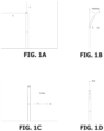
FIGS. 1A-1D illustrate an example coordinate system for three-dimensional image pose estimation.
FIG. 2A illustrates a side view of a distal end of an embodiment of an endovascular catheter.
FIG. 2B is a fluoroscopic image illustrating an endovascular catheter, such as that shown in FIG. 2A, navigating through a vascular network of a patient, according to an embodiment.
FIGS. 3A-3F illustrate an embodiment of a marker on a distal end of a catheter at different orientations, according to an example.
FIG. 4 illustrates an example model of a vascular network of a patient.
FIG. 5A is an example fluoroscopic image of a catheter navigating through the vasculature.
FIG. 5B is another example fluoroscopic image of a catheter navigating through the vasculature.
FIGS. 6A-6F illustrate determination of out-of-plane angle based on detection of a shape of the marker within a medical image, according to some examples.
FIGS. 7A-7C illustrate an example of a semicircular marker for a catheter configured to allow for, among other things, determination of the sign of the incline of the catheter.
FIG. 7D illustrates an additional example of a catheter including different marker types that can be configured to allow for, among other things, determination of the sign of the incline of the catheter.
FIGS. 8A-8B illustrate example fluoroscopic images of a catheter including an example of a non-circumferential ring configured to allow for determination of, among other things, both the sign and magnitude of the incline of the catheter.
FIG. 8C illustrates example two-dimensional appearances of radio-opaque markers at various heading and roll positions.
FIG. 9A illustrates examples of projections of three-dimensional generated catheters onto real world two-dimensional X-ray images, according to some examples.
FIGS. 9B-9C illustrate an example prediction of a trained deep neural network for predicting a position of a body of a catheter body, according to an example.
FIG. 9D illustrates an example determination of a centerline of a catheter.
FIG. 9E illustrates an example determination of a position and heading of a catheter.
FIG. 10 is a block diagram of an embodiment of a computer system configured to implement features described herein.
FIGS. 11A and 11B are side and top views of an embodiment of a catheter that includes markers configured to allow for determination of, among other things, a catheter roll angle.
FIGS. 12A-12D show the catheter and markers at various roll positions.
FIGS. 13A and 13B are perspective and side views of another embodiment of a catheter that includes markers configured to allow for determination of a catheter roll angle.
FIGS. 14A and 14B are perspective and top views of another embodiment of a catheter that includes markers configured to allow for determination of a catheter roll angle.
FIGS. 15A-15H illustrate determination of roll angle based on detection of a phase of a sinusoid of a helical fiducial within a medical image, according to some examples.
FIG. 16A is a perspective view of another embodiment of a catheter that includes a radio-opaque one and one quarter roll helix fiducial configured to allow for determination of a catheter roll angle.
FIGS. 16B-16E show fluoroscopic images of a catheter for determination of a catheter roll angle, according to some examples.
FIG. 16F illustrates the two-dimensional appearance of a radio-opaque marker at different roll positions.
FIGS. 17A-17B illustrate an embodiment of a catheter that includes radio opaque braids can be used to determine roll, according to some examples.
FIGS. 18A-18B illustrate another embodiment of a catheter where radio opaque markers or fiducials can be used to detect planarity.
FIG. 19 illustrates another embodiment of a catheter that includes markers can be used to determine whether the catheter is angled into or out of the image plane, according to some examples.
FIGS. 20A-20D illustrate an embodiment of a graphical user interface for providing image space control of a medical instrument.
FIGS. 21A-21B illustrate two example embodiments for roll estimate determination.
FIGS. 22A-22B illustrate an embodiment of a user input device for providing image space control of a medical instrument.
FIG. 23 illustrates another embodiment of a user input device for providing image space control of a medical instrument.
FIG. 24 is a flowchart depicting an example user space control method.
DETAILED DESCRIPTION
This application describes devices, systems, and methods for detecting or determining the position and/or orientation of endovascular or other intraluminal tools or medical instruments, such as catheters. In some instances, the term “pose” is used herein to refer to the position and orientation of a catheter. In some embodiments, determination of pose can be made based on a two-dimensional medical image, such as a single plane X-ray image, and one or more radio-opaque markers included on a catheter. Computer vision models can be employed to detect the radio-opaque markers in the two-dimensional medical image and to determine the pose of the catheter therefrom. In some instances, the pose can be defined by five degrees of freedom for the catheter. The five degrees of freedom can include two positional degrees of freedom (e.g., x and y position) and three degrees of freedom relating to orientation (e.g., heading, incline, and roll). In other embodiments, the pose can comprise greater (e.g., six) or fewer (e.g., four or fewer) degrees of freedom. The pose of an instrument can be defined in many different ways. While this application primarily describes examples of pose in terms of x, y, and z for position, and heading, incline, and roll for orientation, other methods for describing or defining the pose (e.g., alternative coordinate systems, alternative naming conventions, etc.) are possible, and the principles of this application extend to all methods for defining pose. Further, in some embodiments, the methods and systems of this application may be used to determine one, more than one, or all elements of pose.
This application also describes devices, systems, and methods for controlling endovascular or other intraluminal tools or medical instruments, such as catheters, wherein control inputs are provided with respect to a plane of a two-dimensional medical image. For example, a user can provide control inputs to change a heading of an instrument within the plane of the medical image and/or to change an incline of the instrument into or out of the plane of the medical image. A computer system can determine appropriate motor commands to cause the desired movement/articulation of the instrument based on the control inputs and an estimate of a current roll of the instrument. The estimate of the current roll of the instrument can be determined based on an appearance of one or more radio-opaque markers or fiducials that are included on a distal end of the image and which are visible within the medical image. In some instances, the estimate of current roll is determined by the system based on a computer vision analysis of the medical image. In some instances, the estimate of the current roll is determined and input by the user based on a user-identified appearance of the fiducials.
This type of control system is referred to herein as “image space control” because control inputs are provided with respect to the plane of the image (e.g., adjust heading within the plane or adjust inclination into or out of the plane). This type of control system is intuitive as the user may provide such inputs while viewing the medical image. That is, the user can provide control inputs relative to the current appearance of the instrument within a medical image and without, in some embodiments, needed to specifically understand which pull wires of the instrument need to be actuated to achieve a desired motion.
The principals described herein can be applicable to robotic medical procedures, for example, where the catheter is robotically controlled by a robotic medical system that is configured to insert, retract, roll, and/or articulate the catheter based on inputs received from a physician or in an autonomous or semi-autonomous manner. In some instances the principals of this disclosure may also be applicable to manually controlled catheters.
The principles of this disclosure are described below with primary reference to examples wherein the medical instrument or tool is an endovascular catheter configured to navigate within the vasculature of the patient. These examples, however, should not be construed as limiting of the principles of the disclosure. Those of skill in the art, upon consideration of the principles disclosed herein, will appreciate that the devices, systems, and methods for detecting or determining position and/or orientation described herein have application in other contexts. For examples, the principles described herein can be useful with other endoluminal, endoscopic, or laparoscopic tools, instruments, procedures and/or the like. For ease of illustration, however, a primary example related to an endovascular catheter is provided. Accordingly, it should be realized that any of the following description of an endovascular catheter or catheter may also be applied to other endoluminal, endoscopic, and/or laparoscopic tools or the like. Additionally, it should be realized that while this application provides several example configurations for tools or medical instruments that include specific configurations of radio-opaque markers, other configurations of radio-opaque markers can also be used.
Safe navigation of a catheter within a patient's body generally requires an accurate understanding of the current pose of the catheter. It can be difficult to gain an accurate understanding of pose from a single two-dimensional medical image. For example, FIG. 2B provides an example X-ray image of a catheter 100 navigating through an aortic arch of a patient. From FIG. 2B alone, however, a person would have difficulty understanding the exact pose of the catheter 100. For example, does the catheter 100 lie completely within the plane of the image, or is it inclined into or out of the plane of the image? Highly skilled physicians may be able to make educated guesses with respect to these questions based on their understanding of human anatomy. Still, however, uncertainty exists, which increases the risk of damage to the patient during a medical procedure.
Perhaps even more critically, from FIG. 2B alone, it is extremely difficult, if not impossible, for even skilled physicians to determine the current roll angle of the catheter 100 (i.e., the rotational angle of the catheter about its longitudinal axis). Understanding the current roll of the catheter 100 can be critical for safe navigation, especially considering how most articulable catheters are controlled. Most articulable catheters include pullwires that can be actuated (e.g., tensioned or pulled) to cause deflection of a distal tip of the catheter. See, for example, the catheter 100 of FIG. 2A described below. Commonly, catheters include four pullwires, each configured to cause deflection of the catheter in one of four cardinal directions. For example, one pullwire can be associated with deflecting the tip of the catheter up, one pullwire can be associated with deflecting the tip down, one pullwire can be associated with deflecting the tip right, and one pullwire can be associated with deflecting the tip down. However, in order to know which pullwire to actuate to cause a given deflection requires an understanding of the current roll position of the catheter. For example, if the distal tip of the catheter is rolled by 90 degrees, actuating the pullwire generally associated with an upward deflection of the tip would instead cause the catheter to articulate (possibly unexpectedly) to the right or left. Unintended articulation can frustrate navigation and cause injury to a patient. Moreover, the distal tip of a catheter often rolls (in unexpected ways) as the catheter is navigated through complex anatomy, such as through a vascular network of a patient, even if roll inputs are not provided at the proximal (e.g., external) end of the catheter.
As will be described in more detail below, the systems, methods, and devices provide for accurate determination of the pose of a catheter (including its roll) based on detection of radio-opaque fiducials included on the catheter. In some embodiments, detection of the radio-opaque fiducials is achieved using computer vision analysis of a two-dimensional medical image of the catheter. The methods and systems described herein can also be used with biplane imaging systems to determine six degree of freedom pose estimates of the catheter. In such cases, determination of incline may (in some instances) be determined from the biplane images, while roll angle can be determined based on computer vision analysis of the radio-opaque fiducials included on the catheter.
FIGS. 1A-1D illustrate an example coordinate system for three-dimensional image pose estimation or determination. As noted above, the term “pose” is used herein to refer to the different combinations of positions and/or orientations of an endovascular tool, intraluminal tool, medical instrument and/or the like. Position can refer to, for example, an x, y, and z position (for example, a location within three-dimensional space). In some embodiments, position can refer to the x and y position within the two-dimensional image plane of a medical image, such as an X-ray. Orientation can be represented in many different ways. In general, in this application, orientation is referred to using three Euler angles: (1) heading, which can be a measure of angulation or articulation about the z-axis and/or where the device is pointing in the image plane; (2) incline, which can be a measure of rotation about the x-axis and/or where the device is pointing out of the image plane (e.g., pitch); and (3) roll which can be a measure of rotation about the longitudinal or central axis of the catheter.
FIGS. 1A-1D provide additional illustrations. FIG. 1A represents two-dimensional position within the x-y plane of the medical image. FIG. 1B illustrates the heading angle, measured about the z-axis, which generally corresponds to the apparent heading or direction of the catheter within the x-y plane of the image. FIG. 1C illustrates the incline angle, measured about the x-axis, which generally corresponds to a measurement of the angle into or out of the plane of the image. FIG. 1D illustrates the roll of the catheter, measured about the catheter's longitudinal or central axis. The methods and systems described herein are also applicable to determination of one, more than one, or all elements of pose, regardless of the manner in which pose is defined (e.g., regardless of coordinate system, nomenclature, etc.).
As will be further described herein, the use of computer vision algorithms and unique radio-opaque markings or fiducials can be included on the catheter that may be used to quantitatively estimate the endovascular tool's five-dimensional pose (for example, two-dimensional position (e.g., see FIG. 1A), as well as its heading (e.g., FIG. 1B), incline (e.g., FIG. 1C), and roll (e.g., FIG. 1D). The use of radio-opaque markings can preserve the readily visible dimensions, for example, the position of the endovascular tool on the image plane (the x and y position) and the direction the endovascular tool points in the image plane (the heading), and further, the use of unique radio-opaque markings can further allow the sign of the incline dimension, the degree of incline dimension, and the roll to be quantitatively estimated or determined. While many different radio-opaque materials may be used, in some embodiments, it may be preferable to use platinum, tungsten, and/or gold because of their superior X-ray attenuation properties. In some embodiments, the radio-opaque material may be a piece of wire, metal, radio-opaque ink and/or the like that is place within a layer of the catheter or other tool. Examples are provided below.
FIG. 2A illustrates a distal end of an embodiment of an endovascular catheter 100. In the illustrated embodiment, the catheter 100 includes a long, thin, and flexible body 101 that extends to a distal end 103. The body 101 can be configured to be navigated through the patient's vasculature. In some embodiments, a channel may be formed through the body 101 such that other tools or instruments can be passed through the catheter 100 and gain access to the patient's anatomy through an opening that can be included on the distal end 103 of the catheter. In some embodiments, one or more tools can be integrated directly into the catheter 100 itself.
To facilitate navigation, in some embodiments (such as the illustrated embodiment of FIG. 2A), the catheter 100 or a distal portion thereof can be configured to be articulable or deflectable. To achieve articulation, the catheter 100 includes one or more pull wires 105 that extend on, in, or through the body 101 and attach at or near the distal end 103. Actuation (e.g., pulling or shortening) the pull wires 105 at or near their proximal end can be configured to cause a distal portion of the catheter 100 to deflect or articulate. Depending on the number and arrangement of pull wires 105, the catheter 100 can be configured for one-way, two-way, three-way, or four-way deflection, although other configurations providing different degrees of articulation or deflection are also possible.
The catheter 100 can be configured such that control thereof (e.g., control of the deflection of the distal portion of the catheter 100) can be accomplished manually or robotically. For example, in some embodiments that are configured for manual control, the body 101 and pull wires 105 extend proximally to a handle located on a proximal end of the catheter 100 (not shown). The handle can be configured to by operated by hand (e.g., manually) to actuate the pull wires 105. For example, the handle can include one or more manual inputs such as levers, buttons, dials and/or the like that allow a user to manually actuate the pull wires 105 to cause deflection of the distal portion of the catheter 100. In some robotically controllable embodiments, the body 101 and pull wires 105 extend proximally to a base located on a proximal end of the catheter 100 (not shown). The base can be configured to connect to and be operated by a robotic medical system to actuate the pull wires 105. For example, the base can include one or more robotic inputs configured to engage with robotic outputs or actuators on the robotic medical system. In some embodiments, other methods and configurations for manual and robotic control may be used.
FIG. 2A also illustrates that, in some embodiments, the catheter 100 can include a marker (or fiducial) 107. In the illustrated embodiment, the marker 107 is positioned at the distal end 103 of the catheter 100. The marker 107 can be configured to facilitate identification of the distal end 103 of the catheter 100 in a medical image captured during a medical procedure. For example, the marker 107 can be radio-opaque so as to be readily identifiable within a fluoroscopic image. In some embodiments, the marker 107 comprises a radio-opaque ring positioned on the distal end 103 of the catheter 100. When the marker 107 comprises a radio-opaque material, it can be more easily identified within, for example, a fluoroscopic image such as an X-ray. Identification of the distal end 103 within a medical image during a procedure can greatly facilitate navigation and control of the catheter 100.
FIG. 2B provides an example medical image of a catheter 100, such as the catheter 100 of FIG. 2A, navigating within the vasculature of the patient. In particular, the image of FIG. 2B is a fluoroscopic X-ray image. As shown, both blood vessels 109 of the patient's vasculature, as well as the catheter 100 itself, are visible in the image. The marker 107 included at the distal end 103 of the catheter 100 helps a user (or a computer-vision algorithm) viewing the image to identify the distal end 103 of the catheter 100. Because the marker 107 comprises a radio-opaque material, it shows up well within the image.
In general, during an endovascular procedure, a physician or other operator, attempts to guide the distal end 103 of the catheter 100 to a specific location, such as, for example a treatment site. For example, one such procedure is a mechanical thrombectomy. A large vessel occlusion (LVO) stroke occurs when a blood clot lodges in at least one of the internal carotid, proximal middle cerebral artery, proximal anterior cerebral artery, basilar artery, or vertebral artery. Such a clot can partially or completely occlude downstream blood supply to brain tissue resulting in neuronal infarction and subsequent neurological impairment or death. During a mechanical thrombectomy, a physician gains access to the patient's vasculature and inserts a catheter, such as catheter 100. The catheter 100 is guided to the obstruction using, for example, one or more medical images similar to the one shown in FIG. 2B. Once the distal end 103 of the catheter 100 is positioned near the obstruction, tools are passed through the working channel of the catheter 100 to remove the obstruction.
While medical images, such as that shown in FIG. 2B, may help the physician guide the catheter 100 to the treatment site, it is still difficult to fully determine the orientation or pose of the catheter 100 from the medical image alone. This occurs, for example and among other reasons, because the medical image often provides only a two-dimensional view of the patient's anatomy (e.g., the vasculature) and the catheter 100, each of which, in actuality, comprise three-dimensional shapes. In the past (for example, without the systems, methods, and devices described herein), physicians needed to rely on their knowledge of anatomy as well as various other assumptions (such as an assumption that the catheter 100 is located within the vasculature) to interpret the two-dimensional medical image in a three-dimensional way. While many specialists are able to do this to a limited extent, this can provide a barrier to the availability of such procedures. Further, because different patients have different anatomies, the results are not always precise.
Considering FIG. 2B, for example, one can relatively easily understand the shape of the catheter 100 within the plane of the two-dimensional of the image. However, the shape of the catheter 100 out of the plane of the image (e.g., the incline of the catheter) is harder to discern. For example, in FIG. 2B, it is difficult to determine whether the catheter 100 is moving in a direction that is into or out of the plane of the image. While an understanding of anatomy can inform the answer to this question, the result is still not wholly determinable. As will be described in more detail below, this application offers new devices, systems, and methods for determining an out of the plane angle of the distal end 103 of the catheter 100. Increasing a physician's understanding of the out of the plane angle of the distal end 103 of the catheter 100 can greatly facilitate navigation and improve the experience of driving or controlling the catheter 100.
As described above, the catheter 100 may include an articulable portion that is actuated via pull wires. To accurately control the articulation of the catheter 100, one must understand the roll orientation of the catheter 100. As a simplified example, if the physician actuates the right most pull wire 105 expecting that this will cause the catheter 100 to deflect to the right, the catheter 100 may move unexpectedly to the left if the catheter 100 is rolled 180 degrees such that the right most pull wire 105 is positioned on the left side of the catheter 100. The physician may estimate the roll position of the catheter 100 based on the roll position of the proximal end of the catheter 100. However, due to the complex shape of the vasculature, the roll position at the proximal end of the catheter 100 may not (and often does not) directly correspond to the roll position at the distal end 103 of the catheter 100. Thus, to understand how actuation of the pull wires 105 will cause the distal portion of the catheter 100 to deflect, one must generally understand the roll position at the distal portion of the catheter 100.
Considering FIG. 2B further, one can see that the roll position of the distal portion of the catheter 100 is not readily discernible. As will be described in more detail below, this application offers new devices, systems, and methods for determining the roll position of the distal end 103 of the catheter 100. Increasing a physician's understanding of the roll position of the distal end 103 of the catheter 100 can greatly facilitate navigation and improve the experience of driving or controlling the catheter 100.
Out-of-Plane or Incline Angle Detection for Endovascular and Other Intraluminal Tools
As discussed in the preceding section, in some embodiments, such as the embodiment illustrated in FIG. 2A, a catheter 100 can include a marker 107 (or a plurality of markers) positioned on the distal end 103 thereof. In some embodiments, such as the illustrated embodiments, the marker 107 comprises a ring positioned on the distal end 103. The marker 107 can be radio-opaque such that it can be easily identifiable within a medical image, such as, for example, the medical image shown in FIG. 2B. As described in this section and throughout this application, the shape of the marker(s) 107 within the two-dimensional image can be analyzed to determine the out of the plane angle or incline of the catheter 100. In other words, the two-dimensional projection of the three-dimensional shape of the marker 107 can be analyzed to determine the out of the plane angle of the catheter 100. The term “incline,” as referred to herein, can refer to the degree of angulation of the catheter towards or away from the X-ray source (e.g., into or out of the imaging plane), for example, as shown in FIG. 1C. In some examples, a positive degree of angulation indicates that the catheter is angled towards the X-ray emitter, with a maximum incline of +90-degrees. A negative degree of angulation indicates that the catheter is angled away from the X-ray emitter, with a maximum incline of −90-degrees.
Considering the example of FIG. 2A, in the illustrated orientation, the ring-shaped marker 107 presents or appears as a rectangle having a straight edge at the distal most tip within the two-dimensional plane of FIG. 2A. With this orientation, it can be determined that the distal portion of the catheter 100 lies in the plane of the FIG. 2A (e.g., in the illustrated orientation, the catheter 100 is not curving into or out of the plane of FIG. 2A).
To further illustrate the principles and concepts, FIGS. 3A-3F illustrate the marker 107 in different orientations. In FIGS. 3A-3F, the distal most end of the marker 107 is illustrated with a double line. As before, the marker 107 comprises a ring shape that can be positioned on the end of a catheter, such as the catheter 100 of FIG. 2A. As shown in FIG. 3A, one can see that, within the plane of the FIG. 3A, the marker 107 is generally pointed up and to the left. One can further see that the distal end of the marker 107 presents as an ellipse within the plane of FIG. 3A. Because the entire ellipse is visible, it can be determined that the marker 107 is pointed out of the plane of the page. In contrast, consider FIG. 3F. In FIG. 3F, within the plane of the page, one can see that the marker 107 is pointed straight up. Considering the distal edge of the marker 107, one can only see half of the ellipse (the other half being blocked from view). From this, it can be determined the marker 107 of FIG. 3F is angled into the page.
FIG. 3B presents a similar example to FIG. 3F, except, as shown in FIG. 3B, the entire ellipse is visible. From this it can be determined that the marker is angled out of the plane of FIG. 3B. FIG. 3C presents an example where the marker 107 is pointed up and to the right within the plane of FIG. 3C and angled slightly out of the page based on the shape of the ellipse. FIG. 3D illustrates another example where the marker 107 is angled out of the plane of the page. Comparing FIGS. 3B and 3D, one can see that the length of the minor axis of the ellipse is shorter in FIG. 3D as compared to FIG. 3B. This indicates that the degree of the angle out of the page in FIG. 3D is less than the degree of the angle out of the page of FIG. 3B.
If one considers that the marker 107 continues to turn out of the plane of the page, the minor axis of the ellipse will continue to increase in length until the minor and major axes are equal and the distal end of the marker 107 will present as a circle in the plane of the page. FIG. 3E illustrates an example similar to FIG. 2A, in which the marker is pointed upwards, within the plane of the page. At this orientation, the minor axis has decreased to zero, indicating that the marker 107 is pointed upwards within the plane of the page.
From the examples provided, it can be seen that one can analyze the two-dimensional shape created by the ring or circled-shaped marker 107 within a two-dimensional imaging plane to determine the orientation of the marker 107 into and out of the page. Other shapes for marker 107 are possible. For example, the marker 107 need not always comprise a ring shape.
In some embodiments, a computer system, such as or which can include a computer vision system, can be used to (1) detect the shape (e.g., the visible, ellipse, circle, curve, or line) created by the distal end of the ring-shaped marker 107 within the two-dimensional image, and (2) extract or determine the out of the plane angle of the marker 107 or the tool incline from the detected shape. In some embodiments, the computer system may utilize artificial intelligence or machine learning to perform such functionality. In some embodiments, for example, a neural network can be trained to detect the shape created by the distal end of the ring-shaped marker 107 within the two-dimensional image, and extract or determine the out of the plane angle of the marker 107 from the detected shape. In some embodiments, computer vision can be used to define the orientation of the tool along the z-axis.
As mentioned above, determination of the out of the plane angle of the catheter 100 can be important in improving and/or facilitating navigation through a luminal network, such as the vasculature. In general, the vasculature of a patient will not lie within a single plane. This is apparent considering the model example vasculature provided in FIG. 4 . As shown in FIG. 4 , for example, the arch of the aorta does move slightly from left to right, but it moves or arches predominately from front to back. Thus, if the patient (on an operating table) is imaged from the top down, a tool navigating through the arch of the aorta will be moving significantly out of the plane of the imaging device. To fully understand this motion, the angle of the catheter 100 out of the page can be determined as described above.
FIGS. 5A and 5B provide additional example medical images of a catheter, such as the catheter 100 of FIG. 2A, navigating through vasculature. These figures illustrate how the catheter 100 moves at an angle into and out of the plane of the medical image based on the portion of the anatomy through which the catheter 100 passes. For example, as shown in FIG. 5A, which illustrates the catheter 100 navigating through a portion of the carotid artery, the distal end 103 of the catheter 100 lies generally within the plane of the medical image, and thus the distal end 103 of the marker 107 does not form an ellipse. In contrast, FIG. 5B illustrates the catheter 100 navigating through a portion of the aortic arch. As shown, the distal end 103 of the marker 107 does forms an ellipse which indicates that the catheter 100 is moving with at an angle that is moving out of the plane of FIG. 5B.
FIGS. 6A-6F provide additional examples of detecting the shape (e.g., the visible, ellipse, circle, curve, or line) created by the distal end of the ring-shaped marker 107 within the two-dimensional image and extracting or determining the out of the plane angle of the marker 107 from the detected shape. FIGS. 6A-6C illustrate three example images, and FIGS. 6D-6F illustrate the same images with the shape of the ring-shaped marker 107 that has been detected and highlighted.
Alternatively or in addition to detecting the shape of the distal tip of the catheter 100 within the plane of the image, other methods or mechanisms may also be employed for determining the out of the plane angle of the catheter 100. For example, in some embodiments, a degree of angulation may be presumed for each vessel through which the catheter 100 passes, for example, based on the general or average angulation of that vessel across the population. In some embodiments, the angulation of a vessel can be determined based on a CT scan. In some embodiments, an additional medical image at a different orientation than the first medical image (e.g., a lateral angiographic view) can be provided. In some embodiments, the medical imager can be moved so as to gain an understanding of the out of the plane angulation.
Although many of the preceding examples have described the use of a ring-shaped marker 107, other types of markers or fiducials can be used as described further below.
Incline Sign Detection for Endovascular and Other Intraluminal Tools
As discussed in the preceding section, the magnitude of the incline of endovascular and other intraluminal tools can, in some embodiments, be determined by analysis of the elliptical shape of the tool mouth (or a marker, such a ring-shaped marker, included thereon). However, the sign of the degree of angulation is not always readily identifiable solely from analysis of the marker 107 because the elliptical shape may look the same when imaged in two dimensions for both positive angulation and negative angulations of the same degree of incline. To determine whether the incline is positive or negative, an additional method may be desired.
FIG. 7A illustrates one method for determining the sign of the incline of catheter 100 where catheter 100 can include a semicircular marker 110 positioned on the distal end 103 thereof. The semicircular marker 110 can be radio-opaque such that it can easily be identifiable within a medical image. In the illustrated example, the semicircular marker 110 extends around one half of the distal end 103 of the catheter 100. In other embodiments, other portions can be used (e.g., ¼, etc.). In some embodiments, additional fiducials, such as helical fiducial 111 may also be used. As described in this section, the position of the marker 110 within the two-dimensional image can be analyzed to determine the sign of the incline of the catheter 100. The sign of the incline of catheter 100 can be determined by whether the semicircular marker 110 appears to be above or below the distal end 103 in the two-dimensional image.
FIGS. 7B-7C illustrate the appearance of the marker 110 on a catheter tip on an X-ray at different inclines. The catheter itself is not shown in these figures. As shown, the semicircular marker 110 in combination with helical fiducial 111 will produce a different appearance in the two-dimensional image when inclined at the same angle, but at different signed inclines (e.g., whether into or out of the plane of the image). For example, the magnitude of the incline could be determined to be 45-degrees using a method such as the ring-shaped marker method described above. The semicircular marker 110 in combination with helical fiducial 111 could then be used to determine the signed incline. For example, in FIG. 7B, the catheter tip is inclined at negative 45-degrees, and in FIG. 7C, the catheter tip is inclined at positive 45-degrees.
In some embodiments, a computer system, such as a computer vision system, can be used to (1) detect the position of the semicircular marker 110 in combination with helical fiducial 111 within the two-dimensional image, and (2) extract or determine the sign of the tool incline from the detected position. In some embodiments, the computer system may utilize artificial intelligence or machine learning to perform such functionality. In some embodiments, for example, a neural network can be trained to detect the position of the semicircular marker 110 in combination with helical fiducial 111 within the two-dimensional image, and extract or determine the sign of the tool incline from the detected position. It should be noted that in some embodiments, the machine learning algorithm does not hardcode the aforementioned approach. Instead, the machine learning algorithm trains a deep neural network to directly predict the incline angle from the input of the X-ray image.
FIG. 7D illustrates an additional example of a catheter 100 including a helical marker 111 and additional markers 114. In the illustrated embodiment, the additional markers 114 include a semi-circular portion that extends partially around the radius of the catheter 100 and a tail portion that extends along longitudinally along the catheter.
FIGS. 8A-8B illustrate provide an additional example of determination of the sign and magnitude of incline of catheter 100, where the catheter 100 can include one or more non-circumferential rings 113. In the illustrated embodiment, the non-circumferential rings are semi-circular, extending part way around the catheter 100. In some embodiments, the non-circumferential rings 113 can be radio-opaque such that it can easily be identifiable within a medical image. The appearance of the non-circumferential rings 113 can be analyzed to determine the sign and magnitude of the incline of the catheter 100. The sign and magnitude of the incline of catheter 100 can be determined by the unique appearance of the non-circumferential rings 113 in the two-dimensional image at varying degrees of incline, both positive and negative. In some embodiments, non-circumferential rings 113 are arranged in an asymmetrical design. That is, in some embodiments, the non-circumferential rings 113 are each positioned at a different rotational position around the catheter 100. In the illustrated embodiments, the non-circumferential rings are positioned at 90-degree offsets. In some embodiments, non-circumferential rings 113 are multiple ellipses offset from each other.
FIG. 8C illustrates how an example arrangement of non-circumferential rings 113 positioned on a distal end of a catheter may provide a unique appearance at different inclination and roll angles. Images are provided at positive, neutral (i.e., zero), and negative inclinations, as well as at different roll positions provided in 30-degree increments. As shown, each of the 36 different illustrated positions provides a unique appearance. By detected, for example, using computer vision, this appearance within a medical image, the incline (including its sign) and the roll of the catheter can be determined. While FIG. 8C illustrates how the radio-opaque markers provide different two-dimensional appearances for different roll positions at 30-degree increments and for different positive, neutral (zero), and negative inclines, the illustrated increments are not intended to be limiting.
In some embodiments, the radio-opaque markers provide unique or visually distinguishable two-dimensional appearances at all different roll or incline positions. In some embodiments, the radio-opaque markers provide unique or visually distinguishable two-dimensional appearances at different roll or incline positions within increments of about, at least, or at most 1 degree, 2 degrees, 3 degrees, 4 degrees, 5 degrees, 7.5 degrees, 10 degrees, 12.5 degrees, 15 degrees, 17.5 degrees, 20 degrees, 25 degrees, 30 degrees, or 40 degrees. That is, in some embodiments, the radio-opaque markers are configured with a three-dimensional shape that, when viewed within the two-dimensional plane of a two-dimensional medical imaging device, provides a unique or visually distinguishable appearance that can be distinguished at the different incremental roll or incline angles listed above. The above listed increments can be considered minimum resolutions for the system or the minimum change in roll or incline that is detectable by the system.
Tool Position and Heading for Endovascular and Other Intraluminal Tools
FIG. 9A illustrates examples of projections of three-dimensional generated catheters onto real world two-dimensional X-ray images. FIGS. 9B-9C illustrate an example prediction of the trained deep neural network for predicting where the catheter body is. As noted above, position can refer to translation of endovascular and/or other intraluminal tools along the x, y, and z directions. In some embodiments, instead of determining the three-dimensional position of the instrument (z, y, and z), only the two-dimensional (x and y) position is used. This can be because estimating the z position (i.e., depth) may require calibrating the X-ray camera to obtain determine intrinsic parameters thereof. While this is feasible, it would likely (1) add a burdensome pre-operative image calibration step, (2) may not help that much because motion planning is primarily done in two-dimensions, and (3) we the C-arm can be rotated to obtain a Z position estimate.
In some embodiments, the system may be configured to predict where the full tool body is, and then from this tool body we the two-dimensional tip location can be extracted. This approach may be beneficial because the tool body provides a very strong training signal for learning deep neural network segmentation models. That is, in some instances, it may be easier for a neural network of computer vision algorithm to detect the body of a catheter and then extract the location of the tip from there. In some embodiments, catheter kinematics are further used refine this estimate.
For example, a deep neural network can be used to estimate the two-dimensional centerline position of the catheter based on one or more images of the catheter navigating within the body. FIG. 9D illustrates an example, in which the neural network has identified the catheter within the image, superimposed its estimated centerline onto the image, and highlighted the catheter. Once the centerline of the catheter has been identified within the image, the two-dimensional position can be directly extracted by computing the most distal position along the centerline. Similarly, the heading of the catheter can also be directly extracted from the body estimate by computing the vector of the tip of the body line. FIG. 9E illustrates an example in which the distal tip position and heading angle have been determined and the image has been updated to include a highlight identifying the position and an arrow indicating the heading.
In some embodiments, a machine learning algorithm for estimating the position of a catheter and/or other tool may use the following approach. First, the image generation procedure is modified by drawing the catheter on top of tangible X-ray images (e.g., as shown in FIG. 9B). This process may have the advantage of training the deep neural network with realistic noise and occlusions that would be seen in actual X-rays, making the system robust to real world conditions.
Second, the two-dimensional x and y position is estimated. In some embodiments, radio-opaque markings may be added to the tool body, such as, for example, a full-length helix, to assist with the identification. In some embodiments, the three-dimensional x, y, and z position may be estimated instead. However, estimation of the Z position may require calibration of the X-ray camera to obtain its camera intrinsic, which requires an additional step of a pre-operation image calibration. In some instances, the two-dimensional position estimation will be preferable so the pre-operation image calibration step does not need to be completed and because the z position may not be necessary because motion planning is primarily conducted in two-dimensions. Further, a z position estimate can be obtained by rotating the C-arm. Using this method, the two-dimensional x and y position of the full tool body may be predicted. Thereafter, the two-dimensional x and y position location of the tool tip (such as, for example, the distal end 103 of catheter 100) can be determined. This approach may be used because the tool body provides a very strong training signal for learning deep neural network segmentation models. In some embodiments, catheter kinematics may be used to further refine the position estimate.
As noted above, heading can refer to a measure of angulation or articulation about the z-axis and/or where the device is pointing in the image plane. To determine the heading of endovascular and/or other intraluminal tools, such as a catheter, the deep neural network prediction of the catheter body position may be used. Based on the prediction of the two-dimensional x and y position of the catheter tip, a second position located on the catheter body may be determined. The second position may be an infinitesimal distance from the tool tip in a direction along the catheter body. The heading angle of the catheter may then be calculated using trigonometry based on the x and y position of the tool tip and the second position along the catheter body.
Roll Angle Detection for Endovascular and Other Intraluminal Tools
As noted above, radio-opaque markers can be placed at the distal tip 103 of a catheter 100 to improve the visibility of the catheter 100 in a medical image (see FIGS. 2A and 2B). In some embodiments, these markers are symmetric about the tools axis and thus do not provide any information related to the roll angle of the catheter. As described in this section, the degree of rotation of a tool about its centerline may be informed by the addition of radio-opaque rotation fiducials. Numerous configurations of radio-opaque rotation fiducials can be utilized to determine the degree of tool rotation, provided the configurations result in a unique X-ray appearance of the tool at differing degrees of rotation. While multiple configurations will be disclosed with reference to certain embodiments, it will be understood that various changes may be made, and equivalents may be substituted for elements thereof without departing from the scope of the disclosure. For example, markers 108 that are rotationally asymmetric can be utilized on the catheter 100 and configured to provide information from which the roll angle of the catheter 100 can be determined. In some embodiments, a computer vision algorithm can be used to detect and analyze the positions of the markers 108 to determine the rotation or roll of the catheter 100 about its longitudinal axis. As described above, the rotation of the catheter 100 determines how an actuation of a given pull wire will move the catheter 100. Thus, an accurate understanding of the roll angle of the catheter 100 can be important for successful navigation of the catheter 100 through the vasculature.
FIGS. 11A and 11B illustrate side and top views respectively of a distal portion of a catheter 100 that has been configured with markers 108 from which the roll angle of the catheter 100 can be determined. In this embodiment, the catheter 100 includes markers 108A-108D configured as radio-opaque fiducials (e.g., dots) placed at different distances from the distal tip 103, at differing angles/arcs from the center of the tool. This configuration allows the catheter 100 to take on a unique appearance depending on its rotation around its longitudinal axis. In some embodiments, the markers may be other radio-opaque fiducials, such as, for example squares, circles, diamonds, and/or the like.
In the illustrated embodiment, a first marker 108A is positioned a first distance 2D (twice the diameter of the tool) from the distal tip 103 and at a 45-degree rotational offset with respect to a first pull wire 105. A second marker 108B is positioned an additional distance 2D from the distal tip 103 (4D) and at a 135-degree rotational offset with respect to the first pull wire 105. A third marker 108C is positioned an additional distance 2D from the distal tip 103 (6D) and at a 225-degree rotational offset with respect to the first pull wire 105. A fourth marker 108D is positioned an additional distance 2D from the distal tip 103 (8D) and at a 315-degree rotational offset with respect to the first pull wire 105. In some embodiments, the rotational offset of first marker 108A from the first pull wire may be, for example, 0-degrees, 5-degrees, 10-degrees, 15-degrees, 20-degrees, 25-degrees, 30-degrees, 35-degrees, 40-degrees, 45-degrees, 50-degrees, 55-degrees, 60-degrees, 65-degrees, 70-degrees, 75-degrees, 80-degrees, 85-degrees, 90-degrees, and/or the like, with the second marker 108B, third marker 108C, and fourth marker 108D being an additional 90-degrees, 180 degrees, and 270-degrees respectively rotationally offset from first marker 108A. In some embodiments, the distance 2D is approximately 5 mm.
In the illustrated example, each marker 108 is positioned at a longitudinal distance that is twice the diameter D of the catheter 100 below the marker 108 above it (or below the distal tip 103 for the first marker). This need not be the case in all embodiments, and other spacings are possible. In the illustrated example, each marker 108 is positioned at 90-degree offsets and between the adjacent pull wires 105. Again, this need not be the case in all embodiments and other spacings are possible. Further, in FIG. 6A, the catheter 100 is illustrated as transparent, allowing all four markers 108 to be visible. It should be appreciated, however, that in the illustrated example, markers 108A and 108D are on the back side of the catheter 100 (the side facing away relative to the orientation of the image) and thus would not be visible if the catheter were not illustrated as transparent.
With such a configuration or other suitable configurations, the appearance of the markers 108A-108D within a medical image provides a unique appearance from which the roll of the catheter 100 can be determined. FIGS. 12A-12D provide various examples of the catheter 100 at different orientations. In each of FIGS. 12A-12D, both a model of the catheter and a corresponding image of the catheter are shown. FIGS. 12A-12D illustrate that for each roll position, the appearance of the markers 108A-108D is different, thus allowing for roll determination.
In some embodiments, determining roll from the markers 108A-108D can be accomplished as follows: (1) the locations of the markers 108A-108D within an image can be determined, in some embodiments, this is accomplished through computer vision or a neural network that has been trained to identify the markers 108A-108D; (2) the centerline of the catheter 100 can be determined using, for example, computer vision or a neural network; (3) the distance (with appropriate sign, positive or negative) between each of the markers 108A-108D and the centerline can be determined; (4) the signed distance between the markers and the centerline can be used to determine the roll angle using geometry principles.
Use of four markers 108A-108D, for example, as shown in FIGS. 11A-11B and FIGS. 12A-12D, can be advantageous for various reasons. For example, because each marker 108A-108D is placed at a different distance from the distal tip 103, they can each be uniquely identified by that distance. This can allow the machine learning model and/or loss to be much more robust and/or generalizable. Use of four markers 108A-108D may also prevent against or eliminate angle aliasing, for example, allowing for full determination of roll between 0 and 360 degrees. Because the markers 108A-108D are equidistantly spaced along the longitudinal axis, the markers 108A-108D can be analyzed to determine out-of-of plane rotations. Further, use of four markers 108A-108D can allow for determination of the centerline of the catheter 100. Use of markers 108A-108D and four pull wires 105 can also facilitate control and verification.
In some embodiments, increasing the axial distance between the markers 108A-108D, can increase the signal to noise ratio, for example, allowing the markers 108A-108D to be more easily identified within the medical image. In some embodiments, more than four markers may be used to determine the roll of the catheter 100. In some embodiments, less than four markers may be used to determine the roll of the catheter 100.
FIGS. 13A and 13B illustrate another embodiment of markers 115 that can be used to determine roll angle of a catheter 100. FIG. 13A is a perspective view of a distal end of a catheter 100 including markers thereon. FIG. 13B is a side view of the markers 115. In the illustrated embodiment of FIGS. 13A and 13B, multiple ring-shaped markers 115 are included. Each ring-shaped marker 115 can include a through hole formed therethrough. When the ring 115 is rotated such that the holes align, there will be a visible gap in the ring. When the ring 115 is rotated such that the holes do not align, the ring will appear solid. This distinction may be detectable through a centroid detection algorithm or a computer vision algorithm trained for this type of device. In other embodiments, the hole need not be circular, the hole may be, for example, any polygonal shape.
As shown in FIGS. 13A and 13B, multiple rings 115 may be stacked at set rotations, such that the rotation of the tool can be determined by identifying which of the rings 115 presents a visible gap.
In some embodiments, radio-opaque sleeves or other features can be coupled to the pull wires. In such cases, a computer vision algorithm can be configured to either detect the features at opposite sides of the catheter or to detect when the features overlap. In either case, these features would allow the computer vision system to assess if the tool is oriented with each pull wire in plane.
FIGS. 14A and 14B illustrate another embodiment of catheter 100 that includes the use of two markers 117 and 119 of different lengths oriented at 90 degrees with respect to each other. Because the markers 117 and 119 are of different length, the relative position of the markers 117 to marker 119 can be determined, allowing roll angle to be reliably computed using only two markers.
FIGS. 15A-15H illustrate another embodiment of a configuration that may be used to determine the roll of the catheter 100. In this embodiment, a radio-opaque helix fiducial 121 is coupled to catheter 100. In some embodiments, the radio-opaque helix fiducial 121 is approximately sinusoidal such that the phase of the sinusoid can be used to determine the degree of roll. In some embodiments, the phase of the sinusoid may be determined by the location of the radio-opaque helix fiducial 121 closest to the distal end of the catheter 100 and by the location of the radio-opaque helix fiducial 121 furthest from the distal end of the catheter 100, near the base of the cylindrical band. It should be noted that in some embodiments, the machine learning algorithm does not hardcode the phase determination. Instead, the machine learning algorithm trains a deep neural network to directly predict the roll angle form the input X-ray image. FIGS. 15A-15H illustrate X-ray images of catheter 100 at different degrees of roll and different degrees of incline.
FIG. 16A illustrates another embodiment of a configuration that may be used to determine the roll of the catheter 100. In this embodiment, a radio-opaque one and one quarter roll helix fiducial 123 is coupled to catheter 100, where the helix is made slightly longer than one complete revolution, such that the roll helix fiducial 123 is approximately 1.25 times the articulation length. The degree of roll of catheter 100 can be determined because the roll helix 123 takes on a different appearance depending on the degree of roll. In FIG. 16A, the roll helix fiducial can comprise other lengths greater than or less than one and one quarters. For example, as shown in FIGS. 16B-16E, at different degrees of roll, the roll helix 123 takes on a distinct appearance. In some embodiments, the articulation length is approximately two centimeters. Notably, the embodiments illustrated in FIGS. 16A-16E also include examples of the non-circumferential markers discussed above.
FIG. 16F illustrates the two-dimensional appearance (e.g., as within the plane of medial image) of the helical fiducial 123 of FIG. 16A and different roll positions in 30-degree increments. As shown, each roll position provides a unique appearance which can be used to determine roll, for example, by a computer vision, neural network, or machine learning system. While FIG. 16F illustrates how the radio-opaque markers provide different two-dimensional appearances for different roll positions at 30-degree increments, the illustrated increments are not intended to be limiting.
In some embodiments, the radio-opaque markers provide unique or visually distinguishable two-dimensional appearances at all different roll positions. In some embodiments, the radio-opaque markers provide unique or visually distinguishable two-dimensional appearances at different roll positions within increments of about, at least, or at most 1 degree, 2 degrees, 3 degrees, 4 degrees, 5 degrees, 7.5 degrees, 10 degrees, 12.5 degrees, 15 degrees, 17.5 degrees, 20 degrees, 25 degrees, 30 degrees, or 40 degrees. The above listed increments can be considered minimum resolutions for the system or the minimum change in roll that is detectable by the system.
In some embodiments, the roll angle determined based on the markers of any of these embodiments can be used by a motion planning algorithm to determine how it will move the catheter. In one embodiment, the algorithm can be configured to rotate the catheter until the radio-opaque identifiers aligns with the imaging plane. In another embodiment, the algorithm can measure the rotation of the tool using the radio-opaque identifiers and update which pull wires it uses to execute a maneuver.
Additional Detail
FIGS. 17A and 17B illustrate an embodiment where radio opaque braids 125 can be used to determine roll. For example, the way in which the radio opaque braids 125 are wound around the catheter 100 may be used to detect out-of-plane deflection. For example, one can detect the plane of deflection based on the frequency of the sinusoidal shape of the tantalum wire as shown in FIGS. 17A and 17B.
FIGS. 18A and 18B illustrate that radio opaque markers or fiducials 127 can be used to detect planarity. For example, the distance observed in a single plane can be used to provide information regarding a tool's degree of out-of-plane deflection. For example, in FIGS. 18A and 18B below, the shorter distance between the two fiducials 127 indicates bending out of plane, whereas the longer distance indicates the tool is more planar.
As shown in FIG. 19 for example, by adding markers on opposite sides of the catheter that can be distinguished from one another, one can determine whether the catheter is angled into or out of the image plane. In FIG. 19 , a double dot 131 is shown on one side and a single dot 133 on the other side. The first image is a side view, and the second shows the device head on (from x-ray view). When angled out of the plane, one can see the double dot 131 above the single dot 133. When angled into the plane, the single dot 133 is above the double dot 131. One may need to know the roll of the device to use this information (for example, to know which one is in front and which one is behind). With at least two pairs of front/back markers 90 degrees apart and the roll is known, one could determine this deflection for any roll value. In some embodiments, alternative markers could be used, such as shapes, for example circles, squares, donuts, lines, and or the like. Sime some embodiments, markers such as a solid ring and/or a partial ring(s) and/or the like may be used.
Safeguards Against Unexpected Catheter Motion
Unexpected motion of the distal end of a catheter can jeopardize the safety of endovascular or other procedures. The term “unexpected motion,” as referred to herein, describes any movement or behavior of the distal end of a catheter that is not predicted based on the movement and/or control of the proximal end of the catheter. An example of unexpected motion may be a poor torque response where an unexpected roll motion occurs at the distal end of a catheter. The unexpected roll motion may occur when the rotation at the distal end of the catheter does not correlate to the rotation at the proximal end. For example, sometimes when the proximal end of the catheter is rotating, the distal end of the catheter may be rotating at a slower rate or may not be rotating at all. As the proximal end of the catheter continues to rotate and the distal end rotates at a slower rate or does not rotate at all, torque builds up in the catheter. If the proximal end of the catheter continues to rotate, eventually the torque in the catheter may cause the distal end of the catheter to rotate very quickly to catch up with the rotation imposed on the proximal end of the catheter and the quick rotation may be characterized as unexpected motion which could cause harm to the patient. For example, the unexpected motion at the distal end could cause damage to or a tear in a vessel wall.
As previously described, the degree of rotation of the distal end of a tool about its centerline may be informed by the addition of radio-opaque rotation fiducials. Using the methods described herein, unexpected motion at the distal end of a catheter may be prevented by tracking and comparing the rotation rate and roll of the distal and proximal ends of a catheter. In some embodiments, the comparison may be performed at discrete steps. In some embodiments, the comparison may be performed continuously. In some embodiments, rotation at the proximal end of a catheter may be prevented when there is a difference of more than a specific number of degrees of rotation between the proximal and distal ends of the catheter. By preventing further rotation after the difference in rotation is calculated at a specific amount, the system may prevent unexpected motion (for example, snapping and/or whipping of the distal end) to increase the safety of the procedure.
In some embodiments, a computer vision system may be used to identify the fiducials to model how far the distal catheter tip has rotated in relation to how far the motors controlling rotation at the proximal end of the catheter have moved. In some embodiments, this method may be paired with other safety information such as, for example, force detection and/or the like. In some embodiments, a similar method may be applied to detect discrepancies in expected advancement and retraction of the catheter as compared to actual advancement and retraction of the catheter. Use of this method may be used to identify potential obstructions to catheter motion. For example, using the methods described herein to determine the actual position a catheter tip can be compared to the expected position of a catheter tip based on how the catheter was controlled.
Automated Tool Tracking
The automated identification of a tool, tool tip and/or tool orientation may be used to control movement of a decoupled imaging source to maintain optimal viewing. For example, in an endovascular procedure, movement of an angiography system could be precisely controlled and/or centered on the tool in question without manual manipulation. In another example, in a laparoscopic surgery, movement of a camera could be precisely controlled and/or centered on the tool in question without manual manipulation. Being able to maintain optimal viewing in this manner may have the advantage of significantly better imaging for the surgeon. In some cases, automated tool tracking may improve the speed and efficiency of procedures, for example, the procedure would be faster and more efficient because the surgeon does not have to put down the tools and move the camera intermittently. In some cases, automated tool tracking may reduce the number of personal required in the operation room because no one needs to control the camera.
Automated tool tracking may be most useful for interventional and/or surgical applications where the source of input imaging is decoupled from the navigating and/or interventional tool. In these procedures, generally an assistant must manually track the surgeon's tools which may result in both lag and imprecision. For example, in an angiographic procedure, the automated tool tracking system may be used to maintain the tool tip halfway across and one third up the image screen for the entire procedure instead of the current method of having the physician put down the tools and manually readjust the screen to focus on the tool. In another example, in a laparoscopic or thoracoscopic procedure, the automated tool tracking system may be used to enable an external camera source to be automatically adjusted to maintain the tools in the center of the image, thus improving the focus and positioning of the camera.
Example Endovascular and Other Applicable Procedures
The various technologies disclosed herein related to determination of position and/or orientation determination can be used to facilitate the treatment of various diseases and other conditions where a robotic or manual device is advanced through an intraluminal (e.g., intravascular) network of a subject to reach the site of intravascular pathology (e.g., thrombosis, embolus, occlusion, aneurysm, rupture, bleeding, dissection, etc.). In some embodiments, the systems, devices, and methods described herein can be used to facilitate one or more endovascular purposes, surgeries, and/or treatments. For example, in some embodiments, the systems, processes, and methods described herein can be used for one or more of removal of intravascular blockage/reestablishment of perfusion; treatment of vessel wall injury (aneurysm and/or dissection); treatment of bleeding: aneurysm rupture/trauma; and/or the like. Moreover, in some embodiments, the systems, devices, and methods described herein can be used to treat vascular trauma.
In some embodiments, the systems, devices, and methods described herein can be used to facilitate neurovascular applications and/or treatments, such as for example to treat subarachnoid hemorrhage, aneurysm, arteriovenous malformation, and/or the like. In some embodiments, the systems, devices, and methods described herein can be used for cardiovascular applications and/or treatments, such as for example to treat myocardial infarction, coronary artery disease, pacemaker insertion, and/or the like. In some embodiments, the systems, devices, and methods described herein can be used for aortic applications and/or treatments, such as for example to treat aortic dissection, aortic aneurysm, and/or the like. In some embodiments, the systems, devices, and methods described herein can be used for peripheral emboli applications and/or treatments. In some embodiments, the systems, devices, and methods described herein can be used for vascular trauma applications and/or treatments. In some embodiments, the systems, devices, and methods described herein can be used for venous applications and/or treatments.
While the features of this application have largely been described in the context of endoluminal or endovascular procedures, the inventions described herein may also be practiced fluoroscopically guided procedures, such as endoscopic retrograde cholangiopancreatography (ERCP), discography and vertebroplasty, orthopedic and podiatric surgery, urological procedures including pyelography, intracardiac placement of intracardiac devices, ablations, and lumbar punctures.
Image Space Control Systems
This section describes devices, systems, and methods for controlling medical instruments, such as catheters, wherein user inputs are provided with respect to a plane of a two-dimensional medical image. For example, a user, such as a physician that is controlling a robotic medical instrument or a medical instrument that is coupled to a robotic system, can provide user inputs to change a heading of the instrument within the plane of the medical image (e.g., as shown in FIG. 1B) and/or to change an incline of the instrument into or out of the plane of the medical image (e.g., as shown in FIG. 1C). This type of control system can be referred to herein as “image space control” because the user inputs are provided with respect to the plane of the image (e.g., adjusting the heading within the plane or adjusting the inclination into or out of the plane).
This type of control system is intuitive as the user may provide such inputs while viewing the medical image which includes at least a representation of a distal portion of the instrument. That is, the user can provide control inputs relative to the current appearance of the instrument within a medical image.
As discussed above with respect to FIG. 2A, many articulable medical instruments or catheters use one or more pull wires to control articulation (bending or deflection) of a distal tip of the instrument. For example, some catheters include four pullwires, each configured to cause deflection of the catheter in one of four directions: one pullwire can be associated with deflecting the tip of the catheter up, one pullwire can be associated with deflecting the tip down, one pullwire can be associated with deflecting the tip right, and one pullwire can be associated with deflecting the tip down. However, knowing which pullwire to actuate to cause a given deflection requires an understanding of the current roll position of the catheter. If the distal tip of the catheter is rolled by 90 degrees, actuating the pullwire generally associated with an upward deflection of the tip would instead cause the catheter to articulate (possibly unexpectedly) to the right or left.
However, without the fiducials described in this application, which allow for vision-based determination of, among other things, the current roll of the instrument (see, e.g., FIG. 16F), it can be extremely difficult or even impossible to determine the current roll of a medical instrument from an X-ray image. Thus, a physician controlling the instrument will have great difficulty in deciding which pullwires to actuate in order to cause a desired motion.
The image space control systems and methods described herein reduce or eliminate these difficulties and provide a natural and intuitive way to control a medical instrument by providing simplified user inputs with respect to a medical image, such as a two-dimensional X-ray. Specifically, in some embodiments, a computer system can determine appropriate motor commands to cause the desired movement/articulation of the instrument based on user provided control inputs and an estimate of a current roll of the instrument. The estimate of the current roll of the instrument can be determined based on an appearance of one or more radio-opaque markers or fiducials that are included on a distal end of the image and which are visible within the medical image. In some instances, the estimate of current roll is determined by the system based on a computer vision analysis of the medical image. In some instances, the estimate of the current roll is determined and input by the user based on a user-identified appearance of the fiducials.
In this way, the user can provide natural and intuitive inputs with respect to the current position and orientation of the instrument within a medical image, and the system can determine appropriate motor commands (e.g., commands for actuating one or more of the pullwires of the instrument) to cause the desired motion. In some embodiments, this can allow the user to control the catheter in one or more of the following three directions: forward and back (insertion), left and right (heading), and/or into and out of the image (incline). These directions move with respect the plane of the image regardless of how the X-ray is moved or how the catheter is rolled in the body. This control mode is intuitive and provides a large advancement over the current standard of care, which requires the user to frequently guess and check which way the catheter will move on screen. Using these controls, the user can easily access tricky vessels and ensure safe navigation of the instrument through the vessels in an atraumatic fashion.
A user may provide user inputs in various ways. For example, in some embodiments, the user can specify desired targets for insertion, heading, and/or incline. Once specified, the system can determine the appropriate motor commands for causing the instrument to move from its current position and orientation to the desired position and orientation. Providing such absolute targets (e.g., desired targets for insertion, heading, and/or incline) may advantageously provide some resiliency and safety in the event in a lag in communication between the user and the robotic medical system. This can be advantageous for situations wherein the user is remotely located from the robotic system and patient and communication occurs of a computer network, such as the internet.
As another example, a user may provide user inputs that are indicated relative to the current position or orientation of the instrument. For example, a user can specify that the instrument adjust its heading to the right relative to the current heading of the instrument, While such a system may be less tolerant to high latency and communication lag, it still allows user to navigate in a simple and intuitive manner.
To enable image space control, it is necessary that the robotic system that is controlling the instrument have an accurate estimate of the current roll of the instrument in order to determine which pullwires to actuate to cause a desired movement. In some embodiments, the roll estimate is determined automatically the system based on the appearance of one or more fiducials on the instrument in the image. In some embodiments, the roll estimate may be determined with assistance from the user. For example, the user may select or provide a roll estimate by comparing the current appearance of the one or more fiducials in the image to one or more sample images representative of the appearance of the one or more fiducials at different roll angles.
Another advantage to image space control is that it continues to function even if the imaging device, for example, a C-arm of an X-ray machine, is moved. This is because control inputs are provided with respect to the plane of the image. If the imaging device is moved, the plane will move also, and control inputs will be provided with respect to the moved plane.
FIGS. 20A-20D illustrate an embodiment of a graphical user interface 200 for providing image space control of a medical instrument. In the illustrated embodiment, the graphical user interface is configured to display a two-dimensional medical image 202, such as an X-ray. The medical image 202 includes a view of a distal end of a medical instrument, such as a catheter 204. The catheter 204 includes one or more fiducials 206 positioned thereon. The fiducials 206 are visible within the medical image 202. The fiducials 206 can be configured as described above in order to allow for vision-based determination of the position and orientation (including roll) of the medical instrument. For example, at least one fiducial 206 can be configured such that it provides unique two-dimensional appearances associated with different roll angles for the catheter 204, for example, as described above with reference to FIG. 16F.
The graphical user interface 200 may also include a user input device 208. The user input device 208 is configured to receive user inputs from a user that are provided with respect to the two-dimensional medical image 202. For example, in the illustrated embodiment, the user input device 208 includes features for allowing a user to input insert commands (e.g., to advance or retract the instrument 204), heading commands (e.g., to alter the heading of the medical instrument 204 within the plane of the medical image 202, for example, to the right or left of the instrument's current heading), and incline commands (e.g., to alter the incline of the medical instrument 204 into or out of the plane of the medical image 202. The user input device 208 may include other options as well. For example, in the illustrated embodiment, the user input device 208 includes options to inject contrast, confirm an entered movement, and to relax the catheter.
Although the user input device 208 is illustrated as a component of the graphical user interface 200, this need not be the case in all embodiments. For example, in some embodiments, the user input device 208 can comprise a handheld control.
Importantly, the user input device 208 allows the user to provide user inputs for controlling the instrument 204 with respect to the current configuration of instrument as shown in the two-dimensional medical image 202. For example, as shown in FIG. 20B, the user may input a desired heading for the medical instrument via the heading input of the user input device. In the illustrated configuration, the user can input a desired heading by selecting a target point on the wheel. In FIG. 20B, the desired heading is shown at about 355 degrees with a highlighted circle. The current heading is also shown on the wheel at about 270 degrees as a lighter circle. The user may also select a desired inclination using the incline slider, if desired.
Continuing this example, with reference to FIG. 20C, by selecting the confirm move option, the robotic system can determine appropriate motor commands to cause the instrument 204 to move to the desired heading and incline. FIG. 20C shows the instrument 204 after movement. FIG. 20D illustrates that, by using the insert arrows of the user input device 208 the user can command forward and backward motion of the instrument 208.
The graphical user interface 200 and user input device 208 of FIGS. 20A-20D provide only one example of how these features may be configured. Additional examples are discussed below with reference to FIGS. 22A-23 , and further embodiments will be apparent to those of ordinary skill in the art upon consideration of this disclosure.
In order to generate appropriate motor commands based on the user inputs to cause the instrument to move appropriately, it is important that the current roll of the instrument be accounted for. This is necessary to ensure that the appropriate pullwires are actuated to cause the specified motion. In some embodiments, the system determines the roll of the instrument automatically, for example, using computer vision analysis of the appearance of one or more of the fiducials in the image as discussed above.
In other embodiments, the system may determine the roll of the instrument based upon a user input. For example, FIGS. 21A-21B illustrate two example embodiments for roll estimate determination. In FIG. 21A, the user is presented with both the medical image and a plurality of sample images. Each of the sample images illustrates the appearance of a fiducial at a specified roll value (e.g., similar to FIG. 16F). The user is prompted to select which images most closely corresponds to the appearance of the fiducial in the medical image. By increasing the number of sample images, the accuracy of the roll estimate can be improved. In some instances, the sample images are presented to the user in a series of steps (e.g., a first set of images at roll increments of 30 degrees, a second set of images at roll increments of 5 degrees, and a third set of images at roll increments of 1 degree).
FIG. 21B provides an alternative embodiment, wherein a user is asked to adjust a position of a slider (or provide another input) that causes a sample image that includes a representation of the fiducial at a given roll angle to change. The position of the slide is adjusted until the sample images corresponds to the appearance of the fiducial in the image.
In either embodiment, once the roll estimate is determined, this information can be used in conjunction with the user inputs of heading, incline, and/or insertion to provide appropriate motor commands.
FIGS. 22A-22B illustrate an embodiment of a user input device for providing image space control of a medical instrument. In this example, the user input device is similar to that which is shown in FIGS. 20A-20D. In this example, the user input device is configured to provide absolute or target-based inputs for heading and incline. That is, using the wheel for heading and the slider for incline, the user can select desired angles. By selecting confirm move, the system can determine the appropriate motor commands and cause movement of the instrument until the specified angles are reached. In some embodiments, the system only moves while the user holds down the confirm move button, although this need not be the case in all embodiments. The mechanisms for providing absolute or target-based inputs for heading and incline should not be limited to only the wheel and slider shown. Other mechanisms are possible.
In the example of FIGS. 22A-22B, insert and retract commands can be provided using the appropriate arrows. This is an example of a relative input scheme. Pressing the up arrow can cause the instrument to advance relative to its current position, an pressing the down arrow can cause the instrument to retract relative to its current position. In some embodiments, insert commands can be provided in an absolute or target-based manner. For example, a user can specify a desired insertion or retraction (e.g., in terms of millimeters, pixels, etc.) and the system can generate motor commands configured to cause movement to the target.
FIG. 23 illustrates another embodiment of a user input device for providing image space control of a medical instrument. In the example of FIG. 23 , arrows are provided for each of insert, heading, and incline in order to provide relative control. Pressing any of the arrows can cause motion in the indicated direction (e.g., insert or retract; alter heading in the plane of the image; or alter incline into or out of the plane of direction) relative to the current position and/or heading of the instrument,
FIG. 24 is a flowchart depicting an example user space control method 300. The method 300 begins at block 302 at which the system displays a medical image to the user. The medical image can be displayed, for example, on a graphical user interface. The medical image can be a two-dimensional medical image, such as an X-ray. The medical image can include a view of at least a distal end of a medical instrument as well as one or more fiducials positioned on the instrument.
At block 304, a roll estimate for the instrument is determined based on the medical image. In some embodiments, the roll estimate is determined based on a two-dimensional appearance of the one or more fiducials in the medical image. In some embodiments, the roll estimate is determined based on a computer vision analysis of the one or more fiducials in the medical image. In other embodiments, the roll estimate is determined based on a user input, for example, as described with reference to FIGS. 21A and 21B. For example, the user may select which of a plurality of sample images, each corresponding to a different roll angle, most closely corresponds to the appearance of the fiducial in the medical image.
Next, at block 306, user inputs for desired motion are provided. For example, a user input can be received from a user input device. The user input can comprise at least one of a heading command to change a heading of the medical instrument within a plane of the medical image, or an incline command to change an incline of the medical instrument into or out of the plane of the medical image. In some embodiments, the user input comprises an insert or retract command. The user inputs can be provided relative to the current position of the instrument or as absolute or desired targets.
At block 308, based on the roll estimate and the user input, the method 300 determines one or more motor commands configured to cause a robotic system coupled to the medical instrument to move the robotic medical instrument according to the user input. In some embodiments, the motor commands comprise pullwire commands configured to actuate one or more pullwires of the medical instrument.
Finally, at block 310, the motor commands are transmitted to a robotic system that moves the instrument according to the commands.
Computer System
In some embodiments, the systems, processes, and methods described herein are implemented using a computing system, such as the one illustrated in FIG. 10 . The example computer system 1002 is in communication with one or more computing systems 1020 and/or one or more data sources 1022 via one or more networks 1018. While FIG. 10 illustrates an embodiment of a computing system 1002, it is recognized that the functionality provided for in the components and modules of computer system 1002 can be combined into fewer components and modules, or further separated into additional components and modules.
The computer system 1002 can comprise a pose determination module 1014 that carries out the functions, methods, acts, and/or processes described herein. The module 1014 is executed on the computer system 1002 by a central processing unit 1006 discussed further below.
In general the word “module,” as used herein, refers to logic embodied in hardware or firmware or to a collection of software instructions, having entry and exit points. Modules are written in a program language, such as JAVA, C, C++, and/or the like. Software modules can be compiled or linked into an executable program, installed in a dynamic link library, or can be written in an interpreted language such as BASIC, PERL, LAU, PHP, or Python and/or any such languages. Software modules can be called from other modules or from themselves, and/or can be invoked in response to detected events or interruptions. Modules implemented in hardware include connected logic units such as gates and flip-flops, and/or can include programmable units, such as programmable gate arrays and/or processors.
Generally, the modules described herein refer to logical modules that can be combined with other modules or divided into sub-modules despite their physical organization or storage. The modules are executed by one or more computing systems and can be stored on or within any suitable computer readable medium, or implemented in-whole or in-part within special designed hardware or firmware. Not all calculations, analysis, and/or optimization require the use of computer systems, though any of the above-described methods, calculations, processes, or analyses can be facilitated through the use of computers. Further, in some embodiments, process blocks described herein can be altered, rearranged, combined, and/or omitted.
The computer system 1002 includes one or more processing units (CPU) 1006, which can comprise a microprocessor. The computer system 1002 further includes a physical memory 1010, such as random access memory (RAM) for temporary storage of information, a read only memory (ROM) for permanent storage of information, and a mass storage device 1004, such as a backing store, hard drive, rotating magnetic disks, solid state disks (SSD), flash memory, phase-change memory (PCM), 3D XPoint memory, diskette, or optical media storage device. Alternatively, the mass storage device can be implemented in an array of servers. Typically, the components of the computer system 1002 are connected to the computer using a standards-based bus system. The bus system can be implemented using various protocols, such as Peripheral Component Interconnect (PCI), Micro Channel, SCSI, Industrial Standard Architecture (ISA) and Extended ISA (EISA) architectures.
The computer system 1002 includes one or more input/output (I/O) devices and interfaces 1012, such as a keyboard, mouse, touch pad, and printer. The I/O devices and interfaces 1012 can include one or more display devices, such as a monitor, which allows the visual presentation of data to a user. More particularly, a display device provides for the presentation of GUIs as application software data, and multi-media presentations, for example. The I/O devices and interfaces 1012 can also provide a communications interface to various external devices. The computer system 1002 can comprise one or more multi-media devices 1008, such as speakers, video cards, graphics accelerators, and microphones, for example.
Computing System Device/Operating System
The computer system 1002 can run on a variety of computing devices, such as a server, a Windows server, a Structure Query Language server, a Unix Server, a personal computer, a laptop computer, and so forth. In other embodiments, the computer system 1002 can run on a cluster computer system, a mainframe computer system and/or other computing system suitable for controlling and/or communicating with large databases, performing high volume transaction processing, and generating reports from large databases. The computing system 1002 is generally controlled and coordinated by an operating system software, such as z/OS, Windows, Linux, UNIX, BSD, PHP, SunOS, Solaris, MacOS, ICloud services or other compatible operating systems, including proprietary operating systems. Operating systems control and schedule computer processes for execution, perform memory management, provide file system, networking, and I/O services, and provide a user interface, such as a graphical user interface (GUI), among other things.
Network
The computer system 1002 illustrated in FIG. 10 is coupled to a network 1018, such as a LAN, WAN, or the Internet via a communication link 1016 (wired, wireless, or a combination thereof). Network 1018 communicates with various computing devices and/or other electronic devices. Network 1018 is communicating with one or more computing systems 1020 and one or more data sources 1022. The pose determination module 1014 can access or can be accessed by computing systems 1020 and/or data sources 1022 through a web-enabled user access point. Connections can be a direct physical connection, a virtual connection, and other connection type. The web-enabled user access point can comprise a browser module that uses text, graphics, audio, video, and other media to present data and to allow interaction with data via the network 1018.
The output module can be implemented as a combination of an all-points addressable display such as a cathode ray tube (CRT), a liquid crystal display (LCD), a plasma display, or other types and/or combinations of displays. The output module can be implemented to communicate with input devices 1012 and they also include software with the appropriate interfaces which allow a user to access data through the use of stylized screen elements, such as menus, windows, dialogue boxes, tool bars, and controls (for example, radio buttons, check boxes, sliding scales, and so forth). Furthermore, the output module can communicate with a set of input and output devices to receive signals from the user.
Other Systems
The computing system 1002 can include one or more internal and/or external data sources (for example, data sources 1022). In some embodiments, one or more of the data repositories and the data sources described above can be implemented using a relational database, such as DB2, Sybase, Oracle, CodeBase, and Microsoft® SQL Server as well as other types of databases such as a flat-file database, an entity relationship database, and object-oriented database, and/or a record-based database.
The computer system 1002 can also access one or more databases 1022. The databases 1022 can be stored in a database or data repository. The computer system 1002 can access the one or more databases 1022 through a network 1018 or can directly access the database or data repository through I/O devices and interfaces 1012. The data repository storing the one or more databases 1022 can reside within the computer system 1002.
URLs and Cookies
In some embodiments, one or more features of the systems, methods, and devices described herein can utilize a URL and/or cookies, for example for storing and/or transmitting data or user information. A Uniform Resource Locator (URL) can include a web address and/or a reference to a web resource that is stored on a database and/or a server. The URL can specify the location of the resource on a computer and/or a computer network. The URL can include a mechanism to retrieve the network resource. The source of the network resource can receive a URL, identify the location of the web resource, and transmit the web resource back to the requestor. A URL can be converted to an IP address, and a Doman Name System (DNS) can look up the URL and its corresponding IP address. URLs can be references to web pages, file transfers, emails, database accesses, and other applications. The URLs can include a sequence of characters that identify a path, domain name, a file extension, a host name, a query, a fragment, scheme, a protocol identifier, a port number, a username, a password, a flag, an object, a resource name and/or the like. The systems disclosed herein can generate, receive, transmit, apply, parse, serialize, render, and/or perform an action on a URL.
A cookie, also referred to as an HTTP cookie, a web cookie, an internet cookie, and a browser cookie, can include data sent from a website and/or stored on a user's computer. This data can be stored by a user's web browser while the user is browsing. The cookies can include useful information for websites to remember prior browsing information, such as a shopping cart on an online store, clicking of buttons, login information, and/or records of web pages or network resources visited in the past. Cookies can also include information that the user enters, such as names, addresses, passwords, credit card information, etc. Cookies can also perform computer functions. For example, authentication cookies can be used by applications (for example, a web browser) to identify whether the user is already logged in (for example, to a web site). The cookie data can be encrypted to provide security for the consumer. Tracking cookies can be used to compile historical browsing histories of individuals. Systems disclosed herein can generate and use cookies to access data of an individual. Systems can also generate and use JSON web tokens to store authenticity information, HTTP authentication as authentication protocols, IP addresses to track session or identity information, URLs, and the like.
Embodiments
It will now be evident to those skilled in the art that there has been described herein methods, systems, and devices for improved routing of catheters and other devices to targeted anatomical locations using robotically controlled assemblies. Although the inventions hereof have been described by way of several embodiments, it will be evident that other adaptations and modifications can be employed without departing from the spirit and scope thereof. The terms and expressions employed herein have been used as terms of description and not of limitation; and thus, there is no intent of excluding equivalents, but on the contrary, it is intended to cover any and all equivalents that may be employed without departing from the spirit and scope of the inventions.
While the disclosure has been described with reference to certain embodiments, it will be understood that various changes may be made, and equivalents may be substituted for elements thereof without departing from the scope of the disclosure. In addition, many modifications will be appreciated to adapt a particular instrument, situation, or material to the teachings of the disclosure without departing from the essential scope thereof. Therefore, it is intended that the disclosure is not limited to the particular embodiment disclosed as the best mode contemplated for carrying out this disclosure, but that the disclosure will include all embodiments falling within the scope of the appended claims.
Although several embodiments and examples are disclosed herein, the present application extends beyond the specifically disclosed embodiments to other alternative embodiments and/or uses of the inventions and modifications and equivalents thereof. It is also contemplated that various combinations or subcombinations of the specific features and aspects of the embodiments may be made and still fall within the scope of the inventions. Accordingly, it should be understood that various features and aspects of the disclosed embodiments can be combined with or substituted for one another in order to form varying modes of the disclosed inventions. Thus, it is intended that the scope of the present inventions herein disclosed should not be limited by the particular disclosed embodiments described above but should be determined only by a fair reading of the claims that follow.
While the embodiments disclosed herein are susceptible to various modifications, and alternative forms, specific examples thereof have been shown in the drawings and are herein described in detail. It should be understood, however, that the inventions are not to be limited to the particular forms or methods disclosed, but, to the contrary, the inventions are to cover all modifications, equivalents, and alternatives falling within the spirit and scope of the various embodiments described and the appended claims. Any methods disclosed herein need not be performed in the order recited. The methods disclosed herein include certain actions taken by a practitioner; however, they can also include any third-party instruction of those actions, either expressly or by implication. For example, actions such as “advancing a catheter or microcatheter” or “advancing one portion of the device (e.g., linearly) relative to another portion of the device to rotate the distal end of the device” include instructing “advancing a catheter” or “instructing advancing one portion of the device,” respectively. The ranges disclosed herein also encompass any and all overlap, sub-ranges, and combinations thereof. Language such as “up to,” “at least,” “greater than,” “less than,” “between,” and the like includes the number recited. Numbers preceded by a term such as “about” or “approximately” include the recited numbers. For example, “about 10 mm” includes “10 mm.” Terms or phrases preceded by a term such as “substantially” include the recited term or phrase. For example, “substantially parallel” includes “parallel.”

Claims (21)

What is claimed is:
1. A computer-implemented system comprising at least one processor and at least one electronic storage medium storing instructions configured to cause the at least one processor to:
display, on a graphical user interface, a two-dimensional medical image including a view of at least a distal end of a medical instrument the distal end including one or more fiducials positioned thereon that are visible in the medical image, wherein the two-dimensional medical image comprises a fluoroscopic image captured with a medical imaging device decoupled from the medical instrument;
determine, based on the one or more fiducials in the medical image, a roll estimate of a current roll angle of the medical instrument;
receive a user input from a user input device configured to allow a user to provide control commands for control of the medical instrument relative to a plane of the medical image, the user input comprising at least one of:
a heading command to change a heading of the medical instrument within the plane of the medical image, wherein the heading command comprises a command to cause articulation of the distal end of the medical instrument either in a clockwise or counterclockwise direction within the plane of the medical image, or
an incline command to change an incline of the medical instrument into or out of the plane of the medical image, wherein the incline command comprises a command to cause articulation of the distal end of the medical instrument to articulate either into or out of the plane of the medical image;
generate one or more motor commands configured to cause a robotic system coupled to the medical instrument to move the medical instrument according to the user input, wherein the one or more motor commands are generated based on (i) the roll estimate and (ii) the user input provided relative to the plane of the medical instrument; and
cause the robotic system to move the medical instrument based on the one or more motor commands.
2. The system of claim 1, wherein the one or more motor commands comprise pullwire commands configured to actuate one or more pullwires of the medical instrument.
3. The system of claim 1, wherein the roll estimate is determined based on a two-dimensional appearance of the one or more fiducials in the medical image.
4. The system of claim 3, wherein the at least one processor is configured to determine the roll estimate based on a computer vision analysis of the one or more fiducials in the medical image.
5. The system of claim 3, wherein the processor is further configured to:
display, on the graphical user interface, a plurality of sample images, each sample image comprising a shape corresponding to a sample two-dimensional projection of the one or more fiducials onto a plane at a different roll angle; and
receive a sample selection on the user input device, wherein the sample selection comprises an indication of a sample image that most closely corresponds to the two-dimensional appearance of the one or more fiducials in the medical image;
wherein the roll estimate is determined based on the sample selection.
6. The system of claim 3, wherein the one or more fiducials are configured such that the two-dimensional appearance of the fiducials within the medical image is visually distinguishable for different roll angles and different inclines of the medical instrument.
7. The system of claim 1, wherein the heading command to change the heading of the medical instrument comprises an indication to move the distal end of the medical instrument to the clockwise or counterclockwise direction within the plane of the medical image relative to a current heading of the medical instrument.
8. The system of claim 1, wherein the incline command to change the incline of the medical instrument comprises an indication to move the distal end of the medical instrument into or out of the plane of the medical image relative to the current heading of the medical instrument.
9. The system of claim 1, wherein the heading command to change the heading of the medical instrument comprises an indication of a desired heading for the distal end of the medical instrument within the plane of the medical image.
10. The system of claim 1, wherein the incline command to change the incline of the medical instrument comprises an indication of a desired incline of the distal end of the medical instrument into or out of the plane of the medical image.
11. The system of claim 1, wherein the processor is further configured to, based on the one or more fiducials in the medical image, determine a current incline of the distal end of the medical instrument into or out of the plane of the medical image.
12. The system of claim 11, wherein the processor is further configured to display, on the graphical user interface, an indication of the current incline of the distal end of the medical instrument.
13. The system of claim 1, wherein the processor is further configured to, based on the medical image, determine a current heading of the distal end of the medical instrument within the plane of the medical image.
14. The system of claim 13, wherein the processor is further configured to display, on the graphical user interface, an indication of the current heading of the distal end of the medical instrument.
15. The system of claim 1, wherein the graphical user interface comprises the user input device.
16. The system of claim 1, wherein the processor is further configured to display the user input device on the graphical user interface, the user input device comprising:
a heading user input comprising a user selectable graphic configured to allow the user to input a command to cause articulation of the distal end of the medical instrument within the plane of the two-dimensional medical image either in a direction to the right or to the left of the current heading of the medical instrument relative to the appearance of the distal end of the medical instrument within the two-dimensional medical image, and
an incline user input comprising a user selectable graphic configured to allow the user to input a command to cause articulation of the distal end of the medical instrument to either increase or decrease an incline angle of the medical instrument into or out of the plane of the two-dimensional medical image.
17. A method, comprising:
displaying, on a graphical user interface, a two-dimensional medical image including a view of at least a distal end of a medical instrument, the distal end including one or more fiducials positioned thereon that are visible in the medical image, wherein the two-dimensional medical image comprises a fluoroscopic image captured with a medical imaging device decoupled from the medical instrument;
determining, based on the one or more fiducials in the medical image, a roll estimate of a current roll angle of the medical instrument;
receiving a user input from a user input device configured to allow a user to provide control commands for control of the medical instrument relative to a plane of the medical image, the user input comprising at least one of:
a heading command to change a heading of the medical instrument within the plane of the medical image, wherein the heading command comprises a command to cause articulation of the distal end of the medical instrument either in a clockwise or counterclockwise direction within the plane of the medical image, or
an incline command to change an incline of the medical instrument into or out of the plane of the medical image, wherein the incline command comprises a command to cause articulation of the distal end of the medical instrument to articulate either into or out of the plane of the medical image;
generating one or more motor commands configured to cause a robotic system coupled to the medical instrument to move the medical instrument according to the user input, wherein the one or more motor commands are generated based (i) the roll estimate and (ii) the user input provided relative to the plane of the medical instrument; and
causing the robotic system to move the medical instrument based on the one or more motor commands.
18. The method of claim 17, wherein the one or more motor commands comprise pullwire commands configured to actuate one or more pullwires of the medical instrument.
19. The method of claim 17, wherein the roll estimate is determined based on a two-dimensional appearance of the one or more fiducials in the medical image.
20. The method of claim 19, wherein determining the roll estimate is based on a computer vision analysis of the one or more fiducials in the medical image.
21. The method of claim 19, further comprising:
displaying, on the graphical user interface, a plurality of sample images, each sample image comprising a shape corresponding to a sample two-dimensional projection of the one or more fiducials onto a plane at a different roll angle; and
receiving a sample selection on the user input device, wherein the sample selection comprises an indication of a sample image that most closely corresponds to the two-dimensional appearance of the one or more fiducials in the medical image;
wherein the roll estimate is determined based on the sample selection.
US17/819,101 2021-07-01 2022-08-11 Image space control for endovascular tools Active US11707332B2 (en)

Priority Applications (2)

Application Number Priority Date Filing Date Title
US17/819,101 US11707332B2 (en) 2021-07-01 2022-08-11 Image space control for endovascular tools
US18/352,491 US20240000517A1 (en) 2021-07-01 2023-07-14 Image space control for endovascular tools

Applications Claiming Priority (4)

Application Number Priority Date Filing Date Title
US202163202963P 2021-07-01 2021-07-01
US202163264531P 2021-11-24 2021-11-24
US17/810,102 US11690683B2 (en) 2021-07-01 2022-06-30 Vision-based position and orientation determination for endovascular tools
US17/819,101 US11707332B2 (en) 2021-07-01 2022-08-11 Image space control for endovascular tools

Related Parent Applications (1)

Application Number Title Priority Date Filing Date
US17/810,102 Continuation-In-Part US11690683B2 (en) 2021-07-01 2022-06-30 Vision-based position and orientation determination for endovascular tools

Related Child Applications (1)

Application Number Title Priority Date Filing Date
US18/352,491 Continuation US20240000517A1 (en) 2021-07-01 2023-07-14 Image space control for endovascular tools

Publications (2)

Publication Number Publication Date
US20230000566A1 US20230000566A1 (en) 2023-01-05
US11707332B2 true US11707332B2 (en) 2023-07-25

Family

ID=84785946

Family Applications (1)

Application Number Title Priority Date Filing Date
US17/819,101 Active US11707332B2 (en) 2021-07-01 2022-08-11 Image space control for endovascular tools

Country Status (1)

Country Link
US (1) US11707332B2 (en)

Citations (376)

* Cited by examiner, † Cited by third party
Publication number Priority date Publication date Assignee Title
US5456574A (en) 1993-08-03 1995-10-10 United Technologies Corporation Centrifugal pump with starting stage
US5607393A (en) 1990-03-01 1997-03-04 Michigan Transtech Corporation Implantable access devices
US5792123A (en) 1990-03-01 1998-08-11 Michigan Transtech Corporation Implantable access devices
US6132368A (en) 1996-12-12 2000-10-17 Intuitive Surgical, Inc. Multi-component telepresence system and method
US6171329B1 (en) 1994-12-19 2001-01-09 Gore Enterprise Holdings, Inc. Self-expanding defect closure device and method of making and using
US6203568B1 (en) 1996-04-05 2001-03-20 Medtronic, Inc. Endoluminal prostheses having position indicating markers
US6361557B1 (en) 1999-02-05 2002-03-26 Medtronic Ave, Inc. Staplebutton radiopaque marker
US6522933B2 (en) 2001-03-30 2003-02-18 Biosense, Webster, Inc. Steerable catheter with a control handle having a pulley mechanism
US6572610B2 (en) 2001-08-21 2003-06-03 Cryogen, Inc. Cryogenic catheter with deflectable tip
US6592581B2 (en) 1998-05-05 2003-07-15 Cardiac Pacemakers, Inc. Preformed steerable catheter with movable outer sleeve and method for use
US6602267B2 (en) 2001-10-17 2003-08-05 Medcanica, Inc. Articulable and reciprocable surgical knife
US6645218B1 (en) 2002-08-05 2003-11-11 Endius Incorporated Surgical instrument
US6648875B2 (en) 2001-05-04 2003-11-18 Cardiac Pacemakers, Inc. Means for maintaining tension on a steering tendon in a steerable catheter
US6652506B2 (en) 2001-05-04 2003-11-25 Cardiac Pacemakers, Inc. Self-locking handle for steering a single or multiple-profile catheter
US6669692B1 (en) 2000-08-21 2003-12-30 Biosense Webster, Inc. Ablation catheter with cooled linear electrode
US6743239B1 (en) 2000-05-25 2004-06-01 St. Jude Medical, Inc. Devices with a bendable tip for medical procedures
US6858005B2 (en) 2000-04-03 2005-02-22 Neo Guide Systems, Inc. Tendon-driven endoscope and methods of insertion
US6860878B2 (en) 1998-02-24 2005-03-01 Endovia Medical Inc. Interchangeable instrument
US6869414B2 (en) 2002-03-22 2005-03-22 Cardiac Pacemakers, Inc. Pre-shaped catheter with proximal articulation and pre-formed distal end
US6872433B2 (en) 2001-03-27 2005-03-29 The Regents Of The University Of California Shape memory alloy/shape memory polymer tools
US6926711B2 (en) 2003-07-30 2005-08-09 Cryocor, Inc. Articulating catheter for cryoablation with reduced diameter section
US6979312B2 (en) 2001-04-12 2005-12-27 Biotran Corporation, Inc. Steerable sheath catheters
US7011655B2 (en) 1996-05-13 2006-03-14 Boston Scientific Scimed, Inc. Assemblies for creating compound curves in distal catheter regions
US7052489B2 (en) 2003-12-05 2006-05-30 Scimed Life Systems, Inc. Medical device with deflecting shaft and related methods of manufacture and use
US7122020B2 (en) 2004-06-25 2006-10-17 Mogul Enterprises, Inc. Linkage steering mechanism for deflectable catheters
US20070078334A1 (en) 2005-10-04 2007-04-05 Ascension Technology Corporation DC magnetic-based position and orientation monitoring system for tracking medical instruments
US7285108B2 (en) 2004-06-24 2007-10-23 Cryocor, Inc. Active system for deflecting a distal portion of a catheter into a hoop configuration
US7331967B2 (en) 2002-09-09 2008-02-19 Hansen Medical, Inc. Surgical instrument coupling mechanism
US20080119872A1 (en) 1998-02-24 2008-05-22 Hansen Medical, Inc. Surgical instrument
US7379790B2 (en) 2004-05-04 2008-05-27 Intuitive Surgical, Inc. Tool memory-based software upgrades for robotic surgery
US20080125794A1 (en) 1998-02-24 2008-05-29 Hansen Medical, Inc. Surgical instrument
US20080177285A1 (en) 1998-02-24 2008-07-24 Hansen Medical, Inc. Surgical instrument
US20080228065A1 (en) 2007-03-13 2008-09-18 Viswanathan Raju R System and Method for Registration of Localization and Imaging Systems for Navigational Control of Medical Devices
US20080262301A1 (en) 2007-04-20 2008-10-23 Wilson-Cook Medical Inc. Steerable overtube
US20080319314A1 (en) 1998-06-04 2008-12-25 Biosense Webster, Inc. Injection catheter
US7503914B2 (en) 2001-12-31 2009-03-17 Biosense Webster, Inc. Dual-function catheter handle
US20090105700A1 (en) 2007-09-28 2009-04-23 Anderson Neil L Catheter assembly
US20090171147A1 (en) 2007-12-31 2009-07-02 Woojin Lee Surgical instrument
US7608056B2 (en) 2005-10-31 2009-10-27 Wilson-Cook Medical Inc. Steerable catheter devices and methods of articulating catheter devices
US7615044B2 (en) 2006-05-03 2009-11-10 Greatbatch Ltd. Deflectable sheath handle assembly and method therefor
US20090324161A1 (en) 2008-06-30 2009-12-31 Intuitive Surgical, Inc. Fiber optic shape sensor
US7717875B2 (en) 2004-07-20 2010-05-18 St. Jude Medical, Atrial Fibrillation Division, Inc. Steerable catheter with hydraulic or pneumatic actuator
US7731706B2 (en) 2006-12-29 2010-06-08 St. Jude Medical, Atrial Fibrillation Division, Inc. True angular catheter shaft deflection apparatus
US7758569B2 (en) 1998-02-24 2010-07-20 Hansen Medical, Inc. Interchangeable surgical instrument
US20100204646A1 (en) 2009-02-11 2010-08-12 Gianni Plicchi Robotic manipulator for the remote maneuvering of catheters
US20100234938A1 (en) 2008-11-18 2010-09-16 Taheri Syde A Grasper System For Placement Of Intraluminal Device
US7803130B2 (en) 2006-01-09 2010-09-28 Vance Products Inc. Deflectable tip access sheath
US20100249497A1 (en) 2009-03-30 2010-09-30 Peine William J Surgical instrument
US7819884B2 (en) 2001-02-15 2010-10-26 Hansen Medical, Inc. Robotically controlled medical instrument
US7840261B2 (en) 2002-06-05 2010-11-23 Biocardia, Inc. Catheter systems and methods for placing bi-ventricular pacing leads
US20110046441A1 (en) 2003-01-15 2011-02-24 Usgi Medical, Inc. Endoluminal tool deployment system
US7942854B1 (en) 2008-01-29 2011-05-17 Abbott Cardiovascular Systems Inc. Agent delivery catheter including an anchor and injection needle
US7963913B2 (en) 1996-12-12 2011-06-21 Intuitive Surgical Operations, Inc. Instrument interface of a robotic surgical system
US20110154473A1 (en) 2009-12-23 2011-06-23 Craig Anderson Systems and methods for cross site forgery protection
US7972323B1 (en) 1998-10-02 2011-07-05 Boston Scientific Scimed, Inc. Steerable device for introducing diagnostic and therapeutic apparatus into the body
US8000764B2 (en) 1997-06-20 2011-08-16 St. Jude Medical, Atrial Fibrillation Division, Inc. Electrophysiology/ablation catheter having second passage
US8002739B2 (en) 2002-05-21 2011-08-23 Abbott Cardiovascular Systems Inc. Deflectable microimplant delivery system
US8016784B1 (en) 2003-09-30 2011-09-13 Abbott Cardiovascular Systems Inc. Deflectable catheter assembly having compression compensation mechanism
US8052607B2 (en) 2008-04-22 2011-11-08 St. Jude Medical, Atrial Fibrillation Division, Inc. Ultrasound imaging catheter with pivoting head
US20110276034A1 (en) 2009-01-15 2011-11-10 Cathrx Ltd Steerable stylet
US8062212B2 (en) 2000-04-03 2011-11-22 Intuitive Surgical Operations, Inc. Steerable endoscope and improved method of insertion
US8066664B2 (en) 2005-12-12 2011-11-29 Taheri Laduca Llc Tri-directional articulating catheter
US20110319714A1 (en) 2010-06-24 2011-12-29 Hansen Medical, Inc. Methods and devices for controlling a shapeable medical device
US20120016311A1 (en) 1999-10-13 2012-01-19 Biocardia, Inc. Drug Delivery Catheters That Attach to Tissue and Methods for Their Use
US8118803B1 (en) 2006-12-19 2012-02-21 Abbott Cardiovascular Systems Inc. Deflectable catheter assembly
US8137263B2 (en) 2007-08-24 2012-03-20 Karl Storz Endovision, Inc. Articulating endoscope instrument
US8142367B2 (en) 2000-09-12 2012-03-27 Medtronic, Inc. Method and apparatus for deflecting a screw-in lead
US8162934B2 (en) 2007-12-21 2012-04-24 St. Jude Medical, Atrial Fibrillation Division, Inc. Medical catheter assembly with deflection pull ring and distal tip interlock
US8170657B1 (en) 2008-08-13 2012-05-01 Abbott Cadiovascular Systems Inc. Delivery catheters for light activated agents
US8182470B2 (en) 2005-12-20 2012-05-22 Intuitive Surgical Operations, Inc. Telescoping insertion axis of a robotic surgical system
US8192399B2 (en) 2007-05-23 2012-06-05 Biosense Webster, Inc. Extension control handle with adjustable locking mechanism
US8214019B2 (en) 2004-02-23 2012-07-03 Biosense Webster, Inc. Robotically guided catheter
US8218846B2 (en) 2008-05-15 2012-07-10 Superdimension, Ltd. Automatic pathway and waypoint generation and navigation method
US8231610B2 (en) 2006-09-06 2012-07-31 National Cancer Center Robotic surgical system for laparoscopic surgery
US8251977B2 (en) 2006-11-28 2012-08-28 Cathrx Ltd Catheter steering system
US8256428B2 (en) 2003-03-12 2012-09-04 Biosense Webster, Inc. Method for treating tissue
US8273054B2 (en) 2006-09-01 2012-09-25 St. Jude Medical Puerto Rico, Llc System and method for arterial access
US8273016B2 (en) 2006-03-10 2012-09-25 Biosense Webster, Inc. Esophagus isolation device
US20120253324A1 (en) 2006-05-23 2012-10-04 Cambridge Endoscopic Devices, Inc. Surgical instrument
US8295943B2 (en) 2007-08-20 2012-10-23 Medtronic, Inc. Implantable medical lead with biased electrode
US8298177B2 (en) 2006-10-31 2012-10-30 Biosense Webster, Inc. Insert molded catheter puller member connectors and method of making the same
US8303576B2 (en) 1998-02-24 2012-11-06 Hansen Medical, Inc. Interchangeable surgical instrument
US20120287238A1 (en) 2011-01-24 2012-11-15 Olympus Medical Systems Corp. Medical device
US8348931B2 (en) 2005-01-24 2013-01-08 Intuitive Surgical Operations, Inc. Modular mainpulator support for robotic surgery
US8372033B2 (en) 2008-12-31 2013-02-12 St. Jude Medical, Atrial Fibrillation Division, Inc. Catheter having proximal heat sensitive deflection mechanism and related methods of use and manufacturing
US20130041314A1 (en) 2011-08-11 2013-02-14 Cook Medical Technologies Llc Steerable Catheters
US8388572B2 (en) 2005-10-12 2013-03-05 Cordis Corporation Steerable catheter system
US8409273B2 (en) 1999-04-09 2013-04-02 Abbott Vascular Inc Multi-catheter steerable guiding system and methods of use
US8409245B2 (en) 2007-05-22 2013-04-02 Woojin Lee Surgical instrument
US8414598B2 (en) 1998-02-24 2013-04-09 Hansen Medical, Inc. Flexible instrument
US8460236B2 (en) 2010-06-24 2013-06-11 Hansen Medical, Inc. Fiber optic instrument sensing system
US20130158509A1 (en) 2011-12-19 2013-06-20 Paul M. Consigny System, apparatus, and method for denervating an artery
US8486022B2 (en) 2008-07-03 2013-07-16 Abbott Cardiovascular Systems Inc. Needle catheter with an angled distal tip lumen
US8506555B2 (en) 2006-02-03 2013-08-13 The European Atomic Energy Community (Euratom) Robotic surgical system for performing minimally invasive medical procedures
US8506562B2 (en) 2007-06-15 2013-08-13 Cathrx Ltd. Deflectable stylet
US8517923B2 (en) 2000-04-03 2013-08-27 Intuitive Surgical Operations, Inc. Apparatus and methods for facilitating treatment of tissue via improved delivery of energy based and non-energy based modalities
US8529582B2 (en) 1996-12-12 2013-09-10 Intuitive Surgical Operations, Inc. Instrument interface of a robotic surgical system
US20130253469A1 (en) 2004-05-13 2013-09-26 Boston Scientific Scimed, Inc. Handle for steerable catheter
WO2013141011A1 (en) 2012-03-19 2013-09-26 日本ライフライン株式会社 Medical tube control handle and medical tube device
DE202012006263U1 (en) 2012-06-28 2013-09-30 Itp Innovative Tomography Products Gmbh handle
US8568435B2 (en) 2009-08-21 2013-10-29 Vascular Access Technologies, Inc. Transvascular retrograde access devices
US8603135B2 (en) 2011-07-20 2013-12-10 Covidien Lp Articulating surgical apparatus
US8607935B2 (en) 2005-12-20 2013-12-17 Intuitive Surgical Operations, Inc. Guide systems for laminated spring assemblies
US8608773B2 (en) 1996-12-12 2013-12-17 Intuitive Surgical Operations, Inc. Surgical robotic tools, data architecture, and use
US8620400B2 (en) 2010-04-14 2013-12-31 St. Jude Medical, Atrial Fibrillation Division, Inc. Dual-deflecting electrophysiology catheter
US8632468B2 (en) 2009-02-25 2014-01-21 Koninklijke Philips N.V. Method, system and devices for transjugular intrahepatic portosystemic shunt (TIPS) procedures
US8636764B2 (en) 2009-06-17 2014-01-28 Coherex Medical, Inc. Medical device for modification of left atrial appendage and related systems and methods
US8647362B2 (en) 2003-10-10 2014-02-11 Boston Scientific Scimed, Inc. Device with deflectable distal end and related methods of use
US8672922B2 (en) 2005-12-20 2014-03-18 Intuitive Surgical Operations, Inc. Wireless communication in a robotic surgical system
US8671817B1 (en) 2012-11-28 2014-03-18 Hansen Medical, Inc. Braiding device for catheter having acuately varying pullwires
US8690871B2 (en) 2005-03-04 2014-04-08 Cathrx Ltd. Catheter handle and a catheter assembly including such a handle
US8706260B2 (en) 2000-10-10 2014-04-22 Medtronic, Inc. Heart wall ablation/mapping catheter and method
US8709037B2 (en) 2006-08-16 2014-04-29 Woojin Lee Surgical instrument
USD708740S1 (en) 2013-07-10 2014-07-08 Oscor Inc. Steerable guiding sheath handle
US8808169B2 (en) 2006-03-31 2014-08-19 Boston Scientific Scimed, Inc. Steering system tension control devices
US8827948B2 (en) 2010-09-17 2014-09-09 Hansen Medical, Inc. Steerable catheters
US8840560B2 (en) 2006-04-04 2014-09-23 Volcano Corporation Ultrasound catheter and hand-held device for manipulating a transducer on the catheter's distal end
US8864656B2 (en) 2009-06-03 2014-10-21 Gyrus Acmi, Inc. Endoscope combined deflection control and lock
US8894610B2 (en) 2012-11-28 2014-11-25 Hansen Medical, Inc. Catheter having unirail pullwire architecture
USD718437S1 (en) 2012-04-23 2014-11-25 Oscor Inc. Steerable guiding catheter handle
US8920429B2 (en) 2004-06-07 2014-12-30 Intuitive Surgical Operations, Inc. Link systems and articulation mechanisms for remote manipulation of surgical or diagnostic tools
US8939960B2 (en) 2004-12-17 2015-01-27 Biocardia, Inc. Steerable guide catheters and methods for their use
US20150045696A1 (en) 2013-08-09 2015-02-12 Oscor Inc. Steerable dilator
US20150057610A1 (en) 2013-08-23 2015-02-26 Oscor Inc. Steerable medical devices
US8979740B2 (en) 2005-04-26 2015-03-17 St. Jude Medical, Atrial Fibrillation Division, Inc. Bi-directional handle for a catheter
US9005217B2 (en) 2009-08-12 2015-04-14 Biosense Webster, Inc. Robotic drive for catheter
US20150105721A1 (en) 2013-10-10 2015-04-16 Oscor Inc. Steerable medical devices
US20150164594A1 (en) 2013-10-24 2015-06-18 Auris Surgical Robotics, Inc. Endoscopic device with helical lumen design
US9061120B2 (en) 2004-08-05 2015-06-23 Oscor Inc. Catheter control mechanism and steerable catheter
US9085085B2 (en) 2003-05-23 2015-07-21 Intuitive Surgical Operations, Inc. Articulating mechanisms with actuatable elements
US9084621B2 (en) 2006-12-01 2015-07-21 Boston Scientific Scimed, Inc. Guide tube systems and methods
US20150202020A1 (en) 2012-07-24 2015-07-23 Montefiore Medical Center Method for epicardial pacing or cardiac tissue ablation
US9089356B2 (en) 2005-06-22 2015-07-28 Boston Scientific Scimed, Inc. Medical device control system
US9095253B2 (en) 2004-06-07 2015-08-04 Intuitive Surgical Operations, Inc. Articulating mechanism with flex hinged links
US9101735B2 (en) 2008-07-07 2015-08-11 Intuitive Surgical Operations, Inc. Catheter control systems
US9101379B2 (en) 2010-11-12 2015-08-11 Intuitive Surgical Operations, Inc. Tension control in actuation of multi-joint medical instruments
US9107673B2 (en) 2005-12-23 2015-08-18 Cathrx Ltd. Irrigation catheter
US9114232B2 (en) 2011-12-30 2015-08-25 St. Jude Medical, Atrial Fibrillation Division, Inc. Catheter for manual and remote manipulation
US9138166B2 (en) 2011-07-29 2015-09-22 Hansen Medical, Inc. Apparatus and methods for fiber integration and registration
US9155449B2 (en) 2004-11-23 2015-10-13 Intuitive Surgical Operations Inc. Instrument systems and methods of use
US9173713B2 (en) 2013-03-14 2015-11-03 Hansen Medical, Inc. Torque-based catheter articulation
US9173551B2 (en) 2011-09-09 2015-11-03 Children's National Medical Center Enhanced control of flexible endoscopes through human-machine interface
US9186046B2 (en) 2007-08-14 2015-11-17 Koninklijke Philips Electronics N.V. Robotic instrument systems and methods utilizing optical fiber sensor
US20150335383A9 (en) 2010-05-11 2015-11-26 Todd J. Cohen Apparatus for safe performance of transseptal technique and placement and positioning of an ablation catheter
US9199061B2 (en) 2011-11-18 2015-12-01 Biosense Webster (Israel) Ltd. Medical device control handle
US9204933B2 (en) 2009-01-12 2015-12-08 Hansen Medical, Inc. Modular interfaces and drive actuation through barrier
CN105125241A (en) 2015-09-28 2015-12-09 宁波胜杰康生物科技有限公司 Novel surgical instrument with multiple sections being bendable after adjusting
US9241770B2 (en) 2011-09-30 2016-01-26 Ethicon Endo-Surgery, Inc. Methods and devices for remotely controlling movement of surgical tools
US9254372B2 (en) 2010-08-13 2016-02-09 Cathrx Ltd Catheter assembly with deflection size adjustability
US9259271B2 (en) 2009-11-27 2016-02-16 Mehran Anvari Automated in-bore MR guided robotic diagnostic and therapeutic system
US9308349B2 (en) 2013-02-08 2016-04-12 Vention Medical Advanced Components, Inc. Universal catheter handle
US9314591B2 (en) 2010-05-11 2016-04-19 Cathrx Ltd Catheter shape adjustment mechanism
US9314587B2 (en) 2012-04-18 2016-04-19 Edwards Lifesciences Corporation Retrograde cardioplegia delivery catheter and method for inducing cardioplegic arrest
US20160113711A1 (en) 2014-10-22 2016-04-28 Oscor Inc. Ablation catheter and method of forming a circular lesion
US9326822B2 (en) 2013-03-14 2016-05-03 Hansen Medical, Inc. Active drives for robotic catheter manipulators
US9333324B2 (en) 2005-07-11 2016-05-10 Catheter Robotics Inc. Remotely controlled catheter insertion system
US9351716B2 (en) 2009-06-17 2016-05-31 Coherex Medical, Inc. Medical device and delivery system for modification of left atrial appendage and methods thereof
US9364636B2 (en) 2013-10-31 2016-06-14 Cook Medical Technologies Llc Steerable intraluminal medical device
US20160213423A1 (en) 2006-10-10 2016-07-28 St. Jude Medical, Atrial Fibrillation Division, Inc. Steerable sheath access device
US20160213884A1 (en) 2015-01-27 2016-07-28 Hansen Medical, Inc. Adaptive catheter control for planar user interface
US20160228032A1 (en) 2013-03-15 2016-08-11 Hansen Medical, Inc. Flexible instrument localization from both remote and elongation sensors
US20160287226A1 (en) 2015-04-02 2016-10-06 Mustafa H. Abdullah Al-Obandi Apparatus for closure of atrial septal defects
US9474527B1 (en) 2011-04-26 2016-10-25 Bryan D. Knodel Surgical instrument with discrete articulation
US9477301B2 (en) 2011-08-04 2016-10-25 Olympus Corporation Operation support device and assembly method thereof
US9492192B2 (en) 2006-06-30 2016-11-15 Atheromed, Inc. Atherectomy devices, systems, and methods
US9498602B2 (en) 2014-05-20 2016-11-22 Oscor Inc. Guided intravascular catheter sheath having bi-directional steering assembly
US9504371B2 (en) 2008-04-02 2016-11-29 Usgi Medical, Inc. Endoscopic system with torque transmitting sheath
US9504372B2 (en) 2009-11-13 2016-11-29 Daniel H. Kim Intradural endoscope
US9510885B2 (en) 2007-11-16 2016-12-06 Osseon Llc Steerable and curvable cavity creation system
US9533122B2 (en) 2007-05-18 2017-01-03 Boston Scientific Scimed, Inc. Catheter drive system with control handle rotatable about two axes separated from housing by shaft
WO2017003453A1 (en) 2015-06-30 2017-01-05 Canon U.S.A., Inc. Fiducial markers, systems, and methods of registration
US9572957B2 (en) 2014-03-17 2017-02-21 Oscor Inc. Steerable medical devices and steering assemblies
US9585647B2 (en) 2009-08-26 2017-03-07 Abbott Laboratories Medical device for repairing a fistula
USD782037S1 (en) 2014-08-08 2017-03-21 Oscor Inc. Steerable guiding catheter handle
US9597514B2 (en) 2014-12-05 2017-03-21 Vquad Medical Epicardial heart rhythm management devices, systems and methods
US9622729B2 (en) 2012-10-06 2017-04-18 Steerable Instruments nv Crosstalk reducing handle for surgical articulated instruments
US20170106170A1 (en) 2015-10-19 2017-04-20 Biocardia, Inc. Multi-Directional Steerable Catheter
US9642514B2 (en) 2002-04-17 2017-05-09 Covidien Lp Endoscope structures and techniques for navigating to a target in a branched structure
US9662473B2 (en) 2005-12-29 2017-05-30 Biosense Webster, Inc. Deflectable catheter with a high modulus fiber puller element
US9675422B2 (en) 1999-09-17 2017-06-13 Intuitive Surgical Operations, Inc. Systems and methods for avoiding collisions between manipulator arms using a null-space
US9693759B2 (en) 2011-11-16 2017-07-04 Coloplast A/S Operating device with a control handle and a flexible element connected to the control handle
WO2017115352A1 (en) 2015-12-28 2017-07-06 Elbit Systems Ltd. System and method for determining the position and orientation of a tool tip relative to eye tissue of interest
US9713509B2 (en) 2013-10-24 2017-07-25 Auris Surgical Robotics, Inc. Instrument device manipulator with back-mounted tool attachment mechanism
US9724163B2 (en) 1996-12-12 2017-08-08 Intuitive Surgical Operations, Inc. Disposable sterile surgical adaptor
US20170224199A1 (en) 2013-03-15 2017-08-10 Research & Development International, Inc. Method and apparatus for steerable, rotatable, microendoscope with tool for cutting, coagulating, desiccating and fulgurating tissue
US9737365B2 (en) 2003-05-23 2017-08-22 Intuitive Surgical Operations, Inc. Tool with articulation lock
US9737371B2 (en) 2014-09-30 2017-08-22 Auris Surgical Robotics, Inc. Configurable robotic surgical system with virtual rail and flexible endoscope
US9744335B2 (en) 2014-07-01 2017-08-29 Auris Surgical Robotics, Inc. Apparatuses and methods for monitoring tendons of steerable catheters
US9750577B2 (en) 2013-09-06 2017-09-05 Catheter Precision, Inc. Single hand operated remote controller for remote catheter positioning system
US9757149B2 (en) 2006-06-13 2017-09-12 Intuitive Surgical Operations, Inc. Surgical system entry guide
US9757538B2 (en) 2011-12-15 2017-09-12 Imricor Medical Systems, Inc. MRI compatible control handle for steerable sheath with audible, tactile and/or visual means
WO2017155867A1 (en) 2016-03-07 2017-09-14 Imricor Medical Systems, Inc. Mri compatible handle with steerable sheath and neutral position indicator
US20170273665A1 (en) 2016-03-28 2017-09-28 Siemens Medical Solutions Usa, Inc. Pose Recovery of an Ultrasound Transducer
US9775963B2 (en) 2010-11-03 2017-10-03 Biocardia, Inc. Steerable endoluminal devices and methods
US9782130B2 (en) 2004-05-28 2017-10-10 St. Jude Medical, Atrial Fibrillation Division, Inc. Robotic surgical system
US20170312002A1 (en) 2012-04-23 2017-11-02 St. Jude Medical, Inc. Ultrasonic Lesion Feedback, Antipop Monitoring, and Force Detection
US9814490B2 (en) 2013-10-25 2017-11-14 Cook Medical Technologies Llc Deflectable access sheath handle with locking mechanism
US9848949B2 (en) 2014-01-21 2017-12-26 Oscor Inc. Renal denervation system
US9861790B2 (en) 2004-06-15 2018-01-09 Biosense Webster, Inc. Steering mechanism for bi-directional catheter
US9867982B2 (en) 2011-11-17 2018-01-16 Medtronic, Inc. Delivery system assemblies and associated methods for implantable medical devices
US9877781B2 (en) 2010-11-19 2018-01-30 St. Jude Medical, Atrial Fibrillation Division, Inc. Electrode catheter device with indifferent electrode for direct current tissue therapies
US9889273B2 (en) 2011-01-06 2018-02-13 W. L. Gore & Associates, Inc. Methods and apparatus for an adjustable stiffness catheter
US9895813B2 (en) 2008-03-31 2018-02-20 Intuitive Surgical Operations, Inc. Force and torque sensing in a surgical robot setup arm
US9901408B2 (en) 2007-06-13 2018-02-27 Intuitive Surgical Operations, Inc. Preventing instrument/tissue collisions
US9913684B2 (en) 2013-08-23 2018-03-13 Oscor Inc. Steerable ablation catheter for renal denervation
US9937322B2 (en) 2015-04-23 2018-04-10 Medtronic, Inc. Assemblies and methods for deflectable shaft catheters
US20180104007A1 (en) 2011-12-09 2018-04-19 Katalyst Surgical, Llc Steerable laser probe
US9949749B2 (en) 2015-10-30 2018-04-24 Auris Surgical Robotics, Inc. Object capture with a basket
US9955986B2 (en) 2015-10-30 2018-05-01 Auris Surgical Robotics, Inc. Basket apparatus
US20180117280A1 (en) 2016-10-31 2018-05-03 Boston Scientific Scimed, Inc. Medical systems, devices, and related methods
WO2018080470A1 (en) 2016-10-26 2018-05-03 Medtronic, Inc. Interventional medical systems and catheters
US9962066B2 (en) 2005-12-30 2018-05-08 Intuitive Surgical Operations, Inc. Methods and apparatus to shape flexible entry guides for minimally invasive surgery
US9968241B2 (en) 2013-02-22 2018-05-15 Ambu A/S Apparatus for maintaining a tensioned pull-wire in an endoscope
US9974619B2 (en) 2015-02-11 2018-05-22 Engineering Services Inc. Surgical robot
US20180140177A1 (en) 2016-11-24 2018-05-24 NINGBO WISE OptoMech Technology Corporation Flexible Digital Ureteroscope
US9993211B2 (en) 2013-09-20 2018-06-12 The Brigham And Women's Hospital, Inc. System and method for automatic detection and registration of medical images
US10010367B2 (en) 2015-09-11 2018-07-03 Corebio Technologies Co., Ltd. Steerable electrosurgical electrode
US10010699B2 (en) 2008-01-16 2018-07-03 Catheter Precision, Inc. Remotely controlled catheter insertion system
US10010700B2 (en) 2013-04-30 2018-07-03 St Jude Medical International Holding S.À F Control handles for catheters
US10016191B2 (en) 2009-03-17 2018-07-10 Pivot Medical, Inc. Method and apparatus for distracting a joint
US10016187B2 (en) 2013-05-20 2018-07-10 Medrobotics Corporation Articulating surgical instruments and method of deploying the same
US10029073B2 (en) 2012-11-13 2018-07-24 Abbott Cardiovascular Systems, Inc. Steerable assembly for surgical catheter
US10029074B2 (en) 2015-07-13 2018-07-24 Jamil Mogul Steerable catheter handle with slide lock
US20180207402A1 (en) 2008-12-31 2018-07-26 Troy T. Tegg Shaft and handle for a catheter with independently-deflectable segments
US10035002B2 (en) 2011-06-23 2018-07-31 Koninklijke Philips N.V. Composite fiber guidewires
US10039436B2 (en) 2008-03-17 2018-08-07 Boston Scientific Scimed, Inc. Steering mechanism
US20180228557A1 (en) 2015-04-20 2018-08-16 Medrobotics Corporation Articulating robotic probes, systems and methods incorporating the same, and methods for performing surgical procedures
US10080608B2 (en) 2012-03-02 2018-09-25 Biosense Webster (Israel) Ltd. Catheter for treatment of atrial flutter having single action dual deflection mechanism
US10099036B2 (en) 2006-05-16 2018-10-16 St. Jude Medical, Atrial Fibrillation Division, Inc. Steerable catheter using flat pull wires and having torque transfer layer made of braided flat wires
WO2018204202A1 (en) 2017-05-03 2018-11-08 Canon U.S.A., Inc. Steerable medical device and method
US20180344979A1 (en) 2008-12-30 2018-12-06 Biosense Webster, Inc. Deflectable sheath introducer
US10159533B2 (en) 2014-07-01 2018-12-25 Auris Health, Inc. Surgical system with configurable rail-mounted mechanical arms
US20190000546A1 (en) 2010-04-09 2019-01-03 St. Jude Medical International Holding S.À R.L. Control handle for a contact force ablation catheter
US10173073B2 (en) 2008-08-13 2019-01-08 Abbott Cardiovascular Systems Inc. Reduced profile and enhanced flexibility delivery catheters for light activated agents
US20190008601A1 (en) 2017-07-06 2019-01-10 Boston Scientific Scimed, Inc. Scope devices and methods
US20190015633A1 (en) 2004-12-28 2019-01-17 St. Jude Medical, Atrial Fibrillation Division, Inc. Fixed dimensional and bi-directional steerable catheter control handle
US20190022356A1 (en) 2013-09-30 2019-01-24 St. Jude Medical, Cardiology Division, Inc. Catheter having an active return-to-straight mechanism
US10188832B2 (en) 2009-06-24 2019-01-29 Shifamed Holdings, Llc Steerable delivery sheaths
US10188273B2 (en) 2007-01-30 2019-01-29 Loma Vista Medical, Inc. Biological navigation device
US10201394B2 (en) 2015-06-01 2019-02-12 Olympus Corporation Medical manipulator system
US20190076093A1 (en) 2015-10-09 2019-03-14 Koninklijke Philips N.V. Handheld steering devices for intra vascular devices and associated systems and methods
US20190076160A1 (en) 2016-03-15 2019-03-14 The Regents Of The University Of California Articulable Endoscopic Instruments
US10238837B2 (en) 2011-10-14 2019-03-26 Intuitive Surgical Operations, Inc. Catheters with control modes for interchangeable probes
US20190105481A1 (en) 2015-10-30 2019-04-11 Acclarent, Inc. Apparatus for bending malleable guide of surgical instrument
US20190111239A1 (en) 2015-01-21 2019-04-18 Medtronic Vascular, Inc. Guide catheter with steering mechanisms
US10265502B2 (en) 2013-02-19 2019-04-23 Beth Israel Deaconess Medical Center, Inc. Adjustable stiffness catheter
WO2019089053A1 (en) 2017-11-06 2019-05-09 Vanderbilt University Surgical device tip with deflectable joint
US10286183B2 (en) 2015-11-25 2019-05-14 Merit Medical Systems, Inc. Steerable sheath catheter and methods of use
US20190142413A1 (en) 2011-03-10 2019-05-16 Boston Scientific Scimed, Inc. Flexible suturing instrument
US20190142591A1 (en) 2015-12-18 2019-05-16 Boston Scientific Scimed, Inc. Introducer systems, devices and methods for heart valve reductions
US10292719B2 (en) 2009-05-20 2019-05-21 Merit Medical Systems, Inc. Steerable curvable vertebroplasty drill
US10300286B2 (en) 2013-09-27 2019-05-28 Medtronic, Inc. Tools and assemblies thereof for implantable medical devices
US10307214B2 (en) 2015-11-23 2019-06-04 Vanderbilt University Modular sterilizable robotic system for endonasal surgery
US10321964B2 (en) 2014-09-15 2019-06-18 Covidien Lp Robotically controlling surgical assemblies
US10321923B2 (en) 2015-01-22 2019-06-18 Boston Scientific Scimed, Inc. Devices for medical retrieval procedures and methods of use thereof
US10342411B2 (en) 2014-11-14 2019-07-09 Covidien Lp Handle remote control for use with bronchoscopy navigation system
US20190209810A1 (en) 2018-01-09 2019-07-11 Boston Scientific Scimed, Inc. Medical devices, systems and methods with tip deflection
WO2019136357A1 (en) 2018-01-08 2019-07-11 St. Jude Medical, Cardiology Division, Inc. Introducer positioning device for controlling a catheter shaft
US10349943B2 (en) 2014-02-26 2019-07-16 Koninklijke Philips N.V. System for performing extraluminal coronary bypass and method of operation thereof
US20190216486A1 (en) 2010-07-07 2019-07-18 Carevature Medical Ltd. Flexible surgical device for tissue removal
US20190223734A1 (en) 2018-01-22 2019-07-25 Dhanunjaya Lakkireddy Esophageal management system for use in displacing an esophagus during a medical procedure
US20190224466A1 (en) 2018-01-19 2019-07-25 St. Jude Medical, Cardiology Division, Inc. Coupling for Medical Devices
US10363109B2 (en) 2014-03-17 2019-07-30 Intuitive Surgical Operations, Inc. Signal connector for sterile barrier between surgical instrument and teleoperated actuator
US10376170B2 (en) 2015-08-10 2019-08-13 Boston Scientific Scimed, Inc. Catheter with annular lumen to provide distal flushing
WO2019156559A1 (en) 2018-02-12 2019-08-15 Deam Holding B.V. Surgical instrument with mechanically operable lever
US20190254690A1 (en) 2017-10-18 2019-08-22 Bendit Technologies Ltd. Changing catheter into steering tool
US20190255292A1 (en) 2018-02-16 2019-08-22 Oscor Inc. Deflectable sheath with inflatable balloon
US10398499B2 (en) 2013-05-24 2019-09-03 Biosense Webster (Israel) Ltd. Configurable control handle for catheters and other surgical tool
US20190269368A1 (en) 2004-05-28 2019-09-05 St. Jude Medical, Atrial Fibrillation Division, Inc. Robotic Surgical System and Method for Automated Creation of Ablation Lesions
US20190274757A1 (en) 2007-03-13 2019-09-12 University Of Virginia Patent Foundation Epicardial ablation catheter and method of use
US10413708B2 (en) 2014-08-05 2019-09-17 Jeffrey Thomas Loh Swivel enhanced guidewire and related methods
US20190290886A1 (en) 2012-09-27 2019-09-26 Boston Scientific Scimed, Inc. Steerable catheter with brake assembly
US10426557B2 (en) 2008-03-27 2019-10-01 St. Jude Medical, Atrial Fibrillation Division, Inc. System and method of automatic detection of obstructions for a robotic catheter system
US10426560B2 (en) 2012-08-03 2019-10-01 Stryker Corporation Robotic system and method for reorienting a surgical instrument moving along a tool path
US20190298969A1 (en) 2013-11-12 2019-10-03 St. Jude Medical, Cardiology Division, Inc. Introducer with steerable distal tip section
US20190307517A1 (en) 2016-12-27 2019-10-10 Olympus Corporation Shape acquiring method and controlling method for medical manipulator
US20190314608A1 (en) 2018-04-11 2019-10-17 Medtronic Vascular, Inc. Vector flush sizing catheter and method
US20190314052A1 (en) 2006-05-12 2019-10-17 VrtronUS, Inc. Method for ablating body tissue
US10454347B2 (en) 2016-04-29 2019-10-22 Auris Health, Inc. Compact height torque sensing articulation axis assembly
US20190321597A1 (en) 2015-06-19 2019-10-24 Evalve, Inc. Catheter guiding system and methods
US10463439B2 (en) 2016-08-26 2019-11-05 Auris Health, Inc. Steerable catheter with shaft load distributions
US10463440B2 (en) 2012-08-03 2019-11-05 Stryker Corporation Surgical manipulator and method for resuming semi-autonomous tool path position
US10470830B2 (en) 2017-12-11 2019-11-12 Auris Health, Inc. Systems and methods for instrument based insertion architectures
US10478296B2 (en) 2008-05-09 2019-11-19 Edwards Lifesciences Corporation Low profile delivery system for transcatheter heart valve
US10482599B2 (en) 2015-09-18 2019-11-19 Auris Health, Inc. Navigation of tubular networks
US20190365204A1 (en) 2013-05-17 2019-12-05 Endochoice, Inc. Endoscope control unit with braking system
US20190366040A1 (en) 2008-01-14 2019-12-05 Boston Scientific Scimed, Inc. Medical device
US20190365536A1 (en) 2016-11-17 2019-12-05 Evalve, Inc. Cardiac implant delivery system
US10500373B2 (en) 2015-12-04 2019-12-10 Project Moray, Inc. Lateral articulation anchors for catheters and other uses
US10507063B2 (en) 2014-11-21 2019-12-17 Think Surgical, Inc. Visible light communication system for transmitting data between visual tracking systems and tracking markers
WO2019240655A1 (en) 2018-06-12 2019-12-19 Allytec Ab An endotracheal tube-inserting device
US10512757B2 (en) 2016-03-25 2019-12-24 Project Moray, Inc. Fluid-actuated sheath displacement and articulation behavior improving systems, devices, and methods for catheters, continuum manipulators, and other uses
US20190388099A1 (en) 2017-03-21 2019-12-26 Think Surgical, Inc. Two degree of freedom system and method for spinal applications
US10529088B2 (en) * 2016-12-02 2020-01-07 Gabriel Fine Automatically determining orientation and position of medically invasive devices via image processing
US10525257B2 (en) 2016-10-14 2020-01-07 Boston Scientific Neuromodulation Corporation Orientation marker for implantable leads and leads, systems, and methods utilizing the orientation marker
US10525233B2 (en) 2015-12-04 2020-01-07 Project Moray, Inc. Input and articulation system for catheters and other uses
US20200015911A1 (en) 2017-02-21 2020-01-16 Koh Young Technology Inc. Image matching device and image matching method
US10537713B2 (en) 2009-05-25 2020-01-21 Stereotaxis, Inc. Remote manipulator device
US10537385B2 (en) 2008-12-31 2020-01-21 Medtronic Ardian Luxembourg S.A.R.L. Intravascular, thermally-induced renal neuromodulation for treatment of polycystic ovary syndrome or infertility
US20200023151A1 (en) 2016-12-14 2020-01-23 Allytec Ab An endotracheal tube-inserting device
US10543047B2 (en) 2013-03-15 2020-01-28 Auris Health, Inc. Remote catheter manipulator
US10556092B2 (en) 2013-03-14 2020-02-11 Auris Health, Inc. Active drives for robotic catheter manipulators
US20200060820A1 (en) 2018-09-20 2020-02-27 Mitralix Ltd. Systems and methods for positioning medical devices relative to heart valve anatomy
US20200060683A1 (en) 2016-09-29 2020-02-27 Rapid Medical Ltd. Rotationally torquable endovascular device with variable flexibility tip
US10576243B2 (en) 2011-01-31 2020-03-03 Boston Scientific Scimed, Inc. Medical devices having releasable coupling
US10575745B2 (en) 2013-09-16 2020-03-03 Biosense Webster (Israel) Ltd. Basket catheter with deflectable spine
US10583271B2 (en) 2012-11-28 2020-03-10 Auris Health, Inc. Method of anchoring pullwire directly articulatable region in catheter
US20200078019A1 (en) 2011-09-13 2020-03-12 Abbott Cardiovascular Systems Inc. Gripper pusher mechanism for tissue apposition systems
US10588495B2 (en) 2016-07-28 2020-03-17 Cook Medical Technologies LL Brake mechanism of a steerable catheter
US10588620B2 (en) 2018-03-23 2020-03-17 Neochord, Inc. Device for suture attachment for minimally invasive heart valve repair
US20200085483A1 (en) 2016-12-09 2020-03-19 St. Jude Medical, Cardiology Division, Inc. Pulmonary vein isolation balloon catheter
US10603124B2 (en) 2016-11-08 2020-03-31 The Board Of Trustees Of The Leland Stanford Junior University Method for navigating a robotic surgical catheter
US20200100896A1 (en) 2009-07-14 2020-04-02 Edwards Lifesciences Corporation Methods of heart valve delivery on a beating heart
US10610312B2 (en) 2013-10-07 2020-04-07 SS Innovations China Co., LTD Modular interface for a robotic system
US10617402B2 (en) 2015-07-22 2020-04-14 Cameron Health, Inc. Minimally invasive method to implant a subcutaneous electrode
US10631937B2 (en) 2017-04-14 2020-04-28 Boston Scientific Neuromodulation Corporation Systems and methods for determining orientation of an implanted electrical stimulation lead
US10631949B2 (en) 2015-09-09 2020-04-28 Auris Health, Inc. Instrument device manipulator with back-mounted tool attachment mechanism
US10632281B2 (en) 2000-12-22 2020-04-28 Biocardia, Inc. Drug delivery catheters that attach to tissue and methods for their use
US20200138454A1 (en) 2012-11-05 2020-05-07 Relievant Medsystems, Inc. Systems for navigation and treatment within a vertebral body
US10646696B2 (en) 2015-03-27 2020-05-12 Project Moray, Inc. Articulation systems, devices, and methods for catheters and other uses
US20200179651A1 (en) 2017-06-29 2020-06-11 Deam Holding B.V. Medical device with flexible tip
US20200179650A1 (en) 2018-12-11 2020-06-11 Biosense Webster (Israel) Ltd. Balloon Catheter with High Articulation
US10682503B2 (en) 2015-06-30 2020-06-16 Sanovas Intellectual Property, Llc Sinus ostia dilation system
US10687691B2 (en) 2012-01-25 2020-06-23 Boston Scientific Scimed, Inc. Endoscopic instrument having movable distal tool
US20200197111A1 (en) 2017-12-29 2020-06-25 Xcath, Inc. Steerable surgical robotic system
US10695536B2 (en) 2001-02-15 2020-06-30 Auris Health, Inc. Catheter driver system
US10709512B2 (en) 2016-11-03 2020-07-14 Verb Surgical Inc. Tool driver with linear drives for use in robotic surgery
US20200222667A1 (en) 2015-05-18 2020-07-16 Biosense Webster (Israel) Ltd. Steerable sheath with variable curve span
WO2020150709A1 (en) 2019-01-18 2020-07-23 Ipg Photonics Corporation Ergonomic steering handle
US20200230354A1 (en) 2016-07-29 2020-07-23 Cephea Valve Technologies, Inc. Mechanical interlock for catheters
US10737064B1 (en) 2019-12-13 2020-08-11 IMEDICOM Co., Ltd. Balloon catheter
US20200269017A1 (en) 2016-11-07 2020-08-27 Edwards Lifesciences Corporation Apparatus for the introduction and manipulation of multiple telescoping catheters
US10758310B2 (en) 2017-12-28 2020-09-01 Ethicon Llc Wireless pairing of a surgical device with another device within a sterile surgical field based on the usage and situational awareness of devices
US20200276415A1 (en) 2016-12-07 2020-09-03 Biosense Webster (Israel) Ltd. Steerable guiding sheath with rack and pinion deflection mechanism
US20200289789A1 (en) 2017-03-14 2020-09-17 Greatbatch Ltd. Steerable medical device and method
US20200289224A1 (en) 2019-03-15 2020-09-17 Globus Medical, Inc. Active end effectors for surgical robots
US10779710B2 (en) 2015-05-27 2020-09-22 Ambu A/S Endoscope
US10779803B2 (en) 2014-04-02 2020-09-22 Intuitive Surgical Operations, Inc. Devices, systems, and methods using a steerable stylet and flexible needle
US20200297444A1 (en) * 2019-03-21 2020-09-24 The Board Of Trustees Of The Leland Stanford Junior University Systems and methods for localization based on machine learning
WO2020187663A1 (en) 2019-03-15 2020-09-24 Biotronik Se & Co. Kg Catheter device for implanting a medical device
US20200297971A1 (en) 2017-11-16 2020-09-24 Biosense Webster (Israel) Ltd. Catheter Handle
US10792464B2 (en) 2014-07-01 2020-10-06 Auris Health, Inc. Tool and method for using surgical endoscope with spiral lumens
US10792061B2 (en) 2014-12-08 2020-10-06 Steerable Instruments nv Motion amplifier for a steering mechanism of a steerable tool
US10799096B2 (en) 2008-05-13 2020-10-13 Boston Scientific Scimed, Inc. Steering system with locking mechanism
US10799224B2 (en) 2016-03-30 2020-10-13 Ihsan Tasci Device for laparoscopic surgery
US10806899B2 (en) 2016-02-17 2020-10-20 Project Moray, Inc. Local contraction of flexible bodies using balloon expansion for extension-contraction catheter articulation and other uses
US10806897B2 (en) 2014-09-12 2020-10-20 Freudenberg Medical, Llc Modular handle assembly for a steerable catheter
US20200330729A1 (en) 2017-10-24 2020-10-22 Ecole Polytechnique Federale De Lausanne (Epfl) Steerable device and system
US10813708B2 (en) 2014-12-16 2020-10-27 Koninklijke Philips N.V. Remote robotic actuation of a transesophageal echocardiography probe
US10814102B2 (en) 2016-09-28 2020-10-27 Project Moray, Inc. Base station, charging station, and/or server for robotic catheter systems and other uses, and improved articulated devices and systems
US20200337766A1 (en) 2018-01-10 2020-10-29 Jeremy Dando Device and accessories for a percutaneous endoscopic access and ablation systems
US20200337792A1 (en) 2016-05-26 2020-10-29 Covidien Lp Robotic surgical assemblies
US20200383734A1 (en) 2019-06-07 2020-12-10 Verb Surgical Inc. Supervised robot-human collaboration in surgical robotics
US20200405397A1 (en) * 2018-02-26 2020-12-31 Cornell University Augmented reality guidance system for cardiac interventional surgery
US20210015573A1 (en) 2018-03-21 2021-01-21 The Regents Of The University Of California Rapid and precise tool exchange mechanism for intraocular robotic surgical systems
US20210030496A1 (en) 2019-07-29 2021-02-04 Verb Surgical Inc. Robotic arm having an extendable prismatic link
US20210045626A1 (en) 2019-08-15 2021-02-18 Auris Health, Inc. Medical device having multiple bending sections
US10932877B2 (en) 2014-03-17 2021-03-02 Intuitive Surgical Operations, Inc. Surgical drape and systems including surgical drape and attachment sensor
US10939973B2 (en) 2016-07-01 2021-03-09 Intuitive Surgical Operations, Inc. Computer-assisted medical systems and methods
US10944728B2 (en) 2017-12-28 2021-03-09 Ethicon Llc Interactive surgical systems with encrypted communication capabilities
US10939972B2 (en) 2014-09-09 2021-03-09 Intuitive Surgical Operations, Inc. System with guides and tools of different flexibility
US20210154473A1 (en) 2019-11-26 2021-05-27 Heraeus Medical Components Llc Implantable lead with asymmetric fiducial marker
WO2021138096A1 (en) 2019-12-30 2021-07-08 Intuitive Surgical Operations, Inc. Systems and methods for indicating approach to an anatomical boundary
US11058508B2 (en) 2017-06-29 2021-07-13 Verb Surgical Inc. Sterile adapter for a linearly-actuating instrument driver
US20210236773A1 (en) 2020-01-24 2021-08-05 Children's Medical Center Corporation Autonomous Robotic Catheter for Minimally Invasive Interventions
US20210267702A1 (en) 2017-06-29 2021-09-02 Colubrismx, Inc Surgical apparatus
US11160621B2 (en) 2017-11-17 2021-11-02 Intuitive Surgical Operations, Inc. Surgical instrument sterile adapter with optical coupler
US11213362B2 (en) 2019-11-28 2022-01-04 Microbot Medical Ltd. Device for automatically inserting and manipulating a medical tool into and within a bodily lumen
US20220008152A1 (en) 2018-10-05 2022-01-13 Intuitive Surgical Operations, Inc. Systems and methods for positioning medical instruments
US20220044057A1 (en) 2020-08-06 2022-02-10 Canon U.S.A., Inc. Device-to-image registration method, apparatus, and storage medium
WO2022066730A1 (en) 2020-09-23 2022-03-31 Cornell Univesity Mixed reality image guidance for medical interventions
US11318297B2 (en) 2017-09-21 2022-05-03 Medtronic, Inc. Imaging markers for stimulator leads
US11369450B2 (en) 2016-05-20 2022-06-28 Intuitive Surgical Operations, Inc. Instrument drape
US20220230348A1 (en) 2021-01-19 2022-07-21 The Boeing Company Method and apparatus for determining a three-dimensional position and pose of a fiducial marker
US20220304758A1 (en) 2016-12-20 2022-09-29 Verb Surgical Inc. Sterile adapter drive disks for use in a robotic surgical system
US20220361959A1 (en) 2019-10-06 2022-11-17 Universitat Bern System and Method for Computation of Coordinate System Transformations

Patent Citations (466)

* Cited by examiner, † Cited by third party
Publication number Priority date Publication date Assignee Title
US5607393A (en) 1990-03-01 1997-03-04 Michigan Transtech Corporation Implantable access devices
US5792123A (en) 1990-03-01 1998-08-11 Michigan Transtech Corporation Implantable access devices
US5456574A (en) 1993-08-03 1995-10-10 United Technologies Corporation Centrifugal pump with starting stage
US6171329B1 (en) 1994-12-19 2001-01-09 Gore Enterprise Holdings, Inc. Self-expanding defect closure device and method of making and using
US6203568B1 (en) 1996-04-05 2001-03-20 Medtronic, Inc. Endoluminal prostheses having position indicating markers
US7011655B2 (en) 1996-05-13 2006-03-14 Boston Scientific Scimed, Inc. Assemblies for creating compound curves in distal catheter regions
US9439732B2 (en) 1996-12-12 2016-09-13 Intuitive Surgical Operations, Inc. Instrument interface of a robotic surgical system
US9724163B2 (en) 1996-12-12 2017-08-08 Intuitive Surgical Operations, Inc. Disposable sterile surgical adaptor
US8608773B2 (en) 1996-12-12 2013-12-17 Intuitive Surgical Operations, Inc. Surgical robotic tools, data architecture, and use
US7357774B2 (en) 1996-12-12 2008-04-15 Intuitive Surgical Inc. Multi-component telepresence system and method
US8529582B2 (en) 1996-12-12 2013-09-10 Intuitive Surgical Operations, Inc. Instrument interface of a robotic surgical system
US6132368A (en) 1996-12-12 2000-10-17 Intuitive Surgical, Inc. Multi-component telepresence system and method
US7819885B2 (en) 1996-12-12 2010-10-26 Intuitive Surgical Operations, Inc. Multi-component telepresence system and method
US7963913B2 (en) 1996-12-12 2011-06-21 Intuitive Surgical Operations, Inc. Instrument interface of a robotic surgical system
US20110066161A1 (en) 1996-12-12 2011-03-17 Intuitive Surgical Operations, Inc. Multi-Component Telepresence System and Method
US6623508B2 (en) 1996-12-20 2003-09-23 Gore Enterprise Holdings, Inc. Self-expanding defect closure device and method of making and using
US8000764B2 (en) 1997-06-20 2011-08-16 St. Jude Medical, Atrial Fibrillation Division, Inc. Electrophysiology/ablation catheter having second passage
US8414598B2 (en) 1998-02-24 2013-04-09 Hansen Medical, Inc. Flexible instrument
US20080125793A1 (en) 1998-02-24 2008-05-29 Brock David L Surgical instrument
US7789875B2 (en) 1998-02-24 2010-09-07 Hansen Medical, Inc. Surgical instruments
US6860878B2 (en) 1998-02-24 2005-03-01 Endovia Medical Inc. Interchangeable instrument
US20080119872A1 (en) 1998-02-24 2008-05-22 Hansen Medical, Inc. Surgical instrument
US7758569B2 (en) 1998-02-24 2010-07-20 Hansen Medical, Inc. Interchangeable surgical instrument
US8303576B2 (en) 1998-02-24 2012-11-06 Hansen Medical, Inc. Interchangeable surgical instrument
US20080125794A1 (en) 1998-02-24 2008-05-29 Hansen Medical, Inc. Surgical instrument
US20080177285A1 (en) 1998-02-24 2008-07-24 Hansen Medical, Inc. Surgical instrument
US6592581B2 (en) 1998-05-05 2003-07-15 Cardiac Pacemakers, Inc. Preformed steerable catheter with movable outer sleeve and method for use
US20080319314A1 (en) 1998-06-04 2008-12-25 Biosense Webster, Inc. Injection catheter
US7972323B1 (en) 1998-10-02 2011-07-05 Boston Scientific Scimed, Inc. Steerable device for introducing diagnostic and therapeutic apparatus into the body
US6361557B1 (en) 1999-02-05 2002-03-26 Medtronic Ave, Inc. Staplebutton radiopaque marker
US8409273B2 (en) 1999-04-09 2013-04-02 Abbott Vascular Inc Multi-catheter steerable guiding system and methods of use
US9675422B2 (en) 1999-09-17 2017-06-13 Intuitive Surgical Operations, Inc. Systems and methods for avoiding collisions between manipulator arms using a null-space
US20120016311A1 (en) 1999-10-13 2012-01-19 Biocardia, Inc. Drug Delivery Catheters That Attach to Tissue and Methods for Their Use
US10327625B2 (en) 2000-04-03 2019-06-25 Intuitive Surgical Operations, Inc. Apparatus and methods for facilitating treatment of tissue via improved delivery of energy based and non-energy based modalities
US9427282B2 (en) 2000-04-03 2016-08-30 Intuitive Surgical Operations, Inc. Apparatus and methods for facilitating treatment of tissue via improved delivery of energy based and non-energy based modalities
US8517923B2 (en) 2000-04-03 2013-08-27 Intuitive Surgical Operations, Inc. Apparatus and methods for facilitating treatment of tissue via improved delivery of energy based and non-energy based modalities
US6858005B2 (en) 2000-04-03 2005-02-22 Neo Guide Systems, Inc. Tendon-driven endoscope and methods of insertion
US8641602B2 (en) 2000-04-03 2014-02-04 Intuitive Surgical Operations, Inc. Steerable endoscope and improved method of insertion
US8062212B2 (en) 2000-04-03 2011-11-22 Intuitive Surgical Operations, Inc. Steerable endoscope and improved method of insertion
US8721530B2 (en) 2000-04-03 2014-05-13 Intuitive Surgical Operations, Inc. Tendon-driven endoscope and methods of use
US6743239B1 (en) 2000-05-25 2004-06-01 St. Jude Medical, Inc. Devices with a bendable tip for medical procedures
US6986769B2 (en) 2000-08-21 2006-01-17 Biosense Webster, Inc. Ablation catheter with cooled linear electrode
US6669692B1 (en) 2000-08-21 2003-12-30 Biosense Webster, Inc. Ablation catheter with cooled linear electrode
US8142367B2 (en) 2000-09-12 2012-03-27 Medtronic, Inc. Method and apparatus for deflecting a screw-in lead
US8706260B2 (en) 2000-10-10 2014-04-22 Medtronic, Inc. Heart wall ablation/mapping catheter and method
US10632281B2 (en) 2000-12-22 2020-04-28 Biocardia, Inc. Drug delivery catheters that attach to tissue and methods for their use
US7819884B2 (en) 2001-02-15 2010-10-26 Hansen Medical, Inc. Robotically controlled medical instrument
US10695536B2 (en) 2001-02-15 2020-06-30 Auris Health, Inc. Catheter driver system
US6872433B2 (en) 2001-03-27 2005-03-29 The Regents Of The University Of California Shape memory alloy/shape memory polymer tools
US6522933B2 (en) 2001-03-30 2003-02-18 Biosense, Webster, Inc. Steerable catheter with a control handle having a pulley mechanism
US6979312B2 (en) 2001-04-12 2005-12-27 Biotran Corporation, Inc. Steerable sheath catheters
US6652506B2 (en) 2001-05-04 2003-11-25 Cardiac Pacemakers, Inc. Self-locking handle for steering a single or multiple-profile catheter
US6648875B2 (en) 2001-05-04 2003-11-18 Cardiac Pacemakers, Inc. Means for maintaining tension on a steering tendon in a steerable catheter
US6572610B2 (en) 2001-08-21 2003-06-03 Cryogen, Inc. Cryogenic catheter with deflectable tip
US6602267B2 (en) 2001-10-17 2003-08-05 Medcanica, Inc. Articulable and reciprocable surgical knife
US7503914B2 (en) 2001-12-31 2009-03-17 Biosense Webster, Inc. Dual-function catheter handle
US6869414B2 (en) 2002-03-22 2005-03-22 Cardiac Pacemakers, Inc. Pre-shaped catheter with proximal articulation and pre-formed distal end
US7419477B2 (en) 2002-03-22 2008-09-02 Cardiac Pacemakers, Inc. Catheterization method using proximal articulation and pre-formed distal end
US9642514B2 (en) 2002-04-17 2017-05-09 Covidien Lp Endoscope structures and techniques for navigating to a target in a branched structure
US8002739B2 (en) 2002-05-21 2011-08-23 Abbott Cardiovascular Systems Inc. Deflectable microimplant delivery system
US7840261B2 (en) 2002-06-05 2010-11-23 Biocardia, Inc. Catheter systems and methods for placing bi-ventricular pacing leads
US6645218B1 (en) 2002-08-05 2003-11-11 Endius Incorporated Surgical instrument
US7947050B2 (en) 2002-09-09 2011-05-24 Hansen Medical, Inc. Surgical instrument coupling mechanism
US7331967B2 (en) 2002-09-09 2008-02-19 Hansen Medical, Inc. Surgical instrument coupling mechanism
US7947051B2 (en) 2002-09-09 2011-05-24 Hansen Medical, Inc. Surgical instrument coupling mechanism
US20110213383A1 (en) 2002-09-09 2011-09-01 Hansen Medical, Inc. Surgical instrument coupling mechanism
US20110046441A1 (en) 2003-01-15 2011-02-24 Usgi Medical, Inc. Endoluminal tool deployment system
US8256428B2 (en) 2003-03-12 2012-09-04 Biosense Webster, Inc. Method for treating tissue
US9085085B2 (en) 2003-05-23 2015-07-21 Intuitive Surgical Operations, Inc. Articulating mechanisms with actuatable elements
US9737365B2 (en) 2003-05-23 2017-08-22 Intuitive Surgical Operations, Inc. Tool with articulation lock
US9434077B2 (en) 2003-05-23 2016-09-06 Intuitive Surgical Operations, Inc Articulating catheters
US9370868B2 (en) 2003-05-23 2016-06-21 Intuitive Surgical Operations, Inc. Articulating endoscopes
US6926711B2 (en) 2003-07-30 2005-08-09 Cryocor, Inc. Articulating catheter for cryoablation with reduced diameter section
US8016784B1 (en) 2003-09-30 2011-09-13 Abbott Cardiovascular Systems Inc. Deflectable catheter assembly having compression compensation mechanism
US8647362B2 (en) 2003-10-10 2014-02-11 Boston Scientific Scimed, Inc. Device with deflectable distal end and related methods of use
US7052489B2 (en) 2003-12-05 2006-05-30 Scimed Life Systems, Inc. Medical device with deflecting shaft and related methods of manufacture and use
US8214019B2 (en) 2004-02-23 2012-07-03 Biosense Webster, Inc. Robotically guided catheter
US7379790B2 (en) 2004-05-04 2008-05-27 Intuitive Surgical, Inc. Tool memory-based software upgrades for robotic surgery
US20130253469A1 (en) 2004-05-13 2013-09-26 Boston Scientific Scimed, Inc. Handle for steerable catheter
US20190269368A1 (en) 2004-05-28 2019-09-05 St. Jude Medical, Atrial Fibrillation Division, Inc. Robotic Surgical System and Method for Automated Creation of Ablation Lesions
US9782130B2 (en) 2004-05-28 2017-10-10 St. Jude Medical, Atrial Fibrillation Division, Inc. Robotic surgical system
US9517326B2 (en) 2004-06-07 2016-12-13 Intuitive Surgical Operations, Inc. Link systems and articulation mechanisms for remote manipulation of surgical or diagnostic tools
US8920429B2 (en) 2004-06-07 2014-12-30 Intuitive Surgical Operations, Inc. Link systems and articulation mechanisms for remote manipulation of surgical or diagnostic tools
US9095253B2 (en) 2004-06-07 2015-08-04 Intuitive Surgical Operations, Inc. Articulating mechanism with flex hinged links
US9861790B2 (en) 2004-06-15 2018-01-09 Biosense Webster, Inc. Steering mechanism for bi-directional catheter
US7285108B2 (en) 2004-06-24 2007-10-23 Cryocor, Inc. Active system for deflecting a distal portion of a catheter into a hoop configuration
US7122020B2 (en) 2004-06-25 2006-10-17 Mogul Enterprises, Inc. Linkage steering mechanism for deflectable catheters
US7717875B2 (en) 2004-07-20 2010-05-18 St. Jude Medical, Atrial Fibrillation Division, Inc. Steerable catheter with hydraulic or pneumatic actuator
US9061120B2 (en) 2004-08-05 2015-06-23 Oscor Inc. Catheter control mechanism and steerable catheter
US9155449B2 (en) 2004-11-23 2015-10-13 Intuitive Surgical Operations Inc. Instrument systems and methods of use
US8939960B2 (en) 2004-12-17 2015-01-27 Biocardia, Inc. Steerable guide catheters and methods for their use
US20190015633A1 (en) 2004-12-28 2019-01-17 St. Jude Medical, Atrial Fibrillation Division, Inc. Fixed dimensional and bi-directional steerable catheter control handle
US8834489B2 (en) 2005-01-24 2014-09-16 Intuitive Surgical Operations, Inc. Modular manipulator support for robotic surgery
US8348931B2 (en) 2005-01-24 2013-01-08 Intuitive Surgical Operations, Inc. Modular mainpulator support for robotic surgery
US9023060B2 (en) 2005-01-24 2015-05-05 Intuitive Surgical Operations, Inc. Modular manipulator support for robotic surgery
US8690871B2 (en) 2005-03-04 2014-04-08 Cathrx Ltd. Catheter handle and a catheter assembly including such a handle
US8979740B2 (en) 2005-04-26 2015-03-17 St. Jude Medical, Atrial Fibrillation Division, Inc. Bi-directional handle for a catheter
US9089356B2 (en) 2005-06-22 2015-07-28 Boston Scientific Scimed, Inc. Medical device control system
US9333324B2 (en) 2005-07-11 2016-05-10 Catheter Robotics Inc. Remotely controlled catheter insertion system
US20070078334A1 (en) 2005-10-04 2007-04-05 Ascension Technology Corporation DC magnetic-based position and orientation monitoring system for tracking medical instruments
US8388572B2 (en) 2005-10-12 2013-03-05 Cordis Corporation Steerable catheter system
US7608056B2 (en) 2005-10-31 2009-10-27 Wilson-Cook Medical Inc. Steerable catheter devices and methods of articulating catheter devices
US8066664B2 (en) 2005-12-12 2011-11-29 Taheri Laduca Llc Tri-directional articulating catheter
US8607935B2 (en) 2005-12-20 2013-12-17 Intuitive Surgical Operations, Inc. Guide systems for laminated spring assemblies
US9149937B2 (en) 2005-12-20 2015-10-06 Intuitive Surgical Operations Inc. Passive guide systems for laminated spring assemblies
US9399300B2 (en) 2005-12-20 2016-07-26 Intuitive Surgical Operations, Inc. Guide systems including a guide wall for laminated spring assemblies
US8672922B2 (en) 2005-12-20 2014-03-18 Intuitive Surgical Operations, Inc. Wireless communication in a robotic surgical system
US9480533B2 (en) 2005-12-20 2016-11-01 Intuitive Surgical Operations, Inc. Telescoping insertion axis of a robotic surgical system
US8641700B2 (en) 2005-12-20 2014-02-04 Intuitive Surgical Operations, Inc. Telescoping insertion axis of a robotic surgical system
US8808278B2 (en) 2005-12-20 2014-08-19 Intuitive Surgical Operations, Inc. Patient side systems with a counterbalance subsystem
US8182470B2 (en) 2005-12-20 2012-05-22 Intuitive Surgical Operations, Inc. Telescoping insertion axis of a robotic surgical system
US10342625B2 (en) 2005-12-20 2019-07-09 Intuitive Surgical Operations, Inc. Wireless communication in a robotic surgical system
US9107673B2 (en) 2005-12-23 2015-08-18 Cathrx Ltd. Irrigation catheter
US9662473B2 (en) 2005-12-29 2017-05-30 Biosense Webster, Inc. Deflectable catheter with a high modulus fiber puller element
US9962066B2 (en) 2005-12-30 2018-05-08 Intuitive Surgical Operations, Inc. Methods and apparatus to shape flexible entry guides for minimally invasive surgery
US7803130B2 (en) 2006-01-09 2010-09-28 Vance Products Inc. Deflectable tip access sheath
US8506555B2 (en) 2006-02-03 2013-08-13 The European Atomic Energy Community (Euratom) Robotic surgical system for performing minimally invasive medical procedures
US8273016B2 (en) 2006-03-10 2012-09-25 Biosense Webster, Inc. Esophagus isolation device
US8808169B2 (en) 2006-03-31 2014-08-19 Boston Scientific Scimed, Inc. Steering system tension control devices
US8840560B2 (en) 2006-04-04 2014-09-23 Volcano Corporation Ultrasound catheter and hand-held device for manipulating a transducer on the catheter's distal end
US7615044B2 (en) 2006-05-03 2009-11-10 Greatbatch Ltd. Deflectable sheath handle assembly and method therefor
US20190314052A1 (en) 2006-05-12 2019-10-17 VrtronUS, Inc. Method for ablating body tissue
US10099036B2 (en) 2006-05-16 2018-10-16 St. Jude Medical, Atrial Fibrillation Division, Inc. Steerable catheter using flat pull wires and having torque transfer layer made of braided flat wires
US20120253324A1 (en) 2006-05-23 2012-10-04 Cambridge Endoscopic Devices, Inc. Surgical instrument
US9757149B2 (en) 2006-06-13 2017-09-12 Intuitive Surgical Operations, Inc. Surgical system entry guide
US10456166B2 (en) 2006-06-13 2019-10-29 Intuitive Surgical Operations, Inc. Surgical system entry guide
US9492192B2 (en) 2006-06-30 2016-11-15 Atheromed, Inc. Atherectomy devices, systems, and methods
US8709037B2 (en) 2006-08-16 2014-04-29 Woojin Lee Surgical instrument
US8273054B2 (en) 2006-09-01 2012-09-25 St. Jude Medical Puerto Rico, Llc System and method for arterial access
US8231610B2 (en) 2006-09-06 2012-07-31 National Cancer Center Robotic surgical system for laparoscopic surgery
US20160213423A1 (en) 2006-10-10 2016-07-28 St. Jude Medical, Atrial Fibrillation Division, Inc. Steerable sheath access device
US8298177B2 (en) 2006-10-31 2012-10-30 Biosense Webster, Inc. Insert molded catheter puller member connectors and method of making the same
US8251977B2 (en) 2006-11-28 2012-08-28 Cathrx Ltd Catheter steering system
US9084621B2 (en) 2006-12-01 2015-07-21 Boston Scientific Scimed, Inc. Guide tube systems and methods
US8118803B1 (en) 2006-12-19 2012-02-21 Abbott Cardiovascular Systems Inc. Deflectable catheter assembly
US7731706B2 (en) 2006-12-29 2010-06-08 St. Jude Medical, Atrial Fibrillation Division, Inc. True angular catheter shaft deflection apparatus
US10188273B2 (en) 2007-01-30 2019-01-29 Loma Vista Medical, Inc. Biological navigation device
US20080228065A1 (en) 2007-03-13 2008-09-18 Viswanathan Raju R System and Method for Registration of Localization and Imaging Systems for Navigational Control of Medical Devices
US20190274757A1 (en) 2007-03-13 2019-09-12 University Of Virginia Patent Foundation Epicardial ablation catheter and method of use
US20080262301A1 (en) 2007-04-20 2008-10-23 Wilson-Cook Medical Inc. Steerable overtube
US10617848B2 (en) 2007-05-18 2020-04-14 Boston Scientific Scimed, Inc. Drive systems and methods of use
US9533122B2 (en) 2007-05-18 2017-01-03 Boston Scientific Scimed, Inc. Catheter drive system with control handle rotatable about two axes separated from housing by shaft
US8409245B2 (en) 2007-05-22 2013-04-02 Woojin Lee Surgical instrument
US8192399B2 (en) 2007-05-23 2012-06-05 Biosense Webster, Inc. Extension control handle with adjustable locking mechanism
US9901408B2 (en) 2007-06-13 2018-02-27 Intuitive Surgical Operations, Inc. Preventing instrument/tissue collisions
US8506562B2 (en) 2007-06-15 2013-08-13 Cathrx Ltd. Deflectable stylet
US9186046B2 (en) 2007-08-14 2015-11-17 Koninklijke Philips Electronics N.V. Robotic instrument systems and methods utilizing optical fiber sensor
US8295943B2 (en) 2007-08-20 2012-10-23 Medtronic, Inc. Implantable medical lead with biased electrode
US8137263B2 (en) 2007-08-24 2012-03-20 Karl Storz Endovision, Inc. Articulating endoscope instrument
US20090105700A1 (en) 2007-09-28 2009-04-23 Anderson Neil L Catheter assembly
US9510885B2 (en) 2007-11-16 2016-12-06 Osseon Llc Steerable and curvable cavity creation system
US8162934B2 (en) 2007-12-21 2012-04-24 St. Jude Medical, Atrial Fibrillation Division, Inc. Medical catheter assembly with deflection pull ring and distal tip interlock
US20090171147A1 (en) 2007-12-31 2009-07-02 Woojin Lee Surgical instrument
US20190366040A1 (en) 2008-01-14 2019-12-05 Boston Scientific Scimed, Inc. Medical device
US10010699B2 (en) 2008-01-16 2018-07-03 Catheter Precision, Inc. Remotely controlled catheter insertion system
US7942854B1 (en) 2008-01-29 2011-05-17 Abbott Cardiovascular Systems Inc. Agent delivery catheter including an anchor and injection needle
US10039436B2 (en) 2008-03-17 2018-08-07 Boston Scientific Scimed, Inc. Steering mechanism
US10426557B2 (en) 2008-03-27 2019-10-01 St. Jude Medical, Atrial Fibrillation Division, Inc. System and method of automatic detection of obstructions for a robotic catheter system
US9895813B2 (en) 2008-03-31 2018-02-20 Intuitive Surgical Operations, Inc. Force and torque sensing in a surgical robot setup arm
US9504371B2 (en) 2008-04-02 2016-11-29 Usgi Medical, Inc. Endoscopic system with torque transmitting sheath
US8052607B2 (en) 2008-04-22 2011-11-08 St. Jude Medical, Atrial Fibrillation Division, Inc. Ultrasound imaging catheter with pivoting head
US10478296B2 (en) 2008-05-09 2019-11-19 Edwards Lifesciences Corporation Low profile delivery system for transcatheter heart valve
US10799096B2 (en) 2008-05-13 2020-10-13 Boston Scientific Scimed, Inc. Steering system with locking mechanism
US8218846B2 (en) 2008-05-15 2012-07-10 Superdimension, Ltd. Automatic pathway and waypoint generation and navigation method
US20090324161A1 (en) 2008-06-30 2009-12-31 Intuitive Surgical, Inc. Fiber optic shape sensor
US8486022B2 (en) 2008-07-03 2013-07-16 Abbott Cardiovascular Systems Inc. Needle catheter with an angled distal tip lumen
US9101735B2 (en) 2008-07-07 2015-08-11 Intuitive Surgical Operations, Inc. Catheter control systems
US8170657B1 (en) 2008-08-13 2012-05-01 Abbott Cadiovascular Systems Inc. Delivery catheters for light activated agents
US10173073B2 (en) 2008-08-13 2019-01-08 Abbott Cardiovascular Systems Inc. Reduced profile and enhanced flexibility delivery catheters for light activated agents
US20100234938A1 (en) 2008-11-18 2010-09-16 Taheri Syde A Grasper System For Placement Of Intraluminal Device
US20180344979A1 (en) 2008-12-30 2018-12-06 Biosense Webster, Inc. Deflectable sheath introducer
US20180207402A1 (en) 2008-12-31 2018-07-26 Troy T. Tegg Shaft and handle for a catheter with independently-deflectable segments
US10537385B2 (en) 2008-12-31 2020-01-21 Medtronic Ardian Luxembourg S.A.R.L. Intravascular, thermally-induced renal neuromodulation for treatment of polycystic ovary syndrome or infertility
US8372033B2 (en) 2008-12-31 2013-02-12 St. Jude Medical, Atrial Fibrillation Division, Inc. Catheter having proximal heat sensitive deflection mechanism and related methods of use and manufacturing
US9204933B2 (en) 2009-01-12 2015-12-08 Hansen Medical, Inc. Modular interfaces and drive actuation through barrier
US20110276034A1 (en) 2009-01-15 2011-11-10 Cathrx Ltd Steerable stylet
US20100204646A1 (en) 2009-02-11 2010-08-12 Gianni Plicchi Robotic manipulator for the remote maneuvering of catheters
US8632468B2 (en) 2009-02-25 2014-01-21 Koninklijke Philips N.V. Method, system and devices for transjugular intrahepatic portosystemic shunt (TIPS) procedures
US10016191B2 (en) 2009-03-17 2018-07-10 Pivot Medical, Inc. Method and apparatus for distracting a joint
US20100249497A1 (en) 2009-03-30 2010-09-30 Peine William J Surgical instrument
US10292719B2 (en) 2009-05-20 2019-05-21 Merit Medical Systems, Inc. Steerable curvable vertebroplasty drill
US10537713B2 (en) 2009-05-25 2020-01-21 Stereotaxis, Inc. Remote manipulator device
US8864656B2 (en) 2009-06-03 2014-10-21 Gyrus Acmi, Inc. Endoscope combined deflection control and lock
US10772637B2 (en) 2009-06-17 2020-09-15 Coherex Medical, Inc. Medical device and delivery system for modification of left atrial appendage and methods thereof
US9693780B2 (en) 2009-06-17 2017-07-04 Coherex Medical, Inc. Medical device for modification of left atrial appendage and related systems and methods
US10076337B2 (en) 2009-06-17 2018-09-18 Coherex Medical, Inc. Medical device for modification of left atrial appendage and related systems and methods
US10582929B2 (en) 2009-06-17 2020-03-10 Coherex Medical, Inc. Medical device for modification of left atrial appendage and related systems and methods
US9883864B2 (en) 2009-06-17 2018-02-06 Coherex Medical, Inc. Medical device for modification of left atrial appendage and related systems and methods
US8715318B2 (en) 2009-06-17 2014-05-06 Coherex Medical, Inc. Medical device for modification of left atrial appendage and related systems and methods
US9351716B2 (en) 2009-06-17 2016-05-31 Coherex Medical, Inc. Medical device and delivery system for modification of left atrial appendage and methods thereof
US8636764B2 (en) 2009-06-17 2014-01-28 Coherex Medical, Inc. Medical device for modification of left atrial appendage and related systems and methods
US10188832B2 (en) 2009-06-24 2019-01-29 Shifamed Holdings, Llc Steerable delivery sheaths
US20200100896A1 (en) 2009-07-14 2020-04-02 Edwards Lifesciences Corporation Methods of heart valve delivery on a beating heart
US9005217B2 (en) 2009-08-12 2015-04-14 Biosense Webster, Inc. Robotic drive for catheter
US8568435B2 (en) 2009-08-21 2013-10-29 Vascular Access Technologies, Inc. Transvascular retrograde access devices
US9585647B2 (en) 2009-08-26 2017-03-07 Abbott Laboratories Medical device for repairing a fistula
US9504372B2 (en) 2009-11-13 2016-11-29 Daniel H. Kim Intradural endoscope
US9259271B2 (en) 2009-11-27 2016-02-16 Mehran Anvari Automated in-bore MR guided robotic diagnostic and therapeutic system
US20110154473A1 (en) 2009-12-23 2011-06-23 Craig Anderson Systems and methods for cross site forgery protection
US20190000546A1 (en) 2010-04-09 2019-01-03 St. Jude Medical International Holding S.À R.L. Control handle for a contact force ablation catheter
US8620400B2 (en) 2010-04-14 2013-12-31 St. Jude Medical, Atrial Fibrillation Division, Inc. Dual-deflecting electrophysiology catheter
US9314591B2 (en) 2010-05-11 2016-04-19 Cathrx Ltd Catheter shape adjustment mechanism
US20150335383A9 (en) 2010-05-11 2015-11-26 Todd J. Cohen Apparatus for safe performance of transseptal technique and placement and positioning of an ablation catheter
US20220296322A1 (en) 2010-05-14 2022-09-22 Intuitive Surgical Operations, Inc. Surgical system instrument mounting
US8672837B2 (en) 2010-06-24 2014-03-18 Hansen Medical, Inc. Methods and devices for controlling a shapeable medical device
US8460236B2 (en) 2010-06-24 2013-06-11 Hansen Medical, Inc. Fiber optic instrument sensing system
US10143360B2 (en) 2010-06-24 2018-12-04 Auris Health, Inc. Methods and devices for controlling a shapeable medical device
US20110319714A1 (en) 2010-06-24 2011-12-29 Hansen Medical, Inc. Methods and devices for controlling a shapeable medical device
US20190216486A1 (en) 2010-07-07 2019-07-18 Carevature Medical Ltd. Flexible surgical device for tissue removal
US9254372B2 (en) 2010-08-13 2016-02-09 Cathrx Ltd Catheter assembly with deflection size adjustability
US10130427B2 (en) 2010-09-17 2018-11-20 Auris Health, Inc. Systems and methods for positioning an elongate member inside a body
US8961533B2 (en) 2010-09-17 2015-02-24 Hansen Medical, Inc. Anti-buckling mechanisms and methods
US8827948B2 (en) 2010-09-17 2014-09-09 Hansen Medical, Inc. Steerable catheters
US10555780B2 (en) 2010-09-17 2020-02-11 Auris Health, Inc. Systems and methods for positioning an elongate member inside a body
US20180085552A1 (en) 2010-11-03 2018-03-29 Biocardia, Inc. Steerable endoluminal devices and methods
US9775963B2 (en) 2010-11-03 2017-10-03 Biocardia, Inc. Steerable endoluminal devices and methods
US9101379B2 (en) 2010-11-12 2015-08-11 Intuitive Surgical Operations, Inc. Tension control in actuation of multi-joint medical instruments
US10568708B2 (en) 2010-11-12 2020-02-25 Intuitive Surgical Operations, Inc. Tension control in actuation of multi-joint medical instruments
US9743990B2 (en) 2010-11-12 2017-08-29 Intuitive Surgical Operations, Inc. Tension control in actuation of multi-joint medical instrument
US9877781B2 (en) 2010-11-19 2018-01-30 St. Jude Medical, Atrial Fibrillation Division, Inc. Electrode catheter device with indifferent electrode for direct current tissue therapies
US9889273B2 (en) 2011-01-06 2018-02-13 W. L. Gore & Associates, Inc. Methods and apparatus for an adjustable stiffness catheter
US20120287238A1 (en) 2011-01-24 2012-11-15 Olympus Medical Systems Corp. Medical device
US10576243B2 (en) 2011-01-31 2020-03-03 Boston Scientific Scimed, Inc. Medical devices having releasable coupling
US20190142413A1 (en) 2011-03-10 2019-05-16 Boston Scientific Scimed, Inc. Flexible suturing instrument
US9474527B1 (en) 2011-04-26 2016-10-25 Bryan D. Knodel Surgical instrument with discrete articulation
US10035002B2 (en) 2011-06-23 2018-07-31 Koninklijke Philips N.V. Composite fiber guidewires
US8603135B2 (en) 2011-07-20 2013-12-10 Covidien Lp Articulating surgical apparatus
US9138166B2 (en) 2011-07-29 2015-09-22 Hansen Medical, Inc. Apparatus and methods for fiber integration and registration
US9477301B2 (en) 2011-08-04 2016-10-25 Olympus Corporation Operation support device and assembly method thereof
US20130041314A1 (en) 2011-08-11 2013-02-14 Cook Medical Technologies Llc Steerable Catheters
US9173551B2 (en) 2011-09-09 2015-11-03 Children's National Medical Center Enhanced control of flexible endoscopes through human-machine interface
US20200078019A1 (en) 2011-09-13 2020-03-12 Abbott Cardiovascular Systems Inc. Gripper pusher mechanism for tissue apposition systems
US9956051B2 (en) 2011-09-30 2018-05-01 Ethicon Endo-Surgery, Inc. Methods and devices for remotely controlling movement of surgical tools
US9241770B2 (en) 2011-09-30 2016-01-26 Ethicon Endo-Surgery, Inc. Methods and devices for remotely controlling movement of surgical tools
US10238837B2 (en) 2011-10-14 2019-03-26 Intuitive Surgical Operations, Inc. Catheters with control modes for interchangeable probes
US10744303B2 (en) 2011-10-14 2020-08-18 Intuitive Surgical Operations, Inc. Catheters with control modes for interchangeable probes
US9693759B2 (en) 2011-11-16 2017-07-04 Coloplast A/S Operating device with a control handle and a flexible element connected to the control handle
US9867982B2 (en) 2011-11-17 2018-01-16 Medtronic, Inc. Delivery system assemblies and associated methods for implantable medical devices
US20160067457A1 (en) 2011-11-18 2016-03-10 Biosense Webster (Israel), Ltd. Medical device control handle
US9199061B2 (en) 2011-11-18 2015-12-01 Biosense Webster (Israel) Ltd. Medical device control handle
US20180104007A1 (en) 2011-12-09 2018-04-19 Katalyst Surgical, Llc Steerable laser probe
US9757538B2 (en) 2011-12-15 2017-09-12 Imricor Medical Systems, Inc. MRI compatible control handle for steerable sheath with audible, tactile and/or visual means
US20130158509A1 (en) 2011-12-19 2013-06-20 Paul M. Consigny System, apparatus, and method for denervating an artery
US9114232B2 (en) 2011-12-30 2015-08-25 St. Jude Medical, Atrial Fibrillation Division, Inc. Catheter for manual and remote manipulation
US10687691B2 (en) 2012-01-25 2020-06-23 Boston Scientific Scimed, Inc. Endoscopic instrument having movable distal tool
US10080608B2 (en) 2012-03-02 2018-09-25 Biosense Webster (Israel) Ltd. Catheter for treatment of atrial flutter having single action dual deflection mechanism
WO2013141011A1 (en) 2012-03-19 2013-09-26 日本ライフライン株式会社 Medical tube control handle and medical tube device
US9314587B2 (en) 2012-04-18 2016-04-19 Edwards Lifesciences Corporation Retrograde cardioplegia delivery catheter and method for inducing cardioplegic arrest
US20170312002A1 (en) 2012-04-23 2017-11-02 St. Jude Medical, Inc. Ultrasonic Lesion Feedback, Antipop Monitoring, and Force Detection
USD718437S1 (en) 2012-04-23 2014-11-25 Oscor Inc. Steerable guiding catheter handle
DE202012006263U1 (en) 2012-06-28 2013-09-30 Itp Innovative Tomography Products Gmbh handle
US20150202020A1 (en) 2012-07-24 2015-07-23 Montefiore Medical Center Method for epicardial pacing or cardiac tissue ablation
US10426560B2 (en) 2012-08-03 2019-10-01 Stryker Corporation Robotic system and method for reorienting a surgical instrument moving along a tool path
US10463440B2 (en) 2012-08-03 2019-11-05 Stryker Corporation Surgical manipulator and method for resuming semi-autonomous tool path position
US20190290886A1 (en) 2012-09-27 2019-09-26 Boston Scientific Scimed, Inc. Steerable catheter with brake assembly
US9622729B2 (en) 2012-10-06 2017-04-18 Steerable Instruments nv Crosstalk reducing handle for surgical articulated instruments
US20200138454A1 (en) 2012-11-05 2020-05-07 Relievant Medsystems, Inc. Systems for navigation and treatment within a vertebral body
US10029073B2 (en) 2012-11-13 2018-07-24 Abbott Cardiovascular Systems, Inc. Steerable assembly for surgical catheter
US8671817B1 (en) 2012-11-28 2014-03-18 Hansen Medical, Inc. Braiding device for catheter having acuately varying pullwires
US8894610B2 (en) 2012-11-28 2014-11-25 Hansen Medical, Inc. Catheter having unirail pullwire architecture
US10583271B2 (en) 2012-11-28 2020-03-10 Auris Health, Inc. Method of anchoring pullwire directly articulatable region in catheter
US9308349B2 (en) 2013-02-08 2016-04-12 Vention Medical Advanced Components, Inc. Universal catheter handle
US10265502B2 (en) 2013-02-19 2019-04-23 Beth Israel Deaconess Medical Center, Inc. Adjustable stiffness catheter
US9968241B2 (en) 2013-02-22 2018-05-15 Ambu A/S Apparatus for maintaining a tensioned pull-wire in an endoscope
US10493239B2 (en) 2013-03-14 2019-12-03 Auris Health, Inc. Torque-based catheter articulation
US9636483B2 (en) 2013-03-14 2017-05-02 Hansen Medical, Inc. Torque-based catheter articulation
US10556092B2 (en) 2013-03-14 2020-02-11 Auris Health, Inc. Active drives for robotic catheter manipulators
US20200230360A1 (en) 2013-03-14 2020-07-23 Auris Health, Inc. Active drives for robotic catheter manipulators
US9326822B2 (en) 2013-03-14 2016-05-03 Hansen Medical, Inc. Active drives for robotic catheter manipulators
US9173713B2 (en) 2013-03-14 2015-11-03 Hansen Medical, Inc. Torque-based catheter articulation
US20160228032A1 (en) 2013-03-15 2016-08-11 Hansen Medical, Inc. Flexible instrument localization from both remote and elongation sensors
US10543047B2 (en) 2013-03-15 2020-01-28 Auris Health, Inc. Remote catheter manipulator
US20170224199A1 (en) 2013-03-15 2017-08-10 Research & Development International, Inc. Method and apparatus for steerable, rotatable, microendoscope with tool for cutting, coagulating, desiccating and fulgurating tissue
US10010700B2 (en) 2013-04-30 2018-07-03 St Jude Medical International Holding S.À F Control handles for catheters
US20190365204A1 (en) 2013-05-17 2019-12-05 Endochoice, Inc. Endoscope control unit with braking system
US10016187B2 (en) 2013-05-20 2018-07-10 Medrobotics Corporation Articulating surgical instruments and method of deploying the same
US10398499B2 (en) 2013-05-24 2019-09-03 Biosense Webster (Israel) Ltd. Configurable control handle for catheters and other surgical tool
USD708740S1 (en) 2013-07-10 2014-07-08 Oscor Inc. Steerable guiding sheath handle
US20150045696A1 (en) 2013-08-09 2015-02-12 Oscor Inc. Steerable dilator
US20150057610A1 (en) 2013-08-23 2015-02-26 Oscor Inc. Steerable medical devices
US9913684B2 (en) 2013-08-23 2018-03-13 Oscor Inc. Steerable ablation catheter for renal denervation
US9907570B2 (en) 2013-08-23 2018-03-06 Oscor Inc. Steerable medical devices
US9750577B2 (en) 2013-09-06 2017-09-05 Catheter Precision, Inc. Single hand operated remote controller for remote catheter positioning system
US20200196896A1 (en) 2013-09-16 2020-06-25 Biosense Webster (Israel) Ltd. Basket catheter with deflectable spine
US10575745B2 (en) 2013-09-16 2020-03-03 Biosense Webster (Israel) Ltd. Basket catheter with deflectable spine
US9993211B2 (en) 2013-09-20 2018-06-12 The Brigham And Women's Hospital, Inc. System and method for automatic detection and registration of medical images
US10300286B2 (en) 2013-09-27 2019-05-28 Medtronic, Inc. Tools and assemblies thereof for implantable medical devices
US20190022356A1 (en) 2013-09-30 2019-01-24 St. Jude Medical, Cardiology Division, Inc. Catheter having an active return-to-straight mechanism
US10610312B2 (en) 2013-10-07 2020-04-07 SS Innovations China Co., LTD Modular interface for a robotic system
US20150105721A1 (en) 2013-10-10 2015-04-16 Oscor Inc. Steerable medical devices
US9844412B2 (en) 2013-10-24 2017-12-19 Auris Surgical Robotics, Inc. Methods and apparatus for constructing endoscopic device with helical lumen design
US9713509B2 (en) 2013-10-24 2017-07-25 Auris Surgical Robotics, Inc. Instrument device manipulator with back-mounted tool attachment mechanism
US20150164594A1 (en) 2013-10-24 2015-06-18 Auris Surgical Robotics, Inc. Endoscopic device with helical lumen design
US10405939B2 (en) 2013-10-24 2019-09-10 Auris Health, Inc. Endoscopic device with helical lumen design
US10405940B2 (en) 2013-10-24 2019-09-10 Auris Health, Inc. Endoscopic device with double-helical lumen design
US9993313B2 (en) 2013-10-24 2018-06-12 Auris Health, Inc. Instrument device manipulator with roll mechanism
US9763741B2 (en) 2013-10-24 2017-09-19 Auris Surgical Robotics, Inc. System for robotic-assisted endolumenal surgery and related methods
US10219874B2 (en) 2013-10-24 2019-03-05 Auris Health, Inc. Instrument device manipulator with tension sensing apparatus
US9814490B2 (en) 2013-10-25 2017-11-14 Cook Medical Technologies Llc Deflectable access sheath handle with locking mechanism
US9364636B2 (en) 2013-10-31 2016-06-14 Cook Medical Technologies Llc Steerable intraluminal medical device
US20190298969A1 (en) 2013-11-12 2019-10-03 St. Jude Medical, Cardiology Division, Inc. Introducer with steerable distal tip section
US9848949B2 (en) 2014-01-21 2017-12-26 Oscor Inc. Renal denervation system
US10349943B2 (en) 2014-02-26 2019-07-16 Koninklijke Philips N.V. System for performing extraluminal coronary bypass and method of operation thereof
US10485621B2 (en) 2014-03-17 2019-11-26 Intuitive Surgical Operations, Inc. Sterile barrier between surgical instrument and teleoperated actuator
US20200222139A1 (en) 2014-03-17 2020-07-16 Intuitive Surgical Operations, Inc. Mounting datum of surgical instrument
US10363109B2 (en) 2014-03-17 2019-07-30 Intuitive Surgical Operations, Inc. Signal connector for sterile barrier between surgical instrument and teleoperated actuator
US11446105B2 (en) 2014-03-17 2022-09-20 Intuitive Surgical Operations, Inc. Signal connector for sterile barrier between surgical instrument and teleoperated actuator
US20200069389A1 (en) 2014-03-17 2020-03-05 Intuitive Surgical Operations, Inc. Sterile barrier between surgical instrument and teleoperated actuator
US9572957B2 (en) 2014-03-17 2017-02-21 Oscor Inc. Steerable medical devices and steering assemblies
US20210267703A1 (en) 2014-03-17 2021-09-02 Intuitive Surgical Operations, Inc. Surgical drape and systems including surgical drape and attachment sensor
US10610320B2 (en) 2014-03-17 2020-04-07 Intuitive Surgical Operations, Inc. Mounting datum of surgical instrument
US10932877B2 (en) 2014-03-17 2021-03-02 Intuitive Surgical Operations, Inc. Surgical drape and systems including surgical drape and attachment sensor
US10779803B2 (en) 2014-04-02 2020-09-22 Intuitive Surgical Operations, Inc. Devices, systems, and methods using a steerable stylet and flexible needle
US9498602B2 (en) 2014-05-20 2016-11-22 Oscor Inc. Guided intravascular catheter sheath having bi-directional steering assembly
US9744335B2 (en) 2014-07-01 2017-08-29 Auris Surgical Robotics, Inc. Apparatuses and methods for monitoring tendons of steerable catheters
US10792464B2 (en) 2014-07-01 2020-10-06 Auris Health, Inc. Tool and method for using surgical endoscope with spiral lumens
US10159533B2 (en) 2014-07-01 2018-12-25 Auris Health, Inc. Surgical system with configurable rail-mounted mechanical arms
US10493241B2 (en) 2014-07-01 2019-12-03 Auris Health, Inc. Apparatuses and methods for monitoring tendons of steerable catheters
US10814101B2 (en) 2014-07-01 2020-10-27 Auris Health, Inc. Apparatuses and methods for monitoring tendons of steerable catheters
US10413708B2 (en) 2014-08-05 2019-09-17 Jeffrey Thomas Loh Swivel enhanced guidewire and related methods
USD782037S1 (en) 2014-08-08 2017-03-21 Oscor Inc. Steerable guiding catheter handle
US10939972B2 (en) 2014-09-09 2021-03-09 Intuitive Surgical Operations, Inc. System with guides and tools of different flexibility
US10806897B2 (en) 2014-09-12 2020-10-20 Freudenberg Medical, Llc Modular handle assembly for a steerable catheter
US10321964B2 (en) 2014-09-15 2019-06-18 Covidien Lp Robotically controlling surgical assemblies
US10667871B2 (en) 2014-09-30 2020-06-02 Auris Health, Inc. Configurable robotic surgical system with virtual rail and flexible endoscope
US9737371B2 (en) 2014-09-30 2017-08-22 Auris Surgical Robotics, Inc. Configurable robotic surgical system with virtual rail and flexible endoscope
US20160113711A1 (en) 2014-10-22 2016-04-28 Oscor Inc. Ablation catheter and method of forming a circular lesion
US10342411B2 (en) 2014-11-14 2019-07-09 Covidien Lp Handle remote control for use with bronchoscopy navigation system
US10507063B2 (en) 2014-11-21 2019-12-17 Think Surgical, Inc. Visible light communication system for transmitting data between visual tracking systems and tracking markers
US9597514B2 (en) 2014-12-05 2017-03-21 Vquad Medical Epicardial heart rhythm management devices, systems and methods
US10792061B2 (en) 2014-12-08 2020-10-06 Steerable Instruments nv Motion amplifier for a steering mechanism of a steerable tool
US10813708B2 (en) 2014-12-16 2020-10-27 Koninklijke Philips N.V. Remote robotic actuation of a transesophageal echocardiography probe
US10792468B2 (en) 2015-01-21 2020-10-06 Medtronic Vascular, Inc. Guide catheter with steering mechanisms
US20190111239A1 (en) 2015-01-21 2019-04-18 Medtronic Vascular, Inc. Guide catheter with steering mechanisms
US10321923B2 (en) 2015-01-22 2019-06-18 Boston Scientific Scimed, Inc. Devices for medical retrieval procedures and methods of use thereof
US20160213884A1 (en) 2015-01-27 2016-07-28 Hansen Medical, Inc. Adaptive catheter control for planar user interface
US9974619B2 (en) 2015-02-11 2018-05-22 Engineering Services Inc. Surgical robot
US20180333212A1 (en) 2015-02-11 2018-11-22 Andrew A. Goldenberg Surgical robot
US10737073B2 (en) 2015-03-27 2020-08-11 Project Moray, Inc. Fluid-expandable body articulation of catheters and other flexible structures
US10646696B2 (en) 2015-03-27 2020-05-12 Project Moray, Inc. Articulation systems, devices, and methods for catheters and other uses
US10758714B2 (en) 2015-03-27 2020-09-01 Project Moray, Inc. Fluid drive system for catheter articulation and other uses
US20160287226A1 (en) 2015-04-02 2016-10-06 Mustafa H. Abdullah Al-Obandi Apparatus for closure of atrial septal defects
US20180228557A1 (en) 2015-04-20 2018-08-16 Medrobotics Corporation Articulating robotic probes, systems and methods incorporating the same, and methods for performing surgical procedures
US9937322B2 (en) 2015-04-23 2018-04-10 Medtronic, Inc. Assemblies and methods for deflectable shaft catheters
US20200222667A1 (en) 2015-05-18 2020-07-16 Biosense Webster (Israel) Ltd. Steerable sheath with variable curve span
US10779710B2 (en) 2015-05-27 2020-09-22 Ambu A/S Endoscope
US10201394B2 (en) 2015-06-01 2019-02-12 Olympus Corporation Medical manipulator system
US10335243B2 (en) 2015-06-01 2019-07-02 Olympus Corporation Drape unit
US20190321597A1 (en) 2015-06-19 2019-10-24 Evalve, Inc. Catheter guiding system and methods
US10682503B2 (en) 2015-06-30 2020-06-16 Sanovas Intellectual Property, Llc Sinus ostia dilation system
WO2017003453A1 (en) 2015-06-30 2017-01-05 Canon U.S.A., Inc. Fiducial markers, systems, and methods of registration
US10029074B2 (en) 2015-07-13 2018-07-24 Jamil Mogul Steerable catheter handle with slide lock
US10617402B2 (en) 2015-07-22 2020-04-14 Cameron Health, Inc. Minimally invasive method to implant a subcutaneous electrode
US10376170B2 (en) 2015-08-10 2019-08-13 Boston Scientific Scimed, Inc. Catheter with annular lumen to provide distal flushing
US10631949B2 (en) 2015-09-09 2020-04-28 Auris Health, Inc. Instrument device manipulator with back-mounted tool attachment mechanism
US10786329B2 (en) 2015-09-09 2020-09-29 Auris Health, Inc. Instrument device manipulator with roll mechanism
US10010367B2 (en) 2015-09-11 2018-07-03 Corebio Technologies Co., Ltd. Steerable electrosurgical electrode
US10482599B2 (en) 2015-09-18 2019-11-19 Auris Health, Inc. Navigation of tubular networks
CN105125241A (en) 2015-09-28 2015-12-09 宁波胜杰康生物科技有限公司 Novel surgical instrument with multiple sections being bendable after adjusting
US20190076093A1 (en) 2015-10-09 2019-03-14 Koninklijke Philips N.V. Handheld steering devices for intra vascular devices and associated systems and methods
US20190151614A1 (en) 2015-10-19 2019-05-23 Biocardia, Inc. Multi-Directional Steerable Catheter
WO2017070193A1 (en) 2015-10-19 2017-04-27 Biocardia, Inc. Multi-directional steerable catheter
US20170106170A1 (en) 2015-10-19 2017-04-20 Biocardia, Inc. Multi-Directional Steerable Catheter
US20190105481A1 (en) 2015-10-30 2019-04-11 Acclarent, Inc. Apparatus for bending malleable guide of surgical instrument
US9955986B2 (en) 2015-10-30 2018-05-01 Auris Surgical Robotics, Inc. Basket apparatus
US9949749B2 (en) 2015-10-30 2018-04-24 Auris Surgical Robotics, Inc. Object capture with a basket
US10307214B2 (en) 2015-11-23 2019-06-04 Vanderbilt University Modular sterilizable robotic system for endonasal surgery
US10286183B2 (en) 2015-11-25 2019-05-14 Merit Medical Systems, Inc. Steerable sheath catheter and methods of use
US10525233B2 (en) 2015-12-04 2020-01-07 Project Moray, Inc. Input and articulation system for catheters and other uses
US10500373B2 (en) 2015-12-04 2019-12-10 Project Moray, Inc. Lateral articulation anchors for catheters and other uses
US20190142591A1 (en) 2015-12-18 2019-05-16 Boston Scientific Scimed, Inc. Introducer systems, devices and methods for heart valve reductions
WO2017115352A1 (en) 2015-12-28 2017-07-06 Elbit Systems Ltd. System and method for determining the position and orientation of a tool tip relative to eye tissue of interest
US10806899B2 (en) 2016-02-17 2020-10-20 Project Moray, Inc. Local contraction of flexible bodies using balloon expansion for extension-contraction catheter articulation and other uses
WO2017155867A1 (en) 2016-03-07 2017-09-14 Imricor Medical Systems, Inc. Mri compatible handle with steerable sheath and neutral position indicator
US20190076160A1 (en) 2016-03-15 2019-03-14 The Regents Of The University Of California Articulable Endoscopic Instruments
US10512757B2 (en) 2016-03-25 2019-12-24 Project Moray, Inc. Fluid-actuated sheath displacement and articulation behavior improving systems, devices, and methods for catheters, continuum manipulators, and other uses
US20170273665A1 (en) 2016-03-28 2017-09-28 Siemens Medical Solutions Usa, Inc. Pose Recovery of an Ultrasound Transducer
US10799224B2 (en) 2016-03-30 2020-10-13 Ihsan Tasci Device for laparoscopic surgery
US10454347B2 (en) 2016-04-29 2019-10-22 Auris Health, Inc. Compact height torque sensing articulation axis assembly
US20220273388A1 (en) 2016-05-20 2022-09-01 Intuitive Surgical Operations, Inc. Instrument drape
US11369450B2 (en) 2016-05-20 2022-06-28 Intuitive Surgical Operations, Inc. Instrument drape
US20210220060A1 (en) 2016-05-26 2021-07-22 Covidien Lp Robotic surgical assemblies
US11129685B2 (en) 2016-05-26 2021-09-28 Covidien Lp Robotic surgical assemblies
US11284956B2 (en) 2016-05-26 2022-03-29 Covidien Lp Robotic surgical assemblies
US11406465B2 (en) 2016-05-26 2022-08-09 Covidien Lp Robotic surgical assemblies
US20200337792A1 (en) 2016-05-26 2020-10-29 Covidien Lp Robotic surgical assemblies
US20210153961A1 (en) 2016-07-01 2021-05-27 Intuitive Surgical Operations, Inc. Computer-assisted medical systems and methods
US10939973B2 (en) 2016-07-01 2021-03-09 Intuitive Surgical Operations, Inc. Computer-assisted medical systems and methods
US10588495B2 (en) 2016-07-28 2020-03-17 Cook Medical Technologies LL Brake mechanism of a steerable catheter
US20200230354A1 (en) 2016-07-29 2020-07-23 Cephea Valve Technologies, Inc. Mechanical interlock for catheters
US10463439B2 (en) 2016-08-26 2019-11-05 Auris Health, Inc. Steerable catheter with shaft load distributions
US10814102B2 (en) 2016-09-28 2020-10-27 Project Moray, Inc. Base station, charging station, and/or server for robotic catheter systems and other uses, and improved articulated devices and systems
US20200060683A1 (en) 2016-09-29 2020-02-27 Rapid Medical Ltd. Rotationally torquable endovascular device with variable flexibility tip
US10525257B2 (en) 2016-10-14 2020-01-07 Boston Scientific Neuromodulation Corporation Orientation marker for implantable leads and leads, systems, and methods utilizing the orientation marker
WO2018080470A1 (en) 2016-10-26 2018-05-03 Medtronic, Inc. Interventional medical systems and catheters
US20180117280A1 (en) 2016-10-31 2018-05-03 Boston Scientific Scimed, Inc. Medical systems, devices, and related methods
US10881832B2 (en) 2016-10-31 2021-01-05 Boston Scientific Scimed, Inc. Medical systems, devices, and related methods
US11259881B2 (en) 2016-11-03 2022-03-01 Verb Surgical Inc. Tool driver with reaction torque sensor for use in robotic surgery
US10765486B2 (en) 2016-11-03 2020-09-08 Verb Surgical Inc. Tool driver with rotary drives for use in robotic surgery
US10709512B2 (en) 2016-11-03 2020-07-14 Verb Surgical Inc. Tool driver with linear drives for use in robotic surgery
US20200269017A1 (en) 2016-11-07 2020-08-27 Edwards Lifesciences Corporation Apparatus for the introduction and manipulation of multiple telescoping catheters
US10603124B2 (en) 2016-11-08 2020-03-31 The Board Of Trustees Of The Leland Stanford Junior University Method for navigating a robotic surgical catheter
US20190365536A1 (en) 2016-11-17 2019-12-05 Evalve, Inc. Cardiac implant delivery system
US20180140177A1 (en) 2016-11-24 2018-05-24 NINGBO WISE OptoMech Technology Corporation Flexible Digital Ureteroscope
US10529088B2 (en) * 2016-12-02 2020-01-07 Gabriel Fine Automatically determining orientation and position of medically invasive devices via image processing
US20200276415A1 (en) 2016-12-07 2020-09-03 Biosense Webster (Israel) Ltd. Steerable guiding sheath with rack and pinion deflection mechanism
US20200085483A1 (en) 2016-12-09 2020-03-19 St. Jude Medical, Cardiology Division, Inc. Pulmonary vein isolation balloon catheter
US20200023151A1 (en) 2016-12-14 2020-01-23 Allytec Ab An endotracheal tube-inserting device
US20220304758A1 (en) 2016-12-20 2022-09-29 Verb Surgical Inc. Sterile adapter drive disks for use in a robotic surgical system
US20190307517A1 (en) 2016-12-27 2019-10-10 Olympus Corporation Shape acquiring method and controlling method for medical manipulator
US20200015911A1 (en) 2017-02-21 2020-01-16 Koh Young Technology Inc. Image matching device and image matching method
US20200289789A1 (en) 2017-03-14 2020-09-17 Greatbatch Ltd. Steerable medical device and method
US20190388099A1 (en) 2017-03-21 2019-12-26 Think Surgical, Inc. Two degree of freedom system and method for spinal applications
US10631937B2 (en) 2017-04-14 2020-04-28 Boston Scientific Neuromodulation Corporation Systems and methods for determining orientation of an implanted electrical stimulation lead
WO2018204202A1 (en) 2017-05-03 2018-11-08 Canon U.S.A., Inc. Steerable medical device and method
US20200179651A1 (en) 2017-06-29 2020-06-11 Deam Holding B.V. Medical device with flexible tip
US20210267702A1 (en) 2017-06-29 2021-09-02 Colubrismx, Inc Surgical apparatus
US11419691B2 (en) 2017-06-29 2022-08-23 The Board Of Regents Of The University Of Texas System Surgical apparatus
US11058508B2 (en) 2017-06-29 2021-07-13 Verb Surgical Inc. Sterile adapter for a linearly-actuating instrument driver
US20190008601A1 (en) 2017-07-06 2019-01-10 Boston Scientific Scimed, Inc. Scope devices and methods
US11318297B2 (en) 2017-09-21 2022-05-03 Medtronic, Inc. Imaging markers for stimulator leads
US20190254690A1 (en) 2017-10-18 2019-08-22 Bendit Technologies Ltd. Changing catheter into steering tool
US20200330729A1 (en) 2017-10-24 2020-10-22 Ecole Polytechnique Federale De Lausanne (Epfl) Steerable device and system
WO2019089053A1 (en) 2017-11-06 2019-05-09 Vanderbilt University Surgical device tip with deflectable joint
US20200297971A1 (en) 2017-11-16 2020-09-24 Biosense Webster (Israel) Ltd. Catheter Handle
US20220000570A1 (en) 2017-11-17 2022-01-06 Intuitive Surgical Operations, Inc. Surgical instrument sterile adapter with optical coupler
US11160621B2 (en) 2017-11-17 2021-11-02 Intuitive Surgical Operations, Inc. Surgical instrument sterile adapter with optical coupler
US10779898B2 (en) 2017-12-11 2020-09-22 Auris Health, Inc. Systems and methods for instrument based insertion architectures
US10470830B2 (en) 2017-12-11 2019-11-12 Auris Health, Inc. Systems and methods for instrument based insertion architectures
US10758310B2 (en) 2017-12-28 2020-09-01 Ethicon Llc Wireless pairing of a surgical device with another device within a sterile surgical field based on the usage and situational awareness of devices
US10944728B2 (en) 2017-12-28 2021-03-09 Ethicon Llc Interactive surgical systems with encrypted communication capabilities
US20200197111A1 (en) 2017-12-29 2020-06-25 Xcath, Inc. Steerable surgical robotic system
WO2019136357A1 (en) 2018-01-08 2019-07-11 St. Jude Medical, Cardiology Division, Inc. Introducer positioning device for controlling a catheter shaft
US20190209810A1 (en) 2018-01-09 2019-07-11 Boston Scientific Scimed, Inc. Medical devices, systems and methods with tip deflection
US20200337766A1 (en) 2018-01-10 2020-10-29 Jeremy Dando Device and accessories for a percutaneous endoscopic access and ablation systems
US20190224466A1 (en) 2018-01-19 2019-07-25 St. Jude Medical, Cardiology Division, Inc. Coupling for Medical Devices
US20190223734A1 (en) 2018-01-22 2019-07-25 Dhanunjaya Lakkireddy Esophageal management system for use in displacing an esophagus during a medical procedure
WO2019156559A1 (en) 2018-02-12 2019-08-15 Deam Holding B.V. Surgical instrument with mechanically operable lever
US20190255292A1 (en) 2018-02-16 2019-08-22 Oscor Inc. Deflectable sheath with inflatable balloon
US20200405397A1 (en) * 2018-02-26 2020-12-31 Cornell University Augmented reality guidance system for cardiac interventional surgery
US20210015573A1 (en) 2018-03-21 2021-01-21 The Regents Of The University Of California Rapid and precise tool exchange mechanism for intraocular robotic surgical systems
US10588620B2 (en) 2018-03-23 2020-03-17 Neochord, Inc. Device for suture attachment for minimally invasive heart valve repair
US20190314608A1 (en) 2018-04-11 2019-10-17 Medtronic Vascular, Inc. Vector flush sizing catheter and method
WO2019240655A1 (en) 2018-06-12 2019-12-19 Allytec Ab An endotracheal tube-inserting device
US20200060820A1 (en) 2018-09-20 2020-02-27 Mitralix Ltd. Systems and methods for positioning medical devices relative to heart valve anatomy
US20220008152A1 (en) 2018-10-05 2022-01-13 Intuitive Surgical Operations, Inc. Systems and methods for positioning medical instruments
US20200179650A1 (en) 2018-12-11 2020-06-11 Biosense Webster (Israel) Ltd. Balloon Catheter with High Articulation
WO2020150709A1 (en) 2019-01-18 2020-07-23 Ipg Photonics Corporation Ergonomic steering handle
US20200289224A1 (en) 2019-03-15 2020-09-17 Globus Medical, Inc. Active end effectors for surgical robots
WO2020187663A1 (en) 2019-03-15 2020-09-24 Biotronik Se & Co. Kg Catheter device for implanting a medical device
US20200297444A1 (en) * 2019-03-21 2020-09-24 The Board Of Trustees Of The Leland Stanford Junior University Systems and methods for localization based on machine learning
US20200383734A1 (en) 2019-06-07 2020-12-10 Verb Surgical Inc. Supervised robot-human collaboration in surgical robotics
US20210030496A1 (en) 2019-07-29 2021-02-04 Verb Surgical Inc. Robotic arm having an extendable prismatic link
US20210045626A1 (en) 2019-08-15 2021-02-18 Auris Health, Inc. Medical device having multiple bending sections
US20220361959A1 (en) 2019-10-06 2022-11-17 Universitat Bern System and Method for Computation of Coordinate System Transformations
US20210154473A1 (en) 2019-11-26 2021-05-27 Heraeus Medical Components Llc Implantable lead with asymmetric fiducial marker
US11213362B2 (en) 2019-11-28 2022-01-04 Microbot Medical Ltd. Device for automatically inserting and manipulating a medical tool into and within a bodily lumen
US20220071723A1 (en) 2019-11-28 2022-03-10 Microbot Medical Ltd. Device for automatically inserting and manipulating a medical tool into and within a bodily lumen
US11241291B2 (en) 2019-11-28 2022-02-08 Microbot Medical Ltd. Modular robotic system for driving movement of surgical tools
US20220296321A1 (en) 2019-11-28 2022-09-22 Microbot Medical Ltd. Device for automatically inserting and manipulating a medical tool into and within a bodily lumen
US10737064B1 (en) 2019-12-13 2020-08-11 IMEDICOM Co., Ltd. Balloon catheter
WO2021138096A1 (en) 2019-12-30 2021-07-08 Intuitive Surgical Operations, Inc. Systems and methods for indicating approach to an anatomical boundary
US20210236773A1 (en) 2020-01-24 2021-08-05 Children's Medical Center Corporation Autonomous Robotic Catheter for Minimally Invasive Interventions
US20220044057A1 (en) 2020-08-06 2022-02-10 Canon U.S.A., Inc. Device-to-image registration method, apparatus, and storage medium
WO2022066730A1 (en) 2020-09-23 2022-03-31 Cornell Univesity Mixed reality image guidance for medical interventions
US20220230348A1 (en) 2021-01-19 2022-07-21 The Boeing Company Method and apparatus for determining a three-dimensional position and pose of a fiducial marker

Non-Patent Citations (45)

* Cited by examiner, † Cited by third party
Title
A. Bajo and N. Simaan, "Hybrid motion/force control of multibackbone continuum robots," The International Journal of Robotics Research. 35(4): 422-434. 2016.
A. Bajo and N. Simaan, "Kinematics-Based Detection and Localization of Contacts Along Multisegment Continuum Robots," IEEE Transactions on Robotics, vol. 28, No. 2, pp. 291-302, Apr. 2012.
A. Brij Koolwal, F. Barbagli, C. Carlson, and D. Liang, "An Ultrasound-based Localization Algorithm for Catheter Ablation Guidance in the Left Atrium," The International Journal of Robotics Research, vol. 29, No. 6, pp. 643-665, May 2010.
A. Degirmenci, P. M. Loschak, C. M. Tschabrunn, E. Anter, and R. D. Howe, "Compensation for Unconstrained Catheter Shaft Motion in Cardiac Catheters," in 2016 IEEE International Conference on Robotics and Automation (ICRA). May 2016, pp. 4436-4 442.
A. W. Mahoney, T. L. Bruns, P. J. Swaney, and R. J. Webster, "On the inseparable nature of sensor selection, sensor placement, and state estimation for continuum robots or where to put your sensors and how to use them," in 2016 IEEE International Conference on Robotics and Automation (ICRA). IEEE, May 2016, pp. 4472-4478.
Adeoye O, Albright K, Carr B, et al., "Geographic access to acute stroke care in the United States." Stroke. 2014. 45: 3019-3024.
B. Jones and I. Walker, "Kinematics for multisection continuum robots," IEEE Transactions on Robotics, vol. 22, No. 1, pp. 43-55, Feb. 2006.
B. Kim, J. Ha, F. C. Park, and P. E. Dupont, "Optimizing curvature sensor placement for fast, accurate shape sensing of continuum robots," in Proceedings—IEEE International Conference on Robotics and Automation. Institute of Electrical and Electronics Engineers Inc., 2014, pp. 5374-5379.
Bajo et al.. "Finding Lost Wrenches: Using Continuum Robots for Contact Detection and Estimation of Contact Location." 2010 IEEE International Conference on Robotics and Automation. Anchorage Convention District. May 3-8, 2010, Anchorage, Alaska, USA, pp. 3666-3673.
Buther F, Dawood M, Stegger L, Wubbeling F, Schafers M, Schober O, Schafers KP. List mode-driven cardiac and respiratory gating in PET. J Nucl Med. 2009;50(5):674-81. Epub Apr. 18, 2009. doi: 10.2967/jnumed.108.059204. PubMed PMID: 19372491.
C. S. Dela Cruz et al. "Lung Cancer: Epidemiology, Etiology, and Prevention," Clinics in Chest Medicine, vol. 32, No. 4, pp. 605-644, 2011.
Campbell BCV, De Silva DA, Macleod MR, Coutts SB, Schwamm LH, Davis SM, and Donnan GA, "Ischaemic stroke" (2019) 5(70) Nature Reviews Disease Primers; pp. 1-6.
Chunwoo Kim, S. C. Ryu, and P. E. Dupont, "Real-time adaptive kinematic model estimation of concentric tube robots," in 2015 IEEE/RSJ International Conference on Intelligent Robots and Systems (IROS). IEEE, Sep. 2015, pp. 3214-3219.
Comprehensive Stroke Center, The Joint Commission (Web Page) (2021); pp. 1-5.
D. E. Ost, et al., "Diagnostic Yield and Complications of Bronchoscopy for Peripheral Lung Lesions. Results of the AQuIRE Registry," American Journal of Respiratory and Critical Care Medicine, vol. 193, No. 1, pp. 68-77, Jan. 2016.
Dasgupta et al., A Fully Convolutional Neural Network Based Structure Prediction Approach towards the Retival Vessel Segmentation, Nov. 16, 2016; pp. 1-4.
Desjardins B, Kazerooni EA. ECG-gated cardiac CT. AJR Am J Roentgenol. 2004;182(4):993-1010. Epub Mar. 25, 2004. doi: 10.2214/ajr.182.4.1820993. PubMed PMID: 15039178.
E. Wan and R. Van Der Merwe, "The unscented Kalman filter for nonlinear estimation," in Proceedings of the IEEE 2000 Adaptive Systems for Signal Processing, Communications, and Control Symposium (Cat. No. 00EX373). IEEE, pp. 153-158.
Fallavollita P. Is single-view fluoroscopy sufficient in guiding cardiac ablation procedures? Int J Biomed Imaging. 2010;2010:631264. doi: 10.1155/2010/631264. PubMed PMID: 20368770; PMCID: PMC2846336.
International Search Report and Written Opinion for International Application No. PCT/US2021/070726 dated Sep. 17, 2021.
International Search Report for International Application No. PCT/US2022/035848 dated Aug. 12, 2022.
International Search Report for International Application No. PCT/US2022/040118 dated Nov. 22, 2022.
J. Burgner-Kahrs, D. C. Rucker, and H. Choset, "Continuum Robots for Medical Applications—A Survey," IEEE Transactions on Robotics, 31(6): 1261-1280, Dec. 2015.
J. J. Craig, Introduction to Robotics: Mechanics and Control. Pearson Prentice Hall Upper Saddle River, 2005, vol. 3. TOC.
J. Rosell, A. Perez, P. Cabras, and A. Rosell, "Motion planning for the Virtual Bronchoscopy," in 2012 IEEE International Conference on Robotics and Automation. IEEE, May 2012, pp. 2932-2937.
Jang S-J, Torabinia M, Dhrif H, Caprio A, Liu J, Wong SC, Mosadegh B. Development of a Hybrid Training Simulator for Structural Heart Disease Interventions. Advanced Intelligent Systems. 2020;2(12):2000109.
Koivumaki T, Nekolla SG, Furst S, Loher S, Vauhkonen M, Schwaiger M, Hakulinen MA. An integrated bioimpedance—ECG gating technique for respiratory and cardiac motion compensation in cardiac PET. Phys Med Biol. 2014;59(21):6373-85. Epub Oct. 9, 2014. doi: 10.1088/0031-9155/59/21/6373. PubMed PMID: 25295531.
Liu J, AF Aref SJ, Singh G, Caprio A, Moghadam AAA, Jang S-J, Wong SC, Min JK, Dunham S, Mosadegh B. An augmented reality system for image guidance of transcatheter procedures for structural heart disease. PLOS ONE. 2019;14(7):e0219174. doi: 10.1371/journal. pone.0219174.
M. Yip and D. Camarillo, "Model-Less Feedback Control of Continuum Manipulators in Constrained Environments," IEEE Transactions on Robotics, vol. 30, No. 4, pp. 880-889, Aug. 2014.
Messenger JC, Ho KKL, Young CH et al. and NCDR Science and Quality Oversight Committee Data Quality Workgroup, "The National Cardiovascular Data Registry (NCDR) Data Quality Brief: The NCDR Data Quality Program in 2012." Journal of the American College of Cardiology. (2012); 60(16):1484-1488.
O. K. Bruno Siciliano, Handbook of Robotics, 2008, Springer, vol. 53, No. 9. TOC.
R. J. Webster and B. A. Jones, "Design and Kinematic Modeling of Constant Curvature Continuum Robots: A Review," The International Journal of Robotics Research, vol. 29, No. 13, pp. 1661-1683, Nov. 2010.
R. Xu, A. Yurkewich, and R. V. Patel, "Curvature, Torsion, and Force Sensing in Continuum Robots Using Helically Wrapped FBG Sensors," IEEE Robotics and Automation Letters, vol. 1, No. 2, pp. 1052-1059, Jul. 2016.
R. Xu, A. Yurkewich, and R. V. Patel, "Shape sensing for torsionally compliant concentric-tube robots," in SPIE BiOS, I. Gannot, Ed. International Society for Optics and Photonics, Mar. 2016, Proc. of SPIE vol. 9702, 97020V. 9 pages.
Ronneberger O, Fischer P, Brox T, editors. U-net: Convolutional networks for biomedical image segmentation. International Conference on Medical image computing and computer-assisted intervention; 2015: Springer.
S. Tully and H. Choset, "A Filtering Approach for Image-Guided Surgery with a Highly Articulated Surgical Snake Robot," IEEE Transactions on Biomedical Engineering, vol. 63, No. 2, pp. 392-402, Feb. 2016.
Saver JL, Goyal M, van der Lugt A, et al., "Time to treatment with endovascular thrombectomy and outcomes from ischemic stroke: a meta-analysis." JAMA (2016) 316(12):1279-1288.
Sganga, Jake, et al. "Autonomous Driving in the Lung using Deep Learning for Localization." Main Paper. Jul. 16, 2019; pp. 1-10.
Sganga, Jake, et al. "OffsetNet: Deep Learning for Localization in the Lung using Rendered Images." Stanford Education; Sep. 15, 2018. pp. 1-7.
Sganga, Jake, et al. "Orientation Estimation of a Continuum Manipulator in a Phantom Lung." Stanford Education; pp. 1-7.
Sra J, Krum D, Choudhuri I, Belanger B, Palma M, Brodnick D, Rowe DB. Identifying the third dimension in 2D fluoroscopy to create 3D cardiac maps. JCI Insight. 2016;I(21):e90453. doi: 10.1172/jci.insight.90453. PubMed PMID: 28018976; PMCID: PMC5 161213.
Torabinia, M., Caprio, A., Jang, S. J., Ma, T., Tran, H., Mekki, L., & Mosadegh, B. (2021). Deep learning-driven catheter tracking from bi-plane X-ray fluoroscopy of 3D printed heart phantoms. Mini-invasive Surgery, 5.
Venema E, Groot AE, Lingsma HF, et al., ‘Effect of interhospital transfer on endovascular treatment for acute ischemic stroke’ (2019); pp. 1-8.
Walker. "Continuous Backbone "Continuum" Robot Manipulators." ISRN Robotics. Hindawi Publishing Corporation. vol. 2013, Article ID 726506, 19 pages.
Yang et al., Deep Learning Segmentation of Major Vessels in X-Ray Coronary Angiography, Scientific Reports (2019); pp. 1-11.

Also Published As

Publication number Publication date
US20230000566A1 (en) 2023-01-05

Similar Documents

Publication Publication Date Title
US11464591B2 (en) Robot-assisted driving systems and methods
JP5285270B2 (en) Automatic guide wire operation system
CN106572827B (en) Intelligent display
US7961924B2 (en) Method of three-dimensional device localization using single-plane imaging
CN112040875A (en) Image-based navigation system and method of using the same
US11779406B2 (en) Systems and methods for guidance of intraluminal devices within the vasculature
US9918798B2 (en) Accurate three-dimensional instrument positioning
US20080097200A1 (en) Location and Display of Occluded Portions of Vessels on 3-D Angiographic Images
US10362943B2 (en) Dynamic overlay of anatomy from angiography to fluoroscopy
US9603578B2 (en) Method and apparatus for graphical assistance in a medical procedure
US11707332B2 (en) Image space control for endovascular tools
US20240000517A1 (en) Image space control for endovascular tools
US11690683B2 (en) Vision-based position and orientation determination for endovascular tools
US20230355320A1 (en) Vision-based position and orientation determination for endovascular tools
WO2023096679A1 (en) Image space control for endovascular tools
EP3389539B1 (en) Navigation assistance system
Wu et al. Comparative Analysis of Interactive Modalities for Intuitive Endovascular Interventions
WO2024061859A1 (en) Re-routing in lung-related interventions
gezag van de Rector Magnificus et al. Tips for TIPS

Legal Events

Date Code Title Description
FEPP Fee payment procedure

Free format text: ENTITY STATUS SET TO UNDISCOUNTED (ORIGINAL EVENT CODE: BIG.); ENTITY STATUS OF PATENT OWNER: SMALL ENTITY

FEPP Fee payment procedure

Free format text: ENTITY STATUS SET TO SMALL (ORIGINAL EVENT CODE: SMAL); ENTITY STATUS OF PATENT OWNER: SMALL ENTITY

STPP Information on status: patent application and granting procedure in general

Free format text: NON FINAL ACTION MAILED

AS Assignment

Owner name: REMEDY ROBOTICS, INC., CALIFORNIA

Free format text: ASSIGNMENT OF ASSIGNORS INTEREST;ASSIGNORS:BELL, DAVID JAMES;SGANGA, JAKE ANTHONY;KAHN, GREGORY;REEL/FRAME:063583/0585

Effective date: 20230504

STPP Information on status: patent application and granting procedure in general

Free format text: PUBLICATIONS -- ISSUE FEE PAYMENT VERIFIED

STCF Information on status: patent grant

Free format text: PATENTED CASE