EP1327598B1 - Elevator with small-sized driving gear - Google Patents
Elevator with small-sized driving gear Download PDFInfo
- Publication number
- EP1327598B1 EP1327598B1 EP03000339A EP03000339A EP1327598B1 EP 1327598 B1 EP1327598 B1 EP 1327598B1 EP 03000339 A EP03000339 A EP 03000339A EP 03000339 A EP03000339 A EP 03000339A EP 1327598 B1 EP1327598 B1 EP 1327598B1
- Authority
- EP
- European Patent Office
- Prior art keywords
- elevator
- traction sheave
- rope
- ropes
- hoisting
- Prior art date
- Legal status (The legal status is an assumption and is not a legal conclusion. Google has not performed a legal analysis and makes no representation as to the accuracy of the status listed.)
- Revoked
Links
Images


Classifications
-
- B—PERFORMING OPERATIONS; TRANSPORTING
- B66—HOISTING; LIFTING; HAULING
- B66B—ELEVATORS; ESCALATORS OR MOVING WALKWAYS
- B66B11/00—Main component parts of lifts in, or associated with, buildings or other structures
- B66B11/04—Driving gear ; Details thereof, e.g. seals
- B66B11/08—Driving gear ; Details thereof, e.g. seals with hoisting rope or cable operated by frictional engagement with a winding drum or sheave
-
- B—PERFORMING OPERATIONS; TRANSPORTING
- B66—HOISTING; LIFTING; HAULING
- B66B—ELEVATORS; ESCALATORS OR MOVING WALKWAYS
- B66B11/00—Main component parts of lifts in, or associated with, buildings or other structures
- B66B11/0065—Roping
- B66B11/008—Roping with hoisting rope or cable operated by frictional engagement with a winding drum or sheave
- B66B11/009—Roping with hoisting rope or cable operated by frictional engagement with a winding drum or sheave with separate traction and suspension ropes
-
- B—PERFORMING OPERATIONS; TRANSPORTING
- B66—HOISTING; LIFTING; HAULING
- B66B—ELEVATORS; ESCALATORS OR MOVING WALKWAYS
- B66B11/00—Main component parts of lifts in, or associated with, buildings or other structures
-
- B—PERFORMING OPERATIONS; TRANSPORTING
- B66—HOISTING; LIFTING; HAULING
- B66B—ELEVATORS; ESCALATORS OR MOVING WALKWAYS
- B66B11/00—Main component parts of lifts in, or associated with, buildings or other structures
- B66B11/0065—Roping
- B66B11/008—Roping with hoisting rope or cable operated by frictional engagement with a winding drum or sheave
-
- B—PERFORMING OPERATIONS; TRANSPORTING
- B66—HOISTING; LIFTING; HAULING
- B66B—ELEVATORS; ESCALATORS OR MOVING WALKWAYS
- B66B11/00—Main component parts of lifts in, or associated with, buildings or other structures
- B66B11/04—Driving gear ; Details thereof, e.g. seals
-
- B—PERFORMING OPERATIONS; TRANSPORTING
- B66—HOISTING; LIFTING; HAULING
- B66B—ELEVATORS; ESCALATORS OR MOVING WALKWAYS
- B66B15/00—Main component parts of mining-hoist winding devices
- B66B15/02—Rope or cable carriers
- B66B15/04—Friction sheaves; "Koepe" pulleys
-
- B—PERFORMING OPERATIONS; TRANSPORTING
- B66—HOISTING; LIFTING; HAULING
- B66B—ELEVATORS; ESCALATORS OR MOVING WALKWAYS
- B66B7/00—Other common features of elevators
- B66B7/06—Arrangements of ropes or cables
-
- D—TEXTILES; PAPER
- D07—ROPES; CABLES OTHER THAN ELECTRIC
- D07B—ROPES OR CABLES IN GENERAL
- D07B1/00—Constructional features of ropes or cables
- D07B1/06—Ropes or cables built-up from metal wires, e.g. of section wires around a hemp core
- D07B1/0673—Ropes or cables built-up from metal wires, e.g. of section wires around a hemp core having a rope configuration
-
- D—TEXTILES; PAPER
- D07—ROPES; CABLES OTHER THAN ELECTRIC
- D07B—ROPES OR CABLES IN GENERAL
- D07B1/00—Constructional features of ropes or cables
- D07B1/16—Ropes or cables with an enveloping sheathing or inlays of rubber or plastics
-
- D—TEXTILES; PAPER
- D07—ROPES; CABLES OTHER THAN ELECTRIC
- D07B—ROPES OR CABLES IN GENERAL
- D07B2201/00—Ropes or cables
- D07B2201/20—Rope or cable components
- D07B2201/2001—Wires or filaments
- D07B2201/2006—Wires or filaments characterised by a value or range of the dimension given
-
- D—TEXTILES; PAPER
- D07—ROPES; CABLES OTHER THAN ELECTRIC
- D07B—ROPES OR CABLES IN GENERAL
- D07B2501/00—Application field
- D07B2501/20—Application field related to ropes or cables
- D07B2501/2007—Elevators
-
- Y—GENERAL TAGGING OF NEW TECHNOLOGICAL DEVELOPMENTS; GENERAL TAGGING OF CROSS-SECTIONAL TECHNOLOGIES SPANNING OVER SEVERAL SECTIONS OF THE IPC; TECHNICAL SUBJECTS COVERED BY FORMER USPC CROSS-REFERENCE ART COLLECTIONS [XRACs] AND DIGESTS
- Y10—TECHNICAL SUBJECTS COVERED BY FORMER USPC
- Y10T—TECHNICAL SUBJECTS COVERED BY FORMER US CLASSIFICATION
- Y10T74/00—Machine element or mechanism
- Y10T74/18—Mechanical movements
- Y10T74/18568—Reciprocating or oscillating to or from alternating rotary
- Y10T74/18832—Reciprocating or oscillating to or from alternating rotary including flexible drive connector [e.g., belt, chain, strand, etc.]
- Y10T74/18848—Reciprocating or oscillating to or from alternating rotary including flexible drive connector [e.g., belt, chain, strand, etc.] with pulley
Definitions
- the present invention relates to an elevator as defined in claim 1.
- the size and weight of the machine are a problem regarding installation, even so much so that the required machine size and weight have in practice limited the sphere of application of the concept of elevator without machine room or at least retarded the introduction of said concept in larger elevators. If the size of the machine and the traction sheave of the elevator is reduced, then a further problem is often the question of how to ensure a sufficient grip between the hoisting ropes and the traction sheave.
- MO 99/43589 discloses an elevator suspended using flat belts in which relatively small diversion diameters on the traction sheave and diverting pulleys are achieved.
- the problem with this solution is the limitations regarding lay-out solutions, the disposition of components in the elevator shaft and the alignment of diverting pulleys.
- the alignment of polyurethane-coated belts having a load-bearing steel component inside is problematic e.g. in a situation where the car is tilted.
- an elevator so implemented needs to be rather robustly constructed at least as regards the machine and/or the structures supporting it.
- the massive construction of other parts of the elevator needed to maintain alignment between the traction sheave and diverting pulleys also increases the weight and cost of the elevator.
- installing and adjusting such a system is a difficult task requiring great precision. In this case, too, there is the problem of how to ensure sufficient grip between the traction sheave and the hoisting ropes.
- the object of the invention is to achieve at least one of the following objectives.
- it is an aim the invention to develop the elevator without machine room further so as to allow more effective space utilization in the building and elevator shaft than before. This means that the elevator must be so constructed that it can be installed in a fairly narrow elevator shaft if necessary.
- it is an aim of the invention to reduce the size and/or weight of the elevator or at least those of its machine.
- a third objective is to achieve an elevator with a thin hoisting rope and/or small traction sheave in which, the hoisting rope has a good grip/contact on the traction sheave.
- US-A 6,035,974 discloses an elevator having a traction sheave with a diameter of 150 - 300 mm.
- the elevator further uses aramid hoisting ropes which are quite expensive compared with steel wire ropes.
- the object of the invention should be achieved without impairing the possibility of varying the basic elevator layout.
- the elevator of the invention is characterized by what is presented in the characterization part of claim 1.
- Other embodiments of the invention are characterised by what is presented in the other claims.
- Some inventive embodiments are also discussed in the description section of the present application.
- the inventive content of the application can also be defined differently than in the claims presented below.
- the primary area of application of the invention is elevators designed for transporting people and/or freight.
- the invention is primarily intended for use in elevators whose speed range, in the case of passenger elevators, is normally about or above 1.0 m/s but may also be e.g. only about 0.5 m/s.
- the speed is preferably at least about 0.5 m/s, although slower speeds can also be used with large loads.
- the elevator of the invention can be provided with elevator hoisting ropes twisted e.g. from round and strong wires. From round wires, the rope can be twisted in many ways using wires of different or equal thickness. In ropes applicable with the invention, the wire thickness is below 0.4 mm on an average. Well applicable ropes made from strong wires are those in which the average wire thickness is below 0.3 mm or even below 0.2 mm. For instance, thin-wired and strong 4 mm ropes can be twisted relatively economically from wires such that the mean wire thickness in the finished rope is in the range of 0.15 ... 0.25 mm, while the thinnest wires may have a thickness as small as only about 0.1 mm. Thin rope wires can easily be made very strong.
- the invention employs rope wires having a strength of over 200C N/mm 2 .
- a suitable range of rope wire strength is 2300-2700 N/mm 2 .
- the grip between the traction sheave and the hoisting ropes can be improved. Therefore, it is possible to reduce the weight of the car and counterweight and their size can be reduced as well, thus increasing the space saving potential of the elevator. Alternatively or at the same time, it is possible to reduce the weight of the elevator car in relation to the weight of the counterweight.
- a contact angle of over 180° between the traction sheave and the hoisting rope is achieved by using one or more auxiliary diverting pulleys.
- a preferred embodiment of the elevator of the invention is an elevator with machine above without machine room, the drive machine of which comprises a coated traction sheave and which uses thin hoisting ropes of substantially round cross-section.
- the contact angle between the hoisting ropes of the elevator and the traction sheave is larger than 180°.
- the elevator comprises a unit comprising a drive machine, a traction sheave and a diverting pulley fitted at a correct angle relative to the traction sheave, all this equipment being fitted on a mounting base. The unit is secured to the elevator guide rails.
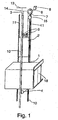
- Fig. 1 is a diagrammatic representation of the structure of an elevator.
- the elevator is preferably an elevator without machine room, with a drive machine 6 placed in the elevator shaft.
- the elevator shown in the figure is a traction sheave elevator with machine above.
- the passage of the hoisting ropes 3 of the elevator is as follows: One end of the ropes is immovably fixed to an anchorage 13 located in the upper part of the shaft above the path of a counterweight 2 moving along counterweight guide rails 11.
- the ropes 3 go further downwards via the rope grooves of diverting pulley 15 to the elevator car 1 moving along the car guide rails 10 of the elevator, passing under the car via diverting pulleys 4 used to suspend the elevator car on the ropes, and going then upward again from the elevator car to an anchorage 14 in the upper part of the elevator shaft, to which anchorage the second end of the ropes 3 is immovably fixed.
- Anchorage 13 in the upper part of the shaft, the traction sheave 7 and the diverting pulley 9 suspending the counterweight on the ropes are preferably so disposed in relation to each other that both the rope portion going from the anchorage 13 to the counterweight 2 and the rope portion going from the counterweight 2 to the traction sheave 7 are substantially parallel to the path of the counterweight 2.
- anchorage 14 in the upper part of the shaft, the traction sheave 7, diverting pulley 15 and the diverting pulleys 4 suspending the elevator car on the ropes are so disposed in relation to each other that the rope portion going from the anchorage 14 to the elevator car 1 and the rope portion going from the elevator car 1 via diverting pulley 15 to the traction sheave 7 are substantially parallel to the path of the elevator car 1. With this arrangement, no additional diverting pulleys are needed to define the passage of the ropes in the shaft.
- Double Wrap roping The roping arrangement between the traction sheave 7 and the diverting pulley 15 is referred to as Double Wrap roping, wherein the hoisting ropes are wrapped around the traction sheave two and/or more times- In this way, the contact angle can be increased in two and/or more stages. For example, in the embodiment presented in Fig. 1 , a contact angle of 180° + 180°, i.e. 360 ° between the traction sheave 7 and the hoisting ropes 3 is achieved. Double Wrap roping can be arranged in other ways, too, e.g.
- the rope suspension acts in a substantially centric manner on the elevator car 1, provided that the rope pulleys 4 supporting the elevator car are mounted substantially symmetrically relative to the vertical center line passing via the center of gravity of the elevator car 1.
- a preferable solution is to dispose the traction sheave 7 and the diverting pulley 15 in such a way that the diverting pulley 15 will also function as a guide of the hoisting ropes 3 and as a damping pulley.
- the drive machine 6 placed in the elevator shaft is preferably of a flat construction, in other words, the machine has a small thickness dimension as compared with its width and/or height, or at least the machine is slim enough to be accommodated between the elevator car and a wall of the elevator shaft.
- the machine may also be placed differently, e.g. by disposing the slim machine partly or completely between an imaginary extension of the elevator car and a shaft wall.
- the elevator shaft is advantageously provided with equipment required for the supply of power to the motor driving the traction sheave 7 as well as equipment for elevator control, both of which can be placed in a common instrument panel 8 or mounted separately from each other or integrated partly or wholly with the drive machine 6.
- the drive machine may be of a geared or gearless type.
- a preferable solution is a gearless machine comprising a permanent magnet motor.
- Another advantageous solution is to build a complete unit comprising both an elevator drive machine with a traction sheave and one or more diverting pulleys with bearings in a correct operating angle relative to the traction sheave.
- the operating angle is determined by the roping used between the traction sheave an the diverting pulley/pulleys, which defines the way in which the mutual positions and angle between the traction sheave and diverting pulley/diverting pulleys relative to each other are fitted in the unit.
- This unit can be mounted in place as a unitary aggregate in the same way as a drive machine.
- the drive machine may be fixed to a wall of the elevator shaft, to the ceiling, to a guide rail or guide rails or to some other structure, such as a beam or frame.
- a further possibility is to mount the machine on the bottom of the elevator shaft.
- Fig. 1 illustrates the economical 2:1 suspension, but the invention can also be implemented in an elevator using a 1:1 suspension ratio, in other words, in an elevator in which the hoisting ropes are connected directly to the counterweight and elevator car without diverting pulleys.
- Other suspension arrangements are also possible in an implementation of the invention.
- an elevator according to the invention can be implemented using a suspension ratio of 3:1, 4:1 or even higher suspension ratios.
- the counterweight and the elevator car may also be suspended in such manner that the counterweight is suspended using a suspension ratio of n:1 while the elevator car is suspended with a suspension ratio of m:1, where m is an integer at least equal to 1 and n is an integer greater than m.
- the elevator presented in the figure has automatic telescoping doors, but other types of automatic doors or turning doors may also be used within the framework of the invention.
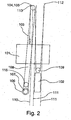
- Fig. 2 presents a diagram representing another traction sheave elevator according to the invention.
- This type of elevator is generally a traction sheave elevator with machine below.
- the elevator car 101 and the counterweight 102 are suspended on the hoisting ropes 103 of the elevator.
- the elevator drive machine unit 106 is mounted in the elevator shaft, preferably in the lower part of the shaft, a diverting pulley 115 is mounted near the drive machine unit 106, said diverting pulley allowing a sufficiently large contact angle to be achieved between the traction sheave 107 and the hoisting ropes 103.
- the hoisting ropes are passed via diverting pulleys 104,105 provided in the upper part of the elevator shaft to the car 101 and to the counterweight 102. Diverting pulleys 104,105 are placed in the upper part of the shaft and preferably separately mounted with bearings on the same axle so that they can rotate independently of each other.
- Double Wrap roping is also applied in an elevator with machine below.
- the elevator car 101 and the counterweight 102 move in the elevator shaft along elevator and counterweight guide rails 110,111 guiding them.
- the hoisting ropes run as follows: One end of the ropes is fixed to an anchorage 112 in the upper part of the shaft, from where it goes downward to the counterweight 102.
- the counterweight is suspended on the ropes 103 via a diverting pulley 109.
- the ropes go further upward to a first diverting pulley 105 mounted on an elevator guide rail 110, and from the diverting pulley 105 further via the rope grooves of diverting pulley 115 to the traction sheave 107 driven by the drive machine 106. From the traction sheave, the ropes go again upwards to diverting pulley 115, and having wrapped around it they go back to the traction sheave 107.
- one or more of the rope portions between the diverting pulleys or between the diverting pulleys and the traction sheave or between the diverting pulleys and the anchorages may deviate from an exact vertical direction, a circumstance that makes it easy to provide a sufficient distance between different rope portions or a sufficient distance between the hoisting ropes and the other elevator components.
- the traction sheave 107 and the hoisting machine 106 are preferably disposed somewhat aside from the path of the elevator car 101 as well as that of the counterweight 102, so they can be easily placed almost at any height in the elevator shaft below the diverting pulleys 104 and 105.
- the minimum height of the elevator shaft is exclusively determined on the basis of the length of the paths of the counterweight and elevator car and the safety clearances needed above and below these.
- a smaller space at the top or bottom of the shaft will be sufficient due to the reduced rope pulley diameters as compared with earlier solutions, depending on how the rope pulleys are mounted on the elevator car and/or on the frame of the elevator car.
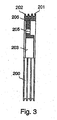
- Fig. 3 presents a partially sectioned view of a rope pulley 200 applying the invention.
- the rim 206 of the rope pulley is provided with rope grooves 201, which are covered by a coating 202.
- a space 203 for a bearing used to mount the rope pulley is provided in the hub of the rope pulley.
- the rope pulley is also provided with holes 205 for bolts, allowing the rope pulley to be fastened by its side to an anchorage in the hoisting machine 6, e.g. to a rotating flange, to form a traction sheave 7, so that no bearing separate from the hoisting machine is needed.
- the coating material used on the traction sheave and the rope pulleys may consist of rubber, polyurethane or a corresponding elastic material that increases friction.
- the material of the traction sheave and/or rope pulleys may also be so chosen that, together with the hoisting rope used, it forms a material pair such that the hoisting rope will bite into the pulley after the coating on the pulley has been worn out. This ensures a sufficient grip between the rope pulley 200 and the hoisting rope 3 in an emergency where the coating 202 has been worn out from the rope pulley 200. This feature allows the elevator to maintain its functionality and operational reliability in the situation referred to.
- the traction sheave and/or the rope pulleys can also be manufactured in such manner that only the rim 206 of the rope pulley 200 is made of a material forming a grip increasing material pair with the hoisting rope 3.
- the use of strong hoisting ropes that are considerably thinner than normally allows the traction sheave and the rope pulleys to be designed to considerably smaller dimensions and sizes than when normal-sized ropes are used.
- This also makes it possible to use a motor of a smaller size with a lower torque as the drive motor of the elevator, which leads to a reduction in the acquisition costs of the motor.
- the traction sheave diameter is preferably 120-200 mm, but it may even be less than this.
- the traction sheave diameter depends on the thickness of the hoisting ropes used.
- the use of a small traction sheave e.g. in the case of elevators for a nominal load below 1000 kg, makes it possible to achieve a machine weight even as low as about one half of the weight of currently used machines, which means producing elevator machines weighing 100-150 kg or even less.
- the machine is understood as comprising at least the traction sheave, the motor, the machine housing structures and the brakes.
- the weight of the elevator machine and its supporting elements used to hold the machine in place in the elevator shaft is at most about 1/5 of the nominal load. If the machine is exclusively or almost exclusively supported by one or more elevator and/or counterweight guide rails, then the total weight of the machine and its supporting elements may be less than about 1/6 or even less than 1/8 of the nominal load.
- Nominal load of an elevator means a load defined for elevators of a given size.
- the supporting elements of the elevator machine may include e.g. a beam, carriage or suspension bracket used to support or suspend the machine on/from a wall structure or ceiling of the elevator shaft or on the elevator or counterweight guide rails, or clamps used to hold the machine fastened to the sides of the elevator guide rails.
- the ratio of machine weight to nominal load is given for a conventional elevator in which the counterweight has a weight substantially equal to the weight of an empty car plus half the nominal load.
- the combined weight of the machine and its supporting elements may be only 75 kg when the traction sheave diameter is 160 mm and hoisting ropes having a diameter of 4 mm are used, in other words, the total weight of the machine and its supporting elements is about 1/8 of the nominal load of the elevator.
- the total weight of the machine and its supporting elements is about 150 kg, so in this case the machine and its supporting elements have a total weight equaling about 1/6 of the nominal load.
- the suspension ratio is 2:1
- the traction sheave diameter 240 mm and the hoisting rope diameter 6 mm the total weight of the machine and its supporting elements will be about 300 kg, i.e. about 1/7 of the nominal load.
- the hoisting rope suspension arrangements By varying the hoisting rope suspension arrangements, it is possible to reach a still lower total weight of the machine and its supporting elements. For example, when a 4:1 suspension ratio, a 160 mm traction sheave diameter and a 4 mm hoisting rope diameter are used in an elevator designed for a nominal load of 500 kg, a total weight of hoisting machine and its supporting elements of about 50 kg will be achieved. In this case, the total weight of the machine and its supporting elements is as small as only about 1/10 of the nominal load.
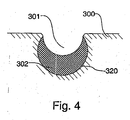
- Fig. 4 presents a solution in which the rope groove 301 is in a coating 302, which is thinner at the sides' of the rope groove than at the bottom.
- the coating is placed in a basic groove 320 provided in the rope pulley 300 so that deformations produced in the coating by the pressure imposed on it by the rope will be small and mainly limited to the rope surface texture sinking into the coating.
- the rope pulley coating consists of rope groove-specific sub-coatings separate from each other, but considering manufacturing or other aspects it may be appropriate to design the rope pulley coating so that it extends continuously over a number of grooves.
- the coating By making the coating thinner at the sides of the groove than at its bottom, the strain imposed by the rope on the bottom of the rope groove while sinking into the groove is avoided or at least reduced. As the pressure cannot be discharged laterally but is directed by the combined effect of the shape of the basic groove 320 and the thickness variation of the coating 302 to support the rope in the rope groove 301, lower maximum surface pressures acting on the rope and the coating are also achieved.
- One method of making a grooved coating 302 like this is to fill the round-bottomed basic groove 320 with coating material and then form a half-round rope groove 301 in this coating material in the basic groove.
- the shape of the rope grooves is well supported and the load-bearing surface layer under the rope provides a better resistance against lateral propagation of the compression stress produced by the ropes.
- the lateral spreading or rather adjustment of the coating caused by the pressure is promoted by thickness and elasticity of the coating and reduced by hardness and eventual reinforcements of the coating.
- the coating thickness on the bottom of the rope groove can be made large, even as large as half the rope thickness, in which case a hard and inelastic coating is needed.
- the coating material may be clearly softer.
- An elevator for eight persons could be implemented using a coating thickness at the bottom of the groove equal to about one fifth of the rope thickness if the ropes and the rope load are chosen appropriately.
- the coating thickness should equal at least 2-3 times the depth of the rope surface texture formed by the surface wires of the rope.
- Such a very thin coating having a thickness even less than the thickness of the surface wire of the rope, will net necessarily endure the strain imposed on it.
- the coating must have a thickness larger than this minimum thickness because the coating will also have to receive rope surface variations rougher than the surface texture. Such a rougher area is formed e.g. where the level differences between rope strands are larger than those between wires.
- a suitable minimum coating thickness is about 1-3 times the surface wire thickness.
- this thickness definition leads to a coating at least about 1 mm thick. Since a coating on the traction sheave, which causes more rope wear than the other rope pulleys of the elevator, will reduce rope wear and therefore also the need to provide the rope with thick surface wires, the rope can be made smoother. Rope smoothness can naturally be improved by coating the rope with a material suited for this purpose, such as e.g. polyurethane or equivalent.
- the use of thin wires allows the rope itself to be made thinner, because thin steel wires can be manufactured from a stronger material than thicker wires.
- the wires in the steel wire rope may preferably have a thickness between 0.15 mm and 0.5 mm, in which range there are readily available steel wires with good strength properties in which even an individual wire has a sufficient wear resistance and a sufficiently low susceptibility to damage.
- ropes made of round steel wires have been discussed. Applying the same principles, the ropes can be wholly or partly twisted from non-round profiled wires. In this case, the cross-sectional areas of the wires are preferably substantially the same as for round wires, i.e.
- a traction sheave coating well suited for such a rope is already clearly below 1 mm thick.
- the coating should be thick enough to ensure that it will not be very easily scratched away or pierced e.g. by an occasional sand grain or similar particle that may have got between the rope groove and the hoisting rope.
- a desirable minimum coating thickness, even when thin-wire hoisting ropes are used, would be about 0.5...1 mm.
- a coating having a thickness of the form A+Bcosa is well suited.
- a and B are constants so that A+B is the coating thickness at the bottom of the rope groove 301 and the angle a is the angular distance from the bottom of the rope groove as measured from the center of curvature of the rope groove cross-section. Constant A is larger than or equal to zero, and constant B is always larger than zero.
- the thickness of the coating growing thinner towards the edges can also be defined in other ways besides using the formula A+Bcosa so that the elasticity decreases towards the edges of the rope groove.
- the elasticity in the central part of the rope groove can also be increased by making an undercut rope groove and/or by adding to the coating on the bottom of the rope groove a portion of different material of special elasticity, where the elasticity has been increased, in addition to increasing the material thickness, by the use of a material that is softer than the rest of the coating.
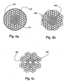
- Fig. 5a, 5b and 5c present longitudinal cross-sections of steel wire ropes used in the invention.
- the ropes in these figures contain thin steel wires 403, a coating 402 on the steel wires and/or partly between the steel wires, and in Fig. 5a a coating 401 over the steel wires.
- the rope presented in Fig. 5b is an uncoated steel wire rope with a rubber-like filler added to its interior structure, and Fig. 5a presents a steel wire rope provided with a coating in addition to a filler added to the internal structure.
- the rope presented in Fig. 5c has a non-metallic core 404, which may be a solid or fibrous structure made of plastic, natural fiber or some other material suited for the purpose.
- a fibrous structure will be good if the rope is lubricated, in which case lubricant will accumulate in the fibrous core.
- the core thus acts as a kind of lubricant storage.
- the steel wire ropes of substantially round cross-section used in the elevator of the invention may be coated, uncoated and/or provided with a rubber-like filler, such as e.g. polyurethane or some other suitable filler, added to the interior structure of the rope and acting as a kind of lubricant lubricating the rope and also balancing the pressure between wires and strands.
- a filler makes it possible to achieve a rope that needs no lubrication, so its surface can be dry.
- the coating used in the steel wire ropes may be made of the same or nearly the same material as the filler or of a material that is better suited for use as a coating and has properties, such as friction and wear resistance properties, that are better suited to the purpose than a filler.
- the coating of the steel wire rope may also be so implemented that the coating material penetrates partially into the rope or through the entire thickness of the rope, giving the rope the same properties as the filler mentioned above.
- the use of thin and strong steel wire ropes according to the invention is possible because the steel wires used are wires of special strength, allowing the ropes to be made substantially thin as compared with steel wire ropes used before.
- the ropes presented in Fig. 5a and 5b are steel wire ropes having a diameter of about 4 mm.
- the thin and strong steel wire ropes of the invention preferably have a diameter of about 2.5 - 5 mm in elevators for a nominal load below 1000 kg, and preferably about 5 - 8 mm in elevators for a nominal load above 1000 kg.
- ropes thinner than those mentioned above can be used for corresponding loads, and at the same time a smaller and lighter elevator machine can be achieved.
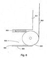
- Fig. 6 illustrates the manner in which a rope pulley 502 connected to a horizontal beam 504 comprised in the structure supporting the elevator car 501 is placed in relation to the beam 504, said rope pulley being used to support the elevator car and associated structures.
- the rope pulley 502 presented in the figure may have a diameter equal to or less than the height of the beam 504 comprised in the structure.
- the beam 504 supporting the elevator car 501 may be located either below or above the elevator car.
- the rope pulley 502 may be placed completely or partially inside the beam 504, as shown in the figure.
- the hoisting ropes 503 of the elevator in the figure run as follows:
- the hoisting ropes 503 come to the coated rope pulley 502 connected to the beam 504 comprised in the structure supporting the elevator car 501, from which pulley the hoisting rope runs further, protected by the beam, e.g. in a hollow 506 inside the beam, under the elevator car and goes then further via a second rope pulley placed on the other side of the elevator car.
- the elevator car 501 rests on the beam 504 comprised in the structure, on vibration absorbers 505 placed between them.
- the beam 504 also acts as a rope guard for the hoisting rope 503.
- the beam 504 may be a C-, U-, I-, Z-section beam or a hollow beam or equivalent.
- Fig. 7 presents a diagrammatic illustration of the structure of an elevator according to the invention.
- the elevator is preferably an elevator without machine room, with a drive machine 706 placed in the elevator shaft.
- the elevator shown in the figure is a traction sheave elevator with machine above.
- the passage of the hoisting ropes 703 of the elevator is as follows: One end of the ropes is immovably fixed to an anchorage 713 located in the upper part of the shaft above the path of a counterweight 702 moving along counterweight guide rails 711.
- the ropes run downwards to diverting pulleys 709 suspending the counterweight, which are rotatably mounted on the counterweight 702 and from which the ropes 703 run further upward via the rope grooves of diverting pulley 715 to the traction sheave 707 of the drive machine 706, passing around the traction sheave along the rope grooves on the sheave.
- the ropes 703 run further downwards back to diverting pulley 715, wrapping around it along the rope grooves of the diverting pulley and returning then back up to the traction sheave 707, over which the ropes run in the traction sheave rope grooves.
- the ropes 703 go further downwards via the rope grooves of the diverting pulley to the elevator car 701 moving along the car guide rails 710 of the elevator, passing under the car via diverting pulleys 704 used to suspend the elevator car on the ropes, and going then upwards again from the elevator car to an anchorage 714 in the upper part of the elevator shaft, to which anchorage the second end of the ropes 703 is immovably fixed.
- Anchorage 713 in the upper part of the shaft, the traction sheave 707, diverting pulley 715 and the diverting pulley 709 suspending the counterweight on the ropes are preferably so disposed in relation to each other that both the rope portion going from the anchorage 713 to the counterweight 702 and the rope portion going from the counterweight 702 via diverting pulley 715 to the traction sheave 707 are substantially parallel to the path of the counterweight 702.
- the anchorage 714 in the upper part of the shaft, the traction sheave 707, diverting pulleys 715,712 and the diverting pulleys 704 suspending the elevator car on the ropes are so disposed in relation to each other that the rope portion going from the anchorage 714 to the elevator car 701 and the rope portion going from the elevator car 701 via diverting pulley 715 to the traction sheave 707 are substantially parallel to the path of the elevator car 701. With this arrangement, no additional diverting pulleys are needed to define the passage of the ropes in the shaft.
- the roping arrangement between the traction sheave 707 and the diverting pulley 715 is referred to as Double Wrap roping, wherein the hoisting ropes are wrapped around the traction sheave two and/or more times.
- the contact angle can be increased in two and/or more stages.
- a contact angle of 180° + 180°, i.e. 360 ° between the traction sheave 707 and the hoisting ropes 703 is achieved.
- the rope suspension acts in a substantially centric manner on the elevator car 701, provided that the rope pulleys 704 suspending the elevator car are mounted substantially symmetrically relative to the vertical center line passing via the center of gravity of the elevator car 701.
- a preferable solution is to dispose the traction sheave 707 and the diverting pulley 715 in such a way that the diverting pulley 715 will also function as a guide of the hoisting ropes 703 and as a damping pulley.
- the drive machine 706 placed in the elevator shaft is preferably of flat construction, in other words, the machine has a small thickness dimension as compared with its width and/or height, or at least the machine is slim enough to be accommodated between the elevator car and a wall of the elevator shaft.
- the machine may also be placed differently, e.g. by disposing the slim machine partly or completely between an imaginary extension of the elevator car. and a shaft wall.
- the elevator shaft is advantageously provided with equipment required for the supply of power to the motor driving the traction sheave 707 as well as equipment needed for elevator control, both of which can be placed in a common instrument panel 708 or mounted separately from each other or integrated partly or wholly with the drive machine 706.
- the drive machine may be of geared or gearless type.
- a preferable solution is a gearless machine comprising a permanent magnet motor.
- Another advantageous solution is to build a complete unit comprising both the elevator drive machine 706 and the diverting pulley 715 and its bearings, which is used to increase the contact angle, in a correct operating angle relative to the traction sheave 707, which unit can be mounted in place as a unitary aggregate in the same way as a drive machine.
- the drive machine may be fixed to a wall of the elevator shaft, to the ceiling, to a guide rail or guide rails or to some other structure, such as a beam or frame.
- the diverting pulley/diverting pulleys to be placed near the drive machine to increase the operating angle can be mounted in the same way.
- diverting pulley 715 when diverting pulley 715 is of substantially equal size with the traction sheave 707, diverting pulley 715 can also function as a damping wheel. In this case, the ropes going from the traction sheave 707 to the counterweight 702 and to the elevator car 701 are passed via the rope grooves of the diverting pulley 715 and the rope deflection caused by the diverting pulley is very small. It could be said that the ropes coming from the traction sheave only touch the diverting pulley tangentially.
- SW Single Wrap
- the diverting pulley is of substantially equal size with the traction sheave of the drive machine and where a diverting pulley used for tangential rope contact as described above.
- the ropes wrap around the traction sheave only once, with a contact angle of about 180° between the rope and the traction sheave, the diverting pulley is only used as a means of producing a tangential contact as described above and the diverting pulley functions as a rope guide and as a damping wheel for the damping of vibrations.
- the suspension ratio of the elevator is of no importance with respect to the application of SW roping described in the example; instead, it can be used in connection with any suspension ratio.
- the embodiment using SW roping as described in the example may have an inventive value in itself, at least in regard of damping.
- the diverting pulley 715 may also be of substantially different size than the traction sheave, in which case it functions as a diverting pulley increasing the contact angle and not as a damping wheel.
- Fig. 7 presents an elevator according to the invention that uses a suspension ratio of 4:1.
- the invention can also be implemented using other suspension arrangements.
- an elevator according to the invention can be implemented using a suspension ratio of 1:1, 2:1, 3:1 or even suspension ratios higher than 4:1.
- the elevator presented in the figure has automatic telescoping doors, but other types of automatic doors or turning doors may also be used within the framework of the invention.
- Fig. 8 presents a diagrammatic illustration of the structure of an elevator according to the invention.
- the elevator is preferably an elevator without machine room, with a drive machine .806 placed in the elevator shaft.
- the elevator shown in the figure is a traction sheave elevator with machine above.
- the passage of the hoisting ropes 803 of the elevator is as follows: One end of the ropes is immovably fixed to an anchorage 813 located in the upper part of the shaft above the path of a counterweight 802 moving along counterweight guide rails 811.
- the ropes run downwards to diverting pulleys 809 suspending the counterweight, which are rotatably mounted on the counterweight 802 and from which the ropes 803 run further upward via the rope grooves of diverting pulley 815 to the traction sheave 807 of the drive machine 806, wrapping around the traction sheave along the rope grooves on the sheave.
- the ropes 803 run further downwards, going crosswise relative to the upwards going ropes, and further via the rope grooves of the diverting pulley to the elevator car 801 moving along the car guide rails 810 of the elevator, passing under the car via diverting pulleys 804 used to suspend the elevator car on the ropes, and going then upwards again from the elevator car to an anchorage 814 in the upper part of the elevator shaft, to which anchorage the second end of the ropes 803 is immovably fixed.
- Anchorage 813 in the upper part of the shaft, the traction sheave 807, diverting pulley 815 and the diverting pulley 809 suspending the counterweight on the ropes are preferably so disposed in relation to each other that both the rope portion going from the anchorage 813 to the counterweight 802 and the rope portion going from the counterweight 802 via diverting pulley 815 to the traction sheave 807 are substantially parallel to the path of the counterweight 802.
- the anchorage 814 in the upper part of the shaft, the traction sheave 807, diverting pulley 815 and the diverting pulleys 804 suspending the elevator car on the ropes are so disposed in relation to each other that the rope portion going from the anchorage 814 to the elevator car 801 and the rope portion going from the elevator car 801 via diverting pulley 815 to the traction sheave 807 are substantially parallel to the path of the elevator car 801. With this arrangement, no additional diverting pulleys are needed to define the passage of the ropes in the shaft.
- This roping arrangement between the traction sheave 807 and the diverting pulley 815 can be referred to as X Wrap (XW) roping, while Double Wrap (DW) roping, Single Wrap (SW) roping and Extended Wrap (ESW) roping are previously known concepts.
- X Wrap roping the ropes are caused to wrap around the traction sheave with a large contact angle. For example, in the case illustrated in Fig. 8 , a contact angle of well over 180°, i.e. about 270° between the traction sheave 807 and the hoisting ropes 803 is achieved.
- X Wrap roping presented in the figure can also be arranged in another way, e.g.
- diverting pulley 815 has been fitted in a position designed to form an angle relative to the traction sheave 807 such that the ropes will run crosswise in a manner known in itself so that the ropes are not damaged.
- the rope suspension acts in a substantially centric manner on the elevator car 801, provided that the rope pulleys 804 suspending the elevator car are mounted substantially symmetrically relative to the vertical center line passing via the.center of gravity of the elevator car 801.
- the drive machine 806 placed in the elevator shaft is preferably of flat construction, in other words, the machine has a small thickness dimension as compared with its width and/or height, or at least the machine is slim enough to be accommodated between the elevator car and a wall of the elevator shaft.
- the machine may also be placed differently, e.g. by disposing the slim machine partly or completely between an imaginary extension of the elevator car and a shaft wall.
- the elevator shaft is advantageously provided with equipment required for the supply of power to the motor driving the traction sheave 807 as well as equipment needed for elevator control, both of which can be placed in a common instrument panel 808 or mounted separately from each other or integrated partly or wholly with the drive machine 806.
- the drive machine may be of geared or gearless type.
- a preferable solution is a gearless machine comprising a permanent magnet motor.
- Another advantageous solution is to build a complete unit comprising both the elevator drive machine 806 and the diverting pulley 815 and its bearings, which is used to increase the contact angle, in a correct operating angle relative to the traction sheave 807, which unit can be mounted in place as a unitary aggregate in the same way as a drive machine.
- Using a complete unit means less need for rigging during installation.
- X Wrap roping can also be implemented by mounting a diverting pulley directly on the drive machine.
- the drive machine may be fixed to a wall of the elevator shaft, to the ceiling, to a guide rail or guide rails or to some other structure, such as a beam or frame.
- Fig. 8 illustrates the economical 2:1 suspension, but the invention can also be implemented in an elevator with 1:1 suspension ratio, in other words, in an elevator with the hoisting ropes connected directly to the counterweight and elevator car without a diverting pulley.
- the invention can also be implemented using other suspension arrangements.
- an elevator according to the invention can be implemented using a suspension ratio of 3:1, 4:1 or even higher suspension ratios.
- the elevator presented in the figure has automatic telescoping doors, but other types of automatic doors or turning doors may also be used within the framework of the invention.
- Fig. 9 presents a diagrammatic illustration of the structure of an elevator according to the invention.
- the elevator is preferably an elevator without machine room, with a drive machine 906 placed in the elevator shaft.
- the elevator shown in the figure is a traction sheave elevator with machine above.
- the passage of the hoisting ropes 903 of the elevator is as follows: One end of the ropes is immovably fixed to an anchorage 913 located in the upper part of the shaft above the path of a counterweight 902 moving along counterweight guide rails 911.
- the ropes run downwards to diverting pulleys 909 suspending the counterweight, which are rotatably mounted on the counterweight 902 and from which diverting pulleys 909 the ropes 903 run further upward to the traction sheave 907 of the drive machine 906, wrapping around the traction sheave along the rope grooves on the sheave.
- the ropes 903 run further downwards, going crosswise relative to the upwards going ropes, and further to diverting pulley 915, wrapping around it along the rope grooves of the diverting pulley 915.
- Anchorage 913 in the upper part of the shaft, the traction sheave 907 and the diverting pulley 909 suspending the counterweight on the ropes are preferably so disposed in relation to each other that both the rope portion going from the anchorage 913 to the counterweight 902 and the rope portion going from the counterweight 902 to the traction sheave 907 are substantially parallel to the path of the counterweight 902.
- the anchorage 914 in the upper part of the shaft, the traction sheave 907, diverting pulley 915 and the diverting pulleys 904 suspending the elevator car on the ropes are so disposed in relation to each other that the rope portion going from the anchorage 914 to the elevator car 901 and the rope portion going from the elevator car 901 via diverting pulley 915 to the traction sheave 907 are substantially parallel to the path of the elevator car 901. with this arrangement, no additional diverting pulleys are needed to define the passage of the ropes in the shaft.
- This roping arrangement between the traction sheave 907 and the diverting pulley 915 can be referred to as Extended Single Wrap roping.
- Extended Single Wrap roping by using a diverting pulley, the hoisting ropes are caused to wrap around the traction sheave with a larger contact angle.
- a contact angle of well over 180°, i.e. about 270° between the traction sheave 907 and the hoisting ropes 903 is achieved.
- Extended Single Wrap roping presented in the figure can also be arranged in another way, e.g. by disposing the drive machine and the diverting pulley in another way in relation to each other, e.g. the other way round relative to each other than in the case presented in Fig. 9 .
- Diverting pulley 915 has been fitted in a position designed to form an angle relative to the traction sheave 907 such that the ropes will run crosswise in a manner known in itself so that the ropes are not damaged.
- the rope suspension acts in a substantially centric manner on the elevator car 901, provided that the rope pulleys 904 suspending the elevator car are mounted substantially symmetrically relative to the vertical center line passing via the center of gravity of the elevator car 901.
- the drive machine 906 can preferably be placed e.g. in the free space above the counterweight, thereby increasing the space saving potential of the elevator.
- the drive machine 906 placed in the elevator shaft is preferably of flat construction, in other words, the machine has a small thickness dimension as compared with its width and/or height, or at least the machine is slim enough to be accommodated between the elevator car and a wall of the elevator shaft.
- the machine may also be placed differently, e.g. by disposing the slim machine partly or completely between an imaginary extension of the elevator car and a shaft wall.
- the elevator shaft is advantageously provided with equipment required for the supply of power to the motor driving the traction sheave 907 as well as equipment needed for elevator control, both of which can be placed in a common instrument panel 908 or mounted separately from each other or integrated partly or wholly with the drive machine 906.
- the drive machine may be of geared or gearless type.
- a preferable solution is a gearless machine comprising a permanent magnet motor.
- Another advantageous solution is to build a complete unit comprising both the elevator drive machine 906 and/or the diverting pulley/diverting pulleys 915 with their bearings, mounted in a correct operating angle relative to the traction sheave 907 to increase the contact angle, all this equipment being ready fitted on a mounting base, which unit can be mounted in place as a unitary aggregate in the same way as a drive machine.
- Using a unitary aggregate solution reduces the need for rigging at installation time.
- the drive machine may be fixed to a wall of the elevator shaft, to the ceiling, to a guide rail or guide rails or to some other structure, such as a beam or frame.
- Fig. 9 illustrates the economical 2:1 suspension, but the invention can also be implemented in an elevator with 1:1 suspension ratio, in other words, in an elevator with the hoisting ropes connected directly to the counterweight and elevator car without a diverting pulley.
- the invention can also be implemented using other suspension arrangements.
- an elevator according to the invention can be implemented using a suspension ratio of 3:1, 4:1 or even higher suspension ratios.
- the elevator presented in the figure has automatic telescoping doors, but other types of automatic doors or turning doors may also be used within the framework of the invention.
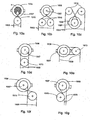
- Figures 10a, 10b, 10c, 10d, 10e, 10f and 10g present some variations of the roping arrangements according to the invention that can be used between the traction sheave 1007 and the diverting pulley 1015 to increase the contact angle between the ropes 1003 and the traction sheave 1007, in which arrangements the ropes 1003 go downwards from the drive machine 1006 towards the elevator car and counterweight.
- These roping arrangedments make it possible to increase the contact angle between the hoisting rope 1003 and the traction sheave 1007.
- contact angle ⁇ refers to the length of the arc of contact between the traction sheave and the hoisting rope.
- the magnitude of the contact angle ⁇ may be expressed e.g.
- the contact angle ⁇ is presented in greater detail in Fig. 10a . In the other figures, the contact angle ⁇ is not expressly indicated, but it can be seen from the other figures as well without specific description.
- roping arrangements presented in Fig. 10a, 10b, 10c represent some variations of the X Wrap roping described above.
- the ropes 1003 come via diverting pulley 1015, wrapping around it along rope grooves, to the traction sheave 1007, over which the ropes pass along its rope grooves and then go further back to the diverting pulley 1015, passing crosswise with respect to the rope portion coming from the diverting pulley, and continuing their passage further.
- Crosswise, passage of the ropes 1003 between the diverting pulley 1015 and the traction sheave 1007 can be implemented e.g.
- the contact angle ⁇ between the ropes 1003 and the traction sheave 1007 is represented by the shaded area.
- the magnitude of the contact angle ⁇ in this figure is about 310°.
- the size of the diameter of the diverting pulley can be used as a means of determining the distance of suspension that is to be provided between the diverting pulley 1015 and the traction sheave 1007.
- the magnitude of the contact angle can be varied by varying the distance between the diverting pulley 1015 and the traction sheave 1007.
- the magnitude of the angle ⁇ can also be varied by varying the diameter of the diverting pulley and/or by varying the diameter of the traction sheave and also by varying the relation between the diameters of the diverting pulley and the traction sheave.
- Fig. 10b and 10c present an example of implementing a corresponding XW roping arrangement using two diverting pulleys.
- roping arrangements presented in Fig. 10d and 10e are different variations of the above-mentioned Double Wrap roping.
- the ropes run via the rope grooves of diverting pulley 1015 to the traction sheave traction sheave 1007 of the drive machine 1006, passing over it along the rope grooves of the traction sheave.
- the ropes 1003 go further downwards back to diverting pulley 1015, wrapping around it along the rope grooves of the diverting pulley and returning then back to the traction sheave 1007, over which the ropes run in the rope grooves of the traction sheave.
- the ropes 1003 run further downwards via the rope grooves of the diverting pulley.
- the hoisting ropes are caused to wrap around the traction sheave twice and/or more times.
- the contact angle can be increased in two and/or more stages. For example, in the case presented in Fig. 10d , a contact angle of 180° + 180° between the traction sheave 1007 and the ropes 1003 is achieved.
- Double Wrap roping when the diverting pulley 1015 is substantially of equal size with the traction sheave 1007, the diverting pulley 1015 also functions as a damping wheel.
- the ropes going from the traction sheave 1007 to the counterweight and elevator car pass via the rope grooves of the diverting pulley 1015 and the rope deflection produced by the diverting pulley is very small. It could be said that the ropes coming from the traction sheave only touch the diverting pulley tangentially. Such tangential contact serves as a solution damping the vibrations of outgoing ropes and it can applied in other roping arrangements as well.
- the diverting pulley 1015 also functions as a rope guide.
- the ratio of the diameters of the diverting pulley and traction sheave can be varied by varying the diameters of the diverting pulley and/or traction sheave.
- DW roping can also be implemented in other ways, such as e.g. the way illustrated in Fig. 10e , where the diverting pulley 1015 is disposed on the side of the traction sheave 1007. In this roping arrangement, the ropes 1003 are passed in a manner corresponding to Fig. 10d , but in this case a contact angle of 180° + 90°, i.e.
- Fig. 10f presents an embodiment of the invention applying Extended Single Wrap roping as mentioned above.
- the ropes 1003 run to the traction sheave 1007 of the drive machine 1006, wrapping around it along the rope grooves of the traction sheave. From the traction sheave 1007, the ropes 1003 go further downwards, running crosswise relative to the upwards going ropes and further to diverting pulley 1015, passing over it along the rope grooves of the diverting pulley 1015. From the diverting pulley 1015, the ropes 1003 run further on.
- the hoisting ropes are caused to wrap around the traction sheave with a larger contact angle than in ordinary Single Wrap roping.
- a contact angle of about 270° between the ropes 1003 and the traction sheave 1007 is obtained.
- the diverting pulley 1015 is fitted in position at an angle such that the ropes run crosswise in a manner known in itself, so that the ropes are not damaged.
- Fig. 10g One possibility of increasing the contact angle is illustrated in Fig. 10g , where the hoisting ropes do not run crosswise relative to each other after wrapping around the traction sheave and/or diverting pulley. By using a roping arrangement like this, it is also possible increase the contact angle between the hoisting ropes 1003 and the traction sheave 1007 of the drive machine 1006 to a magnitude substantially over 180°.
- Figures 10a,b,c,d,f and g present different variations of roping arrangements between the traction sheave and the diverting pulley/diverting pulleys, in which the ropes go downwards from the drive machine towards the counterweight and the elevator car.
- these roping arrangements can be inverted and implemented in a corresponding manner so that the ropes go upwards from the elevator drive machine towards the counterweight and the elevator car.
- Fig. 11 presents yet another embodiment of the invention, wherein the elevator drive machine 1106 is fitted together with a diverting pulley 1115 on the same mounting base 1121 in a ready-made unit 1120, which can be fitted as such to form a part of an elevator according to the invention.
- the unit contains the elevator drive machine 1106, the traction sheave 1107 and diverting pulley 1115 ready-fitted on the mounting base 1121, the traction sheave and diverting pulley being ready fitted at a correct operating angle relative to each other, depending on the roping arrangement used between the traction sheave 1107 and the diverting pulley 1115.
- the unit 1120 may comprise more than only one diverting pulley 1115, or it may only comprise the drive machine 1106 fitted on the mounting base .1121.
- the unit can be mounted in an elevator according to the invention like a drive machine, the mounting arrangement being described in greater detail in connection with the previous figures. If necessary, the unit can be used together with any of the roping arrangements described above, such as e.g. embodiments using ESW, DW, SW or XW roping.
- the skilled person can vary the embodiment of the invention, while the traction sheaves and rope pulleys, instead of being coated metal pulleys, may also be uncoated metal pulleys or uncoated pulleys made of some other material suited to the purpose.
- the metallic traction sheaves and rope pulleys used in the invention which are coated with a non-metallic material at least in the area of their grooves, may be implemented using a coating material consisting of e.g. rubber, polyurethane or some other material suited to the purpose.
- the elevator car, the counterweight and the machine unit may be laid out in the cross-section of the elevator shaft in a manner differing from the lay-out described in the examples.
- Such a different lay-out might be e.g. one in which the machine and the counterweight are located behind the car as seen from the shaft door and the ropes are passed under the car diagonally relative to the bottom of the car. Passing the ropes under the car in a diagonal or otherwise oblique direction relative to the form of the bottom provides an advantage when the suspension of the car on the ropes is to be made symmetrical relative to the center of mass of the elevator in other types of suspension lay-out as well.
- suspension solutions according to the invention can also be implemented using some other type of flexible hoisting means as hoisting ropes than the means described here, to achieve small deflection diameters of the hoisting means, for example by using flexible rope of one or more strands, flat belt, cogged belt, trapezoidal belt or some other type of belt applicable to the purpose, or even using different types of chains.
- the invention may be implemented using ropes without filler, which are either lubricated or unlubricated.
- the ropes may be twisted in many different ways.
- the average of the wire thicknesses may be understood as referring to a statistical, geometrical or arithmetical mean value. To determine a statistical average, the standard deviation or Gauss distribution can be used. It is further obvious that the wire thicknesses in the rope may vary, e.g. even by a factor of 3 or more.
- the elevator of the invention can be implemented using different roping arrangements for increasing the contact angle ⁇ between the traction sheave and the diverting pulley/diverting pulleys than those described as examples.
Priority Applications (2)
| Application Number | Priority Date | Filing Date | Title |
|---|---|---|---|
| SI200331332T SI1327598T1 (sl) | 2002-01-09 | 2003-01-09 | Dvigalo s pogonom majhne velikosti |
| CY20081100864T CY1108261T1 (el) | 2002-01-09 | 2008-08-13 | Ανελκυστηρας με μικρου μεγεθους κινητηρα |
Applications Claiming Priority (2)
| Application Number | Priority Date | Filing Date | Title |
|---|---|---|---|
| FI20020043 | 2002-01-09 | ||
| FI20020043A FI119234B (fi) | 2002-01-09 | 2002-01-09 | Hissi |
Publications (2)
| Publication Number | Publication Date |
|---|---|
| EP1327598A1 EP1327598A1 (en) | 2003-07-16 |
| EP1327598B1 true EP1327598B1 (en) | 2008-05-28 |
Family
ID=8562740
Family Applications (2)
| Application Number | Title | Priority Date | Filing Date |
|---|---|---|---|
| EP03000339A Revoked EP1327598B1 (en) | 2002-01-09 | 2003-01-09 | Elevator with small-sized driving gear |
| EP03729267.9A Expired - Lifetime EP1463680B1 (en) | 2002-01-09 | 2003-01-09 | Elevator with small-sized driving gear |
Family Applications After (1)
| Application Number | Title | Priority Date | Filing Date |
|---|---|---|---|
| EP03729267.9A Expired - Lifetime EP1463680B1 (en) | 2002-01-09 | 2003-01-09 | Elevator with small-sized driving gear |
Country Status (24)
| Country | Link |
|---|---|
| US (3) | US20050006180A1 (zh) |
| EP (2) | EP1327598B1 (zh) |
| JP (2) | JP2005514293A (zh) |
| KR (1) | KR100977728B1 (zh) |
| CN (2) | CN1309648C (zh) |
| AT (1) | ATE396948T1 (zh) |
| AU (1) | AU2003201170B2 (zh) |
| BR (1) | BR0306804B1 (zh) |
| CA (1) | CA2468798C (zh) |
| CY (1) | CY1108261T1 (zh) |
| DE (1) | DE60321251D1 (zh) |
| DK (1) | DK1327598T3 (zh) |
| EA (1) | EA006029B1 (zh) |
| ES (2) | ES2529566T3 (zh) |
| FI (1) | FI119234B (zh) |
| HK (2) | HK1058660A1 (zh) |
| MX (1) | MXPA04006657A (zh) |
| NO (1) | NO336874B1 (zh) |
| PT (1) | PT1327598E (zh) |
| SI (1) | SI1327598T1 (zh) |
| TW (1) | TWI288110B (zh) |
| UA (1) | UA85818C2 (zh) |
| WO (1) | WO2003057611A2 (zh) |
| ZA (1) | ZA200404302B (zh) |
Cited By (1)
| Publication number | Priority date | Publication date | Assignee | Title |
|---|---|---|---|---|
| US9315363B2 (en) | 2000-12-08 | 2016-04-19 | Kone Corporation | Elevator and elevator rope |
Families Citing this family (46)
| Publication number | Priority date | Publication date | Assignee | Title |
|---|---|---|---|---|
| FI117434B (fi) * | 2000-12-08 | 2006-10-13 | Kone Corp | Hissi ja hissin vetopyörä |
| US9573792B2 (en) | 2001-06-21 | 2017-02-21 | Kone Corporation | Elevator |
| PL206645B1 (pl) | 2001-06-21 | 2010-09-30 | Kone Corp | Winda |
| FI119234B (fi) | 2002-01-09 | 2008-09-15 | Kone Corp | Hissi |
| US7448474B2 (en) | 2002-05-28 | 2008-11-11 | Kone Corporation | Method for making an elevator and system for elevator delivery |
| FI119242B (fi) * | 2002-05-28 | 2008-09-15 | Kone Corp | Menetelmä hissin tekemiseksi ja hissin toimitusjärjestelmä |
| FI119236B (fi) * | 2002-06-07 | 2008-09-15 | Kone Corp | Päällystetyllä nostoköydellä varustettu hissi |
| EP1606208B1 (de) | 2003-03-06 | 2015-12-09 | Inventio AG | Aufzug mit 2:1 zahnriemenführung |
| KR100950668B1 (ko) * | 2003-09-30 | 2010-04-02 | 삼성전자주식회사 | 직교 주파수 분할 다중 접속 방식을 사용하는 통신 시스템에서 업링크 파일럿 신호 송수신 장치 및 방법 |
| JP2005154042A (ja) * | 2003-11-21 | 2005-06-16 | Toshiba Elevator Co Ltd | エレベータ用ワイヤロープ探傷装置 |
| FI20031718A0 (fi) * | 2003-11-24 | 2003-11-24 | Kone Corp | Hissin ripustusjärjestely |
| JP2005157051A (ja) * | 2003-11-27 | 2005-06-16 | Fuji Photo Film Co Ltd | 直動移動体駆動装置 |
| ES2253981B1 (es) * | 2004-05-10 | 2007-06-16 | Orona, S. Coop. | Cable y cinta para limitador de velocidad de ascensores y poleas asociadas. |
| JP4504113B2 (ja) * | 2004-06-23 | 2010-07-14 | 東京製綱株式会社 | 被覆ワイヤロープ |
| JP4523364B2 (ja) * | 2004-08-31 | 2010-08-11 | 株式会社日立製作所 | エレベータ |
| JP4172451B2 (ja) * | 2004-12-14 | 2008-10-29 | 株式会社日立製作所 | エレベーター装置 |
| CN101048332A (zh) * | 2005-07-13 | 2007-10-03 | 三菱电机株式会社 | 电梯装置 |
| KR100926862B1 (ko) | 2005-07-13 | 2009-11-13 | 미쓰비시덴키 가부시키가이샤 | 엘리베이터 장치 |
| JP5017904B2 (ja) * | 2006-03-31 | 2012-09-05 | 株式会社日立製作所 | エレベーター装置 |
| WO2008001149A1 (en) * | 2006-06-26 | 2008-01-03 | Otis Elevator Company | Elevator installation with reduced hoistway dimensions |
| CN101108712B (zh) * | 2006-07-21 | 2012-05-23 | 因温特奥股份公司 | 优化电梯系统的对重重量的方法和具有此种对重的电梯系统 |
| ITMI20062542A1 (it) * | 2006-12-29 | 2008-06-30 | L A Consulting S A S | Ascensore con doppia puleggia di trazione |
| JP2008214037A (ja) * | 2007-03-05 | 2008-09-18 | Toshiba Elevator Co Ltd | エレベータのワイヤロープ検査装置及びロープ外径測定方法 |
| EP1975111A1 (de) * | 2007-03-28 | 2008-10-01 | Inventio Ag | Aufzugriemen, Herstellungsverfahren für einen solchen Aufzugriemen und Aufzuganlage mit einem solchen Riemen |
| JP2008308265A (ja) * | 2007-06-13 | 2008-12-25 | Okamura Corp | 荷の昇降装置 |
| ES2420524T3 (es) * | 2008-01-28 | 2013-08-23 | Thyssenkrupp Aufzugswerke Gmbh | Instalación de ascensor |
| US9701515B2 (en) * | 2008-06-17 | 2017-07-11 | Otis Elevator Company | Underslung elevator car configuration |
| RU2535956C2 (ru) * | 2009-03-16 | 2014-12-20 | Отис Элевэйтор Компани | Конфигурация лифтовых приводных механизмов |
| JP2010254394A (ja) * | 2009-04-22 | 2010-11-11 | Mitsubishi Electric Building Techno Service Co Ltd | ワイヤロープおよびそのワイヤロープの寿命を点検する方法 |
| ES2567783T3 (es) * | 2009-10-14 | 2016-04-26 | Inventio Ag | Instalación de ascensor y medio de suspensión para dicha instalación |
| RU2475441C1 (ru) * | 2011-06-08 | 2013-02-20 | Открытое Акционерное Общество "Государственный Ракетный Центр Имени Академика В.П. Макеева" | Способ определения износа канатного блока грузоподъемного крана |
| EP2703330B1 (en) * | 2012-08-31 | 2015-08-26 | KONE Corporation | Elevator |
| CN103498356A (zh) * | 2013-10-14 | 2014-01-08 | 无锡通用钢绳有限公司 | 一种18×7+fc钢丝绳生产工艺 |
| CN103485218A (zh) * | 2013-10-14 | 2014-01-01 | 无锡通用钢绳有限公司 | 一种18×7+fc钢丝绳 |
| EP3142955B1 (en) | 2014-05-14 | 2023-01-04 | Otis Elevator Company | Traction geared machine for elevator |
| CN107567425B (zh) | 2015-05-06 | 2019-10-01 | 因温特奥股份公司 | 使用电梯运输重型超载负荷 |
| CN107787300A (zh) * | 2015-06-23 | 2018-03-09 | 奥的斯电梯公司 | 电梯系统皮带的增加的牵引力 |
| JP6494760B2 (ja) * | 2015-07-21 | 2019-04-03 | 三菱電機株式会社 | エレベータ装置 |
| JP2017100865A (ja) * | 2015-12-03 | 2017-06-08 | 東芝エレベータ株式会社 | ガバナ装置及びこれを備えたエレベータ装置 |
| WO2017155943A1 (en) * | 2016-03-09 | 2017-09-14 | Otis Elevator Company | Reinforced fabric elevator belt with improved internal wear resistance |
| US10669125B2 (en) * | 2017-05-15 | 2020-06-02 | Otis Elevator Company | Elevator rope guide system |
| DE102017222107B4 (de) * | 2017-12-07 | 2019-10-31 | Leoni Bordnetz-Systeme Gmbh | Verfahren sowie Vorrichtung zur Herstellung einer Leitung |
| CN108163675A (zh) * | 2017-12-28 | 2018-06-15 | 洛阳矿山机械工程设计研究院有限责任公司 | 一种改进型井塔式多绳摩擦式提升系统 |
| US10766746B2 (en) | 2018-08-17 | 2020-09-08 | Otis Elevator Company | Friction liner and traction sheave |
| CN109969914A (zh) * | 2019-05-07 | 2019-07-05 | 天津京安高新技术有限公司 | 一种竖井多绳摩擦提升系统 |
| CN111810602B (zh) * | 2020-06-19 | 2023-06-09 | 合立智能装备有限责任公司 | 绳链组合式自平衡传动装置 |
Family Cites Families (154)
| Publication number | Priority date | Publication date | Assignee | Title |
|---|---|---|---|---|
| US1625084A (en) * | 1924-09-12 | 1927-04-19 | Otis Elevator Co | Roping for hoisting apparatus |
| FR1056837A (fr) | 1952-10-07 | 1954-03-03 | Câble métallique ne se tordant pas | |
| DE1032496B (de) | 1954-01-18 | 1958-06-19 | Joseph Tepper Maschinenfabrik | Aufzugsanlage fuer Treibscheibenantrieb |
| DE1033383B (de) | 1956-12-21 | 1958-07-03 | Stahl Maschinenfabrik R | Triebwerk fuer Aufzuege, insbesondere Kleinlastenaufzuege |
| US3141386A (en) * | 1962-01-15 | 1964-07-21 | Robert F Loughridge | Hydraulic control apparatus and systems |
| US3259487A (en) | 1963-01-31 | 1966-07-05 | United States Steel Corp | High-strength wire rope |
| US3279762A (en) | 1964-03-11 | 1966-10-18 | Otis Elevator Co | Noise abating and traction improving elevator sheave |
| DE1756950A1 (de) | 1968-08-07 | 1970-11-12 | British Ropes Ltd | Reibungs-Foerdereinrichtung |
| BE754103A (fr) * | 1969-07-31 | 1970-12-31 | Voest Ag | Dispositif de securite pour rupture de cable ou de |
| US3559768A (en) * | 1969-12-22 | 1971-02-02 | Henry P Cox | Emergency elevator evacuation of tall buildings |
| US3907541A (en) * | 1971-10-12 | 1975-09-23 | Ciba Geigy Corp | Pyridazonylphosphoric acid derivatives as herbicides |
| CA951601A (en) * | 1972-08-11 | 1974-07-23 | John R. Naud | Swaged wire rope and method of manufacture |
| DE2521430A1 (de) | 1974-06-03 | 1975-12-11 | Rexnord Inc | Spannvorrichtung zum zusammenspannen von zwei gliedern |
| DE2455273C3 (de) * | 1974-11-22 | 1978-01-19 | Feiten & Guilleaume Carlswerk AG, 5000 Köln | Kranseil aus Kunststoff |
| FI751562A (zh) | 1975-05-28 | 1976-11-29 | Kone Oy | |
| US4022080A (en) * | 1975-08-29 | 1977-05-10 | Bachmann Mario E | Transcription mechanism for tape player |
| US4102118A (en) | 1977-03-16 | 1978-07-25 | Wire Rope Corporation Of America, Inc. | Multi-part wire rope fabric assembly |
| ATE4734T1 (de) * | 1979-09-18 | 1983-10-15 | Kupferdraht-Isolierwerk Ag Wildegg | Element zur uebertragung von zugkraeften und verwendung desselben als tragorgan fuer freileitungskabel. |
| JPS57114061A (en) * | 1981-01-07 | 1982-07-15 | Hitachi Ltd | Driving sheave |
| GB2092629B (en) | 1981-02-06 | 1984-09-19 | Bekaert Sa Nv | Improvements in fatigue resistant cables |
| JPS57137285A (en) | 1981-02-17 | 1982-08-24 | Mitsubishi Electric Corp | Hoisting device for elevator |
| JPS6055436B2 (ja) | 1981-04-09 | 1985-12-05 | 三菱電機株式会社 | エレベ−タの巻上装置 |
| JPS5874951A (ja) | 1981-10-30 | 1983-05-06 | Hitachi Ltd | 駆動用シ−ブ |
| US4434850A (en) | 1981-12-02 | 1984-03-06 | Texaco Inc. | Method for demulsification of bitumen emulsions using polyalkylene polyamine salts |
| JPS58117476U (ja) | 1982-02-05 | 1983-08-10 | 三菱電機株式会社 | トラクシヨン式エレベ−タ装置 |
| JPS594588A (ja) | 1982-06-25 | 1984-01-11 | 株式会社東芝 | トラクシヨンシ−ブ及びその製法 |
| JPS5958261A (ja) | 1982-09-28 | 1984-04-03 | Hitachi Ltd | 駆動用シ−ブ |
| JPS59164450A (ja) | 1983-03-04 | 1984-09-17 | Toshiba Corp | エレベ−タのトラクシヨンシ−ブ |
| US4555091A (en) | 1983-06-23 | 1985-11-26 | Power Climber, Inc. | Efficient lightweight hoist with multiple-cable-size traction and safety systems |
| KR890002052B1 (ko) * | 1983-09-21 | 1989-06-15 | 미쓰비시전기주식회사 | 트랙션(traction)식엘리베이터 장치 |
| US4807723A (en) * | 1983-10-17 | 1989-02-28 | Otis Elevator Company | Elevator roping arrangement |
| GB8332395D0 (en) | 1983-12-05 | 1984-01-11 | Bekaert Sa Nv | Steel wires |
| JPS60145170A (ja) | 1984-01-06 | 1985-07-31 | ベントレイ・ジヤパン株式会社 | ロ−ラ−スケ−ト |
| US4624097A (en) * | 1984-03-23 | 1986-11-25 | Greening Donald Co. Ltd. | Rope |
| US4606183A (en) | 1984-11-20 | 1986-08-19 | Amsted Industries Incorporated | Lubricated and thermoplastic impregnated wire rope |
| US5054987A (en) * | 1985-05-29 | 1991-10-08 | Valcomatic Systems, Inc. | Load transfer device |
| FI77207C (fi) * | 1986-05-29 | 1989-02-10 | Kone Oy | Drivskivehiss. |
| US4676058A (en) | 1986-06-09 | 1987-06-30 | Amsted Industries Incorporated | Wire rope with ductile core |
| DE3632298A1 (de) * | 1986-09-23 | 1988-04-07 | Saar Gmbh Drahtseilwerk | Drahtseil fuer einen haengenden einsatz ueber eine grosse hoehendifferenz, insbesondere foerderkorbseil, tiefseeseil oder seilbahnseil |
| DE3866019D1 (de) * | 1987-05-20 | 1991-12-12 | Bekaert Sa Nv | Zwischenbeschichtung von stahldraht. |
| FI83625C (fi) * | 1987-06-17 | 1991-08-12 | Kone Oy | Foerfarande foer subzoning av en hissgrupp. |
| EP0324068B1 (de) * | 1988-01-14 | 1991-12-18 | Inventio Ag | Verfahren zur Bewältigung des Personenverkehrs auf der Haupthaltestelle einer Aufzugsanlage |
| FI84051C (fi) * | 1988-03-09 | 1991-10-10 | Kone Oy | Linupphaengning foer en hiss. |
| FI20021959A (fi) | 2002-11-04 | 2004-05-05 | Kone Corp | Hissi |
| FI119237B (fi) | 2003-01-31 | 2008-09-15 | Kone Corp | Hissi, menetelmä hissin muodostamiseksi ja tasauslaitteiston käyttö |
| DE3882375T2 (de) | 1988-06-01 | 1993-11-11 | Bekaert Sa Nv | Aufbau eines stahlcords mit hoher zugfestigkeit. |
| JP2614747B2 (ja) * | 1988-06-10 | 1997-05-28 | 日本オーチス・エレベータ株式会社 | エレベータロープの制振装置 |
| JPH03256986A (ja) | 1990-03-06 | 1991-11-15 | Toshiba Corp | エレベータ装置 |
| FI86784C (fi) * | 1990-03-13 | 1992-10-12 | Kone Oy | Foerfarande och anordning foer bromsning av en av en frekvenskonverter matad kortsluten asynkronmotor i en hiss i en felsituation |
| EP0493807B1 (en) | 1990-12-28 | 1996-01-31 | Kabushiki Kaisha Kobe Seiko Sho | Steel cord for reinforcement of rubber articles, made from steel wires with high strength and high toughness, and process for manufacturing the same |
| US5112933A (en) | 1991-04-16 | 1992-05-12 | Otis Elevator Company | Ether-based polyurethane elevator sheave liner-polyurethane-urea made from polyether urethane prepolymer chain extended with polyester/diamine blend |
| JPH04365771A (ja) * | 1991-06-13 | 1992-12-17 | Toshiba Corp | エレベータ |
| JP2627373B2 (ja) | 1991-07-08 | 1997-07-02 | 金井 宏之 | 高強度極細金属線 |
| JP2992783B2 (ja) | 1991-12-19 | 1999-12-20 | 東京製綱株式会社 | 高強度ワイヤロープ |
| FI96302C (fi) * | 1992-04-14 | 1996-06-10 | Kone Oy | Vetopyörähissi |
| CA2093090C (en) | 1992-07-01 | 1997-12-09 | Yukio Yamaoka | Two-phase stainless steel wire rope having high fatigue resistance and corrosion resistance |
| FI92182C (fi) * | 1992-07-07 | 1994-10-10 | Kone Oy | Vetopyörähissi |
| CA2109904C (en) | 1992-12-18 | 2004-09-14 | Pol Bruyneel | Multi-strand steel cord |
| FI93631C (fi) | 1993-01-11 | 1995-05-10 | Kone Oy | Vastapainoon sijoitettu hissimoottori |
| FI94123C (fi) * | 1993-06-28 | 1995-07-25 | Kone Oy | Vetopyörähissi |
| FI93632C (fi) | 1993-06-28 | 1995-05-10 | Kone Oy | Alakoneistoinen vetopyörähissi |
| FI95688C (fi) | 1993-06-28 | 1996-03-11 | Kone Oy | Vastapainoon sijoitettu hissimoottori |
| FI98210C (fi) * | 1993-06-28 | 1997-05-12 | Kone Oy | Järjestely hissikoneiston liittämiseksi rakennukseen |
| JPH0710478A (ja) | 1993-06-29 | 1995-01-13 | Tokyo Seiko Co Ltd | 高強度ワイヤロープ |
| JPH0716729A (ja) * | 1993-06-30 | 1995-01-20 | Nippon Steel Corp | 高張力複合線材 |
| JPH0761745A (ja) * | 1993-08-18 | 1995-03-07 | Otis Elevator Co | 巻き上げ式エレベーター |
| JPH0761744A (ja) | 1993-08-18 | 1995-03-07 | Otis Elevator Co | 巻き上げ式エレベーター |
| US5899301A (en) * | 1993-12-30 | 1999-05-04 | Kone Oy | Elevator machinery mounted on a guide rail and its installation |
| MXPA95001137A (es) | 1994-03-02 | 2004-02-16 | Inventio Ag | Cable como medio de suspension para un elevador. |
| US5490577A (en) * | 1994-06-22 | 1996-02-13 | Otis Elevator Company | Flexible elevator hitch |
| JP2849667B2 (ja) | 1994-08-12 | 1999-01-20 | 法弘 中嶋 | プラスチック製滑車及びその製造方法 |
| JPH08158275A (ja) | 1994-11-25 | 1996-06-18 | Tokyo Seiko Co Ltd | 高強度ワイヤロープ |
| FI99108C (fi) | 1994-11-29 | 1997-10-10 | Kone Oy | Menetelmä hissin ohjaamiseksi |
| FI99109C (fi) | 1994-11-29 | 1997-10-10 | Kone Oy | Varavoimajärjestelmä |
| US5655727A (en) | 1995-05-18 | 1997-08-12 | Meurer Research, Inc. | Sludge collector method and drive with shared reel for taking up and paying out cables |
| FI100791B (fi) | 1995-06-22 | 1998-02-27 | Kone Oy | Vetopyörähissi |
| FI100793B (fi) | 1995-06-22 | 1998-02-27 | Kone Oy | Vetopyörähissi |
| JPH0921084A (ja) | 1995-07-06 | 1997-01-21 | Yamamori Giken Kogyo Kk | ワイヤロープ構造 |
| EP0763495A1 (de) * | 1995-09-15 | 1997-03-19 | Inventio Ag | Maschinenrahmen |
| AU1050197A (en) | 1995-11-08 | 1997-05-29 | John M. Ackerman | Apparatus and method for detecting extrasensory perception |
| US5839264A (en) | 1996-01-29 | 1998-11-24 | Tokyo Rope Manufacturing Co. | Steel cord for reinforcement of off-road tire |
| JPH09290983A (ja) | 1996-04-26 | 1997-11-11 | Hitachi Ltd | エレベータ駆動装置の寿命改善方法及びエレベータ駆動装置 |
| JPH09290984A (ja) | 1996-04-26 | 1997-11-11 | Hitachi Ltd | エレベータ駆動装置の修理方法及びエレベータ駆動装置 |
| DE19632850C2 (de) | 1996-08-14 | 1998-09-10 | Regina Koester | Treibscheibenaufzug ohne Gegengewicht |
| US5881843A (en) | 1996-10-15 | 1999-03-16 | Otis Elevator Company | Synthetic non-metallic rope for an elevator |
| JPH10139295A (ja) * | 1996-11-07 | 1998-05-26 | Nippon Otis Elevator Co | エレベータの制御装置 |
| DK0846645T3 (da) * | 1996-12-03 | 2004-11-15 | Inventio Ag | Modulært opbygget elevator |
| US5899300A (en) * | 1996-12-20 | 1999-05-04 | Otis Elevator Company | Mounting for an elevator traction machine |
| WO1998029327A1 (en) | 1996-12-30 | 1998-07-09 | Kone Corporation | Elevator rope arrangement |
| FI109596B (fi) * | 1997-01-23 | 2002-09-13 | Kone Corp | Hissin käyttökoneisto ja hissi |
| FR2759709B1 (fr) | 1997-02-18 | 1999-03-19 | Ugine Savoie Sa | Acier inoxydable pour l'elaboration de fil trefile notamment de fil de renfort de pneumatique et procede de realisation dudit fil |
| EP0864688A1 (en) * | 1997-03-13 | 1998-09-16 | N.V. Bekaert S.A. | Push-pull cable with polymer coating |
| BR9808020B1 (pt) * | 1997-03-14 | 2009-01-13 | cabo de aÇo hÍbrido para uso em pneumÁticos, processo para melhorar a resistÊncia em fadiga por contato-corrosço de um ou vÁrios fio(s) de aÇo carbono em um cabo de aÇo hÍbrido, utilizaÇço de pelo menos um fio de aÇo inoxÍdÁvel em um cabo de aÇo hÍbrido, e, artigo de material plÁstico e/ou de borracha. | |
| US5931265A (en) * | 1997-03-27 | 1999-08-03 | Otis Elevator Company | Rope climbing elevator |
| US6401871B2 (en) * | 1998-02-26 | 2002-06-11 | Otis Elevator Company | Tension member for an elevator |
| US5921351A (en) * | 1997-04-29 | 1999-07-13 | Otis Elevator Company | Modular drive mechanism for a passenger conveyor |
| US5984052A (en) * | 1997-09-17 | 1999-11-16 | Otis Elevator Company | Elevator with reduced counterweight |
| JP4145977B2 (ja) | 1997-09-26 | 2008-09-03 | 東芝エレベータ株式会社 | エレベータ |
| DE69810558T2 (de) * | 1997-09-26 | 2003-11-20 | Toshiba Kawasaki Kk | Einsetzen einer Antriebseinheit in einem Aufzugsschacht |
| US5929400A (en) * | 1997-12-22 | 1999-07-27 | Otis Elevator Company | Self commissioning controller for field-oriented elevator motor/drive system |
| US6397974B1 (en) * | 1998-10-09 | 2002-06-04 | Otis Elevator Company | Traction elevator system using flexible, flat rope and a permanent magnet machine |
| DE29924761U1 (de) | 1998-02-26 | 2005-06-23 | Otis Elevator Co., Farmington | Zugelement für einen Aufzug |
| WO1999043602A1 (en) | 1998-02-26 | 1999-09-02 | Otis Elevator Company | Belt-climbing elevator having drive in counterweight and common drive and suspension rope |
| WO1999043589A1 (en) | 1998-02-26 | 1999-09-02 | Otis Elevator Company | Elevator system having drive motor located between elevator car and hoistway sidewall |
| DE29924745U1 (de) | 1998-02-26 | 2005-06-09 | Otis Elevator Co., Farmington | Richtungsübereinstimmung von Flachseilen für Aufzüge |
| PT1056679E (pt) * | 1998-02-26 | 2003-11-28 | Otis Elevator Co | Sistema de elevador sem casa de maquinas com uma maquina de elevador montada numa cabina de elevador |
| FI109684B (fi) * | 1998-03-23 | 2002-09-30 | Kone Corp | Menetelmä vetopyörähissin jarruttamiseksi ja vetopyörähissi |
| ES2204069T3 (es) | 1998-06-16 | 2004-04-16 | Bridgestone Corporation | Cable de acero destinado al refuerzo de articulos de caucho. |
| JP4131764B2 (ja) * | 1998-09-01 | 2008-08-13 | 東芝エレベータ株式会社 | エレベータ装置 |
| JP2000095461A (ja) | 1998-09-24 | 2000-04-04 | Hitachi Ltd | トラクションエレベータ |
| US6478117B2 (en) * | 1998-10-30 | 2002-11-12 | Otis Elevator Company | Elevator system having governor positioned under controller in hoistway at top floor level |
| FI109468B (fi) | 1998-11-05 | 2002-08-15 | Kone Corp | Vetopyörähissi |
| DE69931193T3 (de) | 1998-12-22 | 2012-02-09 | Otis Elevator Co. | Zugglied für einen aufzug |
| US6202793B1 (en) | 1998-12-22 | 2001-03-20 | Richard N. Fargo | Elevator machine with counter-rotating rotors |
| ES2155007B1 (es) | 1999-02-05 | 2001-12-01 | Omega Elevator S A | Nuevo sistema de traccion para ascensores de impulsion electrica. |
| JP4190641B2 (ja) | 1999-02-10 | 2008-12-03 | 三菱電機株式会社 | エレベーター装置 |
| CA2262307C (en) * | 1999-02-23 | 2006-01-24 | Joseph Misrachi | Low stretch elevator rope |
| EP1033435A1 (en) * | 1999-03-04 | 2000-09-06 | N.V. Bekaert S.A. | Steel cord with polymer core |
| US6601828B2 (en) * | 2001-01-31 | 2003-08-05 | Otis Elevator Company | Elevator hoist machine and related assembly method |
| JP4200603B2 (ja) | 1999-06-03 | 2008-12-24 | 三菱電機株式会社 | エレベーター装置 |
| JP4135262B2 (ja) | 1999-07-15 | 2008-08-20 | 三菱電機株式会社 | 自走式エレベータ装置 |
| FI111241B (fi) * | 1999-09-23 | 2003-06-30 | Kone Corp | Menetelmä vetopyörähissin jarruttamiseksi, vetopyörähissi ja varavirtalähteen käyttö |
| US6295799B1 (en) * | 1999-09-27 | 2001-10-02 | Otis Elevator Company | Tension member for an elevator |
| US6513792B1 (en) * | 1999-10-21 | 2003-02-04 | Inventio Ag | Rope deflection and suitable synthetic fiber rope and their use |
| US7137483B2 (en) * | 2000-03-15 | 2006-11-21 | Hitachi, Ltd. | Rope and elevator using the same |
| JP3724322B2 (ja) * | 2000-03-15 | 2005-12-07 | 株式会社日立製作所 | ワイヤロープとそれを用いたエレベータ |
| US6325179B1 (en) * | 2000-07-19 | 2001-12-04 | Otis Elevator Company | Determining elevator brake, traction and related performance parameters |
| FI115966B (fi) * | 2000-08-29 | 2005-08-31 | Kci Kone Cranes Int Oy | Menetelmä ja laitteisto nostimen nostomoottorin jarrun avautumisen valvontaan |
| DE50102491D1 (de) * | 2000-09-27 | 2004-07-08 | Inventio Ag | Aufzug mit im aufzugsschacht oben seitlich angeordneter antriebseinheit |
| DK1199276T3 (da) | 2000-10-20 | 2003-05-05 | Daetwyler Ag | Kompensationsvægt og elevatorsystem. |
| EP1346102B1 (en) * | 2000-12-01 | 2005-12-07 | N.V. Bekaert S.A. | Steel cord for reinforcing off-the-road tires and conveyor belts |
| FI117434B (fi) * | 2000-12-08 | 2006-10-13 | Kone Corp | Hissi ja hissin vetopyörä |
| FI118732B (fi) | 2000-12-08 | 2008-02-29 | Kone Corp | Hissi |
| EP1215189A1 (de) | 2000-12-14 | 2002-06-19 | Haarmann & Reimer Gmbh | Verfahren zur Herstellung von Isolongifolanol |
| AU2002228028B2 (en) * | 2001-01-04 | 2006-04-13 | Kone Corporation | Gearless cable lift with a dual wind drive disk mechanism |
| FI4928U1 (fi) * | 2001-01-25 | 2001-05-23 | Kone Corp | Hissi |
| FI109897B (fi) * | 2001-03-19 | 2002-10-31 | Kone Corp | Hissi ja hissin vetopyörä |
| US9573792B2 (en) * | 2001-06-21 | 2017-02-21 | Kone Corporation | Elevator |
| PL206645B1 (pl) | 2001-06-21 | 2010-09-30 | Kone Corp | Winda |
| FI119234B (fi) | 2002-01-09 | 2008-09-15 | Kone Corp | Hissi |
| DE60315027T2 (de) | 2002-06-07 | 2007-11-15 | Kone Corp. | Aufzug |
| FI119236B (fi) | 2002-06-07 | 2008-09-15 | Kone Corp | Päällystetyllä nostoköydellä varustettu hissi |
| EP1516845B1 (en) * | 2002-06-27 | 2010-01-20 | Mitsubishi Denki Kabushiki Kaisha | Rope for elevator and method of manufacturing the rope |
| JP4468892B2 (ja) | 2002-11-04 | 2010-05-26 | コネ コーポレイション | カウンタウェイトがないトラクションシーブエレベータ |
| ES2289326T3 (es) | 2002-11-04 | 2008-02-01 | Kone Corporation | Ascensor con polea de traccion sin contrapeso. |
| US20040089502A1 (en) * | 2002-11-11 | 2004-05-13 | Angelo Martini | Lift system with reduced power |
| US20040154871A1 (en) * | 2003-02-12 | 2004-08-12 | Uwe Allerding | Method for operating a fork-lift truck |
| JP4485514B2 (ja) | 2003-02-27 | 2010-06-23 | ナムローゼ・フェンノートシャップ・ベーカート・ソシエテ・アノニム | エレベータロープ |
| FI118684B (fi) | 2004-01-09 | 2008-02-15 | Kone Corp | Menetelmä ja järjestelmä hissin jarrujen kunnon testaamiseksi |
| FI117381B (fi) * | 2005-03-11 | 2006-09-29 | Kone Corp | Hissiryhmä ja menetelmä hissiryhmän ohjaamiseksi |
| US7326854B2 (en) * | 2005-06-30 | 2008-02-05 | Schlumberger Technology Corporation | Cables with stranded wire strength members |
| CN103261076B (zh) * | 2010-12-22 | 2016-02-17 | 奥的斯电梯公司 | 电梯悬挂和/或驱动组件 |
| KR20140006982A (ko) * | 2011-04-14 | 2014-01-16 | 오티스 엘리베이터 컴파니 | 엘리베이터 시스템을 위한 코팅 로프 또는 벨트 |
| JP5815854B2 (ja) * | 2011-06-10 | 2015-11-17 | オーチス エレベータ カンパニーOtis Elevator Company | エレベータ引張り部材 |
-
2002
- 2002-01-09 FI FI20020043A patent/FI119234B/fi not_active IP Right Cessation
-
2003
- 2003-01-06 TW TW092100162A patent/TWI288110B/zh not_active IP Right Cessation
- 2003-01-09 BR BRPI0306804-8A patent/BR0306804B1/pt not_active IP Right Cessation
- 2003-01-09 EA EA200400665A patent/EA006029B1/ru not_active IP Right Cessation
- 2003-01-09 AT AT03000339T patent/ATE396948T1/de active
- 2003-01-09 DE DE60321251T patent/DE60321251D1/de not_active Expired - Lifetime
- 2003-01-09 MX MXPA04006657A patent/MXPA04006657A/es active IP Right Grant
- 2003-01-09 AU AU2003201170A patent/AU2003201170B2/en not_active Ceased
- 2003-01-09 ES ES03729267.9T patent/ES2529566T3/es not_active Expired - Lifetime
- 2003-01-09 JP JP2003557938A patent/JP2005514293A/ja active Pending
- 2003-01-09 CA CA2468798A patent/CA2468798C/en not_active Expired - Fee Related
- 2003-01-09 EP EP03000339A patent/EP1327598B1/en not_active Revoked
- 2003-01-09 SI SI200331332T patent/SI1327598T1/sl unknown
- 2003-01-09 DK DK03000339T patent/DK1327598T3/da active
- 2003-01-09 WO PCT/FI2003/000012 patent/WO2003057611A2/en active Application Filing
- 2003-01-09 ES ES03000339T patent/ES2303871T3/es not_active Expired - Lifetime
- 2003-01-09 CN CNB031226566A patent/CN1309648C/zh not_active Expired - Fee Related
- 2003-01-09 PT PT03000339T patent/PT1327598E/pt unknown
- 2003-01-09 JP JP2003003681A patent/JP2003221176A/ja active Pending
- 2003-01-09 CN CNB038020041A patent/CN100455504C/zh not_active Expired - Fee Related
- 2003-01-09 KR KR1020047010679A patent/KR100977728B1/ko not_active IP Right Cessation
- 2003-01-09 EP EP03729267.9A patent/EP1463680B1/en not_active Expired - Lifetime
- 2003-09-01 UA UA20040604335A patent/UA85818C2/uk unknown
-
2004
- 2004-02-27 HK HK04101426A patent/HK1058660A1/xx not_active IP Right Cessation
- 2004-06-01 ZA ZA2004/04302A patent/ZA200404302B/en unknown
- 2004-06-09 US US10/863,292 patent/US20050006180A1/en not_active Abandoned
- 2004-08-05 NO NO20043281A patent/NO336874B1/no not_active IP Right Cessation
-
2005
- 2005-06-15 HK HK05105034.2A patent/HK1072414A1/xx not_active IP Right Cessation
-
2008
- 2008-08-13 CY CY20081100864T patent/CY1108261T1/el unknown
-
2010
- 2010-04-13 US US12/662,353 patent/US8556041B2/en not_active Expired - Fee Related
-
2013
- 2013-09-10 US US14/022,988 patent/US9446931B2/en not_active Expired - Fee Related
Cited By (1)
| Publication number | Priority date | Publication date | Assignee | Title |
|---|---|---|---|---|
| US9315363B2 (en) | 2000-12-08 | 2016-04-19 | Kone Corporation | Elevator and elevator rope |
Also Published As
Similar Documents
| Publication | Publication Date | Title |
|---|---|---|
| EP1327598B1 (en) | Elevator with small-sized driving gear | |
| EP1347930B1 (en) | Elevator hoist rope thin high-strengh wires | |
| EP1558514B1 (en) | Elevator | |
| AU2002313014B2 (en) | Elevator | |
| AU2002217179A1 (en) | Elevator hoist rope thin high-strengh wires | |
| AU2002313014A1 (en) | Elevator | |
| ZA200304388B (en) | Elevator hoist rope thin high-strength wires. | |
| US9573792B2 (en) | Elevator | |
| EP1511683B1 (en) | Elevator | |
| EP1567442B1 (en) | Traction sheave elevator without counterweight |
Legal Events
| Date | Code | Title | Description |
|---|---|---|---|
| PUAI | Public reference made under article 153(3) epc to a published international application that has entered the european phase |
Free format text: ORIGINAL CODE: 0009012 |
|
| AK | Designated contracting states |
Designated state(s): AT BE BG CH CY CZ DE DK EE ES FI FR GB GR HU IE IT LI LU MC NL PT SE SI SK TR |
|
| AX | Request for extension of the european patent |
Extension state: AL LT LV MK RO |
|
| 17P | Request for examination filed |
Effective date: 20031222 |
|
| AKX | Designation fees paid |
Designated state(s): AT BE BG CH CY CZ DE DK EE ES FI FR GB GR HU IE IT LI LU MC NL PT SE SI SK TR |
|
| AXX | Extension fees paid |
Extension state: RO Payment date: 20031222 Extension state: LV Payment date: 20031222 Extension state: LT Payment date: 20031222 Extension state: AL Payment date: 20031222 Extension state: MK Payment date: 20031222 |
|
| TPAC | Observations filed by third parties |
Free format text: ORIGINAL CODE: EPIDOSNTIPA |
|
| 17Q | First examination report despatched |
Effective date: 20040712 |
|
| 17Q | First examination report despatched |
Effective date: 20040712 |
|
| GRAP | Despatch of communication of intention to grant a patent |
Free format text: ORIGINAL CODE: EPIDOSNIGR1 |
|
| GRAS | Grant fee paid |
Free format text: ORIGINAL CODE: EPIDOSNIGR3 |
|
| GRAA | (expected) grant |
Free format text: ORIGINAL CODE: 0009210 |
|
| AK | Designated contracting states |
Kind code of ref document: B1 Designated state(s): AT BE BG CH CY CZ DE DK EE ES FI FR GB GR HU IE IT LI LU MC NL PT SE SI SK TR |
|
| AX | Request for extension of the european patent |
Extension state: AL LT LV MK RO |
|
| REG | Reference to a national code |
Ref country code: GB Ref legal event code: FG4D |
|
| REG | Reference to a national code |
Ref country code: CH Ref legal event code: EP |
|
| REF | Corresponds to: |
Ref document number: 60321251 Country of ref document: DE Date of ref document: 20080710 Kind code of ref document: P |
|
| REG | Reference to a national code |
Ref country code: PT Ref legal event code: SC4A Free format text: AVAILABILITY OF NATIONAL TRANSLATION Effective date: 20080703 |
|
| REG | Reference to a national code |
Ref country code: DK Ref legal event code: T3 |
|
| REG | Reference to a national code |
Ref country code: IE Ref legal event code: FG4D |
|
| REG | Reference to a national code |
Ref country code: ES Ref legal event code: FG2A Ref document number: 2303871 Country of ref document: ES Kind code of ref document: T3 |
|
| REG | Reference to a national code |
Ref country code: SE Ref legal event code: TRGR |
|
| REG | Reference to a national code |
Ref country code: GR Ref legal event code: EP Ref document number: 20080402109 Country of ref document: GR |
|
| REG | Reference to a national code |
Ref country code: HU Ref legal event code: AG4A Ref document number: E003671 Country of ref document: HU |
|
| PLBI | Opposition filed |
Free format text: ORIGINAL CODE: 0009260 |
|
| PLAX | Notice of opposition and request to file observation + time limit sent |
Free format text: ORIGINAL CODE: EPIDOSNOBS2 |
|
| 26 | Opposition filed |
Opponent name: OTIS ELEVATOR COMPANY Effective date: 20090227 Opponent name: INVENTIO AG Effective date: 20090227 |
|
| PLAF | Information modified related to communication of a notice of opposition and request to file observations + time limit |
Free format text: ORIGINAL CODE: EPIDOSCOBS2 |
|
| NLR1 | Nl: opposition has been filed with the epo |
Opponent name: OTIS ELEVATOR COMPANY Opponent name: INVENTIO AG |
|
| PLBB | Reply of patent proprietor to notice(s) of opposition received |
Free format text: ORIGINAL CODE: EPIDOSNOBS3 |
|
| PLCK | Communication despatched that opposition was rejected |
Free format text: ORIGINAL CODE: EPIDOSNREJ1 |
|
| APAH | Appeal reference modified |
Free format text: ORIGINAL CODE: EPIDOSCREFNO |
|
| APBM | Appeal reference recorded |
Free format text: ORIGINAL CODE: EPIDOSNREFNO |
|
| APBP | Date of receipt of notice of appeal recorded |
Free format text: ORIGINAL CODE: EPIDOSNNOA2O |
|
| APAH | Appeal reference modified |
Free format text: ORIGINAL CODE: EPIDOSCREFNO |
|
| APBQ | Date of receipt of statement of grounds of appeal recorded |
Free format text: ORIGINAL CODE: EPIDOSNNOA3O |
|
| APAW | Appeal reference deleted |
Free format text: ORIGINAL CODE: EPIDOSDREFNO |
|
| APAY | Date of receipt of notice of appeal deleted |
Free format text: ORIGINAL CODE: EPIDOSDNOA2O |
|
| APBA | Date of receipt of statement of grounds of appeal deleted |
Free format text: ORIGINAL CODE: EPIDOSDNOA3O |
|
| APBM | Appeal reference recorded |
Free format text: ORIGINAL CODE: EPIDOSNREFNO |
|
| APBP | Date of receipt of notice of appeal recorded |
Free format text: ORIGINAL CODE: EPIDOSNNOA2O |
|
| APBQ | Date of receipt of statement of grounds of appeal recorded |
Free format text: ORIGINAL CODE: EPIDOSNNOA3O |
|
| PGFP | Annual fee paid to national office [announced via postgrant information from national office to epo] |
Ref country code: TR Payment date: 20120214 Year of fee payment: 10 |
|
| PGFP | Annual fee paid to national office [announced via postgrant information from national office to epo] |
Ref country code: IT Payment date: 20120127 Year of fee payment: 10 |
|
| PGFP | Annual fee paid to national office [announced via postgrant information from national office to epo] |
Ref country code: CZ Payment date: 20121217 Year of fee payment: 11 |
|
| PGFP | Annual fee paid to national office [announced via postgrant information from national office to epo] |
Ref country code: SK Payment date: 20121231 Year of fee payment: 11 Ref country code: LU Payment date: 20130125 Year of fee payment: 11 |
|
| PGFP | Annual fee paid to national office [announced via postgrant information from national office to epo] |
Ref country code: IE Payment date: 20130122 Year of fee payment: 11 Ref country code: BG Payment date: 20130111 Year of fee payment: 11 Ref country code: MC Payment date: 20130111 Year of fee payment: 11 Ref country code: SE Payment date: 20130122 Year of fee payment: 11 Ref country code: GB Payment date: 20130122 Year of fee payment: 11 Ref country code: FR Payment date: 20130213 Year of fee payment: 11 Ref country code: DK Payment date: 20130121 Year of fee payment: 11 Ref country code: FI Payment date: 20130111 Year of fee payment: 11 Ref country code: EE Payment date: 20130114 Year of fee payment: 11 Ref country code: CH Payment date: 20130123 Year of fee payment: 11 Ref country code: DE Payment date: 20130122 Year of fee payment: 11 Ref country code: HU Payment date: 20130205 Year of fee payment: 11 Ref country code: ES Payment date: 20130117 Year of fee payment: 11 |
|
| PGFP | Annual fee paid to national office [announced via postgrant information from national office to epo] |
Ref country code: NL Payment date: 20130122 Year of fee payment: 11 Ref country code: BE Payment date: 20130128 Year of fee payment: 11 Ref country code: SI Payment date: 20130103 Year of fee payment: 11 Ref country code: GR Payment date: 20130117 Year of fee payment: 11 Ref country code: CY Payment date: 20130103 Year of fee payment: 11 |
|
| PGFP | Annual fee paid to national office [announced via postgrant information from national office to epo] |
Ref country code: AT Payment date: 20130111 Year of fee payment: 11 Ref country code: PT Payment date: 20130103 Year of fee payment: 11 |
|
| REG | Reference to a national code |
Ref country code: DE Ref legal event code: R103 Ref document number: 60321251 Country of ref document: DE Ref country code: DE Ref legal event code: R064 Ref document number: 60321251 Country of ref document: DE |
|
| APBU | Appeal procedure closed |
Free format text: ORIGINAL CODE: EPIDOSNNOA9O |
|
| RDAF | Communication despatched that patent is revoked |
Free format text: ORIGINAL CODE: EPIDOSNREV1 |
|
| RDAG | Patent revoked |
Free format text: ORIGINAL CODE: 0009271 |
|
| STAA | Information on the status of an ep patent application or granted ep patent |
Free format text: STATUS: PATENT REVOKED |
|
| REG | Reference to a national code |
Ref country code: CH Ref legal event code: PL |
|
| 27W | Patent revoked |
Effective date: 20130926 |
|
| GBPR | Gb: patent revoked under art. 102 of the ep convention designating the uk as contracting state |
Effective date: 20130926 |
|
| REG | Reference to a national code |
Ref country code: PT Ref legal event code: MP4A Effective date: 20140219 |
|
| REG | Reference to a national code |
Ref country code: DE Ref legal event code: R107 Ref document number: 60321251 Country of ref document: DE Effective date: 20140327 |
|
| REG | Reference to a national code |
Ref country code: EE Ref legal event code: MF4A Ref document number: E002126 Country of ref document: EE Effective date: 20140218 |
|
| PG25 | Lapsed in a contracting state [announced via postgrant information from national office to epo] |
Ref country code: LI Free format text: LAPSE BECAUSE OF THE APPLICANT RENOUNCES Effective date: 20080528 Ref country code: CH Free format text: LAPSE BECAUSE OF THE APPLICANT RENOUNCES Effective date: 20080528 |
|
| REG | Reference to a national code |
Ref country code: AT Ref legal event code: MA03 Ref document number: 396948 Country of ref document: AT Kind code of ref document: T Effective date: 20130602 |
|
| REG | Reference to a national code |
Ref country code: SK Ref legal event code: MC4A Ref document number: E3937 Country of ref document: SK Effective date: 20130926 |
|
| REG | Reference to a national code |
Ref country code: SE Ref legal event code: ECNC |
|
| REG | Reference to a national code |
Ref country code: SE Ref legal event code: ECNC |
|
| REG | Reference to a national code |
Ref country code: SI Ref legal event code: KO00 Effective date: 20140909 |