EP0809314B1 - Matière active positive, procédé de fabrication et pile secondaire l'utilisant - Google Patents
Matière active positive, procédé de fabrication et pile secondaire l'utilisant Download PDFInfo
- Publication number
- EP0809314B1 EP0809314B1 EP97200434A EP97200434A EP0809314B1 EP 0809314 B1 EP0809314 B1 EP 0809314B1 EP 97200434 A EP97200434 A EP 97200434A EP 97200434 A EP97200434 A EP 97200434A EP 0809314 B1 EP0809314 B1 EP 0809314B1
- Authority
- EP
- European Patent Office
- Prior art keywords
- compound
- transition metal
- oxide
- positive electrode
- active material
- Prior art date
- Legal status (The legal status is an assumption and is not a legal conclusion. Google has not performed a legal analysis and makes no representation as to the accuracy of the status listed.)
- Expired - Lifetime
Links
- 239000007774 positive electrode material Substances 0.000 title claims description 62
- 238000004519 manufacturing process Methods 0.000 title claims description 13
- 238000000034 method Methods 0.000 claims description 204
- 239000000463 material Substances 0.000 claims description 132
- 229910052744 lithium Inorganic materials 0.000 claims description 100
- 229910052723 transition metal Inorganic materials 0.000 claims description 98
- WHXSMMKQMYFTQS-UHFFFAOYSA-N Lithium Chemical compound [Li] WHXSMMKQMYFTQS-UHFFFAOYSA-N 0.000 claims description 94
- 239000000243 solution Substances 0.000 claims description 93
- 150000001875 compounds Chemical class 0.000 claims description 84
- 150000003624 transition metals Chemical class 0.000 claims description 84
- -1 transition metal salt Chemical class 0.000 claims description 76
- 239000013078 crystal Substances 0.000 claims description 59
- OKTJSMMVPCPJKN-UHFFFAOYSA-N Carbon Chemical compound [C] OKTJSMMVPCPJKN-UHFFFAOYSA-N 0.000 claims description 54
- QVGXLLKOCUKJST-UHFFFAOYSA-N atomic oxygen Chemical compound [O] QVGXLLKOCUKJST-UHFFFAOYSA-N 0.000 claims description 53
- 229910052760 oxygen Inorganic materials 0.000 claims description 53
- 239000001301 oxygen Substances 0.000 claims description 53
- 239000007789 gas Substances 0.000 claims description 51
- 238000006243 chemical reaction Methods 0.000 claims description 48
- LFQSCWFLJHTTHZ-UHFFFAOYSA-N Ethanol Chemical compound CCO LFQSCWFLJHTTHZ-UHFFFAOYSA-N 0.000 claims description 45
- 229910052799 carbon Inorganic materials 0.000 claims description 45
- XLYOFNOQVPJJNP-UHFFFAOYSA-N water Substances O XLYOFNOQVPJJNP-UHFFFAOYSA-N 0.000 claims description 45
- 239000002904 solvent Substances 0.000 claims description 43
- 229920005989 resin Polymers 0.000 claims description 41
- 239000011347 resin Substances 0.000 claims description 41
- 239000008151 electrolyte solution Substances 0.000 claims description 39
- 239000000843 powder Substances 0.000 claims description 39
- 229910052751 metal Inorganic materials 0.000 claims description 38
- 239000002184 metal Substances 0.000 claims description 38
- 229910044991 metal oxide Inorganic materials 0.000 claims description 38
- 150000004706 metal oxides Chemical class 0.000 claims description 38
- 230000008569 process Effects 0.000 claims description 34
- 150000003839 salts Chemical class 0.000 claims description 33
- 239000000203 mixture Substances 0.000 claims description 32
- XKRFYHLGVUSROY-UHFFFAOYSA-N Argon Chemical compound [Ar] XKRFYHLGVUSROY-UHFFFAOYSA-N 0.000 claims description 28
- UFHFLCQGNIYNRP-UHFFFAOYSA-N Hydrogen Chemical compound [H][H] UFHFLCQGNIYNRP-UHFFFAOYSA-N 0.000 claims description 28
- 239000004020 conductor Substances 0.000 claims description 28
- RTZKZFJDLAIYFH-UHFFFAOYSA-N ether Substances CCOCC RTZKZFJDLAIYFH-UHFFFAOYSA-N 0.000 claims description 27
- 239000003792 electrolyte Substances 0.000 claims description 26
- 239000002994 raw material Substances 0.000 claims description 25
- IJGRMHOSHXDMSA-UHFFFAOYSA-N Atomic nitrogen Chemical compound N#N IJGRMHOSHXDMSA-UHFFFAOYSA-N 0.000 claims description 24
- 150000002736 metal compounds Chemical class 0.000 claims description 24
- 229910001935 vanadium oxide Inorganic materials 0.000 claims description 24
- 239000007788 liquid Substances 0.000 claims description 23
- XUIMIQQOPSSXEZ-UHFFFAOYSA-N Silicon Chemical compound [Si] XUIMIQQOPSSXEZ-UHFFFAOYSA-N 0.000 claims description 22
- 229910052710 silicon Inorganic materials 0.000 claims description 22
- XHCLAFWTIXFWPH-UHFFFAOYSA-N [O-2].[O-2].[O-2].[O-2].[O-2].[V+5].[V+5] Chemical compound [O-2].[O-2].[O-2].[O-2].[O-2].[V+5].[V+5] XHCLAFWTIXFWPH-UHFFFAOYSA-N 0.000 claims description 21
- XLYOFNOQVPJJNP-UHFFFAOYSA-M hydroxide Chemical compound [OH-] XLYOFNOQVPJJNP-UHFFFAOYSA-M 0.000 claims description 21
- 229910001416 lithium ion Inorganic materials 0.000 claims description 21
- 239000010703 silicon Substances 0.000 claims description 21
- HBBGRARXTFLTSG-UHFFFAOYSA-N Lithium ion Chemical compound [Li+] HBBGRARXTFLTSG-UHFFFAOYSA-N 0.000 claims description 20
- 239000001257 hydrogen Substances 0.000 claims description 20
- 229910052739 hydrogen Inorganic materials 0.000 claims description 20
- 150000003623 transition metal compounds Chemical class 0.000 claims description 20
- 239000004743 Polypropylene Substances 0.000 claims description 18
- 229920001155 polypropylene Polymers 0.000 claims description 18
- 239000004698 Polyethylene Substances 0.000 claims description 17
- 229920000573 polyethylene Polymers 0.000 claims description 17
- 239000012298 atmosphere Substances 0.000 claims description 15
- 150000004820 halides Chemical class 0.000 claims description 15
- 239000013081 microcrystal Substances 0.000 claims description 15
- QGZKDVFQNNGYKY-UHFFFAOYSA-N Ammonia Chemical class N QGZKDVFQNNGYKY-UHFFFAOYSA-N 0.000 claims description 14
- 229910052786 argon Inorganic materials 0.000 claims description 14
- YCKRFDGAMUMZLT-UHFFFAOYSA-N Fluorine atom Chemical compound [F] YCKRFDGAMUMZLT-UHFFFAOYSA-N 0.000 claims description 13
- 239000011737 fluorine Substances 0.000 claims description 13
- 229910052731 fluorine Inorganic materials 0.000 claims description 13
- 238000002844 melting Methods 0.000 claims description 13
- 229910052757 nitrogen Inorganic materials 0.000 claims description 12
- 239000002253 acid Substances 0.000 claims description 11
- 239000003513 alkali Substances 0.000 claims description 11
- 150000004703 alkoxides Chemical class 0.000 claims description 11
- 238000001816 cooling Methods 0.000 claims description 11
- 238000010438 heat treatment Methods 0.000 claims description 11
- 230000008018 melting Effects 0.000 claims description 11
- 229910000476 molybdenum oxide Inorganic materials 0.000 claims description 11
- 239000007773 negative electrode material Substances 0.000 claims description 11
- PQQKPALAQIIWST-UHFFFAOYSA-N oxomolybdenum Chemical compound [Mo]=O PQQKPALAQIIWST-UHFFFAOYSA-N 0.000 claims description 11
- 229910000314 transition metal oxide Inorganic materials 0.000 claims description 11
- 229910052782 aluminium Inorganic materials 0.000 claims description 10
- 238000001035 drying Methods 0.000 claims description 10
- 238000010574 gas phase reaction Methods 0.000 claims description 10
- 239000011777 magnesium Substances 0.000 claims description 10
- 229910052749 magnesium Inorganic materials 0.000 claims description 10
- FYYHWMGAXLPEAU-UHFFFAOYSA-N Magnesium Chemical compound [Mg] FYYHWMGAXLPEAU-UHFFFAOYSA-N 0.000 claims description 9
- 238000005507 spraying Methods 0.000 claims description 9
- 229910000733 Li alloy Inorganic materials 0.000 claims description 8
- VZISNXYSKWKESC-UHFFFAOYSA-N [O].[V].[Mo] Chemical compound [O].[V].[Mo] VZISNXYSKWKESC-UHFFFAOYSA-N 0.000 claims description 8
- 239000000654 additive Substances 0.000 claims description 8
- 230000000996 additive effect Effects 0.000 claims description 8
- XAGFODPZIPBFFR-UHFFFAOYSA-N aluminium Chemical compound [Al] XAGFODPZIPBFFR-UHFFFAOYSA-N 0.000 claims description 8
- 239000012159 carrier gas Substances 0.000 claims description 8
- 239000001989 lithium alloy Substances 0.000 claims description 8
- ATJFFYVFTNAWJD-UHFFFAOYSA-N Tin Chemical compound [Sn] ATJFFYVFTNAWJD-UHFFFAOYSA-N 0.000 claims description 7
- 229910052796 boron Inorganic materials 0.000 claims description 7
- 239000011133 lead Substances 0.000 claims description 7
- 238000002156 mixing Methods 0.000 claims description 7
- 239000011135 tin Substances 0.000 claims description 7
- 229910052718 tin Inorganic materials 0.000 claims description 7
- DGAQECJNVWCQMB-PUAWFVPOSA-M Ilexoside XXIX Chemical compound C[C@@H]1CC[C@@]2(CC[C@@]3(C(=CC[C@H]4[C@]3(CC[C@@H]5[C@@]4(CC[C@@H](C5(C)C)OS(=O)(=O)[O-])C)C)[C@@H]2[C@]1(C)O)C)C(=O)O[C@H]6[C@@H]([C@H]([C@@H]([C@H](O6)CO)O)O)O.[Na+] DGAQECJNVWCQMB-PUAWFVPOSA-M 0.000 claims description 6
- OAICVXFJPJFONN-UHFFFAOYSA-N Phosphorus Chemical compound [P] OAICVXFJPJFONN-UHFFFAOYSA-N 0.000 claims description 6
- 238000006460 hydrolysis reaction Methods 0.000 claims description 6
- 229910052738 indium Inorganic materials 0.000 claims description 6
- APFVFJFRJDLVQX-UHFFFAOYSA-N indium atom Chemical compound [In] APFVFJFRJDLVQX-UHFFFAOYSA-N 0.000 claims description 6
- 229910052708 sodium Inorganic materials 0.000 claims description 6
- 239000011734 sodium Substances 0.000 claims description 6
- 239000007787 solid Substances 0.000 claims description 6
- ZOXJGFHDIHLPTG-UHFFFAOYSA-N Boron Chemical compound [B] ZOXJGFHDIHLPTG-UHFFFAOYSA-N 0.000 claims description 5
- ZAMOUSCENKQFHK-UHFFFAOYSA-N Chlorine atom Chemical compound [Cl] ZAMOUSCENKQFHK-UHFFFAOYSA-N 0.000 claims description 5
- 239000003575 carbonaceous material Substances 0.000 claims description 5
- 239000000460 chlorine Substances 0.000 claims description 5
- 229910052801 chlorine Inorganic materials 0.000 claims description 5
- 150000002894 organic compounds Chemical class 0.000 claims description 5
- 229910052698 phosphorus Inorganic materials 0.000 claims description 5
- OYPRJOBELJOOCE-UHFFFAOYSA-N Calcium Chemical compound [Ca] OYPRJOBELJOOCE-UHFFFAOYSA-N 0.000 claims description 4
- ZLMJMSJWJFRBEC-UHFFFAOYSA-N Potassium Chemical compound [K] ZLMJMSJWJFRBEC-UHFFFAOYSA-N 0.000 claims description 4
- 239000011149 active material Substances 0.000 claims description 4
- 230000005587 bubbling Effects 0.000 claims description 4
- 229910052791 calcium Inorganic materials 0.000 claims description 4
- 239000011575 calcium Substances 0.000 claims description 4
- 239000011574 phosphorus Substances 0.000 claims description 4
- 229910052700 potassium Inorganic materials 0.000 claims description 4
- 239000011591 potassium Substances 0.000 claims description 4
- POILWHVDKZOXJZ-ARJAWSKDSA-M (z)-4-oxopent-2-en-2-olate Chemical compound C\C([O-])=C\C(C)=O POILWHVDKZOXJZ-ARJAWSKDSA-M 0.000 claims description 3
- BVKZGUZCCUSVTD-UHFFFAOYSA-L Carbonate Chemical compound [O-]C([O-])=O BVKZGUZCCUSVTD-UHFFFAOYSA-L 0.000 claims description 3
- 229910002651 NO3 Inorganic materials 0.000 claims description 3
- NHNBFGGVMKEFGY-UHFFFAOYSA-N Nitrate Chemical compound [O-][N+]([O-])=O NHNBFGGVMKEFGY-UHFFFAOYSA-N 0.000 claims description 3
- QAOWNCQODCNURD-UHFFFAOYSA-L Sulfate Chemical compound [O-]S([O-])(=O)=O QAOWNCQODCNURD-UHFFFAOYSA-L 0.000 claims description 3
- 229910052787 antimony Inorganic materials 0.000 claims description 3
- WATWJIUSRGPENY-UHFFFAOYSA-N antimony atom Chemical compound [Sb] WATWJIUSRGPENY-UHFFFAOYSA-N 0.000 claims description 3
- 229910052788 barium Inorganic materials 0.000 claims description 3
- DSAJWYNOEDNPEQ-UHFFFAOYSA-N barium atom Chemical compound [Ba] DSAJWYNOEDNPEQ-UHFFFAOYSA-N 0.000 claims description 3
- 229910052797 bismuth Inorganic materials 0.000 claims description 3
- JCXGWMGPZLAOME-UHFFFAOYSA-N bismuth atom Chemical compound [Bi] JCXGWMGPZLAOME-UHFFFAOYSA-N 0.000 claims description 3
- 125000005609 naphthenate group Chemical group 0.000 claims description 3
- 150000007524 organic acids Chemical class 0.000 claims description 3
- 229910052785 arsenic Inorganic materials 0.000 claims description 2
- RQNWIZPPADIBDY-UHFFFAOYSA-N arsenic atom Chemical compound [As] RQNWIZPPADIBDY-UHFFFAOYSA-N 0.000 claims description 2
- 238000009832 plasma treatment Methods 0.000 claims description 2
- 150000004678 hydrides Chemical class 0.000 claims 3
- BTBUEUYNUDRHOZ-UHFFFAOYSA-N Borate Chemical compound [O-]B([O-])[O-] BTBUEUYNUDRHOZ-UHFFFAOYSA-N 0.000 claims 1
- 229910019142 PO4 Inorganic materials 0.000 claims 1
- 150000001339 alkali metal compounds Chemical class 0.000 claims 1
- 239000004411 aluminium Substances 0.000 claims 1
- 239000003125 aqueous solvent Substances 0.000 claims 1
- 150000001728 carbonyl compounds Chemical class 0.000 claims 1
- 239000007769 metal material Substances 0.000 claims 1
- 239000012768 molten material Substances 0.000 claims 1
- WWZKQHOCKIZLMA-UHFFFAOYSA-N octanoic acid Chemical compound CCCCCCCC(O)=O WWZKQHOCKIZLMA-UHFFFAOYSA-N 0.000 claims 1
- NBIIXXVUZAFLBC-UHFFFAOYSA-K phosphate Chemical compound [O-]P([O-])([O-])=O NBIIXXVUZAFLBC-UHFFFAOYSA-K 0.000 claims 1
- 239000010452 phosphate Substances 0.000 claims 1
- 239000000376 reactant Substances 0.000 claims 1
- 239000011541 reaction mixture Substances 0.000 claims 1
- 239000010408 film Substances 0.000 description 127
- 239000010410 layer Substances 0.000 description 67
- PXHVJJICTQNCMI-UHFFFAOYSA-N Nickel Chemical compound [Ni] PXHVJJICTQNCMI-UHFFFAOYSA-N 0.000 description 60
- 238000002360 preparation method Methods 0.000 description 53
- 230000000052 comparative effect Effects 0.000 description 49
- 229920000642 polymer Polymers 0.000 description 49
- 239000010936 titanium Substances 0.000 description 42
- 229910052719 titanium Inorganic materials 0.000 description 38
- RTAQQCXQSZGOHL-UHFFFAOYSA-N Titanium Chemical compound [Ti] RTAQQCXQSZGOHL-UHFFFAOYSA-N 0.000 description 35
- 238000000576 coating method Methods 0.000 description 33
- 238000004544 sputter deposition Methods 0.000 description 32
- 230000003213 activating effect Effects 0.000 description 31
- 229910052759 nickel Inorganic materials 0.000 description 31
- WMFOQBRAJBCJND-UHFFFAOYSA-M lithium hydroxide Inorganic materials [Li+].[OH-] WMFOQBRAJBCJND-UHFFFAOYSA-M 0.000 description 26
- 235000019441 ethanol Nutrition 0.000 description 25
- 239000004065 semiconductor Substances 0.000 description 24
- 238000002441 X-ray diffraction Methods 0.000 description 23
- 238000005315 distribution function Methods 0.000 description 22
- 238000005229 chemical vapour deposition Methods 0.000 description 21
- 238000004438 BET method Methods 0.000 description 20
- 239000011248 coating agent Substances 0.000 description 20
- XEEYBQQBJWHFJM-UHFFFAOYSA-N Iron Chemical compound [Fe] XEEYBQQBJWHFJM-UHFFFAOYSA-N 0.000 description 19
- 210000001787 dendrite Anatomy 0.000 description 19
- 239000000178 monomer Substances 0.000 description 17
- 238000005268 plasma chemical vapour deposition Methods 0.000 description 17
- 238000006116 polymerization reaction Methods 0.000 description 17
- 239000010949 copper Substances 0.000 description 16
- AMWRITDGCCNYAT-UHFFFAOYSA-L hydroxy(oxo)manganese;manganese Chemical compound [Mn].O[Mn]=O.O[Mn]=O AMWRITDGCCNYAT-UHFFFAOYSA-L 0.000 description 16
- 150000002500 ions Chemical class 0.000 description 16
- BASFCYQUMIYNBI-UHFFFAOYSA-N platinum Chemical compound [Pt] BASFCYQUMIYNBI-UHFFFAOYSA-N 0.000 description 16
- 239000003960 organic solvent Substances 0.000 description 15
- CSCPPACGZOOCGX-UHFFFAOYSA-N Acetone Chemical compound CC(C)=O CSCPPACGZOOCGX-UHFFFAOYSA-N 0.000 description 14
- WYURNTSHIVDZCO-UHFFFAOYSA-N Tetrahydrofuran Chemical compound C1CCOC1 WYURNTSHIVDZCO-UHFFFAOYSA-N 0.000 description 14
- 238000010908 decantation Methods 0.000 description 14
- 239000002131 composite material Substances 0.000 description 13
- 239000011810 insulating material Substances 0.000 description 13
- 238000004062 sedimentation Methods 0.000 description 13
- QTBSBXVTEAMEQO-UHFFFAOYSA-N Acetic acid Chemical compound CC(O)=O QTBSBXVTEAMEQO-UHFFFAOYSA-N 0.000 description 12
- ZMXDDKWLCZADIW-UHFFFAOYSA-N N,N-Dimethylformamide Chemical compound CN(C)C=O ZMXDDKWLCZADIW-UHFFFAOYSA-N 0.000 description 12
- 229910052802 copper Inorganic materials 0.000 description 12
- 150000004767 nitrides Chemical class 0.000 description 12
- VYPSYNLAJGMNEJ-UHFFFAOYSA-N Silicium dioxide Chemical compound O=[Si]=O VYPSYNLAJGMNEJ-UHFFFAOYSA-N 0.000 description 11
- 238000005566 electron beam evaporation Methods 0.000 description 11
- 238000001182 laser chemical vapour deposition Methods 0.000 description 11
- 229910052720 vanadium Inorganic materials 0.000 description 11
- LYCAIKOWRPUZTN-UHFFFAOYSA-N Ethylene glycol Chemical compound OCCO LYCAIKOWRPUZTN-UHFFFAOYSA-N 0.000 description 10
- GWEVSGVZZGPLCZ-UHFFFAOYSA-N Titan oxide Chemical compound O=[Ti]=O GWEVSGVZZGPLCZ-UHFFFAOYSA-N 0.000 description 10
- XLOMVQKBTHCTTD-UHFFFAOYSA-N Zinc monoxide Chemical compound [Zn]=O XLOMVQKBTHCTTD-UHFFFAOYSA-N 0.000 description 10
- YRKCREAYFQTBPV-UHFFFAOYSA-N acetylacetone Chemical compound CC(=O)CC(C)=O YRKCREAYFQTBPV-UHFFFAOYSA-N 0.000 description 10
- 238000004140 cleaning Methods 0.000 description 10
- 229920001577 copolymer Polymers 0.000 description 10
- 238000004132 cross linking Methods 0.000 description 10
- 230000000694 effects Effects 0.000 description 10
- 239000011572 manganese Substances 0.000 description 10
- 238000000790 scattering method Methods 0.000 description 10
- OGIDPMRJRNCKJF-UHFFFAOYSA-N titanium oxide Inorganic materials [Ti]=O OGIDPMRJRNCKJF-UHFFFAOYSA-N 0.000 description 10
- RYGMFSIKBFXOCR-UHFFFAOYSA-N Copper Chemical compound [Cu] RYGMFSIKBFXOCR-UHFFFAOYSA-N 0.000 description 9
- VEXZGXHMUGYJMC-UHFFFAOYSA-N Hydrochloric acid Chemical compound Cl VEXZGXHMUGYJMC-UHFFFAOYSA-N 0.000 description 9
- OKKJLVBELUTLKV-UHFFFAOYSA-N Methanol Chemical compound OC OKKJLVBELUTLKV-UHFFFAOYSA-N 0.000 description 9
- 229910052742 iron Inorganic materials 0.000 description 9
- VNWKTOKETHGBQD-UHFFFAOYSA-N methane Chemical compound C VNWKTOKETHGBQD-UHFFFAOYSA-N 0.000 description 9
- 229910000480 nickel oxide Inorganic materials 0.000 description 9
- 229920000620 organic polymer Polymers 0.000 description 9
- GNRSAWUEBMWBQH-UHFFFAOYSA-N oxonickel Chemical compound [Ni]=O GNRSAWUEBMWBQH-UHFFFAOYSA-N 0.000 description 9
- 229910052697 platinum Inorganic materials 0.000 description 9
- 239000010935 stainless steel Substances 0.000 description 9
- 229910001220 stainless steel Inorganic materials 0.000 description 9
- WSFSSNUMVMOOMR-UHFFFAOYSA-N Formaldehyde Chemical compound O=C WSFSSNUMVMOOMR-UHFFFAOYSA-N 0.000 description 8
- UQSXHKLRYXJYBZ-UHFFFAOYSA-N Iron oxide Chemical compound [Fe]=O UQSXHKLRYXJYBZ-UHFFFAOYSA-N 0.000 description 8
- MUBZPKHOEPUJKR-UHFFFAOYSA-N Oxalic acid Chemical compound OC(=O)C(O)=O MUBZPKHOEPUJKR-UHFFFAOYSA-N 0.000 description 8
- BLRPTPMANUNPDV-UHFFFAOYSA-N Silane Chemical compound [SiH4] BLRPTPMANUNPDV-UHFFFAOYSA-N 0.000 description 8
- PNEYBMLMFCGWSK-UHFFFAOYSA-N aluminium oxide Inorganic materials [O-2].[O-2].[O-2].[Al+3].[Al+3] PNEYBMLMFCGWSK-UHFFFAOYSA-N 0.000 description 8
- 238000010894 electron beam technology Methods 0.000 description 8
- 239000011521 glass Substances 0.000 description 8
- 125000005843 halogen group Chemical group 0.000 description 8
- 238000007747 plating Methods 0.000 description 8
- 229910052721 tungsten Inorganic materials 0.000 description 8
- 229920002554 vinyl polymer Polymers 0.000 description 8
- 239000004215 Carbon black (E152) Substances 0.000 description 7
- 229910021529 ammonia Inorganic materials 0.000 description 7
- 230000018044 dehydration Effects 0.000 description 7
- 238000006297 dehydration reaction Methods 0.000 description 7
- 238000001704 evaporation Methods 0.000 description 7
- 239000010419 fine particle Substances 0.000 description 7
- 229930195733 hydrocarbon Natural products 0.000 description 7
- 150000002430 hydrocarbons Chemical class 0.000 description 7
- 229910052748 manganese Inorganic materials 0.000 description 7
- 239000007858 starting material Substances 0.000 description 7
- YLQBMQCUIZJEEH-UHFFFAOYSA-N tetrahydrofuran Natural products C=1C=COC=1 YLQBMQCUIZJEEH-UHFFFAOYSA-N 0.000 description 7
- LEONUFNNVUYDNQ-UHFFFAOYSA-N vanadium atom Chemical compound [V] LEONUFNNVUYDNQ-UHFFFAOYSA-N 0.000 description 7
- 125000000391 vinyl group Chemical group [H]C([*])=C([H])[H] 0.000 description 7
- 229910052725 zinc Inorganic materials 0.000 description 7
- 239000011701 zinc Substances 0.000 description 7
- UXVMQQNJUSDDNG-UHFFFAOYSA-L Calcium chloride Chemical compound [Cl-].[Cl-].[Ca+2] UXVMQQNJUSDDNG-UHFFFAOYSA-L 0.000 description 6
- KFZMGEQAYNKOFK-UHFFFAOYSA-N Isopropanol Chemical compound CC(C)O KFZMGEQAYNKOFK-UHFFFAOYSA-N 0.000 description 6
- YXFVVABEGXRONW-UHFFFAOYSA-N Toluene Chemical compound CC1=CC=CC=C1 YXFVVABEGXRONW-UHFFFAOYSA-N 0.000 description 6
- XSQUKJJJFZCRTK-UHFFFAOYSA-N Urea Natural products NC(N)=O XSQUKJJJFZCRTK-UHFFFAOYSA-N 0.000 description 6
- HCHKCACWOHOZIP-UHFFFAOYSA-N Zinc Chemical compound [Zn] HCHKCACWOHOZIP-UHFFFAOYSA-N 0.000 description 6
- 239000006230 acetylene black Substances 0.000 description 6
- 229910052783 alkali metal Inorganic materials 0.000 description 6
- 150000001340 alkali metals Chemical class 0.000 description 6
- 239000001110 calcium chloride Substances 0.000 description 6
- 229910001628 calcium chloride Inorganic materials 0.000 description 6
- 239000000084 colloidal system Substances 0.000 description 6
- 150000003983 crown ethers Chemical class 0.000 description 6
- 238000007598 dipping method Methods 0.000 description 6
- XUCNUKMRBVNAPB-UHFFFAOYSA-N fluoroethene Chemical compound FC=C XUCNUKMRBVNAPB-UHFFFAOYSA-N 0.000 description 6
- 239000012535 impurity Substances 0.000 description 6
- PQXKHYXIUOZZFA-UHFFFAOYSA-M lithium fluoride Chemical compound [Li+].[F-] PQXKHYXIUOZZFA-UHFFFAOYSA-M 0.000 description 6
- 239000002808 molecular sieve Substances 0.000 description 6
- VLKZOEOYAKHREP-UHFFFAOYSA-N n-Hexane Chemical compound CCCCCC VLKZOEOYAKHREP-UHFFFAOYSA-N 0.000 description 6
- 238000012856 packing Methods 0.000 description 6
- 239000012071 phase Substances 0.000 description 6
- 238000003825 pressing Methods 0.000 description 6
- RUOJZAUFBMNUDX-UHFFFAOYSA-N propylene carbonate Chemical compound CC1COC(=O)O1 RUOJZAUFBMNUDX-UHFFFAOYSA-N 0.000 description 6
- 229910000077 silane Inorganic materials 0.000 description 6
- URGAHOPLAPQHLN-UHFFFAOYSA-N sodium aluminosilicate Chemical compound [Na+].[Al+3].[O-][Si]([O-])=O.[O-][Si]([O-])=O URGAHOPLAPQHLN-UHFFFAOYSA-N 0.000 description 6
- DLYUQMMRRRQYAE-UHFFFAOYSA-N tetraphosphorus decaoxide Chemical compound O1P(O2)(=O)OP3(=O)OP1(=O)OP2(=O)O3 DLYUQMMRRRQYAE-UHFFFAOYSA-N 0.000 description 6
- WFKWXMTUELFFGS-UHFFFAOYSA-N tungsten Chemical compound [W] WFKWXMTUELFFGS-UHFFFAOYSA-N 0.000 description 6
- 239000010937 tungsten Substances 0.000 description 6
- 239000011800 void material Substances 0.000 description 6
- MYMOFIZGZYHOMD-UHFFFAOYSA-N Dioxygen Chemical compound O=O MYMOFIZGZYHOMD-UHFFFAOYSA-N 0.000 description 5
- PWHULOQIROXLJO-UHFFFAOYSA-N Manganese Chemical compound [Mn] PWHULOQIROXLJO-UHFFFAOYSA-N 0.000 description 5
- 238000004458 analytical method Methods 0.000 description 5
- 125000003118 aryl group Chemical group 0.000 description 5
- QDOXWKRWXJOMAK-UHFFFAOYSA-N dichromium trioxide Chemical compound O=[Cr]O[Cr]=O QDOXWKRWXJOMAK-UHFFFAOYSA-N 0.000 description 5
- 229910001882 dioxygen Inorganic materials 0.000 description 5
- 238000007599 discharging Methods 0.000 description 5
- 239000006185 dispersion Substances 0.000 description 5
- 230000001747 exhibiting effect Effects 0.000 description 5
- 229910052737 gold Inorganic materials 0.000 description 5
- 239000010931 gold Substances 0.000 description 5
- 239000001307 helium Substances 0.000 description 5
- 229910052734 helium Inorganic materials 0.000 description 5
- SWQJXJOGLNCZEY-UHFFFAOYSA-N helium atom Chemical compound [He] SWQJXJOGLNCZEY-UHFFFAOYSA-N 0.000 description 5
- 125000002887 hydroxy group Chemical group [H]O* 0.000 description 5
- XGZVUEUWXADBQD-UHFFFAOYSA-L lithium carbonate Chemical compound [Li+].[Li+].[O-]C([O-])=O XGZVUEUWXADBQD-UHFFFAOYSA-L 0.000 description 5
- 229910052808 lithium carbonate Inorganic materials 0.000 description 5
- 229910002102 lithium manganese oxide Inorganic materials 0.000 description 5
- VLXXBCXTUVRROQ-UHFFFAOYSA-N lithium;oxido-oxo-(oxomanganiooxy)manganese Chemical compound [Li+].[O-][Mn](=O)O[Mn]=O VLXXBCXTUVRROQ-UHFFFAOYSA-N 0.000 description 5
- URIIGZKXFBNRAU-UHFFFAOYSA-N lithium;oxonickel Chemical compound [Li].[Ni]=O URIIGZKXFBNRAU-UHFFFAOYSA-N 0.000 description 5
- QGLKJKCYBOYXKC-UHFFFAOYSA-N nonaoxidotritungsten Chemical compound O=[W]1(=O)O[W](=O)(=O)O[W](=O)(=O)O1 QGLKJKCYBOYXKC-UHFFFAOYSA-N 0.000 description 5
- 229920000098 polyolefin Polymers 0.000 description 5
- 238000007650 screen-printing Methods 0.000 description 5
- 239000013049 sediment Substances 0.000 description 5
- 239000000377 silicon dioxide Substances 0.000 description 5
- 239000000126 substance Substances 0.000 description 5
- RCYJPSGNXVLIBO-UHFFFAOYSA-N sulfanylidenetitanium Chemical compound [S].[Ti] RCYJPSGNXVLIBO-UHFFFAOYSA-N 0.000 description 5
- 238000004381 surface treatment Methods 0.000 description 5
- 229910001930 tungsten oxide Inorganic materials 0.000 description 5
- 239000011787 zinc oxide Substances 0.000 description 5
- DHKHKXVYLBGOIT-UHFFFAOYSA-N 1,1-Diethoxyethane Chemical compound CCOC(C)OCC DHKHKXVYLBGOIT-UHFFFAOYSA-N 0.000 description 4
- BQCIDUSAKPWEOX-UHFFFAOYSA-N 1,1-Difluoroethene Chemical compound FC(F)=C BQCIDUSAKPWEOX-UHFFFAOYSA-N 0.000 description 4
- YEJRWHAVMIAJKC-UHFFFAOYSA-N 4-Butyrolactone Chemical compound O=C1CCCO1 YEJRWHAVMIAJKC-UHFFFAOYSA-N 0.000 description 4
- 239000004342 Benzoyl peroxide Substances 0.000 description 4
- OMPJBNCRMGITSC-UHFFFAOYSA-N Benzoylperoxide Chemical compound C=1C=CC=CC=1C(=O)OOC(=O)C1=CC=CC=C1 OMPJBNCRMGITSC-UHFFFAOYSA-N 0.000 description 4
- VYZAMTAEIAYCRO-UHFFFAOYSA-N Chromium Chemical compound [Cr] VYZAMTAEIAYCRO-UHFFFAOYSA-N 0.000 description 4
- 238000005727 Friedel-Crafts reaction Methods 0.000 description 4
- OFOBLEOULBTSOW-UHFFFAOYSA-N Malonic acid Chemical compound OC(=O)CC(O)=O OFOBLEOULBTSOW-UHFFFAOYSA-N 0.000 description 4
- NBIIXXVUZAFLBC-UHFFFAOYSA-N Phosphoric acid Chemical compound OP(O)(O)=O NBIIXXVUZAFLBC-UHFFFAOYSA-N 0.000 description 4
- NINIDFKCEFEMDL-UHFFFAOYSA-N Sulfur Chemical compound [S] NINIDFKCEFEMDL-UHFFFAOYSA-N 0.000 description 4
- QAOWNCQODCNURD-UHFFFAOYSA-N Sulfuric acid Chemical compound OS(O)(=O)=O QAOWNCQODCNURD-UHFFFAOYSA-N 0.000 description 4
- MCMNRKCIXSYSNV-UHFFFAOYSA-N Zirconium dioxide Chemical compound O=[Zr]=O MCMNRKCIXSYSNV-UHFFFAOYSA-N 0.000 description 4
- PJUOKQISABOMRL-UHFFFAOYSA-N [Co]=O.[Cu].[Li] Chemical compound [Co]=O.[Cu].[Li] PJUOKQISABOMRL-UHFFFAOYSA-N 0.000 description 4
- QTHKJEYUQSLYTH-UHFFFAOYSA-N [Co]=O.[Ni].[Li] Chemical compound [Co]=O.[Ni].[Li] QTHKJEYUQSLYTH-UHFFFAOYSA-N 0.000 description 4
- ZXSYOVLJVNONFK-UHFFFAOYSA-N [Fe].[Co]=O.[Li] Chemical compound [Fe].[Co]=O.[Li] ZXSYOVLJVNONFK-UHFFFAOYSA-N 0.000 description 4
- VSCWAEJMTAWNJL-UHFFFAOYSA-K aluminium trichloride Chemical compound Cl[Al](Cl)Cl VSCWAEJMTAWNJL-UHFFFAOYSA-K 0.000 description 4
- 125000003277 amino group Chemical group 0.000 description 4
- 150000004945 aromatic hydrocarbons Chemical class 0.000 description 4
- 229960003328 benzoyl peroxide Drugs 0.000 description 4
- 235000019400 benzoyl peroxide Nutrition 0.000 description 4
- 239000011230 binding agent Substances 0.000 description 4
- 239000007853 buffer solution Substances 0.000 description 4
- 239000003795 chemical substances by application Substances 0.000 description 4
- MVPPADPHJFYWMZ-UHFFFAOYSA-N chlorobenzene Chemical compound ClC1=CC=CC=C1 MVPPADPHJFYWMZ-UHFFFAOYSA-N 0.000 description 4
- 239000011651 chromium Substances 0.000 description 4
- 229910017052 cobalt Inorganic materials 0.000 description 4
- 239000010941 cobalt Substances 0.000 description 4
- GUTLYIVDDKVIGB-UHFFFAOYSA-N cobalt atom Chemical compound [Co] GUTLYIVDDKVIGB-UHFFFAOYSA-N 0.000 description 4
- 229910000428 cobalt oxide Inorganic materials 0.000 description 4
- IVMYJDGYRUAWML-UHFFFAOYSA-N cobalt(ii) oxide Chemical compound [Co]=O IVMYJDGYRUAWML-UHFFFAOYSA-N 0.000 description 4
- 230000008878 coupling Effects 0.000 description 4
- 238000010168 coupling process Methods 0.000 description 4
- 238000005859 coupling reaction Methods 0.000 description 4
- YSSSPARMOAYJTE-UHFFFAOYSA-N dibenzo-18-crown-6 Chemical compound O1CCOCCOC2=CC=CC=C2OCCOCCOC2=CC=CC=C21 YSSSPARMOAYJTE-UHFFFAOYSA-N 0.000 description 4
- 229910001873 dinitrogen Inorganic materials 0.000 description 4
- 230000008020 evaporation Effects 0.000 description 4
- 239000011888 foil Substances 0.000 description 4
- PCHJSUWPFVWCPO-UHFFFAOYSA-N gold Chemical compound [Au] PCHJSUWPFVWCPO-UHFFFAOYSA-N 0.000 description 4
- IXCSERBJSXMMFS-UHFFFAOYSA-N hydrogen chloride Substances Cl.Cl IXCSERBJSXMMFS-UHFFFAOYSA-N 0.000 description 4
- 229910000041 hydrogen chloride Inorganic materials 0.000 description 4
- 229910052809 inorganic oxide Inorganic materials 0.000 description 4
- 239000011229 interlayer Substances 0.000 description 4
- 239000000395 magnesium oxide Substances 0.000 description 4
- CPLXHLVBOLITMK-UHFFFAOYSA-N magnesium oxide Inorganic materials [Mg]=O CPLXHLVBOLITMK-UHFFFAOYSA-N 0.000 description 4
- AXZKOIWUVFPNLO-UHFFFAOYSA-N magnesium;oxygen(2-) Chemical compound [O-2].[Mg+2] AXZKOIWUVFPNLO-UHFFFAOYSA-N 0.000 description 4
- NUJOXMJBOLGQSY-UHFFFAOYSA-N manganese dioxide Chemical compound O=[Mn]=O NUJOXMJBOLGQSY-UHFFFAOYSA-N 0.000 description 4
- WPBNNNQJVZRUHP-UHFFFAOYSA-L manganese(2+);methyl n-[[2-(methoxycarbonylcarbamothioylamino)phenyl]carbamothioyl]carbamate;n-[2-(sulfidocarbothioylamino)ethyl]carbamodithioate Chemical compound [Mn+2].[S-]C(=S)NCCNC([S-])=S.COC(=O)NC(=S)NC1=CC=CC=C1NC(=S)NC(=O)OC WPBNNNQJVZRUHP-UHFFFAOYSA-L 0.000 description 4
- 238000005259 measurement Methods 0.000 description 4
- 229910052750 molybdenum Inorganic materials 0.000 description 4
- LQNUZADURLCDLV-UHFFFAOYSA-N nitrobenzene Chemical compound [O-][N+](=O)C1=CC=CC=C1 LQNUZADURLCDLV-UHFFFAOYSA-N 0.000 description 4
- 239000002245 particle Substances 0.000 description 4
- 229920006254 polymer film Polymers 0.000 description 4
- 238000003980 solgel method Methods 0.000 description 4
- 229910052717 sulfur Inorganic materials 0.000 description 4
- 239000011593 sulfur Substances 0.000 description 4
- 239000006228 supernatant Substances 0.000 description 4
- BFKJFAAPBSQJPD-UHFFFAOYSA-N tetrafluoroethene Chemical group FC(F)=C(F)F BFKJFAAPBSQJPD-UHFFFAOYSA-N 0.000 description 4
- 239000010409 thin film Substances 0.000 description 4
- UMGDCJDMYOKAJW-UHFFFAOYSA-N thiourea Chemical compound NC(N)=S UMGDCJDMYOKAJW-UHFFFAOYSA-N 0.000 description 4
- UHOVQNZJYSORNB-UHFFFAOYSA-N Benzene Chemical compound C1=CC=CC=C1 UHOVQNZJYSORNB-UHFFFAOYSA-N 0.000 description 3
- 229920000049 Carbon (fiber) Polymers 0.000 description 3
- VEXZGXHMUGYJMC-UHFFFAOYSA-M Chloride anion Chemical compound [Cl-] VEXZGXHMUGYJMC-UHFFFAOYSA-M 0.000 description 3
- QPLDLSVMHZLSFG-UHFFFAOYSA-N Copper oxide Chemical compound [Cu]=O QPLDLSVMHZLSFG-UHFFFAOYSA-N 0.000 description 3
- 239000005751 Copper oxide Substances 0.000 description 3
- RWSOTUBLDIXVET-UHFFFAOYSA-N Dihydrogen sulfide Chemical compound S RWSOTUBLDIXVET-UHFFFAOYSA-N 0.000 description 3
- XTHFKEDIFFGKHM-UHFFFAOYSA-N Dimethoxyethane Chemical compound COCCOC XTHFKEDIFFGKHM-UHFFFAOYSA-N 0.000 description 3
- QMMFVYPAHWMCMS-UHFFFAOYSA-N Dimethyl sulfide Chemical compound CSC QMMFVYPAHWMCMS-UHFFFAOYSA-N 0.000 description 3
- VGGSQFUCUMXWEO-UHFFFAOYSA-N Ethene Chemical compound C=C VGGSQFUCUMXWEO-UHFFFAOYSA-N 0.000 description 3
- 239000005977 Ethylene Substances 0.000 description 3
- KRHYYFGTRYWZRS-UHFFFAOYSA-N Fluorane Chemical compound F KRHYYFGTRYWZRS-UHFFFAOYSA-N 0.000 description 3
- 239000002841 Lewis acid Substances 0.000 description 3
- UFWIBTONFRDIAS-UHFFFAOYSA-N Naphthalene Chemical compound C1=CC=CC2=CC=CC=C21 UFWIBTONFRDIAS-UHFFFAOYSA-N 0.000 description 3
- 239000004677 Nylon Substances 0.000 description 3
- CTQNGGLPUBDAKN-UHFFFAOYSA-N O-Xylene Chemical compound CC1=CC=CC=C1C CTQNGGLPUBDAKN-UHFFFAOYSA-N 0.000 description 3
- KWYUFKZDYYNOTN-UHFFFAOYSA-M Potassium hydroxide Chemical compound [OH-].[K+] KWYUFKZDYYNOTN-UHFFFAOYSA-M 0.000 description 3
- DNIAPMSPPWPWGF-UHFFFAOYSA-N Propylene glycol Chemical compound CC(O)CO DNIAPMSPPWPWGF-UHFFFAOYSA-N 0.000 description 3
- 229910052581 Si3N4 Inorganic materials 0.000 description 3
- HEMHJVSKTPXQMS-UHFFFAOYSA-M Sodium hydroxide Chemical compound [OH-].[Na+] HEMHJVSKTPXQMS-UHFFFAOYSA-M 0.000 description 3
- 229910003074 TiCl4 Inorganic materials 0.000 description 3
- 238000010539 anionic addition polymerization reaction Methods 0.000 description 3
- 125000004429 atom Chemical group 0.000 description 3
- 239000002585 base Substances 0.000 description 3
- 239000004917 carbon fiber Substances 0.000 description 3
- 238000010538 cationic polymerization reaction Methods 0.000 description 3
- 239000003153 chemical reaction reagent Substances 0.000 description 3
- 229910052804 chromium Inorganic materials 0.000 description 3
- 229910021446 cobalt carbonate Inorganic materials 0.000 description 3
- UFMZWBIQTDUYBN-UHFFFAOYSA-N cobalt dinitrate Chemical compound [Co+2].[O-][N+]([O-])=O.[O-][N+]([O-])=O UFMZWBIQTDUYBN-UHFFFAOYSA-N 0.000 description 3
- 229910001981 cobalt nitrate Inorganic materials 0.000 description 3
- ZOTKGJBKKKVBJZ-UHFFFAOYSA-L cobalt(2+);carbonate Chemical compound [Co+2].[O-]C([O-])=O ZOTKGJBKKKVBJZ-UHFFFAOYSA-L 0.000 description 3
- 229910000431 copper oxide Inorganic materials 0.000 description 3
- 238000000354 decomposition reaction Methods 0.000 description 3
- 229910003460 diamond Inorganic materials 0.000 description 3
- 239000010432 diamond Substances 0.000 description 3
- 238000004455 differential thermal analysis Methods 0.000 description 3
- 229920001971 elastomer Polymers 0.000 description 3
- 239000000835 fiber Substances 0.000 description 3
- 229910000040 hydrogen fluoride Inorganic materials 0.000 description 3
- 229910000037 hydrogen sulfide Inorganic materials 0.000 description 3
- 230000007062 hydrolysis Effects 0.000 description 3
- 150000007522 mineralic acids Chemical class 0.000 description 3
- KBJMLQFLOWQJNF-UHFFFAOYSA-N nickel(ii) nitrate Chemical compound [Ni+2].[O-][N+]([O-])=O.[O-][N+]([O-])=O KBJMLQFLOWQJNF-UHFFFAOYSA-N 0.000 description 3
- 229920001778 nylon Polymers 0.000 description 3
- WWZKQHOCKIZLMA-UHFFFAOYSA-M octanoate Chemical compound CCCCCCCC([O-])=O WWZKQHOCKIZLMA-UHFFFAOYSA-M 0.000 description 3
- 150000001451 organic peroxides Chemical class 0.000 description 3
- 239000003973 paint Substances 0.000 description 3
- KDLHZDBZIXYQEI-UHFFFAOYSA-N palladium Substances [Pd] KDLHZDBZIXYQEI-UHFFFAOYSA-N 0.000 description 3
- 229920002627 poly(phosphazenes) Polymers 0.000 description 3
- 229920000768 polyamine Polymers 0.000 description 3
- 238000010526 radical polymerization reaction Methods 0.000 description 3
- 150000003254 radicals Chemical class 0.000 description 3
- 238000005546 reactive sputtering Methods 0.000 description 3
- 238000001004 secondary ion mass spectrometry Methods 0.000 description 3
- HQVNEWCFYHHQES-UHFFFAOYSA-N silicon nitride Chemical compound N12[Si]34N5[Si]62N3[Si]51N64 HQVNEWCFYHHQES-UHFFFAOYSA-N 0.000 description 3
- 229910052709 silver Inorganic materials 0.000 description 3
- 239000002356 single layer Substances 0.000 description 3
- 238000006467 substitution reaction Methods 0.000 description 3
- 238000012360 testing method Methods 0.000 description 3
- XOLBLPGZBRYERU-UHFFFAOYSA-N tin dioxide Chemical compound O=[Sn]=O XOLBLPGZBRYERU-UHFFFAOYSA-N 0.000 description 3
- 229910001887 tin oxide Inorganic materials 0.000 description 3
- XJDNKRIXUMDJCW-UHFFFAOYSA-J titanium tetrachloride Chemical compound Cl[Ti](Cl)(Cl)Cl XJDNKRIXUMDJCW-UHFFFAOYSA-J 0.000 description 3
- VXUYXOFXAQZZMF-UHFFFAOYSA-N titanium(IV) isopropoxide Chemical compound CC(C)O[Ti](OC(C)C)(OC(C)C)OC(C)C VXUYXOFXAQZZMF-UHFFFAOYSA-N 0.000 description 3
- 238000004804 winding Methods 0.000 description 3
- 239000008096 xylene Substances 0.000 description 3
- SCYULBFZEHDVBN-UHFFFAOYSA-N 1,1-Dichloroethane Chemical compound CC(Cl)Cl SCYULBFZEHDVBN-UHFFFAOYSA-N 0.000 description 2
- NPNPZTNLOVBDOC-UHFFFAOYSA-N 1,1-difluoroethane Chemical compound CC(F)F NPNPZTNLOVBDOC-UHFFFAOYSA-N 0.000 description 2
- RFFLAFLAYFXFSW-UHFFFAOYSA-N 1,2-dichlorobenzene Chemical compound ClC1=CC=CC=C1Cl RFFLAFLAYFXFSW-UHFFFAOYSA-N 0.000 description 2
- WNXJIVFYUVYPPR-UHFFFAOYSA-N 1,3-dioxolane Chemical compound C1COCO1 WNXJIVFYUVYPPR-UHFFFAOYSA-N 0.000 description 2
- XEZNGIUYQVAUSS-UHFFFAOYSA-N 18-crown-6 Chemical compound C1COCCOCCOCCOCCOCCO1 XEZNGIUYQVAUSS-UHFFFAOYSA-N 0.000 description 2
- HZAXFHJVJLSVMW-UHFFFAOYSA-N 2-Aminoethan-1-ol Chemical compound NCCO HZAXFHJVJLSVMW-UHFFFAOYSA-N 0.000 description 2
- QTBSBXVTEAMEQO-UHFFFAOYSA-M Acetate Chemical compound CC([O-])=O QTBSBXVTEAMEQO-UHFFFAOYSA-M 0.000 description 2
- WFDIJRYMOXRFFG-UHFFFAOYSA-N Acetic anhydride Chemical compound CC(=O)OC(C)=O WFDIJRYMOXRFFG-UHFFFAOYSA-N 0.000 description 2
- WEVYAHXRMPXWCK-UHFFFAOYSA-N Acetonitrile Chemical compound CC#N WEVYAHXRMPXWCK-UHFFFAOYSA-N 0.000 description 2
- QGZKDVFQNNGYKY-UHFFFAOYSA-O Ammonium Chemical compound [NH4+] QGZKDVFQNNGYKY-UHFFFAOYSA-O 0.000 description 2
- VHUUQVKOLVNVRT-UHFFFAOYSA-N Ammonium hydroxide Chemical compound [NH4+].[OH-] VHUUQVKOLVNVRT-UHFFFAOYSA-N 0.000 description 2
- 229910017048 AsF6 Inorganic materials 0.000 description 2
- HEDRZPFGACZZDS-UHFFFAOYSA-N Chloroform Chemical compound ClC(Cl)Cl HEDRZPFGACZZDS-UHFFFAOYSA-N 0.000 description 2
- KRKNYBCHXYNGOX-UHFFFAOYSA-K Citrate Chemical compound [O-]C(=O)CC(O)(CC([O-])=O)C([O-])=O KRKNYBCHXYNGOX-UHFFFAOYSA-K 0.000 description 2
- KMTRUDSVKNLOMY-UHFFFAOYSA-N Ethylene carbonate Chemical compound O=C1OCCO1 KMTRUDSVKNLOMY-UHFFFAOYSA-N 0.000 description 2
- PYVHTIWHNXTVPF-UHFFFAOYSA-N F.F.F.F.C=C Chemical compound F.F.F.F.C=C PYVHTIWHNXTVPF-UHFFFAOYSA-N 0.000 description 2
- BDAGIHXWWSANSR-UHFFFAOYSA-M Formate Chemical compound [O-]C=O BDAGIHXWWSANSR-UHFFFAOYSA-M 0.000 description 2
- 238000005033 Fourier transform infrared spectroscopy Methods 0.000 description 2
- ZRALSGWEFCBTJO-UHFFFAOYSA-N Guanidine Chemical compound NC(N)=N ZRALSGWEFCBTJO-UHFFFAOYSA-N 0.000 description 2
- HMSWAIKSFDFLKN-UHFFFAOYSA-N Hexacosane Natural products CCCCCCCCCCCCCCCCCCCCCCCCCC HMSWAIKSFDFLKN-UHFFFAOYSA-N 0.000 description 2
- CPELXLSAUQHCOX-UHFFFAOYSA-N Hydrogen bromide Chemical compound Br CPELXLSAUQHCOX-UHFFFAOYSA-N 0.000 description 2
- 229910021578 Iron(III) chloride Inorganic materials 0.000 description 2
- FEWJPZIEWOKRBE-JCYAYHJZSA-L L-tartrate(2-) Chemical compound [O-]C(=O)[C@H](O)[C@@H](O)C([O-])=O FEWJPZIEWOKRBE-JCYAYHJZSA-L 0.000 description 2
- TWRXJAOTZQYOKJ-UHFFFAOYSA-L Magnesium chloride Chemical compound [Mg+2].[Cl-].[Cl-] TWRXJAOTZQYOKJ-UHFFFAOYSA-L 0.000 description 2
- ZOKXTWBITQBERF-UHFFFAOYSA-N Molybdenum Chemical compound [Mo] ZOKXTWBITQBERF-UHFFFAOYSA-N 0.000 description 2
- 229910021586 Nickel(II) chloride Inorganic materials 0.000 description 2
- GRYLNZFGIOXLOG-UHFFFAOYSA-N Nitric acid Chemical compound O[N+]([O-])=O GRYLNZFGIOXLOG-UHFFFAOYSA-N 0.000 description 2
- 239000004372 Polyvinyl alcohol Substances 0.000 description 2
- ATUOYWHBWRKTHZ-UHFFFAOYSA-N Propane Chemical compound CCC ATUOYWHBWRKTHZ-UHFFFAOYSA-N 0.000 description 2
- 229910007264 Si2H6 Inorganic materials 0.000 description 2
- 229910003822 SiHCl3 Inorganic materials 0.000 description 2
- BQCADISMDOOEFD-UHFFFAOYSA-N Silver Chemical compound [Ag] BQCADISMDOOEFD-UHFFFAOYSA-N 0.000 description 2
- 229910000831 Steel Inorganic materials 0.000 description 2
- RAHZWNYVWXNFOC-UHFFFAOYSA-N Sulphur dioxide Chemical compound O=S=O RAHZWNYVWXNFOC-UHFFFAOYSA-N 0.000 description 2
- 229910021627 Tin(IV) chloride Inorganic materials 0.000 description 2
- QYKIQEUNHZKYBP-UHFFFAOYSA-N Vinyl ether Chemical compound C=COC=C QYKIQEUNHZKYBP-UHFFFAOYSA-N 0.000 description 2
- 238000010521 absorption reaction Methods 0.000 description 2
- 150000000475 acetylene derivatives Chemical class 0.000 description 2
- 150000001412 amines Chemical class 0.000 description 2
- MWPLVEDNUUSJAV-UHFFFAOYSA-N anthracene Chemical compound C1=CC=CC2=CC3=CC=CC=C3C=C21 MWPLVEDNUUSJAV-UHFFFAOYSA-N 0.000 description 2
- 150000001491 aromatic compounds Chemical class 0.000 description 2
- FNEPSTUXZLEUCK-UHFFFAOYSA-N benzo-15-crown-5 Chemical compound O1CCOCCOCCOCCOC2=CC=CC=C21 FNEPSTUXZLEUCK-UHFFFAOYSA-N 0.000 description 2
- WPYMKLBDIGXBTP-UHFFFAOYSA-N benzoic acid Chemical compound OC(=O)C1=CC=CC=C1 WPYMKLBDIGXBTP-UHFFFAOYSA-N 0.000 description 2
- 230000015572 biosynthetic process Effects 0.000 description 2
- WTEOIRVLGSZEPR-UHFFFAOYSA-N boron trifluoride Chemical compound FB(F)F WTEOIRVLGSZEPR-UHFFFAOYSA-N 0.000 description 2
- FPCJKVGGYOAWIZ-UHFFFAOYSA-N butan-1-ol;titanium Chemical compound [Ti].CCCCO.CCCCO.CCCCO.CCCCO FPCJKVGGYOAWIZ-UHFFFAOYSA-N 0.000 description 2
- 239000004202 carbamide Substances 0.000 description 2
- 229910001914 chlorine tetroxide Inorganic materials 0.000 description 2
- 238000010276 construction Methods 0.000 description 2
- VPUGDVKSAQVFFS-UHFFFAOYSA-N coronene Chemical compound C1=C(C2=C34)C=CC3=CC=C(C=C3)C4=C4C3=CC=C(C=C3)C4=C2C3=C1 VPUGDVKSAQVFFS-UHFFFAOYSA-N 0.000 description 2
- 238000002425 crystallisation Methods 0.000 description 2
- 230000008025 crystallization Effects 0.000 description 2
- 238000006356 dehydrogenation reaction Methods 0.000 description 2
- 230000001419 dependent effect Effects 0.000 description 2
- 238000000151 deposition Methods 0.000 description 2
- 230000008021 deposition Effects 0.000 description 2
- 238000011161 development Methods 0.000 description 2
- 150000004985 diamines Chemical class 0.000 description 2
- 125000005442 diisocyanate group Chemical group 0.000 description 2
- 238000010790 dilution Methods 0.000 description 2
- 239000012895 dilution Substances 0.000 description 2
- PZPGRFITIJYNEJ-UHFFFAOYSA-N disilane Chemical compound [SiH3][SiH3] PZPGRFITIJYNEJ-UHFFFAOYSA-N 0.000 description 2
- GNTDGMZSJNCJKK-UHFFFAOYSA-N divanadium pentaoxide Chemical compound O=[V](=O)O[V](=O)=O GNTDGMZSJNCJKK-UHFFFAOYSA-N 0.000 description 2
- XYIBRDXRRQCHLP-UHFFFAOYSA-N ethyl acetoacetate Chemical compound CCOC(=O)CC(C)=O XYIBRDXRRQCHLP-UHFFFAOYSA-N 0.000 description 2
- 229940093858 ethyl acetoacetate Drugs 0.000 description 2
- 238000011156 evaluation Methods 0.000 description 2
- 239000006260 foam Substances 0.000 description 2
- 230000008014 freezing Effects 0.000 description 2
- 238000007710 freezing Methods 0.000 description 2
- 150000002366 halogen compounds Chemical class 0.000 description 2
- 150000002431 hydrogen Chemical class 0.000 description 2
- 230000003301 hydrolyzing effect Effects 0.000 description 2
- 125000001165 hydrophobic group Chemical group 0.000 description 2
- WGCNASOHLSPBMP-UHFFFAOYSA-N hydroxyacetaldehyde Natural products OCC=O WGCNASOHLSPBMP-UHFFFAOYSA-N 0.000 description 2
- 229910003437 indium oxide Inorganic materials 0.000 description 2
- PJXISJQVUVHSOJ-UHFFFAOYSA-N indium(iii) oxide Chemical compound [O-2].[O-2].[O-2].[In+3].[In+3] PJXISJQVUVHSOJ-UHFFFAOYSA-N 0.000 description 2
- 229920000831 ionic polymer Polymers 0.000 description 2
- RBTARNINKXHZNM-UHFFFAOYSA-K iron trichloride Chemical compound Cl[Fe](Cl)Cl RBTARNINKXHZNM-UHFFFAOYSA-K 0.000 description 2
- 239000012948 isocyanate Substances 0.000 description 2
- 150000002513 isocyanates Chemical class 0.000 description 2
- 229960004592 isopropanol Drugs 0.000 description 2
- 229910000464 lead oxide Inorganic materials 0.000 description 2
- 239000007791 liquid phase Substances 0.000 description 2
- KWGKDLIKAYFUFQ-UHFFFAOYSA-M lithium chloride Chemical compound [Li+].[Cl-] KWGKDLIKAYFUFQ-UHFFFAOYSA-M 0.000 description 2
- IDBFBDSKYCUNPW-UHFFFAOYSA-N lithium nitride Chemical compound [Li]N([Li])[Li] IDBFBDSKYCUNPW-UHFFFAOYSA-N 0.000 description 2
- ORUIBWPALBXDOA-UHFFFAOYSA-L magnesium fluoride Chemical compound [F-].[F-].[Mg+2] ORUIBWPALBXDOA-UHFFFAOYSA-L 0.000 description 2
- 229910001635 magnesium fluoride Inorganic materials 0.000 description 2
- 229940071125 manganese acetate Drugs 0.000 description 2
- UOGMEBQRZBEZQT-UHFFFAOYSA-L manganese(2+);diacetate Chemical compound [Mn+2].CC([O-])=O.CC([O-])=O UOGMEBQRZBEZQT-UHFFFAOYSA-L 0.000 description 2
- 229910021645 metal ion Inorganic materials 0.000 description 2
- BDAGIHXWWSANSR-UHFFFAOYSA-N methanoic acid Natural products OC=O BDAGIHXWWSANSR-UHFFFAOYSA-N 0.000 description 2
- TZIHFWKZFHZASV-UHFFFAOYSA-N methyl formate Chemical compound COC=O TZIHFWKZFHZASV-UHFFFAOYSA-N 0.000 description 2
- 239000011733 molybdenum Substances 0.000 description 2
- 238000000465 moulding Methods 0.000 description 2
- QKCGXXHCELUCKW-UHFFFAOYSA-N n-[4-[4-(dinaphthalen-2-ylamino)phenyl]phenyl]-n-naphthalen-2-ylnaphthalen-2-amine Chemical compound C1=CC=CC2=CC(N(C=3C=CC(=CC=3)C=3C=CC(=CC=3)N(C=3C=C4C=CC=CC4=CC=3)C=3C=C4C=CC=CC4=CC=3)C3=CC4=CC=CC=C4C=C3)=CC=C21 QKCGXXHCELUCKW-UHFFFAOYSA-N 0.000 description 2
- QMMRZOWCJAIUJA-UHFFFAOYSA-L nickel dichloride Chemical compound Cl[Ni]Cl QMMRZOWCJAIUJA-UHFFFAOYSA-L 0.000 description 2
- 229910052758 niobium Inorganic materials 0.000 description 2
- 239000010955 niobium Substances 0.000 description 2
- 229910017604 nitric acid Inorganic materials 0.000 description 2
- 125000004433 nitrogen atom Chemical group N* 0.000 description 2
- 229910017464 nitrogen compound Inorganic materials 0.000 description 2
- 150000002830 nitrogen compounds Chemical class 0.000 description 2
- LYGJENNIWJXYER-UHFFFAOYSA-N nitromethane Chemical compound C[N+]([O-])=O LYGJENNIWJXYER-UHFFFAOYSA-N 0.000 description 2
- 150000002832 nitroso derivatives Chemical class 0.000 description 2
- 235000006408 oxalic acid Nutrition 0.000 description 2
- 239000007800 oxidant agent Substances 0.000 description 2
- YTBWYQYUOZHUKJ-UHFFFAOYSA-N oxocobalt;oxonickel Chemical compound [Co]=O.[Ni]=O YTBWYQYUOZHUKJ-UHFFFAOYSA-N 0.000 description 2
- YEXPOXQUZXUXJW-UHFFFAOYSA-N oxolead Chemical compound [Pb]=O YEXPOXQUZXUXJW-UHFFFAOYSA-N 0.000 description 2
- 150000002927 oxygen compounds Chemical class 0.000 description 2
- RVTZCBVAJQQJTK-UHFFFAOYSA-N oxygen(2-);zirconium(4+) Chemical compound [O-2].[O-2].[Zr+4] RVTZCBVAJQQJTK-UHFFFAOYSA-N 0.000 description 2
- 229910052763 palladium Inorganic materials 0.000 description 2
- 230000035515 penetration Effects 0.000 description 2
- VLTRZXGMWDSKGL-UHFFFAOYSA-M perchlorate Chemical compound [O-]Cl(=O)(=O)=O VLTRZXGMWDSKGL-UHFFFAOYSA-M 0.000 description 2
- VLTRZXGMWDSKGL-UHFFFAOYSA-N perchloric acid Chemical compound OCl(=O)(=O)=O VLTRZXGMWDSKGL-UHFFFAOYSA-N 0.000 description 2
- XNGKCOFXDHYSGR-UHFFFAOYSA-N perillene Chemical compound CC(C)=CCCC=1C=COC=1 XNGKCOFXDHYSGR-UHFFFAOYSA-N 0.000 description 2
- YNPNZTXNASCQKK-UHFFFAOYSA-N phenanthrene Chemical compound C1=CC=C2C3=CC=CC=C3C=CC2=C1 YNPNZTXNASCQKK-UHFFFAOYSA-N 0.000 description 2
- XHXFXVLFKHQFAL-UHFFFAOYSA-N phosphoryl trichloride Chemical compound ClP(Cl)(Cl)=O XHXFXVLFKHQFAL-UHFFFAOYSA-N 0.000 description 2
- GBROPGWFBFCKAG-UHFFFAOYSA-N picene Chemical compound C1=CC2=C3C=CC=CC3=CC=C2C2=C1C1=CC=CC=C1C=C2 GBROPGWFBFCKAG-UHFFFAOYSA-N 0.000 description 2
- 229920003023 plastic Polymers 0.000 description 2
- 239000004033 plastic Substances 0.000 description 2
- 229920006122 polyamide resin Polymers 0.000 description 2
- 229920000728 polyester Polymers 0.000 description 2
- 229920001228 polyisocyanate Polymers 0.000 description 2
- 239000005056 polyisocyanate Substances 0.000 description 2
- 230000000379 polymerizing effect Effects 0.000 description 2
- 229920001343 polytetrafluoroethylene Polymers 0.000 description 2
- 239000004810 polytetrafluoroethylene Substances 0.000 description 2
- 229920002451 polyvinyl alcohol Polymers 0.000 description 2
- NROKBHXJSPEDAR-UHFFFAOYSA-M potassium fluoride Chemical compound [F-].[K+] NROKBHXJSPEDAR-UHFFFAOYSA-M 0.000 description 2
- QQONPFPTGQHPMA-UHFFFAOYSA-N propylene Natural products CC=C QQONPFPTGQHPMA-UHFFFAOYSA-N 0.000 description 2
- 125000004805 propylene group Chemical group [H]C([H])([H])C([H])([*:1])C([H])([H])[*:2] 0.000 description 2
- BBEAQIROQSPTKN-UHFFFAOYSA-N pyrene Chemical compound C1=CC=C2C=CC3=CC=CC4=CC=C1C2=C43 BBEAQIROQSPTKN-UHFFFAOYSA-N 0.000 description 2
- 239000012495 reaction gas Substances 0.000 description 2
- 230000009257 reactivity Effects 0.000 description 2
- 238000007789 sealing Methods 0.000 description 2
- 238000000926 separation method Methods 0.000 description 2
- HBMJWWWQQXIZIP-UHFFFAOYSA-N silicon carbide Chemical compound [Si+]#[C-] HBMJWWWQQXIZIP-UHFFFAOYSA-N 0.000 description 2
- 229910010271 silicon carbide Inorganic materials 0.000 description 2
- 239000004332 silver Substances 0.000 description 2
- PUZPDOWCWNUUKD-UHFFFAOYSA-M sodium fluoride Chemical compound [F-].[Na+] PUZPDOWCWNUUKD-UHFFFAOYSA-M 0.000 description 2
- 229910001415 sodium ion Inorganic materials 0.000 description 2
- 239000007921 spray Substances 0.000 description 2
- 239000010959 steel Substances 0.000 description 2
- 238000003756 stirring Methods 0.000 description 2
- 150000003464 sulfur compounds Chemical class 0.000 description 2
- 239000000725 suspension Substances 0.000 description 2
- 229910052715 tantalum Inorganic materials 0.000 description 2
- 229940095064 tartrate Drugs 0.000 description 2
- CIHOLLKRGTVIJN-UHFFFAOYSA-N tert‐butyl hydroperoxide Chemical compound CC(C)(C)OO CIHOLLKRGTVIJN-UHFFFAOYSA-N 0.000 description 2
- FYSNRJHAOHDILO-UHFFFAOYSA-N thionyl chloride Chemical compound ClS(Cl)=O FYSNRJHAOHDILO-UHFFFAOYSA-N 0.000 description 2
- HPGGPRDJHPYFRM-UHFFFAOYSA-J tin(iv) chloride Chemical compound Cl[Sn](Cl)(Cl)Cl HPGGPRDJHPYFRM-UHFFFAOYSA-J 0.000 description 2
- 230000007704 transition Effects 0.000 description 2
- 239000013638 trimer Substances 0.000 description 2
- 125000000297 undecanoyl group Chemical group O=C([*])C([H])([H])C([H])([H])C([H])([H])C([H])([H])C([H])([H])C([H])([H])C([H])([H])C([H])([H])C([H])([H])C([H])([H])[H] 0.000 description 2
- 229930195735 unsaturated hydrocarbon Natural products 0.000 description 2
- 238000001771 vacuum deposition Methods 0.000 description 2
- 239000003021 water soluble solvent Substances 0.000 description 2
- 229910001928 zirconium oxide Inorganic materials 0.000 description 2
- VHORWXUDZFBLPU-MHZLTWQESA-N (2S)-2-(didodecylamino)pentanedioic acid Chemical compound C(CCCCCCCCCCC)N([C@@H](CCC(=O)O)C(=O)O)CCCCCCCCCCCC VHORWXUDZFBLPU-MHZLTWQESA-N 0.000 description 1
- DRUBNMYMVUOWGG-ZDUSSCGKSA-N (2s)-2-(11-bromoundecanoylamino)pentanedioic acid Chemical compound OC(=O)CC[C@@H](C(O)=O)NC(=O)CCCCCCCCCCBr DRUBNMYMVUOWGG-ZDUSSCGKSA-N 0.000 description 1
- WYTZZXDRDKSJID-UHFFFAOYSA-N (3-aminopropyl)triethoxysilane Chemical compound CCO[Si](OCC)(OCC)CCCN WYTZZXDRDKSJID-UHFFFAOYSA-N 0.000 description 1
- MIZLGWKEZAPEFJ-UHFFFAOYSA-N 1,1,2-trifluoroethene Chemical group FC=C(F)F MIZLGWKEZAPEFJ-UHFFFAOYSA-N 0.000 description 1
- NALFRYPTRXKZPN-UHFFFAOYSA-N 1,1-bis(tert-butylperoxy)-3,3,5-trimethylcyclohexane Chemical compound CC1CC(C)(C)CC(OOC(C)(C)C)(OOC(C)(C)C)C1 NALFRYPTRXKZPN-UHFFFAOYSA-N 0.000 description 1
- MSHXSYMNYJAOSS-UHFFFAOYSA-N 1,1-dichloro-2-fluoroethene Chemical group FC=C(Cl)Cl MSHXSYMNYJAOSS-UHFFFAOYSA-N 0.000 description 1
- UBRWPVTUQDJKCC-UHFFFAOYSA-N 1,3-bis(2-tert-butylperoxypropan-2-yl)benzene Chemical compound CC(C)(C)OOC(C)(C)C1=CC=CC(C(C)(C)OOC(C)(C)C)=C1 UBRWPVTUQDJKCC-UHFFFAOYSA-N 0.000 description 1
- NLMDJJTUQPXZFG-UHFFFAOYSA-N 1,4,10,13-tetraoxa-7,16-diazacyclooctadecane Chemical compound C1COCCOCCNCCOCCOCCN1 NLMDJJTUQPXZFG-UHFFFAOYSA-N 0.000 description 1
- STHIZMRUXPMSCW-UHFFFAOYSA-N 1,4,10-trioxa-7,13-diazacyclopentadecane Chemical compound C1COCCNCCOCCOCCN1 STHIZMRUXPMSCW-UHFFFAOYSA-N 0.000 description 1
- NBXKUSNBCPPKRA-UHFFFAOYSA-N 1,4,7,10,13-pentaoxa-16-azacyclooctadecane Chemical compound C1COCCOCCOCCOCCOCCN1 NBXKUSNBCPPKRA-UHFFFAOYSA-N 0.000 description 1
- BJUOQSZSDIHZNP-UHFFFAOYSA-N 1,4,7,10-tetraoxa-13-azacyclopentadecane Chemical compound C1COCCOCCOCCOCCN1 BJUOQSZSDIHZNP-UHFFFAOYSA-N 0.000 description 1
- MDAXKAUIABOHTD-UHFFFAOYSA-N 1,4,8,11-tetraazacyclotetradecane Chemical compound C1CNCCNCCCNCCNC1 MDAXKAUIABOHTD-UHFFFAOYSA-N 0.000 description 1
- MHQQUNBFUUWAAJ-UHFFFAOYSA-N 1,4-dihexadecoxy-1,4-dioxobutane-2-sulfonic acid;sodium Chemical compound [Na].CCCCCCCCCCCCCCCCOC(=O)CC(S(O)(=O)=O)C(=O)OCCCCCCCCCCCCCCCC MHQQUNBFUUWAAJ-UHFFFAOYSA-N 0.000 description 1
- UKLHHIPXESCOQU-UHFFFAOYSA-N 1,5,9,13-tetrathiacyclohexadecane-3,11-diol Chemical compound OC1CSCCCSCC(O)CSCCCSC1 UKLHHIPXESCOQU-UHFFFAOYSA-N 0.000 description 1
- INZDTEICWPZYJM-UHFFFAOYSA-N 1-(chloromethyl)-4-[4-(chloromethyl)phenyl]benzene Chemical compound C1=CC(CCl)=CC=C1C1=CC=C(CCl)C=C1 INZDTEICWPZYJM-UHFFFAOYSA-N 0.000 description 1
- ASHWCZGUFCJMLW-UHFFFAOYSA-N 1-propoxyoctane-1,8-diol;titanium Chemical compound [Ti].CCCOC(O)CCCCCCCO ASHWCZGUFCJMLW-UHFFFAOYSA-N 0.000 description 1
- SGDQOAKAHLFKBV-UHFFFAOYSA-N 13-phenyl-1,4,7,10-tetraoxa-13-azacyclopentadecane Chemical compound C1COCCOCCOCCOCCN1C1=CC=CC=C1 SGDQOAKAHLFKBV-UHFFFAOYSA-N 0.000 description 1
- XIWRBQVYCZCEPG-UHFFFAOYSA-N 17-nitro-2,5,8,11,14-pentaoxabicyclo[13.4.0]nonadeca-1(15),16,18-triene Chemical compound O1CCOCCOCCOCCOC2=CC([N+](=O)[O-])=CC=C21 XIWRBQVYCZCEPG-UHFFFAOYSA-N 0.000 description 1
- RNFJDJUURJAICM-UHFFFAOYSA-N 2,2,4,4,6,6-hexaphenoxy-1,3,5-triaza-2$l^{5},4$l^{5},6$l^{5}-triphosphacyclohexa-1,3,5-triene Chemical compound N=1P(OC=2C=CC=CC=2)(OC=2C=CC=CC=2)=NP(OC=2C=CC=CC=2)(OC=2C=CC=CC=2)=NP=1(OC=1C=CC=CC=1)OC1=CC=CC=C1 RNFJDJUURJAICM-UHFFFAOYSA-N 0.000 description 1
- DSFHXKRFDFROER-UHFFFAOYSA-N 2,5,8,11,14,17-hexaoxabicyclo[16.4.0]docosa-1(22),18,20-triene Chemical compound O1CCOCCOCCOCCOCCOC2=CC=CC=C21 DSFHXKRFDFROER-UHFFFAOYSA-N 0.000 description 1
- DMWVYCCGCQPJEA-UHFFFAOYSA-N 2,5-bis(tert-butylperoxy)-2,5-dimethylhexane Chemical compound CC(C)(C)OOC(C)(C)CCC(C)(C)OOC(C)(C)C DMWVYCCGCQPJEA-UHFFFAOYSA-N 0.000 description 1
- XMNIXWIUMCBBBL-UHFFFAOYSA-N 2-(2-phenylpropan-2-ylperoxy)propan-2-ylbenzene Chemical compound C=1C=CC=CC=1C(C)(C)OOC(C)(C)C1=CC=CC=C1 XMNIXWIUMCBBBL-UHFFFAOYSA-N 0.000 description 1
- KTXWGMUMDPYXNN-UHFFFAOYSA-N 2-ethylhexan-1-olate;titanium(4+) Chemical compound [Ti+4].CCCCC(CC)C[O-].CCCCC(CC)C[O-].CCCCC(CC)C[O-].CCCCC(CC)C[O-] KTXWGMUMDPYXNN-UHFFFAOYSA-N 0.000 description 1
- JWUJQDFVADABEY-UHFFFAOYSA-N 2-methyltetrahydrofuran Chemical compound CC1CCCO1 JWUJQDFVADABEY-UHFFFAOYSA-N 0.000 description 1
- KXYAVSFOJVUIHT-UHFFFAOYSA-N 2-vinylnaphthalene Chemical compound C1=CC=CC2=CC(C=C)=CC=C21 KXYAVSFOJVUIHT-UHFFFAOYSA-N 0.000 description 1
- KGIGUEBEKRSTEW-UHFFFAOYSA-N 2-vinylpyridine Chemical compound C=CC1=CC=CC=N1 KGIGUEBEKRSTEW-UHFFFAOYSA-N 0.000 description 1
- PHRHANASDXMZLU-UHFFFAOYSA-N 3-[10-(2-carboxyethyl)anthracen-9-yl]propanoic acid Chemical compound C1=CC=C2C(CCC(=O)O)=C(C=CC=C3)C3=C(CCC(O)=O)C2=C1 PHRHANASDXMZLU-UHFFFAOYSA-N 0.000 description 1
- OXYZDRAJMHGSMW-UHFFFAOYSA-N 3-chloropropyl(trimethoxy)silane Chemical compound CO[Si](OC)(OC)CCCCl OXYZDRAJMHGSMW-UHFFFAOYSA-N 0.000 description 1
- KNTKCYKJRSMRMZ-UHFFFAOYSA-N 3-chloropropyl-dimethoxy-methylsilane Chemical compound CO[Si](C)(OC)CCCCl KNTKCYKJRSMRMZ-UHFFFAOYSA-N 0.000 description 1
- OSWFIVFLDKOXQC-UHFFFAOYSA-N 4-(3-methoxyphenyl)aniline Chemical compound COC1=CC=CC(C=2C=CC(N)=CC=2)=C1 OSWFIVFLDKOXQC-UHFFFAOYSA-N 0.000 description 1
- LQTZHJWCIIFJRG-UHFFFAOYSA-N 4-octoxyaniline;hydrochloride Chemical compound Cl.CCCCCCCCOC1=CC=C(N)C=C1 LQTZHJWCIIFJRG-UHFFFAOYSA-N 0.000 description 1
- GHYUCQLUMXYVRT-UHFFFAOYSA-N 8-[2-[2-[2-(2-quinolin-8-yloxyethoxy)ethoxy]ethoxy]ethoxy]quinoline Chemical compound C1=CN=C2C(OCCOCCOCCOCCOC=3C4=NC=CC=C4C=CC=3)=CC=CC2=C1 GHYUCQLUMXYVRT-UHFFFAOYSA-N 0.000 description 1
- GVJQKFZKVWKOBN-UHFFFAOYSA-N 9,10-bis(2-phenylethyl)anthracene Chemical compound C=1C=CC=CC=1CCC(C1=CC=CC=C11)=C2C=CC=CC2=C1CCC1=CC=CC=C1 GVJQKFZKVWKOBN-UHFFFAOYSA-N 0.000 description 1
- OGOYZCQQQFAGRI-UHFFFAOYSA-N 9-ethenylanthracene Chemical compound C1=CC=C2C(C=C)=C(C=CC=C3)C3=CC2=C1 OGOYZCQQQFAGRI-UHFFFAOYSA-N 0.000 description 1
- NLXLAEXVIDQMFP-UHFFFAOYSA-N Ammonia chloride Chemical compound [NH4+].[Cl-] NLXLAEXVIDQMFP-UHFFFAOYSA-N 0.000 description 1
- 229910052582 BN Inorganic materials 0.000 description 1
- FMMWHPNWAFZXNH-UHFFFAOYSA-N Benz[a]pyrene Chemical compound C1=C2C3=CC=CC=C3C=C(C=C3)C2=C2C3=CC=CC2=C1 FMMWHPNWAFZXNH-UHFFFAOYSA-N 0.000 description 1
- 239000005711 Benzoic acid Substances 0.000 description 1
- 229920002799 BoPET Polymers 0.000 description 1
- PZNSFCLAULLKQX-UHFFFAOYSA-N Boron nitride Chemical compound N#B PZNSFCLAULLKQX-UHFFFAOYSA-N 0.000 description 1
- CPELXLSAUQHCOX-UHFFFAOYSA-M Bromide Chemical compound [Br-] CPELXLSAUQHCOX-UHFFFAOYSA-M 0.000 description 1
- WKBOTKDWSSQWDR-UHFFFAOYSA-N Bromine atom Chemical compound [Br] WKBOTKDWSSQWDR-UHFFFAOYSA-N 0.000 description 1
- UXENBKGPQTXUGM-UHFFFAOYSA-N C.F.Cl.Cl.Cl Chemical compound C.F.Cl.Cl.Cl UXENBKGPQTXUGM-UHFFFAOYSA-N 0.000 description 1
- WQNTXSXCXGWOBT-UHFFFAOYSA-N C=C.C=C.F.F.F.F Chemical group C=C.C=C.F.F.F.F WQNTXSXCXGWOBT-UHFFFAOYSA-N 0.000 description 1
- POASCNXUZWQNGW-UHFFFAOYSA-N C=C.F.F.F.F.Cl Chemical compound C=C.F.F.F.F.Cl POASCNXUZWQNGW-UHFFFAOYSA-N 0.000 description 1
- UGFAIRIUMAVXCW-UHFFFAOYSA-N Carbon monoxide Chemical compound [O+]#[C-] UGFAIRIUMAVXCW-UHFFFAOYSA-N 0.000 description 1
- 229920002134 Carboxymethyl cellulose Polymers 0.000 description 1
- KZBUYRJDOAKODT-UHFFFAOYSA-N Chlorine Chemical compound ClCl KZBUYRJDOAKODT-UHFFFAOYSA-N 0.000 description 1
- 229910021580 Cobalt(II) chloride Inorganic materials 0.000 description 1
- 229910017608 Cu(OC4H9)2 Inorganic materials 0.000 description 1
- 229920000858 Cyclodextrin Polymers 0.000 description 1
- SNRUBQQJIBEYMU-UHFFFAOYSA-N Dodecane Natural products CCCCCCCCCCCC SNRUBQQJIBEYMU-UHFFFAOYSA-N 0.000 description 1
- 239000004593 Epoxy Substances 0.000 description 1
- JOYRKODLDBILNP-UHFFFAOYSA-N Ethyl urethane Chemical compound CCOC(N)=O JOYRKODLDBILNP-UHFFFAOYSA-N 0.000 description 1
- GJEPCLZVXSSTRW-UHFFFAOYSA-N F.F.F.Cl Chemical compound F.F.F.Cl GJEPCLZVXSSTRW-UHFFFAOYSA-N 0.000 description 1
- GYHNNYVSQQEPJS-UHFFFAOYSA-N Gallium Chemical compound [Ga] GYHNNYVSQQEPJS-UHFFFAOYSA-N 0.000 description 1
- WHUUTDBJXJRKMK-VKHMYHEASA-N L-Glutamic acid Natural products OC(=O)[C@@H](N)CCC(O)=O WHUUTDBJXJRKMK-VKHMYHEASA-N 0.000 description 1
- 229910020863 La(C5H7O2)3 Inorganic materials 0.000 description 1
- 229910020866 La(C7H15COO)2 Inorganic materials 0.000 description 1
- 229910021380 Manganese Chloride Inorganic materials 0.000 description 1
- GLFNIEUTAYBVOC-UHFFFAOYSA-L Manganese chloride Chemical compound Cl[Mn]Cl GLFNIEUTAYBVOC-UHFFFAOYSA-L 0.000 description 1
- NPPQSCRMBWNHMW-UHFFFAOYSA-N Meprobamate Chemical compound NC(=O)OCC(C)(CCC)COC(N)=O NPPQSCRMBWNHMW-UHFFFAOYSA-N 0.000 description 1
- 229910018331 Mn(C7H15COO)2 Inorganic materials 0.000 description 1
- 229910015221 MoCl5 Inorganic materials 0.000 description 1
- 239000005041 Mylar™ Substances 0.000 description 1
- CHJJGSNFBQVOTG-UHFFFAOYSA-N N-methyl-guanidine Natural products CNC(N)=N CHJJGSNFBQVOTG-UHFFFAOYSA-N 0.000 description 1
- 229910017843 NF3 Inorganic materials 0.000 description 1
- 241000047703 Nonion Species 0.000 description 1
- 229920003171 Poly (ethylene oxide) Polymers 0.000 description 1
- 239000004952 Polyamide Substances 0.000 description 1
- 239000002202 Polyethylene glycol Substances 0.000 description 1
- 239000004642 Polyimide Substances 0.000 description 1
- 239000004721 Polyphenylene oxide Substances 0.000 description 1
- 239000004793 Polystyrene Substances 0.000 description 1
- 229910018503 SF6 Inorganic materials 0.000 description 1
- 241000791876 Selene Species 0.000 description 1
- BUGBHKTXTAQXES-UHFFFAOYSA-N Selenium Chemical compound [Se] BUGBHKTXTAQXES-UHFFFAOYSA-N 0.000 description 1
- 229910003818 SiH2Cl2 Inorganic materials 0.000 description 1
- 229910003816 SiH2F2 Inorganic materials 0.000 description 1
- 229910003824 SiH3F Inorganic materials 0.000 description 1
- 229910004473 SiHF3 Inorganic materials 0.000 description 1
- BOTDANWDWHJENH-UHFFFAOYSA-N Tetraethyl orthosilicate Chemical compound CCO[Si](OCC)(OCC)OCC BOTDANWDWHJENH-UHFFFAOYSA-N 0.000 description 1
- FZWLAAWBMGSTSO-UHFFFAOYSA-N Thiazole Chemical compound C1=CSC=N1 FZWLAAWBMGSTSO-UHFFFAOYSA-N 0.000 description 1
- NRTOMJZYCJJWKI-UHFFFAOYSA-N Titanium nitride Chemical compound [Ti]#N NRTOMJZYCJJWKI-UHFFFAOYSA-N 0.000 description 1
- SLGBZMMZGDRARJ-UHFFFAOYSA-N Triphenylene Natural products C1=CC=C2C3=CC=CC=C3C3=CC=CC=C3C2=C1 SLGBZMMZGDRARJ-UHFFFAOYSA-N 0.000 description 1
- 229910003091 WCl6 Inorganic materials 0.000 description 1
- 229910009259 Y(C5H7O2)3 Inorganic materials 0.000 description 1
- 229910009261 Y(C7H15COO)2 Inorganic materials 0.000 description 1
- 229910009452 Y(OC4H9)3 Inorganic materials 0.000 description 1
- 229910009523 YCl3 Inorganic materials 0.000 description 1
- 229910007932 ZrCl4 Inorganic materials 0.000 description 1
- VCANKBLUHKRQLL-UHFFFAOYSA-N [2-(trimethylamino)ethyl]phosphonate zwitterion Chemical compound C[N+](C)(C)CCP(O)([O-])=O VCANKBLUHKRQLL-UHFFFAOYSA-N 0.000 description 1
- XMPJTOGNICKQNH-UHFFFAOYSA-N [Mo+2]=O.[O-2].[V+5] Chemical compound [Mo+2]=O.[O-2].[V+5] XMPJTOGNICKQNH-UHFFFAOYSA-N 0.000 description 1
- 238000000862 absorption spectrum Methods 0.000 description 1
- 230000004308 accommodation Effects 0.000 description 1
- 125000000218 acetic acid group Chemical group C(C)(=O)* 0.000 description 1
- MQRWBMAEBQOWAF-UHFFFAOYSA-N acetic acid;nickel Chemical compound [Ni].CC(O)=O.CC(O)=O MQRWBMAEBQOWAF-UHFFFAOYSA-N 0.000 description 1
- 150000001343 alkyl silanes Chemical class 0.000 description 1
- 125000002947 alkylene group Chemical group 0.000 description 1
- HSFWRNGVRCDJHI-UHFFFAOYSA-N alpha-acetylene Natural products C#C HSFWRNGVRCDJHI-UHFFFAOYSA-N 0.000 description 1
- SMZOGRDCAXLAAR-UHFFFAOYSA-N aluminium isopropoxide Chemical compound [Al+3].CC(C)[O-].CC(C)[O-].CC(C)[O-] SMZOGRDCAXLAAR-UHFFFAOYSA-N 0.000 description 1
- ILRRQNADMUWWFW-UHFFFAOYSA-K aluminium phosphate Chemical compound O1[Al]2OP1(=O)O2 ILRRQNADMUWWFW-UHFFFAOYSA-K 0.000 description 1
- 229910000147 aluminium phosphate Inorganic materials 0.000 description 1
- 229910003481 amorphous carbon Inorganic materials 0.000 description 1
- 238000000889 atomisation Methods 0.000 description 1
- AGLSQWBSHDEAHB-UHFFFAOYSA-N azane;boric acid Chemical compound N.OB(O)O AGLSQWBSHDEAHB-UHFFFAOYSA-N 0.000 description 1
- OYLGJCQECKOTOL-UHFFFAOYSA-L barium fluoride Chemical compound [F-].[F-].[Ba+2] OYLGJCQECKOTOL-UHFFFAOYSA-L 0.000 description 1
- 229910001632 barium fluoride Inorganic materials 0.000 description 1
- 230000008901 benefit Effects 0.000 description 1
- 235000010233 benzoic acid Nutrition 0.000 description 1
- ZADPBFCGQRWHPN-UHFFFAOYSA-N boronic acid Chemical compound OBO ZADPBFCGQRWHPN-UHFFFAOYSA-N 0.000 description 1
- GDTBXPJZTBHREO-UHFFFAOYSA-N bromine Substances BrBr GDTBXPJZTBHREO-UHFFFAOYSA-N 0.000 description 1
- 229910052794 bromium Inorganic materials 0.000 description 1
- 239000001273 butane Substances 0.000 description 1
- BRPQOXSCLDDYGP-UHFFFAOYSA-N calcium oxide Chemical compound [O-2].[Ca+2] BRPQOXSCLDDYGP-UHFFFAOYSA-N 0.000 description 1
- 239000000292 calcium oxide Substances 0.000 description 1
- ODINCKMPIJJUCX-UHFFFAOYSA-N calcium oxide Inorganic materials [Ca]=O ODINCKMPIJJUCX-UHFFFAOYSA-N 0.000 description 1
- DKVNPHBNOWQYFE-UHFFFAOYSA-N carbamodithioic acid Chemical compound NC(S)=S DKVNPHBNOWQYFE-UHFFFAOYSA-N 0.000 description 1
- 239000006229 carbon black Substances 0.000 description 1
- 229910002091 carbon monoxide Inorganic materials 0.000 description 1
- 125000003178 carboxy group Chemical group [H]OC(*)=O 0.000 description 1
- 239000001768 carboxy methyl cellulose Substances 0.000 description 1
- 235000010948 carboxy methyl cellulose Nutrition 0.000 description 1
- 239000008112 carboxymethyl-cellulose Substances 0.000 description 1
- 239000001913 cellulose Substances 0.000 description 1
- 229920002678 cellulose Polymers 0.000 description 1
- 239000000919 ceramic Substances 0.000 description 1
- 230000008859 change Effects 0.000 description 1
- XTEGARKTQYYJKE-UHFFFAOYSA-N chloric acid Chemical compound OCl(=O)=O XTEGARKTQYYJKE-UHFFFAOYSA-N 0.000 description 1
- 229940005991 chloric acid Drugs 0.000 description 1
- 125000001309 chloro group Chemical group Cl* 0.000 description 1
- UUAGAQFQZIEFAH-UHFFFAOYSA-N chlorotrifluoroethylene Chemical group FC(F)=C(F)Cl UUAGAQFQZIEFAH-UHFFFAOYSA-N 0.000 description 1
- 229920001688 coating polymer Polymers 0.000 description 1
- GVPFVAHMJGGAJG-UHFFFAOYSA-L cobalt dichloride Chemical compound [Cl-].[Cl-].[Co+2] GVPFVAHMJGGAJG-UHFFFAOYSA-L 0.000 description 1
- 230000006835 compression Effects 0.000 description 1
- 238000007906 compression Methods 0.000 description 1
- 238000011109 contamination Methods 0.000 description 1
- 238000007334 copolymerization reaction Methods 0.000 description 1
- 229940116318 copper carbonate Drugs 0.000 description 1
- 229940120693 copper naphthenate Drugs 0.000 description 1
- 229910000365 copper sulfate Inorganic materials 0.000 description 1
- PMHQVHHXPFUNSP-UHFFFAOYSA-M copper(1+);methylsulfanylmethane;bromide Chemical compound Br[Cu].CSC PMHQVHHXPFUNSP-UHFFFAOYSA-M 0.000 description 1
- ARUVKPQLZAKDPS-UHFFFAOYSA-L copper(II) sulfate Chemical compound [Cu+2].[O-][S+2]([O-])([O-])[O-] ARUVKPQLZAKDPS-UHFFFAOYSA-L 0.000 description 1
- SEVNKWFHTNVOLD-UHFFFAOYSA-L copper;3-(4-ethylcyclohexyl)propanoate;3-(3-ethylcyclopentyl)propanoate Chemical compound [Cu+2].CCC1CCC(CCC([O-])=O)C1.CCC1CCC(CCC([O-])=O)CC1 SEVNKWFHTNVOLD-UHFFFAOYSA-L 0.000 description 1
- GEZOTWYUIKXWOA-UHFFFAOYSA-L copper;carbonate Chemical compound [Cu+2].[O-]C([O-])=O GEZOTWYUIKXWOA-UHFFFAOYSA-L 0.000 description 1
- 239000007822 coupling agent Substances 0.000 description 1
- 239000002739 cryptand Substances 0.000 description 1
- 238000009831 deintercalation Methods 0.000 description 1
- LSXWFXONGKSEMY-UHFFFAOYSA-N di-tert-butyl peroxide Chemical compound CC(C)(C)OOC(C)(C)C LSXWFXONGKSEMY-UHFFFAOYSA-N 0.000 description 1
- RLHPCAZNBDUUDH-UHFFFAOYSA-N diazocyclooctadecane Chemical compound [N-]=[N+]=C1CCCCCCCCCCCCCCCCC1 RLHPCAZNBDUUDH-UHFFFAOYSA-N 0.000 description 1
- UNTITLLXXOKDTB-UHFFFAOYSA-N dibenzo-24-crown-8 Chemical compound O1CCOCCOCCOC2=CC=CC=C2OCCOCCOCCOC2=CC=CC=C21 UNTITLLXXOKDTB-UHFFFAOYSA-N 0.000 description 1
- MXCSCGGRLMRZMF-UHFFFAOYSA-N dibenzo-30-crown-10 Chemical compound O1CCOCCOCCOCCOC2=CC=CC=C2OCCOCCOCCOCCOC2=CC=CC=C21 MXCSCGGRLMRZMF-UHFFFAOYSA-N 0.000 description 1
- QDGONURINHVBEW-UHFFFAOYSA-N dichlorodifluoroethylene Chemical group FC(F)=C(Cl)Cl QDGONURINHVBEW-UHFFFAOYSA-N 0.000 description 1
- YKLVAJZBWVTOGT-YCBFMBTMSA-N didodecyl (2s)-2-aminopentanedioate;hydrochloride Chemical compound Cl.CCCCCCCCCCCCOC(=O)CC[C@H](N)C(=O)OCCCCCCCCCCCC YKLVAJZBWVTOGT-YCBFMBTMSA-N 0.000 description 1
- 150000001993 dienes Chemical class 0.000 description 1
- 229960004132 diethyl ether Drugs 0.000 description 1
- MGNHOGAVECORPT-UHFFFAOYSA-N difluorosilicon Chemical compound F[Si]F MGNHOGAVECORPT-UHFFFAOYSA-N 0.000 description 1
- VIXPKJNAOIWFMW-UHFFFAOYSA-M dihexadecyl(dimethyl)azanium;bromide Chemical compound [Br-].CCCCCCCCCCCCCCCC[N+](C)(C)CCCCCCCCCCCCCCCC VIXPKJNAOIWFMW-UHFFFAOYSA-M 0.000 description 1
- SWSQBOPZIKWTGO-UHFFFAOYSA-N dimethylaminoamidine Natural products CN(C)C(N)=N SWSQBOPZIKWTGO-UHFFFAOYSA-N 0.000 description 1
- KPUWHANPEXNPJT-UHFFFAOYSA-N disiloxane Chemical class [SiH3]O[SiH3] KPUWHANPEXNPJT-UHFFFAOYSA-N 0.000 description 1
- 239000002612 dispersion medium Substances 0.000 description 1
- 238000009826 distribution Methods 0.000 description 1
- 239000012990 dithiocarbamate Substances 0.000 description 1
- 125000003438 dodecyl group Chemical group [H]C([H])([H])C([H])([H])C([H])([H])C([H])([H])C([H])([H])C([H])([H])C([H])([H])C([H])([H])C([H])([H])C([H])([H])C([H])([H])C([H])([H])* 0.000 description 1
- 230000005684 electric field Effects 0.000 description 1
- 238000002848 electrochemical method Methods 0.000 description 1
- 238000003487 electrochemical reaction Methods 0.000 description 1
- 238000007772 electroless plating Methods 0.000 description 1
- 238000007720 emulsion polymerization reaction Methods 0.000 description 1
- 238000005516 engineering process Methods 0.000 description 1
- 125000003700 epoxy group Chemical group 0.000 description 1
- 239000003822 epoxy resin Substances 0.000 description 1
- 229940031098 ethanolamine Drugs 0.000 description 1
- MASNVFNHVJIXLL-UHFFFAOYSA-N ethenyl(ethoxy)silicon Chemical compound CCO[Si]C=C MASNVFNHVJIXLL-UHFFFAOYSA-N 0.000 description 1
- NKSJNEHGWDZZQF-UHFFFAOYSA-N ethenyl(trimethoxy)silane Chemical compound CO[Si](OC)(OC)C=C NKSJNEHGWDZZQF-UHFFFAOYSA-N 0.000 description 1
- 125000005677 ethinylene group Chemical group [*:2]C#C[*:1] 0.000 description 1
- ZOOODBUHSVUZEM-UHFFFAOYSA-N ethoxymethanedithioic acid Chemical compound CCOC(S)=S ZOOODBUHSVUZEM-UHFFFAOYSA-N 0.000 description 1
- 125000001495 ethyl group Chemical group [H]C([H])([H])C([H])([H])* 0.000 description 1
- SBRXLTRZCJVAPH-UHFFFAOYSA-N ethyl(trimethoxy)silane Chemical compound CC[Si](OC)(OC)OC SBRXLTRZCJVAPH-UHFFFAOYSA-N 0.000 description 1
- 229920001038 ethylene copolymer Polymers 0.000 description 1
- 239000004744 fabric Substances 0.000 description 1
- 239000003063 flame retardant Substances 0.000 description 1
- GVEPBJHOBDJJJI-UHFFFAOYSA-N fluoranthrene Natural products C1=CC(C2=CC=CC=C22)=C3C2=CC=CC3=C1 GVEPBJHOBDJJJI-UHFFFAOYSA-N 0.000 description 1
- 150000002221 fluorine Chemical class 0.000 description 1
- 150000002222 fluorine compounds Chemical class 0.000 description 1
- ZHPNWZCWUUJAJC-UHFFFAOYSA-N fluorosilicon Chemical compound [Si]F ZHPNWZCWUUJAJC-UHFFFAOYSA-N 0.000 description 1
- 238000005187 foaming Methods 0.000 description 1
- 235000019253 formic acid Nutrition 0.000 description 1
- 125000002485 formyl group Chemical class [H]C(*)=O 0.000 description 1
- 229910052733 gallium Inorganic materials 0.000 description 1
- YBMRDBCBODYGJE-UHFFFAOYSA-N germanium oxide Inorganic materials O=[Ge]=O YBMRDBCBODYGJE-UHFFFAOYSA-N 0.000 description 1
- 239000003365 glass fiber Substances 0.000 description 1
- 229960002989 glutamic acid Drugs 0.000 description 1
- 229910052735 hafnium Inorganic materials 0.000 description 1
- 229910052736 halogen Inorganic materials 0.000 description 1
- 150000002367 halogens Chemical class 0.000 description 1
- 230000020169 heat generation Effects 0.000 description 1
- 125000005842 heteroatom Chemical group 0.000 description 1
- 239000011964 heteropoly acid Substances 0.000 description 1
- 229910000042 hydrogen bromide Inorganic materials 0.000 description 1
- 229920001477 hydrophilic polymer Polymers 0.000 description 1
- 229920001600 hydrophobic polymer Polymers 0.000 description 1
- 230000006698 induction Effects 0.000 description 1
- 150000002484 inorganic compounds Chemical class 0.000 description 1
- 229910010272 inorganic material Inorganic materials 0.000 description 1
- 238000009830 intercalation Methods 0.000 description 1
- 230000002687 intercalation Effects 0.000 description 1
- PNDPGZBMCMUPRI-UHFFFAOYSA-N iodine Chemical compound II PNDPGZBMCMUPRI-UHFFFAOYSA-N 0.000 description 1
- 238000010884 ion-beam technique Methods 0.000 description 1
- 229910052741 iridium Inorganic materials 0.000 description 1
- PCIREHBGYFWXKH-UHFFFAOYSA-N iron oxocobalt Chemical compound [Fe].[Co]=O PCIREHBGYFWXKH-UHFFFAOYSA-N 0.000 description 1
- 229910000398 iron phosphate Inorganic materials 0.000 description 1
- WBJZTOZJJYAKHQ-UHFFFAOYSA-K iron(3+) phosphate Chemical compound [Fe+3].[O-]P([O-])([O-])=O WBJZTOZJJYAKHQ-UHFFFAOYSA-K 0.000 description 1
- PVFSDGKDKFSOTB-UHFFFAOYSA-K iron(3+);triacetate Chemical compound [Fe+3].CC([O-])=O.CC([O-])=O.CC([O-])=O PVFSDGKDKFSOTB-UHFFFAOYSA-K 0.000 description 1
- 238000004898 kneading Methods 0.000 description 1
- 229910052746 lanthanum Inorganic materials 0.000 description 1
- 229910052745 lead Inorganic materials 0.000 description 1
- 229910000103 lithium hydride Inorganic materials 0.000 description 1
- AZVCGYPLLBEUNV-UHFFFAOYSA-N lithium;ethanolate Chemical compound [Li+].CC[O-] AZVCGYPLLBEUNV-UHFFFAOYSA-N 0.000 description 1
- 238000003754 machining Methods 0.000 description 1
- 229910001629 magnesium chloride Inorganic materials 0.000 description 1
- VTHJTEIRLNZDEV-UHFFFAOYSA-L magnesium dihydroxide Chemical compound [OH-].[OH-].[Mg+2] VTHJTEIRLNZDEV-UHFFFAOYSA-L 0.000 description 1
- 239000000347 magnesium hydroxide Substances 0.000 description 1
- 229910001862 magnesium hydroxide Inorganic materials 0.000 description 1
- 239000011565 manganese chloride Substances 0.000 description 1
- MIVBAHRSNUNMPP-UHFFFAOYSA-N manganese(2+);dinitrate Chemical compound [Mn+2].[O-][N+]([O-])=O.[O-][N+]([O-])=O MIVBAHRSNUNMPP-UHFFFAOYSA-N 0.000 description 1
- SGGOJYZMTYGPCH-UHFFFAOYSA-L manganese(2+);naphthalene-2-carboxylate Chemical compound [Mn+2].C1=CC=CC2=CC(C(=O)[O-])=CC=C21.C1=CC=CC2=CC(C(=O)[O-])=CC=C21 SGGOJYZMTYGPCH-UHFFFAOYSA-L 0.000 description 1
- 239000011159 matrix material Substances 0.000 description 1
- 230000035800 maturation Effects 0.000 description 1
- 239000002609 medium Substances 0.000 description 1
- 125000005395 methacrylic acid group Chemical group 0.000 description 1
- VMTCKFAPVIWNOF-UHFFFAOYSA-N methane tetrahydrofluoride Chemical compound C.F.F.F.F VMTCKFAPVIWNOF-UHFFFAOYSA-N 0.000 description 1
- UNRFQJSWBQGLDR-UHFFFAOYSA-N methane trihydrofluoride Chemical compound C.F.F.F UNRFQJSWBQGLDR-UHFFFAOYSA-N 0.000 description 1
- 229920000609 methyl cellulose Polymers 0.000 description 1
- 239000001923 methylcellulose Substances 0.000 description 1
- 235000010981 methylcellulose Nutrition 0.000 description 1
- GICWIDZXWJGTCI-UHFFFAOYSA-I molybdenum pentachloride Chemical compound Cl[Mo](Cl)(Cl)(Cl)Cl GICWIDZXWJGTCI-UHFFFAOYSA-I 0.000 description 1
- MGRWKWACZDFZJT-UHFFFAOYSA-N molybdenum tungsten Chemical compound [Mo].[W] MGRWKWACZDFZJT-UHFFFAOYSA-N 0.000 description 1
- ICYJJTNLBFMCOZ-UHFFFAOYSA-J molybdenum(4+);disulfate Chemical compound [Mo+4].[O-]S([O-])(=O)=O.[O-]S([O-])(=O)=O ICYJJTNLBFMCOZ-UHFFFAOYSA-J 0.000 description 1
- 239000004570 mortar (masonry) Substances 0.000 description 1
- PHQOGHDTIVQXHL-UHFFFAOYSA-N n'-(3-trimethoxysilylpropyl)ethane-1,2-diamine Chemical compound CO[Si](OC)(OC)CCCNCCN PHQOGHDTIVQXHL-UHFFFAOYSA-N 0.000 description 1
- MQWFLKHKWJMCEN-UHFFFAOYSA-N n'-[3-[dimethoxy(methyl)silyl]propyl]ethane-1,2-diamine Chemical compound CO[Si](C)(OC)CCCNCCN MQWFLKHKWJMCEN-UHFFFAOYSA-N 0.000 description 1
- GEMHFKXPOCTAIP-UHFFFAOYSA-N n,n-dimethyl-n'-phenylcarbamimidoyl chloride Chemical compound CN(C)C(Cl)=NC1=CC=CC=C1 GEMHFKXPOCTAIP-UHFFFAOYSA-N 0.000 description 1
- IJDNQMDRQITEOD-UHFFFAOYSA-N n-butane Chemical compound CCCC IJDNQMDRQITEOD-UHFFFAOYSA-N 0.000 description 1
- OFBQJSOFQDEBGM-UHFFFAOYSA-N n-pentane Natural products CCCCC OFBQJSOFQDEBGM-UHFFFAOYSA-N 0.000 description 1
- 125000005487 naphthalate group Chemical group 0.000 description 1
- UIEKYBOPAVTZKW-UHFFFAOYSA-L naphthalene-2-carboxylate;nickel(2+) Chemical compound [Ni+2].C1=CC=CC2=CC(C(=O)[O-])=CC=C21.C1=CC=CC2=CC(C(=O)[O-])=CC=C21 UIEKYBOPAVTZKW-UHFFFAOYSA-L 0.000 description 1
- 150000002815 nickel Chemical class 0.000 description 1
- 229940078494 nickel acetate Drugs 0.000 description 1
- 229910000008 nickel(II) carbonate Inorganic materials 0.000 description 1
- ZULUUIKRFGGGTL-UHFFFAOYSA-L nickel(ii) carbonate Chemical compound [Ni+2].[O-]C([O-])=O ZULUUIKRFGGGTL-UHFFFAOYSA-L 0.000 description 1
- GUCVJGMIXFAOAE-UHFFFAOYSA-N niobium atom Chemical compound [Nb] GUCVJGMIXFAOAE-UHFFFAOYSA-N 0.000 description 1
- GVGCUCJTUSOZKP-UHFFFAOYSA-N nitrogen trifluoride Chemical compound FN(F)F GVGCUCJTUSOZKP-UHFFFAOYSA-N 0.000 description 1
- MCCIMQKMMBVWHO-UHFFFAOYSA-N octadecanoic acid;titanium Chemical compound [Ti].CCCCCCCCCCCCCCCCCC(O)=O.CCCCCCCCCCCCCCCCCC(O)=O.CCCCCCCCCCCCCCCCCC(O)=O.CCCCCCCCCCCCCCCCCC(O)=O MCCIMQKMMBVWHO-UHFFFAOYSA-N 0.000 description 1
- 125000002347 octyl group Chemical group [H]C([*])([H])C([H])([H])C([H])([H])C([H])([H])C([H])([H])C([H])([H])C([H])([H])C([H])([H])[H] 0.000 description 1
- 125000005447 octyloxy group Chemical group [H]C([H])([H])C([H])([H])C([H])([H])C([H])([H])C([H])([H])C([H])([H])C([H])([H])C([H])([H])O* 0.000 description 1
- 150000002902 organometallic compounds Chemical class 0.000 description 1
- 229910052762 osmium Inorganic materials 0.000 description 1
- LSQODMMMSXHVCN-UHFFFAOYSA-N ovalene Chemical compound C1=C(C2=C34)C=CC3=CC=C(C=C3C5=C6C(C=C3)=CC=C3C6=C6C(C=C3)=C3)C4=C5C6=C2C3=C1 LSQODMMMSXHVCN-UHFFFAOYSA-N 0.000 description 1
- 230000003647 oxidation Effects 0.000 description 1
- 238000007254 oxidation reaction Methods 0.000 description 1
- 230000001590 oxidative effect Effects 0.000 description 1
- 150000002923 oximes Chemical class 0.000 description 1
- PVADDRMAFCOOPC-UHFFFAOYSA-N oxogermanium Chemical compound [Ge]=O PVADDRMAFCOOPC-UHFFFAOYSA-N 0.000 description 1
- BPUBBGLMJRNUCC-UHFFFAOYSA-N oxygen(2-);tantalum(5+) Chemical compound [O-2].[O-2].[O-2].[O-2].[O-2].[Ta+5].[Ta+5] BPUBBGLMJRNUCC-UHFFFAOYSA-N 0.000 description 1
- 150000002978 peroxides Chemical class 0.000 description 1
- 125000001997 phenyl group Chemical group [H]C1=C([H])C([H])=C(*)C([H])=C1[H] 0.000 description 1
- UHZYTMXLRWXGPK-UHFFFAOYSA-N phosphorus pentachloride Chemical compound ClP(Cl)(Cl)(Cl)Cl UHZYTMXLRWXGPK-UHFFFAOYSA-N 0.000 description 1
- IEQIEDJGQAUEQZ-UHFFFAOYSA-N phthalocyanine Chemical compound N1C(N=C2C3=CC=CC=C3C(N=C3C4=CC=CC=C4C(=N4)N3)=N2)=C(C=CC=C2)C2=C1N=C1C2=CC=CC=C2C4=N1 IEQIEDJGQAUEQZ-UHFFFAOYSA-N 0.000 description 1
- WLJVNTCWHIRURA-UHFFFAOYSA-L pimelate(2-) Chemical compound [O-]C(=O)CCCCCC([O-])=O WLJVNTCWHIRURA-UHFFFAOYSA-L 0.000 description 1
- 239000000088 plastic resin Substances 0.000 description 1
- 229920002492 poly(sulfone) Polymers 0.000 description 1
- 229920002401 polyacrylamide Polymers 0.000 description 1
- 229920002647 polyamide Polymers 0.000 description 1
- 229920003257 polycarbosilane Polymers 0.000 description 1
- 229920000647 polyepoxide Polymers 0.000 description 1
- 229920000570 polyether Polymers 0.000 description 1
- 229920001223 polyethylene glycol Polymers 0.000 description 1
- 229920001721 polyimide Polymers 0.000 description 1
- 239000005518 polymer electrolyte Substances 0.000 description 1
- 239000002861 polymer material Substances 0.000 description 1
- 229920001296 polysiloxane Polymers 0.000 description 1
- 229920002223 polystyrene Polymers 0.000 description 1
- 229920006295 polythiol Polymers 0.000 description 1
- 229920002635 polyurethane Polymers 0.000 description 1
- 239000004814 polyurethane Substances 0.000 description 1
- 239000011148 porous material Substances 0.000 description 1
- 239000011698 potassium fluoride Substances 0.000 description 1
- 235000003270 potassium fluoride Nutrition 0.000 description 1
- 229910001414 potassium ion Inorganic materials 0.000 description 1
- 125000002924 primary amino group Chemical group [H]N([H])* 0.000 description 1
- 239000000047 product Substances 0.000 description 1
- BYOIQYHAYWYSCZ-UHFFFAOYSA-N prop-2-enoxysilane Chemical compound [SiH3]OCC=C BYOIQYHAYWYSCZ-UHFFFAOYSA-N 0.000 description 1
- 239000001294 propane Substances 0.000 description 1
- 230000035484 reaction time Effects 0.000 description 1
- 238000001953 recrystallisation Methods 0.000 description 1
- 230000009467 reduction Effects 0.000 description 1
- 229910052702 rhenium Inorganic materials 0.000 description 1
- 229910052703 rhodium Inorganic materials 0.000 description 1
- 238000007151 ring opening polymerisation reaction Methods 0.000 description 1
- 229910052707 ruthenium Inorganic materials 0.000 description 1
- 229920006395 saturated elastomer Polymers 0.000 description 1
- 229930195734 saturated hydrocarbon Natural products 0.000 description 1
- HFHDHCJBZVLPGP-UHFFFAOYSA-N schardinger α-dextrin Chemical compound O1C(C(C2O)O)C(CO)OC2OC(C(C2O)O)C(CO)OC2OC(C(C2O)O)C(CO)OC2OC(C(O)C2O)C(CO)OC2OC(C(C2O)O)C(CO)OC2OC2C(O)C(O)C1OC2CO HFHDHCJBZVLPGP-UHFFFAOYSA-N 0.000 description 1
- 239000011669 selenium Substances 0.000 description 1
- 229910052711 selenium Inorganic materials 0.000 description 1
- 238000010008 shearing Methods 0.000 description 1
- 230000035939 shock Effects 0.000 description 1
- 150000004756 silanes Chemical class 0.000 description 1
- 150000003377 silicon compounds Chemical class 0.000 description 1
- 229910052814 silicon oxide Inorganic materials 0.000 description 1
- XLUBVTJUEUUZMR-UHFFFAOYSA-B silicon(4+);tetraphosphate Chemical compound [Si+4].[Si+4].[Si+4].[O-]P([O-])([O-])=O.[O-]P([O-])([O-])=O.[O-]P([O-])([O-])=O.[O-]P([O-])([O-])=O XLUBVTJUEUUZMR-UHFFFAOYSA-B 0.000 description 1
- 239000010944 silver (metal) Substances 0.000 description 1
- 239000011775 sodium fluoride Substances 0.000 description 1
- 235000013024 sodium fluoride Nutrition 0.000 description 1
- 239000001488 sodium phosphate Substances 0.000 description 1
- 229910000162 sodium phosphate Inorganic materials 0.000 description 1
- 238000005476 soldering Methods 0.000 description 1
- 239000000758 substrate Substances 0.000 description 1
- IIACRCGMVDHOTQ-UHFFFAOYSA-M sulfamate Chemical compound NS([O-])(=O)=O IIACRCGMVDHOTQ-UHFFFAOYSA-M 0.000 description 1
- PXQLVRUNWNTZOS-UHFFFAOYSA-N sulfanyl Chemical class [SH] PXQLVRUNWNTZOS-UHFFFAOYSA-N 0.000 description 1
- 229940124530 sulfonamide Drugs 0.000 description 1
- 150000003456 sulfonamides Chemical class 0.000 description 1
- SFZCNBIFKDRMGX-UHFFFAOYSA-N sulfur hexafluoride Chemical compound FS(F)(F)(F)(F)F SFZCNBIFKDRMGX-UHFFFAOYSA-N 0.000 description 1
- 229960000909 sulfur hexafluoride Drugs 0.000 description 1
- YBBRCQOCSYXUOC-UHFFFAOYSA-N sulfuryl dichloride Chemical compound ClS(Cl)(=O)=O YBBRCQOCSYXUOC-UHFFFAOYSA-N 0.000 description 1
- 239000002335 surface treatment layer Substances 0.000 description 1
- 239000004094 surface-active agent Substances 0.000 description 1
- GUVRBAGPIYLISA-UHFFFAOYSA-N tantalum atom Chemical compound [Ta] GUVRBAGPIYLISA-UHFFFAOYSA-N 0.000 description 1
- 229910001936 tantalum oxide Inorganic materials 0.000 description 1
- 229910052713 technetium Inorganic materials 0.000 description 1
- PNWOTXLVRDKNJA-UHFFFAOYSA-N tert-butylperoxybenzene Chemical compound CC(C)(C)OOC1=CC=CC=C1 PNWOTXLVRDKNJA-UHFFFAOYSA-N 0.000 description 1
- IFLREYGFSNHWGE-UHFFFAOYSA-N tetracene Chemical compound C1=CC=CC2=CC3=CC4=CC=CC=C4C=C3C=C21 IFLREYGFSNHWGE-UHFFFAOYSA-N 0.000 description 1
- VZGDMQKNWNREIO-UHFFFAOYSA-N tetrachloromethane Chemical compound ClC(Cl)(Cl)Cl VZGDMQKNWNREIO-UHFFFAOYSA-N 0.000 description 1
- LRIUTQPZISVIHK-UHFFFAOYSA-N tetradeca-1,3-diene Chemical compound CCCCCCCCCCC=CC=C LRIUTQPZISVIHK-UHFFFAOYSA-N 0.000 description 1
- FMZAYHNSJGQHCZ-UHFFFAOYSA-J tetralithium tetrafluoride Chemical compound [F-].[F-].[F-].[F-].[Li+].[Li+].[Li+].[Li+] FMZAYHNSJGQHCZ-UHFFFAOYSA-J 0.000 description 1
- LFQCEHFDDXELDD-UHFFFAOYSA-N tetramethyl orthosilicate Chemical compound CO[Si](OC)(OC)OC LFQCEHFDDXELDD-UHFFFAOYSA-N 0.000 description 1
- 238000002411 thermogravimetry Methods 0.000 description 1
- 150000003568 thioethers Chemical class 0.000 description 1
- KUAZQDVKQLNFPE-UHFFFAOYSA-N thiram Chemical compound CN(C)C(=S)SSC(=S)N(C)C KUAZQDVKQLNFPE-UHFFFAOYSA-N 0.000 description 1
- 229960002447 thiram Drugs 0.000 description 1
- 150000003608 titanium Chemical class 0.000 description 1
- 150000003609 titanium compounds Chemical class 0.000 description 1
- CFJRPNFOLVDFMJ-UHFFFAOYSA-N titanium disulfide Chemical compound S=[Ti]=S CFJRPNFOLVDFMJ-UHFFFAOYSA-N 0.000 description 1
- 230000001131 transforming effect Effects 0.000 description 1
- YNJBWRMUSHSURL-UHFFFAOYSA-N trichloroacetic acid Chemical compound OC(=O)C(Cl)(Cl)Cl YNJBWRMUSHSURL-UHFFFAOYSA-N 0.000 description 1
- FAQYAMRNWDIXMY-UHFFFAOYSA-N trichloroborane Chemical compound ClB(Cl)Cl FAQYAMRNWDIXMY-UHFFFAOYSA-N 0.000 description 1
- ZBZJXHCVGLJWFG-UHFFFAOYSA-N trichloromethyl(.) Chemical compound Cl[C](Cl)Cl ZBZJXHCVGLJWFG-UHFFFAOYSA-N 0.000 description 1
- JOHWNGGYGAVMGU-UHFFFAOYSA-N trifluorochlorine Chemical compound FCl(F)F JOHWNGGYGAVMGU-UHFFFAOYSA-N 0.000 description 1
- ATVLVRVBCRICNU-UHFFFAOYSA-N trifluorosilicon Chemical compound F[Si](F)F ATVLVRVBCRICNU-UHFFFAOYSA-N 0.000 description 1
- MTPVUVINMAGMJL-UHFFFAOYSA-N trimethyl(1,1,2,2,2-pentafluoroethyl)silane Chemical compound C[Si](C)(C)C(F)(F)C(F)(F)F MTPVUVINMAGMJL-UHFFFAOYSA-N 0.000 description 1
- 125000005580 triphenylene group Chemical group 0.000 description 1
- WCAGGTLUGWSHOV-UHFFFAOYSA-N tris(tert-butylperoxy)-ethenylsilane Chemical compound CC(C)(C)OO[Si](OOC(C)(C)C)(OOC(C)(C)C)C=C WCAGGTLUGWSHOV-UHFFFAOYSA-N 0.000 description 1
- RYFMWSXOAZQYPI-UHFFFAOYSA-K trisodium phosphate Chemical compound [Na+].[Na+].[Na+].[O-]P([O-])([O-])=O RYFMWSXOAZQYPI-UHFFFAOYSA-K 0.000 description 1
- UONOETXJSWQNOL-UHFFFAOYSA-N tungsten carbide Chemical compound [W+]#[C-] UONOETXJSWQNOL-UHFFFAOYSA-N 0.000 description 1
- KPGXUAIFQMJJFB-UHFFFAOYSA-H tungsten hexachloride Chemical compound Cl[W](Cl)(Cl)(Cl)(Cl)Cl KPGXUAIFQMJJFB-UHFFFAOYSA-H 0.000 description 1
- UUUGYDOQQLOJQA-UHFFFAOYSA-L vanadyl sulfate Chemical compound [V+2]=O.[O-]S([O-])(=O)=O UUUGYDOQQLOJQA-UHFFFAOYSA-L 0.000 description 1
- 229910000352 vanadyl sulfate Inorganic materials 0.000 description 1
- 229940041260 vanadyl sulfate Drugs 0.000 description 1
- 238000010792 warming Methods 0.000 description 1
- 238000003466 welding Methods 0.000 description 1
- 239000012991 xanthate Substances 0.000 description 1
- 229910052724 xenon Inorganic materials 0.000 description 1
- FHNFHKCVQCLJFQ-UHFFFAOYSA-N xenon atom Chemical compound [Xe] FHNFHKCVQCLJFQ-UHFFFAOYSA-N 0.000 description 1
- PCMOZDDGXKIOLL-UHFFFAOYSA-K yttrium chloride Chemical compound [Cl-].[Cl-].[Cl-].[Y+3] PCMOZDDGXKIOLL-UHFFFAOYSA-K 0.000 description 1
- 229910052726 zirconium Inorganic materials 0.000 description 1
- DUNKXUFBGCUVQW-UHFFFAOYSA-J zirconium tetrachloride Chemical compound Cl[Zr](Cl)(Cl)Cl DUNKXUFBGCUVQW-UHFFFAOYSA-J 0.000 description 1
Images

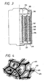


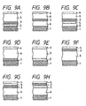

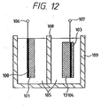
Classifications
-
- H—ELECTRICITY
- H01—ELECTRIC ELEMENTS
- H01M—PROCESSES OR MEANS, e.g. BATTERIES, FOR THE DIRECT CONVERSION OF CHEMICAL ENERGY INTO ELECTRICAL ENERGY
- H01M10/00—Secondary cells; Manufacture thereof
- H01M10/05—Accumulators with non-aqueous electrolyte
-
- H—ELECTRICITY
- H01—ELECTRIC ELEMENTS
- H01M—PROCESSES OR MEANS, e.g. BATTERIES, FOR THE DIRECT CONVERSION OF CHEMICAL ENERGY INTO ELECTRICAL ENERGY
- H01M10/00—Secondary cells; Manufacture thereof
- H01M10/05—Accumulators with non-aqueous electrolyte
- H01M10/052—Li-accumulators
-
- H—ELECTRICITY
- H01—ELECTRIC ELEMENTS
- H01M—PROCESSES OR MEANS, e.g. BATTERIES, FOR THE DIRECT CONVERSION OF CHEMICAL ENERGY INTO ELECTRICAL ENERGY
- H01M10/00—Secondary cells; Manufacture thereof
- H01M10/24—Alkaline accumulators
-
- H—ELECTRICITY
- H01—ELECTRIC ELEMENTS
- H01M—PROCESSES OR MEANS, e.g. BATTERIES, FOR THE DIRECT CONVERSION OF CHEMICAL ENERGY INTO ELECTRICAL ENERGY
- H01M4/00—Electrodes
- H01M4/02—Electrodes composed of, or comprising, active material
-
- H—ELECTRICITY
- H01—ELECTRIC ELEMENTS
- H01M—PROCESSES OR MEANS, e.g. BATTERIES, FOR THE DIRECT CONVERSION OF CHEMICAL ENERGY INTO ELECTRICAL ENERGY
- H01M4/00—Electrodes
- H01M4/02—Electrodes composed of, or comprising, active material
- H01M4/04—Processes of manufacture in general
-
- H—ELECTRICITY
- H01—ELECTRIC ELEMENTS
- H01M—PROCESSES OR MEANS, e.g. BATTERIES, FOR THE DIRECT CONVERSION OF CHEMICAL ENERGY INTO ELECTRICAL ENERGY
- H01M4/00—Electrodes
- H01M4/02—Electrodes composed of, or comprising, active material
- H01M4/04—Processes of manufacture in general
- H01M4/0402—Methods of deposition of the material
- H01M4/0404—Methods of deposition of the material by coating on electrode collectors
-
- H—ELECTRICITY
- H01—ELECTRIC ELEMENTS
- H01M—PROCESSES OR MEANS, e.g. BATTERIES, FOR THE DIRECT CONVERSION OF CHEMICAL ENERGY INTO ELECTRICAL ENERGY
- H01M4/00—Electrodes
- H01M4/02—Electrodes composed of, or comprising, active material
- H01M4/04—Processes of manufacture in general
- H01M4/0402—Methods of deposition of the material
- H01M4/0409—Methods of deposition of the material by a doctor blade method, slip-casting or roller coating
-
- H—ELECTRICITY
- H01—ELECTRIC ELEMENTS
- H01M—PROCESSES OR MEANS, e.g. BATTERIES, FOR THE DIRECT CONVERSION OF CHEMICAL ENERGY INTO ELECTRICAL ENERGY
- H01M4/00—Electrodes
- H01M4/02—Electrodes composed of, or comprising, active material
- H01M4/04—Processes of manufacture in general
- H01M4/0402—Methods of deposition of the material
- H01M4/0414—Methods of deposition of the material by screen printing
-
- H—ELECTRICITY
- H01—ELECTRIC ELEMENTS
- H01M—PROCESSES OR MEANS, e.g. BATTERIES, FOR THE DIRECT CONVERSION OF CHEMICAL ENERGY INTO ELECTRICAL ENERGY
- H01M4/00—Electrodes
- H01M4/02—Electrodes composed of, or comprising, active material
- H01M4/04—Processes of manufacture in general
- H01M4/0402—Methods of deposition of the material
- H01M4/0416—Methods of deposition of the material involving impregnation with a solution, dispersion, paste or dry powder
-
- H—ELECTRICITY
- H01—ELECTRIC ELEMENTS
- H01M—PROCESSES OR MEANS, e.g. BATTERIES, FOR THE DIRECT CONVERSION OF CHEMICAL ENERGY INTO ELECTRICAL ENERGY
- H01M4/00—Electrodes
- H01M4/02—Electrodes composed of, or comprising, active material
- H01M4/04—Processes of manufacture in general
- H01M4/0402—Methods of deposition of the material
- H01M4/0419—Methods of deposition of the material involving spraying
-
- H—ELECTRICITY
- H01—ELECTRIC ELEMENTS
- H01M—PROCESSES OR MEANS, e.g. BATTERIES, FOR THE DIRECT CONVERSION OF CHEMICAL ENERGY INTO ELECTRICAL ENERGY
- H01M4/00—Electrodes
- H01M4/02—Electrodes composed of, or comprising, active material
- H01M4/04—Processes of manufacture in general
- H01M4/0402—Methods of deposition of the material
- H01M4/0421—Methods of deposition of the material involving vapour deposition
- H01M4/0423—Physical vapour deposition
- H01M4/0426—Sputtering
-
- H—ELECTRICITY
- H01—ELECTRIC ELEMENTS
- H01M—PROCESSES OR MEANS, e.g. BATTERIES, FOR THE DIRECT CONVERSION OF CHEMICAL ENERGY INTO ELECTRICAL ENERGY
- H01M4/00—Electrodes
- H01M4/02—Electrodes composed of, or comprising, active material
- H01M4/04—Processes of manufacture in general
- H01M4/0402—Methods of deposition of the material
- H01M4/0421—Methods of deposition of the material involving vapour deposition
- H01M4/0428—Chemical vapour deposition
-
- H—ELECTRICITY
- H01—ELECTRIC ELEMENTS
- H01M—PROCESSES OR MEANS, e.g. BATTERIES, FOR THE DIRECT CONVERSION OF CHEMICAL ENERGY INTO ELECTRICAL ENERGY
- H01M4/00—Electrodes
- H01M4/02—Electrodes composed of, or comprising, active material
- H01M4/04—Processes of manufacture in general
- H01M4/043—Processes of manufacture in general involving compressing or compaction
- H01M4/0435—Rolling or calendering
-
- H—ELECTRICITY
- H01—ELECTRIC ELEMENTS
- H01M—PROCESSES OR MEANS, e.g. BATTERIES, FOR THE DIRECT CONVERSION OF CHEMICAL ENERGY INTO ELECTRICAL ENERGY
- H01M4/00—Electrodes
- H01M4/02—Electrodes composed of, or comprising, active material
- H01M4/04—Processes of manufacture in general
- H01M4/0438—Processes of manufacture in general by electrochemical processing
- H01M4/045—Electrochemical coating; Electrochemical impregnation
- H01M4/0452—Electrochemical coating; Electrochemical impregnation from solutions
-
- H—ELECTRICITY
- H01—ELECTRIC ELEMENTS
- H01M—PROCESSES OR MEANS, e.g. BATTERIES, FOR THE DIRECT CONVERSION OF CHEMICAL ENERGY INTO ELECTRICAL ENERGY
- H01M4/00—Electrodes
- H01M4/02—Electrodes composed of, or comprising, active material
- H01M4/04—Processes of manufacture in general
- H01M4/0438—Processes of manufacture in general by electrochemical processing
- H01M4/0464—Electro organic synthesis
- H01M4/0466—Electrochemical polymerisation
-
- H—ELECTRICITY
- H01—ELECTRIC ELEMENTS
- H01M—PROCESSES OR MEANS, e.g. BATTERIES, FOR THE DIRECT CONVERSION OF CHEMICAL ENERGY INTO ELECTRICAL ENERGY
- H01M4/00—Electrodes
- H01M4/02—Electrodes composed of, or comprising, active material
- H01M4/04—Processes of manufacture in general
- H01M4/0471—Processes of manufacture in general involving thermal treatment, e.g. firing, sintering, backing particulate active material, thermal decomposition, pyrolysis
-
- H—ELECTRICITY
- H01—ELECTRIC ELEMENTS
- H01M—PROCESSES OR MEANS, e.g. BATTERIES, FOR THE DIRECT CONVERSION OF CHEMICAL ENERGY INTO ELECTRICAL ENERGY
- H01M4/00—Electrodes
- H01M4/02—Electrodes composed of, or comprising, active material
- H01M4/13—Electrodes for accumulators with non-aqueous electrolyte, e.g. for lithium-accumulators; Processes of manufacture thereof
- H01M4/131—Electrodes based on mixed oxides or hydroxides, or on mixtures of oxides or hydroxides, e.g. LiCoOx
-
- H—ELECTRICITY
- H01—ELECTRIC ELEMENTS
- H01M—PROCESSES OR MEANS, e.g. BATTERIES, FOR THE DIRECT CONVERSION OF CHEMICAL ENERGY INTO ELECTRICAL ENERGY
- H01M4/00—Electrodes
- H01M4/02—Electrodes composed of, or comprising, active material
- H01M4/13—Electrodes for accumulators with non-aqueous electrolyte, e.g. for lithium-accumulators; Processes of manufacture thereof
- H01M4/134—Electrodes based on metals, Si or alloys
-
- H—ELECTRICITY
- H01—ELECTRIC ELEMENTS
- H01M—PROCESSES OR MEANS, e.g. BATTERIES, FOR THE DIRECT CONVERSION OF CHEMICAL ENERGY INTO ELECTRICAL ENERGY
- H01M4/00—Electrodes
- H01M4/02—Electrodes composed of, or comprising, active material
- H01M4/13—Electrodes for accumulators with non-aqueous electrolyte, e.g. for lithium-accumulators; Processes of manufacture thereof
- H01M4/139—Processes of manufacture
-
- H—ELECTRICITY
- H01—ELECTRIC ELEMENTS
- H01M—PROCESSES OR MEANS, e.g. BATTERIES, FOR THE DIRECT CONVERSION OF CHEMICAL ENERGY INTO ELECTRICAL ENERGY
- H01M4/00—Electrodes
- H01M4/02—Electrodes composed of, or comprising, active material
- H01M4/24—Electrodes for alkaline accumulators
-
- H—ELECTRICITY
- H01—ELECTRIC ELEMENTS
- H01M—PROCESSES OR MEANS, e.g. BATTERIES, FOR THE DIRECT CONVERSION OF CHEMICAL ENERGY INTO ELECTRICAL ENERGY
- H01M4/00—Electrodes
- H01M4/02—Electrodes composed of, or comprising, active material
- H01M4/24—Electrodes for alkaline accumulators
- H01M4/244—Zinc electrodes
-
- H—ELECTRICITY
- H01—ELECTRIC ELEMENTS
- H01M—PROCESSES OR MEANS, e.g. BATTERIES, FOR THE DIRECT CONVERSION OF CHEMICAL ENERGY INTO ELECTRICAL ENERGY
- H01M4/00—Electrodes
- H01M4/02—Electrodes composed of, or comprising, active material
- H01M4/36—Selection of substances as active materials, active masses, active liquids
- H01M4/362—Composites
- H01M4/366—Composites as layered products
-
- H—ELECTRICITY
- H01—ELECTRIC ELEMENTS
- H01M—PROCESSES OR MEANS, e.g. BATTERIES, FOR THE DIRECT CONVERSION OF CHEMICAL ENERGY INTO ELECTRICAL ENERGY
- H01M4/00—Electrodes
- H01M4/02—Electrodes composed of, or comprising, active material
- H01M4/36—Selection of substances as active materials, active masses, active liquids
- H01M4/38—Selection of substances as active materials, active masses, active liquids of elements or alloys
- H01M4/40—Alloys based on alkali metals
-
- H—ELECTRICITY
- H01—ELECTRIC ELEMENTS
- H01M—PROCESSES OR MEANS, e.g. BATTERIES, FOR THE DIRECT CONVERSION OF CHEMICAL ENERGY INTO ELECTRICAL ENERGY
- H01M4/00—Electrodes
- H01M4/02—Electrodes composed of, or comprising, active material
- H01M4/36—Selection of substances as active materials, active masses, active liquids
- H01M4/48—Selection of substances as active materials, active masses, active liquids of inorganic oxides or hydroxides
-
- H—ELECTRICITY
- H01—ELECTRIC ELEMENTS
- H01M—PROCESSES OR MEANS, e.g. BATTERIES, FOR THE DIRECT CONVERSION OF CHEMICAL ENERGY INTO ELECTRICAL ENERGY
- H01M4/00—Electrodes
- H01M4/02—Electrodes composed of, or comprising, active material
- H01M4/36—Selection of substances as active materials, active masses, active liquids
- H01M4/58—Selection of substances as active materials, active masses, active liquids of inorganic compounds other than oxides or hydroxides, e.g. sulfides, selenides, tellurides, halogenides or LiCoFy; of polyanionic structures, e.g. phosphates, silicates or borates
- H01M4/582—Halogenides
-
- H—ELECTRICITY
- H01—ELECTRIC ELEMENTS
- H01M—PROCESSES OR MEANS, e.g. BATTERIES, FOR THE DIRECT CONVERSION OF CHEMICAL ENERGY INTO ELECTRICAL ENERGY
- H01M4/00—Electrodes
- H01M4/02—Electrodes composed of, or comprising, active material
- H01M4/62—Selection of inactive substances as ingredients for active masses, e.g. binders, fillers
- H01M4/621—Binders
- H01M4/622—Binders being polymers
- H01M4/623—Binders being polymers fluorinated polymers
-
- H—ELECTRICITY
- H01—ELECTRIC ELEMENTS
- H01M—PROCESSES OR MEANS, e.g. BATTERIES, FOR THE DIRECT CONVERSION OF CHEMICAL ENERGY INTO ELECTRICAL ENERGY
- H01M4/00—Electrodes
- H01M4/02—Electrodes composed of, or comprising, active material
- H01M4/64—Carriers or collectors
- H01M4/70—Carriers or collectors characterised by shape or form
- H01M4/72—Grids
- H01M4/74—Meshes or woven material; Expanded metal
- H01M4/742—Meshes or woven material; Expanded metal perforated material
-
- H—ELECTRICITY
- H01—ELECTRIC ELEMENTS
- H01M—PROCESSES OR MEANS, e.g. BATTERIES, FOR THE DIRECT CONVERSION OF CHEMICAL ENERGY INTO ELECTRICAL ENERGY
- H01M10/00—Secondary cells; Manufacture thereof
- H01M10/05—Accumulators with non-aqueous electrolyte
- H01M10/056—Accumulators with non-aqueous electrolyte characterised by the materials used as electrolytes, e.g. mixed inorganic/organic electrolytes
-
- H—ELECTRICITY
- H01—ELECTRIC ELEMENTS
- H01M—PROCESSES OR MEANS, e.g. BATTERIES, FOR THE DIRECT CONVERSION OF CHEMICAL ENERGY INTO ELECTRICAL ENERGY
- H01M10/00—Secondary cells; Manufacture thereof
- H01M10/05—Accumulators with non-aqueous electrolyte
- H01M10/058—Construction or manufacture
-
- H—ELECTRICITY
- H01—ELECTRIC ELEMENTS
- H01M—PROCESSES OR MEANS, e.g. BATTERIES, FOR THE DIRECT CONVERSION OF CHEMICAL ENERGY INTO ELECTRICAL ENERGY
- H01M10/00—Secondary cells; Manufacture thereof
- H01M10/05—Accumulators with non-aqueous electrolyte
- H01M10/058—Construction or manufacture
- H01M10/0585—Construction or manufacture of accumulators having only flat construction elements, i.e. flat positive electrodes, flat negative electrodes and flat separators
-
- H—ELECTRICITY
- H01—ELECTRIC ELEMENTS
- H01M—PROCESSES OR MEANS, e.g. BATTERIES, FOR THE DIRECT CONVERSION OF CHEMICAL ENERGY INTO ELECTRICAL ENERGY
- H01M10/00—Secondary cells; Manufacture thereof
- H01M10/05—Accumulators with non-aqueous electrolyte
- H01M10/058—Construction or manufacture
- H01M10/0587—Construction or manufacture of accumulators having only wound construction elements, i.e. wound positive electrodes, wound negative electrodes and wound separators
-
- H—ELECTRICITY
- H01—ELECTRIC ELEMENTS
- H01M—PROCESSES OR MEANS, e.g. BATTERIES, FOR THE DIRECT CONVERSION OF CHEMICAL ENERGY INTO ELECTRICAL ENERGY
- H01M10/00—Secondary cells; Manufacture thereof
- H01M10/24—Alkaline accumulators
- H01M10/30—Nickel accumulators
-
- H—ELECTRICITY
- H01—ELECTRIC ELEMENTS
- H01M—PROCESSES OR MEANS, e.g. BATTERIES, FOR THE DIRECT CONVERSION OF CHEMICAL ENERGY INTO ELECTRICAL ENERGY
- H01M12/00—Hybrid cells; Manufacture thereof
- H01M12/08—Hybrid cells; Manufacture thereof composed of a half-cell of a fuel-cell type and a half-cell of the secondary-cell type
-
- H—ELECTRICITY
- H01—ELECTRIC ELEMENTS
- H01M—PROCESSES OR MEANS, e.g. BATTERIES, FOR THE DIRECT CONVERSION OF CHEMICAL ENERGY INTO ELECTRICAL ENERGY
- H01M4/00—Electrodes
- H01M4/02—Electrodes composed of, or comprising, active material
- H01M2004/026—Electrodes composed of, or comprising, active material characterised by the polarity
- H01M2004/027—Negative electrodes
-
- H—ELECTRICITY
- H01—ELECTRIC ELEMENTS
- H01M—PROCESSES OR MEANS, e.g. BATTERIES, FOR THE DIRECT CONVERSION OF CHEMICAL ENERGY INTO ELECTRICAL ENERGY
- H01M4/00—Electrodes
- H01M4/02—Electrodes composed of, or comprising, active material
- H01M4/13—Electrodes for accumulators with non-aqueous electrolyte, e.g. for lithium-accumulators; Processes of manufacture thereof
- H01M4/133—Electrodes based on carbonaceous material, e.g. graphite-intercalation compounds or CFx
-
- H—ELECTRICITY
- H01—ELECTRIC ELEMENTS
- H01M—PROCESSES OR MEANS, e.g. BATTERIES, FOR THE DIRECT CONVERSION OF CHEMICAL ENERGY INTO ELECTRICAL ENERGY
- H01M4/00—Electrodes
- H01M4/02—Electrodes composed of, or comprising, active material
- H01M4/13—Electrodes for accumulators with non-aqueous electrolyte, e.g. for lithium-accumulators; Processes of manufacture thereof
- H01M4/139—Processes of manufacture
- H01M4/1391—Processes of manufacture of electrodes based on mixed oxides or hydroxides, or on mixtures of oxides or hydroxides, e.g. LiCoOx
-
- H—ELECTRICITY
- H01—ELECTRIC ELEMENTS
- H01M—PROCESSES OR MEANS, e.g. BATTERIES, FOR THE DIRECT CONVERSION OF CHEMICAL ENERGY INTO ELECTRICAL ENERGY
- H01M4/00—Electrodes
- H01M4/02—Electrodes composed of, or comprising, active material
- H01M4/36—Selection of substances as active materials, active masses, active liquids
- H01M4/38—Selection of substances as active materials, active masses, active liquids of elements or alloys
- H01M4/42—Alloys based on zinc
-
- H—ELECTRICITY
- H01—ELECTRIC ELEMENTS
- H01M—PROCESSES OR MEANS, e.g. BATTERIES, FOR THE DIRECT CONVERSION OF CHEMICAL ENERGY INTO ELECTRICAL ENERGY
- H01M4/00—Electrodes
- H01M4/02—Electrodes composed of, or comprising, active material
- H01M4/36—Selection of substances as active materials, active masses, active liquids
- H01M4/48—Selection of substances as active materials, active masses, active liquids of inorganic oxides or hydroxides
- H01M4/485—Selection of substances as active materials, active masses, active liquids of inorganic oxides or hydroxides of mixed oxides or hydroxides for inserting or intercalating light metals, e.g. LiTi2O4 or LiTi2OxFy
-
- H—ELECTRICITY
- H01—ELECTRIC ELEMENTS
- H01M—PROCESSES OR MEANS, e.g. BATTERIES, FOR THE DIRECT CONVERSION OF CHEMICAL ENERGY INTO ELECTRICAL ENERGY
- H01M4/00—Electrodes
- H01M4/02—Electrodes composed of, or comprising, active material
- H01M4/36—Selection of substances as active materials, active masses, active liquids
- H01M4/48—Selection of substances as active materials, active masses, active liquids of inorganic oxides or hydroxides
- H01M4/50—Selection of substances as active materials, active masses, active liquids of inorganic oxides or hydroxides of manganese
- H01M4/505—Selection of substances as active materials, active masses, active liquids of inorganic oxides or hydroxides of manganese of mixed oxides or hydroxides containing manganese for inserting or intercalating light metals, e.g. LiMn2O4 or LiMn2OxFy
-
- H—ELECTRICITY
- H01—ELECTRIC ELEMENTS
- H01M—PROCESSES OR MEANS, e.g. BATTERIES, FOR THE DIRECT CONVERSION OF CHEMICAL ENERGY INTO ELECTRICAL ENERGY
- H01M4/00—Electrodes
- H01M4/02—Electrodes composed of, or comprising, active material
- H01M4/36—Selection of substances as active materials, active masses, active liquids
- H01M4/48—Selection of substances as active materials, active masses, active liquids of inorganic oxides or hydroxides
- H01M4/52—Selection of substances as active materials, active masses, active liquids of inorganic oxides or hydroxides of nickel, cobalt or iron
- H01M4/525—Selection of substances as active materials, active masses, active liquids of inorganic oxides or hydroxides of nickel, cobalt or iron of mixed oxides or hydroxides containing iron, cobalt or nickel for inserting or intercalating light metals, e.g. LiNiO2, LiCoO2 or LiCoOxFy
-
- H—ELECTRICITY
- H01—ELECTRIC ELEMENTS
- H01M—PROCESSES OR MEANS, e.g. BATTERIES, FOR THE DIRECT CONVERSION OF CHEMICAL ENERGY INTO ELECTRICAL ENERGY
- H01M4/00—Electrodes
- H01M4/02—Electrodes composed of, or comprising, active material
- H01M4/36—Selection of substances as active materials, active masses, active liquids
- H01M4/58—Selection of substances as active materials, active masses, active liquids of inorganic compounds other than oxides or hydroxides, e.g. sulfides, selenides, tellurides, halogenides or LiCoFy; of polyanionic structures, e.g. phosphates, silicates or borates
- H01M4/581—Chalcogenides or intercalation compounds thereof
-
- H—ELECTRICITY
- H01—ELECTRIC ELEMENTS
- H01M—PROCESSES OR MEANS, e.g. BATTERIES, FOR THE DIRECT CONVERSION OF CHEMICAL ENERGY INTO ELECTRICAL ENERGY
- H01M4/00—Electrodes
- H01M4/02—Electrodes composed of, or comprising, active material
- H01M4/62—Selection of inactive substances as ingredients for active masses, e.g. binders, fillers
- H01M4/621—Binders
-
- H—ELECTRICITY
- H01—ELECTRIC ELEMENTS
- H01M—PROCESSES OR MEANS, e.g. BATTERIES, FOR THE DIRECT CONVERSION OF CHEMICAL ENERGY INTO ELECTRICAL ENERGY
- H01M4/00—Electrodes
- H01M4/02—Electrodes composed of, or comprising, active material
- H01M4/62—Selection of inactive substances as ingredients for active masses, e.g. binders, fillers
- H01M4/624—Electric conductive fillers
- H01M4/625—Carbon or graphite
-
- H—ELECTRICITY
- H01—ELECTRIC ELEMENTS
- H01M—PROCESSES OR MEANS, e.g. BATTERIES, FOR THE DIRECT CONVERSION OF CHEMICAL ENERGY INTO ELECTRICAL ENERGY
- H01M4/00—Electrodes
- H01M4/02—Electrodes composed of, or comprising, active material
- H01M4/64—Carriers or collectors
- H01M4/70—Carriers or collectors characterised by shape or form
- H01M4/72—Grids
- H01M4/74—Meshes or woven material; Expanded metal
-
- H—ELECTRICITY
- H01—ELECTRIC ELEMENTS
- H01M—PROCESSES OR MEANS, e.g. BATTERIES, FOR THE DIRECT CONVERSION OF CHEMICAL ENERGY INTO ELECTRICAL ENERGY
- H01M4/00—Electrodes
- H01M4/02—Electrodes composed of, or comprising, active material
- H01M4/64—Carriers or collectors
- H01M4/70—Carriers or collectors characterised by shape or form
- H01M4/80—Porous plates, e.g. sintered carriers
- H01M4/808—Foamed, spongy materials
-
- H—ELECTRICITY
- H01—ELECTRIC ELEMENTS
- H01M—PROCESSES OR MEANS, e.g. BATTERIES, FOR THE DIRECT CONVERSION OF CHEMICAL ENERGY INTO ELECTRICAL ENERGY
- H01M50/00—Constructional details or processes of manufacture of the non-active parts of electrochemical cells other than fuel cells, e.g. hybrid cells
- H01M50/40—Separators; Membranes; Diaphragms; Spacing elements inside cells
- H01M50/46—Separators, membranes or diaphragms characterised by their combination with electrodes
-
- Y—GENERAL TAGGING OF NEW TECHNOLOGICAL DEVELOPMENTS; GENERAL TAGGING OF CROSS-SECTIONAL TECHNOLOGIES SPANNING OVER SEVERAL SECTIONS OF THE IPC; TECHNICAL SUBJECTS COVERED BY FORMER USPC CROSS-REFERENCE ART COLLECTIONS [XRACs] AND DIGESTS
- Y02—TECHNOLOGIES OR APPLICATIONS FOR MITIGATION OR ADAPTATION AGAINST CLIMATE CHANGE
- Y02E—REDUCTION OF GREENHOUSE GAS [GHG] EMISSIONS, RELATED TO ENERGY GENERATION, TRANSMISSION OR DISTRIBUTION
- Y02E60/00—Enabling technologies; Technologies with a potential or indirect contribution to GHG emissions mitigation
- Y02E60/10—Energy storage using batteries
-
- Y—GENERAL TAGGING OF NEW TECHNOLOGICAL DEVELOPMENTS; GENERAL TAGGING OF CROSS-SECTIONAL TECHNOLOGIES SPANNING OVER SEVERAL SECTIONS OF THE IPC; TECHNICAL SUBJECTS COVERED BY FORMER USPC CROSS-REFERENCE ART COLLECTIONS [XRACs] AND DIGESTS
- Y10—TECHNICAL SUBJECTS COVERED BY FORMER USPC
- Y10T—TECHNICAL SUBJECTS COVERED BY FORMER US CLASSIFICATION
- Y10T29/00—Metal working
- Y10T29/49—Method of mechanical manufacture
- Y10T29/49002—Electrical device making
- Y10T29/49108—Electric battery cell making
Definitions
- the present invention relates to a secondary battery which can repeatedly be used, and more particularly to a reliable secondary battery capable of preventing short circuit occurring due to dendrite even if the battery is repeatedly charged and discharged.
- a locking chair type lithium ion battery capable of serving as the foregoing high performance secondary battery and comprising a positive electrode active material comprising lithium ions introduced into an interlayer compound thereof and a negative electrode active material comprising carbon has been developed and partially put into practical use.
- the lithium ion battery has not achieved the high energy density that is the original characteristics of the lithium battery which uses the metal lithium as the negative electrode active material.
- the reason why a large capacity lithium accumulator of the type that uses the lithium metal as the negative electrode has not been put into practical use is that generation of dendrite of the lithium (tree branch like crystal) which is the main cause of a short circuit cannot be prevented yet.
- An object of the present invention is to provide a lithium or lithium alloy secondary battery capable of overcoming the foregoing problems experienced with the conventional secondary batteries and exhibiting a long cycle life.
- the invention is a method of manufacturing a positive electrode active material of a lithium secondary battery, said method comprising the steps of:
- a positive electrode active material 13104 of a lithium secondary battery made of a compound of one or more types of transition metals having a crystal grain size of 50nm (500 ⁇ ) or less enables high capacity, large energy and long cycle life to be realized.
- the secondary battery of the foregoing type has a cross sectional shape schematically shown in Fig. 12 .
- the same reference numerals as those shown in Fig. 1 represent the same structures.
- the main component material of the positive electrode active material has a structure of an aggregate selected from a group consisting of amorphous, microcrystal, a mixture of amorphous, microcrystal and a mixture of amorphous, microcrystal and multi-crystal.
- the positive electrode active material of the lithium secondary battery is made of a compound of the transition metal having a structure of the aggregate selected from a group consisting of amorphous, microcrystal, a mixture of amorphous and a microcrystal and a mixture of an amorphous, a microcrystal and a multi-crystal, and oxygen and having a crystal grain size of 50nm (500 ⁇ ) or less, more preferably 20nm (200 ⁇ ) enables the following effects to be obtained:
- the specific area of the positive electrode active material mainly composed of the compound of the transition metal and oxygen be 50 m 2 /g or more in a state before the material is formed into the positive electrode, more preferably 100 m 2 /g or more.
- the solid-liquid reactions between the electrolyte and the positive electrode active material can be made further smooth at the time of charge and the discharge.
- the transition metal oxide is exemplified by a metal oxide such as a nickel oxide, a cobalt oxide, a titanium oxide, an iron oxide, a vanadium oxide, a manganese oxide, a molybdenum oxide, a chrome oxide or a tungsten oxide.
- a metal oxide such as a nickel oxide, a cobalt oxide, a titanium oxide, an iron oxide, a vanadium oxide, a manganese oxide, a molybdenum oxide, a chrome oxide or a tungsten oxide.
- a lithium secondary battery comprising a negative electrode substantially made of a negative electrode active material, a positive electrode substantially made of a positive electrode active material disposed from said negative electrode with an interposed separator; and an electrolyte or an electrolyte solution held between said negative electrode and said positive electrode, characterised in that:
- a secondary battery according to the present invention comprises a negative electrode, a separator, a positive electrode, an electrolyte and a collector.
- Fig. 1 is a basic structural view which illustrates the secondary battery. Referring to Fig. 1 , reference numeral 100 represents a negative collector, 101 represents a negative electrode substantially made of negative electrode active material, 102 represents a film 103 represents a positive collector, 104 represents a positive electrode substantially made of positive electrode active material, 105 represents an electrolyte solution (electrolyte), 106 represents a negative terminal, 107 represents a positive terminal, 109 represents a case for the secondary battery, and 108 represents a separator.
- reference numeral 100 represents a negative collector
- 101 represents a negative electrode substantially made of negative electrode active material
- 102 represents a film 103 represents a positive collector
- 104 represents a positive electrode substantially made of positive electrode active material
- 105 represents an electrolyte solution (electrolyte)
- 106 represents a negative terminal
- lithium or lithium alloy is used as the negative electrode active activating material 101.
- the lithium alloy may contain one or more types of elements selected from a group consisting of magnesium, aluminum, titanium, tin, indium, boron, gallium, potassium, sodium, calcium, zinc and lead and the like.
- the binding material is exemplified by polyvinyl alcohol, a cellulose material such as methyl cellulose or carboxymethyl cellulose, a polyolefin material such as polyethylene, a fluororesin such as polytetrafluoroethylene and a polyamide resin such as nylon.
- the kneading solution may be an organic solvent such as ethylene glycol or water containing oxo acid salt such as sodium phosphate or the like.
- the collector may be an iron plate applied with nickel plating and having apertures, a foam metal or nickel mesh or the like.
- the positive electrode is formed by mixing a positive electrode active material, conductive powder and a binding material on the collector.
- a solvent-resisting resin such as polypropylene or polyethylene or fluororesin is used as the bonding material if necessary.
- the conductive powder is mixed at the time of the formation.
- the material of the conductive powder is exemplified by various carbon, copper, nickel and titanium and the like.
- the positive pole activating material 104 of the lithium secondary battery is made of a compound having layers through which lithium ions can be passed, the compound being prepared as set out in the appended claims.
- a transition metal oxide is exemplified by manganese oxide, vanadium oxide, molybdenum oxide, chrome oxide, cobalt oxide, nickel oxide, titanium oxide, iron oxide, and tungsten oxide.
- the transition metal element may be an element having partially shell d or shell f.
- the positive pole is manufactured in such a manner that paste obtained by adding a bonding material, such as polyethylene, polypropylene or a fluororesin, to the positive pole activating material 104 is pressed against the positive pole collector 103.
- a bonding material such as polyethylene, polypropylene or a fluororesin
- the conductive powder may be a carbon material such as acetylene black or metal such as copper, nickel or titanium.
- the collector 103 may be fiber-like, porous or mesh-shape carbon material, stainless steel, titanium, nickel, copper, platinum or gold.
- the electrolyte is used as it is or in the form of a solution in which it is dissolved in a solvent or after it has been solidified by adding a gelatinizing material, such as a polymer, to the solution.
- a gelatinizing material such as a polymer
- the conductance of the electrolyte must be raised as much as possible because it relates to the internal resistance of the battery and considerably affects the current density at the time of the charge and the discharge. It is preferable that the conductance at 25°C be 1 x 10 -3 S/cm or higher, more preferably 5 x 10 -3 S/cm or higher.
- the Negative Pole Activating Material is Lithium or Lithium Alloy.
- the electrolyte is made of an acid, such as H 2 SO 4 , HCl or HNO 3 , a salt composed of Lewis acid ion (BF 4 - , PF 6 - , AsF 6 - or ClO 4 - ) or their mixture. Further, positive ions, such as sodium ions, potassium ions, tetraalkylammonium ions, and the Lewis acid ions may be used together. It is preferable that the foregoing salt is heated under lowered pressure to sufficiently dehydrate and deoxidize the salt.
- an acid such as H 2 SO 4 , HCl or HNO 3
- a salt composed of Lewis acid ion BF 4 - , PF 6 - , AsF 6 - or ClO 4 -
- positive ions such as sodium ions, potassium ions, tetraalkylammonium ions, and the Lewis acid ions may be used together. It is preferable that the foregoing salt is heated under lowered pressure to sufficiently dehydrate and deoxid
- the solvent of the electrolyte is exemplified by acetonitryl (CH 3 CN), benzonitryl (C 6 H 5 CN), propylene carbonate (PC), ethylene carbonate (EC), dimethyl formamide (DMF), tetrahydrofuran (THF), nitrobenzene (C 6 H 5 NO 2 ), dichloroethane, diethoxyethane, chlorobenzene, ⁇ - butylolactone, dioxolan, sulforan, nitromethane, dimethylsulfide, dimethylsuloxide, dimethoxyethane, methyl formate, 3 - methyl - 2 - oxydazolidinone, 2 - methyltetrahydrofuran, sulfur dioxide, phosphoryl chloride, thionyl chloride, sulfuryl chloride, dimethyl formaldehyde, ⁇ - butyrolactone and tetrahydrofuran and their mixture.
- the foregoing solvent be dehydrated with active alumina, molecular sieves, phosphorus pentaoxide or calcium chloride.
- the solvent be distilled under presence of alkali metal in inactive gas to remove impurities and to be dehydrated.
- the electrolyte solution it is preferable to gel the electrolyte solution to prevent leakage of the electrolyte solution.
- the gelling material it is preferable to use a polymer of a type which swells when it absorbs the solvent of the electrolyte solution, the gelling material being a polymer exemplified by a polyethylene oxide, polyvinyl alcohol and a polyacryl amide.
- the separators (108, 208 and 308) are provided to prevent short circuits between the positive pole and the negative pole. They also act to hold the electroytic solution.
- the separator must meet the following conditions.
- the material that is able to meet the foregoing conditions is exemplified by a unwoven fabric or a micropore structure of glass, polypropylene, polyethylene, or fluororesin.
- a metal oxide film having small apertures or a resin film formed by combining metal oxides may be used. If a metal oxide film in the form of a multi-layer structure is used, dendrite cannot easily pass through it and therefore an effect of preventing the short circuits can be obtained. If a fluororesin film which is a flame retardant or a glass or a metal oxide film which is a noncombustible material is used, the safety can further be improved.
- Collectors 100, 103, 200 and 300 are made of fiber, porous or mesh-like carbon, stainless steel, titanium, nickel, copper, platinum or gold.
- the battery is formed into a flat, cylindrical, square (rectangular) or a sheet shape battery.
- the spiral and cylindrical structure is enabled to have a large electrode area by winding while interposing the separator between the negative pole and the positive pole so that a large electric current can be caused to flow at the time of the charge and the discharge.
- the rectangular type battery enables an accommodation space for accommodating the secondary battery to be used effectively.
- the structure may be a single-layer structure and a multi-layer structure.
- Figs. 2 and 3 illustrate the schematic cross sectional views which respectively illustrate an example of a single-layer flat battery and a spiral and cylindrical battery.
- reference numeral 201 and 301 represent negative poles covered with films
- 200 and 300 represent collectors for the negative poles 201 and 301.
- Reference numeral 203 and 303 represent positive pole made of the positive pole activating material.
- Reference numeral 304 represents a collector for the positive pole
- 206 and 306 represent negative terminals (caps for the negative poles 201 and 301).
- Reference numeral 207 and 307 represent outer cases (cases serving as positive pole cases and battery cases), 208 and 308 represent separators which hold the electrolytic solution, 210 and 310 represent insulating packings, and 311 represents an insulating plate.
- reference numeral 5102 represents lithium members subjected to surface treatment.
- the batteries shown in Figs. 2 and 3 are manufactured in such a manner that the separators 208 and 308 are held between the negative poles 201, 201 subjected to the surface treatment and the positive poles 203 and 303 to be placed in the positive pole cases 207 and 307 followed by injecting the electrolytic solution. Then, the negative pole caps 206, 306, the insulating packing 210 and 310 are assembled so that the batteries are manufactured.
- the preparation of the material and assembling of the battery are performed in dry air from which water has sufficiently be removed or in a dry inactive gas.
- the battery case may be a metal outer case also serving as an output terminal or a plastic resin case.
- the positive pole cases 207, 307, the negative pole caps 206 and 306 are made of stainless steel, and in particular, titanium clad stainless steel or copper clad stainless steel or a steel plate applied with nickel-plating.
- the battery case may be made of metal such as aluminum or zinc, plastic such as polypropylene or a composite material of metal, glass fiber and plastic as well as the stainless steel.
- the insulating packings 210 and 310 may be made of fluororesin, polyamide resin, polysulfon resin or rubber.
- the capping method may be a bonding method, welding method, soldering method or a glass sealing method as well as a caulking method using a gasket such as an insulating packing.
- the insulting plate 311 for insulating the inside of the battery may be made of an organic resin or ceramics.
- a safety valve (not shown in Figs. 2 and 3 ) using rubber, a spring or a metal ball may be used to serve as a safety means to act if the internal pressure in the battery has been raised.
- the basic structure of another embodiment of the lithium secondary battery according to the present invention comprises a side opposing at least the positive pole, the side being composed of a lithium negative pole subjected to treatment using a reactive gas containing nitrogen or halogen, a separator, a positive pole activating material, electrolyte and a collector.
- Fig. 5 is a basic structural view which illustrates the lithium secondary battery according to the present invention. Referring to Fig.
- reference numeral 100 represents a collector for a negative electrode
- 101 represents a negative electrode active material (lithium or lithium alloy)
- 5102 represents a surface treatment layer for the lithium portion
- 103 represents a collector for the positive electrode
- 5104 represents a positive electrode active material
- 105 represents an electrolyte solution
- 106 represents a negative terminal
- 107 represents a positive terminal
- 108 represents a separator
- 109 represents a battery case.
- lithium ions in the electrolyte solution 105 are introduced into the interlayer of the positive electrode active material 5104. Simultaneously, lithium ions are eluted from the lithium negative electrode 101 into the electrolyte solution 105 by way of a treatment-applied surface 5102.
- lithium ions in the electrolyte solution 105 are, lithium metal ions are precipitated to the lithium negative electrode 101 by way of the treatment-applied surface 5102. Simultaneously, lithium in the interlayer of the positive electrode active material 5104 is eluted into the electrolyte solution 105.
- the nitrogen compound for treating the surface of lithium or the lithium alloy is exemplified by nitrogen, ammonia and nitrogen trifluoride. If nitrogen is used as the nitride, it must be activated as to be formed into a plasma form by DC or high frequency discharge or by laser beam application. Also other nitrides are enabled to have improved reactivity when formed into plasma.
- the halogen compound is exemplified by fluorine, chlorine, bromine, iodine, hydrogen fluoride, hydrogen chloride, hydrogen bromide, chlorine trifluoride, methane tetrafluoride, methane tetrachloride, methane trifluoride, methane fluoride trichloride, sulfur hexafluoride and boron trichloride.
- the inactive gas such as carbon halide must be formed into plasma as to have improved reactivity. It is preferable that the very active gas such as fluorine, chlorine, hydrogen fluoride, hydrogen chloride or chloride trifluoride be diluted with inactive gas such as argon gas or helium gas.
- the nitrogen compound and the halogen compound may be mixed with each other or contain oxygen gas, hydrogen gas, argon gas, helium gas, xenon gas or the like added thereto to improve the activity of the reactive gas or to control the activity.
- the negative electrode may be treated with plasma of hydrogen gas or argon gas prior to treating the surface of the negative electrode so that a fresh negative electrode surface is caused to appear.
- a secondary battery manufactured in such a manner that active nitrogen plasma or fluorine plasma or hydrogen fluoride is brought into contact with the surface of lithium to cause reactions to take place, an inactive thin film made of lithium nitride or lithium fluoride and allowing lithium ions to pass through is formed on the surface of lithium, and the lithium portion is used as the negative electrode.
- the direct contact of lithium precipitated at the time of the charge with the electrolyte solution is prevented so that the generation of dendrite at the time of the charge is prevented. Therefore, a lithium battery exhibiting a long life against the charge and discharge cycle can be obtained.
- the application of the foregoing treatment to the surface of lithium prevents the reactions between lithium and water. Further, handling can be made easier.
- the thickness of the treatment layer to be formed on the surface of lithium ranges from 1nm (10 ⁇ ) to 1 ⁇ , more preferably 5nm to 50nm (50 ⁇ to 1000 ⁇ .) The thickness is adjusted by the reaction time or the concentration of the reaction gas.
- the concentration of nitrogen atoms or halogen atoms in the treatment layer formed on the surface of lithium be gradually lowered from the surface to the inside portion of lithium.
- the positive pole activating material 5104 is be a material into which lithium can be introduced into the interlayer thereof, the material being a metal oxide such as a nickel oxide, cobalt oxide, titanium oxide, iron oxide, vanadium oxide, manganese oxide, molybdenum oxide, chrome oxide or tungsten oxide.
- solvent-resisting resin such as polypropylene, polyethylene or fluororesin is used as a bonding material if necessary.
- solvent-resisting resin such as polypropylene, polyethylene or fluororesin is used as a bonding material if necessary.
- conductive powder may be carbon black, copper, nickel or titanium.
- Fig. 8 illustrates an example a pattern of stacked layers according to the present invention in which a conductive layer, a semiconductor layer and an insulating layer are formed between the negative pole and the separator.
- reference numeral 001 represents a negative pole
- 002 represents a dendrite
- 003 represents the conductive layer or the semiconductor layer
- 004 represents a separator
- 005 represents an insulating layer
- 006 represents an electrolytic solution
- 007 represents a positive pole.
- Fig. 8 is a schematic view which illustrates an effect of the present invention in an example in which the insulating layer through which lithium ions can be passed and a conductive layer are stacked on the surface of the lithium negative pole.
- Figs. 9A to 9H illustrate various examples in which one or more types of layers selected from the ion permeable conductor, semiconductor and insulating material are formed between the negative pole and the separator.
- Reference numerals shown in Figs. 9A to 9H are the same as those shown in Fig. 8 .
- the present invention is not limited to the structure shown in Figs. 9A to 9H .
- the conductive layer to be formed between the negative pole and the separator be made of carbon, Ni, Ti, Pt, Al, Pb, Cr, Cu, V, Mo, W, Fe, Co, Zn or Mg, more preferably made of carbon, Ni or Ti.
- the semiconductor layer is formed in place of the conductive layer, a similar effect obtainable from the conductive layer can be obtained. If the semiconductor layer is employed, the current density at the time of the growth of dendrite is higher than that in the case where the conductive layer is formed. However, the conductivity is lowered as compared with the case where the conductive layer is formed. Therefore, an advantage can be realized that the easy conduction with the positive pole is prevented.
- the semiconductor layer may be made of diamond, Si, nickel oxide, copper oxide, manganese oxide, titanium oxide, zinc oxide, zirconium oxide, tungsten oxide, molybdenum oxide or vanadium oxide.
- the insulating layer may be made of a halide such as lithium fluoride or magnesium fluoride, a nitride such as silicon nitride, a carbide such as silicon carbide, or a polymer such as polyethylene, polypropylene or fluororesin.
- a halide such as lithium fluoride or magnesium fluoride
- a nitride such as silicon nitride
- a carbide such as silicon carbide
- a polymer such as polyethylene, polypropylene or fluororesin.
- water If water is left in the raw material, water and lithium react with each other. Therefore, water must be previously removed by a method of dehydration using active alumina, molecular sieve, phosphorus pentaoxide or calcium chloride. If a solvent is used, it is sometime preferable that the solvent be distilled under presence of alkali metal in inactive gas to remove impurities and to be dehydrated.
- the temperature at which the foregoing layer is applied to the surface of the negative pole must be lower than a level at which the negative pole activating material is melted.
- the conductive layer As a typical example of the conductive layer, manufacturing method of carbon conductive layer or a metal conductive layer made of, for example, Ni or Ti, will now be described.
- the form of the carbon crystal is categorized to crystal, amorphous, and a mixture of them.
- the carbon to be applied may be carbon powder or carbon fiber or a carbon paper sheet or the like obtainable by paper machining.
- the surface of the negative pole can be covered with carbon by any one of the following methods.
- the carbon powder or the carbon fiber must be pressed against the surface so that the contact is improved.
- the pressing work is performed by using a pressing machine or a roller press.
- the temperature at the time of the pressing work must be lower than a level at which the negative pole activating material is melted. It is preferable that the thickness of the coating range from 10 to 100 ⁇ m, more preferably from 50 ⁇ m or thinner in order to prevent reduction of the quantity of the contained negative pole activating material.
- the pressing method to be performed after the carbon paper has been stacked may be a method using a pressing machine or a roller press, a method in which the positive pole plate and the negative pole plate are wound while interposing the separator, and a method in which winding pressure or stacking pressure is applied while interposing the carbon paper at the time of stacking the carbon paper.
- the latter method is able to eliminate a process of previously pressing the carbon paper against the negative pole and the carbon paper can be pressed in the winding or the stacking process. It is preferable that the carbon paper having a thickness ranging from 150 to 300 ⁇ m be pressed to have a thickness ranging from 75 to 150 ⁇ m.
- the sputtering coating method is performed in such a manner that carbon is used as the target in an inactive atmosphere of argon and DC or RF discharge is performed so that the surface of the negative pole is covered with carbon.
- the raw material of the CVD carbon coating method may be saturated hydrocarbon such as methane, unsaturated hydrocarbon such as acetylene, ethylene, propylene or benzene, carbon monoxide, alcohol or acetone.
- the exciting method is exemplified by a method using plasma, laser or heating filament. It is preferable that the thickness of the carbon applied be 1 ⁇ m or thinner, more preferably 100nm (1000 ⁇ ).
- the power source for the glow discharge may be a high frequency or a DC power source.
- the high frequency source may be a usual band source such as radio frequency (RF), VHF or microwave source.
- RF radio frequency
- VHF microwave source.
- the wavelength of the radio waves is typified by 13.56 MHz, while that of the microwave is typified by 2.45 GHz.
- an ultraviolet ArF eximer laser or infrared ray CO 2 is used as the laser beam source.
- the metal such as Ni or Ti is applied to the surface of the negative pole by a sputtering method as is employed to apply carbon, a CVD method, an electron beam evaporation method or a cluster ion beam evaporation method.
- the target for use in the sputtering method may be Ni or Ti or the like.
- two or more kinds of targets are used to perform either or both of the targets are subjected to the sputtering process.
- the sputtering method must be performed under an inactive atmosphere of argon similarly to carbon.
- the CVD coating method employs the following materials as the raw materials.
- a solution in which organic metal such as acetylacetone complex of nickel (or titanium) is dissolved in non-water-soluble solvent such as hexane, acetone or toluene or a solution in which a halide such as nickel chloride (or titanium) is dissolved in a non-water-soluble solvent such as ethanol is subjected to bubbling in a carrier gas (hydrogen or the like) and then the solution is introduced into the CVD reaction chamber to cause the CVD reactions to take place so that coating is performed.
- a carrier gas hydrogen or the like
- a hydrocarbon such as methane is used together with a metal compound.
- the semiconductor layer is exemplified by diamond, Si, nickel oxide, copper oxide, cobalt oxide, manganese oxide, titanium oxide, zinc oxide, zirconium oxide, tungsten oxide, molybdenum oxide or vanadium oxide.
- the coating method may be a sputtering method, an electron beam evaporation method, a plasma CVD method, a light CVD method, a laser CVD method or a heat CVD method.
- Si As the target for use in the sputtering method, Si or the like is used.
- the raw material for Si may be hydroxide gas such as SiH 4 or Si 2 H 6 , fluorine gas such as SiHF 3 , SiH 2 F 2 or SiH 3 F, or a chlorine gas such as SiHCl 3 , SiH 2 Cl 2 or SiHCl 3 .
- hydroxide gas such as SiH 4 or Si 2 H 6
- fluorine gas such as SiHF 3 , SiH 2 F 2 or SiH 3 F
- a chlorine gas such as SiHCl 3 , SiH 2 Cl 2 or SiHCl 3 .
- Oxide such as Nickel Oxide and Titanium Oxide
- the nickel oxide and titanium oxide can be prepared by a sol-gel method in which alkoxide such as nickel or titanium or organic metal is dissolved in alcohol and then it is hydrolyzed, an anodic oxidation method in which a solution in which nickel salt or titanium salt is dissolved is electrolyzed, or a CVD method or an electron beam evaporation method to introduce oxygen gas into the reaction chamber.
- a halide, a nitride, a carbide or resin such as polyethylene (PE), polypropylene (PP) or fluororesin is used.
- a sputtering method, a plasma CVD method or a coating method is used.
- resins may be used such that a resin obtained by gasifying a monomer of an organic polymer and by plasma polymerizing it or a resin obtained by sputtering an organic polymer or a film of an organic polymer may be used.
- the resin member must have small aperture through which ions can be passed and must not react with the electrolytic solution.
- a target comprising nitride exemplified by silicon nitride or lithium nitride is used.
- Si or Li is used as the target
- nitrogen gas or ammonia is used as the reaction gas and sputtering is performed in the foregoing state.
- SiH 4 or Si 2 H 6 and ammonia, nitrogen gas or NF 3 are used together as the raw materials.
- a PE or PP target is used to perform sputtering to cover the insulting layer.
- ethylene is used as the raw material in the case of PE, while propylene is used in the case of PP.
- the target comprises a polymer or a copolymer such as polytetrafluoroethylene, polytrifluoroethylene, vinyl fluoride, vinylidene fluoride or dichlorodifluoroethylene.
- tetrafluoroethylene trifluoroethylene
- vinyl fluoride vinylidene fluoride or dichlorofluoroethylene
- a fluororesin film having micropores can be used.
- the composite layer is selected from a group consisting of the foregoing conductor, semiconductor and insulating material.
- the composite layer is formed by a sputtering method or a CVD method.
- two or more types of powder selected from a group consisting of conductor powder, semiconductor powder and insulating material powder are melted in a melted or dissolved resin so that the film for use as the composite film is manufactured.
- Another structure may be employed as a preferred structure in which the concentrations (content) of the conductor, semiconductor and the insulating material in the composite layer are changed continuously or discontinuously in the direction of the thickness of the layer.
- the apertures in the layer can be formed in such a manner that: an electrolyte is mixed with the raw material at the time of applying the conductor, semiconductor and the insulating material by the sputtering method or the CVD method to add the electrolyte into the conductor, semiconductor and the insulating material.
- the foregoing electrolyte is eluted into the electrolytic solution of the battery so that micropore structures are formed in the conductor, semiconductor and the insulating material. Since lithium ions and hydroxide ions can easily be introduced and discharged in the micropores, the charging and discharging efficiencies can be improved. Since the pore has a small size, the growth of the dendrite can be prevented, and therefore the life against the charging and discharging cycle can be lengthened.
- the conductor, semiconductor and the insulating material layers may be formed into a single layer or a multi-layer composed of two or more layers.
- the stacking method comprises a step of stacking a film selected from the group consisting of the conductor, semiconductor and the insulating material between the negative pole and the separator.
- the film is stacked on the surface of the negative pole, or stacked between the negative pole and the separator in a non-contact manner or stacked on the surface of the separator.
- the negative pole or the separator or a substance through which ions can be passed may be used as the base on which the conductor, semiconductor and the insulating material are stacked by a sputtering method or a CVD method.
- the optimum thickness of the single, multi-layer or the composite layer composed of the one or more types of layers selected from the group consisting of the conductor, semiconductor and the insulating material differs depending upon the void ratio, the aperture distribution, the material of the layers and the number of layers. If the material includes a large volume of gaps as the polymer material, it is preferable the thickness be 10 ⁇ m or thinner, more preferably 1 ⁇ m or thinner. If a precise material such as the inorganic compound is used, it is preferable to make the thickness to be 1 ⁇ m or thinner, more preferably 100nm (1000 ⁇ ) or thinner.
- the multi-layer metal oxide 10102 must contain one or more types of materials selected from a group consisting of alumina, titanium oxide, silica, selium oxide, zirconia oxide, magnesium oxide, chrome oxide, calcium oxide, tin oxide, indium oxide and germanium oxide.
- the multi-layer metal oxide film is formed by molding a bimolecular film in a mold.
- a metal oxide film having small apertures and a large specific area and formed into a multi-layer film structure can be obtained.
- the preparation is usually in such a manner that: a sol in which very fine particles of the metal oxide is, in a colloid manner, dispersed in a solvent, such as water, is added to a supersonic dispersion solution of water or buffer solution of a film forming compound for forming a bimolecular film selected depending upon the type of the sol and upon the surface charge so that a uniformly-dispersed solution is prepared; then it is developed on a fluororesin film or a glass plate followed by developing the solution; and a cast film is manufactured. If the uniformly-dispersed film cannot be obtained, any one of the following methods is employed:
- the mechanical strength can be improved by any one of the following methods:
- any one of the following methods may be employed: a chloric acid (surface active agent) method which is used at the time of preparing ribosome; a freezing-melting method; an inverse-phase evaporation method; and a macro-ribosome preparation method.
- the film forming compound may be a compound having both hydrophobic group and a hydrophilic group (substance having amphipathic property) is used.
- the film forming compound may be an ammonia compound, an anion compound, a nonion compound and a polymerizable compound depending upon the molecular structure.
- the hydrophobic group of the film forming compound is categorized to a hydrocarbon, fluorine carbide, unsaturated hydrocarbon, and unsaturated fluorine carbide.
- a material containing a chromophore structure introduced thereto in order to improve the molecular orientation in the film forming compound may be used.
- the film forming compound is exemplified by p - octyloxyaniline hydrochloride, p - (octyloxy) - p' - hydroxyazobenzene, p - (10 - octyloxy) - p' - octyloxyazobenzene, dodecyl - N - [p - (p - (10 - bromodecyloxy)phenylazo ⁇ benzoil]L - alaninate, L - glutamic acid didodecylester hydrochloride, N - [11 - bromoundecanoyl] - L glutamic acid didodecylester, dimethyldihexadecylammonium bromide, N - [ ⁇ - (trimethylamino) ethyloxybenzoyl]didodecyl - L - glutamic acid bromide, dioctade
- the surface of the multi-layer metal oxide film of a non-water-soluble battery of a type comprising the negative pole activating material which is lithium is subjected to lipophillic treatment using an organic metal compound such as a silane coupling material or titanate coupling agent.
- the surface of the multi-layer metal oxide film on the negative pole side may be applied with a conductive material by evaporation or plating.
- the dispersed sol of very fine particles of the metal oxide is usually obtained by an acid, a base and water are added to an alcohol solution of an organic metal compound such as metal alkoxide as to be hydrolyzed to form colloid of the very fine particles of the metal oxide.
- the dispersion medium of the very fine particle sol is obtained by substituting to an organic solvent if necessary.
- the alkoxide is typified by tetramethoxysilane, tetraethoxysilane, aluminum isopropoxide, and titanium isopropoxide.
- Another metal organic compound such as acetyl acetone complex salt, alkyl metal compound, acetylacetone metal salt, naphthenate metal salt or octylate metal salt may be used.
- the very fine particles of the metal oxide can be obtained by another method for obtaining the same from the gas phase reaction of the vapor of the organic metal compound or the metal.
- the obtained very fine particles of the oxide are dispersed in a solvent so that a dispersed sol is prepared.
- lithium ions relate to the battery reactions.
- any one of the following materials may be used which is selected from a group consisting of a polymer of the derivative of a large ring compound, a polymer of the derivative of an aromatic hydrocarbon, fluororesin, silicon resin, titanium resin, polyolefin, inorganic oxide, nitride, carbide and halide. It is effective for the positive pole of the lithium secondary battery to be covered with the polymer of the derivative of the large ring compound, the polymer of the derivative of the aromatic hydrocarbon or the fluororesin.
- the large ring compound is a ring compound of a type comprising hetero-atoms of one or more types selected from a group consisting of oxygen, nitrogen, sulfur and phosphorus.
- the large ring compound is a ring polyether having hole each having a radius larger than the radius of the lithium ion.
- the large ring compound has one or more structures selected from a group consisting of ring polyamine, ring polythioether, azacrown ether, ring thioether, thiocrown ether, cryptand, cyclam, nonactine, variomicine, thyracrown which is a crown ether containing silicon atoms, cyclodextrin, cyclofan, phthalocyanin and porphyrin compound.
- the surface of the positive pole is covered with the large ring compound by any one of the following methods.
- An electrolyte may be mixed at the time of forming the film. As a result, the wettability between the electrolytic solution and the film can be improved, causing ions to easily pass through the film.
- the polymer for use as the coating solution may be poly [(dibenzo - 18 - crown - 6) - co - formaldehyde] or the like.
- the coating polymer can be newly formed by the following polymerizing reactions: a large ring compound having a carboxylic group or an amino group or a hydroxyl group at the terminal group thereof is condensed and polymerized so that polyamide is obtained if the carboxylic group and the amino group react with each other. If the carboxylic group and the hydroxyl group react with each other, polyester can be obtained.
- the vinyl compound of the large ring compound or diene of the large ring compound can be obtained in the form of an addition polymer by radical polymerization, cation polymerization or anion polymerization.
- the starting material in the radical polymerization may be azobisisobutyronitryl (AIBN), benzoylperoxide (BPO) or t - butylhydroperoxide.
- a starting material for the cation polymerization is exemplified by an acid such as H 2 SO 4 , H 3 PO 4 , HClO 4 , CCl 3 CO 2 H and Friedel-Crafts catalyzer such as BF 3 , AlCl 3 , TiCl 4 or SnCl 4 .
- a large ring compound having an aromatic ring can be polymerized by dehydrogenation in which the Friedel-Crafts catalyzer and an oxidizer are combined to each other.
- a starting material for the anion polymerization may be an alkaline metal compound or an organic metal compound.
- the monomer of the large ring compound for use in the polymerization may be crown ether/(+) - 18 - crown - 6 - tetracarboxylic acid, 1, 5, 9, 13, 17, 21 - hexathiacyclotetrakosan - 3, 11 - 19 - triol, 1, 5, 9, 13 - tetrathiacyclohexadecan - 3, 11 - diol, 1 - aza - 12 - crown - 4, 1 - aza - 15 - crown - 5, 1 - aza - 18 - crown - 6, 1, 4, 10, 13 - tetraxyso - 7, 16 - diazocyclooctadecan, 1, 4, 10 - trioxa - 7, 13 - diazacyclopentadecan, or 6, 8 - dioxabicyclo [3. 2. 1] - oxtane - 7 - on.
- dibenzocrown ether can be used.
- a copolymer of two more types of derivatives of the large ring compounds or a copolymer of the large ring compound and another monomer may be used as well as the polymer of the derivatives of the large ring compounds.
- a polymer obtainable by introducing the derivative of the large ring compound into a polymer by substitution may be employed.
- a polymer When a battery is manufactured, a polymer must be selected so as not to be dissolved in the solvent of the electrolytic solution or the polymer crosslinking reactions are caused to proceed so as not be dissolved in the electrolytic solution.
- the derivative of the large ring compound having, at the terminative group thereof, carboxylic group or amino group or a hydroxyl group or having a vinyl bond or a diene bond and a crosslinking material are mixed in the polymer serving as the binder, and then the mixed material is hardened.
- An accelerating material may be mixed at this time.
- the crosslinking material is selected from a group consisting of diisocyanate, a polyisocyanate prepolymer, block isocyanate, an organic peroxide, polyamine, oximes, a nitroso compound, sulfur, a sulfur compound, selene, a magnesium oxide, a lead oxide and a zinc oxide.
- the organic peroxide is exemplified by di - cumyl - peroxide, 2, 5 - dimethyl - 2, 5 - di - (t - butyl - peroxy) hexane, 1, 3 - bis - (t-butyl - peroxy isopropyl) benzene, 1, 1 - bis - (t-butyl - peroxy) - 3, 3, 5 - trimethyl - cyclohexane, n - buty - 4, 4 - bis - (t - butylperoxy) valelate, 2, 2 - bis - (t - butyl - peroxide) butane, t - butyl - peroxy - benzene, and vinyl - tris - (t - butyl - peroxy) silane.
- a guanidine, aldehyde - amine; aldhyde-ammonia, thiazol, sulfonamide, thiourea, thiuram, dithiocarbamate, xanthate accelerating agent is used.
- Another coating method using the binder polymer is exemplified by a method in which a mixture of the large ring compound and the binder polymer is applied, and then radial rays, electron rays or ultraviolet rays are applied to cause the applied material to be crosslinked.
- a monomer such as dibenzocrown ether
- the electrolytic polymerization is performed while using the negative pole activating material or the conductive matrix as an anode.
- the solvent of the electrolytic solution is exemplified by acetonitryl (CH 3 CN), benzonitryl (C 6 H 5 CN), propylene carbonate (PC), dimethylformamide (DMF), tetrahydrofuran (THF), nitrobenzene (C 6 H 5 NO 2 ), dichloroethane, diethoxyethane, chlorobenzene, ⁇ - butyrolactone and dioxolan and their mixture.
- the solvent be dehydrated with active alumina, molecular sieve, phosphorus pentaoxide or calcium chloride.
- the supporting electroyte is an acid, such as H 2 SO 4 , HCl or HNO 3 or salt composed of monovalent metal ion (Li + , K + , Na + , Rb + or Ag + ) or tetraammonia ion (tetrabutyl ammonia ion (TBA + ) and tetraethyl ammonia ion (TEA + )) and Lewis acid ion (BF 4 - , PF 6 - , AsF 6 - or ClO 4 - ). It is preferable that the foregoing salt is refined by re-crystallization or it is heated under lowered pressure to sufficiently dehydrate and deoxidize the salt.
- monovalent metal ion Li + , K + , Na + , Rb + or Ag +
- tetraammonia ion tetrabutyl ammonia ion (TBA + ) and tetraethyl ammonia ion (
- the performance of the battery deteriorates if the polymer film for covering the surface of the negative pole activating material is dissolved in the electrolytic solution, it is preferable to be crosslinked.
- the thickness of the film to be formed on the surface of lithium ranges from 1nm (10 ⁇ ) to 100 ⁇ , further preferably ranges from 5nm (50 ⁇ ) to 10 ⁇ .
- the optimum thickness of the film differs depending upon the density or the void ratio of the film and considerably differs depending upon the type of the electrolytic solution.
- the thickness of the film can be adjusted by changing the concentration of the main material in the coating liquid for forming the film.
- the derivative of the aromatic hydrocarbon for forming the charge moving complex is one or more types of derivatives selected from a group consisting of naphthalene, anthracene, phenanthrene, naphthacene, pyrene, triphenylene, perillene, picene, benzopyrene, coronene and ovalene.
- the polymer for use to form the coating material can be prepared by polymerization or copolymerization of vinyl monomer, monomer of acetylene derivative or dicarboxylic acid and diamine, and dicarboxylic acid and glycol.
- the polymerization of the vinyl monomer can be performed by radical or ion polymerization.
- the monomer of the acetylene derivative can be polymerized while using a chloride of tungsten as a catalyzer.
- the dicarboxylic acid and diamine can be polycondensed and the dicarboxylic acid and glycol can as well as be polycondensed.
- the monomer of the aromatic derivative for forming the polymer is exemplified by 2 - vinyl naphthalene, 2 - vinyl pyridine, 9 - vinyl anthracene, 9, 10 - anthracene dipropionic acid, 9, 10 - bis (phenyl ethyl) anthracene and 5, 12 - bis (phenyl ethynyl) naphthalene.
- a starting material for the radical polymerization is exemplified by azobisisobutylonitryl (AIBN), benzoylperoxide (BPO) and t - butylhydroperoxide.
- a starting material for the cation polymerization is exemplified by an acid such as H 2 SO 4 , H 3 PO 4 , HClO 4 , CCl 3 or CO 2 H and Friedel-Crafts catalyzer such as BF 3 , AlCl 3 , TiCl 4 or SnCl 4 .
- a large ring compound having an aromatic ring can be polymerized by dehydrogenation in which the Friedel-Crafts catalyzer and an oxidizer are combined to each other.
- a starting material for the anion polymerization may be an alkaline metal compound or an organic metal compound.
- a polymer into which an aromatic group can be obtained by subjecting the side chain of each polymer to a substitution reaction with a derivative of an aromatic compound may be employed in which an electrolytic polymerization reaction is caused to take place in an electroytic solution containing a monomer mixed therein to form directly a polymer of an aromatic compound on the surface of positive pole.
- the surface of the positive pole is applied with a coating by using the foregoing polymer solution
- a polymer solution dehydrated and deoxidized sufficiently in inactive gas dehydrated sufficiently It is preferable to use a solvent in the foregoing solution which has been dehydrated with active alumina, molecular sieve, phosphorus pentaoxide or calcium chloride.
- the solvent it is preferable depending upon the type of the solvent that the solvent be distilled under presence of alkali metal in inactive gas to remove impurities and to be dehydrated.
- An electrolyte may previously be mixed when the foregoing film is formed. It leads to a fact that wettability between the electrolytic solution and the film can be improved, causing ions to easily pass through the film.
- the polymer coating film Since the performance of the battery deteriorates if the polymer coating film is dissolved in an organic solvent of the electrolyte, it is preferable to be crosslinked in such a manner, for example, ultraviolet rays, electron rays or radial rays are applied or a crosslinking material, such as a radical generating agent, is used.
- a crosslinking material such as a radical generating agent
- the fluororesin for covering the surface of the positive pole is exemplified by ethylene tetrafluoride-ethylene copolymer, ethylene tetrafluoride chloride, ethylene tetrafluoride - per - fluoroalkylvinyl ether copolymer, ethylene tetrafluoride - propylene hexafluoride copolymer, vinylidene fluoride resin, vinyl fluoride resin, and ethylene tetrafluoride resin. Since the foregoing materials are not dissolved in a solvent, it is preferable to employ sputtering or plasma polymerization to cover the surface of the positive pole with the fluororesin.
- the fluororesin having the ether bond is exemplified by: a copolymer of ethylene fluoride and vinyl monomer such as vinyl ether, dioxysol, dioxyne or dioxycene having an ether bond or dienemonomer derivative or a copolymer with a vinyl monomer, such as vinyl ether, dioxysol or dioxyne, dioxycene having a fluorized ether bond with a diene compound, such as ethylene.
- the fluoroethylene may be a fluoroethylene derivative such as tetrafluoroethylene, chlorotrifluoroethylene, vinylidenefluoride or vinyl fluoride.
- the fluoroethylene copolymer containing the ether bond can be polymerized by a solution, suspension, block or emulsion polymerization.
- a peroxide, alkyl boron, light or radial rays may be employed.
- the fluororesin can be coated on the surface of the positive pole by any one of the following methods.
- the lithium surface is coated by using the fluororesin solution, it is preferable to use, in an inactive gas dehydrated sufficiently, a fluororesin solution dehydrated and deoxidized sufficiently. It is preferable to use a solvent in the foregoing solution which has been dehydrated with active alumina, molecular sieve, phosphorus pentaoxide or calcium chloride. As an alternative to this, it is preferable depending upon the type of the solvent that the solvent be distilled under presence of alkali metal in inactive gas to remove impurities and to be dehydrated.
- An electrolyte may previously be mixed when the foregoing film is formed. It leads to a fact that wettability between the electrolytic solution and the film can be improved, causing ions to easily pass through the film.
- the film is crosslinked.
- ethylene fluoride and vinyl monomer are used as the main raw material as to be plasma-polymerized so that the surface is covered.
- the plasma can effectively be generated by a DC or RF glow discharge method, a microwave discharge method or a laser beam irradiation method.
- the fluororesin having the ether bond may be sputtered to cover the surface of the positive pole.
- the thickness of the film to be formed on the surface of lithium ranges from 1nm (10 ⁇ ) to 100 ⁇ , more preferably ranges from 5nm (50 ⁇ ) to 10 ⁇ .
- the optimum thickness of the film differs depending upon the density or the void ratio of the film and considerably differs depending upon the type of the electrolytic solution.
- the thickness of the film can be adjusted by changing the concentration of the main material in the coating liquid for forming the film. If the plasma polymerization or sputtering is performed, the thickness can be adjusted by controlling the deposition time period.
- the organic silicon compound may be any one of a material selected from a group consisting of alkoxysilane, alkylsilane, halogenated silane, siloxane, silane containing vinyl group, amino group, epoxy group, methacrylic group or mercaptal group introduced thereto, hydrogen - denatured, vinyl - denatured, hydroxyl group denatured, amino - denatured, carboxylic group denatured, chloro - denatured, epoxy denatured, methacryloxy - denatured, mercapto - denatured, fluorine - denatured, long-chain-alkyl denatured or phenyl - denatured polysiloxane, alkylene oxide denatured siloxane copolymer, silicon - denatured copolymer, alkoxysilane - denatured polymer, silicon - denatured urethane or silicon - denatured nylon.
- the film can be formed by a direct coating method or the organic compound is diluted in a solvent and then applied. If the organic compound is solid, a solution dissolved in a solvent may be applied.
- the application method may be a dipping method, a screen printing method, a spraying method, a roll coating method or the like. The viscosity of the coating solution must adequately be adjusted to be adaptable to the coating method.
- a titanium polymer obtained by causing an organic titanium compound to act on an organic polymer may be used.
- a thiranopolymer of silicon polymer formed by cross linking the main chain of a polycarbosilane skeleton with the titanium organic compound may be used.
- a material obtained by introducing the derivative of an organic metal compound, such as an organic aluminum compound, into a polymer by substitution reactions may be used as the coating material.
- Polyphosphazene which is a polymer in which phosphor atoms and nitrogen atoms alternately form phosphor-nitrogen double bonds can be obtained by heating a dichloropolyphosphazene trimer to 200 to 300°C and by ring-opening polymerization.
- the dichloropolyphosphazene trimer can be synthesized from phosphorus pentachloride and ammonia chloride or ammonia. Any one of the following catalyzer is used at the time of the polymerization: benzoic acid, sodium benzonate, 2, 6 - di - p - cresol, water, methanol, ethanol, nitromethane, ether, heteropoly acid, sulfur, zinc, tin and sodium.
- polyorganophosphazene can be obtained by substituting chloride atoms of polydichlorophosphazene by an organic reagent or an organic metal reagent.
- the polymer solution dehydrated and deoxidized sufficiently be used in inactive gas dehydrated sufficiently. It is preferable to use a solvent in the foregoing solution which has been dehydrated with active alumina, molecular sieve, phosphorus pentaoxide or calcium chloride. As an alternative to this, it is preferable depending upon the type of the solvent that the solvent be distilled under presence of alkali metal in inactive gas to remove impurities and to be dehydrated.
- An electrolyte may previously be mixed when the foregoing film is formed. It leads to a fact that wettability between the electrolytic solution and the film can be improved, causing ions to easily pass through the film.
- the polymer coating film Since the performance of the battery deteriorates if the polymer coating film is dissolved in an organic solvent of the electrolyte, it is preferable to be crosslinked in such a manner, for example, ultraviolet rays, electron rays or radial rays are applied or a crosslinking material, such as a radical generating agent, is used.
- a crosslinking material such as a radical generating agent
- the thickness of the film to be formed on the surface of lithium ranges from 1nm (10 ⁇ ) to 100 ⁇ , more preferably ranges from 5nm (50 ⁇ ) to 10 ⁇ .
- the optimum thickness of the film differs depending upon the density or the void ratio of the film and considerably differs depending upon the type of the electrolytic solution.
- the thickness of the film can be adjusted by changing the concentration of the main material in the coating liquid for forming the film.
- polyethylene or polypropylene may be used as polyolefin.
- Polyolefin is used in such a manner that the positive pole is dipped in a solution dissolved in a solvent such as tetrahydrofuran or o-dichlorobenzene, the positive pole is then dried and crosslinked by ultraviolet, electrons, radial rays or the like so that the film is formed on the surface of the positive pole.
- the film can be formed by sputtering or plasma CVD method.
- ethylene gas or propylene gas may be used.
- the inorganic glass is made of a material, such as silica, titanium oxide, alumina, zirconia oxide, magnesium oxide, tantalum oxide, molybdenum oxide, tungsten molybdenum, tin oxide, indium oxide, iron oxide, chrome oxide, aluminum phosphate, iron phosphate, silicon phosphate and their mixtures.
- a sol-gel method is one of adequate methods for forming the inorganic glass.
- the raw material for the material having the inorganic glass structure is obtained in such a manner that an acid or a base and water are added to a solution of alcohol of an organic metal compound such as a metal alkoxide to hydrolyze the raw material so as to form colloid particles having metal atom-oxygen atom bonds, and then the colloid solution is directly applied to the surface of the positive pole.
- a solution in which a monomer or an organic polymer or the organic polymer and a crosslinking material are dissolved in the colloid solution is applied, and then the solution is polymerized or dried and polymerized so that the film is formed.
- strength against cracks and separation can be improved. If the electrolyte forming the lithium battery is dissolved in the colloid solution to form the film, the wettability with the electrolytic solution can be improved and ions are enabled to move easily.
- any one of the following organic metal compound may be employed: acetyl acetone complex salt, an alkyl metal compound, acetyl acetone metal salt, naphthene acid metal salt, and octyl acid metal salt.
- the organic polymer for combining the organic polymers is exemplified by epoxy resin, polyester, polyimide, polyethylene, polypropylene, polyurethane, polystyrene, polyethylene glycol, nylon, fluorine resin and silicon resin.
- the polymer crosslinking material is exemplified by diisocyanate, polyisocyanate prepolymer, block isocyanate, organic peroxide, polyamine, oxims, nitroso compound, sulfur or sulfur compound, selenium, magnesium oxide, lead oxide and zinc oxide.
- a method may be employed in which radial rays or electron rays or ultraviolet rays are applied to polymerize or crosslink the polymer.
- a dipping method, screen printing, spraying or a roll coating method may be employed as an application method.
- the viscosity of the liquid to be applied must adequately be adjusted to be adaptable to the application method.
- Another method of forming the film by the glass inorganic oxide may be employed, for example, any one of the following evaporation method or a CVD method may be employed: a sputtering method, an electron beam evaporation method, a plasma CVD (Chemical Vapor Deposition) method, and a laser CVD method.
- the sputtering process and the electron beam evaporation can be performed by a method in which the oxide material is directly evaporated or by a method in which silicon or metal vapor and oxygen gas are caused to react with each other to form the film.
- the plasma CVD method and the laser CVD method is performed in such a manner that oxygen gas and any one of a hydroxide or halide of silicon or metal and an organic metal compound are used as the raw materials to be decomposed by discharge or laser so that the film is formed.
- the inorganic oxide can be used to form the film by another method, that is, an electrochemical method comprising the steps of forming a metal film made of aluminum, titanium, tantalum, niobium by sputtering or electron beam, anode-oxidizing the film by using an oxalic acid, a phosphoric acid or ammonia borate as an electrolytic solution to form the oxide film.
- an electrochemical method comprising the steps of forming a metal film made of aluminum, titanium, tantalum, niobium by sputtering or electron beam, anode-oxidizing the film by using an oxalic acid, a phosphoric acid or ammonia borate as an electrolytic solution to form the oxide film.
- a film forming method may be employed which utilizes the equilibrium reaction in the water solution to precipitate and cause the oxide film to grow on the surface of the dipped substrate.
- silica a silicon oxide
- titanium oxide or vanadium oxide film can be formed.
- a specific method of forming the silica film comprises the step of dipping the positive pole in a solution in which silica is saturated in a water solution of hydrofluosilisic acid to form the film.
- the nitride can be obtained from silicon nitride, titanium nitride, aluminum nitride or boron nitride or the like.
- the nitride film can be formed on the positive pole by-sputtering, an electron beam evaporation method, a plasma CVD method or a laser CVD method.
- the sputtering and the electron beam evaporation methods are categorized to a method in which the nitride material is directly evaporated and a method in which vapor of silicon, titanium or aluminum and nitrogen plasma generated from nitrogen gas or ammonia gas are caused to react with each other to form the film.
- the plasma CVD method and the laser CVD method respectively comprise the step of decomposing the raw material gas, such as nitrogen gas, ammonia gas or nitrogen trifluoride and a hydroxide such as silicon, titanium or aluminum, halide or an organic metal compound by discharge or laser to form the film.
- the raw material gas such as nitrogen gas, ammonia gas or nitrogen trifluoride and a hydroxide such as silicon, titanium or aluminum, halide or an organic metal compound by discharge or laser to form the film.
- the carbide can be obtained from a material exemplified by amorphous carbon, silicon carbide, titanium carbide, vanadium carbide and tungsten carbide.
- the carbide film can be formed by a similar method employed to form the nitride.
- the sputtering and the electron beam evaporation methods are categorized to a method in which the material from which the carbide is obtained is directly evaporated and a method in which silicon, titanium, vanadium or tungsten and carbon are used as the raw materials to form the film.
- the plasma CVD method and the laser CVD method respectively comprise the step of, by laser, decomposing the material, such as hydrocarbon, from which carbon is obtained and a hydroxide such as silicon, titanium, vanadium or tungsten or a halide or an organic metal compound to form the film.
- the halide can be obtained from a material selected from a group consisting of lithium fluoride, magnesium fluoride, sodium fluoride, potassium fluoride, barium fluoride or lithium chloride.
- the halide film can be formed by a sputtering method or an electron beam evaporation method.
- a CVD method such as the plasma CVD method or the laser CVD method may be employed.
- the semiconductor for covering the positive pole is made of a material exemplified by diamond (carbon), silicon, nickel oxide, copper oxide, vanadium oxide, tin oxide and zinc oxide.
- Alkali metal, phosphorus or boron may be added as impurities.
- the semiconductor film may be formed by sputtering, electron beam evaporation, plasma CVD or laser CVD as well as the foregoing method of forming the inorganic acid film.
- the thickness of the film for covering the surface of the positive pole can be controlled by adjusting the concentration of the solution if the surface is covered by utilizing the liquid layer reactions performed by the polymer solution or the sol-gel method. The same can be controlled by adjusting the deposition time if sputtering, the electron beam evaporation, the CVD method or the plasma polymerization is employed.
- the apertures and the void ratio of the coating film for covering the surface of the positive pole can be controlled by adjusting the concentration of the solution or the drying condition if covering is performed by using the polymer solution or by utilizing the sol-gel method. Further, any one of the following methods may be employed: a method for forming the film while causing foam to be generated by adjusting the concentration of the foaming material; a method having the steps of forming a film in which the content of the electrolyte is adjusted, and dissolving the electrolyte; a method for controlling the evaporation rate; and a method for adjusting the mixture ratio of the reactive materials.
- the negative pole is covered with the coating material of a type employed to cover the positive pole, growth of dendrite from the negative pole can be prevented. Therefore, short circuits in the battery can be prevented in effect obtainable from covering the positive pole. As a result, the battery cycle can further be lengthened.
- the transition metal element in the positive pole activating material according to the present invention may be an element having partially shell d or shell f and selected from a group consisting of Ti, Zr, Hf, V, Nb, Ta, Cr, Mo, W, Wn, Tc, Re, Fe, Ru, Os, Co, Rh, Ir, Ni, Pd, Pt, Cu, Ag and Au.
- Any one of the first transition system metal is mainly used which is exemplified by Ti, V, Cr, Mn, Fe, Co, Ni or Cu.
- a compound of the transition metal and the group 6A element is manufactured by a material exemplified by the transition metal, the salt of the transition metal, an oxide of the transition metal and a hydroxide of the transition metal.
- the element can be effectively added by a method comprising the step of adding the salt, the halide or an organic metal compound of one or more types of elements selected from a group consisting of lithium, magnesium, sodium, potassium, aluminum, zinc, calcium, barium, lead, indium, boron, silicon, tin, phosphor, arsenic, antimony, bismuth, chlorine and fluorine. It is preferable that the atom ratio of the additive element with respect to the transition metal element be 1 or less.
- the compound of the transition metal and oxygen according to the present invention is manufactured by any one of methods categorized to a method in which the compound is prepared from the solution of the salt of the transition metal or the organic transition metal compound by way of a hydroxide, a method comprising the steps of melting the transition metal or the transition metal compound and rapidly cooling it, and a method in which the transition metal compound is caused to react in a gas phase.
- the method of preparing the transition metal oxide from the hydroxide is exemplified by a method comprising the step of baking or drying hydroxide in air or in an oxygen atmosphere to prepare powder.
- the rapid cooling method for preparing the transition metal oxide comprises the steps of melting the transition metal compound, such as the transition metal or the transition metal oxide, and spraying oxygen gas containing inactive gas mixed thereto to a rotating disc to prepare the powder.
- the method of preparing the transition metal oxide by the gas phase reactions comprises the step of oxidizing or hydrolyzing the salt of the transition metal or causing vapor of the transition metal to react with oxygen or a compound of oxygen or decomposing the organic transition metal compound to prepare the powder.
- each process be performed at 400°C or lower, more preferable 300°C or lower.
- a method of preparing the hydroxide for use in the main reaction in the method of manufacturing the material from the solution by way of the hydroxide is exemplified by:
- the transition metal hydroxide be prepared by reactions between the salt of the transition metal and alkali or by hydrolysis of the organic transition metal compound or by reactions between the transition metal and alkali. It is preferable that the preparation temperature be 150°C or lower, more preferably 100°C or lower.
- a hydroxide of the transition metal is sedimentated to be prepared.
- a hydroxide of a composite transition metal can be obtained.
- the salt of the transition metal is typified by a carbonate, a nitrate, a halide, a sulfate, a sulfamate, acetate, oxalate, citrate, tartrate, formate or ammonate.
- the alkali may be lithium hydroxide, sodium hydroxide, potassium hydroxide or ammonia hydroxide.
- urea or thiourea may be used which raises the pH by generating hydroxide ions when heated.
- an organic acid or inorganic acid or an amine is, in a small quantity, added or an organic solvent such as alcohol is added at the time of causing alkali to react with the water solution of the transition metal salt in order to fine the sediment particles of the hydroxide.
- the sediment particles By vibrating the sediment with ultrasonic waves, the sediment particles can be fined. Therefore, the specific area can be enlarged.
- the hydroxide of the transition metal can be prepared by hydrolyzing an organic metal compound of the transition metal, such as alkoxide, acetyl acetenate, octylate or naphthalate.
- the hydrolysis of alkoxide is specifically performed in such a manner that alkoxide of the transition metal is dissolved by water, alcohol or ethanol amine or the like, and an inorganic acid such as hydrochloric acid or an organic acid such as acetic acid or ammonia hydroxide or amine is added.
- an inorganic acid such as hydrochloric acid or an organic acid such as acetic acid or ammonia hydroxide or amine is added.
- the alkoxide of the transition metal may be a material selected from a group consisting of Mn(OC 2 H 5 ) 2 , Mn(OC 3 H 7 ) 2 , Mn(OC 4 H 9 ) 2 , Ni(OC 2 H 5 ), Ni(OC 3 H 7 ) 2 , Ni(OC 4 H 9 ) 2 , Co(OC 2 H 5 ) 2 , Co(OC 3 H 7 )2, Co(OC 4 H 9 ) 2 , Ti(OC 2 H 5 ) 2 , Ti(OC 3 H 7 ) 2 , Ti(OC 4 H 9 ) 2 , Fe(OC 2 H 5 ) 2 , Fe(OC 3 H 7 ) 2 , Fe(OC 4 H 9 ) 2 , Cu(OC 2 H 5 ) 2 , Cu(OC 3 H 7 ) 2 , Cu(OC 4 H 9 ) 2 , VO(OCH 3 ) 3 , VO(OC 2 H 5 ) 3 , VO(OC 3 H 7 ) 3 ,
- the acetylacetonate of the transition metal is exemplified by Cu(C 5 H 7 O 2 ) 2 , Co(C 5 H 7 O 2 ) 2 , (H 2 O) 2 , Co(C 5 H 7 O 2 ) 3 , Ni(C 5 H 7 O 2 ) 2 (H 2 O) 2 , Mn(C 5 H 7 O 2 ) 2 (H 2 O) 2 , Cr(C 5 H 7 O 2 ) 3 , VO(C 5 H 7 O 2 ) 2 , Fe(C 5 H 7 O 2 ) 3 , Ti(OC 4 H 9 ) 2 (C 5 H 7 O) 2 , La(C 5 H 7 O 2 ) 3 , Y(C 5 H 7 O 2 ) 3 , and Zr(C 5 H 7 O 2 ) 4 .
- the octylate of the transition metal is exemplified by Cu(C 7 H 15 COO) 2 , Ni(C 7 H 15 COO) 2 , Fe(C 7 H 15 COO) 2 , Mn(C 7 H 15 COO) 2 , Co(C 7 H 15 COO) 2 , Zr(C 7 H 15 COO) 2 , Y(C 7 H 15 COO) 2 , and La(C 7 H 15 COO) 2 .
- the naphthate of the transition metal is exemplified by the salt of naphthate expressed by a general formula C n H 2n-2 O 2 , that is, cobalt naphthenate, copper naphthenate, manganese naphthenate, iron naphthenate, nickel naphthenate, vanadium naphthenate, yttrim naphthenate and lanthanum naphthenate.
- the alcohol is exemplified by methyl alcohol, ethyl alcohol, isopropyl alcohol, ethylene glycol and propylene glycol.
- the transition metal hydroxide is immersed in an organic solvent such as alcohol or acetone which is mixed with ether to sufficiently substitute water, and then it is dried in a vacuum state at 100°C or higher.
- an organic solvent such as alcohol or acetone which is mixed with ether to sufficiently substitute water
- heating and dehydration is performed by using microwaves. If the drying temperature is too high, crystallization is enhanced and therefore the hydroxide groups are deceased. Therefore, it is preferable that the temperature be 400°C or lower.
- the frequency of the microwaves be a frequency which can easily be absorbed by water.
- Hydrogen is mixed into the dried atmosphere at the time of drying the transition metal oxide followed by performing heat treatment.
- a method is employed in which the transition metal hydroxide or the transition metal oxide is subjected to hydrogen plasma treatment.
- the hydrogen plasma can be generated by a hydrogen gas discharge method or by a method of exciting and decomposing the hydrogen gas by laser beams.
- a gasified transition metal salt or an organic transition metal compound or vapor of the transition metal and oxygen or an oxygen compound are caused to react with each other in the gas phase to prepare powder.
- Another method may be employed in which the gasified transition metal salt or the organic transition metal compound containing oxygen is decomposed in the gas phase to prepare the compound of the transition metal and oxygen.
- transition metal salt or the organic transition metal compound is in the form of solid, it is heated as to be formed into vapor or it is heated as to be formed into liquid. Then, carrier gas is bubbled as to be introduced into the reaction chamber. If the transition metal salt or the organic transition metal compound is in the form of liquid, it may be heated as to be formed into vapor or carrier gas is bubbled as to be introduced into the reaction chamber.
- the salt of the transition metal may mainly be a halide such as a chloride.
- the chloride is exemplified by VOCl 3 , MnCl 2 , MoCl 5 , TiCl 4 , NiCl 2 , CoCl 2 , FeCl 3 , WCl 6 , YCl 3 and ZrCl 4 .
- the raw material from which oxygen can be obtained is exemplified by oxygen, hydroxide and an oxyhalide.
- any one of the following methods a heat CVD (Chemical Vapor Deposition) method, a plasma CVD method, a laser CVD method, a filament method, a reactive sputtering method and the electron beam method.
- a heat CVD Chemical Vapor Deposition
- a plasma CVD method a plasma CVD method
- a laser CVD method a filament method
- a reactive sputtering method the electron beam method.
- gas phase reactions are respectively performed so that the material is prepared. It is preferable that the raw material be in the form of solid in the reactive sputtering method or the electron beam method.
- any one of the following methods may be employed: a gun method comprising the steps of generating, while breaking a Mylar film, shock waves by helium gas, in which oxygen or hydrogen sulfide is mixed, as to be sprayed to the transition metal or the transition metal compound melted with high frequency waves, and causing blown compound powder to impact against a cooling steel plate in the form of a slide disposed below so that the temperature is rapidly cooled; a method in which a molten bath is dispersed by spraying with inactive gas jet in which oxygen or hydrogen sulfide is mixed; and an atomization method in which molten bath of the transition metal or the transition metal compound is sprayed in an atmosphere containing oxygen or an oxygen compound as to be formed into powder.
- a gun method comprising the steps of generating, while breaking a Mylar film, shock waves by helium gas, in which oxygen or hydrogen sulfide is mixed, as to be sprayed to the transition metal or the transition metal compound melted with high frequency waves, and
- the rapid cooling rate be 10 1 to 10 8 K per second, more preferable 10 2 to 10 8 K per second.
- the melting and heating furnace may be a crucible furnace, an induction furnace, an arc furnace or an electron beam furnace.
- the method of causing the alkali to directly react with the transition metal is exemplified by a method in which metal such as vanadium is caused to react with molten alkali to prepare an oxide.
- the conductor powder may be made of one or more types of materials selected from a group consisting of carbon, titanium, nickel, cobalt, iron, chrome, manganese, vanadium, platinum, palladium, copper, silver, gold, zinc, tin, indium, lead, tungsten and molybdenum. It is preferable to use one or more types of elements selected from a group consisting of carbon, titanium, nickel, cobalt, iron, chrome, manganese, vanadium and platinum.
- the shape of the conductor powder is formed into one or more types of shapes selected from a group consisting of a spherical shape, a flake shape, a needle shape and a fiber shape.
- a spherical shape a flake shape
- a needle shape a needle shape
- a fiber shape a shape selected from a group consisting of a spherical shape, a flake shape, a needle shape and a fiber shape.
- the compound powder of the transition metal and oxygen can be formed into the spherical, flake, needle or fiber shape. Therefore, the efficiency of the electron movement between the positive pole activating material can be raised, and therefore the charging and discharging efficiency can be improved.
- the diameter of the conductor powder be 1nm (10 ⁇ ) to 100 ⁇ when measured by an electron microscope, more preferably 1nm (10 ⁇ ) to 10 ⁇ .
- the prepared positive pole activating material must be crushed as to have an adequate grain size if obtained positive pole activating material is in the form of a block.
- the prepared compound of the transition metal and oxygen is covered with a conductor thin film by chemical plating (electroless plating) or by evaporation.
- chemical plating electroless plating
- evaporation evaporation
- the conductor thin film may be made of one or more types of materials selected from a group consisting of carbon, titanium, nickel, cobalt, iron, chrome, manganese, vanadium, platinum, paradium, copper, silver, gold, zinc, tin, indium, lead, tungsten and molybdenum. It is preferable to use one or more types of elements selected from a group consisting of carbon, titanium, nickel, cobalt, iron, chrome, manganese, vanadium and platinum.
- the chemical plating method is a method in which metal ions are deoxidized by a deoxidizer such as formaldehyde to precipitate the metal film.
- the evaporation is performed by any one of the following methods: a method in which vapor of metal is generated by electron beams or laser beams as to be applied to the subject; a method in which a carbon or metal target is sputtered as to be applied to the subject; a method in which hydrocarbon or organic solvent or an organic metal compound is decomposed by discharge or laser or heat as to be applied to the subject.
- a method in which vapor of metal is generated by electron beams or laser beams as to be applied to the subject
- a carbon or metal target is sputtered as to be applied to the subject
- hydrocarbon or organic solvent or an organic metal compound is decomposed by discharge or laser or heat as to be applied to the subject.
- the thickness of the conductor film ranges from 5nm (50 ⁇ ) to 1 ⁇ .
- the positive pole activating material is subjected to the lipophilic treatment in such a manner that the organic metal compound is immersed in a solution, in which an organic solvent is dissolved, and then it is dried.
- the organic metal compound for use in the lipophilic treatment be an organic metal compound such as silane coupling material or organic titanate. If dilution is performed, the dilution concentration with respect to the solvent ranges from 0.05 to 2 wt%.
- the silane coupling material is exemplified by vinyltrimethoxysilane, vinylethoxysilane, N - (2 - aminoethyl) 3 - aminopropylmethyl dimethoxysilane, N - (2 - aminoethyl) 3 - aminopropyltrimethoxysilane, 3 - aminopropyltriethoxysilane, 3 - glycidexypropyltrimethoxysilane, 3 - glycidexypropylmethyldimethoxysilane, 2 - (3,4 - epoxycychlohexyl) ethyltrimethoxysilane, 3 - chloropropylmethyldimethoxysilane, 3 - chloropropyltrimethoxysilane, 3 - methacryloxytrimethoxysilane, 3 - mercaptotrimethoxysilane, and N - [2 - (vinylpenzilamino)e
- the organic titanate is exemplified by tetra - i - propoxytitanium, tetra - n - butoxytitanium, tetrakis (2 - ethylhexyloxy)titanium, tetrastearyloxytitanium, di - i - proxy ⁇ bis (acetylacetate)titanium, dihydroxy ⁇ bis (lactato)titanium, titanium - i - propoxyoctylene glycol, titanium stearate, propane dioxytitanbis (ethylacetoacetate), propanedioxytitanium (acetylacetonate) (ethylacetoacetate), oxotitanbis (monoammonaium oxalate), tri - n - butoxytitanmonostearate, and titan polymer.
- the size of the crystal grain of the positive pole activating material which is the compound of the transition metal and oxygen for use in the secondary battery according to the present invention is 50nm (500 ⁇ ) or less when calculated by using the foregoing Scherrer's Formula, more preferably 20nm (200 ⁇ ) or less.
- the crystal structure of the positive pole activating material prepared by the method according to the present invention can be observed in such a manner that the waveform of the radial distribution function can be observed by X-ray diffraction, the diffraction pattern can be observed by reflecting high speed electron beam diffraction (RHEED) and the waveform of the X-ray diffraction curve can be observed.
- RHEED high speed electron beam diffraction
- the radial distribution function can be obtained by Fourier transforming the dispersion intensity of measured X-ray or neutron beam.
- the radial distribution function is expressed by the presence possibility of atoms with respect to an arbitrary atom or a function of the deviation distance from an average numerical density. If the specimen is made of amorphous material, a moderate peak curve can be obtained. If the specimen is crystal material, a discontinuous sharp peak can be obtained.
- the RHEED enables a halo pattern to be observed if the specimen is made of amorphous material, enables a ring pattern to be observed if the specimen is made of microcrystal material and enables a spot pattern to be observed if the specimen is made of a multi-crystal material.
- the dispersion angle and the dispersion intensity obtainable in the X-ray small angle dispersion method also enables of fluctuation of ununiform density peculiar to the amorphous material.
- the differential thermal analysis enables heat absorption or heat generation due to the structural relaxation or the crystallization structural change occurring to the temperature rise to be observed if the specimen is amorphous material. If a hydroxide group is present, heat absorption due to dehydration can be observed.
- the structure of the compound of the transition metal and oxygen prepared by the manufacturing method according to the present invention can be analyzed so that the amorphous structure, the microcrystal structure and the multi-crystal structure are confirmed.
- the compound of the transition metal containing hydrogen and oxygen is subjected to qualitatively analyzed by SIMS (Secondary Ion Mass Spectrometry) analysis.
- the positive electrode is manufactured in such a manner that the bonding material, and conductive powder if necessary, is mixed with the powder of the compound of the transition metal and oxygen manufactured by the foregoing method, and then formed into the positive electrode together with the collector. It is preferable that the forgoing forming process be performed in dry air from which water has sufficiently been removed, more particularly under inactive gas atmosphere.
- the conductive powder acts to enhance the electron conduction and facilitate the current collection because the active material, which is the compound of the transition metal and oxygen, does not substantially have the electron conductivity.
- the conductive powder may be carbon material, such as acetylene black, ketchen black or graphite powder, or metal, such as nickel, titanium, copper or stainless steel. It is preferable that the mixture ratio of the conductive powder with respect to the positive pole active material be 1 or less.
- the bonding material bonds the positive pole active material powder to one another and prevents generation of cracks in the charge and discharge cycle to prevent the separation from the collector.
- the bonding material may be one or more types of resin which are stable against the organic solvent and which are selected from a group consisting of fluororesin, polyethylene, polypropylene and silicon resin. It is preferable that the foregoing resin be in the form of liquid or solution or having a low melting point. Further, it is preferable that the solvent be removed and the resin is crosslinked during the process of manufacturing the positive pole. As a result, the content of the bonding material in the positive pole can be lowered and the capacity of the battery can be improved.
- the liquid resin or the resin which can be dissolved in the solvent is exemplified by fluororesin having an ether bond and silicon resin. If the fluororesin having the ether bond is used, the concentration can be lowered when it is dissolved in a solvent. Therefore, the content in the positive pole can be lowered as much as possible and the void ratio can be raised. Further, the state is very stable after crosslinking has been performed so that a satisfactory effect can be obtained upon the charge and discharge cycle.
- dehydration is performed with heat generated by microwaves and a vacuum drier is used to dehydrate the positive pole after the positive pole has been formed.
- the mixture ratio of the bonding material with respect to the positive active material be 0.1 or less.
- a lithium-manganese oxide was prepared as follows.
- Manganese acetate was dissolved in water, and then super fine nickel powder ENP-005 manufactured by Sumitomo Denko was suspended in a water solution of manganese nitrate. Then, a water solution of lithium hydroxide was dripped until the pH was 8 or higher while vibrating the suspension solution with supersonic vibrations of 20 kHz so that sedimentation was generated. Then, ethyl alcohol was added, and supernatant liquid of the solution including the sediment was removed by decantation. The ethylalcohol cleaning and the decantation were repeated. Then, it was dissolved in 0.1% methyl alcohol solution of Sila Ace S210 (vinylmethoxysilane) which was a silane coupling material manufactured by Chisso. Then, the solvent was removed by a centrifugal separator. The obtained sedimentation was dried at 120°C, and dried at 200°C in a vacuum drier so that grains of manganese oxide were prepared.
- the size of crystal grains was measured from the half value width of the X-ray analysis curve with respect to a manganese oxide and the angle of diffraction in accordance with the Scherrer's Equation.
- the size of the crystal grain was 6nm (60 ⁇ ) or larger.
- the RHEED pattern resulted in a ring pattern like a halo pattern.
- the X-ray radial distribution function resulted in a continuous and moderate peak curve.
- the scattering angle and the scattering intensity obtainable from the X-ray small angle scattering method resulted in non-uniform density fluctuation to be observed.
- the specific area was measured by the BET method, resulting in that the specific area was 123 m 2 /g.
- Vanadium oxide was prepared as follows.
- Vanadium pentaoxide was gradually added to a water solution of lithium hydroxide as to be dissolved. While applying supersonic vibrations, the water solution was sprayed into liquid nitrogen as to be frozen. Then, the temperature was raised to -20°C, and the pressure was lowered so that freezing and drying were performed to dehydrate and dry the material. Obtained grains were dried at 150°C, and further dried in a vacuum drier at 250°C so that grains of vanadium oxide were obtained. Then, the sample was immersed in 0.1 % isopropylalcohol solution of tetra-iso-propoxytitanium, and then the solvent was removed by a centrifugal separator. The obtained sedimentation was dried at 120°C, and then dried at 200°C in a vacuum state so that grains of manganese oxide were prepared.
- crystal grains Although the size of crystal grains was intended to measure from the half value width of the X-ray analysis curve and the angle of diffraction in accordance with the Scherrer's Equation, it could not be measured because the diffraction curve resulted in a broad form.
- the RHEED pattern resulted in a halo pattern.
- the X-ray radial distribution function resulted in a continuous and moderate peak curve.
- the scattering angle and the scattering intensity obtainable from the X-ray small angle scattering method resulted in non-uniform density fluctuation to be observed.
- the specific area was measured by the BET method, resulting in that the specific area was 105 m 2 /g.
- a lithium-nickel oxide was prepared as follows.
- Nickel acetate was dissolved in a mixture solvent of acetic acid, ethyl alcohol and water. While vibrating the solution with supersonic vibrations of 20 kHz, an ethyl alcohol solution of ethoxylithium, which was alkoxide, was dripped as to be mixed. Then, the solution was heated to 80°C to enhance the hydrolysis decomposition reactions so that sol was generated. The supernatant liquid of the solution including the sol-shape sedimentation was removed by decantation, cleaned with ethyl alcohol, the decantation was repeated and the solvent was removed by a centrifugal separator.
- the obtained sedimentation was dried at 150°C, and then suspended in a non-electrolyzed nickel plating solution Ni-701 manufactured by Kojundo Kagaku. Then, it was heated to 70°C, nickel coating was performed, and water cleaning and decantation were repeated. Then, ethyl alcohol cleaning was performed, and decantation was repeated, and then the solvent was removed by a centrifugal separator.
- the sample was dried at 230°C in a vacuum state so that grains of nickel oxide were obtained.
- the RHEED pattern resulted in a ring pattern considered due to nickel plating.
- the pattern before the nickel plating process resulted in a halo pattern.
- the X-ray radial distribution function resulted in a continuous and moderate peak curve.
- the scattering angle and the scattering intensity obtainnable from the X-ray small angle scattering method resulted in non-uniform density fluctuation to be observed.
- the specific area was measured by the BET method, resulting in that the specific area was 210 m 2 /g.
- a lithium-nickel-cobalt oxide was prepared by the following method.
- Nickel nitrate and cobalt nitrate were dissolved in water, and then a water solution of lithium hydroxide was dripped to a solution of the nickel nitrate and cobalt nitrate while vibrating with supersonic vibrations of 20 kHz until the pH was 8 or higher so that sedimentation was generated. Then, ethyl alcohol was added so that the supernatant liquid of the solution including the sedimentation was removed by decantation. The ethyl alcohol cleaning and the decantation were repeated and the solvent was removed by a centrifugal separator. The obtained sedimentation was dryed at 120°C, dried at 200°C in a vacuum state so that grains of a nickel cobalt oxide were prepared.
- the size of crystal grains was measured from the half value width of the X-ray analysis curve and the angle of diffraction in accordance with the Scherrer's Equation.
- the size of the crystal grain was 14nm (140 ⁇ ).
- the RHEED pattern resulted in a ring pattern like a halo pattern.
- the X-ray radial distribution function resulted in a continuous and moderate peak curve.
- the scattering angle and the scattering intensity obtainable from the X-ray small angle scattering method resulted in non-uniform density fluctuation to be observed.
- the specific area was measured by the BET method, resulting in that the specific area was 160 m 2 /g.
- Vanadium-molybdenum oxide was prepared as follows.
- Vanadyl sulfate and molybdenum sulfate were added to water as to be suspended, and acetic acid was gradually added as to be dissolved. Then, a water solution of lithium hydroxide was dripped to a solution of the vanadium oxide and acetic acid while vibrating with supersonic vibrations of 20 kHz until the pH was 8 or higher so that sedimentation was generated. Then, ethyl alcohol was added so that the supernatant liquid of the solution including the sedimentation was removed by decantation. The ethyl alcohol cleaning and the decantation were repeated and the solvent was removed by a centrifugal separator. The obtained sedimentation was dryed at 120°C, dried at 200°C in a vacuum state so that grains of a vanadium oxide were prepared.
- the size of crystal grains was measured from the half value width of the X-ray analysis curve and the angle of diffraction in accordance with the Scherrer's Equation.
- the size of the crystal grain was 8nm (80 ⁇ ).
- the RHEED pattern resulted in a ring pattern like a halo pattern.
- the X-ray radial distribution function resulted in a continuous and moderate peak curve.
- the scattering angle and the scattering intensity obtainable from the X-ray small angle scattering method resulted in non-uniform density fluctuation to be observed.
- the specific area was measured by the BET method, resulting in that the specific area was 100 m 2 /g.
- Vanadium-molybdenum oxide was prepared by the following method.
- the vanadium oxide and the molybdenum oxide were mixed at a ratio of 7:3, and heated up to 800°C as to be melted and mixed so that a molten bath was made. Then, the molten bath was dispersed by jet gas which was a mixture of 20% oxygen and 2% hydrogen with argon gas. It was sprayed at high speed to a cooled and retaining metal disc so that grains of vanadium oxide and molybdenum oxide were prepared.
- the size of crystal grains was measured from the half value width of the X-ray analysis curve and the angle of diffraction in accordance with the Scherrer's Equation.
- the size of the crystal grain was 11nm (110 ⁇ ).
- the RHEED pattern resulted in a ring pattern having weak intensity.
- the X-ray radial distribution function resulted in a continuous and moderate peak curve.
- the scattering angle and the scattering intensity obtainable from the X-ray small angle scattering method resulted in non-uniform density fluctuation to be observed.
- the specific area was measured by the BET method, resulting in that the specific area was 60 m 2 /g.
- Titanium sulfide was prepared by the following method.
- Hydrogen gas was allowed to flow by 500 sccm into a reaction chamber of a plasma CVD apparatus degasified as to be vacuum state.
- the pressure was maintained at 1.3kPa (10 Torr) and discharge was caused to take place at a high frequency wave of 13.56 MHz.
- 200 sccm of helium gas was, as a carrier gas, bubbled in a hexane solution of tetrabutoxytitanium, and injected by 200 sccm through a nozzle into the reaction chamber of the plasma CVD apparatus.
- 250 sccm of hydrogen sulfide was introduced as to be reacted in a gas phase to capture grains of titanium sulfide by a capturing machine.
- the size of crystal grains was measured from the half value width of the X-ray analysis curve and the angle of diffraction in accordance with the Scherrer's Equation.
- the size of the crystal grain was 20nm (200 ⁇ ).
- the RHEED pattern resulted in a ring pattern having weak intensity.
- the X-ray radial distribution function resulted in a continuous and moderate peak curve.
- the scattering angle and the scattering intensity obtainable from the X-ray small angle scattering method resulted in non-uniform density fluctuation to be observed.
- the specific area was measured by the BET method, resulting in that the specific area was 175 m 2 /g.
- Lithium-iron-cobalt oxide was prepared by the following method.
- reaction chamber was set to 100°C to be matured. After the maturation, it was injected into cooled water, and cleaning was performed with water cooled by water by means of decantation until the pH of the solution was 8. It was dried at 200°C in a vacuum state, and crushed by a ball mill in an atmosphere of argon gas.
- the size of crystal grains was measured from the half value width of the X-ray analysis curve and the angle of diffraction in accordance with the Scherrer's Equation.
- the size of the crystal grain was 15nm (150 ⁇ ).
- the RHEED pattern resulted in a ring pattern having weak intensity to be observed.
- the X-ray radial distribution function resulted in a continuous and moderate peak curve.
- the scattering angle and the scattering intensity obtainable from the X-ray small angle scattering method resulted in non-uniform density fluctuation to be observed.
- the specific area was measured by the BET method, resulting in that the specific area was 2100 m 2 /g.
- Manganese Acetate, magnesium chloride and urea were added to a solution in which 300 g of vanadium pentoxide was dissolved in 2 liters of hydrochloric acid, followed by heating the solution to 95 to 95°C for 10 minutes to generate ammonia. Lithium hydride solution was dripped to make the pH to generate sediment. Then, decantation and water cleaning were repeated, and then cleaning with ethyl alcohol was performed, and the material was dried by a spray drier. Then, the sample was dried at 200°C in a vacuum state.
- the size of crystal grains was measured from the half value width of the X-ray analysis curve and the angle of diffraction in accordance with the Scherrer's Equation.
- the size of the crystal grain was 9nm (90 ⁇ ).
- the RHEED pattern resulted in a ring pattern like a halo pattern.
- the X-ray radial distribution function resulted in a continuous and moderate peak curve.
- the scattering angle and the scattering intensity obtainable from the X-ray small angle scattering method resulted in non-uniform density fluctuation to be observed.
- the specific area was measured by the BET method, resulting in that the specific area was 80 m 2 /g .
- a lithium-copper-cobalt oxide was prepared by the following method.
- An oxalic acid was added to a water solution in which a copper sulfate and a cobalt nitrate were dissolved. Then, supersonic vibrations were applied, and lithium hydroxide was dripped until the pH was 7 so that sedimentation was generated. Water cleaning and decantation were repeated, and then, a water solution of lithium hydroxide was added, supersonic vibrations were applied, and an ethyl alcohol was added. Decantation and cleaning with ethyl alcohol were repeated, and the material was dried by using a spray drier. Further, the material was dried at 200°C in a vacuum state.
- the size of crystal grains was measured from the half value width of the X-ray analysis curve and the angle of diffraction in accordance with the Scherrer's Equation.
- the size of the crystal grain was 16nm (160 ⁇ ).
- the RHEED pattern resulted in a ring pattern having weak intensity.
- the X-ray radial distribution function resulted a continuous and moderate peak curve.
- the scattering angle and the scattering intensity obtainable from the X-ray small angle scattering method resulted in non-uniform density fluctuation to be observed.
- the specific area was measured by the BET method, resulting in that the specific area was 50 m 2 /g.
- a lithium-manganese oxide was prepared by the following method.
- Powder of electrolyzed manganese dioxide manufactured by Mitsui Kinzoku and lithium carbonate were mixed with each other at a ratio of 1:0.4 and they were heated at 800°C so that lithium manganese oxide was prepared.
- the size of crystal grains was measured from the half value width of the X-ray analysis curve and the angle of diffraction in accordance with the Scherrer's Equation.
- the size of the crystal grain was 60nm (600 ⁇ ) or larger.
- the RHEED pattern resulted in a ring pattern in which a spot pattern could be confirmed.
- the X-ray radial distribution function resulted in discontinuous peak curve.
- the specific area was measured by the BET method, resulting in that the specific area was 40 m 2 /g.
- a reagent manufactured by Wako was dried at 400°C in a vacuum state.
- the size of crystal grains was measured from the half value width of the X-ray analysis curve and the angle of diffraction in accordance with the Scherrer's Equation.
- the size of the crystal grain was 80nm (800 ⁇ ).
- the RHEED pattern resulted in a ring pattern in which a spot pattern could be confirmed.
- the X-ray radial distribution function resulted in discontinuous peak curve.
- the specific area was measured by the BET method, resulting in that the specific area was 4 m 2 /g.
- a lithium-nickel oxide was prepared by the following method.
- a lithium carbonate and nickel nitrate were mixed at an equal mol ratio of 1:1 and the mixture was heated to 800°C so that a lithium-nickel oxide was prepared.
- the size of crystal grains was measured from the half value width of the X-ray analysis curve and the angle of diffraction in accordance with the Scherrer's Equation.
- the size of the crystal grain was 200nm (2000 ⁇ ) or larger.
- the RHEED pattern resulted in a ring pattern in which a spot pattern could be confirmed.
- the X-ray radial distribution function resulted in discontinuous peak curve.
- the specific area was measured by the BET method, resulting in that the specific area was 50 m 2 /g.
- a lithium-nickel-cobalt oxide was prepared by the following method.
- a lithium carbonate, nickel carbonate and cobalt carbonate were mixed at a mol ratio of 10:3:7 and the mixture was heated to 900°C for 20 hours as to be decomposed so that a nickel-cobalt oxide was prepared.
- the size of crystal grains was measured from the half value width of the X-ray analysis curve and the angle of diffraction in accordance with the Scherrer's Equation.
- the size of the crystal grain was 110nm (1100 ⁇ ) or larger.
- the RHEED pattern resulted in a ring pattern in which a spot pattern could be confirmed.
- the X-ray radial distribution function resulted in discontinuous peak curve.
- the specific area was measured by the BET method, resulting in that the specific area was 40 m 2 /g.
- a vanadium-molybdenum oxide was prepared by the following method.
- a vanadium oxide and a molybdenum oxide were mixed at a ratio of 7:3, and the mixture was heated to 800°C in a platinum crucible as to be melted and mixed. Then, the mixture was cooled gradually so that the block-shape vanadium oxide and molybdenum oxide were prepared. They were crushed by a roller mill so that grains of vanadium oxide-molybdenum oxide were prepared.
- the size of crystal grains was measured from the half value width of the X-ray analysis curve and the angle of diffraction in accordance with the Scherrer's Equation.
- the size of the crystal grain was 70nm (700 ⁇ ) or larger.
- the RHEED pattern resulted in a ring pattern in which a spot pattern could be confirmed.
- the X-ray radial distribution function resulted in discontinuous peak curve.
- the specific area was measured by the BET method, resulting in that the specific area was 10 m 2 /g.
- a titanium sulfide was prepared by the following method.
- a titanium disulfide powder manufactured by Kojundo Kagaku was dried at 400°C in a vacuum state.
- the size of crystal grains was measured from the half value width of the X-ray analysis curve and the angle of diffraction in accordance with the Scherrer's Equation.
- the size of the crystal grain was 90nm (900 ⁇ ) or larger.
- the RHEED pattern resulted in a ring pattern in which a spot pattern could be confirmed.
- the X-ray radial distribution function resulted in discontinuous peak curve.
- the specific area was measured by the BET method, resulting in that the specific area was 50 m 2 /g.
- a lithium-iron-cobalt oxide was prepared by the following method.
- Lithium carbonate, iron acetate and cobalt carbonate were mixed at the same mole ratio, and decomposed at 600°C in air so that an iron cobalt oxide was prepared. Then, it was crushed by a ball mill so that grains were obtained.
- the size of crystal grains was measured from the half value width of the X-ray analysis curve and the angle of diffraction in accordance with the Scherrer's Equation.
- the size of the crystal grain was 100nm (1000 ⁇ ) or larger.
- the RHEED pattern resulted in a ring pattern in which a spot pattern could be confirmed.
- the X-ray radial distribution function resulted in discontinuous peak curve.
- the specific area was measured by the BET method, resulting in that the specific area was 40 m 2 /g.
- a manganese containing magnesium added thereto-vanadium oxide was prepared by the following method.
- a manganese dioxide, vanadium pentaoxide and magnesium hydroxide were mixed at a mol ratio of 10:10: 1, and then they were decomposed at 700°C in air. As a result, the manganese containing magnesium added thereto-vanadium oxide was prepared. Then, they were crushed by a ball mill so that grains were obtained.
- the size of crystal grains was measured from the half value width of the X-ray analysis curve and the angle of diffraction in accordance with the Scherrer's Equation.
- the size of the crystal grain was 130nm (1300 ⁇ ) or larger.
- the RHEED pattern resulted in a ring pattern in which a spot pattern could be confirmed.
- the X-ray radial distribution function resulted in discontinuous peak curve.
- the specific area was measured by the BET method, resulting in that the specific area was 27 m 2 /g.
- a lithium-copper-cobalt oxide was prepared by the following method.
- a lithium carbonate, cobalt carbonate and copper carbonate were mixed at the same mol ratio, and then they were decomposed at 600°C in air.
- the manganese containing magnesium added thereto-vanadium oxide was prepared. Then, they were crushed by a ball mill so that grains were obtained.
- the size of crystal grains was measured from the half value width of the X-ray analysis curve and the angle of diffraction in accordance with the Scherrer's Equation.
- the size of the crystal grain was 110nm (1100 ⁇ ) or larger.
- the RHEED pattern resulted in a ring pattern in which a pot pattern could be confirmed.
- the X-ray radial distribution function resulted in discontinuous peak curve.
- the specific area was measured by the BET method, resulting in that the specific area was 10 m 2 /g.
- the positive electrode active material prepared by Preparation Methods 46 to 55 and Comparative Preparation Methods 46 to 54 were analyzed by using the following apparatuses.
- the X-ray diffraction measurement was performed by using MXP3VA manufactured by MacScience.
- the RHEED measurement was performed by using JEM-100SX manufactured by Nihon Denshi.
- the specific area measurement by the BET method was performed by using GEMIN12300 manufactured by Micromeritex.
- the compounds according to the present invention exhibited smaller particle grain size as compared with the results of Comparative Preparation Method while having an amorphous or microcrystal structure.
- Lithium secondary batteries were manufactured by using the positive electrode active materials prepared by the foregoing preparation methods.
- the positive electrode active material prepared by the foregoing Preparation Method 46 was used to manufacture a battery which had a simple structure, which could be assembed simply and which had a cross sectional shape schematically shown in Fig. 2 .
- the negative pole activating material 201 was used in such a manner that the titanium mesh collector 200 was pressed against the reverse side of the lithium metal foil. Then, the surface of lithium was covered with a fluororesin thin film by using thin solution of Lumiflon, which was a fluororesin paint manufactured by Asahi Glass, so that the negative electrode was manufactured.
- Acetylene black powder and xylene solution of the Lumiflon which was a fluororesin paint manufactured by Asahi Glass, were mixed with the positive electrode active material which was prepared by Preparation Methood 46 and which was lithium-manganese oxide. The mixture was applied to the titanium mesh, and it was hardened at 80°C, and then heated with microwaves. As a result, the positive pole 203 was formed.
- the electrolytic solution was prepared by dissolving, by 1 M (mol/l), boronic acid tetrafluoride lithium salt in an equal quantity mixture solvent of propylene carbonate (PC) and dimethoxyethane (DME).
- PC propylene carbonate
- DME dimethoxyethane
- the separator 208 was manufactured in such a manner that a polypropylene separator having small apertures was sandwiched by unwoven polypropylene sheets.
- the assembly was performed in such a manner that the separator 208 was sandwiched between the negative electrode 201 and the positive electrode 203, followed by inserting them into a positive electrode case 207 made of titanium clad stainless steel. Then, the electrolyte solution was injected. Then, the negative electrode cap 206 made of the titanium clad stainless steel and the insulating packing 210 made of fluorine rubber were used for sealing so that the lithium secondary battery was manufactured.
- the vanadium oxide prepared by Preparation Method 47 was used as the positive electrode active material, a battery having a cross sectional shape schematically shown in Fig. 2 was manufactured.
- the nickel mesh collector was pressed against the reverse side of the lithium metal foil in an atmosphere of dry argon gas so that the negative electrode was manufactured.
- Acetylene black powder and Super Konak F which was a fluororesin paint manufactured by Nihon-Yushi were mixed with the vanadium oxide serving as the positive electrode activating material and prepared by Preparation Method 2, followed by adding xylene by a small quantity. The mixture was applied to the nickel mesh, and it was hardened at 150°C. As a result, the positive electrode was manufactured.
- the nickel mesh collector was pressed against the reverse side of the lithium metal foil in an atmosphere of dry argon gas so that the negative electrode was manufactured.
- Acetylene black powder and tetrafluoroethylene polymer powder were mixed with the lithium-nickel oxide prepared by Preparation Method 48 and serving as the positive electrode active material. The mixture was pressed against the nickel mesh with heat as to be formed into the positive electrode 203.
- the lithium-nickel-cobalt oxide prepared by Preparation Method 49 was used as the positive electrode active material so that the battery shown in Fig. 2 was manufactured by the process similar to that according to Example 48.
- the vanadium-molybdenum oxide prepared by Preparation Method 50 was used as the positive electrode active material so that the battery shown in Fig. 2 was manufactured by the process similar to that according to Example 48.
- the vanadium-molybdenum oxide prepared by Preparation Method 51 was used as the positive electrode active material so that the battery shown in Fig. 2 was manufactured by the process similar to that according to Example 48.
- the titanium sulfide prepared by Preparation Method 52 was used as the positive electrode active material so that the battery shown in Fig. 2 was manufactured by the process similar to that according to Example 48.
- the lithium-iron-cobalt oxide prepared by Preparation Method 53 was used as the positive electrode active material so that the battery shown in Fig. 2 was manufactured by the process similar to that according to Example 48.
- the manganese containing magnesium added thereto-vanadium oxide prepared by Preparation Method 54 was used as the positive electrode active material so that the battery shown in Fig. 2 was manufactured by the process similar to that according to Example 48.
- the lithium-copper-cobalt oxide prepared by Preparation Method 55 was used as the positive electrode active material so that the battery shown in Fig. 2 was manufactured by the process similar to that according to Example 48.
- the titanium mesh collector 200 was pressed against the reverse side of the lithium metal foil in an atmosphere of dry argon so that the negative electrode was manufactured.
- Acetylene black powder and tetrafluoroethylene polymer powder were mixed to the lithium-manganese oxide prepared by Comparative Preparation Method 46 and serving as the positive electrode active material as to be, with heat, pressed and formed into the positive electrode 203.
- the vanadium oxide prepared by Comparative Preparation Method 47 was used as the positive electrode active material so that the battery shown in Fig. 2 was manufactured by the process similar to that according to Example 48.
- the lithium-nickel oxide prepared by Comparative Preparation Method 48 was used as the positive electrode active material so that the battery shown in Fig. 2 was manufactured by the process similar to that according to Example 48.
- the lithium-nickel-cobalt oxide prepared by Comparative Preparation Method 49 was used as the positive electrode active material so that the battery shown in Fig. 2 was manufactured by the process similar to that according to Example 48.
- the vanadium-molybdenum oxide prepared by Comparative Preparation Method 50 was used as the positive electrode active material so that the battery shown in Fig. 2 was manufactured by the process similar to that according to Example 48.
- the titanium sulfide prepared by Comparative Preparation Method 51 was used as the positive electrode active material so that the battery shown in Fig. 2 was manufactured by the process similar to that according to Example 48.
- the lithium-iron-cobalt oxide prepared by Comparative Preparation Method 52 was used as the positive electrode active material so that the battery shown in Fig. 2 was manufactured by the process similar to that according to Example 48.
- the manganese containing magnesium added thereto-vanadium oxide prepared by Comparative Preparation Method 53 was used as the positive electrode active material so that the battery shown in Fig. 2 was manufactured by the process similar to that according to Example 48.
- the lithium-copper-cobalt oxide prepared by Comparative Preparation Method 54 was used as the positive electrode active material so that the battery shown in Fig. 2 was manufactured by the process similar to that according to Example 48.
- the conditions for the cycle test were made as follows: the charge and discharge was performed by 0.2C (electric current which was 0.2 times capacity/time), pause for 30 minutes and a cut-off voltage of 1.0V was applied. A charging/discharging apparatus HJ-101M6 manufactured by Hokuto Electric was used. The charge/discharge test was commenced at discharge, the battery capacity was evaluate the quantity of the third discharge and the cycle life was evaluate by the number of cycles when the battery capacity had deteriorated to 60% or less.
- the lithium batteries using the positive electrode active materials respectively according to the present invention and the comparative examples that is, the battery capacities and cycle life of the examples of the present invention and the comparative examples were evaluated as shown in Table 12 while making the performance of the battery according to the comparative example to be a reference value of 1.
- the present invention if dendrites of lithium grow at the time of charge, short circuits between the negative electrode and the positive electrode can be prevented. Therefore, a lithium secondary battery exhibiting a long charge/discharge cycle life can be manufactured. Further, the metal lithium can be used as the negative electrode active material. Therefore, a secondary battery exhibiting a high energy density can be manufactured while improving safety.
Landscapes
- Chemical & Material Sciences (AREA)
- Chemical Kinetics & Catalysis (AREA)
- Electrochemistry (AREA)
- General Chemical & Material Sciences (AREA)
- Engineering & Computer Science (AREA)
- Manufacturing & Machinery (AREA)
- Materials Engineering (AREA)
- Inorganic Chemistry (AREA)
- Composite Materials (AREA)
- Dispersion Chemistry (AREA)
- Secondary Cells (AREA)
- Battery Electrode And Active Subsutance (AREA)
Claims (46)
- Procédé de fabrication d'une matière active pour électrode positive d'une pile secondaire au lithium, ledit procédé comprenant les étapes qui consistent :à former un composé ayant une taille de grains du cristal de 50 nm (500 Å) ou moins en utilisant une réaction sélectionnée dans un groupe consistant en une réaction de solution, une réaction gazeuse et une réaction de fusion et de refroidissement rapide ;caractérisé en ce que ledit composé est constitué d'un oxyde métallique d'un ou plusieurs métaux de transition et d'oxygène.
- Procédé selon la revendication 1, dans lequel ledit oxyde métallique d'un ou plusieurs métaux de transition et d'oxygène est un agrégat choisi dans un groupe constitué d'une matière amorphe, d'un microcristal, d'un mélange d'une matière amorphe et d'un microcristal et d'un mélange d'une matière amorphe, d'un microcristal et d'un cristal multiple.
- Procédé selon la revendication 1 ou 2, dans lequel ladite matière active pour électrode positive est substantiellement constituée d'un composé dudit oxyde métallique d'un ou plusieurs métaux de transition et d'oxygène, la matière brute dudit élément métallique de transition dudit composé étant un ou plusieurs types de matières choisies dans un groupe constitué dudit métal de transition, d'un sel dudit métal de transition, d'un composé organométallique dudit métal de transition, d'un hydrure dudit métal de transition, d'un hydroxyde dudit métal de transition, d'un composé carbonyle dudit métal de transition et d'un oxyde du métal de transition.
- Procédé selon la revendication 1 ou 2, dans lequel ladite matière active pour électrode positive est constituée d'un composé dudit oxyde métallique d'un ou plusieurs métaux de transition et d'oxygène, la matière brute dudit oxyde dudit composé étant un ou plusieurs types de matières choisies dans un groupe constitué de l'eau, d'un alcool, d'un hydrure, d'un hydroxyde et d'un halogénure.
- Procédé selon l'une quelconque des revendications précédentes, dans lequel ledit processus pour la formation dudit composé dudit oxyde métallique d'un ou plusieurs métaux de transition et d'oxygène comprend un processus pour l'amener à réagir avec de l'hydrogène.
- Procédé selon l'une quelconque des revendications précédentes, dans lequel ladite matière active pour électrode positive est constituée d'un composé dudit oxyde métallique d'un ou plusieurs métaux de transition et d'oxygène formé dans une réaction de solution et ladite réaction de solution comprend au moins un processus pour former un hydroxyde dudit métal de transition par l'utilisation d'une ou plusieurs réactions choisies dans un groupe consistant en une réaction entre un sel dudit métal de transition et une substance alcaline, une réaction d'hydrolyse d'un composé organique du métal de transition et une réaction entre ledit métal de transition et une substance alcaline.
- Procédé selon la revendication 6, comprenant le séchage de l'oxyde métallique d'un ou plusieurs métaux de transition et d'oxygène suivi d'un traitement thermique, dans lequel de l'hydrogène est introduit en mélange dans l'atmosphère de séchage au moment du séchage.
- Procédé selon la revendication 6, comprenant le fait de soumettre l'oxyde métallique d'un ou plusieurs métaux de transition et d'oxygène à un traitement par plasma d'hydrogène.
- Procédé selon la revendication 8, dans lequel le plasma d'hydrogène est généré par un procédé de décharge dans de l'hydrogène gazeux ou par un procédé d'excitation et de décomposition de l'hydrogène gazeux par un faisceau laser.
- Procédé selon l'une quelconque des revendications 1 à 4, dans lequel ladite réaction en phase gazeuse comprend au moins un processus pour amener un sel gazéifié d'un métal de transition ou un composé organique d'un métal de transition ou une vapeur dudit oxyde métallique d'un ou plusieurs métaux de transition et d'oxygène ou un composé d'oxygène à réagir entre eux dans une phase gazeuse ou un processus pour décomposer un sel de métal de transition contenant de l'oxygène gazéifié ou un composé organique de métal de transition dans une phase gazeuse, grâce à quoi ledit oxyde métallique d'un ou plusieurs métaux de transition et d'oxygène est préparé.
- Procédé selon la revendication 10, dans lequel de l'hydrogène gazeux est incorporé dans le mélange réactionnel.
- Procédé selon l'une quelconque des revendications 1 à 4, dans lequel ladite matière active est constituée d'un composé dudit oxyde métallique d'un ou plusieurs métaux de transition et d'oxygène et ladite réaction de fusion et de refroidissement rapide comprend au moins un processus pour faire fondre un ou plusieurs types de matières choisies dans un groupe constitué dudit métal de transition et dudit oxyde de métal de transition devant être amené à réagir avec un ou plusieurs types de matières choisies parmi l'oxygène et un oxyde, et pour faire refroidir rapidement ledit mélange réactionnel.
- Procédé selon la revendication 12, dans lequel un bain de fusion est dispersé par une projection à l'aide d'un jet de gaz inactif dans lequel de l'oxygène et de l'hydrogène sont mélangés.
- Procédé selon l'une quelconque des revendications 1 à 4, comprenant un processus pour appliquer des vibrations supersoniques.
- Procédé selon la revendication 3, dans lequel ledit sel dudit métal de transition est constitué d'un ou plusieurs types de sels choisis dans un groupe consistant en un nitrate, un carbonate, un sulfate, un halogénure, un phosphate, un borate, un sel d'un acide organique et un sel d'ammoniac.
- Procédé selon la revendication 3, dans lequel ledit composé organique d'un métal de transition est constitué d'un ou plusieurs types de sels choisis dans un groupe consistant en un alkoxyde métallique, un acétylacétonate, un sel ou de l'acide octylique et du naphténate.
- Procédé selon la revendication 6, dans lequel un acide et/ou une substance alcaline sont ajoutés dans ladite réaction d'hydrolyse dudit composé organique d'un métal de transition.
- Procédé selon la revendication 6, comprenant en outre un processus de réaction de déshydratation.
- Procédé selon la revendication 10, dans lequel un sel solide d'un métal de transition ou un composé organique d'un métal de transition est chauffé de façon à être formé en une vapeur ou est chauffé de façon à être liquide, et un gaz véhiculaire est amené à barboter pour être introduit dans une chambre de réaction, ou bien une solution dissoute dans un solvant est introduite dans ladite chambre de réaction pendant un barbotage dudit gaz véhiculaire afin qu'une phase de réaction gazeuse soit amenée à avoir lieu.
- Procédé selon la revendication 10, dans lequel ledit sel liquide d'un métal de transition ou ledit composé organique d'un métal de transition est chauffé de façon à être formé en une vapeur, ou bien un gaz véhiculaire est amené à barboter pour être introduit dans une chambre de réaction afin qu'une réaction en phase gazeuse soit amenée à avoir lieu.
- Procédé selon la revendication 12, dans lequel une vitesse de refroidissement rapide est de 101 à 108 degrés K par seconde.
- Procédé selon la revendication 1 pour produire un composé dudit oxyde métallique d'un ou plusieurs métaux de transition et d'oxygène, comprenant en outre au moins une étape d'addition d'un ou plusieurs types d'éléments choisis dans un groupe constitué du lithium, du carbone, du magnésium, du sodium, du potassium, de l'azote, de l'aluminium, du calcium, du baryum, du plomb, de l'indium, du bore, du silicium, de l'étain, du phosphore, de l'antimoine, du bismuth, du fluor et du chlore.
- Procédé selon la revendication 22, dans lequel la matière brute des éléments additifs devant être ajoutés à ladite matière active pour électrode positive est constituée d'un ou plusieurs types de matières choisies dans un groupe constitué dudit élément additif, d'un sel dudit élément additif, d'un composé organique dudit élément additif, d'un hydrure dudit élément additif et d'un hydroxyde dudit élément additif.
- Procédé selon la revendication 1, comprenant en outre une étape de mélange d'une poudre conductrice devant être utilisée en tant que noyau dudit composé d'un oxyde métallique d'un ou plusieurs métaux de transition et d'oxygène.
- Procédé selon la revendication 1, comprenant en outre une étape de recouvrement avec une matière conductrice après que ledit composé dudit oxyde métallique d'un ou plusieurs métaux de transition et d'oxygène a été préparé.
- Procédé de fabrication d'une électrode positive (104, 203, 303), comprenant l'étape consistant :à mélanger un ou plusieurs types ou résines choisis parmi un groupe constitué d'une résine fluorée, de polyéthylène, de polypropylène et de résine de silicium dans ladite matière active pour électrode positive préparée par ledit procédé de fabrication selon l'une quelconque des revendications 1 à 25.
- Procédé selon la revendication 26, dans lequel ladite matière du type résine est une résine liquide, en solution ou à bas point de fusion.
- Procédé selon la revendication 26 ou 27, dans lequel ladite matière du type résine est une résine fluorée ayant une liaison éther.
- Procédé selon la revendication 12, comprenant :le mélange d'oxyde de vanadium et d'oxyde de molybdène dans un rapport de 7:3 ;le chauffage du mélange à 800°C pour le faire fondre ;la dispersion du bain de fusion en utilisant un jet de gaz comprenant 20 % d'oxygène et 2 % d'hydrogène dans de l'argon ; etla projection de la matière fondue dispersée sur un disque métallique refroidi ;grâce à quoi des grains d'un cristal d'oxyde de vanadium-molybdène d'une taille de 11 nm sont obtenus.
- Pile secondaire au lithium comportant une électrode négative (101, 201, 301) sensiblement constituée d'une matière active pour électrode négative, une électrode positive (104, 203, 303) sensiblement constituée d'une matière active pour électrode positive disposée à partir de ladite électrode négative (101, 201, 301) avec l'interposition d'un séparateur (108, 208, 308) ; et
un électrolyte (105) ou une solution d'électrolyte maintenu entre ladite électrode négative et ladite électrode positive,
caractérisée en ce que :ladite matière active pour électrode positive comprend en tant que constituant principal un oxyde métallique d'un ou plusieurs métaux de transition et d'oxygène ayant une taille de grains de cristal de 50 nm (500 Å) ou moins. - Pile secondaire au lithium selon la revendication 30, dans laquelle ladite matière active pour électrode positive est un agrégat choisi dans un groupe constitué d'une matière amorphe, d'un microcristal, d'un mélange d'une matière amorphe et d'un microcristal et d'un mélange d'une matière amorphe, d'un microcristal et d'un cristal multiple.
- Pile secondaire au lithium selon la revendication 31, dans laquelle ladite matière active pour électrode positive contient un hydroxyde.
- Pile secondaire au lithium selon l'une quelconque des revendications 30 à 32, dans laquelle ladite matière active pour électrode positive contient un élément choisi dans un groupe constitué du lithium, du carbone, du magnésium, du sodium, du potassium, de l'azote, de l'aluminium, du calcium, du baryum, du plomb, de l'indium, du bore, du silicium, de l'étain, du phosphore, de l'arsenic, de l'antimoine, du bismuth, du fluor et du chlore.
- Pile secondaire au lithium selon l'une quelconque des revendications 30 à 33, dans laquelle ladite matière active pour électrode positive est revêtue d'une matière conductrice.
- Pile secondaire au lithium selon l'une quelconque des revendications 30 à 34, dans laquelle on utilise une matière active pour électrode positive d'un type dans lequel une poudre conductrice servant de noyau est recouverte d'un oxyde métallique d'un ou plusieurs métaux de transition et d'oxygène.
- Pile secondaire au lithium selon l'une quelconque des revendications 30 à 35, dans laquelle ladite matière active pour électrode positive contient en mélange une ou plusieurs matières choisies dans un groupe constitué d'une matière carbonée, d'une matière du type résine et d'une matière métallique pour former une électrode positive (104, 203, 303).
- Pile secondaire au lithium selon l'une quelconque des revendications 30 à 36, dans laquelle ladite matière active pour électrode positive est soumise à un traitement la rendant lipophile.
- Pile secondaire au lithium selon la revendication 37, dans laquelle ledit traitement rendant la matière lipophile est un traitement utilisant un composé organométallique.
- Pile secondaire au lithium selon l'une quelconque des revendications 36 à 38, dans laquelle ladite matière du type résine contient un ou plusieurs types de résines choisies dans un groupe constitué d'une résine fluorée, de polyéthylène, de polypropylène et d'une résine de silicium.
- Pile secondaire au lithium selon la revendication 39, dans laquelle ladite matière du type résine est une résine sous la forme d'un liquide ou d'un liquide fondu, ou bien une résine ayant un bas point de fusion.
- Pile secondaire au lithium selon la revendication 40, dans laquelle ladite résine est une résine fluorée ayant une liaison éther.
- Pile secondaire au lithium selon l'une quelconque des revendications 30 à 41, dans laquelle ladite matière active pour électrode négative est composée d'un ou plusieurs types de matières choisies dans un groupe constitué du lithium, d'un alliage de lithium et du carbone.
- Pile secondaire au lithium selon l'une quelconque des revendications 30 à 42, dans laquelle la surface de ladite matière active pour électrode négative de ladite pile secondaire est recouverte d'un film à travers lequel des ions lithium peuvent passer.
- Pile secondaire au lithium selon l'une quelconque des revendications 30 à 43, dans laquelle ledit électrolyte (105) est composé d'au moins un composé de métal alcalin.
- Pile secondaire au lithium selon l'une quelconque des revendications 30 à 44, dans laquelle ledit électrolyte (105) est dans un état choisi dans un groupe constitué d'un état solide, un état en solution dissous dans un solvant non aqueux et un état solide-liquide.
- Pile secondaire au lithium selon la revendication 30, dans laquelle la matière active pour électrode positive comprend, en tant que constituant principal, un oxyde de vanadium-molybdène ayant une taille de grains du cristal de 11 nm.
Applications Claiming Priority (13)
| Application Number | Priority Date | Filing Date | Title |
|---|---|---|---|
| JP320559/92 | 1992-11-30 | ||
| JP32056092A JP3487556B2 (ja) | 1992-11-30 | 1992-11-30 | リチウム二次電池 |
| JP4320559A JP2771406B2 (ja) | 1992-11-30 | 1992-11-30 | 二次電池 |
| JP320558/92 | 1992-11-30 | ||
| JP4320557A JP2943127B2 (ja) | 1992-11-30 | 1992-11-30 | 二次電池 |
| JP4320558A JP3067426B2 (ja) | 1992-11-30 | 1992-11-30 | リチウム二次電池と正極活物質の製造方法 |
| JP320557/92 | 1992-11-30 | ||
| JP320560/92 | 1992-11-30 | ||
| JP34456392A JP3423338B2 (ja) | 1992-12-24 | 1992-12-24 | 二次電池 |
| JP344563/92 | 1992-12-24 | ||
| JP78342/93 | 1993-04-05 | ||
| JP07834293A JP3530544B2 (ja) | 1992-09-14 | 1993-04-05 | 二次電池 |
| EP93309571A EP0600718B1 (fr) | 1992-11-30 | 1993-11-30 | Batterie secondaire |
Related Parent Applications (2)
| Application Number | Title | Priority Date | Filing Date |
|---|---|---|---|
| EP93309571A Division EP0600718B1 (fr) | 1992-11-30 | 1993-11-30 | Batterie secondaire |
| EP93309571.3 Division | 1993-11-30 |
Publications (3)
| Publication Number | Publication Date |
|---|---|
| EP0809314A2 EP0809314A2 (fr) | 1997-11-26 |
| EP0809314A3 EP0809314A3 (fr) | 1998-10-14 |
| EP0809314B1 true EP0809314B1 (fr) | 2008-08-13 |
Family
ID=27551420
Family Applications (2)
| Application Number | Title | Priority Date | Filing Date |
|---|---|---|---|
| EP93309571A Expired - Lifetime EP0600718B1 (fr) | 1992-11-30 | 1993-11-30 | Batterie secondaire |
| EP97200434A Expired - Lifetime EP0809314B1 (fr) | 1992-11-30 | 1993-11-30 | Matière active positive, procédé de fabrication et pile secondaire l'utilisant |
Family Applications Before (1)
| Application Number | Title | Priority Date | Filing Date |
|---|---|---|---|
| EP93309571A Expired - Lifetime EP0600718B1 (fr) | 1992-11-30 | 1993-11-30 | Batterie secondaire |
Country Status (5)
| Country | Link |
|---|---|
| US (6) | US5824434A (fr) |
| EP (2) | EP0600718B1 (fr) |
| AU (1) | AU5200393A (fr) |
| CA (1) | CA2110097C (fr) |
| DE (2) | DE69334239D1 (fr) |
Families Citing this family (321)
| Publication number | Priority date | Publication date | Assignee | Title |
|---|---|---|---|---|
| EP0693792B1 (fr) * | 1994-07-19 | 2003-01-08 | Canon Kabushiki Kaisha | Batteries rechargeables pourvues d'une anode particulière et procédé pour leur production |
| JP3359164B2 (ja) * | 1994-10-19 | 2002-12-24 | キヤノン株式会社 | 二次電池 |
| FR2727246A1 (fr) * | 1994-11-17 | 1996-05-24 | Sorapec Lab | Accumulateur a electrodes poreuses a base d'un metal alcalin ou alcalino-terreux et comprenant un electrolyte a l'etat liquide et un electrolyte a l'etat solide |
| US6025094A (en) * | 1994-11-23 | 2000-02-15 | Polyplus Battery Company, Inc. | Protective coatings for negative electrodes |
| JP3347555B2 (ja) * | 1994-12-01 | 2002-11-20 | キヤノン株式会社 | リチウム二次電池の負極の作製方法 |
| FR2729009B1 (fr) * | 1994-12-28 | 1997-01-31 | Accumulateurs Fixes | Electrode bifonctionnelle pour generateur electrochimique ou supercondensateur et son procede de fabrication |
| US5512392A (en) * | 1995-02-10 | 1996-04-30 | Arthur D. Little, Inc. | Electrolytic cell using small particle graphite |
| EP0836238B1 (fr) * | 1995-06-28 | 2005-11-16 | Ube Industries, Ltd. | Batterie bivalente non aqueuse |
| US6287720B1 (en) * | 1995-08-28 | 2001-09-11 | Asahi Kasei Kabushiki Kaisha | Nonaqueous battery having porous separator and production method thereof |
| JP3489771B2 (ja) * | 1996-08-23 | 2004-01-26 | 松下電器産業株式会社 | リチウム電池およびリチウム電池の製造法 |
| EP0855752B1 (fr) * | 1997-01-28 | 2006-11-29 | Canon Kabushiki Kaisha | Electrode de corps structural, accumulateur pourvu de cet électrode de corps structural et procédé de fabrication d'une telle éléctrode et un tel accumulateur |
| FR2760292B1 (fr) | 1997-03-03 | 1999-04-02 | Alsthom Cge Alcatel | Procede de fabrication d'un generateur electrochimique a electrolyte organique ayant une structure unitaire |
| JPH10302794A (ja) * | 1997-04-30 | 1998-11-13 | Matsushita Electric Ind Co Ltd | リチウム二次電池 |
| KR100498859B1 (ko) * | 1997-05-27 | 2005-07-04 | 티디케이가부시기가이샤 | 비수성 전해질 전지용 전극의 제조방법 |
| US6824920B1 (en) | 1997-06-03 | 2004-11-30 | Matsushita Electric Industrial Co., Ltd. | Non-aqueous electrolyte secondary battery comprising composite particles |
| FR2766295B1 (fr) | 1997-07-17 | 1999-09-24 | Alsthom Cge Alcatel | Separateur polymerique, procede de fabrication et generateur electrochimique le comprenant |
| FR2766296B1 (fr) | 1997-07-17 | 1999-08-20 | Alsthom Cge Alcatel | Procede de fabrication d'un generateur electrochimique de structure unitaire |
| US6749648B1 (en) * | 2000-06-19 | 2004-06-15 | Nanagram Corporation | Lithium metal oxides |
| FR2770339B1 (fr) | 1997-10-27 | 2003-06-13 | Commissariat Energie Atomique | Structure munie de contacts electriques formes a travers le substrat de cette structure et procede d'obtention d'une telle structure |
| US6153337A (en) | 1997-12-19 | 2000-11-28 | Moltech Corporation | Separators for electrochemical cells |
| EP0954033A1 (fr) * | 1998-04-29 | 1999-11-03 | Nunzio Dr. La Vecchia | Dispositif semi-conducteur, en particulier une cellule solaire, ayant une couche de pyrite et méthode de fabrication |
| US6821675B1 (en) * | 1998-06-03 | 2004-11-23 | Matsushita Electric Industrial Co., Ltd. | Non-Aqueous electrolyte secondary battery comprising composite particles |
| US6653019B1 (en) | 1998-06-03 | 2003-11-25 | Matsushita Electric Industrial Co., Ltd. | Non-aqueous electrolyte secondary cell |
| US6492064B1 (en) | 1998-06-04 | 2002-12-10 | California Institute Of Technology | Organic solvents, electrolytes, and lithium ion cells with good low temperature performance |
| CA2310374C (fr) | 1998-09-18 | 2007-09-04 | Canon Kabushiki Kaisha | Materiau electrode pour pole negatif d'une cellule secondaire au lithium, structure d'electrode utilisant ce materiau electrode, cellule secondaire au lithium utilisant cette structure d'electrode, et procede de fabrication de cette structure d'electrode et de cette cellule secondaire au lithium |
| JP3620703B2 (ja) * | 1998-09-18 | 2005-02-16 | キヤノン株式会社 | 二次電池用負極電極材、電極構造体、二次電池、及びこれらの製造方法 |
| JP3403090B2 (ja) | 1998-09-18 | 2003-05-06 | キヤノン株式会社 | 多孔質構造の金属酸化物、電極構造体、二次電池及びこれらの製造方法 |
| US6072694A (en) * | 1998-09-30 | 2000-06-06 | Kemet Electronics Corporation | Electrolytic capacitor with improved leakage and dissipation factor |
| US6277514B1 (en) | 1998-12-17 | 2001-08-21 | Moltech Corporation | Protective coating for separators for electrochemical cells |
| US6194098B1 (en) | 1998-12-17 | 2001-02-27 | Moltech Corporation | Protective coating for separators for electrochemical cells |
| KR100307453B1 (ko) * | 1999-02-19 | 2001-09-26 | 김순택 | 리튬이온 2차 전지의 음극 |
| US6553263B1 (en) | 1999-07-30 | 2003-04-22 | Advanced Bionics Corporation | Implantable pulse generators using rechargeable zero-volt technology lithium-ion batteries |
| US7295878B1 (en) | 1999-07-30 | 2007-11-13 | Advanced Bionics Corporation | Implantable devices using rechargeable zero-volt technology lithium-ion batteries |
| US7163713B2 (en) * | 1999-07-31 | 2007-01-16 | The Regents Of The University Of California | Method for making dense crack free thin films |
| TW508862B (en) | 1999-09-09 | 2002-11-01 | Canon Kk | Alkali rechargeable batteries and process for the production of said rechargeable batteries |
| EP1234348B1 (fr) | 1999-11-23 | 2003-10-22 | Moltech Corporation | Anodes au lithium pour cellules electrochimiques |
| US7771870B2 (en) * | 2006-03-22 | 2010-08-10 | Sion Power Corporation | Electrode protection in both aqueous and non-aqueous electrochemical cells, including rechargeable lithium batteries |
| US7247408B2 (en) * | 1999-11-23 | 2007-07-24 | Sion Power Corporation | Lithium anodes for electrochemical cells |
| US20110165471A9 (en) * | 1999-11-23 | 2011-07-07 | Sion Power Corporation | Protection of anodes for electrochemical cells |
| US6797428B1 (en) * | 1999-11-23 | 2004-09-28 | Moltech Corporation | Lithium anodes for electrochemical cells |
| US6733924B1 (en) | 1999-11-23 | 2004-05-11 | Moltech Corporation | Lithium anodes for electrochemical cells |
| US6153328A (en) * | 1999-11-24 | 2000-11-28 | Metallic Power, Inc. | System and method for preventing the formation of dendrites in a metal/air fuel cell, battery or metal recovery apparatus |
| JP4938919B2 (ja) * | 2000-01-14 | 2012-05-23 | ソニー株式会社 | 二次電池 |
| KR100637117B1 (ko) * | 2000-02-25 | 2006-10-20 | 삼성에스디아이 주식회사 | 리튬 2차전지용 집전체의 표면처리 조성물 및 이를 이용한표면처리방법 |
| US6432586B1 (en) | 2000-04-10 | 2002-08-13 | Celgard Inc. | Separator for a high energy rechargeable lithium battery |
| US6596439B1 (en) * | 2000-04-26 | 2003-07-22 | Quallion Llc | Lithium ion battery capable of being discharged to zero volts |
| JP2001332304A (ja) | 2000-05-24 | 2001-11-30 | Sony Corp | 電解質およびそれを用いた電池 |
| US6522955B1 (en) | 2000-07-28 | 2003-02-18 | Metallic Power, Inc. | System and method for power management |
| US6465128B1 (en) | 2000-08-03 | 2002-10-15 | The Gillette Company | Method of making a cathode or battery from a metal napthenate |
| JP4002829B2 (ja) | 2000-09-06 | 2007-11-07 | 日立マクセル株式会社 | 電気化学素子用電極材料とその製造方法および電気化学素子 |
| US6767662B2 (en) | 2000-10-10 | 2004-07-27 | The Regents Of The University Of California | Electrochemical device and process of making |
| NZ510554A (en) * | 2001-03-15 | 2003-08-29 | Univ Massey | Rechargeable zinc electrode comprising a zinc salt and a derivative of a fatty acid or alkyl sulfonic acid |
| US6743548B2 (en) | 2001-04-19 | 2004-06-01 | Zinc Matrix Power, Inc. | Silver-zinc alkaline rechargeable battery (stacking order) |
| US6558849B2 (en) | 2001-04-19 | 2003-05-06 | Zinc Matrix Power, Inc. | Battery separator with copper-containing inorganic salt |
| JP4415241B2 (ja) * | 2001-07-31 | 2010-02-17 | 日本電気株式会社 | 二次電池用負極およびそれを用いた二次電池、および負極の製造方法 |
| US20030035984A1 (en) | 2001-08-15 | 2003-02-20 | Colborn Jeffrey A. | Metal fuel cell system for providing backup power to one or more loads |
| US6911274B1 (en) | 2001-10-19 | 2005-06-28 | Metallic Power, Inc. | Fuel cell system |
| US6679280B1 (en) | 2001-10-19 | 2004-01-20 | Metallic Power, Inc. | Manifold for fuel cell system |
| EP1313158A3 (fr) * | 2001-11-20 | 2004-09-08 | Canon Kabushiki Kaisha | Materiau d'électrode pour pile rechargeable au lithium, électrode comprenant ce matériau, pile rechargeable au lithium comprenant une telle électrode et procédé de fabrication |
| US6515449B1 (en) * | 2001-11-21 | 2003-02-04 | Ngk Spark Plug Co., Ltd | Battery with lead/nugget protection insert |
| WO2003050899A2 (fr) * | 2001-12-13 | 2003-06-19 | Rayovac Corporation | Additifs polymeres conducteurs pour une pile electrochimique alcaline presentant une anode en zinc |
| WO2003052858A1 (fr) | 2001-12-18 | 2003-06-26 | The Regents Of The University Of California | Collecte metallique de courant protegee par un film d'oxyde |
| DE60239956D1 (de) | 2001-12-18 | 2011-06-16 | Univ California | Verfahren zur herstellung dichter dünnfilme |
| TW512554B (en) * | 2001-12-18 | 2002-12-01 | Ind Tech Res Inst | A method for adhesion of wound electrodes or electrode |
| US6911280B1 (en) * | 2001-12-21 | 2005-06-28 | Polyplus Battery Company | Chemical protection of a lithium surface |
| JP3995484B2 (ja) * | 2002-01-24 | 2007-10-24 | 三洋電機株式会社 | リチウム一次電池 |
| WO2003081699A1 (fr) * | 2002-02-25 | 2003-10-02 | Bridgestone Corporation | Electrode positive pour batterie a electrolyte non aqueux, procede de production de celle-ci et batterie a electrolyte non aqueux |
| KR100634772B1 (ko) * | 2002-03-19 | 2006-10-16 | 가부시키가이샤 브리지스톤 | 리튬 1차 전지용 양극 및 그 제조방법, 그리고 리튬 1차전지 |
| US6953566B2 (en) * | 2002-03-29 | 2005-10-11 | Council Of Scientific & Industrial Research | Process for preparing cathode material for lithium batteries |
| US6873157B2 (en) * | 2002-04-04 | 2005-03-29 | Metallic Power, Inc. | Method of and system for determining the remaining energy in a metal fuel cell |
| AU2003256251A1 (en) * | 2002-04-24 | 2003-11-10 | The Regents Of The University Of California | Planar electrochemical device assembly |
| WO2003096470A1 (fr) * | 2002-05-07 | 2003-11-20 | The Regents Of The University Of California | Ensemble de piles de cellules electrochimiques |
| EP1363343B1 (fr) * | 2002-05-15 | 2004-12-15 | Mes-Dea S.A. | Batterie à sodium et chlorure métallique à basse température |
| US6764588B2 (en) * | 2002-05-17 | 2004-07-20 | Metallic Power, Inc. | Method of and system for flushing one or more cells in a particle-based electrochemical power source in standby mode |
| US6979513B2 (en) * | 2002-06-28 | 2005-12-27 | Firefly Energy Inc. | Battery including carbon foam current collectors |
| EP1559163A4 (fr) * | 2002-10-04 | 2011-04-20 | Univ California | Dispositif permettant de produire et de separer le fluor |
| US20080057386A1 (en) | 2002-10-15 | 2008-03-06 | Polyplus Battery Company | Ionically conductive membranes for protection of active metal anodes and battery cells |
| US7645543B2 (en) | 2002-10-15 | 2010-01-12 | Polyplus Battery Company | Active metal/aqueous electrochemical cells and systems |
| EP1552572A2 (fr) * | 2002-10-15 | 2005-07-13 | Polyplus Battery Company | Composites conducteurs d'ions servant a proteger des anodes metalliques actives |
| US7390591B2 (en) | 2002-10-15 | 2008-06-24 | Polyplus Battery Company | Ionically conductive membranes for protection of active metal anodes and battery cells |
| US7282302B2 (en) | 2002-10-15 | 2007-10-16 | Polyplus Battery Company | Ionically conductive composites for protection of active metal anodes |
| US20040086774A1 (en) * | 2002-11-05 | 2004-05-06 | Munoz Beth C. | Gas diffusion electrodes |
| US7033703B2 (en) * | 2002-12-20 | 2006-04-25 | Firefly Energy, Inc. | Composite material and current collector for battery |
| US7341806B2 (en) * | 2002-12-23 | 2008-03-11 | Caterpillar Inc. | Battery having carbon foam current collector |
| JP2004220819A (ja) * | 2003-01-09 | 2004-08-05 | Sony Corp | 電解質、負極および電池 |
| US7186478B2 (en) * | 2003-01-23 | 2007-03-06 | Lithium Technology Corporation | Electrochemical device |
| US20040157101A1 (en) * | 2003-02-11 | 2004-08-12 | Smedley Stuart I. | Fuel cell electrode assembly |
| JP2004265806A (ja) * | 2003-03-04 | 2004-09-24 | Canon Inc | リチウム金属複合酸化物粒子、前記リチウム金属複合酸化物粒子の製造方法、前記リチウム金属複合酸化物粒子を含有す電極構造体、前記電極構造体の製造方法、及び前記電極構造体を有するリチウム二次電池 |
| US20040180246A1 (en) * | 2003-03-10 | 2004-09-16 | Smedley Stuart I. | Self-contained fuel cell |
| JP4366101B2 (ja) * | 2003-03-31 | 2009-11-18 | キヤノン株式会社 | リチウム二次電池 |
| DE10319464A1 (de) * | 2003-04-29 | 2004-11-18 | Basf Ag | Verfahren zur Herstellung von nanokristallinen Lithiumtitanat-Spinellen |
| US20040229107A1 (en) * | 2003-05-14 | 2004-11-18 | Smedley Stuart I. | Combined fuel cell and battery |
| JP2004356048A (ja) * | 2003-05-30 | 2004-12-16 | Canon Inc | リチウム二次電池用電極材料、前記電極材料を有する電極構造体及び前記電極構造体を有するリチウム二次電池 |
| JP2005019064A (ja) * | 2003-06-24 | 2005-01-20 | Canon Inc | イオン伝導構造体、二次電池及びそれらの製造方法 |
| JP4095499B2 (ja) * | 2003-06-24 | 2008-06-04 | キヤノン株式会社 | リチウム二次電池用の電極材料、電極構造体及びリチウム二次電池 |
| KR100776912B1 (ko) * | 2003-06-25 | 2007-11-15 | 주식회사 엘지화학 | 리튬 이차 전지용 고용량 부극재 |
| US7968235B2 (en) | 2003-07-17 | 2011-06-28 | Uchicago Argonne Llc | Long life lithium batteries with stabilized electrodes |
| US7858267B2 (en) * | 2003-07-24 | 2010-12-28 | Kabushiki Kaisha Toyota Chuo Kenkyusho | Fuel cell electrode, fuel cell, and manufacturing methods thereof |
| US7585579B1 (en) * | 2003-07-29 | 2009-09-08 | The United States Of America As Represented By The Secretary Of The Army | Electrolyte for metal-oxygen battery and method for its preparation |
| US7407724B2 (en) * | 2003-09-02 | 2008-08-05 | Rechargeable Battery Corporation | Embedded electrode conformations for balanced energy, power, and cost in an alkaline cell |
| WO2005022671A1 (fr) * | 2003-09-02 | 2005-03-10 | Rechargeable Battery Corporation | Cellule de batterie cylindrique presentant des caracteristiques de puissance ameliorees et procede de fabrication associe |
| US7914920B2 (en) * | 2003-10-09 | 2011-03-29 | The Gillette Company | Battery separator |
| US7491458B2 (en) | 2003-11-10 | 2009-02-17 | Polyplus Battery Company | Active metal fuel cells |
| US7608178B2 (en) * | 2003-11-10 | 2009-10-27 | Polyplus Battery Company | Active metal electrolyzer |
| US10629947B2 (en) | 2008-08-05 | 2020-04-21 | Sion Power Corporation | Electrochemical cell |
| US10297827B2 (en) | 2004-01-06 | 2019-05-21 | Sion Power Corporation | Electrochemical cell, components thereof, and methods of making and using same |
| US8828610B2 (en) | 2004-01-06 | 2014-09-09 | Sion Power Corporation | Electrolytes for lithium sulfur cells |
| US7358012B2 (en) | 2004-01-06 | 2008-04-15 | Sion Power Corporation | Electrolytes for lithium sulfur cells |
| US7282295B2 (en) | 2004-02-06 | 2007-10-16 | Polyplus Battery Company | Protected active metal electrode and battery cell structures with non-aqueous interlayer architecture |
| CN100568613C (zh) * | 2004-02-06 | 2009-12-09 | 波利普拉斯电池有限公司 | 具有非水中间层构造的受保护的活性金属电极和电池组电池结构 |
| US9368775B2 (en) | 2004-02-06 | 2016-06-14 | Polyplus Battery Company | Protected lithium electrodes having porous ceramic separators, including an integrated structure of porous and dense Li ion conducting garnet solid electrolyte layers |
| KR100588288B1 (ko) * | 2004-02-16 | 2006-06-09 | 주식회사 엘지화학 | 리튬 이차 전지용 전극 |
| KR100767560B1 (ko) * | 2004-02-18 | 2007-10-17 | 마쯔시다덴기산교 가부시키가이샤 | 2차전지 |
| WO2005098997A1 (fr) | 2004-03-30 | 2005-10-20 | Matsushita Electric Industrial Co., Ltd. | Batterie secondaire à électrolytes non aqueux |
| CN100394632C (zh) * | 2004-03-30 | 2008-06-11 | 松下电器产业株式会社 | 非水电解液二次电池 |
| US9012096B2 (en) * | 2004-05-28 | 2015-04-21 | Uchicago Argonne, Llc | Long life lithium batteries with stabilized electrodes |
| WO2005124899A1 (fr) | 2004-06-22 | 2005-12-29 | Matsushita Electric Industrial Co., Ltd. | Batterie secondaire et procede de fabrication de ladite batterie |
| WO2006020167A2 (fr) * | 2004-07-15 | 2006-02-23 | Board Of Control Of Michigan Technological University | Electrodes en mousse de carbone impregnees d'hydroxyde de nickel pour batteries au nickel rechargeables |
| US20060078790A1 (en) * | 2004-10-05 | 2006-04-13 | Polyplus Battery Company | Solid electrolytes based on lithium hafnium phosphate for active metal anode protection |
| CN101068860A (zh) * | 2004-12-03 | 2007-11-07 | 旭硝子株式会社 | 乙烯-四氟乙烯类共聚物的成形物及其制造方法 |
| US7615314B2 (en) * | 2004-12-10 | 2009-11-10 | Canon Kabushiki Kaisha | Electrode structure for lithium secondary battery and secondary battery having such electrode structure |
| US8163201B2 (en) * | 2004-12-20 | 2012-04-24 | Performance Indicator, Llc | High-intensity, persistent photoluminescent formulations and objects, and methods for creating the same |
| US7910022B2 (en) * | 2006-09-15 | 2011-03-22 | Performance Indicator, Llc | Phosphorescent compositions for identification |
| CN101160684A (zh) * | 2005-03-02 | 2008-04-09 | U芝加哥阿谷尼有限公司 | 用于锂电池的充电过度保护的新型氧化还原穿梭化合物 |
| US20060210877A1 (en) * | 2005-03-15 | 2006-09-21 | Rechargable Battery Corporation | Flexible pasted anode, primary cell with pasted anode, and method for making same |
| JP2006278267A (ja) * | 2005-03-30 | 2006-10-12 | Sanyo Electric Co Ltd | 非水電解質電池 |
| JP2008536267A (ja) * | 2005-03-31 | 2008-09-04 | ファイアフライ エナジー インコーポレイテッド | エネルギー蓄積装置の電流キャリア |
| JP4794893B2 (ja) * | 2005-04-12 | 2011-10-19 | パナソニック株式会社 | 非水電解液二次電池 |
| US8062792B2 (en) * | 2005-04-26 | 2011-11-22 | Uchicago Argonne Llc | Processes for making dense, spherical active materials for lithium-ion cells |
| US20080206484A1 (en) * | 2005-05-31 | 2008-08-28 | The Regents Of The University Of California | Graphitized Carbon Coatings for Composite Electrodes |
| US8404388B2 (en) | 2005-08-09 | 2013-03-26 | Polyplus Battery Company | Compliant seal structures for protected active metal anodes |
| CN101313426B (zh) * | 2005-08-09 | 2012-12-12 | 波利普拉斯电池有限公司 | 用于被保护的活性金属阳极的适应性密封结构 |
| US8048570B2 (en) * | 2005-08-09 | 2011-11-01 | Polyplus Battery Company | Compliant seal structures for protected active metal anodes |
| US8129052B2 (en) | 2005-09-02 | 2012-03-06 | Polyplus Battery Company | Polymer adhesive seals for protected anode architectures |
| US20070082268A1 (en) * | 2005-09-02 | 2007-04-12 | Kurt Star | Chemical protection of metal surface |
| US20090220857A1 (en) * | 2005-09-02 | 2009-09-03 | Toyota Motor Engineering & Manufacturing North America, Inc. | Chemical protection of metal surface |
| CN100426562C (zh) * | 2005-09-14 | 2008-10-15 | 松下电器产业株式会社 | 非水电解质二次电池 |
| KR100901535B1 (ko) * | 2005-10-26 | 2009-06-08 | 주식회사 엘지화학 | 수명 특성이 향상된 이차전지 |
| KR100789093B1 (ko) * | 2005-10-27 | 2007-12-26 | 주식회사 엘지화학 | 이차 전지용 고용량 전극활물질 |
| KR100814618B1 (ko) * | 2005-10-27 | 2008-03-18 | 주식회사 엘지화학 | 이차 전지용 전극활물질 |
| KR100814617B1 (ko) * | 2005-10-27 | 2008-03-18 | 주식회사 엘지화학 | 이차 전지용 전극활물질 |
| WO2007062220A2 (fr) * | 2005-11-23 | 2007-05-31 | Polyplus Battery Company | Batteries non aqueuses li/air |
| WO2007075867A2 (fr) | 2005-12-19 | 2007-07-05 | Polyplus Battery Company | Electrolyte solide composite pour la protection d'anodes en metal actif |
| US7968231B2 (en) * | 2005-12-23 | 2011-06-28 | U Chicago Argonne, Llc | Electrode materials and lithium battery systems |
| US7692411B2 (en) * | 2006-01-05 | 2010-04-06 | Tpl, Inc. | System for energy harvesting and/or generation, storage, and delivery |
| US20070161308A1 (en) * | 2006-01-12 | 2007-07-12 | North Carolina State University | Atmospheric pressure plasma-aided antimicrobial finishes of textiles |
| US8367253B2 (en) * | 2006-02-02 | 2013-02-05 | U Chicago Argonne Llc | Lithium-ion batteries with intrinsic pulse overcharge protection |
| US8883354B2 (en) | 2006-02-15 | 2014-11-11 | Optodot Corporation | Separators for electrochemical cells |
| US7504010B2 (en) * | 2006-03-09 | 2009-03-17 | Elkem As | Anode for electrolysis of aluminum |
| FR2899018B1 (fr) * | 2006-03-21 | 2008-05-23 | Accumulateurs Fixes | Electrode plastifiee pour accumulateur alcalin |
| JP2007273123A (ja) * | 2006-03-30 | 2007-10-18 | Matsushita Electric Ind Co Ltd | 非水電解質二次電池とその製造方法 |
| EP2008329B1 (fr) * | 2006-04-12 | 2017-09-06 | Sampath Kumar Thothathri | Dispersion électrochimique nanoscopique pour batteries rechargeables alcalines au zinc |
| US7532455B2 (en) * | 2006-04-14 | 2009-05-12 | Maxwell Technologies, Inc. | Energy storage device having a separator blocking parasitic ions |
| US8080335B2 (en) | 2006-06-09 | 2011-12-20 | Canon Kabushiki Kaisha | Powder material, electrode structure using the powder material, and energy storage device having the electrode structure |
| US7265891B1 (en) * | 2006-06-20 | 2007-09-04 | Eclipse Energy Systems | Electrochromic device with self-forming ion transfer layer and lithium-fluoro-nitride electrolyte |
| JP4359780B2 (ja) * | 2006-06-29 | 2009-11-04 | ソニー株式会社 | リチウムイオン二次電池 |
| US20080026288A1 (en) * | 2006-07-26 | 2008-01-31 | Eveready Battery Company, Inc. | Electrochemical cell with positive container |
| US20080026294A1 (en) * | 2006-07-26 | 2008-01-31 | Zhiping Jiang | Batteries, electrodes for batteries, and methods of their manufacture |
| US20080026293A1 (en) * | 2006-07-26 | 2008-01-31 | Eveready Battery Company, Inc. | Lithium-iron disulfide cylindrical cell with modified positive electrode |
| US7722991B2 (en) * | 2006-08-09 | 2010-05-25 | Toyota Motor Corporation | High performance anode material for lithium-ion battery |
| US7864507B2 (en) | 2006-09-06 | 2011-01-04 | Tpl, Inc. | Capacitors with low equivalent series resistance |
| US7547894B2 (en) | 2006-09-15 | 2009-06-16 | Performance Indicator, L.L.C. | Phosphorescent compositions and methods for identification using the same |
| US20080070103A1 (en) * | 2006-09-19 | 2008-03-20 | Caleb Technology Corporation | Activation of Anode and Cathode in Lithium-Ion Polymer Battery |
| US20080070104A1 (en) * | 2006-09-19 | 2008-03-20 | Caleb Technology Corporation | Forming Polymer Electrolyte Coating on Lithium-Ion Polymer Battery Electrode |
| US7527894B2 (en) | 2006-09-19 | 2009-05-05 | Caleb Technology Corporation | Identifying defective electrodes in lithium-ion polymer batteries |
| US20080070108A1 (en) * | 2006-09-19 | 2008-03-20 | Caleb Technology Corporation | Directly Coating Solid Polymer Composite Having Edge Extensions on Lithium-Ion Polymer Battery Electrode Surface |
| US20100273036A1 (en) * | 2006-10-17 | 2010-10-28 | Eveready Battery Company, Inc. | Lithium-Iron Disulfide Cell Design with Core Reinforcement |
| US20080127735A1 (en) * | 2006-11-21 | 2008-06-05 | Stephen Bruce Berman | Sonar and Ultrasound Emitter that Generates Shock Wave Vibratory Forces by the Fracturing, Breaking or Cracking of Materials for Testing and Measuring and Imaging Purposes |
| US7799455B2 (en) * | 2006-11-29 | 2010-09-21 | The Gillette Company | Battery separator and method of making same |
| JP5564260B2 (ja) | 2006-12-04 | 2014-07-30 | シオン・パワー・コーポレーション | リチウム電池内における電解質の分離 |
| US20080206632A1 (en) * | 2007-02-23 | 2008-08-28 | Wang Ruike R | Battery separator |
| JP5153200B2 (ja) * | 2007-04-27 | 2013-02-27 | 三洋電機株式会社 | 非水電解質二次電池及びその製造方法 |
| JP4501963B2 (ja) * | 2007-05-28 | 2010-07-14 | ソニー株式会社 | リチウムイオン二次電池用負極およびリチウムイオン二次電池 |
| US8673477B2 (en) | 2008-06-16 | 2014-03-18 | Polyplus Battery Company | High energy density aqueous lithium/air-battery cells |
| JP5251024B2 (ja) * | 2007-07-26 | 2013-07-31 | ソニー株式会社 | リチウムイオン二次電池用負極およびリチウムイオン二次電池 |
| JP2009164104A (ja) * | 2007-09-06 | 2009-07-23 | Canon Inc | 負極用電極材料、その製造方法ならびに該材料を用いた電極構造体及び蓄電デバイス |
| US7842128B2 (en) * | 2007-09-13 | 2010-11-30 | Performance Indicatior LLC | Tissue marking compositions |
| US8039193B2 (en) * | 2007-09-13 | 2011-10-18 | Performance Indicator Llc | Tissue markings and methods for reversibly marking tissue employing the same |
| JP4748136B2 (ja) * | 2007-10-03 | 2011-08-17 | ソニー株式会社 | 耐熱絶縁層付きセパレータ及び非水電解質二次電池 |
| US8399134B2 (en) * | 2007-11-20 | 2013-03-19 | Firefly Energy, Inc. | Lead acid battery including a two-layer carbon foam current collector |
| US20090148773A1 (en) * | 2007-12-06 | 2009-06-11 | Ener1, Inc. | Lithium-ion secondary battery cell, electrode for the battery cell, and method of making the same |
| US20090148769A1 (en) * | 2007-12-06 | 2009-06-11 | Ener1, Inc. | Dendrite-free lithium electrode and method of making the same |
| US9722275B2 (en) * | 2007-12-14 | 2017-08-01 | Nanotek Instruments, Inc. | Anode protective layer compositions for lithium metal batteries |
| CN101471432B (zh) * | 2007-12-27 | 2012-11-21 | 比亚迪股份有限公司 | 一种隔膜及其制备方法及锂离子电池 |
| JP5305678B2 (ja) * | 2008-02-07 | 2013-10-02 | 株式会社東芝 | 非水電解液電池及び組電池 |
| US20110123850A1 (en) | 2008-03-27 | 2011-05-26 | Zpower, Inc. | Electrode Separator |
| US8277683B2 (en) * | 2008-05-30 | 2012-10-02 | Uchicago Argonne, Llc | Nano-sized structured layered positive electrode materials to enable high energy density and high rate capability lithium batteries |
| EP2284235B1 (fr) * | 2008-06-02 | 2016-08-31 | Dainichiseika Color & Chemicals Mfg. Co., Ltd. | Liquide de revêtement, liquide de revêtement pour la fabrication d'une électrode plane, agent de sous-couche et leur utilisation |
| WO2010053962A1 (fr) * | 2008-11-04 | 2010-05-14 | California Institute Of Technology | Générateur électrochimique hybride à anode soluble |
| CN102307511B (zh) * | 2008-12-10 | 2015-06-03 | 微创设备股份有限公司 | 使用手术窥镜期间优化和维持手术区可视化的系统 |
| DE102009004491A1 (de) * | 2009-01-09 | 2010-07-15 | Merck Patent Gmbh | Funktionelles Material für gedruckte elektronische Bauteile |
| JP5621248B2 (ja) * | 2009-02-03 | 2014-11-12 | ソニー株式会社 | セパレータおよび電池 |
| KR102138988B1 (ko) | 2009-05-26 | 2020-07-29 | 옵토도트 코포레이션 | 나노다공성 세퍼레이터층을 이용한 리튬 배터리 |
| FR2947283B1 (fr) * | 2009-06-24 | 2011-07-01 | Commissariat Energie Atomique | Procede d'elimination de lithium metallique |
| US20120177998A1 (en) * | 2009-10-05 | 2012-07-12 | Sumitomo Electric Industries, Ltd. | Nonaqueous electrolyte battery |
| US8443922B2 (en) | 2009-10-07 | 2013-05-21 | The Boeing Company | Containment device and method for containing energy storage devices |
| US8236452B2 (en) * | 2009-11-02 | 2012-08-07 | Nanotek Instruments, Inc. | Nano-structured anode compositions for lithium metal and lithium metal-air secondary batteries |
| US20110117413A1 (en) * | 2009-11-19 | 2011-05-19 | Yichun Wang | Alkaline Battery Separators with Ion-Trapping Molecules |
| US8962188B2 (en) | 2010-01-07 | 2015-02-24 | Nanotek Instruments, Inc. | Anode compositions for lithium secondary batteries |
| KR20120083459A (ko) * | 2010-01-18 | 2012-07-25 | 도요타지도샤가부시키가이샤 | 리튬 공기 전지 |
| US20110287189A1 (en) * | 2010-05-12 | 2011-11-24 | Enerize Corporation | Method of the electrode production |
| JP5859746B2 (ja) * | 2010-05-28 | 2016-02-16 | 株式会社半導体エネルギー研究所 | 蓄電装置およびその作製方法 |
| WO2012002136A1 (fr) | 2010-06-30 | 2012-01-05 | Semiconductor Energy Laboratory Co., Ltd. | Procédé de fabrication d'un dispositif de stockage d'énergie |
| CN103283060B (zh) | 2010-07-19 | 2017-02-15 | 奥普图多特公司 | 用于电化学电池的隔膜 |
| US20120021303A1 (en) * | 2010-07-21 | 2012-01-26 | Steven Amendola | Electrically rechargeable, metal-air battery systems and methods |
| US8802304B2 (en) | 2010-08-10 | 2014-08-12 | Eos Energy Storage, Llc | Bifunctional (rechargeable) air electrodes comprising a corrosion-resistant outer layer and conductive inner layer |
| KR20130105838A (ko) | 2010-08-24 | 2013-09-26 | 바스프 에스이 | 전기화학 셀용 전해질 물질 |
| KR101731671B1 (ko) | 2010-08-31 | 2017-05-11 | 교리쯔 가가꾸 산교 가부시키가이샤 | 전지 또는 전기 이중층 캐패시터 집전체 코팅용 도전성 조성물, 전지 또는 전기 이중층 캐패시터 집전체, 전지 및 전기 이중층 캐패시터 |
| US9985326B2 (en) * | 2011-02-11 | 2018-05-29 | Iucf-Hyu (Industry-University Cooperation Foundation Hanyang University) | Method for manufacturing a lithiated metal-carbon composite electrode, lithiated metal-carbon composite electrode manufactured thereby, and electrochemical device including the electrode |
| DE102011004094A1 (de) * | 2011-02-15 | 2012-08-16 | Robert Bosch Gmbh | Polymer-Ionophor-Separator |
| JP6010279B2 (ja) * | 2011-04-08 | 2016-10-19 | 信越化学工業株式会社 | 非水電解質二次電池用負極活物質の製造方法 |
| JP5808480B2 (ja) | 2011-05-09 | 2015-11-10 | ワシントン ステート ユニバーシティ リサーチ ファウンデーション | 可撓固体導体 |
| KR101941557B1 (ko) * | 2011-05-12 | 2019-01-23 | 어플라이드 머티어리얼스, 인코포레이티드 | 배터리 활성 물질들 합성을 위한 전구체 포뮬레이션 |
| US9853283B2 (en) * | 2011-05-17 | 2017-12-26 | Indiana University Research And Technology Corporation | Rechargeable alkaline metal and alkaline earth electrodes having controlled dendritic growth and methods for making and using the same |
| WO2012162071A1 (fr) * | 2011-05-20 | 2012-11-29 | The Board Of Trustees Of The University Of Illinois | Électrode à base de silicium pour une cellule lithium-ion |
| US8735002B2 (en) | 2011-09-07 | 2014-05-27 | Sion Power Corporation | Lithium sulfur electrochemical cell including insoluble nitrogen-containing compound |
| JP6228915B2 (ja) | 2011-06-17 | 2017-11-08 | シオン・パワー・コーポレーション | 電極用プレーティング技術 |
| US8951673B2 (en) | 2011-06-22 | 2015-02-10 | The Board Of Trustees Of The Leland Stanford Junior University | High rate, long cycle life battery electrode materials with an open framework structure |
| US9029015B2 (en) | 2011-08-31 | 2015-05-12 | The Board Of Trustees Of The Leland Stanford Junior University | High rate, long cycle life electrochemical energy storage devices |
| US10873090B2 (en) | 2011-07-06 | 2020-12-22 | Research Foundation Of The City University Of New York | Reduced-area current collectors for rechargeable batteries |
| US9660311B2 (en) | 2011-08-19 | 2017-05-23 | Polyplus Battery Company | Aqueous lithium air batteries |
| KR20130024769A (ko) | 2011-08-30 | 2013-03-08 | 가부시키가이샤 한도오따이 에네루기 켄큐쇼 | 축전 장치 |
| KR101905233B1 (ko) | 2011-10-13 | 2018-10-05 | 시온 파워 코퍼레이션 | 전극 구조물 및 그의 제조 방법 |
| US9048505B2 (en) * | 2011-11-03 | 2015-06-02 | Robert Bosch Gmbh | Lithium-ion battery with life extension additive |
| US8828575B2 (en) | 2011-11-15 | 2014-09-09 | PolyPlus Batter Company | Aqueous electrolyte lithium sulfur batteries |
| US8828573B2 (en) | 2011-11-15 | 2014-09-09 | Polyplus Battery Company | Electrode structures for aqueous electrolyte lithium sulfur batteries |
| US9660265B2 (en) | 2011-11-15 | 2017-05-23 | Polyplus Battery Company | Lithium sulfur batteries and electrolytes and sulfur cathodes thereof |
| US8828574B2 (en) | 2011-11-15 | 2014-09-09 | Polyplus Battery Company | Electrolyte compositions for aqueous electrolyte lithium sulfur batteries |
| JP5574516B2 (ja) * | 2011-11-16 | 2014-08-20 | 日本碍子株式会社 | 亜鉛空気二次電池 |
| MX2014006903A (es) * | 2011-12-14 | 2014-09-04 | Eos Energy Storage Llc | Celda y bateria de anodo metalico, electricamente recargable, sistemas y metodos. |
| US8546288B2 (en) | 2012-02-15 | 2013-10-01 | Ford Global Technologies, Llc | Substrate selection for a catalyst |
| KR102027616B1 (ko) | 2012-03-16 | 2019-10-01 | 에이일이삼 시스템즈, 엘엘씨 | 리튬 이온 배터리 물질의 마이크로파 건조 |
| US8932771B2 (en) | 2012-05-03 | 2015-01-13 | Polyplus Battery Company | Cathode architectures for alkali metal / oxygen batteries |
| US9692039B2 (en) | 2012-07-24 | 2017-06-27 | Quantumscape Corporation | Nanostructured materials for electrochemical conversion reactions |
| TWI504507B (zh) | 2012-08-03 | 2015-10-21 | Lg Chemical Ltd | 黏合膜及使用彼之有機電子裝置之封裝方法 |
| WO2014071160A1 (fr) | 2012-11-02 | 2014-05-08 | Sion Power Corporation | Prétraitement de surface active d'électrode |
| CN102931385B (zh) * | 2012-11-05 | 2015-02-25 | 湖南丰日电源电气股份有限公司 | 一种碱性电池负极材料及其制备方法 |
| US9577289B2 (en) | 2012-12-17 | 2017-02-21 | Sion Power Corporation | Lithium-ion electrochemical cell, components thereof, and methods of making and using same |
| JP5854009B2 (ja) | 2012-12-26 | 2016-02-09 | 株式会社デンソー | マグネシウム二次電池用負極の表面処理方法 |
| KR102256769B1 (ko) * | 2013-02-01 | 2021-05-26 | 가부시키가이샤 닛폰 쇼쿠바이 | 전극 전구체, 전극 및 전지 |
| KR101739298B1 (ko) * | 2013-02-20 | 2017-05-24 | 삼성에스디아이 주식회사 | 전지용 바인더, 이를 채용한 음극과 리튬전지 |
| US12261284B2 (en) | 2013-03-15 | 2025-03-25 | Sion Power Corporation | Protective structures for electrodes |
| WO2014153551A1 (fr) * | 2013-03-21 | 2014-09-25 | Liox Power, Inc. | Piles à métal alcalin/oxygène à température intermédiaire utilisant des électrolytes de type nitrate fondu |
| US10879513B2 (en) | 2013-04-29 | 2020-12-29 | Optodot Corporation | Nanoporous composite separators with increased thermal conductivity |
| US20160104919A1 (en) * | 2013-05-29 | 2016-04-14 | Hitachi Automotive Systems, Ltd. | Lithium ion secondary battery |
| US9905860B2 (en) | 2013-06-28 | 2018-02-27 | Polyplus Battery Company | Water activated battery system having enhanced start-up behavior |
| KR101819813B1 (ko) * | 2013-07-08 | 2018-01-17 | 산요가세이고교 가부시키가이샤 | 리튬 이온 전지 활물질 피복용 수지, 리튬 이온 전지 활물질 피복용 수지 조성물 및 리튬 이온 전지용 피복 활물질 |
| US9466830B1 (en) | 2013-07-25 | 2016-10-11 | Quantumscape Corporation | Method and system for processing lithiated electrode material |
| DE102013218681A1 (de) | 2013-09-18 | 2015-03-19 | Robert Bosch Gmbh | Verfahren zum Betreiben einer Batteriezelle |
| EP3111493B1 (fr) | 2014-02-25 | 2020-12-09 | QuantumScape Corporation | Électrodes hybrides comportant à la fois une matière d'intercalation et une matière de conversion |
| JP6466744B2 (ja) | 2014-03-11 | 2019-02-06 | パナソニック株式会社 | 乱層構造物質、蓄電デバイス用活物質材料、電極および蓄電デバイス |
| GB2526312B (en) | 2014-05-20 | 2018-10-17 | Dyson Technology Ltd | Method of manufacturing an electrochemical cell |
| DE102014210803A1 (de) * | 2014-06-05 | 2015-12-17 | Fraunhofer-Gesellschaft zur Förderung der angewandten Forschung e.V. | Elektroenergiespeicherelement, Verfahren und Vorrichtung zu seiner Herstellung |
| US10326135B2 (en) | 2014-08-15 | 2019-06-18 | Quantumscape Corporation | Doped conversion materials for secondary battery cathodes |
| CN104319425B (zh) * | 2014-08-25 | 2016-06-22 | 江苏华东锂电技术研究院有限公司 | 对锂离子电池的容量进行管理的方法 |
| US20160204441A1 (en) * | 2014-09-02 | 2016-07-14 | Panisolar, Inc. | Wall Mounted Zinc Batteries |
| WO2016040461A1 (fr) | 2014-09-09 | 2016-03-17 | Sion Power Corporation | Couches de protection de cellules électrochimiques au lithium-ion ainsi qu'électrodes et procédés associés |
| WO2016084557A1 (fr) | 2014-11-25 | 2016-06-02 | 日本碍子株式会社 | Batterie secondaire mettant en œuvre un séparateur en céramique conducteur d'ions hydroxyde |
| US12454478B2 (en) | 2022-09-09 | 2025-10-28 | Polyplus Battery Company | Ionically conductive glass preform |
| US12294050B2 (en) | 2014-12-02 | 2025-05-06 | Polyplus Battery Company | Lithium ion conducting sulfide glass fabrication |
| US10164289B2 (en) | 2014-12-02 | 2018-12-25 | Polyplus Battery Company | Vitreous solid electrolyte sheets of Li ion conducting sulfur-based glass and associated structures, cells and methods |
| US20190173128A1 (en) | 2014-12-02 | 2019-06-06 | Polyplus Battery Company | Making and inspecting a web of vitreous lithium sulfide separator sheet and lithium electrode assemblies and battery cells |
| EP3262706B1 (fr) | 2015-02-25 | 2020-04-01 | SES Holdings Pte. Ltd | Système électrolytique pour batterie au lithium à haute tension |
| EP3353844B1 (fr) | 2015-03-27 | 2022-05-11 | Mason K. Harrup | Solvants entièrement inorganiques pour électrolytes |
| JP2018510466A (ja) | 2015-03-30 | 2018-04-12 | ソリッドエナジー システムズ | 電池使用におけるリチウム金属負極のための複合材被覆システムおよび方法 |
| US12040506B2 (en) | 2015-04-15 | 2024-07-16 | Lg Energy Solution, Ltd. | Nanoporous separators for batteries and related manufacturing methods |
| US10381623B2 (en) | 2015-07-09 | 2019-08-13 | Optodot Corporation | Nanoporous separators for batteries and related manufacturing methods |
| US10461372B2 (en) | 2015-05-20 | 2019-10-29 | Sion Power Corporation | Protective layers for electrochemical cells |
| WO2016205653A1 (fr) | 2015-06-19 | 2016-12-22 | SolidEnergy Systems | Anode de lithium revêtue de polymère multicouche pour batterie au métal lithium à haute densité |
| US10476075B2 (en) | 2015-11-06 | 2019-11-12 | Nissan Motor Co., Ltd. | Zinc negative electrode material for secondary cell |
| US11145851B2 (en) | 2015-11-11 | 2021-10-12 | The Board Of Trustees Of The Leland Stanford Junior University | Composite lithium metal anodes for lithium batteries with reduced volumetric fluctuation during cycling and dendrite suppression |
| JP6728716B2 (ja) * | 2016-01-28 | 2020-07-22 | 住友金属鉱山株式会社 | 被覆ニッケル系リチウム−ニッケル複合酸化物粒子の製造方法 |
| US10707536B2 (en) * | 2016-05-10 | 2020-07-07 | Polyplus Battery Company | Solid-state laminate electrode assemblies and methods of making |
| US12482827B2 (en) | 2021-04-13 | 2025-11-25 | Polyplus Battery Company | Binary phosphorus nitride protective solid electrolyte intermediary structures for electrode assemblies |
| WO2017201376A1 (fr) | 2016-05-20 | 2017-11-23 | Sion Power Corporation | Couches de protection pour électrodes et cellules électrochimiques |
| US10707531B1 (en) | 2016-09-27 | 2020-07-07 | New Dominion Enterprises Inc. | All-inorganic solvents for electrolytes |
| JP6149147B1 (ja) | 2016-11-25 | 2017-06-14 | Attaccato合同会社 | 骨格形成剤及びこれを用いた負極 |
| KR20190085918A (ko) * | 2016-11-25 | 2019-07-19 | 이데미쓰 고산 가부시키가이샤 | 전기 화학 소자용 바인더 |
| DE102017201559A1 (de) * | 2017-01-31 | 2018-08-02 | Fraunhofer-Gesellschaft zur Förderung der angewandten Forschung e.V. | Atmosphärendruckplasmaverfahren zur Herstellung von plasmapolymeren Beschichtungen |
| CN110582877B (zh) * | 2017-05-01 | 2022-03-11 | 株式会社村田制作所 | 锂离子二次电池用负极及锂离子二次电池 |
| US10923723B1 (en) | 2017-05-11 | 2021-02-16 | Richard Carl Auchterlonie | Electro-conductive polymers of halogenated para-aminophenol, and electrochemical cells employing same |
| US11923545B2 (en) * | 2020-01-22 | 2024-03-05 | Enevate Corporation | Crown ethers as additives for silicon-based Li-ion batteries |
| WO2019132017A1 (fr) * | 2017-12-29 | 2019-07-04 | 株式会社村田製作所 | Condensateur céramique stratifié, structure de montage pour condensateur céramique stratifié, et réseau de composants électroniques |
| US11186917B2 (en) | 2018-01-30 | 2021-11-30 | The Board Of Trustees Of The University Of Alabama | Composite electrodes and methods for the fabrication and use thereof |
| US20190379010A1 (en) * | 2018-06-08 | 2019-12-12 | Cyberx Engineering Inc. | Flexible batteries |
| EP3591743A1 (fr) | 2018-07-04 | 2020-01-08 | Kemijski Institut | Couche protectrice interfaciale de cellulose silylée sur une surface métallique |
| US20210273268A1 (en) * | 2018-07-13 | 2021-09-02 | Nanyang Technological University | Electrochemically active interlayers for rechargeable batteries |
| WO2020036936A1 (fr) * | 2018-08-14 | 2020-02-20 | Massachusetts Institute Of Technology | Procédés de fabrication de films minces comprenant des matériaux contenant du lithium |
| CN109860546B (zh) * | 2019-01-10 | 2022-02-15 | 宁德新能源科技有限公司 | 正极材料和包含所述正极材料的电化学装置 |
| CN109786708B (zh) * | 2019-01-18 | 2022-03-01 | 中国科学院宁波材料技术与工程研究所 | 一种锂金属负极、其制备方法及金属锂二次电池 |
| CN112421128B (zh) * | 2019-08-05 | 2021-10-22 | 宁德时代新能源科技股份有限公司 | 一种锂离子电池 |
| JP7167903B2 (ja) * | 2019-11-11 | 2022-11-09 | トヨタ自動車株式会社 | 亜鉛二次電池 |
| CN110854367B (zh) * | 2019-11-21 | 2022-05-03 | 陕西煤业化工技术研究院有限责任公司 | 一种硅碳负极材料浆料及其制备方法 |
| CN112928319B (zh) * | 2019-12-06 | 2022-12-27 | 中国科学院大连化学物理研究所 | 一种高容量锌溴单液流电池结构 |
| CN113036170B (zh) * | 2019-12-09 | 2022-02-11 | 中国科学院大连化学物理研究所 | 一种锌-溴电池 |
| EP4122032A4 (fr) * | 2020-03-18 | 2025-02-19 | Piersica Inc. | Anode à base de métal lithium à haute densité d'énergie pour batteries lithium-ion à l'état solide |
| CN111900388B (zh) * | 2020-05-26 | 2021-12-07 | 北京理工大学 | 一种锌离子电池负极材料、其制备及应用 |
| US12021238B2 (en) | 2020-08-04 | 2024-06-25 | Polyplus Battery Company | Glassy embedded solid-state electrode assemblies, solid-state batteries and methods of making electrode assemblies and solid-state batteries |
| US12021187B2 (en) | 2020-08-04 | 2024-06-25 | Polyplus Battery Company | Surface treatment of a sulfide glass solid electrolyte layer |
| US12034116B2 (en) | 2020-08-04 | 2024-07-09 | Polyplus Battery Company | Glass solid electrolyte layer, methods of making glass solid electrolyte layer and electrodes and battery cells thereof |
| CN112563446A (zh) * | 2020-11-22 | 2021-03-26 | 扬州大学 | 具有生物聚合物涂层的电极及其制备方法 |
| CN114530589B (zh) * | 2020-11-23 | 2023-10-17 | 宁德时代新能源科技股份有限公司 | 锂金属负极、其制备方法及其相关的锂金属电池和装置 |
| GB2602139B (en) * | 2020-12-18 | 2024-07-24 | Nexeon Ltd | Electroactive materials for metal-ion batteries |
| CN113140809B (zh) * | 2021-04-22 | 2022-05-10 | 大连理工大学 | 一种基于二维材料MoS2下的高性能可充电溴离子电池及其制备方法 |
| CN117256062A (zh) | 2021-04-29 | 2023-12-19 | 24M技术公司 | 具有多个隔膜的电化学电池及其生产方法 |
| EP4356466A1 (fr) * | 2021-05-25 | 2024-04-24 | Evonik Operations GmbH | Électrolytes polymères solides pour batteries secondaires au lithium-métal à l'état solide |
| JP2022186278A (ja) * | 2021-06-04 | 2022-12-15 | トヨタ自動車株式会社 | 亜鉛二次電池 |
| CN116745946A (zh) * | 2021-10-15 | 2023-09-12 | 宁德时代新能源科技股份有限公司 | 锂离子电池 |
| CN113991086B (zh) * | 2021-10-28 | 2023-06-20 | 东北师范大学 | 一种锌离子电池负极复合材料及其制备方法和应用 |
| CN114558337B (zh) * | 2022-03-15 | 2023-12-01 | 广东长信精密设备有限公司 | 一种金属雾化制粉生产设备 |
| TW202341553A (zh) * | 2022-04-12 | 2023-10-16 | 中原大學 | 鋰電池及其製造方法 |
| US20230343994A1 (en) * | 2022-04-26 | 2023-10-26 | Electronics And Telecommunications Research Institute | All-solid-state secondary battery |
| CN115513536B (zh) * | 2022-09-01 | 2025-10-03 | 海目星激光科技集团股份有限公司 | 一种分体式卷针结构及卷针套件 |
| TW202443944A (zh) | 2022-12-16 | 2024-11-01 | 美商24M科技公司 | 用於最小化及預防電化電池中形成枝晶的系統及方法 |
| CN116031359A (zh) * | 2022-12-29 | 2023-04-28 | 北京理工大学 | 一种自支撑锌负极制备 |
| CN118367116B (zh) * | 2023-01-19 | 2025-09-16 | 宁德时代新能源科技股份有限公司 | 负极材料、负极极片、二次电池以及用电装置 |
| CN116454418A (zh) * | 2023-04-07 | 2023-07-18 | 重庆理工大学 | 一种水系锌离子电解液、锌离子电池及其制备方法 |
| CN119560652A (zh) * | 2023-09-01 | 2025-03-04 | 中国科学院大连化学物理研究所 | 一种低温水系电解液及其制备方法和应用 |
| CN117525321B (zh) * | 2023-11-08 | 2024-05-07 | 葫芦岛市铭浩新能源材料有限公司 | 一种锂离子电池负极硅碳复合材料的制备方法 |
| US12431545B1 (en) | 2024-03-26 | 2025-09-30 | 24M Technologies, Inc. | Systems and methods for minimizing and preventing dendrite formation in electrochemical cells |
| CN120072952B (zh) * | 2025-03-04 | 2025-11-18 | 哈尔滨工业大学 | 一种锂金属负极铜基集流体的表面改性方法 |
Family Cites Families (97)
| Publication number | Priority date | Publication date | Assignee | Title |
|---|---|---|---|---|
| FR806723A (fr) * | 1934-08-25 | 1936-12-23 | Maxolite Holdings Ltd | Perfectionnement aux batteries sèches |
| US3625771A (en) * | 1969-03-27 | 1971-12-07 | Mc Donnell Douglas Corp | Battery separator |
| US3953241A (en) * | 1970-03-12 | 1976-04-27 | Westinghouse Electric Corporation | Heat resistant substrates and battery separators made therefrom |
| US4326014A (en) * | 1972-05-19 | 1982-04-20 | Duracell International Inc. | High temperature organic electrolyte cells |
| FR2195846B1 (fr) * | 1972-08-11 | 1975-01-03 | Centre Nat Etd Spatiales | |
| DE2360026A1 (de) * | 1973-12-01 | 1975-06-05 | Forst | Verfahren zur herstellung von zinkelektroden fuer wiederaufladbare galvanische elemente |
| US3957533A (en) * | 1974-11-19 | 1976-05-18 | Wilson Greatbatch Ltd. | Lithium-iodine battery having coated anode |
| JPS5626108B2 (fr) * | 1975-01-20 | 1981-06-16 | ||
| US4323480A (en) * | 1975-12-17 | 1982-04-06 | Exxon Research & Engineering Co. | Method of preparing di and poly chalcogenides of group IVb, Vb, molybdenum and tungsten transition metals by low temperature precipitation from non-aqueous solution and the product obtained by said method |
| DE2925383A1 (de) * | 1978-06-29 | 1980-01-03 | Ebauches Sa | Elektrochemische energiequelle |
| JPS5516342A (en) * | 1978-07-19 | 1980-02-05 | Hitachi Maxell Ltd | Manufacture of solid electrolyte cell |
| US4518397A (en) * | 1979-06-29 | 1985-05-21 | Minnesota Mining And Manufacturing Company | Articles containing non-fused aluminum oxide-based abrasive mineral |
| JPS567352A (en) * | 1979-06-30 | 1981-01-26 | Furukawa Battery Co Ltd:The | Separator for alkaline cell |
| US4298666A (en) * | 1980-02-27 | 1981-11-03 | Celanese Corporation | Coated open-celled microporous membranes |
| JPS56149771A (en) * | 1980-04-19 | 1981-11-19 | Hitachi Maxell Ltd | Silver-oxide secondary battery |
| US4279978A (en) * | 1980-05-23 | 1981-07-21 | Energy Research Corporation | Battery separator employing zinc selective additive materials |
| JPS5769677A (en) * | 1980-10-16 | 1982-04-28 | Toyota Central Res & Dev Lab Inc | Alkaline zinc storage battery |
| JPS57126068A (en) * | 1981-01-28 | 1982-08-05 | Yuasa Battery Co Ltd | Zinc alkaline secondary battery |
| DE3117660C2 (de) * | 1981-05-05 | 1984-08-02 | Dieter H. Dr. 3400 Göttingen Buss | Wiederaufladbare elektrochemische Zelle |
| JPS58137975A (ja) * | 1982-02-09 | 1983-08-16 | Sanyo Electric Co Ltd | 非水電解液二次電池 |
| JPS58142771A (ja) * | 1982-02-19 | 1983-08-24 | Nippon Telegr & Teleph Corp <Ntt> | リチウム電池用負極 |
| JPS58165243A (ja) * | 1982-03-25 | 1983-09-30 | Japan Storage Battery Co Ltd | ニツケル亜鉛電池 |
| JPS58197664A (ja) * | 1982-05-12 | 1983-11-17 | Sanyo Electric Co Ltd | アルカリ亜鉛二次電池 |
| US4450214A (en) * | 1982-06-14 | 1984-05-22 | Union Carbide Corporation | Lithium halide additives for nonaqueous cell systems |
| JPS59873A (ja) * | 1982-06-25 | 1984-01-06 | Sanyo Electric Co Ltd | 有機電解質二次電池 |
| DE3367083D1 (en) * | 1982-12-06 | 1986-11-27 | Nat Res Dev | Cathode material for alkali-metal rechargeable cell |
| JPS59157973A (ja) * | 1983-02-24 | 1984-09-07 | Kao Corp | 二次電池用電極 |
| ATE39789T1 (de) * | 1983-06-27 | 1989-01-15 | Voltaix Inc | Ueberzuege fuer elektrochemische elektroden und verfahren zur herstellung derselben. |
| US4861573A (en) * | 1983-06-27 | 1989-08-29 | Voltaix, Inc. | Composite coating for electrochemical electrode and method |
| US4624902A (en) * | 1983-06-27 | 1986-11-25 | Voltaix, Incorporated | Coatings for electrochemical electrodes and methods of making the same |
| GB8329212D0 (en) * | 1983-11-02 | 1983-12-07 | Raychem Ltd | Electrode article |
| US4567031A (en) * | 1983-12-27 | 1986-01-28 | Combustion Engineering, Inc. | Process for preparing mixed metal oxides |
| JPS60189163A (ja) * | 1984-03-06 | 1985-09-26 | Sony Corp | リチウム・二酸化マンガン電池 |
| US4520084A (en) * | 1984-06-07 | 1985-05-28 | Standard Oil Company (Indiana) | Etched metal electrodes and their use in nonaqueous electrochemical cells |
| JPH06101335B2 (ja) * | 1984-11-26 | 1994-12-12 | 株式会社日立製作所 | 全固体リチウム電池 |
| GB8507510D0 (en) * | 1985-03-22 | 1985-05-01 | Raychem Ltd | Protected electrode |
| JPS61263069A (ja) * | 1985-05-17 | 1986-11-21 | Matsushita Electric Ind Co Ltd | 電池 |
| US4567032A (en) * | 1985-06-05 | 1986-01-28 | Koppers Company, Inc. | Zirconium-manganese-iron alloys |
| JPS61290662A (ja) * | 1985-06-18 | 1986-12-20 | Sanyo Electric Co Ltd | 非水電解液電池 |
| JPS61295235A (ja) * | 1985-06-21 | 1986-12-26 | Mitsue Koizumi | 微粒状硫化チタンの製造方法 |
| FR2584867A1 (fr) * | 1985-07-15 | 1987-01-16 | Innolab | Separateurs ceramiques pour batteries d'accumulateurs electriques |
| JPH0719609B2 (ja) * | 1985-07-31 | 1995-03-06 | ソニー株式会社 | 有機電解質電池 |
| JPS62140358A (ja) * | 1985-12-13 | 1987-06-23 | Matsushita Electric Ind Co Ltd | 非水電解液二次電池 |
| US4677041A (en) * | 1986-03-03 | 1987-06-30 | Gould Inc. | Electrode assemblies for electrochemical cells |
| EP0243653B1 (fr) * | 1986-03-24 | 1994-01-05 | W.R. Grace & Co.-Conn. | Electrode cathodique |
| US4654281A (en) * | 1986-03-24 | 1987-03-31 | W. R. Grace & Co. | Composite cathodic electrode |
| US4822590A (en) * | 1986-04-23 | 1989-04-18 | Simon Fraser University | Forms of transition metal dichalcogenides |
| GB8620071D0 (en) * | 1986-08-18 | 1986-10-01 | British Gas Corp | Structures of polymeric plastics material |
| US4684590A (en) * | 1986-08-29 | 1987-08-04 | Eltron Research, Inc. | Solvated electron lithium electrode for high energy density battery |
| JPS63289759A (ja) * | 1987-05-20 | 1988-11-28 | Hitachi Ltd | 非水二次電池 |
| US4751157A (en) * | 1987-06-08 | 1988-06-14 | The United States Of America As Represented By The Secretary Of The Army | Cathode material for use in lithium electrochemical cell and lithium electrochemical cell including said cathode material |
| JPS63308867A (ja) * | 1987-06-10 | 1988-12-16 | Hitachi Ltd | 非水系二次電池 |
| US5238758A (en) * | 1987-10-30 | 1993-08-24 | Mhb Joint Venture | Badiation cured solid electrolytes and electrochemical devices employing the same |
| DE3838329A1 (de) * | 1987-11-11 | 1989-05-24 | Ricoh Kk | Negative elektrode fuer sekundaerbatterie |
| GB8804860D0 (en) * | 1988-03-01 | 1988-03-30 | Ici Plc | Solid electrolyte devices |
| JPH01239764A (ja) * | 1988-03-19 | 1989-09-25 | Furukawa Battery Co Ltd:The | アルカリ蓄電池用ペースト式正極板並にその製造法 |
| JP2576064B2 (ja) * | 1988-06-16 | 1997-01-29 | 日本合成ゴム株式会社 | 正極活物質構造体 |
| JPH01319253A (ja) * | 1988-06-17 | 1989-12-25 | Fuji Elelctrochem Co Ltd | リチウム電池 |
| US4812375A (en) * | 1988-06-27 | 1989-03-14 | The United States Of America As Represented By The Secretary Of The Army | Separator for lithium batteries and lithium batteries including the separator |
| DE3826281A1 (de) * | 1988-07-29 | 1990-02-01 | Hahn Meitner Kernforsch | Uebergangsmetallchalkogenid der zusammensetzung mx(pfeil abwaerts)2(pfeil abwaerts), verfahren zur herstellung von mx(pfeil abwaerts)2(pfeil abwaerts)-material und dessen verwendung |
| JPH02148653A (ja) * | 1988-11-30 | 1990-06-07 | Otsuka Chem Co Ltd | リチウム二次電池 |
| JPH02234351A (ja) | 1989-03-07 | 1990-09-17 | Ube Ind Ltd | リチウム電池 |
| JPH02284358A (ja) | 1989-04-25 | 1990-11-21 | Matsushita Electric Ind Co Ltd | 有機電解質電池 |
| JPH02288068A (ja) * | 1989-04-26 | 1990-11-28 | Bridgestone Corp | 非水電解液二次電池 |
| JP2709303B2 (ja) * | 1990-02-20 | 1998-02-04 | 三洋電機株式会社 | 非水電解液二次電池 |
| JPH03263758A (ja) * | 1990-03-14 | 1991-11-25 | Asahi Chem Ind Co Ltd | 電池 |
| JP2999793B2 (ja) * | 1990-04-05 | 2000-01-17 | 三洋電機株式会社 | 非水電解質二次電池の製造方法 |
| JPH042065A (ja) * | 1990-04-18 | 1992-01-07 | Matsushita Electric Ind Co Ltd | 非水電解液二次電池とその製造法 |
| US5320723A (en) | 1990-05-07 | 1994-06-14 | Canon Kabushiki Kaisha | Method of removing short-circuit portion in photoelectric conversion device |
| JP3021543B2 (ja) | 1990-05-17 | 2000-03-15 | 三洋電機株式会社 | 非水電解質電池の製造方法 |
| JPH0428173A (ja) * | 1990-05-24 | 1992-01-30 | Hitachi Ltd | 非水電解液二次電池 |
| EP0459425A1 (fr) * | 1990-05-30 | 1991-12-04 | Idemitsu Petrochemical Company Limited | Procédé pour la préparation de diamant |
| JP2642223B2 (ja) | 1990-06-25 | 1997-08-20 | シャープ株式会社 | 電池用電極とその製造方法 |
| US5180574A (en) * | 1990-07-23 | 1993-01-19 | Moli Energy (1990) Limited | Hydrides of lithiated nickel dioxide and secondary cells prepared therefrom |
| US5264201A (en) * | 1990-07-23 | 1993-11-23 | Her Majesty The Queen In Right Of The Province Of British Columbia | Lithiated nickel dioxide and secondary cells prepared therefrom |
| US5147739A (en) * | 1990-08-01 | 1992-09-15 | Honeywell Inc. | High energy electrochemical cell having composite solid-state anode |
| DE4025208A1 (de) * | 1990-08-09 | 1992-02-13 | Varta Batterie | Elektrochemisches sekundaerelement |
| US5196281A (en) * | 1990-09-20 | 1993-03-23 | Gates Energy Products, Inc. | Electrode having a conductive contact area and method of making the same |
| US5110696A (en) * | 1990-11-09 | 1992-05-05 | Bell Communications Research | Rechargeable lithiated thin film intercalation electrode battery |
| JP3326185B2 (ja) * | 1990-12-27 | 2002-09-17 | 三洋電機株式会社 | 非水電解液二次電池 |
| US5176968A (en) * | 1990-12-27 | 1993-01-05 | Duracell Inc. | Electrochemical cell |
| US5135732A (en) * | 1991-04-23 | 1992-08-04 | Bell Communications Research, Inc. | Method for preparation of LiMn2 O4 intercalation compounds and use thereof in secondary lithium batteries |
| JP3211259B2 (ja) * | 1991-05-02 | 2001-09-25 | ソニー株式会社 | 非水電解液二次電池 |
| FR2677175B1 (fr) * | 1991-05-31 | 1997-01-31 | Alsthom Cge Alcatel | Generateur electrochimique rechargeable a electrolyte liquide et a anode lithium/carbone. |
| US5700596A (en) * | 1991-07-08 | 1997-12-23 | Matsushita Electric Industrial Co., Ltd. | Nickel hydroxide active material powder and nickel positive electrode and alkali storage battery using them |
| US5194341A (en) * | 1991-12-03 | 1993-03-16 | Bell Communications Research, Inc. | Silica electrolyte element for secondary lithium battery |
| EP0571858B1 (fr) * | 1992-05-18 | 1996-08-14 | Mitsubishi Cable Industries, Ltd. | Batterie secondaire au lithium |
| GB9216393D0 (en) * | 1992-08-01 | 1992-09-16 | Atomic Energy Authority Uk | Electrochemical cell |
| US5382482A (en) * | 1992-08-07 | 1995-01-17 | Nippon Oil Company, Limited | Zinc electrode for alkaline storage battery |
| US5464453A (en) * | 1992-09-18 | 1995-11-07 | Pinnacle Research Institute, Inc. | Method to fabricate a reliable electrical storage device and the device thereof |
| US5328782A (en) * | 1992-10-13 | 1994-07-12 | The United States Of America As Represented By The Secretary Of The Army | Treated porous carbon black cathode and lithium based, nonaqueous electrolyte cell including said treated cathode |
| US5378560A (en) * | 1993-01-21 | 1995-01-03 | Fuji Photo Film Co., Ltd. | Nonaqueous secondary battery |
| US5354631A (en) * | 1993-06-08 | 1994-10-11 | Valence Technology, Inc. | Enhanced lithium surface |
| US5314765A (en) * | 1993-10-14 | 1994-05-24 | Martin Marietta Energy Systems, Inc. | Protective lithium ion conducting ceramic coating for lithium metal anodes and associate method |
| JP3717085B2 (ja) * | 1994-10-21 | 2005-11-16 | キヤノン株式会社 | 二次電池用負極、該負極を有する二次電池及び電極の作製方法 |
| US5437692A (en) * | 1994-11-02 | 1995-08-01 | Dasgupta; Sankar | Method for forming an electrode-electrolyte assembly |
| US5814420A (en) * | 1994-11-23 | 1998-09-29 | Polyplus Battery Company, Inc. | Rechargeable positive electrodes |
-
1993
- 1993-11-26 CA CA002110097A patent/CA2110097C/fr not_active Expired - Fee Related
- 1993-11-29 AU AU52003/93A patent/AU5200393A/en not_active Abandoned
- 1993-11-30 EP EP93309571A patent/EP0600718B1/fr not_active Expired - Lifetime
- 1993-11-30 EP EP97200434A patent/EP0809314B1/fr not_active Expired - Lifetime
- 1993-11-30 DE DE69334239T patent/DE69334239D1/de not_active Expired - Lifetime
- 1993-11-30 DE DE69328469T patent/DE69328469T2/de not_active Expired - Fee Related
- 1993-11-30 US US08/159,141 patent/US5824434A/en not_active Expired - Fee Related
-
1995
- 1995-06-07 US US08/482,569 patent/US6391492B1/en not_active Expired - Lifetime
-
1997
- 1997-11-26 US US08/980,055 patent/US6207326B1/en not_active Expired - Lifetime
-
1998
- 1998-09-30 US US09/163,545 patent/US6395423B1/en not_active Expired - Lifetime
-
2001
- 2001-06-13 US US09/879,227 patent/US7081320B2/en not_active Expired - Fee Related
-
2007
- 2007-03-27 US US11/691,912 patent/US20070180688A1/en not_active Abandoned
Also Published As
| Publication number | Publication date |
|---|---|
| DE69328469T2 (de) | 2000-09-14 |
| DE69328469D1 (de) | 2000-05-31 |
| CA2110097A1 (fr) | 1994-05-31 |
| AU5200393A (en) | 1994-06-09 |
| US6391492B1 (en) | 2002-05-21 |
| EP0600718A3 (en) | 1995-11-15 |
| US6207326B1 (en) | 2001-03-27 |
| CA2110097C (fr) | 2002-07-09 |
| EP0809314A2 (fr) | 1997-11-26 |
| EP0600718A2 (fr) | 1994-06-08 |
| US6395423B1 (en) | 2002-05-28 |
| US7081320B2 (en) | 2006-07-25 |
| EP0809314A3 (fr) | 1998-10-14 |
| US5824434A (en) | 1998-10-20 |
| US20020031701A1 (en) | 2002-03-14 |
| DE69334239D1 (de) | 2008-09-25 |
| EP0600718B1 (fr) | 2000-04-26 |
| US20070180688A1 (en) | 2007-08-09 |
Similar Documents
| Publication | Publication Date | Title |
|---|---|---|
| EP0809314B1 (fr) | Matière active positive, procédé de fabrication et pile secondaire l'utilisant | |
| JP3717085B2 (ja) | 二次電池用負極、該負極を有する二次電池及び電極の作製方法 | |
| KR100661402B1 (ko) | 재충전가능한 리튬전지용의 전극재료, 상기 전극재료로이루어진 전극구조체, 상기 전극구조체를 지닌재충전가능한 리튬전지, 상기 전극구조체의 제조방법 및상기 재충전가능한 리튬전지의 제조방법 | |
| KR100331186B1 (ko) | 전극구조체,이전극구조체가구비된2차전지및상기전극구조체와2차전지의제조방법 | |
| JP2771406B2 (ja) | 二次電池 | |
| CA2331602C (fr) | Procede de fabrication d'un materiau actif pour electrode positive d'une batterie secondaire | |
| JP2943127B2 (ja) | 二次電池 | |
| EP2219253A2 (fr) | Matériau d'électrode | |
| EP2624340B1 (fr) | Matériau actif négatif, son procédé de préparation, électrode négative pour batterie secondaire au lithium comprenant un matériau actif négatif et batterie secondaire au lithium comprenant une électrode négative | |
| JP3729155B2 (ja) | 非水電解質電池及びその製造方法 | |
| CN1167156C (zh) | 锂二次电池 | |
| CN1492529A (zh) | 用于锂二次电池的负极及包含它的锂二次电池 | |
| JP2000340226A (ja) | リチウムマンガン複合酸化物粒子およびその製造方法 | |
| CN117254023A (zh) | 锂二次电池用负极活性物质、其制备方法及含其的锂二次电池 | |
| JP2004047449A (ja) | 表面修飾リチウムニッケル複合酸化物の製造方法並びに表面修飾リチウムニッケル複合酸化物を用いた正極活物質、正極材料、及びリチウム二次電池 | |
| JPH09223498A (ja) | カソード材料と接触した集電装置の製造方法 | |
| CN1256781C (zh) | 阳极材料和使用该阳极材料的电池 | |
| JP3067426B2 (ja) | リチウム二次電池と正極活物質の製造方法 | |
| KR101573424B1 (ko) | 양극 활물질, 및 이의 제조 방법, 그리고 상기 양극을 포함하는 전기 화학 소자 | |
| AU715180B2 (en) | Secondary battery | |
| JP3379567B2 (ja) | リチウム二次電池 | |
| JP3255670B2 (ja) | 電極及びそれを備えた二次電池 | |
| JP3403857B2 (ja) | 有機電解質電池 | |
| JP3581631B2 (ja) | 非水溶媒二次電池用負極材料 | |
| JP3159725B2 (ja) | 二次電池用電極 |
Legal Events
| Date | Code | Title | Description |
|---|---|---|---|
| PUAI | Public reference made under article 153(3) epc to a published international application that has entered the european phase |
Free format text: ORIGINAL CODE: 0009012 |
|
| AC | Divisional application: reference to earlier application |
Ref document number: 600718 Country of ref document: EP |
|
| AK | Designated contracting states |
Kind code of ref document: A2 Designated state(s): CH DE FR GB IT LI |
|
| PUAL | Search report despatched |
Free format text: ORIGINAL CODE: 0009013 |
|
| AK | Designated contracting states |
Kind code of ref document: A3 Designated state(s): CH DE FR GB IT LI |
|
| 17P | Request for examination filed |
Effective date: 19990226 |
|
| 17Q | First examination report despatched |
Effective date: 20000114 |
|
| GRAP | Despatch of communication of intention to grant a patent |
Free format text: ORIGINAL CODE: EPIDOSNIGR1 |
|
| RIN1 | Information on inventor provided before grant (corrected) |
Inventor name: MISHINA, SHINYA Inventor name: KOBAYASHI, NAOYA Inventor name: KAWAKAMI, SOICHIRO |
|
| GRAS | Grant fee paid |
Free format text: ORIGINAL CODE: EPIDOSNIGR3 |
|
| GRAA | (expected) grant |
Free format text: ORIGINAL CODE: 0009210 |
|
| AC | Divisional application: reference to earlier application |
Ref document number: 0600718 Country of ref document: EP Kind code of ref document: P |
|
| AK | Designated contracting states |
Kind code of ref document: B1 Designated state(s): CH DE FR GB IT LI |
|
| REG | Reference to a national code |
Ref country code: GB Ref legal event code: FG4D |
|
| REG | Reference to a national code |
Ref country code: CH Ref legal event code: NV Representative=s name: BOVARD AG PATENTANWAELTE Ref country code: CH Ref legal event code: EP |
|
| REF | Corresponds to: |
Ref document number: 69334239 Country of ref document: DE Date of ref document: 20080925 Kind code of ref document: P |
|
| PLBE | No opposition filed within time limit |
Free format text: ORIGINAL CODE: 0009261 |
|
| STAA | Information on the status of an ep patent application or granted ep patent |
Free format text: STATUS: NO OPPOSITION FILED WITHIN TIME LIMIT |
|
| 26N | No opposition filed |
Effective date: 20090514 |
|
| PGFP | Annual fee paid to national office [announced via postgrant information from national office to epo] |
Ref country code: DE Payment date: 20101130 Year of fee payment: 18 |
|
| PGFP | Annual fee paid to national office [announced via postgrant information from national office to epo] |
Ref country code: IT Payment date: 20101112 Year of fee payment: 18 Ref country code: GB Payment date: 20101126 Year of fee payment: 18 |
|
| REG | Reference to a national code |
Ref country code: CH Ref legal event code: PFA Owner name: CANON KABUSHIKI KAISHA Free format text: CANON KABUSHIKI KAISHA#30-2, 3-CHOME, SHIMOMARUKO, OHTA-KU#TOKYO (JP) -TRANSFER TO- CANON KABUSHIKI KAISHA#30-2, 3-CHOME, SHIMOMARUKO, OHTA-KU#TOKYO (JP) |
|
| PGFP | Annual fee paid to national office [announced via postgrant information from national office to epo] |
Ref country code: CH Payment date: 20111109 Year of fee payment: 19 Ref country code: FR Payment date: 20111212 Year of fee payment: 19 |
|
| REG | Reference to a national code |
Ref country code: CH Ref legal event code: PL |
|
| GBPC | Gb: european patent ceased through non-payment of renewal fee |
Effective date: 20121130 |
|
| PG25 | Lapsed in a contracting state [announced via postgrant information from national office to epo] |
Ref country code: CH Free format text: LAPSE BECAUSE OF NON-PAYMENT OF DUE FEES Effective date: 20121130 Ref country code: LI Free format text: LAPSE BECAUSE OF NON-PAYMENT OF DUE FEES Effective date: 20121130 |
|
| REG | Reference to a national code |
Ref country code: FR Ref legal event code: ST Effective date: 20130731 |
|
| PG25 | Lapsed in a contracting state [announced via postgrant information from national office to epo] |
Ref country code: IT Free format text: LAPSE BECAUSE OF NON-PAYMENT OF DUE FEES Effective date: 20121130 |
|
| REG | Reference to a national code |
Ref country code: DE Ref legal event code: R119 Ref document number: 69334239 Country of ref document: DE Effective date: 20130601 |
|
| PG25 | Lapsed in a contracting state [announced via postgrant information from national office to epo] |
Ref country code: DE Free format text: LAPSE BECAUSE OF NON-PAYMENT OF DUE FEES Effective date: 20130601 |
|
| PG25 | Lapsed in a contracting state [announced via postgrant information from national office to epo] |
Ref country code: GB Free format text: LAPSE BECAUSE OF NON-PAYMENT OF DUE FEES Effective date: 20121130 Ref country code: FR Free format text: LAPSE BECAUSE OF NON-PAYMENT OF DUE FEES Effective date: 20121130 |