EP4152414A2 - Systeme avec une branche de generateurs photovoltaiques - Google Patents
Systeme avec une branche de generateurs photovoltaiques Download PDFInfo
- Publication number
- EP4152414A2 EP4152414A2 EP22191698.4A EP22191698A EP4152414A2 EP 4152414 A2 EP4152414 A2 EP 4152414A2 EP 22191698 A EP22191698 A EP 22191698A EP 4152414 A2 EP4152414 A2 EP 4152414A2
- Authority
- EP
- European Patent Office
- Prior art keywords
- power
- safety
- voltage
- photovoltaic
- circuit
- Prior art date
- Legal status (The legal status is an assumption and is not a legal conclusion. Google has not performed a legal analysis and makes no representation as to the accuracy of the status listed.)
- Pending
Links
- 238000000034 method Methods 0.000 claims abstract description 33
- 230000004044 response Effects 0.000 claims abstract description 20
- 238000004891 communication Methods 0.000 claims description 68
- 238000005259 measurement Methods 0.000 claims description 27
- 238000009434 installation Methods 0.000 claims description 15
- 230000008859 change Effects 0.000 claims description 7
- 238000004519 manufacturing process Methods 0.000 claims description 4
- 238000010248 power generation Methods 0.000 claims description 3
- 230000007704 transition Effects 0.000 claims 3
- 239000004020 conductor Substances 0.000 description 67
- 239000003990 capacitor Substances 0.000 description 41
- 230000001276 controlling effect Effects 0.000 description 17
- 230000003213 activating effect Effects 0.000 description 8
- 230000008901 benefit Effects 0.000 description 8
- 238000010586 diagram Methods 0.000 description 6
- 230000005669 field effect Effects 0.000 description 4
- 230000004048 modification Effects 0.000 description 4
- 238000012986 modification Methods 0.000 description 4
- 230000010267 cellular communication Effects 0.000 description 3
- 230000008878 coupling Effects 0.000 description 3
- 238000010168 coupling process Methods 0.000 description 3
- 238000005859 coupling reaction Methods 0.000 description 3
- 238000005516 engineering process Methods 0.000 description 3
- 238000012544 monitoring process Methods 0.000 description 3
- 230000001105 regulatory effect Effects 0.000 description 3
- 239000004065 semiconductor Substances 0.000 description 3
- 230000009471 action Effects 0.000 description 2
- 230000003466 anti-cipated effect Effects 0.000 description 2
- 230000000295 complement effect Effects 0.000 description 2
- 230000003247 decreasing effect Effects 0.000 description 2
- 238000013461 design Methods 0.000 description 2
- 238000004146 energy storage Methods 0.000 description 2
- 230000007257 malfunction Effects 0.000 description 2
- 229910044991 metal oxide Inorganic materials 0.000 description 2
- 150000004706 metal oxides Chemical group 0.000 description 2
- 230000008569 process Effects 0.000 description 2
- 230000000007 visual effect Effects 0.000 description 2
- 238000013475 authorization Methods 0.000 description 1
- 230000001413 cellular effect Effects 0.000 description 1
- 238000006243 chemical reaction Methods 0.000 description 1
- 238000010276 construction Methods 0.000 description 1
- 238000013480 data collection Methods 0.000 description 1
- 238000001514 detection method Methods 0.000 description 1
- 238000007599 discharging Methods 0.000 description 1
- 230000009977 dual effect Effects 0.000 description 1
- 230000003203 everyday effect Effects 0.000 description 1
- 238000007667 floating Methods 0.000 description 1
- 239000000446 fuel Substances 0.000 description 1
- 230000006870 function Effects 0.000 description 1
- 238000003306 harvesting Methods 0.000 description 1
- 230000003993 interaction Effects 0.000 description 1
- 238000012804 iterative process Methods 0.000 description 1
- 238000012423 maintenance Methods 0.000 description 1
- 230000007246 mechanism Effects 0.000 description 1
- 238000003825 pressing Methods 0.000 description 1
- 238000012545 processing Methods 0.000 description 1
- 239000007787 solid Substances 0.000 description 1
Images


Classifications
-
- H—ELECTRICITY
- H02—GENERATION; CONVERSION OR DISTRIBUTION OF ELECTRIC POWER
- H02H—EMERGENCY PROTECTIVE CIRCUIT ARRANGEMENTS
- H02H7/00—Emergency protective circuit arrangements specially adapted for specific types of electric machines or apparatus or for sectionalised protection of cable or line systems, and effecting automatic switching in the event of an undesired change from normal working conditions
- H02H7/20—Emergency protective circuit arrangements specially adapted for specific types of electric machines or apparatus or for sectionalised protection of cable or line systems, and effecting automatic switching in the event of an undesired change from normal working conditions for electronic equipment
-
- H—ELECTRICITY
- H02—GENERATION; CONVERSION OR DISTRIBUTION OF ELECTRIC POWER
- H02M—APPARATUS FOR CONVERSION BETWEEN AC AND AC, BETWEEN AC AND DC, OR BETWEEN DC AND DC, AND FOR USE WITH MAINS OR SIMILAR POWER SUPPLY SYSTEMS; CONVERSION OF DC OR AC INPUT POWER INTO SURGE OUTPUT POWER; CONTROL OR REGULATION THEREOF
- H02M7/00—Conversion of ac power input into dc power output; Conversion of dc power input into ac power output
- H02M7/42—Conversion of dc power input into ac power output without possibility of reversal
- H02M7/44—Conversion of dc power input into ac power output without possibility of reversal by static converters
- H02M7/48—Conversion of dc power input into ac power output without possibility of reversal by static converters using discharge tubes with control electrode or semiconductor devices with control electrode
-
- H—ELECTRICITY
- H01—ELECTRIC ELEMENTS
- H01L—SEMICONDUCTOR DEVICES NOT COVERED BY CLASS H10
- H01L31/00—Semiconductor devices sensitive to infrared radiation, light, electromagnetic radiation of shorter wavelength or corpuscular radiation and specially adapted either for the conversion of the energy of such radiation into electrical energy or for the control of electrical energy by such radiation; Processes or apparatus specially adapted for the manufacture or treatment thereof or of parts thereof; Details thereof
- H01L31/02—Details
- H01L31/02016—Circuit arrangements of general character for the devices
- H01L31/02019—Circuit arrangements of general character for the devices for devices characterised by at least one potential jump barrier or surface barrier
- H01L31/02021—Circuit arrangements of general character for the devices for devices characterised by at least one potential jump barrier or surface barrier for solar cells
-
- H—ELECTRICITY
- H02—GENERATION; CONVERSION OR DISTRIBUTION OF ELECTRIC POWER
- H02M—APPARATUS FOR CONVERSION BETWEEN AC AND AC, BETWEEN AC AND DC, OR BETWEEN DC AND DC, AND FOR USE WITH MAINS OR SIMILAR POWER SUPPLY SYSTEMS; CONVERSION OF DC OR AC INPUT POWER INTO SURGE OUTPUT POWER; CONTROL OR REGULATION THEREOF
- H02M3/00—Conversion of dc power input into dc power output
- H02M3/02—Conversion of dc power input into dc power output without intermediate conversion into ac
- H02M3/04—Conversion of dc power input into dc power output without intermediate conversion into ac by static converters
- H02M3/10—Conversion of dc power input into dc power output without intermediate conversion into ac by static converters using discharge tubes with control electrode or semiconductor devices with control electrode
- H02M3/145—Conversion of dc power input into dc power output without intermediate conversion into ac by static converters using discharge tubes with control electrode or semiconductor devices with control electrode using devices of a triode or transistor type requiring continuous application of a control signal
-
- H—ELECTRICITY
- H02—GENERATION; CONVERSION OR DISTRIBUTION OF ELECTRIC POWER
- H02S—GENERATION OF ELECTRIC POWER BY CONVERSION OF INFRARED RADIATION, VISIBLE LIGHT OR ULTRAVIOLET LIGHT, e.g. USING PHOTOVOLTAIC [PV] MODULES
- H02S40/00—Components or accessories in combination with PV modules, not provided for in groups H02S10/00 - H02S30/00
- H02S40/30—Electrical components
- H02S40/34—Electrical components comprising specially adapted electrical connection means to be structurally associated with the PV module, e.g. junction boxes
-
- H—ELECTRICITY
- H02—GENERATION; CONVERSION OR DISTRIBUTION OF ELECTRIC POWER
- H02S—GENERATION OF ELECTRIC POWER BY CONVERSION OF INFRARED RADIATION, VISIBLE LIGHT OR ULTRAVIOLET LIGHT, e.g. USING PHOTOVOLTAIC [PV] MODULES
- H02S40/00—Components or accessories in combination with PV modules, not provided for in groups H02S10/00 - H02S30/00
- H02S40/30—Electrical components
- H02S40/36—Electrical components characterised by special electrical interconnection means between two or more PV modules, e.g. electrical module-to-module connection
-
- H—ELECTRICITY
- H02—GENERATION; CONVERSION OR DISTRIBUTION OF ELECTRIC POWER
- H02S—GENERATION OF ELECTRIC POWER BY CONVERSION OF INFRARED RADIATION, VISIBLE LIGHT OR ULTRAVIOLET LIGHT, e.g. USING PHOTOVOLTAIC [PV] MODULES
- H02S50/00—Monitoring or testing of PV systems, e.g. load balancing or fault identification
- H02S50/10—Testing of PV devices, e.g. of PV modules or single PV cells
-
- H—ELECTRICITY
- H02—GENERATION; CONVERSION OR DISTRIBUTION OF ELECTRIC POWER
- H02H—EMERGENCY PROTECTIVE CIRCUIT ARRANGEMENTS
- H02H3/00—Emergency protective circuit arrangements for automatic disconnection directly responsive to an undesired change from normal electric working condition with or without subsequent reconnection ; integrated protection
- H02H3/08—Emergency protective circuit arrangements for automatic disconnection directly responsive to an undesired change from normal electric working condition with or without subsequent reconnection ; integrated protection responsive to excess current
-
- H—ELECTRICITY
- H02—GENERATION; CONVERSION OR DISTRIBUTION OF ELECTRIC POWER
- H02H—EMERGENCY PROTECTIVE CIRCUIT ARRANGEMENTS
- H02H9/00—Emergency protective circuit arrangements for limiting excess current or voltage without disconnection
- H02H9/008—Intrinsically safe circuits
-
- H—ELECTRICITY
- H02—GENERATION; CONVERSION OR DISTRIBUTION OF ELECTRIC POWER
- H02H—EMERGENCY PROTECTIVE CIRCUIT ARRANGEMENTS
- H02H9/00—Emergency protective circuit arrangements for limiting excess current or voltage without disconnection
- H02H9/02—Emergency protective circuit arrangements for limiting excess current or voltage without disconnection responsive to excess current
-
- Y—GENERAL TAGGING OF NEW TECHNOLOGICAL DEVELOPMENTS; GENERAL TAGGING OF CROSS-SECTIONAL TECHNOLOGIES SPANNING OVER SEVERAL SECTIONS OF THE IPC; TECHNICAL SUBJECTS COVERED BY FORMER USPC CROSS-REFERENCE ART COLLECTIONS [XRACs] AND DIGESTS
- Y02—TECHNOLOGIES OR APPLICATIONS FOR MITIGATION OR ADAPTATION AGAINST CLIMATE CHANGE
- Y02E—REDUCTION OF GREENHOUSE GAS [GHG] EMISSIONS, RELATED TO ENERGY GENERATION, TRANSMISSION OR DISTRIBUTION
- Y02E10/00—Energy generation through renewable energy sources
- Y02E10/50—Photovoltaic [PV] energy
- Y02E10/56—Power conversion systems, e.g. maximum power point trackers
Definitions
- Safety regulations may require disconnecting and/or short-circuiting one or more photovoltaic (PV) generators or other components in case of an unsafe condition occurring in a photovoltaic installation.
- safety regulations require that in case of an unsafe condition (e.g. a fire, a short-circuit, carrying out of maintenance work), the maximum voltage at any point in a photovoltaic installation may not exceed a safe voltage level.
- an unsafe condition e.g. a fire, a short-circuit, carrying out of maintenance work
- it may be necessary to disconnect and/or short-circuit one or more photovoltaic generator(s) to achieve the safe voltage requirement. While photovoltaic systems may be deployed for tens of years, safety regulations may change at shorter time intervals (e.g. every several years).
- controllable safety switch which may be controlled to disconnect or short-circuit a PV generator in case of a safety hazard, and which may be controlled to reconnect the photovoltaic generator once the system is safe again. It would be desirable for controllable safety switches to be cost-effective and easily deployed.
- Embodiments herein may employ safety switches and associated apparatuses and methods for controlling currents through branches and/or voltages at nodes in photovoltaic (PV) installations.
- PV photovoltaic
- a group of electrical safety switches may be electrically connectable to a plurality of electrical power sources.
- the electrical safety switches may be controllable to maintain safe operation of the electrical systems.
- a safety switch may be deployed between serially-connected photovoltaic generators in a photovoltaic installation.
- safety switches may be installed between each pair of PV generators.
- the number and location of safety switches may be chosen with regard to current safety regulations, and in some embodiments, the number and location of safety switches may be chosen with regard to anticipated "worst-case" safety regulations.
- safety switches may be deployed in a PV installation in accordance with the safety regulations at the time the installation was built.
- safety switches may be deployed in a manner that complies with a "worst-case" (i.e. most stringent) prediction of future regulations.
- Illustrative safety switches according to some embodiments may be retrofit to existing photovoltaic installations and components. Illustrative safety switches according to some embodiments may be integrated in other PV system components (e.g. connectors, PV generators, power devices, combiner boxes, batteries and/or inverters), potentially reducing the cost of design and manufacturing of the safety switches, and increasing
- auxiliary power circuits are used to provide power to safety switches and associated controllers.
- safety switches are located at system points which do not carry significant electrical power when the safety switches are in a particular state (e.g., when safety switches are in the ON state).
- Illustrative auxiliary power circuits are disclosed herein, along with associated methods for providing power to the auxiliary power circuits and safety switches regardless of the state of the safety switches.
- components and design of safety switches may be selected to regulate or withstand electrical parameters when illustrative safety switches are in the ON or OFF states.
- some illustrative safety switches may comprise shunt resistors sized to regulate electrical current flowing through safety switches when the safety switches are in the OFF position.
- Photovoltaic power devices comprising internal circuitry configured to limit a voltage between input terminals to the photovoltaic power devices in case of a potentially unsafe condition while continuously providing operational power to the photovoltaic power devices.
- safety switches may be in communication with accompanying system devices, such as system control devices and/or end-user devices such as graphical user interfaces for monitoring applications.
- the list may be a graphical user interface (GUI) viewable on a computing device, such as a computer monitor, tablet, smart-television, smartphone, or the like.
- GUI graphical user interface
- the system operator may be able to manually control safety switches (e.g. by pressing buttons).
- PV system 100 may comprise a plurality of PV strings 104 coupled in parallel between a ground bus and a power bus.
- Each of PV strings 104 may comprise a plurality of serially-connected PV generators 101 and a plurality of safety switches 102.
- PV generators 101 may comprise one or more photovoltaic cells(s), module(s), panel(s) or shingle(s).
- PV generators 101 may be replaced by direct current (DC) batteries or alternative direct current or alternating current (AC) power sources.
- a safety switch 102 is disposed between each pair of PV generators 101.
- a safety switch 102 may be disposed between groups of more than one serially-connected PV generators.
- Safety switch 102 may comprise a control device and a communication device, and may be operated to disconnect adjacent PV generators when receiving (e.g. via the communication device) a command to disconnect PV generators.
- system power device 110 may include a DC/AC inverter and may output alternating current (AC) power to a power grid, home or other destinations.
- system power device 110 may comprise a combiner box, transformer and/or safety disconnect circuit.
- system power device 110 may comprise a DC combiner box for receiving DC power from a plurality of PV strings 104 and outputting the combined DC power.
- system power device 110 may include a fuse coupled to each string 104 for overcurrent protection, and/or one or more disconnect switches for disconnecting one or more PV strings 104.
- system power device 110 may include or be coupled to a control device and/or a communication device for controlling or communicating with safety switches 102.
- system power device 110 may comprise a control device such as a microprocessor, Digital Signal Processor (DSP) and/or a Field Programmable Gate Array (FPGA) configured to control the operation of system power device 110.
- DSP Digital Signal Processor
- FPGA Field Programmable Gate Array
- system power device 110 may comprise multiple interacting control devices.
- System power device 110 may further comprise a communication device (e.g. a Power Line Communication circuit and/or a wireless transceiver) configured to communicate with linked communication devices included in safety switches 102.
- a communication device e.g. a Power Line Communication circuit and/or a wireless transceiver
- system power device 110 may comprise both a control device and a communication device, the control device configured to determine desirable modes of operation for PV power devices (e.g. power devices 103), and the communication device configured to transmit operational commands and receive reports from communication devices included in the PV power devices.
- control device configured to determine desirable modes of operation for PV power devices (e.g. power devices 103)
- communication device configured to transmit operational commands and receive reports from communication devices included in the PV power devices.
- System power device 110 may be coupled to any number of other devices and/or systems such as PV systems 100 (e.g., various discrete and/or interconnected devices such as disconnect(s), PV cell(s)/array(s), inverter(s), micro inverter(s), PV power device(s), safety device(s), meter(s), breaker(s), AC main(s), junction box(es), camera etc.), network(s)/Intranet/Internet, computing devices, smart phone devices, tablet devices, camera, one or more servers which may include data bases and/or work stations.
- System power device 110 may be configured for controlling the operation of components within PV system 100 and/or for controlling the interactions with other elements coupled to PV system 100.
- the power and ground buses may be further coupled to energy storage devices such as batteries, flywheels or other energy storage devices.
- Safety regulations may define a maximum allowable voltage between the ground bus and any other voltage point in PV system 100, during both regular operating conditions and during potentially unsafe conditions. Similarly, safety regulations may define a maximum allowable voltage between any two voltage points in PV system 100. In some scenarios, an unsafe condition in PV system 100 may require disconnecting or short-circuiting one or more of the PV generators 101 in a PV string 104.
- an illustrative PV string 104 may comprise 20 serially-connected PV generators 101. Each PV generator 101 may have an open-circuit voltage of 45V.
- Safety regulations may further require that in case of an unsafe condition, the maximum voltage between any two points in PV system 100 may not exceed, for example, 80V.
- safety switches 102 may disconnect the plurality of PV generators 101 comprising PV string 104, resulting in PV generators 101 (excluding the PV generators 101 coupled to the ground and power buses) having a "floating" voltage with regard to ground, and a voltage drop of about 45V between the two terminals of each PV generator.
- system power device 110 may respond to an indication of a potentially unsafe system condition by limiting the voltage across each PV string 104.
- system power device 110 may comprise an inverter configured to regulate a voltage of about 60V across each PV string 104 in case of a potentially unsafe condition.
- a system power device 110 may respond to an indication of a potentially unsafe system condition by short-circuiting each PV string 104.
- system power device 110 may include a switch (not explicitly shown) disposed across the inputs to system power device 110 (between the power bus and the ground bus), and in response to an indication of a potentially unsafe power condition (e.g., detecting a grid current, voltage, frequency or harmonic content outside of an allowable range, or in response to a manually activated button), system power device 110 (or the retrofit safety device) may activate the switch to substantially connect the power bus to the ground bus, short-circuiting PV strings 104.
- safety switches 102 included in the PV string 104 may detect (e.g., by a current sensor) that the current of the PV string 104 has risen dramatically, and may move (e.g., by a controller receiving the current measurement and controlling the switch accordingly) to the OFF state, to reduce the string voltage.
- system power device 110 may include a switch (not explicitly shown) disposed in series at one or more of the inputs to system power device 110 (between the power bus and the system power device, and/or between the ground bus and the system power device), and in response to an indication of a potentially unsafe power condition (e.g., detecting a grid current, voltage, frequency or harmonic content outside of an allowable range, or in response to a manually activated button), system power device 110 (or the retrofit safety device) may activate (e.g., by moving the switch to the OFF state) the switch to disconnect the power bus and/or the ground bus from PV strings 104.
- a switch not explicitly shown
- safety switches 102 included in the PV string 104 may detect (e.g., by a current sensor) that the current of the PV string 104 has fallen dramatically, and may move (e.g., by a controller receiving the current measurement and controlling the switch accordingly) to the OFF state, to reduce the string voltage.
- Fig. 1B illustrates a single PV string 104 coupled to system power device 110.
- safety switches 102 may disconnect (i.e. each switch may move to the OFF state), and system power device 110 may apply a voltage to PV string 104.
- each PV generator is assumed to be operating at an open-circuit voltage of 45V, and system power device 110 may apply a voltage of 60V across PV string 104.
- Safety switches 102 in accordance with embodiments disclosed herein, may be configured to provide and withstand a voltage drop of opposite polarity to the PV generators.
- Fig. 1B illustrates a single PV string 104 coupled to system power device 110.
- PV string 104 comprises twenty PV generators 101 and twenty safety switches 102.
- Each PV generator has a positive voltage drop of 45V
- the ratio of photovoltaic generators to safety switches, and the location of safety switches may change depending on electrical parameters of photovoltaic generators and safety regulations. For example, if low-voltage PV generators (e.g. PV generators having an open-circuit voltage of 10V) are used as PV generators 101, and safety regulations allow a maximum point-to-point voltage of 55V in case of a potentially unsafe condition, a single safety switch 102 may be disposed per five PV generators 101. If safety regulations are changed to allow a maximum point-to-point voltage of 45V in case of a potentially unsafe condition, additional safety switches 102 may be added.
- PV generators e.g. PV generators having an open-circuit voltage of 10V
- safety regulations allow a maximum point-to-point voltage of 55V in case of a potentially unsafe condition
- additional safety switches 102 may be added.
- Safety switches 102 may comprise a resistor for regulating current through safety switches 102 when the switches are in the OFF state.
- the value of a shunt resistor may vary according to expected OFF-state voltages and currents, and may be between 10 ⁇ and 5k ⁇ .
- the values may vary depending on the regulated voltage provided by system power device 110 and the open-circuit voltage of each PV generator 101.
- string 104 may comprise ten PV generators, and ten safety switches, each PV generator having an open-circuit voltage of 30V, and system power device 110 may provide a voltage of 50V across PV string 104.
- PV string 204 may comprise a plurality of PV generators 101 and safety switches 102.
- PV generators 101 may be similar to or the same as PV generators 101 of Fig. 1A
- safety switches 102 may be similar to or the same as safety switches 102 of Fig. 1 .
- Safety switches 102 may be installed between each pair of PV generators 101, such that each PV generator 101 (excluding the PV generators connected to the ground and power buses) has a first terminal connected to a different PV generator 101 and a second terminal connected to a safety switch 102.
- the arrangement illustrated in Fig. 2 may reduce costs by reducing the required number of safety switches while still complying with safety regulations.
- Safety switch 302 may be used as safety switch 102 in Fig. 1A and Fig. 2 .
- Safety switch may comprise male connector 306 and female connector 307, male connector 306 designed to fit a female connector features by a PV generator (e.g. PV generator 101) and female connector 307 designed to fit a male connector features by a PV generator.
- Conductor 308 may provide an electrical connection to male connector 306, and conductor 309 may provide an electrical connection to female connector 307.
- various interconnecting connectors may be used.
- Safety switch 302 may include a switching element disposed between conductor 308 and conductor 309. In the illustrative embodiment of Fig.
- transistor Q1 may be used as a switching element disposed between conductor 308 and conductor 309.
- Safety switch 302 may further include controller 303 for controlling the operation of transistor Q1.
- Transistor Q1 may be realized using various electrical devices, such as Metal-Oxide-Semiconductor Field Effect Transistor (MOSFET), Insulated Gate Bipolar Junction transistor (IGBT), Bipolar Junction Transistor (BJT), Junction gate field-effect transistor (JFET) or other appropriate devices.
- MOSFET Metal-Oxide-Semiconductor Field Effect Transistor
- IGBT Insulated Gate Bipolar Junction transistor
- BJT Bipolar Junction Transistor
- JFET Junction gate field-effect transistor
- transistor Q1 may be realized using multiple transistors connected in parallel, to improve electrical performance (e.g. to reduce losses).
- transistor Q1 and similar switching elements will be assumed to be MOSFETs comprising a body diode.
- Diode D31 may be the body diode of transistor Q1.
- a separate diode may be coupled in parallel to diode D31 to function as an alternative bypass diode.
- Diode D31 may be oriented to prevent forward bias of diode D31 when the transistor is in the OFF position.
- Resistor R31 may be disposed across the terminals of transistor Q1.
- Resistor R31 may be sized to regulate the OFF-state resistance across the terminals of transistor Q1.
- Safety switch 302 may comprise communication device 305 for communicating with other devices and controller 303 for controlling the operation (e.g. turning ON and OFF) of transistor Q1.
- Controller 303 may be an analog circuit, microprocessor, Digital Signal Processor (DSP), Application-Specific Integrated Circuit (ASIC) and/or a Field Programmable Gate Array (FPGA).
- communication device 305 may receive a command from an external device to change the state of transistor Q1, and communication device 305 may convey the command to controller 303.
- Communication device 305 may communicate with external devices using various technologies such as Power Line Communications (PLC), acoustic communications transmitted over conductors 308 and 309, and wireless communication protocols (e.g. Wi-Fi TM , ZigBee TM , Bluetooth TM , cellular communications, etc.).
- PLC Power Line Communications
- wireless communication protocols e.g. Wi-Fi TM , ZigBee TM , Bluetooth TM , cellular communications, etc.
- Auxiliary power circuit 304 may be coupled to conductors 308 and/or 309, and may provide power to controller 303, sensor(s)/sensor interface(s) 310 and/or communication device 305.
- Auxiliary power circuit 304 may be variously realized, with illustrative embodiments disclosed herein (e.g. in Figs. 7A-7C , 7E , 7H ).
- two or more of controller 303, auxiliary power circuit 304 and communication device 305 may be integrated as a single unit.
- communication device 305 may receive a PLC signal which also provides power to controller 303.
- safety switch 302 may further comprise measurement sensor(s) and/or sensor interface(s) 310 for measuring parameters such as current, voltage and/or temperature.
- sensor(s)/sensor interface(s) 310 may include a current sensor for measuring the current through conductor 308 or conductor 309, and/or a voltage sensor for measuring the voltage drop across transistor Q1, and/or a temperature sensor for measuring the temperature at or near male connector 306, female connector 307 and/or transistor Q1.
- sensor(s)/sensor interface(s) 310 may provide measurements to controller 303, with controller 303 configured to take action (e.g. change the state of transistor Q1) according to the measurements received.
- controller 303 may be configured to set the state of Q1 to OFF if a high current is measured through conductor 309, or if a high temperature is measured near male connector 306.
- controller 303 may provide the measurements obtained from sensor(s)/sensor interface(s) 310 to communication device 305, with communication device 305 configured to transmit the measurements to a system controller or data-collection device (not explicitly depicted), such as system power device 110 of Fig. 1 .
- sensor(s)/sensor interface(s) 310 may provide measurements directly to communication device 305, bypassing controller 303.
- a preferred embodiment of the disclosure includes providing transistor Q1 for safety features (e.g. the ability to disconnect two PV generators from each other), other embodiments included herein might not include transistor Q1.
- Sensor(s)/sensor interface(s) 310, auxiliary power circuit 304 and communication device 305 may be combined to provide measurement and data-reporting features even without the safety advantages (e.g. ability to disconnect a photovoltaic generator) provided by safety transistor Q1.
- Safety switch 402 may be similar to or the same as safety switch 302 of Fig. 3 .
- Safety switch 402 may comprise male connector 406 for connecting to connector 403, with connector 403 connected to conductor 404 which carries power generated by a first PV generator (not explicitly depicted).
- safety switch 402 may comprise female connector 407 for connecting to connector 408, with connector 408 connected to conductor 409 which carries power generated by a second PV generator (not explicitly depicted).
- the first and second photovoltaic generators may be serially connected by connecting connector 403 to connector 408.
- Safety switch 402 may be designed to seamlessly connect to connector 403 on one end and to connector 408 on the other end, adding safety-disconnect, control and/or monitoring features to a photovoltaic installation, either during construction of the installation or as a retrofit feature at a later time.
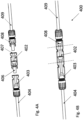
- Fig. 4A shows safety switch 402 along with connectors 408 and 403 prior to connecting, according to illustrative embodiments, while Fig. 4B shows connection point 400 comprising safety switch 402 connected to connectors 408 and 403 (the component boundaries indicated by dashed lines).
- safety switch 402 may be built into connector 403 or connector 408 of a PV generator, providing safety switching functionality in a PV generator without necessitating additional components and connections. Integrating safety switches in PV generator connectors or junction boxes may reduce costs (e.g. by not requiring a separate enclosure and connectors for the safety switch) and simplify installation (since no additional components need be connected).
- PV string 500 may be part of a string of PV generators 101 (e.g. part of a string similar to or the same as PV string 104 of Fig. 1A , comprising generators similar to or the same as PV generators 101 of Fig. 1A and Fig. 2 ) connected to each other via connection points 400.
- Connection points 400 may be similar to or the same as connection point 400 of Fig. 4A and Fig. 4B , and may include a safety switch (e.g. safety switch 402) coupled in between two PV generator connectors (e.g. connectors 403 and 408).
- Each PV generator 101 may comprise conductors 404 and 409 for carrying photovoltaic power from PV cells comprising the PV generator, and connectors 403 and 408 for connecting to safety switch 402.
- PV generator 101 may comprise junction box 511 and conductors 404 and 409.
- Fig. 5B may illustrate the back side on a PV generator, with PV cells mounted on the front side of the PV generator (not explicitly shown).
- PV cells may be mounted on both sides of the PV generator, or the back side of the PV generator may be constructed to allow solar irradiance to reach the PV cells from both sides of the PV generator.
- Junction box 511 may comprise electrical connections 512 and 513 for collecting photovoltaic power from the PV cells, and providing the photovoltaic power via conductors 409 and 404.
- safety switch 502 may be disposed between conductor 404 and electrical connection 512.
- Safety switch 502 may be functionally similar or the same as safety switch 302 of Fig. 3 , without requiring the physical enclosure and male and female connectors 306 and 307.
- Transistor Q1, diode D31, sensor(s)/sensor interfaces 510, controller 503, communication device 505 and/or auxiliary power circuit 504 may be integrated in junction box 511.
- a resistor may be coupled across the terminals of transistor Q1 (similarly to resistor R31 of Fig. 3 ) for regulating the OFF-state current through safety switch 502.
- auxiliary power circuit 504 may be coupled between conductors 404 and 409 for receiving photovoltaic power generated by PV generator 101, and may provide power to controller 503, communication device 505 and/or sensor(s)/sensor interfaces 510.
- junction box 511 may further include an integrated PV power device similar to or the same as PV power device 903 of Fig. 9 .
- PV power device 903 may be coupled between conductors 404 and 409 and electrical connections 512 and 513.
- power converter 900 of Fig. 9 may receive power from electrical connections 512 and 513, and may output power to conductors 404 and 409.
- Safety switch 502 may be disposed between PV power device 903 and electrical connection 512, or, in some embodiments, may be integrated into PV power device 903.
- Fig. 6 shows a method for operating a safety switch (e.g. safety switch 102 of Fig. 1A , safety switch 302 of Fig. 3 ).
- Method 600 may be carried out by a controller similar to or the same as controller 303 of Fig. 3 .
- the initial condition may be that the switch is in the ON state, allowing current to flow between the two conductors coupled to the switch (e.g. conductors 404 and 409 of Fig. 5A ).
- an auxiliary power circuit coupled to the safety switch may provide power to the controller and/or a gate driver for maintaining the switch in the ON state (for example, some types of transistors implementing safety switches may be "normally OFF", in which case the auxiliary power circuit may power a voltage signal applied to a transistor gate node to maintain the ON state).
- the controller may receive a command to turn the switch to the OFF state.
- the command may be received via a communication device (e.g. communication device 305) in communication with a system control device.
- the controller may independently determine that an unsafe condition may be present (e.g.
- a determination that the switch should be turned to the OFF state may be made in response to not receiving a signal.
- a system control device continuously provides a "keep alive" signal to associated safety switches and PV power devices. Not receiving a "keep alive" signal may indicate a potentially unsafe condition and may cause a determination that the switch should be turned to the OFF state.
- the controller turns the switch to the OFF state.
- turning the switch to the OFF state may include applying a voltage to a transistor terminal
- turning the switch to the OFF state may include ceasing to apply a voltage to a transistor terminal.
- the controller waits to receive a command to turn the switch back to the ON position.
- a system control device may provide a signal indicating that it is safe to reconnect PV generators and to resume providing power.
- the controller may independently determine that it is safe to return the switch to the ON position (e.g., due to a sensor reporting that the unsafe condition is no longer present).
- the controller determines if a command (or, in some embodiments, a self-determination) to turn the switch to the ON state has been received. If no such command (or determination) has been received, the controller carrying out method 600 returns to step 604. If a command (or, in some embodiments, a self-determination) to turn the switch to the ON state has been received, the controller carrying out method 600 proceeds to step 606, turns the switch back to the ON state (e.g. by applying a voltage to a transistor node, or removing an applied voltage from a transistor node) and returns to step 601.
- auxiliary circuit for providing continuous power supply to a safety switch may be variously implemented.
- Auxiliary power circuits may provide power for operating a safety switch under varying conditions and at various times.
- auxiliary power circuits may provide operational power to a safety switch at three times: at initial startup (i.e. when the system comprising a safety switch is first deployed), at steady-state ON time (i.e. when the system is up and running, during normal operating conditions, when the switch is ON), and at steady-state OFF time (i.e. when the system is up and running, during a potentially unsafe condition, when the switch is OFF).
- Safety switch 702a may comprise conductors 708 and 709, transistor Q1, controller 710 and auxiliary power circuit 704.
- Safety switch 702a may further comprise a communication device similar to or the same as communication device 305 of Fig. 3 (not explicitly depicted, to reduce visual noise).
- Transistor Q1 may be similar to or the same as transistor Q1 described with regard to Fig. 3
- resistor R31 may be the same as R31 of Fig. 3
- diode D31 may be the same as D31 of Fig. 3
- controller 710 may be similar to or the same as controller 303 of Fig. 3
- conductors 708 and 709 may be similar to or the same as conductors 308 and 309, respectively, of Fig. 3 .
- Auxiliary power circuit 704 may be coupled in parallel to transistor Q1.
- a first input of auxiliary power circuit 704 may be coupled to conductor 708, and a second input of auxiliary power circuit 704 may be coupled to conductor 709.
- auxiliary power circuit 704 may comprise analog circuitry configured to provide an appropriate control signal to transistor Q1. In some embodiments, auxiliary power circuit 704 may provide power to controller 710, with controller 710 configured to provide a control signal to transistor Q1.
- Safety switch 702b may comprise conductors 708 and 709, transistor Q1, controller 710 and auxiliary power circuit 714.
- Safety switch 702b may further comprise a communication device similar to or the same as communication device 305 of Fig. 3 (not explicitly depicted, to reduce visual noise).
- Transistor Q1 may be similar to or the same as transistor Q1 described with regard to Fig. 3
- resistor R31 may be the same as R31 of Fig. 3
- diode D31 may be the same as D31 of Fig. 3
- controller 710 may be similar to or the same as controller 303 of Fig. 3
- conductors 708 and 709 may be similar to or the same as conductors 308 and 309, respectively, of Fig. 3 .
- Auxiliary power circuit 714 may be coupled in series with transistor Q1.
- a first input of auxiliary power circuit 714 may be coupled to conductor 708, and a second input of auxiliary power circuit 704a may be coupled to transistor Q1.
- auxiliary power circuit 704a may be used as auxiliary power circuit 704 of Fig. 7A .
- a first input to auxiliary power circuit 704a may be coupled to the source terminal of a transistor (e.g. Q1 of Fig. 7A ), and a second input to auxiliary power circuit 704a may be coupled to the drain terminal of a transistor.
- An output of auxiliary power circuit 704a may be coupled to the gate terminal of a transistor.
- Auxiliary power circuit 704a may comprise Ultra Low Voltage Direct-Current to Direct Current (DC/DC) converter (ULVC) 720.
- DC/DC Direct-Current to Direct Current
- Controller 710 may be an analog or digital controller, and may be similar to controller 303 of Fig. 3 . Controller 710 may be integrated with or separate from auxiliary power circuit 304a. In some embodiments, an output of ULVC 720 may be coupled to an input of controller 710, with controller 710 applying a voltage to the gate of a transistor. ULVC 720 may be configured to receive a very low voltage (e.g. tens or hundreds of millivolts) at its input, and output a substantially larger voltage (e.g. several volts). ULVC 720 may be variously implemented. In some embodiments, ULVC may comprise an oscillator charge pump and/or several conversion stages.
- auxiliary power circuit 704a may be coupled as described above to the terminals of a MOSFET.
- ULVC 720 may be coupled between the source (Vs) and drain (Vd) terminals of the MOSFET. When the MOSFET is in the OFF position, the voltage drop between terminals Vs and Vd may be substantial, e.g. close to the open-circuit voltage of a PV generator.
- ULVC 720 When the MOSFET is in the OFF position, ULVC 720 may be bypassed or disabled, with the substantial voltage drop between terminals Vs and Vd processed to provide power to controller 710. Controller 710 may hold the voltage between the MOSFET gate and source terminals to a low value, (e.g. 0V or 1V, under a minimum source-gate threshold of 2V), maintaining the MOSFET in the OFF position.
- a low value e.g. 0V or 1V, under a minimum source-gate threshold of 2V
- controller 710 may receive a command via a communication circuit (not explicitly depicted) to turn the MOSFET to the ON state. Controller 710 may increase the gate-to-source voltage to about 5V. In illustrative PV systems, the current flowing through a PV string at certain points of operation may be about 10A. At a gate-to-source voltage of 5V and drain-to-source current of 10A, the drain-to-source voltage may be about 90mV.
- ULVC 720 may boost the drain-to-source voltage of 90mV to a voltage of several volts or more (e.g. 5V, 10V, 12V or 20V) for powering controller 710.
- Controller 710 may continuously hold the gate-to-source voltage at about 5V until a command is received to turn the MOSFET OFF.
- the MOSFET is turned OFF at the end of every day, i.e. when PV generators cease producing significant power due to nightfall.
- controller may decrease the gate-to-source voltage back to about 0V or 1V.
- auxiliary power circuit 704a may provide several advantages.
- the steady-state voltage across safety switch 702a may be substantially constant when in the ON position (e.g. 90mV).
- auxiliary power circuit 704b may be used as auxiliary power circuit 704 of Fig. 7A .
- a first input to auxiliary power circuit 704b may be coupled to the source terminal of a transistor (e.g. Q1 of Fig. 7A ), and a second input to auxiliary power circuit 704b may be coupled to the drain terminal of a transistor.
- An output of auxiliary power circuit 704b may be coupled to the gate terminal of a transistor.
- Auxiliary power circuit 704b may comprise capacitor C2, diode D2, diode Z2, transistor Q70 and DC-to-DC converter 721.
- capacitor C2 may be replaced by a different charge device (e.g. a battery).
- Controller 710 may be analog or digital, and may be similar to controller 303 of Fig. 3 . Controller 710 may be integrated with or separate from auxiliary power circuit 304a.
- Diode Z2 may be a Zener diode designed to limit and hold a reverse-bias voltage to a predetermined value. In this illustrative embodiment, diode Z2 is assumed to have a reverse-bias voltage of 4V.
- a first input to auxiliary power circuit 704b may be coupled to the source terminal of a transistor (e.g. Q1 of Fig.
- auxiliary power circuit 704b may be coupled to the drain terminal of a transistor (e.g. Q1).
- An output of auxiliary power circuit 704b may be coupled to the gate terminal of a transistor (e.g. Q1).
- an output of converter 721 may be coupled to an input of controller 710, with controller 710 applying a voltage to the gate of a transistor.
- Converter 721 may be configured to receive a voltage of several volts (e.g. between 3V-10V) at its input, and output a voltage for powering controller 710 or controlling the gate voltage of a transistor gate terminal.
- the anode of diode D2 may be coupled to a transistor drain terminal (Vd), and the cathode of diode D2 may be coupled to the cathode of diode Z2 and a first terminal of capacitor C2.
- the anode of diode Z2 may be coupled to a drain terminal of transistor Q70, with the source terminal of transistor Q70 coupled to a transistor source terminal (Vs) and to a second terminal of capacitor C2.
- the gate voltage of transistor Q70 may be controlled by controller 710 (the control line is not explicitly depicted).
- the inputs of converter 721 may be coupled in parallel with capacitor C2.
- Auxiliary power circuits 704a-b and 714 may be operated to provide a voltage drop across the terminals of safety switch 702 according to safety and effective system operation requirements.
- the drain-to-source voltage may be desired to be low during normal system operation, when safety switch 702 is in the "steady ON state", i.e. when the switch provides a low-impedance path for photovoltaic power to flow through a PV string.
- safety switch 702 When safety switch 702 is in a "steady OFF state", safety switch 702 may be required to provide a drain-to-source voltage of about an open-circuit voltage of a PV generator without providing a low-impedance path for current flow.
- controller 710 may operate transistor Q70 and transistor Q1 of Fig. 7A to provide a voltage drop across the terminals of safety switch 702 according to safety and effective system operation requirements.
- transistors Q1 and Q70 may be held in the OFF state.
- transistor Q1 may be ON, providing a low impedance path between the drain and source terminals, and transistor Q70 may be either ON or OFF. It may be desirable during the "steady ON state” to temporarily move Q1 to the "temporarily OFF state” for a short period of time, to allow capacitor C2 to recharge and continue providing operational power to controller 710.
- transistor Q1 may be OFF and transistor Q70 may be ON.
- Diode Z2 may provide a limited charging voltage (e.g. 4V) across the terminals of capacitor C2, with capacitor C2 providing a current path for the current of a PV string.
- auxiliary power circuit 704a may be coupled as described above to the terminals of a MOSFET.
- Converter 721 may be coupled between the source (Vs) and drain (Vd) terminals of the MOSFET.
- Vs source
- Vd drain
- the voltage drop between terminals Vs and Vd may be substantial, e.g. close to the open-circuit voltage of a PV generator.
- converter 721 When the MOSFET is in the steady-OFF-state, converter 721 may be bypassed or disabled, with the substantial voltage drop between terminals Vs and Vd processed to provide power to controller 710. In some embodiments, when the MOSFET is in the steady-OFF-state, converter 721 may process the drain-to-source voltage to provide power to controller 710. Controller 710 may hold the voltage between the MOSFET gate terminal and source terminals to a low value, (e.g. 0V or 1V, under a minimum source-gate threshold of 2V), maintaining the MOSFET in the OFF position. When the MOSFET is in the steady-OFF-state, capacitor C2 may be charged to about the voltage between the drain and source terminals.
- a low value e.g. 0V or 1V, under a minimum source-gate threshold of 2V
- diode Z2 may be disconnected (e.g. by turning Q70 to the OFF state), to increase the drain-to-source voltage when the MOSFET is in the steady-OFF-state.
- having a large drain-to-source voltage e.g. about the same voltage as a PV generator open-circuit voltage
- increases system safety by decreasing the total voltage across a PV generator and an accompanying safety switch.
- controller 710 may receive a command via a communication circuit (not explicitly depicted) to turn the MOSFET to the ON state. Controller 710 may increase the gate-to-source voltage of Q1 to about 6V.
- the current flowing through a PV string at certain points of operation may be about 10A.
- the drain-to-source voltage may be about 65mV.
- Diode D2 might not be forward biased (e.g., if diode has a forward voltage of 0.6V, a drain-to-source voltage of 65mV might not forward-bias diode D2), disconnecting capacitor C2 from the drain terminal.
- Capacitor C2 may slowly discharge by providing power to converter 721.
- Converter 721 may include circuitry (e.g. analog comparators) to monitor the voltage across capacitor C2, and may respond to the voltage across capacitor C2 falling below a first threshold. If the voltage across capacitor falls below the first threshold, controller 710 may reduce the gate-to-source voltage to about 0V or 1V, resulting in the MOSFET moving to the OFF state. Diode D2 may then become forward-biased, and diode Z2 may limit the drain-to-source voltage to a second threshold. Transistor Q70 may be held in the ON state, allowing diode Z2 to regulate the drain-to-source voltage.
- Capacitor C2 may then be rapidly charged back to about the voltage level of the second threshold, with controller 710 configured to increase the gate-to-source voltage back to 6V when capacitor C2 reaches the second threshold voltage.
- This iterative process may repeat itself while the MOSFET is operating in a "steady ON state" mode.
- the first threshold is 2V
- the second threshold is 4V.
- the voltage across capacitor C2 varies between the two levels, with the gate-to-source voltage alternating between about 0V and about 6V, and the drain-to-source voltage alternating between 4V and 65mV.
- Operating auxiliary power circuit 704b may provide several advantages.
- a converter designed to receive an input voltage between 2 - 30V e.g. converter 721
- one or more additional Zener diodes may be coupled in series with diode Z2, increasing the first voltages.
- Increasing the first threshold voltage e.g. to 10V, 15V or 20V, respectively
- illustrative operating points comprising MOSFET drain-to-source voltages of 65mV and 90mV, MOSFET gate-to-source voltages of 5V and 6V, and MOSFET drain-to-source currents of 10A are used for illustrative purposes and are not intended to be limiting of operating points used in conjunction with illustrative embodiments disclosed herein.
- multiple MOSFET transistors may be parallel-coupled to reduce ON-state resistance, thereby reducing the drain-to-source voltage across MOSFETs when in the ON state. For example, coupling five MOSFETs in parallel may reduce a drain-to-source ON-state voltage from 65mV to 15mV.
- auxiliary power circuit 704c may be used as auxiliary power circuit 704 of Fig. 7A .
- Auxiliary power circuit 704c may be similar to auxiliary power circuit 704b, with a modification in that the anode of diode Z2 is coupled to the drain terminal of transistor Q1 (Vs), and that the drain terminal of transistor Q70 is also coupled to the source terminal of transistor Q1 (Vs).
- safety switch 702 is in the "steady ON state"
- transistors Q1 and Q70 may be ON, providing a low impedance path for PV string current.
- transistors Q1 and Q70 When safety switch 702 is in the "steady OFF state", transistors Q1 and Q70 may be OFF, preventing a low impedance path for a PV string current, and providing a substantial voltage drop across the terminals of safety switch 702 (e.g. about the same voltage or a slightly lower voltage than a PV-generator open-circuit voltage).
- transistor Q1 When safety switch 702 is in the "temporarily OFF state”, transistor Q1 may be OFF and transistor Q70 may be ON, diode Z2 providing a charging voltage to capacitor C2 and Q70 providing a low-impedance current path for a PV string current.
- Safety switch 702c may comprise conductors 708 and 709, transistor Q1, controller 710 and auxiliary power circuit 715.
- Auxiliary power circuit 715 may be used auxiliary power circuit 714 of Fig. 7B .
- auxiliary power circuit 715 may double as a power line communication (PLC) device.
- Inductor L4, capacitor C3 and resistor R may be coupled in parallel, with a first node of inductor L4 coupled to conductor 708, and a second node of inductor L4 coupled to the source terminal of transistor Q1.
- the values of inductor L4 and capacitor C3 may be selected to resonate at a resonant frequency (e.g. 60kHz).
- an external device may transmit a PLC high-frequency alternating current signal (e.g. using frequency shift keying, amplitude modulation or other modulation schemes) over conductor 708.
- the PLC signal may induce a high-frequency alternating-current voltage drop across the terminals of resistor R, with diode D7 providing a voltage to controller 710 when the voltage across resistor R is positive (i.e. the voltage at conductor 708 is higher than the voltage at the source terminal of transistor Q1).
- diode D7 may be replaced by a "full bridge" of diodes providing a voltage to controller 710 when the voltage across R is nonzero (either positive or negative).
- the PLC-induced voltage across resistor R may serve a dual purpose.
- the PLC signal may provide operational information to controller 710 by varying the voltage drop across resistor R .
- the PLC signal may provide operational power to controller 710.
- Controller 710 may draw power from the resonant circuit comprising resistor R, capacitor C3 and inductor L4, and use the drawn power to set the state of transistor Q1.
- auxiliary power circuit 715 may double as a communication device, reducing the total component count in safety switch 702c.
- integrating control and power signals may reduce the complexity required to program controller 710.
- an 'ON' signal may be broadcast by a system controller at a high power
- an 'OFF' signal may be broadcast by a system controller at low power.
- Auxiliary power circuit 715 may directly apply the converted power signal to the gate of transistor Q1, wherein the power of the 'ON' signal may be sufficient to hold Q1 in the ON state, and the power of the 'OFF' signal might not be sufficient to hold Q1 in the ON state.
- auxiliary power circuits 704a, 704b and 715 may be variously combined.
- auxiliary power circuit 714 of Fig. 7B may be added to safety switch 702a of Fig. 7A , auxiliary power circuit 714 functioning as a PLC circuit as well as being configured to provide power to controller 710 in case of a malfunction in auxiliary power circuit 704.
- auxiliary power circuit 714 may provide initial power to controller 710 at system setup, with auxiliary power circuit 704 providing power to controller 710 during "steady state" operation.
- Fig. 71 illustrates part of a MOSFET datasheet according to an illustrative embodiment.
- Plot 770 may depict relationships between drain-to-source voltage and drain-to-source current through a MOSFET.
- Curve 771 may depict a current-voltage relationship when the gate-to-source voltage applied to a MOSFET is 5V.
- Curve 771 may depict a current-voltage relationship when the gate-to-source voltage applied to a MOSFET is 6V.
- Operating point A may indicate that when a gate-to-source voltage applied to a MOSFET is 6V and the drain-to-source current flowing through the MOSFET is 10A, the drain-to-source voltage across the MOSFET is about 65mV.
- Operating point B may indicate that when a gate-to-source voltage applied to a MOSFET is 5V and the drain-to-source current flowing through the MOSFET is 10A, the drain-to-source voltage across the MOSFET is about 90mV. This may correspond to a possible operating point for a MOSFET operated according to Fig. 7D . As noted above, these operating points are illustrative only, and may adapted by connected multiple MOSFETs in parallel to obtain new operating points.
- PV system 800 may comprise a plurality of PV strings 804 coupled in parallel between a ground bus and a power bus.
- Each of PV strings 804 may comprise a plurality of photovoltaic generators 801, a plurality of safety switches 802 and a plurality of PV power devices 803.
- PV generators 801 may be similar to or the same as PV generators 101 of Fig. 1A
- safety switches 802 may be similar to or the same as safety switch 102 of Fig. 1A , safety switch 302 of Fig. 3 and/or safety switches 702a-702c of Figs. 7A-7C .
- system power device 810 may include a DC/AC inverter and may output alternating current (AC) power to a power grid, home or other destinations.
- system power device 810 may comprise a combiner box, transformer and/or safety disconnect circuit.
- system power device 810 may comprise a DC combiner box for receiving DC power from a plurality of PV strings 804 and outputting the combined DC power.
- system power device 810 may include a fuse coupled to each PV string 804 for overcurrent protection, and/or one or more disconnect switches for disconnecting one or more PV strings 804.
- system power device 810 may comprise a system controller (e.g.
- an analog control circuit for providing commands to and receiving data from PV power devices 803 and safety switches 802.
- DSP Digital Signal Processor
- ASIC Application-Specific Integrated Circuit
- FPGA Field Programmable Gate Array
- Each safety switch 802 may be coupled between a first output of a first PV generator and a second output of a second output generator, and each PV power device may have two input terminals: a first input terminal coupled to the second output of the first PV generator, and a second input terminal coupled to the first output of the second PV generator.
- each pair of PV generators 801 are effectively coupled in series, with the combined voltage and power of the two PV generators provided to the input of PV power device 803.
- Each safety switch 802 is disposed between the two PV generators, for disconnecting the pair of PV generators in case of a potentially unsafe condition.
- PV power device 803 may stop drawing power from the PV generators, resulting in an open-circuit voltage at the PV power device input terminals which is about double the open-circuit voltage of each PV power generator.
- This voltage may, in some systems, be as high as 80, 100 or even 120 volts, which may be higher than the allowed safe voltage defined by safety regulations.
- one or more safety switches 802 may move to the OFF state, reducing the voltage drop between the input terminals of each PV power device 803 to about 40-60 volts, which may be an adequately safe voltage level.
- Each PV power device 803 may receive power from two photovoltaic generators 801 coupled to the inputs of PV power device 803, and may provide the combined power of the two photovoltaic generators at the outputs of PV power device 803.
- the outputs of a plurality of PV power devices 803 may be coupled in series to form a PV string 804, with a plurality of PV strings 804 coupled in parallel to provide power to system power device 810.
- Fig. 8 illustrates an arrangement wherein two PV generators 801 are coupled in parallel to each PV power device 803, various arrangements can be easily obtained.
- each PV power device receive power from three or more serially-connected PV generators 801, with safety switches 802 disposed between the PV generators.
- some PV power devices 803 may receive power from a single PV generator 801, some PV power devices may receive power from two PV generators 801, and some PV power devices may receive power from more than two PV generators 801.
- PV power devices 803 may receive power from multiple parallel-connected serial strings of PV generators 801, with safety switches 802 disposed in the serial strings.
- Embodiments disclosed herein include the aforementioned modifications, and other modifications which will be evident to one of ordinary skill in the art.
- PV power device 903 may be similar to or the same as PV power device 803 of Fig. 8 .
- PV power device 903 may include power converter 900.
- Power converter 900 may comprise a direct current-direct current (DC/DC) converter such as a Buck, Boost, Buck/Boost, Buck + Boost, Cuk, Flyback and/or forward converter.
- power converter 900 may comprise a direct current - alternating current (DC/AC) converter (also known as an inverter), such a micro-inverter.
- DC/DC direct current-direct current
- DC/AC direct current - alternating current
- Power converter 900 may have two input terminals and two output terminals, which may be the same as the input terminals and output terminals of PV power device 903.
- PV power device 903 may include Maximum Power Point Tracking (MPPT) circuit 906, configured to extract increased power from a power source the power device is coupled to.
- MPPT circuit 906 may implement impedance matching algorithms to extract increased power from a power source the power device is coupled to.
- PV power device 903 may further comprise controller 905 such as a microprocessor, Digital Signal Processor (DSP), Application-Specific Integrated Circuit (ASIC) and/or a Field Programmable Gate Array (FPGA).
- DSP Digital Signal Processor
- ASIC Application-Specific Integrated Circuit
- FPGA Field Programmable Gate Array
- PV power device 903 may include circuitry and/or sensors/sensor interfaces 904 configured to measure parameters directly or receive measured parameters from connected sensors and/or sensor interfaces 904 configured to measure parameters on or near the power source, such as the voltage and/or current output by the power source and/or the power output by the power source.
- the power source may be a PV generator comprising PV cells, and a sensor or sensor interface may directly measure or receive measurements of the irradiance received by the PV cells, and/or the temperature on or near the PV generator.
- PV power device 903 may include communication device 911, configured to transmit and/or receive data and/or commands from other devices.
- Communication device 911 may communicate using Power Line Communication (PLC) technology, or wireless technologies such as ZigBee TM , Wi-Fi, cellular communication or other wireless methods.
- PV power device 903 may include memory device 909, for logging measurements taken by sensor(s)/sensor interfaces 904 to store code, operational protocols or other operating information.
- Memory device 909 may be flash, Electrically Erasable Programmable Read-Only Memory (EEPROM), Random Access Memory (RAM), Solid State Devices (SSD) or other types of appropriate memory devices.
- EEPROM Electrically Erasable Programmable Read-Only Memory
- RAM Random Access Memory
- SSD Solid State Devices
- PV power device 903 may include safety devices 907 (e.g. fuses, circuit breakers and Residual Current Detectors).
- Safety devices 907 may be passive or active.
- safety devices 907 may comprise one or more passive fuses disposed within PV power device 903 and designed to melt when a certain current flows through it, disconnecting part of PV power device 903 to avoid damage.
- safety devices 907 may comprise active disconnect switches, configured to receive commands from a controller (e.g. controller 905, or an external controller) to disconnect portions of PV power device 903, or configured to disconnect portions of PV power device 903 in response to a measurement measured by a sensor (e.g.
- PV power device 903 may comprise auxiliary power circuit 908, configured to receive power from a power source coupled to PV power device 903, and output power suitable for operating other circuitry components (e.g. controller 905, communication device 911, etc.). Communication, electrical coupling and/or data-sharing between the various components of PV power device 903 may be carried out over common bus 920.
- PV power device 903 may comprise transistor Q9 coupled between the inputs of power converter 900.
- Transistor Q9 may be controlled by controller 905. If an unsafe condition is detected, controller 905 may set transistor Q9 to ON, short-circuiting the input to power converter 900.
- Transistor Q9 may be controlled in conjunction with safety switch 802 of Fig. 8 . When safety switch 802 and transistor Q9 are OFF, each pair of PV generators 801 of Fig. 8 are disconnected, each PV generator providing an open-circuit voltage at its output terminals. When safety switch 802 and transistor Q9 are ON, each pair of PV generators 801 of Fig.
- the pair of PV generators providing a voltage of about zero to power converter 900.
- a safe voltage at all system locations may be maintained, and the two scenarios may be staggered to alternate between open-circuiting and short-circuiting PV generators.
- This mode of operation may allow continuous power supply to system control devices, as well as provide backup mechanisms for maintaining a safe voltage (i.e. in case a safety switch 802 malfunctions, operation of transistor Q9 may allow continued safe operating conditions).
- PV system 1000 may comprise a plurality of PV strings 1004 coupled in parallel between a ground bus and a power bus.
- Each of PV strings 1004 may comprise a plurality of photovoltaic generators 1001 and a plurality of PV power devices 1003.
- PV generators 1001 may be similar to or the same as PV generators 801 of Fig. 8 .
- the power and ground buses may be input to system power device 1010, which may be similar to or the same as system power device 810 of Fig. 8 .
- Each of photovoltaic power devices 1003 may comprise four input terminals: T1, T2, T3 and T4.
- T1 and T2 may be coupled to and receive power from a first PV generator
- T3 and T4 may be coupled to and receive power from a second PV generator.
- PV power device 1003 may be substantially the same as PV power device 803 of Fig. 8 , with the addition of safety switch 802 integrated into PV power device 1003 and connected in between terminals T2 and T3 of PV power device 1003.
- PV power device 1103a may be used as PV power device 1003 of Fig. 10 .
- PV power device 1103a may comprise a PV power device similar to or the same as PV power device 803 of Fig. 8 or PV power device 903 of Fig. 9 .
- PV power device 1103a will be assumed to comprise PV power device 903 of Fig. 9 .
- PV power device 1103a may comprise transistors Q3, Q4 and Q5.
- Transistors Q3-Q5 may be MOSFETs, JFETs, IGBTs, BJTs or other appropriate transistors.
- transistors Q3-Q5 will be assumed to be MOSFETs.
- Transistor Q3 may be connected between input terminals T2 and T3.
- Transistor Q4 may be connected between input terminals T2 and T4.
- Transistor Q1 may be connected between input terminals T1 and T3.
- Transistors Q3-Q5 may be controlled (e.g. have gate signals provided) by one or more controllers such as controller 905 of PV power device 903.
- the elements comprising PV power device 1103a may be jointly enclosed by enclosure 1108.
- a first PV generator (not explicitly depicted) may be coupled between terminals T1 and T2, and a second PV generator (not explicitly depicted) may be coupled between terminals T3 and T4.
- transistor Q3 may be ON, and transistors Q4 and Q5 may be OFF.
- the two photovoltaic generators may be serially connected, with the combined serial voltage of the two PV generators provided between terminals T1 and T4.
- the controller controlling transistor Q3 may turn Q3 to the OFF state, reducing the voltage drop between terminals T1 and T4.
- controller(s) controlling transistors Q4 and Q5 may switch Q4 and Q5 to the ON state when Q3 is OFF, resulting in terminal T1 being short-circuited to terminal T3, and terminal T2 being short-circuited to terminal T4.
- the first and second photovoltaic generator may be coupled in parallel between terminal T1 and T4, allowing PV power device 903 to draw power from the PV generators (e.g. for powering devices such as controller 905, communication device 911, auxiliary power circuit 908 and other devices depicted in Fig. 9 ).
- Q4 or Q5 might not be included in PV power device 1103a.
- Q4 might not be included, in which case by turning Q5 to the ON position when Q3 is OFF, power is provided to PV power device 903 by a single PV generator (coupled between T3 and T4).
- Q5 might not be included, in which case by turning Q4 to the ON position when Q3 is OFF, power is provided to PV power device 903 by a single PV generator (coupled between T1 and T2).
- PV power device 1103b may be used as PV power device 1003 of Fig. 10 .
- PV power device 1103b may comprise a PV power device similar to or the same as PV power device 803 of Fig. 8 or PV power device 903 of Fig. 9 .
- PV power device 1103a will be assumed to comprise PV power device 903 of Fig. 9 .
- Transistor Q6 may be similar to or the same as transistor Q3 of Fig. 11A .
- PV power device 1103b may further comprise diodes D3 and D4.
- the anode of diode D3 may be coupled to terminal T3 and the cathode of diode D3 may be coupled to the positive input of PV power device 903 at node N1.
- the anode of diode D4 may be coupled to terminal T1 and the cathode of diode D3 may be coupled to the positive input of PV power device 903 at node N1.
- the elements comprising PV power device 1103b may be jointly enclosed by enclosure 1108.
- a first PV generator (not explicitly depicted) may be coupled between terminals T1 and T2, and a second PV generator (not explicitly depicted) may be coupled between terminals T3 and T4.
- transistor Q3 may be ON, connecting terminals T2 and T3.
- the voltage at terminal T1 may be higher than the voltage at terminal T2 (e.g. if the positive output of a PV generator is coupled to terminal T1 and the negative output of the PV generator is coupled to terminal T2), so diode D4 may be forward-biased and diode D3 may be reverse-biased.
- the voltage at node N1 may be about the voltage at terminal T1 (assuming an insignificant voltage drop across diode D4), resulting in a voltage input to PV power device 903 about equal to the voltage between terminals T1 and T4.
- the controller controlling transistor Q6 may turn Q6 to the OFF state, disconnecting the coupling of terminals T2 and T3.
- the voltage at node N1 may be the voltage at terminal T1 or the voltage at terminal T3, the greater of the two. While the voltage at node N1 might not be predetermined, in either possible scenario, a PV generator may be coupled to the inputs of PV power device 903, providing power to PV power device 903 (e.g. for powering devices such as controller 905, communication device 911, auxiliary power circuit 908 and other devices depicted in Fig. 9 ).
- PV system 1200 may comprise a plurality of PV strings 1204 coupled in parallel between a ground bus and a power bus.
- Each of PV strings 1204 may comprise a plurality of photovoltaic generators 1201, a pliurality of safety switches 1202 and a plurality of PV power devices 1203.
- PV generators 1001 may be similar to or the same as PV generators 801 of Fig. 8 .
- the power and ground buses may be input to system power device 1210, which may be similar to or the same as system power device 810 of Fig. 8 .
- Each PV power device 1203 may be designed to be coupled to more than one PV power generator 1201.
- each PV power device 1203 (except for the PV power devices coupled to the power bus) is coupled to two PV power generators and to two safety switches 1202, with each safety switch 1202 (except for the safety switch 1202 which is coupled to the ground bus) coupled to two PV generators 1201 and two PV power devices 1203.
- each PV power device 1203 may receive power from two PV generators 1201, and may forward the power along PV string 1204 towards the power bus.
- each safety switch 1202 may provide a connection between two PV generators 1201 and may provide a connection between two PV power devices 1203 for forwarding power along PV string 1204.
- safety switch 1202a provides a connection between PV generators 1201a and 1201b.
- PV power device 1203a may receive power generated by PV generators 1201a and 1201b, with safety switches 1202b disposed between PV power devices 1203a and 1203b, providing PV power device 1203a with a connection for forwarding power to PV power device 1203b.
- safety switch 1202b provides a connection between PV generators 1201c and 1201d, with PV power device 1203b receiving power from PV generators 1201c and 1201d.
- safety switch 1202a may be operated to disconnect PV generator 1201a from PV generator 1201b, and to disconnect PV power device 1203a from the ground bus.
- safety switch 1202b may be operated to disconnect PV generator 1201c from PV generator 1201d, and to disconnect PV power device 1203a PV power device 1203b. Operating safety switches 1202 in this manner may reduce the voltage in various locations in PV system 1200 to safe voltage levels.
- Safety switch 1205 may comprise terminals T1-T4, transistors (e.g. MOSFETs) Q7 and Q8, capacitors C4 and C5, and inductors L4 and L5.
- Inductor L4 may be provided between terminal T3 and terminal T1 to reduce ripples and/or spikes in a current flowing from terminal T1 to terminal T3, and inductor L5 may be provided between terminal T4 and midpoint node X to reduce ripples and/or spikes in a current flowing from transistor Q7 to terminal T4.
- inductors L4 and L5 might not be provided.
- transistors Q7 and Q8 may be replaced by alternative switching elements, such as IGBTs, BJTs, JFETs or other switching elements.
- Capacitor C4 may be coupled between terminals T1 and T2.
- Transistor Q7 may be coupled between terminal T2 and midpoint node X
- capacitor C5 may be coupled between terminal T1 and midpoint node X.
- Transistor Q8 may be coupled in parallel to capacitor C5, between terminal T1 and midpoint node X. In some embodiments, capacitor C5 and/or capacitor C4 might not be provided.
- transistor Q7 may be held in the ON state, and transistor Q8 may be in the OFF state.
- Capacitor C5 may then be in parallel with capacitor C4, and a first PV generator may be coupled between terminals T1 and T2, applying a voltage to capacitors C4 and C5 and providing electrical power at terminals T1 and T2.
- Terminal T4 may be coupled to an output terminal of a second PV generator, and terminal T3 may be coupled to an input terminal of a PV power device 1203.
- the power input to safety switch 1205 at terminals T1 and T2 may be output at terminals T3 and T4 to the second PV generators and the PV power device 1203.
- Transistors Q7 and Q8 may be controlled by a controller (not explicitly depicted) similar to or the same as controller 710 of Fig. 7A .
- the controller may be powered by capacitor C4 (e.g. a controller input power terminal may be coupled to terminal T2 or terminal T1 for receiving power from capacitor C4).
- Safety switch 1205 may further comprise a communication device (e.g. similar to or the same as communication device 305 of Fig. 3 ) for receiving operational commands from a system control device.
- the controller may switch transistor Q7 to the OFF state and transistor Q8 to the ON state.
- Capacitor C5 may be short-circuited by transistor Q8, while capacitor C4 may maintain the voltage imposed between terminals T1 and T2.
- PV power device 1203 may comprise a variation of a Buck + Boost DC/DC converter.
- the power device may include a circuit having two input terminals, denoted Vin and common, and two output terminals which output the same voltage Vout. The output voltage is in relation to the common terminal.
- the circuit may include an input capacitor Cin coupled between the common terminal and the Vin terminal, an output capacitor coupled between the common terminal and the Vout terminals.
- the circuit may include two central points used for reference.
- the circuit may include a plurality of switches (e.g.
- MOSFET transistors Q11 , Q12 , Q13 and Q14 with Q11 connected between Vin and the first central point, and Q12 connected between the common terminal and the first central point.
- Q13 may be connected between the Vout terminal and the second central point, and Q14 may be connected between the common terminal and the second central point.
- the circuit may further include inductor L6 coupled between the two central points.
- the operation of the Buck + Boost DC/DC converter in PV power device 1203 may be variously configured. If an output voltage lower than he input voltage is desired, Q13 may be statically ON, Q14 may be statically OFF, and with Q11 and Q12 being Pulse-Width-Modulation(PWM)-switched in a complementary manner to one another, the circuit is temporarily equivalent to a Buck converter and the input voltage is bucked. If an output voltage higher than he input voltage is desired, Q11 may be statically ON, Q12 may be statically OFF, and with Q13 and Q14 being PWM-switched in a complementary manner to one another, the input voltage is boosted.
- PWM Pulse-Width-Modulation
- the circuit may convert the input voltage Vin to output voltage Vout. If current is input to the circuit by the Vin and common terminals, and the voltage drop across capacitors Cin and Cout are about constant voltages Vin and Vout respectively, the currents input to the circuit are combined at inductor L6 to form an inductor current which is equal to the sum of the current input at the Vin and common terminals.
- the inductor current may contain a ripple due to the charging and discharging of capacitors Cin and Cout, but if the voltage drop across capacitors Cin and Cout are about constant, the voltage ripples over the capacitors are small, and similarly the inductor current ripple may be small.
- the inductor current may be output by the pair of output terminals Vout. In some embodiments, a single output terminal may be included, and system designers may split the output terminal externally (i.e. outside of the PV power device circuit), if desired.
- PV power device 1203 may be similar to or the same as PV power device 903 of Fig. 9 , with power converter 900 of Fig. 9 comprising the Buck + Boost converter of Fig. 13B .
- power converter 900 of Fig. 9 comprising the Buck + Boost converter of Fig. 13B .
- boosting the voltage input to a PV power device 1203 might not be necessary, in which case PV power device 1203 may comprise a Buck converter similar to the Buck + Boost converter of Fig. 13B , with switch Q14 removed (i.e. replaced by an open-circuit) and switch Q13 replaced with a wire (i.e. connecting the Vout terminal to the second central point).
- safety switch 1202b may be coupled to photovoltaic generators 1201c and 1201d, and to PV power devices 1203a and 1203b.
- Terminal T2 may be connected to the positive output of PV generator 1201c
- terminal T4 may be connected to the negative output of PV generator 1201d.
- Terminal T1 may be coupled to a first Vout terminal of PV power device 1203a
- terminal T3 may be coupled to the common terminal of PV power device 1203b.
- the positive output terminal of PV generator 1201d may be coupled to the Vin terminal of PV power device 1203b
- the negative output terminal of PV generator 1201c may be coupled to a second Vout terminal of PV power device 1203a.
- PV generators 1201c and 1201d are serially coupled, the combined voltage of PV generators 1201c and 1201d input between the common and Vin terminals of PV power device 1203b.
- safety switch 1202b may disconnect the connection between terminals T2 and T4 (e.g. by setting transistor Q7 of Fig. 13A to OFF) and couple terminals T3 and T4 (e.g. by setting transistor Q8 of Fig. 13A to ON).
- PV generator 1201d may be coupled between the common and Vin terminals of PV power device 1203b
- PV generator 1201c may be coupled between terminals T1 and T2 of safety switch 1202b.
- the system topology illustrated in Fig. 12 may provide certain advantages. For example, during normal system operation, two PV generators 1201 provide a combined voltage and power to a PV power device 1203, requiring a reduced number of PV power devices for processing power generated by the PV generators. Furthermore, continuous operational power (i.e. power used for powering device components such as controllers and transistors) is provided to all PV power devices 1203 and safety switches 1202 both during normal operations and during a potentially unsafe condition.
- continuous operational power i.e. power used for powering device components such as controllers and transistors
- Chain 1400 may comprise a plurality of PV power devices 1203 and a plurality of safety switches 1202. Each safety switch 1202 may be connected, using conductors, between two PV power devices 1203. Terminal T1 of safety switch 1202 may be connected to a Vout terminal of a first PV power device, and terminal T3 of safety switch 1202 may be connected to a common terminal of a second PV power device. Terminals T2 and T4 may be accessible via external connectors similar to or the same as connectors 406 and 407 of Fig. 4A .
- each PV power device 1203 may be accessible via external connectors similar to or the same as connectors 406 and 407 of Fig. 4A .
- Conductors connecting a PV power device terminal (e.g. the common terminal) to a safety switch terminal (e.g. terminal T3) may be sized to facilitate connecting chain 1400 to a plurality of PV generators, as depicted in Fig. 12 .
- each conductor disposed between a safety switch 1202 and a PV power device 1203 may be about 1-2 meters long.
- Chain 1400 may be assembled and sold as a single unit, saving cost and time when constructing a PV installation similar to or the same as PV system 1200 of Fig. 12 .
- an illustrative application running on a smart phone, tablet, computer, workstation, mobile device (such as a cellular device) and/or a similar computing device is shown.
- the application may provide a list of safety switches disposed in an electrical power system (e.g. PV system 100 of Fig. 1 ).
- the application may indicate a serial number or other identifying information of each safety switch, as well as identifying information of coupled PV generators and/or identifying information of a PV string each safety switch is coupled to.
- the application may indicate the state of each safety switch and/or electrical parameters of one or more safety switches, for example, the voltage across or current through one or more safety switches.
- the application may provide touch-screen buttons or similar input controllers for controlling the state of one or more switches. For example, activating a button 151 may move an associated safety switch to the OFF state, and activating a button 152 may move an associated safety switch to the ON state. Activating button 153 may move all safety switches to the OFF state, and activating button 154 may move all safety switches to the ON state. In some embodiments, activating buttons 151-154 may be restricted based on a user access level. For example, the application may enable buttons 151-154 only when running in "Installer/Administrator" mode, to restrict the actions of unsophisticated users.
- activating button 155 may enable a user to reconfigure a threshold.
- a threshold For example, an electrical voltage, current or power threshold which may be indicative of an arcing condition and trigger a system response (e.g. moving one or more safety switches to the OFF state) may be reconfigured by a user using the application of Fig. 15 .
- Activating button 156 may display a graphical layout of an electrical system represented by the application, including physical location details of one or more safety switches.
- Activating button 157 may download current or past operational system data such as the state of safety switches, and/or electrical parameter measurement measured by safety switches. Buttons 155-157 may similarly be restricted depending on the level of user authorization.
- the application of Fig. 15 may communicate directly with safety switches via wireless communications (e.g. cellular communication, or over the internet).
- the application may communicate with a system power device (e.g. system power device 110 of Fig. 1 ), with the system power device configured to relay communication between the application and the safety switches via wireless communication or wired communication (e.g. power line communication).
- photovoltaic generators are used as examples of power sources which may make use of the novel features disclosed.
- Each PV generator may comprise one or more solar cells, one or more solar cell strings, one or more solar cell substrings, one or more solar panels, one or more solar shingles, or combinations thereof.
- the power sources may include batteries, flywheels, wind or hydroelectric turbines, fuel cells or other energy sources in addition to or instead of photovoltaic generators.
- Systems, apparatuses and methods disclosed herein which use PV generators may be equally applicable to alternative systems using additional power sources, and these alternative systems are included in embodiments disclosed herein.
- PV power device circuitry of one embodiments may be combined with and/or exchanged for power device circuitry of a different embodiment.
- transistor Q9 of PV power device 903 may be disposed between electrical connections 512 and 513 of junction box 511 and operated to short-circuit the input to PV generator 101 of Fig. 5A .
- An apparatus comprising:
- Feature 2 The apparatus of feature 1, wherein the first electrical connector is designed to be connected to a photovoltaic generator and the second electrical connector is designed to be connected to a photovoltaic generator.
- Feature 4 The apparatus of any preceding feature, further comprising a communication device coupled to the controller, the communication device coupled to the controller and configured to receive a message indicating a potentially unsafe condition and provide an indication of a potentially unsafe condition to the controller.
- Feature 5 The apparatus of feature 4, wherein the communication device comprises at least one of a Power Line Communication device and a wireless communication device.
- Feature 6 The apparatus of feature 5, wherein the communication device is coupled to a power-supply terminal of the controller and is designed to provide operational power to the controller.
- Feature 7 The apparatus of any preceding feature, further comprising a sensor coupled to the controller, the sensor configured to measure one or more electrical parameters and provide one or more measurements to the controller.
- Feature 8 The apparatus of feature 7, wherein the sensor is a current sensor, and wherein the controller is configured to switch the switching element to disconnect the first electrical conductor from the second electrical conductor in response to a current measurement indicating a potentially unsafe condition.
- Feature 9 The apparatus of any preceding feature, further comprising an auxiliary power circuit coupled to the first electrical conductor and the controller, the auxiliary power circuit configured to draw power from the first electrical conductor and provide power to the controller.
- Feature 10 The apparatus of any preceding feature, further comprising a resistor coupled in parallel to the switching element.
- Feature 11 The apparatus of feature 10, wherein the resistor has resistance between 10 ⁇ and 5k ⁇ .
- a method comprising:
- Feature 13 The method of feature 12 wherein detecting comprises receiving a message via a communication device, the message indicating a potentially unsafe condition.
- Feature 14 The method of feature 12 wherein detecting comprises receiving an electrical current measurement and determining that the electrical current measurement is indicative of a potentially unsafe condition.
- Feature 15 The method of any of features 12 to 14, further comprising:
- Feature 16 The method of any of features 12 to 15, wherein the controller is one of an analog circuit, microprocessor, Digital Signal Processor (DSP), Application-Specific Integrated Circuit (ASIC) and/or a Field Programmable Gate Array (FPGA).
- DSP Digital Signal Processor
- ASIC Application-Specific Integrated Circuit
- FPGA Field Programmable Gate Array
- An apparatus comprising:
- Feature 18 The apparatus of feature 17, wherein the transistor is a Metal Oxide Semiconductor Field Effect Transistor (MOSFET), and the diode is a built-in body diode.
- MOSFET Metal Oxide Semiconductor Field Effect Transistor
- Feature 19 The apparatus of features 17 or 18, wherein the resistor has resistance between 10 ⁇ and 5k ⁇ .
- Feature 20 The apparatus of any of features 17 to 19, further comprising the first photovoltaic generator, wherein the transistor is integrated into a junction box of the first photovoltaic generator.
- An apparatus comprising:
- Feature 22 The apparatus of feature 21, wherein the first power device terminal and the second power device terminal are two input terminals to a power device comprising one of a direct-current to direct-current (DC/DC) converter or a direct-current to alternating-current (DC/AC) converter.
- DC/DC direct-current to direct-current
- DC/AC direct-current to alternating-current
- Feature 23 The apparatus of feature 21, wherein the first power device terminal is an input terminal to a first power device comprising one of a direct-current to direct-current (DC/DC) converter or a direct-current to alternating-current (DC/AC) converter, and the second power device terminal is an input terminal to a second power device comprising one of a direct-current to direct-current (DC/DC) converter or a direct-current to alternating-current (DC/AC) converter.
- DC/DC direct-current to direct-current
- DC/AC direct-current to alternating-current
- Feature 24 The apparatus of any of features 21 to 23, wherein the switching element comprises a Metal Oxide Semiconductor Field Effect Transistor (MOSFET).
- MOSFET Metal Oxide Semiconductor Field Effect Transistor
- Feature 25 The apparatus of feature 22, wherein the switching element shares an enclosure with the power device comprising one of a direct-current to direct-current (DC/DC) converter or a direct-current to alternating-current (DC/AC) converter.
- DC/DC direct-current to direct-current
- DC/AC direct-current to alternating-current
Landscapes
- Engineering & Computer Science (AREA)
- Power Engineering (AREA)
- Life Sciences & Earth Sciences (AREA)
- Sustainable Development (AREA)
- Sustainable Energy (AREA)
- Physics & Mathematics (AREA)
- Condensed Matter Physics & Semiconductors (AREA)
- Electromagnetism (AREA)
- General Physics & Mathematics (AREA)
- Computer Hardware Design (AREA)
- Microelectronics & Electronic Packaging (AREA)
- Charge And Discharge Circuits For Batteries Or The Like (AREA)
- Emergency Protection Circuit Devices (AREA)
- Photovoltaic Devices (AREA)
- Safety Devices In Control Systems (AREA)
- Supply And Distribution Of Alternating Current (AREA)
Applications Claiming Priority (4)
| Application Number | Priority Date | Filing Date | Title |
|---|---|---|---|
| US201662318303P | 2016-04-05 | 2016-04-05 | |
| US201662341147P | 2016-05-25 | 2016-05-25 | |
| US15/250,068 US10230310B2 (en) | 2016-04-05 | 2016-08-29 | Safety switch for photovoltaic systems |
| EP17187230.2A EP3291309B1 (fr) | 2016-08-29 | 2017-08-22 | Commutateur de sécurité pour des systèmes photovoltaïques |
Related Parent Applications (1)
| Application Number | Title | Priority Date | Filing Date |
|---|---|---|---|
| EP17187230.2A Division EP3291309B1 (fr) | 2016-04-05 | 2017-08-22 | Commutateur de sécurité pour des systèmes photovoltaïques |
Publications (2)
| Publication Number | Publication Date |
|---|---|
| EP4152414A2 true EP4152414A2 (fr) | 2023-03-22 |
| EP4152414A3 EP4152414A3 (fr) | 2023-08-09 |
Family
ID=59959784
Family Applications (1)
| Application Number | Title | Priority Date | Filing Date |
|---|---|---|---|
| EP22191698.4A Pending EP4152414A3 (fr) | 2016-04-05 | 2017-08-22 | Systeme avec une branche de generateurs photovoltaiques |
Country Status (4)
| Country | Link |
|---|---|
| US (1) | US10230310B2 (fr) |
| EP (1) | EP4152414A3 (fr) |
| JP (1) | JP7095962B2 (fr) |
| CN (2) | CN107800376B (fr) |
Families Citing this family (40)
| Publication number | Priority date | Publication date | Assignee | Title |
|---|---|---|---|---|
| US8013472B2 (en) | 2006-12-06 | 2011-09-06 | Solaredge, Ltd. | Method for distributed power harvesting using DC power sources |
| US8384243B2 (en) | 2007-12-04 | 2013-02-26 | Solaredge Technologies Ltd. | Distributed power harvesting systems using DC power sources |
| US8319471B2 (en) | 2006-12-06 | 2012-11-27 | Solaredge, Ltd. | Battery power delivery module |
| US8319483B2 (en) | 2007-08-06 | 2012-11-27 | Solaredge Technologies Ltd. | Digital average input current control in power converter |
| US11569659B2 (en) | 2006-12-06 | 2023-01-31 | Solaredge Technologies Ltd. | Distributed power harvesting systems using DC power sources |
| US11687112B2 (en) | 2006-12-06 | 2023-06-27 | Solaredge Technologies Ltd. | Distributed power harvesting systems using DC power sources |
| US8947194B2 (en) | 2009-05-26 | 2015-02-03 | Solaredge Technologies Ltd. | Theft detection and prevention in a power generation system |
| US11855231B2 (en) | 2006-12-06 | 2023-12-26 | Solaredge Technologies Ltd. | Distributed power harvesting systems using DC power sources |
| US11735910B2 (en) | 2006-12-06 | 2023-08-22 | Solaredge Technologies Ltd. | Distributed power system using direct current power sources |
| US11309832B2 (en) | 2006-12-06 | 2022-04-19 | Solaredge Technologies Ltd. | Distributed power harvesting systems using DC power sources |
| US9088178B2 (en) | 2006-12-06 | 2015-07-21 | Solaredge Technologies Ltd | Distributed power harvesting systems using DC power sources |
| US11728768B2 (en) | 2006-12-06 | 2023-08-15 | Solaredge Technologies Ltd. | Pairing of components in a direct current distributed power generation system |
| US8963369B2 (en) | 2007-12-04 | 2015-02-24 | Solaredge Technologies Ltd. | Distributed power harvesting systems using DC power sources |
| US8473250B2 (en) | 2006-12-06 | 2013-06-25 | Solaredge, Ltd. | Monitoring of distributed power harvesting systems using DC power sources |
| CN101933209B (zh) | 2007-12-05 | 2015-10-21 | 太阳能安吉有限公司 | 分布式电力装置中的安全机构、醒来和关闭方法 |
| WO2009136358A1 (fr) | 2008-05-05 | 2009-11-12 | Solaredge Technologies Ltd. | Circuit combinateur de puissance de courant continu |
| US10673229B2 (en) | 2010-11-09 | 2020-06-02 | Solaredge Technologies Ltd. | Arc detection and prevention in a power generation system |
| GB2485527B (en) | 2010-11-09 | 2012-12-19 | Solaredge Technologies Ltd | Arc detection and prevention in a power generation system |
| GB2483317B (en) | 2011-01-12 | 2012-08-22 | Solaredge Technologies Ltd | Serially connected inverters |
| GB2498365A (en) | 2012-01-11 | 2013-07-17 | Solaredge Technologies Ltd | Photovoltaic module |
| GB2498791A (en) | 2012-01-30 | 2013-07-31 | Solaredge Technologies Ltd | Photovoltaic panel circuitry |
| US9853565B2 (en) | 2012-01-30 | 2017-12-26 | Solaredge Technologies Ltd. | Maximized power in a photovoltaic distributed power system |
| GB2498790A (en) | 2012-01-30 | 2013-07-31 | Solaredge Technologies Ltd | Maximising power in a photovoltaic distributed power system |
| KR101800188B1 (ko) * | 2014-07-28 | 2017-11-23 | 김주한 | 가구용 장신단추의 제조방법 |
| US11018623B2 (en) | 2016-04-05 | 2021-05-25 | Solaredge Technologies Ltd. | Safety switch for photovoltaic systems |
| US11177663B2 (en) | 2016-04-05 | 2021-11-16 | Solaredge Technologies Ltd. | Chain of power devices |
| DE102017127466A1 (de) * | 2017-11-21 | 2019-05-23 | Sma Solar Technology Ag | Schaltungsanordnung zur Vermeidung der Degradation von Solarmodulen, Solarmodul und Photovoltaikanlage |
| CN107947325B (zh) * | 2017-12-15 | 2020-01-21 | 阳光电源股份有限公司 | 一种多输入电源的供电选择电路及供电装置 |
| DE102018103740A1 (de) * | 2018-02-20 | 2019-08-22 | Turck Duotec GmbH | Anordnung von Solarelementen und Verfahren zum Verschalten von Solarelementen |
| AU2019321446A1 (en) * | 2018-08-14 | 2021-04-08 | Generac Power Systems, Inc. | Two-terminal protective device using parasitic energy harvesting |
| WO2020073009A1 (fr) * | 2018-10-04 | 2020-04-09 | Span. Io, Inc. | Système et architecture de gestion électrique intégrés |
| WO2020097833A1 (fr) * | 2018-11-14 | 2020-05-22 | Oppo广东移动通信有限公司 | Procédé et système de vérification de défaillance d'un équipement électronique |
| JP6851671B2 (ja) * | 2018-12-25 | 2021-03-31 | ヒラソル・エナジー株式会社 | 電力線通信装置および太陽光発電モジュール |
| US11017967B2 (en) | 2019-06-27 | 2021-05-25 | EMA Electromechanics, Inc. | Distribution grounding switch to support distributed energy resources |
| JP2021035217A (ja) * | 2019-08-27 | 2021-03-01 | オムロン株式会社 | 太陽光発電網遮断ユニットおよびこれを備えた太陽光発電網遮断システム |
| CN110854919A (zh) * | 2019-12-13 | 2020-02-28 | 浙江佳明天和缘光伏科技有限公司 | 一种直流电流型plc光伏快速关断装置 |
| CN112436557A (zh) * | 2020-12-07 | 2021-03-02 | 阳光电源股份有限公司 | 中压光伏并网逆变系统及光伏发电系统 |
| EP4060861A1 (fr) * | 2021-03-15 | 2022-09-21 | Nxp B.V. | Système de communication de ligne électrique |
| US11831271B1 (en) * | 2021-06-09 | 2023-11-28 | Aderis Energy, Llc | Medium voltage inrush current regulation and interconnection control system and method |
| CN114284390B (zh) * | 2021-12-23 | 2024-04-16 | 中国电子科技集团公司第四十四研究所 | 垂直入射超宽带集成型光电探测器芯片及其制作方法 |
Family Cites Families (1397)
| Publication number | Priority date | Publication date | Assignee | Title |
|---|---|---|---|---|
| DE486145C (de) | 1927-11-26 | 1929-11-27 | Rheinische Metallw & Maschf | Kombination einer Rechenmaschine fuer alle vier Rechnungsarten mit einer Karten-Lochmaschine |
| US2367925A (en) | 1942-05-15 | 1945-01-23 | Westinghouse Electric & Mfg Co | Power line synchronizing and control system |
| GB612859A (en) | 1943-05-25 | 1948-11-18 | Standard Telephones Cables Ltd | Improvements in or relating to moulding articles of glass or other mouldable material |
| US2586804A (en) | 1945-10-16 | 1952-02-26 | John M Fluke | System for measuring electrical quantities |
| US2852721A (en) | 1954-06-16 | 1958-09-16 | Dortmund Harder Huttenunion Ag | Glow discharge circuits |
| US2758219A (en) | 1955-05-25 | 1956-08-07 | Frank N Miller | Single-control variable phase-shift network |
| US2958171A (en) | 1956-07-20 | 1960-11-01 | Deckers Joseph | Apparatus for the simultaneous manufacture and filling of packages |
| DE1161639B (de) | 1963-01-18 | 1964-01-23 | Licentia Gmbh | Schutzanordnung fuer Wechselrichter |
| US3369210A (en) | 1965-07-28 | 1968-02-13 | Electro Nite | Electrical connector |
| US3392326A (en) | 1966-09-28 | 1968-07-09 | Gen Electric | Coil winding buffer conductors having impedance means |
| US3496029A (en) | 1966-10-12 | 1970-02-17 | Ion Physics Corp | Process of doping semiconductor with analyzing magnet |
| US3528046A (en) | 1966-11-22 | 1970-09-08 | Gen Electric | Interlaced disk winding with improved impulse voltage gradient |
| US3517300A (en) | 1968-04-16 | 1970-06-23 | Gen Electric | Power converter circuits having a high frequency link |
| US3643564A (en) | 1968-10-28 | 1972-02-22 | Canon Kk | Indicator for flashlight photography |
| US3566143A (en) | 1969-03-11 | 1971-02-23 | Nasa | Maximum power point tracker |
| GB1231961A (fr) | 1969-09-09 | 1971-05-12 | ||
| US3696286A (en) | 1970-08-06 | 1972-10-03 | North American Rockwell | System for detecting and utilizing the maximum available power from solar cells |
| US3740652A (en) | 1971-11-17 | 1973-06-19 | Monsanto Co | Signal selector circuit |
| US3958136A (en) | 1974-08-09 | 1976-05-18 | Bell Telephone Laboratories, Incorporated | Level shifter circuit |
| US4324225A (en) | 1975-07-11 | 1982-04-13 | Trihey John M | Solar tracking device |
| GB1554411A (en) | 1975-08-09 | 1979-10-17 | Communications Patents Ltd | Control systems |
| FR2393448A1 (fr) | 1976-08-18 | 1978-12-29 | Wago Kontakttechnik Gmbh | Appareil electrique de branchement ou de connexion |
| US4060757A (en) | 1976-09-17 | 1977-11-29 | General Electric Co. | Inverters having a transformer-coupled commutating circuit |
| US4101816A (en) | 1976-11-03 | 1978-07-18 | Vibra-Metrics, Inc. | Switch control system |
| US4104687A (en) | 1976-11-24 | 1978-08-01 | S&C Electric Company | Device for detecting unbalanced conditions in a polyphase equipment bank |
| DE2658456C2 (de) | 1976-12-23 | 1984-02-16 | Licentia Patent-Verwaltungs-Gmbh, 6000 Frankfurt | Zweiteiliger Magnet |
| US4127797A (en) | 1977-04-04 | 1978-11-28 | Iota Engineering, Inc. | Inverter oscillator with current feedback |
| US4129788A (en) | 1977-04-26 | 1978-12-12 | Dracon Industries | High efficiency DC to DC converter |
| JPS6011545B2 (ja) | 1977-07-05 | 1985-03-26 | ソニー株式会社 | 自励式dc−dcコンバ−タ用の発振トランス |
| US4161771A (en) | 1977-07-25 | 1979-07-17 | Gulton Industries, Inc. | Inverter ripple regulator |
| US4129823A (en) | 1977-11-03 | 1978-12-12 | Sensor Technology, Inc. | System for determining the current-voltage characteristics of a photovoltaic array |
| US4146785A (en) | 1978-02-13 | 1979-03-27 | Sunpower Systems Corporation | Sun-tracking control system for solar collector |
| DE2810534C2 (de) | 1978-03-10 | 1983-10-20 | Siemens AG, 1000 Berlin und 8000 München | Rundsteueranlage |
| GB1571681A (en) | 1978-04-25 | 1980-07-16 | Itt Creed Ltd Dc Ac | Inverter |
| US4296461A (en) | 1979-01-29 | 1981-10-20 | Duracell International Inc. | Battery package with DC to DC converter |
| US4257087A (en) | 1979-04-02 | 1981-03-17 | California Institute Of Technology | DC-to-DC switching converter with zero input and output current ripple and integrated magnetics circuits |
| JPS563421A (en) | 1979-06-21 | 1981-01-14 | Canon Inc | Signal converting device |
| JPS5642365A (en) | 1979-09-13 | 1981-04-20 | Seiko Epson Corp | Semiconductor device |
| FR2467508A1 (fr) | 1979-10-10 | 1981-04-17 | Commissariat Energie Atomique | Dispositif de pilotage, a la puissance maximale, d'un convertisseur photovoltaique |
| US4375662A (en) | 1979-11-26 | 1983-03-01 | Exxon Research And Engineering Co. | Method of and apparatus for enabling output power of solar panel to be maximized |
| US4384321A (en) | 1980-04-29 | 1983-05-17 | California Institute Of Technology | Unity power factor switching regulator |
| USRE33057E (en) | 1980-06-23 | 1989-09-12 | Brigham Young University | High frequency supply system for gas discharge lamps and electronic ballast therefor |
| US4327318A (en) | 1980-10-31 | 1982-04-27 | Exxon Research & Engineering Co. | Source shedding regulator |
| SE426761B (sv) | 1980-12-09 | 1983-02-07 | Ellemtel Utvecklings Ab | Pulsbreddsmodulerad spenningsomvandlare for omvandling av en likspenning till en lagfrekvent och foretredesvis sinusformad vexelspenning |
| US4412142A (en) | 1980-12-24 | 1983-10-25 | General Electric Company | Integrated circuit incorporating low voltage and high voltage semiconductor devices |
| US4346341A (en) | 1981-03-02 | 1982-08-24 | General Electric Company | Method and apparatus for automatic voltage reduction control |
| US4488136A (en) | 1981-05-18 | 1984-12-11 | Westinghouse Electric Corp. | Combination transformer with common core portions |
| US4404472A (en) | 1981-12-28 | 1983-09-13 | General Electric Company | Maximum power control for a solar array connected to a load |
| US4453207A (en) | 1982-03-31 | 1984-06-05 | Best Energy Systems For Tomorrow, Inc. | DC To AC power inverter |
| US4460232A (en) | 1982-05-24 | 1984-07-17 | Amp, Incorporated | Junction box for solar modules |
| DE3236071A1 (de) | 1982-07-09 | 1984-01-12 | Siemens AG, 1000 Berlin und 8000 München | Vorrichtung zur paralleleinspeisung in ein wechsel- oder drehstromnetz |
| US4479175A (en) | 1982-08-13 | 1984-10-23 | Honeywell Inc. | Phase modulated switchmode power amplifier and waveform generator |
| US4481654A (en) | 1982-09-09 | 1984-11-06 | General Electric Company | X-Ray tube bias supply |
| US4639844A (en) | 1982-09-13 | 1987-01-27 | Venus Scientific Inc. | Resonant current driven power source for low input voltages |
| GB2128017B (en) | 1982-09-18 | 1986-05-08 | Fuji Electric Co Ltd | Solar cell unit |
| US4470213A (en) | 1983-01-14 | 1984-09-11 | Thompson Marion E | Load bearing solar powered displays |
| DE3301648A1 (de) | 1983-01-19 | 1984-07-19 | Siemens AG, 1000 Berlin und 8000 München | Misfet mit eingangsverstaerker |
| US4549254A (en) | 1983-02-03 | 1985-10-22 | Chrysler Corporation | Buck-boost regulated D.C. to D.C. power supply |
| CH660543A5 (de) | 1983-02-21 | 1987-04-30 | Jaeger Walter | Verfahren zur erzeugung eines wechselstromes aus gleichstrom. |
| US4452867A (en) | 1983-02-28 | 1984-06-05 | Pittway Corporation | Storage battery containing voltage reducing means |
| US4433096A (en) | 1983-03-14 | 1984-02-21 | Dow Corning Corporation | Polymerization of polydiorganosiloxane in the presence of filler |
| US4545997A (en) | 1983-03-21 | 1985-10-08 | Hershey Foods Corporation | Process of manufacturing candy bars containing wafers and wafer bars manufactured thereby |
| US4526553A (en) | 1983-04-11 | 1985-07-02 | Mattel, Inc. | Floppy limbed water immersible figure toy |
| US4554502A (en) | 1983-05-06 | 1985-11-19 | Frederick Rohatyn | Power factor correction system |
| JPS6027964A (ja) | 1983-07-27 | 1985-02-13 | Nec Corp | メモリアクセス制御回路 |
| US4580090A (en) | 1983-09-16 | 1986-04-01 | Motorola, Inc. | Maximum power tracker |
| JPS6079417A (ja) | 1983-10-06 | 1985-05-07 | Nishimu Denshi Kogyo Kk | 同期制御手段不要の太陽電池用電力変換装置 |
| US4604567A (en) | 1983-10-11 | 1986-08-05 | Sundstrand Corporation | Maximum power transfer system for a solar cell array |
| US4533986A (en) | 1983-10-31 | 1985-08-06 | General Electric Company | Compact electrical power supply for signal processing applications |
| US4623753A (en) | 1983-10-31 | 1986-11-18 | Amp Incorporated | Watertight junction box |
| JPS60148172A (ja) | 1984-01-12 | 1985-08-05 | Seikosha Co Ltd | 色つき太陽電池 |
| JPH0710149B2 (ja) | 1984-02-20 | 1995-02-01 | 日本電装株式会社 | 車両用充電制御装置 |
| US4644458A (en) | 1984-03-19 | 1987-02-17 | Nec Corporation | Electric power supply circuit capable of reducing a loss of electric power |
| US4602322A (en) | 1984-04-02 | 1986-07-22 | Hewlett-Packard Company | Transistor rectifier |
| JPS60249832A (ja) | 1984-05-25 | 1985-12-10 | 株式会社東芝 | インバ−タの保護方法 |
| GB8416153D0 (en) | 1984-06-25 | 1984-08-01 | Transtar Ltd | Power supply |
| US4554515A (en) | 1984-07-06 | 1985-11-19 | At&T Laboratories | CMOS Operational amplifier |
| JPH0823781B2 (ja) | 1984-09-06 | 1996-03-06 | 株式会社東芝 | 太陽光発電システム |
| EP0178757A3 (fr) | 1984-10-15 | 1987-10-14 | Trw Inc. | Régulateur de panneau solaire |
| US4649334A (en) | 1984-10-18 | 1987-03-10 | Kabushiki Kaisha Toshiba | Method of and system for controlling a photovoltaic power system |
| US4591965A (en) | 1984-10-19 | 1986-05-27 | Dickerson Arthur F | Inverter for use with solar arrays |
| US4598330A (en) | 1984-10-31 | 1986-07-01 | International Business Machines Corporation | High power direct current switching circuit |
| US4637677A (en) | 1984-12-18 | 1987-01-20 | Amp Incorporated | Electrical connector |
| JPS61173636A (ja) | 1984-12-18 | 1986-08-05 | 三菱電機株式会社 | 電源装置 |
| US4611090A (en) | 1984-12-28 | 1986-09-09 | Standard Oil Company | Semirigid photovoltaic module assembly and structural support therefor |
| CA1256942A (fr) | 1985-06-20 | 1989-07-04 | Gunther Mieth | Circuit pour alimenter une charge electrique a partir d'une generatrice solaire |
| WO1987000312A1 (fr) | 1985-07-11 | 1987-01-15 | Allan Russell Jones | Circuit de commande electronique |
| DE3525630A1 (de) | 1985-07-18 | 1987-01-29 | Licentia Gmbh | Verfahren zur optimalen anpassung der spannung von einem solargenerator an eine parallel geschaltete batterie |
| JPH0638696B2 (ja) | 1985-09-20 | 1994-05-18 | 株式会社東芝 | 電力変換装置 |
| US4888063A (en) | 1985-11-21 | 1989-12-19 | Powell Roger A | Variable aperture, variable flux density, aerospace solar collector |
| US4685040A (en) | 1985-12-06 | 1987-08-04 | General Electric Company | Integrated circuit for controlling power converter by frequency modulation and pulse width modulation |
| JP2553327B2 (ja) | 1985-12-27 | 1996-11-13 | 京セラ株式会社 | 太陽光発電装置 |
| US4799059A (en) | 1986-03-14 | 1989-01-17 | Enscan, Inc. | Automatic/remote RF instrument monitoring system |
| US4783728A (en) | 1986-04-29 | 1988-11-08 | Modular Power Corp. | Modular power supply with PLL control |
| US4686617A (en) | 1986-06-06 | 1987-08-11 | Rca Corporation | Current limited constant frequency dc converter |
| US4720667A (en) | 1986-06-20 | 1988-01-19 | Lee Fred C | Zero-current switching quasi-resonant converters operating in a full-wave mode |
| US4720668A (en) | 1986-06-20 | 1988-01-19 | Lee Fred C | Zero-voltage switching quasi-resonant converters |
| US4746879A (en) | 1986-08-28 | 1988-05-24 | Ma John Y | Digitally temperature compensated voltage-controlled oscillator |
| US4683529A (en) | 1986-11-12 | 1987-07-28 | Zytec Corporation | Switching power supply with automatic power factor correction |
| CH676515A5 (fr) | 1986-12-19 | 1991-01-31 | Stuart Maxwell Watkinson | |
| US4736151A (en) | 1986-12-23 | 1988-04-05 | Sundstrand Corporation | Bi-directional buck/boost DC/DC converter |
| US4706181A (en) | 1987-02-02 | 1987-11-10 | Unisys Corporation | Switching converter with enhanced voltage clamping and energy recovery |
| FR2612347B1 (fr) | 1987-03-09 | 1989-05-26 | Merlin Gerin | Declencheur statique comportant un circuit de detection d'un courant homopolaire |
| US4719553A (en) | 1987-05-07 | 1988-01-12 | Unisys Corporation | Inrush-current limiter for switching regulator power supply |
| JPH0746898B2 (ja) | 1987-05-28 | 1995-05-17 | 株式会社東芝 | 電力変換装置 |
| US4910518A (en) | 1987-07-16 | 1990-03-20 | Samsun Semiconductor and Telecommunications Co., Ltd. | Comparator unit for a flash analog-to-digital converter |
| US4888702A (en) | 1987-08-20 | 1989-12-19 | Integrated Power Corporation | Photovoltaic system controller |
| JPS6450554A (en) | 1987-08-21 | 1989-02-27 | Nec Corp | Manufacture of complementary semiconductor device |
| DE3729000A1 (de) | 1987-08-31 | 1989-03-09 | Rudolf Kiesslinger | Universalregler zur leistungsmaximierung photovoltaischer stromversorgungen und fuer hocheffiziente gleichspannungswandler |
| US4772994A (en) | 1987-09-10 | 1988-09-20 | Nishimu Electronics Industries, Co., Ltd. | Power source using high-frequency phase control |
| US5138422A (en) | 1987-10-27 | 1992-08-11 | Nippondenso Co., Ltd. | Semiconductor device which includes multiple isolated semiconductor segments on one chip |
| JPH01144606A (ja) | 1987-11-30 | 1989-06-06 | Nec Corp | オートトランス |
| CA1295670C (fr) | 1987-12-11 | 1992-02-11 | Tooru Kido | Alimentation c.c. a regulation constante de la haute et basse tension pour un regulateur-onduleur |
| US4797803A (en) | 1987-12-23 | 1989-01-10 | Dci Technology | Switching power supply VCO |
| FR2634293B2 (fr) | 1988-01-29 | 1990-10-19 | Centre Nat Etd Spatiales | Systeme de regulation du point de fonctionnement d'une alimentation a courant continu en zone de caracteristique generateur de tension ou de courant imposee |
| US4947312A (en) | 1988-04-28 | 1990-08-07 | Matsushita Electric Industrial Co., Ltd. | Non-resonance type AC power source apparatus |
| JP2676789B2 (ja) | 1988-06-09 | 1997-11-17 | 松下電器産業株式会社 | 交流電源装置 |
| US4868379A (en) | 1988-06-20 | 1989-09-19 | Utility Power Group | Photovoltaic array with two-axis power maximization tracking |
| US4903851A (en) | 1988-07-07 | 1990-02-27 | Slough Donovan L | Molded plastic stud box support and box |
| US4873480A (en) | 1988-08-03 | 1989-10-10 | Lafferty Donald L | Coupling network for improving conversion efficiency of photovoltaic power source |
| US4994981A (en) | 1988-09-30 | 1991-02-19 | Electric Power Research Institute, Inc. | Method and apparatus for controlling a power converter |
| US4987360A (en) | 1988-12-27 | 1991-01-22 | Bill's Ice Cream, Inc. | Self-contained rechargeable battery power source with voltage reducer |
| US5143556A (en) | 1989-03-13 | 1992-09-01 | Matlin Ronald W | Support for photovoltaic arrays |
| US4978870A (en) | 1989-07-19 | 1990-12-18 | Industrial Technology Research Institute | CMOS digital level shifter circuit |
| US5027059A (en) | 1989-08-24 | 1991-06-25 | Schlumberger Industries, Inc. | Differential current shunt |
| JPH0389493A (ja) | 1989-08-31 | 1991-04-15 | Toshiba Lighting & Technol Corp | 放電灯点灯装置 |
| CN2071396U (zh) | 1989-12-27 | 1991-02-13 | 郅孝生 | 变阻式电力线防盗报警器 |
| JPH0834709B2 (ja) | 1990-01-31 | 1996-03-29 | 株式会社日立製作所 | 半導体集積回路及びそれを使つた電動機制御装置 |
| US5081558A (en) | 1990-02-02 | 1992-01-14 | Northrop Corporation | High voltage DC relays |
| US5027051A (en) | 1990-02-20 | 1991-06-25 | Donald Lafferty | Photovoltaic source switching regulator with maximum power transfer efficiency without voltage change |
| US5237194A (en) | 1990-04-27 | 1993-08-17 | Nec Corporation | Power semiconductor device |
| US5235266A (en) | 1990-06-02 | 1993-08-10 | Schottel-Werft Josef Becker Gmbh & Co. Kg | Energy-generating plant, particularly propeller-type ship's propulsion plant, including a solar generator |
| DE4017860A1 (de) | 1990-06-02 | 1991-12-05 | Schottel Werft | Energiegewinnungsanlage, insbesondere propeller-schiffsantrieb, mit speisung durch einen solargenerator |
| DE4019710A1 (de) | 1990-06-21 | 1992-01-02 | Telefunken Systemtechnik | Verfahren zur steuerung eines zwischen einer alternativen energiequelle und einem verbraucher angeordneten anpassungsgeraetes |
| GB9014003D0 (en) | 1990-06-22 | 1990-08-15 | British Aerospace | Data transmission apparatus |
| US5045988A (en) | 1990-07-31 | 1991-09-03 | Eaton Corporation | Isolated adjustable frequency AC inverter control |
| US5196781A (en) | 1990-09-14 | 1993-03-23 | Weiss Instruments, Inc. | Method and apparatus for power control of solar powered display devices |
| DE4032569A1 (de) | 1990-10-13 | 1992-04-16 | Flachglas Solartechnik Gmbh | Netzgekoppelte photovoltaikanlage |
| IT1244799B (it) | 1990-10-19 | 1994-09-05 | Italtel Spa | Convertitore cc-ca |
| DE4038225A1 (de) | 1990-11-30 | 1992-06-04 | Bosch Gmbh Robert | Verfahren und vorrichtung zur spannungsregelung in abhaengigkeit vom batterie-ladezustand |
| JPH04219982A (ja) | 1990-12-20 | 1992-08-11 | Sanyo Electric Co Ltd | 太陽電池パネル並びにその接続方法 |
| DE4041672A1 (de) | 1990-12-22 | 1992-06-25 | Zsw | Ueberwachungseinrichtung fuer einen gleichstromkreis sowie damit ausgeruestete photovoltaische energiegewinnungsanalge |
| US5144222A (en) | 1991-01-07 | 1992-09-01 | Edward Herbert | Apparatus for controlling the input impedance of a power converter |
| US6933627B2 (en) | 1991-01-08 | 2005-08-23 | Nextek Power Systems Inc. | High efficiency lighting system |
| DE4100444A1 (de) | 1991-01-09 | 1992-07-16 | Fraunhofer Ges Forschung | Integrierte leistungsschalterstruktur |
| US5289361A (en) | 1991-01-16 | 1994-02-22 | Vlt Corporation | Adaptive boost switching preregulator and method |
| JPH04299027A (ja) | 1991-03-27 | 1992-10-22 | Toshiba Corp | インバータ装置 |
| DE69131786T2 (de) | 1991-05-06 | 2000-06-21 | Koninkl Philips Electronics Nv | Gebäudeleitsystem |
| US5097196A (en) | 1991-05-24 | 1992-03-17 | Rockwell International Corporation | Zero-voltage-switched multiresonant DC to DC converter |
| JP2892183B2 (ja) | 1991-06-12 | 1999-05-17 | 三菱電機株式会社 | 太陽光発電用電力変換装置 |
| JP3015512B2 (ja) | 1991-06-25 | 2000-03-06 | 東芝エフエーシステムエンジニアリング株式会社 | Dc/ac電源装置 |
| JPH0513562A (ja) | 1991-07-05 | 1993-01-22 | Hitachi Ltd | 駆動制御装置 |
| JP2766407B2 (ja) | 1991-08-20 | 1998-06-18 | 株式会社東芝 | 太陽光発電用インバータの制御装置 |
| US5155670A (en) | 1991-09-24 | 1992-10-13 | Brian Matley J | Bootstrap modified topologies for wide-input range switchmode DC to DC converters |
| GB2261533A (en) | 1991-10-14 | 1993-05-19 | Astec Int Ltd | Indirect inductor current measurements in SMPS |
| US5289998A (en) | 1991-10-15 | 1994-03-01 | General Electric Co. | Solar array output regulator using variable light transmission |
| US5327071A (en) | 1991-11-05 | 1994-07-05 | The United States Of America As Represented By The Administrator Of The National Aeronautics & Space Administration | Microprocessor control of multiple peak power tracking DC/DC converters for use with solar cell arrays |
| US5280133A (en) | 1991-12-13 | 1994-01-18 | United Solar Systems Corporation | Junction box for a solar panel |
| US5345375A (en) | 1991-12-16 | 1994-09-06 | Regents Of The University Of Minnesota | System and method for reducing harmonic currents by current injection |
| US5245527A (en) | 1991-12-24 | 1993-09-14 | Siemens Electric Limited | Modular ac drive controller |
| IT1250558B (it) | 1991-12-30 | 1995-04-20 | Hospal Dasco Spa | Macchina per dialisi con controllo della sicurezza e relativo metodo di controllo della sicurezza. |
| GB2264403B (en) | 1992-02-18 | 1996-09-04 | Hitachi Ltd | An apparatus for controlling parallel running of inverters |
| DE4208894A1 (de) | 1992-03-19 | 1993-09-23 | Abb Patent Gmbh | Schaltung zur ansteuerung eines spannungsgesteuerten halbleiterschalters |
| GB9206022D0 (en) | 1992-03-19 | 1992-04-29 | Astec Int Ltd | Push-pull inverter |
| US5391235A (en) | 1992-03-31 | 1995-02-21 | Canon Kabushiki Kaisha | Solar cell module and method of manufacturing the same |
| US5504449A (en) | 1992-04-09 | 1996-04-02 | Harris Corporation | Power driver circuit |
| US5513075A (en) | 1992-05-08 | 1996-04-30 | The Whitaker Corporation | Module for electrically connecting conductor wires to circuits of flat surfaces such as solar panels |
| US5287261A (en) | 1992-06-23 | 1994-02-15 | The Texas A&M University System | Power conversion using zero current soft switching |
| AU655889B2 (en) | 1992-06-24 | 1995-01-12 | Kabushiki Kaisha Toshiba | Inverter protection device |
| CA2096358A1 (fr) | 1992-07-02 | 1994-01-03 | Apurba Roy | Appareil a champ magnetique partiel |
| JP3318974B2 (ja) | 1992-07-16 | 2002-08-26 | 日本電池株式会社 | 太陽電池の最大電力点追跡制御法 |
| US5539238A (en) | 1992-09-02 | 1996-07-23 | Texas Instruments Incorporated | Area efficient high voltage Mosfets with vertical resurf drift regions |
| DE4232356C2 (de) | 1992-09-26 | 1997-01-09 | Inst Solare Energieversorgungstechnik Iset | Stromversorgungseinrichtung mit mindestens zwei Stromquellen |
| JP2809026B2 (ja) | 1992-09-30 | 1998-10-08 | 三菱電機株式会社 | インバ−タ装置およびインバ−タ装置の使用方法 |
| JP2882952B2 (ja) | 1992-10-19 | 1999-04-19 | キヤノン株式会社 | 発電装置 |
| JP2749487B2 (ja) | 1992-10-26 | 1998-05-13 | オリンパス光学工業株式会社 | 頭部装着式表示システム |
| AU691792B2 (en) | 1992-11-25 | 1998-05-28 | Solar Systems Pty Ltd | The production of hydrogen from solar radiation at high efficiency |
| US5329222A (en) | 1992-11-30 | 1994-07-12 | Westinghouse Electric Corporation | Apparatus and method for dynamic voltage restoration of utility distribution networks |
| EP0604777A1 (fr) | 1992-12-28 | 1994-07-06 | Motorola, Inc. | Système et méthode de transmission de données |
| US5379209A (en) | 1993-02-09 | 1995-01-03 | Performance Controls, Inc. | Electronic switching circuit |
| JP2626868B2 (ja) | 1993-03-08 | 1997-07-02 | モレックス インコーポレーテッド | 電気コネクタの端子及びその製造方法 |
| US5493154A (en) | 1993-04-21 | 1996-02-20 | Astec International, Ltd. | Temperature share scheme |
| US5530335A (en) | 1993-05-11 | 1996-06-25 | Trw Inc. | Battery regulated bus spacecraft power control system |
| US5402060A (en) | 1993-05-13 | 1995-03-28 | Toko America, Inc. | Controller for two-switch buck-boost converter |
| US6862349B1 (en) | 1993-05-28 | 2005-03-01 | Mediaone Group, Inc. | Method and apparatus for delivering secured telephony service in a hybrid coaxial cable network |
| JP2771096B2 (ja) | 1993-06-11 | 1998-07-02 | キヤノン株式会社 | 電力制御装置、電力制御方法及び電力発生装置 |
| IL105990A (en) | 1993-06-11 | 1997-04-15 | Uri Segev And Benjamin Machnes | Infra-red communication system |
| US5428268A (en) | 1993-07-12 | 1995-06-27 | Led Corporation N.V. | Low frequency square wave electronic ballast for gas discharge |
| JPH0726849A (ja) | 1993-07-14 | 1995-01-27 | Sekisui House Ltd | 二重サッシ窓の換気装置 |
| DE4325436C2 (de) | 1993-07-29 | 2000-06-29 | Inst Luft & Kaeltetechnik Ggmbh | Schaltungsanordnung zur MPP-Regelung photovoltaischer Solaranlagen und Schaltungsanordnung zur Durchführung des Verfahrens |
| JPH0758843A (ja) | 1993-08-10 | 1995-03-03 | Matsushita Electric Ind Co Ltd | 構内自動交換システム |
| DE4328511C2 (de) | 1993-08-25 | 1995-06-22 | Zsw | Einschaltsteuerungsverfahren und -steuerschaltung für einen einen Solargenerator an das Stromnetz ankoppelnden Wechselrichter |
| DE4330381A1 (de) | 1993-09-08 | 1995-03-09 | Abb Management Ag | Schutzschaltung für einen Stromkreis mit einer Kondensatorschaltung |
| US5530638A (en) | 1993-09-24 | 1996-06-25 | At&T Corp. | Multi-resonant electronic power converter with a wide dynamic range |
| US5504418A (en) | 1993-11-26 | 1996-04-02 | Hughes Aircraft Company | Full shunt boost switching voltage limiter for solar panel array |
| US5504415A (en) | 1993-12-03 | 1996-04-02 | Electronic Power Technology, Inc. | Method and apparatus for automatic equalization of series-connected batteries |
| US5563780A (en) | 1993-12-08 | 1996-10-08 | International Power Systems, Inc. | Power conversion array applying small sequentially switched converters in parallel |
| SE514827C2 (sv) | 1993-12-09 | 2001-04-30 | Abb Ab | Likströmsbrytaranordning för hög effekt |
| JPH07222436A (ja) | 1994-01-26 | 1995-08-18 | Meidensha Corp | 平滑用電解コンデンサの寿命検出装置 |
| WO1995025374A1 (fr) | 1994-03-16 | 1995-09-21 | Alpha Real Ag | Procede permettant de proteger une installation electrique, notamment une installation a tension continue, par ex. une installation photovoltaique, et unite de detection pour cette installation |
| US5726615A (en) | 1994-03-24 | 1998-03-10 | Bloom; Gordon E. | Integrated-magnetic apparatus |
| JP3029185B2 (ja) | 1994-04-12 | 2000-04-04 | キヤノン株式会社 | 単独運転防止装置、それを用いた分散型発電装置及び発電システム |
| JP2874156B2 (ja) | 1994-04-13 | 1999-03-24 | キヤノン株式会社 | 発電システム |
| US5793184A (en) | 1994-04-20 | 1998-08-11 | Opcon, Ltd. | Solar power supply unit for battery operated devices |
| DE19515786C2 (de) | 1994-04-28 | 1997-08-21 | Kyocera Corp | Solarenergiesystem |
| US5917722A (en) | 1994-05-11 | 1999-06-29 | B&W Loudspeakers Ltd. | Controlled commutator circuit |
| JP3298738B2 (ja) | 1994-05-19 | 2002-07-08 | 富士通株式会社 | 通信装置 |
| JPH07322529A (ja) * | 1994-05-23 | 1995-12-08 | Nec Eng Ltd | 太陽電池電源装置 |
| WO1995034121A1 (fr) | 1994-06-03 | 1995-12-14 | Philips Electronics N.V. | Alimentation a efficacite amelioree et emetteur comprenant une telle alimentation |
| JP3430185B2 (ja) | 1994-06-16 | 2003-07-28 | 株式会社日立産機システム | インバータ装置 |
| JPH089557A (ja) | 1994-06-20 | 1996-01-12 | Toshiba Corp | 太陽光発電用インバータ |
| EP0690551B1 (fr) | 1994-07-01 | 1998-10-07 | Consorzio per la Ricerca sulla Microelettronica nel Mezzogiorno - CoRiMMe | Procédé de contrÔle à logique floue pour alimentations à découpage et dispositif pour sa mise en oeuvre |
| JP3202536B2 (ja) | 1994-07-19 | 2001-08-27 | シャープ株式会社 | バイパス機能付太陽電池セル |
| JPH0833347A (ja) | 1994-07-21 | 1996-02-02 | Hitachi Ltd | インバータ装置の保守方式 |
| DE4427077C1 (de) | 1994-07-30 | 1996-03-21 | Fraunhofer Ges Forschung | Vorrichtung zum Ladungsaustausch zwischen einer Vielzahl von in Reine geschalteten Energiespeichern oder -wandlern |
| US5576941A (en) | 1994-08-10 | 1996-11-19 | York Technologies, Inc. | Modular power supply system |
| ATE252841T1 (de) | 1994-09-16 | 2003-11-15 | Kraft Foods North America Inc | Schäumende kaffeesahne und heisser instant cappuccino |
| JPH0897460A (ja) | 1994-09-22 | 1996-04-12 | Nissin Electric Co Ltd | 太陽電池発電装置 |
| US5659465A (en) | 1994-09-23 | 1997-08-19 | Aeroviroment, Inc. | Peak electrical power conversion system |
| US5604430A (en) | 1994-10-11 | 1997-02-18 | Trw Inc. | Solar array maximum power tracker with arcjet load |
| JPH08116628A (ja) | 1994-10-14 | 1996-05-07 | Nitto Kogyo Kk | ソーラ断路器 |
| WO1996013093A1 (fr) | 1994-10-24 | 1996-05-02 | Hitachi, Ltd. | Onduleur |
| JP2715941B2 (ja) | 1994-10-31 | 1998-02-18 | 日本電気株式会社 | 半導体装置の製造方法 |
| JPH08140209A (ja) | 1994-11-11 | 1996-05-31 | Fuji Heavy Ind Ltd | 電気自動車のバッテリ管理システム |
| DE4441280C2 (de) | 1994-11-19 | 1998-08-27 | Asea Brown Boveri | Kaltleiter und Vorrichtung zur Strombegrenzung mit mindestens einem Kaltleiter |
| JP3499941B2 (ja) | 1994-12-21 | 2004-02-23 | 三洋電機株式会社 | 太陽光発電装置 |
| DE4446303C2 (de) | 1994-12-23 | 1997-01-23 | Deutsche Forsch Luft Raumfahrt | Vorrichtung zum Konzentrieren von Solarstrahlung |
| US5585749A (en) | 1994-12-27 | 1996-12-17 | Motorola, Inc. | High current driver providing battery overload protection |
| JP3165606B2 (ja) | 1994-12-27 | 2001-05-14 | シャープ株式会社 | 太陽電池モジュールの異常チェック機能付連系形太陽光発電装置 |
| JP3719729B2 (ja) | 1994-12-27 | 2005-11-24 | シャープ株式会社 | 連系インバータの経年劣化予測方法 |
| US5726505A (en) | 1995-01-13 | 1998-03-10 | Omron Corporation | Device to prevent reverse current flow, rectifier device and solar generator system |
| DE19502762C2 (de) | 1995-01-30 | 2000-05-31 | Inst Luft Kaeltetech Gem Gmbh | Verfahren und Schaltungsanordnung zur MPP-Regelung photovoltaischer Solaranlagen |
| JPH08204220A (ja) | 1995-01-31 | 1996-08-09 | Mitsubishi Electric Corp | 太陽電池セル、太陽電池モジュール及び太陽電池モジュール群 |
| JP3516101B2 (ja) | 1995-02-20 | 2004-04-05 | オムロン株式会社 | 太陽光発電装置 |
| FR2732170B1 (fr) | 1995-03-24 | 1997-05-09 | Guyonneau Claude | Station d'energie photovoltaique haute tension a stockage personnalise |
| US5903138A (en) | 1995-03-30 | 1999-05-11 | Micro Linear Corporation | Two-stage switching regulator having low power modes responsive to load power consumption |
| US5777515A (en) | 1995-05-11 | 1998-07-07 | Matsushita Electric Industrial Co., Ltd. | Operational amplifier apparatus |
| US5677833A (en) | 1995-05-16 | 1997-10-14 | Raytheon Company | Power conditioning system for a four quadrant photovoltaic array with an inverter for each array quadrant |
| JP3316336B2 (ja) | 1995-05-17 | 2002-08-19 | 三洋電機株式会社 | 太陽電池装置 |
| JP3541982B2 (ja) | 1995-05-17 | 2004-07-14 | 株式会社安川電機 | 太陽光発電用電力変換装置の系統過電圧保護方法及び装置 |
| JPH094692A (ja) | 1995-06-20 | 1997-01-07 | Akira Konishi | 運搬用変速装置 |
| JP3270303B2 (ja) | 1995-07-26 | 2002-04-02 | キヤノン株式会社 | 電池電源装置特性測定装置および測定方法 |
| JP3651972B2 (ja) | 1995-07-26 | 2005-05-25 | キヤノン株式会社 | 系統連系インバータの制御装置およびそれを用いた太陽光発電システム |
| US5751120A (en) | 1995-08-18 | 1998-05-12 | Siemens Stromberg-Carlson | DC operated electronic ballast for fluorescent light |
| GB9516913D0 (en) | 1995-08-18 | 1995-10-18 | Advanced Power Conversion Ltd | A transformer assembly |
| US5631534A (en) | 1995-08-21 | 1997-05-20 | Delco Electronics Corp. | Bidirectional current pump for battery charge balancing |
| US6064086A (en) | 1995-08-24 | 2000-05-16 | Kabushiki Kaisha Toshiba | Semiconductor device having lateral IGBT |
| US5731603A (en) | 1995-08-24 | 1998-03-24 | Kabushiki Kaisha Toshiba | Lateral IGBT |
| JPH0962387A (ja) | 1995-08-29 | 1997-03-07 | Canon Inc | 電池電源の電力制御方法及び装置並びに電池電源システム |
| JP3098695B2 (ja) | 1995-09-28 | 2000-10-16 | キヤノン株式会社 | 太陽電池モジュール |
| JP3382434B2 (ja) | 1995-09-22 | 2003-03-04 | キヤノン株式会社 | 電池電源の電圧制御装置および電圧制御方法 |
| US5734259A (en) | 1995-09-29 | 1998-03-31 | Cherry Semiconductor Corporation | Balanced delta current method for current control in a hysteretic power supply |
| EP0864178A4 (fr) | 1995-10-02 | 2001-10-10 | Siliconix Inc | Mosfet a grille en tranchee comportant une diode integree de detection de la temperature |
| US5798631A (en) | 1995-10-02 | 1998-08-25 | The State Of Oregon Acting By And Through The State Board Of Higher Education On Behalf Of Oregon State University | Performance optimization controller and control method for doubly-fed machines |
| US5646501A (en) | 1995-11-02 | 1997-07-08 | Lucent Technologies Inc. | Flexible power architecture which supports multiple battery technologies for use with a portable device |
| US5708970A (en) | 1995-11-13 | 1998-01-13 | Gerry Baby Products | Wireless sound monitoring apparatus with subaudible squelch control |
| US5636107A (en) | 1995-11-15 | 1997-06-03 | International Power Devices, Inc. | DC-DC converters |
| JP3349317B2 (ja) | 1995-11-24 | 2002-11-25 | 三洋電機株式会社 | 太陽電池モジュール |
| JPH09148611A (ja) | 1995-11-24 | 1997-06-06 | Sanyo Electric Co Ltd | 太陽電池装置 |
| JPH09167708A (ja) | 1995-12-15 | 1997-06-24 | Toko Inc | インバータトランス |
| EP0780750B1 (fr) | 1995-12-20 | 2002-03-27 | Sharp Kabushiki Kaisha | Procédé de commande pour onduleur et dispositif onduleur utilisant le procédé |
| KR970048612A (ko) | 1995-12-29 | 1997-07-29 | 김주용 | 솔라 어레이를 이용한 태양 추적 시스템 및 방법 |
| US5747967A (en) | 1996-02-22 | 1998-05-05 | Midwest Research Institute | Apparatus and method for maximizing power delivered by a photovoltaic array |
| US5822186A (en) | 1996-02-23 | 1998-10-13 | Apple Computer, Inc. | Auxiliary electrical component utilized on the exterior of an electrical device that can be removed when the electrical device is powered |
| DE19609189A1 (de) | 1996-03-09 | 1997-09-11 | Webasto Karosseriesysteme | Solargenerator mit Anpaßwandler |
| JP3575908B2 (ja) | 1996-03-28 | 2004-10-13 | 株式会社東芝 | 半導体装置 |
| JPH09275644A (ja) | 1996-04-01 | 1997-10-21 | Omron Corp | 太陽電池モジュールおよびそれを用いた太陽光発電システム |
| JP3591978B2 (ja) | 1996-04-12 | 2004-11-24 | キヤノン株式会社 | 非安定電源を電源とする給液装置 |
| DE19618882A1 (de) | 1996-05-10 | 1997-11-13 | Webasto Karosseriesysteme | Schaltungsanordnung zur Stromversorgung eines Verbrauchers durch einen Solargenerator |
| KR100205229B1 (ko) | 1996-05-15 | 1999-07-01 | 윤종용 | 태양전지 전원장치 |
| EP0809293B1 (fr) | 1996-05-21 | 2001-08-29 | Co.Ri.M.Me. Consorzio Per La Ricerca Sulla Microelettronica Nel Mezzogiorno | Structure semi-conductrice de puissance avec transistor latéral commandé par un transistor vertical |
| US5734258A (en) | 1996-06-03 | 1998-03-31 | General Electric Company | Bidirectional buck boost converter |
| US5886882A (en) | 1996-06-11 | 1999-03-23 | Advanced Power Conversion Ltd. | Push-pull DC-DC converter with transformer having multiple primary and secondary windings with diodes connected between them with MOSFET switching |
| GB2314474B (en) | 1996-06-21 | 2001-03-07 | Univ Bristol | Low power audio device |
| US5801519A (en) | 1996-06-21 | 1998-09-01 | The Board Of Trustees Of The University Of Illinois | Self-excited power minimizer/maximizer for switching power converters and switching motor drive applications |
| DE69738593T2 (de) | 1996-06-24 | 2009-04-23 | Sanyo Electric Co., Ltd., Moriguchi | Stromversorgungssystem mit Systemverbindung |
| JPH1017445A (ja) | 1996-06-27 | 1998-01-20 | Lion Corp | 口腔用組成物及びその製造方法 |
| US5708576A (en) | 1996-07-10 | 1998-01-13 | Sundstrand Corporation | Fault tolerant power converter |
| JPH1054118A (ja) | 1996-08-08 | 1998-02-24 | Canon Inc | 太陽電池モジュール |
| US5734565A (en) | 1996-08-16 | 1998-03-31 | American Superconductor Corporation | Reducing switching losses in series connected bridge inverters and amplifiers |
| US5804894A (en) | 1996-08-16 | 1998-09-08 | Telxon Corporation | Low voltage battery pack monitoring circuit with adjustable set points |
| JP3571860B2 (ja) | 1996-08-23 | 2004-09-29 | キヤノン株式会社 | 非安定電源を電源とする電動機運転装置 |
| US5654740A (en) | 1996-08-23 | 1997-08-05 | Pavlo Bobrek | Portable computer integrated power supply and pointing device |
| JP3663455B2 (ja) | 1996-08-29 | 2005-06-22 | 株式会社安川電機 | 太陽光電力変換装置 |
| US5773963A (en) | 1996-08-29 | 1998-06-30 | Apple Computer Inc. | Method and apparatus for programmably adjusting output voltage of a battery charger |
| JP3352334B2 (ja) | 1996-08-30 | 2002-12-03 | キヤノン株式会社 | 太陽電池の電力制御装置 |
| JP3554116B2 (ja) | 1996-09-06 | 2004-08-18 | キヤノン株式会社 | 電力制御装置及びそれを用いた太陽光発電システム |
| WO1998013918A1 (fr) | 1996-09-24 | 1998-04-02 | Siemens Aktiengesellschaft | Circuit d'alimentation en energie de declencheurs electroniques |
| DE19639279C2 (de) | 1996-09-25 | 2002-01-17 | Daimlerchrysler Rail Systems | Stromrichterschaltung |
| JPH10136574A (ja) | 1996-10-31 | 1998-05-22 | Hitachi Ltd | バッテリ制御装置 |
| US5847549A (en) | 1996-11-19 | 1998-12-08 | Pairgain Technologies, Inc. | Power converter stabilization loop |
| SE515366C2 (sv) | 1996-11-20 | 2001-07-23 | Ericsson Telefon Ab L M | Batteripaket för en portabel elektrisk apparat samt sätt vid uppladdning av detsamma |
| US5905645A (en) | 1996-12-02 | 1999-05-18 | Astec International Limited | Thermally aided power sharing of power supplies with or without an external current share line |
| JPH10201086A (ja) | 1997-01-14 | 1998-07-31 | Nissin Electric Co Ltd | 太陽光発電装置 |
| JP3630967B2 (ja) | 1997-01-21 | 2005-03-23 | キヤノン株式会社 | 太陽電池アレイおよび太陽光発電装置 |
| DE19701897A1 (de) | 1997-01-21 | 1998-07-23 | Peter Schwarz | Solarstromversorgung für Kleingeräte |
| US6104209A (en) | 1998-08-27 | 2000-08-15 | Micron Technology, Inc. | Low skew differential receiver with disable feature |
| JP3644615B2 (ja) | 1997-02-17 | 2005-05-11 | Tdk株式会社 | スイッチング電源 |
| SG68026A1 (en) | 1997-02-28 | 1999-10-19 | Int Rectifier Corp | Integrated photovoltaic switch with integrated power device |
| CN2305016Y (zh) | 1997-03-06 | 1999-01-20 | 深圳众大实业股份有限公司 | 光伏水泵逆变器 |
| DE19709766C1 (de) | 1997-03-10 | 1998-09-03 | Siemens Ag | Verfahren zum Ansteuern mehrerer Endstufen, Steuermodul und Leistungsverstärker |
| US5923100A (en) | 1997-03-31 | 1999-07-13 | Lockheed Martin Corporation | Apparatus for controlling a solar array power system |
| DE19718046A1 (de) | 1997-04-29 | 1998-11-12 | Sun Power Solartechnik Gmbh | Verfahren zur kontaktlosen Stromübertragung von photovoltaischen Solarmodulen auf eine elektrische Sammelleitung |
| JPH10308523A (ja) | 1997-05-07 | 1998-11-17 | Toyota Motor Corp | 太陽電池装置 |
| US6781507B1 (en) | 1997-05-16 | 2004-08-24 | Directed Electronics, Inc. | Remote start, passive anti theft security system |
| US5898585A (en) | 1997-05-29 | 1999-04-27 | Premier Global Corporation, Ltd. | Apparatus and method for providing supplemental alternating current from a solar cell array |
| JP3565470B2 (ja) | 1997-06-13 | 2004-09-15 | キヤノン株式会社 | 地絡保護装置並びにその動作方法、これを有した太陽光発電システム及びこれを有した太陽光発電システム用インバータ |
| US5929614A (en) | 1997-06-13 | 1999-07-27 | Northrop Grumman Corporation | High efficiency DC step-up voltage converter |
| US6353929B1 (en) | 1997-06-23 | 2002-03-05 | One River Worldtrek, Inc. | Cooperative system for measuring electronic media |
| GB2327208B (en) | 1997-07-15 | 1999-09-29 | Chin Wen Lin | Waterproof keyboard assembly |
| JPH1141832A (ja) | 1997-07-17 | 1999-02-12 | Nippon Telegr & Teleph Corp <Ntt> | 太陽電池発電システム及び方法 |
| JPH1146457A (ja) | 1997-07-25 | 1999-02-16 | Tdk Corp | 太陽電池を利用した充電装置 |
| DE19732218C1 (de) | 1997-07-26 | 1999-03-18 | Dirk Schekulin | Transformatorlose Wechselrichter-Schaltungsanordnung |
| FR2766589B1 (fr) | 1997-07-28 | 1999-09-24 | Centre Nat Etd Spatiales | Dispositif de commande du point de fonctionnement d'un generateur d'energie electrique, notamment d'un generateur solaire |
| US5961739A (en) | 1997-08-19 | 1999-10-05 | Osborne; Michael J. | Hemispheric moving focus power plant apparatus and method |
| NL1006838C2 (nl) | 1997-08-25 | 1999-03-04 | Univ Eindhoven Tech | Paneelvormige hybride fotovoltaïsche/thermische inrichting. |
| DE19737286C2 (de) | 1997-08-27 | 2000-05-31 | Webasto Karosseriesysteme | Solarmodul |
| US5982253A (en) | 1997-08-27 | 1999-11-09 | Nartron Corporation | In-line module for attenuating electrical noise with male and female blade terminals |
| US5945806A (en) | 1997-08-29 | 1999-08-31 | Compaq Computer Corporation | Variable-voltage programmable battery module |
| US5821734A (en) | 1997-08-29 | 1998-10-13 | Compaq Computer Corporation | Converting battery module with resistor programmation of default output voltage |
| US6021052A (en) | 1997-09-22 | 2000-02-01 | Statpower Technologies Partnership | DC/AC power converter |
| US6105317A (en) | 1997-09-24 | 2000-08-22 | Matsushita Electric Works, Ltd. | Mounting system for installing an array of solar battery modules of a panel-like configuration on a roof |
| JPH11103538A (ja) | 1997-09-27 | 1999-04-13 | My Way Giken Kk | 光発電システム |
| US5990659A (en) | 1997-10-01 | 1999-11-23 | Telefonaktiebolaget Lm Ericsson | Battery pack that communicates intrinsic information over battery voltage terminals |
| TW414898B (en) | 1997-10-06 | 2000-12-11 | Tdk Corp | Electronic device and its production |
| AU1699499A (en) | 1997-11-17 | 1999-06-07 | Lifestyle Technologies | Universal power supply |
| AU766871B2 (en) | 1997-11-24 | 2003-10-23 | Plug Power Inc. | Anti-islanding method and apparatus for distributed power generation |
| GB9725128D0 (en) | 1997-11-27 | 1998-01-28 | Weinberg Alan H | Solar array system |
| JPH11159090A (ja) | 1997-11-27 | 1999-06-15 | Canon Inc | 太陽電池屋根およびその施工方法 |
| AU1815799A (en) | 1997-12-10 | 1999-06-28 | Shelby J. Morris Jr. | Fault sensing wire and alarm apparatus |
| US6088205A (en) | 1997-12-19 | 2000-07-11 | Leviton Manufacturing Co., Inc. | Arc fault detector with circuit interrupter |
| US6002290A (en) | 1997-12-23 | 1999-12-14 | Sarnoff Corporation | Crisscross voltage level shifter |
| US6346451B1 (en) | 1997-12-24 | 2002-02-12 | Philips Electronics North America Corporation | Laterial thin-film silicon-on-insulator (SOI) device having a gate electrode and a field plate electrode |
| US5959438A (en) | 1998-01-09 | 1999-09-28 | Delta Electronics, Inc. | Soft-switched boost converter with isolated active snubber |
| JPH11206038A (ja) | 1998-01-20 | 1999-07-30 | Sharp Corp | 太陽光発電系統連系ネットワークシステム |
| US5963078A (en) | 1998-01-26 | 1999-10-05 | Peco Ii, Inc. | Transformer coupled FET drive circuit |
| US6876181B1 (en) | 1998-02-27 | 2005-04-05 | Power Integrations, Inc. | Off-line converter with digital control |
| JPH11251615A (ja) | 1998-03-03 | 1999-09-17 | Canon Inc | 融雪機能付き太陽光発電システム |
| JPH11330521A (ja) | 1998-03-13 | 1999-11-30 | Canon Inc | 太陽電池モジュ―ル、太陽電池アレイ、太陽光発電装置、太陽電池モジュ―ルの故障特定方法 |
| JPH11266545A (ja) | 1998-03-17 | 1999-09-28 | Nippon Telegr & Teleph Corp <Ntt> | 携帯型非接触給電装置 |
| US6008971A (en) * | 1998-03-23 | 1999-12-28 | Electric Boat Corporation | Fault protection arrangement for electric power distribution systems |
| CN1161678C (zh) | 1998-03-30 | 2004-08-11 | 三洋电机株式会社 | 太阳能发电装置 |
| JP3744679B2 (ja) | 1998-03-30 | 2006-02-15 | 三洋電機株式会社 | 太陽光発電装置 |
| JPH11282557A (ja) | 1998-03-31 | 1999-10-15 | Sanyo Electric Co Ltd | 検出部の校正方法及び太陽光発電装置 |
| US5930128A (en) | 1998-04-02 | 1999-07-27 | Ericsson Inc. | Power waveform synthesis using bilateral devices |
| US5933327A (en) | 1998-04-03 | 1999-08-03 | Ericsson, Inc. | Wire bond attachment of a integrated circuit package to a heat sink |
| JP3662108B2 (ja) | 1998-04-13 | 2005-06-22 | 株式会社荏原製作所 | 太陽電池駆動自動潅水装置 |
| FR2777715B1 (fr) | 1998-04-15 | 2000-06-09 | Agence Spatiale Europeenne | Module convertisseur d'alimentation electrique et systeme le comprenant |
| KR100281528B1 (ko) | 1998-04-29 | 2001-02-15 | 윤종용 | 전원 공급 회로 |
| JP3568023B2 (ja) | 1998-05-07 | 2004-09-22 | シャープ株式会社 | 太陽光発電用電力変換装置 |
| US5986909A (en) | 1998-05-21 | 1999-11-16 | Robicon Corporation | Multiphase power supply with plural series connected cells and failed cell bypass |
| JP3545203B2 (ja) | 1998-05-22 | 2004-07-21 | 三洋電機株式会社 | インバータの運転方法及び電源システム |
| US6278054B1 (en) | 1998-05-28 | 2001-08-21 | Tecstar Power Systems, Inc. | Solar cell having an integral monolithically grown bypass diode |
| US5930131A (en) | 1998-05-28 | 1999-07-27 | Long Well Electronics Corp. | Controlling device for conversion of DC power to sine wave AC power |
| JP2000286437A (ja) | 1998-06-12 | 2000-10-13 | Canon Inc | 太陽電池モジュールおよび製造方法 |
| JP2000068537A (ja) | 1998-06-12 | 2000-03-03 | Canon Inc | 太陽電池モジュ―ル、ストリングおよびシステムならびに管理方法 |
| FR2780222B1 (fr) | 1998-06-18 | 2000-08-11 | Sgs Thomson Microelectronics | Procede et systeme de detection par couplage inductif d'un signal de modulation de charge |
| US6111767A (en) | 1998-06-22 | 2000-08-29 | Heliotronics, Inc. | Inverter integrated instrumentation having a current-voltage curve tracer |
| US6891838B1 (en) | 1998-06-22 | 2005-05-10 | Statsignal Ipc, Llc | System and method for monitoring and controlling residential devices |
| DE19828669C2 (de) | 1998-06-26 | 2003-08-21 | Infineon Technologies Ag | Lateraler IGBT in SOI-Bauweise und Verfahren zur Herstellung |
| DE19828560C2 (de) | 1998-06-26 | 2000-05-25 | Fraunhofer Ges Forschung | Vorrichtung zum Überprüfen von autonomen Solaranlagen |
| JP2000020150A (ja) | 1998-06-30 | 2000-01-21 | Toshiba Fa Syst Eng Corp | 太陽光発電インバータ装置 |
| DE19831010C2 (de) | 1998-07-10 | 2000-07-06 | Gkn Loebro Gmbh | Antriebsanordnung mit mindestens einem Gleichlauffestgelenk und mit einer Wälzkörperführung |
| JP2000114567A (ja) * | 1998-08-03 | 2000-04-21 | Canon Inc | 太陽電池モジュ―ルおよび太陽光発電システム |
| US6087738A (en) | 1998-08-20 | 2000-07-11 | Robicon Corporation | Variable output three-phase transformer |
| DE19838230A1 (de) | 1998-08-22 | 2000-02-24 | Gfe Ges Fuer Energieelektronik | Verfahren zur Realisierung des Betriebes fotovoltaischer oder thermovoltaischer Energiewandler im Punkt maximaler Leistung |
| US6072302A (en) | 1998-08-26 | 2000-06-06 | Northrop Grumman Corporation | Integrated control system and method for controlling mode, synchronization, power factor, and utility outage ride-through for micropower generation systems |
| JP4010060B2 (ja) | 1998-08-27 | 2007-11-21 | ソニー株式会社 | 昇圧型コンバータ装置 |
| US6111391A (en) | 1998-09-11 | 2000-08-29 | Cullen; Richard A. | Controller for solar electric generator for recreational vehicles |
| US6057665A (en) | 1998-09-18 | 2000-05-02 | Fire Wind & Rain Technologies Llc | Battery charger with maximum power tracking |
| DE19844977A1 (de) | 1998-09-30 | 2000-04-13 | Siemens Solar Gmbh | Schutzsystem für ein Solarmodul |
| GB9821434D0 (en) | 1998-10-03 | 1998-11-25 | Grant Duncan | A battery management system |
| DE19846818A1 (de) | 1998-10-10 | 2000-04-13 | Karl Swiontek | Maximumregler |
| US6218043B1 (en) | 1998-10-20 | 2001-04-17 | The United States Of America As Represented By The Secretary Of The Army | Dual voltage multiple configuration battery and adapter |
| US6037720A (en) | 1998-10-23 | 2000-03-14 | Philips Electronics North America Corporation | Level shifter |
| JP3624720B2 (ja) | 1998-10-29 | 2005-03-02 | 住友電装株式会社 | 太陽電池モジュール用端子ボックス装置 |
| US6429546B1 (en) | 1998-11-20 | 2002-08-06 | Georgia Tech Research Corporation | Systems and methods for preventing islanding of grid-connected electrical power systems |
| US6081104A (en) | 1998-11-20 | 2000-06-27 | Applied Power Corporation | Method and apparatus for providing energy to a lighting system |
| JP2000166097A (ja) | 1998-11-25 | 2000-06-16 | Daiwa House Ind Co Ltd | 太陽光発電用インバータの並列運転システム |
| JP2000228529A (ja) | 1998-11-30 | 2000-08-15 | Canon Inc | 過電圧防止素子を有する太陽電池モジュール及びこれを用いた太陽光発電システム |
| JP2000160789A (ja) | 1998-11-30 | 2000-06-13 | Toshiba Corp | 太陽電池搭載の屋根建材を用いた発電装置 |
| US6078511A (en) | 1998-12-01 | 2000-06-20 | Lucent Technologies, Inc. | Temperature protection circuit for power converter and method of operation thereof |
| JP2000174307A (ja) | 1998-12-01 | 2000-06-23 | Toshiba Corp | 太陽電池発電モジュール及びモジュール接続台数診断装置 |
| US6038148A (en) | 1998-12-11 | 2000-03-14 | Ericsson, Inc. | Self-driven synchronous rectification scheme |
| US6198178B1 (en) | 1999-12-21 | 2001-03-06 | International Power Systems, Inc. | Step wave power converter |
| JP2000269531A (ja) | 1999-01-14 | 2000-09-29 | Canon Inc | 太陽電池モジュール、太陽電池モジュール付き建材、太陽電池モジュール外囲体及び太陽光発電装置 |
| US6166455A (en) | 1999-01-14 | 2000-12-26 | Micro Linear Corporation | Load current sharing and cascaded power supply modules |
| JP2000284006A (ja) | 1999-01-27 | 2000-10-13 | Canon Inc | 発電システムに用いられる情報表示装置、太陽光発電システム、情報中継装置、情報表示方法、情報中継方法、コンピュータプロダクト、および情報伝送方法 |
| JP3809316B2 (ja) | 1999-01-28 | 2006-08-16 | キヤノン株式会社 | 太陽光発電装置 |
| DE19904561C1 (de) | 1999-02-04 | 2000-08-24 | Rossendorf Forschzent | Verfahren und Schaltungsanordnung zur Maximum-Power-Point-Steuerung von Solargeneratoren |
| JP2000232793A (ja) | 1999-02-12 | 2000-08-22 | Toyota Autom Loom Works Ltd | インバータ |
| JP3398912B2 (ja) | 1999-02-12 | 2003-04-21 | 日本電信電話株式会社 | 多相式電荷リサイクル階段状電源回路 |
| US6002603A (en) | 1999-02-25 | 1999-12-14 | Elliott Energy Systems, Inc. | Balanced boost/buck DC to DC converter |
| NL1011483C2 (nl) | 1999-03-08 | 2000-09-12 | Hendrik Oldenkamp | Inrichting voor het omzetten van een gelijkstroom in een wisselstroom. |
| EP1039620A3 (fr) | 1999-03-19 | 2002-01-30 | Winz Corporation | Dispositif de conversion d'énergie |
| JP3796095B2 (ja) | 1999-03-24 | 2006-07-12 | 三洋電機株式会社 | 太陽光発電装置 |
| JP3469807B2 (ja) | 1999-03-24 | 2003-11-25 | 鐘淵化学工業株式会社 | 太陽電池発電装置と該装置用配線器具及び配線構造 |
| US6291764B1 (en) | 1999-03-24 | 2001-09-18 | Sanyo Electronics Co., Ltd. | Photovoltaic power generation device |
| DE19916742C1 (de) | 1999-04-13 | 2000-08-24 | Angew Solarenergie Ase Gmbh | Schaltungsanordnung zur Stromerzeugung mit Solarzellen |
| US6285572B1 (en) | 1999-04-20 | 2001-09-04 | Sanyo Electric Co., Ltd. | Method of operating a power supply system having parallel-connected inverters, and power converting system |
| JP2000316282A (ja) | 1999-04-28 | 2000-11-14 | Toshiba Fa Syst Eng Corp | 太陽光発電用パワーコンディショナ装置 |
| DE19921545A1 (de) | 1999-05-11 | 2000-11-23 | Angew Solarenergie Ase Gmbh | Solarzelle sowie Verfahren zur Herstellung einer solchen |
| JP2000324852A (ja) | 1999-05-14 | 2000-11-24 | Sanyo Electric Co Ltd | 太陽光発電用電流形インバータ装置 |
| FI991135A (fi) | 1999-05-18 | 2000-11-19 | Nokia Networks Oy | Integroitu tasavirtamuunnin |
| DE19924318A1 (de) | 1999-05-27 | 2000-11-30 | Bosch Gmbh Robert | Schaltungsanordnung eines Steuergeräts zur Überwachung einer Spannung |
| JP2000341974A (ja) | 1999-05-28 | 2000-12-08 | Mitsubishi Electric Corp | 車載用電力変換装置 |
| FR2794890B1 (fr) | 1999-06-08 | 2001-08-10 | Crouzet Automatismes | Relais electromecanique assiste a la commutation par semi-conducteur |
| JP3930999B2 (ja) | 1999-06-08 | 2007-06-13 | 三菱電機株式会社 | 太陽電池制御装置及び太陽光発電装置 |
| US7090509B1 (en) | 1999-06-11 | 2006-08-15 | Stratos International, Inc. | Multi-port pluggable transceiver (MPPT) with multiple LC duplex optical receptacles |
| JP2000358330A (ja) | 1999-06-14 | 2000-12-26 | Nissin Electric Co Ltd | 太陽光発電装置 |
| EP1185868A1 (fr) | 1999-06-15 | 2002-03-13 | Biosensor Systems Design, Inc. | Dispositif et procede servant a detecter des substances a analyser |
| DE19928809B4 (de) | 1999-06-17 | 2008-05-08 | Solarc Innovative Solarprodukte Gmbh | Universelle Energieversorgungseinheit für unterschiedliche elektrische Kleingeräte |
| US6509712B1 (en) | 1999-06-24 | 2003-01-21 | David M. Landis | Voltage bus regulation circuit |
| US6545450B1 (en) | 1999-07-02 | 2003-04-08 | Advanced Energy Industries, Inc. | Multiple power converter system using combining transformers |
| FR2796216B1 (fr) | 1999-07-06 | 2008-01-04 | Jean Marc Boutet | Systeme de stockage d'energie electrique |
| US6469919B1 (en) | 1999-07-22 | 2002-10-22 | Eni Technology, Inc. | Power supplies having protection circuits |
| US6274804B1 (en) | 1999-07-28 | 2001-08-14 | Angewandte Solarenergie - Ase Gmbh | Thin-film solar module |
| DE60040721D1 (de) | 1999-08-03 | 2008-12-18 | Nxp Bv | Aufwärts/abwärtsgleichstromwandler |
| DE19937410A1 (de) | 1999-08-07 | 2001-02-15 | Elektro & Automatisierungstech | Dreiphasiger Solarwechselrichter für Netz- und Inselbetrieb |
| US6160722A (en) | 1999-08-13 | 2000-12-12 | Powerware Corporation | Uninterruptible power supplies with dual-sourcing capability and methods of operation thereof |
| JP3567808B2 (ja) | 1999-08-20 | 2004-09-22 | 松下電工株式会社 | 太陽電池の最大電力制御方法 |
| JP3422954B2 (ja) | 1999-08-31 | 2003-07-07 | 日本電信電話株式会社 | 太陽電池の最大電力追従制御方法及びその制御プログラムを記録した記録媒体 |
| US6310785B1 (en) | 1999-09-01 | 2001-10-30 | Regents Of The University Of Minnesota | Zero voltage switching DC-DC converter |
| US6272025B1 (en) | 1999-10-01 | 2001-08-07 | Online Power Supply, Inc. | Individual for distributed non-saturated magnetic element(s) (referenced herein as NSME) power converters |
| GB9924299D0 (en) | 1999-10-15 | 1999-12-15 | Siemens Ag | Apparatus and method for measuring current |
| JP2001161032A (ja) | 1999-12-01 | 2001-06-12 | Canon Inc | 系統連系パワーコンディショナ及びそれを用いた発電システム |
| JP3351410B2 (ja) | 1999-12-20 | 2002-11-25 | 株式会社村田製作所 | インバータ用コンデンサモジュール、インバータ及びコンデンサモジュール |
| JP2001178145A (ja) | 1999-12-20 | 2001-06-29 | Akihiko Yonetani | 最大電力運転インバータシステム |
| DE19961705B4 (de) | 1999-12-21 | 2005-12-01 | Sma Technologie Ag | Vorrichtung zur dezentralen Einspeisung regenerativer Energie |
| JP2001189476A (ja) | 1999-12-27 | 2001-07-10 | Kyocera Corp | 太陽電池装置 |
| JP3547355B2 (ja) | 1999-12-28 | 2004-07-28 | 株式会社日立製作所 | 電力変換システム |
| JP3687464B2 (ja) | 2000-02-08 | 2005-08-24 | 日新電機株式会社 | 太陽光発電装置 |
| US6301128B1 (en) | 2000-02-09 | 2001-10-09 | Delta Electronics, Inc. | Contactless electrical energy transmission system |
| JP3754898B2 (ja) * | 2000-02-29 | 2006-03-15 | キヤノン株式会社 | 太陽光発電用集電箱、太陽光発電装置および制御方法 |
| US6593520B2 (en) | 2000-02-29 | 2003-07-15 | Canon Kabushiki Kaisha | Solar power generation apparatus and control method therefor |
| JP2001250964A (ja) | 2000-03-03 | 2001-09-14 | Fuji Electric Co Ltd | 太陽電池の光照射試験方法 |
| US6297621B1 (en) | 2000-03-13 | 2001-10-02 | City University Of Hong Kong | Voltage sensorless control of power converters |
| IL151841A0 (en) | 2000-03-22 | 2003-04-10 | Univ Illinois | Oscillatorless dc-dc power converter |
| US6400579B2 (en) | 2000-03-24 | 2002-06-04 | Slobodan Cuk | Lossless switching DC to DC converter with DC transformer |
| US6166527A (en) | 2000-03-27 | 2000-12-26 | Linear Technology Corporation | Control circuit and method for maintaining high efficiency in a buck-boost switching regulator |
| US6292379B1 (en) | 2000-03-29 | 2001-09-18 | Powerware Corporation | Distributed internal fault bypass in a modular uninterruptible power supply |
| JP2001275259A (ja) | 2000-03-29 | 2001-10-05 | Canon Inc | 系統連系インバータおよび分散形発電システム |
| US6465931B2 (en) | 2000-03-29 | 2002-10-15 | Qortek, Inc. | Device and method for driving symmetric load systems |
| US6396170B1 (en) | 2000-03-29 | 2002-05-28 | Powerware Corporation | Method and apparatus for coordinating uninterruptible power supply modules to provide scalable, redundant power |
| AU2001253674A1 (en) | 2000-04-19 | 2001-11-07 | Current Technologies, Llc | Method and apparatus for interfacing rf signals to medium voltage power lines |
| US20050257827A1 (en) | 2000-04-27 | 2005-11-24 | Russell Gaudiana | Rotational photovoltaic cells, systems and methods |
| DE10120595B4 (de) | 2000-04-28 | 2004-08-05 | Sharp K.K. | Solarenergiesystem |
| DE20115473U1 (de) | 2001-09-19 | 2003-02-20 | Biester Klaus | Universelles Energieversorgungssystem |
| US6255360B1 (en) | 2000-05-15 | 2001-07-03 | Novartis Ag | Process for the manufacture of moldings |
| US7327095B2 (en) | 2000-05-24 | 2008-02-05 | Mitsubishi Denki Kabushiki Kaisha | Discharge lamp lighting apparatus |
| US6531848B1 (en) | 2000-05-26 | 2003-03-11 | Arris International, Inc. | Battery voltage regulation circuit |
| US6350944B1 (en) | 2000-05-30 | 2002-02-26 | Hughes Electronics Corporation | Solar module array with reconfigurable tile |
| US6894911B2 (en) | 2000-06-02 | 2005-05-17 | Iwatt, Inc. | Method of driving a power converter by using a power pulse and a sense pulse |
| JP3605032B2 (ja) | 2000-06-07 | 2004-12-22 | 三洋電機株式会社 | 太陽電池モジュール,太陽電池モジュールの接続方法,太陽電池モジュールの設置方法及び太陽電池モジュールのアース接続方法 |
| US6483203B1 (en) | 2000-06-08 | 2002-11-19 | 3Com Corporation | Single unit integrated transformer assembly |
| US6709291B1 (en) | 2000-06-22 | 2004-03-23 | Trw Inc. | Apparatus and method for shielding a circuit from electromagnetic interference |
| US6384579B2 (en) | 2000-06-27 | 2002-05-07 | Origin Electric Company, Limited | Capacitor charging method and charging apparatus |
| AUPQ865900A0 (en) | 2000-07-07 | 2000-08-03 | Cleansun Pty Ltd | Power line communications method |
| US6653549B2 (en) | 2000-07-10 | 2003-11-25 | Canon Kabushiki Kaisha | Photovoltaic power generation systems and methods of controlling photovoltaic power generation systems |
| EP1172863A3 (fr) | 2000-07-10 | 2007-02-14 | Sanyo Electric Co., Ltd. | Procédé pour installer des modules de cellules solaires et module de cellules solaires |
| US6628011B2 (en) | 2000-07-28 | 2003-09-30 | International Power System, Inc. | DC to DC converter and power management system |
| JP3656531B2 (ja) | 2000-08-31 | 2005-06-08 | 松下電工株式会社 | 太陽光発電システム |
| US6239997B1 (en) | 2000-09-01 | 2001-05-29 | Ford Motor Company | System for connecting and synchronizing a supplemental power source to a power grid |
| US6369461B1 (en) | 2000-09-01 | 2002-04-09 | Abb Inc. | High efficiency power conditioner employing low voltage DC bus and buck and boost converters |
| DE10044096A1 (de) | 2000-09-07 | 2002-04-04 | Aloys Wobben | Inselnetz und Verfahren zum Betrieb eines Inselnetzes |
| JP3634731B2 (ja) | 2000-09-21 | 2005-03-30 | シャープ株式会社 | 太陽光発電管理システム、そのシステムに用いられる太陽光発電管理サーバおよび太陽光発電装置 |
| JP3743704B2 (ja) | 2000-09-25 | 2006-02-08 | Necトーキン栃木株式会社 | 電池パック |
| US6281485B1 (en) | 2000-09-27 | 2001-08-28 | The Aerospace Corporation | Maximum power tracking solar power system |
| JP2002112459A (ja) | 2000-09-29 | 2002-04-12 | Canon Inc | 太陽電池モジュールおよび発電装置 |
| US7733069B2 (en) | 2000-09-29 | 2010-06-08 | Canon Kabushiki Kaisha | Power converting apparatus and power generating apparatus |
| JP2002112553A (ja) | 2000-09-29 | 2002-04-12 | Canon Inc | 電力変換装置およびその制御方法、並びに、発電装置 |
| TW531647B (en) | 2000-10-13 | 2003-05-11 | Primarion Inc | System and method for current sensing |
| TW497326B (en) | 2000-10-23 | 2002-08-01 | Delta Electronics Inc | Zero-voltage and zero-current boosting-type converter |
| US6307749B1 (en) | 2000-10-23 | 2001-10-23 | Delphi Technologies, Inc. | Overmolded electronic module with underfilled surface-mount components |
| JP2002142462A (ja) | 2000-10-30 | 2002-05-17 | Canon Inc | 電力変換装置およびその盗難防止方法 |
| JP2002141541A (ja) | 2000-10-31 | 2002-05-17 | Canon Inc | 太陽光発電装置および建造物 |
| JP2002141540A (ja) | 2000-10-31 | 2002-05-17 | Canon Inc | 電力変換装置一体型太陽電池モジュール |
| US6603672B1 (en) | 2000-11-10 | 2003-08-05 | Ballard Power Systems Corporation | Power converter system |
| DE10060108B4 (de) | 2000-11-27 | 2006-05-11 | Technische Universität Dresden | Verfahren zur Einstellung des Punktes maximaler Leistung eines Solargenerators einer photovoltaischen Solaranlage |
| JP2002165357A (ja) | 2000-11-27 | 2002-06-07 | Canon Inc | 電力変換装置およびその制御方法、および発電システム |
| US6501362B1 (en) | 2000-11-28 | 2002-12-31 | Umec Usa, Inc. | Ferrite core |
| JP4119081B2 (ja) | 2000-11-29 | 2008-07-16 | 本田技研工業株式会社 | 太陽電池を備えた電力供給システム |
| US20030066555A1 (en) | 2000-12-04 | 2003-04-10 | Hui Ron Shu Yuen | Maximum power tracking technique for solar panels |
| JP3391384B2 (ja) | 2000-12-04 | 2003-03-31 | サンケン電気株式会社 | Dc−dcコンバータ |
| DE60144043D1 (de) | 2000-12-04 | 2011-03-31 | Nec Tokin Corp | Symmetrischer Gleichstromwandler mit Synchrongleichrichtern und Operationsverstärkern in der Treiberstufe |
| US6348781B1 (en) | 2000-12-11 | 2002-02-19 | Motorola, Inc. | Buck or boost power converter |
| US6538568B2 (en) | 2000-12-21 | 2003-03-25 | Iota Engineering Co. | Emergency lighting remote monitoring and control system |
| JP2002199614A (ja) | 2000-12-28 | 2002-07-12 | Nec Corp | 太陽光電力充電装置 |
| FR2819653B1 (fr) | 2001-01-16 | 2003-04-11 | Centre Nat Rech Scient | Commande d'un convertisseur de puissance pour une recherche automatique du point de puissance maximale |
| DE10103431C2 (de) | 2001-01-26 | 2003-03-06 | Fraunhofer Ges Forschung | Stromversorgungs-Einrichtung |
| JP2002231578A (ja) | 2001-01-30 | 2002-08-16 | Meidensha Corp | 電解コンデンサの取付装置とその工具 |
| US6930473B2 (en) | 2001-08-23 | 2005-08-16 | Fairchild Semiconductor Corporation | Method and circuit for reducing losses in DC-DC converters |
| DE10106359C1 (de) | 2001-02-12 | 2002-09-05 | Hanning Elektro Werke | Laterales Halbleiterbauelement in Dünnfilm-SOI-Technik |
| US6465910B2 (en) | 2001-02-13 | 2002-10-15 | Utc Fuel Cells, Llc | System for providing assured power to a critical load |
| US6560131B1 (en) | 2001-02-13 | 2003-05-06 | Vonbrethorst William F. | Stored energy power system |
| JP3655831B2 (ja) | 2001-02-14 | 2005-06-02 | シャープ株式会社 | 昇圧ユニット、パワーコンディショナ、およびそれらを用いた太陽光発電システム |
| US6275016B1 (en) | 2001-02-15 | 2001-08-14 | Texas Instruments Incorporated | Buck-boost switching regulator |
| DE10107600C1 (de) | 2001-02-17 | 2002-08-22 | Saint Gobain | Verfahren zum Betreiben eines photovoltaischen Solarmoduls und photovoltaischer Solarmodul |
| US7072408B2 (en) | 2001-02-20 | 2006-07-04 | Lucent Technologies Inc. | Method and system for using power lines for signaling, telephony and data communications |
| JP2002252986A (ja) | 2001-02-26 | 2002-09-06 | Canon Inc | インバータ、電源システム及び電源システムにおける漏れ電流低減方法 |
| KR20010044490A (ko) | 2001-02-27 | 2001-06-05 | 이종관 | 태양열 발전장치 |
| US6653552B2 (en) | 2001-02-28 | 2003-11-25 | Kyocera Corporation | Photoelectric conversion device and method of manufacturing the same |
| US6907283B2 (en) | 2001-03-02 | 2005-06-14 | Ge Medical Systems Information Technologies, Inc. | Patient telemetry device with auto-compensation for impedance changes in leadset antenna |
| US6304065B1 (en) | 2001-03-02 | 2001-10-16 | Technical Witts, Inc. | Power electronic circuits with all terminal currents non-pulsating |
| US7277853B1 (en) | 2001-03-02 | 2007-10-02 | Mindspeed Technologies, Inc. | System and method for a endpoint detection of speech for improved speech recognition in noisy environments |
| JP4651832B2 (ja) | 2001-03-05 | 2011-03-16 | 富士通セミコンダクター株式会社 | 電源システムの過電圧保護装置 |
| AT411946B (de) | 2001-03-09 | 2004-07-26 | Fronius Schweissmasch Prod | Verfahren zum regeln eines wechselrichtersystems |
| JP3394996B2 (ja) | 2001-03-09 | 2003-04-07 | 独立行政法人産業技術総合研究所 | 最大電力動作点追尾方法及びその装置 |
| WO2002073785A1 (fr) | 2001-03-14 | 2002-09-19 | International Power Systems, Inc. | Unite de commande de convertisseur/inverseur |
| JP2002270876A (ja) | 2001-03-14 | 2002-09-20 | Nissin Electric Co Ltd | 太陽光発電装置 |
| US6967283B2 (en) | 2001-03-20 | 2005-11-22 | American Power Conversion Corporation | Adjustable scalable rack power system and method |
| JP2002289900A (ja) | 2001-03-23 | 2002-10-04 | Canon Inc | 集光型太陽電池モジュール及び集光型太陽光発電システム |
| JP2003102134A (ja) | 2001-03-26 | 2003-04-04 | Hino Jushi:Kk | 電力デ−タ取引システム |
| US6633824B2 (en) | 2001-03-29 | 2003-10-14 | Siemens Energy & Automation, Inc. | Direct current electrical system arc detection apparatus and method |
| US6445599B1 (en) | 2001-03-29 | 2002-09-03 | Maxim Integrated Products, Inc. | Ripple canceling, soft switching isolated DC/DC converters with reduced voltage stress synchronous rectification |
| US7150938B2 (en) | 2001-03-30 | 2006-12-19 | Lithium Power Technologies, Inc. | Structurally embedded intelligent power unit |
| JP2002300735A (ja) | 2001-03-30 | 2002-10-11 | Fuji Electric Co Ltd | 電力線におけるデータ収集装置 |
| US6396239B1 (en) | 2001-04-06 | 2002-05-28 | William M. Benn | Portable solar generator |
| TW550878B (en) | 2001-04-06 | 2003-09-01 | Delta Electronics Inc | Zero-voltage zero-current switching power factor correction converter |
| JP3772096B2 (ja) | 2001-04-13 | 2006-05-10 | シャープ株式会社 | 太陽光発電システム用パワーコンディショナ |
| US6433522B1 (en) | 2001-05-02 | 2002-08-13 | The Aerospace Corporation | Fault tolerant maximum power tracking solar power system |
| US6369462B1 (en) | 2001-05-02 | 2002-04-09 | The Aerospace Corporation | Maximum power tracking solar power system |
| NL1018067C2 (nl) | 2001-05-14 | 2002-11-15 | Stichting Energie | Inrichting voor het genereren van fotovoltaïsche energie. |
| JP3884627B2 (ja) | 2001-05-18 | 2007-02-21 | ミサワホーム株式会社 | 太陽電池付屋根の融雪装置および融雪制御方法 |
| DE10219956B4 (de) | 2001-05-18 | 2004-07-08 | Webasto Vehicle Systems International Gmbh | Solarsystem |
| US7027770B2 (en) | 2001-05-22 | 2006-04-11 | Andrew Corporation | Repeater for customer premises |
| EP1261121A3 (fr) | 2001-05-22 | 2004-02-04 | Powerdsine Limited | Distribution de puissance avec commande de courant digitale |
| WO2002095929A1 (fr) | 2001-05-23 | 2002-11-28 | Ebara Corporation | Turboalternateur a gaz |
| US6650552B2 (en) | 2001-05-25 | 2003-11-18 | Tdk Corporation | Switching power supply unit with series connected converter circuits |
| JP2002354677A (ja) | 2001-05-28 | 2002-12-06 | Japan Storage Battery Co Ltd | 太陽光発電用パワーコンディショナ |
| JP2002354678A (ja) | 2001-05-29 | 2002-12-06 | Canon Inc | 発電装置およびその制御方法 |
| JP2003052185A (ja) | 2001-05-30 | 2003-02-21 | Canon Inc | 電力変換器およびそれを用いる光起電力素子モジュール並びに発電装置 |
| KR20040007652A (ko) | 2001-06-05 | 2004-01-24 | 윌리암 디. 맥다니엘 | 자동 역률보정시스템 |
| US7002321B2 (en) | 2001-06-05 | 2006-02-21 | Mcdaniel William D | Automatic power factor correction using power measurement chip |
| GB2376801B (en) | 2001-06-22 | 2005-10-19 | * Motorola Israel Limited | R F Radiators and Transmitters |
| US6688303B2 (en) | 2001-06-22 | 2004-02-10 | Science Applications International Corporation | Method and system for controlling operation of an energy conversion device |
| US20030116154A1 (en) | 2001-06-22 | 2003-06-26 | Butler Barry Lynn | Method and system for controlling a solar collector |
| US6738692B2 (en) | 2001-06-25 | 2004-05-18 | Sustainable Energy Technologies | Modular, integrated power conversion and energy management system |
| US6809942B2 (en) | 2001-06-29 | 2004-10-26 | Sanyo Electric Co., Ltd. | System interconnection electric power generator and control method therefor |
| ITVA20010022A1 (it) | 2001-07-11 | 2003-01-11 | Chemieco Srl | Invertitore statico di tensione per sistema a batterie |
| DE10136147B4 (de) | 2001-07-25 | 2004-11-04 | Kolm, Hendrik, Dipl.-Ing. | Photovoltaischer Wechselstromerzeuger |
| NL1020893C2 (nl) | 2001-07-29 | 2003-01-30 | Stichting Energie | Maximumvermogensvolgerschakeling. |
| JP2003046453A (ja) | 2001-07-31 | 2003-02-14 | Denso Corp | 電源ic |
| FR2832870B1 (fr) | 2001-08-14 | 2006-08-04 | Somfy | Perfectionnement pour chargeur de type photovoltaique |
| US6664762B2 (en) | 2001-08-21 | 2003-12-16 | Power Designers, Llc | High voltage battery charger |
| US20050242795A1 (en) | 2001-08-22 | 2005-11-03 | Shihab Al-Kuran | MMIC DC-to-DC converter |
| JP2003158282A (ja) | 2001-08-30 | 2003-05-30 | Canon Inc | 太陽光発電システム |
| US7208674B2 (en) | 2001-09-11 | 2007-04-24 | Eric Aylaian | Solar cell having photovoltaic cells inclined at acute angle to each other |
| DE20115475U1 (de) | 2001-09-19 | 2003-02-20 | Biester Klaus | Gleichspannungs-Wandlervorrichtung |
| US6452814B1 (en) | 2001-09-19 | 2002-09-17 | Technical Witts, Inc. | Zero voltage switching cells for power converters |
| DE10146527A1 (de) | 2001-09-21 | 2003-04-24 | Siemens Ag | Umrichter mit einem netz- und lastseitigen selbstgeführten Pulsstromrichter |
| DE10146581C1 (de) | 2001-09-21 | 2003-04-24 | Infineon Technologies Ag | Schaltungsanordnung mit einem Halbleiterschalter und einer Schutzschaltung |
| JP2003098215A (ja) | 2001-09-26 | 2003-04-03 | Canon Inc | 電力変換システムにおける地絡検出のための装置及び方法 |
| US6781357B2 (en) | 2001-09-27 | 2004-08-24 | Power Integrations, Inc. | Method and apparatus for maintaining a constant load current with line voltage in a switch mode power supply |
| US20030066076A1 (en) | 2001-09-28 | 2003-04-03 | Minahan Michael R. | Method of distribution of digital media having durational limits for digital media usage |
| JP2003180036A (ja) | 2001-10-01 | 2003-06-27 | Canon Inc | 電力変換装置、電力変換システム、及び単独運転検出方法 |
| US7034647B2 (en) | 2001-10-12 | 2006-04-25 | Northeastern University | Integrated magnetics for a DC-DC converter with flexible output inductor |
| US6672018B2 (en) | 2001-10-12 | 2004-01-06 | Jefferson Shingleton | Solar module mounting method and clip |
| JP2003134667A (ja) | 2001-10-17 | 2003-05-09 | Mitsubishi Heavy Ind Ltd | 太陽光発電装置 |
| JP2003134661A (ja) | 2001-10-17 | 2003-05-09 | Mitsubishi Heavy Ind Ltd | 負荷遮断検出装置および太陽光発電装置 |
| JP2003124492A (ja) | 2001-10-18 | 2003-04-25 | Tdk Corp | 太陽電池モジュール |
| FR2831305B1 (fr) | 2001-10-23 | 2004-01-30 | Inside Technologies | Circuit integre sans contact comprenant des moyens d'identification automatique de trame |
| JP2005507169A (ja) | 2001-10-25 | 2005-03-10 | サンディア コーポレーション | 交流光起電ビルディングブロック |
| WO2003038970A2 (fr) | 2001-10-26 | 2003-05-08 | Youtility, Inc. | Techniques anti-ilotage pour une production d'energie repartie |
| US6441597B1 (en) | 2001-10-31 | 2002-08-27 | Semtech Corporation | Method and apparatus for sensing output inductor current in a DC-to-DC power converter |
| US6650560B2 (en) | 2001-12-03 | 2003-11-18 | Mobility Electronics, Inc. | Dual input AC and DC power supply having a programmable DC output utilizing single-loop optical feedback |
| US6731136B2 (en) | 2001-11-01 | 2004-05-04 | Hewlett-Packard Development Company, L.P. | Differential CMOS logic with dynamic bias |
| US20030090246A1 (en) | 2001-11-05 | 2003-05-15 | Krishna Shenai | DC-DC converter with current control |
| CN2514538Y (zh) | 2001-11-12 | 2002-10-02 | 武汉加伟光电科技有限公司 | 一种太阳能电池自动功率伺服装置 |
| US20030090233A1 (en) | 2001-11-13 | 2003-05-15 | Browe David S. | Renewable stored energy power generating apparatus |
| US6996741B1 (en) | 2001-11-15 | 2006-02-07 | Xiotech Corporation | System and method for redundant communication between redundant controllers |
| US6657419B2 (en) | 2001-11-19 | 2003-12-02 | Solarmate Corporation | Micro-solar insolation circuit |
| US6683441B2 (en) | 2001-11-26 | 2004-01-27 | Analog Devices, Inc. | Multi-phase switching regulator |
| US6608396B2 (en) | 2001-12-06 | 2003-08-19 | General Motors Corporation | Electrical motor power management system |
| US6970365B2 (en) | 2001-12-12 | 2005-11-29 | Jpmorgan Chase Bank, N.A. | Controlled frequency power factor correction circuit and method |
| DE10161178A1 (de) | 2001-12-13 | 2003-07-10 | Aloys Wobben | Wechselrichter |
| US6690590B2 (en) | 2001-12-26 | 2004-02-10 | Ljubisav S. Stamenic | Apparatus for regulating the delivery of power from a DC power source to an active or passive load |
| ITRM20020027A1 (it) | 2002-01-22 | 2003-07-22 | Telecom Italia Mobile Spa | Stazione radio base per telefonia mobile cellulare con centrale di energia elettrica da sorgente fotovoltaica-eolica a funzionamento continu |
| US6686533B2 (en) | 2002-01-29 | 2004-02-03 | Israel Aircraft Industries Ltd. | System and method for converting solar energy to electricity |
| US6724593B1 (en) | 2002-01-30 | 2004-04-20 | National Semiconductor Corporation | Reverse charger protection |
| AU2003238599B8 (en) | 2002-01-31 | 2008-07-31 | Ebara Corporation | Method and device for controlling photovoltaic inverter, and feed water device |
| JP2003244966A (ja) | 2002-02-18 | 2003-08-29 | Mitsubishi Electric Corp | 駆動回路 |
| US6933714B2 (en) | 2002-02-19 | 2005-08-23 | Institut Fuer Solare Energieversorgungs-Technik (Iset) Verein An Der Universitaet Gesamthochschule Kassel E.V. | Method and apparatus for measuring the impedance of an electrical energy supply system |
| DE10207560A1 (de) | 2002-02-22 | 2003-09-04 | Kolm Hendrik | Verfahren zum Überwachen von dezentralen Energieerzegungsanlagen |
| JP4174227B2 (ja) | 2002-03-26 | 2008-10-29 | 京セラ株式会社 | 太陽電池モジュール |
| JP2003289674A (ja) | 2002-03-27 | 2003-10-10 | Tama Tlo Kk | インバータ回路および光発電装置 |
| US6751107B2 (en) | 2002-03-27 | 2004-06-15 | Shindengen Electric Manufacturing Co., Ltd. | DC power supply device with constant power output level |
| AUPS143902A0 (en) | 2002-03-28 | 2002-05-09 | Curtin University Of Technology | Power conversion system and method of converting power |
| US6768180B2 (en) | 2002-04-04 | 2004-07-27 | C. Andre T. Salama | Superjunction LDMOST using an insulator substrate for power integrated circuits |
| US20030193821A1 (en) | 2002-04-10 | 2003-10-16 | Michael Krieger | Inverter for producing a true sine wave |
| JP3744458B2 (ja) | 2002-04-10 | 2006-02-08 | 住友電装株式会社 | 太陽電池モジュール用端子ボックス装置 |
| US7435897B2 (en) | 2002-04-11 | 2008-10-14 | Schott Solar, Inc. | Apparatus and method for mounting photovoltaic power generating systems on buildings |
| US20030214274A1 (en) | 2002-05-14 | 2003-11-20 | Lethellier Patrice R. | Multiple-phase power converter having current sharing and high frequency filtering |
| DE10222621A1 (de) | 2002-05-17 | 2003-11-27 | Josef Steger | Verfahren und Schaltungsanordnung zur Steuer- und Regelung von Photovoltaikanlagen |
| CA2388434A1 (fr) | 2002-05-31 | 2003-11-30 | Catena Networks Canada Inc. | Methode de commande de courants de charge de basse frequence tires d'une source c.c. |
| JP4162523B2 (ja) | 2002-06-03 | 2008-10-08 | シャープ株式会社 | インバータ |
| US6800964B2 (en) | 2002-06-10 | 2004-10-05 | Bernhard Beck | Plural configurable DC sources to provide optimal power to plural configurable inverters |
| US6768047B2 (en) | 2002-06-13 | 2004-07-27 | Koninklijke Philips Electronics N.V. | Autonomous solid state lighting system |
| JP2004079997A (ja) | 2002-06-19 | 2004-03-11 | Canon Inc | 発電システム及び発電装置 |
| US7339287B2 (en) | 2002-06-23 | 2008-03-04 | Powerlynx A/S | Power converter |
| US8116889B2 (en) | 2002-06-27 | 2012-02-14 | Openpeak Inc. | Method, system, and computer program product for managing controlled residential or non-residential environments |
| US6833635B2 (en) | 2002-07-08 | 2004-12-21 | Artesyn Technologies, Inc. | Dual input DC-to-DC power converter |
| AU2003281409A1 (en) | 2002-07-09 | 2004-01-23 | Canon Kabushiki Kaisha | Solar power generation apparatus and its manufacturing method |
| US7612283B2 (en) | 2002-07-09 | 2009-11-03 | Canon Kabushiki Kaisha | Solar power generation apparatus and its manufacturing method |
| AU2003238635A1 (en) | 2002-07-15 | 2004-02-02 | Koninklijke Philips Electronics N.V. | Inverter |
| JP2004055603A (ja) | 2002-07-16 | 2004-02-19 | Canon Inc | 太陽電池モジュール、太陽電池アレイ、及び太陽光発電システム |
| US7087332B2 (en) | 2002-07-31 | 2006-08-08 | Sustainable Energy Systems, Inc. | Power slope targeting for DC generators |
| US7371963B2 (en) | 2002-07-31 | 2008-05-13 | Kyocera Corporation | Photovoltaic power generation system |
| DE10235162A1 (de) | 2002-08-01 | 2004-02-19 | Robert Bosch Gmbh | Steuergerät in einem Fahrzeug |
| US6850074B2 (en) | 2002-08-05 | 2005-02-01 | Encorp, Inc. | System and method for island detection |
| US6788033B2 (en) | 2002-08-08 | 2004-09-07 | Vlt, Inc. | Buck-boost DC-DC switching power conversion |
| JP2004129483A (ja) | 2002-08-08 | 2004-04-22 | Canon Inc | 電力変換装置および発電装置 |
| FR2843464B1 (fr) | 2002-08-09 | 2006-09-08 | Cit Alcatel | Circuit de conditionnement d'une source au point de puissance maximum |
| JP2004096601A (ja) | 2002-09-03 | 2004-03-25 | Yazaki Corp | 車両用電源重畳多重通信装置 |
| US6768658B2 (en) | 2002-09-04 | 2004-07-27 | Artesyn Technologies, Inc. | DC-DC power supply with at least two paralleled converters and current share method for same |
| US6744643B2 (en) | 2002-09-06 | 2004-06-01 | Phoenixtec Power Co., Ltd. | Push-pull booster circuit with a pair of inductors for coupling |
| US7024568B2 (en) | 2002-09-06 | 2006-04-04 | National Semiconductor Corporation | Method and system for providing self-calibration for adaptively adjusting a power supply voltage in a digital processing system |
| JP2004111528A (ja) | 2002-09-17 | 2004-04-08 | Matsushita Electric Ind Co Ltd | マグネトロン駆動用昇圧トランス |
| JP2004111754A (ja) | 2002-09-19 | 2004-04-08 | Sumitomo Special Metals Co Ltd | インダクタ |
| FR2844890B1 (fr) | 2002-09-19 | 2005-01-14 | Cit Alcatel | Circuit de conditionnement pour une source de puissance au point de puissance maximum, generateur solaire et procede de conditionnement |
| US6838856B2 (en) | 2002-10-04 | 2005-01-04 | Spx Corporation | Apparatus and method for high-frequency operation in a battery charger |
| DE10248447A1 (de) | 2002-10-17 | 2004-04-29 | Badische Stahl-Engineering Gmbh | Verfahren und Vorrichtungen zur Impedanzanpassung |
| JP3705259B2 (ja) | 2002-10-22 | 2005-10-12 | 株式会社デンソー | 電源コントローラ |
| CN100338869C (zh) | 2002-11-15 | 2007-09-19 | 轻风株式会社 | 风力发电装置 |
| US6813168B2 (en) | 2002-11-18 | 2004-11-02 | Power Integrations, Inc. | Method and apparatus for providing input EMI filtering in power supplies |
| US7138730B2 (en) | 2002-11-22 | 2006-11-21 | Virginia Tech Intellectual Properties, Inc. | Topologies for multiple energy sources |
| US6966184B2 (en) | 2002-11-25 | 2005-11-22 | Canon Kabushiki Kaisha | Photovoltaic power generating apparatus, method of producing same and photovoltaic power generating system |
| US6795318B2 (en) | 2002-11-27 | 2004-09-21 | Hewlett-Packard Development Company, Lp. | Portable modular electronic system |
| WO2004053993A1 (fr) | 2002-12-10 | 2004-06-24 | Power Electronics Design Centre | Circuits integres de puissance |
| JP2004208494A (ja) | 2002-12-11 | 2004-07-22 | Canon Inc | 信号発生器の制御方法 |
| JP2004241753A (ja) | 2002-12-13 | 2004-08-26 | Canon Inc | 太陽電池モジュール |
| US6788146B2 (en) | 2002-12-16 | 2004-09-07 | Texas Instruments Incorporated | Capacitor compensation in miller compensated circuits |
| US20040125618A1 (en) | 2002-12-26 | 2004-07-01 | Michael De Rooij | Multiple energy-source power converter system |
| DE102004001011B4 (de) | 2003-01-08 | 2010-04-15 | Sumitomo Wiring Systems, Ltd., Yokkaichi | Anschlusskastenvorrichtung für ein Solarzellenmodul und ein Verbindungsverfahren für eine Anschlusskastenvorrichtung |
| US7088015B2 (en) | 2003-01-17 | 2006-08-08 | Intersil Americas Inc. | Smooth voltage regulation transition circuit having fast recovery |
| US6853569B2 (en) | 2003-01-17 | 2005-02-08 | The Hong Kong Polytechnic University | DC to DC converter |
| US7342171B2 (en) | 2003-01-23 | 2008-03-11 | Solar Intergrated Technologies, Inc. | Integrated photovoltaic roofing component and panel |
| US6837739B2 (en) | 2003-01-31 | 2005-01-04 | Hewlett-Packard Development Company, L.P. | Battery connection interrupter |
| US6833713B2 (en) | 2003-01-31 | 2004-12-21 | Delphi Technologies, Inc. | Smart wire harness for an electrical circuit |
| AU2003200316B2 (en) | 2003-01-31 | 2009-10-01 | Mono Pumps Limited | Solar-powered pumping device |
| IES20030065A2 (en) | 2003-02-03 | 2004-03-10 | John Blake | An electrical box |
| US7046532B2 (en) | 2003-02-06 | 2006-05-16 | Matsushita Electric Industrial Co., Ltd. | Switching power supply |
| KR100468127B1 (ko) | 2003-02-13 | 2005-01-27 | 넥스콘 테크놀러지 주식회사 | 배터리 셀의 균등 충전장치 |
| US7463500B2 (en) | 2003-02-21 | 2008-12-09 | Xantrex Technology, Inc. | Monopolar DC to bipolar DC to AC converter |
| US7099169B2 (en) | 2003-02-21 | 2006-08-29 | Distributed Power, Inc. | DC to AC inverter with single-switch bipolar boost circuit |
| US6936995B2 (en) | 2003-02-25 | 2005-08-30 | General Motors Corporation | Battery voltage reduction |
| JP2004260944A (ja) | 2003-02-26 | 2004-09-16 | Sharp Corp | 発電機器の管理方法、管理装置、発電機器、通信装置、そのプログラム、および、発電機器の管理システム |
| US7600349B2 (en) | 2003-02-26 | 2009-10-13 | Unirac, Inc. | Low profile mounting system |
| US6894466B2 (en) | 2003-02-28 | 2005-05-17 | Astec International Limited | Active current sharing circuit |
| JP2004265671A (ja) | 2003-02-28 | 2004-09-24 | Hitachi Ltd | 燃料電池の運転制御方法および装置 |
| JP4585774B2 (ja) | 2003-03-07 | 2010-11-24 | キヤノン株式会社 | 電力変換装置および電源装置 |
| JP3548765B1 (ja) | 2003-03-11 | 2004-07-28 | オムロン株式会社 | 最大電力追従制御装置 |
| GB2399465A (en) | 2003-03-13 | 2004-09-15 | Bombardier Transp | A protection arrangement for transferring electric power to a power consumer |
| DE10312921A1 (de) | 2003-03-22 | 2004-10-14 | Sma Regelsysteme Gmbh | Schaltungsanordnung, Zusatzmodul und Solaranlagen-System |
| JP2004312994A (ja) | 2003-03-27 | 2004-11-04 | Tokyo Rika Daigaku Kagaku Gijutsu Koryu Center | 受動型発電装置出力システム用パワーコンディショナ |
| EP1471661A1 (fr) | 2003-03-31 | 2004-10-27 | Magnetek S.p.A. | Communication par paquet sur la ligne d'alimentation entre une unité de rassemblement et une pluralité de dispositifs de commande |
| FR2853469B1 (fr) | 2003-04-02 | 2008-08-22 | Electricite De France | Panneau photovoltaique securise contre le vol |
| US7259474B2 (en) | 2003-04-09 | 2007-08-21 | Utstarcom, Inc. | Method and apparatus for aggregating power from multiple sources |
| US7506179B2 (en) | 2003-04-11 | 2009-03-17 | Zilker Labs, Inc. | Method and apparatus for improved DC power delivery management and configuration |
| US6914418B2 (en) | 2003-04-21 | 2005-07-05 | Phoenixtec Power Co., Ltd. | Multi-mode renewable power converter system |
| US7009406B2 (en) | 2003-04-24 | 2006-03-07 | Delphi Technologies, Inc. | Arc fault detector and method |
| US20040211458A1 (en) | 2003-04-28 | 2004-10-28 | General Electric Company | Tandem photovoltaic cell stacks |
| WO2004098261A2 (fr) | 2003-05-02 | 2004-11-18 | Xantrex Technology Inc. | Systeme de commande de generateur d'induction a double alimentation |
| US7256566B2 (en) | 2003-05-02 | 2007-08-14 | Ballard Power Systems Corporation | Method and apparatus for determining a maximum power point of photovoltaic cells |
| DE202004021675U1 (de) | 2003-05-06 | 2010-05-12 | Enecsys Ltd., Cambridge | Leistungsversorgungsschaltungen |
| US8067855B2 (en) | 2003-05-06 | 2011-11-29 | Enecsys Limited | Power supply circuits |
| US7054173B2 (en) | 2003-05-07 | 2006-05-30 | Toshiba International Corporation | Circuit with DC filter having a link fuse serially connected between a pair of capacitors |
| JP2004336944A (ja) | 2003-05-09 | 2004-11-25 | Canon Inc | 電力変換装置及び太陽光発電システム |
| JP2004334704A (ja) | 2003-05-09 | 2004-11-25 | Canon Inc | 電力変換装置およびその制御方法、並びに、太陽光発電装置 |
| US6985799B2 (en) | 2003-05-13 | 2006-01-10 | Bae Systems Controls, Inc. | Energy storage modules and management system |
| US7446750B2 (en) | 2003-05-23 | 2008-11-04 | Samsung Electronics Co., Ltd. | Inverter and liquid crystal display including inverter |
| EP1642355A4 (fr) | 2003-05-28 | 2015-05-27 | Beacon Power Llc | Convertisseur de puissance pour panneau solaire |
| DE602004032434D1 (de) | 2003-06-09 | 2011-06-09 | Big Belly Solar Inc | Mit sonnenenergie gespeiste verdichtungsvorrichtung |
| ES2307944T3 (es) | 2003-06-09 | 2008-12-01 | Kyosemi Corporation | Sistema generador. |
| US6995658B2 (en) | 2003-06-11 | 2006-02-07 | The Boeing Company | Digital communication over 28VDC power line |
| US6949843B2 (en) | 2003-07-11 | 2005-09-27 | Morningstar, Inc. | Grid-connected power systems having back-up power sources and methods of providing back-up power in grid-connected power systems |
| DE20311183U1 (de) | 2003-07-21 | 2004-07-08 | Tyco Electronics Amp Gmbh | Anschlussdose für ein Solarpaneel und Solarpaneel |
| TWM240729U (en) | 2003-07-21 | 2004-08-11 | Richtek Techohnology Corp | Voltage transformer with enhanced efficiency |
| DE60309155T2 (de) | 2003-08-01 | 2007-08-30 | Infineon Technologies Ag | Stromfühlerschaltung |
| EP1652200B1 (fr) | 2003-08-06 | 2013-03-06 | Biosource, Inc. | Systeme de condensateur a circulation continue a bon rendement energetique |
| US6842354B1 (en) | 2003-08-08 | 2005-01-11 | Rockwell Automation Technologies, Inc. | Capacitor charge balancing technique for a three-level PWM power converter |
| US7061212B2 (en) | 2003-08-08 | 2006-06-13 | Astec International Limited | Circuit for maintaining hold-up time while reducing bulk capacitor size and improving efficiency in a power supply |
| KR100512128B1 (ko) | 2003-08-14 | 2005-09-05 | 한국에너지기술연구원 | 태양전지 자동배열장치 |
| US7872454B2 (en) | 2003-08-21 | 2011-01-18 | Marvell World Trade Ltd. | Digital low dropout regulator |
| EP1661234B1 (fr) | 2003-08-29 | 2010-04-28 | Nxp B.V. | Systeme de distribution de puissance a etages abaisseurs de tension en cascade |
| US7068017B2 (en) | 2003-09-05 | 2006-06-27 | Daimlerchrysler Corporation | Optimization arrangement for direct electrical energy converters |
| JP2005086021A (ja) | 2003-09-09 | 2005-03-31 | Mitsubishi Electric Corp | シールドケース |
| CN100379113C (zh) | 2003-09-11 | 2008-04-02 | 上海交通大学 | 同时实现并网发电和电网无功功率补偿的一体化方法 |
| US20050057214A1 (en) | 2003-09-15 | 2005-03-17 | Stefan Matan | Systems and methods for generating renewable energy |
| US20050057215A1 (en) | 2003-09-15 | 2005-03-17 | Stefan Matan | Systems and methods for charging a battery |
| SE0302453D0 (sv) | 2003-09-16 | 2003-09-16 | Solarit Ab | A module, a converter, a node, and a system |
| US7091707B2 (en) | 2003-09-29 | 2006-08-15 | Xantrex Technology, Inc. | Method and apparatus for controlling power drawn from an energy converter |
| JP4391989B2 (ja) | 2003-09-30 | 2009-12-24 | 三菱電機株式会社 | 電力変換装置 |
| DE10345302A1 (de) | 2003-09-30 | 2005-04-21 | Hella Kgaa Hueck & Co | Elektronisches Gerät sowie Verfahren zu seiner Herstellung |
| US7358442B2 (en) | 2003-09-30 | 2008-04-15 | Rockwell Automation Technologies, Inc. | Bus structure for power switching circuits |
| JP4791689B2 (ja) | 2003-10-06 | 2011-10-12 | パナソニック株式会社 | 電源装置 |
| US20050077879A1 (en) | 2003-10-14 | 2005-04-14 | Near Timothy Paul | Energy transfer device for series connected energy source and storage devices |
| EP1676356A1 (fr) | 2003-10-14 | 2006-07-05 | Koninklijke Philips Electronics N.V. | Convertisseur de puissance |
| DE20316088U1 (de) | 2003-10-21 | 2003-12-18 | Aeg Svs Power Supply Systems Gmbh | Vorrichtung zum Stellen von Wechselstrom |
| FR2861179B1 (fr) | 2003-10-21 | 2006-01-20 | Thales Sa | Dispositif de mesure non dissipatif du courant dans une inductance |
| US6984967B2 (en) | 2003-10-29 | 2006-01-10 | Allegro Microsystems, Inc. | Multi-mode switching regulator |
| US7420815B2 (en) | 2003-11-06 | 2008-09-02 | Gateway Inc. | System for assembling computers to provide a favorable import classification |
| US20050109386A1 (en) | 2003-11-10 | 2005-05-26 | Practical Technology, Inc. | System and method for enhanced thermophotovoltaic generation |
| JP2005151662A (ja) | 2003-11-13 | 2005-06-09 | Sharp Corp | インバータ装置および分散電源システム |
| US7074659B2 (en) | 2003-11-13 | 2006-07-11 | Volterra Semiconductor Corporation | Method of fabricating a lateral double-diffused MOSFET (LDMOS) transistor |
| US6940735B2 (en) | 2003-11-14 | 2005-09-06 | Ballard Power Systems Corporation | Power converter system |
| JP2005150318A (ja) | 2003-11-14 | 2005-06-09 | Canon Inc | 太陽電池モジュール及びその製造方法 |
| JP4231769B2 (ja) | 2003-11-14 | 2009-03-04 | 株式会社日立産機システム | フィルタ装置、及びそのフィルタ装置が接続される電力変換装置 |
| US7061214B2 (en) | 2003-11-25 | 2006-06-13 | Texas Instruments Incorporated | Single inductor dual output buck converter with frequency and time varying offset control |
| TWI232361B (en) | 2003-11-25 | 2005-05-11 | Delta Electronics Inc | Maximum-power tracking method and device of solar power generation system |
| JP4667240B2 (ja) | 2003-11-28 | 2011-04-06 | コンシステル プライベート リミテッド | 無線通信システムにおけるrfリンクを向上させる方法 |
| US7183667B2 (en) | 2003-12-19 | 2007-02-27 | Square D Company | Method and apparatus for power inverter synchronization |
| JP2005192314A (ja) | 2003-12-25 | 2005-07-14 | Kyocera Corp | 電力変換装置 |
| CN2672938Y (zh) | 2003-12-29 | 2005-01-19 | 中国科学院电工研究所 | 一种独立运行太阳能光伏电站控制器 |
| US20050139258A1 (en) | 2003-12-29 | 2005-06-30 | Yung-Hsiang Liu | Solar cell array control device |
| TWI260807B (en) | 2003-12-31 | 2006-08-21 | Ind Tech Res Inst | Equalizer for series of connected battery strings |
| US7443052B2 (en) | 2004-01-09 | 2008-10-28 | Koninklijke Philips Electronics N.V. | DC/DC converter and decentralized power generation system comprising a DC/DC converter |
| WO2005076445A1 (fr) | 2004-01-09 | 2005-08-18 | Philips Intellectual Property & Standards Gmbh | Systeme de production d'energie decentralise |
| WO2005069096A1 (fr) | 2004-01-12 | 2005-07-28 | Koninklijke Philips Electronics, N.V. | Source d'energie solaire dotee d'une fonction de suivi a puissance maximum |
| US7352154B2 (en) | 2004-01-14 | 2008-04-01 | Vanner, Inc. | Electrical system control for a vehicle |
| US7227278B2 (en) | 2004-01-21 | 2007-06-05 | Nextek Power Systems Inc. | Multiple bi-directional input/output power control system |
| WO2005071512A1 (fr) | 2004-01-26 | 2005-08-04 | European Space Agency | Dispositif d'extinction d'arc pour panneaux solaires |
| DE202004001246U1 (de) | 2004-01-27 | 2004-04-08 | Institut für Solare Energieversorgungstechnik Verein an der Universität Kassel e.V. | Bestrahlungsstärkemessvorrichtung |
| DE102004004292A1 (de) | 2004-01-28 | 2005-09-08 | Siemens Ag | Anordnung und Verfahren zum bidirektionalen Übertragen von Signalen bei einem Kraftfahrzeug |
| US7148669B2 (en) | 2004-02-02 | 2006-12-12 | The Regents Of The University Of Colorado, A Body Corporate | Predictive digital current controllers for switching power converters |
| US7510640B2 (en) | 2004-02-18 | 2009-03-31 | General Motors Corporation | Method and apparatus for hydrogen generation |
| JP3916163B2 (ja) | 2004-02-19 | 2007-05-16 | ローム株式会社 | 電流方向検出回路及びそれを備えたスイッチングレギュレータ |
| JP4457692B2 (ja) | 2004-02-23 | 2010-04-28 | パナソニック電工株式会社 | 最大電力追尾制御方法及び電力変換装置 |
| TWI342659B (en) | 2004-03-05 | 2011-05-21 | Rohm Co Ltd | Dc-ac converter, controller ic thereof, and electronic device using such dc-ac converter |
| ATE407543T1 (de) | 2004-03-05 | 2008-09-15 | Koninkl Philips Electronics Nv | Lampentreiber mit solarzellen |
| JP2005251039A (ja) | 2004-03-05 | 2005-09-15 | Japan Science & Technology Agency | 太陽電池の最大電力制御方法及びその制御装置 |
| US7282814B2 (en) | 2004-03-08 | 2007-10-16 | Electrovaya Inc. | Battery controller and method for controlling a battery |
| WO2005091483A1 (fr) | 2004-03-18 | 2005-09-29 | Mitsui & Co., Ltd. | Convertisseur cc-cc |
| JP4217644B2 (ja) | 2004-03-23 | 2009-02-04 | キヤノン株式会社 | 発電システム、発電システムの管理装置及び管理方法 |
| TWI234339B (en) | 2004-03-25 | 2005-06-11 | Richtek Techohnology Corp | High-efficiency voltage transformer |
| JP2004194500A (ja) | 2004-03-25 | 2004-07-08 | Sharp Corp | 太陽光発電用電力変換装置 |
| JP4196867B2 (ja) | 2004-03-31 | 2008-12-17 | 株式会社デンソー | 双方向昇降圧型チョッパ回路及びそれを用いたインバータ回路並びにdc−dcコンバータ回路 |
| US7078883B2 (en) | 2004-04-07 | 2006-07-18 | The Board Of Trustees Of The University Of Illinois | Method and apparatus for starting power converters |
| JP2005312138A (ja) | 2004-04-19 | 2005-11-04 | Canon Inc | 電力制御装置、発電システム及び電力系統システム |
| US7248946B2 (en) | 2004-05-11 | 2007-07-24 | Advanced Energy Conversion, Llc | Inverter control methodology for distributed generation sources connected to a utility grid |
| US20060043942A1 (en) | 2004-05-13 | 2006-03-02 | Isaac Cohen | Power converter apparatus and methods using output current feedforward control |
| US6856102B1 (en) | 2004-05-14 | 2005-02-15 | Hitech Electronics Co., Ltd. | Three-stage electronic ballast for metal halide lamps |
| WO2005112551A2 (fr) | 2004-05-21 | 2005-12-01 | Hansung Engineering Co. Ltd | Procede de compensation d'une ombre partielle dans un systeme d'energie photovoltaique |
| JP4704099B2 (ja) | 2004-05-21 | 2011-06-15 | ローム株式会社 | 電源装置およびそれを用いた電子機器 |
| BRPI0511337A (pt) | 2004-05-27 | 2007-12-04 | Lawrence Kates | sistema de sensor sem fios, unidades sem fios de sensor de ambiente e de monitoração de sensor sem fios, repetidoras sem fios para sistema de sensor de ambiente e respectivo método de repetição, sistemas e método de detecção de condições favoráveis para fungos e sistema de detecção de vazamento de água e respectivo método de sensoriamento |
| US7042352B2 (en) | 2004-05-27 | 2006-05-09 | Lawrence Kates | Wireless repeater for sensor system |
| US7595616B2 (en) | 2004-05-28 | 2009-09-29 | Texas Instruments Deutschland Gmbh | Control circuit for a polarity inverting buck-boost DC-DC converter |
| US20050269988A1 (en) | 2004-06-04 | 2005-12-08 | Maxwell Technologies, Inc. | Voltage balancing circuit for multi-cell modules |
| EP1602934A1 (fr) | 2004-06-04 | 2005-12-07 | Hendrik Oldenkamp | Capteur pour controller le fonctionnement d'un systeme photovoltaique, et systeme photovoltaique avec ce capteur. |
| US20050269989A1 (en) | 2004-06-05 | 2005-12-08 | Geren Michael D | Cell balancing circuit |
| US7262979B2 (en) | 2004-06-09 | 2007-08-28 | Yuan Ze University | Current source wave voltage inverter voltage-clamping and soft-switching techniques, and fuel cell system using the same |
| US7615981B2 (en) | 2004-06-09 | 2009-11-10 | O2Micro International Limited | Boost converter with enhanced control capabilities of emulating an inductor current |
| CA2476030A1 (fr) | 2004-06-09 | 2005-12-09 | Wilsun Xu | Technique basee sur la signalisation de l'energie permettant de detecter des conditions d'ilotage dans les reseaux de distribution d'energie electrique |
| JP4367251B2 (ja) | 2004-06-15 | 2009-11-18 | ソニー株式会社 | 電源装置及び電子機器 |
| US7348802B2 (en) | 2004-06-15 | 2008-03-25 | Stmicroelectronics Pvt. Ltd. | Differential receiver |
| US7248490B2 (en) | 2004-06-17 | 2007-07-24 | Gaia Power Technologies, Inc. | Battery and inverter configuration with increased efficiency |
| EP1766491B1 (fr) | 2004-06-21 | 2011-10-12 | Xantrex Technology Inc. | Regulation du facteur de puissance de sortie d'un inverseur a modulation d'impulsions en duree |
| US20050287402A1 (en) | 2004-06-23 | 2005-12-29 | Maly Douglas K | AC impedance monitoring of fuel cell stack |
| US7174973B1 (en) | 2004-06-24 | 2007-02-13 | C.E. Electronics, Inc. | Power tool interface |
| WO2006002380A2 (fr) | 2004-06-24 | 2006-01-05 | Ambient Control Systems, Inc. | Systemes et procedes de poursuite du pic d'energie d'un microcapteur photovoltaique |
| US20050286274A1 (en) | 2004-06-29 | 2005-12-29 | Hans-Erik Pfitzer | Self-testing power supply apparatus, methods and computer program products |
| US20060001406A1 (en) | 2004-07-01 | 2006-01-05 | Stefan Matan | Power extractor circuit |
| US8013583B2 (en) | 2004-07-01 | 2011-09-06 | Xslent Energy Technologies, Llc | Dynamic switch power converter |
| ES2249147B1 (es) | 2004-07-01 | 2007-05-01 | Fundacion Robotiker | Modulo fotovoltaico inteligente. |
| ES2249149B1 (es) | 2004-07-08 | 2007-04-16 | Electronic Intelligent Controls, S.L. | Sistema de aviso a camareros. |
| CN2706955Y (zh) | 2004-07-08 | 2005-06-29 | 浙江大学 | 升压型有源交错并联软开关直流-直流变换器 |
| CN100334797C (zh) | 2004-07-08 | 2007-08-29 | 浙江大学 | 升压型有源交错并联软开关电路 |
| US7839022B2 (en) | 2004-07-13 | 2010-11-23 | Tigo Energy, Inc. | Device for distributed maximum power tracking for solar arrays |
| AU2005262278B2 (en) | 2004-07-13 | 2009-03-26 | Tigo Energy, Inc. | A device for distributed maximum power tracking for solar arrays |
| EP1771780B1 (fr) | 2004-07-20 | 2017-06-21 | Philips Lighting Holding B.V. | Circuit et procede de conversion solaire triphase |
| US7564149B2 (en) | 2004-07-21 | 2009-07-21 | Kasemsan Siri | Sequentially-controlled solar array power system with maximum power tracking |
| US7218541B2 (en) | 2004-07-21 | 2007-05-15 | Dell Products L.P. | High efficiency two stage inverter |
| WO2006011359A1 (fr) | 2004-07-30 | 2006-02-02 | Honda Motor Co., Ltd. | Dispositif de source d’énergie |
| JP2006041440A (ja) | 2004-07-30 | 2006-02-09 | Canon Inc | Acモジュール及びその製造方法及び太陽光発電システム |
| DE102004037446B4 (de) | 2004-08-02 | 2006-11-02 | Conergy Ag | Trafoloser Wechselrichter für solare Netzeinspeisung |
| ITRM20040396A1 (it) | 2004-08-04 | 2004-11-04 | Univ Roma | Sistema distribuito per l'alimentazione elettrica di bus di potenza e metodo di controllo della potenza utilizzante tale sistema. |
| US7280377B2 (en) | 2004-08-16 | 2007-10-09 | Caterpillar Inc. | Power converter in a utility interactive system |
| US7538684B2 (en) | 2004-08-18 | 2009-05-26 | Hamilton Sundstrand Corporation | Circuit health monitoring system and method |
| US7456518B2 (en) | 2004-08-31 | 2008-11-25 | American Power Conversion Corporation | Method and apparatus for providing uninterruptible power |
| JP4606935B2 (ja) | 2004-09-13 | 2011-01-05 | 株式会社ダイヘン | 太陽光発電システムの制御方法 |
| JP4502767B2 (ja) | 2004-09-29 | 2010-07-14 | 株式会社リコー | レベルシフト回路 |
| US20060068239A1 (en) | 2004-09-30 | 2006-03-30 | Yasuaki Norimatsu | Electric power source apparatus using fuel cell and method of controlling the same |
| JP4423157B2 (ja) | 2004-10-06 | 2010-03-03 | キヤノン株式会社 | 電力線通信装置およびその制御方法 |
| WO2006044934A2 (fr) | 2004-10-20 | 2006-04-27 | Ballard Power Systems Corporation | Systeme electrique et procede et appareil correspondants |
| US8141306B2 (en) | 2004-10-22 | 2012-03-27 | Kyocera Corporation | Solar battery module device and method of installing the same |
| US7701083B2 (en) | 2004-10-27 | 2010-04-20 | Nextek Power Systems, Inc. | Portable hybrid applications for AC/DC load sharing |
| JP2006136086A (ja) | 2004-11-04 | 2006-05-25 | Hitachi Ltd | 電流検知方法と電流検知装置及びこの電流検知装置を用いた電力変換装置並びにこの電力変換装置を用いた車両 |
| GB2419968B (en) | 2004-11-08 | 2010-02-03 | Enecsys Ltd | Power supply circuits |
| US8077437B2 (en) | 2004-11-08 | 2011-12-13 | Enecsys Limited | Integrated circuits and power supplies |
| GB2415841B (en) | 2004-11-08 | 2006-05-10 | Enecsys Ltd | Power conditioning unit |
| GB2421847B (en) | 2004-11-08 | 2006-12-27 | Enecsys Ltd | Integrated circuits |
| DE102004053942A1 (de) | 2004-11-09 | 2006-05-11 | Solarwatt Solar-Systeme Gmbh | Anschlusseinheit für photovoltaische Solarmodule |
| US20060132102A1 (en) | 2004-11-10 | 2006-06-22 | Harvey Troy A | Maximum power point tracking charge controller for double layer capacitors |
| DE102004054933B3 (de) | 2004-11-13 | 2006-05-04 | Sma Technologie Ag | Schutzvorrichtung für ein Laststrom führendes Gerät |
| JP4841829B2 (ja) | 2004-11-17 | 2011-12-21 | ルネサスエレクトロニクス株式会社 | 半導体装置及びその製造方法 |
| US7304461B2 (en) | 2004-11-18 | 2007-12-04 | Honda Motor Co., Ltd. | DC/DC converter |
| DE102004056436B4 (de) | 2004-11-19 | 2019-04-04 | Jenoptik Advanced Systems Gmbh | Verfahren und Vorrichtung zur Erkennung von Fehlerstrom-Lichtbögen in elektrischen Stromkreisen |
| GB2420659B (en) | 2004-11-25 | 2006-10-11 | Simon Richard Daniel | Collapsible rechargeable battery assembly with integral connector |
| JP2006155045A (ja) | 2004-11-26 | 2006-06-15 | Sony Corp | 電子価値情報伝送システム及び電子価値情報伝送方法 |
| JP2006158067A (ja) | 2004-11-29 | 2006-06-15 | Renesas Technology Corp | 電源ドライバ回路 |
| KR20060060825A (ko) | 2004-12-01 | 2006-06-07 | 이성룡 | 병렬 전력전달방식을 적용한 고효율 직류전력 변환기 |
| JP4945077B2 (ja) | 2004-12-03 | 2012-06-06 | シャープ株式会社 | 蓄電設備管理システム |
| US20060118162A1 (en) | 2004-12-06 | 2006-06-08 | Florida Atlantic University | Powering a vehicle and providing excess energy to an external device using photovoltaic cells |
| US7142997B1 (en) | 2004-12-08 | 2006-11-28 | Tripac Systems, Inc. | Automatic power factor corrector |
| WO2006071436A2 (fr) | 2004-12-29 | 2006-07-06 | Atira Technologies, Llc | Circuit convertisseur et procede permettant d'accroitre le rendement de sortie d'une source de puissance variable |
| US20060174939A1 (en) | 2004-12-29 | 2006-08-10 | Isg Technologies Llc | Efficiency booster circuit and technique for maximizing power point tracking |
| US20060185727A1 (en) | 2004-12-29 | 2006-08-24 | Isg Technologies Llc | Converter circuit and technique for increasing the output efficiency of a variable power source |
| KR100618775B1 (ko) | 2004-12-31 | 2006-08-31 | 동부일렉트로닉스 주식회사 | 반도체 소자 |
| PT1836735E (pt) | 2005-01-14 | 2011-01-21 | Multi Holding Ag | Caixa de ligação eléctrica para um painel solar e painel solar provido de uma caixa de ligação eléctrica |
| US8204709B2 (en) | 2005-01-18 | 2012-06-19 | Solar Sentry Corporation | System and method for monitoring photovoltaic power generation systems |
| JP4556677B2 (ja) | 2005-01-18 | 2010-10-06 | オムロン株式会社 | カーブトレーサを内蔵したパワーコンディショナ |
| US7714550B2 (en) | 2005-01-24 | 2010-05-11 | Linear Technology Corporation | System and method for tracking a variable characteristic through a range of operation |
| DE102005012213B4 (de) | 2005-01-26 | 2009-01-15 | G. Spelsberg Gmbh & Co. Kg | Anschlußschaltung |
| EP1849189B9 (fr) | 2005-01-26 | 2012-12-26 | Günther Spelsberg GmbH & Co. KG | Circuit de protection a derivation de courant destine a un module de cellules solaires |
| CN101107712A (zh) | 2005-01-26 | 2008-01-16 | 冈瑟斯佩尔斯堡有限责任两合公司 | 太阳能电池模块的具有电流旁路的保护电路 |
| US7193872B2 (en) | 2005-01-28 | 2007-03-20 | Kasemsan Siri | Solar array inverter with maximum power tracking |
| US7281141B2 (en) | 2005-01-31 | 2007-10-09 | Powersdsine, Ltd.-Microsemi Corporation | Bypass discharge path for a power sourcing equipment |
| JP4945727B2 (ja) | 2005-01-31 | 2012-06-06 | 豊次 阿閉 | 漏洩電流遮断装置及び方法 |
| JP5379948B2 (ja) | 2005-02-02 | 2013-12-25 | シャープ株式会社 | 分散型発電管理システム用のサーバーおよびそれを用いた発電管理システム |
| US20060176031A1 (en) | 2005-02-04 | 2006-08-10 | Ess Technology, Inc. | Dual output switching regulator and method of operation |
| US7126314B2 (en) | 2005-02-04 | 2006-10-24 | Micrel, Incorporated | Non-synchronous boost converter including switched schottky diode for true disconnect |
| US7466112B2 (en) | 2005-02-08 | 2008-12-16 | Linear Technology Corporation | Variable frequency current-mode control for switched step up-step down regulators |
| JP4527768B2 (ja) | 2005-02-25 | 2010-08-18 | 三菱電機株式会社 | 電力変換装置 |
| EP2464000A3 (fr) | 2005-02-25 | 2017-08-30 | Mitsubishi Denki Kabushiki Kaisha | Convertisseur de courant |
| CN100566110C (zh) | 2005-02-25 | 2009-12-02 | 三菱电机株式会社 | 电力转换装置 |
| DE102005008809A1 (de) | 2005-02-26 | 2006-10-12 | Kostal Industrie Elektrik Gmbh | Wechselrichter |
| TWI274454B (en) | 2005-03-04 | 2007-02-21 | Ind Tech Res Inst | A power management method and system of a hybrid power supply |
| JP4546296B2 (ja) | 2005-03-17 | 2010-09-15 | 三菱電機株式会社 | Dc/dcコンバータ装置 |
| JP2006262665A (ja) | 2005-03-18 | 2006-09-28 | Toyota Motor Corp | 車両用インバータユニット |
| US7919952B1 (en) | 2005-03-21 | 2011-04-05 | Microsemi Corporation | Automatic gain control technique for current monitoring in current-mode switching regulators |
| JP2006278755A (ja) | 2005-03-29 | 2006-10-12 | Kyocera Corp | 太陽電池モジュール及びこれを用いた太陽光発電システム |
| US7359223B2 (en) | 2005-03-30 | 2008-04-15 | General Electric Company | Power converter system and method |
| JP4794189B2 (ja) | 2005-03-30 | 2011-10-19 | 三洋電機株式会社 | 太陽光発電装置 |
| JP2006286408A (ja) | 2005-03-31 | 2006-10-19 | Hitachi Ltd | 燃料電池の最大電力点電圧特定方法および燃料電池制御システムならびに燃料電池制御システムに使用される電力制御装置 |
| DE102005015992B4 (de) | 2005-04-07 | 2011-09-15 | Texas Instruments Deutschland Gmbh | DC-DC-Wandler |
| US20060225781A1 (en) | 2005-04-07 | 2006-10-12 | Steve Locher | Portable solar panel with attachment points |
| WO2006110613A2 (fr) | 2005-04-11 | 2006-10-19 | The University Of Toledo | Cellule d'electrolyse photovoltaique integree |
| US7221107B2 (en) | 2005-04-13 | 2007-05-22 | Ballastronic, Inc. | Low frequency electronic ballast for gas discharge lamps |
| DE102005017835B3 (de) | 2005-04-18 | 2006-11-23 | Beck Energy Gmbh | Photovoltaikgenerator mit Thermoschalterelement |
| US20060235717A1 (en) | 2005-04-18 | 2006-10-19 | Solaria Corporation | Method and system for manufacturing solar panels using an integrated solar cell using a plurality of photovoltaic regions |
| DE102005018173B4 (de) | 2005-04-19 | 2009-05-14 | Swiontek, Karl, Dipl.-Ing. | Schalteinrichtung zur sicheren Betriebsunterbrechung von Photovoltaikanlagen |
| US20060237058A1 (en) | 2005-04-25 | 2006-10-26 | Mcclintock Ronald B | Direct current combiner box with power monitoring, ground fault detection and communications interface |
| JP4628172B2 (ja) | 2005-04-28 | 2011-02-09 | セイコーインスツル株式会社 | 昇圧型dc−dc、および、昇圧型dc−dcを有する半導体装置 |
| FR2885237B1 (fr) | 2005-05-02 | 2007-06-29 | Agence Spatiale Europeenne | Dispositif de commande d'un convertisseur de tension continue a commutation et son utilisation pour maximiser la puissance delivree par un generateur photovoltaique |
| US7602408B2 (en) | 2005-05-04 | 2009-10-13 | Honeywood Technologies, Llc | Luminance suppression power conservation |
| GB2425884A (en) | 2005-05-04 | 2006-11-08 | Lontra Environmental Technolog | Photovoltaic module |
| JP4584024B2 (ja) | 2005-05-17 | 2010-11-17 | 日本電気株式会社 | 放電防止回路及び該放電防止回路が設けられている電子機器 |
| DE102005023291A1 (de) | 2005-05-20 | 2006-11-23 | Sma Technologie Ag | Wechselrichter |
| DE102005036153B4 (de) | 2005-05-24 | 2007-03-22 | Fraunhofer-Gesellschaft zur Förderung der angewandten Forschung e.V. | Schutzschalteinrichtung für ein Solarmodul |
| US7233112B2 (en) | 2005-05-26 | 2007-06-19 | Electronic Theatre Controls, Inc. | PWM switching power supply control methods |
| US8063300B2 (en) | 2005-05-26 | 2011-11-22 | Solfocus, Inc. | Concentrator solar photovoltaic array with compact tailored imaging power units |
| JP5151012B2 (ja) | 2005-05-30 | 2013-02-27 | 富士電機株式会社 | 半導体装置の製造方法 |
| US7385833B2 (en) | 2005-06-03 | 2008-06-10 | Astec International Limited | Snubber circuit for a power converter |
| JP5148073B2 (ja) | 2005-06-17 | 2013-02-20 | 日清紡ホールディングス株式会社 | ソーラシミュレータによる測定方法 |
| US7148650B1 (en) | 2005-06-22 | 2006-12-12 | World Water & Power Corp. | Maximum power point motor control |
| DE102005030907B4 (de) | 2005-06-30 | 2012-01-12 | Pairan Gmbh | Solargeneratoranlage, Multistrangwechselrichter für Solargeneratoranlagen und Verfahren zum Überprüfen der Isolationswiderstände der Solargeneratorstränge |
| DE202005020161U1 (de) | 2005-07-12 | 2006-11-23 | REV Renewable Energy Ventures, Inc., Aloha | Modulüberwachung |
| ITSA20050014A1 (it) | 2005-07-13 | 2007-01-14 | Univ Degli Studi Salerno | Dispositivo invertitore a singolo stadio, e relativo metodo di controllo, per convertitori di potenza da sorgenti di energia, in particolare sorgenti fotovoltaiche. |
| DE102005032864B4 (de) | 2005-07-14 | 2011-04-14 | Sma Solar Technology Ag | Verfahren zum Auffinden eines Leistungsmaximums eines Photovoltaik-Generators |
| US7388348B2 (en) | 2005-07-15 | 2008-06-17 | Mattichak Alan D | Portable solar energy system |
| US20070013349A1 (en) | 2005-07-18 | 2007-01-18 | Bassett John A | Zero voltage switching buck converter |
| CA2615899C (fr) | 2005-07-20 | 2014-09-23 | Ecosol Solar Technologies, Inc. | Dispositif utilisant une puissance de sortie photovoltaique |
| JP2007058845A (ja) | 2005-07-27 | 2007-03-08 | Gunma Prefecture | 太陽光発電装置 |
| CN1933315B (zh) | 2005-07-27 | 2011-05-11 | 武藤健一 | 太阳光发电装置 |
| US7309850B2 (en) | 2005-08-05 | 2007-12-18 | Sinton Consulting, Inc. | Measurement of current-voltage characteristic curves of solar cells and solar modules |
| JP4188954B2 (ja) | 2005-08-08 | 2008-12-03 | 三菱電機株式会社 | 不帰還型負荷電流装置 |
| US7319313B2 (en) | 2005-08-10 | 2008-01-15 | Xantrex Technology, Inc. | Photovoltaic DC-to-AC power converter and control method |
| GB0516738D0 (en) | 2005-08-16 | 2005-09-21 | Trw Ltd | Motor drive circuit |
| US7786716B2 (en) | 2005-08-29 | 2010-08-31 | The Aerospace Corporation | Nanosatellite solar cell regulator |
| KR200402282Y1 (ko) | 2005-09-13 | 2005-11-28 | 주식회사 에스에너지 | 태양광 어레이 모니터링 장치 |
| US7277304B2 (en) | 2005-09-23 | 2007-10-02 | Gm Global Technology Operations, Inc. | Multiple inverter system with single controller and related operating method |
| WO2007084196A2 (fr) | 2005-09-26 | 2007-07-26 | Atira Technologies, Llc | Convertisseur de puissance à commutation dynamique |
| KR20070036528A (ko) | 2005-09-29 | 2007-04-03 | 매그나칩 반도체 유한회사 | 이미지 센서 및 그 제조방법 |
| JP2007095617A (ja) | 2005-09-30 | 2007-04-12 | Hitachi Ltd | 燃料電池装置及びその制御方法 |
| US7276886B2 (en) | 2005-10-03 | 2007-10-02 | Texas Instruments Incorporated | Dual buck-boost converter with single inductor |
| EP1931690A2 (fr) | 2005-10-04 | 2008-06-18 | Thompson Technology Industrie, Inc. | Systeme et methode pour une surveillance de niveau d'agencement et de corde d'un systeme de puissance photovoltaique relie a une grille |
| JP2007104872A (ja) | 2005-10-07 | 2007-04-19 | Ebara Densan Ltd | 電力変換器 |
| CN2891438Y (zh) | 2005-10-10 | 2007-04-18 | 浙江容大电力设备制造有限公司 | 电力有源滤波装置 |
| US7375994B2 (en) | 2005-10-11 | 2008-05-20 | Texas Instruments Incorporated | Highly efficient isolated AC/DC power conversion technique |
| US7944191B2 (en) | 2005-10-14 | 2011-05-17 | Monolithic Power Systems, Inc. | Switching regulator with automatic multi mode conversion |
| JP4591304B2 (ja) | 2005-10-17 | 2010-12-01 | 株式会社豊田自動織機 | 双方向dc/acインバータ |
| WO2007048421A2 (fr) | 2005-10-24 | 2007-05-03 | Conergy Ag | Interrupteur a fusibles avec gestion de commande pour piles solaires |
| EP1785800A1 (fr) | 2005-11-11 | 2007-05-16 | Monodraught Limited | Régulation de ventilation |
| US20070107767A1 (en) | 2005-11-16 | 2007-05-17 | Arizona Public Service Company | DC power-generation system and integral control apparatus therefor |
| US20070115635A1 (en) | 2005-11-18 | 2007-05-24 | Low Andrew G | Passive cooling for fiber to the premise (FTTP) electronics |
| CN100553398C (zh) | 2005-11-18 | 2009-10-21 | 清华大学 | 基于单级逆变器的太阳能高压钠灯控制器 |
| US20070121648A1 (en) | 2005-11-28 | 2007-05-31 | Philip Hahn | Wireless communication system |
| US20080186004A1 (en) | 2005-11-29 | 2008-08-07 | Advanced Analogic Technologies, Inc. | High-Frequency Power MESFET Boost Switching Power Supply |
| US10693415B2 (en) | 2007-12-05 | 2020-06-23 | Solaredge Technologies Ltd. | Testing of a photovoltaic panel |
| FR2894401B1 (fr) | 2005-12-07 | 2008-01-18 | Transenergie Sa | Dispositif de controle d'une installation de production d'energie electrique et installation de production d'energie electrique mettant en oeuvre un tel dispositif |
| US7656811B2 (en) | 2005-12-12 | 2010-02-02 | At&T Intellectual Property I, L.P. | Digital subscriber line access multiplexer wiring validation |
| CN101374978B (zh) | 2005-12-15 | 2010-12-08 | 通用汽车环球科技运作公司 | 优化光伏电解器效率 |
| DE102005061532B4 (de) | 2005-12-22 | 2008-05-29 | Siemens Ag Österreich | Lasttrennschaltung zum stromlosen Verbinden und Trennen von elektrischen Kontakten |
| EP1964233B8 (fr) | 2005-12-22 | 2016-12-14 | ABB Schweiz AG | Systeme pour la production d'energie electrique a partir de sources renouvelables et son procede de commande |
| CN1328591C (zh) | 2005-12-26 | 2007-07-25 | 通领科技集团有限公司 | 接地故障断路器寿命终止检测保护方法及其电路 |
| KR101212210B1 (ko) | 2005-12-26 | 2012-12-13 | 엘지디스플레이 주식회사 | 백라이트 유닛 및 그를 구비한 액정표시장치 |
| JP4585454B2 (ja) | 2006-01-11 | 2010-11-24 | ルネサスエレクトロニクス株式会社 | スイッチング電源装置 |
| US7375503B2 (en) | 2006-01-11 | 2008-05-20 | Atmel Corporation | System for current sensing in switched DC-to-DC converters |
| US8405367B2 (en) | 2006-01-13 | 2013-03-26 | Enecsys Limited | Power conditioning units |
| GB2434490B (en) | 2006-01-13 | 2009-04-01 | Enecsys Ltd | Power conditioning unit |
| US20080012724A1 (en) | 2006-01-30 | 2008-01-17 | Corcoran Kevin F | Power line communications module and method |
| US7649434B2 (en) | 2006-01-31 | 2010-01-19 | Virginia Tech Intellectual Properties, Inc. | Multiphase voltage regulator having coupled inductors with reduced winding resistance |
| DE102006005853A1 (de) | 2006-02-09 | 2007-08-23 | Robert Bosch Gmbh | Schaltnetzteil mit adaptiven und verlustfreien Schaltvorgängen |
| US7336085B2 (en) | 2006-02-17 | 2008-02-26 | Infineon Technologies Ag | Current sensing circuit |
| KR100727017B1 (ko) | 2006-02-20 | 2007-06-13 | 이원기 | 증기가열식 조리장치 |
| US7485987B2 (en) | 2006-02-23 | 2009-02-03 | Mitsubishi Denki Kabushiki Kaisha | Power converting device |
| CN1838191A (zh) | 2006-02-24 | 2006-09-27 | 南京联宏自动化系统工程有限公司 | 电力电缆防盗报警器 |
| US7315052B2 (en) | 2006-03-02 | 2008-01-01 | Micrel, Inc. | Power FET with embedded body pickup |
| US7518346B2 (en) | 2006-03-03 | 2009-04-14 | Texas Instruments Deutschland Gmbh | Buck-boost DC/DC converter with overlap control using ramp shift signal |
| MX2008011362A (es) | 2006-03-09 | 2009-01-12 | Sunpower Corp Systems | Abrazadera de montaje de modulo fotovoltaico con conexion integral a tierra. |
| US20070227574A1 (en) | 2006-03-13 | 2007-10-04 | Green Volts, Inc. | Tracking solar power system |
| EP1998428B9 (fr) | 2006-03-22 | 2021-08-11 | Mitsubishi Electric Corporation | Convertisseur continu-continu bidirectionnel abaisseur/élévateur, système de controle des voitures de chemin de fer, et système d'alimentation ferroviaire |
| JP4759422B2 (ja) | 2006-03-27 | 2011-08-31 | 日立アプライアンス株式会社 | 電力変換器システム、および、それを利用した洗濯機 |
| JP4890247B2 (ja) | 2006-03-27 | 2012-03-07 | 三菱電機株式会社 | 系統連系インバータ装置 |
| US8033686B2 (en) | 2006-03-28 | 2011-10-11 | Wireless Environment, Llc | Wireless lighting devices and applications |
| WO2007113358A1 (fr) | 2006-03-31 | 2007-10-11 | Univ Rovira I Virgili | Circuit et procédé permettant de contrôler le point de puissance maximale pour des sources d'énergie solaire et générateur solaire intégrant ledit circuit |
| US7495419B1 (en) | 2006-04-03 | 2009-02-24 | National Semiconductor Corporation | Apparatus and method for PFM buck-or-boost converter with smooth transition between modes |
| CN101050770B (zh) | 2006-04-05 | 2010-05-12 | 上海万德风力发电股份有限公司 | 多风机并联型风光互补提水系统 |
| US8563845B2 (en) | 2006-04-06 | 2013-10-22 | Carmanah Technologies Corp. | Adaptive solar powered system |
| US7479774B2 (en) | 2006-04-07 | 2009-01-20 | Yuan Ze University | High-performance solar photovoltaic (PV) energy conversion system |
| KR100772658B1 (ko) | 2006-04-19 | 2007-11-01 | 학교법인 포항공과대학교 | 능동 클램프 전류원 푸쉬풀 직류-직류 컨버터 |
| JP4355711B2 (ja) | 2006-04-20 | 2009-11-04 | フェリカネットワークス株式会社 | 情報処理端末,icカード,携帯型通信装置,無線通信方法,およびプログラム |
| US20090217965A1 (en) | 2006-04-21 | 2009-09-03 | Dougal Roger A | Apparatus and method for enhanced solar power generation and maximum power point tracking |
| JP4335887B2 (ja) | 2006-04-21 | 2009-09-30 | 東光株式会社 | 電流検出装置 |
| AT503542B1 (de) | 2006-04-27 | 2009-07-15 | Fronius Int Gmbh | Verfahren und wechselrichter zur umwandlung einer gleichspannung in eine wechselspannung |
| US8103389B2 (en) | 2006-05-18 | 2012-01-24 | Gridpoint, Inc. | Modular energy control system |
| DE102006023563B4 (de) | 2006-05-19 | 2020-09-10 | Kostal Industrie Elektrik Gmbh | Photovoltaik-Anlage |
| US20070273342A1 (en) | 2006-05-25 | 2007-11-29 | Ebara Corporation | Electric power supply apparatus and method of synchronously operating power converter |
| US7471524B1 (en) | 2006-05-26 | 2008-12-30 | University Of Central Florida Research Foundation, Inc. | Isolated DC-DC converters with high current capability |
| US8206861B2 (en) | 2006-06-03 | 2012-06-26 | Daimler Ag | Intermediate circuit with a first switch for switching a fuel cell stack and second switch for short-circuting the fuel stack, fuel cell system with an intermediate circuit, and method for controlling the intermediate circuit |
| DE102006026073A1 (de) | 2006-06-03 | 2007-12-13 | Adensis Gmbh | Sonnenkollektoranlage mit elektromagnetischer Energieumsetzung |
| JP2007334507A (ja) | 2006-06-13 | 2007-12-27 | Felica Networks Inc | 集積回路、非接触型icカード、リーダライタ、無線通信方法およびコンピュータプログラム |
| TWI328730B (en) | 2006-06-16 | 2010-08-11 | Ablerex Electronics Co Ltd | Maximum power point tracking method and tracker thereof for a solar power system |
| US7375984B2 (en) | 2006-06-16 | 2008-05-20 | Astec Custom Power (Hk) Ltd. | Zero voltage zero current switching converter |
| WO2007148745A1 (fr) | 2006-06-22 | 2007-12-27 | Fdk Corporation | Cellule d'accumulation multi-sÉrie, dispositif À cellule d'accumulation en sÉrie et circuit de correction de l'Équilibre de tension pour cellule en sÉrie |
| EP2033292B1 (fr) | 2006-06-28 | 2017-03-29 | ABB Schweiz AG | Convertisseur ccht modulaire |
| US7626834B2 (en) | 2006-06-29 | 2009-12-01 | Enecsys Limited | Double ended converter with output synchronous rectifier and auxiliary input regulator |
| US20080012640A1 (en) | 2006-07-14 | 2008-01-17 | Cascade Microtech, Inc. | Unilateralized amplifier |
| MX2009001097A (es) | 2006-07-28 | 2009-07-02 | Megawatt Solar Llc | Ensambles, sistemas y metodos reflectores para la recoleccion de la radiacion solar para generacion de lectricidad fotovoltaica. |
| US7808125B1 (en) | 2006-07-31 | 2010-10-05 | Sustainable Energy Technologies | Scheme for operation of step wave power converter |
| GB0615562D0 (en) | 2006-08-04 | 2006-09-13 | Ceres Power Ltd | Power supply control for power |
| DE102006037043B3 (de) | 2006-08-08 | 2008-02-07 | Siemens Ag Österreich | Photovoltaikanlage mit Isolationswiderstandsmessung von Solargeneratoren und Verfahren zum Betreiben derselben |
| CN100433525C (zh) | 2006-08-09 | 2008-11-12 | 哈尔滨工业大学 | 一种用于太阳能光伏并网发电的软开关反激逆变器 |
| WO2008026207A2 (fr) | 2006-08-29 | 2008-03-06 | Ilan Yoscovich | Architecture de traitement de supports destinée à un contenu numérique |
| US7471014B2 (en) | 2006-09-01 | 2008-12-30 | Cisco Technology, Inc. | Method and apparatus distributing power to a load in a powered device |
| DE102006060815B4 (de) | 2006-09-21 | 2013-05-29 | Solarworld Innovations Gmbh | Solarenergieerzeugungsanlage |
| CN100426175C (zh) | 2006-09-25 | 2008-10-15 | 清华大学深圳研究生院 | 光伏扬水系统的混成最大功率点跟踪控制方法 |
| US7893346B2 (en) | 2006-09-28 | 2011-02-22 | Jack Nachamkin | Integrated voltaic energy system |
| CN101153992A (zh) | 2006-09-29 | 2008-04-02 | 鸿富锦精密工业(深圳)有限公司 | 背光源及其发光二极管模组 |
| US8004113B2 (en) | 2006-10-06 | 2011-08-23 | Apple Inc. | Methods and apparatuses for operating devices with solar power |
| ITPD20060382A1 (it) | 2006-10-13 | 2008-04-14 | Elettronica Santerno S P A | Inverter solare e impianto di conversione di energia solare in energia elettrica |
| US7906870B2 (en) | 2006-10-13 | 2011-03-15 | Pv Powered, Inc. | System and method for anti-islanding, such as anti-islanding for a grid-connected photovoltaic inverter |
| WO2008048933A2 (fr) | 2006-10-16 | 2008-04-24 | Assa Abloy Hospitality, Inc. | Réseau sans fil centralisé possédant des propriétés étendues multi-salles |
| TW200820538A (en) | 2006-10-17 | 2008-05-01 | Syspotek Corp | Power supply apparatus |
| WO2008046370A1 (fr) | 2006-10-19 | 2008-04-24 | Fpe Fischer Gmbh | Procédé et circuit pour la surveillance antivol de panneaux solaires |
| US8751053B2 (en) | 2006-10-19 | 2014-06-10 | Tigo Energy, Inc. | Method and system to provide a distributed local energy production system with high-voltage DC bus |
| ATE437461T1 (de) | 2006-10-21 | 2009-08-15 | Sma Solar Technology Ag | Schaltungseinrichtung und verfahren, insbesondere für photovoltaik-generatoren |
| DE102006052295B3 (de) | 2006-11-03 | 2008-06-12 | Sma Technologie Ag | Verfahren und Schaltungsanordnung zur Überwachung eines Photovoltaikgenerators |
| US7291036B1 (en) | 2006-11-08 | 2007-11-06 | Tyco Electronics Corporation | Photovoltaic connection system |
| US20080111529A1 (en) | 2006-11-10 | 2008-05-15 | Dell Products L.P. | Methods, apparatus and media for control scheme for parallel high-side switching mosfets |
| KR100725755B1 (ko) | 2006-11-17 | 2007-06-08 | 주식회사 텐코리아 | 태양광 발전장치 |
| EP1926199B1 (fr) | 2006-11-21 | 2019-07-31 | Dialog Semiconductor GmbH | Convertisseur abaisseur avec pré-excitation de l'inductance |
| US20080115823A1 (en) | 2006-11-21 | 2008-05-22 | Kinsey Geoffrey S | Curved focal plane receiver for concentrating light in a photovoltaic system |
| US8013474B2 (en) | 2006-11-27 | 2011-09-06 | Xslent Energy Technologies, Llc | System and apparatuses with multiple power extractors coupled to different power sources |
| US8212399B2 (en) | 2006-11-27 | 2012-07-03 | Xslent Energy Technologies, Llc | Power extractor with control loop |
| US9431828B2 (en) | 2006-11-27 | 2016-08-30 | Xslent Energy Technologies | Multi-source, multi-load systems with a power extractor |
| US7960870B2 (en) | 2006-11-27 | 2011-06-14 | Xslent Energy Technologies, Llc | Power extractor for impedance matching |
| US20080123375A1 (en) | 2006-11-29 | 2008-05-29 | Itt Manufacturing Enterprises, Inc. | Multi-Mode Power Converter |
| JP2008141871A (ja) | 2006-12-01 | 2008-06-19 | Honda Motor Co Ltd | 電力変換器 |
| US20080144294A1 (en) | 2006-12-06 | 2008-06-19 | Meir Adest | Removal component cartridge for increasing reliability in power harvesting systems |
| US8816535B2 (en) | 2007-10-10 | 2014-08-26 | Solaredge Technologies, Ltd. | System and method for protection during inverter shutdown in distributed power installations |
| US8319471B2 (en) | 2006-12-06 | 2012-11-27 | Solaredge, Ltd. | Battery power delivery module |
| US8963369B2 (en) | 2007-12-04 | 2015-02-24 | Solaredge Technologies Ltd. | Distributed power harvesting systems using DC power sources |
| US8618692B2 (en) * | 2007-12-04 | 2013-12-31 | Solaredge Technologies Ltd. | Distributed power system using direct current power sources |
| WO2008132553A2 (fr) | 2006-12-06 | 2008-11-06 | Solaredge Technologies | Systèmes de collecte d'énergie distribuée utilisant des sources d'alimentation cc |
| US8384243B2 (en) | 2007-12-04 | 2013-02-26 | Solaredge Technologies Ltd. | Distributed power harvesting systems using DC power sources |
| US8947194B2 (en) | 2009-05-26 | 2015-02-03 | Solaredge Technologies Ltd. | Theft detection and prevention in a power generation system |
| US8473250B2 (en) | 2006-12-06 | 2013-06-25 | Solaredge, Ltd. | Monitoring of distributed power harvesting systems using DC power sources |
| US7900361B2 (en) | 2006-12-06 | 2011-03-08 | Solaredge, Ltd. | Current bypass for distributed power harvesting systems using DC power sources |
| US9112379B2 (en) | 2006-12-06 | 2015-08-18 | Solaredge Technologies Ltd. | Pairing of components in a direct current distributed power generation system |
| US9088178B2 (en) | 2006-12-06 | 2015-07-21 | Solaredge Technologies Ltd | Distributed power harvesting systems using DC power sources |
| US8013472B2 (en) | 2006-12-06 | 2011-09-06 | Solaredge, Ltd. | Method for distributed power harvesting using DC power sources |
| US8319483B2 (en) | 2007-08-06 | 2012-11-27 | Solaredge Technologies Ltd. | Digital average input current control in power converter |
| EP2557650B1 (fr) | 2006-12-06 | 2019-06-05 | Solaredge Technologies Ltd. | Dérivation de courant pour des systèmes de collecte d'énergie distribuée utilisant des sources de courant continu |
| US9130401B2 (en) | 2006-12-06 | 2015-09-08 | Solaredge Technologies Ltd. | Distributed power harvesting systems using DC power sources |
| US7538990B2 (en) | 2006-12-14 | 2009-05-26 | Hamilton Sundstrand Corporation | High voltage DC contactor hybrid without a DC arc break |
| US20080142071A1 (en) | 2006-12-15 | 2008-06-19 | Miasole | Protovoltaic module utilizing a flex circuit for reconfiguration |
| EP2054944A2 (fr) | 2006-12-21 | 2009-05-06 | SP Solarprojekt Gmbh | Installation pour la production d'énergie solaire |
| CN100561846C (zh) | 2006-12-22 | 2009-11-18 | 群康科技(深圳)有限公司 | 换流电路 |
| US7994657B2 (en) | 2006-12-22 | 2011-08-09 | Solarbridge Technologies, Inc. | Modular system for unattended energy generation and storage |
| TWI331264B (en) | 2006-12-26 | 2010-10-01 | Richtek Technology Corp | Analog photovoltaic power circuit |
| US7336056B1 (en) | 2007-01-04 | 2008-02-26 | Rf Micro Devices, Inc. | Switching power converter that supports both a boost mode of operation and a buck mode of operation using a common duty-cycle timing signal |
| US7667440B2 (en) | 2007-01-05 | 2010-02-23 | Intersil Americas Inc. | Power-supply control |
| DE102007037130B3 (de) | 2007-08-07 | 2009-04-16 | Phoenix Contact Gmbh & Co. Kg | Anschluss- und Verbindungsdose für ein Solarmodul |
| DE102007051134B4 (de) | 2007-09-07 | 2009-07-09 | Phoenix Contact Gmbh & Co. Kg | Anschluss- und Verbindungsdose für ein Solarmodul |
| CA2680561C (fr) | 2007-02-06 | 2020-07-14 | Xslent Energy Technologies, Llc | Systemes multi-sources et multi-charges muni d'un extracteur de puissance |
| JP5317413B2 (ja) | 2007-02-06 | 2013-10-16 | 株式会社東芝 | 半導体スイッチおよび当該半導体スイッチを適用した電力変換装置 |
| DE202007002077U1 (de) | 2007-02-13 | 2008-04-03 | Dehm, Christian | Notabschaltung für Solarstromanlagen |
| FR2912848B1 (fr) | 2007-02-20 | 2010-09-17 | Commissariat Energie Atomique | Limiteur de tension et protection d'un module photovoltaique |
| CN101842956A (zh) | 2007-02-22 | 2010-09-22 | 弗吉尼亚科技知识产权有限公司 | 通用功率调节系统的控制系统和方法 |
| WO2008106450A1 (fr) | 2007-02-26 | 2008-09-04 | Black & Decker Inc. | Alimentation portable |
| CN101257221A (zh) | 2007-02-28 | 2008-09-03 | 北京恒基伟业投资发展有限公司 | 光伏电池-dc/dc升压转换充电的方法 |
| WO2008108909A1 (fr) | 2007-03-07 | 2008-09-12 | Greenrey, Inc. | Cadre multifonction et système de montage intégré pour stratifiés générateurs de puissance photovoltaïques |
| EP1971018A1 (fr) | 2007-03-13 | 2008-09-17 | SMA Solar Technology AG | Circuit destiné à la transformation sans transformateur d'une tension continue en tension alternative avec deux convertisseurs à courant continu et un onduleur |
| US8115454B2 (en) | 2007-03-26 | 2012-02-14 | The Gillette Company | Battery with an integrated voltage converter having a bypass circuit |
| US9196770B2 (en) | 2007-03-27 | 2015-11-24 | Newdoll Enterprises Llc | Pole-mounted power generation systems, structures and processes |
| US7645931B2 (en) | 2007-03-27 | 2010-01-12 | Gm Global Technology Operations, Inc. | Apparatus to reduce the cost of renewable hydrogen fuel generation by electrolysis using combined solar and grid power |
| US7772716B2 (en) | 2007-03-27 | 2010-08-10 | Newdoll Enterprises Llc | Distributed maximum power point tracking system, structure and process |
| DE102007020843A1 (de) | 2007-03-28 | 2008-10-02 | Günther Spelsberg GmbH & Co. KG | Paneldose |
| US8158877B2 (en) | 2007-03-30 | 2012-04-17 | Sunpower Corporation | Localized power point optimizer for solar cell installations |
| US7772818B2 (en) | 2007-04-03 | 2010-08-10 | Apple Inc. | Method and apparatus for measuring an average output current of a switching regulator using current-sensing-circuitry |
| KR100908156B1 (ko) | 2007-04-13 | 2009-07-16 | 경남대학교 산학협력단 | 태양광 최대전력추적 장치 및 방법 |
| KR100912945B1 (ko) | 2007-04-16 | 2009-08-20 | (주)제이디에이테크놀로지 | 직류/직류 변환기 |
| DE112007003780A5 (de) | 2007-04-24 | 2012-04-12 | Mitsubishi Electric Corp. | Solarzellenmodul |
| JP5888578B2 (ja) | 2007-05-04 | 2016-03-30 | インプレンディトール ピーティーワイ リミテッド | 監視システム |
| RU2475923C2 (ru) | 2007-05-08 | 2013-02-20 | Американ Пауэр Конвершн Корпорейшн | Управление энергией альтернативных источников |
| US20090000654A1 (en) | 2007-05-17 | 2009-01-01 | Larankelo, Inc. | Distributed inverter and intelligent gateway |
| US7660135B2 (en) | 2007-05-23 | 2010-02-09 | Hamilton Sundstrand Corporation | Universal AC high power inveter with galvanic isolation for linear and non-linear loads |
| US20080297963A1 (en) | 2007-05-31 | 2008-12-04 | Hung-Ta Lee | Adjustable over current protection circuit with low power loss |
| US20080304680A1 (en) | 2007-06-01 | 2008-12-11 | Clinton Wilcox | Sound Generating Device |
| US7758011B2 (en) | 2007-06-06 | 2010-07-20 | Robert M. M. Haddock | Adjustable mounting assembly for standing seam panels |
| US7787270B2 (en) | 2007-06-06 | 2010-08-31 | General Electric Company | DC-DC and DC-AC power conversion system |
| DE102007028077B4 (de) | 2007-06-15 | 2009-04-16 | Sma Solar Technology Ag | Vorrichtung zur Einspeisung elektrischer Energie in ein Energieversorgungsnetz und Gleichspannungswandler für eine solche Vorrichtung |
| DE102007031038A1 (de) | 2007-07-04 | 2009-01-08 | Tridonicatco Schweiz Ag | Schaltung zum Betrieb von Leuchtdioden (LEDs) |
| DE102007032605A1 (de) | 2007-07-11 | 2009-02-05 | Robert Maier | Fotovoltaikanlage |
| US20090014057A1 (en) | 2007-07-13 | 2009-01-15 | Miasole | Photovoltaic modules with integrated devices |
| US20090014050A1 (en) | 2007-07-13 | 2009-01-15 | Peter Haaf | Solar module system and method using transistors for bypass |
| US20090014058A1 (en) | 2007-07-13 | 2009-01-15 | Miasole | Rooftop photovoltaic systems |
| US20090020151A1 (en) | 2007-07-16 | 2009-01-22 | Pvi Solutions, Inc. | Method and apparatus for converting a direct current to alternating current utilizing a plurality of inverters |
| US7899632B2 (en) | 2007-07-16 | 2011-03-01 | Enphase Energy, Inc. | Method and apparatus for anti-islanding of distributed power generation systems |
| US8203069B2 (en) | 2007-08-03 | 2012-06-19 | Advanced Energy Industries, Inc | System, method, and apparatus for coupling photovoltaic arrays |
| US8294296B2 (en) | 2007-08-03 | 2012-10-23 | Advanced Energy Industries, Inc. | System, method, and apparatus for remotely coupling photovoltaic arrays |
| US7768751B2 (en) | 2008-01-29 | 2010-08-03 | Advanced Energy Industries, Inc. | System and method for ground fault detection and interruption |
| DE602007013892D1 (de) | 2007-08-24 | 2011-05-26 | Tenaris Connections Ag | Gewindeverbindungsstück mit hoher Radiallast und unterschiedlich behandelten Oberflächen |
| CN201167381Y (zh) | 2007-08-29 | 2008-12-17 | 李永臣 | 太阳能供电的监测、报警装置 |
| AT505731B1 (de) | 2007-08-29 | 2013-03-15 | Fronius Int Gmbh | Verfahren zur diebstahlerkennung bei einer photovoltaikanlage und wechselrichter für eine photovoltaikanlage |
| US8418194B2 (en) | 2007-08-31 | 2013-04-09 | Centurylink Intellectual Property Llc | System and method for dynamic bandwidth allocation |
| US7945413B2 (en) | 2007-09-04 | 2011-05-17 | Solarbridge Technologies, Inc. | Voltage-sensed system and method for anti-islanding protection of grid-connected inverters |
| US9048693B2 (en) | 2007-09-06 | 2015-06-02 | Enphase Energy, Inc. | Method and apparatus for detecting impairment of a solar array |
| TW200913491A (en) | 2007-09-11 | 2009-03-16 | Richtek Technology Corp | Level shift electric circuit |
| US20090078300A1 (en) | 2007-09-11 | 2009-03-26 | Efficient Solar Power System, Inc. | Distributed maximum power point tracking converter |
| CA2699941A1 (fr) | 2007-09-18 | 2009-03-26 | Flyback Energy, Inc. | Construction de forme d'onde de courant pour generer une puissance alternative avec une faible distorsion harmonique a partir de sources d'energie localisees |
| CN101136129A (zh) | 2007-09-18 | 2008-03-05 | 北京意科通信技术有限责任公司 | 太阳能电池板防盗装置及其防盗方法 |
| US7986539B2 (en) | 2007-09-26 | 2011-07-26 | Enphase Energy, Inc. | Method and apparatus for maximum power point tracking in power conversion based on dual feedback loops and power ripples |
| US8222533B2 (en) | 2007-10-02 | 2012-07-17 | Tyco Electronics Corporation | Low profile photovoltaic (LPPV) box |
| WO2009046533A1 (fr) | 2007-10-11 | 2009-04-16 | Icp Global Technologies Inc. | Contrôleur autonome d'énergie renouvelable hybride |
| DE502007003419D1 (de) | 2007-10-12 | 2010-05-20 | Sma Solar Technology Ag | Lasttrenner-Anordnung |
| WO2009055474A1 (fr) | 2007-10-23 | 2009-04-30 | And, Llc | Systèmes d'alimentation à haute fiabilité et convertisseurs d'énergie solaire |
| EP2212983B1 (fr) | 2007-10-15 | 2021-04-07 | Ampt, Llc | Systèmes pour énergie solaire hautement efficace |
| DE102007050031B3 (de) | 2007-10-17 | 2009-04-16 | Hanning Elektro-Werke Gmbh & Co. Kg | Steuerungssystem für Solaranlagen |
| US7937227B2 (en) | 2007-10-18 | 2011-05-03 | Shiseido Company, Ltd. | Method, apparatus, program, and recording medium for evaluating ultraviolet radiation protection effect |
| JP4987661B2 (ja) | 2007-10-19 | 2012-07-25 | 東洋製罐株式会社 | 注出部材 |
| DE102007050554B4 (de) | 2007-10-23 | 2011-07-14 | Adensis GmbH, 01129 | Photovoltaikanlage |
| US20090102440A1 (en) | 2007-10-23 | 2009-04-23 | Advanced Analogic Technologies, Inc. | Buck-Boost Switching Voltage Regulator |
| FR2923020B1 (fr) | 2007-10-30 | 2009-11-13 | Mge Ups Systems | Procede et dispositif de prediction de defaillances de condensateur electrolytique, convertisseur et alimentation sans interruption equipes d'un tel dispositif |
| ITMI20072094A1 (it) | 2007-10-30 | 2009-04-30 | Tonali Spa | Sistema antifurto per pannelli solari |
| US7884278B2 (en) | 2007-11-02 | 2011-02-08 | Tigo Energy, Inc. | Apparatuses and methods to reduce safety risks associated with photovoltaic systems |
| US8933321B2 (en) | 2009-02-05 | 2015-01-13 | Tigo Energy, Inc. | Systems and methods for an enhanced watchdog in solar module installations |
| US7602080B1 (en) | 2008-11-26 | 2009-10-13 | Tigo Energy, Inc. | Systems and methods to balance solar panels in a multi-panel system |
| DE102007052653B4 (de) | 2007-11-05 | 2016-08-18 | Erhard Dumps | Diebstahlüberwachungseinrichtung sowie Verfahren zum Überwachen eines elektrischen Geräts, insbesondere eines Solarmoduls |
| US8018748B2 (en) | 2007-11-14 | 2011-09-13 | General Electric Company | Method and system to convert direct current (DC) to alternating current (AC) using a photovoltaic inverter |
| US9218013B2 (en) | 2007-11-14 | 2015-12-22 | Tigo Energy, Inc. | Method and system for connecting solar cells or slices in a panel system |
| ITMO20070344A1 (it) | 2007-11-16 | 2009-05-17 | Meta System Spa | Impianto fotovoltaico perfezionato |
| DE102007056600B4 (de) | 2007-11-21 | 2011-05-05 | Solon Se | Photovoltaikanlage mit einer Matrix aus rahmenlosen Solarmodulen |
| US7868599B2 (en) | 2007-11-26 | 2011-01-11 | Texas Instruments Incorporated | Method of optimum current blanking time implementation in current sense circuit |
| DE102007057021B3 (de) | 2007-11-27 | 2009-06-18 | Lumberg Connect Gmbh | Anschlussdose für Photovoltaikpaneele |
| US8294451B2 (en) | 2007-12-03 | 2012-10-23 | Texas Instruments Incorporated | Smart sensors for solar panels |
| CN101933209B (zh) | 2007-12-05 | 2015-10-21 | 太阳能安吉有限公司 | 分布式电力装置中的安全机构、醒来和关闭方法 |
| EP2232690B1 (fr) | 2007-12-05 | 2016-08-31 | Solaredge Technologies Ltd. | Onduleurs connectés en parallèle |
| WO2009072076A2 (fr) | 2007-12-05 | 2009-06-11 | Solaredge Technologies Ltd. | Détection de courant sur un transistor mosfet |
| WO2009072077A1 (fr) | 2007-12-05 | 2009-06-11 | Meir Adest | Test d'un panneau photovoltaïque |
| WO2009072075A2 (fr) | 2007-12-05 | 2009-06-11 | Solaredge Technologies Ltd. | Procédé de suivi de puissance d'un système photovoltaïque |
| US7898112B2 (en) | 2007-12-06 | 2011-03-01 | Tigo Energy, Inc. | Apparatuses and methods to connect power sources to an electric power system |
| WO2009073995A1 (fr) | 2007-12-10 | 2009-06-18 | Pasan Sa | Dispositif d'eclairage pour la verification de panneaux photovoltaïques |
| EP2235807B1 (fr) | 2007-12-20 | 2019-05-08 | SolarCity Corporation | Synchronisation de réseau de distribution |
| US8138631B2 (en) | 2007-12-21 | 2012-03-20 | Eiq Energy, Inc. | Advanced renewable energy harvesting |
| WO2009088843A2 (fr) | 2008-01-03 | 2009-07-16 | Teknic, Inc. | Procédé et appareil pour enlever de l'énergie à charges de courant continu |
| DE102008003272A1 (de) | 2008-01-05 | 2009-07-09 | Hans-Hermann Hunfeld | Überwachungseinheit für Photovoltaik-Module |
| US7812701B2 (en) | 2008-01-08 | 2010-10-12 | Samsung Electro-Mechanics | Compact multiple transformers |
| US20090179662A1 (en) | 2008-01-10 | 2009-07-16 | Moulton Thomas A | System for Monitoring Individual Photovoltaic Modules |
| ITVA20080002A1 (it) | 2008-01-10 | 2009-07-11 | St Microelectronics Srl | Sistema fotovoltaico a pannelli multicellulari con conversione dc-dc multiplata per gruppi di celle in serie di ciascun pannello e struttura di pannello fotovoltaico |
| CN101488271B (zh) | 2008-01-16 | 2011-02-16 | 福建三元达通讯股份有限公司 | 采用电源设备防盗系统进行检测告警的方法 |
| US20090184746A1 (en) | 2008-01-22 | 2009-07-23 | Microsemi Corporation | Low Voltage Drop Unidirectional Electronic Valve |
| US7612466B2 (en) | 2008-01-28 | 2009-11-03 | VPT Energy Systems | System and method for coordinated control and utilization of local storage and generation, with a power grid |
| DE102008008504A1 (de) | 2008-02-11 | 2009-08-13 | Siemens Aktiengesellschaft | Verfahren zur Diebstahlerkennung eines PV-Moduls und zur Ausfallerkennung einer Bypassdiode eines PV-Moduls sowie dazu korrespondierender PV-Teilgenerator-Anschlusskasten, PV-Wechselrichter und dazu korrespondierende PV-Anlage |
| US20090207543A1 (en) * | 2008-02-14 | 2009-08-20 | Independent Power Systems, Inc. | System and method for fault detection and hazard prevention in photovoltaic source and output circuits |
| FR2927733B1 (fr) | 2008-02-19 | 2011-05-06 | Photowatt Internat | Installation de modules photovoltaiques telecommandes |
| US20100217551A1 (en) | 2009-02-25 | 2010-08-26 | Lonnie Calvin Goff | Embedded microprocessor system for vehicular batteries |
| CN101521459B (zh) | 2008-02-29 | 2011-09-28 | 香港理工大学 | 谐振开关电容直流电压变换器 |
| JP4607976B2 (ja) | 2008-03-07 | 2011-01-05 | 株式会社東芝 | 半導体集積装置 |
| US7925552B2 (en) | 2008-03-13 | 2011-04-12 | Solarcity Corporation | Renewable energy system monitor |
| US20090234692A1 (en) | 2008-03-13 | 2009-09-17 | Tigo Energy, Inc. | Method and System for Configuring Solar Energy Systems |
| EP2104200B1 (fr) | 2008-03-22 | 2019-02-27 | SMA Solar Technology AG | Procédé de commande d'un onduleur multi-string pour installations photovoltaïques |
| WO2009118682A2 (fr) | 2008-03-24 | 2009-10-01 | Solaredge Technolgies Ltd. | Commutation sous intensité nulle |
| US7928698B2 (en) | 2008-03-25 | 2011-04-19 | Spx Corporation | Battery charging apparatus and method |
| EP2105856A1 (fr) | 2008-03-26 | 2009-09-30 | Esmolo Ltd. | Système d'alimentation électrique avec module solaire protégé |
| KR100912892B1 (ko) | 2008-04-21 | 2009-08-20 | 서울마린 (주) | 태양광 발전장치 원격 자가진단 모니터링 및 원격제어시스템 |
| US8289183B1 (en) | 2008-04-25 | 2012-10-16 | Texas Instruments Incorporated | System and method for solar panel array analysis |
| CN201203438Y (zh) | 2008-04-30 | 2009-03-04 | 上海绿色环保能源有限公司 | 太阳能光伏组测试仪 |
| DE102008022050B3 (de) | 2008-05-03 | 2009-02-26 | Lumberg Connect Gmbh | Anschlussdose für ein Solarmodul |
| DE102008022049B4 (de) | 2008-05-03 | 2010-07-15 | Lumberg Connect Gmbh | Anschlussdose zur Anbindung eines Solarmoduls |
| WO2009136358A1 (fr) | 2008-05-05 | 2009-11-12 | Solaredge Technologies Ltd. | Circuit combinateur de puissance de courant continu |
| US8279644B2 (en) | 2008-05-14 | 2012-10-02 | National Semiconductor Corporation | Method and system for providing maximum power point tracking in an energy generating system |
| US8139382B2 (en) | 2008-05-14 | 2012-03-20 | National Semiconductor Corporation | System and method for integrating local maximum power point tracking into an energy generating system having centralized maximum power point tracking |
| TW201013361A (en) | 2008-05-14 | 2010-04-01 | Nat Semiconductor Corp | System and method for integrating local maximum power point tracking into an energy generating system having centralized maximum power point tracking |
| US7969133B2 (en) | 2008-05-14 | 2011-06-28 | National Semiconductor Corporation | Method and system for providing local converters to provide maximum power point tracking in an energy generating system |
| US7991511B2 (en) | 2008-05-14 | 2011-08-02 | National Semiconductor Corporation | Method and system for selecting between centralized and distributed maximum power point tracking in an energy generating system |
| TWI494734B (zh) | 2008-05-14 | 2015-08-01 | Nat Semiconductor Corp | 在能量產生系統中提供最大功率點追蹤的方法與系統 |
| TWI498705B (zh) | 2008-05-14 | 2015-09-01 | Nat Semiconductor Corp | 在能量產生系統中之集中式與分散式最大功率點追蹤間作選擇的方法與系統 |
| JP2011522505A (ja) | 2008-05-14 | 2011-07-28 | ナショナル セミコンダクタ コーポレイション | 複数個のインテリジェントインバータからなるアレイ用のシステム及び方法 |
| CN101582592B (zh) | 2008-05-15 | 2013-07-10 | 宣昆 | 无变压器光伏并网逆变装置及其控制方法 |
| US8176693B2 (en) | 2008-05-19 | 2012-05-15 | Robert W. Mitchell | Photovoltaic mounting system with locking connectors, adjustable rail height and hinge lock |
| US7646116B2 (en) | 2008-05-22 | 2010-01-12 | Petra Solar Inc. | Method and system for balancing power distribution in DC to DC power conversion |
| US8630098B2 (en) | 2008-06-12 | 2014-01-14 | Solaredge Technologies Ltd. | Switching circuit layout with heatsink |
| US8046385B2 (en) | 2008-06-20 | 2011-10-25 | Ab Initio Technology Llc | Data quality tracking |
| US7759575B2 (en) | 2008-06-20 | 2010-07-20 | Tyco Electronics Corporation | Expandable power distribution unit |
| TW201001107A (en) | 2008-06-30 | 2010-01-01 | Delta Electronics Inc | Controlling device and system |
| IT1390778B1 (it) | 2008-07-01 | 2011-09-23 | St Microelectronics Srl | Architettura per diodo di by-pass di celle in serie di un pannello fotovoltaico |
| WO2010002960A1 (fr) | 2008-07-01 | 2010-01-07 | Satcon Technology Corporation | Microconvertisseur continu/continu photovoltaïque |
| US8823342B2 (en) | 2008-07-07 | 2014-09-02 | Advanced Analogic Technologies Incorporated | Multiple-output dual-polarity DC/DC converters and voltage regulators |
| EP2299497A4 (fr) | 2008-07-08 | 2014-02-19 | Mitsubishi Electric Corp | Dispositif de production d'électricité solaire |
| DE102008032813A1 (de) | 2008-07-11 | 2010-01-21 | Siemens Aktiengesellschaft | Netzanbindung von Solarzellen |
| US8207720B2 (en) | 2008-07-18 | 2012-06-26 | Infineon Technologies Austria Ag | Methods and apparatus for power supply load dump compensation |
| EP2148417B1 (fr) | 2008-07-22 | 2018-01-10 | SMA Solar Technology AG | Dispositif onduleur pour un générateur photovoltaique avec plusieurs ondulateurs couplé en serie à leur entrée |
| US8098055B2 (en) | 2008-08-01 | 2012-01-17 | Tigo Energy, Inc. | Step-up converter systems and methods |
| WO2010014073A1 (fr) | 2008-08-01 | 2010-02-04 | Petra Solar Inc. | Système et procédé de production d'électricité solaire distribuée sur poteau électrique |
| US7619200B1 (en) * | 2008-08-10 | 2009-11-17 | Advanced Energy Industries, Inc. | Device system and method for coupling multiple photovoltaic arrays |
| US20100038907A1 (en) | 2008-08-14 | 2010-02-18 | EncoGen LLC | Power Generation |
| DE102008039205A1 (de) | 2008-08-22 | 2010-04-22 | EPROTECH Reimann e.K. Jürgen Reimann | Vorrichtung und Verfahren zur Überwachung einzelner Photovoltaikmodule einer Photovoltaikanlage |
| US8901411B2 (en) | 2008-08-27 | 2014-12-02 | General Electric Company | System and method for controlling ramp rate of solar photovoltaic system |
| US7679420B1 (en) | 2008-08-28 | 2010-03-16 | Micrel, Incorporated | Slew rate controlled level shifter with reduced quiescent current |
| US8188610B2 (en) | 2008-09-08 | 2012-05-29 | General Electric Company | Wind turbine having a main power converter and an auxiliary power converter and a method for the control thereof |
| US8670255B2 (en) | 2008-09-12 | 2014-03-11 | Infineon Technologies Austria Ag | Utilization of a multifunctional pin combining voltage sensing and zero current detection to control a switched-mode power converter |
| US8378656B2 (en) | 2008-09-19 | 2013-02-19 | General Electric Company | Quasi-AC, photovoltaic module for unfolder photovoltaic inverter |
| US20100181957A1 (en) | 2008-09-19 | 2010-07-22 | Christoph Goeltner | Solar powered, grid independent EV charging system |
| US20110208372A1 (en) | 2008-10-01 | 2011-08-25 | Sunsil A/S | Power generation system and method of operating a power generation system |
| US20100085670A1 (en) | 2008-10-07 | 2010-04-08 | Krishnan Palaniswami | Photovoltaic module monitoring system |
| WO2010042124A1 (fr) | 2008-10-10 | 2010-04-15 | Ampt, Llc | Nouveaux circuits à énergie solaire et procédés d'alimentation électrique |
| DE102009051186A1 (de) | 2008-10-29 | 2010-05-06 | Fraunhofer-Gesellschaft zur Förderung der angewandten Forschung e.V. | Anpassschaltung |
| JP2010114150A (ja) | 2008-11-04 | 2010-05-20 | Sharp Corp | 太陽光発電システム |
| DK176983B1 (en) | 2008-11-07 | 2010-09-20 | Danfoss Solar Inverters As | Photovoltaic power plant |
| US8653689B2 (en) | 2008-11-12 | 2014-02-18 | Tigo Energy, Inc. | Method and system for current-mode power line communications |
| US8325059B2 (en) | 2008-11-12 | 2012-12-04 | Tigo Energy, Inc. | Method and system for cost-effective power line communications for sensor data collection |
| EP2187510B1 (fr) | 2008-11-15 | 2016-08-03 | SMA Solar Technology AG | Circuit de démarrage d'un convertisseur de courant |
| DE102008057874A1 (de) | 2008-11-18 | 2010-05-20 | Adensis Gmbh | Schaltanordnung zum Zuschalten und Trennen einer Photovoltaikanlage zu bzw. von einem Stromkreis |
| US10153383B2 (en) | 2008-11-21 | 2018-12-11 | National Semiconductor Corporation | Solar string power point optimization |
| JPWO2010061654A1 (ja) | 2008-11-25 | 2012-04-26 | 株式会社村田製作所 | Pfcコンバータ |
| US8860241B2 (en) | 2008-11-26 | 2014-10-14 | Tigo Energy, Inc. | Systems and methods for using a power converter for transmission of data over the power feed |
| WO2010062662A2 (fr) | 2008-11-26 | 2010-06-03 | Tigo Energy, Inc. | Systèmes et procédés d'utilisation d'un convertisseur de puissance pour la transmission de données sur l'alimentation |
| US20100132757A1 (en) | 2008-12-01 | 2010-06-03 | Chung Yuan Christian University | Solar energy system |
| US8362644B2 (en) | 2008-12-02 | 2013-01-29 | Advanced Energy Industries, Inc. | Device, system, and method for managing an application of power from photovoltaic arrays |
| US8053929B2 (en) | 2008-12-03 | 2011-11-08 | Solar Power Technologies, Inc. | Solar power array with maximized panel power extraction |
| US8050804B2 (en) | 2008-12-15 | 2011-11-01 | Array Converter, Inc. | Detection and prevention of hot spots in a solar panel |
| JP2010146047A (ja) | 2008-12-16 | 2010-07-01 | Renesas Electronics Corp | バッファ回路挿入方法、バッファ回路挿入装置及びバッファ回路挿入プログラム |
| JP4725641B2 (ja) | 2008-12-17 | 2011-07-13 | 日本テキサス・インスツルメンツ株式会社 | 昇降圧型スイッチングレギュレータ |
| CN102301578B (zh) | 2008-12-20 | 2015-01-28 | 太阳架技术公司 | 带有功率控制的能量转换系统 |
| US8791598B2 (en) | 2008-12-21 | 2014-07-29 | NavSemi Energy Private Ltd. | System and method for selectively controlling a solar panel in segments |
| FR2940459B1 (fr) | 2008-12-22 | 2012-11-30 | Commissariat Energie Atomique | Procede de detection d'arc electrique dans une installation photovoltaique. |
| US8212408B2 (en) | 2008-12-24 | 2012-07-03 | Alencon Acquisition Co., Llc. | Collection of electric power from renewable energy sources via high voltage, direct current systems with conversion and supply to an alternating current transmission network |
| WO2010078303A2 (fr) | 2008-12-29 | 2010-07-08 | Atonometrics, Inc. | Système d'arrêt de sécurité électrique et dispositifs pour modules photovoltaïques |
| US8835748B2 (en) | 2009-01-06 | 2014-09-16 | Sunlight Photonics Inc. | Multi-junction PV module |
| ITMC20090002U1 (it) | 2009-01-19 | 2010-07-20 | Gen Building Srl | Staffa universale per il fissaggio di pannelli fotovoltaici. |
| US20100191383A1 (en) | 2009-01-28 | 2010-07-29 | Intersil Americas, Inc. | Connection systems and methods for solar cells |
| DE102009006999A1 (de) | 2009-01-30 | 2010-08-12 | Schott Solar Ag | Alarmsystem für Photovoltaikmodule sowie Verfahren zum Schutz einer Photovoltaikanlage vor Diebstahl |
| US8648497B2 (en) | 2009-01-30 | 2014-02-11 | Renewable Power Conversion, Inc. | Photovoltaic power plant with distributed DC-to-DC power converters |
| US20100197051A1 (en) | 2009-02-04 | 2010-08-05 | Applied Materials, Inc. | Metrology and inspection suite for a solar production line |
| US20100206378A1 (en) | 2009-02-13 | 2010-08-19 | Miasole | Thin-film photovoltaic power system with integrated low-profile high-efficiency inverter |
| MX2011008581A (es) | 2009-02-13 | 2011-09-01 | First Solar Inc | Salida de planta de energia fotovoltaica. |
| US8058752B2 (en) | 2009-02-13 | 2011-11-15 | Miasole | Thin-film photovoltaic power element with integrated low-profile high-efficiency DC-DC converter |
| US8693228B2 (en) | 2009-02-19 | 2014-04-08 | Stefan Matan | Power transfer management for local power sources of a grid-tied load |
| US8344548B2 (en) | 2009-03-17 | 2013-01-01 | Renewable Power Conversion, Inc. | Photovoltaic power plant with minimized power collection losses |
| US8918124B2 (en) | 2009-03-20 | 2014-12-23 | Kenneth Bland | Communications platform |
| KR20110131305A (ko) | 2009-03-23 | 2011-12-06 | 코닌클리즈케 필립스 일렉트로닉스 엔.브이. | 공급 회로 |
| US20100241375A1 (en) | 2009-03-23 | 2010-09-23 | Solar Simplified Llc | Smart device for enabling real-time monitoring, measuring, managing and reporting of energy by solar panels and method therefore |
| US9401439B2 (en) | 2009-03-25 | 2016-07-26 | Tigo Energy, Inc. | Enhanced systems and methods for using a power converter for balancing modules in single-string and multi-string configurations |
| EP2234237A1 (fr) | 2009-03-26 | 2010-09-29 | ABB Research Ltd. | Procédé pour le contrôle de convertisseurs CC/CA monophasiques et agencement convertisseur |
| JP2010245532A (ja) | 2009-04-06 | 2010-10-28 | Savio Spa | 太陽光発電パネルの防犯及び監視システム |
| US9995507B2 (en) | 2009-04-15 | 2018-06-12 | Richard Norman | Systems for cost-effective concentration and utilization of solar energy |
| US7824189B1 (en) | 2009-04-15 | 2010-11-02 | Tyco Electronics Corporation | Junction box for photovoltaic modules |
| CN102484364B (zh) | 2009-04-17 | 2016-04-13 | 美国国家半导体公司 | 借助分布式最大功率点跟踪对光伏系统进行过电压保护的系统和方法 |
| SG175717A1 (en) | 2009-04-17 | 2011-12-29 | Ampt Llc | Methods and apparatus for adaptive operation of solar power systems |
| US8248804B2 (en) | 2009-04-24 | 2012-08-21 | Connex Electronics Co., Ltd. | Smart junction box for solar cell module |
| WO2010126477A1 (fr) | 2009-04-27 | 2010-11-04 | Hewlett-Packard Development Company, L.P. | Mode d'attente économiseur d'énergie dans une alimentation électrique à commutation |
| EP2249457A1 (fr) | 2009-05-08 | 2010-11-10 | Nxp B.V. | Cellule solaire PV |
| US8138914B2 (en) | 2009-05-08 | 2012-03-20 | Man Kit Wong | Method and apparatus for implementing enhanced signature checking security measures for solar energy systems |
| US20120042588A1 (en) | 2009-05-11 | 2012-02-23 | The Regents Of The University Of Colorado | Integrated photovoltaic module |
| US20100288327A1 (en) | 2009-05-13 | 2010-11-18 | National Semiconductor Corporation | System and method for over-Voltage protection of a photovoltaic string with distributed maximum power point tracking |
| US8390147B2 (en) | 2009-05-13 | 2013-03-05 | Solar Semiconductor, Inc. | Methods and apparatuses for photovoltaic power management |
| US8476524B2 (en) | 2009-05-22 | 2013-07-02 | Solaredge Technologies Ltd. | Electrically isolated heat dissipating junction box |
| US8303349B2 (en) | 2009-05-22 | 2012-11-06 | Solaredge Technologies Ltd. | Dual compressive connector |
| DE102009022508A1 (de) | 2009-05-25 | 2010-12-09 | Eaton Industries Gmbh | Safety-Schaltanlage für Solaranlagen |
| US8690110B2 (en) | 2009-05-25 | 2014-04-08 | Solaredge Technologies Ltd. | Bracket for connection of a junction box to photovoltaic panels |
| DE102009022569A1 (de) | 2009-05-25 | 2010-12-02 | Yamaichi Electronics Deutschland Gmbh | Anschlußdose, Solarpaneel und Verwendung des Solarpaneels |
| DE202009007318U1 (de) | 2009-05-25 | 2009-08-27 | Yamaichi Electronics Deutschland Gmbh | Anschlussdose und Solarpaneel |
| DE102009054039B4 (de) | 2009-05-25 | 2016-03-31 | Yamaichi Electronics Deutschland Gmbh | Anschlussdose für ein Solarmodul, Verwendung und Verfahren |
| US8184460B2 (en) | 2009-05-28 | 2012-05-22 | General Electric Company | Solar inverter and control method |
| US8427010B2 (en) | 2009-05-29 | 2013-04-23 | General Electric Company | DC-to-AC power conversion system and method |
| US8569956B2 (en) | 2009-06-04 | 2013-10-29 | Point Somee Limited Liability Company | Apparatus, method and system for providing AC line power to lighting devices |
| US20100321148A1 (en) | 2009-06-18 | 2010-12-23 | Peter Gevorkian | Wireless intelligent solar power reader (wispr) structure and process |
| US8039730B2 (en) | 2009-06-18 | 2011-10-18 | Tigo Energy, Inc. | System and method for prevention of open loop damage during or immediately after manufacturing |
| US8954203B2 (en) | 2009-06-24 | 2015-02-10 | Tigo Energy, Inc. | Systems and methods for distributed power factor correction and phase balancing |
| US8405349B2 (en) | 2009-06-25 | 2013-03-26 | Tigo Energy, Inc. | Enhanced battery storage and recovery energy systems |
| US9467053B2 (en) | 2009-07-09 | 2016-10-11 | Infineon Technologies Ag | Controlling a multi-mode switching converter |
| EP2452363A1 (fr) | 2009-07-09 | 2012-05-16 | Microsemi Corporation | Valve électronique unidirectionnelle à boucle fermée à faible chute de tension |
| CN102549873B (zh) | 2009-07-16 | 2015-11-11 | 美国通控集团公司 | 智能可扩展型电力逆变器 |
| US8358033B2 (en) | 2009-07-20 | 2013-01-22 | General Electric Company | Systems, methods, and apparatus for converting DC power to AC power |
| CA2758815A1 (fr) | 2009-07-23 | 2011-01-27 | Enphase Energy, Inc. | Procede et appareil de detection d'arcs electriques |
| DE102009027991A1 (de) | 2009-07-24 | 2011-01-27 | Robert Bosch Gmbh | Energiebereitstellungsanordnung |
| US8102074B2 (en) | 2009-07-30 | 2012-01-24 | Tigo Energy, Inc. | Systems and method for limiting maximum voltage in solar photovoltaic power generation systems |
| US9312697B2 (en) | 2009-07-30 | 2016-04-12 | Tigo Energy, Inc. | System and method for addressing solar energy production capacity loss due to field buildup between cells and glass and frame assembly |
| EP2280469B1 (fr) | 2009-07-30 | 2016-07-06 | Nxp B.V. | Unité photovoltaïque, son convertisseur cc/cc, et son procédé de fonctionnement |
| US8040115B2 (en) | 2009-08-04 | 2011-10-18 | International Business Machines Corporation | Multiple branch alternative element power regulation |
| DE102009036816A1 (de) | 2009-08-10 | 2011-02-17 | Rwe Ag | Steuerung von Ladestationen |
| US9200818B2 (en) | 2009-08-14 | 2015-12-01 | Newdoll Enterprises Llc | Enhanced solar panels, liquid delivery systems and associated processes for solar energy systems |
| AT509251A1 (de) | 2009-08-14 | 2011-07-15 | Fronius Int Gmbh | 4erfahren zur lichtbogendetektion in photovoltaikanlagen und eine solche photovoltaikanlage |
| CN102574166B (zh) | 2009-08-14 | 2015-06-10 | 纽道尔企业有限责任公司 | 增强的太阳能面板、流体传送系统和用于太阳能系统的相关过程 |
| US8410950B2 (en) | 2009-08-17 | 2013-04-02 | Paceco Corp. | Photovoltaic panel monitoring apparatus |
| US8314375B2 (en) | 2009-08-21 | 2012-11-20 | Tigo Energy, Inc. | System and method for local string management unit |
| US8436591B2 (en) | 2009-08-24 | 2013-05-07 | Micrel, Inc. | Buck-boost converter with smooth transitions between modes |
| US8080986B2 (en) | 2009-08-26 | 2011-12-20 | National Taipei University Technology | Driving control device and method for power converting system |
| EP2457258B1 (fr) | 2009-08-26 | 2015-11-04 | Fraunhofer-Gesellschaft zur Förderung der angewandten Forschung e.V. | Circuit de dérivation et de protection pour un module solaire et procédé de commande d'un module solaire |
| JP2011055634A (ja) * | 2009-09-01 | 2011-03-17 | Fujitsu Ten Ltd | 電源遮断装置および電子機器 |
| US9143036B2 (en) | 2009-09-02 | 2015-09-22 | Tigo Energy, Inc. | Systems and methods for enhanced efficiency auxiliary power supply module |
| TWI390817B (zh) | 2009-09-10 | 2013-03-21 | Inergy Technology Inc | 具電流匹配功能之串聯式太陽能系統 |
| US8558102B2 (en) | 2009-09-11 | 2013-10-15 | Miasole | Rotatable junction box for a solar module |
| DE102009047936A1 (de) | 2009-10-01 | 2011-04-07 | Dr. Johannes Heidenhain Gmbh | Verfahren zum Betreiben eines Wechselrichters und Wechselrichter |
| US9324885B2 (en) | 2009-10-02 | 2016-04-26 | Tigo Energy, Inc. | Systems and methods to provide enhanced diode bypass paths |
| US8462518B2 (en) | 2009-10-12 | 2013-06-11 | Solarbridge Technologies, Inc. | Power inverter docking system for photovoltaic modules |
| AU2010306419A1 (en) | 2009-10-16 | 2012-05-31 | Consuntrate Pty Ltd | A solar collector |
| US8859884B2 (en) | 2009-10-19 | 2014-10-14 | Helios Focus Llc | Solar photovoltaic module safety shutdown system |
| US9466737B2 (en) | 2009-10-19 | 2016-10-11 | Ampt, Llc | Solar panel string converter topology |
| US20110090607A1 (en) | 2009-10-20 | 2011-04-21 | Luebke Charles J | String and system employing direct current electrical generating modules and a number of string protectors |
| CN101697462A (zh) | 2009-10-30 | 2010-04-21 | 河北省激光研究所 | 一种太阳能电池组动态互联控制系统和控制方法 |
| EP2503426A4 (fr) | 2009-11-16 | 2015-08-19 | Omron Tateisi Electronics Co | Dispositif de réglage de tension, système de production d'énergie photovoltaïque et procédé de commande de dispositif de réglage de tension |
| US20110017267A1 (en) | 2009-11-19 | 2011-01-27 | Joseph Isaac Lichy | Receiver for concentrating photovoltaic-thermal system |
| EP2325970A3 (fr) | 2009-11-19 | 2015-01-21 | Samsung SDI Co., Ltd. | Système de gestion d'énergie et système de stockage d'énergie raccordée au réseau incluant le système de gestion d'énergie |
| US8710699B2 (en) | 2009-12-01 | 2014-04-29 | Solaredge Technologies Ltd. | Dual use photovoltaic system |
| US8509032B2 (en) | 2009-12-09 | 2013-08-13 | Selim Shlomo Rakib | Vibration mediated networks for photovoltaic arrays |
| US20110139213A1 (en) | 2009-12-11 | 2011-06-16 | Du Pont Apollo Limited | Photovoltaic system and boost converter thereof |
| DE102009058118A1 (de) | 2009-12-12 | 2011-06-16 | Lumberg Connect Gmbh | Anschlussdose für Solarmodule |
| IT1397463B1 (it) | 2009-12-14 | 2013-01-16 | Sacchetti | Sistemi antieffrazione ed antifurto per pannelli fotovoltaici. |
| CN201601477U (zh) | 2009-12-17 | 2010-10-06 | 深圳市永联科技有限公司 | 光伏阵列防雷汇流箱 |
| GB2476508B (en) | 2009-12-23 | 2013-08-21 | Control Tech Ltd | Voltage compensation for photovoltaic generator systems |
| US8773236B2 (en) | 2009-12-29 | 2014-07-08 | Tigo Energy, Inc. | Systems and methods for a communication protocol between a local controller and a master controller |
| US8854193B2 (en) | 2009-12-29 | 2014-10-07 | Tigo Energy, Inc. | Systems and methods for remote or local shut-off of a photovoltaic system |
| CN201623478U (zh) | 2010-01-08 | 2010-11-03 | 常州佳讯光电产业发展有限公司 | 光伏直流防雷汇流箱 |
| US8271599B2 (en) | 2010-01-08 | 2012-09-18 | Tigo Energy, Inc. | Systems and methods for an identification protocol between a local controller and a master controller in a photovoltaic power generation system |
| EP2526568B1 (fr) | 2010-01-23 | 2017-04-19 | Solarwat Ltd. | Système solaire destiné à produire de l'électricité |
| AU2011207434B2 (en) | 2010-01-25 | 2014-10-02 | Enphase Energy, Inc. | Method and apparatus for interconnecting distributed power sources |
| US8766696B2 (en) | 2010-01-27 | 2014-07-01 | Solaredge Technologies Ltd. | Fast voltage level shifter circuit |
| EP2355268A1 (fr) | 2010-02-10 | 2011-08-10 | SMA Solar Technology AG | Connecteur pour modules photovoltaïques |
| CN102148584B (zh) | 2010-02-10 | 2013-04-17 | 上海英孚特电子技术有限公司 | 光伏并网逆变器直流电压波动的补偿方法 |
| US8618456B2 (en) | 2010-02-16 | 2013-12-31 | Western Gas And Electric Company | Inverter for a three-phase AC photovoltaic system |
| US8836162B2 (en) | 2010-02-26 | 2014-09-16 | Ziehl-Abegg Ag | Inverter for photovoltaic systems |
| CN201663167U (zh) | 2010-03-03 | 2010-12-01 | 无锡尚德太阳能电力有限公司 | 一种太阳电池组件 |
| US9425783B2 (en) | 2010-03-15 | 2016-08-23 | Tigo Energy, Inc. | Systems and methods to provide enhanced diode bypass paths |
| US8922061B2 (en) | 2010-03-22 | 2014-12-30 | Tigo Energy, Inc. | Systems and methods for detecting and correcting a suboptimal operation of one or more inverters in a multi-inverter system |
| US9502904B2 (en) | 2010-03-23 | 2016-11-22 | Eaton Corporation | Power conversion system and method providing maximum efficiency of power conversion for a photovoltaic system, and photovoltaic system employing a photovoltaic array and an energy storage device |
| EP2553618A4 (fr) | 2010-04-01 | 2015-01-07 | Enphase Energy Inc | Procédé et appareil pour gérer des informations d'installation |
| US9312399B2 (en) | 2010-04-02 | 2016-04-12 | Tigo Energy, Inc. | Systems and methods for mapping the connectivity topology of local management units in photovoltaic arrays |
| CN201854208U (zh) | 2010-04-06 | 2011-06-01 | 鸿富锦精密工业(深圳)有限公司 | 温控接线盒及使用其的光伏发电系统 |
| US8749395B2 (en) | 2010-04-16 | 2014-06-10 | Enphase Energy, Inc. | Method and apparatus for indicating a disconnection within a distributed generator |
| EP2561596B1 (fr) | 2010-04-22 | 2019-05-22 | Tigo Energy, Inc. | Système et procédé destiné à une horloge de surveillance améliorée dans des installations de panneaux solaires |
| US9007210B2 (en) | 2010-04-22 | 2015-04-14 | Tigo Energy, Inc. | Enhanced system and method for theft prevention in a solar power array during nonoperative periods |
| JP2011249790A (ja) | 2010-04-28 | 2011-12-08 | Kyocera Corp | 太陽電池装置 |
| IT1400921B1 (it) | 2010-05-14 | 2013-07-02 | St Microelectronics Srl | Diodo di by-pass o interruttore realizzato con un mosfet a bassa resistenza di conduzione e relativo circuito di controllo autoalimentato |
| BR112012030036A2 (pt) | 2010-05-26 | 2016-12-13 | Dow Global Technologies Llc | módulo de dispositivo eletrônico compreendendo copolímero de poliolefina com baixa insaturação e vinil silano opcional |
| EP2577630B1 (fr) | 2010-05-31 | 2019-06-26 | Solaredge Technologies Ltd. | Détection et prévention du vol dans un système de génération d'alimentation |
| DE102010023549B4 (de) | 2010-06-03 | 2016-03-24 | Dmos Gmbh | Photovoltaikgenerator mit Schaltungsanlage und Verfahren zum Schutz von Photovoltaikmodulen |
| US8837097B2 (en) | 2010-06-07 | 2014-09-16 | Eaton Corporation | Protection, monitoring or indication apparatus for a direct current electrical generating apparatus or a plurality of strings |
| GB2482653B (en) | 2010-06-07 | 2012-08-29 | Enecsys Ltd | Solar photovoltaic systems |
| KR101116430B1 (ko) | 2010-06-07 | 2012-02-27 | 삼성에스디아이 주식회사 | 에너지 저장 시스템 |
| US8853886B2 (en) | 2010-06-09 | 2014-10-07 | Tigo Energy, Inc. | System for use of static inverters in variable energy generation environments |
| CN101902051B (zh) | 2010-07-15 | 2013-07-03 | 谢永亮 | 一种用于太阳能电池板的高效能量转换装置,阵列及其应用方法 |
| US8717720B2 (en) | 2010-07-20 | 2014-05-06 | Siemens Industry, Inc. | Systems and methods for providing arc fault and/or ground fault protection for distributed generation sources |
| US8395919B2 (en) | 2010-07-29 | 2013-03-12 | General Electric Company | Photovoltaic inverter system and method of starting same at high open-circuit voltage |
| JP5710175B2 (ja) * | 2010-08-04 | 2015-04-30 | ラピスセミコンダクタ株式会社 | 電源切替回路 |
| US20120033392A1 (en) | 2010-08-09 | 2012-02-09 | Tyco Electronics Corporation | Modular Junction Box for a Photovoltaic Module |
| CN201926948U (zh) | 2010-08-12 | 2011-08-10 | 苏州氢洁电源科技有限公司 | 电力系统 |
| US8872384B2 (en) * | 2010-08-18 | 2014-10-28 | Volterra Semiconductor Corporation | Switching circuits for extracting power from an electric power source and associated methods |
| US20120049627A1 (en) | 2010-08-24 | 2012-03-01 | Sanyo Electric Co., Ltd. | Current collecting box for photovoltaic power generation |
| US8461716B2 (en) | 2010-08-24 | 2013-06-11 | Sanyo Electric Co., Ltd. | Photovoltaic power generating device, and controlling method |
| CN101951011B (zh) | 2010-08-25 | 2013-01-23 | 南京航空航天大学 | 太阳能光伏与市电联合供电系统的控制方法 |
| US8742722B2 (en) | 2010-08-27 | 2014-06-03 | International Rectifier Corporation | Dynamic power management system and method |
| US8415937B2 (en) | 2010-08-31 | 2013-04-09 | Texas Instruments Incorporated | Switching method to improve the efficiency of switched-mode power converters employing a bridge topology |
| CN102386259A (zh) * | 2010-09-02 | 2012-03-21 | 国琏电子(上海)有限公司 | 接线盒 |
| JP2012060714A (ja) | 2010-09-06 | 2012-03-22 | On Semiconductor Trading Ltd | 集積回路 |
| CN101951190B (zh) | 2010-09-08 | 2012-10-24 | 文创太阳能(福建)科技有限公司 | 可以电隔离的光伏组件 |
| IT1402433B1 (it) | 2010-09-29 | 2013-09-04 | St Microelectronics Srl | Sistema automatico di abilitazione/disabilitazione sincrona di pannelli fotovoltaici di un impianto a conversione dc/dc distribuita |
| US8576591B2 (en) | 2010-09-30 | 2013-11-05 | Astec International Limited | Converters and inverters for photovoltaic power systems |
| US20120080943A1 (en) | 2010-09-30 | 2012-04-05 | Astec International Limited | Photovoltaic Power Systems |
| CN101976952A (zh) | 2010-10-08 | 2011-02-16 | 刘闯 | 光伏发电系统的串联谐振dc/dc变换器 |
| US8503200B2 (en) | 2010-10-11 | 2013-08-06 | Solarbridge Technologies, Inc. | Quadrature-corrected feedforward control apparatus and method for DC-AC power conversion |
| JPWO2012049910A1 (ja) | 2010-10-15 | 2014-02-24 | 三洋電機株式会社 | 電力供給システムの出力回路 |
| US20120091817A1 (en) | 2010-10-18 | 2012-04-19 | Advanced Energy Industries, Inc. | System, method, and apparatus for ac grid connection of series-connected inverters |
| GB2485335B (en) | 2010-10-25 | 2012-10-03 | Enecsys Ltd | Renewable energy monitoring system |
| CN101976852A (zh) | 2010-11-02 | 2011-02-16 | 深圳市合兴加能科技有限公司 | 光伏电源系统结构及其方法 |
| US8508896B2 (en) | 2010-11-09 | 2013-08-13 | Eaton Corporation | DC feeder protection system |
| GB2485527B (en) | 2010-11-09 | 2012-12-19 | Solaredge Technologies Ltd | Arc detection and prevention in a power generation system |
| CN101980409B (zh) | 2010-11-25 | 2013-06-19 | 河北工业大学 | 一种光伏并网逆变器 |
| CN101976855B (zh) | 2010-11-28 | 2013-06-19 | 河海大学常州校区 | 智能太阳能电池组件及其阵列的控制方法 |
| US8441276B2 (en) | 2010-11-30 | 2013-05-14 | Tungnan University | Solar photovoltaic panel test platform |
| CN103250260A (zh) | 2010-12-02 | 2013-08-14 | 陶氏环球技术有限责任公司 | 用于测量辐照度和温度的光伏器件 |
| GB2486408A (en) | 2010-12-09 | 2012-06-20 | Solaredge Technologies Ltd | Disconnection of a string carrying direct current |
| CN102570804B (zh) | 2010-12-28 | 2015-02-25 | 台达电子工业股份有限公司 | 直流电源转换模组、其控制方法、连接器及能量采集系统 |
| GB2496140B (en) | 2011-11-01 | 2016-05-04 | Solarcity Corp | Photovoltaic power conditioning units |
| GB2483317B (en) | 2011-01-12 | 2012-08-22 | Solaredge Technologies Ltd | Serially connected inverters |
| US8547669B2 (en) | 2011-01-12 | 2013-10-01 | Schneider Electric USA, Inc. | Arc fault mitigation for photovoltaic systems |
| GB2487368B (en) | 2011-01-18 | 2012-12-05 | Enecsys Ltd | Inverters |
| GB2485423B (en) | 2011-01-18 | 2014-06-04 | Enecsys Ltd | Solar photovoltaic systems |
| WO2012100263A2 (fr) * | 2011-01-21 | 2012-07-26 | Ampt, Llc | Architecture de détection d'anomalie et procédés pour systèmes photovoltaïques |
| AU2011358195B2 (en) | 2011-02-02 | 2015-12-24 | Sma Solar Technology Ag | Protective device for a photovoltaic system |
| JP5626798B2 (ja) | 2011-02-04 | 2014-11-19 | シャープ株式会社 | 太陽光発電システム、スイッチングシステム、およびバイパス装置 |
| EP2495766A1 (fr) | 2011-02-13 | 2012-09-05 | Fabio Brucchi | Système de sécurité pour réduire les risques d'électrocution dans des panneaux photovoltaïques |
| US9043039B2 (en) | 2011-02-24 | 2015-05-26 | Tigo Energy, Inc. | System and method for arc detection and intervention in solar energy systems |
| EP2681821B1 (fr) | 2011-02-28 | 2018-04-11 | SMA Solar Technology AG | Procédé et système de détection d'un défaut d'arc dans un circuit électrique |
| US8841916B2 (en) | 2011-02-28 | 2014-09-23 | Tigo Energy, Inc. | System and method for flash bypass |
| AU2012225199A1 (en) | 2011-03-07 | 2013-10-17 | William John KIRKHAM | Solar cell installation. cut-out switch and method |
| DE102011005282A1 (de) | 2011-03-09 | 2012-09-13 | Robert Bosch Gmbh | Anschlussdose und Solarzellenanordnung |
| GB2486509B (en) | 2011-03-22 | 2013-01-09 | Enecsys Ltd | Solar photovoltaic power conditioning units |
| GB2486032B (en) | 2011-03-22 | 2013-06-19 | Enecsys Ltd | Solar photovoltaic inverters |
| US20120240490A1 (en) | 2011-03-25 | 2012-09-27 | Gangemi Ronald J | Roof mounted photovoltaic system with accessible panel electronics |
| US8310102B2 (en) | 2011-03-30 | 2012-11-13 | General Electric Company | System and method for power conversion |
| CN201956938U (zh) | 2011-04-12 | 2011-08-31 | 浙江埃菲生物能源科技有限公司 | 光伏阵列汇流箱 |
| CN202034903U (zh) | 2011-04-19 | 2011-11-09 | 苏州工业职业技术学院 | 一种软开关升压型dc-dc变换器 |
| KR101073143B1 (ko) | 2011-04-20 | 2011-10-13 | 이앤에이치(주) | 태양광 발전 장치의 출력 성능을 개선한 에이씨형 태양전지 모듈 |
| DE102011018355A1 (de) | 2011-04-20 | 2012-10-25 | Diehl Ako Stiftung & Co. Kg | Gleichspannungswandler |
| WO2012145715A2 (fr) * | 2011-04-22 | 2012-10-26 | Expanergy,Llc. | Systèmes et procédés pour analyser une utilisation d'énergie |
| KR101820376B1 (ko) | 2011-04-26 | 2018-01-19 | 엘지전자 주식회사 | 태양광 모듈 |
| US8174856B2 (en) | 2011-04-27 | 2012-05-08 | Solarbridge Technologies, Inc. | Configurable power supply assembly |
| US8922063B2 (en) | 2011-04-27 | 2014-12-30 | Green Charge Networks, Llc | Circuit for rendering energy storage devices parallelable |
| US8710351B2 (en) | 2011-06-22 | 2014-04-29 | Steven Andrew Robbins | Solar power system with communication network utilizing magnetic fields |
| US8963375B2 (en) | 2011-06-30 | 2015-02-24 | Sunpower Corporation | Device and method for electrically decoupling a solar module from a solar system |
| EP2546947B1 (fr) | 2011-07-14 | 2020-07-01 | Solaredge Technologies Ltd. | Systèmes de collecte d'énergie distribuée utilisant des sources de courant continu |
| CN202178274U (zh) | 2011-07-20 | 2012-03-28 | 浙江尖山光电股份有限公司 | 一种光伏阵列智能汇流箱 |
| EP2549635B1 (fr) | 2011-07-20 | 2018-12-05 | Solaredge Technologies Ltd. | Systèmes de collecte d'énergie distribuée utilisant des sources de courant continu |
| US9368965B2 (en) | 2011-07-28 | 2016-06-14 | Tigo Energy, Inc. | Enhanced system and method for string-balancing |
| US9431825B2 (en) | 2011-07-28 | 2016-08-30 | Tigo Energy, Inc. | Systems and methods to reduce the number and cost of management units of distributed power generators |
| US9142965B2 (en) | 2011-07-28 | 2015-09-22 | Tigo Energy, Inc. | Systems and methods to combine strings of solar panels |
| US9472691B2 (en) | 2011-08-25 | 2016-10-18 | Sunpower Corporation | Device for shunting current from photovoltaic circuit near the open circuit voltage and/or disconnecting solar module of a solar system |
| US8570005B2 (en) | 2011-09-12 | 2013-10-29 | Solaredge Technologies Ltd. | Direct current link circuit |
| EP2574949A3 (fr) | 2011-09-30 | 2013-10-30 | Kabushiki Kaisha Toshiba | Dispositif, procédé et programme de diagnose des panneaux photovoltaïques |
| US8878563B2 (en) | 2011-10-13 | 2014-11-04 | Steven Andrew Robbins | System and apparatus for arc detection and location in solar arrays |
| US8982591B2 (en) | 2011-10-18 | 2015-03-17 | Tigo Energy, Inc. | System and method for exchangeable capacitor modules for high power inverters and converters |
| GB2496139B (en) | 2011-11-01 | 2016-05-04 | Solarcity Corp | Photovoltaic power conditioning units |
| GB2496163B (en) | 2011-11-03 | 2015-11-11 | Enecsys Ltd | Transformer construction |
| GB2497275A (en) | 2011-11-25 | 2013-06-12 | Enecsys Ltd | Modular adjustable power factor renewable energy inverter system |
| DE202011109688U1 (de) * | 2011-12-31 | 2012-03-01 | Raik Stiebert | Sicherheitsgerichtete Konstruktion und Freischaltung von Photovoltaikanlagen und sicherheitsgerichtete Erdung von Löscheinrichtungen |
| GB2498365A (en) | 2012-01-11 | 2013-07-17 | Solaredge Technologies Ltd | Photovoltaic module |
| GB2498791A (en) | 2012-01-30 | 2013-07-31 | Solaredge Technologies Ltd | Photovoltaic panel circuitry |
| GB2498790A (en) | 2012-01-30 | 2013-07-31 | Solaredge Technologies Ltd | Maximising power in a photovoltaic distributed power system |
| US20130192657A1 (en) | 2012-02-01 | 2013-08-01 | Tigo Energy, Inc. | Enhanced System and Method for Matrix Panel Ties for Large Installations |
| WO2013130563A1 (fr) | 2012-02-27 | 2013-09-06 | Tigo Energy, Inc. | Système et procédé antivol pour systèmes de panneau solaire de grande dimension |
| GB2499991A (en) | 2012-03-05 | 2013-09-11 | Solaredge Technologies Ltd | DC link circuit for photovoltaic array |
| US8972765B1 (en) | 2012-04-04 | 2015-03-03 | The Boeing Company | Electrical energy management method and apparatus for multiple distribution buses and batteries |
| DE102012104384B4 (de) | 2012-05-22 | 2014-03-13 | Solarworld Innovations Gmbh | Einpolige Schalteinheit für die Begrenzung des Energieflusses in einer Reihenschaltung von Photovoltaikmodulen, Photovoltaikmodul-Anordnung und Photovoltaikmodul |
| US10115841B2 (en) | 2012-06-04 | 2018-10-30 | Solaredge Technologies Ltd. | Integrated photovoltaic panel circuitry |
| CN202871823U (zh) | 2012-06-21 | 2013-04-10 | 苏州天正光伏科技有限公司 | 一种具有散热防护功能的光伏电池组件模块化接线盒 |
| JP6008668B2 (ja) * | 2012-09-19 | 2016-10-19 | シャープ株式会社 | 電力変換装置及び蓄電システム並びに蓄電方法 |
| US8937469B2 (en) | 2012-10-09 | 2015-01-20 | Delta-Q Technologies Corp. | Digital controller based detection methods for adaptive mixed conduction mode power factor correction circuit |
| TWI473397B (zh) | 2012-11-01 | 2015-02-11 | Luxmill Electronic Co Ltd | 應用於電源轉換器之電流控制電路及其控制方法 |
| US10439429B2 (en) * | 2012-11-02 | 2019-10-08 | Lex Products, Llc | Modular microgrid unit and method of use |
| US9337731B2 (en) | 2012-12-13 | 2016-05-10 | Linear Technology Corporation | Power converter for generating both positive and negative output signals |
| US9379639B2 (en) | 2013-01-04 | 2016-06-28 | Solarcity Corporation | Inverter system enabling self-configuration |
| US9257837B2 (en) | 2013-01-04 | 2016-02-09 | Solarcity Corporation | Power balancing in a multi-phase system |
| DE102013101314A1 (de) * | 2013-02-11 | 2014-08-14 | Phoenix Contact Gmbh & Co. Kg | Sichere Photovoltaik-Anlage |
| GB2510871B (en) | 2013-02-15 | 2016-03-09 | Control Tech Ltd | Electrical protection device and method |
| US9548619B2 (en) | 2013-03-14 | 2017-01-17 | Solaredge Technologies Ltd. | Method and apparatus for storing and depleting energy |
| US9654176B2 (en) * | 2013-03-14 | 2017-05-16 | Hiq Solar, Inc. | Measurement, control and harvest optimization device for solar modules requiring fewer connections |
| EP3506370B1 (fr) | 2013-03-15 | 2023-12-20 | Solaredge Technologies Ltd. | Mécanisme de dérivation |
| WO2014143021A1 (fr) | 2013-03-15 | 2014-09-18 | Ampt, Llc | Système d'alimentation électrique solaire entrelacé de haut rendement |
| US9524832B2 (en) | 2013-03-15 | 2016-12-20 | Solantro Semiconductor Corp | Intelligent safety disconnect switching |
| FR3003410B1 (fr) * | 2013-03-18 | 2016-07-01 | Win Ms | Dispositif de protection de reseaux electriques |
| US9882507B2 (en) | 2013-04-16 | 2018-01-30 | Solarcity Corporation | Power factor adjustment in multi-phase power system |
| JP2014212212A (ja) * | 2013-04-18 | 2014-11-13 | Jx日鉱日石エネルギー株式会社 | スイッチング装置、故障検知装置、太陽光発電システム、及びスイッチング方法 |
| US9543455B2 (en) | 2013-05-01 | 2017-01-10 | Tigo Energy, Inc. | System and method for low-cost, high-efficiency solar panel power feed |
| DE102013106255A1 (de) | 2013-06-14 | 2014-12-18 | Phoenix Contact Gmbh & Co. Kg | Kabelmodul für Modulwechselrichter eines Photovoltaikgenerators |
| CN203367304U (zh) | 2013-06-18 | 2013-12-25 | 南京集能易新能源技术有限公司 | 一种太阳能电池组件 |
| DE102013106808A1 (de) | 2013-06-28 | 2014-12-31 | Sma Solar Technology Ag | Schaltungsanordnung zur Inline-Spannungsversorgung |
| US9461535B2 (en) | 2013-12-30 | 2016-10-04 | King Fahd University Of Petroleum And Minerals | Photovoltaic systems with maximum power point tracking controller |
| EP2919374B1 (fr) | 2014-03-12 | 2018-05-02 | DET International Holding Limited | Contrôleur de rapport cyclique |
| JP6478470B2 (ja) * | 2014-03-20 | 2019-03-06 | 株式会社竹中工務店 | 出力制御装置 |
| JP2015233386A (ja) * | 2014-06-10 | 2015-12-24 | 日東工業株式会社 | 太陽光発電システム |
| US20150364918A1 (en) | 2014-06-11 | 2015-12-17 | Innorel System Private Limited | System and method of optimizing load current in a string of solar panels |
| US9853443B2 (en) | 2014-06-26 | 2017-12-26 | Solantro Semiconductor Corp. | ARC fault detection and extinguishing |
| US9843193B2 (en) * | 2014-07-30 | 2017-12-12 | Robert Getsla | Safety shutdown system for photovoltaic power generators |
| US9769948B2 (en) * | 2014-12-10 | 2017-09-19 | Eaton Corporation | Modular uninterruptible power supply apparatus and methods of operating same |
| KR101671078B1 (ko) * | 2014-12-19 | 2016-10-31 | 공주대학교 산학협력단 | 태양광 발전 시스템의 최대 전력점 추종 장치 및 방법 |
| US10715034B2 (en) * | 2015-01-20 | 2020-07-14 | Enphase Energy, Inc. | Isolated gate driver auxiliary power supply |
| US9871379B2 (en) * | 2015-02-18 | 2018-01-16 | Cyboenergy, Inc. | Smart microgrids and dual-output off-grid power inverters with DC source flexibility |
| US10704827B2 (en) * | 2015-12-28 | 2020-07-07 | Eaton Intelligent Power Limited | Systems and methods for testing electrical connectors |
| DE102016100758A1 (de) | 2016-01-18 | 2017-07-20 | Sma Solar Technology Ag | Trennvorrichtung für einen photovoltaischen String, Solaranlage und Betriebsverfahren für eine Solaranlage mit photovoltaischem String |
| US11062588B2 (en) * | 2016-03-23 | 2021-07-13 | Solaredge Technologies Ltd. | Conductor temperature detector |
| US11177663B2 (en) | 2016-04-05 | 2021-11-16 | Solaredge Technologies Ltd. | Chain of power devices |
| EP3433914B1 (fr) | 2016-05-09 | 2022-04-06 | Solaredge Technologies Ltd. | Maximisation de l'énergie dans un système d'énergie photovoltaïque distribuée |
| EP3687019A1 (fr) | 2016-05-25 | 2020-07-29 | Solaredge Technologies Ltd. | Dispositif et câblage d'alimentation photovoltaïque |
| JP6813711B1 (ja) | 2019-06-26 | 2021-01-13 | 楽天株式会社 | 不正推定システム、不正推定方法、及びプログラム |
-
2016
- 2016-08-29 US US15/250,068 patent/US10230310B2/en active Active
-
2017
- 2017-08-21 JP JP2017158887A patent/JP7095962B2/ja active Active
- 2017-08-22 EP EP22191698.4A patent/EP4152414A3/fr active Pending
- 2017-08-28 CN CN201710749388.9A patent/CN107800376B/zh active Active
- 2017-08-28 CN CN202110858752.1A patent/CN113708721A/zh active Pending
Also Published As
| Publication number | Publication date |
|---|---|
| CN107800376A (zh) | 2018-03-13 |
| EP4152414A3 (fr) | 2023-08-09 |
| JP2018038254A (ja) | 2018-03-08 |
| JP7095962B2 (ja) | 2022-07-05 |
| US20170288384A1 (en) | 2017-10-05 |
| US10230310B2 (en) | 2019-03-12 |
| CN113708721A (zh) | 2021-11-26 |
| CN107800376B (zh) | 2021-08-17 |
Similar Documents
| Publication | Publication Date | Title |
|---|---|---|
| EP4152414A2 (fr) | Systeme avec une branche de generateurs photovoltaiques | |
| US11728724B2 (en) | Bypass circuit and method to bypass power modules in power system | |
| US11876369B2 (en) | System and method for interconnected elements of a power system | |
| US20230223898A1 (en) | Safety Switch for Photovoltaic Systems | |
| US8531055B2 (en) | Safety mechanisms, wake up and shutdown methods in distributed power installations | |
| US20170222542A1 (en) | Safety mechanisms, wake up and shutdown methods in distributed power installations | |
| CN102447384A (zh) | 用于光伏发电系统的变换器和逆变器 | |
| CN102447427A (zh) | 光伏发电系统 | |
| EP3683909A1 (fr) | Commutateur de sécurité pour des systèmes photovoltaïques | |
| EP3291309B1 (fr) | Commutateur de sécurité pour des systèmes photovoltaïques | |
| JP2020074661A (ja) | パワーシステム内のパワーモジュールをバイパスするためのバイパス回路および方法 | |
| US20230369965A1 (en) | Bypass Circuit and Method to Bypass Power Modules in Power System | |
| Sachin et al. | Design and Development of PWM based Solar Hybrid Charge Controller |
Legal Events
| Date | Code | Title | Description |
|---|---|---|---|
| PUAI | Public reference made under article 153(3) epc to a published international application that has entered the european phase |
Free format text: ORIGINAL CODE: 0009012 |
|
| STAA | Information on the status of an ep patent application or granted ep patent |
Free format text: STATUS: REQUEST FOR EXAMINATION WAS MADE |
|
| 17P | Request for examination filed |
Effective date: 20220823 |
|
| AC | Divisional application: reference to earlier application |
Ref document number: 3291309 Country of ref document: EP Kind code of ref document: P |
|
| AK | Designated contracting states |
Kind code of ref document: A2 Designated state(s): AL AT BE BG CH CY CZ DE DK EE ES FI FR GB GR HR HU IE IS IT LI LT LU LV MC MK MT NL NO PL PT RO RS SE SI SK SM TR |
|
| P01 | Opt-out of the competence of the unified patent court (upc) registered |
Effective date: 20230505 |
|
| PUAL | Search report despatched |
Free format text: ORIGINAL CODE: 0009013 |
|
| AK | Designated contracting states |
Kind code of ref document: A3 Designated state(s): AL AT BE BG CH CY CZ DE DK EE ES FI FR GB GR HR HU IE IS IT LI LT LU LV MC MK MT NL NO PL PT RO RS SE SI SK SM TR |
|
| RIC1 | Information provided on ipc code assigned before grant |
Ipc: H02S 50/00 20140101ALI20230703BHEP Ipc: H01L 31/02 20060101AFI20230703BHEP |
|
| RAP3 | Party data changed (applicant data changed or rights of an application transferred) |
Owner name: SOLAREDGE TECHNOLOGIES LTD. |