EP4152414A2 - System comprising a string of photovoltaic generators - Google Patents
System comprising a string of photovoltaic generators Download PDFInfo
- Publication number
- EP4152414A2 EP4152414A2 EP22191698.4A EP22191698A EP4152414A2 EP 4152414 A2 EP4152414 A2 EP 4152414A2 EP 22191698 A EP22191698 A EP 22191698A EP 4152414 A2 EP4152414 A2 EP 4152414A2
- Authority
- EP
- European Patent Office
- Prior art keywords
- power
- safety
- voltage
- photovoltaic
- circuit
- Prior art date
- Legal status (The legal status is an assumption and is not a legal conclusion. Google has not performed a legal analysis and makes no representation as to the accuracy of the status listed.)
- Pending
Links
- 238000000034 method Methods 0.000 claims abstract description 33
- 230000004044 response Effects 0.000 claims abstract description 20
- 238000004891 communication Methods 0.000 claims description 68
- 238000005259 measurement Methods 0.000 claims description 27
- 238000009434 installation Methods 0.000 claims description 15
- 230000008859 change Effects 0.000 claims description 7
- 238000004519 manufacturing process Methods 0.000 claims description 4
- 238000010248 power generation Methods 0.000 claims description 3
- 230000007704 transition Effects 0.000 claims 3
- 239000004020 conductor Substances 0.000 description 67
- 239000003990 capacitor Substances 0.000 description 41
- 230000001276 controlling effect Effects 0.000 description 17
- 230000003213 activating effect Effects 0.000 description 8
- 230000008901 benefit Effects 0.000 description 8
- 238000010586 diagram Methods 0.000 description 6
- 230000005669 field effect Effects 0.000 description 4
- 230000004048 modification Effects 0.000 description 4
- 238000012986 modification Methods 0.000 description 4
- 230000010267 cellular communication Effects 0.000 description 3
- 230000008878 coupling Effects 0.000 description 3
- 238000010168 coupling process Methods 0.000 description 3
- 238000005859 coupling reaction Methods 0.000 description 3
- 238000005516 engineering process Methods 0.000 description 3
- 238000012544 monitoring process Methods 0.000 description 3
- 230000001105 regulatory effect Effects 0.000 description 3
- 239000004065 semiconductor Substances 0.000 description 3
- 230000009471 action Effects 0.000 description 2
- 230000003466 anti-cipated effect Effects 0.000 description 2
- 230000000295 complement effect Effects 0.000 description 2
- 230000003247 decreasing effect Effects 0.000 description 2
- 238000013461 design Methods 0.000 description 2
- 238000004146 energy storage Methods 0.000 description 2
- 230000007257 malfunction Effects 0.000 description 2
- 229910044991 metal oxide Inorganic materials 0.000 description 2
- 150000004706 metal oxides Chemical group 0.000 description 2
- 230000008569 process Effects 0.000 description 2
- 230000000007 visual effect Effects 0.000 description 2
- 238000013475 authorization Methods 0.000 description 1
- 230000001413 cellular effect Effects 0.000 description 1
- 238000006243 chemical reaction Methods 0.000 description 1
- 238000010276 construction Methods 0.000 description 1
- 238000013480 data collection Methods 0.000 description 1
- 238000001514 detection method Methods 0.000 description 1
- 238000007599 discharging Methods 0.000 description 1
- 230000009977 dual effect Effects 0.000 description 1
- 230000003203 everyday effect Effects 0.000 description 1
- 238000007667 floating Methods 0.000 description 1
- 239000000446 fuel Substances 0.000 description 1
- 230000006870 function Effects 0.000 description 1
- 238000003306 harvesting Methods 0.000 description 1
- 230000003993 interaction Effects 0.000 description 1
- 238000012804 iterative process Methods 0.000 description 1
- 238000012423 maintenance Methods 0.000 description 1
- 230000007246 mechanism Effects 0.000 description 1
- 238000003825 pressing Methods 0.000 description 1
- 238000012545 processing Methods 0.000 description 1
- 239000007787 solid Substances 0.000 description 1
Images


Classifications
-
- H—ELECTRICITY
- H02—GENERATION; CONVERSION OR DISTRIBUTION OF ELECTRIC POWER
- H02H—EMERGENCY PROTECTIVE CIRCUIT ARRANGEMENTS
- H02H7/00—Emergency protective circuit arrangements specially adapted for specific types of electric machines or apparatus or for sectionalised protection of cable or line systems, and effecting automatic switching in the event of an undesired change from normal working conditions
- H02H7/20—Emergency protective circuit arrangements specially adapted for specific types of electric machines or apparatus or for sectionalised protection of cable or line systems, and effecting automatic switching in the event of an undesired change from normal working conditions for electronic equipment
-
- H—ELECTRICITY
- H02—GENERATION; CONVERSION OR DISTRIBUTION OF ELECTRIC POWER
- H02M—APPARATUS FOR CONVERSION BETWEEN AC AND AC, BETWEEN AC AND DC, OR BETWEEN DC AND DC, AND FOR USE WITH MAINS OR SIMILAR POWER SUPPLY SYSTEMS; CONVERSION OF DC OR AC INPUT POWER INTO SURGE OUTPUT POWER; CONTROL OR REGULATION THEREOF
- H02M7/00—Conversion of ac power input into dc power output; Conversion of dc power input into ac power output
- H02M7/42—Conversion of dc power input into ac power output without possibility of reversal
- H02M7/44—Conversion of dc power input into ac power output without possibility of reversal by static converters
- H02M7/48—Conversion of dc power input into ac power output without possibility of reversal by static converters using discharge tubes with control electrode or semiconductor devices with control electrode
-
- H—ELECTRICITY
- H01—ELECTRIC ELEMENTS
- H01L—SEMICONDUCTOR DEVICES NOT COVERED BY CLASS H10
- H01L31/00—Semiconductor devices sensitive to infrared radiation, light, electromagnetic radiation of shorter wavelength or corpuscular radiation and specially adapted either for the conversion of the energy of such radiation into electrical energy or for the control of electrical energy by such radiation; Processes or apparatus specially adapted for the manufacture or treatment thereof or of parts thereof; Details thereof
- H01L31/02—Details
- H01L31/02016—Circuit arrangements of general character for the devices
- H01L31/02019—Circuit arrangements of general character for the devices for devices characterised by at least one potential jump barrier or surface barrier
- H01L31/02021—Circuit arrangements of general character for the devices for devices characterised by at least one potential jump barrier or surface barrier for solar cells
-
- H—ELECTRICITY
- H02—GENERATION; CONVERSION OR DISTRIBUTION OF ELECTRIC POWER
- H02M—APPARATUS FOR CONVERSION BETWEEN AC AND AC, BETWEEN AC AND DC, OR BETWEEN DC AND DC, AND FOR USE WITH MAINS OR SIMILAR POWER SUPPLY SYSTEMS; CONVERSION OF DC OR AC INPUT POWER INTO SURGE OUTPUT POWER; CONTROL OR REGULATION THEREOF
- H02M3/00—Conversion of dc power input into dc power output
- H02M3/02—Conversion of dc power input into dc power output without intermediate conversion into ac
- H02M3/04—Conversion of dc power input into dc power output without intermediate conversion into ac by static converters
- H02M3/10—Conversion of dc power input into dc power output without intermediate conversion into ac by static converters using discharge tubes with control electrode or semiconductor devices with control electrode
- H02M3/145—Conversion of dc power input into dc power output without intermediate conversion into ac by static converters using discharge tubes with control electrode or semiconductor devices with control electrode using devices of a triode or transistor type requiring continuous application of a control signal
-
- H—ELECTRICITY
- H02—GENERATION; CONVERSION OR DISTRIBUTION OF ELECTRIC POWER
- H02S—GENERATION OF ELECTRIC POWER BY CONVERSION OF INFRARED RADIATION, VISIBLE LIGHT OR ULTRAVIOLET LIGHT, e.g. USING PHOTOVOLTAIC [PV] MODULES
- H02S40/00—Components or accessories in combination with PV modules, not provided for in groups H02S10/00 - H02S30/00
- H02S40/30—Electrical components
- H02S40/34—Electrical components comprising specially adapted electrical connection means to be structurally associated with the PV module, e.g. junction boxes
-
- H—ELECTRICITY
- H02—GENERATION; CONVERSION OR DISTRIBUTION OF ELECTRIC POWER
- H02S—GENERATION OF ELECTRIC POWER BY CONVERSION OF INFRARED RADIATION, VISIBLE LIGHT OR ULTRAVIOLET LIGHT, e.g. USING PHOTOVOLTAIC [PV] MODULES
- H02S40/00—Components or accessories in combination with PV modules, not provided for in groups H02S10/00 - H02S30/00
- H02S40/30—Electrical components
- H02S40/36—Electrical components characterised by special electrical interconnection means between two or more PV modules, e.g. electrical module-to-module connection
-
- H—ELECTRICITY
- H02—GENERATION; CONVERSION OR DISTRIBUTION OF ELECTRIC POWER
- H02S—GENERATION OF ELECTRIC POWER BY CONVERSION OF INFRARED RADIATION, VISIBLE LIGHT OR ULTRAVIOLET LIGHT, e.g. USING PHOTOVOLTAIC [PV] MODULES
- H02S50/00—Monitoring or testing of PV systems, e.g. load balancing or fault identification
- H02S50/10—Testing of PV devices, e.g. of PV modules or single PV cells
-
- H—ELECTRICITY
- H02—GENERATION; CONVERSION OR DISTRIBUTION OF ELECTRIC POWER
- H02H—EMERGENCY PROTECTIVE CIRCUIT ARRANGEMENTS
- H02H3/00—Emergency protective circuit arrangements for automatic disconnection directly responsive to an undesired change from normal electric working condition with or without subsequent reconnection ; integrated protection
- H02H3/08—Emergency protective circuit arrangements for automatic disconnection directly responsive to an undesired change from normal electric working condition with or without subsequent reconnection ; integrated protection responsive to excess current
-
- H—ELECTRICITY
- H02—GENERATION; CONVERSION OR DISTRIBUTION OF ELECTRIC POWER
- H02H—EMERGENCY PROTECTIVE CIRCUIT ARRANGEMENTS
- H02H9/00—Emergency protective circuit arrangements for limiting excess current or voltage without disconnection
- H02H9/008—Intrinsically safe circuits
-
- H—ELECTRICITY
- H02—GENERATION; CONVERSION OR DISTRIBUTION OF ELECTRIC POWER
- H02H—EMERGENCY PROTECTIVE CIRCUIT ARRANGEMENTS
- H02H9/00—Emergency protective circuit arrangements for limiting excess current or voltage without disconnection
- H02H9/02—Emergency protective circuit arrangements for limiting excess current or voltage without disconnection responsive to excess current
-
- Y—GENERAL TAGGING OF NEW TECHNOLOGICAL DEVELOPMENTS; GENERAL TAGGING OF CROSS-SECTIONAL TECHNOLOGIES SPANNING OVER SEVERAL SECTIONS OF THE IPC; TECHNICAL SUBJECTS COVERED BY FORMER USPC CROSS-REFERENCE ART COLLECTIONS [XRACs] AND DIGESTS
- Y02—TECHNOLOGIES OR APPLICATIONS FOR MITIGATION OR ADAPTATION AGAINST CLIMATE CHANGE
- Y02E—REDUCTION OF GREENHOUSE GAS [GHG] EMISSIONS, RELATED TO ENERGY GENERATION, TRANSMISSION OR DISTRIBUTION
- Y02E10/00—Energy generation through renewable energy sources
- Y02E10/50—Photovoltaic [PV] energy
- Y02E10/56—Power conversion systems, e.g. maximum power point trackers
Definitions
- Safety regulations may require disconnecting and/or short-circuiting one or more photovoltaic (PV) generators or other components in case of an unsafe condition occurring in a photovoltaic installation.
- safety regulations require that in case of an unsafe condition (e.g. a fire, a short-circuit, carrying out of maintenance work), the maximum voltage at any point in a photovoltaic installation may not exceed a safe voltage level.
- an unsafe condition e.g. a fire, a short-circuit, carrying out of maintenance work
- it may be necessary to disconnect and/or short-circuit one or more photovoltaic generator(s) to achieve the safe voltage requirement. While photovoltaic systems may be deployed for tens of years, safety regulations may change at shorter time intervals (e.g. every several years).
- controllable safety switch which may be controlled to disconnect or short-circuit a PV generator in case of a safety hazard, and which may be controlled to reconnect the photovoltaic generator once the system is safe again. It would be desirable for controllable safety switches to be cost-effective and easily deployed.
- Embodiments herein may employ safety switches and associated apparatuses and methods for controlling currents through branches and/or voltages at nodes in photovoltaic (PV) installations.
- PV photovoltaic
- a group of electrical safety switches may be electrically connectable to a plurality of electrical power sources.
- the electrical safety switches may be controllable to maintain safe operation of the electrical systems.
- a safety switch may be deployed between serially-connected photovoltaic generators in a photovoltaic installation.
- safety switches may be installed between each pair of PV generators.
- the number and location of safety switches may be chosen with regard to current safety regulations, and in some embodiments, the number and location of safety switches may be chosen with regard to anticipated "worst-case" safety regulations.
- safety switches may be deployed in a PV installation in accordance with the safety regulations at the time the installation was built.
- safety switches may be deployed in a manner that complies with a "worst-case" (i.e. most stringent) prediction of future regulations.
- Illustrative safety switches according to some embodiments may be retrofit to existing photovoltaic installations and components. Illustrative safety switches according to some embodiments may be integrated in other PV system components (e.g. connectors, PV generators, power devices, combiner boxes, batteries and/or inverters), potentially reducing the cost of design and manufacturing of the safety switches, and increasing
- auxiliary power circuits are used to provide power to safety switches and associated controllers.
- safety switches are located at system points which do not carry significant electrical power when the safety switches are in a particular state (e.g., when safety switches are in the ON state).
- Illustrative auxiliary power circuits are disclosed herein, along with associated methods for providing power to the auxiliary power circuits and safety switches regardless of the state of the safety switches.
- components and design of safety switches may be selected to regulate or withstand electrical parameters when illustrative safety switches are in the ON or OFF states.
- some illustrative safety switches may comprise shunt resistors sized to regulate electrical current flowing through safety switches when the safety switches are in the OFF position.
- Photovoltaic power devices comprising internal circuitry configured to limit a voltage between input terminals to the photovoltaic power devices in case of a potentially unsafe condition while continuously providing operational power to the photovoltaic power devices.
- safety switches may be in communication with accompanying system devices, such as system control devices and/or end-user devices such as graphical user interfaces for monitoring applications.
- the list may be a graphical user interface (GUI) viewable on a computing device, such as a computer monitor, tablet, smart-television, smartphone, or the like.
- GUI graphical user interface
- the system operator may be able to manually control safety switches (e.g. by pressing buttons).
- PV system 100 may comprise a plurality of PV strings 104 coupled in parallel between a ground bus and a power bus.
- Each of PV strings 104 may comprise a plurality of serially-connected PV generators 101 and a plurality of safety switches 102.
- PV generators 101 may comprise one or more photovoltaic cells(s), module(s), panel(s) or shingle(s).
- PV generators 101 may be replaced by direct current (DC) batteries or alternative direct current or alternating current (AC) power sources.
- a safety switch 102 is disposed between each pair of PV generators 101.
- a safety switch 102 may be disposed between groups of more than one serially-connected PV generators.
- Safety switch 102 may comprise a control device and a communication device, and may be operated to disconnect adjacent PV generators when receiving (e.g. via the communication device) a command to disconnect PV generators.
- system power device 110 may include a DC/AC inverter and may output alternating current (AC) power to a power grid, home or other destinations.
- system power device 110 may comprise a combiner box, transformer and/or safety disconnect circuit.
- system power device 110 may comprise a DC combiner box for receiving DC power from a plurality of PV strings 104 and outputting the combined DC power.
- system power device 110 may include a fuse coupled to each string 104 for overcurrent protection, and/or one or more disconnect switches for disconnecting one or more PV strings 104.
- system power device 110 may include or be coupled to a control device and/or a communication device for controlling or communicating with safety switches 102.
- system power device 110 may comprise a control device such as a microprocessor, Digital Signal Processor (DSP) and/or a Field Programmable Gate Array (FPGA) configured to control the operation of system power device 110.
- DSP Digital Signal Processor
- FPGA Field Programmable Gate Array
- system power device 110 may comprise multiple interacting control devices.
- System power device 110 may further comprise a communication device (e.g. a Power Line Communication circuit and/or a wireless transceiver) configured to communicate with linked communication devices included in safety switches 102.
- a communication device e.g. a Power Line Communication circuit and/or a wireless transceiver
- system power device 110 may comprise both a control device and a communication device, the control device configured to determine desirable modes of operation for PV power devices (e.g. power devices 103), and the communication device configured to transmit operational commands and receive reports from communication devices included in the PV power devices.
- control device configured to determine desirable modes of operation for PV power devices (e.g. power devices 103)
- communication device configured to transmit operational commands and receive reports from communication devices included in the PV power devices.
- System power device 110 may be coupled to any number of other devices and/or systems such as PV systems 100 (e.g., various discrete and/or interconnected devices such as disconnect(s), PV cell(s)/array(s), inverter(s), micro inverter(s), PV power device(s), safety device(s), meter(s), breaker(s), AC main(s), junction box(es), camera etc.), network(s)/Intranet/Internet, computing devices, smart phone devices, tablet devices, camera, one or more servers which may include data bases and/or work stations.
- System power device 110 may be configured for controlling the operation of components within PV system 100 and/or for controlling the interactions with other elements coupled to PV system 100.
- the power and ground buses may be further coupled to energy storage devices such as batteries, flywheels or other energy storage devices.
- Safety regulations may define a maximum allowable voltage between the ground bus and any other voltage point in PV system 100, during both regular operating conditions and during potentially unsafe conditions. Similarly, safety regulations may define a maximum allowable voltage between any two voltage points in PV system 100. In some scenarios, an unsafe condition in PV system 100 may require disconnecting or short-circuiting one or more of the PV generators 101 in a PV string 104.
- an illustrative PV string 104 may comprise 20 serially-connected PV generators 101. Each PV generator 101 may have an open-circuit voltage of 45V.
- Safety regulations may further require that in case of an unsafe condition, the maximum voltage between any two points in PV system 100 may not exceed, for example, 80V.
- safety switches 102 may disconnect the plurality of PV generators 101 comprising PV string 104, resulting in PV generators 101 (excluding the PV generators 101 coupled to the ground and power buses) having a "floating" voltage with regard to ground, and a voltage drop of about 45V between the two terminals of each PV generator.
- system power device 110 may respond to an indication of a potentially unsafe system condition by limiting the voltage across each PV string 104.
- system power device 110 may comprise an inverter configured to regulate a voltage of about 60V across each PV string 104 in case of a potentially unsafe condition.
- a system power device 110 may respond to an indication of a potentially unsafe system condition by short-circuiting each PV string 104.
- system power device 110 may include a switch (not explicitly shown) disposed across the inputs to system power device 110 (between the power bus and the ground bus), and in response to an indication of a potentially unsafe power condition (e.g., detecting a grid current, voltage, frequency or harmonic content outside of an allowable range, or in response to a manually activated button), system power device 110 (or the retrofit safety device) may activate the switch to substantially connect the power bus to the ground bus, short-circuiting PV strings 104.
- safety switches 102 included in the PV string 104 may detect (e.g., by a current sensor) that the current of the PV string 104 has risen dramatically, and may move (e.g., by a controller receiving the current measurement and controlling the switch accordingly) to the OFF state, to reduce the string voltage.
- system power device 110 may include a switch (not explicitly shown) disposed in series at one or more of the inputs to system power device 110 (between the power bus and the system power device, and/or between the ground bus and the system power device), and in response to an indication of a potentially unsafe power condition (e.g., detecting a grid current, voltage, frequency or harmonic content outside of an allowable range, or in response to a manually activated button), system power device 110 (or the retrofit safety device) may activate (e.g., by moving the switch to the OFF state) the switch to disconnect the power bus and/or the ground bus from PV strings 104.
- a switch not explicitly shown
- safety switches 102 included in the PV string 104 may detect (e.g., by a current sensor) that the current of the PV string 104 has fallen dramatically, and may move (e.g., by a controller receiving the current measurement and controlling the switch accordingly) to the OFF state, to reduce the string voltage.
- Fig. 1B illustrates a single PV string 104 coupled to system power device 110.
- safety switches 102 may disconnect (i.e. each switch may move to the OFF state), and system power device 110 may apply a voltage to PV string 104.
- each PV generator is assumed to be operating at an open-circuit voltage of 45V, and system power device 110 may apply a voltage of 60V across PV string 104.
- Safety switches 102 in accordance with embodiments disclosed herein, may be configured to provide and withstand a voltage drop of opposite polarity to the PV generators.
- Fig. 1B illustrates a single PV string 104 coupled to system power device 110.
- PV string 104 comprises twenty PV generators 101 and twenty safety switches 102.
- Each PV generator has a positive voltage drop of 45V
- the ratio of photovoltaic generators to safety switches, and the location of safety switches may change depending on electrical parameters of photovoltaic generators and safety regulations. For example, if low-voltage PV generators (e.g. PV generators having an open-circuit voltage of 10V) are used as PV generators 101, and safety regulations allow a maximum point-to-point voltage of 55V in case of a potentially unsafe condition, a single safety switch 102 may be disposed per five PV generators 101. If safety regulations are changed to allow a maximum point-to-point voltage of 45V in case of a potentially unsafe condition, additional safety switches 102 may be added.
- PV generators e.g. PV generators having an open-circuit voltage of 10V
- safety regulations allow a maximum point-to-point voltage of 55V in case of a potentially unsafe condition
- additional safety switches 102 may be added.
- Safety switches 102 may comprise a resistor for regulating current through safety switches 102 when the switches are in the OFF state.
- the value of a shunt resistor may vary according to expected OFF-state voltages and currents, and may be between 10 ⁇ and 5k ⁇ .
- the values may vary depending on the regulated voltage provided by system power device 110 and the open-circuit voltage of each PV generator 101.
- string 104 may comprise ten PV generators, and ten safety switches, each PV generator having an open-circuit voltage of 30V, and system power device 110 may provide a voltage of 50V across PV string 104.
- PV string 204 may comprise a plurality of PV generators 101 and safety switches 102.
- PV generators 101 may be similar to or the same as PV generators 101 of Fig. 1A
- safety switches 102 may be similar to or the same as safety switches 102 of Fig. 1 .
- Safety switches 102 may be installed between each pair of PV generators 101, such that each PV generator 101 (excluding the PV generators connected to the ground and power buses) has a first terminal connected to a different PV generator 101 and a second terminal connected to a safety switch 102.
- the arrangement illustrated in Fig. 2 may reduce costs by reducing the required number of safety switches while still complying with safety regulations.
- Safety switch 302 may be used as safety switch 102 in Fig. 1A and Fig. 2 .
- Safety switch may comprise male connector 306 and female connector 307, male connector 306 designed to fit a female connector features by a PV generator (e.g. PV generator 101) and female connector 307 designed to fit a male connector features by a PV generator.
- Conductor 308 may provide an electrical connection to male connector 306, and conductor 309 may provide an electrical connection to female connector 307.
- various interconnecting connectors may be used.
- Safety switch 302 may include a switching element disposed between conductor 308 and conductor 309. In the illustrative embodiment of Fig.
- transistor Q1 may be used as a switching element disposed between conductor 308 and conductor 309.
- Safety switch 302 may further include controller 303 for controlling the operation of transistor Q1.
- Transistor Q1 may be realized using various electrical devices, such as Metal-Oxide-Semiconductor Field Effect Transistor (MOSFET), Insulated Gate Bipolar Junction transistor (IGBT), Bipolar Junction Transistor (BJT), Junction gate field-effect transistor (JFET) or other appropriate devices.
- MOSFET Metal-Oxide-Semiconductor Field Effect Transistor
- IGBT Insulated Gate Bipolar Junction transistor
- BJT Bipolar Junction Transistor
- JFET Junction gate field-effect transistor
- transistor Q1 may be realized using multiple transistors connected in parallel, to improve electrical performance (e.g. to reduce losses).
- transistor Q1 and similar switching elements will be assumed to be MOSFETs comprising a body diode.
- Diode D31 may be the body diode of transistor Q1.
- a separate diode may be coupled in parallel to diode D31 to function as an alternative bypass diode.
- Diode D31 may be oriented to prevent forward bias of diode D31 when the transistor is in the OFF position.
- Resistor R31 may be disposed across the terminals of transistor Q1.
- Resistor R31 may be sized to regulate the OFF-state resistance across the terminals of transistor Q1.
- Safety switch 302 may comprise communication device 305 for communicating with other devices and controller 303 for controlling the operation (e.g. turning ON and OFF) of transistor Q1.
- Controller 303 may be an analog circuit, microprocessor, Digital Signal Processor (DSP), Application-Specific Integrated Circuit (ASIC) and/or a Field Programmable Gate Array (FPGA).
- communication device 305 may receive a command from an external device to change the state of transistor Q1, and communication device 305 may convey the command to controller 303.
- Communication device 305 may communicate with external devices using various technologies such as Power Line Communications (PLC), acoustic communications transmitted over conductors 308 and 309, and wireless communication protocols (e.g. Wi-Fi TM , ZigBee TM , Bluetooth TM , cellular communications, etc.).
- PLC Power Line Communications
- wireless communication protocols e.g. Wi-Fi TM , ZigBee TM , Bluetooth TM , cellular communications, etc.
- Auxiliary power circuit 304 may be coupled to conductors 308 and/or 309, and may provide power to controller 303, sensor(s)/sensor interface(s) 310 and/or communication device 305.
- Auxiliary power circuit 304 may be variously realized, with illustrative embodiments disclosed herein (e.g. in Figs. 7A-7C , 7E , 7H ).
- two or more of controller 303, auxiliary power circuit 304 and communication device 305 may be integrated as a single unit.
- communication device 305 may receive a PLC signal which also provides power to controller 303.
- safety switch 302 may further comprise measurement sensor(s) and/or sensor interface(s) 310 for measuring parameters such as current, voltage and/or temperature.
- sensor(s)/sensor interface(s) 310 may include a current sensor for measuring the current through conductor 308 or conductor 309, and/or a voltage sensor for measuring the voltage drop across transistor Q1, and/or a temperature sensor for measuring the temperature at or near male connector 306, female connector 307 and/or transistor Q1.
- sensor(s)/sensor interface(s) 310 may provide measurements to controller 303, with controller 303 configured to take action (e.g. change the state of transistor Q1) according to the measurements received.
- controller 303 may be configured to set the state of Q1 to OFF if a high current is measured through conductor 309, or if a high temperature is measured near male connector 306.
- controller 303 may provide the measurements obtained from sensor(s)/sensor interface(s) 310 to communication device 305, with communication device 305 configured to transmit the measurements to a system controller or data-collection device (not explicitly depicted), such as system power device 110 of Fig. 1 .
- sensor(s)/sensor interface(s) 310 may provide measurements directly to communication device 305, bypassing controller 303.
- a preferred embodiment of the disclosure includes providing transistor Q1 for safety features (e.g. the ability to disconnect two PV generators from each other), other embodiments included herein might not include transistor Q1.
- Sensor(s)/sensor interface(s) 310, auxiliary power circuit 304 and communication device 305 may be combined to provide measurement and data-reporting features even without the safety advantages (e.g. ability to disconnect a photovoltaic generator) provided by safety transistor Q1.
- Safety switch 402 may be similar to or the same as safety switch 302 of Fig. 3 .
- Safety switch 402 may comprise male connector 406 for connecting to connector 403, with connector 403 connected to conductor 404 which carries power generated by a first PV generator (not explicitly depicted).
- safety switch 402 may comprise female connector 407 for connecting to connector 408, with connector 408 connected to conductor 409 which carries power generated by a second PV generator (not explicitly depicted).
- the first and second photovoltaic generators may be serially connected by connecting connector 403 to connector 408.
- Safety switch 402 may be designed to seamlessly connect to connector 403 on one end and to connector 408 on the other end, adding safety-disconnect, control and/or monitoring features to a photovoltaic installation, either during construction of the installation or as a retrofit feature at a later time.
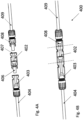
- Fig. 4A shows safety switch 402 along with connectors 408 and 403 prior to connecting, according to illustrative embodiments, while Fig. 4B shows connection point 400 comprising safety switch 402 connected to connectors 408 and 403 (the component boundaries indicated by dashed lines).
- safety switch 402 may be built into connector 403 or connector 408 of a PV generator, providing safety switching functionality in a PV generator without necessitating additional components and connections. Integrating safety switches in PV generator connectors or junction boxes may reduce costs (e.g. by not requiring a separate enclosure and connectors for the safety switch) and simplify installation (since no additional components need be connected).
- PV string 500 may be part of a string of PV generators 101 (e.g. part of a string similar to or the same as PV string 104 of Fig. 1A , comprising generators similar to or the same as PV generators 101 of Fig. 1A and Fig. 2 ) connected to each other via connection points 400.
- Connection points 400 may be similar to or the same as connection point 400 of Fig. 4A and Fig. 4B , and may include a safety switch (e.g. safety switch 402) coupled in between two PV generator connectors (e.g. connectors 403 and 408).
- Each PV generator 101 may comprise conductors 404 and 409 for carrying photovoltaic power from PV cells comprising the PV generator, and connectors 403 and 408 for connecting to safety switch 402.
- PV generator 101 may comprise junction box 511 and conductors 404 and 409.
- Fig. 5B may illustrate the back side on a PV generator, with PV cells mounted on the front side of the PV generator (not explicitly shown).
- PV cells may be mounted on both sides of the PV generator, or the back side of the PV generator may be constructed to allow solar irradiance to reach the PV cells from both sides of the PV generator.
- Junction box 511 may comprise electrical connections 512 and 513 for collecting photovoltaic power from the PV cells, and providing the photovoltaic power via conductors 409 and 404.
- safety switch 502 may be disposed between conductor 404 and electrical connection 512.
- Safety switch 502 may be functionally similar or the same as safety switch 302 of Fig. 3 , without requiring the physical enclosure and male and female connectors 306 and 307.
- Transistor Q1, diode D31, sensor(s)/sensor interfaces 510, controller 503, communication device 505 and/or auxiliary power circuit 504 may be integrated in junction box 511.
- a resistor may be coupled across the terminals of transistor Q1 (similarly to resistor R31 of Fig. 3 ) for regulating the OFF-state current through safety switch 502.
- auxiliary power circuit 504 may be coupled between conductors 404 and 409 for receiving photovoltaic power generated by PV generator 101, and may provide power to controller 503, communication device 505 and/or sensor(s)/sensor interfaces 510.
- junction box 511 may further include an integrated PV power device similar to or the same as PV power device 903 of Fig. 9 .
- PV power device 903 may be coupled between conductors 404 and 409 and electrical connections 512 and 513.
- power converter 900 of Fig. 9 may receive power from electrical connections 512 and 513, and may output power to conductors 404 and 409.
- Safety switch 502 may be disposed between PV power device 903 and electrical connection 512, or, in some embodiments, may be integrated into PV power device 903.
- Fig. 6 shows a method for operating a safety switch (e.g. safety switch 102 of Fig. 1A , safety switch 302 of Fig. 3 ).
- Method 600 may be carried out by a controller similar to or the same as controller 303 of Fig. 3 .
- the initial condition may be that the switch is in the ON state, allowing current to flow between the two conductors coupled to the switch (e.g. conductors 404 and 409 of Fig. 5A ).
- an auxiliary power circuit coupled to the safety switch may provide power to the controller and/or a gate driver for maintaining the switch in the ON state (for example, some types of transistors implementing safety switches may be "normally OFF", in which case the auxiliary power circuit may power a voltage signal applied to a transistor gate node to maintain the ON state).
- the controller may receive a command to turn the switch to the OFF state.
- the command may be received via a communication device (e.g. communication device 305) in communication with a system control device.
- the controller may independently determine that an unsafe condition may be present (e.g.
- a determination that the switch should be turned to the OFF state may be made in response to not receiving a signal.
- a system control device continuously provides a "keep alive" signal to associated safety switches and PV power devices. Not receiving a "keep alive" signal may indicate a potentially unsafe condition and may cause a determination that the switch should be turned to the OFF state.
- the controller turns the switch to the OFF state.
- turning the switch to the OFF state may include applying a voltage to a transistor terminal
- turning the switch to the OFF state may include ceasing to apply a voltage to a transistor terminal.
- the controller waits to receive a command to turn the switch back to the ON position.
- a system control device may provide a signal indicating that it is safe to reconnect PV generators and to resume providing power.
- the controller may independently determine that it is safe to return the switch to the ON position (e.g., due to a sensor reporting that the unsafe condition is no longer present).
- the controller determines if a command (or, in some embodiments, a self-determination) to turn the switch to the ON state has been received. If no such command (or determination) has been received, the controller carrying out method 600 returns to step 604. If a command (or, in some embodiments, a self-determination) to turn the switch to the ON state has been received, the controller carrying out method 600 proceeds to step 606, turns the switch back to the ON state (e.g. by applying a voltage to a transistor node, or removing an applied voltage from a transistor node) and returns to step 601.
- auxiliary circuit for providing continuous power supply to a safety switch may be variously implemented.
- Auxiliary power circuits may provide power for operating a safety switch under varying conditions and at various times.
- auxiliary power circuits may provide operational power to a safety switch at three times: at initial startup (i.e. when the system comprising a safety switch is first deployed), at steady-state ON time (i.e. when the system is up and running, during normal operating conditions, when the switch is ON), and at steady-state OFF time (i.e. when the system is up and running, during a potentially unsafe condition, when the switch is OFF).
- Safety switch 702a may comprise conductors 708 and 709, transistor Q1, controller 710 and auxiliary power circuit 704.
- Safety switch 702a may further comprise a communication device similar to or the same as communication device 305 of Fig. 3 (not explicitly depicted, to reduce visual noise).
- Transistor Q1 may be similar to or the same as transistor Q1 described with regard to Fig. 3
- resistor R31 may be the same as R31 of Fig. 3
- diode D31 may be the same as D31 of Fig. 3
- controller 710 may be similar to or the same as controller 303 of Fig. 3
- conductors 708 and 709 may be similar to or the same as conductors 308 and 309, respectively, of Fig. 3 .
- Auxiliary power circuit 704 may be coupled in parallel to transistor Q1.
- a first input of auxiliary power circuit 704 may be coupled to conductor 708, and a second input of auxiliary power circuit 704 may be coupled to conductor 709.
- auxiliary power circuit 704 may comprise analog circuitry configured to provide an appropriate control signal to transistor Q1. In some embodiments, auxiliary power circuit 704 may provide power to controller 710, with controller 710 configured to provide a control signal to transistor Q1.
- Safety switch 702b may comprise conductors 708 and 709, transistor Q1, controller 710 and auxiliary power circuit 714.
- Safety switch 702b may further comprise a communication device similar to or the same as communication device 305 of Fig. 3 (not explicitly depicted, to reduce visual noise).
- Transistor Q1 may be similar to or the same as transistor Q1 described with regard to Fig. 3
- resistor R31 may be the same as R31 of Fig. 3
- diode D31 may be the same as D31 of Fig. 3
- controller 710 may be similar to or the same as controller 303 of Fig. 3
- conductors 708 and 709 may be similar to or the same as conductors 308 and 309, respectively, of Fig. 3 .
- Auxiliary power circuit 714 may be coupled in series with transistor Q1.
- a first input of auxiliary power circuit 714 may be coupled to conductor 708, and a second input of auxiliary power circuit 704a may be coupled to transistor Q1.
- auxiliary power circuit 704a may be used as auxiliary power circuit 704 of Fig. 7A .
- a first input to auxiliary power circuit 704a may be coupled to the source terminal of a transistor (e.g. Q1 of Fig. 7A ), and a second input to auxiliary power circuit 704a may be coupled to the drain terminal of a transistor.
- An output of auxiliary power circuit 704a may be coupled to the gate terminal of a transistor.
- Auxiliary power circuit 704a may comprise Ultra Low Voltage Direct-Current to Direct Current (DC/DC) converter (ULVC) 720.
- DC/DC Direct-Current to Direct Current
- Controller 710 may be an analog or digital controller, and may be similar to controller 303 of Fig. 3 . Controller 710 may be integrated with or separate from auxiliary power circuit 304a. In some embodiments, an output of ULVC 720 may be coupled to an input of controller 710, with controller 710 applying a voltage to the gate of a transistor. ULVC 720 may be configured to receive a very low voltage (e.g. tens or hundreds of millivolts) at its input, and output a substantially larger voltage (e.g. several volts). ULVC 720 may be variously implemented. In some embodiments, ULVC may comprise an oscillator charge pump and/or several conversion stages.
- auxiliary power circuit 704a may be coupled as described above to the terminals of a MOSFET.
- ULVC 720 may be coupled between the source (Vs) and drain (Vd) terminals of the MOSFET. When the MOSFET is in the OFF position, the voltage drop between terminals Vs and Vd may be substantial, e.g. close to the open-circuit voltage of a PV generator.
- ULVC 720 When the MOSFET is in the OFF position, ULVC 720 may be bypassed or disabled, with the substantial voltage drop between terminals Vs and Vd processed to provide power to controller 710. Controller 710 may hold the voltage between the MOSFET gate and source terminals to a low value, (e.g. 0V or 1V, under a minimum source-gate threshold of 2V), maintaining the MOSFET in the OFF position.
- a low value e.g. 0V or 1V, under a minimum source-gate threshold of 2V
- controller 710 may receive a command via a communication circuit (not explicitly depicted) to turn the MOSFET to the ON state. Controller 710 may increase the gate-to-source voltage to about 5V. In illustrative PV systems, the current flowing through a PV string at certain points of operation may be about 10A. At a gate-to-source voltage of 5V and drain-to-source current of 10A, the drain-to-source voltage may be about 90mV.
- ULVC 720 may boost the drain-to-source voltage of 90mV to a voltage of several volts or more (e.g. 5V, 10V, 12V or 20V) for powering controller 710.
- Controller 710 may continuously hold the gate-to-source voltage at about 5V until a command is received to turn the MOSFET OFF.
- the MOSFET is turned OFF at the end of every day, i.e. when PV generators cease producing significant power due to nightfall.
- controller may decrease the gate-to-source voltage back to about 0V or 1V.
- auxiliary power circuit 704a may provide several advantages.
- the steady-state voltage across safety switch 702a may be substantially constant when in the ON position (e.g. 90mV).
- auxiliary power circuit 704b may be used as auxiliary power circuit 704 of Fig. 7A .
- a first input to auxiliary power circuit 704b may be coupled to the source terminal of a transistor (e.g. Q1 of Fig. 7A ), and a second input to auxiliary power circuit 704b may be coupled to the drain terminal of a transistor.
- An output of auxiliary power circuit 704b may be coupled to the gate terminal of a transistor.
- Auxiliary power circuit 704b may comprise capacitor C2, diode D2, diode Z2, transistor Q70 and DC-to-DC converter 721.
- capacitor C2 may be replaced by a different charge device (e.g. a battery).
- Controller 710 may be analog or digital, and may be similar to controller 303 of Fig. 3 . Controller 710 may be integrated with or separate from auxiliary power circuit 304a.
- Diode Z2 may be a Zener diode designed to limit and hold a reverse-bias voltage to a predetermined value. In this illustrative embodiment, diode Z2 is assumed to have a reverse-bias voltage of 4V.
- a first input to auxiliary power circuit 704b may be coupled to the source terminal of a transistor (e.g. Q1 of Fig.
- auxiliary power circuit 704b may be coupled to the drain terminal of a transistor (e.g. Q1).
- An output of auxiliary power circuit 704b may be coupled to the gate terminal of a transistor (e.g. Q1).
- an output of converter 721 may be coupled to an input of controller 710, with controller 710 applying a voltage to the gate of a transistor.
- Converter 721 may be configured to receive a voltage of several volts (e.g. between 3V-10V) at its input, and output a voltage for powering controller 710 or controlling the gate voltage of a transistor gate terminal.
- the anode of diode D2 may be coupled to a transistor drain terminal (Vd), and the cathode of diode D2 may be coupled to the cathode of diode Z2 and a first terminal of capacitor C2.
- the anode of diode Z2 may be coupled to a drain terminal of transistor Q70, with the source terminal of transistor Q70 coupled to a transistor source terminal (Vs) and to a second terminal of capacitor C2.
- the gate voltage of transistor Q70 may be controlled by controller 710 (the control line is not explicitly depicted).
- the inputs of converter 721 may be coupled in parallel with capacitor C2.
- Auxiliary power circuits 704a-b and 714 may be operated to provide a voltage drop across the terminals of safety switch 702 according to safety and effective system operation requirements.
- the drain-to-source voltage may be desired to be low during normal system operation, when safety switch 702 is in the "steady ON state", i.e. when the switch provides a low-impedance path for photovoltaic power to flow through a PV string.
- safety switch 702 When safety switch 702 is in a "steady OFF state", safety switch 702 may be required to provide a drain-to-source voltage of about an open-circuit voltage of a PV generator without providing a low-impedance path for current flow.
- controller 710 may operate transistor Q70 and transistor Q1 of Fig. 7A to provide a voltage drop across the terminals of safety switch 702 according to safety and effective system operation requirements.
- transistors Q1 and Q70 may be held in the OFF state.
- transistor Q1 may be ON, providing a low impedance path between the drain and source terminals, and transistor Q70 may be either ON or OFF. It may be desirable during the "steady ON state” to temporarily move Q1 to the "temporarily OFF state” for a short period of time, to allow capacitor C2 to recharge and continue providing operational power to controller 710.
- transistor Q1 may be OFF and transistor Q70 may be ON.
- Diode Z2 may provide a limited charging voltage (e.g. 4V) across the terminals of capacitor C2, with capacitor C2 providing a current path for the current of a PV string.
- auxiliary power circuit 704a may be coupled as described above to the terminals of a MOSFET.
- Converter 721 may be coupled between the source (Vs) and drain (Vd) terminals of the MOSFET.
- Vs source
- Vd drain
- the voltage drop between terminals Vs and Vd may be substantial, e.g. close to the open-circuit voltage of a PV generator.
- converter 721 When the MOSFET is in the steady-OFF-state, converter 721 may be bypassed or disabled, with the substantial voltage drop between terminals Vs and Vd processed to provide power to controller 710. In some embodiments, when the MOSFET is in the steady-OFF-state, converter 721 may process the drain-to-source voltage to provide power to controller 710. Controller 710 may hold the voltage between the MOSFET gate terminal and source terminals to a low value, (e.g. 0V or 1V, under a minimum source-gate threshold of 2V), maintaining the MOSFET in the OFF position. When the MOSFET is in the steady-OFF-state, capacitor C2 may be charged to about the voltage between the drain and source terminals.
- a low value e.g. 0V or 1V, under a minimum source-gate threshold of 2V
- diode Z2 may be disconnected (e.g. by turning Q70 to the OFF state), to increase the drain-to-source voltage when the MOSFET is in the steady-OFF-state.
- having a large drain-to-source voltage e.g. about the same voltage as a PV generator open-circuit voltage
- increases system safety by decreasing the total voltage across a PV generator and an accompanying safety switch.
- controller 710 may receive a command via a communication circuit (not explicitly depicted) to turn the MOSFET to the ON state. Controller 710 may increase the gate-to-source voltage of Q1 to about 6V.
- the current flowing through a PV string at certain points of operation may be about 10A.
- the drain-to-source voltage may be about 65mV.
- Diode D2 might not be forward biased (e.g., if diode has a forward voltage of 0.6V, a drain-to-source voltage of 65mV might not forward-bias diode D2), disconnecting capacitor C2 from the drain terminal.
- Capacitor C2 may slowly discharge by providing power to converter 721.
- Converter 721 may include circuitry (e.g. analog comparators) to monitor the voltage across capacitor C2, and may respond to the voltage across capacitor C2 falling below a first threshold. If the voltage across capacitor falls below the first threshold, controller 710 may reduce the gate-to-source voltage to about 0V or 1V, resulting in the MOSFET moving to the OFF state. Diode D2 may then become forward-biased, and diode Z2 may limit the drain-to-source voltage to a second threshold. Transistor Q70 may be held in the ON state, allowing diode Z2 to regulate the drain-to-source voltage.
- Capacitor C2 may then be rapidly charged back to about the voltage level of the second threshold, with controller 710 configured to increase the gate-to-source voltage back to 6V when capacitor C2 reaches the second threshold voltage.
- This iterative process may repeat itself while the MOSFET is operating in a "steady ON state" mode.
- the first threshold is 2V
- the second threshold is 4V.
- the voltage across capacitor C2 varies between the two levels, with the gate-to-source voltage alternating between about 0V and about 6V, and the drain-to-source voltage alternating between 4V and 65mV.
- Operating auxiliary power circuit 704b may provide several advantages.
- a converter designed to receive an input voltage between 2 - 30V e.g. converter 721
- one or more additional Zener diodes may be coupled in series with diode Z2, increasing the first voltages.
- Increasing the first threshold voltage e.g. to 10V, 15V or 20V, respectively
- illustrative operating points comprising MOSFET drain-to-source voltages of 65mV and 90mV, MOSFET gate-to-source voltages of 5V and 6V, and MOSFET drain-to-source currents of 10A are used for illustrative purposes and are not intended to be limiting of operating points used in conjunction with illustrative embodiments disclosed herein.
- multiple MOSFET transistors may be parallel-coupled to reduce ON-state resistance, thereby reducing the drain-to-source voltage across MOSFETs when in the ON state. For example, coupling five MOSFETs in parallel may reduce a drain-to-source ON-state voltage from 65mV to 15mV.
- auxiliary power circuit 704c may be used as auxiliary power circuit 704 of Fig. 7A .
- Auxiliary power circuit 704c may be similar to auxiliary power circuit 704b, with a modification in that the anode of diode Z2 is coupled to the drain terminal of transistor Q1 (Vs), and that the drain terminal of transistor Q70 is also coupled to the source terminal of transistor Q1 (Vs).
- safety switch 702 is in the "steady ON state"
- transistors Q1 and Q70 may be ON, providing a low impedance path for PV string current.
- transistors Q1 and Q70 When safety switch 702 is in the "steady OFF state", transistors Q1 and Q70 may be OFF, preventing a low impedance path for a PV string current, and providing a substantial voltage drop across the terminals of safety switch 702 (e.g. about the same voltage or a slightly lower voltage than a PV-generator open-circuit voltage).
- transistor Q1 When safety switch 702 is in the "temporarily OFF state”, transistor Q1 may be OFF and transistor Q70 may be ON, diode Z2 providing a charging voltage to capacitor C2 and Q70 providing a low-impedance current path for a PV string current.
- Safety switch 702c may comprise conductors 708 and 709, transistor Q1, controller 710 and auxiliary power circuit 715.
- Auxiliary power circuit 715 may be used auxiliary power circuit 714 of Fig. 7B .
- auxiliary power circuit 715 may double as a power line communication (PLC) device.
- Inductor L4, capacitor C3 and resistor R may be coupled in parallel, with a first node of inductor L4 coupled to conductor 708, and a second node of inductor L4 coupled to the source terminal of transistor Q1.
- the values of inductor L4 and capacitor C3 may be selected to resonate at a resonant frequency (e.g. 60kHz).
- an external device may transmit a PLC high-frequency alternating current signal (e.g. using frequency shift keying, amplitude modulation or other modulation schemes) over conductor 708.
- the PLC signal may induce a high-frequency alternating-current voltage drop across the terminals of resistor R, with diode D7 providing a voltage to controller 710 when the voltage across resistor R is positive (i.e. the voltage at conductor 708 is higher than the voltage at the source terminal of transistor Q1).
- diode D7 may be replaced by a "full bridge" of diodes providing a voltage to controller 710 when the voltage across R is nonzero (either positive or negative).
- the PLC-induced voltage across resistor R may serve a dual purpose.
- the PLC signal may provide operational information to controller 710 by varying the voltage drop across resistor R .
- the PLC signal may provide operational power to controller 710.
- Controller 710 may draw power from the resonant circuit comprising resistor R, capacitor C3 and inductor L4, and use the drawn power to set the state of transistor Q1.
- auxiliary power circuit 715 may double as a communication device, reducing the total component count in safety switch 702c.
- integrating control and power signals may reduce the complexity required to program controller 710.
- an 'ON' signal may be broadcast by a system controller at a high power
- an 'OFF' signal may be broadcast by a system controller at low power.
- Auxiliary power circuit 715 may directly apply the converted power signal to the gate of transistor Q1, wherein the power of the 'ON' signal may be sufficient to hold Q1 in the ON state, and the power of the 'OFF' signal might not be sufficient to hold Q1 in the ON state.
- auxiliary power circuits 704a, 704b and 715 may be variously combined.
- auxiliary power circuit 714 of Fig. 7B may be added to safety switch 702a of Fig. 7A , auxiliary power circuit 714 functioning as a PLC circuit as well as being configured to provide power to controller 710 in case of a malfunction in auxiliary power circuit 704.
- auxiliary power circuit 714 may provide initial power to controller 710 at system setup, with auxiliary power circuit 704 providing power to controller 710 during "steady state" operation.
- Fig. 71 illustrates part of a MOSFET datasheet according to an illustrative embodiment.
- Plot 770 may depict relationships between drain-to-source voltage and drain-to-source current through a MOSFET.
- Curve 771 may depict a current-voltage relationship when the gate-to-source voltage applied to a MOSFET is 5V.
- Curve 771 may depict a current-voltage relationship when the gate-to-source voltage applied to a MOSFET is 6V.
- Operating point A may indicate that when a gate-to-source voltage applied to a MOSFET is 6V and the drain-to-source current flowing through the MOSFET is 10A, the drain-to-source voltage across the MOSFET is about 65mV.
- Operating point B may indicate that when a gate-to-source voltage applied to a MOSFET is 5V and the drain-to-source current flowing through the MOSFET is 10A, the drain-to-source voltage across the MOSFET is about 90mV. This may correspond to a possible operating point for a MOSFET operated according to Fig. 7D . As noted above, these operating points are illustrative only, and may adapted by connected multiple MOSFETs in parallel to obtain new operating points.
- PV system 800 may comprise a plurality of PV strings 804 coupled in parallel between a ground bus and a power bus.
- Each of PV strings 804 may comprise a plurality of photovoltaic generators 801, a plurality of safety switches 802 and a plurality of PV power devices 803.
- PV generators 801 may be similar to or the same as PV generators 101 of Fig. 1A
- safety switches 802 may be similar to or the same as safety switch 102 of Fig. 1A , safety switch 302 of Fig. 3 and/or safety switches 702a-702c of Figs. 7A-7C .
- system power device 810 may include a DC/AC inverter and may output alternating current (AC) power to a power grid, home or other destinations.
- system power device 810 may comprise a combiner box, transformer and/or safety disconnect circuit.
- system power device 810 may comprise a DC combiner box for receiving DC power from a plurality of PV strings 804 and outputting the combined DC power.
- system power device 810 may include a fuse coupled to each PV string 804 for overcurrent protection, and/or one or more disconnect switches for disconnecting one or more PV strings 804.
- system power device 810 may comprise a system controller (e.g.
- an analog control circuit for providing commands to and receiving data from PV power devices 803 and safety switches 802.
- DSP Digital Signal Processor
- ASIC Application-Specific Integrated Circuit
- FPGA Field Programmable Gate Array
- Each safety switch 802 may be coupled between a first output of a first PV generator and a second output of a second output generator, and each PV power device may have two input terminals: a first input terminal coupled to the second output of the first PV generator, and a second input terminal coupled to the first output of the second PV generator.
- each pair of PV generators 801 are effectively coupled in series, with the combined voltage and power of the two PV generators provided to the input of PV power device 803.
- Each safety switch 802 is disposed between the two PV generators, for disconnecting the pair of PV generators in case of a potentially unsafe condition.
- PV power device 803 may stop drawing power from the PV generators, resulting in an open-circuit voltage at the PV power device input terminals which is about double the open-circuit voltage of each PV power generator.
- This voltage may, in some systems, be as high as 80, 100 or even 120 volts, which may be higher than the allowed safe voltage defined by safety regulations.
- one or more safety switches 802 may move to the OFF state, reducing the voltage drop between the input terminals of each PV power device 803 to about 40-60 volts, which may be an adequately safe voltage level.
- Each PV power device 803 may receive power from two photovoltaic generators 801 coupled to the inputs of PV power device 803, and may provide the combined power of the two photovoltaic generators at the outputs of PV power device 803.
- the outputs of a plurality of PV power devices 803 may be coupled in series to form a PV string 804, with a plurality of PV strings 804 coupled in parallel to provide power to system power device 810.
- Fig. 8 illustrates an arrangement wherein two PV generators 801 are coupled in parallel to each PV power device 803, various arrangements can be easily obtained.
- each PV power device receive power from three or more serially-connected PV generators 801, with safety switches 802 disposed between the PV generators.
- some PV power devices 803 may receive power from a single PV generator 801, some PV power devices may receive power from two PV generators 801, and some PV power devices may receive power from more than two PV generators 801.
- PV power devices 803 may receive power from multiple parallel-connected serial strings of PV generators 801, with safety switches 802 disposed in the serial strings.
- Embodiments disclosed herein include the aforementioned modifications, and other modifications which will be evident to one of ordinary skill in the art.
- PV power device 903 may be similar to or the same as PV power device 803 of Fig. 8 .
- PV power device 903 may include power converter 900.
- Power converter 900 may comprise a direct current-direct current (DC/DC) converter such as a Buck, Boost, Buck/Boost, Buck + Boost, Cuk, Flyback and/or forward converter.
- power converter 900 may comprise a direct current - alternating current (DC/AC) converter (also known as an inverter), such a micro-inverter.
- DC/DC direct current-direct current
- DC/AC direct current - alternating current
- Power converter 900 may have two input terminals and two output terminals, which may be the same as the input terminals and output terminals of PV power device 903.
- PV power device 903 may include Maximum Power Point Tracking (MPPT) circuit 906, configured to extract increased power from a power source the power device is coupled to.
- MPPT circuit 906 may implement impedance matching algorithms to extract increased power from a power source the power device is coupled to.
- PV power device 903 may further comprise controller 905 such as a microprocessor, Digital Signal Processor (DSP), Application-Specific Integrated Circuit (ASIC) and/or a Field Programmable Gate Array (FPGA).
- DSP Digital Signal Processor
- ASIC Application-Specific Integrated Circuit
- FPGA Field Programmable Gate Array
- PV power device 903 may include circuitry and/or sensors/sensor interfaces 904 configured to measure parameters directly or receive measured parameters from connected sensors and/or sensor interfaces 904 configured to measure parameters on or near the power source, such as the voltage and/or current output by the power source and/or the power output by the power source.
- the power source may be a PV generator comprising PV cells, and a sensor or sensor interface may directly measure or receive measurements of the irradiance received by the PV cells, and/or the temperature on or near the PV generator.
- PV power device 903 may include communication device 911, configured to transmit and/or receive data and/or commands from other devices.
- Communication device 911 may communicate using Power Line Communication (PLC) technology, or wireless technologies such as ZigBee TM , Wi-Fi, cellular communication or other wireless methods.
- PV power device 903 may include memory device 909, for logging measurements taken by sensor(s)/sensor interfaces 904 to store code, operational protocols or other operating information.
- Memory device 909 may be flash, Electrically Erasable Programmable Read-Only Memory (EEPROM), Random Access Memory (RAM), Solid State Devices (SSD) or other types of appropriate memory devices.
- EEPROM Electrically Erasable Programmable Read-Only Memory
- RAM Random Access Memory
- SSD Solid State Devices
- PV power device 903 may include safety devices 907 (e.g. fuses, circuit breakers and Residual Current Detectors).
- Safety devices 907 may be passive or active.
- safety devices 907 may comprise one or more passive fuses disposed within PV power device 903 and designed to melt when a certain current flows through it, disconnecting part of PV power device 903 to avoid damage.
- safety devices 907 may comprise active disconnect switches, configured to receive commands from a controller (e.g. controller 905, or an external controller) to disconnect portions of PV power device 903, or configured to disconnect portions of PV power device 903 in response to a measurement measured by a sensor (e.g.
- PV power device 903 may comprise auxiliary power circuit 908, configured to receive power from a power source coupled to PV power device 903, and output power suitable for operating other circuitry components (e.g. controller 905, communication device 911, etc.). Communication, electrical coupling and/or data-sharing between the various components of PV power device 903 may be carried out over common bus 920.
- PV power device 903 may comprise transistor Q9 coupled between the inputs of power converter 900.
- Transistor Q9 may be controlled by controller 905. If an unsafe condition is detected, controller 905 may set transistor Q9 to ON, short-circuiting the input to power converter 900.
- Transistor Q9 may be controlled in conjunction with safety switch 802 of Fig. 8 . When safety switch 802 and transistor Q9 are OFF, each pair of PV generators 801 of Fig. 8 are disconnected, each PV generator providing an open-circuit voltage at its output terminals. When safety switch 802 and transistor Q9 are ON, each pair of PV generators 801 of Fig.
- the pair of PV generators providing a voltage of about zero to power converter 900.
- a safe voltage at all system locations may be maintained, and the two scenarios may be staggered to alternate between open-circuiting and short-circuiting PV generators.
- This mode of operation may allow continuous power supply to system control devices, as well as provide backup mechanisms for maintaining a safe voltage (i.e. in case a safety switch 802 malfunctions, operation of transistor Q9 may allow continued safe operating conditions).
- PV system 1000 may comprise a plurality of PV strings 1004 coupled in parallel between a ground bus and a power bus.
- Each of PV strings 1004 may comprise a plurality of photovoltaic generators 1001 and a plurality of PV power devices 1003.
- PV generators 1001 may be similar to or the same as PV generators 801 of Fig. 8 .
- the power and ground buses may be input to system power device 1010, which may be similar to or the same as system power device 810 of Fig. 8 .
- Each of photovoltaic power devices 1003 may comprise four input terminals: T1, T2, T3 and T4.
- T1 and T2 may be coupled to and receive power from a first PV generator
- T3 and T4 may be coupled to and receive power from a second PV generator.
- PV power device 1003 may be substantially the same as PV power device 803 of Fig. 8 , with the addition of safety switch 802 integrated into PV power device 1003 and connected in between terminals T2 and T3 of PV power device 1003.
- PV power device 1103a may be used as PV power device 1003 of Fig. 10 .
- PV power device 1103a may comprise a PV power device similar to or the same as PV power device 803 of Fig. 8 or PV power device 903 of Fig. 9 .
- PV power device 1103a will be assumed to comprise PV power device 903 of Fig. 9 .
- PV power device 1103a may comprise transistors Q3, Q4 and Q5.
- Transistors Q3-Q5 may be MOSFETs, JFETs, IGBTs, BJTs or other appropriate transistors.
- transistors Q3-Q5 will be assumed to be MOSFETs.
- Transistor Q3 may be connected between input terminals T2 and T3.
- Transistor Q4 may be connected between input terminals T2 and T4.
- Transistor Q1 may be connected between input terminals T1 and T3.
- Transistors Q3-Q5 may be controlled (e.g. have gate signals provided) by one or more controllers such as controller 905 of PV power device 903.
- the elements comprising PV power device 1103a may be jointly enclosed by enclosure 1108.
- a first PV generator (not explicitly depicted) may be coupled between terminals T1 and T2, and a second PV generator (not explicitly depicted) may be coupled between terminals T3 and T4.
- transistor Q3 may be ON, and transistors Q4 and Q5 may be OFF.
- the two photovoltaic generators may be serially connected, with the combined serial voltage of the two PV generators provided between terminals T1 and T4.
- the controller controlling transistor Q3 may turn Q3 to the OFF state, reducing the voltage drop between terminals T1 and T4.
- controller(s) controlling transistors Q4 and Q5 may switch Q4 and Q5 to the ON state when Q3 is OFF, resulting in terminal T1 being short-circuited to terminal T3, and terminal T2 being short-circuited to terminal T4.
- the first and second photovoltaic generator may be coupled in parallel between terminal T1 and T4, allowing PV power device 903 to draw power from the PV generators (e.g. for powering devices such as controller 905, communication device 911, auxiliary power circuit 908 and other devices depicted in Fig. 9 ).
- Q4 or Q5 might not be included in PV power device 1103a.
- Q4 might not be included, in which case by turning Q5 to the ON position when Q3 is OFF, power is provided to PV power device 903 by a single PV generator (coupled between T3 and T4).
- Q5 might not be included, in which case by turning Q4 to the ON position when Q3 is OFF, power is provided to PV power device 903 by a single PV generator (coupled between T1 and T2).
- PV power device 1103b may be used as PV power device 1003 of Fig. 10 .
- PV power device 1103b may comprise a PV power device similar to or the same as PV power device 803 of Fig. 8 or PV power device 903 of Fig. 9 .
- PV power device 1103a will be assumed to comprise PV power device 903 of Fig. 9 .
- Transistor Q6 may be similar to or the same as transistor Q3 of Fig. 11A .
- PV power device 1103b may further comprise diodes D3 and D4.
- the anode of diode D3 may be coupled to terminal T3 and the cathode of diode D3 may be coupled to the positive input of PV power device 903 at node N1.
- the anode of diode D4 may be coupled to terminal T1 and the cathode of diode D3 may be coupled to the positive input of PV power device 903 at node N1.
- the elements comprising PV power device 1103b may be jointly enclosed by enclosure 1108.
- a first PV generator (not explicitly depicted) may be coupled between terminals T1 and T2, and a second PV generator (not explicitly depicted) may be coupled between terminals T3 and T4.
- transistor Q3 may be ON, connecting terminals T2 and T3.
- the voltage at terminal T1 may be higher than the voltage at terminal T2 (e.g. if the positive output of a PV generator is coupled to terminal T1 and the negative output of the PV generator is coupled to terminal T2), so diode D4 may be forward-biased and diode D3 may be reverse-biased.
- the voltage at node N1 may be about the voltage at terminal T1 (assuming an insignificant voltage drop across diode D4), resulting in a voltage input to PV power device 903 about equal to the voltage between terminals T1 and T4.
- the controller controlling transistor Q6 may turn Q6 to the OFF state, disconnecting the coupling of terminals T2 and T3.
- the voltage at node N1 may be the voltage at terminal T1 or the voltage at terminal T3, the greater of the two. While the voltage at node N1 might not be predetermined, in either possible scenario, a PV generator may be coupled to the inputs of PV power device 903, providing power to PV power device 903 (e.g. for powering devices such as controller 905, communication device 911, auxiliary power circuit 908 and other devices depicted in Fig. 9 ).
- PV system 1200 may comprise a plurality of PV strings 1204 coupled in parallel between a ground bus and a power bus.
- Each of PV strings 1204 may comprise a plurality of photovoltaic generators 1201, a pliurality of safety switches 1202 and a plurality of PV power devices 1203.
- PV generators 1001 may be similar to or the same as PV generators 801 of Fig. 8 .
- the power and ground buses may be input to system power device 1210, which may be similar to or the same as system power device 810 of Fig. 8 .
- Each PV power device 1203 may be designed to be coupled to more than one PV power generator 1201.
- each PV power device 1203 (except for the PV power devices coupled to the power bus) is coupled to two PV power generators and to two safety switches 1202, with each safety switch 1202 (except for the safety switch 1202 which is coupled to the ground bus) coupled to two PV generators 1201 and two PV power devices 1203.
- each PV power device 1203 may receive power from two PV generators 1201, and may forward the power along PV string 1204 towards the power bus.
- each safety switch 1202 may provide a connection between two PV generators 1201 and may provide a connection between two PV power devices 1203 for forwarding power along PV string 1204.
- safety switch 1202a provides a connection between PV generators 1201a and 1201b.
- PV power device 1203a may receive power generated by PV generators 1201a and 1201b, with safety switches 1202b disposed between PV power devices 1203a and 1203b, providing PV power device 1203a with a connection for forwarding power to PV power device 1203b.
- safety switch 1202b provides a connection between PV generators 1201c and 1201d, with PV power device 1203b receiving power from PV generators 1201c and 1201d.
- safety switch 1202a may be operated to disconnect PV generator 1201a from PV generator 1201b, and to disconnect PV power device 1203a from the ground bus.
- safety switch 1202b may be operated to disconnect PV generator 1201c from PV generator 1201d, and to disconnect PV power device 1203a PV power device 1203b. Operating safety switches 1202 in this manner may reduce the voltage in various locations in PV system 1200 to safe voltage levels.
- Safety switch 1205 may comprise terminals T1-T4, transistors (e.g. MOSFETs) Q7 and Q8, capacitors C4 and C5, and inductors L4 and L5.
- Inductor L4 may be provided between terminal T3 and terminal T1 to reduce ripples and/or spikes in a current flowing from terminal T1 to terminal T3, and inductor L5 may be provided between terminal T4 and midpoint node X to reduce ripples and/or spikes in a current flowing from transistor Q7 to terminal T4.
- inductors L4 and L5 might not be provided.
- transistors Q7 and Q8 may be replaced by alternative switching elements, such as IGBTs, BJTs, JFETs or other switching elements.
- Capacitor C4 may be coupled between terminals T1 and T2.
- Transistor Q7 may be coupled between terminal T2 and midpoint node X
- capacitor C5 may be coupled between terminal T1 and midpoint node X.
- Transistor Q8 may be coupled in parallel to capacitor C5, between terminal T1 and midpoint node X. In some embodiments, capacitor C5 and/or capacitor C4 might not be provided.
- transistor Q7 may be held in the ON state, and transistor Q8 may be in the OFF state.
- Capacitor C5 may then be in parallel with capacitor C4, and a first PV generator may be coupled between terminals T1 and T2, applying a voltage to capacitors C4 and C5 and providing electrical power at terminals T1 and T2.
- Terminal T4 may be coupled to an output terminal of a second PV generator, and terminal T3 may be coupled to an input terminal of a PV power device 1203.
- the power input to safety switch 1205 at terminals T1 and T2 may be output at terminals T3 and T4 to the second PV generators and the PV power device 1203.
- Transistors Q7 and Q8 may be controlled by a controller (not explicitly depicted) similar to or the same as controller 710 of Fig. 7A .
- the controller may be powered by capacitor C4 (e.g. a controller input power terminal may be coupled to terminal T2 or terminal T1 for receiving power from capacitor C4).
- Safety switch 1205 may further comprise a communication device (e.g. similar to or the same as communication device 305 of Fig. 3 ) for receiving operational commands from a system control device.
- the controller may switch transistor Q7 to the OFF state and transistor Q8 to the ON state.
- Capacitor C5 may be short-circuited by transistor Q8, while capacitor C4 may maintain the voltage imposed between terminals T1 and T2.
- PV power device 1203 may comprise a variation of a Buck + Boost DC/DC converter.
- the power device may include a circuit having two input terminals, denoted Vin and common, and two output terminals which output the same voltage Vout. The output voltage is in relation to the common terminal.
- the circuit may include an input capacitor Cin coupled between the common terminal and the Vin terminal, an output capacitor coupled between the common terminal and the Vout terminals.
- the circuit may include two central points used for reference.
- the circuit may include a plurality of switches (e.g.
- MOSFET transistors Q11 , Q12 , Q13 and Q14 with Q11 connected between Vin and the first central point, and Q12 connected between the common terminal and the first central point.
- Q13 may be connected between the Vout terminal and the second central point, and Q14 may be connected between the common terminal and the second central point.
- the circuit may further include inductor L6 coupled between the two central points.
- the operation of the Buck + Boost DC/DC converter in PV power device 1203 may be variously configured. If an output voltage lower than he input voltage is desired, Q13 may be statically ON, Q14 may be statically OFF, and with Q11 and Q12 being Pulse-Width-Modulation(PWM)-switched in a complementary manner to one another, the circuit is temporarily equivalent to a Buck converter and the input voltage is bucked. If an output voltage higher than he input voltage is desired, Q11 may be statically ON, Q12 may be statically OFF, and with Q13 and Q14 being PWM-switched in a complementary manner to one another, the input voltage is boosted.
- PWM Pulse-Width-Modulation
- the circuit may convert the input voltage Vin to output voltage Vout. If current is input to the circuit by the Vin and common terminals, and the voltage drop across capacitors Cin and Cout are about constant voltages Vin and Vout respectively, the currents input to the circuit are combined at inductor L6 to form an inductor current which is equal to the sum of the current input at the Vin and common terminals.
- the inductor current may contain a ripple due to the charging and discharging of capacitors Cin and Cout, but if the voltage drop across capacitors Cin and Cout are about constant, the voltage ripples over the capacitors are small, and similarly the inductor current ripple may be small.
- the inductor current may be output by the pair of output terminals Vout. In some embodiments, a single output terminal may be included, and system designers may split the output terminal externally (i.e. outside of the PV power device circuit), if desired.
- PV power device 1203 may be similar to or the same as PV power device 903 of Fig. 9 , with power converter 900 of Fig. 9 comprising the Buck + Boost converter of Fig. 13B .
- power converter 900 of Fig. 9 comprising the Buck + Boost converter of Fig. 13B .
- boosting the voltage input to a PV power device 1203 might not be necessary, in which case PV power device 1203 may comprise a Buck converter similar to the Buck + Boost converter of Fig. 13B , with switch Q14 removed (i.e. replaced by an open-circuit) and switch Q13 replaced with a wire (i.e. connecting the Vout terminal to the second central point).
- safety switch 1202b may be coupled to photovoltaic generators 1201c and 1201d, and to PV power devices 1203a and 1203b.
- Terminal T2 may be connected to the positive output of PV generator 1201c
- terminal T4 may be connected to the negative output of PV generator 1201d.
- Terminal T1 may be coupled to a first Vout terminal of PV power device 1203a
- terminal T3 may be coupled to the common terminal of PV power device 1203b.
- the positive output terminal of PV generator 1201d may be coupled to the Vin terminal of PV power device 1203b
- the negative output terminal of PV generator 1201c may be coupled to a second Vout terminal of PV power device 1203a.
- PV generators 1201c and 1201d are serially coupled, the combined voltage of PV generators 1201c and 1201d input between the common and Vin terminals of PV power device 1203b.
- safety switch 1202b may disconnect the connection between terminals T2 and T4 (e.g. by setting transistor Q7 of Fig. 13A to OFF) and couple terminals T3 and T4 (e.g. by setting transistor Q8 of Fig. 13A to ON).
- PV generator 1201d may be coupled between the common and Vin terminals of PV power device 1203b
- PV generator 1201c may be coupled between terminals T1 and T2 of safety switch 1202b.
- the system topology illustrated in Fig. 12 may provide certain advantages. For example, during normal system operation, two PV generators 1201 provide a combined voltage and power to a PV power device 1203, requiring a reduced number of PV power devices for processing power generated by the PV generators. Furthermore, continuous operational power (i.e. power used for powering device components such as controllers and transistors) is provided to all PV power devices 1203 and safety switches 1202 both during normal operations and during a potentially unsafe condition.
- continuous operational power i.e. power used for powering device components such as controllers and transistors
- Chain 1400 may comprise a plurality of PV power devices 1203 and a plurality of safety switches 1202. Each safety switch 1202 may be connected, using conductors, between two PV power devices 1203. Terminal T1 of safety switch 1202 may be connected to a Vout terminal of a first PV power device, and terminal T3 of safety switch 1202 may be connected to a common terminal of a second PV power device. Terminals T2 and T4 may be accessible via external connectors similar to or the same as connectors 406 and 407 of Fig. 4A .
- each PV power device 1203 may be accessible via external connectors similar to or the same as connectors 406 and 407 of Fig. 4A .
- Conductors connecting a PV power device terminal (e.g. the common terminal) to a safety switch terminal (e.g. terminal T3) may be sized to facilitate connecting chain 1400 to a plurality of PV generators, as depicted in Fig. 12 .
- each conductor disposed between a safety switch 1202 and a PV power device 1203 may be about 1-2 meters long.
- Chain 1400 may be assembled and sold as a single unit, saving cost and time when constructing a PV installation similar to or the same as PV system 1200 of Fig. 12 .
- an illustrative application running on a smart phone, tablet, computer, workstation, mobile device (such as a cellular device) and/or a similar computing device is shown.
- the application may provide a list of safety switches disposed in an electrical power system (e.g. PV system 100 of Fig. 1 ).
- the application may indicate a serial number or other identifying information of each safety switch, as well as identifying information of coupled PV generators and/or identifying information of a PV string each safety switch is coupled to.
- the application may indicate the state of each safety switch and/or electrical parameters of one or more safety switches, for example, the voltage across or current through one or more safety switches.
- the application may provide touch-screen buttons or similar input controllers for controlling the state of one or more switches. For example, activating a button 151 may move an associated safety switch to the OFF state, and activating a button 152 may move an associated safety switch to the ON state. Activating button 153 may move all safety switches to the OFF state, and activating button 154 may move all safety switches to the ON state. In some embodiments, activating buttons 151-154 may be restricted based on a user access level. For example, the application may enable buttons 151-154 only when running in "Installer/Administrator" mode, to restrict the actions of unsophisticated users.
- activating button 155 may enable a user to reconfigure a threshold.
- a threshold For example, an electrical voltage, current or power threshold which may be indicative of an arcing condition and trigger a system response (e.g. moving one or more safety switches to the OFF state) may be reconfigured by a user using the application of Fig. 15 .
- Activating button 156 may display a graphical layout of an electrical system represented by the application, including physical location details of one or more safety switches.
- Activating button 157 may download current or past operational system data such as the state of safety switches, and/or electrical parameter measurement measured by safety switches. Buttons 155-157 may similarly be restricted depending on the level of user authorization.
- the application of Fig. 15 may communicate directly with safety switches via wireless communications (e.g. cellular communication, or over the internet).
- the application may communicate with a system power device (e.g. system power device 110 of Fig. 1 ), with the system power device configured to relay communication between the application and the safety switches via wireless communication or wired communication (e.g. power line communication).
- photovoltaic generators are used as examples of power sources which may make use of the novel features disclosed.
- Each PV generator may comprise one or more solar cells, one or more solar cell strings, one or more solar cell substrings, one or more solar panels, one or more solar shingles, or combinations thereof.
- the power sources may include batteries, flywheels, wind or hydroelectric turbines, fuel cells or other energy sources in addition to or instead of photovoltaic generators.
- Systems, apparatuses and methods disclosed herein which use PV generators may be equally applicable to alternative systems using additional power sources, and these alternative systems are included in embodiments disclosed herein.
- PV power device circuitry of one embodiments may be combined with and/or exchanged for power device circuitry of a different embodiment.
- transistor Q9 of PV power device 903 may be disposed between electrical connections 512 and 513 of junction box 511 and operated to short-circuit the input to PV generator 101 of Fig. 5A .
- An apparatus comprising:
- Feature 2 The apparatus of feature 1, wherein the first electrical connector is designed to be connected to a photovoltaic generator and the second electrical connector is designed to be connected to a photovoltaic generator.
- Feature 4 The apparatus of any preceding feature, further comprising a communication device coupled to the controller, the communication device coupled to the controller and configured to receive a message indicating a potentially unsafe condition and provide an indication of a potentially unsafe condition to the controller.
- Feature 5 The apparatus of feature 4, wherein the communication device comprises at least one of a Power Line Communication device and a wireless communication device.
- Feature 6 The apparatus of feature 5, wherein the communication device is coupled to a power-supply terminal of the controller and is designed to provide operational power to the controller.
- Feature 7 The apparatus of any preceding feature, further comprising a sensor coupled to the controller, the sensor configured to measure one or more electrical parameters and provide one or more measurements to the controller.
- Feature 8 The apparatus of feature 7, wherein the sensor is a current sensor, and wherein the controller is configured to switch the switching element to disconnect the first electrical conductor from the second electrical conductor in response to a current measurement indicating a potentially unsafe condition.
- Feature 9 The apparatus of any preceding feature, further comprising an auxiliary power circuit coupled to the first electrical conductor and the controller, the auxiliary power circuit configured to draw power from the first electrical conductor and provide power to the controller.
- Feature 10 The apparatus of any preceding feature, further comprising a resistor coupled in parallel to the switching element.
- Feature 11 The apparatus of feature 10, wherein the resistor has resistance between 10 ⁇ and 5k ⁇ .
- a method comprising:
- Feature 13 The method of feature 12 wherein detecting comprises receiving a message via a communication device, the message indicating a potentially unsafe condition.
- Feature 14 The method of feature 12 wherein detecting comprises receiving an electrical current measurement and determining that the electrical current measurement is indicative of a potentially unsafe condition.
- Feature 15 The method of any of features 12 to 14, further comprising:
- Feature 16 The method of any of features 12 to 15, wherein the controller is one of an analog circuit, microprocessor, Digital Signal Processor (DSP), Application-Specific Integrated Circuit (ASIC) and/or a Field Programmable Gate Array (FPGA).
- DSP Digital Signal Processor
- ASIC Application-Specific Integrated Circuit
- FPGA Field Programmable Gate Array
- An apparatus comprising:
- Feature 18 The apparatus of feature 17, wherein the transistor is a Metal Oxide Semiconductor Field Effect Transistor (MOSFET), and the diode is a built-in body diode.
- MOSFET Metal Oxide Semiconductor Field Effect Transistor
- Feature 19 The apparatus of features 17 or 18, wherein the resistor has resistance between 10 ⁇ and 5k ⁇ .
- Feature 20 The apparatus of any of features 17 to 19, further comprising the first photovoltaic generator, wherein the transistor is integrated into a junction box of the first photovoltaic generator.
- An apparatus comprising:
- Feature 22 The apparatus of feature 21, wherein the first power device terminal and the second power device terminal are two input terminals to a power device comprising one of a direct-current to direct-current (DC/DC) converter or a direct-current to alternating-current (DC/AC) converter.
- DC/DC direct-current to direct-current
- DC/AC direct-current to alternating-current
- Feature 23 The apparatus of feature 21, wherein the first power device terminal is an input terminal to a first power device comprising one of a direct-current to direct-current (DC/DC) converter or a direct-current to alternating-current (DC/AC) converter, and the second power device terminal is an input terminal to a second power device comprising one of a direct-current to direct-current (DC/DC) converter or a direct-current to alternating-current (DC/AC) converter.
- DC/DC direct-current to direct-current
- DC/AC direct-current to alternating-current
- Feature 24 The apparatus of any of features 21 to 23, wherein the switching element comprises a Metal Oxide Semiconductor Field Effect Transistor (MOSFET).
- MOSFET Metal Oxide Semiconductor Field Effect Transistor
- Feature 25 The apparatus of feature 22, wherein the switching element shares an enclosure with the power device comprising one of a direct-current to direct-current (DC/DC) converter or a direct-current to alternating-current (DC/AC) converter.
- DC/DC direct-current to direct-current
- DC/AC direct-current to alternating-current
Abstract
Description
- The present application claims priority to
U.S. non-provisional patent application Ser. No. 15/250,068, filed August 29, 2016 U.S. Patent Application serial no. 62/318,303, filed April 5, 2016 U.S. Patent Application serial no. 62/341,147, filed May 25, 2016 - Safety regulations may require disconnecting and/or short-circuiting one or more photovoltaic (PV) generators or other components in case of an unsafe condition occurring in a photovoltaic installation. For example, safety regulations require that in case of an unsafe condition (e.g. a fire, a short-circuit, carrying out of maintenance work), the maximum voltage at any point in a photovoltaic installation may not exceed a safe voltage level. In some photovoltaic systems, it may be necessary to disconnect and/or short-circuit one or more photovoltaic generator(s) to achieve the safe voltage requirement. While photovoltaic systems may be deployed for tens of years, safety regulations may change at shorter time intervals (e.g. every several years). It would be advantageous to have a controllable safety switch which may be controlled to disconnect or short-circuit a PV generator in case of a safety hazard, and which may be controlled to reconnect the photovoltaic generator once the system is safe again. It would be desirable for controllable safety switches to be cost-effective and easily deployed.
- The following summary is a short summary of some of the inventive concepts for illustrative purposes only, and is not intended to limit or constrain the inventions and examples in the detailed description. One skilled in the art will recognize other novel combinations and features from the detailed description.
- Embodiments herein may employ safety switches and associated apparatuses and methods for controlling currents through branches and/or voltages at nodes in photovoltaic (PV) installations.
- In illustrative embodiments comprising one or more electrical systems, a group of electrical safety switches may be electrically connectable to a plurality of electrical power sources. The electrical safety switches may be controllable to maintain safe operation of the electrical systems.
- In illustrative electrical systems, a safety switch may be deployed between serially-connected photovoltaic generators in a photovoltaic installation. In some embodiments, safety switches may be installed between each pair of PV generators. In some embodiments, the number and location of safety switches may be chosen with regard to current safety regulations, and in some embodiments, the number and location of safety switches may be chosen with regard to anticipated "worst-case" safety regulations. For example, in locales where adding, reconfiguring and/or removing system components is easy and inexpensive, safety switches may be deployed in a PV installation in accordance with the safety regulations at the time the installation was built. In locales where adding, reconfiguring and/or removing system components may be difficult or expensive, safety switches may be deployed in a manner that complies with a "worst-case" (i.e. most stringent) prediction of future regulations.
- Illustrative safety switches according to some embodiments may be retrofit to existing photovoltaic installations and components. Illustrative safety switches according to some embodiments may be integrated in other PV system components (e.g. connectors, PV generators, power devices, combiner boxes, batteries and/or inverters), potentially reducing the cost of design and manufacturing of the safety switches, and increasing
- In some embodiments, auxiliary power circuits are used to provide power to safety switches and associated controllers. In some embodiments, safety switches are located at system points which do not carry significant electrical power when the safety switches are in a particular state (e.g., when safety switches are in the ON state). Illustrative auxiliary power circuits are disclosed herein, along with associated methods for providing power to the auxiliary power circuits and safety switches regardless of the state of the safety switches.
- In some embodiments, components and design of safety switches may be selected to regulate or withstand electrical parameters when illustrative safety switches are in the ON or OFF states. For example, some illustrative safety switches may comprise shunt resistors sized to regulate electrical current flowing through safety switches when the safety switches are in the OFF position.
- Further embodiments include photovoltaic power devices comprising internal circuitry configured to limit a voltage between input terminals to the photovoltaic power devices in case of a potentially unsafe condition while continuously providing operational power to the photovoltaic power devices.
- Further embodiments include electrical circuits for interconnecting photovoltaic generators and photovoltaic power devices configured to limit a voltage between various system nodes while continuously providing operational power to the photovoltaic power devices.
- Further embodiments include a chain of preconnected photovoltaic power devices with associated safety switches, which may provide a cost-effective, easy way to wire a photovoltaic generation system along with associated safety switches.
- In some embodiments, safety switches may be in communication with accompanying system devices, such as system control devices and/or end-user devices such as graphical user interfaces for monitoring applications.
- Further embodiments include user interfaces for monitoring the state of and parameters measured by safety switches in illustrative power systems. A system owner or operator may be able to view a list of system safety switches, associated switch states and electrical parameter measured thereby.. In some embodiments, the list may be a graphical user interface (GUI) viewable on a computing device, such as a computer monitor, tablet, smart-television, smartphone, or the like. In some embodiments, the system operator may be able to manually control safety switches (e.g. by pressing buttons).
- As noted above, this Summary is merely a summary of some of the features described herein and is provided to introduce a selection of concepts in a simplified form that are further described below in the Detailed Description. The Summary is not exhaustive, is not intended to identify key features or essential features of the claimed subject matter and is not to be a limitation on the claims.
- These and other features, aspects, and advantages of the present disclosure will become better understood with regard to the following description, claims, and drawings. The present disclosure is illustrated by way of example, and not limited by, the accompanying figures.
-
Fig. 1A illustrates a photovoltaic system configuration according to various aspects of the present disclosure. -
Fig. 1B illustrates a photovoltaic system configuration according to various aspects of the present disclosure. -
Fig. 2 illustrates part of a photovoltaic system configuration according to various aspects of the present disclosure. -
Fig. 3 illustrates a safety switch according to various aspects of the present disclosure. -
Figs. 4A-4B illustrate a safety switch according to various aspects of the present disclosure. -
Fig. 5A illustrates part of a photovoltaic system configuration according to various aspects of the present disclosure. -
Fig. 5B illustrates a photovoltaic generator according to various aspects of the present disclosure. -
Fig. 6 illustrates a method for operating a safety switch according to various aspects of the present disclosure. -
Figs. 7A-7C illustrate circuits for providing operational power to a safety switch according to various aspects of the present disclosure. -
Fig. 7D illustrates a timing diagram depicting some of the operational parameters of a safety switch according to various aspects of the present disclosure. -
Fig. 7E illustrates a circuit for providing operational power to a safety switch according to various aspects of the present disclosure. -
Fig. 7F illustrates a timing diagram depicting some of the operational parameters of a safety switch according to various aspects of the present disclosure. -
Fig. 7G illustrates a circuit for providing operational power to a safety switch according to various aspects of the present disclosure. -
Fig. 7H illustrates a circuit for providing operational power to a safety switch according to various aspects of the present disclosure. -
Fig. 71 illustrates part of an illustrative datasheet indicating possible operating points for operating a transistor according to various aspects of the present disclosure. -
Fig. 8 illustrates a photovoltaic system configuration according to various aspects of the present disclosure. -
Fig. 9 illustrates a photovoltaic power device according to various aspects of the present disclosure. -
Fig. 10 illustrates a photovoltaic system configuration according to various aspects of the present disclosure. -
Figs. 11A-11B illustrate photovoltaic power devices according to various aspects of the present disclosure. -
Fig. 12 illustrates a photovoltaic system configuration according to various aspects of the present disclosure. -
Fig. 13A illustrates circuitry of a safety switch according to various aspects of the present disclosure. -
Fig. 13B illustrates circuitry of a photovoltaic power device according to various aspects of the present disclosure. -
Fig. 14 illustrates a portion of a chain of photovoltaic power devices according to various aspects of the present disclosure. -
Fig. 15 is an illustrative mockup of a user interface for an electrical system according to illustrative embodiments. - In the following description of various illustrative embodiments, reference is made to the accompanying drawings, which form a part hereof, and in which is shown, by way of illustration, various embodiments in which aspects of the disclosure may be practiced. It is to be understood that other embodiments may be utilized and structural and functional modifications may be made, without departing from the scope of the present disclosure.
- Reference is now made to
Fig. 1A , which shows a photovoltaic (PV) system according to illustrative embodiments.PV system 100 may comprise a plurality ofPV strings 104 coupled in parallel between a ground bus and a power bus. Each ofPV strings 104 may comprise a plurality of serially-connectedPV generators 101 and a plurality of safety switches 102.PV generators 101 may comprise one or more photovoltaic cells(s), module(s), panel(s) or shingle(s). In some embodiments,PV generators 101 may be replaced by direct current (DC) batteries or alternative direct current or alternating current (AC) power sources. - In the illustrative embodiment of
Fig. 1A , asafety switch 102 is disposed between each pair ofPV generators 101. In some embodiments (e.g. the embodiment shown inFig. 2 ) asafety switch 102 may be disposed between groups of more than one serially-connected PV generators.Safety switch 102 may comprise a control device and a communication device, and may be operated to disconnect adjacent PV generators when receiving (e.g. via the communication device) a command to disconnect PV generators. - In some embodiments, the power and ground buses may be input to
system power device 110. In some embodiments,system power device 110 may include a DC/AC inverter and may output alternating current (AC) power to a power grid, home or other destinations. In some embodiments,system power device 110 may comprise a combiner box, transformer and/or safety disconnect circuit. For example,system power device 110 may comprise a DC combiner box for receiving DC power from a plurality ofPV strings 104 and outputting the combined DC power. In some embodiments,system power device 110 may include a fuse coupled to eachstring 104 for overcurrent protection, and/or one or more disconnect switches for disconnecting one or more PV strings 104. - In some embodiments,
system power device 110 may include or be coupled to a control device and/or a communication device for controlling or communicating with safety switches 102. For example,system power device 110 may comprise a control device such as a microprocessor, Digital Signal Processor (DSP) and/or a Field Programmable Gate Array (FPGA) configured to control the operation ofsystem power device 110. In some embodiments,system power device 110 may comprise multiple interacting control devices.System power device 110 may further comprise a communication device (e.g. a Power Line Communication circuit and/or a wireless transceiver) configured to communicate with linked communication devices included in safety switches 102. In some embodiments,system power device 110 may comprise both a control device and a communication device, the control device configured to determine desirable modes of operation for PV power devices (e.g. power devices 103), and the communication device configured to transmit operational commands and receive reports from communication devices included in the PV power devices. -
System power device 110 may be coupled to any number of other devices and/or systems such as PV systems 100 (e.g., various discrete and/or interconnected devices such as disconnect(s), PV cell(s)/array(s), inverter(s), micro inverter(s), PV power device(s), safety device(s), meter(s), breaker(s), AC main(s), junction box(es), camera etc.), network(s)/Intranet/Internet, computing devices, smart phone devices, tablet devices, camera, one or more servers which may include data bases and/or work stations.System power device 110 may be configured for controlling the operation of components withinPV system 100 and/or for controlling the interactions with other elements coupled toPV system 100. - In some embodiments, the power and ground buses may be further coupled to energy storage devices such as batteries, flywheels or other energy storage devices.
- Safety regulations may define a maximum allowable voltage between the ground bus and any other voltage point in
PV system 100, during both regular operating conditions and during potentially unsafe conditions. Similarly, safety regulations may define a maximum allowable voltage between any two voltage points inPV system 100. In some scenarios, an unsafe condition inPV system 100 may require disconnecting or short-circuiting one or more of thePV generators 101 in aPV string 104. - As a numerical example, an
illustrative PV string 104 may comprise 20 serially-connectedPV generators 101. EachPV generator 101 may have an open-circuit voltage of 45V. In case of an unsafe condition (e.g. a fire, detection of an arc or a dangerous short-circuit somewhere in PV system 100), safety regulations may require thatsystem power device 110 cease drawing power fromPV string 104, resulting in an open-circuit voltage of 45 · 20 = 900V acrossPV string 104. Safety regulations may further require that in case of an unsafe condition, the maximum voltage between any two points inPV system 100 may not exceed, for example, 80V. To comply with safety regulations,safety switches 102 may disconnect the plurality ofPV generators 101 comprisingPV string 104, resulting in PV generators 101 (excluding thePV generators 101 coupled to the ground and power buses) having a "floating" voltage with regard to ground, and a voltage drop of about 45V between the two terminals of each PV generator. - In some embodiments,
system power device 110 may respond to an indication of a potentially unsafe system condition by limiting the voltage across eachPV string 104. For example,system power device 110 may comprise an inverter configured to regulate a voltage of about 60V across eachPV string 104 in case of a potentially unsafe condition. - According to aspects of the disclosure herein, a system power device 110 (or a retrofit safety device) may respond to an indication of a potentially unsafe system condition by short-circuiting each
PV string 104. For example,system power device 110 may include a switch (not explicitly shown) disposed across the inputs to system power device 110 (between the power bus and the ground bus), and in response to an indication of a potentially unsafe power condition (e.g., detecting a grid current, voltage, frequency or harmonic content outside of an allowable range, or in response to a manually activated button), system power device 110 (or the retrofit safety device) may activate the switch to substantially connect the power bus to the ground bus, short-circuiting PV strings 104. If aPV string 104 is short-circuited, safety switches 102 included in thePV string 104 may detect (e.g., by a current sensor) that the current of thePV string 104 has risen dramatically, and may move (e.g., by a controller receiving the current measurement and controlling the switch accordingly) to the OFF state, to reduce the string voltage. - As another example, system power device 110 (or a retrofit safety device connected at the inputs of system power device 110) may include a switch (not explicitly shown) disposed in series at one or more of the inputs to system power device 110 (between the power bus and the system power device, and/or between the ground bus and the system power device), and in response to an indication of a potentially unsafe power condition (e.g., detecting a grid current, voltage, frequency or harmonic content outside of an allowable range, or in response to a manually activated button), system power device 110 (or the retrofit safety device) may activate (e.g., by moving the switch to the OFF state) the switch to disconnect the power bus and/or the ground bus from PV strings 104. If a
PV string 104 is disconnected, safety switches 102 included in thePV string 104 may detect (e.g., by a current sensor) that the current of thePV string 104 has fallen dramatically, and may move (e.g., by a controller receiving the current measurement and controlling the switch accordingly) to the OFF state, to reduce the string voltage. - Reference is now made to
Fig. 1B , which illustrates asingle PV string 104 coupled tosystem power device 110. In case of a potentially unsafe system condition,safety switches 102 may disconnect (i.e. each switch may move to the OFF state), andsystem power device 110 may apply a voltage toPV string 104. In the numerical example ofFig. 1B , each PV generator is assumed to be operating at an open-circuit voltage of 45V, andsystem power device 110 may apply a voltage of 60V acrossPV string 104. Safety switches 102, in accordance with embodiments disclosed herein, may be configured to provide and withstand a voltage drop of opposite polarity to the PV generators. In the numerical example ofFig. 1B ,PV string 104 comprises twentyPV generators 101 and twenty safety switches 102. Each PV generator has a positive voltage drop of 45V, and eachsafety switch 102 has a negative voltage drop of 42V, providing a string voltage of (45 - 42) · 20 = 60V. It may be noted that the voltage drop between each pair of locations in the PV system does not exceed 60V. - It is to be noted that the ratio of photovoltaic generators to safety switches, and the location of safety switches, may change depending on electrical parameters of photovoltaic generators and safety regulations. For example, if low-voltage PV generators (e.g. PV generators having an open-circuit voltage of 10V) are used as
PV generators 101, and safety regulations allow a maximum point-to-point voltage of 55V in case of a potentially unsafe condition, asingle safety switch 102 may be disposed per fivePV generators 101. If safety regulations are changed to allow a maximum point-to-point voltage of 45V in case of a potentially unsafe condition,additional safety switches 102 may be added. - Safety switches 102 may comprise a resistor for regulating current through
safety switches 102 when the switches are in the OFF state. For example, each ofsafety switches 102 may comprise a shunt resistor (e.g. resistor R31 ofFig. 3 ) having a resistance of about 1kΩ, to regulate the OFF-state current to be about 42V/1kΩ = 42mA. In general, the value of a shunt resistor may vary according to expected OFF-state voltages and currents, and may be between 10Ω and 5kΩ. - In some embodiments, the values may vary depending on the regulated voltage provided by
system power device 110 and the open-circuit voltage of eachPV generator 101. For example,string 104 may comprise ten PV generators, and ten safety switches, each PV generator having an open-circuit voltage of 30V, andsystem power device 110 may provide a voltage of 50V acrossPV string 104. In that case, each safety switch may be operated to have a negative voltage of 25V, providing the string voltage of (30 - 25) · 10 = 50V. - Reference is now made to
Fig. 2 , which shows a photovoltaic string according to illustrative embodiments.PV string 204 may comprise a plurality ofPV generators 101 and safety switches 102.PV generators 101 may be similar to or the same asPV generators 101 ofFig. 1A , andsafety switches 102 may be similar to or the same assafety switches 102 ofFig. 1 . Safety switches 102 may be installed between each pair ofPV generators 101, such that each PV generator 101 (excluding the PV generators connected to the ground and power buses) has a first terminal connected to adifferent PV generator 101 and a second terminal connected to asafety switch 102. The arrangement illustrated inFig. 2 may be appropriate in systems where the maximum allowed safe voltage is greater than or equal to double the open-circuit voltage of asingle PV generator 101. For example, if eachPV generator 101 has an open-circuit voltage of 45V and the maximum allowed safe voltage is 100V, or eachPV generator 101 has an open-circuit voltage of 30V and the maximum allowed safe voltage is 80V, the arrangement illustrated inFig. 2 may reduce costs by reducing the required number of safety switches while still complying with safety regulations. - Reference is now made to
Fig. 3 , which illustrates a safety switch according to illustrative embodiment.Safety switch 302 may be used assafety switch 102 inFig. 1A andFig. 2 . Safety switch may comprisemale connector 306 andfemale connector 307,male connector 306 designed to fit a female connector features by a PV generator (e.g. PV generator 101) andfemale connector 307 designed to fit a male connector features by a PV generator.Conductor 308 may provide an electrical connection tomale connector 306, andconductor 309 may provide an electrical connection tofemale connector 307. In some embodiments, various interconnecting connectors may be used.Safety switch 302 may include a switching element disposed betweenconductor 308 andconductor 309. In the illustrative embodiment ofFig. 3 , transistor Q1 may be used as a switching element disposed betweenconductor 308 andconductor 309.Safety switch 302 may further includecontroller 303 for controlling the operation of transistor Q1. Transistor Q1 may be realized using various electrical devices, such as Metal-Oxide-Semiconductor Field Effect Transistor (MOSFET), Insulated Gate Bipolar Junction transistor (IGBT), Bipolar Junction Transistor (BJT), Junction gate field-effect transistor (JFET) or other appropriate devices. In some embodiments, transistor Q1 may be realized using multiple transistors connected in parallel, to improve electrical performance (e.g. to reduce losses). In the illustrative embodiments disclosed herein, transistor Q1 and similar switching elements will be assumed to be MOSFETs comprising a body diode. Diode D31 may be the body diode of transistor Q1. In some embodiments (e.g. in case Q1 is a MOSFET comprising a low-quality body diode) a separate diode may be coupled in parallel to diode D31 to function as an alternative bypass diode. Diode D31 may be oriented to prevent forward bias of diode D31 when the transistor is in the OFF position. Resistor R31 may be disposed across the terminals of transistor Q1. Resistor R31 may be sized to regulate the OFF-state resistance across the terminals of transistor Q1. For example, if the anticipated OFF-state voltage drop across transistor Q1 is 40V, and the desired OFF-state leakage current throughsafety switch 302 is 20mA, R31 may be about 40V/20mA = 2000Ω. In some embodiments, R31 might not be featured (e.g. if there is no need or desire to regulate the OFF-state leakage current). -
Safety switch 302 may comprisecommunication device 305 for communicating with other devices andcontroller 303 for controlling the operation (e.g. turning ON and OFF) of transistor Q1.Controller 303 may be an analog circuit, microprocessor, Digital Signal Processor (DSP), Application-Specific Integrated Circuit (ASIC) and/or a Field Programmable Gate Array (FPGA). In some embodiments,communication device 305 may receive a command from an external device to change the state of transistor Q1, andcommunication device 305 may convey the command tocontroller 303.Communication device 305 may communicate with external devices using various technologies such as Power Line Communications (PLC), acoustic communications transmitted overconductors - Auxiliary power circuit 304 may be coupled to
conductors 308 and/or 309, and may provide power tocontroller 303, sensor(s)/sensor interface(s) 310 and/orcommunication device 305. Auxiliary power circuit 304 may be variously realized, with illustrative embodiments disclosed herein (e.g. inFigs. 7A-7C ,7E ,7H ). In some embodiments, two or more ofcontroller 303, auxiliary power circuit 304 andcommunication device 305 may be integrated as a single unit. For example, inFig. 7C ,communication device 305 may receive a PLC signal which also provides power tocontroller 303. - In some embodiments,
safety switch 302 may further comprise measurement sensor(s) and/or sensor interface(s) 310 for measuring parameters such as current, voltage and/or temperature. For example, sensor(s)/sensor interface(s) 310 may include a current sensor for measuring the current throughconductor 308 orconductor 309, and/or a voltage sensor for measuring the voltage drop across transistor Q1, and/or a temperature sensor for measuring the temperature at or nearmale connector 306,female connector 307 and/or transistor Q1. In some embodiments, sensor(s)/sensor interface(s) 310 may provide measurements tocontroller 303, withcontroller 303 configured to take action (e.g. change the state of transistor Q1) according to the measurements received. For example,controller 303 may be configured to set the state of Q1 to OFF if a high current is measured throughconductor 309, or if a high temperature is measured nearmale connector 306. In some embodiments,controller 303 may provide the measurements obtained from sensor(s)/sensor interface(s) 310 tocommunication device 305, withcommunication device 305 configured to transmit the measurements to a system controller or data-collection device (not explicitly depicted), such assystem power device 110 ofFig. 1 . In some embodiments, sensor(s)/sensor interface(s) 310 may provide measurements directly tocommunication device 305, bypassingcontroller 303. - It should be noted that while a preferred embodiment of the disclosure includes providing transistor Q1 for safety features (e.g. the ability to disconnect two PV generators from each other), other embodiments included herein might not include transistor Q1. Sensor(s)/sensor interface(s) 310, auxiliary power circuit 304 and
communication device 305 may be combined to provide measurement and data-reporting features even without the safety advantages (e.g. ability to disconnect a photovoltaic generator) provided by safety transistor Q1. - Reference is now made to
Figs. 4A-4B , which illustrates the connectivity of a safety switch according to illustrative embodiments.Safety switch 402 may be similar to or the same assafety switch 302 ofFig. 3 .Safety switch 402 may comprisemale connector 406 for connecting toconnector 403, withconnector 403 connected toconductor 404 which carries power generated by a first PV generator (not explicitly depicted). Similarly,safety switch 402 may comprisefemale connector 407 for connecting toconnector 408, withconnector 408 connected toconductor 409 which carries power generated by a second PV generator (not explicitly depicted). In some conventional photovoltaic systems, the first and second photovoltaic generators may be serially connected by connectingconnector 403 toconnector 408.Safety switch 402 may be designed to seamlessly connect toconnector 403 on one end and toconnector 408 on the other end, adding safety-disconnect, control and/or monitoring features to a photovoltaic installation, either during construction of the installation or as a retrofit feature at a later time. -
Fig. 4A showssafety switch 402 along withconnectors Fig. 4B showsconnection point 400 comprisingsafety switch 402 connected toconnectors 408 and 403 (the component boundaries indicated by dashed lines). - In some embodiments, advantages may be obtained by integrating
safety switch 402 into a photovoltaic generator connector or a PV generator junction box. For example,safety switch 402 may be built intoconnector 403 orconnector 408 of a PV generator, providing safety switching functionality in a PV generator without necessitating additional components and connections. Integrating safety switches in PV generator connectors or junction boxes may reduce costs (e.g. by not requiring a separate enclosure and connectors for the safety switch) and simplify installation (since no additional components need be connected). - Reference is now made to
Fig. 5A , which shows part of a photovoltaic (PV) string featuring a safety switch according to illustrative embodiments.PV string 500 may be part of a string of PV generators 101 (e.g. part of a string similar to or the same asPV string 104 ofFig. 1A , comprising generators similar to or the same asPV generators 101 ofFig. 1A andFig. 2 ) connected to each other via connection points 400. Connection points 400 may be similar to or the same asconnection point 400 ofFig. 4A and Fig. 4B , and may include a safety switch (e.g. safety switch 402) coupled in between two PV generator connectors (e.g. connectors 403 and 408). EachPV generator 101 may compriseconductors connectors safety switch 402. - Reference is now made to
Fig. 5B , which illustrates a PV generator comprising a safety switch according to illustrative embodiments.PV generator 101 may comprisejunction box 511 andconductors Fig. 5B may illustrate the back side on a PV generator, with PV cells mounted on the front side of the PV generator (not explicitly shown). In some embodiments, PV cells may be mounted on both sides of the PV generator, or the back side of the PV generator may be constructed to allow solar irradiance to reach the PV cells from both sides of the PV generator.Junction box 511 may compriseelectrical connections conductors - In illustrative embodiments disclosed herein,
safety switch 502 may be disposed betweenconductor 404 andelectrical connection 512.Safety switch 502 may be functionally similar or the same assafety switch 302 ofFig. 3 , without requiring the physical enclosure and male andfemale connectors sensor interfaces 510,controller 503,communication device 505 and/or auxiliary power circuit 504 may be integrated injunction box 511. In some embodiments, a resistor may be coupled across the terminals of transistor Q1 (similarly to resistor R31 ofFig. 3 ) for regulating the OFF-state current throughsafety switch 502. In some embodiments, auxiliary power circuit 504 may be coupled betweenconductors PV generator 101, and may provide power tocontroller 503,communication device 505 and/or sensor(s)/sensor interfaces 510. - In some embodiments,
junction box 511 may further include an integrated PV power device similar to or the same asPV power device 903 ofFig. 9 .PV power device 903 may be coupled betweenconductors electrical connections power converter 900 ofFig. 9 may receive power fromelectrical connections conductors Safety switch 502 may be disposed betweenPV power device 903 andelectrical connection 512, or, in some embodiments, may be integrated intoPV power device 903. - Reference is now made to
Fig. 6 , which shows a method for operating a safety switch (e.g. safety switch 102 ofFig. 1A ,safety switch 302 ofFig. 3 ).Method 600 may be carried out by a controller similar to or the same ascontroller 303 ofFig. 3 . Atstep 601, the initial condition may be that the switch is in the ON state, allowing current to flow between the two conductors coupled to the switch (e.g.conductors Fig. 5A ). Duringstep 601, an auxiliary power circuit coupled to the safety switch may provide power to the controller and/or a gate driver for maintaining the switch in the ON state (for example, some types of transistors implementing safety switches may be "normally OFF", in which case the auxiliary power circuit may power a voltage signal applied to a transistor gate node to maintain the ON state). Atstep 602, the controller may receive a command to turn the switch to the OFF state. In some embodiments, the command may be received via a communication device (e.g. communication device 305) in communication with a system control device. In some embodiments, atstep 602, instead of receiving a command to turn the switch to the OFF state, the controller may independently determine that an unsafe condition may be present (e.g. due to sensor reporting high current or temperature, or a sensor detecting a rapid change in current flowing through the switch, or based on comparing two electrical parameters and detecting a substantial mismatch) and determine that the switch should be turned to the OFF state. In some embodiments, a determination that the switch should be turned to the OFF state may be made in response to not receiving a signal. For example, in some illustrative systems, a system control device continuously provides a "keep alive" signal to associated safety switches and PV power devices. Not receiving a "keep alive" signal may indicate a potentially unsafe condition and may cause a determination that the switch should be turned to the OFF state. - Still referring to
Fig. 6 , atstep 603, the controller turns the switch to the OFF state. In some embodiments (e.g. if the switch is a "normally ON" transistor), turning the switch to the OFF state may include applying a voltage to a transistor terminal, and in some embodiments (e.g. if the switch is a "normally OFF" transistor), turning the switch to the OFF state may include ceasing to apply a voltage to a transistor terminal. Atstep 604, the controller waits to receive a command to turn the switch back to the ON position. Generally, once an unsafe condition has been resolved, a system control device may provide a signal indicating that it is safe to reconnect PV generators and to resume providing power. In some embodiments, atstep 604 the controller may independently determine that it is safe to return the switch to the ON position (e.g., due to a sensor reporting that the unsafe condition is no longer present). - At
step 605, the controller determines if a command (or, in some embodiments, a self-determination) to turn the switch to the ON state has been received. If no such command (or determination) has been received, the controller carrying outmethod 600 returns to step 604. If a command (or, in some embodiments, a self-determination) to turn the switch to the ON state has been received, the controller carrying outmethod 600 proceeds to step 606, turns the switch back to the ON state (e.g. by applying a voltage to a transistor node, or removing an applied voltage from a transistor node) and returns to step 601. - An auxiliary circuit for providing continuous power supply to a safety switch according to embodiments disclosed herein may be variously implemented. Auxiliary power circuits may provide power for operating a safety switch under varying conditions and at various times. For example, auxiliary power circuits may provide operational power to a safety switch at three times: at initial startup (i.e. when the system comprising a safety switch is first deployed), at steady-state ON time (i.e. when the system is up and running, during normal operating conditions, when the switch is ON), and at steady-state OFF time (i.e. when the system is up and running, during a potentially unsafe condition, when the switch is OFF).
- Reference is now made to
Fig. 7A , which illustrates asafety switch 702a comprising an auxiliary power circuit according to illustrative embodiments.Safety switch 702a may compriseconductors controller 710 andauxiliary power circuit 704.Safety switch 702a may further comprise a communication device similar to or the same ascommunication device 305 ofFig. 3 (not explicitly depicted, to reduce visual noise). Transistor Q1 may be similar to or the same as transistor Q1 described with regard toFig. 3 , resistor R31 may be the same as R31 ofFig. 3 , diode D31 may be the same as D31 ofFig. 3 ,controller 710 may be similar to or the same ascontroller 303 ofFig. 3 , andconductors conductors Fig. 3 . -
Auxiliary power circuit 704 may be coupled in parallel to transistor Q1. A first input ofauxiliary power circuit 704 may be coupled toconductor 708, and a second input ofauxiliary power circuit 704 may be coupled toconductor 709. - In some embodiments,
auxiliary power circuit 704 may comprise analog circuitry configured to provide an appropriate control signal to transistor Q1. In some embodiments,auxiliary power circuit 704 may provide power tocontroller 710, withcontroller 710 configured to provide a control signal to transistor Q1. - Reference is now made to
Fig. 7B , which illustrates asafety switch 702b comprising an auxiliary power circuit according to illustrative embodiments.Safety switch 702b may compriseconductors controller 710 andauxiliary power circuit 714.Safety switch 702b may further comprise a communication device similar to or the same ascommunication device 305 ofFig. 3 (not explicitly depicted, to reduce visual noise). Transistor Q1 may be similar to or the same as transistor Q1 described with regard toFig. 3 , resistor R31 may be the same as R31 ofFig. 3 , diode D31 may be the same as D31 ofFig. 3 ,controller 710 may be similar to or the same ascontroller 303 ofFig. 3 , andconductors conductors Fig. 3 . -
Auxiliary power circuit 714 may be coupled in series with transistor Q1. A first input ofauxiliary power circuit 714 may be coupled toconductor 708, and a second input ofauxiliary power circuit 704a may be coupled to transistor Q1. - Reference is now made to
Fig. 7C , which depicts an auxiliary power circuit according to illustrative embodiments.Auxiliary power circuit 704a may be used asauxiliary power circuit 704 ofFig. 7A . A first input toauxiliary power circuit 704a may be coupled to the source terminal of a transistor (e.g. Q1 ofFig. 7A ), and a second input toauxiliary power circuit 704a may be coupled to the drain terminal of a transistor. An output ofauxiliary power circuit 704a may be coupled to the gate terminal of a transistor.Auxiliary power circuit 704a may comprise Ultra Low Voltage Direct-Current to Direct Current (DC/DC) converter (ULVC) 720.Controller 710 may be an analog or digital controller, and may be similar tocontroller 303 ofFig. 3 .Controller 710 may be integrated with or separate from auxiliary power circuit 304a. In some embodiments, an output of ULVC 720 may be coupled to an input ofcontroller 710, withcontroller 710 applying a voltage to the gate of a transistor. ULVC 720 may be configured to receive a very low voltage (e.g. tens or hundreds of millivolts) at its input, and output a substantially larger voltage (e.g. several volts). ULVC 720 may be variously implemented. In some embodiments, ULVC may comprise an oscillator charge pump and/or several conversion stages. Variations of illustrative circuits found in "0.18-V Input Charge Pump with Forward Body Biasing in Startup Circuit using 65nm CMOS" (P.H. Chen et. al., ©IEEE 2010), "Low voltage integrated charge pump circuits for energy harvesting applications" (W.P.M. Randhika Pathirana, 2014) may be used as or as part of ULVC 720. - Reference is now made to
Fig. 7D , which shows a timing diagram for operatingauxiliary power circuit 704a ofFig. 7C according to an illustrative embodiment. As a numerical example,auxiliary power circuit 704a may be coupled as described above to the terminals of a MOSFET. ULVC 720 may be coupled between the source (Vs) and drain (Vd) terminals of the MOSFET. When the MOSFET is in the OFF position, the voltage drop between terminals Vs and Vd may be substantial, e.g. close to the open-circuit voltage of a PV generator. When the MOSFET is in the OFF position, ULVC 720 may be bypassed or disabled, with the substantial voltage drop between terminals Vs and Vd processed to provide power tocontroller 710.Controller 710 may hold the voltage between the MOSFET gate and source terminals to a low value, (e.g. 0V or 1V, under a minimum source-gate threshold of 2V), maintaining the MOSFET in the OFF position. - Still referring to
Fig. 7D ,controller 710 may receive a command via a communication circuit (not explicitly depicted) to turn the MOSFET to the ON state.Controller 710 may increase the gate-to-source voltage to about 5V. In illustrative PV systems, the current flowing through a PV string at certain points of operation may be about 10A. At a gate-to-source voltage of 5V and drain-to-source current of 10A, the drain-to-source voltage may be about 90mV. ULVC 720 may boost the drain-to-source voltage of 90mV to a voltage of several volts or more (e.g. 5V, 10V, 12V or 20V) for poweringcontroller 710.Controller 710 may continuously hold the gate-to-source voltage at about 5V until a command is received to turn the MOSFET OFF. In some embodiments, the MOSFET is turned OFF at the end of every day, i.e. when PV generators cease producing significant power due to nightfall. When it is time to turn the MOSFET OFF, controller may decrease the gate-to-source voltage back to about 0V or 1V. - Operating
auxiliary power circuit 704a according to the illustrative timing diagrams ofFig. 7D may provide several advantages. For example, the steady-state power consumed bysafety switch 702a usingauxiliary power circuit 704a may be low, in this illustrative example, 90mV ∗ 10A = 900mW when in the ON position, and 30V ∗ 10uA = 0.3mW when in the OFF position. Furthermore, the steady-state voltage acrosssafety switch 702a may be substantially constant when in the ON position (e.g. 90mV). - Reference is now made to
Fig. 7E , which depicts an auxiliary power circuit according to illustrative embodiments.Auxiliary power circuit 704b may be used asauxiliary power circuit 704 ofFig. 7A . A first input toauxiliary power circuit 704b may be coupled to the source terminal of a transistor (e.g. Q1 ofFig. 7A ), and a second input toauxiliary power circuit 704b may be coupled to the drain terminal of a transistor. An output ofauxiliary power circuit 704b may be coupled to the gate terminal of a transistor.Auxiliary power circuit 704b may comprise capacitor C2, diode D2, diode Z2, transistor Q70 and DC-to-DC converter 721. In some embodiments, capacitor C2 may be replaced by a different charge device (e.g. a battery).Controller 710 may be analog or digital, and may be similar tocontroller 303 ofFig. 3 .Controller 710 may be integrated with or separate from auxiliary power circuit 304a. Diode Z2 may be a Zener diode designed to limit and hold a reverse-bias voltage to a predetermined value. In this illustrative embodiment, diode Z2 is assumed to have a reverse-bias voltage of 4V. A first input toauxiliary power circuit 704b may be coupled to the source terminal of a transistor (e.g. Q1 ofFig. 7A ), and a second input toauxiliary power circuit 704b may be coupled to the drain terminal of a transistor (e.g. Q1). An output ofauxiliary power circuit 704b may be coupled to the gate terminal of a transistor (e.g. Q1). In some embodiments, an output ofconverter 721 may be coupled to an input ofcontroller 710, withcontroller 710 applying a voltage to the gate of a transistor.Converter 721 may be configured to receive a voltage of several volts (e.g. between 3V-10V) at its input, and output a voltage for poweringcontroller 710 or controlling the gate voltage of a transistor gate terminal. - The anode of diode D2 may be coupled to a transistor drain terminal (Vd), and the cathode of diode D2 may be coupled to the cathode of diode Z2 and a first terminal of capacitor C2. The anode of diode Z2 may be coupled to a drain terminal of transistor Q70, with the source terminal of transistor Q70 coupled to a transistor source terminal (Vs) and to a second terminal of capacitor C2. The gate voltage of transistor Q70 may be controlled by controller 710 (the control line is not explicitly depicted). The inputs of
converter 721 may be coupled in parallel with capacitor C2. -
Auxiliary power circuits 704a-b and 714 may be operated to provide a voltage drop across the terminals of safety switch 702 according to safety and effective system operation requirements. The drain-to-source voltage may be desired to be low during normal system operation, when safety switch 702 is in the "steady ON state", i.e. when the switch provides a low-impedance path for photovoltaic power to flow through a PV string. When safety switch 702 is in a "steady OFF state", safety switch 702 may be required to provide a drain-to-source voltage of about an open-circuit voltage of a PV generator without providing a low-impedance path for current flow. - Referring back to
Fig. 7E ,controller 710 may operate transistor Q70 and transistor Q1 ofFig. 7A to provide a voltage drop across the terminals of safety switch 702 according to safety and effective system operation requirements. In the "steady OFF state", transistors Q1 and Q70 may be held in the OFF state. In the "steady ON state" transistor Q1 may be ON, providing a low impedance path between the drain and source terminals, and transistor Q70 may be either ON or OFF. It may be desirable during the "steady ON state" to temporarily move Q1 to the "temporarily OFF state" for a short period of time, to allow capacitor C2 to recharge and continue providing operational power tocontroller 710. In the "temporarily OFF" state, transistor Q1 may be OFF and transistor Q70 may be ON. Diode Z2 may provide a limited charging voltage (e.g. 4V) across the terminals of capacitor C2, with capacitor C2 providing a current path for the current of a PV string. - Reference is now made to
Fig. 7F , which shows a timing diagram for operatingauxiliary power circuit 704b ofFig. 7E according to an illustrative embodiment. As a numerical example,auxiliary power circuit 704a may be coupled as described above to the terminals of a MOSFET.Converter 721 may be coupled between the source (Vs) and drain (Vd) terminals of the MOSFET. When the MOSFET is in the steady-OFF-state, the voltage drop between terminals Vs and Vd may be substantial, e.g. close to the open-circuit voltage of a PV generator. When the MOSFET is in the steady-OFF-state,converter 721 may be bypassed or disabled, with the substantial voltage drop between terminals Vs and Vd processed to provide power tocontroller 710. In some embodiments, when the MOSFET is in the steady-OFF-state,converter 721 may process the drain-to-source voltage to provide power tocontroller 710.Controller 710 may hold the voltage between the MOSFET gate terminal and source terminals to a low value, (e.g. 0V or 1V, under a minimum source-gate threshold of 2V), maintaining the MOSFET in the OFF position. When the MOSFET is in the steady-OFF-state, capacitor C2 may be charged to about the voltage between the drain and source terminals. In some embodiments, diode Z2 may be disconnected (e.g. by turning Q70 to the OFF state), to increase the drain-to-source voltage when the MOSFET is in the steady-OFF-state. In some embodiments, having a large drain-to-source voltage (e.g. about the same voltage as a PV generator open-circuit voltage) when the MOSFET is in the steady-OFF-state increases system safety by decreasing the total voltage across a PV generator and an accompanying safety switch. - Still referring to
Fig. 7F ,controller 710 may receive a command via a communication circuit (not explicitly depicted) to turn the MOSFET to the ON state.Controller 710 may increase the gate-to-source voltage of Q1 to about 6V. In illustrative PV systems, the current flowing through a PV string at certain points of operation may be about 10A. At a gate-to-source voltage of 6V and drain-to-source current of 10A, the drain-to-source voltage may be about 65mV. Diode D2 might not be forward biased (e.g., if diode has a forward voltage of 0.6V, a drain-to-source voltage of 65mV might not forward-bias diode D2), disconnecting capacitor C2 from the drain terminal. Capacitor C2 may slowly discharge by providing power toconverter 721.Converter 721 may include circuitry (e.g. analog comparators) to monitor the voltage across capacitor C2, and may respond to the voltage across capacitor C2 falling below a first threshold. If the voltage across capacitor falls below the first threshold,controller 710 may reduce the gate-to-source voltage to about 0V or 1V, resulting in the MOSFET moving to the OFF state. Diode D2 may then become forward-biased, and diode Z2 may limit the drain-to-source voltage to a second threshold. Transistor Q70 may be held in the ON state, allowing diode Z2 to regulate the drain-to-source voltage. Capacitor C2 may then be rapidly charged back to about the voltage level of the second threshold, withcontroller 710 configured to increase the gate-to-source voltage back to 6V when capacitor C2 reaches the second threshold voltage. This iterative process may repeat itself while the MOSFET is operating in a "steady ON state" mode. In the illustrative embodiment illustrated inFig. 7F , the first threshold is 2V, and the second threshold is 4V. The voltage across capacitor C2 varies between the two levels, with the gate-to-source voltage alternating between about 0V and about 6V, and the drain-to-source voltage alternating between 4V and 65mV. - Operating
auxiliary power circuit 704b according to the illustrative timing diagrams ofFig. 7F may provide several advantages. For example, a converter designed to receive an input voltage between 2 - 30V (e.g. converter 721) may be cheap, efficient and easy to implement. In some embodiments, one or more additional Zener diodes may be coupled in series with diode Z2, increasing the first voltages. Increasing the first threshold voltage (e.g. to 10V, 15V or 20V, respectively) may provide advantages such as decreasing the frequency of charge-discharge cycles over capacitor C2, and may provide a voltage toconverter 721 which may be easier to process. - It is to be understood that illustrative operating points comprising MOSFET drain-to-source voltages of 65mV and 90mV, MOSFET gate-to-source voltages of 5V and 6V, and MOSFET drain-to-source currents of 10A are used for illustrative purposes and are not intended to be limiting of operating points used in conjunction with illustrative embodiments disclosed herein. In some embodiments, multiple MOSFET transistors may be parallel-coupled to reduce ON-state resistance, thereby reducing the drain-to-source voltage across MOSFETs when in the ON state. For example, coupling five MOSFETs in parallel may reduce a drain-to-source ON-state voltage from 65mV to 15mV.
- Reference is now made to
Fig. 7G , which depicts an auxiliary power circuit according to illustrative embodiments.Auxiliary power circuit 704c may be used asauxiliary power circuit 704 ofFig. 7A .Auxiliary power circuit 704c may be similar toauxiliary power circuit 704b, with a modification in that the anode of diode Z2 is coupled to the drain terminal of transistor Q1 (Vs), and that the drain terminal of transistor Q70 is also coupled to the source terminal of transistor Q1 (Vs). When safety switch 702 is in the "steady ON state", transistors Q1 and Q70 may be ON, providing a low impedance path for PV string current. When safety switch 702 is in the "steady OFF state", transistors Q1 and Q70 may be OFF, preventing a low impedance path for a PV string current, and providing a substantial voltage drop across the terminals of safety switch 702 (e.g. about the same voltage or a slightly lower voltage than a PV-generator open-circuit voltage). When safety switch 702 is in the "temporarily OFF state", transistor Q1 may be OFF and transistor Q70 may be ON, diode Z2 providing a charging voltage to capacitor C2 and Q70 providing a low-impedance current path for a PV string current. - Reference is now made to
Fig. 7H , which illustrates a safety switch comprising an auxiliary power circuit according to illustrative embodiments.Safety switch 702c may compriseconductors controller 710 andauxiliary power circuit 715.Auxiliary power circuit 715 may be usedauxiliary power circuit 714 ofFig. 7B . In this illustrative embodiment,auxiliary power circuit 715 may double as a power line communication (PLC) device. Inductor L4, capacitor C3 and resistor R may be coupled in parallel, with a first node of inductor L4 coupled toconductor 708, and a second node of inductor L4 coupled to the source terminal of transistor Q1. The values of inductor L4 and capacitor C3 may be selected to resonate at a resonant frequency (e.g. 60kHz). - Still referring to
Fig. 7H , an external device (e.g.system power device 110 ofFig. 1 ) may transmit a PLC high-frequency alternating current signal (e.g. using frequency shift keying, amplitude modulation or other modulation schemes) overconductor 708. The PLC signal may induce a high-frequency alternating-current voltage drop across the terminals of resistor R, with diode D7 providing a voltage tocontroller 710 when the voltage across resistor R is positive (i.e. the voltage atconductor 708 is higher than the voltage at the source terminal of transistor Q1). In some embodiments, diode D7 may be replaced by a "full bridge" of diodes providing a voltage tocontroller 710 when the voltage across R is nonzero (either positive or negative). In some embodiments, the PLC-induced voltage across resistor R may serve a dual purpose. The PLC signal may provide operational information tocontroller 710 by varying the voltage drop across resistor R. Additionally, in some embodiments, the PLC signal may provide operational power tocontroller 710.Controller 710 may draw power from the resonant circuit comprising resistor R, capacitor C3 and inductor L4, and use the drawn power to set the state of transistor Q1. - Implementing
auxiliary power circuit 715 as illustrated inFig. 7H may provide certain advantages. For example,auxiliary power circuit 715 ofFig. 7H may double as a communication device, reducing the total component count insafety switch 702c. Furthermore, integrating control and power signals may reduce the complexity required to programcontroller 710. For example, an 'ON' signal may be broadcast by a system controller at a high power, and an 'OFF' signal may be broadcast by a system controller at low power.Auxiliary power circuit 715 may directly apply the converted power signal to the gate of transistor Q1, wherein the power of the 'ON' signal may be sufficient to hold Q1 in the ON state, and the power of the 'OFF' signal might not be sufficient to hold Q1 in the ON state. - Elements of
auxiliary power circuits auxiliary power circuit 714 ofFig. 7B may be added tosafety switch 702a ofFig. 7A ,auxiliary power circuit 714 functioning as a PLC circuit as well as being configured to provide power tocontroller 710 in case of a malfunction inauxiliary power circuit 704. In some embodiments,auxiliary power circuit 714 may provide initial power tocontroller 710 at system setup, withauxiliary power circuit 704 providing power tocontroller 710 during "steady state" operation. - Reference is now made to
Fig. 71 , which illustrates part of a MOSFET datasheet according to an illustrative embodiment. Plot 770 may depict relationships between drain-to-source voltage and drain-to-source current through a MOSFET.Curve 771 may depict a current-voltage relationship when the gate-to-source voltage applied to a MOSFET is 5V.Curve 771 may depict a current-voltage relationship when the gate-to-source voltage applied to a MOSFET is 6V. Operating point A may indicate that when a gate-to-source voltage applied to a MOSFET is 6V and the drain-to-source current flowing through the MOSFET is 10A, the drain-to-source voltage across the MOSFET is about 65mV. This may correspond to a possible operating point for a MOSFET operated according toFig. 7F . Operating point B may indicate that when a gate-to-source voltage applied to a MOSFET is 5V and the drain-to-source current flowing through the MOSFET is 10A, the drain-to-source voltage across the MOSFET is about 90mV. This may correspond to a possible operating point for a MOSFET operated according toFig. 7D . As noted above, these operating points are illustrative only, and may adapted by connected multiple MOSFETs in parallel to obtain new operating points. - Reference is now made to
Fig. 8 , which shows a photovoltaic (PV) system according to illustrative embodiments.PV system 800 may comprise a plurality ofPV strings 804 coupled in parallel between a ground bus and a power bus. Each ofPV strings 804 may comprise a plurality ofphotovoltaic generators 801, a plurality ofsafety switches 802 and a plurality ofPV power devices 803.PV generators 801 may be similar to or the same asPV generators 101 ofFig. 1A , andsafety switches 802 may be similar to or the same assafety switch 102 ofFig. 1A ,safety switch 302 ofFig. 3 and/orsafety switches 702a-702c ofFigs. 7A-7C . - In some embodiments, the power and ground buses may be input to
system power device 810. In some embodiments,system power device 810 may include a DC/AC inverter and may output alternating current (AC) power to a power grid, home or other destinations. In some embodiments,system power device 810 may comprise a combiner box, transformer and/or safety disconnect circuit. For example,system power device 810 may comprise a DC combiner box for receiving DC power from a plurality ofPV strings 804 and outputting the combined DC power. In some embodiments,system power device 810 may include a fuse coupled to eachPV string 804 for overcurrent protection, and/or one or more disconnect switches for disconnecting one or more PV strings 804. In some embodiments,system power device 810 may comprise a system controller (e.g. an analog control circuit, a microcontroller, a Digital Signal Processor (DSP), Application-Specific Integrated Circuit (ASIC) and/or a Field Programmable Gate Array (FPGA)) for providing commands to and receiving data fromPV power devices 803 and safety switches 802. - Each
safety switch 802 may be coupled between a first output of a first PV generator and a second output of a second output generator, and each PV power device may have two input terminals: a first input terminal coupled to the second output of the first PV generator, and a second input terminal coupled to the first output of the second PV generator. In this "two-to-one" arrangement, each pair ofPV generators 801 are effectively coupled in series, with the combined voltage and power of the two PV generators provided to the input ofPV power device 803. Eachsafety switch 802 is disposed between the two PV generators, for disconnecting the pair of PV generators in case of a potentially unsafe condition. - Some conventional PV installations feature a similar arrangement, with each pair of
PV generators 801 directly connected to each other without a safety switch disposed in between the generators. In case of an unsafe condition, aPV power device 803 may stop drawing power from the PV generators, resulting in an open-circuit voltage at the PV power device input terminals which is about double the open-circuit voltage of each PV power generator. This voltage may, in some systems, be as high as 80, 100 or even 120 volts, which may be higher than the allowed safe voltage defined by safety regulations. - By operating
safety switches 802 according to apparatuses and methods disclosed herein, in case of an unsafe condition (e.g. detected bysystem power device 810, aPV power device 803 and/or a safety switch 802), one ormore safety switches 802 may move to the OFF state, reducing the voltage drop between the input terminals of eachPV power device 803 to about 40-60 volts, which may be an adequately safe voltage level. - Each
PV power device 803 may receive power from twophotovoltaic generators 801 coupled to the inputs ofPV power device 803, and may provide the combined power of the two photovoltaic generators at the outputs ofPV power device 803. The outputs of a plurality ofPV power devices 803 may be coupled in series to form aPV string 804, with a plurality ofPV strings 804 coupled in parallel to provide power tosystem power device 810. - While
Fig. 8 illustrates an arrangement wherein twoPV generators 801 are coupled in parallel to eachPV power device 803, various arrangements can be easily obtained. For example, each PV power device receive power from three or more serially-connectedPV generators 801, withsafety switches 802 disposed between the PV generators. In some embodiments, somePV power devices 803 may receive power from asingle PV generator 801, some PV power devices may receive power from twoPV generators 801, and some PV power devices may receive power from more than twoPV generators 801. In some embodiments,PV power devices 803 may receive power from multiple parallel-connected serial strings ofPV generators 801, withsafety switches 802 disposed in the serial strings. Embodiments disclosed herein include the aforementioned modifications, and other modifications which will be evident to one of ordinary skill in the art. - Reference is now made to
Fig. 9 , which illustrates circuitry which may be found in a power device such asPV power device 903, according to an illustrative embodiment.PV power device 903 may be similar to or the same asPV power device 803 ofFig. 8 . In some embodiments,PV power device 903 may includepower converter 900.Power converter 900 may comprise a direct current-direct current (DC/DC) converter such as a Buck, Boost, Buck/Boost, Buck + Boost, Cuk, Flyback and/or forward converter. In some embodiments,power converter 900 may comprise a direct current - alternating current (DC/AC) converter (also known as an inverter), such amicro-inverter. Power converter 900 may have two input terminals and two output terminals, which may be the same as the input terminals and output terminals ofPV power device 903. In some embodiments,PV power device 903 may include Maximum Power Point Tracking (MPPT)circuit 906, configured to extract increased power from a power source the power device is coupled to. According to some aspects of the disclosure herein,power converter 900 may include MPPT functionality. In some embodiments,MPPT circuit 906 may implement impedance matching algorithms to extract increased power from a power source the power device is coupled to.PV power device 903 may further comprisecontroller 905 such as a microprocessor, Digital Signal Processor (DSP), Application-Specific Integrated Circuit (ASIC) and/or a Field Programmable Gate Array (FPGA). - Still referring to
Fig. 9 ,controller 905 may control and/or communicate with other elements ofPV power device 903 over common bus 920. According to features of the disclosure herein,PV power device 903 may include circuitry and/or sensors/sensor interfaces 904 configured to measure parameters directly or receive measured parameters from connected sensors and/orsensor interfaces 904 configured to measure parameters on or near the power source, such as the voltage and/or current output by the power source and/or the power output by the power source. In some embodiments the power source may be a PV generator comprising PV cells, and a sensor or sensor interface may directly measure or receive measurements of the irradiance received by the PV cells, and/or the temperature on or near the PV generator. - Still referring to
Fig. 9 , according to aspects of the disclosure herein,PV power device 903 may includecommunication device 911, configured to transmit and/or receive data and/or commands from other devices.Communication device 911 may communicate using Power Line Communication (PLC) technology, or wireless technologies such as ZigBee™, Wi-Fi, cellular communication or other wireless methods.. In some embodiments,PV power device 903 may includememory device 909, for logging measurements taken by sensor(s)/sensor interfaces 904 to store code, operational protocols or other operating information.Memory device 909 may be flash, Electrically Erasable Programmable Read-Only Memory (EEPROM), Random Access Memory (RAM), Solid State Devices (SSD) or other types of appropriate memory devices. - Still referring to
Fig. 9 , in some embodiments,PV power device 903 may include safety devices 907 (e.g. fuses, circuit breakers and Residual Current Detectors).Safety devices 907 may be passive or active. For example,safety devices 907 may comprise one or more passive fuses disposed withinPV power device 903 and designed to melt when a certain current flows through it, disconnecting part ofPV power device 903 to avoid damage. In some embodiments,safety devices 907 may comprise active disconnect switches, configured to receive commands from a controller (e.g. controller 905, or an external controller) to disconnect portions ofPV power device 903, or configured to disconnect portions ofPV power device 903 in response to a measurement measured by a sensor (e.g. a measurement measured or obtained by sensors/sensor interfaces 904). In some embodiments,PV power device 903 may compriseauxiliary power circuit 908, configured to receive power from a power source coupled toPV power device 903, and output power suitable for operating other circuitry components (e.g. controller 905,communication device 911, etc.). Communication, electrical coupling and/or data-sharing between the various components ofPV power device 903 may be carried out over common bus 920. - Still referring to
Fig. 9 , in some embodiments,PV power device 903 may comprise transistor Q9 coupled between the inputs ofpower converter 900. Transistor Q9 may be controlled bycontroller 905. If an unsafe condition is detected,controller 905 may set transistor Q9 to ON, short-circuiting the input topower converter 900. Transistor Q9 may be controlled in conjunction withsafety switch 802 ofFig. 8 . Whensafety switch 802 and transistor Q9 are OFF, each pair ofPV generators 801 ofFig. 8 are disconnected, each PV generator providing an open-circuit voltage at its output terminals. Whensafety switch 802 and transistor Q9 are ON, each pair ofPV generators 801 ofFig. 8 are connected and short-circuited, the pair of PV generators providing a voltage of about zero topower converter 900. In both scenarios, a safe voltage at all system locations may be maintained, and the two scenarios may be staggered to alternate between open-circuiting and short-circuiting PV generators. This mode of operation may allow continuous power supply to system control devices, as well as provide backup mechanisms for maintaining a safe voltage (i.e. in case asafety switch 802 malfunctions, operation of transistor Q9 may allow continued safe operating conditions). - Reference is now made to
Fig. 10 , which shows a photovoltaic (PV) system according to illustrative embodiments.PV system 1000 may comprise a plurality ofPV strings 1004 coupled in parallel between a ground bus and a power bus. Each ofPV strings 1004 may comprise a plurality ofphotovoltaic generators 1001 and a plurality ofPV power devices 1003.PV generators 1001 may be similar to or the same asPV generators 801 ofFig. 8 . In some embodiments, the power and ground buses may be input tosystem power device 1010, which may be similar to or the same assystem power device 810 ofFig. 8 . - Each of
photovoltaic power devices 1003 may comprise four input terminals: T1, T2, T3 and T4. T1 and T2 may be coupled to and receive power from a first PV generator, and T3 and T4 may be coupled to and receive power from a second PV generator. In some embodiments,PV power device 1003 may be substantially the same asPV power device 803 ofFig. 8 , with the addition ofsafety switch 802 integrated intoPV power device 1003 and connected in between terminals T2 and T3 ofPV power device 1003. - Reference is now made to
Fig. 11A , which shows a photovoltaic power device according to illustrative embodiments.PV power device 1103a may be used asPV power device 1003 ofFig. 10 .PV power device 1103a may comprise a PV power device similar to or the same asPV power device 803 ofFig. 8 orPV power device 903 ofFig. 9 . For convenience, in the illustrative embodiments ofFig. 11A and Fig. 11B ,PV power device 1103a will be assumed to comprisePV power device 903 ofFig. 9 . -
PV power device 1103a may comprise transistors Q3, Q4 and Q5. Transistors Q3-Q5 may be MOSFETs, JFETs, IGBTs, BJTs or other appropriate transistors. For the illustrative embodiment ofFig. 11A , transistors Q3-Q5 will be assumed to be MOSFETs. Transistor Q3 may be connected between input terminals T2 and T3. Transistor Q4 may be connected between input terminals T2 and T4. Transistor Q1 may be connected between input terminals T1 and T3. Transistors Q3-Q5 may be controlled (e.g. have gate signals provided) by one or more controllers such ascontroller 905 ofPV power device 903. The elements comprisingPV power device 1103a may be jointly enclosed byenclosure 1108. - A first PV generator (not explicitly depicted) may be coupled between terminals T1 and T2, and a second PV generator (not explicitly depicted) may be coupled between terminals T3 and T4. Under normal operating conditions, transistor Q3 may be ON, and transistors Q4 and Q5 may be OFF. Under these conditions, the two photovoltaic generators may be serially connected, with the combined serial voltage of the two PV generators provided between terminals T1 and T4. When a potentially unsafe condition is detected, the controller controlling transistor Q3 may turn Q3 to the OFF state, reducing the voltage drop between terminals T1 and T4.
- Even when transistor Q3 is OFF, power may still be provided at the input to
PV power device 903. For example, in some embodiments, controller(s) controlling transistors Q4 and Q5 may switch Q4 and Q5 to the ON state when Q3 is OFF, resulting in terminal T1 being short-circuited to terminal T3, and terminal T2 being short-circuited to terminal T4. Under these conditions, the first and second photovoltaic generator may be coupled in parallel between terminal T1 and T4, allowingPV power device 903 to draw power from the PV generators (e.g. for powering devices such ascontroller 905,communication device 911,auxiliary power circuit 908 and other devices depicted inFig. 9 ). In some embodiments, Q4 or Q5 might not be included inPV power device 1103a. For example, Q4 might not be included, in which case by turning Q5 to the ON position when Q3 is OFF, power is provided toPV power device 903 by a single PV generator (coupled between T3 and T4). Similarly, Q5 might not be included, in which case by turning Q4 to the ON position when Q3 is OFF, power is provided toPV power device 903 by a single PV generator (coupled between T1 and T2). - Reference is now made to
Fig. 11B , which shows a photovoltaic power device according to illustrative embodiments.PV power device 1103b may be used asPV power device 1003 ofFig. 10 .PV power device 1103b may comprise a PV power device similar to or the same asPV power device 803 ofFig. 8 orPV power device 903 ofFig. 9 . For convenience, in the illustrative embodiments ofFig. 11A and Fig. 11B ,PV power device 1103a will be assumed to comprisePV power device 903 ofFig. 9 . - Transistor Q6 may be similar to or the same as transistor Q3 of
Fig. 11A .PV power device 1103b may further comprise diodes D3 and D4. The anode of diode D3 may be coupled to terminal T3 and the cathode of diode D3 may be coupled to the positive input ofPV power device 903 at node N1. The anode of diode D4 may be coupled to terminal T1 and the cathode of diode D3 may be coupled to the positive input ofPV power device 903 at node N1. The elements comprisingPV power device 1103b may be jointly enclosed byenclosure 1108. - Still referring to
Fig. 11B , a first PV generator (not explicitly depicted) may be coupled between terminals T1 and T2, and a second PV generator (not explicitly depicted) may be coupled between terminals T3 and T4. Under normal operating conditions, transistor Q3 may be ON, connecting terminals T2 and T3. The voltage at terminal T1 may be higher than the voltage at terminal T2 (e.g. if the positive output of a PV generator is coupled to terminal T1 and the negative output of the PV generator is coupled to terminal T2), so diode D4 may be forward-biased and diode D3 may be reverse-biased. The voltage at node N1 may be about the voltage at terminal T1 (assuming an insignificant voltage drop across diode D4), resulting in a voltage input toPV power device 903 about equal to the voltage between terminals T1 and T4. - When a potentially unsafe condition is detected, the controller controlling transistor Q6 may turn Q6 to the OFF state, disconnecting the coupling of terminals T2 and T3. The voltage at node N1 may be the voltage at terminal T1 or the voltage at terminal T3, the greater of the two. While the voltage at node N1 might not be predetermined, in either possible scenario, a PV generator may be coupled to the inputs of
PV power device 903, providing power to PV power device 903 (e.g. for powering devices such ascontroller 905,communication device 911,auxiliary power circuit 908 and other devices depicted inFig. 9 ). - Reference is now made to
Fig. 12 , which shows a photovoltaic (PV) system according to illustrative embodiments.PV system 1200 may comprise a plurality ofPV strings 1204 coupled in parallel between a ground bus and a power bus. Each ofPV strings 1204 may comprise a plurality ofphotovoltaic generators 1201, a pliurality ofsafety switches 1202 and a plurality ofPV power devices 1203.PV generators 1001 may be similar to or the same asPV generators 801 ofFig. 8 . In some embodiments, the power and ground buses may be input tosystem power device 1210, which may be similar to or the same assystem power device 810 ofFig. 8 . - Each
PV power device 1203 may be designed to be coupled to more than onePV power generator 1201. For example, inPV system 1200, each PV power device 1203 (except for the PV power devices coupled to the power bus) is coupled to two PV power generators and to twosafety switches 1202, with each safety switch 1202 (except for thesafety switch 1202 which is coupled to the ground bus) coupled to twoPV generators 1201 and twoPV power devices 1203. - Under normal operating conditions, each
PV power device 1203 may receive power from twoPV generators 1201, and may forward the power alongPV string 1204 towards the power bus. Under normal operating conditions, eachsafety switch 1202 may provide a connection between twoPV generators 1201 and may provide a connection between twoPV power devices 1203 for forwarding power alongPV string 1204. For example, under normal operating conditions,safety switch 1202a provides a connection between PV generators 1201a and 1201b.PV power device 1203a may receive power generated by PV generators 1201a and 1201b, withsafety switches 1202b disposed betweenPV power devices PV power device 1203a with a connection for forwarding power toPV power device 1203b. Similarly,safety switch 1202b provides a connection between PV generators 1201c and 1201d, withPV power device 1203b receiving power from PV generators 1201c and 1201d. - In case of an unsafe condition,
safety switch 1202a may be operated to disconnect PV generator 1201a from PV generator 1201b, and to disconnectPV power device 1203a from the ground bus. Similarly,safety switch 1202b may be operated to disconnect PV generator 1201c from PV generator 1201d, and to disconnectPV power device 1203aPV power device 1203b.Operating safety switches 1202 in this manner may reduce the voltage in various locations inPV system 1200 to safe voltage levels. - Reference is now made to
Fig. 13A , which showssafety switch 1205 according to an illustrative embodiment.Safety switch 1205 may comprise terminals T1-T4, transistors (e.g. MOSFETs) Q7 and Q8, capacitors C4 and C5, and inductors L4 and L5. Inductor L4 may be provided between terminal T3 and terminal T1 to reduce ripples and/or spikes in a current flowing from terminal T1 to terminal T3, and inductor L5 may be provided between terminal T4 and midpoint node X to reduce ripples and/or spikes in a current flowing from transistor Q7 to terminal T4. In some embodiments, inductors L4 and L5 might not be provided. In some embodiments, transistors Q7 and Q8 may be replaced by alternative switching elements, such as IGBTs, BJTs, JFETs or other switching elements. Capacitor C4 may be coupled between terminals T1 and T2. Transistor Q7 may be coupled between terminal T2 and midpoint node X, and capacitor C5 may be coupled between terminal T1 and midpoint node X. Transistor Q8 may be coupled in parallel to capacitor C5, between terminal T1 and midpoint node X. In some embodiments, capacitor C5 and/or capacitor C4 might not be provided. - During normal system operation, transistor Q7 may be held in the ON state, and transistor Q8 may be in the OFF state. Capacitor C5 may then be in parallel with capacitor C4, and a first PV generator may be coupled between terminals T1 and T2, applying a voltage to capacitors C4 and C5 and providing electrical power at terminals T1 and T2. Terminal T4 may be coupled to an output terminal of a second PV generator, and terminal T3 may be coupled to an input terminal of a
PV power device 1203. The power input tosafety switch 1205 at terminals T1 and T2 may be output at terminals T3 and T4 to the second PV generators and thePV power device 1203. - Transistors Q7 and Q8 may be controlled by a controller (not explicitly depicted) similar to or the same as
controller 710 ofFig. 7A . In some embodiments, the controller may be powered by capacitor C4 (e.g. a controller input power terminal may be coupled to terminal T2 or terminal T1 for receiving power from capacitor C4).Safety switch 1205 may further comprise a communication device (e.g. similar to or the same ascommunication device 305 ofFig. 3 ) for receiving operational commands from a system control device. - When an unsafe condition is detected, the controller may switch transistor Q7 to the OFF state and transistor Q8 to the ON state. Capacitor C5 may be short-circuited by transistor Q8, while capacitor C4 may maintain the voltage imposed between terminals T1 and T2.
- Reference is now made to
Fig. 13B , which shows some of the internal circuitry of a photovoltaic power device according to one illustrative embodiment. In some embodiments,PV power device 1203 may comprise a variation of a Buck + Boost DC/DC converter. The power device may include a circuit having two input terminals, denoted Vin and common, and two output terminals which output the same voltage Vout. The output voltage is in relation to the common terminal. The circuit may include an input capacitor Cin coupled between the common terminal and the Vin terminal, an output capacitor coupled between the common terminal and the Vout terminals. The circuit may include two central points used for reference. The circuit may include a plurality of switches (e.g. MOSFET transistors) Q11, Q12, Q13 and Q14 with Q11 connected between Vin and the first central point, and Q12 connected between the common terminal and the first central point. Q13 may be connected between the Vout terminal and the second central point, and Q14 may be connected between the common terminal and the second central point. The circuit may further include inductor L6 coupled between the two central points. - The operation of the Buck + Boost DC/DC converter in
PV power device 1203 may be variously configured. If an output voltage lower than he input voltage is desired, Q13 may be statically ON, Q14 may be statically OFF, and with Q11 and Q12 being Pulse-Width-Modulation(PWM)-switched in a complementary manner to one another, the circuit is temporarily equivalent to a Buck converter and the input voltage is bucked. If an output voltage higher than he input voltage is desired, Q11 may be statically ON, Q12 may be statically OFF, and with Q13 and Q14 being PWM-switched in a complementary manner to one another, the input voltage is boosted. Staggering the switching of switches Q11 and Q12, the circuit may convert the input voltage Vin to output voltage Vout. If current is input to the circuit by the Vin and common terminals, and the voltage drop across capacitors Cin and Cout are about constant voltages Vin and Vout respectively, the currents input to the circuit are combined at inductor L6 to form an inductor current which is equal to the sum of the current input at the Vin and common terminals. The inductor current may contain a ripple due to the charging and discharging of capacitors Cin and Cout, but if the voltage drop across capacitors Cin and Cout are about constant, the voltage ripples over the capacitors are small, and similarly the inductor current ripple may be small. The inductor current may be output by the pair of output terminals Vout. In some embodiments, a single output terminal may be included, and system designers may split the output terminal externally (i.e. outside of the PV power device circuit), if desired. - In illustrative embodiments,
PV power device 1203 may be similar to or the same asPV power device 903 ofFig. 9 , withpower converter 900 ofFig. 9 comprising the Buck + Boost converter ofFig. 13B . In some embodiments, boosting the voltage input to aPV power device 1203 might not be necessary, in which casePV power device 1203 may comprise a Buck converter similar to the Buck + Boost converter ofFig. 13B , with switch Q14 removed (i.e. replaced by an open-circuit) and switch Q13 replaced with a wire (i.e. connecting the Vout terminal to the second central point). - Referring back to
Fig. 12 ,safety switch 1202b may be coupled to photovoltaic generators 1201c and 1201d, and toPV power devices PV power device 1203a, and terminal T3 may be coupled to the common terminal ofPV power device 1203b. The positive output terminal of PV generator 1201d may be coupled to the Vin terminal ofPV power device 1203b, and the negative output terminal of PV generator 1201c may be coupled to a second Vout terminal ofPV power device 1203a. Under normal operating conditions, PV generators 1201c and 1201d are serially coupled, the combined voltage of PV generators 1201c and 1201d input between the common and Vin terminals ofPV power device 1203b. If an unsafe condition is detected,safety switch 1202b may disconnect the connection between terminals T2 and T4 (e.g. by setting transistor Q7 ofFig. 13A to OFF) and couple terminals T3 and T4 (e.g. by setting transistor Q8 ofFig. 13A to ON). As a result, PV generator 1201d may be coupled between the common and Vin terminals ofPV power device 1203b, and PV generator 1201c may be coupled between terminals T1 and T2 ofsafety switch 1202b. - The system topology illustrated in
Fig. 12 may provide certain advantages. For example, during normal system operation, twoPV generators 1201 provide a combined voltage and power to aPV power device 1203, requiring a reduced number of PV power devices for processing power generated by the PV generators. Furthermore, continuous operational power (i.e. power used for powering device components such as controllers and transistors) is provided to allPV power devices 1203 andsafety switches 1202 both during normal operations and during a potentially unsafe condition. - Reference is now made to
Fig. 14 , which shows part of a chain of photovoltaic devices according to an illustrative embodiment.Chain 1400 may comprise a plurality ofPV power devices 1203 and a plurality of safety switches 1202. Eachsafety switch 1202 may be connected, using conductors, between twoPV power devices 1203. Terminal T1 ofsafety switch 1202 may be connected to a Vout terminal of a first PV power device, and terminal T3 ofsafety switch 1202 may be connected to a common terminal of a second PV power device. Terminals T2 and T4 may be accessible via external connectors similar to or the same asconnectors Fig. 4A . Similarly, a Vout terminal and a Vin terminal of eachPV power device 1203 may be accessible via external connectors similar to or the same asconnectors Fig. 4A . Conductors connecting a PV power device terminal (e.g. the common terminal) to a safety switch terminal (e.g. terminal T3) may be sized to facilitate connectingchain 1400 to a plurality of PV generators, as depicted inFig. 12 . For example, in locales where PV generators are commonly 1-2 meters wide, each conductor disposed between asafety switch 1202 and aPV power device 1203 may be about 1-2 meters long.Chain 1400 may be assembled and sold as a single unit, saving cost and time when constructing a PV installation similar to or the same asPV system 1200 ofFig. 12 . - Referring to
Fig. 15 , an illustrative application running on a smart phone, tablet, computer, workstation, mobile device (such as a cellular device) and/or a similar computing device is shown. The application may provide a list of safety switches disposed in an electrical power system (e.g. PV system 100 ofFig. 1 ). The application may indicate a serial number or other identifying information of each safety switch, as well as identifying information of coupled PV generators and/or identifying information of a PV string each safety switch is coupled to. In some embodiments, the application may indicate the state of each safety switch and/or electrical parameters of one or more safety switches, for example, the voltage across or current through one or more safety switches. In some embodiments, the application may provide touch-screen buttons or similar input controllers for controlling the state of one or more switches. For example, activating abutton 151 may move an associated safety switch to the OFF state, and activating abutton 152 may move an associated safety switch to the ON state. Activatingbutton 153 may move all safety switches to the OFF state, and activatingbutton 154 may move all safety switches to the ON state. In some embodiments, activating buttons 151-154 may be restricted based on a user access level. For example, the application may enable buttons 151-154 only when running in "Installer/Administrator" mode, to restrict the actions of unsophisticated users. - Still referring to
Fig. 15 , activatingbutton 155 may enable a user to reconfigure a threshold. For example, an electrical voltage, current or power threshold which may be indicative of an arcing condition and trigger a system response (e.g. moving one or more safety switches to the OFF state) may be reconfigured by a user using the application ofFig. 15 . Activatingbutton 156 may display a graphical layout of an electrical system represented by the application, including physical location details of one or more safety switches. Activatingbutton 157 may download current or past operational system data such as the state of safety switches, and/or electrical parameter measurement measured by safety switches. Buttons 155-157 may similarly be restricted depending on the level of user authorization. - The application of
Fig. 15 may communicate directly with safety switches via wireless communications (e.g. cellular communication, or over the internet). In some embodiments, the application may communicate with a system power device (e.g.system power device 110 ofFig. 1 ), with the system power device configured to relay communication between the application and the safety switches via wireless communication or wired communication (e.g. power line communication). - In illustrative embodiments disclosed herein, photovoltaic generators are used as examples of power sources which may make use of the novel features disclosed. Each PV generator may comprise one or more solar cells, one or more solar cell strings, one or more solar cell substrings, one or more solar panels, one or more solar shingles, or combinations thereof. According to aspects of the disclosure, the power sources may include batteries, flywheels, wind or hydroelectric turbines, fuel cells or other energy sources in addition to or instead of photovoltaic generators. Systems, apparatuses and methods disclosed herein which use PV generators may be equally applicable to alternative systems using additional power sources, and these alternative systems are included in embodiments disclosed herein.
- It is noted that various connections are set forth between elements herein. These connections are described in general and, unless specified otherwise, may be direct or indirect; this specification is not intended to be limiting in this respect. Further, elements and/or features described with regard to one embodiment may be combined with elements and/or features from other embodiments in appropriate combinations or subcombinations. For example, PV power device circuitry of one embodiments may be combined with and/or exchanged for power device circuitry of a different embodiment. For example, transistor Q9 of
PV power device 903 may be disposed betweenelectrical connections junction box 511 and operated to short-circuit the input toPV generator 101 ofFig. 5A . -
Feature 1. An apparatus comprising: - a first electrical conductor coupled to a first electrical connector, the first electrical connector designed to be connectable to a first power source;
- a second electrical conductor coupled to a second electrical connector, the second electrical connector designed to be connectable to a second power source;
- a switching element coupled between the first electrical conductor the second electrical conductor; and
- a controller coupled to a control terminal of the switching element, the controller responsive to an indication of a potentially unsafe condition and configured to control the switching element to disconnect the first electrical conductor from the second electrical conductor in response to an indication of a potentially unsafe condition.
- Feature 2. The apparatus of
feature 1, wherein the first electrical connector is designed to be connected to a photovoltaic generator and the second electrical connector is designed to be connected to a photovoltaic generator. - Feature 3. The apparatus of any preceding feature, wherein the switching element is a transistor.
- Feature 4. The apparatus of any preceding feature, further comprising a communication device coupled to the controller, the communication device coupled to the controller and configured to receive a message indicating a potentially unsafe condition and provide an indication of a potentially unsafe condition to the controller.
- Feature 5. The apparatus of feature 4, wherein the communication device comprises at least one of a Power Line Communication device and a wireless communication device.
- Feature 6. The apparatus of feature 5, wherein the communication device is coupled to a power-supply terminal of the controller and is designed to provide operational power to the controller.
- Feature 7. The apparatus of any preceding feature, further comprising a sensor coupled to the controller, the sensor configured to measure one or more electrical parameters and provide one or more measurements to the controller.
- Feature 8. The apparatus of feature 7, wherein the sensor is a current sensor, and wherein the controller is configured to switch the switching element to disconnect the first electrical conductor from the second electrical conductor in response to a current measurement indicating a potentially unsafe condition.
- Feature 9. The apparatus of any preceding feature, further comprising an auxiliary power circuit coupled to the first electrical conductor and the controller, the auxiliary power circuit configured to draw power from the first electrical conductor and provide power to the controller.
- Feature 10. The apparatus of any preceding feature, further comprising a resistor coupled in parallel to the switching element.
- Feature 11. The apparatus of feature 10, wherein the resistor has resistance between 10Ω and 5kΩ.
- Feature 12. A method comprising:
- detecting, by a controller, a potentially unsafe condition at a power generation installation comprising two or more power sources and one or more safety switches, each safety switch disposed between two power sources;
- controlling, by the controller, the one or more safety switches to disconnect one or more of the two or more power sources;
- receiving, by the controller, an indication that the potentially unsafe condition has been resolved; and
- controlling the one or more safety switches to reconnect one or more of the two or more power sources.
- Feature 13. The method of feature 12 wherein detecting comprises receiving a message via a communication device, the message indicating a potentially unsafe condition.
- Feature 14. The method of feature 12 wherein detecting comprises receiving an electrical current measurement and determining that the electrical current measurement is indicative of a potentially unsafe condition.
- Feature 15. The method of any of features 12 to 14, further comprising:
- receiving, by the controller, operational power provided by an auxiliary power circuit; and
- receiving, by the auxiliary power circuit, power from one or more of the two or more power sources.
- Feature 16. The method of any of features 12 to 15, wherein the controller is one of an analog circuit, microprocessor, Digital Signal Processor (DSP), Application-Specific Integrated Circuit (ASIC) and/or a Field Programmable Gate Array (FPGA).
- Feature 17. An apparatus comprising:
- a transistor;
- a diode coupled in parallel to the transistor;
- a resistor coupled in parallel to the transistor; and
- a power circuit coupled in parallel to the transistor, the power circuit configured to receive as input a voltage disposed between a first terminal of the transistor and a second terminal of the transistor and output a voltage to a third terminal of the transistor, wherein the power circuit comprises a direct current to direct current converter,
- wherein the first terminal of the transistor is coupled to a first terminal of a first photovoltaic generator and the second terminal of the transistor is coupled to a terminal of a second photovoltaic generator.
- Feature 18. The apparatus of feature 17, wherein the transistor is a Metal Oxide Semiconductor Field Effect Transistor (MOSFET), and the diode is a built-in body diode.
- Feature 19. The apparatus of features 17 or 18, wherein the resistor has resistance between 10Ω and 5kΩ.
- Feature 20. The apparatus of any of features 17 to 19, further comprising the first photovoltaic generator, wherein the transistor is integrated into a junction box of the first photovoltaic generator.
- Feature 21. An apparatus comprising:
- a first terminal configured to be coupled to a first power device terminal;
- a second terminal configured to be coupled to a first electrical power source;
- a third terminal configured to be coupled to a second power device terminal;
- a fourth terminal configured to be coupled to a second electrical power source;
- a switching element coupled between the second terminal and the fourth terminal; and
- a controller configured to control a state of the switching element, the controller responsive to an indication of a potentially unsafe condition and configured to disconnect the first electrical power source from the second electrical power source in response to an indication of a potentially unsafe condition.
- Feature 22. The apparatus of feature 21, wherein the first power device terminal and the second power device terminal are two input terminals to a power device comprising one of a direct-current to direct-current (DC/DC) converter or a direct-current to alternating-current (DC/AC) converter.
- Feature 23. The apparatus of feature 21, wherein the first power device terminal is an input terminal to a first power device comprising one of a direct-current to direct-current (DC/DC) converter or a direct-current to alternating-current (DC/AC) converter, and the second power device terminal is an input terminal to a second power device comprising one of a direct-current to direct-current (DC/DC) converter or a direct-current to alternating-current (DC/AC) converter.
- Feature 24. The apparatus of any of features 21 to 23, wherein the switching element comprises a Metal Oxide Semiconductor Field Effect Transistor (MOSFET).
- Feature 25. The apparatus of feature 22, wherein the switching element shares an enclosure with the power device comprising one of a direct-current to direct-current (DC/DC) converter or a direct-current to alternating-current (DC/AC) converter.
- The claim set as filed in the original application is repeated now as clauses in order to preserve all the subject matter of the original application in the present divisional application. The present application also discloses:
- Clause 1: An apparatus comprising:
- a first electrical conductor coupled to a first electrical connector, the first electrical connector designed to be connectable to a first power source;
- a second electrical conductor coupled to a second electrical connector, the second electrical connector designed to be connectable to a second power source;
- a switching element coupled between the first electrical conductor and the second electrical conductor;
- a controller coupled to a control terminal of the switching element, the controller configured to be responsive to an indication of a potentially unsafe condition and configured to control the switching element to disconnect the first electrical conductor from the second electrical conductor in response to an indication of a potentially unsafe condition; and
- an auxiliary power circuit coupled to the first electrical conductor and the controller, the auxiliary power circuit configured to draw power from the first electrical conductor and provide power to the controller.
- Clause 2: The apparatus of
clause 1, wherein the first electrical connector is designed to be connected to a first photovoltaic generator and the second electrical connector is designed to be connected to a second photovoltaic generator. - Clause 3: The apparatus of any preceding clause, wherein the switching element is a transistor.
- Clause 4: The apparatus of any preceding clause, further comprising a communication device coupled to the controller, the communication device coupled to the controller and configured to receive a message indicating a potentially unsafe condition and provide an indication of the potentially unsafe condition to the controller.
- Clause 5: The apparatus of clause 4, wherein the communication device comprises at least one of a power line communication device and a wireless communication device.
- Clause 6: The apparatus of any preceding clause, further comprising a sensor coupled to the controller, the sensor configured to measure one or more electrical parameters and to provide one or more measurements to the controller.
- Clause 7: The apparatus of clause 6, wherein the sensor is a current sensor, and wherein the controller is configured to switch the switching element to disconnect the first electrical conductor from the second electrical conductor in response to a current measurement indicating a potentially unsafe condition.
- Clause 8: The apparatus of any preceding clause, further comprising a resistor coupled in parallel to the switching element.
- Clause 9: A method comprising:
- receiving, by a controller, operational power provided by an auxiliary power circuit;
- detecting, by the controller, a potentially unsafe condition at a power generation installation comprising two or more power sources and one or more safety switches, each safety switch disposed between a first conductor and a second conductor, each conductor connected to a power source of the two or more power sources;
- controlling, by the controller, the one or more safety switches to disconnect one or more of the two or more power sources;
- receiving, by the controller, an indication that the potentially unsafe condition has been resolved;
- controlling the one or more safety switches to reconnect one or more of the two or more power sources; and
- receiving, by the auxiliary power circuit, power from at least one of the first conductor and the second conductor.
- Clause 10: The method of clause 9, wherein detecting comprises receiving a message via a communication device, the message indicating a potentially unsafe condition.
- Clause 11: The method of clause 9, wherein detecting comprises receiving an electrical parameter measurement and determining that the electrical parameter measurement is indicative of a potentially unsafe condition.
- Clause 12: The method of clause 11, wherein receiving the electrical parameter measurement comprises receiving an electrical current measurement.
- Clause 13: The method of any of clauses 9 to 12, wherein receiving the indication that the potentially unsafe condition has been resolved comprises receiving a command from a system control device via a communication device.
- Clause 14: The method of any of clauses 9 to 12, wherein receiving the indication that the potentially unsafe condition has been resolved comprises receiving a sensor measurement indicative that the potentially unsafe condition is no longer present.
- Clause 15: The method of any of clauses 9 to 14, wherein the auxiliary power circuit is coupled between the first conductor and the second conductor, and further comprising receiving, by the auxiliary power device, a voltage between the first conductor and the second conductor and converting the voltage to a supply voltage provided to the controller.
Claims (20)
- A system comprising:
a photovoltaic string (104, 204, 801+802) comprisinga plurality of photovoltaic generators (101, 801) coupled in series through one or more safety switches (102, 302, 402, 502, 702a, 802);wherein each safety switch (102, 302, 402, 502, 702a, 802) of the one or
more safety switches is connected between a corresponding pair of adjacent photovoltaic generators of the plurality of photovoltaic generators;wherein each safety switch of the one or more safety switches has an ON state that provides a connection between the adjacent pair of photovoltaic generators, and an OFF state that disconnects the adjacent pair of photovoltaic generators; andwherein each safety switch of the one or more safety switches comprises a transistor comprising a source (Vs), a drain (Vd) and a gate (Vg) and a power circuit (704, 704a, 704b, 704c), wherein the power circuit (704, 704a, 704b, 704c) is configured to:during power production of the photovoltaic string (104, 204, 801+802), convert a drain-to-source voltage to a larger voltage and apply the larger voltage to the gate to maintain the transistor (Q1) in the ON state,in response to a stop of power production by the photovoltaic string, switch the transistor (Q1) to the OFF state. - The system of claim 1, further comprising a power device (110, 803, 903) comprising:a power converter (110, 900) having inputs connected across the photovoltaic string, anda control circuit (110, 905) configured to control photovoltaic power generated by the plurality of photovoltaic generators,wherein the power device (110, 803, 903) is configured to stop drawing power from the photovoltaic string in response to an unsafe condition.
- The system of claim 2, wherein the power device is configured to stop drawing power from the photovoltaic string in response to an unsafe condition by creating an open-circuit across the photovoltaic string terminals.
- The system of any of claims 1-3,wherein the one or more safety switches are configured to receive a power line communication signal through the photovoltaic string, andwherein the one ore safety switches are configured to transition from the OFF state to the ON state in response to the power line communication signal.
- The system of any one of claim 2 to claim 4, wherein the power converter (110, 900) is a direct-current to direct-current, DC/DC, power converter or a direct current to alternating current, DC/AC, converter.
- The system of any one of claim 2 to claim 5, wherein the power converter (110, 900) is configured to extract increased power from the photovoltaic string by using maximum power point tracking.
- The system of any one of claim 2 to claim 4, wherein the power converter (900) is a DC/DC power converter and further comprising a DC/AC converter (110) connected an output of the DC/DC power converter, wherein the DC/AC converter comprises a safety disconnect circuit configured to disconnect the photovoltaic string in case of an unsafe condition.
- The system of any one of claim 2 to claim 7, wherein the power device (803, 903, 110) comprises a disconnect switch (110, 907) configured to disconnect the power converter from the photovoltaic string.
- The system of any one claim 1 to claim 8, wherein at least one safety switch of the one or more safety switches comprises a resistor (R31) connected between the source and the drain of the transistor.
- The system of any one of claim 1 to claim 9, wherein each safety switch of the one or more safety switches is configured to:detect a change in current flowing through the photovoltaic string, andin response to the change in current, switch into the OFF state.
- The system of any one of claim 2 to claim 10, wherein the power device (110, 803, 903) is configured to, in response to an indication of an unsafe condition, stop drawing power from the plurality of photovoltaic generators to transition the one or more safety switches to the OFF state.
- The system of any one of claim 1 to claim 11, wherein each safety switch of the one or more safety switches is configured to:monitor the photovoltaic string for a keep alive signal;maintain the safety switch in the ON state based on receiving the keep alive signal; andtransition the safety switch into the OFF state based on an absence of the keep alive signal.
- The system of any one of claim 1 to claim 12, further comprising a user interface (151) communicatively coupled to at least one safety switch of the one or more safety switches, wherein in response to a user interface command, at least one safety switch of the one or more switches is transitioned from one state to another state.
- The system of claim 13, wherein user interface is a button (153, 154, 151, 152).
- A method comprising: detecting a potentially unsafe condition at a power generation installation comprising two or more power sources (101, 801) and one or more safety switches (102, 302, 402, 502, 702a, 802), each safety switch disposed between two power sources; controlling, by a power circuit (704, 704a, 704b, 704c) one or more safety switches to disconnect one or more of the two or more power sources; receiving an indication that the potentially unsafe condition has been resolved; and controlling the one or more safety switches to reconnect one or more of the two or more power sources.
- The method of claim 12, wherein detecting comprises receiving a message via a communication device (302), the message indicating a potentially unsafe condition.
- The method of any of claims 15-16, wherein detecting comprises receiving an electrical current measurement and determining that the electrical current measurement is indicative of a potentially unsafe condition.
- The method of any of claims 15-16, wherein detecting a potentially unsafe condition comprises detecting a stop in power production by the two or more power sources.
- The method of any of claims 15 to 18, further comprising: receiving operational power provided by an auxiliary power circuit; and receiving, by the auxiliary power circuit, power from one or more of the two or more power sources.
- The method of any of claims 15 to 19, wherein the power circuit comprises at least one of an analog circuit, microprocessor, Digital Signal Processor, DSP, Application-Specific Integrated Circuit, ASIC, and/or a Field Programmable Gate Array, FPGA.
Applications Claiming Priority (4)
| Application Number | Priority Date | Filing Date | Title |
|---|---|---|---|
| US201662318303P | 2016-04-05 | 2016-04-05 | |
| US201662341147P | 2016-05-25 | 2016-05-25 | |
| US15/250,068 US10230310B2 (en) | 2016-04-05 | 2016-08-29 | Safety switch for photovoltaic systems |
| EP17187230.2A EP3291309B1 (en) | 2016-08-29 | 2017-08-22 | Safety switch for photovoltaic systems |
Related Parent Applications (1)
| Application Number | Title | Priority Date | Filing Date |
|---|---|---|---|
| EP17187230.2A Division EP3291309B1 (en) | 2016-04-05 | 2017-08-22 | Safety switch for photovoltaic systems |
Publications (2)
| Publication Number | Publication Date |
|---|---|
| EP4152414A2 true EP4152414A2 (en) | 2023-03-22 |
| EP4152414A3 EP4152414A3 (en) | 2023-08-09 |
Family
ID=59959784
Family Applications (1)
| Application Number | Title | Priority Date | Filing Date |
|---|---|---|---|
| EP22191698.4A Pending EP4152414A3 (en) | 2016-04-05 | 2017-08-22 | System comprising a string of photovoltaic generators |
Country Status (4)
| Country | Link |
|---|---|
| US (1) | US10230310B2 (en) |
| EP (1) | EP4152414A3 (en) |
| JP (1) | JP7095962B2 (en) |
| CN (2) | CN113708721A (en) |
Families Citing this family (40)
| Publication number | Priority date | Publication date | Assignee | Title |
|---|---|---|---|---|
| US8473250B2 (en) | 2006-12-06 | 2013-06-25 | Solaredge, Ltd. | Monitoring of distributed power harvesting systems using DC power sources |
| US8319483B2 (en) | 2007-08-06 | 2012-11-27 | Solaredge Technologies Ltd. | Digital average input current control in power converter |
| US8947194B2 (en) | 2009-05-26 | 2015-02-03 | Solaredge Technologies Ltd. | Theft detection and prevention in a power generation system |
| US11728768B2 (en) | 2006-12-06 | 2023-08-15 | Solaredge Technologies Ltd. | Pairing of components in a direct current distributed power generation system |
| US8013472B2 (en) | 2006-12-06 | 2011-09-06 | Solaredge, Ltd. | Method for distributed power harvesting using DC power sources |
| US11735910B2 (en) | 2006-12-06 | 2023-08-22 | Solaredge Technologies Ltd. | Distributed power system using direct current power sources |
| US9088178B2 (en) | 2006-12-06 | 2015-07-21 | Solaredge Technologies Ltd | Distributed power harvesting systems using DC power sources |
| US11687112B2 (en) | 2006-12-06 | 2023-06-27 | Solaredge Technologies Ltd. | Distributed power harvesting systems using DC power sources |
| US8963369B2 (en) | 2007-12-04 | 2015-02-24 | Solaredge Technologies Ltd. | Distributed power harvesting systems using DC power sources |
| US11855231B2 (en) | 2006-12-06 | 2023-12-26 | Solaredge Technologies Ltd. | Distributed power harvesting systems using DC power sources |
| US11569659B2 (en) | 2006-12-06 | 2023-01-31 | Solaredge Technologies Ltd. | Distributed power harvesting systems using DC power sources |
| US8319471B2 (en) | 2006-12-06 | 2012-11-27 | Solaredge, Ltd. | Battery power delivery module |
| US8384243B2 (en) | 2007-12-04 | 2013-02-26 | Solaredge Technologies Ltd. | Distributed power harvesting systems using DC power sources |
| US11309832B2 (en) | 2006-12-06 | 2022-04-19 | Solaredge Technologies Ltd. | Distributed power harvesting systems using DC power sources |
| JP2011507465A (en) | 2007-12-05 | 2011-03-03 | ソラレッジ テクノロジーズ リミテッド | Safety mechanism, wake-up method and shutdown method in distributed power installation |
| EP3121922B1 (en) | 2008-05-05 | 2020-03-04 | Solaredge Technologies Ltd. | Direct current power combiner |
| GB2485527B (en) | 2010-11-09 | 2012-12-19 | Solaredge Technologies Ltd | Arc detection and prevention in a power generation system |
| US10673229B2 (en) | 2010-11-09 | 2020-06-02 | Solaredge Technologies Ltd. | Arc detection and prevention in a power generation system |
| GB2483317B (en) | 2011-01-12 | 2012-08-22 | Solaredge Technologies Ltd | Serially connected inverters |
| GB2498365A (en) | 2012-01-11 | 2013-07-17 | Solaredge Technologies Ltd | Photovoltaic module |
| US9853565B2 (en) | 2012-01-30 | 2017-12-26 | Solaredge Technologies Ltd. | Maximized power in a photovoltaic distributed power system |
| GB2498790A (en) | 2012-01-30 | 2013-07-31 | Solaredge Technologies Ltd | Maximising power in a photovoltaic distributed power system |
| GB2498791A (en) | 2012-01-30 | 2013-07-31 | Solaredge Technologies Ltd | Photovoltaic panel circuitry |
| KR101800188B1 (en) * | 2014-07-28 | 2017-11-23 | 김주한 | Method of producing accessory button |
| US11018623B2 (en) | 2016-04-05 | 2021-05-25 | Solaredge Technologies Ltd. | Safety switch for photovoltaic systems |
| US11177663B2 (en) | 2016-04-05 | 2021-11-16 | Solaredge Technologies Ltd. | Chain of power devices |
| DE102017127466A1 (en) * | 2017-11-21 | 2019-05-23 | Sma Solar Technology Ag | Circuit arrangement for avoiding the degradation of solar modules, solar module and photovoltaic system |
| CN107947325B (en) * | 2017-12-15 | 2020-01-21 | 阳光电源股份有限公司 | Power supply selection circuit and power supply unit of multiple input power supply |
| DE102018103740A1 (en) * | 2018-02-20 | 2019-08-22 | Turck Duotec GmbH | Arrangement of solar elements and method for interconnecting solar elements |
| WO2020037034A1 (en) * | 2018-08-14 | 2020-02-20 | Pika Energy, Inc. | Two-terminal protective device using parasitic energy harvesting |
| US20200112199A1 (en) * | 2018-10-04 | 2020-04-09 | Span.IO, Inc. | Integrated electrical management system and architecture |
| WO2020097833A1 (en) * | 2018-11-14 | 2020-05-22 | Oppo广东移动通信有限公司 | Method and system for verifying failure of electronic equipment |
| EP3905537A4 (en) * | 2018-12-25 | 2022-08-31 | Girasol Energy Inc. | Power line communication device and solar power generation module |
| US11017967B2 (en) | 2019-06-27 | 2021-05-25 | EMA Electromechanics, Inc. | Distribution grounding switch to support distributed energy resources |
| JP2021035217A (en) * | 2019-08-27 | 2021-03-01 | オムロン株式会社 | Photovoltaic power generation network shutoff unit, and photovoltaic power generation network shutoff system comprising the same |
| CN110854919A (en) * | 2019-12-13 | 2020-02-28 | 浙江佳明天和缘光伏科技有限公司 | Direct current type PLC photovoltaic fast turn-off device |
| CN112436557A (en) * | 2020-12-07 | 2021-03-02 | 阳光电源股份有限公司 | Medium-voltage photovoltaic grid-connected inverter system and photovoltaic power generation system |
| EP4060861A1 (en) * | 2021-03-15 | 2022-09-21 | Nxp B.V. | A power line communication system |
| US11831271B1 (en) * | 2021-06-09 | 2023-11-28 | Aderis Energy, Llc | Medium voltage inrush current regulation and interconnection control system and method |
| CN114284390B (en) * | 2021-12-23 | 2024-04-16 | 中国电子科技集团公司第四十四研究所 | Vertical incidence ultra-wideband integrated photoelectric detector chip and manufacturing method thereof |
Family Cites Families (1397)
| Publication number | Priority date | Publication date | Assignee | Title |
|---|---|---|---|---|
| DE486145C (en) | 1927-11-26 | 1929-11-27 | Rheinische Metallw & Maschf | Combination of a calculator for all four types of invoices with a card punching machine |
| US2367925A (en) | 1942-05-15 | 1945-01-23 | Westinghouse Electric & Mfg Co | Power line synchronizing and control system |
| GB612859A (en) | 1943-05-25 | 1948-11-18 | Standard Telephones Cables Ltd | Improvements in or relating to moulding articles of glass or other mouldable material |
| US2586804A (en) | 1945-10-16 | 1952-02-26 | John M Fluke | System for measuring electrical quantities |
| US2852721A (en) | 1954-06-16 | 1958-09-16 | Dortmund Harder Huttenunion Ag | Glow discharge circuits |
| US2758219A (en) | 1955-05-25 | 1956-08-07 | Frank N Miller | Single-control variable phase-shift network |
| US2958171A (en) | 1956-07-20 | 1960-11-01 | Deckers Joseph | Apparatus for the simultaneous manufacture and filling of packages |
| DE1161639B (en) | 1963-01-18 | 1964-01-23 | Licentia Gmbh | Protection arrangement for inverter |
| US3369210A (en) | 1965-07-28 | 1968-02-13 | Electro Nite | Electrical connector |
| US3392326A (en) | 1966-09-28 | 1968-07-09 | Gen Electric | Coil winding buffer conductors having impedance means |
| US3496029A (en) | 1966-10-12 | 1970-02-17 | Ion Physics Corp | Process of doping semiconductor with analyzing magnet |
| US3528046A (en) | 1966-11-22 | 1970-09-08 | Gen Electric | Interlaced disk winding with improved impulse voltage gradient |
| US3517300A (en) | 1968-04-16 | 1970-06-23 | Gen Electric | Power converter circuits having a high frequency link |
| US3643564A (en) | 1968-10-28 | 1972-02-22 | Canon Kk | Indicator for flashlight photography |
| US3566143A (en) | 1969-03-11 | 1971-02-23 | Nasa | Maximum power point tracker |
| GB1231961A (en) | 1969-09-09 | 1971-05-12 | ||
| US3696286A (en) | 1970-08-06 | 1972-10-03 | North American Rockwell | System for detecting and utilizing the maximum available power from solar cells |
| US3740652A (en) | 1971-11-17 | 1973-06-19 | Monsanto Co | Signal selector circuit |
| US3958136A (en) | 1974-08-09 | 1976-05-18 | Bell Telephone Laboratories, Incorporated | Level shifter circuit |
| US4324225A (en) | 1975-07-11 | 1982-04-13 | Trihey John M | Solar tracking device |
| GB1554411A (en) | 1975-08-09 | 1979-10-17 | Communications Patents Ltd | Control systems |
| FR2393448A1 (en) | 1976-08-18 | 1978-12-29 | Wago Kontakttechnik Gmbh | ELECTRICAL CONNECTION OR CONNECTION DEVICE |
| US4060757A (en) | 1976-09-17 | 1977-11-29 | General Electric Co. | Inverters having a transformer-coupled commutating circuit |
| US4101816A (en) | 1976-11-03 | 1978-07-18 | Vibra-Metrics, Inc. | Switch control system |
| US4104687A (en) | 1976-11-24 | 1978-08-01 | S&C Electric Company | Device for detecting unbalanced conditions in a polyphase equipment bank |
| DE2658456C2 (en) | 1976-12-23 | 1984-02-16 | Licentia Patent-Verwaltungs-Gmbh, 6000 Frankfurt | Two-part magnet |
| US4127797A (en) | 1977-04-04 | 1978-11-28 | Iota Engineering, Inc. | Inverter oscillator with current feedback |
| US4129788A (en) | 1977-04-26 | 1978-12-12 | Dracon Industries | High efficiency DC to DC converter |
| JPS6011545B2 (en) | 1977-07-05 | 1985-03-26 | ソニー株式会社 | Oscillation transformer for self-excited DC-DC converter |
| US4161771A (en) | 1977-07-25 | 1979-07-17 | Gulton Industries, Inc. | Inverter ripple regulator |
| US4129823A (en) | 1977-11-03 | 1978-12-12 | Sensor Technology, Inc. | System for determining the current-voltage characteristics of a photovoltaic array |
| US4146785A (en) | 1978-02-13 | 1979-03-27 | Sunpower Systems Corporation | Sun-tracking control system for solar collector |
| DE2810534C2 (en) | 1978-03-10 | 1983-10-20 | Siemens AG, 1000 Berlin und 8000 München | Ripple control system |
| GB1571681A (en) | 1978-04-25 | 1980-07-16 | Itt Creed Ltd Dc Ac | Inverter |
| US4296461A (en) | 1979-01-29 | 1981-10-20 | Duracell International Inc. | Battery package with DC to DC converter |
| US4257087A (en) | 1979-04-02 | 1981-03-17 | California Institute Of Technology | DC-to-DC switching converter with zero input and output current ripple and integrated magnetics circuits |
| JPS563421A (en) | 1979-06-21 | 1981-01-14 | Canon Inc | Signal converting device |
| JPS5642365A (en) | 1979-09-13 | 1981-04-20 | Seiko Epson Corp | Semiconductor device |
| FR2467508A1 (en) | 1979-10-10 | 1981-04-17 | Commissariat Energie Atomique | DEVICE FOR CONTROLLING, AT MAXIMUM POWER, A PHOTOVOLTAIC CONVERTER |
| US4375662A (en) | 1979-11-26 | 1983-03-01 | Exxon Research And Engineering Co. | Method of and apparatus for enabling output power of solar panel to be maximized |
| US4384321A (en) | 1980-04-29 | 1983-05-17 | California Institute Of Technology | Unity power factor switching regulator |
| USRE33057E (en) | 1980-06-23 | 1989-09-12 | Brigham Young University | High frequency supply system for gas discharge lamps and electronic ballast therefor |
| US4327318A (en) | 1980-10-31 | 1982-04-27 | Exxon Research & Engineering Co. | Source shedding regulator |
| SE426761B (en) | 1980-12-09 | 1983-02-07 | Ellemtel Utvecklings Ab | Pulse-width modulated voltage converter for converting a DC voltage to a low frequency and preferably sinusoidal AC voltage |
| US4412142A (en) | 1980-12-24 | 1983-10-25 | General Electric Company | Integrated circuit incorporating low voltage and high voltage semiconductor devices |
| US4346341A (en) | 1981-03-02 | 1982-08-24 | General Electric Company | Method and apparatus for automatic voltage reduction control |
| US4488136A (en) | 1981-05-18 | 1984-12-11 | Westinghouse Electric Corp. | Combination transformer with common core portions |
| US4404472A (en) | 1981-12-28 | 1983-09-13 | General Electric Company | Maximum power control for a solar array connected to a load |
| US4453207A (en) | 1982-03-31 | 1984-06-05 | Best Energy Systems For Tomorrow, Inc. | DC To AC power inverter |
| US4460232A (en) | 1982-05-24 | 1984-07-17 | Amp, Incorporated | Junction box for solar modules |
| DE3236071A1 (en) | 1982-07-09 | 1984-01-12 | Siemens AG, 1000 Berlin und 8000 München | Device for parallel supply into an AC or three-phase network |
| US4479175A (en) | 1982-08-13 | 1984-10-23 | Honeywell Inc. | Phase modulated switchmode power amplifier and waveform generator |
| US4481654A (en) | 1982-09-09 | 1984-11-06 | General Electric Company | X-Ray tube bias supply |
| US4639844A (en) | 1982-09-13 | 1987-01-27 | Venus Scientific Inc. | Resonant current driven power source for low input voltages |
| GB2128017B (en) | 1982-09-18 | 1986-05-08 | Fuji Electric Co Ltd | Solar cell unit |
| US4470213A (en) | 1983-01-14 | 1984-09-11 | Thompson Marion E | Load bearing solar powered displays |
| DE3301648A1 (en) | 1983-01-19 | 1984-07-19 | Siemens AG, 1000 Berlin und 8000 München | MISFET WITH INPUT AMPLIFIER |
| US4549254A (en) | 1983-02-03 | 1985-10-22 | Chrysler Corporation | Buck-boost regulated D.C. to D.C. power supply |
| CH660543A5 (en) | 1983-02-21 | 1987-04-30 | Jaeger Walter | METHOD FOR GENERATING AN AC DIRECT CURRENT. |
| US4452867A (en) | 1983-02-28 | 1984-06-05 | Pittway Corporation | Storage battery containing voltage reducing means |
| US4433096A (en) | 1983-03-14 | 1984-02-21 | Dow Corning Corporation | Polymerization of polydiorganosiloxane in the presence of filler |
| US4545997A (en) | 1983-03-21 | 1985-10-08 | Hershey Foods Corporation | Process of manufacturing candy bars containing wafers and wafer bars manufactured thereby |
| US4526553A (en) | 1983-04-11 | 1985-07-02 | Mattel, Inc. | Floppy limbed water immersible figure toy |
| US4554502A (en) | 1983-05-06 | 1985-11-19 | Frederick Rohatyn | Power factor correction system |
| JPS6027964A (en) | 1983-07-27 | 1985-02-13 | Nec Corp | Memory access control circuit |
| US4580090A (en) | 1983-09-16 | 1986-04-01 | Motorola, Inc. | Maximum power tracker |
| JPS6079417A (en) | 1983-10-06 | 1985-05-07 | Nishimu Denshi Kogyo Kk | Power converter for solar battery |
| US4604567A (en) | 1983-10-11 | 1986-08-05 | Sundstrand Corporation | Maximum power transfer system for a solar cell array |
| US4623753A (en) | 1983-10-31 | 1986-11-18 | Amp Incorporated | Watertight junction box |
| US4533986A (en) | 1983-10-31 | 1985-08-06 | General Electric Company | Compact electrical power supply for signal processing applications |
| JPS60148172A (en) | 1984-01-12 | 1985-08-05 | Seikosha Co Ltd | Colored solar cell |
| JPH0710149B2 (en) | 1984-02-20 | 1995-02-01 | 日本電装株式会社 | Vehicle charge control device |
| US4644458A (en) | 1984-03-19 | 1987-02-17 | Nec Corporation | Electric power supply circuit capable of reducing a loss of electric power |
| US4602322A (en) | 1984-04-02 | 1986-07-22 | Hewlett-Packard Company | Transistor rectifier |
| JPS60249832A (en) | 1984-05-25 | 1985-12-10 | 株式会社東芝 | Method of protecting inverter |
| GB8416153D0 (en) | 1984-06-25 | 1984-08-01 | Transtar Ltd | Power supply |
| US4554515A (en) | 1984-07-06 | 1985-11-19 | At&T Laboratories | CMOS Operational amplifier |
| JPH0823781B2 (en) | 1984-09-06 | 1996-03-06 | 株式会社東芝 | Solar power system |
| EP0178757A3 (en) | 1984-10-15 | 1987-10-14 | Trw Inc. | Solar array regulator |
| US4649334A (en) | 1984-10-18 | 1987-03-10 | Kabushiki Kaisha Toshiba | Method of and system for controlling a photovoltaic power system |
| US4591965A (en) | 1984-10-19 | 1986-05-27 | Dickerson Arthur F | Inverter for use with solar arrays |
| US4598330A (en) | 1984-10-31 | 1986-07-01 | International Business Machines Corporation | High power direct current switching circuit |
| US4637677A (en) | 1984-12-18 | 1987-01-20 | Amp Incorporated | Electrical connector |
| JPS61173636A (en) | 1984-12-18 | 1986-08-05 | 三菱電機株式会社 | Power source unit |
| US4611090A (en) | 1984-12-28 | 1986-09-09 | Standard Oil Company | Semirigid photovoltaic module assembly and structural support therefor |
| CA1256942A (en) | 1985-06-20 | 1989-07-04 | Gunther Mieth | Circuit arrangement for feeding an electrical load from a solar generator |
| WO1987000312A1 (en) | 1985-07-11 | 1987-01-15 | Allan Russell Jones | Electronic control circuit |
| DE3525630A1 (en) | 1985-07-18 | 1987-01-29 | Licentia Gmbh | Method for optimum matching of the voltage from a solar generator to a parallel-connected battery |
| JPH0638696B2 (en) | 1985-09-20 | 1994-05-18 | 株式会社東芝 | Power converter |
| US4888063A (en) | 1985-11-21 | 1989-12-19 | Powell Roger A | Variable aperture, variable flux density, aerospace solar collector |
| US4685040A (en) | 1985-12-06 | 1987-08-04 | General Electric Company | Integrated circuit for controlling power converter by frequency modulation and pulse width modulation |
| JP2553327B2 (en) | 1985-12-27 | 1996-11-13 | 京セラ株式会社 | Solar power generator |
| US4799059A (en) | 1986-03-14 | 1989-01-17 | Enscan, Inc. | Automatic/remote RF instrument monitoring system |
| US4783728A (en) | 1986-04-29 | 1988-11-08 | Modular Power Corp. | Modular power supply with PLL control |
| US4686617A (en) | 1986-06-06 | 1987-08-11 | Rca Corporation | Current limited constant frequency dc converter |
| US4720668A (en) | 1986-06-20 | 1988-01-19 | Lee Fred C | Zero-voltage switching quasi-resonant converters |
| US4720667A (en) | 1986-06-20 | 1988-01-19 | Lee Fred C | Zero-current switching quasi-resonant converters operating in a full-wave mode |
| US4746879A (en) | 1986-08-28 | 1988-05-24 | Ma John Y | Digitally temperature compensated voltage-controlled oscillator |
| US4683529A (en) | 1986-11-12 | 1987-07-28 | Zytec Corporation | Switching power supply with automatic power factor correction |
| PH25015A (en) | 1986-12-19 | 1991-01-28 | Stuart Maxwell Watkins | Electrical power transfer apparatus |
| US4736151A (en) | 1986-12-23 | 1988-04-05 | Sundstrand Corporation | Bi-directional buck/boost DC/DC converter |
| US4706181A (en) | 1987-02-02 | 1987-11-10 | Unisys Corporation | Switching converter with enhanced voltage clamping and energy recovery |
| FR2612347B1 (en) | 1987-03-09 | 1989-05-26 | Merlin Gerin | STATIC TRIGGER COMPRISING A HOMOPOLAR CURRENT DETECTION CIRCUIT |
| US4719553A (en) | 1987-05-07 | 1988-01-12 | Unisys Corporation | Inrush-current limiter for switching regulator power supply |
| JPH0746898B2 (en) | 1987-05-28 | 1995-05-17 | 株式会社東芝 | Power converter |
| US4910518A (en) | 1987-07-16 | 1990-03-20 | Samsun Semiconductor and Telecommunications Co., Ltd. | Comparator unit for a flash analog-to-digital converter |
| US4888702A (en) | 1987-08-20 | 1989-12-19 | Integrated Power Corporation | Photovoltaic system controller |
| JPS6450554A (en) | 1987-08-21 | 1989-02-27 | Nec Corp | Manufacture of complementary semiconductor device |
| DE3729000A1 (en) | 1987-08-31 | 1989-03-09 | Rudolf Kiesslinger | Universal regulator for maximising the power of photovoltaic electrical power supplies and for high-efficiency DC/DC voltage converters |
| US4772994A (en) | 1987-09-10 | 1988-09-20 | Nishimu Electronics Industries, Co., Ltd. | Power source using high-frequency phase control |
| US5138422A (en) | 1987-10-27 | 1992-08-11 | Nippondenso Co., Ltd. | Semiconductor device which includes multiple isolated semiconductor segments on one chip |
| JPH01144606A (en) | 1987-11-30 | 1989-06-06 | Nec Corp | Autotransformer |
| CA1295670C (en) | 1987-12-11 | 1992-02-11 | Tooru Kido | Dc supply having low and high constant voltages for powering an inverter controller |
| US4797803A (en) | 1987-12-23 | 1989-01-10 | Dci Technology | Switching power supply VCO |
| FR2634293B2 (en) | 1988-01-29 | 1990-10-19 | Centre Nat Etd Spatiales | SYSTEM FOR REGULATING THE OPERATING POINT OF A DIRECT CURRENT SUPPLY IN A VOLTAGE OR CURRENT GENERATOR CHARACTERISTIC AREA |
| US4947312A (en) | 1988-04-28 | 1990-08-07 | Matsushita Electric Industrial Co., Ltd. | Non-resonance type AC power source apparatus |
| JP2676789B2 (en) | 1988-06-09 | 1997-11-17 | 松下電器産業株式会社 | AC power supply |
| US4868379A (en) | 1988-06-20 | 1989-09-19 | Utility Power Group | Photovoltaic array with two-axis power maximization tracking |
| US4903851A (en) | 1988-07-07 | 1990-02-27 | Slough Donovan L | Molded plastic stud box support and box |
| US4873480A (en) | 1988-08-03 | 1989-10-10 | Lafferty Donald L | Coupling network for improving conversion efficiency of photovoltaic power source |
| US4994981A (en) | 1988-09-30 | 1991-02-19 | Electric Power Research Institute, Inc. | Method and apparatus for controlling a power converter |
| US4987360A (en) | 1988-12-27 | 1991-01-22 | Bill's Ice Cream, Inc. | Self-contained rechargeable battery power source with voltage reducer |
| US5143556A (en) | 1989-03-13 | 1992-09-01 | Matlin Ronald W | Support for photovoltaic arrays |
| US4978870A (en) | 1989-07-19 | 1990-12-18 | Industrial Technology Research Institute | CMOS digital level shifter circuit |
| US5027059A (en) | 1989-08-24 | 1991-06-25 | Schlumberger Industries, Inc. | Differential current shunt |
| JPH0389493A (en) | 1989-08-31 | 1991-04-15 | Toshiba Lighting & Technol Corp | Lighting device for discharge lamp |
| CN2071396U (en) | 1989-12-27 | 1991-02-13 | 郅孝生 | Resistance changing anti-sheft alarm for electric wire |
| JPH0834709B2 (en) | 1990-01-31 | 1996-03-29 | 株式会社日立製作所 | Semiconductor integrated circuit and electric motor control device using the same |
| US5081558A (en) | 1990-02-02 | 1992-01-14 | Northrop Corporation | High voltage DC relays |
| US5027051A (en) | 1990-02-20 | 1991-06-25 | Donald Lafferty | Photovoltaic source switching regulator with maximum power transfer efficiency without voltage change |
| US5237194A (en) | 1990-04-27 | 1993-08-17 | Nec Corporation | Power semiconductor device |
| US5235266A (en) | 1990-06-02 | 1993-08-10 | Schottel-Werft Josef Becker Gmbh & Co. Kg | Energy-generating plant, particularly propeller-type ship's propulsion plant, including a solar generator |
| DE4017860A1 (en) | 1990-06-02 | 1991-12-05 | Schottel Werft | ENERGY RECOVERY SYSTEM, IN PARTICULAR PROPELLER SHIP DRIVE, WITH POWER FROM A SOLAR GENERATOR |
| DE4019710A1 (en) | 1990-06-21 | 1992-01-02 | Telefunken Systemtechnik | Energy source and load adaptor control method - involving iterative comparison of actual and pre-established source power levels until max. power point is attained |
| GB9014003D0 (en) | 1990-06-22 | 1990-08-15 | British Aerospace | Data transmission apparatus |
| US5045988A (en) | 1990-07-31 | 1991-09-03 | Eaton Corporation | Isolated adjustable frequency AC inverter control |
| US5196781A (en) | 1990-09-14 | 1993-03-23 | Weiss Instruments, Inc. | Method and apparatus for power control of solar powered display devices |
| DE4032569A1 (en) | 1990-10-13 | 1992-04-16 | Flachglas Solartechnik Gmbh | Photovoltaic system coupled to mains network - has individual modules incorporating respective DC-AC converter for direct supply of mains network |
| IT1244799B (en) | 1990-10-19 | 1994-09-05 | Italtel Spa | DC-AC CONVERTER |
| DE4038225A1 (en) | 1990-11-30 | 1992-06-04 | Bosch Gmbh Robert | METHOD AND DEVICE FOR VOLTAGE REGULATION DEPENDING ON THE BATTERY CHARGE STATE |
| JPH04219982A (en) | 1990-12-20 | 1992-08-11 | Sanyo Electric Co Ltd | Solar battery panel and its connection |
| DE4041672A1 (en) | 1990-12-22 | 1992-06-25 | Zsw | Monitoring unit for DC circuit for photovoltaic prodn. plants - which with line interference occuring within monitored stretch, current flow through monitored line section is interrupted using two monitoring lines |
| US5144222A (en) | 1991-01-07 | 1992-09-01 | Edward Herbert | Apparatus for controlling the input impedance of a power converter |
| US6933627B2 (en) | 1991-01-08 | 2005-08-23 | Nextek Power Systems Inc. | High efficiency lighting system |
| DE4100444A1 (en) | 1991-01-09 | 1992-07-16 | Fraunhofer Ges Forschung | INTEGRATED CIRCUIT BREAKER STRUCTURE |
| US5289361A (en) | 1991-01-16 | 1994-02-22 | Vlt Corporation | Adaptive boost switching preregulator and method |
| JPH04299027A (en) | 1991-03-27 | 1992-10-22 | Toshiba Corp | Inverter device |
| EP0513443B1 (en) | 1991-05-06 | 1999-11-17 | Koninklijke Philips Electronics N.V. | Building management system |
| US5097196A (en) | 1991-05-24 | 1992-03-17 | Rockwell International Corporation | Zero-voltage-switched multiresonant DC to DC converter |
| JP2892183B2 (en) | 1991-06-12 | 1999-05-17 | 三菱電機株式会社 | Power converter for photovoltaic power generation |
| JP3015512B2 (en) | 1991-06-25 | 2000-03-06 | 東芝エフエーシステムエンジニアリング株式会社 | DC / AC power supply |
| JPH0513562A (en) | 1991-07-05 | 1993-01-22 | Hitachi Ltd | Driving control device |
| JP2766407B2 (en) | 1991-08-20 | 1998-06-18 | 株式会社東芝 | Inverter control device for photovoltaic power generation |
| US5155670A (en) | 1991-09-24 | 1992-10-13 | Brian Matley J | Bootstrap modified topologies for wide-input range switchmode DC to DC converters |
| GB2261533A (en) | 1991-10-14 | 1993-05-19 | Astec Int Ltd | Indirect inductor current measurements in SMPS |
| US5289998A (en) | 1991-10-15 | 1994-03-01 | General Electric Co. | Solar array output regulator using variable light transmission |
| US5327071A (en) | 1991-11-05 | 1994-07-05 | The United States Of America As Represented By The Administrator Of The National Aeronautics & Space Administration | Microprocessor control of multiple peak power tracking DC/DC converters for use with solar cell arrays |
| US5280133A (en) | 1991-12-13 | 1994-01-18 | United Solar Systems Corporation | Junction box for a solar panel |
| US5345375A (en) | 1991-12-16 | 1994-09-06 | Regents Of The University Of Minnesota | System and method for reducing harmonic currents by current injection |
| US5245527A (en) | 1991-12-24 | 1993-09-14 | Siemens Electric Limited | Modular ac drive controller |
| IT1250558B (en) | 1991-12-30 | 1995-04-20 | Hospal Dasco Spa | DIALYSIS MACHINE WITH SAFETY CONTROL AND RELATED SAFETY CONTROL METHOD. |
| GB2264403B (en) | 1992-02-18 | 1996-09-04 | Hitachi Ltd | An apparatus for controlling parallel running of inverters |
| DE4208894A1 (en) | 1992-03-19 | 1993-09-23 | Abb Patent Gmbh | CIRCUIT FOR CONTROLLING A VOLTAGE-CONTROLLED SEMICONDUCTOR SWITCH |
| GB9206022D0 (en) | 1992-03-19 | 1992-04-29 | Astec Int Ltd | Push-pull inverter |
| US5391235A (en) | 1992-03-31 | 1995-02-21 | Canon Kabushiki Kaisha | Solar cell module and method of manufacturing the same |
| US5504449A (en) | 1992-04-09 | 1996-04-02 | Harris Corporation | Power driver circuit |
| US5513075A (en) | 1992-05-08 | 1996-04-30 | The Whitaker Corporation | Module for electrically connecting conductor wires to circuits of flat surfaces such as solar panels |
| US5287261A (en) | 1992-06-23 | 1994-02-15 | The Texas A&M University System | Power conversion using zero current soft switching |
| AU655889B2 (en) | 1992-06-24 | 1995-01-12 | Kabushiki Kaisha Toshiba | Inverter protection device |
| CA2096358A1 (en) | 1992-07-02 | 1994-01-03 | Apurba Roy | Partial gap magnetic core apparatus |
| JP3318974B2 (en) | 1992-07-16 | 2002-08-26 | 日本電池株式会社 | Maximum power point tracking control method for solar cells |
| US5539238A (en) | 1992-09-02 | 1996-07-23 | Texas Instruments Incorporated | Area efficient high voltage Mosfets with vertical resurf drift regions |
| DE4232356C2 (en) | 1992-09-26 | 1997-01-09 | Inst Solare Energieversorgungstechnik Iset | Power supply device with at least two power sources |
| JP2809026B2 (en) | 1992-09-30 | 1998-10-08 | 三菱電機株式会社 | INVERTER DEVICE AND METHOD OF USING INVERTER DEVICE |
| JP2882952B2 (en) | 1992-10-19 | 1999-04-19 | キヤノン株式会社 | Power generator |
| JP2749487B2 (en) | 1992-10-26 | 1998-05-13 | オリンパス光学工業株式会社 | Head-mounted display system |
| EP0670915B1 (en) | 1992-11-25 | 1999-07-28 | LASICH, John Beavis | The production of hydrogen from solar radiation at high efficiency |
| US5329222A (en) | 1992-11-30 | 1994-07-12 | Westinghouse Electric Corporation | Apparatus and method for dynamic voltage restoration of utility distribution networks |
| EP0604777A1 (en) | 1992-12-28 | 1994-07-06 | Motorola, Inc. | Data transmission device system and method |
| US5379209A (en) | 1993-02-09 | 1995-01-03 | Performance Controls, Inc. | Electronic switching circuit |
| JP2626868B2 (en) | 1993-03-08 | 1997-07-02 | モレックス インコーポレーテッド | Terminal of electrical connector and method of manufacturing the same |
| US5493154A (en) | 1993-04-21 | 1996-02-20 | Astec International, Ltd. | Temperature share scheme |
| US5530335A (en) | 1993-05-11 | 1996-06-25 | Trw Inc. | Battery regulated bus spacecraft power control system |
| US5402060A (en) | 1993-05-13 | 1995-03-28 | Toko America, Inc. | Controller for two-switch buck-boost converter |
| US6862349B1 (en) | 1993-05-28 | 2005-03-01 | Mediaone Group, Inc. | Method and apparatus for delivering secured telephony service in a hybrid coaxial cable network |
| IL105990A (en) | 1993-06-11 | 1997-04-15 | Uri Segev And Benjamin Machnes | Infra-red communication system |
| JP2771096B2 (en) | 1993-06-11 | 1998-07-02 | キヤノン株式会社 | Power control device, power control method, and power generation device |
| US5428268A (en) | 1993-07-12 | 1995-06-27 | Led Corporation N.V. | Low frequency square wave electronic ballast for gas discharge |
| JPH0726849A (en) | 1993-07-14 | 1995-01-27 | Sekisui House Ltd | Ventilator of double sash window |
| DE4325436C2 (en) | 1993-07-29 | 2000-06-29 | Inst Luft & Kaeltetechnik Ggmbh | Circuit arrangement for MPP control of photovoltaic solar systems and circuit arrangement for carrying out the method |
| JPH0758843A (en) | 1993-08-10 | 1995-03-03 | Matsushita Electric Ind Co Ltd | Private automatic exchange system |
| DE4328511C2 (en) | 1993-08-25 | 1995-06-22 | Zsw | Switch-on control method and control circuit for an inverter coupling a solar generator to the power grid |
| DE4330381A1 (en) | 1993-09-08 | 1995-03-09 | Abb Management Ag | Protection circuit for a circuit with a capacitor circuit |
| US5530638A (en) | 1993-09-24 | 1996-06-25 | At&T Corp. | Multi-resonant electronic power converter with a wide dynamic range |
| US5504418A (en) | 1993-11-26 | 1996-04-02 | Hughes Aircraft Company | Full shunt boost switching voltage limiter for solar panel array |
| US5504415A (en) | 1993-12-03 | 1996-04-02 | Electronic Power Technology, Inc. | Method and apparatus for automatic equalization of series-connected batteries |
| US5563780A (en) | 1993-12-08 | 1996-10-08 | International Power Systems, Inc. | Power conversion array applying small sequentially switched converters in parallel |
| SE514827C2 (en) | 1993-12-09 | 2001-04-30 | Abb Ab | DC switch for high power |
| JPH07222436A (en) | 1994-01-26 | 1995-08-18 | Meidensha Corp | Life detection apparatus of smoothing electrolytic capacitor |
| WO1995025374A1 (en) | 1994-03-16 | 1995-09-21 | Alpha Real Ag | Method of protecting electrical equipment, in particular direct current equipment, e.g. photo-voltaic equipment, and a detection unit for said equipment |
| US5726615A (en) | 1994-03-24 | 1998-03-10 | Bloom; Gordon E. | Integrated-magnetic apparatus |
| JP3029185B2 (en) | 1994-04-12 | 2000-04-04 | キヤノン株式会社 | Islanding prevention device, distributed power generation device and power generation system using the same |
| JP2874156B2 (en) | 1994-04-13 | 1999-03-24 | キヤノン株式会社 | Power generation system |
| US5793184A (en) | 1994-04-20 | 1998-08-11 | Opcon, Ltd. | Solar power supply unit for battery operated devices |
| US5644219A (en) | 1994-04-28 | 1997-07-01 | Kyocera Corporation | Solar energy system |
| US5917722A (en) | 1994-05-11 | 1999-06-29 | B&W Loudspeakers Ltd. | Controlled commutator circuit |
| JP3298738B2 (en) | 1994-05-19 | 2002-07-08 | 富士通株式会社 | Communication device |
| JPH07322529A (en) * | 1994-05-23 | 1995-12-08 | Nec Eng Ltd | Solar cell power supply |
| JP3727064B2 (en) | 1994-06-03 | 2005-12-14 | コーニンクレッカ フィリップス エレクトロニクス エヌ ヴィ | Improved efficiency power supply and transmitter comprising such a power supply |
| JP3430185B2 (en) | 1994-06-16 | 2003-07-28 | 株式会社日立産機システム | Inverter device |
| JPH089557A (en) | 1994-06-20 | 1996-01-12 | Toshiba Corp | Inverter for photovoltaic power generation |
| DE69413812T2 (en) | 1994-07-01 | 1999-06-10 | Cons Ric Microelettronica | Fuzzy logic based control method for power supplies and device for carrying it out |
| JP3202536B2 (en) | 1994-07-19 | 2001-08-27 | シャープ株式会社 | Solar cell with bypass function |
| JPH0833347A (en) | 1994-07-21 | 1996-02-02 | Hitachi Ltd | Maintenance system for inverter |
| DE4427077C1 (en) | 1994-07-30 | 1996-03-21 | Fraunhofer Ges Forschung | Device for the exchange of charges between a plurality of energy stores or converters connected in pure |
| US5576941A (en) | 1994-08-10 | 1996-11-19 | York Technologies, Inc. | Modular power supply system |
| DE69532041T2 (en) | 1994-09-16 | 2004-07-01 | Kraft Foods North America, Inc., Northfield | FOAMING COFFEE CREAM AND HOT INSTANT CAPPUCCINO |
| JPH0897460A (en) | 1994-09-22 | 1996-04-12 | Nissin Electric Co Ltd | Solar cell power generator |
| US5659465A (en) | 1994-09-23 | 1997-08-19 | Aeroviroment, Inc. | Peak electrical power conversion system |
| US5604430A (en) | 1994-10-11 | 1997-02-18 | Trw Inc. | Solar array maximum power tracker with arcjet load |
| JPH08116628A (en) | 1994-10-14 | 1996-05-07 | Nitto Kogyo Kk | Solar disconnecting switch |
| WO1996013093A1 (en) | 1994-10-24 | 1996-05-02 | Hitachi, Ltd. | Inverter device |
| JP2715941B2 (en) | 1994-10-31 | 1998-02-18 | 日本電気株式会社 | Method for manufacturing semiconductor device |
| JPH08140209A (en) | 1994-11-11 | 1996-05-31 | Fuji Heavy Ind Ltd | Battery managing system for electric motor vehicle |
| DE4441280C2 (en) | 1994-11-19 | 1998-08-27 | Asea Brown Boveri | PTC thermistor and device for current limitation with at least one PTC thermistor |
| JP3499941B2 (en) | 1994-12-21 | 2004-02-23 | 三洋電機株式会社 | Solar power generator |
| DE4446303C2 (en) | 1994-12-23 | 1997-01-23 | Deutsche Forsch Luft Raumfahrt | Device for concentrating solar radiation |
| JP3719729B2 (en) | 1994-12-27 | 2005-11-24 | シャープ株式会社 | Aging prediction method for interconnection inverter |
| US5585749A (en) | 1994-12-27 | 1996-12-17 | Motorola, Inc. | High current driver providing battery overload protection |
| JP3165606B2 (en) | 1994-12-27 | 2001-05-14 | シャープ株式会社 | Interconnected solar power generation system with solar cell module abnormality check function |
| US5726505A (en) | 1995-01-13 | 1998-03-10 | Omron Corporation | Device to prevent reverse current flow, rectifier device and solar generator system |
| DE19502762C2 (en) | 1995-01-30 | 2000-05-31 | Inst Luft Kaeltetech Gem Gmbh | Process and circuit arrangement for MPP control of photovoltaic solar systems |
| JPH08204220A (en) | 1995-01-31 | 1996-08-09 | Mitsubishi Electric Corp | Solar cell, solar cell module and solar cell module group |
| JP3516101B2 (en) | 1995-02-20 | 2004-04-05 | オムロン株式会社 | Solar power generator |
| FR2732170B1 (en) | 1995-03-24 | 1997-05-09 | Guyonneau Claude | HIGH VOLTAGE PHOTOVOLTAIC ENERGY STATION WITH PERSONALIZED STORAGE |
| US5903138A (en) | 1995-03-30 | 1999-05-11 | Micro Linear Corporation | Two-stage switching regulator having low power modes responsive to load power consumption |
| US5777515A (en) | 1995-05-11 | 1998-07-07 | Matsushita Electric Industrial Co., Ltd. | Operational amplifier apparatus |
| US5677833A (en) | 1995-05-16 | 1997-10-14 | Raytheon Company | Power conditioning system for a four quadrant photovoltaic array with an inverter for each array quadrant |
| JP3316336B2 (en) | 1995-05-17 | 2002-08-19 | 三洋電機株式会社 | Solar cell device |
| JP3541982B2 (en) | 1995-05-17 | 2004-07-14 | 株式会社安川電機 | System overvoltage protection method and device for photovoltaic power converter |
| JPH094692A (en) | 1995-06-20 | 1997-01-07 | Akira Konishi | Transmission for transport |
| JP3270303B2 (en) | 1995-07-26 | 2002-04-02 | キヤノン株式会社 | Battery power supply device characteristic measuring device and measuring method |
| JP3651972B2 (en) | 1995-07-26 | 2005-05-25 | キヤノン株式会社 | Control device for grid-connected inverter and photovoltaic power generation system using the same |
| US5751120A (en) | 1995-08-18 | 1998-05-12 | Siemens Stromberg-Carlson | DC operated electronic ballast for fluorescent light |
| GB9516913D0 (en) | 1995-08-18 | 1995-10-18 | Advanced Power Conversion Ltd | A transformer assembly |
| US5631534A (en) | 1995-08-21 | 1997-05-20 | Delco Electronics Corp. | Bidirectional current pump for battery charge balancing |
| US5731603A (en) | 1995-08-24 | 1998-03-24 | Kabushiki Kaisha Toshiba | Lateral IGBT |
| US6064086A (en) | 1995-08-24 | 2000-05-16 | Kabushiki Kaisha Toshiba | Semiconductor device having lateral IGBT |
| JPH0962387A (en) | 1995-08-29 | 1997-03-07 | Canon Inc | Method and device for power control of battery power source and battery power source system |
| JP3098695B2 (en) | 1995-09-28 | 2000-10-16 | キヤノン株式会社 | Solar cell module |
| JP3382434B2 (en) | 1995-09-22 | 2003-03-04 | キヤノン株式会社 | Battery power supply voltage control device and voltage control method |
| US5734259A (en) | 1995-09-29 | 1998-03-31 | Cherry Semiconductor Corporation | Balanced delta current method for current control in a hysteretic power supply |
| US5798631A (en) | 1995-10-02 | 1998-08-25 | The State Of Oregon Acting By And Through The State Board Of Higher Education On Behalf Of Oregon State University | Performance optimization controller and control method for doubly-fed machines |
| EP0864178A4 (en) | 1995-10-02 | 2001-10-10 | Siliconix Inc | Trench-gated mosfet including integral temperature detection diode |
| US5646501A (en) | 1995-11-02 | 1997-07-08 | Lucent Technologies Inc. | Flexible power architecture which supports multiple battery technologies for use with a portable device |
| US5708970A (en) | 1995-11-13 | 1998-01-13 | Gerry Baby Products | Wireless sound monitoring apparatus with subaudible squelch control |
| US5636107A (en) | 1995-11-15 | 1997-06-03 | International Power Devices, Inc. | DC-DC converters |
| JP3349317B2 (en) | 1995-11-24 | 2002-11-25 | 三洋電機株式会社 | Solar cell module |
| JPH09148611A (en) | 1995-11-24 | 1997-06-06 | Sanyo Electric Co Ltd | Solar battery device |
| JPH09167708A (en) | 1995-12-15 | 1997-06-24 | Toko Inc | Inverter transformer |
| EP0780750B1 (en) | 1995-12-20 | 2002-03-27 | Sharp Kabushiki Kaisha | Inverter control method and inverter apparatus using the method |
| KR970048612A (en) | 1995-12-29 | 1997-07-29 | 김주용 | Solar Tracking System and Method Using Solar Array |
| US5747967A (en) | 1996-02-22 | 1998-05-05 | Midwest Research Institute | Apparatus and method for maximizing power delivered by a photovoltaic array |
| US5822186A (en) | 1996-02-23 | 1998-10-13 | Apple Computer, Inc. | Auxiliary electrical component utilized on the exterior of an electrical device that can be removed when the electrical device is powered |
| DE19609189A1 (en) | 1996-03-09 | 1997-09-11 | Webasto Karosseriesysteme | Solar power generator for mounting on vehicle roof and including adaptive voltage converter e.g. for driving fan motor |
| JP3575908B2 (en) | 1996-03-28 | 2004-10-13 | 株式会社東芝 | Semiconductor device |
| JPH09275644A (en) | 1996-04-01 | 1997-10-21 | Omron Corp | Solar battery module and solar power generation system using it |
| JP3591978B2 (en) | 1996-04-12 | 2004-11-24 | キヤノン株式会社 | Fluid supply device powered by unstable power supply |
| DE19618882A1 (en) | 1996-05-10 | 1997-11-13 | Webasto Karosseriesysteme | Circuit for supplying electric load such as fan or storage battery of vehicle from solar generator |
| KR100205229B1 (en) | 1996-05-15 | 1999-07-01 | 윤종용 | The source for solar cells |
| EP0809293B1 (en) | 1996-05-21 | 2001-08-29 | Co.Ri.M.Me. Consorzio Per La Ricerca Sulla Microelettronica Nel Mezzogiorno | Power semiconductor structure with lateral transistor driven by vertical transistor |
| US5734258A (en) | 1996-06-03 | 1998-03-31 | General Electric Company | Bidirectional buck boost converter |
| US5886882A (en) | 1996-06-11 | 1999-03-23 | Advanced Power Conversion Ltd. | Push-pull DC-DC converter with transformer having multiple primary and secondary windings with diodes connected between them with MOSFET switching |
| GB2314474B (en) | 1996-06-21 | 2001-03-07 | Univ Bristol | Low power audio device |
| US5801519A (en) | 1996-06-21 | 1998-09-01 | The Board Of Trustees Of The University Of Illinois | Self-excited power minimizer/maximizer for switching power converters and switching motor drive applications |
| EP0817350B1 (en) | 1996-06-24 | 2008-03-26 | SANYO ELECTRIC Co., Ltd. | Power-supply system involving system interconnection |
| JPH1017445A (en) | 1996-06-27 | 1998-01-20 | Lion Corp | Composition for oral cavity and its production |
| US5708576A (en) | 1996-07-10 | 1998-01-13 | Sundstrand Corporation | Fault tolerant power converter |
| JPH1054118A (en) | 1996-08-08 | 1998-02-24 | Canon Inc | Solar cell module |
| US5804894A (en) | 1996-08-16 | 1998-09-08 | Telxon Corporation | Low voltage battery pack monitoring circuit with adjustable set points |
| US5734565A (en) | 1996-08-16 | 1998-03-31 | American Superconductor Corporation | Reducing switching losses in series connected bridge inverters and amplifiers |
| JP3571860B2 (en) | 1996-08-23 | 2004-09-29 | キヤノン株式会社 | Motor driving device using an unstable power supply |
| US5654740A (en) | 1996-08-23 | 1997-08-05 | Pavlo Bobrek | Portable computer integrated power supply and pointing device |
| JP3663455B2 (en) | 1996-08-29 | 2005-06-22 | 株式会社安川電機 | Solar power converter |
| US5773963A (en) | 1996-08-29 | 1998-06-30 | Apple Computer Inc. | Method and apparatus for programmably adjusting output voltage of a battery charger |
| JP3352334B2 (en) | 1996-08-30 | 2002-12-03 | キヤノン株式会社 | Solar cell power controller |
| JP3554116B2 (en) | 1996-09-06 | 2004-08-18 | キヤノン株式会社 | Power control device and solar power generation system using the same |
| WO1998013918A1 (en) | 1996-09-24 | 1998-04-02 | Siemens Aktiengesellschaft | Circuit arrangement to provide electronic tripping devices with an electricity supply |
| DE19639279C2 (en) | 1996-09-25 | 2002-01-17 | Daimlerchrysler Rail Systems | Converter circuit |
| JPH10136574A (en) | 1996-10-31 | 1998-05-22 | Hitachi Ltd | Battery control device |
| US5847549A (en) | 1996-11-19 | 1998-12-08 | Pairgain Technologies, Inc. | Power converter stabilization loop |
| SE515366C2 (en) | 1996-11-20 | 2001-07-23 | Ericsson Telefon Ab L M | Battery pack for a portable electrical appliance and way of charging the same |
| US5905645A (en) | 1996-12-02 | 1999-05-18 | Astec International Limited | Thermally aided power sharing of power supplies with or without an external current share line |
| JPH10201086A (en) | 1997-01-14 | 1998-07-31 | Nissin Electric Co Ltd | Solar beam power generation system |
| DE19701897A1 (en) | 1997-01-21 | 1998-07-23 | Peter Schwarz | Solar power supply for small electronic device |
| JP3630967B2 (en) | 1997-01-21 | 2005-03-23 | キヤノン株式会社 | Solar cell array and solar power generation device |
| US6104209A (en) | 1998-08-27 | 2000-08-15 | Micron Technology, Inc. | Low skew differential receiver with disable feature |
| JP3644615B2 (en) | 1997-02-17 | 2005-05-11 | Tdk株式会社 | Switching power supply |
| JPH10284591A (en) | 1997-02-28 | 1998-10-23 | Internatl Rectifier Corp | Semiconductor device and its manufacture |
| CN2305016Y (en) | 1997-03-06 | 1999-01-20 | 深圳众大实业股份有限公司 | D/A convertor for pump driven by photocell |
| DE19709766C1 (en) | 1997-03-10 | 1998-09-03 | Siemens Ag | Controlling several coupled end stages esp. with gradient amplifier of nuclear resonance tomography e.g. Project 039 |
| US5923100A (en) | 1997-03-31 | 1999-07-13 | Lockheed Martin Corporation | Apparatus for controlling a solar array power system |
| DE19718046A1 (en) | 1997-04-29 | 1998-11-12 | Sun Power Solartechnik Gmbh | Contactless current transfer from photovoltaic solar module to busbar |
| JPH10308523A (en) | 1997-05-07 | 1998-11-17 | Toyota Motor Corp | Solar cell device |
| US6781507B1 (en) | 1997-05-16 | 2004-08-24 | Directed Electronics, Inc. | Remote start, passive anti theft security system |
| US5898585A (en) | 1997-05-29 | 1999-04-27 | Premier Global Corporation, Ltd. | Apparatus and method for providing supplemental alternating current from a solar cell array |
| US5929614A (en) | 1997-06-13 | 1999-07-27 | Northrop Grumman Corporation | High efficiency DC step-up voltage converter |
| JP3565470B2 (en) | 1997-06-13 | 2004-09-15 | キヤノン株式会社 | Ground fault protection device and operation method thereof, photovoltaic power generation system having the same, and inverter for photovoltaic power generation system having the same |
| US6353929B1 (en) | 1997-06-23 | 2002-03-05 | One River Worldtrek, Inc. | Cooperative system for measuring electronic media |
| GB2327208B (en) | 1997-07-15 | 1999-09-29 | Chin Wen Lin | Waterproof keyboard assembly |
| JPH1141832A (en) | 1997-07-17 | 1999-02-12 | Nippon Telegr & Teleph Corp <Ntt> | System and method for solar cell generation |
| JPH1146457A (en) | 1997-07-25 | 1999-02-16 | Tdk Corp | Charging device utilizing solar cell |
| DE19732218C1 (en) | 1997-07-26 | 1999-03-18 | Dirk Schekulin | Transformerless ac. inverter circuit, for coupling photovoltaic systems or wind generator systems, esp. in the low power range, to current networks |
| FR2766589B1 (en) | 1997-07-28 | 1999-09-24 | Centre Nat Etd Spatiales | DEVICE FOR CONTROLLING THE OPERATION POINT OF AN ELECTRIC POWER GENERATOR, PARTICULARLY A SOLAR GENERATOR |
| US5961739A (en) | 1997-08-19 | 1999-10-05 | Osborne; Michael J. | Hemispheric moving focus power plant apparatus and method |
| NL1006838C2 (en) | 1997-08-25 | 1999-03-04 | Univ Eindhoven Tech | Panel-shaped hybrid photovoltaic / thermal device. |
| DE19737286C2 (en) | 1997-08-27 | 2000-05-31 | Webasto Karosseriesysteme | Solar panel |
| US5982253A (en) | 1997-08-27 | 1999-11-09 | Nartron Corporation | In-line module for attenuating electrical noise with male and female blade terminals |
| US5945806A (en) | 1997-08-29 | 1999-08-31 | Compaq Computer Corporation | Variable-voltage programmable battery module |
| US5821734A (en) | 1997-08-29 | 1998-10-13 | Compaq Computer Corporation | Converting battery module with resistor programmation of default output voltage |
| US6021052A (en) | 1997-09-22 | 2000-02-01 | Statpower Technologies Partnership | DC/AC power converter |
| US6105317A (en) | 1997-09-24 | 2000-08-22 | Matsushita Electric Works, Ltd. | Mounting system for installing an array of solar battery modules of a panel-like configuration on a roof |
| JPH11103538A (en) | 1997-09-27 | 1999-04-13 | My Way Giken Kk | Optical power generating system |
| US5990659A (en) | 1997-10-01 | 1999-11-23 | Telefonaktiebolaget Lm Ericsson | Battery pack that communicates intrinsic information over battery voltage terminals |
| TW414898B (en) | 1997-10-06 | 2000-12-11 | Tdk Corp | Electronic device and its production |
| EP1032964A2 (en) | 1997-11-17 | 2000-09-06 | Lifestyle Technologies | Universal power supply |
| US6219623B1 (en) | 1997-11-24 | 2001-04-17 | Plug Power, Inc. | Anti-islanding method and apparatus for distributed power generation |
| JPH11159090A (en) | 1997-11-27 | 1999-06-15 | Canon Inc | Solar battery roof and its execution method |
| GB9725128D0 (en) | 1997-11-27 | 1998-01-28 | Weinberg Alan H | Solar array system |
| CA2313092A1 (en) | 1997-12-10 | 1999-06-17 | Bpw Inc | Fault sensing wire and alarm apparatus |
| US6088205A (en) | 1997-12-19 | 2000-07-11 | Leviton Manufacturing Co., Inc. | Arc fault detector with circuit interrupter |
| US6002290A (en) | 1997-12-23 | 1999-12-14 | Sarnoff Corporation | Crisscross voltage level shifter |
| US6346451B1 (en) | 1997-12-24 | 2002-02-12 | Philips Electronics North America Corporation | Laterial thin-film silicon-on-insulator (SOI) device having a gate electrode and a field plate electrode |
| US5959438A (en) | 1998-01-09 | 1999-09-28 | Delta Electronics, Inc. | Soft-switched boost converter with isolated active snubber |
| JPH11206038A (en) | 1998-01-20 | 1999-07-30 | Sharp Corp | Network system connected to solar power generation system |
| US5963078A (en) | 1998-01-26 | 1999-10-05 | Peco Ii, Inc. | Transformer coupled FET drive circuit |
| US6876181B1 (en) | 1998-02-27 | 2005-04-05 | Power Integrations, Inc. | Off-line converter with digital control |
| JPH11251615A (en) | 1998-03-03 | 1999-09-17 | Canon Inc | Photovoltaic power generation system with snow melting function |
| JPH11330521A (en) | 1998-03-13 | 1999-11-30 | Canon Inc | Solar battery module, solar battery array, photovolatic power plant, and method of specifying fault of solar battery module |
| JPH11266545A (en) | 1998-03-17 | 1999-09-28 | Nippon Telegr & Teleph Corp <Ntt> | Portable noncontact power-feeding device |
| US6008971A (en) * | 1998-03-23 | 1999-12-28 | Electric Boat Corporation | Fault protection arrangement for electric power distribution systems |
| CN1161678C (en) | 1998-03-30 | 2004-08-11 | 三洋电机株式会社 | Solar generating device |
| JP3744679B2 (en) | 1998-03-30 | 2006-02-15 | 三洋電機株式会社 | Solar power plant |
| JPH11282557A (en) | 1998-03-31 | 1999-10-15 | Sanyo Electric Co Ltd | Method for calibrating detecting part and solar power generator |
| US5930128A (en) | 1998-04-02 | 1999-07-27 | Ericsson Inc. | Power waveform synthesis using bilateral devices |
| US5933327A (en) | 1998-04-03 | 1999-08-03 | Ericsson, Inc. | Wire bond attachment of a integrated circuit package to a heat sink |
| JP3662108B2 (en) | 1998-04-13 | 2005-06-22 | 株式会社荏原製作所 | Solar cell driven automatic irrigation system |
| FR2777715B1 (en) | 1998-04-15 | 2000-06-09 | Agence Spatiale Europeenne | POWER SUPPLY CONVERTER MODULE AND INCLUDING SYSTEM |
| KR100281528B1 (en) | 1998-04-29 | 2001-02-15 | 윤종용 | Power supply circuit |
| JP3568023B2 (en) | 1998-05-07 | 2004-09-22 | シャープ株式会社 | Power converter for photovoltaic power generation |
| US5986909A (en) | 1998-05-21 | 1999-11-16 | Robicon Corporation | Multiphase power supply with plural series connected cells and failed cell bypass |
| JP3545203B2 (en) | 1998-05-22 | 2004-07-21 | 三洋電機株式会社 | Inverter operation method and power supply system |
| US5930131A (en) | 1998-05-28 | 1999-07-27 | Long Well Electronics Corp. | Controlling device for conversion of DC power to sine wave AC power |
| US6278054B1 (en) | 1998-05-28 | 2001-08-21 | Tecstar Power Systems, Inc. | Solar cell having an integral monolithically grown bypass diode |
| JP2000286437A (en) | 1998-06-12 | 2000-10-13 | Canon Inc | Solar cell module and manufacturing method |
| JP2000068537A (en) | 1998-06-12 | 2000-03-03 | Canon Inc | Solar cell module, string, system, and management method |
| FR2780222B1 (en) | 1998-06-18 | 2000-08-11 | Sgs Thomson Microelectronics | METHOD AND SYSTEM FOR DETECTION BY INDUCTIVE COUPLING OF A LOAD MODULATION SIGNAL |
| US6111767A (en) | 1998-06-22 | 2000-08-29 | Heliotronics, Inc. | Inverter integrated instrumentation having a current-voltage curve tracer |
| US6891838B1 (en) | 1998-06-22 | 2005-05-10 | Statsignal Ipc, Llc | System and method for monitoring and controlling residential devices |
| DE19828560C2 (en) | 1998-06-26 | 2000-05-25 | Fraunhofer Ges Forschung | Device for checking autonomous solar systems |
| DE19828669C2 (en) | 1998-06-26 | 2003-08-21 | Infineon Technologies Ag | Lateral IGBT in SOI construction and manufacturing process |
| JP2000020150A (en) | 1998-06-30 | 2000-01-21 | Toshiba Fa Syst Eng Corp | Solar power generation inverter device |
| DE19831010C2 (en) | 1998-07-10 | 2000-07-06 | Gkn Loebro Gmbh | Drive arrangement with at least one constant velocity fixed joint and with a rolling element guide |
| JP2000114567A (en) * | 1998-08-03 | 2000-04-21 | Canon Inc | Solar battery module and solar power generating system |
| US6087738A (en) | 1998-08-20 | 2000-07-11 | Robicon Corporation | Variable output three-phase transformer |
| DE19838230A1 (en) | 1998-08-22 | 2000-02-24 | Gfe Ges Fuer Energieelektronik | Operating point optimization for photo-voltaic or thermo-voltaic energy converter with variable internal resistance, changing load current periodically around operating point at high frequency |
| US6072302A (en) | 1998-08-26 | 2000-06-06 | Northrop Grumman Corporation | Integrated control system and method for controlling mode, synchronization, power factor, and utility outage ride-through for micropower generation systems |
| JP4010060B2 (en) | 1998-08-27 | 2007-11-21 | ソニー株式会社 | Boost converter device |
| US6111391A (en) | 1998-09-11 | 2000-08-29 | Cullen; Richard A. | Controller for solar electric generator for recreational vehicles |
| US6057665A (en) | 1998-09-18 | 2000-05-02 | Fire Wind & Rain Technologies Llc | Battery charger with maximum power tracking |
| DE19844977A1 (en) | 1998-09-30 | 2000-04-13 | Siemens Solar Gmbh | Protection system for a solar module |
| GB9821434D0 (en) | 1998-10-03 | 1998-11-25 | Grant Duncan | A battery management system |
| DE19846818A1 (en) | 1998-10-10 | 2000-04-13 | Karl Swiontek | Maximum regulator e.g. for regulating electrical power of solar cells, uses control value produced by conventional regulator, or another value derived from it, to influence demand value generation in demand value generator |
| US6218043B1 (en) | 1998-10-20 | 2001-04-17 | The United States Of America As Represented By The Secretary Of The Army | Dual voltage multiple configuration battery and adapter |
| US6037720A (en) | 1998-10-23 | 2000-03-14 | Philips Electronics North America Corporation | Level shifter |
| JP3624720B2 (en) | 1998-10-29 | 2005-03-02 | 住友電装株式会社 | Terminal box device for solar cell module |
| US6429546B1 (en) | 1998-11-20 | 2002-08-06 | Georgia Tech Research Corporation | Systems and methods for preventing islanding of grid-connected electrical power systems |
| US6081104A (en) | 1998-11-20 | 2000-06-27 | Applied Power Corporation | Method and apparatus for providing energy to a lighting system |
| JP2000166097A (en) | 1998-11-25 | 2000-06-16 | Daiwa House Ind Co Ltd | Parallel operation system of solar-generating inverter |
| JP2000160789A (en) | 1998-11-30 | 2000-06-13 | Toshiba Corp | Generator device using roof building material mounted with solar battery |
| JP2000228529A (en) | 1998-11-30 | 2000-08-15 | Canon Inc | Solar cell module having overvoltage preventing element and solar light power generating system using the same |
| US6078511A (en) | 1998-12-01 | 2000-06-20 | Lucent Technologies, Inc. | Temperature protection circuit for power converter and method of operation thereof |
| JP2000174307A (en) | 1998-12-01 | 2000-06-23 | Toshiba Corp | Solar battery power generation module and device for diagnosing number of connected modules |
| US6038148A (en) | 1998-12-11 | 2000-03-14 | Ericsson, Inc. | Self-driven synchronous rectification scheme |
| US6198178B1 (en) | 1999-12-21 | 2001-03-06 | International Power Systems, Inc. | Step wave power converter |
| US6166455A (en) | 1999-01-14 | 2000-12-26 | Micro Linear Corporation | Load current sharing and cascaded power supply modules |
| JP2000269531A (en) | 1999-01-14 | 2000-09-29 | Canon Inc | Solar battery module, building material therewith envelope thereof and photovoltaic power generation device |
| JP2000284006A (en) | 1999-01-27 | 2000-10-13 | Canon Inc | Information-displaying device used for generation system, solar light generation system, information relay device, information display method, information relay method, computer product, and information transmission method |
| JP3809316B2 (en) | 1999-01-28 | 2006-08-16 | キヤノン株式会社 | Solar power plant |
| DE19904561C1 (en) | 1999-02-04 | 2000-08-24 | Rossendorf Forschzent | Maximum power point control method for solar generator uses current characteristic for sensor of similar type and charge for calculation of power characteristic used for providing setting parameter for solar generator |
| JP3398912B2 (en) | 1999-02-12 | 2003-04-21 | 日本電信電話株式会社 | Multi-phase charge recycling step power supply circuit |
| JP2000232793A (en) | 1999-02-12 | 2000-08-22 | Toyota Autom Loom Works Ltd | Inverter |
| US6002603A (en) | 1999-02-25 | 1999-12-14 | Elliott Energy Systems, Inc. | Balanced boost/buck DC to DC converter |
| NL1011483C2 (en) | 1999-03-08 | 2000-09-12 | Hendrik Oldenkamp | Device for converting a direct current into an alternating current. |
| EP1039620A3 (en) | 1999-03-19 | 2002-01-30 | Winz Corporation | Energy conversion apparatus |
| US6291764B1 (en) | 1999-03-24 | 2001-09-18 | Sanyo Electronics Co., Ltd. | Photovoltaic power generation device |
| JP3469807B2 (en) | 1999-03-24 | 2003-11-25 | 鐘淵化学工業株式会社 | Solar cell power generation device, wiring device for the device, and wiring structure |
| JP3796095B2 (en) | 1999-03-24 | 2006-07-12 | 三洋電機株式会社 | Solar power plant |
| DE19916742C1 (en) | 1999-04-13 | 2000-08-24 | Angew Solarenergie Ase Gmbh | Solar cell current generation circuit has bypass diodes across each solar cell chain connected in series and bridged in groups by further diodes |
| US6285572B1 (en) | 1999-04-20 | 2001-09-04 | Sanyo Electric Co., Ltd. | Method of operating a power supply system having parallel-connected inverters, and power converting system |
| JP2000316282A (en) | 1999-04-28 | 2000-11-14 | Toshiba Fa Syst Eng Corp | Power conditioner device for solar power generation |
| DE19921545A1 (en) | 1999-05-11 | 2000-11-23 | Angew Solarenergie Ase Gmbh | Solar cell and method for producing such |
| JP2000324852A (en) | 1999-05-14 | 2000-11-24 | Sanyo Electric Co Ltd | Current type inverter for photovoltaic power generation |
| FI991135A (en) | 1999-05-18 | 2000-11-19 | Nokia Networks Oy | Integrated DC converter |
| DE19924318A1 (en) | 1999-05-27 | 2000-11-30 | Bosch Gmbh Robert | Circuit arrangement of a control device for monitoring a voltage |
| JP2000341974A (en) | 1999-05-28 | 2000-12-08 | Mitsubishi Electric Corp | Power converter for mounting on vehicle |
| FR2794890B1 (en) | 1999-06-08 | 2001-08-10 | Crouzet Automatismes | ELECTROMECHANICAL RELAY ASSISTED SWITCHING BY SEMICONDUCTOR |
| JP3930999B2 (en) | 1999-06-08 | 2007-06-13 | 三菱電機株式会社 | Solar cell control device and solar power generation device |
| US7090509B1 (en) | 1999-06-11 | 2006-08-15 | Stratos International, Inc. | Multi-port pluggable transceiver (MPPT) with multiple LC duplex optical receptacles |
| JP2000358330A (en) | 1999-06-14 | 2000-12-26 | Nissin Electric Co Ltd | Photovoltaic power generating apparatus |
| AU5868700A (en) | 1999-06-15 | 2001-01-02 | Biosensor Systems Design, Inc. | Analytic sensor apparatus and method |
| DE19928809B4 (en) | 1999-06-17 | 2008-05-08 | Solarc Innovative Solarprodukte Gmbh | Universal power supply unit for various small electrical appliances |
| US6509712B1 (en) | 1999-06-24 | 2003-01-21 | David M. Landis | Voltage bus regulation circuit |
| US6545450B1 (en) | 1999-07-02 | 2003-04-08 | Advanced Energy Industries, Inc. | Multiple power converter system using combining transformers |
| CA2277343A1 (en) | 1999-07-06 | 2001-01-06 | Jean-Marc Boutet | Electrical energy storage system |
| US6469919B1 (en) | 1999-07-22 | 2002-10-22 | Eni Technology, Inc. | Power supplies having protection circuits |
| US6274804B1 (en) | 1999-07-28 | 2001-08-14 | Angewandte Solarenergie - Ase Gmbh | Thin-film solar module |
| JP2003507997A (en) | 1999-08-03 | 2003-02-25 | コーニンクレッカ フィリップス エレクトロニクス エヌ ヴィ | DC / DC up / down converter |
| DE19937410A1 (en) | 1999-08-07 | 2001-02-15 | Elektro & Automatisierungstech | Three-phase solar converter for mains and island power operations adapts voltage levels from DC voltage generated by solar cells to the public mains power supply by raising and converting power. |
| US6160722A (en) | 1999-08-13 | 2000-12-12 | Powerware Corporation | Uninterruptible power supplies with dual-sourcing capability and methods of operation thereof |
| JP3567808B2 (en) | 1999-08-20 | 2004-09-22 | 松下電工株式会社 | Maximum power control method for solar cells |
| JP3422954B2 (en) | 1999-08-31 | 2003-07-07 | 日本電信電話株式会社 | Maximum power follow-up control method of solar cell and recording medium storing the control program |
| US6310785B1 (en) | 1999-09-01 | 2001-10-30 | Regents Of The University Of Minnesota | Zero voltage switching DC-DC converter |
| US6272025B1 (en) | 1999-10-01 | 2001-08-07 | Online Power Supply, Inc. | Individual for distributed non-saturated magnetic element(s) (referenced herein as NSME) power converters |
| GB9924299D0 (en) | 1999-10-15 | 1999-12-15 | Siemens Ag | Apparatus and method for measuring current |
| JP2001161032A (en) | 1999-12-01 | 2001-06-12 | Canon Inc | System interconnection power conditioner and power generating system using the same |
| JP2001178145A (en) | 1999-12-20 | 2001-06-29 | Akihiko Yonetani | Maximum power operating inverter system |
| JP3351410B2 (en) | 1999-12-20 | 2002-11-25 | 株式会社村田製作所 | Inverter capacitor module, inverter and capacitor module |
| DE19961705B4 (en) | 1999-12-21 | 2005-12-01 | Sma Technologie Ag | Device for the decentralized supply of regenerative energy |
| JP2001189476A (en) | 1999-12-27 | 2001-07-10 | Kyocera Corp | Solar battery |
| JP3547355B2 (en) | 1999-12-28 | 2004-07-28 | 株式会社日立製作所 | Power conversion system |
| JP3687464B2 (en) | 2000-02-08 | 2005-08-24 | 日新電機株式会社 | Solar power plant |
| US6301128B1 (en) | 2000-02-09 | 2001-10-09 | Delta Electronics, Inc. | Contactless electrical energy transmission system |
| JP3754898B2 (en) * | 2000-02-29 | 2006-03-15 | キヤノン株式会社 | Collector box for photovoltaic power generation, photovoltaic power generation apparatus and control method |
| US6593520B2 (en) | 2000-02-29 | 2003-07-15 | Canon Kabushiki Kaisha | Solar power generation apparatus and control method therefor |
| JP2001250964A (en) | 2000-03-03 | 2001-09-14 | Fuji Electric Co Ltd | Method for coducting light irradiation test of solar battery |
| US6297621B1 (en) | 2000-03-13 | 2001-10-02 | City University Of Hong Kong | Voltage sensorless control of power converters |
| AU2001249226A1 (en) | 2000-03-22 | 2001-10-03 | The Board Of Trustees Of The University Of Illinois | Oscillatorless dc-dc power converter |
| US6400579B2 (en) | 2000-03-24 | 2002-06-04 | Slobodan Cuk | Lossless switching DC to DC converter with DC transformer |
| US6166527A (en) | 2000-03-27 | 2000-12-26 | Linear Technology Corporation | Control circuit and method for maintaining high efficiency in a buck-boost switching regulator |
| US6465931B2 (en) | 2000-03-29 | 2002-10-15 | Qortek, Inc. | Device and method for driving symmetric load systems |
| US6292379B1 (en) | 2000-03-29 | 2001-09-18 | Powerware Corporation | Distributed internal fault bypass in a modular uninterruptible power supply |
| JP2001275259A (en) | 2000-03-29 | 2001-10-05 | Canon Inc | Linked system inverter and distributed power generation system |
| US6396170B1 (en) | 2000-03-29 | 2002-05-28 | Powerware Corporation | Method and apparatus for coordinating uninterruptible power supply modules to provide scalable, redundant power |
| AU2001253674A1 (en) | 2000-04-19 | 2001-11-07 | Current Technologies, Llc | Method and apparatus for interfacing rf signals to medium voltage power lines |
| US20050257827A1 (en) | 2000-04-27 | 2005-11-24 | Russell Gaudiana | Rotational photovoltaic cells, systems and methods |
| DE10120595B4 (en) | 2000-04-28 | 2004-08-05 | Sharp K.K. | Solar Energy System |
| DE20115473U1 (en) | 2001-09-19 | 2003-02-20 | Biester Klaus | Universal energy supply system |
| US6255360B1 (en) | 2000-05-15 | 2001-07-03 | Novartis Ag | Process for the manufacture of moldings |
| US7327095B2 (en) | 2000-05-24 | 2008-02-05 | Mitsubishi Denki Kabushiki Kaisha | Discharge lamp lighting apparatus |
| US6531848B1 (en) | 2000-05-26 | 2003-03-11 | Arris International, Inc. | Battery voltage regulation circuit |
| US6350944B1 (en) | 2000-05-30 | 2002-02-26 | Hughes Electronics Corporation | Solar module array with reconfigurable tile |
| US6894911B2 (en) | 2000-06-02 | 2005-05-17 | Iwatt, Inc. | Method of driving a power converter by using a power pulse and a sense pulse |
| JP3605032B2 (en) | 2000-06-07 | 2004-12-22 | 三洋電機株式会社 | Solar cell module, solar cell module connection method, solar cell module installation method, and solar cell module ground connection method |
| US6483203B1 (en) | 2000-06-08 | 2002-11-19 | 3Com Corporation | Single unit integrated transformer assembly |
| US6709291B1 (en) | 2000-06-22 | 2004-03-23 | Trw Inc. | Apparatus and method for shielding a circuit from electromagnetic interference |
| US6384579B2 (en) | 2000-06-27 | 2002-05-07 | Origin Electric Company, Limited | Capacitor charging method and charging apparatus |
| AUPQ865900A0 (en) | 2000-07-07 | 2000-08-03 | Cleansun Pty Ltd | Power line communications method |
| EP1172863A3 (en) | 2000-07-10 | 2007-02-14 | Sanyo Electric Co., Ltd. | Method of installing solar cell modules, and solar cell module |
| US6653549B2 (en) | 2000-07-10 | 2003-11-25 | Canon Kabushiki Kaisha | Photovoltaic power generation systems and methods of controlling photovoltaic power generation systems |
| US6628011B2 (en) | 2000-07-28 | 2003-09-30 | International Power System, Inc. | DC to DC converter and power management system |
| JP3656531B2 (en) | 2000-08-31 | 2005-06-08 | 松下電工株式会社 | Solar power system |
| US6239997B1 (en) | 2000-09-01 | 2001-05-29 | Ford Motor Company | System for connecting and synchronizing a supplemental power source to a power grid |
| US6369461B1 (en) | 2000-09-01 | 2002-04-09 | Abb Inc. | High efficiency power conditioner employing low voltage DC bus and buck and boost converters |
| DE10044096A1 (en) | 2000-09-07 | 2002-04-04 | Aloys Wobben | Off-grid and method for operating an off-grid |
| JP3634731B2 (en) | 2000-09-21 | 2005-03-30 | シャープ株式会社 | Photovoltaic power generation management system, solar power generation management server and solar power generation apparatus used in the system |
| JP3743704B2 (en) | 2000-09-25 | 2006-02-08 | Necトーキン栃木株式会社 | Battery pack |
| US6281485B1 (en) | 2000-09-27 | 2001-08-28 | The Aerospace Corporation | Maximum power tracking solar power system |
| US7733069B2 (en) | 2000-09-29 | 2010-06-08 | Canon Kabushiki Kaisha | Power converting apparatus and power generating apparatus |
| JP2002112459A (en) | 2000-09-29 | 2002-04-12 | Canon Inc | Solar battery module and power generation device |
| JP2002112553A (en) | 2000-09-29 | 2002-04-12 | Canon Inc | Power converter, its control method, and generator |
| ATE294397T1 (en) | 2000-10-13 | 2005-05-15 | Primarion Inc | SYSTEM AND METHOD FOR CURRENT MEASUREMENT |
| TW497326B (en) | 2000-10-23 | 2002-08-01 | Delta Electronics Inc | Zero-voltage and zero-current boosting-type converter |
| US6307749B1 (en) | 2000-10-23 | 2001-10-23 | Delphi Technologies, Inc. | Overmolded electronic module with underfilled surface-mount components |
| JP2002142462A (en) | 2000-10-30 | 2002-05-17 | Canon Inc | Power converter and method of preventing its burglary |
| JP2002141540A (en) | 2000-10-31 | 2002-05-17 | Canon Inc | Solar cell module integrated with power converter |
| JP2002141541A (en) | 2000-10-31 | 2002-05-17 | Canon Inc | Solarlight power generator and construction |
| US6603672B1 (en) | 2000-11-10 | 2003-08-05 | Ballard Power Systems Corporation | Power converter system |
| JP2002165357A (en) | 2000-11-27 | 2002-06-07 | Canon Inc | Power converter and its control method, and power generating system |
| DE10060108B4 (en) | 2000-11-27 | 2006-05-11 | Technische Universität Dresden | Method for setting the point of maximum power of a solar generator of a photovoltaic solar system |
| US6501362B1 (en) | 2000-11-28 | 2002-12-31 | Umec Usa, Inc. | Ferrite core |
| JP4119081B2 (en) | 2000-11-29 | 2008-07-16 | 本田技研工業株式会社 | Power supply system with solar cell |
| JP3391384B2 (en) | 2000-12-04 | 2003-03-31 | サンケン電気株式会社 | DC-DC converter |
| US20030066555A1 (en) | 2000-12-04 | 2003-04-10 | Hui Ron Shu Yuen | Maximum power tracking technique for solar panels |
| CN1269296C (en) | 2000-12-04 | 2006-08-09 | Nec东金株式会社 | Symmetrical DC/DC converter |
| US6348781B1 (en) | 2000-12-11 | 2002-02-19 | Motorola, Inc. | Buck or boost power converter |
| US6538568B2 (en) | 2000-12-21 | 2003-03-25 | Iota Engineering Co. | Emergency lighting remote monitoring and control system |
| JP2002199614A (en) | 2000-12-28 | 2002-07-12 | Nec Corp | Photovoltaic power charger |
| FR2819653B1 (en) | 2001-01-16 | 2003-04-11 | Centre Nat Rech Scient | CONTROL OF A POWER CONVERTER FOR AN AUTOMATIC SEARCH FOR THE MAXIMUM POINT OF POWER |
| DE10103431C2 (en) | 2001-01-26 | 2003-03-06 | Fraunhofer Ges Forschung | Power supply device |
| JP2002231578A (en) | 2001-01-30 | 2002-08-16 | Meidensha Corp | Device and tool for fitting electrolytic capacitor |
| US6930473B2 (en) | 2001-08-23 | 2005-08-16 | Fairchild Semiconductor Corporation | Method and circuit for reducing losses in DC-DC converters |
| DE10106359C1 (en) | 2001-02-12 | 2002-09-05 | Hanning Elektro Werke | Lateral semiconductor device using thin-film SOI technology |
| US6465910B2 (en) | 2001-02-13 | 2002-10-15 | Utc Fuel Cells, Llc | System for providing assured power to a critical load |
| US6560131B1 (en) | 2001-02-13 | 2003-05-06 | Vonbrethorst William F. | Stored energy power system |
| JP3655831B2 (en) | 2001-02-14 | 2005-06-02 | シャープ株式会社 | Booster unit, power conditioner, and solar power generation system using them |
| US6275016B1 (en) | 2001-02-15 | 2001-08-14 | Texas Instruments Incorporated | Buck-boost switching regulator |
| DE10107600C1 (en) | 2001-02-17 | 2002-08-22 | Saint Gobain | Method for operating a photovoltaic solar module and photovoltaic solar module |
| US7072408B2 (en) | 2001-02-20 | 2006-07-04 | Lucent Technologies Inc. | Method and system for using power lines for signaling, telephony and data communications |
| JP2002252986A (en) | 2001-02-26 | 2002-09-06 | Canon Inc | Inverter, power supply system and method for reducing leakage current in power supply system |
| KR20010044490A (en) | 2001-02-27 | 2001-06-05 | 이종관 | Apparatus for Generating of Electric Power by Solar Energy |
| US6653552B2 (en) | 2001-02-28 | 2003-11-25 | Kyocera Corporation | Photoelectric conversion device and method of manufacturing the same |
| US6907283B2 (en) | 2001-03-02 | 2005-06-14 | Ge Medical Systems Information Technologies, Inc. | Patient telemetry device with auto-compensation for impedance changes in leadset antenna |
| US6304065B1 (en) | 2001-03-02 | 2001-10-16 | Technical Witts, Inc. | Power electronic circuits with all terminal currents non-pulsating |
| US7277853B1 (en) | 2001-03-02 | 2007-10-02 | Mindspeed Technologies, Inc. | System and method for a endpoint detection of speech for improved speech recognition in noisy environments |
| JP4651832B2 (en) | 2001-03-05 | 2011-03-16 | 富士通セミコンダクター株式会社 | Overvoltage protection device for power system |
| AT411946B (en) | 2001-03-09 | 2004-07-26 | Fronius Schweissmasch Prod | METHOD FOR REGULATING A INVERTER SYSTEM |
| JP3394996B2 (en) | 2001-03-09 | 2003-04-07 | 独立行政法人産業技術総合研究所 | Maximum power operating point tracking method and device |
| JP2002270876A (en) | 2001-03-14 | 2002-09-20 | Nissin Electric Co Ltd | Solarlight power generator |
| US6765315B2 (en) | 2001-03-14 | 2004-07-20 | International Power Systems, Inc. | Bi-directional regulator/converter with buck/boost by fuzzy logic control |
| US6967283B2 (en) | 2001-03-20 | 2005-11-22 | American Power Conversion Corporation | Adjustable scalable rack power system and method |
| JP2002289900A (en) | 2001-03-23 | 2002-10-04 | Canon Inc | Concentrating solar cell module and concentrating photovoltaic power generation system |
| JP2003102134A (en) | 2001-03-26 | 2003-04-04 | Hino Jushi:Kk | Electric power data transaction system |
| US6633824B2 (en) | 2001-03-29 | 2003-10-14 | Siemens Energy & Automation, Inc. | Direct current electrical system arc detection apparatus and method |
| US6445599B1 (en) | 2001-03-29 | 2002-09-03 | Maxim Integrated Products, Inc. | Ripple canceling, soft switching isolated DC/DC converters with reduced voltage stress synchronous rectification |
| JP2002300735A (en) | 2001-03-30 | 2002-10-11 | Fuji Electric Co Ltd | Power cable data collecting device |
| US7150938B2 (en) | 2001-03-30 | 2006-12-19 | Lithium Power Technologies, Inc. | Structurally embedded intelligent power unit |
| TW550878B (en) | 2001-04-06 | 2003-09-01 | Delta Electronics Inc | Zero-voltage zero-current switching power factor correction converter |
| US6396239B1 (en) | 2001-04-06 | 2002-05-28 | William M. Benn | Portable solar generator |
| JP3772096B2 (en) | 2001-04-13 | 2006-05-10 | シャープ株式会社 | Power conditioner for photovoltaic system |
| US6369462B1 (en) | 2001-05-02 | 2002-04-09 | The Aerospace Corporation | Maximum power tracking solar power system |
| US6433522B1 (en) | 2001-05-02 | 2002-08-13 | The Aerospace Corporation | Fault tolerant maximum power tracking solar power system |
| NL1018067C2 (en) | 2001-05-14 | 2002-11-15 | Stichting Energie | Device for generating photovoltaic energy. |
| DE10219956B4 (en) | 2001-05-18 | 2004-07-08 | Webasto Vehicle Systems International Gmbh | solar system |
| JP3884627B2 (en) | 2001-05-18 | 2007-02-21 | ミサワホーム株式会社 | Snow melting apparatus for roof with solar cell and snow melting control method |
| US6841979B2 (en) | 2001-05-22 | 2005-01-11 | Powerdsine, Ltd. | Power distribution with digital current control |
| US7027770B2 (en) | 2001-05-22 | 2006-04-11 | Andrew Corporation | Repeater for customer premises |
| WO2002095929A1 (en) | 2001-05-23 | 2002-11-28 | Ebara Corporation | Gas turbine generator |
| US6650552B2 (en) | 2001-05-25 | 2003-11-18 | Tdk Corporation | Switching power supply unit with series connected converter circuits |
| JP2002354677A (en) | 2001-05-28 | 2002-12-06 | Japan Storage Battery Co Ltd | Power conditioner for solar energy generation |
| JP2002354678A (en) | 2001-05-29 | 2002-12-06 | Canon Inc | Power generating device, and its control method |
| JP2003052185A (en) | 2001-05-30 | 2003-02-21 | Canon Inc | Power converter, and photovoltaic element module using the same and power generator |
| KR20040007652A (en) | 2001-06-05 | 2004-01-24 | 윌리암 디. 맥다니엘 | Automatic power factor correction system |
| US7002321B2 (en) | 2001-06-05 | 2006-02-21 | Mcdaniel William D | Automatic power factor correction using power measurement chip |
| GB2376801B (en) | 2001-06-22 | 2005-10-19 | * Motorola Israel Limited | R F Radiators and Transmitters |
| US20030116154A1 (en) | 2001-06-22 | 2003-06-26 | Butler Barry Lynn | Method and system for controlling a solar collector |
| US6688303B2 (en) | 2001-06-22 | 2004-02-10 | Science Applications International Corporation | Method and system for controlling operation of an energy conversion device |
| US6738692B2 (en) | 2001-06-25 | 2004-05-18 | Sustainable Energy Technologies | Modular, integrated power conversion and energy management system |
| US6809942B2 (en) | 2001-06-29 | 2004-10-26 | Sanyo Electric Co., Ltd. | System interconnection electric power generator and control method therefor |
| ITVA20010022A1 (en) | 2001-07-11 | 2003-01-11 | Chemieco Srl | STATIC VOLTAGE INVERTER FOR BATTERY SYSTEM |
| DE10136147B4 (en) | 2001-07-25 | 2004-11-04 | Kolm, Hendrik, Dipl.-Ing. | Photovoltaic alternator |
| NL1020893C2 (en) | 2001-07-29 | 2003-01-30 | Stichting Energie | Maximum power follower circuit. |
| JP2003046453A (en) | 2001-07-31 | 2003-02-14 | Denso Corp | Power supply ic |
| FR2832870B1 (en) | 2001-08-14 | 2006-08-04 | Somfy | IMPROVEMENT FOR PHOTOVOLTAIC TYPE CHARGER |
| US6664762B2 (en) | 2001-08-21 | 2003-12-16 | Power Designers, Llc | High voltage battery charger |
| US20050242795A1 (en) | 2001-08-22 | 2005-11-03 | Shihab Al-Kuran | MMIC DC-to-DC converter |
| JP2003158282A (en) | 2001-08-30 | 2003-05-30 | Canon Inc | Solar photovoltaic power-generation system |
| US7208674B2 (en) | 2001-09-11 | 2007-04-24 | Eric Aylaian | Solar cell having photovoltaic cells inclined at acute angle to each other |
| DE20115475U1 (en) | 2001-09-19 | 2003-02-20 | Biester Klaus | DC converter device |
| US6452814B1 (en) | 2001-09-19 | 2002-09-17 | Technical Witts, Inc. | Zero voltage switching cells for power converters |
| DE10146527A1 (en) | 2001-09-21 | 2003-04-24 | Siemens Ag | Converter with a line and load side self-commutated pulse converter |
| DE10146581C1 (en) | 2001-09-21 | 2003-04-24 | Infineon Technologies Ag | Circuit arrangement with a semiconductor switch and a protective circuit |
| JP2003098215A (en) | 2001-09-26 | 2003-04-03 | Canon Inc | Earth detection method and device in power conversion system |
| US6781357B2 (en) | 2001-09-27 | 2004-08-24 | Power Integrations, Inc. | Method and apparatus for maintaining a constant load current with line voltage in a switch mode power supply |
| US20030066076A1 (en) | 2001-09-28 | 2003-04-03 | Minahan Michael R. | Method of distribution of digital media having durational limits for digital media usage |
| JP2003180036A (en) | 2001-10-01 | 2003-06-27 | Canon Inc | Power converter, power conversion system, and method of detecting single operation |
| US6672018B2 (en) | 2001-10-12 | 2004-01-06 | Jefferson Shingleton | Solar module mounting method and clip |
| WO2003032477A2 (en) | 2001-10-12 | 2003-04-17 | Northeastern University | Integrated magnetics for a dc-dc converter with flexible output inductor |
| JP2003134667A (en) | 2001-10-17 | 2003-05-09 | Mitsubishi Heavy Ind Ltd | Photovoltaic power generation device |
| JP2003134661A (en) | 2001-10-17 | 2003-05-09 | Mitsubishi Heavy Ind Ltd | Load interruption detecting device and photovoltaic power generator |
| JP2003124492A (en) | 2001-10-18 | 2003-04-25 | Tdk Corp | Solar cell module |
| FR2831305B1 (en) | 2001-10-23 | 2004-01-30 | Inside Technologies | CONTACTLESS INTEGRATED CIRCUIT COMPRISING AUTOMATIC FRAME IDENTIFICATION MEANS |
| AU2002348084A1 (en) | 2001-10-25 | 2003-05-06 | Sandia Corporation | Alternating current photovoltaic building block |
| US7138728B2 (en) | 2001-10-26 | 2006-11-21 | Youtility, Inc. | Anti-islanding techniques for distributed power generation |
| US6650560B2 (en) | 2001-12-03 | 2003-11-18 | Mobility Electronics, Inc. | Dual input AC and DC power supply having a programmable DC output utilizing single-loop optical feedback |
| US6441597B1 (en) | 2001-10-31 | 2002-08-27 | Semtech Corporation | Method and apparatus for sensing output inductor current in a DC-to-DC power converter |
| US6731136B2 (en) | 2001-11-01 | 2004-05-04 | Hewlett-Packard Development Company, L.P. | Differential CMOS logic with dynamic bias |
| US20030090246A1 (en) | 2001-11-05 | 2003-05-15 | Krishna Shenai | DC-DC converter with current control |
| CN2514538Y (en) | 2001-11-12 | 2002-10-02 | 武汉加伟光电科技有限公司 | Automatic power servo unit for solar battery |
| US20030090233A1 (en) | 2001-11-13 | 2003-05-15 | Browe David S. | Renewable stored energy power generating apparatus |
| US6996741B1 (en) | 2001-11-15 | 2006-02-07 | Xiotech Corporation | System and method for redundant communication between redundant controllers |
| US6657419B2 (en) | 2001-11-19 | 2003-12-02 | Solarmate Corporation | Micro-solar insolation circuit |
| US6683441B2 (en) | 2001-11-26 | 2004-01-27 | Analog Devices, Inc. | Multi-phase switching regulator |
| US6608396B2 (en) | 2001-12-06 | 2003-08-19 | General Motors Corporation | Electrical motor power management system |
| US6970365B2 (en) | 2001-12-12 | 2005-11-29 | Jpmorgan Chase Bank, N.A. | Controlled frequency power factor correction circuit and method |
| DE10161178A1 (en) | 2001-12-13 | 2003-07-10 | Aloys Wobben | inverter |
| US6690590B2 (en) | 2001-12-26 | 2004-02-10 | Ljubisav S. Stamenic | Apparatus for regulating the delivery of power from a DC power source to an active or passive load |
| ITRM20020027A1 (en) | 2002-01-22 | 2003-07-22 | Telecom Italia Mobile Spa | RADIO BASE STATION FOR MOBILE MOBILE TELEPHONE WITH ELECTRICITY POWER STATION FROM PHOTOVOLTAIC-WIND ENERGY WITH CONTINUOUS OPERATION |
| US6686533B2 (en) | 2002-01-29 | 2004-02-03 | Israel Aircraft Industries Ltd. | System and method for converting solar energy to electricity |
| US6724593B1 (en) | 2002-01-30 | 2004-04-20 | National Semiconductor Corporation | Reverse charger protection |
| US7126294B2 (en) | 2002-01-31 | 2006-10-24 | Ebara Corporation | Method and device for controlling photovoltaic inverter, and feed water device |
| JP2003244966A (en) | 2002-02-18 | 2003-08-29 | Mitsubishi Electric Corp | Drive circuit |
| EP1339153B1 (en) | 2002-02-19 | 2011-10-05 | Fraunhofer-Gesellschaft zur Förderung der angewandten Forschung e.V. | Device for connecting a building or similar to a low voltage electric network |
| DE10207560A1 (en) | 2002-02-22 | 2003-09-04 | Kolm Hendrik | Process for monitoring decentralized energy generation plants |
| JP4174227B2 (en) | 2002-03-26 | 2008-10-29 | 京セラ株式会社 | Solar cell module |
| US6751107B2 (en) | 2002-03-27 | 2004-06-15 | Shindengen Electric Manufacturing Co., Ltd. | DC power supply device with constant power output level |
| JP2003289674A (en) | 2002-03-27 | 2003-10-10 | Tama Tlo Kk | Inverter circuit and photovoltaic generator |
| AUPS143902A0 (en) | 2002-03-28 | 2002-05-09 | Curtin University Of Technology | Power conversion system and method of converting power |
| US6768180B2 (en) | 2002-04-04 | 2004-07-27 | C. Andre T. Salama | Superjunction LDMOST using an insulator substrate for power integrated circuits |
| US20030193821A1 (en) | 2002-04-10 | 2003-10-16 | Michael Krieger | Inverter for producing a true sine wave |
| JP3744458B2 (en) | 2002-04-10 | 2006-02-08 | 住友電装株式会社 | Terminal box device for solar cell module |
| WO2003087493A1 (en) | 2002-04-11 | 2003-10-23 | Rwe Schott Solar Inc. | Apparatus and method for mounting photovoltaic power generating systems on buildings |
| US20030214274A1 (en) | 2002-05-14 | 2003-11-20 | Lethellier Patrice R. | Multiple-phase power converter having current sharing and high frequency filtering |
| DE10222621A1 (en) | 2002-05-17 | 2003-11-27 | Josef Steger | Process and circuit to control and regulated a photovoltaic device assembly for solar energy has controlled bypass for each cell to ensure maximum power operation |
| CA2388434A1 (en) | 2002-05-31 | 2003-11-30 | Catena Networks Canada Inc. | Method of controlling low frequency load currents drawn from a dc source |
| JP4162523B2 (en) | 2002-06-03 | 2008-10-08 | シャープ株式会社 | Inverter |
| US6800964B2 (en) | 2002-06-10 | 2004-10-05 | Bernhard Beck | Plural configurable DC sources to provide optimal power to plural configurable inverters |
| US6768047B2 (en) | 2002-06-13 | 2004-07-27 | Koninklijke Philips Electronics N.V. | Autonomous solid state lighting system |
| JP2004079997A (en) | 2002-06-19 | 2004-03-11 | Canon Inc | Power generation system and power generating device |
| AU2003240440A1 (en) | 2002-06-23 | 2004-01-06 | Powerlynx A/S | Power converter |
| US8116889B2 (en) | 2002-06-27 | 2012-02-14 | Openpeak Inc. | Method, system, and computer program product for managing controlled residential or non-residential environments |
| US6833635B2 (en) | 2002-07-08 | 2004-12-21 | Artesyn Technologies, Inc. | Dual input DC-to-DC power converter |
| US7612283B2 (en) | 2002-07-09 | 2009-11-03 | Canon Kabushiki Kaisha | Solar power generation apparatus and its manufacturing method |
| WO2004006342A1 (en) | 2002-07-09 | 2004-01-15 | Canon Kabushiki Kaisha | Solar power generation apparatus and its manufacturing method |
| US7031176B2 (en) | 2002-07-15 | 2006-04-18 | Koninklijke Philips Electronics N.V. | Inverter |
| JP2004055603A (en) | 2002-07-16 | 2004-02-19 | Canon Inc | Solar cell module, solar cell array, and photovoltaic power generation system |
| US7371963B2 (en) | 2002-07-31 | 2008-05-13 | Kyocera Corporation | Photovoltaic power generation system |
| US7087332B2 (en) | 2002-07-31 | 2006-08-08 | Sustainable Energy Systems, Inc. | Power slope targeting for DC generators |
| DE10235162A1 (en) | 2002-08-01 | 2004-02-19 | Robert Bosch Gmbh | Controller in vehicle, especially for airbag, has converter with electrical isolation for supplying energy to components with earth connections, and data transfer coupling elements with isolation |
| US6850074B2 (en) | 2002-08-05 | 2005-02-01 | Encorp, Inc. | System and method for island detection |
| US6788033B2 (en) | 2002-08-08 | 2004-09-07 | Vlt, Inc. | Buck-boost DC-DC switching power conversion |
| JP2004129483A (en) | 2002-08-08 | 2004-04-22 | Canon Inc | Power converter and generator |
| FR2843464B1 (en) | 2002-08-09 | 2006-09-08 | Cit Alcatel | CIRCUIT FOR CONDITIONING A SOURCE AT THE MAXIMUM POWER POINT |
| JP2004096601A (en) | 2002-09-03 | 2004-03-25 | Yazaki Corp | Power source superimposition multiplex communication equipment for vehicle |
| US6768658B2 (en) | 2002-09-04 | 2004-07-27 | Artesyn Technologies, Inc. | DC-DC power supply with at least two paralleled converters and current share method for same |
| US6744643B2 (en) | 2002-09-06 | 2004-06-01 | Phoenixtec Power Co., Ltd. | Push-pull booster circuit with a pair of inductors for coupling |
| US7024568B2 (en) | 2002-09-06 | 2006-04-04 | National Semiconductor Corporation | Method and system for providing self-calibration for adaptively adjusting a power supply voltage in a digital processing system |
| JP2004111528A (en) | 2002-09-17 | 2004-04-08 | Matsushita Electric Ind Co Ltd | Step-up transformer for magnetron drive |
| JP2004111754A (en) | 2002-09-19 | 2004-04-08 | Sumitomo Special Metals Co Ltd | Inductor |
| FR2844890B1 (en) | 2002-09-19 | 2005-01-14 | Cit Alcatel | CONDITIONING CIRCUIT FOR POWER SOURCE AT MAXIMUM POINT OF POWER, SOLAR GENERATOR, AND CONDITIONING METHOD |
| US6838856B2 (en) | 2002-10-04 | 2005-01-04 | Spx Corporation | Apparatus and method for high-frequency operation in a battery charger |
| DE10248447A1 (en) | 2002-10-17 | 2004-04-29 | Badische Stahl-Engineering Gmbh | Process and device for impedance matching especially for solar modules has differentiating unit and amplifier to maximize power at the load |
| JP3705259B2 (en) | 2002-10-22 | 2005-10-12 | 株式会社デンソー | Power controller |
| JP4249134B2 (en) | 2002-11-15 | 2009-04-02 | ゼファー株式会社 | Wind power generator |
| US6813168B2 (en) | 2002-11-18 | 2004-11-02 | Power Integrations, Inc. | Method and apparatus for providing input EMI filtering in power supplies |
| US7138730B2 (en) | 2002-11-22 | 2006-11-21 | Virginia Tech Intellectual Properties, Inc. | Topologies for multiple energy sources |
| US6966184B2 (en) | 2002-11-25 | 2005-11-22 | Canon Kabushiki Kaisha | Photovoltaic power generating apparatus, method of producing same and photovoltaic power generating system |
| US6795318B2 (en) | 2002-11-27 | 2004-09-21 | Hewlett-Packard Development Company, Lp. | Portable modular electronic system |
| EP1576669A1 (en) | 2002-12-10 | 2005-09-21 | Power Electronics Design Centre | Power integrated circuits |
| JP2004208494A (en) | 2002-12-11 | 2004-07-22 | Canon Inc | Method for controlling signal generator |
| JP2004241753A (en) | 2002-12-13 | 2004-08-26 | Canon Inc | Solar cell module |
| US6788146B2 (en) | 2002-12-16 | 2004-09-07 | Texas Instruments Incorporated | Capacitor compensation in miller compensated circuits |
| US20040125618A1 (en) | 2002-12-26 | 2004-07-01 | Michael De Rooij | Multiple energy-source power converter system |
| DE102004001011B4 (en) | 2003-01-08 | 2010-04-15 | Sumitomo Wiring Systems, Ltd., Yokkaichi | Connection box device for a solar cell module and a connection method for a connection box device |
| US6853569B2 (en) | 2003-01-17 | 2005-02-08 | The Hong Kong Polytechnic University | DC to DC converter |
| US7088015B2 (en) | 2003-01-17 | 2006-08-08 | Intersil Americas Inc. | Smooth voltage regulation transition circuit having fast recovery |
| US7342171B2 (en) | 2003-01-23 | 2008-03-11 | Solar Intergrated Technologies, Inc. | Integrated photovoltaic roofing component and panel |
| US6833713B2 (en) | 2003-01-31 | 2004-12-21 | Delphi Technologies, Inc. | Smart wire harness for an electrical circuit |
| AU2003200316B2 (en) | 2003-01-31 | 2009-10-01 | Mono Pumps Limited | Solar-powered pumping device |
| US6837739B2 (en) | 2003-01-31 | 2005-01-04 | Hewlett-Packard Development Company, L.P. | Battery connection interrupter |
| IES20030065A2 (en) | 2003-02-03 | 2004-03-10 | John Blake | An electrical box |
| US7046532B2 (en) | 2003-02-06 | 2006-05-16 | Matsushita Electric Industrial Co., Ltd. | Switching power supply |
| KR100468127B1 (en) | 2003-02-13 | 2005-01-27 | 넥스콘 테크놀러지 주식회사 | Uniform Charging Device of Battery Cell |
| US7099169B2 (en) | 2003-02-21 | 2006-08-29 | Distributed Power, Inc. | DC to AC inverter with single-switch bipolar boost circuit |
| US7463500B2 (en) | 2003-02-21 | 2008-12-09 | Xantrex Technology, Inc. | Monopolar DC to bipolar DC to AC converter |
| US6936995B2 (en) | 2003-02-25 | 2005-08-30 | General Motors Corporation | Battery voltage reduction |
| US7600349B2 (en) | 2003-02-26 | 2009-10-13 | Unirac, Inc. | Low profile mounting system |
| JP2004260944A (en) | 2003-02-26 | 2004-09-16 | Sharp Corp | Power generation equipment, method and apparatus for controlling the same, communication apparatus, its program, and control system of power generation equipment |
| US6894466B2 (en) | 2003-02-28 | 2005-05-17 | Astec International Limited | Active current sharing circuit |
| JP2004265671A (en) | 2003-02-28 | 2004-09-24 | Hitachi Ltd | Operation control method and device for fuel cell |
| JP4585774B2 (en) | 2003-03-07 | 2010-11-24 | キヤノン株式会社 | Power conversion device and power supply device |
| JP3548765B1 (en) | 2003-03-11 | 2004-07-28 | オムロン株式会社 | Maximum power tracking controller |
| GB2399465A (en) | 2003-03-13 | 2004-09-15 | Bombardier Transp | A protection arrangement for transferring electric power to a power consumer |
| DE10312921A1 (en) | 2003-03-22 | 2004-10-14 | Sma Regelsysteme Gmbh | Circuit arrangement, additional module and solar system |
| JP2004312994A (en) | 2003-03-27 | 2004-11-04 | Tokyo Rika Daigaku Kagaku Gijutsu Koryu Center | Power conditioner for passive generator output system |
| EP1471661A1 (en) | 2003-03-31 | 2004-10-27 | Magnetek S.p.A. | Packet communication between a collecting unit and a plurality of control devices over the power supply line |
| FR2853469B1 (en) | 2003-04-02 | 2008-08-22 | Electricite De France | SAFETY PHOTOVOLTAIC PANEL AGAINST FLIGHT |
| US7259474B2 (en) | 2003-04-09 | 2007-08-21 | Utstarcom, Inc. | Method and apparatus for aggregating power from multiple sources |
| US7506179B2 (en) | 2003-04-11 | 2009-03-17 | Zilker Labs, Inc. | Method and apparatus for improved DC power delivery management and configuration |
| US6914418B2 (en) | 2003-04-21 | 2005-07-05 | Phoenixtec Power Co., Ltd. | Multi-mode renewable power converter system |
| US7009406B2 (en) | 2003-04-24 | 2006-03-07 | Delphi Technologies, Inc. | Arc fault detector and method |
| US20040211458A1 (en) | 2003-04-28 | 2004-10-28 | General Electric Company | Tandem photovoltaic cell stacks |
| WO2004100344A2 (en) | 2003-05-02 | 2004-11-18 | Ballard Power Systems Corporation | Method and apparatus for tracking maximum power point for inverters in photovoltaic applications |
| CA2518074C (en) | 2003-05-02 | 2011-07-26 | Xantrex Technology Inc. | Control system for doubly fed induction generator |
| US8067855B2 (en) | 2003-05-06 | 2011-11-29 | Enecsys Limited | Power supply circuits |
| EP1623495B1 (en) | 2003-05-06 | 2009-10-07 | Enecsys Limited | Power supply circuits |
| US7054173B2 (en) | 2003-05-07 | 2006-05-30 | Toshiba International Corporation | Circuit with DC filter having a link fuse serially connected between a pair of capacitors |
| JP2004334704A (en) | 2003-05-09 | 2004-11-25 | Canon Inc | Power converter, its control method, and photovoltaic generator |
| JP2004336944A (en) | 2003-05-09 | 2004-11-25 | Canon Inc | Power converter and phtovolatic generation system |
| US6985799B2 (en) | 2003-05-13 | 2006-01-10 | Bae Systems Controls, Inc. | Energy storage modules and management system |
| US7446750B2 (en) | 2003-05-23 | 2008-11-04 | Samsung Electronics Co., Ltd. | Inverter and liquid crystal display including inverter |
| EP1642355A4 (en) | 2003-05-28 | 2015-05-27 | Beacon Power Llc | Power converter for a solar panel |
| ES2365616T3 (en) | 2003-06-09 | 2011-10-07 | Big Belly Solar, Inc. | APPARATUS FOR COMPACTION PROMOTED BY SOLAR ENERGY. |
| ATE425574T1 (en) | 2003-06-09 | 2009-03-15 | Kyosemi Corp | GENERATOR SYSTEM |
| US6995658B2 (en) | 2003-06-11 | 2006-02-07 | The Boeing Company | Digital communication over 28VDC power line |
| US6949843B2 (en) | 2003-07-11 | 2005-09-27 | Morningstar, Inc. | Grid-connected power systems having back-up power sources and methods of providing back-up power in grid-connected power systems |
| TWM240729U (en) | 2003-07-21 | 2004-08-11 | Richtek Techohnology Corp | Voltage transformer with enhanced efficiency |
| DE20311183U1 (en) | 2003-07-21 | 2004-07-08 | Tyco Electronics Amp Gmbh | Junction box for a solar panel and solar panel |
| EP1503490B1 (en) | 2003-08-01 | 2006-10-18 | Infineon Technologies AG | Current sensing circuit |
| EP1652200B1 (en) | 2003-08-06 | 2013-03-06 | Biosource, Inc. | Power efficient flow through capacitor system |
| US6842354B1 (en) | 2003-08-08 | 2005-01-11 | Rockwell Automation Technologies, Inc. | Capacitor charge balancing technique for a three-level PWM power converter |
| WO2005015718A2 (en) | 2003-08-08 | 2005-02-17 | Astec International Limited | A circuit for maintaining hold-up time while reducing bulk capacitor size and improving efficiency in a power supply |
| KR100512128B1 (en) | 2003-08-14 | 2005-09-05 | 한국에너지기술연구원 | Automatic arraying machine of solar cells |
| US7872454B2 (en) | 2003-08-21 | 2011-01-18 | Marvell World Trade Ltd. | Digital low dropout regulator |
| KR20060121854A (en) | 2003-08-29 | 2006-11-29 | 코닌클리즈케 필립스 일렉트로닉스 엔.브이. | Power delivery system having cascaded buck stages |
| US7068017B2 (en) | 2003-09-05 | 2006-06-27 | Daimlerchrysler Corporation | Optimization arrangement for direct electrical energy converters |
| JP2005086021A (en) | 2003-09-09 | 2005-03-31 | Mitsubishi Electric Corp | Shielding case |
| CN100379113C (en) | 2003-09-11 | 2008-04-02 | 上海交通大学 | Integrated method for realizing parallel operation power generation and power network reactive power compensation simultaneously |
| US20050057214A1 (en) | 2003-09-15 | 2005-03-17 | Stefan Matan | Systems and methods for generating renewable energy |
| US20050057215A1 (en) | 2003-09-15 | 2005-03-17 | Stefan Matan | Systems and methods for charging a battery |
| SE0302453D0 (en) | 2003-09-16 | 2003-09-16 | Solarit Ab | A module, a converter, a node, and a system |
| US7091707B2 (en) | 2003-09-29 | 2006-08-15 | Xantrex Technology, Inc. | Method and apparatus for controlling power drawn from an energy converter |
| DE10345302A1 (en) | 2003-09-30 | 2005-04-21 | Hella Kgaa Hueck & Co | Electronic device manufacturing method has electronic component enclosed by plastics housing with applied metallized layer for providing electromagnetic screening |
| JP4391989B2 (en) | 2003-09-30 | 2009-12-24 | 三菱電機株式会社 | Power converter |
| US7358442B2 (en) | 2003-09-30 | 2008-04-15 | Rockwell Automation Technologies, Inc. | Bus structure for power switching circuits |
| JP4791689B2 (en) | 2003-10-06 | 2011-10-12 | パナソニック株式会社 | Power supply |
| WO2005036725A1 (en) | 2003-10-14 | 2005-04-21 | Koninklijke Philips Electronics N.V. | Power converter |
| US20050077879A1 (en) | 2003-10-14 | 2005-04-14 | Near Timothy Paul | Energy transfer device for series connected energy source and storage devices |
| DE20316088U1 (en) | 2003-10-21 | 2003-12-18 | Aeg Svs Power Supply Systems Gmbh | Device for setting alternating current |
| FR2861179B1 (en) | 2003-10-21 | 2006-01-20 | Thales Sa | DEVICE FOR NON-DISSIPATING CURRENT MEASUREMENT IN INDUCTANCE |
| US6984967B2 (en) | 2003-10-29 | 2006-01-10 | Allegro Microsystems, Inc. | Multi-mode switching regulator |
| US7420815B2 (en) | 2003-11-06 | 2008-09-02 | Gateway Inc. | System for assembling computers to provide a favorable import classification |
| US20050109386A1 (en) | 2003-11-10 | 2005-05-26 | Practical Technology, Inc. | System and method for enhanced thermophotovoltaic generation |
| US7074659B2 (en) | 2003-11-13 | 2006-07-11 | Volterra Semiconductor Corporation | Method of fabricating a lateral double-diffused MOSFET (LDMOS) transistor |
| JP2005151662A (en) | 2003-11-13 | 2005-06-09 | Sharp Corp | Inverter device and distributed power supply system |
| JP2005150318A (en) | 2003-11-14 | 2005-06-09 | Canon Inc | Solar cell module and its manufacturing method |
| JP4231769B2 (en) | 2003-11-14 | 2009-03-04 | 株式会社日立産機システム | Filter device and power conversion device to which the filter device is connected |
| US6940735B2 (en) | 2003-11-14 | 2005-09-06 | Ballard Power Systems Corporation | Power converter system |
| TWI232361B (en) | 2003-11-25 | 2005-05-11 | Delta Electronics Inc | Maximum-power tracking method and device of solar power generation system |
| US7061214B2 (en) | 2003-11-25 | 2006-06-13 | Texas Instruments Incorporated | Single inductor dual output buck converter with frequency and time varying offset control |
| NZ547562A (en) | 2003-11-28 | 2008-02-29 | Consistel Pte Ltd | Wireless communication system for an enclosed environment and a lift system having the same |
| US7183667B2 (en) | 2003-12-19 | 2007-02-27 | Square D Company | Method and apparatus for power inverter synchronization |
| JP2005192314A (en) | 2003-12-25 | 2005-07-14 | Kyocera Corp | Power converter |
| US20050139258A1 (en) | 2003-12-29 | 2005-06-30 | Yung-Hsiang Liu | Solar cell array control device |
| CN2672938Y (en) | 2003-12-29 | 2005-01-19 | 中国科学院电工研究所 | Independently operating solar energy photovoltaic power station controller |
| TWI260807B (en) | 2003-12-31 | 2006-08-21 | Ind Tech Res Inst | Equalizer for series of connected battery strings |
| US7443052B2 (en) | 2004-01-09 | 2008-10-28 | Koninklijke Philips Electronics N.V. | DC/DC converter and decentralized power generation system comprising a DC/DC converter |
| CN1902808B (en) | 2004-01-09 | 2011-10-05 | 皇家飞利浦电子股份有限公司 | Decentralized power generation system |
| WO2005069096A1 (en) | 2004-01-12 | 2005-07-28 | Koninklijke Philips Electronics, N.V. | Solar power source with maximum power-point tracking |
| US7352154B2 (en) | 2004-01-14 | 2008-04-01 | Vanner, Inc. | Electrical system control for a vehicle |
| US7227278B2 (en) | 2004-01-21 | 2007-06-05 | Nextek Power Systems Inc. | Multiple bi-directional input/output power control system |
| US7463460B2 (en) | 2004-01-26 | 2008-12-09 | European Space Agency | Arc quenching device for a solar array |
| DE202004001246U1 (en) | 2004-01-27 | 2004-04-08 | Institut für Solare Energieversorgungstechnik Verein an der Universität Kassel e.V. | Solar radiation monitor for power installation planning and evaluation has solar cell sensor with self powered supply and radio data transmission |
| DE102004004292A1 (en) | 2004-01-28 | 2005-09-08 | Siemens Ag | Arrangement and method for bidirectionally transmitting signals in a motor vehicle |
| US7148669B2 (en) | 2004-02-02 | 2006-12-12 | The Regents Of The University Of Colorado, A Body Corporate | Predictive digital current controllers for switching power converters |
| US7510640B2 (en) | 2004-02-18 | 2009-03-31 | General Motors Corporation | Method and apparatus for hydrogen generation |
| JP3916163B2 (en) | 2004-02-19 | 2007-05-16 | ローム株式会社 | Current direction detection circuit and switching regulator provided with the same |
| JP4457692B2 (en) | 2004-02-23 | 2010-04-28 | パナソニック電工株式会社 | Maximum power tracking control method and power conversion device |
| JP2005251039A (en) | 2004-03-05 | 2005-09-15 | Japan Science & Technology Agency | Maximum power control method for solar battery and its controller |
| TWI342659B (en) | 2004-03-05 | 2011-05-21 | Rohm Co Ltd | Dc-ac converter, controller ic thereof, and electronic device using such dc-ac converter |
| US20070138970A1 (en) | 2004-03-05 | 2007-06-21 | Koninklijke Philips Electronics, N.V. | Lamp driver using solar cells |
| US7282814B2 (en) | 2004-03-08 | 2007-10-16 | Electrovaya Inc. | Battery controller and method for controlling a battery |
| EP1727265B1 (en) | 2004-03-18 | 2013-01-23 | Panasonic Corporation | Dc-dc converter |
| JP4217644B2 (en) | 2004-03-23 | 2009-02-04 | キヤノン株式会社 | Power generation system, power generation system management apparatus and management method |
| JP2004194500A (en) | 2004-03-25 | 2004-07-08 | Sharp Corp | Power conversion apparatus for solar power generation |
| TWI234339B (en) | 2004-03-25 | 2005-06-11 | Richtek Techohnology Corp | High-efficiency voltage transformer |
| JP4196867B2 (en) | 2004-03-31 | 2008-12-17 | 株式会社デンソー | Bidirectional buck-boost chopper circuit, inverter circuit using the same, and DC-DC converter circuit |
| US7078883B2 (en) | 2004-04-07 | 2006-07-18 | The Board Of Trustees Of The University Of Illinois | Method and apparatus for starting power converters |
| JP2005312138A (en) | 2004-04-19 | 2005-11-04 | Canon Inc | Power controller, power generation system and power system |
| US7248946B2 (en) | 2004-05-11 | 2007-07-24 | Advanced Energy Conversion, Llc | Inverter control methodology for distributed generation sources connected to a utility grid |
| US20060043942A1 (en) | 2004-05-13 | 2006-03-02 | Isaac Cohen | Power converter apparatus and methods using output current feedforward control |
| US6856102B1 (en) | 2004-05-14 | 2005-02-15 | Hitech Electronics Co., Ltd. | Three-stage electronic ballast for metal halide lamps |
| JP4704099B2 (en) | 2004-05-21 | 2011-06-15 | ローム株式会社 | Power supply device and electronic device using the same |
| WO2005112551A2 (en) | 2004-05-21 | 2005-12-01 | Hansung Engineering Co. Ltd | Method for compensating for partial shade in photovoltaic power system |
| CA2566606A1 (en) | 2004-05-27 | 2005-12-15 | Lawrence Kates | Wireless sensor system |
| US7042352B2 (en) | 2004-05-27 | 2006-05-09 | Lawrence Kates | Wireless repeater for sensor system |
| US7595616B2 (en) | 2004-05-28 | 2009-09-29 | Texas Instruments Deutschland Gmbh | Control circuit for a polarity inverting buck-boost DC-DC converter |
| US20050269988A1 (en) | 2004-06-04 | 2005-12-08 | Maxwell Technologies, Inc. | Voltage balancing circuit for multi-cell modules |
| EP1602934A1 (en) | 2004-06-04 | 2005-12-07 | Hendrik Oldenkamp | Sensor device for monitoring the operation of a PV system, and PV system with such a sensor device |
| US20050269989A1 (en) | 2004-06-05 | 2005-12-08 | Geren Michael D | Cell balancing circuit |
| CA2476030A1 (en) | 2004-06-09 | 2005-12-09 | Wilsun Xu | A power signaling based technique for detecting islanding conditions in electric power distribution systems |
| US7262979B2 (en) | 2004-06-09 | 2007-08-28 | Yuan Ze University | Current source wave voltage inverter voltage-clamping and soft-switching techniques, and fuel cell system using the same |
| US7615981B2 (en) | 2004-06-09 | 2009-11-10 | O2Micro International Limited | Boost converter with enhanced control capabilities of emulating an inductor current |
| US7348802B2 (en) | 2004-06-15 | 2008-03-25 | Stmicroelectronics Pvt. Ltd. | Differential receiver |
| JP4367251B2 (en) | 2004-06-15 | 2009-11-18 | ソニー株式会社 | Power supply device and electronic device |
| US7248490B2 (en) | 2004-06-17 | 2007-07-24 | Gaia Power Technologies, Inc. | Battery and inverter configuration with increased efficiency |
| US7660139B2 (en) | 2004-06-21 | 2010-02-09 | Xantrex International | Output power factor control of pulse-width modulated inverter |
| US20050287402A1 (en) | 2004-06-23 | 2005-12-29 | Maly Douglas K | AC impedance monitoring of fuel cell stack |
| US7174973B1 (en) | 2004-06-24 | 2007-02-13 | C.E. Electronics, Inc. | Power tool interface |
| US20080036440A1 (en) | 2004-06-24 | 2008-02-14 | Ambient Control Systems, Inc. | Systems and Methods for Providing Maximum Photovoltaic Peak Power Tracking |
| US20050286274A1 (en) | 2004-06-29 | 2005-12-29 | Hans-Erik Pfitzer | Self-testing power supply apparatus, methods and computer program products |
| US20060001406A1 (en) | 2004-07-01 | 2006-01-05 | Stefan Matan | Power extractor circuit |
| ES2249147B1 (en) | 2004-07-01 | 2007-05-01 | Fundacion Robotiker | SMART PHOTOVOLTAIC MODULE. |
| US8013583B2 (en) | 2004-07-01 | 2011-09-06 | Xslent Energy Technologies, Llc | Dynamic switch power converter |
| CN2706955Y (en) | 2004-07-08 | 2005-06-29 | 浙江大学 | Boost type active staggered parallel soft switch DC-DC converter |
| ES2249149B1 (en) | 2004-07-08 | 2007-04-16 | Electronic Intelligent Controls, S.L. | CAMAREROS NOTICE SYSTEM. |
| CN100334797C (en) | 2004-07-08 | 2007-08-29 | 浙江大学 | Boost type active interlaced parallel soft switch circuit |
| AU2005262278B2 (en) | 2004-07-13 | 2009-03-26 | Tigo Energy, Inc. | A device for distributed maximum power tracking for solar arrays |
| WO2006005125A1 (en) | 2004-07-13 | 2006-01-19 | Central Queensland University | A device for distributed maximum power tracking for solar arrays |
| EP1771780B1 (en) | 2004-07-20 | 2017-06-21 | Philips Lighting Holding B.V. | 3-phase solar converter circuit and method |
| US7564149B2 (en) | 2004-07-21 | 2009-07-21 | Kasemsan Siri | Sequentially-controlled solar array power system with maximum power tracking |
| US7218541B2 (en) | 2004-07-21 | 2007-05-15 | Dell Products L.P. | High efficiency two stage inverter |
| WO2006011359A1 (en) | 2004-07-30 | 2006-02-02 | Honda Motor Co., Ltd. | Power source device |
| JP2006041440A (en) | 2004-07-30 | 2006-02-09 | Canon Inc | Ac module, its manufacturing method, and solar energy power generating system |
| DE102004037446B4 (en) | 2004-08-02 | 2006-11-02 | Conergy Ag | Transformerless inverter for solar grid feed-in |
| ITRM20040396A1 (en) | 2004-08-04 | 2004-11-04 | Univ Roma | SYSTEM DISTRIBUTED FOR THE POWER SUPPLY OF THE POWER BUS AND METHOD OF CONTROL OF THE POWER USING SUCH SYSTEM. |
| US7280377B2 (en) | 2004-08-16 | 2007-10-09 | Caterpillar Inc. | Power converter in a utility interactive system |
| US7538684B2 (en) | 2004-08-18 | 2009-05-26 | Hamilton Sundstrand Corporation | Circuit health monitoring system and method |
| US7456518B2 (en) | 2004-08-31 | 2008-11-25 | American Power Conversion Corporation | Method and apparatus for providing uninterruptible power |
| JP4606935B2 (en) | 2004-09-13 | 2011-01-05 | 株式会社ダイヘン | Control method of photovoltaic power generation system |
| JP4502767B2 (en) | 2004-09-29 | 2010-07-14 | 株式会社リコー | Level shift circuit |
| US20060068239A1 (en) | 2004-09-30 | 2006-03-30 | Yasuaki Norimatsu | Electric power source apparatus using fuel cell and method of controlling the same |
| JP4423157B2 (en) | 2004-10-06 | 2010-03-03 | キヤノン株式会社 | Power line communication apparatus and control method thereof |
| EP1805880A2 (en) | 2004-10-20 | 2007-07-11 | Ballard Power Systems Corporation | Power system method and apparatus |
| US8141306B2 (en) | 2004-10-22 | 2012-03-27 | Kyocera Corporation | Solar battery module device and method of installing the same |
| WO2006047715A2 (en) | 2004-10-27 | 2006-05-04 | Nextek Power Systems, Inc. | Portable hybrid applications for ac/dc load sharing |
| JP2006136086A (en) | 2004-11-04 | 2006-05-25 | Hitachi Ltd | Current detection method, current detector, power converter using current detector and vehicle using power converter |
| GB2421847B (en) | 2004-11-08 | 2006-12-27 | Enecsys Ltd | Integrated circuits |
| US8077437B2 (en) | 2004-11-08 | 2011-12-13 | Enecsys Limited | Integrated circuits and power supplies |
| GB2415841B (en) | 2004-11-08 | 2006-05-10 | Enecsys Ltd | Power conditioning unit |
| GB2419968B (en) | 2004-11-08 | 2010-02-03 | Enecsys Ltd | Power supply circuits |
| DE102004053942A1 (en) | 2004-11-09 | 2006-05-11 | Solarwatt Solar-Systeme Gmbh | Connection unit for photovoltaic solar modules |
| US20060132102A1 (en) | 2004-11-10 | 2006-06-22 | Harvey Troy A | Maximum power point tracking charge controller for double layer capacitors |
| DE102004054933B3 (en) | 2004-11-13 | 2006-05-04 | Sma Technologie Ag | Protection device for a load current leading device |
| JP4841829B2 (en) | 2004-11-17 | 2011-12-21 | ルネサスエレクトロニクス株式会社 | Semiconductor device and manufacturing method thereof |
| US7304461B2 (en) | 2004-11-18 | 2007-12-04 | Honda Motor Co., Ltd. | DC/DC converter |
| DE102004056436B4 (en) | 2004-11-19 | 2019-04-04 | Jenoptik Advanced Systems Gmbh | Method and device for detecting residual current arcs in electrical circuits |
| GB2420659B (en) | 2004-11-25 | 2006-10-11 | Simon Richard Daniel | Collapsible rechargeable battery assembly with integral connector |
| JP2006155045A (en) | 2004-11-26 | 2006-06-15 | Sony Corp | Electronic value information transmission system, and electronic value information transmission method |
| JP2006158067A (en) | 2004-11-29 | 2006-06-15 | Renesas Technology Corp | Power supply driver circuit |
| KR20060060825A (en) | 2004-12-01 | 2006-06-07 | 이성룡 | High efficiency dc/dc converter using parallel power transfer |
| JP4945077B2 (en) | 2004-12-03 | 2012-06-06 | シャープ株式会社 | Power storage equipment management system |
| US20060118162A1 (en) | 2004-12-06 | 2006-06-08 | Florida Atlantic University | Powering a vehicle and providing excess energy to an external device using photovoltaic cells |
| US7142997B1 (en) | 2004-12-08 | 2006-11-28 | Tripac Systems, Inc. | Automatic power factor corrector |
| US20060185727A1 (en) | 2004-12-29 | 2006-08-24 | Isg Technologies Llc | Converter circuit and technique for increasing the output efficiency of a variable power source |
| US20060174939A1 (en) | 2004-12-29 | 2006-08-10 | Isg Technologies Llc | Efficiency booster circuit and technique for maximizing power point tracking |
| WO2006071436A2 (en) | 2004-12-29 | 2006-07-06 | Atira Technologies, Llc | A converter circuit and technique for increasing the output efficiency of a variable power source |
| KR100618775B1 (en) | 2004-12-31 | 2006-08-31 | 동부일렉트로닉스 주식회사 | semiconductor device |
| CN100479199C (en) | 2005-01-14 | 2009-04-15 | 马尔遆公开股份有限公司 | Connection box for a solar panel and solar panel comprising a connection box |
| US8204709B2 (en) | 2005-01-18 | 2012-06-19 | Solar Sentry Corporation | System and method for monitoring photovoltaic power generation systems |
| JP4556677B2 (en) | 2005-01-18 | 2010-10-06 | オムロン株式会社 | Power conditioner with built-in curve tracer |
| US7714550B2 (en) | 2005-01-24 | 2010-05-11 | Linear Technology Corporation | System and method for tracking a variable characteristic through a range of operation |
| WO2006079503A2 (en) | 2005-01-26 | 2006-08-03 | Günther Spelsberg GmbH & Co. KG | Protective circuit with current bypass for solar cell module |
| DE102005012213B4 (en) | 2005-01-26 | 2009-01-15 | G. Spelsberg Gmbh & Co. Kg | Connected circuit |
| CN101107712A (en) | 2005-01-26 | 2008-01-16 | 冈瑟斯佩尔斯堡有限责任两合公司 | Protective circuit with current bypass for solar cell module |
| US7193872B2 (en) | 2005-01-28 | 2007-03-20 | Kasemsan Siri | Solar array inverter with maximum power tracking |
| US7281141B2 (en) | 2005-01-31 | 2007-10-09 | Powersdsine, Ltd.-Microsemi Corporation | Bypass discharge path for a power sourcing equipment |
| JP4945727B2 (en) | 2005-01-31 | 2012-06-06 | 豊次 阿閉 | Leakage current interruption device and method |
| JP5379948B2 (en) | 2005-02-02 | 2013-12-25 | シャープ株式会社 | Server for distributed power generation management system and power generation management system using the same |
| US7126314B2 (en) | 2005-02-04 | 2006-10-24 | Micrel, Incorporated | Non-synchronous boost converter including switched schottky diode for true disconnect |
| US20060176031A1 (en) | 2005-02-04 | 2006-08-10 | Ess Technology, Inc. | Dual output switching regulator and method of operation |
| US7466112B2 (en) | 2005-02-08 | 2008-12-16 | Linear Technology Corporation | Variable frequency current-mode control for switched step up-step down regulators |
| CN100566110C (en) | 2005-02-25 | 2009-12-02 | 三菱电机株式会社 | Power inverter |
| EP1852962A4 (en) | 2005-02-25 | 2011-07-27 | Mitsubishi Electric Corp | Power conversion apparatus |
| WO2006090675A1 (en) | 2005-02-25 | 2006-08-31 | Mitsubishi Denki Kabushiki Kaisha | Power converter |
| DE102005008809A1 (en) | 2005-02-26 | 2006-10-12 | Kostal Industrie Elektrik Gmbh | inverter |
| TWI274454B (en) | 2005-03-04 | 2007-02-21 | Ind Tech Res Inst | A power management method and system of a hybrid power supply |
| JP4546296B2 (en) | 2005-03-17 | 2010-09-15 | 三菱電機株式会社 | DC / DC converter device |
| JP2006262665A (en) | 2005-03-18 | 2006-09-28 | Toyota Motor Corp | Inverter unit for vehicle |
| US7919952B1 (en) | 2005-03-21 | 2011-04-05 | Microsemi Corporation | Automatic gain control technique for current monitoring in current-mode switching regulators |
| JP2006278755A (en) | 2005-03-29 | 2006-10-12 | Kyocera Corp | Solar battery module and solar power generation system using same |
| US7359223B2 (en) | 2005-03-30 | 2008-04-15 | General Electric Company | Power converter system and method |
| JP4794189B2 (en) | 2005-03-30 | 2011-10-19 | 三洋電機株式会社 | Solar power plant |
| JP2006286408A (en) | 2005-03-31 | 2006-10-19 | Hitachi Ltd | Maximum power point voltage specifying method for fuel cell, fuel cell control system, and power control device used for fuel cell control system |
| US20060225781A1 (en) | 2005-04-07 | 2006-10-12 | Steve Locher | Portable solar panel with attachment points |
| DE102005015992B4 (en) | 2005-04-07 | 2011-09-15 | Texas Instruments Deutschland Gmbh | DC-DC converter |
| WO2006110613A2 (en) | 2005-04-11 | 2006-10-19 | The University Of Toledo | Integrated photovoltaic-electrolysis cell |
| US7221107B2 (en) | 2005-04-13 | 2007-05-22 | Ballastronic, Inc. | Low frequency electronic ballast for gas discharge lamps |
| DE102005017835B3 (en) | 2005-04-18 | 2006-11-23 | Beck Energy Gmbh | Photovoltaic generator with thermal switch element |
| US20060235717A1 (en) | 2005-04-18 | 2006-10-19 | Solaria Corporation | Method and system for manufacturing solar panels using an integrated solar cell using a plurality of photovoltaic regions |
| DE102005018173B4 (en) | 2005-04-19 | 2009-05-14 | Swiontek, Karl, Dipl.-Ing. | Switching device for safe interruption of operation of photovoltaic systems |
| US20060237058A1 (en) | 2005-04-25 | 2006-10-26 | Mcclintock Ronald B | Direct current combiner box with power monitoring, ground fault detection and communications interface |
| JP4628172B2 (en) | 2005-04-28 | 2011-02-09 | セイコーインスツル株式会社 | Boost DC-DC and semiconductor device having boost DC-DC |
| FR2885237B1 (en) | 2005-05-02 | 2007-06-29 | Agence Spatiale Europeenne | DEVICE FOR CONTROLLING CONTINUOUS VOLTAGE SWITCH CONVERTER AND USE THEREOF FOR MAXIMIZING THE POWER SUPPLIED BY A PHOTOVOLTAIC GENERATOR |
| US7602408B2 (en) | 2005-05-04 | 2009-10-13 | Honeywood Technologies, Llc | Luminance suppression power conservation |
| GB2425884A (en) | 2005-05-04 | 2006-11-08 | Lontra Environmental Technolog | Photovoltaic module |
| JP4584024B2 (en) | 2005-05-17 | 2010-11-17 | 日本電気株式会社 | Discharge prevention circuit and electronic device provided with the discharge prevention circuit |
| DE102005023291A1 (en) | 2005-05-20 | 2006-11-23 | Sma Technologie Ag | inverter |
| DE102005036153B4 (en) | 2005-05-24 | 2007-03-22 | Fraunhofer-Gesellschaft zur Förderung der angewandten Forschung e.V. | Protection switching device for a solar module |
| US7233112B2 (en) | 2005-05-26 | 2007-06-19 | Electronic Theatre Controls, Inc. | PWM switching power supply control methods |
| US8063300B2 (en) | 2005-05-26 | 2011-11-22 | Solfocus, Inc. | Concentrator solar photovoltaic array with compact tailored imaging power units |
| JP5151012B2 (en) | 2005-05-30 | 2013-02-27 | 富士電機株式会社 | Manufacturing method of semiconductor device |
| US7385833B2 (en) | 2005-06-03 | 2008-06-10 | Astec International Limited | Snubber circuit for a power converter |
| JP5148073B2 (en) | 2005-06-17 | 2013-02-20 | 日清紡ホールディングス株式会社 | Measurement method using solar simulator |
| US7148650B1 (en) | 2005-06-22 | 2006-12-12 | World Water & Power Corp. | Maximum power point motor control |
| DE102005030907B4 (en) | 2005-06-30 | 2012-01-12 | Pairan Gmbh | Solar generator system, multi-rank inverter for solar generator systems and method for checking the insulation resistance of the solar generator strings |
| DE202005020161U1 (en) | 2005-07-12 | 2006-11-23 | REV Renewable Energy Ventures, Inc., Aloha | module monitoring |
| ITSA20050014A1 (en) | 2005-07-13 | 2007-01-14 | Univ Degli Studi Salerno | SINGLE STAGE INVERTER DEVICE, AND ITS CONTROL METHOD, FOR POWER CONVERTERS FROM ENERGY SOURCES, IN PARTICULAR PHOTOVOLTAIC SOURCES. |
| DE102005032864B4 (en) | 2005-07-14 | 2011-04-14 | Sma Solar Technology Ag | Method for finding a maximum power of a photovoltaic generator |
| US7388348B2 (en) | 2005-07-15 | 2008-06-17 | Mattichak Alan D | Portable solar energy system |
| US20070013349A1 (en) | 2005-07-18 | 2007-01-18 | Bassett John A | Zero voltage switching buck converter |
| ATE508479T1 (en) | 2005-07-20 | 2011-05-15 | Ecosol Solar Technologies Inc | PHOTOVOLTAIC POWER OUTPUT USING DEVICE |
| CN1933315B (en) | 2005-07-27 | 2011-05-11 | 武藤健一 | Sun's rays generating device |
| JP2007058845A (en) | 2005-07-27 | 2007-03-08 | Gunma Prefecture | Photovoltaic power generator |
| US7309850B2 (en) | 2005-08-05 | 2007-12-18 | Sinton Consulting, Inc. | Measurement of current-voltage characteristic curves of solar cells and solar modules |
| JP4188954B2 (en) | 2005-08-08 | 2008-12-03 | 三菱電機株式会社 | Non-feedback load current device |
| US7319313B2 (en) | 2005-08-10 | 2008-01-15 | Xantrex Technology, Inc. | Photovoltaic DC-to-AC power converter and control method |
| GB0516738D0 (en) | 2005-08-16 | 2005-09-21 | Trw Ltd | Motor drive circuit |
| US7786716B2 (en) | 2005-08-29 | 2010-08-31 | The Aerospace Corporation | Nanosatellite solar cell regulator |
| KR200402282Y1 (en) | 2005-09-13 | 2005-11-28 | 주식회사 에스에너지 | Monitering apparatus of solar photo condensing array |
| US7277304B2 (en) | 2005-09-23 | 2007-10-02 | Gm Global Technology Operations, Inc. | Multiple inverter system with single controller and related operating method |
| WO2007084196A2 (en) | 2005-09-26 | 2007-07-26 | Atira Technologies, Llc | Dynamic switch power converter |
| KR20070036528A (en) | 2005-09-29 | 2007-04-03 | 매그나칩 반도체 유한회사 | Image sensor and method for manufacturing the same |
| JP2007095617A (en) | 2005-09-30 | 2007-04-12 | Hitachi Ltd | Fuel cell apparatus and method of controlling same |
| US7276886B2 (en) | 2005-10-03 | 2007-10-02 | Texas Instruments Incorporated | Dual buck-boost converter with single inductor |
| WO2007041693A2 (en) | 2005-10-04 | 2007-04-12 | Thompson Technology Industries, Inc. | System and method for array and string level monitoring of a grid-connected photovoltaic power system |
| JP2007104872A (en) | 2005-10-07 | 2007-04-19 | Ebara Densan Ltd | Power converter |
| CN2891438Y (en) | 2005-10-10 | 2007-04-18 | 浙江容大电力设备制造有限公司 | Active power filter |
| US7375994B2 (en) | 2005-10-11 | 2008-05-20 | Texas Instruments Incorporated | Highly efficient isolated AC/DC power conversion technique |
| US7944191B2 (en) | 2005-10-14 | 2011-05-17 | Monolithic Power Systems, Inc. | Switching regulator with automatic multi mode conversion |
| JP4591304B2 (en) | 2005-10-17 | 2010-12-01 | 株式会社豊田自動織機 | Bidirectional DC / AC inverter |
| EP2369709B1 (en) | 2005-10-24 | 2016-05-04 | Robert Bosch GmbH | Switch-Fuse with control management for solar cells |
| EP1785800A1 (en) | 2005-11-11 | 2007-05-16 | Monodraught Limited | Ventilation control |
| US20070107767A1 (en) | 2005-11-16 | 2007-05-17 | Arizona Public Service Company | DC power-generation system and integral control apparatus therefor |
| US20070115635A1 (en) | 2005-11-18 | 2007-05-24 | Low Andrew G | Passive cooling for fiber to the premise (FTTP) electronics |
| CN100553398C (en) | 2005-11-18 | 2009-10-21 | 清华大学 | Solar energy high voltage sodium lamp controller based on single-stage inverter |
| US20070121648A1 (en) | 2005-11-28 | 2007-05-31 | Philip Hahn | Wireless communication system |
| US20080186004A1 (en) | 2005-11-29 | 2008-08-07 | Advanced Analogic Technologies, Inc. | High-Frequency Power MESFET Boost Switching Power Supply |
| US10693415B2 (en) | 2007-12-05 | 2020-06-23 | Solaredge Technologies Ltd. | Testing of a photovoltaic panel |
| US8324921B2 (en) | 2007-12-05 | 2012-12-04 | Solaredge Technologies Ltd. | Testing of a photovoltaic panel |
| FR2894401B1 (en) | 2005-12-07 | 2008-01-18 | Transenergie Sa | DEVICE FOR CONTROLLING AN ELECTRIC POWER GENERATION PLANT AND ELECTRIC POWER GENERATING PLANT USING SUCH A DEVICE |
| US7656811B2 (en) | 2005-12-12 | 2010-02-02 | At&T Intellectual Property I, L.P. | Digital subscriber line access multiplexer wiring validation |
| CN101374978B (en) | 2005-12-15 | 2010-12-08 | 通用汽车环球科技运作公司 | Optimizing photovoltaic-electrolyzer efficiency |
| WO2007072517A1 (en) | 2005-12-22 | 2007-06-28 | Power-One Italy S.P.A. | A system for producing electric power from renewable sources and a control method thereof |
| DE102005061532B4 (en) | 2005-12-22 | 2008-05-29 | Siemens Ag Österreich | Load disconnecting circuit for the currentless connection and disconnection of electrical contacts |
| KR101212210B1 (en) | 2005-12-26 | 2012-12-13 | 엘지디스플레이 주식회사 | Backlight and liquid crystal display having the same |
| CN1328591C (en) | 2005-12-26 | 2007-07-25 | 通领科技集团有限公司 | Earth-fault circuit breaker life termination detecting-protecting method and its circuit |
| US7375503B2 (en) | 2006-01-11 | 2008-05-20 | Atmel Corporation | System for current sensing in switched DC-to-DC converters |
| JP4585454B2 (en) | 2006-01-11 | 2010-11-24 | ルネサスエレクトロニクス株式会社 | Switching power supply |
| US8405367B2 (en) | 2006-01-13 | 2013-03-26 | Enecsys Limited | Power conditioning units |
| GB2434490B (en) | 2006-01-13 | 2009-04-01 | Enecsys Ltd | Power conditioning unit |
| US20080012724A1 (en) | 2006-01-30 | 2008-01-17 | Corcoran Kevin F | Power line communications module and method |
| US7649434B2 (en) | 2006-01-31 | 2010-01-19 | Virginia Tech Intellectual Properties, Inc. | Multiphase voltage regulator having coupled inductors with reduced winding resistance |
| DE102006005853A1 (en) | 2006-02-09 | 2007-08-23 | Robert Bosch Gmbh | Switching power supply with adaptive and lossless switching operations |
| US7336085B2 (en) | 2006-02-17 | 2008-02-26 | Infineon Technologies Ag | Current sensing circuit |
| KR100727017B1 (en) | 2006-02-20 | 2007-06-13 | 이원기 | Cooking device by steam |
| US7485987B2 (en) | 2006-02-23 | 2009-02-03 | Mitsubishi Denki Kabushiki Kaisha | Power converting device |
| CN1838191A (en) | 2006-02-24 | 2006-09-27 | 南京联宏自动化系统工程有限公司 | Anti-theft alarm for electric power cable |
| US7315052B2 (en) | 2006-03-02 | 2008-01-01 | Micrel, Inc. | Power FET with embedded body pickup |
| US7518346B2 (en) | 2006-03-03 | 2009-04-14 | Texas Instruments Deutschland Gmbh | Buck-boost DC/DC converter with overlap control using ramp shift signal |
| CN102067389B (en) | 2006-03-09 | 2014-10-22 | 尚能系统有限公司 | Photovoltaic module mounting clip with integral grounding |
| KR20080109754A (en) | 2006-03-13 | 2008-12-17 | 그린 볼츠, 인코포레이티드 | Tracking solar power system |
| KR100975485B1 (en) | 2006-03-22 | 2010-08-11 | 미쓰비시덴키 가부시키가이샤 | Bidirectional step-up/step-down dc/dc converter apparatus, railway coach drive control system, railway feeder system |
| JP4759422B2 (en) | 2006-03-27 | 2011-08-31 | 日立アプライアンス株式会社 | Power converter system and washing machine using the same |
| JP4890247B2 (en) | 2006-03-27 | 2012-03-07 | 三菱電機株式会社 | Grid-connected inverter device |
| US8033686B2 (en) | 2006-03-28 | 2011-10-11 | Wireless Environment, Llc | Wireless lighting devices and applications |
| JP2009531762A (en) | 2006-03-31 | 2009-09-03 | アントワーヌ・カペル | Circuit and method for controlling the maximum power point for a solar generator incorporating a solar energy source and circuit |
| US7495419B1 (en) | 2006-04-03 | 2009-02-24 | National Semiconductor Corporation | Apparatus and method for PFM buck-or-boost converter with smooth transition between modes |
| CN101050770B (en) | 2006-04-05 | 2010-05-12 | 上海万德风力发电股份有限公司 | Multiple fan parallel type wind-light complementary water pumping system |
| US8563845B2 (en) | 2006-04-06 | 2013-10-22 | Carmanah Technologies Corp. | Adaptive solar powered system |
| US7479774B2 (en) | 2006-04-07 | 2009-01-20 | Yuan Ze University | High-performance solar photovoltaic (PV) energy conversion system |
| KR100772658B1 (en) | 2006-04-19 | 2007-11-01 | 학교법인 포항공과대학교 | Active-clamp current-source push-pull dc-dc converter |
| JP4355711B2 (en) | 2006-04-20 | 2009-11-04 | フェリカネットワークス株式会社 | Information processing terminal, IC card, portable communication device, wireless communication method, and program |
| JP4335887B2 (en) | 2006-04-21 | 2009-09-30 | 東光株式会社 | Current detector |
| US20090217965A1 (en) | 2006-04-21 | 2009-09-03 | Dougal Roger A | Apparatus and method for enhanced solar power generation and maximum power point tracking |
| AT503542B1 (en) | 2006-04-27 | 2009-07-15 | Fronius Int Gmbh | METHOD AND INVERTER FOR CONVERTING AN EQUIVALENT VOLTAGE INTO AN ALTERNATING VOLTAGE |
| US8103389B2 (en) | 2006-05-18 | 2012-01-24 | Gridpoint, Inc. | Modular energy control system |
| DE102006023563B4 (en) | 2006-05-19 | 2020-09-10 | Kostal Industrie Elektrik Gmbh | Photovoltaic system |
| US20070273342A1 (en) | 2006-05-25 | 2007-11-29 | Ebara Corporation | Electric power supply apparatus and method of synchronously operating power converter |
| US7471524B1 (en) | 2006-05-26 | 2008-12-30 | University Of Central Florida Research Foundation, Inc. | Isolated DC-DC converters with high current capability |
| DE102006026073A1 (en) | 2006-06-03 | 2007-12-13 | Adensis Gmbh | Solar panel plant with electromagnetic energy conversion |
| DE112006003916A5 (en) | 2006-06-03 | 2009-04-30 | Daimler Ag | Intermediate circuit, fuel cell system with intermediate circuit and method for driving the intermediate circuit |
| JP2007334507A (en) | 2006-06-13 | 2007-12-27 | Felica Networks Inc | Integrated circuit, non-contact type ic card, reader/writer, radio communication method and computer program |
| US7375984B2 (en) | 2006-06-16 | 2008-05-20 | Astec Custom Power (Hk) Ltd. | Zero voltage zero current switching converter |
| TWI328730B (en) | 2006-06-16 | 2010-08-11 | Ablerex Electronics Co Ltd | Maximum power point tracking method and tracker thereof for a solar power system |
| WO2007148745A1 (en) | 2006-06-22 | 2007-12-27 | Fdk Corporation | Multi-series accumulation cell, series accumulation cell device, and series cell voltage balance correction circuit |
| EP2033292B1 (en) | 2006-06-28 | 2017-03-29 | ABB Schweiz AG | Modular hvdc converter |
| US7626834B2 (en) | 2006-06-29 | 2009-12-01 | Enecsys Limited | Double ended converter with output synchronous rectifier and auxiliary input regulator |
| US20080012640A1 (en) | 2006-07-14 | 2008-01-17 | Cascade Microtech, Inc. | Unilateralized amplifier |
| BRPI0714924A2 (en) | 2006-07-28 | 2013-05-21 | Megawatt Solar Llc | reflector assembly, systems and methods for solar radiation collection for photovoltaic electricity generation |
| US7808125B1 (en) | 2006-07-31 | 2010-10-05 | Sustainable Energy Technologies | Scheme for operation of step wave power converter |
| GB0615562D0 (en) | 2006-08-04 | 2006-09-13 | Ceres Power Ltd | Power supply control for power |
| DE102006037043B3 (en) | 2006-08-08 | 2008-02-07 | Siemens Ag Österreich | Photovoltaic system for generating current, has inverters, where each inverter has bypass lines for bypassing service sections, and high impedance resistors arranged at bypass lines |
| CN100433525C (en) | 2006-08-09 | 2008-11-12 | 哈尔滨工业大学 | Soft switch back exciting converter used for solar energy photovoltaic generation incorporate in power network |
| WO2008026207A2 (en) | 2006-08-29 | 2008-03-06 | Ilan Yoscovich | Media handling architecture for digital content |
| US7471014B2 (en) | 2006-09-01 | 2008-12-30 | Cisco Technology, Inc. | Method and apparatus distributing power to a load in a powered device |
| DE102006060815B4 (en) | 2006-09-21 | 2013-05-29 | Solarworld Innovations Gmbh | Solar power generation plant |
| CN100426175C (en) | 2006-09-25 | 2008-10-15 | 清华大学深圳研究生院 | Mixed maximum power point-tracing control method of photovoltaic water-raising system |
| US7893346B2 (en) | 2006-09-28 | 2011-02-22 | Jack Nachamkin | Integrated voltaic energy system |
| CN101153992A (en) | 2006-09-29 | 2008-04-02 | 鸿富锦精密工业(深圳)有限公司 | Back light source and its light emitting diode module group |
| US8004113B2 (en) | 2006-10-06 | 2011-08-23 | Apple Inc. | Methods and apparatuses for operating devices with solar power |
| US7906870B2 (en) | 2006-10-13 | 2011-03-15 | Pv Powered, Inc. | System and method for anti-islanding, such as anti-islanding for a grid-connected photovoltaic inverter |
| ITPD20060382A1 (en) | 2006-10-13 | 2008-04-14 | Elettronica Santerno S P A | SOLAR INVERTER AND SOLAR ENERGY CONVERSION PLANT IN ELECTRICITY |
| US8102799B2 (en) | 2006-10-16 | 2012-01-24 | Assa Abloy Hospitality, Inc. | Centralized wireless network for multi-room large properties |
| TW200820538A (en) | 2006-10-17 | 2008-05-01 | Syspotek Corp | Power supply apparatus |
| US8751053B2 (en) | 2006-10-19 | 2014-06-10 | Tigo Energy, Inc. | Method and system to provide a distributed local energy production system with high-voltage DC bus |
| WO2008046370A1 (en) | 2006-10-19 | 2008-04-24 | Fpe Fischer Gmbh | Method and circuit for monitoring a solar panel for theft |
| DE502006004329D1 (en) | 2006-10-21 | 2009-09-03 | Sma Solar Technology Ag | Circuit device and method, in particular for photovoltaic generators |
| DE102006052295B3 (en) | 2006-11-03 | 2008-06-12 | Sma Technologie Ag | Method and circuit arrangement for monitoring a photovoltaic generator |
| US7291036B1 (en) | 2006-11-08 | 2007-11-06 | Tyco Electronics Corporation | Photovoltaic connection system |
| US20080111529A1 (en) | 2006-11-10 | 2008-05-15 | Dell Products L.P. | Methods, apparatus and media for control scheme for parallel high-side switching mosfets |
| KR100725755B1 (en) | 2006-11-17 | 2007-06-08 | 주식회사 텐코리아 | Photovoltaic power generation apparatus |
| EP1926199B1 (en) | 2006-11-21 | 2019-07-31 | Dialog Semiconductor GmbH | Buck converter with inductor pre-energizing |
| US20080115823A1 (en) | 2006-11-21 | 2008-05-22 | Kinsey Geoffrey S | Curved focal plane receiver for concentrating light in a photovoltaic system |
| US8212399B2 (en) | 2006-11-27 | 2012-07-03 | Xslent Energy Technologies, Llc | Power extractor with control loop |
| US7960870B2 (en) | 2006-11-27 | 2011-06-14 | Xslent Energy Technologies, Llc | Power extractor for impedance matching |
| US8013474B2 (en) | 2006-11-27 | 2011-09-06 | Xslent Energy Technologies, Llc | System and apparatuses with multiple power extractors coupled to different power sources |
| US9431828B2 (en) | 2006-11-27 | 2016-08-30 | Xslent Energy Technologies | Multi-source, multi-load systems with a power extractor |
| US20080123375A1 (en) | 2006-11-29 | 2008-05-29 | Itt Manufacturing Enterprises, Inc. | Multi-Mode Power Converter |
| JP2008141871A (en) | 2006-12-01 | 2008-06-19 | Honda Motor Co Ltd | Power converter |
| US8319471B2 (en) | 2006-12-06 | 2012-11-27 | Solaredge, Ltd. | Battery power delivery module |
| US20080144294A1 (en) | 2006-12-06 | 2008-06-19 | Meir Adest | Removal component cartridge for increasing reliability in power harvesting systems |
| US8473250B2 (en) | 2006-12-06 | 2013-06-25 | Solaredge, Ltd. | Monitoring of distributed power harvesting systems using DC power sources |
| US9088178B2 (en) | 2006-12-06 | 2015-07-21 | Solaredge Technologies Ltd | Distributed power harvesting systems using DC power sources |
| US9112379B2 (en) | 2006-12-06 | 2015-08-18 | Solaredge Technologies Ltd. | Pairing of components in a direct current distributed power generation system |
| US8319483B2 (en) | 2007-08-06 | 2012-11-27 | Solaredge Technologies Ltd. | Digital average input current control in power converter |
| US9130401B2 (en) | 2006-12-06 | 2015-09-08 | Solaredge Technologies Ltd. | Distributed power harvesting systems using DC power sources |
| WO2008125915A2 (en) | 2006-12-06 | 2008-10-23 | Solaredge, Ltd. | Monitoring of distributed power harvesting systems using dc power sources |
| US7900361B2 (en) | 2006-12-06 | 2011-03-08 | Solaredge, Ltd. | Current bypass for distributed power harvesting systems using DC power sources |
| US8947194B2 (en) | 2009-05-26 | 2015-02-03 | Solaredge Technologies Ltd. | Theft detection and prevention in a power generation system |
| JP2010512139A (en) | 2006-12-06 | 2010-04-15 | ソーラーエッジ エルティーディ | Monitoring system and method for distributed power harvesting system using DC power supply |
| US8384243B2 (en) | 2007-12-04 | 2013-02-26 | Solaredge Technologies Ltd. | Distributed power harvesting systems using DC power sources |
| US8816535B2 (en) | 2007-10-10 | 2014-08-26 | Solaredge Technologies, Ltd. | System and method for protection during inverter shutdown in distributed power installations |
| US8618692B2 (en) * | 2007-12-04 | 2013-12-31 | Solaredge Technologies Ltd. | Distributed power system using direct current power sources |
| US8963369B2 (en) | 2007-12-04 | 2015-02-24 | Solaredge Technologies Ltd. | Distributed power harvesting systems using DC power sources |
| US8013472B2 (en) | 2006-12-06 | 2011-09-06 | Solaredge, Ltd. | Method for distributed power harvesting using DC power sources |
| US7538990B2 (en) | 2006-12-14 | 2009-05-26 | Hamilton Sundstrand Corporation | High voltage DC contactor hybrid without a DC arc break |
| US20080142071A1 (en) | 2006-12-15 | 2008-06-19 | Miasole | Protovoltaic module utilizing a flex circuit for reconfiguration |
| WO2008077473A2 (en) | 2006-12-21 | 2008-07-03 | Sp Solarprojekt Gmbh | Solar power generation plant |
| CN100561846C (en) | 2006-12-22 | 2009-11-18 | 群康科技(深圳)有限公司 | converter circuit |
| US7994657B2 (en) | 2006-12-22 | 2011-08-09 | Solarbridge Technologies, Inc. | Modular system for unattended energy generation and storage |
| TWI331264B (en) | 2006-12-26 | 2010-10-01 | Richtek Technology Corp | Analog photovoltaic power circuit |
| US7336056B1 (en) | 2007-01-04 | 2008-02-26 | Rf Micro Devices, Inc. | Switching power converter that supports both a boost mode of operation and a buck mode of operation using a common duty-cycle timing signal |
| US7782031B2 (en) | 2007-01-05 | 2010-08-24 | Intersil Americas Inc. | Power supply control |
| DE102007037130B3 (en) | 2007-08-07 | 2009-04-16 | Phoenix Contact Gmbh & Co. Kg | Junction box and connecting box for use in connecting device for photovoltaic solar module, comprises flexible flat conductor strip that protrude from surface of solar module, where junction device has electric contact clip |
| DE102007051134B4 (en) | 2007-09-07 | 2009-07-09 | Phoenix Contact Gmbh & Co. Kg | Connection and connection box for a solar module |
| JP5317413B2 (en) | 2007-02-06 | 2013-10-16 | 株式会社東芝 | Semiconductor switch and power converter using the semiconductor switch |
| MX2009008381A (en) | 2007-02-06 | 2010-03-22 | Xslent Energy Technologies Llc | Multi-source, multi-load systems with a power extractor. |
| DE202007002077U1 (en) | 2007-02-13 | 2008-04-03 | Dehm, Christian | Emergency shutdown for solar power systems |
| FR2912848B1 (en) | 2007-02-20 | 2010-09-17 | Commissariat Energie Atomique | VOLTAGE LIMITER AND PROTECTION OF A PHOTOVOLTAIC MODULE |
| EP2122816A4 (en) | 2007-02-22 | 2011-11-30 | Virginia Tech Intell Prop | Control method for a universal power condition system |
| EP2115849A4 (en) | 2007-02-26 | 2015-12-23 | Black & Decker Inc | Portable power supply |
| CN101257221A (en) | 2007-02-28 | 2008-09-03 | 北京恒基伟业投资发展有限公司 | Photovoltaic battery- DC / DC voltage boosting convert charging method |
| US20100147362A1 (en) | 2007-03-07 | 2010-06-17 | Greenrey, Inc. | Multi-function frame and integrated mounting system for photovoltaic power generating laminates |
| EP1971018A1 (en) | 2007-03-13 | 2008-09-17 | SMA Solar Technology AG | Switching device for transformerless conversion of a direct voltage into an alternating voltage with two DC/DC converters and a DC/AC converter |
| US8115454B2 (en) | 2007-03-26 | 2012-02-14 | The Gillette Company | Battery with an integrated voltage converter having a bypass circuit |
| US7645931B2 (en) | 2007-03-27 | 2010-01-12 | Gm Global Technology Operations, Inc. | Apparatus to reduce the cost of renewable hydrogen fuel generation by electrolysis using combined solar and grid power |
| US7772716B2 (en) | 2007-03-27 | 2010-08-10 | Newdoll Enterprises Llc | Distributed maximum power point tracking system, structure and process |
| WO2011019936A1 (en) | 2009-08-14 | 2011-02-17 | Newdoll Enterprises Llc | Enhanced solar panels, liquid delivery systems and associated processes for solar energy systems |
| US9196770B2 (en) | 2007-03-27 | 2015-11-24 | Newdoll Enterprises Llc | Pole-mounted power generation systems, structures and processes |
| DE102007020843A1 (en) | 2007-03-28 | 2008-10-02 | Günther Spelsberg GmbH & Co. KG | junction box |
| US8158877B2 (en) | 2007-03-30 | 2012-04-17 | Sunpower Corporation | Localized power point optimizer for solar cell installations |
| US7772818B2 (en) | 2007-04-03 | 2010-08-10 | Apple Inc. | Method and apparatus for measuring an average output current of a switching regulator using current-sensing-circuitry |
| KR100908156B1 (en) | 2007-04-13 | 2009-07-16 | 경남대학교 산학협력단 | Solar maximum power tracking device and method |
| KR100912945B1 (en) | 2007-04-16 | 2009-08-20 | (주)제이디에이테크놀로지 | Dc/dc converter |
| CN101663763B (en) | 2007-04-24 | 2012-10-03 | 三菱电机株式会社 | Solar battery module |
| CN105592142A (en) | 2007-05-04 | 2016-05-18 | 伊姆普然迪塔有限公司 | Monitoring apparatus and system |
| CN101765959B (en) | 2007-05-08 | 2015-04-15 | 美国电力转换有限公司 | Alternative-source energy management |
| US20090000654A1 (en) | 2007-05-17 | 2009-01-01 | Larankelo, Inc. | Distributed inverter and intelligent gateway |
| US7660135B2 (en) | 2007-05-23 | 2010-02-09 | Hamilton Sundstrand Corporation | Universal AC high power inveter with galvanic isolation for linear and non-linear loads |
| US20080297963A1 (en) | 2007-05-31 | 2008-12-04 | Hung-Ta Lee | Adjustable over current protection circuit with low power loss |
| US20080304680A1 (en) | 2007-06-01 | 2008-12-11 | Clinton Wilcox | Sound Generating Device |
| US7758011B2 (en) | 2007-06-06 | 2010-07-20 | Robert M. M. Haddock | Adjustable mounting assembly for standing seam panels |
| US7787270B2 (en) | 2007-06-06 | 2010-08-31 | General Electric Company | DC-DC and DC-AC power conversion system |
| DE102007028077B4 (en) | 2007-06-15 | 2009-04-16 | Sma Solar Technology Ag | Device for feeding electrical energy into a power supply network and DC-DC converter for such a device |
| DE102007031038A1 (en) | 2007-07-04 | 2009-01-08 | Tridonicatco Schweiz Ag | Circuit for operating light-emitting diodes (LEDs) |
| DE102007032605A1 (en) | 2007-07-11 | 2009-02-05 | Robert Maier | Fotovoltaikanlage |
| US20090014050A1 (en) | 2007-07-13 | 2009-01-15 | Peter Haaf | Solar module system and method using transistors for bypass |
| US20090014057A1 (en) | 2007-07-13 | 2009-01-15 | Miasole | Photovoltaic modules with integrated devices |
| US20090014058A1 (en) | 2007-07-13 | 2009-01-15 | Miasole | Rooftop photovoltaic systems |
| US20090020151A1 (en) | 2007-07-16 | 2009-01-22 | Pvi Solutions, Inc. | Method and apparatus for converting a direct current to alternating current utilizing a plurality of inverters |
| CA2693109A1 (en) | 2007-07-16 | 2009-01-22 | Enphase Energy, Inc. | Method and apparatus for anti-islanding of distributed power generation systems |
| US7768751B2 (en) | 2008-01-29 | 2010-08-03 | Advanced Energy Industries, Inc. | System and method for ground fault detection and interruption |
| US8294296B2 (en) | 2007-08-03 | 2012-10-23 | Advanced Energy Industries, Inc. | System, method, and apparatus for remotely coupling photovoltaic arrays |
| US8203069B2 (en) | 2007-08-03 | 2012-06-19 | Advanced Energy Industries, Inc | System, method, and apparatus for coupling photovoltaic arrays |
| DE602007013892D1 (en) | 2007-08-24 | 2011-05-26 | Tenaris Connections Ag | Threaded connector with high radial load and differently treated surfaces |
| AT505731B1 (en) | 2007-08-29 | 2013-03-15 | Fronius Int Gmbh | METHOD FOR THE ALARM DETECTION OF A PHOTOVOLTAIC SYSTEM AND INVERTERS FOR A PHOTOVOLTAIC SYSTEM |
| CN201167381Y (en) | 2007-08-29 | 2008-12-17 | 李永臣 | Apparatus for monitoring and alarming solar power supply |
| US8418194B2 (en) | 2007-08-31 | 2013-04-09 | Centurylink Intellectual Property Llc | System and method for dynamic bandwidth allocation |
| US7945413B2 (en) | 2007-09-04 | 2011-05-17 | Solarbridge Technologies, Inc. | Voltage-sensed system and method for anti-islanding protection of grid-connected inverters |
| US9048693B2 (en) | 2007-09-06 | 2015-06-02 | Enphase Energy, Inc. | Method and apparatus for detecting impairment of a solar array |
| TW200913491A (en) | 2007-09-11 | 2009-03-16 | Richtek Technology Corp | Level shift electric circuit |
| US20090078300A1 (en) | 2007-09-11 | 2009-03-26 | Efficient Solar Power System, Inc. | Distributed maximum power point tracking converter |
| JP5539879B2 (en) | 2007-09-18 | 2014-07-02 | フライバック エネルギー,インク. | Current waveform structure that generates AC power with low harmonic distortion from a local energy source |
| CN101136129A (en) | 2007-09-18 | 2008-03-05 | 北京意科通信技术有限责任公司 | Solar panel theft preventing installation and anti-theft method thereof |
| US7986539B2 (en) | 2007-09-26 | 2011-07-26 | Enphase Energy, Inc. | Method and apparatus for maximum power point tracking in power conversion based on dual feedback loops and power ripples |
| US8222533B2 (en) | 2007-10-02 | 2012-07-17 | Tyco Electronics Corporation | Low profile photovoltaic (LPPV) box |
| WO2009046533A1 (en) | 2007-10-11 | 2009-04-16 | Icp Global Technologies Inc. | Autonomous hybrid renewable energy controller |
| DE502007003419D1 (en) | 2007-10-12 | 2010-05-20 | Sma Solar Technology Ag | Load breaker arrangement |
| PL2212983T3 (en) | 2007-10-15 | 2021-10-25 | Ampt, Llc | Systems for highly efficient solar power |
| DE102007050031B3 (en) | 2007-10-17 | 2009-04-16 | Hanning Elektro-Werke Gmbh & Co. Kg | Control system for solar systems |
| EP2204646B1 (en) | 2007-10-18 | 2013-03-27 | Shiseido Company, Ltd. | Ultraviolet protection effect evaluation method, evaluation device, evaluation program, and recording medium where the program is recorded |
| JP4987661B2 (en) | 2007-10-19 | 2012-07-25 | 東洋製罐株式会社 | Extraction material |
| DE102007050554B4 (en) | 2007-10-23 | 2011-07-14 | Adensis GmbH, 01129 | photovoltaic system |
| US20090102440A1 (en) | 2007-10-23 | 2009-04-23 | Advanced Analogic Technologies, Inc. | Buck-Boost Switching Voltage Regulator |
| US7919953B2 (en) | 2007-10-23 | 2011-04-05 | Ampt, Llc | Solar power capacitor alternative switch circuitry system for enhanced capacitor life |
| ITMI20072094A1 (en) | 2007-10-30 | 2009-04-30 | Tonali Spa | ANTI-THEFT SYSTEM FOR SOLAR PANELS |
| FR2923020B1 (en) | 2007-10-30 | 2009-11-13 | Mge Ups Systems | METHOD AND DEVICE FOR PREDICTING ELECTROLYTIC CAPACITOR FAILURES, CONVERTER AND NON-INTERRUPTION POWER EQUIPPED WITH SUCH A DEVICE |
| US7884278B2 (en) | 2007-11-02 | 2011-02-08 | Tigo Energy, Inc. | Apparatuses and methods to reduce safety risks associated with photovoltaic systems |
| US8933321B2 (en) | 2009-02-05 | 2015-01-13 | Tigo Energy, Inc. | Systems and methods for an enhanced watchdog in solar module installations |
| US7602080B1 (en) | 2008-11-26 | 2009-10-13 | Tigo Energy, Inc. | Systems and methods to balance solar panels in a multi-panel system |
| DE102007052653B4 (en) | 2007-11-05 | 2016-08-18 | Erhard Dumps | Theft monitoring device and method for monitoring an electrical device, in particular a solar module |
| US8018748B2 (en) | 2007-11-14 | 2011-09-13 | General Electric Company | Method and system to convert direct current (DC) to alternating current (AC) using a photovoltaic inverter |
| US9218013B2 (en) | 2007-11-14 | 2015-12-22 | Tigo Energy, Inc. | Method and system for connecting solar cells or slices in a panel system |
| ITMO20070344A1 (en) | 2007-11-16 | 2009-05-17 | Meta System Spa | PERFECT PHOTOVOLTAIC PLANT |
| DE102007056600B4 (en) | 2007-11-21 | 2011-05-05 | Solon Se | Photovoltaic system with a matrix of frameless solar modules |
| US7868599B2 (en) | 2007-11-26 | 2011-01-11 | Texas Instruments Incorporated | Method of optimum current blanking time implementation in current sense circuit |
| DE102007057021B3 (en) | 2007-11-27 | 2009-06-18 | Lumberg Connect Gmbh | Junction box for photovoltaic panels |
| US8294451B2 (en) | 2007-12-03 | 2012-10-23 | Texas Instruments Incorporated | Smart sensors for solar panels |
| WO2009073867A1 (en) | 2007-12-05 | 2009-06-11 | Solaredge, Ltd. | Parallel connected inverters |
| US8049523B2 (en) | 2007-12-05 | 2011-11-01 | Solaredge Technologies Ltd. | Current sensing on a MOSFET |
| JP2011507465A (en) | 2007-12-05 | 2011-03-03 | ソラレッジ テクノロジーズ リミテッド | Safety mechanism, wake-up method and shutdown method in distributed power installation |
| US9291696B2 (en) | 2007-12-05 | 2016-03-22 | Solaredge Technologies Ltd. | Photovoltaic system power tracking method |
| US7898112B2 (en) | 2007-12-06 | 2011-03-01 | Tigo Energy, Inc. | Apparatuses and methods to connect power sources to an electric power system |
| WO2009073995A1 (en) | 2007-12-10 | 2009-06-18 | Pasan Sa | Lighting device for checking photovoltaic panels |
| EP2235807B1 (en) | 2007-12-20 | 2019-05-08 | SolarCity Corporation | Grid synchronisation |
| US8138631B2 (en) | 2007-12-21 | 2012-03-20 | Eiq Energy, Inc. | Advanced renewable energy harvesting |
| US8004866B2 (en) | 2008-01-03 | 2011-08-23 | Teknic, Inc. | Method and apparatus to remove energy from DC loads |
| DE102008003272A1 (en) | 2008-01-05 | 2009-07-09 | Hans-Hermann Hunfeld | Monitoring unit for photovoltaic modules |
| US7812701B2 (en) | 2008-01-08 | 2010-10-12 | Samsung Electro-Mechanics | Compact multiple transformers |
| US20090179662A1 (en) | 2008-01-10 | 2009-07-16 | Moulton Thomas A | System for Monitoring Individual Photovoltaic Modules |
| ITVA20080002A1 (en) | 2008-01-10 | 2009-07-11 | St Microelectronics Srl | PHOTOVOLTAIC SYSTEM WITH MULTICELLULAR PANELS WITH MULTIPLATE DC-DC CONVERSION FOR CELL GROUPS IN SERIES OF EACH PANEL AND PHOTOVOLTAIC PANEL STRUCTURE |
| CN101488271B (en) | 2008-01-16 | 2011-02-16 | 福建三元达通讯股份有限公司 | Method for alarming by anti-theft system of electric power source equipment |
| US20090184746A1 (en) | 2008-01-22 | 2009-07-23 | Microsemi Corporation | Low Voltage Drop Unidirectional Electronic Valve |
| US7612466B2 (en) | 2008-01-28 | 2009-11-03 | VPT Energy Systems | System and method for coordinated control and utilization of local storage and generation, with a power grid |
| DE102008008504A1 (en) | 2008-02-11 | 2009-08-13 | Siemens Aktiengesellschaft | Method for theft detection of a PV module and failure detection of a bypass diode of a PV module as well as corresponding PV sub-generator junction box, PV inverter and corresponding PV system |
| US20090207543A1 (en) * | 2008-02-14 | 2009-08-20 | Independent Power Systems, Inc. | System and method for fault detection and hazard prevention in photovoltaic source and output circuits |
| FR2927733B1 (en) | 2008-02-19 | 2011-05-06 | Photowatt Internat | INSTALLATION OF REMOTE CONTROLLED PHOTOVOLTAIC MODULES |
| US20100217551A1 (en) | 2009-02-25 | 2010-08-26 | Lonnie Calvin Goff | Embedded microprocessor system for vehicular batteries |
| CN101521459B (en) | 2008-02-29 | 2011-09-28 | 香港理工大学 | Resonant switched capacitor direct current voltage converter |
| JP4607976B2 (en) | 2008-03-07 | 2011-01-05 | 株式会社東芝 | Semiconductor integrated device |
| US7925552B2 (en) | 2008-03-13 | 2011-04-12 | Solarcity Corporation | Renewable energy system monitor |
| US20090234692A1 (en) | 2008-03-13 | 2009-09-17 | Tigo Energy, Inc. | Method and System for Configuring Solar Energy Systems |
| EP2104200B1 (en) | 2008-03-22 | 2019-02-27 | SMA Solar Technology AG | Method for controlling a multi-string inverter for photovoltaic systems |
| EP4145691A1 (en) | 2008-03-24 | 2023-03-08 | Solaredge Technologies Ltd. | Switch mode converter including auxiliary commutation circuit for achieving zero current switching |
| US7928698B2 (en) | 2008-03-25 | 2011-04-19 | Spx Corporation | Battery charging apparatus and method |
| EP2105856A1 (en) | 2008-03-26 | 2009-09-30 | Esmolo Ltd. | Energy supply system with a protected solar module |
| KR100912892B1 (en) | 2008-04-21 | 2009-08-20 | 서울마린 (주) | Remote self test monitoring and remote control system of solar power apparatus |
| US8289183B1 (en) | 2008-04-25 | 2012-10-16 | Texas Instruments Incorporated | System and method for solar panel array analysis |
| CN201203438Y (en) | 2008-04-30 | 2009-03-04 | 上海绿色环保能源有限公司 | Solar photovoltaic set tester |
| DE102008022050B3 (en) | 2008-05-03 | 2009-02-26 | Lumberg Connect Gmbh | Connection box for solar module, has base part with two holders, where one holder for contacting section of supply cable maintains contacting section in parallel plane at position displaced by angle, and holders form bracket cross |
| DE102008022049B4 (en) | 2008-05-03 | 2010-07-15 | Lumberg Connect Gmbh | Connection box for connecting a solar module |
| EP3121922B1 (en) | 2008-05-05 | 2020-03-04 | Solaredge Technologies Ltd. | Direct current power combiner |
| US8279644B2 (en) | 2008-05-14 | 2012-10-02 | National Semiconductor Corporation | Method and system for providing maximum power point tracking in an energy generating system |
| US7969133B2 (en) | 2008-05-14 | 2011-06-28 | National Semiconductor Corporation | Method and system for providing local converters to provide maximum power point tracking in an energy generating system |
| TWI494734B (en) | 2008-05-14 | 2015-08-01 | Nat Semiconductor Corp | Method and system for providing maximum power point tracking in an energy generating system |
| JP2011522505A (en) | 2008-05-14 | 2011-07-28 | ナショナル セミコンダクタ コーポレイション | System and method for an array of multiple intelligent inverters |
| US7991511B2 (en) | 2008-05-14 | 2011-08-02 | National Semiconductor Corporation | Method and system for selecting between centralized and distributed maximum power point tracking in an energy generating system |
| US8139382B2 (en) | 2008-05-14 | 2012-03-20 | National Semiconductor Corporation | System and method for integrating local maximum power point tracking into an energy generating system having centralized maximum power point tracking |
| TWI498705B (en) | 2008-05-14 | 2015-09-01 | Nat Semiconductor Corp | Method and system for selecting between centralized and distributed maximum power point tracking in an energy generating system |
| TW201013361A (en) | 2008-05-14 | 2010-04-01 | Nat Semiconductor Corp | System and method for integrating local maximum power point tracking into an energy generating system having centralized maximum power point tracking |
| CN101582592B (en) | 2008-05-15 | 2013-07-10 | 宣昆 | Transformer-less photovoltaic merging and inverting device and control method thereof |
| US8176693B2 (en) | 2008-05-19 | 2012-05-15 | Robert W. Mitchell | Photovoltaic mounting system with locking connectors, adjustable rail height and hinge lock |
| US7646116B2 (en) | 2008-05-22 | 2010-01-12 | Petra Solar Inc. | Method and system for balancing power distribution in DC to DC power conversion |
| US8630098B2 (en) | 2008-06-12 | 2014-01-14 | Solaredge Technologies Ltd. | Switching circuit layout with heatsink |
| US8046385B2 (en) | 2008-06-20 | 2011-10-25 | Ab Initio Technology Llc | Data quality tracking |
| US7759575B2 (en) | 2008-06-20 | 2010-07-20 | Tyco Electronics Corporation | Expandable power distribution unit |
| TW201001107A (en) | 2008-06-30 | 2010-01-01 | Delta Electronics Inc | Controlling device and system |
| EP2311163A4 (en) | 2008-07-01 | 2013-08-21 | Satcon Technology Corp | Photovoltaic dc/dc micro-converter |
| IT1390778B1 (en) | 2008-07-01 | 2011-09-23 | St Microelectronics Srl | ARCHITECTURE FOR CELL BY-PASS DIODE IN SERIES OF A PHOTOVOLTAIC PANEL |
| US8823342B2 (en) | 2008-07-07 | 2014-09-02 | Advanced Analogic Technologies Incorporated | Multiple-output dual-polarity DC/DC converters and voltage regulators |
| EP2299497A4 (en) | 2008-07-08 | 2014-02-19 | Mitsubishi Electric Corp | Solar power generation device |
| DE102008032813A1 (en) | 2008-07-11 | 2010-01-21 | Siemens Aktiengesellschaft | Grid connection of solar cells |
| US8207720B2 (en) | 2008-07-18 | 2012-06-26 | Infineon Technologies Austria Ag | Methods and apparatus for power supply load dump compensation |
| EP2148417B1 (en) | 2008-07-22 | 2018-01-10 | SMA Solar Technology AG | Inverter apparatus for a photovoltaic generator with a plurality of inverters being serially coupled at their input side |
| US8098055B2 (en) | 2008-08-01 | 2012-01-17 | Tigo Energy, Inc. | Step-up converter systems and methods |
| CN102113118B (en) | 2008-08-01 | 2014-07-30 | 佩特拉太阳能公司 | System and method for utility pole distributed solar power generation |
| US7619200B1 (en) * | 2008-08-10 | 2009-11-17 | Advanced Energy Industries, Inc. | Device system and method for coupling multiple photovoltaic arrays |
| US20100038907A1 (en) | 2008-08-14 | 2010-02-18 | EncoGen LLC | Power Generation |
| DE102008039205A1 (en) | 2008-08-22 | 2010-04-22 | EPROTECH Reimann e.K. Jürgen Reimann | Device and method for monitoring individual photovoltaic modules of a photovoltaic system |
| US8901411B2 (en) | 2008-08-27 | 2014-12-02 | General Electric Company | System and method for controlling ramp rate of solar photovoltaic system |
| US7679420B1 (en) | 2008-08-28 | 2010-03-16 | Micrel, Incorporated | Slew rate controlled level shifter with reduced quiescent current |
| US8188610B2 (en) | 2008-09-08 | 2012-05-29 | General Electric Company | Wind turbine having a main power converter and an auxiliary power converter and a method for the control thereof |
| US8670255B2 (en) | 2008-09-12 | 2014-03-11 | Infineon Technologies Austria Ag | Utilization of a multifunctional pin combining voltage sensing and zero current detection to control a switched-mode power converter |
| US8378656B2 (en) | 2008-09-19 | 2013-02-19 | General Electric Company | Quasi-AC, photovoltaic module for unfolder photovoltaic inverter |
| US20100181957A1 (en) | 2008-09-19 | 2010-07-22 | Christoph Goeltner | Solar powered, grid independent EV charging system |
| BRPI0919487A2 (en) | 2008-10-01 | 2015-12-01 | Sunsil As | power generation system (pgs), and method of operating a power generation system (pgs) |
| US20100085670A1 (en) | 2008-10-07 | 2010-04-08 | Krishnan Palaniswami | Photovoltaic module monitoring system |
| US20110210611A1 (en) | 2008-10-10 | 2011-09-01 | Ampt, Llc | Novel Solar Power Circuits |
| DE102009051186A1 (en) | 2008-10-29 | 2010-05-06 | Fraunhofer-Gesellschaft zur Förderung der angewandten Forschung e.V. | Matching circuit for use in solar generator, has controller controlling switching device, where controller is designed in such manner that direct current/direct current converter is taken into account during timing loss |
| JP2010114150A (en) | 2008-11-04 | 2010-05-20 | Sharp Corp | Photovoltaic generation system |
| DK176983B1 (en) | 2008-11-07 | 2010-09-20 | Danfoss Solar Inverters As | Photovoltaic power plant |
| US8325059B2 (en) | 2008-11-12 | 2012-12-04 | Tigo Energy, Inc. | Method and system for cost-effective power line communications for sensor data collection |
| US8653689B2 (en) | 2008-11-12 | 2014-02-18 | Tigo Energy, Inc. | Method and system for current-mode power line communications |
| EP2187510B1 (en) | 2008-11-15 | 2016-08-03 | SMA Solar Technology AG | Inverter start up switch |
| DE102008057874A1 (en) | 2008-11-18 | 2010-05-20 | Adensis Gmbh | Switch circuit for a photo-voltaic assembly, at a current circuit, has a mechanical switch and a second electronic switch |
| US10153383B2 (en) | 2008-11-21 | 2018-12-11 | National Semiconductor Corporation | Solar string power point optimization |
| WO2010061654A1 (en) | 2008-11-25 | 2010-06-03 | 株式会社村田製作所 | Pfc converter |
| EP2359455A2 (en) | 2008-11-26 | 2011-08-24 | Tigo Energy, Inc. | Systems and methods for using a power converter for transmission of data over the power feed |
| US8860241B2 (en) | 2008-11-26 | 2014-10-14 | Tigo Energy, Inc. | Systems and methods for using a power converter for transmission of data over the power feed |
| US20100132757A1 (en) | 2008-12-01 | 2010-06-03 | Chung Yuan Christian University | Solar energy system |
| US8362644B2 (en) | 2008-12-02 | 2013-01-29 | Advanced Energy Industries, Inc. | Device, system, and method for managing an application of power from photovoltaic arrays |
| US8053929B2 (en) | 2008-12-03 | 2011-11-08 | Solar Power Technologies, Inc. | Solar power array with maximized panel power extraction |
| US8050804B2 (en) | 2008-12-15 | 2011-11-01 | Array Converter, Inc. | Detection and prevention of hot spots in a solar panel |
| JP2010146047A (en) | 2008-12-16 | 2010-07-01 | Renesas Electronics Corp | Buffer circuit insertion method, buffer circuit insertion device, and buffer circuit insertion program |
| JP4725641B2 (en) | 2008-12-17 | 2011-07-13 | 日本テキサス・インスツルメンツ株式会社 | Buck-boost switching regulator |
| KR20110104525A (en) | 2008-12-20 | 2011-09-22 | 애즈레이 테크놀로지즈, 아이엔씨. | Energy conversion systems with power control |
| WO2010071877A2 (en) | 2008-12-21 | 2010-06-24 | Navsemi, Inc. | System and method for selectively controlling a solar panel in segments |
| FR2940459B1 (en) | 2008-12-22 | 2012-11-30 | Commissariat Energie Atomique | METHOD FOR DETECTING ELECTRIC ARC IN A PHOTOVOLTAIC INSTALLATION |
| US8212408B2 (en) | 2008-12-24 | 2012-07-03 | Alencon Acquisition Co., Llc. | Collection of electric power from renewable energy sources via high voltage, direct current systems with conversion and supply to an alternating current transmission network |
| WO2010078303A2 (en) | 2008-12-29 | 2010-07-08 | Atonometrics, Inc. | Electrical safety shutoff system and devices for photovoltaic modules |
| US8835748B2 (en) | 2009-01-06 | 2014-09-16 | Sunlight Photonics Inc. | Multi-junction PV module |
| ITMC20090002U1 (en) | 2009-01-19 | 2010-07-20 | Gen Building Srl | UNIVERSAL BRACKET FOR FASTENING OF PHOTOVOLTAIC PANELS. |
| US20100191383A1 (en) | 2009-01-28 | 2010-07-29 | Intersil Americas, Inc. | Connection systems and methods for solar cells |
| DE102009006999A1 (en) | 2009-01-30 | 2010-08-12 | Schott Solar Ag | Alarm system for photovoltaic modules and method for protecting a photovoltaic system from theft |
| US8648497B2 (en) | 2009-01-30 | 2014-02-11 | Renewable Power Conversion, Inc. | Photovoltaic power plant with distributed DC-to-DC power converters |
| CN102725859B (en) | 2009-02-04 | 2016-01-27 | 应用材料公司 | Metering and the detection cover group of solar energy production line |
| US20100206378A1 (en) | 2009-02-13 | 2010-08-19 | Miasole | Thin-film photovoltaic power system with integrated low-profile high-efficiency inverter |
| US8058752B2 (en) | 2009-02-13 | 2011-11-15 | Miasole | Thin-film photovoltaic power element with integrated low-profile high-efficiency DC-DC converter |
| EP2396513A4 (en) | 2009-02-13 | 2018-03-07 | First Solar, Inc | Photovoltaic power plant output |
| US8693228B2 (en) | 2009-02-19 | 2014-04-08 | Stefan Matan | Power transfer management for local power sources of a grid-tied load |
| US8344548B2 (en) | 2009-03-17 | 2013-01-01 | Renewable Power Conversion, Inc. | Photovoltaic power plant with minimized power collection losses |
| US8918124B2 (en) | 2009-03-20 | 2014-12-23 | Kenneth Bland | Communications platform |
| US20100241375A1 (en) | 2009-03-23 | 2010-09-23 | Solar Simplified Llc | Smart device for enabling real-time monitoring, measuring, managing and reporting of energy by solar panels and method therefore |
| BRPI1006225A2 (en) | 2009-03-23 | 2016-02-10 | Konink Philps Electronics Nv | power circuit and device |
| US9401439B2 (en) | 2009-03-25 | 2016-07-26 | Tigo Energy, Inc. | Enhanced systems and methods for using a power converter for balancing modules in single-string and multi-string configurations |
| EP2234237A1 (en) | 2009-03-26 | 2010-09-29 | ABB Research Ltd. | Method for controlling single-phase DC/AC converters and converter arrangement |
| JP2010245532A (en) | 2009-04-06 | 2010-10-28 | Savio Spa | Antitheft and monitoring system for photovoltaic panel |
| US9995507B2 (en) | 2009-04-15 | 2018-06-12 | Richard Norman | Systems for cost-effective concentration and utilization of solar energy |
| US7824189B1 (en) | 2009-04-15 | 2010-11-02 | Tyco Electronics Corporation | Junction box for photovoltaic modules |
| JP5783614B2 (en) | 2009-04-17 | 2015-09-24 | ナショナル セミコンダクター コーポレーションNational Semiconductor Corporation | Overvoltage protection system and method for photovoltaic system with distributed maximum power point tracking |
| SG175717A1 (en) | 2009-04-17 | 2011-12-29 | Ampt Llc | Methods and apparatus for adaptive operation of solar power systems |
| US8248804B2 (en) | 2009-04-24 | 2012-08-21 | Connex Electronics Co., Ltd. | Smart junction box for solar cell module |
| US9401635B2 (en) | 2009-04-27 | 2016-07-26 | Hewlett Packard Enterprise Development Lp | Switching power supply for a load in stanby mode |
| US8138914B2 (en) | 2009-05-08 | 2012-03-20 | Man Kit Wong | Method and apparatus for implementing enhanced signature checking security measures for solar energy systems |
| EP2249457A1 (en) | 2009-05-08 | 2010-11-10 | Nxp B.V. | PV solar cell |
| US20120042588A1 (en) | 2009-05-11 | 2012-02-23 | The Regents Of The University Of Colorado | Integrated photovoltaic module |
| US20100288327A1 (en) | 2009-05-13 | 2010-11-18 | National Semiconductor Corporation | System and method for over-Voltage protection of a photovoltaic string with distributed maximum power point tracking |
| US8390147B2 (en) | 2009-05-13 | 2013-03-05 | Solar Semiconductor, Inc. | Methods and apparatuses for photovoltaic power management |
| US8303349B2 (en) | 2009-05-22 | 2012-11-06 | Solaredge Technologies Ltd. | Dual compressive connector |
| EP2602832B1 (en) | 2009-05-22 | 2014-07-16 | Solaredge Technologies Ltd. | Electrically isolated heat dissipating junction box |
| US8690110B2 (en) | 2009-05-25 | 2014-04-08 | Solaredge Technologies Ltd. | Bracket for connection of a junction box to photovoltaic panels |
| DE102009054039B4 (en) | 2009-05-25 | 2016-03-31 | Yamaichi Electronics Deutschland Gmbh | Junction box for a solar module, use and procedures |
| DE102009022508A1 (en) | 2009-05-25 | 2010-12-09 | Eaton Industries Gmbh | Safety switchgear for solar systems |
| DE202009007318U1 (en) | 2009-05-25 | 2009-08-27 | Yamaichi Electronics Deutschland Gmbh | Junction box and solar panel |
| DE102009022569A1 (en) | 2009-05-25 | 2010-12-02 | Yamaichi Electronics Deutschland Gmbh | Junction box, solar panel and use of the solar panel |
| US8184460B2 (en) | 2009-05-28 | 2012-05-22 | General Electric Company | Solar inverter and control method |
| US8427010B2 (en) | 2009-05-29 | 2013-04-23 | General Electric Company | DC-to-AC power conversion system and method |
| US8569956B2 (en) | 2009-06-04 | 2013-10-29 | Point Somee Limited Liability Company | Apparatus, method and system for providing AC line power to lighting devices |
| US8039730B2 (en) | 2009-06-18 | 2011-10-18 | Tigo Energy, Inc. | System and method for prevention of open loop damage during or immediately after manufacturing |
| US20100321148A1 (en) | 2009-06-18 | 2010-12-23 | Peter Gevorkian | Wireless intelligent solar power reader (wispr) structure and process |
| US8954203B2 (en) | 2009-06-24 | 2015-02-10 | Tigo Energy, Inc. | Systems and methods for distributed power factor correction and phase balancing |
| US8405349B2 (en) | 2009-06-25 | 2013-03-26 | Tigo Energy, Inc. | Enhanced battery storage and recovery energy systems |
| US8169252B2 (en) | 2009-07-09 | 2012-05-01 | Microsemi Corporation | Low voltage drop closed loop unidirectional electronic valve |
| US9467053B2 (en) | 2009-07-09 | 2016-10-11 | Infineon Technologies Ag | Controlling a multi-mode switching converter |
| WO2011008944A2 (en) | 2009-07-16 | 2011-01-20 | General Cybernation Group, Inc. | Smart and scalable power inverters |
| US8358033B2 (en) | 2009-07-20 | 2013-01-22 | General Electric Company | Systems, methods, and apparatus for converting DC power to AC power |
| CA2758815A1 (en) | 2009-07-23 | 2011-01-27 | Enphase Energy, Inc. | Method and apparatus for detection and control of dc arc faults |
| DE102009027991A1 (en) | 2009-07-24 | 2011-01-27 | Robert Bosch Gmbh | Power supply assembly |
| US9312697B2 (en) | 2009-07-30 | 2016-04-12 | Tigo Energy, Inc. | System and method for addressing solar energy production capacity loss due to field buildup between cells and glass and frame assembly |
| US8102074B2 (en) | 2009-07-30 | 2012-01-24 | Tigo Energy, Inc. | Systems and method for limiting maximum voltage in solar photovoltaic power generation systems |
| EP2280469B1 (en) | 2009-07-30 | 2016-07-06 | Nxp B.V. | A photovoltaic unit, a dc-dc converter therefor, and a method of operating the same |
| US8040115B2 (en) | 2009-08-04 | 2011-10-18 | International Business Machines Corporation | Multiple branch alternative element power regulation |
| DE102009036816A1 (en) | 2009-08-10 | 2011-02-17 | Rwe Ag | Control of charging stations |
| US9200818B2 (en) | 2009-08-14 | 2015-12-01 | Newdoll Enterprises Llc | Enhanced solar panels, liquid delivery systems and associated processes for solar energy systems |
| AT509251A1 (en) | 2009-08-14 | 2011-07-15 | Fronius Int Gmbh | 4 EXPERTS IN THE FIELD OF ARC FLASH IN PHOTOVOLTAIC PLANTS AND ONE SUCH PHOTOVOLTAIC PLANT |
| US8410950B2 (en) | 2009-08-17 | 2013-04-02 | Paceco Corp. | Photovoltaic panel monitoring apparatus |
| US8314375B2 (en) | 2009-08-21 | 2012-11-20 | Tigo Energy, Inc. | System and method for local string management unit |
| US8436591B2 (en) | 2009-08-24 | 2013-05-07 | Micrel, Inc. | Buck-boost converter with smooth transitions between modes |
| US8080986B2 (en) | 2009-08-26 | 2011-12-20 | National Taipei University Technology | Driving control device and method for power converting system |
| ES2558341T3 (en) | 2009-08-26 | 2016-02-03 | Fraunhofer-Gesellschaft zur Förderung der angewandten Forschung e.V. | Bypass and protection circuit for a solar module and procedure for the control of a solar module |
| JP2011055634A (en) * | 2009-09-01 | 2011-03-17 | Fujitsu Ten Ltd | Power supply breaker and electronic apparatus |
| US9143036B2 (en) | 2009-09-02 | 2015-09-22 | Tigo Energy, Inc. | Systems and methods for enhanced efficiency auxiliary power supply module |
| TWI390817B (en) | 2009-09-10 | 2013-03-21 | Inergy Technology Inc | Series solar system with current-matching function |
| US8558102B2 (en) | 2009-09-11 | 2013-10-15 | Miasole | Rotatable junction box for a solar module |
| DE102009047936A1 (en) | 2009-10-01 | 2011-04-07 | Dr. Johannes Heidenhain Gmbh | Method of operating an inverter and inverter |
| US9324885B2 (en) | 2009-10-02 | 2016-04-26 | Tigo Energy, Inc. | Systems and methods to provide enhanced diode bypass paths |
| US8462518B2 (en) | 2009-10-12 | 2013-06-11 | Solarbridge Technologies, Inc. | Power inverter docking system for photovoltaic modules |
| WO2011044641A1 (en) | 2009-10-16 | 2011-04-21 | Consuntrate Pty Ltd | A solar collector |
| US8859884B2 (en) | 2009-10-19 | 2014-10-14 | Helios Focus Llc | Solar photovoltaic module safety shutdown system |
| WO2011049985A1 (en) | 2009-10-19 | 2011-04-28 | Ampt, Llc | Novel solar panel string converter topology |
| US20110090607A1 (en) | 2009-10-20 | 2011-04-21 | Luebke Charles J | String and system employing direct current electrical generating modules and a number of string protectors |
| CN101697462A (en) | 2009-10-30 | 2010-04-21 | 河北省激光研究所 | Dynamic interconnected control system and control method for solar battery pack |
| WO2011059067A1 (en) | 2009-11-16 | 2011-05-19 | オムロン株式会社 | Voltage setting device, photovoltaic power generation system, and control method of voltage setting device |
| US20110017267A1 (en) | 2009-11-19 | 2011-01-27 | Joseph Isaac Lichy | Receiver for concentrating photovoltaic-thermal system |
| EP2325970A3 (en) | 2009-11-19 | 2015-01-21 | Samsung SDI Co., Ltd. | Energy management system and grid-connected energy storage system including the energy management system |
| US8710699B2 (en) | 2009-12-01 | 2014-04-29 | Solaredge Technologies Ltd. | Dual use photovoltaic system |
| US8509032B2 (en) | 2009-12-09 | 2013-08-13 | Selim Shlomo Rakib | Vibration mediated networks for photovoltaic arrays |
| US20110139213A1 (en) | 2009-12-11 | 2011-06-16 | Du Pont Apollo Limited | Photovoltaic system and boost converter thereof |
| DE102009058118A1 (en) | 2009-12-12 | 2011-06-16 | Lumberg Connect Gmbh | Junction box for solar modules |
| IT1397463B1 (en) | 2009-12-14 | 2013-01-16 | Sacchetti | ANTI-BURNING AND ANTI-THEFT SYSTEMS FOR PHOTOVOLTAIC PANELS. |
| CN201601477U (en) | 2009-12-17 | 2010-10-06 | 深圳市永联科技有限公司 | Lightning-protection header box of photovoltaic array |
| GB2476508B (en) | 2009-12-23 | 2013-08-21 | Control Tech Ltd | Voltage compensation for photovoltaic generator systems |
| US8854193B2 (en) | 2009-12-29 | 2014-10-07 | Tigo Energy, Inc. | Systems and methods for remote or local shut-off of a photovoltaic system |
| US8773236B2 (en) | 2009-12-29 | 2014-07-08 | Tigo Energy, Inc. | Systems and methods for a communication protocol between a local controller and a master controller |
| US8271599B2 (en) | 2010-01-08 | 2012-09-18 | Tigo Energy, Inc. | Systems and methods for an identification protocol between a local controller and a master controller in a photovoltaic power generation system |
| CN201623478U (en) | 2010-01-08 | 2010-11-03 | 常州佳讯光电产业发展有限公司 | Photovoltaic direct-current lightning-protection header box |
| JP5792742B2 (en) | 2010-01-23 | 2015-10-14 | ソーラーワット リミテッド | Solar system for power generation |
| CN102771017B (en) | 2010-01-25 | 2015-06-03 | 恩菲斯能源公司 | Method and apparatus for interconnecting distributed power sources |
| US8766696B2 (en) | 2010-01-27 | 2014-07-01 | Solaredge Technologies Ltd. | Fast voltage level shifter circuit |
| EP2355268A1 (en) | 2010-02-10 | 2011-08-10 | SMA Solar Technology AG | Connector for Power Generator Modules |
| CN102148584B (en) | 2010-02-10 | 2013-04-17 | 上海英孚特电子技术有限公司 | Compensation method of direct current (DC) voltage fluctuation of photovoltaic grid-connected inverter |
| US8618456B2 (en) | 2010-02-16 | 2013-12-31 | Western Gas And Electric Company | Inverter for a three-phase AC photovoltaic system |
| US8836162B2 (en) | 2010-02-26 | 2014-09-16 | Ziehl-Abegg Ag | Inverter for photovoltaic systems |
| CN201663167U (en) | 2010-03-03 | 2010-12-01 | 无锡尚德太阳能电力有限公司 | Solar battery pack |
| US9425783B2 (en) | 2010-03-15 | 2016-08-23 | Tigo Energy, Inc. | Systems and methods to provide enhanced diode bypass paths |
| US8922061B2 (en) | 2010-03-22 | 2014-12-30 | Tigo Energy, Inc. | Systems and methods for detecting and correcting a suboptimal operation of one or more inverters in a multi-inverter system |
| US9502904B2 (en) | 2010-03-23 | 2016-11-22 | Eaton Corporation | Power conversion system and method providing maximum efficiency of power conversion for a photovoltaic system, and photovoltaic system employing a photovoltaic array and an energy storage device |
| AU2011235110B2 (en) | 2010-04-01 | 2013-10-31 | Enphase Energy, Inc. | Method and apparatus for managing installation information |
| US9312399B2 (en) | 2010-04-02 | 2016-04-12 | Tigo Energy, Inc. | Systems and methods for mapping the connectivity topology of local management units in photovoltaic arrays |
| CN201854208U (en) | 2010-04-06 | 2011-06-01 | 鸿富锦精密工业(深圳)有限公司 | Temperature control junction box and photovoltaic power generating system using same |
| US8749395B2 (en) | 2010-04-16 | 2014-06-10 | Enphase Energy, Inc. | Method and apparatus for indicating a disconnection within a distributed generator |
| WO2011133928A2 (en) | 2010-04-22 | 2011-10-27 | Tigo Energy, Inc. | System and method for enhanced watch dog in solar panel installations |
| US9007210B2 (en) | 2010-04-22 | 2015-04-14 | Tigo Energy, Inc. | Enhanced system and method for theft prevention in a solar power array during nonoperative periods |
| JP2011249790A (en) | 2010-04-28 | 2011-12-08 | Kyocera Corp | Solar battery device |
| IT1400921B1 (en) | 2010-05-14 | 2013-07-02 | St Microelectronics Srl | BY-PASS DIODE OR SWITCH MADE WITH A LOW RESISTANCE CONDUCTING MOSFET AND ITS SELF-POWERED CONTROL CIRCUIT |
| CN102906179A (en) | 2010-05-26 | 2013-01-30 | 陶氏环球技术有限公司 | Electronic device module comprising polyolefin copolymer with low unsaturation and optional vinyl silane |
| EP2577630B1 (en) | 2010-05-31 | 2019-06-26 | Solaredge Technologies Ltd. | Theft detection and prevention in a power generation system |
| DE102010023549B4 (en) | 2010-06-03 | 2016-03-24 | Dmos Gmbh | Photovoltaic generator with circuit system and method for protecting photovoltaic modules |
| KR101116430B1 (en) | 2010-06-07 | 2012-02-27 | 삼성에스디아이 주식회사 | Energy Storage System |
| GB2482653B (en) | 2010-06-07 | 2012-08-29 | Enecsys Ltd | Solar photovoltaic systems |
| US8837097B2 (en) | 2010-06-07 | 2014-09-16 | Eaton Corporation | Protection, monitoring or indication apparatus for a direct current electrical generating apparatus or a plurality of strings |
| US8853886B2 (en) | 2010-06-09 | 2014-10-07 | Tigo Energy, Inc. | System for use of static inverters in variable energy generation environments |
| CN101902051B (en) | 2010-07-15 | 2013-07-03 | 谢永亮 | Efficient energy conversion device for solar cell panel, array and application method |
| US8717720B2 (en) | 2010-07-20 | 2014-05-06 | Siemens Industry, Inc. | Systems and methods for providing arc fault and/or ground fault protection for distributed generation sources |
| US8395919B2 (en) | 2010-07-29 | 2013-03-12 | General Electric Company | Photovoltaic inverter system and method of starting same at high open-circuit voltage |
| JP5710175B2 (en) * | 2010-08-04 | 2015-04-30 | ラピスセミコンダクタ株式会社 | Power switching circuit |
| US20120033392A1 (en) | 2010-08-09 | 2012-02-09 | Tyco Electronics Corporation | Modular Junction Box for a Photovoltaic Module |
| CN201926948U (en) | 2010-08-12 | 2011-08-10 | 苏州氢洁电源科技有限公司 | Electric power system |
| US8872384B2 (en) | 2010-08-18 | 2014-10-28 | Volterra Semiconductor Corporation | Switching circuits for extracting power from an electric power source and associated methods |
| US8461716B2 (en) | 2010-08-24 | 2013-06-11 | Sanyo Electric Co., Ltd. | Photovoltaic power generating device, and controlling method |
| US20120049627A1 (en) | 2010-08-24 | 2012-03-01 | Sanyo Electric Co., Ltd. | Current collecting box for photovoltaic power generation |
| CN101951011B (en) | 2010-08-25 | 2013-01-23 | 南京航空航天大学 | Solar photovoltaic and commercial power combined power supply system and control method thereof |
| US8742722B2 (en) | 2010-08-27 | 2014-06-03 | International Rectifier Corporation | Dynamic power management system and method |
| US8415937B2 (en) | 2010-08-31 | 2013-04-09 | Texas Instruments Incorporated | Switching method to improve the efficiency of switched-mode power converters employing a bridge topology |
| CN102386259A (en) * | 2010-09-02 | 2012-03-21 | 国琏电子(上海)有限公司 | Wiring box |
| JP2012060714A (en) | 2010-09-06 | 2012-03-22 | On Semiconductor Trading Ltd | Integrated circuit |
| CN101951190B (en) | 2010-09-08 | 2012-10-24 | 文创太阳能(福建)科技有限公司 | Photovoltaic module capable of being electrically isolated |
| IT1402433B1 (en) | 2010-09-29 | 2013-09-04 | St Microelectronics Srl | SYNCHRONOUS AUTOMATIC SYSTEM FOR ENABLING / DISABLING PHOTOVOLTAIC PANELS OF A DISTRIBUTED DC / DC CONVERSION SYSTEM |
| US8576591B2 (en) | 2010-09-30 | 2013-11-05 | Astec International Limited | Converters and inverters for photovoltaic power systems |
| US20120080943A1 (en) | 2010-09-30 | 2012-04-05 | Astec International Limited | Photovoltaic Power Systems |
| CN101976952A (en) | 2010-10-08 | 2011-02-16 | 刘闯 | Series resonance DC/DC converter of photovoltaic system |
| US8503200B2 (en) | 2010-10-11 | 2013-08-06 | Solarbridge Technologies, Inc. | Quadrature-corrected feedforward control apparatus and method for DC-AC power conversion |
| WO2012049910A1 (en) | 2010-10-15 | 2012-04-19 | 三洋電機株式会社 | Output circuit for electric power supply system |
| US20120091817A1 (en) | 2010-10-18 | 2012-04-19 | Advanced Energy Industries, Inc. | System, method, and apparatus for ac grid connection of series-connected inverters |
| GB2485335B (en) | 2010-10-25 | 2012-10-03 | Enecsys Ltd | Renewable energy monitoring system |
| CN101976852A (en) | 2010-11-02 | 2011-02-16 | 深圳市合兴加能科技有限公司 | Photovoltaic power supply system structure and method thereof |
| US8508896B2 (en) | 2010-11-09 | 2013-08-13 | Eaton Corporation | DC feeder protection system |
| GB2485527B (en) | 2010-11-09 | 2012-12-19 | Solaredge Technologies Ltd | Arc detection and prevention in a power generation system |
| CN101980409B (en) | 2010-11-25 | 2013-06-19 | 河北工业大学 | Grid-connected photovoltaic inverter |
| CN101976855B (en) | 2010-11-28 | 2013-06-19 | 河海大学常州校区 | Intelligent solar cell component and control method of array thereof |
| US8441276B2 (en) | 2010-11-30 | 2013-05-14 | Tungnan University | Solar photovoltaic panel test platform |
| EP2647055B1 (en) | 2010-12-02 | 2015-08-12 | Dow Global Technologies LLC | Photovoltaic device for measuring irradiance and temperature |
| GB2486408A (en) * | 2010-12-09 | 2012-06-20 | Solaredge Technologies Ltd | Disconnection of a string carrying direct current |
| CN102570804B (en) | 2010-12-28 | 2015-02-25 | 台达电子工业股份有限公司 | DC (direct current) power supply conversion module and control method thereof as well as connector and energy collection system |
| GB2496140B (en) | 2011-11-01 | 2016-05-04 | Solarcity Corp | Photovoltaic power conditioning units |
| US8547669B2 (en) | 2011-01-12 | 2013-10-01 | Schneider Electric USA, Inc. | Arc fault mitigation for photovoltaic systems |
| GB2483317B (en) | 2011-01-12 | 2012-08-22 | Solaredge Technologies Ltd | Serially connected inverters |
| GB2487368B (en) | 2011-01-18 | 2012-12-05 | Enecsys Ltd | Inverters |
| GB2485423B (en) | 2011-01-18 | 2014-06-04 | Enecsys Ltd | Solar photovoltaic systems |
| WO2012100263A2 (en) | 2011-01-21 | 2012-07-26 | Ampt, Llc | Abnormality detection architecture and methods for photovoltaic systems |
| WO2012103963A1 (en) | 2011-02-02 | 2012-08-09 | Sma Solar Technology Ag | Protective device for a photovoltaic system |
| JP5626798B2 (en) | 2011-02-04 | 2014-11-19 | シャープ株式会社 | Photovoltaic power generation system, switching system, and bypass device |
| EP2495766A1 (en) | 2011-02-13 | 2012-09-05 | Fabio Brucchi | Safety system to reduce risk of electrocution at photovoltaic panels level |
| US9043039B2 (en) | 2011-02-24 | 2015-05-26 | Tigo Energy, Inc. | System and method for arc detection and intervention in solar energy systems |
| US8841916B2 (en) | 2011-02-28 | 2014-09-23 | Tigo Energy, Inc. | System and method for flash bypass |
| CN103548226B (en) | 2011-02-28 | 2015-12-02 | Sma太阳能技术股份公司 | For the method and system of arc fault in testing circuit |
| WO2012119194A1 (en) | 2011-03-07 | 2012-09-13 | Kirkham William John | Solar cell installation. cut-out switch and method |
| DE102011005282A1 (en) | 2011-03-09 | 2012-09-13 | Robert Bosch Gmbh | Junction box and solar cell arrangement |
| GB2486032B (en) | 2011-03-22 | 2013-06-19 | Enecsys Ltd | Solar photovoltaic inverters |
| GB2486509B (en) | 2011-03-22 | 2013-01-09 | Enecsys Ltd | Solar photovoltaic power conditioning units |
| US20120240490A1 (en) | 2011-03-25 | 2012-09-27 | Gangemi Ronald J | Roof mounted photovoltaic system with accessible panel electronics |
| US8310102B2 (en) | 2011-03-30 | 2012-11-13 | General Electric Company | System and method for power conversion |
| CN201956938U (en) | 2011-04-12 | 2011-08-31 | 浙江埃菲生物能源科技有限公司 | Photovoltaic array confluence box |
| CN202034903U (en) | 2011-04-19 | 2011-11-09 | 苏州工业职业技术学院 | Soft switching pressure rising direct current to direct current (DC-DC) convertor |
| DE102011018355A1 (en) | 2011-04-20 | 2012-10-25 | Diehl Ako Stiftung & Co. Kg | DC converter |
| KR101073143B1 (en) | 2011-04-20 | 2011-10-13 | 이앤에이치(주) | Ac type photovoltaic power module with improved power performance of photovoltaic system |
| EP2700061A4 (en) * | 2011-04-22 | 2014-11-19 | Expanergy Llc | Systems and methods for analyzing energy usage |
| KR101820376B1 (en) | 2011-04-26 | 2018-01-19 | 엘지전자 주식회사 | Photovoltaic module |
| US8922063B2 (en) | 2011-04-27 | 2014-12-30 | Green Charge Networks, Llc | Circuit for rendering energy storage devices parallelable |
| US8174856B2 (en) | 2011-04-27 | 2012-05-08 | Solarbridge Technologies, Inc. | Configurable power supply assembly |
| US8710351B2 (en) | 2011-06-22 | 2014-04-29 | Steven Andrew Robbins | Solar power system with communication network utilizing magnetic fields |
| US8963375B2 (en) | 2011-06-30 | 2015-02-24 | Sunpower Corporation | Device and method for electrically decoupling a solar module from a solar system |
| EP3726688A1 (en) | 2011-07-14 | 2020-10-21 | Solaredge Technologies Ltd. | Distributed power harvesting systems using dc power sources |
| CN202178274U (en) | 2011-07-20 | 2012-03-28 | 浙江尖山光电股份有限公司 | Intelligent photovoltaic array combiner box |
| EP2549635B1 (en) | 2011-07-20 | 2018-12-05 | Solaredge Technologies Ltd. | Distributed power harvesting systems using DC power sources |
| US9142965B2 (en) | 2011-07-28 | 2015-09-22 | Tigo Energy, Inc. | Systems and methods to combine strings of solar panels |
| US9368965B2 (en) | 2011-07-28 | 2016-06-14 | Tigo Energy, Inc. | Enhanced system and method for string-balancing |
| US9431825B2 (en) | 2011-07-28 | 2016-08-30 | Tigo Energy, Inc. | Systems and methods to reduce the number and cost of management units of distributed power generators |
| US9472691B2 (en) | 2011-08-25 | 2016-10-18 | Sunpower Corporation | Device for shunting current from photovoltaic circuit near the open circuit voltage and/or disconnecting solar module of a solar system |
| US8570005B2 (en) | 2011-09-12 | 2013-10-29 | Solaredge Technologies Ltd. | Direct current link circuit |
| US20130082724A1 (en) | 2011-09-30 | 2013-04-04 | Kabushiki Kaisha Toshiba | Pv panel diagnosis device, diagnosis method and diagnosis program |
| US8878563B2 (en) | 2011-10-13 | 2014-11-04 | Steven Andrew Robbins | System and apparatus for arc detection and location in solar arrays |
| US8982591B2 (en) | 2011-10-18 | 2015-03-17 | Tigo Energy, Inc. | System and method for exchangeable capacitor modules for high power inverters and converters |
| GB2496139B (en) | 2011-11-01 | 2016-05-04 | Solarcity Corp | Photovoltaic power conditioning units |
| GB2496163B (en) | 2011-11-03 | 2015-11-11 | Enecsys Ltd | Transformer construction |
| GB2497275A (en) | 2011-11-25 | 2013-06-12 | Enecsys Ltd | Modular adjustable power factor renewable energy inverter system |
| DE202011109688U1 (en) * | 2011-12-31 | 2012-03-01 | Raik Stiebert | Safety-related design and activation of photovoltaic systems and safety-related grounding of extinguishing equipment |
| GB2498365A (en) | 2012-01-11 | 2013-07-17 | Solaredge Technologies Ltd | Photovoltaic module |
| GB2498790A (en) | 2012-01-30 | 2013-07-31 | Solaredge Technologies Ltd | Maximising power in a photovoltaic distributed power system |
| GB2498791A (en) | 2012-01-30 | 2013-07-31 | Solaredge Technologies Ltd | Photovoltaic panel circuitry |
| US20130192657A1 (en) | 2012-02-01 | 2013-08-01 | Tigo Energy, Inc. | Enhanced System and Method for Matrix Panel Ties for Large Installations |
| WO2013130563A1 (en) | 2012-02-27 | 2013-09-06 | Tigo Energy, Inc. | Anti-theft system and method for large solar panel systems |
| GB2499991A (en) | 2012-03-05 | 2013-09-11 | Solaredge Technologies Ltd | DC link circuit for photovoltaic array |
| US8972765B1 (en) | 2012-04-04 | 2015-03-03 | The Boeing Company | Electrical energy management method and apparatus for multiple distribution buses and batteries |
| DE102012104384B4 (en) | 2012-05-22 | 2014-03-13 | Solarworld Innovations Gmbh | Single-pole switching unit for limiting the flow of energy in a series connection of photovoltaic modules, photovoltaic module arrangement and photovoltaic module |
| US10115841B2 (en) | 2012-06-04 | 2018-10-30 | Solaredge Technologies Ltd. | Integrated photovoltaic panel circuitry |
| CN202871823U (en) | 2012-06-21 | 2013-04-10 | 苏州天正光伏科技有限公司 | Photovoltaic battery assembly modularized junction box having heat-radiation protection function |
| JP6008668B2 (en) * | 2012-09-19 | 2016-10-19 | シャープ株式会社 | Power conversion device, power storage system, and power storage method |
| US8937469B2 (en) | 2012-10-09 | 2015-01-20 | Delta-Q Technologies Corp. | Digital controller based detection methods for adaptive mixed conduction mode power factor correction circuit |
| TWI473397B (en) | 2012-11-01 | 2015-02-11 | Luxmill Electronic Co Ltd | Current control circuit and control method for a power converter |
| US10439429B2 (en) * | 2012-11-02 | 2019-10-08 | Lex Products, Llc | Modular microgrid unit and method of use |
| US9337731B2 (en) | 2012-12-13 | 2016-05-10 | Linear Technology Corporation | Power converter for generating both positive and negative output signals |
| US9379639B2 (en) | 2013-01-04 | 2016-06-28 | Solarcity Corporation | Inverter system enabling self-configuration |
| US9257837B2 (en) | 2013-01-04 | 2016-02-09 | Solarcity Corporation | Power balancing in a multi-phase system |
| DE102013101314A1 (en) | 2013-02-11 | 2014-08-14 | Phoenix Contact Gmbh & Co. Kg | Safe photovoltaic system |
| GB2510871B (en) | 2013-02-15 | 2016-03-09 | Control Tech Ltd | Electrical protection device and method |
| US9548619B2 (en) | 2013-03-14 | 2017-01-17 | Solaredge Technologies Ltd. | Method and apparatus for storing and depleting energy |
| US9654176B2 (en) * | 2013-03-14 | 2017-05-16 | Hiq Solar, Inc. | Measurement, control and harvest optimization device for solar modules requiring fewer connections |
| US9524832B2 (en) | 2013-03-15 | 2016-12-20 | Solantro Semiconductor Corp | Intelligent safety disconnect switching |
| JP6521531B2 (en) | 2013-03-15 | 2019-05-29 | エーエムピーティー, エルエルシー | High efficiency interleaved solar power supply system |
| EP4318001A3 (en) | 2013-03-15 | 2024-05-01 | Solaredge Technologies Ltd. | Bypass mechanism |
| FR3003410B1 (en) * | 2013-03-18 | 2016-07-01 | Win Ms | DEVICE FOR PROTECTING ELECTRICAL NETWORKS |
| US9882507B2 (en) | 2013-04-16 | 2018-01-30 | Solarcity Corporation | Power factor adjustment in multi-phase power system |
| JP2014212212A (en) * | 2013-04-18 | 2014-11-13 | Jx日鉱日石エネルギー株式会社 | Switching device, fault detector, photovoltaic power generation system, and switching method |
| US9543455B2 (en) | 2013-05-01 | 2017-01-10 | Tigo Energy, Inc. | System and method for low-cost, high-efficiency solar panel power feed |
| DE102013106255A1 (en) | 2013-06-14 | 2014-12-18 | Phoenix Contact Gmbh & Co. Kg | Cable module for the module inverter of a photovoltaic generator |
| CN203367304U (en) | 2013-06-18 | 2013-12-25 | 南京集能易新能源技术有限公司 | Solar cell module |
| DE102013106808A1 (en) | 2013-06-28 | 2014-12-31 | Sma Solar Technology Ag | Circuit arrangement for inline power supply |
| US9461535B2 (en) | 2013-12-30 | 2016-10-04 | King Fahd University Of Petroleum And Minerals | Photovoltaic systems with maximum power point tracking controller |
| EP2919374B1 (en) | 2014-03-12 | 2018-05-02 | DET International Holding Limited | Duty-ratio controller |
| JP6478470B2 (en) * | 2014-03-20 | 2019-03-06 | 株式会社竹中工務店 | Output control device |
| JP2015233386A (en) * | 2014-06-10 | 2015-12-24 | 日東工業株式会社 | Photovoltaic power generation system |
| US20150364918A1 (en) | 2014-06-11 | 2015-12-17 | Innorel System Private Limited | System and method of optimizing load current in a string of solar panels |
| US9853443B2 (en) | 2014-06-26 | 2017-12-26 | Solantro Semiconductor Corp. | ARC fault detection and extinguishing |
| US9843193B2 (en) * | 2014-07-30 | 2017-12-12 | Robert Getsla | Safety shutdown system for photovoltaic power generators |
| US9769948B2 (en) * | 2014-12-10 | 2017-09-19 | Eaton Corporation | Modular uninterruptible power supply apparatus and methods of operating same |
| KR101671078B1 (en) * | 2014-12-19 | 2016-10-31 | 공주대학교 산학협력단 | Maximum power point tracking apparatus and method |
| US10715034B2 (en) * | 2015-01-20 | 2020-07-14 | Enphase Energy, Inc. | Isolated gate driver auxiliary power supply |
| US9871379B2 (en) * | 2015-02-18 | 2018-01-16 | Cyboenergy, Inc. | Smart microgrids and dual-output off-grid power inverters with DC source flexibility |
| US10704827B2 (en) * | 2015-12-28 | 2020-07-07 | Eaton Intelligent Power Limited | Systems and methods for testing electrical connectors |
| DE102016100758A1 (en) | 2016-01-18 | 2017-07-20 | Sma Solar Technology Ag | Separating device for a photovoltaic string, solar system and operating method for a solar system with photovoltaic string |
| US11062588B2 (en) * | 2016-03-23 | 2021-07-13 | Solaredge Technologies Ltd. | Conductor temperature detector |
| US11177663B2 (en) | 2016-04-05 | 2021-11-16 | Solaredge Technologies Ltd. | Chain of power devices |
| WO2017196735A1 (en) | 2016-05-09 | 2017-11-16 | Solaredge Technologies Ltd. | Maximizing power in a photovoltaic distributed power system |
| EP3687019A1 (en) | 2016-05-25 | 2020-07-29 | Solaredge Technologies Ltd. | Photovoltaic power device and wiring |
| JP6813711B1 (en) | 2019-06-26 | 2021-01-13 | 楽天株式会社 | Fraud estimation system, fraud estimation method, and program |
-
2016
- 2016-08-29 US US15/250,068 patent/US10230310B2/en active Active
-
2017
- 2017-08-21 JP JP2017158887A patent/JP7095962B2/en active Active
- 2017-08-22 EP EP22191698.4A patent/EP4152414A3/en active Pending
- 2017-08-28 CN CN202110858752.1A patent/CN113708721A/en active Pending
- 2017-08-28 CN CN201710749388.9A patent/CN107800376B/en active Active
Also Published As
| Publication number | Publication date |
|---|---|
| CN107800376B (en) | 2021-08-17 |
| US20170288384A1 (en) | 2017-10-05 |
| CN107800376A (en) | 2018-03-13 |
| CN113708721A (en) | 2021-11-26 |
| EP4152414A3 (en) | 2023-08-09 |
| JP2018038254A (en) | 2018-03-08 |
| JP7095962B2 (en) | 2022-07-05 |
| US10230310B2 (en) | 2019-03-12 |
Similar Documents
| Publication | Publication Date | Title |
|---|---|---|
| EP4152414A2 (en) | System comprising a string of photovoltaic generators | |
| US11728724B2 (en) | Bypass circuit and method to bypass power modules in power system | |
| US11876369B2 (en) | System and method for interconnected elements of a power system | |
| US20230223898A1 (en) | Safety Switch for Photovoltaic Systems | |
| US8531055B2 (en) | Safety mechanisms, wake up and shutdown methods in distributed power installations | |
| US20170222542A1 (en) | Safety mechanisms, wake up and shutdown methods in distributed power installations | |
| CN102447384A (en) | Converters and inverters for photovoltaic power systems | |
| CN102447427A (en) | Photovoltaic power systems | |
| EP3291309B1 (en) | Safety switch for photovoltaic systems | |
| JP2020074661A (en) | Bypass circuit and method for bypassing power module within power system | |
| US20230369965A1 (en) | Bypass Circuit and Method to Bypass Power Modules in Power System | |
| EP3683909A1 (en) | Safety switch for photovoltaic systems | |
| Sachin et al. | Design and Development of PWM based Solar Hybrid Charge Controller |
Legal Events
| Date | Code | Title | Description |
|---|---|---|---|
| PUAI | Public reference made under article 153(3) epc to a published international application that has entered the european phase |
Free format text: ORIGINAL CODE: 0009012 |
|
| STAA | Information on the status of an ep patent application or granted ep patent |
Free format text: STATUS: REQUEST FOR EXAMINATION WAS MADE |
|
| 17P | Request for examination filed |
Effective date: 20220823 |
|
| AC | Divisional application: reference to earlier application |
Ref document number: 3291309 Country of ref document: EP Kind code of ref document: P |
|
| AK | Designated contracting states |
Kind code of ref document: A2 Designated state(s): AL AT BE BG CH CY CZ DE DK EE ES FI FR GB GR HR HU IE IS IT LI LT LU LV MC MK MT NL NO PL PT RO RS SE SI SK SM TR |
|
| P01 | Opt-out of the competence of the unified patent court (upc) registered |
Effective date: 20230505 |
|
| PUAL | Search report despatched |
Free format text: ORIGINAL CODE: 0009013 |
|
| AK | Designated contracting states |
Kind code of ref document: A3 Designated state(s): AL AT BE BG CH CY CZ DE DK EE ES FI FR GB GR HR HU IE IS IT LI LT LU LV MC MK MT NL NO PL PT RO RS SE SI SK SM TR |
|
| RIC1 | Information provided on ipc code assigned before grant |
Ipc: H02S 50/00 20140101ALI20230703BHEP Ipc: H01L 31/02 20060101AFI20230703BHEP |
|
| RAP3 | Party data changed (applicant data changed or rights of an application transferred) |
Owner name: SOLAREDGE TECHNOLOGIES LTD. |