EP2249457A1 - Cellule solaire PV - Google Patents
Cellule solaire PV Download PDFInfo
- Publication number
- EP2249457A1 EP2249457A1 EP20090159824 EP09159824A EP2249457A1 EP 2249457 A1 EP2249457 A1 EP 2249457A1 EP 20090159824 EP20090159824 EP 20090159824 EP 09159824 A EP09159824 A EP 09159824A EP 2249457 A1 EP2249457 A1 EP 2249457A1
- Authority
- EP
- European Patent Office
- Prior art keywords
- current
- solar
- converter
- modules
- module
- Prior art date
- Legal status (The legal status is an assumption and is not a legal conclusion. Google has not performed a legal analysis and makes no representation as to the accuracy of the status listed.)
- Withdrawn
Links
- 238000000034 method Methods 0.000 claims description 11
- 230000002457 bidirectional effect Effects 0.000 claims description 7
- 238000003491 array Methods 0.000 claims description 5
- 230000032683 aging Effects 0.000 abstract description 3
- 230000000694 effects Effects 0.000 description 7
- 238000005516 engineering process Methods 0.000 description 5
- 239000003990 capacitor Substances 0.000 description 4
- 238000002955 isolation Methods 0.000 description 4
- 239000004065 semiconductor Substances 0.000 description 4
- 239000010409 thin film Substances 0.000 description 4
- 238000006243 chemical reaction Methods 0.000 description 3
- 230000008092 positive effect Effects 0.000 description 3
- 229920003266 Leaf® Polymers 0.000 description 2
- 238000004891 communication Methods 0.000 description 2
- 238000010276 construction Methods 0.000 description 2
- 229910021419 crystalline silicon Inorganic materials 0.000 description 2
- 238000013461 design Methods 0.000 description 2
- 230000005611 electricity Effects 0.000 description 2
- 238000004804 winding Methods 0.000 description 2
- MARUHZGHZWCEQU-UHFFFAOYSA-N 5-phenyl-2h-tetrazole Chemical compound C1=CC=CC=C1C1=NNN=N1 MARUHZGHZWCEQU-UHFFFAOYSA-N 0.000 description 1
- 229910004613 CdTe Inorganic materials 0.000 description 1
- 239000002253 acid Substances 0.000 description 1
- 230000003466 anti-cipated effect Effects 0.000 description 1
- 230000033228 biological regulation Effects 0.000 description 1
- 230000015556 catabolic process Effects 0.000 description 1
- 238000011109 contamination Methods 0.000 description 1
- HVMJUDPAXRRVQO-UHFFFAOYSA-N copper indium Chemical compound [Cu].[In] HVMJUDPAXRRVQO-UHFFFAOYSA-N 0.000 description 1
- 230000001419 dependent effect Effects 0.000 description 1
- 238000010586 diagram Methods 0.000 description 1
- 230000008030 elimination Effects 0.000 description 1
- 238000003379 elimination reaction Methods 0.000 description 1
- 230000007613 environmental effect Effects 0.000 description 1
- 210000003608 fece Anatomy 0.000 description 1
- 230000004907 flux Effects 0.000 description 1
- 239000012634 fragment Substances 0.000 description 1
- QNWMNMIVDYETIG-UHFFFAOYSA-N gallium(ii) selenide Chemical compound [Se]=[Ga] QNWMNMIVDYETIG-UHFFFAOYSA-N 0.000 description 1
- 230000020169 heat generation Effects 0.000 description 1
- 238000010438 heat treatment Methods 0.000 description 1
- 238000009434 installation Methods 0.000 description 1
- 239000012212 insulator Substances 0.000 description 1
- 238000012423 maintenance Methods 0.000 description 1
- 238000004519 manufacturing process Methods 0.000 description 1
- 229910021421 monocrystalline silicon Inorganic materials 0.000 description 1
- 229910021420 polycrystalline silicon Inorganic materials 0.000 description 1
- 238000009420 retrofitting Methods 0.000 description 1
- 229920006395 saturated elastomer Polymers 0.000 description 1
- 238000012360 testing method Methods 0.000 description 1
Images


Classifications
-
- H—ELECTRICITY
- H02—GENERATION; CONVERSION OR DISTRIBUTION OF ELECTRIC POWER
- H02J—CIRCUIT ARRANGEMENTS OR SYSTEMS FOR SUPPLYING OR DISTRIBUTING ELECTRIC POWER; SYSTEMS FOR STORING ELECTRIC ENERGY
- H02J7/00—Circuit arrangements for charging or depolarising batteries or for supplying loads from batteries
- H02J7/34—Parallel operation in networks using both storage and other dc sources, e.g. providing buffering
- H02J7/35—Parallel operation in networks using both storage and other dc sources, e.g. providing buffering with light sensitive cells
-
- H—ELECTRICITY
- H01—ELECTRIC ELEMENTS
- H01L—SEMICONDUCTOR DEVICES NOT COVERED BY CLASS H10
- H01L31/00—Semiconductor devices sensitive to infrared radiation, light, electromagnetic radiation of shorter wavelength or corpuscular radiation and specially adapted either for the conversion of the energy of such radiation into electrical energy or for the control of electrical energy by such radiation; Processes or apparatus specially adapted for the manufacture or treatment thereof or of parts thereof; Details thereof
- H01L31/02—Details
- H01L31/02016—Circuit arrangements of general character for the devices
- H01L31/02019—Circuit arrangements of general character for the devices for devices characterised by at least one potential jump barrier or surface barrier
- H01L31/02021—Circuit arrangements of general character for the devices for devices characterised by at least one potential jump barrier or surface barrier for solar cells
-
- H—ELECTRICITY
- H02—GENERATION; CONVERSION OR DISTRIBUTION OF ELECTRIC POWER
- H02S—GENERATION OF ELECTRIC POWER BY CONVERSION OF INFRARED RADIATION, VISIBLE LIGHT OR ULTRAVIOLET LIGHT, e.g. USING PHOTOVOLTAIC [PV] MODULES
- H02S40/00—Components or accessories in combination with PV modules, not provided for in groups H02S10/00 - H02S30/00
- H02S40/30—Electrical components
- H02S40/32—Electrical components comprising DC/AC inverter means associated with the PV module itself, e.g. AC modules
-
- Y—GENERAL TAGGING OF NEW TECHNOLOGICAL DEVELOPMENTS; GENERAL TAGGING OF CROSS-SECTIONAL TECHNOLOGIES SPANNING OVER SEVERAL SECTIONS OF THE IPC; TECHNICAL SUBJECTS COVERED BY FORMER USPC CROSS-REFERENCE ART COLLECTIONS [XRACs] AND DIGESTS
- Y02—TECHNOLOGIES OR APPLICATIONS FOR MITIGATION OR ADAPTATION AGAINST CLIMATE CHANGE
- Y02E—REDUCTION OF GREENHOUSE GAS [GHG] EMISSIONS, RELATED TO ENERGY GENERATION, TRANSMISSION OR DISTRIBUTION
- Y02E10/00—Energy generation through renewable energy sources
- Y02E10/50—Photovoltaic [PV] energy
- Y02E10/56—Power conversion systems, e.g. maximum power point trackers
Definitions
- the present invention relates to increasing power efficiency of photovoltaic systems with solar cell(s) or modules by compensating for output-power loss caused by insolation difference and mismatch, to systems comprising said solar cells and to a method of operating said solar cells.
- PV systems are increasingly used to generate electrical energy from solar energy falling on solar modules.
- each solar module is formed by placing a large amount of solar cells in series.
- a PV system is then formed by placing a number of solar modules in series in a string and sometimes by placing multiple strings of in-series-connected solar modules in parallel, depending on the desired output voltage and power range of the PV system.
- differences will exist between output powers of individual solar cells in the various modules, e.g. due to (part of) the modules being temporarily shaded, pollution on one or more solar cells, or even spread in solar-cell behavior that may become worse during aging. Due to the current-source-type behavior of solar cells and their series connection these differences will lead to a relatively large drop in output power coming from a PV system.
- a solar cell converts incoming solar energy into electrical energy.
- two distinct types of cells can be distinguished.
- various types of thin-film solar cells are being introduced.
- the single-junction mono or multi-crystalline silicon-based solar cells dominate today's market (>80% market share) and have a power conversion efficiency of up to roughly 20%, with a theoretical maximum of 27%.
- Multi-junction cells based e.g. on III-V semiconductors and multiple stacked PN junctions tuned at different wavelengths of light achieve efficiencies of 40% and higher, but these currently only exist in laboratories and still have to find their way to mass production at an acceptable cost level.
- thin-film technologies together take up to 20% of today's market.
- Examples of thin-film technologies are CdTe (Cadmium Telluride) and CIGS (Copper Indium Gallium Selenium). Efficiencies are generally below 10%, but costs are significantly lower than for crystalline-silicon-based cells. Thin-film technologies are expected to take an increasing market share at the cost of crystalline cells in the future, but both are expected to co-exist in future markets.
- modules are usually placed in series in a string and several strings are placed in parallel. This is referred to as an array. How the modules are arranged in the array strongly depends on the application. Basically, four groups of applications can be distinguished:
- PV system In a stand-alone PV system there is no connection to a mains grid. Such a system is mainly applied in road signage or in places where there is no infrastructure, such as remote locations or in developing countries. Power ranges are typically from 100 W-1 kW. In most cases, a single module will fulfill a desired function, where e.g. a lead-acid battery is charged during the day and either DC loads are connected at night or an inverter is used to boost e.g. a 12 V DC up to e.g., 110 Vrms AC to accommodate AC loads up to a few 100 W.
- a lead-acid battery is charged during the day and either DC loads are connected at night or an inverter is used to boost e.g. a 12 V DC up to e.g., 110 Vrms AC to accommodate AC loads up to a few 100 W.
- Solar plants are typically operated by utility companies to generate electrical energy for large numbers of houses. Solar plants are placed in large fields and deserts and occupy large areas. (Partial) shading is much less likely to appear now and also pollution will occur less or during a shorter time span than for residential and commercial applications, since operators will clean modules when applicable. This is a fundamental difference with residential and commercial systems, where maintenance is less likely to occur. Powers are in the order of at least 1 MW or larger. Again, similar remarks hold for the number of panels placed in series/parallel. In any case, large amounts of strings are placed in parallel, since a practical input range of a central inverter is still 100s of V, implying e.g. 20 modules of 30 V each in series with e.g. 4 kW per string.
- FIG. 3 shows a picture of each of the four PV system types described above.
- bypass diodes are typically used inside the module. Practically, these bypass diodes are placed across each group of 18-24 solar cells.
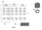
- An example is shown in Fig. 4 for a solar module (400) consisting of 54-72 cells (100) in series, typically in a meander-type fashion with a width of 9-12 cells (402) and one bypass diode (401) per 18-24 cells. The number of cells is typically coupled to the breakdown voltage of the solar cells used.
- a segment (403) comprising one series of solar cells and a bypass diode (401) is indicated as well.
- the 3 diodes in figure 4 are typically placed in a junction box (404) with a heat sink that is placed on the backside of each module.
- the present invention addresses the above problems by adding DC/DC converters on a single or multiple solar-cell level that add or subtract difference currents thereby increasing the output power of the complete PV system.
- the series and parallel connections of the solar modules in the PV system are left in tact.
- the present invention relates to a module comprising one or more PV solar cells, preferably 4 or more PV solar cells, more preferably 32 or more PV solar cells, each solar cell preferably comprising a photosensitive layer, wherein the one or more PV solar cells are arranged in one or more series, characterized in that the module comprises one or more current compensators, systems comprising said modules, and a method of operating said modules.
- the current compensator is integrated in the module.
- the one or more current compensators are integrated in a junction box, said junction box being typically present in or forming part of a module.
- Such a module overcomes the above-mentioned problems and drawbacks.
- the present invention further relates to:
- the present invention relates to a module comprising one or more PV solar cells, preferably 4 or more PV solar cells, more preferably 32 or more PV solar cells, each solar cell preferably comprising a photosensitive layer, wherein the one or more PV solar cells are arranged in one or more series, characterized in that the module comprises one or more current compensators.
- PV solar cell refers to any type of physical element wherein solar energy, i.e. light, is converted to electrical energy.
- solar energy i.e. light
- solar cell comprises a photosensitive layer; however, any structural element, capable of converting light into electrical energy is envisaged.
- a module typically comprises 60 or more PV cells.
- segments (403) can be distinguished comprising a series of solar cells and a bypass diode.
- segment (403) typically comprises connectors, going from a front side of the module to the back side thereof. These connectors are typically in connection with a junction box (404).
- a junction box will comprise one or more bypass diodes. As such the junction box is a preferred place to situate the one or more current compensators.
- any type of solar cell (100) can be modelled with an electrical circuit diagram as shown in Fig. 1a .
- I ins (101), a photodiode (102), R p (106), R s (103), and resulting I PV (104) and V PV (105) are shown.
- I-V characteristic is shown in Fig. 1b .
- short-circuit current I sc (109) in iraddiated (107) and dark (108) situations are shown, versus V.
- V max (112) open-circuit voltageV oc (111), I max (113) and P max (110) are shown.
- R s low-ohmic series resistance
- R p typically in a k ⁇ to M ⁇ range.
- a delivered power i.e. I PV *V PV is maximum.
- I PV I max
- V PV V max .
- a cell output current depends e.g. on amount of incoming light (insolation) and further cell behaviour is also temperature dependent, as a consequence the current and voltage value at which maximum power is obtained from a cell varies with environmental conditions. Therefore, in order to obtain a maximum output, in any practical solar system preferably this maximum power point needs to be continuously updated, which is referred to as Maximum-Power-Point Tracking (MPPT). In a sub-optimal configuration this is usually performed for all solar cells simultaneously.
- MPPT Maximum-Power-Point Tracking
- a practical module consists of a number of solar cells in series.
- the amount of series-connected solar cells inside a module ranges from 32-72.
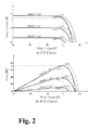
- Fig. 2 shows an example of the I-V (a) and P-V (b) characteristics of a solar module of 36 cells in series as a function of light and temperature as explained above.
- STC Standard Test Condition
- Practical values of the insolation current I ins for this amount of incoming light range from 3-9 A.
- a current at MPP is practically 7% lower than I ins .
- a practical value of MPP voltage is 0.5 V per cell, roughly 80% of V oc .
- a linear dependence of I ins on amount of incoming light can be clearly recognized from Fig. 2a .
- One of the major problems overcome by the present invention is decrease in output power due to sub-optimum performance of one or more PV solar cells present, e.g. due to shading, breakage, electrical disconnects, etc
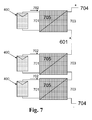
- One bypass diode (401) is placed across 20 cells (100).
- An incoming light strength of 1000 W/m 2 is assumed with an I ins (101) value of 8 A (604).
- I ins (101) value of 8 A (604) 604.
- one cell has been assumed to be completely malfunctioning e.g. due to shading, which relates to an extreme case where there is zero (no) current (605) flowing.
- the present invention does not have the above problems or drawbacks.
- a series typically comprises two or more cells, such as 10 or more cells.
- Each series typically comprises the above bypass diodes. Typically one bypass diode per group of 18-24 solar cells is present.
- the present invention relates to modules comprising one or more PV solar cells, characterized in that the module comprises one or more current compensators.
- Each compensator is in electrical connection to one or more PV solar cells.
- at least one compensator is present per segment (403) of solar cells, more preferred is one compensator per half a segment (403) of solar cells, even more preferred is one compensator per 4 PV solar cells, even more preferred is one compensator per 2 PV solar cells, and most preferred is one compensator per PV solar cell.
- the present current compensator is capable of compensating for current differences in the order of the maximum current output of the module.
- Such output is typically 8A.
- Current compensation can be done in two ways; adding a current to a module with a relatively lower current, which is typically lower than an average current, and removing a current from a module with a relatively higher current. Also combinations of current compensation are envisaged, such as in more complex systems, e.g. comprising many modules. By using one or more current compensators, which current compensators can then be considered to be in an active state, one module having a lower or no output can still provide a significantly higher output at a relatively low cost, namely the addition of one or more compensators to the module, and possibly some output loss in another module.
- the invention relates to a module, wherein the current compensator is a DC/DC converter, such as a bidirectional converter, wherein the converter is preferably a switched-mode converter, such as a flyback converter, preferably a unidirectional flyback converter.
- the current compensator is a DC/DC converter, such as a bidirectional converter
- the converter is preferably a switched-mode converter, such as a flyback converter, preferably a unidirectional flyback converter.
- a DC/DC converter In electronic engineering, a DC/DC converter is an electronic circuit, which converts a source of direct current (DC) from one voltage level to another. It is a class of power converter.
- a bi-directional converter offers power conversion between both a first voltage to a second voltage and a second voltage to a first voltage.
- the converter typically utilizes common magnetic components such as a transformer and a filter inductor and dual-function built-in diodes across transistors.
- Such a converter also typically utilizes a bridge converter, a push-pull converter, and a boost converter.
- a switched-mode power supply (also switching-mode power supply and SMPS) is an electronic power supply unit (PSU) that incorporates a switching regulator.
- the switched-mode power supply switches a power transistor between saturation (full on) and cutoff (completely off) with a variable duty cycle whose average is the desired output voltage. It switches at a much higher frequency (tens to hundreds of kHz) than that of the AC line (mains), which means that the transformer that it feeds can be much smaller than one connected directly to the line/mains. Switching creates a rectangular waveform that typically goes to the primary of the transformer; typically several secondary-side rectifiers, series inductors, and filter capacitors provide various DC outputs with low ripple.
- the main advantage of this method is greater efficiency because the switching transistor dissipates little power in the saturated state and the off state compared to the semiconducting state (active region).
- Other advantages include smaller size and lighter weight (from the elimination of low-frequency transformers which have a high weight) and lower heat generation due to higher efficiency.
- Disadvantages include greater complexity, the generation of high-amplitude, high-frequency energy that the low-pass filter must block to avoid electromagnetic interference (EMI), and a ripple voltage at the switching frequency and the harmonic frequencies thereof.
- the flyback converter is a DC/DC converter with a galvanic isolation between the input and the output(s).
- the flyback converter is a buck-boost converter with the inductor split to form a transformer, so that the voltage ratios are multiplied with an additional advantage of isolation.
- the rectifying diode of the Buck-Boost converter is left out and the device is called a flyback transformer.
- the inductor split is equivalent to that of a buck-boost converter, with the inductor split to form a transformer. Therefore the operating principle of both converters is very close:
- the switch is on, the primary of the transformer is directly connected to the input voltage source. This results in an increase of magnetic flux in the transformer.
- the voltage across the secondary winding is negative, so the diode is reverse-biased (i.e. blocked).
- the output capacitor supplies energy to the output load.
- the switch is off, the energy stored in the transformer is transferred to the output of the converter.
- flyback converter In the on-state, the energy is transferred from the input voltage source to the transformer (the output capacitor supplies energy to the output load). In the off-state, the energy is transferred from the transformer to the output load (and the output capacitor).
- the flyback converter may form an isolated power converter, in which case the isolation of the control circuit is also needed.
- the two prevailing control schemes are voltage-mode control and current-mode control. Both require a signal related to the output voltage. There are three common ways to generate this voltage. The first is to use an optocoupler on the secondary circuitry to send a signal to the controller. The second is to wind a separate winding on the coil and rely on the cross regulation of the design. The third is to use the reflected output voltage on the primary side during the flyback stroke (primary sensing).
- the invention relates to a module, further comprising one or more of a central controller, a monitor device, an isolated input, and an isolated output.
- a central controller can be used to optimize the output, e.g. in terms of number of active modules, actually delivering power, versus a prior-art situation wherein modules might even consume power.
- Such a controller calculates on-line, i.e. at any point in time, an optimum combination of active current compensators, both in terms of number of active current compensators and in terms of numbers of current compensators delivering a current and removing a current.
- a maximum output of a system comprising one ore more modules, is provided.
- a monitor device can be used to monitor individual performance of cells, segments, modules etc. As such it can be used to provide input to optimize performance of the present module.
- aDC/DC converter inside the module will comprise an isolated input and an isolated output.
- a module will have various components integrated. Such is advantageous in terms of costs, performance, area used, etc.
- the present invention relates to a string, comprising two or more modules according to the invention.
- the present modules are combined to strings, wherein the modules are placed in series.
- the present invention relates to an array, comprising two or more parallel strings according to the invention. Typically the present strings are combined to arrays.
- the present invention relates to a system, such as a stand-alone system, a residential system, a commercial system, or a solar plant, comprising two or more modules according to the invention, and/or comprising one or more strings according to the invention, and/or comprising one or more arrays according to the invention.
- a system such as a stand-alone system, a residential system, a commercial system, or a solar plant, comprising two or more modules according to the invention, and/or comprising one or more strings according to the invention, and/or comprising one or more arrays according to the invention.
- the present modules, strings, and/or arrays are combined to larger units, as mentioned above. Such is a process of scaling up facilities.
- the present invention relates to a method of operating two or more modules according to the invention, wherein a first solar cell provides a current output lower than a current output of a second solar cell, wherein a compensator provides a current to the first solar cell, or wherein a compensator subtracts a current from the second solar cell, and wherein the current is substantially equal to the difference between the current outputs of the first and second solar cell, respectively.
- the invention relates to a method, comprising a number of active compensators, wherein the number of active compensators is minimum.
- the number of active compensators is preferably minimum.
- an optimized output can be provided by determining a minimum set of active compensators.
- the invention relates to a method, wherein more than one first solar cells are present providing a current output lower than a current output of more than one second solar cells, wherein one or more current compensators provide a current to the more than one first solar cells and wherein one or more current compensators subtract a current from the more than one second solar cells.
- one or more, first, solar cells provide a lower output
- one or more, second, solar cells provide a higher output.
- the current subtracted may at the same time be provided to the first cells.
- the current may in some form be added to the total PV-system output current.
- the number of active compensators is minimum, as described above.
- FIG. 8 A basic idea of the present solution is shown in Fig. 8 .
- the figure shows two solar cells (100) in series with different insolation levels with associated different insolation currents I ins,1 (801) and I ins,2 (802).
- the basic idea is to add compensation current sources per cell that deliver current to the cell with the lowest I ins value and/or subtract current from the cell with the highest I ins value such that the net currents per cell are equal.
- the current sources per cell depicted in Fig. 8 are implemented with DC/DC converters (803). In its most versatile form, the current sources are bidirectional. Other implementations with unidirectional sources are also be envisioned.
- the associated power of adding or subtracting currents at the valid voltage level is either subtracted from or delivered to the PV system. Since the DC/DC converters compensate differences between cells, these converters can be named delta converters, as opposed to the sigma converters described above in the state-of-the-art. Further shown are different copensation-current values ⁇ I 1 (804) and ⁇ I 2 (805), solar cells (100), and the string current (601) imposed by the central MPPT controller.
- Fig. 9 illustrates possible scenarios for the example case where I ins,1 (801)>I ins,2 (802). Further ⁇ I (803) and I ins (101) values are shown.
- the same idea can be applied to more than one cell in series.
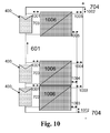
- one DC/DC converter can be added per segment of cells that is bypassed by one bypass diode, or one DC/DC converter can be added per module. The latter case is illustrated in Fig. 10 .
- the DC/DC converters will deliver or subtract the difference in current to or from the associated cells (I out ). The needed power for this is subtracted from the PV system (I in ) (in case additional current is delivered to the cells) or delivered to the PV system (in case current is subtracted from the associated cells).
- Fig. 11 depicts the output powers of several modules (1, 2, ..12) in a string (1102), in which differences occur.
- the power (1101) delivered by the string is depicted at the bottom, whereas the power converted through the delta converters (in the depicted case of a bidirectional implementation, a unipolar implementation is of course also possible) is depicted at the top.
- each delta converter needs to convert power between the module voltage level of e.g. 30 V (in case of a 60-cell module typical for many solar applications) and the string voltage level of e.g. 300 V (in case of 10 modules in series in a string).
- An alternative would be to generate an intermediate voltage centrally in the system from which all delta converters are supplied. The objective is to provide a lower-voltage solution for all delta converters in the system and having only one central high-voltage DC/DC converter.
- a central control function In order to control the current delivered or consumed by the delta converters, one could envision the use of a central control function. This is depicted in Fig. 13 . Here all delta converters (1006) (only two shown for simplicity, connections to modules and string, whether or not via intermediate supply also left out for simplicity) are connected to each other via a communication bus (1301) that is also fed to a central control function (1302). Alternatively, the delta converters could also determine the current to be delivered or subtracted individually.
- the total output power of the PV system is monitored in the central MPPT algorithm.
- This algorithm still resides inside the central inverter.
- the information of this MPP may be fed back to the delta converters, optionally via some form of central control function overseeing the delta-converter operation to find the optimum operating point.
- FIG. 14 A known basic embodiment of a bidirectional DC/DC converter (1006) that allows for different input (1401) and output terminal (1402) voltage levels due to the isolation obtained using a transformer/coupled set of coils is depicted in Figure 14 .
- Unidirectional versions can be derived from this figure by replacing one of the switches by a diode.
- a specific example of a unidirectional converter is a flyback converter that can only deliver current to modules.
- the flyback converter can be given multiple outputs, e.g. one output per section normally bridged by a bypass diode.
- This multi-output converter, or one converter per bypass section may be placed in the junction box, either in combination with the existing bypass diodes or replacing them.
Priority Applications (5)
| Application Number | Priority Date | Filing Date | Title |
|---|---|---|---|
| EP20090159824 EP2249457A1 (fr) | 2009-05-08 | 2009-05-08 | Cellule solaire PV |
| EP20090786562 EP2427946A1 (fr) | 2009-05-08 | 2009-07-10 | Unités photovoltaïques, procédés d'exploitation d'unités photovoltaïques et régulateurs à cet effet |
| CN2009801591152A CN102422506A (zh) | 2009-05-08 | 2009-07-10 | 光伏单元、操作光伏单元的方法及其控制器 |
| PCT/IB2009/053001 WO2010128363A1 (fr) | 2009-05-08 | 2009-07-10 | Unités photovoltaïques, procédés d'exploitation d'unités photovoltaïques et régulateurs à cet effet |
| US13/318,730 US20120098344A1 (en) | 2009-05-08 | 2009-07-10 | Photovoltaic units, methods of operating photovoltaic units and controllers therefor |
Applications Claiming Priority (1)
| Application Number | Priority Date | Filing Date | Title |
|---|---|---|---|
| EP20090159824 EP2249457A1 (fr) | 2009-05-08 | 2009-05-08 | Cellule solaire PV |
Publications (1)
| Publication Number | Publication Date |
|---|---|
| EP2249457A1 true EP2249457A1 (fr) | 2010-11-10 |
Family
ID=41263702
Family Applications (2)
| Application Number | Title | Priority Date | Filing Date |
|---|---|---|---|
| EP20090159824 Withdrawn EP2249457A1 (fr) | 2009-05-08 | 2009-05-08 | Cellule solaire PV |
| EP20090786562 Withdrawn EP2427946A1 (fr) | 2009-05-08 | 2009-07-10 | Unités photovoltaïques, procédés d'exploitation d'unités photovoltaïques et régulateurs à cet effet |
Family Applications After (1)
| Application Number | Title | Priority Date | Filing Date |
|---|---|---|---|
| EP20090786562 Withdrawn EP2427946A1 (fr) | 2009-05-08 | 2009-07-10 | Unités photovoltaïques, procédés d'exploitation d'unités photovoltaïques et régulateurs à cet effet |
Country Status (4)
| Country | Link |
|---|---|
| US (1) | US20120098344A1 (fr) |
| EP (2) | EP2249457A1 (fr) |
| CN (1) | CN102422506A (fr) |
| WO (1) | WO2010128363A1 (fr) |
Cited By (59)
| Publication number | Priority date | Publication date | Assignee | Title |
|---|---|---|---|---|
| CN102522919A (zh) * | 2011-12-08 | 2012-06-27 | 常州天合光能有限公司 | 智能光伏组件及其控制方法 |
| EP2479868A1 (fr) * | 2011-01-25 | 2012-07-25 | ABB Oy | Procédé et appareil pour contrôler les tensions dans des alimentations électriques cc connectées en série |
| CN102916393A (zh) * | 2012-10-09 | 2013-02-06 | 祝厉华 | 太阳能电池保护器、太阳能电池组及太阳能电池保护芯片 |
| WO2012074808A3 (fr) * | 2010-12-02 | 2013-02-28 | Dow Global Technologies Llc | Dispositif photovoltaïque pour mesurer l'irradiation et la température |
| GB2496139A (en) * | 2011-11-01 | 2013-05-08 | Enecsys Ltd | Photovoltaic power conditioning circuit |
| GB2496140A (en) * | 2011-11-01 | 2013-05-08 | Enecsys Ltd | Photovoltaic power conditioning circuit |
| WO2013064828A1 (fr) | 2011-11-01 | 2013-05-10 | Enecsys Limited | Unités de conditionnement d'énergie photovoltaïque |
| US20130320771A1 (en) * | 2012-06-04 | 2013-12-05 | Solaredge Technologies Ltd. | Integrated Photovoltaic Panel Circuitry |
| US8674668B2 (en) | 2010-06-07 | 2014-03-18 | Enecsys Limited | Solar photovoltaic systems |
| CN104320043A (zh) * | 2014-09-24 | 2015-01-28 | 中国人民解放军空军工程设计研究局 | 一种光伏单元及其实现方法 |
| EP2752882A4 (fr) * | 2011-08-30 | 2015-05-27 | Jx Nippon Oil & Energy Corp | Dispositif de calcul optimisant la génération électrique solaire, procédé optimisant la génération électrique solaire, système de génération électrique solaire et système de simulation de génération électrique solaire |
| CN104898753A (zh) * | 2015-04-14 | 2015-09-09 | 华南理工大学 | 串联太阳能电池电流匹配电路及其控制方法 |
| US9639106B2 (en) | 2012-03-05 | 2017-05-02 | Solaredge Technologies Ltd. | Direct current link circuit |
| US9812984B2 (en) | 2012-01-30 | 2017-11-07 | Solaredge Technologies Ltd. | Maximizing power in a photovoltaic distributed power system |
| US9853565B2 (en) | 2012-01-30 | 2017-12-26 | Solaredge Technologies Ltd. | Maximized power in a photovoltaic distributed power system |
| US9853538B2 (en) | 2007-12-04 | 2017-12-26 | Solaredge Technologies Ltd. | Distributed power harvesting systems using DC power sources |
| US9853490B2 (en) | 2006-12-06 | 2017-12-26 | Solaredge Technologies Ltd. | Distributed power system using direct current power sources |
| US9866098B2 (en) | 2011-01-12 | 2018-01-09 | Solaredge Technologies Ltd. | Serially connected inverters |
| US9869701B2 (en) | 2009-05-26 | 2018-01-16 | Solaredge Technologies Ltd. | Theft detection and prevention in a power generation system |
| US9876430B2 (en) | 2008-03-24 | 2018-01-23 | Solaredge Technologies Ltd. | Zero voltage switching |
| US9935458B2 (en) | 2010-12-09 | 2018-04-03 | Solaredge Technologies Ltd. | Disconnection of a string carrying direct current power |
| US9948233B2 (en) | 2006-12-06 | 2018-04-17 | Solaredge Technologies Ltd. | Distributed power harvesting systems using DC power sources |
| US9960731B2 (en) | 2006-12-06 | 2018-05-01 | Solaredge Technologies Ltd. | Pairing of components in a direct current distributed power generation system |
| US9966766B2 (en) | 2006-12-06 | 2018-05-08 | Solaredge Technologies Ltd. | Battery power delivery module |
| US9979280B2 (en) | 2007-12-05 | 2018-05-22 | Solaredge Technologies Ltd. | Parallel connected inverters |
| US10061957B2 (en) | 2016-03-03 | 2018-08-28 | Solaredge Technologies Ltd. | Methods for mapping power generation installations |
| US10097007B2 (en) | 2006-12-06 | 2018-10-09 | Solaredge Technologies Ltd. | Method for distributed power harvesting using DC power sources |
| CN108694276A (zh) * | 2018-04-27 | 2018-10-23 | 河海大学常州校区 | 一种计算串并联光伏组件输出特性的方法 |
| US10116217B2 (en) | 2007-08-06 | 2018-10-30 | Solaredge Technologies Ltd. | Digital average input current control in power converter |
| US10184965B2 (en) | 2006-12-06 | 2019-01-22 | Solaredge Technologies Ltd. | Monitoring of distributed power harvesting systems using DC power sources |
| US10230310B2 (en) | 2016-04-05 | 2019-03-12 | Solaredge Technologies Ltd | Safety switch for photovoltaic systems |
| US10381977B2 (en) | 2012-01-30 | 2019-08-13 | Solaredge Technologies Ltd | Photovoltaic panel circuitry |
| US10396662B2 (en) | 2011-09-12 | 2019-08-27 | Solaredge Technologies Ltd | Direct current link circuit |
| US10461687B2 (en) | 2008-12-04 | 2019-10-29 | Solaredge Technologies Ltd. | Testing of a photovoltaic panel |
| US10468878B2 (en) | 2008-05-05 | 2019-11-05 | Solaredge Technologies Ltd. | Direct current power combiner |
| US10599113B2 (en) | 2016-03-03 | 2020-03-24 | Solaredge Technologies Ltd. | Apparatus and method for determining an order of power devices in power generation systems |
| US10637393B2 (en) | 2006-12-06 | 2020-04-28 | Solaredge Technologies Ltd. | Distributed power harvesting systems using DC power sources |
| US10651647B2 (en) | 2013-03-15 | 2020-05-12 | Solaredge Technologies Ltd. | Bypass mechanism |
| US10673229B2 (en) | 2010-11-09 | 2020-06-02 | Solaredge Technologies Ltd. | Arc detection and prevention in a power generation system |
| US10673222B2 (en) | 2010-11-09 | 2020-06-02 | Solaredge Technologies Ltd. | Arc detection and prevention in a power generation system |
| US10778025B2 (en) | 2013-03-14 | 2020-09-15 | Solaredge Technologies Ltd. | Method and apparatus for storing and depleting energy |
| CN112385108A (zh) * | 2018-07-05 | 2021-02-19 | Abb 瑞士股份有限公司 | 用于太阳能电力系统性能模型调谐的技术 |
| US10931119B2 (en) | 2012-01-11 | 2021-02-23 | Solaredge Technologies Ltd. | Photovoltaic module |
| US10931228B2 (en) | 2010-11-09 | 2021-02-23 | Solaredge Technologies Ftd. | Arc detection and prevention in a power generation system |
| US11018623B2 (en) | 2016-04-05 | 2021-05-25 | Solaredge Technologies Ltd. | Safety switch for photovoltaic systems |
| US11031861B2 (en) | 2006-12-06 | 2021-06-08 | Solaredge Technologies Ltd. | System and method for protection during inverter shutdown in distributed power installations |
| US11081608B2 (en) | 2016-03-03 | 2021-08-03 | Solaredge Technologies Ltd. | Apparatus and method for determining an order of power devices in power generation systems |
| US11177663B2 (en) | 2016-04-05 | 2021-11-16 | Solaredge Technologies Ltd. | Chain of power devices |
| US11264947B2 (en) | 2007-12-05 | 2022-03-01 | Solaredge Technologies Ltd. | Testing of a photovoltaic panel |
| US11296650B2 (en) | 2006-12-06 | 2022-04-05 | Solaredge Technologies Ltd. | System and method for protection during inverter shutdown in distributed power installations |
| US11309832B2 (en) | 2006-12-06 | 2022-04-19 | Solaredge Technologies Ltd. | Distributed power harvesting systems using DC power sources |
| US11569659B2 (en) | 2006-12-06 | 2023-01-31 | Solaredge Technologies Ltd. | Distributed power harvesting systems using DC power sources |
| US11569660B2 (en) | 2006-12-06 | 2023-01-31 | Solaredge Technologies Ltd. | Distributed power harvesting systems using DC power sources |
| US11687112B2 (en) | 2006-12-06 | 2023-06-27 | Solaredge Technologies Ltd. | Distributed power harvesting systems using DC power sources |
| US11728768B2 (en) | 2006-12-06 | 2023-08-15 | Solaredge Technologies Ltd. | Pairing of components in a direct current distributed power generation system |
| US11735910B2 (en) | 2006-12-06 | 2023-08-22 | Solaredge Technologies Ltd. | Distributed power system using direct current power sources |
| US11855231B2 (en) | 2006-12-06 | 2023-12-26 | Solaredge Technologies Ltd. | Distributed power harvesting systems using DC power sources |
| US11881814B2 (en) | 2005-12-05 | 2024-01-23 | Solaredge Technologies Ltd. | Testing of a photovoltaic panel |
| US11888387B2 (en) | 2006-12-06 | 2024-01-30 | Solaredge Technologies Ltd. | Safety mechanisms, wake up and shutdown methods in distributed power installations |
Families Citing this family (25)
| Publication number | Priority date | Publication date | Assignee | Title |
|---|---|---|---|---|
| EP2232663B2 (fr) | 2007-12-05 | 2021-05-26 | Solaredge Technologies Ltd. | Mécanismes de sécurité, procédés d'éveil et d'arrêt dans des installations de puissance réparties |
| US8289742B2 (en) | 2007-12-05 | 2012-10-16 | Solaredge Ltd. | Parallel connected inverters |
| EP2280469B1 (fr) * | 2009-07-30 | 2016-07-06 | Nxp B.V. | Unité photovoltaïque, son convertisseur cc/cc, et son procédé de fonctionnement |
| US9502897B2 (en) | 2011-02-12 | 2016-11-22 | SolarBread LTD | Systems and methods for photovoltaic micro-inverter power harvesting efficiency increase in shaded conditions |
| US9246330B2 (en) | 2011-05-06 | 2016-01-26 | First Solar, Inc. | Photovoltaic device |
| US10181541B2 (en) * | 2011-11-20 | 2019-01-15 | Tesla, Inc. | Smart photovoltaic cells and modules |
| WO2013075144A1 (fr) | 2011-11-20 | 2013-05-23 | Solexel, Inc. | Cellules photovoltaïques intelligentes et modules associés |
| CN102664205A (zh) * | 2012-05-22 | 2012-09-12 | 天津力神电池股份有限公司 | 一种基于多二极管模块的防遮挡太阳能电池组件 |
| US9270226B2 (en) | 2012-09-04 | 2016-02-23 | Texas Instruments Incorporated | Noninvasive monitoring of a photovoltaic system |
| FI124919B (fi) * | 2012-09-19 | 2015-03-31 | Ecoeco Oy | Järjestely energialähdejärjestelmän ohjaamiseksi |
| EP2746793A1 (fr) | 2012-12-21 | 2014-06-25 | Nxp B.V. | Procédé et dispositif de caractérisation d'un cellule photovoltaïque et module photovoltaïque |
| CN104113073A (zh) * | 2013-04-17 | 2014-10-22 | 上海康威特吉能源技术有限公司 | 一种新能源发电系统以及分布式混合最大功率跟踪方法 |
| JP5842860B2 (ja) * | 2013-04-25 | 2016-01-13 | 株式会社安川電機 | 系統連系装置 |
| GB2513868A (en) * | 2013-05-07 | 2014-11-12 | Control Tech Ltd | High performance voltage compensation |
| WO2015011934A1 (fr) * | 2013-07-26 | 2015-01-29 | 京セラ株式会社 | Dispositif de gestion d'énergie, système de gestion d'énergie et procédé de gestion d'énergie |
| US9461581B2 (en) * | 2013-11-06 | 2016-10-04 | Ablerex Electronics Co., Ltd. | Shadowing compensation device for solar cell module |
| EP3291403B8 (fr) * | 2014-03-03 | 2020-08-05 | Solarlytics, Inc. | Système et procédé de gestion d'une pluralité de dispositifs photovoltaïques |
| JP2018509869A (ja) | 2015-03-25 | 2018-04-05 | サンパワー コーポレイション | コンバータのトポロジ及び制御 |
| US20170125621A1 (en) * | 2015-10-29 | 2017-05-04 | The Boeing Company | Multi-junction solar cell with self compensating sub-cells |
| CN105763153A (zh) * | 2016-03-30 | 2016-07-13 | 中国矿业大学 | 一种基于超级电容的智能光伏组件 |
| US9954462B2 (en) | 2016-06-30 | 2018-04-24 | Sunpower Corporation | Converter topologies and control |
| JP6710868B2 (ja) | 2016-06-30 | 2020-06-17 | 国立大学法人 東京大学 | 送信装置、受信装置、監視装置および太陽光発電システム |
| CN107139769B (zh) * | 2017-07-07 | 2023-08-08 | 深圳市皇驰科技有限公司 | 一种基于太阳能供电的智能型充电桩 |
| JP2021027361A (ja) * | 2019-08-07 | 2021-02-22 | ソーラーエッジ テクノロジーズ リミテッド | ソーラ−パネル配列 |
| CN114977985A (zh) * | 2022-04-25 | 2022-08-30 | 西安电子科技大学 | 基于电流注入的光伏发电系统新型拓扑结构 |
Citations (2)
| Publication number | Priority date | Publication date | Assignee | Title |
|---|---|---|---|---|
| DE10219956A1 (de) * | 2001-05-18 | 2003-04-30 | Webasto Vehicle Sys Int Gmbh | Solarsystem |
| US20050139258A1 (en) * | 2003-12-29 | 2005-06-30 | Yung-Hsiang Liu | Solar cell array control device |
Family Cites Families (3)
| Publication number | Priority date | Publication date | Assignee | Title |
|---|---|---|---|---|
| DE10222621A1 (de) * | 2002-05-17 | 2003-11-27 | Josef Steger | Verfahren und Schaltungsanordnung zur Steuer- und Regelung von Photovoltaikanlagen |
| EP1585178B1 (fr) * | 2003-01-14 | 2011-08-31 | Mitsubishi Heavy Industries, Ltd. | Ensemble de modules solaires, systeme de cablage et systeme de generation d'electricite solaire |
| TW200519557A (en) * | 2003-12-02 | 2005-06-16 | Ind Tech Res Inst | Control device of solar cell array |
-
2009
- 2009-05-08 EP EP20090159824 patent/EP2249457A1/fr not_active Withdrawn
- 2009-07-10 US US13/318,730 patent/US20120098344A1/en not_active Abandoned
- 2009-07-10 WO PCT/IB2009/053001 patent/WO2010128363A1/fr active Application Filing
- 2009-07-10 EP EP20090786562 patent/EP2427946A1/fr not_active Withdrawn
- 2009-07-10 CN CN2009801591152A patent/CN102422506A/zh active Pending
Patent Citations (2)
| Publication number | Priority date | Publication date | Assignee | Title |
|---|---|---|---|---|
| DE10219956A1 (de) * | 2001-05-18 | 2003-04-30 | Webasto Vehicle Sys Int Gmbh | Solarsystem |
| US20050139258A1 (en) * | 2003-12-29 | 2005-06-30 | Yung-Hsiang Liu | Solar cell array control device |
Cited By (118)
| Publication number | Priority date | Publication date | Assignee | Title |
|---|---|---|---|---|
| US11881814B2 (en) | 2005-12-05 | 2024-01-23 | Solaredge Technologies Ltd. | Testing of a photovoltaic panel |
| US11476799B2 (en) | 2006-12-06 | 2022-10-18 | Solaredge Technologies Ltd. | Distributed power harvesting systems using DC power sources |
| US10637393B2 (en) | 2006-12-06 | 2020-04-28 | Solaredge Technologies Ltd. | Distributed power harvesting systems using DC power sources |
| US10447150B2 (en) | 2006-12-06 | 2019-10-15 | Solaredge Technologies Ltd. | Distributed power harvesting systems using DC power sources |
| US11888387B2 (en) | 2006-12-06 | 2024-01-30 | Solaredge Technologies Ltd. | Safety mechanisms, wake up and shutdown methods in distributed power installations |
| US11962243B2 (en) | 2006-12-06 | 2024-04-16 | Solaredge Technologies Ltd. | Method for distributed power harvesting using DC power sources |
| US11855231B2 (en) | 2006-12-06 | 2023-12-26 | Solaredge Technologies Ltd. | Distributed power harvesting systems using DC power sources |
| US11735910B2 (en) | 2006-12-06 | 2023-08-22 | Solaredge Technologies Ltd. | Distributed power system using direct current power sources |
| US11728768B2 (en) | 2006-12-06 | 2023-08-15 | Solaredge Technologies Ltd. | Pairing of components in a direct current distributed power generation system |
| US9853490B2 (en) | 2006-12-06 | 2017-12-26 | Solaredge Technologies Ltd. | Distributed power system using direct current power sources |
| US11687112B2 (en) | 2006-12-06 | 2023-06-27 | Solaredge Technologies Ltd. | Distributed power harvesting systems using DC power sources |
| US11682918B2 (en) | 2006-12-06 | 2023-06-20 | Solaredge Technologies Ltd. | Battery power delivery module |
| US11658482B2 (en) | 2006-12-06 | 2023-05-23 | Solaredge Technologies Ltd. | Distributed power harvesting systems using DC power sources |
| US11598652B2 (en) | 2006-12-06 | 2023-03-07 | Solaredge Technologies Ltd. | Monitoring of distributed power harvesting systems using DC power sources |
| US10673253B2 (en) | 2006-12-06 | 2020-06-02 | Solaredge Technologies Ltd. | Battery power delivery module |
| US11594882B2 (en) | 2006-12-06 | 2023-02-28 | Solaredge Technologies Ltd. | Distributed power harvesting systems using DC power sources |
| US11594881B2 (en) | 2006-12-06 | 2023-02-28 | Solaredge Technologies Ltd. | Distributed power harvesting systems using DC power sources |
| US10230245B2 (en) | 2006-12-06 | 2019-03-12 | Solaredge Technologies Ltd | Battery power delivery module |
| US11575260B2 (en) | 2006-12-06 | 2023-02-07 | Solaredge Technologies Ltd. | Distributed power harvesting systems using DC power sources |
| US11575261B2 (en) | 2006-12-06 | 2023-02-07 | Solaredge Technologies Ltd. | Distributed power harvesting systems using DC power sources |
| US11569660B2 (en) | 2006-12-06 | 2023-01-31 | Solaredge Technologies Ltd. | Distributed power harvesting systems using DC power sources |
| US11569659B2 (en) | 2006-12-06 | 2023-01-31 | Solaredge Technologies Ltd. | Distributed power harvesting systems using DC power sources |
| US10184965B2 (en) | 2006-12-06 | 2019-01-22 | Solaredge Technologies Ltd. | Monitoring of distributed power harvesting systems using DC power sources |
| US11309832B2 (en) | 2006-12-06 | 2022-04-19 | Solaredge Technologies Ltd. | Distributed power harvesting systems using DC power sources |
| US11961922B2 (en) | 2006-12-06 | 2024-04-16 | Solaredge Technologies Ltd. | Distributed power harvesting systems using DC power sources |
| US11594880B2 (en) | 2006-12-06 | 2023-02-28 | Solaredge Technologies Ltd. | Distributed power harvesting systems using DC power sources |
| US11296650B2 (en) | 2006-12-06 | 2022-04-05 | Solaredge Technologies Ltd. | System and method for protection during inverter shutdown in distributed power installations |
| US11031861B2 (en) | 2006-12-06 | 2021-06-08 | Solaredge Technologies Ltd. | System and method for protection during inverter shutdown in distributed power installations |
| US11043820B2 (en) | 2006-12-06 | 2021-06-22 | Solaredge Technologies Ltd. | Battery power delivery module |
| US9948233B2 (en) | 2006-12-06 | 2018-04-17 | Solaredge Technologies Ltd. | Distributed power harvesting systems using DC power sources |
| US9960731B2 (en) | 2006-12-06 | 2018-05-01 | Solaredge Technologies Ltd. | Pairing of components in a direct current distributed power generation system |
| US9966766B2 (en) | 2006-12-06 | 2018-05-08 | Solaredge Technologies Ltd. | Battery power delivery module |
| US11063440B2 (en) | 2006-12-06 | 2021-07-13 | Solaredge Technologies Ltd. | Method for distributed power harvesting using DC power sources |
| US11183922B2 (en) | 2006-12-06 | 2021-11-23 | Solaredge Technologies Ltd. | Distributed power harvesting systems using DC power sources |
| US10097007B2 (en) | 2006-12-06 | 2018-10-09 | Solaredge Technologies Ltd. | Method for distributed power harvesting using DC power sources |
| US10116217B2 (en) | 2007-08-06 | 2018-10-30 | Solaredge Technologies Ltd. | Digital average input current control in power converter |
| US10516336B2 (en) | 2007-08-06 | 2019-12-24 | Solaredge Technologies Ltd. | Digital average input current control in power converter |
| US11594968B2 (en) | 2007-08-06 | 2023-02-28 | Solaredge Technologies Ltd. | Digital average input current control in power converter |
| US9853538B2 (en) | 2007-12-04 | 2017-12-26 | Solaredge Technologies Ltd. | Distributed power harvesting systems using DC power sources |
| US11183923B2 (en) | 2007-12-05 | 2021-11-23 | Solaredge Technologies Ltd. | Parallel connected inverters |
| US11183969B2 (en) | 2007-12-05 | 2021-11-23 | Solaredge Technologies Ltd. | Testing of a photovoltaic panel |
| US9979280B2 (en) | 2007-12-05 | 2018-05-22 | Solaredge Technologies Ltd. | Parallel connected inverters |
| US11264947B2 (en) | 2007-12-05 | 2022-03-01 | Solaredge Technologies Ltd. | Testing of a photovoltaic panel |
| US10644589B2 (en) | 2007-12-05 | 2020-05-05 | Solaredge Technologies Ltd. | Parallel connected inverters |
| US11693080B2 (en) | 2007-12-05 | 2023-07-04 | Solaredge Technologies Ltd. | Parallel connected inverters |
| US11894806B2 (en) | 2007-12-05 | 2024-02-06 | Solaredge Technologies Ltd. | Testing of a photovoltaic panel |
| US9876430B2 (en) | 2008-03-24 | 2018-01-23 | Solaredge Technologies Ltd. | Zero voltage switching |
| US11424616B2 (en) | 2008-05-05 | 2022-08-23 | Solaredge Technologies Ltd. | Direct current power combiner |
| US10468878B2 (en) | 2008-05-05 | 2019-11-05 | Solaredge Technologies Ltd. | Direct current power combiner |
| US10461687B2 (en) | 2008-12-04 | 2019-10-29 | Solaredge Technologies Ltd. | Testing of a photovoltaic panel |
| US11867729B2 (en) | 2009-05-26 | 2024-01-09 | Solaredge Technologies Ltd. | Theft detection and prevention in a power generation system |
| US10969412B2 (en) | 2009-05-26 | 2021-04-06 | Solaredge Technologies Ltd. | Theft detection and prevention in a power generation system |
| US9869701B2 (en) | 2009-05-26 | 2018-01-16 | Solaredge Technologies Ltd. | Theft detection and prevention in a power generation system |
| US8674668B2 (en) | 2010-06-07 | 2014-03-18 | Enecsys Limited | Solar photovoltaic systems |
| US9496803B2 (en) | 2010-06-07 | 2016-11-15 | Solarcity Corporation | Solar photovoltaic system with maximized ripple voltage on storage capacitor |
| US11070051B2 (en) | 2010-11-09 | 2021-07-20 | Solaredge Technologies Ltd. | Arc detection and prevention in a power generation system |
| US11489330B2 (en) | 2010-11-09 | 2022-11-01 | Solaredge Technologies Ltd. | Arc detection and prevention in a power generation system |
| US11349432B2 (en) | 2010-11-09 | 2022-05-31 | Solaredge Technologies Ltd. | Arc detection and prevention in a power generation system |
| US10673229B2 (en) | 2010-11-09 | 2020-06-02 | Solaredge Technologies Ltd. | Arc detection and prevention in a power generation system |
| US10673222B2 (en) | 2010-11-09 | 2020-06-02 | Solaredge Technologies Ltd. | Arc detection and prevention in a power generation system |
| US10931228B2 (en) | 2010-11-09 | 2021-02-23 | Solaredge Technologies Ftd. | Arc detection and prevention in a power generation system |
| CN103250260A (zh) * | 2010-12-02 | 2013-08-14 | 陶氏环球技术有限责任公司 | 用于测量辐照度和温度的光伏器件 |
| WO2012074808A3 (fr) * | 2010-12-02 | 2013-02-28 | Dow Global Technologies Llc | Dispositif photovoltaïque pour mesurer l'irradiation et la température |
| US9935458B2 (en) | 2010-12-09 | 2018-04-03 | Solaredge Technologies Ltd. | Disconnection of a string carrying direct current power |
| US11271394B2 (en) | 2010-12-09 | 2022-03-08 | Solaredge Technologies Ltd. | Disconnection of a string carrying direct current power |
| US10141745B2 (en) | 2011-01-11 | 2018-11-27 | Tesla, Inc. | Photovoltaic power conditioning units |
| US10666125B2 (en) | 2011-01-12 | 2020-05-26 | Solaredge Technologies Ltd. | Serially connected inverters |
| US11205946B2 (en) | 2011-01-12 | 2021-12-21 | Solaredge Technologies Ltd. | Serially connected inverters |
| US9866098B2 (en) | 2011-01-12 | 2018-01-09 | Solaredge Technologies Ltd. | Serially connected inverters |
| EP2479868A1 (fr) * | 2011-01-25 | 2012-07-25 | ABB Oy | Procédé et appareil pour contrôler les tensions dans des alimentations électriques cc connectées en série |
| EP2752882A4 (fr) * | 2011-08-30 | 2015-05-27 | Jx Nippon Oil & Energy Corp | Dispositif de calcul optimisant la génération électrique solaire, procédé optimisant la génération électrique solaire, système de génération électrique solaire et système de simulation de génération électrique solaire |
| US10396662B2 (en) | 2011-09-12 | 2019-08-27 | Solaredge Technologies Ltd | Direct current link circuit |
| WO2013064828A1 (fr) | 2011-11-01 | 2013-05-10 | Enecsys Limited | Unités de conditionnement d'énergie photovoltaïque |
| US8526205B2 (en) | 2011-11-01 | 2013-09-03 | Enecsys Limited | Photovoltaic power conditioning units |
| US9520803B2 (en) | 2011-11-01 | 2016-12-13 | Solarcity Corporation | Photovoltaic power conditioning units |
| GB2496140A (en) * | 2011-11-01 | 2013-05-08 | Enecsys Ltd | Photovoltaic power conditioning circuit |
| GB2496139B (en) * | 2011-11-01 | 2016-05-04 | Solarcity Corp | Photovoltaic power conditioning units |
| GB2496140B (en) * | 2011-11-01 | 2016-05-04 | Solarcity Corp | Photovoltaic power conditioning units |
| US8472220B2 (en) | 2011-11-01 | 2013-06-25 | Enecsys Limited | Photovoltaic power conditioning units |
| GB2496139A (en) * | 2011-11-01 | 2013-05-08 | Enecsys Ltd | Photovoltaic power conditioning circuit |
| CN102522919A (zh) * | 2011-12-08 | 2012-06-27 | 常州天合光能有限公司 | 智能光伏组件及其控制方法 |
| US10931119B2 (en) | 2012-01-11 | 2021-02-23 | Solaredge Technologies Ltd. | Photovoltaic module |
| US10992238B2 (en) | 2012-01-30 | 2021-04-27 | Solaredge Technologies Ltd. | Maximizing power in a photovoltaic distributed power system |
| US11620885B2 (en) | 2012-01-30 | 2023-04-04 | Solaredge Technologies Ltd. | Photovoltaic panel circuitry |
| US10381977B2 (en) | 2012-01-30 | 2019-08-13 | Solaredge Technologies Ltd | Photovoltaic panel circuitry |
| US9812984B2 (en) | 2012-01-30 | 2017-11-07 | Solaredge Technologies Ltd. | Maximizing power in a photovoltaic distributed power system |
| US11929620B2 (en) | 2012-01-30 | 2024-03-12 | Solaredge Technologies Ltd. | Maximizing power in a photovoltaic distributed power system |
| US10608553B2 (en) | 2012-01-30 | 2020-03-31 | Solaredge Technologies Ltd. | Maximizing power in a photovoltaic distributed power system |
| US9853565B2 (en) | 2012-01-30 | 2017-12-26 | Solaredge Technologies Ltd. | Maximized power in a photovoltaic distributed power system |
| US11183968B2 (en) | 2012-01-30 | 2021-11-23 | Solaredge Technologies Ltd. | Photovoltaic panel circuitry |
| US10007288B2 (en) | 2012-03-05 | 2018-06-26 | Solaredge Technologies Ltd. | Direct current link circuit |
| US9639106B2 (en) | 2012-03-05 | 2017-05-02 | Solaredge Technologies Ltd. | Direct current link circuit |
| US11177768B2 (en) * | 2012-06-04 | 2021-11-16 | Solaredge Technologies Ltd. | Integrated photovoltaic panel circuitry |
| US20180374966A1 (en) * | 2012-06-04 | 2018-12-27 | Solaredge Technologies Ltd. | Integrated Photovoltaic Panel Circuitry |
| US20130320771A1 (en) * | 2012-06-04 | 2013-12-05 | Solaredge Technologies Ltd. | Integrated Photovoltaic Panel Circuitry |
| US10115841B2 (en) * | 2012-06-04 | 2018-10-30 | Solaredge Technologies Ltd. | Integrated photovoltaic panel circuitry |
| CN102916393B (zh) * | 2012-10-09 | 2014-11-26 | 祝厉华 | 太阳能电池保护器、太阳能电池组及太阳能电池保护芯片 |
| CN102916393A (zh) * | 2012-10-09 | 2013-02-06 | 祝厉华 | 太阳能电池保护器、太阳能电池组及太阳能电池保护芯片 |
| US10778025B2 (en) | 2013-03-14 | 2020-09-15 | Solaredge Technologies Ltd. | Method and apparatus for storing and depleting energy |
| US11424617B2 (en) | 2013-03-15 | 2022-08-23 | Solaredge Technologies Ltd. | Bypass mechanism |
| US10651647B2 (en) | 2013-03-15 | 2020-05-12 | Solaredge Technologies Ltd. | Bypass mechanism |
| CN104320043A (zh) * | 2014-09-24 | 2015-01-28 | 中国人民解放军空军工程设计研究局 | 一种光伏单元及其实现方法 |
| CN104898753A (zh) * | 2015-04-14 | 2015-09-09 | 华南理工大学 | 串联太阳能电池电流匹配电路及其控制方法 |
| US10061957B2 (en) | 2016-03-03 | 2018-08-28 | Solaredge Technologies Ltd. | Methods for mapping power generation installations |
| US10599113B2 (en) | 2016-03-03 | 2020-03-24 | Solaredge Technologies Ltd. | Apparatus and method for determining an order of power devices in power generation systems |
| US10540530B2 (en) | 2016-03-03 | 2020-01-21 | Solaredge Technologies Ltd. | Methods for mapping power generation installations |
| US11081608B2 (en) | 2016-03-03 | 2021-08-03 | Solaredge Technologies Ltd. | Apparatus and method for determining an order of power devices in power generation systems |
| US11824131B2 (en) | 2016-03-03 | 2023-11-21 | Solaredge Technologies Ltd. | Apparatus and method for determining an order of power devices in power generation systems |
| US11538951B2 (en) | 2016-03-03 | 2022-12-27 | Solaredge Technologies Ltd. | Apparatus and method for determining an order of power devices in power generation systems |
| US11018623B2 (en) | 2016-04-05 | 2021-05-25 | Solaredge Technologies Ltd. | Safety switch for photovoltaic systems |
| US11177663B2 (en) | 2016-04-05 | 2021-11-16 | Solaredge Technologies Ltd. | Chain of power devices |
| US10230310B2 (en) | 2016-04-05 | 2019-03-12 | Solaredge Technologies Ltd | Safety switch for photovoltaic systems |
| US11870250B2 (en) | 2016-04-05 | 2024-01-09 | Solaredge Technologies Ltd. | Chain of power devices |
| US11201476B2 (en) | 2016-04-05 | 2021-12-14 | Solaredge Technologies Ltd. | Photovoltaic power device and wiring |
| CN108694276A (zh) * | 2018-04-27 | 2018-10-23 | 河海大学常州校区 | 一种计算串并联光伏组件输出特性的方法 |
| CN108694276B (zh) * | 2018-04-27 | 2022-04-26 | 河海大学常州校区 | 一种计算串并联光伏组件输出特性的方法 |
| US11949239B2 (en) | 2018-07-05 | 2024-04-02 | Hitachi Energy Switzerland Ag | Technologies for solar power system performance model tuning |
| CN112385108A (zh) * | 2018-07-05 | 2021-02-19 | Abb 瑞士股份有限公司 | 用于太阳能电力系统性能模型调谐的技术 |
Also Published As
| Publication number | Publication date |
|---|---|
| EP2427946A1 (fr) | 2012-03-14 |
| CN102422506A (zh) | 2012-04-18 |
| US20120098344A1 (en) | 2012-04-26 |
| WO2010128363A1 (fr) | 2010-11-11 |
Similar Documents
| Publication | Publication Date | Title |
|---|---|---|
| EP2249457A1 (fr) | Cellule solaire PV | |
| US11575261B2 (en) | Distributed power harvesting systems using DC power sources | |
| US11476799B2 (en) | Distributed power harvesting systems using DC power sources | |
| US11063440B2 (en) | Method for distributed power harvesting using DC power sources | |
| EP2280469B1 (fr) | Unité photovoltaïque, son convertisseur cc/cc, et son procédé de fonctionnement | |
| Kjær | Design and control of an inverter for photovoltaic applications | |
| US20120161526A1 (en) | Dc power source conversion modules, power harvesting systems, junction boxes and methods for dc power source conversion modules | |
| TW201223075A (en) | System, method, module, and energy exchanger for optimizing output of series-connected photovoltaic and electrochemical device | |
| CN102857107A (zh) | Dc至dc功率转换器和控制该功率转换器的方法 | |
| JP2010521720A (ja) | Dc電源を用いた分散型電力ハーベストシステム | |
| US20120101645A1 (en) | Power control method using orthogonal-perturbation, power generation system, and power converter | |
| Schmidt et al. | Power conditioning for photovoltaic power systems | |
| US11569659B2 (en) | Distributed power harvesting systems using DC power sources | |
| Seguel et al. | Methodology for the design of a stand-alone photovoltaic power supply | |
| Elanchezhian et al. | Design of two-stage soft-switched module Inverter for Photovoltaic applications | |
| US20230068438A1 (en) | Distributed Power Harvesting Systems Using DC Power Sources | |
| Islam | Thin Film Solar Charge controller: A research paper for commercialization of Thin film Solar Cell | |
| Muoka | Control of power electronic interfaces for photovoltaic power systems for maximum power extraction | |
| Andrade et al. | Design and implementation of boost-zeta module-integrated converter for PV power applications | |
| Kumar et al. | Solar Energy Implementation with Grid Interfacing | |
| Carigiet | Inductive Power Transfer for Photovoltaic Modules | |
| Kumar et al. | Seamless Control and Unified Dynamic Energy Management in a Renewable/Clean Energy Integrated Self-Reliant DC Microgrid: Integration of Renewable Sources With High-Gain Power Processing Stages | |
| Talib et al. | PV System Multiple Source Single Inverter | |
| Ganesan et al. | An Overview of the PV System | |
| Tamrakar | Performance Analysis of SPV System at Different Load Conditions |
Legal Events
| Date | Code | Title | Description |
|---|---|---|---|
| PUAI | Public reference made under article 153(3) epc to a published international application that has entered the european phase |
Free format text: ORIGINAL CODE: 0009012 |
|
| AK | Designated contracting states |
Kind code of ref document: A1 Designated state(s): AT BE BG CH CY CZ DE DK EE ES FI FR GB GR HR HU IE IS IT LI LT LU LV MC MK MT NL NO PL PT RO SE SI SK TR |
|
| 17P | Request for examination filed |
Effective date: 20110510 |
|
| 17Q | First examination report despatched |
Effective date: 20111114 |
|
| STAA | Information on the status of an ep patent application or granted ep patent |
Free format text: STATUS: THE APPLICATION IS DEEMED TO BE WITHDRAWN |
|
| 18D | Application deemed to be withdrawn |
Effective date: 20120327 |