EP3760448A1 - Verfahren zur herstellung von tintenfilmkonstruktionen - Google Patents
Verfahren zur herstellung von tintenfilmkonstruktionen Download PDFInfo
- Publication number
- EP3760448A1 EP3760448A1 EP20192350.5A EP20192350A EP3760448A1 EP 3760448 A1 EP3760448 A1 EP 3760448A1 EP 20192350 A EP20192350 A EP 20192350A EP 3760448 A1 EP3760448 A1 EP 3760448A1
- Authority
- EP
- European Patent Office
- Prior art keywords
- ink
- dot
- substrate
- dots
- printing substrate
- Prior art date
- Legal status (The legal status is an assumption and is not a legal conclusion. Google has not performed a legal analysis and makes no representation as to the accuracy of the status listed.)
- Pending
Links
Images


Classifications
-
- B—PERFORMING OPERATIONS; TRANSPORTING
- B41—PRINTING; LINING MACHINES; TYPEWRITERS; STAMPS
- B41J—TYPEWRITERS; SELECTIVE PRINTING MECHANISMS, i.e. MECHANISMS PRINTING OTHERWISE THAN FROM A FORME; CORRECTION OF TYPOGRAPHICAL ERRORS
- B41J2/00—Typewriters or selective printing mechanisms characterised by the printing or marking process for which they are designed
- B41J2/005—Typewriters or selective printing mechanisms characterised by the printing or marking process for which they are designed characterised by bringing liquid or particles selectively into contact with a printing material
- B41J2/01—Ink jet
-
- C—CHEMISTRY; METALLURGY
- C09—DYES; PAINTS; POLISHES; NATURAL RESINS; ADHESIVES; COMPOSITIONS NOT OTHERWISE PROVIDED FOR; APPLICATIONS OF MATERIALS NOT OTHERWISE PROVIDED FOR
- C09D—COATING COMPOSITIONS, e.g. PAINTS, VARNISHES OR LACQUERS; FILLING PASTES; CHEMICAL PAINT OR INK REMOVERS; INKS; CORRECTING FLUIDS; WOODSTAINS; PASTES OR SOLIDS FOR COLOURING OR PRINTING; USE OF MATERIALS THEREFOR
- C09D11/00—Inks
- C09D11/02—Printing inks
- C09D11/03—Printing inks characterised by features other than the chemical nature of the binder
- C09D11/037—Printing inks characterised by features other than the chemical nature of the binder characterised by the pigment
-
- B—PERFORMING OPERATIONS; TRANSPORTING
- B05—SPRAYING OR ATOMISING IN GENERAL; APPLYING FLUENT MATERIALS TO SURFACES, IN GENERAL
- B05D—PROCESSES FOR APPLYING FLUENT MATERIALS TO SURFACES, IN GENERAL
- B05D1/00—Processes for applying liquids or other fluent materials
-
- B—PERFORMING OPERATIONS; TRANSPORTING
- B32—LAYERED PRODUCTS
- B32B—LAYERED PRODUCTS, i.e. PRODUCTS BUILT-UP OF STRATA OF FLAT OR NON-FLAT, e.g. CELLULAR OR HONEYCOMB, FORM
- B32B3/00—Layered products comprising a layer with external or internal discontinuities or unevennesses, or a layer of non-planar form; Layered products having particular features of form
- B32B3/10—Layered products comprising a layer with external or internal discontinuities or unevennesses, or a layer of non-planar form; Layered products having particular features of form characterised by a discontinuous layer, i.e. formed of separate pieces of material
-
- B—PERFORMING OPERATIONS; TRANSPORTING
- B32—LAYERED PRODUCTS
- B32B—LAYERED PRODUCTS, i.e. PRODUCTS BUILT-UP OF STRATA OF FLAT OR NON-FLAT, e.g. CELLULAR OR HONEYCOMB, FORM
- B32B5/00—Layered products characterised by the non- homogeneity or physical structure, i.e. comprising a fibrous, filamentary, particulate or foam layer; Layered products characterised by having a layer differing constitutionally or physically in different parts
- B32B5/02—Layered products characterised by the non- homogeneity or physical structure, i.e. comprising a fibrous, filamentary, particulate or foam layer; Layered products characterised by having a layer differing constitutionally or physically in different parts characterised by structural features of a fibrous or filamentary layer
-
- B—PERFORMING OPERATIONS; TRANSPORTING
- B41—PRINTING; LINING MACHINES; TYPEWRITERS; STAMPS
- B41M—PRINTING, DUPLICATING, MARKING, OR COPYING PROCESSES; COLOUR PRINTING
- B41M5/00—Duplicating or marking methods; Sheet materials for use therein
- B41M5/025—Duplicating or marking methods; Sheet materials for use therein by transferring ink from the master sheet
- B41M5/0256—Duplicating or marking methods; Sheet materials for use therein by transferring ink from the master sheet the transferable ink pattern being obtained by means of a computer driven printer, e.g. an ink jet or laser printer, or by electrographic means
-
- B—PERFORMING OPERATIONS; TRANSPORTING
- B41—PRINTING; LINING MACHINES; TYPEWRITERS; STAMPS
- B41M—PRINTING, DUPLICATING, MARKING, OR COPYING PROCESSES; COLOUR PRINTING
- B41M5/00—Duplicating or marking methods; Sheet materials for use therein
- B41M5/025—Duplicating or marking methods; Sheet materials for use therein by transferring ink from the master sheet
- B41M5/03—Duplicating or marking methods; Sheet materials for use therein by transferring ink from the master sheet by pressure
-
- C—CHEMISTRY; METALLURGY
- C09—DYES; PAINTS; POLISHES; NATURAL RESINS; ADHESIVES; COMPOSITIONS NOT OTHERWISE PROVIDED FOR; APPLICATIONS OF MATERIALS NOT OTHERWISE PROVIDED FOR
- C09D—COATING COMPOSITIONS, e.g. PAINTS, VARNISHES OR LACQUERS; FILLING PASTES; CHEMICAL PAINT OR INK REMOVERS; INKS; CORRECTING FLUIDS; WOODSTAINS; PASTES OR SOLIDS FOR COLOURING OR PRINTING; USE OF MATERIALS THEREFOR
- C09D11/00—Inks
- C09D11/02—Printing inks
- C09D11/10—Printing inks based on artificial resins
- C09D11/106—Printing inks based on artificial resins containing macromolecular compounds obtained by reactions only involving carbon-to-carbon unsaturated bonds
- C09D11/107—Printing inks based on artificial resins containing macromolecular compounds obtained by reactions only involving carbon-to-carbon unsaturated bonds from unsaturated acids or derivatives thereof
-
- C—CHEMISTRY; METALLURGY
- C09—DYES; PAINTS; POLISHES; NATURAL RESINS; ADHESIVES; COMPOSITIONS NOT OTHERWISE PROVIDED FOR; APPLICATIONS OF MATERIALS NOT OTHERWISE PROVIDED FOR
- C09D—COATING COMPOSITIONS, e.g. PAINTS, VARNISHES OR LACQUERS; FILLING PASTES; CHEMICAL PAINT OR INK REMOVERS; INKS; CORRECTING FLUIDS; WOODSTAINS; PASTES OR SOLIDS FOR COLOURING OR PRINTING; USE OF MATERIALS THEREFOR
- C09D11/00—Inks
- C09D11/30—Inkjet printing inks
- C09D11/32—Inkjet printing inks characterised by colouring agents
- C09D11/322—Pigment inks
-
- C—CHEMISTRY; METALLURGY
- C09—DYES; PAINTS; POLISHES; NATURAL RESINS; ADHESIVES; COMPOSITIONS NOT OTHERWISE PROVIDED FOR; APPLICATIONS OF MATERIALS NOT OTHERWISE PROVIDED FOR
- C09D—COATING COMPOSITIONS, e.g. PAINTS, VARNISHES OR LACQUERS; FILLING PASTES; CHEMICAL PAINT OR INK REMOVERS; INKS; CORRECTING FLUIDS; WOODSTAINS; PASTES OR SOLIDS FOR COLOURING OR PRINTING; USE OF MATERIALS THEREFOR
- C09D11/00—Inks
- C09D11/30—Inkjet printing inks
- C09D11/32—Inkjet printing inks characterised by colouring agents
- C09D11/324—Inkjet printing inks characterised by colouring agents containing carbon black
-
- C—CHEMISTRY; METALLURGY
- C09—DYES; PAINTS; POLISHES; NATURAL RESINS; ADHESIVES; COMPOSITIONS NOT OTHERWISE PROVIDED FOR; APPLICATIONS OF MATERIALS NOT OTHERWISE PROVIDED FOR
- C09D—COATING COMPOSITIONS, e.g. PAINTS, VARNISHES OR LACQUERS; FILLING PASTES; CHEMICAL PAINT OR INK REMOVERS; INKS; CORRECTING FLUIDS; WOODSTAINS; PASTES OR SOLIDS FOR COLOURING OR PRINTING; USE OF MATERIALS THEREFOR
- C09D133/00—Coating compositions based on homopolymers or copolymers of compounds having one or more unsaturated aliphatic radicals, each having only one carbon-to-carbon double bond, and at least one being terminated by only one carboxyl radical, or of salts, anhydrides, esters, amides, imides, or nitriles thereof; Coating compositions based on derivatives of such polymers
- C09D133/04—Homopolymers or copolymers of esters
- C09D133/06—Homopolymers or copolymers of esters of esters containing only carbon, hydrogen and oxygen, the oxygen atom being present only as part of the carboxyl radical
- C09D133/08—Homopolymers or copolymers of acrylic acid esters
-
- C—CHEMISTRY; METALLURGY
- C09—DYES; PAINTS; POLISHES; NATURAL RESINS; ADHESIVES; COMPOSITIONS NOT OTHERWISE PROVIDED FOR; APPLICATIONS OF MATERIALS NOT OTHERWISE PROVIDED FOR
- C09D—COATING COMPOSITIONS, e.g. PAINTS, VARNISHES OR LACQUERS; FILLING PASTES; CHEMICAL PAINT OR INK REMOVERS; INKS; CORRECTING FLUIDS; WOODSTAINS; PASTES OR SOLIDS FOR COLOURING OR PRINTING; USE OF MATERIALS THEREFOR
- C09D175/00—Coating compositions based on polyureas or polyurethanes; Coating compositions based on derivatives of such polymers
- C09D175/04—Polyurethanes
- C09D175/08—Polyurethanes from polyethers
-
- C—CHEMISTRY; METALLURGY
- C09—DYES; PAINTS; POLISHES; NATURAL RESINS; ADHESIVES; COMPOSITIONS NOT OTHERWISE PROVIDED FOR; APPLICATIONS OF MATERIALS NOT OTHERWISE PROVIDED FOR
- C09D—COATING COMPOSITIONS, e.g. PAINTS, VARNISHES OR LACQUERS; FILLING PASTES; CHEMICAL PAINT OR INK REMOVERS; INKS; CORRECTING FLUIDS; WOODSTAINS; PASTES OR SOLIDS FOR COLOURING OR PRINTING; USE OF MATERIALS THEREFOR
- C09D183/00—Coating compositions based on macromolecular compounds obtained by reactions forming in the main chain of the macromolecule a linkage containing silicon, with or without sulfur, nitrogen, oxygen, or carbon only; Coating compositions based on derivatives of such polymers
- C09D183/04—Polysiloxanes
-
- D—TEXTILES; PAPER
- D21—PAPER-MAKING; PRODUCTION OF CELLULOSE
- D21H—PULP COMPOSITIONS; PREPARATION THEREOF NOT COVERED BY SUBCLASSES D21C OR D21D; IMPREGNATING OR COATING OF PAPER; TREATMENT OF FINISHED PAPER NOT COVERED BY CLASS B31 OR SUBCLASS D21G; PAPER NOT OTHERWISE PROVIDED FOR
- D21H19/00—Coated paper; Coating material
- D21H19/36—Coatings with pigments
- D21H19/44—Coatings with pigments characterised by the other ingredients, e.g. the binder or dispersing agent
- D21H19/56—Macromolecular organic compounds or oligomers thereof obtained by reactions only involving carbon-to-carbon unsaturated bonds
- D21H19/58—Polymers or oligomers of diolefins, aromatic vinyl monomers or unsaturated acids or derivatives thereof
-
- D—TEXTILES; PAPER
- D21—PAPER-MAKING; PRODUCTION OF CELLULOSE
- D21H—PULP COMPOSITIONS; PREPARATION THEREOF NOT COVERED BY SUBCLASSES D21C OR D21D; IMPREGNATING OR COATING OF PAPER; TREATMENT OF FINISHED PAPER NOT COVERED BY CLASS B31 OR SUBCLASS D21G; PAPER NOT OTHERWISE PROVIDED FOR
- D21H19/00—Coated paper; Coating material
- D21H19/36—Coatings with pigments
- D21H19/44—Coatings with pigments characterised by the other ingredients, e.g. the binder or dispersing agent
- D21H19/62—Macromolecular organic compounds or oligomers thereof obtained otherwise than by reactions only involving carbon-to-carbon unsaturated bonds
-
- D—TEXTILES; PAPER
- D06—TREATMENT OF TEXTILES OR THE LIKE; LAUNDERING; FLEXIBLE MATERIALS NOT OTHERWISE PROVIDED FOR
- D06P—DYEING OR PRINTING TEXTILES; DYEING LEATHER, FURS OR SOLID MACROMOLECULAR SUBSTANCES IN ANY FORM
- D06P1/00—General processes of dyeing or printing textiles, or general processes of dyeing leather, furs, or solid macromolecular substances in any form, classified according to the dyes, pigments, or auxiliary substances employed
-
- D—TEXTILES; PAPER
- D06—TREATMENT OF TEXTILES OR THE LIKE; LAUNDERING; FLEXIBLE MATERIALS NOT OTHERWISE PROVIDED FOR
- D06P—DYEING OR PRINTING TEXTILES; DYEING LEATHER, FURS OR SOLID MACROMOLECULAR SUBSTANCES IN ANY FORM
- D06P3/00—Special processes of dyeing or printing textiles, or dyeing leather, furs, or solid macromolecular substances in any form, classified according to the material treated
-
- D—TEXTILES; PAPER
- D06—TREATMENT OF TEXTILES OR THE LIKE; LAUNDERING; FLEXIBLE MATERIALS NOT OTHERWISE PROVIDED FOR
- D06Q—DECORATING TEXTILES
- D06Q1/00—Decorating textiles
-
- Y—GENERAL TAGGING OF NEW TECHNOLOGICAL DEVELOPMENTS; GENERAL TAGGING OF CROSS-SECTIONAL TECHNOLOGIES SPANNING OVER SEVERAL SECTIONS OF THE IPC; TECHNICAL SUBJECTS COVERED BY FORMER USPC CROSS-REFERENCE ART COLLECTIONS [XRACs] AND DIGESTS
- Y10—TECHNICAL SUBJECTS COVERED BY FORMER USPC
- Y10T—TECHNICAL SUBJECTS COVERED BY FORMER US CLASSIFICATION
- Y10T428/00—Stock material or miscellaneous articles
- Y10T428/24—Structurally defined web or sheet [e.g., overall dimension, etc.]
- Y10T428/24802—Discontinuous or differential coating, impregnation or bond [e.g., artwork, printing, retouched photograph, etc.]
- Y10T428/24934—Discontinuous or differential coating, impregnation or bond [e.g., artwork, printing, retouched photograph, etc.] including paper layer
Definitions
- the present invention relates to ink film constructions and, more particularly, to ink dots adhered to printing substrates.
- the ink film constructions comprise continuous ink dots, which may by way of example be obtained by ink jetting technology.
- lithographic printing is the process in most common use for producing newspapers and magazines.
- Lithographic printing involves the preparation of plates bearing the image to be printed, which plates are mounted on a plate cylinder.
- An ink image produced on the plate cylinder is transferred to an offset cylinder that carries a rubber blanket. From the blanket, the image is applied to paper, card or another printing medium, termed the substrate, which is fed between the offset cylinder and an impression cylinder.
- offset litho printing is suitable, and economically viable, only for long print runs.
- a process that is better suited for short run high quality digital printing is used in the HP-Indigo digital printing press.
- an electrostatic image is produced on an electrically charged image-bearing cylinder by exposure to laser light.
- the electrostatic charge attracts oilbased inks to form a color ink image on the image-bearing cylinder.
- the ink image is then transferred by way of a blanket cylinder onto the substrate.
- the intermediate transfer member may be a rigid drum or a flexible belt, also herein termed a blanket, guided over rollers.
- inkjet printing directly onto porous paper, or other fibrous material results in poor image quality because of variation of the distance between the print head and the surface of the substrate, and because of the substrate acting as a wick.
- Fibrous substrates, such as paper generally require specific coatings engineered to absorb the liquid ink in a controlled fashion or to prevent its penetration below the surface of the substrate. Using specially coated substrates is, however, a costly option that is unsuitable for certain printing applications.
- coated substrates creates its own problems in that the surface of the substrate remains wet and additional costly steps are needed to dry the ink so that it is not later smeared as the substrate is being handled, for example stacked or wound into a roll. Furthermore, excessive wetting of the substrate causes cockling and makes printing on both sides of the substrate (also termed perfecting or duplex printing) difficult, if not impossible.
- an ink film construction including: (a) a printing substrate; and (b) a plurality of continuous ink films, fixedly adhered to a surface of the printing substrate, the ink films containing at least one colorant dispersed in an organic polymeric resin; the ink films having a first dynamic viscosity within a range of 10 6 cP to 3•10 8 cP for at least a first temperature within a first range of 90°C to 195°C, the ink films having a second dynamic viscosity of at least 8•10 7 cP, for at least a second temperature within a second range of 50°C to 85°C.
- an ink dot construction including: (a) a first fibrous printing substrate selected from the group consisting of an uncoated fibrous printing substrate and a commodity coated fibrous printing substrate; and (b) at least one continuous ink dot, fixedly adhered to a surface of the first printing substrate, the ink dot containing at least one colorant dispersed in an organic polymeric resin, the ink dot covering an area of the top surface; the ink dot fulfilling a structural condition wherein, with respect to a direction normal to the surface over all of the area, the ink dot is disposed entirely above the area, an average or characteristic thickness of the single ink dot being at most 1,800nm.
- an ink film construction including: (a) a printing substrate; and (b) at least one ink film, fixedly adhered to a top surface of the printing substrate, the ink film having an upper film surface distal to the top surface of the substrate, wherein a surface concentration of nitrogen at the upper film surface exceeds a bulk concentration of nitrogen within the film, the bulk concentration being measured at a depth of at least 30 nanometers, at least 50 nanometers, at least 100 nanometers, at least 200 nanometers, or at least 300 nanometers below the upper film surface, and the ratio of the surface concentration to the bulk concentration is at least 1.1 to 1.
- an ink film construction including: (a) a printing substrate; and (b) at least one ink film, fixedly adhered to a top surface of the printing substrate, the ink film containing at least one colorant dispersed in an organic polymeric resin, the ink film having an upper film surface distal to the top surface of the substrate, wherein a surface concentration of nitrogen at the upper film surface exceeds a bulk concentration of nitrogen within the film, the bulk concentration being measured at a depth of at least 30 nanometers below the upper film surface, and wherein a ratio of the surface concentration to the bulk concentration is at least 1.1 to 1.
- an ink film construction including: (a) a printing substrate; and (b) a plurality of continuous ink films, fixedly adhered to a surface of the printing substrate, the plurality of the films containing a plurality of colorants dispersed in at least one organic polymeric resin, the ink films covering an area of the surface, the plurality of films having an average thickness of at most 2,200nm, at most 2,100nm, at most 2,000nm, at most 1,900nm, at most 1,800nm, at most 1,700nm, at most 1600nm, at most 1500nm, or at most 1400nm; wherein, within the area, the ink film construction exhibits a color gamut volume of at least 425 kilo( ⁇ E) 3 , at least 440 kilo( ⁇ E) 3 , at least 460 kilo( ⁇ E) 3 , at least 480 kilo(AE) 3 , or at least 500 kilo( ⁇ E
- the first dynamic viscosity is at most 25•10 7 cP, at most 20•10 7 cP , at most 15•10 7 cP , at most 12•10 7 cP, at most 10•10 7 cP, at most 9•10 7 cP, at most 8•10 7 cP, or at most 7•10 7 cP.
- the first dynamic viscosity is within a range of 10 6 cP to 2.5•10 8 cP, 10 6 cP to 2.0•10 8 cP, 10 6 cP to 10 8 cP, 3•10 6 cP to 10 8 cP, 5•10 6 cP to 3•10 8 cP, 5•10 6 cP to 3•10 8 cP, 8•10 6 cP to 3•10 8 cP, 8•10 6 cP to 10 8 cP, 10 7 cP to 3•10 8 cP, 10 7 cP to 2•10 8 cP, 10 7 cP to 10 8 cP, 2•10 7 cP to 3•10 8 cP, 2•10 7 cP to 2•10 8 cP, or 2•10 7 cP to 10 8 cP.
- the first dynamic viscosity is at least 2•10 6 cP, at least 4•10 6 cP, at least 7•10 6 cP, at least 10 7 cP, at least 2.5•10 7 cP, or at least 4•10 7 cP.
- the second dynamic viscosity being at least 9•10 7 cP, at least 10 8 cP, at least 1.2•10 8 cP, at least 1.5•10 8 cP, at least 2.0•10 8 cP, at least 2.5•10 8 cP, at least 3.0•10 8 cP, at least 3.5•10 8 cP, at least 4.0•10 8 cP, at least 5.0•10 8 cP, at least 7.5•10 8 cP, at least 10 9 cP, at least 2•10 9 cP, at least 4•10 9 cP, or at least 6•10 9 cP.
- the ratio of the second dynamic viscosity, at 90°C, to the first dynamic viscosity, at 60°C, is at least 1.2, at least 1.3, at least 1.5, at least 1.7, at least 2, at least 2.5, at least 3, at least 4, at least 4.5, at least 5, at least 6, at least 7, or at least 8.
- this viscosity ratio is at most 30, at most 25, at most 20, at most 15, at most 12, or at most 10.
- the ink films have a glass transition temperature (T g ) of at most 50°C, at most 44°C, at most 42°C, at most 39°C, at most 37°C, at most 35°C, at most 32°C, at most 30°C, or at most 28°C.
- T g glass transition temperature
- the plurality of ink films contain at least one water-soluble or water dispersible material.
- the at least one water-soluble material includes an aqueous dispersant.
- the ink films contain at least 30%, at least 40%, at least 50%, at least 60%, or at least 70%, by weight, of the water-soluble material or the water dispersible material.
- the ink films contain at most 5%, at most 3%, at most 2%, at most 1%, or at most 0.5% inorganic filler particles (such as silica or titania), by weight.
- the ink films are laminated onto the surface of the printing substrate.
- the ink films contain at least 1.2%, at least 1.5%, at least 2%, at least 3%, at least 4%, at least 6%, at least 8%, or at least 10% of the colorant, by weight.
- the ink films contain at least 5%, at least 7%, at least 10%, at least 15%, at least 20%, at least 30%, at least 40%, at least 50%, at least 60%, or at least 70% of the resin, by weight.
- the colorant includes at least one pigment.
- the weight ratio of the resin to the colorant within the plurality of ink films is at least 1:1, at least 1.25:1, at least 1.5:1, at least 1.75:1, at least 2:1, at least 2.5:1, at least 3:1, at least 3.5:1, at least 4:1, at least 5:1, at least 7:1, or at least 10:1.
- the solubility of the resin in water, at a temperature within a temperature range of 20°C to 60°C, and at a pH within a pH range of 8.5 to 10, is at least 3%, at least 5%, at least 8%, at least 12%, at least 18%, or at least 25%, by weight of dissolved resin to weight of solution.
- the ink films fixedly adhered to the surface are adhered primarily, or substantially solely, by a physical bond between each of the ink films and the surface.
- the adherence of the ink films to the surface is substantially devoid of an ionic character.
- the adherence of the ink films to the surface is substantially devoid of a chemical bonding character.
- the ink dot has a glass transition temperature (T g ) of at most 47°C, at most 40°C, at most 35°C, or at most 30°C.
- the ink dot contains less than 2%, less than 1%, less than 0.5%, or less than 0.1% of one or more charge directors, or is substantially devoid of charge directors.
- the ink dot contains less than 5%, less than 3%, less than 2%, or less than 0.5% of one or more hydrocarbons or oils, or is substantially devoid of such hydrocarbons or oils.
- fibers of the fibrous printing substrate directly contact the ink dot.
- the commodity coated fibrous printing substrate contains a coating having less than 10%, less than 5%, less than 3%, or less than 1%, by weight, of a water-absorbent polymer.
- the first fibrous printing substrate is a paper.
- the fibrous printing substrate is a paper selected from the group of papers consisting of bond paper, uncoated offset paper, coated offset paper, copy paper, groundwood paper, coated groundwood paper, freesheet paper, coated freesheet paper, and laser paper.
- an average single ink-dot or ink film thickness is at most 1,600nm, at most 1,200nm, at most 900nm, at most 800nm, at most 700nm, at most 650nm, at most 600nm, at most 500nm, at most 450nm, or at most 400nm.
- the average single ink-dot thickness is within a range of 100-800nm, 100-600nm, 100-500nm, 100-450nm, 100-400nm, 100-350nm, 100-300nm, 200-450nm, 200-400nm, or 200-350nm.
- the average single ink-dot thickness is at least 50nm, at least 100nm, at least 150nm, at least 200nm, at least 250nm, at least 300nm, or at least 350nm.
- the ink dot is laminated onto the surface of the printing substrate.
- the total concentration of the colorant and the resin within the ink dot is at least 7%, at least 10%, at least 15%, at least 20%, at least 30%, at least 40%, at least 50%, at least 60%, at least 70%, or at least 85%.
- the ratio of the surface concentration of nitrogen at the upper surface of the film to the bulk concentration of nitrogen within the film is at least 1.2:1, at least 1.3:1, at least 1.5:1, at least 1.75:1, at least 2:1, at least 3:1, or at least 5:1.ratio being at least 1.2:1, at least 1.3:1, at least 1.5:1, at least 1.75:1, at least 2:1, at least 3:1, or at least 5:1.
- the atomic surface concentration ratio of nitrogen to carbon (N/C) at the upper film surface to the atomic bulk concentration ratio of nitrogen to carbon (N/C) at the depth is at least 1.1:1, at least 1.2:1, at least 1.3:1, at least 1.5:1, at least 1.75:1, or at least 2:1.
- the ink film contains at least one colorant dispersed in an organic polymeric resin.
- the surface concentration of secondary amines, tertiary amines, and/or an ammonium group at the upper film surface exceeds their respective bulk concentrations at a depth of at least 30 nanometers below the film surface.
- the upper film surface contains at least one polyethylene imine (PEI).
- PEI polyethylene imine
- the upper film surface contains a secondary amine exhibiting an X-Ray Photoelectron Spectroscopy (XPS) peak at 402.0 ⁇ 0.4 eV, 402.0 ⁇ 0.3 eV, or 402.0 ⁇ 0.2 eV.
- XPS X-Ray Photoelectron Spectroscopy
- the upper film surface exhibits an X-Ray Photoelectron Spectroscopy (XPS) peak at 402.0 ⁇ 0.4 eV, 402.0 ⁇ 0.3 eV, or 402.0 ⁇ 0.2 eV.
- XPS X-Ray Photoelectron Spectroscopy
- the upper film surface contains a poly quaternium cationic guar.
- the poly quaternium cationic guar includes at least one of a guar hydroxypropyltrimonium chloride and a hydroxypropyl guar hydroxypropyltrimonium chloride.
- the upper film surface contains a polymer having at least one quaternary amine group.
- the ammonium group includes a salt of a primary amine.
- the salt includes, or consists of, an HCl salt.
- the upper film surface contains a polymer or compound selected from the group consisting of poly(diallyldimethylammonium chloride), poly(4-vinylpyridine), polyallylamine, a vinyl pyrrolidone-dimethylaminopropyl methacrylamide co-polymer, a vinyl caprolactam-dimethylaminopropyl methacryamide hydroxyethyl methacrylate copolymer, a quaternized copolymer of vinyl pyrrolidone and dimethylaminoethyl methacrylate with diethyl sulfate.
- a polymer or compound selected from the group consisting of poly(diallyldimethylammonium chloride), poly(4-vinylpyridine), polyallylamine, a vinyl pyrrolidone-dimethylaminopropyl methacrylamide co-polymer, a vinyl caprolactam-dimethylaminopropyl methacryamide
- the ink film has an average thickness of at most 5,000 nanometers, at most 4,000 nanometers, at most 3,500 nanometers, at most 3,000 nanometers, at most 2,500 nanometers, at most 2,000 nanometers, at most 1,500 nanometers, at most 1,200 nanometers, at most 1,000 nanometers, at most 800 nanometers, or at most 650 nanometers.
- the ink film has an average thickness of at least 100 nanometers, at least 150 nanometers, or at least 175 nanometers.
- the mean deviation from convexity is at most 0.04, at most 0.03, at most 0.025, at most 0.022, at most 0.02, at most 0.018, at most 0.017, at most 0.016, at most 0.015, or at most 0.014.
- the square geometric projection has a side length within a range of 0.5mm to 15mm.
- the square geometric projection has a side length of about 10mm, 5mm, 2mm, 1mm, 0.8mm, or 0.6mm.
- the diameter of the inkjet dot is at least 7, at least 10, at least 12, at least 15, at least 18, or at least 20 micrometers.
- the mean deviation from convexity is at most 0.013, at most 0.012, at most 0.010, at most 0.009, or at most 0.008.
- the mean deviation from convexity for plastic substrates is at most 0.013, at most 0.012, at most 0.010, at most 0.009, or at most 0.008.
- the plurality of ink dots exhibits, on the plastic printing substrate, an adhesive failure of at most 10%, or at most 5%, when subjected to a standard tape test.
- the plurality of ink dots is substantially free of adhesive failure when subjected to a standard tape test.
- the ink dot set has at least 20, at least 50, or at least 200 of the distinct ink dots.
- the DC dot mean is at least 0.0005, at least 0.001, at least 0.0015, at least 0.002, at least 0.0025, at least 0.003, at least 0.004, at least 0.005, at least 0.006, at least 0.008, at least 0.010, at least 0.012, or at least 0.013.
- the average thickness is within a range of 100-1,200nm, 200-1,200nm, 200-1,000nm, 100-800nm, 100-600nm, 100-500nm, 100-450nm, 100-400nm, 100-350nm, 100-300nm, 200-450nm, 200-400nm, or 200-350nm.
- the average thickness being at most 1,800nm, at most 1,500nm, at most 1,200nm, at most 1,000nm, at most 800nm, at most 500nm, at most 450nm, or at most 400nm.
- the average thickness is at least 100nm, at least 150nm, at least 175 nanometers at least 200nm, at least 250nm, at least 300nm, or at least 350nm.
- the mean deviation from roundness being at most 0.60, at most 0.60, at most 0.50, at most 0.45, at most 0.40, at most 0.35, at most 0.30, at most 0.25, or at most 0.20.
- DC dot is at most 0.04, at most 0.03, at most 0.025, at most 0.022, at most 0.02, at most 0.018, at most 0.017, at most 0.016, at most 0.015, at most 0.014, at most 0.013, at most 0.012, at most 0.011, or at most 0.010, for an uncoated substrate.
- DC dot is at least 0.0005, at least 0.001, at least 0.0015, at least 0.002, at least 0.0025, at least 0.003, at least 0.004, at least 0.005, at least 0.006, or at least 0.008, for an uncoated substrate.
- DC dot is at most 0.022, at most 0.02, at most 0.018, at most 0.016, at most 0.014, at most 0.012, at most 0.010, at most 0.008, at most 0.006, at most 0.005, or at most 0.004, for a commodity coated substrate.
- DC dot is at least 0.0005, at least 0.001, at least 0.0015, at least 0.002, at least 0.0025, at least 0.003, or at least 0.0035, for the commodity coated substrate.
- the uncoated printing substrate is a coated or uncoated offset substrate.
- the fibrous printing substrate is a commodity-coated printing substrate.
- the color gamut volume exhibited by the ink film construction is at least 520 kilo( ⁇ E) 3 , at least 540 kilo( ⁇ E) 3 , at least 560 kilo(AE) 3 , or at least 580 kilo( ⁇ E) 3 .
- the plurality of continuous ink films have a plurality of single ink dots, disposed above an area of the substrate, the ink dots having an average thickness of at most 900 nanometers, at most 800 nanometers, at most 700 nanometers, at most 650 nanometers, at most 600 nanometers, at most 550 nanometers, or at most 500 nanometers.
- the plurality of continuous ink films includes a plurality of single ink dots having a first thickness disposed above the area and a second thickness disposed below the area, within the substrate, a total of the first thickness and the second thickness being at most 900 nanometers, at most 800 nanometers, at most 700 nanometers, or at most 600 nanometers.
- the first thickness, or the total thickness is at most 0.8 micrometers, at most 0.7 micrometers, at most 0.65 micrometers, at most 0.6 micrometers, at most 0.55 micrometers, at most 0.5 micrometers, at most 0.45 micrometers, or at most 0.4 micrometers.
- a printing process suitable for the preparation of the ink films according to the invention includes directing droplets of an ink onto an intermediate transfer member to form an ink image, the ink including an organic polymeric resin and a colorant (e.g., a pigment or dye) in an aqueous carrier, and the transfer member having a hydrophobic outer surface, each ink droplet in the ink image spreading on impinging upon the intermediate transfer member to form an ink film (e.g ., a thin film preserving a major part of the flattening and horizontal extension of the droplet present on impact or covering an area dependent upon the mass of ink in the droplet).
- a colorant e.g., a pigment or dye
- the ink is dried while the ink image is being transported by the intermediate transfer member by evaporating the aqueous carrier from the ink image to leave a residue film of resin and colorant.
- the residue film is then transferred to a substrate (e.g., by pressing the intermediate transfer member against the substrate to impress the residue film thereupon).
- the chemical compositions of the ink and of the surface of the intermediate transfer member are selected such that attractive intermolecular forces between molecules in the outer skin of each droplet and on the surface of the intermediate transfer member counteract the tendency of the ink film produced by each droplet to bead under the action of the surface tension of the aqueous carrier, without causing each droplet to spread by wetting the surface of the intermediate transfer member.
- the printing process sets out to preserve, or freeze, the thin pancake shape of each aqueous ink droplet, that is caused by the flattening of the ink droplet on impacting the surface of the intermediate transfer member (also termed the release layer), despite the hydrophobicity of such layer.
- this novel process relies on electrostatic interactions between molecules in the ink and in the outer surface of the transfer member, the molecules being either charged in their respective medium or being mutually chargeable, becoming oppositely charged upon interaction between the ink and the release layer. Further details on the printing processes, and related systems, suitable for the preparation of ink constructions according to the present invention are disclosed in co-pending PCT Application Nos.
- PCT/IB2013/051716 (Agent's reference LIP 5/001 PCT); PCT/IB2013/051717 (Agent's reference LIP 5/003 PCT); and PCT/IB2013/051718 (Agent's reference LIP 5/006 PCT).
- a conventional hydrophobic surface such as a silicone coated surface
- a polymeric resins in an aqueous carrier are likewise generally negatively charged. Therefore, in the absence of additional steps being taken the net intermolecular forces will cause the intermediate transfer member to repel the ink and the droplets will tend to bead into spherical globules.
- the chemical composition of the surface of the intermediate transfer member is modified to provide a positive charge.
- This may be achieved, for example, by including in the surface of the intermediate transfer member (e.g., embedded in the release layer) molecules having one or more Bronsted base functional groups and in particular nitrogen comprising molecules.
- Suitable positively charged or chargeable groups include primary amines, secondary amines, and tertiary amines. Such groups can be covalently bound to polymeric backbones and, for example, the outer surface of the intermediate transfer member may include amino silicones.
- intermediate transfer members including in their release layer Bronsted base functional groups, suitable for the preparation of ink film constructions according to the present invention are disclosed in co-pending PCT Application No. PCT/IB2013/051751 (Agent's reference LIP 10/005 PCT).
- Such positively chargeable functional groups of the molecules of the release layer may interact with Bronsted acid functional groups of molecules of the ink.
- Such groups can be covalently bound to polymeric backbones and preferably be water soluble or dispersible.
- Suitable ink molecules may for example comprise acrylic-based resins such as an acrylic polymer and an acrylic-styrene copolymer having carboxylic acid functional groups. Further details on ink compositions that may be used to achieve the ink film constructions according to the present invention are disclosed in co-pending PCT Application No. PCT/IB2013/051755 (Agent's reference LIP 11/001 PCT).
- An alternative for negating the repelling of the ink droplets by the negatively charged hydrophobic surface of the intermediate transfer member is to apply a conditioning or pretreatment solution to the surface of the intermediate transfer member to reverse its polarity to positive.
- Intermediate transfer members amenable to such treatment may, for example, comprise in their release layer silanol-, sylyl- or silane- modified or terminated polydialkyl-siloxane silicones and further details on suitable ITMs are disclosed in co-pending PCT Application No. PCT/IB2013/051743 (Agent's reference LIP 10/002 PCT).
- Chemical agents suitable for the preparation of such conditioning solutions have relatively high charge density and can be polymers containing amine nitrogen atoms in a plurality of functional groups, which need not be the same and can be combined (e.g. primary, secondary, tertiary amines or quaternary ammonium salts). Though macromolecules having a molecular weight from a few hundred to a few thousand can be suitable conditioning agents, it is believed that polymers having a high molecular weight of 10,000 g/mole or more are preferable.
- Suitable conditioning agents include guar hydroxylpropyltrimonium chloride, hydroxypropyl guar hydroxypropyl-trimonium chloride, linear or branched polyethylene imine, modified polyethylene imine, vinyl pyrrolidone dimethylaminopropyl methacrylamide copolymer, vinyl caprolactam dimethylaminopropyl methacrylamide hydroxyethyl methacrylate, quaternized vinyl pyrrolidone dimethylaminoethyl methacrylate copolymer, poly(diallyldimethyl-ammonium chloride), poly(4-vinylpyridine) and polyallylamine. Further details on elective conditioning solutions suitable for the preparation of ink film constructions according to the present invention are disclosed in co-pending PCT Application No. PCT/IB2013 / (Agent's reference LIP 12/001 PCT).
- inventive ink film constructions may require an ink or an inkjet ink having particular chemical and physical properties.
- These physical properties may include one or more thermo-rheological properties.
- an exemplary inkjet ink formulation (Example 1) containing: Pigment: Jet Magenta DMQ (BASF) 2% Joncryl HPD 296 (35.5 % water solution) (BASF) 30 % Glycerol (Aldrich) 20% BYK 345 (BYK) polyether modified polydimethylsiloxane 0.5 % Water (distilled) Balance to 100 %
- the resin solution may be, or include, an acrylic styrene co-polymer (or co(ethylacrylate metacrylic acid) solution.
- the average molecular weight may be less than 20,000 g/mole.
- a pigment concentrate containing pigment (10%), distilled water (70%) and resin, in the present case, Joncryl HPD 296 (20%), was made from the above-described components.
- the pigment, water and resin were mixed and milled using a homemade milling machine. Alternatively, the milling may be performed using any one of many commercially available milling machines deemed suitable by one of ordinary skill in the art.
- the progress of milling was controlled by particle size measurement (Malvern, Nanosizer). The milling was stopped when the average particle size (dso) reached about 70 nanometers (nm).
- the rest of the components were then added to the pigment concentrate to produce the above-described exemplary inkjet ink formulation. After mixing, the ink was filtered through a 0.5-micrometer ( ⁇ m) filter.
- the viscosity of the solution was about 9 cP at 25°C.
- Surface tension at 25°C was approximately 25 mN/m.
- nano-pigments may be used in the inventive ink formulations. These include pigment preparations such as Hostajet Magenta E5B-PT and Hostajet Black O-PT, both by Clariant as well as pigments demanding post-dispersion processes, such as Cromophtal Jet Magenta DMQ and Irgalite Blue GLO, both by BASF.
- pigment preparations such as Hostajet Magenta E5B-PT and Hostajet Black O-PT, both by Clariant as well as pigments demanding post-dispersion processes, such as Cromophtal Jet Magenta DMQ and Irgalite Blue GLO, both by BASF.
- pigments and pigment formulations may include, or consist essentially of, inkjet colorants and inkjet colorant formulations.
- the colorant may be a dye.
- dyes suitable for use in the ink formulations of the present invention include: Duasyn Yellow 3GF-SF liquid, Duasyn Acid Yellow XX-SF, Duasyn Red 3B-SF liquid, Duasynjet Cyan FRL-SF liquid (all manufactured by Clariant); Basovit Yellow 133, Fastusol Yellow 30 L, Basacid Red 495, Basacid Red 510 Liquid, Basacid Blue 762 Liquid, Basacid Black X34 Liquid, Basacid Black X38 Liquid, Basacid Black X40 Liquid (all manufactured by BASF).
- An inkjet ink formulation was prepared containing: Ingredient Function wt.% PV Fast Blue BG (Clariant) Pigment 2.3 Neocryl BT-9 (40 % water dispersion) (DSM resins) Resin 16.5 Glycerol (Aldrich) Water-miscible co-solvent 3.3 Capstone FS-65 (DuPont) Non-ionic fluorosurfactant 0.1 Water distilled - Balance to 100% Joncryl HPD 296 (35.5 % water solution) (BASF) Dispersant 3.2 (solid resin) Diethyleneglycol (Aldrich) Water-miscible co-solvent 20 Diethyl amine (Aldrich) pH adjustment (basic) 1
- a pigment concentrate containing pigment (14%), water (79%) and Joncryl HPD 296 (7%) were mixed and milled. The progress of milling was controlled on the basis of particle size measurements (Malvern, Nanosizer). The milling was stopped when the average particle size (d 50 ) reached 70 nm. The remaining materials were then added to the pigment concentrate and mixed. After mixing, the ink was filtered through a 0.5 ⁇ m filter.
- the viscosity of the ink thus obtained was about 13 cP, the surface tension about 27 mN/m, and the pH 9-10.
- An inkjet ink formulation was prepared containing: Ingredient Function wt.% Jet Magenta DMQ (BASF) Pigment 2.3 Neocryl BT-26 (40% water dispersion) (DSM resins) Resin 17.5 Monoethanol amine pH adjustment (basic) 1.5 Propylene glycol Water-miscible co-solvent 20 N-methylpyrrolidone Water-miscible co-solvent 10 BYK 349 (BYK) surfactant (silicone) 0.5 Water (distilled) - Balance to 100%
- the pigment (10%), water (69%), Neocryl BT-26 (20%) and monoethanol amine (1%) were mixed and milled until the average particle size (dso) reached 70 nm as described in Example 2. The rest of the materials were then added to the pigment concentrate and mixed. After mixing, the ink was filtered through a 0.5 ⁇ m filter.
- the viscosity of the ink thus obtained was about 8 cP
- the surface tension was approximately 24 mN/m
- the pH was 9-10.
- An inkjet ink formulation was prepared containing: Ingredient Function wt.% Jet Magenta DMQ (BASF) Pigment 2.2 Joncryl 683 neutralized with KOH (BASF) Dispersant 0.6 (solid resin) Neocryl BT-9 (40% water dispersion) (DSM resins) Resin 25 Ethylene glycol Water-miscible co-solvent 25 Propylene glycol Water-miscible co-solvent 10 PEG 400 Water-miscible co-solvent 2 Glycerol Water-miscible co-solvent 3 BYK 349 (BYK) surfactant (silicone) 0.5 Water (distilled) - Balance to 100%
- the viscosity of the ink thus obtained was about 7 cP
- the surface tension was approximately 24 mN/m
- the pH was 7-8.
- An inkjet ink formulation was prepared containing: Ingredient Function wt.% Carbon Black Mogul L (Cabot) Pigment 2.2 Joncryl 671 neutralized with KOH (BASF) Dispersant 0.6 (solid resin) NeoRad R-440 (40% water emulsion) (DSM resins) Resin 30 Propylene glycol Water-miscible co-solvent 40 2-Amino-2-Methyl-1-Propanol pH adjustment (basic) 1 Glycerol Water-miscible co-solvent 5 BYK 349 (BYK) surfactant (silicone) 0.5 Water (distilled) - Balance to 100%
- the viscosity of the ink thus obtained was about 10 cP
- the surface tension was approximately 26 mN/m
- the pH was 9-10.
- An inkjet ink formulation was prepared containing: Ingredient wt.% Hostajet Black O-PT (Clariant) 2.4 Neocryl BT-26, 40% water dispersion (DSM resin) 18.0 Monoethanol amine 1.5 Propylene glycol 20 N-methylpyrrolidone 10 BYK 349 (BYK) 0.5 Water Balance to 100%
- An inkjet ink formulation was prepared containing: Duasyn Red 3B-SF liquid (Clariant) 4 % Joncryl 296 HPD (35.5 % solution in water) 20 % Diethylene glycol 20 % N-methylpyrrolidone 10 % BYK 333 0.5 % Water (distilled) balance to 100%
- a pigment concentrate containing pigment (14%), water (72%) and Disperbyk 198 (14%) were mixed and milled. The progress of milling was controlled on the basis of particle size measurements (Malvern, Nanosizer). The milling was stopped when the average particle size (d 50 ) reached 70 nm. The remaining materials were then added to the pigment concentrate and mixed. After mixing, the ink was filtered through a 0.5 ⁇ m filter.
- the viscosity of the ink thus obtained was about 5.5 cP, the surface tension about 25 mN/m, and the pH 6.5.
- An inkjet ink formulation was prepared containing: Ingredient Function wt.% Novoperm Yellow P-HG (Clariant) Pigment 1.1 Paliotol Yellow L 1155 (BASF) Pigment 1.1 Joncryl 671 neutralized with KOH (BASF) Dispersant 0.6 (solid resin) NeoRad R-440 (40% water emulsion) (DSM resins) Resin 30 Propylene glycol Water-miscible co-solvent 40 2-Amino-2-Methyl-1-Propanol pH adjustment (basic) 1 BYK 349 (BYK) surfactant (silicone) 0.5 Water (distilled) - Balance to 100%
- the pigment (14.6%), Joncryl 671 (3.9%), fully neutralized with a 30% solution of KOH (9.4%), and water (balance) were mixed and milled as described in Example 2, until the average particle size (d 50 ) reached 70 nm. The rest of the materials were then added to the pigment concentrate and mixed. After mixing, the ink was filtered through a 0.5 ⁇ m filter.
- the viscosity of the ink thus obtained was about 9 cP
- the surface tension was approximately 26 mN/m
- the pH was 9-10.
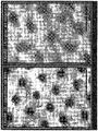
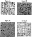
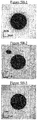
- Figure 1A is a magnified image of a plurality of inkjet ink drops disposed near a top surface of a fibrous (paper) substrate, according to a prior-art technology.
- the inkjet ink drops have penetrated the surface of the paper.
- Such a construction may be typical of various types of paper, including uncoated paper, in which the paper may draw ink carrier solvent and pigment within the matrix of the paper fibers.
- Figure 1B is a magnified image of a plurality of exemplary ink film constructions, such as inkjet ink film constructions, according to one embodiment of the present invention.
- the inventive inkjet ink film construction may be characterized by well-defined individual ink films, disposed generally above, and adhering to, the fibrous substrate.
- the single-drop inkjet films shown in Figure 1B exhibit superior optical density. These characteristics are particularly notable when compared with the characteristics of the prior art ink and substrate construction, which exhibits poorly formed inkjet ink drops or splotches having a low optical density.
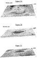
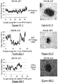
- FIGS. 2A, 2B, and 2C are respective three-dimensional magnified images of a lithographic offset ink splotch ( Figure 2A ), a liquid electro-photography (LEP) of HP-Indigo ink splotch ( Figure 2B ), and an inkjet single-drop ink film ( Figure 2C ) produced according to an embodiment of the present invention.
- the inkjet single-drop ink film (or individual ink dot) was produced using the inventive system and apparatus described herein, using the inventive ink formulation provided herein.
- the above-referenced ink splotches of the prior art are commercially available.
- the offset sample was produced by a Ryobi 755 press, using BestACK process ink by Roller Tiger (Toka Shikiso Chemical Industry).
- the LEP sample was produced by a HP Indigo 7500 digital press, using HP Indigo ink.
- the uncoated substrates were Mondy 170 gsm paper; the coated substrates were APP 170 gsm paper.
- Laser microscopy imaging was performed using an Olympus LEXT 3D measuring laser microscope, model OLS4000.
- the film (dot, drop, or splotch) height above each substrate and the surface roughness of each film or splotch analyzed were calculated by the microscope system in a semi-automatic fashion.
- the perimeter of the offset ink splotch and the perimeter of the LEP ink splotch have a plurality of protrusions or rivulets, and a plurality of inlets or recesses. These ink forms may be irregular, and/or discontinuous.
- the inkjet ink dot ( Figure 2C ) produced according to the present invention has a manifestly rounded, convex, shape.
- the perimeter of the ink film is relatively smooth, regular, continuous and well defined.
- projections of the ink film of the invention against the substrate surface tend to be rounded, convex projections that form a convex set, i.e ., for every pair of points within the projection, every point on the straight line segment that joins them is also within the projection.
- a convex set is shown in Figure 2D .
- the rivulets and inlets in the projections of various prior-art define those projections as a non-convex sets, i.e ., for at least one straight line segment within a particular projection, a portion of that straight line segment is disposed outside the projection, as illustrated in Figure 2E .
- ink images may contain an extremely large plurality of individual or single ink films.
- a 5mm by 5mm ink image, at 600 dpi may contain more than 10,000 of such single ink films. Therefore, it may be appropriate to statistically define the ink film constructions of the present invention: at least 10%, at least 20%, or at least 30%, and more typically, at least 50%, at least 70%, or at least 90%, of the single ink dots, or projections thereof, may be convex sets. These ink dots are preferably selected at random.
- ink images may not have crisp boundaries, particularly when those boundaries are viewed at high magnification. Therefore, it may be appropriate to relax the definition of the convex set whereby non-convexities (rivulets or inlets) having a radial length L r (as shown in Figure 2F ) of up to 3,000nm, up to 1,500nm, up to 1,000nm, up to 700nm, up to 500nm, up to 300nm, or up to 200nm, are ignored, excluded, or are "smoothed", whereby the ink film or ink film projection is considered to be a convex set.
- L r as shown in Figure 2F
- the radial length L r is measured by drawing a radial line L from the center point C of the ink film image, through a particular rivulet or inlet.
- the radial length L r is the distance between the actual edge of the rivulet or inlet, and a smoothed projection P s of the ink image, devoid of that rivulet or inlet, and matching the contour of the ink film image.
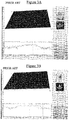
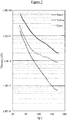
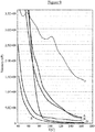
- Figures 3A, 3B , and 3C show surface roughness and surface height measurements for the offset ink splotch, the LEP ink splotch, and the inkjet ink film provided in Figures 2A-2C .
- the instrumentally measured heights (H) or thicknesses of the three samples were 762 nm for the offset ink drop and 1104 nm for the LEP ink drop.
- the instrumentally measured height of the inventive inkjet ink film (H film ) is 355 nm.
- the LEP specimens typically had a height or thickness within a range of 900-1150 nm, while the lithographic offset specimens typically had a height or thickness within a range of 750-1200 nm.
- T AVG MAX V DROP / A FILM * R VOL
- an ink dot disposed on a plastic printing substrate has an area of 1075 square micrometers.
- the nominal size of the jetted drop is 10.0 ⁇ 0.3 picoliters.
- the area of the ink dot may be calculated from the ink dot diameter.
- the dimensionless ratio R VOL is generally about 10 for a wide variety of inkjet inks.
- the actual average thickness may be somewhat less than T AVG(MAX) , this calculation may reliably serve as an upper bound for the average thickness.
- the maximum average supra-substrate thickness may substantially equal the average supra-substrate thickness.
- the maximum average supra-substrate thickness may approach the average supra-substrate thickness, often within 100 nanometers, 200 nanometers, or 300 nanometers.
- T AVG MAX V DROP * ⁇ INK * F nRESIDUE / A FILM * ⁇ FILM wherein:
- F nRESIDUE roughly equals the weight fraction of solids in the inkjet ink.
- Atomic Force Microscopy is another, highly accurate measurement technique for measuring height and determining ink dot thickness on a substrate.
- AFM measurements may be performed using commercially available apparatus, such as a Park Scientific Instruments Model Autoprobe CP, Scanning Probe Microscopy equipped with Proscan version 1.3 software (or later).
- the use of AFM is described in depth in the literature, for example, by Renmei Xu, et al., "The Effect of Ink Jet Papers Roughness on Print Gloss and Ink Film Thickness" [Department of Paper Engineering, Chemical Engineering, and Imaging Center for Ink and Printability, Western Michigan University (Kalamazoo, MI )].
- the thickness of the dry ink film on the substrate may be adjusted by modifying the inkjet ink formulation.
- modifying may entail at least one of the following:
- At least one of the opposite modifications may be made.
- an elevated transfer temperature may reduce ink film thickness.
- Increased pressure of the pressure roller or cylinder toward the impression cylinder during the transfer of the residue film to a substrate at the impression station may also reduce ink film thickness.
- ink film thickness may be reduced by increasing the time of contact between the substrate and the intermediate transfer member, interchangeably termed herein an "image transfer member" and both abbreviated ITM.
- a practical minimum characteristic (i.e ., median) thickness or average thickness for ink films produced according to the present invention may be about 100nm. More typically, such ink films may have a thickness of at least 125nm, at least 150nm, at least 175nm, at least 200nm, at least 250nm, at least 300nm, at least 350nm, at least 400nm, at least 450nm, or at least 500nm.
- inventive film constructions having a characteristic thickness or average thickness of at least 600nm, at least 700nm, at least 800nm, at least 1,000nm, at least 1,200nm, or at least 1,500nm.
- the characteristic thickness or average thickness of a single drop film (or an individual ink dot) may be at most about 2,000nm, at most 1,800nm, at most 1,500nm, at most 1,200nm, at most 1,000nm, or at most 900nm.
- the characteristic thickness or average thickness of a single drop film may be at most 800nm, at most 700nm, at most 650nm, at most 600nm, at most 500nm, at most 450nm, at most 400nm, or at most 350nm.
- a characteristic thickness or average thickness of the ink film may be within a range of 100nm, 125nm or 150nm up to 1,800nm, 1,500nm, 1,200nm, 1,000nm, 800nm, 700nm, 600nm, 550nm, 500nm, 450nm, 400nm, or 350nm. More typically, the characteristic thickness or average thickness of the ink film may be within a range of 175nm, 200nm, 225nm or 250nm up to 800nm, 700nm, 650nm, 600nm, 550nm, 500nm, 450nm, or 400nm. Suitable optical density and optical uniformity may be obtained, using the system, process, and ink formulations of the present invention.
- the diameter of an individual ink dot in the ink film constructions of the present invention may be adjusted, inter alia , by selection of a suitable ink delivery system for applying the ink (e.g., jetting) onto the ITM, and by adjusting the ink formulation properties (e.g., surface tension) to the requirements of the particular ink head.
- a suitable ink delivery system for applying the ink e.g., jetting
- the ink formulation properties e.g., surface tension
- This ink film diameter, D dot , or the average dot diameter on the substrate surface, D dot average may be at least 10 micrometers, at least 15 ⁇ m, or at least 20 ⁇ m, and more typically, at least 30 ⁇ m, at least 40 ⁇ m, at least 50 ⁇ m, at least 60 ⁇ m, or at least 75 ⁇ m.
- D dot or D dot average may be at most 300 micrometers, at most 250 ⁇ m, or at most 200 ⁇ m, and more typically, at most 175 ⁇ m, at most 150 ⁇ m, at most 120 ⁇ m, or at most 100 ⁇ m.
- D dot or D dot average may be in the range of 10-300 micrometers, 10-250 ⁇ m, 15-250 ⁇ m, 15-200 ⁇ m, 15-150 ⁇ m, 15-120 ⁇ m, or 15-100 ⁇ m. More typically, with the currently used ink formulations, and a particular ink head, D dot or D dot average may be in the range of 20-120 ⁇ m, 25-120 ⁇ m, 30-120 ⁇ m, 30-100 ⁇ m, 40-120 ⁇ m, 40-100 ⁇ m, or 40-80 ⁇ m.
- the aspect ratio may be at least 15, at least 20, at least 25, or at least 30, and more typically, at least 40, at least 50, at least 60, at least 75. In many cases, the aspect ratio may be at least at least 95, at least 110, or at least 120. The aspect ratio is typically below 200 or below 175.
- the ink dot may essentially be laminated onto a top surface of the printing substrate.
- the form of the dot may be determined or largely determined prior to the transfer operation, and the dot is transferred as an integral unit to the substrate.
- This integral unit may be substantially devoid of solvent, such that there may be no penetration of any kind of material from the blanket transfer member into, or between, substrate fibers.
- the continuous dot which may largely contain organic polymeric resin and colorant, adheres to, or forms a laminated layer on, the top surface of the fibrous printing substrate.
- Such continuous dots are typically produced by various inkjetting technologies, such as drop-on-demand and continuous jetting technologies.
- organic polymeric resins used in conjunction with the present invention are typically water soluble or water dispersible.
- FIGS 3D and 3E provide schematic cross-sectional views of an inventive ink film construction 300 and an inkjet ink splotch or film construction 370 of the prior art, respectively.
- inkjet ink film construction 370 includes a single-drop ink splotch 305 adhering to, or laminated to, a plurality of substrate fibers 320 in a particular continuous area of a fibrous printing substrate 350.
- Fibrous printing substrate 350 may be, by way of example, an uncoated paper such as bond, copy, or offset paper.
- Fibrous printing substrate 350 may also be one of various commodity coated fibrous printing substrates, such as a coated offset paper.
- a portion of ink splotch 305 is disposed below the top surface of substrate 350 , between fibers 320.
- Various components of the ink including a portion of the colorant, may penetrate the top surface along with the ink carrier solvent, to at least partially fill a volume 380 disposed between fibers 320.
- a portion of the colorant may diffuse or migrate underneath fibers 320 , to a volume 390 disposed beneath fibers 320. In some cases (not shown), some of the colorant may permeate into the fibers.
- inventive ink film construction 300 includes an integral continuous ink dot such as individual ink dot 310 , disposed on, and fixedly adhering (or laminated) to, a top surface of a plurality of substrate fibers 320 , in a particular continuous area of fibrous printing substrate 350.
- the adhesion or lamination may be, primarily or substantially, a physical bond.
- the adhesion or lamination may have little, or substantially no, chemical bonding character or more specifically, no ionic bonding character.
- Ink dot 310 contains at least one colorant dispersed in an organic polymeric resin. Within the particular continuous area of fibrous substrate 350 , there exists at least one direction (as shown by arrows 360 -- several directions) perpendicular to the top surface of printing substrate 350 . With respect to all the directions normal to this top surface over all of the dot area, ink dot 310 is disposed entirely above the area.
- the volume 380 between fibers 320 and the volume 390 underneath fibers 320 are devoid, or substantially devoid, of colorant, resin, and any and all components of the ink.
- the thickness (H dot ) of single-drop ink film or individual ink dot 310 may be at most 1,800nm, at most 1,500nm, at most 1,200nm, at most 1,000nm, or at most 800nm, and more typically, at most 650nm, at most 600nm, at most 550nm, at most 500nm, at most 450nm, or at most 400nm.
- the thickness (H dot ) of single-drop ink dot 310 may be at least 50nm, at least 100nm, or at least 125nm, and more typically, at least 150nm, at least 175nm, at least 200nm, or at least 250nm.
- the extent of penetration of an ink into a printing substrate may be quantitatively determined using various analytical techniques, many of which will be known to those of ordinary skill in the art. Various commercial analytical laboratories may perform such quantitative determination of the extent of penetration.
- TOF-SIMS Time of Flight Secondary Ion Mass Spectrometry
- TOF-SIMS V Spectrometer Ion-ToF (Münster, Germany)
- This apparatus provides elemental and molecular information with regard to the uppermost layer of organic and inorganic surfaces, and also provides depth profiling and imaging having depth resolution on the nanometric scale, submicron lateral resolution and chemical sensitivity on the order of 1 ppm.
- Translation of the raw data of the TOF-SIMS into concentration may be performed by normalizing the signals obtained to the carbon (C+) concentration measured by X-ray Photoelectron Spectroscopy (XPS), in the sample.
- XPS X-ray Photoelectron Spectroscopy
- the XPS data was obtained using a Thermo VG Scientific Sigma Probe (England).
- Small area chemical analysis of solid surfaces with chemical bonding information was obtained by using a microfocused (from 15 to 400 ⁇ m) monochromated x-ray source. Angle resolved information is obtained with and without tilting the sample. This enables depth profiling with good depth resolution.
- the atomic concentration of copper within a fibrous paper substrate was measured, as a function of depth.
- the atomic concentration of copper was found to be substantially zero at the surface, down to a depth of several micrometers. This procedure was repeated for two cyan-colored inkjet ink film constructions of the prior art, and for a cyan-colored ink film construction of the present invention.
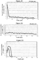
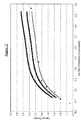
- Figure 3F provides a graph plotting the atomic concentration of copper [Cu] within the ink dot and within the fibrous paper substrate, as a function of the approximate depth, within a first cyan-colored inkjet ink film construction of the prior art.
- the inkjet ink pigment has penetrated into the fibrous paper substrate, possibly attaining a penetration depth of at least 700nm, at least 800nm, or at least 900nm.
- Figure 3G provides a graph plotting the atomic concentration of copper within the ink dot construction, as a function of the approximate depth, within a second cyan-colored inkjet ink film construction of the prior art.
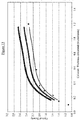
- Figure 3H provides graphs plotting the atomic concentration of copper within the ink dot and within the fibrous paper substrate, as a function of the approximate depth, within a cyan-colored ink film construction of the present invention.
- the two graphs represent measurements made at two different positions ("Sample 1" and "Sample 2") on the inventive ink dot construction.
- the inventors believe that the initial rise in [Cu] over the depth of 75-100nm may be attributed to the orientation of the ink dot due to micro-contours of the substrate, and to surface roughness of the ink dot itself.
- the drop in [Cu] to substantially zero at a depth of 200-250nm may be attributed to the micro-contours of the substrate: for a given cross-section within, and generally parallel to the face or top surface of the substrate, some of the ink dot may be present (see dashed line in Figure 3D ). This notwithstanding, the ink dot being is entirely disposed above the substrate, with respect to a direction perpendicular to the substrate surface.
- the top surface of the ink dots in the ink film constructions of the present invention may be characterized by a low surface roughness, particularly when the substrates of those constructions have a high paper (or substrate) gloss.
- the inventors believe that the relative flatness or smoothness of the ink film constructions of the present invention may largely be attributed to the smoothness of the release layer on the surface of the ITM, and to the inventive system and process in which the emerging ink film surface substantially complements that of that surface layer, and in which the developing ink film image may substantially retain or completely retain that complementary topography through the transfer onto the printing substrate.
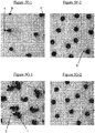
- Figure 4A is an image of the surface of a release layer of an ITM or blanket used in accordance with the present invention. While the surface may be nominally flat, various pockmarks (recesses) and protuberances, typically of the order of 1-5 ⁇ m, may be observed. Many of these marks have sharp, irregular features.
- An image of an ink dot surface produced using this blanket, provided in Figure 4B displays topographical features that are strikingly similar in nature to those shown in Figure 4A .
- the dot surface is peppered with a large plurality of marks having sharp, irregular features, which strongly resemble (and are within the same size range as) the irregular marks in the blanket surface.
- Figure 4C provides an image of the release layer of this blanket.
- the irregular pockmarks of Figure 4A are conspicuously absent.
- Dispersed on the highly smooth surface are highly circular surface blemishes, perhaps made by air bubbles, typically having a diameter of about 1-2 ⁇ m.
- An image of an ink dot surface produced using this blanket, provided in Figure 4D displays topographical features that are strikingly similar in nature to those shown in Figure 4C .
- This image has virtually no distinctive pockmarks, but has a number of highly circular surface blemishes that are strikingly similar in size and form to those shown of the blanket surface.
- the perimeter of various ink dots or films of the prior art may characteristically have a plurality of protrusions or rivulets, and a plurality of inlets or recesses. These ink forms may be irregular, and/or discontinuous.
- the inkjet ink dot produced according to the present invention characteristically has a manifestly rounded, convex, circular shape.
- the perimeter of the ink dot of the invention may be relatively smooth, regular, continuous and well defined. Ink dot roundness, convexity, and edge raggedness are structural parameters used to evaluate or characterize shapes, or optical representations thereof.
- the dot images were loaded to the image-processing software (ImageXpert). Each image was loaded in each of the Red, Green and Blue channels. The processing channel was selected based on a highest visibility criterion. For example, for cyan dots, the Red channel typically yielded the best dot feature visibility, and was thus selected for the image processing step; the Green channel was typically most suitable for a magenta dot.
- the dot edge contour was detected (automatically computed), based on a single threshold. Using a "full screen view" mode on a 21.5" display, this threshold was chosen manually for each image, such that the computed edge contour would best match the real and visible dot edge. Since a single image-channel was processed, the threshold was a gray value (from 0 to 255, the gray value being a non color value).
- a computed perimeter value was obtained from the image-processing software (e.g. , ImageXpert), the perimeter value being the sum of all distances between the adjacent, connected pixels at the edge of the dot or splotch. If, for example, the XY coordinates for adjacent pixels are (x1, y1) and (x2, y2), the distance is ⁇ [(x2-x1) 2 + (y2-y1) 2 ], while the perimeter equals ⁇ ⁇ x i + 1 ⁇ x i 2 + y i + 1 ⁇ y i 2 .
- an image comprising an ink dot is used as input for an algorithm that outputs perimeter length.
- the pixel dimension MxN of the image may be stored in a two-element array or an ordered pair image_pixel_size .
- the image magnification ratio or scale is obtained and stored in variable image _ magnification .
- variable image_magnification is 500.
- image_pixel_size and image_magnification of the two images are equal.
- image_pixel_pitch is 0.05 ⁇ m.
- the image is now converted to grayscale by methods known to the skilled artisan. One proposed method is converting the input image, the image typically in an sRGB color space, to the L * a * b * color space.
- the values for the variables ⁇ and b are changed to zero. It is now possible to apply an edge detection operator to the image.
- the preferred operator is a Canny edge detection operator.
- any operator known in the art may be applied.
- the operators are not limited to first order derivatives, such as the canny operator, but rather open to second derivatives as well.
- a combination of operators may be used in order to obtain results that may be compared between operators and subsequently remove "unwanted" edges. It may be favorable to apply a smoothing operator such as a Gaussian blur prior to applying the edge detection operator.
- the threshold level applied when applying the edge detection operator is such that an edge that forms an endless loop is first obtaining in the area between the formerly described minimal circumference Ink dot engulfing circle and the maximal circumference ink dot enclosed circle.
- a thinning operator is now implemented to render the endless loop edge substantially one pixel wide. Any pixel that is not a part of the endless loop edge has its L * value change to zero, while any pixel that is part of the endless loop edge has its L * value change to 100.
- the endless loop edge is defined as the perimeter of the ink dot.
- a pixel link is defined as a straight line connecting to pixels. Each pixel along the perimeter incorporates two pixel links, a first pixel link and a second pixel link.
- each pixel link may form a line from the center of the pixel to one of eight possible nodes.
- the possible nodes being the corners of the pixel or a midpoint between two neighboring corners of the pixel. Nodes at the corners of the pixels are of the type node_1 one nodes at the midpoint between two corners are of type node_2.
- there are six possibilities of pixel link paths within a pixel. can be categorized into three groups. Group A, B, and C. Each group has its own corresponding coefficient, namely, coefficient_A , coefficient_B , and coefficient_C.
- coefficient_A is 1, the value of coefficient_B is the sqrt(2), and the value of coefficient_C is (1+sqrt(2))/2.
- Group A contains pixels whose pixel link path coincides with nodes of type node_2.
- Group B contains pixels whose pixel link path coincides with nodes of type node_1.
- Group C contains pixels whose pixel link path coincides with nodes of type node_1 and type node_2. It is now possible to calculate the pixel length of the perimeter.
- the pixel length of the perimeter is calculated by summing all of the pixels in the perimeter multiplied by their corresponding coefficient. This value is stored in variable perimeter_pixel_length . It is now possible to calculate the actual length of the ink dot perimeter. This is done by multiplying perimeter_pixel_length by pixel_pitch .
- the deviation from a round, smooth shape may be represented by the expression (ER - 1). For a perfectly circular, idealized ink dot, this expression equals zero.
- the R-square of the roundness factor may be computed for each of the 10 most representative dot images selected for each type of printing technology, and averaged into a single value.
- the deviation from a round, smooth round shape [(ER - 1), henceforth, "deviation"] for the ink dots of the present invention is not ideal, and will exceed 0.
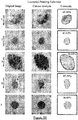
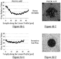
- Exemplary ink film images disposed on coated ( Figure 5A ) and uncoated ( Figure 5B ) substrates are provided for the following printers: HP DeskJet 9000 ( 1 ); Digital press: HP Indigo 7500 ( 2 ); Lithographic Offset: Ryobi 755 ( 3 ); and Xerox DC8000 ( 4 ), and for the inventive digital printing technology ( 5 ).
- These ink film images were obtained generally according to the image acquisition method detailed hereinabove.
- Next to each original image is provided a corresponding processed, black and white image in which the image-processor computed contour of the ink dot, film, or splotch is highlighted, and in which the computed contours are manifestly similar to the contours of the original images.
- the typical, individual inventive ink dots exhibited a deviation (ER - 1) of 0.28 to 0.89.
- some of the inventive ink dots exhibited a deviation (ER - 1) of at most 0.7, at most 0.6, at most 0.5, at most 0.4, at most 0.35, at most 0.3, at most 0.25, or at most 0.20.
- the substrates included coated and uncoated substrates, and wood-free and mechanical substrates.
- the substrates are characterized by differences in thickness, density, roughness (e.g ., Bendtsen number) or smoothness (gloss), etc. These substrates are identified and partially characterized in Table 1.
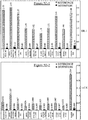
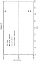
- the deviation from roundness of the inventive ink dot constructions is compared with ink images produced by a commercial inkjet printer (using compatible ink cartridges provided by the manufacturer) in the bar graphs provided in Figure 5C .
- the ink-film constructions of the present invention were produced on an inventive pilot, semi-automatic digital printing press, in which the transfer of the ink dots from the ITM to the printing substrate is performed manually, and consequently, with an impression pressure that may be somewhat lower, and more variable, than the previously described commercial prototype of a fully-automatic digital printing press of the present invention.
- substrate number 6, Condat Gloss 135, is the same substrate used above for the inventive ink dot shown in Figure 5A .
- the deviation from roundness achieved by a typical ink dot was 0.362, which represents a larger deviation than the deviations (0.16 to 0.27) of all of the inventive ink dots printed by the commercial prototype of the inventive digital press printer.
- a portion (albeit lower) of the inventive ink dots produced on the pilot, semi-automatic digital printing press attained deviations as low or lower than the lowest typical deviation (0.16) achieved on the commercial prototype digital press printer.
- the deviation from roundness of the inventive ink dots is greater than zero, and may be at least 0.01, at least 0.02, or at least 0.03.
- the inventive ink dots exhibited a deviation from roundness (on both uncoated and coated fibrous substrates) of at most 0.30, at most 0.25, at most 0.20, at most 0.15, or at most 0.12.
- inventive ink dots when adhering to coated (or commodity-coated) fibrous substrates, may typically exhibit a deviation of at most 0.20, at most 0.18, at most 0.16, at most 0.14, at most 0.12, or at most 0.10. For each of the coated substrates provided in Table 1, at least some of the inventive ink dots exhibited a deviation from roundness of at most 0.25, at most 0.20, at most 0.15, at most 0.12, at most 0.10, at most 0.09, at most 0.08, at most 0.07, or at most 0.06.
- ink images may contain an extremely large plurality of individual ink dots or single drop ink films, it may be meaningful to statistically define the inventive ink film constructions wherein at least 20% or at least 30%, and in some cases, at least 50%, at least 70%, or at least 90%, of the inventive ink dots (or inventive single-drop ink dots), disposed on any uncoated or coated (or commodity-coated) fibrous substrate, and randomly selected, may exhibit a deviation from roundness that is at least 0.01 or at least 0.02, and may be at most 0.8, at most 0.65, at most 0.5, at most 0.35, at most 0.3, at most 0.25, at most 0.2, at most 0.15, at most 0.12, or at most 0.10.
- inventive ink dots disposed on any coated (or commodity-coated) fibrous substrate, and randomly selected, may exhibit a deviation from roundness that is at least 0.01 or at least 0.02, and may be at most 0.8, at most 0.65, at most 0.5, at most 0.35, or at most 0.3, and more typically, at most 0.25, at most 0.2, at most 0.15, at most 0.12, at most 0.10, at most 0.08, at most 0.07, or at most 0.06.
- the ink dots or films of the prior art may characteristically have a plurality of protrusions or rivulets, and a plurality of inlets or recesses. These ink forms may be irregular, and/or discontinuous.
- the inkjet ink film produced according to the present invention characteristically has a manifestly rounded, convex, circular shape. Dot convexity, or deviation therefrom, is a structural parameter that may be used to evaluate or characterize shapes, or optical representations thereof.
- the image acquisition method may be substantially identical to that described hereinabove.
- the dot images were loaded to the image-processing software (ImageXpert). Each image was loaded in each of the Red, Green and Blue channels. The processing channel was selected based on a highest visibility criterion. For example, for cyan dots, the Red channel typically yielded the best dot feature visibility, and was thus selected for the image processing step; the Green channel was typically most suitable for a magenta dot.
- the dot edge contour was detected (automatically computed), based on a single threshold. Using a "full screen view" mode on a 21.5" display, this threshold was chosen manually for each image, such that the computed edge contour would best match the real and visible dot edge. Since a single image-channel was processed, the threshold was a gray value (from 0 to 255, the gray value being a non color value).
- a MATLAB script was created to compute the ratio between the area of the minimal convex shape that bounds the dot contour and the actual area of the dot. For each ink dot image, the (X,Y) set of points of the dot edge contour, created by ImageXpert, was loaded to MATLAB.
- the dot edge was passed through a Savitzky-Golay filter (image-processing low-pass filter) to slightly smooth the edge contour, but without appreciably modifying the raggedness characteristic thereof.
- a window frame size of 5 pixels was found to be generally suitable.
- the convex shape area (CSA) is shown surrounding the actual dot area (AA), and the convexity ratio is provided in percentage form.
- the convexity of the print images of the various prior-art technologies ranged from 87.91% to 94.97% (-0.879 to 0.950 in fractional form), corresponding to a deviation from convexity of 0.050 to 0.121.
- the inventive ink dot exhibited a convexity of 99.48% (-0.995), corresponding to a deviation from convexity of about 0.005.
- This deviation is about 1/10 to 1/25 of the deviation exhibited by the various prior-art technologies.
- the deviation is at least 0.04 less than the deviation exhibited by the various prior-art technologies.
- the difference between the inventive dot images and those of the various prior-art technologies may be more striking on uncoated substrates.
- the convexity of the print images of the various prior-art technologies ranged from 65.58% to 90.19% (-0.656 to 0.902 in fractional form), corresponding to a deviation from convexity of 0.344 to 0.098.
- the inventive ink dot exhibited a convexity of 98.45% (-0.985), corresponding to a deviation from convexity of about 0.015.
- This deviation is at least 1/6 to 1/20 of the deviation exhibited by the various prior-art technologies.
- the deviation is at least 0.08 less than the deviation exhibited by the various prior-art technologies.
- the printed dots of the present invention exhibit superior convexity with respect to the prior art images, for any given substrate, coated or uncoated.
- typical inventive ink dots exhibited a non-convexity of 0.004 to 0.021.
- at least some of the inventive ink dots exhibited a non-convexity of at most 0.018, at most 0.016, at most 0.015, at most 0.014, or at most 0.013.
- inventive ink dots exhibited a non-convexity of 0.004 to 0.015.
- at least some of the inventive ink dots exhibited a non-convexity of at most 0.014, at most 0.012, at most 0.010, at most 0.009, at most 0.008, or at most 0.007.
- At least some of the inventive ink dots exhibited a non-convexity of at most 0.03, at most 0.025, at most 0.022, at most 0.020, at most 0.018, at most 0.016, at most 0.015, at most 0.014, or at most 0.013.
- ink images may contain an extremely large plurality of individual dots or single drop ink films (at least 20, at least 100, or at least 1,000), it may be meaningful to statistically define the inventive ink film constructions wherein at least 10%, at least 20%, or at least 30%, and in some cases, at least 50%, at least 70%, or at least 90%, of the inventive ink dots (or inventive single-drop ink dots), disposed on any uncoated or coated (or commodity-coated) fibrous substrate, and randomly selected, may exhibit a non-convexity of at most 0.04, at most 0.035, at most 0.03, at most 0.025, at most 0.020, at most 0.017, at most 0.014, at most 0.012, at most 0.010, at most 0.009, at most 0.008, or at most 0.007.
- At least 10%, at least 20%, or at least 30%, and in some cases, at least 50%, at least 70%, or at least 90%, of these inventive ink dots (or inventive single-drop ink dots) may exhibit a non-convexity of at least 0.001, at least 0.002, or at least 0.0025.
- At least 10%, at least 20%, or at least 30%, and more typically, at least 50%, at least 70%, or at least 90%, of the inventive ink dots (or the inventive single-drop ink dots), disposed on any uncoated or coated (or "commodity-coated") fibrous substrate, and randomly selected, may exhibit a non-convexity within a range of 0.001-0.002 to 0.05, 0.001-0.002 to 0.04, 0.001-0.002 to 0.035, 0.001-0.002 to 0.030, 0.001-0.002 to 0.025, 0.001-0.002 to 0.020, 0.001-0.002 to 0.015, 0.001-0.002 to 0.012, or 0.001 to 0.010.
- these same dots may exhibit a lower non-convexity, within a range of 0.001-0.002 to 0.020, 0.001-0.002 to 0.015, 0.001-0.002 to 0.012, 0.001-0.002 to 0.010, 0.001 to 0.008, 0.001 to 0.007, 0.001 to 0.006, 0.001 to 0.005, or 0.001 to 0.004.
- these same dots may exhibit a non-convexity within a range of 0.001-0.002 to 0.05, 0.001-0.002 to 0.04, 0.001-0.002 to 0.035, 0.001-0.002 to 0.030, 0.001-0.002 to 0.025, 0.001-0.002 to 0.020, 0.001-0.002 to 0.015, 0.001-0.002 to 0.012, or 0.001 to 0.010.
- the ink dots in the ink dot constructions of the present invention may exhibit consistently good shape properties (e.g., convexity, roundness, edge raggedness, and the like), irrespective, to a large degree, of the particular, local topographical features of the substrate, and irrespective, to some degree, of the type of printing substrate (e.g., commodity-coated or uncoated printing substrates).
- the shape properties of the ink dots in the ink dot constructions of the present invention are not completely independent of the type of printing substrate, as evidenced by the bottom frames of Figures 5A (coated fibrous substrate) vs. the bottom frames of Figures 5B (uncoated fibrous substrate).
- the quality of ink dots in various known printing technologies, and in direct aqueous inkjetting technologies in particular, may vary more substantially with the type of printing substrate.
- a reference inkjet ink along with a reference printing method therefor, may be used to structurally define the various optical properties of ink dot constructions on a substrate to substrate basis, by normalizing those properties to the printing substrate.
- the reference ink contained 15% Basacid Black X34 liquid (BASF), 60% propylene glycol, and 25% distilled water. The dye was added to a mixture of water and propylene glycol. After 5 minutes of stirring, the ink was passed through a 0.2 micrometer filter.
- the reference ink composition is simple, and the components are generic, or at least commercially available. In the event that Basacid Black X34 liquid (BASF) is not available, a similar black inkjet colorant may be substituted therefor. In any event, a supply of the reference ink may be obtained from Landa Corporation, POB 2418, Rehovot 7612301, Israel.
- the reference ink was printed using a FUJIFILM Dimatix Materials Printer, DMP-2800, equipped with a 10 pL print head, DMC-11610.
- the printing parameters were set as follows:
- the printing apparatus is commercially available. If unavailable, a functionally equivalent (or substantially functionally equivalent) printer may be used. Alternatively, such printing apparatus may be available courtesy of Landa Corporation, POB 2418, Rehovot 7612301, Israel.
- the reference inkjet ink was prepared and printed onto various printing substrates, as described hereinabove.
- the printed dots were subjected to image processing for characterization of roundness and convexity.
- Figure 5E-1 provides comparative bar graphs of the deviation from roundness for ink dots produced according to some embodiments of the present invention, vs. ink dots produced using the above-described reference ink formulation and printing method.
- the comparative study was conducted using 10 fibrous substrates of varying physical and chemical properties; these included both coated and uncoated substrates.
- the substrates are identified and partially characterized in Table 2, which further provides the deviation from roundness results of the comparative study, for each of the 10 fibrous substrates.
- the ratio of DR dot /RDR also referred to as the coefficient "K1" , ranges from about 0.02 to about 0.07, corresponding to a factor of 14:1 to 50:1, on a per-substrate basis.
- coefficient K1 may be at most 0.25, at most 0.22, at most 0.20, at most 0.17, at most 0.15, at most 0.12, at most 0.10, at most 0.09, or at most 0.08, for both coated (commodity-coated) and uncoated substrates, and in some cases, at most 0.070, at most 0.065, at most 0.060, at most 0.055, at most 0.050, at most 0.045, or at most about 0.04.
- Coefficient K1 may be at least 0.010, at least 0.015, at least 0.180, or at least about 0.020. In some cases, coefficient K1 may be at least 0.03, at least 0.04, at least 0.05, at least 0.06, at least about 0.07, at least about 0.075, at least about 0.08, at least about 0.09, at least about 0.10.
- coefficient K1 may be at most 0.070, at most 0.065, at most 0.060, or at most 0.055, and in some cases, at most 0.050, at most 0.045, at most 0.040, at most 0.035, at most 0.030, at most 0.025, or at most 0.022.
- Figure 5E-2 provides comparative bar graphs of ink dot convexity of the ink dot constructions of Figure 5E-1 , for each of the 10 above-described fibrous substrates.
- Table 3 provides the non-convexity results of the comparative study, for each of the 10 fibrous substrates.
- Table 3 # Substrate name GSM (g/m 2 ) Type Non-Convexity (1-CX) Reference Dots (RDC) Inventive Dots (DC dot ) Inv./Ref.
- the inventive dot constructions exhibit lower non-convexities ( 1-CX or DC dot ).
- the highest value of DC dot obtained for an uncoated substrate (Hadar Top), 0.010, is still less than 2/5 of the lowest roundness deviation value of the reference ink dots ( RDR ), obtained for a coated gloss substrate (Arjowiggins Gloss), 0.026.
- the ratio of DC dot /RDC also referred to as the coefficient "K" , ranges from about 0.04 to about 0.17, corresponding to a factor of 6:1 to 25:1, on a per-substrate basis.
- coefficient K may be at most 0.35, at most 0.32, at most 0.30, at most 0.27, at most 0.25, at most 0.22, at most 0.20, at most 0.19, or at most 0.18, for both coated (commodity-coated) and uncoated substrates.
- Coefficient K may be at least 0.010, at least 0.02, at least 0.03, or at least about 0.04. In some cases, coefficient K may be at least 0.05, at least 0.07, at least 0.10, at least 0.12, at least 0.15, at least 0.16, at least 0.17, at least 0.18, at least 0.19, or at least about 0.20.
- coefficient K may be at most 0.15, at most 0.12, at most 0.10, at most 0.09, at most 0.08, or at most 0.075, and in some cases, at most 0.070, at most 0.065, at most 0.060, or at most 0.055, and in some cases, at most 0.050, at most 0.045, or at most 0.040.
- Coefficient K may be at least 0.020, at least 0.03, at least 0.04, at least 0.06, at least 0.07, or at least about 0.08. In some cases, particularly for various commodity-coated substrates, coefficient K may be at least 0.10, at least about 0.12, at least about 0.14, at least about 0.16, at least about 0.18, or at least about 0.20.
- the ink dots in the ink dot constructions of the present invention may exhibit consistently good shape properties (e.g., convexity, roundness, edge raggedness, and the like), irrespective, to a large degree, of the particular, local topographical features of the substrate, and irrespective, to some degree, of the type of printing substrate (coated or uncoated printing substrates, plastic printing substrates, etc.).
- the quality of ink dots in various known printing technologies, and in direct aqueous inkjetting technologies in particular, may vary appreciably with the type of printing substrate, and with the particular, local topographical features of the substrate.
- the ink dot obtained may display significantly better shape properties, with respect to the other, or average ink dots disposed elsewhere on the substrate.
- the ink dot constructions may be characterized as a plurality of ink dots disposed on the substrate, within a representative field of view. Assuming the characterization of the dot is obtained through image processing, a field of view contains a plurality of dot images, of which at least 10 dot images are suitable for image processing. Both the field of view and the dot images selected for analysis are preferably representative of the total population of ink dots on the substrate (e.g., in terms of dot shape).
- geometric projection refers to an imaginary geometric construct that is projected onto a printed face of a printing substrate.
- distinct ink dot refers to any ink dot or ink dot image, at least partially disposed within the "geometric projection", that is neither a “satellite”, nor an overlapping dot or dot image.
- the term “mean deviation”, with respect to the roundness, convexity, and the like, of a plurality of “distinct ink dots”, refers to the sum of the individual distinct ink dot deviations divided by the number of individual distinct ink dots.
- a printed sample preferably containing a high incidence of single ink dots, is scanned manually on the LEXT microscope, using a X20 magnification to obtain a field that includes at least 10 single dots in a single frame. Care should be taken to select a field whose ink dot quality is fairly representative of the overall ink dot quality of the printed sample.
- Each dot within the selected frame is analyzed separately. Dots that are "cleaved" by the frame margins (which may be considered a square geometric projection) are considered to be part of the frame, and are analyzed. Any satellites and overlapping dots are excluded from the analysis.
- a "satellite" is defined as an ink dot whose area is less than 25% of the average dot area of the dots within the frame, for frames having a generally homogeneous dot size, or as an ink dot whose area is less than 25% of the nearest adjacent dot, for non-homogeneous frames.
- Each distinct ink dot is subsequently magnified with a X100 zoom, and image processing may be effected according to the procedure provided hereinabove with respect to the convexity and roundness procedures.
- Figure 5F-1 provides a magnified view of a small field of ink dots on a commodity-coated fibrous substrate (Arjowiggins coated recycled gloss, 170gsm), the field produced using a commercially available aqueous, direct inkjet printer.
- Ink image A is a satellite, and is excluded from the analysis.
- Dot B is cleaved by the frame margin, and is included in the analysis (i.e., the full ink dot is analyzed).
- Tail or projection C is considered to be part of the ink dot disposed to its left.
- the field contains only 6 ink dots for image processing.
- Figure 5F-2 provides a magnified view of a field of an ink dot construction according to the present invention, in which the commodity-coated substrate is identical to that of Figure 5F-1 .
- Ink image D by way of example, is a satellite, and is excluded from the analysis.
- the field contains 12 ink dots for image processing.
- Figure 5G-1 provides a magnified view of a field of ink dots or splotches on an uncoated fibrous substrate (Hadar Top uncoated-offset 170gsm), the field produced using a commercially available aqueous, direct inkjet printer. At higher magnification, it became evident that dots E and F are distinct individual dots. While several splotches are reasonably round and well-formed, most of the splotches display poor roundness and convexity, have poorly-defined edges, and appear to contain multiple ink centers that are associated or weakly associated.
- Figure 5G-2 provides a magnified view of a field of an ink dot construction according to the present invention, in which the uncoated substrate is identical to that of Figure 5G-1 .
- Each ink dot exhibits good roundness and convexity, and has well-defined edges.
- each ink dot is disposed on top of the coarse, uncoated fibrous substrate.
- the fields of the ink dot construction according to the present invention exhibited (average) non-convexities of 0.003 for the Arjowiggins coated substrate, and 0.013 for the Hadar Top uncoated substrate. These average values are highly similar to the non-convexities exhibited by individual ink dots of the present invention on these substrates (0.004 and 0.010, respectively).
- the fields of the ink dot construction according to the present invention exhibited (average) deviations from roundness of 0.059 for the Arjowiggins coated substrate, and 0.273 for the Hadar Top uncoated substrate. These average values are higher than, but fairly similar to, the deviations from roundness exhibited by individual ink dots of the present invention on these substrates (0.026 and 0.239, respectively).
- ink dots in the ink dot constructions of the present invention tend to exhibit consistently good shape properties (such as convexity and roundness), largely irrespective of the particular, local topographical features of the substrate.
- fields of the ink dot construction according to the present invention exhibited a mean non-convexity of at most 0.05, at most 0.04, at most 0.03, at most 0.025, at most 0.020, at most 0.015, at most 0.012, at most 0.010, at most 0.009, or at most 0.008.
- fields of the ink dot construction according to the present invention exhibited a mean non-convexity of at most 0.085, at most 0.07, at most 0.06, at most 0.05, at most 0.04, at most 0.03, at most 0.025, at most 0.020, at most 0.018, or at most 0.015.
- the field non-convexity is at least 0.0005, at least 0.001, at least 0.002, at least 0.003, or at least about 0.004.
- the field or mean non-convexity may be at least 0.05, at least 0.07, at least 0.10, at least 0.12, at least 0.15, at least 0.16, at least 0.17, or at least 0.18.
- fields of the ink dot construction according to the present invention exhibited a mean deviation from roundness of at most 0.60, at most 0.50, at most 0.45, at most 0.40, at most 0.35, at most 0.30, at most 0.25, at most 0.20, at most 0.17, at most 0.15, at most 0.12, or at most 0.10.
- fields of the ink dot construction according to the present invention exhibited a mean deviation from roundness of at most 0.85, at most 0.7, at most 0.6, at most 0.5, at most 0.4, at most 0.35, at most 0.3, at most 0.25, at most 0.22, or at most 0.20.
- the mean deviation from roundness is at least 0.010, at least 0.02, at least 0.03, or at least about 0.04. In some cases, the deviation from roundness may be at least 0.05, at least 0.07, at least 0.10, at least 0.12, at least 0.15, at least 0.16, at least 0.17, or at least 0.18.
- non-convexity and deviation from roundness values are for fields having at least 10 dots suitable for evaluation, they further apply to fields having at least 20, at least 50, or at least 200 of such suitable dots.
- the inventors have found that the distinction between both the non-convexity values and deviation from roundness values of the inventive ink dot constructions vs. the prior-art ink dot constructions becomes even more statistically significant with increasing field size.
- the fields of the ink dot construction according to the present invention exhibited a mean non-convexity of at most 0.075, at most 0.06, at most 0.05, at most 0.04, at most 0.03, at most 0.025, at most 0.020, at most 0.015, at most 0.012, at most 0.010, at most 0.009, or at most 0.008;
- the fields of the ink dot construction according to the present invention exhibited a mean deviation from roundness of at most 0.8, at most 0.7, at most 0.6, at most 0.5, at most 0.4, at most 0.35, at most 0.3, at most 0.25, at most 0.20, at most 0.18, or at most 0.15.
- Smooth plastics such as atactic polypropylene and various polyesters, exhibited a mean deviation from roundness of at most 0.35, at most 0.3, at most 0.25, at most 0.20, at most 0.18, at most 0.15, at most 0.12, at most 0.10, at most 0.08, at most 0.06, at most 0.05, at most 0.04, or at most 0.035.
- Figures 5H-1 - 5H-3 provide magnified top views of ink dot constructions according to the present invention, in which an ink dot is printed on each of various exemplary plastic printing substrates, including biaxially oriented polypropylene -- BOPP ( Figure 5H-1 ); anti-static polyester ( Figure 5H-2 ); and atactic polypropylene ( Figure 5H-3 ).
- the ink dots of the present invention exhibited superior optical and shape properties, including roundness, convexity, edge raggedness, and surface roughness.
- Figure 5H-4 provides a magnified top view of an ink dot printed on a polyester substrate, in accordance with the present invention.
- Figure 5H-4 further provides a cross-sectional representation showing the surface roughness of the ink dot and substrate.
- the ink dot has a height of about 600nm. The deviation in height is less than ⁇ 50nm over the middle 80% of the dot diameter, and less than ⁇ 25nm over the middle 60% of the dot diameter.
- Table 5 Substrate Type ER-1 1-CX BOPP 0.1442 0.0097 Anti-Static Polyester 0.0288 0.0016 Atactic Polypropylene 0.0299 0.0020
- the non-convexity, or deviation from convexity for ink dots printed on a wide variety of plastic printing substrates was at most 0.020, at most 0.018, at most 0.016, at most 0.014, at most 0.012, or at most 0.010. At least some of the ink dots, on all these substrates, including BOPP, exhibited non-convexities of at most 0.008, at most 0.006, at most 0.005, at most 0.004, at most 0.0035, at most 0.0030, at most 0.0025, or at most 0.0020.
- typical ink dots exhibited non-convexities of at most 0.006, at most 0.004, at most 0.0035, and even more typically, at most 0.0030, at most 0.0025, or at most 0.0020.
- individual ink dots in the ink dot constructions according to the present invention exhibited a typical deviation from roundness of at most 0.8, at most 0.7, at most 0.6, at most 0.5, at most 0.4, at most 0.35, at most 0.3, at most 0.25, at most 0.20, at most 0.18, or at most 0.15.
- individual ink dots exhibited a typical deviation from roundness of at most 0.35, at most 0.3, at most 0.25, at most 0.20, at most 0.18, at most 0.15, at most 0.12, at most 0.10, at most 0.08, at most 0.06, at most 0.05, at most 0.04, or at most 0.035.
- Figures 5H-5 - 5H-7 each provide a magnified view of a field having an ink dot construction according to the present invention, each field containing ink dots printed onto a respective plastic substrate.
- the substrate is anti-static polyester; in Figure 5H-6 , the substrate is polypropylene (BOPP WBI 35 micron (Dor, Israel)); in Figure 5H-7 , the printing substrate is atactic polypropylene.
- each ink dot exhibits good roundness and convexity, has well-defined edges, and is disposed on top of the particular plastic substrate.
- inventive ink dots-on-plastic constructions may closely resemble the ink dots on commodity-coated substrates, particularly with regard to the roundness, convexity, edge raggedness, and other optical shape properties.
- inventive ink dots-on-plastic constructions display optical shape properties (e.g., deviation from roundness, non-convexity) that equal, or surpass, those of the commodity-coated substrates.
- the original ink film images provided in Figures 5A and 5B are not optically uniform. Generally, the ink film images disposed on uncoated paper are less optically uniform than the corresponding ink film images disposed on coated paper.
- inventive ink dots exhibit superior optical uniformity in comparison with the various prior-art ink forms. This appears to hold for both uncoated and coated printed substrates. That which is readily observed by the human eye may be quantified using image-processing techniques. The method of measuring ink dot uniformity is provided below.
- the dot images are loaded to the ImageXpert Software, preferably using the statistical rules provided hereinabove.
- Each image is loaded in each of the Red, Green and Blue channels.
- the channel selected for the image processing is the channel exhibiting the highest visible details, which include the dot contour and color variance within the dot area, and the substrate surface fibrous structure.
- the Red channel is typically most suitable for a cyan dot
- the Green channel is typically most suitable for a magenta dot.
- a line profile (preferably 3 line profiles for each of the at least 10 most representative dots) is measured across the dot area, crossing through the center of the dot. Since the line profile is measured on a single channel, gray values (0-255, non color values) are measured. The line profiles are taken across the center of the dot and cover only the inner two thirds of the dot diameter, to avoid edge effects.
- the standard for sampling frequency is about 8 optical measurements along the line profile (8 measured gray values evenly spaced along each micrometer, or 125 nanometers +/- 25 nanometers per measurement along the line profile), which was the automatic frequency of the ImageXpert Software, and which was found to be suitable and robust for the task at hand.
- the standard deviation (STD) of each of the line profiles is computed, and multiple line-profile STDs for each type of printed image are averaged into a single value.
- Figures 6A-1 to 6J-2 provide images of ink splotches or dots obtained using various printing technologies, and optical uniformity profiles therefor. More specifically, Figures 6A-1 to 6E-1 provide ink dot images disposed on uncoated paper, for the following printing technologies: HP DeskJet 9000 ( Figure 6A-1 ); Digital press: HP Indigo 7500 ( Figure 6A-2 ); Offset: Ryobi 755 ( Figure 6A-3 ); Xerox DC8000 ( Figure 6A-4 ); and for an embodiment of the inventive printing technology ( Figure 6A-5 ). Similarly, Figures 6F-1 to 6J-1 provide ink dot images disposed on commodity coated paper, for those printing technologies.
- Figures 6A-2 to 6J-2 respectively provide a graph plotting the (non-color) gray relative value as a function of the position on the line passing through the center of the ink dot image, for each of the ink dot images provided by Figures 6A-1 to 6E-1 (on uncoated paper), and by Figures 6F-1 to 6J-1 (on coated paper).
- a relatively flat linear profile for a particular ink dot image indicates high optical uniformity along the line.
- the line profile of the inventive ink film produced by the inventive system and process had an STD of 4.7, which compares favorably to the STDs achieved using the various prior art technologies (13.7 to 19.1).
- the line profile of the inventive ink dot produced by the inventive system and process had an STD of 2.5, which compares favorably, though less strikingly so, to the STDs achieved using the various prior art technologies (4 to 11.6).
- the average of each of the standard deviations (STD) of the dot profiles of the present invention was always below 3. More generally, the STD of the dot profiles of the present invention is less than 4.5, less than 4, less than 3.5, less than 3, or less than 2.7.
- Table 6 STANDARD DEVIATION Uncoated Coated HP DeskJet 9000 19.1 4 HP Indigo 7500 13.7 11.6 Offset: Ryobi 755 18.6 5.75 Xerox DC8000 15.4 7 Inventive System 4.7 2.5
- the STD values for the dots of the present invention are manifestly differentiated from the STD values of the exemplary printed dots of the prior art, both on coated and uncoated papers.
- the standard deviation (STD) of the dot profiles of the present invention was always below 5. More generally, the STD of the dot profiles of the present invention is less than 10, less than 8, less than 7, or less than 6.
- ink images may contain an extremely large plurality of individual or single ink dots (at least 20, at least 100, at least 1,000, at least 10,000, or at least 100,000), it may be meaningful to statistically define the inventive ink dot constructions wherein at least 10%, at least 20%, or at least 30%, and in some cases, at least 50%, at least 70%, or at least 90%, of the inventive ink dots (or inventive single-drop ink dots), disposed on any uncoated or coated (or commodity-coated) fibrous substrate, exhibit the above-mentioned standard deviations for uncoated papers and for commodity-coated papers.
- Ink formulations containing a 1:3 ratio of pigment (Clariant Hostajet Black O-PT nano-dispersion) to resin were prepared, according to Example 6.
- the formulations were applied to Condat Gloss® coated paper (135 gsm) using various coating rods yielding wet layers having a characteristic thickness of 4-50 micrometers.
- the above-provided formulation contains approximately 9.6% ink solids, of which 25% is pigment, and about 75% is resin, by weight. In all of the tests, the ratio of resin to pigment was maintained at 3:1.
- the ink solids fraction in the ink formulations varied between 0.05 and 0.12, by weight (5% to 12%). Drawdown was performed in standard fashion, directly onto the paper. The thickness of each ink film obtained was calculated.
- Table 7 Mayer Rod Size ( ⁇ m) Ink Solids Fraction Ink Film Thickness ( ⁇ m) Optical Density 50 0.096 4.80 2.35 24 0.096 2.30 2.10 12 0.096 1.15 1.85 6 0.096 0.58 1.40 4 0.096 0.38 1.10 12 0.050 0.60 1.40 12 0.075 0.90 1.58 12 0.120 1.44 2.00
- the exemplary curves disposed above the fitted curve in Figure 12 are optical density curves of the inventive ink film construction, in which the optical density is 7% higher or 15% higher, respectively, than OD baseline .
- the optical density of the inventive ink film constructions may be at least 0.08, at least 0.10, at least 0.12, at least 0.15, at least 0.18, at least 0.20, at least 0.25, at least 0.30, at least 0.35, or at least 0.40 higher than any of the optical density points obtained and plotted in Figure 12 , and/or higher than any point on the fitted curve represented by the above-provided function (OD baseline ).
- OD invention may be at least 0.45, at least 0.50, at least 0.55, at least 0.60, at least 0.70, at least 0.80, at least 0.90, at least 1.00, at least 1.10, or at least 1.25 higher than any of the optical density points obtained and plotted in Figure 12 , and/or higher than any point on the fitted curve represented by the above-provided function.
- Figure 13 provides the optical density measurements of Figure 12 , plotted as a function of pigment content or calculated average pigment thickness (T pig ).
- the optical densities (Y-axis) of Figure 13 are identical to those shown in Figure 12 , but the variable of the X-axis is pigment content or calculated average pigment thickness, instead of average measured or calculated ink film thickness.
- OD baseline 0.5321425673 + 7.49686149468 * T pig ⁇ 3.3640505727016 * T pig 2 + 0.6866743765095 * T pig 3 ⁇ 0.0513457817328 * T pig 4
- the calculated average pigment thickness may roughly equal the ink solids thickness multiplied by the weight fraction of the pigment within the ink solids fraction (by way of example, in the above-referenced formulation, the weight fraction of the pigment is 0.25).
- the optical density of the inventive ink film constructions may be at least 5%, at least 7%, at least 10%, at least 12%, at least 15%, at least 18%, at least 20%, at least 22%, at least 25%, at least 28%, at least 30%, at least 35%, or at least 40% higher than any of the optical density points obtained and plotted in Figure 13 , and/or higher than any point on the fitted curve of OD baseline as a function of the calculated average pigment thickness.
- the optical density of the inventive ink film constructions may be at least 0.08, at least 0.10, at least 0.12, at least 0.15, at least 0.18, at least 0.20, at least 0.25, at least 0.30, at least 0.35, or at least 0.40 higher than any of the optical density points obtained and plotted in Figure 13 , and/or higher than any point on the fitted curve represented by the above-provided function (OD baseline ).
- OD invention may be at least 0.45, at least 0.50, at least 0.55, at least 0.60, at least 0.70, at least 0.80, at least 0.90, at least 1.00, at least 1.10, or at least 1.25 higher than any of the optical density points obtained and plotted in Figure 13 , and/or higher than any point on the fitted curve of OD baseline as a function of the calculated average pigment thickness.
- the color gamut of a particular printing technology may be defined as the sum total of all colors that the printing technology can reproduce. While color gamuts may be represented in various ways, a full color gamut is generally represented in a three-dimensional color space.
- ICC International Color Consortium
- ISO Standard 12647-2 ('Amended Standard' version), which is incorporated by reference for all purposes as if fully set forth herein, relates to various printing parameters for offset lithographic processes, including CIELAB coordinates, gloss, and ISO brightness for five typical offset substrates.
- ISO Amended Standard 12647-2 defines CIELAB coordinates of colors for the printing sequence black-cyan-magenta-yellow, for each of the five typical offset substrates, and based thereupon, defines, for each of these substrates, a resulting color gamut of offset lithographic printing.
- the color gamut volume capabilities of the prior art may be, at most, about 400 kilo( ⁇ E) 3 for coated wood free paper (e.g ., Type 1 and possibly Type 2 of ISO Amended Standard 12647-2) utilized as a substrate in offset lithographic printing.
- coated wood free paper e.g ., Type 1 and possibly Type 2 of ISO Amended Standard 12647-2
- the color gamut volume capabilities of the prior art may be somewhat lower for Type 3 substrates (at most about 380 kilo( ⁇ E) 3 ) and for other types of offset lithographic printing substrates such as uncoated papers, e.g ., various uncoated offset papers such as Type 4 and Type 5 of ISO Amended Standard 12647-2.
- the color gamut volume capabilities of the prior art may be, at most, about 350 kilo( ⁇ E) 3 for such uncoated offset papers.
- the print image thickness (single dot or film) associated with these color gamut volumes is at least 0.9-1.1 micrometers.
- the color gamut volume of the ink film constructions of the present invention may exceed or appreciably exceed the above-provided color gamut volumes.
- the color gamut volume of the inventive ink film constructions may exceed the respective, existing color gamut volume capability by at least 7%, at least 10%, at least 12%, at least 15%, at least 18%, at least 20%, at least 25%, at least 30%, or at least 35%.
- the color gamut volume of the inventive ink film constructions may exceed the provided, respective, color gamut volume capabilities by at least 25 kilo( ⁇ E) 3 , at least 40 kilo( ⁇ E) 3 , at least 60 kilo( ⁇ E) 3 , at least 80 kilo( ⁇ E) 3 , at least 100 kilo( ⁇ E) 3 , at least 120 kilo( ⁇ E) 3 , at least 140 kilo( ⁇ E) 3 , or at least 160 kilo( ⁇ E) 3 .
- the color gamut volume of the inventive ink film constructions may be characterized by color gamut volumes of at least 425 kilo( ⁇ E) 3 , at least 440 kilo( ⁇ E) 3 , at least 460 kilo( ⁇ E) 3 , at least 480 kilo( ⁇ E) 3 , or at least 500 kilo( ⁇ E) 3 .
- the inventive ink film constructions may be further characterized by color gamut volumes of at least 520 kilo( ⁇ E) 3 , at least 540 kilo( ⁇ E) 3 , at least 560 kilo( ⁇ E) 3 , or at least 580 kilo( ⁇ E) 3 .
- the inventors believe that the enhanced color gamut volume, as well as the enhanced optical density described hereinabove, may be at least partially, or largely, attributable to the lamination of the inventive ink film onto a top surface of the printing substrate. Because the form of the film may be largely determined prior to the transfer to the substrate, the film may be integrally transferred from the ITM to the substrate. This integral continuous unit may be substantially devoid of solvent, such that there may be no penetration of any kind of material from the blanket into, or between, substrate fibers. The integral film may form a laminated layer disposed entirely above the top surface of the fibrous printing substrate.
- the inventive ink film constructions may achieve the various stated color gamut volumes, not only within the 0.9-1.1 micrometer film thickness range, but, surprisingly, at average film thicknesses or heights that are lower or appreciably lower than the 0.9-1.1 micrometer range.
- the inventive ink film constructions may be characterized by these color gamut volumes for ink film thicknesses of less than 0.8 ⁇ m, less than 0.7 ⁇ m, less than 0.65 ⁇ m, less than 0.6 ⁇ m, less than 0.55 ⁇ m, less than 0.5 ⁇ m, less than 0.45 ⁇ m, or less than 0.4 ⁇ m.
- inventive ink film constructions may also achieve the various stated color gamut volumes at average film thicknesses that are at most 4 micrometers, at most 3.5 ⁇ m, at most 3 ⁇ m, at most 2.6 ⁇ m, at most 2.3 ⁇ m, at most 2 ⁇ m, at most 1.7 ⁇ m, at most 1.5 ⁇ m, at most 1.3 ⁇ m, or at most 1.2 ⁇ m.
- inventive ink film constructions may also achieve full coverage of the color gamuts defined by the above-referenced ISO Standard, within any of the film thickness ranges described hereinabove.
- ISO Standard 15339 A new standard under development, ISO Standard 15339 is provided in Table 8.
- Table 8 Reference printing condition Name Typical Use Volume ISO 15339 dE(CIELAB) 3 1 Universal ColdsetNews Newsprint, small gamut, Printing using coldset offset, flexography, letterpress, etc.
- Color gamut prints were made using Dimatix SAMBA single pass inkjet print heads having a nominal resolution of 1200dpi and providing an average drop volume of 9pL.
- Ink in the print head was maintained 22°C, the blanket was maintained at 70°C. Manual drying was effected at about 450°C at a volume flow of 16CFM. The transfer temperature was about 130°C. Ink formulations were prepared substantially as described above with respect to Examples 2, 5, 8 and 9.
- Each individual color separation had a thickness of up to 600, up to 650, or up to 700nm. The total thickness was at most 2,000nm, and on average, about 1,700nm, 1,800nm or 1900nm. In some runs, each individual color separation had a thickness of up to 450, up to 500, or up to 550nm, and the corresponding average total thickness was about 1,300nm, 1,400nm or 1,500nm.
- the software used to create a color profile from the prints was an ilProfiler, version 1.4.2 (X-Rite® Inc., Grand Rapids, MI). Measurements were done using an i1Pro2 spectrophotometer (X-Rite® Inc.), and standard techniques (similar to those of the i1Profiler) were used to plot the charts and to calculate the color gamut volume.
- Abrasion resistance is a property of printed ink describing the degree to which the printed image can maintain its surface and structural integrity under prolonged rubbing, scratching and scuffing. During shipping and handling, the exposed surface of printed ink films may be appreciably abraded, thereby detracting from print quality. Consequently, a wide variety of printed products (e.g ., magazines and brochures) may require ink film constructions having superior abrasion resistance.
- Abrasion resistance may typically be enhanced by using suitable formulations comprising resins having good abrasion resistance properties.
- suitable formulations comprising resins having good abrasion resistance properties.
- special components such as waxes and/or hard-drying oils, may be introduced to the formulation.
- waxes or oils may affect the overall attributes of the ink and may also lead to other process-related or print-related problems.
- providing the requisite abrasion resistance solely by means of abrasion resistant resins may be advantageous in at least this respect.
- various resins having relatively poor mechanical or "bulk” abrasion resistance properties, may advantageously contribute to the thermo-rheological behavior of those ink formulations, whereby at least one of: the development of the ink film, the transfer from the intermediate transfer member or blanket, and the adhesion to the printing substrate, may be appreciably enhanced.
- the poor mechanical properties of the resins may include a low hardness value.
- Abrasion resistance was measured by sweeping an abrasive block on top of each sample a number of times, and measuring the optical density of the samples as compared to baseline values established for those samples prior to the abrasive testing.
- the samples were placed into a TMI (Testing Machines Incorporated) ink rub tester (model #10-18-01) and a dry ink rub test was performed using a 1.8 kg test block having a piece of Condat Gloss® paper (135 gsm) disposed thereon. Optical densities of the samples were measured before the test and after 100 abrasion cycles. This abrasion resistance measurement procedure is recommended by the TMI Instruction Manual, and is based on ASTM procedure D5264.
- the high molecular weight polymer in Joncryl® 2178 film-forming emulsion was tested for abrasion resistance, and was found to have excellent abrasion resistance properties.
- An ink formulation containing the Joncryl® 2178 was prepared, and applied on Condat Gloss® paper (135 gsm) using a 12 micrometer coating rod. With this ink formulation, a 12 ⁇ m wet thickness approximately corresponds to a dry film having a film thickness of 1.2 ⁇ m. Drawdown was performed in standard fashion. The dry ink film sample was then tested for abrasion resistance. The optical density loss was only 18% after 100 abrasion cycles, which is considered an excellent result for various printing applications.
- the Joncryl® 2178 film-forming emulsion was further tested for thermo-rheological compatibility with the inventive process, and was found to have poor transfer properties.
- a second, lower molecular weight resin (Neocryl® BT-26) was tested for abrasion resistance, and was found to have relatively poor abrasion resistance properties.
- a second ink formulation containing the above-referenced resin was prepared, and applied on Condat Gloss® paper (135 gsm) using the 12 ⁇ m coating rod.
- the optical density loss was 53% after 100 abrasion cycles, nearly three times the loss borne by sample 1.
- the inventive ink formulation was further tested for thermo-rheological compatibility with the inventive process, and was found to have adequate transfer properties.
- the printed substrate obtained using the second ink formulation was subjected to an abrasion resistance test identical to that performed for the drawdown samples. Surprisingly, the optical density loss was 16.6%, which is comparable to the abrasion resistance of the first, highly abrasion-resistant dry ink film sample, and which is a sufficiently good result for a wide range of printing applications.
- an ink formulation was prepared, according to the composition provided in Example 8. The ink was applied on Condat Gloss® paper (135 gsm) using the 12 ⁇ m coating rod. Then the ink was dried by hot air and the abrasion resistance was tested, as described above. The optical density loss was 30% after 100 abrasion cycles.
- the above-described ink formulation was used to produce a dry film by means of the inventive process.
- the dry film having a thickness of about 1 micrometer, was obtained by applying the wet ink (12 ⁇ m, as above) on a hot (130°C) [silanol-terminated polydimethyl-siloxane] silicone blanket, drying the film, and transferring the dried film to Condat Gloss® paper (135 gsm).
- the optical density loss was 19% after 100 abrasion cycles.
- the adhesive properties of the inventive ink film constructions were evaluated and compared against the adhesive properties of ink dot or ink film constructions of the prior art.
- the direct (drop-on-demand) inkjet technologies displayed poor ink adhesion to the various plastic substrates.
- the solid ink technology exemplified by the XEROX Phaser 8560 and the latex printing technology exemplified by the HP Designjet Z6200 also displayed poor ink adhesion to various plastic substrates.
- Lithographic offset printing, gravure, and some LEP and DEP technologies displayed strong adhesive properties on the plastic substrates tested.
- the ink-film constructions of the present invention exhibited strong adhesive properties.
- polypropylene sheets e.g., biaxially oriented polypropylene -- BOPP
- polyethylene sheets e.g., polyethylene sheets
- polyethylene terephthalate sheets e.g., polyethylene terephthalate sheets
- the ink dots-on-plastic ink constructions exhibited an adhesive failure of at most 10%, and more typically, at most 5%, when subjected to a standard tape test (FINAT FTM 21, basic ink adhesion test). In most cases, the ink dots-on-plastic ink constructions were free or substantially free of adhesive failure when subjected to this tape test.
- the softening temperature (or glass transition temperature for at least partially amorphous resins) may be a useful indicator of resin suitability.
- the resins used in the ink formulations (and disposed in the ink films of the present invention) may have a T g below 47°C or below 45°C, and more typically, below 43°C, below 40°C, below 35°C, below 30°C, below 25°C, or below 20°C.
- the ink formulations disposed on the ITM after becoming devoid or substantially devoid of water, any co-solvent, and any other vaporizable material that would be vaporized under process conditions, e.g., pH adjusting agents, (producing "ink solids” an "ink residue", or the like), and/or the resins thereof, may have a T g below 47°C or below 45°C, and more typically, below 43°C, below 40°C, below 35°C, below 30°C, below 25°C, or below 20°C.
- the inventive process may include the heating of the ink film or image, during transport on the surface of the image transfer member, to evaporate the aqueous carrier from the ink image.
- the heating may also facilitate the reduction of the ink viscosity to enable the transfer conditions from the ITM to the substrate.
- the ink image may be heated to a temperature at which the residue film of organic polymeric resin and colorant that remains after evaporation of the aqueous carrier is rendered tacky ( e . g,, by softening of the resin).
- the residue film on the surface of the image transfer member may be dry or substantially dry.
- the film includes the resin and the colorant from the ink formulation.
- the residue film may further include small amounts of one or more surfactants or dispersants, which are typically water soluble at the pH of the ink ( i.e., prior to jetting).
- the residue film may further include one or more plasticizers.
- the ink residue film may be rendered tacky before it reaches the impression cylinder.
- the film may cool at the impression station, by its contact with the substrate and exposure to the environment.
- the already tacky ink film may adhere immediately to the substrate onto which it is impressed under pressure, and the cooling of the film may be sufficient to reduce film adhesion to the image transfer surface to the point that the film peels away neatly from the image transfer member, without compromising adhesion to the substrate.
- Tack (or tackiness) may be defined as the property of a material that enables it to bond with a surface on immediate contact under light pressure. Tack performance may be highly related to various viscoelastic properties of the material (polymeric resin, or ink solids). Both the viscous and the elastic properties would appear to be of importance: the viscous properties at least partially characterize the ability of a material to spread over a surface and form intimate contact, while the elastic properties at least partially characterize the bond strength of the material. These and other thermo-rheological properties are rate and temperature dependent.
- the effect of the cooling may be to increase the cohesion of the residue film, whereby its cohesion exceeds its adhesion to the transfer member so that all or substantially all of the residue film is separated from the image transfer member and impressed as a film onto the substrate. In this way, it is possible to ensure that the residue film is impressed on the substrate without significant modification to the area covered by the film nor to its thickness.
- Viscosity temperature sweeps -- ramp and step -- were performed using a Thermo Scientific HAAKE RheoStress® 6000 rheometer having a TM-PE-P Peltier plate temperature module and a P20 Ti L measuring geometry (spindle).
- Samples of dried ink residue having a 1mm depth in a 2cm diameter module were tested.
- the samples were dried overnight in an oven at an operating temperature of 100°C.
- a volume of sample (pellet) was inserted into the 2cm diameter module and softened by gentle heating.
- the sample volume was then reduced to the desired size by lowering the spindle to reduce the sample volume to the desired depth of 1mm.
- the sample temperature was allowed to stabilize at low temperature (typically 25°C to 40°C) before being ramped up to a high temperature (typically 160°C to 190°C) at a rate of approximately 0.33°C per second. Viscosity measurements were taken at intervals of approximately 10 seconds. The sample temperature was then allowed to stabilize at high temperature for 120 seconds before being ramped down to low temperature, at a rate of approximately 0.33°C per second. Again, viscosity measurements were taken at intervals of approximately 10 seconds. Oscillation temperature sweeps were performed at a gamma of 0.001 and at a frequency of 0.1 Hz.
- Figure 7 provides ramped-down temperature sweep plots of dynamic viscosity as a function of temperature, for several dried ink formulations suitable for the ink film construction of the present invention. After reaching a maximum temperature of approximately 160°C, and waiting 120 seconds, the temperature was ramped down as described.
- the lowest viscosity curve is that of a dried residue of an inventive yellow ink formulation, containing about 2% pigment solids, and produced according to the procedure described hereinabove.
- the rheometer measured a viscosity of about 6.7•10 6 cP. As the temperature was ramped down, the viscosity steadily and monotonically increased to about 6•10 7 cP at 95°C, and to about 48•10 7 cP at 58°C.
- the intermediate viscosity curve is that of a dried residue of an inventive cyan ink formulation, containing about 2% pigment solids, and produced according to the procedure described hereinabove.
- the rheometer measured a viscosity of about 86•10 6 cP.
- the viscosity increased to about 187•10 6 cP at 94°C, and to about 8•10 8 cP at 57°C.
- the highest viscosity curve is that of a dried residue of an inventive black ink formulation, containing about 2% pigment solids, and produced according to the procedure described hereinabove.
- the rheometer measured a viscosity of about 196•10 6 cP.
- the viscosity steadily and monotonically increased to about 763•10 6 cP at 95°C, and to about 302•10 7 cP at 59°C.
- Figure 8 is a ramped-down temperature sweep plot of dynamic viscosity as a function of temperature, for several dried ink formulations of the present invention, vs. several ink residues of prior art ink formulations.
- the viscosity curves of the prior art formulations are labeled 1 to 5, and are represented by dashed lines; the viscosity curves of the inventive formulations are labeled A to E, and are represented by solid lines.
- the residues of the prior art inks were prepared from various commercially available inkjet inks, of different colors.
- FIG. 9 A magnified view of the plot of Figure 8 , for viscosities of less than 36•10 8 , is provided in Figure 9 . Only the viscosity curves of the inventive formulations A to E, and that of prior-art formulation 5, may be seen in Figure 9 .
- Samples 1 to 5 of the prior art exhibited viscosity values that exceeded the viscosity measured at about 160°C, and/or appear sufficiently high so as to preclude transfer of the film.
- the inventors of the present invention successfully transferred all five of the inventive ink films to a printing substrate, but failed to transfer any of the five prior-art ink films to a printing substrate, even after heating to over 160°C.
- the inventors have calculated the ratio of a "cold" dynamic viscosity, at least one temperature within a range of 50°C to 85°C, to the "hot” dynamic viscosity, at least one temperature within a range of 125°C to 160°C. The inventors believe that this ratio may be important in distinguishing between ink formulations that meet the multiple requirements of the inventive process, and ink formulations that fail to meet the multiple requirements of the inventive process.
- the solution was stirred for 10 minutes at room temperature (e.g., circa 23°C), after which the mixture was filtered through a 10 micron filter.
- the filtrate mainly containing the dissolved ink and the pigment particles, was dried using a rotary evaporator.
- the filtrate residue was then dissolved in 5 grams of dimethyl sulfoxide (DMSO) and was then dried in an oven at 110°C for 12 hours to yield the "recovered residue".
- DMSO dimethyl sulfoxide
- thermo-rheological behavior of the recovered residue obtained from the de-inking process was characterized by viscosity measurements in a ramp-up and ramp-down temperature sweep (as described hereinabove). The results obtained are plotted in Figure 10 .
- thermo-rheological behavior of the ink solids extracted from the printed images is similar to the thermo-rheological behavior characteristic of the dried ink residues produced by directly drying ink formulations of the present invention. It further appears manifest that the thermo-rheological behavior of the recovered residue is markedly different from the thermo-rheological behavior of the dried residues of various water based ink-jet formulations such as samples 1 to 5 (as shown in Figure 8 ).
- HP black inkjet ink (as supplied for use in HP DeskJet 9803) from the cartridge was dried to form a residue.
- the residue was dissolved in 5 grams of dimethyl sulfoxide (DMSO) and was then dried in an oven at 110°C for 12 hours.
- 100 mg of the dry sample was dissolved/dispersed in 0.5 ml of distilled water (or a suitable solvent such as DMSO).
- the liquid material was introduced into a silicon rubber mold. Afterwards the mold was placed on a plate (heated to 250°C) for 10 minutes.
- the dry tablet obtained was allowed to cool to room temperature, and was then subjected to a dynamic viscosity measurement at high temperature (-190°C).
- the viscosity, in cP is plotted in Figure 11 .
- the identical black inkjet ink was also printed onto several sheets of Condat Gloss® paper using the afore-mentioned HP inkjet printer. After 1 week, the sheets were cut into small pieces and introduced into a 1% solution of 2-amino-2-methyl-1-propanol in distilled water, substantially as described hereinabove. The flask was stirred for 10 minutes at room temperature, after which the mixture was filtered through a 10 micron filter. The filtrate was dried using a rotary evaporator. The residue was dissolved in 5 grams of dimethyl sulfoxide (DMSO) and was then dried in an oven at 110°C for 12 hours.
- DMSO dimethyl sulfoxide
- the inkjet ink residue obtained by de-inking of the HP samples exhibited a dynamic viscosity that was similar to the dynamic viscosity exhibited by the dried residue of the identical HP inkjet ink.
- the recovered inkjet ink residue obtained by de-inking of the inventive ink film constructions, exhibited a dynamic viscosity that was similar to the dynamic viscosity exhibited by the dried residue of the identical inventive inkjet ink.
- PCT/IB2013/051755 (Agent's reference LIP 11/001 PCT) using Landa inks, and subjected to the following procedure: after 1 week, the sheets are cut into 3x3 cm pieces and introduced into 300 grams of a solution containing 1% 2-amino-2-methyl-1-propanol dissolved in water, which is able to sufficiently dissolve ink images printed using various water-soluble inks. If, however, the solution remains colorless, the water is separated off and an identical weight of a less polar solvent, ethanol, is introduced. Again, if the solution remains colorless, the solvent is separated off, and an identical weight of a less polar solvent, methyl ethyl ketone, is introduced.
- the inventors attribute the improved thermo-rheological results of this procedure (i.e., appreciably closer to the results obtained by direct drying of inkjet ink) to the increased dissolution of the printed ink, due to both the increased residence time and the use of additional solvents.
- this advanced procedure may advantageously be used to determine the thermo-rheological properties of the dried ink from ink residue recovered from printed matter such as magazines and brochures.
- the absolute dynamic viscosity values of the prior-art inkjet ink residues exceed the dynamic viscosity values of the inventive inkjet ink residues by a factor of more than 30-40.
- the absolute dynamic viscosity values of the prior-art and inventive inkjet ink residues may be substantially reproduced by measuring the absolute dynamic viscosity values of the corresponding inkjet ink residues recovered from printed images. It is further manifest that this method may be utilized to characterize an inkjet ink residue by reconstituting the ink from printed substrates.
- the present inkjet inks are aqueous inks, in that they contain water, usually at least 30 wt.% and more commonly around 50 wt.% or more; optionally, one or more water-miscible co-solvents; at least one colorant dispersed or at least partly dissolved in the water and optional co-solvent; and an organic polymeric resin binder, dispersed or at least partly dissolved in the water and optional co-solvent.
- the resin binder has a negative charge at pH 8 or higher; in some embodiments the resin binder has a negative charge at pH 9 or higher.
- the solubility or the dispersability of the resin binder in water may be affected by pH.
- the formulation includes a pH-raising compound, non-limiting examples of which include diethyl amine, monoethanol amine, and 2-amino-2-methyl propanol.
- Such compounds when included in the ink, are generally included in small amounts, e.g., about 1 wt.% of the formulation and usually not more than about 2 wt.% of the formulation.
- acrylic-based polymers having free carboxylic acid groups may be characterized in terms of their charge density or, equivalently, the acid number, i.e., the number of milligrams of KOH needed to neutralize one gram of dry polymer.
- the acrylic-based polymer has an acid number in the range of 70-144.
- the ink film of the inventive ink film construction contains at least one colorant.
- the concentration of the at least one colorant within the ink film may be at least 2%, at least 3%, at least 4%, at least 6%, at least 8%, at least 10%, at least 15%, at least 20%, or at least 22%, by weight of the complete ink formulation.
- the concentration of the at least one colorant within the ink film is at most 40%, at most 35%, at most 30%, or at most 25%.
- the ink film may contain 2-30%, 3-25%, or 4-25% of the at least one colorant.
- the colorant may be a pigment or a dye.
- the particle size of the pigments may depend on the type of pigment and on the size reduction methods used in the preparation of the pigments. Generally, the d 50 of the pigment particles may be within a range of 10nm to 300nm. Pigments of various particle sizes, utilized to give different colors, may be used for the same print.
- the ink film contains at least one resin or resin binder, typically an organic polymeric resin.
- concentration of the at least one resin within the ink film may be at least 10%, at least 15%, at least 20%, at least 25%, at least 35%, at least 40%, at least 50%, at least 60%, at least 70%, or at least 80%, by weight.
- the total concentration of the colorant and the resin within the ink film may be at least 10%, at least 15%, at least 20%, at least 30%, or at least 40%, by weight. More typically, however, the total concentration of the colorant and the resin within the ink film may be at least 50%, at least 60%, at least 70%, at least 80%, or at least 85%. In many cases, the total concentration of the colorant and the resin within the ink film may be at least 90%, at least 95%, or at least 97% of the ink film weight.
- the weight ratio of the resin to the colorant may be at least 1:1, at least 2:1, at least 2.5:1, at least 3:1, at least 4:1, at least 5:1, or at least 7:1.
- the weight ratio of the resin to the colorant within the ink film constructions of the invention may be at most 15:1, at most 12:1, or at most 10:1.
- the weight ratio of the resin to the colorant may be at most 7:1, at most 5:1, at most 3:1, at most 2.5:1, at most 2:1, at most 1.7:1, at most 1.5:1 at most 1.2:1, at most 1:1, at most 0.75:1, or at most 0.5:1.
- Specific resins that may be suitable for use in the inventive ink formulation, system, and process of the present invention include water-soluble acrylic styrene copolymers within a particular range of molecular weights and a low glass transition temperature (T g ).
- Commercial examples of such copolymers may include Joncryl® HPD 296, Joncryl® 142E, Joncryl® 637, Joncryl® 638, and Joncryl® 8004; Neocryl® BT-100, Neocryl® BT-26, Neocryl® BT-9, and Neocryl® BT-102.
- the resin solution or dispersion may be, or include, an acrylic styrene copolymer (or co(ethylacrylate metacrylic acid) solution or dispersion.
- an acrylic styrene copolymer or co(ethylacrylate metacrylic acid) solution or dispersion.
- the acrylic styrene copolymer from the ink formulation ultimately remains in the ink film adhering to the printing substrate.
- the average molecular weight of the acrylic styrene co-polymer may be less than 100,000, less than 80,000, less than 70,000, less than 60,000, less than 40,000, or less than 20,000 g/mole.
- the average molecular weight of the acrylic styrene co-polymer may be at least 10,000, at least 12,000, at least 13,000, or at least 14,000, and in some cases, at least 16,000, or at least 18,000 g/mole.
- the ink film in the ink film constructions according to the present invention is devoid or substantially devoid of wax.
- the ink film according to the present invention contains less than 30% wax, less than 20% wax, less than 15% wax, less than 10% wax, less than 7% wax, less than 5% wax, less than 3% wax, less than 2% wax, or less than 1% wax.
- the ink film according to the present invention is devoid or substantially devoid of oils such as mineral oils and vegetable oils (e.g., linseed oil and soybean oil), or various oils used in offset ink formulations.
- oils such as mineral oils and vegetable oils (e.g., linseed oil and soybean oil), or various oils used in offset ink formulations.
- the ink film according to the present invention contains at most 20%, at most 12%, at most 8%, at most 5%, at most 3%, at most 1%, at most 0.5%, or at most 0.1%, by weight, of one or more oils, cross-linked fatty acids, or fatty acid derivatives produced upon air-drying.
- the ink film according to the present invention is devoid or substantially devoid of one or more salts, including salts used to coagulate or precipitate ink on a transfer member or on a substrate (e.g., calcium chloride).
- the ink film according to the present invention contains at most 8%, at most 5%, at most 4%, at most 3%, at most 1%, at most 0.5%, at most 0.3%, or at most 0.1% of one or more salts.
- the ink film according to the present invention is devoid or substantially devoid of one or more photoinitiators.
- the ink film according to the present invention contains at most 2%, at most 1%, at most 0.5%, at most 0.3%, at most 0.2%, or at most 0.1% of one or more photoinitiators.
- the printing substrate of the inventive ink film construction is devoid or substantially devoid of one or more soluble salts, including salts used for, or suitable for coagulating or precipitating ink, or components thereof, on the substrate (e.g., calcium chloride).
- the printing substrate of the inventive ink film construction contains, per 1 m 2 of paper, at most 100 mg of soluble salts, at most 50 mg of soluble salts, or at most 30 mg of soluble salts, and more typically, at most 20 mg of soluble salts, at most 10 mg of soluble salts, at most 5 mg of soluble salts, or at most 2 mg of soluble salts.
- the ink film in the ink film constructions according to the present invention contains at most 5%, at most 3%, at most 2%, at most 1%, or at most 0.5%, by weight, of inorganic filler particles such as silica.
- the dried resins present in the ink film of the invention may have a solubility of at least 3%, at least 5%, or at least 10% in water, at at least one particular temperature within a temperature range of 20°C to 60°C, at a pH within a range of 8 to 10 or within a range of 8 to 11.
- the recovered ink film of the invention may have a solubility of at least 3%, at least 5%, or at least 10% in water, at at least one particular temperature within a temperature range of 20°C to 60°C, at a pH within a range of 8 to 10 or within a range of 8 to 11.
- ASTM Standard F2292 - 03 (2008) "Standard Practice for Determining the Waterfastness of Images Produced by Ink Jet Printers Utilizing Four Different Test Methods-Drip, Spray, Submersion and Rub ", may be used to assess the waterfastness of ink dots and films printed on various substrates.
- the outer surface of the ITM is pre-treated or conditioned with a chemical agent that is, or contains, at least one nitrogen-based conditioning agent such as a polyethylene imine (PEI)
- a chemical agent that is, or contains, at least one nitrogen-based conditioning agent such as a polyethylene imine (PEI)
- transfer of the printed image to a substrate may typically result in at least some of the nitrogen-based conditioner being transferred as well.
- This conditioner may be detected using X-ray photoelectron spectroscopy (XPS) or by other means that will be known to those of ordinary skill in the art of polymer analysis or chemical analysis of polymers or organic nitrogen-containing species.
- two printed paper substrates were prepared under substantially identical conditions (including: inkjetting aqueous inkjet ink having nanopigment particles onto a transfer member; drying the ink on the transfer member; and transferring the ink film produced to the particular substrate), except that the first substrate was printed without preconditioning of the transfer member, while for the second substrate the ITM was conditioned with a polyethylene imine.
- XPS analysis of the printed images was conducted using a VG Scientific Sigma Probe and monochromatic Al K ⁇ x-rays at 1486.6eV having a beam size of 400 ⁇ m. Survey spectra were recorded with a pass energy of 150eV. For chemical state identification of nitrogen, high energy resolution measurements of N1s were performed with a pass energy of 50eV.
- the core level binding energies of the different peaks were normalized by setting the binding energy for the C1s at 285.0eV. Deconvolution of the observed peaks revealed that the PEI pre-treated sample contained a unique peak at about 402 eV, which corresponds to a C-NH 2 + -C group.
- a printed ink image having an XPS peak at 402.0 ⁇ 0.4 eV, 402.0 ⁇ 0.3 eV, or 402.0 ⁇ 0.2 eV.
- the surface concentration of nitrogen may appreciably exceed the concentration of nitrogen within the bulk of the film.
- the concentration of nitrogen within the bulk of the film may be measured at a depth of at least 30 nanometers, at least 50 nanometers, at least 100 nanometers, at least 200 nanometers, or at least 300 nanometers below the upper film surface.
- the ratio of the surface nitrogen concentration to a nitrogen concentration within the bulk of the film is at least 1.1:1, at least 1.2:1, at least 1.3:1, at least 1.5:1, at least 1.75:1, at least 2:1, at least 3:1, or at least 5:1.
- the ratio of nitrogen to carbon (N/C) at the upper film surface to a ratio of nitrogen to carbon (N/C) within the bulk of the film is at least 1.1:1, at least 1.2:1, at least 1.3:1, at least 1.5:1, at least 1.75:1, or at least 2:1.
- the concentration of a secondary amine group at the upper film surface exceeds a concentration of a secondary amine group within the bulk of the film.
- the concentration of a tertiary amine group at the upper film surface exceeds a concentration of a tertiary amine group within the bulk of the film.
- the concentration of secondary and tertiary amine groups at the upper film surface exceeds a concentration of secondary and tertiary amine groups within the bulk of the film.
- the upper film surface contains at least one PEI.
- the upper film surface contains at least one poly quaternium cationic guar, such as a guar hydroxypropyltrimonium chloride, and a hydroxypropyl guar hydroxypropyltrimonium chloride.
- the upper film surface contains a polymer having quaternary amine groups, such as an HCl salt of various primary amines.
- colorant refers to a substance that is considered, or would be considered to be, a colorant in the art of printing.
- pigment refers to a finely divided solid colorant having an average particle size (D 50 ) of at most 300nm. Typically, the average particle size is within a range of 10nm to 300nm.
- the pigment may have an organic and/or inorganic composition. Typically, pigments are insoluble in, and essentially physically and chemically unaffected by, the vehicle or medium in which they are incorporated. Pigments may be colored, fluorescent, metallic, magnetic, transparent or opaque.
- Pigments may alter appearance by selective absorption, interference and/or scattering of light. They are usually incorporated by dispersion in a variety of systems and may retain their crystal or particulate nature throughout the pigmentation process.
- die refers to at least one colored substance that is soluble or goes into solution during the application process and imparts color by selective absorption of light.
- average particle size refers to an average particle size, by volume, as determined by a laser diffraction particle size analyzer (e.g., MastersizerTM 2000 of Malvern Instruments, England), using standard practice.
- a laser diffraction particle size analyzer e.g., MastersizerTM 2000 of Malvern Instruments, England
- coated papers used for printing may be generally classified, functionally and/or chemically, into two groups, coated papers designed for use with non-inkjet printing methods (e.g., offset printing) and coated papers designed specifically for use with inkjet printing methods employing aqueous inks.
- the former type of coated papers utilize mineral fillers not only to replace some of the paper fibers in order to reduce costs, but to impart specific properties to paper, such as improved printability, brightness, opacity, and smoothness.
- minerals are used as white pigments to conceal the fiber, thereby improving brightness, whiteness, opacity, and smoothness.
- Minerals commonly used to this end are kaolin, calcined clay, ground calcium carbonate, precipitated calcium carbonate, talc, gypsum, alumina, satin white, blanc fixe, zinc sulfide, zinc oxide, and plastic pigment (polystyrene).
- Coated papers designed for use in non-inkjet printing methods have hitherto been unsuitable for use with aqueous inkjet inks, or produce print dots or splotches that may be manifestly different from the printed ink film constructions of the present invention.
- specialty coated papers designed for use with inkjet inks which in some cases may have layer of filler pigment as with other types of coated papers, may also include a layer of highly porous mineral, usually silica, in combination with a water-soluble polymer such as polyvinyl alcohol (PVA) or polyvinyl pyrrolidone (PVP), which acts as a binder, upon which the ink is printed.
- PVA polyvinyl alcohol
- PVP polyvinyl pyrrolidone
- coated inkjet papers are designed to quickly remove the water from the printed ink, facilitating the printing of ink droplets with good uniformity and edge roughness.
- the present invention encompasses ink droplets printed on uncoated paper as well as coated paper not designed for inkjet use, but some embodiments of the present invention are not intended to encompass ink droplets printed on special coated inkjet paper.
- the substrate is an uncoated paper.
- the substrate is a coated paper that does not contain a water-soluble polymer binder in a layer upon which the ink is printed.
- composition coated fibrous printing substrate is meant to exclude specialty and high-end coated papers, including photographic paper and coated inkjet papers.
- the coating formulation may be prepared by dispersing pigments, such as kaolin clay and calcium carbonate into water, then adding in binder, such as polystyrene butadiene copolymer and/or an aqueous solution of cooked starch.
- binder such as polystyrene butadiene copolymer and/or an aqueous solution of cooked starch.
- Other paper coating ingredients such as rheological modifiers, biocides, lubricants, antifoaming compounds, crosslinkers, and pH adjusting additives may also be present in small amounts in the coating.
- binders are starch, casein, soy protein, polyvinylacetate, styrene butadiene latex, acrylate latex, vinylacrylic latex, and mixtures thereof.
- ingredients that may be present in the paper coating are, for example, dispersants such as polyacrylates, lubricants such as stearic acid salts, preservatives, antifoam agents that can be either oil based, such as dispersed silica in hydrocarbon oil, or water-based such as hexalene glycol, pH adjusting agents such as sodium hydroxide, rheology modifiers such as sodium alginates, carboxymethylcellulose, starch, protein, high viscosity hydroxyethylcellulose, and alkali-soluble lattices.
- dispersants such as polyacrylates
- lubricants such as stearic acid salts
- preservatives preservatives
- antifoam agents that can be either oil based, such as dispersed silica in hydrocarbon oil, or water-based such as hexalene glycol
- pH adjusting agents such as sodium hydroxide
- rheology modifiers such as sodium alginates, carboxymethylcellulose, starch, protein,
- fibrous printing substrate of the present invention is specifically meant to include:
- fibrous printing substrate of the present invention is specifically meant to include all five types of fibrous offset substrates described in ISO 12647-2.
Applications Claiming Priority (21)
| Application Number | Priority Date | Filing Date | Title |
|---|---|---|---|
| US201261606913P | 2012-03-05 | 2012-03-05 | |
| US201261606985P | 2012-03-05 | 2012-03-05 | |
| US201261607537P | 2012-03-06 | 2012-03-06 | |
| US201261611557P | 2012-03-15 | 2012-03-15 | |
| US201261611570P | 2012-03-15 | 2012-03-15 | |
| US201261611567P | 2012-03-15 | 2012-03-15 | |
| US201261619349P | 2012-04-02 | 2012-04-02 | |
| US201261619372P | 2012-04-02 | 2012-04-02 | |
| US201261640493P | 2012-04-30 | 2012-04-30 | |
| US201261641258P | 2012-05-01 | 2012-05-01 | |
| US201261641223P | 2012-05-01 | 2012-05-01 | |
| US201261640881P | 2012-05-01 | 2012-05-01 | |
| US201261641133P | 2012-05-01 | 2012-05-01 | |
| US201261641653P | 2012-05-02 | 2012-05-02 | |
| US201261645076P | 2012-05-10 | 2012-05-10 | |
| US201261645075P | 2012-05-10 | 2012-05-10 | |
| US201261645077P | 2012-05-10 | 2012-05-10 | |
| US201261645086P | 2012-05-10 | 2012-05-10 | |
| US201261645085P | 2012-05-10 | 2012-05-10 | |
| PCT/IB2013/000822 WO2013132343A1 (en) | 2012-03-05 | 2013-03-05 | Ink film constructions |
| EP13758700.2A EP2823006B1 (de) | 2012-03-05 | 2013-03-05 | Tintenfilmkonstruktionen |
Related Parent Applications (2)
| Application Number | Title | Priority Date | Filing Date |
|---|---|---|---|
| EP13758700.2A Division-Into EP2823006B1 (de) | 2012-03-05 | 2013-03-05 | Tintenfilmkonstruktionen |
| EP13758700.2A Division EP2823006B1 (de) | 2012-03-05 | 2013-03-05 | Tintenfilmkonstruktionen |
Publications (1)
| Publication Number | Publication Date |
|---|---|
| EP3760448A1 true EP3760448A1 (de) | 2021-01-06 |
Family
ID=49116007
Family Applications (2)
| Application Number | Title | Priority Date | Filing Date |
|---|---|---|---|
| EP20192350.5A Pending EP3760448A1 (de) | 2012-03-05 | 2013-03-05 | Verfahren zur herstellung von tintenfilmkonstruktionen |
| EP13758700.2A Active EP2823006B1 (de) | 2012-03-05 | 2013-03-05 | Tintenfilmkonstruktionen |
Family Applications After (1)
| Application Number | Title | Priority Date | Filing Date |
|---|---|---|---|
| EP13758700.2A Active EP2823006B1 (de) | 2012-03-05 | 2013-03-05 | Tintenfilmkonstruktionen |
Country Status (13)
| Country | Link |
|---|---|
| US (2) | US9327496B2 (de) |
| EP (2) | EP3760448A1 (de) |
| JP (3) | JP6185938B2 (de) |
| KR (1) | KR102066303B1 (de) |
| CN (3) | CN106084986B (de) |
| AU (4) | AU2013229140B2 (de) |
| BR (1) | BR112014021758B1 (de) |
| CA (1) | CA2866204C (de) |
| DE (1) | DE202013012736U1 (de) |
| ES (1) | ES2835225T3 (de) |
| HK (1) | HK1204639A1 (de) |
| IL (2) | IL234515B (de) |
| WO (1) | WO2013132343A1 (de) |
Families Citing this family (43)
| Publication number | Priority date | Publication date | Assignee | Title |
|---|---|---|---|---|
| WO2017208152A1 (en) | 2016-05-30 | 2017-12-07 | Landa Corporation Ltd. | Digital printing process and system |
| US10632740B2 (en) | 2010-04-23 | 2020-04-28 | Landa Corporation Ltd. | Digital printing process |
| EP4019596A1 (de) | 2012-03-05 | 2022-06-29 | Landa Corporation Ltd. | Herstellungsverfahren für eine tintenfilmkonstruktion |
| US10190012B2 (en) | 2012-03-05 | 2019-01-29 | Landa Corporation Ltd. | Treatment of release layer and inkjet ink formulations |
| US10434761B2 (en) | 2012-03-05 | 2019-10-08 | Landa Corporation Ltd. | Digital printing process |
| US9643403B2 (en) | 2012-03-05 | 2017-05-09 | Landa Corporation Ltd. | Printing system |
| EP2822776B1 (de) | 2012-03-05 | 2018-08-01 | Landa Corporation Ltd. | Transferdruckverfahren |
| GB2534186A (en) | 2015-01-15 | 2016-07-20 | Landa Corp Ltd | Printing system and method |
| US9902147B2 (en) | 2012-03-05 | 2018-02-27 | Landa Corporation Ltd. | Digital printing system |
| US10569534B2 (en) | 2012-03-05 | 2020-02-25 | Landa Corporation Ltd. | Digital printing system |
| US9327496B2 (en) | 2012-03-05 | 2016-05-03 | Landa Corporation Ltd. | Ink film constructions |
| US10642198B2 (en) | 2012-03-05 | 2020-05-05 | Landa Corporation Ltd. | Intermediate transfer members for use with indirect printing systems and protonatable intermediate transfer members for use with indirect printing systems |
| CN104271356B (zh) | 2012-03-05 | 2016-10-19 | 兰达公司 | 数字印刷工艺 |
| US9498946B2 (en) | 2012-03-05 | 2016-11-22 | Landa Corporation Ltd. | Apparatus and method for control or monitoring of a printing system |
| JP6393190B2 (ja) | 2012-03-15 | 2018-09-19 | ランダ コーポレイション リミテッド | 印刷システムのためのエンドレスフレキシブルベルト |
| EP3044010B1 (de) | 2013-09-11 | 2019-11-06 | Landa Corporation Ltd. | Trennschichtbehandlungsformulierungen |
| GB201401173D0 (en) | 2013-09-11 | 2014-03-12 | Landa Corp Ltd | Ink formulations and film constructions thereof |
| GB2522422A (en) | 2014-01-22 | 2015-07-29 | Landa Corp Ltd | Apparatus and method for half-toning |
| CN103968772A (zh) * | 2014-05-19 | 2014-08-06 | 南京信息工程大学 | 一种基于单目视觉检测的活塞环检测方法 |
| GB2536489B (en) | 2015-03-20 | 2018-08-29 | Landa Corporation Ltd | Indirect printing system |
| GB2537813A (en) | 2015-04-14 | 2016-11-02 | Landa Corp Ltd | Apparatus for threading an intermediate transfer member of a printing system |
| GB201609463D0 (en) | 2016-05-30 | 2016-07-13 | Landa Labs 2012 Ltd | Method of manufacturing a multi-layer article |
| US10933661B2 (en) | 2016-05-30 | 2021-03-02 | Landa Corporation Ltd. | Digital printing process |
| US10532582B2 (en) | 2016-07-19 | 2020-01-14 | Hewlett-Packard Development Company, L.P. | Printing systems |
| WO2018017058A1 (en) * | 2016-07-19 | 2018-01-25 | Hewlett-Packard Development Company, L.P. | Printing systems |
| US10952309B2 (en) | 2016-07-19 | 2021-03-16 | Hewlett-Packard Development Company, L.P. | Plasma treatment heads |
| RU2750565C1 (ru) | 2017-09-19 | 2021-06-29 | Болл Корпорейшен | Машина для нанесения изображений на контейнеры и способ |
| CN111212736B (zh) | 2017-10-19 | 2021-11-23 | 兰达公司 | 用于打印系统的环形柔性带 |
| WO2019097464A1 (en) | 2017-11-19 | 2019-05-23 | Landa Corporation Ltd. | Digital printing system |
| US11511536B2 (en) | 2017-11-27 | 2022-11-29 | Landa Corporation Ltd. | Calibration of runout error in a digital printing system |
| US11707943B2 (en) | 2017-12-06 | 2023-07-25 | Landa Corporation Ltd. | Method and apparatus for digital printing |
| WO2019111223A1 (en) | 2017-12-07 | 2019-06-13 | Landa Corporation Ltd. | Digital printing process and method |
| CN112399918B (zh) | 2018-06-26 | 2023-01-31 | 兰达公司 | 数字印刷系统的中间传输构件 |
| US10994528B1 (en) | 2018-08-02 | 2021-05-04 | Landa Corporation Ltd. | Digital printing system with flexible intermediate transfer member |
| US11318734B2 (en) | 2018-10-08 | 2022-05-03 | Landa Corporation Ltd. | Friction reduction means for printing systems and method |
| EP3902680A4 (de) | 2018-12-24 | 2022-08-31 | Landa Corporation Ltd. | Digitales drucksystem |
| JP7369902B2 (ja) | 2019-08-20 | 2023-10-27 | ランダ コーポレイション リミテッド | 柔軟な部材に加えられるテンションを制御するための加圧流体に基づくダンサを利用する装置 |
| WO2021044303A1 (en) | 2019-09-05 | 2021-03-11 | Landa Corporation Ltd. | Controlling and monitoring a digital printing system by inspecting a periodic pattern of a flexible substrate |
| EP4066064A4 (de) | 2019-11-25 | 2024-01-10 | Landa Corp Ltd | Trocknen von tinte im digitaldruck mit infrarotstrahlung, die von in einem itm eingebetteten partikeln absorbiert wird |
| US11321028B2 (en) | 2019-12-11 | 2022-05-03 | Landa Corporation Ltd. | Correcting registration errors in digital printing |
| NL2027002B1 (en) * | 2020-11-27 | 2022-07-04 | Flint Group Germany Gmbh | Photosensitive composition |
| CN116848473A (zh) | 2021-02-02 | 2023-10-03 | 兰达公司 | 减轻印刷图像中的失真 |
| CN117529406A (zh) | 2021-06-15 | 2024-02-06 | 兰达公司 | 数字印刷系统和方法 |
Citations (6)
| Publication number | Priority date | Publication date | Assignee | Title |
|---|---|---|---|---|
| EP0606490A1 (de) * | 1992-07-02 | 1994-07-20 | Seiko Epson Corporation | Tintenstrahlaufzeichnungsverfahren durch zwischenübertragung |
| EP1247821A2 (de) * | 2001-04-05 | 2002-10-09 | Kansai Paint Co., Ltd. | Pigment dispergierendes Harz |
| JP2003292855A (ja) * | 2002-04-08 | 2003-10-15 | Konica Corp | インクジェット記録用インクおよび画像形成方法 |
| JP2004025708A (ja) * | 2002-06-27 | 2004-01-29 | Konica Minolta Holdings Inc | インクジェット記録方法 |
| US20080055385A1 (en) * | 2006-09-04 | 2008-03-06 | Fujifilm Corporation | Ink Set and Image Forming Apparatus and Method |
| US20090211490A1 (en) * | 2008-02-25 | 2009-08-27 | Fuji Xerox Co., Ltd. | Material set for recording and recording apparatus |
Family Cites Families (450)
| Publication number | Priority date | Publication date | Assignee | Title |
|---|---|---|---|---|
| US2839181A (en) | 1954-12-31 | 1958-06-17 | Adamson Stephens Mfg Co | Movable tubular conveyor belt |
| US3697551A (en) | 1968-12-31 | 1972-10-10 | Hercules Inc | Silane sulfonyl azides |
| CA977818A (en) | 1972-06-30 | 1975-11-11 | Carl H. Hertz | Liquid jet recorder with contact image transfer to plural continuous paper webs |
| JPS50137744A (de) | 1974-04-20 | 1975-11-01 | ||
| US3947113A (en) | 1975-01-20 | 1976-03-30 | Itek Corporation | Electrophotographic toner transfer apparatus |
| US4093764A (en) | 1976-10-13 | 1978-06-06 | Dayco Corporation | Compressible printing blanket |
| JPS5581163A (en) | 1978-12-13 | 1980-06-18 | Ricoh Co Ltd | Recorder |
| JPS567968A (en) | 1979-06-29 | 1981-01-27 | Hitachi Ltd | Method of restarting lowwtemperature cooling section |
| JPS57159865A (en) | 1981-03-27 | 1982-10-02 | Toray Silicone Co Ltd | Primer composition for bonding |
| JPS58174950A (ja) | 1982-04-08 | 1983-10-14 | Manabu Fukuda | 輪転印刷用帯状凸版 |
| US4542059A (en) | 1982-08-23 | 1985-09-17 | Canon Kabushiki Kaisha | Recording medium |
| US4538156A (en) | 1983-05-23 | 1985-08-27 | At&T Teletype Corporation | Ink jet printer |
| JPS60199692A (ja) * | 1984-03-23 | 1985-10-09 | Seiko Epson Corp | 印写装置 |
| WO1986000327A1 (en) | 1984-06-18 | 1986-01-16 | The Gillette Company | Pigmented aqueous ink compositions and method |
| JP2529651B2 (ja) | 1987-06-22 | 1996-08-28 | 大阪シ−リング印刷株式会社 | 熱転写性インクおよびそれを使用した熱転写用シ−ト |
| US4853737A (en) | 1988-05-31 | 1989-08-01 | Eastman Kodak Company | Roll useful in electrostatography |
| US4976197A (en) | 1988-07-27 | 1990-12-11 | Ryobi, Ltd. | Reverse side printing device employing sheet feed cylinder in sheet-fed printer |
| US5039339A (en) | 1988-07-28 | 1991-08-13 | Eastman Kodak Company | Ink composition containing a blend of a polyester and an acrylic polymer |
| EP0425439B1 (de) | 1989-10-26 | 1995-08-02 | Ciba-Geigy Ag | Wässerige Drucktinten für den Tintenstrahldruck |
| US5190582A (en) | 1989-11-21 | 1993-03-02 | Seiko Epson Corporation | Ink for ink-jet printing |
| US6009284A (en) | 1989-12-13 | 1999-12-28 | The Weinberger Group, L.L.C. | System and method for controlling image processing devices from a remote location |
| JPH0698814B2 (ja) | 1990-03-13 | 1994-12-07 | 富士ゼロックス株式会社 | インク記録媒体の再生方法 |
| US5012072A (en) | 1990-05-14 | 1991-04-30 | Xerox Corporation | Conformable fusing system |
| US5099256A (en) | 1990-11-23 | 1992-03-24 | Xerox Corporation | Ink jet printer with intermediate drum |
| CA2059867A1 (en) | 1991-02-13 | 1992-08-14 | Miles Inc. | Binder and vehicle for inks and other color formulations |
| US5128091A (en) | 1991-02-25 | 1992-07-07 | Xerox Corporation | Processes for forming polymeric seamless belts and imaging members |
| US5246100A (en) | 1991-03-13 | 1993-09-21 | Illinois Tool Works, Inc. | Conveyor belt zipper |
| US5352507A (en) | 1991-04-08 | 1994-10-04 | W. R. Grace & Co.-Conn. | Seamless multilayer printing blanket |
| US5777576A (en) | 1991-05-08 | 1998-07-07 | Imagine Ltd. | Apparatus and methods for non impact imaging and digital printing |
| JP3356279B2 (ja) | 1991-08-14 | 2002-12-16 | インデイゴ ナムローゼ フェンノートシャップ | 両面印刷機 |
| JP3223927B2 (ja) | 1991-08-23 | 2001-10-29 | セイコーエプソン株式会社 | 転写式記録装置 |
| WO1993007000A1 (en) | 1991-10-04 | 1993-04-15 | Indigo N.V. | Ink-jet printer |
| JPH05147208A (ja) | 1991-11-30 | 1993-06-15 | Mita Ind Co Ltd | インクジエツトプリンタ |
| JP2778331B2 (ja) | 1992-01-29 | 1998-07-23 | 富士ゼロックス株式会社 | インクジェット記録装置 |
| DE69321789T2 (de) | 1992-08-12 | 1999-06-10 | Seiko Epson Corp | Verfahren und Vorrichtung für Tintenstrahlaufzeichnung |
| JPH06100807A (ja) * | 1992-09-17 | 1994-04-12 | Seiko Instr Inc | 記録用インク |
| US5902841A (en) | 1992-11-25 | 1999-05-11 | Tektronix, Inc. | Use of hydroxy-functional fatty amides in hot melt ink jet inks |
| US5305099A (en) | 1992-12-02 | 1994-04-19 | Joseph A. Morcos | Web alignment monitoring system |
| JP3314971B2 (ja) | 1993-01-28 | 2002-08-19 | 理想科学工業株式会社 | 孔版印刷用エマルジョンインク |
| JP3074105B2 (ja) | 1993-05-13 | 2000-08-07 | 株式会社桜井グラフィックシステムズ | 枚葉印刷機の枚葉紙反転機構 |
| US5677719A (en) | 1993-09-27 | 1997-10-14 | Compaq Computer Corporation | Multiple print head ink jet printer |
| JPH07112841A (ja) | 1993-10-18 | 1995-05-02 | Canon Inc | シート搬送装置及び画像形成装置 |
| JPH07238243A (ja) | 1994-03-01 | 1995-09-12 | Seiko Instr Inc | 記録用インク |
| JPH07278490A (ja) | 1994-04-06 | 1995-10-24 | Dainippon Toryo Co Ltd | 水性被覆組成物 |
| EP0685420B1 (de) | 1994-06-03 | 1998-08-05 | Ferag AG | Kontrollverfahren zur Anwendung bei der Herstellung von Druckprodukten und Anordnung zur Durchführung des Verfahrens |
| US5614933A (en) | 1994-06-08 | 1997-03-25 | Tektronix, Inc. | Method and apparatus for controlling phase-change ink-jet print quality factors |
| NL9401352A (nl) | 1994-08-22 | 1996-04-01 | Oce Nederland Bv | Inrichting voor het overdragen van tonerbeelden. |
| JPH0862999A (ja) | 1994-08-26 | 1996-03-08 | Toray Ind Inc | 中間転写体およびこれを用いた画像形成方法 |
| US5883144A (en) | 1994-09-19 | 1999-03-16 | Sentinel Products Corp. | Silane-grafted materials for solid and foam applications |
| KR960010734A (ko) | 1994-09-19 | 1996-04-20 | 존 디. 밤바라 | 필수 선형 폴리올레핀의 교차- 결합된 발포 구조 및 그 제조방법 |
| US5929129A (en) | 1994-09-19 | 1999-07-27 | Sentinel Products Corp. | Crosslinked foamable compositions of silane-grafted, essentially linear polyolefins blended with polypropylene |
| US5932659A (en) | 1994-09-19 | 1999-08-03 | Sentinel Products Corp. | Polymer blend |
| JP3720396B2 (ja) | 1994-10-17 | 2005-11-24 | 富士写真フイルム株式会社 | 感熱転写記録材料 |
| IL111845A (en) | 1994-12-01 | 2004-06-01 | Hewlett Packard Indigo Bv | Imaging apparatus and method and liquid toner therefor |
| US6108513A (en) | 1995-04-03 | 2000-08-22 | Indigo N.V. | Double sided imaging |
| IL113235A (en) | 1995-04-03 | 2006-07-17 | Hewlett Packard Indigo Bv | Double sided imaging |
| JPH08333531A (ja) | 1995-06-07 | 1996-12-17 | Xerox Corp | 水性インクジェットインク組成物 |
| US5679463A (en) | 1995-07-31 | 1997-10-21 | Eastman Kodak Company | Condensation-cured PDMS filled with zinc oxide and tin oxide mixed fillers for improved fusing member materials |
| TW300204B (de) | 1995-08-25 | 1997-03-11 | Avery Dennison Corp | |
| EP0784244B1 (de) | 1996-01-10 | 2003-03-12 | Canon Kabushiki Kaisha | Zwischenübertragungselement und dieses enthaltendes elektrophotografisches Gerät |
| WO1997036210A1 (en) | 1996-03-28 | 1997-10-02 | Minnesota Mining And Manufacturing Company | Perfluoroether release coatings for organic photoreceptors |
| JPH09268266A (ja) | 1996-04-01 | 1997-10-14 | Toyo Ink Mfg Co Ltd | インクジェット記録液 |
| JP3758232B2 (ja) | 1996-04-15 | 2006-03-22 | セイコーエプソン株式会社 | 像担持体ベルトの駆動機構 |
| US5660108A (en) | 1996-04-26 | 1997-08-26 | Presstek, Inc. | Modular digital printing press with linking perfecting assembly |
| JP3225889B2 (ja) | 1996-06-27 | 2001-11-05 | 富士ゼロックス株式会社 | 静電潜像現像剤用トナー、その製造方法、静電潜像現像剤及び画像形成方法 |
| WO1998005504A1 (fr) | 1996-08-01 | 1998-02-12 | Seiko Epson Corporation | Procede d'enregistrement par jet d'encre au moyen de deux liquides |
| US5736250A (en) | 1996-08-08 | 1998-04-07 | Xerox Corporation | Crosslinked latex polymer surfaces and methods thereof |
| JP3802616B2 (ja) | 1996-08-19 | 2006-07-26 | シャープ株式会社 | インクジェット記録方法 |
| DE69712279D1 (de) | 1996-08-22 | 2002-06-06 | Sony Corp | Drucker und Druckverfahren |
| US5733698A (en) | 1996-09-30 | 1998-03-31 | Minnesota Mining And Manufacturing Company | Release layer for photoreceptors |
| US5978638A (en) | 1996-10-31 | 1999-11-02 | Canon Kabushiki Kaisha | Intermediate transfer belt and image forming apparatus adopting the belt |
| US5777650A (en) | 1996-11-06 | 1998-07-07 | Tektronix, Inc. | Pressure roller |
| JP3216799B2 (ja) | 1996-11-13 | 2001-10-09 | 松下電工株式会社 | 加熱定着ロール |
| US6221928B1 (en) | 1996-11-15 | 2001-04-24 | Sentinel Products Corp. | Polymer articles including maleic anhydride |
| JP2938403B2 (ja) | 1996-12-13 | 1999-08-23 | 住友ゴム工業株式会社 | 印刷用ブランケット |
| US6071368A (en) | 1997-01-24 | 2000-06-06 | Hewlett-Packard Co. | Method and apparatus for applying a stable printed image onto a fabric substrate |
| US5698018A (en) | 1997-01-29 | 1997-12-16 | Eastman Kodak Company | Heat transferring inkjet ink images |
| GB2321616B (en) | 1997-01-29 | 1999-11-17 | Bond A Band Transmissions Ltd | Band joining system |
| US6354700B1 (en) | 1997-02-21 | 2002-03-12 | Ncr Corporation | Two-stage printing process and apparatus for radiant energy cured ink |
| US5891934A (en) | 1997-03-24 | 1999-04-06 | Hewlett-Packard Company | Waterfast macromolecular chromophores using amphiphiles |
| US6720367B2 (en) | 1997-03-25 | 2004-04-13 | Seiko Epson Corporation | Ink composition comprising cationic, water-soluble resin |
| US6024018A (en) | 1997-04-03 | 2000-02-15 | Intex Israel Technologies Corp., Ltd | On press color control system |
| DE69810001T2 (de) | 1997-04-28 | 2003-04-17 | Seiko Epson Corp | Tintenzusammensetzung zum Herstellung eines lichtechten Bildes |
| WO1998055901A1 (en) | 1997-06-03 | 1998-12-10 | Indigo N.V. | Intermediate transfer blanket and method of producing the same |
| KR200147792Y1 (ko) | 1997-06-30 | 1999-06-15 | 윤종용 | 습식 전자사진방식 프린터 |
| JP2002508015A (ja) | 1997-06-30 | 2002-03-12 | ビーエーエスエフ アクチェンゲゼルシャフト | インクジェット印刷のための顔料配合物 |
| KR200151066Y1 (ko) | 1997-07-18 | 1999-07-15 | 윤종용 | 칼라 레이저 프린터 |
| US6397034B1 (en) | 1997-08-29 | 2002-05-28 | Xerox Corporation | Fluorinated carbon filled polyimide intermediate transfer components |
| US6827018B1 (en) | 1997-09-26 | 2004-12-07 | Heidelberger Druckmaschinen Ag | Device and method for driving a printing machine with multiple uncoupled motors |
| US6045817A (en) | 1997-09-26 | 2000-04-04 | Diversey Lever, Inc. | Ultramild antibacterial cleaning composition for frequent use |
| JPH11106081A (ja) | 1997-10-01 | 1999-04-20 | Ricoh Co Ltd | 電子写真装置の感光ベルト寄止め機構 |
| US6471803B1 (en) | 1997-10-24 | 2002-10-29 | Ray Pelland | Rotary hot air welder and stitchless seaming |
| US6024786A (en) | 1997-10-30 | 2000-02-15 | Hewlett-Packard Company | Stable compositions of nano-particulate unmodified pigments and insoluble colorants in aqueous microemulsions, and principle of stability and methods of formation thereof |
| JP3634952B2 (ja) | 1997-11-18 | 2005-03-30 | 株式会社金陽社 | 電子機器用転写ベルトの製造方法 |
| JP4033363B2 (ja) | 1997-11-28 | 2008-01-16 | リコープリンティングシステムズ株式会社 | 転写ベルトおよびそれを用いた電子写真装置 |
| EP0925940B1 (de) | 1997-12-26 | 2003-09-24 | Ricoh Company, Ltd. | Tintenstrahldrucken unter Verwendung von Viskositätsverbessernde Schicht |
| US6213580B1 (en) | 1998-02-25 | 2001-04-10 | Xerox Corporation | Apparatus and method for automatically aligning print heads |
| JPH11327315A (ja) | 1998-05-12 | 1999-11-26 | Brother Ind Ltd | 転写装置及び画像形成装置 |
| AU7447998A (en) | 1998-05-24 | 1999-12-13 | Indigo N.V. | Printing system |
| US6912952B1 (en) | 1998-05-24 | 2005-07-05 | Hewlett-Packard Indigo B.V. | Duplex printing system |
| US6234625B1 (en) | 1998-06-26 | 2001-05-22 | Eastman Kodak Company | Printing apparatus with receiver treatment |
| US6195112B1 (en) | 1998-07-16 | 2001-02-27 | Eastman Kodak Company | Steering apparatus for re-inkable belt |
| EP0985715B1 (de) | 1998-09-01 | 2011-10-12 | Mitsubishi Chemical Corporation | Aufzeichnungsflüssigkeit, Druckprodukt und Tintenstrahlaufzeichnungsverfahren |
| JP2000103052A (ja) | 1998-09-29 | 2000-04-11 | Brother Ind Ltd | 画像形成装置 |
| US6166105A (en) | 1998-10-13 | 2000-12-26 | Eastman Kodak Company | Process for making an ink jet ink |
| US6053438A (en) | 1998-10-13 | 2000-04-25 | Eastman Kodak Company | Process for making an ink jet ink |
| JP2000169772A (ja) | 1998-12-07 | 2000-06-20 | Toyo Ink Mfg Co Ltd | インクジェット用記録液およびそれを用いたインクジェット記録方法 |
| US6586100B1 (en) | 1998-12-16 | 2003-07-01 | Nexpress Solutions Llc | Fluorocarbon-silicone interpenetrating network useful as fuser member coating |
| US7239407B1 (en) | 1998-12-16 | 2007-07-03 | Silverbrook Research Pty Ltd | Controller for controlling printing on both surfaces of a sheet of print media |
| US6262207B1 (en) | 1998-12-18 | 2001-07-17 | 3M Innovative Properties Company | ABN dispersants for hydrophobic particles in water-based systems |
| US5991590A (en) | 1998-12-21 | 1999-11-23 | Xerox Corporation | Transfer/transfuse member release agent |
| EP1013466A3 (de) | 1998-12-22 | 2001-05-02 | E.I. Du Pont De Nemours And Company | Farbstoffempfangsfolie für den Transferdruck |
| JP3943742B2 (ja) | 1999-01-11 | 2007-07-11 | キヤノン株式会社 | 画像形成装置及び中間転写ベルト |
| US6455132B1 (en) | 1999-02-04 | 2002-09-24 | Kodak Polychrome Graphics Llc | Lithographic printing printable media and process for the production thereof |
| US7304753B1 (en) | 1999-03-11 | 2007-12-04 | Electronics For Imaging, Inc. | Systems for print job monitoring |
| US6678068B1 (en) | 1999-03-11 | 2004-01-13 | Electronics For Imaging, Inc. | Client print server link for output peripheral device |
| CA2371258A1 (en) | 1999-04-23 | 2000-11-02 | Scott Williams | Coated transfer sheet comprising a thermosetting or uv curable material |
| AUPP996099A0 (en) | 1999-04-23 | 1999-05-20 | Silverbrook Research Pty Ltd | A method and apparatus(sprint01) |
| US6917437B1 (en) | 1999-06-29 | 2005-07-12 | Xerox Corporation | Resource management for a printing system via job ticket |
| DE19934282A1 (de) | 1999-07-21 | 2001-01-25 | Degussa | Wäßrige Rußdispersionen |
| DE50004352D1 (de) | 1999-08-13 | 2003-12-11 | Basf Ag | Farbmittelzubereitungen |
| US6261688B1 (en) | 1999-08-20 | 2001-07-17 | Xerox Corporation | Tertiary amine functionalized fuser fluids |
| JP2001347747A (ja) | 1999-12-24 | 2001-12-18 | Ricoh Co Ltd | 画像粘度設定方法及び装置、粘度画像の転写方法及び装置、該粘度画像の分離方法及び装置及びその粘度画像設定装置、転写装置及び分離装置を用いた画像形成方法及び装置 |
| US6461422B1 (en) | 2000-01-27 | 2002-10-08 | Chartpak, Inc. | Pressure sensitive ink jet media for digital printing |
| JP2001206522A (ja) | 2000-01-28 | 2001-07-31 | Nitto Denko Corp | 蛇行防止ガイド付エンドレスベルト |
| WO2001070512A1 (en) | 2000-03-21 | 2001-09-27 | Day International, Inc. | Flexible image transfer blanket having non-extensible backing |
| JP3782920B2 (ja) | 2000-03-28 | 2006-06-07 | セイコーインスツル株式会社 | インク噴射式印刷装置 |
| JP2002020673A (ja) | 2000-04-10 | 2002-01-23 | Seiko Epson Corp | 顔料分散液の製造方法、その方法により得られた顔料分散液、その顔料分散液を用いたインクジェット記録用インク、並びに、そのインクを用いた記録方法および記録物 |
| EP1158029A1 (de) | 2000-05-22 | 2001-11-28 | Illinois Tool Works Inc. | Neue Tintenstrahldrucktinten und Druckverfahren |
| DE60122428T2 (de) | 2000-06-21 | 2007-03-08 | Canon K.K. | Tintenstrahltinte, Tintenstrahldruckverfahren, Tintenstrahl-Druckvorrichtung,Tintenstrahldruckeinheit und Tintenpatrone |
| US6648468B2 (en) | 2000-08-03 | 2003-11-18 | Creo Srl | Self-registering fluid droplet transfer methods |
| US6409331B1 (en) | 2000-08-30 | 2002-06-25 | Creo Srl | Methods for transferring fluid droplet patterns to substrates via transferring surfaces |
| US6755519B2 (en) | 2000-08-30 | 2004-06-29 | Creo Inc. | Method for imaging with UV curable inks |
| US6357870B1 (en) | 2000-10-10 | 2002-03-19 | Lexmark International, Inc. | Intermediate transfer medium coating solution and method of ink jet printing using coating solution |
| JP4246367B2 (ja) | 2000-10-16 | 2009-04-02 | 株式会社リコー | 印刷装置 |
| DE10056703C2 (de) | 2000-11-15 | 2002-11-21 | Technoplot Cad Vertriebs Gmbh | Tintenstrahldrucker mit einem Piezo-Druckkopf zum Ausstoßen von Lactat-Tinte auf ein unbeschichtetes Druckmedium |
| US6363234B2 (en) | 2000-11-21 | 2002-03-26 | Indigo N.V. | Printing system |
| US6841206B2 (en) | 2000-11-30 | 2005-01-11 | Agfa-Gevaert | Ink jet recording element |
| JP2002229276A (ja) | 2000-11-30 | 2002-08-14 | Ricoh Co Ltd | 画像形成装置および方法ならびに画像形成システム |
| JP2002169383A (ja) | 2000-12-05 | 2002-06-14 | Ricoh Co Ltd | 画像形成装置及び画像形成装置の中間転写体停止位置制御方法 |
| US6680095B2 (en) | 2001-01-30 | 2004-01-20 | Xerox Corporation | Crosslinking of fluoropolymers with polyfunctional siloxanes for release enhancement |
| JP2002234243A (ja) * | 2001-02-09 | 2002-08-20 | Hitachi Koki Co Ltd | インクジェット記録方法 |
| US6623817B1 (en) | 2001-02-22 | 2003-09-23 | Ghartpak, Inc. | Inkjet printable waterslide transferable media |
| US6843976B2 (en) * | 2001-02-27 | 2005-01-18 | Noranda Inc. | Reduction of zinc oxide from complex sulfide concentrates using chloride processing |
| JP4545336B2 (ja) | 2001-03-21 | 2010-09-15 | 株式会社リコー | ベルト駆動装置及びこれを備えた画像形成装置 |
| US20030018119A1 (en) | 2001-03-28 | 2003-01-23 | Moshe Frenkel | Method and compositions for preventing the agglomeration of aqueous pigment dispersions |
| US7244485B2 (en) | 2001-04-11 | 2007-07-17 | Xerox Corporation | Imageable seamed belts having polyamide adhesive between interlocking seaming members |
| JP3676693B2 (ja) | 2001-04-27 | 2005-07-27 | 京セラミタ株式会社 | ベルト搬送装置及び画像形成装置 |
| JP3994375B2 (ja) | 2001-05-11 | 2007-10-17 | ニッタ株式会社 | ビード付きコンベアベルト |
| US6630047B2 (en) | 2001-05-21 | 2003-10-07 | 3M Innovative Properties Company | Fluoropolymer bonding composition and method |
| US6753087B2 (en) | 2001-05-21 | 2004-06-22 | 3M Innovative Properties Company | Fluoropolymer bonding |
| JP2002371208A (ja) | 2001-06-14 | 2002-12-26 | Canon Inc | 中間転写型記録用インクジェットインクおよびインクジェット記録方法 |
| JP3558056B2 (ja) * | 2001-06-27 | 2004-08-25 | セイコーエプソン株式会社 | 画像形成装置 |
| JP3496830B2 (ja) | 2001-06-28 | 2004-02-16 | バンドー化学株式会社 | 高負荷伝動用vベルト |
| US6896944B2 (en) * | 2001-06-29 | 2005-05-24 | 3M Innovative Properties Company | Imaged articles comprising a substrate having a primed surface |
| US6806013B2 (en) | 2001-08-10 | 2004-10-19 | Samsung Electronics Co. Ltd. | Liquid inks comprising stabilizing plastisols |
| JP4045759B2 (ja) | 2001-08-20 | 2008-02-13 | 富士ゼロックス株式会社 | 画像形成方法 |
| US20030055129A1 (en) | 2001-09-17 | 2003-03-20 | Westvaco Corporation | In Jet Inks |
| JP2003114558A (ja) | 2001-10-03 | 2003-04-18 | Yuka Denshi Co Ltd | エンドレスベルト及び画像形成装置 |
| US6682189B2 (en) | 2001-10-09 | 2004-01-27 | Nexpress Solutions Llc | Ink jet imaging via coagulation on an intermediate member |
| US6719423B2 (en) | 2001-10-09 | 2004-04-13 | Nexpress Solutions Llc | Ink jet process including removal of excess liquid from an intermediate member |
| US6557992B1 (en) | 2001-10-26 | 2003-05-06 | Hewlett-Packard Development Company, L.P. | Method and apparatus for decorating an imaging device |
| US6639527B2 (en) | 2001-11-19 | 2003-10-28 | Hewlett-Packard Development Company, L.P. | Inkjet printing system with an intermediate transfer member between the print engine and print medium |
| US6606476B2 (en) | 2001-12-19 | 2003-08-12 | Xerox Corporation | Transfix component having haloelastomer and silicone hybrid material |
| AU2002317533A1 (en) | 2002-01-07 | 2003-07-24 | Rohm And Haas Company | Process for preparing emulsion polymers and polymers formed therefrom |
| JP2003211770A (ja) | 2002-01-18 | 2003-07-29 | Hitachi Printing Solutions Ltd | カラー画像記録装置 |
| US6789887B2 (en) | 2002-02-20 | 2004-09-14 | Eastman Kodak Company | Inkjet printing method |
| JP2003246135A (ja) | 2002-02-26 | 2003-09-02 | Ricoh Co Ltd | 画像形成用処理液及び該処理液を用いる画像形成方法 |
| JP2003246484A (ja) | 2002-02-27 | 2003-09-02 | Kyocera Corp | ベルト搬送装置 |
| WO2003076319A1 (fr) | 2002-03-08 | 2003-09-18 | Brother Kogyo Kabushiki Kaisha | Dispositif imageur et courroie transporteuse utilisee avec ce dispositif |
| JP2003267580A (ja) | 2002-03-15 | 2003-09-25 | Fuji Xerox Co Ltd | ベルト搬送装置及びこれを用いた画像形成装置 |
| US6743560B2 (en) | 2002-03-28 | 2004-06-01 | Heidelberger Druckmaschinen Ag | Treating composition and process for toner fusing in electrostatographic reproduction |
| US6911993B2 (en) | 2002-05-15 | 2005-06-28 | Konica Corporation | Color image forming apparatus using registration marks |
| US6881458B2 (en) * | 2002-06-03 | 2005-04-19 | 3M Innovative Properties Company | Ink jet receptive coating |
| US7084202B2 (en) | 2002-06-05 | 2006-08-01 | Eastman Kodak Company | Molecular complexes and release agents |
| JP2004009632A (ja) | 2002-06-10 | 2004-01-15 | Konica Minolta Holdings Inc | インクジェット記録方法 |
| JP4250748B2 (ja) | 2002-06-14 | 2009-04-08 | フジコピアン株式会社 | 転写シート及び画像転写方法 |
| US6843559B2 (en) | 2002-06-20 | 2005-01-18 | Xerox Corporation | Phase change ink imaging component with MICA-type silicate layer |
| JP2004034441A (ja) | 2002-07-02 | 2004-02-05 | Konica Minolta Holdings Inc | 画像形成方法 |
| AT411605B (de) | 2002-07-05 | 2004-03-25 | Huyck Austria | Gewebeband-einrichtung |
| DE10235872A1 (de) | 2002-07-30 | 2004-02-19 | Ebe Hesterman | Satellitendruckmaschine zum Bedrucken von bogenförmigen Substraten |
| US7066088B2 (en) | 2002-07-31 | 2006-06-27 | Day International, Inc. | Variable cut-off offset press system and method of operation |
| DE10235027A1 (de) | 2002-07-31 | 2004-02-12 | Degussa Ag | Wäßrige, kolloidale, gefrier- und lagerstabile Gasrußsuspension |
| ITBO20020531A1 (it) | 2002-08-08 | 2004-02-09 | Gd Spa | Dispositivo e metodo di giunzione di nastri. |
| AU2003225641A1 (en) | 2002-09-03 | 2004-03-29 | Bloomberg Lp | Bezel-less electronic display |
| AU2003259569A1 (en) | 2002-09-04 | 2004-03-29 | Canon Kabushiki Kaisha | Image forming process and image forming apparatus |
| JP4006374B2 (ja) | 2002-09-04 | 2007-11-14 | キヤノン株式会社 | 画像形成方法、画像形成装置および記録物の製造方法 |
| US6898403B2 (en) | 2002-09-13 | 2005-05-24 | Samsung Electronics Co. Ltd. | Apparatus and method for removing carrier liquid from an intermediate transfer member surface or from a toned imaged on an intermediate transfer member |
| JP2004114377A (ja) | 2002-09-24 | 2004-04-15 | Konica Minolta Holdings Inc | インクジェット記録装置及びこの装置に用いるインク |
| JP2004148687A (ja) | 2002-10-30 | 2004-05-27 | Mitsubishi Heavy Ind Ltd | バリアブルカットオフ印刷機 |
| US6709096B1 (en) | 2002-11-15 | 2004-03-23 | Lexmark International, Inc. | Method of printing and layered intermediate used in inkjet printing |
| DE10253447A1 (de) | 2002-11-16 | 2004-06-03 | Degussa Ag | Wäßrige, kolloidale Gasrußsuspension |
| US7407899B2 (en) | 2003-01-10 | 2008-08-05 | Milliken & Company | Textile substrates having layered finish structure for improving liquid repellency and stain release |
| JP4264969B2 (ja) | 2003-01-29 | 2009-05-20 | セイコーエプソン株式会社 | 水性顔料インク組成物、並びにこれを用いた記録方法、記録システム及び記録物 |
| KR20050105215A (ko) | 2003-02-14 | 2005-11-03 | 다이이치 아스비오파마 가부시키가이샤 | 당지질 유도체 및 그 제조 방법 및 그 합성 중간체 및 그제조 방법 |
| JP4239152B2 (ja) | 2003-02-17 | 2009-03-18 | セイコーエプソン株式会社 | 液体組成物 |
| ATE466057T1 (de) | 2003-03-04 | 2010-05-15 | Seiko Epson Corp | Dispergierte pigmente enthaltende wässrige aufzeichnungsflüssigkeit und bedrucktes material |
| US7162167B2 (en) | 2003-03-28 | 2007-01-09 | Canon Kabushiki Kaisha | Image forming apparatus, method of adjusting developing unit of the apparatus, developing unit, and storage medium |
| CA2529284A1 (en) | 2003-06-20 | 2004-12-29 | Kaneka Corporation | Curing composition |
| JP4054721B2 (ja) | 2003-06-23 | 2008-03-05 | キヤノン株式会社 | 画像形成方法および画像形成装置 |
| KR100867045B1 (ko) | 2003-06-23 | 2008-11-04 | 캐논 가부시끼가이샤 | 화상 형성 방법, 화상 형성 장치, 화상 형성 장치에 이용되는 중간 전사체 및 그 제조 방법 |
| JP4054722B2 (ja) | 2003-06-23 | 2008-03-05 | キヤノン株式会社 | 画像形成方法、画像形成装置および記録物の製造方法 |
| JP4216153B2 (ja) | 2003-09-17 | 2009-01-28 | 株式会社リコー | ベルト搬送装置及びこれを用いた画像形成装置 |
| US7128412B2 (en) | 2003-10-03 | 2006-10-31 | Xerox Corporation | Printing processes employing intermediate transfer with molten intermediate transfer materials |
| DE10347034B4 (de) | 2003-10-09 | 2006-11-09 | J. S. Staedtler Gmbh & Co. Kg | Verwendung einer Tinte |
| DE10349049B3 (de) | 2003-10-17 | 2005-06-09 | Interroll Schweiz Ag | Gurtbandförderer mit separaten Führungsschuhen |
| EP1676175B1 (de) | 2003-10-23 | 2009-03-25 | Hewlett-Packard Development Company, L.P. | Gleichzeitige verwendung eines kontaktheizgerätes zum aufheizen eines tonerbildes auf einem zwischenträger und eines internen heizgerätes in diesem zwischenträger |
| JP4006386B2 (ja) | 2003-11-20 | 2007-11-14 | キヤノン株式会社 | 画像形成方法および画像形成装置 |
| US7257358B2 (en) | 2003-12-19 | 2007-08-14 | Lexmark International, Inc. | Method and apparatus for detecting registration errors in an image forming device |
| JP4091005B2 (ja) | 2004-01-29 | 2008-05-28 | 株式会社東芝 | 電子写真装置 |
| US7442244B2 (en) | 2004-03-22 | 2008-10-28 | Seiko Epson Corporation | Water-base ink composition |
| JP4010009B2 (ja) | 2004-03-25 | 2007-11-21 | 富士フイルム株式会社 | 画像記録装置及びメンテナンス方法 |
| US20050266332A1 (en) | 2004-05-28 | 2005-12-01 | Pavlisko Joseph A | Oil-free process for full color digital printing |
| EP1786393A1 (de) | 2004-09-09 | 2007-05-23 | Wella Aktiengesellschaft | Zusammensetzung zur pflege des haares |
| JP2006095870A (ja) | 2004-09-29 | 2006-04-13 | Fuji Photo Film Co Ltd | インクジェットプリンタ及びその記録方法並びにこのプリンタで用いるインクと記録媒体 |
| JP2006102975A (ja) | 2004-09-30 | 2006-04-20 | Fuji Photo Film Co Ltd | 吐出装置及び画像記録装置 |
| US7264328B2 (en) | 2004-09-30 | 2007-09-04 | Xerox Corporation | Systems and methods for print head defect detection and print head maintenance |
| DE602005013992D1 (de) | 2004-09-30 | 2009-05-28 | Dainippon Printing Co Ltd | Wärmeübertragungsschutzsschichtfilm |
| US7204584B2 (en) | 2004-10-01 | 2007-04-17 | Xerox Corporation | Conductive bi-layer intermediate transfer belt for zero image blooming in field assisted ink jet printing |
| US7459491B2 (en) | 2004-10-19 | 2008-12-02 | Hewlett-Packard Development Company, L.P. | Pigment dispersions that exhibit variable particle size or variable vicosity |
| ATE452947T1 (de) | 2004-10-22 | 2010-01-15 | Seiko Epson Corp | Tinte für den tintenstrahldruck |
| JP2006137127A (ja) | 2004-11-15 | 2006-06-01 | Konica Minolta Medical & Graphic Inc | インクジェットプリンタ |
| JP4553690B2 (ja) | 2004-11-16 | 2010-09-29 | サン美術印刷株式会社 | 情報担持シート及びそのための印刷インキ |
| JP2006152133A (ja) * | 2004-11-30 | 2006-06-15 | Seiko Epson Corp | インクジェットインクおよびインクジェット記録装置 |
| US7575314B2 (en) * | 2004-12-16 | 2009-08-18 | Agfa Graphics, N.V. | Dotsize control fluid for radiation curable ink-jet printing process |
| KR20070087670A (ko) | 2004-12-21 | 2007-08-28 | 다우 글로벌 테크놀로지스 인크. | 폴리프로필렌-기재의 접착제 조성물 |
| EP1833864B1 (de) | 2005-01-04 | 2013-06-12 | Dow Corning Corporation | Durch organoboran-amin-komplexe gehärtete siloxane und silane |
| DE112006000664A5 (de) | 2005-01-18 | 2007-12-27 | Siegling Gmbh | Mehrschichtiges Band |
| US7677716B2 (en) | 2005-01-26 | 2010-03-16 | Hewlett-Packard Development Company, L.P. | Latent inkjet printing, to avoid drying and liquid-loading problems, and provide sharper imaging |
| EP1863886B8 (de) | 2005-02-04 | 2013-12-18 | Ricoh Company, Ltd. | Aufzeichnungstinte, tintensatz, tintenpatrone, tintenaufzeichnung, tintenstrahlaufzeichnungsvorrichtung und tintenstrahlaufzeichnungsverfahren |
| DE602006007201D1 (de) | 2005-02-18 | 2009-07-23 | Taiyo Yuden Kk | Optisches Informationsaufzeichnungsmaterial und Verfahren zu dessen Herstellung |
| EP1851059A2 (de) | 2005-02-24 | 2007-11-07 | E.I. Dupont De Nemours And Company | Ausgewähltes textilmedium zum übertragungsdruck |
| JP2006263984A (ja) | 2005-03-22 | 2006-10-05 | Fuji Photo Film Co Ltd | インクジェット記録方法及び装置 |
| US7322689B2 (en) | 2005-04-25 | 2008-01-29 | Xerox Corporation | Phase change ink transfix pressure component with dual-layer configuration |
| US7296882B2 (en) | 2005-06-09 | 2007-11-20 | Xerox Corporation | Ink jet printer performance adjustment |
| JP2006347081A (ja) | 2005-06-17 | 2006-12-28 | Fuji Xerox Co Ltd | パターン形成方法およびパターン形成装置 |
| JP4449831B2 (ja) | 2005-06-17 | 2010-04-14 | 富士ゼロックス株式会社 | インク受容性粒子、マーキング材料、インク受容方法、記録方法、及び記録装置 |
| US7506975B2 (en) | 2005-06-28 | 2009-03-24 | Xerox Corporation | Sticky baffle |
| US7233761B2 (en) | 2005-07-13 | 2007-06-19 | Ricoh Company, Ltd. | Method and apparatus for transferring multiple toner images and image forming apparatus |
| GB0515052D0 (en) | 2005-07-22 | 2005-08-31 | Dow Corning | Organosiloxane compositions |
| US7673741B2 (en) | 2005-08-08 | 2010-03-09 | Inter-Source Recovery Systems | Apparatus and method for conveying materials |
| JP4803356B2 (ja) | 2005-08-15 | 2011-10-26 | セイコーエプソン株式会社 | インクセット及びこれを用いた記録方法、記録物 |
| US7655708B2 (en) | 2005-08-18 | 2010-02-02 | Eastman Kodak Company | Polymeric black pigment dispersions and ink jet ink compositions |
| JP2007069584A (ja) | 2005-09-09 | 2007-03-22 | Fujifilm Corp | 中間転写回転ドラム及びその製造方法 |
| US7891799B2 (en) * | 2005-09-12 | 2011-02-22 | Electronics For Imaging, Inc. | Metallic ink jet printing system for graphics applications |
| JP4725262B2 (ja) | 2005-09-14 | 2011-07-13 | 富士フイルム株式会社 | 画像形成装置 |
| JP2007111867A (ja) * | 2005-10-18 | 2007-05-10 | Watanabe Norihiko | インクジェット転写印刷法、転写シート及びその製造方法 |
| EP1956060B1 (de) | 2005-10-31 | 2012-01-11 | DIC Corporation | Wässrige pigmentdispersion und tinte für farbstrahlaufzeichnungsverfahren |
| US7658486B2 (en) | 2005-11-30 | 2010-02-09 | Xerox Corporation | Phase change inks |
| US7655707B2 (en) | 2005-12-02 | 2010-02-02 | Hewlett-Packard Development Company, L.P. | Pigmented ink-jet inks with improved image quality on glossy media |
| KR100980746B1 (ko) | 2005-12-22 | 2010-09-07 | 가부시키가이샤 리코 | 안료 분산체, 기록용 잉크, 잉크 카트리지, 잉크젯 기록방법 및 잉크젯 기록 장치 |
| US7926933B2 (en) | 2005-12-27 | 2011-04-19 | Canon Kabushiki Kaisha | Ink jet printing method and ink jet printing apparatus |
| US7527359B2 (en) | 2005-12-29 | 2009-05-05 | Xerox Corporation | Circuitry for printer |
| JP2007190745A (ja) | 2006-01-18 | 2007-08-02 | Fuji Xerox Co Ltd | パターン形成方法およびパターン形成装置 |
| JP2007216673A (ja) | 2006-01-19 | 2007-08-30 | Brother Ind Ltd | プリント装置及び転写体 |
| US8025388B2 (en) | 2006-02-01 | 2011-09-27 | Fujifilm Corporation | Image forming apparatus and image forming method with decreased image transfer disturbance |
| JP4951990B2 (ja) | 2006-02-13 | 2012-06-13 | 富士ゼロックス株式会社 | 弾性体ロール及び定着装置 |
| JP2007253347A (ja) | 2006-03-20 | 2007-10-04 | Ricoh Co Ltd | 接合部材製造方法、無端状接合ベルト、定着ユニット、中間転写ユニット、画像形成装置、及び、シート接合装置 |
| JP2007268802A (ja) | 2006-03-30 | 2007-10-18 | Fujifilm Corp | 画像形成装置及び画像形成方法 |
| JP4752600B2 (ja) | 2006-05-08 | 2011-08-17 | 富士ゼロックス株式会社 | 液滴吐出装置 |
| US7712890B2 (en) | 2006-06-02 | 2010-05-11 | Fujifilm Corporation | Image forming apparatus and image forming method |
| JP2008006816A (ja) | 2006-06-02 | 2008-01-17 | Fujifilm Corp | 画像形成装置および画像形成方法 |
| US20070285486A1 (en) | 2006-06-08 | 2007-12-13 | Xerox Corporation | Low viscosity intermediate transfer coating |
| US7699922B2 (en) | 2006-06-13 | 2010-04-20 | Xerox Corporation | Organic phase change carriers containing nanoparticles, phase change inks including same and methods for making same |
| JP4829843B2 (ja) | 2006-06-15 | 2011-12-07 | キヤノン株式会社 | 記録物(印刷物)の製造方法および画像形成装置 |
| US8011781B2 (en) | 2006-06-15 | 2011-09-06 | Canon Kabushiki Kaisha | Method of producing recorded product (printed product) and image forming apparatus |
| JP4668853B2 (ja) | 2006-06-16 | 2011-04-13 | 株式会社リコー | 電子写真感光体、並びにこれを用いた画像形成装置及びプロセスカートリッジ |
| CN101421110B (zh) | 2006-06-16 | 2011-07-27 | 佳能株式会社 | 记录产品的制造方法及用于该制造方法的中间转印体和图像记录设备 |
| JP5085893B2 (ja) * | 2006-07-10 | 2012-11-28 | 富士フイルム株式会社 | 画像形成装置及びインクセット |
| JP2008036968A (ja) | 2006-08-07 | 2008-02-21 | Fujifilm Corp | 画像記録装置及び画像記録方法 |
| JP2008044235A (ja) | 2006-08-16 | 2008-02-28 | Fujifilm Corp | インクジェット記録方法及び装置 |
| JP2008049671A (ja) | 2006-08-28 | 2008-03-06 | Fujifilm Corp | 画像形成装置および画像形成方法 |
| JP5182092B2 (ja) | 2006-08-31 | 2013-04-10 | コニカミノルタアドバンストレイヤー株式会社 | 光学フィルムとその製造方法、偏光板及び液晶表示装置 |
| US7887177B2 (en) | 2006-09-01 | 2011-02-15 | Fuji Xerox Co., Ltd. | Ink-recipient particle, material for recording, recording apparatus and storage member for ink-recipient particle |
| JP4895729B2 (ja) | 2006-09-01 | 2012-03-14 | 富士フイルム株式会社 | インクジェット記録装置 |
| JP2008074018A (ja) | 2006-09-22 | 2008-04-03 | Fujifilm Corp | 画像形成装置 |
| US8460450B2 (en) | 2006-11-20 | 2013-06-11 | Hewlett-Packard Development Company, L.P. | Rapid drying, water-based ink-jet ink |
| JP2008142962A (ja) | 2006-12-07 | 2008-06-26 | Fuji Xerox Co Ltd | インク受容性粒子、記録用の材料、記録装置、及びインク受容性粒子収納カートリッジ |
| US7754298B2 (en) | 2006-12-11 | 2010-07-13 | Hewlett-Packard Development Company, L.P. | Intermediate transfer member and method for making same |
| GB0625530D0 (en) | 2006-12-21 | 2007-01-31 | Eastman Kodak Co | Aqueous inkjet fluid |
| US7919544B2 (en) | 2006-12-27 | 2011-04-05 | Ricoh Company, Ltd. | Ink-media set, ink composition, ink cartridge, inkjet recording method, inkjet recording apparatus, and ink recorded matter |
| JP5144243B2 (ja) | 2006-12-28 | 2013-02-13 | 富士フイルム株式会社 | 画像形成方法及び画像形成装置 |
| JP2008200899A (ja) | 2007-02-16 | 2008-09-04 | Fuji Xerox Co Ltd | インク受容性粒子、記録用の材料、記録装置、及びインク受容性粒子収納カートリッジ |
| US8733249B2 (en) | 2007-02-20 | 2014-05-27 | Goss International Americas, Inc. | Real-time print product status |
| JP2008201564A (ja) | 2007-02-22 | 2008-09-04 | Fuji Xerox Co Ltd | ベルト回転装置及び画像形成装置 |
| JP5170508B2 (ja) | 2007-03-16 | 2013-03-27 | 株式会社リコー | インクメディアセット、及びインクジェット記録方法、記録物、記録装置 |
| JP2008255135A (ja) | 2007-03-30 | 2008-10-23 | Fujifilm Corp | インク及び画像形成方法並びにその装置 |
| JP5386796B2 (ja) * | 2007-05-24 | 2014-01-15 | セイコーエプソン株式会社 | インクジェット記録用インクセットおよびインクジェット記録方法 |
| JP2009025570A (ja) | 2007-07-19 | 2009-02-05 | Ricoh Co Ltd | 画像形成装置、像担持体およびプロセスカートリッジ |
| JP2009037311A (ja) | 2007-07-31 | 2009-02-19 | Dainippon Printing Co Ltd | 偏光板用表面フィルム及びこれを用いた偏光板 |
| JP5213382B2 (ja) | 2007-08-09 | 2013-06-19 | 富士フイルム株式会社 | 水性インク組成物、インクセット、及び画像記録方法 |
| JP2009045794A (ja) | 2007-08-17 | 2009-03-05 | Fujifilm Corp | 画像形成方法及び画像形成装置 |
| JP2010536615A (ja) | 2007-08-20 | 2010-12-02 | ムーア ウォリス ノース アメリカ、 インコーポレーテッド | インクジェット印刷装置及びインクジェット印刷方法 |
| JP2009045885A (ja) | 2007-08-22 | 2009-03-05 | Fuji Xerox Co Ltd | 冷却装置、画像形成装置、及び定着装置 |
| US8295733B2 (en) | 2007-09-13 | 2012-10-23 | Ricoh Company, Ltd. | Image forming apparatus, belt unit, and belt driving control method |
| JP2009069753A (ja) | 2007-09-18 | 2009-04-02 | Oki Data Corp | ベルト回転装置及び画像形成装置 |
| US8042906B2 (en) | 2007-09-25 | 2011-10-25 | Fujifilm Corporation | Image forming method and apparatus |
| JP5330763B2 (ja) | 2007-09-25 | 2013-10-30 | 富士フイルム株式会社 | 画像形成方法及び画像形成装置 |
| JP4931751B2 (ja) | 2007-09-25 | 2012-05-16 | 富士フイルム株式会社 | 画像形成装置及び画像形成方法 |
| JP5247102B2 (ja) | 2007-09-26 | 2013-07-24 | 富士フイルム株式会社 | インクジェット用インク及びその製造方法、並びにインクセット |
| JP2009083325A (ja) | 2007-09-28 | 2009-04-23 | Fujifilm Corp | 画像形成方法及びインクジェット記録装置 |
| JP2009083314A (ja) | 2007-09-28 | 2009-04-23 | Fujifilm Corp | 画像形成方法及びインクジェット記録装置 |
| JP2009083317A (ja) | 2007-09-28 | 2009-04-23 | Fujifilm Corp | 画像形成方法及び画像形成装置 |
| JP2009083324A (ja) | 2007-09-28 | 2009-04-23 | Fujifilm Corp | インクジェット記録方法 |
| US7703601B2 (en) | 2007-10-31 | 2010-04-27 | Habasit Ag | Hybrid mesh belt |
| JP2009116128A (ja) | 2007-11-07 | 2009-05-28 | Fuji Xerox Co Ltd | 定着装置及び画像形成装置 |
| CN101177057A (zh) | 2007-11-26 | 2008-05-14 | 杭州远洋实业有限公司 | 一种气垫印刷橡皮布生产工艺 |
| JP2009148908A (ja) | 2007-12-18 | 2009-07-09 | Fuji Xerox Co Ltd | インクジェット記録用中間転写無端ベルト及び記録装置 |
| JP2009154330A (ja) | 2007-12-25 | 2009-07-16 | Seiko Epson Corp | インクジェット記録方法及びインクジェット記録装置 |
| JP4971126B2 (ja) | 2007-12-26 | 2012-07-11 | 富士フイルム株式会社 | 液体塗布装置 |
| WO2009087789A1 (ja) | 2008-01-04 | 2009-07-16 | Sakura Color Products Corporation | 水変色性布帛シート |
| JP5235432B2 (ja) | 2008-01-30 | 2013-07-10 | キヤノン株式会社 | 画像形成装置 |
| JP4513868B2 (ja) | 2008-02-12 | 2010-07-28 | 富士ゼロックス株式会社 | ベルト回転装置及び記録装置 |
| JP2009190375A (ja) | 2008-02-18 | 2009-08-27 | Fuji Xerox Co Ltd | インク受容性粒子、及び記録装置 |
| JP5018547B2 (ja) | 2008-02-26 | 2012-09-05 | 富士ゼロックス株式会社 | 記録装置 |
| JP2009208349A (ja) | 2008-03-04 | 2009-09-17 | Fujifilm Corp | ノズルプレートの凸部製造方法、ノズルプレート、インクジェットヘッド及び画像形成装置 |
| JP2009214318A (ja) | 2008-03-07 | 2009-09-24 | Fuji Xerox Co Ltd | 記録装置、及び記録用の材料 |
| JP2009214439A (ja) | 2008-03-11 | 2009-09-24 | Fujifilm Corp | インクジェット記録装置及び画像形成方法 |
| US8342672B2 (en) | 2008-03-24 | 2013-01-01 | Fuji Xerox Co., Ltd. | Recording apparatus |
| JP5106199B2 (ja) | 2008-03-25 | 2012-12-26 | 富士フイルム株式会社 | 画像形成方法および画像形成装置 |
| JP2009226852A (ja) | 2008-03-25 | 2009-10-08 | Fujifilm Corp | インクジェット記録装置および記録方法 |
| JP2009233977A (ja) | 2008-03-26 | 2009-10-15 | Fuji Xerox Co Ltd | 記録用の材料、および記録装置 |
| JP2009234219A (ja) | 2008-03-28 | 2009-10-15 | Fujifilm Corp | 画像形成方法、画像形成装置 |
| US8038280B2 (en) | 2008-04-09 | 2011-10-18 | Xerox Corporation | Ink-jet printer and method for decurling cut sheet media prior to ink-jet printing |
| US8829142B2 (en) | 2008-04-22 | 2014-09-09 | Toagosei Co., Ltd. | Curable composition and process for production of organosilicon compound |
| EP2313279B1 (de) | 2008-05-02 | 2019-03-13 | Hewlett-Packard Development Company, L.P. | Tintenstrahlbildgebungsverfahren, bildgebungsverfahren und hartbildgebungsvorrichtungen |
| JP5353059B2 (ja) | 2008-05-26 | 2013-11-27 | 株式会社リコー | 画像形成方法 |
| JP5006934B2 (ja) | 2008-06-03 | 2012-08-22 | キヤノン株式会社 | 画像形成方法および画像形成装置 |
| JP2010000712A (ja) | 2008-06-20 | 2010-01-07 | Fuji Xerox Co Ltd | 画像記録用組成物、画像記録用インクセット、および記録装置 |
| JP5203065B2 (ja) | 2008-06-24 | 2013-06-05 | 富士フイルム株式会社 | 液体塗布方法及び画像形成装置 |
| JP5253013B2 (ja) | 2008-06-24 | 2013-07-31 | 富士フイルム株式会社 | 画像形成方法及び装置 |
| US8136476B2 (en) | 2008-07-18 | 2012-03-20 | Xerox Corporation | Liquid layer applicator assembly |
| US7810922B2 (en) | 2008-07-23 | 2010-10-12 | Xerox Corporation | Phase change ink imaging component having conductive coating |
| JP2010054855A (ja) | 2008-08-28 | 2010-03-11 | Fuji Xerox Co Ltd | 画像形成装置 |
| JP5317598B2 (ja) | 2008-09-12 | 2013-10-16 | キヤノン株式会社 | プリンタ |
| JP5453750B2 (ja) | 2008-09-17 | 2014-03-26 | 株式会社リコー | インクジェット記録用インクセット及びインクジェット記録方法 |
| JP2010076215A (ja) | 2008-09-25 | 2010-04-08 | Fuji Xerox Co Ltd | インク受容性粒子、記録用の材料および記録装置 |
| JP4803233B2 (ja) | 2008-09-26 | 2011-10-26 | 富士ゼロックス株式会社 | 記録装置 |
| JP5435194B2 (ja) | 2008-10-08 | 2014-03-05 | セイコーエプソン株式会社 | インクジェット記録方式の印刷方法および水性インク組成物 |
| JP4780347B2 (ja) | 2008-10-10 | 2011-09-28 | 富士ゼロックス株式会社 | 画像形成装置及び画像形成方法 |
| WO2010042784A2 (en) | 2008-10-10 | 2010-04-15 | Massachusetts Institute Of Technology | Method of hydrolytically stable bonding of elastomers to substrates |
| US8041275B2 (en) | 2008-10-30 | 2011-10-18 | Hewlett-Packard Development Company, L.P. | Release layer |
| JP2010105365A (ja) | 2008-10-31 | 2010-05-13 | Fuji Xerox Co Ltd | インク受容性粒子、インク記録用材料、記録方法、記録装置、及びインク受容性粒子収納カートリッジ |
| JP5370815B2 (ja) | 2009-01-30 | 2013-12-18 | 株式会社リコー | 画像形成装置 |
| JP2010184376A (ja) * | 2009-02-10 | 2010-08-26 | Fujifilm Corp | インクジェット記録装置およびインクジェット記録方法 |
| JP5089629B2 (ja) | 2009-02-19 | 2012-12-05 | 株式会社リコー | 画像形成装置及び画像形成方法 |
| JP2010214652A (ja) * | 2009-03-13 | 2010-09-30 | Fujifilm Corp | 画像形成装置及びミスト回収方法 |
| JP2010214885A (ja) | 2009-03-18 | 2010-09-30 | Mitsubishi Heavy Ind Ltd | ブランケット張力調節装置及び印刷機 |
| JP2010247528A (ja) * | 2009-03-25 | 2010-11-04 | Konica Minolta Holdings Inc | 画像形成方法 |
| JP5391772B2 (ja) | 2009-03-26 | 2014-01-15 | 富士ゼロックス株式会社 | 記録装置 |
| JP2010228192A (ja) | 2009-03-26 | 2010-10-14 | Fuji Xerox Co Ltd | インクジェット記録用中間転写体及びインクジェット記録装置 |
| US7910183B2 (en) | 2009-03-30 | 2011-03-22 | Xerox Corporation | Layered intermediate transfer members |
| JP5679637B2 (ja) | 2009-04-09 | 2015-03-04 | キヤノン株式会社 | 転写型インクジェット記録用中間転写体、及び、係る中間転写体を用いた転写型インクジェット記録方法 |
| JP5487702B2 (ja) | 2009-04-24 | 2014-05-07 | セイコーエプソン株式会社 | 光電変換装置の製造方法 |
| JP2010260204A (ja) | 2009-04-30 | 2010-11-18 | Canon Inc | インクジェット記録装置 |
| JP2010260956A (ja) | 2009-05-07 | 2010-11-18 | Seiko Epson Corp | インクジェット記録用インク組成物 |
| JP5445328B2 (ja) | 2009-06-02 | 2014-03-19 | 株式会社リコー | 画像形成装置 |
| JP2010281943A (ja) | 2009-06-03 | 2010-12-16 | Ricoh Co Ltd | 画像形成装置 |
| JP5179441B2 (ja) | 2009-06-10 | 2013-04-10 | シャープ株式会社 | 転写装置及びこれを用いる画像形成装置 |
| US8456586B2 (en) | 2009-06-11 | 2013-06-04 | Apple Inc. | Portable computer display structures |
| JP2011025431A (ja) | 2009-07-22 | 2011-02-10 | Fuji Xerox Co Ltd | 画像記録装置 |
| US8714731B2 (en) | 2009-07-31 | 2014-05-06 | Hewlett-Packard Development Company, L.P. | Inkjet ink and intermediate transfer medium for inkjet printing |
| JP5472791B2 (ja) | 2009-08-24 | 2014-04-16 | 株式会社リコー | 画像形成装置 |
| JP2011073190A (ja) | 2009-09-29 | 2011-04-14 | Fujifilm Corp | 液体供給装置及び画像形成装置 |
| JP5304584B2 (ja) | 2009-10-14 | 2013-10-02 | 株式会社リコー | 画像形成装置、画像形成方法、およびプログラム |
| US8256857B2 (en) | 2009-12-16 | 2012-09-04 | Xerox Corporation | System and method for compensating for small ink drop size in an indirect printing system |
| JP5743398B2 (ja) | 2009-12-16 | 2015-07-01 | キヤノン株式会社 | 画像形成方法および画像形成装置 |
| JP5093218B2 (ja) | 2009-12-17 | 2012-12-12 | コニカミノルタビジネステクノロジーズ株式会社 | ベルト駆動装置および画像形成装置 |
| JP2011144271A (ja) | 2010-01-15 | 2011-07-28 | Toyo Ink Sc Holdings Co Ltd | インクジェット用水性顔料分散組成物 |
| US8231196B2 (en) | 2010-02-12 | 2012-07-31 | Xerox Corporation | Continuous feed duplex printer |
| JP2011173326A (ja) | 2010-02-24 | 2011-09-08 | Canon Inc | 画像形成装置 |
| JP2011173325A (ja) | 2010-02-24 | 2011-09-08 | Canon Inc | 転写型インクジェット印刷用中間転写体 |
| JP2011186346A (ja) | 2010-03-11 | 2011-09-22 | Seiko Epson Corp | 転写装置及び画像形成装置 |
| JP5424945B2 (ja) | 2010-03-15 | 2014-02-26 | キヤノン株式会社 | 転写型インクジェット記録方法及び転写型インクジェット記録装置 |
| JP5581764B2 (ja) | 2010-03-24 | 2014-09-03 | 信越化学工業株式会社 | シリコーンゴム組成物及び帯電防止性シリコーンゴム硬化物の耐圧縮永久歪性を向上する方法 |
| JP5552856B2 (ja) * | 2010-03-24 | 2014-07-16 | セイコーエプソン株式会社 | インクジェット記録方法および記録物 |
| JP5579475B2 (ja) | 2010-03-26 | 2014-08-27 | 富士フイルム株式会社 | インクジェット用インクセット、及び画像形成方法 |
| JP5276041B2 (ja) | 2010-04-15 | 2013-08-28 | 株式会社まめいた | 摺洗具 |
| US8362108B2 (en) | 2010-04-28 | 2013-01-29 | Canon Kabushiki Kaisha | Transfer ink jet recording aqueous ink |
| JP5488190B2 (ja) | 2010-05-12 | 2014-05-14 | 株式会社リコー | 画像形成装置及び記録液 |
| US9434201B2 (en) | 2010-05-17 | 2016-09-06 | Eastman Kodak Company | Inkjet recording medium and methods therefor |
| US8382270B2 (en) | 2010-06-14 | 2013-02-26 | Xerox Corporation | Contact leveling using low surface tension aqueous solutions |
| JP2012020441A (ja) | 2010-07-13 | 2012-02-02 | Canon Inc | 転写型インクジェット記録装置 |
| JP2012022188A (ja) | 2010-07-15 | 2012-02-02 | Sharp Corp | 画像形成装置 |
| JP5959805B2 (ja) | 2010-07-30 | 2016-08-02 | キヤノン株式会社 | 中間転写体及び転写型インクジェット記録方法 |
| US8496324B2 (en) | 2010-07-30 | 2013-07-30 | Hewlett-Packard Development Company, L.P. | Ink composition, digital printing system and methods |
| US20120039647A1 (en) | 2010-08-12 | 2012-02-16 | Xerox Corporation | Fixing devices including extended-life components and methods of fixing marking material to substrates |
| US8693032B2 (en) | 2010-08-18 | 2014-04-08 | Ricoh Company, Ltd. | Methods and structure for improved presentation of job status in a print server |
| PL2444547T3 (pl) * | 2010-10-19 | 2016-01-29 | N R Spuntech Ind Ltd | Zintegrowany sposób drukowania na mokrym materiale włókninowym i wyroby otrzymywane tym sposobem |
| JP5822450B2 (ja) | 2010-10-21 | 2015-11-24 | キヤノン株式会社 | インクジェット記録方法及びインクジェット記録装置 |
| US8573768B2 (en) | 2010-10-25 | 2013-11-05 | Canon Kabushiki Kaisha | Recording apparatus |
| JP2012091454A (ja) | 2010-10-28 | 2012-05-17 | Canon Inc | 転写型インクジェット記録方法 |
| JP5699552B2 (ja) | 2010-11-09 | 2015-04-15 | 株式会社リコー | 画像形成装置 |
| JP2012101433A (ja) | 2010-11-10 | 2012-05-31 | Canon Inc | 転写型インクジェット記録方法および転写型インクジェット記録装置 |
| JP5725808B2 (ja) | 2010-11-18 | 2015-05-27 | キヤノン株式会社 | 転写型インクジェット記録方法 |
| JP5800663B2 (ja) | 2010-11-24 | 2015-10-28 | キヤノン株式会社 | 転写型インクジェット記録方法 |
| JP2012111194A (ja) | 2010-11-26 | 2012-06-14 | Konica Minolta Business Technologies Inc | インクジェット記録装置 |
| DE102010060999A1 (de) | 2010-12-03 | 2012-06-06 | OCé PRINTING SYSTEMS GMBH | Tintendruckgerät zum Bedrucken eines Aufzeichnungsträgers |
| JP5669545B2 (ja) | 2010-12-03 | 2015-02-12 | キヤノン株式会社 | 転写型インクジェット記録方法 |
| JP2012126008A (ja) | 2010-12-15 | 2012-07-05 | Fuji Xerox Co Ltd | 被覆装置および画像形成装置 |
| US20120156375A1 (en) | 2010-12-20 | 2012-06-21 | Brust Thomas B | Inkjet ink composition with jetting aid |
| JP5459202B2 (ja) | 2010-12-28 | 2014-04-02 | ブラザー工業株式会社 | インクジェット記録装置 |
| US8824003B2 (en) | 2011-01-27 | 2014-09-02 | Ricoh Company, Ltd. | Print job status identification using graphical objects |
| CN107678263A (zh) | 2011-03-07 | 2018-02-09 | 惠普发展公司,有限责任合伙企业 | 中间转移膜 |
| JP5717134B2 (ja) | 2011-03-15 | 2015-05-13 | 大日精化工業株式会社 | エマルジョンバインダー及びそれを含有するインクジェット用水性顔料インク、並びにエマルジョンバインダーの製造方法 |
| US9063472B2 (en) | 2011-03-17 | 2015-06-23 | Ricoh Company, Limited | Image forming apparatus and belt tensioning unit |
| SG193935A1 (en) | 2011-03-25 | 2013-11-29 | Toray Industries | Black resin composition, resin black matrix substrate, and touch panel |
| EP2702110B1 (de) | 2011-04-29 | 2020-02-19 | Hewlett-Packard Development Company, L.P. | Latextinten für thermotintenstrahldruck |
| CN102229294A (zh) * | 2011-05-07 | 2011-11-02 | 广州市昌成陶瓷有限公司 | 一种复合转印方法 |
| CN102183854B (zh) | 2011-05-09 | 2012-11-21 | 深圳市华星光电技术有限公司 | 面板对位装置及面板对位方法 |
| EP2714408B2 (de) | 2011-06-01 | 2018-04-11 | Koenig & Bauer AG | Druckmaschine und ein verfahren zur regelung einer bahnspannung |
| JP2013001081A (ja) | 2011-06-21 | 2013-01-07 | Kao Corp | 熱転写受像シート |
| JP2013060299A (ja) | 2011-08-22 | 2013-04-04 | Ricoh Co Ltd | 画像形成装置 |
| US9573361B2 (en) | 2011-10-06 | 2017-02-21 | Canon Kabushiki Kaisha | Image-forming method |
| WO2013060377A1 (en) | 2011-10-27 | 2013-05-02 | Hewlett Packard Indigo B.V. | Method of forming a release layer |
| JP2013103474A (ja) | 2011-11-16 | 2013-05-30 | Ricoh Co Ltd | 転写装置及び画像形成装置 |
| JP2013121671A (ja) | 2011-12-09 | 2013-06-20 | Fuji Xerox Co Ltd | 画像記録装置 |
| EP2734375B1 (de) | 2011-12-16 | 2015-06-03 | Koenig & Bauer Aktiengesellschaft | Rollen-druckmaschine |
| JP2013129158A (ja) | 2011-12-22 | 2013-07-04 | Fuji Xerox Co Ltd | 画像形成装置 |
| EP2822776B1 (de) | 2012-03-05 | 2018-08-01 | Landa Corporation Ltd. | Transferdruckverfahren |
| US9643403B2 (en) | 2012-03-05 | 2017-05-09 | Landa Corporation Ltd. | Printing system |
| CN104395415B (zh) | 2012-03-05 | 2016-08-31 | 兰达公司 | 油墨膜构造 |
| US9498946B2 (en) | 2012-03-05 | 2016-11-22 | Landa Corporation Ltd. | Apparatus and method for control or monitoring of a printing system |
| CN104271356B (zh) | 2012-03-05 | 2016-10-19 | 兰达公司 | 数字印刷工艺 |
| US9229664B2 (en) | 2012-03-05 | 2016-01-05 | Landa Corporation Ltd. | Apparatus and methods for monitoring operation of a printing system |
| GB2514977A (en) | 2012-03-05 | 2014-12-10 | Landa Corp Ltd | Apparatus and methods for monitoring operation of a printing system |
| US10642198B2 (en) | 2012-03-05 | 2020-05-05 | Landa Corporation Ltd. | Intermediate transfer members for use with indirect printing systems and protonatable intermediate transfer members for use with indirect printing systems |
| US20150024648A1 (en) | 2012-03-05 | 2015-01-22 | Landa Corporation Ltd. | Intermediate transfer members for use with indirect printing systems |
| EP2822779B1 (de) | 2012-03-05 | 2018-07-18 | Landa Corporation Ltd. | Protonierbare zwischenübertragungselemente zur verwendung mit indirekten drucksystemen |
| US9186884B2 (en) | 2012-03-05 | 2015-11-17 | Landa Corporation Ltd. | Control apparatus and method for a digital printing system |
| US9568862B2 (en) | 2012-03-05 | 2017-02-14 | Landa Corporation Ltd. | Digital printing system |
| US9327496B2 (en) | 2012-03-05 | 2016-05-03 | Landa Corporation Ltd. | Ink film constructions |
| US10434761B2 (en) | 2012-03-05 | 2019-10-08 | Landa Corporation Ltd. | Digital printing process |
| GB2518169B (en) | 2013-09-11 | 2015-12-30 | Landa Corp Ltd | Digital printing system |
| EP4019596A1 (de) | 2012-03-05 | 2022-06-29 | Landa Corporation Ltd. | Herstellungsverfahren für eine tintenfilmkonstruktion |
| US20150025179A1 (en) | 2012-03-05 | 2015-01-22 | Landa Corporation Ltd. | Inkjet ink formulations |
| CN104220934B (zh) | 2012-03-05 | 2018-04-06 | 兰达公司 | 印刷系统 |
| US9902147B2 (en) | 2012-03-05 | 2018-02-27 | Landa Corporation Ltd. | Digital printing system |
| US10190012B2 (en) | 2012-03-05 | 2019-01-29 | Landa Corporation Ltd. | Treatment of release layer and inkjet ink formulations |
| JP6393190B2 (ja) | 2012-03-15 | 2018-09-19 | ランダ コーポレイション リミテッド | 印刷システムのためのエンドレスフレキシブルベルト |
| CN102925002B (zh) | 2012-11-27 | 2014-07-16 | 江南大学 | 一种纺织品喷墨印花用白色涂料墨水的制备方法 |
| JP6186645B2 (ja) | 2013-02-14 | 2017-08-30 | 株式会社ミヤコシ | 転写型インクジェットプリンタ装置 |
| JP2014162812A (ja) | 2013-02-21 | 2014-09-08 | Seiko Epson Corp | インク組成物及びインクジェット記録方法 |
| US9400456B2 (en) | 2013-05-14 | 2016-07-26 | Canon Kabushiki Kaisha | Belt conveyor unit and image forming apparatus |
| EP3044011B1 (de) | 2013-09-11 | 2020-01-08 | Landa Corporation Ltd. | Behandlung einer trennschicht |
| EP3044010B1 (de) | 2013-09-11 | 2019-11-06 | Landa Corporation Ltd. | Trennschichtbehandlungsformulierungen |
| GB201401173D0 (en) | 2013-09-11 | 2014-03-12 | Landa Corp Ltd | Ink formulations and film constructions thereof |
| US9227392B2 (en) | 2014-05-21 | 2016-01-05 | Eastman Kodak Company | Slip sheet removal |
| GB2537813A (en) | 2015-04-14 | 2016-11-02 | Landa Corp Ltd | Apparatus for threading an intermediate transfer member of a printing system |
| JP2018146850A (ja) | 2017-03-07 | 2018-09-20 | 富士ゼロックス株式会社 | ベルト状部材の潤滑装置、定着装置及び画像形成装置 |
-
2013
- 2013-03-05 US US14/382,875 patent/US9327496B2/en active Active
- 2013-03-05 EP EP20192350.5A patent/EP3760448A1/de active Pending
- 2013-03-05 JP JP2014560462A patent/JP6185938B2/ja active Active
- 2013-03-05 KR KR1020147027659A patent/KR102066303B1/ko active IP Right Grant
- 2013-03-05 CN CN201610302523.0A patent/CN106084986B/zh active Active
- 2013-03-05 BR BR112014021758-0A patent/BR112014021758B1/pt active IP Right Grant
- 2013-03-05 EP EP13758700.2A patent/EP2823006B1/de active Active
- 2013-03-05 AU AU2013229140A patent/AU2013229140B2/en active Active
- 2013-03-05 WO PCT/IB2013/000822 patent/WO2013132343A1/en active Application Filing
- 2013-03-05 DE DE202013012736.8U patent/DE202013012736U1/de not_active Expired - Lifetime
- 2013-03-05 CA CA2866204A patent/CA2866204C/en active Active
- 2013-03-05 CN CN201380012293.9A patent/CN104220539B/zh active Active
- 2013-03-05 CN CN201910500119.8A patent/CN110217010B/zh active Active
- 2013-03-05 ES ES13758700T patent/ES2835225T3/es active Active
-
2014
- 2014-09-07 IL IL234515A patent/IL234515B/en active IP Right Grant
-
2015
- 2015-06-02 HK HK15105227.7A patent/HK1204639A1/xx unknown
-
2016
- 2016-03-28 US US15/083,204 patent/US10300690B2/en active Active
-
2017
- 2017-02-13 AU AU2017200978A patent/AU2017200978B2/en active Active
- 2017-07-28 JP JP2017146603A patent/JP2018008520A/ja active Pending
-
2018
- 2018-03-22 AU AU2018202043A patent/AU2018202043A1/en not_active Abandoned
- 2018-06-14 IL IL260042A patent/IL260042B/en active IP Right Grant
-
2019
- 2019-04-25 JP JP2019084067A patent/JP2019162880A/ja active Pending
-
2020
- 2020-02-10 AU AU2020200938A patent/AU2020200938B2/en active Active
Patent Citations (6)
| Publication number | Priority date | Publication date | Assignee | Title |
|---|---|---|---|---|
| EP0606490A1 (de) * | 1992-07-02 | 1994-07-20 | Seiko Epson Corporation | Tintenstrahlaufzeichnungsverfahren durch zwischenübertragung |
| EP1247821A2 (de) * | 2001-04-05 | 2002-10-09 | Kansai Paint Co., Ltd. | Pigment dispergierendes Harz |
| JP2003292855A (ja) * | 2002-04-08 | 2003-10-15 | Konica Corp | インクジェット記録用インクおよび画像形成方法 |
| JP2004025708A (ja) * | 2002-06-27 | 2004-01-29 | Konica Minolta Holdings Inc | インクジェット記録方法 |
| US20080055385A1 (en) * | 2006-09-04 | 2008-03-06 | Fujifilm Corporation | Ink Set and Image Forming Apparatus and Method |
| US20090211490A1 (en) * | 2008-02-25 | 2009-08-27 | Fuji Xerox Co., Ltd. | Material set for recording and recording apparatus |
Non-Patent Citations (2)
| Title |
|---|
| "FINAT Technical Handbook", vol. 53, 2001 |
| RENMEI XU ET AL.: "Handbook of Sample Preparation for Scanning Electron Microscopy and X-Ray Microanalysis", 2009, DEPARTMENT OF PAPER ENGINEERING, CHEMICAL ENGINEERING, pages: 140 - 143 |
Also Published As
Similar Documents
| Publication | Publication Date | Title |
|---|---|---|
| US11713399B2 (en) | Ink film constructions | |
| AU2020200938B2 (en) | Ink film constructions | |
| CA2866200C (en) | Ink film constructions | |
| MX2014010682A (es) | Estructuras de película de tinta. |
Legal Events
| Date | Code | Title | Description |
|---|---|---|---|
| PUAI | Public reference made under article 153(3) epc to a published international application that has entered the european phase |
Free format text: ORIGINAL CODE: 0009012 |
|
| STAA | Information on the status of an ep patent application or granted ep patent |
Free format text: STATUS: THE APPLICATION HAS BEEN PUBLISHED |
|
| AC | Divisional application: reference to earlier application |
Ref document number: 2823006 Country of ref document: EP Kind code of ref document: P |
|
| AK | Designated contracting states |
Kind code of ref document: A1 Designated state(s): AL AT BE BG CH CY CZ DE DK EE ES FI FR GB GR HR HU IE IS IT LI LT LU LV MC MK MT NL NO PL PT RO RS SE SI SK SM TR |
|
| STAA | Information on the status of an ep patent application or granted ep patent |
Free format text: STATUS: REQUEST FOR EXAMINATION WAS MADE |
|
| 17P | Request for examination filed |
Effective date: 20210628 |
|
| RBV | Designated contracting states (corrected) |
Designated state(s): AL AT BE BG CH CY CZ DE DK EE ES FI FR GB GR HR HU IE IS IT LI LT LU LV MC MK MT NL NO PL PT RO RS SE SI SK SM TR |
|
| STAA | Information on the status of an ep patent application or granted ep patent |
Free format text: STATUS: EXAMINATION IS IN PROGRESS |
|
| 17Q | First examination report despatched |
Effective date: 20221209 |