EP2065774B1 - Autonomous coverage robot navigation system - Google Patents
Autonomous coverage robot navigation system Download PDFInfo
- Publication number
- EP2065774B1 EP2065774B1 EP20090154458 EP09154458A EP2065774B1 EP 2065774 B1 EP2065774 B1 EP 2065774B1 EP 20090154458 EP20090154458 EP 20090154458 EP 09154458 A EP09154458 A EP 09154458A EP 2065774 B1 EP2065774 B1 EP 2065774B1
- Authority
- EP
- European Patent Office
- Prior art keywords
- robot
- emission
- beacon
- gateway
- directional
- Prior art date
- Legal status (The legal status is an assumption and is not a legal conclusion. Google has not performed a legal analysis and makes no representation as to the accuracy of the status listed.)
- Not-in-force
Links
- 238000004891 communication Methods 0.000 claims abstract description 14
- 230000005012 migration Effects 0.000 claims description 64
- 238000013508 migration Methods 0.000 claims description 64
- 238000004140 cleaning Methods 0.000 claims description 57
- 238000000034 method Methods 0.000 claims description 50
- 238000003032 molecular docking Methods 0.000 claims description 48
- 230000004044 response Effects 0.000 claims description 17
- 230000000977 initiatory effect Effects 0.000 claims description 11
- 230000002093 peripheral effect Effects 0.000 abstract 7
- 230000006266 hibernation Effects 0.000 abstract 2
- 230000003213 activating effect Effects 0.000 abstract 1
- 230000006399 behavior Effects 0.000 description 238
- 238000001514 detection method Methods 0.000 description 29
- 230000008569 process Effects 0.000 description 12
- 230000005540 biological transmission Effects 0.000 description 10
- 230000003542 behavioural effect Effects 0.000 description 9
- 238000013459 approach Methods 0.000 description 7
- 230000006870 function Effects 0.000 description 6
- 238000010586 diagram Methods 0.000 description 5
- 230000003993 interaction Effects 0.000 description 5
- 230000033001 locomotion Effects 0.000 description 5
- 238000012544 monitoring process Methods 0.000 description 5
- 230000007704 transition Effects 0.000 description 5
- 206010000210 abortion Diseases 0.000 description 4
- 230000003750 conditioning effect Effects 0.000 description 4
- 230000003247 decreasing effect Effects 0.000 description 4
- 239000003550 marker Substances 0.000 description 4
- 230000002829 reductive effect Effects 0.000 description 4
- 230000008859 change Effects 0.000 description 3
- 230000001143 conditioned effect Effects 0.000 description 3
- 239000000428 dust Substances 0.000 description 3
- 230000007717 exclusion Effects 0.000 description 3
- 230000000670 limiting effect Effects 0.000 description 3
- 238000012423 maintenance Methods 0.000 description 3
- 230000003287 optical effect Effects 0.000 description 3
- 230000002441 reversible effect Effects 0.000 description 3
- 230000009471 action Effects 0.000 description 2
- 238000006073 displacement reaction Methods 0.000 description 2
- 238000000465 moulding Methods 0.000 description 2
- 230000000704 physical effect Effects 0.000 description 2
- 230000009467 reduction Effects 0.000 description 2
- 230000011664 signaling Effects 0.000 description 2
- 230000001960 triggered effect Effects 0.000 description 2
- 239000013598 vector Substances 0.000 description 2
- 238000012935 Averaging Methods 0.000 description 1
- 235000004443 Ricinus communis Nutrition 0.000 description 1
- 230000004913 activation Effects 0.000 description 1
- 239000002216 antistatic agent Substances 0.000 description 1
- 230000000712 assembly Effects 0.000 description 1
- 238000000429 assembly Methods 0.000 description 1
- 230000004888 barrier function Effects 0.000 description 1
- 230000008901 benefit Effects 0.000 description 1
- 238000006243 chemical reaction Methods 0.000 description 1
- 230000003749 cleanliness Effects 0.000 description 1
- 238000010276 construction Methods 0.000 description 1
- 238000003869 coulometry Methods 0.000 description 1
- 238000005520 cutting process Methods 0.000 description 1
- 230000009849 deactivation Effects 0.000 description 1
- 230000001419 dependent effect Effects 0.000 description 1
- 238000009795 derivation Methods 0.000 description 1
- 230000000694 effects Effects 0.000 description 1
- 230000002452 interceptive effect Effects 0.000 description 1
- 230000004807 localization Effects 0.000 description 1
- 238000004519 manufacturing process Methods 0.000 description 1
- 238000013507 mapping Methods 0.000 description 1
- 239000000463 material Substances 0.000 description 1
- 230000010355 oscillation Effects 0.000 description 1
- 230000000272 proprioceptive effect Effects 0.000 description 1
- 238000009877 rendering Methods 0.000 description 1
- 230000001360 synchronised effect Effects 0.000 description 1
- 230000009897 systematic effect Effects 0.000 description 1
- 238000010407 vacuum cleaning Methods 0.000 description 1
- 238000005406 washing Methods 0.000 description 1
Images


Classifications
-
- A—HUMAN NECESSITIES
- A47—FURNITURE; DOMESTIC ARTICLES OR APPLIANCES; COFFEE MILLS; SPICE MILLS; SUCTION CLEANERS IN GENERAL
- A47L—DOMESTIC WASHING OR CLEANING; SUCTION CLEANERS IN GENERAL
- A47L11/00—Machines for cleaning floors, carpets, furniture, walls, or wall coverings
- A47L11/40—Parts or details of machines not provided for in groups A47L11/02 - A47L11/38, or not restricted to one of these groups, e.g. handles, arrangements of switches, skirts, buffers, levers
- A47L11/4011—Regulation of the cleaning machine by electric means; Control systems and remote control systems therefor
-
- G—PHYSICS
- G05—CONTROLLING; REGULATING
- G05D—SYSTEMS FOR CONTROLLING OR REGULATING NON-ELECTRIC VARIABLES
- G05D1/00—Control of position, course, altitude or attitude of land, water, air or space vehicles, e.g. using automatic pilots
- G05D1/02—Control of position or course in two dimensions
-
- A—HUMAN NECESSITIES
- A47—FURNITURE; DOMESTIC ARTICLES OR APPLIANCES; COFFEE MILLS; SPICE MILLS; SUCTION CLEANERS IN GENERAL
- A47L—DOMESTIC WASHING OR CLEANING; SUCTION CLEANERS IN GENERAL
- A47L11/00—Machines for cleaning floors, carpets, furniture, walls, or wall coverings
- A47L11/24—Floor-sweeping machines, motor-driven
-
- A—HUMAN NECESSITIES
- A47—FURNITURE; DOMESTIC ARTICLES OR APPLIANCES; COFFEE MILLS; SPICE MILLS; SUCTION CLEANERS IN GENERAL
- A47L—DOMESTIC WASHING OR CLEANING; SUCTION CLEANERS IN GENERAL
- A47L11/00—Machines for cleaning floors, carpets, furniture, walls, or wall coverings
- A47L11/40—Parts or details of machines not provided for in groups A47L11/02 - A47L11/38, or not restricted to one of these groups, e.g. handles, arrangements of switches, skirts, buffers, levers
- A47L11/4013—Contaminants collecting devices, i.e. hoppers, tanks or the like
-
- A—HUMAN NECESSITIES
- A47—FURNITURE; DOMESTIC ARTICLES OR APPLIANCES; COFFEE MILLS; SPICE MILLS; SUCTION CLEANERS IN GENERAL
- A47L—DOMESTIC WASHING OR CLEANING; SUCTION CLEANERS IN GENERAL
- A47L11/00—Machines for cleaning floors, carpets, furniture, walls, or wall coverings
- A47L11/40—Parts or details of machines not provided for in groups A47L11/02 - A47L11/38, or not restricted to one of these groups, e.g. handles, arrangements of switches, skirts, buffers, levers
- A47L11/4027—Filtering or separating contaminants or debris
-
- A—HUMAN NECESSITIES
- A47—FURNITURE; DOMESTIC ARTICLES OR APPLIANCES; COFFEE MILLS; SPICE MILLS; SUCTION CLEANERS IN GENERAL
- A47L—DOMESTIC WASHING OR CLEANING; SUCTION CLEANERS IN GENERAL
- A47L11/00—Machines for cleaning floors, carpets, furniture, walls, or wall coverings
- A47L11/40—Parts or details of machines not provided for in groups A47L11/02 - A47L11/38, or not restricted to one of these groups, e.g. handles, arrangements of switches, skirts, buffers, levers
- A47L11/4036—Parts or details of the surface treating tools
- A47L11/4041—Roll shaped surface treating tools
-
- A—HUMAN NECESSITIES
- A47—FURNITURE; DOMESTIC ARTICLES OR APPLIANCES; COFFEE MILLS; SPICE MILLS; SUCTION CLEANERS IN GENERAL
- A47L—DOMESTIC WASHING OR CLEANING; SUCTION CLEANERS IN GENERAL
- A47L11/00—Machines for cleaning floors, carpets, furniture, walls, or wall coverings
- A47L11/40—Parts or details of machines not provided for in groups A47L11/02 - A47L11/38, or not restricted to one of these groups, e.g. handles, arrangements of switches, skirts, buffers, levers
- A47L11/4061—Steering means; Means for avoiding obstacles; Details related to the place where the driver is accommodated
-
- A—HUMAN NECESSITIES
- A47—FURNITURE; DOMESTIC ARTICLES OR APPLIANCES; COFFEE MILLS; SPICE MILLS; SUCTION CLEANERS IN GENERAL
- A47L—DOMESTIC WASHING OR CLEANING; SUCTION CLEANERS IN GENERAL
- A47L11/00—Machines for cleaning floors, carpets, furniture, walls, or wall coverings
- A47L11/40—Parts or details of machines not provided for in groups A47L11/02 - A47L11/38, or not restricted to one of these groups, e.g. handles, arrangements of switches, skirts, buffers, levers
- A47L11/4072—Arrangement of castors or wheels
-
- A—HUMAN NECESSITIES
- A47—FURNITURE; DOMESTIC ARTICLES OR APPLIANCES; COFFEE MILLS; SPICE MILLS; SUCTION CLEANERS IN GENERAL
- A47L—DOMESTIC WASHING OR CLEANING; SUCTION CLEANERS IN GENERAL
- A47L5/00—Structural features of suction cleaners
- A47L5/12—Structural features of suction cleaners with power-driven air-pumps or air-compressors, e.g. driven by motor vehicle engine vacuum
- A47L5/22—Structural features of suction cleaners with power-driven air-pumps or air-compressors, e.g. driven by motor vehicle engine vacuum with rotary fans
- A47L5/28—Suction cleaners with handles and nozzles fixed on the casings, e.g. wheeled suction cleaners with steering handle
- A47L5/30—Suction cleaners with handles and nozzles fixed on the casings, e.g. wheeled suction cleaners with steering handle with driven dust-loosening tools, e.g. rotating brushes
-
- A—HUMAN NECESSITIES
- A47—FURNITURE; DOMESTIC ARTICLES OR APPLIANCES; COFFEE MILLS; SPICE MILLS; SUCTION CLEANERS IN GENERAL
- A47L—DOMESTIC WASHING OR CLEANING; SUCTION CLEANERS IN GENERAL
- A47L9/00—Details or accessories of suction cleaners, e.g. mechanical means for controlling the suction or for effecting pulsating action; Storing devices specially adapted to suction cleaners or parts thereof; Carrying-vehicles specially adapted for suction cleaners
- A47L9/009—Carrying-vehicles; Arrangements of trollies or wheels; Means for avoiding mechanical obstacles
-
- A—HUMAN NECESSITIES
- A47—FURNITURE; DOMESTIC ARTICLES OR APPLIANCES; COFFEE MILLS; SPICE MILLS; SUCTION CLEANERS IN GENERAL
- A47L—DOMESTIC WASHING OR CLEANING; SUCTION CLEANERS IN GENERAL
- A47L9/00—Details or accessories of suction cleaners, e.g. mechanical means for controlling the suction or for effecting pulsating action; Storing devices specially adapted to suction cleaners or parts thereof; Carrying-vehicles specially adapted for suction cleaners
- A47L9/02—Nozzles
- A47L9/04—Nozzles with driven brushes or agitators
- A47L9/0405—Driving means for the brushes or agitators
- A47L9/0411—Driving means for the brushes or agitators driven by electric motor
-
- A—HUMAN NECESSITIES
- A47—FURNITURE; DOMESTIC ARTICLES OR APPLIANCES; COFFEE MILLS; SPICE MILLS; SUCTION CLEANERS IN GENERAL
- A47L—DOMESTIC WASHING OR CLEANING; SUCTION CLEANERS IN GENERAL
- A47L9/00—Details or accessories of suction cleaners, e.g. mechanical means for controlling the suction or for effecting pulsating action; Storing devices specially adapted to suction cleaners or parts thereof; Carrying-vehicles specially adapted for suction cleaners
- A47L9/02—Nozzles
- A47L9/04—Nozzles with driven brushes or agitators
- A47L9/0461—Dust-loosening tools, e.g. agitators, brushes
- A47L9/0466—Rotating tools
- A47L9/0477—Rolls
-
- A—HUMAN NECESSITIES
- A47—FURNITURE; DOMESTIC ARTICLES OR APPLIANCES; COFFEE MILLS; SPICE MILLS; SUCTION CLEANERS IN GENERAL
- A47L—DOMESTIC WASHING OR CLEANING; SUCTION CLEANERS IN GENERAL
- A47L9/00—Details or accessories of suction cleaners, e.g. mechanical means for controlling the suction or for effecting pulsating action; Storing devices specially adapted to suction cleaners or parts thereof; Carrying-vehicles specially adapted for suction cleaners
- A47L9/02—Nozzles
- A47L9/04—Nozzles with driven brushes or agitators
- A47L9/0461—Dust-loosening tools, e.g. agitators, brushes
- A47L9/0488—Combinations or arrangements of several tools, e.g. edge cleaning tools
-
- A—HUMAN NECESSITIES
- A47—FURNITURE; DOMESTIC ARTICLES OR APPLIANCES; COFFEE MILLS; SPICE MILLS; SUCTION CLEANERS IN GENERAL
- A47L—DOMESTIC WASHING OR CLEANING; SUCTION CLEANERS IN GENERAL
- A47L9/00—Details or accessories of suction cleaners, e.g. mechanical means for controlling the suction or for effecting pulsating action; Storing devices specially adapted to suction cleaners or parts thereof; Carrying-vehicles specially adapted for suction cleaners
- A47L9/10—Filters; Dust separators; Dust removal; Automatic exchange of filters
- A47L9/12—Dry filters
-
- A—HUMAN NECESSITIES
- A47—FURNITURE; DOMESTIC ARTICLES OR APPLIANCES; COFFEE MILLS; SPICE MILLS; SUCTION CLEANERS IN GENERAL
- A47L—DOMESTIC WASHING OR CLEANING; SUCTION CLEANERS IN GENERAL
- A47L9/00—Details or accessories of suction cleaners, e.g. mechanical means for controlling the suction or for effecting pulsating action; Storing devices specially adapted to suction cleaners or parts thereof; Carrying-vehicles specially adapted for suction cleaners
- A47L9/10—Filters; Dust separators; Dust removal; Automatic exchange of filters
- A47L9/14—Bags or the like; Rigid filtering receptacles; Attachment of, or closures for, bags or receptacles
- A47L9/1409—Rigid filtering receptacles
-
- A—HUMAN NECESSITIES
- A47—FURNITURE; DOMESTIC ARTICLES OR APPLIANCES; COFFEE MILLS; SPICE MILLS; SUCTION CLEANERS IN GENERAL
- A47L—DOMESTIC WASHING OR CLEANING; SUCTION CLEANERS IN GENERAL
- A47L9/00—Details or accessories of suction cleaners, e.g. mechanical means for controlling the suction or for effecting pulsating action; Storing devices specially adapted to suction cleaners or parts thereof; Carrying-vehicles specially adapted for suction cleaners
- A47L9/28—Installation of the electric equipment, e.g. adaptation or attachment to the suction cleaner; Controlling suction cleaners by electric means
- A47L9/2805—Parameters or conditions being sensed
- A47L9/2826—Parameters or conditions being sensed the condition of the floor
-
- A—HUMAN NECESSITIES
- A47—FURNITURE; DOMESTIC ARTICLES OR APPLIANCES; COFFEE MILLS; SPICE MILLS; SUCTION CLEANERS IN GENERAL
- A47L—DOMESTIC WASHING OR CLEANING; SUCTION CLEANERS IN GENERAL
- A47L9/00—Details or accessories of suction cleaners, e.g. mechanical means for controlling the suction or for effecting pulsating action; Storing devices specially adapted to suction cleaners or parts thereof; Carrying-vehicles specially adapted for suction cleaners
- A47L9/28—Installation of the electric equipment, e.g. adaptation or attachment to the suction cleaner; Controlling suction cleaners by electric means
- A47L9/2836—Installation of the electric equipment, e.g. adaptation or attachment to the suction cleaner; Controlling suction cleaners by electric means characterised by the parts which are controlled
- A47L9/2852—Elements for displacement of the vacuum cleaner or the accessories therefor, e.g. wheels, casters or nozzles
-
- A—HUMAN NECESSITIES
- A47—FURNITURE; DOMESTIC ARTICLES OR APPLIANCES; COFFEE MILLS; SPICE MILLS; SUCTION CLEANERS IN GENERAL
- A47L—DOMESTIC WASHING OR CLEANING; SUCTION CLEANERS IN GENERAL
- A47L9/00—Details or accessories of suction cleaners, e.g. mechanical means for controlling the suction or for effecting pulsating action; Storing devices specially adapted to suction cleaners or parts thereof; Carrying-vehicles specially adapted for suction cleaners
- A47L9/28—Installation of the electric equipment, e.g. adaptation or attachment to the suction cleaner; Controlling suction cleaners by electric means
- A47L9/2857—User input or output elements for control, e.g. buttons, switches or displays
-
- A—HUMAN NECESSITIES
- A47—FURNITURE; DOMESTIC ARTICLES OR APPLIANCES; COFFEE MILLS; SPICE MILLS; SUCTION CLEANERS IN GENERAL
- A47L—DOMESTIC WASHING OR CLEANING; SUCTION CLEANERS IN GENERAL
- A47L9/00—Details or accessories of suction cleaners, e.g. mechanical means for controlling the suction or for effecting pulsating action; Storing devices specially adapted to suction cleaners or parts thereof; Carrying-vehicles specially adapted for suction cleaners
- A47L9/28—Installation of the electric equipment, e.g. adaptation or attachment to the suction cleaner; Controlling suction cleaners by electric means
- A47L9/2894—Details related to signal transmission in suction cleaners
-
- A—HUMAN NECESSITIES
- A47—FURNITURE; DOMESTIC ARTICLES OR APPLIANCES; COFFEE MILLS; SPICE MILLS; SUCTION CLEANERS IN GENERAL
- A47L—DOMESTIC WASHING OR CLEANING; SUCTION CLEANERS IN GENERAL
- A47L9/00—Details or accessories of suction cleaners, e.g. mechanical means for controlling the suction or for effecting pulsating action; Storing devices specially adapted to suction cleaners or parts thereof; Carrying-vehicles specially adapted for suction cleaners
- A47L9/28—Installation of the electric equipment, e.g. adaptation or attachment to the suction cleaner; Controlling suction cleaners by electric means
- A47L9/30—Arrangement of illuminating devices
-
- B—PERFORMING OPERATIONS; TRANSPORTING
- B25—HAND TOOLS; PORTABLE POWER-DRIVEN TOOLS; MANIPULATORS
- B25J—MANIPULATORS; CHAMBERS PROVIDED WITH MANIPULATION DEVICES
- B25J11/00—Manipulators not otherwise provided for
- B25J11/008—Manipulators for service tasks
- B25J11/0085—Cleaning
-
- B—PERFORMING OPERATIONS; TRANSPORTING
- B25—HAND TOOLS; PORTABLE POWER-DRIVEN TOOLS; MANIPULATORS
- B25J—MANIPULATORS; CHAMBERS PROVIDED WITH MANIPULATION DEVICES
- B25J13/00—Controls for manipulators
- B25J13/006—Controls for manipulators by means of a wireless system for controlling one or several manipulators
-
- B—PERFORMING OPERATIONS; TRANSPORTING
- B25—HAND TOOLS; PORTABLE POWER-DRIVEN TOOLS; MANIPULATORS
- B25J—MANIPULATORS; CHAMBERS PROVIDED WITH MANIPULATION DEVICES
- B25J5/00—Manipulators mounted on wheels or on carriages
- B25J5/007—Manipulators mounted on wheels or on carriages mounted on wheels
-
- B—PERFORMING OPERATIONS; TRANSPORTING
- B25—HAND TOOLS; PORTABLE POWER-DRIVEN TOOLS; MANIPULATORS
- B25J—MANIPULATORS; CHAMBERS PROVIDED WITH MANIPULATION DEVICES
- B25J9/00—Programme-controlled manipulators
- B25J9/0003—Home robots, i.e. small robots for domestic use
-
- B—PERFORMING OPERATIONS; TRANSPORTING
- B25—HAND TOOLS; PORTABLE POWER-DRIVEN TOOLS; MANIPULATORS
- B25J—MANIPULATORS; CHAMBERS PROVIDED WITH MANIPULATION DEVICES
- B25J9/00—Programme-controlled manipulators
- B25J9/16—Programme controls
- B25J9/1656—Programme controls characterised by programming, planning systems for manipulators
- B25J9/1664—Programme controls characterised by programming, planning systems for manipulators characterised by motion, path, trajectory planning
- B25J9/1666—Avoiding collision or forbidden zones
-
- B—PERFORMING OPERATIONS; TRANSPORTING
- B25—HAND TOOLS; PORTABLE POWER-DRIVEN TOOLS; MANIPULATORS
- B25J—MANIPULATORS; CHAMBERS PROVIDED WITH MANIPULATION DEVICES
- B25J9/00—Programme-controlled manipulators
- B25J9/16—Programme controls
- B25J9/1694—Programme controls characterised by use of sensors other than normal servo-feedback from position, speed or acceleration sensors, perception control, multi-sensor controlled systems, sensor fusion
-
- B—PERFORMING OPERATIONS; TRANSPORTING
- B60—VEHICLES IN GENERAL
- B60L—PROPULSION OF ELECTRICALLY-PROPELLED VEHICLES; SUPPLYING ELECTRIC POWER FOR AUXILIARY EQUIPMENT OF ELECTRICALLY-PROPELLED VEHICLES; ELECTRODYNAMIC BRAKE SYSTEMS FOR VEHICLES IN GENERAL; MAGNETIC SUSPENSION OR LEVITATION FOR VEHICLES; MONITORING OPERATING VARIABLES OF ELECTRICALLY-PROPELLED VEHICLES; ELECTRIC SAFETY DEVICES FOR ELECTRICALLY-PROPELLED VEHICLES
- B60L1/00—Supplying electric power to auxiliary equipment of vehicles
- B60L1/003—Supplying electric power to auxiliary equipment of vehicles to auxiliary motors, e.g. for pumps, compressors
-
- B—PERFORMING OPERATIONS; TRANSPORTING
- B60—VEHICLES IN GENERAL
- B60L—PROPULSION OF ELECTRICALLY-PROPELLED VEHICLES; SUPPLYING ELECTRIC POWER FOR AUXILIARY EQUIPMENT OF ELECTRICALLY-PROPELLED VEHICLES; ELECTRODYNAMIC BRAKE SYSTEMS FOR VEHICLES IN GENERAL; MAGNETIC SUSPENSION OR LEVITATION FOR VEHICLES; MONITORING OPERATING VARIABLES OF ELECTRICALLY-PROPELLED VEHICLES; ELECTRIC SAFETY DEVICES FOR ELECTRICALLY-PROPELLED VEHICLES
- B60L15/00—Methods, circuits, or devices for controlling the traction-motor speed of electrically-propelled vehicles
- B60L15/20—Methods, circuits, or devices for controlling the traction-motor speed of electrically-propelled vehicles for control of the vehicle or its driving motor to achieve a desired performance, e.g. speed, torque, programmed variation of speed
- B60L15/2036—Electric differentials, e.g. for supporting steering vehicles
-
- B—PERFORMING OPERATIONS; TRANSPORTING
- B60—VEHICLES IN GENERAL
- B60L—PROPULSION OF ELECTRICALLY-PROPELLED VEHICLES; SUPPLYING ELECTRIC POWER FOR AUXILIARY EQUIPMENT OF ELECTRICALLY-PROPELLED VEHICLES; ELECTRODYNAMIC BRAKE SYSTEMS FOR VEHICLES IN GENERAL; MAGNETIC SUSPENSION OR LEVITATION FOR VEHICLES; MONITORING OPERATING VARIABLES OF ELECTRICALLY-PROPELLED VEHICLES; ELECTRIC SAFETY DEVICES FOR ELECTRICALLY-PROPELLED VEHICLES
- B60L50/00—Electric propulsion with power supplied within the vehicle
- B60L50/50—Electric propulsion with power supplied within the vehicle using propulsion power supplied by batteries or fuel cells
- B60L50/52—Electric propulsion with power supplied within the vehicle using propulsion power supplied by batteries or fuel cells characterised by DC-motors
-
- B—PERFORMING OPERATIONS; TRANSPORTING
- B60—VEHICLES IN GENERAL
- B60L—PROPULSION OF ELECTRICALLY-PROPELLED VEHICLES; SUPPLYING ELECTRIC POWER FOR AUXILIARY EQUIPMENT OF ELECTRICALLY-PROPELLED VEHICLES; ELECTRODYNAMIC BRAKE SYSTEMS FOR VEHICLES IN GENERAL; MAGNETIC SUSPENSION OR LEVITATION FOR VEHICLES; MONITORING OPERATING VARIABLES OF ELECTRICALLY-PROPELLED VEHICLES; ELECTRIC SAFETY DEVICES FOR ELECTRICALLY-PROPELLED VEHICLES
- B60L53/00—Methods of charging batteries, specially adapted for electric vehicles; Charging stations or on-board charging equipment therefor; Exchange of energy storage elements in electric vehicles
- B60L53/10—Methods of charging batteries, specially adapted for electric vehicles; Charging stations or on-board charging equipment therefor; Exchange of energy storage elements in electric vehicles characterised by the energy transfer between the charging station and the vehicle
- B60L53/14—Conductive energy transfer
-
- B—PERFORMING OPERATIONS; TRANSPORTING
- B60—VEHICLES IN GENERAL
- B60R—VEHICLES, VEHICLE FITTINGS, OR VEHICLE PARTS, NOT OTHERWISE PROVIDED FOR
- B60R19/00—Wheel guards; Radiator guards, e.g. grilles; Obstruction removers; Fittings damping bouncing force in collisions
- B60R19/02—Bumpers, i.e. impact receiving or absorbing members for protecting vehicles or fending off blows from other vehicles or objects
- B60R19/24—Arrangements for mounting bumpers on vehicles
- B60R19/38—Arrangements for mounting bumpers on vehicles adjustably or movably mounted, e.g. horizontally displaceable for securing a space between parked vehicles
-
- G—PHYSICS
- G05—CONTROLLING; REGULATING
- G05D—SYSTEMS FOR CONTROLLING OR REGULATING NON-ELECTRIC VARIABLES
- G05D1/00—Control of position, course, altitude or attitude of land, water, air or space vehicles, e.g. using automatic pilots
- G05D1/02—Control of position or course in two dimensions
- G05D1/021—Control of position or course in two dimensions specially adapted to land vehicles
- G05D1/0212—Control of position or course in two dimensions specially adapted to land vehicles with means for defining a desired trajectory
- G05D1/0225—Control of position or course in two dimensions specially adapted to land vehicles with means for defining a desired trajectory involving docking at a fixed facility, e.g. base station or loading bay
-
- G—PHYSICS
- G05—CONTROLLING; REGULATING
- G05D—SYSTEMS FOR CONTROLLING OR REGULATING NON-ELECTRIC VARIABLES
- G05D1/00—Control of position, course, altitude or attitude of land, water, air or space vehicles, e.g. using automatic pilots
- G05D1/02—Control of position or course in two dimensions
- G05D1/021—Control of position or course in two dimensions specially adapted to land vehicles
- G05D1/0227—Control of position or course in two dimensions specially adapted to land vehicles using mechanical sensing means, e.g. for sensing treated area
-
- G—PHYSICS
- G05—CONTROLLING; REGULATING
- G05D—SYSTEMS FOR CONTROLLING OR REGULATING NON-ELECTRIC VARIABLES
- G05D1/00—Control of position, course, altitude or attitude of land, water, air or space vehicles, e.g. using automatic pilots
- G05D1/02—Control of position or course in two dimensions
- G05D1/021—Control of position or course in two dimensions specially adapted to land vehicles
- G05D1/0231—Control of position or course in two dimensions specially adapted to land vehicles using optical position detecting means
- G05D1/0234—Control of position or course in two dimensions specially adapted to land vehicles using optical position detecting means using optical markers or beacons
-
- G—PHYSICS
- G05—CONTROLLING; REGULATING
- G05D—SYSTEMS FOR CONTROLLING OR REGULATING NON-ELECTRIC VARIABLES
- G05D1/00—Control of position, course, altitude or attitude of land, water, air or space vehicles, e.g. using automatic pilots
- G05D1/02—Control of position or course in two dimensions
- G05D1/021—Control of position or course in two dimensions specially adapted to land vehicles
- G05D1/0231—Control of position or course in two dimensions specially adapted to land vehicles using optical position detecting means
- G05D1/0242—Control of position or course in two dimensions specially adapted to land vehicles using optical position detecting means using non-visible light signals, e.g. IR or UV signals
-
- G—PHYSICS
- G05—CONTROLLING; REGULATING
- G05D—SYSTEMS FOR CONTROLLING OR REGULATING NON-ELECTRIC VARIABLES
- G05D1/00—Control of position, course, altitude or attitude of land, water, air or space vehicles, e.g. using automatic pilots
- G05D1/02—Control of position or course in two dimensions
- G05D1/021—Control of position or course in two dimensions specially adapted to land vehicles
- G05D1/0255—Control of position or course in two dimensions specially adapted to land vehicles using acoustic signals, e.g. ultra-sonic singals
-
- G—PHYSICS
- G05—CONTROLLING; REGULATING
- G05D—SYSTEMS FOR CONTROLLING OR REGULATING NON-ELECTRIC VARIABLES
- G05D1/00—Control of position, course, altitude or attitude of land, water, air or space vehicles, e.g. using automatic pilots
- G05D1/02—Control of position or course in two dimensions
- G05D1/021—Control of position or course in two dimensions specially adapted to land vehicles
- G05D1/0268—Control of position or course in two dimensions specially adapted to land vehicles using internal positioning means
- G05D1/0272—Control of position or course in two dimensions specially adapted to land vehicles using internal positioning means comprising means for registering the travel distance, e.g. revolutions of wheels
-
- G—PHYSICS
- G05—CONTROLLING; REGULATING
- G05D—SYSTEMS FOR CONTROLLING OR REGULATING NON-ELECTRIC VARIABLES
- G05D1/00—Control of position, course, altitude or attitude of land, water, air or space vehicles, e.g. using automatic pilots
- G05D1/02—Control of position or course in two dimensions
- G05D1/021—Control of position or course in two dimensions specially adapted to land vehicles
- G05D1/0268—Control of position or course in two dimensions specially adapted to land vehicles using internal positioning means
- G05D1/0274—Control of position or course in two dimensions specially adapted to land vehicles using internal positioning means using mapping information stored in a memory device
-
- G—PHYSICS
- G05—CONTROLLING; REGULATING
- G05D—SYSTEMS FOR CONTROLLING OR REGULATING NON-ELECTRIC VARIABLES
- G05D1/00—Control of position, course, altitude or attitude of land, water, air or space vehicles, e.g. using automatic pilots
- G05D1/02—Control of position or course in two dimensions
- G05D1/021—Control of position or course in two dimensions specially adapted to land vehicles
- G05D1/0276—Control of position or course in two dimensions specially adapted to land vehicles using signals provided by a source external to the vehicle
- G05D1/028—Control of position or course in two dimensions specially adapted to land vehicles using signals provided by a source external to the vehicle using a RF signal
-
- A—HUMAN NECESSITIES
- A47—FURNITURE; DOMESTIC ARTICLES OR APPLIANCES; COFFEE MILLS; SPICE MILLS; SUCTION CLEANERS IN GENERAL
- A47L—DOMESTIC WASHING OR CLEANING; SUCTION CLEANERS IN GENERAL
- A47L2201/00—Robotic cleaning machines, i.e. with automatic control of the travelling movement or the cleaning operation
- A47L2201/04—Automatic control of the travelling movement; Automatic obstacle detection
-
- B—PERFORMING OPERATIONS; TRANSPORTING
- B60—VEHICLES IN GENERAL
- B60L—PROPULSION OF ELECTRICALLY-PROPELLED VEHICLES; SUPPLYING ELECTRIC POWER FOR AUXILIARY EQUIPMENT OF ELECTRICALLY-PROPELLED VEHICLES; ELECTRODYNAMIC BRAKE SYSTEMS FOR VEHICLES IN GENERAL; MAGNETIC SUSPENSION OR LEVITATION FOR VEHICLES; MONITORING OPERATING VARIABLES OF ELECTRICALLY-PROPELLED VEHICLES; ELECTRIC SAFETY DEVICES FOR ELECTRICALLY-PROPELLED VEHICLES
- B60L2200/00—Type of vehicles
- B60L2200/40—Working vehicles
-
- B—PERFORMING OPERATIONS; TRANSPORTING
- B60—VEHICLES IN GENERAL
- B60L—PROPULSION OF ELECTRICALLY-PROPELLED VEHICLES; SUPPLYING ELECTRIC POWER FOR AUXILIARY EQUIPMENT OF ELECTRICALLY-PROPELLED VEHICLES; ELECTRODYNAMIC BRAKE SYSTEMS FOR VEHICLES IN GENERAL; MAGNETIC SUSPENSION OR LEVITATION FOR VEHICLES; MONITORING OPERATING VARIABLES OF ELECTRICALLY-PROPELLED VEHICLES; ELECTRIC SAFETY DEVICES FOR ELECTRICALLY-PROPELLED VEHICLES
- B60L2250/00—Driver interactions
- B60L2250/10—Driver interactions by alarm
-
- B—PERFORMING OPERATIONS; TRANSPORTING
- B60—VEHICLES IN GENERAL
- B60L—PROPULSION OF ELECTRICALLY-PROPELLED VEHICLES; SUPPLYING ELECTRIC POWER FOR AUXILIARY EQUIPMENT OF ELECTRICALLY-PROPELLED VEHICLES; ELECTRODYNAMIC BRAKE SYSTEMS FOR VEHICLES IN GENERAL; MAGNETIC SUSPENSION OR LEVITATION FOR VEHICLES; MONITORING OPERATING VARIABLES OF ELECTRICALLY-PROPELLED VEHICLES; ELECTRIC SAFETY DEVICES FOR ELECTRICALLY-PROPELLED VEHICLES
- B60L2250/00—Driver interactions
- B60L2250/16—Driver interactions by display
-
- B—PERFORMING OPERATIONS; TRANSPORTING
- B60—VEHICLES IN GENERAL
- B60L—PROPULSION OF ELECTRICALLY-PROPELLED VEHICLES; SUPPLYING ELECTRIC POWER FOR AUXILIARY EQUIPMENT OF ELECTRICALLY-PROPELLED VEHICLES; ELECTRODYNAMIC BRAKE SYSTEMS FOR VEHICLES IN GENERAL; MAGNETIC SUSPENSION OR LEVITATION FOR VEHICLES; MONITORING OPERATING VARIABLES OF ELECTRICALLY-PROPELLED VEHICLES; ELECTRIC SAFETY DEVICES FOR ELECTRICALLY-PROPELLED VEHICLES
- B60L2260/00—Operating Modes
- B60L2260/20—Drive modes; Transition between modes
- B60L2260/32—Auto pilot mode
-
- B—PERFORMING OPERATIONS; TRANSPORTING
- B60—VEHICLES IN GENERAL
- B60L—PROPULSION OF ELECTRICALLY-PROPELLED VEHICLES; SUPPLYING ELECTRIC POWER FOR AUXILIARY EQUIPMENT OF ELECTRICALLY-PROPELLED VEHICLES; ELECTRODYNAMIC BRAKE SYSTEMS FOR VEHICLES IN GENERAL; MAGNETIC SUSPENSION OR LEVITATION FOR VEHICLES; MONITORING OPERATING VARIABLES OF ELECTRICALLY-PROPELLED VEHICLES; ELECTRIC SAFETY DEVICES FOR ELECTRICALLY-PROPELLED VEHICLES
- B60L53/00—Methods of charging batteries, specially adapted for electric vehicles; Charging stations or on-board charging equipment therefor; Exchange of energy storage elements in electric vehicles
- B60L53/30—Constructional details of charging stations
- B60L53/31—Charging columns specially adapted for electric vehicles
-
- H—ELECTRICITY
- H04—ELECTRIC COMMUNICATION TECHNIQUE
- H04B—TRANSMISSION
- H04B1/00—Details of transmission systems, not covered by a single one of groups H04B3/00 - H04B13/00; Details of transmission systems not characterised by the medium used for transmission
- H04B1/02—Transmitters
-
- H—ELECTRICITY
- H04—ELECTRIC COMMUNICATION TECHNIQUE
- H04B—TRANSMISSION
- H04B1/00—Details of transmission systems, not covered by a single one of groups H04B3/00 - H04B13/00; Details of transmission systems not characterised by the medium used for transmission
- H04B1/06—Receivers
-
- H—ELECTRICITY
- H04—ELECTRIC COMMUNICATION TECHNIQUE
- H04L—TRANSMISSION OF DIGITAL INFORMATION, e.g. TELEGRAPHIC COMMUNICATION
- H04L1/00—Arrangements for detecting or preventing errors in the information received
- H04L1/12—Arrangements for detecting or preventing errors in the information received by using return channel
- H04L1/16—Arrangements for detecting or preventing errors in the information received by using return channel in which the return channel carries supervisory signals, e.g. repetition request signals
-
- Y—GENERAL TAGGING OF NEW TECHNOLOGICAL DEVELOPMENTS; GENERAL TAGGING OF CROSS-SECTIONAL TECHNOLOGIES SPANNING OVER SEVERAL SECTIONS OF THE IPC; TECHNICAL SUBJECTS COVERED BY FORMER USPC CROSS-REFERENCE ART COLLECTIONS [XRACs] AND DIGESTS
- Y02—TECHNOLOGIES OR APPLICATIONS FOR MITIGATION OR ADAPTATION AGAINST CLIMATE CHANGE
- Y02P—CLIMATE CHANGE MITIGATION TECHNOLOGIES IN THE PRODUCTION OR PROCESSING OF GOODS
- Y02P90/00—Enabling technologies with a potential contribution to greenhouse gas [GHG] emissions mitigation
- Y02P90/60—Electric or hybrid propulsion means for production processes
-
- Y—GENERAL TAGGING OF NEW TECHNOLOGICAL DEVELOPMENTS; GENERAL TAGGING OF CROSS-SECTIONAL TECHNOLOGIES SPANNING OVER SEVERAL SECTIONS OF THE IPC; TECHNICAL SUBJECTS COVERED BY FORMER USPC CROSS-REFERENCE ART COLLECTIONS [XRACs] AND DIGESTS
- Y02—TECHNOLOGIES OR APPLICATIONS FOR MITIGATION OR ADAPTATION AGAINST CLIMATE CHANGE
- Y02T—CLIMATE CHANGE MITIGATION TECHNOLOGIES RELATED TO TRANSPORTATION
- Y02T10/00—Road transport of goods or passengers
- Y02T10/60—Other road transportation technologies with climate change mitigation effect
- Y02T10/64—Electric machine technologies in electromobility
-
- Y—GENERAL TAGGING OF NEW TECHNOLOGICAL DEVELOPMENTS; GENERAL TAGGING OF CROSS-SECTIONAL TECHNOLOGIES SPANNING OVER SEVERAL SECTIONS OF THE IPC; TECHNICAL SUBJECTS COVERED BY FORMER USPC CROSS-REFERENCE ART COLLECTIONS [XRACs] AND DIGESTS
- Y02—TECHNOLOGIES OR APPLICATIONS FOR MITIGATION OR ADAPTATION AGAINST CLIMATE CHANGE
- Y02T—CLIMATE CHANGE MITIGATION TECHNOLOGIES RELATED TO TRANSPORTATION
- Y02T10/00—Road transport of goods or passengers
- Y02T10/60—Other road transportation technologies with climate change mitigation effect
- Y02T10/70—Energy storage systems for electromobility, e.g. batteries
-
- Y—GENERAL TAGGING OF NEW TECHNOLOGICAL DEVELOPMENTS; GENERAL TAGGING OF CROSS-SECTIONAL TECHNOLOGIES SPANNING OVER SEVERAL SECTIONS OF THE IPC; TECHNICAL SUBJECTS COVERED BY FORMER USPC CROSS-REFERENCE ART COLLECTIONS [XRACs] AND DIGESTS
- Y02—TECHNOLOGIES OR APPLICATIONS FOR MITIGATION OR ADAPTATION AGAINST CLIMATE CHANGE
- Y02T—CLIMATE CHANGE MITIGATION TECHNOLOGIES RELATED TO TRANSPORTATION
- Y02T10/00—Road transport of goods or passengers
- Y02T10/60—Other road transportation technologies with climate change mitigation effect
- Y02T10/7072—Electromobility specific charging systems or methods for batteries, ultracapacitors, supercapacitors or double-layer capacitors
-
- Y—GENERAL TAGGING OF NEW TECHNOLOGICAL DEVELOPMENTS; GENERAL TAGGING OF CROSS-SECTIONAL TECHNOLOGIES SPANNING OVER SEVERAL SECTIONS OF THE IPC; TECHNICAL SUBJECTS COVERED BY FORMER USPC CROSS-REFERENCE ART COLLECTIONS [XRACs] AND DIGESTS
- Y02—TECHNOLOGIES OR APPLICATIONS FOR MITIGATION OR ADAPTATION AGAINST CLIMATE CHANGE
- Y02T—CLIMATE CHANGE MITIGATION TECHNOLOGIES RELATED TO TRANSPORTATION
- Y02T10/00—Road transport of goods or passengers
- Y02T10/60—Other road transportation technologies with climate change mitigation effect
- Y02T10/72—Electric energy management in electromobility
-
- Y—GENERAL TAGGING OF NEW TECHNOLOGICAL DEVELOPMENTS; GENERAL TAGGING OF CROSS-SECTIONAL TECHNOLOGIES SPANNING OVER SEVERAL SECTIONS OF THE IPC; TECHNICAL SUBJECTS COVERED BY FORMER USPC CROSS-REFERENCE ART COLLECTIONS [XRACs] AND DIGESTS
- Y02—TECHNOLOGIES OR APPLICATIONS FOR MITIGATION OR ADAPTATION AGAINST CLIMATE CHANGE
- Y02T—CLIMATE CHANGE MITIGATION TECHNOLOGIES RELATED TO TRANSPORTATION
- Y02T90/00—Enabling technologies or technologies with a potential or indirect contribution to GHG emissions mitigation
- Y02T90/10—Technologies relating to charging of electric vehicles
- Y02T90/14—Plug-in electric vehicles
-
- Y—GENERAL TAGGING OF NEW TECHNOLOGICAL DEVELOPMENTS; GENERAL TAGGING OF CROSS-SECTIONAL TECHNOLOGIES SPANNING OVER SEVERAL SECTIONS OF THE IPC; TECHNICAL SUBJECTS COVERED BY FORMER USPC CROSS-REFERENCE ART COLLECTIONS [XRACs] AND DIGESTS
- Y02—TECHNOLOGIES OR APPLICATIONS FOR MITIGATION OR ADAPTATION AGAINST CLIMATE CHANGE
- Y02T—CLIMATE CHANGE MITIGATION TECHNOLOGIES RELATED TO TRANSPORTATION
- Y02T90/00—Enabling technologies or technologies with a potential or indirect contribution to GHG emissions mitigation
- Y02T90/10—Technologies relating to charging of electric vehicles
- Y02T90/16—Information or communication technologies improving the operation of electric vehicles
-
- Y—GENERAL TAGGING OF NEW TECHNOLOGICAL DEVELOPMENTS; GENERAL TAGGING OF CROSS-SECTIONAL TECHNOLOGIES SPANNING OVER SEVERAL SECTIONS OF THE IPC; TECHNICAL SUBJECTS COVERED BY FORMER USPC CROSS-REFERENCE ART COLLECTIONS [XRACs] AND DIGESTS
- Y10—TECHNICAL SUBJECTS COVERED BY FORMER USPC
- Y10S—TECHNICAL SUBJECTS COVERED BY FORMER USPC CROSS-REFERENCE ART COLLECTIONS [XRACs] AND DIGESTS
- Y10S901/00—Robots
- Y10S901/01—Mobile robot
-
- Y—GENERAL TAGGING OF NEW TECHNOLOGICAL DEVELOPMENTS; GENERAL TAGGING OF CROSS-SECTIONAL TECHNOLOGIES SPANNING OVER SEVERAL SECTIONS OF THE IPC; TECHNICAL SUBJECTS COVERED BY FORMER USPC CROSS-REFERENCE ART COLLECTIONS [XRACs] AND DIGESTS
- Y10—TECHNICAL SUBJECTS COVERED BY FORMER USPC
- Y10S—TECHNICAL SUBJECTS COVERED BY FORMER USPC CROSS-REFERENCE ART COLLECTIONS [XRACs] AND DIGESTS
- Y10S901/00—Robots
- Y10S901/50—Miscellaneous
Definitions
- This invention relates to robots, and more particularly to autonomous coverage robots and associated navigation systems.
- Autonomous robots are robots which can perform desired tasks in unstructured environments without continuous human guidance. Many kinds of robots are autonomous to some degree. Different robots can be autonomous in different ways. An autonomous coverage robot traverses a work surface without continuous human guidance to perform one or more tasks. In the field of home, office and/or consumer-oriented robotics, mobile robots that perform household functions such as vacuum cleaning, floor washing, patrolling, lawn cutting and other such tasks have been widely adopted. Relevant prior art is disclosed in documents WO 03/026474 A2 and US 2004/111184 A1 .
- the invention is defined by independent method claim 1 and by independent system claim 19.
- an autonomous coverage robot includes a chassis defining a forward drive direction, a controller carried by the chassis, omni-directional receiver carried by the chassis, and a directional receiver disposed on a forward portion of the chassis and responsive to an emission incident on the forward portion of the chassis from the drive direction.
- the directional receiver includes a mounting receptacle defining first and second apertures substantially aligned with the drive direction, and first and second component receivers housed in the receptacle and positioned to be responsive to the emission received through the first and second apertures, respectively.
- the component receivers are each configured to generate a respective signal in response to the emission.
- the controller is configured to determine a direction of the emission in relation to the drive direction based on the signals generated by the component receivers.
- the directional receiver is installed onto a front portion of the chassis and housed within the mounting receptacle.
- the mounting structure stabilizes and supports the directional receiver which is used for docking and navigation throughout a room.
- the directional receiver includes two detectors which are highly directional in the sense that they are able to detect peaks of an overlapping signal from far away and servo in on the source of the beam using those peaks.
- the first and second component receivers of the directional receiver are positioned to form an angle of between about 1 and 15 degrees there between.
- the first and second component receivers may be collimated to focus at a point between about 3 and 5 meters from the robot or on any point within each bounded area.
- the controller maneuvers the robot to detect an emission with the omni-directional receiver, and in response to the detection, orients the chassis to align the robot drive direction with the determined emission direction based on the signals generated by the component receivers of the directional receiver.
- the controller in response to a detected emission with the directional receiver, orients the chassis to align the robot drive direction with the determined emission direction based on the signals generated by the component receivers of the directional receiver.
- the receivers may be configured to receive transmissions of infrared light.
- the omni-directional receiver includes a housing having an upper portion and defining an inner cavity, a conical, and an emission receiver.
- the upper portion allows a transmission of an emission into the inner cavity.
- the conical reflector is disposed on an upper surface of the cavity to reflect emissions incident on the upper portion of the housing down into the cavity.
- the emission receiver is disposed in the cavity below the conical reflector.
- the robot includes a floor cleaning assembly carried by the chassis, a cleaning bin carried by the chassis and arranged to collect debris removed from a floor by the cleaning assembly, and a bin sensor.
- the bin sensor is configured to generate a signal indicative of the cleaning bin reaching a threshold filling that causes the controller to initiate a docking sequence.
- an autonomous mobile robot system for bounded areas includes a navigation beacon and an autonomous coverage robot.
- the navigation beacon has a gateway beacon emitter arranged to transmit a gateway marking emission with the navigation beacon disposed within a gateway between the first bounded area and an adjacent second bounded area.
- the autonomous coverage robot includes a beacon emission sensor responsive to the beacon emission, and a drive system configured to maneuver the robot about the first bounded area in a cleaning mode in which the robot is redirected in response to detecting the gateway marking emission.
- the drive system is also configured to maneuver the robot through the gateway into the second bounded area in a migration mode.
- the beacon may be configured to emit an infrared signal for the gateway marking emission, or any other type of signal, which is readily stopped by a wall so as not to "bleed over" into adjacent rooms and uniquely identify the current room or locality in which the robot is located.
- the robot remains in the first bounded area upon the robot redirection in response to detecting the gateway marking emission in the cleaning mode.
- the gateway marking emission may be infrared light and the beacon emission sensor is configured to detect transmissions of infrared light.
- the drive system is configured to maneuver the robot about the first bounded area in the cleaning mode for a preset time interval, and to automatically initiate the migration mode at expiration of the time interval.
- the drive system is configured to maneuver the robot across the gateway emission in the migration mode.
- the drive system is configured to maneuver the robot about the first bounded area in the cleaning mode until a preset number of encounters of the gateway marking emission have been detected, and then to automatically initiate the migration mode.
- the coverage robot's dwell time in one room or selective rooms can also be set by a timer or schedule, a number of collisions or interactions with a proximity beam of a particular beacon, a character or number of dirt or debris detections, remaining battery life, and maintenance or remote control overrides.
- the robot includes a floor cleaning system that removes debris from the floor as the robot is maneuvered.
- the robot includes a transmitter that signals the beacon to disrupt transmission of the gateway emission in the migration mode.
- the navigation beacon includes a vectoring beacon emitter arranged to transmit a directed vectoring emission into the first bounded area with the beacon disposed within the gateway.
- the robot drive system is configured to direct the robot toward the beacon upon encountering the vectoring emission in the migration mode.
- the navigation beacon transmits the directed vectoring emission, which may be infrared light, at an angle adjacent the cross-gateway direction of between about 45 and 90 degrees.
- the robot while in the migration mode, discerns a position of the navigation beacon in response to detection of the directed vectoring emission and aligns a drive direction defined by the robot in relation to an emission path defined by the directed vectoring emission.
- the robot advances along the emission path to reach and traverse the gateway.
- the navigation beacon may also transmit a proximity emission laterally about the beacon, where the robot avoids cleaning and migration within the proximity emission.
- the robot wirelessly communicates with the navigation beacon to deactivate the directed vectoring emission while in the cleaning mode and activate the directed vectoring emission while in the migration mode.
- the robot remotely activates the directed vectoring emission of the navigation beacon and deactivates the gateway emission upon initiating the migration mode.
- the robot remotely deactivates the directed vectoring emission of the navigation beacon and activates the gateway emission upon terminating the migration mode.
- the robot remotely activates and deactivates the emissions of the navigation beacon with a radiofrequency communication.
- the navigation beacon may also be configured to communicate schedule information with the robot.
- the system may also include a base station located in one of the bounded areas.
- the base station includes a base defining a docking direction from which the robot may properly dock, and a robot charger housed in the base.
- An omni-directional beam emitter may be mounted on the base and configured to project a proximity beam laterally around the docking station.
- Two navigational field emitters are housed in the base and arranged to emit respective, laterally bounded and overlapping fields of emissions of signal beams, respectively.
- One of the emitted fields defines a lateral field edge aligned with the docking direction and overlapped by the other of the fields.
- the two navigational field emitters of the base station are positioned to form an angle therebetween of between about 45 and 90 degrees.
- the fields of emissions of the two navigational field emitters of the base station may be infrared light.
- a method of navigating an autonomous coverage robot between bounded areas includes positioning a navigation beacon in a gateway between adjoining first and second bounded areas.
- the beacon configured to transmit a gateway marking emission across the gateway.
- the navigation beacon may also transmit a proximity emission laterally about the beacon, where the robot avoids cleaning and migration within the proximity emission.
- the method also includes placing the coverage robot within the first bounded area.
- the robot autonomously traverses the first bounded area in a cleaning mode and upon encountering the gateway marking emission in the gateway, the robot remains in the first bounded area, thereby avoiding the robot migration into the second area.
- the robot autonomously initiates a migration mode to move through the gateway, past the beacon, into the second bounded area.
- the robot remotely deactivates the gateway marking emission of the navigation beacon upon initiating the migration mode and activates the gateway marking emission upon terminating the migration mode.
- the gateway marking emission may be infrared light.
- the robot is non-responsive to the gateway emission while in the migration mode.
- the robot autonomously initiates the cleaning mode in the second bounded area.
- the navigation beacon is configured to transmit a directed vectoring emission into the first bounded area with the beacon disposed within the gateway.
- the robot drives toward the beacon upon detecting the vectoring emission in the migration mode.
- Detecting the directed vectoring emission in the migration mode includes the robot sensing the directed vectoring emission with a directional receiver on the robot, where the directional receiver is aligned with a robot drive direction, and the robot aligning the robot drive direction with a path defined by the directed vectoring emission.
- the robot may also sense the directed vectoring emission with an omni-directional receiver on the robot before maneuvering to detect the directed vectoring emission by the directional receiver on the robot.
- the robot moves past the beacon by moving towards the beacon along the emission path, sensing a beacon perimeter emitted by the beacon, and moving along the beam perimeter through the gateway and into the second area.
- a method of navigating an autonomous coverage robot between bounded areas includes positioning a navigation beacon in a gateway between adjoining first and second bounded areas.
- the beacon is configured to transmit a directed emission into the first bounded area and a gateway emission in a cross-gateway direction.
- the method also includes placing the coverage robot within the first bounded area.
- the robot autonomously traverses the first bounded area in a cleaning mode and upon encountering the gateway emission, the robot remains in the first bounded area, thereby avoiding the robot migration into the second area.
- the robot autonomously initiates a migration mode to move through the gateway into the second bounded area by detecting the directed emission and, in response to the directed emission, moves past the beacon through the gateway and into the second area.
- the navigation beacon includes a base positionable in the gateway, the base defining a cross-gateway direction.
- a gateway beam emitter is housed in the base and arranged to emit a beam in the cross-gateway direction.
- First and second directional beam emitters are housed in the base and arranged to emit respective focused beams into each of the adjoining areas when the base is positioned in the gateway.
- An omni-directional beam emitter is disposed on the base and configured to project a proximity beam laterally around the beacon. The first and second directional focused beams form angles adjacent the cross-gateway direction of between about 45 and 90 degrees.
- the navigation beacon includes a beam emitter emitting a beam along the line of a "virtual wall" and a circular proximity beam (and/or RF zone) to prevent the robot collisions when detected by the robot.
- a first beam emitter may be positioned in the gateway to emit a beam across the gateway.
- a second beam emitter may be positioned in the gateway to emit a beam angled into a first room and modulated to signify the first room.
- a third beam emitter may be positioned in the gateway to emit a beam angled into a second adjoining room and modulated to signify the second room.
- the navigation beacon can also act as a virtual temporary confinement wall or gateway, where the robot stays within the virtual gateway(s) for, e.g., a predetermined number of virtual gateway interactions or time span, then crosses the virtual gateway and resets its time or incident counter to dwell in the next "room" which could be partially or wholly defined by virtual gateways.
- beacons may be employed to define the boundaries of each bounded area.
- the directed vectoring and gateway emissions may be infrared light. Each transmitted emission is differentiated by time division multiplexing with a fixed period random offset.
- Each beacon is encoded differently (e.g. left and right beams) and can be set by a DIP switch or other such device located on the beacon.
- the beacon encoding can be set or changed by the robot (e.g. via RF commands issued by the robot) as the robot encounters successive beacons or two beacons with the same encoding.
- the beacon may be set to be virtual walls or threshold markers (or both). As the robot encounters each beacon, the robot counts the beacons and identifies them by their modulation. The first one encountered is number one, and is believed to be nearest a base.
- the second one is number two, farther yet.
- the third one is number three, farther yet.
- the left and right side beams or directed beams of the beacons are encoded differently.
- the robot can record which side is thought to be nearer to the base.
- the robot looks for the lowest numbered beacon with an away-side beam and heads in that direction.
- the directionality of the beam also allows the robot to maneuver past the beacon appropriately. For example, on the way out from the base station, the robot passes directed beam A and directed beam B, sequentially, of a beacon, either one or both on the left side of the robot.
- the robot should wait/hunt/clean until it detects directed beam B of the beacon.
- the robot then approaches the beacon by following beam B until it detects a proximity beam of the beacon.
- the robot turns left and proceeds in a curved path along an edge of the proximity beam while hunting/cleaning until the robot detects beam A.
- the robot follows beam A out away from the beacon and then hunts/cleans for the base station. This is merely one example of how to navigate using the directionality of the room-identifying left and right beacons.
- the robot autonomously initiates a docking mode to maneuver towards a base station in the second area and docking with the station.
- the base station includes a base defining a docking direction from which the robot may properly dock, a robot charger housed in the base, an omni-directional beam emitter mounted on the base and configured to project a proximity beam latently around the base station, and two navigational field emitters housed in the base and arranged to emit respective, laterally bounded and overlapping fields of emissions of signal beams, respectively.
- One of the emitted fields defines a lateral field edge aligned with the docking direction and overlapped by the other of the fields.
- the robot maneuvers towards the base station by detecting and advancing along the lateral field edge of the overlapping fields aligned with the docking direction until docked with the station.
- the two navigational field emitters which may be infrared emitters, are positioned to form an angle therebetween of between about 45 and 90 degrees.
- the robot detects the emissions of the base station with an omni-directional receiver on the robot and maneuvers to detect an outer lateral field edge of at least one field emission.
- the robot advances along the outer lateral field edge of the one field emission to the aligned lateral field edge of the overlapping fields.
- the robot Upon detecting the aligned lateral field edge, the robot advances along the aligned lateral field edge until docked with the station.
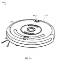
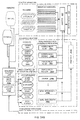
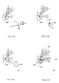
- FIGs 1A and 1B show above-perspective and exploded views of an autonomous coverage robot 100.
- the robot 100 has a chassis 102, a controller 103, an omni-directional receiver 104, and a directional receiver 106.
- Chassis 102 has a forward drive direction and carries controller 103 and the receivers 104 and 106 on a bumper 107.
- Receivers 104 and 106 provide navigation information to controller 103.
- controller 103 uses input from receivers 104 and 106, controller 103 generates commands to be carried out by the robot 100.
- the robot 100 is capable of cleaning floors in an autonomous fashion.
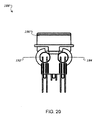
- FIG. 2 illustrates the positions of omni-directional receiver 104 and directional receiver 106 on the bumper 107 of the robot 100.
- Bumper 107 may also have other sensors, as shown in FIG. 1C , to aid the robot 100 as it navigates about its surroundings.
- Proximity sensors 1072 may be used to determine when an obstacle is close to the robot 100.
- Contact sensors 1074 may be used to determine when the robot 100 has physically encountered an object.
- Cliff sensors 1076 may be used to sense when the robot 100 has encountered the edge of the floor, such as when it encounters a set of stairs.
- Omni directional sensors 104 may be used to sense when the robot 100 is in close proximity to a navigation beacon.
- the omni-directional sensor 104 may relay a signal to a control system that indicates the strength of an emission, where a stronger signal indicates closer proximity to a navigation beacon.
- Proximity sensors 1072 may be used to detect when an obstacle is nearby.
- the proximity sensors 1072 may, for example, be infrared or ultrasonic sensors that provide a signal when an object is within a given range of the robot 100.
- Contact or bump sensors 1074 may be used to detect if the robot 100 physically encounters an obstacle. Such sensors 1074 may use a physical property such as capacitance or physical displacement within the robot 100 to determine when it has encountered an obstacle.
- Cliff sensors 1076 may be used to sense when the robot 100 has encountered the edge of the floor, such as when it encounters a set of stairs.
- the robot 100 may have behaviors that cause it to take an action, such as changing its direction of travel, when an edge is detected.
- cliff sensors 1074 may be installed within a mounting apparatus that stabilizes and protects the sensor and which positions the sensor to point towards the window installed onto the bottom of the mounting apparatus. Together the sensor, the mounting apparatus and the window comprise a cliff sensor unit. There may, for instance, be four cliff sensor units installed within the bumper.
- a window may be installed on the bottom of the mounting apparatus which includes a shield mounted within a slanted molding composed of a material which prevents dust build up, such as an antistatic material.
- the shield component and the molding may be welded together.
- the shield may be mounted on a slant to allow dirt to more easily slide off.
- a secondary cliff sensor may be present behind existing cliff sensors to detect floor edges in the event that a wheel drop sensor on the caster wheel fail.
- Controller 103 may be configured to propel the robot 100 according to a heading setting and a speed setting.
- Signals received from proximity and contact sensors may be used by the control system to issue commands that deal with obstacles.
- Signals from the proximity and contact sensors may cause the control system to change the commanded speed or heading of the robot 100.
- a signal from a proximity sensor due to a nearby wall may result in the control system issuing a command to slow down.
- a collision signal from the contact sensors due to an encounter with a chair may cause the control system to issue a command to change heading.
- the speed setting of the mobile the robot may not be reduced in response to the contact sensor; and/or the heading setting of the mobile the robot may not be altered in response to the proximity sensor, but instead the two sensors may operate independently.
- Controller 103 may include a first independent behavioral routine configured to adjust the speed setting of the mobile the robot; and a second independent behavioral routine configured to alter the heading setting of the mobile the robot, in which the first and second independent behavioral routines are configured to execute concurrently and mutually independently.
- the first independent behavioral routine may be configured to poll the proximity sensor, and the second independent behavioral routine may be configured to poll the kinetic bump sensor.
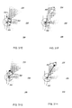
- FIG. 3-5 show perspective, front, and exploded views of the directional receiver 106.
- the directional receiver 106 is positioned on the front of the chassis 102. Emissions may be received along the drive direction by the directional receiver 106 which generates and sends corresponding signals to controller 103.
- the directional receiver 106 includes a mounting receptacle 108 with a first aperture 110 and a second aperture 112 that are aligned with the drive direction of the chassis 102. Associated with the apertures 110, 112 are a first component receiver 114 and a second component receiver 116.
- the component receivers 114, 116 are positioned relative to the apertures 110, 112 such that emissions which originate along the driving direction and fall on the directional receiver 106 may pass through the apertures 110, 112 and onto their respective component receivers 114, 116. Emissions falling on the component receivers 114, 116 result in a corresponding signals being generated which may be used by controller 103 to determine the direction of the emission relative to the robot's drive direction.
- a cover 117 attached to the top of the mounting receptacle 108 to prevent emissions that do not originate along the driving direction from falling on the component receivers 114, 116.
- locking tabs 119 or some other fastening method may be used to secure the cover 117 to the mounting receptacle 108.
- the component receivers 114, 116 of the directional receiver 106 can detect a homing beam with an overlap of substantially between 10 % and 30%.
- the first and second component receivers 114, 116 may be positioned such that emissions falling squarely on each would form an angle in the range of 1 to 15 degrees.
- the first and second component receivers 114, 116 may be aligned so emissions aligned with them cross at a point 3 to 5 meters in front of the robot.
- each component receiver 114, 116 receives emissions within a sweep angle of between about 28 to 33 degrees with a center of the sweep at about 14 degrees from a direction normal to the directional receiver 106 and a sweep overlap of about 10 degrees with the other component receiver 114, 116.
- the controller 103 may maneuver the robot 100 to detect an emission with the omni-directional receiver 104.
- the direction of the emission may be determined using the component receivers 114, 116.
- the controller 103 may orient the chassis 102 to align the robot drive direction with the determined emission direction.
- controller 103 may orient the chassis 102 to align the robot drive direction with the determined emission direction based on the signals generated by the component receivers 114, 116 in response to emissions detected with the directional receiver 106.
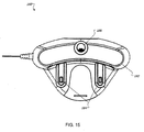
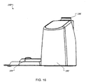
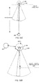
- FIGs. 6-8 show perspective, side, and cut-away views of the omni-directional receiver 104.
- the omni-directional receiver 104 may include a housing 118, a conical reflector 120 and an emission receiver 122.
- the housing 118 has an upper portion 124 and an inner cavity 126.
- the upper portion 124 may allow a transmission of an emission into inner cavity 126.
- Conical reflector 120 is located on an upper surface of the cavity 126 to reflect emissions falling on the upper portion 124 of the housing 118 into the inner cavity 126.
- Emission receiver 122 is located in inner cavity 126 below conical reflector 120.
- the receivers 114, 116, and 122 may be configured to receive transmissions of infrared light (IR).
- a guide 128 e.g. a light pipe
- a guide 128 may guide emissions reflected off the conical reflector 120 and channels them to emission receiver 122.
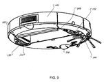
- FIG. 9 shows a below-perspective view of the autonomous coverage robot 100.
- a drive system 130 includes a first drive wheel 132 and a second drive wheel 134 which support chassis 102.
- a castor 136 may provide additional support to chassis 102.
- Motors may be mechanically coupled to the drive wheels to propel the robot 100, providing forward, reverse, and turning capabilities.
- the robot 100 may have a floor cleaning system that removes dirt and debris from the floor as it maneuvers about.
- the floor cleaning system may include a floor cleaning assembly 140, a cleaning bin 142 and a bin sensor (not shown).
- the floor cleaning assemblies 140 and 146 and cleaning bin 142 may be carried by the chassis 102.
- Cleaning bin 142 may be arranged to collect debris removed from a floor being cleaned by cleaning assembly 140.
- the bin sensor may be configured to generate a signal that indicates whether the cleaning bin has been filled to a threshold. When the threshold has been reached, controller 103 may initiate a docking sequence with a base station (described below).
- Cleaning bin 142 may be accessed to empty its contents either manually or, in some implementations, the robot 100 may automatically empty cleaning bin 142 when docked.
- the chassis 102 may have a ridge on its front which is higher than all other points on the chassis 102. Such a ridge may be stop the robot 100 if it encounters an overhead obstacle, such as a couch, and prevent it from becoming wedged underneath.
- controller 103 may normally command the drive system 130 to operate at less than maximum torque, for instance at 50% of capacity. If the robot 100 becomes wedged, for instance, sensed by increased current flowing to the drive motors, controller 103 may command increased torque to free the robot 100.
- an anti-wedging system includes a spring loaded wheel system having a potentiometer to measure how much the robot 100 is pushed down by a potential wedging obstacle.
- Another example includes an infrared sensor disposed on a lower surface of the robot 100, where the infrared sensor is used to measure a distance that the robot 100 is pushed down.
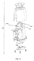
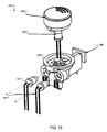
- FIG. 10 shows an exploded view of an example navigation beacon 150.
- Navigation beacon 150 may be used in conjunction with existing walls or other obstacles to create a bounded area. Bounding an area may be done, for example, to restrict a robot from entering or leaving an area.
- Navigation beacon 150 has a beacon emitter assembly 152, which includes a gateway beacon emitter 154 and an omni-directional emitter 160.
- Gateway beacon emitter 154 may be arranged to transmit a gateway marking emission.
- beacon 150 may be located within a gateway that separates a first and second adjacent areas and emit the gateway marking emission to form a boundary.
- Omni-directional receiver 104 and directional receiver 106 on the robot 100 may detect the gateway marking emissions and thereby function as beacon emission sensors.
- beacon 150 and the robot 100 may use infrared light (IR) emitters and sensors to create and detect the gateway marking emissions.
- IR infrared light
- the robot 100 controls the state of the navigation beams through commands transmitted over a packet radio network.
- the address that the beacons respond to on this network is a combination of a robot address and a node address.
- the beacon 150 After installing batteries in the beacon 150, the beacon 150 periodically tries to contact any robot to see if it should wake up and operate its emitters.
- a robot 100 may respond by transmitting a radio packet containing an invitation to join its network and a temporary address to use. While operating with a temporary address, the beacon 150 transmits an infrared code in a fence beam from emitter 154 and force field beam from omni-directional emitter 160 indicating that it is not bound, i.e. its radio address is temporary.
- a robot 100 When a robot 100 sees a beam with the bound code, it iteratively transmits a radio packet to every recently assigned temporary address to send a new code in its beam called a wink. If the robot 100 sees a wink code, it transmits a radio packet containing a new node address to be used from now on as well as a time indicating the number of hours the address is valid for use. Having bound to a robot 100 successfully, the beacon 150 will henceforth only wake up in the presence of that robot 100.
- the technique of confirming radio communications using infrared light signals is designed to prevent a robot 100 that is not on the same floor as the beacon 150 from controlling it permanently.
- Drive system 130 may be configured to maneuver the robot 100 about the first area while in a cleaning mode. In the cleaning mode, the robot 100 may be redirected in response to detecting the gateway marking emission. In addition, the drive system 130 may also be configured to maneuver the robot 100 through the gateway into the second bounded area while in a migration mode.
- the robot 100 While in the cleaning mode, the robot 100 may remain in the first bounded area by changing its drive direction when it detects the gateway marking emission.
- the gateway marking emission thus acts as a virtual barrier which may prevent the robot 100 from leaving the first bounded area.
- the drive system 130 may be configured to maneuver the robot 100 about the first bounded area in the cleaning mode for a preset time interval. When the preset time interval elapses, the drive system 130 may be automatically put in migration mode. While in migration mode, drive system 130 may be configured to maneuver the robot 100 across the gateway emission. In other instances, the drive system may configured to maneuver the robot about the first bounded area in the cleaning mode until it encounters of the gateway marking emission a preset number of times. Once the gateway marking emission has been encountered the preset number of times, the migration mode may be automatically initiated.
- the robot 100 may include a transmitter for communicating with beacon 150.
- the transmitter may be used to signals beacon 150 to halt or pause transmission of the gateway emission in the migration mode.
- the system may implement a power-saving function. Such a function may serve to extend battery life in beacon 150.
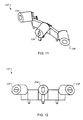
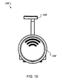
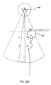
- FIGs. 11 and 12 show perspective and front views of beacon emitter assembly 152.
- Beacon emitter assembly 152 includes a first directed vectoring beacon emitter 156 and a second directed vectoring beacon emitter 158.
- Directed vectoring beam emitters may be used to create an emission field with a characteristic edge and spread pattern that may be used to define a navigation route.
- Navigation beacon 150 may be located within a gateway between two bounded areas with vectoring beacon emitter 156 arranged to transmit a directed vectoring emission into the first bounded area.
- the angle between the directed vectoring emission and the gateway may be, for example, in the range of 45-90 degrees.
- the directed vectoring emission may consist of infrared light.
- drive system 130 may be configured to direct the robot 100 toward beacon 150 when it encounters the directed vectoring emission emanating from vectoring beacon emitter 156.
- the robot 100 may then determine the position of the beacon 150 based on the detected direction of the directed vectoring emission relative to directional receiver 106. Once position is determined, the robot 100 may align itself in a drive direction relative to the directed vectoring emission. For example, the robot 100 may advance forward along the path of the directed vectoring emission to reach and traverse the gateway in which beacon 150 is located.
- the robot 100 may be able to remotely activate and deactivate the beacon emissions.
- the robot 100 may use wireless communication, such as radiofrequency (RF) communication, to pass activation and deactivation signals.
- the robot 100 may remotely activate the directed vectoring emission of the beacon 150 and deactivate the gateway emission upon initiating the migration mode.
- the robot 100 may remotely deactivate the directed vectoring emission of beacon 150 and activate the gateway emission upon terminating the migration mode.
- RF radiofrequency
- the beacon 150 may be configured to communicate schedule information with the robot 100. For example, beacon 150 may be able to transmit times for which the robot 100 should enter cleaning mode, when it should enter migration mode, etc. Schedule information may include details such as starting or ending times and dates.
- Navigation beacon 150 may also transmit a proximity emission laterally about itself.
- the robot 100 may avoid cleaning and migration within the proximity emission by executing a pre-configured behavior such as changing its course when the proximity emission is detected.
- the proximity emission may be thought of as a "force field" through which the robot 100 is not permitted to pass.
- Navigation beacon 150 may have a switch to select between a confinement mode, a navigation mode, and an off mode. Navigation beacon 150 may have a range select switch like a virtual wall. There may be a light to indicate when the navigation beacon is operating. The navigation beacon 150 may turn on an operational indicator light it is enabled or only when commanded to do so by the robot 100. There may also be a low battery warning, and there may be a separate low battery light.
- navigation beacon 150 may be in a low power mode in which emitters are off and the navigation beacon periodically monitors the communication link to determine if a wakeup is necessary.
- the robot 100 may send a signal to a single or multiple navigation beacons to turn on their respective emitters. There may be different commands to turn on the various emitters.
- the navigation beacon may return to low power mode after an elapsed time.
- each navigation beacon may have a unique identifier, such as a 16-bit (or larger) identification number contained in memory.
- This identifier may be generated in the factory or by the navigation beacon itself. If the identifier is generated in the factory it may be stored in non-volatile memory in the beacon.
- the robot 100 may use the unique identifier to generate an internal map which may be used to navigate from one bounded region to another by navigating from one navigation beacon to another.
- the identifier for navigation beacon 150 may be used to generate signals encoded in its emissions that may be detected by the robot 100.
- a unique code maybe generated as a derivation of the ID or by negotiation between the navigation beacons that are present and/or the robot 100.
- the robot and navigation beacons may communicate via point to point or via broadcast transmissions.
- the robot would have to learn the identifiers of all of the navigation beacons. Then it could send transmissions with a data field indicating the destination navigation beacon. That navigation beacon and only that navigation beacon would respond accordingly. This has the advantage that only specific navigation beacons would respond, keeping other navigation beacons off and thus increasing their battery life. User interaction may be used to train the robot to know the navigation beacons.
- An alternate concept is for the robot to broadcast to all navigation beacons a command to enable them. This scheme works without user interaction. In order to mitigate this effect of increased battery consumption and reduced battery life on these navigation beacons, an alleviating technique is to reduce the power of the robot transmission.
- FIG. 13 shows an example of a simplified navigation beacon 152 that may be used with an autonomous mobile robot navigation system.
- the beacon has a beacon emitter assembly 152 including a gateway emitter 154 and an omni-directional emitter 160, but does not have vectoring emitters.
- a beacon may be used to define boundaries of a region but not necessarily support migration functionality.
- FIGs. 14-17 show various views of an example base station 180 that may be included in the autonomous mobile robot system.
- Base station 180 may be located in a bounded area served by the system.
- Base station 180 has a base 182 with a defined docking direction and a robot charger 184.
- the robot 100 may approach base 182 from the docking direction to dock with the base 182.
- the robot charger 184 is housed in the base 182 and may be used to charge the robot 100 when it is properly docked.
- the robot charger 184 may begins operating when triggered by a detection circuit after the robot 100 is docked to base 182. Battery conditions may be used to govern whether a deeply discharge mode, a pre-charge trickle mode, or a post charge trickle mode is used to charge the battery.
- FIGs 18-21 show perspective, top, rear, and side views of an example emitter assembly 186 used in base station 180.
- Emitter assembly 186 has a lower housing 188 which holds an omni-directional beam emitter 190 and two navigational field emitters 192 and 194.
- the omni-directional emitter 190 may be mounted on housing 188 and be configured to project a proximity beam laterally around the docking station through the use of an upper housing 196.
- Upper housing 196 may be configured such that emissions from omni-directional emitter 190 form a desired pattern outside base 182, such as a circle.
- Navigational field emitters 192 and 194 may be attached to lower housing 188 and arranged to emit respective, laterally bounded and overlapping fields of emissions of signal beams.
- One of the emitted fields may define a lateral field edge aligned with the docking direction and be overlapped by the other emitted fields.
- the two navigational field emitters of the base station may be positioned such that their angle of overlap may be about 6 degrees and each emitter's aperture angle may be 20-30 degrees.
- a projection 198 on lower housing 188 may be used to shape the emissions from emitters 192, 194 to achieve the above pattern.
- the navigational field emitters 192 projects a beam at about 12 degrees from a direction normal to the emitter assembly 186, where the beam sweeps about 40 degrees starting from about -5 degrees to about 35.
- the emission fields may consist of infrared light (IR).
- field emitters 190, 192, and 194 may consist of infrared light emitting diodes (LEDs).
- FIG. 22 shows a schematic view of electronics 101 of the robot 100.
- the electronics 101 include the controller 103 which communicates with a bumper microcontroller 107A that controls the omni-directional receiver 104, directional receiver 106, wall proximity sensors 1072, and bumper switch 1074.
- the controller 103 monitors all other sensor inputs, including the cliff sensors 1076.
- FIGs. 23A-B show an example of applying of a method of navigating an autonomous coverage robot between bounded areas using navigation beacons.
- the method may be applied to a system such as the example the robot navigation system described above. While the following description relates a particular software architecture and set of algorithms to the navigation beacons disclosed as a physical infrastructure, the very same embodiments of a robot, control and software architecture, and/or many particular algorithms can be used with a different physical infrastructure.
- “navigation beacon” includes active and passive landmarks of other physical kinds (e.g., bar codes, retro-reflective tags, illuminated or IR spots projected on the ceiling or walls, directional RF or visible light, and other features identifiable in the environment), and “beam” includes directed vectors of other physical kinds (including inferred directional vectors calculated or kept in memory that may be followed, as well as line-of-sight directions to distant observed objects).
- landmarks of other physical kinds e.g., bar codes, retro-reflective tags, illuminated or IR spots projected on the ceiling or walls, directional RF or visible light, and other features identifiable in the environment
- beam includes directed vectors of other physical kinds (including inferred directional vectors calculated or kept in memory that may be followed, as well as line-of-sight directions to distant observed objects).
- walls 201, a first navigation beacon 202 and a second navigation beacon 203 define a first bounded area 204, a second bounded area 206, and a third bounded area 207 (which are typically rooms of a home).
- Navigation beacon 202 may be configured to transmit a gateway marking emission 208 (also noted herein as a “virtual gateway” or “gateway beam”) across a gateway 210 (typically a doorway, but openings of a few feet to 10 or 12 feet are possible, as well as arbitrary segmenting of a room without any particular openings).
- the gateway marking emission 208 may be an IR signal, for example, which can be sensed by a coverage robot 212.
- the robot 212 may be placed within a bounded area 204.
- the robot 212 may autonomously traverse the bounded area 204 in a cleaning mode. If the robot 212 encounters gateway marking emission 208 in gateway 210, the robot 212 remains in the bounded area 204 without moving into an adjacent bounded area 206.
- the robot 212 may autonomously (i.e., in response to an internal trigger condition as discussed herein, e.g., time expired, distance covered, percent covered) enter a migration mode in which the robot continues cleaning but monitors for the gateway 210, locates a gateway 210, moves to and through gateway 210, (past beacon 202,) into the adjacent bounded area 206.
- the robot 212 may autonomously enter the cleaning mode after the migration to bounded area 206 has been completed. While in the migration mode, the robot 202 may be non-responsive to gateway emission 208 (although the robot may record having crossed the gateway emission 208). In some cases, the robot 212 may remotely (i.e., by direct or relayed RF communications or line-of-sight or reflected optical signaling) deactivate gateway marking emission 208 upon entering migration mode. The robot 212 may also activate gateway marking emission 208 after exiting the migration mode.
- navigation beacon 202 may transmit a proximity emission or field 214 laterally around (surrounding) itself, establishing an exclusion zone or "force field".
- the robot 212 may detect this proximity field and use the detection to attempt to avoid maneuvering within the exclusion zone around a beacon 202 while in the cleaning or migrating modes.
- the primary purpose of the exclusion zone is to prevent the robot 202 from striking the beacon 202 itself and moving it.
- Navigation beacon 202 may be configured to transmit a first directed vectoring emission 216 (also discussed herein as a “directed emission,” “directed beam,” “launch beam” or “tractor beam”) into bounded area 204 and a second directed vectoring emission 217 into bounded area 206, with beacon 202 positioned within gateway 210.
- the robot 212 may drive toward beacon 202 upon detecting directed emission 216 while in the migration mode.
- the robot 212 may detect the directed emission 216 by sensing the directed emission 216 with a directional receiver 218 (also discussed herein as a "binocular sensor,” e.g., including twin detectors in collimated tubes) located on the front of the robot 212 (i.e. the side of the robot 212 that is aligned with the forward the robot drive direction).
- a directional receiver 218 also discussed herein as a "binocular sensor,” e.g., including twin detectors in collimated tubes located on the front of the robot 212 (i.e. the side of the robot 212 that is aligned with the forward the robot drive direction).
- the robot 212 may sense the directed emission 216 with an omni-directional receiver 222 prior to detection by directional receiver 218.
- the term "omni-directional receiver” as discussed herein includes non-directional and multi-directional receivers, e.g., receivers including two or more sensors (at compass points, etc.) directed about the periphery of the robot.
- the robot 212 may use the signal detected by omni-directional receiver 222 to then maneuver (turn in place or turn going in forward or reverse directions) to sense directed emission 216 with directional receiver 218.
- the robot 212 may align its direction of travel with a path defined by an edge 220 of directed emission 216.
- Directional and omni-directional receivers 218 and 222 may have construction and function similar to that described above.
- the robot 212 may move towards the beacon 202 along the emission path (i.e., servoing using the two beam detectors 114 and 116 of the binocular sensor 106) until it senses a beacon perimeter 224 (i.e. the edge of proximity field emission 214).
- the robot 212 may move along beam perimeter 224 through the gateway 210 and into bounded area 206.
- the angle between the gateway emission 208 and directed emission 216 may, in some instances, be between about 45 and 90 degrees, and optionally is about 60 degrees.
- the gateway emission 208 is sized according to the robot diameter, and diverges to be approximately the width of the robot at the proximity field edge or range of detection (e.g., to prevent the robot crossing at that point).
- each directed emission 216 beam is a diverging beam made diffuse by the slot mask near the emitter, and is, in two different examples, about 20-30 degrees (e.g., 25 degrees) or about 30-50 degrees (e.g., 40 degrees).
- the directed emissions 216 and 217 may consist of infrared light.
- the robot 212 may remotely activate and/or deactivate emissions coming from beacon 202, such as directed emission 216 or gateway emission 208.
- emissions coming from beacon 202 such as directed emission 216 or gateway emission 208.
- Various methods may be used to transmit signals between the robot 212 and the navigation beacons 202 and 203.
- each emitter may be encoded (e.g., modulated with a different serial code). This also helps avoid confusion with household and other remote controls as well as IR components of sunlight and other ambient sources.
- the robot 212 can encounter situations in which it is traveling through the emission paths of several different emitters.
- the sensor or software structure is configured to be capable of discerning one emitter from another when several signals are simultaneously received. If different frequencies are available, then these may be employed.
- One strategy is for the emitters to take turns, being synchronized by their communications with the robot or each other. However, this is complex and introduces a failure mode when synchronization breaks down. It is advantageous for each beacon 202, 203 and dock 240 to self-control, and stagger their own signals in time, with intervals between each emission.
- each transmitted emission may be differentiated by time division multiplexing (i.e., multiplexing as the beam origins are taken together as a system, including within a beacon having more than one beam or among several beacons) with a fixed period random offset (e.g., which may be different for each beam source).
- the interval or random offset may be changed from time to time (e.g., at random intervals) or by communication with the robot (e.g., by RF communication when the robot detects an interference condition).
- the offset may be selected from a set of offsets unlikely to harmonically interfere, or that do not share common factors. In this manner, the robot may encounter several emission paths at once yet discern the identity of each.
- each transmitted emission may be differentiated by different wavelengths of light, infrared modulations, and wavelength filters/windows on the emitters and receivers.
- the robot 212 may use RF communication to signal to beacon 202 to remotely activate directed emission 216 and deactivate gateway emission 208 upon initiating the migration mode. In another example, the robot 212 may remotely deactivate the directed vectoring emission 216 and activate gateway emission 208 upon exiting the migration mode.
- the robot 212 may activate a gateway emission 226 separating bounded areas 206 and 207 and initiate the cleaning mode. Similarly to that described above, the robot 212 may be prevented from leaving bounded area 206 when it encounters gateway emissions 208 and 226. When finished cleaning in bounded area 206, the robot 212 may initiate the migration mode and navigate through gateway 228 by following directed emission 230 to a perimeter 234 of a proximity emission 232 and enter bounded area 207. Once in bounded area 207, the robot 212 may re-enter the cleaning or working mode. After, for instance, a set time period or preset number of encounters with gateway emission 208, the robot 212 may migrate from bounded area 204 to bounded area 206.
- a virtual wall emitter may be set to independently deactivate itself on a schedule to permit the robot to cross the gateway, e.g., acting as a virtual wall for a first interval (to confine in a first or current room), then deactivating temporarily or intermittently, then acting as a virtual wall for a second interval (to confine in a second or successive room).
- This technique may also be interactive, e.g., the robot may use RF communication with one or more beacons to deactivate a virtual wall or bypass/cross a virtual wall.
- the robot's behavior system is arranged such that obstacle events, including cliff detection events, have a higher priority than any room-to-room navigation or cleaning. Accordingly, for example, when the robot encounters a cliff detection in the middle of a navigation or other set of sequenced behaviors, the robot may nonetheless avoid the cliff (aborting the current part of the sequence and resetting the state of the sequence).
- FIG. 23 shows a set of rooms similar to FIG. 22 , but arranged (with the addition of a base station) to illustrate the situation in which the robot encounters multiple beams from two beacon emitters and also from a dock 240.
- the robot 212 may nonetheless navigate from room to room or the robot 212 may autonomously initiate a docking mode to maneuver towards the base station 240 in bounded area 206 and dock with the station upon termination of the migration mode in the second area.
- the base station 240 may include a base, a robot charger, an omni-directional beam emitter and two navigational field emitters and be similar to the base station 180 described above.
- the robot 212 may maneuver towards base station 240 by detecting and advancing along one of the lateral field edges 242 or 244 of the overlapping fields 246, 248 aligned with the docking direction until docked with the station 240.
- the robot 212 may detect the emissions of base station 240 with omni-directional receiver 222 on the robot and maneuver to detect an outer lateral field edge (e.g. 247) of at least one field emission 246 or 248. The robot 212 may then advance along outer lateral field edge 247 or 249 to the aligned lateral field edge 242 or 244 of the overlapping fields. Upon detecting the aligned lateral field edge 242 or 244, the robot 212 advances along the aligned lateral field edge242 or 244 until docked with base station 240.
- an outer lateral field edge e.g. 247
- FIG.24A is a block diagram showing a behavioral software architecture within a controller 250, in which goal-oriented or sequenced behaviors are depicted in simplified form.
- FIG. 24B shows the same software architecture, but provides more detail on the goal-oriented or sequenced behaviors while simplifying some of the elements of FIG. 24A .
- FIG. 24A and 24B depict a software architecture that permits improved control of a mobile robot. Rather than being a purely reactive architecture, FIG. 24A and 24B introduce an element of planning that is partially reactive (and therefore more robust) - goal oriented, sequenced reactive behaviors.
- the implied success of a related behavior in a sequence is an enabling condition (among others) for each behavior beyond the initiating behavior in the sequence (some sequences may have more than one initiating behavior or branches).
- the implied success is kept as a state signifying an enabling condition of a successive behavior, in the form of a flag, state machine, or the like.
- the state may be set or changed by a behavior itself upon completion, by an arbiter process, or by a planning process.
- the robot 302 employs a control and software architecture that has a number of behaviors that are executed by an arbiter 252 in controller 250.
- a behavior is entered into the arbiter 252 in response to a sensor event, or a sequence state event from the planner 253.
- all behaviors have a fixed relative priority with respect to one another.
- the arbiter 252 (in this case) recognizes enabling conditions, which behaviors have a full set of enabling conditions, and selects the behavior having the highest priority among those that have fulfilled enabling conditions.
- the diagram shown in FIGs. 24A and 24B does not necessarily reflect the (fixed) priority hierarchy of the robot 302.
- the behaviors are generally categorized as escape and/or avoidance behaviors (such as avoiding a cliff or escaping a corner), working behaviors (e.g., wall following, bouncing, or driving in a straight line), and for the purposes of this application, sequenced reactive behaviors.
- the behaviors may include: different escape behaviors 255, 255a, 255n (including escaping corners, anti-canyoning, stuck situations, "ballistic" temporary fire-and-forget movement that suppress some avoid behaviors, e.g., as disclosed in U.S. Patent No.
- cliff avoiding 256 virtual wall avoiding 258 (a virtual wall may be a beacon with a gateway beam), other avoidance 258n as a class (e.g., avoiding people via a pyrometer, in general the class of detecting and moving away from something that is a hazard to the robot 302 or to which the robot 302 may be a hazard), spot coverage 264a (covering in a confined pattern such as a spiral or boustrophedon patch), align 264b (turning in place, using side proximity sensors to align with a forward obstacle encountered while obstacle following, e.g., an inside corner), following 264c (representing either or both of substantially parallel or bump following along an obstacle using a side proximity sensor or bumper that extends to the side of the robot), responding to a bump in order to "bounce" 264d (a behavior that occurs after the robot bumps an object), and drive 266.
- a class e.g., avoiding people via a pyrometer, in general the class of detecting
- the reactive behaviors have, as their enabling conditions or triggers, various sensors and detections of phenomena, but, in general, not (arbitrary) states of a sequence. As shown in FIG. 24A , these include sensors for obstacle avoidance and detection, such as forward proximity detection (multiple), forward bump detection (multiple), cliff sensors (multiple), detection of a virtual wall signal (which may instead be considered a coverage trigger).
- sensors for obstacle avoidance and detection such as forward proximity detection (multiple), forward bump detection (multiple), cliff sensors (multiple), detection of a virtual wall signal (which may instead be considered a coverage trigger).
- Sensors of these types are be monitored and conditioned by filters, conditioning 292c, and their drivers 292b, which can generate the enabling conditions as well as record data that helps the behavior act predictably and on all available information (e.g., conversion to one-bit "true/false” signals, recording of likely angle of impact or incidence based on strength or time differences from a group of sensors, or historical, averaging, frequency, or variance information).
- filters, conditioning 292c and their drivers 292b
- Actual physical sensors may be represented in the architecture by "virtual” sensors synthesized from the conditioning and drivers. Additional “virtual” sensors that are synthesized from detectable or interpreted physical properties, proprioceptive or interpreted upon the robot 302, such as over-current of a motor, stasis or stuck condition of the robot 302 (by monitoring a lack of odometry reading from a wheel encoder or counter), battery charge state via coulometry, and other virtual sensors "virtual N.”
- reactive behaviors can act according to enabling conditions that represent detected phenomena to be sought or followed.
- a beam or wireless (RF, acoustic) signal can be detected without direction; or in some cases with direction.
- a remote beam or marker bar code, retro-reflective, distinctive, fiducial, or natural recognized by vision landmark
- giving a direction can permit homing or relative movement; without direction the robot 302 can nonetheless move to servo on the presence, absence, and/or relative strength of a detected signal.
- the reflection of a beam from the robot 302, edge, or line can be similarly detected, and following behaviors (such as obstacle following by the robot 302) conducted by servoing on such signal.
- a debris or artifact signal can be collected by monitoring debris or objects collected by or traversed by the robot, and that signal can be an enabling condition for a reactive behavior controlling a spot coverage pattern.
- a general class of "seek/servo N" signals are thus also reactive behavior enabling conditions or triggers.
- the robot 302 maintains concurrent processes, "parallel" processes that are not generally considered reactive behaviors.
- a scheduler 292d may be necessary to allocate processor time to most other processes, e.g., including the arbiter and behaviors, in a co-operative or other multitasking manner. If more threading is available, less processes may be managed by the scheduler 292d.
- filters and conditioning 292c and drivers 292b can interpret and translate raw signals. These processes are not considered reactive behaviors, and exercise no direct control over the motor drives or other actuators.
- brush motor controller(s) 292a control the main and side brushes, although these may alternatively be controlled by dedicated brush behaviors and a brush control arbiter.
- sequence planner 253 is capable of monitoring and/or maintaining state in order to control sequenced reactive behaviors, e.g., setting enabling conditions (that will be caught by the arbiter 252), and/or resetting states in the case of abort conditions (e.g., time-outs, escape or avoidance behavior execution), and/or monitoring or supervising finite state machines that themselves transition between states.
- sequenced reactive behaviors e.g., setting enabling conditions (that will be caught by the arbiter 252), and/or resetting states in the case of abort conditions (e.g., time-outs, escape or avoidance behavior execution), and/or monitoring or supervising finite state machines that themselves transition between states.
- enabling condition states or flags or supervised state machines that request a transition between sequential reactive behaviors can be set by a behavior itself, by the arbiter, or by the sequence planner 253, depending on efficiencies and circumstances.
- the sequence planner 253 may optionally be capable of directly controlling the arbiter 252 (or second arbiter 252A) to prefer (e.g., re-prioritize) a behavior or directly control a sequenced reactive behavior without setting an enabling condition, state variable or state machine.
- sequences of intended actions may require the maintenance of some state. As discussed herein, if sequenced reactive behaviors are controlled to execute using request states which may be robustly reset or erased without primary function failure, the reduction in robustness can be reduced.
- a homing beam align behavior 294a includes an enabling condition that an align start (e.g., a homing request) enabling condition be activated, and that the beam to be homed upon is detected by a multi-directional sensor.
- an align start e.g., a homing request
- the homing request enabling condition can be set and maintained in different ways.
- a homing beam homing behavior 294b is to execute once alignment is successful.
- the homing beam homing condition also has as an enabling condition the homing request (flag or state), as well as a detection using a directional sensor (binoculars) that substantially necessarily directed at the beam identified as one to be homed upon (or, e.g., filtered to be equivalent to such a detection).
- a sensor-based enabling condition fails, these behaviors are aborted (internally or by the planner 253) and the sequence request remains active (or may be reset).
- the sequence may be restarted the next time either sensor-based enabling condition occurs.
- a random component (such as a random distance or time return to random coverage, while disabling the sequence request or homing request enabling condition) is permitted to occur following an abort of a sequential reactive behavior in order to decrease the likelihood of systematic failure or looping.
- a (new) align start enabling condition (e.g., field align state or request) may be set by the completing sequenced reactive behavior or by the planner, via condition flag or state machine.
- the detection of the proximity field by the multi-directional receiver is an equivalent (OR) condition to the field align request, if the homing request is active when the field is encountered, this combination also should initiate field align behavior 294c.
- the field align behavior 294c executes.
- the sequence (of sequenced reactive behaviors) is in a state where a next assumption is made regarding the state - that the robot is oriented appropriately to begin field following.
- a (new) follow start enabling condition (e.g., field follow state or request) may be set by the completing sequenced reactive behavior or by the planner, via condition flag or state machine.
- the launch behavior 294e may have as a primary enabling condition a state-based request rather than a sensor detection.
- a state to enter the entire sequence is maintained and an additional state to begin a next part of the sequence (field follow request; launch request) is set and both conditions are necessary to start the next sequenced reactive behavior.
- the entire sequence entry request is reset and the only the next sequenced reactive behavior entry condition is set (field align request or field follow request). This would cause the entire sequence to be otherwise restarted (e.g., by a new or continued occurrence of conditions that would cause the planner to set the sequence request) after an abort, which could improve general robustness (although not necessarily goal-specific robustness) by erasing essentially all states.
- no sensor-based condition is an enabling condition for the next sequenced reactive behavior in the sequence
- an enabling condition is a sequence-based or a state-based request - e.g., field follow request, launch request.
- a sequence may include sequenced reactive behaviors that include only sequence states or progress as enabling conditions for the next sequenced reactive behavior (such as the field follow behavior, or launch behavior), as well as sequenced reactive behaviors that include both sensor-based conditions and sequence states, progress or requests as enabling conditions (such as the beam align or tractor homing behaviors).
- a state to enter the entire sequence is maintained and either a sensor-based condition or a sequence-based request is an enabling condition for a next sequenced reactive behavior (field align) in the sequence - e.g., a homing request AND (field align request OR field detection) is interpreted by the arbiter to permit field aligning if no reactive behaviors have higher priority.
- a sequence may include sequenced reactive behaviors that include either a combination of sequence state/requests, or both sensor-based conditions and sequence request/states, as enabling conditions for a next sequenced reactive behavior.
- entry and mid-sequence branching is possible by enabling different behaviors depending on different combinations of sensor-based conditions and sequence states. For example, just as two possible entry points into the sequence are permitted by detecting different sensor events (multi-directional or directional) at the same time as a common entry point enabling condition (homing request), branches in the sequence to different next sequenced reactive behaviors are permitted by detecting different sensor events at the same time as a common mid-sequence enabling condition (e.g., candidate behaviors each enabled by a unique combination of sensor event and sequence state).
- a common mid-sequence enabling condition e.g., candidate behaviors each enabled by a unique combination of sensor event and sequence state.
- different mid-sequence state combinations permit nesting of sequences (candidate behaviors each enabled by a unique combination).
- Sequence planner 253 optionally maintains a navigation mode state switch or finite state machine 243a, and/or such states or requests are maintained separately (e.g., follow start, follow done).
- the planner 253 may control different goal-oriented sequences 1-N, each having more than one sequenced reactive behavior therein.
- the behaviors therein can have as initial conditions a goal state, entry request, or other state, that the arbiter 252 identifies as requiring rendering a candidate behavior available for execution.
- Initial behaviors of a sequence may require a sequence request; subsequent behaviors may require either a next sequenced reactive behavior request (or, in addition, the sequence request as well).
- sequenced behaviors are "reactive" despite being dependent upon sequence state at least because they may be subject to the same arbiter 252 as the reactive behaviors, and/or react to sequence states as enabling conditions in the same manner as reactive behaviors react to real-time sensor events, and/or are prioritized lower than at least escape and avoidance behaviors.
- the states may be wholly reset to restart a reactive process. Even when a sequence or next sequenced reactive behavior's enabling conditions are satisfied, a reactive behavior that also has enabling conditions satisfied and preserves continuous autonomous operation will be executed instead.
- Reactive docking behaviors which generally permit the robot to return and recharge for continued autonomous operation, may be prioritized higher than, in particular, navigation-related sequenced reactive behaviors. Reactive coverage behaviors may be prioritized below navigation sequenced reactive behaviors, in particular.
- a second arbiter 252a may supervise a sequence of sequenced reactive behaviors (e.g., in combination with the sequence planner 253); or a master arbiter (not shown) may supervise a first arbiter (e.g., 252) of reactive behaviors and a subsequent arbiters (e.g., 252a) of different sequenced reactive behaviors.
- the sequence planner 253 may include, monitor, or maintain location state in the form of a topological state map or its equivalent with respect to the environment in which the robot operates.
- this may be a topological map having nodes and links, in which the nodes may be rooms (links thereby being gateways or beacons) or gateways (links thereby being sides of the gateway).
- a primary use of the location state is to provide a homing beam or homing fiducial identity to the arbiter or to the sequenced reactive behaviors.
- the arbiter may recognize a sensor-based enabling condition (e.g., beam detection) for a behavior only when the beam has the correct identity (encoding) for the location state.
- a sensor-based enabling condition e.g., beam detection
- the behavior itself examines the identity or encoding of a received enabling condition (e.g., beam detection).
- An abort condition can result if beacons have been rearranged or the like, and this abort condition can cause blacklisting of a beacon or fiducial or a reset of the map (new mapping needed). In either case, the robot 302 continues to provide coverage and all other remaining reactive behaviors in the local area.
- the location state is used by the planner 253 to successively execute sequences of sequenced reactive behaviors in order to traverse a distance to or from a remote or distal room (for returning from the dock for charging; for directly proceeding to a remote or distal chamber from the dock); and permits the same sequenced reactive behaviors to be used for navigation in different directions (so long as the location state is maintained) by providing the identities of the guiding fiducials or beams in the correct order for a navigation direction, depending on the direction to be traveled on the topological map.
- the planner routine monitors (502) a goal-oriented or sequence initiating condition. As discussed, this may be a variable that keeps track of a time, distance, cleanliness measure, history of obstacle interactions, or other criterion that, when satisfied, indicates that a planned sequence (such as navigation from room to room) is to be carried out.
- the condition may be a state, flag or state of a finite state machine. If such a condition exists (504), the planner checks (506) the state of the robot along the called for sequence, if the planner maintains such a sequence state.
- the planner 253 may maintain or monitor the current state of a state map or finite state machine defining states of the beacon crossing sequence, as shown in FIG. 25B (in which "aligning to launch”, “homing”, “aligning after homing”, and “following field” states are available); alternatively a state map or finite state machine may be instantiated.
- the planner 253 may additionally or in the alternative set (508) behavior enabling conditions for entry into a sequence, such as a homing request as discussed herein, or an entire sequence entry behavior enabling condition and/or next sequenced reactive behavior enabling condition.
- the planner 253 may additionally set (510) guiding variables for the behavior or arbiter to recognize (e.g., such as the identity of a beam to be followed or fiducial to be homed upon or bearing to proceed in), according to, e.g., the state of a map identifying such (e.g., as shown in FIG. 25C , according to the state of a map defining which beam A or B - "green” or “red” - of lighthouses/beacons X, Y, Z connects to which rooms 1, 2, 3 and a dock, and according to the next goal room defined by the planner 253).
- guiding variables for the behavior or arbiter to recognize e.g., such as the identity of a beam to be followed or fiducial to be homed upon or bearing to proceed in
- the state of a map identifying e.g., as shown in FIG. 25C , according to the state of a map defining which beam A or B - "green” or “red” - of lighthouses
- the planner 253 may additionally monitor abort conditions (512, e.g., time out, interruption by a reactive avoidance or escape behavior) of sequenced reactive behaviors in progress, and set or reset the state of a sequence and/or the state of a map upon such an abort (although behaviors may also set or reset these internally before aborting).
- abort conditions 512, e.g., time out, interruption by a reactive avoidance or escape behavior
- the sequence planner 253 executing on the controller 250 will decide to exit the cleaning mode and enter the migration mode.
- the robot may also enter the migration mode right from the dock, in order to proceed to a distal or remote room in order to begin cleaning there.
- the migration mode executes the task of moving from one room to an adjacent room.
- the migration mode is advantageously not a monolithic process, but is a succession of sequenced reactive behaviors started by an initial behavior - that has an enabling condition of a migration mode request (also discussed herein as a "homing request").
- the planner 253 will raise a "new room"/homing request enabling condition, state, or flag.
- the remaining enabling condition is a sensor detection of a guiding tractor beam (optionally, limited to one beam identified according to the location state 253b as originating with the lighthouse/beacon to be homed upon), which, when the beam is detected (substantially immediately if the robot is in the beam, or after the robot encounters the beam as it continues the coverage behaviors having satisfied enabling conditions), triggers the homing beam - align behavior 294a to be selected by the arbiter 252 for execution.
- the robot 302 performs the task of migrating from one bounded area to an adjacent bounded area by executing the homing beam - align behavior 294a while at the same time possibly executing the cliff avoiding 256 (on any occasion when any cliff detector fails to see the floor - i.e., the enabling condition of the higher priority & reactive avoidance behavior is also satisfied) and drive 266 behaviors (e.g., if an abort condition resets the sequence).
- the arbiter 252 will arbitrate the behaviors in order of priority. That is, the arbiter may also arbitrate among different sequences of reactive behaviors, or the planner may only start one sequence.
- the beacon crossing sequence 262 has five sequenced reactive behaviors, beginning with the homing beam - align behavior 294a, which are executed or sequentially based on controller inputs as discussed herein. If the robot 302 experiences a signal input (such as a bump sensor input) that requires execution of a behavior having a higher priority, the robot 302 will execute the behavior of higher priority and afterwards, upon the presence of the necessary enabling conditions, may reinitiate a previous sequence of reactive sequenced behaviors.
- a signal input such as a bump sensor input
- FIGs. 31A-G are overhead views showing a behavior based autonomous coverage robot 302 as it uses a navigation beacon 304 to migrate from one area to another.
- FIGs. 26-30 are diagrams illustrating the beacon crossing sequenced reactive behaviors 262, including beam aligning 294a, beam homing 294b, field following 294c, field aligning 294d, and leaving beacon 294e behaviors.
- the beacon crossing sequence 262 commences by entering the beam homing 294b or beam aligning behaviors 294a, depending on a robot position within the first bounded area in relation to the beacon 304. Generally, the robot 302 will initiate a maneuver to detect with its omni-directional receiver 104 the first directed beam 306 from the navigational beacon 304 into a first area (e.g. turning 360 degrees or driving in a circle).
- a first area e.g. turning 360 degrees or driving in a circle.
- FIG. 26 depicts the beam align behavior 294a.
- the arbiter 252 will not permit the beam align behavior 294a as a candidate (i.e., to be prioritized with other behaviors with satisfied enabling conditions) at least until a homing request state or request is present, as well as the directional or tractor beam 306 is received by the multi or omni-directional sensor 322 of the robot 302, as behavior enabling conditions or triggers.
- no higher priority behaviors e.g., reactive behaviors
- This tractor or directed beam 306 may be limited to one expected at the present location of the robot 302 on the state map (e.g., by responding only to a beam having an identity or encoding corresponding to the current map state).
- the arbiter 252 permits the beam align behavior 294a to execute. If either condition is no longer satisfied, the behavior may abort. As noted in FIG. 26 , abort conditions (e.g., including missing behavior enabling conditions; time-out; or displacement by a higher priority behavior) may be monitored by the planner 253, which may also keep states reflecting the progress of the sequence as well as the location of the robot 302.
- the beam align behavior 294a turns or pivots the robot 302 essentially in place (522), starting in a random direction.
- a likely beam direction may also be maintained as a state, e.g., based on past beam detections monitored by, e.g., a concurrent process, and if so, the turning direction may be the one expected to be shorter.
- the directional receiver 318 senses the directed beam 306 (524), the behavior ends. There is no need to set a state as a request for the beam homing behavior 294b likely to follow, as the robot 302 will, so long as the homing request is active, continue to attempt to align and home when the correct beam is encountered and either is a valid entry point for the sequence. Later stages of the sequence are mid-sequence, and may use such states. Accordingly, the beam align behavior 294a is an example of choosing not to set a state in order to maintain a higher level of reactive control and likely robustness.
- FIG. 31A shows the robot 302 during readiness for and execution of the beam align behavior 294a, as it encounters a first directed beam 306 emitted by a navigation beacon 304, when a homing request from the planner 293 is active.
- the robot 302 Upon detecting the first directed beam 306, the robot 302 commences the beam aligning behavior 294a.
- the drive system 130 maneuvers (e.g., by turning in place, e.g., starting in a random direction) the robot 302 to detect the first directed beam emission 306 with the directional receiver 318, which is to be aligned with a robot drive direction.
- the robot 302 aligns the drive direction with the directed emission 306 of the beacon 304.
- FIG. 31B shows the robot 302 as it detects beam 306 with the omni-directional receiver 322 and turns to face beacon 304.
- the robot 302 may commence the beam homing behavior 294b.
- FIG. 27 depicts the tractor or directed beam homing behavior 294b.
- the arbiter 252 will not permit execution (of the highest priority candidate) until at least a homing request state or request is active, and the directional or tractor beam 306 is received by the directional sensor 318 of the robot 322 as behavior enabling conditions or triggers.
- This tractor or directed beam 306 may again be limited to one expected at the present location of the robot 302 on the state map.
- the arbiter 252 may permit the beam homing behavior 294b to execute. If either condition is no longer satisfied, the behavior 294b may abort. As noted in FIG. 27 , abort conditions and resulting states may be supervised by the planner 253.
- the tractor or directed beam homing behavior 294b follows the directed beam emission (532).
- One exemplary way of following is using alternating curves.
- Each parallel sensor 114 and 116 of the directional binocular sensor 318 is conditioned to return a one bit true-false value reflecting beam presence, based on signal strength (e.g., independently thresholded, or thresholded with respect to one another).
- signal strength e.g., independently thresholded, or thresholded with respect to one another.
- beam detections of true-false, true-true, and false-true are possible (conditioning may also limit the possibilities to true-false and false-true).
- a "bang-bang" servoing may be used to change turning direction as the robot 302 moves forward.
- Each turn is an arc with decreasing radius, i.e., part of an inward spiral.
- analog values may be maintained and more complex feedback control employed.
- the following (532) may alternatively employ the frequency and variance tracking discussed herein with respect to docking to determine that the robot is proceeding in the correct direction and move forward in a straight line.
- a state is to be set to continue the sequence of sequenced reactive behaviors - i.e., a field aligning request.
- the behavior 294b may set this state itself (536), e.g., as a flag in memory; or the planner 253 may monitor that the behavior 294a is complete and set such a flag or state in a finite state map or machine.
- the behavioral sequence permits the robot 302, after initiating the beacon crossing sequence 262, to skip the beam aligning behavior 294a if the directional receiver 318 already detects the directed beam emission 306 and is already aligned with the directed beam emission 306. Abort conditions may prevent these and permit later restarts.
- a combination of reactive behavior based control and sequenced reactive behavior control is advantageous. However, some embodiments discussed herein do not necessarily exclude other reactive or non reactive techniques.
- the robot 302 While executing the beam homing behavior 294b, the robot 302 moves towards the navigational beacon 304 while maintaining its alignment with (e.g., servoing upon) the directed beam 306 in response to the signals of the directional receiver 318.
- FIG. 31C shows the robot 302 approaching the navigation beacon 304.
- the robot 302 adjusts its course as shown by arrows 308. As shown in FIG. 31C , the robot 302 stops moving towards the beacon 304 when it encounters a proximity field emission (or "force field") 310 projected laterally from beacon 304 in all directions.
- a proximity field emission or "force field”
- the directional receiver 318 may receive the force field emission 310 even though the omni-directional sensor 322 does not.
- the directional sensor 318 may be used to alternatively home on the force field emission 310.
- an alternative behavior is provided in the sequence, identical to the tractor homing behavior 294b except that the sensor-based enabling condition is that the force field 310 is seen in the directional sensor 318; and the homing is on this emission 310.
- this behavior may be arbitrarily added to the sequence of reactive behaviors without changing any other behavior or disrupting any other process, with a priority above or below the existing tractor homing behavior 294a depending on empirical evidence that one or the other tended to be more reliable.
- FIG. 28 depicts the field align behavior 294c.
- the arbiter 252 will not permit execution (of the highest priority candidate) until at least a homing request state or request is active, and either a field align request is active, or the proximity field 310 is seen in the non-directional sensor 322 (this latter permitting the behavior sequence to advance to field aligning 294c when the robot 302 fortuitously "stumbles" into the proximity field 310 before encountering the directed beam 306).
- the field may again be limited to one expected at the present location of the robot 302 on the state map.
- the arbiter 252 may permit the field align behavior 294c to execute, abort conditions supervised as previously noted by the planner 253.
- the field align behavior 294c turns or pivots the robot essentially in place (544).
- a likely beam direction may be determined according to the beam identity (e.g., facing the dock 340, following a left beam 350 to the dock 340 likely means the robot 302 should turn clockwise, following a right beam 360 counterclockwise) or other state or information.
- the robot 302 may turn in the direction expected to be shorter or randomly.
- the behavior 294c does not end until an additional condition is satisfied - that the directional beam 306 is not present in the directional receiver 318 (which increases the likelihood that the robot 302 is rotated transversely to the dock 340).
- a field follow request is to be set to continue the sequence of sequenced reactive behaviors, as discussed, by the behavior itself (548), by the planner 253, or otherwise.
- the robot 302 can detect the proximity field 310 with the directional receiver 318, as when the robot 302 is facing the beacon 304, the robot 302 will initiate a pivot maneuver (e.g., turn in place for differential drive robots having drive wheels on the center diameter or holonomic drives or highly steerable robots, turn substantially in place for other configurations) altering the robot drive direction to the right or left toward the other directed beam 314, based on the beam encoding of the first directed beam 306.
- the robot 302 stops the pivot maneuver when it no longer detects the proximity beam 310 with the directional receiver 106.
- the robot 302 may encounter the proximity field 310 before encountering the directed beam 306. In this case, the robot 302 does not execute the beam aligning or beam homing behavior, 294a and 294b, respectively. Instead, the robot 302 recognizes the encoding of the proximity field 310 and executes the field aligning behavior 294d.
- the robot 302 executes the field following behavior 294c.
- FIG. 29 depicts the field following behavior 294d.
- the arbiter 252 will not permit execution (of the highest priority candidate) until at least a homing request state or request is active, and a field follow request is active. As noted, this may be limited to simply the field follow request if the sequence is to be more readily abandoned to preserve robustness.
- the field is optionally limited to an expected one. Once these are satisfied, the arbiter 252 may permit the field follow behavior 294d to execute subject to abort conditions.
- the field follow behavior 294c follows the edge 312 of the proximity field emission 310 (554) using alternating, decreasing radius curves as previously discussed.
- the non-directional sensor 322 may be conditioned to return a one bit true-false value reflecting beam presence, based on signal strength.
- the behavior 294d further checks and proceeds until the directional receiver 318 does not sense the launch beam 314 (which tends to exclude those cases in which the omni-directional detector 322 detects a launch beam 314 too early via a reflection from a highly reflective surface, such as a nearby white door or wall corner).
- a state is to be set to continue the sequence of sequenced reactive behaviors - i.e., a launch request.
- the behavior 294c may set this state itself (558), or the planner 253 may control this.
- the robot 302 maneuvers in an resultant arc around the beacon 304 while following an edge 312 of the proximity beam 310 via omni-directional receiver 322.
- the robot 302 follows the edge 312 of the force field 310 by monitoring the received signal strength of the force field emission 310 on the robot's emission sensors 318 and 322.
- the robot 302 "zigzagging" back and forth (e.g., "bang-bang” servoing or following using a one-bit true-false detection and forward motion in initially arced, steadily decreasing turn radius, e.g., spiraling in) along the edge 312 of the proximity beam 310, where the robot 302 detects entering and exiting the field of emission of the proximity beam 310 with the omni-directional receiver 322.
- the robot 302 follows the edge 312 of the force field by using a PID control system based on the time in the force field 310 or the time out of the force field 310.
- the PID control system controls the arc of the robot 302.
- the robot 302 executes the maneuver at a reduced speed (e.g., less than 50% of coverage speed) for both drive wheels 132 and 134, so that both drive wheels 132 and 134 are being driven in a forward direction. This facilitates easier traversing of transitions and thresholds.
- the robot 302 passes through the area normally covered by a gateway beam 316.
- the robot 302 continues to follow the edge 312 of the proximity beam 310 until the omni-directional receiver 322 detects that the robot 302 has entered the second directional beam 314 and the directional receiver 318 no longer detects the second directed beam 314, as shown in FIG. 31E .
- satisfying both criteria helps prevent the robot 302 from detecting reflected beam emissions off of adjacent objects, such as a white door.
- FIG. 29 depicts the launch behavior 294e.
- the arbiter 252 will not permit execution (of the highest priority candidate) until the launch request is active, and may also require the homing request.
- the launch behavior 294e assumes a last position with the omni-directional detector 322 in the launch beam 314 and a bearing substantially transverse to the launch beam 314, and curves away from the field 314/beacon 304 in the approximate direction of the launch beam 314 (e.g., facing the dock 340, if the robot 302 has traversed left to right, curving clockwise, and if the robot 202 has traversed the opposite direction, curving counterclockwise).
- the robot 302 may try to stay within the launch beam 314 by servoing to return to the launch beam 314 when the launch beam 314 is not detected in the omni-directional sensor 322. After a predetermined time (e.g., 5s) or distance (e.g., 1m) or obstacle encounter, the behavior is ready to end.
- the planner 253 may terminate the homing request (and, e.g., updating the location state of the topological map as well as clearing or resetting a navigation mode state if one is kept), and the reactive behaviors will begin the robot's coverage work in the subsequent chamber (or, if the battery is to be charged, this may initiate another homing request in the direction of the dock according to the location state of the map).
- the planner 253 may also immediately initiate another homing request; or reset variables of the current homing request according to the location state of the map such that the robot 302 will proceed from room to room to room, e.g., moving directly to or from a distal or remote room.
- the robot 302 may execute the leaving beacon behavior 294e, as shown in FIG. 30 , which entails the robot 302 moving away from the beacon 304.
- this can be performed as a pivot and launch, and/or guided by the launch beam 314 and omni-directional receiver 322, e.g., FIG. 31G shows the robot 302 turning away from navigation beacon 304 to face a second area as the robot 302 passes the edge of directed beam 314. If the robot 302 detects the second directed beam emission 314 with the omni-directional receiver 322, the robot 302 maneuvers away from the beacon 304.
- the robot 302 does not detect the second directed beam emission 314 with the omni-directional receiver 322, the robot 302 moves in a forward direction as shown in FIG. 31H without turning in order to avoid arcing back into the gateway.
- Another example of the leave beacon behavior 294e includes the robot 302 aligning itself in a particular direction using odometry (or a next beacon in a sequence, e.g., when the planner 253 includes a distal or remote room traversal sequence that restarts the sequence of behaviors at beam align with a next beacon's beam or field according to the map) and moving in that direction without guidance from any of the beams emitted from the current beacon 304.
- FIG. 31G shows the robot 302 moving away from navigation beacon 304 as it finishes migrating.
- the robot 302 While migrating, the robot 302 stores in memory the beam encodings of the first and second directed beams 306 and 314, respectively, at each navigational beacon 304 encountered while away from a base station 340. To return to the base station 340, the robot 302 conducts coverage behaviors while the homing request is on, resulting in discovering the appropriate directed beams 306 and 314, respectively, and corresponding encodings, to follow a sequence of encountered beams back to the base station 340. In one example, the robot 302 can wirelessly communicate (e.g.
- radiofrequency with the navigational beacons 304 to independently activate each previously encountered beam 306, 314, and 316 one at a time to find (traversing a room using random bounce and/or obstacle following to place itself in a beam path) and follow each beam back to the base station 340.
- navigation beacons may emit at least one, two, or three beam signals: fence/gate beam (referred to herein as "yellow”, but in reality having a first modulation of a first frequency in the IR band), right-hand navigation beam (referred to as “red”, but in reality having either or both of different modulation or a different frequency in the IR band from the "yellow” beam), and lefthand navigation beam (referred to as "green”, but in reality having either or both of a different modulation or a different frequency in the IR band from the "yellow” and “red” beams).
- fence/gate beam referred to herein as "yellow”
- red right-hand navigation beam
- red right-hand navigation beam
- lefthand navigation beam referred to as "green”
- green but in reality having either or both of a different modulation or a different frequency in the IR band from the "yellow” and “red” beams
- each would have different modulation of its beams, but the emitters of the fence/gate beam, right hand beam, or left hand beam would preferably be consistent among the navigation beacons.
- a navigation beacon also may emit a geometrically determined force field ("blue", again in actuality either or both of a different modulation or frequency in the IR band, although a force field could also be radio frequency RF rather than visible or IR light) in a circular region around their base. This may identify its presence to a robot, and allow a robot to follow a path around the Navigation beacon (through a gate or past a trail marker), for example.
- An IR-based beacon system can be designed to use a geometric solution, similar in certain respects to a non-limiting example such as a shaded floor lamp which lights up only a small area around itself, in order to provide a well-defined force field via IR, for example.
- a fence navigation beacon may emit a yellow beam directly out the front of the navigation beacon (0 degrees) and a single navigation beam (red or green) at about a 60-degree angle to the right or left of the yellow beam, for example.
- a gate navigation beacon may emit a yellow beam to the front, a red beam at -60 degrees, and a green beam at about +60 degrees, as another non-limiting example; also, for example, a trail marker Navigation beacon may emit a red beam at about -60 degrees and a green beam at about +60 degrees.
- Navigation beacon "beams” in some non-limiting examples may not be narrowly focused (thus not requiring a special lens); they may fan out to light as much of the room as may be practicable without mutual interference.
- a standard home base LED not requiring other optics may also be used.
- the docking behavior priorities include docking retry docking bump follow 264c, docking bounce 264d, docking quick turn 296c, docking distant homing 296b, docking lobe following 296a, and docking field following 296d.
- the robot 302 must generally approach the dock 340 from a forward direction with less than 4 degrees of skew in order to dock properly.
- the default docking behavior, docking lobe following 296a, as shown in FIG. 32A is executed when no other docking behavior has a higher priority.
- the robot 302 detects the left (red) beam 350 only, it follows the edge of the red beam 350 in a clockwise direction.
- the robot 302 detects the right (green) beam 360 or the overlap area of the red and green beams 350 and 360, respectively, it follows the edge of the green beam 360 in a counterclockwise direction. This results in the robot 302 appearing to follow the outside of the nearest docking beam 350 or 360 around to the front of the dock 340 at zero degrees and then following a normal (zero degree) edge 362 right onto the docking contacts.
- the robot 302 detects the force field 370 during this behavior it slows down in order to follow more accurately.
- the robot 302 keeps track of the signals detected by the omni-directional receiver 322 over a window of 30 seconds.
- the robot 302 detects that the frequency and variance of line crossing events (crossing the normal (zero degree) edge 362) is above about 1 Hz and below a variance of about 2.5 seconds it determines that the robot 302 is following the normal (zero degree) edge 362 and will simply drive straight by executing a smooth homing behavior, instead of continuing to follow the edge 362 (with the inevitable right-left oscillation) under the lobe following behavior 296a.
- the quick turn behavior 296c is activated when the robot 302 has encountered a docking beam 350 or 360 while driving straight, spiraling, bump following, or wall following, is not in the force field 370, and has not detected the dock 340 with its directional receivers 318 in the last several seconds.
- the robot 302 detects the red beam 350, it arcs clockwise toward the dock 340.
- the robot 302 detects the green beam 360 or the overlap area of the red and green beams 350 and 360 or it arcs counterclockwise toward the dock 340.
- the robot 302 detects the other beam 350 or 360 detects the dock 340 with its directional receivers 318, or has arced more than 360 degrees, this behavior 296c aborts. Typically it is then followed by the lobe following behavior 296a.
- the distant homing behavior 296b is activated when the robot 302 has not detected the force field 370 in its omni-directional receiver 322 in the last several seconds, and detects the dock 340 with the directional receiver 318. If the robot 340 detects the red or green beams 350 and 360, respectively, it will drive toward them. If the robot 340 only detects the force field 370 it will drive toward the force field 370. This allows the robot 302 to approach the dock 340 from a distance at any angle. When the robot 302 detects the force field 370 with its omni-directional receiver 322 this behavior 296b aborts. During a front approach this is typically followed by the lobe following behavior 296a. During a side approach this is typically followed by the field following behavior 296d.
- the field following behavior 296b activates when the robot 302 detects the force field 370 with its omni-directional receiver 322, has not detected the red or green beam, 350 and 360 respectively, with its omni-directional receiver 322 in the last second, and does not see the red or green beam 350 and 360, respectively, with its directional receivers318.
- the robot 302 follows the edge 372 of the force field 370 with its omni-directional receiver 322 in a random direction (cw or ccw) until it detects the red or green beam, 350 and 360 respectively, a bump, a cliff, or has traveled more than 1 meter.
- the robot 302 When the robot 302 detects the red or green beam, 350 and 360 respectively, it engages in reverse lobe following 296a for a distance of about 1 meter or until a bump is detected in order to travel away from the dock 340 along the normal (zero degree) edge 362 and straighten out. Then the robot 302 turns 180 degrees or until it faces the dock 340. Then the behavior 296b aborts. Typically the lobe following behavior 296a activates next to finish docking.
- the robot 302 can dock successfully even when there are obstacles completely or partially occluding the docking beams 350 and 360 or the robot's physical access to the dock 340 from some, but not all, approach angles by executing an obstacle dock behavior 296e.
- the robot 302 is seeking the dock 340 and has detected a docking beam 350 or 360 in its omni-directional receiver 322 in the last several seconds, and then also detects a bump, it activates the docking bounce behavior 264c.
- the obstacle dock behavior 296e initiates a bump follow behavior 264c and with about a 33% probability, the docking bounce behavior 264d which has the robot 302 simply back up, turn a random angle between 10 and 170 degrees for side impacts or 75 and 255 degrees for front impacts, and then aborts the behavior 264d.
- the bump follow behavior 264c follows an edge of the obstacle with the robot's bumper until one of the following conditions occurs: a) the robot 302 detects the dock 340 with the directional receiver 318 and does not detect it with is omni-directional receiver 322, with about a 66% probability; b) the robot 302 detects a crossing of the normal (zero degree) edge 362 from right to left and is bump following 264c in a clockwise direction, or the robot 302 detects a crossing of the normal (zero degree) edge 362 from left to right and is bump following 264c in a counterclockwise direction, with about a 66% probability; c) the robot 362 detects the force field 370 with its omni-directional receiver 322; d) 30 seconds has passed since the onset of the bump follow behavior 264c; or e) no docking beam 350 or 360 has been detected by the omni-directional receiver 322 for more than about 5 seconds.
- bump follow 264c includes the robot 302 keeping track of the projected location of the dock 340 and turning preferentially toward the estimated dock location during bump follow 264c.
- the robot 302 uses odometry to project the location of the dock 340 about 5 feet out along a direction of travel.
- the robot 302 can use odometry throughout the docking maneuver to estimate the orientation of itself to the projected location of the dock 340.
- the combination of short bouts of bump following and normal docking methods allow the robot 302 to dock in the face of a large variety of obstacles including but not limited to walls, chairs, and boxes, as well as reflections of the IR docking beams.
- ROBOT OBSTACLE DETECTION SYSTEM U.S. Patent No. 6,594,844 , disclosing proximity sensors such as cliff sensors and wall following sensors;
- AUTONOMOUS FLOOR-CLEANING ROBOT U.S. Patent No. 6,883,201 , disclosing a general structure of an iRobot Roomba coverage/cleaning robot and main and edge cleaning heads in detail;
- METONOMOUS FLOOR-CLEANING ROBOT U.S. Patent No. 6,883,201
Landscapes
- Engineering & Computer Science (AREA)
- Mechanical Engineering (AREA)
- Physics & Mathematics (AREA)
- Radar, Positioning & Navigation (AREA)
- Remote Sensing (AREA)
- Aviation & Aerospace Engineering (AREA)
- Automation & Control Theory (AREA)
- General Physics & Mathematics (AREA)
- Power Engineering (AREA)
- Transportation (AREA)
- Robotics (AREA)
- Electromagnetism (AREA)
- Acoustics & Sound (AREA)
- Sustainable Development (AREA)
- Sustainable Energy (AREA)
- Life Sciences & Earth Sciences (AREA)
- Computer Networks & Wireless Communication (AREA)
- Electric Vacuum Cleaner (AREA)
- Control Of Position, Course, Altitude, Or Attitude Of Moving Bodies (AREA)
- Manipulator (AREA)
- Electric Suction Cleaners (AREA)
- Connector Housings Or Holding Contact Members (AREA)
- Illuminated Signs And Luminous Advertising (AREA)
- Nozzles For Electric Vacuum Cleaners (AREA)
Abstract
Description
- This invention relates to robots, and more particularly to autonomous coverage robots and associated navigation systems.
- Autonomous robots are robots which can perform desired tasks in unstructured environments without continuous human guidance. Many kinds of robots are autonomous to some degree. Different robots can be autonomous in different ways. An autonomous coverage robot traverses a work surface without continuous human guidance to perform one or more tasks. In the field of home, office and/or consumer-oriented robotics, mobile robots that perform household functions such as vacuum cleaning, floor washing, patrolling, lawn cutting and other such tasks have been widely adopted. Relevant prior art is disclosed in documents
WO 03/026474 A2 US 2004/111184 A1 . - The invention is defined by
independent method claim 1 and by independent system claim 19. - In one aspect, an autonomous coverage robot includes a chassis defining a forward drive direction, a controller carried by the chassis, omni-directional receiver carried by the chassis, and a directional receiver disposed on a forward portion of the chassis and responsive to an emission incident on the forward portion of the chassis from the drive direction. The directional receiver includes a mounting receptacle defining first and second apertures substantially aligned with the drive direction, and first and second component receivers housed in the receptacle and positioned to be responsive to the emission received through the first and second apertures, respectively. The component receivers are each configured to generate a respective signal in response to the emission. The controller is configured to determine a direction of the emission in relation to the drive direction based on the signals generated by the component receivers.
- The directional receiver is installed onto a front portion of the chassis and housed within the mounting receptacle. The mounting structure stabilizes and supports the directional receiver which is used for docking and navigation throughout a room. The directional receiver includes two detectors which are highly directional in the sense that they are able to detect peaks of an overlapping signal from far away and servo in on the source of the beam using those peaks. In one example, the first and second component receivers of the directional receiver are positioned to form an angle of between about 1 and 15 degrees there between. In addition, the first and second component receivers may be collimated to focus at a point between about 3 and 5 meters from the robot or on any point within each bounded area.
- The controller maneuvers the robot to detect an emission with the omni-directional receiver, and in response to the detection, orients the chassis to align the robot drive direction with the determined emission direction based on the signals generated by the component receivers of the directional receiver. The controller, in response to a detected emission with the directional receiver, orients the chassis to align the robot drive direction with the determined emission direction based on the signals generated by the component receivers of the directional receiver. The receivers may be configured to receive transmissions of infrared light.
- In one implementation, the omni-directional receiver includes a housing having an upper portion and defining an inner cavity, a conical, and an emission receiver. The upper portion allows a transmission of an emission into the inner cavity. The conical reflector is disposed on an upper surface of the cavity to reflect emissions incident on the upper portion of the housing down into the cavity. The emission receiver is disposed in the cavity below the conical reflector.
- In one example, the robot includes a floor cleaning assembly carried by the chassis, a cleaning bin carried by the chassis and arranged to collect debris removed from a floor by the cleaning assembly, and a bin sensor. The bin sensor is configured to generate a signal indicative of the cleaning bin reaching a threshold filling that causes the controller to initiate a docking sequence.
- In another aspect, an autonomous mobile robot system for bounded areas includes a navigation beacon and an autonomous coverage robot. The navigation beacon has a gateway beacon emitter arranged to transmit a gateway marking emission with the navigation beacon disposed within a gateway between the first bounded area and an adjacent second bounded area. The autonomous coverage robot includes a beacon emission sensor responsive to the beacon emission, and a drive system configured to maneuver the robot about the first bounded area in a cleaning mode in which the robot is redirected in response to detecting the gateway marking emission. The drive system is also configured to maneuver the robot through the gateway into the second bounded area in a migration mode.
- The beacon may be configured to emit an infrared signal for the gateway marking emission, or any other type of signal, which is readily stopped by a wall so as not to "bleed over" into adjacent rooms and uniquely identify the current room or locality in which the robot is located.
- In one implementation, the robot remains in the first bounded area upon the robot redirection in response to detecting the gateway marking emission in the cleaning mode. The gateway marking emission may be infrared light and the beacon emission sensor is configured to detect transmissions of infrared light.
- In another implementation, the drive system is configured to maneuver the robot about the first bounded area in the cleaning mode for a preset time interval, and to automatically initiate the migration mode at expiration of the time interval. The drive system is configured to maneuver the robot across the gateway emission in the migration mode.
- In yet another implementation, the drive system is configured to maneuver the robot about the first bounded area in the cleaning mode until a preset number of encounters of the gateway marking emission have been detected, and then to automatically initiate the migration mode. The coverage robot's dwell time in one room or selective rooms can also be set by a timer or schedule, a number of collisions or interactions with a proximity beam of a particular beacon, a character or number of dirt or debris detections, remaining battery life, and maintenance or remote control overrides.
- In one example, the robot includes a floor cleaning system that removes debris from the floor as the robot is maneuvered.
- In some examples, the robot includes a transmitter that signals the beacon to disrupt transmission of the gateway emission in the migration mode.
- In another example, the navigation beacon includes a vectoring beacon emitter arranged to transmit a directed vectoring emission into the first bounded area with the beacon disposed within the gateway. The robot drive system is configured to direct the robot toward the beacon upon encountering the vectoring emission in the migration mode. The navigation beacon transmits the directed vectoring emission, which may be infrared light, at an angle adjacent the cross-gateway direction of between about 45 and 90 degrees. The robot, while in the migration mode, discerns a position of the navigation beacon in response to detection of the directed vectoring emission and aligns a drive direction defined by the robot in relation to an emission path defined by the directed vectoring emission. The robot advances along the emission path to reach and traverse the gateway. The navigation beacon may also transmit a proximity emission laterally about the beacon, where the robot avoids cleaning and migration within the proximity emission.
- In some examples, the robot wirelessly communicates with the navigation beacon to deactivate the directed vectoring emission while in the cleaning mode and activate the directed vectoring emission while in the migration mode. In other examples, the robot remotely activates the directed vectoring emission of the navigation beacon and deactivates the gateway emission upon initiating the migration mode. Furthermore, the robot remotely deactivates the directed vectoring emission of the navigation beacon and activates the gateway emission upon terminating the migration mode. The robot remotely activates and deactivates the emissions of the navigation beacon with a radiofrequency communication. The navigation beacon may also be configured to communicate schedule information with the robot.
- The system may also include a base station located in one of the bounded areas. The base station includes a base defining a docking direction from which the robot may properly dock, and a robot charger housed in the base. An omni-directional beam emitter may be mounted on the base and configured to project a proximity beam laterally around the docking station. Two navigational field emitters are housed in the base and arranged to emit respective, laterally bounded and overlapping fields of emissions of signal beams, respectively. One of the emitted fields defines a lateral field edge aligned with the docking direction and overlapped by the other of the fields. The two navigational field emitters of the base station are positioned to form an angle therebetween of between about 45 and 90 degrees. The fields of emissions of the two navigational field emitters of the base station may be infrared light.
- In another aspect, a method of navigating an autonomous coverage robot between bounded areas includes positioning a navigation beacon in a gateway between adjoining first and second bounded areas. The beacon configured to transmit a gateway marking emission across the gateway. In some example, the navigation beacon may also transmit a proximity emission laterally about the beacon, where the robot avoids cleaning and migration within the proximity emission. The method also includes placing the coverage robot within the first bounded area. The robot autonomously traverses the first bounded area in a cleaning mode and upon encountering the gateway marking emission in the gateway, the robot remains in the first bounded area, thereby avoiding the robot migration into the second area. Upon termination of the cleaning mode in the first area, the robot autonomously initiates a migration mode to move through the gateway, past the beacon, into the second bounded area.
- In some examples, the robot remotely deactivates the gateway marking emission of the navigation beacon upon initiating the migration mode and activates the gateway marking emission upon terminating the migration mode. The gateway marking emission may be infrared light. In other examples, the robot is non-responsive to the gateway emission while in the migration mode.
- In one example, upon termination of the migration mode in the second area, the robot autonomously initiates the cleaning mode in the second bounded area.
- In one example, the navigation beacon is configured to transmit a directed vectoring emission into the first bounded area with the beacon disposed within the gateway.
- The robot drives toward the beacon upon detecting the vectoring emission in the migration mode. Detecting the directed vectoring emission in the migration mode includes the robot sensing the directed vectoring emission with a directional receiver on the robot, where the directional receiver is aligned with a robot drive direction, and the robot aligning the robot drive direction with a path defined by the directed vectoring emission. The robot may also sense the directed vectoring emission with an omni-directional receiver on the robot before maneuvering to detect the directed vectoring emission by the directional receiver on the robot. The robot moves past the beacon by moving towards the beacon along the emission path, sensing a beacon perimeter emitted by the beacon, and moving along the beam perimeter through the gateway and into the second area.
- In another aspect, a method of navigating an autonomous coverage robot between bounded areas includes positioning a navigation beacon in a gateway between adjoining first and second bounded areas. The beacon is configured to transmit a directed emission into the first bounded area and a gateway emission in a cross-gateway direction. The method also includes placing the coverage robot within the first bounded area. The robot autonomously traverses the first bounded area in a cleaning mode and upon encountering the gateway emission, the robot remains in the first bounded area, thereby avoiding the robot migration into the second area. Upon termination of the cleaning mode in the first area, the robot autonomously initiates a migration mode to move through the gateway into the second bounded area by detecting the directed emission and, in response to the directed emission, moves past the beacon through the gateway and into the second area.
- The navigation beacon includes a base positionable in the gateway, the base defining a cross-gateway direction. A gateway beam emitter is housed in the base and arranged to emit a beam in the cross-gateway direction. First and second directional beam emitters are housed in the base and arranged to emit respective focused beams into each of the adjoining areas when the base is positioned in the gateway. An omni-directional beam emitter is disposed on the base and configured to project a proximity beam laterally around the beacon. The first and second directional focused beams form angles adjacent the cross-gateway direction of between about 45 and 90 degrees.
- Another example of the navigation beacon includes a beam emitter emitting a beam along the line of a "virtual wall" and a circular proximity beam (and/or RF zone) to prevent the robot collisions when detected by the robot. A first beam emitter may be positioned in the gateway to emit a beam across the gateway. A second beam emitter may be positioned in the gateway to emit a beam angled into a first room and modulated to signify the first room. A third beam emitter may be positioned in the gateway to emit a beam angled into a second adjoining room and modulated to signify the second room.
- The navigation beacon can also act as a virtual temporary confinement wall or gateway, where the robot stays within the virtual gateway(s) for, e.g., a predetermined number of virtual gateway interactions or time span, then crosses the virtual gateway and resets its time or incident counter to dwell in the next "room" which could be partially or wholly defined by virtual gateways.
- Multiple beacons may be employed to define the boundaries of each bounded area. The directed vectoring and gateway emissions may be infrared light. Each transmitted emission is differentiated by time division multiplexing with a fixed period random offset. Each beacon is encoded differently (e.g. left and right beams) and can be set by a DIP switch or other such device located on the beacon. The beacon encoding can be set or changed by the robot (e.g. via RF commands issued by the robot) as the robot encounters successive beacons or two beacons with the same encoding. The beacon may be set to be virtual walls or threshold markers (or both). As the robot encounters each beacon, the robot counts the beacons and identifies them by their modulation. The first one encountered is number one, and is believed to be nearest a base. The second one is number two, farther yet. The third one is number three, farther yet. The left and right side beams or directed beams of the beacons are encoded differently. As a result, the robot can record which side is thought to be nearer to the base. When the robot is ready to return to the base (e.g. timed out, low battery remaining, bin full, schedule finished, maintenance needed, general event triggered, or under any other circumstances), the robot looks for the lowest numbered beacon with an away-side beam and heads in that direction. The directionality of the beam also allows the robot to maneuver past the beacon appropriately. For example, on the way out from the base station, the robot passes directed beam A and directed beam B, sequentially, of a beacon, either one or both on the left side of the robot. To return to the base station the robot should wait/hunt/clean until it detects directed beam B of the beacon. The robot then approaches the beacon by following beam B until it detects a proximity beam of the beacon. The robot turns left and proceeds in a curved path along an edge of the proximity beam while hunting/cleaning until the robot detects beam A. The robot follows beam A out away from the beacon and then hunts/cleans for the base station. This is merely one example of how to navigate using the directionality of the room-identifying left and right beacons.
- In some examples, upon termination of the migration mode in the second area, the robot autonomously initiates a docking mode to maneuver towards a base station in the second area and docking with the station. The base station includes a base defining a docking direction from which the robot may properly dock, a robot charger housed in the base, an omni-directional beam emitter mounted on the base and configured to project a proximity beam latently around the base station, and two navigational field emitters housed in the base and arranged to emit respective, laterally bounded and overlapping fields of emissions of signal beams, respectively. One of the emitted fields defines a lateral field edge aligned with the docking direction and overlapped by the other of the fields. The robot maneuvers towards the base station by detecting and advancing along the lateral field edge of the overlapping fields aligned with the docking direction until docked with the station. The two navigational field emitters, which may be infrared emitters, are positioned to form an angle therebetween of between about 45 and 90 degrees. The robot detects the emissions of the base station with an omni-directional receiver on the robot and maneuvers to detect an outer lateral field edge of at least one field emission. The robot advances along the outer lateral field edge of the one field emission to the aligned lateral field edge of the overlapping fields. Upon detecting the aligned lateral field edge, the robot advances along the aligned lateral field edge until docked with the station.
-
-
FIG. 1A is a perspective view showing an example of an autonomous coverage robot. -
FIG. 1B is an exploded views of an autonomous coverage robot. -
FIG. 1C is an exploded views of a bumper of an autonomous coverage robot. -
FIG. 2 illustrates the positions of omni-directional receiver and directional receiver on the bumper of an autonomous coverage robot. -
FIG. 3 is a perspective view of a directional receiver. -
FIG. 4 is a front view of a directional receiver. -
FIG. 5 is an exploded view of the directional receiver.
Like reference symbols in the various drawings indicate like elements. -
FIGs. 6-8 show perspective, side, and cut-away views of the omni-directional receiver. -
FIG. 9 shows a below-perspective view autonomous coverage robot. -
FIG. 10 shows an exploded view of an example navigation beacon. -
FIGs. 11 and 12 show perspective and front views of an example beacon emitter assembly. -
FIG. 13 shows an example of a simplified navigation beacon that may be used with an autonomous mobile robot navigation system. -
FIGs. 14-17 show various views of an example base station that may be included in the autonomous mobile robot system. -
FIGs 18-21 show perspective, top, rear, and side views of an example emitter assembly used in base station. -
FIG. 22 shows a block diagram of representative electronic structure of an autonomous coverage robot. -
FIG. 23A shows a first example of applying of a method of navigating an autonomous coverage robot between bounded areas using navigation beacons with the addition of a base station; andFIG. 23B shows a second example in which the robot encounters more than one beam at the same time. -
FIGs. 24A and24B are block diagrams illustrating a software architecture for navigating an autonomous coverage robot. -
FIGs. 25A-C show schematic views of a robot moving from one area to another using a navigation beacon. -
FIG. 26 shows a schematic view of a beam align behavior of a robot. -
FIG. 27 shows a schematic view of a directed beam homing behavior of a robot. -
FIG. 28 shows a schematic view of a field align behavior of a robot. -
FIG. 29 shows a schematic view of a field following behavior of a robot. -
FIG. 30 shows a schematic view of a leaving beacon behavior of a robot. -
FIGs. 31A-H show schematic views of a robot moving from one area to another using a navigation beacon. -
FIGs. 32A-E show schematic views of a robot docking with a base station. -
FIGs 1A and1B show above-perspective and exploded views of anautonomous coverage robot 100. Therobot 100 has achassis 102, acontroller 103, an omni-directional receiver 104, and adirectional receiver 106.Chassis 102 has a forward drive direction and carriescontroller 103 and thereceivers bumper 107.Receivers controller 103. Using input fromreceivers controller 103 generates commands to be carried out by therobot 100. As a result, therobot 100 is capable of cleaning floors in an autonomous fashion. -
FIG. 2 illustrates the positions of omni-directional receiver 104 anddirectional receiver 106 on thebumper 107 of therobot 100.Bumper 107 may also have other sensors, as shown inFIG. 1C , to aid therobot 100 as it navigates about its surroundings.Proximity sensors 1072 may be used to determine when an obstacle is close to therobot 100.Contact sensors 1074 may be used to determine when therobot 100 has physically encountered an object.Cliff sensors 1076 may be used to sense when therobot 100 has encountered the edge of the floor, such as when it encounters a set of stairs. - Omni
directional sensors 104 may be used to sense when therobot 100 is in close proximity to a navigation beacon. For example, the omni-directional sensor 104 may relay a signal to a control system that indicates the strength of an emission, where a stronger signal indicates closer proximity to a navigation beacon. -
Proximity sensors 1072 may be used to detect when an obstacle is nearby. Theproximity sensors 1072 may, for example, be infrared or ultrasonic sensors that provide a signal when an object is within a given range of therobot 100. - Contact or bump
sensors 1074 may be used to detect if therobot 100 physically encounters an obstacle.Such sensors 1074 may use a physical property such as capacitance or physical displacement within therobot 100 to determine when it has encountered an obstacle. -
Cliff sensors 1076 may be used to sense when therobot 100 has encountered the edge of the floor, such as when it encounters a set of stairs. Therobot 100 may have behaviors that cause it to take an action, such as changing its direction of travel, when an edge is detected. - In some implementations,
cliff sensors 1074 may be installed within a mounting apparatus that stabilizes and protects the sensor and which positions the sensor to point towards the window installed onto the bottom of the mounting apparatus. Together the sensor, the mounting apparatus and the window comprise a cliff sensor unit. There may, for instance, be four cliff sensor units installed within the bumper. - Reliability of a cliff sensor may be increased by reducing dust buildup.
In some implementations, a window may be installed on the bottom of the mounting apparatus which includes a shield mounted within a slanted molding composed of a material which prevents dust build up, such as an antistatic material. The shield component and the molding may be welded together. To further facilitate the reduction in dust and dirt buildup, the shield may be mounted on a slant to allow dirt to more easily slide off. - In some implementations, a secondary cliff sensor may be present behind existing cliff sensors to detect floor edges in the event that a wheel drop sensor on the caster wheel fail.
-
Controller 103 may be configured to propel therobot 100 according to a heading setting and a speed setting. Signals received from proximity and contact sensors may be used by the control system to issue commands that deal with obstacles. Signals from the proximity and contact sensors may cause the control system to change the commanded speed or heading of therobot 100. For instance, a signal from a proximity sensor due to a nearby wall may result in the control system issuing a command to slow down. In another instance, a collision signal from the contact sensors due to an encounter with a chair may cause the control system to issue a command to change heading. In other instances, the speed setting of the mobile the robot may not be reduced in response to the contact sensor; and/or the heading setting of the mobile the robot may not be altered in response to the proximity sensor, but instead the two sensors may operate independently. -
Controller 103 may include a first independent behavioral routine configured to adjust the speed setting of the mobile the robot; and a second independent behavioral routine configured to alter the heading setting of the mobile the robot, in which the first and second independent behavioral routines are configured to execute concurrently and mutually independently. The first independent behavioral routine may be configured to poll the proximity sensor, and the second independent behavioral routine may be configured to poll the kinetic bump sensor. -
FIG. 3-5 show perspective, front, and exploded views of thedirectional receiver 106. Thedirectional receiver 106 is positioned on the front of thechassis 102. Emissions may be received along the drive direction by thedirectional receiver 106 which generates and sends corresponding signals tocontroller 103. Thedirectional receiver 106 includes a mounting receptacle 108 with afirst aperture 110 and asecond aperture 112 that are aligned with the drive direction of thechassis 102. Associated with theapertures second component receiver 116. - The
component receivers 114, 116 are positioned relative to theapertures directional receiver 106 may pass through theapertures respective component receivers 114, 116. Emissions falling on thecomponent receivers 114, 116 result in a corresponding signals being generated which may be used bycontroller 103 to determine the direction of the emission relative to the robot's drive direction. A cover 117 attached to the top of the mounting receptacle 108 to prevent emissions that do not originate along the driving direction from falling on thecomponent receivers 114, 116. In some implementations, locking tabs 119 or some other fastening method may be used to secure the cover 117 to the mounting receptacle 108. - In some implementations, the
component receivers 114, 116 of thedirectional receiver 106 can detect a homing beam with an overlap of substantially between 10 % and 30%. In one example, the first andsecond component receivers 114, 116 may be positioned such that emissions falling squarely on each would form an angle in the range of 1 to 15 degrees. In another example, the first andsecond component receivers 114, 116 may be aligned so emissions aligned with them cross at apoint 3 to 5 meters in front of the robot. In one example, eachcomponent receiver 114, 116 receives emissions within a sweep angle of between about 28 to 33 degrees with a center of the sweep at about 14 degrees from a direction normal to thedirectional receiver 106 and a sweep overlap of about 10 degrees with theother component receiver 114, 116. - In some cases, the
controller 103 may maneuver therobot 100 to detect an emission with the omni-directional receiver 104. The direction of the emission may be determined using thecomponent receivers 114, 116. In response to the detection, thecontroller 103 may orient thechassis 102 to align the robot drive direction with the determined emission direction. - In other cases,
controller 103 may orient thechassis 102 to align the robot drive direction with the determined emission direction based on the signals generated by thecomponent receivers 114, 116 in response to emissions detected with thedirectional receiver 106. -
FIGs. 6-8 show perspective, side, and cut-away views of the omni-directional receiver 104. The omni-directional receiver 104 may include ahousing 118, aconical reflector 120 and anemission receiver 122. Thehousing 118 has anupper portion 124 and aninner cavity 126. Theupper portion 124 may allow a transmission of an emission intoinner cavity 126.Conical reflector 120 is located on an upper surface of thecavity 126 to reflect emissions falling on theupper portion 124 of thehousing 118 into theinner cavity 126.Emission receiver 122 is located ininner cavity 126 belowconical reflector 120. - In some implementations, the
receivers conical reflector 120 and channels them toemission receiver 122. -
FIG. 9 shows a below-perspective view of theautonomous coverage robot 100. A drive system 130 includes a first drive wheel 132 and a second drive wheel 134 whichsupport chassis 102. Acastor 136 may provide additional support tochassis 102. Motors may be mechanically coupled to the drive wheels to propel therobot 100, providing forward, reverse, and turning capabilities. - The
robot 100 may have a floor cleaning system that removes dirt and debris from the floor as it maneuvers about. The floor cleaning system may include afloor cleaning assembly 140, acleaning bin 142 and a bin sensor (not shown). Thefloor cleaning assemblies 140 and 146 and cleaningbin 142 may be carried by thechassis 102.Cleaning bin 142 may be arranged to collect debris removed from a floor being cleaned by cleaningassembly 140. The bin sensor may be configured to generate a signal that indicates whether the cleaning bin has been filled to a threshold. When the threshold has been reached,controller 103 may initiate a docking sequence with a base station (described below).Cleaning bin 142 may be accessed to empty its contents either manually or, in some implementations, therobot 100 may automaticallyempty cleaning bin 142 when docked. - In addition to providing a framework for the other elements that make up the
robot 100, thechassis 102 may have a ridge on its front which is higher than all other points on thechassis 102. Such a ridge may be stop therobot 100 if it encounters an overhead obstacle, such as a couch, and prevent it from becoming wedged underneath. To enable therobot 100 to more easily free itself in the event it becomes wedged,controller 103 may normally command the drive system 130 to operate at less than maximum torque, for instance at 50% of capacity. If therobot 100 becomes wedged, for instance, sensed by increased current flowing to the drive motors,controller 103 may command increased torque to free therobot 100. - Another example of an anti-wedging system includes a spring loaded wheel system having a potentiometer to measure how much the
robot 100 is pushed down by a potential wedging obstacle. Another example includes an infrared sensor disposed on a lower surface of therobot 100, where the infrared sensor is used to measure a distance that therobot 100 is pushed down. -
FIG. 10 shows an exploded view of anexample navigation beacon 150.Navigation beacon 150 may be used in conjunction with existing walls or other obstacles to create a bounded area. Bounding an area may be done, for example, to restrict a robot from entering or leaving an area. Thenavigation beacon 150, along with therobot 100 described above, form an example of an autonomous mobile robot system. -
Navigation beacon 150 has abeacon emitter assembly 152, which includes agateway beacon emitter 154 and an omni-directional emitter 160.Gateway beacon emitter 154 may be arranged to transmit a gateway marking emission. For instance,beacon 150 may be located within a gateway that separates a first and second adjacent areas and emit the gateway marking emission to form a boundary. Omni-directional receiver 104 anddirectional receiver 106 on therobot 100 may detect the gateway marking emissions and thereby function as beacon emission sensors. For example,beacon 150 and therobot 100 may use infrared light (IR) emitters and sensors to create and detect the gateway marking emissions. - In one example, the
robot 100 controls the state of the navigation beams through commands transmitted over a packet radio network. The address that the beacons respond to on this network is a combination of a robot address and a node address. After installing batteries in thebeacon 150, thebeacon 150 periodically tries to contact any robot to see if it should wake up and operate its emitters. Arobot 100 may respond by transmitting a radio packet containing an invitation to join its network and a temporary address to use. While operating with a temporary address, thebeacon 150 transmits an infrared code in a fence beam fromemitter 154 and force field beam from omni-directional emitter 160 indicating that it is not bound, i.e. its radio address is temporary. When arobot 100 sees a beam with the bound code, it iteratively transmits a radio packet to every recently assigned temporary address to send a new code in its beam called a wink. If therobot 100 sees a wink code, it transmits a radio packet containing a new node address to be used from now on as well as a time indicating the number of hours the address is valid for use. Having bound to arobot 100 successfully, thebeacon 150 will henceforth only wake up in the presence of thatrobot 100. The technique of confirming radio communications using infrared light signals is designed to prevent arobot 100 that is not on the same floor as thebeacon 150 from controlling it permanently. - Drive system 130 may be configured to maneuver the
robot 100 about the first area while in a cleaning mode. In the cleaning mode, therobot 100 may be redirected in response to detecting the gateway marking emission. In addition, the drive system 130 may also be configured to maneuver therobot 100 through the gateway into the second bounded area while in a migration mode. - While in the cleaning mode, the
robot 100 may remain in the first bounded area by changing its drive direction when it detects the gateway marking emission. The gateway marking emission thus acts as a virtual barrier which may prevent therobot 100 from leaving the first bounded area. - In some instances, the drive system 130 may be configured to maneuver the
robot 100 about the first bounded area in the cleaning mode for a preset time interval. When the preset time interval elapses, the drive system 130 may be automatically put in migration mode. While in migration mode, drive system 130 may be configured to maneuver therobot 100 across the gateway emission. In other instances, the drive system may configured to maneuver the robot about the first bounded area in the cleaning mode until it encounters of the gateway marking emission a preset number of times. Once the gateway marking emission has been encountered the preset number of times, the migration mode may be automatically initiated. - The
robot 100 may include a transmitter for communicating withbeacon 150. The transmitter may be used tosignals beacon 150 to halt or pause transmission of the gateway emission in the migration mode. By signalingbeacon 150 to turn on its various emitters only when needed, the system may implement a power-saving function. Such a function may serve to extend battery life inbeacon 150. -
FIGs. 11 and 12 show perspective and front views ofbeacon emitter assembly 152.Beacon emitter assembly 152 includes a first directed vectoringbeacon emitter 156 and a second directed vectoringbeacon emitter 158. Directed vectoring beam emitters may be used to create an emission field with a characteristic edge and spread pattern that may be used to define a navigation route.Navigation beacon 150 may be located within a gateway between two bounded areas with vectoringbeacon emitter 156 arranged to transmit a directed vectoring emission into the first bounded area. The angle between the directed vectoring emission and the gateway may be, for example, in the range of 45-90 degrees. In some instances, the directed vectoring emission may consist of infrared light. - While in migration mode, drive system 130 may be configured to direct the
robot 100 towardbeacon 150 when it encounters the directed vectoring emission emanating from vectoringbeacon emitter 156. Therobot 100 may then determine the position of thebeacon 150 based on the detected direction of the directed vectoring emission relative todirectional receiver 106. Once position is determined, therobot 100 may align itself in a drive direction relative to the directed vectoring emission. For example, therobot 100 may advance forward along the path of the directed vectoring emission to reach and traverse the gateway in whichbeacon 150 is located. - The
robot 100 may be able to remotely activate and deactivate the beacon emissions. For example, therobot 100 may use wireless communication, such as radiofrequency (RF) communication, to pass activation and deactivation signals. Therobot 100 may remotely activate the directed vectoring emission of thebeacon 150 and deactivate the gateway emission upon initiating the migration mode. Therobot 100 may remotely deactivate the directed vectoring emission ofbeacon 150 and activate the gateway emission upon terminating the migration mode. - In some instances, the
beacon 150 may be configured to communicate schedule information with therobot 100. For example,beacon 150 may be able to transmit times for which therobot 100 should enter cleaning mode, when it should enter migration mode, etc. Schedule information may include details such as starting or ending times and dates. -
Navigation beacon 150 may also transmit a proximity emission laterally about itself. Therobot 100 may avoid cleaning and migration within the proximity emission by executing a pre-configured behavior such as changing its course when the proximity emission is detected. The proximity emission may be thought of as a "force field" through which therobot 100 is not permitted to pass. -
Navigation beacon 150 may have a switch to select between a confinement mode, a navigation mode, and an off mode.Navigation beacon 150 may have a range select switch like a virtual wall. There may be a light to indicate when the navigation beacon is operating. Thenavigation beacon 150 may turn on an operational indicator light it is enabled or only when commanded to do so by therobot 100. There may also be a low battery warning, and there may be a separate low battery light. - In order to reduce power consumption and thus increase battery life, different operational modes may exist for the navigation beacon. When the
robot 100 is not operating,navigation beacon 150 may be in a low power mode in which emitters are off and the navigation beacon periodically monitors the communication link to determine if a wakeup is necessary. When therobot 100 is operating, it may send a signal to a single or multiple navigation beacons to turn on their respective emitters. There may be different commands to turn on the various emitters. In addition, the navigation beacon may return to low power mode after an elapsed time. - In the event multiple navigation beacon are used with the
robot 100, each navigation beacon may have a unique identifier, such as a 16-bit (or larger) identification number contained in memory. This identifier may be generated in the factory or by the navigation beacon itself. If the identifier is generated in the factory it may be stored in non-volatile memory in the beacon. Therobot 100 may use the unique identifier to generate an internal map which may be used to navigate from one bounded region to another by navigating from one navigation beacon to another. In some implementations, the identifier fornavigation beacon 150 may be used to generate signals encoded in its emissions that may be detected by therobot 100. In the event thatnavigation beacon 150 is unable to transmit the entire identification number, a unique code maybe generated as a derivation of the ID or by negotiation between the navigation beacons that are present and/or therobot 100. - The robot and navigation beacons may communicate via point to point or via broadcast transmissions. In the point to point scheme, the robot would have to learn the identifiers of all of the navigation beacons. Then it could send transmissions with a data field indicating the destination navigation beacon. That navigation beacon and only that navigation beacon would respond accordingly. This has the advantage that only specific navigation beacons would respond, keeping other navigation beacons off and thus increasing their battery life. User interaction may be used to train the robot to know the navigation beacons.
- An alternate concept is for the robot to broadcast to all navigation beacons a command to enable them. This scheme works without user interaction. In order to mitigate this effect of increased battery consumption and reduced battery life on these navigation beacons, an alleviating technique is to reduce the power of the robot transmission.
-
FIG. 13 shows an example of asimplified navigation beacon 152 that may be used with an autonomous mobile robot navigation system. In this example, the beacon has abeacon emitter assembly 152 including agateway emitter 154 and an omni-directional emitter 160, but does not have vectoring emitters. Such a beacon may be used to define boundaries of a region but not necessarily support migration functionality. -
FIGs. 14-17 show various views of anexample base station 180 that may be included in the autonomous mobile robot system.Base station 180 may be located in a bounded area served by the system.Base station 180 has a base 182 with a defined docking direction and arobot charger 184. Therobot 100 may approach base 182 from the docking direction to dock with thebase 182. Therobot charger 184 is housed in thebase 182 and may be used to charge therobot 100 when it is properly docked. - The
robot charger 184 may begins operating when triggered by a detection circuit after therobot 100 is docked tobase 182. Battery conditions may be used to govern whether a deeply discharge mode, a pre-charge trickle mode, or a post charge trickle mode is used to charge the battery. -
FIGs 18-21 show perspective, top, rear, and side views of anexample emitter assembly 186 used inbase station 180.Emitter assembly 186 has a lower housing 188 which holds an omni-directional beam emitter 190 and twonavigational field emitters 192 and 194. - The omni-
directional emitter 190 may be mounted on housing 188 and be configured to project a proximity beam laterally around the docking station through the use of anupper housing 196.Upper housing 196 may be configured such that emissions from omni-directional emitter 190 form a desired pattern outsidebase 182, such as a circle. -
Navigational field emitters 192 and 194 may be attached to lower housing 188 and arranged to emit respective, laterally bounded and overlapping fields of emissions of signal beams. One of the emitted fields may define a lateral field edge aligned with the docking direction and be overlapped by the other emitted fields. The two navigational field emitters of the base station may be positioned such that their angle of overlap may be about 6 degrees and each emitter's aperture angle may be 20-30 degrees. Aprojection 198 on lower housing 188 may be used to shape the emissions fromemitters 192, 194 to achieve the above pattern. In one example, the navigational field emitters 192 projects a beam at about 12 degrees from a direction normal to theemitter assembly 186, where the beam sweeps about 40 degrees starting from about -5 degrees to about 35. The othernavigational field emitters 194, with the L-shaped baffle or mask 198 terminating near the middle of the LED, projects a beam at about 12 degrees from a direction normal to theemitter assembly 186, where the beam sweeps from straight out to about -35 degrees. In some implementations, the emission fields may consist of infrared light (IR). In such cases,field emitters -
FIG. 22 shows a schematic view ofelectronics 101 of therobot 100. Theelectronics 101 include thecontroller 103 which communicates with abumper microcontroller 107A that controls the omni-directional receiver 104,directional receiver 106,wall proximity sensors 1072, andbumper switch 1074. Thecontroller 103 monitors all other sensor inputs, including thecliff sensors 1076. -
FIGs. 23A-B show an example of applying of a method of navigating an autonomous coverage robot between bounded areas using navigation beacons. The method may be applied to a system such as the example the robot navigation system described above. While the following description relates a particular software architecture and set of algorithms to the navigation beacons disclosed as a physical infrastructure, the very same embodiments of a robot, control and software architecture, and/or many particular algorithms can be used with a different physical infrastructure. - Accordingly, because the manner and methods by which the robot handles sequences of goals and navigation are relatively independent of the actual physical form of the infrastructure, for discussions involving such manner and methods, "navigation beacon" includes active and passive landmarks of other physical kinds (e.g., bar codes, retro-reflective tags, illuminated or IR spots projected on the ceiling or walls, directional RF or visible light, and other features identifiable in the environment), and "beam" includes directed vectors of other physical kinds (including inferred directional vectors calculated or kept in memory that may be followed, as well as line-of-sight directions to distant observed objects). In the example shown,
walls 201, a first navigation beacon 202 and a second navigation beacon 203 (also discussed herein as "lighthouses") define a first boundedarea 204, a second boundedarea 206, and a third bounded area 207 (which are typically rooms of a home). Navigation beacon 202 may be configured to transmit a gateway marking emission 208 (also noted herein as a "virtual gateway" or "gateway beam") across a gateway 210 (typically a doorway, but openings of a few feet to 10 or 12 feet are possible, as well as arbitrary segmenting of a room without any particular openings). Thegateway marking emission 208 may be an IR signal, for example, which can be sensed by acoverage robot 212. - The
robot 212 may be placed within abounded area 204. Therobot 212 may autonomously traverse thebounded area 204 in a cleaning mode. If therobot 212 encountersgateway marking emission 208 ingateway 210, therobot 212 remains in the boundedarea 204 without moving into an adjacent boundedarea 206. Upon termination of the cleaning or coverage mode in the first area, therobot 212 may autonomously (i.e., in response to an internal trigger condition as discussed herein, e.g., time expired, distance covered, percent covered) enter a migration mode in which the robot continues cleaning but monitors for thegateway 210, locates agateway 210, moves to and throughgateway 210, (past beacon 202,) into the adjacent boundedarea 206. - In some implementations, the
robot 212 may autonomously enter the cleaning mode after the migration to boundedarea 206 has been completed. While in the migration mode, the robot 202 may be non-responsive to gateway emission 208 (although the robot may record having crossed the gateway emission 208). In some cases, therobot 212 may remotely (i.e., by direct or relayed RF communications or line-of-sight or reflected optical signaling) deactivategateway marking emission 208 upon entering migration mode. Therobot 212 may also activategateway marking emission 208 after exiting the migration mode. - Furthermore, navigation beacon 202 may transmit a proximity emission or
field 214 laterally around (surrounding) itself, establishing an exclusion zone or "force field". Therobot 212 may detect this proximity field and use the detection to attempt to avoid maneuvering within the exclusion zone around a beacon 202 while in the cleaning or migrating modes. The primary purpose of the exclusion zone is to prevent the robot 202 from striking the beacon 202 itself and moving it. - Navigation beacon 202 may be configured to transmit a first directed vectoring emission 216 (also discussed herein as a "directed emission," "directed beam," "launch beam" or "tractor beam") into bounded
area 204 and a second directed vectoring emission 217 into boundedarea 206, with beacon 202 positioned withingateway 210. For example, therobot 212 may drive toward beacon 202 upon detecting directedemission 216 while in the migration mode. - While in the migration mode, the
robot 212 may detect the directedemission 216 by sensing the directedemission 216 with a directional receiver 218 (also discussed herein as a "binocular sensor," e.g., including twin detectors in collimated tubes) located on the front of the robot 212 (i.e. the side of therobot 212 that is aligned with the forward the robot drive direction). Alternatively, therobot 212 may sense the directedemission 216 with an omni-directional receiver 222 prior to detection bydirectional receiver 218. The term "omni-directional receiver" as discussed herein includes non-directional and multi-directional receivers, e.g., receivers including two or more sensors (at compass points, etc.) directed about the periphery of the robot. Therobot 212 may use the signal detected by omni-directional receiver 222 to then maneuver (turn in place or turn going in forward or reverse directions) to sense directedemission 216 withdirectional receiver 218. Therobot 212 may align its direction of travel with a path defined by anedge 220 of directedemission 216. Directional and omni-directional receivers - In some cases, the
robot 212 may move towards the beacon 202 along the emission path (i.e., servoing using the twobeam detectors 114 and 116 of the binocular sensor 106) until it senses a beacon perimeter 224 (i.e. the edge of proximity field emission 214). Therobot 212 may move along beam perimeter 224 through thegateway 210 and into boundedarea 206. The angle between thegateway emission 208 and directedemission 216 may, in some instances, be between about 45 and 90 degrees, and optionally is about 60 degrees. Thegateway emission 208 is sized according to the robot diameter, and diverges to be approximately the width of the robot at the proximity field edge or range of detection (e.g., to prevent the robot crossing at that point). This may be a span of 10 degrees or more, but is determined by the robot diameter. The angle between the center of thegateway emission 208 and the center of each directedemission 216 is, in two different examples, about 45 degrees or about 60 degrees, and each directedemission 216 beam is a diverging beam made diffuse by the slot mask near the emitter, and is, in two different examples, about 20-30 degrees (e.g., 25 degrees) or about 30-50 degrees (e.g., 40 degrees). In some instances, the directedemissions 216 and 217 may consist of infrared light. - The
robot 212 may remotely activate and/or deactivate emissions coming from beacon 202, such as directedemission 216 orgateway emission 208. Various methods may be used to transmit signals between therobot 212 and thenavigation beacons 202 and 203. - In particular, it is effective to use the same inexpensive, common IR-LED emitters for each of the emitters of each of the
beacons 202, 203, and in addition for a recharging orother dock 240 for therobot 212. The same sensors on therobot 212 can detect all of the emitters; and different sensors on the robot 212 (e.g., the multi-directional as well as the collimated directional sensors) can detect the same emitters for different purposes (as discussed herein, e.g., following, homing, stopping). In order to differentiate between the different emitters, each emitter may be encoded (e.g., modulated with a different serial code). This also helps avoid confusion with household and other remote controls as well as IR components of sunlight and other ambient sources. However, as shown inFIG. 23 , therobot 212 can encounter situations in which it is traveling through the emission paths of several different emitters. - In this situation, especially when using optical multi-directional receivers or a common optical omni-directional receiver (but also in other instances, e.g., RF) the sensor or software structure is configured to be capable of discerning one emitter from another when several signals are simultaneously received. If different frequencies are available, then these may be employed. One strategy is for the emitters to take turns, being synchronized by their communications with the robot or each other. However, this is complex and introduces a failure mode when synchronization breaks down. It is advantageous for each
beacon 202, 203 and dock 240 to self-control, and stagger their own signals in time, with intervals between each emission. For instance, each transmitted emission may be differentiated by time division multiplexing (i.e., multiplexing as the beam origins are taken together as a system, including within a beacon having more than one beam or among several beacons) with a fixed period random offset (e.g., which may be different for each beam source). The interval or random offset may be changed from time to time (e.g., at random intervals) or by communication with the robot (e.g., by RF communication when the robot detects an interference condition). At manufacture, or upon changing offset, e.g., the offset may be selected from a set of offsets unlikely to harmonically interfere, or that do not share common factors. In this manner, the robot may encounter several emission paths at once yet discern the identity of each. In other instances, each transmitted emission may be differentiated by different wavelengths of light, infrared modulations, and wavelength filters/windows on the emitters and receivers. - The
robot 212 may use RF communication to signal to beacon 202 to remotely activate directedemission 216 and deactivategateway emission 208 upon initiating the migration mode. In another example, therobot 212 may remotely deactivate the directedvectoring emission 216 and activategateway emission 208 upon exiting the migration mode. - In some instances, the
robot 212 may activate a gateway emission 226 separating boundedareas robot 212 may be prevented from leaving boundedarea 206 when it encountersgateway emissions 208 and 226. When finished cleaning inbounded area 206, therobot 212 may initiate the migration mode and navigate throughgateway 228 by following directedemission 230 to aperimeter 234 of aproximity emission 232 and enter boundedarea 207. Once inbounded area 207, therobot 212 may re-enter the cleaning or working mode. After, for instance, a set time period or preset number of encounters withgateway emission 208, therobot 212 may migrate frombounded area 204 to boundedarea 206. - Alternatively, a virtual wall emitter (gateway) may be set to independently deactivate itself on a schedule to permit the robot to cross the gateway, e.g., acting as a virtual wall for a first interval (to confine in a first or current room), then deactivating temporarily or intermittently, then acting as a virtual wall for a second interval (to confine in a second or successive room). This technique may also be interactive, e.g., the robot may use RF communication with one or more beacons to deactivate a virtual wall or bypass/cross a virtual wall.
- It should be noted that in all instances herein, the robot's behavior system is arranged such that obstacle events, including cliff detection events, have a higher priority than any room-to-room navigation or cleaning. Accordingly, for example, when the robot encounters a cliff detection in the middle of a navigation or other set of sequenced behaviors, the robot may nonetheless avoid the cliff (aborting the current part of the sequence and resetting the state of the sequence).
-
FIG. 23 shows a set of rooms similar toFIG. 22 , but arranged (with the addition of a base station) to illustrate the situation in which the robot encounters multiple beams from two beacon emitters and also from adock 240. Using the strategies avoiding beam confusion noted above, therobot 212 may nonetheless navigate from room to room or therobot 212 may autonomously initiate a docking mode to maneuver towards thebase station 240 inbounded area 206 and dock with the station upon termination of the migration mode in the second area. - The
base station 240 may include a base, a robot charger, an omni-directional beam emitter and two navigational field emitters and be similar to thebase station 180 described above. Therobot 212 may maneuver towardsbase station 240 by detecting and advancing along one of the lateral field edges 242 or 244 of the overlappingfields station 240. - The
robot 212 may detect the emissions ofbase station 240 with omni-directional receiver 222 on the robot and maneuver to detect an outer lateral field edge (e.g. 247) of at least onefield emission robot 212 may then advance along outerlateral field edge 247 or 249 to the alignedlateral field edge 242 or 244 of the overlapping fields. Upon detecting the alignedlateral field edge 242 or 244, therobot 212 advances along the aligned lateral field edge242 or 244 until docked withbase station 240. -
FIG.24A is a block diagram showing a behavioral software architecture within a controller 250, in which goal-oriented or sequenced behaviors are depicted in simplified form.FIG. 24B shows the same software architecture, but provides more detail on the goal-oriented or sequenced behaviors while simplifying some of the elements ofFIG. 24A . - While embodiments of the robot discussed herein may use behavioral based control only in part or not at all, behavior based control is effective at controlling the robot to be robust (i.e. not getting stuck or failing) as well as safe. Accordingly,
FIG. 24A and24B depict a software architecture that permits improved control of a mobile robot. Rather than being a purely reactive architecture,FIG. 24A and24B introduce an element of planning that is partially reactive (and therefore more robust) - goal oriented, sequenced reactive behaviors. - In the reactive yet sequenced behaviors, the implied success of a related behavior in a sequence is an enabling condition (among others) for each behavior beyond the initiating behavior in the sequence (some sequences may have more than one initiating behavior or branches). The implied success is kept as a state signifying an enabling condition of a successive behavior, in the form of a flag, state machine, or the like. The state may be set or changed by a behavior itself upon completion, by an arbiter process, or by a planning process.
- Referring to
FIG. 24A , therobot 302 employs a control and software architecture that has a number of behaviors that are executed by anarbiter 252 in controller 250. A behavior is entered into thearbiter 252 in response to a sensor event, or a sequence state event from theplanner 253. In one embodiment, all behaviors have a fixed relative priority with respect to one another. The arbiter 252 (in this case) recognizes enabling conditions, which behaviors have a full set of enabling conditions, and selects the behavior having the highest priority among those that have fulfilled enabling conditions. The diagram shown inFIGs. 24A and24B does not necessarily reflect the (fixed) priority hierarchy of therobot 302. In order of decreasing priority, the behaviors are generally categorized as escape and/or avoidance behaviors (such as avoiding a cliff or escaping a corner), working behaviors (e.g., wall following, bouncing, or driving in a straight line), and for the purposes of this application, sequenced reactive behaviors. The behaviors may include:different escape behaviors 255, 255a, 255n (including escaping corners, anti-canyoning, stuck situations, "ballistic" temporary fire-and-forget movement that suppress some avoid behaviors, e.g., as disclosed inU.S. Patent No. 6,809,490 ), cliff avoiding 256, virtual wall avoiding 258 (a virtual wall may be a beacon with a gateway beam), other avoidance 258n as a class (e.g., avoiding people via a pyrometer, in general the class of detecting and moving away from something that is a hazard to therobot 302 or to which therobot 302 may be a hazard),spot coverage 264a (covering in a confined pattern such as a spiral or boustrophedon patch), align 264b (turning in place, using side proximity sensors to align with a forward obstacle encountered while obstacle following, e.g., an inside corner), following 264c (representing either or both of substantially parallel or bump following along an obstacle using a side proximity sensor or bumper that extends to the side of the robot), responding to a bump in order to "bounce" 264d (a behavior that occurs after the robot bumps an object), and drive 266. Movement of therobot 302, if any, occurs while a behavior is arbitrated. If more than one behavior is in thearbiter 252, the behavior with a higher priority is executed, as long as any corresponding required conditions are met. For example, thecliff avoiding behavior 256 will not be executed unless a cliff has been detected by a cliff detection sensor, but execution of thecliff avoiding behavior 256 always takes precedence over the execution of other behaviors that also have satisfied enabling conditions. - The reactive behaviors have, as their enabling conditions or triggers, various sensors and detections of phenomena, but, in general, not (arbitrary) states of a sequence. As shown in
FIG. 24A , these include sensors for obstacle avoidance and detection, such as forward proximity detection (multiple), forward bump detection (multiple), cliff sensors (multiple), detection of a virtual wall signal (which may instead be considered a coverage trigger). Sensors of these types are be monitored and conditioned by filters, conditioning 292c, and their drivers 292b, which can generate the enabling conditions as well as record data that helps the behavior act predictably and on all available information (e.g., conversion to one-bit "true/false" signals, recording of likely angle of impact or incidence based on strength or time differences from a group of sensors, or historical, averaging, frequency, or variance information). - Actual physical sensors may be represented in the architecture by "virtual" sensors synthesized from the conditioning and drivers. Additional "virtual" sensors that are synthesized from detectable or interpreted physical properties, proprioceptive or interpreted upon the
robot 302, such as over-current of a motor, stasis or stuck condition of the robot 302 (by monitoring a lack of odometry reading from a wheel encoder or counter), battery charge state via coulometry, and other virtual sensors "virtual N." - In addition, reactive behaviors can act according to enabling conditions that represent detected phenomena to be sought or followed. A beam or wireless (RF, acoustic) signal can be detected without direction; or in some cases with direction. A remote beam or marker (bar code, retro-reflective, distinctive, fiducial, or natural recognized by vision landmark) giving a direction can permit homing or relative movement; without direction the
robot 302 can nonetheless move to servo on the presence, absence, and/or relative strength of a detected signal. The reflection of a beam from therobot 302, edge, or line can be similarly detected, and following behaviors (such as obstacle following by the robot 302) conducted by servoing on such signal. A debris or artifact signal can be collected by monitoring debris or objects collected by or traversed by the robot, and that signal can be an enabling condition for a reactive behavior controlling a spot coverage pattern. A general class of "seek/servo N" signals are thus also reactive behavior enabling conditions or triggers. - The
robot 302 maintains concurrent processes, "parallel" processes that are not generally considered reactive behaviors. A scheduler 292d may be necessary to allocate processor time to most other processes, e.g., including the arbiter and behaviors, in a co-operative or other multitasking manner. If more threading is available, less processes may be managed by the scheduler 292d. As noted, filters and conditioning 292c and drivers 292b, can interpret and translate raw signals. These processes are not considered reactive behaviors, and exercise no direct control over the motor drives or other actuators. In addition, in the present embodiment, brush motor controller(s) 292a control the main and side brushes, although these may alternatively be controlled by dedicated brush behaviors and a brush control arbiter. - With reference to
FIG. 24B (the same representation asFIG. 24A , with other areas of the drawing emphasized/deemphasized for clarity), a special concurrent process is asequence planner 253. Thesequence planner 253 is capable of monitoring and/or maintaining state in order to control sequenced reactive behaviors, e.g., setting enabling conditions (that will be caught by the arbiter 252), and/or resetting states in the case of abort conditions (e.g., time-outs, escape or avoidance behavior execution), and/or monitoring or supervising finite state machines that themselves transition between states. It should be noted that enabling condition states or flags or supervised state machines that request a transition between sequential reactive behaviors can be set by a behavior itself, by the arbiter, or by thesequence planner 253, depending on efficiencies and circumstances. It should also be noted that thesequence planner 253 may optionally be capable of directly controlling the arbiter 252 (or second arbiter 252A) to prefer (e.g., re-prioritize) a behavior or directly control a sequenced reactive behavior without setting an enabling condition, state variable or state machine. - While maintaining state is recognized to potentially reduce the robustness of competent reactive control architecture, sequences of intended actions may require the maintenance of some state. As discussed herein, if sequenced reactive behaviors are controlled to execute using request states which may be robustly reset or erased without primary function failure, the reduction in robustness can be reduced.
- One exemplary sequenced reactive behavior set is employed by the
robot 302 to transition between rooms or navigate to a distal room. As depicted inFIG. 24B , a homing beam alignbehavior 294a includes an enabling condition that an align start (e.g., a homing request) enabling condition be activated, and that the beam to be homed upon is detected by a multi-directional sensor. As will be discussed below, the homing request enabling condition can be set and maintained in different ways. A homingbeam homing behavior 294b is to execute once alignment is successful. However, because alignment may happen serendipitously (the robot may already be aligned when the homing request is activated), the homing beam homing condition also has as an enabling condition the homing request (flag or state), as well as a detection using a directional sensor (binoculars) that substantially necessarily directed at the beam identified as one to be homed upon (or, e.g., filtered to be equivalent to such a detection). Accordingly, two sequenced reactive behaviors are each separate entry points to the sequence, and share a common reactive sequence request enabling condition. When a sensor-based enabling condition fails, these behaviors are aborted (internally or by the planner 253) and the sequence request remains active (or may be reset). In this case, the sequence may be restarted the next time either sensor-based enabling condition occurs. Optionally, a random component (such as a random distance or time return to random coverage, while disabling the sequence request or homing request enabling condition) is permitted to occur following an abort of a sequential reactive behavior in order to decrease the likelihood of systematic failure or looping. - After the homing
beam homing behavior 294b has completed, the sequence is in a state where an assumption is made regarding the state that the robot is located appropriately to align with the field to permit begin field following about a beacon to transition to a new chamber. A (new) align start enabling condition (e.g., field align state or request) may be set by the completing sequenced reactive behavior or by the planner, via condition flag or state machine. In order to accommodate the possibility that the field may be the first detectable signal encountered upon initiation of the homing request, the detection of the proximity field by the multi-directional receiver is an equivalent (OR) condition to the field align request, if the homing request is active when the field is encountered, this combination also should initiate field alignbehavior 294c. If there are no abort conditions, the field alignbehavior 294c executes. After the field alignbehavior 294c has completed, the sequence (of sequenced reactive behaviors) is in a state where a next assumption is made regarding the state - that the robot is oriented appropriately to begin field following. A (new) follow start enabling condition (e.g., field follow state or request) may be set by the completing sequenced reactive behavior or by the planner, via condition flag or state machine. Similarly, thelaunch behavior 294e may have as a primary enabling condition a state-based request rather than a sensor detection. Each of thesebehaviors - In two of these cases, optionally, a state to enter the entire sequence (homing request) is maintained and an additional state to begin a next part of the sequence (field follow request; launch request) is set and both conditions are necessary to start the next sequenced reactive behavior. This would permit restarting the sequence immediately after an abort (by maintaining the entire sequence request state). Alternatively, the entire sequence entry request is reset and the only the next sequenced reactive behavior entry condition is set (field align request or field follow request). This would cause the entire sequence to be otherwise restarted (e.g., by a new or continued occurrence of conditions that would cause the planner to set the sequence request) after an abort, which could improve general robustness (although not necessarily goal-specific robustness) by erasing essentially all states.
- In two cases, no sensor-based condition is an enabling condition for the next sequenced reactive behavior in the sequence, but an enabling condition is a sequence-based or a state-based request - e.g., field follow request, launch request. Accordingly, a sequence may include sequenced reactive behaviors that include only sequence states or progress as enabling conditions for the next sequenced reactive behavior (such as the field follow behavior, or launch behavior), as well as sequenced reactive behaviors that include both sensor-based conditions and sequence states, progress or requests as enabling conditions (such as the beam align or tractor homing behaviors).
- In one case, a state to enter the entire sequence (homing request) is maintained and either a sensor-based condition or a sequence-based request is an enabling condition for a next sequenced reactive behavior (field align) in the sequence - e.g., a homing request AND (field align request OR field detection) is interpreted by the arbiter to permit field aligning if no reactive behaviors have higher priority. Accordingly, a sequence may include sequenced reactive behaviors that include either a combination of sequence state/requests, or both sensor-based conditions and sequence request/states, as enabling conditions for a next sequenced reactive behavior.
- It should be noted that entry and mid-sequence branching is possible by enabling different behaviors depending on different combinations of sensor-based conditions and sequence states. For example, just as two possible entry points into the sequence are permitted by detecting different sensor events (multi-directional or directional) at the same time as a common entry point enabling condition (homing request), branches in the sequence to different next sequenced reactive behaviors are permitted by detecting different sensor events at the same time as a common mid-sequence enabling condition (e.g., candidate behaviors each enabled by a unique combination of sensor event and sequence state). Optionally, if different sequences each are maintained with different states, different mid-sequence state combinations permit nesting of sequences (candidate behaviors each enabled by a unique combination).
-
Sequence planner 253 optionally maintains a navigation mode state switch or finite state machine 243a, and/or such states or requests are maintained separately (e.g., follow start, follow done). - As shown in
FIG. 24B , theplanner 253 may control different goal-oriented sequences 1-N, each having more than one sequenced reactive behavior therein. The behaviors therein can have as initial conditions a goal state, entry request, or other state, that thearbiter 252 identifies as requiring rendering a candidate behavior available for execution. Initial behaviors of a sequence may require a sequence request; subsequent behaviors may require either a next sequenced reactive behavior request (or, in addition, the sequence request as well). - The sequenced behaviors are "reactive" despite being dependent upon sequence state at least because they may be subject to the
same arbiter 252 as the reactive behaviors, and/or react to sequence states as enabling conditions in the same manner as reactive behaviors react to real-time sensor events, and/or are prioritized lower than at least escape and avoidance behaviors. In addition, the states may be wholly reset to restart a reactive process. Even when a sequence or next sequenced reactive behavior's enabling conditions are satisfied, a reactive behavior that also has enabling conditions satisfied and preserves continuous autonomous operation will be executed instead. Reactive docking behaviors, which generally permit the robot to return and recharge for continued autonomous operation, may be prioritized higher than, in particular, navigation-related sequenced reactive behaviors. Reactive coverage behaviors may be prioritized below navigation sequenced reactive behaviors, in particular. Some portions of the docking behaviors noted herein are alternatively arranged as sequenced reactive behaviors; or other sequences are possible. Beacon-based navigation as discussed herein is an example of one implementation of combining sequenced reactive behaviors with non-sequenced reactive behaviors. - As shown in
FIG. 24B , a second arbiter 252a may supervise a sequence of sequenced reactive behaviors (e.g., in combination with the sequence planner 253); or a master arbiter (not shown) may supervise a first arbiter (e.g., 252) of reactive behaviors and a subsequent arbiters (e.g., 252a) of different sequenced reactive behaviors. - As shown in
FIG. 24B , for a navigation application in particular, thesequence planner 253 may include, monitor, or maintain location state in the form of a topological state map or its equivalent with respect to the environment in which the robot operates. Using beacons, this may be a topological map having nodes and links, in which the nodes may be rooms (links thereby being gateways or beacons) or gateways (links thereby being sides of the gateway). A primary use of the location state is to provide a homing beam or homing fiducial identity to the arbiter or to the sequenced reactive behaviors. If provided to the arbiter, the arbiter may recognize a sensor-based enabling condition (e.g., beam detection) for a behavior only when the beam has the correct identity (encoding) for the location state. Alternatively, the behavior itself examines the identity or encoding of a received enabling condition (e.g., beam detection). An abort condition can result if beacons have been rearranged or the like, and this abort condition can cause blacklisting of a beacon or fiducial or a reset of the map (new mapping needed). In either case, therobot 302 continues to provide coverage and all other remaining reactive behaviors in the local area. The location state is used by theplanner 253 to successively execute sequences of sequenced reactive behaviors in order to traverse a distance to or from a remote or distal room (for returning from the dock for charging; for directly proceeding to a remote or distal chamber from the dock); and permits the same sequenced reactive behaviors to be used for navigation in different directions (so long as the location state is maintained) by providing the identities of the guiding fiducials or beams in the correct order for a navigation direction, depending on the direction to be traveled on the topological map. - One candidate routine maintained/executed by the
planner 253 is shown inFIG. 25A . The elements of this routine are not necessarily in order (e.g., different states may be checked out of the depicted order). The planner routine monitors (502) a goal-oriented or sequence initiating condition. As discussed, this may be a variable that keeps track of a time, distance, cleanliness measure, history of obstacle interactions, or other criterion that, when satisfied, indicates that a planned sequence (such as navigation from room to room) is to be carried out. The condition may be a state, flag or state of a finite state machine. If such a condition exists (504), the planner checks (506) the state of the robot along the called for sequence, if the planner maintains such a sequence state. For example, theplanner 253 may maintain or monitor the current state of a state map or finite state machine defining states of the beacon crossing sequence, as shown inFIG. 25B (in which "aligning to launch", "homing", "aligning after homing", and "following field" states are available); alternatively a state map or finite state machine may be instantiated. Theplanner 253 may additionally or in the alternative set (508) behavior enabling conditions for entry into a sequence, such as a homing request as discussed herein, or an entire sequence entry behavior enabling condition and/or next sequenced reactive behavior enabling condition. Theplanner 253 may additionally set (510) guiding variables for the behavior or arbiter to recognize (e.g., such as the identity of a beam to be followed or fiducial to be homed upon or bearing to proceed in), according to, e.g., the state of a map identifying such (e.g., as shown inFIG. 25C , according to the state of a map defining which beam A or B - "green" or "red" - of lighthouses/beacons X, Y, Z connects to whichrooms planner 253 may additionally monitor abort conditions (512, e.g., time out, interruption by a reactive avoidance or escape behavior) of sequenced reactive behaviors in progress, and set or reset the state of a sequence and/or the state of a map upon such an abort (although behaviors may also set or reset these internally before aborting). - After the
robot 302 has detected a specified cleaning period has elapsed or therobot 302 has detected a specified number of bumps or the robot has detected a specified condition requiring a set of sequenced behaviors, thesequence planner 253 executing on the controller 250 will decide to exit the cleaning mode and enter the migration mode. The robot may also enter the migration mode right from the dock, in order to proceed to a distal or remote room in order to begin cleaning there. The migration mode executes the task of moving from one room to an adjacent room. As discussed above, the migration mode is advantageously not a monolithic process, but is a succession of sequenced reactive behaviors started by an initial behavior - that has an enabling condition of a migration mode request (also discussed herein as a "homing request"). Theplanner 253 will raise a "new room"/homing request enabling condition, state, or flag. The remaining enabling condition is a sensor detection of a guiding tractor beam (optionally, limited to one beam identified according to the location state 253b as originating with the lighthouse/beacon to be homed upon), which, when the beam is detected (substantially immediately if the robot is in the beam, or after the robot encounters the beam as it continues the coverage behaviors having satisfied enabling conditions), triggers the homing beam -align behavior 294a to be selected by thearbiter 252 for execution. Therobot 302 performs the task of migrating from one bounded area to an adjacent bounded area by executing the homing beam -align behavior 294a while at the same time possibly executing the cliff avoiding 256 (on any occasion when any cliff detector fails to see the floor - i.e., the enabling condition of the higher priority & reactive avoidance behavior is also satisfied) and drive 266 behaviors (e.g., if an abort condition resets the sequence). When multiple behaviors are trigged by sensor inputs or theplanner 253,thearbiter 252 will arbitrate the behaviors in order of priority. That is, the arbiter may also arbitrate among different sequences of reactive behaviors, or the planner may only start one sequence. The beacon crossing sequence 262 has five sequenced reactive behaviors, beginning with the homing beam -align behavior 294a, which are executed or sequentially based on controller inputs as discussed herein. If therobot 302 experiences a signal input (such as a bump sensor input) that requires execution of a behavior having a higher priority, therobot 302 will execute the behavior of higher priority and afterwards, upon the presence of the necessary enabling conditions, may reinitiate a previous sequence of reactive sequenced behaviors. -
FIGs. 31A-G are overhead views showing a behavior basedautonomous coverage robot 302 as it uses anavigation beacon 304 to migrate from one area to another.FIGs. 26-30 are diagrams illustrating the beacon crossing sequenced reactive behaviors 262, including beam aligning 294a, beam homing 294b, field following 294c, field aligning 294d, and leavingbeacon 294e behaviors. - The beacon crossing sequence 262 commences by entering the beam homing 294b or
beam aligning behaviors 294a, depending on a robot position within the first bounded area in relation to thebeacon 304. Generally, therobot 302 will initiate a maneuver to detect with its omni-directional receiver 104 the first directedbeam 306 from thenavigational beacon 304 into a first area (e.g. turning 360 degrees or driving in a circle). -
FIG. 26 depicts the beam alignbehavior 294a. As shown, thearbiter 252 will not permit the beam alignbehavior 294a as a candidate (i.e., to be prioritized with other behaviors with satisfied enabling conditions) at least until a homing request state or request is present, as well as the directional ortractor beam 306 is received by the multi or omni-directional sensor 322 of therobot 302, as behavior enabling conditions or triggers. To permit execution, no higher priority behaviors (e.g., reactive behaviors) have satisfied enabling conditions. This tractor or directedbeam 306 may be limited to one expected at the present location of therobot 302 on the state map (e.g., by responding only to a beam having an identity or encoding corresponding to the current map state). Once these are satisfied, thearbiter 252 permits the beam alignbehavior 294a to execute. If either condition is no longer satisfied, the behavior may abort. As noted inFIG. 26 , abort conditions (e.g., including missing behavior enabling conditions; time-out; or displacement by a higher priority behavior) may be monitored by theplanner 253, which may also keep states reflecting the progress of the sequence as well as the location of therobot 302. The beam alignbehavior 294a turns or pivots therobot 302 essentially in place (522), starting in a random direction. A likely beam direction may also be maintained as a state, e.g., based on past beam detections monitored by, e.g., a concurrent process, and if so, the turning direction may be the one expected to be shorter. Once thedirectional receiver 318 senses the directed beam 306 (524), the behavior ends. There is no need to set a state as a request for thebeam homing behavior 294b likely to follow, as therobot 302 will, so long as the homing request is active, continue to attempt to align and home when the correct beam is encountered and either is a valid entry point for the sequence. Later stages of the sequence are mid-sequence, and may use such states. Accordingly, the beam alignbehavior 294a is an example of choosing not to set a state in order to maintain a higher level of reactive control and likely robustness. -
FIG. 31A shows therobot 302 during readiness for and execution of the beam alignbehavior 294a, as it encounters a first directedbeam 306 emitted by anavigation beacon 304, when a homing request from the planner 293 is active. Upon detecting the first directedbeam 306, therobot 302 commences thebeam aligning behavior 294a. During beam aligning 294a, the drive system 130 maneuvers (e.g., by turning in place, e.g., starting in a random direction) therobot 302 to detect the first directedbeam emission 306 with thedirectional receiver 318, which is to be aligned with a robot drive direction. By using the signals from the twocomponent receivers 114, 116 of thedirectional receiver 318, therobot 302 aligns the drive direction with the directedemission 306 of thebeacon 304.FIG. 31B shows therobot 302 as it detectsbeam 306 with the omni-directional receiver 322 and turns to facebeacon 304. - After the
robot 302 has aligned the drive direction with the directedemission 306 of thebeacon 304 by using thedirectional receiver 106, the robot may commence thebeam homing behavior 294b. -
FIG. 27 depicts the tractor or directedbeam homing behavior 294b. As shown, thearbiter 252 will not permit execution (of the highest priority candidate) until at least a homing request state or request is active, and the directional ortractor beam 306 is received by thedirectional sensor 318 of the robot 322 as behavior enabling conditions or triggers. This tractor or directedbeam 306 may again be limited to one expected at the present location of therobot 302 on the state map. Once these are satisfied, thearbiter 252 may permit thebeam homing behavior 294b to execute. If either condition is no longer satisfied, thebehavior 294b may abort. As noted inFIG. 27 , abort conditions and resulting states may be supervised by theplanner 253. The tractor or directedbeam homing behavior 294b follows the directed beam emission (532). One exemplary way of following is using alternating curves. Eachparallel sensor 114 and 116 of the directionalbinocular sensor 318 is conditioned to return a one bit true-false value reflecting beam presence, based on signal strength (e.g., independently thresholded, or thresholded with respect to one another). As therobot 302 turns toward and away from thebeam 306, beam detections of true-false, true-true, and false-true are possible (conditioning may also limit the possibilities to true-false and false-true). A "bang-bang" servoing may be used to change turning direction as therobot 302 moves forward. Each turn is an arc with decreasing radius, i.e., part of an inward spiral. Alternatively, analog values may be maintained and more complex feedback control employed. The following (532) may alternatively employ the frequency and variance tracking discussed herein with respect to docking to determine that the robot is proceeding in the correct direction and move forward in a straight line. Once the non-directional/omni-directional receiver 322 senses the directed beam 306 (534), the behavior is ready to end. A state is to be set to continue the sequence of sequenced reactive behaviors - i.e., a field aligning request. Thebehavior 294b may set this state itself (536), e.g., as a flag in memory; or theplanner 253 may monitor that thebehavior 294a is complete and set such a flag or state in a finite state map or machine. - The behavioral sequence, as discussed, permits the
robot 302, after initiating the beacon crossing sequence 262, to skip thebeam aligning behavior 294a if thedirectional receiver 318 already detects the directedbeam emission 306 and is already aligned with the directedbeam emission 306. Abort conditions may prevent these and permit later restarts. As discussed herein, a combination of reactive behavior based control and sequenced reactive behavior control is advantageous. However, some embodiments discussed herein do not necessarily exclude other reactive or non reactive techniques. While executing thebeam homing behavior 294b, therobot 302 moves towards thenavigational beacon 304 while maintaining its alignment with (e.g., servoing upon) the directedbeam 306 in response to the signals of thedirectional receiver 318.FIG. 31C shows therobot 302 approaching thenavigation beacon 304. As therobot 302 follows theedge 320 of thebeam 306, therobot 302 adjusts its course as shown byarrows 308. As shown inFIG. 31C , therobot 302 stops moving towards thebeacon 304 when it encounters a proximity field emission (or "force field") 310 projected laterally frombeacon 304 in all directions. - As an alternative behavior that would be suitable as part of the sequenced reactive behaviors, if the
directional receiver 318 is selected to be more sensitive (e.g., by collimation and confinement) at remote distances than the omni-directional receiver 322, thedirectional receiver 318 may receive theforce field emission 310 even though the omni-directional sensor 322 does not. In this case, thedirectional sensor 318 may be used to alternatively home on theforce field emission 310. In this case, an alternative behavior is provided in the sequence, identical to thetractor homing behavior 294b except that the sensor-based enabling condition is that theforce field 310 is seen in thedirectional sensor 318; and the homing is on thisemission 310. As an example of behavioral robustness, this behavior may be arbitrarily added to the sequence of reactive behaviors without changing any other behavior or disrupting any other process, with a priority above or below the existingtractor homing behavior 294a depending on empirical evidence that one or the other tended to be more reliable. - Upon detecting the
proximity field 310, therobot 302 executes thefield aligning behavior 294c.FIG. 28 depicts the field alignbehavior 294c. As shown, thearbiter 252 will not permit execution (of the highest priority candidate) until at least a homing request state or request is active, and either a field align request is active, or theproximity field 310 is seen in the non-directional sensor 322 (this latter permitting the behavior sequence to advance to field aligning 294c when therobot 302 fortuitously "stumbles" into theproximity field 310 before encountering the directed beam 306). The field may again be limited to one expected at the present location of therobot 302 on the state map. Once these are satisfied, thearbiter 252 may permit the field alignbehavior 294c to execute, abort conditions supervised as previously noted by theplanner 253. The field alignbehavior 294c turns or pivots the robot essentially in place (544). A likely beam direction may be determined according to the beam identity (e.g., facing thedock 340, following aleft beam 350 to thedock 340 likely means therobot 302 should turn clockwise, following aright beam 360 counterclockwise) or other state or information. Therobot 302 may turn in the direction expected to be shorter or randomly. Once the omni or non-directional receiver 322 senses the directed beam 306 (546), thebehavior 294c ends. Optionally, thebehavior 294c does not end until an additional condition is satisfied - that thedirectional beam 306 is not present in the directional receiver 318 (which increases the likelihood that therobot 302 is rotated transversely to the dock 340). A field follow request is to be set to continue the sequence of sequenced reactive behaviors, as discussed, by the behavior itself (548), by theplanner 253, or otherwise. - Accordingly, as shown in
FIG. 31D , therobot 302 can detect theproximity field 310 with thedirectional receiver 318, as when therobot 302 is facing thebeacon 304, therobot 302 will initiate a pivot maneuver (e.g., turn in place for differential drive robots having drive wheels on the center diameter or holonomic drives or highly steerable robots, turn substantially in place for other configurations) altering the robot drive direction to the right or left toward the other directedbeam 314, based on the beam encoding of the first directedbeam 306. Therobot 302 stops the pivot maneuver when it no longer detects theproximity beam 310 with thedirectional receiver 106. - The
robot 302 may encounter theproximity field 310 before encountering the directedbeam 306. In this case, therobot 302 does not execute the beam aligning or beam homing behavior, 294a and 294b, respectively. Instead, therobot 302 recognizes the encoding of theproximity field 310 and executes thefield aligning behavior 294d. - When the
robot 302 no longer detects theproximity field beam 310 with thedirectional receiver 218, therobot 302 executes thefield following behavior 294c. -
FIG. 29 depicts thefield following behavior 294d. As shown, thearbiter 252 will not permit execution (of the highest priority candidate) until at least a homing request state or request is active, and a field follow request is active. As noted, this may be limited to simply the field follow request if the sequence is to be more readily abandoned to preserve robustness. The field is optionally limited to an expected one. Once these are satisfied, thearbiter 252 may permit the field followbehavior 294d to execute subject to abort conditions. The field followbehavior 294c follows theedge 312 of the proximity field emission 310 (554) using alternating, decreasing radius curves as previously discussed. The non-directional sensor 322 may be conditioned to return a one bit true-false value reflecting beam presence, based on signal strength. Once the non-directional/omni-directional receiver 322 senses the next directed beam 314 (534), i.e., the launch beam (this detection limited to the expected beam of thebeacon 304 followed and/or according to the location state of the robot 304), the behavior is ready to end. Optionally, thebehavior 294d further checks and proceeds until thedirectional receiver 318 does not sense the launch beam 314 (which tends to exclude those cases in which the omni-directional detector 322 detects alaunch beam 314 too early via a reflection from a highly reflective surface, such as a nearby white door or wall corner). A state is to be set to continue the sequence of sequenced reactive behaviors - i.e., a launch request. Thebehavior 294c may set this state itself (558), or theplanner 253 may control this. - As shown in
FIG. 31E , during thefield following behavior 294d, therobot 302 maneuvers in an resultant arc around thebeacon 304 while following anedge 312 of theproximity beam 310 via omni-directional receiver 322. Therobot 302 follows theedge 312 of theforce field 310 by monitoring the received signal strength of theforce field emission 310 on the robot'semission sensors 318 and 322. One example of the arc maneuver entails therobot 302 "zigzagging" back and forth (e.g., "bang-bang" servoing or following using a one-bit true-false detection and forward motion in initially arced, steadily decreasing turn radius, e.g., spiraling in) along theedge 312 of theproximity beam 310, where therobot 302 detects entering and exiting the field of emission of theproximity beam 310 with the omni-directional receiver 322. In another example, therobot 302 follows theedge 312 of the force field by using a PID control system based on the time in theforce field 310 or the time out of theforce field 310. The PID control system controls the arc of therobot 302. Therobot 302 executes the maneuver at a reduced speed (e.g., less than 50% of coverage speed) for both drive wheels 132 and 134, so that both drive wheels 132 and 134 are being driven in a forward direction. This facilitates easier traversing of transitions and thresholds. Therobot 302 passes through the area normally covered by agateway beam 316. Therobot 302 continues to follow theedge 312 of theproximity beam 310 until the omni-directional receiver 322 detects that therobot 302 has entered the seconddirectional beam 314 and thedirectional receiver 318 no longer detects the second directedbeam 314, as shown inFIG. 31E . As noted, satisfying both criteria helps prevent therobot 302 from detecting reflected beam emissions off of adjacent objects, such as a white door. -
FIG. 29 depicts thelaunch behavior 294e. As shown, thearbiter 252 will not permit execution (of the highest priority candidate) until the launch request is active, and may also require the homing request. Thelaunch behavior 294e assumes a last position with the omni-directional detector 322 in thelaunch beam 314 and a bearing substantially transverse to thelaunch beam 314, and curves away from thefield 314/beacon 304 in the approximate direction of the launch beam 314 (e.g., facing thedock 340, if therobot 302 has traversed left to right, curving clockwise, and if the robot 202 has traversed the opposite direction, curving counterclockwise). Optionally, therobot 302 may try to stay within thelaunch beam 314 by servoing to return to thelaunch beam 314 when thelaunch beam 314 is not detected in the omni-directional sensor 322. After a predetermined time (e.g., 5s) or distance (e.g., 1m) or obstacle encounter, the behavior is ready to end. At this point, theplanner 253 may terminate the homing request (and, e.g., updating the location state of the topological map as well as clearing or resetting a navigation mode state if one is kept), and the reactive behaviors will begin the robot's coverage work in the subsequent chamber (or, if the battery is to be charged, this may initiate another homing request in the direction of the dock according to the location state of the map). Theplanner 253 may also immediately initiate another homing request; or reset variables of the current homing request according to the location state of the map such that therobot 302 will proceed from room to room to room, e.g., moving directly to or from a distal or remote room. - That is, as shown in
FIG. 31F , upon completing thefield following behavior 294c, therobot 302 may execute the leavingbeacon behavior 294e, as shown inFIG. 30 , which entails therobot 302 moving away from thebeacon 304. Alternatively, this can be performed as a pivot and launch, and/or guided by thelaunch beam 314 and omni-directional receiver 322, e.g.,FIG. 31G shows therobot 302 turning away fromnavigation beacon 304 to face a second area as therobot 302 passes the edge of directedbeam 314. If therobot 302 detects the second directedbeam emission 314 with the omni-directional receiver 322, therobot 302 maneuvers away from thebeacon 304. If therobot 302 does not detect the second directedbeam emission 314 with the omni-directional receiver 322, therobot 302 moves in a forward direction as shown inFIG. 31H without turning in order to avoid arcing back into the gateway. Another example of theleave beacon behavior 294e includes therobot 302 aligning itself in a particular direction using odometry (or a next beacon in a sequence, e.g., when theplanner 253 includes a distal or remote room traversal sequence that restarts the sequence of behaviors at beam align with a next beacon's beam or field according to the map) and moving in that direction without guidance from any of the beams emitted from thecurrent beacon 304.FIG. 31G shows therobot 302 moving away fromnavigation beacon 304 as it finishes migrating. - While migrating, the
robot 302 stores in memory the beam encodings of the first and second directedbeams navigational beacon 304 encountered while away from abase station 340. To return to thebase station 340, therobot 302 conducts coverage behaviors while the homing request is on, resulting in discovering the appropriate directedbeams base station 340. In one example, therobot 302 can wirelessly communicate (e.g. radiofrequency) with thenavigational beacons 304 to independently activate each previously encounteredbeam base station 340. - In another example (not shown), navigation beacons may emit at least one, two, or three beam signals: fence/gate beam (referred to herein as "yellow", but in reality having a first modulation of a first frequency in the IR band), right-hand navigation beam (referred to as "red", but in reality having either or both of different modulation or a different frequency in the IR band from the "yellow" beam), and lefthand navigation beam (referred to as "green", but in reality having either or both of a different modulation or a different frequency in the IR band from the "yellow" and "red" beams).
- If multiple navigation beacons are provided, each would have different modulation of its beams, but the emitters of the fence/gate beam, right hand beam, or left hand beam would preferably be consistent among the navigation beacons.
- Regardless of its assignment as fence, gate, or trail marker, as one example, a navigation beacon also may emit a geometrically determined force field ("blue", again in actuality either or both of a different modulation or frequency in the IR band, although a force field could also be radio frequency RF rather than visible or IR light) in a circular region around their base. This may identify its presence to a robot, and allow a robot to follow a path around the Navigation beacon (through a gate or past a trail marker), for example.
- An IR-based beacon system can be designed to use a geometric solution, similar in certain respects to a non-limiting example such as a shaded floor lamp which lights up only a small area around itself, in order to provide a well-defined force field via IR, for example.
- A fence navigation beacon may emit a yellow beam directly out the front of the navigation beacon (0 degrees) and a single navigation beam (red or green) at about a 60-degree angle to the right or left of the yellow beam, for example. A gate navigation beacon may emit a yellow beam to the front, a red beam at -60 degrees, and a green beam at about +60 degrees, as another non-limiting example; also, for example, a trail marker Navigation beacon may emit a red beam at about -60 degrees and a green beam at about +60 degrees.
- Navigation beacon "beams" in some non-limiting examples may not be narrowly focused (thus not requiring a special lens); they may fan out to light as much of the room as may be practicable without mutual interference. As an alternative, for example, a standard home base LED not requiring other optics may also be used.
- Referring to
FIGs. 24A-B and32A-E , the docking behavior priorities (from highest to lowest) include docking retry docking bump follow 264c, docking bounce 264d, docking quick turn 296c, docking distant homing 296b, docking lobe following 296a, and docking field following 296d. Therobot 302 must generally approach thedock 340 from a forward direction with less than 4 degrees of skew in order to dock properly. - The default docking behavior, docking lobe following 296a, as shown in
FIG. 32A , is executed when no other docking behavior has a higher priority. When therobot 302 detects the left (red)beam 350 only, it follows the edge of thered beam 350 in a clockwise direction. When therobot 302 detects the right (green)beam 360 or the overlap area of the red andgreen beams green beam 360 in a counterclockwise direction. This results in therobot 302 appearing to follow the outside of thenearest docking beam dock 340 at zero degrees and then following a normal (zero degree)edge 362 right onto the docking contacts. When therobot 302 detects theforce field 370 during this behavior it slows down in order to follow more accurately. - The
robot 302 keeps track of the signals detected by the omni-directional receiver 322 over a window of 30 seconds. When therobot 302 detects that the frequency and variance of line crossing events (crossing the normal (zero degree) edge 362) is above about 1 Hz and below a variance of about 2.5 seconds it determines that therobot 302 is following the normal (zero degree)edge 362 and will simply drive straight by executing a smooth homing behavior, instead of continuing to follow the edge 362 (with the inevitable right-left oscillation) under the lobe following behavior 296a. - Referring to
FIG. 32B , the quick turn behavior 296c is activated when therobot 302 has encountered adocking beam force field 370, and has not detected thedock 340 with itsdirectional receivers 318 in the last several seconds. When therobot 302 detects thered beam 350, it arcs clockwise toward thedock 340. When therobot 302 detects thegreen beam 360 or the overlap area of the red andgreen beams dock 340. When therobot 302 detects theother beam dock 340 with itsdirectional receivers 318, or has arced more than 360 degrees, this behavior 296c aborts. Typically it is then followed by the lobe following behavior 296a. - Referring to
FIG. 32C , the distant homing behavior 296b is activated when therobot 302 has not detected theforce field 370 in its omni-directional receiver 322 in the last several seconds, and detects thedock 340 with thedirectional receiver 318. If therobot 340 detects the red orgreen beams robot 340 only detects theforce field 370 it will drive toward theforce field 370. This allows therobot 302 to approach thedock 340 from a distance at any angle. When therobot 302 detects theforce field 370 with its omni-directional receiver 322 this behavior 296b aborts. During a front approach this is typically followed by the lobe following behavior 296a. During a side approach this is typically followed by thefield following behavior 296d. - Referring to
FIG. 32D , the field following behavior 296b activates when therobot 302 detects theforce field 370 with its omni-directional receiver 322, has not detected the red or green beam, 350 and 360 respectively, with its omni-directional receiver 322 in the last second, and does not see the red orgreen beam robot 302 follows theedge 372 of theforce field 370 with its omni-directional receiver 322 in a random direction (cw or ccw) until it detects the red or green beam, 350 and 360 respectively, a bump, a cliff, or has traveled more than 1 meter. When therobot 302 detects the red or green beam, 350 and 360 respectively, it engages in reverse lobe following 296a for a distance of about 1 meter or until a bump is detected in order to travel away from thedock 340 along the normal (zero degree)edge 362 and straighten out. Then therobot 302 turns 180 degrees or until it faces thedock 340. Then the behavior 296b aborts. Typically the lobe following behavior 296a activates next to finish docking. - Referring to
FIG. 32E , therobot 302 can dock successfully even when there are obstacles completely or partially occluding the docking beams 350 and 360 or the robot's physical access to thedock 340 from some, but not all, approach angles by executing an obstacle dock behavior 296e. When therobot 302 is seeking thedock 340 and has detected adocking beam robot 302 simply back up, turn a random angle between 10 and 170 degrees for side impacts or 75 and 255 degrees for front impacts, and then aborts the behavior 264d. The bump follow behavior 264c follows an edge of the obstacle with the robot's bumper until one of the following conditions occurs: a) therobot 302 detects thedock 340 with thedirectional receiver 318 and does not detect it with is omni-directional receiver 322, with about a 66% probability; b) therobot 302 detects a crossing of the normal (zero degree) edge 362 from right to left and is bump following 264c in a clockwise direction, or therobot 302 detects a crossing of the normal (zero degree) edge 362 from left to right and is bump following 264c in a counterclockwise direction, with about a 66% probability; c) therobot 362 detects theforce field 370 with its omni-directional receiver 322; d) 30 seconds has passed since the onset of the bump follow behavior 264c; or e) nodocking beam - Another possible implementation of bump follow 264c includes the
robot 302 keeping track of the projected location of thedock 340 and turning preferentially toward the estimated dock location during bump follow 264c. Each time therobot 302 crosses the normal (zero degree)edge 362 while facing thedock 340 and detecting thedock 340 by itsdirectional receiver 318, therobot 302 uses odometry to project the location of thedock 340 about 5 feet out along a direction of travel. Therobot 302 can use odometry throughout the docking maneuver to estimate the orientation of itself to the projected location of thedock 340. - The combination of short bouts of bump following and normal docking methods allow the
robot 302 to dock in the face of a large variety of obstacles including but not limited to walls, chairs, and boxes, as well as reflections of the IR docking beams. - "ROBOT OBSTACLE DETECTION SYSTEM",
U.S. Patent No. 6,594,844 , disclosing proximity sensors such as cliff sensors and wall following sensors; "AUTONOMOUS FLOOR-CLEANING ROBOT",U.S. Patent No. 6,883,201 , disclosing a general structure of an iRobot Roomba coverage/cleaning robot and main and edge cleaning heads in detail; "METHOD AND SYSTEM FOR MULTI-MODE COVERAGE FOR AN AUTONOMOUS ROBOT",U.S. Patent No. 6,809,490 , disclosing motion control and coverage behaviors, including escape behaviors, selected by an arbiter according to the principles of behavior based robotics; and "METHOD AND SYSTEM FOR ROBOT LOCALIZATION AND CONFINEMENT",U.S. Patent No. 6,781,338 , disclosing virtual walls, i.e,. robot confinement using wall-simulating directed beams. - Other robot details and features combinable with those described herein may be found in the following U.S. patent applications, entitled "COVERAGE ROBOT MOBILITY" having assigned
serial number US 2007/0234492 and "ROBOT SYSTEM" having assignedserial number US 2007/0250212 .
Claims (19)
- A method of navigating an autonomous coverage robot (100,212,302) between bounded areas, the method comprising:positioning a navigation beacon (150,202,203,304) in a gateway (210) between adjoining first and second bounded areas (204;206), the beacon configured to transmit a gateway beam (208) across the gateway and to transmit a directed vectoring emission (216) into the first bounded area (204) with the navigation beacon (150,202;203,304) disposed within the gateway (210) and wherein the robot drives toward the beacon upon detecting the directed vectoring emission (216) in the migration mode; andplacing the coverage robot (100,212,302) within the first bounded area, the robot autonomously traversing the first bounded area (204) in a cleaning mode and, upon encountering the gateway marking beam in the gateway, remaining in the first bounded area (204), thereby avoiding robot migration into the second area (206);wherein upon termination of the cleaning mode in the first area (204), the robot autonomously initiates a migration mode to move through the gateway (210), past the beacon (150,202,203,304), into the second bounded area (206).
- The method of claim 1, wherein, upon termination of the migration mode in the second area, the robot (100,212,302) autonomously initiates the cleaning mode in the second bounded area (206), and/or wherein the robot remotely deactivates the gateway marking emission (208) of the navigation beacon (150,202,304) upon initiating the migration mode and activates the gateway marking emission (208) upon terminating the migration mode, and/or wherein the navigation beacon (150,202,203,304) transmits a proximity emission (214,232,310) laterally about the beacon, wherein the robot avoids cleaning and migration within the proximity emission.
- The method of claim 1 or claim 2, wherein the robot is non-responsive to the gateway emission (208) while in the migration mode.
- The method of claims 1 to 3, wherein detecting the directed vectoring emission (216,306) in the migration mode comprises:the robot (100,212,302) sensing the directed vectoring emission (216,306) with a directional receiver (106,218,318) on the robot, the directional receiver aligned with a robot drive direction; andthe robot (100,212,302) aligning the robot drive direction with a path (308) defined by the directed vectoring emission.
- The method of claim 4, further comprising the robot sensing the directed vectoring emission (216,306) with an omni-directional receiver (104,222,322) on the robot before maneuvering to detect the directed vectoring emission (216,306) with the directional receiver (106,218,318) on the robot.
- The method of claim 4, wherein moving past the beacon (150,202,203,304) further comprises:the robot (100,212,302) moving towards the beacon (150,202,203,304) along the emission path (308);the robot sensing a beacon beam perimeter (214,232,310) emitted by the beacon; andthe robot moving along the beam perimeter (214,323,310) through the gateway (210) and into the second area (206).
- The method of any of claims 1 to 6, wherein the navigation beacon (150,202,203,304) transmits the directed vectoring emission (216,306) at an angle (216a) of between about 45-90 degrees to the cross-gateway direction, and/or wherein the robot (100,212,302) remotely activates the directed vectoring emission of the navigation beacon and deactivates the gateway emission (208) upon initiating the migration mode, and/or wherein the directed vectoring emission (216,306) comprises infrared light.
- The method of any of claims 1 to 7, wherein the robot (100,212,302) remotely deactivates the directed vectoring emission (216,306) of the navigation beacon (150,202,203,304) and activates the gateway emission (208) upon terminating the migration mode, and/or wherein the robot remotely activates and deactivates the emissions (214,216,208,217,306,316,310,314) of the navigation beacon with a radio frequency communication.
- The method of any of claims 1 to 8, wherein each transmitted emission (214,216,208,217,306,316,310,314) is differentiated by time division multiplexing with a fixed period random offset.
- The method of any of claims 1 to 9, wherein the robot defines a drive direction and further comprises:an omni-directional (104,222,322) receiver carried by the robot; anda directional receiver (106,218,318) disposed on a forward portion of the robot and responsive to an emission incident on the forward portion of the robot from the drive direction, the directional receiver (106,218,318) comprising:a mounting receptacle (108) defining first and second apertures (110;112) substantially aligned with the drive direction; andfirst and second component receivers (114;116) housed in the receptacle (108) and positioned to be responsive to the emission received through the first and second apertures (110;112), respectively, the component receivers (114;116) each configured to generate a respective signal in response to the emission;wherein a controller (103) of the robot is configured to determine a position of the emission in relation to the drive direction based on the signals generated by the component receivers (114;116).
- The method of claim 10, wherein the first and second component receivers (114;116) of the directional receiver (106,218,318) are positioned to form an angle (111) of overlap of about 6 degrees therebetween, and/or wherein the first and second component receivers (114;116) of the directional receiver (106,218,318) are capable of detecting an emitter located between about 3 and 5 meters away from the robot.
- The method of claim 10 or claim 11, wherein the first and second component receivers (114;116) of the directional receiver (106,218,318) are capable of focusing on a single point while in each bounded area (204,206).
- The method of any of claims 1 to 12, wherein the navigation beacon (150) comprises:a base (202,203,304) positionable in the gateway (210), the base defining a cross-gateway direction;a gateway beam emitter (154) housed in the base and arranged to emit a beam (208,316) in the cross-gateway direction;first and second directional beam emitters (156,158) housed in the base and arranged to emit respective focused beams (216;217,306;314) into each of the adjoining areas (204,206) when the base (202,203,304) is positioned in the gateway (210); andan omni-directional beam emitter (190) disposed on the base and configured to project a proximity beam (214,232,310) laterally around the beacon.
- The method of claim 13, wherein the first and second directional focused beams (216;217,306;314) form angles (216a,217a) of between about 45 and 90 degrees to the cross-gateway direction.
- The method of any of claims 1 to 14, wherein upon termination of the migration mode in the second area, the robot autonomously initiates a docking mode to maneuver towards a base station (180,240,340) in the second area (206) and docks with the base station.
- The method of claim 15, wherein the base station (180,240,340) comprises:a base (181) defining a docking direction from which the robot (100,212,302) may properly dock;a robot charger housed in the base;an omni-directional beam emitter mounted on the base (181), and configured to project a proximity beam latently around the base station (180, 240, 340); andtwo navigational field emitters (192,194) housed in the base (181) and arranged to emit respective, laterally bounded and overlapping fields (146;148,350;360) of emissions of signal beams, respectively;wherein one of the emitted fields (148,360) defines a lateral field edge (362) aligned with the docking direction and overlapped by the other of the fields (146,350); andwherein the robot (100,212,302) maneuvers towards the base station (180,240,340) by detecting and advancing along the lateral field edge (362) of the overlapping fields (146;148,350;360) aligned with the docking direction, until docked with the station (180,240,340).
- The method of claim 16, wherein the two navigational field emitters (192,194) of the base station (180,240,340) are positioned to form an angle of overlap (355) of about 6 degrees, and wherein each emitter has an aperture angle (351,361) of between about 20 and 30 degrees; and/or wherein the fields of emissions of the two navigational field emitters (192,194) of the base station comprise infrared light.
- The method of claim 16 or claim 17, wherein the robot (100,212,302) detects the emissions of the base station (180,240,340) with an omni-directional receiver (104,222,322) on the robot;
maneuvers to detect an outer lateral field edge of at least one field emission (146;148,350;360);
advances along the outer lateral field edge of the one field emission to the aligned lateral field edge (362) of the overlapping fields (146;148,350;360); and
upon detecting the aligned lateral field edge (362), advances along the aligned lateral field edge (362) until docked with the station. - An autonomous robot system for bounded areas, the system comprising:a navigation beacon (150,202,203,304) with a gateway beacon emitter (154) arranged to transmit a gateway beam (208,316), with the navigation beacon disposed within a gateway (210) between a first bounded area (204) and an adjacent second bounded area (206), the navigation beacon (150, 202, 203, 204) further arranged to transmit a directed vectoring emission (216) into the first bounded area (204), wherein the navigation beacon (150,202,203,304) is disposed within the gateway (210) and wherein the robot drives toward the beacon upon detecting the directed vectoring emission (216) in the migration mode; andan autonomous coverage robot (100,212,302) comprising:a beacon emission sensor (104,106) responsive to the gateway beam (208,316); anda drive system (130,132) configured to maneuver the robot about the first bounded area (204) in a cleaning mode in which the robot is redirected in response to detecting the gateway beam (208,316);wherein the drive system (130,132) is also configured to maneuver the robot through the gateway (210) into the second bounded area (206) in a migration mode.
Priority Applications (2)
| Application Number | Priority Date | Filing Date | Title |
|---|---|---|---|
| EP14183566.0A EP2829939B1 (en) | 2005-12-02 | 2006-12-04 | Autonomous coverage robot navigation system |
| EP20100181669 EP2267568B1 (en) | 2005-12-02 | 2006-12-04 | Autonomous coverage robot navigation system |
Applications Claiming Priority (2)
| Application Number | Priority Date | Filing Date | Title |
|---|---|---|---|
| US74144205P | 2005-12-02 | 2005-12-02 | |
| EP20060839007 EP1963940B1 (en) | 2005-12-02 | 2006-12-04 | Autonomous coverage robot navigation system |
Related Parent Applications (2)
| Application Number | Title | Priority Date | Filing Date |
|---|---|---|---|
| EP20060839007 Division EP1963940B1 (en) | 2005-12-02 | 2006-12-04 | Autonomous coverage robot navigation system |
| EP06839007.9 Division | 2006-12-04 |
Related Child Applications (3)
| Application Number | Title | Priority Date | Filing Date |
|---|---|---|---|
| EP14183566.0A Division EP2829939B1 (en) | 2005-12-02 | 2006-12-04 | Autonomous coverage robot navigation system |
| EP20100181669 Division EP2267568B1 (en) | 2005-12-02 | 2006-12-04 | Autonomous coverage robot navigation system |
| EP10181669.2 Division-Into | 2010-09-29 |
Publications (2)
| Publication Number | Publication Date |
|---|---|
| EP2065774A1 EP2065774A1 (en) | 2009-06-03 |
| EP2065774B1 true EP2065774B1 (en) | 2013-10-23 |
Family
ID=37758689
Family Applications (3)
| Application Number | Title | Priority Date | Filing Date |
|---|---|---|---|
| EP14183566.0A Not-in-force EP2829939B1 (en) | 2005-12-02 | 2006-12-04 | Autonomous coverage robot navigation system |
| EP20090154458 Not-in-force EP2065774B1 (en) | 2005-12-02 | 2006-12-04 | Autonomous coverage robot navigation system |
| EP20100181669 Not-in-force EP2267568B1 (en) | 2005-12-02 | 2006-12-04 | Autonomous coverage robot navigation system |
Family Applications Before (1)
| Application Number | Title | Priority Date | Filing Date |
|---|---|---|---|
| EP14183566.0A Not-in-force EP2829939B1 (en) | 2005-12-02 | 2006-12-04 | Autonomous coverage robot navigation system |
Family Applications After (1)
| Application Number | Title | Priority Date | Filing Date |
|---|---|---|---|
| EP20100181669 Not-in-force EP2267568B1 (en) | 2005-12-02 | 2006-12-04 | Autonomous coverage robot navigation system |
Country Status (5)
| Country | Link |
|---|---|
| US (11) | US9144360B2 (en) |
| EP (3) | EP2829939B1 (en) |
| JP (18) | JP2011092750A (en) |
| KR (1) | KR101214757B1 (en) |
| ES (5) | ES2718831T3 (en) |
Cited By (1)
| Publication number | Priority date | Publication date | Assignee | Title |
|---|---|---|---|---|
| EP4300249A3 (en) * | 2018-01-09 | 2024-03-27 | LG Electronics Inc. | Robotic vacuum cleaner and control method therefor |
Families Citing this family (394)
| Publication number | Priority date | Publication date | Assignee | Title |
|---|---|---|---|---|
| US8412377B2 (en) | 2000-01-24 | 2013-04-02 | Irobot Corporation | Obstacle following sensor scheme for a mobile robot |
| US8788092B2 (en) | 2000-01-24 | 2014-07-22 | Irobot Corporation | Obstacle following sensor scheme for a mobile robot |
| US6956348B2 (en) | 2004-01-28 | 2005-10-18 | Irobot Corporation | Debris sensor for cleaning apparatus |
| US6690134B1 (en) | 2001-01-24 | 2004-02-10 | Irobot Corporation | Method and system for robot localization and confinement |
| US7571511B2 (en) | 2002-01-03 | 2009-08-11 | Irobot Corporation | Autonomous floor-cleaning robot |
| US8396592B2 (en) | 2001-06-12 | 2013-03-12 | Irobot Corporation | Method and system for multi-mode coverage for an autonomous robot |
| US7663333B2 (en) | 2001-06-12 | 2010-02-16 | Irobot Corporation | Method and system for multi-mode coverage for an autonomous robot |
| US9128486B2 (en) | 2002-01-24 | 2015-09-08 | Irobot Corporation | Navigational control system for a robotic device |
| US8428778B2 (en) | 2002-09-13 | 2013-04-23 | Irobot Corporation | Navigational control system for a robotic device |
| US8386081B2 (en) | 2002-09-13 | 2013-02-26 | Irobot Corporation | Navigational control system for a robotic device |
| US7533435B2 (en) | 2003-05-14 | 2009-05-19 | Karcher North America, Inc. | Floor treatment apparatus |
| US7332890B2 (en) | 2004-01-21 | 2008-02-19 | Irobot Corporation | Autonomous robot auto-docking and energy management systems and methods |
| JP2007530978A (en) | 2004-03-29 | 2007-11-01 | エヴォリューション ロボティクス インコーポレイテッド | Position estimation method and apparatus using reflected light source |
| WO2006002385A1 (en) | 2004-06-24 | 2006-01-05 | Irobot Corporation | Programming and diagnostic tool for a mobile robot |
| US7706917B1 (en) | 2004-07-07 | 2010-04-27 | Irobot Corporation | Celestial navigation system for an autonomous robot |
| US11209833B2 (en) * | 2004-07-07 | 2021-12-28 | Irobot Corporation | Celestial navigation system for an autonomous vehicle |
| US8972052B2 (en) | 2004-07-07 | 2015-03-03 | Irobot Corporation | Celestial navigation system for an autonomous vehicle |
| EP1841349A2 (en) | 2004-11-23 | 2007-10-10 | S.C. Johnson & Son, Inc. | Device and methods of providing air purification in combination with cleaning of surfaces |
| ES2346343T3 (en) | 2005-02-18 | 2010-10-14 | Irobot Corporation | AUTONOMOUS SURFACE CLEANING ROBOT FOR DRY AND WET CLEANING. |
| US7620476B2 (en) | 2005-02-18 | 2009-11-17 | Irobot Corporation | Autonomous surface cleaning robot for dry cleaning |
| US8392021B2 (en) | 2005-02-18 | 2013-03-05 | Irobot Corporation | Autonomous surface cleaning robot for wet cleaning |
| US8930023B2 (en) | 2009-11-06 | 2015-01-06 | Irobot Corporation | Localization by learning of wave-signal distributions |
| US9534899B2 (en) | 2005-03-25 | 2017-01-03 | Irobot Corporation | Re-localization of a robot for slam |
| US9002511B1 (en) | 2005-10-21 | 2015-04-07 | Irobot Corporation | Methods and systems for obstacle detection using structured light |
| EP2116914B1 (en) | 2005-12-02 | 2013-03-13 | iRobot Corporation | Modular robot |
| EP2120122B1 (en) * | 2005-12-02 | 2013-10-30 | iRobot Corporation | Coverage robot mobility |
| ES2718831T3 (en) | 2005-12-02 | 2019-07-04 | Irobot Corp | Robot system |
| EP2533120B1 (en) | 2005-12-02 | 2019-01-16 | iRobot Corporation | Robot system |
| EP2816434A3 (en) | 2005-12-02 | 2015-01-28 | iRobot Corporation | Autonomous coverage robot |
| US7499376B2 (en) * | 2005-12-08 | 2009-03-03 | Electronics And Telecommunications Research Institute | System and method for position awareness for minimizing power consumption in sensor network environment |
| WO2007109624A2 (en) | 2006-03-17 | 2007-09-27 | Irobot Corporation | Robot confinement |
| KR100766439B1 (en) * | 2006-03-29 | 2007-10-12 | 엘지전자 주식회사 | Returning system to charging station for moving robot |
| US8528157B2 (en) | 2006-05-19 | 2013-09-10 | Irobot Corporation | Coverage robots and associated cleaning bins |
| US8417383B2 (en) | 2006-05-31 | 2013-04-09 | Irobot Corporation | Detecting robot stasis |
| KR100791384B1 (en) * | 2006-07-05 | 2008-01-07 | 삼성전자주식회사 | Method for dividing regions by feature points and apparatus thereof and mobile cleaning robot |
| KR100769910B1 (en) * | 2006-09-11 | 2007-10-24 | 엘지전자 주식회사 | Moving robot and operating method for same |
| KR100847771B1 (en) * | 2006-10-25 | 2008-07-23 | 엘지전자 주식회사 | Charging apparatus for moving robot and method thereof |
| US9391723B2 (en) | 2006-11-27 | 2016-07-12 | At&T Intellectual Property I, Lp | System and method for high speed data communications |
| TWI330305B (en) * | 2006-12-28 | 2010-09-11 | Ind Tech Res Inst | Method for routing a robotic apparatus to a service station and robotic apparatus service system using thereof |
| US7715966B2 (en) * | 2007-03-02 | 2010-05-11 | Cnh America Llc | Method for creating spiral swath patterns for convex polygon shaped field boundaries |
| US7706948B2 (en) * | 2007-03-02 | 2010-04-27 | Cnh America Llc | Method for creating spiral swaths for irregular field boundaries |
| US20080229528A1 (en) * | 2007-03-23 | 2008-09-25 | Gooten Innolife Corporation | Floor-cleaning device |
| EP3031375B1 (en) | 2007-05-09 | 2021-11-03 | iRobot Corporation | Compact autonomous coverage robot |
| US20090082879A1 (en) | 2007-09-20 | 2009-03-26 | Evolution Robotics | Transferable intelligent control device |
| JP2009093308A (en) * | 2007-10-05 | 2009-04-30 | Hitachi Industrial Equipment Systems Co Ltd | Robot system |
| WO2009055296A1 (en) * | 2007-10-22 | 2009-04-30 | Honda Motor Co., Ltd. | Design and evaluation of communication middleware in a distributed humanoid robot architecture |
| WO2009072121A1 (en) * | 2007-12-03 | 2009-06-11 | Eran Ben-Shmuel | Treating mixable materials by radiation |
| KR101415879B1 (en) * | 2008-01-04 | 2014-07-07 | 삼성전자 주식회사 | Method and apparatus for docking moving robot |
| WO2009097354A2 (en) | 2008-01-28 | 2009-08-06 | Seegrid Corporation | Service robot and method of operating same |
| WO2009097334A2 (en) * | 2008-01-28 | 2009-08-06 | Seegrid Corporation | Methods for real-time and near-real time interactions with robots that service a facility |
| US8755936B2 (en) * | 2008-01-28 | 2014-06-17 | Seegrid Corporation | Distributed multi-robot system |
| EP2249999B1 (en) * | 2008-01-28 | 2013-03-27 | Seegrid Corporation | Methods for repurposing temporal-spatial information collected by service robots |
| US8154424B2 (en) * | 2008-03-15 | 2012-04-10 | Selevan James R | Sequenced vehicular traffic guiding system |
| US20130293396A1 (en) | 2008-03-15 | 2013-11-07 | James R. Selevan | Sequenced guiding systems for vehicles and pedestrians |
| EP2286704A2 (en) * | 2008-06-02 | 2011-02-23 | Woongjin Coway Co., Ltd. | Robot cleaner system and method for controlling a robot cleaner |
| US20100030382A1 (en) * | 2008-07-31 | 2010-02-04 | University Of Medicine And Dentistry Of New Jersey | Inhalable particulate environmental robotic sampler |
| WO2010101929A2 (en) | 2009-03-02 | 2010-09-10 | Diversey, Inc. | Hygiene monitoring and management system and method |
| US20100292884A1 (en) * | 2009-05-12 | 2010-11-18 | Rogelio Manfred Neumann | Device for Influencing Navigation of an Autonomous Vehicle |
| KR101487781B1 (en) * | 2009-05-15 | 2015-01-30 | 삼성전자주식회사 | Mobile robot system and control method thereof |
| EP2256572B1 (en) * | 2009-05-15 | 2013-01-16 | Samsung Electronics Co., Ltd. | Mobile robot system and improved method of working space confinement |
| US8774970B2 (en) | 2009-06-11 | 2014-07-08 | S.C. Johnson & Son, Inc. | Trainable multi-mode floor cleaning device |
| CN103948358B (en) * | 2009-06-19 | 2017-04-26 | 三星电子株式会社 | Docking station for robot cleaner |
| KR101473870B1 (en) | 2009-06-19 | 2014-12-18 | 삼성전자 주식회사 | Cleaning apparatus |
| KR101672787B1 (en) * | 2009-06-19 | 2016-11-17 | 삼성전자주식회사 | Robot cleaner and docking station and robot cleaner system having the same and control method thereof |
| ES2764108T3 (en) * | 2009-06-30 | 2020-06-02 | Lg Electronics Inc | Cleaning robot charging device and method of assembling a cleaning robot to the charging device |
| CN102048499B (en) * | 2009-10-26 | 2015-04-01 | 三星电子株式会社 | Mobile robot system and control method thereof |
| KR101691940B1 (en) * | 2009-10-30 | 2017-01-02 | 삼성전자주식회사 | Robot and control method thereof |
| KR20110047847A (en) * | 2009-10-30 | 2011-05-09 | 삼성전자주식회사 | Humanoid robot and control method the same |
| CN104970741B (en) | 2009-11-06 | 2017-08-29 | 艾罗伯特公司 | Method and system for surface to be completely covered by autonomous humanoid robot |
| KR101277452B1 (en) * | 2009-12-09 | 2013-07-05 | 한국전자통신연구원 | Mobile robot based on a crowed intelligence, method for controlling the same and watching robot system |
| US9310806B2 (en) * | 2010-01-06 | 2016-04-12 | Irobot Corporation | System for localization and obstacle detection using a common receiver |
| US8892251B1 (en) | 2010-01-06 | 2014-11-18 | Irobot Corporation | System and method for autonomous mopping of a floor surface |
| CN108378771B (en) | 2010-02-16 | 2021-06-11 | 艾罗伯特公司 | Vacuum cleaner brush |
| TWI424296B (en) * | 2010-05-25 | 2014-01-21 | Micro Star Int Co Ltd | Guidance device and operation system utilizing the same |
| US20110295423A1 (en) * | 2010-05-27 | 2011-12-01 | Noel Wayne Anderson | Condition based keep-out for machines |
| US8744626B2 (en) | 2010-05-27 | 2014-06-03 | Deere & Company | Managing autonomous machines across multiple areas |
| JP4866470B2 (en) * | 2010-05-31 | 2012-02-01 | 株式会社エナリス | Power demand management apparatus and power demand management system |
| US9906838B2 (en) | 2010-07-12 | 2018-02-27 | Time Warner Cable Enterprises Llc | Apparatus and methods for content delivery and message exchange across multiple content delivery networks |
| JP5560979B2 (en) * | 2010-07-13 | 2014-07-30 | 村田機械株式会社 | Autonomous mobile |
| US8582119B2 (en) * | 2010-08-24 | 2013-11-12 | Nikon Corporation | Large scale metrology apparatus and method |
| USD665547S1 (en) * | 2010-08-31 | 2012-08-14 | Lg Electronics Inc. | Robot cleaner |
| US8532821B2 (en) * | 2010-09-14 | 2013-09-10 | Joseph Y. Ko | Automatic veering structure for floor cleaning apparatus |
| CN201840415U (en) * | 2010-10-11 | 2011-05-25 | 洋通工业股份有限公司 | Self-propelled dust collector with detachable fan |
| CN201840423U (en) * | 2010-10-11 | 2011-05-25 | 洋通工业股份有限公司 | Charging stand of self-walking dust collector |
| KR101527417B1 (en) * | 2010-10-27 | 2015-06-17 | 삼성전자 주식회사 | Bumper structure of cleaning robot |
| US9746558B2 (en) | 2010-12-20 | 2017-08-29 | Mattel, Inc. | Proximity sensor apparatus for a game device |
| JP5832553B2 (en) | 2010-12-30 | 2015-12-16 | アイロボット コーポレイション | Coverage robot navigation |
| US20120167917A1 (en) | 2011-01-03 | 2012-07-05 | Gilbert Jr Duane L | Autonomous coverage robot |
| US8751063B2 (en) | 2011-01-05 | 2014-06-10 | Orbotix, Inc. | Orienting a user interface of a controller for operating a self-propelled device |
| US9090214B2 (en) | 2011-01-05 | 2015-07-28 | Orbotix, Inc. | Magnetically coupled accessory for a self-propelled device |
| US10281915B2 (en) | 2011-01-05 | 2019-05-07 | Sphero, Inc. | Multi-purposed self-propelled device |
| US9218316B2 (en) | 2011-01-05 | 2015-12-22 | Sphero, Inc. | Remotely controlling a self-propelled device in a virtualized environment |
| US9429940B2 (en) | 2011-01-05 | 2016-08-30 | Sphero, Inc. | Self propelled device with magnetic coupling |
| TWI555496B (en) * | 2011-05-17 | 2016-11-01 | 微星科技股份有限公司 | Cleaning system and control method thereof |
| US8726458B1 (en) * | 2011-05-26 | 2014-05-20 | Scott Reinhold Mahr | Solar collector washing device |
| US9165756B2 (en) | 2011-06-08 | 2015-10-20 | Xenex Disinfection Services, Llc | Ultraviolet discharge lamp apparatuses with one or more reflectors |
| US9093258B2 (en) | 2011-06-08 | 2015-07-28 | Xenex Disinfection Services, Llc | Ultraviolet discharge lamp apparatuses having optical filters which attenuate visible light |
| US11048268B2 (en) * | 2011-08-11 | 2021-06-29 | Chien Ouyang | Mapping and tracking system for robots |
| US10098277B2 (en) * | 2011-08-11 | 2018-10-16 | Chien Ouyang | Robotic lawn mower with boundary stands |
| US9471063B2 (en) * | 2011-08-11 | 2016-10-18 | Chien Ouyang | Robotic lawn mower with network sensors |
| US9656392B2 (en) * | 2011-09-20 | 2017-05-23 | Disney Enterprises, Inc. | System for controlling robotic characters to enhance photographic results |
| US8798840B2 (en) | 2011-09-30 | 2014-08-05 | Irobot Corporation | Adaptive mapping with spatial summaries of sensor data |
| US8531282B1 (en) * | 2011-10-24 | 2013-09-10 | William Santiago | Vehicle bumper guard and monitoring assembly |
| USD669235S1 (en) * | 2011-10-26 | 2012-10-16 | Hoover Limited | Vacuum cleaners |
| TWM425634U (en) * | 2011-11-14 | 2012-04-01 | Agait Technology Corp | Automatic walking device and electric charging base |
| DE102012100406A1 (en) * | 2012-01-19 | 2013-07-25 | Vorwerk & Co. Interholding Gmbh | Automatically movable device and method for operating such a device |
| CN103251359B (en) * | 2012-02-16 | 2017-03-08 | 恩斯迈电子(深圳)有限公司 | Control method of sweeping robot |
| KR20130097623A (en) * | 2012-02-24 | 2013-09-03 | 삼성전자주식회사 | Sensor assembly and robot cleaner having the same |
| EP2631730B1 (en) * | 2012-02-24 | 2014-09-24 | Samsung Electronics Co., Ltd | Sensor assembly and robot cleaner having the same |
| US9146560B2 (en) * | 2012-03-30 | 2015-09-29 | Irobot Corporation | System and method for implementing force field deterrent for robot |
| CN103356122A (en) * | 2012-04-05 | 2013-10-23 | 科沃斯机器人科技(苏州)有限公司 | Glass cleaning device |
| TWI462427B (en) * | 2012-04-12 | 2014-11-21 | Compal Electronics Inc | Charging device for automatically charging mobile carrier and charging system having the same |
| US9144362B2 (en) * | 2012-05-07 | 2015-09-29 | Joseph Y. Ko | Movement operation system for autonomous moving cleaning apparatus |
| US8965623B2 (en) | 2012-05-11 | 2015-02-24 | International Business Machines Corporation | Automated cleaning in a sensor network |
| US9827487B2 (en) | 2012-05-14 | 2017-11-28 | Sphero, Inc. | Interactive augmented reality using a self-propelled device |
| US9280717B2 (en) | 2012-05-14 | 2016-03-08 | Sphero, Inc. | Operating a computing device by detecting rounded objects in an image |
| EP2858794B2 (en) | 2012-06-08 | 2024-02-28 | iRobot Corporation | Carpet drift estimation and compensation using two sets of sensors |
| JP2014000227A (en) * | 2012-06-18 | 2014-01-09 | Keika Co Ltd | Ornament for self-propelled vacuum cleaner |
| US10056791B2 (en) | 2012-07-13 | 2018-08-21 | Sphero, Inc. | Self-optimizing power transfer |
| CN103565344B (en) * | 2012-08-08 | 2017-04-19 | 科沃斯机器人股份有限公司 | Self-moving robot and walking method thereof |
| JP6202544B2 (en) | 2012-08-27 | 2017-09-27 | アクティエボラゲット エレクトロラックス | Robot positioning system |
| NL2009410C2 (en) * | 2012-09-04 | 2014-03-05 | Lely Patent Nv | SYSTEM AND METHOD FOR PERFORMING AN ANIMAL-RELATED ACT. |
| US9259369B2 (en) | 2012-09-18 | 2016-02-16 | Stryker Corporation | Powered patient support apparatus |
| JP5885147B2 (en) * | 2012-09-21 | 2016-03-15 | アイロボット コーポレイション | Automatic robot |
| JP2015535373A (en) * | 2012-10-05 | 2015-12-10 | アイロボット コーポレイション | Robot management system and method for using it to determine the attitude of a docking station including a mobile robot |
| AU348866S (en) * | 2012-10-19 | 2013-05-28 | Qleeno Ab | Cleaning machine |
| TWM451103U (en) * | 2012-10-30 | 2013-04-21 | Agait Technology Corp | Walking device |
| TWI493211B (en) * | 2012-11-02 | 2015-07-21 | Ind Tech Res Inst | Proximity sensing method, proximity sensing apparatus and mobile platform using the same |
| AU2012396233B2 (en) | 2012-12-06 | 2017-09-28 | Xenex Disinfection Services, Llc | Systems which determine operating parameters and disinfection schedules for germicidal devices and germicidal lamp apparatuses including lens systems |
| US9874007B2 (en) * | 2012-12-28 | 2018-01-23 | Galina Ivanovna Belykh | Transformable platform |
| US9483055B2 (en) | 2012-12-28 | 2016-11-01 | Irobot Corporation | Autonomous coverage robot |
| US9178370B2 (en) * | 2012-12-28 | 2015-11-03 | Irobot Corporation | Coverage robot docking station |
| WO2014129941A1 (en) * | 2013-02-20 | 2014-08-28 | Husqvarna Ab | A robotic work tool configured for improved turning in a slope, a robotic work tool system, and a method for use in the robot work tool. |
| US9288088B1 (en) | 2013-02-22 | 2016-03-15 | Pi Variables, Inc. | Synchronizing the behavior of discrete digital devices |
| US9842584B1 (en) * | 2013-03-14 | 2017-12-12 | Amazon Technologies, Inc. | Providing content on multiple devices |
| US9326654B2 (en) | 2013-03-15 | 2016-05-03 | Irobot Corporation | Roller brush for surface cleaning robots |
| JP2014200449A (en) * | 2013-04-04 | 2014-10-27 | シャープ株式会社 | Self-propelled vacuum cleaner |
| CN110448222A (en) | 2013-04-15 | 2019-11-15 | 伊莱克斯公司 | Robotic vacuum cleaner |
| EP2986193B1 (en) | 2013-04-15 | 2020-07-29 | Aktiebolaget Electrolux | Robotic vacuum cleaner with protruding sidebrush |
| CN104905736B (en) * | 2013-04-23 | 2017-03-29 | 宁波市智能制造产业研究院 | Multifunctional intellectual clean robot device |
| US9557740B2 (en) | 2013-07-02 | 2017-01-31 | David Crawley | Autonomous mobile platform for service applications |
| KR20150006996A (en) * | 2013-07-10 | 2015-01-20 | 엘에스산전 주식회사 | A charger for electric vehicle |
| JP6406680B2 (en) * | 2013-08-06 | 2018-10-17 | アルフレッド ケルヒャー エスエー ウント コンパニー カーゲー | Method for operating a floor cleaning device and floor cleaning device |
| JP6289054B2 (en) * | 2013-11-25 | 2018-03-07 | シャープ株式会社 | Self-propelled vacuum cleaner |
| JP6135481B2 (en) | 2013-11-28 | 2017-05-31 | トヨタ自動車株式会社 | Autonomous mobile |
| JP5949734B2 (en) | 2013-11-29 | 2016-07-13 | トヨタ自動車株式会社 | Abnormality determination system and determination method thereof |
| AU2014357421B2 (en) | 2013-12-02 | 2017-09-14 | Austin Star Detonator Company | Method and apparatus for wireless blasting |
| JP2017503267A (en) | 2013-12-18 | 2017-01-26 | アイロボット コーポレイション | Autonomous mobile robot |
| EP3082541B1 (en) | 2013-12-19 | 2018-04-04 | Aktiebolaget Electrolux | Adaptive speed control of rotating side brush |
| EP3084538B1 (en) | 2013-12-19 | 2017-11-01 | Aktiebolaget Electrolux | Robotic cleaning device with perimeter recording function |
| WO2015094052A1 (en) * | 2013-12-19 | 2015-06-25 | Husqvarna Ab | Obstacle detection for a robotic working tool |
| WO2015090404A1 (en) | 2013-12-19 | 2015-06-25 | Aktiebolaget Electrolux | Prioritizing cleaning areas |
| US10209080B2 (en) | 2013-12-19 | 2019-02-19 | Aktiebolaget Electrolux | Robotic cleaning device |
| WO2015090398A1 (en) | 2013-12-19 | 2015-06-25 | Aktiebolaget Electrolux | Robotic vacuum cleaner with side brush moving in spiral pattern |
| JP6687286B2 (en) | 2013-12-19 | 2020-04-22 | アクチエボラゲット エレクトロルックス | Robot cleaner and landmark recognition method |
| JP6494118B2 (en) | 2013-12-19 | 2019-04-03 | アクチエボラゲット エレクトロルックス | Control method of robot cleaner associated with detection of obstacle climbing, and robot cleaner, program, and computer product having the method |
| US9829882B2 (en) | 2013-12-20 | 2017-11-28 | Sphero, Inc. | Self-propelled device with center of mass drive system |
| CN105848545B (en) | 2013-12-20 | 2019-02-19 | 伊莱克斯公司 | Dust receptacle |
| JP6207388B2 (en) | 2013-12-27 | 2017-10-04 | シャープ株式会社 | Self-propelled vacuum cleaner |
| WO2015123658A1 (en) | 2014-02-14 | 2015-08-20 | Sonic Blocks, Inc. | Modular quick-connect a/v system and methods thereof |
| EP3111285B1 (en) | 2014-02-25 | 2020-02-12 | Alfred Kärcher SE & Co. KG | Method for docking a floor treatment device to a base station, and floor treatment system |
| KR20150104311A (en) * | 2014-03-05 | 2015-09-15 | 엘지전자 주식회사 | Robor cleaner and method for controlling the same |
| KR101578879B1 (en) * | 2014-03-11 | 2015-12-18 | 에브리봇 주식회사 | A robot cleaner and a method for operating it |
| US9987743B2 (en) | 2014-03-13 | 2018-06-05 | Brain Corporation | Trainable modular robotic apparatus and methods |
| US9533413B2 (en) | 2014-03-13 | 2017-01-03 | Brain Corporation | Trainable modular robotic apparatus and methods |
| TWI635303B (en) * | 2014-04-09 | 2018-09-11 | 燕成祥 | Guided cleaning device and guided cleaning group |
| US9875588B2 (en) * | 2014-04-15 | 2018-01-23 | Disney Enterprises, Inc. | System and method for identification triggered by beacons |
| JP6397649B2 (en) * | 2014-04-16 | 2018-09-26 | バルミューダ株式会社 | Power supply device |
| US10800038B1 (en) * | 2014-05-13 | 2020-10-13 | Al Incorporated | System and method for confinement of a robotic device |
| FR3021914B1 (en) * | 2014-06-05 | 2018-02-23 | Aldebaran Robotics | BASE FOR RECHARGING A BATTERY AND METHOD FOR CHARGING USING SUCH A BASE |
| JP6513709B2 (en) | 2014-07-10 | 2019-05-15 | アクチエボラゲット エレクトロルックス | Method of detecting measurement error in robot type cleaning device, robot type cleaning device, computer program and computer program product |
| JP6325946B2 (en) | 2014-08-27 | 2018-05-16 | 東芝ライフスタイル株式会社 | Autonomous vehicle |
| GB2529846B (en) | 2014-09-03 | 2019-02-20 | Dyson Technology Ltd | Illumination Control of a Vision System for a Mobile Robot |
| GB2529847B (en) * | 2014-09-03 | 2018-12-19 | Dyson Technology Ltd | A mobile Robot with Independently Adjustable Light Sources |
| EP3190938A1 (en) | 2014-09-08 | 2017-07-19 | Aktiebolaget Electrolux | Robotic vacuum cleaner |
| KR102271785B1 (en) | 2014-09-08 | 2021-06-30 | 에이비 엘렉트로룩스 | Robotic vacuum cleaner |
| TWM495819U (en) * | 2014-09-29 | 2015-02-21 | Airos Corp | Cleaning system and cleaning device |
| CN106687878B (en) * | 2014-10-31 | 2021-01-22 | 深圳市大疆创新科技有限公司 | System and method for monitoring with visual indicia |
| CN105629972B (en) * | 2014-11-07 | 2018-05-18 | 科沃斯机器人股份有限公司 | Guiding virtual wall system |
| KR101664582B1 (en) * | 2014-11-12 | 2016-10-10 | 현대자동차주식회사 | Path Planning Apparatus and Method for Autonomous Vehicle |
| US9835319B2 (en) | 2014-11-15 | 2017-12-05 | James R. Selevan | Sequential and coordinated flashing of electronic roadside flares with active energy conservation |
| USD778753S1 (en) | 2015-04-29 | 2017-02-14 | Pi Variables, Inc. | Electronic traffic safety/guidance flare |
| US11313546B2 (en) | 2014-11-15 | 2022-04-26 | James R. Selevan | Sequential and coordinated flashing of electronic roadside flares with active energy conservation |
| US9623560B1 (en) * | 2014-11-26 | 2017-04-18 | Daniel Theobald | Methods of operating a mechanism and systems related therewith |
| US9998501B2 (en) * | 2014-12-02 | 2018-06-12 | Netgear, Inc. | Sensor gateway |
| WO2016091291A1 (en) | 2014-12-10 | 2016-06-16 | Aktiebolaget Electrolux | Using laser sensor for floor type detection |
| CN114668335A (en) | 2014-12-12 | 2022-06-28 | 伊莱克斯公司 | Side brush and robot dust catcher |
| CN107003669B (en) | 2014-12-16 | 2023-01-31 | 伊莱克斯公司 | Experience-based road sign for robotic cleaning devices |
| EP3234713B1 (en) | 2014-12-16 | 2022-06-15 | Aktiebolaget Electrolux | Cleaning method for a robotic cleaning device |
| US9538702B2 (en) * | 2014-12-22 | 2017-01-10 | Irobot Corporation | Robotic mowing of separated lawn areas |
| US10405488B2 (en) | 2014-12-23 | 2019-09-10 | Husqvarna Ab | Zone control system for a robotic vehicle |
| USD778752S1 (en) | 2014-12-31 | 2017-02-14 | Pi Variables, Inc. | Electronic traffic safety/guidance flare |
| JP6706882B2 (en) * | 2015-01-20 | 2020-06-10 | シャープ株式会社 | Self-propelled vacuum cleaner |
| US9358684B1 (en) * | 2015-02-18 | 2016-06-07 | Merry Electronics Co., Ltd. | Wireless transmission device and robot arm using the same |
| KR101635593B1 (en) * | 2015-03-17 | 2016-07-01 | 김정곤 | Disinfection and sterilization robot |
| US9776520B2 (en) * | 2015-03-27 | 2017-10-03 | Proterra Inc. | System and method to assist in vehicle positioning |
| US9679420B2 (en) * | 2015-04-01 | 2017-06-13 | Smartdrive Systems, Inc. | Vehicle event recording system and method |
| JP6428453B2 (en) * | 2015-04-06 | 2018-11-28 | トヨタ自動車株式会社 | Robot control method and robot control apparatus |
| US11099554B2 (en) | 2015-04-17 | 2021-08-24 | Aktiebolaget Electrolux | Robotic cleaning device and a method of controlling the robotic cleaning device |
| US9746854B2 (en) | 2015-04-24 | 2017-08-29 | Autonomous Solutions, Inc. | System and method for controlling a vehicle |
| EP3285630B1 (en) | 2015-04-24 | 2023-08-16 | Avidbots Corp. | Apparatus and methods for semi-autonomous cleaning of surfaces |
| US20190381665A1 (en) * | 2015-05-08 | 2019-12-19 | C2 Systems Limited | System, method, computer program and data signal for the registration, monitoring and control of machines and devices |
| US9505140B1 (en) | 2015-06-02 | 2016-11-29 | Irobot Corporation | Contact sensors for a mobile robot |
| DE102015109775B3 (en) | 2015-06-18 | 2016-09-22 | RobArt GmbH | Optical triangulation sensor for distance measurement |
| USD760649S1 (en) | 2015-06-22 | 2016-07-05 | Mtd Products Inc | Docking station |
| US9840003B2 (en) | 2015-06-24 | 2017-12-12 | Brain Corporation | Apparatus and methods for safe navigation of robotic devices |
| US9919425B2 (en) | 2015-07-01 | 2018-03-20 | Irobot Corporation | Robot navigational sensor system |
| JP6554946B2 (en) * | 2015-07-03 | 2019-08-07 | 株式会社デンソーウェーブ | Robot system |
| US11115798B2 (en) | 2015-07-23 | 2021-09-07 | Irobot Corporation | Pairing a beacon with a mobile robot |
| EP3338151A4 (en) | 2015-08-18 | 2019-04-17 | Nilfisk A/S | Mobile robotic cleaner |
| US10430744B2 (en) * | 2015-08-21 | 2019-10-01 | Autodesk, Inc. | Robot service platform |
| CN107920709A (en) | 2015-09-03 | 2018-04-17 | 伊莱克斯公司 | Robotic cleaning device system |
| DE102015114883A1 (en) | 2015-09-04 | 2017-03-09 | RobArt GmbH | Identification and localization of a base station of an autonomous mobile robot |
| KR101678443B1 (en) * | 2015-09-23 | 2016-12-06 | 엘지전자 주식회사 | Robot Cleaner |
| KR102431996B1 (en) * | 2015-10-12 | 2022-08-16 | 삼성전자주식회사 | Cleaning robot and controlling method thereof |
| WO2017063884A1 (en) * | 2015-10-12 | 2017-04-20 | Philips Lighting Holding B.V. | Commissioning of a wireless-communication enabled device |
| US10842331B1 (en) * | 2015-10-20 | 2020-11-24 | Ali Ebrahimi Afrouzi | Debris compacting system for robotic vacuums |
| DE102015119501A1 (en) | 2015-11-11 | 2017-05-11 | RobArt GmbH | Subdivision of maps for robot navigation |
| DE102015119865B4 (en) | 2015-11-17 | 2023-12-21 | RobArt GmbH | Robot-assisted processing of a surface using a robot |
| KR102656197B1 (en) | 2015-11-18 | 2024-04-09 | 삼성전자주식회사 | A movable apparatus, a robot cleaner, a device for determining a condition of a surface of floor, a method for controlling the movable apparatus and a method for controlling the robot cleaner |
| SG10201604137QA (en) * | 2016-05-24 | 2017-12-28 | Creative Tech Ltd | An apparatus for controlling lighting behavior of a plurality of lighting elements and a method therefor |
| DE102015121666B3 (en) | 2015-12-11 | 2017-05-24 | RobArt GmbH | Remote control of a mobile, autonomous robot |
| US9934389B2 (en) | 2015-12-18 | 2018-04-03 | Amazon Technologies, Inc. | Provisioning of a shippable storage device and ingesting data from the shippable storage device |
| DE102015225989B3 (en) * | 2015-12-18 | 2017-05-18 | Kuka Roboter Gmbh | Method for carrying out at least one energy supply operation between a power supply unit and at least one motor vehicle to be supplied with energy |
| TWI582322B (en) * | 2016-01-26 | 2017-05-11 | 日本電產股份有限公司 | Wheel driving device and cleaner robot using the same |
| US10262289B2 (en) * | 2016-02-02 | 2019-04-16 | Mikko Vaananen | Social drone |
| CN107020641B (en) * | 2016-02-02 | 2020-05-19 | 科沃斯机器人股份有限公司 | Self-moving robot cross-region system and walking method thereof |
| DE102016102644A1 (en) | 2016-02-15 | 2017-08-17 | RobArt GmbH | Method for controlling an autonomous mobile robot |
| JP6606442B2 (en) * | 2016-02-24 | 2019-11-13 | 本田技研工業株式会社 | Mobile route plan generation device |
| US10496063B1 (en) * | 2016-03-03 | 2019-12-03 | AI Incorporated | Method for devising a schedule based on user input |
| US9904283B2 (en) * | 2016-03-08 | 2018-02-27 | Fuji Xerox Co., Ltd. | Systems and methods employing coded light to dock aerial drones, self-driving cars and surface robots |
| WO2017157421A1 (en) | 2016-03-15 | 2017-09-21 | Aktiebolaget Electrolux | Robotic cleaning device and a method at the robotic cleaning device of performing cliff detection |
| CN105982623B (en) * | 2016-04-14 | 2019-08-02 | 北京小米移动软件有限公司 | Rolling brush assembly of automatic cleaning equipment, wind path structure and automatic cleaning equipment |
| CN105982622B (en) * | 2016-04-14 | 2019-08-06 | 北京小米移动软件有限公司 | Air duct structure and air path structure of automatic cleaning equipment and automatic cleaning equipment |
| CN105982620B (en) * | 2016-04-14 | 2020-01-10 | 北京小米移动软件有限公司 | Air duct structure and air path structure of automatic cleaning equipment and automatic cleaning equipment |
| US10698417B2 (en) | 2016-05-06 | 2020-06-30 | Mtd Products Inc | Autonomous mower navigation system and method |
| US11122953B2 (en) | 2016-05-11 | 2021-09-21 | Aktiebolaget Electrolux | Robotic cleaning device |
| CN107398899A (en) * | 2016-05-20 | 2017-11-28 | 富泰华工业(深圳)有限公司 | Wireless signal strength positioning guidance system and method |
| CN107402571A (en) * | 2016-05-20 | 2017-11-28 | 富泰华工业(深圳)有限公司 | Intensity of sound positioning guidance system and method |
| US10010806B2 (en) * | 2016-05-24 | 2018-07-03 | Creative Technology Ltd | Apparatus for controlling lighting behavior of a plurality of lighting elements and a method therefor |
| CN106002916A (en) * | 2016-06-08 | 2016-10-12 | 国网天津市电力公司 | Warehousing robot capable of automatically making tour for inspecting, cleaning and checking inventories |
| US11020860B2 (en) * | 2016-06-15 | 2021-06-01 | Irobot Corporation | Systems and methods to control an autonomous mobile robot |
| US20170364828A1 (en) * | 2016-06-15 | 2017-12-21 | James Duane Bennett | Multifunction mobile units |
| JP6571051B2 (en) * | 2016-07-14 | 2019-09-04 | 日立グローバルライフソリューションズ株式会社 | Autonomous traveling vacuum cleaner system and charging stand |
| US10405440B2 (en) | 2017-04-10 | 2019-09-03 | Romello Burdoucci | System and method for interactive protection of a mobile electronic device |
| DE102016114628A1 (en) * | 2016-08-08 | 2018-02-08 | Vorwerk & Co. Interholding Gmbh | Method for operating a self-propelled surface treatment device |
| CN106092091B (en) * | 2016-08-10 | 2019-07-02 | 京东方科技集团股份有限公司 | E-machine equipment |
| US10845817B1 (en) | 2016-08-11 | 2020-11-24 | Ali Ebrahimi Afrouzi | System and method for confining robotic devices |
| CN106308685B (en) * | 2016-08-23 | 2019-10-11 | 北京小米移动软件有限公司 | cleaning robot and control method thereof |
| US10213082B2 (en) * | 2016-08-30 | 2019-02-26 | Samsung Electronics Co., Ltd. | Robot cleaner |
| CN109195751B (en) * | 2016-09-14 | 2022-12-06 | 艾罗伯特公司 | System and method for configurable operation of zone-based robots |
| JP2018061539A (en) * | 2016-10-11 | 2018-04-19 | 日立アプライアンス株式会社 | Vacuum cleaner |
| KR102613442B1 (en) | 2016-10-12 | 2023-12-13 | 삼성전자주식회사 | Clensing robot and controlling method of the same |
| JP6382906B2 (en) * | 2016-10-17 | 2018-08-29 | ファナック株式会社 | Robot and indicator light installation method for robot |
| JP6837319B2 (en) * | 2016-11-18 | 2021-03-03 | 日立グローバルライフソリューションズ株式会社 | Self-propelled vacuum cleaner |
| CN106514717B (en) * | 2016-11-23 | 2019-04-26 | 上海螺趣科技有限公司 | A kind of service robot |
| JP6450737B2 (en) * | 2016-12-08 | 2019-01-09 | ファナック株式会社 | Robot system |
| US10698411B1 (en) * | 2016-12-13 | 2020-06-30 | AI Incorporated | Recharge station for mobile robot |
| WO2018116919A1 (en) | 2016-12-20 | 2018-06-28 | 日本電気株式会社 | Waterborne body control device, method for control of waterborne body, and program for control of waterborne body control device |
| CN113949721B (en) * | 2016-12-22 | 2024-06-04 | 日本电产株式会社 | Multi-motor system |
| KR101897732B1 (en) * | 2016-12-30 | 2018-09-12 | 엘지전자 주식회사 | Cleaner |
| KR101897731B1 (en) * | 2016-12-30 | 2018-09-12 | 엘지전자 주식회사 | Cleaner |
| WO2018124544A1 (en) * | 2016-12-30 | 2018-07-05 | 엘지전자 주식회사 | Robot cleaner |
| US10375880B2 (en) | 2016-12-30 | 2019-08-13 | Irobot Corporation | Robot lawn mower bumper system |
| WO2018124543A1 (en) | 2016-12-30 | 2018-07-05 | 엘지전자 주식회사 | Cleaner |
| US10661432B2 (en) * | 2017-01-03 | 2020-05-26 | Sphero, Inc. | Inductive coupling across a moving boundary of a mobile device |
| USD856682S1 (en) * | 2017-02-08 | 2019-08-20 | AI Incorporated | Circular brush |
| USD854437S1 (en) | 2017-02-10 | 2019-07-23 | Pi Variables, Inc. | Portable electronic flare system |
| USD854438S1 (en) | 2017-02-10 | 2019-07-23 | Pi Variables, Inc. | Portable electronic flare |
| US10551014B2 (en) | 2017-02-10 | 2020-02-04 | James R. Selevan | Portable electronic flare carrying case and system |
| US11725785B2 (en) | 2017-02-10 | 2023-08-15 | James R. Selevan | Portable electronic flare carrying case and system |
| EP3974934A1 (en) | 2017-03-02 | 2022-03-30 | Robart GmbH | Method for controlling an autonomous mobile robot |
| KR101984101B1 (en) * | 2017-03-06 | 2019-05-30 | 엘지전자 주식회사 | Cleaner and controlling method thereof |
| JP2018143649A (en) | 2017-03-08 | 2018-09-20 | オムロン株式会社 | Self-propelled movable body, humidity sensor and liquid detection device |
| KR102329614B1 (en) * | 2017-03-23 | 2021-11-22 | 엘지전자 주식회사 | Cleaner and controlling method thereof |
| CN107030691B (en) * | 2017-03-24 | 2020-04-14 | 华为技术有限公司 | Data processing method and device for nursing robot |
| CN110621207A (en) | 2017-05-04 | 2019-12-27 | 阿尔弗雷德·卡赫欧洲两合公司 | Floor cleaner and method for cleaning a floor surface |
| US9977433B1 (en) * | 2017-05-05 | 2018-05-22 | Hayward Industries, Inc. | Automatic pool cleaner traction correction |
| US10882186B1 (en) * | 2017-05-11 | 2021-01-05 | AI Incorporated | Method for efficient operation of mobile robotic devices |
| US11202542B2 (en) | 2017-05-25 | 2021-12-21 | Sharkninja Operating Llc | Robotic cleaner with dual cleaning rollers |
| CN110621208A (en) | 2017-06-02 | 2019-12-27 | 伊莱克斯公司 | Method for detecting a height difference of a surface in front of a robotic cleaning device |
| CN115376362A (en) | 2017-07-06 | 2022-11-22 | 詹姆斯·R·塞勒凡 | Moving pedestrian or vehicle position synchronization signal apparatus and method |
| CN108879807A (en) * | 2017-07-10 | 2018-11-23 | 北京石头世纪科技有限公司 | Charging pile and the application charging pile seek piling method and charge control system |
| DE102018116065A1 (en) | 2017-07-13 | 2019-01-17 | Vorwerk & Co. Interholding Gmbh | Method for operating a self-propelled service device |
| DE102017115847A1 (en) * | 2017-07-14 | 2019-01-17 | Vorwerk & Co. Interholding Gmbh | Method for operating a self-propelled robot |
| US12097424B2 (en) * | 2017-07-21 | 2024-09-24 | Unruly Studios, Inc. | System of distributed interactive objects |
| US10353399B2 (en) * | 2017-07-21 | 2019-07-16 | AI Incorporated | Polymorphic path planning for robotic devices |
| TWI645276B (en) * | 2017-08-30 | 2018-12-21 | 世擘股份有限公司 | Automatic charging method and cleaning robot |
| KR102366796B1 (en) * | 2017-09-14 | 2022-02-24 | 삼성전자주식회사 | Mobile robot, controlling method of mobile robot and mobile robot system |
| JP6814118B2 (en) * | 2017-09-15 | 2021-01-13 | 株式会社日立製作所 | Robot controls, systems, and methods |
| CN108852174B (en) | 2017-09-25 | 2022-02-25 | 北京石头创新科技有限公司 | Autonomous mobile robot and pile searching method, control device and intelligent cleaning system thereof |
| CN108873879B (en) * | 2017-09-25 | 2022-03-04 | 北京石头创新科技有限公司 | Autonomous mobile robot and pile searching method, control device and intelligent cleaning system thereof |
| CN111093447B (en) | 2017-09-26 | 2022-09-02 | 伊莱克斯公司 | Movement control of a robotic cleaning device |
| US11058270B2 (en) * | 2017-10-17 | 2021-07-13 | Maidbot, Inc. | Robotic apparatus, method, and applications |
| US10422648B2 (en) * | 2017-10-17 | 2019-09-24 | AI Incorporated | Methods for finding the perimeter of a place using observed coordinates |
| JP2019084096A (en) * | 2017-11-08 | 2019-06-06 | 日立アプライアンス株式会社 | Autonomous travel type vacuum cleaner |
| TWI672586B (en) | 2017-11-10 | 2019-09-21 | 威剛科技股份有限公司 | Power saving system and power saving method applied to intelligent robot |
| USD838992S1 (en) * | 2017-11-20 | 2019-01-29 | AI Incorporated | Side brush |
| US10761539B2 (en) * | 2017-11-22 | 2020-09-01 | Locus Robotics Corp. | Robot charger docking control |
| CN109830998A (en) * | 2017-11-23 | 2019-05-31 | 富泰华工业(深圳)有限公司 | Recharging device |
| USD885062S1 (en) * | 2017-11-28 | 2020-05-26 | AI Incorporated | Side brush |
| USD859843S1 (en) * | 2017-11-28 | 2019-09-17 | Al Incorporated | Side brush |
| USD838109S1 (en) * | 2017-11-28 | 2019-01-15 | AI Incorporated | Side brush |
| USD849410S1 (en) * | 2017-11-28 | 2019-05-28 | AI Incorporated | Side brush |
| USD838993S1 (en) * | 2017-11-28 | 2019-01-29 | AI Incorporated | Side brush |
| USD849409S1 (en) * | 2017-11-28 | 2019-05-28 | AI Incorporated | Side brush |
| USD836917S1 (en) * | 2017-12-11 | 2019-01-01 | AI Incorporated | Side brush |
| USD832585S1 (en) * | 2017-12-11 | 2018-11-06 | AI Incorporated | Side brush |
| USD836915S1 (en) * | 2017-12-11 | 2019-01-01 | AI Incorporated | Side brush |
| USD836916S1 (en) * | 2017-12-11 | 2019-01-01 | AI Incorporated | Side brush |
| US20190187721A1 (en) * | 2017-12-15 | 2019-06-20 | Ankobot (Shanghai) Smart Technologies Co., Ltd. | Control method and system, and mobile robot using the same |
| US10795377B2 (en) * | 2018-01-03 | 2020-10-06 | AI Incorporated | Method for autonomously controlling speed of components and functions of a robot |
| US11568236B2 (en) | 2018-01-25 | 2023-01-31 | The Research Foundation For The State University Of New York | Framework and methods of diverse exploration for fast and safe policy improvement |
| CN110151059A (en) * | 2018-02-12 | 2019-08-23 | 小管家智能芯片科技(上海)有限公司 | Smart home sweeping robot |
| US20210365029A1 (en) * | 2018-03-27 | 2021-11-25 | Avidbots Corporation | Safety systems for semi-autonomous devices and methods of using the same |
| EP3928329B1 (en) | 2018-04-23 | 2024-04-03 | SharkNinja Operating LLC | Techniques for bounding cleaning operations of a robotic surface cleaning device within a region of interest |
| GB2573294B (en) * | 2018-04-30 | 2021-10-06 | Sony Interactive Entertainment Inc | System and Method of robot control |
| US10595696B2 (en) | 2018-05-01 | 2020-03-24 | Sharkninja Operating Llc | Docking station for robotic cleaner |
| JP7052546B2 (en) * | 2018-05-11 | 2022-04-12 | トヨタ自動車株式会社 | Autonomous mobile systems, autonomous mobiles, charging docks, control methods, and programs |
| CN108589510B (en) * | 2018-05-15 | 2020-08-04 | 嘉兴晟源工业设计有限公司 | Anti-eutrophication bridge |
| KR102130691B1 (en) | 2018-05-18 | 2020-08-05 | 삼성전자주식회사 | Vacuum cleaner and method for controlling thereof |
| CN108481327B (en) * | 2018-05-31 | 2023-11-07 | 珠海一微半导体股份有限公司 | Positioning device, positioning method and robot for enhancing vision |
| US10789200B2 (en) | 2018-06-01 | 2020-09-29 | Dell Products L.P. | Server message block remote direct memory access persistent memory dialect |
| KR102515485B1 (en) | 2018-06-14 | 2023-03-29 | 삼성전자주식회사 | Charging station of robot cleaner |
| TWI675528B (en) * | 2018-06-28 | 2019-10-21 | 廣達電腦股份有限公司 | Robotic system capable of facilitating return alignment |
| CN110653810B (en) * | 2018-06-28 | 2021-03-02 | 深圳市优必选科技有限公司 | Robot distance measuring method and device and terminal equipment |
| WO2020018971A1 (en) | 2018-07-20 | 2020-01-23 | Sharkninja Operating Llc | Robotic cleaner debris removal docking station |
| CN109094652A (en) * | 2018-07-24 | 2018-12-28 | 安徽信息工程学院 | Anticollision robot chassis |
| KR20210035280A (en) | 2018-08-01 | 2021-03-31 | 샤크닌자 오퍼레이팅 엘엘씨 | Robot vacuum cleaner |
| CN108908339A (en) * | 2018-08-02 | 2018-11-30 | 常州大学 | A kind of merchandising machine people's system for region distribution |
| CN114287827B (en) * | 2018-09-11 | 2023-04-11 | 原相科技股份有限公司 | Cleaning robot system, cleaning robot thereof, and charging path determining method |
| EP3633955B1 (en) * | 2018-10-04 | 2023-10-25 | Nokia Solutions and Networks Oy | An apparatus, method and computer program for controlling wireless network capacity |
| KR102118350B1 (en) * | 2018-10-05 | 2020-06-23 | 주식회사 아이포바인 | Apparatus for guiding robot cleaner charging |
| JP7247333B2 (en) | 2018-10-22 | 2023-03-28 | シャークニンジャ オペレーティング エルエルシー | Docking station for robot cleaner |
| KR20210087994A (en) * | 2018-11-06 | 2021-07-13 | 가부시키가이샤 니혼 비즈니스 데이터 프로세싱 센터 | self-propelled cleaning robot |
| CN109586360B (en) * | 2018-11-09 | 2020-09-22 | 深圳市银星智能科技股份有限公司 | Robot automatic charging method and device, charging pile and robot |
| CN113272672A (en) * | 2018-11-28 | 2021-08-17 | 尚科宁家运营有限公司 | Optical beacon for autonomous device and autonomous device configured to use the optical beacon |
| WO2020116412A1 (en) * | 2018-12-03 | 2020-06-11 | Groove X株式会社 | Charging station for robot |
| CN109343544B (en) * | 2018-12-19 | 2021-06-04 | 武汉科技大学 | Mobile robot wall-following efficient traversal algorithm combined with historical state |
| US11304581B2 (en) | 2019-01-08 | 2022-04-19 | Bissell Inc. | Surface cleaning apparatus |
| AU2020100041A4 (en) * | 2019-01-11 | 2020-02-20 | Bissell Inc. | Artificial barrier for autonomous floor cleaner |
| EP3683643B1 (en) * | 2019-01-15 | 2022-06-15 | Honda Research Institute Europe GmbH | System comprising an autonomous mobile device and a base station communicating via a boundary wire |
| USD907868S1 (en) | 2019-01-24 | 2021-01-12 | Karcher North America, Inc. | Floor cleaner |
| US11335341B1 (en) * | 2019-01-29 | 2022-05-17 | Ezlo Innovation Llc | Voice orchestrated infrastructure system |
| KR102677261B1 (en) * | 2019-02-13 | 2024-06-25 | 삼성전자주식회사 | Cleaning robot and controlling method thereof |
| US11175652B2 (en) * | 2019-02-20 | 2021-11-16 | International Business Machines Corporation | Real-time detection and visualization of potential impairments in under-floor appliances |
| US11109727B2 (en) | 2019-02-28 | 2021-09-07 | Irobot Corporation | Cleaning rollers for cleaning robots |
| CN109901590B (en) | 2019-03-30 | 2020-06-05 | 珠海市一微半导体有限公司 | Recharging control method of desktop robot |
| CN109933071B (en) * | 2019-04-01 | 2020-07-14 | 珠海市一微半导体有限公司 | Robot seat returning control method |
| WO2020214787A1 (en) * | 2019-04-16 | 2020-10-22 | University Of Louisville Research Foundation, Inc. | Adaptive robotic nursing assistant |
| US11221631B2 (en) * | 2019-04-24 | 2022-01-11 | Innovation First, Inc. | Performance arena for robots with position location system |
| US11305417B2 (en) | 2019-06-28 | 2022-04-19 | Baidu Online Network Technology (Beijing) Co., Ltd. | Service robot |
| KR102306437B1 (en) * | 2019-07-05 | 2021-09-28 | 엘지전자 주식회사 | Moving Robot and controlling method |
| US11602847B2 (en) * | 2019-07-30 | 2023-03-14 | Tata Consultancy Services Limited | Method and system for robotic task planning |
| US11597104B2 (en) * | 2019-07-31 | 2023-03-07 | X Development Llc | Mobile robot sensor configuration |
| US11548140B2 (en) * | 2019-08-15 | 2023-01-10 | Covidien Lp | System and method for radio based location of modular arm carts in a surgical robotic system |
| US11480431B1 (en) | 2019-08-27 | 2022-10-25 | Alarm.Com Incorporated | Lighting adaptive navigation |
| CN210931186U (en) * | 2019-09-05 | 2020-07-07 | 北京石头世纪科技股份有限公司 | Seal and block up and intelligent cleaning equipment |
| US11958183B2 (en) | 2019-09-19 | 2024-04-16 | The Research Foundation For The State University Of New York | Negotiation-based human-robot collaboration via augmented reality |
| AU2020260510B2 (en) | 2019-11-06 | 2022-03-31 | Bissell Inc. | Surface cleaning apparatus |
| KR20210073032A (en) * | 2019-12-10 | 2021-06-18 | 엘지전자 주식회사 | Charging device |
| US11878795B2 (en) | 2019-12-19 | 2024-01-23 | Honda Motor Co., Ltd. | Autonomous mobile workforce system and method |
| US11830464B2 (en) * | 2019-12-27 | 2023-11-28 | Roland Corporation | Wireless communication device and wireless communication method |
| IL272970A (en) * | 2020-02-27 | 2021-08-31 | Seamless Vision 2017 Ltd | Self-navigating guide robot |
| CN111452860A (en) * | 2020-03-27 | 2020-07-28 | 淮阴师范学院 | Bookshelf environment detector with protection device |
| US12053873B2 (en) | 2020-07-22 | 2024-08-06 | Flexxbotics | Mesh network of reconfigurable robots |
| USD1045297S1 (en) * | 2020-08-14 | 2024-10-01 | Irobot Corporation | Mobile cleaning robot |
| US11730328B2 (en) * | 2020-08-14 | 2023-08-22 | Irobot Corporation | Visual fiducial for behavior control zone |
| CN111839372A (en) * | 2020-08-24 | 2020-10-30 | 长沙酷哇人工智能及大数据产业技术研究院有限公司 | Automatic detection cleaning device |
| CN112244690A (en) * | 2020-08-28 | 2021-01-22 | 南京驭逡通信科技有限公司 | Indoor cleaning anti-collision robot and cleaning method thereof |
| EP3968051B1 (en) * | 2020-09-15 | 2024-10-30 | Infineon Technologies AG | Guiding system for a robot, base station including such a guiding system, and method for guiding a robot |
| USD1017154S1 (en) * | 2020-09-17 | 2024-03-05 | Irobot Corporation | Mobile cleaning robot |
| CN112251885B (en) * | 2020-09-30 | 2021-09-21 | 天津工业大学 | Mixed weaving carbon/carbon combined material prefabricated part shaping frock location optical axis plug manipulator |
| DE102020127411A1 (en) * | 2020-10-19 | 2022-04-21 | Miele & Cie. Kg | Method of cleaning a surface using a floor cleaning system |
| TWI771790B (en) | 2020-11-03 | 2022-07-21 | 財團法人工業技術研究院 | Intelligent store system and intelligent store method |
| TWI756904B (en) | 2020-11-05 | 2022-03-01 | 財團法人工業技術研究院 | Intelligent storage device and intelligent storage method |
| USD935712S1 (en) * | 2020-11-17 | 2021-11-09 | Shenzhen Hua Xin Information Technology CO., Ltd. | Sweeping machine |
| US11835949B2 (en) | 2020-11-24 | 2023-12-05 | Mobile Industrial Robots A/S | Autonomous device safety system |
| CN114762579B (en) * | 2021-01-11 | 2023-07-25 | 宁波方太厨具有限公司 | Control method and system for cleaning robot to return to base station |
| US11577380B2 (en) * | 2021-01-12 | 2023-02-14 | Irobot Corporation | Systems and methods for privacy management in an autonomous mobile robot |
| JP7524788B2 (en) * | 2021-02-08 | 2024-07-30 | トヨタ自動車株式会社 | Delivery shelves and delivery vehicles |
| US11402890B1 (en) * | 2021-03-05 | 2022-08-02 | Spotify Ab | Systems and methods for communicating with a device in a low power mode |
| USD1032509S1 (en) | 2021-04-23 | 2024-06-25 | Mtd Products Inc | Docking station |
| CN115509218B (en) * | 2021-06-22 | 2024-10-18 | 速感科技(北京)有限公司 | Automatic recharging method and system for autonomous mobile equipment |
| US12114386B2 (en) | 2021-08-17 | 2024-10-08 | Xerox Corporation | Building environmental sensor method and system for collecting data from same |
| US11595226B1 (en) | 2021-08-17 | 2023-02-28 | Xerox Corporation | Method and system for collecting sensor data in buildings |
| US11856419B2 (en) | 2021-08-17 | 2023-12-26 | Xerox Corporation | Method and system for commissioning environmental sensors |
| US11953908B2 (en) | 2021-10-12 | 2024-04-09 | Google Llc | Deployable safety fence for mobile robots |
| CN114393607B (en) * | 2021-12-17 | 2024-04-02 | 重庆特斯联智慧科技股份有限公司 | Accessible auxiliary assembly towards wheeled commodity circulation robot |
| US20230195133A1 (en) * | 2021-12-20 | 2023-06-22 | Blue Ocean Robotics Aps | Methods of area mapping with a mobile robot that crosses areas without communications network availability, and sharing the same with other mobile robots |
| USD1016416S1 (en) | 2022-02-14 | 2024-02-27 | Karcher North America, Inc. | Floor cleaning machine |
| USD1008584S1 (en) * | 2022-06-10 | 2023-12-19 | Irobot Corporation | Mobile cleaning robot |
| USD1046344S1 (en) * | 2022-12-30 | 2024-10-08 | Beijing Roborock Technology Co., Ltd. | Cleaning robot |
| US11876713B1 (en) * | 2023-03-13 | 2024-01-16 | Intuit Inc. | Client side backoff filter for rate limiting |
Family Cites Families (1385)
| Publication number | Priority date | Publication date | Assignee | Title |
|---|---|---|---|---|
| NL28010C (en) | 1928-01-03 | |||
| US1780221A (en) | 1930-05-08 | 1930-11-04 | Buchmann John | Brush |
| FR722755A (en) | 1930-09-09 | 1932-03-25 | Machine for dusting, stain removal and cleaning of laid floors and carpets | |
| US1970302A (en) | 1932-09-13 | 1934-08-14 | Charles C Gerhardt | Brush |
| US2136324A (en) | 1934-09-05 | 1938-11-08 | Simon Louis John | Apparatus for cleansing floors and like surfaces |
| US2302111A (en) | 1940-11-26 | 1942-11-17 | Air Way Electric Appl Corp | Vacuum cleaner |
| US2353621A (en) | 1941-10-13 | 1944-07-11 | Ohio Citizens Trust Company | Dust indicator for air-method cleaning systems |
| US2770825A (en) | 1951-09-10 | 1956-11-20 | Bissell Carpet Sweeper Co | Carpet sweeper and brush cleaning combs therefor |
| GB702426A (en) | 1951-12-28 | 1954-01-13 | Bissell Carpet Sweeper Co | Improvements in or relating to carpet sweepers |
| US2930055A (en) | 1957-12-16 | 1960-03-29 | Burke R Fallen | Floor wax dispensing and spreading unit |
| US3888181A (en) | 1959-09-10 | 1975-06-10 | Us Army | Munition control system |
| US3119369A (en) | 1960-12-28 | 1964-01-28 | Ametek Inc | Device for indicating fluid flow |
| US3166138A (en) | 1961-10-26 | 1965-01-19 | Jr Edward D Dunn | Stair climbing conveyance |
| US3550714A (en) | 1964-10-20 | 1970-12-29 | Mowbot Inc | Lawn mower |
| US3375375A (en) | 1965-01-08 | 1968-03-26 | Honeywell Inc | Orientation sensing means comprising photodetectors and projected fans of light |
| US3381652A (en) | 1965-10-21 | 1968-05-07 | Nat Union Electric Corp | Visual-audible alarm for a vacuum cleaner |
| DE1503746B1 (en) | 1965-12-23 | 1970-01-22 | Bissell Gmbh | Carpet sweeper |
| US3333564A (en) | 1966-06-28 | 1967-08-01 | Sunbeam Corp | Vacuum bag indicator |
| US3569727A (en) | 1968-09-30 | 1971-03-09 | Bendix Corp | Control means for pulse generating apparatus |
| SE320779B (en) | 1968-11-08 | 1970-02-16 | Electrolux Ab | |
| US3696727A (en) | 1968-12-24 | 1972-10-10 | Zenza Bronica Kogyo Kk | Photographic apparatus with electrically operated focal plane shutter |
| JPS5035330B1 (en) | 1969-03-12 | 1975-11-15 | ||
| US3649981A (en) | 1970-02-25 | 1972-03-21 | Wayne Manufacturing Co | Curb travelling sweeper vehicle |
| US3989311A (en) | 1970-05-14 | 1976-11-02 | Debrey Robert J | Particle monitoring apparatus |
| US3674316A (en) | 1970-05-14 | 1972-07-04 | Robert J De Brey | Particle monitor |
| US3845831A (en) | 1970-08-11 | 1974-11-05 | Martin C | Vehicle for rough and muddy terrain |
| US3690559A (en) | 1970-09-16 | 1972-09-12 | Robert H Rudloff | Tractor mounted pavement washer |
| DE2049136A1 (en) | 1970-10-07 | 1972-04-13 | Bosch Gmbh Robert | vehicle |
| CA908697A (en) | 1971-01-21 | 1972-08-29 | Bombardier Jerome | Suspension for tracked vehicles |
| ES403465A1 (en) | 1971-05-26 | 1975-05-01 | Tecneco Spa | Device for measuring the opacity of smokes |
| US3678882A (en) | 1971-05-28 | 1972-07-25 | Nat Union Electric Corp | Combination alarm and filter bypass device for a suction cleaner |
| DE2128842C3 (en) | 1971-06-11 | 1980-12-18 | Robert Bosch Gmbh, 7000 Stuttgart | Fuel electrode for electrochemical fuel elements |
| SE362784B (en) | 1972-02-11 | 1973-12-27 | Electrolux Ab | |
| US4175892A (en) | 1972-05-10 | 1979-11-27 | Brey Robert J De | Particle monitor |
| US3809004A (en) | 1972-09-18 | 1974-05-07 | W Leonheart | All terrain vehicle |
| FR2211202B3 (en) | 1972-12-21 | 1976-10-15 | Haaga Hermann | |
| US3863285A (en) | 1973-07-05 | 1975-02-04 | Hiroshi Hukuba | Carpet sweeper |
| US3851349A (en) | 1973-09-26 | 1974-12-03 | Clarke Gravely Corp | Floor scrubber flow divider |
| GB1473109A (en) | 1973-10-05 | 1977-05-11 | ||
| US4119900A (en) | 1973-12-21 | 1978-10-10 | Ito Patent-Ag | Method and system for the automatic orientation and control of a robot |
| IT1021244B (en) | 1974-09-10 | 1978-01-30 | Ceccato & Co | ROTARY BRUSH WITH VERTICAL SHAFT FOR VEHICLE WASHING SYSTEMS IN GENERAL |
| JPS5321869Y2 (en) | 1974-11-08 | 1978-06-07 | ||
| US4012681A (en) | 1975-01-03 | 1977-03-15 | Curtis Instruments, Inc. | Battery control system for battery operated vehicles |
| US3989931A (en) | 1975-05-19 | 1976-11-02 | Rockwell International Corporation | Pulse count generator for wide range digital phase detector |
| SE394077B (en) | 1975-08-20 | 1977-06-06 | Electrolux Ab | DEVICE BY DUST CONTAINER. |
| JPS5933511B2 (en) | 1976-02-19 | 1984-08-16 | 増田 将翁 | Internal grinding machine for cylindrical workpieces |
| US4099284A (en) | 1976-02-20 | 1978-07-11 | Tanita Corporation | Hand sweeper for carpets |
| JPS5714726Y2 (en) | 1976-07-10 | 1982-03-26 | ||
| JPS5316183A (en) | 1976-07-28 | 1978-02-14 | Hitachi Ltd | Fluid pressure driving device |
| JPS5321869U (en) | 1976-07-31 | 1978-02-23 | ||
| JPS5364055U (en) | 1976-10-29 | 1978-05-30 | ||
| US4108539A (en) * | 1976-11-18 | 1978-08-22 | Hewlett-Packard Company | Reflecting lens system |
| JPS53110257U (en) | 1977-02-07 | 1978-09-04 | ||
| JPS53110257A (en) | 1977-03-08 | 1978-09-26 | Matsushita Electric Ind Co Ltd | Automatic vacuum cleaner |
| US4618213A (en) | 1977-03-17 | 1986-10-21 | Applied Elastomerics, Incorporated | Gelatinous elastomeric optical lens, light pipe, comprising a specific block copolymer and an oil plasticizer |
| SE407738B (en) | 1977-09-15 | 1979-04-23 | Electrolux Ab | VACUUM CLEANER INDICATOR DEVICE |
| US4198727A (en) | 1978-01-19 | 1980-04-22 | Farmer Gary L | Baseboard dusters for vacuum cleaners |
| FR2416480A1 (en) | 1978-02-03 | 1979-08-31 | Thomson Csf | RADIANT SOURCE LOCATION DEVICE AND STEERING TRACKING SYSTEM INCLUDING SUCH A DEVICE |
| US4196727A (en) | 1978-05-19 | 1980-04-08 | Becton, Dickinson And Company | See-through anesthesia mask |
| DE2966785D1 (en) | 1978-08-01 | 1984-04-19 | Ici Plc | Driverless vehicle carrying directional detectors auto-guided by light signals |
| EP0007790A1 (en) | 1978-08-01 | 1980-02-06 | Imperial Chemical Industries Plc | Driverless vehicle carrying non-directional detectors auto-guided by light signals |
| USD258901S (en) | 1978-10-16 | 1981-04-14 | Douglas Keyworth | Wheeled figure toy |
| JPS595315B2 (en) | 1978-10-31 | 1984-02-03 | 東和精工株式会社 | Lower tag attaching device |
| GB2038615B (en) | 1978-12-31 | 1983-04-13 | Nintendo Co Ltd | Self-moving type vacuum cleaner |
| JPS55124238A (en) | 1979-03-19 | 1980-09-25 | Matsushita Electric Ind Co Ltd | Method of fabricating semiconductor device |
| US4373804A (en) | 1979-04-30 | 1983-02-15 | Diffracto Ltd. | Method and apparatus for electro-optically determining the dimension, location and attitude of objects |
| US5164579A (en) | 1979-04-30 | 1992-11-17 | Diffracto Ltd. | Method and apparatus for electro-optically determining the dimension, location and attitude of objects including light spot centroid determination |
| US4297578A (en) | 1980-01-09 | 1981-10-27 | Carter William R | Airborne dust monitor |
| US4367403A (en) | 1980-01-21 | 1983-01-04 | Rca Corporation | Array positioning system with out-of-focus solar cells |
| JPS56110064A (en) * | 1980-02-04 | 1981-09-01 | Toshihiro Tsumura | Measuring device for current position and azimuth of moving body |
| US4305234A (en) | 1980-02-04 | 1981-12-15 | Flo-Pac Corporation | Composite brush |
| US4492058A (en) | 1980-02-14 | 1985-01-08 | Adolph E. Goldfarb | Ultracompact miniature toy vehicle with four-wheel drive and unusual climbing capability |
| US4369543A (en) | 1980-04-14 | 1983-01-25 | Jen Chen | Remote-control radio vacuum cleaner |
| JPS5714726A (en) | 1980-07-01 | 1982-01-26 | Minolta Camera Co Ltd | Measuring device for quantity of light |
| JPS595315Y2 (en) | 1980-09-13 | 1984-02-17 | 講三 鈴木 | Nose ring for friend fishing |
| JPS6031611Y2 (en) | 1980-10-03 | 1985-09-21 | 株式会社徳寿工作所 | Short pipe connecting device |
| JPS5764217A (en) | 1980-10-07 | 1982-04-19 | Canon Inc | Automatic focusing camera |
| JPS5933511Y2 (en) | 1980-10-14 | 1984-09-18 | 日本鋼管株式会社 | helical scum skimmer |
| JPS5771968A (en) | 1980-10-21 | 1982-05-06 | Nagasawa Seisakusho | Button lock |
| US4401909A (en) | 1981-04-03 | 1983-08-30 | Dickey-John Corporation | Grain sensor using a piezoelectric element |
| US4769700A (en) | 1981-11-20 | 1988-09-06 | Diffracto Ltd. | Robot tractors |
| US4482960A (en) | 1981-11-20 | 1984-11-13 | Diffracto Ltd. | Robot tractors |
| JPS5814730A (en) | 1981-07-20 | 1983-01-27 | Shin Etsu Polymer Co Ltd | Silicone rubber molded body |
| USD278838S (en) | 1981-08-25 | 1985-05-14 | Tomy Kogyo Company, Incorporated | Animal-like figure toy |
| US4416033A (en) | 1981-10-08 | 1983-11-22 | The Hoover Company | Full bag indicator |
| US4652917A (en) | 1981-10-28 | 1987-03-24 | Honeywell Inc. | Remote attitude sensor using single camera and spiral patterns |
| JPS58100840A (en) | 1981-12-12 | 1983-06-15 | Canon Inc | Finder of camera |
| CH656665A5 (en) | 1982-07-05 | 1986-07-15 | Sommer Schenk Ag | METHOD AND CLEANING DEVICE FOR CLEANING A WATER BASIN. |
| JPS5914711A (en) | 1982-07-13 | 1984-01-25 | 株式会社クボタ | Unmanned running working vehicle |
| GB2128842B (en) | 1982-08-06 | 1986-04-16 | Univ London | Method of presenting visual information |
| US4445245A (en) | 1982-08-23 | 1984-05-01 | Lu Ning K | Surface sweeper |
| JPS5933511U (en) | 1982-08-24 | 1984-03-01 | 三菱電機株式会社 | Safety device for self-driving trolleys |
| US4624026A (en) | 1982-09-10 | 1986-11-25 | Tennant Company | Surface maintenance machine with rotary lip |
| US4556313A (en) | 1982-10-18 | 1985-12-03 | United States Of America As Represented By The Secretary Of The Army | Short range optical rangefinder |
| JPS5994005A (en) | 1982-11-22 | 1984-05-30 | Mitsubishi Electric Corp | Position detector for unmanned self-travelling truck |
| JPS5994005U (en) | 1982-12-16 | 1984-06-26 | 株式会社古川製作所 | Device that manipulates bags with multiple suction cups |
| JPS5999308U (en) | 1982-12-23 | 1984-07-05 | 三菱電機株式会社 | Fasteners for lighting fixture covers |
| JPS59120124A (en) | 1982-12-28 | 1984-07-11 | 松下電器産業株式会社 | Electric cleaner |
| JPS59112311U (en) | 1983-01-17 | 1984-07-28 | 九州日立マクセル株式会社 | Cassette type cleaning device for magnetic heads |
| JPS59120124U (en) | 1983-02-02 | 1984-08-13 | 三菱鉛筆株式会社 | injection mold |
| JPS59131668U (en) | 1983-02-24 | 1984-09-04 | 日本原子力研究所 | piezoelectric valve |
| JPS59164973A (en) | 1983-03-10 | 1984-09-18 | Nippon Tsushin Gijutsu Kk | Pair type measuring head for robot |
| US4481692A (en) | 1983-03-29 | 1984-11-13 | Gerhard Kurz | Operating-condition indicator for vacuum cleaners |
| JPS59184917A (en) | 1983-04-05 | 1984-10-20 | Tsubakimoto Chain Co | Guiding method of unmanned truck |
| US4575211A (en) | 1983-04-18 | 1986-03-11 | Canon Kabushiki Kaisha | Distance measuring device |
| JPS59164973U (en) | 1983-04-20 | 1984-11-05 | 株式会社 ミタチ音響製作所 | Drive mechanism of linear tracking arm |
| DE3317376A1 (en) | 1983-05-13 | 1984-11-15 | Diehl GmbH & Co, 8500 Nürnberg | Safety circuit for a projectile fuzing circuit |
| JPS59212924A (en) | 1983-05-17 | 1984-12-01 | Mitsubishi Electric Corp | Position detector for traveling object |
| JPS59184917U (en) | 1983-05-25 | 1984-12-08 | 東京鉄鋼株式会社 | filtration device |
| US4477998A (en) | 1983-05-31 | 1984-10-23 | You Yun Long | Fantastic wall-climbing toy |
| JPS59226909A (en) | 1983-06-07 | 1984-12-20 | Kobe Steel Ltd | Positioning method of automotive robot |
| US4513469A (en) | 1983-06-13 | 1985-04-30 | Godfrey James O | Radio controlled vacuum cleaner |
| US4674048A (en) | 1983-10-26 | 1987-06-16 | Automax Kabushiki-Kaisha | Multiple robot control system using grid coordinate system for tracking and completing travel over a mapped region containing obstructions |
| US4700301A (en) | 1983-11-02 | 1987-10-13 | Dyke Howard L | Method of automatically steering agricultural type vehicles |
| JPS6089213U (en) | 1983-11-26 | 1985-06-19 | 小畑 邦夫 | thin film gloves |
| JPS60137332A (en) | 1983-12-26 | 1985-07-20 | 松下電器産業株式会社 | Electric cleaner |
| JPS60118912U (en) | 1984-01-18 | 1985-08-12 | アルプス電気株式会社 | Code wheel of reflective optical rotary encoder |
| DE3404202A1 (en) | 1984-02-07 | 1987-05-14 | Wegmann & Co | Device for the remotely controlled guidance of armoured combat vehicles |
| DE3431175C2 (en) | 1984-02-08 | 1986-01-09 | Gerhard 7262 Althengstett Kurz | Protective device for dust collection devices |
| DE3431164A1 (en) | 1984-02-08 | 1985-08-14 | Gerhard 7262 Althengstett Kurz | VACUUM CLEANER |
| JPS60168272A (en) | 1984-02-13 | 1985-08-31 | Canon Inc | Information filing device |
| US4712740A (en) | 1984-03-02 | 1987-12-15 | The Regina Co., Inc. | Venturi spray nozzle for a cleaning device |
| HU191301B (en) | 1984-03-23 | 1987-02-27 | Richter Gedeon Vegyeszeti Gyar Rt,Hu | Process for preparing 1-/hydroxy-methyl/-1,6,7,11b-tetrahydro-2h,4h-/1,3/-oxazino- or -thiazino/4,3-a/isoquinoline -derivatives |
| US4626995A (en) | 1984-03-26 | 1986-12-02 | Ndc Technologies, Inc. | Apparatus and method for optical guidance system for automatic guided vehicle |
| JPS60162832U (en) | 1984-04-04 | 1985-10-29 | 楯 節男 | Exhaust duct |
| JPS60211510A (en) | 1984-04-05 | 1985-10-23 | Komatsu Ltd | Position detecting method of mobile body |
| DE3413793A1 (en) | 1984-04-12 | 1985-10-24 | Brown, Boveri & Cie Ag, 6800 Mannheim | DRIVE FOR A SWITCH |
| US4832098A (en) | 1984-04-16 | 1989-05-23 | The Uniroyal Goodrich Tire Company | Non-pneumatic tire with supporting and cushioning members |
| US4620285A (en) | 1984-04-24 | 1986-10-28 | Heath Company | Sonar ranging/light detection system for use in a robot |
| US4649504A (en) | 1984-05-22 | 1987-03-10 | Cae Electronics, Ltd. | Optical position and orientation measurement techniques |
| ZA853615B (en) | 1984-05-31 | 1986-02-26 | Ici Plc | Vehicle guidance means |
| JPS60259895A (en) | 1984-06-04 | 1985-12-21 | Toshiba Corp | Multi tube type super heat steam returning device |
| US4638445A (en) | 1984-06-08 | 1987-01-20 | Mattaboni Paul J | Autonomous mobile robot |
| JPS6170407A (en) | 1984-08-08 | 1986-04-11 | Canon Inc | Instrument for measuring distance |
| JPS6190697A (en) | 1984-10-09 | 1986-05-08 | 松下電器産業株式会社 | Clothing dryer |
| JPS6197712A (en) | 1984-10-18 | 1986-05-16 | Casio Comput Co Ltd | Target of infrared-ray tracking robot |
| JPS6197711A (en) | 1984-10-18 | 1986-05-16 | Casio Comput Co Ltd | Infrared-ray tracking robot system |
| IT8423851V0 (en) | 1984-11-21 | 1984-11-21 | Cavalli Alfredo | MULTI-PURPOSE HOUSEHOLD APPLIANCE PARTICULARLY FOR CLEANING FLOORS, CARPETS AND CARPETS ON THE WORK AND SIMILAR. |
| JPS6197712U (en) | 1984-12-03 | 1986-06-23 | ||
| JPS61160366A (en) | 1984-12-30 | 1986-07-21 | Shinwa Seisakusho:Kk | Loading platform adjusting equipment for cart |
| GB8502506D0 (en) | 1985-01-31 | 1985-03-06 | Emi Ltd | Smoke detector |
| JPS61190607A (en) | 1985-02-18 | 1986-08-25 | Toyoda Mach Works Ltd | Numerically controlled machine tool provided with abnormality stop function |
| US4679152A (en) | 1985-02-20 | 1987-07-07 | Heath Company | Navigation system and method for a mobile robot |
| JPS61160366U (en) | 1985-03-27 | 1986-10-04 | ||
| EP0200553B1 (en) | 1985-05-01 | 1990-12-19 | Nippondenso Co., Ltd. | Optical dust detector assembly |
| USD292223S (en) | 1985-05-17 | 1987-10-06 | Showscan Film Corporation | Toy robot or the like |
| JPS6215336A (en) | 1985-06-21 | 1987-01-23 | Murata Mach Ltd | Automatically running type cleaning truck |
| FR2583701B1 (en) | 1985-06-21 | 1990-03-23 | Commissariat Energie Atomique | VARIABLE GEOMETRY CRAWLER VEHICLE |
| US4860653A (en) | 1985-06-28 | 1989-08-29 | D. J. Moorhouse | Detonator actuator |
| US4662854A (en) | 1985-07-12 | 1987-05-05 | Union Electric Corp. | Self-propellable toy and arrangement for and method of controlling the movement thereof |
| IT206218Z2 (en) | 1985-07-26 | 1987-07-13 | Dulevo Spa | MOTOR SWEEPER WITH REMOVABLE CONTAINER |
| JPH026312Y2 (en) | 1985-08-30 | 1990-02-15 | ||
| JPS6255760A (en) | 1985-09-04 | 1987-03-11 | Fujitsu Ltd | Transaction system for reenter transmission of transfer accumulation closing data |
| SE451770B (en) | 1985-09-17 | 1987-10-26 | Hyypae Ilkka Kalevi | KIT FOR NAVIGATION OF A LARGE VESSEL IN ONE PLAN, EXTRA A TRUCK, AND TRUCK FOR EXTENDING THE KIT |
| JPS6274018A (en) | 1985-09-27 | 1987-04-04 | Kawasaki Heavy Ind Ltd | Operating method for converter waste gas treatment device |
| DE3534621A1 (en) | 1985-09-28 | 1987-04-02 | Interlava Ag | VACUUM CLEANER |
| JPH0421069Y2 (en) | 1985-09-30 | 1992-05-14 | ||
| NO864109L (en) | 1985-10-17 | 1987-04-21 | Knepper Hans Reinhard | PROCEDURE FOR AUTOMATIC LINING OF AUTOMATIC FLOOR CLEANING MACHINES AND FLOOR CLEANING MACHINE FOR PERFORMING THE PROCEDURE. |
| JPH0319408Y2 (en) | 1985-10-19 | 1991-04-24 | ||
| JPS6270709U (en) | 1985-10-22 | 1987-05-06 | ||
| JPS6274018U (en) | 1985-10-29 | 1987-05-12 | ||
| US4909972A (en) | 1985-12-02 | 1990-03-20 | Britz Johannes H | Method and apparatus for making a solid foamed tire core |
| FR2591329B1 (en) | 1985-12-10 | 1992-05-22 | Canon Kk | APPARATUS AND METHOD FOR PROCESSING THREE-DIMENSIONAL INFORMATION |
| US4654924A (en) | 1985-12-31 | 1987-04-07 | Whirlpool Corporation | Microcomputer control system for a canister vacuum cleaner |
| JPS62120510U (en) | 1986-01-24 | 1987-07-31 | ||
| EP0231419A1 (en) | 1986-02-05 | 1987-08-12 | Interlava AG | Indicating and function controlling optical unit for a vacuum cleaner |
| US4817000A (en) | 1986-03-10 | 1989-03-28 | Si Handling Systems, Inc. | Automatic guided vehicle system |
| JPS62154008U (en) | 1986-03-19 | 1987-09-30 | ||
| GB8607365D0 (en) | 1986-03-25 | 1986-04-30 | Roneo Alcatel Ltd | Electromechanical drives |
| JPS62164431U (en) | 1986-04-08 | 1987-10-19 | ||
| USD298766S (en) | 1986-04-11 | 1988-11-29 | Playtime Products, Inc. | Toy robot |
| JPS62263508A (en) | 1986-05-12 | 1987-11-16 | Sanyo Electric Co Ltd | Autonomous type work track |
| JPH0782385B2 (en) | 1986-05-12 | 1995-09-06 | 三洋電機株式会社 | Mobile guidance device |
| US4829442A (en) * | 1986-05-16 | 1989-05-09 | Denning Mobile Robotics, Inc. | Beacon navigation system and method for guiding a vehicle |
| US4777416A (en) | 1986-05-16 | 1988-10-11 | Denning Mobile Robotics, Inc. | Recharge docking system for mobile robot |
| US4710020A (en) | 1986-05-16 | 1987-12-01 | Denning Mobil Robotics, Inc. | Beacon proximity detection system for a vehicle |
| JPS62189057U (en) | 1986-05-22 | 1987-12-01 | ||
| JPH0523269Y2 (en) | 1986-05-28 | 1993-06-15 | ||
| US4955714A (en) | 1986-06-26 | 1990-09-11 | Stotler James G | System for simulating the appearance of the night sky inside a room |
| JPH0351023Y2 (en) | 1986-07-02 | 1991-10-31 | ||
| US4752799A (en) | 1986-07-07 | 1988-06-21 | Honeywell Inc. | Optical proximity sensing optics |
| FR2601443B1 (en) | 1986-07-10 | 1991-11-29 | Centre Nat Etd Spatiales | POSITION SENSOR AND ITS APPLICATION TO TELEMETRY, ESPECIALLY FOR SPATIAL ROBOTICS |
| EP0254479A3 (en) | 1986-07-23 | 1989-03-29 | Advanced Micro Devices, Inc. | Integrated circuit programmable sequencing element apparatus and associated method |
| JPS6330934U (en) | 1986-08-13 | 1988-02-29 | ||
| JPH07102204B2 (en) | 1986-09-25 | 1995-11-08 | 株式会社マキタ | Brush cleaner |
| FI74829C (en) | 1986-10-01 | 1988-03-10 | Allaway Oy | Method for controlling a plant such as vacuum cleaner, central vacuum cleaner, mechanical air conditioning system or the like. |
| KR940002923B1 (en) | 1986-10-08 | 1994-04-07 | 가부시키가이샤 히타치세이사쿠쇼 | Method and apparatus for operating vacuum cleaner |
| US4920060A (en) | 1986-10-14 | 1990-04-24 | Hercules Incorporated | Device and process for mixing a sample and a diluent |
| US4796198A (en) | 1986-10-17 | 1989-01-03 | The United States Of America As Represented By The United States Department Of Energy | Method for laser-based two-dimensional navigation system in a structured environment |
| EP0265542A1 (en) | 1986-10-28 | 1988-05-04 | Richard R. Rathbone | Optical navigation system |
| JPS6371857U (en) | 1986-10-28 | 1988-05-13 | ||
| IE59553B1 (en) | 1986-10-30 | 1994-03-09 | Inst For Ind Res & Standards | Position sensing apparatus |
| JPS63116615A (en) * | 1986-11-04 | 1988-05-20 | 株式会社クボタ | Working hand for fruits and vegetables |
| US4884506A (en) | 1986-11-06 | 1989-12-05 | Electronic Warfare Associates, Inc. | Remote detonation of explosive charges |
| JPS6379623U (en) | 1986-11-13 | 1988-05-26 | ||
| US4733431A (en) | 1986-12-09 | 1988-03-29 | Whirlpool Corporation | Vacuum cleaner with performance monitoring system |
| US4733430A (en) | 1986-12-09 | 1988-03-29 | Whirlpool Corporation | Vacuum cleaner with operating condition indicator system |
| FR2620070A2 (en) | 1986-12-11 | 1989-03-10 | Jonas Andre | AUTOBULATED MOBILE UNIT AND CLEANING APPARATUS SUCH AS A VACUUM COMPRISING SUCH A UNIT |
| JPS63158032A (en) | 1986-12-22 | 1988-07-01 | 三洋電機株式会社 | Moving working vehicle with cord reel |
| US4735136A (en) | 1986-12-23 | 1988-04-05 | Whirlpool Corporation | Full receptacle indicator for compactor |
| JPS63166144A (en) * | 1986-12-26 | 1988-07-09 | Matsushita Electric Ind Co Ltd | Organic electrolyte battery |
| CA1311852C (en) | 1987-01-09 | 1992-12-22 | James R. Allard | Knowledge acquisition tool for automated knowledge extraction |
| JPS63183032A (en) | 1987-01-26 | 1988-07-28 | 松下電器産業株式会社 | Cleaning robot |
| JPS63203483A (en) | 1987-02-18 | 1988-08-23 | Res Dev Corp Of Japan | Active adaptation type crawler travel vehicle |
| US4796019A (en) | 1987-02-19 | 1989-01-03 | Rca Licensing Corporation | Input device for a display system |
| US4855915A (en) | 1987-03-13 | 1989-08-08 | Dallaire Rodney J | Autoguided vehicle using reflective materials |
| JPH0786767B2 (en) | 1987-03-30 | 1995-09-20 | 株式会社日立製作所 | Travel control method for self-propelled robot |
| US4818875A (en) | 1987-03-30 | 1989-04-04 | The Foxboro Company | Portable battery-operated ambient air analyzer |
| KR900003080B1 (en) | 1987-03-30 | 1990-05-07 | 마쓰시다덴기산교 가부시기가이샤 | Nozzle of electric-cleaners |
| DK172087A (en) | 1987-04-03 | 1988-10-04 | Rotowash Scandinavia | APPLIANCES FOR WATER CLEANING OF FLOOR OR WALL SURFACES |
| JPS63158032U (en) | 1987-04-03 | 1988-10-17 | ||
| JPS63183032U (en) | 1987-05-15 | 1988-11-25 | ||
| JPS63192414U (en) | 1987-05-28 | 1988-12-12 | ||
| JP2606842B2 (en) | 1987-05-30 | 1997-05-07 | 株式会社東芝 | Electric vacuum cleaner |
| IL82731A (en) | 1987-06-01 | 1991-04-15 | El Op Electro Optic Ind Limite | System for measuring the angular displacement of an object |
| SE464837B (en) | 1987-06-22 | 1991-06-17 | Arnex Hb | PROCEDURE AND DEVICE FOR LASER OPTICAL NAVIGATION |
| JPH0816241B2 (en) | 1987-07-07 | 1996-02-21 | 三菱マテリアル株式会社 | Powder compression molding method for molded article having boss and flange |
| JPH0759702B2 (en) | 1987-09-07 | 1995-06-28 | 三菱電機株式会社 | Guest-host liquid crystal composition |
| US4858132A (en) | 1987-09-11 | 1989-08-15 | Ndc Technologies, Inc. | Optical navigation system for an automatic guided vehicle, and method |
| KR910009450B1 (en) | 1987-10-16 | 1991-11-16 | 문수정 | Superconducting coils and method of manufacturing the same |
| JPH01118752A (en) | 1987-10-31 | 1989-05-11 | Shimadzu Corp | Method for introducing sample for icp emission analysis |
| GB8728508D0 (en) | 1987-12-05 | 1988-01-13 | Brougham Pickard J G | Accessory unit for vacuum cleaner |
| DE3779649D1 (en) | 1987-12-16 | 1992-07-09 | Hako Gmbh & Co | HAND-MADE SWEEPER. |
| JPH01180010A (en) | 1988-01-08 | 1989-07-18 | Sanyo Electric Co Ltd | Moving vehicle |
| US5002145A (en) | 1988-01-29 | 1991-03-26 | Nec Corporation | Method and apparatus for controlling automated guided vehicle |
| US5024529A (en) | 1988-01-29 | 1991-06-18 | Synthetic Vision Systems, Inc. | Method and system for high-speed, high-resolution, 3-D imaging of an object at a vision station |
| DE3803824A1 (en) | 1988-02-09 | 1989-08-17 | Gerhard Kurz | INSTALLATION DEVICE FOR SENSORS AND SENSORS |
| US4891762A (en) | 1988-02-09 | 1990-01-02 | Chotiros Nicholas P | Method and apparatus for tracking, mapping and recognition of spatial patterns |
| US4782550A (en) | 1988-02-12 | 1988-11-08 | Von Schrader Company | Automatic surface-treating apparatus |
| US4851661A (en) | 1988-02-26 | 1989-07-25 | The United States Of America As Represented By The Secretary Of The Navy | Programmable near-infrared ranging system |
| US4905151A (en) | 1988-03-07 | 1990-02-27 | Transitions Research Corporation | One dimensional image visual system for a moving vehicle |
| DE3812633A1 (en) | 1988-04-15 | 1989-10-26 | Daimler Benz Ag | METHOD FOR CONTACTLESS RESISTANCE MEASUREMENT |
| JP2583958B2 (en) | 1988-04-20 | 1997-02-19 | 松下電器産業株式会社 | Floor nozzle for vacuum cleaner |
| US4919489A (en) | 1988-04-20 | 1990-04-24 | Grumman Aerospace Corporation | Cog-augmented wheel for obstacle negotiation |
| US4977618A (en) | 1988-04-21 | 1990-12-11 | Photonics Corporation | Infrared data communications |
| US4919224A (en) | 1988-05-16 | 1990-04-24 | Industrial Technology Research Institute | Automatic working vehicular system |
| JPH01175669U (en) | 1988-05-23 | 1989-12-14 | ||
| US4887415A (en) | 1988-06-10 | 1989-12-19 | Martin Robert L | Automated lawn mower or floor polisher |
| KR910006887B1 (en) | 1988-06-15 | 1991-09-10 | 마쯔시다덴기산교 가부시기가이샤 | Dust detector for vacuum cleaner |
| JPH0215417A (en) | 1988-07-04 | 1990-01-19 | Matsushita Electric Ind Co Ltd | Magnetic recording medium and its production |
| JPH0540519Y2 (en) | 1988-07-15 | 1993-10-14 | ||
| GB8817039D0 (en) | 1988-07-18 | 1988-08-24 | Martecon Uk Ltd | Improvements in/relating to polymer filled tyres |
| US4857912A (en) | 1988-07-27 | 1989-08-15 | The United States Of America As Represented By The Secretary Of The Navy | Intelligent security assessment system |
| USD318500S (en) | 1988-08-08 | 1991-07-23 | Monster Robots Inc. | Monster toy robot |
| KR910006885B1 (en) | 1988-08-15 | 1991-09-10 | 미쯔비시 덴끼 가부시기가이샤 | Floor detector for vacuum cleaners |
| US4954962A (en) | 1988-09-06 | 1990-09-04 | Transitions Research Corporation | Visual navigation and obstacle avoidance structured light system |
| US5040116A (en) | 1988-09-06 | 1991-08-13 | Transitions Research Corporation | Visual navigation and obstacle avoidance structured light system |
| US4932831A (en) | 1988-09-26 | 1990-06-12 | Remotec, Inc. | All terrain mobile robot |
| US4933864A (en) | 1988-10-04 | 1990-06-12 | Transitions Research Corporation | Mobile robot navigation employing ceiling light fixtures |
| US5155684A (en) | 1988-10-25 | 1992-10-13 | Tennant Company | Guiding an unmanned vehicle by reference to overhead features |
| JPH02188414A (en) | 1988-10-25 | 1990-07-24 | Mitsui Toatsu Chem Inc | Method for purifying gaseous nitrogen trifluoride |
| US4962453A (en) | 1989-02-07 | 1990-10-09 | Transitions Research Corporation | Autonomous vehicle for working on a surface and method of controlling same |
| JPH0779791B2 (en) | 1988-11-07 | 1995-08-30 | 松下電器産業株式会社 | Vacuum cleaner |
| GB2225221A (en) | 1988-11-16 | 1990-05-30 | Unilever Plc | Nozzle arrangement on robot vacuum cleaning machine |
| GB2225211A (en) | 1988-11-24 | 1990-05-30 | Robert James Desbruslais | Footwear |
| JPH0824652B2 (en) | 1988-12-06 | 1996-03-13 | 松下電器産業株式会社 | Electric vacuum cleaner |
| JPH063251Y2 (en) | 1988-12-13 | 1994-01-26 | 極東工業株式会社 | Pipe support |
| DE3914306A1 (en) | 1988-12-16 | 1990-06-28 | Interlava Ag | DEVICE FOR REGULATING AND / OR DISPLAYING THE OPERATION OF VACUUM CLEANERS |
| IT1228112B (en) | 1988-12-21 | 1991-05-28 | Cavi Pirelli S P A M Soc | METHOD AND OPTICAL SENSOR FOR DETERMINING THE POSITION OF A MOBILE BODY |
| US4918441A (en) | 1988-12-22 | 1990-04-17 | Ford New Holland, Inc. | Non-contact sensing unit for row crop harvester guidance system |
| US4893025A (en) | 1988-12-30 | 1990-01-09 | Us Administrat | Distributed proximity sensor system having embedded light emitters and detectors |
| US4967862A (en) | 1989-03-13 | 1990-11-06 | Transitions Research Corporation | Tether-guided vehicle and method of controlling same |
| JPH06105781B2 (en) | 1989-04-25 | 1994-12-21 | 住友電気工業株式会社 | Method of manufacturing integrated circuit |
| US4971591A (en) | 1989-04-25 | 1990-11-20 | Roni Raviv | Vehicle with vacuum traction |
| JP2815606B2 (en) | 1989-04-25 | 1998-10-27 | 株式会社トキメック | Control method of concrete floor finishing robot |
| JP2520732B2 (en) | 1989-04-25 | 1996-07-31 | 株式会社テック | Vacuum cleaner suction body |
| US5154617A (en) | 1989-05-09 | 1992-10-13 | Prince Corporation | Modular vehicle electronic system |
| US5182833A (en) | 1989-05-11 | 1993-02-02 | Matsushita Electric Industrial Co., Ltd. | Vacuum cleaner |
| JPH0313611A (en) | 1989-06-07 | 1991-01-22 | Toshiba Corp | Automatic cleaner |
| US5051906A (en) | 1989-06-07 | 1991-09-24 | Transitions Research Corporation | Mobile robot navigation employing retroreflective ceiling features |
| FR2648071B1 (en) | 1989-06-07 | 1995-05-19 | Onet | SELF-CONTAINED METHOD AND APPARATUS FOR AUTOMATIC FLOOR CLEANING BY EXECUTING PROGRAMMED MISSIONS |
| JPH03129328A (en) | 1989-06-27 | 1991-06-03 | Victor Co Of Japan Ltd | Electromagnetic radiation flux scanning device and display device |
| US4961303A (en) | 1989-07-10 | 1990-10-09 | Ford New Holland, Inc. | Apparatus for opening conditioning rolls |
| US5127128A (en) | 1989-07-27 | 1992-07-07 | Goldstar Co., Ltd. | Cleaner head |
| JPH0744911B2 (en) | 1989-08-09 | 1995-05-17 | 東京コスモス電機株式会社 | Vacuum cleaner |
| US5144715A (en) | 1989-08-18 | 1992-09-08 | Matsushita Electric Industrial Co., Ltd. | Vacuum cleaner and method of determining type of floor surface being cleaned thereby |
| US5157222A (en) | 1989-10-10 | 1992-10-20 | Joanell Laboratories, Inc. | Pyrotechnic ignition apparatus and method |
| US4961304A (en) | 1989-10-20 | 1990-10-09 | J. I. Case Company | Cotton flow monitoring system for a cotton harvester |
| US5045769A (en) | 1989-11-14 | 1991-09-03 | The United States Of America As Represented By The Secretary Of The Navy | Intelligent battery charging system |
| US5033291A (en) | 1989-12-11 | 1991-07-23 | Tekscan, Inc. | Flexible tactile sensor for measuring foot pressure distributions and for gaskets |
| JP2714588B2 (en) | 1989-12-13 | 1998-02-16 | 株式会社ブリヂストン | Tire inspection device |
| IL92720A (en) | 1989-12-15 | 1993-02-21 | Neta Holland | Toothbrush |
| JPH03186243A (en) | 1989-12-15 | 1991-08-14 | Matsushita Electric Ind Co Ltd | Upright type vacuum cleaner |
| US5063846A (en) | 1989-12-21 | 1991-11-12 | Hughes Aircraft Company | Modular, electronic safe-arm device |
| JPH03197758A (en) | 1989-12-25 | 1991-08-29 | Yokohama Rubber Co Ltd:The | Soundproof double floor |
| JPH03201903A (en) | 1989-12-28 | 1991-09-03 | Seibutsukei Tokutei Sangyo Gijutsu Kenkyu Suishin Kiko | Autonomic traveling system for field working vehicle |
| US5093956A (en) | 1990-01-12 | 1992-03-10 | Royal Appliance Mfg. Co. | Snap-together housing |
| US5647554A (en) | 1990-01-23 | 1997-07-15 | Sanyo Electric Co., Ltd. | Electric working apparatus supplied with electric power through power supply cord |
| US5084934A (en) | 1990-01-24 | 1992-02-04 | Black & Decker Inc. | Vacuum cleaners |
| US5187662A (en) | 1990-01-24 | 1993-02-16 | Honda Giken Kogyo Kabushiki Kaisha | Steering control system for moving vehicle |
| US5115538A (en) | 1990-01-24 | 1992-05-26 | Black & Decker Inc. | Vacuum cleaners |
| US5020186A (en) | 1990-01-24 | 1991-06-04 | Black & Decker Inc. | Vacuum cleaners |
| US4956891A (en) | 1990-02-21 | 1990-09-18 | Castex Industries, Inc. | Floor cleaner |
| JP3149430B2 (en) | 1990-02-22 | 2001-03-26 | 松下電器産業株式会社 | Upright vacuum cleaner |
| US5049802A (en) | 1990-03-01 | 1991-09-17 | Caterpillar Industrial Inc. | Charging system for a vehicle |
| US5233682A (en) | 1990-04-10 | 1993-08-03 | Matsushita Electric Industrial Co., Ltd. | Vacuum cleaner with fuzzy control |
| US5018240A (en) | 1990-04-27 | 1991-05-28 | Cimex Limited | Carpet cleaner |
| US5170352A (en) | 1990-05-07 | 1992-12-08 | Fmc Corporation | Multi-purpose autonomous vehicle with path plotting |
| US5111401A (en) | 1990-05-19 | 1992-05-05 | The United States Of America As Represented By The Secretary Of The Navy | Navigational control system for an autonomous vehicle |
| JPH08393Y2 (en) | 1990-06-01 | 1996-01-10 | 株式会社豊田自動織機製作所 | Air supply device in jet loom |
| US5142985A (en) | 1990-06-04 | 1992-09-01 | Motorola, Inc. | Optical detection device |
| US5109566A (en) | 1990-06-28 | 1992-05-05 | Matsushita Electric Industrial Co., Ltd. | Self-running cleaning apparatus |
| JPH04227507A (en) | 1990-07-02 | 1992-08-17 | Nec Corp | Method for forming and keeping map for moving robot |
| JPH0484921A (en) | 1990-07-27 | 1992-03-18 | Mitsubishi Electric Corp | Vacuum cleaner |
| EP0543954B1 (en) * | 1990-08-17 | 1996-10-30 | Spatial Positioning Systems, Inc. | Spatial positioning system |
| US5093955A (en) | 1990-08-29 | 1992-03-10 | Tennant Company | Combined sweeper and scrubber |
| US5307273A (en) | 1990-08-29 | 1994-04-26 | Goldstar Co., Ltd. | Apparatus and method for recognizing carpets and stairs by cleaning robot |
| DK0550473T3 (en) | 1990-09-24 | 1997-05-12 | Andre Colens | Continuous self-propelled lawnmower (solar powered robotic lawnmower) |
| US5202742A (en) | 1990-10-03 | 1993-04-13 | Aisin Seiki Kabushiki Kaisha | Laser radar for a vehicle lateral guidance system |
| US5086535A (en) | 1990-10-22 | 1992-02-11 | Racine Industries, Inc. | Machine and method using graphic data for treating a surface |
| US5086539A (en) * | 1990-10-31 | 1992-02-11 | Racine Industries, Inc. | Carpet cleaning machine with pattern-oriented vacuum nozzle |
| US5204814A (en) | 1990-11-13 | 1993-04-20 | Mobot, Inc. | Autonomous lawn mower |
| JPH0824655B2 (en) | 1990-11-26 | 1996-03-13 | 松下電器産業株式会社 | Electric vacuum cleaner |
| US5216777A (en) | 1990-11-26 | 1993-06-08 | Matsushita Electric Industrial Co., Ltd. | Fuzzy control apparatus generating a plurality of membership functions for determining a drive condition of an electric vacuum cleaner |
| JPH0483393U (en) | 1990-11-30 | 1992-07-20 | ||
| KR930000081B1 (en) | 1990-12-07 | 1993-01-08 | 주식회사 금성사 | Cleansing method of electric vacuum cleaner |
| US5136675A (en) | 1990-12-20 | 1992-08-04 | General Electric Company | Slewable projection system with fiber-optic elements |
| US5098262A (en) | 1990-12-28 | 1992-03-24 | Abbott Laboratories | Solution pumping system with compressible pump cassette |
| US5062819A (en) | 1991-01-28 | 1991-11-05 | Mallory Mitchell K | Toy vehicle apparatus |
| JP2983658B2 (en) | 1991-02-14 | 1999-11-29 | 三洋電機株式会社 | Electric vacuum cleaner |
| JP3036863B2 (en) | 1991-02-21 | 2000-04-24 | 三洋電機株式会社 | Traveling robot |
| US5094311A (en) | 1991-02-22 | 1992-03-10 | Gmfanuc Robotics Corporation | Limited mobility transporter |
| US5327952A (en) | 1991-03-08 | 1994-07-12 | The Goodyear Tire & Rubber Company | Pneumatic tire having improved wet traction |
| US5173881A (en) | 1991-03-19 | 1992-12-22 | Sindle Thomas J | Vehicular proximity sensing system |
| US5165064A (en) * | 1991-03-22 | 1992-11-17 | Cyberotics, Inc. | Mobile robot guidance and navigation system |
| US5105550A (en) | 1991-03-25 | 1992-04-21 | Wilson Sporting Goods Co. | Apparatus for measuring golf clubs |
| JP2955605B2 (en) * | 1991-05-17 | 1999-10-04 | 東京タングステン株式会社 | Rotating anode for X-ray tube and method for producing the same |
| US5321614A (en) | 1991-06-06 | 1994-06-14 | Ashworth Guy T D | Navigational control apparatus and method for autonomus vehicles |
| KR930005714B1 (en) | 1991-06-25 | 1993-06-24 | 주식회사 금성사 | Attratus and method for controlling speed of suction motor in vacuum cleaner |
| US5400244A (en) | 1991-06-25 | 1995-03-21 | Kabushiki Kaisha Toshiba | Running control system for mobile robot provided with multiple sensor information integration system |
| US5560065A (en) | 1991-07-03 | 1996-10-01 | Tymco, Inc. | Broom assisted pick-up head |
| US5152202A (en) | 1991-07-03 | 1992-10-06 | The Ingersoll Milling Machine Company | Turning machine with pivoted armature |
| DE4122280C2 (en) | 1991-07-05 | 1994-08-18 | Henkel Kgaa | Mobile floor cleaning machine |
| JP3205006B2 (en) * | 1991-07-05 | 2001-09-04 | ヤンマー農機株式会社 | Automatic steering control device for work vehicle |
| DE69129407T2 (en) | 1991-07-10 | 1998-11-19 | Elf Lp | Movable monitor |
| KR930003937Y1 (en) | 1991-08-14 | 1993-06-25 | 주식회사 금성사 | Apparatus for detecting suction dirt for vacuum cleaner |
| US5442358A (en) | 1991-08-16 | 1995-08-15 | Kaman Aerospace Corporation | Imaging lidar transmitter downlink for command guidance of underwater vehicle |
| US5227985A (en) | 1991-08-19 | 1993-07-13 | University Of Maryland | Computer vision system for position monitoring in three dimensions using non-coplanar light sources attached to a monitored object |
| JP2738610B2 (en) | 1991-09-07 | 1998-04-08 | 富士重工業株式会社 | Travel control device for self-propelled bogie |
| JP2901112B2 (en) | 1991-09-19 | 1999-06-07 | 矢崎総業株式会社 | Vehicle periphery monitoring device |
| DE4131667C2 (en) | 1991-09-23 | 2002-07-18 | Schlafhorst & Co W | Device for removing thread remnants |
| JP3198553B2 (en) | 1991-10-07 | 2001-08-13 | 松下電器産業株式会社 | Electric vacuum cleaner |
| US5239720A (en) | 1991-10-24 | 1993-08-31 | Advance Machine Company | Mobile surface cleaning machine |
| JP2555263Y2 (en) | 1991-10-28 | 1997-11-19 | 日本電気ホームエレクトロニクス株式会社 | Cleaning robot |
| US5174222A (en) | 1991-11-04 | 1992-12-29 | Rogers Mark C | Apparatus for cleaning of ship hulls |
| EP0564661B1 (en) | 1991-11-05 | 1997-09-03 | Seiko Epson Corporation | Micro-robot |
| JPH05150827A (en) | 1991-11-29 | 1993-06-18 | Suzuki Motor Corp | Guide system for unattended vehicle |
| JPH05150829A (en) | 1991-11-29 | 1993-06-18 | Suzuki Motor Corp | Guide system for automatic vehicle |
| KR940006561B1 (en) | 1991-12-30 | 1994-07-22 | 주식회사 금성사 | Auto-drive sensor for vacuum cleaner |
| US5222786A (en) | 1992-01-10 | 1993-06-29 | Royal Appliance Mfg. Co. | Wheel construction for vacuum cleaner |
| IL100633A (en) | 1992-01-12 | 1999-04-11 | Israel State | Large area movement robot |
| JP3076122B2 (en) | 1992-01-13 | 2000-08-14 | オリンパス光学工業株式会社 | camera |
| NZ245692A (en) | 1992-01-22 | 1995-07-26 | Acushnet Co | Monitoring initial flight of golf ball using two cameras |
| DE4201596C2 (en) | 1992-01-22 | 2001-07-05 | Gerhard Kurz | Floor nozzle for vacuum cleaners |
| US5502638A (en) | 1992-02-10 | 1996-03-26 | Honda Giken Kogyo Kabushiki Kaisha | System for obstacle avoidance path planning for multiple-degree-of-freedom mechanism |
| JPH05228090A (en) * | 1992-02-20 | 1993-09-07 | Matsushita Electric Ind Co Ltd | Self-traveling type cleaner |
| US5276618A (en) | 1992-02-26 | 1994-01-04 | The United States Of America As Represented By The Secretary Of The Navy | Doorway transit navigational referencing system |
| US5568589A (en) | 1992-03-09 | 1996-10-22 | Hwang; Jin S. | Self-propelled cleaning machine with fuzzy logic control |
| JPH05257533A (en) | 1992-03-12 | 1993-10-08 | Tokimec Inc | Method and device for sweeping floor surface by moving robot |
| JP3397336B2 (en) | 1992-03-13 | 2003-04-14 | 神鋼電機株式会社 | Unmanned vehicle position / direction detection method |
| KR940004375B1 (en) | 1992-03-25 | 1994-05-23 | 삼성전자 주식회사 | Drive system for automatic vacuum cleaner |
| JPH05285861A (en) | 1992-04-07 | 1993-11-02 | Fujita Corp | Marking method for ceiling |
| US5277064A (en) | 1992-04-08 | 1994-01-11 | General Motors Corporation | Thick film accelerometer |
| JP2591399B2 (en) * | 1992-04-17 | 1997-03-19 | 株式会社イナックス | How to display the fault diagnosis of the hot water cleaning device |
| JPH0816776B2 (en) | 1992-04-27 | 1996-02-21 | 富士写真フイルム株式会社 | Method for manufacturing disc for controlling winding diameter of photo film |
| JPH05302836A (en) | 1992-04-27 | 1993-11-16 | Yashima Denki Co Ltd | Encoder having eight-pole magnetized ball |
| JP3134485B2 (en) * | 1992-04-27 | 2001-02-13 | 株式会社豊田自動織機製作所 | Side brush support structure for floor cleaning vehicles |
| JPH05312514A (en) | 1992-05-11 | 1993-11-22 | Yashima Denki Co Ltd | Encoder equipped with light reflecting/absorbing ball |
| FR2691093B1 (en) | 1992-05-12 | 1996-06-14 | Univ Joseph Fourier | ROBOT FOR GUIDANCE OF GESTURES AND CONTROL METHOD. |
| US5742760A (en) | 1992-05-12 | 1998-04-21 | Compaq Computer Corporation | Network packet switch using shared memory for repeating and bridging packets at media rate |
| US5432907A (en) | 1992-05-12 | 1995-07-11 | Network Resources Corporation | Network hub with integrated bridge |
| DE4217093C1 (en) | 1992-05-22 | 1993-07-01 | Siemens Ag, 8000 Muenchen, De | |
| GB2267360B (en) | 1992-05-22 | 1995-12-06 | Octec Ltd | Method and system for interacting with floating objects |
| US5206500A (en) | 1992-05-28 | 1993-04-27 | Cincinnati Microwave, Inc. | Pulsed-laser detection with pulse stretcher and noise averaging |
| JPH05341904A (en) | 1992-06-12 | 1993-12-24 | Yashima Denki Co Ltd | Encoder provided with hall element and magnetized ball |
| US5637973A (en) | 1992-06-18 | 1997-06-10 | Kabushiki Kaisha Yaskawa Denki | Noncontacting electric power transfer apparatus, noncontacting signal transfer apparatus, split-type mechanical apparatus employing these transfer apparatus and a control method for controlling same |
| US6615434B1 (en) | 1992-06-23 | 2003-09-09 | The Kegel Company, Inc. | Bowling lane cleaning machine and method |
| JPH064130A (en) | 1992-06-23 | 1994-01-14 | Sanyo Electric Co Ltd | Cleaning robot |
| US5279672A (en) | 1992-06-29 | 1994-01-18 | Windsor Industries, Inc. | Automatic controlled cleaning machine |
| US5303448A (en) | 1992-07-08 | 1994-04-19 | Tennant Company | Hopper and filter chamber for direct forward throw sweeper |
| US5331713A (en) | 1992-07-13 | 1994-07-26 | White Consolidated Industries, Inc. | Floor scrubber with recycled cleaning solution |
| JPH0638912A (en) | 1992-07-22 | 1994-02-15 | Matsushita Electric Ind Co Ltd | Dust detecting device for vacuum cleaner |
| JPH06154143A (en) | 1992-08-07 | 1994-06-03 | Johnson Kk | Floor washing machine |
| US5410479A (en) | 1992-08-17 | 1995-04-25 | Coker; William B. | Ultrasonic furrow or crop row following sensor |
| JPH0662991A (en) | 1992-08-21 | 1994-03-08 | Yashima Denki Co Ltd | Vacuum cleaner |
| US5613269A (en) | 1992-10-26 | 1997-03-25 | Miwa Science Laboratory Inc. | Recirculating type cleaner |
| US5324948A (en) | 1992-10-27 | 1994-06-28 | The United States Of America As Represented By The United States Department Of Energy | Autonomous mobile robot for radiologic surveys |
| JPH06137828A (en) | 1992-10-29 | 1994-05-20 | Kajima Corp | Detecting method for position of obstacle |
| US5548511A (en) | 1992-10-29 | 1996-08-20 | White Consolidated Industries, Inc. | Method for controlling self-running cleaning apparatus |
| JPH06149350A (en) | 1992-10-30 | 1994-05-27 | Johnson Kk | Guidance system for self-traveling car |
| US5319828A (en) | 1992-11-04 | 1994-06-14 | Tennant Company | Low profile scrubber |
| US5369838A (en) | 1992-11-16 | 1994-12-06 | Advance Machine Company | Automatic floor scrubber |
| US5261139A (en) | 1992-11-23 | 1993-11-16 | Lewis Steven D | Raised baseboard brush for powered floor sweeper |
| USD345707S (en) | 1992-12-18 | 1994-04-05 | U.S. Philips Corporation | Dust sensor device |
| GB2273865A (en) | 1992-12-19 | 1994-07-06 | Fedag | A vacuum cleaner with an electrically driven brush roller |
| US5284452A (en) | 1993-01-15 | 1994-02-08 | Atlantic Richfield Company | Mooring buoy with hawser tension indicator system |
| US5491670A (en) | 1993-01-21 | 1996-02-13 | Weber; T. Jerome | System and method for sonic positioning |
| US5315227A (en) | 1993-01-29 | 1994-05-24 | Pierson Mark V | Solar recharge station for electric vehicles |
| US5310379A (en) | 1993-02-03 | 1994-05-10 | Mattel, Inc. | Multiple configuration toy vehicle |
| JP3244840B2 (en) | 1993-02-26 | 2002-01-07 | 豊和工業株式会社 | Automatic cleaning car |
| DE9303254U1 (en) | 1993-03-05 | 1993-09-30 | Raimondi S.r.l., Modena | Machine for washing tiled surfaces |
| US5451135A (en) | 1993-04-02 | 1995-09-19 | Carnegie Mellon University | Collapsible mobile vehicle |
| JP2551316B2 (en) | 1993-04-09 | 1996-11-06 | 株式会社日立製作所 | panel |
| US5345649A (en) | 1993-04-21 | 1994-09-13 | Whitlow William T | Fan brake for textile cleaning machine |
| US5352901A (en) | 1993-04-26 | 1994-10-04 | Cummins Electronics Company, Inc. | Forward and back scattering loss compensated smoke detector |
| US5363935A (en) | 1993-05-14 | 1994-11-15 | Carnegie Mellon University | Reconfigurable mobile vehicle with magnetic tracks |
| US5435405A (en) | 1993-05-14 | 1995-07-25 | Carnegie Mellon University | Reconfigurable mobile vehicle with magnetic tracks |
| JPH06327598A (en) | 1993-05-21 | 1994-11-29 | Tokyo Electric Co Ltd | Intake port body for vacuum cleaner |
| US5440216A (en) | 1993-06-08 | 1995-08-08 | Samsung Electronics Co., Ltd. | Robot cleaner |
| JPH088764Y2 (en) * | 1993-06-29 | 1996-03-13 | 専一 清水 | Cleaning guard for floor cleaner |
| US5460124A (en) | 1993-07-15 | 1995-10-24 | Perimeter Technologies Incorporated | Receiver for an electronic animal confinement system |
| IT1264951B1 (en) | 1993-07-20 | 1996-10-17 | Anna Maria Boesi | ASPIRATING APPARATUS FOR CLEANING SURFACES |
| US5410754A (en) | 1993-07-22 | 1995-04-25 | Minute Makers, Inc. | Bi-directional wire-line to local area network interface and method |
| DE9311014U1 (en) | 1993-07-23 | 1993-09-02 | Kurz, Gerhard, 70565 Stuttgart | Floor nozzle for vacuum cleaners |
| JPH0747046A (en) | 1993-08-03 | 1995-02-21 | Matsushita Electric Ind Co Ltd | Self-mobile electric vacuum cleaner |
| JPH0746710A (en) * | 1993-08-04 | 1995-02-14 | Matsushita Electric Ind Co Ltd | Mobile working robot |
| KR0140499B1 (en) | 1993-08-07 | 1998-07-01 | 김광호 | Vacuum cleaner and control method |
| US5510893A (en) | 1993-08-18 | 1996-04-23 | Digital Stream Corporation | Optical-type position and posture detecting device |
| JP3486923B2 (en) | 1993-08-24 | 2004-01-13 | 松下電器産業株式会社 | Vacuum cleaner |
| US5586063A (en) | 1993-09-01 | 1996-12-17 | Hardin; Larry C. | Optical range and speed detection system |
| CA2128676C (en) | 1993-09-08 | 1997-12-23 | John D. Sotack | Capacitive sensor |
| KR0161031B1 (en) | 1993-09-09 | 1998-12-15 | 김광호 | Position error correction device of robot |
| KR100197676B1 (en) | 1993-09-27 | 1999-06-15 | 윤종용 | Robot cleaner |
| JP3319093B2 (en) | 1993-11-08 | 2002-08-26 | 松下電器産業株式会社 | Mobile work robot |
| GB9323316D0 (en) | 1993-11-11 | 1994-01-05 | Crowe Gordon M | Motorized carrier |
| DE4338841C2 (en) | 1993-11-13 | 1999-08-05 | Axel Dickmann | lamp |
| GB2284957B (en) | 1993-12-14 | 1998-02-18 | Gec Marconi Avionics Holdings | Optical systems for the remote tracking of the position and/or orientation of an object |
| JP3314500B2 (en) * | 1993-12-20 | 2002-08-12 | 松下電器産業株式会社 | Self-propelled vacuum cleaner |
| JP2594880B2 (en) | 1993-12-29 | 1997-03-26 | 西松建設株式会社 | Autonomous traveling intelligent work robot |
| US5511147A (en) | 1994-01-12 | 1996-04-23 | Uti Corporation | Graphical interface for robot |
| JPH07222705A (en) | 1994-02-10 | 1995-08-22 | Fujitsu General Ltd | Floor cleaning robot |
| BE1008777A6 (en) | 1994-02-11 | 1996-08-06 | Solar And Robotics Sa | Power system of mobile autonomous robots. |
| SE502428C2 (en) | 1994-02-21 | 1995-10-16 | Electrolux Ab | Nozzle |
| US5608306A (en) | 1994-03-15 | 1997-03-04 | Ericsson Inc. | Rechargeable battery pack with identification circuit, real time clock and authentication capability |
| JPH07262025A (en) | 1994-03-18 | 1995-10-13 | Fujitsu Ltd | Execution control system |
| JP3201903B2 (en) | 1994-03-18 | 2001-08-27 | 富士通株式会社 | Semiconductor logic circuit and semiconductor integrated circuit device using the same |
| JPH07311041A (en) | 1994-03-22 | 1995-11-28 | Minolta Co Ltd | Position detector |
| JP3530954B2 (en) | 1994-03-24 | 2004-05-24 | 清之 竹迫 | Far-infrared sterilizer |
| SE502834C2 (en) | 1994-03-29 | 1996-01-29 | Electrolux Ab | Method and apparatus for detecting obstacles in self-propelled apparatus |
| US5646494A (en) | 1994-03-29 | 1997-07-08 | Samsung Electronics Co., Ltd. | Charge induction apparatus of robot cleaner and method thereof |
| JPH07265240A (en) | 1994-03-31 | 1995-10-17 | Hookii:Kk | Wall side cleaning body for floor cleaner |
| JPH07270518A (en) | 1994-03-31 | 1995-10-20 | Komatsu Ltd | Distance measuring instrument |
| KR970000582B1 (en) | 1994-03-31 | 1997-01-14 | 삼성전자 주식회사 | Method for controlling driving of a robot cleaner |
| JP3293314B2 (en) | 1994-04-14 | 2002-06-17 | ミノルタ株式会社 | Cleaning robot |
| DE4414683A1 (en) | 1994-04-15 | 1995-10-19 | Vorwerk Co Interholding | Cleaning device |
| US5455982A (en) | 1994-04-22 | 1995-10-10 | Advance Machine Company | Hard and soft floor surface cleaning apparatus |
| US5485653A (en) | 1994-04-25 | 1996-01-23 | Windsor Industries, Inc. | Floor cleaning apparatus |
| US5802665A (en) | 1994-04-25 | 1998-09-08 | Widsor Industries, Inc. | Floor cleaning apparatus with two brooms |
| JPH07295643A (en) | 1994-04-26 | 1995-11-10 | Minolta Co Ltd | Travel path controller |
| HUT75482A (en) | 1994-05-10 | 1997-05-28 | Iglseder | Method of detecting particles in a two-phase stream, vacuum cleaner and a method of controlling or adjusting a vacuum cleaner |
| US5507067A (en) | 1994-05-12 | 1996-04-16 | Newtronics Pty Ltd. | Electronic vacuum cleaner control system |
| JPH07313417A (en) | 1994-05-30 | 1995-12-05 | Minolta Co Ltd | Self-running working car |
| JPH07319542A (en) | 1994-05-30 | 1995-12-08 | Minolta Co Ltd | Self-traveling work wagon |
| SE514791C2 (en) | 1994-06-06 | 2001-04-23 | Electrolux Ab | Improved method for locating lighthouses in self-propelled equipment |
| JP3051023B2 (en) | 1994-06-10 | 2000-06-12 | 東芝セラミックス株式会社 | Processing method and apparatus for high-precision analysis of impurities in siliconaceous analysis sample |
| JP3451723B2 (en) * | 1994-06-14 | 2003-09-29 | 松下電器産業株式会社 | Mobile robot |
| JPH08322774A (en) | 1995-03-24 | 1996-12-10 | Minolta Co Ltd | Working apparatus |
| JPH08256960A (en) | 1995-01-24 | 1996-10-08 | Minolta Co Ltd | Working device |
| US5735959A (en) | 1994-06-15 | 1998-04-07 | Minolta Co, Ltd. | Apparatus spreading fluid on floor while moving |
| US5636402A (en) | 1994-06-15 | 1997-06-10 | Minolta Co., Ltd. | Apparatus spreading fluid on floor while moving |
| JP3346513B2 (en) | 1994-07-01 | 2002-11-18 | ミノルタ株式会社 | Map storage method and route creation method using the map |
| BE1008470A3 (en) | 1994-07-04 | 1996-05-07 | Colens Andre | Device and automatic system and equipment dedusting sol y adapted. |
| JPH0822322A (en) | 1994-07-07 | 1996-01-23 | Johnson Kk | Method and device for controlling floor surface cleaning car |
| JP2569279B2 (en) | 1994-08-01 | 1997-01-08 | コナミ株式会社 | Non-contact position detection device for moving objects |
| CA2137706C (en) | 1994-12-09 | 2001-03-20 | Murray Evans | Cutting mechanism |
| US5551525A (en) | 1994-08-19 | 1996-09-03 | Vanderbilt University | Climber robot |
| JP3296105B2 (en) | 1994-08-26 | 2002-06-24 | ミノルタ株式会社 | Autonomous mobile robot |
| US5454129A (en) | 1994-09-01 | 1995-10-03 | Kell; Richard T. | Self-powered pool vacuum with remote controlled capabilities |
| JP3197758B2 (en) | 1994-09-13 | 2001-08-13 | 日本電信電話株式会社 | Optical coupling device and method of manufacturing the same |
| JPH0884696A (en) | 1994-09-16 | 1996-04-02 | Fuji Heavy Ind Ltd | Cleaning robot control method and device therefor |
| JP3188116B2 (en) | 1994-09-26 | 2001-07-16 | 日本輸送機株式会社 | Self-propelled vacuum cleaner |
| JPH0889449A (en) | 1994-09-27 | 1996-04-09 | Kunihiro Michihashi | Suctional structure |
| US6188643B1 (en) | 1994-10-13 | 2001-02-13 | Schlumberger Technology Corporation | Method and apparatus for inspecting well bore casing |
| US5498948A (en) | 1994-10-14 | 1996-03-12 | Delco Electornics | Self-aligning inductive charger |
| JPH08123548A (en) | 1994-10-24 | 1996-05-17 | Minolta Co Ltd | Autonomous traveling vehicle |
| US5546631A (en) | 1994-10-31 | 1996-08-20 | Chambon; Michael D. | Waterless container cleaner monitoring system |
| GB9422911D0 (en) | 1994-11-14 | 1995-01-04 | Moonstone Technology Ltd | Capacitive touch detectors |
| US5505072A (en) | 1994-11-15 | 1996-04-09 | Tekscan, Inc. | Scanning circuit for pressure responsive array |
| US5560077A (en) | 1994-11-25 | 1996-10-01 | Crotchett; Diane L. | Vacuum dustpan apparatus |
| JP3396977B2 (en) | 1994-11-30 | 2003-04-14 | 松下電器産業株式会社 | Mobile work robot |
| GB9500943D0 (en) | 1994-12-01 | 1995-03-08 | Popovich Milan M | Optical position sensing system |
| JP3183445B2 (en) * | 1994-12-26 | 2001-07-09 | 東芝テック株式会社 | Suction port of vacuum cleaner and its rotary cleaning body |
| US7188003B2 (en) | 1994-12-30 | 2007-03-06 | Power Measurement Ltd. | System and method for securing energy management systems |
| US7761910B2 (en) | 1994-12-30 | 2010-07-20 | Power Measurement Ltd. | System and method for assigning an identity to an intelligent electronic device |
| US5710506A (en) | 1995-02-07 | 1998-01-20 | Benchmarq Microelectronics, Inc. | Lead acid charger |
| KR100384194B1 (en) | 1995-03-22 | 2003-08-21 | 혼다 기켄 고교 가부시키가이샤 | Adsorption wall walking device |
| JP3201208B2 (en) | 1995-03-23 | 2001-08-20 | ミノルタ株式会社 | Autonomous vehicles |
| US5548649A (en) | 1995-03-28 | 1996-08-20 | Iowa State University Research Foundation | Network security bridge and associated method |
| US5634237A (en) | 1995-03-29 | 1997-06-03 | Paranjpe; Ajit P. | Self-guided, self-propelled, convertible cleaning apparatus |
| IT236779Y1 (en) | 1995-03-31 | 2000-08-17 | Dulevo Int Spa | SUCTION AND FILTER SWEEPER MACHINE |
| JP3201216B2 (en) | 1995-04-14 | 2001-08-20 | ミノルタ株式会社 | Autonomous vehicles |
| JPH08286741A (en) | 1995-04-14 | 1996-11-01 | Minolta Co Ltd | Autonomous running vehicle |
| JP3536418B2 (en) | 1995-04-14 | 2004-06-07 | ミノルタ株式会社 | Autonomous vehicles |
| US5947225A (en) | 1995-04-14 | 1999-09-07 | Minolta Co., Ltd. | Automatic vehicle |
| JPH08286744A (en) | 1995-04-14 | 1996-11-01 | Minolta Co Ltd | Autonomous running vehicle |
| EP0822774B1 (en) | 1995-04-21 | 2002-03-20 | VORWERK & CO. INTERHOLDING GmbH | Vacuum cleaner attachment for carrying out a surface wet cleaning process |
| GB2300082B (en) | 1995-04-21 | 1999-09-22 | British Aerospace | Altitude measuring methods |
| JP3455324B2 (en) * | 1995-04-21 | 2003-10-14 | 俊弘 津村 | Mobile body movement control system |
| US5537711A (en) | 1995-05-05 | 1996-07-23 | Tseng; Yu-Che | Electric board cleaner |
| SE9501810D0 (en) | 1995-05-16 | 1995-05-16 | Electrolux Ab | Scratch of elastic material |
| IL113913A (en) | 1995-05-30 | 2000-02-29 | Friendly Machines Ltd | Navigation method and system |
| US5655658A (en) | 1995-05-31 | 1997-08-12 | Eastman Kodak Company | Cassette container having effective centering capability |
| US5781697A (en) | 1995-06-02 | 1998-07-14 | Samsung Electronics Co., Ltd. | Method and apparatus for automatic running control of a robot |
| US5608944A (en) | 1995-06-05 | 1997-03-11 | The Hoover Company | Vacuum cleaner with dirt detection |
| IT1275326B (en) | 1995-06-07 | 1997-08-05 | Bticino Spa | MECHANICAL AND ELECTRIC CONNECTION SYSTEM BETWEEN ELECTRONIC DEVICES SUITABLE FOR INTEGRATION IN BUILT-IN ELECTRICAL EQUIPMENT |
| US5935333A (en) | 1995-06-07 | 1999-08-10 | The Kegel Company | Variable speed bowling lane maintenance machine |
| JPH08335112A (en) | 1995-06-08 | 1996-12-17 | Minolta Co Ltd | Mobile working robot system |
| JPH08339297A (en) | 1995-06-12 | 1996-12-24 | Fuji Xerox Co Ltd | User interface device |
| JP2640736B2 (en) | 1995-07-13 | 1997-08-13 | 株式会社エイシン技研 | Cleaning and bowling lane maintenance machines |
| US5764888A (en) | 1995-07-20 | 1998-06-09 | Dallas Semiconductor Corporation | Electronic micro identification circuit that is inherently bonded to someone or something |
| US5555587A (en) | 1995-07-20 | 1996-09-17 | The Scott Fetzer Company | Floor mopping machine |
| JPH0944240A (en) | 1995-08-01 | 1997-02-14 | Kubota Corp | Guide device for moving vehicle |
| JPH0947413A (en) | 1995-08-08 | 1997-02-18 | Minolta Co Ltd | Cleaning robot |
| EP0760460B1 (en) | 1995-08-28 | 2002-07-03 | Matsushita Electric Works, Ltd. | Optical displacement measuring system using a triangulation |
| USD375592S (en) | 1995-08-29 | 1996-11-12 | Aktiebolaget Electrolux | Vacuum cleaner |
| JPH0966855A (en) | 1995-09-04 | 1997-03-11 | Minolta Co Ltd | Crawler vehicle |
| JP4014662B2 (en) | 1995-09-18 | 2007-11-28 | ファナック株式会社 | Robot teaching operation panel |
| JP3152622B2 (en) | 1995-09-19 | 2001-04-03 | 光雄 藤井 | Wiper cleaning method and device |
| US5819008A (en) | 1995-10-18 | 1998-10-06 | Rikagaku Kenkyusho | Mobile robot sensor system |
| GB2348030B (en) | 1995-10-20 | 2001-01-03 | Baker Hughes Inc | Communication in a wellbore utilizing acoustic signals |
| SE505115C2 (en) | 1995-10-27 | 1997-06-30 | Electrolux Ab | Vacuum cleaner nozzle comprising a brush nozzle and method for effecting suction along the front edge of the brush nozzle, seen in the direction of movement |
| KR0133745B1 (en) | 1995-10-31 | 1998-04-24 | 배순훈 | Dust meter device of a vacuum cleaner |
| US6041472A (en) | 1995-11-06 | 2000-03-28 | Bissell Homecare, Inc. | Upright water extraction cleaning machine |
| US6167587B1 (en) | 1997-07-09 | 2001-01-02 | Bissell Homecare, Inc. | Upright extraction cleaning machine |
| US5867861A (en) | 1995-11-13 | 1999-02-09 | Kasen; Timothy E. | Upright water extraction cleaning machine with two suction nozzles |
| US5777596A (en) | 1995-11-13 | 1998-07-07 | Symbios, Inc. | Touch sensitive flat panel display |
| US5996167A (en) | 1995-11-16 | 1999-12-07 | 3M Innovative Properties Company | Surface treating articles and method of making same |
| JPH09145309A (en) | 1995-11-20 | 1997-06-06 | Kenichi Suzuki | Position detection system |
| US5621294A (en) * | 1995-11-21 | 1997-04-15 | Universal Instruments Corporation | Apparatus and method for force compensation in a variable reluctance motor |
| JP3025348U (en) | 1995-11-30 | 1996-06-11 | 株式会社トミー | Traveling body |
| JPH09160644A (en) | 1995-12-06 | 1997-06-20 | Fujitsu General Ltd | Control method for floor cleaning robot |
| US6049620A (en) | 1995-12-15 | 2000-04-11 | Veridicom, Inc. | Capacitive fingerprint sensor with adjustable gain |
| KR970032722A (en) | 1995-12-19 | 1997-07-22 | 최진호 | Cordless cleaner |
| JPH09179625A (en) | 1995-12-26 | 1997-07-11 | Hitachi Electric Syst:Kk | Method for controlling traveling of autonomous traveling vehicle and controller therefor |
| JPH09179100A (en) | 1995-12-27 | 1997-07-11 | Sharp Corp | Picture display device |
| US5793900A (en) | 1995-12-29 | 1998-08-11 | Stanford University | Generating categorical depth maps using passive defocus sensing |
| US6373573B1 (en) | 2000-03-13 | 2002-04-16 | Lj Laboratories L.L.C. | Apparatus for measuring optical characteristics of a substrate and pigments applied thereto |
| US5989700A (en) | 1996-01-05 | 1999-11-23 | Tekscan Incorporated | Pressure sensitive ink means, and methods of use |
| JPH09185410A (en) | 1996-01-08 | 1997-07-15 | Hitachi Electric Syst:Kk | Method and device for controlling traveling of autonomous traveling vehicle |
| US5784755A (en) | 1996-01-18 | 1998-07-28 | White Consolidated Industries, Inc. | Wet extractor system |
| US5611106A (en) | 1996-01-19 | 1997-03-18 | Castex Incorporated | Carpet maintainer |
| JPH09192069A (en) | 1996-01-19 | 1997-07-29 | Fujitsu General Ltd | Floor surface washing wheel |
| US6220865B1 (en) | 1996-01-22 | 2001-04-24 | Vincent J. Macri | Instruction for groups of users interactively controlling groups of images to make idiosyncratic, simulated, physical movements |
| JPH10113318A (en) | 1996-10-15 | 1998-05-06 | Penguin Wax Kk | Working machine for floor |
| US6830120B1 (en) | 1996-01-25 | 2004-12-14 | Penguin Wax Co., Ltd. | Floor working machine with a working implement mounted on a self-propelled vehicle for acting on floor |
| JP3424786B2 (en) | 1996-03-29 | 2003-07-07 | ミノルタ株式会社 | Mobile control device |
| US6574536B1 (en) | 1996-01-29 | 2003-06-03 | Minolta Co., Ltd. | Moving apparatus for efficiently moving on floor with obstacle |
| JPH09204223A (en) | 1996-01-29 | 1997-08-05 | Minolta Co Ltd | Autonomous mobile working vehicle |
| JP3237500B2 (en) | 1996-01-29 | 2001-12-10 | ミノルタ株式会社 | Autonomous mobile work vehicle |
| JP3660042B2 (en) | 1996-02-01 | 2005-06-15 | 富士重工業株式会社 | Cleaning robot control method |
| DE19605573C2 (en) | 1996-02-15 | 2000-08-24 | Eurocopter Deutschland | Three-axis rotary control stick |
| DE19605780A1 (en) | 1996-02-16 | 1997-08-21 | Branofilter Gmbh | Detection device for filter bags in vacuum cleaners |
| US5828770A (en) | 1996-02-20 | 1998-10-27 | Northern Digital Inc. | System for determining the spatial position and angular orientation of an object |
| JP3697768B2 (en) | 1996-02-21 | 2005-09-21 | 神鋼電機株式会社 | Automatic charging system |
| US5659918A (en) | 1996-02-23 | 1997-08-26 | Breuer Electric Mfg. Co. | Vacuum cleaner and method |
| ATE185006T1 (en) | 1996-03-06 | 1999-10-15 | Gmd Gmbh | AUTONOMOUS MOBILE ROBOT SYSTEM FOR SENSOR AND CARD-BASED NAVIGATION IN A LINE NETWORK |
| JPH09244730A (en) | 1996-03-11 | 1997-09-19 | Komatsu Ltd | Robot system and controller for robot |
| JPH09251318A (en) | 1996-03-18 | 1997-09-22 | Minolta Co Ltd | Level difference sensor |
| BE1013948A3 (en) | 1996-03-26 | 2003-01-14 | Egemin Naanloze Vennootschap | MEASURING SYSTEM FOR POSITION OF THE KEYS OF A VEHICLE AND ABOVE sensing device. |
| JPH09263140A (en) | 1996-03-27 | 1997-10-07 | Minolta Co Ltd | Unmanned service car |
| JPH09265319A (en) | 1996-03-28 | 1997-10-07 | Minolta Co Ltd | Autonomously traveling vehicle |
| US5735017A (en) | 1996-03-29 | 1998-04-07 | Bissell Inc. | Compact wet/dry vacuum cleaner with flexible bladder |
| JPH09269810A (en) | 1996-03-29 | 1997-10-14 | Minolta Co Ltd | Traveling object controller |
| US5732401A (en) | 1996-03-29 | 1998-03-24 | Intellitecs International Ltd. | Activity based cost tracking systems |
| JPH09269807A (en) | 1996-03-29 | 1997-10-14 | Minolta Co Ltd | Traveling object controller |
| SE509317C2 (en) | 1996-04-25 | 1999-01-11 | Electrolux Ab | Nozzle arrangement for a self-propelled vacuum cleaner |
| SE506907C2 (en) | 1996-04-30 | 1998-03-02 | Electrolux Ab | Self-orientating device system and device |
| SE506372C2 (en) | 1996-04-30 | 1997-12-08 | Electrolux Ab | Self-propelled device |
| US5935179A (en) | 1996-04-30 | 1999-08-10 | Aktiebolaget Electrolux | System and device for a self orienting device |
| DE19617986B4 (en) | 1996-05-04 | 2004-02-26 | Ing. Haaga Werkzeugbau Kg | sweeper |
| US5742975A (en) | 1996-05-06 | 1998-04-28 | Windsor Industries, Inc. | Articulated floor scrubber |
| SE9601742L (en) | 1996-05-07 | 1997-11-08 | Besam Ab | Ways to determine the distance and position of an object |
| JP3343027B2 (en) | 1996-05-17 | 2002-11-11 | アマノ株式会社 | Squeegee for floor washer |
| FR2749073B1 (en) | 1996-05-24 | 1998-08-14 | Davey Bickford | PROCEDURE FOR ORDERING DETONATORS OF THE TYPE WITH ELECTRONIC IGNITION MODULE, FIRE CONTROL CODE ASSEMBLY AND IGNITION MODULE FOR ITS IMPLEMENTATION |
| US5831597A (en) | 1996-05-24 | 1998-11-03 | Tanisys Technology, Inc. | Computer input device for use in conjunction with a mouse input device |
| JPH09319432A (en) | 1996-06-03 | 1997-12-12 | Minolta Co Ltd | Mobile robot |
| JP3493539B2 (en) | 1996-06-03 | 2004-02-03 | ミノルタ株式会社 | Traveling work robot |
| JPH09315061A (en) | 1996-06-03 | 1997-12-09 | Minolta Co Ltd | Ic card and ic card-mounting apparatus |
| JPH09319431A (en) | 1996-06-03 | 1997-12-12 | Minolta Co Ltd | Movable robot |
| JPH09319434A (en) | 1996-06-03 | 1997-12-12 | Minolta Co Ltd | Movable robot |
| JPH09324875A (en) | 1996-06-03 | 1997-12-16 | Minolta Co Ltd | Tank |
| JPH09325812A (en) | 1996-06-05 | 1997-12-16 | Minolta Co Ltd | Autonomous mobile robot |
| US5983448A (en) | 1996-06-07 | 1999-11-16 | Royal Appliance Mfg. Co. | Cordless wet mop and vacuum assembly |
| JP3581911B2 (en) | 1996-06-07 | 2004-10-27 | コニカミノルタホールディングス株式会社 | Mobile vehicle |
| US6065182A (en) | 1996-06-07 | 2000-05-23 | Royal Appliance Mfg. Co. | Cordless wet mop and vacuum assembly |
| US6101671A (en) | 1996-06-07 | 2000-08-15 | Royal Appliance Mfg. Co. | Wet mop and vacuum assembly |
| US5709007A (en) | 1996-06-10 | 1998-01-20 | Chiang; Wayne | Remote control vacuum cleaner |
| US5767960A (en) | 1996-06-14 | 1998-06-16 | Ascension Technology Corporation | Optical 6D measurement system with three fan-shaped beams rotating around one axis |
| WO1997050218A1 (en) | 1996-06-26 | 1997-12-31 | Philips Electronics N.V. | Trellis coded qam using rate compatible, punctured, convolutional codes |
| US6030465A (en) | 1996-06-26 | 2000-02-29 | Matsushita Electric Corporation Of America | Extractor with twin, counterrotating agitators |
| US5812267A (en) | 1996-07-10 | 1998-09-22 | The United States Of America As Represented By The Secretary Of The Navy | Optically based position location system for an autonomous guided vehicle |
| JP3498495B2 (en) | 1996-09-25 | 2004-02-16 | ミノルタ株式会社 | Autonomous vehicles |
| US6142252A (en) | 1996-07-11 | 2000-11-07 | Minolta Co., Ltd. | Autonomous vehicle that runs while recognizing work area configuration, and method of selecting route |
| JP3396014B2 (en) | 1996-07-11 | 2003-04-14 | ミノルタ株式会社 | Autonomous vehicles |
| JP3395874B2 (en) | 1996-08-12 | 2003-04-14 | ミノルタ株式会社 | Mobile vehicle |
| US5926909A (en) | 1996-08-28 | 1999-07-27 | Mcgee; Daniel | Remote control vacuum cleaner and charging system |
| US5756904A (en) | 1996-08-30 | 1998-05-26 | Tekscan, Inc. | Pressure responsive sensor having controlled scanning speed |
| JPH10105236A (en) | 1996-09-30 | 1998-04-24 | Minolta Co Ltd | Positioning device for traveling object and its method |
| US5829095A (en) | 1996-10-17 | 1998-11-03 | Nilfisk-Advance, Inc. | Floor surface cleaning machine |
| DE19643465C2 (en) | 1996-10-22 | 1999-08-05 | Bosch Gmbh Robert | Control device for an optical sensor, in particular a rain sensor |
| JPH10117973A (en) | 1996-10-23 | 1998-05-12 | Minolta Co Ltd | Autonomous moving vehicle |
| JPH10118963A (en) | 1996-10-23 | 1998-05-12 | Minolta Co Ltd | Autonomous mobil vehicle |
| DE19644570C2 (en) | 1996-10-26 | 1999-11-18 | Kaercher Gmbh & Co Alfred | Mobile floor cleaning device |
| US5815884A (en) | 1996-11-27 | 1998-10-06 | Yashima Electric Co., Ltd. | Dust indication system for vacuum cleaner |
| EP0845237B1 (en) | 1996-11-29 | 2000-04-05 | YASHIMA ELECTRIC CO., Ltd. | Vacuum cleaner |
| JP3525658B2 (en) | 1996-12-12 | 2004-05-10 | 松下電器産業株式会社 | Operation controller for air purifier |
| US5974348A (en) | 1996-12-13 | 1999-10-26 | Rocks; James K. | System and method for performing mobile robotic work operations |
| US5940346A (en) | 1996-12-13 | 1999-08-17 | Arizona Board Of Regents | Modular robotic platform with acoustic navigation system |
| JPH10177414A (en) | 1996-12-16 | 1998-06-30 | Matsushita Electric Ind Co Ltd | Device for recognizing traveling state by ceiling picture |
| JPH10174669A (en) * | 1996-12-16 | 1998-06-30 | Masahito Tashiro | Cleaning apparatus using steam |
| US5987696A (en) | 1996-12-24 | 1999-11-23 | Wang; Kevin W. | Carpet cleaning machine |
| US6146278A (en) | 1997-01-10 | 2000-11-14 | Konami Co., Ltd. | Shooting video game machine |
| US6504610B1 (en) | 1997-01-22 | 2003-01-07 | Siemens Aktiengesellschaft | Method and system for positioning an autonomous mobile unit for docking |
| US6076226A (en) | 1997-01-27 | 2000-06-20 | Robert J. Schaap | Controlled self operated vacuum cleaning system |
| JP3375843B2 (en) | 1997-01-29 | 2003-02-10 | 本田技研工業株式会社 | Robot autonomous traveling method and autonomous traveling robot control device |
| JP3731021B2 (en) | 1997-01-31 | 2006-01-05 | 株式会社トプコン | Position detection surveying instrument |
| JP3323772B2 (en) | 1997-02-13 | 2002-09-09 | 本田技研工業株式会社 | Autonomous mobile robot with deadlock prevention device |
| US5942869A (en) | 1997-02-13 | 1999-08-24 | Honda Giken Kogyo Kabushiki Kaisha | Mobile robot control device |
| US5819367A (en) | 1997-02-25 | 1998-10-13 | Yashima Electric Co., Ltd. | Vacuum cleaner with optical sensor |
| JPH10240343A (en) | 1997-02-27 | 1998-09-11 | Minolta Co Ltd | Autonomously traveling vehicle |
| JPH10240342A (en) | 1997-02-28 | 1998-09-11 | Minolta Co Ltd | Autonomous traveling vehicle |
| DE19708955A1 (en) | 1997-03-05 | 1998-09-10 | Bosch Siemens Hausgeraete | Multifunctional suction cleaning device |
| US5995884A (en) * | 1997-03-07 | 1999-11-30 | Allen; Timothy P. | Computer peripheral floor cleaning system and navigation method |
| US5860707A (en) | 1997-03-13 | 1999-01-19 | Rollerblade, Inc. | In-line skate wheel |
| ATE246871T1 (en) | 1997-03-18 | 2003-08-15 | Solar And Robotics Sa | ROBOT MOWER |
| WO1998041822A1 (en) | 1997-03-20 | 1998-09-24 | Crotzer David R | Dust sensor apparatus |
| US5767437A (en) | 1997-03-20 | 1998-06-16 | Rogers; Donald L. | Digital remote pyrotactic firing mechanism |
| JPH10260727A (en) | 1997-03-21 | 1998-09-29 | Minolta Co Ltd | Automatic traveling working vehicle |
| US6587573B1 (en) | 2000-03-20 | 2003-07-01 | Gentex Corporation | System for controlling exterior vehicle lights |
| JPH10295595A (en) | 1997-04-23 | 1998-11-10 | Minolta Co Ltd | Autonomously moving work wagon |
| US5987383C1 (en) | 1997-04-28 | 2006-06-13 | Trimble Navigation Ltd | Form line following guidance system |
| US6557104B2 (en) | 1997-05-02 | 2003-04-29 | Phoenix Technologies Ltd. | Method and apparatus for secure processing of cryptographic keys |
| US6108031A (en) | 1997-05-08 | 2000-08-22 | Kaman Sciences Corporation | Virtual reality teleoperated remote control vehicle |
| KR200155821Y1 (en) | 1997-05-12 | 1999-10-01 | 최진호 | Remote controller of vacuum cleaner |
| JPH10314088A (en) | 1997-05-15 | 1998-12-02 | Fuji Heavy Ind Ltd | Self-advancing type cleaner |
| JP2002512757A (en) | 1997-05-19 | 2002-04-23 | クリエイター・リミテッド | Control device and method for household appliances |
| US6070290A (en) | 1997-05-27 | 2000-06-06 | Schwarze Industries, Inc. | High maneuverability riding turf sweeper and surface cleaning apparatus |
| US5994998A (en) | 1997-05-29 | 1999-11-30 | 3Com Corporation | Power transfer apparatus for concurrently transmitting data and power over data wires |
| IL133233A (en) | 1997-05-30 | 2005-05-17 | British Broadcasting Corp | Position determination |
| GB2326353B (en) | 1997-06-20 | 2001-02-28 | Wong T K Ass Ltd | Toy |
| JPH1115941A (en) | 1997-06-24 | 1999-01-22 | Minolta Co Ltd | Ic card, and ic card system including the same |
| US6009358A (en) | 1997-06-25 | 1999-12-28 | Thomas G. Xydis | Programmable lawn mower |
| US6032542A (en) | 1997-07-07 | 2000-03-07 | Tekscan, Inc. | Prepressured force/pressure sensor and method for the fabrication thereof |
| US6131237A (en) | 1997-07-09 | 2000-10-17 | Bissell Homecare, Inc. | Upright extraction cleaning machine |
| US6192548B1 (en) | 1997-07-09 | 2001-02-27 | Bissell Homecare, Inc. | Upright extraction cleaning machine with flow rate indicator |
| US6438793B1 (en) | 1997-07-09 | 2002-08-27 | Bissell Homecare, Inc. | Upright extraction cleaning machine |
| US5905209A (en) | 1997-07-22 | 1999-05-18 | Tekscan, Inc. | Output circuit for pressure sensor |
| WO1999005580A2 (en) | 1997-07-23 | 1999-02-04 | Duschek Horst Juergen | Method for controlling an unmanned transport vehicle and unmanned transport vehicle system therefor |
| US5950408A (en) | 1997-07-25 | 1999-09-14 | Mtd Products Inc | Bag-full indicator mechanism |
| JPH1155941A (en) | 1997-07-31 | 1999-02-26 | Nec Corp | Dc/dc converter using piezoelectric transformer |
| US5821730A (en) | 1997-08-18 | 1998-10-13 | International Components Corp. | Low cost battery sensing technique |
| US6226830B1 (en) | 1997-08-20 | 2001-05-08 | Philips Electronics North America Corp. | Vacuum cleaner with obstacle avoidance |
| US5998953A (en) | 1997-08-22 | 1999-12-07 | Minolta Co., Ltd. | Control apparatus of mobile that applies fluid on floor |
| JPH1165655A (en) | 1997-08-26 | 1999-03-09 | Minolta Co Ltd | Controller for mobile object |
| JP3583588B2 (en) | 1997-08-22 | 2004-11-04 | コニカミノルタホールディングス株式会社 | Mobile unit control device |
| JP4282772B2 (en) | 1997-08-25 | 2009-06-24 | コーニンクレッカ フィリップス エレクトロニクス エヌ ヴィ | Electrical surface treatment device with acoustic surface type detector |
| TW410593U (en) | 1997-08-29 | 2000-11-01 | Sanyo Electric Co | Suction head for electric vacuum cleaner |
| JPH1185269A (en) | 1997-09-08 | 1999-03-30 | Seibutsukei Tokutei Sangyo Gijutsu Kenkyu Suishin Kiko | Guide control device for moving vehicle |
| IL126149A (en) | 1997-09-09 | 2003-07-31 | Sanctum Ltd | Method and system for protecting operations of trusted internal networks |
| US6023814A (en) | 1997-09-15 | 2000-02-15 | Imamura; Nobuo | Vacuum cleaner |
| AU4222197A (en) | 1997-09-19 | 1999-04-12 | Hitachi Limited | Synchronous integrated circuit device |
| SE510524C2 (en) | 1997-09-19 | 1999-05-31 | Electrolux Ab | Electronic demarcation system |
| KR19990025888A (en) | 1997-09-19 | 1999-04-06 | 손욱 | Manufacturing Method of Anode Plate for Lithium-Based Secondary Battery |
| US5933102A (en) | 1997-09-24 | 1999-08-03 | Tanisys Technology, Inc. | Capacitive sensitive switch method and system |
| JPH11102219A (en) | 1997-09-26 | 1999-04-13 | Minolta Co Ltd | Controller for moving body |
| JPH11102220A (en) | 1997-09-26 | 1999-04-13 | Minolta Co Ltd | Controller for moving body |
| US6076026A (en) | 1997-09-30 | 2000-06-13 | Motorola, Inc. | Method and device for vehicle control events data recording and securing |
| US20010032278A1 (en) | 1997-10-07 | 2001-10-18 | Brown Stephen J. | Remote generation and distribution of command programs for programmable devices |
| SE511504C2 (en) | 1997-10-17 | 1999-10-11 | Apogeum Ab | Method and apparatus for associating anonymous reflectors to detected angular positions |
| US5974365A (en) | 1997-10-23 | 1999-10-26 | The United States Of America As Represented By The Secretary Of The Army | System for measuring the location and orientation of an object |
| DE19747318C1 (en) | 1997-10-27 | 1999-05-27 | Kaercher Gmbh & Co Alfred | Cleaning device |
| US5943730A (en) | 1997-11-24 | 1999-08-31 | Tennant Company | Scrubber vac-fan seal |
| ES2172936T3 (en) | 1997-11-27 | 2002-10-01 | Solar & Robotics | IMPROVEMENTS IN MOBILE ROBOTS AND THEIR CONTROL SYSTEM. |
| US6532404B2 (en) | 1997-11-27 | 2003-03-11 | Colens Andre | Mobile robots and their control system |
| US6125498A (en) | 1997-12-05 | 2000-10-03 | Bissell Homecare, Inc. | Handheld extraction cleaner |
| GB2332283A (en) | 1997-12-10 | 1999-06-16 | Nec Technologies | Coulometric battery state of charge metering |
| JPH11175149A (en) | 1997-12-10 | 1999-07-02 | Minolta Co Ltd | Autonomous traveling vehicle |
| JPH11174145A (en) | 1997-12-11 | 1999-07-02 | Minolta Co Ltd | Ultrasonic range finding sensor and autonomous driving vehicle |
| US6055042A (en) | 1997-12-16 | 2000-04-25 | Caterpillar Inc. | Method and apparatus for detecting obstacles using multiple sensors for range selective detection |
| JPH11178764A (en) | 1997-12-22 | 1999-07-06 | Honda Motor Co Ltd | Traveling robot |
| JP3426487B2 (en) | 1997-12-22 | 2003-07-14 | 本田技研工業株式会社 | Cleaning robot |
| SE523080C2 (en) | 1998-01-08 | 2004-03-23 | Electrolux Ab | Docking system for self-propelled work tools |
| SE511254C2 (en) | 1998-01-08 | 1999-09-06 | Electrolux Ab | Electronic search system for work tools |
| US6003196A (en) | 1998-01-09 | 1999-12-21 | Royal Appliance Mfg. Co. | Upright vacuum cleaner with cyclonic airflow |
| US5967747A (en) | 1998-01-20 | 1999-10-19 | Tennant Company | Low noise fan |
| US5984880A (en) | 1998-01-20 | 1999-11-16 | Lander; Ralph H | Tactile feedback controlled by various medium |
| US6099091A (en) | 1998-01-20 | 2000-08-08 | Letro Products, Inc. | Traction enhanced wheel apparatus |
| JP3479212B2 (en) | 1998-01-21 | 2003-12-15 | 本田技研工業株式会社 | Control method and device for self-propelled robot |
| JP3597384B2 (en) | 1998-06-08 | 2004-12-08 | シャープ株式会社 | Electric vacuum cleaner |
| CA2251295C (en) | 1998-01-27 | 2002-08-20 | Sharp Kabushiki Kaisha | Electric vacuum cleaner |
| US6030464A (en) | 1998-01-28 | 2000-02-29 | Azevedo; Steven | Method for diagnosing, cleaning and preserving carpeting and other fabrics |
| JPH11213157A (en) | 1998-01-29 | 1999-08-06 | Minolta Co Ltd | Camera mounted mobile object |
| JP3051023U (en) | 1998-01-29 | 1998-08-11 | 株式会社鈴機商事 | Track pad |
| DE19804195A1 (en) | 1998-02-03 | 1999-08-05 | Siemens Ag | Path planning procedure for a mobile unit for surface processing |
| US6272936B1 (en) | 1998-02-20 | 2001-08-14 | Tekscan, Inc | Pressure sensor |
| SE9800583D0 (en) | 1998-02-26 | 1998-02-26 | Electrolux Ab | Nozzle |
| US6036572A (en) | 1998-03-04 | 2000-03-14 | Sze; Chau-King | Drive for toy with suction cup feet |
| US6026539A (en) | 1998-03-04 | 2000-02-22 | Bissell Homecare, Inc. | Upright vacuum cleaner with full bag and clogged filter indicators thereon |
| ITTO980209A1 (en) | 1998-03-12 | 1998-06-12 | Cavanna Spa | PROCEDURE FOR COMMANDING THE OPERATION OF MACHINES FOR THE TREATMENT OF ARTICLES, FOR EXAMPLE FOR THE PACKAGING OF PRODUCTS |
| JPH11282533A (en) | 1998-03-26 | 1999-10-15 | Sharp Corp | Mobile robot system |
| JP3479215B2 (en) | 1998-03-27 | 2003-12-15 | 本田技研工業株式会社 | Self-propelled robot control method and device by mark detection |
| US6263989B1 (en) | 1998-03-27 | 2001-07-24 | Irobot Corporation | Robotic platform |
| WO1999054676A2 (en) | 1998-03-30 | 1999-10-28 | Magicfire, Inc. | Precision pyrotechnic display system and method having increased safety and timing accuracy |
| KR100384980B1 (en) | 1998-04-03 | 2003-06-02 | 마츠시타 덴끼 산교 가부시키가이샤 | Rotational brush device and electric instrument using same |
| US6023813A (en) | 1998-04-07 | 2000-02-15 | Spectrum Industrial Products, Inc. | Powered floor scrubber and buffer |
| US6041471A (en) | 1998-04-09 | 2000-03-28 | Madvac International Inc. | Mobile walk-behind sweeper |
| JPH11295412A (en) | 1998-04-09 | 1999-10-29 | Minolta Co Ltd | Apparatus for recognizing position of mobile |
| US6154279A (en) | 1998-04-09 | 2000-11-28 | John W. Newman | Method and apparatus for determining shapes of countersunk holes |
| AUPP299498A0 (en) | 1998-04-15 | 1998-05-07 | Commonwealth Scientific And Industrial Research Organisation | Method of tracking and sensing position of objects |
| US6233504B1 (en) | 1998-04-16 | 2001-05-15 | California Institute Of Technology | Tool actuation and force feedback on robot-assisted microsurgery system |
| US6504941B2 (en) | 1998-04-30 | 2003-01-07 | Hewlett-Packard Company | Method and apparatus for digital watermarking of images |
| DE19820628C1 (en) | 1998-05-08 | 1999-09-23 | Kaercher Gmbh & Co Alfred | Roller mounting or carpet sweeper |
| JP3895464B2 (en) | 1998-05-11 | 2007-03-22 | 株式会社東海理化電機製作所 | Data carrier system |
| IL124413A (en) | 1998-05-11 | 2001-05-20 | Friendly Robotics Ltd | System and method for area coverage with an autonomous robot |
| EP2306229A1 (en) | 1998-05-25 | 2011-04-06 | Panasonic Corporation | Range finder device and camera |
| US6279001B1 (en) | 1998-05-29 | 2001-08-21 | Webspective Software, Inc. | Web service |
| CA2337609C (en) | 1998-07-20 | 2007-01-02 | The Procter & Gamble Company | Robotic system |
| US6941199B1 (en) | 1998-07-20 | 2005-09-06 | The Procter & Gamble Company | Robotic system |
| JP2000047728A (en) | 1998-07-28 | 2000-02-18 | Denso Corp | Electric charging controller in moving robot system |
| US6108859A (en) | 1998-07-29 | 2000-08-29 | Alto U. S. Inc. | High efficiency squeegee |
| WO2000007492A1 (en) | 1998-07-31 | 2000-02-17 | Volker Sommer | Household robot for the automatic suction of dust from the floor surfaces |
| US6112143A (en) | 1998-08-06 | 2000-08-29 | Caterpillar Inc. | Method and apparatus for establishing a perimeter defining an area to be traversed by a mobile machine |
| US6463368B1 (en) | 1998-08-10 | 2002-10-08 | Siemens Aktiengesellschaft | Method and device for determining a path around a defined reference position |
| JP2000056831A (en) | 1998-08-12 | 2000-02-25 | Minolta Co Ltd | Moving travel vehicle |
| US6088020A (en) | 1998-08-12 | 2000-07-11 | Mitsubishi Electric Information Technology Center America, Inc. (Ita) | Haptic device |
| JP2000056006A (en) | 1998-08-14 | 2000-02-25 | Minolta Co Ltd | Position recognizing device for mobile |
| US6491127B1 (en) | 1998-08-14 | 2002-12-10 | 3Com Corporation | Powered caster wheel module for use on omnidirectional drive systems |
| JP3478476B2 (en) | 1998-08-18 | 2003-12-15 | シャープ株式会社 | Cleaning robot |
| JP2000066722A (en) | 1998-08-19 | 2000-03-03 | Minolta Co Ltd | Autonomously traveling vehicle and rotation angle detection method |
| JP2000075925A (en) | 1998-08-28 | 2000-03-14 | Minolta Co Ltd | Autonomous traveling vehicle |
| US6216307B1 (en) | 1998-09-25 | 2001-04-17 | Cma Manufacturing Co. | Hand held cleaning device |
| US20020104963A1 (en) | 1998-09-26 | 2002-08-08 | Vladimir Mancevski | Multidimensional sensing system for atomic force microscopy |
| JP2000102499A (en) | 1998-09-30 | 2000-04-11 | Kankyo Co Ltd | Vacuum cleaner with rotary brush |
| US6108269A (en) | 1998-10-01 | 2000-08-22 | Garmin Corporation | Method for elimination of passive noise interference in sonar |
| CA2251243C (en) | 1998-10-21 | 2006-12-19 | Robert Dworkowski | Distance tracking control system for single pass topographical mapping |
| DE19849978C2 (en) | 1998-10-29 | 2001-02-08 | Erwin Prasler | Self-propelled cleaning device |
| JP2000135186A (en) | 1998-10-30 | 2000-05-16 | Ym Creation:Kk | Cleaning toy |
| WO2000025653A1 (en) * | 1998-11-02 | 2000-05-11 | Kabushiki Kaisha Kankyo | Circulation air type cleaner |
| EP1155787B1 (en) | 1998-11-30 | 2016-10-05 | Sony Corporation | Robot device and control method thereof |
| JP3980205B2 (en) | 1998-12-17 | 2007-09-26 | コニカミノルタホールディングス株式会社 | Work robot |
| GB2344884A (en) | 1998-12-18 | 2000-06-21 | Notetry Ltd | Light Detection Apparatus - eg for a robotic cleaning device |
| GB2344751B (en) | 1998-12-18 | 2002-01-09 | Notetry Ltd | Vacuum cleaner |
| GB2344745B (en) | 1998-12-18 | 2002-06-05 | Notetry Ltd | Vacuum cleaner |
| US6513046B1 (en) | 1999-12-15 | 2003-01-28 | Tangis Corporation | Storing and recalling information to augment human memories |
| GB2344888A (en) | 1998-12-18 | 2000-06-21 | Notetry Ltd | Obstacle detection system |
| GB2344747B (en) | 1998-12-18 | 2002-05-29 | Notetry Ltd | Autonomous vacuum cleaner |
| GB9827779D0 (en) | 1998-12-18 | 1999-02-10 | Notetry Ltd | Improvements in or relating to appliances |
| GB2344750B (en) | 1998-12-18 | 2002-06-26 | Notetry Ltd | Vacuum cleaner |
| US6108076A (en) | 1998-12-21 | 2000-08-22 | Trimble Navigation Limited | Method and apparatus for accurately positioning a tool on a mobile machine using on-board laser and positioning system |
| US6339735B1 (en) | 1998-12-29 | 2002-01-15 | Friendly Robotics Ltd. | Method for operating a robot |
| KR200211751Y1 (en) | 1998-12-31 | 2001-02-01 | 송영소 | Dust collection tester for vacuum cleaner |
| DE19900484A1 (en) | 1999-01-08 | 2000-08-10 | Wap Reinigungssysteme | Measuring system for residual dust monitoring for safety vacuums |
| US6154917A (en) | 1999-01-08 | 2000-12-05 | Royal Appliance Mfg. Co. | Carpet extractor housing |
| US6238451B1 (en) | 1999-01-08 | 2001-05-29 | Fantom Technologies Inc. | Vacuum cleaner |
| JP2000207215A (en) | 1999-01-14 | 2000-07-28 | Sharp Corp | Autonomous travel type robot |
| US6282526B1 (en) | 1999-01-20 | 2001-08-28 | The United States Of America As Represented By The Secretary Of The Navy | Fuzzy logic based system and method for information processing with uncertain input data |
| US6167332A (en) | 1999-01-28 | 2000-12-26 | International Business Machines Corporation | Method and apparatus suitable for optimizing an operation of a self-guided vehicle |
| JP2000235416A (en) | 1999-02-17 | 2000-08-29 | Sharp Corp | Autonomously traveling robot |
| US6124694A (en) | 1999-03-18 | 2000-09-26 | Bancroft; Allen J. | Wide area navigation for a robot scrubber |
| JP3513419B2 (en) | 1999-03-19 | 2004-03-31 | キヤノン株式会社 | Coordinate input device, control method therefor, and computer-readable memory |
| JP2000275321A (en) | 1999-03-25 | 2000-10-06 | Ushio U-Tech Inc | Method and system for measuring position coordinate of traveling object |
| JP4198262B2 (en) | 1999-03-29 | 2008-12-17 | 富士重工業株式会社 | Position adjustment mechanism of dust absorber in floor cleaning robot |
| US6415203B1 (en) | 1999-05-10 | 2002-07-02 | Sony Corporation | Toboy device and method for controlling the same |
| US7707082B1 (en) | 1999-05-25 | 2010-04-27 | Silverbrook Research Pty Ltd | Method and system for bill management |
| US6202243B1 (en) | 1999-05-26 | 2001-03-20 | Tennant Company | Surface cleaning machine with multiple control positions |
| GB2350696A (en) | 1999-05-28 | 2000-12-06 | Notetry Ltd | Visual status indicator for a robotic machine, eg a vacuum cleaner |
| US6261379B1 (en) | 1999-06-01 | 2001-07-17 | Fantom Technologies Inc. | Floating agitator housing for a vacuum cleaner head |
| US6446192B1 (en) | 1999-06-04 | 2002-09-03 | Embrace Networks, Inc. | Remote monitoring and control of equipment over computer networks using a single web interfacing chip |
| AU772590B2 (en) | 1999-06-08 | 2004-04-29 | Diversey, Inc. | Floor cleaning apparatus |
| JP3598881B2 (en) | 1999-06-09 | 2004-12-08 | 株式会社豊田自動織機 | Cleaning robot |
| JP4132415B2 (en) | 1999-06-09 | 2008-08-13 | 株式会社豊田自動織機 | Cleaning robot |
| JP4415422B2 (en) | 1999-06-09 | 2010-02-17 | 株式会社豊田自動織機 | Cleaning robot |
| JP2000342496A (en) | 1999-06-09 | 2000-12-12 | Toyota Autom Loom Works Ltd | Cleaning robot |
| JP2003502993A (en) | 1999-06-11 | 2003-01-21 | アーベーベー・リサーチ・リミテッド | Method and apparatus for powering multiple actuators without using wires, actuators and primary windings for this purpose, and systems for machines with multiple actuators |
| US6446302B1 (en) | 1999-06-14 | 2002-09-10 | Bissell Homecare, Inc. | Extraction cleaning machine with cleaning control |
| AU5376400A (en) | 1999-06-17 | 2001-01-09 | Solar And Robotics S.A. | Device for automatically picking up objects |
| JP2001002243A (en) | 1999-06-21 | 2001-01-09 | Okura Yusoki Co Ltd | Discharging device and picking device |
| AU6065700A (en) | 1999-06-30 | 2001-01-31 | Nilfisk-Advance, Inc. | Riding floor scrubber |
| JP4165965B2 (en) | 1999-07-09 | 2008-10-15 | フィグラ株式会社 | Autonomous work vehicle |
| US6611738B2 (en) | 1999-07-12 | 2003-08-26 | Bryan J. Ruffner | Multifunctional mobile appliance |
| GB9917232D0 (en) | 1999-07-23 | 1999-09-22 | Notetry Ltd | Method of operating a floor cleaning device |
| GB9917348D0 (en) | 1999-07-24 | 1999-09-22 | Procter & Gamble | Robotic system |
| US6283034B1 (en) | 1999-07-30 | 2001-09-04 | D. Wayne Miles, Jr. | Remotely armed ammunition |
| US6677938B1 (en) | 1999-08-04 | 2004-01-13 | Trimble Navigation, Ltd. | Generating positional reality using RTK integrated with scanning lasers |
| JP2001054494A (en) * | 1999-08-20 | 2001-02-27 | Sharp Corp | Vacuum cleaner |
| JP3700487B2 (en) | 1999-08-30 | 2005-09-28 | トヨタ自動車株式会社 | Vehicle position detection device |
| ATE306096T1 (en) | 1999-08-31 | 2005-10-15 | Swisscom Ag | MOBILE ROBOT AND CONTROL METHOD FOR A MOBILE ROBOT |
| JP3355346B2 (en) | 1999-09-13 | 2002-12-09 | 村田機械株式会社 | Automatic guided vehicle system |
| JP2001087182A (en) | 1999-09-20 | 2001-04-03 | Mitsubishi Electric Corp | Vacuum cleaner |
| US6480762B1 (en) | 1999-09-27 | 2002-11-12 | Olympus Optical Co., Ltd. | Medical apparatus supporting system |
| DE19948974A1 (en) | 1999-10-11 | 2001-04-12 | Nokia Mobile Phones Ltd | Method for recognizing and selecting a tone sequence, in particular a piece of music |
| US6530102B1 (en) | 1999-10-20 | 2003-03-11 | Tennant Company | Scrubber head anti-vibration mounting |
| JP2001125646A (en) * | 1999-10-26 | 2001-05-11 | Honda Motor Co Ltd | Movable printer and printed matter delivering method |
| JP4207336B2 (en) | 1999-10-29 | 2009-01-14 | ソニー株式会社 | Charging system for mobile robot, method for searching for charging station, mobile robot, connector, and electrical connection structure |
| JP2001121455A (en) | 1999-10-29 | 2001-05-08 | Sony Corp | Charge system of and charge control method for mobile robot, charge station, mobile robot and its control method |
| JP2001216482A (en) | 1999-11-10 | 2001-08-10 | Matsushita Electric Ind Co Ltd | Electric equipment and portable recording medium |
| JP2003515210A (en) | 1999-11-18 | 2003-04-22 | ザ プロクター アンド ギャンブル カンパニー | Household cleaning robot |
| US6548982B1 (en) | 1999-11-19 | 2003-04-15 | Regents Of The University Of Minnesota | Miniature robotic vehicles and methods of controlling same |
| US6374155B1 (en) | 1999-11-24 | 2002-04-16 | Personal Robotics, Inc. | Autonomous multi-platform robot system |
| US6362875B1 (en) | 1999-12-10 | 2002-03-26 | Cognax Technology And Investment Corp. | Machine vision system and method for inspection, homing, guidance and docking with respect to remote objects |
| US6263539B1 (en) | 1999-12-23 | 2001-07-24 | Taf Baig | Carpet/floor cleaning wand and machine |
| JP4019586B2 (en) | 1999-12-27 | 2007-12-12 | 富士電機リテイルシステムズ株式会社 | Store management system, information management method, and computer-readable recording medium recording a program for causing a computer to execute the method |
| JP2001197008A (en) | 2000-01-13 | 2001-07-19 | Tsubakimoto Chain Co | Mobile optical communication system, photodetection device, optical communication device, and carrier device |
| US6467122B2 (en) | 2000-01-14 | 2002-10-22 | Bissell Homecare, Inc. | Deep cleaner with tool mount |
| JP2001203744A (en) | 2000-01-19 | 2001-07-27 | Soriton Syst:Kk | Communication equipment |
| US6146041A (en) | 2000-01-19 | 2000-11-14 | Chen; He-Jin | Sponge mop with cleaning tank attached thereto |
| US8788092B2 (en) | 2000-01-24 | 2014-07-22 | Irobot Corporation | Obstacle following sensor scheme for a mobile robot |
| US6332400B1 (en) | 2000-01-24 | 2001-12-25 | The United States Of America As Represented By The Secretary Of The Navy | Initiating device for use with telemetry systems |
| US7155308B2 (en) | 2000-01-24 | 2006-12-26 | Irobot Corporation | Robot obstacle detection system |
| US8412377B2 (en) | 2000-01-24 | 2013-04-02 | Irobot Corporation | Obstacle following sensor scheme for a mobile robot |
| US6594844B2 (en) | 2000-01-24 | 2003-07-22 | Irobot Corporation | Robot obstacle detection system |
| AU2001239732A1 (en) | 2000-01-28 | 2001-08-07 | Ibeam Broadcasting Corporation | A system and method for determining optimal server in a distributed network for serving content streams |
| JP2001287183A (en) | 2000-01-31 | 2001-10-16 | Matsushita Electric Works Ltd | Automatic conveyance robot |
| US6418586B2 (en) | 2000-02-02 | 2002-07-16 | Alto U.S., Inc. | Liquid extraction machine |
| JP2001289939A (en) | 2000-02-02 | 2001-10-19 | Mitsubishi Electric Corp | Ultrasonic wave transmitter/receiver and peripheral obstacle detector for vehicle |
| GB2358843B (en) | 2000-02-02 | 2002-01-23 | Logical Technologies Ltd | An autonomous mobile apparatus for performing work within a pre-defined area |
| US6421870B1 (en) | 2000-02-04 | 2002-07-23 | Tennant Company | Stacked tools for overthrow sweeping |
| US6615109B1 (en) | 2000-02-10 | 2003-09-02 | Sony Corporation | System and method for generating an action of an automatic apparatus |
| DE10006493C2 (en) | 2000-02-14 | 2002-02-07 | Hilti Ag | Method and device for optoelectronic distance measurement |
| US6276478B1 (en) | 2000-02-16 | 2001-08-21 | Kathleen Garrubba Hopkins | Adherent robot |
| DE10007864A1 (en) | 2000-02-21 | 2001-08-30 | Wittenstein Gmbh & Co Kg | Detecting, determining, locating at least one object and/or space involves transmitting spatial coordinates and/or coordinates of any object in space to robot to orient it |
| US20010025183A1 (en) | 2000-02-25 | 2001-09-27 | Ramin Shahidi | Methods and apparatuses for maintaining a trajectory in sterotaxi for tracking a target inside a body |
| US6490539B1 (en) | 2000-02-28 | 2002-12-03 | Case Corporation | Region of interest selection for varying distances between crop rows for a vision guidance system |
| US6285930B1 (en) | 2000-02-28 | 2001-09-04 | Case Corporation | Tracking improvement for a vision guidance system |
| US6278918B1 (en) | 2000-02-28 | 2001-08-21 | Case Corporation | Region of interest selection for a vision guidance system |
| JP2001258807A (en) | 2000-03-16 | 2001-09-25 | Sharp Corp | Self-traveling vacuum cleaner |
| JP2001265437A (en) | 2000-03-16 | 2001-09-28 | Figla Co Ltd | Traveling object controller |
| US6443509B1 (en) | 2000-03-21 | 2002-09-03 | Friendly Robotics Ltd. | Tactile sensor |
| US6540424B1 (en) | 2000-03-24 | 2003-04-01 | The Clorox Company | Advanced cleaning system |
| JP2001275908A (en) | 2000-03-30 | 2001-10-09 | Matsushita Seiko Co Ltd | Cleaning device |
| JP4032603B2 (en) | 2000-03-31 | 2008-01-16 | コニカミノルタセンシング株式会社 | 3D measuring device |
| JP2001277163A (en) | 2000-04-03 | 2001-10-09 | Sony Corp | Device and method for controlling robot |
| US20010045883A1 (en) | 2000-04-03 | 2001-11-29 | Holdaway Charles R. | Wireless digital launch or firing system |
| JP4480843B2 (en) | 2000-04-03 | 2010-06-16 | ソニー株式会社 | Legged mobile robot, control method therefor, and relative movement measurement sensor for legged mobile robot |
| WO2001074652A2 (en) | 2000-04-04 | 2001-10-11 | Irobot Corporation | Wheeled platforms |
| US6870792B2 (en) | 2000-04-04 | 2005-03-22 | Irobot Corporation | Sonar Scanner |
| US6956348B2 (en) | 2004-01-28 | 2005-10-18 | Irobot Corporation | Debris sensor for cleaning apparatus |
| KR100332984B1 (en) | 2000-04-24 | 2002-04-15 | 이충전 | Combine structure of edge brush in a vaccum cleaner type upright |
| DE10020503A1 (en) | 2000-04-26 | 2001-10-31 | Bsh Bosch Siemens Hausgeraete | Machining appliance incorporates vacuum generator between machining appliance and machined surface, with support and working appliance |
| JP2001306170A (en) | 2000-04-27 | 2001-11-02 | Canon Inc | Image processing device, image processing system, method for restricting use of image processing device and storage medium |
| US6769004B2 (en) | 2000-04-27 | 2004-07-27 | Irobot Corporation | Method and system for incremental stack scanning |
| JP5306566B2 (en) | 2000-05-01 | 2013-10-02 | アイロボット コーポレーション | Method and system for remotely controlling a mobile robot |
| US6845297B2 (en) | 2000-05-01 | 2005-01-18 | Irobot Corporation | Method and system for remote control of mobile robot |
| WO2001082766A2 (en) | 2000-05-02 | 2001-11-08 | Personal Robotics, Inc. | Autonomous floor mopping apparatus |
| US6633150B1 (en) | 2000-05-02 | 2003-10-14 | Personal Robotics, Inc. | Apparatus and method for improving traction for a mobile robot |
| JP2001320781A (en) | 2000-05-10 | 2001-11-16 | Inst Of Physical & Chemical Res | Support system using data carrier system |
| US6454036B1 (en) | 2000-05-15 | 2002-09-24 | ′Bots, Inc. | Autonomous vehicle navigation system and method |
| US6854148B1 (en) | 2000-05-26 | 2005-02-15 | Poolvernguegen | Four-wheel-drive automatic swimming pool cleaner |
| US6481515B1 (en) | 2000-05-30 | 2002-11-19 | The Procter & Gamble Company | Autonomous mobile surface treating apparatus |
| JP2001344161A (en) | 2000-06-01 | 2001-12-14 | Matsushita Electric Ind Co Ltd | Network apparatus management system |
| EP1316170A2 (en) | 2000-06-07 | 2003-06-04 | Conexant Systems, Inc. | Method and apparatus for medium access control in powerline communication network systems |
| US6385515B1 (en) | 2000-06-15 | 2002-05-07 | Case Corporation | Trajectory path planner for a vision guidance system |
| FR2810195B1 (en) | 2000-06-16 | 2002-08-30 | Kuhn Audureau Sa | CUTTING MACHINE THAT CAN BE HANGED TO A TRACTOR AND INCLUDING AN IMPROVED ROTOR AND KNIFE MECHANISM |
| US6629028B2 (en) | 2000-06-29 | 2003-09-30 | Riken | Method and system of optical guidance of mobile body |
| JP2002016684A (en) | 2000-06-30 | 2002-01-18 | Sony Corp | Portable terminal device and radio card modem |
| US6397429B1 (en) | 2000-06-30 | 2002-06-04 | Nilfisk-Advance, Inc. | Riding floor scrubber |
| US6659947B1 (en) | 2000-07-13 | 2003-12-09 | Ge Medical Systems Information Technologies, Inc. | Wireless LAN architecture for integrated time-critical and non-time-critical services within medical facilities |
| US6539284B2 (en) | 2000-07-25 | 2003-03-25 | Axonn Robotics, Llc | Socially interactive autonomous robot |
| EP1176487A1 (en) | 2000-07-27 | 2002-01-30 | Gmd - Forschungszentrum Informationstechnik Gmbh | Autonomously navigating robot system |
| US6571422B1 (en) | 2000-08-01 | 2003-06-03 | The Hoover Company | Vacuum cleaner with a microprocessor-based dirt detection circuit |
| KR100391179B1 (en) | 2000-08-02 | 2003-07-12 | 한국전력공사 | Teleoperated mobile cleanup device for highly radioactive fine waste |
| US6720879B2 (en) | 2000-08-08 | 2004-04-13 | Time-N-Space Technology, Inc. | Animal collar including tracking and location device |
| US6832407B2 (en) | 2000-08-25 | 2004-12-21 | The Hoover Company | Moisture indicator for wet pick-up suction cleaner |
| JP2002073170A (en) | 2000-08-25 | 2002-03-12 | Matsushita Electric Ind Co Ltd | Movable working robot |
| CN100380324C (en) | 2000-08-28 | 2008-04-09 | 索尼公司 | Communication device and communication method, network system, and robot apparatus |
| JP3674481B2 (en) | 2000-09-08 | 2005-07-20 | 松下電器産業株式会社 | Self-propelled vacuum cleaner |
| JP2002085305A (en) | 2000-09-12 | 2002-03-26 | Toshiba Tec Corp | Robot cleaner and robot cleaner system |
| JP2002092762A (en) | 2000-09-12 | 2002-03-29 | Toshiba Tec Corp | Monitoring system and moving body for monitoring system |
| US7040869B2 (en) | 2000-09-14 | 2006-05-09 | Jan W. Beenker | Method and device for conveying media |
| KR20020022444A (en) | 2000-09-20 | 2002-03-27 | 김대홍 | Fuselage and wings and model plane using the same |
| US20050255425A1 (en) | 2000-09-21 | 2005-11-17 | Pierson Paul R | Mixing tip for dental materials |
| US6502657B2 (en) | 2000-09-22 | 2003-01-07 | The Charles Stark Draper Laboratory, Inc. | Transformable vehicle |
| EP1191166A1 (en) | 2000-09-26 | 2002-03-27 | The Procter & Gamble Company | Process of cleaning the inner surface of a water-containing vessel |
| US6674259B1 (en) | 2000-10-06 | 2004-01-06 | Innovation First, Inc. | System and method for managing and controlling a robot competition |
| USD458318S1 (en) | 2000-10-10 | 2002-06-04 | Sharper Image Corporation | Robot |
| US6658693B1 (en) | 2000-10-12 | 2003-12-09 | Bissell Homecare, Inc. | Hand-held extraction cleaner with turbine-driven brush |
| US6690993B2 (en) | 2000-10-12 | 2004-02-10 | R. Foulke Development Company, Llc | Reticle storage system |
| US6457206B1 (en) | 2000-10-20 | 2002-10-01 | Scott H. Judson | Remote-controlled vacuum cleaner |
| NO313533B1 (en) | 2000-10-30 | 2002-10-21 | Torbjoern Aasen | Mobile robot |
| US6615885B1 (en) | 2000-10-31 | 2003-09-09 | Irobot Corporation | Resilient wheel structure |
| JP2002307354A (en) | 2000-11-07 | 2002-10-23 | Sega Toys:Kk | Electronic toy |
| TWI246382B (en) * | 2000-11-08 | 2005-12-21 | Orbotech Ltd | Multi-layer printed circuit board fabrication system and method |
| KR20020037618A (en) | 2000-11-15 | 2002-05-22 | 윤종용 | Digital companion robot and system thereof |
| AUPR154400A0 (en) | 2000-11-17 | 2000-12-14 | Duplex Cleaning Machines Pty. Limited | Robot machine |
| US6496754B2 (en) | 2000-11-17 | 2002-12-17 | Samsung Kwangju Electronics Co., Ltd. | Mobile robot and course adjusting method thereof |
| US6572711B2 (en) | 2000-12-01 | 2003-06-03 | The Hoover Company | Multi-purpose position sensitive floor cleaning device |
| US6571415B2 (en) | 2000-12-01 | 2003-06-03 | The Hoover Company | Random motion cleaner |
| SE0004465D0 (en) | 2000-12-04 | 2000-12-04 | Abb Ab | Robot system |
| JP4084921B2 (en) | 2000-12-13 | 2008-04-30 | 日産自動車株式会社 | Chip removal device for broaching machine |
| US6684511B2 (en) | 2000-12-14 | 2004-02-03 | Wahl Clipper Corporation | Hair clipping device with rotating bladeset having multiple cutting edges |
| JP2002199470A (en) * | 2000-12-25 | 2002-07-12 | Yoichi Sakai | Home automation through interactive virtual robot system |
| JP2002196821A (en) * | 2000-12-27 | 2002-07-12 | Matsushita Electric Ind Co Ltd | Self-traveling object and information terminal and equipment management system |
| JP3946499B2 (en) | 2000-12-27 | 2007-07-18 | フジノン株式会社 | Method for detecting posture of object to be observed and apparatus using the same |
| US6661239B1 (en) | 2001-01-02 | 2003-12-09 | Irobot Corporation | Capacitive sensor systems and methods with increased resolution and automatic calibration |
| US6388013B1 (en) | 2001-01-04 | 2002-05-14 | Equistar Chemicals, Lp | Polyolefin fiber compositions |
| US6444003B1 (en) | 2001-01-08 | 2002-09-03 | Terry Lee Sutcliffe | Filter apparatus for sweeper truck hopper |
| JP4479101B2 (en) | 2001-01-12 | 2010-06-09 | パナソニック株式会社 | Self-propelled vacuum cleaner |
| JP2002204768A (en) | 2001-01-12 | 2002-07-23 | Matsushita Electric Ind Co Ltd | Self-propelled cleaner |
| US6658325B2 (en) | 2001-01-16 | 2003-12-02 | Stephen Eliot Zweig | Mobile robotic with web server and digital radio links |
| KR20020061341A (en) | 2001-01-16 | 2002-07-24 | 조승환 | The remote gaming system with various microrobot on internet |
| US6883201B2 (en) | 2002-01-03 | 2005-04-26 | Irobot Corporation | Autonomous floor-cleaning robot |
| US6690134B1 (en) | 2001-01-24 | 2004-02-10 | Irobot Corporation | Method and system for robot localization and confinement |
| US7571511B2 (en) | 2002-01-03 | 2009-08-11 | Irobot Corporation | Autonomous floor-cleaning robot |
| JP4426181B2 (en) | 2001-01-25 | 2010-03-03 | コーニンクレッカ フィリップス エレクトロニクス エヌ ヴィ | Robot for vacuum cleaning the surface via cycloid movement |
| FR2820216B1 (en) | 2001-01-26 | 2003-04-25 | Wany Sa | METHOD AND DEVICE FOR DETECTING OBSTACLE AND MEASURING DISTANCE BY INFRARED RADIATION |
| ITMI20010193A1 (en) | 2001-02-01 | 2002-08-01 | Pierangelo Bertola | CRUSHER COLLECTION BRUSH WITH MEANS PERFECTED FOR THE HOLDING OF DIRT COLLECTION |
| ITFI20010021A1 (en) | 2001-02-07 | 2002-08-07 | Zucchetti Ct Sistemi S P A | AUTOMATIC VACUUM CLEANING APPARATUS FOR FLOORS |
| USD471243S1 (en) | 2001-02-09 | 2003-03-04 | Irobot Corporation | Robot |
| US6530117B2 (en) | 2001-02-12 | 2003-03-11 | Robert A. Peterson | Wet vacuum |
| US6810305B2 (en) | 2001-02-16 | 2004-10-26 | The Procter & Gamble Company | Obstruction management system for robots |
| JP2002312275A (en) | 2001-04-12 | 2002-10-25 | Sanyo Electric Co Ltd | System for automatically delivering motion program for robot, and robot device |
| JP4438237B2 (en) | 2001-02-22 | 2010-03-24 | ソニー株式会社 | Receiving apparatus and method, recording medium, and program |
| DE60201020T3 (en) | 2001-02-24 | 2008-05-15 | Dyson Technology Ltd., Malmesbury | COLLECTION CHAMBER FOR A VACUUM CLEANER |
| SE518483C2 (en) | 2001-02-28 | 2002-10-15 | Electrolux Ab | Wheel suspension for a self-cleaning cleaner |
| SE518482C2 (en) | 2001-02-28 | 2002-10-15 | Electrolux Ab | Obstacle detection system for a self-cleaning cleaner |
| DE10110905A1 (en) | 2001-03-07 | 2002-10-02 | Kaercher Gmbh & Co Alfred | Soil cultivation device, in particular floor cleaning device |
| DE10110907A1 (en) | 2001-03-07 | 2002-09-19 | Kaercher Gmbh & Co Alfred | Floor cleaning device |
| DE10110906A1 (en) | 2001-03-07 | 2002-09-19 | Kaercher Gmbh & Co Alfred | sweeper |
| SE0100924D0 (en) | 2001-03-15 | 2001-03-15 | Electrolux Ab | Energy-efficient navigation of an autonomous surface treatment apparatus |
| SE518683C2 (en) | 2001-03-15 | 2002-11-05 | Electrolux Ab | Method and apparatus for determining the position of an autonomous apparatus |
| SE0100926L (en) | 2001-03-15 | 2002-10-01 | Electrolux Ab | Proximity sensing system for an autonomous device and ultrasonic sensor |
| JP4726392B2 (en) | 2001-03-16 | 2011-07-20 | ヴィジョン・ロボティクス・コーポレーション | Canister-type vacuum cleaner that moves autonomously |
| SE523318C2 (en) | 2001-03-20 | 2004-04-13 | Ingenjoers N D C Netzler & Dah | Camera based distance and angle gauges |
| JP2002287824A (en) * | 2001-03-26 | 2002-10-04 | Toshiba Tec Corp | Autonomous traveling robot |
| JP3849442B2 (en) | 2001-03-27 | 2006-11-22 | 株式会社日立製作所 | Self-propelled vacuum cleaner |
| DE10116892A1 (en) | 2001-04-04 | 2002-10-17 | Outokumpu Oy | Process for conveying granular solids |
| US7328196B2 (en) | 2003-12-31 | 2008-02-05 | Vanderbilt University | Architecture for multiple interacting robot intelligences |
| JP2002369778A (en) | 2001-04-13 | 2002-12-24 | Yashima Denki Co Ltd | Dust detecting device and vacuum cleaner |
| AU767561B2 (en) * | 2001-04-18 | 2003-11-13 | Samsung Kwangju Electronics Co., Ltd. | Robot cleaner, system employing the same and method for reconnecting to external recharging device |
| RU2220643C2 (en) | 2001-04-18 | 2004-01-10 | Самсунг Гванджу Электроникс Ко., Лтд. | Automatic cleaning apparatus, automatic cleaning system and method for controlling of system (versions) |
| KR100437372B1 (en) | 2001-04-18 | 2004-06-25 | 삼성광주전자 주식회사 | Robot cleaning System using by mobile communication network |
| US6929548B2 (en) | 2002-04-23 | 2005-08-16 | Xiaoling Wang | Apparatus and a method for more realistic shooting video games on computers or similar devices |
| JP2002321180A (en) | 2001-04-24 | 2002-11-05 | Matsushita Electric Ind Co Ltd | Robot control system |
| FR2823842B1 (en) | 2001-04-24 | 2003-09-05 | Romain Granger | MEASURING METHOD FOR DETERMINING THE POSITION AND ORIENTATION OF A MOBILE ASSEMBLY, AND DEVICE FOR CARRYING OUT SAID METHOD |
| US6438456B1 (en) | 2001-04-24 | 2002-08-20 | Sandia Corporation | Portable control device for networked mobile robots |
| US6408226B1 (en) | 2001-04-24 | 2002-06-18 | Sandia Corporation | Cooperative system and method using mobile robots for testing a cooperative search controller |
| US6687571B1 (en) | 2001-04-24 | 2004-02-03 | Sandia Corporation | Cooperating mobile robots |
| JP2002323925A (en) | 2001-04-26 | 2002-11-08 | Matsushita Electric Ind Co Ltd | Moving working robot |
| US6540607B2 (en) | 2001-04-26 | 2003-04-01 | Midway Games West | Video game position and orientation detection system |
| US20020159051A1 (en) | 2001-04-30 | 2002-10-31 | Mingxian Guo | Method for optical wavelength position searching and tracking |
| US7809944B2 (en) | 2001-05-02 | 2010-10-05 | Sony Corporation | Method and apparatus for providing information for decrypting content, and program executed on information processor |
| US6487474B1 (en) | 2001-05-10 | 2002-11-26 | International Business Machines Corporation | Automated data storage library with multipurpose slots providing user-selected control path to shared robotic device |
| JP2002333920A (en) | 2001-05-11 | 2002-11-22 | Figla Co Ltd | Movement controller for traveling object for work |
| JP2002341937A (en) | 2001-05-18 | 2002-11-29 | Hitachi Ltd | Method for moving work robot |
| JP2002354139A (en) | 2001-05-23 | 2002-12-06 | Toshiba Tec Corp | Robot control system and robot used for the system |
| US6711280B2 (en) | 2001-05-25 | 2004-03-23 | Oscar M. Stafsudd | Method and apparatus for intelligent ranging via image subtraction |
| WO2002096184A1 (en) | 2001-05-28 | 2002-12-05 | Solar & Robotics Sa | Improvement to a robotic lawnmower |
| JP4802397B2 (en) | 2001-05-30 | 2011-10-26 | コニカミノルタホールディングス株式会社 | Image photographing system and operation device |
| JP2002355206A (en) | 2001-06-04 | 2002-12-10 | Matsushita Electric Ind Co Ltd | Traveling vacuum cleaner |
| US6763282B2 (en) | 2001-06-04 | 2004-07-13 | Time Domain Corp. | Method and system for controlling a robot |
| JP3632618B2 (en) * | 2001-06-04 | 2005-03-23 | 松下電器産業株式会社 | Mobile work robot |
| JP2002366227A (en) | 2001-06-05 | 2002-12-20 | Matsushita Electric Ind Co Ltd | Movable working robot |
| US6901624B2 (en) | 2001-06-05 | 2005-06-07 | Matsushita Electric Industrial Co., Ltd. | Self-moving cleaner |
| JP3346417B1 (en) * | 2001-06-05 | 2002-11-18 | 松下電器産業株式会社 | Moving equipment |
| JP4017840B2 (en) | 2001-06-05 | 2007-12-05 | 松下電器産業株式会社 | Self-propelled vacuum cleaner |
| JP3301436B1 (en) * | 2001-06-05 | 2002-07-15 | 松下電器産業株式会社 | Independent traveling device |
| JP3356170B1 (en) | 2001-06-05 | 2002-12-09 | 松下電器産業株式会社 | Cleaning robot |
| US6670817B2 (en) | 2001-06-07 | 2003-12-30 | Heidelberger Druckmaschinen Ag | Capacitive toner level detection |
| WO2002101018A2 (en) | 2001-06-11 | 2002-12-19 | Fred Hutchinson Cancer Research Center | Methods for inducing reversible stasis |
| US8396592B2 (en) | 2001-06-12 | 2013-03-12 | Irobot Corporation | Method and system for multi-mode coverage for an autonomous robot |
| ES2660836T3 (en) | 2001-06-12 | 2018-03-26 | Irobot Corporation | Multi-code coverage method and system for an autonomous robot |
| US7663333B2 (en) * | 2001-06-12 | 2010-02-16 | Irobot Corporation | Method and system for multi-mode coverage for an autonomous robot |
| US6473167B1 (en) | 2001-06-14 | 2002-10-29 | Ascension Technology Corporation | Position and orientation determination using stationary fan beam sources and rotating mirrors to sweep fan beams |
| US6507773B2 (en) | 2001-06-14 | 2003-01-14 | Sharper Image Corporation | Multi-functional robot with remote and video system |
| US6685092B2 (en) | 2001-06-15 | 2004-02-03 | Symbol Technologies, Inc. | Molded imager optical package and miniaturized linear sensor-based code reading engines |
| JP2003005296A (en) | 2001-06-18 | 2003-01-08 | Noritsu Koki Co Ltd | Photographic processing device |
| US6604021B2 (en) | 2001-06-21 | 2003-08-05 | Advanced Telecommunications Research Institute International | Communication robot |
| JP4553524B2 (en) | 2001-06-27 | 2010-09-29 | フィグラ株式会社 | Liquid application method |
| JP2003006532A (en) | 2001-06-27 | 2003-01-10 | Fujitsu Ltd | Movable robot and service providing system through server using the acquired image |
| JP2003010076A (en) | 2001-06-27 | 2003-01-14 | Figla Co Ltd | Vacuum cleaner |
| JP2003016203A (en) | 2001-06-27 | 2003-01-17 | Casio Comput Co Ltd | System and method for preparing operating program, system, method and server device for vending operating program |
| JP4765209B2 (en) | 2001-07-03 | 2011-09-07 | パナソニック株式会社 | Remote control system |
| JP2003015740A (en) | 2001-07-04 | 2003-01-17 | Figla Co Ltd | Traveling controller for traveling object for work |
| US6622465B2 (en) | 2001-07-10 | 2003-09-23 | Deere & Company | Apparatus and method for a material collection fill indicator |
| JP4601215B2 (en) | 2001-07-16 | 2010-12-22 | 三洋電機株式会社 | Cryogenic refrigerator |
| US20030233870A1 (en) | 2001-07-18 | 2003-12-25 | Xidex Corporation | Multidimensional sensing system for atomic force microscopy |
| US20030015232A1 (en) | 2001-07-23 | 2003-01-23 | Thomas Nguyen | Portable car port |
| JP2003036116A (en) | 2001-07-25 | 2003-02-07 | Toshiba Tec Corp | Autonomous travel robot |
| US6585827B2 (en) | 2001-07-30 | 2003-07-01 | Tennant Company | Apparatus and method of use for cleaning a hard floor surface utilizing an aerated cleaning liquid |
| US6735811B2 (en) | 2001-07-30 | 2004-05-18 | Tennant Company | Cleaning liquid dispensing system for a hard floor surface cleaner |
| US7051399B2 (en) | 2001-07-30 | 2006-05-30 | Tennant Company | Cleaner cartridge |
| US6671925B2 (en) | 2001-07-30 | 2004-01-06 | Tennant Company | Chemical dispenser for a hard floor surface cleaner |
| JP2003038401A (en) | 2001-08-01 | 2003-02-12 | Toshiba Tec Corp | Cleaner |
| JP2003038402A (en) | 2001-08-02 | 2003-02-12 | Toshiba Tec Corp | Cleaner |
| JP2003047579A (en) | 2001-08-06 | 2003-02-18 | Toshiba Tec Corp | Vacuum cleaner |
| FR2828589B1 (en) | 2001-08-07 | 2003-12-05 | France Telecom | ELECTRIC CONNECTION SYSTEM BETWEEN A VEHICLE AND A CHARGING STATION OR THE LIKE |
| KR100420171B1 (en) | 2001-08-07 | 2004-03-02 | 삼성광주전자 주식회사 | Robot cleaner and system therewith and method of driving thereof |
| US6580246B2 (en) | 2001-08-13 | 2003-06-17 | Steven Jacobs | Robot touch shield |
| JP2003061882A (en) | 2001-08-28 | 2003-03-04 | Matsushita Electric Ind Co Ltd | Self-propelled vacuum cleaner |
| US20030168081A1 (en) | 2001-09-06 | 2003-09-11 | Timbucktoo Mfg., Inc. | Motor-driven, portable, adjustable spray system for cleaning hard surfaces |
| JP2003084994A (en) | 2001-09-12 | 2003-03-20 | Olympus Optical Co Ltd | Medical system |
| US6877574B2 (en) | 2001-09-14 | 2005-04-12 | Massachusetts Institute Of Technology | Modular robotic teaching tool |
| DE10242257C5 (en) | 2001-09-14 | 2017-05-11 | Vorwerk & Co. Interholding Gmbh | Automatically movable floor dust collecting device, and combination of such a collecting device and a base station |
| DE50204973D1 (en) | 2001-09-14 | 2005-12-22 | Vorwerk Co Interholding | SELF-TAILABLE PROCESSABLE SOIL DUST RECORDER, AND COMBINATION OF SUCH A COMBINATION UNIT AND A BASE STATON |
| US7302469B2 (en) | 2001-09-17 | 2007-11-27 | Ricoh Company, Ltd. | System, method, and computer program product for transferring remote device support data to a monitor using e-mail |
| JP2003179556A (en) | 2001-09-21 | 2003-06-27 | Casio Comput Co Ltd | Information transmission method, information transmission system, imaging apparatus and information transmission method |
| WO2003026474A2 (en) * | 2001-09-26 | 2003-04-03 | Friendly Robotics Ltd. | Robotic vacuum cleaner |
| IL145680A0 (en) * | 2001-09-26 | 2002-06-30 | Friendly Robotics Ltd | Robotic vacuum cleaner |
| US6624744B1 (en) | 2001-10-05 | 2003-09-23 | William Neil Wilson | Golf cart keyless control system |
| US6980229B1 (en) | 2001-10-16 | 2005-12-27 | Ebersole Jr John F | System for precise rotational and positional tracking |
| GB0126497D0 (en) | 2001-11-03 | 2002-01-02 | Dyson Ltd | An autonomous machine |
| GB0126492D0 (en) | 2001-11-03 | 2002-01-02 | Dyson Ltd | An autonomous machine |
| GB0126499D0 (en) | 2001-11-03 | 2002-01-02 | Dyson Ltd | An autonomous machine |
| DE10155271A1 (en) | 2001-11-09 | 2003-05-28 | Bosch Gmbh Robert | Common rail injector |
| US6776817B2 (en) | 2001-11-26 | 2004-08-17 | Honeywell International Inc. | Airflow sensor, system and method for detecting airflow within an air handling system |
| JP2003167628A (en) | 2001-11-28 | 2003-06-13 | Figla Co Ltd | Autonomous traveling service car |
| JP3968501B2 (en) * | 2001-11-30 | 2007-08-29 | ソニー株式会社 | Robot self-position identification system and self-position identification method |
| KR100449710B1 (en) | 2001-12-10 | 2004-09-22 | 삼성전자주식회사 | Remote pointing method and apparatus therefor |
| US6860206B1 (en) | 2001-12-14 | 2005-03-01 | Irobot Corporation | Remote digital firing system |
| JP3626724B2 (en) | 2001-12-14 | 2005-03-09 | 株式会社日立製作所 | Self-propelled vacuum cleaner |
| JP3986310B2 (en) | 2001-12-19 | 2007-10-03 | シャープ株式会社 | Parent-child type vacuum cleaner |
| JP3907169B2 (en) | 2001-12-21 | 2007-04-18 | 富士フイルム株式会社 | Mobile robot |
| JP2003190064A (en) | 2001-12-25 | 2003-07-08 | Duskin Co Ltd | Self-traveling vacuum cleaner |
| US7335271B2 (en) | 2002-01-02 | 2008-02-26 | Lewis & Clark College | Adhesive microstructure and method of forming same |
| US6886651B1 (en) | 2002-01-07 | 2005-05-03 | Massachusetts Institute Of Technology | Material transportation system |
| USD474312S1 (en) | 2002-01-11 | 2003-05-06 | The Hoover Company | Robotic vacuum cleaner |
| EP1467223B1 (en) | 2002-01-18 | 2007-09-12 | Hitachi, Ltd. | Radar device |
| US9128486B2 (en) | 2002-01-24 | 2015-09-08 | Irobot Corporation | Navigational control system for a robotic device |
| DE60301148T2 (en) | 2002-01-24 | 2006-06-01 | Irobot Corp., Burlington | Method and system for robot localization and limitation of the work area |
| US6674687B2 (en) | 2002-01-25 | 2004-01-06 | Navcom Technology, Inc. | System and method for navigation using two-way ultrasonic positioning |
| US7315821B2 (en) | 2002-01-31 | 2008-01-01 | Sanyo Electric Co., Ltd. | System and method for health care information processing based on acoustic features |
| US6856811B2 (en) | 2002-02-01 | 2005-02-15 | Warren L. Burdue | Autonomous portable communication network |
| US6844606B2 (en) | 2002-02-04 | 2005-01-18 | Delphi Technologies, Inc. | Surface-mount package for an optical sensing device and method of manufacture |
| JP2003241836A (en) | 2002-02-19 | 2003-08-29 | Keio Gijuku | Control method and apparatus for free-running mobile unit |
| US6735812B2 (en) | 2002-02-22 | 2004-05-18 | Tennant Company | Dual mode carpet cleaning apparatus utilizing an extraction device and a soil transfer cleaning medium |
| US6756703B2 (en) | 2002-02-27 | 2004-06-29 | Chi Che Chang | Trigger switch module |
| US7860680B2 (en) | 2002-03-07 | 2010-12-28 | Microstrain, Inc. | Robotic system for powering and interrogating sensors |
| JP3812463B2 (en) | 2002-03-08 | 2006-08-23 | 株式会社日立製作所 | Direction detecting device and self-propelled cleaner equipped with the same |
| JP3863447B2 (en) | 2002-03-08 | 2006-12-27 | インターナショナル・ビジネス・マシーンズ・コーポレーション | Authentication system, firmware device, electrical device, and authentication method |
| JP2002360482A (en) | 2002-03-15 | 2002-12-17 | Matsushita Electric Ind Co Ltd | Self-propelled cleaner |
| US6658354B2 (en) | 2002-03-15 | 2003-12-02 | American Gnc Corporation | Interruption free navigator |
| AU2003220444A1 (en) | 2002-03-21 | 2003-10-08 | Rapistan System Advertising Corp. | Graphical system configuration program for material handling |
| JP4032793B2 (en) | 2002-03-27 | 2008-01-16 | ソニー株式会社 | Charging system, charging control method, robot apparatus, charging control program, and recording medium |
| US7103457B2 (en) | 2002-03-28 | 2006-09-05 | Dean Technologies, Inc. | Programmable lawn mower |
| JP2004001162A (en) | 2002-03-28 | 2004-01-08 | Fuji Photo Film Co Ltd | Pet robot charging system, receiving arrangement, robot, and robot system |
| JP2003296855A (en) | 2002-03-29 | 2003-10-17 | Toshiba Corp | Monitoring device |
| WO2003088136A2 (en) * | 2002-04-15 | 2003-10-23 | Epos Technologies Limited | Method and system for obtaining positioning data |
| KR20030082040A (en) | 2002-04-16 | 2003-10-22 | 삼성광주전자 주식회사 | Robot cleaner |
| JP2003304992A (en) | 2002-04-17 | 2003-10-28 | Hitachi Ltd | Self-running type vacuum cleaner |
| US20040030448A1 (en) | 2002-04-22 | 2004-02-12 | Neal Solomon | System, methods and apparatus for managing external computation and sensor resources applied to mobile robotic network |
| US20040134336A1 (en) | 2002-04-22 | 2004-07-15 | Neal Solomon | System, methods and apparatus for aggregating groups of mobile robotic vehicles |
| US20040030570A1 (en) | 2002-04-22 | 2004-02-12 | Neal Solomon | System, methods and apparatus for leader-follower model of mobile robotic system aggregation |
| US20040030571A1 (en) | 2002-04-22 | 2004-02-12 | Neal Solomon | System, method and apparatus for automated collective mobile robotic vehicles used in remote sensing surveillance |
| US20040068351A1 (en) | 2002-04-22 | 2004-04-08 | Neal Solomon | System, methods and apparatus for integrating behavior-based approach into hybrid control model for use with mobile robotic vehicles |
| US20040068416A1 (en) | 2002-04-22 | 2004-04-08 | Neal Solomon | System, method and apparatus for implementing a mobile sensor network |
| US20040068415A1 (en) | 2002-04-22 | 2004-04-08 | Neal Solomon | System, methods and apparatus for coordination of and targeting for mobile robotic vehicles |
| JP2003310509A (en) | 2002-04-23 | 2003-11-05 | Hitachi Ltd | Mobile cleaner |
| US6691058B2 (en) | 2002-04-29 | 2004-02-10 | Hewlett-Packard Development Company, L.P. | Determination of pharmaceutical expiration date |
| US7113847B2 (en) | 2002-05-07 | 2006-09-26 | Royal Appliance Mfg. Co. | Robotic vacuum with removable portable vacuum and semi-automated environment mapping |
| JP4107999B2 (en) * | 2002-05-07 | 2008-06-25 | ロイヤル アプライアンス マニュファクチュアリング カンパニー | Robot vacuum cleaner with removable portable suction machine for semi-automated environment mapping |
| US6836701B2 (en) | 2002-05-10 | 2004-12-28 | Royal Appliance Mfg. Co. | Autonomous multi-platform robotic system |
| FI20020904A0 (en) | 2002-05-14 | 2002-05-14 | Nokia Corp | A method and apparatus for updating an object apparatus |
| JP2003330543A (en) | 2002-05-17 | 2003-11-21 | Toshiba Tec Corp | Charging type autonomous moving system |
| JP2003340759A (en) | 2002-05-20 | 2003-12-02 | Sony Corp | Robot device and robot control method, recording medium and program |
| GB0211644D0 (en) | 2002-05-21 | 2002-07-03 | Wesby Philip B | System and method for remote asset management |
| DE10226853B3 (en) | 2002-06-15 | 2004-02-19 | Kuka Roboter Gmbh | Method for limiting the force of a robot part |
| US6967275B2 (en) | 2002-06-25 | 2005-11-22 | Irobot Corporation | Song-matching system and method |
| KR100483548B1 (en) | 2002-07-26 | 2005-04-15 | 삼성광주전자 주식회사 | Robot cleaner and system and method of controlling thereof |
| KR100556612B1 (en) | 2002-06-29 | 2006-03-06 | 삼성전자주식회사 | Apparatus and method of localization using laser |
| WO2004006134A1 (en) | 2002-07-03 | 2004-01-15 | Iotapi.Com, Inc. | Text-processing code, system and method |
| US20050150519A1 (en) | 2002-07-08 | 2005-07-14 | Alfred Kaercher Gmbh & Co. Kg | Method for operating a floor cleaning system, and floor cleaning system for use of the method |
| DE10231387A1 (en) | 2002-07-08 | 2004-02-12 | Alfred Kärcher Gmbh & Co. Kg | Floor cleaning device |
| DE10231384A1 (en) | 2002-07-08 | 2004-02-05 | Alfred Kärcher Gmbh & Co. Kg | Method for operating a floor cleaning system and floor cleaning system for applying the method |
| DE10231386B4 (en) | 2002-07-08 | 2004-05-06 | Alfred Kärcher Gmbh & Co. Kg | Sensor device and self-propelled floor cleaning device with a sensor device |
| DE10231388A1 (en) | 2002-07-08 | 2004-02-05 | Alfred Kärcher Gmbh & Co. Kg | Tillage system |
| DE10231390A1 (en) | 2002-07-08 | 2004-02-05 | Alfred Kärcher Gmbh & Co. Kg | Suction device for cleaning purposes |
| DE10231391A1 (en) | 2002-07-08 | 2004-02-12 | Alfred Kärcher Gmbh & Co. Kg | Tillage system |
| US6925357B2 (en) | 2002-07-25 | 2005-08-02 | Intouch Health, Inc. | Medical tele-robotic system |
| US6741364B2 (en) | 2002-08-13 | 2004-05-25 | Harris Corporation | Apparatus for determining relative positioning of objects and related methods |
| US20040031113A1 (en) | 2002-08-14 | 2004-02-19 | Wosewick Robert T. | Robotic surface treating device with non-circular housing |
| US7085623B2 (en) | 2002-08-15 | 2006-08-01 | Asm International Nv | Method and system for using short ranged wireless enabled computers as a service tool |
| US7162056B2 (en) | 2002-08-16 | 2007-01-09 | Evolution Robotics, Inc. | Systems and methods for the automated sensing of motion in a mobile robot using visual data |
| USD478884S1 (en) | 2002-08-23 | 2003-08-26 | Motorola, Inc. | Base for a cordless telephone |
| US7103447B2 (en) | 2002-09-02 | 2006-09-05 | Sony Corporation | Robot apparatus, and behavior controlling method for robot apparatus |
| JP4409816B2 (en) | 2002-09-05 | 2010-02-03 | 三井企画株式会社 | Fraud prevention tool attached to game machines such as pachinko machines and pachislot machines |
| JP2004097264A (en) * | 2002-09-05 | 2004-04-02 | Matsushita Electric Ind Co Ltd | Moving work robot |
| US7054716B2 (en) | 2002-09-06 | 2006-05-30 | Royal Appliance Mfg. Co. | Sentry robot system |
| EP1547361B1 (en) * | 2002-09-13 | 2016-04-06 | iRobot Corporation | A navigational control system for a robotic device |
| US20040143919A1 (en) | 2002-09-13 | 2004-07-29 | Wildwood Industries, Inc. | Floor sweeper having a viewable receptacle |
| US8428778B2 (en) | 2002-09-13 | 2013-04-23 | Irobot Corporation | Navigational control system for a robotic device |
| WO2004031878A1 (en) | 2002-10-01 | 2004-04-15 | Fujitsu Limited | Robot |
| KR100493159B1 (en) * | 2002-10-01 | 2005-06-02 | 삼성전자주식회사 | Landmark, apparatus and method for determining position of autonomous vehicles effectively |
| JP2004123040A (en) | 2002-10-07 | 2004-04-22 | Figla Co Ltd | Omnidirectional moving vehicle |
| US7054718B2 (en) | 2002-10-11 | 2006-05-30 | Sony Corporation | Motion editing apparatus and method for legged mobile robot and computer program |
| US6871115B2 (en) | 2002-10-11 | 2005-03-22 | Taiwan Semiconductor Manufacturing Co., Ltd | Method and apparatus for monitoring the operation of a wafer handling robot |
| US7303010B2 (en) | 2002-10-11 | 2007-12-04 | Intelligent Robotic Corporation | Apparatus and method for an autonomous robotic system for performing activities in a well |
| US6804579B1 (en) | 2002-10-16 | 2004-10-12 | Abb, Inc. | Robotic wash cell using recycled pure water |
| JP2004135993A (en) | 2002-10-21 | 2004-05-13 | Hitachi Ltd | Self-traveling cleaner |
| KR100459465B1 (en) | 2002-10-22 | 2004-12-03 | 엘지전자 주식회사 | Dust suction structure of robot cleaner |
| KR100492577B1 (en) * | 2002-10-22 | 2005-06-03 | 엘지전자 주식회사 | Suction head of robot cleaner |
| US7069124B1 (en) | 2002-10-28 | 2006-06-27 | Workhorse Technologies, Llc | Robotic modeling of voids |
| KR100468107B1 (en) | 2002-10-31 | 2005-01-26 | 삼성광주전자 주식회사 | Robot cleaner system having external charging apparatus and method for docking with the same apparatus |
| KR100466321B1 (en) | 2002-10-31 | 2005-01-14 | 삼성광주전자 주식회사 | Robot cleaner, system thereof and method for controlling the same |
| JP2004148021A (en) | 2002-11-01 | 2004-05-27 | Hitachi Home & Life Solutions Inc | Self-traveling cleaner |
| US7079924B2 (en) | 2002-11-07 | 2006-07-18 | The Regents Of The University Of California | Vision-based obstacle avoidance |
| GB2395261A (en) | 2002-11-11 | 2004-05-19 | Qinetiq Ltd | Ranging apparatus |
| JP2004160102A (en) | 2002-11-11 | 2004-06-10 | Figla Co Ltd | Vacuum cleaner |
| JP2004159736A (en) * | 2002-11-11 | 2004-06-10 | Matsushita Electric Ind Co Ltd | Self-propelled vacuum cleaner |
| US7032469B2 (en) | 2002-11-12 | 2006-04-25 | Raytheon Company | Three axes line-of-sight transducer |
| US20050209736A1 (en) | 2002-11-13 | 2005-09-22 | Figla Co., Ltd. | Self-propelled working robot |
| JP2004174228A (en) | 2002-11-13 | 2004-06-24 | Figla Co Ltd | Self-propelled work robot |
| KR100542340B1 (en) | 2002-11-18 | 2006-01-11 | 삼성전자주식회사 | home network system and method for controlling home network system |
| JP2004166968A (en) | 2002-11-20 | 2004-06-17 | Zojirushi Corp | Self-propelled cleaning robot |
| US7346428B1 (en) | 2002-11-22 | 2008-03-18 | Bissell Homecare, Inc. | Robotic sweeper cleaner with dusting pad |
| US7320149B1 (en) | 2002-11-22 | 2008-01-22 | Bissell Homecare, Inc. | Robotic extraction cleaner with dusting pad |
| JP3885019B2 (en) | 2002-11-29 | 2007-02-21 | 株式会社東芝 | Security system and mobile robot |
| JP2004185586A (en) | 2002-12-04 | 2004-07-02 | Toshitoki Inoue | Self-propelled robot and its control method |
| US6845831B2 (en) * | 2002-12-05 | 2005-01-25 | Deere & Company | PTO shaft brake |
| US7496665B2 (en) | 2002-12-11 | 2009-02-24 | Broadcom Corporation | Personal access and control of media peripherals on a media exchange network |
| JP2004194751A (en) * | 2002-12-16 | 2004-07-15 | Toshiba Tec Corp | Electric vacuum cleaner |
| JP4838978B2 (en) * | 2002-12-16 | 2011-12-14 | アイロボット コーポレイション | Autonomous floor cleaning robot |
| GB2396407A (en) | 2002-12-19 | 2004-06-23 | Nokia Corp | Encoder |
| JP3731123B2 (en) | 2002-12-20 | 2006-01-05 | 新菱冷熱工業株式会社 | Object position detection method and apparatus |
| DE10261788B3 (en) | 2002-12-23 | 2004-01-22 | Alfred Kärcher Gmbh & Co. Kg | Mobile tillage device |
| DE10261787B3 (en) | 2002-12-23 | 2004-01-22 | Alfred Kärcher Gmbh & Co. Kg | Mobile tillage device |
| JP3884377B2 (en) | 2002-12-27 | 2007-02-21 | ジーイー・メディカル・システムズ・グローバル・テクノロジー・カンパニー・エルエルシー | X-ray equipment |
| KR100506533B1 (en) * | 2003-01-11 | 2005-08-05 | 삼성전자주식회사 | Mobile robot and autonomic traveling system and method thereof |
| JP2004219185A (en) | 2003-01-14 | 2004-08-05 | Meidensha Corp | Electrical inertia evaluation device for dynamometer and its method |
| JP2004216528A (en) * | 2003-01-16 | 2004-08-05 | Matsushita Electric Works Ltd | Personal service robot and method of creating work plan for the same |
| US20040148419A1 (en) | 2003-01-23 | 2004-07-29 | Chen Yancy T. | Apparatus and method for multi-user entertainment |
| US7146682B2 (en) | 2003-01-31 | 2006-12-12 | The Hoover Company | Powered edge cleaner |
| JP2004237392A (en) | 2003-02-05 | 2004-08-26 | Sony Corp | Robotic device and expression method of robotic device |
| JP2004237075A (en) | 2003-02-06 | 2004-08-26 | Samsung Kwangju Electronics Co Ltd | Robot cleaner system provided with external charger and connection method for robot cleaner to external charger |
| KR100485696B1 (en) | 2003-02-07 | 2005-04-28 | 삼성광주전자 주식회사 | Location mark detecting method for a robot cleaner and a robot cleaner using the same method |
| GB2398394B (en) | 2003-02-14 | 2006-05-17 | Dyson Ltd | An autonomous machine |
| JP4467244B2 (en) | 2003-02-28 | 2010-05-26 | 東芝機械株式会社 | Reprinting device for printing press |
| JP2004267236A (en) | 2003-03-05 | 2004-09-30 | Hitachi Ltd | Self-traveling type vacuum cleaner and charging device used for the same |
| JP4033005B2 (en) * | 2003-03-10 | 2008-01-16 | 日産自動車株式会社 | Obstacle detection device for vehicle |
| US20040181706A1 (en) | 2003-03-13 | 2004-09-16 | Chen Yancy T. | Time-controlled variable-function or multi-function apparatus and methods |
| KR100492590B1 (en) | 2003-03-14 | 2005-06-03 | 엘지전자 주식회사 | Auto charge system and return method for robot |
| US20050010331A1 (en) | 2003-03-14 | 2005-01-13 | Taylor Charles E. | Robot vacuum with floor type modes |
| US7805220B2 (en) | 2003-03-14 | 2010-09-28 | Sharper Image Acquisition Llc | Robot vacuum with internal mapping system |
| US20040211444A1 (en) | 2003-03-14 | 2004-10-28 | Taylor Charles E. | Robot vacuum with particulate detector |
| US20040200505A1 (en) | 2003-03-14 | 2004-10-14 | Taylor Charles E. | Robot vac with retractable power cord |
| US7801645B2 (en) | 2003-03-14 | 2010-09-21 | Sharper Image Acquisition Llc | Robotic vacuum cleaner with edge and object detection system |
| JP2004275468A (en) | 2003-03-17 | 2004-10-07 | Hitachi Home & Life Solutions Inc | Self-traveling vacuum cleaner and method of operating the same |
| JP3484188B1 (en) | 2003-03-31 | 2004-01-06 | 貴幸 関島 | Steam injection cleaning device |
| KR20040086940A (en) | 2003-04-03 | 2004-10-13 | 엘지전자 주식회사 | Mobile robot in using image sensor and his mobile distance mesurement method |
| KR100538949B1 (en) | 2003-04-04 | 2005-12-27 | 삼성광주전자 주식회사 | Driving unit for robot cleaner |
| US7627197B2 (en) | 2003-04-07 | 2009-12-01 | Honda Motor Co., Ltd. | Position measurement method, an apparatus, a computer program and a method for generating calibration information |
| KR100486737B1 (en) | 2003-04-08 | 2005-05-03 | 삼성전자주식회사 | Method and apparatus for generating and tracing cleaning trajectory for home cleaning robot |
| KR100488524B1 (en) | 2003-04-09 | 2005-05-11 | 삼성전자주식회사 | Charging equipment for robot |
| US7057120B2 (en) | 2003-04-09 | 2006-06-06 | Research In Motion Limited | Shock absorbent roller thumb wheel |
| US20040221790A1 (en) | 2003-05-02 | 2004-11-11 | Sinclair Kenneth H. | Method and apparatus for optical odometry |
| JP4251010B2 (en) | 2003-05-08 | 2009-04-08 | ソニー株式会社 | Wireless communication system |
| US6975246B1 (en) | 2003-05-13 | 2005-12-13 | Itt Manufacturing Enterprises, Inc. | Collision avoidance using limited range gated video |
| US20040235468A1 (en) | 2003-05-19 | 2004-11-25 | Luebke Charles J. | Wireless network clustering communication system, wireless communication network, and access port for same |
| JP2004357187A (en) | 2003-05-30 | 2004-12-16 | Hitachi Cable Ltd | Wireless lan access point |
| JP4266734B2 (en) | 2003-06-19 | 2009-05-20 | 埼玉日本電気株式会社 | Case fitting structure in portable terminal and portable telephone having the structure |
| US6972152B2 (en) * | 2003-06-27 | 2005-12-06 | Intel Corporation | Use of direct gold surface finish on a copper wire-bond substrate, methods of making same, and methods of testing same |
| US7250907B2 (en) | 2003-06-30 | 2007-07-31 | Microsoft Corporation | System and methods for determining the location dynamics of a portable computing device |
| KR100507926B1 (en) | 2003-06-30 | 2005-08-17 | 삼성광주전자 주식회사 | Device for driving of robot cleaner |
| US6888333B2 (en) | 2003-07-02 | 2005-05-03 | Intouch Health, Inc. | Holonomic platform for a robot |
| JP2005025516A (en) | 2003-07-02 | 2005-01-27 | Fujitsu Ltd | Mobile robot capable of autonomously recovering radio wave status |
| US7133746B2 (en) | 2003-07-11 | 2006-11-07 | F Robotics Acquistions, Ltd. | Autonomous machine for docking with a docking station and method for docking |
| DE10331874A1 (en) | 2003-07-14 | 2005-03-03 | Robert Bosch Gmbh | Remote programming of a program-controlled device |
| DE10333395A1 (en) | 2003-07-16 | 2005-02-17 | Alfred Kärcher Gmbh & Co. Kg | Floor Cleaning System |
| US7170252B2 (en) * | 2003-07-23 | 2007-01-30 | Renesas Technology Corporation | Location aware automata |
| KR20050012047A (en) | 2003-07-24 | 2005-01-31 | 삼성광주전자 주식회사 | Robot cleaner having a rotating damp cloth |
| AU2004202834B2 (en) | 2003-07-24 | 2006-02-23 | Samsung Gwangju Electronics Co., Ltd. | Robot Cleaner |
| AU2004202836B2 (en) | 2003-07-24 | 2006-03-09 | Samsung Gwangju Electronics Co., Ltd. | Dust Receptacle of Robot Cleaner |
| KR100478681B1 (en) | 2003-07-29 | 2005-03-25 | 삼성광주전자 주식회사 | an robot-cleaner equipped with floor-disinfecting function |
| JP4196339B2 (en) | 2003-08-07 | 2008-12-17 | 三菱電機株式会社 | Vacuum cleaner |
| CN2637136Y (en) | 2003-08-11 | 2004-09-01 | 泰怡凯电器(苏州)有限公司 | Self-positioning mechanism for robot |
| JP4271193B2 (en) | 2003-08-12 | 2009-06-03 | 株式会社国際電気通信基礎技術研究所 | Communication robot control system |
| US7027893B2 (en) | 2003-08-25 | 2006-04-11 | Ati Industrial Automation, Inc. | Robotic tool coupler rapid-connect bus |
| JP2005078375A (en) * | 2003-08-29 | 2005-03-24 | Sony Corp | Direction recognition device, direction recognition method, direction recognition system, and robot device |
| JP2005078456A (en) * | 2003-09-01 | 2005-03-24 | Sony Corp | Content providing system |
| US20070061041A1 (en) * | 2003-09-02 | 2007-03-15 | Zweig Stephen E | Mobile robot with wireless location sensing apparatus |
| US7174238B1 (en) | 2003-09-02 | 2007-02-06 | Stephen Eliot Zweig | Mobile robotic system with web server and digital radio links |
| CA2537850C (en) | 2003-09-05 | 2008-02-26 | Brunswick Bowling & Billiards Corporation | Apparatus and method for conditioning a bowling lane using precision delivery injectors |
| US7784147B2 (en) | 2003-09-05 | 2010-08-31 | Brunswick Bowling & Billiards Corporation | Bowling lane conditioning machine |
| US20050055792A1 (en) | 2003-09-15 | 2005-03-17 | David Kisela | Autonomous vacuum cleaner |
| US7225501B2 (en) | 2003-09-17 | 2007-06-05 | The Hoover Company | Brush assembly for a cleaning device |
| JP2005088179A (en) | 2003-09-22 | 2005-04-07 | Honda Motor Co Ltd | Autonomous mobile robot system |
| JP2005101887A (en) | 2003-09-25 | 2005-04-14 | Oki Electric Ind Co Ltd | Remote control system |
| JP2005103678A (en) * | 2003-09-29 | 2005-04-21 | Toshiba Corp | Robot apparatus |
| US7233137B2 (en) * | 2003-09-30 | 2007-06-19 | Sharp Kabushiki Kaisha | Power supply system |
| US7030768B2 (en) | 2003-09-30 | 2006-04-18 | Wanie Andrew J | Water softener monitoring device |
| JP2005116209A (en) | 2003-10-03 | 2005-04-28 | Sumitomo Wiring Syst Ltd | Lever type connector |
| JP4429850B2 (en) | 2004-09-07 | 2010-03-10 | フィグラ株式会社 | Self-propelled working robot |
| US7660650B2 (en) | 2003-10-08 | 2010-02-09 | Figla Co., Ltd. | Self-propelled working robot having horizontally movable work assembly retracting in different speed based on contact sensor input on the assembly |
| JP2005135400A (en) | 2003-10-08 | 2005-05-26 | Figla Co Ltd | Self-propelled working robot |
| JP4391364B2 (en) | 2004-09-07 | 2009-12-24 | フィグラ株式会社 | Self-propelled working robot |
| TWM247170U (en) | 2003-10-09 | 2004-10-21 | Cheng-Shiang Yan | Self-moving vacuum floor cleaning device |
| JP2005118354A (en) | 2003-10-17 | 2005-05-12 | Matsushita Electric Ind Co Ltd | House interior cleaning system and operation method |
| US7312752B2 (en) | 2003-10-22 | 2007-12-25 | Awarepoint Corporation | Wireless position location and tracking system |
| US7392566B2 (en) | 2003-10-30 | 2008-07-01 | Gordon Evan A | Cleaning machine for cleaning a surface |
| DE60319542T2 (en) | 2003-11-07 | 2009-04-02 | Harman Becker Automotive Systems Gmbh | Methods and apparatus for access control to encrypted data services for an entertainment and information processing device in a vehicle |
| US7313461B2 (en) * | 2003-11-26 | 2007-12-25 | Hewlett-Packard Development Company, L.P. | Data connectivity with a robotic device |
| DE10357637A1 (en) | 2003-12-10 | 2005-07-07 | Vorwerk & Co. Interholding Gmbh | Self-propelled or traveling sweeper and combination of a sweeper with a base station |
| DE10357636B4 (en) | 2003-12-10 | 2013-05-08 | Vorwerk & Co. Interholding Gmbh | Automatically movable floor dust collecting device |
| DE10357635B4 (en) | 2003-12-10 | 2013-10-31 | Vorwerk & Co. Interholding Gmbh | Floor cleaning device |
| US7201786B2 (en) | 2003-12-19 | 2007-04-10 | The Hoover Company | Dust bin and filter for robotic vacuum cleaner |
| KR20050063546A (en) | 2003-12-22 | 2005-06-28 | 엘지전자 주식회사 | Robot cleaner and operating method thereof |
| ITMI20032565A1 (en) | 2003-12-22 | 2005-06-23 | Calzoni Srl | OPTICAL DEVICE INDICATOR OF PLANATA ANGLE FOR AIRCRAFT |
| EP1553472A1 (en) | 2003-12-31 | 2005-07-13 | Alcatel | Remotely controlled vehicle using wireless LAN |
| KR100552476B1 (en) | 2004-01-05 | 2006-02-22 | 상 민 안 | Flectionmoving toy with RPM sensor |
| KR20050072300A (en) | 2004-01-06 | 2005-07-11 | 삼성전자주식회사 | Cleaning robot and control method thereof |
| US7624473B2 (en) | 2004-01-07 | 2009-12-01 | The Hoover Company | Adjustable flow rate valve for a cleaning apparatus |
| JP4244812B2 (en) | 2004-01-16 | 2009-03-25 | ソニー株式会社 | Action control system and action control method for robot apparatus |
| JP2005210199A (en) | 2004-01-20 | 2005-08-04 | Alps Electric Co Ltd | Inter-terminal connection method in radio network |
| US7332890B2 (en) | 2004-01-21 | 2008-02-19 | Irobot Corporation | Autonomous robot auto-docking and energy management systems and methods |
| AU2004316156B2 (en) | 2004-01-21 | 2010-09-02 | Irobot Corporation | Method of docking an autonomous robot |
| DE102004004505B9 (en) | 2004-01-22 | 2010-08-05 | Alfred Kärcher Gmbh & Co. Kg | Soil cultivation device and method for its control |
| KR101296410B1 (en) | 2004-01-28 | 2013-08-13 | 아이로보트 코퍼레이션 | Debris sensor for cleaning apparatus |
| JP2005211493A (en) | 2004-01-30 | 2005-08-11 | Funai Electric Co Ltd | Self-propelled cleaner |
| JP2005211364A (en) | 2004-01-30 | 2005-08-11 | Funai Electric Co Ltd | Self-propelled cleaner |
| JP2005211495A (en) * | 2004-01-30 | 2005-08-11 | Funai Electric Co Ltd | Self-propelled cleaner |
| JP2005211365A (en) | 2004-01-30 | 2005-08-11 | Funai Electric Co Ltd | Autonomous traveling robot cleaner |
| US20050183230A1 (en) | 2004-01-30 | 2005-08-25 | Funai Electric Co., Ltd. | Self-propelling cleaner |
| JP2005211368A (en) * | 2004-01-30 | 2005-08-11 | Funai Electric Co Ltd | Self-propelled cleaner |
| JP2005211359A (en) * | 2004-01-30 | 2005-08-11 | Funai Electric Co Ltd | Autonomous traveling robot cleaner system |
| JP2005211360A (en) | 2004-01-30 | 2005-08-11 | Funai Electric Co Ltd | Self-propelled cleaner |
| JP2005216209A (en) | 2004-02-02 | 2005-08-11 | Matsushita Electric Ind Co Ltd | Autonomous traveling device |
| US7729801B2 (en) | 2004-02-03 | 2010-06-01 | F Robotics Acquisitions Ltd. | Robot docking station and robot for use therewith |
| DE602005006526D1 (en) | 2004-02-04 | 2008-06-19 | Johnson & Son Inc S C | SURFACE TREATMENT DEVICE WITH CLEANING SYSTEM BASED ON CARTRIDGE |
| JP2005218559A (en) | 2004-02-04 | 2005-08-18 | Funai Electric Co Ltd | Self-propelled vacuum cleaner network system |
| JP2005218560A (en) * | 2004-02-04 | 2005-08-18 | Funai Electric Co Ltd | Self-propelled vacuum cleaner |
| DE602005024365D1 (en) | 2004-02-06 | 2010-12-09 | Koninkl Philips Electronics Nv | SYSTEM AND METHOD FOR A HIBERNATION MODE FOR BARK EQUIPMENT |
| JP2005224265A (en) | 2004-02-10 | 2005-08-25 | Funai Electric Co Ltd | Self-traveling vacuum cleaner |
| JP2005224263A (en) | 2004-02-10 | 2005-08-25 | Funai Electric Co Ltd | Self-traveling cleaner |
| DE102004007677B4 (en) | 2004-02-16 | 2011-11-17 | Miele & Cie. Kg | Suction nozzle for a vacuum cleaner with a dust flow indicator |
| JP2005230032A (en) | 2004-02-17 | 2005-09-02 | Funai Electric Co Ltd | Autonomous running robot cleaner |
| JP4263636B2 (en) | 2004-02-18 | 2009-05-13 | Kddi株式会社 | Robot content playback system, robot and program |
| KR100561863B1 (en) | 2004-02-19 | 2006-03-16 | 삼성전자주식회사 | Navigation method and navigation apparatus using virtual sensor for mobile robot |
| JP2005242489A (en) | 2004-02-24 | 2005-09-08 | Matsushita Electric Works Ltd | System and program of operation control for autonomous mobile body |
| KR100601942B1 (en) | 2004-02-26 | 2006-07-14 | 삼성전자주식회사 | Method and apparatus for color transformation and multiple color display apparatus using the same |
| DE102004010827B4 (en) | 2004-02-27 | 2006-01-05 | Alfred Kärcher Gmbh & Co. Kg | Soil cultivation device and method for its control |
| KR100571834B1 (en) | 2004-02-27 | 2006-04-17 | 삼성전자주식회사 | Method and apparatus of detecting dust on the floor in a robot for cleaning |
| JP4309785B2 (en) | 2004-03-08 | 2009-08-05 | フィグラ株式会社 | Electric vacuum cleaner |
| US20060020369A1 (en) | 2004-03-11 | 2006-01-26 | Taylor Charles E | Robot vacuum cleaner |
| US20050273967A1 (en) | 2004-03-11 | 2005-12-15 | Taylor Charles E | Robot vacuum with boundary cones |
| US7360277B2 (en) | 2004-03-24 | 2008-04-22 | Oreck Holdings, Llc | Vacuum cleaner fan unit and access aperture |
| JP2005275898A (en) * | 2004-03-25 | 2005-10-06 | Funai Electric Co Ltd | Self-propelled cleaner |
| ATE524783T1 (en) | 2004-03-27 | 2011-09-15 | Harvey Koselka | AUTONOMOUS PERSONAL SERVICE ROBOT |
| US7148458B2 (en) | 2004-03-29 | 2006-12-12 | Evolution Robotics, Inc. | Circuit for estimating position and orientation of a mobile object |
| US20050213109A1 (en) | 2004-03-29 | 2005-09-29 | Evolution Robotics, Inc. | Sensing device and method for measuring position and orientation relative to multiple light sources |
| JP2007530978A (en) * | 2004-03-29 | 2007-11-01 | エヴォリューション ロボティクス インコーポレイテッド | Position estimation method and apparatus using reflected light source |
| US7535071B2 (en) | 2004-03-29 | 2009-05-19 | Evolution Robotics, Inc. | System and method of integrating optics into an IC package |
| US7603744B2 (en) | 2004-04-02 | 2009-10-20 | Royal Appliance Mfg. Co. | Robotic appliance with on-board joystick sensor and associated methods of operation |
| US7617557B2 (en) | 2004-04-02 | 2009-11-17 | Royal Appliance Mfg. Co. | Powered cleaning appliance |
| JP2005296509A (en) * | 2004-04-15 | 2005-10-27 | Funai Electric Co Ltd | Self-traveling cleaner |
| JP2005296511A (en) | 2004-04-15 | 2005-10-27 | Funai Electric Co Ltd | Self-propelled vacuum cleaner |
| JP2005296512A (en) | 2004-04-15 | 2005-10-27 | Funai Electric Co Ltd | Self-traveling cleaner |
| JP2005309487A (en) * | 2004-04-16 | 2005-11-04 | Funai Electric Co Ltd | Self-propelled cleaner |
| US7640624B2 (en) | 2004-04-16 | 2010-01-05 | Panasonic Corporation Of North America | Dirt cup with dump door in bottom wall and dump door actuator on top wall |
| JP2005304516A (en) * | 2004-04-16 | 2005-11-04 | Funai Electric Co Ltd | Self-running type vacuum cleaner |
| TWI258259B (en) | 2004-04-20 | 2006-07-11 | Jason Yan | Automatic charging system of mobile robotic electronic device |
| TWI262777B (en) | 2004-04-21 | 2006-10-01 | Jason Yan | Robotic vacuum cleaner |
| US7041029B2 (en) | 2004-04-23 | 2006-05-09 | Alto U.S. Inc. | Joystick controlled scrubber |
| USD510066S1 (en) | 2004-05-05 | 2005-09-27 | Irobot Corporation | Base station for robot |
| JP2005346700A (en) | 2004-05-07 | 2005-12-15 | Figla Co Ltd | Self-propelled working robot |
| JP4377744B2 (en) | 2004-05-13 | 2009-12-02 | 本田技研工業株式会社 | Robot controller |
| US7208697B2 (en) | 2004-05-20 | 2007-04-24 | Lincoln Global, Inc. | System and method for monitoring and controlling energy usage |
| US7949616B2 (en) * | 2004-06-01 | 2011-05-24 | George Samuel Levy | Telepresence by human-assisted remote controlled devices and robots |
| JP4163150B2 (en) | 2004-06-10 | 2008-10-08 | 日立アプライアンス株式会社 | Self-propelled vacuum cleaner |
| WO2006002385A1 (en) | 2004-06-24 | 2006-01-05 | Irobot Corporation | Programming and diagnostic tool for a mobile robot |
| US7778640B2 (en) | 2004-06-25 | 2010-08-17 | Lg Electronics Inc. | Method of communicating data in a wireless mobile communication system |
| JP2006007368A (en) * | 2004-06-25 | 2006-01-12 | Funai Electric Co Ltd | Self-propelled vacuum cleaner |
| US7254864B2 (en) | 2004-07-01 | 2007-08-14 | Royal Appliance Mfg. Co. | Hard floor cleaner |
| US8972052B2 (en) | 2004-07-07 | 2015-03-03 | Irobot Corporation | Celestial navigation system for an autonomous vehicle |
| US7706917B1 (en) * | 2004-07-07 | 2010-04-27 | Irobot Corporation | Celestial navigation system for an autonomous robot |
| JP2006026028A (en) | 2004-07-14 | 2006-02-02 | Sanyo Electric Co Ltd | Cleaner |
| EP1640880B1 (en) | 2004-07-20 | 2009-06-17 | Alcatel Lucent | A method, a web document description language, a web server, a web document transfer protocol and a computer software product for retrieving a web document |
| US20060020370A1 (en) | 2004-07-22 | 2006-01-26 | Shai Abramson | System and method for confining a robot |
| US6993954B1 (en) | 2004-07-27 | 2006-02-07 | Tekscan, Incorporated | Sensor equilibration and calibration system and method |
| WO2006015177A2 (en) | 2004-07-28 | 2006-02-09 | University Of South Florida | A system and method to assure node connectivity in an ad hoc network |
| KR20040072581A (en) | 2004-07-29 | 2004-08-18 | (주)제이씨 프로텍 | An amplification relay device of electromagnetic wave and a radio electric power conversion apparatus using the above device |
| DE102004038074B3 (en) | 2004-07-29 | 2005-06-30 | Alfred Kärcher Gmbh & Co. Kg | Self-propelled cleaning robot for floor surfaces has driven wheel rotated in arc about eccentric steering axis upon abutting obstacle in movement path of robot |
| JP4201747B2 (en) | 2004-07-29 | 2008-12-24 | 三洋電機株式会社 | Self-propelled vacuum cleaner |
| KR100641113B1 (en) | 2004-07-30 | 2006-11-02 | 엘지전자 주식회사 | Mobile robot and his moving control method |
| JP4268911B2 (en) | 2004-08-04 | 2009-05-27 | 日立アプライアンス株式会社 | Self-propelled vacuum cleaner |
| KR100601960B1 (en) | 2004-08-05 | 2006-07-14 | 삼성전자주식회사 | Simultaneous localization and map building method for robot |
| DE102004041021B3 (en) | 2004-08-17 | 2005-08-25 | Alfred Kärcher Gmbh & Co. Kg | Floor cleaning system with self-propelled, automatically-controlled roller brush sweeper and central dirt collection station, reverses roller brush rotation during dirt transfer and battery charging |
| GB0418376D0 (en) | 2004-08-18 | 2004-09-22 | Loc8Tor Ltd | Locating system |
| US20060042042A1 (en) | 2004-08-26 | 2006-03-02 | Mertes Richard H | Hair ingestion device and dust protector for vacuum cleaner |
| CA2578525A1 (en) | 2004-08-27 | 2006-03-09 | Sharper Image Corporation | Robot cleaner with improved vacuum unit |
| KR100677252B1 (en) | 2004-09-23 | 2007-02-02 | 엘지전자 주식회사 | Remote observation system and method in using robot cleaner |
| KR100664053B1 (en) | 2004-09-23 | 2007-01-03 | 엘지전자 주식회사 | Cleaning tool auto change system and method for robot cleaner |
| DE102004046383B4 (en) | 2004-09-24 | 2009-06-18 | Stein & Co Gmbh | Device for brushing roller of floor care appliances |
| DE102005044617A1 (en) | 2004-10-01 | 2006-04-13 | Vorwerk & Co. Interholding Gmbh | Method for the care and / or cleaning of a floor covering and flooring and Bodenpflege- and or cleaning device for this purpose |
| US7430462B2 (en) | 2004-10-20 | 2008-09-30 | Infinite Electronics Inc. | Automatic charging station for autonomous mobile machine |
| US8078338B2 (en) | 2004-10-22 | 2011-12-13 | Irobot Corporation | System and method for behavior based control of an autonomous vehicle |
| KR100656701B1 (en) | 2004-10-27 | 2006-12-13 | 삼성광주전자 주식회사 | Robot cleaner system and Method for return to external charge apparatus |
| JP5102952B2 (en) | 2004-10-27 | 2012-12-19 | 株式会社豊田自動織機 | Sliding member and method of manufacturing sliding member |
| JP4485320B2 (en) | 2004-10-29 | 2010-06-23 | アイシン精機株式会社 | Fuel cell system |
| JP4074285B2 (en) | 2004-10-29 | 2008-04-09 | モレックス インコーポレーテッド | Flat cable insertion structure and insertion method |
| KR100575708B1 (en) | 2004-11-11 | 2006-05-03 | 엘지전자 주식회사 | Distance detection apparatus and method for robot cleaner |
| WO2006053028A2 (en) | 2004-11-12 | 2006-05-18 | Tennant Company | Mobile floor cleaner data communication |
| KR20060059006A (en) | 2004-11-26 | 2006-06-01 | 삼성전자주식회사 | Method and apparatus of self-propelled mobile unit with obstacle avoidance during wall-following |
| JP4277214B2 (en) | 2004-11-30 | 2009-06-10 | 日立アプライアンス株式会社 | Self-propelled vacuum cleaner |
| KR100664059B1 (en) | 2004-12-04 | 2007-01-03 | 엘지전자 주식회사 | Obstacle position recognition apparatus and method in using robot cleaner |
| WO2006061133A1 (en) | 2004-12-09 | 2006-06-15 | Alfred Kärcher Gmbh & Co. Kg | Cleaning robot |
| KR100588061B1 (en) | 2004-12-22 | 2006-06-09 | 주식회사유진로보틱스 | Cleaning robot having double suction device |
| US20060143295A1 (en) | 2004-12-27 | 2006-06-29 | Nokia Corporation | System, method, mobile station and gateway for communicating with a universal plug and play network |
| KR100499770B1 (en) | 2004-12-30 | 2005-07-07 | 주식회사 아이오. 테크 | Network based robot control system |
| KR100588059B1 (en) | 2005-01-03 | 2006-06-09 | 주식회사유진로보틱스 | A non-contact close obstacle detection device for a cleaning robot |
| KR100497310B1 (en) | 2005-01-10 | 2005-06-23 | 주식회사 아이오. 테크 | Selection and playback method of multimedia content having motion information in network based robot system |
| US7906071B2 (en) | 2005-01-12 | 2011-03-15 | Agilent Technologies, Inc. | Flame photometric detector having improved sensitivity |
| JP2006227673A (en) | 2005-02-15 | 2006-08-31 | Matsushita Electric Ind Co Ltd | Autonomous travel device |
| ES2346343T3 (en) | 2005-02-18 | 2010-10-14 | Irobot Corporation | AUTONOMOUS SURFACE CLEANING ROBOT FOR DRY AND WET CLEANING. |
| US7620476B2 (en) | 2005-02-18 | 2009-11-17 | Irobot Corporation | Autonomous surface cleaning robot for dry cleaning |
| US7389156B2 (en) | 2005-02-18 | 2008-06-17 | Irobot Corporation | Autonomous surface cleaning robot for wet and dry cleaning |
| US8392021B2 (en) | 2005-02-18 | 2013-03-05 | Irobot Corporation | Autonomous surface cleaning robot for wet cleaning |
| US20060200281A1 (en) | 2005-02-18 | 2006-09-07 | Andrew Ziegler | Autonomous surface cleaning robot for wet and dry cleaning |
| KR100661339B1 (en) | 2005-02-24 | 2006-12-27 | 삼성광주전자 주식회사 | Automatic cleaning apparatus |
| KR100654676B1 (en) | 2005-03-07 | 2006-12-08 | 삼성광주전자 주식회사 | Mobile robot having body sensor |
| ES2238196B1 (en) | 2005-03-07 | 2006-11-16 | Electrodomesticos Taurus, S.L. | BASE STATION WITH VACUUM ROBOT. |
| JP2006247467A (en) | 2005-03-08 | 2006-09-21 | Figla Co Ltd | Self-travelling working vehicle |
| JP2006260161A (en) | 2005-03-17 | 2006-09-28 | Figla Co Ltd | Self-propelled working robot |
| JP4533787B2 (en) | 2005-04-11 | 2010-09-01 | フィグラ株式会社 | Work robot |
| JP2006296697A (en) | 2005-04-20 | 2006-11-02 | Figla Co Ltd | Cleaning robot |
| TWI278731B (en) * | 2005-05-09 | 2007-04-11 | Infinite Electronics Inc | Self-propelled apparatus for virtual wall system |
| US20060259494A1 (en) | 2005-05-13 | 2006-11-16 | Microsoft Corporation | System and method for simultaneous search service and email search |
| US7578020B2 (en) | 2005-06-28 | 2009-08-25 | S.C. Johnson & Son, Inc. | Surface treating device with top load cartridge-based cleaning system |
| US7389166B2 (en) | 2005-06-28 | 2008-06-17 | S.C. Johnson & Son, Inc. | Methods to prevent wheel slip in an autonomous floor cleaner |
| JP4492462B2 (en) | 2005-06-30 | 2010-06-30 | ソニー株式会社 | Electronic device, video processing apparatus, and video processing method |
| US20070006404A1 (en) | 2005-07-08 | 2007-01-11 | Gooten Innolife Corporation | Remote control sweeper |
| JP4630146B2 (en) | 2005-07-11 | 2011-02-09 | 本田技研工業株式会社 | Position management system and position management program |
| US20070017061A1 (en) | 2005-07-20 | 2007-01-25 | Jason Yan | Steering control sensor for an automatic vacuum cleaner |
| JP2007034866A (en) | 2005-07-29 | 2007-02-08 | Hitachi Appliances Inc | Travel control method for moving body and self-propelled cleaner |
| US20070028574A1 (en) | 2005-08-02 | 2007-02-08 | Jason Yan | Dust collector for autonomous floor-cleaning device |
| KR100780553B1 (en) * | 2005-08-18 | 2007-11-29 | 한올제약주식회사 | Pharmaceutical compositions and formulations of Metformin extended release tablets and its preparing method |
| US7456596B2 (en) | 2005-08-19 | 2008-11-25 | Cisco Technology, Inc. | Automatic radio site survey using a robot |
| WO2007028049A2 (en) | 2005-09-02 | 2007-03-08 | Neato Robotics, Inc. | Multi-function robotic device |
| DE102005046639A1 (en) | 2005-09-29 | 2007-04-05 | Vorwerk & Co. Interholding Gmbh | Automatically displaceable floor dust collector, has passive wheel is monitored for its movement and measure is initiated when intensity of movement of passive wheel changes |
| DE102005046813A1 (en) | 2005-09-30 | 2007-04-05 | Vorwerk & Co. Interholding Gmbh | Household appliance e.g. floor dust collecting device, operating method for room, involves arranging station units that transmit radio signals, in addition to base station, and orienting household appliance in room by processing signals |
| US7789175B2 (en) | 2005-10-11 | 2010-09-07 | Cycogs, Llc | Modular dual wheel drive assembly, wheeled devices that include modular dual wheel drive assemblies and methods for moving and/or maneuvering wheeled devices using modular dual wheel drive assemblies |
| US8097414B2 (en) | 2005-11-25 | 2012-01-17 | K. K. Dnaform | Method for detecting and amplifying nucleic acid |
| EP2116914B1 (en) | 2005-12-02 | 2013-03-13 | iRobot Corporation | Modular robot |
| ATE442618T1 (en) | 2005-12-02 | 2009-09-15 | Irobot Corp | COVER ROBOT MOBILITY |
| ES2718831T3 (en) | 2005-12-02 | 2019-07-04 | Irobot Corp | Robot system |
| EP2120122B1 (en) | 2005-12-02 | 2013-10-30 | iRobot Corporation | Coverage robot mobility |
| EP2533120B1 (en) | 2005-12-02 | 2019-01-16 | iRobot Corporation | Robot system |
| EP2816434A3 (en) | 2005-12-02 | 2015-01-28 | iRobot Corporation | Autonomous coverage robot |
| US7568259B2 (en) | 2005-12-13 | 2009-08-04 | Jason Yan | Robotic floor cleaner |
| KR100683074B1 (en) | 2005-12-22 | 2007-02-15 | (주)경민메카트로닉스 | Robot cleaner |
| TWI290881B (en) | 2005-12-26 | 2007-12-11 | Ind Tech Res Inst | Mobile robot platform and method for sensing movement of the same |
| TWM294301U (en) | 2005-12-27 | 2006-07-21 | Supply Internat Co Ltd E | Self-propelled vacuum cleaner with dust collecting structure |
| WO2008013568A2 (en) | 2005-12-30 | 2008-01-31 | Irobot Corporation | Autonomous mobile robot |
| US20070156541A1 (en) * | 2006-01-05 | 2007-07-05 | Blasko Tanya N | Beauty care product selling aid and method for facilitating the selling of a beauty care product |
| KR20070074147A (en) | 2006-01-06 | 2007-07-12 | 삼성전자주식회사 | Cleaner system |
| KR20070074146A (en) | 2006-01-06 | 2007-07-12 | 삼성전자주식회사 | Cleaner system |
| JP2007213180A (en) | 2006-02-08 | 2007-08-23 | Figla Co Ltd | Movable body system |
| EP1836941B1 (en) | 2006-03-14 | 2014-02-12 | Toshiba TEC Kabushiki Kaisha | Electric vacuum cleaner |
| WO2007109624A2 (en) | 2006-03-17 | 2007-09-27 | Irobot Corporation | Robot confinement |
| CA2541635A1 (en) | 2006-04-03 | 2007-10-03 | Servo-Robot Inc. | Hybrid sensing apparatus for adaptive robotic processes |
| EP1842474A3 (en) | 2006-04-04 | 2007-11-28 | Samsung Electronics Co., Ltd. | Robot cleaner system having robot cleaner and docking station |
| KR20070104989A (en) | 2006-04-24 | 2007-10-30 | 삼성전자주식회사 | Robot cleaner system and method to eliminate dust thereof |
| US8528157B2 (en) | 2006-05-19 | 2013-09-10 | Irobot Corporation | Coverage robots and associated cleaning bins |
| US7211980B1 (en) | 2006-07-05 | 2007-05-01 | Battelle Energy Alliance, Llc | Robotic follow system and method |
| DE602007007026D1 (en) | 2006-09-05 | 2010-07-22 | Lg Electronics Inc | cleaning robot |
| TWI312279B (en) | 2006-09-19 | 2009-07-21 | Ind Tech Res Inst | Robotic vacuum cleaner |
| US7408157B2 (en) | 2006-09-27 | 2008-08-05 | Jason Yan | Infrared sensor |
| US7318248B1 (en) | 2006-11-13 | 2008-01-15 | Jason Yan | Cleaner having structures for jumping obstacles |
| US20090102296A1 (en) | 2007-01-05 | 2009-04-23 | Powercast Corporation | Powering cell phones and similar devices using RF energy harvesting |
| JP5285861B2 (en) | 2007-02-22 | 2013-09-11 | 新光電子株式会社 | Tuning fork vibrator for load conversion |
| EP3031375B1 (en) * | 2007-05-09 | 2021-11-03 | iRobot Corporation | Compact autonomous coverage robot |
| US20080302586A1 (en) | 2007-06-06 | 2008-12-11 | Jason Yan | Wheel set for robot cleaner |
| JP2009015611A (en) | 2007-07-05 | 2009-01-22 | Figla Co Ltd | Charging system, charging unit, and system for automatically charging moving robot |
| JP5040519B2 (en) | 2007-08-14 | 2012-10-03 | ソニー株式会社 | Image processing apparatus, image processing method, and program |
| US20090048727A1 (en) | 2007-08-17 | 2009-02-19 | Samsung Electronics Co., Ltd. | Robot cleaner and control method and medium of the same |
| KR101330734B1 (en) | 2007-08-24 | 2013-11-20 | 삼성전자주식회사 | Robot cleaner system having robot cleaner and docking station |
| JP5091604B2 (en) | 2007-09-26 | 2012-12-05 | 株式会社東芝 | Distribution evaluation method, product manufacturing method, distribution evaluation program, and distribution evaluation system |
| FR2923465B1 (en) | 2007-11-13 | 2013-08-30 | Valeo Systemes Thermiques Branche Thermique Habitacle | LOADING AND UNLOADING DEVICE FOR HANDLING TROLLEY. |
| JP5150827B2 (en) | 2008-01-07 | 2013-02-27 | 株式会社高尾 | A gaming machine with speaker breakage detection function |
| JP5042076B2 (en) | 2008-03-11 | 2012-10-03 | 新明和工業株式会社 | Suction device and suction wheel |
| JP5046239B2 (en) | 2008-03-28 | 2012-10-10 | 住友大阪セメント株式会社 | Organic inorganic composite |
| JP5054620B2 (en) | 2008-06-17 | 2012-10-24 | 未来工業株式会社 | Ventilation valve |
| JP5023269B2 (en) | 2008-08-22 | 2012-09-12 | サンノプコ株式会社 | Surfactant and coating composition containing the same |
| JP2010198552A (en) | 2009-02-27 | 2010-09-09 | Konica Minolta Holdings Inc | Driving state monitoring device |
| JP5046246B2 (en) | 2009-03-31 | 2012-10-10 | サミー株式会社 | Pachinko machine |
| TWI399190B (en) | 2009-05-21 | 2013-06-21 | Ind Tech Res Inst | Cleaning apparatus and detecting method thereof |
| JP5302836B2 (en) | 2009-09-28 | 2013-10-02 | 黒崎播磨株式会社 | Stopper control type immersion nozzle |
| JP5035330B2 (en) | 2009-12-16 | 2012-09-26 | カシオ計算機株式会社 | Image processing apparatus and program |
| JP3162814U (en) | 2010-07-07 | 2010-09-16 | パイロットインキ株式会社 | Thermochromic writing instrument |
| KR101264137B1 (en) | 2010-07-30 | 2013-05-14 | 가부시키가이샤 고마쓰 세이사쿠쇼 | Method for manufacturing branched pipe and apparatus for manufacturing branched pipe |
| JP5312514B2 (en) | 2011-04-28 | 2013-10-09 | 上銀科技股▲分▼有限公司 | Crossed roller bearing |
| WO2013007273A1 (en) | 2011-07-08 | 2013-01-17 | Cardionovum Sp.Z.O.O. | Balloon surface coating |
| JP5257533B2 (en) | 2011-09-26 | 2013-08-07 | ダイキン工業株式会社 | Power converter |
| JP5257527B2 (en) | 2012-02-03 | 2013-08-07 | 日立電線株式会社 | Photoelectric composite transmission module |
| JP6003251B2 (en) | 2012-06-06 | 2016-10-05 | ブラザー工業株式会社 | Exposure equipment |
| JP6330934B2 (en) | 2017-02-09 | 2018-05-30 | 株式会社三洋物産 | Game machine |
| JP7059702B2 (en) | 2018-03-09 | 2022-04-26 | 横浜ゴム株式会社 | Rubber composition for tires and pneumatic tires |
-
2006
- 2006-12-04 ES ES12179855T patent/ES2718831T3/en active Active
- 2006-12-04 EP EP14183566.0A patent/EP2829939B1/en not_active Not-in-force
- 2006-12-04 ES ES10183383.8T patent/ES2522926T3/en active Active
- 2006-12-04 ES ES12155298T patent/ES2706727T3/en active Active
- 2006-12-04 EP EP20090154458 patent/EP2065774B1/en not_active Not-in-force
- 2006-12-04 ES ES12179853.2T patent/ES2623920T3/en active Active
- 2006-12-04 ES ES12179857T patent/ES2706729T3/en active Active
- 2006-12-04 EP EP20100181669 patent/EP2267568B1/en not_active Not-in-force
- 2006-12-04 US US11/633,869 patent/US9144360B2/en active Active
-
2007
- 2007-06-05 US US11/758,278 patent/US8954192B2/en not_active Expired - Fee Related
- 2007-07-05 US US11/773,845 patent/US9149170B2/en active Active
-
2008
- 2008-07-01 KR KR1020087016060A patent/KR101214757B1/en active IP Right Grant
- 2008-12-23 US US12/343,430 patent/US8380350B2/en active Active
-
2010
- 2010-07-01 US US12/828,525 patent/US8606401B2/en active Active
- 2010-12-17 JP JP2010282185A patent/JP2011092750A/en active Pending
-
2011
- 2011-04-12 JP JP2011088402A patent/JP4889815B2/en active Active
- 2011-12-21 JP JP2011280350A patent/JP5189676B2/en active Active
-
2012
- 2012-04-02 JP JP2012083706A patent/JP5555737B2/en not_active Expired - Fee Related
- 2012-04-06 JP JP2012087445A patent/JP5318988B2/en active Active
-
2013
- 2013-01-31 JP JP2013017419A patent/JP5642814B2/en active Active
- 2013-09-30 JP JP2013203404A patent/JP2014014711A/en active Pending
- 2013-10-22 JP JP2013219510A patent/JP5632524B2/en active Active
-
2014
- 2014-07-03 JP JP2014137644A patent/JP6405136B2/en active Active
- 2014-09-18 JP JP2014189863A patent/JP2015027539A/en active Pending
-
2015
- 2015-08-21 US US14/832,449 patent/US20160075024A1/en not_active Abandoned
-
2016
- 2016-02-08 JP JP2016021531A patent/JP6267731B2/en active Active
- 2016-04-07 JP JP2016076966A patent/JP6392269B2/en not_active Expired - Fee Related
- 2016-06-15 US US15/182,849 patent/US9599990B2/en active Active
- 2016-07-26 JP JP2016145865A patent/JP6436939B2/en active Active
-
2017
- 2017-01-27 US US15/417,997 patent/US9901236B2/en active Active
- 2017-02-23 JP JP2017031644A patent/JP2017094213A/en active Pending
- 2017-04-14 US US15/487,591 patent/US10070763B2/en active Active
- 2017-06-01 JP JP2017108877A patent/JP6981779B2/en active Active
- 2017-09-01 JP JP2017168189A patent/JP6539699B2/en not_active Expired - Fee Related
- 2017-09-14 JP JP2017176478A patent/JP2018020139A/en not_active Withdrawn
- 2017-12-22 JP JP2017245811A patent/JP2018043081A/en not_active Withdrawn
-
2018
- 2018-01-26 US US15/880,767 patent/US10182695B2/en active Active
-
2019
- 2019-12-18 US US16/718,450 patent/US11737632B2/en active Active
Cited By (1)
| Publication number | Priority date | Publication date | Assignee | Title |
|---|---|---|---|---|
| EP4300249A3 (en) * | 2018-01-09 | 2024-03-27 | LG Electronics Inc. | Robotic vacuum cleaner and control method therefor |
Also Published As
Similar Documents
| Publication | Publication Date | Title |
|---|---|---|
| EP2065774B1 (en) | Autonomous coverage robot navigation system | |
| EP1963940B1 (en) | Autonomous coverage robot navigation system | |
| US9146560B2 (en) | System and method for implementing force field deterrent for robot | |
| US8718821B2 (en) | Navigational control system for a robotic device | |
| US20230190060A1 (en) | Robotic Device With Energy Storage Device |
Legal Events
| Date | Code | Title | Description |
|---|---|---|---|
| PUAI | Public reference made under article 153(3) epc to a published international application that has entered the european phase |
Free format text: ORIGINAL CODE: 0009012 |
|
| AC | Divisional application: reference to earlier application |
Ref document number: 1963940 Country of ref document: EP Kind code of ref document: P |
|
| AK | Designated contracting states |
Kind code of ref document: A1 Designated state(s): AT BE BG CH CY CZ DE DK EE ES FI FR GB GR HU IE IS IT LI LT LU LV MC NL PL PT RO SE SI SK TR |
|
| AX | Request for extension of the european patent |
Extension state: AL BA HR MK RS |
|
| RIN1 | Information on inventor provided before grant (corrected) |
Inventor name: OZICK, DANIEL N. Inventor name: MAMMEN, JEFFRY W. Inventor name: HALLORAN, MICHAEL J. Inventor name: OKERHOLM, ANDREA M. Inventor name: WON, CHIKYUNG Inventor name: SANDIN, PAUL E. |
|
| 17P | Request for examination filed |
Effective date: 20091104 |
|
| 17Q | First examination report despatched |
Effective date: 20091201 |
|
| AKX | Designation fees paid |
Designated state(s): AT BE BG CH CY CZ DE DK EE ES FI FR GB GR HU IE IS IT LI LT LU LV MC NL PL PT RO SE SI SK TR |
|
| REG | Reference to a national code |
Ref country code: DE Ref legal event code: R079 Ref document number: 602006039000 Country of ref document: DE Free format text: PREVIOUS MAIN CLASS: G05D0001020000 Ipc: A47L0005300000 |
|
| RIC1 | Information provided on ipc code assigned before grant |
Ipc: A47L 11/40 20060101ALI20130314BHEP Ipc: A47L 9/04 20060101ALI20130314BHEP Ipc: A47L 5/30 20060101AFI20130314BHEP Ipc: G05D 1/02 20060101ALI20130314BHEP Ipc: A47L 11/24 20060101ALI20130314BHEP |
|
| GRAP | Despatch of communication of intention to grant a patent |
Free format text: ORIGINAL CODE: EPIDOSNIGR1 |
|
| INTG | Intention to grant announced |
Effective date: 20130523 |
|
| GRAS | Grant fee paid |
Free format text: ORIGINAL CODE: EPIDOSNIGR3 |
|
| GRAA | (expected) grant |
Free format text: ORIGINAL CODE: 0009210 |
|
| AC | Divisional application: reference to earlier application |
Ref document number: 1963940 Country of ref document: EP Kind code of ref document: P |
|
| AK | Designated contracting states |
Kind code of ref document: B1 Designated state(s): AT BE BG CH CY CZ DE DK EE ES FI FR GB GR HU IE IS IT LI LT LU LV MC NL PL PT RO SE SI SK TR |
|
| REG | Reference to a national code |
Ref country code: GB Ref legal event code: FG4D |
|
| REG | Reference to a national code |
Ref country code: CH Ref legal event code: EP |
|
| REG | Reference to a national code |
Ref country code: AT Ref legal event code: REF Ref document number: 637083 Country of ref document: AT Kind code of ref document: T Effective date: 20131115 |
|
| REG | Reference to a national code |
Ref country code: IE Ref legal event code: FG4D |
|
| REG | Reference to a national code |
Ref country code: DE Ref legal event code: R096 Ref document number: 602006039000 Country of ref document: DE Effective date: 20131219 |
|
| REG | Reference to a national code |
Ref country code: NL Ref legal event code: VDEP Effective date: 20131023 |
|
| REG | Reference to a national code |
Ref country code: AT Ref legal event code: MK05 Ref document number: 637083 Country of ref document: AT Kind code of ref document: T Effective date: 20131023 |
|
| REG | Reference to a national code |
Ref country code: LT Ref legal event code: MG4D |
|
| PG25 | Lapsed in a contracting state [announced via postgrant information from national office to epo] |
Ref country code: BE Free format text: LAPSE BECAUSE OF FAILURE TO SUBMIT A TRANSLATION OF THE DESCRIPTION OR TO PAY THE FEE WITHIN THE PRESCRIBED TIME-LIMIT Effective date: 20131023 Ref country code: LT Free format text: LAPSE BECAUSE OF FAILURE TO SUBMIT A TRANSLATION OF THE DESCRIPTION OR TO PAY THE FEE WITHIN THE PRESCRIBED TIME-LIMIT Effective date: 20131023 Ref country code: FI Free format text: LAPSE BECAUSE OF FAILURE TO SUBMIT A TRANSLATION OF THE DESCRIPTION OR TO PAY THE FEE WITHIN THE PRESCRIBED TIME-LIMIT Effective date: 20131023 Ref country code: IS Free format text: LAPSE BECAUSE OF FAILURE TO SUBMIT A TRANSLATION OF THE DESCRIPTION OR TO PAY THE FEE WITHIN THE PRESCRIBED TIME-LIMIT Effective date: 20140223 Ref country code: NL Free format text: LAPSE BECAUSE OF FAILURE TO SUBMIT A TRANSLATION OF THE DESCRIPTION OR TO PAY THE FEE WITHIN THE PRESCRIBED TIME-LIMIT Effective date: 20131023 Ref country code: SE Free format text: LAPSE BECAUSE OF FAILURE TO SUBMIT A TRANSLATION OF THE DESCRIPTION OR TO PAY THE FEE WITHIN THE PRESCRIBED TIME-LIMIT Effective date: 20131023 |
|
| PG25 | Lapsed in a contracting state [announced via postgrant information from national office to epo] |
Ref country code: LV Free format text: LAPSE BECAUSE OF FAILURE TO SUBMIT A TRANSLATION OF THE DESCRIPTION OR TO PAY THE FEE WITHIN THE PRESCRIBED TIME-LIMIT Effective date: 20131023 Ref country code: ES Free format text: LAPSE BECAUSE OF FAILURE TO SUBMIT A TRANSLATION OF THE DESCRIPTION OR TO PAY THE FEE WITHIN THE PRESCRIBED TIME-LIMIT Effective date: 20131023 Ref country code: CY Free format text: LAPSE BECAUSE OF FAILURE TO SUBMIT A TRANSLATION OF THE DESCRIPTION OR TO PAY THE FEE WITHIN THE PRESCRIBED TIME-LIMIT Effective date: 20131023 Ref country code: AT Free format text: LAPSE BECAUSE OF FAILURE TO SUBMIT A TRANSLATION OF THE DESCRIPTION OR TO PAY THE FEE WITHIN THE PRESCRIBED TIME-LIMIT Effective date: 20131023 |
|
| PG25 | Lapsed in a contracting state [announced via postgrant information from national office to epo] |
Ref country code: PT Free format text: LAPSE BECAUSE OF FAILURE TO SUBMIT A TRANSLATION OF THE DESCRIPTION OR TO PAY THE FEE WITHIN THE PRESCRIBED TIME-LIMIT Effective date: 20140224 |
|
| REG | Reference to a national code |
Ref country code: DE Ref legal event code: R097 Ref document number: 602006039000 Country of ref document: DE |
|
| PG25 | Lapsed in a contracting state [announced via postgrant information from national office to epo] |
Ref country code: EE Free format text: LAPSE BECAUSE OF FAILURE TO SUBMIT A TRANSLATION OF THE DESCRIPTION OR TO PAY THE FEE WITHIN THE PRESCRIBED TIME-LIMIT Effective date: 20131023 |
|
| REG | Reference to a national code |
Ref country code: CH Ref legal event code: PL |
|
| PG25 | Lapsed in a contracting state [announced via postgrant information from national office to epo] |
Ref country code: SK Free format text: LAPSE BECAUSE OF FAILURE TO SUBMIT A TRANSLATION OF THE DESCRIPTION OR TO PAY THE FEE WITHIN THE PRESCRIBED TIME-LIMIT Effective date: 20131023 Ref country code: IT Free format text: LAPSE BECAUSE OF FAILURE TO SUBMIT A TRANSLATION OF THE DESCRIPTION OR TO PAY THE FEE WITHIN THE PRESCRIBED TIME-LIMIT Effective date: 20131023 Ref country code: CZ Free format text: LAPSE BECAUSE OF FAILURE TO SUBMIT A TRANSLATION OF THE DESCRIPTION OR TO PAY THE FEE WITHIN THE PRESCRIBED TIME-LIMIT Effective date: 20131023 Ref country code: LU Free format text: LAPSE BECAUSE OF FAILURE TO SUBMIT A TRANSLATION OF THE DESCRIPTION OR TO PAY THE FEE WITHIN THE PRESCRIBED TIME-LIMIT Effective date: 20131204 Ref country code: PL Free format text: LAPSE BECAUSE OF FAILURE TO SUBMIT A TRANSLATION OF THE DESCRIPTION OR TO PAY THE FEE WITHIN THE PRESCRIBED TIME-LIMIT Effective date: 20131023 Ref country code: RO Free format text: LAPSE BECAUSE OF FAILURE TO SUBMIT A TRANSLATION OF THE DESCRIPTION OR TO PAY THE FEE WITHIN THE PRESCRIBED TIME-LIMIT Effective date: 20131023 Ref country code: MC Free format text: LAPSE BECAUSE OF FAILURE TO SUBMIT A TRANSLATION OF THE DESCRIPTION OR TO PAY THE FEE WITHIN THE PRESCRIBED TIME-LIMIT Effective date: 20131023 |
|
| PLBE | No opposition filed within time limit |
Free format text: ORIGINAL CODE: 0009261 |
|
| STAA | Information on the status of an ep patent application or granted ep patent |
Free format text: STATUS: NO OPPOSITION FILED WITHIN TIME LIMIT |
|
| REG | Reference to a national code |
Ref country code: IE Ref legal event code: MM4A |
|
| PG25 | Lapsed in a contracting state [announced via postgrant information from national office to epo] |
Ref country code: DK Free format text: LAPSE BECAUSE OF FAILURE TO SUBMIT A TRANSLATION OF THE DESCRIPTION OR TO PAY THE FEE WITHIN THE PRESCRIBED TIME-LIMIT Effective date: 20131023 |
|
| 26N | No opposition filed |
Effective date: 20140724 |
|
| PG25 | Lapsed in a contracting state [announced via postgrant information from national office to epo] |
Ref country code: LI Free format text: LAPSE BECAUSE OF NON-PAYMENT OF DUE FEES Effective date: 20131231 Ref country code: IE Free format text: LAPSE BECAUSE OF NON-PAYMENT OF DUE FEES Effective date: 20131204 Ref country code: CH Free format text: LAPSE BECAUSE OF NON-PAYMENT OF DUE FEES Effective date: 20131231 |
|
| REG | Reference to a national code |
Ref country code: DE Ref legal event code: R097 Ref document number: 602006039000 Country of ref document: DE Effective date: 20140724 |
|
| PG25 | Lapsed in a contracting state [announced via postgrant information from national office to epo] |
Ref country code: SI Free format text: LAPSE BECAUSE OF FAILURE TO SUBMIT A TRANSLATION OF THE DESCRIPTION OR TO PAY THE FEE WITHIN THE PRESCRIBED TIME-LIMIT Effective date: 20131023 |
|
| REG | Reference to a national code |
Ref country code: DE Ref legal event code: R082 Ref document number: 602006039000 Country of ref document: DE Representative=s name: PETERREINS SCHLEY PATENT- UND RECHTSANWAELTE, DE |
|
| PG25 | Lapsed in a contracting state [announced via postgrant information from national office to epo] |
Ref country code: TR Free format text: LAPSE BECAUSE OF FAILURE TO SUBMIT A TRANSLATION OF THE DESCRIPTION OR TO PAY THE FEE WITHIN THE PRESCRIBED TIME-LIMIT Effective date: 20131023 |
|
| PG25 | Lapsed in a contracting state [announced via postgrant information from national office to epo] |
Ref country code: BG Free format text: LAPSE BECAUSE OF FAILURE TO SUBMIT A TRANSLATION OF THE DESCRIPTION OR TO PAY THE FEE WITHIN THE PRESCRIBED TIME-LIMIT Effective date: 20131023 Ref country code: HU Free format text: LAPSE BECAUSE OF FAILURE TO SUBMIT A TRANSLATION OF THE DESCRIPTION OR TO PAY THE FEE WITHIN THE PRESCRIBED TIME-LIMIT; INVALID AB INITIO Effective date: 20061204 |
|
| PG25 | Lapsed in a contracting state [announced via postgrant information from national office to epo] |
Ref country code: GR Free format text: LAPSE BECAUSE OF NON-PAYMENT OF DUE FEES Effective date: 20131023 |
|
| REG | Reference to a national code |
Ref country code: FR Ref legal event code: PLFP Year of fee payment: 10 |
|
| PG25 | Lapsed in a contracting state [announced via postgrant information from national office to epo] |
Ref country code: GR Free format text: LAPSE BECAUSE OF FAILURE TO SUBMIT A TRANSLATION OF THE DESCRIPTION OR TO PAY THE FEE WITHIN THE PRESCRIBED TIME-LIMIT Effective date: 20140124 |
|
| REG | Reference to a national code |
Ref country code: FR Ref legal event code: PLFP Year of fee payment: 11 |
|
| REG | Reference to a national code |
Ref country code: FR Ref legal event code: PLFP Year of fee payment: 12 |
|
| PGFP | Annual fee paid to national office [announced via postgrant information from national office to epo] |
Ref country code: DE Payment date: 20181218 Year of fee payment: 13 |
|
| PGFP | Annual fee paid to national office [announced via postgrant information from national office to epo] |
Ref country code: FR Payment date: 20181221 Year of fee payment: 13 Ref country code: GB Payment date: 20181211 Year of fee payment: 13 |
|
| REG | Reference to a national code |
Ref country code: DE Ref legal event code: R119 Ref document number: 602006039000 Country of ref document: DE |
|
| GBPC | Gb: european patent ceased through non-payment of renewal fee |
Effective date: 20191204 |
|
| PG25 | Lapsed in a contracting state [announced via postgrant information from national office to epo] |
Ref country code: DE Free format text: LAPSE BECAUSE OF NON-PAYMENT OF DUE FEES Effective date: 20200701 Ref country code: FR Free format text: LAPSE BECAUSE OF NON-PAYMENT OF DUE FEES Effective date: 20191231 Ref country code: GB Free format text: LAPSE BECAUSE OF NON-PAYMENT OF DUE FEES Effective date: 20191204 |