EP3702418B1 - Methods and systems for printing 3d object by inkjet - Google Patents
Methods and systems for printing 3d object by inkjet Download PDFInfo
- Publication number
- EP3702418B1 EP3702418B1 EP20160458.4A EP20160458A EP3702418B1 EP 3702418 B1 EP3702418 B1 EP 3702418B1 EP 20160458 A EP20160458 A EP 20160458A EP 3702418 B1 EP3702418 B1 EP 3702418B1
- Authority
- EP
- European Patent Office
- Prior art keywords
- layer
- printing
- particles
- temperature
- dispersant
- Prior art date
- Legal status (The legal status is an assumption and is not a legal conclusion. Google has not performed a legal analysis and makes no representation as to the accuracy of the status listed.)
- Active
Links
Images


Classifications
-
- B—PERFORMING OPERATIONS; TRANSPORTING
- B29—WORKING OF PLASTICS; WORKING OF SUBSTANCES IN A PLASTIC STATE IN GENERAL
- B29C—SHAPING OR JOINING OF PLASTICS; SHAPING OF MATERIAL IN A PLASTIC STATE, NOT OTHERWISE PROVIDED FOR; AFTER-TREATMENT OF THE SHAPED PRODUCTS, e.g. REPAIRING
- B29C64/00—Additive manufacturing, i.e. manufacturing of three-dimensional [3D] objects by additive deposition, additive agglomeration or additive layering, e.g. by 3D printing, stereolithography or selective laser sintering
- B29C64/10—Processes of additive manufacturing
- B29C64/188—Processes of additive manufacturing involving additional operations performed on the added layers, e.g. smoothing, grinding or thickness control
- B29C64/194—Processes of additive manufacturing involving additional operations performed on the added layers, e.g. smoothing, grinding or thickness control during lay-up
-
- B—PERFORMING OPERATIONS; TRANSPORTING
- B22—CASTING; POWDER METALLURGY
- B22F—WORKING METALLIC POWDER; MANUFACTURE OF ARTICLES FROM METALLIC POWDER; MAKING METALLIC POWDER; APPARATUS OR DEVICES SPECIALLY ADAPTED FOR METALLIC POWDER
- B22F10/00—Additive manufacturing of workpieces or articles from metallic powder
- B22F10/10—Formation of a green body
- B22F10/14—Formation of a green body by jetting of binder onto a bed of metal powder
-
- B—PERFORMING OPERATIONS; TRANSPORTING
- B22—CASTING; POWDER METALLURGY
- B22F—WORKING METALLIC POWDER; MANUFACTURE OF ARTICLES FROM METALLIC POWDER; MAKING METALLIC POWDER; APPARATUS OR DEVICES SPECIALLY ADAPTED FOR METALLIC POWDER
- B22F10/00—Additive manufacturing of workpieces or articles from metallic powder
- B22F10/20—Direct sintering or melting
-
- B—PERFORMING OPERATIONS; TRANSPORTING
- B22—CASTING; POWDER METALLURGY
- B22F—WORKING METALLIC POWDER; MANUFACTURE OF ARTICLES FROM METALLIC POWDER; MAKING METALLIC POWDER; APPARATUS OR DEVICES SPECIALLY ADAPTED FOR METALLIC POWDER
- B22F10/00—Additive manufacturing of workpieces or articles from metallic powder
- B22F10/30—Process control
-
- B—PERFORMING OPERATIONS; TRANSPORTING
- B28—WORKING CEMENT, CLAY, OR STONE
- B28B—SHAPING CLAY OR OTHER CERAMIC COMPOSITIONS; SHAPING SLAG; SHAPING MIXTURES CONTAINING CEMENTITIOUS MATERIAL, e.g. PLASTER
- B28B1/00—Producing shaped prefabricated articles from the material
- B28B1/001—Rapid manufacturing of 3D objects by additive depositing, agglomerating or laminating of material
-
- B—PERFORMING OPERATIONS; TRANSPORTING
- B28—WORKING CEMENT, CLAY, OR STONE
- B28B—SHAPING CLAY OR OTHER CERAMIC COMPOSITIONS; SHAPING SLAG; SHAPING MIXTURES CONTAINING CEMENTITIOUS MATERIAL, e.g. PLASTER
- B28B17/00—Details of, or accessories for, apparatus for shaping the material; Auxiliary measures taken in connection with such shaping
- B28B17/0063—Control arrangements
- B28B17/0081—Process control
-
- B—PERFORMING OPERATIONS; TRANSPORTING
- B29—WORKING OF PLASTICS; WORKING OF SUBSTANCES IN A PLASTIC STATE IN GENERAL
- B29C—SHAPING OR JOINING OF PLASTICS; SHAPING OF MATERIAL IN A PLASTIC STATE, NOT OTHERWISE PROVIDED FOR; AFTER-TREATMENT OF THE SHAPED PRODUCTS, e.g. REPAIRING
- B29C64/00—Additive manufacturing, i.e. manufacturing of three-dimensional [3D] objects by additive deposition, additive agglomeration or additive layering, e.g. by 3D printing, stereolithography or selective laser sintering
- B29C64/10—Processes of additive manufacturing
- B29C64/106—Processes of additive manufacturing using only liquids or viscous materials, e.g. depositing a continuous bead of viscous material
- B29C64/112—Processes of additive manufacturing using only liquids or viscous materials, e.g. depositing a continuous bead of viscous material using individual droplets, e.g. from jetting heads
-
- B—PERFORMING OPERATIONS; TRANSPORTING
- B29—WORKING OF PLASTICS; WORKING OF SUBSTANCES IN A PLASTIC STATE IN GENERAL
- B29C—SHAPING OR JOINING OF PLASTICS; SHAPING OF MATERIAL IN A PLASTIC STATE, NOT OTHERWISE PROVIDED FOR; AFTER-TREATMENT OF THE SHAPED PRODUCTS, e.g. REPAIRING
- B29C64/00—Additive manufacturing, i.e. manufacturing of three-dimensional [3D] objects by additive deposition, additive agglomeration or additive layering, e.g. by 3D printing, stereolithography or selective laser sintering
- B29C64/40—Structures for supporting 3D objects during manufacture and intended to be sacrificed after completion thereof
-
- B—PERFORMING OPERATIONS; TRANSPORTING
- B33—ADDITIVE MANUFACTURING TECHNOLOGY
- B33Y—ADDITIVE MANUFACTURING, i.e. MANUFACTURING OF THREE-DIMENSIONAL [3-D] OBJECTS BY ADDITIVE DEPOSITION, ADDITIVE AGGLOMERATION OR ADDITIVE LAYERING, e.g. BY 3-D PRINTING, STEREOLITHOGRAPHY OR SELECTIVE LASER SINTERING
- B33Y10/00—Processes of additive manufacturing
-
- B—PERFORMING OPERATIONS; TRANSPORTING
- B33—ADDITIVE MANUFACTURING TECHNOLOGY
- B33Y—ADDITIVE MANUFACTURING, i.e. MANUFACTURING OF THREE-DIMENSIONAL [3-D] OBJECTS BY ADDITIVE DEPOSITION, ADDITIVE AGGLOMERATION OR ADDITIVE LAYERING, e.g. BY 3-D PRINTING, STEREOLITHOGRAPHY OR SELECTIVE LASER SINTERING
- B33Y30/00—Apparatus for additive manufacturing; Details thereof or accessories therefor
-
- B—PERFORMING OPERATIONS; TRANSPORTING
- B33—ADDITIVE MANUFACTURING TECHNOLOGY
- B33Y—ADDITIVE MANUFACTURING, i.e. MANUFACTURING OF THREE-DIMENSIONAL [3-D] OBJECTS BY ADDITIVE DEPOSITION, ADDITIVE AGGLOMERATION OR ADDITIVE LAYERING, e.g. BY 3-D PRINTING, STEREOLITHOGRAPHY OR SELECTIVE LASER SINTERING
- B33Y40/00—Auxiliary operations or equipment, e.g. for material handling
- B33Y40/20—Post-treatment, e.g. curing, coating or polishing
-
- B—PERFORMING OPERATIONS; TRANSPORTING
- B33—ADDITIVE MANUFACTURING TECHNOLOGY
- B33Y—ADDITIVE MANUFACTURING, i.e. MANUFACTURING OF THREE-DIMENSIONAL [3-D] OBJECTS BY ADDITIVE DEPOSITION, ADDITIVE AGGLOMERATION OR ADDITIVE LAYERING, e.g. BY 3-D PRINTING, STEREOLITHOGRAPHY OR SELECTIVE LASER SINTERING
- B33Y70/00—Materials specially adapted for additive manufacturing
-
- C—CHEMISTRY; METALLURGY
- C01—INORGANIC CHEMISTRY
- C01G—COMPOUNDS CONTAINING METALS NOT COVERED BY SUBCLASSES C01D OR C01F
- C01G41/00—Compounds of tungsten
-
- C—CHEMISTRY; METALLURGY
- C01—INORGANIC CHEMISTRY
- C01G—COMPOUNDS CONTAINING METALS NOT COVERED BY SUBCLASSES C01D OR C01F
- C01G51/00—Compounds of cobalt
-
- C—CHEMISTRY; METALLURGY
- C09—DYES; PAINTS; POLISHES; NATURAL RESINS; ADHESIVES; COMPOSITIONS NOT OTHERWISE PROVIDED FOR; APPLICATIONS OF MATERIALS NOT OTHERWISE PROVIDED FOR
- C09D—COATING COMPOSITIONS, e.g. PAINTS, VARNISHES OR LACQUERS; FILLING PASTES; CHEMICAL PAINT OR INK REMOVERS; INKS; CORRECTING FLUIDS; WOODSTAINS; PASTES OR SOLIDS FOR COLOURING OR PRINTING; USE OF MATERIALS THEREFOR
- C09D11/00—Inks
- C09D11/02—Printing inks
- C09D11/03—Printing inks characterised by features other than the chemical nature of the binder
- C09D11/033—Printing inks characterised by features other than the chemical nature of the binder characterised by the solvent
-
- C—CHEMISTRY; METALLURGY
- C09—DYES; PAINTS; POLISHES; NATURAL RESINS; ADHESIVES; COMPOSITIONS NOT OTHERWISE PROVIDED FOR; APPLICATIONS OF MATERIALS NOT OTHERWISE PROVIDED FOR
- C09D—COATING COMPOSITIONS, e.g. PAINTS, VARNISHES OR LACQUERS; FILLING PASTES; CHEMICAL PAINT OR INK REMOVERS; INKS; CORRECTING FLUIDS; WOODSTAINS; PASTES OR SOLIDS FOR COLOURING OR PRINTING; USE OF MATERIALS THEREFOR
- C09D11/00—Inks
- C09D11/30—Inkjet printing inks
- C09D11/32—Inkjet printing inks characterised by colouring agents
- C09D11/322—Pigment inks
-
- A—HUMAN NECESSITIES
- A43—FOOTWEAR
- A43D—MACHINES, TOOLS, EQUIPMENT OR METHODS FOR MANUFACTURING OR REPAIRING FOOTWEAR
- A43D2200/00—Machines or methods characterised by special features
- A43D2200/60—Computer aided manufacture of footwear, e.g. CAD or CAM
-
- B—PERFORMING OPERATIONS; TRANSPORTING
- B33—ADDITIVE MANUFACTURING TECHNOLOGY
- B33Y—ADDITIVE MANUFACTURING, i.e. MANUFACTURING OF THREE-DIMENSIONAL [3-D] OBJECTS BY ADDITIVE DEPOSITION, ADDITIVE AGGLOMERATION OR ADDITIVE LAYERING, e.g. BY 3-D PRINTING, STEREOLITHOGRAPHY OR SELECTIVE LASER SINTERING
- B33Y50/00—Data acquisition or data processing for additive manufacturing
- B33Y50/02—Data acquisition or data processing for additive manufacturing for controlling or regulating additive manufacturing processes
-
- B—PERFORMING OPERATIONS; TRANSPORTING
- B33—ADDITIVE MANUFACTURING TECHNOLOGY
- B33Y—ADDITIVE MANUFACTURING, i.e. MANUFACTURING OF THREE-DIMENSIONAL [3-D] OBJECTS BY ADDITIVE DEPOSITION, ADDITIVE AGGLOMERATION OR ADDITIVE LAYERING, e.g. BY 3-D PRINTING, STEREOLITHOGRAPHY OR SELECTIVE LASER SINTERING
- B33Y80/00—Products made by additive manufacturing
-
- Y—GENERAL TAGGING OF NEW TECHNOLOGICAL DEVELOPMENTS; GENERAL TAGGING OF CROSS-SECTIONAL TECHNOLOGIES SPANNING OVER SEVERAL SECTIONS OF THE IPC; TECHNICAL SUBJECTS COVERED BY FORMER USPC CROSS-REFERENCE ART COLLECTIONS [XRACs] AND DIGESTS
- Y02—TECHNOLOGIES OR APPLICATIONS FOR MITIGATION OR ADAPTATION AGAINST CLIMATE CHANGE
- Y02P—CLIMATE CHANGE MITIGATION TECHNOLOGIES IN THE PRODUCTION OR PROCESSING OF GOODS
- Y02P10/00—Technologies related to metal processing
- Y02P10/25—Process efficiency
Definitions
- the present invention generally relates to 3D (three-dimensional) printing.
- 3D printing or additive manufacturing is any of various processes for making a 3D object of almost any shape from a 3D model or other electronic data source primarily through additive processes in which successive layers of material are laid down under computer control.
- a 3D printer is a type of industrial robot.
- Conventional processes include stereo lithography employing UV lasers to cure photopolymers, inkjet printers utilizing UV lamps to cure photopolymers, metal sintering (such as selective laser sintering and direct metal laser sintering), plastic extrusion technology, and deposition of liquid binder on powder.
- 3D printing is used in applications such as product development, data visualization, rapid prototyping, specialized manufacturing, and production (job production, mass production, and distributed manufacturing).
- Fields of use are many, including architecture, construction (AEC), industrial design, automotive, aerospace, military, engineering, dental and medical industries, biotech (human tissue replacement), fashion, footwear, jewelry, eyewear, education, geographic information systems, food, and many other fields.
- US 2010/040767 discloses a process for producing three-dimensional shaped ceramic bodies by layerwise printing of a suspension.
- the printing is via at least one printing head jetting the at least one ink.
- at least one of the printing heads is modulated according to a content of the first layer.
- the carrier is a liquid.
- the particles are a material used to construct the object and dispersed in the carrier liquid, and the dispersant is dissolved in the carrier liquid, adhere to the particles' surface, and inhibit agglomeration of the particles to each other.
- the method includes a step of evaporating the carrier prior to the step of evaporating at least a portion of the dispersant.
- the dispersant binds the particles to each other after the carrier is evaporated.
- the dispersant inhibits sintering of the particles to each other after the carrier is evaporated.
- the printing is selective, printing to areas that are part of the first layer of the object.
- the object is printed on a tray made of a thermal isolation material.
- a temperature of the upper surface (TS) of the object is at least 4% higher than the carrier boiling point temperature T1, thereby creating a porous structure in the object's printed lattice.
- the lower-bound ([T1]) includes 20% less than the carrier boiling point temperature (T1) in degrees Kelvin.
- the upper-bound ([T2]) is 20% more or less than the dispersant boiling point temperature (T2) in degrees Kelvin.
- the step of maintaining is via use of an electro-magnetic (EM) radiation source above the obj ect.
- EM electro-magnetic
- the printing is selective, printing to areas that are part of the first layer of the object and the EM radiation source is non-selective, irradiating an entire area on which the object is being printed.
- the process includes a step of: printing a subsequent layer of the at least one ink on the first layer of at least one ink.
- the printing is selective, printing to areas that are part of the first layer of the object and the EM radiation source is non-selective, irradiating an entire area on which the object is being printed.
- At least two inks are printed, each of the at least two inks including particles of different types, and a local proportion of each of the at least two inks is determined by the first layer's specification.
- the particles are selected from a group consisting of: metal; metal oxides; metal carbides; metal alloys; inorganic salts; polymeric particles; Polyolefin; and poly (4-methyl 1-pentene).
- a catalyst is added to the first layer.
- the catalyst is added via a technique selected from the group consisting of: including the catalyst in at least one of the inks; jetting the catalyst in gaseous form from above the first layer; jetting the catalyst in liquid form from above the first layer; spraying the catalyst in gaseous form from above the first layer; and spraying the catalyst in liquid form from above the first layer.
- the catalyst is selected from the group consisting of: a halide compound; and a copper chloride compound.
- a system for printing an object including: at least one printing head configured to print a first layer of at least one ink, each of the at least one ink including: a carrier having a carrier boiling point temperature (T1); a dispersant having a dispersant boiling point temperature (T2); and particles having a particle sintering temperature (T3), a controller configured to maintain a temperature of the first layer (TL) in a pre-defined range of temperatures, wherein the pre-defined range of temperatures is above a lower-bound ([T1]) of the carrier boiling point temperature and below an upper-bound ([T2]) of the dispersant boiling point temperature ([T1] ⁇ TL ⁇ [T2]), thus evaporating the carrier while the dispersant remains in the first layer.
- T1 carrier boiling point temperature
- T2 dispersant boiling point temperature
- a system for printing an object including: at least one printing head configured to print a first layer of at least one ink, each of the at least one ink including: a carrier having a carrier boiling point temperature (T1); a dispersant having a dispersant boiling point temperature (T2); and particles having a particle sintering temperature (T3), a controller configured for: evaporating at least a portion of the dispersant; and subsequent operation selected from the group consisting of: at least partially sintering the first layer; and repeating step (a) by printing a subsequent layer of the at least one ink on the first layer.
- T1 carrier having a carrier boiling point temperature
- T2 dispersant having a dispersant boiling point temperature
- T3 particles having a particle sintering temperature
- At least one of the printing heads is an ink-jet head configured to print the at least one ink via jetting. In another optional embodiment, at least one of the printing heads is modulated according to a content of the first layer.
- the carrier is a liquid.
- the particles are a material used to construct the object and dispersed in the carrier liquid; and the dispersant is dissolved in the carrier liquid, adhere to the particles' surface, and inhibit agglomeration of the particles to each other.
- the printing is selective, printing to areas that are part of the first layer of the object.
- the object is printed on a tray made of a thermal isolation material.
- the lower-bound ([T1]) includes 20% less than the carrier boiling point temperature (T1) in degrees Kelvin.
- the upper-bound ([T2]) is 20% more or less than the dispersant boiling point temperature (T2) in degrees Kelvin.
- the step of maintaining is via use of an electro-magnetic (EM) radiation source above the obj ect.
- EM electro-magnetic
- the printing is selective, printing to areas that are part of the first layer of the object and the EM radiation source is non-selective, irradiating an entire area on which the object is being printed.
- each of the at least two inks including particles of different types, and a local proportion of each of the at least two inks is determined by the first layer's specification.
- the horizontal roller is mounted on a horizontal axis with respect to a plane of the first layer.
- the horizontal roller is selected from the group consisting of: grinding roller having an abrasive surface; a cutting roller having discrete blades; a cutting roller having spiral blades; and a cutting roller having discrete blades of steel and/or Tungsten Carbide.
- particle waste produced from leveling is removed from the first layer via use of a technique selected from the group consisting of: suction; and suction via a pipe through a dust filter.
- the horizontal roller is heated to a roller temperature higher than a layer temperature of the first layer, using a heating source selected from the group consisting of: a heat source external to the roller; a heat source internal to the roller; and a static internal heat source.
- the method includes a step of: printing a subsequent layer of at least one ink on the first layer.
- a system for printing an object (not according to the invention) is disclosed, the system including: at least one printing head configured to print a first layer of at least one ink; a horizontal roller having a rotation generally perpendicular to a plane of the first layer; and a controller configured for at least partially hardening the first layer; and leveling the first layer using the horizontal roller.
- the horizontal roller is mounted on a horizontal axis with respect to a plane of the first layer.
- the roller is selected from the group consisting of: a grinding roller having an abrasive surface; a cutting roller having discrete blades; a cutting roller having spiral blades; and a cutting roller having discrete blades of steel and Tungsten Carbide.
- a method for printing an object with support (not according to the invention) is disclosed, the method including the steps of:
- the first and second carriers may be liquids.
- the method may further include a step of: printing a subsequent layer including respective object and support portions on the first layer.
- the second particles may be selected from a group consisting of: miscible in water; at least partially soluble in water; inorganic solid; organic; polymer; particles having a hardness less than the hardness of the first particles; salt; Metal oxides; Silica (SiO2); Calcium sulfate; and tungsten carbide (WC).
- the method may further include removing the support using a technique on the object with support, the technique selected from the group consisting of: firing; immersing to dissolve the support; immersing in water to dissolve the support; immersing in acid; sand blasting; and water jetting.
- a technique on the object with support the technique selected from the group consisting of: firing; immersing to dissolve the support; immersing in water to dissolve the support; immersing in acid; sand blasting; and water jetting.
- the particles may be selected from a group consisting of: metal; metal oxides; metal carbides; metal alloys; inorganic salts; polymeric particles; Polyolefin; and poly (4-methyl 1-pentene).
- a system for printing an object with support (not according to the invention) is disclosed, the system including: at least one printing head a controller configured for: printing, via the at least one printing head, an object portion of a first layer using at least a first ink, the first ink including: a first carrier; and first particles used to construct the object and dispersed in the first carrier, printing, via the at least one printing head, a support portion of the first layer using at least a second ink, the second ink including: a second carrier; and second particles used to construct the support and dispersed in the second carrier.
- the second carrier may be the first carrier.
- the second particles may be other than the first particles.
- the printing a support portion may be additionally with the first ink.
- the printing an object portion may be via at least a first printing head jetting the first ink and the printing a support portion is via at least a second printing head jetting the second ink. At least one of the printing heads may be modulated according to a content of the first layer.
- a computer program (not according to the invention) is disclosed that can be loaded onto a server connected to a network, so that the server running the computer program constitutes a controller in a system implementing any one of the above system claims.
- a computer-readable storage medium (not according to the invention) having embedded thereon computer-readable code for printing an object, the computer-readable code comprising program code for:
- a computer-readable storage medium (not according to the invention) having embedded thereon computer-readable code for printing an object, the computer-readable code comprising program code for:
- a computer-readable storage medium (not according to the invention) having embedded thereon computer-readable code for printing an object, the computer-readable code comprising program code for:
- a present invention is a system and method for 3D (three-dimensional) printing by dispensing ink including particles of any chosen material.
- the particles in the dispensed ink are micro or nano particles.
- the particles combine to each other (i.e. sinter) to form solid or porous solid material.
- the system facilitates:
- object generally refers to an item that a user desires to produce, in particular via 3D printing.
- object refers to an item to be produced by the 3D printing process.
- object can refer to an incomplete or partially generated item.
- burn out or “burn off”, “fire-off”, or “firing-off refer to evaporating or disintegrating and evaporating a component of the ink.
- the mathematical sign for power may appear as " ⁇ ", e.g. cm ⁇ 2 means centimeter square.
- printing liquid and “ink” refer in general to a material used for printing, and includes, but is not limited to homogeneous and non-homogenous materials, for example a carrier liquid containing a dissolved material such as metal particles to be deposited via the printing process.
- dispersion generally refers to particles distributed and suspended in a liquid or gas and/or distributed evenly throughout a medium.
- pencil laser beam generally refers to a laser beam that can be focused to a point
- linear laser beam refers to a laser beam that can be focused to a line
- liquid-ejection nozzles of a liquid-ejection mechanism such as nozzle dispensers.
- Liquid-ejection nozzles are also referred to as dispensing heads.
- a preferred embodiment is using inkjet printing heads for dispensing ink.
- Another option is to use spray nozzles.
- inkjet printing provides increased speed, finer object dimensions, and increased quality of finished objects as compared to spray nozzles.
- the inkjet heads normally dispense the ink layer-by-layer, dispensing subsequent layers on previously dispensed layers. Typically, each layer is hardened before dispensing the succeeding layer.
- the inkjet heads dispense each layer according to the image content of that layer.
- the inkjet heads "blindly" dispense the layer, and a hardening tool (e.g. a scanning laser beam) hardens the layer according to the layer's specific image content.
- a hardening tool e.g. a scanning laser beam
- a printing system will include more than one type of ink.
- Inks include object ink and support ink.
- Object ink is used to produce the desired object, and support ink is used temporarily during printing, for example to support "negative" tilted walls of the object.
- support ink is used temporarily during printing, for example to support "negative" tilted walls of the object.
- inks typically include the following ingredients:
- the dispersant remains in the final object, typically at concentrations of about 10%. While having dispersant as part of a final 3D product may be acceptable for the construction of some objects, for other objects there is an essential need to remove substantially all of the dispersant. For example, to have the final concentration of dispersant be less than 0.1%. This is because:
- the dispersant must be removed before final sintering.
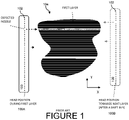
- FIGURE 1 a simplified diagram of 3D printing an individual layer.
- a printing head 100 is shown in a first position 100A when preparing to print a first layer 104 of the object, and in a second position 100B when preparing to print a subsequent layer of the object.
- the printing head 100 (e.g. inkjet head) includes a nozzle array 102 that scans the layer 104 in an X direction substantially perpendicular to the longitudinal axis Y of the layer 104.
- the jetted droplet volume of different individual nozzles may be slightly different from each other individual nozzle (of the nozzle array 102) because of technology deficiency of the head 100 construction. Moreover, a nozzle can stop jetting as the nozzle can become clogged by aggregated ink particles or because of other reasons.
- the head 100 is shifted along the Y-axis before every subsequent layer is printed.
- the shift amount from layer to layer may be set random within a predetermined shift range.
- the appropriate leveling apparatus includes a vertical grinding roller or cutting (machining) roller.
- the appropriate leveling apparatus includes a horizontal (i.e. parallel to the printing surface) grinding roller or cutting (machining) roller.
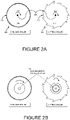
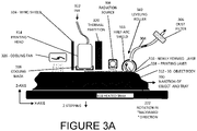
- FIGURE 2A a simplified diagram of leveling apparatus and FIGURE 3A , a simplified exemplary system for 3D printing.
- a 3D object 312 is typically constructed layer-by-layer on a substrate or tray.
- the tray is typically heated, and a non-limiting example of a heated tray 318 is generally used in this description.
- the object is printed in the plane of the X-Y axis, and a newly formed layer 310 (also referred to in the context of this document as the upper-layer) is built along the Z-axis during every printing pass.
- Ink 322 is supplied or contained in a printing head 314.
- Optional cooling mask 316, windshield 324, thermal partition 320 are used to protect the printing head 314 from the other printing equipment and/or vice versa.
- Optional radiation source 308 and/or cooling fan 326 can be used to assist with temperature control of the newly printed layer and/or 3D object body 312.
- Optional leveling roller 302 can be used during printing to smooth the surface of the newly formed layer 310 and/or the top surface (outermost surface along the Z-axis) of the 3D object body 312.
- An optional dust filter 306 can be used to suck the dust output of leveling.
- Leveling apparatus are also known in the field as “leveling rollers” or simply “rollers”.
- the leveling apparatus operates on a newly formed layer 310 of a 3D object 312 after or as the layer has/is being been printed (dispensed and solidified).
- the leveling apparatus typically peels off between 5% and 30% of material of the most recently printed layer's height. In other words, shaving the top of the first layer (most recently printed layer).
- the roller meets the ink after the carrier liquid ink has evaporated and the layer is at least partially dry and solid.
- solid means "a piece of metal", i.e. well sintered particles.
- solid means a pile of particles adhered to each other by organic material or by some initial sintering.
- the leveling roller 302 may be a grinding roller 202 including a metal cylinder 204 with an abrasive surface 206, for example coated with hard grinding particles, e.g. WC (Tungsten carbide) or diamond "dust".
- the leveling roller 302 may be a cutting roller 212 (also referred to in the context of this document as a "bladed” roller) including a milling cutting tool 214 with sharp blades 216.
- Smooth and knurled rollers 202 are known in the art, for example smooth rollers as taught by Kritchman in US8038427 and knurled rollers as taught by Leyden in US6660209 .
- a smooth roller is typically used to meter a liquid layer of material, and acts like a delicate shaving pump.
- a knurled roller typically adapted to meter soft wax surface, consists of a multitude of relatively small knurls, or particles, as compared to the size of the cylinder 204 and/or relative to the size of the object to be ground.
- a typical cutting roller 212 features discrete blades 216 that can be relatively large compared to the size of the object to be ground.
- smooth nor knurled rollers can be adapted to level dry solid material for many reasons.
- the grinding roller is substantially constantly in contact with the object to be leveled.
- a cutting roller 212 is intermittently in contact with the object to be ground - only when the edge of a blade 216 encounters the surface to be leveled.
- a knurled roller can be adapted to level dry solid material, is the direction of force that the vertical roller applies onto the shaped surface.
- the blade When a rotating blade touches the surface, the blade first cuts in by applying horizontal force, and second lifts the cut chip up by applying upward force.
- the knurl touches the surface, the knurl first presses and pushes the material both downward and forward by applying downward and horizontal force, and second pushes the detached material up by applying forward and upward force.
- the downward force may be harmful to delicate object features, since the downward force will easily break the fragile object features.
- vertical milling or smoothing tools including multiple cutting blades or grinding disk (e.g. including diamond dust surface), are mounted to a vertical beam that is perpendicular to the plane of printing / plane of the upper surface of the object, and rotates about the beam. These vertical milling tools are used to level the upper-layer (most recently printed and at least partially solidified). The cutting or grinding surface of the vertical tools is parallel to the plane of printing, but the rotation vector points vertically upwards.
- the leveling roller is mounted on a horizontal axis and rotates about a horizontal axis (horizontal to the plane of the upper layer of the object), thus providing a horizontal roller.
- the grinding surface of a horizontal roller at the point of contact (touch) with the material is generally also horizontal (parallel to the plane of printing), but the rotation vector is horizontal (points horizontally, perpendicular to the sweep direction X).
- the horizontal roller rotates about a horizontal axis 220 relative to the layer being ground. In other words, the outer surface of the roller (or the blade's tip) moves horizontally at the point of contact with the object's new layer.
- the horizontal roller can be a grinding roller 202, or preferably, the horizontal roller allows implementation with a cutting (bladed) roller 212.
- a feature of the horizontal roller as compared to the vertical tools is the feasibility to collect outcome dust (including shaved material). While a vertical tool ejects the dust to all directions pointing outward from the vertical axle (i.e. all around directions parallel to the printing surface), a horizontal roller lifts the dust upward in such manner that the dust can be more easily collected and pumped out, such as via into a dust filter 306.
- the vertical tool can be very sensitive to precise alignment, since the vertical tool touches the printing surface all over the vertical tool's horizontal surface.
- a horizontal roller touches the printing surface substantially only at a line, and therefore there is no need to align a horizontal roller in the X-axis direction.
- a substantial disadvantage of the grinding surface in comparison to the cutting bladed roller / tool is that the grinding surface is vulnerable to dust (shaved particles) sticking to the diamond dust (of the grinding surface) and disturb thereby proper grinding.
- the cutting roller includes N blades and rotates at an F RPM (revolution per minute), and the relative sweep velocity between the roller and the object in X direction is V. For a given V, the smallest chip is obtained when N and F are set to maximum values.
- using a spiral blade in comparison to using a straight blade has also positive influence on preventing harm to delicate details, since a spiral blade cuts only a relatively small spot (as compared to a straight blade) in the shaved surface at a time, while the spot's neighboring area holds the spot from breaking.
- orientation of a horizontal roller is described as being perpendicular to the direction of sweep during printing.
- orientation does not have to be (can be other than) strictly perpendicular and may be at an angle (non-zero) to the sweep direction.
- the rotation direction 222 of the cutting roller 212 vs. the relative sweep direction between the roller and the object can be either in the "cutting and lifting" direction (for example, clockwise in FIGURE 2A and FIGURE 2B ), or in the "dig and push” direction (counter clockwise in FIGURE 2A and FIGURE 2B ).
- the direction of the relative object shift vs. roller during leveling is not definite (undefined / not pre-defined), and can be different in different applications. Based on this description, one skilled in the art will be able to determined specific details, attributes of the printed material, and other considerations of the printing machine for implementing a specific application depending on the.
- particle waste can be generated.
- the particle waste can include shaved particles and/or dust of the solid particles from the printing ink. Techniques to prevent the particle waste from being scattered over the printing surface, and to remove the waste from the roller blades, should be applied.
- the horizontal roller facilitates implementation of techniques for preventing scattering of particle waste, for example by adding a shield around the roller (half-arch shield 303) and applying sucking force via pipe 304 during "rolling". The particle waste is sucked off the surface of the object and the blades, optionally through a filter 306.
- the roller may be installed before or preferably after a radiation source 308 such as incandescent or discharge lamp (shown), coherent beam (laser), or ultra-violet (UV), visible, or infrared (IR) radiation source, etc.
- a radiation source 308 such as incandescent or discharge lamp (shown), coherent beam (laser), or ultra-violet (UV), visible, or infrared (IR) radiation source, etc.
- FIGURE 2B a simplified diagram of leveling apparatus with warming sources.
- the ink particles may stick to the roller blades or grinding particles and thereby disturb proper leveling. This might be a consequence of insufficient drying of the ink or insufficient firing the organic elements.
- the layer can be further dried by elevating the layer temperature. This technique of elevating the layer temperature might be unacceptable in some cases because of other aspects of the printing process, e.g. deformation of the printed object.
- the roller can be warmed to high enough temperature in which the problem of stickiness of the ink is avoided.
- the roller may be set 100 degrees Celsius (°C) or even higher than the layer's temperature.
- Warming the roller may be done by heating the roller's outer surface by an external heat source (i.e. located outside the roller) or by an inner heat source located in the roller.
- Inner heat sources preferably include static (non-rotating) warming element, such as a halogen lamp or a heat rode 230.
- a mask refers to a plate that partially covers an orifice plate and has an opening to facilitate printing from nozzles to a print area.
- Masks are also referred to as “cooling masks” and can be used as a “thermal buffer”.
- the printing heads 314 (such as printing head 100) that scan the upper layer in close vicinity (0.5- 3 mm between the printing head 314 and object 312) must be protected from the heat and fumes emerging from the newly formed layer 310 (dispensed layer).
- a cooling mask 316 maintained at a relatively low temperature compared to the temperature of the object while being printed e.g. from 10 to 40°C is installed as a buffer between the printing head 314 and the printed object 312.
- the printed object should preferably be maintained substantially at uniform and constant temperature throughout printing.
- the upper surface of the object body keeps losing heat to the surrounding atmosphere during printing, and also supplies heat to the newly dispensed layer, since the dispensed ink is usually colder than the object, and since heat is consumed by the evaporation of the liquid carrier of the new layer.
- the heat source is only below the object (for example, a heated tray 318), the heat constantly flows up to the upper layer, and because of the heat-flow resistance of the material, a temperature gradient is built, high temperature at the bottom of the object and low at the upper surface of the object (along the Z-axis).
- the heat should also (or merely) be supplied directly to the upper surface or layer.
- the temperature of the upper layer should be the same during the printing (though may be higher than the temperature of the bulk), because drying and possibly evaporating the organics and partial sintering occur in that layer, processes that strongly depend on the layer temperature.
- the term "printing surface” 328 typically includes the most recently printed finished layer, prior to printing of the current, newly formed layer 310.
- the printing surface 328 is the upper surface or upper layer, most recently previously printed along the Z-axis, and is the surface upon which the newly formed layer 310 is printed.
- the printing surface is the substrate, for example the heated tray 318.
- the printing surface is typically the upper surface of the object body, plus supporting material, as appropriate.
- Heat is supplied to the upper surface by an electromagnetic (EM) energy source through the surrounding gas or vacuum.
- the EM energy source is a radiation source 308.
- the radiation source 308 is located above the upper layer / object being printed.
- the direct heating by the EM source can assure constant temperature of the upper layer.
- the temperature of the tray 318 on which the object is printed
- An additional supply of heat to the upper surface is a stream of hot air blown on the upper printed layer.
- hot air is not only for increasing the temperature of the upper layer but also, or rather for encouraging, the evaporation of liquid carrier (and in some cases the dispersing agent and other organic material) from the upper surface.
- a combination of EM radiation, hot air, and warm tray (or any combination thereof) can be used to maximize the heating and/or evaporation performance.
- the substrate's surface on which printing is accomplished presents intimate touch with the object and therefore should be at the same temperature of the object.
- the substrate i.e. tray
- the substrate is thermally conductive, e.g. made of metal, warming the tray to the required object temperature can be essential for producing correctly a desired object.
- the tray may include thermally insulating material, e.g. wood, plastic, or insulating ceramics. In this case, the substrate keeps the object's temperature, while heating of the object is accomplished by heat radiation from above.
- high enough heat conductance generally means that the temperature gradient (which is given by the product of heat conductance per length multiplied by the height Z) is small, e.g. smaller than 1% of the object temperature during printing, measured in Celsius.
- the heat conductance is comparable to that of fully sintered metals (100 W/(C.m)
- the condition on the temperature gradient can be met up to a relatively small printing height of 10 mm. This, however, is not always the case.
- the object can be high, e.g. higher than 10 mm in the current example, and can be made of poor material heat conductance (e.g. 1 W/(C.m) and smaller). Therefore heating from the upper side of the object is essential. Heating from the upper side can be done by the EM energy source, as is described below.
- the EM energy source is typically positioned aside the printing head 314, and can be of a UV, visible or IR radiation type.
- a radiation source 308 is installed after, or preferably before, the leveling roller 302.
- the radiation source 308 can be used for one or more tasks, including:
- UV radiation has the potential to disintegrate dispersing molecules that are attached to the particles by breaking molecular connections. At the same time, the UV also heats up the layer, assisting thereby the evaporation of the dispersant material or the dispersant material's fragments.
- the temperature of the upper surface is preferably maintained at TS, which is substantially comparable to or higher than T1 (e.g. higher than 0.8xT 1 in Kelvin) so that after jetting the ink, the temperature of the new layer (TL) abruptly increases to TS, and carrier liquid evaporates immediately.
- T1 e.g. higher than 0.8xT 1 in Kelvin
- TL new layer
- carrier liquid evaporates immediately.
- the temperature of the whole object during printing can be maintained at TS as well.
- higher temperature of the upper (new) layer TL may be required.
- Substantial increase of the temperature of printing surface TS above T1 e.g. by 30 °C
- the landing ink droplets on such a hot surface would explode rather than attach to the surface, like when water droplets land on a surface of 120 °C (the explosion effect can be exploited in a special embodiment which will be described later).
- the rest of the object is not required to maintain at such high temperature (TL), but just maintain at a constant and uniform temperature TS.
- the layer When a newly formed first layer is dispensed, the layer is typically exposed to air (the environment of the printing machine), and thus organics in the ink have the chance to evaporate, prior to this first layer being covered by a subsequent printed layer.
- FIGURE 3B a diagram of a lamp as an exemplary radiation source.
- heating the new layer is accomplished by a radiation source 308 typically from above the object. If lower layers under the upper layer are at a lower temperature than the upper layer, maximizing the heat irradiance (i.e. irradiated power per surface area of the new layer) is important in order to get an instant higher temperature of the layer, before the heat dissipates to the preceding (previously printed) layers by conduction or dissipates to the air above by conduction and convection. Therefore, given a heating lamp 308A (as radiation source 308), the lamp should be as close to the body 312 surface and reflector aperture as narrow as possible.
- a lamp housing 332 typically includes a metal envelop covered with an insulation material to prevent heating adjacent elements.
- a polished aluminum reflector 334 is typically required especially to protect the reflector and housing from overheating.
- the polished aluminum reflector 334 typically reflects 97% of heat.
- a transparent glass window 336 is typically high transparency (i.e. small radiation absorbance is required especially to protect the window from overheating).
- the window 336 is made of a material appropriate for the specific application (e.g. Pyrex or quartz).
- An aperture 338 (ex.: 9 mm) is used for a given radiation power.
- a relatively small lamp's aperture assures high irradiation power (i.e. high radiation power per unit area of the printed layer).
- a small gap 340 between the heating lamp 308A (more specifically, typically from the transparent window 336) to the upper layer of the object body 312) assists in preventing the lamp radiation illuminating large area of the layer at one time.
- focused radiation enables much higher irradiance ( FIGURE 3C ).
- the layer's structure is continuously solid, and then the relevant thermal conductivity is that cited for the metal (e.g. 430 W/ (C.m for silver), and the temperature rise ⁇ T is as calculated in the table above (much less the 1 °C).
- the layer's structure is like a pile of particles. Measurements show that nearly only half the printed volume is occupied by solid particles, while the rest is mostly air. Thus, in each direction (X, Y, Z) only 80% of the layer is occupied by solid particle (since 0.8x0.8x0.8 ⁇ 0.5), and the rest of the volume of the non- or partially-sintered object is air. Thus, every layer is equivalent to a layer that includes in height of the layer 80% metal and 20% air. Since air conductivity (0.04 W/(C.m)) is substantially lower than metal conductivity (for example WC: 84 W/(C.m)) the air layer portion dominants the conductivity of the layer.
- a linear laser beam which includes a focused line
- flash radiation wherein high power radiation is absorbed at very short time (see typical example below)
- thermal conductivity is typically between 0.5 to 5 W/(C.m) (see Table 2). If after warming the upper layer, the upper layer does not become sintered (remains un-sintered), the air layer portion conductivity is still lower than oxide layer conductivity and the air dominants the conductivity of the layer as in the case of metal particles. If the layer becomes sintered (under the flash radiation), because of the high irradiation power Ir and despite of the high thermal conductivity, the temperature rise ⁇ T of the layer will go up to 70 to 700 °C (see the fourth row of Table 2).
- a fan for example cooling fan 3266 may be required to lower the temperature back to a lower object temperature.
- the upper surface of the body will dissipate to the surrounding air roughly 3W/cm ⁇ 2 at a temperature of 400 °C. Therefore the lamp above should supply this much power to the upper layer in order to maintaining the object body's temperature constant and even, and even larger power is required in order to compensate for the material evaporation and sintering heat consumption.
- focused radiation may be used to obtain an instant temperature of the upper layer higher than the body temperature.
- a layer of dry particles is evenly spread on the preceding layer, and then focused radiation (for example, a scanning focused point (i.e. spot) laser beam) scans the layer and selectively solidifies the required portion of the layer according to a layer map.
- focused radiation for example, a scanning focused point (i.e. spot) laser beam
- the particles used to construct the current layer are not evenly spread (unevenly distributed) on the preceding layer, but the particles (layer) is selectively dispensed according to a layer map. This facilitates use of non-selective radiation to create a newly formed layer only where the particles have been selectively dispensed.
- Embodiments can include one or more of the following techniques:
- a first embodiment is a hot radiating lamp 350, including a linear bulb (discussed above), including a linear radiating filament 352 enclosed a quartz transparent pipe 356, coupled with a focusing reflective surface having elliptic transection 358, enclosed in a transparent window 354 (for example, protective glass).
- the filament is located in one focal point 360F1 of the elliptic curvature, while the filament's hot image is obtained in the other focal point 360F2, on the upper surface of the body being printed.
- the width of the image can be comparable to the length of the filament perimeter (but never smaller).
- the filament perimeter is equal to 1 mm
- the width of the image of the filament on the 3D upper surface is 3 mm
- the radiated power is 50W/(cm length).
- a second embodiment includes a linear coherent beam 370.
- An appropriate laser device 372 can be obtained from, e.g. from Coherent Inc, Part No LIM-C-60. Such laser has a focal plane, which is the plane of minimal waist. A typical waist width is 50 ⁇ . A typical power of the laser is 20W/cm. Hence, the irradiation power is 4000 W/cm ⁇ 2. At such power, heat loss is much smaller than the input heat, and therefore the layer temperature can substantially exceed the body's temperature.
- a third embodiment includes a spot (point) coherent beam with a scanning apparatus (e.g. rotating mirror polygon).
- a scanning apparatus e.g. rotating mirror polygon
- the beam in the current embodiment can be "dumb” (although the beam can also be modulated according to the image, at least for saving energy).
- This "dumb" beam scans a line in the Y direction, while the object body moves in X direction.
- a typical laser power is 500 W, and focal spot of 50 ⁇ diameter.
- Such irradiation power can warm the layer much above the sintering temperature of all metals and ceramic material.
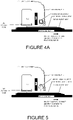
- FIGURE 3A and FIGURE 4A a simplified diagram of a system for removing fumes during printing
- FIGURE 5 a simplified diagram of a system for removing fumes during printing using an alternative radiation source.
- the fumes maybe harmful to the printer parts since they can condense on relatively colder surfaces (as compared to the temperature of the 3D object 312 during printing) including surfaces such as electronic boards and parts.
- the fumes are collected by sucking pipe(s) 404 providing sucking 414 located adjacent to the printing head 314 and/or near the spot where the layer is further heated by the radiation source 308.
- glue is often added to the particle ink (e.g. photo-polymer, thermo-plastic polymer etc).
- This glue material assists sustaining the 3D structure during printing, a time before subsequent hardening process (i.e. sintering) of the entire object in a high temperature oven.
- a powder dispenser spreads solid (dry) particles over the entire tray (tray on which the object is being printed/constructed, such as heated tray 318), and a printing head subsequently dispenses liquid glue on the particles spread according to the desired content of the layer being printed. This process repeats layer by layer until the printing finishes. Later, the loose particles are removed, and the glued object is transferred from the printer to an oven.
- the object In the oven, the object is heated to a high temperature for accomplishing sintering. During the sintering process a majority of the glue fires off, however typically a portion of the glue remains. The remaining glue interferes and/or interrupts sintering if the glue does not completely evaporate in the oven. In addition, the presence of glue in an object's structure may be undesirable, as described elsewhere in this document.
- a technique for avoiding problems with glue is to do sintering during printing on a layer basis, and therefore glue is not required.
- a powder dispenser spreads particles over the entire tray, and a subsequent focused laser beam scans the spread particles according to the content of the layer. Every spot that is illuminated by the beam heats up sufficiently to sinter the powder at the illuminated location.
- the particle construction is sustained at least in part by:
- the preparation of the solid particles 610 can includes a fraction of much smaller particles 612 than the average size of the main (larger) particles (e.g. 50 nm size when the average size is 700 nm). These smaller particles will sinter at a lower temperature (e.g. 800°C as compared to 1400°C), and partially stick the large particles to each other by a "bridging" structure.
- a lower temperature e.g. 800°C as compared to 1400°C
- the ink contains carrier liquid, dispersing material, and possibly more than one additive that participate in perfecting printing, all are often organic material. As described above, a desired feature is to get rid of this organic material as soon as possible, or at least before final sintering.
- the carrier liquid substantially evaporates during the formation of the layer and thus the layer becomes solid. This is accomplished at least in part by maintaining a relatively high temperature of the body of the 3D object (or at least the upper layers of the 3D object).
- the high temperature is a temperature kept at a temperature comparable to the boiling point of the liquid carrier or higher. In some embodiments, the high temperature can be 20% more or less than the boiling temperature of the carrier when the temperature is measured in Kelvin.
- the dispersant remains in the bulk material during printing.
- the organic material which plays the role of a binder
- the object is referred to as a "green object".
- an extra stage of initial heating is performed usually in an oven.
- the organic material whether disintegrates or not
- This initial heating is done before elevating the firing temperature to a temperature where full sintering occurs.
- a desirable feature is to prevent complete sintering of the object particles during the stage of organics extraction. This is desirable for reasons including:
- Preventing complete sintering in the stage of organics evaporation can be done by adjusting the particles' characteristic temperature T3 of sintering (depending on particles material and size) or by choosing the organics (dispersant and additives) with appropriate burn out temperature T2, so that T3>T2.
- Partial sintering during printing can strengthen the newly formed layer before leveling, or (as explained above) strengthen the object before removing the object from the substrate, and/or prior to firing the object (in an oven).
- partial sintering generally refers to particles melting to each other only partially, that is at one or more locations on the surface of each particle without the complete surface of the particles contacting surrounding particle surfaces.
- partial sintering of an object body is obtained during printing of the object. Partial sintering can allow subsequent firing and removing dispersant, even when firing of the dispersant is done after completing printing the object, because the open porous structure is still there.
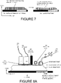
- FIGURE 7 a diagram of partial sintering.
- objects typically contract since the particles move closer to each other and fill voids in-between particles. In most cases, this contraction of the object being sintered is substantial (e.g. 20% in every dimension).
- the newly formed layer is typically very thin (e.g. 5 micron before contraction) as compared to the lateral dimension (X-Y) of the object (e.g 50 mm)
- the friction of the newly formed layer with the former (previously) printed and dried layer diminishes the contraction in X-Y plan, and the vast contraction accomplished only in the bottom direction, i.e. towards the preceding layer that has already sintered.
- the capillary force that acts to contract also in the layer plane i.e.
- partial sintering 700 can be enough for holding the particles together and yet not introducing too large contraction force in the (newly formed) layer.
- partial sintering facilitates maintaining a desired nature (shape) of the object during printing 710.
- Sintering temperature should be considered carefully for enabling partial sintering. At high enough temperature, the particles melt to each other and form a nearly or fully solid material (complete sintering).
- the required sintering temperature substantially depends on the melting point of the particles' material and the size of the particles. For example, the melting point of silver is 960 °C; 1 ⁇ m (micrometer) silver particles sinter at 800 °C, but 20 nm (nano-meter) silver particles sinter at 200 °C.
- the newly formed layer can be warmed for example to 500 °C, a temperature in which the organics are fired off and partial sintering replaces the organic material to hold the object from being dismantled.
- the dispersant (and possibly other additives in the ink) can interfere with the desired quality of sintering, and thus removing these materials (the dispersant and possibly other additives) can be important for obtaining sintering (but not necessarily sufficient for obtaining sintering).
- references to dispersant can also refer to possibly other additives.
- the innovative technique (not according to the invention) of complete sintering when printing a layer includes features such as:
- Extra heating of the new layer by focused radiation or by a high power flash light can be used to accomplish evaporating of the disturbing materials (such as dispersant), and also heating the upper layer to as high temperature as required for sintering the layer.
- the disturbing materials such as dispersant
- the upper layer can be heated to as high temperature as required for sintering the layer.
- the dispersant evaporates or disintegrates and evaporates, and later full or sufficient sintering takes place.
- this technique is done by dispensing the new layer on a moderately warm preceding layer, such that the carrier liquid is evaporated before entering the extra heating device, reducing thereby the required energy in the device for evaporating both the carrier liquid and the dispersant, and accomplishing sintering.
- Printing a layer can be accompanied by dispensing catalyst material, which accelerates sintering.
- a preferred embodiment includes material that disintegrates the dispersant molecules, so that they evaporate out or at least do not disturb sintering. Furthermore, added heat can be used to evaporate out the disintegrated molecules.
- the bare solid molecules left after removing the dispersant spontaneously sinter at this stage to each other, given that the temperature is high enough. For example, if the solid particles are silver particles of 20 nanometer diameter, a temperature as high as 200 °C is sufficient for complete sintering, given that the dispersant has removed.
- the catalyst can be dispensed after or just before dispensing the model layer.
- Dispensing the catalyst 802 can be done by a catalyst droplet jetting head 800 or by spray nozzle.
- the catalyst can be dispensed selectively according to the object layer image, or "blindly" on the entire reserved area for the object.
- the catalyst can come in liquid form or gas.
- the catalyst can be dispensed by a roller that spreads the catalyst over or under the new layer being printed.
- the catalyst can be included in the ink beforehand, and then heated with the layer heating after printed, when activation is desired.
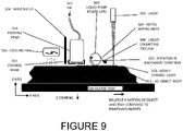
- FIGURE 9 a diagram of using a liquid pump roller.
- An alternative embodiment of printing, leveling, and heating includes printing layer by layer while the temperature of the printed body is substantially smaller than the boiling temperature of the carrier liquid (e.g. 150 °C when the boiling temperature of the carrier liquid is 230 °C).
- the layer is flattened (leveled) by a liquid pump roller (LPR) 900.
- LPR is typically a smooth roller with an axis parallel to Y-axis of the object, rotating in "reverse” (opposite the relative X-axis motion of the object).
- the newly formed layer 310 is irradiated by a high irradiation power beam (for example laser 902) to at least evaporate the liquid and solidify the layer (e.g. warming the layer to a temperature of 230 °C or higher). Later on, before dispensing the next layer, the layer is cooled to the low object temperature (e.g. by a cooling fan 326).
- the excess ink from the flattened layer attaches to the rotating roller surface of the LPR 900, and is wiped by the roller wiper (for example by metal wiping knife 904), and flows into a collecting trough 906, from which the excess collected ink is cycled back to an ink tank for re-delivery to the printing head 314 or pumped out to a waste tank.
- the jetting nozzles are positioned close to the printed layer, e.g. 1 mm apart. Thus, the nozzles may heat up by the warm upper surface of the body being printed, and the jetting quality injured.
- Techniques to prevent nozzle heating may include a cooled shell (see FIGURE 3A , cooling mask 316) that behaves as a thermal buffer between the hot layer and jetting nozzles.
- a cooled shell is described in patent International publication No WO2010/134072 A1 to Xjet Solar Corporation.
- An innovative solution is differentiation between the body (object) temperature and the temperature of the new layer. This can be accomplished by the following steps:
- FIGURE 10A a diagram of objects built with different materials. Often the required object includes different materials in different parts of the object. A special and important case is when the bulk material 1006 of a first object 1002 should be laminated (coated) with a coating material 1007 at an outer surface of the first object 1002. Similarly, the bulk material 1006 of a second object 1004 can be laminated with a coating material 1007 at an outer surface of the second object 1004.
- FIGURE 10B a diagram of objects built with a mix of materials.
- Requirements for a third object 1010 include a mix of two or more materials required either over the entire object or over part of the object.
- third object 1010 includes a mix of a first material (material 1 1018) and a second material (material 2 1020).
- first material material 1 1018
- second material material 2 1020
- the mix of materials can be seen in that each pixel 1016 is an alternating material.
- One technique for printing an object with a mix of materials in a given location of a layer can be done by dispensing one material in certain pixels of the layer and another material in other pixels.
- one layer is printed by one material and another layer by another material.
- a special case is impregnation-like of a coating-like material 1008 at the outer surface of an object (for example, second object 1004).
- the impregnation-like can include a gradual decrease of the proportion of impregnating material and bulk material as the distance from the object surface increases.
- a plurality of inks and ink heads can be used to differentiate printing between object material and object support.
- one ink can be used to build both the object and support structures (layer by layer), while another ink is dispensed only on the layer part that belongs to only one of the object or support, introducing thereby a difference in a mechanical attribute of both materials. This difference is used later when the support is removed from the object.
- a first ink including Ag particles is used to print both object and support portions of a layer.
- a mold is printed together with an object.
- a mold is any auxiliary body that is attached to the object body 312 and can be removed from the object body.
- a mold can be considered support for the object, as described below.
- the mold can be printed by a different ink than the bulk in the same layer-by-layer printing. Printing an object and a mold facilitates the object including particles that do not adhere (are unattached or only lightly adhere) to each other until the body is fired and sintered in an oven (at typically 600 to 1500 °C) .
- the mold preferably includes material that holds tight at a low temperature and disintegrates at high temperature, or at least can be removed from the object. The mold can also protect the object during printing.
- the mold protects the delicate edges of the object 312 from breaking while the cutting roller 302 levels out the printed layer 310. Even if the mold's material does not hold tighter (holds looser) than the object's material, yet the mold protects the object's edges while scarifying the mold's own edges through, for example, when leveling the new layer or transporting the object after printing to the firing oven.
- the mold can be thin (e.g.0.5 mm thick), and can get the shape of a skin around the object or part of the object.
- the object (and simultaneously the mold) can be printed embedded in a mold, expanding the range of materials and processed available for creation of 3D objects.
- An example of this technique is an object ink that includes particles of high hardness (e.g. WC) wrapped with a dispersant.
- a dispersant behaves like a glue that holds the particles together.
- medium temperature e.g. 400 °C
- the dispersant evaporates and the 3D object may fall into a pile of particles. If the object is surrounded with a material that partially sinters at 400 °C but melts or disintegrates and evaporates at above 800 °C (e.g.
- the mold stays solid at and above a medium temperature, allowing evaporation of the object's dispersant, until at higher temperature (e.g.700 °C) partial sintering of the object takes place.
- a positive or negative angle can be specified per every spot on the object's surface, as follows: If an object material is found just under the spot, the surface angle is specified positive. Otherwise, the surface angle at that point is specified negative (a negative angle or negative tilt of the object). In other words, a negative angle is an area of an object that while being built lacks a portion of the object immediately beneath the area being printed.
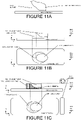
- FIGURE 11A a diagram of support when building a 3D object.
- Supporting negative angles of the 3D object can be critical for 3D printing.
- the support 1100 material should differ from the object 312 material in a way that the support material can be removed after printing or after following steps like sintering, without deteriorating the object.
- the support may need to fulfill many additional requirements, including being easy to remove, hardly mixing with the model material at the touch interface line, low cost, self-sustained, and compatible with the printing technology (inkjet), etc.
- the printer typically includes at least two printing nozzle groups (often two printing heads), one jetting object material, and one support material.
- Each layer being printed may have zero, one, or multiple portions of the layer that are desired in the final object, referred to as "object portions" of the (current) layer.
- object portions of the (current) layer.
- support portions are generally used as support, molds, or other structures to assist during production of the object, but are removed and/or lacking in the final object.
- references to support can also include reference to the ink used to create the support (support ink) and to the portion adjacent to the object (that either supports the object in the gravitational sense, or surrounds the object for any purposed, including to serve as a mold) (support portion).
- the current description will use the current example of at least two printing heads. Based on this description, one skilled in the art will be able to apply the current methods to other implementations.
- FIGURE 11B a diagram of printing support portions and object portions of layers.
- a side view 1120 shows the 3D object 312 and support 1100 during printing.
- a corresponding top view 1122 shows the upper layer.
- Each layer can include a support layer adjacent to an object layer.
- the upper layer includes a portion that is support layer 1102 (building support for subsequent object layers), and a portion that is object layer 1104 (built on top of preceding object and/or support layers).
- the support includes inorganic solid particles (e.g. high melting temperature particles like oxide, carbides, nitrides, metals, e.g. Tungsten) or organic particles (e.g. hard polymers) dispersed in a volatile carrier liquid.
- the polymeric material should be hard because otherwise the polymeric material can be difficult or not possible to grind (to micro particle size).
- the liquid carrier evaporates, leaving a solid laminate behind.
- the object printing is finished, the object is supported or even wrapped by the support material. Considerations in choosing and preparing the inks take care of establishing a substantial difference in the adherence between the particles of the object (cohesiveness) and of the support.
- This difference can show up just after printing, or later after partial or complete firing.
- the difference can be a result of a difference in the dispersant attributes (e.g. different gluing characteristics between the solid particles), or a difference in the sintering tendency of the solid particles to each other.
- the support structure should be softer or more brittle or more miscible in water or solvents then the object, and therefore ready for being removed from the printed object.
- An ideal support is such that during firing the support disappears, e.g. by or disintegration and evaporation.
- the support includes solid material dissolved in a volatile liquid. After the liquid evaporation, a solid laminate is left behind to form a solid support.
- the solid support material after printing is soluble in a post treatment liquid.
- the object and support can be immersed in the post treatment liquid such as water or light acid, to remove the support by dissolution.
- the solid support material is such that the solid support material evaporates or is burned during the firing process.
- An example is dissolved wax in an organic solvent, or dispersed particles of polymer in a dispersing liquid.
- the solvent or dispersing liquid evaporates off layer by layer during printing (at, for example, 200 °C) and the wax or polymer hardens.
- the object with the supporting body is fired in an oven, preferably in vacuum.
- the wax evaporates and disappears, and the same thing with the polymer at 700 °C.
- An example of the second and third embodiments is using salt (e.g. NaCl- Sodium Chloride, also known as table salt) solution in water. After the water evaporates, a solid support is left behind. After completion of printing, the object can be immersed in water and the salt is dissolved away.
- salt e.g. NaCl- Sodium Chloride, also known as table salt
- strong acid e.g. HNO3
- ZnO+2HNO3 Zn(NO3)2 +H2O
- An alternative of the former example is a mix of oxide particles and dissolved salt in a carrier liquid. After printing (when the support dries), the object and support are immersing in water or acid liquid, the salt is dissolved by the liquid and the oxide particles stay as a pile of loose dust.
- silica is a readily available and relatively inexpensive material. When the dispersion is dried, the remaining silica particles are only loosely attach to each other even after warming to 700 °C, and therefore the supporting body of Silica can be removed from the object.
- Silica dispersion is Aerodisp G1220 by EVONIK Industries, including SiO2 particle of an average diameter of 12 nm, dispersed in ethylene glycol and Degbe (Di-ethylene Glycol Butyl Ether) solvents.
- Calcium sulfate is common material used for many applications such as gypsum board, plaster, and even as a food additive. Calcium sulfate is an inorganic salt that is water miscible, enabling removal of this support material by washing in water after printing and/ or firing. Calcium sulfate ink can be prepared by the following steps:
- a side view 1130 shows the 3D object 312 and support columns 1110 during printing.
- a corresponding top view 1132 shows the upper layer.
- the view of the upper layer includes a portion that is support 1114 (building support for subsequent object layers), and a portion that is object layer 1104 (built on top of object and/or support layers).
- reinforcement may be added, preferably by adding columns 1110 of object material.
- a pedestal 1112 including support can be added even under the lower surface of the object.
- the pedestal can include all support layers (either reinforced or not) that are lower than the lower object layer.
- the pedestal 1112 can assist also obtaining proper and accurate Z-axis dimension of the 3D object. This is achieved at least in part by printing layers of support-pedestal to such a height (in Z-axis direction) wherein the leveling apparatus (such as roller 1116, similar to leveling roller 302) completely touches the pedestal 1112 and flattens the pedestal. Subsequently, printing of object and supporting material takes place on top of the leveled pedestal.
- This final (complete) sintering stage can include the following steps:
- Part of the firing steps can include applying vacuum, applying pressure, adding inert gas to prevent oxidation, and adding other gases that may add desired molecular diffusion or chemical reaction with the body, as described elsewhere in this document.
- FIGURE 12 a diagram of an exemplary carousel machine for production of 3D objects.
- 3D printing is typically characterized by low output because each object is typically constructed from thousands of printed layers.
- a plurality of trays 1200 of a carousel production machine for 3D objects 1220 can be used to increase the production throughput of 3D objects (such as 3D object 312)
- a 3D production machine 1220 will preferably include a plurality of printing (preferably inkjet) heads 1214 and a plurality of trays 1200 so as to enable production of many objects in the same run by many printing (jetting) heads.
- Multiple printing heads can be grouped into a group of printing heads (1206A, 1206B, 1206C).
- Many and different parts may be printed on each tray. Every object passes multiple times (cycles) through the printing section (under the printing heads), wherein each time adds one or a few layers.
- each object is typically constructed from thousands of printed layers, typically thousands of cycles are necessary. In a case where each cycle includes multiple printings from a plurality of printing heads, the number of cycles can be reduced from thousands to hundreds or less. Based on this description, one skilled in the art will be able to determine how many heads and cycles and trays 1200 are necessary for constructing specific plurality of objects.
- the plurality of heads is arranged in the Y-axis direction and are shifted in Y direction from each other so that respective nozzles of the plurality of heads are staggered to fill completely a layer's surface in one pass. More printing heads than required for filling one layer can be used, e.g. to print more than one layer in a pass. Heads for different building material can be employed. For example, a first group of printing heads 1206A is configured for printing a first material (material A) and a second group of printing heads 1206B is configured for printing a second material (material B). Heads for support material can be employed. For example, a third group of printing heads 1206C configured for printing support material.
- a heat-radiating source 1208 (such as radiation source 308) from above the printed layers follows the deposition of the layer(s) in a pass (i.e. a cycle).
- a leveling apparatus 1210 (for example, leveling roller 302) can be included in the carousel's cycle, typically after the printing heads.
- a robotic arm 1204 can remove the completed tray 1200 from the carousel 1212 or remove object(s) 1202 from a tray 1200, and send the object to further production steps (e.g. firing) without stopping the carousel rotation. Note that from layer to layer each tray shifts a little lower in Z direction, so as the last printed layer is brought to the height appropriate for the leveling apparatus to shave the upper surface of the dried layer. In a preferred case where the tray 1200 stays on the carousel 1212, when all parts from a tray have been removed, the tray Z level (height) is controlled to an initial position, and the machine would start printing a succeeding group of parts.
- An alternative implementation is to initially load a removal plate 1216 on each tray 1200, on which the one or more objects 1202 are later printed.
- the tray 1200 is fixed to the carousel and is referred to as a "chuck" which holds the removal plate 1216.
- the robotic arm 1204 removes the removal plate 1216 and sends the removal plate with the objects on the removal plate to a follow-on stage, such as the firing stage.
- the removal plate may include a thin metal plate, or, if a temperature higher than typically 900 °C is used in the firing stage, a carbon plate.
- the plate may be held on the chuck by a vacuum force or by holding "fingers" around the plate.
- the portion of the carousel 1212 track under the printing heads 1214 should preferably be straight.
- the heads should move in Y-axis direction once a carousel cycle to perform "nozzle scatter".
- the trays 1200 are warmed according to the required temperature during printing and the printing heads 1214 are protected from the tray heat and fumes.
- FIGURE 13 is a high-level partial block diagram of an exemplary system 1300 configured to implement a controller for the present invention.
- System (processing system) 1300 includes a processor 1302 (one or more) and four exemplary memory devices: a RAM 1304, a boot ROM 1306, a mass storage device (hard disk) 1308, and a flash memory 1310, all communicating via a common bus 1312.
- processing and memory can include any computer readable medium storing software and/or firmware and/or any hardware element(s) including but not limited to field programmable logic array (FPLA) element(s), hard-wired logic element(s), field programmable gate array (FPGA) element(s), and application-specific integrated circuit (ASIC) element(s).
- FPLA field programmable logic array
- FPGA field programmable gate array
- ASIC application-specific integrated circuit
- processor 1302 Any instruction set architecture may be used in processor 1302 including but not limited to reduced instruction set computer (RISC) architecture and/or complex instruction set computer (CISC) architecture.
- RISC reduced instruction set computer
- CISC complex instruction set computer
- a module (processing module) 1314 is shown on mass storage 1308, but as will be obvious to one skilled in the art, could be located on any of the memory devices.
- Mass storage device 1308 is a non-limiting example of a computer-readable storage medium bearing computer-readable code for implementing the methods described herein.
- Other examples of such computer-readable storage media include read-only memories such as CDs bearing such code.
- System 1300 may have an operating system stored on the memory devices, the ROM may include boot code for the system, and the processor may be configured for executing the boot code to load the operating system to RAM 1304, executing the operating system to copy computer-readable code to RAM 1304 and execute the code.
- Network connection 1320 provides communications to and from system 1300.
- a single network connection provides one or more links, including virtual connections, to other devices on local and/or remote networks.
- system 1300 can include more than one network connection (not shown), each network connection providing one or more links to other devices and/or networks.
- System 1300 can be implemented as a server or client respectively connected through a network to a client or server.
- system 1300 can be implemented as an embedded controller.
- a present embodiment is a method for printing an object.
- the method facilitates evaporating a carrier liquid during printing while at least a portion of dispersant remains in the printed layer.
- a feature of the current embodiment is bringing or maintaining the temperature (TL) of the (most recently / current) printed layer (upper surface of the body of the object) near or above the boiling point of the carrier T1 (e.g. above 0.7xT1 in Celsius) and simultaneously below the boiling point of the dispersant.
- T1 temperature of the carrier
- the carrier liquid evaporates as the ink is printing, in contrast to conventional techniques of evaporating the carrier after printing, while at least a portion of the dispersant remains in the printed layer of the object.
- the remaining dispersant serves to bind the solid particles together after the carrier liquid is evaporated.
- other materials can be added to the ink to assist in binding of the solid particles together after the carrier liquid evaporates.
- the exact carrier boiling point temperature T1 does not have to be used, but rather there is a known range even below the carrier boiling point temperature T1 in which the carrier will evaporate.
- This range below the carrier boiling point temperature T1 is referred to in this document as a lower-bound ([T1]) of the carrier boiling point temperature.
- an exact dispersant boiling point temperature T2 does not have to be used, but rather there is a known range around the dispersant boiling point temperature T2 in which the dispersant will not evaporate (remains liquid).
- This range around the dispersant boiling point temperature T2 is referred to in this document as an upper-bound ([T2]) of the dispersant boiling point temperature.
- the lower-bound and upper-bound are typically 20% more or less than the respective boiling point temperatures (typically measured in degrees Kelvin).
- the lower-bound ([T1]) can be 20% less than the carrier boiling point temperature (T1) typically measured in degrees Kelvin.
- the upper-bound ([T2]) can be 20% more or less than the dispersant boiling point temperature (T2) typically measured in degrees Kelvin.
- a first layer is printed on a printing surface of the object.
- the object part of the first layer is printed with at least one ink, typically from at least one corresponding inkjet printing head.
- One or more of the printing heads typically all of the printing heads, can be modulated according to a content of the first layer.
- Each of the at least one inks typically include a carrier having a carrier boiling point temperature (T1), a dispersant having a dispersant boiling point temperature (T2) and particles having a particle sintering temperature (T3).
- T1 carrier having a carrier boiling point temperature
- T2 dispersant having a dispersant boiling point temperature
- T3 particle sintering temperature
- each of the at least two inks can include particles of different types, and a local proportion of each of the at last two inks is determined by the specification for the layer being printed (first layer's specification).
- the local proportion of each of the inks varies from one printed layer to another printed layer, and from one point in a layer to another point in the same layer.
- the layer also includes a support portion, the support is printed adjacent to the object layer, as described below.
- the dispersant can be chosen to additionally and/or alternatively bind the particles to each other after the carrier is evaporated and/or inhibit sintering of the particles to each other after the carrier is evaporated.
- a feature of inkjet printing is that the printing can be selective, in other words, printing to areas that are part of each layer being printed (such as the first layer of the object).
- Each layer is typically printed based on a layer specification or layer content (description) including information on what portion of the current layer is the desired object.
- the layer specification can include information on areas of the current layer not to be printed (to remain un-printed), to be printed with an alternate ink (second ink, third ink, etc.), support areas, and/or mold areas.
- bringing to or maintaining a temperature of the upper layer can be achieved via techniques such as use of a radiation source such as a heating lamp, an electro-magnetic (EM) radiation source above the object, a selective or non-selective laser, a focused linear laser beam, a scanned laser beam, a scanned focused pencil laser beam, focused light from a linear incandescent bulb, focused light from a gas discharge lamp bulb, a flash light, an ultra-violet (UV) light source, a visible light source, an infra-red (IR) light source, and substrate (tray) temperature control.
- a radiation source such as a heating lamp, an electro-magnetic (EM) radiation source above the object, a selective or non-selective laser, a focused linear laser beam, a scanned laser beam, a scanned focused pencil laser beam, focused light from a linear incandescent bulb, focused light from a gas discharge lamp bulb, a flash light, an ultra-violet (UV) light source, a visible
- a non-selective laser can be used to irradiate an entire area on which the object is being printed (for example, using a line focused laser).
- This technique of selective printing followed by non-selective use of a heating source, in particular using a non-selective laser, can be used for heating the upper surface.
- conventional techniques use non-selective printing (or simply providing to the printing area an ink or other substance from which to construct the 3D object) followed by a selective laser to sinter desired portions of the object.
- a subsequent layer ise printed on top of the first layer after evaporating the carrier.
- an object is built from hundreds or thousands of printed layers, so the method repeats by printing a subsequent layer (as a new "first layer") on top of the previously printed (first) layer.
- a catalyst can be added to the layer being printed (first layer).
- Catalysts can be selected from compounds such as halides and copper chloride.
- the catalyst can be added by a variety of techniques, for example:
- the object is typically printed on a tray that is heated or made of thermal isolation material.
- the liquid carrier in the newly dispensed layer abruptly boils (explodes like) when the ink lands on the upper surface, creating a sponge like layer including open plenty tiny inflations. This is because during the abrupt boiling, tiny segments of the dispensed ink inflate (by the carrier gas) and freeze (i.e. become dry), just before the gas makes an opening and "flies" out.
- the resulting structure of the 3D object body is thus porous. Creating a porous object body may be desirable to allow the remaining dispersant to flow out of the structure of the object during subsequent heating in an oven. Subsequent heating is used to remove (disintegrate and/or evaporate) remaining dispersant and/or other ink components such as organic material.
- a present embodiment is a system and method for printing an object.
- the system facilitates evaporating dispersant in a first layer prior to sintering the first layer and/or prior to printing a second layer.
- a feature of the current embodiment is evaporating at least a portion of the dispersant during printing.
- a method for printing an object starts with printing a first layer of at least one ink then evaporating at least a portion of the dispersant, typically substantially all the dispersant. After evaporating at least a portion of the dispersant, a subsequent operation is performed. Subsequent operations include:
- the carrier prior to evaporating at least a portion of the dispersant, can be evaporated while the dispersant remains in the first layer.
- a present embodiment is a system and method for printing an object.
- the system facilitates leveling an upper-layer of a printed object using a horizontal roller.
- printing can result in an upper-layer (most recently printed / first layer) that is not sufficiently flat (too rough) for subsequent processing.
- leveling the top of the object is desired.
- Conventional implementations use vertical milling or grinding disks rotating about vertical beam, or smooth or knurled rollers.
- an innovative horizontal roller is used.
- the horizontal roller is a cutting (bladed) roller.
- a method for printing an object starts with printing a first layer of at least one ink and then at least partially hardening the first layer. Then the first layer is leveled using an innovative horizontal roller.
- the horizontal roller can include one or more blades (or alternatively a cylindrical grinding surface) and rotation generally about an axis parallel to a plane of the first layer (typically the Y-axis).
- leveling apparatus After leveling and optionally: cleaning, further hardening, evaporating at least a portion of the dispersant, and/or partial sintering, if the object is not yet complete (incomplete) a subsequent layer of at least one ink is printed on the first layer.
- a present embodiment is a system and method for printing an object with support.
- the system facilitates repeatedly printing layers according to a map, each layer with potentially both object and support portions, resulting in an object with support. In particular, support for negative angles and molds.
- techniques for using support can facilitate using molds, support for negative angles, using reinforced support, and pedestals.
- the object portion of the layer is printed with object ink, generally referred to as a first ink.
- the support portion of the object is printed with support ink, generally referred to as a second ink.
- a method for printing an object with support starts with printing an object portion of a first layer using at least a first ink, the first ink including:
- a support portion of the first layer using at least a second ink is printed prior to, simultaneously with, or after the object portion is printed.
- the second ink includes:
- the second carrier is the first carrier.
- the second particles are other than the first particles and the carriers are liquids.
- the support portion can be printed with the second ink and additionally with the first ink.
- printing is via at least a first printing head, typically two or more printing heads, each printing head jetting one type of ink and each printing head modulated according to a content (object, support, and empty portions) of the first layer.
- a subsequent layer is printed on the first layer, the subsequent layer including respective object and support portions on the first layer.
- the solid particles in the support ink can include particles that are: miscible in water; at least partially soluble in water, inorganic solid, organic, polymer, particles having a hardness less than the hardness of the first particles, salt, metal oxides (e.g. Zinc oxide), Silica (SiO2), Calcium sulfate, and tungsten carbide (WC).
- metal oxides e.g. Zinc oxide
- Silica SiO2
- Calcium sulfate tungsten carbide
- the particles used in the object and support portions depend on the specific application, requirements, and object properties.
- Particles used can include metal, metal oxides, metal carbides, metal alloys, inorganic salts, polymeric particles, Polyolefin, and Polyolefin poly (4-methyl 1-pentene).
- the support When printing of the object with support is complete, the support must be removed from the object either just after printing or after subsequent processing in an oven.
- the support can be removed from the object using various techniques, the specific technique depending on the type of support. Techniques include firing, immersing to dissolve the support, immersing in water to dissolve the support, immersing in acid to dissolve the support, immersing in a light acid, immersing in a strong acid, immersing in HNO3, sand blasting, water jetting, etc.
- Non-limiting examples include flexible metal or composite antennas and biological sensors.
- 2D objects may be composed of a single layer, or relatively few layers. In these cases, the 2D object may have similar requirements as construction of a 3D object. For example, where an ink being used to print a 2D object includes a dispersant for printing but the dispersant must be removed in the completed object.
- inks referred to in the current description are commercially available conventional inks. It is foreseen that alternative, additional, and new inks can be used with the current invention.
Landscapes
- Chemical & Material Sciences (AREA)
- Engineering & Computer Science (AREA)
- Materials Engineering (AREA)
- Manufacturing & Machinery (AREA)
- Organic Chemistry (AREA)
- Mechanical Engineering (AREA)
- Wood Science & Technology (AREA)
- Life Sciences & Earth Sciences (AREA)
- Physics & Mathematics (AREA)
- Optics & Photonics (AREA)
- Ceramic Engineering (AREA)
- Chemical Kinetics & Catalysis (AREA)
- General Chemical & Material Sciences (AREA)
- Inorganic Chemistry (AREA)
- Automation & Control Theory (AREA)
- Powder Metallurgy (AREA)
- Inks, Pencil-Leads, Or Crayons (AREA)
- Ink Jet (AREA)
- Ink Jet Recording Methods And Recording Media Thereof (AREA)
- Coating Apparatus (AREA)
- Application Of Or Painting With Fluid Materials (AREA)
- Exposure Of Semiconductors, Excluding Electron Or Ion Beam Exposure (AREA)
Applications Claiming Priority (3)
| Application Number | Priority Date | Filing Date | Title |
|---|---|---|---|
| US201361891926P | 2013-10-17 | 2013-10-17 | |
| PCT/IB2014/065400 WO2015056230A1 (en) | 2013-10-17 | 2014-10-17 | Methods and systems for printing 3d object by inkjet |
| EP14853860.6A EP3057777A4 (en) | 2013-10-17 | 2014-10-17 | Methods and systems for printing 3d object by inkjet |
Related Parent Applications (1)
| Application Number | Title | Priority Date | Filing Date |
|---|---|---|---|
| EP14853860.6A Division EP3057777A4 (en) | 2013-10-17 | 2014-10-17 | Methods and systems for printing 3d object by inkjet |
Publications (2)
| Publication Number | Publication Date |
|---|---|
| EP3702418A1 EP3702418A1 (en) | 2020-09-02 |
| EP3702418B1 true EP3702418B1 (en) | 2023-01-25 |
Family
ID=52827743
Family Applications (5)
| Application Number | Title | Priority Date | Filing Date |
|---|---|---|---|
| EP20160458.4A Active EP3702418B1 (en) | 2013-10-17 | 2014-10-17 | Methods and systems for printing 3d object by inkjet |
| EP14853631.1A Active EP3058037B1 (en) | 2013-10-17 | 2014-10-17 | Tungsten-carbide/cobalt ink composition for 3d inkjet printing |
| EP20163180.1A Pending EP3685997A3 (en) | 2013-10-17 | 2014-10-17 | Support ink for three dimensional (3d) printing |
| EP14853860.6A Withdrawn EP3057777A4 (en) | 2013-10-17 | 2014-10-17 | Methods and systems for printing 3d object by inkjet |
| EP14853583.4A Active EP3057776B1 (en) | 2013-10-17 | 2014-10-17 | Support ink for three dimensional (3d) printing |
Family Applications After (4)
| Application Number | Title | Priority Date | Filing Date |
|---|---|---|---|
| EP14853631.1A Active EP3058037B1 (en) | 2013-10-17 | 2014-10-17 | Tungsten-carbide/cobalt ink composition for 3d inkjet printing |
| EP20163180.1A Pending EP3685997A3 (en) | 2013-10-17 | 2014-10-17 | Support ink for three dimensional (3d) printing |
| EP14853860.6A Withdrawn EP3057777A4 (en) | 2013-10-17 | 2014-10-17 | Methods and systems for printing 3d object by inkjet |
| EP14853583.4A Active EP3057776B1 (en) | 2013-10-17 | 2014-10-17 | Support ink for three dimensional (3d) printing |
Country Status (9)
Families Citing this family (170)
| Publication number | Priority date | Publication date | Assignee | Title |
|---|---|---|---|---|
| US20100066779A1 (en) | 2006-11-28 | 2010-03-18 | Hanan Gothait | Method and system for nozzle compensation in non-contact material deposition |
| CN102227387B (zh) | 2008-11-30 | 2015-05-20 | 迅捷有限公司 | 将材料施加至衬底上的方法及系统 |
| KR101387192B1 (ko) | 2009-05-18 | 2014-04-21 | 엑스제트 엘티디. | 가열된 기판에 프린팅하기 위한 방법 및 장치 |
| WO2011138729A2 (en) | 2010-05-02 | 2011-11-10 | Xjet Ltd. | Printing system with self-purge, sediment prevention and fumes removal arrangements |
| US10479122B2 (en) | 2010-07-22 | 2019-11-19 | Xjet Ltd. | Printing head nozzle evaluation |
| WO2012052930A2 (en) | 2010-10-18 | 2012-04-26 | Xjet Ltd. | Inkjet head storage and cleaning |
| CN105408091B (zh) | 2013-03-14 | 2018-12-18 | 斯特拉塔西斯公司 | 陶瓷支撑结构 |
| EP3702418B1 (en) | 2013-10-17 | 2023-01-25 | Xjet Ltd. | Methods and systems for printing 3d object by inkjet |
| JP6235311B2 (ja) | 2013-11-15 | 2017-11-22 | 株式会社東芝 | 三次元造形ヘッド、及び三次元造形装置 |
| US20160325495A1 (en) * | 2013-12-23 | 2016-11-10 | The Exone Company | Methods and Systems for Three-Dimensional Printing Utilizing a Jetted-Particle Binder Fluid |
| US9925440B2 (en) | 2014-05-13 | 2018-03-27 | Bauer Hockey, Llc | Sporting goods including microlattice structures |
| US10737324B2 (en) * | 2014-10-02 | 2020-08-11 | Lawrence Livermore National Security, Llc | System and method for forming material substrate printer |
| DE102014222129A1 (de) * | 2014-10-29 | 2016-05-04 | Eos Gmbh Electro Optical Systems | Verfahren, Vorrichtung und Beschichtungsmodul zum Herstellen eines dreidimensionalen Objekts |
| DE102014117199B4 (de) * | 2014-11-24 | 2021-06-02 | Heraeus Noblelight Gmbh | Verfahren zur Herstellung eines Reflektors auf einem Reflektor-Basiskörper aus Glas |
| US10245786B2 (en) * | 2014-12-17 | 2019-04-02 | Xerox Corporation | System for planarizing objects in three-dimensional object printing systems with reduced debris |
| JP6584101B2 (ja) | 2015-03-12 | 2019-10-02 | キヤノン株式会社 | 立体物の製造方法およびその製造装置 |
| US20150192919A1 (en) * | 2015-03-24 | 2015-07-09 | Caterpillar Inc. | Support members for three dimensional object printing |
| US10392512B2 (en) | 2015-04-24 | 2019-08-27 | Hewlett-Packard Development Company, L.P. | Detailing agent for three-dimensional (3D) printing |
| JP6560756B2 (ja) * | 2015-04-30 | 2019-08-14 | ヒューレット−パッカード デベロップメント カンパニー エル.ピー.Hewlett‐Packard Development Company, L.P. | 多重構造3d物体の印刷 |
| US9975182B2 (en) * | 2015-05-13 | 2018-05-22 | Kennametal Inc. | Cutting tool made by additive manufacturing |
| GB2538289B (en) * | 2015-05-14 | 2018-05-09 | Dev Ltd | Inkjet type additive manufacturing |
| EP3297808A1 (en) * | 2015-05-22 | 2018-03-28 | LUXeXcel Holding B.V. | Method for printing a three-dimensional structure and a system for printing a three-dimensional structure |
| JP6536199B2 (ja) * | 2015-06-16 | 2019-07-03 | セイコーエプソン株式会社 | 3次元形成装置 |
| DE102015211670A1 (de) | 2015-06-24 | 2016-12-29 | Airbus Operations Gmbh | Verfahren und Vorrichtung zur Serienfertigung von Bauteilen aus einem faserverstärkten Verbundmaterial |
| CN104959594B (zh) * | 2015-07-10 | 2017-02-22 | 北京科技大学 | 一种3d打印用高固相低粘度磁性合金粉的制备方法 |
| KR20180021221A (ko) * | 2015-07-17 | 2018-02-28 | 어플라이드 머티어리얼스, 인코포레이티드 | 냉각제 시스템을 갖는 적층 제조 |
| KR102037558B1 (ko) * | 2015-07-20 | 2019-10-28 | 주식회사 엘지화학 | 3d 프린팅 지지체용 잉크 조성물 및 이를 이용한 3d 프린팅 제조방법 |
| JP2017025386A (ja) * | 2015-07-24 | 2017-02-02 | セイコーエプソン株式会社 | 3次元成形物および3次元成形方法 |
| JP6661920B2 (ja) * | 2015-08-26 | 2020-03-11 | セイコーエプソン株式会社 | 3次元形成装置 |
| EP3135459A1 (en) * | 2015-08-31 | 2017-03-01 | Nederlandse Organisatie voor toegepast- natuurwetenschappelijk onderzoek TNO | Method and apparatus for layerwise production of a tangible object |
| JP6682782B2 (ja) * | 2015-09-07 | 2020-04-15 | 日本電気株式会社 | 造形装置および造形方法 |
| US10974495B2 (en) * | 2015-09-14 | 2021-04-13 | Xerox Corporation | Thermal management methods and apparatus for producing uniform material deposition and curing for high speed three-dimensional printing |
| WO2017052337A1 (ko) | 2015-09-25 | 2017-03-30 | 주식회사 엘지화학 | 3d 프린팅용 조성물 |
| AU2016334413B2 (en) * | 2015-10-09 | 2022-10-27 | Ossiform Aps | Feedstock for 3D printing and uses thereof |
| JP6901697B2 (ja) * | 2015-10-15 | 2021-07-14 | セイコーエプソン株式会社 | 流動性組成物セット及び流動性組成物 |
| WO2017075575A1 (en) | 2015-10-30 | 2017-05-04 | Polar 3D Llc | Apparatus and method for forming 3d objects |
| JP6718132B2 (ja) | 2015-11-06 | 2020-07-08 | セイコーエプソン株式会社 | 三次元構造物の製造方法及びその製造装置 |
| JP6669985B2 (ja) * | 2015-11-12 | 2020-03-18 | セイコーエプソン株式会社 | 三次元造形物の製造方法 |
| CN108698297A (zh) * | 2015-12-16 | 2018-10-23 | 德仕托金属有限公司 | 用于增材制造的方法和系统 |
| CN108431132A (zh) * | 2015-12-18 | 2018-08-21 | 株式会社理光 | 水崩解性复合材料和三维成型物的制造方法 |
| JP6170994B2 (ja) * | 2015-12-22 | 2017-07-26 | 株式会社フジミインコーポレーテッド | 粉末積層造形に用いるための造形用材料 |
| US10449713B2 (en) | 2016-01-25 | 2019-10-22 | Te Connectivity Corporation | Article and method of forming an article |
| JP2017159475A (ja) | 2016-03-07 | 2017-09-14 | セイコーエプソン株式会社 | 三次元造形物の製造方法、三次元造形物製造装置および三次元造形物 |
| JP2017159474A (ja) * | 2016-03-07 | 2017-09-14 | セイコーエプソン株式会社 | 三次元造形物の製造方法、三次元造形物製造装置および三次元造形物 |
| DE102016002777A1 (de) | 2016-03-09 | 2017-09-14 | Voxeljet Ag | Verfahren und Vorrichtung zum Herstellen von 3D-Formteilen mit Baufeldwerkzeugen |
| WO2017160299A1 (en) * | 2016-03-17 | 2017-09-21 | Hewlett-Packard Development Company, L.P. | Spreader roller for additive manufacturing |
| KR102056100B1 (ko) * | 2016-04-01 | 2019-12-17 | 주식회사 엘지화학 | 3d 프린팅 방법 |
| JP2019522105A (ja) | 2016-04-14 | 2019-08-08 | デスクトップ メタル インコーポレイテッドDesktop Metal, Inc. | 支持構造を有する付加製造 |
| WO2017178084A1 (en) * | 2016-04-15 | 2017-10-19 | Sandvik Intellectual Property Ab | Three dimensional printing of cermet or cemented carbide |
| EP3448943A4 (en) | 2016-04-28 | 2019-12-25 | Hewlett-Packard Development Company, L.P. | SETS OF PHOTOLUMINESCENT MATERIALS |
| US11241828B2 (en) | 2016-04-28 | 2022-02-08 | Hewlett-Packard Development Company, L.P. | 3-dimensional printing |
| CN108712957A (zh) | 2016-04-28 | 2018-10-26 | 惠普发展公司,有限责任合伙企业 | 三维打印部件 |
| GB2550338A (en) | 2016-05-12 | 2017-11-22 | Hewlett Packard Development Co Lp | Reflector and additive manufacturing system |
| EP3243583B1 (en) | 2016-05-13 | 2019-05-08 | SLM Solutions Group AG | Apparatus and method for associating a position in a construction data set with a position in a building section of the apparatus |
| EP3263300A1 (en) * | 2016-06-27 | 2018-01-03 | Siemens Aktiengesellschaft | Coating mechanism and apparatus for additive manufacturing |
| US10160218B2 (en) * | 2016-06-28 | 2018-12-25 | Seiko Epson Corporation | Printer |
| DE102016112499A1 (de) * | 2016-07-07 | 2018-01-11 | Jens Reimann | Fertigung kundenspezifischer lingualer Brackets |
| US10857727B2 (en) | 2016-07-20 | 2020-12-08 | Hewlett-Packard Development Company, L.P. | Material sets |
| CN109070462B (zh) * | 2016-07-20 | 2020-11-03 | 惠普发展公司,有限责任合伙企业 | 在3d打印中形成微观结构 |
| US11167478B2 (en) | 2016-07-20 | 2021-11-09 | Hewlett-Packard Development Company, L.P. | Material sets |
| EP3445516A4 (en) * | 2016-07-26 | 2019-12-11 | Hewlett-Packard Development Company, L.P. | PRINT THREE-DIMENSIONAL (3D) |
| KR102077206B1 (ko) * | 2016-08-30 | 2020-02-14 | 리즈 인코포레이티드 | 제거 가능한 지지 구조를 갖는 3차원 물체의 제조 방법 |
| WO2018053235A1 (en) | 2016-09-15 | 2018-03-22 | NanoCore Technologies, Inc. | System and method for additive metal manufacturing |
| KR20190058527A (ko) | 2016-09-22 | 2019-05-29 | 스트라타시스 엘티디. | 임의 형상 제작 방법 및 시스템 |
| WO2018055522A1 (en) * | 2016-09-22 | 2018-03-29 | Stratasys Ltd. | Formulation, method and system for solid freeform fabrication |
| JP6774020B2 (ja) * | 2016-09-29 | 2020-10-21 | セイコーエプソン株式会社 | 三次元造形物の製造装置及び三次元造形物の製造方法 |
| CN108367487B (zh) * | 2016-10-17 | 2020-05-19 | 瓦克化学股份公司 | 用于生产打印质量提高的聚硅氧烷弹性体制品的方法 |
| BR112019003589A2 (pt) * | 2016-10-19 | 2019-05-21 | Hewlett-Packard Development Company, L.P. | fabricação aditiva |
| US10759112B2 (en) | 2016-10-25 | 2020-09-01 | Hewlett-Packard Development Company, L.P. | Three-dimensional printing method |
| EP3397455B1 (en) | 2016-10-25 | 2022-07-06 | Hewlett-Packard Development Company, L.P. | Three-dimensional (3d) printing |
| KR102185463B1 (ko) | 2016-10-25 | 2020-12-02 | 휴렛-팩커드 디벨롭먼트 컴퍼니, 엘.피. | 세슘텅스텐 산화물의 나노입자 및 쯔비터이온성 안정화제를 함유하는 분산액 및 분사가능 조성물 |
| US10953465B2 (en) | 2016-11-01 | 2021-03-23 | The Nanosteel Company, Inc. | 3D printable hard ferrous metallic alloys for powder bed fusion |
| AU2017355375B2 (en) * | 2016-11-01 | 2023-09-28 | The Nanosteel Company, Inc. | 3D printable hard ferrous metallic alloys for powder bed fusion |
| DE102016221889A1 (de) * | 2016-11-08 | 2018-05-09 | Brose Fahrzeugteile GmbH & Co. Kommanditgesellschaft, Würzburg | 3D-Druckvorrichtung und 3D-Druckverfahren |
| DE102016121594A1 (de) * | 2016-11-10 | 2018-05-17 | Fraunhofer-Gesellschaft zur Förderung der angewandten Forschung e.V. | Verfahren zur verbesserung der oberflächenqualität generativ hergestellter bauteile |
| FR3058354B1 (fr) * | 2016-11-10 | 2020-01-31 | Addup | Dispositif porte-outil pour appareil de fabrication additive selective |
| FR3058659B1 (fr) * | 2016-11-14 | 2019-01-25 | Addup | Installation de fabrication additive a base de poudre a dispositif de nettoyage par raclage |
| US10800108B2 (en) | 2016-12-02 | 2020-10-13 | Markforged, Inc. | Sinterable separation material in additive manufacturing |
| US10000011B1 (en) | 2016-12-02 | 2018-06-19 | Markforged, Inc. | Supports for sintering additively manufactured parts |
| EP4000878B1 (en) * | 2016-12-02 | 2023-12-06 | Markforged, Inc. | Method of reducing distortion in an additively manufactured part |
| US20180154439A1 (en) * | 2016-12-02 | 2018-06-07 | Markforged, Inc. | Additively manufactured parts with debinding acceleration |
| AU2017372858B2 (en) | 2016-12-06 | 2023-02-02 | Markforged, Inc. | Additive manufacturing with heat-flexed material feeding |
| DE102016015027A1 (de) * | 2016-12-16 | 2018-01-11 | Daimler Ag | Verfahren zum Glätten einer Oberfläche |
| JP6955658B2 (ja) * | 2017-01-11 | 2021-10-27 | Dic株式会社 | 液状組成物の組み合わせ |
| WO2018156656A1 (en) * | 2017-02-21 | 2018-08-30 | Desktop Metal, Inc. | Nanoparticles in binder jetting fabrication of metal objects |
| FR3063221B1 (fr) * | 2017-02-24 | 2019-04-19 | Mojito | Procede de fabrication d'un element dentaire par impression tridimensionnelle |
| US10317881B2 (en) * | 2017-03-01 | 2019-06-11 | General Electric Company | Parallelized CAD using multi laser additive printing |
| JP6855846B2 (ja) * | 2017-03-06 | 2021-04-07 | セイコーエプソン株式会社 | ペースト及び三次元造形物の製造方法 |
| EP3592531A4 (en) * | 2017-03-07 | 2021-02-17 | Nano-Dimension Technologies, Ltd. | COMPOSITE COMPONENT MANUFACTURING USING INKJET PRINTING |
| CN106915084B (zh) * | 2017-03-07 | 2019-04-02 | 杭州杭景模型有限公司 | 3d打印机及其打印平台 |
| US20180264731A1 (en) * | 2017-03-15 | 2018-09-20 | Xjet Ltd. | System and method for delivering ink into a 3d printing apparatus |
| EP3595866B1 (en) * | 2017-03-17 | 2021-05-05 | 3D Systems, Inc. | Method of calibrating an inkjet based three dimensional printing system |
| CN107053653B (zh) * | 2017-03-30 | 2019-04-09 | 大连理工大学 | 基于电场-热场复合的电喷射3d打印装置及方法 |
| US9925726B1 (en) * | 2017-04-03 | 2018-03-27 | Xerox Corporation | Apparatus for holding three-dimensional (3-D) objects during printing thereon |
| US20180290400A1 (en) * | 2017-04-07 | 2018-10-11 | Sony Corporation | 3d printing device and method for 3d printing |
| IT201700041694A1 (it) * | 2017-04-13 | 2018-10-13 | 3D New Tech S R L | Apparato di pre- e/o post-riscaldamento per polveri metalliche in un processo di additive manufacturing |
| JP7366407B2 (ja) * | 2017-04-20 | 2023-10-23 | エックスジェット・リミテッド | 印刷物を作成するシステムおよび方法 |
| WO2018194688A1 (en) * | 2017-04-21 | 2018-10-25 | Hewlett-Packard Development Company, L.P. | Additive manufacturing roller within radiative heat transfer area |
| CN110573325A (zh) * | 2017-04-21 | 2019-12-13 | 惠普发展公司,有限责任合伙企业 | 增材制造机器热流 |
| US12251884B2 (en) * | 2017-04-28 | 2025-03-18 | Divergent Technologies, Inc. | Support structures in additive manufacturing |
| US20200114575A1 (en) * | 2017-06-27 | 2020-04-16 | Sabic Global Technologies B.V. | Additive manufacturing of multiple materials with nanoparticulate slurry printing |
| CN107538741A (zh) * | 2017-08-12 | 2018-01-05 | 西安电子科技大学 | 非展开曲面导电图形的打印及光子固化一体系统及方法 |
| CN111448068A (zh) * | 2017-09-12 | 2020-07-24 | 马格纳斯金属有限公司 | 用于零件的增材铸造的装置和方法 |
| JP2019055507A (ja) * | 2017-09-20 | 2019-04-11 | 株式会社ミマキエンジニアリング | 造形装置および回収装置 |
| US10933587B2 (en) * | 2017-10-06 | 2021-03-02 | International Business Machines Corporation | Removing a printed item from a printer |
| US11897193B2 (en) * | 2017-10-24 | 2024-02-13 | Hewlett-Packard Development Company, L.P. | Build material slurry |
| WO2019083531A1 (en) | 2017-10-25 | 2019-05-02 | Hewlett-Packard Development Company, L.P. | THERMAL SUPPORTS FOR 3D ELEMENTS FORMED FROM PARTICLES |
| CN107839218A (zh) * | 2017-11-07 | 2018-03-27 | 陕西百普生医疗科技发展有限公司 | 一种选区激光蒸发沉积方法及装置 |
| CN108045105B (zh) * | 2017-11-21 | 2020-10-09 | 西安电子科技大学 | 一种导电图形打印、线性扫描固化一体系统及方法 |
| WO2019113412A1 (en) * | 2017-12-07 | 2019-06-13 | General Electric Company | Binder jetting apparatus and methods |
| RU2669135C1 (ru) * | 2017-12-11 | 2018-10-08 | Федеральное государственное бюджетное образовательное учреждение высшего образования "Московский государственный технологический университет "СТАНКИН" (ФГБОУ ВО "МГТУ "СТАНКИН") | Способ изготовления изделий селективным лазерным плавлением порошковой композиции WC-Co |
| CN107825706A (zh) * | 2017-12-15 | 2018-03-23 | 佛山三维二次方科技有限公司 | 热塑性高分子材料的3d打印工艺 |
| CN111479668B (zh) * | 2017-12-19 | 2022-04-05 | 惠普发展公司,有限责任合伙企业 | 三维(3d)打印中的熔融 |
| US12246377B2 (en) | 2018-01-02 | 2025-03-11 | Hewlett-Packard Development Company, L.P. | Powder bed materials |
| CN108126875A (zh) * | 2018-01-25 | 2018-06-08 | 长春市漫思教育科技有限公司 | 一种3d打印零件表面处理装置及方法 |
| US11772163B2 (en) | 2018-02-09 | 2023-10-03 | Hewlett-Packard Development Company, L.P. | Three-dimensional printing systems |
| EP3758918B1 (en) | 2018-02-28 | 2024-02-21 | Hewlett-Packard Development Company, L.P. | Binder jetting additive manufacturing with a patterned breakable connection by gas precursor |
| CN110315757B (zh) * | 2018-03-28 | 2021-09-14 | 昆山市工研院智能制造技术有限公司 | 一种熔融沉积成形3d打印机的工件加热保温系统 |
| WO2019212484A1 (en) * | 2018-04-30 | 2019-11-07 | Hewlett-Packard Development Company, L.P. | Build material heaters with baffles |
| ES2732766B2 (es) * | 2018-05-24 | 2021-01-20 | Consejo Superior Investigacion | Procedimiento de obtención de una pieza por modelado por deposición de hilo fundido |
| JP7066878B2 (ja) | 2018-06-01 | 2022-05-13 | アプライド マテリアルズ インコーポレイテッド | 付加製造のためのエアナイフ |
| US11273608B2 (en) * | 2018-06-07 | 2022-03-15 | Sakuu Corporation | Multi-material three-dimensional printer |
| CN108655407A (zh) * | 2018-06-13 | 2018-10-16 | 沈阳精合数控科技开发有限公司 | 一种超细颗粒载液喷射微波烧结成形方法 |
| EP3697556A4 (en) * | 2018-06-13 | 2020-09-23 | Rize, Inc. | SEPARATION OF FABRICATED PARTS OF NEARLY FINAL SHAPE FROM SUPPORT STRUCTURES |
| US20210331410A1 (en) * | 2018-06-17 | 2021-10-28 | Hewlett-Packard Development Company, L.P. | Additive manufacturing |
| WO2020034093A1 (zh) * | 2018-08-14 | 2020-02-20 | 西门子(中国)有限公司 | 3d打印方法 |
| CN112888568A (zh) * | 2018-08-29 | 2021-06-01 | 三全音科技有限公司 | 特别用于金属及/或陶瓷的硬化方法及设备 |
| CN109111223B (zh) * | 2018-09-18 | 2021-06-18 | 中国科学院宁波材料技术与工程研究所 | 3d直写打印用二氧化钛陶瓷组合物、浆料、制法及应用 |
| JP7114147B2 (ja) * | 2018-10-02 | 2022-08-08 | エルジー・ケム・リミテッド | 成形装置及び成形体の製造方法 |
| KR102135311B1 (ko) * | 2018-10-10 | 2020-07-17 | 주식회사 클리셀 | 바이오 3d 프린터용 디스펜서 내부 생체 물질의 uv 경화 방지를 위한 셔터 구조 및 방법 |
| WO2020076343A1 (en) * | 2018-10-12 | 2020-04-16 | Hewlett-Packard Development Company, L.P. | Baffles to absorb reflected energy in reflectors |
| WO2020091743A1 (en) * | 2018-10-30 | 2020-05-07 | Hewlett-Packard Development Company, L.P. | Microwave energy emitters with tips |
| PL3659547T3 (pl) | 2018-11-29 | 2022-03-21 | Ivoclar Vivadent Ag | Sposób i zastosowanie gęstwy do wytwarzania form ceramicznych z tlenku cyrkonu w procesie druku 3D technologią atramentową |
| WO2020132162A1 (en) * | 2018-12-20 | 2020-06-25 | Jabil Inc. | Apparatus, system and method of additive manufacturing using ultra-fine jetted material |
| JP7515816B2 (ja) * | 2018-12-25 | 2024-07-16 | エルジー・ケム・リミテッド | 成形装置及び成形体の製造方法 |
| DE102018133705B4 (de) | 2018-12-29 | 2022-05-05 | Jens Reimann | Computergestütztes Verfahren zum Entwurf einer orthodontischen Behandlungsapparatur und orthodontische Behandlungsapparatur |
| US11548304B2 (en) * | 2019-02-25 | 2023-01-10 | Green Dot Sign Incorporated | Eco-friendly signage |
| US12053929B2 (en) | 2019-04-29 | 2024-08-06 | Hewlett-Packard Development Company, L.P. | Build units for three-dimensional printers |
| CN110076997A (zh) * | 2019-05-10 | 2019-08-02 | 黄春燕 | 三维增材打印机的气压调节式墨压控制装置 |
| CA3157206A1 (en) | 2019-05-21 | 2020-11-26 | Bauer Hockey Ltd. | Helmets comprising additively-manufactured components |
| CN110238395B (zh) * | 2019-06-27 | 2020-04-24 | 南京工业大学 | 通过预制砂型增材制造打印金属零件的方法 |
| IL289809B2 (en) * | 2019-07-14 | 2025-05-01 | Tritone Tech Ltd | Preparing a mold and filling it with paste |
| CN110303157B (zh) * | 2019-08-02 | 2020-04-14 | 南京中科煜宸激光技术有限公司 | 预制砂型支撑增材制造打印金属零件的方法 |
| US12202039B2 (en) | 2019-09-16 | 2025-01-21 | Hewlett-Packard Development Company, L.P. | Circulation paths for fluid dispensing devices |
| US11400649B2 (en) | 2019-09-26 | 2022-08-02 | Applied Materials, Inc. | Air knife assembly for additive manufacturing |
| US11413817B2 (en) | 2019-09-26 | 2022-08-16 | Applied Materials, Inc. | Air knife inlet and exhaust for additive manufacturing |
| CN111014677B (zh) * | 2019-10-18 | 2021-10-22 | 南京钛陶智能系统有限责任公司 | 一种基于磁力搅拌的三维打印锻造方法 |
| DE102019130940A1 (de) * | 2019-10-25 | 2021-04-29 | Gühring KG | Verfahren zur Herstellung einer Wendeschneidplatte sowie ein zerspanendes Werkzeug |
| JP6865803B2 (ja) * | 2019-11-07 | 2021-04-28 | 株式会社Screenホールディングス | 平坦化装置 |
| CN110773737B (zh) * | 2019-11-14 | 2021-11-23 | 安徽汇正电子科技有限公司 | 一种选择性激光熔化防翘曲形变的3d打印机 |
| JP2021085041A (ja) * | 2019-11-25 | 2021-06-03 | 株式会社リコー | 立体造形物の製造方法、及び立体造形物の製造装置 |
| WO2021108634A1 (en) | 2019-11-26 | 2021-06-03 | Lubbe Steven | Devices, systems, and methods for 3d printing |
| US20230024611A1 (en) * | 2020-03-03 | 2023-01-26 | University Of Kansas | Methods for inkjet printing objects for microfluidic devices |
| EP3875185A1 (de) * | 2020-03-05 | 2021-09-08 | Evonik Operations GmbH | Selective superparamagnetic sintering und eine dafür geeignete tinte |
| US11485089B2 (en) * | 2020-03-12 | 2022-11-01 | Xerox Corporation | Method and system for operating a modular heater to improve layer bonding in a metal drop ejecting three-dimensional (3D) object printer |
| JP7367575B2 (ja) * | 2020-03-18 | 2023-10-24 | 株式会社リコー | 立体造形物製造装置および立体造形物の製造方法 |
| US11833586B2 (en) | 2020-03-30 | 2023-12-05 | University Of Florida Research Foundation, Incorporated | Systems, methods, and apparatuses for printing 3D metallic parts from powder suspensions |
| CN111873407B (zh) * | 2020-07-27 | 2021-11-19 | 南通理工学院 | 一种3d打印方法及用于该方法的3d打印组件和3d打印平台 |
| JP7596710B2 (ja) * | 2020-10-27 | 2024-12-10 | セイコーエプソン株式会社 | 立体物印刷装置および立体物印刷方法 |
| EP4274698A4 (en) * | 2021-01-29 | 2024-11-27 | Essentium IPCo, LLC | ABLATION SUPPORT MATERIAL FOR MANUFACTURING DIRECTED ENERGY DEPOSITION ADDITIVES |
| JP7554138B2 (ja) | 2021-02-26 | 2024-09-19 | 三菱重工業株式会社 | 積層造形方法及び積層造形体 |
| IL283302B2 (en) | 2021-05-19 | 2023-05-01 | Magnus Metal Ltd | A system and method for additive molding |
| CN113591300B (zh) * | 2021-07-29 | 2024-03-15 | 深圳市创想三维科技股份有限公司 | 3d打印文件的生成方法、装置、计算机设备和存储介质 |
| WO2023086908A1 (en) * | 2021-11-10 | 2023-05-19 | Brigham Young University | Method and system for generating a three-dimensional object with edge definition |
| EP4440818A1 (en) * | 2021-12-03 | 2024-10-09 | Hewlett-Packard Development Company, L.P. | Kit for three-dimensional printing |
| US11718026B1 (en) * | 2022-07-20 | 2023-08-08 | General Electric Company | Recoat assemblies for additive manufacturing systems and methods of using the same |
| JP2024047016A (ja) * | 2022-09-26 | 2024-04-05 | 株式会社ミマキエンジニアリング | 造形物の製造装置及び造形物の製造方法 |
| CN115972572B (zh) * | 2023-01-06 | 2024-12-27 | 华中科技大学 | 连续纤维复材层间增强的机器人辅助激光增材制造系统 |
| IT202300006870A1 (it) | 2023-04-07 | 2024-10-07 | Durst Group Ag | "Struttura di supporto per Material Jetting" |
| CN116393715B (zh) * | 2023-04-19 | 2023-09-19 | 安徽艾密克电联科技有限责任公司 | 一种3d金属粉末打印机 |
Family Cites Families (145)
| Publication number | Priority date | Publication date | Assignee | Title |
|---|---|---|---|---|
| US3451791A (en) * | 1967-08-16 | 1969-06-24 | Du Pont | Cobalt-bonded tungsten carbide |
| US4376716A (en) * | 1974-07-18 | 1983-03-15 | The United States Of America As Represented By The Secretary Of The Air Force | Preparation of stable sodium carbonate dispersions |
| DE2713891A1 (de) * | 1977-03-29 | 1978-10-12 | Schweizer Helgi Jon Dr | Vorrichtung zur herstellung und anwendung rhythmischer reizstrukturen |
| US4364059A (en) | 1979-12-17 | 1982-12-14 | Ricoh Company, Ltd. | Ink jet printing apparatus |
| US4472537A (en) * | 1982-09-17 | 1984-09-18 | Corning Glass Works | Thermoplastic inks for decorating purposes |
| US4554130A (en) * | 1984-10-01 | 1985-11-19 | Cdp, Ltd. | Consolidation of a part from separate metallic components |
| US4630692A (en) * | 1984-07-23 | 1986-12-23 | Cdp, Ltd. | Consolidation of a drilling element from separate metallic components |
| US4592252A (en) * | 1984-07-23 | 1986-06-03 | Cdp, Ltd. | Rolling cutters for drill bits, and processes to produce same |
| US4562892A (en) * | 1984-07-23 | 1986-01-07 | Cdp, Ltd. | Rolling cutters for drill bits |
| EP0245544A3 (en) * | 1986-03-11 | 1988-03-23 | Cellutane Co Ltd | Method and apparatus for continuously producing sheet-like products from waste plastics |
| US4847636A (en) | 1987-10-27 | 1989-07-11 | International Business Machines Corporation | Thermal drop-on-demand ink jet print head |
| US5136515A (en) | 1989-11-07 | 1992-08-04 | Richard Helinski | Method and means for constructing three-dimensional articles by particle deposition |
| JPH03184852A (ja) | 1989-12-15 | 1991-08-12 | Canon Inc | インクジェット記録装置 |
| JP2667277B2 (ja) | 1990-03-14 | 1997-10-27 | キヤノン株式会社 | インクジェット記録装置 |
| JPH04235054A (ja) | 1991-01-09 | 1992-08-24 | Seiko Epson Corp | インクジェット記録装置 |
| US5151377A (en) | 1991-03-07 | 1992-09-29 | Mobil Solar Energy Corporation | Method for forming contacts |
| US5510823A (en) * | 1991-03-07 | 1996-04-23 | Fuji Xerox Co., Ltd. | Paste for resistive element film |
| JPH0690014A (ja) | 1992-07-22 | 1994-03-29 | Mitsubishi Electric Corp | 薄型太陽電池及びその製造方法,エッチング方法及び自動エッチング装置,並びに半導体装置の製造方法 |
| US5385706A (en) * | 1993-04-07 | 1995-01-31 | The Proctor & Gamble Company | Process of making a refastenable mechanical fastening system with substrate having protrusions |
| US5640183A (en) | 1994-07-20 | 1997-06-17 | Hewlett-Packard Company | Redundant nozzle dot matrix printheads and method of use |
| JP3467716B2 (ja) | 1995-05-25 | 2003-11-17 | セイコーエプソン株式会社 | インクジェット記録ヘッド用キャッピング装置 |
| US6270335B2 (en) * | 1995-09-27 | 2001-08-07 | 3D Systems, Inc. | Selective deposition modeling method and apparatus for forming three-dimensional objects and supports |
| US6305769B1 (en) * | 1995-09-27 | 2001-10-23 | 3D Systems, Inc. | Selective deposition modeling system and method |
| US5812158A (en) | 1996-01-18 | 1998-09-22 | Lexmark International, Inc. | Coated nozzle plate for ink jet printing |
| KR0182788B1 (ko) * | 1996-02-02 | 1999-04-15 | 유규재 | 초미세 교질 탄산칼슘의 제조방법 |
| JP4346684B2 (ja) | 1996-04-17 | 2009-10-21 | コーニンクレッカ フィリップス エレクトロニクス エヌ ヴィ | 基板上への焼結体の製造方法 |
| US6596224B1 (en) * | 1996-05-24 | 2003-07-22 | Massachusetts Institute Of Technology | Jetting layers of powder and the formation of fine powder beds thereby |
| JPH10140209A (ja) | 1996-11-05 | 1998-05-26 | Toyo Kohan Co Ltd | 射出成形による超硬合金の製造方法 |
| DE19715582B4 (de) * | 1997-04-15 | 2009-02-12 | Ederer, Ingo, Dr. | Verfahren und System zur Erzeugung dreidimensionaler Körper aus Computerdaten |
| JPH11342598A (ja) | 1998-03-31 | 1999-12-14 | Canon Inc | 記録装置および記録ヘッド |
| US6283997B1 (en) * | 1998-11-13 | 2001-09-04 | The Trustees Of Princeton University | Controlled architecture ceramic composites by stereolithography |
| JP2000310881A (ja) * | 1999-04-28 | 2000-11-07 | Minolta Co Ltd | トナージェット用トナー |
| US6328418B1 (en) | 1999-08-11 | 2001-12-11 | Hitachi Koki Co., Ltd | Print head having array of printing elements for printer |
| US6514343B1 (en) | 1999-10-01 | 2003-02-04 | Tokyo Electron Limited | Coating apparatus |
| US20050104241A1 (en) * | 2000-01-18 | 2005-05-19 | Objet Geometried Ltd. | Apparatus and method for three dimensional model printing |
| JP2001228320A (ja) | 2000-02-21 | 2001-08-24 | Canon Inc | カラーフィルタの製造方法及び製造装置 |
| US7300619B2 (en) * | 2000-03-13 | 2007-11-27 | Objet Geometries Ltd. | Compositions and methods for use in three dimensional model printing |
| US6824603B1 (en) * | 2000-04-20 | 2004-11-30 | Parelec, Inc. | Composition and method for printing resistors, capacitors and inductors |
| JP2001341319A (ja) | 2000-06-02 | 2001-12-11 | Canon Inc | インクジェット記録装置、カラーフィルタ製造装置、及びこれらのワイピング方法 |
| US20020015855A1 (en) | 2000-06-16 | 2002-02-07 | Talex Sajoto | System and method for depositing high dielectric constant materials and compatible conductive materials |
| US6562269B2 (en) * | 2001-01-05 | 2003-05-13 | 3D Systems, Inc. | Layer normalizing device for selective deposition modeling |
| US7435426B2 (en) * | 2001-03-22 | 2008-10-14 | Church & Dwight Co., Inc. | Micron sized bicarbonate particles and slurrys containing the same |
| AUPR399001A0 (en) | 2001-03-27 | 2001-04-26 | Silverbrook Research Pty. Ltd. | An apparatus and method(ART104) |
| US6536853B2 (en) | 2001-04-20 | 2003-03-25 | Caterpillar Inc | Arrangement for supporting a track chain of a track type work machine |
| DE10128664A1 (de) * | 2001-06-15 | 2003-01-30 | Univ Clausthal Tech | Verfahren und Vorrichtung zur Herstellung von keramischen Formförpern |
| US6656410B2 (en) * | 2001-06-22 | 2003-12-02 | 3D Systems, Inc. | Recoating system for using high viscosity build materials in solid freeform fabrication |
| JP4611629B2 (ja) * | 2001-09-27 | 2011-01-12 | ゼット コーポレーション | 3次元プリンタ |
| JP3948247B2 (ja) | 2001-10-29 | 2007-07-25 | セイコーエプソン株式会社 | 膜パターンの形成方法 |
| US6736484B2 (en) | 2001-12-14 | 2004-05-18 | Seiko Epson Corporation | Liquid drop discharge method and discharge device; electro optical device, method of manufacture thereof, and device for manufacture thereof; color filter method of manufacture thereof, and device for manufacturing thereof; and device incorporating backing, method of manufacturing thereof, and device for manufacture thereof |
| JP2003184852A (ja) | 2001-12-17 | 2003-07-03 | Nippon Flex Kogyo Kk | コントロールケーブル用内索 |
| JP2003262646A (ja) | 2002-03-08 | 2003-09-19 | Ntn Corp | ワイヤレス回転検出装置および無線スイッチ装置 |
| JP4126996B2 (ja) * | 2002-03-13 | 2008-07-30 | セイコーエプソン株式会社 | デバイスの製造方法及びデバイス製造装置 |
| EP1452321A4 (en) | 2002-04-22 | 2006-10-18 | Seiko Epson Corp | PROCEDURE FOR CLEANING A PRINT HEAD |
| KR100503790B1 (ko) | 2002-05-24 | 2005-07-26 | 삼성전자주식회사 | 잉크젯 기록을 위한 금속산화물을 포함하는 액체조성물 및상기 액체조성물을 사용하는 잉크젯 기록 방법 |
| JP2004042551A (ja) | 2002-07-15 | 2004-02-12 | Fuji Electric Holdings Co Ltd | インクジェット記録装置 |
| IL151354A (en) | 2002-08-20 | 2005-11-20 | Zach Moshe | Multi-printhead digital printer |
| US7131722B2 (en) | 2002-08-30 | 2006-11-07 | Konica Corporation | Ink jet printer and image recording method using a humidity detector to control the curing of an image |
| JP4440523B2 (ja) | 2002-09-19 | 2010-03-24 | 大日本印刷株式会社 | インクジェット法による有機el表示装置及びカラーフィルターの製造方法、製造装置 |
| JP2004139838A (ja) | 2002-10-17 | 2004-05-13 | Noritake Co Ltd | 導体ペーストおよびその利用 |
| JP3801158B2 (ja) | 2002-11-19 | 2006-07-26 | セイコーエプソン株式会社 | 多層配線基板の製造方法、多層配線基板、電子デバイス及び電子機器 |
| US20040151978A1 (en) | 2003-01-30 | 2004-08-05 | Huang Wen C. | Method and apparatus for direct-write of functional materials with a controlled orientation |
| JP4106282B2 (ja) | 2003-01-31 | 2008-06-25 | ホシデン株式会社 | 多接点入力装置 |
| WO2004096556A2 (en) | 2003-04-28 | 2004-11-11 | Matsushita Electric Industrial Co. Ltd. | Nozzle head, line head using the same, and ink jet recording apparatus mounted with its line head |
| US7500846B2 (en) | 2003-05-01 | 2009-03-10 | Objet Geometries Ltd. | Rapid prototyping apparatus |
| CN100462411C (zh) * | 2003-08-12 | 2009-02-18 | 三菱铅笔株式会社 | 用于细笔头圆珠笔的水基墨水组合物及细笔头圆珠笔 |
| JP2005199523A (ja) | 2004-01-14 | 2005-07-28 | Brother Ind Ltd | インクジェット記録装置 |
| JP4085429B2 (ja) | 2004-05-14 | 2008-05-14 | 富士フイルム株式会社 | 画像形成方法及び装置 |
| JP4052295B2 (ja) | 2004-08-25 | 2008-02-27 | セイコーエプソン株式会社 | 多層配線基板の製造方法、電子デバイス及び電子機器 |
| JP4715209B2 (ja) | 2004-09-01 | 2011-07-06 | コニカミノルタホールディングス株式会社 | インクジェット記録装置 |
| EP1827833B1 (en) | 2004-12-03 | 2015-04-29 | Fujifilm Dimatix, Inc. | Printheads and systems using printheads |
| US7236166B2 (en) | 2005-01-18 | 2007-06-26 | Stratasys, Inc. | High-resolution rapid manufacturing |
| US7344220B2 (en) | 2005-01-25 | 2008-03-18 | Fujifilm Dimatix, Inc. | Ink jet printing apparatus having non-contact print head maintenance station |
| US7494607B2 (en) | 2005-04-14 | 2009-02-24 | E.I. Du Pont De Nemours And Company | Electroconductive thick film composition(s), electrode(s), and semiconductor device(s) formed therefrom |
| JP2007061784A (ja) | 2005-09-02 | 2007-03-15 | Seiko Epson Corp | 液状体の吐出装置および液状体の吐出方法、電気光学装置の製造装置および電気光学装置の製造方法 |
| US20070063366A1 (en) | 2005-09-19 | 2007-03-22 | 3D Systems, Inc. | Removal of fluid by-product from a solid deposition modeling process |
| US7718092B2 (en) | 2005-10-11 | 2010-05-18 | E.I. Du Pont De Nemours And Company | Aluminum thick film composition(s), electrode(s), semiconductor device(s) and methods of making thereof |
| US20070107773A1 (en) | 2005-11-17 | 2007-05-17 | Palo Alto Research Center Incorporated | Bifacial cell with extruded gridline metallization |
| JP2007152161A (ja) | 2005-11-30 | 2007-06-21 | Kubota Matsushitadenko Exterior Works Ltd | 建築板の塗装装置 |
| US20090014916A1 (en) * | 2005-12-01 | 2009-01-15 | Matsushita Electric Industrial Co., Ltd. | Method and apparatus for producing three-dimensional structure |
| US7604320B2 (en) | 2005-12-22 | 2009-10-20 | Lexmark International, Inc. | Maintenance on a hand-held printer |
| US20090119914A1 (en) | 2005-12-27 | 2009-05-14 | Clark Roger F | Process for Forming Electrical Contacts on a Semiconductor Wafer Using a Phase Changing Ink |
| WO2007079424A2 (en) | 2005-12-30 | 2007-07-12 | Discovery Productions, Inc. | Method for combining input data with run-time parameters into xml output using xsl/xslt |
| KR100667850B1 (ko) | 2006-01-03 | 2007-01-12 | 삼성전자주식회사 | 잉크젯 화상형성장치 및 그 제어 방법 |
| US7857430B2 (en) | 2006-03-07 | 2010-12-28 | Fujifilm Corporation | Ink jet recording head and ink jet recording apparatus |
| KR100769348B1 (ko) * | 2006-03-17 | 2007-11-27 | 주식회사 나노테크 | 초미립 텅스텐카바이드-코발트 복합분말 제조방법 |
| DE102006015014B4 (de) * | 2006-03-31 | 2008-07-24 | Uibel, Krishna, Dipl.-Ing. | Verfahren zur Herstellung dreidimensionaler keramischer Formkörper |
| US7717540B1 (en) | 2006-04-04 | 2010-05-18 | Hewlett-Packard Development Company, L.P. | Clog detection and clearing method for ink delivery system |
| JP4784379B2 (ja) * | 2006-04-25 | 2011-10-05 | 株式会社村田製作所 | 3次元構造体の製造方法 |
| US20080024557A1 (en) | 2006-07-26 | 2008-01-31 | Moynihan Edward R | Printing on a heated substrate |
| JP2009545868A (ja) | 2006-08-03 | 2009-12-24 | ビーエーエスエフ ソシエタス・ヨーロピア | 構造化導電性表面を製造するための方法 |
| PT1894608E (pt) * | 2006-09-01 | 2009-07-14 | Bernard Hansez-Gonne | Sistema de protecção multifuncional para um campo desportivo |
| KR100726817B1 (ko) | 2006-09-07 | 2007-06-11 | 한국생산기술연구원 | 티타늄 수소화물 분말의 제조방법 |
| JP2008073647A (ja) | 2006-09-22 | 2008-04-03 | Fujifilm Corp | 液体吐出装置及びレジストパターン形成方法 |
| JP4869967B2 (ja) | 2006-10-20 | 2012-02-08 | 三菱電機株式会社 | シリコン基板の粗面化方法および光起電力装置の製造方法 |
| US8322025B2 (en) | 2006-11-01 | 2012-12-04 | Solarworld Innovations Gmbh | Apparatus for forming a plurality of high-aspect ratio gridline structures |
| TWI410333B (zh) | 2006-11-28 | 2013-10-01 | Xjet Ltd | 具有可移動式列印頭之噴墨列印系統及其方法 |
| JP2010511773A (ja) * | 2006-12-06 | 2010-04-15 | ダウ グローバル テクノロジーズ インコーポレイティド | 赤外線減衰剤を含むスチレンアクリロニトリルコポリマーフォーム |
| KR101407801B1 (ko) * | 2006-12-08 | 2014-06-20 | 3디 시스템즈 인코오퍼레이티드 | 과산화물 경화를 사용하는 3차원 인쇄 물질 시스템 및 방법 |
| KR100931184B1 (ko) | 2007-01-09 | 2009-12-10 | 주식회사 엘지화학 | 다중 노즐 헤드를 이용한 라인 패턴 형성 방법 및 이방법에 의하여 제조된 디스플레이 기판 |
| JP4854540B2 (ja) | 2007-02-22 | 2012-01-18 | 理想科学工業株式会社 | 画像記録装置 |
| WO2009017648A1 (en) * | 2007-07-26 | 2009-02-05 | The Ex One Company, Llc | Nanoparticle suspensions for use in the three-dimensional printing process |
| US8028198B2 (en) * | 2007-07-30 | 2011-09-27 | Micron Technology, Inc. | Devices, methods, and apparatuses for detection, sensing, and reporting functionality for semiconductor memory |
| JP4947303B2 (ja) | 2007-07-31 | 2012-06-06 | セイコーエプソン株式会社 | 液体噴射ヘッドユニット及び液体噴射装置 |
| US7812064B2 (en) | 2007-08-07 | 2010-10-12 | Xerox Corporation | Phase change ink compositions |
| TW200918325A (en) | 2007-08-31 | 2009-05-01 | Optomec Inc | AEROSOL JET® printing system for photovoltaic applications |
| JP4954837B2 (ja) | 2007-09-21 | 2012-06-20 | 富士フイルム株式会社 | 液体吐出ヘッド及び液体吐出装置並びに液体吐出ヘッド製造方法 |
| US8334453B2 (en) | 2007-12-11 | 2012-12-18 | Evergreen Solar, Inc. | Shaped tab conductors for a photovoltaic cell |
| ATE490293T1 (de) * | 2007-12-28 | 2010-12-15 | Eckart Gmbh | Pigmentzubereitung und tintenstrahldrucktinte |
| JP4975667B2 (ja) | 2008-03-21 | 2012-07-11 | 理想科学工業株式会社 | インクジェット記録装置 |
| JP4992788B2 (ja) | 2008-03-27 | 2012-08-08 | セイコーエプソン株式会社 | 補正値算出方法、及び、液体吐出方法 |
| KR101552464B1 (ko) * | 2008-03-31 | 2015-09-10 | 다이니폰 인사츠 가부시키가이샤 | 염기 발생제, 감광성 수지 조성물, 당해 감광성 수지 조성물을 포함하는 패턴 형성용 재료, 당해 감광성 수지 조성물을 사용한 패턴 형성 방법 및 물품 |
| ATE544601T1 (de) | 2008-05-23 | 2012-02-15 | Oce Tech Bv | Einstellung einer druckanordnung und substrat in einer druckvorrichtung |
| EP2305012B1 (en) | 2008-06-24 | 2012-12-05 | Xjet Ltd. | Method and system for non-contact materials deposition |
| JP4995166B2 (ja) | 2008-09-22 | 2012-08-08 | 東芝テック株式会社 | 液体吐出装置およびその制御方法 |
| CN102227387B (zh) | 2008-11-30 | 2015-05-20 | 迅捷有限公司 | 将材料施加至衬底上的方法及系统 |
| KR101673639B1 (ko) * | 2009-03-24 | 2016-11-22 | 바스프 에스이 | 열교환기용 열자기 성형체 제조를 위한 인쇄 방법 |
| US9301390B2 (en) | 2009-03-30 | 2016-03-29 | Tokuyama Corporation | Process for producing metallized substrate, and metallized substrate |
| KR101387192B1 (ko) * | 2009-05-18 | 2014-04-21 | 엑스제트 엘티디. | 가열된 기판에 프린팅하기 위한 방법 및 장치 |
| WO2010137491A1 (ja) | 2009-05-29 | 2010-12-02 | コニカミノルタホールディングス株式会社 | インクジェット記録装置 |
| JP5451221B2 (ja) | 2009-07-09 | 2014-03-26 | キヤノン株式会社 | インクジェット記録装置およびインクジェット記録方法 |
| JP5462549B2 (ja) | 2009-08-20 | 2014-04-02 | 住友電気工業株式会社 | 超硬合金 |
| JP5725597B2 (ja) | 2010-03-19 | 2015-05-27 | 富士フイルム株式会社 | 微細パターン位置検出方法及び装置、不良ノズル検出方法及び装置、及び液体吐出方法及び装置 |
| WO2011138729A2 (en) | 2010-05-02 | 2011-11-10 | Xjet Ltd. | Printing system with self-purge, sediment prevention and fumes removal arrangements |
| US8319808B2 (en) | 2010-05-25 | 2012-11-27 | Kabushiki Kaisha Toshiba | Image forming apparatus |
| US20110293898A1 (en) * | 2010-05-28 | 2011-12-01 | Seiko Epson Corporation | Ink set, textile printing method and printed textile |
| JP5429052B2 (ja) * | 2010-05-31 | 2014-02-26 | セイコーエプソン株式会社 | 造形方法 |
| EP2399965B1 (en) * | 2010-06-24 | 2013-01-09 | Agfa-Gevaert | Flexible, Scratch Resistant Radiation Curable Inkjet Inks |
| US10479122B2 (en) | 2010-07-22 | 2019-11-19 | Xjet Ltd. | Printing head nozzle evaluation |
| JPWO2012011562A1 (ja) | 2010-07-23 | 2013-09-09 | 京セラ株式会社 | 光照射デバイス、光照射モジュール、および印刷装置 |
| WO2012052930A2 (en) * | 2010-10-18 | 2012-04-26 | Xjet Ltd. | Inkjet head storage and cleaning |
| KR101305119B1 (ko) * | 2010-11-05 | 2013-09-12 | 현대자동차주식회사 | 잉크젯 인쇄용 반도체 산화물 잉크 조성물과 이의 제조방법 및 이를 이용한 광전변환 소자의 제조방법 |
| US20140035995A1 (en) * | 2010-12-07 | 2014-02-06 | Sun Chemical Corporation | Aerosol jet printable metal conductive inks, glass coated metal conductive inks and uv-curable dielectric inks and methods of preparing and printing the same |
| JP4887458B2 (ja) | 2011-03-25 | 2012-02-29 | リコーエレメックス株式会社 | ヘッド面清掃装置、インクジェット記録装置、およびヘッド面清掃方法 |
| EP2529694B1 (de) | 2011-05-31 | 2017-11-15 | Ivoclar Vivadent AG | Verfahren zur generativen Herstellung von Keramikformkörpern durch 3D-Inkjet-Drucken |
| JP2013181055A (ja) * | 2012-02-29 | 2013-09-12 | Seiko Epson Corp | インクジェット記録用インク組成物及び記録物 |
| US9032874B2 (en) * | 2012-03-21 | 2015-05-19 | Xerox Corporation | Dampening fluid deposition by condensation in a digital lithographic system |
| TWI482699B (zh) * | 2012-05-21 | 2015-05-01 | Univ Nat Taipei Technology | A method for preparing inorganic green bodies with three - dimensional contours |
| WO2013179282A1 (en) | 2012-05-28 | 2013-12-05 | Xjet Ltd. | Solar cell electrically conductive structure and method |
| EP3659971B1 (en) * | 2012-10-29 | 2024-07-03 | Alpha Assembly Solutions Inc. | Sintering powder |
| WO2014068579A1 (en) | 2012-11-05 | 2014-05-08 | Yehoshua Sheinman | System and method for direct inkjet printing of 3d objects |
| US20160121432A1 (en) * | 2013-05-16 | 2016-05-05 | Bando Chemical Industries, Ltd. | Composition for metal bonding |
| US9234112B2 (en) | 2013-06-05 | 2016-01-12 | Korea Institute Of Machinery & Materials | Metal precursor powder, method of manufacturing conductive metal layer or pattern, and device including the same |
| EP3702418B1 (en) * | 2013-10-17 | 2023-01-25 | Xjet Ltd. | Methods and systems for printing 3d object by inkjet |
| EP3268809B1 (en) * | 2015-03-11 | 2021-10-13 | Stratasys Ltd. | Support material formulation and additive manufacturing processes employing same |
| DE102015108646A1 (de) * | 2015-06-01 | 2016-12-01 | Bundesrepublik Deutschland, Vertreten Durch Den Bundesminister Für Wirtschaft Und Energie, Dieser Vertreten Durch Den Präsidenten Der Bundesanstalt Für Materialforschung Und -Prüfung (Bam) | Verfahren zur Herstellung keramischer Multilagen-Schaltungsträger auf Basis einer schlickerbasierten additiven Fertigung |
-
2014
- 2014-10-17 EP EP20160458.4A patent/EP3702418B1/en active Active
- 2014-10-17 CN CN201480057370.7A patent/CN106457673A/zh active Pending
- 2014-10-17 WO PCT/IB2014/065400 patent/WO2015056230A1/en active Application Filing
- 2014-10-17 IL IL294425A patent/IL294425B2/en unknown
- 2014-10-17 IL IL291209A patent/IL291209B/en unknown
- 2014-10-17 EP EP14853631.1A patent/EP3058037B1/en active Active
- 2014-10-17 KR KR1020167012894A patent/KR20160091323A/ko not_active Ceased
- 2014-10-17 CN CN202210110619.2A patent/CN114603850A/zh active Pending
- 2014-10-17 CN CN201480057374.5A patent/CN106414033A/zh active Pending
- 2014-10-17 CA CA2927249A patent/CA2927249C/en active Active
- 2014-10-17 CN CN202211463121.0A patent/CN116377301A/zh active Pending
- 2014-10-17 EP EP20163180.1A patent/EP3685997A3/en active Pending
- 2014-10-17 US US15/029,815 patent/US20160243619A1/en not_active Abandoned
- 2014-10-17 JP JP2016523930A patent/JP6625529B2/ja active Active
- 2014-10-17 CN CN201480057373.0A patent/CN105849208A/zh active Pending
- 2014-10-17 EP EP14853860.6A patent/EP3057777A4/en not_active Withdrawn
- 2014-10-17 JP JP2016524083A patent/JP6967348B2/ja active Active
- 2014-10-17 WO PCT/IB2014/065401 patent/WO2015056231A1/en active Application Filing
- 2014-10-17 BR BR112016008376-8A patent/BR112016008376B1/pt active IP Right Grant
- 2014-10-17 US US15/029,831 patent/US10913112B2/en active Active
- 2014-10-17 CN CN202211314475.9A patent/CN115723335A/zh active Pending
- 2014-10-17 WO PCT/IB2014/065402 patent/WO2015056232A1/en active Application Filing
- 2014-10-17 US US15/029,854 patent/US11000897B2/en active Active
- 2014-10-17 EP EP14853583.4A patent/EP3057776B1/en active Active
- 2014-10-17 JP JP2016524126A patent/JP2017504468A/ja active Pending
-
2016
- 2016-04-15 IL IL245144A patent/IL245144B/en unknown
- 2016-04-15 IL IL245143A patent/IL245143B/en active IP Right Grant
- 2016-04-15 IL IL245142A patent/IL245142B/en unknown
-
2019
- 2019-11-22 JP JP2019211218A patent/JP7197914B2/ja active Active
-
2020
- 2020-01-06 JP JP2020000358A patent/JP6933402B2/ja active Active
- 2020-07-07 US US16/923,034 patent/US11623280B2/en active Active
-
2021
- 2021-01-08 US US17/144,262 patent/US11577319B2/en active Active
Also Published As
Similar Documents
| Publication | Publication Date | Title |
|---|---|---|
| EP3702418B1 (en) | Methods and systems for printing 3d object by inkjet | |
| CN113677481B (zh) | 由打印工艺形成的阴离子抛光垫 | |
| CN108698206B (zh) | 多孔化学机械抛光垫 | |
| JP7032543B2 (ja) | 粉末分注を用いた付加製造 | |
| JP6503375B2 (ja) | 選択的焼結による3d印刷のための方法及び装置 | |
| EP4011923B1 (en) | Methods of making metal bond and vitreous bond abrasive articles | |
| CN110337347B (zh) | 金属粘结磨料制品及制备金属粘结磨料制品的方法 | |
| US20210187835A1 (en) | Build material particle layering | |
| CN105073343A (zh) | 具有特定形状的磨粒以及形成这种粒子的方法 | |
| JP6725694B2 (ja) | ヒートシンクの3d印刷 | |
| CN113165207B (zh) | 陶瓷制品的制造方法及陶瓷制品 | |
| CN114270129A (zh) | 用于热管理的装置、系统和方法 | |
| US20250091290A1 (en) | Methods and systems for printing 3d object by inkjet | |
| EP4334119A2 (en) | 3d particle printing | |
| WO2018080507A1 (en) | Recoater for 3d printers | |
| US20250100211A1 (en) | Manufacturing device for manufacturing objects in layers | |
| CN110475634B (zh) | 三维造型物的制造方法 | |
| WO2018075032A1 (en) | Three-dimensional (3d) printing | |
| JP2022027172A (ja) | 立体造形装置 | |
| US20230382043A1 (en) | Air-permeable platforms for additive manufacturing |
Legal Events
| Date | Code | Title | Description |
|---|---|---|---|
| PUAI | Public reference made under article 153(3) epc to a published international application that has entered the european phase |
Free format text: ORIGINAL CODE: 0009012 |
|
| STAA | Information on the status of an ep patent application or granted ep patent |
Free format text: STATUS: THE APPLICATION HAS BEEN PUBLISHED |
|
| AC | Divisional application: reference to earlier application |
Ref document number: 3057777 Country of ref document: EP Kind code of ref document: P |
|
| AK | Designated contracting states |
Kind code of ref document: A1 Designated state(s): AL AT BE BG CH CY CZ DE DK EE ES FI FR GB GR HR HU IE IS IT LI LT LU LV MC MK MT NL NO PL PT RO RS SE SI SK SM TR |
|
| RIN1 | Information on inventor provided before grant (corrected) |
Inventor name: BENICHOU, AXEL Inventor name: GOTHAIT, HANAN Inventor name: DAYAGI, YOHAI Inventor name: LAVID, LIOR Inventor name: EYTAN, GUY Inventor name: SHMAL, TIMOFEY Inventor name: KRITCHMAN, ELI Inventor name: KODINETS, OLEG Inventor name: SALALHA, WAEL |
|
| TPAC | Observations filed by third parties |
Free format text: ORIGINAL CODE: EPIDOSNTIPA |
|
| STAA | Information on the status of an ep patent application or granted ep patent |
Free format text: STATUS: REQUEST FOR EXAMINATION WAS MADE |
|
| 17P | Request for examination filed |
Effective date: 20210301 |
|
| RBV | Designated contracting states (corrected) |
Designated state(s): AL AT BE BG CH CY CZ DE DK EE ES FI FR GB GR HR HU IE IS IT LI LT LU LV MC MK MT NL NO PL PT RO RS SE SI SK SM TR |
|
| STAA | Information on the status of an ep patent application or granted ep patent |
Free format text: STATUS: EXAMINATION IS IN PROGRESS |
|
| 17Q | First examination report despatched |
Effective date: 20210617 |
|
| RIC1 | Information provided on ipc code assigned before grant |
Ipc: B33Y 30/00 20150101ALN20220829BHEP Ipc: B33Y 10/00 20150101ALN20220829BHEP Ipc: B29C 64/112 20170101ALI20220829BHEP Ipc: B29C 67/04 20170101ALI20220829BHEP Ipc: B28B 1/00 20060101ALI20220829BHEP Ipc: B22F 3/10 20060101ALI20220829BHEP Ipc: C22C 29/08 20060101ALI20220829BHEP Ipc: C09D 11/30 20140101ALI20220829BHEP Ipc: C09D 11/101 20140101AFI20220829BHEP |
|
| GRAP | Despatch of communication of intention to grant a patent |
Free format text: ORIGINAL CODE: EPIDOSNIGR1 |
|
| STAA | Information on the status of an ep patent application or granted ep patent |
Free format text: STATUS: GRANT OF PATENT IS INTENDED |
|
| INTG | Intention to grant announced |
Effective date: 20221007 |
|
| RIN1 | Information on inventor provided before grant (corrected) |
Inventor name: LAVID, LIOR Inventor name: KODINETS, OLEG Inventor name: DAYAGI, YOHAI Inventor name: SALALHA, WAEL Inventor name: EYTAN, GUY Inventor name: SHMAL, TIMOFEY Inventor name: BENICHOU, AXEL Inventor name: KRITCHMAN, ELI Inventor name: GOTHAIT, HANAN |
|
| GRAS | Grant fee paid |
Free format text: ORIGINAL CODE: EPIDOSNIGR3 |
|
| GRAA | (expected) grant |
Free format text: ORIGINAL CODE: 0009210 |
|
| STAA | Information on the status of an ep patent application or granted ep patent |
Free format text: STATUS: THE PATENT HAS BEEN GRANTED |
|
| AC | Divisional application: reference to earlier application |
Ref document number: 3057777 Country of ref document: EP Kind code of ref document: P |
|
| AK | Designated contracting states |
Kind code of ref document: B1 Designated state(s): AL AT BE BG CH CY CZ DE DK EE ES FI FR GB GR HR HU IE IS IT LI LT LU LV MC MK MT NL NO PL PT RO RS SE SI SK SM TR |
|
| REG | Reference to a national code |
Ref country code: GB Ref legal event code: FG4D |
|
| REG | Reference to a national code |
Ref country code: CH Ref legal event code: EP |
|
| REG | Reference to a national code |
Ref country code: AT Ref legal event code: REF Ref document number: 1545904 Country of ref document: AT Kind code of ref document: T Effective date: 20230215 Ref country code: IE Ref legal event code: FG4D |
|
| REG | Reference to a national code |
Ref country code: DE Ref legal event code: R096 Ref document number: 602014086173 Country of ref document: DE |
|
| REG | Reference to a national code |
Ref country code: LT Ref legal event code: MG9D |
|
| REG | Reference to a national code |
Ref country code: NL Ref legal event code: MP Effective date: 20230125 |
|
| REG | Reference to a national code |
Ref country code: AT Ref legal event code: MK05 Ref document number: 1545904 Country of ref document: AT Kind code of ref document: T Effective date: 20230125 |
|
| PG25 | Lapsed in a contracting state [announced via postgrant information from national office to epo] |
Ref country code: NL Free format text: LAPSE BECAUSE OF FAILURE TO SUBMIT A TRANSLATION OF THE DESCRIPTION OR TO PAY THE FEE WITHIN THE PRESCRIBED TIME-LIMIT Effective date: 20230125 |
|
| PG25 | Lapsed in a contracting state [announced via postgrant information from national office to epo] |
Ref country code: RS Free format text: LAPSE BECAUSE OF FAILURE TO SUBMIT A TRANSLATION OF THE DESCRIPTION OR TO PAY THE FEE WITHIN THE PRESCRIBED TIME-LIMIT Effective date: 20230125 Ref country code: PT Free format text: LAPSE BECAUSE OF FAILURE TO SUBMIT A TRANSLATION OF THE DESCRIPTION OR TO PAY THE FEE WITHIN THE PRESCRIBED TIME-LIMIT Effective date: 20230525 Ref country code: NO Free format text: LAPSE BECAUSE OF FAILURE TO SUBMIT A TRANSLATION OF THE DESCRIPTION OR TO PAY THE FEE WITHIN THE PRESCRIBED TIME-LIMIT Effective date: 20230425 Ref country code: LV Free format text: LAPSE BECAUSE OF FAILURE TO SUBMIT A TRANSLATION OF THE DESCRIPTION OR TO PAY THE FEE WITHIN THE PRESCRIBED TIME-LIMIT Effective date: 20230125 Ref country code: LT Free format text: LAPSE BECAUSE OF FAILURE TO SUBMIT A TRANSLATION OF THE DESCRIPTION OR TO PAY THE FEE WITHIN THE PRESCRIBED TIME-LIMIT Effective date: 20230125 Ref country code: HR Free format text: LAPSE BECAUSE OF FAILURE TO SUBMIT A TRANSLATION OF THE DESCRIPTION OR TO PAY THE FEE WITHIN THE PRESCRIBED TIME-LIMIT Effective date: 20230125 Ref country code: ES Free format text: LAPSE BECAUSE OF FAILURE TO SUBMIT A TRANSLATION OF THE DESCRIPTION OR TO PAY THE FEE WITHIN THE PRESCRIBED TIME-LIMIT Effective date: 20230125 Ref country code: AT Free format text: LAPSE BECAUSE OF FAILURE TO SUBMIT A TRANSLATION OF THE DESCRIPTION OR TO PAY THE FEE WITHIN THE PRESCRIBED TIME-LIMIT Effective date: 20230125 |
|
| PG25 | Lapsed in a contracting state [announced via postgrant information from national office to epo] |
Ref country code: SE Free format text: LAPSE BECAUSE OF FAILURE TO SUBMIT A TRANSLATION OF THE DESCRIPTION OR TO PAY THE FEE WITHIN THE PRESCRIBED TIME-LIMIT Effective date: 20230125 Ref country code: PL Free format text: LAPSE BECAUSE OF FAILURE TO SUBMIT A TRANSLATION OF THE DESCRIPTION OR TO PAY THE FEE WITHIN THE PRESCRIBED TIME-LIMIT Effective date: 20230125 Ref country code: IS Free format text: LAPSE BECAUSE OF FAILURE TO SUBMIT A TRANSLATION OF THE DESCRIPTION OR TO PAY THE FEE WITHIN THE PRESCRIBED TIME-LIMIT Effective date: 20230525 Ref country code: GR Free format text: LAPSE BECAUSE OF FAILURE TO SUBMIT A TRANSLATION OF THE DESCRIPTION OR TO PAY THE FEE WITHIN THE PRESCRIBED TIME-LIMIT Effective date: 20230426 Ref country code: FI Free format text: LAPSE BECAUSE OF FAILURE TO SUBMIT A TRANSLATION OF THE DESCRIPTION OR TO PAY THE FEE WITHIN THE PRESCRIBED TIME-LIMIT Effective date: 20230125 |
|
| REG | Reference to a national code |
Ref country code: DE Ref legal event code: R097 Ref document number: 602014086173 Country of ref document: DE |
|
| PG25 | Lapsed in a contracting state [announced via postgrant information from national office to epo] |
Ref country code: SM Free format text: LAPSE BECAUSE OF FAILURE TO SUBMIT A TRANSLATION OF THE DESCRIPTION OR TO PAY THE FEE WITHIN THE PRESCRIBED TIME-LIMIT Effective date: 20230125 Ref country code: RO Free format text: LAPSE BECAUSE OF FAILURE TO SUBMIT A TRANSLATION OF THE DESCRIPTION OR TO PAY THE FEE WITHIN THE PRESCRIBED TIME-LIMIT Effective date: 20230125 Ref country code: EE Free format text: LAPSE BECAUSE OF FAILURE TO SUBMIT A TRANSLATION OF THE DESCRIPTION OR TO PAY THE FEE WITHIN THE PRESCRIBED TIME-LIMIT Effective date: 20230125 Ref country code: DK Free format text: LAPSE BECAUSE OF FAILURE TO SUBMIT A TRANSLATION OF THE DESCRIPTION OR TO PAY THE FEE WITHIN THE PRESCRIBED TIME-LIMIT Effective date: 20230125 Ref country code: CZ Free format text: LAPSE BECAUSE OF FAILURE TO SUBMIT A TRANSLATION OF THE DESCRIPTION OR TO PAY THE FEE WITHIN THE PRESCRIBED TIME-LIMIT Effective date: 20230125 |
|
| PG25 | Lapsed in a contracting state [announced via postgrant information from national office to epo] |
Ref country code: SK Free format text: LAPSE BECAUSE OF FAILURE TO SUBMIT A TRANSLATION OF THE DESCRIPTION OR TO PAY THE FEE WITHIN THE PRESCRIBED TIME-LIMIT Effective date: 20230125 |
|
| PLBE | No opposition filed within time limit |
Free format text: ORIGINAL CODE: 0009261 |
|
| STAA | Information on the status of an ep patent application or granted ep patent |
Free format text: STATUS: NO OPPOSITION FILED WITHIN TIME LIMIT |
|
| 26N | No opposition filed |
Effective date: 20231026 |
|
| PG25 | Lapsed in a contracting state [announced via postgrant information from national office to epo] |
Ref country code: SI Free format text: LAPSE BECAUSE OF FAILURE TO SUBMIT A TRANSLATION OF THE DESCRIPTION OR TO PAY THE FEE WITHIN THE PRESCRIBED TIME-LIMIT Effective date: 20230125 |
|
| PG25 | Lapsed in a contracting state [announced via postgrant information from national office to epo] |
Ref country code: IT Free format text: LAPSE BECAUSE OF FAILURE TO SUBMIT A TRANSLATION OF THE DESCRIPTION OR TO PAY THE FEE WITHIN THE PRESCRIBED TIME-LIMIT Effective date: 20230125 Ref country code: MC Free format text: LAPSE BECAUSE OF FAILURE TO SUBMIT A TRANSLATION OF THE DESCRIPTION OR TO PAY THE FEE WITHIN THE PRESCRIBED TIME-LIMIT Effective date: 20230125 |
|
| REG | Reference to a national code |
Ref country code: CH Ref legal event code: PL |
|
| REG | Reference to a national code |
Ref country code: BE Ref legal event code: MM Effective date: 20231031 |
|
| PG25 | Lapsed in a contracting state [announced via postgrant information from national office to epo] |
Ref country code: LU Free format text: LAPSE BECAUSE OF NON-PAYMENT OF DUE FEES Effective date: 20231017 |
|
| PG25 | Lapsed in a contracting state [announced via postgrant information from national office to epo] |
Ref country code: LU Free format text: LAPSE BECAUSE OF NON-PAYMENT OF DUE FEES Effective date: 20231017 |
|
| PG25 | Lapsed in a contracting state [announced via postgrant information from national office to epo] |
Ref country code: CH Free format text: LAPSE BECAUSE OF NON-PAYMENT OF DUE FEES Effective date: 20231031 |
|
| PG25 | Lapsed in a contracting state [announced via postgrant information from national office to epo] |
Ref country code: CH Free format text: LAPSE BECAUSE OF NON-PAYMENT OF DUE FEES Effective date: 20231031 |
|
| PG25 | Lapsed in a contracting state [announced via postgrant information from national office to epo] |
Ref country code: BE Free format text: LAPSE BECAUSE OF NON-PAYMENT OF DUE FEES Effective date: 20231031 |
|
| PG25 | Lapsed in a contracting state [announced via postgrant information from national office to epo] |
Ref country code: IE Free format text: LAPSE BECAUSE OF NON-PAYMENT OF DUE FEES Effective date: 20231017 |
|
| PG25 | Lapsed in a contracting state [announced via postgrant information from national office to epo] |
Ref country code: IE Free format text: LAPSE BECAUSE OF NON-PAYMENT OF DUE FEES Effective date: 20231017 |
|
| PG25 | Lapsed in a contracting state [announced via postgrant information from national office to epo] |
Ref country code: BG Free format text: LAPSE BECAUSE OF FAILURE TO SUBMIT A TRANSLATION OF THE DESCRIPTION OR TO PAY THE FEE WITHIN THE PRESCRIBED TIME-LIMIT Effective date: 20230125 |
|
| PG25 | Lapsed in a contracting state [announced via postgrant information from national office to epo] |
Ref country code: BG Free format text: LAPSE BECAUSE OF FAILURE TO SUBMIT A TRANSLATION OF THE DESCRIPTION OR TO PAY THE FEE WITHIN THE PRESCRIBED TIME-LIMIT Effective date: 20230125 |
|
| PGFP | Annual fee paid to national office [announced via postgrant information from national office to epo] |
Ref country code: DE Payment date: 20241021 Year of fee payment: 11 |
|
| PGFP | Annual fee paid to national office [announced via postgrant information from national office to epo] |
Ref country code: GB Payment date: 20241025 Year of fee payment: 11 |
|
| PGFP | Annual fee paid to national office [announced via postgrant information from national office to epo] |
Ref country code: FR Payment date: 20241030 Year of fee payment: 11 |
|
| PG25 | Lapsed in a contracting state [announced via postgrant information from national office to epo] |
Ref country code: CY Free format text: LAPSE BECAUSE OF FAILURE TO SUBMIT A TRANSLATION OF THE DESCRIPTION OR TO PAY THE FEE WITHIN THE PRESCRIBED TIME-LIMIT; INVALID AB INITIO Effective date: 20141017 |
|
| PG25 | Lapsed in a contracting state [announced via postgrant information from national office to epo] |
Ref country code: HU Free format text: LAPSE BECAUSE OF FAILURE TO SUBMIT A TRANSLATION OF THE DESCRIPTION OR TO PAY THE FEE WITHIN THE PRESCRIBED TIME-LIMIT; INVALID AB INITIO Effective date: 20141017 |