EP3058037B1 - Tungsten-carbide/cobalt ink composition for 3d inkjet printing - Google Patents
Tungsten-carbide/cobalt ink composition for 3d inkjet printing Download PDFInfo
- Publication number
- EP3058037B1 EP3058037B1 EP14853631.1A EP14853631A EP3058037B1 EP 3058037 B1 EP3058037 B1 EP 3058037B1 EP 14853631 A EP14853631 A EP 14853631A EP 3058037 B1 EP3058037 B1 EP 3058037B1
- Authority
- EP
- European Patent Office
- Prior art keywords
- ink composition
- particles
- cobalt
- tungsten carbide
- ink
- Prior art date
- Legal status (The legal status is an assumption and is not a legal conclusion. Google has not performed a legal analysis and makes no representation as to the accuracy of the status listed.)
- Active
Links
- 239000010941 cobalt Substances 0.000 title claims description 71
- 229910017052 cobalt Inorganic materials 0.000 title claims description 71
- GUTLYIVDDKVIGB-UHFFFAOYSA-N cobalt atom Chemical compound [Co] GUTLYIVDDKVIGB-UHFFFAOYSA-N 0.000 title claims description 71
- 239000000203 mixture Substances 0.000 title claims description 66
- UONOETXJSWQNOL-UHFFFAOYSA-N tungsten carbide Chemical compound [W+]#[C-] UONOETXJSWQNOL-UHFFFAOYSA-N 0.000 title claims description 48
- 238000007641 inkjet printing Methods 0.000 title description 2
- 239000002245 particle Substances 0.000 claims description 160
- 238000000034 method Methods 0.000 claims description 46
- 239000002270 dispersing agent Substances 0.000 claims description 36
- 238000007639 printing Methods 0.000 claims description 32
- 239000007788 liquid Substances 0.000 claims description 30
- 230000008569 process Effects 0.000 claims description 29
- 239000011230 binding agent Substances 0.000 claims description 27
- 239000003795 chemical substances by application Substances 0.000 claims description 21
- -1 organo cobalt compound Chemical class 0.000 claims description 17
- XTHFKEDIFFGKHM-UHFFFAOYSA-N Dimethoxyethane Chemical compound COCCOC XTHFKEDIFFGKHM-UHFFFAOYSA-N 0.000 claims description 16
- LYCAIKOWRPUZTN-UHFFFAOYSA-N Ethylene glycol Chemical compound OCCO LYCAIKOWRPUZTN-UHFFFAOYSA-N 0.000 claims description 16
- 238000010438 heat treatment Methods 0.000 claims description 14
- 239000000654 additive Substances 0.000 claims description 13
- DNIAPMSPPWPWGF-UHFFFAOYSA-N Propylene glycol Chemical compound CC(O)CO DNIAPMSPPWPWGF-UHFFFAOYSA-N 0.000 claims description 12
- 238000004519 manufacturing process Methods 0.000 claims description 10
- 239000004094 surface-active agent Substances 0.000 claims description 9
- XLYOFNOQVPJJNP-UHFFFAOYSA-N water Substances O XLYOFNOQVPJJNP-UHFFFAOYSA-N 0.000 claims description 6
- MTHSVFCYNBDYFN-UHFFFAOYSA-N diethylene glycol Chemical compound OCCOCCO MTHSVFCYNBDYFN-UHFFFAOYSA-N 0.000 claims description 4
- 239000011368 organic material Substances 0.000 claims description 4
- 239000007787 solid Substances 0.000 claims description 4
- 229920002134 Carboxymethyl cellulose Polymers 0.000 claims description 3
- 239000001856 Ethyl cellulose Substances 0.000 claims description 3
- ZZSNKZQZMQGXPY-UHFFFAOYSA-N Ethyl cellulose Chemical compound CCOCC1OC(OC)C(OCC)C(OCC)C1OC1C(O)C(O)C(OC)C(CO)O1 ZZSNKZQZMQGXPY-UHFFFAOYSA-N 0.000 claims description 3
- 230000000996 additive effect Effects 0.000 claims description 3
- 239000001768 carboxy methyl cellulose Substances 0.000 claims description 3
- 235000010948 carboxy methyl cellulose Nutrition 0.000 claims description 3
- 239000008112 carboxymethyl-cellulose Substances 0.000 claims description 3
- 229920002301 cellulose acetate Polymers 0.000 claims description 3
- 238000001816 cooling Methods 0.000 claims description 3
- 235000019325 ethyl cellulose Nutrition 0.000 claims description 3
- 229920001249 ethyl cellulose Polymers 0.000 claims description 3
- 239000001866 hydroxypropyl methyl cellulose Substances 0.000 claims description 3
- 235000010979 hydroxypropyl methyl cellulose Nutrition 0.000 claims description 3
- 229920003088 hydroxypropyl methyl cellulose Polymers 0.000 claims description 3
- UFVKGYZPFZQRLF-UHFFFAOYSA-N hydroxypropyl methyl cellulose Chemical compound OC1C(O)C(OC)OC(CO)C1OC1C(O)C(O)C(OC2C(C(O)C(OC3C(C(O)C(O)C(CO)O3)O)C(CO)O2)O)C(CO)O1 UFVKGYZPFZQRLF-UHFFFAOYSA-N 0.000 claims description 3
- 239000003381 stabilizer Substances 0.000 claims description 3
- 229920000620 organic polymer Polymers 0.000 claims description 2
- 239000000976 ink Substances 0.000 description 90
- 239000006185 dispersion Substances 0.000 description 53
- 238000005245 sintering Methods 0.000 description 34
- 239000000843 powder Substances 0.000 description 22
- 238000010146 3D printing Methods 0.000 description 20
- 239000000463 material Substances 0.000 description 19
- 239000002105 nanoparticle Substances 0.000 description 14
- 239000012071 phase Substances 0.000 description 12
- 238000002844 melting Methods 0.000 description 10
- 230000008018 melting Effects 0.000 description 10
- WGCNASOHLSPBMP-UHFFFAOYSA-N hydroxyacetaldehyde Natural products OCC=O WGCNASOHLSPBMP-UHFFFAOYSA-N 0.000 description 8
- 238000009736 wetting Methods 0.000 description 8
- OKTJSMMVPCPJKN-UHFFFAOYSA-N Carbon Chemical compound [C] OKTJSMMVPCPJKN-UHFFFAOYSA-N 0.000 description 7
- 229910052799 carbon Inorganic materials 0.000 description 7
- 239000002243 precursor Substances 0.000 description 7
- 238000006722 reduction reaction Methods 0.000 description 7
- 238000005520 cutting process Methods 0.000 description 6
- 238000009472 formulation Methods 0.000 description 6
- 239000002923 metal particle Substances 0.000 description 6
- 238000011282 treatment Methods 0.000 description 6
- WRIDQFICGBMAFQ-UHFFFAOYSA-N (E)-8-Octadecenoic acid Natural products CCCCCCCCCC=CCCCCCCC(O)=O WRIDQFICGBMAFQ-UHFFFAOYSA-N 0.000 description 5
- LQJBNNIYVWPHFW-UHFFFAOYSA-N 20:1omega9c fatty acid Natural products CCCCCCCCCCC=CCCCCCCCC(O)=O LQJBNNIYVWPHFW-UHFFFAOYSA-N 0.000 description 5
- QSBYPNXLFMSGKH-UHFFFAOYSA-N 9-Heptadecensaeure Natural products CCCCCCCC=CCCCCCCCC(O)=O QSBYPNXLFMSGKH-UHFFFAOYSA-N 0.000 description 5
- 239000005642 Oleic acid Substances 0.000 description 5
- ZQPPMHVWECSIRJ-UHFFFAOYSA-N Oleic acid Natural products CCCCCCCCC=CCCCCCCCC(O)=O ZQPPMHVWECSIRJ-UHFFFAOYSA-N 0.000 description 5
- 150000001875 compounds Chemical class 0.000 description 5
- QXJSBBXBKPUZAA-UHFFFAOYSA-N isooleic acid Natural products CCCCCCCC=CCCCCCCCCC(O)=O QXJSBBXBKPUZAA-UHFFFAOYSA-N 0.000 description 5
- 229910052751 metal Inorganic materials 0.000 description 5
- 239000002184 metal Substances 0.000 description 5
- 238000003801 milling Methods 0.000 description 5
- ZQPPMHVWECSIRJ-KTKRTIGZSA-N oleic acid Chemical compound CCCCCCCC\C=C/CCCCCCCC(O)=O ZQPPMHVWECSIRJ-KTKRTIGZSA-N 0.000 description 5
- 230000006641 stabilisation Effects 0.000 description 5
- 238000011105 stabilization Methods 0.000 description 5
- WFKWXMTUELFFGS-UHFFFAOYSA-N tungsten Chemical compound [W] WFKWXMTUELFFGS-UHFFFAOYSA-N 0.000 description 5
- 229910052721 tungsten Inorganic materials 0.000 description 5
- 239000010937 tungsten Substances 0.000 description 5
- LFQSCWFLJHTTHZ-UHFFFAOYSA-N Ethanol Chemical compound CCO LFQSCWFLJHTTHZ-UHFFFAOYSA-N 0.000 description 4
- 239000011324 bead Substances 0.000 description 4
- 230000015572 biosynthetic process Effects 0.000 description 4
- 239000003638 chemical reducing agent Substances 0.000 description 4
- 238000001704 evaporation Methods 0.000 description 4
- 229920000642 polymer Polymers 0.000 description 4
- 229920005862 polyol Polymers 0.000 description 4
- 150000003077 polyols Chemical class 0.000 description 4
- 239000000047 product Substances 0.000 description 4
- 239000002002 slurry Substances 0.000 description 4
- 239000000758 substrate Substances 0.000 description 4
- HEMHJVSKTPXQMS-UHFFFAOYSA-M Sodium hydroxide Chemical compound [OH-].[Na+] HEMHJVSKTPXQMS-UHFFFAOYSA-M 0.000 description 3
- 230000002776 aggregation Effects 0.000 description 3
- 239000012300 argon atmosphere Substances 0.000 description 3
- 238000009835 boiling Methods 0.000 description 3
- 238000006243 chemical reaction Methods 0.000 description 3
- 239000013078 crystal Substances 0.000 description 3
- 230000008021 deposition Effects 0.000 description 3
- 238000010586 diagram Methods 0.000 description 3
- 238000001035 drying Methods 0.000 description 3
- 238000005516 engineering process Methods 0.000 description 3
- 239000007791 liquid phase Substances 0.000 description 3
- 230000007246 mechanism Effects 0.000 description 3
- 238000002156 mixing Methods 0.000 description 3
- 238000004917 polyol method Methods 0.000 description 3
- 230000009467 reduction Effects 0.000 description 3
- 239000002904 solvent Substances 0.000 description 3
- 238000010792 warming Methods 0.000 description 3
- QGLWBTPVKHMVHM-KTKRTIGZSA-N (z)-octadec-9-en-1-amine Chemical compound CCCCCCCC\C=C/CCCCCCCCN QGLWBTPVKHMVHM-KTKRTIGZSA-N 0.000 description 2
- CSCPPACGZOOCGX-UHFFFAOYSA-N Acetone Chemical compound CC(C)=O CSCPPACGZOOCGX-UHFFFAOYSA-N 0.000 description 2
- XKRFYHLGVUSROY-UHFFFAOYSA-N Argon Chemical compound [Ar] XKRFYHLGVUSROY-UHFFFAOYSA-N 0.000 description 2
- 229910009043 WC-Co Inorganic materials 0.000 description 2
- MCMNRKCIXSYSNV-UHFFFAOYSA-N Zirconium dioxide Chemical compound O=[Zr]=O MCMNRKCIXSYSNV-UHFFFAOYSA-N 0.000 description 2
- DJTZIDSZSYWGKR-UHFFFAOYSA-N acetic acid tetrahydrate Chemical compound O.O.O.O.CC(O)=O DJTZIDSZSYWGKR-UHFFFAOYSA-N 0.000 description 2
- 239000002253 acid Substances 0.000 description 2
- 238000005054 agglomeration Methods 0.000 description 2
- QVGXLLKOCUKJST-UHFFFAOYSA-N atomic oxygen Chemical compound [O] QVGXLLKOCUKJST-UHFFFAOYSA-N 0.000 description 2
- 239000013590 bulk material Substances 0.000 description 2
- 238000000354 decomposition reaction Methods 0.000 description 2
- 238000013461 design Methods 0.000 description 2
- MQIKJSYMMJWAMP-UHFFFAOYSA-N dicobalt octacarbonyl Chemical group [Co+2].[Co+2].[O+]#[C-].[O+]#[C-].[O+]#[C-].[O+]#[C-].[O+]#[C-].[O+]#[C-].[O+]#[C-].[O+]#[C-] MQIKJSYMMJWAMP-UHFFFAOYSA-N 0.000 description 2
- 125000003438 dodecyl group Chemical group [H]C([H])([H])C([H])([H])C([H])([H])C([H])([H])C([H])([H])C([H])([H])C([H])([H])C([H])([H])C([H])([H])C([H])([H])C([H])([H])C([H])([H])* 0.000 description 2
- JRBPAEWTRLWTQC-UHFFFAOYSA-N dodecylamine Chemical compound CCCCCCCCCCCCN JRBPAEWTRLWTQC-UHFFFAOYSA-N 0.000 description 2
- 230000008020 evaporation Effects 0.000 description 2
- 239000012467 final product Substances 0.000 description 2
- 239000003292 glue Substances 0.000 description 2
- 238000000227 grinding Methods 0.000 description 2
- 239000004615 ingredient Substances 0.000 description 2
- 230000003993 interaction Effects 0.000 description 2
- 238000011835 investigation Methods 0.000 description 2
- 230000001404 mediated effect Effects 0.000 description 2
- 239000000155 melt Substances 0.000 description 2
- 238000012986 modification Methods 0.000 description 2
- 230000004048 modification Effects 0.000 description 2
- 239000001301 oxygen Substances 0.000 description 2
- 229910052760 oxygen Inorganic materials 0.000 description 2
- 238000010587 phase diagram Methods 0.000 description 2
- 238000000053 physical method Methods 0.000 description 2
- 238000012805 post-processing Methods 0.000 description 2
- 239000002244 precipitate Substances 0.000 description 2
- 238000002360 preparation method Methods 0.000 description 2
- 230000005855 radiation Effects 0.000 description 2
- 229910052594 sapphire Inorganic materials 0.000 description 2
- 239000010980 sapphire Substances 0.000 description 2
- 238000004062 sedimentation Methods 0.000 description 2
- 238000000110 selective laser sintering Methods 0.000 description 2
- 238000003860 storage Methods 0.000 description 2
- 239000000126 substance Substances 0.000 description 2
- 238000003786 synthesis reaction Methods 0.000 description 2
- 238000012360 testing method Methods 0.000 description 2
- IJGRMHOSHXDMSA-UHFFFAOYSA-N Atomic nitrogen Chemical compound N#N IJGRMHOSHXDMSA-UHFFFAOYSA-N 0.000 description 1
- 230000005653 Brownian motion process Effects 0.000 description 1
- 238000012356 Product development Methods 0.000 description 1
- 238000004220 aggregation Methods 0.000 description 1
- 239000000956 alloy Substances 0.000 description 1
- 229910045601 alloy Inorganic materials 0.000 description 1
- 229910052786 argon Inorganic materials 0.000 description 1
- 238000000149 argon plasma sintering Methods 0.000 description 1
- 238000003491 array Methods 0.000 description 1
- 239000012298 atmosphere Substances 0.000 description 1
- 238000005537 brownian motion Methods 0.000 description 1
- 230000001680 brushing effect Effects 0.000 description 1
- 239000006229 carbon black Substances 0.000 description 1
- 239000000919 ceramic Substances 0.000 description 1
- 230000008859 change Effects 0.000 description 1
- 238000004140 cleaning Methods 0.000 description 1
- 229940011182 cobalt acetate Drugs 0.000 description 1
- 229910000428 cobalt oxide Inorganic materials 0.000 description 1
- ZBYYWKJVSFHYJL-UHFFFAOYSA-L cobalt(2+);diacetate;tetrahydrate Chemical compound O.O.O.O.[Co+2].CC([O-])=O.CC([O-])=O ZBYYWKJVSFHYJL-UHFFFAOYSA-L 0.000 description 1
- QAHREYKOYSIQPH-UHFFFAOYSA-L cobalt(II) acetate Chemical compound [Co+2].CC([O-])=O.CC([O-])=O QAHREYKOYSIQPH-UHFFFAOYSA-L 0.000 description 1
- IVMYJDGYRUAWML-UHFFFAOYSA-N cobalt(ii) oxide Chemical compound [Co]=O IVMYJDGYRUAWML-UHFFFAOYSA-N 0.000 description 1
- 238000005094 computer simulation Methods 0.000 description 1
- 238000010276 construction Methods 0.000 description 1
- 239000000356 contaminant Substances 0.000 description 1
- 238000011109 contamination Methods 0.000 description 1
- 238000013079 data visualisation Methods 0.000 description 1
- 230000007423 decrease Effects 0.000 description 1
- 238000000280 densification Methods 0.000 description 1
- 238000011161 development Methods 0.000 description 1
- 230000018109 developmental process Effects 0.000 description 1
- 238000009792 diffusion process Methods 0.000 description 1
- 229910001873 dinitrogen Inorganic materials 0.000 description 1
- 238000009826 distribution Methods 0.000 description 1
- 238000001125 extrusion Methods 0.000 description 1
- 238000010304 firing Methods 0.000 description 1
- 238000010100 freeform fabrication Methods 0.000 description 1
- 239000007789 gas Substances 0.000 description 1
- 238000011065 in-situ storage Methods 0.000 description 1
- 238000010348 incorporation Methods 0.000 description 1
- 230000001939 inductive effect Effects 0.000 description 1
- 239000011261 inert gas Substances 0.000 description 1
- 230000000977 initiatory effect Effects 0.000 description 1
- 230000001788 irregular Effects 0.000 description 1
- 239000012669 liquid formulation Substances 0.000 description 1
- 238000001459 lithography Methods 0.000 description 1
- 230000007774 longterm Effects 0.000 description 1
- 239000002122 magnetic nanoparticle Substances 0.000 description 1
- 230000005415 magnetization Effects 0.000 description 1
- 239000011159 matrix material Substances 0.000 description 1
- 150000001247 metal acetylides Chemical class 0.000 description 1
- 239000005416 organic matter Substances 0.000 description 1
- 239000003960 organic solvent Substances 0.000 description 1
- 230000003647 oxidation Effects 0.000 description 1
- 238000007254 oxidation reaction Methods 0.000 description 1
- 238000012856 packing Methods 0.000 description 1
- 230000000149 penetrating effect Effects 0.000 description 1
- 125000002097 pentamethylcyclopentadienyl group Chemical group 0.000 description 1
- 230000000704 physical effect Effects 0.000 description 1
- 229920001223 polyethylene glycol Polymers 0.000 description 1
- 238000003825 pressing Methods 0.000 description 1
- 238000012545 processing Methods 0.000 description 1
- 230000001737 promoting effect Effects 0.000 description 1
- 150000003839 salts Chemical class 0.000 description 1
- 238000007493 shaping process Methods 0.000 description 1
- 238000007711 solidification Methods 0.000 description 1
- 230000008023 solidification Effects 0.000 description 1
- 238000001179 sorption measurement Methods 0.000 description 1
- UWHCKJMYHZGTIT-UHFFFAOYSA-N tetraethylene glycol Chemical compound OCCOCCOCCOCCO UWHCKJMYHZGTIT-UHFFFAOYSA-N 0.000 description 1
- 230000009466 transformation Effects 0.000 description 1
- 239000000080 wetting agent Substances 0.000 description 1
Images

Classifications
-
- B—PERFORMING OPERATIONS; TRANSPORTING
- B29—WORKING OF PLASTICS; WORKING OF SUBSTANCES IN A PLASTIC STATE IN GENERAL
- B29C—SHAPING OR JOINING OF PLASTICS; SHAPING OF MATERIAL IN A PLASTIC STATE, NOT OTHERWISE PROVIDED FOR; AFTER-TREATMENT OF THE SHAPED PRODUCTS, e.g. REPAIRING
- B29C64/00—Additive manufacturing, i.e. manufacturing of three-dimensional [3D] objects by additive deposition, additive agglomeration or additive layering, e.g. by 3D printing, stereolithography or selective laser sintering
- B29C64/10—Processes of additive manufacturing
- B29C64/188—Processes of additive manufacturing involving additional operations performed on the added layers, e.g. smoothing, grinding or thickness control
- B29C64/194—Processes of additive manufacturing involving additional operations performed on the added layers, e.g. smoothing, grinding or thickness control during lay-up
-
- B—PERFORMING OPERATIONS; TRANSPORTING
- B22—CASTING; POWDER METALLURGY
- B22F—WORKING METALLIC POWDER; MANUFACTURE OF ARTICLES FROM METALLIC POWDER; MAKING METALLIC POWDER; APPARATUS OR DEVICES SPECIALLY ADAPTED FOR METALLIC POWDER
- B22F10/00—Additive manufacturing of workpieces or articles from metallic powder
- B22F10/10—Formation of a green body
- B22F10/14—Formation of a green body by jetting of binder onto a bed of metal powder
-
- B—PERFORMING OPERATIONS; TRANSPORTING
- B22—CASTING; POWDER METALLURGY
- B22F—WORKING METALLIC POWDER; MANUFACTURE OF ARTICLES FROM METALLIC POWDER; MAKING METALLIC POWDER; APPARATUS OR DEVICES SPECIALLY ADAPTED FOR METALLIC POWDER
- B22F10/00—Additive manufacturing of workpieces or articles from metallic powder
- B22F10/20—Direct sintering or melting
-
- B—PERFORMING OPERATIONS; TRANSPORTING
- B22—CASTING; POWDER METALLURGY
- B22F—WORKING METALLIC POWDER; MANUFACTURE OF ARTICLES FROM METALLIC POWDER; MAKING METALLIC POWDER; APPARATUS OR DEVICES SPECIALLY ADAPTED FOR METALLIC POWDER
- B22F10/00—Additive manufacturing of workpieces or articles from metallic powder
- B22F10/30—Process control
-
- B—PERFORMING OPERATIONS; TRANSPORTING
- B28—WORKING CEMENT, CLAY, OR STONE
- B28B—SHAPING CLAY OR OTHER CERAMIC COMPOSITIONS; SHAPING SLAG; SHAPING MIXTURES CONTAINING CEMENTITIOUS MATERIAL, e.g. PLASTER
- B28B1/00—Producing shaped prefabricated articles from the material
- B28B1/001—Rapid manufacturing of 3D objects by additive depositing, agglomerating or laminating of material
-
- B—PERFORMING OPERATIONS; TRANSPORTING
- B28—WORKING CEMENT, CLAY, OR STONE
- B28B—SHAPING CLAY OR OTHER CERAMIC COMPOSITIONS; SHAPING SLAG; SHAPING MIXTURES CONTAINING CEMENTITIOUS MATERIAL, e.g. PLASTER
- B28B17/00—Details of, or accessories for, apparatus for shaping the material; Auxiliary measures taken in connection with such shaping
- B28B17/0063—Control arrangements
- B28B17/0081—Process control
-
- B—PERFORMING OPERATIONS; TRANSPORTING
- B29—WORKING OF PLASTICS; WORKING OF SUBSTANCES IN A PLASTIC STATE IN GENERAL
- B29C—SHAPING OR JOINING OF PLASTICS; SHAPING OF MATERIAL IN A PLASTIC STATE, NOT OTHERWISE PROVIDED FOR; AFTER-TREATMENT OF THE SHAPED PRODUCTS, e.g. REPAIRING
- B29C64/00—Additive manufacturing, i.e. manufacturing of three-dimensional [3D] objects by additive deposition, additive agglomeration or additive layering, e.g. by 3D printing, stereolithography or selective laser sintering
- B29C64/10—Processes of additive manufacturing
- B29C64/106—Processes of additive manufacturing using only liquids or viscous materials, e.g. depositing a continuous bead of viscous material
- B29C64/112—Processes of additive manufacturing using only liquids or viscous materials, e.g. depositing a continuous bead of viscous material using individual droplets, e.g. from jetting heads
-
- B—PERFORMING OPERATIONS; TRANSPORTING
- B29—WORKING OF PLASTICS; WORKING OF SUBSTANCES IN A PLASTIC STATE IN GENERAL
- B29C—SHAPING OR JOINING OF PLASTICS; SHAPING OF MATERIAL IN A PLASTIC STATE, NOT OTHERWISE PROVIDED FOR; AFTER-TREATMENT OF THE SHAPED PRODUCTS, e.g. REPAIRING
- B29C64/00—Additive manufacturing, i.e. manufacturing of three-dimensional [3D] objects by additive deposition, additive agglomeration or additive layering, e.g. by 3D printing, stereolithography or selective laser sintering
- B29C64/40—Structures for supporting 3D objects during manufacture and intended to be sacrificed after completion thereof
-
- B—PERFORMING OPERATIONS; TRANSPORTING
- B33—ADDITIVE MANUFACTURING TECHNOLOGY
- B33Y—ADDITIVE MANUFACTURING, i.e. MANUFACTURING OF THREE-DIMENSIONAL [3-D] OBJECTS BY ADDITIVE DEPOSITION, ADDITIVE AGGLOMERATION OR ADDITIVE LAYERING, e.g. BY 3-D PRINTING, STEREOLITHOGRAPHY OR SELECTIVE LASER SINTERING
- B33Y10/00—Processes of additive manufacturing
-
- B—PERFORMING OPERATIONS; TRANSPORTING
- B33—ADDITIVE MANUFACTURING TECHNOLOGY
- B33Y—ADDITIVE MANUFACTURING, i.e. MANUFACTURING OF THREE-DIMENSIONAL [3-D] OBJECTS BY ADDITIVE DEPOSITION, ADDITIVE AGGLOMERATION OR ADDITIVE LAYERING, e.g. BY 3-D PRINTING, STEREOLITHOGRAPHY OR SELECTIVE LASER SINTERING
- B33Y30/00—Apparatus for additive manufacturing; Details thereof or accessories therefor
-
- B—PERFORMING OPERATIONS; TRANSPORTING
- B33—ADDITIVE MANUFACTURING TECHNOLOGY
- B33Y—ADDITIVE MANUFACTURING, i.e. MANUFACTURING OF THREE-DIMENSIONAL [3-D] OBJECTS BY ADDITIVE DEPOSITION, ADDITIVE AGGLOMERATION OR ADDITIVE LAYERING, e.g. BY 3-D PRINTING, STEREOLITHOGRAPHY OR SELECTIVE LASER SINTERING
- B33Y40/00—Auxiliary operations or equipment, e.g. for material handling
- B33Y40/20—Post-treatment, e.g. curing, coating or polishing
-
- B—PERFORMING OPERATIONS; TRANSPORTING
- B33—ADDITIVE MANUFACTURING TECHNOLOGY
- B33Y—ADDITIVE MANUFACTURING, i.e. MANUFACTURING OF THREE-DIMENSIONAL [3-D] OBJECTS BY ADDITIVE DEPOSITION, ADDITIVE AGGLOMERATION OR ADDITIVE LAYERING, e.g. BY 3-D PRINTING, STEREOLITHOGRAPHY OR SELECTIVE LASER SINTERING
- B33Y50/00—Data acquisition or data processing for additive manufacturing
- B33Y50/02—Data acquisition or data processing for additive manufacturing for controlling or regulating additive manufacturing processes
-
- B—PERFORMING OPERATIONS; TRANSPORTING
- B33—ADDITIVE MANUFACTURING TECHNOLOGY
- B33Y—ADDITIVE MANUFACTURING, i.e. MANUFACTURING OF THREE-DIMENSIONAL [3-D] OBJECTS BY ADDITIVE DEPOSITION, ADDITIVE AGGLOMERATION OR ADDITIVE LAYERING, e.g. BY 3-D PRINTING, STEREOLITHOGRAPHY OR SELECTIVE LASER SINTERING
- B33Y70/00—Materials specially adapted for additive manufacturing
-
- B—PERFORMING OPERATIONS; TRANSPORTING
- B33—ADDITIVE MANUFACTURING TECHNOLOGY
- B33Y—ADDITIVE MANUFACTURING, i.e. MANUFACTURING OF THREE-DIMENSIONAL [3-D] OBJECTS BY ADDITIVE DEPOSITION, ADDITIVE AGGLOMERATION OR ADDITIVE LAYERING, e.g. BY 3-D PRINTING, STEREOLITHOGRAPHY OR SELECTIVE LASER SINTERING
- B33Y80/00—Products made by additive manufacturing
-
- C—CHEMISTRY; METALLURGY
- C01—INORGANIC CHEMISTRY
- C01G—COMPOUNDS CONTAINING METALS NOT COVERED BY SUBCLASSES C01D OR C01F
- C01G41/00—Compounds of tungsten
-
- C—CHEMISTRY; METALLURGY
- C01—INORGANIC CHEMISTRY
- C01G—COMPOUNDS CONTAINING METALS NOT COVERED BY SUBCLASSES C01D OR C01F
- C01G51/00—Compounds of cobalt
-
- C—CHEMISTRY; METALLURGY
- C09—DYES; PAINTS; POLISHES; NATURAL RESINS; ADHESIVES; COMPOSITIONS NOT OTHERWISE PROVIDED FOR; APPLICATIONS OF MATERIALS NOT OTHERWISE PROVIDED FOR
- C09D—COATING COMPOSITIONS, e.g. PAINTS, VARNISHES OR LACQUERS; FILLING PASTES; CHEMICAL PAINT OR INK REMOVERS; INKS; CORRECTING FLUIDS; WOODSTAINS; PASTES OR SOLIDS FOR COLOURING OR PRINTING; USE OF MATERIALS THEREFOR
- C09D11/00—Inks
- C09D11/02—Printing inks
- C09D11/03—Printing inks characterised by features other than the chemical nature of the binder
- C09D11/033—Printing inks characterised by features other than the chemical nature of the binder characterised by the solvent
-
- C—CHEMISTRY; METALLURGY
- C09—DYES; PAINTS; POLISHES; NATURAL RESINS; ADHESIVES; COMPOSITIONS NOT OTHERWISE PROVIDED FOR; APPLICATIONS OF MATERIALS NOT OTHERWISE PROVIDED FOR
- C09D—COATING COMPOSITIONS, e.g. PAINTS, VARNISHES OR LACQUERS; FILLING PASTES; CHEMICAL PAINT OR INK REMOVERS; INKS; CORRECTING FLUIDS; WOODSTAINS; PASTES OR SOLIDS FOR COLOURING OR PRINTING; USE OF MATERIALS THEREFOR
- C09D11/00—Inks
- C09D11/30—Inkjet printing inks
- C09D11/32—Inkjet printing inks characterised by colouring agents
- C09D11/322—Pigment inks
-
- A—HUMAN NECESSITIES
- A43—FOOTWEAR
- A43D—MACHINES, TOOLS, EQUIPMENT OR METHODS FOR MANUFACTURING OR REPAIRING FOOTWEAR
- A43D2200/00—Machines or methods characterised by special features
- A43D2200/60—Computer aided manufacture of footwear, e.g. CAD or CAM
-
- Y—GENERAL TAGGING OF NEW TECHNOLOGICAL DEVELOPMENTS; GENERAL TAGGING OF CROSS-SECTIONAL TECHNOLOGIES SPANNING OVER SEVERAL SECTIONS OF THE IPC; TECHNICAL SUBJECTS COVERED BY FORMER USPC CROSS-REFERENCE ART COLLECTIONS [XRACs] AND DIGESTS
- Y02—TECHNOLOGIES OR APPLICATIONS FOR MITIGATION OR ADAPTATION AGAINST CLIMATE CHANGE
- Y02P—CLIMATE CHANGE MITIGATION TECHNOLOGIES IN THE PRODUCTION OR PROCESSING OF GOODS
- Y02P10/00—Technologies related to metal processing
- Y02P10/25—Process efficiency
Description
- The present invention generally relates to inks for ink jet print heads and in particular to inks for 3D (three-dimensional) printing.
- The 3D (three-dimensional) printing market is maturing rapidly. 3D printing or additive manufacturing (AM) is any of various processes for making a 3D object of almost any shape from a 3D computer model or other electronic data source primarily through additive processes in which successive layers of material are laid down under computer control. A 3D printer is a type of industrial robot, which utilize printing technologies for fabricating the required object.
- Conventional 3D processes include stereo lithography employing UV lasers to cure photopolymers, inkjet printers utilizing UV radiation to polymerize photomonomers and oligomers, metal sintering (such as selective laser sintering and direct metal laser sintering), fused deposition modeling (FDM, based on extrusion technology), and deposition of liquid binders onto powders.
- 3D printing is used in applications such as product development, data visualization, rapid prototyping, specialized manufacturing, and production (job production, mass production, and distributed manufacturing). Such 3D printing technologies are used in many fields, such architecture, construction (AEC), industrial design, automotive, aerospace, military, engineering, dental and medical industries, biotech (human tissue replacement), fashion, footwear, jewelry, eyewear, education, geographic information systems, food, and many other fields.
- Massachusetts Institute of Technology provided many early developments in three dimensional printing (3DP). These three dimensional printing processes are often compared with inkjet process. However, in a 3D printing process, instead of an ink, a polymer "glue" is deposited on a metallic powder layer. When "printing" of the three dimensional object has finished, the powder free of glue is then removed by vacuum, followed by additional cleaning including brushing.
- Solid-Freeform Fabrication (SFF) - also known as Rapid Prototyping (RP) of WC-9 wt% (weight percent) Co has been previously explored by selective laser sintering of both mixed and mechanically alloyed less than 25 to 50 microns WC and 2-4 microns Co powders to form thick 2-D layers, but not 3 dimensional parts. In metal cutting applications, small (1 micron) WC grains are needed for adequate toughness; while in wear applications, larger WC grains are tolerable.
- Slurry-based Three Dimensional Printing (3DP) is another SFF technique. A ceramic powder bed is formed by jetting a slurry through a small diameter nozzle which is raster-scanned over a porous substrate, forming a thin slip cast layer of material. After drying, a binder material is ink-jet printed into the powder bed to form the layer geometry; followed by a second drying step. This process is repeated, building each layer on top of the previous one, until the part is completed. Large amounts of binder must be printed to form the layer geometry, and to penetrate through the thickness of the top slip cast layer to the layer below and knit the layers together. The regions of unprinted material serve as support for the printed regions, enabling formation of complex geometries, such as internal cavities, passages or negative draft angles. In that process, large amount of metallic powder used a support could not be completely recycled for further printing. After printing is complete, the binder is cured and the parts are then retrieved from the powder bed in a highly costly process called redispersion.
- "Three-dimensional printing of tungsten carbide - 10 wt% cobalt using cobalt oxide precursor" by Kernan et al discloses a slurry based three-dimensional printing method in which the WC-Co containing slurry is alternatively printed with a binder material.
- In accordance with aspects of the invention there are provided a method for manufacturing a three-dimensional object and an ink composition for printing a three-dimensional object as set out in claims 1 and 5 respectively.
- Embodiments of the invention are directed to inks for 3D printing from ink jet print heads designed for 3D printing.
- Embodiments of the present invention are directed to materials and compositions utilized for 3D printing objects which are comprised of tungsten carbide and cobalt in a liquid carrier. The 3D printed objects are then subjected to heat treatments to obtain the final product.
- Embodiments of the present invention provide inks for 3D printing. These inks comprise a liquid vehicle, which serves as a carrier, Tungsten Carbide (WC) and Cobalt (Co) as submicron particles, nanoparticles. Cobalt could also be present in the ink in the form of precursors, such as soluble organo cobalt compounds, salts or complexes. Embodiments of the invention also provide inks for 3D printing, which also include additives, depending on the resultant desired physical properties of the inks and the resulting object after the post-printing treatment, for example, a heat treatment. These additives include, for example, wetting agents, dispersing agents, binders, rheological agent, leveling agents. The additives may also include a binder material, including organic binders, which provide the printed object with the mechanical strength necessary for maintaining its shape, one printed and formed as a "green part" or a "green body," prior to any post printing processes, such as heat treatments.
- Throughout this document, "green bodies" and "green parts" are used interchangeably to describe articles of parts printed with the disclosed inks by the disclosed 3D printing techniques, but prior to any post processing treatments, typically heat treatments, such as sintering.
- As used herein, "sintering" is a process used to merge individual particles into a continuous bulk structure. Sintering involves is the heating and/or pressurizing particles in a material, without melting them to the point of liquefaction, to form a solid mass of the material. During sintering, the atoms in the particles diffuse across the boundaries of the particles, fusing the particles together and creating one solid piece. Because the sintering temperature does not have to reach the melting point of the material, sintering is often chosen as the shaping process for materials with extremely high melting points such as tungsten (W). The required sintering temperature substantially depends on the type and size of the particles and the melting point of the particles material.
- Embodiments of the invention are directed to processes for post treatments of the printed parts, while they are "green parts." These post-printing processes are typically heat treatments, including those for sintering the particles or "green bodies" of the "green parts." The sintering results in an object with sintered, or unified WC and Co particles, with enhanced mechanical properties, when compared to the object upon printing. The sintered objects are useful, for example, as cutting tools.
- After printing, the green part undergoes a sintering process, consisting of heating under vacuum and low temperature (few hundred degrees Celsius) where the organic material is removed (de-binding phase), followed by liquid phase sintering at temperatures close to the melting point of Co. After sintering, the WC/Co objects have the required mechanical strength and hardness to be used, for example, as cutting tools.
- Other embodiments of the present invention may use additional inks for localized deposition of specific materials, for example, by adding it into the print head or by using an additional print head, to add the ink to the printed article, at certain times during printing.
- Embodiments of the invention are directed to 3D printing with inks formed of micron and submicron powders, so as to produce metal cutting inserts (milling, turning, etc.).
- Embodiments of the present invention provide inks, used to produce the desired 3D printed object. These disclosed inks are also useful with support inks, which are typically used at certain times during printing, but may be used through the entire 3D printing process. The support inks are used, for example to support "negative" tilted walls of the object.
- Throughout this document, the term "dispersion" generally refers to particles distributed and suspended in a liquid.
- Embodiments of the invention are directed to an ink composition. The ink composition comprises: (a) a liquid dispersion of tungsten carbide (WC) particles and cobalt (Co) particles, wherein the weight ratio of tungsten carbide particles to cobalt particles is approximately (or about) 8:2 to approximately (or about) 9.5:0.5; and, (b) a carrier vehicle for the dispersion of tungsten carbide particles and the dispersion of cobalt particles, wherein the composition is of a viscosity between approximately (or about) 10 cPs to approximately 30 cPs.
- Optionally, the liquid dispersion includes one liquid dispersion of tungsten carbide particles and one liquid dispersion of cobalt particles.
- Optionally, the weight ratio of tungsten carbide particles to cobalt particles is approximately 9:1.
- Optionally, the tungsten carbide particles are of diameter sizes less than 2 micrometers.
- Optionally, the cobalt particles are of diameter sizes less than 2 micrometers.
- Optionally, the cobalt particles are of diameter sizes less than 50 nanometers.
- Optionally, the cobalt particles are of diameter sizes to inhibit magnetic attractions with other cobalt particles.
- Optionally, the cobalt particles are of diameter sizes less than 20 nanometers.
- Optionally, the tungsten carbide and cobalt particles are approximately 40 to approximately 60 weight percent of the ink composition.
- Optionally, the carrier vehicle is approximately 40 to approximately 60 weight percent of the ink composition.
- Another embodiment is directed to a method for printing a three dimensional object. The method comprises, for example, the steps or processes of: printing, with an ink jet print head, a three dimensional object from an ink composition comprising: (a) a liquid dispersion of tungsten carbide particles and cobalt particles, wherein the weight ratio of tungsten carbide particles to cobalt particles is approximately 8:2 to approximately 9.5:0.5; and, (b) a carrier vehicle for the dispersion of tungsten carbide particles and the dispersion of cobalt particles, wherein the composition is of a viscosity between approximately 10 cPs to approximately 30 cPs; and, heat treating the printed object.
- Optionally, the heat treating includes melting the Co particles and sintering the WC particles.
- Optionally, the objet includes a cutting tool.
- Optionally, the liquid dispersion includes one liquid dispersion of tungsten carbide particles and one liquid dispersion of cobalt particles.
- Optionally, the weight ratio of tungsten carbide particles to cobalt particles is approximately 9:1.
- Optionally, the tungsten carbide particles are of diameter sizes less than 2 micrometers.
- Optionally, the cobalt particles are of diameter sizes less than 2 micrometers.
- Optionally, the cobalt particles are of diameter sizes less than 50 nanometers.
- Optionally, the cobalt particles are of diameter sizes to inhibit magnetic attractions with other cobalt particles.
- Optionally, the cobalt particles are of diameter sizes less than 20 nanometers.
- Optionally, the tungsten carbide and cobalt particles are approximately 40 to approximately 60 weight percent of the ink composition.
- Optionally, the carrier vehicle is approximately 40 to approximately 60 weight percent of the ink composition.
- Unless otherwise defined, all technical and/or scientific terms used herein have the same meaning as commonly understood by one of ordinary skill in the art to which the invention pertains. Although methods and materials similar or equivalent to those described herein can be used in the practice or testing of embodiments of the invention, exemplary methods and/or materials are described below. In case of conflict, the patent specification, including definitions, will control. In addition, the materials, methods, and examples are illustrative only and are not intended to be necessarily limiting.
- Some embodiments of the invention are herein described, by way of example only, with reference to the accompanying drawings. With specific reference now to the drawings in detail, it is stressed that the particulars shown are by way of example and for purposes of illustrative discussion of embodiments of the invention. In this regard, the description taken with the drawings makes apparent to those skilled in the art how embodiments of the invention may be practiced.
- In the drawings:
-
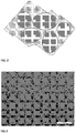
FIG. 1A is a photomicrograph of an exemplary dispersion of tungsten carbide (WC) particles in an ink in accordance with an embodiment of the present invention; -
FIG. 1B is a diagram of an exemplary dispersion of tungsten carbide (WC) particles in an ink in accordance with the embodiment ofFIG. 1A ; -
FIG. 2 is a schematic representation of Tungsten Carbide/Cobalt (WC/Co) particles dispersion during post printing treatment at temperature where Cobalt (Co) melts and before Tungsten Carbide (WC) particles have sintered; -
FIG. 3 is a photomicrograph of printed WC/Co ink after the Tungsten Carbide particles have been sintered; -
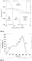
FIG. 4 is a vertical section of the phase diagram for Co-W-C system at 10 wt% Co. FCC (Face Centered Cubic)-Co is faced centered cubic crystalline phase, and, -
FIG. 5 is a diagram of a sintering temperature profile for WC/Co printed part. - Described herein are stable liquid formulations useful as inks for 3D Printing machines and processes of printing using the disclosed inks. These inks include Tungsten Carbide (WC) particles and Cobalt (Co) particles in a liquid carrier, with additional additives, either alone, or in any combination, also being part of the ink. Such additives may include, for example, dispersing agents, wetting and leveling agents, rheological agents and binders. The ink compositions are of viscosities between approximately 10 cPs (centi poise) to approximately 30 cPs, and typically 15±5 cPs, at jetting temperature, so as to be suitable for use as ink jet printing inks.
- The inks of the present invention allow for the rapid fabrication, typically in small batches, of prototype parts for design iterations, testing or small-scale production runs.
- The embodiments of the invention disclosed herein utilize Tungsten Carbide (WC) particles and Cobalt (Co) particles in liquid dispersion to form inks, which are used in 3D printing operations. These inks have long term stability as the particles are prevented from exposure to atmospheric oxygen and other contaminants.
- The particles for the inks include particles of Tungsten Carbide (WC) and Cobalt (Co). These particles are, for example, spherical, but may be of another shape, including rounded, partially rounded, polygonal, rectangular and the like. The particles may be crystalline or amorphous, or combinations thereof. Throughout this document, when particle sizes are listed, the sizes are diameters, except where specifically indicated.
- The WC particles are, for example, spherical or substantially spherical or rounded, and are of diameters of approximately less than 2 micrometers, and, for example, approximately 1 micrometer or less. The particles may be obtained by physical methods such grinding bulk material, such as WC powder, available from General Carbide Corporation, Greensburg, PA, USA. WC powder can also be prepared by reaction of tungsten (W) metal and carbon (Carbon black) at 1450-1500 °C.
- The Co particles are, for example, spherical or substantially spherical or rounded, and are of diameters of approximately less than 2 micrometers, and, for example, approximately 1 micrometer or less. In alternative embodiments, the Co particles may be approximately 50 nanometers or less. In alternative embodiments, the Co particles may be approximately 20 nanometers or less. The particles may be obtained by physical methods such grinding bulk material, such as Co powder, available from Global Tungsten & Powder (GTP), Towanda, PA, USA. Co nanoparticles dispersion, of sizes ranging from 5 to 50 nm may also be obtained from the reduction of cobalt acetate in polyol as described in: Surface investigation and magnetic behavior of Co nanoparticles prepared via a surfactant-mediated polyol process, J. Phys. Chem., 113, 5081-508, 2009. The chemical reduction may be performed for example by reducing Co acetate tetrahydrate in polyol/oleic acid mixture under Argon atmosphere. The WC particles and Co particles are initially in separate dispersions.
- These particle sizes for WC and Co allow for compatibility with ink jet print heads such as a Diamatics Sapphire QS-256 print head from Konica Minolta, and useful in 3D printing processes, such as those disclosed herein.
- The WC particle dispersion is formed of WC powder (detailed above) dispersed in a liquid carrier vehicle, i.e., glycol ether, that contain a dispersing agent that will adsorb on the WC particles during milling processes. An example WC dispersion includes 55±2 wt% WC powder (0.8 micron) in glycol ethers, approximately 45 wt%, and stabilized with a polymeric dispersant of up to approximately 5 wt% on WC particles).
- The Co dispersion is formed of cobalt powder (detailed above) dispersed in a liquid carrier vehicle, i.e., glycol ether that contains dispersing agent that will adsorb on the Co particles during milling processes. An example Co dispersion includes dispersing approximately 60 wt% Co powder of a diameter of approximately 70 nm, in glycol ethers, at approximately 40 wt% and stabilized with a polymeric dispersant of up to approximately 5wt% on WC particles. For example, and in accordance with some embodiments, wetting and leveling agents may be added to the Co dispersion to adjust specific properties of the ink, such as viscosity, surface tension, drying behavior.
- The overall weight percent of the WC/Co powders is approximately 40 to approximately 60 weight percent of the ink (ink composition).
- Alternately, there may be a cobalt precursor (organo cobalt compound) solution instead of or with the Co dispersion. In this case, cobalt precursor dissolved in the ink liquid carrier, will revert to metallic Co during post printing process. Organo cobalt compounds could be taken from the following non limiting list: Dicobalt octacarbonyl, Cyclopentadienylcobalt dicarbonyl, Dicarbonylcyclopentadienyl cobalt, Pentamethylcyclopentadienyl cobalt(I) dicarbonyl, Cobalt tetracarbonyl (Sigma, USA). Since these molecules will be incorporated in a dissolved manner in the ink carrier, no dispersant is required in most cases. In some examples, a low molecular surfactant may be added to the organo cobalt compound solution to control the size the new formed Co nanoparticles and to enhance its solubility. Possible surfactants could be: lauryl acid, oleic acid, lauryl amine, oleylamine at a concentration of 5-10 wt% based on Co content.
- The WC and Co dispersions are such that the respective metal particles themselves, are, for example, in a mixture of approximately 89 ± 10 weight percent WC metal particles, and 11± 10 weight percent Co metal particles, or at an approximately 9:1 WC to Co metal particle weight ratio. While, this weight ratio of 9:1 is preferred, the weight ratio of WC metal particles (the first number in the ratio) to Co metal particles (the second number in the ratio) may range from approximately 8:2 to approximately 9.5:0.5. This mixture is then mixed with the desired additives to form the final ink at a controlled WC/Co weight ratio to reach the correct mechanical behavior of the 3D printed article (object).
- Alternatively, the WC and Co particles are obtained in a single dispersion. Typical mixture dispersions range from approximately weight ratios of WC particles to Co particles of approximately 80:20 to approximately 95:5 respectively. Single dispersion is usually formed of 90 wt% (weight percent) WC particles and 10 wt% (weight percent) Co particles, in a carrier vehicle, such as glycol ethers and their mixtures, as detailed below. In some dispersions, a certain amount of smaller particles, e.g., 20 nm size Co particles may be added. A Co nanoparticles dispersion is prepared by chemical reduction in an organic liquid under Argon atmosphere as described in one of the following procedures:
- 1. Surface investigation and magnetic behavior of Co nanoparticles prepared via a surfactant-mediated polyol process, J. Phys. Chem. C., 113,5081-508,2009
- 2. Size and structure control of magnetic nanoparticles by using a modified polyol process, J. Appl. Phys., 95 (11), 2004
- 3. Process for the reduction of metallic compounds by polyols, and metallic powders obtained by this process, in accordance with
US Patent No. 4,539,041 . - These nanoparticles allow for close packing of the formed green body, and also enable initiation of the sintering process at a much lower temperature (e.g., approximately 400 °C) than for large Cobalt particles (GTP, Towanda, PA, USA). For example, Co nanoparticles at sizes of approximately 20 nm or less combine with WC large particles, of approximately 2 microns result in a stable ink formulation. The stability is due, at least in part, due steric stabilization mechanism due to presence of the dispersant. It should be noted that other stabilization mechanism can be utilized, such as electrostatic, electrosteric, particles based stabilization and combination thereof. Additionally, a mixture of WC and Co particles of substantially the same size, for example, spherical and/or rounded particles of approximately 1 micrometer in diameter, are also stable, due to the lower melting point of Co (1495°C) when compared to the melting point of WC (2870°C) such that the Co particles sinter before the WC particles. Typical sintering temperatures for WC particle range from approximately 1430°C to 1490°C while pure Cobalt melts at 1495°C. During sintering, Co particles liquefy and easily dissolve Tungsten (W) and Carbon (C), which lowers the melting temperature. After solidification, the binder (Cobalt) still gets the face centered cubic (FCC) crystalline structure, but due to the high concentration of dissolved Tungsten (W), the natural phase transformation to hexagonal close packed (HCP) crystal structure is suppressed to some extent. A combination of HCP and FCC with stacking faults is the resulting structure. The Co grains are often dendritic and may grow to very large sizes, up to approximately 1 mm.
- The present mixtures also account for the magnetic nature of the cobalt particles, by using spherical and/or rounded cobalt particles of approximately below 20 nanometers in diameter. This size minimizes the magnetic attractions between the cobalt particles. Further reduction of the magnetic attraction may occur when the aforementioned cobalt particles are of non-crystalline or in a suitable crystalline structure. Bulk cobalt exists in two allotropes, namely: (a) hexagonal close-packed Co (HCP-Co) and (b) face-centered cubic Co (FCC-Co). Thermodynamically, HCP-Co is the stable phase below 450°C, while FCC-Co forms at higher temperatures. Accordingly, these phases are in equilibrium at approximately 422°C - 427°C. Because of the difference in crystal structure, variations in physical and magnetic properties between the two polymorphs arise. HCP-Co is slightly denser than FCC-Co, even though both phases are close-packed structures. Furthermore, HCP-Co is also magnetically harder than the FCC phase due to its magnetic anisotropy and high coercivity as compared to the symmetrical and low coercivity FCC phase. HCP-Co is the stable phase at room temperature; both phases can co-exist at ambient temperature in bulk samples. In the case of fine Co particles, recent works on the preparation of Co nanoparticles by low temperature solution chemistry have similarly produced mixtures of HCP and FCC-Co, with FCC as the predominant phase. It was found that FCC-Co has become more stable at ambient conditions when the particle size is reduced.
- The magnitude of the magnetic dipole P is proportional to the particle volume, i.e. to P∼ r(3), where r is the particle radius. The magnetic attraction force Fm between two dipoles P is proportional to PxPxd(-4), where d is the distance between the two dipoles (and x is the multiplication operation). Therefore the energy associated with the two dipole interaction Wm∼ PxPxd(-3). For a given proportion of Cobalt in the dispersion, when the radii of the particle change, the distance d changes linearly with d, i.e. d~ r. Therefore Fm∼ PxPxr(-4) ∼r6x r(-4) = r2, and Wm ∼ PxPxr(-3) ∼r3. The thermal energy associated with each of the degree of freedom is kT/2, including the three translational degrees of freedom (x, y, z) and three rotational degrees of freedom. This energy works to separate the particles from each other and to randomly rotate the magnetization direction. Thus, while energy that opposes agglomeration of the particles does not depend on r, energy per particle that encourages agglomeration decreases in proportion to r4. As a consequence, for small enough r, the tendency of the Cobalt particles to agglomerate vanishes, which makes the dispersion stable. Accordingly, the smaller the size of the particles, the more stable dispersion of such particles due to the higher dominance of the Brownian motion in respect to the gravitational tendency of the particles precipitate. Qualitative experience showed that r<50 nm and, in particular, 20 nm is required for reducing the magnetic interaction between the particle below the insignificance level.
- Carrier vehicles support the dispersions of the particles, e.g., the WC and Co particles detailed above. Exemplary carrier vehicles include solvents, such as organic solvents, water, and mixtures thereof. When the carrier vehicle is a solvent, the ink is referred to as solvent-based. When the carrier vehicle is water, the ink is referred to as water based.
- The carrier vehicle may include one or more miscible liquids, enabling proper control of parameters, including, for example, evaporation rate, latency, viscosity and surface tension. The carrier vehicle is such that it evaporates quickly after printing so that the subsequent layer is deposited on a solid layer. To achieve this characteristic, the carrier vehicle has a boiling point at or below the temperature of the object surface during printing, while also allowing for proper performance of the print head.
- Exemplary carrier vehicles include glycol ethers, and water soluble liquids such as ethylene glycol, propylene glycol. Glycol ethers such as propylene glycol or ethylene glycol series from Dow Chemical, Dimethoxyethane, also known as glyme, monoglyme, dimethyl glycol, ethylene glycol dimethyl ether, dimethyl cellosolve) series from Clariant and their mixtures could be used. In that manner, one can reach a wide range of boiling point for the carrier vehicle (from 100°C up to 320°C).
- When present in the ink, the carrier vehicles may be from approximately 40 to approximately 60 weight percent of the ink (ink composition).
- The ink composition of WC and Co particles in the liquid carrier vehicle may include additives. The additives are presented as follows, with any one or more of these additives, e.g., dispersing agents, wetting and leveling agents, rheological agents, and binders, being permissible in an ink.
- Dispersing agents, such as a surfactants and polymers, may be used as stabilizers to stabilize the ink. The dispersing agent should be of a composition, which has affinity to the WC and/or Co particle surface, and prevents the aggregation of the dispersed WC and/or Co particles, by a steric, electrostatic or electrosteric stabilization mechanism.
- The dispersing agent is molecularly compatible with the carrier vehicle, for stability purposes. In water based inks, the stabilization can be achieved by proper control of the surface properties, such as by changing the pH of the dispersion. It should be noted that the stabilizer may be bound to the particles' surface by covalent bonds or by physical adsorption. The dispersing agent should also be such that it may be removed from the printed object prior to any desired post processing stage, and specifically before heat treatments to the printer object, such as sintering. By removing the dispersing agent, sintering between WC and Co particles can proceed without interference or contamination by particles of the dispersing agent. Additionally, with the dispersing agent removed, the formation of "islands" of dispersing agent particles within the printed object, which will weaken the resulting solidified 3D structure, is prevented. Polymeric dispersants and other non-volatile compounds are typically burned or fired off, during post printing process.
- Exemplary dispersing agents include: Disperbyk 180, Disperbyk 190, Disperbyk 163 from Byk Chemie. Solsperse 39000, Solsperse 33000, Solsperse 35000 from Lubrizol. Rheosperse 3020, 3450, 3620 from Coatex (Arkema), Efka 7701, Efka 7731, Efka 7732 from BASF.
- When present in the ink, dispersing agents may be from approximately 1 to approximately 10 weight percent of the ink, depending on the resulting ink properties, such as viscosity.
- These are usually surface active molecules that enable control of the surface tension of the ink to: 1) enable proper jetting (expulsion) of the ink from the ink jet print head, 2) enable proper wetting of the ink droplet upon contact with the substrate, and, 3) to enable control of the flow of deposited materials and the morphology of the resulting printed pattern, by preventing or inducing surface tension gradients.
- Exemplary wetting and leveling agents include Byk 333, Byk 307 from Byk Chemie, Tego Wet 270, Tego Wet 280, Tego Wet KL245 from Evonik.
- When present in the ink, the wetting and leveling agents may be from approximately 0.01 to approximately 5 weight percent of the ink.
- These are molecules that enable control of the rheological properties of the ink, which affect the stability of ink during storage (mainly sedimentation rate), the jetting (expulsion) performance, and the flow of ink after being deposited. It should be noted that the ink may be a Newtonian liquid or pseudoplastic liquid. The later may, for example, enable minimizing particles sedimentation during storage (high viscosity at low shear rate), and reduce the flow of ink after being printed (for better printing resolution). Rheological agents include, for example, cellulosic polymers such as ethyl cellulose, carboxymethyl cellulose, hydroxypropyl methyl cellulose, cellulose acetate. These rheological agents may also serve as binders, in accordance with the binders detailed below.
- When present in the ink, they may be from approximately 0.01 to approximately 10 weight percent of the ink.
- The binder (binding agent) serves to promote binding of the WC and Co particles after the printing is terminated, for example, in post-printing processes such as sintering. The binders, when in the post-printed and unsinterd object or "green body" assist the object in maintaining its physical shape prior to heat treatment processes, such as sintering. The binder may include various materials, such as organic polymers or surfactants. Additionally, the above discussed dispersing agent can also serve as a binder.
- When present in the ink, the binders may be from approximately 0.1 to approximately 30 weight percent of the ink.
- The above-disclosed inks are used in 3D printers, which are formed of components including, a print head, e.g., a Diamatics Sapphire QS-256 print head from Konica Minolta, an ink delivery system from the ink cartridge/bottle to the print head, an x-y scanning system, a substrate holder, a motorized substrate stage that keeps the distance between the printed layer and the print head constant, a leveling device and, a heating system (optional). Exemplary printing systems suitable for use with the above-disclosed inks is described in commonly owned and related PCT Patent Application, entitled: 3D Particle Printing, Docket No. 4619/20, referenced above.
- An example of dispensing engine comprises one or more inkjet heads one after the other in X (scan) direction, each comprising an inkjet array of nozzles, including nozzles of 30 µ (µ = micrometer or micron) diameter, wherein the nozzle arrays are aligned along Y (cross scan) direction.
- In order to avoid nozzle clogging and to assure proper jetting power and direction, the particle should be smaller than roughly 1/20 of the nozzle diameter. Hence, in this example, the particle size should preferably be equal or smaller than 1.5 µm.
- The dispensing heads with the ink therein are maintained at a temperature between 20°C and 60°C, and scan above the object in close vicinity (e.g. 1.5 mm above the object surface. Since the object is maintained at high temperature, which is comparable to the boiling point of the liquid carrier (e.g. 200°C), a thermal buffer is required for protecting the heads from the object high temperature. A radiation heating device will further heat up the newly dispensed layer, assisting thereby to evaporate the liquid carrier. A dispensing engine comprises one or more inkjet heads protected by a "mask" (i.e. thermal buffer) is specified in commonly owned and related patent application entitled: 3D Particle Printing (Docket No. 4619/20), referenced above. The cooling mask is maintained at a relatively low temperature compared to the temperature of the object while being printed (e.g. from 10 to 40°C).
- It should be noted that in order to obtain a 3D WC-Co object with proper mechanical properties, all the additional materials, for example, organic materials, should be removed from that body during printing and or before high temperature treatments including sintering stage. This can be achieved by various means, such as burning or decomposition to dissolve the dispersants prior to evaporation. In the context of this document, the terms "burn out" or "burn off" or "fire off" refer to evaporating or disintegrating/decomposition followed by evaporating a component of the ink.
- After completion of printing, the object is typically placed in an oven where the object is fired to the required temperature until complete sintering occurs. This final (complete) sintering stage can include the following steps: 1) initial warming to burn out all organic material; 2) further warming to liquidize inorganic additives, including the Cobalt particles; and, 3) a final warming to sinter the particles, e.g., the WC particles, in the liquid phase.
- Part of the firing steps can include applying vacuum, applying pressure, adding inert gas to prevent oxidation, and adding other gases that may add desired molecular diffusion or chemical reaction with the body.
Figure 4 describes phase diagram of WC/Co at a 90:10 weight ratio. Here, the cobalt particles have melted to serve as a binder for sintering of the WC particles, that occurs at approximately 1400°C, and for example, is in accordance with, "WC Grain Growth During Sintering of Cemented Carbides," Mannesson K., Doctoral Thesis, KTH, Stockholm, Sweden 2011. -
Figure 4 shows a calculated vertical section through the Co-WC system at 10 wt% Co. If only WC and Co are desired in the final object, the content is limited to the carbon range 5.38-5.54 wt% as shown by the two-phase region (WC + FCC Co). During sintering some carbon reacts with oxygen present and the final carbon content should be adjusted during the process to balance the carbon loss and to obtain the desired composition of the final product. During liquid-phase sintering the microstructure coarsens simultaneously with the densification process. The small grains dissolve and reprecipitate as the larger grains. The mean grain size will thus increase with increasing sintering time. - Tungsten Carbide (WC) and Cobalt (Co) powder has been milled during ink formulation and powder dispersion. Accordingly, agglomerates are broken and the particles obtain an irregular shape that is slightly rounded, which makes sintering easier. Milling also provides a more even distribution of the cobalt (Co) and tungsten carbide (WC) particles and makes the surfaces more reactive, promoting the wetting of cobalt (Co) on the carbide (C) surfaces. The tungsten carbide (WC) has an anisotropic surface energy due to its hexagonal crystal structure and therefore easily forms prismatic grains during sintering. From Figures (
FIGs.) 1A, 1B ,2 and 3 , the particles of WC and Co have more rounded shapes directly after milling and that the facets are formed during sintering. The carbon content also influences the shape of the WC grains. In a Carbide (C)-rich alloy, the grains are more faceted and triangular prisms with sharp corners may occur. - Attention is directed to
Figure 5 , which shows a diagram of a sintering profile for WC/Co green body. The first lines 501 and 502 show a temperature increase up to approximately 600°C and keeping it at this temperature for 10 hours are necessary to burnout of all organic matter present in the green part (see alsoFigures 1A and 1B for result description). Supplementary heating, shown by line 503 and 504, to 950-980°C as shown schematically inFigure 2 . This permits liquefaction of Cobalt (melting) that is penetrating the WC matrix that can start to sinter at a higher temperature (approximately 1400°C), as shown byline FIG. 3 ) and its mechanical properties. - Products which may be made by the aforementioned process include cutting tools.
- The following Examples present formulations for inks and their preparations.
- EXAMPLE-1: Ink formulation composed of WC and Co particles is prepared by mixing a dispersion of WC particles in liquid carrier, with a dispersion of cobalt particles smaller than 100 nm.

Ink property 15.0 ± 5.0 Viscosity (cPs), 25°C 29.0 ± 2.0 Surface tension, 25°C - WC Dispersion - WC dispersion was prepared by dispersing 55±2 wt% WC powder (0.8 micron) in glycol ethers and stabilized with a polymeric dispersant (5 wt% on WC particles). All components were mixed in a vertical agitator (vertical agitator mill) filled with 0.5 mm WC beads and a volume ratio of 67/33 (beads/product; vol/vol) for 6 hours at 15 °C. The WC dispersion is stabilized with a polymeric dispersant, which serves as a dispersing agent. The dispersing agent includes one or more of Disperbyk 180, Disperbyk 190, Disperbyk 163 from Byk Chemie of Germany, Solsperse 39000, Solsperse 33000, Solsperse 35000 from Lubrizol of the UK, Rheosperse 3020, 3450, 3620 from Coatex (Arkema, France), Efka 7701, Efka 7731, Efka 7732 from BASF of Germany.
- Co Dispersion- Co dispersion was prepared by dispersing 60 wt% Co powder (70 nm, American Elements, USA) in glycol ethers and stabilized with a polymeric dispersant (5 wt% on Co particles). All components were mixed in a vertical agitator filled with 0.4 mm ZrO2 beads and a volume ratio of 67/33 (beads/product; vol/vol) for 12 hours at 15 °C. The Co dispersion is stabilized with a polymeric dispersant, which serves as a dispersing agent. The dispersing agent includes one or more of Disperbyk 180, Disperbyk 190, Disperbyk 163 from Byk Chemie, Solsperse 39000, Solsperse 33000, Solsperse 35000 from Lubrizol, Rheosperse 3020, 3450, 3620 from Coatex (Arkema), Efka 7701, Efka 7731, Efka 7732 from BASF.
- Rheologic Agent/Binders - Cellulosic polymers examples: ethyl cellulose, carboxymethyl cellulose, hydroxypropyl methyl cellulose, cellulose acetate.
- Carrier Vehicles - Glycol ethers examples: all propylene glycol or ethylene glycol series from Dow Chemical, Midland Michigan, USA, all glymes series (Dimethoxyethane, also known as glyme, monoglyme, dimethyl glycol, ethylene glycol dimethyl ether, dimethyl cellosolve) from Clariant and their mixtures.
- EXAMPLE-2: Ink formulation composed of WC and Co particles are prepared by mixing a dispersion of WC particles in liquid carrier, with a dispersion of cobalt particles smaller than 20 nm.

Ink property 15.0 ± 5.0 Viscosity (cPs), 25°C 29.0 ± 2.0 Surface tension, 25°C - WC Dispersion - Same as in Example 1 above
Rheologic Agent/Binders - Same as in Example 1 above
Carrier Vehicle - Same as in Example 1 above - Co Dispersion - Co dispersion prepared by chemical reduction in an organic liquid. The chemical reduction may be performed for example by reducing Co acetate tetrahydrate in polyol/oleic acid mixture under Argon atmosphere. In a typical synthesis of Co nanoparticles, 5 grams of cobalt acetate tetrahydrate, Co(CH3CO2)2-4 H2O, and 0.8 gram of NaOH were mixed and stirred in 100 mL of deoxygenated tetraethylene glycol in a 250 mL round-bottomed flask under an Argon (Ar) atmosphere. The solution was heated to 200°C at a rate of 10°C/min. At this temperature, 6 grams of oleic acid was added to the solution. The mixture was heated to 314°C at a rate of 5°C/min and refluxed for 6 hours. After the reaction, the solution was cooled to room temperature, and precipitated with ethanol/acetone (1/1; wt/wt). The precipitate was washed repeatedly with excess ethanol and dried with nitrogen gas.
- EXAMPLE-3: Ink formulation composed of WC and Co precursor is prepared by mixing a dispersion of WC particles in liquid carrier, with an organo cobalt compound.

Ink property 15.0 ± 5.0 Viscosity (cPs), 25°C 29.0 ± 2.0 Surface tension, 25°C - WC Dispersion - Same as in Example 1 above
Rheologic Agent/Binders - Same as in Example 1 above
Carrier Vehicle - Same as in Example 1 above - Co Precursor/Dispersion - Organo cobalt compound could be taken from the following non limiting list: Dicobalt octacarbonyl, Cyclopentadienylcobalt dicarbonyl, Dicarbonylcyclopentadienyl cobalt, Pentamethylcyclopentadienyl)cobalt(I) dicarbonyl, Cobalt tetracarbonyl (Sigma, USA).
- In some examples, a low molecular surfactant may be added to the organo cobalt compound solution to control the size the new formed Co nanoparticles. Suitable surfactants include: lauryl acid, oleic acid, lauryl amine, oleylamine at a concentration of 5-10 wt% based on Co content. During high temperature post printing treatment, the precursor will be converted into nanometric cobalt nanoparticles in situ, thus overcoming the need to stabilize a dispersion of Co nanoparticles and thus the use of dispersant (Synthesis and magnetic properties of ε-cobalt nanoparticles, Surf. Interface Anal., 2004; 36: 155-160).
- The terms "comprises", "comprising", "includes", "including", "having" and their conjugates mean "including but not limited to". This term encompasses the terms "consisting of" and "consisting essentially of".
- The phrase "consisting essentially of" means that the composition or method may include additional ingredients and/or steps, but only if the additional ingredients and/or steps do not materially alter the basic and novel characteristics of the claimed composition or method.
- As used herein, the singular form "a", "an" and "the" include plural references unless the context clearly dictates otherwise. For example, the term "a compound" or "at least one compound" may include a plurality of compounds, including mixtures thereof.
- The word "exemplary" is used herein to mean "serving as an example, instance or illustration". Any embodiment described as "exemplary" is not necessarily to be construed as preferred or advantageous over other embodiments and/or to exclude the incorporation of features from other embodiments.
- The word "optionally" is used herein to mean "is provided in some embodiments and not provided in other embodiments". Any particular embodiment of the invention may include a plurality of "optional" features unless such features conflict.
- Throughout this application, various embodiments of this invention may be presented in a range format. It should be understood that the description in range format is merely for convenience and brevity and should not be construed as an inflexible limitation on the scope of the invention. Accordingly, the description of a range should be considered to have specifically disclosed all the possible subranges as well as individual numerical values within that range. For example, description of a range such as from 1 to 6 should be considered to have specifically disclosed subranges such as from 1 to 3, from 1 to 4, from 1 to 5, from 2 to 4, from 2 to 6, from 3 to 6 etc., as well as individual numbers within that range, for example, 1, 2, 3, 4, 5, and 6. This applies regardless of the breadth of the range.
- Whenever a numerical range is indicated herein, it is meant to include any cited numeral (fractional or integral) within the indicated range. The phrases "ranging/ranges between" a first indicate number and a second indicate number and "ranging/ranges from" a first indicate number "to" a second indicate number are used herein interchangeably and are meant to include the first and second indicated numbers and all the fractional and integral numerals therebetween.
- When expressing amounts, ranges and sizes, dimensions and other measurable quantities the words "approximately" and "about" are used interchangeably.
- It is appreciated that certain features of the invention, which are, for clarity, described in the context of separate embodiments, may also be provided in combination in a single embodiment. Conversely, various features of the invention, which are, for brevity, described in the context of a single embodiment, may also be provided separately or in any suitable subcombination or as suitable in any other described embodiment of the invention. Certain features described in the context of various embodiments are not to be considered essential features of those embodiments, unless the embodiment is inoperative without those elements.
- Although the invention has been described in conjunction with specific embodiments thereof, it is evident that many alternatives, modifications and variations will be apparent to those skilled in the art. Accordingly, it is intended to embrace all such alternatives, modifications and variations that fall within the scope of the appended claims.
Claims (15)
- A method for manufacturing a three-dimensional object, the method comprising:providing an ink composition, wherein the ink composition includes a carrier vehicle, tungsten carbide particles, at least one dispersing agent, at least one binder, and cobalt particles, wherein the carrier vehicle includes at least one glycol ether; and wherein the cobalt particles are cobalt and/or organo cobalt compound;dispensing the ink composition from a print head to form a three-dimensional object using an additive process in which successive layers of the ink composition are laid down, wherein each layer from the ink composition is dispensed onto a previously dispensed solid layer from the ink composition; andheat treating the dispensed ink composition by:heating the dispensed ink composition up to a first temperature sufficient to evaporate, or disintegrate and evaporate, all organic material in the dispensed ink composition; andfurther heating the heated dispensed ink composition up to a second temperature sufficient to melt the cobalt particles and sinter the tungsten carbide particles.
- The method of claim 1, wherein the weight ratio of tungsten carbide particles to cobalt particles is between about 8:2 to about 9.5:0.5.
- The method of claim 1, wherein the second temperature is about 1400°C.
- The method of claim 1, further comprising:
cooling the three-dimensional object from the second temperature to a room temperature. - An ink composition for printing a three-dimensional object, comprising:
a carrier vehicle, tungsten carbide particles, at least one dispersing agent, at least one binder, and cobalt particles, wherein the carrier vehicle includes at least one glycol ether; and wherein the cobalt particles are cobalt and/or organo cobalt compound. - The ink composition of claim 5, wherein a weight of the tungsten carbide and cobalt particles together is between about 40% to about 60% of a weight of the ink composition.
- The ink composition of claim 5, wherein the carrier vehicle includes dimethoxyethane.
- The ink composition of claim 5, wherein the carrier vehicle includes at least one water soluble liquid selected from a group including: ethylene glycol and propylene glycol.
- The ink composition of claim 5, wherein the at least one dispersing agent serves as a stabilizer, the at least one dispersing agent selected from a group including: Disperbyk 180, Disperbyk 190, Disperbyk 163, Solsperse 39000, Solsperse 33000, Solsperse 35000, Rheosperse 3020, Rheosperse 3450, Rheosperse 3620, Efka 7701, Efka 7731, and Efka 7732.
- The ink composition of claim 5, further including at least one surface agent that affects a surface tension of the ink composition, the at least one surface agent selected from a group including: Byk 333, Byk 307, Tego Wet 270, Tego Wet 280, and Tego Wet KL245.
- The ink composition of claim 5, further including at least one rheological agent that affects rheological properties of the ink composition, the at least one rheological agent selected from a group including: ethyl cellulose, carboxymethyl cellulose, hydroxypropyl methyl cellulose, and cellulose acetate.
- The ink composition of claim 5, wherein the weight ratio of tungsten carbide particles to cobalt particles is between about 8:2 and about 9.5:0.5, and the ink composition has a viscosity between about 10 cPs to about 30 cPs.
- The ink composition of claim 5, wherein the cobalt particles are of diameter sizes to inhibit magnetic attractions with other cobalt particles.
- The ink composition of claim 13, wherein a grain size of the tungsten carbide particles is about 2 microns or less, and a grain size of the cobalt particles is about 1 micron or less.
- The ink composition of claim 13, wherein the binder is selected from the group consisting of organic polymers, surfactants, and the rheological agent, and is from 0.1 to 30 wt% of the ink composition.
Applications Claiming Priority (2)
| Application Number | Priority Date | Filing Date | Title |
|---|---|---|---|
| US201361891926P | 2013-10-17 | 2013-10-17 | |
| PCT/IB2014/065401 WO2015056231A1 (en) | 2013-10-17 | 2014-10-17 | Tungsten-carbide/cobalt ink composition for 3d inkjet printing |
Publications (3)
| Publication Number | Publication Date |
|---|---|
| EP3058037A1 EP3058037A1 (en) | 2016-08-24 |
| EP3058037A4 EP3058037A4 (en) | 2017-07-12 |
| EP3058037B1 true EP3058037B1 (en) | 2020-07-22 |
Family
ID=52827743
Family Applications (5)
| Application Number | Title | Priority Date | Filing Date |
|---|---|---|---|
| EP14853631.1A Active EP3058037B1 (en) | 2013-10-17 | 2014-10-17 | Tungsten-carbide/cobalt ink composition for 3d inkjet printing |
| EP14853860.6A Withdrawn EP3057777A4 (en) | 2013-10-17 | 2014-10-17 | Methods and systems for printing 3d object by inkjet |
| EP20160458.4A Active EP3702418B1 (en) | 2013-10-17 | 2014-10-17 | Methods and systems for printing 3d object by inkjet |
| EP20163180.1A Pending EP3685997A3 (en) | 2013-10-17 | 2014-10-17 | Support ink for three dimensional (3d) printing |
| EP14853583.4A Active EP3057776B1 (en) | 2013-10-17 | 2014-10-17 | Support ink for three dimensional (3d) printing |
Family Applications After (4)
| Application Number | Title | Priority Date | Filing Date |
|---|---|---|---|
| EP14853860.6A Withdrawn EP3057777A4 (en) | 2013-10-17 | 2014-10-17 | Methods and systems for printing 3d object by inkjet |
| EP20160458.4A Active EP3702418B1 (en) | 2013-10-17 | 2014-10-17 | Methods and systems for printing 3d object by inkjet |
| EP20163180.1A Pending EP3685997A3 (en) | 2013-10-17 | 2014-10-17 | Support ink for three dimensional (3d) printing |
| EP14853583.4A Active EP3057776B1 (en) | 2013-10-17 | 2014-10-17 | Support ink for three dimensional (3d) printing |
Country Status (9)
| Country | Link |
|---|---|
| US (5) | US20160243619A1 (en) |
| EP (5) | EP3058037B1 (en) |
| JP (5) | JP6967348B2 (en) |
| KR (1) | KR20160091323A (en) |
| CN (6) | CN106414033A (en) |
| BR (1) | BR112016008376B1 (en) |
| CA (1) | CA2927249C (en) |
| IL (5) | IL291209B (en) |
| WO (3) | WO2015056232A1 (en) |
Cited By (1)
| Publication number | Priority date | Publication date | Assignee | Title |
|---|---|---|---|---|
| US11577319B2 (en) | 2013-10-17 | 2023-02-14 | Xiet Ltd. | Tungsten-carbide/cobalt ink composition for 3D inkjet printing |
Families Citing this family (155)
| Publication number | Priority date | Publication date | Assignee | Title |
|---|---|---|---|---|
| US20100066779A1 (en) | 2006-11-28 | 2010-03-18 | Hanan Gothait | Method and system for nozzle compensation in non-contact material deposition |
| CN102227387B (en) | 2008-11-30 | 2015-05-20 | 迅捷有限公司 | Method and system for applying materials on substrate |
| KR101387192B1 (en) | 2009-05-18 | 2014-04-21 | 엑스제트 엘티디. | Method and device for printing on heated substrates |
| JP6132352B2 (en) | 2010-05-02 | 2017-05-24 | エックスジェット エルティーディー. | Printing system with self-purge, precipitation prevention, and gas removal structure |
| US10479122B2 (en) | 2010-07-22 | 2019-11-19 | Xjet Ltd. | Printing head nozzle evaluation |
| JP5933883B2 (en) | 2010-10-18 | 2016-06-15 | エックスジェット エルティーディー. | Inkjet head storage and cleaning |
| EP2969487B1 (en) * | 2013-03-14 | 2020-09-09 | Stratasys, Inc. | A method of producing a three-dimensional printed article |
| JP6235311B2 (en) * | 2013-11-15 | 2017-11-22 | 株式会社東芝 | 3D modeling head and 3D modeling apparatus |
| WO2015100085A2 (en) * | 2013-12-23 | 2015-07-02 | The Exone Company | Methods and systems for three-dimensional printing utilizing a jetted-particle binder fluid |
| US9925440B2 (en) | 2014-05-13 | 2018-03-27 | Bauer Hockey, Llc | Sporting goods including microlattice structures |
| DE102014117199B4 (en) * | 2014-11-24 | 2021-06-02 | Heraeus Noblelight Gmbh | Process for the production of a reflector on a reflector base body made of glass |
| US10245786B2 (en) * | 2014-12-17 | 2019-04-02 | Xerox Corporation | System for planarizing objects in three-dimensional object printing systems with reduced debris |
| JP6584101B2 (en) | 2015-03-12 | 2019-10-02 | キヤノン株式会社 | Method for manufacturing three-dimensional object and apparatus for manufacturing the same |
| US20150192919A1 (en) * | 2015-03-24 | 2015-07-09 | Caterpillar Inc. | Support members for three dimensional object printing |
| EP3230383B1 (en) * | 2015-04-24 | 2024-02-28 | Hewlett-Packard Development Company, L.P. | Detailing agent for three-dimensional (3d) printing |
| BR112017015821A2 (en) * | 2015-04-30 | 2018-07-17 | Hewlett-Packard Development Company, L.P. | printing of a multi-structured 3d object |
| US9975182B2 (en) * | 2015-05-13 | 2018-05-22 | Kennametal Inc. | Cutting tool made by additive manufacturing |
| GB2538289B (en) * | 2015-05-14 | 2018-05-09 | Dev Ltd | Inkjet type additive manufacturing |
| EP3297808A1 (en) * | 2015-05-22 | 2018-03-28 | LUXeXcel Holding B.V. | Method for printing a three-dimensional structure and a system for printing a three-dimensional structure |
| JP6536199B2 (en) * | 2015-06-16 | 2019-07-03 | セイコーエプソン株式会社 | Three-dimensional forming device |
| DE102015211670A1 (en) | 2015-06-24 | 2016-12-29 | Airbus Operations Gmbh | Method and device for mass production of components made of a fiber-reinforced composite material |
| CN104959594B (en) * | 2015-07-10 | 2017-02-22 | 北京科技大学 | Method for preparing high-solid-phase low-adherence magnetic alloy powder used for 3D printing |
| KR20180021221A (en) | 2015-07-17 | 2018-02-28 | 어플라이드 머티어리얼스, 인코포레이티드 | Laminate fabrication with coolant system |
| KR102037558B1 (en) * | 2015-07-20 | 2019-10-28 | 주식회사 엘지화학 | An Ink Composition for 3D Printing Support and the Manufacturing Method using the Same |
| JP2017025386A (en) * | 2015-07-24 | 2017-02-02 | セイコーエプソン株式会社 | Three-dimensional molded object and three-dimensional molding method |
| JP6661920B2 (en) * | 2015-08-26 | 2020-03-11 | セイコーエプソン株式会社 | 3D forming equipment |
| EP3135459A1 (en) | 2015-08-31 | 2017-03-01 | Nederlandse Organisatie voor toegepast- natuurwetenschappelijk onderzoek TNO | Method and apparatus for layerwise production of a tangible object |
| JP6682782B2 (en) * | 2015-09-07 | 2020-04-15 | 日本電気株式会社 | Modeling apparatus and modeling method |
| US10974495B2 (en) * | 2015-09-14 | 2021-04-13 | Xerox Corporation | Thermal management methods and apparatus for producing uniform material deposition and curing for high speed three-dimensional printing |
| US10892075B2 (en) * | 2015-09-25 | 2021-01-12 | Lg Chem, Ltd. | Composition for 3D printing |
| US10800934B2 (en) * | 2015-10-09 | 2020-10-13 | Particle3D AdS | Process for 3D printing |
| JP6901697B2 (en) * | 2015-10-15 | 2021-07-14 | セイコーエプソン株式会社 | Fluid composition set and fluid composition |
| WO2017075575A1 (en) | 2015-10-30 | 2017-05-04 | Polar 3D Llc | Apparatus and method for forming 3d objects |
| JP6718132B2 (en) | 2015-11-06 | 2020-07-08 | セイコーエプソン株式会社 | Method and apparatus for manufacturing three-dimensional structure |
| JP6669985B2 (en) | 2015-11-12 | 2020-03-18 | セイコーエプソン株式会社 | Manufacturing method of three-dimensional objects |
| CN108698297A (en) * | 2015-12-16 | 2018-10-23 | 德仕托金属有限公司 | Method and system for increasing material manufacturing |
| WO2017104415A1 (en) * | 2015-12-18 | 2017-06-22 | 株式会社リコー | Water-disintegrable composite material, and method for producing three-dimensional model |
| JP6170994B2 (en) * | 2015-12-22 | 2017-07-26 | 株式会社フジミインコーポレーテッド | Materials for modeling for use in powder additive manufacturing |
| US10449713B2 (en) | 2016-01-25 | 2019-10-22 | Te Connectivity Corporation | Article and method of forming an article |
| JP2017159474A (en) | 2016-03-07 | 2017-09-14 | セイコーエプソン株式会社 | Method of producing three-dimensional modeled product, apparatus for producing three-dimensional modeled product, and three-dimensional modeled product |
| JP2017159475A (en) | 2016-03-07 | 2017-09-14 | セイコーエプソン株式会社 | Method of producing three-dimensional modeled product, apparatus for producing three-dimensional modeled product, and three-dimensional modeled product |
| DE102016002777A1 (en) * | 2016-03-09 | 2017-09-14 | Voxeljet Ag | Method and device for producing 3D molded parts with construction field tools |
| US10589464B2 (en) | 2016-03-17 | 2020-03-17 | Hewlett-Packard Development Company, L.P. | Spreader roller for additive manufacturing |
| KR102056100B1 (en) * | 2016-04-01 | 2019-12-17 | 주식회사 엘지화학 | 3D Printing Method |
| US10350682B2 (en) | 2016-04-14 | 2019-07-16 | Desktop Metal, Inc. | Sinterable article with removable support structures |
| KR102514163B1 (en) * | 2016-04-15 | 2023-03-24 | 산드빅 인터렉츄얼 프로퍼티 에이비 | 3D printing of cermet or cemented carbide |
| EP3448658B1 (en) | 2016-04-28 | 2022-12-28 | Hewlett-Packard Development Company, L.P. | 3-dimensional printed parts |
| KR102179605B1 (en) | 2016-04-28 | 2020-11-17 | 휴렛-팩커드 디벨롭먼트 컴퍼니, 엘.피. | Photoluminescent material set |
| GB2550338A (en) | 2016-05-12 | 2017-11-22 | Hewlett Packard Development Co Lp | Reflector and additive manufacturing system |
| EP3243583B1 (en) * | 2016-05-13 | 2019-05-08 | SLM Solutions Group AG | Apparatus and method for associating a position in a construction data set with a position in a building section of the apparatus |
| EP3263300A1 (en) * | 2016-06-27 | 2018-01-03 | Siemens Aktiengesellschaft | Coating mechanism and apparatus for additive manufacturing |
| US10160218B2 (en) * | 2016-06-28 | 2018-12-25 | Seiko Epson Corporation | Printer |
| DE102016112499A1 (en) * | 2016-07-07 | 2018-01-11 | Jens Reimann | Production of customized lingual brackets |
| US10857727B2 (en) | 2016-07-20 | 2020-12-08 | Hewlett-Packard Development Company, L.P. | Material sets |
| WO2018017072A1 (en) * | 2016-07-20 | 2018-01-25 | Hewlett-Packard Development Company, L.P. | Material sets |
| EP3433084B1 (en) * | 2016-07-20 | 2024-01-10 | Hewlett-Packard Development Company, L.P. | Forming microstructures in 3d printing |
| CN109414763B (en) * | 2016-07-26 | 2021-07-13 | 惠普发展公司,有限责任合伙企业 | Three-dimensional (3D) printing |
| KR102077206B1 (en) * | 2016-08-30 | 2020-02-14 | 리즈 인코포레이티드 | Method for manufacturing three-dimensional object with removable support structure |
| WO2018053235A1 (en) | 2016-09-15 | 2018-03-22 | NanoCore Technologies, Inc. | System and method for additive metal manufacturing |
| JP6802368B2 (en) | 2016-09-22 | 2020-12-16 | ストラタシス リミテッド | Formulations, methods, and systems for solid free-form fabrication |
| KR20190058527A (en) | 2016-09-22 | 2019-05-29 | 스트라타시스 엘티디. | Method and system for making arbitrary shape |
| JP6774020B2 (en) * | 2016-09-29 | 2020-10-21 | セイコーエプソン株式会社 | 3D model manufacturing equipment and 3D model manufacturing method |
| EP3362260B1 (en) * | 2016-10-17 | 2019-06-19 | Wacker Chemie AG | Method for the production of silicone elastomer parts having increased printing quality |
| CN109562564B (en) | 2016-10-19 | 2021-07-23 | 惠普发展公司,有限责任合伙企业 | Additive manufacturing |
| EP3397455B1 (en) | 2016-10-25 | 2022-07-06 | Hewlett-Packard Development Company, L.P. | Three-dimensional (3d) printing |
| CN109641449B (en) | 2016-10-25 | 2021-07-13 | 惠普发展公司,有限责任合伙企业 | Dispersions and sprayable compositions containing cesium tungsten oxide nanoparticles and zwitterionic stabilizers |
| US11305486B2 (en) | 2016-10-25 | 2022-04-19 | Hewlett-Packard Development Company, L.P. | Dispersion and jettable composition containing metal oxide nanoparticles |
| CN115584434A (en) * | 2016-11-01 | 2023-01-10 | 麦克莱恩-福格公司 | 3D printable hard ferrous metallic alloy for powder layer fusing |
| DE102016221889A1 (en) | 2016-11-08 | 2018-05-09 | Brose Fahrzeugteile GmbH & Co. Kommanditgesellschaft, Würzburg | 3D printing device and 3D printing process |
| DE102016121594A1 (en) * | 2016-11-10 | 2018-05-17 | Fraunhofer-Gesellschaft zur Förderung der angewandten Forschung e.V. | METHOD FOR IMPROVING THE SURFACE QUALITY OF GENERATIVELY PRODUCED COMPONENTS |
| FR3058354B1 (en) * | 2016-11-10 | 2020-01-31 | Addup | TOOL HOLDER DEVICE FOR SELECTIVE ADDITIVE MANUFACTURING APPARATUS |
| FR3058659B1 (en) * | 2016-11-14 | 2019-01-25 | Addup | POWDER-BASED ADDITIVE MANUFACTURING FACILITY WITH ROTATING CLEANING DEVICE |
| US10000011B1 (en) | 2016-12-02 | 2018-06-19 | Markforged, Inc. | Supports for sintering additively manufactured parts |
| CA3040866A1 (en) * | 2016-12-02 | 2018-06-07 | Markforged, Inc. | Supports for sintering additively manufactured parts |
| US10800108B2 (en) | 2016-12-02 | 2020-10-13 | Markforged, Inc. | Sinterable separation material in additive manufacturing |
| EP3548212B1 (en) * | 2016-12-02 | 2023-03-08 | Markforged, Inc. | Method of reducing distortion in an additively manufactured part |
| JP6908705B2 (en) | 2016-12-06 | 2021-07-28 | マークフォージド,インコーポレーテッド | Addition manufacturing by supplying heat bending material |
| DE102016015027A1 (en) * | 2016-12-16 | 2018-01-11 | Daimler Ag | Method for smoothing a surface |
| JP6955658B2 (en) * | 2017-01-11 | 2021-10-27 | Dic株式会社 | Liquid composition combination |
| US20210276083A1 (en) * | 2017-02-21 | 2021-09-09 | Desktop Metal, Inc. | Nanoparticles in binder jetting fabrication of metal objects |
| FR3063221B1 (en) * | 2017-02-24 | 2019-04-19 | Mojito | METHOD FOR MANUFACTURING A DENTAL ELEMENT BY THREE DIMENSIONAL PRINTING |
| US10317881B2 (en) * | 2017-03-01 | 2019-06-11 | General Electric Company | Parallelized CAD using multi laser additive printing |
| JP6855846B2 (en) * | 2017-03-06 | 2021-04-07 | セイコーエプソン株式会社 | Manufacturing method of paste and 3D model |
| CN106915084B (en) * | 2017-03-07 | 2019-04-02 | 杭州杭景模型有限公司 | 3D printer and its print platform |
| US11351610B2 (en) * | 2017-03-07 | 2022-06-07 | Nano Dimension Technologies, Ltd. | Composite component fabrication using inkjet printing |
| US20180264731A1 (en) * | 2017-03-15 | 2018-09-20 | Xjet Ltd. | System and method for delivering ink into a 3d printing apparatus |
| US11104076B2 (en) * | 2017-03-17 | 2021-08-31 | 3D Systems, Inc. | Method and calibrating an inkjet based three-dimensional printing system |
| CN107053653B (en) * | 2017-03-30 | 2019-04-09 | 大连理工大学 | Based on the compound electrojet 3D printing device and method of electric field-thermal field |
| US9925726B1 (en) * | 2017-04-03 | 2018-03-27 | Xerox Corporation | Apparatus for holding three-dimensional (3-D) objects during printing thereon |
| US20180290400A1 (en) * | 2017-04-07 | 2018-10-11 | Sony Corporation | 3d printing device and method for 3d printing |
| IT201700041694A1 (en) * | 2017-04-13 | 2018-10-13 | 3D New Tech S R L | PRE-AND / OR POST-HEATING SYSTEM FOR METALLIC POWDERS IN AN ADDITIVE MANUFACTURING PROCESS |
| CN115815629A (en) | 2017-04-20 | 2023-03-21 | Xjet有限公司 | System and method for manufacturing printed articles |
| US11254055B2 (en) * | 2017-04-21 | 2022-02-22 | Hewlett-Packard Development Company, L.P. | Additive manufacturing machine heat flux |
| US11305487B2 (en) * | 2017-04-21 | 2022-04-19 | Hewlett-Packard Development Company, L.P. | Additive manufacturing roller within radiative heat transfer area |
| EP3645245A1 (en) * | 2017-06-27 | 2020-05-06 | SABIC Global Technologies B.V. | Additive manufacturing of multiple materials with nanoparticulate slurry printing |
| CN107538741A (en) * | 2017-08-12 | 2018-01-05 | 西安电子科技大学 | The printing of non-deployed curved surface conductive pattern and multi-photon curing integrated system and method |
| JP2019055507A (en) * | 2017-09-20 | 2019-04-11 | 株式会社ミマキエンジニアリング | Molding device and recovery device |
| US10933587B2 (en) * | 2017-10-06 | 2021-03-02 | International Business Machines Corporation | Removing a printed item from a printer |
| WO2019083515A1 (en) * | 2017-10-24 | 2019-05-02 | Hewlett-Packard Development Company, L.P. | Build material slurry |
| US11607842B2 (en) | 2017-10-25 | 2023-03-21 | Hewlett-Packard Development Company, L.P. | Thermal supports for 3D features formed from particles |
| CN107839218A (en) * | 2017-11-07 | 2018-03-27 | 陕西百普生医疗科技发展有限公司 | A kind of precinct laser vapor deposition method and device |
| CN108045105B (en) * | 2017-11-21 | 2020-10-09 | 西安电子科技大学 | Conductive pattern printing and linear scanning curing integrated system and method |
| US11712843B2 (en) * | 2017-12-07 | 2023-08-01 | General Electric Company | Binder jetting apparatus and methods |
| RU2669135C1 (en) * | 2017-12-11 | 2018-10-08 | Федеральное государственное бюджетное образовательное учреждение высшего образования "Московский государственный технологический университет "СТАНКИН" (ФГБОУ ВО "МГТУ "СТАНКИН") | METHOD OF MANUFACTURING PRODUCTS BY SELECTIVE LASER MELTING OF WC-Co POWDER COMPOSITION |
| CN107825706A (en) * | 2017-12-15 | 2018-03-23 | 佛山三维二次方科技有限公司 | The 3D printing technique of thermoplastic macromolecule material |
| EP3691817A4 (en) * | 2018-01-02 | 2021-04-07 | Hewlett-Packard Development Company, L.P. | Powder bed materials |
| CN108126875A (en) * | 2018-01-25 | 2018-06-08 | 长春市漫思教育科技有限公司 | A kind of 3D printing piece surface processing unit and method |
| EP3681719A4 (en) * | 2018-02-09 | 2021-03-10 | Hewlett-Packard Development Company, L.P. | Three-dimensional printing systems |
| EP3758918B1 (en) | 2018-02-28 | 2024-02-21 | Hewlett-Packard Development Company, L.P. | Binder jetting additive manufacturing with a patterned breakable connection by gas precursor |
| CN110315757B (en) * | 2018-03-28 | 2021-09-14 | 昆山市工研院智能制造技术有限公司 | Workpiece heating and heat-insulating system of fused deposition forming 3D printer |
| EP3717207A4 (en) * | 2018-04-30 | 2022-05-18 | Hewlett-Packard Development Company, L.P. | Build material heaters with baffles |
| ES2732766B2 (en) * | 2018-05-24 | 2021-01-20 | Consejo Superior Investigacion | Procedure for obtaining a part by modeling by deposition of molten wire |
| KR102408607B1 (en) | 2018-06-01 | 2022-06-14 | 어플라이드 머티어리얼스, 인코포레이티드 | Air Knife for Additive Manufacturing |
| US11273608B2 (en) | 2018-06-07 | 2022-03-15 | Sakuu Corporation | Multi-material three-dimensional printer |
| CN108655407A (en) * | 2018-06-13 | 2018-10-16 | 沈阳精合数控科技开发有限公司 | A kind of ultra-fine grain carrier fluid injection microwave sintering manufacturing process |
| EP3725434A1 (en) * | 2018-06-13 | 2020-10-21 | Rize Inc. | Separation of near net shape manufactured parts from support structures |
| US20210331410A1 (en) * | 2018-06-17 | 2021-10-28 | Hewlett-Packard Development Company, L.P. | Additive manufacturing |
| WO2020034093A1 (en) * | 2018-08-14 | 2020-02-20 | 西门子(中国)有限公司 | 3d printing method |
| US20210178484A1 (en) * | 2018-08-29 | 2021-06-17 | Tritone Technologies Ltd. | Hardening method and apparatus, particularly applicable to metal and/or ceramics |
| CN109111223B (en) * | 2018-09-18 | 2021-06-18 | 中国科学院宁波材料技术与工程研究所 | Titanium dioxide ceramic composition for 3D direct-writing printing, slurry, preparation method and application |
| JP7114147B2 (en) * | 2018-10-02 | 2022-08-08 | エルジー・ケム・リミテッド | Molding apparatus and molded product manufacturing method |
| KR102135311B1 (en) * | 2018-10-10 | 2020-07-17 | 주식회사 클리셀 | Shutter structure and method for preventing uv curing for biomaterial within a dispenser for bio 3d printer |
| WO2020076343A1 (en) * | 2018-10-12 | 2020-04-16 | Hewlett-Packard Development Company, L.P. | Baffles to absorb reflected energy in reflectors |
| US11872757B2 (en) * | 2018-10-30 | 2024-01-16 | Hewlett-Packard Development Company, L.P. | Microwave energy emitters with tips |
| EP3659547B1 (en) | 2018-11-29 | 2021-11-17 | Ivoclar Vivadent AG | Method and use of slip for producing ceramic moulded bodies made of zirconium by means of 3d ink jet printing |
| CN113316513A (en) * | 2018-12-20 | 2021-08-27 | 捷普有限公司 | Apparatus, system, and method for additive manufacturing using ultra-fine jetted material |
| JP2020100885A (en) * | 2018-12-25 | 2020-07-02 | エルジー・ケム・リミテッド | Molding apparatus and production method of molded body |
| DE102018133705B4 (en) | 2018-12-29 | 2022-05-05 | Jens Reimann | Computer-aided method for designing an orthodontic treatment appliance and orthodontic treatment appliance |
| US11548304B2 (en) * | 2019-02-25 | 2023-01-10 | Green Dot Sign Incorporated | Eco-friendly signage |
| CN110076997A (en) * | 2019-05-10 | 2019-08-02 | 黄春燕 | Three-dimensional increases the air pressure adjusting type ink pressure control device of material printer |
| CA3157206A1 (en) | 2019-05-21 | 2020-11-26 | Bauer Hockey Ltd. | Helmets comprising additively-manufactured components |
| CN110238395B (en) * | 2019-06-27 | 2020-04-24 | 南京工业大学 | Method for additive manufacturing of printed metal parts by means of prefabricated sand moulds |
| US20220314330A1 (en) * | 2019-07-14 | 2022-10-06 | Tritone Technologies Ltd. | Mold preparation and paste filling |
| CN110303157B (en) * | 2019-08-02 | 2020-04-14 | 南京中科煜宸激光技术有限公司 | Method for supporting additive manufacturing and printing metal part by prefabricated sand mold |
| US11400649B2 (en) * | 2019-09-26 | 2022-08-02 | Applied Materials, Inc. | Air knife assembly for additive manufacturing |
| US11413817B2 (en) | 2019-09-26 | 2022-08-16 | Applied Materials, Inc. | Air knife inlet and exhaust for additive manufacturing |
| CN111014677B (en) * | 2019-10-18 | 2021-10-22 | 南京钛陶智能系统有限责任公司 | Three-dimensional printing forging method based on magnetic stirring |
| DE102019130940A1 (en) * | 2019-10-25 | 2021-04-29 | Gühring KG | Process for the production of an indexable insert and a cutting tool |
| JP6865803B2 (en) * | 2019-11-07 | 2021-04-28 | 株式会社Screenホールディングス | Flattening device |
| CN110773737B (en) * | 2019-11-14 | 2021-11-23 | 安徽汇正电子科技有限公司 | Selective laser melting prevents warp deformation's 3D printer |
| US20230024611A1 (en) * | 2020-03-03 | 2023-01-26 | University Of Kansas | Methods for inkjet printing objects for microfluidic devices |
| EP3875185A1 (en) * | 2020-03-05 | 2021-09-08 | Evonik Operations GmbH | Selective superparamagnetic sintering and corresponding ink |
| US11485089B2 (en) * | 2020-03-12 | 2022-11-01 | Xerox Corporation | Method and system for operating a modular heater to improve layer bonding in a metal drop ejecting three-dimensional (3D) object printer |
| JP7367575B2 (en) | 2020-03-18 | 2023-10-24 | 株式会社リコー | Three-dimensional object manufacturing device and three-dimensional object manufacturing method |
| US11833586B2 (en) | 2020-03-30 | 2023-12-05 | University Of Florida Research Foundation, Incorporated | Systems, methods, and apparatuses for printing 3D metallic parts from powder suspensions |
| CN111873407B (en) * | 2020-07-27 | 2021-11-19 | 南通理工学院 | 3D printing method, 3D printing assembly and 3D printing platform used for same |
| JP2022070443A (en) * | 2020-10-27 | 2022-05-13 | セイコーエプソン株式会社 | Three-dimensional object printing device and three-dimensional object printing method |
| WO2022164866A1 (en) * | 2021-01-29 | 2022-08-04 | Essentium, Inc. | Ablative support material for directed energy deposition additive manufacturing |
| CN113591300B (en) * | 2021-07-29 | 2024-03-15 | 深圳市创想三维科技股份有限公司 | Method, device, computer equipment and storage medium for generating 3D printing file |
| WO2023086908A1 (en) * | 2021-11-10 | 2023-05-19 | Brigham Young University | Method and system for generating a three-dimensional object with edge definition |
| WO2023101688A1 (en) * | 2021-12-03 | 2023-06-08 | Hewlett-Packard Development Company, L.P. | Kit for three-dimensional printing |
| US11718026B1 (en) * | 2022-07-20 | 2023-08-08 | General Electric Company | Recoat assemblies for additive manufacturing systems and methods of using the same |
| JP2024047016A (en) * | 2022-09-26 | 2024-04-05 | 株式会社ミマキエンジニアリング | Apparatus and method for manufacturing molded object |
| CN115972572A (en) * | 2023-01-06 | 2023-04-18 | 华中科技大学 | Robot-assisted laser additive manufacturing system for interlayer reinforcement of continuous fiber composite material |
| CN116393715B (en) * | 2023-04-19 | 2023-09-19 | 安徽艾密克电联科技有限责任公司 | 3D metal powder printer |
Family Cites Families (143)
| Publication number | Priority date | Publication date | Assignee | Title |
|---|---|---|---|---|
| US3451791A (en) * | 1967-08-16 | 1969-06-24 | Du Pont | Cobalt-bonded tungsten carbide |
| US4376716A (en) * | 1974-07-18 | 1983-03-15 | The United States Of America As Represented By The Secretary Of The Air Force | Preparation of stable sodium carbonate dispersions |
| DE2713891A1 (en) * | 1977-03-29 | 1978-10-12 | Schweizer Helgi Jon Dr | DEVICE FOR THE PRODUCTION AND APPLICATION OF RHYTHMIC IRRITATION STRUCTURES |
| US4364059A (en) | 1979-12-17 | 1982-12-14 | Ricoh Company, Ltd. | Ink jet printing apparatus |
| US4472537A (en) * | 1982-09-17 | 1984-09-18 | Corning Glass Works | Thermoplastic inks for decorating purposes |
| US4592252A (en) * | 1984-07-23 | 1986-06-03 | Cdp, Ltd. | Rolling cutters for drill bits, and processes to produce same |
| US4554130A (en) * | 1984-10-01 | 1985-11-19 | Cdp, Ltd. | Consolidation of a part from separate metallic components |
| US4630692A (en) * | 1984-07-23 | 1986-12-23 | Cdp, Ltd. | Consolidation of a drilling element from separate metallic components |
| US4562892A (en) * | 1984-07-23 | 1986-01-07 | Cdp, Ltd. | Rolling cutters for drill bits |
| EP0245544A3 (en) * | 1986-03-11 | 1988-03-23 | Cellutane Co Ltd | Method and apparatus for continuously producing sheet-like products from waste plastics |
| US4847636A (en) | 1987-10-27 | 1989-07-11 | International Business Machines Corporation | Thermal drop-on-demand ink jet print head |
| US5136515A (en) | 1989-11-07 | 1992-08-04 | Richard Helinski | Method and means for constructing three-dimensional articles by particle deposition |
| JPH03184852A (en) | 1989-12-15 | 1991-08-12 | Canon Inc | Ink jet recording device |
| JP2667277B2 (en) | 1990-03-14 | 1997-10-27 | キヤノン株式会社 | Ink jet recording device |
| JPH04235054A (en) | 1991-01-09 | 1992-08-24 | Seiko Epson Corp | Ink jet recording apparatus |
| US5151377A (en) | 1991-03-07 | 1992-09-29 | Mobil Solar Energy Corporation | Method for forming contacts |
| US5510823A (en) * | 1991-03-07 | 1996-04-23 | Fuji Xerox Co., Ltd. | Paste for resistive element film |
| JPH0690014A (en) | 1992-07-22 | 1994-03-29 | Mitsubishi Electric Corp | Thin solar cell and its production, etching method and automatic etching device, and production of semiconductor device |
| US5385706A (en) * | 1993-04-07 | 1995-01-31 | The Proctor & Gamble Company | Process of making a refastenable mechanical fastening system with substrate having protrusions |
| US5640183A (en) | 1994-07-20 | 1997-06-17 | Hewlett-Packard Company | Redundant nozzle dot matrix printheads and method of use |
| JP3467716B2 (en) | 1995-05-25 | 2003-11-17 | セイコーエプソン株式会社 | Capping device for inkjet recording head |
| US6270335B2 (en) * | 1995-09-27 | 2001-08-07 | 3D Systems, Inc. | Selective deposition modeling method and apparatus for forming three-dimensional objects and supports |
| US6305769B1 (en) * | 1995-09-27 | 2001-10-23 | 3D Systems, Inc. | Selective deposition modeling system and method |
| US5812158A (en) | 1996-01-18 | 1998-09-22 | Lexmark International, Inc. | Coated nozzle plate for ink jet printing |
| KR0182788B1 (en) * | 1996-02-02 | 1999-04-15 | 유규재 | Manufacturing method of calcium carbonate |
| JP4346684B2 (en) | 1996-04-17 | 2009-10-21 | コーニンクレッカ フィリップス エレクトロニクス エヌ ヴィ | Method for manufacturing sintered body on substrate |
| US6596224B1 (en) * | 1996-05-24 | 2003-07-22 | Massachusetts Institute Of Technology | Jetting layers of powder and the formation of fine powder beds thereby |
| JPH10140209A (en) * | 1996-11-05 | 1998-05-26 | Toyo Kohan Co Ltd | Production of cemented carbide by injection molding |
| DE19715582B4 (en) * | 1997-04-15 | 2009-02-12 | Ederer, Ingo, Dr. | Method and system for generating three-dimensional bodies from computer data |
| JPH11342598A (en) | 1998-03-31 | 1999-12-14 | Canon Inc | Recording device and recording head |
| US6283997B1 (en) * | 1998-11-13 | 2001-09-04 | The Trustees Of Princeton University | Controlled architecture ceramic composites by stereolithography |
| JP2000310881A (en) * | 1999-04-28 | 2000-11-07 | Minolta Co Ltd | Toner for toner jet |
| US6328418B1 (en) | 1999-08-11 | 2001-12-11 | Hitachi Koki Co., Ltd | Print head having array of printing elements for printer |
| US6514343B1 (en) | 1999-10-01 | 2003-02-04 | Tokyo Electron Limited | Coating apparatus |
| US20050104241A1 (en) | 2000-01-18 | 2005-05-19 | Objet Geometried Ltd. | Apparatus and method for three dimensional model printing |
| JP2001228320A (en) | 2000-02-21 | 2001-08-24 | Canon Inc | Method of manufacturing color filter and its manufacturing device |
| US7300619B2 (en) * | 2000-03-13 | 2007-11-27 | Objet Geometries Ltd. | Compositions and methods for use in three dimensional model printing |
| US6824603B1 (en) * | 2000-04-20 | 2004-11-30 | Parelec, Inc. | Composition and method for printing resistors, capacitors and inductors |
| JP2001341319A (en) | 2000-06-02 | 2001-12-11 | Canon Inc | Ink jet recorder, apparatus for manufacturing color filter, and their wiping method |
| WO2002020864A2 (en) | 2000-06-16 | 2002-03-14 | Applied Materials, Inc. | System and method for depositing high dielectric constant materials and compatible conductive materials |
| US6562269B2 (en) * | 2001-01-05 | 2003-05-13 | 3D Systems, Inc. | Layer normalizing device for selective deposition modeling |
| US7435426B2 (en) * | 2001-03-22 | 2008-10-14 | Church & Dwight Co., Inc. | Micron sized bicarbonate particles and slurrys containing the same |
| AUPR399001A0 (en) | 2001-03-27 | 2001-04-26 | Silverbrook Research Pty. Ltd. | An apparatus and method(ART104) |
| US6536853B2 (en) | 2001-04-20 | 2003-03-25 | Caterpillar Inc | Arrangement for supporting a track chain of a track type work machine |
| DE10128664A1 (en) | 2001-06-15 | 2003-01-30 | Univ Clausthal Tech | Method and device for producing ceramic moldings |
| US6656410B2 (en) * | 2001-06-22 | 2003-12-02 | 3D Systems, Inc. | Recoating system for using high viscosity build materials in solid freeform fabrication |
| CA2460447A1 (en) * | 2001-09-27 | 2003-04-03 | Z Corporation | Three-dimensional printer |
| JP3948247B2 (en) | 2001-10-29 | 2007-07-25 | セイコーエプソン株式会社 | Method for forming a film pattern |
| US6736484B2 (en) | 2001-12-14 | 2004-05-18 | Seiko Epson Corporation | Liquid drop discharge method and discharge device; electro optical device, method of manufacture thereof, and device for manufacture thereof; color filter method of manufacture thereof, and device for manufacturing thereof; and device incorporating backing, method of manufacturing thereof, and device for manufacture thereof |
| JP2003184852A (en) | 2001-12-17 | 2003-07-03 | Nippon Flex Kogyo Kk | Inner cord for control cable |
| JP2003262646A (en) | 2002-03-08 | 2003-09-19 | Ntn Corp | Wireless rotation detector and radio switching device |
| JP4126996B2 (en) | 2002-03-13 | 2008-07-30 | セイコーエプソン株式会社 | Device manufacturing method and device manufacturing apparatus |
| WO2003089246A1 (en) | 2002-04-22 | 2003-10-30 | Seiko Epson Corporation | Method of cleaning print head |
| KR100503790B1 (en) | 2002-05-24 | 2005-07-26 | 삼성전자주식회사 | Liquid formulation which contains metal oxides for ink-jet recording, and ink-jet recording process using the liquid formulation which contains metal oxides |
| JP2004042551A (en) | 2002-07-15 | 2004-02-12 | Fuji Electric Holdings Co Ltd | Inkjet recorder |
| IL151354A (en) | 2002-08-20 | 2005-11-20 | Zach Moshe | Multi-printhead digital printer |
| US7131722B2 (en) | 2002-08-30 | 2006-11-07 | Konica Corporation | Ink jet printer and image recording method using a humidity detector to control the curing of an image |
| JP4440523B2 (en) | 2002-09-19 | 2010-03-24 | 大日本印刷株式会社 | Organic EL display device by inkjet method, color filter manufacturing method, manufacturing device |
| JP2004139838A (en) * | 2002-10-17 | 2004-05-13 | Noritake Co Ltd | Conductive paste and its use |
| JP3801158B2 (en) | 2002-11-19 | 2006-07-26 | セイコーエプソン株式会社 | MULTILAYER WIRING BOARD MANUFACTURING METHOD, MULTILAYER WIRING BOARD, ELECTRONIC DEVICE, AND ELECTRONIC DEVICE |
| US20040151978A1 (en) | 2003-01-30 | 2004-08-05 | Huang Wen C. | Method and apparatus for direct-write of functional materials with a controlled orientation |
| JP4106282B2 (en) | 2003-01-31 | 2008-06-25 | ホシデン株式会社 | Multi-contact input device |
| WO2004096556A2 (en) | 2003-04-28 | 2004-11-11 | Matsushita Electric Industrial Co. Ltd. | Nozzle head, line head using the same, and ink jet recording apparatus mounted with its line head |
| ATE370832T1 (en) | 2003-05-01 | 2007-09-15 | Objet Geometries Ltd | RAPID PROTOTYPING APPARATUS |
| JP2005199523A (en) | 2004-01-14 | 2005-07-28 | Brother Ind Ltd | Ink jet recorder |
| JP4085429B2 (en) | 2004-05-14 | 2008-05-14 | 富士フイルム株式会社 | Image forming method and apparatus |
| JP4052295B2 (en) | 2004-08-25 | 2008-02-27 | セイコーエプソン株式会社 | MULTILAYER WIRING BOARD MANUFACTURING METHOD, ELECTRONIC DEVICE, AND ELECTRONIC DEVICE |
| JP4715209B2 (en) | 2004-09-01 | 2011-07-06 | コニカミノルタホールディングス株式会社 | Inkjet recording device |
| JP5004803B2 (en) | 2004-12-03 | 2012-08-22 | フジフィルム ディマティックス, インコーポレイテッド | Printhead and system using printhead |
| US7236166B2 (en) | 2005-01-18 | 2007-06-26 | Stratasys, Inc. | High-resolution rapid manufacturing |
| US7344220B2 (en) | 2005-01-25 | 2008-03-18 | Fujifilm Dimatix, Inc. | Ink jet printing apparatus having non-contact print head maintenance station |
| US7494607B2 (en) | 2005-04-14 | 2009-02-24 | E.I. Du Pont De Nemours And Company | Electroconductive thick film composition(s), electrode(s), and semiconductor device(s) formed therefrom |
| JP2007061784A (en) | 2005-09-02 | 2007-03-15 | Seiko Epson Corp | Delivery apparatus for liquid-like substance, delivery method for liquid-like substance manufacturing apparatus for electro-optic apparatus and manufacturing method for electro-optic apparatus |
| US20070063366A1 (en) * | 2005-09-19 | 2007-03-22 | 3D Systems, Inc. | Removal of fluid by-product from a solid deposition modeling process |
| US7718092B2 (en) | 2005-10-11 | 2010-05-18 | E.I. Du Pont De Nemours And Company | Aluminum thick film composition(s), electrode(s), semiconductor device(s) and methods of making thereof |
| US20070107773A1 (en) | 2005-11-17 | 2007-05-17 | Palo Alto Research Center Incorporated | Bifacial cell with extruded gridline metallization |
| JP2007152161A (en) | 2005-11-30 | 2007-06-21 | Kubota Matsushitadenko Exterior Works Ltd | Coating device of construction plate |
| KR20080072788A (en) | 2005-12-01 | 2008-08-07 | 마쓰시타 일렉트릭 인더스트리얼 코우.,엘티디. | Method and apparatus for producing three-dimensional structure |
| US7604320B2 (en) | 2005-12-22 | 2009-10-20 | Lexmark International, Inc. | Maintenance on a hand-held printer |
| US20090119914A1 (en) | 2005-12-27 | 2009-05-14 | Clark Roger F | Process for Forming Electrical Contacts on a Semiconductor Wafer Using a Phase Changing Ink |
| US20070157078A1 (en) | 2005-12-30 | 2007-07-05 | Discovery Productions, Inc. | Method for combining input data with run-time parameters into xml output using xsl/xslt |
| KR100667850B1 (en) | 2006-01-03 | 2007-01-12 | 삼성전자주식회사 | Inkjet image forming apparatus and the control method of the same |
| US7857430B2 (en) | 2006-03-07 | 2010-12-28 | Fujifilm Corporation | Ink jet recording head and ink jet recording apparatus |
| KR100769348B1 (en) * | 2006-03-17 | 2007-11-27 | 주식회사 나노테크 | Manufacturing method for ultra fine composite powder of tungsten carbide and cobalt |
| DE102006015014B4 (en) * | 2006-03-31 | 2008-07-24 | Uibel, Krishna, Dipl.-Ing. | Process for producing three-dimensional ceramic shaped bodies |
| US7717540B1 (en) | 2006-04-04 | 2010-05-18 | Hewlett-Packard Development Company, L.P. | Clog detection and clearing method for ink delivery system |
| JP4784379B2 (en) | 2006-04-25 | 2011-10-05 | 株式会社村田製作所 | Manufacturing method of three-dimensional structure |
| US20080024557A1 (en) | 2006-07-26 | 2008-01-31 | Moynihan Edward R | Printing on a heated substrate |
| WO2008015201A1 (en) | 2006-08-03 | 2008-02-07 | Basf Se | Method for producing structured electrically conductive surfaces |
| EP1894608B1 (en) * | 2006-09-01 | 2009-04-22 | Bernard Hansez-Gonne | Mutlifunctional sport field protective cover |
| KR100726817B1 (en) | 2006-09-07 | 2007-06-11 | 한국생산기술연구원 | Manufacturing method for titanium hydride powders |
| JP2008073647A (en) | 2006-09-22 | 2008-04-03 | Fujifilm Corp | Liquid discharge apparatus and method of forming resist pattern |
| JP4869967B2 (en) | 2006-10-20 | 2012-02-08 | 三菱電機株式会社 | Method for roughening silicon substrate and method for producing photovoltaic device |
| US8322025B2 (en) | 2006-11-01 | 2012-12-04 | Solarworld Innovations Gmbh | Apparatus for forming a plurality of high-aspect ratio gridline structures |
| TWI410333B (en) | 2006-11-28 | 2013-10-01 | Xjet Ltd | Inkjet printing system with movable print heads and methods thereof |
| RU2459842C2 (en) | 2006-12-06 | 2012-08-27 | ДАУ ГЛОБАЛ ТЕКНОЛОДЖИЗ ЭлЭлСи | Foam plastic made from styrene and acrylonitrile copolymer with infrared radiation damping agent |
| KR101407801B1 (en) * | 2006-12-08 | 2014-06-20 | 3디 시스템즈 인코오퍼레이티드 | Three dimensional printing material system and method using peroxide cure |
| KR100931184B1 (en) | 2007-01-09 | 2009-12-10 | 주식회사 엘지화학 | Line pattern forming method using multiple nozzle head and display substrate manufactured by this method |
| JP4854540B2 (en) | 2007-02-22 | 2012-01-18 | 理想科学工業株式会社 | Image recording device |
| WO2009017648A1 (en) * | 2007-07-26 | 2009-02-05 | The Ex One Company, Llc | Nanoparticle suspensions for use in the three-dimensional printing process |
| US8028198B2 (en) * | 2007-07-30 | 2011-09-27 | Micron Technology, Inc. | Devices, methods, and apparatuses for detection, sensing, and reporting functionality for semiconductor memory |
| JP4947303B2 (en) | 2007-07-31 | 2012-06-06 | セイコーエプソン株式会社 | Liquid ejecting head unit and liquid ejecting apparatus |
| US7812064B2 (en) * | 2007-08-07 | 2010-10-12 | Xerox Corporation | Phase change ink compositions |
| TW200918325A (en) | 2007-08-31 | 2009-05-01 | Optomec Inc | AEROSOL JET® printing system for photovoltaic applications |
| JP4954837B2 (en) | 2007-09-21 | 2012-06-20 | 富士フイルム株式会社 | Liquid discharge head, liquid discharge apparatus, and liquid discharge head manufacturing method |
| JP2011507275A (en) | 2007-12-11 | 2011-03-03 | エバーグリーン ソーラー, インコーポレイテッド | Photovoltaic panel having fine fingers, photovoltaic cell, and method for producing the same |
| ATE490293T1 (en) | 2007-12-28 | 2010-12-15 | Eckart Gmbh | PIGMENT PREPARATION AND INKJET PRINTING INK |
| JP4975667B2 (en) | 2008-03-21 | 2012-07-11 | 理想科学工業株式会社 | Inkjet recording device |
| JP4992788B2 (en) | 2008-03-27 | 2012-08-08 | セイコーエプソン株式会社 | Correction value calculation method and liquid ejection method |
| KR101552464B1 (en) * | 2008-03-31 | 2015-09-10 | 다이니폰 인사츠 가부시키가이샤 | Base-generating agent, photosensitive resin composition, pattern-forming material comprising the photosensitive resin composition, pattern formation method using the photosensitive resin composition, and article |
| EP2280831B1 (en) | 2008-05-23 | 2012-02-08 | OCE-Technologies B.V. | Adjustment of a print array and a substrate in a printing device |
| US8343869B2 (en) | 2008-06-24 | 2013-01-01 | Xjet Ltd. | Method for non-contact materials deposition |
| JP4995166B2 (en) | 2008-09-22 | 2012-08-08 | 東芝テック株式会社 | Liquid ejecting apparatus and control method thereof |
| CN102227387B (en) | 2008-11-30 | 2015-05-20 | 迅捷有限公司 | Method and system for applying materials on substrate |
| US9403323B2 (en) * | 2009-03-24 | 2016-08-02 | Basf Se | Printing method for producing thermomagnetic form bodies for heat exchangers |
| WO2010113892A1 (en) | 2009-03-30 | 2010-10-07 | 株式会社トクヤマ | Process for producing metallized substrate and metallized substrate |
| KR101387192B1 (en) | 2009-05-18 | 2014-04-21 | 엑스제트 엘티디. | Method and device for printing on heated substrates |
| EP2436519B1 (en) | 2009-05-29 | 2013-11-06 | Konica Minolta Holdings, Inc. | Inkjet recording device |
| JP5451221B2 (en) | 2009-07-09 | 2014-03-26 | キヤノン株式会社 | Inkjet recording apparatus and inkjet recording method |
| JP5462549B2 (en) * | 2009-08-20 | 2014-04-02 | 住友電気工業株式会社 | Cemented carbide |
| JP5725597B2 (en) | 2010-03-19 | 2015-05-27 | 富士フイルム株式会社 | Fine pattern position detection method and apparatus, defective nozzle detection method and apparatus, and liquid ejection method and apparatus |
| JP6132352B2 (en) | 2010-05-02 | 2017-05-24 | エックスジェット エルティーディー. | Printing system with self-purge, precipitation prevention, and gas removal structure |
| US8319808B2 (en) | 2010-05-25 | 2012-11-27 | Kabushiki Kaisha Toshiba | Image forming apparatus |
| US20110293898A1 (en) | 2010-05-28 | 2011-12-01 | Seiko Epson Corporation | Ink set, textile printing method and printed textile |
| JP5429052B2 (en) * | 2010-05-31 | 2014-02-26 | セイコーエプソン株式会社 | Modeling method |
| US10479122B2 (en) | 2010-07-22 | 2019-11-19 | Xjet Ltd. | Printing head nozzle evaluation |
| US9004667B2 (en) | 2010-07-23 | 2015-04-14 | Kyocera Corporation | Light irradiation device, light irradiation module, and printing apparatus |
| JP5933883B2 (en) | 2010-10-18 | 2016-06-15 | エックスジェット エルティーディー. | Inkjet head storage and cleaning |
| KR101305119B1 (en) * | 2010-11-05 | 2013-09-12 | 현대자동차주식회사 | Oxide semiconductor ink For Ink-Jet Printing and manufacturing method thereof, manufacturing method of photovoltaics using thereof |
| WO2012078820A2 (en) | 2010-12-07 | 2012-06-14 | Sun Chemical Corporation | Aerosol jet printable metal conductive inks, glass coated metal conductive inks and uv-curable dielectric inks and methods of preparing and printing the same |
| JP4887458B2 (en) | 2011-03-25 | 2012-02-29 | リコーエレメックス株式会社 | Head surface cleaning apparatus, ink jet recording apparatus, and head surface cleaning method |
| EP2529694B1 (en) | 2011-05-31 | 2017-11-15 | Ivoclar Vivadent AG | Method for generative production of ceramic forms by means of 3D jet printing |
| JP2013181055A (en) * | 2012-02-29 | 2013-09-12 | Seiko Epson Corp | Inkjet recording ink composition and recorded matter |
| US9032874B2 (en) * | 2012-03-21 | 2015-05-19 | Xerox Corporation | Dampening fluid deposition by condensation in a digital lithographic system |
| TWI482699B (en) * | 2012-05-21 | 2015-05-01 | Univ Nat Taipei Technology | A method for preparing inorganic green bodies with three - dimensional contours |
| US20150255632A1 (en) | 2012-05-28 | 2015-09-10 | Xjet Ltd. | Solar cell electrically conductive structure and method |
| TWI666656B (en) * | 2012-10-29 | 2019-07-21 | 阿爾發裝配解決方案公司 | Sintering powder |
| JP6397420B2 (en) | 2012-11-05 | 2018-09-26 | ストラタシス リミテッド | Direct inkjet printing system and method for 3D objects |
| JP6349310B2 (en) * | 2013-05-16 | 2018-06-27 | バンドー化学株式会社 | Metal bonding composition |
| US9234112B2 (en) | 2013-06-05 | 2016-01-12 | Korea Institute Of Machinery & Materials | Metal precursor powder, method of manufacturing conductive metal layer or pattern, and device including the same |
| JP6967348B2 (en) * | 2013-10-17 | 2021-11-17 | エックスジェット・リミテッドXjet Ltd. | Tungsten-Carbide / Cobalt Ink Composition for 3D Inkjet Printing |
| CN107533296B (en) * | 2015-03-11 | 2021-11-09 | 斯特拉塔西斯公司 | Support material preparation and lamination manufacturing process using the same |
| DE102015108646A1 (en) * | 2015-06-01 | 2016-12-01 | Bundesrepublik Deutschland, Vertreten Durch Den Bundesminister Für Wirtschaft Und Energie, Dieser Vertreten Durch Den Präsidenten Der Bundesanstalt Für Materialforschung Und -Prüfung (Bam) | Method for producing ceramic multilayer circuit carriers based on a slip-based additive manufacturing |
-
2014
- 2014-10-17 JP JP2016524083A patent/JP6967348B2/en active Active
- 2014-10-17 EP EP14853631.1A patent/EP3058037B1/en active Active
- 2014-10-17 CA CA2927249A patent/CA2927249C/en active Active
- 2014-10-17 EP EP14853860.6A patent/EP3057777A4/en not_active Withdrawn
- 2014-10-17 CN CN201480057374.5A patent/CN106414033A/en active Pending
- 2014-10-17 CN CN202211463121.0A patent/CN116377301A/en active Pending
- 2014-10-17 KR KR1020167012894A patent/KR20160091323A/en active Search and Examination
- 2014-10-17 EP EP20160458.4A patent/EP3702418B1/en active Active
- 2014-10-17 JP JP2016524126A patent/JP2017504468A/en active Pending
- 2014-10-17 CN CN202210110619.2A patent/CN114603850A/en active Pending
- 2014-10-17 US US15/029,815 patent/US20160243619A1/en active Pending
- 2014-10-17 WO PCT/IB2014/065402 patent/WO2015056232A1/en active Application Filing
- 2014-10-17 US US15/029,831 patent/US10913112B2/en active Active
- 2014-10-17 CN CN201480057370.7A patent/CN106457673A/en active Pending
- 2014-10-17 CN CN201480057373.0A patent/CN105849208A/en active Pending
- 2014-10-17 CN CN202211314475.9A patent/CN115723335A/en active Pending
- 2014-10-17 JP JP2016523930A patent/JP6625529B2/en active Active
- 2014-10-17 EP EP20163180.1A patent/EP3685997A3/en active Pending
- 2014-10-17 WO PCT/IB2014/065401 patent/WO2015056231A1/en active Application Filing
- 2014-10-17 EP EP14853583.4A patent/EP3057776B1/en active Active
- 2014-10-17 US US15/029,854 patent/US11000897B2/en active Active
- 2014-10-17 IL IL291209A patent/IL291209B/en unknown
- 2014-10-17 WO PCT/IB2014/065400 patent/WO2015056230A1/en active Application Filing
- 2014-10-17 IL IL294425A patent/IL294425B2/en unknown
- 2014-10-17 BR BR112016008376-8A patent/BR112016008376B1/en active IP Right Grant
-
2016
- 2016-04-15 IL IL245142A patent/IL245142B/en unknown
- 2016-04-15 IL IL245143A patent/IL245143B/en active IP Right Grant
- 2016-04-15 IL IL245144A patent/IL245144B/en unknown
-
2019
- 2019-11-22 JP JP2019211218A patent/JP7197914B2/en active Active
-
2020
- 2020-01-06 JP JP2020000358A patent/JP6933402B2/en active Active
- 2020-07-07 US US16/923,034 patent/US11623280B2/en active Active
-
2021
- 2021-01-08 US US17/144,262 patent/US11577319B2/en active Active
Non-Patent Citations (1)
| Title |
|---|
| None * |
Cited By (1)
| Publication number | Priority date | Publication date | Assignee | Title |
|---|---|---|---|---|
| US11577319B2 (en) | 2013-10-17 | 2023-02-14 | Xiet Ltd. | Tungsten-carbide/cobalt ink composition for 3D inkjet printing |
Also Published As
Similar Documents
| Publication | Publication Date | Title |
|---|---|---|
| US11577319B2 (en) | Tungsten-carbide/cobalt ink composition for 3D inkjet printing | |
| EP3454998B1 (en) | Additive manufacturing method for depositing a metal paste | |
| CN109890568B (en) | Bonded abrasive article including oriented abrasive particles and method of making the same | |
| EP3423216A1 (en) | Methods for creating nanocrystalline articles using additive manufacturing | |
| US11753559B2 (en) | Titanium inks, methods of making and using the same to make titanium articles | |
| CN114286729B (en) | Powder blend for layup manufacture | |
| US20210180165A1 (en) | Additive-containing alloy embodiments and methods of making and using the same | |
| CN113717663A (en) | Binder solutions containing fugitive metal precursors for additive manufacturing | |
| CN117881543A (en) | Method for mixed additive manufacturing metal paste and 3D printing |
Legal Events
| Date | Code | Title | Description |
|---|---|---|---|
| PUAI | Public reference made under article 153(3) epc to a published international application that has entered the european phase |
Free format text: ORIGINAL CODE: 0009012 |
|
| 17P | Request for examination filed |
Effective date: 20160517 |
|
| AK | Designated contracting states |
Kind code of ref document: A1 Designated state(s): AL AT BE BG CH CY CZ DE DK EE ES FI FR GB GR HR HU IE IS IT LI LT LU LV MC MK MT NL NO PL PT RO RS SE SI SK SM TR |
|
| AX | Request for extension of the european patent |
Extension state: BA ME |
|
| DAX | Request for extension of the european patent (deleted) | ||
| A4 | Supplementary search report drawn up and despatched |
Effective date: 20170612 |
|
| RIC1 | Information provided on ipc code assigned before grant |
Ipc: B29C 67/04 20170101ALI20170606BHEP Ipc: C09D 11/30 20140101ALI20170606BHEP Ipc: B22F 3/10 20060101ALI20170606BHEP Ipc: C22C 29/08 20060101ALI20170606BHEP Ipc: B28B 1/00 20060101ALI20170606BHEP Ipc: C09D 11/101 20140101AFI20170606BHEP |
|
| STAA | Information on the status of an ep patent application or granted ep patent |
Free format text: STATUS: EXAMINATION IS IN PROGRESS |
|
| 17Q | First examination report despatched |
Effective date: 20180628 |
|
| GRAP | Despatch of communication of intention to grant a patent |
Free format text: ORIGINAL CODE: EPIDOSNIGR1 |
|
| STAA | Information on the status of an ep patent application or granted ep patent |
Free format text: STATUS: GRANT OF PATENT IS INTENDED |
|
| GRAS | Grant fee paid |
Free format text: ORIGINAL CODE: EPIDOSNIGR3 |
|
| INTG | Intention to grant announced |
Effective date: 20200518 |
|
| GRAA | (expected) grant |
Free format text: ORIGINAL CODE: 0009210 |
|
| STAA | Information on the status of an ep patent application or granted ep patent |
Free format text: STATUS: THE PATENT HAS BEEN GRANTED |
|
| AK | Designated contracting states |
Kind code of ref document: B1 Designated state(s): AL AT BE BG CH CY CZ DE DK EE ES FI FR GB GR HR HU IE IS IT LI LT LU LV MC MK MT NL NO PL PT RO RS SE SI SK SM TR |
|
| REG | Reference to a national code |
Ref country code: GB Ref legal event code: FG4D |
|
| REG | Reference to a national code |
Ref country code: CH Ref legal event code: EP |
|
| REG | Reference to a national code |
Ref country code: DE Ref legal event code: R096 Ref document number: 602014068116 Country of ref document: DE |
|
| REG | Reference to a national code |
Ref country code: AT Ref legal event code: REF Ref document number: 1293364 Country of ref document: AT Kind code of ref document: T Effective date: 20200815 |
|
| REG | Reference to a national code |
Ref country code: IE Ref legal event code: FG4D |
|
| REG | Reference to a national code |
Ref country code: LT Ref legal event code: MG4D |
|
| REG | Reference to a national code |
Ref country code: AT Ref legal event code: MK05 Ref document number: 1293364 Country of ref document: AT Kind code of ref document: T Effective date: 20200722 |
|
| PG25 | Lapsed in a contracting state [announced via postgrant information from national office to epo] |
Ref country code: LT Free format text: LAPSE BECAUSE OF FAILURE TO SUBMIT A TRANSLATION OF THE DESCRIPTION OR TO PAY THE FEE WITHIN THE PRESCRIBED TIME-LIMIT Effective date: 20200722 Ref country code: AT Free format text: LAPSE BECAUSE OF FAILURE TO SUBMIT A TRANSLATION OF THE DESCRIPTION OR TO PAY THE FEE WITHIN THE PRESCRIBED TIME-LIMIT Effective date: 20200722 Ref country code: HR Free format text: LAPSE BECAUSE OF FAILURE TO SUBMIT A TRANSLATION OF THE DESCRIPTION OR TO PAY THE FEE WITHIN THE PRESCRIBED TIME-LIMIT Effective date: 20200722 Ref country code: ES Free format text: LAPSE BECAUSE OF FAILURE TO SUBMIT A TRANSLATION OF THE DESCRIPTION OR TO PAY THE FEE WITHIN THE PRESCRIBED TIME-LIMIT Effective date: 20200722 Ref country code: PT Free format text: LAPSE BECAUSE OF FAILURE TO SUBMIT A TRANSLATION OF THE DESCRIPTION OR TO PAY THE FEE WITHIN THE PRESCRIBED TIME-LIMIT Effective date: 20201123 Ref country code: BG Free format text: LAPSE BECAUSE OF FAILURE TO SUBMIT A TRANSLATION OF THE DESCRIPTION OR TO PAY THE FEE WITHIN THE PRESCRIBED TIME-LIMIT Effective date: 20201022 Ref country code: FI Free format text: LAPSE BECAUSE OF FAILURE TO SUBMIT A TRANSLATION OF THE DESCRIPTION OR TO PAY THE FEE WITHIN THE PRESCRIBED TIME-LIMIT Effective date: 20200722 Ref country code: NO Free format text: LAPSE BECAUSE OF FAILURE TO SUBMIT A TRANSLATION OF THE DESCRIPTION OR TO PAY THE FEE WITHIN THE PRESCRIBED TIME-LIMIT Effective date: 20201022 Ref country code: GR Free format text: LAPSE BECAUSE OF FAILURE TO SUBMIT A TRANSLATION OF THE DESCRIPTION OR TO PAY THE FEE WITHIN THE PRESCRIBED TIME-LIMIT Effective date: 20201023 Ref country code: SE Free format text: LAPSE BECAUSE OF FAILURE TO SUBMIT A TRANSLATION OF THE DESCRIPTION OR TO PAY THE FEE WITHIN THE PRESCRIBED TIME-LIMIT Effective date: 20200722 |
|
| PG25 | Lapsed in a contracting state [announced via postgrant information from national office to epo] |
Ref country code: PL Free format text: LAPSE BECAUSE OF FAILURE TO SUBMIT A TRANSLATION OF THE DESCRIPTION OR TO PAY THE FEE WITHIN THE PRESCRIBED TIME-LIMIT Effective date: 20200722 Ref country code: LV Free format text: LAPSE BECAUSE OF FAILURE TO SUBMIT A TRANSLATION OF THE DESCRIPTION OR TO PAY THE FEE WITHIN THE PRESCRIBED TIME-LIMIT Effective date: 20200722 Ref country code: RS Free format text: LAPSE BECAUSE OF FAILURE TO SUBMIT A TRANSLATION OF THE DESCRIPTION OR TO PAY THE FEE WITHIN THE PRESCRIBED TIME-LIMIT Effective date: 20200722 Ref country code: IS Free format text: LAPSE BECAUSE OF FAILURE TO SUBMIT A TRANSLATION OF THE DESCRIPTION OR TO PAY THE FEE WITHIN THE PRESCRIBED TIME-LIMIT Effective date: 20201122 |
|
| PG25 | Lapsed in a contracting state [announced via postgrant information from national office to epo] |
Ref country code: NL Free format text: LAPSE BECAUSE OF FAILURE TO SUBMIT A TRANSLATION OF THE DESCRIPTION OR TO PAY THE FEE WITHIN THE PRESCRIBED TIME-LIMIT Effective date: 20200722 |
|
| REG | Reference to a national code |
Ref country code: DE Ref legal event code: R097 Ref document number: 602014068116 Country of ref document: DE |
|
| PG25 | Lapsed in a contracting state [announced via postgrant information from national office to epo] |
Ref country code: IT Free format text: LAPSE BECAUSE OF FAILURE TO SUBMIT A TRANSLATION OF THE DESCRIPTION OR TO PAY THE FEE WITHIN THE PRESCRIBED TIME-LIMIT Effective date: 20200722 Ref country code: DK Free format text: LAPSE BECAUSE OF FAILURE TO SUBMIT A TRANSLATION OF THE DESCRIPTION OR TO PAY THE FEE WITHIN THE PRESCRIBED TIME-LIMIT Effective date: 20200722 Ref country code: CZ Free format text: LAPSE BECAUSE OF FAILURE TO SUBMIT A TRANSLATION OF THE DESCRIPTION OR TO PAY THE FEE WITHIN THE PRESCRIBED TIME-LIMIT Effective date: 20200722 Ref country code: SM Free format text: LAPSE BECAUSE OF FAILURE TO SUBMIT A TRANSLATION OF THE DESCRIPTION OR TO PAY THE FEE WITHIN THE PRESCRIBED TIME-LIMIT Effective date: 20200722 Ref country code: RO Free format text: LAPSE BECAUSE OF FAILURE TO SUBMIT A TRANSLATION OF THE DESCRIPTION OR TO PAY THE FEE WITHIN THE PRESCRIBED TIME-LIMIT Effective date: 20200722 Ref country code: EE Free format text: LAPSE BECAUSE OF FAILURE TO SUBMIT A TRANSLATION OF THE DESCRIPTION OR TO PAY THE FEE WITHIN THE PRESCRIBED TIME-LIMIT Effective date: 20200722 |
|
| PLBE | No opposition filed within time limit |
Free format text: ORIGINAL CODE: 0009261 |
|
| STAA | Information on the status of an ep patent application or granted ep patent |
Free format text: STATUS: NO OPPOSITION FILED WITHIN TIME LIMIT |
|
| PG25 | Lapsed in a contracting state [announced via postgrant information from national office to epo] |
Ref country code: AL Free format text: LAPSE BECAUSE OF FAILURE TO SUBMIT A TRANSLATION OF THE DESCRIPTION OR TO PAY THE FEE WITHIN THE PRESCRIBED TIME-LIMIT Effective date: 20200722 |
|
| REG | Reference to a national code |
Ref country code: CH Ref legal event code: PL |
|
| GBPC | Gb: european patent ceased through non-payment of renewal fee |
Effective date: 20201022 |
|
| 26N | No opposition filed |
Effective date: 20210423 |
|
| PG25 | Lapsed in a contracting state [announced via postgrant information from national office to epo] |
Ref country code: SK Free format text: LAPSE BECAUSE OF FAILURE TO SUBMIT A TRANSLATION OF THE DESCRIPTION OR TO PAY THE FEE WITHIN THE PRESCRIBED TIME-LIMIT Effective date: 20200722 Ref country code: LU Free format text: LAPSE BECAUSE OF NON-PAYMENT OF DUE FEES Effective date: 20201017 Ref country code: MC Free format text: LAPSE BECAUSE OF FAILURE TO SUBMIT A TRANSLATION OF THE DESCRIPTION OR TO PAY THE FEE WITHIN THE PRESCRIBED TIME-LIMIT Effective date: 20200722 |
|
| REG | Reference to a national code |
Ref country code: BE Ref legal event code: MM Effective date: 20201031 |
|
| PG25 | Lapsed in a contracting state [announced via postgrant information from national office to epo] |
Ref country code: FR Free format text: LAPSE BECAUSE OF NON-PAYMENT OF DUE FEES Effective date: 20201031 |
|
| PG25 | Lapsed in a contracting state [announced via postgrant information from national office to epo] |
Ref country code: CH Free format text: LAPSE BECAUSE OF NON-PAYMENT OF DUE FEES Effective date: 20201031 Ref country code: BE Free format text: LAPSE BECAUSE OF NON-PAYMENT OF DUE FEES Effective date: 20201031 Ref country code: GB Free format text: LAPSE BECAUSE OF NON-PAYMENT OF DUE FEES Effective date: 20201022 Ref country code: LI Free format text: LAPSE BECAUSE OF NON-PAYMENT OF DUE FEES Effective date: 20201031 Ref country code: SI Free format text: LAPSE BECAUSE OF FAILURE TO SUBMIT A TRANSLATION OF THE DESCRIPTION OR TO PAY THE FEE WITHIN THE PRESCRIBED TIME-LIMIT Effective date: 20200722 |
|
| REG | Reference to a national code |
Ref country code: NL Ref legal event code: MP Effective date: 20200722 |
|
| PG25 | Lapsed in a contracting state [announced via postgrant information from national office to epo] |
Ref country code: IE Free format text: LAPSE BECAUSE OF NON-PAYMENT OF DUE FEES Effective date: 20201017 |
|
| PG25 | Lapsed in a contracting state [announced via postgrant information from national office to epo] |
Ref country code: TR Free format text: LAPSE BECAUSE OF FAILURE TO SUBMIT A TRANSLATION OF THE DESCRIPTION OR TO PAY THE FEE WITHIN THE PRESCRIBED TIME-LIMIT Effective date: 20200722 Ref country code: MT Free format text: LAPSE BECAUSE OF FAILURE TO SUBMIT A TRANSLATION OF THE DESCRIPTION OR TO PAY THE FEE WITHIN THE PRESCRIBED TIME-LIMIT Effective date: 20200722 Ref country code: CY Free format text: LAPSE BECAUSE OF FAILURE TO SUBMIT A TRANSLATION OF THE DESCRIPTION OR TO PAY THE FEE WITHIN THE PRESCRIBED TIME-LIMIT Effective date: 20200722 |
|
| PG25 | Lapsed in a contracting state [announced via postgrant information from national office to epo] |
Ref country code: MK Free format text: LAPSE BECAUSE OF FAILURE TO SUBMIT A TRANSLATION OF THE DESCRIPTION OR TO PAY THE FEE WITHIN THE PRESCRIBED TIME-LIMIT Effective date: 20200722 |
|
| PGFP | Annual fee paid to national office [announced via postgrant information from national office to epo] |
Ref country code: DE Payment date: 20231020 Year of fee payment: 10 |