EP3396747B1 - Structured particles - Google Patents
Structured particles Download PDFInfo
- Publication number
- EP3396747B1 EP3396747B1 EP18155339.7A EP18155339A EP3396747B1 EP 3396747 B1 EP3396747 B1 EP 3396747B1 EP 18155339 A EP18155339 A EP 18155339A EP 3396747 B1 EP3396747 B1 EP 3396747B1
- Authority
- EP
- European Patent Office
- Prior art keywords
- pillars
- particles
- pillared
- particle
- core
- Prior art date
- Legal status (The legal status is an assumption and is not a legal conclusion. Google has not performed a legal analysis and makes no representation as to the accuracy of the status listed.)
- Active
Links
Images


Classifications
-
- B—PERFORMING OPERATIONS; TRANSPORTING
- B22—CASTING; POWDER METALLURGY
- B22F—WORKING METALLIC POWDER; MANUFACTURE OF ARTICLES FROM METALLIC POWDER; MAKING METALLIC POWDER; APPARATUS OR DEVICES SPECIALLY ADAPTED FOR METALLIC POWDER
- B22F1/00—Metallic powder; Treatment of metallic powder, e.g. to facilitate working or to improve properties
- B22F1/05—Metallic powder characterised by the size or surface area of the particles
- B22F1/052—Metallic powder characterised by the size or surface area of the particles characterised by a mixture of particles of different sizes or by the particle size distribution
-
- C—CHEMISTRY; METALLURGY
- C25—ELECTROLYTIC OR ELECTROPHORETIC PROCESSES; APPARATUS THEREFOR
- C25F—PROCESSES FOR THE ELECTROLYTIC REMOVAL OF MATERIALS FROM OBJECTS; APPARATUS THEREFOR
- C25F3/00—Electrolytic etching or polishing
- C25F3/02—Etching
-
- C—CHEMISTRY; METALLURGY
- C22—METALLURGY; FERROUS OR NON-FERROUS ALLOYS; TREATMENT OF ALLOYS OR NON-FERROUS METALS
- C22C—ALLOYS
- C22C49/00—Alloys containing metallic or non-metallic fibres or filaments
- C22C49/14—Alloys containing metallic or non-metallic fibres or filaments characterised by the fibres or filaments
-
- H—ELECTRICITY
- H01—ELECTRIC ELEMENTS
- H01M—PROCESSES OR MEANS, e.g. BATTERIES, FOR THE DIRECT CONVERSION OF CHEMICAL ENERGY INTO ELECTRICAL ENERGY
- H01M10/00—Secondary cells; Manufacture thereof
- H01M10/05—Accumulators with non-aqueous electrolyte
- H01M10/052—Li-accumulators
- H01M10/0525—Rocking-chair batteries, i.e. batteries with lithium insertion or intercalation in both electrodes; Lithium-ion batteries
-
- H—ELECTRICITY
- H01—ELECTRIC ELEMENTS
- H01M—PROCESSES OR MEANS, e.g. BATTERIES, FOR THE DIRECT CONVERSION OF CHEMICAL ENERGY INTO ELECTRICAL ENERGY
- H01M4/00—Electrodes
- H01M4/02—Electrodes composed of, or comprising, active material
- H01M4/04—Processes of manufacture in general
- H01M4/0402—Methods of deposition of the material
-
- H—ELECTRICITY
- H01—ELECTRIC ELEMENTS
- H01M—PROCESSES OR MEANS, e.g. BATTERIES, FOR THE DIRECT CONVERSION OF CHEMICAL ENERGY INTO ELECTRICAL ENERGY
- H01M4/00—Electrodes
- H01M4/02—Electrodes composed of, or comprising, active material
- H01M4/04—Processes of manufacture in general
- H01M4/049—Manufacturing of an active layer by chemical means
- H01M4/0492—Chemical attack of the support material
-
- H—ELECTRICITY
- H01—ELECTRIC ELEMENTS
- H01M—PROCESSES OR MEANS, e.g. BATTERIES, FOR THE DIRECT CONVERSION OF CHEMICAL ENERGY INTO ELECTRICAL ENERGY
- H01M4/00—Electrodes
- H01M4/02—Electrodes composed of, or comprising, active material
- H01M4/13—Electrodes for accumulators with non-aqueous electrolyte, e.g. for lithium-accumulators; Processes of manufacture thereof
- H01M4/133—Electrodes based on carbonaceous material, e.g. graphite-intercalation compounds or CFx
-
- H—ELECTRICITY
- H01—ELECTRIC ELEMENTS
- H01M—PROCESSES OR MEANS, e.g. BATTERIES, FOR THE DIRECT CONVERSION OF CHEMICAL ENERGY INTO ELECTRICAL ENERGY
- H01M4/00—Electrodes
- H01M4/02—Electrodes composed of, or comprising, active material
- H01M4/13—Electrodes for accumulators with non-aqueous electrolyte, e.g. for lithium-accumulators; Processes of manufacture thereof
- H01M4/134—Electrodes based on metals, Si or alloys
-
- H—ELECTRICITY
- H01—ELECTRIC ELEMENTS
- H01M—PROCESSES OR MEANS, e.g. BATTERIES, FOR THE DIRECT CONVERSION OF CHEMICAL ENERGY INTO ELECTRICAL ENERGY
- H01M4/00—Electrodes
- H01M4/02—Electrodes composed of, or comprising, active material
- H01M4/13—Electrodes for accumulators with non-aqueous electrolyte, e.g. for lithium-accumulators; Processes of manufacture thereof
- H01M4/136—Electrodes based on inorganic compounds other than oxides or hydroxides, e.g. sulfides, selenides, tellurides, halogenides or LiCoFy
-
- H—ELECTRICITY
- H01—ELECTRIC ELEMENTS
- H01M—PROCESSES OR MEANS, e.g. BATTERIES, FOR THE DIRECT CONVERSION OF CHEMICAL ENERGY INTO ELECTRICAL ENERGY
- H01M4/00—Electrodes
- H01M4/02—Electrodes composed of, or comprising, active material
- H01M4/13—Electrodes for accumulators with non-aqueous electrolyte, e.g. for lithium-accumulators; Processes of manufacture thereof
- H01M4/139—Processes of manufacture
- H01M4/1393—Processes of manufacture of electrodes based on carbonaceous material, e.g. graphite-intercalation compounds or CFx
-
- H—ELECTRICITY
- H01—ELECTRIC ELEMENTS
- H01M—PROCESSES OR MEANS, e.g. BATTERIES, FOR THE DIRECT CONVERSION OF CHEMICAL ENERGY INTO ELECTRICAL ENERGY
- H01M4/00—Electrodes
- H01M4/02—Electrodes composed of, or comprising, active material
- H01M4/13—Electrodes for accumulators with non-aqueous electrolyte, e.g. for lithium-accumulators; Processes of manufacture thereof
- H01M4/139—Processes of manufacture
- H01M4/1395—Processes of manufacture of electrodes based on metals, Si or alloys
-
- H—ELECTRICITY
- H01—ELECTRIC ELEMENTS
- H01M—PROCESSES OR MEANS, e.g. BATTERIES, FOR THE DIRECT CONVERSION OF CHEMICAL ENERGY INTO ELECTRICAL ENERGY
- H01M4/00—Electrodes
- H01M4/02—Electrodes composed of, or comprising, active material
- H01M4/13—Electrodes for accumulators with non-aqueous electrolyte, e.g. for lithium-accumulators; Processes of manufacture thereof
- H01M4/139—Processes of manufacture
- H01M4/1397—Processes of manufacture of electrodes based on inorganic compounds other than oxides or hydroxides, e.g. sulfides, selenides, tellurides, halogenides or LiCoFy
-
- H—ELECTRICITY
- H01—ELECTRIC ELEMENTS
- H01M—PROCESSES OR MEANS, e.g. BATTERIES, FOR THE DIRECT CONVERSION OF CHEMICAL ENERGY INTO ELECTRICAL ENERGY
- H01M4/00—Electrodes
- H01M4/02—Electrodes composed of, or comprising, active material
- H01M4/36—Selection of substances as active materials, active masses, active liquids
- H01M4/362—Composites
- H01M4/364—Composites as mixtures
-
- H—ELECTRICITY
- H01—ELECTRIC ELEMENTS
- H01M—PROCESSES OR MEANS, e.g. BATTERIES, FOR THE DIRECT CONVERSION OF CHEMICAL ENERGY INTO ELECTRICAL ENERGY
- H01M4/00—Electrodes
- H01M4/02—Electrodes composed of, or comprising, active material
- H01M4/36—Selection of substances as active materials, active masses, active liquids
- H01M4/38—Selection of substances as active materials, active masses, active liquids of elements or alloys
- H01M4/386—Silicon or alloys based on silicon
-
- H—ELECTRICITY
- H01—ELECTRIC ELEMENTS
- H01M—PROCESSES OR MEANS, e.g. BATTERIES, FOR THE DIRECT CONVERSION OF CHEMICAL ENERGY INTO ELECTRICAL ENERGY
- H01M4/00—Electrodes
- H01M4/02—Electrodes composed of, or comprising, active material
- H01M4/36—Selection of substances as active materials, active masses, active liquids
- H01M4/38—Selection of substances as active materials, active masses, active liquids of elements or alloys
- H01M4/387—Tin or alloys based on tin
-
- H—ELECTRICITY
- H01—ELECTRIC ELEMENTS
- H01M—PROCESSES OR MEANS, e.g. BATTERIES, FOR THE DIRECT CONVERSION OF CHEMICAL ENERGY INTO ELECTRICAL ENERGY
- H01M4/00—Electrodes
- H01M4/02—Electrodes composed of, or comprising, active material
- H01M4/36—Selection of substances as active materials, active masses, active liquids
- H01M4/58—Selection of substances as active materials, active masses, active liquids of inorganic compounds other than oxides or hydroxides, e.g. sulfides, selenides, tellurides, halogenides or LiCoFy; of polyanionic structures, e.g. phosphates, silicates or borates
- H01M4/583—Carbonaceous material, e.g. graphite-intercalation compounds or CFx
- H01M4/587—Carbonaceous material, e.g. graphite-intercalation compounds or CFx for inserting or intercalating light metals
-
- H—ELECTRICITY
- H01—ELECTRIC ELEMENTS
- H01M—PROCESSES OR MEANS, e.g. BATTERIES, FOR THE DIRECT CONVERSION OF CHEMICAL ENERGY INTO ELECTRICAL ENERGY
- H01M4/00—Electrodes
- H01M4/02—Electrodes composed of, or comprising, active material
- H01M4/62—Selection of inactive substances as ingredients for active masses, e.g. binders, fillers
- H01M4/624—Electric conductive fillers
- H01M4/625—Carbon or graphite
-
- H—ELECTRICITY
- H01—ELECTRIC ELEMENTS
- H01M—PROCESSES OR MEANS, e.g. BATTERIES, FOR THE DIRECT CONVERSION OF CHEMICAL ENERGY INTO ELECTRICAL ENERGY
- H01M4/00—Electrodes
- H01M4/02—Electrodes composed of, or comprising, active material
- H01M2004/026—Electrodes composed of, or comprising, active material characterised by the polarity
- H01M2004/027—Negative electrodes
-
- H—ELECTRICITY
- H01—ELECTRIC ELEMENTS
- H01M—PROCESSES OR MEANS, e.g. BATTERIES, FOR THE DIRECT CONVERSION OF CHEMICAL ENERGY INTO ELECTRICAL ENERGY
- H01M4/00—Electrodes
- H01M4/02—Electrodes composed of, or comprising, active material
- H01M4/04—Processes of manufacture in general
- H01M4/0402—Methods of deposition of the material
- H01M4/0404—Methods of deposition of the material by coating on electrode collectors
-
- H—ELECTRICITY
- H01—ELECTRIC ELEMENTS
- H01M—PROCESSES OR MEANS, e.g. BATTERIES, FOR THE DIRECT CONVERSION OF CHEMICAL ENERGY INTO ELECTRICAL ENERGY
- H01M4/00—Electrodes
- H01M4/02—Electrodes composed of, or comprising, active material
- H01M4/04—Processes of manufacture in general
- H01M4/0402—Methods of deposition of the material
- H01M4/0421—Methods of deposition of the material involving vapour deposition
- H01M4/0428—Chemical vapour deposition
-
- Y—GENERAL TAGGING OF NEW TECHNOLOGICAL DEVELOPMENTS; GENERAL TAGGING OF CROSS-SECTIONAL TECHNOLOGIES SPANNING OVER SEVERAL SECTIONS OF THE IPC; TECHNICAL SUBJECTS COVERED BY FORMER USPC CROSS-REFERENCE ART COLLECTIONS [XRACs] AND DIGESTS
- Y02—TECHNOLOGIES OR APPLICATIONS FOR MITIGATION OR ADAPTATION AGAINST CLIMATE CHANGE
- Y02E—REDUCTION OF GREENHOUSE GAS [GHG] EMISSIONS, RELATED TO ENERGY GENERATION, TRANSMISSION OR DISTRIBUTION
- Y02E60/00—Enabling technologies; Technologies with a potential or indirect contribution to GHG emissions mitigation
- Y02E60/10—Energy storage using batteries
Definitions
- the present invention relates to particles comprising a core and pillars extending from the core, a method of making said particles and use of said particles in a rechargeable metal ion battery.
- Rechargeable lithium-ion batteries are extensively used in portable electronic devices such as mobile telephones and laptops, and are finding increasing application in electric or hybrid electric vehicles. However, there is an ongoing need to provide batteries that store more energy per unit mass and / or per unit volume.
- the structure of a conventional lithium-ion rechargeable battery cell is shown in Fig. 1 .
- the battery cell includes a single cell but may also include more than one cell.
- Batteries of other metal ions are also known, for example sodium ion and magnesium ion batteries, and have essentially the same cell structure.
- the battery cell comprises a current collector for the anode 10, for example copper, and a current collector for the cathode 12, for example aluminium, which are both externally connectable to a load or to a recharging source as appropriate.
- a composite anode layer 14 overlays the current collector 10 and a lithium containing metal oxide-based composite cathode layer 16 overlays the current collector 12 (for the avoidance of any doubt, the terms "anode” and "cathode” as used herein are used in the sense that the battery is placed across a load - in this sense the negative electrode is referred to as the anode and the positive electrode is referred to as the cathode).
- the cathode comprises a material capable of releasing and reabsorbing lithium ions for example a lithium-based metal oxide or phosphate, LiCoO 2 , LiNi 0.8 Co 0.15 Al 0.05 O 2 , LiMn x Ni x Co 1-2x O 2 or LiFePO 4 .
- a lithium-based metal oxide or phosphate LiCoO 2 , LiNi 0.8 Co 0.15 Al 0.05 O 2 , LiMn x Ni x Co 1-2x O 2 or LiFePO 4 .
- a porous plastic spacer or separator 20 is provided between the graphite-based composite anode layer 14 and the lithium containing metal oxide-based composite cathode layer 16.
- a liquid electrolyte material is dispersed within the porous plastic spacer or separator 20, the composite anode layer 14 and the composite cathode layer 16.
- the porous plastic spacer or separator 20 may be replaced by a polymer electrolyte material and in such cases the polymer electrolyte material is present within both the composite anode layer 14 and the composite cathode layer 16.
- the polymer electrolyte material can be a solid polymer electrolyte or a gel-type polymer electrolyte and can incorporate a separator.
- active material or "electroactive material” as used herein means a material which is able to insert into its structure, and release therefrom, metal ions such as lithium, sodium, potassium, calcium or magnesium during the respective charging phase and discharging phase of a battery.
- active material or "electroactive material” as used herein means a material which is able to insert into its structure, and release therefrom, metal ions such as lithium, sodium, potassium, calcium or magnesium during the respective charging phase and discharging phase of a battery.
- the material is able to insert and release lithium.
- silicon-based active anode material is also known in the art. Silicon has a substantially higher maximum capacity than graphite. However, unlike active graphite which remains substantially unchanged during insertion and release of metal ions, the process of insertion of metal ions into silicon results in substantial structural changes, accompanied by substantial expansion. For example, insertion of lithium ions into silicon results in formation of a Si-Li alloy. The effect of Li ion insertion on the anode material is described in, for example, " Insertion Electrode Materials for Rechargeable Lithium Batteries", Winter et al, Adv. Mater. 1988, 10, No. 10, pages 725-763 .
- WO2009/010758 discloses the etching of silicon powder in order to make silicon material for use in lithium ion batteries.
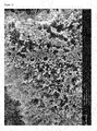
- the resulting etched particles contain pillars on their surface.
- the pillared particles may be fabricated by etching a particle having an initial size of 10 to 1000 microns.
- WO 2010/040985 disclosed a method of etching particles having a mean particle diameter in the range of 5-500 microns.
- US 7402829 discloses etching of a silicon substrate to form an array of silicon pillars extending from the silicon substrate.
- JP 2004281317 discloses growth of silicon nanowires by vapour deposition on a substrate for use in a lithium ion battery anode.
- US 2010/0285358 discloses silicon nanowires grown on a substrate for use in a lithium ion battery.
- US 2010/0297502 discloses silicon nanowires grown on carbon particles for use in a lithium ion battery.
- US 2008/0261112 discloses a network of entangled silicon nanowires connecting silicon particles for use in a lithium ion battery anode.
- WO 2011/117 436 discloses a carbon nanofibre including a plurality of crystalline whiskers extending from the surface of the carbon nanofibre.
- US 2008/166474 A1 relates to a manufacturing method of a conductive composite particle.
- JP 2007/335198 A relates to composite active material for a non-aqueous electrolyte secondary battery which contains active material particles capable of storing and releasing lithium, and fibers grown from surfaces of the active material particles.
- US 2007/099081 A1 relates to a non-aqueous electrolyte secondary battery including a positive electrode, a negative electrode, a separator interposed between the positive and negative electrodes, and a non-aqueous electrolyte.
- US 2009/004566 A1 relates to a negative electrode for non-aqueous electrolyte secondary batteries, with a mixture layer disposed on a current collector.
- US 2007/111102 A1 relates to a negative electrode for non-aqueous electrolyte secondary batteries with a mixture layer including a composite negative electrode active material which is composed of active material cores capable of charging and discharging at least lithium ions; carbon nanofibers; and catalyst elements.
- US 2010/112451 A1 relates to a negative electrode for a non-aqueous electrolytic secondary cell including a current collector and a plurality of active material bodies formed on a surface of the current collector at intervals.
- US 2010/112442 A1 relates to an electrode for an electrochemical device including a current collector and an active material layer formed on the current collector.
- GB 2464158 A relates to a process for etching silicon particles or granules to form pillars etched on to the surface of the particles.
- WO 2009/010757 A1 relates to a pre-charged material comprising silicon-comprising fibres with two or more of the fibres bonded together to create both a bonded felt anode structure.
- the invention is described herein with reference to lithium ion batteries and insertion and desorption of lithium ions, however it will be appreciated that the invention may be applicable to other metal ion batteries, for example sodium, potassium or magnesium ion batteries.
- Pillared particles as used herein mean particles comprising a particle core and a plurality of spaced-apart pillars extending therefrom. It is also to be understood that the pillar may be a wire, nanowire, rod, column, filament, thread, tube, cone or any other elongated structure extending from a particle core.
- the pillared particles comprise an electroactive material such as graphite, graphene, hard carbon, silicon, germanium, gallium, tin, aluminium, lead, indium, antimony, bismuth, oxides, nitrides or hydrides thereof, mixtures of these, mixtures or composite alloys containing these elements and chalcogenides and ceramics that are electrochemically active.
- One exemplary active material is silicon which can insert and release lithium ions. The insertion of lithium ions into silicon or another electroactive material can be described as lithiation and the removal of the lithium can be described as delithiation.
- At least some of the plurality of pillars in a pillared particle comprise an electroactive material.
- the composition of the core and the pillars may be identical or different.
- both the pillars and the core may comprise an electroactive material.
- the pillars may comprise an electroactive material.
- the core is formed from a non-electroactive material, the core preferably comprises an electronically conductive material.
- the active material may be a material that undergoes expansion during insertion of metal ions.
- the expansion may be due to structural changes of the anode caused by formation of an alloy of the active material and the metal ions, for example a Si-Li alloy formed by insertion of lithium ions by silicon.
- Tin is another example of an active material that expands on metal ion insertion.
- the volume of an active material upon metaliation, e.g. lithiation, to its maximum capacity may be at least 10% larger than its volume when substantially unmetallated.
- Exemplary materials that undergo an expansion of at least 10% include silicon and tin.
- the volume change of an active material upon metallation to its maximum capacitiy may be determined by computer modelling.
- the core may be a single doped or undoped material, for example p-doped, n-doped or undoped silicon, or may comprise more than one material.
- the core may comprise a first material at the core centre, which may or may not be electroactive, coated with an electroactive shell formed from a different second material.
- the core may comprise a carbon centre coated with a silicon shell.
- the coating may provide a core surface that partially or fully covers the material at the core centre.
- exemplary cores include hard carbon, graphite and graphene.
- the pillars may be the same material as or a different material to the material forming the core or core surface. In the case where the pillars and core are the same material, the pillars may be integral with the core surface.
- the plurality of pillars can be formed or fabricated on or attached to one or more surfaces of the particle core in a regular or irregular, ordered or disordered array or in a random scattered distribution.
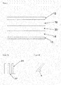
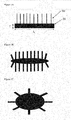
- pillars 205 may be attached at one end to a surface of the core 207 and extend outwards substantially perpendicular to that surface, or may extend at an angle ⁇ that is substantially less than 90 degrees as illustrated in Figure 2B .
- the angle ⁇ is 15-90 degrees, more preferably 40-90 degrees.
- Each pillar may carry one or more branches branching from the pillar, as shown in Figure 2C .
- the pillars may include one or more kinks or changes in direction, as shown in Figure 2D .
- a plurality of pillars may carry a lintel 209, as shown in Figure 2E .
- This lintel may be a porous structure that remains as an artefact of a starting material that has been etched to form a pillared particle, as described in more detail below.
- the pillars may be solid or porous or may comprise a solid core with a porous outer surface. The surface of the pillars may be smooth or rough.
- the pillars may have cross sections that are substantially circular or may form other substantially regular or irregular shapes.
- regular shaped cross-sections include squares, rectangles, diamonds, or stars or variations of such shapes where the sides of the pillars have convex or concave surfaces rather than straight sides.
- Irregular cross-sectional shapes may for example include shapes formed from a combination of the aforementioned substantially regular cross-sectionals shapes.
- the ends of the pillars may be spaced apart from the core surface.
- the ends of one or more pillars may be joined together. This joining of ends may be an artefact of a method of forming a pillared particle wherein the pillars have been formed in a solution and/or the pillars are washed after manufacture and dried such that capillary action and surface tension causes adjacent pillars to be adhered to each other.
- the width of the pillars may be substantially constant along at least part of the length of the pillars, or the width of the pillars may vary along their length.
- the pillar may be a tapered structure having a width W1 at its base that is larger than a width W2 away from the base, as illustrated in Figure 2F .
- the pillars are spaced apart on the particle.
- lithium ions are inserted into the electroactive pillars of the pillared particles during charging (also referred to as lithiation) and are released during discharge of the battery (also referred to as delithiation).
- lithiation electroactive pillars of the pillared particles during charging
- delithiation discharge of the battery
- the volume expansion of the electroactive pillars during charge is substantially in the radial to lateral direction, for example it results in a pillar of increased diameter whilst the height is relatively unchanged or undergoes a relatively small change. Spacing apart of the pillars provides space into which the electroactive pillars may expand and contract without impeding each other, which reduces mechanical stress experienced by the pillars, that could otherwise lead to cracking, detachment and / or disintegration of the pillars from repeated insertion and desorption of lithium.
- the amount of radial expansion of the pillars into the spaces between them during charging may depend on the type of electroactive material contained in the pillars, the maximum amount of metal ions inserted into the pillars, the porosity of the pillars, their shape and other factors.
- the thickness of a composite electrode layer (excluding any substrate or current collector) containing pillared particles as described herein expands by less than 150 %, preferably less than 125 %, when charged for the first time (i.e. with no pre-lithiation) to 3,000 mAh/g, the capacity being per gram of silicon in the anode.
- capacity may be per gram of active material.
- at least 5 weight %, at least 10 weight %, at least 20 weight % or at least 50 weight % of the active material is silicon active material (either in the form of a material consisting essentially of silicon or as a composite material having silicon at a surface thereof).
- Composite electrode as used herein means a composition of at least one active material and one or more further materials.
- the one or more further materials may be selected from, without limitation, binders, further active materials such as active carbon, and non-active conductive materials, for example carbon black.
- the composite electrode does not include cell components that the composite electrode may be in contact with when in use, such as a current collector or electrolyte,
- the composite electrode is a solid composition.
- the constituents of the solid composite electrode may be dispersed in one or more solvents to form a slurry that may be deposited on a surface, in particular a current collector layer, followed by evaporation of the one or more solvents to form a composite electrode layer.
- pillared particles make up at least 5 weight %, at least 10 weight %, at least 20weight %, at least 50 weight % or at least 60 weight % of a composite electrode.
- electrode thickness expansion upon charging to 2,000mAh/g is less than 60%, more preferably less than 50 %.
- electrode thickness expansion upon charging to 1,500mAh/g is less than 35%, more preferably less than 30 %.
- the change in thickness of an electrode in an electrochemical cell may be measured as the cell is charged (first cycle) with an El-Cell® Electrochemical Dilatometer ECD-nano placed inside a temperature controlled chamber at 20°C.
- the plurality of spaced pillars increases the surface area of electroactive material in the pillared particle that can be contacted with the electrolyte in the battery. This increases the rate at which the lithium (or other metal ion) can be inserted into the electroactive material and aids the uniform insertion density of metal ions throughout the active material. Additionally, in a cell with liquid electrolyte, by providing enough spacing between pillars so that when they are fully expanded, space remains around them such that the electrolyte can remain in contact with the pillar and core surface without being squeezed out, then lithium loss during cycling can be reduced.
- the liquid electrolyte will be forced away from the particle surface and no longer be in contact with the surface of the pillars or core. In this case, during discharge it may be more difficult for all the lithium to be released and some could remain trapped in the pillars and/or particle core. Also, if the rate of release of the metal ions varies throughout the particle, peak mechanical stresses on contraction could increase, leading to fracture of the electroactive material.
- the pillared particle may comprise at least some clusters of pillars as illustrated in Figure 2G .
- the pillared particle may comprise both clusters of pillars and pillars that are spaced apart.
- the spacing between pillars and / or clusters of pillars may be regular or irregular.
- the average distance between a pillar or pillar cluster and its adjacent pillars or pillar clusters is at least half the width of the pillar or pillar cluster. More preferably, the average distance between adjacent pillars or pillar clusters is at least the width of the pillar or pillar cluster.
- the width of a pillar is the pillar diameter in the case of a substantially cylindrical pillar.
- At least some of the pillars of a pillared particle are substantially perpendicular to one or more surfaces of the particle core; are unbranched and are substantially straight.
- An average pillar density of the pillars on the particle core may be in the range of about 0.1-80 %, optionally 10-80%. These ranges may provide a balance between a maximum number of electroactive pillars available for lithium insertion and a reduced number of pillars to avoid cracking of the pillared particles and to provide space to avoid electrolyte being forced away from the particle surfaces.
- Coverage can be defined by an average pillar density given by the formula A/(A+B) x 100% where A is the area of a surface of the particle core occupied by pillars and B is the area of the same surface that is unoccupied by pillars.
- the average pillar density can be calculated for a single surface, several surfaces or for all surfaces of the particle core.
- average pillar densities cited herein are calculated using the areas of surfaces occupied by pillars and individual surfaces of the particle core which do not contain any pillars are not included in the calculation.
- the average pillar density may be at least 0.1 %, preferably at least 1 %, more preferably at least 5% and most preferably at least 10%.
- the average pillar density is too high, preferably it is no more than 80%, more preferably it is no more than 60% and most preferably it is no more than 50%.
- the pillars may have a length in the range 0.2 or 1 microns up to about 4 microns, optionally up to about 2 microns.
- the pillar length is preferably less than 10 microns.
- the mean average thickness of the pillars may be at least 10 nm, optionally at least 20 nm and may be less than 1 ⁇ m.
- the mean average thickness may be a pillar diameter in the case of pillars with a substantially circular cross-section.
- the mean average pillar thickness relates to the smallest dimension of the cross-sectional shape.
- the mean average pillar thickness may be in the range of about 10-250 nm, optionally about 30-150 nm.
- the pillars may have a mean average pillar thickness of less than 80 nm.
- the mean average pillar thickness relates to the thickness of the individual pillars, and not to thicknesses of pillar clustersElongated structures or pillars with these diameters are ideally suited to withstand the expansion and contraction during charge and discharge without cracking, fracturing or disintegration.
- the high surface area to volume ratio of the pillars contributes to an excessively high lithium loss during operation of a cell from formation of a Surface Electrolyte Interphase (SEI) layer on the surface of the silicon and reduces the lifetime of a cell.
- SEI Surface Electrolyte Interphase
- the pillared particles may have at least one first dimension (as measured along a single direction across the pillared particle including the core and pillars in the size measurement) of less than 10 ⁇ m.
- Another dimension of the pillared particle, which may be orthogonal to the first dimension, can be longer but is preferably no more than 50 ⁇ m and is preferably no more than 25 ⁇ m, most preferably no more than 20 ⁇ m.
- the dimensions of the pillared particle may be measured by scanning electron microscopy or transmission electron microscopy. Mean average lengths and thicknesses may be obtained by measuring lengths and thicknesses for a plurality of pillars in a sample of a pillared particle material.
- a composition or powder comprising a plurality of pillared particles is used in forming the anode of a lithium ion battery.
- the plurality of pillared particles may have a size distribution.
- Substantially all of the pillared particles in the composition may have at least one dimension of 10 ⁇ m or less.
- the composition may include pillared particles that do not have at least one dimension of 10 ⁇ m or less.
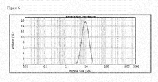
- a distribution of the particle sizes of a powder of starting material particles used to form pillared particles may be measured by laser diffraction, in which the particles being measured are typically assumed to be spherical, and in which particle size is expressed as a spherical equivalent volume diameter, for example using the MastersizerTM particle size analyzer available from Malvern Instruments Ltd.
- a spherical equivalent volume diameter is the diameter of a sphere with the same volume as that of the particle being measured. If all particles in the powder being measured have the same density then the spherical equivalent volume diameter is equal to the spherical equivalent mass diameter which is the diameter of a sphere that has the same mass as the mass of the particle being measured.
- the powder is typically dispersed in a medium with a refractive index that is different to the refractive index of the powder material.
- a suitable dispersant for powders of the present invention is water.
- a particle size analyser provides a spherical equivalent volume diameter distribution curve.
- Size distribution of particles in a powder measured in this way may be expressed as a diameter value Dn in which at least n % of the volume of the powder is formed from particles have a measured spherical equivalent volume diameter equal to or less than D.
- Preferred size distributions for a powder of starting material particles include one or more of the following:
- a pillared particle is formed by etching a starting material particle, for example as described with reference to Figure 3A below, or by growing pillars out of the starting material particle, then it will be appreciated that the particle core of the resultant pillared particle will be smaller than the starting material particle.
- the pillared particles are formed by growing or attaching pillars onto to the surface of a starting material particle, for example as described with reference to Figure 3B , then it will be appreciated that the particle core of the resultant pillared particle will be substantially the same size as the starting material particle.
- a starting material powder has a D10 value of ⁇ 10 ⁇ m then it will be appreciated that the particle core of pillared particles in a product powder formed using this starting material powder must also have a D10 value of ⁇ 10 ⁇ m, regardless of whether the pillared particles are formed by etching the particles of a starting material powder or by growth or attachment of pillars to the particles of a starting material powder.
- Dn size distribution values of pillared particles may be measured directly.
- the Dn values of a pillared particle may relate to a diameter of a sphere having a surface that encompasses the core and the pillars in the case of a pillared particle with rigid pillars, for example pillars formed by etching silicon of a starting material, or may relate substantially to a diameter of a sphere having a surface that encompasses the core only in the case of a pillared particle with flexible pillars.
- Preferred size distributions for pillared particle products are as described above for starting materials.
- An example measurement system for measuring the shapes and dimensions of particles in a powder of pillared particles or a powder of starting material particles using an optical microscope or SEM with digital image processing is MorphologiTM, also available from Malvern Instruments Ltd. In this technique a 2D projection of the area of each particle is captured and the particle dimensions and shape can be measured and classified.
- Pillared particles having at least one dimension of less than 10 ⁇ m may be more easily dispersed and incorporated into composite layers for high capacity anodes for reasons described herein. Additionally, if the particle core comprises an electroactive material which undergoes a large volume expansion and contraction during operation, a smaller core size may enable the particle core to insert and release more lithium (or other metal ion) without cracking or fracture of the core that may occur if larger pillared particles are used. A battery using these pillared particles as an active material may be charged to a higher capacity per unit mass or per unit volume than a battery comprising larger pillared particles, with little or no loss of stability.
- Pillared particles having at least one dimension of less than 10 ⁇ m or a powder of pillared particles where the D10 value of the particle cores is less than 10 ⁇ m may also enable the formation of an anode layer that is thinner than an anode formed from pillared particles that do not have at least one dimension of less than 10 ⁇ m.
- Thin anode coatings may be required to balance the cathode in a cell which typically has a much lower volumetric charge capacity than an anode comprising an electroactive material such as silicon.
- the thickness may be measured by observing cross sections of the anode coating produced using a microtome.
- the average thickness may also be calculated by measuring the mass of the anode coating per unit area if the densities and mass ratios of the components in the anode coating are known together with the coating porosity.
- nanowire core and pillars may have the dimensions described above, however nanowire pillars may have a mean length of no more than 10 times the mean average size of the core.
- the specific surface area measured using the BET (Brunauer, Emmett and Teller) technique may be less than 200 m 2 /g. Preferably it is less than 100 m 2 /g, more preferably it is less than 60 m 2 /g or less than 50 m 2 /g, most preferably it is less than 35 m 2 /g.
- the specific surface area measured using the BET technique may be more than 0.1 m 2 /g, preferably it is more than 1 m 2 /g and more preferably it is more than 5 m 2 /g.
- a higher specific surface area promotes the interaction of the metal ions with the active material, aiding a uniform insertion density of metal ions throughout the active material and enabling faster charge/discharge rates.
- the specific surface area may be dependent on, for example, the size and density of the pillars, the porosity or surface roughness of the pillars and the size of the particle core.
- the plurality of pillared particles in a powder used to form a composite are substantially discrete from one another.
- a "discrete pillared particle" as described herein means a pillared particle that is not joined or bound to another pillared particle.
- anode comprising a plurality of pillared particles, preferably during charging/discharging the relative movement from expansion and contraction of the electroactive material of each pillared particle is substantially independent of the movement from expansion and contraction of other nearby pillared particles.
- the pillars of different pillared particles are not substantially intertwined or entangled.
- Pillared particles with pillars having preferred dimensions described above may avoid intertwining due to their short length, and due to the pillars being relatively inflexible as a result of their short length.
- Use of a composition containing pillared particles that remain substantially discrete from one another and/or experience relative movement during charging/discharging substantially independent of each other may reduce or eliminate the phenomenon of "lift” or "heave” resulting from expansion of an anode formed from a single block or interconnected mass of active material.
- use of discrete particles in an anode may provide good contact between the pillared particles and the electrolyte. It may be more difficult for the electrolyte to wet the surfaces of active pillars in a tangled mass.
- the discrete pillared particles of a powder or composition may contain discrete pillared particles that may come into physical contact with each other and / or with other components, for example a binder or electrolyte, and that the discrete pillared particles may be contained within a matrix defined by a binder or other matrix material.
- the pillared particles may be joined to each other after formation of a coating or composite, for example, sintering of a layer of pillared particles may be performed to provide a self supporting sintered composite.
- the PMF is the mass of silicon pillars divided by the mass of the whole particle.
- the PMF may be determined by various methods. If the pillars are grown on, deposited on or attached to the particle cores then the PMF may be calculated by measuring the mass of a plurality of particle cores before growth or attachment and the mass of the pillared particles after growth or attachment and subtracting one from the other to calculate the mass of pillars in the above equation.
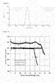
- the PMF may be determined by an oxidation technique. This involves firstly measuring the mass of a quantity of pillared particles and then measuring a change in mass over time of the quantity of pillared particles during oxidation, for example by heating pillared particles in an oxygen-containing atmosphere, e.g. by heating to 1040°C in air.
- the pillars are fully oxidised first, and oxidise at a relatively rapid rate (shown as a relatively rapid increase in the rate of mass increase). Oxidation of the pillars is deemed to be complete when the rate of mass increase is observed to reduce and become linear with time.
- the rate of mass increase is due only by steady oxidation of the silicon into the particle core.
- the observed increase in mass up to this point is mostly due to oxidation of the pillars and using the difference in density between silicon and silicon oxide, the mass of the pillars before oxidation and hence the PMF can be determined.
- the particles cores of the smaller pillared particles may additionally be oxidised and a correction factor may need to be applied to take account of the core oxidation.
- the correction factor can be estimated by doing the measurement on a sample comprising the particle cores with the pillars absent or removed. This method is particularly suitable for pillared particles having silicon pillars.
- the PMF may also be determined by measuring the mass of a quantity of pillared particles, removing the pillars from the particle cores, for example by mechanical agitation (such as ultrasonication), scraping or chemical etching, separating the detached pillars from the particle cores and measuring either the mass of the quantity of particle cores and / or the mass of the detached pillars. This method is preferred because it may be applied to pillared particles of any material.
- the PMF may be affected by, for example, the average length of pillars, their porosity and the percentage coverage of the particle core by the pillars (the pillar density).
- the PMF is preferably greater than or equal to 5 %, more preferably at least 10 %, most preferably at least 20%.
- the PMF is preferably no more than 95%, more preferably no more than 80%. Most preferably the PMF is 20-60%, especially 25-50%.
- a higher PMF value means that the high capacity active pillars make a larger contribution to the active mass of the electrode and a higher overall capacity per unit mass can be obtained.
- the PMF value is too high then the cost of manufacturing the pillared particles may increase so that the cost to performance ratio of the electrode materials becomes uncompetitive, the pillars may become too densely packed and/or the mechanical/electronic integrity of the pillar to core connection may be weakened.
- the Pillar Volume Fraction may be measured instead of PMF, although it will be appreciated that PVF is applicable to the cases in which the core and pillar densities are substantially the same (in which case the PVF value will be substantially the same as the PMF value) and the case in which the core and pillar densities are significantly different.
- PVF may be derived from PMF measurements using a ratio of densities of the core material and the pillar material.
- the volumes of the pillars and the pillared particles are the volumes which do not include volumes of open pores. Closed pores or voids that are completely enclosed within the bulk of a core or pillar are included in the volumes. Accordingly, if the pillars or cores are porous, the porosity may need to be measured.
- Example techniques that may be used to measure porosity include mercury porosimetry and Barret-Joyner-Halenda (BJH) analysis.
- Volumes of pillars and of pillared particles may be measured using a MasterSizer system or other similar laser diffractometry device, as described above.
- the volume of a pillared particle is measured; pillars are detached from the pillared particles by a mechanical process such as ultrasonication; and the volume of the pillars is measured.
- the porosity is determined and the measured volume is adjusted. For example, if porosity is 5 % then measured volume is adjusted by 0.95 to give a solid volume.
- the volumes may also be measured using 2D digital imaging systems such as Morphologi, as described above, though they typically are unable to resolve particles with a dimension below 0.5 ⁇ m.
- the PVF may be affected by, for example, the average length of pillars and the percentage coverage of the particle core by the pillars (the pillar density) and the density of the particle core and pillar materials.
- the PVF is preferably greater than or equal to 5 %, more preferably at least 10 %, most preferably at least 20%.
- the PVF is preferably no more than 95%, more preferably no more than 80%. Most preferably the PVF is 20-60%, especially 25-50%.
- a higher PVF value means that the high capacity active pillars make a larger contribution to the active mass of the electrode and a higher overall capacity per unit volume can be obtained.
- the cost of manufacturing the pillared particles may increase so that the cost to performance ratio of the electrode materials becomes uncompetitive, the pillars may become too densely packed and/or the mechanical/electronic integrity of the pillar to core connection may be weakened.
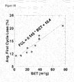
- the BET / PMF ratio of a powder of the pillared particles is less than 3, less than 2, less than 1.5 or less than 1, wherein BET is the specific surface area of the pillared particles in m 2 /g and PMF is expressed a percentage as per the above equation.
- the BET / PMF ratio is greater than 0.1.
- the BET / PMF ratio is an average value for pillared particles in a pillared particle powder.
- the relationship between PMF and BET is not linear (and it can for example be affected by the surface roughness or porosity of the pillars and core).
- the present inventors have found that the above BET / PMF ratio may exclude materials in which one of PMF and BET is too high or too low, leading to the disadvantages of a PMF or BET value that too low or that is is too high, as described above.
- the pillared particles preferably have a specific reversible charge capacity of at least 500mAh per gram of pillared particle mass.
- the reversible charge capacity is the charge provided by discharge of the pillared particles in the anode of the cell after a full charge cycle. More preferably the pillared particles have a reversible charge capacity of at least 800mAh/g, most preferably at least 1,000mAh/g and especially at least 1,800mAh/g.
- these reversible charge capacities are sustained for at least 50 charge/discharge cycles, more preferably at least 100 charge/discharge cycles, most preferably at least 200 charge/discharge cycles and especially at least 300 charge/discharge cycles,
- the starting material for the particle core is preferably in particulate form, for example a powder, and the particles of the starting material may have any shape.
- the starting material particles may be cuboid, cuboidal, substantially spherical or spheroid or flake-like in shape.
- the particle surfaces may be smooth, rough or angular and the particles may be multi-faceted or have a single continuously curved surface.
- the particles may be porous or non-porous.
- a cuboid, multifaceted, flake -like, substantially spherical or spheroid starting material may be obtained by grinding a precursor material, for example doped or undoped silicon as described below, and then sieving or classifying the ground precursor material.
- Exemplary grinding methods include power grinding, jet milling or ball milling.
- different milling processes can produce particles of different size, shape and surface smoothness.
- Flake-like particles may also be made by breaking up / grinding flat sheets of the precursor material.
- the starting materials may alternatively be made by various deposition, thermal plasma or laser ablation techniques by depositing a film or particulate layer onto a substrate and by removing the film or particulate layer from the substrate and grinding it into smaller particles as necessary.
- Samples or powders of the starting material particles may have D90, D50 and / or D10 values as described above.
- a pillared particle is formed by etching a granular starting material having at least one dimension of less than 10 microns
- at least one dimension of the pillared particles produced will likewise be no more than 10 microns.
- one or more dimensions of the pillared particle may be less than the corresponding dimension of the starting material.
- the starting material comprises an electroactive material as described above.
- it comprises an electroactive material that undergoes a volume expansion of at least 10 % upon complete insertion by the material of the metal ion of a metal ion battery.
- the starting material may comprise particles of substantially the same size.
- the starting material may have a distribution of particle sizes.
- sieves and/or classifiers may be used to remove some or all starting materials having maximum or minimum sizes outside desired size limits.
- the starting material may be undoped silicon or doped silicon of either the p- or n-type or a mixture, such as silicon doped with germanium, phosphorous, aluminium, silver, boron and/or zinc. It is preferred that the silicon has some doping since it improves the conductivity of the silicon during the etching process as compared to undoped silicon.
- the starting material is optionally p-doped silicon having 10 19 to 10 20 carriers/cc.
- Silicon granules used to form the pillared particles may have a silicon-purity of 90.00% or over by mass, for example 95.0% to 99.99%, optionally 98% to 99.98%.
- the starting material may be relatively high purity silicon wafers used in the semiconductor industry formed into granules.
- the granules may be relatively low purity metallurgical grade silicon, which is available commercially and which may have a silicon purity of at least 98%; metallurgical grade silicon is particularly suitable because of the relatively low cost and the relatively high density of defects (compared to silicon wafers used in the semiconductor industry). This leads to a low resistance and hence high conductivity, which is advantageous when the pillar particles or fibres are used as anode material in rechargeable cells.
- Impurities present in metallurgical grade silicon may include Iron, Aluminium, Nickel, Boron, Calcium, Copper, Titanium, and Vanadium, oxygen, carbon, manganese and phosphorus.
- Certain impurities such as Al, C, Cu, P and B can further improve the conductivity of the starting material by providing doping elements.
- Such silicon may be ground and graded as discussed above.
- An example of such silicon is "SilgrainTM” from Elkem of Norway, which can be ground and sieved (if necessary) to produce silicon granules, that may be cuboidal and / or spheroidal.
- the granules used for etching may be crystalline, for example mono- or poly-crystalline with a crystallite size equal to or greater than the required pillar height.
- the polycrystalline granules may comprise any number of crystals, for example two or more.
- the starting material may comprise an electroactive material as described above.
- the starting material in this case may also comprise metal or carbon based particles.
- Carbon based starting materials may comprise soft carbon, hard carbon, natural and synthetic graphite, graphite oxide, fluorinated graphite, fluorine-intercalated graphite, graphene, carbon nanotubes (CNT), carbon fibres and multi-walled carbon nanotubes (MWCNT).
- Graphene based starting materials may comprise particles comprising a plurality of graphene nanosheets (GNS) and/or oxidised graphene nanosheets (ox-GNS) or nano Graphene Platelets (NGP).
- Methods of making graphene particles include exfoliation techniques (physical, chemical or mechanical), unzipping of MWCNT or CNT, epitaxial growth by CVD and the reduction of sugars.
- Graphene based particles used as stalling materials for the core of pillared particles preferably have an initial reversible charge capacity (on the first full charge cycle) of at least 400 mAh per gram of graphene particle, more preferably at least 500mAh/g, most preferably at least 800mAh/g and especially at least 1,000mAh/g.
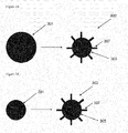
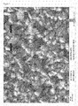
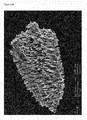
- Figure 3A illustrates a first method of forming pillared particles wherein a starting material is etched to form a pillared particle wherein a starting material 301 is exposed to an etching formulation for selective etching at the surface of the starting material to produce a pillared particle 303 having a core 305 and pillars 307.
- the volume of the particle core of the pillared particle formed by this method is smaller than the volume of the starting material, and the surface of the core is integral with the pillars.
- the size of the pillared particle may be the same as or less than the size of the starting material.
- a suitable process for etching a material having silicon at its surface is metal-assisted chemical etching (alternatively called galvanic exchange etching or galvanic etching) which comprises treatment of the starting material with hydrogen fluoride, a source of silver ions which electrolessly deposit onto the surface of the silicon and an oxidant, for example a source of nitrate ions. More detail on suitable etching processes can be found in, for example, Huang et al., Adv. Mater. 23, pp 285-308 (2011 ).
- the etching process may comprise two steps, including a nucleation step in which silver nanoclusters are formed on the silicon surface of the starting material and an etching step.
- a nucleation step in which silver nanoclusters are formed on the silicon surface of the starting material
- an etching step The presence of an ion that may be reduced is required for the etching step.
- Exemplary cations suitable for this purpose include nitrates of silver, iron (III), alkali metals and ammonium.
- the formation of pillars is thought to be as a result of etching selectively taking place in the areas underlying the silver nanoclusters. It is also known that metal-assisted etching of silicon can produce pillars with porous walls (for example as described in C. Chartier et al., Electrochimica Acta 2008, 53, p5509 ), the level of porosity being dependent on dopant levels and the ratios of the components in the etching solution.
- the nucleation and etching steps may take place in a single solution or may take place in two separate solutions.
- Silver may be recovered from the reaction mixture for re-use.
- Exemplary etching processes suitable for forming pillared particles are disclosed in WO 2009/010758 and in WO 2010/040985 .
- etching processes that may be employed include reactive ion etching, and other chemical or electrochemical etching techniques, optionally using lithography to define the pillar array.
- the pillared particle comprises a first material at its core centre with a shell formed from a second material, for example carbon coated with silicon as described above, then this particle may be formed by etching of silicon-coated carbon to a depth of less than the thickness of the silicon shell in order to form a pillared particle with a composite carbon / silicon core.
- the pillars may also be formed on or attached to a particle core using methods such as growing, adhering or fusing pillars onto a core or growing pillars out of a core.
- Figure 3B illustrates a second method of forming pillared particles wherein pillars 307, for example nanowires, are grown on or attached to a starting material 301 such as a silicon or carbon (e.g. graphite or graphene) starting material.
- the volume of the particle core 305 of the resultant pillared particle 303 may be substantially the same as the volume of the starting material 301.
- the surface of the starting material may provide the surface of the particle core 305 from which the pillars 307 extend.
- Exemplary methods for growing pillars include chemical vapour deposition (CVD) and fluidised bed reactors utilising the vapour-liquid-solid (VLS) method.
- the VLS method comprises the steps of forming a liquid alloy droplet on the starling material surface where a wire is to be grown followed by introduction in vapour form of the substance to form a pillar, which diffuses into the liquid. Supersaturation and nucleation at the liquid/solid interface leads to axial crystal growth.
- the catalyst material used to form the liquid alloy droplet may for example include Au, Ni or Sn.
- Nanowires may be grown on one or more surfaces of a starting material.
- Pillars may also be produced on the surface of the starting material using thermal plasma or laser ablation techniques.
- the pillars may also be formed by nanowire growth out of the starting material using methods such as a solid-liquid-solid growth technique.
- silicon or silicon-based starting material granules are coated with catalyst particles (e.g. Ni) and heated so that a liquid alloy droplet forms on the surface whilst a vapour is introduced containing another element.
- the vapour induces condensation of a product containing the starting material and the other element from the vapour, producing growth of a nanowire out of the starting material.
- the process is stopped before all of the starting material is subsumed into nanowires to produce a pillared particle. In this method the core of the pillared particle will be smaller than the starting material.
- Silicon pillars grown on or out of starting materials may be grown as undoped silicon or they may be doped by introducing a dopant during the nanowire growth or during a post-growth processing step.
- Particle cores illustrated in Figures 3 and 4 are substantially spherical, however the particle core may have any shape, including substantially spherical, spheroidal (oblate and prolate), and irregular or regular multifaceted shapes (including substantially cube and cuboidal shapes).
- the particle core surfaces from which the pillars extend may be smooth, rough or angular and may be multi-faceted or have a single continuously curved surface.
- the particle core may be porous or non-porous.
- a cuboidal core may be in the form of a flake, having a thickness that is substantially smaller than its length or width such that the core has only two major surfaces.
- the aspect ratio of a pillared particle core having dimensions of length L, width W and thickness T is a ratio of the length L to thickness T (L: T) or width W to thickness T (W : T) of the core, wherein the thickness T is taken to be the smallest of the 3 dimensions of the particle core.
- the aspect ratio is 1:1 in the case of a perfectly spherical core.
- Prolate or oblate spheroid, cuboidal or irregular shaped cores preferably have an aspect ratio of at least 1.2:1, more preferably at least 1.5:1 and most preferably at least 2:1.
- Flake like cores may have an aspect ratio of at least 3:1.
- pillars may be provided on one or both hemispheres of the core.
- pillars may be provided on one or more (including all) surfaces of the core.
- the pillars may be provided on only one of the major surfaces of the flake or on both major surfaces.
- the core material may be selected to be a relatively high conductivity material, for example a material with higher conductivity than the pillars, and at least one surface of the core material may remain uncovered with pillars.
- the at least one exposed surface of the conductive core material may provide higher conductivity of a composite anode layer comprising the pillared particles as compared to a particle in which all surfaces are covered with pillars.
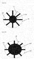
- Figure 5A illustrates an embodiment in which the core 505 is formed from a relatively high conductivity material, for example a graphite particle, graphene sheet or a graphene particle comprising more than one graphene sheet, and silicon nanowires 507 are grown on one surface of the core.
- the core can comprise a doped silicon material.
- the aspect ratio that is the ratio of length L to thickness T, is greater than 3:1 in this example.
- Figure 5B illustrates an embodiment in which pillars are provided on opposing surfaces of a core such as a graphene core or silicon flake.
- Figure 5C illustrates an embodiment in which the core is an oblate spheroid.
- Figure 5D illustrates an embodiment in which the core is multifaceted and has an irregular shape. Pillars are provided on some facets only.
- Figure 5E illustrates an embodiment in which the pillars are flexible.
- the flexibility of a pillar may depend on one or more of pillar length, pillar diameter, the pillar material and the way in which the pillar is made.
- the core is a multifaceted core having an irregular shape, although it will be appreciated that a core carrying flexible pillars may have any particle core shape as described herein.
- a particle core with higher aspect ratio can increase the number of connections of the pillared particle with other elements in the composite electrode layer and/or the current collector and thereby improve the electrode conductivity. This connectivity may be further increased if one or more surfaces or part of one surface of the core have no pillars on them.
- a particle core with a high aspect ratio can enable a higher PMF or PVF value to be obtained whilst providing a pillared particle with at least one dimension that is less than 10 microns.
- a higher aspect ratio core can increase the manufacturing yield of the pillared particle in terms of the ratio of mass of the pillared particles produced relative to the mass of the starting material, compared to the yield with spheroidal starting materials.
- an increase in yield relates to a decrease in the PMF or PVF value but this potential reduction in the maximum lithiation capacity of the pillared particle can be offset if the particle core is made thin enough so that it can be lithiated to a higher degree without pulverisation.
- the particle core has a smallest dimension of at least 0.2 ⁇ m, more preferably at least 0.5 ⁇ m.
- the particle core comprises an electroactive material, for example the core is silicon-comprising, then the core preferably has at least one dimension less than 6 ⁇ m, more preferably less than 5 ⁇ m, most preferably less than 4 ⁇ m and especially less than 3 ⁇ m.
- a smaller core dimension enables higher lithiation of the active material in the core without risk of cracking the core, increasing the potential capacity of the pillared particle. It can also increase the attainable charge rate for high capacity anodes as the diffusion length for metal ions is reduced.
- the pillared particles have a low resistivity - this will increase the conductivity of composites containing them and improve the cycling performance and charge rate of a metal ion battery.
- Some high capacity electroactive materials such as silicon have a relatively high resistivity compared to that of lower capacity electroactive materials such as graphite or non active metallic materials such as copper, however with good electrode design, pillared particles with medium range resistivity values can be used.
- the pillared particle has a resistivity of no more than 1000 ⁇ cm, more preferably no more than 100 ⁇ cm, most preferably no more than 10 ⁇ cm, especially no more than 1 ⁇ cm.
- the pillared particle may have a resistivity of at least 1 x 10 -5 ⁇ cm, for example at least 1 x 10 -4 ⁇ cm or at least 5 x 10 -4 ⁇ cm.
- the pillars preferably have a resistivity of no more than 100 ⁇ cm, more preferably no more than 10 ⁇ cm, especially no more than 1 ⁇ cm.
- the pillars may have a resistivity of at least 1 x 10 -4 ⁇ cm, for example at least 1 x 10 -3 ⁇ cm or at least 1 x 10 -2 ⁇ cm.
- the particle core comprises electroactive material
- it preferably has a resistivity of no more than 100 ⁇ cm, more preferably no more than 10 ⁇ cm, especially no more than 1 ⁇ cm.
- a particle core comprising electroactive material may have a resistivity of at least 1 x 10 -4 ⁇ cm, for example at least 1 x 10 -3 ⁇ cm or at least 1 x 10 -2 ⁇ cm.
- the particle core does not comprise an electroactive material, it preferably has a resistivity of no more than 10 ⁇ cm, more preferably no more than 1 ⁇ cm, most preferably no more than 0.1 ⁇ cm and especially no more than 0.01 ⁇ cm, When the particle core is not electroactive it is particularly preferable that it has a resistivity of less than 5 x 10 -3 ⁇ cm
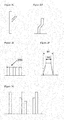
- Figures 4A and 4B illustrate etching of a starting material to produce pillared particles.
- both the starting material 401 and the pillared particle core 405 are substantially spherical for ease of representation, however it will be understood that both the starting material and the pillared particle core may be of any shape.
- a starting material is etched to produce pillars 407 of length L1.
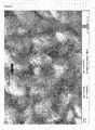
- a starting material 401 is etched to produce shorter pillars 407 of length L2.
- the longer pillars of Figure 4A result in a pillared particle with a higher PMF and may provide for higher capacity per unit mass of active material to insert lithium than the shorter pillars of Figure 4B .
- the longer pillars of Figure 4A also provide a pillared particle with a larger specific surface area promoting contact of the electrolyte with the surface of the active material.
- the yield in terms of the ratio of mass of the pillared particles produced relative to the mass of the starting material will reduce as pillar length increases and may increase the cost of manufacturing electrode material
- the higher specific surface area of the pillared particle in Figure 4A may increase the amount of SEI layer formed in the electrode and may reduce the potential number of charge/discharge cycles that may be achieved.
- Providing pillared particles in which all dimensions are less than 10 microns may limit the maximum length of the pillars, however it is easier to form a composite electrode layer with a uniform thickness and a uniform distribution of pillared particles within the composite and to achieve a suitable density of the composite.
- a cell comprises a composite anode layer where a significant proportion of the active material is pillared particles (for example where at least 20 wt% of the active material is pillared particles) then balancing the capacity of the anode to the cathode in the cell may mean that the anode layer must be made thin, for example less than 30 ⁇ m thick.
- using pillared particles with at least one dimension less than 10 ⁇ m makes it easier to manufacture such thin layers with minimal variations in thickness.
- the ability to stably lithiate and delithiate a higher volume fraction of the smaller core of a small pillared particle may at least partially offset any reduction in capacity from shorter pillars.
- the average pillar length is preferably less than 5 microns, and may be in the range of 0.5-5 microns. However, if pillars are provided on only one of two opposing surfaces of a pillared particle then the average length may be longer, optionally less than 8 microns.
- the pillared particles described herein may be used as an active component of an electrode, preferably an anode or negative electrode, of a metal ion battery, preferably a lithium ion battery, having a structure as described with reference to Figure 1 .
- the pillars of the pillared particles may be detached to form a fibre that may likewise be used as a component of the anode of a lithium ion battery.
- the silicon fibres can be made by detaching the pillars from a pillared particle by one or more of scraping, agitating (especially by ultrasonic vibration) or chemical etching,
- a powder consisting essentially of the pillared particles may be provided, for example by any of the aforementioned processes. This powder may be mixed with other materials to form a composition suitable for use in forming the anode of a metal ion battery,
- compositions may include, without limitation, one or more of:
- the pillared particles may be used as the only active component of an anode, or may be used in combination with one or more other active components.
- the pillars of the pillared particles, and optionally the core are silicon, and the pillared particles are mixed with an active component formed from another material, for example graphite.
- An active graphite electrode may provide for a larger number of charge / discharge cycles without significant loss of capacity than an active silicon electrode, whereas a silicon electrode may provide for a higher capacity than a graphite electrode. Accordingly, a composition of a silicon-containing active material and a graphite active material may provide a lithium ion battery with the advantages of both high capacity and a large number of charge / discharge cycles.
- the use of pillared particles having at least one dimension less than 10 microns as described herein may be particularly advantageous in view of the greater capacity per volume or capacity per mass of such pillared particles as compared to larger pillared particles.
- a composition of graphite and a pillared particle comprising silicon may contain at least 5 weight % silicon, optionally at least 10 weight % silicon.
- a slurry containing the pillared particles in a solvent or solvent mixture may be deposited on an anode current collector formed from a conductive material, for example copper, followed by evaporation of the solvent(s).
- the slurry may contain a binder material and any other active materials to be used in the anode.
- binders include polymer binders such as polyacrylic acid (PAA), polyimide (PI), polyvinylalcohol (PVA) and polyvinylidene fluoride (PVDF), carboxymethylcellulose (CMC), (styrene-butadiene rubber (SBR) and metal ion salts thereof.
- a binder may also be a mixture of one or more polymers.
- Other materials that may be provided in the slurry include, without limitation, a viscosity adjuster, a filler, a cross-linking accelerator, a coupling agent and an adhesive accelerator.
- the component materials of the composite are suitably mixed together to form a homogeneous electrode composition that can be applied as a coating to a substrate or current collector to form a composite electrode layer adhered to said substrate of current collector.
- the composite electrode containing pillared particles may be porous to enable wetting of the active material by the electrolyte and to provide space to accommodate the expansion of active material during charge and prevent swelling of the electrode.
- the composite porosity may be defined as the total volume of pores, voids and empty spaces in the composite electrode in the uncharged state before any electrolyte is added to or contacted with the composite electrode, as a percentage of the total volume occupied by the composite material layer. It may be measured by, for example, mercury or nitrogen porosimetry.
- porosity is too high the mechanical integrity of the electrode may be affected and the charge capacity per unit volume (or mass) may be reduced
- a suitable level of porosity may depend on several factors including but not limited to composition, particle size, type of electrolyte / binder, layer thickness, cell type /design. At least some of the porosity will be provided by the void space between the pillars of the pillared particles.
- the porosity of the composite in the uncharged state is at least 10%, more preferably at least 20% and especially 30%.
- the porosity of the composite in the uncharged state is no more than 80%, more preferably no more than 60%.
- the porosity of the composite material is at least twice the ratio of the volume of the pillars of the pillared particles contained in the composite as a percentage of the total volume occupied by the composite material layer.
- the minimum pore volume is preferably 2 x the volume of the pillars.
- the maximum pore volume is 4 x the volume of the pillars + 1.1 x core volume.
- the porosity may be higher to further accommodate the expansion of the particle cores when they are lithiated.
- a suitable minimum composite porosity may be given by the sum of the volume of pillars multiplied by two and the volume of particle cores multiplied by 1.2, as a percentage of the total volume of the composite material layer.
- the appropriate minimum or maximum composite porosity is calculated from the aforementioned pore volumes by dividing the pore volumes by the total volume of the composite layer x 100%.
- Porosity is of the composite as a whole, which may include, without limitation, porosity provided by space between pillars, and space between particles of the composite electrode.
- Porosity used in a battery is a balance between high porosity to enable good surface contact between the electrolyte of the electroactive materials and to provide a buffer space to minimise overall expansion of the electrode during charging and a porosity that is low enough to provide good cohesion of the composite electrode and good adhesion to the anode current collector, together with an appropriate density of electroactive material per unit volume of electrode which affects the overall volumetric capacity/rating of the battery. Pillared particles as described herein provide an effective way of introducing porosity into a composite electrode, with an optimal level of porosity which is particularly beneficial for silicon-containing anodes due to the high specific capacity of silicon and associated high degree of expansion of silicon upon charging.
- the anode composite material layer may be any suitable thickness.
- the pillared particles of this invention are especially advantageous for making composite layers with an average thickness of less than 60 ⁇ m or even less than 30 ⁇ m (not including the thickness of the current collector).
- the composite layer thickness is at least 10 ⁇ m thick, more preferably at least 12 ⁇ m thick.
- the anode may comprise a composite layer deposited/attached on one or both sides of the current collector.
- cathode materials examples include LiCoO 2 , LiCo 0.99 Al 0.01 O 2 , LiNiO 2 , LiMnO 2 , LiCo 0.5 Ni 0.5 O 2 , LiCo 0.7 Ni 0.3 O 2 , LiCo 0.8 Ni 0.2 O 2 , LiCo 0.82 Ni 0.18 O 2 , LiCo 0.8 Ni 0.15 Al 0.05 O 2 , LiNi 0.4 Co 0.3 Mn 0.3 O 2 and LiNi 0.33 Co 0.33 N4n 0 .
- the cathode current collector is generally of a thickness of between 3 to 500 ⁇ m. Examples of materials that can be used as the cathode current collector include aluminium, stainless steel, nickel, titanium and sintered carbon.
- the electrolyte is suitably a non-aqueous electrolyte containing a lithium salt and may include, without limitation, non-aqueous electrolytic solutions, solid electrolytes and inorganic solid electrolytes.
- non-aqueous electrolyte solutions that can be used include non-protic organic solvents such as N-methylpyrrolidone, propylene carbonate, ethylene carbonate, fluoroethylene carbonate, di fluoroethylene carbonate, vinyl carbonate, vinylene carbonate, vinylethylene carbonate, butylene carbonate, dimethyl carbonate, diethyl carbonate, gamma butyro lactone, 1,2-dimethoxy ethane, 2-methyl tetrahydrofuran, dimethylsulphoxide, 1,3-dioxolane, formamide, dimethylformamide, acetonitrile, nitromethane, methylformate, methyl acetate, phosphoric acid trimester, trimethoxy methane, sulpholane, methyl
- organic solid electrolytes examples include polyethylene derivatives polyethyleneoxide derivatives, polypropylene oxide derivatives, phosphoric acid ester polymers, polyester sulphide, polyvinyl alcohols, polyvinylidine fluoride and polymers containing ionic dissociation groups.
- inorganic solid electrolytes examples include nitrides, halides and sulphides of lithium salts such as Li 5 NI 2 , Li 3 N, LiI, LiSiO 4 , Li 2 SiS 3 , Li 4 SiO 4 , LiOH and Li 3 PO 4 .
- the lithium salt (or mixture of salts) is suitably soluble in the chosen solvent or mixture of solvents.
- suitable lithium salts include LiCl, LiBr, LiI, LiClO 4 , LiBF 4 , LiB 10 C 20 , LiPF 6 , LiCF 3 SO 3, LiAsF 6 , LiSbF 6 , LiAlCl 4 , CH 3 SO 3 Li, Lithium bis(oxalto)borate (LiBOB) and CF 3 SO 3 Li.
- the battery is provided with a separator interposed between the anode and the cathode.
- the separator is typically formed of an insulating material having high ion permeability and high mechanical strength.
- the separator typically has a pore diameter of between 0.01 and 100 ⁇ m and a thickness of between 5 and 300 ⁇ m. Examples of suitable electrode separators include a micro-porous polyethylene film.
- pillared particles as described herein may be used in solar cells (including solar capacitors), capacitors, filters, fuel cells, detectors and sensors.
- Three powder samples of pillared particles were prepared by etching silicon granule starting materials with the D10, D50 and D90 size distribution values listed in Table 1. The particle sizes were measured using a MasterSizerTM 2000 version 5.60 with a water dispersant. Etching to produce silicon pillared particles was performed as described in WO 2010/040985 . Table 1 lists the BET, PMF and average pillar lengths for each pillared particle sample. Average pillar diameters for all three samples were in the range of 50-150nm. A mean average pillar length may be determined from SEM measurements of a plurality of pillar lengths. Typical pillar densities were 25-40%.
- Figure 6 illustrates a size distribution of the spherical equivalent volume diameters of the starting material particles for Powder C.
- the D50 value is 9.9 microns showing that 50% of the volume (and 50% of the mass) of the starting material particles have a spherical equivalent volume diameter of less than or equal to 9.9 microns.
- Figure 7 is a SEM photograph of pillared particles of Powder C (Example 2). It can be seen that the powder includes particles having at least one dimension that is less than 10 microns, as well as particles having a dimension of 10 microns or more, although the size distribution of the particles is such that at least 50% of the particles have a dimension of less than 10 microns.
- Figure 8 is a further SEM photograph of the pillared particles or Powder C (Example 2).
- the pillared particles include pillars having a length of about 2 microns.
- the Dn size distribution of the starting material and the product may be substantially the same.
- Metallurgical grade silicon starting powder available from Elkem (Silgrain HQ) was etched using metal assisted etching as described above under "Pillared Particle Formation".
- the starting material had D10, D50 and D90 values of 2.8, 4.6 and 7.9 microns respectively.
- the product referred to as Powder Product D, had D10, D50 and D90 values of 2.8, 4.6 and 7.6 microns respectively both measured using a Malvern Mastersizer, indicating that the volume distribution of particles with effective spherical diameters of a sphere encompassing the core and pillars of the pillared particles may remain substantially the same as the volume distribution of effective spherical diameters of a sphere encompassing the starting material.
- the volume distribution of the pillared particle product is illustrated in Figure 9 .
- the desired amount of pillared particle composition was added to a conductive carbon mixture that had been bead milled in deionised water. The resulting mixture was then processed using an IKA overhead stirrer at 1200 rpm for around 3 hours. To this mixture, the desired amount of binder in solvent or water was added. The overall mix was finally processed using a ThinkyTM mixer for around 15 minutes. Viscosity of the mix was typically 500-3000 mPas at 20 rpm.
- Product Powder A comprised pillared particles produced from a starting material of silicon particles with average dimensions of 15-25 ⁇ m and a D10 value of 14.7 ⁇ m. Pillared particles produced from this starting material had a pillar volume fraction of 30-35%, a BET value of 45 m 2 /g, pillars of average length 2-3 ⁇ m and diameters of 50-150nm. Composite anode D was made with 70% by mass of these pillared particles, 15% Na-PAA binder and 15% conductive carbon by mass.
- Product Powder B (Example 1) comprised pillared particles produced from a starting material of silicon particles including particles with at least one dimension less than 10 ⁇ m and a D10 value of 8.2 ⁇ m. Pillared particles produced from this starting material had a pillar volume fraction of 34%, a BET value of 32.9 m 2 /g, pillars of average length 1.8-2 ⁇ m and diameters of 50-150nm. Composite anode E was made with 70% by mass of these pillared particles, 15% Na-PAA binder and 15% conductive carbon by mass.
- Product Powder C (Example 2) comprised pillared particles produced from a starting material of silicon particles including particles with at least one dimension less than 10 ⁇ m and a D10 value of 6 ⁇ m. Pillared particles produced from this starting material had a pillar volume fraction of 24%, a BET value of 4.5 m 2 /g, pillars of average length 1.6-1.8 ⁇ m and diameters of 50-150nm. Composite anode F was made with 70% by mass of these pillared particles, 15% Na-PAA binder and 15% conductive carbon by mass.
- the composite anode mixture was applied to a 10 ⁇ m thick copper foil (current collector) using a doctor-blade technique to give a 20-35pm thick coating layer (coat weight of 14-15gsm). The resulting electrode was then allowed to dry.
- the cathode material used in the test cells was a commercially available lithium mixed metal oxide (MMO) electrode material (e.g. Li 1+x Ni 0.8 Co 0.15 Al 0.05 O 2 ) on a stainless steel current collector.
- MMO lithium mixed metal oxide
- the electrolyte used in all cells was lithium hexafluorophosphate, dissolved in a mixture of ethylene carbonate and ethyl methyl carbonate (in the ratio 3:7 by volume) and containing 15wt% fluorethylene carbonate (FEC), and 3wt% vinylene carbonate (VC) additives.
- the electrolyte was also saturated with dissolved CO 2 gas before being placed in the cell.
- Test cells were made using composite anodes D, E and F as follows:
- each cell was connected to an ArbinTM battery cycling rig, and tested on continuous CC charge and discharge cycles as follows. For the initial cycle, the cell was charged to a maximum capacity of 2000 mAh per gram of silicon or until the voltage decreases to 0.005 V, whichever occurs first. After five minutes rest, the cell was then discharged to a voltage of 1.0 V vs lithium. The cell is then rested for 30 minutes. The cell is subsequently charged/discharged at a C/5 rate by charging the cell to either 1200 mAh per gram of silicon (or approx. 1300mAh/g for the cell with composite anode E) or 0.005 V, whichever occurs first, resting for 5 minutes and then a constant current discharge to 1.0 V vs lithium and resting for 30 minutes before commencing the next charge.
- Figure 10 plots the specific discharge capacity vs number of charge/discharge cycles for cells containing composite anodes D (containing the powder of relatively large particles), E and F. It can be seen that composite anodes E and F comprising pillared particles with at least one dimension less than 10 ⁇ m and a D10 value of less than 10 ⁇ m provide more charge/discharge cycles than composite anode D comprising larger pillared particles.
- Powder E has a D10 value that is greater than 10 microns, whereas powder F has a D10 value below 10 microns.
- Figure 11 is a SEM image of pillars of a pillared particle formed by etching the starting material used to form Powder F.
- the discharge capacity at 2C full discharge in 30 minutes
- the discharge capacity at C/5 full discharge over a period of 5 hours
- half cells were made having an composite electrode containing silicon powder, lithium foil as the counter electrode and a liquid electrolyte.
- the silicon containing composite electrodes were made as described above.
- the electrolyte was as described in example 1.
- the increase in the thickness of the silicon-containing composite electrode layer (excluding the current collector) was measured as the cell was charged (first cycle) with an El-Cell® Electrochemical Dilatometer ECD-nano placed inside a temperature controlled chamber at 20°C.
- the electrodes contained 70 : 14: 16 weight % silicon particles : NaPAA binder : carbon additives.
- the carbon additives were a mixture of graphite flakes and conductive carbon such as carbon black.
- Each electrode contained different silicon material as described below in Table 3: Powder products G, and H were pillared particles made by etching silicon starting material powders as used for powders A and B respectively. Powder product J was pillared particles made by etching the same starting material as used for Powder Product D. Powders Hb and Jb were non-pillared particles, being samples of the same starting materials used for Powder Products H and J respectively, but remaining unetched.
- Figure 14 is a SEM image of a pillared particle powder formed by etching the starting material used to form Powder J, showing this particularly small pillared particle material.
- pillared particles as described herein may each have a surface with a plurality of faces and all, some or only one of these faces may carry pillars. It will further be understood that the powders may contain particles on which no pillars have formed, although preferably at least 50 %, at least 75 % or at least 90 % of particles of a powder of pillared particles (as observed by SEM) carry pillars.
- the thickness of the electrodes containing the starting materials expands to a much greater degree than those containing pillared products formed from, the starting material.
- Powders H and J which both have a D10 value below 10 microns, expand less than Powder G, which has a D10 value above 10 microns.
- the starting material is silicon flakes of average thickness 5 ⁇ m and width/length dimensions of about 10 ⁇ m, made from metallurgical grade silicon or doped silicon wafer.
- the flakes are etched to produce silicon pillars (nanowires) on both major surfaces of each flake, the pillars having an average diameter of 80nm, length of 1.5-2 ⁇ m and a average pillar density of 10 to 40 % or 20 to 40%.
- the remaining particle core has a thickness of 1-2 ⁇ m.
- the low value of the particle core thickness enables substantial lithiation of the core without fracture, enhancing the overall specific charge capacity of the particle and the high aspect ratio shape enables a good balance to be obtained between Pillar Volume Fraction and Yield.
- a yield of > 30% combined with a PVF (and PMF) of > 30% is achieved for flakes with an average pillar density of 40% and pillars of length 1.5 ⁇ m.
- a plurality of such pillared particles may be comprise 60-80 wt% of a composite anode, with 8-20wt% of a polymer binder, 0-20wt% graphite particles and 5-20wt% conductive (non active) carbon additives, such that the sum of the component percentages adds up to 100%.
- a thin composite layer e.g. less than 25 ⁇ m, may be necessary to match the anode to the cathode (for example the thickness of the cathode layer may be determined such that it has discharge capacity that is 10-25% in excess of that of the anode layer to increase the number of cycles that can be achieved).
- the small size of the pillared particles with at least one dimension less than 10 ⁇ m makes it easier to coat such a thin anode layer on the current collector.
- Table 4 gives the maximum yield when etching 5 ⁇ m thick square silicon flakes of different aspect ratios (the length of the sides of the square divided by 5 ⁇ m) to produce particles comprising pillars of height 1.5 ⁇ m and diameter 80nm on the top and bottom surfaces at a density sufficient to produce a PMF of 25%.
- the BET values will not be strongly affected by the aspect ratio (e.g. for solid pillars with smooth surfaces the BET values for examples 2a to 2d are 5.9 to 6.4, giving a BET/PMF ratio of 0.24-0.27. Rough or porous pillar surfaces will increase the BET accordingly).
- the aspect ratio is at least 1.5:1 with a pillar density of at least 10%.
- Table 4 Example Aspect ratio Pillar density (%) Yield (%) 2a 1.5 12 19 2b 2 14 26 2c 3 17 34 2d 1 7 8.5
- Figure 16A illustrates a silicon pillared particle having a thin, high aspect ratio core, a BET value of 56 m2/g, a PMF of 33 % and a BET / PMF ratio of 1.7.
- Figure 16B illustrates a silicon pillared particle having a thin, high aspect ratio core, a BET value of 13 m2/g, a PMF of 21 % and a BET / PMF ratio of 0.62. Pillar length is about 1.5 microns.
- the pillared particles described in example 2 may also be used as a high capacity active additive to a graphite based anode composite. Whilst the charge capacity per unit volume of such a cell may be less than one where the majority of the anode active material is silicon comprising, for certain cell designs it may make matching of the electrodes easier since thicker coatings can be used for the composite anode.
- silicon comprising particles are used as additives in a composite where the majority of the active material is graphite, because of the different electrochemical potentials of graphite and silicon, the silicon comprising particles may be fully lithiated before lithiation of the graphite is initiated, therefore it is advantageous if both the core and the pillars of the pillared particles can be substantially fully lithiated over many cycles without degradation.
- a plurality of pillared particles described in example 2 may be comprise 5-25 wt% of a composite anode, with 8-20wt% of a polymer binder, 50-80wt% graphite and/or graphene particles and 5-20wt% conductive (non active) carbon additives, such that the sum of the component percentages adds up to 100%.
- the starting material is graphite and/or conductive carbon particles with at least one smaller dimension less than 8 ⁇ m, preferably around 5 ⁇ m and dimensions orthogonal to the smaller dimension of no more than 20 ⁇ m.
- the starting material has a D10 value less than 10 ⁇ m as measured on a powder sample dispersed in water by a Malvern Mastersizer system.
- the graphite particles are placed on a substrate and coated with Au, Ni or Sn catalyst particles.
- Silicon nanowires are grown on the exposed surfaces of the graphite at points where the catalyst particles are located via CVD-assisted VLS process (for example PECVD, LPCVD or PPCVD systems may be used).
- the silicon nanowires have diameters of 30-60nm and lengths of at least 4 ⁇ m, for example between 4 and 10 ⁇ m long.
- the surface of the graphite/carbon particles in contact with the substrate may not be covered with pillars.
- the starting material can be coated with catalyst particles from solution and the nanowires grown in a fluidised bed reactor to form pillars on all surfaces of the particle core.
- the pillared particles are removed from the substrate (or reactor) for testing or added to a slurry for making a composite anode layer.
- the pillared particles have a PVF value of 5-15% and the BET value is less than 30m 2 /g, the average pillar density is 0.5-5%.
- a composite anode material comprises a mixture of the pillared particles, a binder and additional conductive additives (e.g. carbon) with respective mass percentages of 65-85wt% pillared particles, 8-15wt% binder and 5-20wt% conductive additives, such that the sum of the component percentages adds up to 100%.
- Such a mix would comprise 3-13wt% of active silicon material and 55-80wt% of active graphite material.
- some of the pillared particles could be replaced by bare graphite particles whilst still maintaining the mass percentage of silicon and graphite within these ranges.
- the pillared particles are made as described in example 5 except some or all of the graphite particles are replaced by graphene particles comprising at least 4 graphene sheets.
- the graphene particles have a high aspect ratio with a thickness less than 1 ⁇ m and length/width dimensions less than 15 ⁇ m.
- the BET value of the graphene particles is less than 200 m 2 /g, more preferably less than 100m 2 /g.
- the thinner core means that longer pillars can be grown whilst maintaining the D10 value of less than 10 ⁇ m and increasing the PVF value (i.e. increasing the specific charge capacity), for example in excess of 40%.
- the composite anode mix comprises 8-15wt% binder, 5-20wt% conductive additives, 5-20 wt% silicon and 50-80 wt% graphite and/or graphene, such that the sum of the component percentages adds up to 100%.
- Pillared particles were prepared as described above under “Pillared Particle Formation” using powders available from Elkem of Norway. Cells were prepared as described above under “Cell Construction and Testing”.
- FCL is first cycle loss, which represents the irreversible loss of lithium during the first charge/discharge cycle as a percentage for the charge capacity in the first cycle.
- Powders K and L are smaller than powders M and N, and maintain a capacity above 80 % of a starting capacity for more cycles than larger powders M and N.
- a powder M was prepared in which the density of silver nucleation was controlled to form interconnected pores extending into a surface of the silicon starting material rather than pillars extending from an etched surface of the silicon.
- Figure 17 is a SEM image of Powder M, showing pores extending into the surface of the silicon rather than discrete pillars extending from the surface of a silicon core on the majority of core surfaces.
- Powders containing powders P and Q were cycled at a constant capacity of 1200mAh/g of silicon until the end of discharge voltage reached 4.3V, at which point a capacity of 1200mAh/g can no longer be maintained.
- powder P having a BET/PMF ratio of 1.4, can be cycled at a capacity of 1200mAh/g for twice the number of cycles as powder Q, which has a BET/PMF ratio above 3.
- the present inventors have found a linear relationship between first cycle loss and BET for etched silicon pillared particles. Without wishing to be bound by any theory, it is believed that if the surface area per unit mass is too large then the charge capacity per unit mass and/or cycle life may be reduced through excessive formation of oxide and/or SEI layer on the surface of the active material. The present inventors have found that the non-linear relationship between BET and PMF is such that the preferred BET/PMF ratio below 3.
- Pillared particles, composite electrodes containing the particles and cells containing the electrodes were prepared and tested as in Example 8, except that the cells were lithiated and delithiated to maximum charge/discharge capacity at each cycle rather than between fixed upper and lower voltage limits or at fixed charge capacities (as in previous examples) in order to maximise mechanical stress of the active silicon as both the cores and pillars are fully lithiated.
- Powder O was used for the purpose of comparison. As described above, the density of silver nucleation was controlled to form Powder O containing particles of interconnected pores extending into a surface of the silicon starting material rather than pillars extending from an etched surface of the silicon.
- Figure 19 is a SEM image of Powder S, showing pillars extending from the particle core.
- porous, non-pillared particles provide substantially worse performance than the pillared particle.
- Pillared particles were prepared and devices were prepared and tested as in Example 8 with the cells being cycled at a fixed capacity of 1200mAh/g silicon. Pillared particles having different BET / PMF ratios were prepared from the same starting material as used for powder B.
Landscapes
- Chemical & Material Sciences (AREA)
- Chemical Kinetics & Catalysis (AREA)
- Electrochemistry (AREA)
- General Chemical & Material Sciences (AREA)
- Engineering & Computer Science (AREA)
- Materials Engineering (AREA)
- Manufacturing & Machinery (AREA)
- Composite Materials (AREA)
- Inorganic Chemistry (AREA)
- Metallurgy (AREA)
- Organic Chemistry (AREA)
- Mechanical Engineering (AREA)
- Battery Electrode And Active Subsutance (AREA)
- Secondary Cells (AREA)
- Silicon Compounds (AREA)
- Carbon And Carbon Compounds (AREA)
Applications Claiming Priority (3)
| Application Number | Priority Date | Filing Date | Title |
|---|---|---|---|
| GB1110785.1A GB2492167C (en) | 2011-06-24 | 2011-06-24 | Structured particles |
| PCT/GB2012/051475 WO2012175998A1 (en) | 2011-06-24 | 2012-06-22 | Structured particles |
| EP12733189.0A EP2724404B1 (en) | 2011-06-24 | 2012-06-22 | Structured particles |
Related Parent Applications (2)
| Application Number | Title | Priority Date | Filing Date |
|---|---|---|---|
| EP12733189.0A Division EP2724404B1 (en) | 2011-06-24 | 2012-06-22 | Structured particles |
| EP12733189.0A Division-Into EP2724404B1 (en) | 2011-06-24 | 2012-06-22 | Structured particles |
Publications (2)
| Publication Number | Publication Date |
|---|---|
| EP3396747A1 EP3396747A1 (en) | 2018-10-31 |
| EP3396747B1 true EP3396747B1 (en) | 2021-09-22 |
Family
ID=44485146
Family Applications (2)
| Application Number | Title | Priority Date | Filing Date |
|---|---|---|---|
| EP18155339.7A Active EP3396747B1 (en) | 2011-06-24 | 2012-06-22 | Structured particles |
| EP12733189.0A Active EP2724404B1 (en) | 2011-06-24 | 2012-06-22 | Structured particles |
Family Applications After (1)
| Application Number | Title | Priority Date | Filing Date |
|---|---|---|---|
| EP12733189.0A Active EP2724404B1 (en) | 2011-06-24 | 2012-06-22 | Structured particles |
Country Status (7)
Families Citing this family (48)
| Publication number | Priority date | Publication date | Assignee | Title |
|---|---|---|---|---|
| GB2492167C (en) | 2011-06-24 | 2018-12-05 | Nexeon Ltd | Structured particles |
| US9548489B2 (en) | 2012-01-30 | 2017-01-17 | Nexeon Ltd. | Composition of SI/C electro active material |
| US9337478B2 (en) * | 2012-02-14 | 2016-05-10 | Shailesh Upreti | Composite silicon or composite tin particles |
| GB2499984B (en) | 2012-02-28 | 2014-08-06 | Nexeon Ltd | Composite particles comprising a removable filler |
| GB2502625B (en) | 2012-06-06 | 2015-07-29 | Nexeon Ltd | Method of forming silicon |
| GB2507535B (en) | 2012-11-02 | 2015-07-15 | Nexeon Ltd | Multilayer electrode |
| US9959983B2 (en) | 2013-06-28 | 2018-05-01 | Intel Corporation | Robust porous electrodes for energy storage devices |
| GB2516318B (en) * | 2013-07-19 | 2017-02-15 | Nexeon Ltd | Etched silicon structures, method of forming etched silicon structures and uses thereof |
| EP2919298B1 (en) * | 2014-03-12 | 2017-08-23 | Belenos Clean Power Holding AG | Si/C composite anodes for lithium-ion batteries with a sustained high capacity per unit area |
| US9657723B1 (en) * | 2014-03-26 | 2017-05-23 | Lockheed Martin Corporation | Carbon nanotube-based fluidized bed heat transfer media for concentrating solar power applications |
| KR101567203B1 (ko) | 2014-04-09 | 2015-11-09 | (주)오렌지파워 | 이차 전지용 음극 활물질 및 이의 방법 |
| KR101604352B1 (ko) | 2014-04-22 | 2016-03-18 | (주)오렌지파워 | 음극 활물질 및 이를 포함하는 리튬 이차 전지 |
| JP6252858B2 (ja) * | 2014-04-25 | 2017-12-27 | 株式会社豊田自動織機 | リチウムイオン二次電池用正極及びリチウムイオン二次電池 |
| JP6289995B2 (ja) | 2014-05-13 | 2018-03-07 | 株式会社東芝 | 負極、負極の製造方法、及び非水電解質電池 |
| KR101550781B1 (ko) | 2014-07-23 | 2015-09-08 | (주)오렌지파워 | 2 차 전지용 실리콘계 활물질 입자의 제조 방법 |
| GB2529411A (en) * | 2014-08-18 | 2016-02-24 | Nexeon Ltd | Electroactive materials for metal-ion batteries |
| GB2529410A (en) * | 2014-08-18 | 2016-02-24 | Nexeon Ltd | Electroactive materials for metal-ion batteries |
| KR20170045300A (ko) * | 2014-10-15 | 2017-04-26 | 갓코호우징 도쿄리카다이가쿠 | 칼륨이온 2차 전지용 음극 또는 칼륨이온 캐패시터용 음극, 칼륨이온 2차 전지 또는 칼륨이온 캐패시터 및 칼륨이온 2차 전지 음극용 또는 칼륨이온 캐패시터 음극용 결착제 |
| GB2533161C (en) | 2014-12-12 | 2019-07-24 | Nexeon Ltd | Electrodes for metal-ion batteries |
| KR101614016B1 (ko) | 2014-12-31 | 2016-04-20 | (주)오렌지파워 | 실리콘계 음극 활물질 및 이의 제조 방법 |
| JP6407771B2 (ja) * | 2015-03-10 | 2018-10-17 | 大阪瓦斯株式会社 | 振動吸収材及びその製造方法 |
| KR101726037B1 (ko) | 2015-03-26 | 2017-04-11 | (주)오렌지파워 | 실리콘계 음극 활물질 및 이의 제조 방법 |
| US9601763B2 (en) | 2015-03-27 | 2017-03-21 | Nanotek Instruments, Inc. | Process for mass-producing silicon nanowires and silicon nanowire-graphene hybrid particulates |
| WO2016160703A1 (en) | 2015-03-27 | 2016-10-06 | Harrup Mason K | All-inorganic solvents for electrolytes |
| CN104792679B (zh) * | 2015-04-08 | 2017-10-27 | 东华大学 | 一种中空微球复合材料孔隙率检测标块及其制备方法 |
| DE102015215415A1 (de) * | 2015-08-12 | 2017-02-16 | Wacker Chemie Ag | Siliciumpartikel enthaltende Anodenmaterialien für Lithium-Ionen-Batterien |
| US10319987B2 (en) * | 2015-12-21 | 2019-06-11 | Nissan North America, Inc. | Active material with expansion structure for use in lithium ion batteries |
| US10535873B2 (en) * | 2016-03-04 | 2020-01-14 | Lg Chem, Ltd. | Positive electrode active material for secondary battery, method of preparing the same and secondary battery including the same |
| DE202017007716U1 (de) | 2016-06-14 | 2025-01-22 | Nexeon Limited | Elektroden für Metall-Ionen-Batterien |
| KR101773719B1 (ko) | 2016-08-23 | 2017-09-01 | (주)오렌지파워 | 2 차 전지용 실리콘계 활물질 입자 및 이의 제조 방법 |
| KR101918815B1 (ko) | 2016-08-23 | 2018-11-15 | 넥시온 엘티디. | 이차 전지용 음극 활물질 및 이의 제조 방법 |
| JP6743159B2 (ja) * | 2016-09-23 | 2020-08-19 | 株式会社豊田自動織機 | Si粒子結合体及びその製造方法 |
| US10707531B1 (en) | 2016-09-27 | 2020-07-07 | New Dominion Enterprises Inc. | All-inorganic solvents for electrolytes |
| GB2563455B (en) | 2017-06-16 | 2019-06-19 | Nexeon Ltd | Particulate electroactive materials for use in metal-ion batteries |
| FR3069461B1 (fr) | 2017-07-28 | 2021-12-24 | Enwires | Materiau nanostructure et son procede de preparation |
| GB201803983D0 (en) | 2017-09-13 | 2018-04-25 | Unifrax I Llc | Materials |
| GB201818235D0 (en) * | 2018-11-08 | 2018-12-26 | Nexeon Ltd | Electroactive materials for metal-ion batteries |
| US12218341B2 (en) * | 2018-11-08 | 2025-02-04 | Nexeon Limited | Electroactive materials for metal-ion batteries |
| US12106968B2 (en) * | 2019-08-01 | 2024-10-01 | Ram Nanotech, Incorporated | Injection metal assisted catalytic etching |
| KR20210099433A (ko) | 2020-02-04 | 2021-08-12 | 삼성전자주식회사 | 양극, 이를 포함하는 리튬-공기 전지 및 이의 제조 방법 |
| KR20210099434A (ko) * | 2020-02-04 | 2021-08-12 | 삼성전자주식회사 | 양극, 이를 포함하는 리튬-공기 전지 및 이의 제조 방법 |
| WO2021182617A1 (ja) * | 2020-03-13 | 2021-09-16 | 積水化学工業株式会社 | 導電性粒子、導電材料及び接続構造体 |
| EP4481857A3 (en) * | 2020-08-03 | 2025-04-16 | Nexeon Limited | Electroactive materials for metal-ion batteries |
| KR102411717B1 (ko) * | 2021-05-12 | 2022-06-22 | 아주대학교산학협력단 | 구리 복합 구조체의 제조방법 및 이에 의해 제조된 구리 복합 구조체를 포함하는 에너지 저장 장치 및 라만 분광 기판 구조물 |
| US20250015259A1 (en) * | 2021-12-02 | 2025-01-09 | Wacker Chemie Ag | Process for producing silicon-containing materials |
| US20230216032A1 (en) * | 2022-01-04 | 2023-07-06 | Prologium Technology Co., Ltd. | Composite negative active material ball |
| JP2024122207A (ja) * | 2023-02-28 | 2024-09-09 | Tdk株式会社 | リチウムイオン二次電池用負極及びリチウムイオン二次電池 |
| JP7696640B2 (ja) * | 2023-07-28 | 2025-06-23 | 学校法人東京電機大学 | リチウムイオン二次電池用負極材料、リチウムイオン二次電池用負極及びリチウムイオン二次電池、並びにこれらの製法方法 |
Family Cites Families (285)
| Publication number | Priority date | Publication date | Assignee | Title |
|---|---|---|---|---|
| GB980513A (en) | 1961-11-17 | 1965-01-13 | Licentia Gmbh | Improvements relating to the use of silicon in semi-conductor devices |
| US4002541A (en) | 1972-11-03 | 1977-01-11 | Design Systems, Inc. | Solar energy absorbing article and method of making same |
| SU471402A1 (ru) | 1973-03-02 | 1975-05-25 | Предприятие П/Я Г-4671 | Травильный раствор |
| SU544019A1 (ru) | 1975-07-22 | 1977-01-25 | Одесский Ордена Трудового Красного Знамени Государственный Университет Им.И.И.Мечникова | Травитель дл полупроводниковых материалов |
| IT7849594A0 (it) | 1977-06-01 | 1978-05-30 | British Insulated Callenders | Procedimento per la fabbricazione di prodotti di rame e prodotti co si' ottenuti |
| US4192720A (en) | 1978-10-16 | 1980-03-11 | Exxon Research & Engineering Co. | Electrodeposition process for forming amorphous silicon |
| DE3020012C2 (de) | 1980-05-24 | 1983-03-03 | Daimler-Benz Ag, 7000 Stuttgart | Verfahren zum Freilegen der Siliciumkristalle an der Oberfläche eines Körpers aus einer Aluminiumlegierung mit hohem Siliciumgehalt |
| US4686013A (en) | 1986-03-14 | 1987-08-11 | Gates Energy Products, Inc. | Electrode for a rechargeable electrochemical cell and method and apparatus for making same |
| JPS63215041A (ja) | 1987-03-04 | 1988-09-07 | Toshiba Corp | 結晶欠陥評価用エツチング液 |
| JP2997741B2 (ja) | 1992-07-29 | 2000-01-11 | セイコーインスツルメンツ株式会社 | 非水電解質二次電池及びその製造方法 |
| DE69417521T2 (de) | 1993-06-23 | 1999-09-16 | Toray Industries, Inc. | Elektrode einer zelle, sekundärzelle mit dieser elektrode und verfahren zur herstellung dieser elektrode |
| DE4326944A1 (de) | 1993-08-11 | 1995-02-16 | Varta Batterie | Negative Elektrode für gasdichte alkalische Akkumulatoren, die eine Ruß enthaltende Gasverzehrschicht besitzt |
| WO1995016280A1 (en) | 1993-12-06 | 1995-06-15 | The Secretary Of State For Defence | Porous semiconductor material |
| JPH097638A (ja) | 1995-06-22 | 1997-01-10 | Seiko Instr Inc | 非水電解質二次電池 |
| GB9611437D0 (en) | 1995-08-03 | 1996-08-07 | Secr Defence | Biomaterial |
| US6337156B1 (en) | 1997-12-23 | 2002-01-08 | Sri International | Ion battery using high aspect ratio electrodes |
| JPH11250896A (ja) | 1998-02-27 | 1999-09-17 | Sii Micro Parts:Kk | 化学電池 |
| US6132724A (en) | 1998-04-29 | 2000-10-17 | City Of Hope National Medical Center | Allelic polygene diagnosis of reward deficiency syndrome and treatment |
| AU4822499A (en) | 1998-06-15 | 2000-01-05 | Boeing Company, The | Making particulates of controlled dimensions |
| JP2000022162A (ja) | 1998-07-06 | 2000-01-21 | Advanced Display Inc | 液晶表示装置の製法 |
| GB9815819D0 (en) | 1998-07-22 | 1998-09-16 | Secr Defence | Transferring materials into cells and a microneedle array |
| US6413672B1 (en) | 1998-12-03 | 2002-07-02 | Kao Corporation | Lithium secondary cell and method for manufacturing the same |
| US6809229B2 (en) | 1999-01-12 | 2004-10-26 | Hyperion Catalysis International, Inc. | Method of using carbide and/or oxycarbide containing compositions |
| DE60128411T2 (de) | 2000-02-16 | 2008-01-17 | Nisshinbo Industries, Inc. | Mehrschichtelektrodenstruktur und Verfahren für ihre Herstellung |
| JP2001266866A (ja) | 2000-03-21 | 2001-09-28 | Nippon Steel Corp | リチウムイオン二次電池用負極活物質およびリチウムイオン二次電池 |
| US6334939B1 (en) | 2000-06-15 | 2002-01-01 | The University Of North Carolina At Chapel Hill | Nanostructure-based high energy capacity material |
| EP1184918B1 (en) | 2000-08-28 | 2009-10-14 | Nissan Motor Co., Ltd. | Rechargeable lithium ion battery |
| JP4626105B2 (ja) | 2000-08-28 | 2011-02-02 | 日産自動車株式会社 | リチウムイオン二次電池 |
| WO2002021616A1 (fr) | 2000-09-01 | 2002-03-14 | Sanyo Electric Co., Ltd. | Electrode negative pour accumulateur au lithium et procede de production |
| US6733922B2 (en) | 2001-03-02 | 2004-05-11 | Samsung Sdi Co., Ltd. | Carbonaceous material and lithium secondary batteries comprising same |
| KR100542184B1 (ko) | 2001-07-19 | 2006-01-10 | 삼성에스디아이 주식회사 | 전지용 활물질 및 그의 제조 방법 |
| JP4136344B2 (ja) | 2001-09-05 | 2008-08-20 | アオイ電子株式会社 | リチウム二次電池及びその製造方法 |
| KR100416140B1 (ko) | 2001-09-27 | 2004-01-28 | 삼성에스디아이 주식회사 | 리튬 이차 전지용 음극 활물질 및 그 제조 방법 |
| US20030099883A1 (en) | 2001-10-10 | 2003-05-29 | Rosibel Ochoa | Lithium-ion battery with electrodes including single wall carbon nanotubes |
| EP1313158A3 (en) | 2001-11-20 | 2004-09-08 | Canon Kabushiki Kaisha | Electrode material for rechargeable lithium battery, electrode comprising said electrode material, rechargeable lithium battery having said electrode , and process for the production thereof |
| JP3714665B2 (ja) | 2002-01-25 | 2005-11-09 | Necトーキン栃木株式会社 | リチウムイオン二次電池の製造方法 |
| JP4813021B2 (ja) | 2002-02-14 | 2011-11-09 | レック シリコン インコーポレイテッド | ポリシリコンの製造方法 |
| WO2003078688A1 (en) | 2002-03-15 | 2003-09-25 | Canon Kabushiki Kaisha | Porous material and process for producing the same |
| JP3896025B2 (ja) | 2002-04-10 | 2007-03-22 | 三洋電機株式会社 | 二次電池用電極 |
| US8092940B2 (en) | 2002-05-08 | 2012-01-10 | Gs Yuasa International Ltd. | Non-aqueous electrolyte secondary battery |
| TWI278429B (en) | 2002-05-17 | 2007-04-11 | Shinetsu Chemical Co | Conductive silicon composite, preparation thereof, and negative electrode material for non-aqueous electrolyte secondary cell |
| JP4344121B2 (ja) | 2002-09-06 | 2009-10-14 | パナソニック株式会社 | 非水電解質二次電池用負極材料と非水電解質二次電池 |
| US20040140222A1 (en) | 2002-09-12 | 2004-07-22 | Smedley Stuart I. | Method for operating a metal particle electrolyzer |
| KR100484642B1 (ko) | 2002-09-23 | 2005-04-20 | 삼성에스디아이 주식회사 | 리튬-설퍼 전지용 양극 활물질 및 그 제조방법 |
| GB2395059B (en) | 2002-11-05 | 2005-03-16 | Imp College Innovations Ltd | Structured silicon anode |
| JP3664252B2 (ja) | 2002-11-19 | 2005-06-22 | ソニー株式会社 | 負極およびそれを用いた電池 |
| JP4385589B2 (ja) * | 2002-11-26 | 2009-12-16 | 昭和電工株式会社 | 負極材料及びそれを用いた二次電池 |
| KR101250329B1 (ko) | 2002-11-26 | 2013-04-03 | 쇼와 덴코 가부시키가이샤 | 전극 재료, 및 제조방법 및 그 용도 |
| JP4046601B2 (ja) | 2002-12-03 | 2008-02-13 | 大阪瓦斯株式会社 | リチウム二次電池用負極材及びそれを用いたリチウム二次電池 |
| JP3827642B2 (ja) | 2003-01-06 | 2006-09-27 | 三星エスディアイ株式会社 | リチウム二次電池用負極活物質及びその製造方法並びにリチウム二次電池 |
| US20040214085A1 (en) | 2003-01-06 | 2004-10-28 | Kyou-Yoon Sheem | Negative active material for rechargeable lithium battery, method of preparing same, and rechargeable lithium battery |
| US7244513B2 (en) | 2003-02-21 | 2007-07-17 | Nano-Proprietary, Inc. | Stain-etched silicon powder |
| JP2004281317A (ja) | 2003-03-18 | 2004-10-07 | Matsushita Electric Ind Co Ltd | 非水電解質二次電池用電極材料とその製造方法、ならびにそれを用いた非水電解質二次電池 |
| EP2302720B1 (en) | 2003-03-26 | 2012-06-27 | Canon Kabushiki Kaisha | Electrode material for lithium secondary battery and electrode structure including the same |
| JP4464173B2 (ja) | 2003-03-26 | 2010-05-19 | キヤノン株式会社 | リチウム二次電池用の電極材料、該電極材料を有する電極構造体、及び該電極構造体を有する二次電池 |
| JP2004296161A (ja) * | 2003-03-26 | 2004-10-21 | Shin Etsu Chem Co Ltd | 珪素の導電性物質被覆物及びその製造方法並びに非水電解質二次電池用負極材 |
| US7572553B2 (en) | 2003-07-28 | 2009-08-11 | Showa Denko K.K. | High density electrode and battery using the electrode |
| JP3930002B2 (ja) | 2003-07-28 | 2007-06-13 | 昭和電工株式会社 | 高密度電極及びその電極を用いた電池 |
| JP4171904B2 (ja) | 2003-08-05 | 2008-10-29 | 信越化学工業株式会社 | リチウムイオン二次電池負極材及びその製造方法 |
| US7479351B2 (en) | 2003-10-09 | 2009-01-20 | Samsung Sdi Co., Ltd. | Electrode material for a lithium secondary battery, lithium secondary battery, and preparation method for the electrode material for a lithium secondary battery |
| US20110039690A1 (en) | 2004-02-02 | 2011-02-17 | Nanosys, Inc. | Porous substrates, articles, systems and compositions comprising nanofibers and methods of their use and production |
| US7553371B2 (en) | 2004-02-02 | 2009-06-30 | Nanosys, Inc. | Porous substrates, articles, systems and compositions comprising nanofibers and methods of their use and production |
| US8025960B2 (en) | 2004-02-02 | 2011-09-27 | Nanosys, Inc. | Porous substrates, articles, systems and compositions comprising nanofibers and methods of their use and production |
| CN100338800C (zh) | 2004-02-17 | 2007-09-19 | 比亚迪股份有限公司 | 一种锂电池正极及其制备方法以及锂离子二次电池 |
| US20050186378A1 (en) | 2004-02-23 | 2005-08-25 | Bhatt Sanjiv M. | Compositions comprising carbon nanotubes and articles formed therefrom |
| US8709653B2 (en) | 2004-03-08 | 2014-04-29 | Samsung Sdi Co., Ltd. | Negative active material for a rechargeable lithium battery, a method of preparing the same, and a rechargeable lithium battery comprising the same |
| KR100578871B1 (ko) | 2004-03-08 | 2006-05-11 | 삼성에스디아이 주식회사 | 리튬 이차 전지용 음극 활물질, 그의 제조 방법 및 그를포함하는 리튬 이차 전지 |
| DE102004016766A1 (de) | 2004-04-01 | 2005-10-20 | Degussa | Nanoskalige Siliziumpartikel in negativen Elektrodenmaterialien für Lithium-Ionen-Batterien |
| CN1263677C (zh) | 2004-04-22 | 2006-07-12 | 华中师范大学 | 纳米金属或金属氧化物均布于碳纳米管表面的复合材料制备 |
| JP3799049B2 (ja) | 2004-05-12 | 2006-07-19 | 三井金属鉱業株式会社 | 非水電解液二次電池用負極及びその製造方法 |
| JP4450192B2 (ja) | 2004-07-01 | 2010-04-14 | 信越化学工業株式会社 | 珪素複合体及びその製造方法並びに非水電解質二次電池用負極材 |
| KR100863167B1 (ko) | 2004-07-20 | 2008-10-13 | 미쓰비시 가가꾸 가부시키가이샤 | 리튬 이차전지용 음극 재료 및 그 제조방법, 그리고 그것을이용한 리튬 이차전지용 음극 및 리튬 이차전지 |
| JP4999292B2 (ja) | 2004-07-21 | 2012-08-15 | 三洋電機株式会社 | 非水電解質電池 |
| US20070207318A1 (en) | 2004-07-21 | 2007-09-06 | Sungho Jin | Catalytically Grown Mano-Bent Nanostructure and Method for Making the Same |
| US7713849B2 (en) | 2004-08-20 | 2010-05-11 | Illuminex Corporation | Metallic nanowire arrays and methods for making and using same |
| JP5256403B2 (ja) | 2004-09-06 | 2013-08-07 | 有限会社ジーイーエム | リチウム二次電池用負極活物質粒子と負極及びそれらの製造方法 |
| GB2418144A (en) | 2004-09-17 | 2006-03-22 | Psimedica Ltd | Medical device for delivery of beneficial substance |
| JP2006134770A (ja) | 2004-11-08 | 2006-05-25 | Sony Corp | 正極および電池 |
| JP5030414B2 (ja) * | 2004-11-15 | 2012-09-19 | パナソニック株式会社 | 非水電解質二次電池 |
| JP4646612B2 (ja) | 2004-12-08 | 2011-03-09 | パナソニック株式会社 | 非水電解質二次電池用負極およびその製造法ならびに非水電解質二次電池 |
| JP2006172860A (ja) | 2004-12-15 | 2006-06-29 | Matsushita Electric Ind Co Ltd | リチウム二次電池用負極およびその製造方法、ならびにリチウム二次電池 |
| JP4824394B2 (ja) | 2004-12-16 | 2011-11-30 | パナソニック株式会社 | リチウムイオン二次電池用負極、その製造方法、およびそれを用いたリチウムイオン二次電池 |
| JPWO2006068066A1 (ja) | 2004-12-24 | 2008-06-12 | 松下電器産業株式会社 | 非水電解液二次電池用もしくは非水電解液電気化学キャパシタ用の複合電極活物質およびその製造法 |
| US20060147802A1 (en) | 2005-01-05 | 2006-07-06 | Kiyotaka Yasuda | Anode for nonaqueous secondary battery, process of producing the anode, and nonaqueous secondary battery |
| US20080113269A1 (en) | 2005-01-11 | 2008-05-15 | Teruaki Yamamoto | Negative Electrode Material For Lithium Secondary Battery, Negative Electrode Using The Material, Lithium Secondary Battery Using The Negative Electrode, And Manufacturing Method Of Negative Electrode Material |
| DE102005011940A1 (de) | 2005-03-14 | 2006-09-21 | Degussa Ag | Verfahren zur Herstellung von beschichteten Kohlenstoffpartikel und deren Verwendung in Anodenmaterialien für Lithium-Ionenbatterien |
| JP4024254B2 (ja) | 2005-03-23 | 2007-12-19 | 三井金属鉱業株式会社 | 非水電解液二次電池 |
| US20060216603A1 (en) | 2005-03-26 | 2006-09-28 | Enable Ipc | Lithium-ion rechargeable battery based on nanostructures |
| WO2007037787A1 (en) | 2005-05-09 | 2007-04-05 | Vesta Research, Ltd. | Porous silicon particles |
| JP2006339092A (ja) | 2005-06-06 | 2006-12-14 | Matsushita Electric Ind Co Ltd | 非水電解液二次電池およびその負極 |
| JP2007019638A (ja) * | 2005-07-05 | 2007-01-25 | Toshiba Corp | 鍵管理装置および方法 |
| US7851085B2 (en) | 2005-07-25 | 2010-12-14 | 3M Innovative Properties Company | Alloy compositions for lithium ion batteries |
| US8080334B2 (en) | 2005-08-02 | 2011-12-20 | Panasonic Corporation | Lithium secondary battery |
| JP4942319B2 (ja) | 2005-09-07 | 2012-05-30 | 三洋電機株式会社 | リチウム二次電池 |
| KR100745733B1 (ko) | 2005-09-23 | 2007-08-02 | 삼성에스디아이 주식회사 | 음극 활물질, 그의 제조방법 및 이를 채용한 리튬 전지 |
| JP2007128766A (ja) | 2005-11-04 | 2007-05-24 | Sony Corp | 負極活物質および電池 |
| CN100456533C (zh) | 2005-11-14 | 2009-01-28 | 松下电器产业株式会社 | 非水电解质二次电池用负极及其制造方法、以及二次电池 |
| JP5162825B2 (ja) * | 2005-12-13 | 2013-03-13 | パナソニック株式会社 | 非水電解質二次電池用負極とそれを用いた非水電解質二次電池 |
| FR2895572B1 (fr) | 2005-12-23 | 2008-02-15 | Commissariat Energie Atomique | Materiau a base de nanotubes de carbone et de silicium utilisable dans des electrodes negatives pour accumulateur au lithium |
| GB0526332D0 (en) | 2005-12-23 | 2006-02-01 | Psimedica Ltd | Pharmaceutical product |
| US8080337B2 (en) | 2005-12-27 | 2011-12-20 | Panasonic Corporation | Electrode for lithium secondary battery and lithium secondary battery using same |
| GB0601319D0 (en) * | 2006-01-23 | 2006-03-01 | Imp Innovations Ltd | A method of fabricating pillars composed of silicon-based material |
| GB0601318D0 (en) | 2006-01-23 | 2006-03-01 | Imp Innovations Ltd | Method of etching a silicon-based material |
| CA2535064A1 (fr) | 2006-02-01 | 2007-08-01 | Hydro Quebec | Materiau multi-couches, procede de fabrication et utilisation comme electrode |
| TWI368347B (en) | 2006-02-16 | 2012-07-11 | Lg Chemical Ltd | Electrode including organic/inorganic composite coating layer and electrochemical device prepared thereby |
| JP4208034B2 (ja) * | 2006-02-17 | 2009-01-14 | パナソニック株式会社 | 導電性複合粒子の製造方法 |
| JP2007220585A (ja) | 2006-02-20 | 2007-08-30 | Matsushita Electric Ind Co Ltd | 非水電解質二次電池用負極および非水電解質二次電池 |
| US7776473B2 (en) | 2006-03-27 | 2010-08-17 | Shin-Etsu Chemical Co., Ltd. | Silicon-silicon oxide-lithium composite, making method, and non-aqueous electrolyte secondary cell negative electrode material |
| JP4985949B2 (ja) | 2006-03-27 | 2012-07-25 | 信越化学工業株式会社 | 珪素−珪素酸化物−リチウム系複合体の製造方法、並びに非水電解質二次電池用負極材 |
| JP5003047B2 (ja) | 2006-04-28 | 2012-08-15 | 東ソー株式会社 | エッチング用組成物及びエッチング方法 |
| EA200802296A1 (ru) | 2006-05-09 | 2009-04-28 | Норск Хюдро Аса | Способ производства тетрахлорида кремния |
| JP2007311207A (ja) * | 2006-05-18 | 2007-11-29 | Matsushita Electric Ind Co Ltd | 非水電解液二次電池用負極材料およびそれを用いた非水電解液二次電池、ならびに非水電解液二次電池用負極材料の製造方法 |
| JP2007335198A (ja) * | 2006-06-14 | 2007-12-27 | Matsushita Electric Ind Co Ltd | 非水電解質二次電池用複合活物質とそれを用いた非水電解質二次電池 |
| JP5200339B2 (ja) | 2006-06-16 | 2013-06-05 | パナソニック株式会社 | 非水電解質二次電池 |
| JP5210503B2 (ja) | 2006-06-26 | 2013-06-12 | Necエナジーデバイス株式会社 | 非水電解質二次電池 |
| JP5398962B2 (ja) * | 2006-06-30 | 2014-01-29 | 三洋電機株式会社 | リチウム二次電池及びその製造方法 |
| US7615206B2 (en) | 2006-08-11 | 2009-11-10 | Georgia Tech Research Corporation | Methods of fabricating nanoscale-to-microscale structures |
| WO2008044683A1 (en) | 2006-10-10 | 2008-04-17 | Panasonic Corporation | Negative electrode for nonaqueous electrolyte secondary battery |
| CN101188281A (zh) | 2006-11-16 | 2008-05-28 | 吴乃立 | 用于锂离子二次电池的负极活性材料、其制备方法及含此负极活性材料的锂离子二次电池 |
| US20090010833A1 (en) | 2006-11-28 | 2009-01-08 | Cima Nano Tech Israel Ltd. | Process for producing ultra-fine powder of crystalline silicon |
| JP2010511373A (ja) * | 2006-11-29 | 2010-04-08 | アギア システムズ インコーポレーテッド | 分散バッテリ技術を用いたバッテリ給電型装置の小型化のためのシステム |
| JP2008171802A (ja) | 2006-12-13 | 2008-07-24 | Matsushita Electric Ind Co Ltd | 非水電解質二次電池用負極とその製造方法およびそれを用いた非水電解質二次電池 |
| JP4321584B2 (ja) | 2006-12-18 | 2009-08-26 | ソニー株式会社 | 二次電池用負極および二次電池 |
| KR100818263B1 (ko) | 2006-12-19 | 2008-03-31 | 삼성에스디아이 주식회사 | 다공성 음극 활물질, 그 제조 방법 및 이를 채용한 음극과리튬 전지 |
| JP2008166013A (ja) * | 2006-12-27 | 2008-07-17 | Matsushita Electric Ind Co Ltd | 複合活物質およびそれを用いた電気化学素子 |
| JP5143437B2 (ja) | 2007-01-30 | 2013-02-13 | 日本カーボン株式会社 | リチウムイオン二次電池用負極活物質の製造方法、負極活物質及び負極 |
| JP5162934B2 (ja) | 2007-03-23 | 2013-03-13 | Jsr株式会社 | 上層反射防止膜形成用組成物及びレジストパターン形成方法 |
| KR101400994B1 (ko) | 2007-04-10 | 2014-05-29 | 한국과학기술원 | 고용량 리튬 이차전지용 전극 및 이를 함유하는 리튬이차전지 |
| JP2008269827A (ja) * | 2007-04-17 | 2008-11-06 | Matsushita Electric Ind Co Ltd | 電気化学素子の電極材料およびその製造方法並びにそれを用いた電極極板および電気化学素子 |
| GB0709165D0 (en) | 2007-05-11 | 2007-06-20 | Nexeon Ltd | A silicon anode for a rechargeable battery |
| JP4501963B2 (ja) | 2007-05-28 | 2010-07-14 | ソニー株式会社 | リチウムイオン二次電池用負極およびリチウムイオン二次電池 |
| US20080305395A1 (en) | 2007-06-05 | 2008-12-11 | Sony Corporation | Anode and secondary battery |
| JP5218808B2 (ja) | 2007-06-11 | 2013-06-26 | トヨタ自動車株式会社 | リチウムイオン電池 |
| GB0713895D0 (en) * | 2007-07-17 | 2007-08-29 | Nexeon Ltd | Production |
| GB0713898D0 (en) * | 2007-07-17 | 2007-08-29 | Nexeon Ltd | A method of fabricating structured particles composed of silcon or a silicon-based material and their use in lithium rechargeable batteries |
| GB0713896D0 (en) | 2007-07-17 | 2007-08-29 | Nexeon Ltd | Method |
| JP2010537793A (ja) | 2007-09-06 | 2010-12-09 | ボストン サイエンティフィック リミテッド | ケイ酸塩およびカーボンの粒子を含有する医療用デバイス |
| ATE539454T1 (de) | 2007-09-14 | 2012-01-15 | Hongfujin Prec Ind Shenzhen | Lithiumbatterie und verfahren zur herstellung einer anode dafür |
| JP2009099495A (ja) | 2007-10-19 | 2009-05-07 | Toyota Motor Corp | リチウム二次電池 |
| JP5143700B2 (ja) * | 2007-10-24 | 2013-02-13 | パナソニック株式会社 | 電気化学素子用電極およびそれを用いた電気化学素子 |
| US8734991B2 (en) | 2007-11-12 | 2014-05-27 | Sanyo Electric Co., Ltd. | Negative electrode material for nonaqueous electrolyte secondary battery |
| CN101442124B (zh) | 2007-11-19 | 2011-09-07 | 比亚迪股份有限公司 | 锂离子电池负极用复合材料的制备方法及负极和电池 |
| JP2009176719A (ja) | 2007-12-26 | 2009-08-06 | Sony Corp | 電解液、二次電池およびスルホン化合物 |
| KR101601992B1 (ko) | 2008-01-08 | 2016-03-09 | 시온 파워 코퍼레이션 | 다공성 전극 및 관련 방법 |
| US20090186267A1 (en) | 2008-01-23 | 2009-07-23 | Tiegs Terry N | Porous silicon particulates for lithium batteries |
| WO2009105546A2 (en) | 2008-02-19 | 2009-08-27 | Board Of Regents Of The Nevada System Of Higher Education, On Behalf Of The University Of Nevada, Reno | Target and process for fabricating same |
| GB2457664A (en) | 2008-02-19 | 2009-08-26 | Science Technology Res Partner | Electrolyte composition for a dye sensitized solar cell |
| KR101406013B1 (ko) | 2008-03-17 | 2014-06-11 | 신에쓰 가가꾸 고교 가부시끼가이샤 | 비수 전해질 2차 전지용 부극재 및 그것의 제조 방법, 및 비수 전해질 2차 전지용 부극 및 비수 전해질 2차 전지 |
| JP5266839B2 (ja) | 2008-03-28 | 2013-08-21 | ソニー株式会社 | 二次電池用負極、二次電池および電子機器 |
| JP4998358B2 (ja) | 2008-04-08 | 2012-08-15 | ソニー株式会社 | リチウムイオン二次電池用負極およびリチウムイオン二次電池 |
| WO2009128800A1 (en) | 2008-04-17 | 2009-10-22 | The Board Of Trustees Of The University Of Illinois | Silicon nanowire and composite formation and highly pure and uniform length silicon nanowires |
| CN101591478B (zh) | 2008-05-26 | 2013-03-20 | 连云港东海硅微粉有限责任公司 | 电子级超细硅微粉干法表面改性方法 |
| US20110111135A1 (en) | 2008-07-07 | 2011-05-12 | Yuma Kamiyama | Thin film manufacturing method and silicon material that can be used with said method |
| JP5245592B2 (ja) | 2008-07-14 | 2013-07-24 | 信越化学工業株式会社 | 非水電解質二次電池用負極材、ならびにリチウムイオン二次電池及び電気化学キャパシタ |
| WO2010006763A1 (de) | 2008-07-15 | 2010-01-21 | Universität Duisburg-Essen | Einlagerung von silizium und/oder zinn in poröse kohlenstoffsubstrate |
| CN101335342A (zh) | 2008-07-30 | 2008-12-31 | 郑力 | 内部粒子可活动的蓄电池电极及其生产方法 |
| FR2935546B1 (fr) | 2008-09-02 | 2010-09-17 | Arkema France | Materiau composite d'electrode, electrode de batterie constituee dudit materiau et batterie au lithium comprenant une telle electrode. |
| JP5172564B2 (ja) | 2008-09-25 | 2013-03-27 | 株式会社東芝 | 非水電解質二次電池 |
| GB0817936D0 (en) | 2008-09-30 | 2008-11-05 | Intrinsiq Materials Global Ltd | Porous materials |
| GB2464157B (en) | 2008-10-10 | 2010-09-01 | Nexeon Ltd | A method of fabricating structured particles composed of silicon or a silicon-based material |
| GB2464158B (en) | 2008-10-10 | 2011-04-20 | Nexeon Ltd | A method of fabricating structured particles composed of silicon or a silicon-based material and their use in lithium rechargeable batteries |
| US8580432B2 (en) | 2008-12-04 | 2013-11-12 | Nanotek Instruments, Inc. | Nano graphene reinforced nanocomposite particles for lithium battery electrodes |
| JP2010135170A (ja) | 2008-12-04 | 2010-06-17 | Hitachi Vehicle Energy Ltd | リチウム二次電池、二次電池モジュールおよび二次電池パック |
| EP2369659B1 (en) | 2008-12-19 | 2014-12-17 | NEC Energy Devices, Ltd. | Negative electrode for nonaqueous electrolyte solution secondary cell and nonaqueous electrolyte solution secondary cell using the same, and method for producing negative electrode for nonaqueous electrolyte solution secondary cell |
| EP2383224B1 (en) | 2008-12-26 | 2016-11-16 | Sekisui Chemical Co., Ltd. | Process for producing carbon particles for electrode, carbon particles for electrode, and negative-electrode material for lithium-ion secondary battery |
| US20110027537A1 (en) | 2009-01-28 | 2011-02-03 | Hidetoshi Inoue | Carbon-coated aluminum material and method for manufacturing the same |
| JP2010177033A (ja) | 2009-01-29 | 2010-08-12 | Sony Corp | 負極および二次電池 |
| JP2010205609A (ja) | 2009-03-04 | 2010-09-16 | Nissan Motor Co Ltd | 電極およびこれを用いた電池 |
| JP5603018B2 (ja) | 2009-03-16 | 2014-10-08 | 古河電気工業株式会社 | リチウムイオン二次電池用の負極、それを用いたリチウムイオン二次電池、リチウムイオン二次電池用の負極の製造方法および製造に用いるスラリー |
| JP2010225494A (ja) | 2009-03-25 | 2010-10-07 | Shin-Etsu Chemical Co Ltd | 非水電解質二次電池用負極材及びその製造方法、ならびにリチウムイオン二次電池 |
| JP4835881B2 (ja) | 2009-03-31 | 2011-12-14 | 宇部興産株式会社 | リチウムイオン電池用電極およびその製造方法 |
| CN105476951A (zh) | 2009-05-04 | 2016-04-13 | 普西维达公司 | 多孔硅药物洗脱颗粒 |
| US20100285358A1 (en) | 2009-05-07 | 2010-11-11 | Amprius, Inc. | Electrode Including Nanostructures for Rechargeable Cells |
| GB2470056B (en) | 2009-05-07 | 2013-09-11 | Nexeon Ltd | A method of making silicon anode material for rechargeable cells |
| JP2010262862A (ja) | 2009-05-08 | 2010-11-18 | Panasonic Corp | 非水電解質二次電池用負極活物質、その製造方法、および非水電解質二次電池 |
| GB2495951B (en) | 2011-10-26 | 2014-07-16 | Nexeon Ltd | A composition for a secondary battery cell |
| GB2470190B (en) * | 2009-05-11 | 2011-07-13 | Nexeon Ltd | A binder for lithium ion rechargeable battery cells |
| FR2945378B1 (fr) | 2009-05-11 | 2011-10-14 | Commissariat Energie Atomique | Cellule de pile a combustible haute temperature a reformage interne d'hydrocarbures. |
| GB0908089D0 (en) | 2009-05-11 | 2009-06-24 | Nexeon Ltd | A binder for lithium ion rechargaable battery cells |
| DK2433475T3 (da) * | 2009-05-19 | 2021-05-10 | Oned Mat Inc | Nanostrukturerede materialer til batterianvendelser |
| GB0909460D0 (en) | 2009-06-02 | 2009-07-15 | Intrinsiq Materials Global Ltd | Mesoporus material |
| JP2012532419A (ja) | 2009-06-29 | 2012-12-13 | アプライド マテリアルズ インコーポレイテッド | エネルギー貯蔵デバイスにおける3次元銅含有電極の固体電解質界面のためのパッシベーション膜 |
| CN101938013B (zh) | 2009-06-30 | 2014-07-02 | 比亚迪股份有限公司 | 聚合物电解质及其制备方法和聚合物锂二次电池 |
| JP5610161B2 (ja) | 2009-06-30 | 2014-10-22 | 日本ゼオン株式会社 | 非水電解質二次電池電極用活物質及び非水電解質二次電池 |
| KR101858760B1 (ko) | 2009-08-28 | 2018-05-16 | 시온 파워 코퍼레이션 | 황을 포함하는 다공성 구조체를 포함하는 전기화학 전지 |
| MX2012002732A (es) | 2009-09-03 | 2012-10-09 | Molecular Nanosystems Inc | Metodos y sistemas para producir electrodos que tienen al menos un grandiente funcional en los mismos y los dispositivos resultantes de los mismos. |
| GB0917635D0 (en) | 2009-10-08 | 2009-11-25 | Intrinsiq Materials Global Ltd | Process for the preparation of nano-scale particulate silicon |
| US7964172B2 (en) | 2009-10-13 | 2011-06-21 | Alexander Mukasyan | Method of manufacturing high-surface-area silicon |
| WO2011056847A2 (en) | 2009-11-03 | 2011-05-12 | Envia Systems, Inc. | High capacity anode materials for lithium ion batteries |
| US20110111279A1 (en) | 2009-11-09 | 2011-05-12 | Florida State University Research Foundation Inc. | Binder-free nanocomposite material and method of manufacture |
| JP5175826B2 (ja) | 2009-12-02 | 2013-04-03 | トヨタ自動車株式会社 | 活物質粒子およびその利用 |
| JP5573146B2 (ja) | 2009-12-21 | 2014-08-20 | パナソニック株式会社 | 電気化学素子 |
| JP5379026B2 (ja) | 2010-01-07 | 2013-12-25 | 信越化学工業株式会社 | 非水電解質二次電池負極材用珪素酸化物及び非水電解質二次電池負極材用珪素酸化物の製造方法並びにリチウムイオン二次電池及び電気化学キャパシタ |
| JP5617265B2 (ja) | 2010-02-05 | 2014-11-05 | ソニー株式会社 | リチウムイオン二次電池用負極、リチウムイオン二次電池、電動工具、電気自動車および電力貯蔵システム |
| CN102754250B (zh) | 2010-02-19 | 2015-12-09 | 松下知识产权经营株式会社 | 硬币形锂二次电池 |
| US9172088B2 (en) * | 2010-05-24 | 2015-10-27 | Amprius, Inc. | Multidimensional electrochemically active structures for battery electrodes |
| JP5557003B2 (ja) | 2010-03-19 | 2014-07-23 | 株式会社豊田自動織機 | 負極材料、非水電解質二次電池および負極材料の製造方法 |
| ES2350334B1 (es) | 2010-03-24 | 2011-11-11 | Alberto Muñoz Herencia | Proceso de medicion de la calidad de la estimulacion sexual ofrecida. |
| GB201005979D0 (en) | 2010-04-09 | 2010-05-26 | Nexeon Ltd | A method of fabricating structured particles composed of silicon or a silicon-based material and their use in lithium rechargeable batteries |
| KR101378125B1 (ko) | 2010-04-19 | 2014-03-25 | 주식회사 엘지화학 | 리튬 이차 전지용 음극 활물질, 이의 제조 방법 및 이를 포함하는 리튬 이차 전지 |
| CN102859760B (zh) | 2010-04-26 | 2015-06-03 | 丰田自动车株式会社 | 电极活性物质的制造方法 |
| US9876221B2 (en) | 2010-05-14 | 2018-01-23 | Samsung Sdi Co., Ltd. | Negative active material for rechargeable lithium battery and rechargeable lithium battery including same |
| KR101120053B1 (ko) | 2010-06-04 | 2012-03-22 | 삼화콘덴서공업주식회사 | 복합전극을 이용한 하이브리드 슈퍼 커패시터 |
| US10181600B2 (en) | 2010-06-29 | 2019-01-15 | Umicore | Submicron sized silicon powder with low oxygen content |
| JP5406799B2 (ja) | 2010-07-29 | 2014-02-05 | 信越化学工業株式会社 | 非水電解質二次電池用負極材とその製造方法及びリチウムイオン二次電池 |
| JP5676173B2 (ja) | 2010-08-09 | 2015-02-25 | 日本電気株式会社 | 二次電池用負極の製造方法 |
| US8526166B2 (en) | 2010-08-31 | 2013-09-03 | Samsung Electro-Mechanics Co., Ltd. | Lithium ion capacitor |
| GB201014706D0 (en) | 2010-09-03 | 2010-10-20 | Nexeon Ltd | Porous electroactive material |
| GB201014707D0 (en) | 2010-09-03 | 2010-10-20 | Nexeon Ltd | Electroactive material |
| TWI503277B (zh) | 2010-09-17 | 2015-10-11 | Furukawa Electric Co Ltd | 多孔質矽粒子及多孔質矽複合物粒子、及其等之製造方法 |
| JP5809897B2 (ja) | 2010-09-17 | 2015-11-11 | 古河電気工業株式会社 | 多孔質シリコン粒子及びその製造方法、並びにリチウムイオン二次電池用負極及びリチウムイオン二次電池 |
| JP5535158B2 (ja) | 2010-09-17 | 2014-07-02 | 古河電気工業株式会社 | リチウムイオン二次電池用負極、リチウムイオン二次電池、およびリチウムイオン二次電池用負極の製造方法 |
| CN103222102B (zh) | 2010-10-19 | 2016-08-10 | 大金工业株式会社 | 非水电解液 |
| CN103238238B (zh) | 2010-10-22 | 2016-11-09 | 安普瑞斯股份有限公司 | 含有约束在壳内的高容量多孔活性材料的复合结构体 |
| KR101191625B1 (ko) | 2010-12-01 | 2012-10-17 | 삼성에스디아이 주식회사 | 리튬 이차 전지용 음극 활물질을 포함하는 리튬 이차 전지 |
| KR101253494B1 (ko) | 2010-12-13 | 2013-04-15 | 한양대학교 산학협력단 | 리튬 이차 전지용 음극 활물질, 그 제조방법 및 이를 포함하는 리튬 이차 전지 |
| DE102010063815A1 (de) | 2010-12-21 | 2012-06-21 | Sgl Carbon Se | Kohlenstoff-Silizium-Mehrschichtsysteme |
| FR2970245B1 (fr) | 2011-01-07 | 2013-01-25 | Commissariat Energie Atomique | Materiau composite silicium/carbone, procede de synthese et utilisation d'un tel materiau |
| GB2487569B (en) * | 2011-01-27 | 2014-02-19 | Nexeon Ltd | A binder for a secondary battery cell |
| US9786947B2 (en) | 2011-02-07 | 2017-10-10 | Sila Nanotechnologies Inc. | Stabilization of Li-ion battery anodes |
| JP5598723B2 (ja) | 2011-02-25 | 2014-10-01 | 株式会社豊田自動織機 | リチウムイオン二次電池用負極活物質、および、その負極活物質を用いたリチウムイオン二次電池 |
| CN102157731B (zh) | 2011-03-18 | 2015-03-04 | 上海交通大学 | 一种锂离子电池硅碳复合负极材料及其制备方法 |
| KR101358867B1 (ko) | 2011-04-20 | 2014-02-06 | 한양대학교 산학협력단 | SiOx계 복합 분말, 이의 제조방법, 및 용도 |
| GB2492167C (en) | 2011-06-24 | 2018-12-05 | Nexeon Ltd | Structured particles |
| JP2013008585A (ja) | 2011-06-24 | 2013-01-10 | Sony Corp | リチウムイオン二次電池、リチウムイオン二次電池用負極、電池パック、電動車両、電力貯蔵システム、電動工具および電子機器 |
| JP2014199714A (ja) | 2011-08-09 | 2014-10-23 | パナソニック株式会社 | 非水電解質二次電池用負極およびその非水電解質二次電池 |
| GB2500163B (en) | 2011-08-18 | 2016-02-24 | Nexeon Ltd | Method |
| CA2752844A1 (en) | 2011-09-19 | 2013-03-19 | Hydro-Quebec | Method for preparing a particulate of si or siox-based anode material, and material thus obtained |
| US11502326B2 (en) | 2011-09-21 | 2022-11-15 | Samsung Sdi Co., Ltd. | Negative active material for rechargeable lithium battery, method of preparing the same and rechargeable lithium battery including the same |
| CA2754372A1 (en) | 2011-10-04 | 2013-04-04 | Hydro-Quebec | Positive-electrode material for lithium-ion secondary battery and method of producing same |
| JP5601536B2 (ja) | 2011-10-07 | 2014-10-08 | 株式会社Gsユアサ | 非水電解質二次電池 |
| KR101772113B1 (ko) | 2011-11-08 | 2017-08-29 | 삼성에스디아이 주식회사 | 음극 활물질, 그 제조방법, 이를 포함하는 전극 및 이를 채용한 리튬 전지 |
| CN103107315B (zh) | 2011-11-10 | 2016-03-30 | 北京有色金属研究总院 | 一种纳米硅碳复合材料及其制备方法 |
| CN103165870B (zh) | 2011-12-13 | 2016-03-16 | 上海杉杉科技有限公司 | 一种硅基复合材料、锂离子电池及其制备方法和应用 |
| JP5982811B2 (ja) | 2011-12-20 | 2016-08-31 | ソニー株式会社 | 二次電池用活物質、二次電池および電子機器 |
| JP5861444B2 (ja) | 2011-12-20 | 2016-02-16 | ソニー株式会社 | 二次電池用活物質、二次電池および電子機器 |
| US9548489B2 (en) | 2012-01-30 | 2017-01-17 | Nexeon Ltd. | Composition of SI/C electro active material |
| GB2499984B (en) * | 2012-02-28 | 2014-08-06 | Nexeon Ltd | Composite particles comprising a removable filler |
| KR101368474B1 (ko) | 2012-03-23 | 2014-03-03 | 강원대학교산학협력단 | 리튬 이차 전지용 음극 활물질, 이의 제조방법 및 이를 포함하는 리튬 이차 전지 |
| GB201205178D0 (en) | 2012-03-23 | 2012-05-09 | Nexeon Ltd | Etched silicon structures, method of forming etched silicon structures and uses thereof |
| WO2013146658A1 (ja) | 2012-03-26 | 2013-10-03 | 古河電気工業株式会社 | リチウムイオン二次電池用負極材料及びその製造方法、並びにそれを用いたリチウムイオン二次電池用負極及びリチウムイオン二次電池 |
| US9123955B2 (en) | 2012-04-06 | 2015-09-01 | Samsung Sdi Co., Ltd. | Negative active material, lithium battery including the material, and method for manufacturing the material |
| GB2502625B (en) | 2012-06-06 | 2015-07-29 | Nexeon Ltd | Method of forming silicon |
| KR101363549B1 (ko) | 2012-06-13 | 2014-02-14 | 주식회사 예일전자 | 이차전지의 음극재용 실리콘산화물의 제조방법 |
| JP2014002890A (ja) | 2012-06-18 | 2014-01-09 | Toshiba Corp | 非水電解質二次電池用負極材料、非水電解質二次電池用負極活物質、非水電解質二次電池用負極、非水電解質二次電池、及び電池パック |
| KR101430709B1 (ko) | 2012-07-19 | 2014-08-14 | 엠케이전자 주식회사 | 이차 전지용 음극 활물질 및 이를 포함하는 이차 전지 |
| KR101476043B1 (ko) | 2012-07-20 | 2014-12-24 | 주식회사 엘지화학 | 탄소-실리콘 복합체, 이의 제조방법 및 이를 포함하는 음극 활물질 |
| KR101341951B1 (ko) | 2012-07-23 | 2013-12-16 | 동국대학교 산학협력단 | 리튬이차전지의 음극 활물질용 실리콘-카본 복합체 |
| KR101473968B1 (ko) | 2012-08-14 | 2014-12-18 | 국립대학법인 울산과학기술대학교 산학협력단 | 리튬 이차 전지용 음극 활물질, 리튬 이차 전지용 음극 활물질의 제조 방법 및 이를 포함하는 리튬 이차 전지 |
| CN103633295B (zh) | 2012-08-23 | 2018-03-02 | 上海杉杉科技有限公司 | 一种硅碳复合材料、锂离子电池及其制备方法和应用 |
| KR101730956B1 (ko) | 2012-10-11 | 2017-04-27 | 삼성에스디아이 주식회사 | 음극 활물질, 그 제조방법 및 이를 포함하는 리튬 전지 |
| JP6022297B2 (ja) | 2012-10-17 | 2016-11-09 | 株式会社豊田自動織機 | リチウムイオン二次電池用負極材料、並びにそれを用いた負極及び二次電池 |
| GB2507535B (en) | 2012-11-02 | 2015-07-15 | Nexeon Ltd | Multilayer electrode |
| CN103840140B (zh) | 2012-11-21 | 2017-12-26 | 清华大学 | 多孔碳硅复合材料及其制备方法 |
| KR101494715B1 (ko) | 2012-11-30 | 2015-02-23 | 강원대학교산학협력단 | 리튬 이차 전지용 음극 활물질, 이의 제조 방법, 그리고 이를 포함하는 음극 및 리튬 이차 전지 |
| EP2941783A4 (en) | 2013-01-07 | 2016-07-13 | Univ Rice William M | COMBINED ELECTROCHEMICAL AND CHEMICAL PAINT PROCESSES FOR THE PRODUCTION OF POROUS SILICON PARTICLES |
| US20140235884A1 (en) | 2013-02-20 | 2014-08-21 | The Governors Of The University Of Alberta | Method of preparing silicon nanocrystals |
| US10205165B2 (en) | 2013-03-29 | 2019-02-12 | Sanyo Electric Co., Ltd. | Negative electrode active material for nonaqueous electrolyte secondary batteries and nonaqueous electrolyte secondary battery |
| CN104103807A (zh) | 2013-04-12 | 2014-10-15 | 华为技术有限公司 | 一种硅碳复合负极材料及其制备方法和锂离子电池 |
| DE102013211388A1 (de) | 2013-06-18 | 2014-12-18 | Wacker Chemie Ag | Elektrodenmaterial und dessen Verwendung in Lithium-Ionen-Batterien |
| KR101920975B1 (ko) | 2013-07-10 | 2018-11-21 | 유미코아 | 규소계 분말 및 이것을 포함하는 전극 |
| GB2516895C (en) | 2013-08-05 | 2019-05-15 | Nexeon Ltd | Structured particles |
| EP2873646B1 (en) | 2013-09-02 | 2019-04-03 | LG Chem, Ltd. | Porous silicon based particles, method for preparing same and anode active material comprising same |
| TWI504047B (zh) | 2013-09-16 | 2015-10-11 | Auo Crystal Corp | 電池矽材及其製法 |
| KR101704103B1 (ko) | 2013-09-17 | 2017-02-07 | 주식회사 엘지화학 | 다공성 실리콘계 음극 활물질 및 이를 포함하는 리튬 이차전지 |
| GB2520946A (en) | 2013-12-03 | 2015-06-10 | Nexeon Ltd | Electrodes for Metal-Ion Batteries |
| TWI668901B (zh) | 2014-01-09 | 2019-08-11 | 日商昭和電工股份有限公司 | 鋰離子二次電池用負極活性物質之製造方法 |
| US20150221936A1 (en) | 2014-02-05 | 2015-08-06 | GM Global Technology Operations LLC | Negative electrode material for a lithium ion battery |
| US20170047581A1 (en) | 2014-02-11 | 2017-02-16 | Batelle Memorial Institute | Additives to enhance electrode wetting and performance and methods of making electrodes comprising the same |
| US9637031B2 (en) | 2014-04-08 | 2017-05-02 | Hypnap LLC | Bodyrest |
| KR101567203B1 (ko) | 2014-04-09 | 2015-11-09 | (주)오렌지파워 | 이차 전지용 음극 활물질 및 이의 방법 |
| US10164257B2 (en) | 2014-04-16 | 2018-12-25 | Showa Denko K.K. | Negative electrode material for lithium-ion battery, and use therefor |
| KR20150120795A (ko) | 2014-04-18 | 2015-10-28 | 삼성에스디아이 주식회사 | 음극 조성물 및 이를 포함하는 음극과 리튬 전지 |
| KR101604352B1 (ko) | 2014-04-22 | 2016-03-18 | (주)오렌지파워 | 음극 활물질 및 이를 포함하는 리튬 이차 전지 |
| KR101550781B1 (ko) | 2014-07-23 | 2015-09-08 | (주)오렌지파워 | 2 차 전지용 실리콘계 활물질 입자의 제조 방법 |
| GB2529410A (en) | 2014-08-18 | 2016-02-24 | Nexeon Ltd | Electroactive materials for metal-ion batteries |
| GB2529411A (en) | 2014-08-18 | 2016-02-24 | Nexeon Ltd | Electroactive materials for metal-ion batteries |
| GB2533161C (en) | 2014-12-12 | 2019-07-24 | Nexeon Ltd | Electrodes for metal-ion batteries |
| JP6625646B2 (ja) | 2014-12-23 | 2019-12-25 | ユミコア | 粉末、このような粉末を含む電極および電池 |
| HUE042645T2 (hu) | 2014-12-23 | 2019-07-29 | Umicore Nv | Lítium-ion akkumulátor anódjában használt kompozit por, valamint a szóban forgó kompozit por elõállításának és elemzésének módszere |
| KR101614016B1 (ko) | 2014-12-31 | 2016-04-20 | (주)오렌지파워 | 실리콘계 음극 활물질 및 이의 제조 방법 |
| WO2016137024A1 (ko) | 2015-02-24 | 2016-09-01 | (주)오렌지파워 | 실리콘 음극 활물질 및 이의 제조 방법 |
| KR101726037B1 (ko) | 2015-03-26 | 2017-04-11 | (주)오렌지파워 | 실리콘계 음극 활물질 및 이의 제조 방법 |
| TWI594487B (zh) | 2015-04-28 | 2017-08-01 | 烏明克公司 | 用於鋰離子電池組之陽極中的複合物粉末、用於製造複合物粉末的方法、及鋰離子電池組 |
| CN105742611B (zh) | 2016-05-06 | 2018-09-21 | 中国科学院宁波材料技术与工程研究所 | 一种锂离子电池负极材料、其制备方法及锂离子电池 |
-
2011
- 2011-06-24 GB GB1110785.1A patent/GB2492167C/en not_active Expired - Fee Related
-
2012
- 2012-06-22 GB GBGB1211164.7A patent/GB201211164D0/en not_active Ceased
- 2012-06-22 CN CN201280031212.5A patent/CN103718354B/zh active Active
- 2012-06-22 US US14/128,365 patent/US10077506B2/en active Active
- 2012-06-22 WO PCT/GB2012/051475 patent/WO2012175998A1/en active Application Filing
- 2012-06-22 CN CN201710219059.3A patent/CN107104234B/zh not_active Expired - Fee Related
- 2012-06-22 CN CN201710219056.XA patent/CN106935795B/zh not_active Expired - Fee Related
- 2012-06-22 EP EP18155339.7A patent/EP3396747B1/en active Active
- 2012-06-22 EP EP12733189.0A patent/EP2724404B1/en active Active
- 2012-06-22 GB GB1316571.7A patent/GB2502500B/en active Active
- 2012-06-22 KR KR1020147002032A patent/KR102018168B1/ko active Active
- 2012-06-22 JP JP2014516447A patent/JP6321539B2/ja not_active Expired - Fee Related
-
2018
- 2018-04-05 JP JP2018072859A patent/JP6568973B2/ja active Active
- 2018-08-10 US US16/100,752 patent/US10822713B2/en active Active
Also Published As
| Publication number | Publication date |
|---|---|
| GB2492167C (en) | 2018-12-05 |
| CN106935795B (zh) | 2019-09-24 |
| EP3396747A1 (en) | 2018-10-31 |
| WO2012175998A1 (en) | 2012-12-27 |
| US10077506B2 (en) | 2018-09-18 |
| GB2492167B (en) | 2013-12-11 |
| US20140162131A1 (en) | 2014-06-12 |
| CN103718354A (zh) | 2014-04-09 |
| GB201316571D0 (en) | 2013-10-30 |
| JP2018152346A (ja) | 2018-09-27 |
| JP2014523066A (ja) | 2014-09-08 |
| CN107104234A (zh) | 2017-08-29 |
| GB201110785D0 (en) | 2011-08-10 |
| GB2502500B (en) | 2018-12-12 |
| EP2724404A1 (en) | 2014-04-30 |
| KR20140072863A (ko) | 2014-06-13 |
| GB2492167A (en) | 2012-12-26 |
| JP6568973B2 (ja) | 2019-08-28 |
| CN106935795A (zh) | 2017-07-07 |
| GB201211164D0 (en) | 2012-08-08 |
| CN103718354B (zh) | 2017-05-24 |
| CN107104234B (zh) | 2019-11-08 |
| GB2502500A (en) | 2013-11-27 |
| JP6321539B2 (ja) | 2018-05-09 |
| US10822713B2 (en) | 2020-11-03 |
| KR102018168B1 (ko) | 2019-09-04 |
| US20190119826A1 (en) | 2019-04-25 |
| EP2724404B1 (en) | 2018-04-18 |
Similar Documents
| Publication | Publication Date | Title |
|---|---|---|
| US10822713B2 (en) | Structured particles | |
| US10008716B2 (en) | Device and method of forming a device | |
| US10388948B2 (en) | Composition of SI/C electro active material | |
| US9871248B2 (en) | Porous electroactive material | |
| EP3031091B1 (en) | Structured particles | |
| EP4224559B1 (en) | Cathode for lithium secondary battery, and lithium secondary battery comprising same | |
| GB2498802A (en) | Anode Composition |
Legal Events
| Date | Code | Title | Description |
|---|---|---|---|
| PUAI | Public reference made under article 153(3) epc to a published international application that has entered the european phase |
Free format text: ORIGINAL CODE: 0009012 |
|
| STAA | Information on the status of an ep patent application or granted ep patent |
Free format text: STATUS: THE APPLICATION HAS BEEN PUBLISHED |
|
| AC | Divisional application: reference to earlier application |
Ref document number: 2724404 Country of ref document: EP Kind code of ref document: P |
|
| AK | Designated contracting states |
Kind code of ref document: A1 Designated state(s): AL AT BE BG CH CY CZ DE DK EE ES FI FR GB GR HR HU IE IS IT LI LT LU LV MC MK MT NL NO PL PT RO RS SE SI SK SM TR |
|
| AX | Request for extension of the european patent |
Extension state: BA ME |
|
| STAA | Information on the status of an ep patent application or granted ep patent |
Free format text: STATUS: REQUEST FOR EXAMINATION WAS MADE |
|
| 17P | Request for examination filed |
Effective date: 20190429 |
|
| RBV | Designated contracting states (corrected) |
Designated state(s): AL AT BE BG CH CY CZ DE DK EE ES FI FR GB GR HR HU IE IS IT LI LT LU LV MC MK MT NL NO PL PT RO RS SE SI SK SM TR |
|
| GRAP | Despatch of communication of intention to grant a patent |
Free format text: ORIGINAL CODE: EPIDOSNIGR1 |
|
| STAA | Information on the status of an ep patent application or granted ep patent |
Free format text: STATUS: GRANT OF PATENT IS INTENDED |
|
| INTG | Intention to grant announced |
Effective date: 20210114 |
|
| GRAS | Grant fee paid |
Free format text: ORIGINAL CODE: EPIDOSNIGR3 |
|
| GRAA | (expected) grant |
Free format text: ORIGINAL CODE: 0009210 |
|
| STAA | Information on the status of an ep patent application or granted ep patent |
Free format text: STATUS: THE PATENT HAS BEEN GRANTED |
|
| AC | Divisional application: reference to earlier application |
Ref document number: 2724404 Country of ref document: EP Kind code of ref document: P |
|
| AK | Designated contracting states |
Kind code of ref document: B1 Designated state(s): AL AT BE BG CH CY CZ DE DK EE ES FI FR GB GR HR HU IE IS IT LI LT LU LV MC MK MT NL NO PL PT RO RS SE SI SK SM TR |
|
| REG | Reference to a national code |
Ref country code: GB Ref legal event code: FG4D |
|
| REG | Reference to a national code |
Ref country code: DE Ref legal event code: R096 Ref document number: 602012076771 Country of ref document: DE |
|
| REG | Reference to a national code |
Ref country code: IE Ref legal event code: FG4D |
|
| REG | Reference to a national code |
Ref country code: CH Ref legal event code: EP Ref country code: AT Ref legal event code: REF Ref document number: 1433001 Country of ref document: AT Kind code of ref document: T Effective date: 20211015 |
|
| REG | Reference to a national code |
Ref country code: LT Ref legal event code: MG9D |
|
| REG | Reference to a national code |
Ref country code: NL Ref legal event code: MP Effective date: 20210922 |
|
| PG25 | Lapsed in a contracting state [announced via postgrant information from national office to epo] |
Ref country code: NO Free format text: LAPSE BECAUSE OF FAILURE TO SUBMIT A TRANSLATION OF THE DESCRIPTION OR TO PAY THE FEE WITHIN THE PRESCRIBED TIME-LIMIT Effective date: 20211222 Ref country code: BG Free format text: LAPSE BECAUSE OF FAILURE TO SUBMIT A TRANSLATION OF THE DESCRIPTION OR TO PAY THE FEE WITHIN THE PRESCRIBED TIME-LIMIT Effective date: 20211222 Ref country code: LT Free format text: LAPSE BECAUSE OF FAILURE TO SUBMIT A TRANSLATION OF THE DESCRIPTION OR TO PAY THE FEE WITHIN THE PRESCRIBED TIME-LIMIT Effective date: 20210922 Ref country code: RS Free format text: LAPSE BECAUSE OF FAILURE TO SUBMIT A TRANSLATION OF THE DESCRIPTION OR TO PAY THE FEE WITHIN THE PRESCRIBED TIME-LIMIT Effective date: 20210922 Ref country code: SE Free format text: LAPSE BECAUSE OF FAILURE TO SUBMIT A TRANSLATION OF THE DESCRIPTION OR TO PAY THE FEE WITHIN THE PRESCRIBED TIME-LIMIT Effective date: 20210922 Ref country code: FI Free format text: LAPSE BECAUSE OF FAILURE TO SUBMIT A TRANSLATION OF THE DESCRIPTION OR TO PAY THE FEE WITHIN THE PRESCRIBED TIME-LIMIT Effective date: 20210922 Ref country code: HR Free format text: LAPSE BECAUSE OF FAILURE TO SUBMIT A TRANSLATION OF THE DESCRIPTION OR TO PAY THE FEE WITHIN THE PRESCRIBED TIME-LIMIT Effective date: 20210922 |
|
| REG | Reference to a national code |
Ref country code: AT Ref legal event code: MK05 Ref document number: 1433001 Country of ref document: AT Kind code of ref document: T Effective date: 20210922 |
|
| PG25 | Lapsed in a contracting state [announced via postgrant information from national office to epo] |
Ref country code: LV Free format text: LAPSE BECAUSE OF FAILURE TO SUBMIT A TRANSLATION OF THE DESCRIPTION OR TO PAY THE FEE WITHIN THE PRESCRIBED TIME-LIMIT Effective date: 20210922 Ref country code: GR Free format text: LAPSE BECAUSE OF FAILURE TO SUBMIT A TRANSLATION OF THE DESCRIPTION OR TO PAY THE FEE WITHIN THE PRESCRIBED TIME-LIMIT Effective date: 20211223 |
|
| PG25 | Lapsed in a contracting state [announced via postgrant information from national office to epo] |
Ref country code: AT Free format text: LAPSE BECAUSE OF FAILURE TO SUBMIT A TRANSLATION OF THE DESCRIPTION OR TO PAY THE FEE WITHIN THE PRESCRIBED TIME-LIMIT Effective date: 20210922 |
|
| PG25 | Lapsed in a contracting state [announced via postgrant information from national office to epo] |
Ref country code: IS Free format text: LAPSE BECAUSE OF FAILURE TO SUBMIT A TRANSLATION OF THE DESCRIPTION OR TO PAY THE FEE WITHIN THE PRESCRIBED TIME-LIMIT Effective date: 20220122 Ref country code: SK Free format text: LAPSE BECAUSE OF FAILURE TO SUBMIT A TRANSLATION OF THE DESCRIPTION OR TO PAY THE FEE WITHIN THE PRESCRIBED TIME-LIMIT Effective date: 20210922 Ref country code: RO Free format text: LAPSE BECAUSE OF FAILURE TO SUBMIT A TRANSLATION OF THE DESCRIPTION OR TO PAY THE FEE WITHIN THE PRESCRIBED TIME-LIMIT Effective date: 20210922 Ref country code: PT Free format text: LAPSE BECAUSE OF FAILURE TO SUBMIT A TRANSLATION OF THE DESCRIPTION OR TO PAY THE FEE WITHIN THE PRESCRIBED TIME-LIMIT Effective date: 20220124 Ref country code: PL Free format text: LAPSE BECAUSE OF FAILURE TO SUBMIT A TRANSLATION OF THE DESCRIPTION OR TO PAY THE FEE WITHIN THE PRESCRIBED TIME-LIMIT Effective date: 20210922 Ref country code: NL Free format text: LAPSE BECAUSE OF FAILURE TO SUBMIT A TRANSLATION OF THE DESCRIPTION OR TO PAY THE FEE WITHIN THE PRESCRIBED TIME-LIMIT Effective date: 20210922 Ref country code: ES Free format text: LAPSE BECAUSE OF FAILURE TO SUBMIT A TRANSLATION OF THE DESCRIPTION OR TO PAY THE FEE WITHIN THE PRESCRIBED TIME-LIMIT Effective date: 20210922 Ref country code: EE Free format text: LAPSE BECAUSE OF FAILURE TO SUBMIT A TRANSLATION OF THE DESCRIPTION OR TO PAY THE FEE WITHIN THE PRESCRIBED TIME-LIMIT Effective date: 20210922 Ref country code: CZ Free format text: LAPSE BECAUSE OF FAILURE TO SUBMIT A TRANSLATION OF THE DESCRIPTION OR TO PAY THE FEE WITHIN THE PRESCRIBED TIME-LIMIT Effective date: 20210922 Ref country code: AL Free format text: LAPSE BECAUSE OF FAILURE TO SUBMIT A TRANSLATION OF THE DESCRIPTION OR TO PAY THE FEE WITHIN THE PRESCRIBED TIME-LIMIT Effective date: 20210922 |
|
| REG | Reference to a national code |
Ref country code: DE Ref legal event code: R097 Ref document number: 602012076771 Country of ref document: DE |
|
| PG25 | Lapsed in a contracting state [announced via postgrant information from national office to epo] |
Ref country code: DK Free format text: LAPSE BECAUSE OF FAILURE TO SUBMIT A TRANSLATION OF THE DESCRIPTION OR TO PAY THE FEE WITHIN THE PRESCRIBED TIME-LIMIT Effective date: 20210922 |
|
| PLBE | No opposition filed within time limit |
Free format text: ORIGINAL CODE: 0009261 |
|
| STAA | Information on the status of an ep patent application or granted ep patent |
Free format text: STATUS: NO OPPOSITION FILED WITHIN TIME LIMIT |
|
| 26N | No opposition filed |
Effective date: 20220623 |
|
| PG25 | Lapsed in a contracting state [announced via postgrant information from national office to epo] |
Ref country code: SI Free format text: LAPSE BECAUSE OF FAILURE TO SUBMIT A TRANSLATION OF THE DESCRIPTION OR TO PAY THE FEE WITHIN THE PRESCRIBED TIME-LIMIT Effective date: 20210922 |
|
| PG25 | Lapsed in a contracting state [announced via postgrant information from national office to epo] |
Ref country code: MC Free format text: LAPSE BECAUSE OF FAILURE TO SUBMIT A TRANSLATION OF THE DESCRIPTION OR TO PAY THE FEE WITHIN THE PRESCRIBED TIME-LIMIT Effective date: 20210922 Ref country code: IT Free format text: LAPSE BECAUSE OF FAILURE TO SUBMIT A TRANSLATION OF THE DESCRIPTION OR TO PAY THE FEE WITHIN THE PRESCRIBED TIME-LIMIT Effective date: 20210922 |
|
| REG | Reference to a national code |
Ref country code: CH Ref legal event code: PL |
|
| REG | Reference to a national code |
Ref country code: BE Ref legal event code: MM Effective date: 20220630 |
|
| GBPC | Gb: european patent ceased through non-payment of renewal fee |
Effective date: 20220622 |
|
| PG25 | Lapsed in a contracting state [announced via postgrant information from national office to epo] |
Ref country code: LU Free format text: LAPSE BECAUSE OF NON-PAYMENT OF DUE FEES Effective date: 20220622 Ref country code: LI Free format text: LAPSE BECAUSE OF NON-PAYMENT OF DUE FEES Effective date: 20220630 Ref country code: IE Free format text: LAPSE BECAUSE OF NON-PAYMENT OF DUE FEES Effective date: 20220622 Ref country code: CH Free format text: LAPSE BECAUSE OF NON-PAYMENT OF DUE FEES Effective date: 20220630 |
|
| PG25 | Lapsed in a contracting state [announced via postgrant information from national office to epo] |
Ref country code: GB Free format text: LAPSE BECAUSE OF NON-PAYMENT OF DUE FEES Effective date: 20220622 Ref country code: BE Free format text: LAPSE BECAUSE OF NON-PAYMENT OF DUE FEES Effective date: 20220630 |
|
| P01 | Opt-out of the competence of the unified patent court (upc) registered |
Effective date: 20230517 |
|
| PG25 | Lapsed in a contracting state [announced via postgrant information from national office to epo] |
Ref country code: HU Free format text: LAPSE BECAUSE OF FAILURE TO SUBMIT A TRANSLATION OF THE DESCRIPTION OR TO PAY THE FEE WITHIN THE PRESCRIBED TIME-LIMIT; INVALID AB INITIO Effective date: 20120622 |
|
| PG25 | Lapsed in a contracting state [announced via postgrant information from national office to epo] |
Ref country code: SM Free format text: LAPSE BECAUSE OF FAILURE TO SUBMIT A TRANSLATION OF THE DESCRIPTION OR TO PAY THE FEE WITHIN THE PRESCRIBED TIME-LIMIT Effective date: 20210922 Ref country code: MK Free format text: LAPSE BECAUSE OF FAILURE TO SUBMIT A TRANSLATION OF THE DESCRIPTION OR TO PAY THE FEE WITHIN THE PRESCRIBED TIME-LIMIT Effective date: 20210922 Ref country code: CY Free format text: LAPSE BECAUSE OF FAILURE TO SUBMIT A TRANSLATION OF THE DESCRIPTION OR TO PAY THE FEE WITHIN THE PRESCRIBED TIME-LIMIT Effective date: 20210922 |
|
| PG25 | Lapsed in a contracting state [announced via postgrant information from national office to epo] |
Ref country code: MT Free format text: LAPSE BECAUSE OF FAILURE TO SUBMIT A TRANSLATION OF THE DESCRIPTION OR TO PAY THE FEE WITHIN THE PRESCRIBED TIME-LIMIT Effective date: 20210922 |
|
| PGFP | Annual fee paid to national office [announced via postgrant information from national office to epo] |
Ref country code: DE Payment date: 20250429 Year of fee payment: 14 |
|
| PGFP | Annual fee paid to national office [announced via postgrant information from national office to epo] |
Ref country code: FR Payment date: 20250508 Year of fee payment: 14 |