EP0833427A1 - Noyau pour machines tournantes électriques et procédé de fabrication - Google Patents
Noyau pour machines tournantes électriques et procédé de fabrication Download PDFInfo
- Publication number
- EP0833427A1 EP0833427A1 EP97115744A EP97115744A EP0833427A1 EP 0833427 A1 EP0833427 A1 EP 0833427A1 EP 97115744 A EP97115744 A EP 97115744A EP 97115744 A EP97115744 A EP 97115744A EP 0833427 A1 EP0833427 A1 EP 0833427A1
- Authority
- EP
- European Patent Office
- Prior art keywords
- core
- serial
- segment assembly
- core segment
- segments
- Prior art date
- Legal status (The legal status is an assumption and is not a legal conclusion. Google has not performed a legal analysis and makes no representation as to the accuracy of the status listed.)
- Granted
Links
- 238000004519 manufacturing process Methods 0.000 title claims abstract description 83
- 230000008878 coupling Effects 0.000 claims abstract description 125
- 238000010168 coupling process Methods 0.000 claims abstract description 125
- 238000005859 coupling reaction Methods 0.000 claims abstract description 125
- 238000005452 bending Methods 0.000 claims abstract description 59
- 238000010030 laminating Methods 0.000 claims abstract description 29
- 238000003466 welding Methods 0.000 claims description 25
- 239000012212 insulator Substances 0.000 claims description 15
- 239000011347 resin Substances 0.000 claims description 15
- 229920005989 resin Polymers 0.000 claims description 15
- 239000000463 material Substances 0.000 claims description 9
- 238000004804 winding Methods 0.000 claims description 9
- 238000000465 moulding Methods 0.000 claims description 3
- 230000002349 favourable effect Effects 0.000 abstract description 14
- 238000000034 method Methods 0.000 description 26
- 238000010586 diagram Methods 0.000 description 16
- 230000000694 effects Effects 0.000 description 4
- 238000004080 punching Methods 0.000 description 4
- 229910000831 Steel Inorganic materials 0.000 description 3
- 239000012778 molding material Substances 0.000 description 3
- 239000010959 steel Substances 0.000 description 3
- 238000011282 treatment Methods 0.000 description 3
- 230000015572 biosynthetic process Effects 0.000 description 2
- 239000002699 waste material Substances 0.000 description 2
- 238000007796 conventional method Methods 0.000 description 1
- 238000005520 cutting process Methods 0.000 description 1
- 230000002708 enhancing effect Effects 0.000 description 1
- 230000004907 flux Effects 0.000 description 1
- 238000003780 insertion Methods 0.000 description 1
- 230000037431 insertion Effects 0.000 description 1
- 238000003825 pressing Methods 0.000 description 1
- 238000007493 shaping process Methods 0.000 description 1
- 230000003313 weakening effect Effects 0.000 description 1
Images


Classifications
-
- H—ELECTRICITY
- H02—GENERATION; CONVERSION OR DISTRIBUTION OF ELECTRIC POWER
- H02K—DYNAMO-ELECTRIC MACHINES
- H02K1/00—Details of the magnetic circuit
- H02K1/06—Details of the magnetic circuit characterised by the shape, form or construction
- H02K1/12—Stationary parts of the magnetic circuit
- H02K1/14—Stator cores with salient poles
- H02K1/146—Stator cores with salient poles consisting of a generally annular yoke with salient poles
- H02K1/148—Sectional cores
-
- H—ELECTRICITY
- H02—GENERATION; CONVERSION OR DISTRIBUTION OF ELECTRIC POWER
- H02K—DYNAMO-ELECTRIC MACHINES
- H02K1/00—Details of the magnetic circuit
- H02K1/06—Details of the magnetic circuit characterised by the shape, form or construction
- H02K1/12—Stationary parts of the magnetic circuit
-
- H—ELECTRICITY
- H02—GENERATION; CONVERSION OR DISTRIBUTION OF ELECTRIC POWER
- H02K—DYNAMO-ELECTRIC MACHINES
- H02K15/00—Methods or apparatus specially adapted for manufacturing, assembling, maintaining or repairing of dynamo-electric machines
- H02K15/02—Methods or apparatus specially adapted for manufacturing, assembling, maintaining or repairing of dynamo-electric machines of stator or rotor bodies
- H02K15/022—Methods or apparatus specially adapted for manufacturing, assembling, maintaining or repairing of dynamo-electric machines of stator or rotor bodies with salient poles or claw-shaped poles
-
- Y—GENERAL TAGGING OF NEW TECHNOLOGICAL DEVELOPMENTS; GENERAL TAGGING OF CROSS-SECTIONAL TECHNOLOGIES SPANNING OVER SEVERAL SECTIONS OF THE IPC; TECHNICAL SUBJECTS COVERED BY FORMER USPC CROSS-REFERENCE ART COLLECTIONS [XRACs] AND DIGESTS
- Y10—TECHNICAL SUBJECTS COVERED BY FORMER USPC
- Y10T—TECHNICAL SUBJECTS COVERED BY FORMER US CLASSIFICATION
- Y10T29/00—Metal working
- Y10T29/49—Method of mechanical manufacture
- Y10T29/49002—Electrical device making
- Y10T29/49009—Dynamoelectric machine
-
- Y—GENERAL TAGGING OF NEW TECHNOLOGICAL DEVELOPMENTS; GENERAL TAGGING OF CROSS-SECTIONAL TECHNOLOGIES SPANNING OVER SEVERAL SECTIONS OF THE IPC; TECHNICAL SUBJECTS COVERED BY FORMER USPC CROSS-REFERENCE ART COLLECTIONS [XRACs] AND DIGESTS
- Y10—TECHNICAL SUBJECTS COVERED BY FORMER USPC
- Y10T—TECHNICAL SUBJECTS COVERED BY FORMER US CLASSIFICATION
- Y10T29/00—Metal working
- Y10T29/49—Method of mechanical manufacture
- Y10T29/49002—Electrical device making
- Y10T29/4902—Electromagnet, transformer or inductor
- Y10T29/49075—Electromagnet, transformer or inductor including permanent magnet or core
- Y10T29/49078—Laminated
Definitions
- the present invention relates to a manufacturing method of a core for rotary electric machines which is composed of laminated magnetic steel sheets.
- stator cores for rotary electric machines there is a first method by which a cylindrical core is manufactured by punching out annular sheet cores by press work and laminating these sheet cores.
- This first manufacturing method by which the annular sheet cores are punched out by the press work allows waste rest portions to be produced inside and outside the sheet cores, thereby lowering a yield.
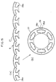
- a core division sheet 1 which has an engaging concavity 1a and an engaging convexity 1b as shown in FIG. 20(a) is first punched out by press work.
- a core segment 2 is composed by laminating such core division sheets 1 as shown in FIG. 20(b), the engaging convexity 1b of the core segment 2 is positioned to one end of the engaging concavity 1a of an adjacent core segment 2 as shown in FIG. 20(c) and the convexity 1b is slid or inserted into the concavity 1a for coupling the core segments 2, thereby forming a cylindrical stator core 3 as shown in FIG. 20(d).
- the second manufacturing method by which the divided core sheets 1 are punced out by the press work does not allow the waste rest portions to be produced unlike the first manufacturing method and provides a favorable yield, but poses a problem that workability is low at the coupling stage shown in FIG. 20(c).
- Speaking concretely of a measure to obtain a favorable stator core 3 by lowering magnetic reluctance it is necessary to reduce clearance between the coupled core segments including the concavity 1a and the engaging convexity 1b so as to eliminate a play among the coupled core segments 2, but a smaller play will require higher dimensional precision for coupling the core segments 2.
- a primary object of the present invention is to provide a stator core which allows core segments to be coupled with high workability and has a favorable magnetic characteristic even when the stator core is manufactured by punching out core division sheets by press working and coupling core segments formed by laminating the divided core sheets so as to obtain a favorable blanking yield.
- a manufacturing method of a core for rotary electric machines is configured to compose serial core segment assembly by coupling a plurality of core segments which are composed of laminated core division sheets, and then form a cylindrical core by bringing both ends of the serial core segment assembly into contact with each other so as to bend it into an annular form.
- stator core which assures a high blanking yield, high workability for core segment coupling and a favorable magnetic characteristic.
- a manufacturing method of a core for rotary electric machines as claimed in claim 1 of the present invention is characterized in that it is configured to compose a plurality of core segments by laminating core division sheets on which tees are formed, compose a serial core segment assembly by coupling adjacent core segments with one another, bend the serial core segment assembly into an annular form so that yokes of all the adjacent core segments are brought into contact with one another and bringing yokes of core segments located at both ends of the serial core segment assembly into contact with each other, thereby forming a magnetic circuit.
- a manufacturing method of a core for rotary electric machines as claimed in claim 2 of the present invention is a method according to claim 1, characterized in that it is configured to couple adjacent core segments with each other at a location which will form an outer circumference when the magnetic circuit is formed by bending the serial core segment assembly into the annular form at the stage to compose the serial core segment assembly by coupling the adjacent core segments with one another.
- a manufacturing method for a core for rotary electric machine as claimed in claim 3 of the present invention is a method according to claim 1, characterized in that it is configured to fix both the ends of the serial core segment assembly by welding or cementing them to each other after the magnetic circuit is formed by bending the serial core segment assembly into the annular form and bringing the yokes at both the ends of the serial core segment assembly into contact with each other.
- a manufacturing method of a core for rotary electric machines as claimed in claim 4 of the present invention is a method according to claim 1, characterized in that it is configured to couple both the ends of the serial core segment assembly with each other using a coupling device after the magnetic circuit is formed by bending the serial core segment assembly into the annular form and bringing the yokes of the core segments located at both the ends of the serial core segment assembly into contact with each other.
- a manufacturing method of a core for rotary electric machines as claimed in claim 5 of the present invention is characterized it is configured to compose a plurality of core segments by laminating core division sheets on which tees are formed, mold resin on surfaces of the core segments except end surfaces of yokes thereof, compose a serial core segment assembly by coupling adjacent core segments with one another, bend the serial core segment assembly into an annular form so that yokes of all adjacent core segments are brought into contact with one another, bring yokes of core segments located at both the ends of the serial core segment assembly into contact with each other for forming a magnetic circuit and couple both the ends of the serial core segment assembly by welding the molded material at both the ends of the serial core segment assembly.
- a manufacturing method of a core for rotary electric machine as claimed in claim 6 of the present invention is characterized in that it is configured to compose a plurality of core segments by laminating core division sheets on which tees are formed, compose a serial core segment assembly by coupling adjacent core segments with one another, molds resin on the surfaces of the serial core segment assembly except end surfaces of yokes of the core segments, bend the serial core segment assembly into an annular form so that yokes of all the adjacent core segments are brought into contact with one another, form a magnetic circuit by bringing yokes of core segments located at both the ends of the serial core segment assembly into contact with each other and couple both the ends of the serial core segment assembly with each other by welding the molded material at both the ends of the serial core segment assembly.
- a manufacturing method of a core for rotary electric machines as claimed in claim 7 of the present invention is characterized in that it is configured to compose a plurality of core segments by laminating core division sheets on which tees are formed, compose a serial core segment assembly by coupling adjacent core segments with one another, bend the serial core segment assembly into an annular form so that yokes of all adjacent core segments are brought into contact with one another, form a magnetic circuit by bringing yokes of the core segments disposed at both ends of the serial core segment assembly into contact with each other and couple both the ends of the serial core segment assembly with each other by molding resin on the serial core segment assembly bent in the annular form.
- a manufacturing method of a core for rotary electric machines as claimed in claim 8 of the present invention is a method according to claim 1, characterized in that it is configured to couple both the ends of the serial core segment assembly with each other by engaging a first engaging portion formed at one end of the serial core segment assembly with a second engaging portion formed at the other end of the serial core segment assembly after the magnetic circuit is formed by bending the serial core segment assembly into the annular form and bringing the yokes of the core segments located at both the ends of the serial core segment assembly into contact with each other.
- a manufacturing method of a core for rotary electric machines as claimed in claim 9 of the present invention is a method according to claim 8, characterized in that it is configured to couple both the ends of the serial core segment assembly by overlapping and engaging first and second engaging portions in a radial direction of the serial core segment assembly bent in the annular form.
- a manufacturing method of a core for rotary electric machines as claimed in claim 10 of the present invention is a method according to claim 8, characterized in that it is configured to couple both the ends of the serial core segment assembly by overlapping and engaging the first and second engaging portions laminated in the laminated direction of the core division sheets.
- a core for rotary electric machines as claimed in claim 11 of the present invention is a core for rotary electric machines whose magnetic circuit is formed by composing a plurality of core segments of laminated core division sheets having tees formed thereon, coupling the core segments with one another so as to form a serial core segment assembly, bending the serial core segment assembly into an annular form so that yokes of all adjacent core segments are brought into contact with one another and bringing yokes of core segments located at both ends of the serial core segment assembly into contact with each other, characterized in that coupling portions for coupling adjacent core segments with one another are disposed over the entire region in the laminated direction of the core segments.
- a core for rotary electric machines as claimed in claim 12 of the present invention is a core for rotary electric machines whose magnetic circuit is formed by composing a plurality of core segments of laminated core division sheets having tees formed thereon, coupling the core segments with one another so as to form a serial core segment assembly, bending the serial core segment assembly into an annular form so that yokes of all adjacent core segments are brought into contact with one another and bringing yokes of core segments located at both ends of the serial core segment assembly into contact with each other, characterized in that coupling portions for coupling the adjacent core segments to one another are formed in a partial region in the laminated direction of the core division sheets.
- a core for rotary electric machines as claimed in claim 13 of the present invention is a core according to claim 12, characterized in that a concavity is formed on an end surface of the yoke of the core segment over the entire region in the laminated direction of the core division sheets as coupling portions for coupling adjacent core segments with one another and a convexity is formed on the other end surface of the yoke of the core segment at a location corresponding to the concavity over a partial region in the laminated direction of the core division sheets.
- a manufacturing method of a core for rotary electric machines as claimed in claim 14 of the present invention is a method according to claim 1 or 2, characterized in that it is configured to engage a coupling convexity which is formed on one of adjacent core segments and has an arc-like tip in a planar shape with the other core segment rotatably over 180 degrees so that an arm connecting a root to a tip of the coupling convexity of the core segment will not be plastically deformed at the stages to compose the serial core segment assembly by engaging the coupling convexity formed on the core segment with the other core segment, and to form the magnetic circuit by bending the serial core segment assembly into the annular form and bringing the yokes of the core segment located at both the ends of the serial core segment assembly into contact with each other.
- a manufacturing method of a core for rotary electric machines as claimed in claim 15 of the present invention is a method according to claim 1 or 2, characterized in that it is configured to engage a coupling convexity which is formed on one of adjacent core segments and has an arc-like tip in a planar shape with the other core segment rotatably within a defined range over 180 degrees and allow an arm connecting a root to the tip of the coupling convexity of the core segment to be plastically deformed in the course of the bending of the serial core segment assembly into the annular form at the stages to compose the serial core segment assembly by engaging the coupling convexity on one of adjacent core segments with the other core segment, and to form the magnetic circuit by bending the serial core segment assembly into the annular form and bringing the yokes of the core segments located at both the ends of the serial core segment assembly into contact with each other.
- a manufacturing method of a core for rotary electric machine as claimed in claim 16 of the present invention is a method according to claim 1 or 2, characterized in that it is configured to allow an arm connecting a root to a tip of the coupling convexity to be plastically deformed while the coupling convexity formed on one of adjacent core segments is fitted into the other core segment and the serial core segment assembly is bent into the annular form at the stages to compose the serial core segment assembly by engaging the coupling convexity formed on one of adjacent core segments with the other core segment, and to form the magnetic circuit by bending the serial core segment assembly into the annular form and bringing the yokes of the core segments located at both the ends of the serial core segment assembly into contact with each other.
- a manufacturing method of a core for rotary electric machines as claimed in claim 17 of the present invention is a method according to claim 1 or 2, characterized in that it is configured to press or insert the coupling convexity toward depth of the coupling concavity while the arc-shaped tip of the coupling convexity formed on one of the adjacent core segments is engaged with the arc-shaped coupling concavity formed in the other core segment and the serial core segment assembly is bent into the annular form at the stages to compose the serial core segment assembly by engaging the coupling convexity formed on one of the adjacent core segments with the other core segment, and to form the magnetic circuit by bending the serial core segment assembly into the annular form and bringing the yokes of the core segments located at both the ends of the serial core segment assembly into contact with each other.
- a manufacturing method of a core for rotary electric machines as claimed in claim 18 of the present invention is a method according to claim 1 or 2, characterized in that it is configured to couple adjacent core segments with each other using a coupling pin and allow the coupling pin to be deformed for bending the serial core segment assembly into the annular form at the stages to compose the serial core segment assembly by engaging the coupling convexity formed on one of adjacent core segments with the other core segment, and to form the magnetic circuit by bending the serial core segment assembly into the annular form and bringing the yokes of the core segments located at both the ends of the serial core segment assembly into contact with each other.
- a manufacturing method of a core for rotary electric machines as claimed in claim 19 of the present invention is a method according to claim 4, characterized in that it is configured to use a coupling pin as the coupling device.
- a manufacturing method of a core for rotary electric machines as claimed in claim 20 of the present invention is a method according to claim 1, characterized in that it is configured to continuously wind a wire in series around a plurality of tees of the serial core segment assembly and form a magnetic circuit by bending the serial core segment assembly having the continuous windings into an annular form.
- a manufacturing method of a core for rotary electric machines as claimed in claim 21 of the present invention is a method according to claim 1, characterized in that it is configured to fix by welding portions which are to form outer circumferences of the coupling portions of the serial core segment assembly after the magnetic circuit is composed by bending the serial core segment assembly into the annular form and bringing the yokes of the core segments located at both the ends of the serial core segment assembly into contact with each other.
- a manufacturing method of a core for rotary electric machines as claimed in claim 22 of the present invention is characterized in that it is configured to compose a plurality of core segments by laminating core division sheets on which tees are formed, compose a serial core segment assembly by coupling adjacent core segments with one another, mount an insulator made of resin on each core segment of the serial core segment assembly, bend the serial core segment assembly into an annular form so that yokes of all adjacent core segments are brought into contact with one another, form a magnetic circuit by bringing yokes of core segments located at both ends of the serial core segment assembly into contact with each other, and couple both the ends of the serial core segment assembly by welding the insulators located at both the ends of the serial core segment assembly.
- a manufacturing method of a core for rotary electric machines as claimed in claim 23 of the present invention is a method according to claim 8, characterized in that it is configured to forcibly expand a concavity which is formed at one end of the serial core segment assembly and couple both ends of the serial core segment assembly by applying a pressure to outside the forcibly expanded concavity after a convexity formed on the other end of the serial core segment assembly is inserted into the forcibly expanded concavity in a radial direction of the serial core segment assembly bent in the annular form.
- FIGS. 1(a) through 4(b) illustrate the first embodiment of the present invention.
- the first embodiment is a manufacturing method of a stator core which has 24 slots.
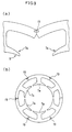
- a first core division sheet 4a shown in FIG. 1(a), and second and third core division sheets 4b and 4c shown in FIGS. 2(a) and 2(c) are formed by punching a magnetic steel plate by press working.
- a reference numeral 5 represents a tee which is to be used as an electrode.
- Sides of the core division sheets 4a through 4c which are to later constitute yokes have an angle ⁇ set in accordance with a finished form of the 24 slots.
- a concavity 8a is formed in one end surface of the yoke 6 over the entire region in the laminated direction and a convexity 8b is formed in the other end surface of the yoke 6 over the entire region in the laminated direction at a location corresponding to the concavity 8a.
- a core segment 7b shown in FIG. 2(b) is composed by laminating the second core division sheet 4b in a required number described above.
- the core segment 7b has the convexity 8b formed in one end surface of the yoke 6 over the entire region in the laminated direction but does not have the concavity 8a in the other end surface unlike the core segment 7a.
- a core segment 7c shown in FIG. 2(d) is composed by laminating the third core division sheet 4c in the required number described above.
- the core segment 7c has the concavity 8a formed in one end surface the yoke 6 over an entire region in the laminated direction, but does not have the convexity 8b in the other end surface of the yoke 6 unlike the core segment 7a.
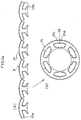
- a serial core segment assembly 9 is composed by connecting 22 core segments 7a in series as shown in FIG. 1(c), and coupling the core segment 7b and the core segment 7c with both ends of the core segments 7a.
- two adjacent core segments are engaged by inserting or sliding the convexity 8b of one core segment into the concavity 8a of the other core segment as shown in FIG. 20(c).
- a round tip is formed at a tip of the convexity 8b and a protrusion 10 is formed on a portion of the yoke located on the side of the tee so that the concavity 8a engages with an outer circumference of the tip of the convexity 8b at an angle exceeding 180 degrees.
- a slant portion 11 having an angle corresponding to the protrusion 10 is formed on the yoke at the root of the convexity 8b on the side of the tee.
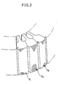
- FIG. 3 shows details of a location at which the core segment 7b and the core segment 7c are brought into contact. At this location, the core segment 7b and the core segment 7c are coupled to each other by welding end surfaces as shown in FIG. 4(a).
- a reference numeral 12 represents a welded location.
- the portions which are brought into contact with each other can be fixed by welding an outer circumferences 14 of these portions without welding the end surfaces.
- the core segment 7b and the core segment 7c can be coupled with an inserting force which is weaker than that conventionally required since the core segment 7b slides in the laminated direction while causing friction only between an inner circumferential surface of the concavity 8a and an outer circumference of the tip of the convexity 8b, and almost all portions of the yokes are free from friction at the stage to couple the core segments 7a, 7b and 7c.
- serial core segment assembly 9 can be bent into a cylindrical form with a weak force since the coupling portions are rotate smoothly around the tips of the convexities 8b at the stage to bend the serial core segment assembly into the annular form. Furthermore, favorable yokes having a low magnetic resistance can be located close to the roots of the tees 5 and a stator core having a favorable magnetic characteristic can be obtained since the core segments are coupled to one another with the coupling portions formed on the portions which are to form an outer circumference when the magnetic circuit is formed by bending the serial core segment assembly 9 into the annular form.
- wires are continuously wound while passing them through slight gaps between tips of the tees 5.
- workability is low when the wires are wound while passing them through the gaps between the tips of the tees.
- the conventional manufacturing method described with reference to FIG. 20 permits winding wires without passing them through the slight gaps between tips of the tees when the wires are wound around the tees 5 of each core segment 2 in the condition shown in FIG. 20(b) where the core segments have not been coupled yet and terminal treatment is carried out for serial connection of the wires wound separately around the tees 5 after the core is finished in the cylindrical form shown in FIG. 20(d).
- the manufacturing method preferred as the first embodiment which is configured to wind a wire continuously around the tees 5 in the condition of the serial core segment assembly and compose the magnetic circuit by bending the serial core segment assembly having the wound wire into the annular form, not only permits winding the wire without passing it through the gaps between the tips of the tees of the stator core finished in the annular form as shown in FIG. 1(d) but also requires no tedious terminal treatment unlike the conventional manufacturing method, thereby assuring favorable winding workability.
- the manufacturing method preferred as the first embodiment allows slot openings to be reduced, thereby capable of enhancing an effective magnetic flux and lowering cogging torques of motors having permanent magnets.
- stator core which has the 24 tees as an example
- manufacturing method is applicable also to stator cores which have tees (slots) in different numbers.
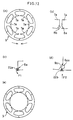
- FIGS. 5(a) through 5(c) show the second embodiment of the present invention.
- the convexities 8b are not plastically deformed at the stage to form the cylindrical stator core by bending the serial core segment assembly 9 into the annular form in the first embodiment, convexities are partially deformed plastically in the second embodiment.
- FIGS. 5(a) through 5(c) exemplify a stator core which has 6 slots.
- FIG. 5(a) illustrates a condition immediately after core segments are coupled in series.
- the core segments smoothly rotate around a tip of the convexity 8b and the convexity 8b is not plastically deformed at an initial stage to bend the serial core segment assembly 9 into the annular form but, once a tip of a protrusion 10 is brought into contact with an arm 15 which connects a tip of the convexity 8b to a yoke 6, subsequent bending causes plastic deformation of the arm as shown in FIG. 5(c) to finish a stator core 3 in a cylindrical form.
- the second embodiment remains unchanged from the first embodiment.
- FIGS. 6(a) and 6(b) illustrate the third embodiment of the present invention.
- the convexities 8b are not plastically deformed at the stage to form the cylindrical stator core by bending the serial core segment assembly 9 into the annular form in the first embodiment, convexities are partially deformed plastically in the third embodiment.
- FIGS. 6(a) and 6(b) exemplify a stator core which has 6 slots.
- FIG. 6(a) shows a condition immediately after core segments are coupled in series wherein a convexity 8b having a triangular tip is engaged with a concavity 8a formed in an adjacent core segment.
- an arm 15 which connects the tip of the convexity 8b to a yoke 6 is plastically deformed as shown in FIG. 6(b) to finish a stator core in a cylindrical form.
- the third embodiment remains unchanged from the first embodiment in the other respects.
- the tip of the convexity 8b may not be triangular and can have another shape which does not permit rotation thereof, concretely rectangular or elliptical shape.
- FIGS. 7(a) and 7(b) show the fourth embodiment of the present invention.
- the fourth embodiment is configured to form, as a convexity 8b, an integral arm 16b which has an arc shape around an angle P of an outer circumference from a portion constituting a yoke of a core division sheet to a tip.
- an arc-shaped notch 16a is formed around the angle P of the outer circumference.
- FIGS. 8(a) through 8(d) illustrate the fifth embodiment of the present invention.
- the fifth embodiment is configured to form an arc-shaped arm 16b separately from a core division sheet 4.
- a plurality of core segment bodies 70 are composed by laminating the core division sheet 4 in a required number as shown in FIG. 8(b).
- a core segment 7 is composed by fitting the separately formed arc-shaped arm member 16b into a groove 18 which is formed in the laminated direction by the arm setting notches formed in the core segment body 70 for setting the arm.
- a serial core segment assembly 9 is composed by coupling the core segments 7 as shown in FIG. 8(c) and bent into an annular form to finish a cylindrical stator core as in the fourth embodiment.
- the arc-shaped arm member 16b is formed by punching out arc-shaped magnetic steel plates and laminating these plates, this member can be formed not by laminating but by cutting it out as an integral lump.
- the fifth embodiment remains unchanged from the fourth embodiment in the other respects.
- FIGS. 9(a) through 10(b) illustrate the sixth embodiment of the present invention.
- the coupling portions which couple the core segments to compose the serial core segment assembly are composed so as to engage the convexity 8b formed at one end of the yoke 6 of the core segment with the concavity 8a formed at the other end of the yoke 6 of the adjacent core segment in the first through fifth embodiments
- the sixth embodiment is configured to compose a serial core segment assembly 9 by coupling adjacent core segments 7a with a pin 19 as shown in FIG. 9(a) and bend the serial core segment assembly 9 into an annular form, thereby bending the pin 19 so as to finish a stator core having a cylindrical form as shown in FIG. 9(b).
- holes 20 are formed at both ends of a portion which is to constitute a yoke of a core division sheet 4a as shown in FIG. 10(a) and a plurality of core segments 7a are composed by laminating the core division sheet 4a in a required number.
- a serial core segment assembly 9 is composed by disposing the core segments 7a and inserting U-shaped pins into the holes 20 of adjacent core segments as shown in FIG. 10(b). When the serial core segment assembly 9 is bent into an annular form, the pins 19 are deformed to finish a cylindrical stator core 3 shown in FIG. 9(b).
- FIGS. 11(a) and 11(b) show the seventh embodiment of the present invention.
- the seventh embodiment is configured to couple both ends of a serial core segment assembly 9 by engaging a first engaging portion 21a formed at one end of the serial core segment assembly 9 with a second engaging portion 21b formed at the other end as shown in FIG. 11(b).
- FIGS. 12(a) through 12(e) illustrate the eighth embodiment of the present invention.
- the eighth embodiment is configured to compose a serial core segment assembly 9 of core segments 7a which have the same shape as shown in FIGS. 12(a) and 12(b), form a magnetic circuit by bending the serial core segment assembly 9 into an annular form, and forcibly expand a concavity 8a formed at one end of the serial core segment assembly 9 with a jig 22a in a direction indicated by an arrow F1 as shown in FIG. 12(c).
- the eighth embodiment is configured to forcibly expand the concavity 8a formed at the one end of the serial core segment assembly 9 after the core segments 7a are composed into the serial core segment assembly 9, it is possible to expand the concavity 8a in each of the core segment 7a and then compose the serial core segment assembly 9.
- FIGS. 13(a) and 13(b) illustrate the ninth embodiment.
- the ninth embodiment is configured to form ends of core division sheets so as to form concavities 23a and convexities 23b which are alternately flush at both ends a serial core segment assembly 9 as shown in FIG. 13(a) and put one and of the serial core segment assembly into the other end for forming a cylindrical magnetic circuit as shown in FIG. 13(b).
- both the ends of the serial core segment assembly are coupled with each other by welding after the magnetic circuit is formed by bending the serial core segment assembly is bent into the annular form and bringing the yokes of the core segments located at both the ends of the serial core segment assembly into contact with each other in each of the first embodiment through the sixth embodiment, it is possible to couple a serial core segment assembly into an annular form by inserting a U-shaped pin 19, which is similar to the pin 19 which is used for composing the serial core segment assembly 9 in the sixth embodiment, into a hole formed at one end of the serial core segment assembly and a hole formed at the other end.
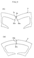
- FIGS. 14(a) and 14(b) show the eleventh embodiment of the present invention.
- the eleventh embodiment is configured to mold resin on surfaces of core segments of a serial core segment assembly 9, except end surfaces of yokes, as shown in FIG. 14(a), and form a magnetic circuit by bending a serial core segment assembly 9 into an annular form so that yokes of all adjacent core segments are brought into contact with one another as shown in FIG. 14(b) and bring yokes of core segments 25a and 25b located at both ends of the serial core segment assembly into contact with each other.
- Both the end of the serial core segment assembly 9 which has been shaped into the annular form are coupled with each other by welding the material molded on an outer circumference 26 or end surfaces 25c and 25d with supersonic waves or similar means.
- the resin is molded selectively at the required locations after the serial core segment assembly is formed and both the ends thereof are coupled with each other by welding the molded material on both the ends of the serial core segment assembly after it is formed into the annular form in the eleventh embodiment
- the resin is molded selectively at the required locations after the serial core segment assembly is composed and both the ends of the serial core segment assembly are coupled with each other by welding after the serial core segment assembly is bent into the annular form in the eleventh embodiment, it is possible to couple both ends of a serial core segment assembly by molding resin on the serial core segment assembly which is bent into an annular form.
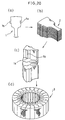
- FIGS. 15(a) through 16 show the fourteenth embodiment of the present invention.
- the fourteenth embodiment is configured to prepare insulators 27, 27 made of resin as shown in FIG. 16, mount the insulator 27 on each of core segments of a serial core segment assembly 9 as shown in FIG. 15(a), bend the serial core segment assembly 9 into an annular form so that yokes of all adjacent core segments are brought into contact with one another as shown in FIG. 15(b) and form a magnetic circuit by bringing yokes at ends 28a and 28b of the insulators 27 located at both ends of the serial core segment assembly 9 into contact with each other.
- the insulators 27 located at both the ends of the serial core segment assembly 9 which is shaped into the annular form can be coupled with each other by welding an outer circumference or end surfaces 28c and 28d of the insulators 27 with ultrasonic waves or the like.
- a magnetic circuit can similarly be formed by mounting the insulators 27, 27 on the core segments 7 as shown in FIG. 16, composing the serial core segment assembly 9 by coupling the core segments on which the insulators 27, 27 have been mounted, bending the serial core segment assembly 9 into an annular form so that yokes of all adjacent core segments are brought into contact with one another, and bringing the yokes of the core segments of the ends 28a and 28b of the insulators 27 located at both the ends of the serial core segment assembly into contact with each other.
- FIGS. 17(a) and 17(b) show the fifteenth embodiment of the present invention.
- the adjacent core segments are coupled by engaging the coupling concavities with the coupling convexities for composing the serial core segment assembly and the magnetic circuit is formed by bending the serial core segment assembly so that the yokes of the adjacent core segments are brought into contact with one another in each of the embodiments described above, it can be expected to enhance mechanical strength and precision of the annular form of a stator core by preliminarily forming an engaging protrusion 30a and an engaging concavity 30b at locations of a core division sheet 4a which are on a side of the tee of the yoke as shown in FIG. 17(a) so that the engaging protrusion 30a engages with the engaging concavity 30b as shown in FIG. 17(b) when the serial core segment assembly is bent into the annular form.
- FIGS. 18(a) and 18(b) show the sixteenth embodiment of the present invention.
- the coupling portions for coupling the core segments are formed as the concavity formed at one end of the yoke of the core segment over the entire width in the laminated direction and the convexity formed at the other end of the yoke of the core segment over the entire width in the laminated direction in each of the embodiments described above, a similar effect can be obtained by forming the similar coupling portions on end surfaces of partially in the laminated direction of the core division sheets.
- FIG. 19 shows the seventeenth embodiment of the present invention.
- the seventeenth embodiment is configured to weld outer circumferences 31 of coupling portions partially or over the entire width in a condition where a serial core segment assembly is bent in an annular form as shown in FIG. 19.
- the similar effects may be obtained by forming a plurality of tees on one core division sheet, composing core segments by laminating such core division sheets and composing a serial core segment assembly by coupling the core segments and bending the serial core segment assembly into an annular form to finish a cylindrical stator core.
- the manufacturing method of a core for rotary electric machines as claimed in claim 1 of the present invention permits composing a cylindrical core of core division sheets, thereby providing a favorable blanking yield. Further, this method is configured to bend a serial core segment assembly after it is composed by coupling core segments and permits coupling the core segments in a condition where yokes of adjacent core segments are free from friction, thereby assuring a high workability at the stage to couple the core segments. Furthermore, the method facilitates to bring the yokes of the adjacent core segments into close contact so as to remain no gap, thereby permitting lowering magnetic reluctance and obtaining a favorable magnetic characteristic.
- the method permits continuously winding a wire around tees of the serial core segment assembly and then bending the serial core segment assembly into an annular form, thereby providing an assembling workability higher than that obtained in a case where wires are wound independently around tees of a core finished in a cylindrical form and the wires are connected in series by terminal treatments of the wires.
- the manufacturing method of a core for rotary electric machines as claimed in claim 2 of the present invention permits locating favorable yokes having a low magnetic reluctance close to roots of tees, thereby making it possible to obtain a stator core having a favorable magnetic characteristic.
- the manufacturing method of a core for rotary electric machines as claimed in claim 3 of the present invention permits stably maintaining a cylindrical form obtained by bending a serial core segment assembly into an annular form, thereby facilitating to handle the core in a stage to build it into a frame of a rotary electric machine.
- the manufacturing method of a core for rotary electric machines as claimed in claim 4 of the present invention permits stably maintaining a cylindrical form obtained by bending a serial core segment assembly into an annular form, thereby facilitating to handle the core at a stage to build it into a frame of a rotary electric machine.
- the manufacturing method of a core for rotary electric machines as claimed in claim 5 of the present invention permits stably maintaining a cylindrical form obtained by bending a serial core segment assembly into an annular form, thereby facilitating to handle the core at a stage to build it into a frame of a rotary electric machine. Further, this method allows both ends of the serial core segment assembly bent in the annular form to be coupled with each other by utilizing a molding material.
- the manufacturing method of a core for rotary electric machines as claimed in claim 6 of the present invention permits stably maintaining a cylindrical form obtained by bending a serial core segment assembly into an annular form, thereby facilitating to handle the core at a stage to build it into a frame of a rotary electric machine. Further, this method allows both ends of the serial core segment assembly bent into an annular form to be coupled with each other by utilizing a molding material.
- the manufacturing method of a core for rotary electric machines as claimed in claim 7 of the present invention permits stably maintaining a cylindrical form obtained by bending a serial core segment assembly into an annular form, thereby facilitating to handle the core at a stage to assemble it into a frame of a rotary electric machine. Further, this method allows both ends of the serial core segment assembly bent into an annular form to be coupled with each other by utilizing a molding material.
- the manufacturing method of a core for rotary electric machines as claimed in claim 8 of the present invention permits stably maintaining a cylindrical form obtained by bending a serial core segment assembly into an annular form, thereby facilitating to handle the core at a stage to assemble it into a frame of a rotary electric machine.
- the manufacturing method of a core for rotary electric machines as claimed in 9 of the present invention permits coupling both ends of a serial core segment assembly with each other simply by slightly changing shapes of core segments located at both the ends of the serial core segment assembly, thereby facilitating to handle the core at a stage to assemble it into a frame of a rotary electric machine.
- the manufacturing method of a core for rotary electric machines as claimed in claim 10 of the present invention allows both ends of a serial core segment assembly with each other simply by slightly changing manufactured lengths of yokes of core division sheets of core segments located at both the ends of the serial core segment assembly, thereby facilitating to handle the core at a stage to build it into a frame of a rotary electric machine.
- the core for rotary electric machines as claimed in claim 11 of the present invention consists of a serial core segment assembly which is composed of core segments composed by laminating core division sheets having the same shape.
- the core for rotary electric machines as claimed in claim 12 of the present invention permits weakening an inserting force for coupling core segments though it requires forming and laminating core division sheets which have several kinds of shapes.
- the core for rotary electric machines as claimed in claim 13 of the present invention is composed of core segments which have no distinction between front and rear surfaces or can be coupled in any direction, thereby featuring a high workability.
- the manufacturing method of a core for rotary electric machines as claimed in claim 14 of the present invention allows core segments to be rotated smoothly around tips of coupling convexities at a stage to bend a serial core segment assembly into an annular form, thereby shaping it into a cylindrical form with a slight force.
- the manufacturing method of a core for rotary electric machines as claimed in claim 15 of the present invention allows a serial core segment assembly to be bent into an annular form or shaped into a cylindrical form with a slight force required for plastic deformation of arms and facilitates to maintain the serial core segment assembly in the annular form owing to the plastic deformation of the arms.
- the manufacturing method of a core for rotary electric machines as claimed in claim 16 of the present invention allows a serial core segment assembly to be bent into an annular form or shaped into a cylindrical form with a slight force required for plastic deformation of arms and facilitates to maintain the serial core segment assembly in the annular form owing to the plastic deformation of the arms.
- the manufacturing method of a core for rotary electric machines as claimed in claim 17 of the present invention allows a serial core segment assembly to be bent into an annular form or shaped into a cylindrical form with a slight force required for pressing or inserting coupling convexities toward depth of coupling concavities.
- the manufacturing method of a core for rotary electric machines as claimed in claim 18 of the present invention is configured to coupled adjacent core segments with each other using a coupling pin and requires only formation of holes in the core segments for inserting the pin, thereby facilitating to manufacture the core segments as compared with core segments which have coupling concavities and convexities formed on outer circumferences thereof.
- the manufacturing method of a core for rotary electric machines as claimed in claim 19 of the present invention requires only formation of holes for inserting coupling pins into core segments to be located at both ends of a serial core segment assembly, thereby facilitating to manufacture the core segments as compared with core segments which have coupling concavities and convexities formed on outer circumferences thereof.
- the manufacturing method of a core for rotary electric machines as claimed in claim 20 of the present invention is configured to continuously wind a wire before a serial core segment assembly is bent into an annular form, thereby facilitating a winding work.
- the manufacturing method of a core for rotary electric machines as claimed in claim 21 of the present invention makes it possible to expect to enhance mechanical strength of a stator core and precision of an annular form thereof when a serial core segment assembly is bent into the annular form or finished in a cylindrical form.
- the manufacturing method of a core for rotary electric machines as claimed in claim 22 of the present invention permits stably maintaining a cylindrical form which is obtained by bending a serial core segment assembly into an annular form and facilitate to handle a core at a stage to assemble it into a frame of a rotary electric machine. Further, this method permits both ends of a serial core segment assembly bent in an annular form to be coupled with each other by utilizing an insulator material.
- the manufacturing method of a core for rotary electric machines as claimed in claim 23 of the present invention permits composing a cylindrical stator core only of core segments which have the same shape.
Landscapes
- Engineering & Computer Science (AREA)
- Power Engineering (AREA)
- Manufacturing & Machinery (AREA)
- Iron Core Of Rotating Electric Machines (AREA)
- Manufacture Of Motors, Generators (AREA)
Applications Claiming Priority (3)
| Application Number | Priority Date | Filing Date | Title |
|---|---|---|---|
| JP25792896 | 1996-09-30 | ||
| JP25792896 | 1996-09-30 | ||
| JP257928/96 | 1996-09-30 |
Publications (2)
| Publication Number | Publication Date |
|---|---|
| EP0833427A1 true EP0833427A1 (fr) | 1998-04-01 |
| EP0833427B1 EP0833427B1 (fr) | 2003-10-22 |
Family
ID=17313150
Family Applications (1)
| Application Number | Title | Priority Date | Filing Date |
|---|---|---|---|
| EP97115744A Expired - Lifetime EP0833427B1 (fr) | 1996-09-30 | 1997-09-10 | Procédé de fabrication d'un noyau pour une machine tournante électrique |
Country Status (9)
| Country | Link |
|---|---|
| US (3) | US6226856B1 (fr) |
| EP (1) | EP0833427B1 (fr) |
| JP (2) | JP3568364B2 (fr) |
| KR (1) | KR100465591B1 (fr) |
| CN (1) | CN1156067C (fr) |
| DE (1) | DE69725672T2 (fr) |
| ES (1) | ES2210437T3 (fr) |
| MY (1) | MY118088A (fr) |
| TW (1) | TW350162B (fr) |
Cited By (16)
| Publication number | Priority date | Publication date | Assignee | Title |
|---|---|---|---|---|
| EP0871282A1 (fr) | 1997-04-11 | 1998-10-14 | Kabushiki Kaisha Toshiba | Stator pour machines électrodynamiques et méthode pour réaliser celui-ci |
| EP0952347A1 (fr) * | 1998-04-20 | 1999-10-27 | Matsushita Refrigeration Company | Dispositif de contrÔle de la course de piston pour un compresseur oscillant |
| EP1109287A2 (fr) * | 1999-12-14 | 2001-06-20 | Mitsubishi Denki Kabushiki Kaisha | Alternateur |
| DE10030129A1 (de) * | 2000-06-20 | 2002-01-17 | Deutsch Zentr Luft & Raumfahrt | Vorrichtungen für Antriebseinheiten von Leichtbaurobotern |
| US6894414B1 (en) | 1999-12-24 | 2005-05-17 | Mitsubishi Denki Kabushiki Kaisha | Alternator |
| EP1598918A1 (fr) | 2004-05-17 | 2005-11-23 | Grundfos A/S | Paquet de tôles faite des segments |
| DE102004043424A1 (de) * | 2004-09-06 | 2006-03-09 | Sew-Eurodrive Gmbh & Co. Kg | Elektromotor |
| EP1720233A3 (fr) * | 2000-03-13 | 2006-11-15 | Mitsubishi Denki Kabushiki Kaisha | Enroulements du stator d'un alternateur |
| WO2007048567A1 (fr) * | 2005-10-26 | 2007-05-03 | Sew-Eurodrive Gmbh & Co. Kg | Moteur electrique et procede de fabrication d'un moteur electrique |
| WO2010125594A1 (fr) * | 2009-04-29 | 2010-11-04 | Ernesto Malvestiti S.P.A. | Procédé et moule pour produire des noyaux ferromagnétiques de moteurs électriques |
| EP2388887A2 (fr) | 2010-05-18 | 2011-11-23 | Aumann GMBH | Chaîne de pôles |
| CN102365805A (zh) * | 2009-05-15 | 2012-02-29 | 株式会社三井高科技 | 层叠铁芯 |
| DE102014019572A1 (de) | 2014-12-23 | 2015-06-25 | Daimler Ag | Ringelement für eine elektrische Maschine sowie Verfahren zum Herstellen eines solchen Ringelements |
| EP2827475A4 (fr) * | 2012-03-13 | 2016-04-27 | Panasonic Corp | Moteur et procédé de fabrication de stator correspondant |
| DE102015201960A1 (de) * | 2015-02-04 | 2016-08-04 | Volkswagen Aktiengesellschaft | Stator für eine elektrische Maschine und Verfahren für dessen Herstellung |
| DE102019125862A1 (de) * | 2019-09-25 | 2021-03-25 | Vacuumschmelze Gmbh & Co. Kg | Mehrteiliger Stator, elektrische Maschine sowie Verfahren zur Herstellung eines mehrteiligen Stators und einer elektrischen Maschine |
Families Citing this family (189)
| Publication number | Priority date | Publication date | Assignee | Title |
|---|---|---|---|---|
| US6335623B1 (en) * | 1992-12-18 | 2002-01-01 | Fonar Corporation | MRI apparatus |
| US7127802B1 (en) | 1997-11-21 | 2006-10-31 | Fonar Corporation | Method of fabricating a composite plate |
| JP3316762B1 (ja) * | 1998-06-30 | 2002-08-19 | 三菱電機株式会社 | 鉄心装置の製造方法 |
| JP3279279B2 (ja) | 1998-06-30 | 2002-04-30 | 三菱電機株式会社 | 鉄心装置 |
| JP3439668B2 (ja) * | 1998-10-02 | 2003-08-25 | 三菱電機株式会社 | 鉄 心 |
| JP3439673B2 (ja) * | 1998-11-10 | 2003-08-25 | 三菱電機株式会社 | 積層鉄心 |
| US6225725B1 (en) * | 1999-02-08 | 2001-05-01 | Itoh Electric Co. Ltd. | Manufacturing process of a divided type stator |
| JP2001069727A (ja) * | 1999-08-26 | 2001-03-16 | Honda Motor Co Ltd | スロットレス固定子の製造方法及び回転電機 |
| JP3496595B2 (ja) * | 1999-10-27 | 2004-02-16 | 日産自動車株式会社 | 回転電機 |
| FR2804552B1 (fr) * | 2000-01-28 | 2003-01-03 | Leroy Somer | Procede de fabrication d'un circuit de machine electrique |
| TW508891B (en) | 2000-02-21 | 2002-11-01 | Misubishi Electric Corp | Stator iron core of electric motor, manufacturing method thereof, electric motor, and compresor |
| DE10013690B4 (de) * | 2000-03-21 | 2004-04-15 | Schuler Pressen Gmbh & Co. Kg | Verfahren zur Herstellung von aus Blechteilen bestehenden Paketen |
| JP2001320842A (ja) * | 2000-05-10 | 2001-11-16 | Sankyo Seiki Mfg Co Ltd | 積層コア及びその製造方法 |
| DE10037804A1 (de) * | 2000-06-09 | 2001-12-13 | Kienle & Spiess Stanz & Druck | Blechlamellen für Blechpakete für Rotoren und/oder Statoren für Generatoren, Motoren, Startergeneratoren, Generatorstarter und dergleichen sowie Verfahren zur Herstellung von solchen Blechlamellen |
| US6822449B1 (en) | 2000-11-22 | 2004-11-23 | Fonar Corporation | Ferromagnetic frame with laminated carbon steel |
| US6487769B2 (en) | 2000-11-30 | 2002-12-03 | Emerson Electric Co. | Method and apparatus for constructing a segmented stator |
| US6597078B2 (en) | 2000-12-04 | 2003-07-22 | Emerson Electric Co. | Electric power steering system including a permanent magnet motor |
| US6897591B2 (en) | 2001-03-26 | 2005-05-24 | Emerson Electric Co. | Sensorless switched reluctance electric machine with segmented stator |
| US7012350B2 (en) | 2001-01-04 | 2006-03-14 | Emerson Electric Co. | Segmented stator switched reluctance machine |
| US6744166B2 (en) * | 2001-01-04 | 2004-06-01 | Emerson Electric Co. | End cap assembly for a switched reluctance electric machine |
| US6584813B2 (en) | 2001-03-26 | 2003-07-01 | Emerson Electric Co. | Washing machine including a segmented stator switched reluctance motor |
| US6700284B2 (en) | 2001-03-26 | 2004-03-02 | Emerson Electric Co. | Fan assembly including a segmented stator switched reluctance fan motor |
| EP1233503A3 (fr) * | 2001-02-14 | 2004-12-01 | Koyo Seiko Co., Ltd. | Moteur à courant continu sans balais et son procédé de fabrication |
| US6583530B2 (en) * | 2001-02-20 | 2003-06-24 | Chun-Pu Hsu | Composite stator structure having corresponding concave embedding receiving grooves and arc-shaped teeth surfaces |
| US6651309B2 (en) * | 2001-02-27 | 2003-11-25 | Delphi Technologies, Inc. | Method for fabricating a highly-dense powder iron pressed stator core for use in alternating current generators and electric motors |
| US7036207B2 (en) * | 2001-03-02 | 2006-05-02 | Encap Motor Corporation | Stator assembly made from a plurality of toroidal core segments and motor using same |
| JP3749444B2 (ja) * | 2001-03-15 | 2006-03-01 | 三菱電機株式会社 | コア |
| JP2002320351A (ja) * | 2001-04-20 | 2002-10-31 | Hitachi Ltd | Dcブラシレスモータ用固定子鉄心 |
| JP2003052139A (ja) * | 2001-08-07 | 2003-02-21 | Hitachi Ltd | 鉄心コアおよびそれを用いた回転電機、ならびにその製造方法 |
| JP3786854B2 (ja) * | 2001-08-30 | 2006-06-14 | 株式会社三井ハイテック | 積層鉄心の製造方法 |
| US7701209B1 (en) | 2001-10-05 | 2010-04-20 | Fonar Corporation | Coils for horizontal field magnetic resonance imaging |
| US7906966B1 (en) | 2001-10-05 | 2011-03-15 | Fonar Corporation | Quadrature foot coil antenna for magnetic resonance imaging |
| JP2003164080A (ja) * | 2001-11-27 | 2003-06-06 | Asmo Co Ltd | 回転電機の電機子及びその製造方法 |
| JP2003169431A (ja) * | 2001-11-29 | 2003-06-13 | Hitachi Ltd | 電動機 |
| FR2835977B1 (fr) * | 2002-02-11 | 2004-07-02 | Leroy Somer Moteurs | Procede et machine pour la fabrication d'un circuit magnetique de machine electrique |
| JP3716808B2 (ja) * | 2002-04-01 | 2005-11-16 | 日産自動車株式会社 | 回転電機 |
| DE10234610A1 (de) * | 2002-07-30 | 2004-02-19 | Robert Bosch Gmbh | Streifenförmige Lamelle sowie Ständerblechpaket für eine elektrische Maschine |
| DE10243986A1 (de) | 2002-09-20 | 2004-04-01 | Robert Bosch Gmbh | Ständer und elektrische Maschine |
| US7062841B2 (en) * | 2002-10-08 | 2006-06-20 | L.H. Carbide Corporation | Method of manufacturing a formable laminated stack in a progressive die assembly having a choke |
| KR100452379B1 (ko) * | 2002-10-10 | 2004-10-12 | 엘지전자 주식회사 | 모터의 단위코어 및 그 제조방법 |
| DE10248771A1 (de) * | 2002-10-18 | 2004-04-29 | Siemens Ag | Permanenterregte Synchronmaschine |
| US7111380B2 (en) * | 2002-10-31 | 2006-09-26 | Emerson Electric Co. | Method for forming an annular stator assembly |
| US6877214B2 (en) | 2002-11-05 | 2005-04-12 | L. H. Carbide Corporation | Method of manufacturing a stack of laminations |
| JP3733120B2 (ja) * | 2002-12-27 | 2006-01-11 | 穩正企業股▲ふん▼有限公司 | モータの組合せ式固定子構造 |
| US6784588B2 (en) * | 2003-02-03 | 2004-08-31 | Metglas, Inc. | Low core loss amorphous metal magnetic components for electric motors |
| US6946769B2 (en) | 2003-05-08 | 2005-09-20 | Asmo Co., Ltd. | Insulator and manufacturing method thereof, and stator for electric rotating machine |
| JP4927134B2 (ja) * | 2003-05-08 | 2012-05-09 | アスモ株式会社 | 回転電機のステータ |
| TW200514334A (en) * | 2003-09-05 | 2005-04-16 | Black & Decker Inc | Field assemblies and methods of making same |
| US20050189844A1 (en) * | 2003-09-05 | 2005-09-01 | Du Hung T. | Field assemblies having pole pieces with dovetail features for attaching to a back iron piece(s) and methods of making same |
| US7211920B2 (en) * | 2003-09-05 | 2007-05-01 | Black & Decker Inc. | Field assemblies having pole pieces with axial lengths less than an axial length of a back iron portion and methods of making same |
| US20060226729A1 (en) * | 2003-09-05 | 2006-10-12 | Du Hung T | Field assemblies and methods of making same with field coils having multiple coils |
| US7233091B2 (en) * | 2003-09-05 | 2007-06-19 | Black & Decker Inc. | Electric motor with field assemblies having core pieces with mating features |
| US7205696B2 (en) * | 2003-09-05 | 2007-04-17 | Black & Decker Inc. | Field assemblies having pole pieces with ends that decrease in width, and methods of making same |
| US6919665B2 (en) * | 2003-09-30 | 2005-07-19 | Nidec Shibaura Corporation | Stator core, an electric motor in which it is utilized, and method of manufacturing a stator core |
| KR100564090B1 (ko) * | 2003-12-10 | 2006-03-24 | 뉴모텍(주) | 모터의 고정자 코어 |
| US8595915B2 (en) * | 2004-01-02 | 2013-12-03 | Mitsubishi Denki Kabushiki Kaisha | Stator of electric rotating machine |
| GB0412085D0 (en) * | 2004-05-29 | 2004-06-30 | Univ Durham | Axial-flux, permanent magnet electrical machine |
| US7737598B2 (en) * | 2004-08-09 | 2010-06-15 | A. O. Smith Corporation | Electric motor having a stator |
| US7247967B2 (en) * | 2004-08-09 | 2007-07-24 | A. O. Smith Corporation | Electric motor having a stator |
| DE102004043425A1 (de) * | 2004-09-06 | 2006-03-30 | Sew-Eurodrive Gmbh & Co. Kg | Elektromotor |
| JP4889988B2 (ja) * | 2004-09-17 | 2012-03-07 | アスモ株式会社 | インシュレータ、ステータ、及びブラシレスモータ |
| JP4706215B2 (ja) * | 2004-09-21 | 2011-06-22 | 日産自動車株式会社 | 複軸多層型回転電機のステータ構造 |
| US20060066171A1 (en) * | 2004-09-28 | 2006-03-30 | Toyo Denso Kabusiki Kaisha | Stator core for rotating electric machine |
| US7148601B2 (en) * | 2004-09-30 | 2006-12-12 | Asia Vital Component Co., Ltd. | Built-up stator assembly |
| JP4546213B2 (ja) * | 2004-10-21 | 2010-09-15 | 本田技研工業株式会社 | モータおよびモータを搭載した電動パワーステアリング装置 |
| JP4887656B2 (ja) * | 2004-10-29 | 2012-02-29 | トヨタ自動車株式会社 | 回転電機およびそれを搭載した自動車 |
| ATE392039T1 (de) * | 2004-11-08 | 2008-04-15 | Etel Sa | Linearmotor mit segmentstator |
| US8401615B1 (en) | 2004-11-12 | 2013-03-19 | Fonar Corporation | Planar coil flexion fixture for magnetic resonance imaging and use thereof |
| US7646281B2 (en) * | 2005-01-14 | 2010-01-12 | Lincoln Global, Inc. | Snap-together choke and transformer assembly for an electric arc welder |
| JP4649225B2 (ja) * | 2005-02-14 | 2011-03-09 | 株式会社東芝 | アウターロータ及びその製造方法 |
| EP2568573A3 (fr) * | 2005-03-07 | 2014-06-04 | Black & Decker Inc. | Outils électriques avec moteur présentant un stator constitué de plusieurs pièces |
| JP4816879B2 (ja) * | 2005-06-30 | 2011-11-16 | 株式会社富士通ゼネラル | アキシャルエアギャップ型電動機 |
| JP2007074875A (ja) * | 2005-09-09 | 2007-03-22 | Toyota Motor Corp | ステータコア、モータ、ステータ製造方法 |
| JP2007110808A (ja) * | 2005-10-12 | 2007-04-26 | Toyota Motor Corp | モーター用コア |
| US7348706B2 (en) * | 2005-10-31 | 2008-03-25 | A. O. Smith Corporation | Stator assembly for an electric machine and method of manufacturing the same |
| JP2007129835A (ja) * | 2005-11-04 | 2007-05-24 | Aisin Seiki Co Ltd | モータ |
| JP4687433B2 (ja) * | 2005-12-09 | 2011-05-25 | トヨタ自動車株式会社 | モーター用コア |
| US8102092B2 (en) * | 2006-01-24 | 2012-01-24 | Kabushiki Kaisha Yaskawa Denki | Split cores for motor stator, motor stator, permanent magnet type synchronous motor and punching method by split core punching die |
| US20070262839A1 (en) * | 2006-05-09 | 2007-11-15 | Spang & Company | Electromagnetic assemblies, core segments that form the same, and their methods of manufacture |
| US20070261231A1 (en) * | 2006-05-09 | 2007-11-15 | Spang & Company | Methods of manufacturing and assembling electromagnetic assemblies and core segments that form the same |
| ES2638426T3 (es) * | 2006-06-05 | 2017-10-20 | Mitsubishi Electric Corporation | Núcleo dividido y procedimiento de fabricación del mismo, y núcleo de estator |
| JP2007329990A (ja) * | 2006-06-06 | 2007-12-20 | Mitsuo Ebisawa | 固定子コア、固定子及び固定子の製造方法 |
| JP4668130B2 (ja) * | 2006-06-16 | 2011-04-13 | トヨタ自動車株式会社 | ステータ |
| KR101275210B1 (ko) * | 2006-06-16 | 2013-06-18 | 엘지전자 주식회사 | 와인딩 타입 스테이터 코어를 갖는 스테이터 및 이를포함한 세탁장치 |
| JP4709114B2 (ja) * | 2006-10-03 | 2011-06-22 | 三菱電機株式会社 | 回転電機用固定子 |
| JP4176121B2 (ja) * | 2006-10-13 | 2008-11-05 | 株式会社三井ハイテック | 回転子積層鉄心およびその製造方法 |
| US7791237B2 (en) * | 2006-12-19 | 2010-09-07 | General Electric Company | Fault-tolerant synchronous permanent magnet machine |
| JP4735529B2 (ja) * | 2006-12-21 | 2011-07-27 | トヨタ自動車株式会社 | モータの固定子 |
| CN101282049B (zh) * | 2007-04-04 | 2011-04-20 | 上海南洋电机有限公司 | 一种大中型电机用链接扇形片及其制造方法 |
| CN101282048B (zh) * | 2007-04-04 | 2011-04-20 | 上海南洋电机有限公司 | 一种大中型电机用链接扇形片及其制造方法 |
| US8136229B2 (en) * | 2007-04-25 | 2012-03-20 | Mitsui High-Tec, Inc. | Method of producing variant-shaped laminated core |
| US9386939B1 (en) | 2007-05-10 | 2016-07-12 | Fonar Corporation | Magnetic resonance imaging of the spine to detect scoliosis |
| CN201118414Y (zh) * | 2007-10-29 | 2008-09-17 | 深圳航天科技创新研究院 | 方波三相无刷永磁直流电动机 |
| CN101422854B (zh) * | 2007-10-31 | 2012-06-27 | 上海海马汽车研发有限公司 | 车身组件预装结构和车身组件预装方法 |
| JP4637159B2 (ja) * | 2007-11-12 | 2011-02-23 | 本田技研工業株式会社 | ステータコア |
| JP5260951B2 (ja) * | 2007-12-13 | 2013-08-14 | 三菱電機株式会社 | 積層固定鉄心 |
| KR100964540B1 (ko) * | 2008-03-31 | 2010-06-21 | 이일환 | 분할코어식 모터 스테이터 |
| US8599215B1 (en) | 2008-05-07 | 2013-12-03 | Fonar Corporation | Method, apparatus and system for joining image volume data |
| JP5151738B2 (ja) * | 2008-07-01 | 2013-02-27 | 株式会社デンソー | 回転電機の固定子及び回転電機 |
| EP2309621B1 (fr) * | 2008-07-24 | 2017-08-23 | Mitsubishi Electric Corporation | Procédé de fabrication de noyau de fer et dispositif de fabrication de noyau de fer |
| JP5237720B2 (ja) * | 2008-08-08 | 2013-07-17 | 三菱電機株式会社 | 積層固定鉄心 |
| JP2010115000A (ja) * | 2008-11-06 | 2010-05-20 | Nippon Densan Corp | モータ及びその製造方法 |
| DE102008054529A1 (de) * | 2008-12-11 | 2010-06-17 | Robert Bosch Gmbh | Elektromotor, insbesondere Stell- oder Antriebsmotor in Kraftfahrzeugen |
| DE102008063783A1 (de) * | 2008-12-18 | 2010-06-24 | Wind-Direct Gmbh | Generator für eine Windenergieanlage und Verfahren zu seiner Herstellung |
| JP2010220288A (ja) * | 2009-03-13 | 2010-09-30 | Mabuchi Motor Co Ltd | コアブロック及び該コアブロックを用いたモータ用の磁極コア |
| JP5213780B2 (ja) * | 2009-03-27 | 2013-06-19 | キヤノン株式会社 | インナーロータ型モータ |
| JP2010259174A (ja) * | 2009-04-23 | 2010-11-11 | Harmonic Drive Syst Ind Co Ltd | モータステータの製造方法 |
| CN103354407B (zh) * | 2009-06-19 | 2016-06-01 | 建准电机工业股份有限公司 | 马达定子及其制造方法 |
| JP4637959B2 (ja) | 2009-06-24 | 2011-02-23 | パナソニック株式会社 | 電動機のステータおよび電動機および電動自転車 |
| JP2011045179A (ja) * | 2009-08-20 | 2011-03-03 | Honda Motor Co Ltd | ステータ及びその製造方法 |
| JP5296888B2 (ja) * | 2009-11-19 | 2013-09-25 | 三菱電機株式会社 | 回転電機のモールドステータの製造方法 |
| KR101074939B1 (ko) * | 2009-11-23 | 2011-10-18 | 뉴모텍(주) | 매그메이트를 갖는 권선 프레임 및 이를 포함하는 고정자 코어 |
| DE102009055400A1 (de) * | 2009-12-30 | 2011-07-07 | Robert Bosch GmbH, 70469 | Stator in einer elektrischen Maschine |
| DE102010028509A1 (de) * | 2009-12-30 | 2011-07-07 | Robert Bosch GmbH, 70469 | Stator in einem Elektromotor |
| JP2011147225A (ja) * | 2010-01-13 | 2011-07-28 | Yaskawa Electric Corp | 回転電機 |
| JP2011147224A (ja) * | 2010-01-13 | 2011-07-28 | Yaskawa Electric Corp | 回転電機 |
| EP2360813A1 (fr) * | 2010-02-12 | 2011-08-24 | Hansjörg Cueni | Machine dynamoélectrique |
| JP5450189B2 (ja) * | 2010-03-16 | 2014-03-26 | アスモ株式会社 | 電機子コアの製造方法 |
| JP5528164B2 (ja) * | 2010-03-18 | 2014-06-25 | 三菱電機株式会社 | 回転電機のステータ及びその製造方法 |
| JP2011200026A (ja) * | 2010-03-19 | 2011-10-06 | Yaskawa Electric Corp | 回転電機及び回転電機の製造方法 |
| WO2011125199A1 (fr) * | 2010-04-08 | 2011-10-13 | 三菱電機株式会社 | Noyau de fer feuilleté de machine électrique tournante |
| US8400041B2 (en) | 2010-05-28 | 2013-03-19 | Nidec Motor Corporation | Segmented stator assemblies having end caps |
| JP5464272B2 (ja) * | 2010-06-18 | 2014-04-09 | トヨタ自動車株式会社 | ステータ製造方法 |
| US8786158B2 (en) | 2010-08-19 | 2014-07-22 | L. H. Carbide Corporation | Continuously formed annular laminated article and method for its manufacture |
| CN101951038A (zh) * | 2010-09-13 | 2011-01-19 | 浙江西子富沃德电机有限公司 | 电机的定子铁芯及其制作方法 |
| DE102010043976A1 (de) * | 2010-11-16 | 2012-05-16 | Robert Bosch Gmbh | Komponente zum Herstellen einer Maschinenkomponente für eine elektrische Maschine |
| US8704422B2 (en) * | 2010-11-18 | 2014-04-22 | Nidec Motor Corporation | Full round stator assembly and electromagnetic machine having high slot fill |
| CN102157993A (zh) * | 2011-03-08 | 2011-08-17 | 大连名阳实业有限公司 | 一种模块化磁通切换永磁电机 |
| US20120275942A1 (en) * | 2011-04-29 | 2012-11-01 | Knapp John M | Systems and Methods for Electric Motor Construction |
| JP5758488B2 (ja) * | 2011-05-26 | 2015-08-05 | 三菱電機株式会社 | 永久磁石型モータ |
| EP2727219A4 (fr) * | 2011-06-30 | 2016-09-14 | Devon R Mcintosh | Machine pm économique à faible saillance |
| TWI443938B (zh) * | 2011-08-26 | 2014-07-01 | Univ Nat Taiwan Science Tech | 定子單元、其繞線方法、及使用其之定子結構及製造方法 |
| US9099897B2 (en) | 2011-09-13 | 2015-08-04 | L.H. Carbide Corporation | Method for connecting end sections of an annular laminated article and articles made therefrom |
| CN103023165B (zh) * | 2011-09-21 | 2017-10-31 | 德昌电机(深圳)有限公司 | 电机定子铁芯结构及定子形成方法 |
| KR20130033668A (ko) * | 2011-09-27 | 2013-04-04 | 엘지이노텍 주식회사 | 모터의 스테이터 코어 |
| WO2013051125A1 (fr) * | 2011-10-06 | 2013-04-11 | 三菱電機株式会社 | Procédé de fabrication d'un noyau stratifié et noyau stratifié fabriqué par ce procédé |
| JP5642291B2 (ja) * | 2011-10-13 | 2014-12-17 | 三菱電機株式会社 | 回転電機 |
| KR101243589B1 (ko) * | 2012-01-02 | 2013-03-20 | 뉴모텍(주) | 세탁기용 모터의 고정자 코어 |
| JP2014107993A (ja) * | 2012-11-29 | 2014-06-09 | Hitachi Automotive Systems Ltd | 電動アクチュエータ |
| US9766310B1 (en) | 2013-03-13 | 2017-09-19 | Fonar Corporation | Method and apparatus for magnetic resonance imaging of the cranio-cervical junction |
| DE102013204759A1 (de) * | 2013-03-19 | 2014-09-25 | Robert Bosch Gmbh | Zahnsegment zum Zusammenbau eines Stators oder Rotors einer elektrischen Maschine und Verfahren für die Herstellung einer solchen |
| BR112015029558A2 (pt) * | 2013-05-28 | 2017-07-25 | Mitsubishi Electric Corp | núcleo de ferro de uma máquina elétrica rotativa |
| US10734850B2 (en) | 2013-08-09 | 2020-08-04 | Johnson Electric International AG | Single-phase motor |
| US10454354B2 (en) | 2013-08-09 | 2019-10-22 | Johnson Electric International AG | Single phase motor |
| CN106487118A (zh) * | 2015-08-28 | 2017-03-08 | 德昌电机(深圳)有限公司 | 单相永磁电机 |
| WO2015026209A1 (fr) * | 2013-08-23 | 2015-02-26 | 주식회사 아모텍 | Stator unique et moteur le comprenant |
| DK2854256T3 (en) * | 2013-09-26 | 2017-09-11 | Siemens Ag | Polar unit and stator assembly for a wind turbine generator and methods for manufacturing them |
| CN103611818B (zh) * | 2013-12-02 | 2015-11-18 | 巢波 | 适于铰链式定子的分切冲片叠压成型模具 |
| CN103595195B (zh) * | 2013-12-02 | 2015-12-30 | 巢波 | 铰链式定子的制作方法 |
| DE102014211254B4 (de) * | 2014-06-12 | 2016-01-14 | Schaeffler Technologies AG & Co. KG | Stator einer elektrischen Maschine und Verfahren zur Herstellung eines Stators |
| EP3166206B1 (fr) * | 2014-07-03 | 2019-05-22 | Panasonic Intellectual Property Management Co., Ltd. | Moteur électrique |
| JP5885890B1 (ja) * | 2014-12-02 | 2016-03-16 | 三菱電機株式会社 | 回転電機用固定子コア、回転電機及び回転電機の製造方法 |
| CN104600883A (zh) * | 2015-01-23 | 2015-05-06 | 广东威灵电机制造有限公司 | 串激电机及其定子铁芯、定子、定子的制造方法 |
| DE102015000769A1 (de) * | 2015-01-26 | 2016-07-28 | Brose Fahrzeugteile GmbH & Co. Kommanditgesellschaft, Würzburg | Stator für einen Elektromotor sowie Verfahren zu dessen Herstellung |
| CN104600924B (zh) * | 2015-01-29 | 2017-04-05 | 广东美的环境电器制造有限公司 | 分块电机定子的绕线工装和绕线方法 |
| DE102015211921A1 (de) * | 2015-06-26 | 2016-12-29 | Siemens Aktiengesellschaft | Stator für eine elektrische Maschine und Herstellungsverfahren |
| CN106487186A (zh) * | 2015-08-28 | 2017-03-08 | 德昌电机(深圳)有限公司 | 单相永磁电机 |
| CN106549512B (zh) * | 2015-09-16 | 2019-06-14 | 雅马哈发动机株式会社 | 旋转电机 |
| JP6578180B2 (ja) * | 2015-09-30 | 2019-09-18 | 日本電産サンキョー株式会社 | ステータ、モータおよびポンプ装置 |
| JP6301899B2 (ja) * | 2015-12-02 | 2018-03-28 | ミネベアミツミ株式会社 | モータのステータ及びそのステータを備えるインナーロータ型モータ |
| WO2017175664A1 (fr) * | 2016-04-08 | 2017-10-12 | 三菱電機株式会社 | Noyau stratifié et procédé de fabrication associé |
| CN106100169A (zh) * | 2016-08-17 | 2016-11-09 | 珠海凯邦电机制造有限公司 | 定子铁芯、定子、电机以及空调器 |
| CN107876535A (zh) * | 2016-09-30 | 2018-04-06 | 无锡菲兰爱尔空气质量技术有限公司 | 导流排风板及导流排风装置 |
| JP6928531B2 (ja) * | 2017-10-10 | 2021-09-01 | 田淵電機株式会社 | リアクトル |
| CN111264016B (zh) * | 2017-11-01 | 2022-03-18 | 三菱电机株式会社 | 铁芯块连结体以及旋转电机的电枢铁芯的制造方法 |
| JP6723475B2 (ja) * | 2017-11-02 | 2020-07-15 | 三菱電機株式会社 | 回転電機の電機子鉄心、及び回転電機の電機子鉄心の製造方法 |
| WO2019111777A1 (fr) * | 2017-12-07 | 2019-06-13 | 京セラインダストリアルツールズ株式会社 | Noyau de stator et procédé permettant de fabriquer un noyau de stator |
| KR20190120836A (ko) | 2018-03-29 | 2019-10-25 | 효성전기주식회사 | 결합이 용이한 모터 스테이터 |
| DE102018205806A1 (de) * | 2018-04-17 | 2019-10-17 | Siemens Aktiengesellschaft | Stator, elektrische Maschine, Luftfahrzeug mit einer elektrischen Maschine und Verfahren zur Herstellung eines Stators |
| WO2019220635A1 (fr) * | 2018-05-18 | 2019-11-21 | 三菱電機株式会社 | Stator, machine dynamo-électrique, et procédé de fabrication de stator |
| KR101913088B1 (ko) | 2018-07-20 | 2018-10-30 | 효성전기주식회사 | 동심 체결이 가능한 환형 유지 결속형 모터 스테이터 |
| TWI671976B (zh) * | 2018-08-08 | 2019-09-11 | 群光電能科技股份有限公司 | 馬達定子結構及定子組件 |
| CN109038870B (zh) * | 2018-08-22 | 2019-12-06 | 珠海格力电器股份有限公司 | 用于电机的铁芯拼块、定子铁芯及其制作方法、定子、电机以及家用电器 |
| CN112640259A (zh) * | 2018-08-24 | 2021-04-09 | 美蓓亚三美株式会社 | 马达及马达的制造方法 |
| CN108900015B (zh) * | 2018-08-30 | 2020-03-17 | 珠海格力电器股份有限公司 | 用于电机的铁芯拼块、定子铁芯及其制作方法、定子、电机以及家用电器 |
| KR102644795B1 (ko) | 2018-09-03 | 2024-03-08 | 엘지이노텍 주식회사 | 모터 |
| CN109904942A (zh) * | 2019-03-15 | 2019-06-18 | 合普动力股份有限公司 | 一种铆钉连接的分瓣式铁芯结构 |
| CN110138155A (zh) * | 2019-05-08 | 2019-08-16 | 佛山市澳亚机电有限公司 | 一种电机定子转子生产工艺 |
| DK3745559T3 (en) * | 2019-05-27 | 2022-06-07 | Magnax Bv | Stator til aksialfluxmaskine |
| JP2020202705A (ja) * | 2019-06-12 | 2020-12-17 | 本田技研工業株式会社 | 回転電機 |
| KR20210042619A (ko) * | 2019-10-10 | 2021-04-20 | 엘지이노텍 주식회사 | 모터 |
| JP7561765B2 (ja) | 2019-12-03 | 2024-10-04 | 日本発條株式会社 | 電機子、回転電機及び電機子の製造方法 |
| CA3170195A1 (fr) | 2020-09-21 | 2022-03-24 | Evr Motors Ltd. | Machine electrique a flux radial |
| DE102021106186A1 (de) * | 2021-03-15 | 2022-09-15 | Ebm-Papst Mulfingen Gmbh & Co. Kg | Modular aufgebautes, segmentiertes Statorpaket |
| CN216981644U (zh) | 2021-08-25 | 2022-07-15 | 米沃奇电动工具公司 | 电动机和包括电动机的电动工具 |
| US12081073B2 (en) | 2021-10-04 | 2024-09-03 | Evr Motors Ltd | Electric machine with multi-tapered yokes |
| WO2023248466A1 (fr) * | 2022-06-24 | 2023-12-28 | 三菱電機株式会社 | Stator, moteur électrique, compresseur, dispositif à cycle de réfrigération et procédé de production de moteur électrique |
| DE102022120521A1 (de) | 2022-08-15 | 2024-02-15 | Hoffmann Gmbh | Baueinheit für eine elektrische Maschine sowie Verfahren und Werkzeugsystem zur Herstellung einer solchen Baueinheit |
| US12046949B1 (en) | 2023-12-28 | 2024-07-23 | Evr Motors Ltd | Electric machine with coils bridged with toothed clips |
Citations (4)
| Publication number | Priority date | Publication date | Assignee | Title |
|---|---|---|---|---|
| US3802066A (en) * | 1972-04-06 | 1974-04-09 | Zenner W | Assembly method for stator or dynamo-electric machine |
| GB2014374A (en) * | 1978-02-09 | 1979-08-22 | Blum Eisen & Metallind | An electromagnetic core for an electrical machine |
| DE3906368A1 (de) * | 1988-03-02 | 1989-09-14 | Emiliane Trancerie Spa | Verfahren zur herstellung eines statormagnetkreises von rotierenden elektrischen maschinen oder eines magnetkreises von transformatoren und ein so erhaltener magnetkreis |
| EP0629034A2 (fr) * | 1993-06-14 | 1994-12-14 | Matsushita Electric Industrial Co., Ltd. | Stator de machine dynamo-électrique |
Family Cites Families (17)
| Publication number | Priority date | Publication date | Assignee | Title |
|---|---|---|---|---|
| US1756672A (en) * | 1922-10-12 | 1930-04-29 | Allis Louis Co | Dynamo-electric machine |
| US4102040A (en) * | 1975-07-03 | 1978-07-25 | Societe Anonyme Pour L'equipement Electrique Des Vehicules S.E.V. Marchal | Method of manufacturing a curved component of a magnetic circuit |
| US4365180A (en) * | 1981-06-25 | 1982-12-21 | General Motors Corporation | Strip wound dynamoelectric machine core |
| JPS6130939A (ja) | 1984-07-20 | 1986-02-13 | Fujitsu General Ltd | ステ−タコアの製造方法 |
| US4564779A (en) * | 1984-09-14 | 1986-01-14 | General Electric Company | Dynamoelectric machine stator using cylindrical keybars |
| US4835839A (en) * | 1985-11-12 | 1989-06-06 | General Electric Company | Method of fabricating a salient pole electronically commutated motor |
| JPH01252141A (ja) * | 1988-03-31 | 1989-10-06 | Shibaura Eng Works Co Ltd | 電動機 |
| JPH01264548A (ja) * | 1988-04-11 | 1989-10-20 | Toshiba Corp | 環状鉄心の製造方法 |
| US5191698A (en) * | 1988-09-14 | 1993-03-09 | Matsushita Electric Industrial Co., Ltd. | Method of making a resin-molded motor |
| US5256926A (en) * | 1989-08-01 | 1993-10-26 | Robert Bosch Gmbh | Alternating-current generator with stator center lamination and method for producing the center lamination |
| JP2888142B2 (ja) * | 1993-11-08 | 1999-05-10 | 三菱電機株式会社 | 回転電動機並びにその製造方法 |
| JPH04344137A (ja) * | 1991-05-20 | 1992-11-30 | Sanyo Electric Co Ltd | 電動機の固定子及び固定子の製造方法 |
| US5382859A (en) * | 1992-09-01 | 1995-01-17 | Unique Mobility | Stator and method of constructing same for high power density electric motors and generators |
| KR950004683A (ko) * | 1993-07-07 | 1995-02-18 | 이헌조 | 전동기 고정자의 철심 적층 방법 |
| DE19505020A1 (de) * | 1995-02-15 | 1996-08-22 | Abb Management Ag | Verfahren und Vorrichtung zur Herstellung von Leiterstäben für dynamoelektrische Maschinen |
| GB2310545B (en) * | 1996-02-22 | 2000-04-19 | Honda Motor Co Ltd | Stator core and method and apparatus for assembling same |
| WO1997031422A1 (fr) * | 1996-02-23 | 1997-08-28 | Matsushita Electric Industrial Co., Ltd. | Moteur |
-
1997
- 1997-06-27 JP JP17080397A patent/JP3568364B2/ja not_active Expired - Lifetime
- 1997-07-23 KR KR1019970034515A patent/KR100465591B1/ko not_active IP Right Cessation
- 1997-09-05 US US08/929,135 patent/US6226856B1/en not_active Expired - Lifetime
- 1997-09-10 ES ES97115744T patent/ES2210437T3/es not_active Expired - Lifetime
- 1997-09-10 EP EP97115744A patent/EP0833427B1/fr not_active Expired - Lifetime
- 1997-09-10 DE DE69725672T patent/DE69725672T2/de not_active Expired - Lifetime
- 1997-09-20 MY MYPI97004385A patent/MY118088A/en unknown
- 1997-09-23 TW TW086113813A patent/TW350162B/zh not_active IP Right Cessation
- 1997-09-26 CN CNB971193266A patent/CN1156067C/zh not_active Expired - Fee Related
-
2000
- 2000-07-13 US US09/615,742 patent/US6504284B1/en not_active Expired - Lifetime
-
2001
- 2001-02-14 US US09/782,252 patent/US6658721B2/en not_active Expired - Fee Related
-
2004
- 2004-04-05 JP JP2004110599A patent/JP3786664B2/ja not_active Expired - Fee Related
Patent Citations (4)
| Publication number | Priority date | Publication date | Assignee | Title |
|---|---|---|---|---|
| US3802066A (en) * | 1972-04-06 | 1974-04-09 | Zenner W | Assembly method for stator or dynamo-electric machine |
| GB2014374A (en) * | 1978-02-09 | 1979-08-22 | Blum Eisen & Metallind | An electromagnetic core for an electrical machine |
| DE3906368A1 (de) * | 1988-03-02 | 1989-09-14 | Emiliane Trancerie Spa | Verfahren zur herstellung eines statormagnetkreises von rotierenden elektrischen maschinen oder eines magnetkreises von transformatoren und ein so erhaltener magnetkreis |
| EP0629034A2 (fr) * | 1993-06-14 | 1994-12-14 | Matsushita Electric Industrial Co., Ltd. | Stator de machine dynamo-électrique |
Cited By (32)
| Publication number | Priority date | Publication date | Assignee | Title |
|---|---|---|---|---|
| US5986377A (en) * | 1997-04-11 | 1999-11-16 | Kabushiki Kaisha Toshiba | Stator for dynamoelectric machine |
| EP0871282A1 (fr) | 1997-04-11 | 1998-10-14 | Kabushiki Kaisha Toshiba | Stator pour machines électrodynamiques et méthode pour réaliser celui-ci |
| SG99958A1 (en) * | 1998-04-20 | 2003-11-27 | Matsushita Refrigeration | Improved structure of linear compressor |
| EP0952347A1 (fr) * | 1998-04-20 | 1999-10-27 | Matsushita Refrigeration Company | Dispositif de contrÔle de la course de piston pour un compresseur oscillant |
| US6084320A (en) * | 1998-04-20 | 2000-07-04 | Matsushita Refrigeration Company | Structure of linear compressor |
| EP1344933A3 (fr) * | 1998-04-20 | 2004-05-19 | Matsushita Refrigeration Company | Structure d'entraínement d'un compresseur linéaire |
| SG101512A1 (en) * | 1998-04-20 | 2004-01-30 | Matsushita Refrigeration | Improved structure of linear compressor |
| EP1344933A2 (fr) * | 1998-04-20 | 2003-09-17 | Matsushita Refrigeration Company | Structure d'entraínement d'un compresseur linéaire |
| EP1109287A2 (fr) * | 1999-12-14 | 2001-06-20 | Mitsubishi Denki Kabushiki Kaisha | Alternateur |
| EP1109287A3 (fr) * | 1999-12-14 | 2002-06-26 | Mitsubishi Denki Kabushiki Kaisha | Alternateur |
| US6894414B1 (en) | 1999-12-24 | 2005-05-17 | Mitsubishi Denki Kabushiki Kaisha | Alternator |
| EP1720233A3 (fr) * | 2000-03-13 | 2006-11-15 | Mitsubishi Denki Kabushiki Kaisha | Enroulements du stator d'un alternateur |
| DE10030129A1 (de) * | 2000-06-20 | 2002-01-17 | Deutsch Zentr Luft & Raumfahrt | Vorrichtungen für Antriebseinheiten von Leichtbaurobotern |
| EP1598918A1 (fr) | 2004-05-17 | 2005-11-23 | Grundfos A/S | Paquet de tôles faite des segments |
| WO2005114813A1 (fr) * | 2004-05-17 | 2005-12-01 | Grundfos A/S | Noyau feuillete produit a base de segments |
| US9000650B2 (en) | 2004-05-17 | 2015-04-07 | Grundfos A/S | Laminated core for electromagnetic applications |
| DE102004043424A1 (de) * | 2004-09-06 | 2006-03-09 | Sew-Eurodrive Gmbh & Co. Kg | Elektromotor |
| WO2007048567A1 (fr) * | 2005-10-26 | 2007-05-03 | Sew-Eurodrive Gmbh & Co. Kg | Moteur electrique et procede de fabrication d'un moteur electrique |
| US8008832B2 (en) | 2005-10-26 | 2011-08-30 | Sew-Eurodrive Gmbh & Co. Kg | Electric motor and method for manufacturing an electric motor |
| WO2010125594A1 (fr) * | 2009-04-29 | 2010-11-04 | Ernesto Malvestiti S.P.A. | Procédé et moule pour produire des noyaux ferromagnétiques de moteurs électriques |
| US8912702B2 (en) | 2009-04-29 | 2014-12-16 | Ernesto Malvestiti S.P.A. | Process and mold for producing ferromagnetic cores of electric motors |
| CN102365805A (zh) * | 2009-05-15 | 2012-02-29 | 株式会社三井高科技 | 层叠铁芯 |
| EP2432099A1 (fr) * | 2009-05-15 | 2012-03-21 | Mitsui High-tec, Inc | Noyau de fer stratifié |
| EP2432099A4 (fr) * | 2009-05-15 | 2013-06-26 | Mitsui High Tec | Noyau de fer stratifié |
| DE102011011809A1 (de) | 2010-05-18 | 2011-11-24 | Aumann Gmbh | Polkette |
| EP2388887A2 (fr) | 2010-05-18 | 2011-11-23 | Aumann GMBH | Chaîne de pôles |
| EP2827475A4 (fr) * | 2012-03-13 | 2016-04-27 | Panasonic Corp | Moteur et procédé de fabrication de stator correspondant |
| US9748810B2 (en) | 2012-03-13 | 2017-08-29 | Panasonic Intellectual Property Management Co., Ltd. | Motor and method for manufacturing stator therefor |
| DE102014019572A1 (de) | 2014-12-23 | 2015-06-25 | Daimler Ag | Ringelement für eine elektrische Maschine sowie Verfahren zum Herstellen eines solchen Ringelements |
| DE102015201960A1 (de) * | 2015-02-04 | 2016-08-04 | Volkswagen Aktiengesellschaft | Stator für eine elektrische Maschine und Verfahren für dessen Herstellung |
| DE102019125862A1 (de) * | 2019-09-25 | 2021-03-25 | Vacuumschmelze Gmbh & Co. Kg | Mehrteiliger Stator, elektrische Maschine sowie Verfahren zur Herstellung eines mehrteiligen Stators und einer elektrischen Maschine |
| EP3799261A1 (fr) | 2019-09-25 | 2021-03-31 | Vacuumschmelze GmbH & Co. KG | Stator à plusieurs pièces, machine électrique ainsi que procédé de fabrication d'un stator à plusieurs pièces et d'une machine électrique |
Also Published As
| Publication number | Publication date |
|---|---|
| MY118088A (en) | 2004-08-30 |
| DE69725672D1 (de) | 2003-11-27 |
| US6658721B2 (en) | 2003-12-09 |
| TW350162B (en) | 1999-01-11 |
| KR19980024104A (ko) | 1998-07-06 |
| KR100465591B1 (ko) | 2005-06-16 |
| JP2004236497A (ja) | 2004-08-19 |
| JP3568364B2 (ja) | 2004-09-22 |
| CN1156067C (zh) | 2004-06-30 |
| US6226856B1 (en) | 2001-05-08 |
| ES2210437T3 (es) | 2004-07-01 |
| JP3786664B2 (ja) | 2006-06-14 |
| US20010005933A1 (en) | 2001-07-05 |
| CN1178410A (zh) | 1998-04-08 |
| EP0833427B1 (fr) | 2003-10-22 |
| US6504284B1 (en) | 2003-01-07 |
| DE69725672T2 (de) | 2004-04-29 |
| JPH10155248A (ja) | 1998-06-09 |
Similar Documents
| Publication | Publication Date | Title |
|---|---|---|
| EP0833427B1 (fr) | Procédé de fabrication d'un noyau pour une machine tournante électrique | |
| KR100433998B1 (ko) | 회전전기의 고정자 및 고정자철심 및 그 제조방법 | |
| EP2466732B1 (fr) | Procédé de fabrication d'un noyau feuilleté de rotor | |
| JP5537964B2 (ja) | 回転電機 | |
| EP3142235B1 (fr) | Procédé de fabrication de stator et stator | |
| WO2006028179A1 (fr) | Procédé de fabrication de noyau stratifié | |
| JPH09308143A (ja) | 回転電機のコア素材およびコアの製造方法 | |
| JP5212129B2 (ja) | 積層コアの製造方法及びその製造治具 | |
| JP5859112B2 (ja) | 回転電機の電機子、及び回転電機の電機子の製造方法 | |
| EP1241769A2 (fr) | Noyau magnétique | |
| JP2003230235A (ja) | 回転電機 | |
| JPH08205485A (ja) | 回転電機用固定子の製造方法 | |
| JP2003134751A (ja) | コイルの形成方法およびコイルの形成に用いられる治具 | |
| JP3379461B2 (ja) | コア部材の積層金型装置、コア部材の積層方法および電動機 | |
| JP2001339881A (ja) | 回転電機のステータおよびその製造方法 | |
| JP3274578B2 (ja) | 固定子用積層鉄心 | |
| JP4062938B2 (ja) | モータのステータコア組立体、及びステータ組立体の組み付け方法 | |
| JP2003230236A (ja) | 回転電機 | |
| JP3474769B2 (ja) | 電機子コイル導体とその製造方法 | |
| JP2000184636A (ja) | モータ | |
| JP2000152528A (ja) | 多極コア及びそれを用いたインナー型電機子、並びにその製造方法 | |
| JP2010259174A (ja) | モータステータの製造方法 | |
| JP2006158003A (ja) | 積層固定子鉄心の製造方法 | |
| JPH08223839A (ja) | 永久磁石式回転子 | |
| JP4707049B2 (ja) | 積層固定子鉄心の製造方法 |
Legal Events
| Date | Code | Title | Description |
|---|---|---|---|
| PUAI | Public reference made under article 153(3) epc to a published international application that has entered the european phase |
Free format text: ORIGINAL CODE: 0009012 |
|
| AK | Designated contracting states |
Kind code of ref document: A1 Designated state(s): DE ES FR GB IT |
|
| AX | Request for extension of the european patent |
Free format text: AL;LT;LV;RO;SI |
|
| 17P | Request for examination filed |
Effective date: 19981001 |
|
| AKX | Designation fees paid |
Free format text: DE ES FR GB IT |
|
| RBV | Designated contracting states (corrected) |
Designated state(s): DE ES FR GB IT |
|
| 17Q | First examination report despatched |
Effective date: 20000901 |
|
| GRAG | Despatch of communication of intention to grant |
Free format text: ORIGINAL CODE: EPIDOS AGRA |
|
| RTI1 | Title (correction) |
Free format text: METHOD FOR MANUFACTURING A CORE OF A ROTARY ELECTRIC MACHINE |
|
| GRAG | Despatch of communication of intention to grant |
Free format text: ORIGINAL CODE: EPIDOS AGRA |
|
| GRAH | Despatch of communication of intention to grant a patent |
Free format text: ORIGINAL CODE: EPIDOS IGRA |
|
| GRAH | Despatch of communication of intention to grant a patent |
Free format text: ORIGINAL CODE: EPIDOS IGRA |
|
| GRAA | (expected) grant |
Free format text: ORIGINAL CODE: 0009210 |
|
| AK | Designated contracting states |
Kind code of ref document: B1 Designated state(s): DE ES FR GB IT |
|
| REG | Reference to a national code |
Ref country code: GB Ref legal event code: FG4D |
|
| REF | Corresponds to: |
Ref document number: 69725672 Country of ref document: DE Date of ref document: 20031127 Kind code of ref document: P |
|
| ET | Fr: translation filed | ||
| REG | Reference to a national code |
Ref country code: ES Ref legal event code: FG2A Ref document number: 2210437 Country of ref document: ES Kind code of ref document: T3 |
|
| PLBE | No opposition filed within time limit |
Free format text: ORIGINAL CODE: 0009261 |
|
| STAA | Information on the status of an ep patent application or granted ep patent |
Free format text: STATUS: NO OPPOSITION FILED WITHIN TIME LIMIT |
|
| 26N | No opposition filed |
Effective date: 20040723 |
|
| PGFP | Annual fee paid to national office [announced via postgrant information from national office to epo] |
Ref country code: GB Payment date: 20110907 Year of fee payment: 15 Ref country code: DE Payment date: 20110907 Year of fee payment: 15 Ref country code: ES Payment date: 20110921 Year of fee payment: 15 Ref country code: FR Payment date: 20110922 Year of fee payment: 15 |
|
| PGFP | Annual fee paid to national office [announced via postgrant information from national office to epo] |
Ref country code: IT Payment date: 20110916 Year of fee payment: 15 |
|
| GBPC | Gb: european patent ceased through non-payment of renewal fee |
Effective date: 20120910 |
|
| REG | Reference to a national code |
Ref country code: FR Ref legal event code: ST Effective date: 20130531 |
|
| PG25 | Lapsed in a contracting state [announced via postgrant information from national office to epo] |
Ref country code: GB Free format text: LAPSE BECAUSE OF NON-PAYMENT OF DUE FEES Effective date: 20120910 Ref country code: DE Free format text: LAPSE BECAUSE OF NON-PAYMENT OF DUE FEES Effective date: 20130403 |
|
| PG25 | Lapsed in a contracting state [announced via postgrant information from national office to epo] |
Ref country code: FR Free format text: LAPSE BECAUSE OF NON-PAYMENT OF DUE FEES Effective date: 20121001 Ref country code: IT Free format text: LAPSE BECAUSE OF NON-PAYMENT OF DUE FEES Effective date: 20120910 |
|
| REG | Reference to a national code |
Ref country code: DE Ref legal event code: R119 Ref document number: 69725672 Country of ref document: DE Effective date: 20130403 |
|
| REG | Reference to a national code |
Ref country code: ES Ref legal event code: FD2A Effective date: 20131021 |
|
| PG25 | Lapsed in a contracting state [announced via postgrant information from national office to epo] |
Ref country code: ES Free format text: LAPSE BECAUSE OF NON-PAYMENT OF DUE FEES Effective date: 20120911 |