EP0609860B1 - Méthode pour la fabrication d'une tête à jet d'encre - Google Patents
Méthode pour la fabrication d'une tête à jet d'encre Download PDFInfo
- Publication number
- EP0609860B1 EP0609860B1 EP94101556A EP94101556A EP0609860B1 EP 0609860 B1 EP0609860 B1 EP 0609860B1 EP 94101556 A EP94101556 A EP 94101556A EP 94101556 A EP94101556 A EP 94101556A EP 0609860 B1 EP0609860 B1 EP 0609860B1
- Authority
- EP
- European Patent Office
- Prior art keywords
- ink
- recording head
- jet recording
- ink jet
- manufacturing
- Prior art date
- Legal status (The legal status is an assumption and is not a legal conclusion. Google has not performed a legal analysis and makes no representation as to the accuracy of the status listed.)
- Expired - Lifetime
Links
- 238000004519 manufacturing process Methods 0.000 title claims abstract description 26
- 229920005989 resin Polymers 0.000 claims abstract description 84
- 239000011347 resin Substances 0.000 claims abstract description 84
- 239000011248 coating agent Substances 0.000 claims abstract description 67
- 238000000576 coating method Methods 0.000 claims abstract description 67
- 239000003822 epoxy resin Substances 0.000 claims abstract description 22
- 229920000647 polyepoxide Polymers 0.000 claims abstract description 22
- 239000002904 solvent Substances 0.000 claims abstract description 12
- 239000000758 substrate Substances 0.000 claims abstract description 10
- 239000007787 solid Substances 0.000 claims abstract description 8
- 239000003638 chemical reducing agent Substances 0.000 claims description 17
- 238000012663 cationic photopolymerization Methods 0.000 claims description 12
- 239000003999 initiator Substances 0.000 claims description 12
- SBTSVTLGWRLWOD-UHFFFAOYSA-L copper(ii) triflate Chemical group [Cu+2].[O-]S(=O)(=O)C(F)(F)F.[O-]S(=O)(=O)C(F)(F)F SBTSVTLGWRLWOD-UHFFFAOYSA-L 0.000 claims description 10
- 238000007598 dipping method Methods 0.000 claims description 8
- 238000010438 heat treatment Methods 0.000 claims description 8
- JPVYNHNXODAKFH-UHFFFAOYSA-N Cu2+ Chemical compound [Cu+2] JPVYNHNXODAKFH-UHFFFAOYSA-N 0.000 claims description 7
- 229910001431 copper ion Inorganic materials 0.000 claims description 7
- 239000004593 Epoxy Substances 0.000 claims description 5
- -1 aromatic iodonium salt Chemical class 0.000 claims description 5
- 238000001312 dry etching Methods 0.000 claims description 4
- 238000000206 photolithography Methods 0.000 claims description 4
- QVGXLLKOCUKJST-UHFFFAOYSA-N atomic oxygen Chemical compound [O] QVGXLLKOCUKJST-UHFFFAOYSA-N 0.000 claims description 3
- 229910052760 oxygen Inorganic materials 0.000 claims description 3
- 239000001301 oxygen Substances 0.000 claims description 3
- 239000010410 layer Substances 0.000 description 43
- 238000000034 method Methods 0.000 description 20
- 239000007788 liquid Substances 0.000 description 13
- 239000000463 material Substances 0.000 description 13
- 238000004132 cross linking Methods 0.000 description 10
- 238000005520 cutting process Methods 0.000 description 10
- 238000011161 development Methods 0.000 description 10
- MTHSVFCYNBDYFN-UHFFFAOYSA-N diethylene glycol Chemical compound OCCOCCO MTHSVFCYNBDYFN-UHFFFAOYSA-N 0.000 description 9
- 230000015572 biosynthetic process Effects 0.000 description 8
- 238000006243 chemical reaction Methods 0.000 description 7
- 150000001875 compounds Chemical class 0.000 description 7
- 238000004528 spin coating Methods 0.000 description 7
- LFQSCWFLJHTTHZ-UHFFFAOYSA-N Ethanol Chemical compound CCO LFQSCWFLJHTTHZ-UHFFFAOYSA-N 0.000 description 6
- KFZMGEQAYNKOFK-UHFFFAOYSA-N isopropyl alcohol Natural products CC(C)O KFZMGEQAYNKOFK-UHFFFAOYSA-N 0.000 description 6
- 239000000047 product Substances 0.000 description 6
- 238000000059 patterning Methods 0.000 description 5
- 238000007639 printing Methods 0.000 description 5
- XLYOFNOQVPJJNP-UHFFFAOYSA-N water Substances O XLYOFNOQVPJJNP-UHFFFAOYSA-N 0.000 description 5
- CIWBSHSKHKDKBQ-JLAZNSOCSA-N Ascorbic acid Chemical compound OC[C@H](O)[C@H]1OC(=O)C(O)=C1O CIWBSHSKHKDKBQ-JLAZNSOCSA-N 0.000 description 4
- NTIZESTWPVYFNL-UHFFFAOYSA-N Methyl isobutyl ketone Chemical compound CC(C)CC(C)=O NTIZESTWPVYFNL-UHFFFAOYSA-N 0.000 description 4
- UIHCLUNTQKBZGK-UHFFFAOYSA-N Methyl isobutyl ketone Natural products CCC(C)C(C)=O UIHCLUNTQKBZGK-UHFFFAOYSA-N 0.000 description 4
- IISBACLAFKSPIT-UHFFFAOYSA-N bisphenol A Chemical compound C=1C=C(O)C=CC=1C(C)(C)C1=CC=C(O)C=C1 IISBACLAFKSPIT-UHFFFAOYSA-N 0.000 description 4
- 238000010538 cationic polymerization reaction Methods 0.000 description 4
- 238000005304 joining Methods 0.000 description 4
- QWVGKYWNOKOFNN-UHFFFAOYSA-N o-cresol Chemical compound CC1=CC=CC=C1O QWVGKYWNOKOFNN-UHFFFAOYSA-N 0.000 description 4
- BRLQWZUYTZBJKN-UHFFFAOYSA-N Epichlorohydrin Chemical compound ClCC1CO1 BRLQWZUYTZBJKN-UHFFFAOYSA-N 0.000 description 3
- CTQNGGLPUBDAKN-UHFFFAOYSA-N O-Xylene Chemical compound CC1=CC=CC=C1C CTQNGGLPUBDAKN-UHFFFAOYSA-N 0.000 description 3
- 239000006087 Silane Coupling Agent Substances 0.000 description 3
- 235000019241 carbon black Nutrition 0.000 description 3
- 239000007795 chemical reaction product Substances 0.000 description 3
- AEDZKIACDBYJLQ-UHFFFAOYSA-N ethane-1,2-diol;hydrate Chemical compound O.OCCO AEDZKIACDBYJLQ-UHFFFAOYSA-N 0.000 description 3
- 238000011156 evaluation Methods 0.000 description 3
- LNEPOXFFQSENCJ-UHFFFAOYSA-N haloperidol Chemical compound C1CC(O)(C=2C=CC(Cl)=CC=2)CCN1CCCC(=O)C1=CC=C(F)C=C1 LNEPOXFFQSENCJ-UHFFFAOYSA-N 0.000 description 3
- 125000001449 isopropyl group Chemical group [H]C([H])([H])C([H])(*)C([H])([H])[H] 0.000 description 3
- XIXADJRWDQXREU-UHFFFAOYSA-M lithium acetate Chemical compound [Li+].CC([O-])=O XIXADJRWDQXREU-UHFFFAOYSA-M 0.000 description 3
- 239000000203 mixture Substances 0.000 description 3
- 229920003986 novolac Polymers 0.000 description 3
- 229920000642 polymer Polymers 0.000 description 3
- 239000008096 xylene Substances 0.000 description 3
- 229960005070 ascorbic acid Drugs 0.000 description 2
- 235000010323 ascorbic acid Nutrition 0.000 description 2
- 239000011668 ascorbic acid Substances 0.000 description 2
- 238000007796 conventional method Methods 0.000 description 2
- YEOCHZFPBYUXMC-UHFFFAOYSA-L copper benzoate Chemical compound [Cu+2].[O-]C(=O)C1=CC=CC=C1.[O-]C(=O)C1=CC=CC=C1 YEOCHZFPBYUXMC-UHFFFAOYSA-L 0.000 description 2
- 238000001035 drying Methods 0.000 description 2
- 230000000694 effects Effects 0.000 description 2
- 239000011521 glass Substances 0.000 description 2
- 230000009477 glass transition Effects 0.000 description 2
- 239000002346 layers by function Substances 0.000 description 2
- 230000008569 process Effects 0.000 description 2
- 239000000126 substance Substances 0.000 description 2
- 238000005406 washing Methods 0.000 description 2
- HXVNBWAKAOHACI-UHFFFAOYSA-N 2,4-dimethyl-3-pentanone Chemical compound CC(C)C(=O)C(C)C HXVNBWAKAOHACI-UHFFFAOYSA-N 0.000 description 1
- WQMWHMMJVJNCAL-UHFFFAOYSA-N 2,4-dimethylpenta-1,4-dien-3-one Chemical compound CC(=C)C(=O)C(C)=C WQMWHMMJVJNCAL-UHFFFAOYSA-N 0.000 description 1
- WKBOTKDWSSQWDR-UHFFFAOYSA-N Bromine atom Chemical compound [Br] WKBOTKDWSSQWDR-UHFFFAOYSA-N 0.000 description 1
- 239000005749 Copper compound Substances 0.000 description 1
- 229910003862 HfB2 Inorganic materials 0.000 description 1
- 206010034972 Photosensitivity reaction Diseases 0.000 description 1
- 150000008065 acid anhydrides Chemical class 0.000 description 1
- 239000000654 additive Substances 0.000 description 1
- 230000002411 adverse Effects 0.000 description 1
- 150000001412 amines Chemical class 0.000 description 1
- 239000012298 atmosphere Substances 0.000 description 1
- 238000009835 boiling Methods 0.000 description 1
- GDTBXPJZTBHREO-UHFFFAOYSA-N bromine Substances BrBr GDTBXPJZTBHREO-UHFFFAOYSA-N 0.000 description 1
- 229910052794 bromium Inorganic materials 0.000 description 1
- 239000000919 ceramic Substances 0.000 description 1
- 238000004891 communication Methods 0.000 description 1
- 239000000470 constituent Substances 0.000 description 1
- 238000010276 construction Methods 0.000 description 1
- 150000001880 copper compounds Chemical group 0.000 description 1
- OPQARKPSCNTWTJ-UHFFFAOYSA-L copper(ii) acetate Chemical compound [Cu+2].CC([O-])=O.CC([O-])=O OPQARKPSCNTWTJ-UHFFFAOYSA-L 0.000 description 1
- 230000002542 deteriorative effect Effects 0.000 description 1
- 238000009792 diffusion process Methods 0.000 description 1
- 238000007599 discharging Methods 0.000 description 1
- 238000009826 distribution Methods 0.000 description 1
- 239000000428 dust Substances 0.000 description 1
- 238000005323 electroforming Methods 0.000 description 1
- 238000002474 experimental method Methods 0.000 description 1
- 239000000945 filler Substances 0.000 description 1
- 239000007888 film coating Substances 0.000 description 1
- 238000009501 film coating Methods 0.000 description 1
- 230000006872 improvement Effects 0.000 description 1
- 230000001939 inductive effect Effects 0.000 description 1
- 230000014759 maintenance of location Effects 0.000 description 1
- 239000002184 metal Substances 0.000 description 1
- 229910052751 metal Inorganic materials 0.000 description 1
- 238000012986 modification Methods 0.000 description 1
- 230000004048 modification Effects 0.000 description 1
- 230000007935 neutral effect Effects 0.000 description 1
- UCUUFSAXZMGPGH-UHFFFAOYSA-N penta-1,4-dien-3-one Chemical compound C=CC(=O)C=C UCUUFSAXZMGPGH-UHFFFAOYSA-N 0.000 description 1
- ISWSIDIOOBJBQZ-UHFFFAOYSA-N phenol group Chemical group C1(=CC=CC=C1)O ISWSIDIOOBJBQZ-UHFFFAOYSA-N 0.000 description 1
- 229920002120 photoresistant polymer Polymers 0.000 description 1
- 230000036211 photosensitivity Effects 0.000 description 1
- 239000000049 pigment Substances 0.000 description 1
- 239000004033 plastic Substances 0.000 description 1
- 229920003023 plastic Polymers 0.000 description 1
- 239000003505 polymerization initiator Substances 0.000 description 1
- 238000006116 polymerization reaction Methods 0.000 description 1
- 229920001296 polysiloxane Polymers 0.000 description 1
- 229920006215 polyvinyl ketone Polymers 0.000 description 1
- 238000011417 postcuring Methods 0.000 description 1
- 238000012545 processing Methods 0.000 description 1
- 230000001737 promoting effect Effects 0.000 description 1
- 239000011241 protective layer Substances 0.000 description 1
- 230000005855 radiation Effects 0.000 description 1
- 230000009257 reactivity Effects 0.000 description 1
- 230000001603 reducing effect Effects 0.000 description 1
- 239000011342 resin composition Substances 0.000 description 1
- 230000004044 response Effects 0.000 description 1
- 230000000717 retained effect Effects 0.000 description 1
- 238000005488 sandblasting Methods 0.000 description 1
- 238000007650 screen-printing Methods 0.000 description 1
- 239000011877 solvent mixture Substances 0.000 description 1
- 238000003860 storage Methods 0.000 description 1
- 238000012360 testing method Methods 0.000 description 1
- 229920001187 thermosetting polymer Polymers 0.000 description 1
Images


Classifications
-
- B—PERFORMING OPERATIONS; TRANSPORTING
- B41—PRINTING; LINING MACHINES; TYPEWRITERS; STAMPS
- B41J—TYPEWRITERS; SELECTIVE PRINTING MECHANISMS, i.e. MECHANISMS PRINTING OTHERWISE THAN FROM A FORME; CORRECTION OF TYPOGRAPHICAL ERRORS
- B41J2/00—Typewriters or selective printing mechanisms characterised by the printing or marking process for which they are designed
- B41J2/005—Typewriters or selective printing mechanisms characterised by the printing or marking process for which they are designed characterised by bringing liquid or particles selectively into contact with a printing material
- B41J2/01—Ink jet
- B41J2/07—Ink jet characterised by jet control
-
- B—PERFORMING OPERATIONS; TRANSPORTING
- B41—PRINTING; LINING MACHINES; TYPEWRITERS; STAMPS
- B41J—TYPEWRITERS; SELECTIVE PRINTING MECHANISMS, i.e. MECHANISMS PRINTING OTHERWISE THAN FROM A FORME; CORRECTION OF TYPOGRAPHICAL ERRORS
- B41J2/00—Typewriters or selective printing mechanisms characterised by the printing or marking process for which they are designed
- B41J2/005—Typewriters or selective printing mechanisms characterised by the printing or marking process for which they are designed characterised by bringing liquid or particles selectively into contact with a printing material
- B41J2/01—Ink jet
- B41J2/135—Nozzles
- B41J2/16—Production of nozzles
- B41J2/1621—Manufacturing processes
- B41J2/1632—Manufacturing processes machining
- B41J2/1634—Manufacturing processes machining laser machining
-
- B—PERFORMING OPERATIONS; TRANSPORTING
- B41—PRINTING; LINING MACHINES; TYPEWRITERS; STAMPS
- B41J—TYPEWRITERS; SELECTIVE PRINTING MECHANISMS, i.e. MECHANISMS PRINTING OTHERWISE THAN FROM A FORME; CORRECTION OF TYPOGRAPHICAL ERRORS
- B41J2/00—Typewriters or selective printing mechanisms characterised by the printing or marking process for which they are designed
- B41J2/005—Typewriters or selective printing mechanisms characterised by the printing or marking process for which they are designed characterised by bringing liquid or particles selectively into contact with a printing material
- B41J2/01—Ink jet
- B41J2/135—Nozzles
- B41J2/16—Production of nozzles
- B41J2/1601—Production of bubble jet print heads
- B41J2/1603—Production of bubble jet print heads of the front shooter type
-
- B—PERFORMING OPERATIONS; TRANSPORTING
- B41—PRINTING; LINING MACHINES; TYPEWRITERS; STAMPS
- B41J—TYPEWRITERS; SELECTIVE PRINTING MECHANISMS, i.e. MECHANISMS PRINTING OTHERWISE THAN FROM A FORME; CORRECTION OF TYPOGRAPHICAL ERRORS
- B41J2/00—Typewriters or selective printing mechanisms characterised by the printing or marking process for which they are designed
- B41J2/005—Typewriters or selective printing mechanisms characterised by the printing or marking process for which they are designed characterised by bringing liquid or particles selectively into contact with a printing material
- B41J2/01—Ink jet
- B41J2/135—Nozzles
- B41J2/16—Production of nozzles
- B41J2/1621—Manufacturing processes
- B41J2/1626—Manufacturing processes etching
- B41J2/1628—Manufacturing processes etching dry etching
-
- B—PERFORMING OPERATIONS; TRANSPORTING
- B41—PRINTING; LINING MACHINES; TYPEWRITERS; STAMPS
- B41J—TYPEWRITERS; SELECTIVE PRINTING MECHANISMS, i.e. MECHANISMS PRINTING OTHERWISE THAN FROM A FORME; CORRECTION OF TYPOGRAPHICAL ERRORS
- B41J2/00—Typewriters or selective printing mechanisms characterised by the printing or marking process for which they are designed
- B41J2/005—Typewriters or selective printing mechanisms characterised by the printing or marking process for which they are designed characterised by bringing liquid or particles selectively into contact with a printing material
- B41J2/01—Ink jet
- B41J2/135—Nozzles
- B41J2/16—Production of nozzles
- B41J2/1621—Manufacturing processes
- B41J2/1631—Manufacturing processes photolithography
-
- B—PERFORMING OPERATIONS; TRANSPORTING
- B41—PRINTING; LINING MACHINES; TYPEWRITERS; STAMPS
- B41J—TYPEWRITERS; SELECTIVE PRINTING MECHANISMS, i.e. MECHANISMS PRINTING OTHERWISE THAN FROM A FORME; CORRECTION OF TYPOGRAPHICAL ERRORS
- B41J2/00—Typewriters or selective printing mechanisms characterised by the printing or marking process for which they are designed
- B41J2/005—Typewriters or selective printing mechanisms characterised by the printing or marking process for which they are designed characterised by bringing liquid or particles selectively into contact with a printing material
- B41J2/01—Ink jet
- B41J2/135—Nozzles
- B41J2/16—Production of nozzles
- B41J2/1621—Manufacturing processes
- B41J2/1632—Manufacturing processes machining
-
- B—PERFORMING OPERATIONS; TRANSPORTING
- B41—PRINTING; LINING MACHINES; TYPEWRITERS; STAMPS
- B41J—TYPEWRITERS; SELECTIVE PRINTING MECHANISMS, i.e. MECHANISMS PRINTING OTHERWISE THAN FROM A FORME; CORRECTION OF TYPOGRAPHICAL ERRORS
- B41J2/00—Typewriters or selective printing mechanisms characterised by the printing or marking process for which they are designed
- B41J2/005—Typewriters or selective printing mechanisms characterised by the printing or marking process for which they are designed characterised by bringing liquid or particles selectively into contact with a printing material
- B41J2/01—Ink jet
- B41J2/135—Nozzles
- B41J2/16—Production of nozzles
- B41J2/1621—Manufacturing processes
- B41J2/1637—Manufacturing processes molding
- B41J2/1639—Manufacturing processes molding sacrificial molding
-
- B—PERFORMING OPERATIONS; TRANSPORTING
- B41—PRINTING; LINING MACHINES; TYPEWRITERS; STAMPS
- B41J—TYPEWRITERS; SELECTIVE PRINTING MECHANISMS, i.e. MECHANISMS PRINTING OTHERWISE THAN FROM A FORME; CORRECTION OF TYPOGRAPHICAL ERRORS
- B41J2/00—Typewriters or selective printing mechanisms characterised by the printing or marking process for which they are designed
- B41J2/005—Typewriters or selective printing mechanisms characterised by the printing or marking process for which they are designed characterised by bringing liquid or particles selectively into contact with a printing material
- B41J2/01—Ink jet
- B41J2/135—Nozzles
- B41J2/16—Production of nozzles
- B41J2/1621—Manufacturing processes
- B41J2/164—Manufacturing processes thin film formation
- B41J2/1645—Manufacturing processes thin film formation thin film formation by spincoating
Definitions
- the present invention relates to a method of manufacturing an ink jet recording head for generating droplets of a recording liquid for use in the ink jet recording process.
- An ink jet recording head used in the ink jet recording process generally comprises outlets for ejecting tiny drops of a recording liquid (hereinafter called orifices), a liquid flow path, and liquid ejection energy generating portions provided in a part of the liquid flow path.
- a recording liquid hereinafter called orifices
- liquid flow path a liquid flow path
- liquid ejection energy generating portions provided in a part of the liquid flow path.
- JP-A-4010940 to JP-A-4010942 disclose methods comprising applying driving signals to ink ejection pressure generating elements (electro-thermal conversion elements) in response to recorded information to cause the electro-thermal conversion elements to generate heat energy inducing a rapid temperature increase surpassing the nucleate boiling of the ink, thereby forming bubble in the ink, and ejecting ink droplets through the communication of the bubble with the atmosphere.
- the ink jet recording head for accomplishing the above methods preferably provides a shorter distance between the electro-thermal conversion element and the orifice (hereinafter called the OH distance).
- the OH distance it is necessary that the OH distance can be set accurately and with good reproducibility, since this parameter virtually determines the ejection volume.
- Conventional methods of manufacturing ink jet recording heads include a method as described in Japanese Patent Publications JP-A-57208255 and JP-A-57208256 which comprises pattern-forming a nozzle comprising ink flow paths and orifice portions on a substrate with the use of a photosensitive resin material, the substrate having ink ejection pressure generating elements thereon, and then joining a cover such as a glass sheet onto the nozzle. Also included is a method as described in Japanese Patent Publication JP-A-61154947 which comprises forming an ink flow path pattern using a dissoluble resin, coating the pattern with an epoxy resin or the like, followed by curing the resin, cutting the base plate, and then removing the dissoluble resin pattern by dissolving.
- ink jet recording heads of the type in which the direction of growth of bubble and the direction of ejection of ink droplets are different (nearly perpendicular).
- the distance between the ink ejection pressure generating element and the orifice is set by cutting the base plate, so that the accuracy and precision of cutting are a very important factor in controlling the distance between the ink ejection pressure generating element and the orifice.
- cutting is generally performed by a mechanical means such as a dicing saw, thus making it difficult to realize high precision and accuracy.
- Japanese Patent Publication JP-A-58008658 which comprises joining together a substrate and a dry film serving as an orifice plate via another patterned dry film, and then forming orifices by photolithography.
- Another such method described in Japanese Patent Publication JP-A-62264975 comprises joining together a substrate having ink ejection pressure generating elements formed thereon and an orifice plate produced by electroforming via a patterned dry film. Both these methods pose difficulty in preparing thin (e.g. 20 ⁇ m or less), uniform orifice plates.
- EP-A-491560 discloses a method for producing a liquid discharging recording head according to the preamble of claim 1.
- the present invention has been accomplished in light of the above problems, and aims to provide a method of manufacturing an ink jet recording head capable of setting a short distance between the ink ejection pressure generating element and the orifice with very high accuracy and precision as well as good reproducibility, and also capable of high grade recording.
- Another object of the invention is to provide a method of manufacturing an inexpensive, highly reliable ink jet recording head through a shortened production process.
- the present invention designed to attain the above-mentioned objectives is a method of manufacturing an ink jet recording head as disclosed in claim 1.
- an ink jet recording head capable of setting a short distance between the ink ejection pressure generating element and the orifice with very high accuracy and precision as well as good reproducibility, and also capable of high grade recording.
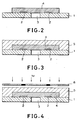
- Figs. 1 to 6 are schematic views for illustrating the fundamental embodiment of the present invention, and each of them shows an example of the construction of and the manufacturing procedure for the ink jet recording head the method of the invention pertains to.
- a base plate 1 comprising glass, ceramic, plastic or metal as shown in Fig. 1 is employed.
- the base plate 1 may be of any shape or any material as long as it can function as a part of the liquid flow path constituting member and as a support for the material layers that form the ink flow path and ink ejection outlets to be described later.
- ink ejection energy generating elements 2 such as electro-thermal conversion elements or piezoelectric elements.
- ink ejection energy generating elements 2 By such ink ejection energy generating elements 2, ejection energy for ejecting droplets of a recording liquid is imparted to the ink, and recording done.
- an electro-thermal conversion element is used as the ink ejection energy generating element 2
- this element heats a nearby recording liquid, thereby changing the state of the recording liquid and generating an ejection energy.
- a piezoelectric element is used, on the other hand, an ejection energy is generated by its mechanical vibrations.
- control signal input electrodes (not shown) for causing these elements to act.
- various functional layers such as protective layers. Needless to say, provision of such functional layers is acceptable.
- Fig. 1 exemplifies a form in which an opening 3 for feeding ink is provided in the base plate beforehand, and ink is fed from behind the base plate.
- any means can be used so long as it is capable of forming a hole in the base plate.
- mechanical means such as a drill, or a light energy such as laser may be employed.
- the ink feed inlet may be formed in the resin pattern rather than in the base plate, and provided on the same plane as the ink ejection outlets with respect to the base plate.
- an ink flow path pattern 4 is formed from a dissoluble resin on the base plate 1 including the ink ejection energy generating elements 2.
- the commonest means for forming the pattern would be one using a photosensitive material, but means such as screen printing can be employed.
- a positive resist or a solubility-changeable negative resist can be used, since the ink flow path pattern is dissoluble.
- a preferred method for forming a resist layer is to dissolve the photosensitive material in a suitable solvent, coating the solution onto a film of PET or the like, followed by drying to prepare a dry film, and laminate the dry film on the base plate.
- a photodecomposable polymeric compound derived from vinylketone such as polymethyl isopropyl ketone or polyvinylketone, can be used preferably. These compounds can be easily laminated on the ink feed inlet, because prior to exposure to light, they retain the properties of polymeric compounds (film-forming properties).
- a filler which can be removed during a subsequent step may be disposed in the ink feed inlet 3, followed by forming a film by an ordinary method such as spin-coating or roll-coating.
- a coating resin layer 5 On the dissoluble resin material layer having the ink flow path so patterned is further formed a coating resin layer 5 by an ordinary method such as spin-coating or roll-coating, as illustrated in Fig. 3.
- characteristics such as that of causing no deformation to the dissoluble resin pattern, are required. That is, when the coating resin layer is to be formed by dissolving the coating resin in a solvent and applying the solution onto the dissoluble resin pattern by spin-coating or roll-coating, it is necessary to select a solvent which will not melt the dissoluble resin pattern.
- a preferred coating resin layer is a photosensitive one, because it enables ink ejection outlets to be formed by photolithography easily and accurately.
- Such a photosensitive coating resin layer is required to have a high mechanical strength as a structural material, adhesion to the base plate, ink resistance, and resolution for patterning an intricate pattern of the ink ejection outlets.
- the cation-polymerized curing product of epoxy resin has a higher crosslinking density (high glass transition temperature [tg] ) than an ordinary curing product of an acid anhydride or amine, and thus exhibits satisfactory properties as a structural material.
- high glass transition temperature [tg] high glass transition temperature
- the use of an epoxy resin solid at ordinary temperatures prevents the diffusion into the epoxy resin of polymerization seeds that have occurred from the cationic polymerization initiator upon exposure to light, thus ensuring highly accurate patterning and obtaining a pattern of a definite shape.
- the step of forming the coating resin layer on the dissoluble resin layer is desirably carried out by dissolving in a solvent a coating resin which is solid at ordinary temperatures, and spin-coating the solution.
- the coating resin layer is desirably formed flat on surface. This is because (1) unevennesses present in the orifice surface would produce untoward ink reservoirs in the depressions, and (2) the flatness will facilitate processing during the formation of ink ejection outlets in the coating resin layer.
- the concentration of the coating resin with respect to the solvent becomes a very important factor in terms of the flatness of the coating resin layer. Concretely, it becomes possible to flatten the surface of the coating resin layer, by dissolving the coating resin in the solvent at a concentration of 30-70 wt.%, preferably 40-60 wt.%, for the spin-coating step.
- the coating resin is dissolved at a concentration of less than 30 wt.% and spin-coated, the resulting coating resin layer bears irregularities following the pattern of the dissoluble resin layer. If the coating resin is dissolved at a concentration exceeding 70 wt.%, the solution itself becomes highly viscous and cannot be spin-coated; even if it could be spin-coated, the resulting film would have an unsatisfactory film thickness distribution.
- the viscosity of the coating solution needs to be 10 to 3000 cps. Too low a viscosity will run the coating solution off; too high a viscosity will result in an ununiform layer of the coating solution. Therefore, it is necessary to select a suitable solvent so that the viscosity of the solution containing the coating resin will become a desirable value at the above-mentioned concentration.
- the aforementioned negative photosensitive material When the aforementioned negative photosensitive material is used as the coating resin, reflection from the base plate surface and scum (development residues) will occur usually.
- the ejection outlet pattern is formed on the ink flow path formed from the dissoluble resin, thus making the influence of reflection from the base plate negligible.
- the scum occurring during development is lifted off during the later-described step of washing away the dissoluble resin which forms the ink flow path. Hence, the scum exerts no adverse influence.
- Examples of the solid epoxy resins for use in the present invention include that reaction product between bisphenol A and epichlorohydrin which has a molecular weight of about 900 or more, the reaction product between bromine-containing bisphenol A and epichlorohydrin, the reaction product between phenolic novolak or o-cresol novolak and epichlorohydrin, and the polyfunctional epoxy resins having oxycyclohexane skeleton described in the specifications of Japanese Patent Application Laying-open Nos. 161973/1985, 221121/1988 and 9216/1989 and 140219/1990. Needless to say, the epoxy resins of the present invention are not restricted to these compounds.
- epoxy compounds those with an epoxy equivalent of 2,000 or less are used preferably, and those with an epoxy equivalent of 1,000 or less are used more preferably.
- An epoxy equivalent in excess of 2,000 may lead to a decrease in the crosslinking density during the curing reaction, thereby lowering the Tg or heat distortion temperature of the curing product, or deteriorating the adhesion or ink resistance.
- Examples of the cationic photopolymerization initiator for curing the epoxy resin include aromatic iodonium salts, aromatic sulfonium salts [see J. POLYMER SCI:Symposium No. 56, 383-395 (1976)], and SP-150 and SP-170 marketed by Asahi-Denka Kogyo Kabushiki Kaisha.
- cationic photopolymerization initiators with reducing agents enables cationic polymerization to be promoted by heating (i.e. the crosslinking density can be increased compared with cationic photopolymerization done without this combination).
- a reducing agent it is necessary to select such a reducing agent as to give a redox type initiator system which does not react at ordinary temperatures, but reacts at a certain temperature or above (preferably 60°C or above).
- Optimal as such a reducing agent is a copper compound, especially copper triflate (copper (II) trifluoromethanesulfonate) in view of the reactivity and the solubility in the epoxy resin.
- a reducing agent such as ascorbic acid is also useful. If a higher crosslinking density (higher Tg) is required because of the increased number of nozzles (high speed printing) or the use of a non-neutral ink (improved water resistance of the pigment), it is possible to raise the crosslinking density, by performing an after-step (to be described) of dipping the coating resin layer in a solution of the reducing agent and heating it, after the development step for the coating resin layer is completed.
- additives may be added if desired.
- flexibilizers may be added to increase the elasticity of the epoxy resin, or silane coupling agents may be added to obtain a further adhesion to the base plate.
- the photosensitive coating resin layer 5 comprising the above-described compounds is pattern-exposed through a mask 6 as illustrated in Fig. 4.
- the photosensitive coating resin layer 5 of the instant embodiment is of a negative type designed to shield the portions, which will constitute ink ejection outlets, with the mask (of course, it also shields the portions which will be electrically connected; not shown).
- the light for pattern exposure may be selected from ultraviolet rays, deep-UV radiation, electron rays, and X- rays in conformity with the photosensitivity region of the cationic photopolymerization initiator used.
- All of the above-mentioned steps are capable of register using a conventional photolithographic technique, and can attain a remarkably improved accuracy in comparison with a method in which an orifice plate is prepared separately and laminated to a base plate.
- the thus pattern-exposed photosensitive coating resin layer 5 may be heat-treated, if desired, to promote the reaction. Since the photosensitive coating resin layer is composed of an epoxy resin solid at ordinary temperatures as mentioned earlier, cationic polymerization seeds occurring upon pattern exposure are minimally diffused, thus enabling high patterning accuracy and shape.
- the pattern-exposed photosensitive coating resin layer 5 is developed using a suitable solvent to form ink ejection outlets as shown in Fig. 5. Simultaneously with the development of the unexposed photosensitive coating resin layer, it is possible to develop the dissoluble resin pattern 4 which will form an ink flow path. Generally, however, a plurality of heads of the same or different shapes are arranged on the base plate, and used as ink jet recording heads after being subjected to a cutting step. Therefore, as a countermeasure against swarf during cutting, the following step may be taken: Only the photosensitive coating resin layer is selectively developed as shown in Fig.
- the photosensitive coating resin layer 5 having the ink flow path and the ink ejection outlets formed therein is then dipped in a solution containing a reducing agent, and heated for post-curing.
- This step further raises the crosslinking density of the photosensitive coating resin layer 5, making the adhesion to the base plate and the fastness to ink very satisfactory.
- this step of dipping in the copper ion-containing solution, followed by heating may be carried out immediately after the photosensitive coating resin layer 5 is pattern-exposed and developed to form the ink ejection outlets. Afterwards, the dissoluble resin pattern 4 may be dissolved.
- the step of dipping and heating may be performed by either heating while dipping, or heating after dipping.
- Such a reducing agent may be any substance having a reducing activity, but a compound containing copper ions, such as copper triflate, copper acetate or copper benzoate, is particularly effective. Of these compounds, copper triflate, in particular, is very effective. In addition to those compounds, ascorbic acid is also useful.
- the base plate having the ink flow path and the ink ejection outlets thus formed thereon is provided with a member 7 for feeding ink and an electrical connection (not shown) for driving the ink ejection pressure generating elements to complete an ink jet recording head (Fig. 7).
- the ink ejection outlets are formed by photolithography, but the present invention is not restricted to it; the ink ejection outlets can be formed by dry etching with oxygen plasma or excimer laser if the mask is changed. If excimer laser or dry etching with oxygen plasma is used to form the ink ejection outlets, the base plate is protected by the resin pattern and is unlikely to be damaged by laser or plasma, thus making it possible to provide a highly accurate and reliable head. If dry etching or excimer laser is used for the formation of the ink ejection outlets, moreover, the coating resin layer may be a photosensitive or thermosetting one.
- the present invention is effective for a full-line type recording head capable of recording onto the whole width of a recording paper at the same time, and for a color recording head integrated with the recording head or having a plurality of the recording heads combined.
- the recording head according to the present invention is applied preferably to solid ink which liquefies at more than a certain temperature.
- a blast mask was placed on a silicone base plate 1 having electro-thermal converting elements 2 (heaters composed of the material HfB 2 ) as ink ejection energy generating elements formed thereon.
- a through-hole 3 for feeding ink was formed by sand blasting (Fig. 1).
- ODUR-1010 polymethyl isopropenyl ketone
- the ODUR-1010 was used in a concentrated form, because it has a low viscosity and cannot be formed into a thick film.
- a resin composition as shown in Table 1 was dissolved in a methyl isobutyl ketone/xylene solvent mixture at a concentration of 50 wt.%, and the solution was spin-coated to form a photosensitive coating resin layer 5 (the film thickness on the pattern 4: 10 ⁇ m, Fig. 3).
- pattern-exposure for ink ejection outlet formation was performed using PLA520 (CM250). The exposure lasted 10 seconds, and after-baking was performed for 30 minutes at 60°C.
- Methyl isobutyl ketone was used for development to form ink ejection outlets.
- a ⁇ 25 ⁇ m ejection outlet pattern was formed.
- the ink flow path pattern 4 was not completely developed, but remained.
- a plurality of heads of the same or different shapes are arranged on base plate 1, so that the base plate is cut by means of a dicer or the like at the above stage to obtain respective ink jet recording heads.
- the ink flow path pattern 4 remains as mentioned above, thus making it possible to prevent dust produced during cutting from entering the head.
- the so obtained ink jet recording head was exposed for 2 minutes using PLA520 (CM290), and dipped in methyl isobutyl ketone while under an ultrasonic wave, to melt the remaining ink flow path pattern 4 (Fig. 6).
- the ink jet recording head was heated for 1 hour at 150°C to cure the photosensitive coating material layer 5 completely.
- an ink feeding member 7 was bonded to the ink feeding port to complete an ink jet recording head.
- Example 2 Evaluations were made likewise, however with the composition of the photosensitive coating resin layer of Example 1 being changed as shown in Table 2.
- the mechanical strength of the nozzle constituent (a curing product of the photosensitive coating resin), its adhesion to the base plate, and so forth were improved further using a combination of a cationic photopolymerization initiator and a reducing agent.
- the steps until the formation of the photosensitive coating resin layer 5 were performed in the same manner as in Example 1.
- the pattern-exposure for ink ejection outlet formation was carried out for 5 seconds using PLA520 (CM250), and after-baking for 10 minutes at 60°C. Under these conditions, the cationic photopolymerization initiator and the reducing agent (copper triflate) do not substantially react, thus enabling patterning by light.
- Example 1 The ink jet recording head of Example 1 was subjected to post-steps of dipping it in a solution containing a reducing agent and heating it, whereafter evaluations were made likewise.
- the ink jet recording head was dipped for 30 minutes in a 2 wt.% ethanol solution of copper triflate while under an ultrasonic wave, and then it was dried. After being heat-treated for 2 hours at 150°C, it was washed with pure water. Then, an ink feeding member 7 was bonded to the ink feeding port in the same way as in Example 1 to complete an ink jet recording head.
- a composition as shown in Table 1 was formed to a thickness of 10 ⁇ m on a capton film, and subjected to photosetting. Then, this laminate was either dipped in an ethanol solution containing copper ions, and heat-treated to prepare a sample (a); or dipped in a pure ethanol solution containing no copper ions, and heat-treated to prepare a sample (b).
- the glass transition points (Tg) of these samples were measured by dynamic evaluation.
- the sample (a) was found to have a Tg of 240°C, and the sample (b), that of 200°C.
- Epoxy resin o-cresol novolak type epoxy resin (Epicoat 180H65, Yuka Shell) 100 parts Cationic photopolymerization initiator 4,4'-di-t-butylphenoliodonium hexafluoroantimonate 1 part Silane coupling agent A-187, Nihon Yuniker 10 parts Epoxy resin Polyfunctional epoxy resin with oxycyclohexane skeleton (EHPE-3150, Daicel Chemical) 100 parts Cationic photopolymerization initiator 4,4'-di-t-butylphenoliodonium hexafluoroantimonate 0.5 part Reducing agent Copper triflate 0.5 part Silane coupling agent A-187, Nihon Yuniker 5 parts
- the above-described present invention is capable of strictly controlling the distances between, and the positional accuracy of, the ink ejection pressure generating elements and the orifices. Hence, it brings the effect that an ink jet recording head with stable ejection properties and high reliability can be produced by a simple method.
Landscapes
- Engineering & Computer Science (AREA)
- Manufacturing & Machinery (AREA)
- Physics & Mathematics (AREA)
- Optics & Photonics (AREA)
- Particle Formation And Scattering Control In Inkjet Printers (AREA)
Claims (14)
- Procédé pour la production d'une tête d'enregistrement par jets d'encre, comprenant les étapes consistant :(a) à former un motif de trajet d'écoulement d'encre (4) sur un substrat (1) au moyen d'une résine pouvant se dissoudre, le substrat portant des éléments (2) engendrant une pression d'éjection d'encre ;(b) à former sur le motif de trajet d'écoulement d'encre (4) une couche de résine de revêtement (5), qui sert à former les parois du motif de trajet d'écoulement d'encre, caractérisé par
le maintien de la résine à appliquer sous forme d'un revêtement en solution dans un solvant convenable, la résine contenant une résine époxy qui est solide aux températures ambiantes, puis l'application de la résine en solution sous forme d'un revêtement sur le motif de trajet d'écoulement d'encre (4) ;(c) la formation d'orifices de sortie d'éjection d'encre dans la couche de résine de revêtement (5) au-dessus des éléments (2) engendrant une pression d'éjection d'encre ; et (d) la dissolution du motif du trajet d'écoulement d'encre (4). - Procédé de production d'une tête d'enregistrement par jets d'encre suivant la revendication 1, caractérisé en ce que la résine de revêtement est une résine photosensible et contient un initiateur de photopolymérisation cationique.
- Procédé de production d'une tête d'enregistrement par jets d'encre suivant la revendication 2, caractérisé en ce que la résine de revêtement contient un agent réducteur.
- Procédé de production d'une tête d'enregistrement par jets d'encre suivant la revendication 2, caractérisé en ce que l'initiateur de photopolymérisation cationique est un sel d'iodonium aromatique.
- Procédé de production d'une tête d'enregistrement par jets d'encre suivant la revendication 3, caractérisé en ce que l'agent réducteur consiste en triflate de cuivre.
- Procédé de production d'une tête d'enregistrement par jets d'encre répondant à la définition suivant la revendication 1, caractérisé en ce que le poids équivalent d'époxy de la résine époxy est égal ou inférieur à 2000.
- Procédé de production d'une tête d'enregistrement par jets d'encre suivant la revendication 1, comprenant en outre une étape d'immersion de la couche de résine de revêtement dans une solution contenant un agent réducteur et de chauffage de couche de résine de revêtement, après la mise en oeuvre de l'étape de dissolution du motif de trajet d'écoulement d'encre.
- Procédé de production d'une tête d'enregistrement par jets d'encre suivant la revendication 7, caractérisé en ce que l'agent réducteur contient des ions cuivre.
- Procédé de production d'une tête d'enregistrement par jets d'encre suivant la revendication 7, caractérisé en ce que l'agent réducteur contient du triflate de cuivre.
- Procédé de production d'une tête d'enregistrement par jets d'encre suivant la revendication 2, caractérisé en ce que les orifices de sortie d'éjection d'encre sont formés par photolithographie.
- Procédé de production d'une tête d'enregistrement par jets d'encre suivant la revendication 1, caractérisé en ce que les orifices de sortie d'éjection d'encre sont formés par attaque à sec avec un plasma d'oxygène.
- Procédé de production d'une tête d'enregistrement par jets d'encre suivant la revendication 1, caractérisé en ce que les orifices de sortie d'éjection d'encre sont formés au moyen d'un laser à excimère.
- Procédé de production d'une tête d'enregistrement par jets d'encre suivant la revendication 1, caractérisé en ce que la concentration de la résine de revêtement dissoute dans le solvant est comprise dans l'intervalle de 30 à 70 % en poids.
- Procédé de production d'une tête d'enregistrement par jets d'encre suivant la revendication 13, caractérisé en ce que la concentration de la résine de revêtement dissoute dans le solvant est comprise dans l'intervalle de 40 à 60 % en poids.
Applications Claiming Priority (4)
| Application Number | Priority Date | Filing Date | Title |
|---|---|---|---|
| JP1623893 | 1993-02-03 | ||
| JP16238/93 | 1993-02-03 | ||
| JP06010078A JP3143307B2 (ja) | 1993-02-03 | 1994-01-31 | インクジェット記録ヘッドの製造方法 |
| JP10078/94 | 1994-01-31 |
Publications (3)
| Publication Number | Publication Date |
|---|---|
| EP0609860A2 EP0609860A2 (fr) | 1994-08-10 |
| EP0609860A3 EP0609860A3 (en) | 1995-08-16 |
| EP0609860B1 true EP0609860B1 (fr) | 1998-06-03 |
Family
ID=26345271
Family Applications (1)
| Application Number | Title | Priority Date | Filing Date |
|---|---|---|---|
| EP94101556A Expired - Lifetime EP0609860B1 (fr) | 1993-02-03 | 1994-02-02 | Méthode pour la fabrication d'une tête à jet d'encre |
Country Status (8)
| Country | Link |
|---|---|
| US (1) | US5478606A (fr) |
| EP (1) | EP0609860B1 (fr) |
| JP (1) | JP3143307B2 (fr) |
| KR (1) | KR0152452B1 (fr) |
| CN (1) | CN1080645C (fr) |
| AT (1) | ATE166836T1 (fr) |
| DE (1) | DE69410648T2 (fr) |
| ES (1) | ES2116478T3 (fr) |
Cited By (2)
| Publication number | Priority date | Publication date | Assignee | Title |
|---|---|---|---|---|
| US8286350B2 (en) | 2009-02-25 | 2012-10-16 | Canon Kabushiki Kaisha | Method of manufacturing a liquid discharge head |
| US8544997B2 (en) | 2011-03-23 | 2013-10-01 | Canon Kabushiki Kaisha | Liquid ejection head and manufacturing method thereof |
Families Citing this family (179)
| Publication number | Priority date | Publication date | Assignee | Title |
|---|---|---|---|---|
| JP3283979B2 (ja) * | 1993-11-12 | 2002-05-20 | キヤノン株式会社 | 液体噴射記録ヘッドの製造方法 |
| JP3143308B2 (ja) | 1994-01-31 | 2001-03-07 | キヤノン株式会社 | インクジェット記録ヘッドの製造方法 |
| JP3236458B2 (ja) * | 1994-11-22 | 2001-12-10 | キヤノン株式会社 | インクジェット記録ヘッド |
| EP0715957B1 (fr) * | 1994-12-05 | 1999-05-26 | Canon Kabushiki Kaisha | Procédé de production d'une tête à jet d'encre |
| JP3229146B2 (ja) * | 1994-12-28 | 2001-11-12 | キヤノン株式会社 | 液体噴射ヘッドおよびその製造方法 |
| US5983486A (en) * | 1995-03-10 | 1999-11-16 | Canon Kabushiki Kaisha | Process for producing ink jet head |
| US6461798B1 (en) * | 1995-03-31 | 2002-10-08 | Canon Kabushiki Kaisha | Process for the production of an ink jet head |
| JP3368094B2 (ja) * | 1995-04-21 | 2003-01-20 | キヤノン株式会社 | インクジェット記録ヘッドの製造方法 |
| JP3459703B2 (ja) * | 1995-06-20 | 2003-10-27 | キヤノン株式会社 | インクジェットヘッドの製造方法、およびインクジェットヘッド |
| JP3361916B2 (ja) * | 1995-06-28 | 2003-01-07 | シャープ株式会社 | 微小構造の形成方法 |
| JP3343875B2 (ja) * | 1995-06-30 | 2002-11-11 | キヤノン株式会社 | インクジェットヘッドの製造方法 |
| US5790154A (en) * | 1995-12-08 | 1998-08-04 | Hitachi Koki Co., Ltd. | Method of manufacturing an ink ejection recording head and a recording apparatus using the recording head |
| US6123863A (en) * | 1995-12-22 | 2000-09-26 | Canon Kabushiki Kaisha | Process for producing liquid-jet recording head, liquid-jet recording head produced thereby, and recording apparatus equipped with recording head |
| JP3372739B2 (ja) * | 1996-01-12 | 2003-02-04 | キヤノン株式会社 | 液体噴射記録ヘッドの製造方法 |
| EP0816089B1 (fr) * | 1996-06-26 | 2003-09-17 | Canon Kabushiki Kaisha | Tête d'enregistrement à jet d'encre et appareil d'enregistrement à jet d'encre |
| US5820771A (en) * | 1996-09-12 | 1998-10-13 | Xerox Corporation | Method and materials, including polybenzoxazole, for fabricating an ink-jet printhead |
| US6137510A (en) * | 1996-11-15 | 2000-10-24 | Canon Kabushiki Kaisha | Ink jet head |
| US5907333A (en) * | 1997-03-28 | 1999-05-25 | Lexmark International, Inc. | Ink jet print head containing a radiation curable resin layer |
| CN1073938C (zh) * | 1997-10-21 | 2001-10-31 | 研能科技股份有限公司 | 快速粘合喷墨头的喷孔片的方法 |
| CN1080646C (zh) * | 1997-10-21 | 2002-03-13 | 研能科技股份有限公司 | 形成喷墨头电阻层的方法 |
| JP3619036B2 (ja) | 1997-12-05 | 2005-02-09 | キヤノン株式会社 | インクジェット記録ヘッドの製造方法 |
| US6409931B1 (en) | 1998-01-26 | 2002-06-25 | Canon Kabushiki Kaisha | Method of producing ink jet recording head and ink jet recording head |
| US6303274B1 (en) * | 1998-03-02 | 2001-10-16 | Hewlett-Packard Company | Ink chamber and orifice shape variations in an ink-jet orifice plate |
| US6379571B1 (en) | 1998-06-11 | 2002-04-30 | Canon Kabushiki Kaisha | Etching method for processing substrate, dry etching method for polyetheramide resin layer, production method of ink-jet printing head, ink-jet head and ink-jet printing apparatus |
| US6164762A (en) * | 1998-06-19 | 2000-12-26 | Lexmark International, Inc. | Heater chip module and process for making same |
| US6203871B1 (en) | 1998-10-14 | 2001-03-20 | Lexmark International, Inc. | Encapsulant for leads in an aqueous environment |
| KR100325521B1 (ko) * | 1998-12-10 | 2002-04-17 | 윤종용 | 유체 분사 장치의 제조 방법 및 그에 의해 제조되는 유체 분사장치 |
| EP1020291A3 (fr) | 1999-01-18 | 2001-04-11 | Canon Kabushiki Kaisha | Tête à jet de liquide et sa methode de fabrication |
| JP4497633B2 (ja) | 1999-03-15 | 2010-07-07 | キヤノン株式会社 | 撥液体層の形成方法及び液体吐出ヘッドの製造方法 |
| CN1143773C (zh) | 1999-06-04 | 2004-03-31 | 佳能株式会社 | 液体排出头及其生产方法,生产微小机械装置的方法 |
| US6310641B1 (en) | 1999-06-11 | 2001-10-30 | Lexmark International, Inc. | Integrated nozzle plate for an inkjet print head formed using a photolithographic method |
| US6364455B1 (en) * | 1999-06-29 | 2002-04-02 | Wisertek International Corporation | Printhead of ink jet printing apparatus and manufacturing method therefor |
| EP1065059B1 (fr) | 1999-07-02 | 2007-01-31 | Canon Kabushiki Kaisha | Procédé de production d'une tête à éjection de liquide, tête à éjection de liquide ainsi produite, cartouche, appareil d'éjection de liquide, procédé de production d'une plaque de silicium et plaque de silicium ainsi produite |
| US6472125B1 (en) * | 1999-11-30 | 2002-10-29 | Canon Kabushiki Kaisha | Method for manufacturing ink jet recording head and ink jet recording head manufactured by such method of manufacture |
| JP3679668B2 (ja) | 1999-12-20 | 2005-08-03 | キヤノン株式会社 | インクジェット記録ヘッドの製造方法 |
| CN1111117C (zh) * | 2000-01-12 | 2003-06-11 | 威硕科技股份有限公司 | 用于打印装置的喷墨头的制造方法 |
| US6482574B1 (en) | 2000-04-20 | 2002-11-19 | Hewlett-Packard Co. | Droplet plate architecture in ink-jet printheads |
| JP2002144584A (ja) * | 2000-11-07 | 2002-05-21 | Sony Corp | プリンタ、プリンタヘッド及びプリンタヘッドの製造方法 |
| US6702413B2 (en) | 2000-11-16 | 2004-03-09 | Canon Kabushiki Kaisha | Liquid discharge head, liquid discharge apparatus, and IC package structure |
| JP4054583B2 (ja) | 2001-02-28 | 2008-02-27 | キヤノン株式会社 | インクジェットプリントヘッドの製造方法 |
| US6409312B1 (en) | 2001-03-27 | 2002-06-25 | Lexmark International, Inc. | Ink jet printer nozzle plate and process therefor |
| JP4532785B2 (ja) | 2001-07-11 | 2010-08-25 | キヤノン株式会社 | 構造体の製造方法、および液体吐出ヘッドの製造方法 |
| JP4095368B2 (ja) | 2001-08-10 | 2008-06-04 | キヤノン株式会社 | インクジェット記録ヘッドの作成方法 |
| EP1297959A1 (fr) * | 2001-09-28 | 2003-04-02 | Hewlett-Packard Company | Têtes d'impression à jet d'encre |
| US6627467B2 (en) | 2001-10-31 | 2003-09-30 | Hewlett-Packard Development Company, Lp. | Fluid ejection device fabrication |
| US7125731B2 (en) | 2001-10-31 | 2006-10-24 | Hewlett-Packard Development Company, L.P. | Drop generator for ultra-small droplets |
| US6698868B2 (en) | 2001-10-31 | 2004-03-02 | Hewlett-Packard Development Company, L.P. | Thermal drop generator for ultra-small droplets |
| JP3986060B2 (ja) * | 2001-12-28 | 2007-10-03 | キヤノン株式会社 | インクジェット記録ヘッドの流路構成部材及びインクジェット記録ヘッドの製造方法 |
| US6986982B2 (en) | 2002-02-20 | 2006-01-17 | Canon Kabushiki Kaisha | Resist material and method of manufacturing inkjet recording head using the same |
| JPWO2003084759A1 (ja) | 2002-04-10 | 2005-08-11 | ソニー株式会社 | 液体吐出ヘッド、液体吐出装置及び液体吐出ヘッドの製造方法 |
| JP2003300323A (ja) | 2002-04-11 | 2003-10-21 | Canon Inc | インクジェットヘッド及びその製造方法 |
| JP2004042389A (ja) | 2002-07-10 | 2004-02-12 | Canon Inc | 微細構造体の製造方法、液体吐出ヘッドの製造方法および液体吐出ヘッド |
| JP4298414B2 (ja) | 2002-07-10 | 2009-07-22 | キヤノン株式会社 | 液体吐出ヘッドの製造方法 |
| JP3862625B2 (ja) * | 2002-07-10 | 2006-12-27 | キヤノン株式会社 | 液体吐出ヘッドの製造方法 |
| JP4280574B2 (ja) * | 2002-07-10 | 2009-06-17 | キヤノン株式会社 | 液体吐出ヘッドの製造方法 |
| US6993840B2 (en) * | 2002-07-18 | 2006-02-07 | Canon Kabushiki Kaisha | Manufacturing method of liquid jet head |
| JP2004050524A (ja) * | 2002-07-18 | 2004-02-19 | Canon Inc | 液体噴射ヘッドの製造方法 |
| US6739519B2 (en) | 2002-07-31 | 2004-05-25 | Hewlett-Packard Development Company, Lp. | Plurality of barrier layers |
| JP4296062B2 (ja) * | 2002-08-30 | 2009-07-15 | 服部 正 | パターン成形用型の製造方法 |
| US7329480B2 (en) * | 2002-08-30 | 2008-02-12 | Toyo Gosei Co., Ltd. | Radiation-sensitive negative-type resist composition for pattern formation method |
| JP2004181901A (ja) | 2002-12-06 | 2004-07-02 | Fuji Xerox Co Ltd | インクジェット記録ヘッド及びその製造方法 |
| JP4078295B2 (ja) | 2002-12-27 | 2008-04-23 | キヤノン株式会社 | インクジェットヘッド用基体およびこれを用いるインクジェットヘッドとその製造方法 |
| CN100355573C (zh) | 2002-12-27 | 2007-12-19 | 佳能株式会社 | 用于制造喷墨记录头的基础件 |
| US7323115B2 (en) | 2003-02-13 | 2008-01-29 | Canon Kabushiki Kaisha | Substrate processing method and ink jet recording head substrate manufacturing method |
| US6709805B1 (en) | 2003-04-24 | 2004-03-23 | Lexmark International, Inc. | Inkjet printhead nozzle plate |
| JP3963456B2 (ja) | 2003-06-16 | 2007-08-22 | キヤノン株式会社 | 感光性樹脂組成物およびこれを用いたインクジェット記録ヘッドおよびその製造方法 |
| US7065874B2 (en) * | 2003-07-18 | 2006-06-27 | Canon Kabushiki Kaisha | Method for making liquid ejection head |
| ATE465008T1 (de) | 2003-07-22 | 2010-05-15 | Canon Kk | Tintenstrahlkopf und herstellungsverfahren dafür |
| CN1741905B (zh) * | 2003-07-22 | 2012-11-28 | 佳能株式会社 | 喷墨头及其制造方法 |
| JP2005074747A (ja) * | 2003-08-29 | 2005-03-24 | Canon Inc | インクジェットヘッドの製造方法およびインクジェットヘッド |
| US7029099B2 (en) * | 2003-10-30 | 2006-04-18 | Eastman Kodak Company | Method of producing ink jet chambers using photo-imageable materials |
| DE10353767B4 (de) * | 2003-11-17 | 2005-09-29 | Infineon Technologies Ag | Vorrichtung zur Häusung einer mikromechanischen Struktur und Verfahren zur Herstellung derselben |
| JP4455282B2 (ja) * | 2003-11-28 | 2010-04-21 | キヤノン株式会社 | インクジェットヘッドの製造方法、インクジェットヘッドおよびインクジェットカートリッジ |
| JP4522086B2 (ja) | 2003-12-15 | 2010-08-11 | キヤノン株式会社 | 梁、梁の製造方法、梁を備えたインクジェット記録ヘッド、および該インクジェット記録ヘッドの製造方法 |
| JP4480132B2 (ja) | 2004-02-18 | 2010-06-16 | キヤノン株式会社 | 液体吐出用ヘッドの製造方法 |
| US7191520B2 (en) * | 2004-03-05 | 2007-03-20 | Eastman Kodak Company | Method of optmizing inkjet printheads using a plasma-etching process |
| US7325309B2 (en) * | 2004-06-08 | 2008-02-05 | Hewlett-Packard Development Company, L.P. | Method of manufacturing a fluid ejection device with a dry-film photo-resist layer |
| US7377625B2 (en) * | 2004-06-25 | 2008-05-27 | Canon Kabushiki Kaisha | Method for producing ink-jet recording head having filter, ink-jet recording head, substrate for recording head, and ink-jet cartridge |
| EP1768848B1 (fr) | 2004-06-28 | 2010-07-21 | Canon Kabushiki Kaisha | Procede de fabrication d'une tete de decharge de liquides et tete de decharge de liquides ainsi obtenue |
| KR100881245B1 (ko) | 2004-06-28 | 2009-02-05 | 캐논 가부시끼가이샤 | 양이온 광중합성 에폭시 수지 조성물, 이것을 사용한 미세구조체, 및 미세 구조체의 제조 방법 |
| US8017307B2 (en) * | 2004-06-28 | 2011-09-13 | Canon Kabushiki Kaisha | Method for manufacturing minute structure, method for manufacturing liquid discharge head, and liquid discharge head |
| DE602005015974D1 (de) | 2004-06-28 | 2009-09-24 | Canon Kk | Kopfs und unter verwendung dieses verfahrens erhaltener flüssigkeitsabgabekopf |
| JP4274554B2 (ja) | 2004-07-16 | 2009-06-10 | キヤノン株式会社 | 素子基板および液体吐出素子の形成方法 |
| KR100560720B1 (ko) * | 2004-08-05 | 2006-03-13 | 삼성전자주식회사 | 광경화성 수지 조성물을 사용한 잉크젯 프린트 헤드의제조방법 |
| KR100560721B1 (ko) * | 2004-08-23 | 2006-03-13 | 삼성전자주식회사 | 금속 챔버층을 구비하는 잉크젯 헤드의 제조방법 및 그에의하여 제조된 잉크젯 헤드 |
| KR100641358B1 (ko) * | 2004-09-23 | 2006-11-01 | 삼성전자주식회사 | 광경화성 수지 조성물을 사용한 잉크젯 프린트 헤드의제조방법 |
| JP2006126116A (ja) | 2004-11-01 | 2006-05-18 | Canon Inc | フィルター用基板の製造方法、インクジェット記録ヘッドおよびその製造方法 |
| TWI289511B (en) * | 2004-11-22 | 2007-11-11 | Canon Kk | Method of manufacturing liquid discharge head, and liquid discharge head |
| KR100497413B1 (ko) * | 2004-11-26 | 2005-06-23 | 에이스하이텍 주식회사 | 텅스텐-화학적 기계적 연마에 유용한 슬러리 및 그 제조방법 |
| JP4614383B2 (ja) * | 2004-12-09 | 2011-01-19 | キヤノン株式会社 | インクジェット記録ヘッドの製造方法、及びインクジェット記録ヘッド |
| JP4667028B2 (ja) | 2004-12-09 | 2011-04-06 | キヤノン株式会社 | 構造体の形成方法及びインクジェット記録ヘッドの製造方法 |
| US7254890B2 (en) * | 2004-12-30 | 2007-08-14 | Lexmark International, Inc. | Method of making a microfluid ejection head structure |
| ATE485538T1 (de) | 2005-01-21 | 2010-11-15 | Canon Kk | Tintenstrahlaufzeichnungskopf, herstellungsverfahren dafür und zusammensetzung für tintenstrahlaufzeichnungskopf |
| TWI295632B (en) | 2005-01-21 | 2008-04-11 | Canon Kk | Ink jet recording head, producing method therefor and composition for ink jet recording head |
| US7735965B2 (en) * | 2005-03-31 | 2010-06-15 | Lexmark International Inc. | Overhanging nozzles |
| JP4693496B2 (ja) * | 2005-05-24 | 2011-06-01 | キヤノン株式会社 | 液体吐出ヘッドおよびその製造方法 |
| JP4881081B2 (ja) * | 2005-07-25 | 2012-02-22 | キヤノン株式会社 | 液体吐出ヘッドの製造方法 |
| US7637013B2 (en) * | 2005-08-23 | 2009-12-29 | Canon Kabushiki Kaisha | Method of manufacturing ink jet recording head |
| US7735961B2 (en) * | 2005-10-20 | 2010-06-15 | Canon Kabushiki Kaisha | Liquid discharge head and method of producing the same |
| JP4810192B2 (ja) * | 2005-11-01 | 2011-11-09 | キヤノン株式会社 | インクジェット記録ヘッドの製造方法、及びインクジェット記録ヘッド |
| EP1957282B1 (fr) * | 2005-12-02 | 2013-04-10 | Canon Kabushiki Kaisha | Procede de production d'une tete de distribution de liquide |
| EP1801142B1 (fr) * | 2005-12-16 | 2016-02-24 | Canon Kabushiki Kaisha | Composition de résine, produit de résine durcit et tête de décharge liquide |
| US7523553B2 (en) * | 2006-02-02 | 2009-04-28 | Canon Kabushiki Kaisha | Method of manufacturing ink jet recording head |
| JP4834426B2 (ja) * | 2006-03-06 | 2011-12-14 | キヤノン株式会社 | インクジェット記録ヘッドの製造方法 |
| WO2007105801A1 (fr) | 2006-03-10 | 2007-09-20 | Canon Kabushiki Kaisha | Corps de base a tete d'ejection de liquide, tete d'ejection de liquide qui utilise ce corps de base et procede pour leur fabrication |
| JP4890962B2 (ja) * | 2006-06-21 | 2012-03-07 | キヤノン株式会社 | 液体噴射記録ヘッド及びその製造方法 |
| JP2008012688A (ja) * | 2006-07-03 | 2008-01-24 | Canon Inc | インクジェット記録ヘッド、インクジェット記録装置およびインクジェット記録ヘッドの製造方法 |
| DE602006013356D1 (de) * | 2006-07-13 | 2010-05-12 | Telecom Italia Spa | Tintenstrahlpatrone mit einer aus einer härtbaren harzzusammensetzung hergestellten schicht |
| JP2008030271A (ja) * | 2006-07-27 | 2008-02-14 | Canon Inc | インクジェット記録ヘッド及びその製造方法 |
| JP2008049531A (ja) | 2006-08-23 | 2008-03-06 | Canon Inc | インクジェット記録ヘッド |
| US8376525B2 (en) * | 2006-09-08 | 2013-02-19 | Canon Kabushiki Kaisha | Liquid discharge head and method of manufacturing the same |
| US8267503B2 (en) | 2006-10-16 | 2012-09-18 | Canon Kabushiki Kaisha | Ink jet recording head and manufacturing method therefor |
| US20080088673A1 (en) * | 2006-10-17 | 2008-04-17 | Sexton Richard W | Method of producing inkjet channels using photoimageable materials and inkjet printhead produced thereby |
| US7699441B2 (en) * | 2006-12-12 | 2010-04-20 | Eastman Kodak Company | Liquid drop ejector having improved liquid chamber |
| US7600856B2 (en) * | 2006-12-12 | 2009-10-13 | Eastman Kodak Company | Liquid ejector having improved chamber walls |
| US8152278B2 (en) | 2006-12-14 | 2012-04-10 | Canon Kabushiki Kaisha | Liquid jet head chip and manufacturing method therefor |
| JP2008149519A (ja) * | 2006-12-15 | 2008-07-03 | Canon Inc | 液体吐出ヘッド及びその製造方法 |
| JP4981491B2 (ja) * | 2007-03-15 | 2012-07-18 | キヤノン株式会社 | インクジェットヘッド製造方法及び貫通電極の製造方法 |
| JP4979440B2 (ja) * | 2007-04-03 | 2012-07-18 | キヤノン株式会社 | 液体吐出ヘッドの製造方法 |
| US20080259134A1 (en) * | 2007-04-20 | 2008-10-23 | Hewlett-Packard Development Company Lp | Print head laminate |
| JP5008448B2 (ja) | 2007-04-20 | 2012-08-22 | キヤノン株式会社 | インクジェット記録ヘッド用の基板の製造方法 |
| JP2008290413A (ja) * | 2007-05-28 | 2008-12-04 | Canon Inc | 液体吐出ヘッドの製造方法 |
| JP4953930B2 (ja) * | 2007-06-13 | 2012-06-13 | キヤノン株式会社 | インクジェット記録ヘッド及びその製造方法 |
| US8273524B2 (en) * | 2007-06-18 | 2012-09-25 | Canon Kabushiki Kaisha | Liquid discharging head, producing method thereof, structure, and producing method thereof |
| JP2009119650A (ja) * | 2007-11-13 | 2009-06-04 | Canon Inc | インクジェットヘッドの製造方法 |
| US20090136875A1 (en) * | 2007-11-15 | 2009-05-28 | Canon Kabushiki Kaisha | Manufacturing method of liquid ejection head |
| JP5311975B2 (ja) | 2007-12-12 | 2013-10-09 | キヤノン株式会社 | 液体吐出ヘッド用基体及びこれを用いる液体吐出ヘッド |
| US20090162797A1 (en) * | 2007-12-19 | 2009-06-25 | Canon Kabushiki Kaisha | Method of manufacturing liquid ejection head |
| JP5100414B2 (ja) * | 2008-01-24 | 2012-12-19 | キヤノン株式会社 | ネットワークデバイス管理装置及びその制御方法、ネットワークシステム、並びにプログラム |
| JP5159336B2 (ja) * | 2008-01-25 | 2013-03-06 | キヤノン株式会社 | インクジェット記録ヘッドおよびその製造方法 |
| JP2009220286A (ja) * | 2008-03-13 | 2009-10-01 | Canon Inc | 液体吐出記録ヘッド及その製造方法 |
| JP2009233955A (ja) | 2008-03-26 | 2009-10-15 | Canon Inc | 微細構造体の製造方法及び液体吐出ヘッドの製造方法 |
| JP5355223B2 (ja) | 2008-06-17 | 2013-11-27 | キヤノン株式会社 | 液体吐出ヘッド |
| US8291576B2 (en) | 2008-06-18 | 2012-10-23 | Canon Kabushiki Kaisha | Method of manufacturing liquid ejection head |
| JP2010000632A (ja) | 2008-06-18 | 2010-01-07 | Canon Inc | インクジェットヘッド用基板および該基板を具えるインクジェットヘッド |
| US8137573B2 (en) * | 2008-06-19 | 2012-03-20 | Canon Kabushiki Kaisha | Liquid ejection head, method for manufacturing liquid ejection head, and method for manufacturing structure |
| JP5224929B2 (ja) * | 2008-06-24 | 2013-07-03 | キヤノン株式会社 | 液体吐出記録ヘッドの製造方法 |
| JP5328608B2 (ja) * | 2008-12-15 | 2013-10-30 | キヤノン株式会社 | 液体吐出ヘッド用基板、液体吐出ヘッド及びそれらの製造方法 |
| JP4942218B2 (ja) * | 2008-12-16 | 2012-05-30 | キヤノン株式会社 | 液体吐出ヘッドの製造方法 |
| JP5566130B2 (ja) * | 2009-02-26 | 2014-08-06 | キヤノン株式会社 | 液体吐出ヘッドの製造方法 |
| US8409454B2 (en) * | 2009-04-01 | 2013-04-02 | Canon Kabushiki Kaisha | Production process for structure and production process for liquid discharge head |
| JP5553538B2 (ja) * | 2009-06-19 | 2014-07-16 | キヤノン株式会社 | 液体吐出ヘッドの製造方法 |
| JP5511283B2 (ja) | 2009-09-24 | 2014-06-04 | キヤノン株式会社 | 液体吐出ヘッドの製造方法 |
| JP5596954B2 (ja) * | 2009-10-08 | 2014-09-24 | キヤノン株式会社 | 液体供給部材、液体供給部材の製造方法及び液体吐出ヘッドの製造方法 |
| JP5279686B2 (ja) * | 2009-11-11 | 2013-09-04 | キヤノン株式会社 | 液体吐出ヘッドの製造方法 |
| JP5393423B2 (ja) | 2009-12-10 | 2014-01-22 | キヤノン株式会社 | インク吐出ヘッド及びその製造方法 |
| JP5586978B2 (ja) * | 2010-02-09 | 2014-09-10 | キヤノン株式会社 | 液体吐出ヘッドの製造方法 |
| JP2011213058A (ja) * | 2010-04-01 | 2011-10-27 | Canon Inc | 感光性樹脂組成物および液体吐出ヘッドの製造方法 |
| US8268539B2 (en) * | 2010-07-23 | 2012-09-18 | Caron Kabushiki Kaisha | Method of manufacturing liquid ejection head |
| GB201013123D0 (en) * | 2010-08-04 | 2010-09-22 | Xaar Technology Ltd | Droplet deposition apparatus and method for manufacturing the same |
| JP5501167B2 (ja) | 2010-09-08 | 2014-05-21 | キヤノン株式会社 | インクジェットヘッドの製造方法 |
| US8500252B2 (en) * | 2010-11-05 | 2013-08-06 | Canon Kabushiki Kaisha | Liquid ejection head and method of manufacturing the same |
| US8434229B2 (en) * | 2010-11-24 | 2013-05-07 | Canon Kabushiki Kaisha | Liquid ejection head manufacturing method |
| JP5350429B2 (ja) | 2011-02-10 | 2013-11-27 | キヤノン株式会社 | インクジェット記録ヘッドの製造方法 |
| ITMI20111011A1 (it) | 2011-06-06 | 2012-12-07 | Telecom Italia Spa | Testina di stampa a getto d'inchiostro comprendente uno strato realizzato con una composizione di resina reticolabile |
| JP6039259B2 (ja) * | 2011-07-25 | 2016-12-07 | キヤノン株式会社 | 液体吐出ヘッド、およびその製造方法 |
| JP5539547B2 (ja) | 2012-01-24 | 2014-07-02 | キヤノン株式会社 | 液体吐出ヘッド及びその製造方法 |
| JP6120574B2 (ja) | 2012-01-31 | 2017-04-26 | キヤノン株式会社 | 感光性ネガ型樹脂組成物、微細構造体、微細構造体の製造方法及び液体吐出ヘッド |
| JP6157184B2 (ja) | 2012-04-10 | 2017-07-05 | キヤノン株式会社 | 液体吐出ヘッドの製造方法 |
| JP6099891B2 (ja) | 2012-07-03 | 2017-03-22 | キヤノン株式会社 | ドライエッチング方法 |
| WO2014061062A1 (fr) * | 2012-10-18 | 2014-04-24 | サンアプロ株式会社 | Sel de sulfonium, générateur photoacide, composition polymérisable et composition de résine photosensible |
| JP6071718B2 (ja) | 2013-04-10 | 2017-02-01 | キヤノン株式会社 | 感光性ネガ型樹脂組成物 |
| JP6132652B2 (ja) * | 2013-05-02 | 2017-05-24 | キヤノン株式会社 | 液体吐出ヘッドの製造方法 |
| JP6230279B2 (ja) | 2013-06-06 | 2017-11-15 | キヤノン株式会社 | 液体吐出ヘッドの製造方法 |
| JP6223006B2 (ja) | 2013-06-12 | 2017-11-01 | キヤノン株式会社 | 液体吐出ヘッドチップ及びその製造方法 |
| JP6184258B2 (ja) | 2013-09-02 | 2017-08-23 | キヤノン株式会社 | 液体吐出ヘッドの製造方法 |
| JP6218517B2 (ja) * | 2013-09-09 | 2017-10-25 | キヤノン株式会社 | 液体吐出ヘッドの製造方法 |
| JP6274954B2 (ja) | 2014-04-09 | 2018-02-07 | キヤノン株式会社 | 液体吐出ヘッドの製造方法 |
| JP6504911B2 (ja) | 2015-05-19 | 2019-04-24 | キヤノン株式会社 | 液体吐出ヘッドの製造方法 |
| JP6217711B2 (ja) * | 2015-08-21 | 2017-10-25 | 日亜化学工業株式会社 | 発光装置の製造方法 |
| US10022979B2 (en) | 2016-01-08 | 2018-07-17 | Canon Kabushiki Kaisha | Liquid ejection head, liquid ejection apparatus, and manufacturing method |
| CN105667090A (zh) * | 2016-03-03 | 2016-06-15 | 中国科学院苏州纳米技术与纳米仿生研究所 | 平整薄膜层喷孔结构及喷墨打印机 |
| US10363746B2 (en) | 2016-12-20 | 2019-07-30 | Canon Kabushiki Kaisha | Method for producing liquid ejection head |
| US10031415B1 (en) * | 2017-08-21 | 2018-07-24 | Funai Electric Co., Ltd. | Method to taylor mechanical properties on MEMS devices and nano-devices with multiple layer photoimageable dry film |
| TW201924950A (zh) * | 2017-11-27 | 2019-07-01 | 愛爾蘭商滿捷特科技公司 | 形成噴墨噴嘴腔室的方法 |
| US12032286B2 (en) | 2019-06-17 | 2024-07-09 | Asahi Kasei Kabushiki Kaisha | Method for producing multi-layered type microchannel device using photosensitive resin laminate |
| US12059900B2 (en) | 2019-08-02 | 2024-08-13 | Canon Kabushiki Kaisha | Method for manufacturing liquid ejection head and liquid ejection head |
| JP7413039B2 (ja) | 2020-01-22 | 2024-01-15 | キヤノン株式会社 | 液体吐出ヘッド及び液体吐出ヘッドの製造方法 |
| JP2021115778A (ja) | 2020-01-27 | 2021-08-10 | キヤノン株式会社 | 液体吐出ヘッド及び液体吐出ヘッドの製造方法 |
Family Cites Families (30)
| Publication number | Priority date | Publication date | Assignee | Title |
|---|---|---|---|---|
| US5204689A (en) * | 1979-04-02 | 1993-04-20 | Canon Kabushiki Kaisha | Ink jet recording head formed by cutting process |
| JPS57208256A (en) * | 1981-06-18 | 1982-12-21 | Canon Inc | Ink jet head |
| JPS57208255A (en) * | 1981-06-18 | 1982-12-21 | Canon Inc | Ink jet head |
| JPS588658A (ja) * | 1981-07-09 | 1983-01-18 | Canon Inc | 液体噴射記録ヘツド |
| JPH0625194B2 (ja) * | 1984-01-30 | 1994-04-06 | ダイセル化学工業株式会社 | 新規なエポキシ樹脂の製造方法 |
| JPH0645242B2 (ja) * | 1984-12-28 | 1994-06-15 | キヤノン株式会社 | 液体噴射記録ヘツドの製造方法 |
| US4730197A (en) * | 1985-11-06 | 1988-03-08 | Pitney Bowes Inc. | Impulse ink jet system |
| JPH0698755B2 (ja) * | 1986-04-28 | 1994-12-07 | キヤノン株式会社 | 液体噴射記録ヘツドの製造方法 |
| JPS62264975A (ja) * | 1986-05-13 | 1987-11-17 | Konika Corp | サ−マルプリンタ |
| JPH07119269B2 (ja) * | 1986-08-26 | 1995-12-20 | ダイセル化学工業株式会社 | エポキシ樹脂 |
| EP0268213B1 (fr) * | 1986-11-13 | 1993-09-01 | Canon Kabushiki Kaisha | Procédé pour le traitement de la surface d'une tête d'enregistrement à jet d'encre |
| JPH0725864B2 (ja) * | 1987-03-09 | 1995-03-22 | ダイセル化学工業株式会社 | エポキシ樹脂 |
| JPH0284343A (ja) * | 1988-03-16 | 1990-03-26 | Canon Inc | 液体噴射記録ヘッド |
| DE68927268T2 (de) * | 1988-06-03 | 1997-02-20 | Canon Kk | Aufzeichnungskopf mit Flüssigkeitsausstoss, Substrat hierfür und Aufzeichnungsapparat mit Flüssigkeitsausstoss, welcher besagten Kopf verwendet |
| JP2744472B2 (ja) * | 1988-06-17 | 1998-04-28 | キヤノン株式会社 | インクジェット記録ヘッド及びその製造方法 |
| US5208604A (en) * | 1988-10-31 | 1993-05-04 | Canon Kabushiki Kaisha | Ink jet head and manufacturing method thereof, and ink jet apparatus with ink jet head |
| JPH0822902B2 (ja) * | 1988-11-21 | 1996-03-06 | ダイセル化学工業株式会社 | エポキシ樹脂の製造方法 |
| EP0393855B1 (fr) * | 1989-03-24 | 1996-06-12 | Canon Kabushiki Kaisha | Procédé pour la production des têtes d'enregistrement à jet d'encre |
| JP3009049B2 (ja) * | 1989-03-24 | 2000-02-14 | キヤノン株式会社 | インクジェット記録ヘッド、インクジェット記録ヘッドの表面処理方法、及びインクジェット記録装置 |
| US5086307A (en) * | 1990-03-21 | 1992-02-04 | Canon Kabushiki Kaisha | Liquid jet recording head |
| JPH0410941A (ja) * | 1990-04-27 | 1992-01-16 | Canon Inc | 液滴噴射方法及び該方法を用いた記録装置 |
| JP2783647B2 (ja) * | 1990-04-27 | 1998-08-06 | キヤノン株式会社 | 液体噴射方法および該方法を用いた記録装置 |
| JPH0410942A (ja) * | 1990-04-27 | 1992-01-16 | Canon Inc | 液体噴射方法および該方法を用いた記録装置 |
| CA2048366C (fr) * | 1990-08-03 | 1996-08-13 | Masatsune Kobayashi | Element moule de tete d'ecriture a jet d'encre, appareil comprenant cet element, et methode de fabrication de cet element |
| US5136310A (en) * | 1990-09-28 | 1992-08-04 | Xerox Corporation | Thermal ink jet nozzle treatment |
| ATE147014T1 (de) * | 1990-10-18 | 1997-01-15 | Canon Kk | Herstellungsverfahren eines tintenstrahldruckkopfes |
| DE69127801T2 (de) * | 1990-12-19 | 1998-02-05 | Canon Kk | Herstellungsverfahren für flüssigkeitsausströmenden Aufzeichnungskopf |
| ATE144197T1 (de) * | 1991-02-20 | 1996-11-15 | Canon Kk | Tintenstrahlaufzeichnungskopf, tintenstrahlaufzeichnungsvorrichtung diesen verwendend und verfahren zu seiner herstellung |
| US5290667A (en) * | 1991-12-03 | 1994-03-01 | Canon Kabushiki Kaisha | Method for producing ink jet recording head |
| JP2960608B2 (ja) * | 1992-06-04 | 1999-10-12 | キヤノン株式会社 | 液体噴射記録ヘッドの製造方法 |
-
1994
- 1994-01-31 JP JP06010078A patent/JP3143307B2/ja not_active Expired - Lifetime
- 1994-02-02 CN CN94102753A patent/CN1080645C/zh not_active Expired - Fee Related
- 1994-02-02 DE DE69410648T patent/DE69410648T2/de not_active Expired - Lifetime
- 1994-02-02 KR KR1019940001857A patent/KR0152452B1/ko not_active IP Right Cessation
- 1994-02-02 ES ES94101556T patent/ES2116478T3/es not_active Expired - Lifetime
- 1994-02-02 AT AT94101556T patent/ATE166836T1/de not_active IP Right Cessation
- 1994-02-02 EP EP94101556A patent/EP0609860B1/fr not_active Expired - Lifetime
-
1995
- 1995-02-23 US US08/392,686 patent/US5478606A/en not_active Expired - Lifetime
Cited By (2)
| Publication number | Priority date | Publication date | Assignee | Title |
|---|---|---|---|---|
| US8286350B2 (en) | 2009-02-25 | 2012-10-16 | Canon Kabushiki Kaisha | Method of manufacturing a liquid discharge head |
| US8544997B2 (en) | 2011-03-23 | 2013-10-01 | Canon Kabushiki Kaisha | Liquid ejection head and manufacturing method thereof |
Also Published As
| Publication number | Publication date |
|---|---|
| CN1080645C (zh) | 2002-03-13 |
| ATE166836T1 (de) | 1998-06-15 |
| EP0609860A2 (fr) | 1994-08-10 |
| KR0152452B1 (ko) | 1998-12-01 |
| EP0609860A3 (en) | 1995-08-16 |
| DE69410648D1 (de) | 1998-07-09 |
| CN1104585A (zh) | 1995-07-05 |
| KR940019477A (ko) | 1994-09-14 |
| JPH06286149A (ja) | 1994-10-11 |
| JP3143307B2 (ja) | 2001-03-07 |
| DE69410648T2 (de) | 1998-12-10 |
| ES2116478T3 (es) | 1998-07-16 |
| US5478606A (en) | 1995-12-26 |
Similar Documents
| Publication | Publication Date | Title |
|---|---|---|
| EP0609860B1 (fr) | Méthode pour la fabrication d'une tête à jet d'encre | |
| EP1380422B1 (fr) | Méthode de fabrication d'une microstructure, méthode de fabrication d'une tête de decharge de liquide et tête de decharge de liquide | |
| EP0814380B1 (fr) | Méthode pour la production d'une tête d'enregistrement à jet liquide | |
| EP0750992B1 (fr) | Procédé de fabrication d'une tête à jet d'encre | |
| KR100591654B1 (ko) | 미세 구조체의 제조 방법, 액체 토출 헤드의 제조 방법,및 이 제조 방법으로 제조된 액체 토출 헤드 | |
| US6895668B2 (en) | Method of manufacturing an ink jet recording head | |
| US7055938B1 (en) | Liquid jet recording head and process for production thereof | |
| EP1766475B1 (fr) | Procédé de formation d'un dessin de différences de niveaux utilisant la composition de résine photosensible et procédé de production d'une tête de jet d'encre | |
| EP1763705B1 (fr) | Tête de jet d'encre utilisant une composition de résine photosensible et procédé servant à fabriquer une tête de jet d'encre | |
| US6638439B2 (en) | Ink-jet recording head and its manufacturing method | |
| JP2001179990A (ja) | インクジェット記録ヘッド及びその製造方法 | |
| JPH05124205A (ja) | 液体噴射記録ヘツド、その製造方法、及び同ヘツドを具備した記録装置 | |
| JP5027991B2 (ja) | インクジェットヘッドおよびその製造方法 | |
| JP2006110910A (ja) | インクジェット記録ヘッド及びその製造方法 | |
| JP2001179979A (ja) | 液体噴射記録ヘッド及びその製造方法 | |
| JP2005125577A (ja) | 液体噴射記録ヘッド及びその製造方法 | |
| JP4646610B2 (ja) | インクジェット記録ヘッド | |
| JP4537498B2 (ja) | 吐出口部材の製造方法 | |
| JP2831485B2 (ja) | 液体噴射記録ヘッド、その製造方法、及び液体噴射記録ヘッドを備えた記録装置。 | |
| JP2001105601A (ja) | 液体噴射記録ヘッドの液流路構成用組成物及び液体噴射記録ヘッドの製造方法 | |
| JP2002200759A (ja) | 液体噴射記録ヘッドおよびその製造方法 | |
| JPH08169114A (ja) | インクジェットヘッド、その製造方法、およびインクジェット装置 |
Legal Events
| Date | Code | Title | Description |
|---|---|---|---|
| PUAI | Public reference made under article 153(3) epc to a published international application that has entered the european phase |
Free format text: ORIGINAL CODE: 0009012 |
|
| AK | Designated contracting states |
Kind code of ref document: A2 Designated state(s): AT BE CH DE DK ES FR GB GR IE IT LI LU NL PT SE |
|
| PUAL | Search report despatched |
Free format text: ORIGINAL CODE: 0009013 |
|
| AK | Designated contracting states |
Kind code of ref document: A3 Designated state(s): AT BE CH DE DK ES FR GB GR IE IT LI LU NL PT SE |
|
| 17P | Request for examination filed |
Effective date: 19960102 |
|
| 17Q | First examination report despatched |
Effective date: 19960301 |
|
| GRAG | Despatch of communication of intention to grant |
Free format text: ORIGINAL CODE: EPIDOS AGRA |
|
| GRAG | Despatch of communication of intention to grant |
Free format text: ORIGINAL CODE: EPIDOS AGRA |
|
| GRAH | Despatch of communication of intention to grant a patent |
Free format text: ORIGINAL CODE: EPIDOS IGRA |
|
| GRAH | Despatch of communication of intention to grant a patent |
Free format text: ORIGINAL CODE: EPIDOS IGRA |
|
| GRAA | (expected) grant |
Free format text: ORIGINAL CODE: 0009210 |
|
| AK | Designated contracting states |
Kind code of ref document: B1 Designated state(s): AT BE CH DE DK ES FR GB GR IE IT LI LU NL PT SE |
|
| PG25 | Lapsed in a contracting state [announced via postgrant information from national office to epo] |
Ref country code: LI Free format text: LAPSE BECAUSE OF FAILURE TO SUBMIT A TRANSLATION OF THE DESCRIPTION OR TO PAY THE FEE WITHIN THE PRESCRIBED TIME-LIMIT Effective date: 19980603 Ref country code: GR Free format text: LAPSE BECAUSE OF NON-PAYMENT OF DUE FEES Effective date: 19980603 Ref country code: CH Free format text: LAPSE BECAUSE OF FAILURE TO SUBMIT A TRANSLATION OF THE DESCRIPTION OR TO PAY THE FEE WITHIN THE PRESCRIBED TIME-LIMIT Effective date: 19980603 Ref country code: BE Free format text: LAPSE BECAUSE OF FAILURE TO SUBMIT A TRANSLATION OF THE DESCRIPTION OR TO PAY THE FEE WITHIN THE PRESCRIBED TIME-LIMIT Effective date: 19980603 Ref country code: AT Free format text: LAPSE BECAUSE OF FAILURE TO SUBMIT A TRANSLATION OF THE DESCRIPTION OR TO PAY THE FEE WITHIN THE PRESCRIBED TIME-LIMIT Effective date: 19980603 |
|
| REF | Corresponds to: |
Ref document number: 166836 Country of ref document: AT Date of ref document: 19980615 Kind code of ref document: T |
|
| REG | Reference to a national code |
Ref country code: CH Ref legal event code: EP |
|
| ITF | It: translation for a ep patent filed | ||
| REF | Corresponds to: |
Ref document number: 69410648 Country of ref document: DE Date of ref document: 19980709 |
|
| REG | Reference to a national code |
Ref country code: ES Ref legal event code: FG2A Ref document number: 2116478 Country of ref document: ES Kind code of ref document: T3 |
|
| ET | Fr: translation filed | ||
| REG | Reference to a national code |
Ref country code: IE Ref legal event code: FG4D |
|
| PG25 | Lapsed in a contracting state [announced via postgrant information from national office to epo] |
Ref country code: SE Free format text: LAPSE BECAUSE OF FAILURE TO SUBMIT A TRANSLATION OF THE DESCRIPTION OR TO PAY THE FEE WITHIN THE PRESCRIBED TIME-LIMIT Effective date: 19980903 Ref country code: PT Free format text: LAPSE BECAUSE OF FAILURE TO SUBMIT A TRANSLATION OF THE DESCRIPTION OR TO PAY THE FEE WITHIN THE PRESCRIBED TIME-LIMIT Effective date: 19980903 Ref country code: DK Free format text: LAPSE BECAUSE OF FAILURE TO SUBMIT A TRANSLATION OF THE DESCRIPTION OR TO PAY THE FEE WITHIN THE PRESCRIBED TIME-LIMIT Effective date: 19980903 |
|
| REG | Reference to a national code |
Ref country code: CH Ref legal event code: PL |
|
| PG25 | Lapsed in a contracting state [announced via postgrant information from national office to epo] |
Ref country code: LU Free format text: LAPSE BECAUSE OF NON-PAYMENT OF DUE FEES Effective date: 19990202 Ref country code: IE Free format text: LAPSE BECAUSE OF NON-PAYMENT OF DUE FEES Effective date: 19990202 |
|
| PLBE | No opposition filed within time limit |
Free format text: ORIGINAL CODE: 0009261 |
|
| STAA | Information on the status of an ep patent application or granted ep patent |
Free format text: STATUS: NO OPPOSITION FILED WITHIN TIME LIMIT |
|
| 26N | No opposition filed | ||
| REG | Reference to a national code |
Ref country code: IE Ref legal event code: MM4A |
|
| REG | Reference to a national code |
Ref country code: GB Ref legal event code: IF02 |
|
| PGFP | Annual fee paid to national office [announced via postgrant information from national office to epo] |
Ref country code: FR Payment date: 20120312 Year of fee payment: 19 |
|
| PGFP | Annual fee paid to national office [announced via postgrant information from national office to epo] |
Ref country code: DE Payment date: 20120229 Year of fee payment: 19 |
|
| PGFP | Annual fee paid to national office [announced via postgrant information from national office to epo] |
Ref country code: GB Payment date: 20120224 Year of fee payment: 19 Ref country code: IT Payment date: 20120209 Year of fee payment: 19 |
|
| PGFP | Annual fee paid to national office [announced via postgrant information from national office to epo] |
Ref country code: NL Payment date: 20120227 Year of fee payment: 19 |
|
| PGFP | Annual fee paid to national office [announced via postgrant information from national office to epo] |
Ref country code: ES Payment date: 20120207 Year of fee payment: 19 |
|
| REG | Reference to a national code |
Ref country code: NL Ref legal event code: V1 Effective date: 20130901 |
|
| GBPC | Gb: european patent ceased through non-payment of renewal fee |
Effective date: 20130202 |
|
| PG25 | Lapsed in a contracting state [announced via postgrant information from national office to epo] |
Ref country code: NL Free format text: LAPSE BECAUSE OF NON-PAYMENT OF DUE FEES Effective date: 20130901 |
|
| REG | Reference to a national code |
Ref country code: FR Ref legal event code: ST Effective date: 20131031 |
|
| REG | Reference to a national code |
Ref country code: DE Ref legal event code: R119 Ref document number: 69410648 Country of ref document: DE Effective date: 20130903 |
|
| PG25 | Lapsed in a contracting state [announced via postgrant information from national office to epo] |
Ref country code: IT Free format text: LAPSE BECAUSE OF NON-PAYMENT OF DUE FEES Effective date: 20130202 |
|
| PG25 | Lapsed in a contracting state [announced via postgrant information from national office to epo] |
Ref country code: FR Free format text: LAPSE BECAUSE OF NON-PAYMENT OF DUE FEES Effective date: 20130228 Ref country code: DE Free format text: LAPSE BECAUSE OF NON-PAYMENT OF DUE FEES Effective date: 20130903 Ref country code: GB Free format text: LAPSE BECAUSE OF NON-PAYMENT OF DUE FEES Effective date: 20130202 |
|
| REG | Reference to a national code |
Ref country code: ES Ref legal event code: FD2A Effective date: 20140408 |
|
| PG25 | Lapsed in a contracting state [announced via postgrant information from national office to epo] |
Ref country code: ES Free format text: LAPSE BECAUSE OF NON-PAYMENT OF DUE FEES Effective date: 20130203 |