WO2013133415A1 - レーザー照射装置、レーザー照射システム及び塗膜又は付着物除去方法 - Google Patents
レーザー照射装置、レーザー照射システム及び塗膜又は付着物除去方法 Download PDFInfo
- Publication number
- WO2013133415A1 WO2013133415A1 PCT/JP2013/056476 JP2013056476W WO2013133415A1 WO 2013133415 A1 WO2013133415 A1 WO 2013133415A1 JP 2013056476 W JP2013056476 W JP 2013056476W WO 2013133415 A1 WO2013133415 A1 WO 2013133415A1
- Authority
- WO
- WIPO (PCT)
- Prior art keywords
- laser
- irradiation
- laser irradiation
- head
- irradiation apparatus
- Prior art date
- Legal status (The legal status is an assumption and is not a legal conclusion. Google has not performed a legal analysis and makes no representation as to the accuracy of the status listed.)
- Ceased
Links
Images


Classifications
-
- B—PERFORMING OPERATIONS; TRANSPORTING
- B23—MACHINE TOOLS; METAL-WORKING NOT OTHERWISE PROVIDED FOR
- B23K—SOLDERING OR UNSOLDERING; WELDING; CLADDING OR PLATING BY SOLDERING OR WELDING; CUTTING BY APPLYING HEAT LOCALLY, e.g. FLAME CUTTING; WORKING BY LASER BEAM
- B23K26/00—Working by laser beam, e.g. welding, cutting or boring
- B23K26/36—Removing material
-
- B—PERFORMING OPERATIONS; TRANSPORTING
- B01—PHYSICAL OR CHEMICAL PROCESSES OR APPARATUS IN GENERAL
- B01J—CHEMICAL OR PHYSICAL PROCESSES, e.g. CATALYSIS OR COLLOID CHEMISTRY; THEIR RELEVANT APPARATUS
- B01J19/00—Chemical, physical or physico-chemical processes in general; Their relevant apparatus
- B01J19/08—Processes employing the direct application of electric or wave energy, or particle radiation; Apparatus therefor
- B01J19/12—Processes employing the direct application of electric or wave energy, or particle radiation; Apparatus therefor employing electromagnetic waves
-
- B—PERFORMING OPERATIONS; TRANSPORTING
- B08—CLEANING
- B08B—CLEANING IN GENERAL; PREVENTION OF FOULING IN GENERAL
- B08B7/00—Cleaning by methods not provided for in a single other subclass or a single group in this subclass
- B08B7/0035—Cleaning by methods not provided for in a single other subclass or a single group in this subclass by radiant energy, e.g. UV, laser, light beam or the like
-
- B—PERFORMING OPERATIONS; TRANSPORTING
- B23—MACHINE TOOLS; METAL-WORKING NOT OTHERWISE PROVIDED FOR
- B23K—SOLDERING OR UNSOLDERING; WELDING; CLADDING OR PLATING BY SOLDERING OR WELDING; CUTTING BY APPLYING HEAT LOCALLY, e.g. FLAME CUTTING; WORKING BY LASER BEAM
- B23K26/00—Working by laser beam, e.g. welding, cutting or boring
- B23K26/0006—Working by laser beam, e.g. welding, cutting or boring taking account of the properties of the material involved
-
- B—PERFORMING OPERATIONS; TRANSPORTING
- B23—MACHINE TOOLS; METAL-WORKING NOT OTHERWISE PROVIDED FOR
- B23K—SOLDERING OR UNSOLDERING; WELDING; CLADDING OR PLATING BY SOLDERING OR WELDING; CUTTING BY APPLYING HEAT LOCALLY, e.g. FLAME CUTTING; WORKING BY LASER BEAM
- B23K26/00—Working by laser beam, e.g. welding, cutting or boring
- B23K26/02—Positioning or observing the workpiece, e.g. with respect to the point of impact; Aligning, aiming or focusing the laser beam
- B23K26/035—Aligning the laser beam
- B23K26/037—Aligning the laser beam by pressing on the workpiece, e.g. using a pressing roller foot
-
- B—PERFORMING OPERATIONS; TRANSPORTING
- B23—MACHINE TOOLS; METAL-WORKING NOT OTHERWISE PROVIDED FOR
- B23K—SOLDERING OR UNSOLDERING; WELDING; CLADDING OR PLATING BY SOLDERING OR WELDING; CUTTING BY APPLYING HEAT LOCALLY, e.g. FLAME CUTTING; WORKING BY LASER BEAM
- B23K26/00—Working by laser beam, e.g. welding, cutting or boring
- B23K26/02—Positioning or observing the workpiece, e.g. with respect to the point of impact; Aligning, aiming or focusing the laser beam
- B23K26/04—Automatically aligning, aiming or focusing the laser beam, e.g. using the back-scattered light
-
- B—PERFORMING OPERATIONS; TRANSPORTING
- B23—MACHINE TOOLS; METAL-WORKING NOT OTHERWISE PROVIDED FOR
- B23K—SOLDERING OR UNSOLDERING; WELDING; CLADDING OR PLATING BY SOLDERING OR WELDING; CUTTING BY APPLYING HEAT LOCALLY, e.g. FLAME CUTTING; WORKING BY LASER BEAM
- B23K26/00—Working by laser beam, e.g. welding, cutting or boring
- B23K26/02—Positioning or observing the workpiece, e.g. with respect to the point of impact; Aligning, aiming or focusing the laser beam
- B23K26/06—Shaping the laser beam, e.g. by masks or multi-focusing
- B23K26/064—Shaping the laser beam, e.g. by masks or multi-focusing by means of optical elements, e.g. lenses, mirrors or prisms
-
- B—PERFORMING OPERATIONS; TRANSPORTING
- B23—MACHINE TOOLS; METAL-WORKING NOT OTHERWISE PROVIDED FOR
- B23K—SOLDERING OR UNSOLDERING; WELDING; CLADDING OR PLATING BY SOLDERING OR WELDING; CUTTING BY APPLYING HEAT LOCALLY, e.g. FLAME CUTTING; WORKING BY LASER BEAM
- B23K26/00—Working by laser beam, e.g. welding, cutting or boring
- B23K26/08—Devices involving relative movement between laser beam and workpiece
- B23K26/082—Scanning systems, i.e. devices involving movement of the laser beam relative to the laser head
-
- B—PERFORMING OPERATIONS; TRANSPORTING
- B23—MACHINE TOOLS; METAL-WORKING NOT OTHERWISE PROVIDED FOR
- B23K—SOLDERING OR UNSOLDERING; WELDING; CLADDING OR PLATING BY SOLDERING OR WELDING; CUTTING BY APPLYING HEAT LOCALLY, e.g. FLAME CUTTING; WORKING BY LASER BEAM
- B23K26/00—Working by laser beam, e.g. welding, cutting or boring
- B23K26/08—Devices involving relative movement between laser beam and workpiece
- B23K26/0869—Devices involving movement of the laser head in at least one axial direction
-
- B—PERFORMING OPERATIONS; TRANSPORTING
- B23—MACHINE TOOLS; METAL-WORKING NOT OTHERWISE PROVIDED FOR
- B23K—SOLDERING OR UNSOLDERING; WELDING; CLADDING OR PLATING BY SOLDERING OR WELDING; CUTTING BY APPLYING HEAT LOCALLY, e.g. FLAME CUTTING; WORKING BY LASER BEAM
- B23K26/00—Working by laser beam, e.g. welding, cutting or boring
- B23K26/14—Working by laser beam, e.g. welding, cutting or boring using a fluid stream, e.g. a jet of gas, in conjunction with the laser beam; Nozzles therefor
-
- B—PERFORMING OPERATIONS; TRANSPORTING
- B23—MACHINE TOOLS; METAL-WORKING NOT OTHERWISE PROVIDED FOR
- B23K—SOLDERING OR UNSOLDERING; WELDING; CLADDING OR PLATING BY SOLDERING OR WELDING; CUTTING BY APPLYING HEAT LOCALLY, e.g. FLAME CUTTING; WORKING BY LASER BEAM
- B23K26/00—Working by laser beam, e.g. welding, cutting or boring
- B23K26/16—Removal of by-products, e.g. particles or vapours produced during treatment of a workpiece
-
- B—PERFORMING OPERATIONS; TRANSPORTING
- B23—MACHINE TOOLS; METAL-WORKING NOT OTHERWISE PROVIDED FOR
- B23K—SOLDERING OR UNSOLDERING; WELDING; CLADDING OR PLATING BY SOLDERING OR WELDING; CUTTING BY APPLYING HEAT LOCALLY, e.g. FLAME CUTTING; WORKING BY LASER BEAM
- B23K26/00—Working by laser beam, e.g. welding, cutting or boring
- B23K26/36—Removing material
- B23K26/40—Removing material taking account of the properties of the material involved
- B23K26/402—Removing material taking account of the properties of the material involved involving non-metallic material, e.g. isolators
-
- B—PERFORMING OPERATIONS; TRANSPORTING
- B23—MACHINE TOOLS; METAL-WORKING NOT OTHERWISE PROVIDED FOR
- B23K—SOLDERING OR UNSOLDERING; WELDING; CLADDING OR PLATING BY SOLDERING OR WELDING; CUTTING BY APPLYING HEAT LOCALLY, e.g. FLAME CUTTING; WORKING BY LASER BEAM
- B23K2103/00—Materials to be soldered, welded or cut
- B23K2103/50—Inorganic materials other than metals or composite materials
- B23K2103/56—Inorganic materials other than metals or composite materials being semiconducting
-
- Y—GENERAL TAGGING OF NEW TECHNOLOGICAL DEVELOPMENTS; GENERAL TAGGING OF CROSS-SECTIONAL TECHNOLOGIES SPANNING OVER SEVERAL SECTIONS OF THE IPC; TECHNICAL SUBJECTS COVERED BY FORMER USPC CROSS-REFERENCE ART COLLECTIONS [XRACs] AND DIGESTS
- Y02—TECHNOLOGIES OR APPLICATIONS FOR MITIGATION OR ADAPTATION AGAINST CLIMATE CHANGE
- Y02E—REDUCTION OF GREENHOUSE GAS [GHG] EMISSIONS, RELATED TO ENERGY GENERATION, TRANSMISSION OR DISTRIBUTION
- Y02E30/00—Energy generation of nuclear origin
- Y02E30/30—Nuclear fission reactors
Definitions
- the present invention relates to a technique for removing a coating film on the surface of a structure by laser irradiation and sucking and recovering the removed substance, and in particular, as a structure, a fixed one such as a bridge, a building, a ship, or a pipe or a large-sized one.
- the surface of the base material is used to prevent corrosion in order to safely use structures that are difficult to move, such as bridges, highways, railway elevated tracks, buildings, tanks, and machinery, for a long period of time. It is necessary to periodically remove, remove, and repaint the paint film applied to.
- Conventionally, as a method for removing a coating film there have been a method by blasting such as sand blasting for removing the coating film by spraying sand, a method using a coating film removing agent, and a method using a mechanical tool. In the blasting method, a large amount of secondary waste is generated.
- This secondary waste is a mixture of dust from coatings containing harmful substances such as lead, hexavalent chromium, and PCB, and abrasives such as silica sand and garnet. Is also big. Moreover, since the abrasive is blown with compressed air, there is a risk that even the base material under the coating layer may be damaged. In addition, there is a problem that a large noise is generated when the abrasive material collides. Each of the methods using the coating film remover and the machine tool has a problem that the processing area per hour is low and is not efficient, and each has a problem that a waste of chemicals is generated and noise is high. is there.
- Patent Document 1 conventionally, as a paint removal of aircraft outer panels such as aircraft, a highly toxic chemical was sprayed on the painted surface, and the paint film was manually scraped off.
- the laser processing apparatus described in Patent Document 1 includes a lens that irradiates a surface of a processing object with laser light, a lens support mechanism that supports the lens and can adjust the height from the processing object surface to the lens, and a laser irradiation part.
- the first deflection is arranged in the optical path of the laser light incident on the lens and moves the irradiation position of the laser light in the first direction in the surface of the processing object by changing the traveling direction of the laser light.
- a sweeping step of sweeping the irradiation position of the laser beam in the first direction using a second deflector that moves the light beam is performed a plurality of times while shifting in a second direction intersecting the first direction. Is described.
- the laser irradiation head is attached to the tip of a manipulator arm, and the manipulator arm is controlled by the manipulator body to move and support the laser irradiation head to a desired position on the surface of the processing object.
- the coating film on the surface of the object to be processed can be removed by laser ablation without using chemicals, and the object to be processed using a gas suction means.
- the removed material scattered from the surface of the object can be collected and discharged.
- the laser processing apparatus described in Patent Document 1 is a laser processing apparatus for applying to removal of a coating film of an aircraft or the like stored in a factory, and consideration is given to moving the laser processing apparatus itself. Absent. That is, the method for removing a coating film described in Patent Document 1 cannot be applied to the removal of a coating film on a structure that is difficult to move (for example, a bridge, a highway, an elevated railway line, a building, or the like).
- Patent Document 1 a first deflector such as a galvanometer mirror or a polygon mirror is used for the scanning optical system, and the irradiation position of the laser beam is scanned linearly (hereinafter referred to as linear scanning).
- linear scanning it is difficult to efficiently process a wide range in a short time, and it is not possible to process a wide range surface of a structure such as a bridge at a low cost.
- the optical path length is changed, and the relative distance between the focal point of the laser beam and the actual irradiation point is changed, so that the coating film cannot be removed uniformly.
- a laser irradiation apparatus of the present invention has a structure in which a laser oscillator, a fiber that transmits laser light output from the laser oscillator, and a laser beam transmitted through the fiber are focused.
- a laser irradiation apparatus including a portable laser head for irradiating the surface of an object, wherein the laser head includes an optical system that irradiates the laser light, and a removed material that is generated from an irradiation point of the laser light.
- a shielding member that protects the optical system, and the optical system draws a locus of a circle having a radius r centered on the optical axis on a surface substantially perpendicular to the optical axis of the laser light. The irradiation point of the laser beam is scanned.
- the optical system deflects the laser light in a direction toward the outside from the optical axis, and deflects the laser light deflected by the first wedge prism in the direction of the optical axis.
- a second wedge prism to be driven, and a driving means for rotating the first wedge prism and the second wedge prism together around an optical axis, and the shielding member is attached to a tip of the laser head, and the laser beam It is preferable to have on the optical axis an exit through which the light passes.
- the laser head may include an attachment configured to be able to contact the surface of the structure.
- the laser irradiation apparatus of the present invention includes a laser oscillator, a fiber that transmits laser light output from the laser oscillator, a suction source, and a laser beam transmitted through the fiber that is focused on the surface of the structure.
- a laser irradiation apparatus including a portable laser head for irradiating, wherein the laser head is an optical system for irradiating the laser light, and a suction means for sucking a removed material generated from the irradiation point of the laser light And an attachment configured to be able to contact the surface of the structure, and the optical system has a radius r1 centered on the optical axis on a surface substantially perpendicular to the optical axis of the laser light. The irradiation point of the laser beam is scanned so as to draw the locus of the first circle.
- the attachment is configured such that the surface of the structure is arranged to be the same as or closer to the focal length of the laser light when contacting the surface of the structure.
- the optical system has a variable focus mechanism
- the laser head has a distance sensor for measuring a distance between surfaces of the optical system from a principal point of the optical system to the surface of the structure, and the distance between the surfaces measured by the distance sensor.
- the surface of the structure is disposed within a range of ⁇ 5 to ⁇ 25 mm closer to the laser head than the focal point of the laser beam.
- the laser head includes a sensor that detects that the attachment is in contact with or close to the surface, and the sensor is in contact with or close to the surface. When not detected, it is preferable to provide a control unit that limits the irradiation of the laser beam.
- the laser head includes a vibration sensor that detects vibration and a vibration unit. When the vibration detected by the vibration sensor is smaller than a predetermined threshold value, the laser head is vibrated by the vibration unit. It is preferable to provide a part.
- the optical system is disposed between the first wedge prism that deflects the laser light with respect to the optical axis, and the first wedge prism and the first wedge prism to the surface of the structure. It is preferable to include a driving unit that rotates the shield member around the optical axis. Further, the optical system has a deflecting means for further deflecting the laser light deflected by the first wedge prism with respect to the optical path, and the surface of the first circle is substantially perpendicular to the optical axis. It is preferable to scan the irradiation point of the laser beam so as to draw a locus of a second circle having a radius r2 centered on a moving point on the circumference. It is preferable that the polarization angle of the deflecting unit is smaller than the deflection angle of the first wedge prism.
- the deflecting means is a second wedge prism, the first wedge prism rotates at a first rotation speed, and the second wedge prism rotates at a second rotation speed higher than the first rotation speed.
- the attachment has a mirror that reflects the irradiated laser light to a side surface of a protrusion formed on the surface of the structure.
- a distance sensor for measuring a distance between surfaces from the principal point of the optical system to the surface of the structure, and the optical system so as to be equal to or longer than the distance between the surfaces measured by the distance sensor.
- a control unit that changes the focal length of the laser beam by the variable focus mechanism.
- the attachment has a telescopic mechanism capable of changing a distance between surfaces from the principal point of the optical system to the surface of the structure.
- the laser head has a sensor that detects that the attachment is in contact with or close to the surface. If the sensor does not detect that the attachment is in contact with or close to the surface, the laser head emits laser light. It is preferable to provide a control unit that limits irradiation.
- the laser head includes a moving unit that travels inside a pipe, and the optical system draws a locus of a circle having a radius r corresponding to 1 ⁇ 2 of the inner diameter of the pipe. You may comprise so that the irradiation point of a laser beam may be scanned.
- the optical system includes a reflection mirror that reflects the laser beam at a predetermined angle, and a driving unit that rotates the reflection mirror around an optical axis, and the irradiation point of the laser beam is from the tip of the laser head. May also be scanned backwards.
- the optical system includes a replaceable optical unit that includes an optical member that focuses or deflects the laser light, and a main body portion that includes a drive unit that rotates the replaceable optical unit, and the replaceable optical unit includes the main body. It is preferable that the portion is configured to be detachable.
- the laser head has at least two irradiation means for irradiating red laser light, and each of the irradiation means is irradiated with the red laser light obliquely with respect to the optical axis of the optical system, and the at least two It is preferable that the red laser light emitted from the irradiation means is arranged so as to intersect at a predetermined position.
- the laser head has gas spraying means for spraying a gas supplied from a gas supply source in the vicinity of the laser light irradiation point.
- the gas spraying means preferably fills the inside of the housing with a gas flow.
- the laser head has auxiliary irradiation means for applying energy near the irradiation point of the laser light.
- the laser head preferably has a cooling means for cooling at least a part of the optical system. In the optical system, it is preferable that the fiber connection portion connected to the tip of the fiber has a lens that focuses the laser beam.
- the energy density per unit time at the focal point of the laser beam is in the range of 1.25 ⁇ 10 ⁇ 4 to 5 ⁇ 10 ⁇ 4 J / ⁇ m 2
- the spot diameter of the irradiation point is in the range of 20 to 200 ⁇ m in diameter. It is preferable. It is preferable to include a control unit that stops irradiation of the laser light from the laser head when the sensor group provided in the laser head determines that the laser light is out of a desired position.
- the laser head has a surface state detection sensor for detecting the surface state or a camera for observing the surface state, and relates to the surface state acquired by at least one of the surface state detection sensor or the camera. It is preferable to provide a display device for displaying information. It is preferable to provide a control unit for setting laser irradiation conditions based on information on the surface state.
- a communication function connectable to a network, and a controller that transmits information to a server via the network by the communication function, obtains a laser irradiation condition selected in the server, and sets a laser irradiation condition; It is preferable to have provided.
- the laser oscillator is preferably a continuous oscillation type.
- the laser oscillator preferably generates laser light having an output of 200 to 500 W and a wavelength of 1060 to 1100 nm.
- Any one of the above laser irradiation devices is preferably mounted on a vehicle configured to be movable.
- the laser irradiation system of the present invention includes a laser head including a surface state detection sensor that detects a surface state of a structure, a communication function that can be connected to a network, and a laser irradiation device that can be connected to the network.
- a server and the server obtains information on the surface state detected by the surface state detection sensor from the laser irradiation device through the network by the communication function, and information on the surface state of the structure.
- the laser irradiation condition is selected based on the laser irradiation condition, the laser irradiation apparatus acquires the selected laser irradiation condition, and laser irradiation is possible based on the selected laser irradiation condition.
- the laser irradiation device is preferably mounted on a vehicle configured to be movable. It is preferable that the laser irradiation apparatus has a control unit that limits the irradiation of laser light until an irradiation permission signal from the server is acquired.
- the server preferably stops the laser beam irradiation of the laser head. The server acquires information on the surface state of the structure after laser irradiation detected by the surface state detection sensor from the laser irradiation device through the network by the communication function, and associates the information with the selected laser irradiation condition. It is preferable to create a database. Moreover, it is preferable that the said server acquires the information regarding the maintenance management of a laser irradiation apparatus including the use condition of the said laser irradiation apparatus, and maintains and manages a laser irradiation apparatus.
- One embodiment of the present invention includes a vehicle including any one of the above laser irradiation apparatuses.
- the server according to the present invention is the surface state acquired through the network from a laser irradiation apparatus including a laser head including a surface state detection sensor that detects a surface state of a structure and a communication function connectable to the network.
- a laser irradiation condition is selected based on information on the surface state acquired by a detection sensor, and the selected laser irradiation condition is transmitted to the laser irradiation apparatus.
- an irradiation permission signal for permitting irradiation of laser light is transmitted to the laser irradiation apparatus.
- the coating film removing method of the present invention is a coating film removing method for removing a coating film on the surface of a structure by laser irradiation, wherein a laser oscillator and a laser output from the laser oscillator are installed at the installation location of the structure
- a laser irradiation device including a fiber for transmitting light, a suction source, and a portable laser head for focusing and irradiating the surface of the structure with laser light transmitted through the fiber;
- a laser beam transmitted through the fiber by the laser head is drawn on a surface substantially perpendicular to the optical axis of the laser beam to draw a locus of a first circle having a radius r1 centered on the optical axis. Further, the removed matter generated from the irradiation point of the laser beam is sucked while irradiating the surface.
- the coating film removing method of the present invention is a coating film removing method for removing a coating film on the surface of a structure by laser irradiation, wherein a laser oscillator and a laser output from the laser oscillator are installed at the installation location of the structure
- Moving a laser irradiation device including a fiber for transmitting light, a suction source, and a portable laser head for focusing and irradiating the surface of the structure with laser light transmitted through the fiber;
- the laser head transmits the optical fiber through the fiber so that the surface-to-surface distance from the principal point of the optical system to the surface of the structure is the same as or shorter than the focal length of the laser light. While removing the laser beam on the surface, the removed matter generated from the irradiation point of the laser beam is sucked.
- the surface of the structure is preferably in the range of ⁇ 5 to ⁇ 25 mm closer to the laser head than the focal point of the laser beam.
- the deposit removal method of the present invention is a deposit removal method for removing deposits inside a pipe by laser irradiation, wherein a laser oscillator and a laser beam output from the laser oscillator are placed at a place where the pipe is installed.
- a laser irradiation device including a fiber to be transmitted, a suction source, and a laser head that irradiates a laser beam transmitted through the fiber, mounted on a moving means capable of traveling inside the pipe, While moving the laser head inside the pipe, the laser beam irradiation point is scanned so as to draw a circular locus with a radius r corresponding to 1/2 of the inner diameter of the pipe, and from the laser light irradiation point It is characterized by aspirating the resulting removal.
- the replaceable optical unit including an optical member that focuses or deflects the laser light is removed from the main body portion, and another replaceable optical unit is attached to the main body portion, thereby You may change the irradiation conditions of a laser beam.
- a transportable and movable laser irradiation device including a small and lightweight laser head
- Objects can also be sucked and collected.
- a laser head including an optical system capable of circular scanning can efficiently treat a wide range of surfaces, and can reduce the cost of removing a coating film.
- the present invention relates to a laser irradiation apparatus and a laser irradiation system including a small and lightweight laser head that efficiently removes a coating film formed on the surface of a structure in a short time and configured to be transportable and movable to a work place. is there. Moreover, the coating film removal method which uses this laser irradiation apparatus and a laser irradiation system is included.
- structures include those that are difficult to move, such as bridges, expressways, railway overhead tracks, large tanks, large equipment, and are difficult to move, such as maintenance of aircraft, ships, rail vehicles, etc. Includes those that can be moved to locations. Further, the structure includes piping installed in various facilities.
- the purpose of the present invention is mainly to remove the coating film on the surface of these structures, but in addition, surface modification such as ground treatment at the time of open inspection of large tanks, welding pretreatment for large machine equipment, etc. It can also be applied to quality treatment and removal of dirt or rust on harbor facilities. In addition, dirt, graffiti and the like attached to the concrete surface can be removed. Furthermore, deposits, deposits, dirt, rust, etc. (hereinafter collectively referred to as deposits) attached to the internal surface of the pipe can be removed. In particular, it is also preferable to use it to remove paint, deposits, etc. contaminated by radioactivity.
- the laser irradiation apparatus of the present invention includes at least a laser head, a laser oscillator, and a fiber that transmits laser light output from the laser oscillator.
- the laser head is connected to a laser oscillator via a fiber and has an optical system for scanning an irradiation point of the laser light. Note that, depending on the case, if the removed material scattered from the laser irradiation point scatters and enters the laser head and adheres to the optical system (lens), the attached part may become hot and damage the optical system. is there.
- the laser head is preferably provided with a shielding member for protecting the optical system from the removed matter generated from the laser irradiation point.
- the shielding member only needs to prevent the removed material from adhering to the optical system inside the laser head, and the shape and arrangement can be appropriately set according to the mode of laser light irradiation, the configuration of the laser head, and the like.
- the shielding member is preferably disposed between the exit end face of the optical system and the surface to be processed.
- the shielding member may be cylindrical so as to cover the optical path of the laser beam (see FIG. 3) or may be dome-shaped (see FIG. 16).
- casing 32 may be sufficient (refer FIG. 10).
- the shielding member may be provided so as to rotate together with the optical system, or may be provided independently of the rotation of the optical system.
- the laser irradiation apparatus of the present invention can also use a conical laser beam with a widened tip, but in this case, the injection port may be widened so that rotating laser light can pass through, You may rotate a shielding member according to the rotational speed of a laser beam (refer FIG. 3). If one shielding port is provided on the optical axis and the conical laser beam having a widened tip is deflected toward the shielding member, the small emitting port can be obtained without rotating the shielding member.
- the exit for allowing the laser beam to pass through the shielding member may be configured with a physical opening, or may be configured with a light-transmitting member capable of transmitting the laser beam instead of the physical opening. Sometimes it is done.
- the entire shielding member may be formed of a light-transmitting member, and in this case, the laser light emission port is at an appropriate position.
- the shielding member is detachably provided so that it can be replaced when dirty.
- the laser irradiation apparatus of the present invention may be provided with a suction source as needed, and the removed matter is sucked into the laser head. You may provide the suction means for doing.
- a suction means is additionally provided in the laser head, most of the removed matter generated at the laser irradiation point is collected by the suction means, but the removed matter may be attracted to the emission end of the optical system, and at the laser irradiation point, There is also a possibility that a part of the generated removed matter adheres to the optical system. For this reason, when a suction unit is provided in the laser head, it is preferable to provide a shielding member for protecting the optical system from the removed matter generated at the laser irradiation point, if necessary.
- an attachment may be attached to the tip of the laser head, and the laser head can move while contacting the surface of the structure.
- the attachment is preferably configured to be removable.
- the laser head is preferably portable so that the operator can work manually.
- the laser head may be placed on moving means (conveying means).
- the moving means is not particularly limited as long as it can move the laser head relative to the surface to be processed.
- a manipulator may be used as the moving means, and the laser head may be appropriately moved along the surface of the structure.
- you may use the cart etc. which can be moved by self-propelled or manual as a moving means.
- the laser head can travel inside the pipe, for example.
- the self-propelled moving means includes a carriage on which a laser head is mounted, a driving means (motor, engine, actuator, etc.), and a driving force transmission means (roller) that transmits the driving force from the driving means to the inner wall of the pipe.
- a wire or a rod may be connected to a carriage on which the laser head is placed, and the laser head may be moved by an operator's operation.
- the carriage on which the laser head is mounted has a cylindrical shape in accordance with the inner diameter of the pipe (see FIGS. 17 and 18).
- the surface to be processed be disposed at the same focal length as that of the laser beam or in front of the focal length. If the side (short distance) is negative and the back side (far distance) is positive, the surface to be treated is preferably in the range of 0 to ⁇ 30 mm, more preferably in the range of ⁇ 5 to ⁇ 25 mm. To place.
- the processing area is narrowed, so that the processing capability for removing the coating film is lowered.
- the energy is too strong, which may damage the base or ignite.
- the processing region (spot diameter) can be widened and processed at an appropriate energy density by shifting the focal point of the laser beam in the optical axis direction from the surface of the structure (defocusing).
- this laser irradiation apparatus is preferably configured so that the distance to the surface to be processed is constant (preferably minus focus) depending on the length of the attachment of the laser head.
- the length of the attachment may be adjustable, and the minus focus amount may be adjusted.
- the focal length of the laser beam can be set as appropriate in addition to the attachment or without the attachment, and the focal length of the laser beam can be adjusted according to the state of the object to be processed (coating film). it can.
- surface distance measuring means may be provided in order to set the distance from the surface to be processed within a predetermined range.
- the optical system of this laser head preferably employs a wedge prism that can rotate around the optical axis and a rotational drive means that rotates the prism, thereby irradiating the laser beam in a conical shape with a wider tip. can do.
- a wedge prism that can rotate around the optical axis and a rotational drive means that rotates the prism, thereby irradiating the laser beam in a conical shape with a wider tip. can do.
- the wedge prism has a circular shape with a radius of deflection.
- scanning the irradiation point of the laser beam in a circle is called “circular scanning” in contrast to the conventional linear scanning.
- the optical system of this laser head can employ a wedge prism and a deflecting means that can rotate around the optical axis, so that the laser beam has a conical shape with a widened tip (may be partially hollow). Can also be irradiated. It is preferable to use a wedge prism as the deflecting means, so that the continuous locus of the laser light irradiation points on the surface has the radius of the deflection amount of the first wedge prism (first wedge prism).
- the second circle whose radius is the deflection amount of the second wedge prism (second wedge prism) is continuously rolled around the moving point on the circumference of the circle of 1.
- the continuous trajectory can be regarded as a ring or a plane of a circle, and is substantially uniform. Laser irradiation is possible.
- an interchangeable optical unit including various optical members and a main body including at least a driving means are configured, and the replaceable optical unit can be detached from the main body of the laser head with a simple operation. Since it comprised, the irradiation conditions of a laser beam can also be changed easily.
- a closed space is formed between the housing and the surface of the laser head to prevent the removal of the removed film containing substances harmful to the environment and the human body. be able to. If a suction means is provided in addition to the attachment, the removal object can be sucked in a closed space.
- the attachment preferably includes an expansion / contraction mechanism and can be expanded / contracted according to the setting. As a result, the distance from the housing to the surface can be kept constant during work.
- at least a part of the attachment is constituted by a deformable joint and an appropriate reflecting means is provided so that the coating film can be removed even in an intricate structure.
- the housing of the laser head can be brought into contact with the surface at an arbitrary angle with respect to the normal line of the surface.
- the attachment may be configured to have a mirror for irradiating a laser beam on the side surface of the protrusion so that the coating film can be removed not only on the flat surface but also on the protrusion on the surface.
- the laser irradiation apparatus may be connected to the server via a network.
- the server acquires information on the surface state detected by a sensor mounted on the laser head, selects laser irradiation conditions suitable for removing the coating film according to the surface state, and sets the laser irradiation apparatus. Can be sent.
- the laser irradiation apparatus is a laser irradiation apparatus including a small and lightweight portable laser head that removes the coating film on the surface 20 of the structure and collects the removed object without scattering.
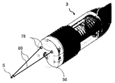
- FIG. 1 is a schematic configuration diagram of a laser irradiation apparatus according to the first embodiment.
- the laser irradiation apparatus includes a laser oscillator 1, a fiber 2, a laser head 3, a suction hose 8, and a suction source 9, and may include a gas supply source 11 and a gas hose 12.
- the laser head 3 is a small and lightweight portable type, and is connected to the laser oscillator 1 through the fiber 2 and can be handled at a work place.
- the laser oscillator 1, the suction source 9 and the gas supply source 11 are also configured to be transportable and movable, and various vehicles 100 (carts, vehicles, carriages, monoracks (including monorails, conveyors, etc.)). It may be mounted on.
- irradiation conditions such as laser output, focal position, beam width, and scanning speed can be set as appropriate according to the type and nature of the surface.
- the laser oscillator 1 includes an excitation source, a laser medium, an optical resonator (mirror), and the like.
- the excitation source may be either a continuous oscillation (CW) type or a pulse oscillation type, and an arc lamp, a flash lamp, or the like can be used.
- the laser medium is preferably a solid laser (ruby laser, YAG laser, etc.) or a semiconductor laser (laser diode). In particular, it is preferable to use a fiber laser as the solid laser.
- the laser medium is not particularly limited, and a gas laser (CO 2 laser, excimer laser, etc.), a liquid laser (dye laser), or the like may be employed.
- the laser output from the laser oscillator 1 is transmitted to the laser head 3 through the transmission fiber 2.
- a fiber laser is mainly a fiber doped with rare earth ions as a laser medium, and can perform optical amplification over a wider band than a solid-state laser using a YAG crystal or the like.
- the fiber can be wound around the oscillator, so that the laser oscillator can be configured to be small and light, easy to move and carry, and sufficient amplification even with a small gain per unit length. Is obtained.
- the fiber laser has a surface area / volume ratio of the fiber which is larger than that of the bulk type solid laser and is excellent in heat dissipation, it is possible to adopt a simple configuration by adopting air cooling as a cooling method. Since the numerical aperture NA is small, it is easy to reduce the light collection diameter. Further, since the fiber laser has a shorter oscillation wavelength and better beam quality than the CO 2 laser, the depth of focus can be set large. Further, since the laser emitted from the fiber laser has a high coupling rate with the transmission fiber, the laser can be transmitted with little loss even when the distance from the laser oscillator body to the surface is large.
- the fiber laser it is possible to carry out the coating film removing work while transporting the laser oscillator 1 itself to the vicinity of the surface (work place) of the structure and moving it appropriately.
- the laser oscillator 1 itself may be disposed within the reach of the fiber 2.
- the present invention aims at removing the coating film on the surface instead of drilling or cutting the workpiece, so that it is not necessary to obtain a large energy density by one laser irradiation, and multiple lasers It is sufficient to obtain an energy density sufficient to remove the coating film by irradiation. Therefore, in this embodiment, it is not necessary to use a high-power laser oscillator.
- either a CW type laser or a pulse type laser may be selected according to the target structure, type of coating film, overall configuration of the apparatus, and the like.
- the CW type laser requires a larger electric power than the pulse type laser to obtain a desired irradiation energy, but is preferable because it is low in cost.
- the CW type laser in laser irradiation per unit time and unit area, the CW type laser has less thermal damage to the base or base material than the pulse type laser, and the surface after removing the coating film Was confirmed to be smooth.
- a CW type laser because the coating process after the coating film removal may be facilitated.
- the present embodiment is not limited to the CW type laser, and either the CW type laser or the pulse type laser is selected according to the target structure, type of coating film, overall configuration of the apparatus, etc. Also good.
- the laser head 3 is a device that irradiates the surface 20 of the structure with the laser output from the laser oscillator 1 and transmitted through the fiber 2, removes the coating film on the surface 20, and sucks the removed material. It is configured to be able to be handled at the work place.
- the laser head 3 includes an optical system 4, suction means 31 for sucking the removed material 60, a housing 32 for storing them, and an attachment 5 attached to the tip of the housing 32.
- the laser head 3 may have a shielding member (not shown) for protecting the optical system 4 from the removed matter generated from the laser irradiation point.
- a gas spraying means 34 for spraying a gas 70 in the vicinity of an irradiation point on the surface 20, a control unit 35 for controlling an optical system, an operation unit 36 for inputting an operation from an operator, and ablation by laser light irradiation May include a sensor group 7 including an auxiliary irradiation means 37, a contact proximity sensor, a coating film visualization sensor, a vibration detection sensor and the like, and a power source (not shown). A specific configuration of the sensor group 7 will be described later with reference to FIG.
- the laser head 3 can appropriately set the intensity of laser irradiation by changing the output of the laser oscillator 1. Further, the laser head 3 is configured by the optical system 4 so that irradiation conditions such as a focal position, a beam width, and a scanning shape can be appropriately set according to the structure and surface state and properties.
- the laser light 30 emitted from the laser head 3 preferably has an output of 100 to 2000 W and a wavelength of 500 nm or more, and particularly preferably has an output of 200 to 500 W and a wavelength of 1060 to 1100 nm.
- the energy density per unit time at the focal point can be appropriately designed according to the surface material, state and irradiation time, but it is 1.25 ⁇ 10 ⁇ 4 to 5 ⁇ 10 ⁇ 4 J / ⁇ m 2 . It is preferable to be in the range.
- the spot diameter of the laser beam may be set as appropriate depending on the relationship between the energy density and the dimension of the workpiece, but preferably has a diameter of 20 to 200 ⁇ m.
- the optical system 4 is composed of, for example, a combination of a condensing element, a reflecting element, a refracting element, a driving unit, and the like.
- the optical system 4 focuses laser light emitted from the emission end of the fiber 2 and irradiates the surface 20 with the laser light 30.
- the irradiation point of the laser beam 30 on the surface 20 can be scanned linearly or curvedly.
- an appropriate configuration can be adopted for the optical system 4, it is preferable to use a transmissive refracting element to deflect the laser beam in order to make the laser head small and simple. A specific configuration of the optical system 4 will be described later with reference to FIGS. 3 and 5.
- the housing 32 is preferably configured in a small shape with excellent grip so that the operator can easily grip it.
- the irradiation point becomes a high temperature and high pressure state and ablation (melting / transpiration) occurs, and the coating is removed by the action of this ablation.
- a removed material is generated from the vicinity of the irradiation point.
- the suction means 31 is provided in the laser head 3, the removed material 60 is basically collected through the suction port 33 of the suction means 31, but a part of the removed material 60 is part of the optical system 4. There is a risk of being attracted in the direction and adhering to the lens of the optical system 4.
- the laser head 3 is provided with a shielding member (not shown) for protecting the optical system 4 from the removed matter generated from the laser irradiation point.
- the shielding member is preferably provided with a shielding member disposed between the exit end face of the optical system 4 and the surface to be processed.
- the shielding member may be a plate-like member provided with an opening only in the optical axis portion, or may be a plate-like member (such as protective glass) having translucency with respect to laser light having no opening. .
- the attachment 5 is preferably detachably attached to the tip of the laser head housing 32 and is in close contact with the surface 20 to form a closed space.
- the closed space is preferably a completely closed and sealed space, but a slight gap may be opened.
- the attachment 5 may be configured to be movable while the laser head 3 is in contact with the surface 20, but is preferably configured to be able to contact a surface having a curved surface.
- the attachment 5 may be formed of a flexible and deformable resin, or may be provided with a sliding assist means on the side in contact with the surface of the tip of the attachment.
- the sliding assist means may be a tire or a roller, or a brush-like or curtain-like member formed by a flexible member.
- the attachment 5 has an expansion / contraction mechanism and can appropriately set the distance d (see FIG. 2A) from the principal point of the scanning optical system 4 to the surface 20.
- the expansion / contraction mechanism of the attachment 5 for example, a general camera zoom mechanism, an autofocus mechanism, or the like may be used.
- the attachment 5 may be formed with a deformable joint portion (flexible tube) at least in part so that the direction of the optical axis L of the laser head 3 can be changed with respect to the normal line of the surface 20.
- the distance between the laser head 3 and the surface 20 can be set as appropriate by the extension / contraction mechanism of the attachment 5 attached to the tip of the laser head. Further, the focal length of the laser beam 30 can be appropriately set by the optical system 4.
- FIG. 2A is an explanatory diagram showing the positional relationship between the focal point F and the irradiation point.
- the present inventor does not place the surface 20 at the focal point F of the laser light 30 but moves the position of the surface 20 from the focal point F to the minus side in the direction of the optical axis L (minus focus). It has been found that the coating film can be removed more efficiently by disposing the treated surface 20 in front of the focal point.
- the defocus amount (in the negative case) is the principal point of the optical system 4.
- the inter-surface distance d and the focal distance f start from the emission side end of the optical system 4 in the housing 32, but actually start from the main point of the optical system.
- the defocus amount ⁇ f is obtained by distance d ⁇ focal length f, and is preferably set in a range of 0 to ⁇ 30 mm, and more preferably in a range of ⁇ 5 to ⁇ 25 mm.
- the defocus amount ⁇ f (in other words, the position of the focal point with respect to the surface to be processed) can be set as appropriate by changing the inter-surface distance d.
- the attachment 5 provided with an expansion / contraction mechanism.
- the focal length f is appropriately changed by the optical system 4 (variable focal mechanism)
- the position of the focal point can be changed without using the expansion / contraction function while keeping the attachment in contact.
- the defocus amount may be appropriately changed by using both the expansion / contraction function of the attachment and the variable focus mechanism of the optical system.
- the suction means 31 sucks the removed matter 60 (coating dust, minute fragments) generated from the irradiation point of the laser 30 from the suction port 33 by the negative pressure applied by the suction source 9.
- the suction source 9 is, for example, a pump that applies suction force, and may include a processing chamber that processes the suctioned removed matter 60, an exhaust filter, and the like.
- the removed matter 60 sucked from the suction means 31 may be collected by the suction source 9 via the suction hose 8, and the other harmless air may be discharged via the exhaust filter.
- the suction unit 31 sucks the removed material 60 generated from the laser light irradiation point from the suction port 33.
- the gas spraying means 34 sprays the gas supplied from the gas supply source 11 through the gas hose 12 to the vicinity of the irradiation point of the laser beam 30, and the removed material 60 (the dust on the coating film) generated from the vicinity of the irradiation point by ablation.
- the removal object 60 is guided toward the suction port 33 of the suction means 31 so that the laser beam 30 is irradiated more reliably on the surface so that the laser irradiation does not become an obstacle to laser irradiation.
- the gas supply source 11 includes, for example, a tank, a cylinder, and a compressor.
- the gas can be appropriately selected according to the working environment, surface condition, material, property, and the like. For example, dry air, nitrogen, carbon dioxide, inert gas (for example, helium, neon, argon, etc.), or a charged gas for countermeasures against static electricity may be employed.
- nitrogen or an inert gas or supply an active gas for neutralizing the reaction gas in order to reduce the generation of these.
- the liquid includes chemicals such as water for heating the surface, a treatment agent for promoting ablation, and a base protecting agent after removing the coating film.
- the removed matter generated near the irradiation point may be charged with static electricity. Since such a removed material tends to adhere to the lens of the optical system, there is a possibility that the life of the lens may be shortened. For this reason, it is preferable to provide a countermeasure against static electricity in the laser head.
- a gas spraying means may be used, and static electricity may be removed by supplying a gas containing ions from the gas spraying means in accordance with the charge amount of the removed matter.
- a shielding member that shields the removal object from being attached to the optical system may be used, and a conductive member may be provided on at least a part of the shielding member to remove the static removal object.
- a member for removing static electricity may be provided at an appropriate position in the laser head.
- the static electricity countermeasure means may remove static electricity from the removed matter flying around the optical system by supplying magnetism.
- the auxiliary irradiation means 37 gives various energies in the vicinity of the irradiation point in order to assist ablation as required (for example, when the coating film on the surface 20 is thick and a long-time laser irradiation is required for removal).
- the auxiliary irradiation unit 37 may be configured to be able to irradiate light, heat, ultrasonic waves, microwaves, and lasers, for example.
- a halogen lamp or metal halide lamp that can be heated by light irradiation, an ultrasonic heater, a magnetron microwave oscillator, a carbon dioxide laser for surface heating, or the like can be employed.
- the auxiliary irradiation means 37 can be used as illumination for photographing the surface state with a CCD camera (reference numeral 73 in FIG. 11).
- the control unit 35 has a function of controlling the scanning mechanism of the optical system 4, the variable focus mechanism, the expansion / contraction mechanism of the attachment 5, the suction unit 31, the gas blowing unit 34, the operation unit 36, the auxiliary irradiation unit 37, and the like.
- the control unit 35 may be configured to realize various processes by cooperating hardware and a program, or may be configured by a dedicated processing circuit.
- the control unit 35 is provided in the laser head main body.
- the control unit 35 may be provided separately from the laser head main body.
- a terminal (see reference numeral 82 in FIG. 14) connected wirelessly or by wire is used as the control unit. This may be configured to control the laser head 3.
- the operation unit 36 has a function of receiving an operation of the worker and outputting it to the control unit 35. Moreover, you may have a function which displays the operation result, the coating-film removal condition, a laser parameter, etc.
- the operation unit 36 includes, for example, various switches, knobs, a software keyboard, a display device, and the like.
- the coating film of the surface can be removed in a work place using the laser irradiation apparatus which can be conveyed and moved, and a removal thing can be collect
- irradiation conditions such as the focus position, beam width, scanning speed and the like can be set as appropriate, and laser irradiation suitable for coating film removal is possible.
- the suction means and attachment provided in the laser head can efficiently suction the removed object without scattering while removing the coating film. If the distance between the surfaces is appropriately set by the attachment expansion / contraction mechanism, the defocus amount can be adjusted according to the surface condition, and ablation suitable for removing the coating film is possible.
- an appropriate space for suctioning the removed object can be secured, and there is little possibility that the removed object will concentrate and block the suction port. Furthermore, it is possible to prevent leakage and scattering of the laser light and ensure the safety of the operator. Since the operator moves the laser head while bringing the attachment into contact with the surface, the distance d between the surfaces can be kept constant, and the removal operation can be carried out efficiently.
- FIGS. 3 and 4 a configuration of a laser head using one wedge prism for a scanning mechanism will be described (FIGS. 3 and 4).
- a wedge prism and a deflection are used for the scanning mechanism.
- the structure of the laser head using the means will be described (FIGS. 5 to 7).
- the present invention is not limited to the following examples.
- a wedge prism that can be rotated around the optical axis and a driving unit that rotates the optical prism are used in the optical system, and laser light is irradiated onto a conical shape (side surface) that has been expanded.
- the continuous trajectory of the laser light irradiation point on the surface is a circle C1 centered on the intersection of the optical axis and the surface, and the deflection amount of the wedge prism is radius r1.
- an optical system that can scan the irradiation point with a drive mechanism or the like is also referred to as a scanning optical system.
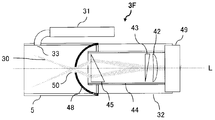
- FIG. 3 is a schematic configuration diagram of the scanning optical system of the laser head according to the second embodiment.
- the laser head 3A is connected to the laser oscillator 1 via the fiber 2 and can be handled at the work place.
- the scanning optical system 4 includes a fiber connecting portion 41, a condensing unit 42, a first wedge prism 43, a support member 44, and a driving unit 49.
- the fiber connection part 41 is an optical element (laser emission collimator (for example, quartz lens)) attached to the emission end of the fiber 2, and the laser beam transmitted through the fiber 2 is directed in parallel toward the condensing means 42. Emits as light.
- laser emission collimator for example, quartz lens
- the condensing means 42 is a condensing optical system composed of one or a plurality of lenses, condenses the laser light output from the fiber connection portion 41 to a high energy density, and forms the laser light 30 on the surface 20. Irradiate.
- the condensing unit 42 can appropriately set the focal length, the focal depth, and the beam spot diameter of the laser light 30.
- the first wedge prism 43 is an optical element that deflects incident laser light with a deflection angle ⁇ with respect to the optical axis L.
- the first wedge prism 43 (and the condensing means 42) are supported by the support member 44.
- a wedge prism is employed as an optical member for deflecting the optical path of laser light.
- the driving means 49 rotates the first wedge prism 43 by rotating the support member 44 around the optical axis L at a predetermined rotational speed ⁇ .
- the drive means 49 can employ an appropriate configuration such as a motor or a rotary actuator, but preferably employs a hollow motor that can be arranged around the optical axis in order to make the laser head small and simple. .
- the irradiation point P (including the irradiation spot) of the laser beam 30 appears on the surface 20 at a distance r from the optical axis intersection point O.
- the distance r is a deflection amount based on the deflection angle ⁇ of the first wedge prism 43 and the distance from the first wedge prism 43 to the surface 20.
- a shielding member 48 that protects the first wedge prism 43 can be employed in order to shield the removed matter generated from the vicinity of the laser light irradiation point.
- the shielding member 48 is fixed to the first wedge prism 43 or the support member 44 and is configured to be rotatable with the first wedge prism 43 or the support member 44.
- An opening that allows the laser beam 30 deflected according to the deflection angle of the wedge prism to pass through at an appropriate position. Have.
- suction means for example, reference numeral 31 in FIG. 1
- attachment for example, reference numeral 5 in FIG. 1 are not provided, and the removed matter generated from the laser irradiation point P is scattered around.
- the wedge prism can be protected from the removed material that is peeled off from the surface 20 and flying.
- a conductive member may be provided on at least a part of the shielding member 48 so as to positively remove a removed object charged with static electricity.
- a gas spraying means (see reference numeral 34 in FIG. 1 or FIG. 11) is used, and a gas containing ions is supplied from the gas spraying means in accordance with the charge amount of the removed matter. The static electricity may be removed.
- the optical path length of the laser 30 is substantially the same at each point of the substantially circular locus. Therefore, unlike the case of the linear scanning, the distance between the focal point and the actual irradiation point is the same as that during the rotational scanning. It is possible to irradiate with a constant irradiation energy without changing. Further, in order to effectively use the energy of the laser, it is preferable to set the focal point position behind the surface (defocus to the minus side). Further, the depth of focus may be set to a certain degree. As a result, it is possible to remove the coating film even on the surface of a structure having a protrusion, a step, or a depth.
- FIG. 2B is a diagram schematically illustrating the positional relationship between the focal point and the irradiation point when the laser light is deflected.
- the focal point F1 and the irradiation point P1 on the optical path L1 when there is no deflection are a new optical path having the deflection angle ⁇ . Move to a position corresponding to F2 and P2 on L2.
- the target surface to be processed is preferably arranged at a position P2 that is in the range of 0 to ⁇ 30 mm with respect to the focus F2, and more preferably from ⁇ 5 to Place in the range of -25mm.
- the principal point S is used as a reference for the sake of convenience. Then it may be different from the main point.
- the laser head is in close contact with the surface by the attachment 5, and the distance from the scanning optical system to the surface is always constant. From this point of view, it is preferable to employ a circular scan in which the optical path length does not change. Furthermore, in the present embodiment, the laser light irradiation point is rotationally scanned in a circle around the optical axis intersection point, so that even if the laser light is reflected from the surface, the return light is incident on the laser head and the fiber 2 There is no risk of damage. In addition, in the present embodiment, since the laser head is provided with the static electricity countermeasure means, the removal object charged with static electricity is not attached to the optical system or the static electricity can be removed from the removal object.
- FIG. 4 is an explanatory diagram showing a locus of a laser irradiation point by the laser head of the second embodiment.
- the first wedge prism 43 rotates around the optical axis L at the rotational speed ⁇ , so that the laser beam
- the irradiation point P is a moving point that moves at a rotational speed ⁇ on the circumference of a circle having a radius r centered on the optical axis intersection point O on the surface 20.
- the irradiation point P describes a locus of a circle C (including a substantially circular shape) having a radius r centered on the optical axis intersection point O. Therefore, when the laser beam 30 is irradiated onto the surface 20 of the structure using the laser head 3A of the second embodiment, the coating film is removed along the circumference of the circle C on the surface 20 by laser ablation.
- the circumference of the circle C is represented as a line having no width in the figure, but the laser beam 30 actually has a spot diameter width.
- the radius r is preferably set to be 5 to 200 mm.
- the laser head 3 When the laser head 3 is moved in a vertical direction or a horizontal direction at a constant speed in parallel with the surface 20 while performing circular scanning like the shape of the circle C, or by an operator's operation, The locus of P is substantially band-shaped. Thus, since the irradiation point P can be scanned substantially uniformly with respect to the surface 20, the wide-area coating film on the surface 20 can be efficiently removed in a short time.
- the laser head 3A is linearly moved in a specific direction. However, depending on the type of structure and the surface condition, the laser head 3A is moved, for example, in a letter shape, zigzag shape, arc shape, or spiral shape. May be.
- the irradiation point is scanned in a circular shape while moving the laser head (that is, the intersection of the optical axes), and therefore the locus of the irradiation point P is not continuous with the circle C, which is a closed curve, but is an open curve. It becomes a shape like a coil. More precisely, the locus of the irradiation point P is the locus of the end point of the radial vector r that rotates at the rotational speed ⁇ .
- the locus (Px, Py) of the irradiation point at the time t ) Is represented by the following equation.
- the locus of the irradiation point P is a distorted circle or ellipse.
- the optical path lengths of the laser beams at the respective irradiation points on the locus are different from each other, so that the actual irradiation point may slightly deviate from the preset focal point.
- the depth of focus is set to a certain extent in advance (the range of the change amount of the optical path length). According to the plurality of rotation scans, a desired energy density for removing the coating film can be accumulated, so that there is no problem even if the optical path length changes to some extent.
- the laser beam irradiation point is rotationally scanned in a circle around the optical axis intersection point.
- a wide range of coating film can be efficiently removed in a short time.
- the optical path of the laser beam becomes simpler and more reflective than when using an optical element such as a galvanometer mirror.
- the mechanism can be made small and simple. As a result, a small laser head that can be handled at the work place can be realized at low cost. Further, in such circular scanning, the optical path length does not change, so that the configuration of the laser head can be simplified.
- the depth of focus may be set to be large to some extent, which makes it possible to remove the coating film on the protrusions, the steps, the surface of the deep structure, and the corners of the structure.
- the required energy density for laser ablation can be given by multiple times of circular scanning, and a coating film can be removed efficiently. Further, according to such circular scanning, even if the laser light is reflected from the surface, there is no possibility that the return light enters the laser head and damages the fiber 2.
- the scanning optical system uses a wedge prism that can rotate around the optical axis and a deflecting unit, and the laser beam is spread in a conical shape (even partially hollow).
- the deflecting unit may be a reflective optical element such as a mirror, but preferably employs a transmissive optical element such as a wedge prism.
- a wedge prism is used as the deflection unit.
- the continuous trajectory can be regarded as a ring or a plane of a circle, and is substantially uniform. Laser irradiation is possible.
- FIG. 5 is a schematic configuration diagram of the scanning optical system of the laser head of the third embodiment.
- the laser head 3B includes a second wedge prism 45, a support member 46, and a transmission means 47 as an additional configuration of the scanning optical system in addition to the configuration of the laser head 3A of the second embodiment. Further, if necessary, the laser head 3 may have a shielding member (not shown) for protecting the scanning optical system from the removed matter generated from the laser irradiation point.
- the same components as those of the laser head 3A of the second embodiment are denoted by the same reference numerals, and detailed description thereof is omitted.
- the second wedge prism 45 is an optical path of the laser beam with respect to the optical path M of the laser beam deflected by the first wedge prism 43 with the deflection angle ⁇ 1 with respect to the optical axis L (hereinafter also referred to as the rotation reference axis M). Is further deflected at a deflection angle ⁇ 2.
- the second wedge prism 45 is supported by the support member 46.
- the transmission means 47 connects the support member 44 including the first wedge prism 43 and the support member 46 including the second wedge prism 45, and transmits the driving force from the driving means 49.
- the driving means 49 for example, a gear mechanism capable of setting an appropriate rotation ratio can be used.
- the driving member 49 rotates the support member 44 around the optical axis L, thereby rotating the first wedge prism 45 at the rotational speed ⁇ 1 and further transmitting the transmission means 47 connected to the support member 46.
- the second wedge prism 45 is rotated at the rotational speed ⁇ 2.
- the distance r1 is a deflection amount based on the deflection angle ⁇ 1 of the first wedge prism 43 and the distance from the first wedge prism 43 to the surface 20, and the distance r2 is the deflection angle ⁇ 2 of the second wedge prism 45 and the first angle. 2 A deflection amount based on the distance from the wedge prism 45 to the surface 20.
- the configuration in which the driving unit 49 directly applies the rotational driving force to the first wedge prism 43 and the transmission unit 47 indirectly applies the rotational driving force by the driving unit 49 to the second wedge prism 45 has been described.
- the present invention is not limited to this. Different rotational driving forces may be separately applied to each wedge prism by the two driving means, or a rotational driving force applied directly from the driving means to the transmission means may be applied to each wedge prism. Any configuration is possible as long as the first wedge prism 43 and the second wedge prism 45 can rotate at different rotational speeds.
- FIG. 6 is an explanatory diagram showing an example of the locus on the processing plane of the laser irradiation point according to the third embodiment.
- This figure shows a case where the optical axis L and the surface 20 are substantially perpendicular, and the surface 20 is substantially flat without curvature or irregularities.
- the rotation reference axis M is a moving radius that rotates around the optical axis L at the rotation speed ⁇ 1
- the intersection point Q between the rotation reference axis M and the surface 20 is a circle C1 having a radius r1 centered on the optical axis intersection point O. It becomes a moving point that moves on the circumference at the rotational speed ⁇ 1 (hereinafter also referred to as moving point Q).
- the irradiation point R of the laser beam is a moving point that moves at a rotational speed ⁇ 2 on the circumference of a circle C2 having a radius r2 with the moving point Q as the center.
- the locus of the circle C2 when the rotation reference axis M makes a round that is, when the moving point Q on the circle C1 makes a round
- C2 has a continuous shape centered on each point on the circle C1.
- the moving point Q moves on the circle C1
- the irradiation point R moves around the circle C1, so that the locus of the irradiation point R is not continuous with the individual circles C2 that are closed curves.
- the shape is like a ring of a coil that is an open curve.
- the trajectory of the irradiation point R is the trajectory of the end point of the radial vector r2 that further rotates at the rotational speed ⁇ 2 around the end point of the radial vector r1 that rotates about the optical axis intersection O at the rotational speed ⁇ 1 ( That is, the locus of the end point of the vector r (r1 + r2).
- the rotational speed ⁇ 2 is preferably set sufficiently higher than the rotational speed ⁇ 1, and the ratio (rotational ratio ⁇ 2 / ⁇ 1) between the rotational speed ⁇ 1 and the rotational speed ⁇ 2 is preferably at least greater than 9/2.
- the rotation ratio ( ⁇ 2 / ⁇ 1) it is preferable to set the rotation ratio ( ⁇ 2 / ⁇ 1) so that the initial position of the irradiation point R does not coincide with the position of the irradiation point R when the rotation reference axis M makes one or several turns. Then, even if the rotation reference axis M rotates several times, C2 which is the locus of the irradiation point R does not overlap on the surface 20, so that substantially uniform scanning is possible.
- the laser head 3B is moved in parallel to the surface 20 at a constant speed in the vertical and horizontal directions while scanning the shape of the circle C2, the irradiation point R is changed.
- a specific range of the surface 20 can be scanned almost uniformly, and a specific range of the coating film on the surface 20 can be efficiently removed in a short time.
- FIG. 7 is an explanatory diagram showing another example of the locus of the laser irradiation point by the laser head of the third embodiment.
- the laser light irradiation point is scanned in an annular shape or a circular surface.
- the coating film in the range can be efficiently removed in a short time. This form is suitable, for example, when removing a coating film around a projection such as a bolt.
- the radius of the center curve C1 and the width of the ring C3 depend on r1 and r2 corresponding to the deflection amount by each wedge prism, r1 and r2, that is, the deflection angle ⁇ 1 of the first wedge prism and By appropriately setting the deflection angle ⁇ 2 of the second wedge prism, it is possible to set an annular irradiation region of various sizes and shapes, or to set a circular shape without an irradiated region at the center. You can also.
- the deflection angle ⁇ 1 and the deflection angle ⁇ 2 are set so that
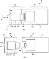
- FIG. 8 is a schematic configuration diagram of a laser head according to the fourth embodiment.
- the attachment is detachable from the tip of the laser head housing 32 and can be attached to the laser head of the first to third embodiments.
- This figure shows an example in which the laser head (FIG. 5) of the third embodiment is attached to the front end of the housing.
- This attachment 5B has a deformable joint part (flexible tube) 53 and is configured to be deformable according to the angle of the surface 20B with respect to the normal line.
- the attachment 5B is configured such that the laser head 3C is substantially perpendicular to the normal line of the surface 20B.
- the attachment 5B includes a first mirror 51 and a second mirror 52 (see FIG. 9). However, you may remove the 2nd mirror 52 according to a use (for example, when it is not desired to irradiate the side surface of a protrusion with a laser beam).
- the laser head 3 ⁇ / b> C may have a shielding member (not shown) for protecting the scanning optical system from the removed matter generated from the laser irradiation point.
- the first mirror 51 is configured so that the normal angle of the first mirror itself with respect to the optical axis L can be changed as appropriate.
- the irradiation direction of the laser light can be changed from the optical axis La to the incident axis Lb.
- the angle between the optical axis La and the incident axis Lb can be arbitrarily set and is not particularly limited, but is preferably set to 90 °, for example.
- the locus of the laser light irradiation point on the surface 20B is the same as the locus on the surface 20 perpendicular to the optical axis L shown in FIG.
- FIG. 9 is a schematic configuration diagram of a part of the attachment of the fourth embodiment, and shows the optical path of the laser beam of the laser head 3C.
- a protrusion 20C for example, a bolt
- the laser beam 30 is rotated by the rotation reference axis Mb rotating around the incident axis Lb deflected by the first mirror 51. Incident while rotating around.
- the laser beam 30 closer to the incident axis Lb is irradiated on the upper surface of the bolt 20C, and the laser beam 30 farther from the incident axis Lb is reflected by the second mirror 52 provided on the attachment 5B, and is reflected on the side surface of the bolt 20C. Irradiated.
- this attachment is used, the coating film removal around the protrusion which was difficult in the past can be easily performed.
- the laser head can be brought into contact with the surface in an arbitrary direction, so that the operator takes an unreasonable posture even in a complicated and narrow structure in which handling is restricted. Therefore, the removing operation can be easily performed. Moreover, if this attachment is attached to the laser head of the third embodiment, the coating film around the protrusion on the surface and the side surface of the protrusion itself can be processed efficiently.
- FIG. 10 is an explanatory view showing still another example of the attachment of the laser head according to the fourth embodiment.
- an attachment including a reflection mirror is attached to the tip of a laser head including the scanning optical system shown in FIG.
- This example has a simpler structure, and can be used in, for example, a narrow part of a structure, and removes a coating film, deposits, etc. on the surface of an intricate part that could not be realized by a conventional blasting method. be able to.
- the attachment 5C is connected to the tip of the laser head housing 32, and a reflection mirror 51 having a predetermined angle is provided at the tip.
- the laser beam 30 irradiated conically from the scanning optical system of the laser head is reflected by the reflection mirror 51, and the laser irradiation point is scanned in a substantially circular shape on the inner surface of the narrow portion of the structure.
- a shielding member 48 for protecting optical members (prisms, lenses, mirrors, etc.) disposed on the exit end side from the removed matter generated from the laser irradiation point is provided at the exit end of the scanning optical system.
- the shielding member 48 has, for example, a flat plate shape, has a laser beam exit 50, and is configured to rotate with the rotation of the scanning optical system.
- the attachment 5C may be provided with a gas spraying means 34 for supplying a gas flow to the reflection mirror 51 in order to protect the reflection mirror 51 from the removed matter generated from the laser irradiation point.
- the gas blowing means 34 blows a gas pumped from a gas supply source (not shown) through the gas hose 12 to the vicinity of the surface of the reflection mirror 51, and prevents the scattered removed matter from adhering to the reflection mirror 51.
- FIG. 11 is a schematic configuration diagram of a laser head according to the fifth embodiment.
- This laser head includes various sensors as the sensor group 7, and includes, for example, a contact proximity sensor 71, a surface state sensor 72, a monitoring sensor 73, a vibration detection sensor 74, a surface-to-surface distance measurement sensor 75, and the like. Note that it is not necessary to include all of the sensor groups 7.
- the sensor group 7 may be selected and employed according to the purpose, or a plurality of functions may be shared by one sensor.
- the contact proximity sensor 71 is a sensor that detects that the attachment 5 is in contact with or close to the surface 20.
- a sensor can use, for example, a pressure sensor attached to a contact portion with the surface to be processed at the tip of the attachment, a sensor for measuring the reflected intensity of the emitted radio wave, and the like. You may comprise so that it may detect.
- the control unit 35 (which may be a management terminal separate from the laser head (see reference numeral 82 in FIG. 14). The same applies hereinafter) may be controlled so as not to allow laser light irradiation unless detected by such a sensor. it can.
- a sensor that measures the reflected intensity of emitted radio waves it may be configured to allow laser light irradiation only when the reflected intensity exceeds a predetermined value. As a result, it is possible to prevent the human body from being irradiated with laser light by mistake.
- the surface condition sensor 72 detects the material of the base of the surface 20 (steel plate, aluminum, etc.), the state of the coating film (lifting, thickness), the state of rust (area, degree), the state of corrosive substances, dirt, and oil and fat adhesion. To do. Moreover, you may detect the removal amount etc. of a coating film. Specifically, a radiation temperature sensor, a visible spectrum image sensor, a near infrared camera, or the like can be employed.
- the monitoring sensor 73 is, for example, a CCD camera or a CMOS camera. As a result, the operator or a manager located away from the work place can observe the surface state and the state inside the laser head, and determine the degree of necessary coating film removal and the necessity of maintenance. Can be obtained.
- the control unit 35 can also collect information on the surface state detected by the sensor (hereinafter referred to as “surface state information”). Further, the control unit 35 may perform control so that the surface state information is displayed on the display device of the operation unit 36. Or you may notify this surface state information to the display apparatus (code
- a sensor capable of detecting toxic reaction gas may be provided inside the attachment (not shown).
- the control unit 35 may be configured to notify a warning to an operator and an administrator when the generation of toxic gas is detected.
- the inter-surface distance measurement sensor 75 is a sensor that measures the distance to the surface with infrared rays or the like.
- the control unit 35 can set the focal point to a position suitable for removing the coating film based on the distance between the surfaces detected by the sensor. Specifically, when the attachment 5 abuts, the expansion / contraction mechanism of the attachment 5 is controlled so that the surface 20 to be processed is arranged at the same distance as or shorter than the focal length of the laser beam. Further, the variable focus mechanism of the optical system is controlled so that the focal length of the laser light is equal to or longer than the measured distance between the surfaces.
- FIG. 12 shows an example of the arrangement of the laser pointer in the laser head
- FIG. 13 shows an example of the focus instruction by the laser pointer.
- two laser pointers 77 are provided on the laser head as surface distance measuring means (only one in front is shown in FIG. 12).
- Each laser pointer 77 is irradiated with the red laser beam 80 obliquely with respect to the optical axis of the scanning optical system 4 and intersects with the red laser beam from the other laser pointer 77 at a predetermined distance (position) s. Has been placed.
- FIG. 12 shows an example of the arrangement of the laser pointer in the laser head
- FIG. 13 shows an example of the focus instruction by the laser pointer.
- two laser pointers 77 are provided on the laser head as surface distance measuring means (only one in front is shown in FIG. 12).
- Each laser pointer 77 is irradiated with the red laser beam 80 obliquely with respect to the optical axis of the scanning optical system 4 and intersects with the red laser beam
- the scanning optical system 4 is arranged so as to intersect at a position S on the optical axis L, and serves as a guide for the distance between the surfaces and can grasp the center of the irradiation point of the laser beam. Yes.
- the irradiation position of the laser head can be grasped by setting the distance s to a desired surface-to-surface distance.
- the red laser light from the laser pointer 77 does not need to intersect on the optical axis of the scanning optical system 4, and is arranged to intersect at another position (for example, a predetermined position in front of the laser pointer 77). May be. Three or more laser pointers may be provided.
- FIG. 13 shows a state in which the red laser light 80 from the two laser pointers is irradiated from the two injection ports 78 provided in the tip cap of the laser head 3 and overlapped at the position S.
- the vibration detection sensor 74 detects vibration of the laser head 3D held by the operator, and may be, for example, an acceleration sensor. Further, the laser head 3D may include a vibration unit 76 that vibrates the laser head body. As the vibration means, a camera shake prevention mechanism mounted on a vibration motor, a general camera, or the like can be used. If the laser beam 30 is continuously irradiated to a specific part during the operation of removing the coating film, only that part may be deeply excavated. When the magnitude of the vibration detected by the vibration detection sensor 74 becomes smaller than a predetermined reference, the control unit 35 vibrates the laser head main body 3D or the scanning optical system 4 using the vibration unit 76, thereby causing the laser. It is preferable to shake the light irradiation point P finely so as not to cut too much a specific part.
- control unit 35 determines that the desired focal position is obtained based on the measurement of the inter-surface distance of the inter-surface distance measurement sensor 75
- the control unit 35 uses the vibration unit 76 or the display device of the operation unit. The operator can be informed that the focus is in the proper position. Further, the control unit 35 may stop the irradiation of the laser light when it is determined that the focal point is not at a desired position based on the measured distance between the surfaces. When the attachment is attached, the irradiation point of the laser beam cannot usually be confirmed from the operator. The operator can confirm the optimum position by vibration or display, which is preferable.
- the fiber connection unit 41 (laser emission collimator) may be configured to have a condensing function.
- the collimator has a function of converting incident light into parallel light.
- a condensing lens may be incorporated in the collimator so that the focused laser beam 30 can be emitted.
- the laser head can be reduced in size and cost.
- the fiber connection part 41 (laser emission collimator) is the last irradiation member of a fiber, it is easy to accumulate
- the cooling means 38 may be air-cooled or water-cooled.
- a gas spraying means 34 disposed inside the housing 32 is used, and the gas spraying means 34 sprays the gas fed from the gas supply source via the gas hose 12 onto the fiber connection portion 41.
- the gas spraying means 34 fills the inside of the housing with a gas flow (purge gas), so that the removed material generated from the irradiation point P flows into the inside of the housing and contaminates the inside of the housing and the optical members of the scanning optical system 4. You may make it prevent.
- the gas blowing means 34 can also be used as a countermeasure against static electricity, and supplies a purge gas (for example, including ions) capable of removing static electricity to the inside of the laser head, so that charges can be discharged from the static removal object. Can be removed.
- a shielding member (not shown) may be provided for protecting the scanning optical system from the removed matter generated from the laser irradiation point in place of or in addition to the gas spraying means 34. Good.
- the laser irradiation apparatus including a laser head having various sensors may be connected to an external server via a network.
- the server stores various types of information acquired by various types of sensors, selects various laser irradiation conditions based on the various types of information, and can instruct optimal conditions to a remote laser irradiation apparatus.
- a system provided with a laser irradiation apparatus will be described.
- FIG. 14 is a schematic diagram illustrating an overall configuration of a laser irradiation system according to the sixth embodiment.
- the laser irradiation system connects a laser irradiation device located at a work place and a server located at a remote place through a network, and based on the information on the coating state acquired by the laser irradiation device, the laser irradiation system Irradiation conditions are set, and efficient coating work according to the state of the structure surface is realized.
- This system includes a laser irradiation device including a small and lightweight laser head 3 used in a work place, and a server, both of which are connected to each other via a network.
- the laser head 3 used in the work place is connected to the vehicle 100 disposed in the vicinity of the work place via the integrated cable 25 (including the fiber 2, the suction hose 8, the gas hose 12, and the power cable).
- the vehicle 100 is preferably a vehicle capable of traveling, but a vehicle, a trolley, a cart configured to be movable via a rail or a cable, or a platform capable of autonomous traveling by remote control may be used.
- the vehicle 100 is equipped with a laser oscillator 1, a suction source 9, and a gas supply source 11 as well as FIG. 1, and a management terminal 82, a power supply device 83, and the like.
- the management terminal 82 is a terminal that manages the laser irradiation device, acquires information from various sensors mounted on the laser head 3 and creates information on the surface state (surface state information), and maintenance of the laser irradiation device. It has a function of creating information related to management (hereinafter referred to as “apparatus management information”), a function of managing laser irradiation conditions, a function of displaying various information, a function of communicating with the server 84 via a network, and the like.
- apparatus management information information related to management
- the management terminal 82 for example, a control unit of the laser head 3, a personal computer, or the like can be employed.
- the power supply device 83 supplies power to each device in the vehicle and the laser head 3.
- the server 84 is a server that manages a plurality of laser irradiation apparatuses, and according to the work location and the surface of the target based on the function of storing various information acquired from the management terminal 82 via the network 90, surface state information, and the like. Function for setting laser irradiation conditions for efficient coating film removal, function for transmitting such irradiation conditions to each laser irradiation device via network 90, function for maintenance management of each laser device based on device management information, etc. Have
- the system may also include a management terminal 85.
- the management terminal 85 is a terminal that manages the server 84, and for example, a personal computer can be employed.
- the management terminal 85 may be directly connected to the server 84 or may be connected to the server 84 and the management terminal 82 via a network. Administrators can access the server 84 and the laser irradiation apparatus management terminal 82 via the management terminal 85.
- the network 90 may be any network as long as the laser irradiation device management terminal 82 (or a communication device not shown) and the server 84 can communicate with each other.
- public telephone network Integrated Service Digital Network, also called Digital Integrated Service Network
- ADSL Asymmetric Digital Subscriber Line
- CATV Common AntennaLenNet
- CS Common Communication Satellite
- the device management information includes, for example, the identification information, format, usage status (use date / time, cumulative usage time, usage frequency, usage conditions, parts replacement history) of the laser head 3 and the like.
- Surface condition information is information on the state of the coating (coating thickness, active film area, rust, dirt state, adhesion (moisture)), base material (base) material, and target surface shape (plane , Corners, protrusions) and structure types (bridges, tanks, etc.).
- the surface condition information includes laser irradiation conditions (laser output, laser wavelength, focal length, defocus amount, spot diameter, scanning mode (rotation speed, scanning speed) when the surface is actually removed. , Energy density, removal amount, etc.), information on the surface of the structure after laser irradiation, and weather conditions (temperature, humidity, etc.) may be associated.
- the server 84 of this system selects an appropriate laser irradiation condition according to the surface state for each work place based on the acquired surface state information and / or the past results of laser irradiation, and the selected laser irradiation condition Can be transmitted to each laser irradiation device.
- the server 84 may have a function of creating a database by associating surface state information with laser irradiation conditions. Further, the server 84 may be configured to transmit a signal for permitting or prohibiting the irradiation of the laser beam to the laser irradiation device based on information from the sensor group (contact of attachment, distance between surfaces, surface state, etc.). Good. Further, the server 84 may notify or manage maintenance timing and contents based on the device management information acquired from each laser device.
- the laser irradiation device As a method for the laser irradiation device to acquire the laser irradiation condition from the server 84, a configuration triggered by the operation on the laser irradiation device side may be used, or the laser from the server 84 is independent of the operation on the laser irradiation device side. Irradiation conditions may be provided to the laser irradiation apparatus. Specifically, when there is an operation on the laser irradiation apparatus side, such as transmission of surface state information, a condition distribution request input by an operator, power-on of the laser head, the server 84 acquires the surface state information, Based on the surface state information, an appropriate laser irradiation condition is selected, and the selected condition is transmitted to the laser irradiation apparatus at the work place.
- an operation on the laser irradiation apparatus side such as transmission of surface state information, a condition distribution request input by an operator, power-on of the laser head
- the server 84 acquires the surface state information, Based on the surface state information
- the server 84 acquires various information stored in the management terminal 82 of the laser irradiation apparatus independently from the operation on the laser irradiation apparatus side based on the identification information registered in advance, and based on them. Appropriate laser irradiation conditions may be selected, and the selected conditions may be stored in the management terminal 82 of the laser irradiation apparatus. In the above description, the server 84 transmits the laser irradiation conditions. However, a configuration in which the management terminal 82 of the laser irradiation apparatus acquires the laser irradiation conditions stored in the server 84 may be adopted. .
- the management terminal 82 may automatically set the irradiation device based on the acquired laser irradiation conditions. Moreover, you may display the acquired laser irradiation conditions on the display part of the management terminal 82, or the operation part 36 of the laser head 3, for example. Furthermore, it may be configured such that various settings can be manually adjusted by an operator so that the laser irradiation conditions can be appropriately changed in accordance with changes in the situation on site. From the viewpoint of safety management, it is preferable to limit the adjustable range (maximum output value, etc.).
- the manager may determine the grade of coating film removal based on the surface condition information and the result of visual observation with a camera, if necessary, and notify the worker of the workplace of the grade.
- the required film removal grade is classified as 1 type 4 to 4 type.
- one type of keren completely removes the coating film, rust, etc. on the surface and completely exposes the metallic luster iron background.
- Type 2 Keren other coatings, corrosive substances, fats and oils, dirt, and other foreign substances are removed except for the coating film that adheres strongly.
- Type 3 Keren rust and floating coating are removed and the active film is left.
- two kinds of keren and three kinds of kelen are generally used. However, in recent years, one kind of kelen is often adopted for a structure in which the coating film of the steel material is significantly deteriorated.
- the server can instruct the laser irradiation apparatus to select a laser irradiation condition suitable for coating film removal based on information detected by various sensors mounted on the laser head. it can.
- FIG. 15 is a schematic configuration diagram illustrating an example of a laser head according to the seventh embodiment.
- This laser head 3E is different from the laser head 3B of the third embodiment shown in FIG. 5 in that the first wedge prism 43 and the second wedge prism 45 are fixed on the support member 44, and a rotational difference is generated in each prism. It is different in that it is not provided and a dome-shaped shielding member 48 having a laser emission port 50 on the optical axis is provided.
- the same components as those of the laser head 3B of the third embodiment are denoted by the same reference numerals, and detailed description thereof is omitted.
- first wedge prism 43 and the second wedge prism 45 are supported by the support member 44, and the first wedge prism 43 and the second wedge prism 45 are both (the same) by the driving force from the driving means 49. Rotate around the optical axis (at rotational speed).
- the first wedge prism 43 deflects the optical path of the laser beam with respect to the optical axis L with a deflection angle ⁇ 1 in the direction from the rotation center (optical axis L) to the outside.
- the second wedge prism 45 deflects the optical path of the laser beam with respect to the deflected optical path M with a deflection angle ⁇ 2 in the direction toward the rotation center (optical axis L) ( ⁇ 2> ⁇ 1).
- the laser light since the laser light once deflected outward with respect to the optical axis L is deflected inward again, the laser light apparently intersects at the intersection X according to the movement of the two prisms that rotate together. Will be.
- the laser light 30 is irradiated from the intersection X at an angle ( ⁇ 2 ⁇ 1) from the optical axis L.
- the exit 50 of the shielding member 48 is arranged in correspondence with the position of the intersection X of the laser light, the exit of the shielding member 48 can be set small on the optical axis, While irradiating the laser beam in a circular shape, it is possible to prevent the removed matter from the laser beam irradiation point on the processing plane from entering the laser head.
- a third wedge prism is provided on the plus side (the surface to be processed in the drawing), and the third wedge prism is rotated at a rotational speed different from that of the first and second wedge prisms. Also good. In this case, a circular scanning mode as shown in FIG. 5 can be realized.
- this embodiment is not comprised so that the removal thing which arises from the laser irradiation point P may be collect
- FIG. 16 is a schematic configuration diagram showing another example of the laser head according to the seventh embodiment.
- the laser head 3F of this example includes a suction unit 31 having an attachment 5 and a suction port 33 as an additional configuration to the laser head 3E shown in FIG. According to the laser head of this example, it is possible to protect the optical system of the laser head from the removed matter generated from the irradiation point of the laser beam and to collect the removed matter without being scattered around.
- the laser beam is not radiated in a circular shape on the planar surface to be treated, but is radiated in a circular shape in accordance with the inner diameter of the pipe.
- This example is particularly suitable for use in removing deposits containing radioactive substances in the secondary cooling piping of a nuclear reactor.
- FIG. 17 is a schematic configuration diagram showing an example of a laser head according to the eighth embodiment.
- the laser head 3 ⁇ / b> G of this example includes a wedge prism 43, a support member 44, a driving unit 49, a fiber connection unit 41, a suction unit 31 having a suction port 33, and a moving unit 110. Since this laser head 3G is used by being inserted into a pipe having a small diameter, it is preferable that the laser head 3G be as small as possible.
- the fiber connection portion 41 receives high-energy laser light as it is from the emission end without using a condensing means. It is preferable that it can supply.
- the main body (41, 43, 44, 49) of the laser head 3G is placed on the moving means 110A that can run inside the pipe 20 automatically or manually, and the suction means 31 is arranged in the traveling direction of the laser head main body. Is placed on the moving means 110B.
- the moving means 110A and 110B have, for example, a traveling roller 112 and appropriate driving means (not shown), and can move along the inside of the pipe.
- the moving means 110A and 110B are preferably configured to be movable by remote operation.
- the moving means 110A and 110B are provided with a sealing means 114 that can be in close contact with the surface inside the pipe.
- the sealing means is constituted by rubber or resin packing, a brush or the like. As a result, the space between the moving means 110A and the moving means 110B is closed, so that it is possible to prevent the harmful removed matter removed by the laser irradiation from scattering.
- the laser head 3G irradiates the laser beam 30 in a circle according to the inner diameter of the pipe 20 while traveling in the pipe by the moving means 110A. That is, since the irradiation point P of the laser beam is scanned so as to draw a locus of a circle with a radius r corresponding to 1/2 of the inner diameter of the pipe, the deposit 22 inside the pipe can be efficiently removed.
- the moving means 110B for placing the suction means 31 travels along with the moving means 110A for placing the laser head main body, and the removed material 60 generated from the irradiation point of the laser beam 30 is collected by the suction means 31.
- FIG. 18 is a schematic configuration diagram showing another example of the laser head according to the eighth embodiment.
- the laser head 3H of this example is different from the example shown in FIG. 17 in that the reflecting mirror 43B is used instead of the wedge prism and the suction means 31 is provided on the main body side of the laser head.
- the reflection mirror 43B is provided at the tip of the laser head and is rotated by the driving means 49.
- the laser light 30 emitted from the fiber connection part (laser emission collimator) 41 is reflected at a predetermined angle ⁇ by the rotating reflection mirror 43B.
- the reflected laser beam 30 travels backward from the tip of the laser head.
- the deposit 22 inside the pipe can be efficiently removed.
- the removed material 60 generated from the irradiation point of the laser beam 30 is collected by the suction unit 31 placed on the moving unit 110.
- the laser head can travel in the pipe, and the irradiation point of the laser beam can be scanned in a circle according to the inner diameter of the pipe. Can be carried out efficiently and safely.
- FIG. 17 illustrates a configuration using one wedge prism as the scanning optical system
- FIG. 18 illustrates a configuration using one reflecting mirror as the scanning optical system
- the laser head of the eighth embodiment is It is not limited to such a configuration.
- the configurations of other embodiments for example, FIG. 1, FIG. 3, FIG. 5, FIG. 8, FIG. 15, FIG. 16, etc. may be combined.
- FIG. 19A is a schematic configuration diagram of a scanning optical system (when connected) in the laser head of the ninth embodiment including a replaceable optical unit
- FIG. 19B is a diagram when the replaceable optical unit is removed. It is a schematic block diagram (at the time of isolation
- the scanning optical system of the laser head of this embodiment is configured by connecting an exchangeable optical unit 190 including at least a focusing or deflecting optical member and a main body portion 191 including at least a driving means 49 (FIG. 19A). )), And the replaceable optical unit 190 is configured to be detachable from the main body portion 191 of the laser head by a simple operation (see FIG. 19B), and the laser light irradiation conditions can be easily changed.
- the interchangeable optical unit 190 is a unit that includes various optical members (for example, one or more of a wedge prism, a condensing lens, a reflection mirror, and the like). , And can be rotated by a driving force applied from the driving means 49.
- the lens holder body 44A, the lens cap 44B, the joint cap 44C, and the like are configured by a support member 44 that rotatably holds the lens holder body 44A, the lens cap 44B, the joint cap 44C, and the like.
- Various optical members are stored in the lens holder main body 44A, the front is closed by a lens cap 44B, and the rear is closed by a joint cap 44C.
- An optical member that needs to be changed may be disposed in the replaceable optical unit, and other optical members may be disposed in the main body portion 191.
- the lens cap 44B is provided with an opening through which laser light passes.
- the joint cap 44C is provided with an opening through which laser light passes, and is configured to engage with the connecting member 49B of the main body portion 191 and transmit the rotational force of the driving means. For this reason, at least a part of the replaceable optical unit 190 can be rotated by the driving force applied from the driving means 49, but can be separated from the main body portion 191 including the driving means 49 by a simple operation. Can be removed from.
- a laser emission port 50 for emitting laser light is provided at the tip of the replaceable optical unit 190.
- the laser beam emitted from the interchangeable optical unit 190 is, for example, circularly scanned by various optical members stored in the lens holder main body 44A, and is irradiated from the laser emission port 50 toward the surface to be processed.
- a gas supplied from a gas supply source (not shown) may be ejected from the laser emission port 50.
- a gas injection port 34B may be provided around the laser injection port 50, and the gas supplied from a gas supply source (not shown) may be injected. .
- the interchangeable optical unit 190 may be provided with a laser pointer (reference numeral 77 shown in FIG. 12) and provided with a laser pointer hole (reference numeral 78 shown in FIG. 12).
- the main body portion 191 includes a hollow motor 49A that is a driving means 49, a connecting member 49B, and the like.
- the joint cap 44 ⁇ / b> C of the replaceable optical unit 190 and the connecting member 49 ⁇ / b> B of the main body portion 191 are fixed via a hook or the like, and the driving means 49 is used.
- the driving force may be transmitted to the interchangeable optical unit 190 via the connecting member 49B and the joint cap 44C.
- the support member 44 is fixed to the housing 32 of the main body portion 191 in a state where the joint cap 44C and the connecting member 49B are engaged with each other so as to be able to transmit rotational motion, whereby the replaceable optical unit 190 is attached to the main body portion 191.
- the lens holder main body 44A can be configured to rotate inside the support member 44 via sliding means such as a bearing while the support member 44 is fixed to the housing 32 of the main body portion 191.
- an additional configuration (such as a laser pointer) is preferably attached to the replaceable optical unit 190 in advance before connecting the replaceable optical unit 190 to the main body portion 191.
- various lasers can be selected by selecting and mounting an appropriate unit according to the purpose (type, state, size, etc. of the object to be processed).
- a light irradiation mode can be realized. Specifically, if a unit including one wedge prism is selected, circular scanning as shown in FIG. 4 can be realized. If a unit including two wedge prisms (with a rotational speed difference) is selected, the annular scanning shown in FIG. 6 or 7 can be realized. If a unit including two wedge prisms (no difference in rotational speed) is selected, the circular scanning shown in FIG. 15 can be realized.
- circular scanning with a desired radius r can be realized.
- Various irradiation conditions may be changed by providing the scanning optical system with a variable focal length and deflection angle.
- the size of circular scanning for example, diameter 10 cm, 5 cm, 3 cm, etc.
- the size of the circular scan eg, diameter 10 cm, 5 cm, 3 cm, etc.
- the size of the circular scan depends on the area of the surface to be processed, and in the case of a large area, a large circular scan is used. For example, a small circular scan may be used.
- the size of circular scanning may be changed by selecting an interchangeable optical unit according to a desired energy density to be applied to the surface to be processed.
- the size of the circular scan can be changed according to the specified output of the laser oscillator to be used, and the energy density of the laser irradiation given to the surface to be processed can be adjusted, so that there is little possibility of applying excessive energy.
- an interchangeable optical unit may be selected according to the state of the surface to be treated.
- a laser head was designed as follows.
- the laser head has a length of 43 cm, a diameter of 7 cm, and a weight of 1400 g.
- the focal length was set to 150 mm
- the beam spot diameter at the focal point was set to 0.04 mm (40 ⁇ m).
- the laser beam input to the laser head is a continuous oscillation type, has an average output of 200 W and a wavelength of 1070 nm.
- a laser head with an attachment was brought into contact with a flat steel plate on which a coating film having a thickness of 30 to 50 ⁇ m was formed, and the surface of the steel plate was irradiated with laser light substantially perpendicularly. Using such a laser head, it was possible to remove the coating film with an operating efficiency of 8 m 2 per hour.
- FIG. 20 is an external view of an embodiment of a laser head employing a replaceable optical unit.
- 20A, 20B, 20C, and 20D are a side view, a top view, a perspective view seen from the front end side, and a perspective view seen from the rear end side, respectively, of the laser head.
- This laser head has a length of 35 cm, a height of 8.5 cm, a width of 6 cm, and a weight of 1.6 kg.
- the interchangeable optical unit 190 includes a condensing lens, a wedge plate, and protective glass (a part of the shielding member). So that the driving force can be transmitted.
- the joint cap 44 ⁇ / b> C of the replaceable optical unit 190 is connected to the connecting member 49 ⁇ / b> B of the main body portion 191 so as to be able to transmit rotational motion, and the casing 44 itself outside the replaceable optical unit 190 is the main body.
- the lens holder main body 44A storing the optical member in the interchangeable optical unit 190 is configured to rotate along the inside of the housing 44 of the interchangeable optical unit 190 via a bearing.
- the interchangeable optical unit 190 When removing the replaceable optical unit 190 from the main body 191, the replaceable optical unit 190 is pulled out while being rotated in the opposite direction to that at the time of attachment.
- the interchangeable optical unit 190 has a length of 4 cm, a height of 8.5 cm, and a width of 6 cm.
- the weight is 200 to 300 g.
- the coating film can be efficiently removed in a short time by scanning the laser irradiation point on the surface of the structure.
- the position of the focal point can be set as appropriate by an expansion / contraction mechanism of the attachment, the irradiation energy, the spot diameter, and the like according to the surface state can be selected.
- the present invention unlike the conventional blasting process, since a quiet laser is used without physical contact with the surface, the influence of noise on the surrounding environment is small.
- by employing various attachments it is difficult to process with conventional methods, such as intricate locations, protrusions, narrow parts, pipe interiors, etc. , The deposits can be removed.
- each embodiment can be combined, and a partial configuration of each embodiment (attachment, shielding member, suction unit, scanning optical system, laser pointer and its irradiation hole, configuration of a gas supply unit supply port, etc. ) Can be combined with each other.
Landscapes
- Physics & Mathematics (AREA)
- Engineering & Computer Science (AREA)
- Optics & Photonics (AREA)
- Plasma & Fusion (AREA)
- Mechanical Engineering (AREA)
- Chemical & Material Sciences (AREA)
- Toxicology (AREA)
- General Health & Medical Sciences (AREA)
- Health & Medical Sciences (AREA)
- Electromagnetism (AREA)
- Organic Chemistry (AREA)
- Chemical Kinetics & Catalysis (AREA)
- Laser Beam Processing (AREA)
- Cleaning In General (AREA)
- Application Of Or Painting With Fluid Materials (AREA)
- Cleaning And De-Greasing Of Metallic Materials By Chemical Methods (AREA)
Priority Applications (7)
| Application Number | Priority Date | Filing Date | Title |
|---|---|---|---|
| EP25216508.9A EP4732982A2 (en) | 2012-03-09 | 2013-03-08 | Laser irradiation device, laser irradiation system, and method for removing coating or adhering matter |
| US14/379,646 US9868179B2 (en) | 2012-03-09 | 2013-03-08 | Laser irradiation device, laser irradiation system, and method for removing coating or adhering matter |
| EP13758038.7A EP2823929B1 (en) | 2012-03-09 | 2013-03-08 | Laser irradiation device, laser irradiation system, and method for removing coating or adhering matter |
| JP2013527208A JP5574354B2 (ja) | 2012-03-09 | 2013-03-08 | 塗膜除去方法及びレーザー塗膜除去装置 |
| US15/828,909 US11135681B2 (en) | 2012-03-09 | 2017-12-01 | Laser irradiation device, laser irradiation system, and method for removing coating or adhering matter |
| US17/464,632 US12365050B2 (en) | 2012-03-09 | 2021-09-01 | Laser irradiation device, laser irradiation system, and method for removing coating or adhering matter |
| US19/239,061 US20250303500A1 (en) | 2012-03-09 | 2025-06-16 | Laser Irradiation Device, Laser Irradiation System, and Method for Removing Coating or Adhering Matter |
Applications Claiming Priority (2)
| Application Number | Priority Date | Filing Date | Title |
|---|---|---|---|
| JP2012-053675 | 2012-03-09 | ||
| JP2012053675 | 2012-03-09 |
Related Child Applications (2)
| Application Number | Title | Priority Date | Filing Date |
|---|---|---|---|
| US14/379,646 A-371-Of-International US9868179B2 (en) | 2012-03-09 | 2013-03-08 | Laser irradiation device, laser irradiation system, and method for removing coating or adhering matter |
| US15/828,909 Continuation US11135681B2 (en) | 2012-03-09 | 2017-12-01 | Laser irradiation device, laser irradiation system, and method for removing coating or adhering matter |
Publications (1)
| Publication Number | Publication Date |
|---|---|
| WO2013133415A1 true WO2013133415A1 (ja) | 2013-09-12 |
Family
ID=49116883
Family Applications (1)
| Application Number | Title | Priority Date | Filing Date |
|---|---|---|---|
| PCT/JP2013/056476 Ceased WO2013133415A1 (ja) | 2012-03-09 | 2013-03-08 | レーザー照射装置、レーザー照射システム及び塗膜又は付着物除去方法 |
Country Status (4)
| Country | Link |
|---|---|
| US (4) | US9868179B2 (https=) |
| EP (2) | EP4732982A2 (https=) |
| JP (8) | JP5574354B2 (https=) |
| WO (1) | WO2013133415A1 (https=) |
Cited By (32)
| Publication number | Priority date | Publication date | Assignee | Title |
|---|---|---|---|---|
| CN103658140A (zh) * | 2013-12-04 | 2014-03-26 | 北京航天时代光电科技有限公司 | 一种手持式激光清洗机的光学整型装置 |
| JP2014079664A (ja) * | 2012-10-12 | 2014-05-08 | Toyokoh Co Ltd | 塗膜除去方法及びレーザー照射装置 |
| JP2015139820A (ja) * | 2014-01-30 | 2015-08-03 | 国立研究開発法人日本原子力研究開発機構 | レーザー光を用いた溶断・破砕適応制御装置 |
| KR20150098584A (ko) * | 2014-02-20 | 2015-08-28 | 가부시끼가이샤 도시바 | 레이저 가공 장치 및 레이저 가공 방법 |
| WO2015156119A1 (ja) * | 2014-04-10 | 2015-10-15 | 三菱電機株式会社 | レーザ加工装置およびレーザ加工方法 |
| WO2016099678A1 (en) * | 2014-12-17 | 2016-06-23 | Zhen Tang | Size-adjustable elliptical laser marker |
| JP2016192346A (ja) * | 2015-03-31 | 2016-11-10 | 株式会社横河ブリッジ | 高周波誘導加熱ヘッドと高周波誘導加熱装置 |
| CN107148494A (zh) * | 2014-12-23 | 2017-09-08 | 皮科德昂有限公司 | 具有旋转镜和圆环目标的灯塔扫描仪 |
| KR101790140B1 (ko) * | 2016-02-26 | 2017-10-25 | 두산중공업 주식회사 | 레이저 피닝 장치 제어방법 |
| JP2017538153A (ja) * | 2014-11-12 | 2017-12-21 | ナノプレシジョン プロダクツ インコーポレイテッドNanoprecision Products, Inc. | コネクタ付き光ファイバをレーザ研磨する方法、および、この方法によって形成されたコネクタ付き光ファイバ |
| EP3191253A4 (en) * | 2014-09-09 | 2018-03-14 | G.C. Laser Systems, Inc. | Laser ablation and processing methods and systems |
| JP2018065171A (ja) * | 2016-10-19 | 2018-04-26 | 三菱日立パワーシステムズ株式会社 | 配管内移動ロボットによる施工システムおよび施工方法 |
| WO2018198427A1 (ja) * | 2017-04-25 | 2018-11-01 | 三菱電機株式会社 | レーザ洗浄装置及びレーザ洗浄方法 |
| JP2019141852A (ja) * | 2018-02-16 | 2019-08-29 | 株式会社トヨコー | レーザ照射装置、及び、レーザ加工方法 |
| JP2019155340A (ja) * | 2018-03-16 | 2019-09-19 | 株式会社Ihi | 汚染除去装置 |
| US10464167B2 (en) | 2014-07-15 | 2019-11-05 | Toyokoh Co., Ltd. | Laser irradiation apparatus |
| JP2020022978A (ja) * | 2018-08-07 | 2020-02-13 | 株式会社トヨコー | レーザ照射装置、流体供給装置、及び、レーザ加工方法 |
| US10703394B2 (en) | 2015-09-10 | 2020-07-07 | Kawasaki Jukogyo Kabushiki Kaisha | Method of producing electrode-equipped plate spring of railcar bogie |
| JP2020163332A (ja) * | 2019-03-29 | 2020-10-08 | 株式会社神鋼環境ソリューション | 除染用レーザ光照射装置 |
| JP2021030243A (ja) * | 2019-08-16 | 2021-03-01 | 公益財団法人レーザー技術総合研究所 | レーザー表面処理装置及びレーザー表面処理方法 |
| WO2021059872A1 (ja) * | 2019-09-27 | 2021-04-01 | 株式会社トヨコー | レーザ照射装置 |
| US11047017B2 (en) | 2014-09-09 | 2021-06-29 | G.C. Laser Systems, Inc. | Laser ablation devices that utilize beam profiling assemblies to clean and process surfaces |
| WO2021210103A1 (ja) * | 2020-04-15 | 2021-10-21 | 株式会社ニコン | 加工装置 |
| CN115213173A (zh) * | 2021-04-15 | 2022-10-21 | 大族激光科技产业集团股份有限公司 | 一种激光清洗系统及其工作方法 |
| JP2022549416A (ja) * | 2019-09-20 | 2022-11-25 | アルテック アンゲヴァンテ レーザーリヒト テヒノロギー ゲゼルシャフト ミット ベシュレンクテル ハフツング | 電磁放射システム |
| WO2022255244A1 (ja) | 2021-06-03 | 2022-12-08 | 株式会社トヨコー | レーザ照射装置、レーザ照射方法、及び、レーザ照射処理表面 |
| CN115815820A (zh) * | 2022-11-07 | 2023-03-21 | 宁波东顺医疗科技有限公司 | 一种自动化打标机 |
| CN116475174A (zh) * | 2023-06-21 | 2023-07-25 | 中数智科(杭州)科技有限公司 | 一种激光除漆设备控制系统 |
| JP7317420B1 (ja) | 2023-03-09 | 2023-07-31 | 小▲柳▼津 清 | アニロックスロールのレーザ洗浄装置 |
| JP2024524120A (ja) * | 2021-06-18 | 2024-07-05 | アイピージー フォトニクス コーポレーション | 手持ち式レーザシステムにおける洗浄機能性 |
| WO2024161449A1 (ja) * | 2023-01-30 | 2024-08-08 | 日本電信電話株式会社 | レーザシステム |
| JP7805605B1 (ja) * | 2025-04-07 | 2026-01-26 | 一般社団法人クリーンレーザー工法協会 | レーザー照射装置用回収フード |
Families Citing this family (88)
| Publication number | Priority date | Publication date | Assignee | Title |
|---|---|---|---|---|
| NO920758D0 (no) * | 1991-09-25 | 1992-02-26 | Takenaka Corp | Hydraulisk substans |
| JP5574354B2 (ja) * | 2012-03-09 | 2014-08-20 | 株式会社トヨコー | 塗膜除去方法及びレーザー塗膜除去装置 |
| KR20150057064A (ko) * | 2013-11-18 | 2015-05-28 | 엘지전자 주식회사 | 전자 다바이스 및 그 제어방법 |
| US20160059346A1 (en) * | 2014-08-26 | 2016-03-03 | Siemens Energy, Inc. | Hybrid mechanical-thermal process for coating removal |
| JP2016107299A (ja) * | 2014-12-05 | 2016-06-20 | 株式会社Ihi検査計測 | レーザクリーニング装置 |
| RU2607736C2 (ru) * | 2015-05-26 | 2017-01-10 | Акционерное общество "Государственный научный центр Российской Федерации Троицкий институт инновационных и термоядерных исследований" (АО "ГНЦ РФ ТРИНИТИ") | Способ лазерного отделения резиновых и полимерных покрытий |
| DE102015110264A1 (de) * | 2015-06-25 | 2016-12-29 | Cl Schutzrechtsverwaltungs Gmbh | Vorrichtung zur generativen Herstellung wenigstens eines dreidimensionalen Objekts |
| DE102015112151A1 (de) * | 2015-07-24 | 2017-02-09 | Lpkf Laser & Electronics Ag | Verfahren und Vorrichtung zur Laserbearbeitung eines Substrates mit mehrfacher Ablenkung einer Laserstrahlung |
| US10232414B2 (en) | 2015-11-20 | 2019-03-19 | United Technologies Corporation | Additive manufactured conglomerated powder removal from internal passages |
| CA3006483A1 (en) * | 2015-11-25 | 2017-06-01 | VHS IP Pty Ltd | Worksite safety device using lidar |
| JP6559557B2 (ja) * | 2015-12-08 | 2019-08-14 | 株式会社Ihi | レーザ照射装置の位置調整治具及び位置調整方法 |
| JP6681198B2 (ja) * | 2016-01-13 | 2020-04-15 | 株式会社Ihi | 表面処理装置 |
| JP6681199B2 (ja) * | 2016-01-15 | 2020-04-15 | 株式会社Ihi | レーザ照射装置 |
| US10232473B2 (en) * | 2016-02-26 | 2019-03-19 | General Electric Company | System and method for performing laser induced breakdown spectroscopy during laser ablation coating removal |
| JP6678496B2 (ja) * | 2016-03-30 | 2020-04-08 | 株式会社総合車両製作所 | レーザ溶接装置 |
| JP6903401B2 (ja) * | 2016-04-28 | 2021-07-14 | 日本特殊陶業株式会社 | 筒状部材の筒状内周面における特定領域の外観検査方法 |
| CN105772447B (zh) * | 2016-05-17 | 2019-02-22 | 上海临仕激光科技有限公司 | 一种铝合金氧化膜焊前激光清洗的方法 |
| JP6807016B2 (ja) * | 2016-06-29 | 2021-01-06 | 株式会社Ihi | 表面処理装置 |
| DE102016123000B3 (de) * | 2016-11-29 | 2017-12-14 | Scansonic Mi Gmbh | Verfahren zur Überwachung eines Schutzglases und Überwachungsvorrichtung |
| CN106493123A (zh) * | 2016-12-01 | 2017-03-15 | 中车长江车辆有限公司 | 一种铁路货车轴承脉冲激光清理装置及方法 |
| WO2018139019A1 (ja) * | 2017-01-25 | 2018-08-02 | パナソニックIpマネジメント株式会社 | レーザ加工ヘッド及びそれを用いたレーザ加工装置 |
| NL2018518B1 (en) * | 2017-03-15 | 2018-09-24 | P Laser N V | Pulsed laser device for cleaning or treating a surface |
| JP6626036B2 (ja) * | 2017-04-18 | 2019-12-25 | ファナック株式会社 | 測定機能を有するレーザ加工システム |
| WO2018211691A1 (ja) * | 2017-05-19 | 2018-11-22 | 三菱電機株式会社 | レーザ加工装置 |
| KR102272649B1 (ko) * | 2017-07-17 | 2021-07-02 | 삼성중공업 주식회사 | 작업 품질 검사 기능을 구비한 레이저 클리닝 장치 및 그 방법 |
| KR102337207B1 (ko) * | 2017-09-19 | 2021-12-09 | 주식회사 스톰테크 | 안전기능이 구비된 포터블 레이저 장치 |
| CN107511369A (zh) * | 2017-09-25 | 2017-12-26 | 北京奥依特科技有限责任公司 | 手持式激光清洗设备 |
| KR102008311B1 (ko) * | 2017-09-29 | 2019-08-07 | 세메스 주식회사 | 기판 처리 장치 및 기판 처리 방법 |
| WO2019082312A1 (ja) * | 2017-10-25 | 2019-05-02 | 株式会社ニコン | 加工装置、及び、移動体の製造方法 |
| WO2019082314A1 (ja) * | 2017-10-25 | 2019-05-02 | 株式会社ニコン | 加工装置、加工システム、及び、移動体の製造方法 |
| EP3498417A1 (en) * | 2017-12-13 | 2019-06-19 | Westinghouse Electric Sweden AB | Welding apparatus with laser cleaning device and method of welding and cleaning |
| KR102081887B1 (ko) * | 2018-01-16 | 2020-02-26 | 한서대학교 산학협력단 | 레이저 각인 절단 장치 |
| KR102083346B1 (ko) * | 2018-05-14 | 2020-03-02 | 삼성중공업 주식회사 | 밀폐 구역에서의 혼재 작업이 실시되는 선박 및 그 방법 |
| JP7168164B2 (ja) * | 2018-08-20 | 2022-11-09 | 大成建設株式会社 | 塗膜除去方法 |
| JP2020037801A (ja) * | 2018-09-04 | 2020-03-12 | 株式会社Ihiインフラシステム | 表面処理方法 |
| JP6779463B2 (ja) * | 2018-09-13 | 2020-11-04 | 明夫 林 | レーザー被膜剥離システム |
| KR102075731B1 (ko) * | 2018-09-27 | 2020-02-10 | 한국기계연구원 | 레이저 제염 시스템 |
| CN109290309A (zh) * | 2018-11-29 | 2019-02-01 | 华核(天津)新技术开发有限公司 | 基于楔形棱镜扫描机构的管道内壁激光清洗装置及清洗方法 |
| CN109365413A (zh) * | 2018-11-29 | 2019-02-22 | 华核(天津)新技术开发有限公司 | 基于圆楔形棱镜旋转的激光清洗头及使用方法 |
| WO2020123529A1 (en) * | 2018-12-10 | 2020-06-18 | Molekule Inc. | System and method for coating removal |
| FR3090125B1 (fr) * | 2018-12-18 | 2021-02-26 | Thales Sa | Système lidar compact |
| US11273520B2 (en) * | 2019-01-31 | 2022-03-15 | General Electric Company | System and method for automated laser ablation |
| DE102019106382A1 (de) * | 2019-03-13 | 2020-09-17 | Evekinger Rohr- Und Profilwerke Gmbh | Vorrichtung und Verfahren zur Bearbeitung einer Wandfläche eines insbesondere rohrförmigen Hohlkörpers |
| JP7276822B2 (ja) * | 2019-03-26 | 2023-05-18 | 株式会社トヨコー | レーザ照射装置 |
| JP7307614B2 (ja) * | 2019-07-09 | 2023-07-12 | 日鉄テックスエンジ株式会社 | 下地処理方法及び下地処理装置 |
| WO2021005773A1 (ja) | 2019-07-11 | 2021-01-14 | 日本電信電話株式会社 | レーザー光走査装置及びレーザー光走査方法 |
| CN110560428A (zh) * | 2019-07-18 | 2019-12-13 | 北京华北莱茵光电技术有限公司 | 激光清洗加工件涂层的方法 |
| JP7181171B2 (ja) * | 2019-09-09 | 2022-11-30 | トヨタ自動車株式会社 | 導線の接合方法 |
| DE102019125103A1 (de) * | 2019-09-18 | 2021-03-18 | Bystronic Laser Ag | Bearbeitungsvorrichtung zur Laserbearbeitung eines Werkstücks, Verfahren zur Laserbearbeitung eines Werkstücks |
| CN114364646A (zh) | 2019-09-30 | 2022-04-15 | 松下知识产权经营株式会社 | 复合构件 |
| JP7330843B2 (ja) * | 2019-10-07 | 2023-08-22 | 株式会社日立プラントコンストラクション | 表面処理装置及び表面処理方法 |
| CN110592583A (zh) * | 2019-10-24 | 2019-12-20 | 江苏点金激光科技有限公司 | 一种激光熔覆工作头保护装置 |
| JP2021093398A (ja) | 2019-12-06 | 2021-06-17 | ファナック株式会社 | 保守性を高めたレーザ発振器 |
| KR102351234B1 (ko) * | 2020-02-27 | 2022-01-14 | 주식회사 아이엠티 | 수작업 레이저 세정 장치 |
| WO2021176568A1 (ja) * | 2020-03-03 | 2021-09-10 | 日本電気株式会社 | 設備診断システム、及び、設備診断方法 |
| JP7473124B2 (ja) * | 2020-03-31 | 2024-04-23 | 前田建設工業株式会社 | レーザ処理済みコンクリート表面 |
| BE1028374B1 (nl) * | 2020-06-05 | 2022-01-11 | P Laser N V | Werkwijze en laser-reinigingsrobot voor het reinigen van contaminatie op een oppervlak |
| KR102189746B1 (ko) * | 2020-08-18 | 2020-12-11 | 국방과학연구소 | 도넛 형상의 빔을 이용한 광섬유 코팅 제거 장치 |
| US12403548B2 (en) * | 2020-08-19 | 2025-09-02 | Panasonic Intellectual Property Management Co., Ltd. | Laser processing apparatus and laser processing method |
| JPWO2022054793A1 (https=) * | 2020-09-10 | 2022-03-17 | ||
| JP7591995B2 (ja) * | 2020-09-25 | 2024-11-29 | 株式会社安藤・間 | 管体内面除染装置 |
| KR102376891B1 (ko) * | 2020-10-27 | 2022-03-22 | 대우조선해양 주식회사 | 레이저 빔 셰이핑을 이용한 에폭시 도장면 제거방법 |
| DE102020213813A1 (de) * | 2020-11-03 | 2022-05-05 | Robert Bosch Gesellschaft mit beschränkter Haftung | Verfahren und Vorrichtung zum Einstellen von Betriebsparametern eines physikalischen Systems |
| CN112775113A (zh) * | 2020-12-15 | 2021-05-11 | 湖南大学 | 一种耐辐照激光清洗与粉尘收集机器人及运行方法 |
| JP7686190B2 (ja) | 2021-01-16 | 2025-06-02 | 株式会社Nttドコモ | 表面処理方法、及び、構造物 |
| JP7623217B2 (ja) * | 2021-05-25 | 2025-01-28 | 清水建設株式会社 | 携行型レーザークリーニング装置 |
| CN113427119B (zh) * | 2021-06-15 | 2022-08-16 | 太原理工大学 | 一种具有吹扫风道机构的激光除锈装置 |
| US11982156B2 (en) | 2021-08-18 | 2024-05-14 | Petróleo Brasileiro S.A.-Petrobras | Laser mandrel for removal of scale in production equipment |
| JP7769853B2 (ja) * | 2021-09-01 | 2025-11-14 | 株式会社東洋ユニオン | 除染方法、除染装置及び除染システム |
| JPWO2023085243A1 (https=) * | 2021-11-09 | 2023-05-19 | ||
| JP7844197B2 (ja) * | 2022-03-08 | 2026-04-13 | 三和テッキ株式会社 | シリンドリカル凹レンズを具備するレーザ付着物除去装置及びこれを用いたレーザ付着物除去方法 |
| JP7250241B1 (ja) | 2022-09-02 | 2023-04-03 | 一般社団法人日本パルスレーザー振興協会 | レーザー処理用回収装置、レーザー処理システム、及び、レーザー処理方法 |
| IT202200018996A1 (it) * | 2022-09-16 | 2024-03-16 | Tekna Automazione E Controllo S R L | Apparato per la rimozione di primer di protezione su materiali ferrosi destinati alla saldatura |
| KR102463625B1 (ko) * | 2022-10-11 | 2022-11-04 | 한국유지보수(주) | 콘크리트 및 강구조물의 표면처리를 위한 레이저 블라스트 시스템 |
| JPWO2024117178A1 (https=) | 2022-11-29 | 2024-06-06 | ||
| KR20240098378A (ko) * | 2022-12-21 | 2024-06-28 | 한국광기술원 | 레이저 기반 배관내 녹 제거장치 |
| GB2628856A (en) * | 2023-04-06 | 2024-10-09 | The Manufacturing Tech Company | Apparatus for treating pipes |
| KR102690692B1 (ko) * | 2023-07-19 | 2024-07-31 | 주영진 | 배관 내벽 전진용 파이버 레이저 회전식 녹제거장치 및 방법 |
| WO2025046119A1 (en) * | 2023-08-30 | 2025-03-06 | Agc Glass Europe | Decoating apparatus and associated methods and use |
| JP7655600B2 (ja) * | 2023-11-07 | 2025-04-02 | 株式会社Ks・S | レーザ溶接機 |
| KR102697979B1 (ko) * | 2023-11-21 | 2024-08-22 | 한국기계연구원 | 레이저 클리닝 장치 |
| WO2025173059A1 (ja) * | 2024-02-13 | 2025-08-21 | ファナック株式会社 | レーザ加工機 |
| JP7572756B1 (ja) | 2024-03-15 | 2024-10-24 | クリーンレーザージャパン株式会社 | レーザー照射装置 |
| US20250305153A1 (en) * | 2024-03-26 | 2025-10-02 | Saudi Arabian Oil Company | Hybrid descaling system with acid injection |
| JP7570157B1 (ja) * | 2024-04-16 | 2024-10-21 | クリーンレーザージャパン株式会社 | レーザー照射装置 |
| CN118287453B (zh) * | 2024-06-04 | 2024-09-03 | 洛阳信成精密机械有限公司 | 一种剑栅除渣装置 |
| JP7727979B1 (ja) | 2024-08-29 | 2025-08-22 | 一般社団法人クリーンレーザー工法協会 | 水中レーザー照射装置及び照射方法 |
| CN120421692B (zh) * | 2025-07-07 | 2025-09-19 | 珠海市迈射科技有限公司 | 一种便携式远距离自动对焦激光发射系统 |
Citations (37)
| Publication number | Priority date | Publication date | Assignee | Title |
|---|---|---|---|---|
| JPH05115988A (ja) * | 1992-03-27 | 1993-05-14 | Shibuya Kogyo Co Ltd | レーザ加工機のフオーカスヘツド |
| JPH05305463A (ja) * | 1992-04-27 | 1993-11-19 | Toshiba Corp | 遠隔保全装置 |
| JPH0663777A (ja) * | 1992-08-19 | 1994-03-08 | Olympus Optical Co Ltd | 管内修理装置 |
| JPH06226473A (ja) * | 1993-02-08 | 1994-08-16 | Fuji Electric Co Ltd | レーザマーキング方法 |
| JPH0947888A (ja) * | 1995-08-04 | 1997-02-18 | Koike Sanso Kogyo Co Ltd | レーザピアシング方法およびその装置 |
| JPH102723A (ja) * | 1996-06-18 | 1998-01-06 | Hitachi Constr Mach Co Ltd | 溶接ビード形状測定装置 |
| JPH10180479A (ja) * | 1996-11-20 | 1998-07-07 | Plasmalaser Technol Ltd | 溶接トーチおよび溶接方法 |
| JPH10202377A (ja) * | 1997-01-17 | 1998-08-04 | Shibuya Kogyo Co Ltd | レーザ加工機 |
| JPH10216979A (ja) * | 1997-02-10 | 1998-08-18 | Mitsubishi Heavy Ind Ltd | レーザ加工ヘッド |
| JPH1119785A (ja) * | 1997-07-03 | 1999-01-26 | Taisei Corp | セメント硬化体の穿孔方法 |
| JPH11147192A (ja) * | 1997-11-12 | 1999-06-02 | Koike Sanso Kogyo Co Ltd | レーザー切断装置 |
| JP2002001563A (ja) * | 2000-06-27 | 2002-01-08 | Toshiba Tec Corp | レーザ加工装置およびその方法 |
| JP2003285171A (ja) * | 2002-03-26 | 2003-10-07 | Toshiba Corp | レーザ除去加工装置、ハンディトーチ及びレーザ除去加工方法 |
| JP2003340581A (ja) * | 2002-05-24 | 2003-12-02 | Koike Sanso Kogyo Co Ltd | レーザ加工装置及びレーザ光の軸ズレ検知部材 |
| JP2005081399A (ja) * | 2003-09-09 | 2005-03-31 | Amada Co Ltd | レーザ加工装置における光軸内汚染防止方法およびその装置並びにレーザ加工機の事故処理方法 |
| JP2005230318A (ja) * | 2004-02-20 | 2005-09-02 | Miyachi Technos Corp | カテーテル加工方法 |
| JP2006312197A (ja) * | 2005-05-09 | 2006-11-16 | Taisei Corp | ライニング鋼板の切断装置及び切断方法 |
| JP2007061856A (ja) * | 2005-08-31 | 2007-03-15 | Keyence Corp | レーザ加工装置及びレーザ加工装置の焦点位置指示方法 |
| JP2008068313A (ja) * | 2006-09-15 | 2008-03-27 | Keyence Corp | レーザ加工装置 |
| JP2008509819A (ja) * | 2004-08-16 | 2008-04-03 | ローマ リンダ ユニヴァーシティ メディカル センター | 材料加工方法および装置 |
| WO2008053915A1 (fr) * | 2006-11-02 | 2008-05-08 | Nabtesco Corporation | Système optique de balayage, dispositif de traitement laser et dispositif optique de balayage |
| JP2009025995A (ja) * | 2007-07-18 | 2009-02-05 | Hamamatsu Photonics Kk | 加工情報供給装置及び供給システム |
| JP2009291811A (ja) * | 2008-06-05 | 2009-12-17 | Cmet Inc | 焦点位置調整装置、及びレーザ加工装置 |
| JP2010139693A (ja) * | 2008-12-11 | 2010-06-24 | Olympus Corp | レーザリペア装置、レーザリペア方法、および情報処理装置 |
| JP2010142846A (ja) * | 2008-12-19 | 2010-07-01 | Panasonic Electric Works Co Ltd | 3次元走査型レーザ加工機 |
| JP2010240674A (ja) * | 2009-04-02 | 2010-10-28 | Ihi Corp | レーザ溶接装置及びレーザ溶接方法 |
| JP2011011212A (ja) * | 2009-06-30 | 2011-01-20 | Mitsuboshi Diamond Industrial Co Ltd | レーザ光によるガラス基板加工装置 |
| JP2011025304A (ja) * | 2009-07-29 | 2011-02-10 | Seishin Shoji Kk | レーザースクライブ加工方法 |
| JP2011025272A (ja) * | 2009-07-23 | 2011-02-10 | Nippon Steel Corp | レーザ切断装置及びレーザ切断方法 |
| JP2011045892A (ja) * | 2009-08-25 | 2011-03-10 | Nippon Sharyo Seizo Kaisha Ltd | ノズルギャップ測定装置 |
| JP2011083814A (ja) * | 2009-10-19 | 2011-04-28 | Ricoh Co Ltd | 描画制御装置、レーザ照射装置、描画制御方法、描画制御プログラム、及びこれを記録した記録媒体 |
| JP2011147965A (ja) * | 2010-01-21 | 2011-08-04 | Sumitomo Electric Ind Ltd | レーザ加工用レンズ装置及びレーザ加工装置 |
| JP2011167704A (ja) * | 2010-02-16 | 2011-09-01 | Hrd Kk | ビームローテータ |
| JP2012017231A (ja) * | 2010-07-09 | 2012-01-26 | Mitsuboshi Diamond Industrial Co Ltd | レーザ光によるガラス基板加工装置 |
| JP2012030251A (ja) * | 2010-07-30 | 2012-02-16 | Miyachi Technos Corp | レーザ加工装置 |
| JP2012035307A (ja) * | 2010-08-09 | 2012-02-23 | Nissan Motor Co Ltd | レーザ溶接モニタリング装置 |
| JP2012047844A (ja) * | 2010-08-25 | 2012-03-08 | Panasonic Corp | ガルバノ装置の制御方法及びレーザ加工機 |
Family Cites Families (100)
| Publication number | Priority date | Publication date | Assignee | Title |
|---|---|---|---|---|
| US4218689A (en) * | 1978-01-30 | 1980-08-19 | Rca Corporation | Ablatable medium for optical recording |
| US4756765A (en) | 1982-01-26 | 1988-07-12 | Avco Research Laboratory, Inc. | Laser removal of poor thermally-conductive materials |
| US4563565A (en) * | 1983-03-02 | 1986-01-07 | Minnesota Mining And Manufacturing Company | Method for forming a peripheral edge on contact lenses |
| DE3505449A1 (de) * | 1984-02-17 | 1985-08-22 | Robert 6600 Saarbrücken Langen | Verfahren zum entfernen von verunreinigungen, insbesondere rost, von einer metalloberflaeche |
| JPH0663777B2 (ja) | 1984-03-24 | 1994-08-22 | ソニー株式会社 | イコライザ装置 |
| JPS6130900U (ja) * | 1984-07-27 | 1986-02-24 | 株式会社アトックス | 壁面除染用デイスクブラシ |
| JPH01162584A (ja) * | 1987-12-18 | 1989-06-27 | Kawasaki Steel Corp | ロールの粗面化方法及びその装置 |
| US4822974A (en) * | 1988-02-18 | 1989-04-18 | United Technologies Corporation | Laser hold drilling system with lens and two wedge prisms including axial displacement of at least one prism |
| JP2622424B2 (ja) * | 1990-04-05 | 1997-06-18 | ファナック株式会社 | レーザ加工機システムの保守時期監視装置 |
| EP0483385B1 (en) * | 1990-05-23 | 1997-12-10 | Shin Meiwa Industry Co., Ltd. | Laser robot and its control method, optical beam deflection apparatus and apparatus for generating its control signal |
| US5281798A (en) | 1991-12-24 | 1994-01-25 | Maxwell Laboratories, Inc. | Method and system for selective removal of material coating from a substrate using a flashlamp |
| JPH06142952A (ja) | 1992-11-05 | 1994-05-24 | Toshiba Corp | レーザマーキング加工方法 |
| JP3255469B2 (ja) * | 1992-11-30 | 2002-02-12 | 三菱電機株式会社 | レーザ薄膜形成装置 |
| JPH0747482A (ja) * | 1993-08-05 | 1995-02-21 | Hitachi Constr Mach Co Ltd | リードフレームの加工方法及びリードフレーム加工装置 |
| JP3079854B2 (ja) * | 1993-10-08 | 2000-08-21 | 三菱電機株式会社 | 制御装置 |
| US5864114A (en) | 1994-03-10 | 1999-01-26 | Toshiharu Ishikawa | Coating removal apparatus using coordinate-controlled laser beam |
| JPH07246488A (ja) * | 1994-03-11 | 1995-09-26 | Fanuc Ltd | レーザ加工装置 |
| DE4413158C2 (de) | 1994-04-15 | 1996-11-28 | Jet Laser Systeme Ges Fuer Obe | Vorrichtung zum großflächigen und umweltschonenden Entfernen einer Schicht aus Lack oder Kunststoff, beispielsweise Polytetrafluoräthylen |
| JPH08112683A (ja) | 1994-10-12 | 1996-05-07 | Ishikawajima Harima Heavy Ind Co Ltd | レーザーによる表面改質処理方法及び装置 |
| JP3481339B2 (ja) * | 1995-03-03 | 2003-12-22 | 三菱電機株式会社 | 駆動制御システム |
| DE19519150A1 (de) * | 1995-05-30 | 1996-12-12 | Fraunhofer Ges Forschung | Laserstrahlgerät und Verfahren zur Bearbeitung von Werkstücken |
| JPH0910968A (ja) | 1995-06-27 | 1997-01-14 | Ricoh Co Ltd | レーザ加工方法およびレーザ加工装置 |
| JP3695834B2 (ja) * | 1996-03-26 | 2005-09-14 | 株式会社東芝 | 原子炉の細管補修装置および補修方法 |
| JPH1050893A (ja) | 1996-07-31 | 1998-02-20 | Hitachi Constr Mach Co Ltd | 半導体装置 |
| JPH10253797A (ja) * | 1997-03-06 | 1998-09-25 | Atox:Kk | 原子炉設備に於ける壁面除染機 |
| US5986234A (en) * | 1997-03-28 | 1999-11-16 | The Regents Of The University Of California | High removal rate laser-based coating removal system |
| JPH10309899A (ja) | 1997-05-12 | 1998-11-24 | Sumitomo Heavy Ind Ltd | レーザ処理装置及び塗装除去方法 |
| JPH1128900A (ja) * | 1997-05-12 | 1999-02-02 | Sumitomo Heavy Ind Ltd | レーザ光を用いた塗装除去方法及びレーザ処理装置 |
| JPH1147962A (ja) * | 1997-07-30 | 1999-02-23 | East Japan Railway Co | レーザ式車体塗膜剥離装置 |
| JPH11285868A (ja) * | 1998-04-01 | 1999-10-19 | Toshiba Corp | レーザ照射による部材の補修方法および装置およびこの装置に補修方法を実行させるプログラムを記録した媒体 |
| JP4054105B2 (ja) * | 1998-04-21 | 2008-02-27 | 大成建設株式会社 | 塗膜処理方法 |
| FR2777810B1 (fr) | 1998-04-28 | 2000-05-19 | Air Liquide | Procede et dispositif de traitement de la surface interne d'une bouteille de gaz |
| JP2000009893A (ja) * | 1998-06-29 | 2000-01-14 | Ishikawajima Inspection & Instrumentation Co | 汚染面清掃装置 |
| JP2931303B1 (ja) | 1998-08-25 | 1999-08-09 | 株式会社菊水製作所 | 回転式有核錠剤機 |
| JP2000061669A (ja) * | 1998-08-27 | 2000-02-29 | Toshiba Corp | レーザ加工装置およびその加工方法 |
| US6333485B1 (en) * | 1998-12-11 | 2001-12-25 | International Business Machines Corporation | Method for minimizing sample damage during the ablation of material using a focused ultrashort pulsed beam |
| DE19900910A1 (de) * | 1999-01-13 | 2000-07-27 | Clean Lasersysteme Gmbh | Vorrichtung und Verfahren zum Behandeln von Oberflächen mittels Laserstrahlung |
| JP2001059892A (ja) | 1999-08-23 | 2001-03-06 | Ishikawajima Harima Heavy Ind Co Ltd | レーザ除染方法及び装置 |
| US6426480B1 (en) * | 2000-08-30 | 2002-07-30 | Igor Troitski | Method and laser system for production of high quality single-layer laser-induced damage portraits inside transparent material |
| JP2002103076A (ja) | 2000-09-29 | 2002-04-09 | Yaskawa Electric Corp | レーザマーキング装置およびレーザマーキング方法 |
| DE10113494A1 (de) | 2001-03-20 | 2002-10-10 | Fraunhofer Ges Forschung | Verfahren und Vorrichtung zum Abtragen von Schichten von einer Oberfläche |
| JP3666434B2 (ja) | 2001-09-28 | 2005-06-29 | 松下電器産業株式会社 | レーザ加工装置とその加工方法 |
| JP2003117672A (ja) | 2001-10-12 | 2003-04-23 | Amada Eng Center Co Ltd | レーザ加工用トーチ |
| US7009141B1 (en) | 2001-10-13 | 2006-03-07 | General Lasertronics Corp. | Rotary scanning laser head with coaxial refractive optics |
| JP2003251484A (ja) | 2002-03-01 | 2003-09-09 | Mitsubishi Heavy Ind Ltd | レーザ加工ヘッド及びこれを備えたレーザ加工装置 |
| JP2003295083A (ja) | 2002-03-29 | 2003-10-15 | Sumitomo Heavy Ind Ltd | 光線束走査装置及び光線束走査方法 |
| US20050155956A1 (en) * | 2002-08-30 | 2005-07-21 | Sumitomo Heavy Industries, Ltd. | Laser processing method and processing device |
| US6747243B1 (en) * | 2002-12-24 | 2004-06-08 | Novellus Systems, Inc. | Spot cleaning of particles after inspection |
| EP1477264A1 (en) | 2003-05-16 | 2004-11-17 | Lasag Ag | Apparatus for generating a rotating laser beam |
| US7271012B2 (en) | 2003-07-15 | 2007-09-18 | Control Systemation, Inc. | Failure analysis methods and systems |
| JP2005115988A (ja) | 2003-10-03 | 2005-04-28 | Fuji Photo Film Co Ltd | 磁気記録媒体 |
| US7633033B2 (en) | 2004-01-09 | 2009-12-15 | General Lasertronics Corporation | Color sensing for laser decoating |
| JP2005211977A (ja) | 2004-01-30 | 2005-08-11 | Sunx Ltd | レーザマーキング装置及びその製造方法 |
| JP4533640B2 (ja) | 2004-02-19 | 2010-09-01 | 日立ビアメカニクス株式会社 | ガルバノスキャナの制御方法およびガルバノスキャナ |
| JP2005305463A (ja) | 2004-04-16 | 2005-11-04 | Cyber Laser Kk | レーザー光による対象物の処理方法および装置 |
| JP2006063777A (ja) | 2004-08-27 | 2006-03-09 | Shigekazu Ito | サッシ枠取付用の躯体側取付材 |
| KR100639402B1 (ko) * | 2004-10-29 | 2006-10-26 | 주식회사 아이엠티 | 레이저를 이용한 이미지센서의 건식 세정방법 및 세정장치 |
| JP4552613B2 (ja) | 2004-11-18 | 2010-09-29 | 日産自動車株式会社 | ロールオーバー時の接地箇所判定装置および接地箇所判定方法 |
| CN100529157C (zh) | 2005-02-08 | 2009-08-19 | 株式会社神户制钢所 | 硬涂层,形成硬涂层用的靶和形成硬涂层的方法 |
| JP2006226473A (ja) | 2005-02-18 | 2006-08-31 | Toyota Motor Corp | 車両の減速制御装置 |
| JP5252673B2 (ja) | 2005-05-20 | 2013-07-31 | サイバーレーザー株式会社 | レーザ装置の不具合診断方法および不具合修理方法 |
| JP3828139B2 (ja) * | 2005-07-05 | 2006-10-04 | 株式会社東芝 | 構造物の補修装置 |
| JP2007014990A (ja) | 2005-07-07 | 2007-01-25 | Aisin Seiki Co Ltd | レーザ加工方法及びレーザ加工装置 |
| JP4993886B2 (ja) | 2005-09-07 | 2012-08-08 | 株式会社ディスコ | レーザー加工装置 |
| JP2007105607A (ja) * | 2005-10-12 | 2007-04-26 | Sumitomo Light Metal Ind Ltd | プレコートアルミニウム合金板からのプレコート塗膜除去方法 |
| JP2007152420A (ja) * | 2005-12-08 | 2007-06-21 | Aisin Seiki Co Ltd | 基板上膜の除去方法 |
| US7456370B2 (en) * | 2006-01-30 | 2008-11-25 | Honeywell International Inc. | Welding shield and flexible skirt for automated welding |
| JP2007253179A (ja) | 2006-03-22 | 2007-10-04 | Tokyu Car Corp | レーザ溶接方法 |
| JP5196097B2 (ja) | 2006-08-29 | 2013-05-15 | 日亜化学工業株式会社 | 半導体発光素子の製造方法及び半導体発光素子、並びにそれを用いた発光装置 |
| JP2008100232A (ja) | 2006-10-17 | 2008-05-01 | Toppan Printing Co Ltd | レーザー加工機またはプラズマ加工機における飛散物回収の方法及び装置 |
| JP2008110348A (ja) | 2006-10-27 | 2008-05-15 | Tokyu Car Corp | レーザ加工装置 |
| JP2008112683A (ja) | 2006-10-31 | 2008-05-15 | Tokyo Electric Power Co Inc:The | 接地装置 |
| DE102007020748A1 (de) | 2007-05-03 | 2008-11-13 | Clean-Lasersysteme Gmbh | Vorrichtung und Verfahren zum Bearbeiten einer Oberfläche eines Werkstücks mittels Laserstrahlung |
| WO2009005840A1 (en) | 2007-07-05 | 2009-01-08 | General Lasertronics Corporation | Aperture adapters for laser-based coating removal end-effector |
| JP2009047888A (ja) | 2007-08-20 | 2009-03-05 | Ricoh Co Ltd | ベルト寄り制御方法、ベルト駆動装置及び画像形成装置 |
| JP2009050869A (ja) * | 2007-08-24 | 2009-03-12 | Laser Net Kk | レーザ加工方法及びレーザ加工装置 |
| JP4724698B2 (ja) | 2007-09-20 | 2011-07-13 | 新日本製鐵株式会社 | コモンレールの製造方法 |
| DE102007063627B4 (de) * | 2007-10-02 | 2010-08-12 | Trumpf Werkzeugmaschinen Gmbh + Co. Kg | Verfahren zur Bestimmung der Lage eines Laserstrahls relativ zu einer Öffnung, sowie Laserbearbeitungsmaschine |
| JP2009139682A (ja) | 2007-12-07 | 2009-06-25 | Kyocera Mita Corp | 定着装置及びこれを備えた画像形成装置 |
| JP2009285674A (ja) | 2008-05-28 | 2009-12-10 | Sunx Ltd | レーザマーキング装置 |
| JP2010002723A (ja) | 2008-06-20 | 2010-01-07 | Asahi Kasei E-Materials Corp | 液晶パネル及び液晶表示装置 |
| JP4772838B2 (ja) | 2008-08-01 | 2011-09-14 | 三菱電機株式会社 | 無線伝送装置 |
| US9669492B2 (en) * | 2008-08-20 | 2017-06-06 | Foro Energy, Inc. | High power laser offshore decommissioning tool, system and methods of use |
| US9089928B2 (en) * | 2008-08-20 | 2015-07-28 | Foro Energy, Inc. | Laser systems and methods for the removal of structures |
| JP5098893B2 (ja) | 2008-08-25 | 2012-12-12 | 富士通株式会社 | アンテナ設置支援装置、アンテナ設置支援方法、及びプログラム |
| JP2010125489A (ja) | 2008-11-28 | 2010-06-10 | Keyence Corp | レーザマーカ及びレーザマーキングシステム |
| JP2010184245A (ja) * | 2009-02-10 | 2010-08-26 | Toyokoh Co Ltd | 塗膜剥離装置 |
| JP2010194560A (ja) | 2009-02-23 | 2010-09-09 | Nisshinbo Holdings Inc | 太陽電池パネルのレーザ加工方法 |
| JP5270404B2 (ja) | 2009-03-05 | 2013-08-21 | 東京製綱株式会社 | ワイヤロープ寿命管理装置および方法 |
| JP2010216979A (ja) | 2009-03-17 | 2010-09-30 | Yokogawa Electric Corp | 半導体試験装置および半導体試験方法 |
| JP2010253498A (ja) | 2009-04-23 | 2010-11-11 | Nec Energy Devices Ltd | レーザー加工機およびその飛散物回収方法 |
| TWI395630B (zh) | 2009-06-30 | 2013-05-11 | Mitsuboshi Diamond Ind Co Ltd | 使用雷射光之玻璃基板加工裝置 |
| JP5323600B2 (ja) | 2009-07-17 | 2013-10-23 | 花王株式会社 | 角層厚の計測方法 |
| DE102009053261A1 (de) | 2009-11-11 | 2011-05-12 | Jenoptik Automatisierungstechnik Gmbh | Vorrichtung zum Punktschweißen mit Laserstrahl |
| WO2011096562A1 (ja) | 2010-02-08 | 2011-08-11 | 三菱電機株式会社 | 制御装置およびレーザ加工機 |
| JP2011224624A (ja) | 2010-04-21 | 2011-11-10 | Honda Motor Co Ltd | 接合装置及び接合方法 |
| DE102010026107B4 (de) | 2010-07-05 | 2015-02-19 | Fraunhofer-Gesellschaft zur Förderung der angewandten Forschung e.V. | Vorrichtung und Verfahren zum prozessgasbegleiteten Bearbeiten von Werkstücken mit energetischer Strahlung |
| JP2012053675A (ja) * | 2010-09-01 | 2012-03-15 | Glory Ltd | 紙葉類処理装置 |
| JP5019655B2 (ja) | 2011-04-28 | 2012-09-05 | キヤノン株式会社 | 光電変換装置及び撮像装置 |
| JP5574354B2 (ja) * | 2012-03-09 | 2014-08-20 | 株式会社トヨコー | 塗膜除去方法及びレーザー塗膜除去装置 |
-
2013
- 2013-03-08 JP JP2013527208A patent/JP5574354B2/ja active Active
- 2013-03-08 WO PCT/JP2013/056476 patent/WO2013133415A1/ja not_active Ceased
- 2013-03-08 US US14/379,646 patent/US9868179B2/en active Active
- 2013-03-08 EP EP25216508.9A patent/EP4732982A2/en active Pending
- 2013-03-08 EP EP13758038.7A patent/EP2823929B1/en active Active
-
2014
- 2014-06-23 JP JP2014128435A patent/JP6059182B2/ja active Active
-
2016
- 2016-12-08 JP JP2016238869A patent/JP6491173B2/ja active Active
-
2017
- 2017-12-01 US US15/828,909 patent/US11135681B2/en active Active
-
2019
- 2019-02-28 JP JP2019035179A patent/JP6797225B2/ja active Active
-
2020
- 2020-11-17 JP JP2020190813A patent/JP7115769B2/ja active Active
-
2021
- 2021-09-01 US US17/464,632 patent/US12365050B2/en active Active
-
2022
- 2022-07-21 JP JP2022116135A patent/JP7487960B2/ja active Active
-
2024
- 2024-04-30 JP JP2024073796A patent/JP7744464B2/ja active Active
-
2025
- 2025-06-16 US US19/239,061 patent/US20250303500A1/en active Pending
- 2025-09-11 JP JP2025150924A patent/JP2025183338A/ja active Pending
Patent Citations (37)
| Publication number | Priority date | Publication date | Assignee | Title |
|---|---|---|---|---|
| JPH05115988A (ja) * | 1992-03-27 | 1993-05-14 | Shibuya Kogyo Co Ltd | レーザ加工機のフオーカスヘツド |
| JPH05305463A (ja) * | 1992-04-27 | 1993-11-19 | Toshiba Corp | 遠隔保全装置 |
| JPH0663777A (ja) * | 1992-08-19 | 1994-03-08 | Olympus Optical Co Ltd | 管内修理装置 |
| JPH06226473A (ja) * | 1993-02-08 | 1994-08-16 | Fuji Electric Co Ltd | レーザマーキング方法 |
| JPH0947888A (ja) * | 1995-08-04 | 1997-02-18 | Koike Sanso Kogyo Co Ltd | レーザピアシング方法およびその装置 |
| JPH102723A (ja) * | 1996-06-18 | 1998-01-06 | Hitachi Constr Mach Co Ltd | 溶接ビード形状測定装置 |
| JPH10180479A (ja) * | 1996-11-20 | 1998-07-07 | Plasmalaser Technol Ltd | 溶接トーチおよび溶接方法 |
| JPH10202377A (ja) * | 1997-01-17 | 1998-08-04 | Shibuya Kogyo Co Ltd | レーザ加工機 |
| JPH10216979A (ja) * | 1997-02-10 | 1998-08-18 | Mitsubishi Heavy Ind Ltd | レーザ加工ヘッド |
| JPH1119785A (ja) * | 1997-07-03 | 1999-01-26 | Taisei Corp | セメント硬化体の穿孔方法 |
| JPH11147192A (ja) * | 1997-11-12 | 1999-06-02 | Koike Sanso Kogyo Co Ltd | レーザー切断装置 |
| JP2002001563A (ja) * | 2000-06-27 | 2002-01-08 | Toshiba Tec Corp | レーザ加工装置およびその方法 |
| JP2003285171A (ja) * | 2002-03-26 | 2003-10-07 | Toshiba Corp | レーザ除去加工装置、ハンディトーチ及びレーザ除去加工方法 |
| JP2003340581A (ja) * | 2002-05-24 | 2003-12-02 | Koike Sanso Kogyo Co Ltd | レーザ加工装置及びレーザ光の軸ズレ検知部材 |
| JP2005081399A (ja) * | 2003-09-09 | 2005-03-31 | Amada Co Ltd | レーザ加工装置における光軸内汚染防止方法およびその装置並びにレーザ加工機の事故処理方法 |
| JP2005230318A (ja) * | 2004-02-20 | 2005-09-02 | Miyachi Technos Corp | カテーテル加工方法 |
| JP2008509819A (ja) * | 2004-08-16 | 2008-04-03 | ローマ リンダ ユニヴァーシティ メディカル センター | 材料加工方法および装置 |
| JP2006312197A (ja) * | 2005-05-09 | 2006-11-16 | Taisei Corp | ライニング鋼板の切断装置及び切断方法 |
| JP2007061856A (ja) * | 2005-08-31 | 2007-03-15 | Keyence Corp | レーザ加工装置及びレーザ加工装置の焦点位置指示方法 |
| JP2008068313A (ja) * | 2006-09-15 | 2008-03-27 | Keyence Corp | レーザ加工装置 |
| WO2008053915A1 (fr) * | 2006-11-02 | 2008-05-08 | Nabtesco Corporation | Système optique de balayage, dispositif de traitement laser et dispositif optique de balayage |
| JP2009025995A (ja) * | 2007-07-18 | 2009-02-05 | Hamamatsu Photonics Kk | 加工情報供給装置及び供給システム |
| JP2009291811A (ja) * | 2008-06-05 | 2009-12-17 | Cmet Inc | 焦点位置調整装置、及びレーザ加工装置 |
| JP2010139693A (ja) * | 2008-12-11 | 2010-06-24 | Olympus Corp | レーザリペア装置、レーザリペア方法、および情報処理装置 |
| JP2010142846A (ja) * | 2008-12-19 | 2010-07-01 | Panasonic Electric Works Co Ltd | 3次元走査型レーザ加工機 |
| JP2010240674A (ja) * | 2009-04-02 | 2010-10-28 | Ihi Corp | レーザ溶接装置及びレーザ溶接方法 |
| JP2011011212A (ja) * | 2009-06-30 | 2011-01-20 | Mitsuboshi Diamond Industrial Co Ltd | レーザ光によるガラス基板加工装置 |
| JP2011025272A (ja) * | 2009-07-23 | 2011-02-10 | Nippon Steel Corp | レーザ切断装置及びレーザ切断方法 |
| JP2011025304A (ja) * | 2009-07-29 | 2011-02-10 | Seishin Shoji Kk | レーザースクライブ加工方法 |
| JP2011045892A (ja) * | 2009-08-25 | 2011-03-10 | Nippon Sharyo Seizo Kaisha Ltd | ノズルギャップ測定装置 |
| JP2011083814A (ja) * | 2009-10-19 | 2011-04-28 | Ricoh Co Ltd | 描画制御装置、レーザ照射装置、描画制御方法、描画制御プログラム、及びこれを記録した記録媒体 |
| JP2011147965A (ja) * | 2010-01-21 | 2011-08-04 | Sumitomo Electric Ind Ltd | レーザ加工用レンズ装置及びレーザ加工装置 |
| JP2011167704A (ja) * | 2010-02-16 | 2011-09-01 | Hrd Kk | ビームローテータ |
| JP2012017231A (ja) * | 2010-07-09 | 2012-01-26 | Mitsuboshi Diamond Industrial Co Ltd | レーザ光によるガラス基板加工装置 |
| JP2012030251A (ja) * | 2010-07-30 | 2012-02-16 | Miyachi Technos Corp | レーザ加工装置 |
| JP2012035307A (ja) * | 2010-08-09 | 2012-02-23 | Nissan Motor Co Ltd | レーザ溶接モニタリング装置 |
| JP2012047844A (ja) * | 2010-08-25 | 2012-03-08 | Panasonic Corp | ガルバノ装置の制御方法及びレーザ加工機 |
Cited By (58)
| Publication number | Priority date | Publication date | Assignee | Title |
|---|---|---|---|---|
| JP2014079664A (ja) * | 2012-10-12 | 2014-05-08 | Toyokoh Co Ltd | 塗膜除去方法及びレーザー照射装置 |
| CN103658140B (zh) * | 2013-12-04 | 2015-09-23 | 北京航天时代光电科技有限公司 | 一种手持式激光清洗机的光学整型装置 |
| CN103658140A (zh) * | 2013-12-04 | 2014-03-26 | 北京航天时代光电科技有限公司 | 一种手持式激光清洗机的光学整型装置 |
| JP2015139820A (ja) * | 2014-01-30 | 2015-08-03 | 国立研究開発法人日本原子力研究開発機構 | レーザー光を用いた溶断・破砕適応制御装置 |
| KR20150098584A (ko) * | 2014-02-20 | 2015-08-28 | 가부시끼가이샤 도시바 | 레이저 가공 장치 및 레이저 가공 방법 |
| KR101678506B1 (ko) * | 2014-02-20 | 2016-11-22 | 가부시끼가이샤 도시바 | 레이저 가공 장치 및 레이저 가공 방법 |
| JPWO2015156119A1 (ja) * | 2014-04-10 | 2017-04-13 | 三菱電機株式会社 | レーザ加工装置 |
| WO2015156119A1 (ja) * | 2014-04-10 | 2015-10-15 | 三菱電機株式会社 | レーザ加工装置およびレーザ加工方法 |
| US10464167B2 (en) | 2014-07-15 | 2019-11-05 | Toyokoh Co., Ltd. | Laser irradiation apparatus |
| US11047017B2 (en) | 2014-09-09 | 2021-06-29 | G.C. Laser Systems, Inc. | Laser ablation devices that utilize beam profiling assemblies to clean and process surfaces |
| EP3970906A1 (en) | 2014-09-09 | 2022-03-23 | G.C. Laser Systems, Inc. | Laser ablation and processing methods and systems |
| EP3191253A4 (en) * | 2014-09-09 | 2018-03-14 | G.C. Laser Systems, Inc. | Laser ablation and processing methods and systems |
| AU2019200676B2 (en) * | 2014-09-09 | 2020-07-23 | G.C. Laser Systems, Inc. | Laser ablation and processing methods and systems |
| EP4372107A2 (en) | 2014-09-09 | 2024-05-22 | G.C. Laser Systems, Inc. | Laser ablation and processing methods and systems |
| AU2015315390B2 (en) * | 2014-09-09 | 2018-11-08 | G.C. Laser Systems, Inc. | Laser ablation and processing methods and systems |
| EP4372107A3 (en) * | 2014-09-09 | 2024-11-20 | G.C. Laser Systems, Inc. | Laser ablation and processing methods and systems |
| JP2017538153A (ja) * | 2014-11-12 | 2017-12-21 | ナノプレシジョン プロダクツ インコーポレイテッドNanoprecision Products, Inc. | コネクタ付き光ファイバをレーザ研磨する方法、および、この方法によって形成されたコネクタ付き光ファイバ |
| WO2016099678A1 (en) * | 2014-12-17 | 2016-06-23 | Zhen Tang | Size-adjustable elliptical laser marker |
| CN107148494A (zh) * | 2014-12-23 | 2017-09-08 | 皮科德昂有限公司 | 具有旋转镜和圆环目标的灯塔扫描仪 |
| US20170350000A1 (en) * | 2014-12-23 | 2017-12-07 | Picodeon Ltd Oy | Lighthouse scanner with a rotating mirror and a circular ring target |
| US10927447B2 (en) * | 2014-12-23 | 2021-02-23 | Pulsedeon Oy | Lighthouse scanner with a rotating mirror and a circular ring target |
| JP2016192346A (ja) * | 2015-03-31 | 2016-11-10 | 株式会社横河ブリッジ | 高周波誘導加熱ヘッドと高周波誘導加熱装置 |
| US10703394B2 (en) | 2015-09-10 | 2020-07-07 | Kawasaki Jukogyo Kabushiki Kaisha | Method of producing electrode-equipped plate spring of railcar bogie |
| KR101790140B1 (ko) * | 2016-02-26 | 2017-10-25 | 두산중공업 주식회사 | 레이저 피닝 장치 제어방법 |
| JP2018065171A (ja) * | 2016-10-19 | 2018-04-26 | 三菱日立パワーシステムズ株式会社 | 配管内移動ロボットによる施工システムおよび施工方法 |
| CN110730694A (zh) * | 2017-04-25 | 2020-01-24 | 三菱电机株式会社 | 激光清洗装置及激光清洗方法 |
| JP6463556B1 (ja) * | 2017-04-25 | 2019-02-06 | 三菱電機株式会社 | 金属部品のレーザ洗浄装置及び金属部品のレーザ洗浄方法 |
| WO2018198427A1 (ja) * | 2017-04-25 | 2018-11-01 | 三菱電機株式会社 | レーザ洗浄装置及びレーザ洗浄方法 |
| CN110730694B (zh) * | 2017-04-25 | 2022-07-22 | 三菱电机株式会社 | 激光清洗装置及激光清洗方法 |
| JP7041543B2 (ja) | 2018-02-16 | 2022-03-24 | 株式会社トヨコー | レーザ加工方法 |
| JP2019141852A (ja) * | 2018-02-16 | 2019-08-29 | 株式会社トヨコー | レーザ照射装置、及び、レーザ加工方法 |
| JP2019155340A (ja) * | 2018-03-16 | 2019-09-19 | 株式会社Ihi | 汚染除去装置 |
| JP2020022978A (ja) * | 2018-08-07 | 2020-02-13 | 株式会社トヨコー | レーザ照射装置、流体供給装置、及び、レーザ加工方法 |
| JP2020163332A (ja) * | 2019-03-29 | 2020-10-08 | 株式会社神鋼環境ソリューション | 除染用レーザ光照射装置 |
| JP2021030243A (ja) * | 2019-08-16 | 2021-03-01 | 公益財団法人レーザー技術総合研究所 | レーザー表面処理装置及びレーザー表面処理方法 |
| JP7351479B2 (ja) | 2019-08-16 | 2023-09-27 | 公益財団法人レーザー技術総合研究所 | レーザー表面処理方法 |
| JP2022549416A (ja) * | 2019-09-20 | 2022-11-25 | アルテック アンゲヴァンテ レーザーリヒト テヒノロギー ゲゼルシャフト ミット ベシュレンクテル ハフツング | 電磁放射システム |
| JP7720832B2 (ja) | 2019-09-20 | 2025-08-08 | アルテック アンゲヴァンテ レーザーリヒト テヒノロギー ゲゼルシャフト ミット ベシュレンクテル ハフツング | 電磁放射システム |
| JP2021053652A (ja) * | 2019-09-27 | 2021-04-08 | 株式会社トヨコー | レーザ照射装置 |
| CN114466723A (zh) * | 2019-09-27 | 2022-05-10 | 丰晃公司 | 激光照射装置 |
| WO2021059872A1 (ja) * | 2019-09-27 | 2021-04-01 | 株式会社トヨコー | レーザ照射装置 |
| JP7332149B2 (ja) | 2019-09-27 | 2023-08-23 | 株式会社トヨコー | レーザ照射装置 |
| CN114466723B (zh) * | 2019-09-27 | 2024-11-05 | 丰晃公司 | 激光照射装置 |
| WO2021210103A1 (ja) * | 2020-04-15 | 2021-10-21 | 株式会社ニコン | 加工装置 |
| CN115213173A (zh) * | 2021-04-15 | 2022-10-21 | 大族激光科技产业集团股份有限公司 | 一种激光清洗系统及其工作方法 |
| WO2022255244A1 (ja) | 2021-06-03 | 2022-12-08 | 株式会社トヨコー | レーザ照射装置、レーザ照射方法、及び、レーザ照射処理表面 |
| JP2024524120A (ja) * | 2021-06-18 | 2024-07-05 | アイピージー フォトニクス コーポレーション | 手持ち式レーザシステムにおける洗浄機能性 |
| CN115815820A (zh) * | 2022-11-07 | 2023-03-21 | 宁波东顺医疗科技有限公司 | 一种自动化打标机 |
| CN115815820B (zh) * | 2022-11-07 | 2024-04-30 | 宁波东顺医疗科技有限公司 | 一种自动化打标机 |
| WO2024161449A1 (ja) * | 2023-01-30 | 2024-08-08 | 日本電信電話株式会社 | レーザシステム |
| JPWO2024161449A1 (https=) * | 2023-01-30 | 2024-08-08 | ||
| JP7835311B2 (ja) | 2023-01-30 | 2026-03-25 | Ntt株式会社 | レーザシステム |
| WO2024185187A1 (ja) * | 2023-03-09 | 2024-09-12 | 株式会社 キヨシ・ネットワーク | アニロックスロールのレーザ洗浄装置 |
| JP2024127394A (ja) * | 2023-03-09 | 2024-09-20 | 小▲柳▼津 清 | アニロックスロールのレーザ洗浄装置 |
| JP7317420B1 (ja) | 2023-03-09 | 2023-07-31 | 小▲柳▼津 清 | アニロックスロールのレーザ洗浄装置 |
| CN116475174B (zh) * | 2023-06-21 | 2023-08-29 | 中数智科(杭州)科技有限公司 | 一种激光除漆设备控制系统 |
| CN116475174A (zh) * | 2023-06-21 | 2023-07-25 | 中数智科(杭州)科技有限公司 | 一种激光除漆设备控制系统 |
| JP7805605B1 (ja) * | 2025-04-07 | 2026-01-26 | 一般社団法人クリーンレーザー工法協会 | レーザー照射装置用回収フード |
Also Published As
| Publication number | Publication date |
|---|---|
| JP2022163065A (ja) | 2022-10-25 |
| US20150076125A1 (en) | 2015-03-19 |
| US11135681B2 (en) | 2021-10-05 |
| US9868179B2 (en) | 2018-01-16 |
| JP2025183338A (ja) | 2025-12-16 |
| JP2014210290A (ja) | 2014-11-13 |
| JP6797225B2 (ja) | 2020-12-09 |
| JPWO2013133415A1 (ja) | 2015-07-30 |
| EP4732982A2 (en) | 2026-04-29 |
| JP2019141909A (ja) | 2019-08-29 |
| JP7744464B2 (ja) | 2025-09-25 |
| US20250303500A1 (en) | 2025-10-02 |
| US20210394308A1 (en) | 2021-12-23 |
| JP2024122967A (ja) | 2024-09-10 |
| EP2823929A1 (en) | 2015-01-14 |
| JP7115769B2 (ja) | 2022-08-09 |
| JP5574354B2 (ja) | 2014-08-20 |
| EP2823929A4 (en) | 2015-12-02 |
| JP7487960B2 (ja) | 2024-05-21 |
| JP6491173B2 (ja) | 2019-03-27 |
| JP6059182B2 (ja) | 2017-01-11 |
| JP2017077586A (ja) | 2017-04-27 |
| EP2823929B1 (en) | 2025-11-19 |
| US20180085858A1 (en) | 2018-03-29 |
| EP2823929C0 (en) | 2025-11-19 |
| JP2021045790A (ja) | 2021-03-25 |
| US12365050B2 (en) | 2025-07-22 |
Similar Documents
| Publication | Publication Date | Title |
|---|---|---|
| JP7487960B2 (ja) | 付着物除去方法及び付着物除去装置 | |
| JP5983933B2 (ja) | 塗膜除去方法及びレーザー照射装置 | |
| US6288362B1 (en) | Method and apparatus for treating surfaces and ablating surface material | |
| JP6779463B2 (ja) | レーザー被膜剥離システム | |
| CN100374237C (zh) | 便携式激光清洗系统 | |
| US6114651A (en) | Laser beam apparatus and workpiece machining process | |
| JP2024035581A (ja) | レーザー処理用回収装置、レーザー処理システム、及び、レーザー処理方法 | |
| US8330073B2 (en) | Method and device for laser ablation of a surface coating from a wall, such as a coat of paint in a nuclear plant | |
| JP6807016B2 (ja) | 表面処理装置 | |
| JP6955664B2 (ja) | 表面処理装置 | |
| US20060138104A1 (en) | Fuel cell and liquid container sealant removal system | |
| LU101809B1 (en) | Method and System for Cleaning a Coke Oven Component |
Legal Events
| Date | Code | Title | Description |
|---|---|---|---|
| ENP | Entry into the national phase |
Ref document number: 2013527208 Country of ref document: JP Kind code of ref document: A |
|
| 121 | Ep: the epo has been informed by wipo that ep was designated in this application |
Ref document number: 13758038 Country of ref document: EP Kind code of ref document: A1 |
|
| NENP | Non-entry into the national phase |
Ref country code: DE |
|
| WWE | Wipo information: entry into national phase |
Ref document number: 2013758038 Country of ref document: EP |
|
| WWE | Wipo information: entry into national phase |
Ref document number: 14379646 Country of ref document: US |
|
| WWG | Wipo information: grant in national office |
Ref document number: 2013758038 Country of ref document: EP |