EP4406489A2 - Flüssigkeitssammelvorrichtungen mit mindestens einem formgedächtnismaterial - Google Patents
Flüssigkeitssammelvorrichtungen mit mindestens einem formgedächtnismaterial Download PDFInfo
- Publication number
- EP4406489A2 EP4406489A2 EP24172135.6A EP24172135A EP4406489A2 EP 4406489 A2 EP4406489 A2 EP 4406489A2 EP 24172135 A EP24172135 A EP 24172135A EP 4406489 A2 EP4406489 A2 EP 4406489A2
- Authority
- EP
- European Patent Office
- Prior art keywords
- fluid
- collection device
- fluid collection
- shape memory
- memory material
- Prior art date
- Legal status (The legal status is an assumption and is not a legal conclusion. Google has not performed a legal analysis and makes no representation as to the accuracy of the status listed.)
- Pending
Links
Images









Classifications
-
- A—HUMAN NECESSITIES
- A61—MEDICAL OR VETERINARY SCIENCE; HYGIENE
- A61F—FILTERS IMPLANTABLE INTO BLOOD VESSELS; PROSTHESES; DEVICES PROVIDING PATENCY TO, OR PREVENTING COLLAPSING OF, TUBULAR STRUCTURES OF THE BODY, e.g. STENTS; ORTHOPAEDIC, NURSING OR CONTRACEPTIVE DEVICES; FOMENTATION; TREATMENT OR PROTECTION OF EYES OR EARS; BANDAGES, DRESSINGS OR ABSORBENT PADS; FIRST-AID KITS
- A61F5/00—Orthopaedic methods or devices for non-surgical treatment of bones or joints; Nursing devices ; Anti-rape devices
- A61F5/44—Devices worn by the patient for reception of urine, faeces, catamenial or other discharge; Colostomy devices
- A61F5/451—Genital or anal receptacles
-
- A—HUMAN NECESSITIES
- A61—MEDICAL OR VETERINARY SCIENCE; HYGIENE
- A61B—DIAGNOSIS; SURGERY; IDENTIFICATION
- A61B10/00—Instruments for taking body samples for diagnostic purposes; Other methods or instruments for diagnosis, e.g. for vaccination diagnosis, sex determination or ovulation-period determination; Throat striking implements
- A61B10/0045—Devices for taking samples of body liquids
- A61B10/007—Devices for taking samples of body liquids for taking urine samples
-
- A—HUMAN NECESSITIES
- A61—MEDICAL OR VETERINARY SCIENCE; HYGIENE
- A61F—FILTERS IMPLANTABLE INTO BLOOD VESSELS; PROSTHESES; DEVICES PROVIDING PATENCY TO, OR PREVENTING COLLAPSING OF, TUBULAR STRUCTURES OF THE BODY, e.g. STENTS; ORTHOPAEDIC, NURSING OR CONTRACEPTIVE DEVICES; FOMENTATION; TREATMENT OR PROTECTION OF EYES OR EARS; BANDAGES, DRESSINGS OR ABSORBENT PADS; FIRST-AID KITS
- A61F13/00—Bandages or dressings; Absorbent pads
- A61F13/15—Absorbent pads, e.g. sanitary towels, swabs or tampons for external or internal application to the body; Supporting or fastening means therefor; Tampon applicators
- A61F13/84—Accessories, not otherwise provided for, for absorbent pads
-
- A—HUMAN NECESSITIES
- A61—MEDICAL OR VETERINARY SCIENCE; HYGIENE
- A61F—FILTERS IMPLANTABLE INTO BLOOD VESSELS; PROSTHESES; DEVICES PROVIDING PATENCY TO, OR PREVENTING COLLAPSING OF, TUBULAR STRUCTURES OF THE BODY, e.g. STENTS; ORTHOPAEDIC, NURSING OR CONTRACEPTIVE DEVICES; FOMENTATION; TREATMENT OR PROTECTION OF EYES OR EARS; BANDAGES, DRESSINGS OR ABSORBENT PADS; FIRST-AID KITS
- A61F5/00—Orthopaedic methods or devices for non-surgical treatment of bones or joints; Nursing devices ; Anti-rape devices
- A61F5/44—Devices worn by the patient for reception of urine, faeces, catamenial or other discharge; Colostomy devices
- A61F5/4404—Details or parts
- A61F5/4407—Closure means other than valves
-
- A—HUMAN NECESSITIES
- A61—MEDICAL OR VETERINARY SCIENCE; HYGIENE
- A61F—FILTERS IMPLANTABLE INTO BLOOD VESSELS; PROSTHESES; DEVICES PROVIDING PATENCY TO, OR PREVENTING COLLAPSING OF, TUBULAR STRUCTURES OF THE BODY, e.g. STENTS; ORTHOPAEDIC, NURSING OR CONTRACEPTIVE DEVICES; FOMENTATION; TREATMENT OR PROTECTION OF EYES OR EARS; BANDAGES, DRESSINGS OR ABSORBENT PADS; FIRST-AID KITS
- A61F5/00—Orthopaedic methods or devices for non-surgical treatment of bones or joints; Nursing devices ; Anti-rape devices
- A61F5/44—Devices worn by the patient for reception of urine, faeces, catamenial or other discharge; Colostomy devices
- A61F5/451—Genital or anal receptacles
- A61F5/453—Genital or anal receptacles for collecting urine or other discharge from male member
-
- A—HUMAN NECESSITIES
- A61—MEDICAL OR VETERINARY SCIENCE; HYGIENE
- A61F—FILTERS IMPLANTABLE INTO BLOOD VESSELS; PROSTHESES; DEVICES PROVIDING PATENCY TO, OR PREVENTING COLLAPSING OF, TUBULAR STRUCTURES OF THE BODY, e.g. STENTS; ORTHOPAEDIC, NURSING OR CONTRACEPTIVE DEVICES; FOMENTATION; TREATMENT OR PROTECTION OF EYES OR EARS; BANDAGES, DRESSINGS OR ABSORBENT PADS; FIRST-AID KITS
- A61F5/00—Orthopaedic methods or devices for non-surgical treatment of bones or joints; Nursing devices ; Anti-rape devices
- A61F5/44—Devices worn by the patient for reception of urine, faeces, catamenial or other discharge; Colostomy devices
- A61F5/451—Genital or anal receptacles
- A61F5/455—Genital or anal receptacles for collecting urine or discharge from female member
-
- A—HUMAN NECESSITIES
- A61—MEDICAL OR VETERINARY SCIENCE; HYGIENE
- A61F—FILTERS IMPLANTABLE INTO BLOOD VESSELS; PROSTHESES; DEVICES PROVIDING PATENCY TO, OR PREVENTING COLLAPSING OF, TUBULAR STRUCTURES OF THE BODY, e.g. STENTS; ORTHOPAEDIC, NURSING OR CONTRACEPTIVE DEVICES; FOMENTATION; TREATMENT OR PROTECTION OF EYES OR EARS; BANDAGES, DRESSINGS OR ABSORBENT PADS; FIRST-AID KITS
- A61F13/00—Bandages or dressings; Absorbent pads
- A61F13/15—Absorbent pads, e.g. sanitary towels, swabs or tampons for external or internal application to the body; Supporting or fastening means therefor; Tampon applicators
- A61F2013/15008—Absorbent pads, e.g. sanitary towels, swabs or tampons for external or internal application to the body; Supporting or fastening means therefor; Tampon applicators characterized by the use
- A61F2013/15146—Absorbent pads, e.g. sanitary towels, swabs or tampons for external or internal application to the body; Supporting or fastening means therefor; Tampon applicators characterized by the use for urine collection
-
- A—HUMAN NECESSITIES
- A61—MEDICAL OR VETERINARY SCIENCE; HYGIENE
- A61F—FILTERS IMPLANTABLE INTO BLOOD VESSELS; PROSTHESES; DEVICES PROVIDING PATENCY TO, OR PREVENTING COLLAPSING OF, TUBULAR STRUCTURES OF THE BODY, e.g. STENTS; ORTHOPAEDIC, NURSING OR CONTRACEPTIVE DEVICES; FOMENTATION; TREATMENT OR PROTECTION OF EYES OR EARS; BANDAGES, DRESSINGS OR ABSORBENT PADS; FIRST-AID KITS
- A61F13/00—Bandages or dressings; Absorbent pads
- A61F13/15—Absorbent pads, e.g. sanitary towels, swabs or tampons for external or internal application to the body; Supporting or fastening means therefor; Tampon applicators
- A61F2013/15008—Absorbent pads, e.g. sanitary towels, swabs or tampons for external or internal application to the body; Supporting or fastening means therefor; Tampon applicators characterized by the use
- A61F2013/15154—Absorbent pads, e.g. sanitary towels, swabs or tampons for external or internal application to the body; Supporting or fastening means therefor; Tampon applicators characterized by the use for hospitalised patients
-
- A—HUMAN NECESSITIES
- A61—MEDICAL OR VETERINARY SCIENCE; HYGIENE
- A61F—FILTERS IMPLANTABLE INTO BLOOD VESSELS; PROSTHESES; DEVICES PROVIDING PATENCY TO, OR PREVENTING COLLAPSING OF, TUBULAR STRUCTURES OF THE BODY, e.g. STENTS; ORTHOPAEDIC, NURSING OR CONTRACEPTIVE DEVICES; FOMENTATION; TREATMENT OR PROTECTION OF EYES OR EARS; BANDAGES, DRESSINGS OR ABSORBENT PADS; FIRST-AID KITS
- A61F13/00—Bandages or dressings; Absorbent pads
- A61F13/15—Absorbent pads, e.g. sanitary towels, swabs or tampons for external or internal application to the body; Supporting or fastening means therefor; Tampon applicators
- A61F13/84—Accessories, not otherwise provided for, for absorbent pads
- A61F2013/8494—Accessories, not otherwise provided for, for absorbent pads including pumping devices
-
- A—HUMAN NECESSITIES
- A61—MEDICAL OR VETERINARY SCIENCE; HYGIENE
- A61L—METHODS OR APPARATUS FOR STERILISING MATERIALS OR OBJECTS IN GENERAL; DISINFECTION, STERILISATION OR DEODORISATION OF AIR; CHEMICAL ASPECTS OF BANDAGES, DRESSINGS, ABSORBENT PADS OR SURGICAL ARTICLES; MATERIALS FOR BANDAGES, DRESSINGS, ABSORBENT PADS OR SURGICAL ARTICLES
- A61L2400/00—Materials characterised by their function or physical properties
- A61L2400/16—Materials with shape-memory or superelastic properties
Definitions
- An individual may have limited or impaired mobility such that typical urination processes are challenging or impossible. For example, the individual may have surgery or a disability that impairs mobility. In another example, the individual may have restricted travel conditions such as those experience by pilots, drivers, and workers in hazardous areas. Additionally, fluid collection from the individual may be needed for monitoring purposes or clinical testing.
- Bed pans and urinary catheters such as a Foley catheter, may be used to address some of these circumstances.
- bed pans and urinary catheters have several problems associated therewith.
- bed pans may be prone to discomfort, spills, and other hygiene issues.
- Urinary catheters be may be uncomfortable, painful, and may cause urinary tract infections.
- Embodiments disclosed herein are related to devices, systems, and methods of using fluid collection devices having shape memory material therein.
- a fluid collection device includes a fluid impermeable barrier at least partially defining a chamber, the fluid impermeable barrier also defining an opening extending therethrough, the opening configured to be positioned adj acent to a female urethra or have a male urethra positioned therethrough.
- the fluid collection device includes a porous material disposed in the chamber.
- the fluid collection device includes a shape memory material incorporated in the fluid collection device. The shape memory material is sized, shaped, and positioned to retain a selected geometric configuration.
- a fluid collection system in an embodiment, includes a fluid storage container configured to hold a fluid.
- the fluid collection system includes a fluid collection device fluidly coupled to the fluid storage container.
- the fluid collection device includes a fluid impermeable barrier at least partially defining a chamber, the fluid impermeable barrier also defining an opening extending therethrough, the opening configured to be positioned adjacent to a female urethra or have a male urethra positioned therethrough.
- the fluid collection device includes a porous material disposed in the chamber.
- the fluid collection device includes a shape memory material incorporated in the fluid collection device. The shape memory material is sized, shaped, and positioned to retain a selected geometric configuration.
- the fluid collection device includes a conduit including an inlet and an outlet, the outlet being fluidly coupled to the fluid storage container and the inlet being positioned in a portion of the chamber selected to be at a gravimetrically low point of the fluid collection device when worn.
- the fluid collection system includes a vacuum source fluidly coupled to one or more of the fluid storage container or the fluid collection device via the conduit, the vacuum source configured to draw fluid from the fluid collection device via the conduit.
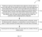
- a method to collect fluid includes positioning an opening of a fluid collection device adjacent to a female urethra or around a male urethra.
- the fluid collection device includes a fluid impermeable barrier at least partially defining a chamber, the fluid impermeable barrier also defining an opening extending therethrough, the opening configured to be positioned adjacent to the female urethra or have the male urethra positioned therethrough.
- the fluid collection device includes a porous material disposed in the chamber.
- the fluid collection device includes a shape memory material incorporated in the fluid collection device. The shape memory material is sized, shaped, and positioned to retain a selected geometric configuration.
- the method includes shaping the fluid collection device into the selected geometric configuration.
- the selected geometric configuration is complementary to contours of anatomy of a wearer in a region proximate to the female urethra or the male urethra of the wearer.
- the method includes receiving fluid from the female urethra or the male urethra into a chamber of the fluid collection device.
- Embodiments disclosed herein are related to devices, systems, and methods of using fluid collection devices and systems.
- the devices, systems, and methods of using fluid collection devices and systems include at least one shape memory material for forming and maintaining the fluid collection device into a selected shape.
- the shape memory material may enable for selective manipulation of the fluid collection device to contour to the anatomical features of variously sized wearers.
- the fluid collection devices disclosed herein include a fluid impermeable barrier that at least partially defines a chamber.
- the fluid impermeable barrier also defines an opening extending therethrough that is configured to be positioned adjacent to a female urethra or have a male urethra positioned therethrough.
- the fluid collection devices disclosed herein may include a porous material disposed in the chamber.
- the fluid collection devices disclosed herein include shape memory material carried by one or more components thereof, such as the fluid impermeable barrier, the porous material, or another component.
- the fluid collection devices also include a conduit having a channel extending between an inlet and outlet thereof. The inlet is configured to be coupled to a suction source and the outlet is configured to be fluidly coupled to a fluid storage (vessel or container).
- the fluid collection devices disclosed herein are configured to collect fluid(s) from a wearer.
- the shape of the fluid collection device may be manipulated and at least temporarily maintained in a selected shape to provide a more comfortable and effective fit on the wearer.
- By shaping the fluid collection device with the shape memory material to match the anatomical shape of the wearer more of the fluid may be collected and retained in the fluid collection device.
- shaping the fluid collection device to match the anatomical shape of the wearer inhibits the fluid collection device from moving away from the groin of the wearer ( e.g., when the wearer moves). Moving the fluid collection device away from the wearer increases the likelihood that fluid leaks from the fluid collection device during use.
- shaping the fluid collection device with the shape memory material to match the anatomical shape of the wear minimizes leaks.
- the fluid collected by the fluid collection devices may include urine.
- the fluid(s) collected by the fluid collection devices may also include at least one of vaginal discharge, penile discharge, reproductive fluids, blood, sweat, or other bodily fluids.
- the fluid collection devices disclosed herein are configured to be used in fluid collection systems, which apply suction in the chamber to remove the fluid from the fluid collection device.
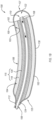
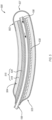
- FIG. 1A is an isometric view of a fluid collection device 100, according to an embodiment.
- FIG. 1B is cross-sectional view of the fluid collection device 100 taken along the plane A-A of FIG. 1A , according to an embodiment.
- the fluid collection device 100 is an example of a female fluid collection device for receiving and collecting fluid(s) from a female.
- the fluid collection device 100 includes a fluid impermeable barrier 102, porous material 115 ( e . g ., wicking material) disposed in a chamber within the fluid impermeable barrier 102, at least one shape memory material 130, and an optional conduit 108 at least partially disposed within the chamber.
- the fluid impermeable barrier 102 at least partially defines a chamber 104 ( e.g ., interior region) and an opening 106.
- a chamber 104 e.g ., interior region
- an opening 106 the interior surface(s) 103 of the fluid impermeable barrier 102 at least partially defines the chamber 104 within the fluid collection device 100.
- the fluid impermeable barrier 102 temporarily stores the fluid(s) in the chamber 104.
- the fluid impermeable barrier 102 may be formed of any suitable fluid impermeable material(s), such as a fluid impermeable polymer (e.g ., silicone, polypropylene, polyethylene, polyethylene terephthalate, a polycarbonate, etc.), a metal film, natural rubber, another suitable material, or combinations thereof.
- a fluid impermeable polymer e.g ., silicone, polypropylene, polyethylene, polyethylene terephthalate, a polycarbonate, etc.
- metal film e.g
- the fluid impermeable barrier 102 substantially prevents the fluid(s) from passing through the fluid impermeable barrier 102.
- the fluid impermeable barrier 102 may be air permeable and fluid impermeable.
- the fluid impermeable barrier 102 may be formed of a hydrophobic material that defines a plurality of pores. At least one or more portions of at least an outer surface 105 of the fluid impermeable barrier 102 may be formed from a soft and/or smooth material, thereby reducing chaffing.
- the fluid impermeable barrier 102 may be tubular (ignoring the opening), such as substantially cylindrical (as shown), oblong, prismatic, or flattened tubes. During use, the outer surface 105 of the fluid impermeable barrier 102 may contact the wearer. The fluid impermeable barrier 102 may be sized and shaped to fit in the gluteal cleft between the legs of a female wearer.
- the opening 106 provides an ingress route for fluids to enter the chamber 104.
- the opening 106 may be defined by the fluid impermeable barrier 102 such as by an inner edge of the fluid impermeable barrier 102.
- the opening 106 is formed in and extends through the fluid impermeable barrier 102, from the outer surface 105 to the inner surface 103, thereby enabling fluid(s) to enter the chamber 104 from outside of the fluid collection device 100.
- the opening 106 may be an elongated hole in the fluid impermeable barrier 102.
- the opening 106 may be defined as a cut-out in the fluid impermeable barrier 102.
- the opening 106 may be located and shaped to be positioned adjacent to a female urethra.
- the fluid collection device 100 may be positioned proximate to the female urethra and urine may enter the chamber of the fluid collection device 100 via the opening 106.
- the fluid collection device 100 is configured to receive the fluid(s) into the chamber 104 via the opening 106.
- the opening 106 may have an elongated shape that extends from a first location below the urethral opening ( e . g ., at or near the anus or the vaginal opening) to a second location above the urethral opening ( e.g ., at or near the top of the vaginal opening or the pubic hair).
- the opening 106 may have an elongated shape because the space between the legs of a female is relatively small when the legs of the female are closed, thereby only permitting the flow of the fluid(s) along a path that corresponds to the elongated shape of the opening 106 ( e . g ., longitudinally extending opening).
- the opening 106 in the fluid impermeable barrier 102 may exhibit a length that is measured along the longitudinal axis of the fluid collection device 100 that may be at least about 10% of the length of the fluid collection device 100, such as about 25% to about 50%, about 40% to about 60%, about 50% to about 75%, about 65% to about 85%, or about 75% to about 95% of the length of the fluid collection device 100.
- the opening 106 in the fluid impermeable barrier 102 may exhibit a width that is measured transverse to the longitudinal axis of the fluid collection device 100 that may be at least about 10% of the circumference of the fluid collection device 100, such as about 25% to about 50%, about 40% to about 60%, about 50% to about 75%, about 65% to about 85%, or about 75% to about 100% of the circumference of the fluid collection device 100.
- the opening 106 may exhibit a width that is greater than 50% of the circumference of the fluid collection device 100 since the vacuum ( e . g ., suction) through the conduit 108 pulls the fluid through the porous material 115 and into the conduit 108.
- the opening 106 may be vertically oriented (e.g., having a major axis parallel to the longitudinal axis of the device 100). In some examples (not shown), the opening 106 may be horizontally oriented (e.g., having a major axis perpendicular to the longitudinal axis of the device 100).
- the fluid impermeable barrier 102 may be configured to be attached to the wearer, such as adhesively attached ( e.g ., with a hydrogel adhesive) to the wearer.
- a suitable adhesive is a hydrogel layer.
- the fluid impermeable barrier 102 may define an aperture 124 sized to receive the conduit 108.
- the at least one conduit 108 may be disposed in the chamber 104 via the aperture 124.
- the aperture 124 may be sized and shaped to form an at least substantially fluid tight seal against the conduit 108 or the at least one tube thereby substantially preventing the fluid(s) from escaping the chamber 104.
- the fluid impermeable barrier 102 may include markings (not shown) thereon, such as one or more markings to aid a wearer in aligning the device 100 on the wearer.
- markings may include one or more of alignment guide or an orientation indicator, such as a stripe or hashes. Such markings may be positioned to align the device 100 to one or more anatomical features such as a pubic bone, etc.
- the fluid collection device 100 includes porous material 115 disposed in the chamber 104.
- the porous material 115 may cover at least a portion ( e.g ., all) of the opening 106.
- the porous material 115 is exposed to the environment outside of the chamber 104 through the opening 106.
- the porous material 115 may be configured to move any fluid away from the opening 106, thereby preventing the fluid from escaping the chamber 104.
- the permeable properties referred to herein may be wicking, capillary action, diffusion, or other similar properties or processes, and are referred to herein as "permeable” and/or "wicking.” Such "wicking" may not include absorption of fluid into the porous material.
- substantially no absorption of fluid into the material may take place after the material is exposed to the fluid and removed from the fluid for a time. While no absorption is desired, the term "substantially no absorption” may allow for nominal amounts of absorption of fluid into the porous material (e . g ., absorbency), such as less than about 10 wt% of the dry weight of the porous material, less than about 7 wt%, less than about 5 wt%, less than about 3 wt%, less than about 2 wt%, less than about 1 wt%, or less than about 0.5 wt% of the dry weight of the porous material.
- absorbency such as less than about 10 wt% of the dry weight of the porous material, less than about 7 wt%, less than about 5 wt%, less than about 3 wt%, less than about 2 wt%, less than about 1 wt%, or less than about 0.5 wt% of the dry weight of the porous material.
- the porous material 115 may also wick the fluid generally towards an interior of the chamber 104, as discussed in more detail below.
- the porous material 115 may include one or more of a fluid permeable membrane 118 or a fluid permeable support 120.
- the porous material 115 may include an absorption material (e . g ., hydrophilic material) instead of a wicking material.
- the fluid collection device 100 may include the fluid permeable membrane 118 disposed in the chamber 104.
- the fluid permeable membrane 118 may cover at least a portion ( e . g ., all) of the opening 106.
- the fluid permeable membrane 118 may be composed to wick fluid away from the opening 106, thereby preventing the fluid from escaping the chamber 104.
- the fluid permeable membrane 118 may include any material that may wick the fluid.
- the fluid permeable membrane 118 may include fabric, such as a gauze (e.g., a silk, linen, or cotton gauze), another soft fabric, or another smooth fabric. Forming the fluid permeable membrane 118 from gauze, soft fabric, and/or smooth fabric may reduce chaffing caused by the fluid collection device 100.
- the fluid collection device 100 may include the fluid permeable support 120 disposed in the chamber 104.
- the fluid permeable support 120 is configured to support the fluid permeable membrane 118 since the fluid permeable membrane 118 may be formed from a relatively foldable, flimsy, or otherwise easily deformable material.
- the fluid permeable support 120 may be positioned such that the fluid permeable membrane 118 is disposed between the fluid permeable support 120 and the fluid impermeable barrier 102.
- the fluid permeable support 120 may support and maintain the position of the fluid permeable membrane 118.
- the fluid permeable support 120 may include any material that may wick the fluid, such as any of the fluid permeable membrane materials disclosed herein above.
- the fluid permeable membrane material(s) may be utilized in a more dense or rigid form than in the fluid permeable membrane 118 when used as the fluid permeable support 120.
- the fluid permeable support 120 may be formed from any fluid permeable material that is less deformable than the fluid permeable membrane 118.
- the fluid permeable support 120 may include a porous polymer (e.g., nylon, polyester, polyurethane, polyethylene, polypropylene, etc.) structure or an open cell foam.
- the fluid permeable support 120 may be formed from a natural material, such as cotton, wool, silk, or combinations thereof.
- the material may have a coating to prevent or limit absorption of fluid into the material, such as a water repellent coating.
- the fluid permeable support 120 may be formed from fabric, felt, gauze, or combinations thereof.
- the fluid permeable membrane 118 may be optional.
- the porous material 115 may include only the fluid permeable support 120.
- the fluid permeable support 120 may be optionally omitted from the fluid collection device 100.
- the porous material 115 may only include the fluid permeable membrane 118.
- the fluid permeable support 120 may have a greater ability to wick fluids than the fluid permeable membrane 118, such as to move the fluid inwardly from the outer surface of the fluid collection device 100.
- the wicking ability of the fluid permeable support 120 and the fluid permeable membrane 118 may be substantially the same.
- the fluid permeable membrane 118 and the fluid permeable support 120 may at least substantially completely fill the portions of the chamber 104 that are not occupied by the conduit 108. In some examples, the fluid permeable membrane 118 and the fluid permeable support 120 may not substantially completely fill the portions of the chamber 104 that are not occupied by the conduit 108. In such an example, the fluid collection device 100 includes the reservoir 122 ( FIG. 1B ) disposed in the chamber 104.
- the reservoir 122 is a substantially unoccupied portion of the chamber 104.
- the reservoir 122 may be defined between the fluid impermeable barrier 102 and one or both of the fluid permeable membrane 118 and fluid permeable support 120.
- the fluid(s) that are in the chamber 104 may flow through the fluid permeable membrane 118 and/or fluid permeable support 120 to the reservoir 122.
- the reservoir 122 may retain of the fluid(s) therein.
- the fluid(s) that are in the chamber 104 may flow through the fluid permeable membrane 118 and/or fluid permeable support 120 to the reservoir 122.
- the fluid impermeable barrier 102 may retain the fluid(s) in the reservoir 122. While depicted in the second end region 127, the reservoir 122 may be located in any portion of the chamber 104 such as the first end region 125.
- the reservoir 122 may be located in a portion of the chamber 104 that is designed to be located in a gravimetrically low point of the fluid collection device when the device is worn.
- the fluid collection device 100 may include multiple reservoirs, such as a first reservoir that is located at the portion of the chamber 104 closest to the inlet 110 ( e.g. , second end region 127) and a second reservoir that is located at the portion of the of the chamber 104 that is closest to the outlet 112 of the conduit 108 (e.g., first end region 125).
- the fluid permeable support 120 is spaced from at least a portion of the conduit, and the reservoir 122 may be the space between the fluid permeable support 120 and the conduit.
- the conduit 108 may be at least partially disposed in the chamber 104.
- the conduit 108 may be used to remove fluid form the chamber 104.
- the conduit 108 (e.g., a tube) includes an inlet 110 and an outlet 112 positioned downstream from the inlet 110.
- the outlet 112 may be operably coupled to a suction source, such as a vacuum pump for withdrawing fluid form the chamber through the conduit 108.
- the conduit 108 may extend into the fluid impermeable barrier 102 from the first end region 125 and may extend to the second end region 127 to a point proximate to the reservoir 122 therein such that the inlet 110 is in fluid communication with the reservoir 122.
- the conduit 108 fluidly couples the chamber 104 with the fluid storage container (not shown) or the vacuum source (not shown).
- the conduit 108 may include a flexible material such as plastic tubing (e.g., medical tubing). Such plastic tubing may include a thermoplastic elastomer, polyvinyl chloride, ethylene vinyl acetate, polytetrafluoroethylene, etc., tubing. In some examples, the conduit 108 may include silicon or latex. In some examples, the conduit 108 may include one or more portions that are resilient, such as to by having one or more of a diameter or wall thickness that allows the conduit to be flexible.
- plastic tubing may include a thermoplastic elastomer, polyvinyl chloride, ethylene vinyl acetate, polytetrafluoroethylene, etc., tubing.
- the conduit 108 may include silicon or latex.
- the conduit 108 may include one or more portions that are resilient, such as to by having one or more of a diameter or wall thickness that allows the conduit to be flexible.
- the end of the conduit 108 may extend through a bore in the fluid permeable membrane 118 and/or fluid permeable support 120, such as into the reservoir 122.
- the inlet 110 may be extend into or be positioned in the reservoir 122.
- the conduit 108 is at least partially disposed in the reservoir 122.
- the conduit 108 may enter the chamber 104 in the second end region and the inlet 110 of the conduit 108 may be disposed in the second end region ( e.g., in the reservoir 122).
- the fluid collected in the fluid collection device 100 may be removed from the chamber 104 via the conduit 108.
- the inlet 110 may not extend into the reservoir 122.
- the inlet 110 may be disposed within the porous material 115 (fluid permeable membrane 118 and/or fluid permeable support 120) or at a terminal end thereof.
- an end of the conduit 108 may be coextensive with or recessed within the fluid permeable membrane 118 and/or fluid permeable support 120.
- Locating the inlet 110 at or near a location expected to be the gravimetrically low point of the chamber 104 when worn by a wearer enables the conduit 108 to receive more of the fluid(s) than if inlet 110 was located elsewhere and reduce the likelihood of pooling (e.g., pooling of the fluid(s) may cause microbe growth and foul odors).
- the fluid(s) in the fluid permeable membrane 118 and the fluid permeable support 120 may flow in any direction due to capillary forces.
- the fluid(s) may exhibit a preference to flow in the direction of gravity, especially when at least a portion of the fluid permeable membrane 118 and/or the fluid permeable support 120 is saturated with the fluid(s).
- one or more of the inlet 110 or the reservoir 122 may be located in the fluid collection device in a position expected to be the gravimetrically low point in the fluid collection device when worn by a wearer, such as the second end region 127.
- the conduit 108 is configured to be at least insertable into the chamber 104.
- the conduit 108 may include one or more markers (not shown) on an exterior thereof that are located to facilitate insertion of the conduit 108 into the chamber 104.
- the conduit 108 may include one or more markings thereon that are configured to prevent over or under insertion of the conduit 108, such as when the conduit 108 defines an inlet 110 that is configured to be disposed in or adjacent to the reservoir 122.
- the conduit 108 may include one or more markings thereon that are configured to facilitate correct rotation of the conduit 108 relative to the chamber 104.
- the one or more markings may include a line, a dot, a sticker, or any other suitable marking.
- the conduit 108 is configured to be coupled to, and at least partially extend between, one or more of the fluid storage container (not shown) and the vacuum source (not shown).
- the conduit 108 is configured to be directly connected to the vacuum source (not shown).
- the conduit 108 may extend from the fluid impermeable barrier 102 by at least one foot, at least two feet, at least three feet, or at least six feet.
- the conduit 108 is configured to be indirectly connected to at least one of the fluid storage container (not shown) and the vacuum source (not shown).
- the conduit is secured to a wearer's skin with a catheter securement device, such as a STATLOCK ® catheter securement device available from C. R. Bard, Inc., including but not limited to those disclosed in U.S. Patent Nos. 6,117,163 ; 6,123,398 ; and 8,211,063 , the disclosures of which are all incorporated herein by reference in their entirety.
- the inlet 110 and the outlet 112 are configured to fluidly couple ( e.g., directly or indirectly) the vacuum source (not shown) to the chamber 104 ( e.g., the reservoir 122).
- the vacuum source FIG. 16
- the fluid(s) in the chamber 104 e.g., at the second end region such as in the reservoir 122
- the conduit may be frosted or opaque (e.g., black) to obscure visibility of the fluid(s) therein.
- the fluid collection device 100 includes a shape memory material 130.
- the shape memory material may be sized, shaped, and positioned in the fluid collection device to cause at least a portion of the fluid collection device 100 to retain a selected shape (e.g., geometric configuration).
- the shape memory material 130 is configured to be bent, shaped, or otherwise deformed (hereafter collectively referred to as "shape,” "shaped,” or “shaping").
- shape memory material 130 is configured to be shaped along an entire length thereof. Allowing the shape memory material 130 to be shaped along the entire length thereof may allow the fluid collection device 100 to exhibit a shape that substantially corresponds to the anatomical features of the wearer.
- the shape memory material 130 is configured to be shaped at one or more selected location thereof.
- the selected locations of the shape memory material 130 may be preferentially shaped relative to the rest of the shape memory material 130. While configuring the shape memory material 130 to be shaped at the selected location may inhibit the fluid collection device 100 from exhibiting a shape that substantially corresponds to the anatomical features of the wearer, it may facilitate shaping of the fluid collection device 100, especially for less experienced wearers.
- the shape memory material may not be configured to be shaped. Instead, the shape memory material may exhibit a selected shape that corresponds or substantially corresponds to the anatomical feature of the wearer.
- the shape memory material 130 may be more rigid and/or resilient than the rest of the fluid collection device 100 thereby causing at least a portion of the fluid collection device 100 to correspond to the selected shape of the shape memory material 130.
- the shape memory material 130 may include a shape memory polymer or a metal (e.g., shape memory metal). Generally, the shape memory materials are composed to adopt an intermediate or permanent shape in response to a stimuli.
- the stimuli may include an external physical force (e.g., bending force), heat, electrical bias, or a magnetic field.
- shape memory is used to describe some of the “shape memory materials” herein, it should be understood that, in some examples, the material modified by the term “shape memory” may not necessarily need to return to a preselected shape upon application of a stimuli, as understood as the classical definition of the "shape memory material.” Rather, at least some of the shape memory materials herein may simply hold a selected shape when bent, set, or cured into a specific shape and/or when cooled in a specific shape, regardless of the stimuli applied thereto after. The shape memory materials may be returned to the original shape or changed to a new shape by application of stimuli.
- a metal wire bent to a first shape may be utilized as the shape memory material, whereinafter the metal wire may be modified to a second shape via physical force applied thereto or via heating.
- the shape memory materials may exhibit a selected shape, as discussed above and application of the stimuli may cause the shape memory material to deform (e.g., elastically deform or bend) into an intermediate shape.
- the shape memory material may return to the initial shape upon removal of the stimuli such that the shape memory material does not maintain the intermediate shape.
- the shape memory material may include metal, such as an elemental metal, an alloy, or shape memory alloy.
- Suitable shape memory metals may include standard steels, stainless steel, carbon alloy steel, head treated steel, aluminum, silver, copper, iron, nickel, zinc, tin, beryllium, or the like.
- Suitable shape memory alloys may include stainless steel; galvanized steel; aluminum alloys; nickel-titanium alloys, such as Nitinol, Ni-Ti-Cu, Ni-Ti, Co, or the like; copper-based alloys such as Cu-Zn-Al, Cu-Al-Ni, Cu-Al-Sn, or the like; Co-Cr-Ni-Mo alloys ( e.g., Elgiloy ® ) or the like; or any other alloy having shape memory characteristics.
- the shape memory metals or alloys may merely be metals or alloys that may be shaped to a selected configuration. In some examples, the shape memory metals or alloys may return to a primary shape when an external stimuli is applied thereto.
- the outer surface of the shape memory metal may be coated with a polymer, anodized, passivated, or otherwise treated to prevent corrosion.
- SMPs Shape memory polymers
- SMPs may include polyurethane-based SMPs such as a copolymer (e.g., copolyester, polyurethane, polyetherester, etc.) including blocks of one or more of poly( ⁇ -caprolactone), polyethyleneterephthalate (PET), polyethyleneoxide (PEO), polyethylene glycol (PEG), polystyrene, polymethylmethacrylate (PMMA), Polybutylmethacrylate (PBMA), poly(N,N-butadiene), poly(N-methyl-N-oxazoline), polytetrahydrofuran, or poly(butylene terephthalate); thermoplastic polymers such as polyether ether ketone (PEEK), nylon, acetal, polytetrafluoroethylene (PTFE), polypropylene, polyethylene, acrylonitrile butadiene styrene (ABS), polysulphone, or the like; Polynorbonene; other deform
- the shape memory material 130 may be located in the fluid impermeable barrier 102, such as being incorporated into the fluid impermeable barrier 102.
- the shape memory material 130 may comprise a shape memory polymer incorporated into the fluid impermeable barrier 102, such as in a mixture of a shape memory polymer and the material of the fluid impermeable barrier 102.
- the amount of shape memory polymer in the fluid impermeable barrier 102 may be present in an amount sufficient to maintain the fluid collection device 100 in a selected shape during use.
- the amount of shape memory polymer in the fluid impermeable barrier 102 may be at least 10 wt% of the total weight of the fluid impermeable barrier 102, such as 10 wt% to 90 wt%, 10 wt% to 50 wt%, 10 wt% to 30 wt%, 30 wt% to 60 wt%, 60 wt% to 90 wt%, or less than 90 wt% of the total weight of the fluid impermeable barrier 102.
- the material of the fluid impermeable barrier 102 may be solely shape memory polymer.
- the shape memory material 130 may comprise a shape memory metal (e.g., aluminum, copper, etc.) incorporated into the fluid impermeable barrier 102, such as in a mixture of a shape memory metal and the material of the fluid impermeable barrier 102.
- the material of the fluid impermeable barrier 102 may be solely shape memory metal.
- FIGS. 1A-1C illustrate that the shape memory material 130 is incorporated in the fluid impermeable barrier 102, it is noted that the shape memory material 130 may be incorporated into other components of the fluid collection device 100.
- the shape memory material 130 is incorporated in the conduit 108 and/or the porous material 115.
- the shape memory material 130 may be incorporated into the conduit 108 and/or the porous material 115 in any of the same manners as discussed above with regards to incorporating the shape memory material 130 into the fluid impermeable barrier 102.
- the amount of the shape memory material 130 may be at least 10 wt% of the total weight of the conduit 108 and/or the porous material 115 or the material of the conduit 108 and/or the porous material 115 may solely include the shape memory material 130.
- Incorporating the shape memory material 130 into the conduit 108 and/or the porous material 115 may cause the conduit 108 to conform to the general shape of the fluid collection device 100 after the fluid collection device 100 is shaped.
- incorporating the shape memory material 130 into the conduit 108 and/or the porous material 115 cause the conduit 108 to conform to the shaping of the fluid collection device 100 without the use of braces.
- the shape memory material 130 may only be disposed in one or more discrete portions of the fluid impermeable barrier 102.
- the fluid impermeable barrier 102 may be at least partially constructed of shape memory material 130 longitudinally extending along the bottom surface ( e.g., substantially opposite the opening) of the fluid collection device 100.
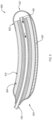
- FIG. 1C is an isometric view of the fluid collection device 100 of FIG. 1A , according to an embodiment.
- FIG. 1C shows the fluid collection device 100 in a second shape which differs from the first shape shown in FIG. 1A .
- the fluid collection device 100 may be shaped to contour to the anatomy of a wearer using the fluid collection device 100 to improve comfort over conventional devices and to remain in position during use.
- the fluid collection device 100 may be manipulated to contour to the anatomy in the groin region of a wearer.
- the second end region 127 may be shaped upwardly such that the fluid collection device 100 maintains a generally arcuate shape with the first end region 125 and the second end region being disposed above a medial portion therebetween.
- the second end region may be positioned in the gluteal cleft of the wearer, the second end region may be positioned against the upper vaginal or pubic area of the wearer, and the portion therebetween may be shaped to contour the anatomy of the wearer.
- the shape in the device may be more or less arcuate depending on the size and shape of the wearer. Accordingly, the devices disclosed herein may be utilized with a variety of differently sized wearers.
- the fluid collection device 100 may be returned to an original shape (e.g., a substantially straight cylinder) or manipulated into a third shape after being manipulated and used in the second shape. Such manipulation may be performed by applying a stimuli, such as any of those disclosed herein.
- one or more components (e.g., fluid impermeable barrier 102, conduit 108, the porous material 115, etc.) of the fluid collection device 100 may include an odor blocking or absorbing material such as a cyclodextrine-containing material or a thermoplastic elastomer (TPE) polymer.
- an odor blocking or absorbing material such as a cyclodextrine-containing material or a thermoplastic elastomer (TPE) polymer.
- the shape memory material in the fluid collection device 100 may be located in one or more different or additional locations than those depicted in FIGS. 1A to 1C .
- the shape memory material 130 used fluid collection devices disclosed may be distinct from the other components of the fluid impermeable barriers (e.g., the fluid impermeable barrier, the porous material, and/or the conduit).
- the shape memory materials that are distinct from the other components of the fluid impermeable barriers may be used instead of or in conjunction with the shape memory materials that are included in the one or more components of the fluid impermeable barrier.
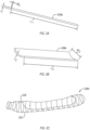
- FIGS. 2A to 2C are isometric views of shape memory materials that are distinct from the other components of the fluid impermeable barrier, according to different embodiments. Except as otherwise disclosed herein, the shape memory materials shown in FIGS. 2A-2C are the same or substantially similar to any of the shape memory materials disclosed herein. For example, the shape memory materials shown in FIGS. 2A-2C may include any of materials disclosed herein or may be configured to be shaped using any the stimuli disclosed herein. Further, except as otherwise disclosed herein, the shape memory materials shown in FIGS. 2A-2C may be used in any of the fluid collection devices disclosed herein.
- the shape memory material 230a includes at least one wire (e.g., at least one rod).
- the wire includes a length L 1 measured along a longitudinal axis of the wire, a width W 1 measured perpendicularly to the length L 1 , and a thickness ti measured perpendicularly to the length L 1 and the width W 1 .
- the length L 1 of the wire is significantly greater than the width W 1 and the thickness ti.
- the wire is sized and configured such that the length L 1 is generally aligned with the longitudinal axis of the fluid impermeable barrier.
- the wire can change the shape of the fluid collection device along the longitudinal axis thereof and/or change the shape of the fluid impermeable barrier globally.
- the wire is sized and configured to such that the length L 1 is not aligned with the longitudinal axis of the fluid impermeable barrier (e.g., the length L 1 is generally perpendicular to the longitudinal axis of the fluid collection device).
- the wire may at least one of extend between and interconnect a plurality of wires that have lengths that are generally aligned with the longitudinal axis of the fluid impermeable barrier, allow the wire to change the shape of the fluid collection device along an axis that is different than the longitudinal axis of the fluid collection device, or facilitate local changes in the shape of the fluid impermeable barrier.
- the length of the wire may be at least 10% of the longitudinal length of the fluid collection device, such as 10% to 100%, 30% to 100%, 10% to 40%, 30% to 60%, 60% to 90%, 40% to 80%, 50% to 100%, less than 100%, or less than 70% of the length of the fluid collection device.
- the wire may exhibit a generally circular cross-sectional shape.
- the width W 1 and the thickness ti are the same.
- the wire may exhibit a slightly oblong cross-sectional shape.
- the width W 1 may be slightly greater ( e.g., at most about 50% greater, at most about 25% greater, or at most 10% greater) than the thickness ti.
- the width W 1 and the thickness ti may be at least 0.5 mm, such as about 0.5 mm to about 1.5 mm, about 1 mm to about 2 mm, about 1.5 mm to about 2.5 mm, about 2 mm to about 3 mm, about 2.5 mm to about 3.5 mm, about 3 mm to about 4 mm, about 3.5 mm to about 4.5 mm, about 4 mm to about 5 mm, about 4.5 mm to about 6 mm, about 5 mm to about 7 mm, about 6 mm to about 8 mm, about 7 mm to about 9 mm, about 8 mm to about 10 mm, about 9 mm to about 1.2 cm, about 1 cm to about 1.5 cm, about 1.25 cm to about 1.75 cm, about 1.5 cm to about 2 cm, about 1.75 cm to about 2.5 cm, or about 2 cm to about 3 cm.
- the shape memory material 230b includes a plate (e.g., strip).
- the plate exhibits a length L 2 , a width W 2 , and a thickness t 2 .
- the length L 2 of the plate may be the same as or substantially similar to any of the lengths disclosed herein. Similar to the shape memory material 230a of FIG. 2A , the plate may be configured such that the length L 2 thereof is aligned or not aligned with the longitudinal axis of the fluid collection device.
- the width W 2 of the plate is greater ( e.g ., at least 50% greater) than the thickness t 2 .
- the width W 2 may be at least 3% of the lateral width of the fluid collection device, such as 3% to 100%, 3% to 50%, 3% to 20%, 20% to 40%, 40% to 60%, 60% to 80%, 80% to 100%, less than 100%, or less than 50% of the width of the fluid collection device.
- the thickness t 2 may the same as or substantially similar to any of the thicknesses disclosed herein.
- the plate may initially (i.e., before shaping the plate) exhibit one or more bends therein (e.g. , the plate is an at least partial tube).
- the plate may exhibit a bend in the direction that is parallel to the width W 2 .
- the bend in the plate may be configured to correspond to the shape of the fluid collection device.
- at least some of the fluid collection devices disclosed herein exhibit a generally cylindrical shape and the bend in the plate may correspond to the curvature of the generally cylindrical shape of the fluid collection device.
- the bend in the plate may make shaping the plate more difficult.
- the plate may be substantially planar.
- the plate may have one or more openings or perforations therein.
- the one or more openings or perforations may allow fluid to flow to through the plate.
- the one or more openings or perforations may also decrease the weight of the plate.
- the one or more openings or perforations may also weaken the plate thereby facilitating shaping of the plate to form regions of the plate that are preferentially shaped relative to other regions of the plate.
- the plate may provide more support to the fluid collection device thereby allowing the fluid collection device to better maintain the desired shape thereof compared to the wire.
- the plate may be more difficult to shape than the wire and may be shaped in fewer directions than the wire due to the increased cross-sectional area of the plate relative to the wire.
- the shape memory material 230c includes a plurality of interconnected wires (e.g. , the shape memory material 230c is a wire mesh). Each of the plurality of interconnected wires may be the same or substantially similar to any of the wires disclosed herein.
- the plurality of wires are interconnected with the plurality of wires are attached to, contact, or are positioned proximate to each other.
- the shape memory material 230c may include at least one longitudinal wire 232 extending in a longitudinal direction of the shape memory material 230c.
- the longitudinal wire 232 is generally aligned with the longitudinal axis of the fluid collection device though, it is noted, that the longitudinal wire 232 may not be generally aligned with the longitudinal axis of the fluid collection device.
- the shape memory material 230c also includes at least one transverse wire 234 extending in a direction that is different than the longitudinal wire 232.
- the transverse wire 234 may extend generally perpendicularly to the longitudinal wire 232, such as in a circumferential direction.
- the longitudinal wire 232 and the transverse wire 234 may generally exhibit the shape of a portion of the fluid collection device.
- the longitudinal wire 232 and the transverse wire 234 exhibit the generally shape of a portion of the fluid collection device 100 shown in FIG. 1A , including an unoccupied gap for the opening 106. It is noted that the longitudinal wire 232 and the transverse wire 234 may also generally exhibit the shape of the fluid collection device illustrated in FIG. 12A.
- any of the fluid collection devices disclosed herein may include a plurality of shape memory materials that include the shape memory materials disclosed herein.
- the shape memory material for any of the fluid collection devices disclosed herein may include a plurality of wires, a plurality of plates, a plurality of interconnected wires, or combinations thereof.
- the shape memory materials illustrated in FIGS. 2A-2C are merely examples of shape memory materials that may be distinct from the other components of the fluid collection device.
- the shape memory materials that are distinct from the other components of the fluid collection device may include a plurality of interconnected plates, one or more annular rings, a tube, a coating, a mesh-like structure, , a sheet, any other suitable structure, or combinations thereof.
- FIG. 3 is a cross-sectional view of a fluid collection device 300, according to an embodiment. Except as otherwise disclosed herein, the fluid collection device 300 is the same or substantially similar to the fluid collection device 100, in one or more aspects.
- the fluid collection device 300 includes the fluid impermeable barrier 302, the porous material 315, and the conduit 108 as disclosed herein.
- the shape memory material 330 is disposed on the outer surface 305 of the fluid impermeable barrier 302.
- the shape memory material 330 may be distinct from the fluid impermeable barrier 302, the porous material 315, and the conduit 108.
- the shape memory material 330 may include longitudinally extending elements.
- the shape memory material 330 may be adhered to one or more portions of the outer surface 305 the fluid impermeable barrier 302.
- the shape memory material 330 may be bonded to the lower portion ( e.g., the back of the device opposite the opening 306) of the fluid impermeable barrier 302.
- the relatively more rigid shape memory material 330 may not contact the wearer, thereby reducing or eliminating discomfort when worn.
- the shape memory material 330 may extend from the first end region 325 to the second end region 327. Accordingly, the shape memory material 330 on the fluid collection device 300 may be formed to, and maintain, a selected shape.
- the shape memory material 330 may be the same or substantially similar to any of the shape memory materials disclosed herein.
- the dimensions of the shape memory material 330 disposed on the fluid impermeable barrier 302 are sufficient to maintain the selected shape of the fluid collection device 300 when in use.
- the thickness, height, and length of the shape memory material 330 may be as disclosed herein with respect to the fluid collection device 300.
- the shape memory material 330 may also include any of the materials disclosed herein.
- the shape memory material maybe coated in a relatively softer material, such as silicone or another polymer.
- the shape memory material 330 may also include a single structure (e.g., a single wire or plate) or a plurality of structures (e.g., a plurality of wires and/or plates) disposed the fluid impermeable barrier 302.
- a single structure e.g., a single wire or plate
- a plurality of structures e.g., a plurality of wires and/or plates
- the shape memory material 330 may be disposed in the lateral portions or in the upper half ( e.g., front, wearer-facing portion) of the fluid impermeable barrier 302 or may be an at least partial tube concentrically disposed on ( e.g., covering at least a portion of) the fluid impermeable barrier 302.
- FIG. 4A is a cross-sectional view of a fluid collection device 400, according to an embodiment. Except as otherwise disclosed herein, the fluid collection device 400 is the same or substantially similar to one or more of fluid collection devices 100 or 300, in one or more aspects.
- the fluid collection device 400 includes the fluid impermeable barrier 402, the porous material 415 (e.g., the fluid permeable membrane 418 and the fluid permeable support 420), the conduit 108 as disclosed herein.
- the shape memory material 430 is disposed on the inner surface 403 of the fluid impermeable barrier 402.
- the shape memory material 430 may be disposed between the fluid impermeable barrier 402 and the porous material 415, such as the fluid permeable membrane 418.
- the shape memory material 430 may distinct from the fluid impermeable barrier 402, the porous material 415, and the conduit 108.
- the shape memory material 430 may be adhered to one or more portions of the outer surface 405 of the fluid impermeable barrier 402.
- the shape memory material 430 may be bonded to the lower ( e.g., back) portion of the inner surface 403 of the fluid impermeable barrier 402.
- the shape memory material 430 may extend from the first end region 425 to the second end region 427.
- the shape memory material 430 on the fluid collection device 400 may be formed to, and maintain, a selected shape.
- the shape memory material 430 may not provide a perceptible feel on the skin of the wearer.
- the shape memory material 430 may be the same or substantially similar to any of the shape memory materials disclosed herein.
- the dimensions of the shape memory material 430 disposed in the chamber 404 are sufficient to maintain the selected shape of the fluid collection device 400 when in use.
- the shape memory material 430 may also include any of the materials disclosed herein.
- the shape memory material 430 may also include a single structure or a plurality of structures disposed on the inner surface 403.
- the shape memory material 430 may be disposed in the lateral portions or in the upper half ( e .g., front, wearer-facing portion) of the inner surface 403 or may be an at least partial tube concentrically disposed on the inner surface 403.
- FIGS. 4B to 4D are cross-sectional view of the fluid collection device 400 taken along the plane B,C,D-B,C,D of FIG. 4A , according to different embodiments.
- FIGS. 4B -4D illustrate how at least one of the fluid impermeable barrier 402 or the porous material 415 accommodate the shape memory material 430.
- the chamber 404b exhibits a shape ( e.g., generally cylindrical shape) and the porous material 415b exhibits a shape that corresponds to the shape of the chamber 404b.
- the shape memory material 430b is disposed in the chamber 404b between the fluid impermeable barrier 402b and the porous material 415b such that the shape memory material 430b is adjacent to ( e.g., attached to) the inner surface 403b of the fluid impermeable barrier 402b.
- a portion of the porous material 415b adjacent to the shape memory material 430b is compressed. Compressing the porous material 415b may at least one of decrease the volume of the porous material 415b or increase the density of the porous material 415b, either of which may decrease the amount of fluid that may be held by the porous material 415b. Compressing the porous material 415b may also cause voids 435 to form adjacent to the shape memory material 430b which provides locations for the fluid to detrimentally pool.
- the fluid impermeable barrier 402c defines at least one recess 436c.
- the recess 436c may be formed by decreasing the thickness of the fluid impermeable barrier 402c or, as illustrated, the fluid impermeable barrier 402c may include at least one protrusion 438 that defines the recess 436c.
- the recess 436c is configured to have the shape memory material 430c at least partially disposed therein. As such, the recess 436c may exhibit a shape that generally corresponds to the shape of the shape memory material 430c.
- Positioning the shape memory material 430c in the recess 436c prevents the shape memory material 430c from compressing the porous material 415c when the recess 436c receives all of the shape memory material 430c or compresses the porous material 415c less than the shape memory material 430b shown in FIG. 4B when the recess 436c only receives a portion of the shape memory material 430c.
- the porous material 415d (e.g., at least one of the fluid permeable membrane or the fluid permeable support) defines at least one recess 436d instead of or in conjunction with the fluid impermeable barrier 402d.
- the recess 436d is configured to have the shape memory material 430d at least partially disposed therein. As such, the recess 436d may exhibit a shape that generally corresponds to the shape of the shape memory material 430d.
- Positioning the shape memory material 430d in the recess 436d prevents the shape memory material 430d from compressing the porous material 415d when the recess 436d exhibits a size that is sufficient to receive all of the shape memory material 430d or compresses the porous material 415d less than the shape memory material 430b shown in FIG. 4B when the recess 436d exhibits a size that is sufficient to only receives a portion of the shape memory material 430d.
- FIG. 5 is a cross-sectional view of a fluid collection device, according to an embodiment. Except as otherwise disclosed herein, the fluid collection device 500 is the same or substantially similar to one or more of fluid collection devices 100, 300, or 400, in one or more aspects.
- the fluid collection device 500 includes the fluid impermeable barrier 502, the porous material 515, the conduit 108 as disclosed herein.
- the shape memory material 530 is disposed within the chamber 504 and spaced from the fluid impermeable barrier 502 along at least a portion of the length of the shape memory material 530 ( e.g., a portion of the shape memory material 530 may contact the fluid impermeable barrier 502, such as a terminal end of the shape memory material 530).
- the shape memory material 530 is disposed within the porous material 515.
- the shape memory material 530 may between the fluid permeable membrane 518 and the fluid permeable support 520, within the fluid permeable membrane 518, or within the fluid permeable support 520.
- the shape memory material 530 may include one or more longitudinally extending elements of shape memory material 530, as disclosed herein.
- the shape memory material 530 may be bonded to fluid permeable support 520, the fluid permeable membrane 518, or both.
- the shape memory material 530 may extend from the first end region 525 to the second end region 527. Accordingly, the shape memory material 530 on the fluid collection device 500 may be formed to, and maintain, a selected shape. By locating the shape memory material 530 within the chamber 504 and spaced from the fluid impermeable barrier 502, the shape memory material 530 may not provide a perceptible feel on the skin of the wearer when in use.
- the porous material 515 may define a recess that is configured to at least partially receive the shape memory material 530.
- the shape memory material 530 may be the same or substantially similar to any of the shape memory materials disclosed herein.
- the dimensions of the shape memory material 530 disposed in the porous material 515 are sufficient to maintain the selected shape of the fluid collection device 500 when in use.
- the shape memory material 530 may also include any of the materials disclosed herein.
- the shape memory material 530 may also include a single structure or a plurality of structures disposed in the porous material 515.
- the shape memory material 530 may be disposed in the lateral portions or in the upper half ( e.g., front, wearer-facing portion) of the porous material 515 or may be an at least partial tube concentrically disposed within the porous material 515.
- the shape memory material may be incorporated into the fluid impermeable barrier, such as located external to the chamber and within the fluid impermeable barrier.
- FIG. 6 is a cross-sectional view of a fluid collection device 600, according to an embodiment. Except as otherwise disclosed herein, the fluid collection device 600 is the same or substantially similar to one or more of fluid collection devices 100 or 300-500, in one or more aspects.
- the fluid collection device 600 includes the fluid impermeable barrier 602, the porous material 615, and the conduit 108 as disclosed herein.
- the shape memory material 630 is disposed outside of the chamber 604 and incorporated within the fluid impermeable barrier 602.
- the shape memory material 630 may be separate from, but at least partially embedded within, the fluid impermeable barrier 602.
- the shape memory material 630 may be overmolded into the fluid impermeable barrier 602. Accordingly, the shape memory material 630 may be isolated within the fluid impermeable barrier 602.
- the shape memory material 630 may be bonded to fluid impermeable barrier 602 and a second portion of the fluid impermeable barrier 602 may be disposed on and over the shape memory material 630.
- the shape memory material 630 may extend from the first end region 625 to the second end region 627. Accordingly, the shape memory material 630 on the fluid collection device 600 may be formed to, and maintain, a selected shape. By locating the shape memory material 630 within the fluid impermeable barrier 602, the shape memory material 630 may not provide a perceptible feel on the skin of the wearer when in use and the shape memory material 630 may be isolated from the fluids in the chamber 604.
- the shape memory material 630 may be the same or substantially similar to any of the shape memory materials disclosed herein.
- the dimensions of the shape memory material 630 disposed in the fluid impermeable barrier 602 are sufficient to maintain the selected shape of the fluid collection device 600 when in use.
- the shape memory material 630 may also include any of the materials disclosed herein.
- the shape memory material 630 may also include a single structure or a plurality of structures disposed in the fluid impermeable barrier 602.
- the shape memory material 630 may be disposed in the lateral portions or in the upper half ( e.g., front, wearer-facing portion) of the fluid impermeable barrier 602 or may be an at least partial tube concentrically disposed within the fluid impermeable barrier 602.
- the fluid impermeable barrier may define a cavity and at least one aperature that allows a shape memory material to be inserted into and removed from the cavity.
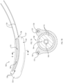
- FIG. 7A is an isometric view of a fluid collection device 700 illustrating at least one shape memory material 730 being inserted into the fluid impermeable barrier 702, according to an embodiment.
- FIG. 7B is a cross-sectional schematic view of the fluid collection device 700 taken along the plane B-B of FIG. 7A with the shape memory material 730 disposed in the fluid impermeable barrier 702, according to an embodiment.
- the fluid collection device 700 is the same or substantially similar to one or more of fluid collection devices 100 or 300-600, in one or more aspects.
- the fluid collection device 700 includes the fluid impermeable barrier 702, the porous material 715, and the conduit 108 as disclosed herein.
- the shape memory material 730 is disposed outside of the chamber 704.
- the fluid impermeable barrier 702 defines at least one cavity 737 and the shape memory material 730 is disposed in the cavity 737.
- the cavity 737 may exhibit a size and shape that allows the cavity 737 to receive at least a portion ( e.g., all or substantially all) of the shape memory material 730 therein.
- the cavity 737 may exhibit a cross-sectional shape that is the same as or slightly larger than the shape memory material 730 such that friction maintains the shape memory material 730 in the cavity 737 during normal operations.
- the fluid impermeable barrier 702 also defines at least one aperture 739.
- the aperture 739 is configured to allow access to the cavity 737 such that the shape memory material 730 may be inserted into and/or removed from the cavity 737.
- Each cavity 737 may include a single aperture 739 or a plurality of apertures 739 (e.g., an aperture 739 on opposing ends of the cavity 737). Further, by locating at least a portion of the shape memory material 730 within the cavity 737 ( e.g., within the fluid impermeable barrier 700), the shape memory material 730 may not provide a perceptible feel on the skin of the wearer when in use and the shape memory material 730 may be isolated from the fluids in the chamber 704.
- the cavity 737 and the aperture 739 allow the shape memory material 730 to be inserted and/or removed from the cavity 737.
- the cavity 737 and the aperture 739 allow the shape memory material 730 to be replaced when damaged or misshaped.
- the cavity 737 and the aperture 739 may allow the shape memory material 730 to be shaped prior to inserting the shape memory material 730 into the cavity 737 which may be easier than shaping the shape memory material 730 while the shape memory material 730 is in the cavity 737.
- the cavity 737 and the aperture 739 may allow the shape memory material 730 to be selected for the particular wearer.
- At least one of the shape memory material 730 may be selected to exhibit an initial shape that is substantially similar to the anatomy of the wearer thereby requiring little to no shaping of the shape memory material 730.
- the cavity 737 and the aperture 739 allows the shape memory material 730 to be reused ( e.g., after washing the shape memory material 730).
- the wearer may remove the shape memory material 730 from a fluid collection device that the wearer previously used and insert the shape memory material 730 into a new fluid collection device that the wearer will use. Inserting the previously used shape memory material 730 into the new fluid collection device may preclude the need to shape the shape memory material 730.
- the cavity 737 and the aperture 739 are sized such that a portion of the shape memory material 730 is accessible (e.g., an wearer can grab the shape memory material 730) after the shape memory material 730 is in the cavity 737.
- the cavity 737 may be exhibit a length that is smaller than the length of the shape memory material 730 such that a portion of the shape memory material 730 protrudes from the cavity 737.
- the aperture 739 may include a flap or other device that is able to switch between an open and closed state. In such an example, the flap or other device may cover the shape memory material 730 when in the closed state such that shape memory material 730 may not provide a perceptible feel on the skin of the wearer. However, the flap or other device may provide access to the shape memory material 730 when in the open state.
- the shape memory material 730 may be the same or substantially similar to any of the shape memory materials disclosed herein.
- the dimensions of the shape memory material 730 disposed in the fluid impermeable barrier 702 are sufficient to maintain the selected shape of the fluid collection device 700 when in use (e.g., the shape memory material 730 may extend from the first end region 725 to the second end region 727).
- the shape memory material 730 may also include any of the materials disclosed herein.
- the cavity 737 and the shape memory material 730 are shown being positioned adjacent to the opening 706.
- the fluid collection device 700 may include a plurality of cavities 737 and the shape memory material 730 may include a corresponding plurality of shape memory materials 730.
- the shape memory material 730 may be disposed in the lateral portions or in the lower half of the fluid impermeable barrier 702.
- FIG. 8 is a cross-sectional view of a fluid collection device 800, according to an embodiment. Except as otherwise disclosed herein, the fluid collection device 800 is the same or substantially similar to one or more of fluid collection devices 100 or 300-700, in one or more aspects.
- the fluid collection device 800 includes the fluid impermeable barrier 802, the porous material 815, and the conduit 108, as disclosed herein.
- the shape memory material 830 is disposed on ( e.g ., attached to or contacts) the conduit 108.
- the shape memory material 830 may be distinct from the conduit 108 and the porous material 815.
- the shape memory material 830 may include longitudinally extending elements.
- the shape memory material may be adhered ( e.g., bonded) to one or more portions of an outer surface 838 of the conduit 108 or enclose the outer surface 838 of the conduit 108. Accordingly, the shape memory material 830 on the may be formed to, and maintain, a selected shape which, in turn, may cause the fluid collection device 800 to exhibit a shape that generally corresponds to the shape of the shape memory material 830. By disposing the shape memory material 830 on the conduit 108, the shape memory material 830 may not provide a perceptible feel on the skin of the wearer.
- the shape memory material 830 may be the same or substantially similar to any of the shape memory materials disclosed herein.
- the dimensions of the shape memory material 830 disposed on the conduit 108 are sufficient to maintain the selected shape of the fluid collection device 800 when in use.
- the shape memory material 830 may also include any of the materials disclosed herein.
- the shape memory material 830 may also include a single structure or a plurality of structures disposed on the conduit 108.
- the shape memory material 830 may be disposed in the lateral portions or in the upper half ( e.g., front, wearer-facing portion) of the conduit 108 or may be an at least partial tube concentrically disposed on the conduit 108.
- the conduit may exhibit an initial shape when the conduit is in its relaxed state.
- the conduit is in its relaxed state when no external forces, such as forces caused by shaping the shape memory material, are applied to the conduit.
- the initial shape of the conduit may be a generally cylindrical shape (e.g., the conduit is straight) or a slightly curved generally cylindrical shape.
- Shaping the shape memory material may apply an external force to the conduit that causes the conduit to change the shape thereof.
- the conduit may resist changing the shape thereof when the external force are applied to the conduit which causes the conduit to apply a normal force that is opposite the external force.
- the normal force from the conduit may cause the conduit to compress a portion of the porous material and/or may cause the formation of detrimental voids in the chamber.
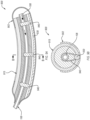
- FIG. 9A is a cross-sectional view of a fluid collection device 900, according to an embodiment.
- FIG. 9B is a cross-sectional view of the fluid collection device 900 taken along plane B-B of FIG. 9A , according to an embodiment.
- the fluid collection device 900 is the same or substantially similar at any of the fluid collection devices disclosed herein.
- the fluid collection device 900 includes a fluid impermeable barrier 902, a porous material 915, a conduit 108, and a shape memory material 930.
- the fluid collection device 900 is illustrated as being substantially similar to the fluid collection device 400 shown in FIG. 4A .
- the fluid collection device 400 may be substantially similar to any of the fluid collection devices disclosed herein.
- the fluid collection device 900 includes at least one brace 940 that is configured to force the conduit 108 to exhibit a shape change that corresponds more closely to the shape change of the shape memory material 930 than if the fluid collection device 900 did not include the brace 940.
- the brace 940 also minimizes the normal force applied from the conduit 108 to the porous material 915.
- the brace 940 is connected to the shape memory material 930 or a component of the fluid collection device 900 that is connected to the shape memory material 930 ( e.g ., the fluid impermeable barrier 902 when the shape memory material 930 is attached to an exterior surface of or embedded within the fluid impermeable barrier 902).
- the brace 940 extends from the shape memory material 930 or the component of the fluid collection device 900 that is connected to the shape memory material 930 to the conduit 108.
- the brace 940 may extend around the conduit 108, as shown in FIG. 9B .
- the brace 940 may be attached to the conduit 108 using other suitable techniques, such as with an adhesive.
- one or more components of the fluid collection device 900 e.g. , the porous material 915
- the brace 940 may be configured to transfer a shape change in the shape memory material 930 to the conduit 108 such that the conduit 108 exhibits a shape change that substantially corresponds to the shape change of the shape memory material 930.
- the fluid collection device 900 may include any suitable number of braces 940, such as 1, 2, 3, 4, 5, 6, 7, 8, 9, 10, or greater than 10 braces 940. Generally increasing the number of braces 940 causes the conduit 108 to more accurately correspond to the shape of the shape memory material 930 and decreases the normal force that is applied to the porous material 915.
- the braces 940 may not always cause the conduit 108 to exhibit the same shape change as the shape memory material 930.
- the braces 940 may only cause the conduit 108 to exhibit the shape change of the shape memory material 930 when the braces 940 pull ( e.g. , the braces 940 are in tension) the conduit 108 towards the shape memory material 930 but not when the braces 940 push ( e.g. , the braces 940 are in compression) the conduit 108 away from the shape memory material 930.
- the braces 940 are formed from any of the shape memory materials disclosed herein. In an embodiment, the braces 940 may be formed from a non-shape memory material, such as fabric.
- FIGS. 1A-9B are examples of female fluid collection devices that are configured to collect fluid(s) from females (e.g ., collect urine from a female urethra).
- the fluid collection devices, systems, and methods disclosed herein may include male fluid collection devices shaped, sized, and otherwise configured to collect fluid(s) from males (e.g ., collect urine from a male urethra).
- FIGS. 10 to 15 are isometric and cross-sectional views of male fluid collection devices according to different embodiments.
- FIG. 10A is an isometric view of a fluid collection device 1000 according to an embodiment.
- FIG. 10B is a cross-sectional view of the fluid collection device 1000 of FIG. 10A taken along the plane B-B of FIG. 10A , according to an embodiment.
- the fluid collection device 1000 includes a receptacle 1050 and a sheath 1052.
- the receptacle 1050 is sized, shaped, and made of a material to be coupled to skin that surrounds the male urethra and have the male urethra positioned therethrough.
- the receptacle 1050 may include an annular base 1054 that defines an opening 1056 in the receptacle 1050.
- the annular base 1054 is sized and shaped to be positioned around the male urethra ( e.g ., positioned around and/or over the penis) and the opening 1056 may be configured to have the male urethra positioned therethrough.
- the annular base 1054 may also be sized, shaped, made of a material, or otherwise configured to be coupled ( e.g ., adhesively attached, such as with a hydrogel adhesive) to the skin around the male urethra ( e.g. , around the penis).
- the annular base 1054 may exhibit the general shape or contours of the skin surface that the annular base 1054 is selected to be coupled with.
- the annular base 1054 may be flexible thereby allowing the annular base 1054 to conform to any shape of the skin surface.
- the annular base 1054 may include a laterally extending flange 1055.
- the receptacle 1050 also defines a hollowed region that is configured to receive ( e.g. , seal against) the sheath 1052.
- the receptacle 1050 may include a longitudinally extending flange 1060 that extends upwardly from the annular base 1054.
- the longitudinally extending flange 1060 may be tall enough to prevent the sheath 1052 from being accidentally removed from the receptacle 1050 ( e.g. , at least 0.25 cm tall, 1 cm tall, at least 10 cm tall, or at least 5 cm tall).
- the receptacle 1050 is located at a proximal region 1042 (with respect to a wearer) of the fluid collection device 1000.
- the sheath 1052 includes ( e.g. , may be formed from) a fluid impermeable barrier 1002 that is sized and shaped to fit into the hollowed region of the receptacle 1050.
- the sheath 1052 may be generally tubular or cup-shaped, as shown.
- the generally tubular or cup-shaped fluid impermeable barrier 102 may at least partially define the outer surface 1005 of the sheath 1052.
- the fluid impermeable barrier 1002 may be similar or identical to the fluid impermeable barrier 102 as disclosed herein, in one or more aspects.
- the fluid impermeable barrier 1002 may be constructed of any of the materials disclosed herein for the fluid impermeable barrier 102.
- the fluid impermeable barrier 1002 at least partially defines the chamber 1004.
- the inner surface 1003 of the fluid impermeable barrier 1002 at least partially defines the perimeter of the chamber 1004.
- the chamber 1004 may be similar or identical to the chamber 104 in one or more aspects.
- the chamber 1004 may at least temporarily retain fluids therein.
- the fluid collection device 1000 may include the porous material 1015 therein.
- the porous material 1015 may be similar or identical to the porous material 115 in one or more aspects.
- the porous material 1015 may include one or more of a fluid permeable membrane 1018 or a fluid permeable support 1020.
- the fluid impermeable barrier 1002 may also define an opening 1010 extending through the fluid impermeable barrier 1002 that is configured to have a male urethra positioned therethrough.
- the sheath 1052 and fluid impermeable barrier 1002 may also include at least one aperture 1062 (e.g. , vacuum relief hole) that allows the chamber 1004 to remain substantially at atmospheric pressure.
- the at least one aperture 1062 may be located at any point on the sheath 1052, such as near or nearer the opening 1056.
- the aperture 1062 may extend through the cap 1066 or be disposed beneath the cap 1066.
- the fluid collection device 1000 may not include the aperture 1062, such as when a more complete seal as desired for the chamber 1004.
- the sheath 1052 also includes at least a portion of the conduit 108 therein, such as at least partially disposed in the chamber 1004.
- the conduit 108 may extend from the sheath 1052 at the distal region 1044 to a proximal region 1042 at least proximate to the opening 1056.
- the proximal region 1042 may be disposed near or on the skin around the male urethra ( e.g ., on the penis or pubic area therearound). Accordingly, when a patient lays on their back, fluid (e.g ., urine) may aggregate near the opening 1056 against the skin of the subject. The fluid may be removed from the chamber 1004 via the conduit 108.
- the fluid impermeable barrier 1002 may be constructed of a material and/or have a thickness that allows the sheath 1052 to collapse when placed under vacuum, such as to remove air around a penis in the fluid collection device 1000 during use.
- the conduit 108 may extend only to or into the distal region 1044 in the chamber 1004 ( e.g. , not through to the area adjacent the opening).
- urine may be collected and removed from the fluid collection device 1000 at the end nearest the aperture 1062.
- the at least one aperture may be located nearest the opening 1056.
- portions of the chamber 1004 may be substantially empty due to the varying sizes and rigidity of the male penis.
- the outermost regions of the chamber 1004 e.g., periphery of the interior regions of the sheath 1052
- may include porous material 1015 e.g., one or more of the fluid permeable membrane 1018 and fluid permeable support 1020.
- the porous material 1015 may be bonded to the inner surface 1003 of the fluid impermeable barrier 1002.
- the porous material 1015 may be positioned ( e.g., at the distal end of the chamber 1004) to blunt a stream of urine from the male urethra thereby limiting splashing and/or to direct the fluid(s) to a selected region of the chamber 1004. Since the chamber 1004 is substantially empty ( e.g., substantially all of the chamber 1004 forms a reservoir), the fluids are likely to pool at a gravimetrically low point of the chamber 1004.
- the gravimetrically low point of the chamber 1004 may be at an intersection of the skin of an wearer and the fluid collection device 1000, a corner formed in the sheath 1052, or another suitable location depending on the orientation of the wearer.
- the porous material 1015 may include one or more of the fluid permeable membrane 1018 or the fluid permeable support 1020.
- the fluid permeable membrane 1018 and the fluid permeable support 1020 may be similar or identical to the fluid permeable membrane 118 or the fluid permeable support 120 as respectively disclosed herein, in one or more aspects such as material make-up or wicking ability.
- One or more of the fluid permeable membrane 1018 or the fluid permeable support 1020 may be disposed between the fluid impermeable barrier 1002 and a penis inserted into the chamber 1004.
- the fluid permeable membrane 1018 may be positioned between the fluid impermeable barrier 1002 and a penis inserted into the chamber 1004, such as between the fluid permeable support 1020 and penis of a wearer as shown.
- the fluid permeable support 1020 may be positioned between the fluid permeable membrane 1018 and the fluid impermeable barrier 1002.
- the inner surface 1003, optionally including the end of the chamber 1004 substantially opposite the opening 1010, may be covered with one or both the fluid permeable membrane 1018 or the fluid permeable support 1020.
- the fluid permeable support 1020 or the fluid permeable membrane 1018 may be affixed ( e.g., adhered) to the fluid impermeable barrier 1002.
- the fluid permeable support 1020 or the fluid permeable membrane 1018 may be affixed to each other.
- the porous material 1015 only includes the fluid permeable membrane 1018 or the fluid permeable support 1020.
- the fluid collection device 1000 includes shape memory material 1030 in one or more portions thereof.
- the shape memory material 1030 may be similar or identical to any of the shape memory materials disclosed herein, in one or more aspects.
- the shape memory material 1030 may be composed of the same materials as those disclosed herein for the shape memory material 130.
- the shape memory material 1030 may be incorporated into the fluid impermeable barrier 1002, incorporated into the porous material 1015, incorporated into the conduit 108, or may be provided as one or more separate bodies ( e.g., is distinct from the other components of the fluid collection device 1000) which are attached to the fluid collection device 1000.
- the shape memory material 1030 may be incorporated into the fluid impermeable barrier 1002 as disclosed herein with respect to the shape memory material 130 of FIGS. 1A-1C .
- the fluid impermeable barrier 1002 may be at least partially composed of shape memory material 1030 such as a shape memory polymer.
- one or more elements of the shape memory material 1030 may be carried by the receptacle 1050, such as attached to a portion of the receptacle 1050 that is expected to be disposed nearest the skin of the wearer when in use.
- the shape memory material 1030 may include one or more elements disposed on or embedded within the receptacle 1050 ( e.g., annular base 1054).
- a laterally extending flange 1055 of the receptacle 1050 may have the shape memory material 1030 attached thereto.
- the shape memory material 1030 on the receptacle 1050 may be provided in a annular shape that has an outer lateral dimension equal to or less than the outer lateral dimension(s) of the receptacle 1050 and has an opening at least as large as the opening 1056. Accordingly, the shape memory material 1030 may be disposed on or over the penis of a wearer in the same manner as the receptacle 1050, such that the male urethra is positioned in the chamber 1004 when worn.
- FIG. 10C is an isometric view of the fluid collection device 1000 in a second state, according to an embodiment.
- the shape memory material 1030 of the fluid collection device 1000 may be placed in a second state or shape compared to the first state or shape depicted in FIG. 10A .
- the shape memory material 1030 around the receptacle 1050 may be shaped ( e.g., bent) to a second shape, such as to conform to one or more body surfaces of the wearer.
- the second shape may be a curve with respect to the longitudinal axis of the fluid collection device 1000 or may be an elliptical or a lenticular shape when viewed perpendicular to the longitudinal axis.
- the sheath 1052 may be placed in a second state (e.g., shape) that is different from the first state, such as being longitudinally collapsed or bent with respect to the longitudinal axis of the fluid collection device 1000 as disclosed with respect to the fluid collection devices of FIGS. 1A-9B .
- the shape memory material 1030 in the sheath 1052 e.g., in the fluid impermeable barrier 1002 may be placed in a second shape different than the first shape, such as by an external stimuli (e.g., mechanical force).
- the shape memory material 1030 in the sheath 1052 may be placed back into the first shape or another shape different than the second shape by exposure to an external stimuli, such as electrical stimulus, a mechanical force, heat, or the like.
- the fluid collection device 1000 includes a cap 1066 at a distal region 1044.
- the cap 1066 defines an interior channel through which the fluids may be removed from the fluid collection device 1000.
- the interior channel is in fluid communication with the chamber 1004.
- the cap 1066 may be disposed over at least a portion of the distal region 1044 of one or more of the fluid impermeable barrier 1002 or the porous material 1015.
- the cap 1066 may be made of a polymer, rubber, or any other fluid impermeable material.
- the cap 1066 may be attached to one or more of the fluid impermeable barrier 1002, the porous material 1015, or the conduit 108.
- the cap 1066 may have a laterally extending flange 1070 and a longitudinally extending flange 1072.
- the laterally extending flange 1070 may cover at least a portion of the distal region 1044 of the fluid collection device 1000.
- the longitudinally extending flange 1072 may laterally extend a distance from the sheath 1052.
- the longitudinally extending flange 1072 is sized and configured to receive and fluidly seal against the conduit 108, such as within the interior channel.
- the conduit 108 may extend a distance within or through the cap 1066, such as to the porous material 1015, through the porous material 1015, or to a point set-off from the porous material 1015. In the latter example, as depicted in FIG. 10B , the interior channel of the cap 1066 may define a reservoir 1022 therein.
- the reservoir 1022 is an unoccupied portion of device such as in the cap 1066 and is void of other material.
- the reservoir 1022 is defined at least partially by the porous material 1015 and the cap 1066.
- the fluids that are in the chamber 1004 may flow through the porous material 1015 to the reservoir 1022.
- the reservoir 1022 may store at least some of the fluids therein and/or position the fluids for removal by the conduit 108.
- at least a portion of the porous material 1015 may extend continuously between at least a portion of the opening of the interior channel and chamber 1004 to wick any fluid from the opening directly to the reservoir 1022.
- the fluid impermeable barrier 1002 may be disposed on or over the cap 1066, such as enclosing the cap 1066 within the chamber 1004.
- the sheath 1052 may include at least a portion of the conduit 108 therein, such as at least partially disposed in the chamber 1004.
- the conduit 108 may extend from the sheath 1052 to a region at least proximate to the opening 1056.
- the inlet of the conduit 108 may be positioned adjacent to the annular base 1054.
- the inlet of the conduit 108 may be positioned to be adjacent or proximate to the gravimetrically low point of the chamber 1004, such as adjacent to the annular base 1054.
- the inlet may be co-extensive with or offset from the opening 1056.
- the inlet may be positioned adjacent to the distal region 1044 of the sheath 1052 ( e.g., substantially opposite the opening).
- the proximal region 1042 may be disposed near or on the skin around the male urethra ( e.g., around the penis) and the inlet of the conduit 108 may be positioned in the proximal region 1042.
- the outlet of the conduit 108 may be directly or indirectly coupled to a vacuum source. Accordingly, fluid may be removed from the proximal region 1042 of the chamber 1004 via the conduit 108.
- the receptacle 1050, the sheath 1052, the cap 1066, and the conduit 108 may be attached together using any suitable method.
- at least two of the receptacle 1050, the sheath 1052, the cap 1066, or the conduit 108 may be attached together using at least one of an interference fit, an adhesive, stitching, welding ( e.g., ultrasonic welding), tape, any other suitable method, or combinations thereof.
- the fluid collection device 1000 may have a one piece design, with one or more of the sheath 1052, the receptacle 1050, and the cap 1066 being a single, integrally formed piece.
- the conduit 108 may be at least partially disposed with the chamber of a fluid collection device.
- the conduit 108 may extend from the distal region 1044 to the proximal region 1042.
- the conduit 108 may extend through the cap 1066 to a point adjacent to the receptacle 1050.
- the conduit 108 is sized and positioned to be coupled to a fluid storage container or the vacuum source ( FIG. 16 ).
- An outlet 112 of the conduit 108 may be operably coupled to the vacuum source, directly or indirectly.
- the inlet 110 of the conduit 108 may be positioned within the chamber 1004 such as at a location expected to be at the gravimetrically low point of the fluid collection device during use.
- fluids introduced into the chamber 1004 may be removed via the conduit 108 to prevent pooling or stagnation of the fluid within the chamber 1004.
- the vacuum source may be remotely located from the fluid collection device 1000.
- the conduit 108 may be fluidly connected to the fluid storage container, which may be disposed between the vacuum source and the fluid collection device 1000.
- a male using the fluid collection device 1000 may discharge fluid(s) (e.g., urine) into the chamber 1004.
- the fluid(s) may pool or otherwise be collected in the chamber 1004. At least some of the fluid(s) may be pulled through the interior of the conduit 108 via the inlet. The fluid may be drawn out of the fluid collection device 1000 via the vacuum/suction provided by the vacuum source.
- the aperture 1062 may substantially maintain the pressure in the chamber 1004 at atmospheric pressure even though fluid is introduced into and subsequently removed from the chamber 1004.
- the shape memory material may be distinct from the other components of the fluid collection device and/or may be disposed in one or more portions of the fluid collection device different than those depicted in FIGS. 10A-10C .
- the shape memory material may be located within the receptacle.
- FIG. 11 is a cross-sectional view of a fluid collection device 1100, according to an embodiment. Except as otherwise disclosed herein, the fluid collection device 1100 is the same or substantially similar to the fluid collection device 1000, in one or more aspects.
- the fluid collection device 1100 includes one or more of the receptacle 1150, the sheath 1152, the cap 1166, or the conduit 118, as described herein.
- the shape memory material 1130 may be carried by the receptacle 1150, such as embedded therein.
- the laterally extending flange 1155 or the longitudinally extending flange 1160 may include the shape memory material 1130 therein, such as overmolded over the shape memory material 1130.
- the shape memory material 1130 may be at least partially ( e.g., completely) encapsulated within the receptacle 1150. While shown as extending perpendicularly to the longitudinal axis of the fluid collection device 1100 in the laterally extending flange 1155, the shape memory material 1130 may be oriented in a longitudinal direction of the fluid collection device 1100, such as within the longitudinally extending flange 1160. By embedding the shape memory material 1130 within the receptacle 1150, the shape memory material 1130 may not be perceptible on the skin of a wearer.
- One or more elements of the shape memory material 1130 may be disposed within the chamber 1104 such as within the porous material 1115. As shown, the shape memory material 1130 may be disposed between the fluid permeable support 1120 and the fluid permeable membrane 1118. By locating the shape memory material 1130 within the porous material 1115, the shape memory material 1130 may not be perceptible ( e.g., felt through the materials) from the outer surface 1105 of the fluid permeable membrane 1118 or the chamber 1104.
- the shape memory material 1130 may be the same or substantially similar to any of the shape memory materials disclosed herein.
- the shape memory material 1130 may include one or more of at least one wire, at least one plate, or a plurality of interconnected wires. As such, the shape memory material 1130 may exhibit any of the dimensions disclosed.
- the fluid permeable support 1120, the fluid permeable membrane 1118, or the shape memory material 1130 may be affixed ( e.g., adhered) to the fluid impermeable barrier 1102.
- One or more of the fluid permeable support 1120, the fluid permeable membrane 1118, and the shape memory material 1130 may be affixed to each other.
- FIG. 12 is a cross-sectional view of a fluid collection device 1200, according to an embodiment. Except as otherwise disclosed herein, the fluid collection device 1200 is the same or substantially similar to one or more of fluid collection devices 1000 or 1100, in one or more aspects.
- the fluid collection device 1200 includes one or more of the receptacle 1250, the sheath 1252, the cap 1266, or the conduit 108, as described herein.
- one or more elements of the shape memory material 1230 may be carried by the receptacle 1250, such as on an outer surface thereof.
- One or more of the laterally extending flange 1255 or the longitudinally extending flange 1260 may carry the shape memory material 1230 thereon.
- the shape memory material 1230 may be disposed at least partially around the longitudinally extending flange 1260 and on the longitudinally extending flange as shown. While shown as extending parallel to the longitudinal axis of the fluid collection device 1200 on the longitudinally extending flange 1260, the shape memory material 1230 may be oriented in a direction perpendicular to the longitudinal axis of the fluid collection device 1200, such as parallel to the laterally extending flange 1260.
- the porous material 1215 may not extend to the annular base 1254 ( e.g., to the laterally extending flange 1255). In such examples, the porous material 1215 may abut or extend from the shape memory material 1230. As shown, the shape memory material 1230 and porous material 1215 may be overcoated or overmolded by the fluid impermeable barrier 1202.
- one or more elements of the shape memory material 1230 may be carried by the sheath 1252, such as between the fluid impermeable barrier 1202 and the porous material 1215 within the chamber 1204.
- the shape memory material 1230 may be disposed between the fluid impermeable barrier 1202 and one or more of the fluid permeable membrane 1218 or the fluid permeable support 1220.
- the shape memory material 1230 may be the same or substantially similar to any of the shape memory materials disclosed herein.
- FIG. 13 is a cross-sectional view of a fluid collection device 1300, according to an embodiment. Except as otherwise disclosed herein, the fluid collection device 1300 is the same or substantially similar to one or more of fluid collection devices 1000-1200, in one or more aspects.
- the fluid collection device 1300 includes one or more of the receptacle 1350, the sheath 1352, the cap 1366, or the conduit 108, as described herein.
- the shape memory material 1330 may be disposed in a discrete portion of the fluid collection device 1300 and at least partially ( e.g., completely) encapsulated within materials of the fluid collection device 1300.
- the shape memory material 1330 may be disposed between the porous material 1315 and the fluid impermeable barrier 1302.
- the laterally extending flange 1355 may include the shape memory material 1330 thereon.
- the fluid impermeable barrier 1302 and the porous material 1315 may extend to the annular base 1354 such as to the laterally extending flange 1355.
- the shape memory material 1330 While shown as extending parallel to the longitudinal axis of the fluid collection device 1300 on the laterally extending flange 1355, the shape memory material 1330 may be oriented perpendicular to the longitudinal axis of the fluid collection device 1300.
- the shape memory material 1330 may be shaped to provide a relatively smooth outer surface or inner surface of the fluid collection device 1300. Such selective shapes may provide a relatively smooth outer surface, which prevents discomfort and sores due to discontinuities on the outer surface of the fluid collection device.
- FIG. 14 is a cross-sectional view of a fluid collection device 1400, according to an embodiment. Except as otherwise disclosed herein, the fluid collection device 1400 is the same or substantially similar to one or more of fluid collection devices 1000-1300, in one or more aspects.
- the fluid collection device 1400 includes one or more of the receptacle 1450, the sheath 1452, the cap 1466, or the conduit 108, as described herein.
- the shape memory material 1430 may be disposed on one or more portions of the outer surface 1405 of the fluid collection device 1400. As shown, the shape memory material 1430 may be affixed to the fluid impermeable barrier 1402 such as via an adhesive.
- the shape memory material 1430 may extend to the receptacle 1450, such as to the annular base 1454.
- the fluid impermeable barrier 1402 and the porous material 1415 may extend to the annular base 1454 such as to the laterally extending flange 1455.
- the shape memory material 1430 may extend around the entire circumference of at least a portion of the sheath 1452.
- the shape memory material 1430 may be substantially tubular.
- the shape memory material 1430 may be shaped to provide a relatively smooth outer surface of the fluid collection device 1400. Such selective a relatively smooth outer surface prevents discomfort and sores due to discontinuities on the outer surface of the fluid collection device. Accordingly, the shape memory material 1430 may be provided with a relatively smooth outer surface. In an embodiment, the shape memory material maybe coated in a relatively softer material such as silicone or another polymer to provide a relatively smooth outer surface.
- FIG. 15 is a cross-sectional view of a fluid collection device 1500, according to an embodiment. Except as otherwise disclosed herein, the fluid collection device 1500 is the same or substantially similar to one or more of fluid collection devices 1000-1400, in one or more aspects.
- the fluid collection device 1400 includes one or more of the receptacle 1550, the sheath 1552, the cap 1566, or the conduit 108, as described herein.
- the fluid impermeable barrier 1502 defines at least one cavity 1537 that is configured to at least partially receive the shape memory material 1530.
- the fluid impermeable barrier 1502 may also define at least one aperture 1539 that allows the shape memory material 1530 to be inserted into and/or removed from the cavity 1537.
- the cavity 1537 and the aperture 1539 may be the same or substantially similar to the cavity 737 and the aperature 739.
- the cavity may only extend around a portion of the circumference of the sheath 1552 or may extend around the entire circumference of at least a portion of the sheath 1552 ( e.g., the cavity 1537 may be substantially tubular).
- the receptacle 1550 may also define at least one cavity (not shown) that is configured to receive at least one shape memory material and at least one aperture that allows the shape memory material to be inserted into and/or removed from the cavity of the receptacle 1550.
- FIG. 16 is a block diagram of a system 1601 for fluid collection, according to an embodiment.
- the system 1601 includes a fluid collection device 1600, a fluid storage container 1607, and a vacuum source 1609.
- the fluid collection device 1600, the fluid storage container 1607, and the vacuum source 1609 may be fluidly coupled to each other via one or more conduits 108.
- fluid collection device 1600 may be operably coupled to one or more of the fluid storage container 1607 or the vacuum source 1609 via the conduit 108.
- Fluid e.g., urine or other bodily fluids
- Fluid e.g., urine or other bodily fluids
- an inlet of the conduit 108 may extend into the fluid collection device 1600, such as to a reservoir therein.
- the outlet of the conduit 108 may extend into the fluid collection device 1600 or the vacuum source 1609.
- Suction force may be introduced into the chamber of the fluid collection device 1600 via the inlet of the conduit 108 responsive to suction (e.g. , vacuum) force applied at the outlet of the conduit 108.
- the suction force may be applied to the outlet of the conduit 108 by the vacuum source 1609 either directly or indirectly.
- the suction force may be applied indirectly via the fluid storage container 1607.
- the outlet of the conduit 108 may be disposed within the fluid storage container 1607 and an additional conduit 108 may extend from the fluid storage container 1607 to the vacuum source 1609.
- the vacuum source 1609 may apply suction to the fluid collection device 1600 via the fluid storage container 1607.
- the suction force may be applied directly via the vacuum source 1609.
- the outlet of the conduit 108 may be disposed within the vacuum source 1609.
- An additional conduit 108 may extend from the vacuum source 1609 to a point outside of the fluid collection device 1600, such as to the fluid storage container 1607.
- the vacuum source 1609 may be disposed between the fluid collection device 1600 and the fluid storage container 1607.
- the fluid collection device 1600 may be similar or identical to any of the fluid collection devices disclosed herein (e.g., 100 and 300-1500) in one or more aspects.
- the fluid collection device 1600 may be shaped and sized to be positioned adjacent to a female urethra or have a male urethra positioned therethrough ( e.g., receive a penis therein).
- the fluid collection device 1600 may include a fluid impermeable barrier at least partially defining a chamber ( e.g., interior region) of the fluid collection device 1600.
- the fluid impermeable barrier also defines an opening extending therethrough from the external environment. The opening may be positioned adjacent to a female urethra or have a male urethra positioned therethrough.
- the fluid collection device 1600 may include a fluid permeable membrane disposed within the fluid impermeable barrier.
- the fluid collection device 1600 may include porous material disposed in the chamber such as one or more of a fluid permeable support and a fluid permeable membrane.
- the fluid collection device 1600 includes the shape memory material on or incorporated in one or more components thereof. The shape memory material is sized, shaped, and positioned to retain a selected geometric configuration as disclosed herein.
- the conduit 108 may extend into the fluid collection device 1600 at a first end (e.g. , proximal) region, through one or more of the fluid impermeable barrier, fluid permeable membrane, or the fluid permeable support to a second end ( e.g., distal) region of the fluid collection device 1600.
- the conduit 108 includes an inlet and an outlet, the outlet being fluidly coupled to the fluid storage container and the inlet being positioned in a portion of the chamber selected to be at a gravimetrically low point of the fluid collection device when worn.
- the fluid storage container 1607 is sized and shaped to retain a fluid therein.
- the fluid storage container 1607 may include a bag (e.g., drainage bag), a bottle or cup ( e.g., collection jar), or any other enclosed container for storing bodily fluid(s) such as urine.
- the conduit 108 may extend from the fluid collection device 1600 and attach to the fluid storage container 1607 at a first point therein.
- An additional conduit 108 may attach to the fluid storage container 1607 at a second point thereon and may extend and attach to the vacuum source 1609. Accordingly, a vacuum (e.g., suction) may be drawn through fluid collection device 1600 via the fluid storage container 1607. Fluid, such as urine, may be drained from the fluid collection device 1600 using the vacuum source 1609.
- a vacuum e.g., suction
- the vacuum source 1609 may include one or more of a manual vacuum pump, and electric vacuum pump, a diaphragm pump, a centrifugal pump, a displacement pump, a magnetically driven pump, a peristaltic pump, or any pump configured to produce a vacuum.
- the vacuum source 1609 may provide a vacuum or suction to remove fluid from the fluid collection device 1600.
- the vacuum source 1609 may be powered by one or more of a power cord ( e . g ., connected to a power socket), one or more batteries, or even manual power ( e.g., a hand operated vacuum pump).
- the vacuum source 1609 may be sized and shaped to fit outside of, on, or within the fluid collection device 1600.
- the vacuum source 1609 may include one or more miniaturized pumps or one or more micro pumps.
- the vacuum sources 1609 disclosed herein may include one or more of a switch, a button, a plug, a remote, or any other device suitable to activate the vacuum source 1609.
- FIG. 17 is a flow diagram of a method 1700 to collect fluid, according to an embodiment.
- the method 1700 of collecting fluid may utilize use any of the fluid collection devices and/or fluid collection systems disclosed herein.
- the method 1700 may include act 1710, which recites "positioning an opening of a fluid collection device adjacent to a female urethra or around a male urethra, the fluid collection device including: a fluid impermeable barrier at least partially defining a chamber, the fluid impermeable barrier also defining an opening extending therethrough, the opening configured to be positioned adjacent to the female urethra or have the male urethra positioned therethrough; a porous material disposed in the chamber; and a shape memory material incorporated in the fluid collection device, the shape memory material being sized, shaped, and positioned to retain a selected geometric configuration.”
- Act 1710 may be followed by act 1720, which recites "shaping the fluid collection device into the selected geometric configuration, wherein the selected geometric configuration is complementary to
- Acts 1710, 1720, 1730 of the method 1700 are for illustrative purposes.
- the act 1710, 1720, 1730 of the method 1700 may be performed in different orders, split into multiple acts, modified, supplemented, or combined.
- one or more of the acts 1710, 1720, 1730 of the method 1700 may be omitted from the method 1700.
- Any of the acts 1710, 1720, or 1730 may include using any of the fluid collection devices or systems disclosed herein.
- Act 1710 recites "positioning an opening of a fluid collection device adjacent to a female urethra or around a male urethra, the fluid collection device including: a fluid impermeable barrier at least partially defining a chamber, the fluid impermeable barrier also defining an opening extending therethrough, the opening configured to be positioned adjacent to the female urethra or have the male urethra positioned therethrough; a porous material disposed in the chamber; and a shape memory material incorporated in the fluid collection device, the shape memory material being sized, shaped, and positioned to retain a selected geometric configuration.”
- the act 1710 of positioning an opening of a fluid collection device adjacent to a female urethra or around a male urethra may include utilizing any of the fluid collection devices or systems disclosed herein.
- act 1710 may include positioning the opening of a female fluid collection device such that the fluid permeable membrane of the female fluid collection device abuts or is positioned proximate to the female urethra.
- positioning an opening of a fluid collection device adjacent to a female urethra or around a male urethra may include positioning the opening over the female urethra, such as positioning a longitudinally extending opening of the fluid collection device over the female urethra.
- act 1710 may include positioned a receptacle of a male fluid collection device around ( e.g., over) the male urethra such that the male urethra is positioned in the receptacle.
- act 1710 may include positioning a sheath of the male fluid collection device around the male urethra, such that the male urethra ( e.g., penis) is positioned through an opening of the sheath and in the chamber of the male fluid collection device.
- positioning an opening of a fluid collection device adjacent to a female urethra or around a male urethra may include positioning a penis in the chamber.
- Act 1720 recites "shaping the fluid collection device into the selected geometric configuration, wherein the selected geometric configuration is complementary to contours of anatomy of a wearer in a region proximate to the female urethra or the male urethra of the wearer.” Shaping the fluid collection device into the selected geometric configuration may include forming the fluid collection device into a second geometric configuration ( e.g., shape) that is different than a first geometric configuration. Shaping the fluid collection device into the selected geometric configuration may include shaping a female fluid collection device ( e.g., 100 and 300-900) to contour to the anatomy around the urethra of a female wearer.
- a female fluid collection device e.g., 100 and 300-900
- shaping the fluid collection device into the selected geometric configuration includes forming the (e.g., a longitudinal shape of the) fluid collection device into an arcuate shape conforming to the perineal region of the wearer.
- shaping the fluid collection device into the selected geometric configuration may include forming the fluid collection device into an arcuate shape conforming to the vaginal and perineal region of a wearer.
- shaping the fluid collection device into the selected geometric configuration includes flattening or rounding a lateral cross-section of the fluid collection device.
- Shaping the fluid collection device into the selected geometric configuration may include shaping a male fluid collection device (e.g., 1000-1500) to contour to the anatomy around the urethra of a male wearer.
- shaping the fluid collection device into the selected geometric configuration may include forming the at least a portion of the receptacle ( e.g., the annular base) into a shape conforming to the anatomy of a penile region or pubic region of a male wearer.
- Shaping the fluid collection device into the selected geometric configuration may include manually bending, stretching, compressing, or otherwise manipulating at least one portion of the fluid collection device to the selected geometric configuration.
- shaping the fluid collection device into the selected geometric configuration includes flattening or rounding a lateral cross-section of the fluid collection device.
- shaping the fluid collection device into the selected geometric configuration includes compressing or bending a the fluid collection device longitudinally.
- shaping the fluid collection device into the selected geometric configuration may include shaping the shape memory material before or after inserting the shape memory material into a cavity defined by the fluid impermeable barrier.
- Act 1730 recites, "receiving fluid from the female urethra or the male urethra into a chamber of the fluid collection device.”
- receiving fluid from the female urethra or the male urethra into a chamber of the fluid collection device includes receiving the fluid through the opening of the fluid collection device.
- Receiving fluid from the female urethra or the male urethra into a chamber of the fluid collection device may include wicking the fluid(s) away from the opening using porous material, such as via a fluid permeable membrane and a fluid permeable support.
- receiving fluid from the female urethra or the male urethra into a chamber of the fluid collection device may include receiving the fluid(s) into the chamber of the sheath of the male fluid collection device.
- Receiving fluid from the female urethra or the male urethra into a chamber of the fluid collection device may include flowing the fluid towards a portion of the chamber that is fluidly coupled to an inlet of a conduit in fluid communication a vacuum source.
- receiving fluid from the female urethra or the male urethra into a chamber of the fluid collection device may include flowing the fluid(s) to a substantially unoccupied portion of the chamber (e.g., a reservoir), to a gravimetrically low point of the chamber, etc., such as via gravity, wicking, or suction force.
- wicking the fluid into the chamber via the fluid permeable membrane and fluid permeable support may include wicking urine into a reservoir in the fluid collection device.
- the method 1700 may include applying suction with a vacuum source effective to suction the fluid(s) from the chamber via a conduit disposed therein and fluidly coupled to the vacuum source may include using any of the vacuum sources disclosed herein.
- Applying suction with a vacuum source may include activating the vacuum source (e.g., suction device) in fluid communication with the inlet of the conduit in the fluid collection device.
- activating the vacuum source in fluid communication with the inlet of the conduit in the fluid collection device may include supplying power to the vacuum source by one or more of flipping an on/off switch, pressing a button, plugging the vacuum source into a power outlet, putting batteries into the vacuum source, etc.
- the vacuum source may include a hand operated vacuum pump and applying suction with a vacuum source may include manually operating the hand operated vacuum pump effective to suction the fluid(s) from the chamber via the conduit disposed therein that is fluidly coupled to the vacuum source.
- applying suction with a vacuum source effective to suction the fluid(s) from the chamber via a conduit disposed therein and fluidly coupled to the vacuum source may be effective to remove at least some fluid (e.g., urine) from the chamber ( e.g., interior region) of the fluid collection device.
- applying suction with a vacuum source effective to suction the fluid(s) from the chamber via a conduit disposed therein and fluidly coupled to the vacuum source may be effective to transfer at least some of the fluid from the chamber to a fluid storage container (e.g., a bottle or bag), such as from one or more of a reservoir, fluid permeable support, or fluid permeable membrane.
- a fluid storage container e.g., a bottle or bag
- the vacuum source (e .g., suction device) may be disposed on or within the fluid collection device and applying suction with the vacuum source may include activating the vacuum source.
- the vacuum source may be spaced from the fluid collection device and applying suction with the vacuum source may include activating the vacuum source.
- applying suction with a vacuum source effective to suction the fluid(s) from the chamber via a conduit disposed therein and fluidly coupled to the vacuum source may include detecting moisture in the chamber (e.g., via one or more moisture sensors) and responsive thereto, activating the vacuum source to provide suction in the chamber.
- the control of the vacuum source responsive to the signals indicating that moisture or a level thereof is present in the chamber may be automatic, such as via a controller ( e.g., computer programmed to perform the operation), or may merely provide an indication that a level of moisture is present that may necessitate removal of fluid from the chamber of the fluid collection device. In the latter case, a wearer may receive the indication ( e.g., from the controller) and activate the vacuum pump manually.
- the method 1500 may include collecting the fluid(s) that are removed from the fluid collection device, such as into a fluid storage container that is spaced from the fluid collection device and fluidly coupled to the conduit.
- the fluid storage container may include any of the fluid storage containers disclosed herein.
Landscapes
- Health & Medical Sciences (AREA)
- Life Sciences & Earth Sciences (AREA)
- Public Health (AREA)
- Veterinary Medicine (AREA)
- Engineering & Computer Science (AREA)
- Biomedical Technology (AREA)
- Heart & Thoracic Surgery (AREA)
- Animal Behavior & Ethology (AREA)
- General Health & Medical Sciences (AREA)
- Vascular Medicine (AREA)
- Epidemiology (AREA)
- Nursing (AREA)
- Orthopedic Medicine & Surgery (AREA)
- Hematology (AREA)
- Pathology (AREA)
- Medical Informatics (AREA)
- Molecular Biology (AREA)
- Surgery (AREA)
- Reproductive Health (AREA)
- Orthopedics, Nursing, And Contraception (AREA)
- Materials For Medical Uses (AREA)
- External Artificial Organs (AREA)
Applications Claiming Priority (4)
| Application Number | Priority Date | Filing Date | Title |
|---|---|---|---|
| US201962876500P | 2019-07-19 | 2019-07-19 | |
| US201962935337P | 2019-11-14 | 2019-11-14 | |
| EP20750139.6A EP3999003B1 (de) | 2019-07-19 | 2020-07-16 | Fluidsammelvorrichtungen mit mindestens einem formgedächtnismaterial |
| PCT/US2020/042262 WO2021016026A1 (en) | 2019-07-19 | 2020-07-16 | Fluid collection devices including at least one shape memory material |
Related Parent Applications (1)
| Application Number | Title | Priority Date | Filing Date |
|---|---|---|---|
| EP20750139.6A Division EP3999003B1 (de) | 2019-07-19 | 2020-07-16 | Fluidsammelvorrichtungen mit mindestens einem formgedächtnismaterial |
Publications (2)
| Publication Number | Publication Date |
|---|---|
| EP4406489A2 true EP4406489A2 (de) | 2024-07-31 |
| EP4406489A3 EP4406489A3 (de) | 2024-10-30 |
Family
ID=71895308
Family Applications (2)
| Application Number | Title | Priority Date | Filing Date |
|---|---|---|---|
| EP20750139.6A Active EP3999003B1 (de) | 2019-07-19 | 2020-07-16 | Fluidsammelvorrichtungen mit mindestens einem formgedächtnismaterial |
| EP24172135.6A Pending EP4406489A3 (de) | 2019-07-19 | 2020-07-16 | Flüssigkeitssammelvorrichtungen mit mindestens einem formgedächtnismaterial |
Family Applications Before (1)
| Application Number | Title | Priority Date | Filing Date |
|---|---|---|---|
| EP20750139.6A Active EP3999003B1 (de) | 2019-07-19 | 2020-07-16 | Fluidsammelvorrichtungen mit mindestens einem formgedächtnismaterial |
Country Status (6)
| Country | Link |
|---|---|
| US (2) | US12329364B2 (de) |
| EP (2) | EP3999003B1 (de) |
| CN (1) | CN114340574B (de) |
| CA (1) | CA3144181A1 (de) |
| ES (1) | ES2980959T3 (de) |
| WO (1) | WO2021016026A1 (de) |
Families Citing this family (68)
| Publication number | Priority date | Publication date | Assignee | Title |
|---|---|---|---|---|
| US10226376B2 (en) | 2014-03-19 | 2019-03-12 | Purewick Corporation | Apparatus and methods for receiving discharged urine |
| US11376152B2 (en) | 2014-03-19 | 2022-07-05 | Purewick Corporation | Apparatus and methods for receiving discharged urine |
| US11806266B2 (en) | 2014-03-19 | 2023-11-07 | Purewick Corporation | Apparatus and methods for receiving discharged urine |
| US10952889B2 (en) | 2016-06-02 | 2021-03-23 | Purewick Corporation | Using wicking material to collect liquid for transport |
| US10390989B2 (en) | 2014-03-19 | 2019-08-27 | Purewick Corporation | Apparatus and methods for receiving discharged urine |
| US10376406B2 (en) | 2016-07-27 | 2019-08-13 | Purewick Corporation | Male urine collection device using wicking material |
| US10973678B2 (en) | 2016-07-27 | 2021-04-13 | Purewick Corporation | Apparatus and methods for receiving discharged urine |
| WO2018144463A1 (en) | 2017-01-31 | 2018-08-09 | Purewick Corporation | Apparatus and methods for receiving discharged urine |
| US11938053B2 (en) | 2018-05-01 | 2024-03-26 | Purewick Corporation | Fluid collection devices, systems, and methods |
| JP7093851B2 (ja) | 2018-05-01 | 2022-06-30 | ピュアウィック コーポレイション | 流体収集衣服 |
| CN112367949B (zh) | 2018-05-01 | 2023-09-12 | 普利维克公司 | 流体收集装置、相关系统及相关方法 |
| CA3098569C (en) | 2018-05-01 | 2023-09-26 | Purewick Corporation | Fluid collection devices, systems, and methods |
| CN112367948A (zh) | 2018-05-01 | 2021-02-12 | 普利维克公司 | 流体收集装置、相关系统和相关方法 |
| KR102492111B1 (ko) | 2018-05-01 | 2023-01-27 | 퓨어윅 코포레이션 | 유체 수집 장치 및 이를 사용하는 방법 |
| WO2019212956A1 (en) | 2018-05-02 | 2019-11-07 | Purewick Corporation | Fluid collection devices, systems, and methods |
| EP3986344B1 (de) | 2019-06-21 | 2023-08-09 | Purewick Corporation | Vorrichtungen und verfahren zum sammeln von flüssigkeiten mit einem basisbefestigungsbereich sowie zugehörige systeme und verfahren |
| CA3143476C (en) | 2019-07-11 | 2024-03-26 | Purewick Corporation | Fluid collection devices, systems, and methods |
| EP3999003B1 (de) | 2019-07-19 | 2024-05-01 | Purewick Corporation | Fluidsammelvorrichtungen mit mindestens einem formgedächtnismaterial |
| WO2021086868A1 (en) | 2019-10-28 | 2021-05-06 | Purewick Corporation | Fluid collection assemblies including a sample port |
| WO2021138414A1 (en) | 2020-01-03 | 2021-07-08 | Purewick Corporation | Urine collection devices having a relatively wide portion and an elongated portion and related methods |
| EP4120971A1 (de) | 2020-03-19 | 2023-01-25 | Purewick Corporation | Flüssigkeitssammelanordnungen mit einer oder mehreren bewegungsverbesserungsmerkmalen |
| EP4125746B1 (de) | 2020-03-26 | 2024-05-15 | Purewick Corporation | Mehrschichtige urinauffangvorrichtung und zugehörige verfahren |
| WO2021207621A1 (en) | 2020-04-10 | 2021-10-14 | Purewick Corporation | Fluid collection assemblies including one or more leak prevention features |
| WO2021211599A1 (en) | 2020-04-17 | 2021-10-21 | Purewick Corporation | Female external catheter devices having a urethral cup, and related systems and methods |
| WO2021211801A1 (en) | 2020-04-17 | 2021-10-21 | Purewick Corporation | Fluid collection assemblies including a fluid impermeable barrier having a sump and a base |
| WO2021211729A1 (en) | 2020-04-17 | 2021-10-21 | Purewick Corporation | Fluid collection devices, systems, and methods securing a protruding portion in position for use |
| US12491104B2 (en) | 2020-04-20 | 2025-12-09 | Purewick Corporation | Fluid collection devices adjustable between a vacuum-based orientation and a gravity-based orientation, and related systems and methods |
| US12048643B2 (en) | 2020-05-27 | 2024-07-30 | Purewick Corporation | Fluid collection assemblies including at least one inflation device and methods and systems of using the same |
| USD967409S1 (en) | 2020-07-15 | 2022-10-18 | Purewick Corporation | Urine collection apparatus cover |
| WO2022031943A1 (en) | 2020-08-06 | 2022-02-10 | Purewick Corporation | A fluid collection system including a garment and a fluid collection device |
| US12350187B2 (en) | 2020-08-11 | 2025-07-08 | Purewick Corporation | Fluid collection assemblies defining waist and leg openings |
| EP4210643A1 (de) * | 2020-09-09 | 2023-07-19 | Purewick Corporation | Flüssigkeitssammelvorrichtungen, -systeme und -verfahren |
| US11801186B2 (en) | 2020-09-10 | 2023-10-31 | Purewick Corporation | Urine storage container handle and lid accessories |
| US12156792B2 (en) | 2020-09-10 | 2024-12-03 | Purewick Corporation | Fluid collection assemblies including at least one inflation device |
| US12042423B2 (en) | 2020-10-07 | 2024-07-23 | Purewick Corporation | Fluid collection systems including at least one tensioning element |
| US12208031B2 (en) | 2020-10-21 | 2025-01-28 | Purewick Corporation | Adapters for fluid collection devices |
| US12440370B2 (en) | 2020-10-21 | 2025-10-14 | Purewick Corporation | Apparatus with compressible casing for receiving discharged urine |
| US12257174B2 (en) | 2020-10-21 | 2025-03-25 | Purewick Corporation | Fluid collection assemblies including at least one of a protrusion or at least one expandable material |
| US12569365B2 (en) | 2020-10-21 | 2026-03-10 | Purewick Corporation | Fluid collection assemblies including at least one shape memory material disposed in the conduit |
| US12048644B2 (en) | 2020-11-03 | 2024-07-30 | Purewick Corporation | Apparatus for receiving discharged urine |
| US12070432B2 (en) | 2020-11-11 | 2024-08-27 | Purewick Corporation | Urine collection system including a flow meter and related methods |
| US12245967B2 (en) * | 2020-11-18 | 2025-03-11 | Purewick Corporation | Fluid collection assemblies including an adjustable spine |
| US12599495B2 (en) | 2021-01-05 | 2026-04-14 | Purewick Corporation | Male external catheter with attachment interface configured to bias against penis |
| US12268627B2 (en) | 2021-01-06 | 2025-04-08 | Purewick Corporation | Fluid collection assemblies including at least one securement body |
| EP4274522A1 (de) | 2021-01-07 | 2023-11-15 | Purewick Corporation | Am rollstuhl fixierbare urinsammelsysteme und zugehörige verfahren |
| JP7500744B2 (ja) * | 2021-01-19 | 2024-06-17 | ピュアウィック コーポレイション | 可変流体収集デバイス、システム、及び方法 |
| US12178735B2 (en) | 2021-02-09 | 2024-12-31 | Purewick Corporation | Noise reduction for a urine suction system |
| CA3195841A1 (en) | 2021-02-26 | 2022-09-01 | Camille Rose Newton | Fluid collection devices having a sump between a tube opening and a barrier, and related systems and methods |
| US12558472B2 (en) | 2021-03-05 | 2026-02-24 | Purewick Corporation | Portable fluid collection systems with storage and related methods |
| US12551385B2 (en) | 2021-03-05 | 2026-02-17 | Purewick Corporation | Fluid collection assembly including a tube having porous wicking material for improved fluid transport |
| US11938054B2 (en) | 2021-03-10 | 2024-03-26 | Purewick Corporation | Bodily waste and fluid collection with sacral pad |
| US12458525B2 (en) | 2021-03-10 | 2025-11-04 | Purewick Corporation | Acoustic silencer for a urine suction system |
| US12029677B2 (en) | 2021-04-06 | 2024-07-09 | Purewick Corporation | Fluid collection devices having a collection bag, and related systems and methods |
| US12233003B2 (en) | 2021-04-29 | 2025-02-25 | Purewick Corporation | Fluid collection assemblies including at least one length adjusting feature |
| US12251333B2 (en) | 2021-05-21 | 2025-03-18 | Purewick Corporation | Fluid collection assemblies including at least one inflation device and methods and systems of using the same |
| US12324767B2 (en) | 2021-05-24 | 2025-06-10 | Purewick Corporation | Fluid collection assembly including a customizable external support and related methods |
| US12150885B2 (en) | 2021-05-26 | 2024-11-26 | Purewick Corporation | Fluid collection system including a cleaning system and methods |
| US20220395391A1 (en) * | 2021-06-11 | 2022-12-15 | Triton Systems, Inc. | Bladder collection system |
| US12575960B2 (en) | 2021-06-24 | 2026-03-17 | Purewick Corporation | Urine collection systems having one or more of volume, pressure, or flow indicators, and related methods |
| JP2024528977A (ja) * | 2021-08-02 | 2024-08-01 | ピュアウィック コーポレイション | 1つ以上の成形された部分、押し出し成形された部分および/またはフィルム部分を有する流体収集装置、ならびに関連するシステムおよび方法 |
| US12551366B2 (en) | 2021-08-02 | 2026-02-17 | Purewick Corporation | Fluid collection devices having multiple fluid collection regions, and related systems and methods |
| WO2023014639A1 (en) * | 2021-08-02 | 2023-02-09 | Purewick Corporation | Molded or extruded fluid collection devices, and related systems and methods |
| US12594062B2 (en) | 2021-09-08 | 2026-04-07 | Purewick Corporation | Fluid collection assemblies including an extension |
| EP4398850A1 (de) * | 2021-09-08 | 2024-07-17 | Purewick Corporation | Flüssigkeitssammelanordnungen mit einem ersten porösen material mit mindestens einer von flüssigkeitspermeabilität oder komprimierbarkeit, die verschieden von einem zweiten porösen material ist |
| WO2023049175A1 (en) * | 2021-09-23 | 2023-03-30 | Purewick Corporation | Fluid collection assemblies including one or more leak prevention features |
| CA3232034A1 (en) * | 2021-09-23 | 2023-03-30 | Purewick Corporation | Fluid collection assemblies including a porous material having a first porous layer, a second porous layer, and a supporting layer |
| JP2025506873A (ja) | 2022-02-28 | 2025-03-13 | ピュアウィック コーポレイション | 小型流体収集システム |
| EP4694841A1 (de) * | 2023-04-13 | 2026-02-18 | Purewick Corporation | Halter für flüssigkeitssammelvorrichtung sowie zugehörige systeme und verfahren |
Citations (4)
| Publication number | Priority date | Publication date | Assignee | Title |
|---|---|---|---|---|
| US6117163A (en) | 1995-08-07 | 2000-09-12 | Venetec International, Inc. | Catheter securement device |
| US6123398A (en) | 1997-09-18 | 2000-09-26 | Honda Giken Kogyo Kabushiki Kaisha | Running stablizing apparatus to be mounted on vehicle |
| US8211063B2 (en) | 2006-04-07 | 2012-07-03 | Venetec International, Inc. | Side loaded securement device |
| US10225376B2 (en) | 2013-11-06 | 2019-03-05 | Telefonaktiebolaget Lm Ericsson (Publ) | Methods and network nodes for compression and decompression of data packets |
Family Cites Families (1221)
| Publication number | Priority date | Publication date | Assignee | Title |
|---|---|---|---|---|
| DE79818C (de) | 1893-10-25 | 1895-02-25 | Pfau Karl Friedrich | Pneumatischer bettabort |
| US670602A (en) | 1900-08-16 | 1901-03-26 | David F Baker | Shingle-machine. |
| US737443A (en) | 1902-07-16 | 1903-08-25 | Peerless Motor Car Company | Muffler. |
| US1015905A (en) | 1911-03-27 | 1912-01-30 | Henry B Northrop | Urinal. |
| US1032841A (en) | 1912-01-27 | 1912-07-16 | Joseph Koenig | Spouted vessel. |
| US1178644A (en) | 1914-06-08 | 1916-04-11 | Charles E Johnson | Surgical appliance. |
| US1387726A (en) | 1919-03-28 | 1921-08-16 | Citizens Nat Bank | Cushion power-transmitting element |
| US1742080A (en) | 1924-04-28 | 1929-12-31 | Howard R Jones | Dental appliance |
| US1979899A (en) | 1932-08-25 | 1934-11-06 | Robert J O'brien | Diaper and the like |
| US2241010A (en) | 1938-12-30 | 1941-05-06 | Burgess Battery Co | Apparatus for silencing pulsating gases |
| US2262772A (en) | 1939-01-23 | 1941-11-18 | Larsen Peder | Vaporizing device |
| US2326881A (en) | 1941-03-03 | 1943-08-17 | Justrite Manufacturing Co | Pouring lip for fluid containers |
| US2379346A (en) | 1943-04-10 | 1945-06-26 | Thomas B Farrell | Urinary appliance |
| US2485555A (en) | 1944-12-15 | 1949-10-25 | Leonard R Bester | Baffle type muffler with plural expansion chambers |
| US2613670A (en) | 1947-04-19 | 1952-10-14 | Sokolik Edward | Sanitary vaginal appliance |
| US2616426A (en) | 1950-06-15 | 1952-11-04 | Gordon Adele | Catamenial trap |
| US2571357A (en) | 1950-12-04 | 1951-10-16 | Gemora Charles | Sanitary pad holder |
| US2648335A (en) | 1951-09-10 | 1953-08-11 | Laura A Chambers | Urinal construction |
| US2644234A (en) | 1952-04-07 | 1953-07-07 | Scott Joseph Earl | Instrument for removing saliva |
| BE570669A (de) | 1956-02-21 | |||
| GB871820A (en) | 1956-12-12 | 1961-07-05 | James Joyner | Improvements in or relating to male urinals for personal use |
| US2971512A (en) | 1958-05-14 | 1961-02-14 | Alberta C Reinhardt | Urine specimen receivers and holders |
| US2944551A (en) | 1958-09-08 | 1960-07-12 | Breer Carl | Body appliance |
| US2968046A (en) | 1959-03-20 | 1961-01-17 | William A Duke | Suction evacuated urinal |
| US3032038A (en) | 1959-04-06 | 1962-05-01 | Moyle A Swinn | Male urinal |
| US3077883A (en) | 1960-09-29 | 1963-02-19 | Edward J Hill | Long term urine collectors |
| US3087938A (en) | 1961-08-02 | 1963-04-30 | Schering Corp | 17alpha-chloro and 17alpha-bromo-progesterones |
| US3198994A (en) | 1961-11-29 | 1965-08-03 | California Inst Res Found | Superconductive magnetic-fieldtrapping device |
| US3221742A (en) | 1962-01-09 | 1965-12-07 | Orowan Egon | Receptacle for enterostomy appliance |
| US3175719A (en) | 1962-04-30 | 1965-03-30 | Bulldog Engineered Products Co | Drum-handling apparatus |
| DE1163568B (de) | 1962-12-06 | 1964-02-20 | Danfoss As | Aus vorgeformten Blechteilen zusammengesetzter Schalldaempfer |
| US3194238A (en) | 1963-03-01 | 1965-07-13 | Resiflex Lab | Urinary device |
| US3169528A (en) | 1963-05-24 | 1965-02-16 | Iii Francis S Knox | Coronary sinus sucker |
| GB1011517A (en) | 1963-09-20 | 1965-12-01 | Francis Xavier Keane | Personal wear apparatus for use in incontinent and voluntary micturition |
| US3312221A (en) | 1963-10-25 | 1967-04-04 | Alfred P H Overment | Urinary drainage apparatus |
| US3312981A (en) | 1963-11-22 | 1967-04-11 | Johnson & Johnson | Nether garment |
| GB1059680A (en) | 1965-02-16 | 1967-02-22 | Francis Xavier Keane | Personal wear apparatus for use in incontinent and voluntary micturition |
| US3366116A (en) | 1965-03-11 | 1968-01-30 | Charles M. Huck | Pediatric urine collector |
| US3406688A (en) | 1965-05-21 | 1968-10-22 | Colgate Palmolive Co | Diaper with paper face |
| US3400717A (en) | 1965-05-21 | 1968-09-10 | Colgate Palmolive Co | Diapers |
| US3424163A (en) | 1965-10-04 | 1969-01-28 | Saba Gmbh | Sanitary napkin |
| US3362590A (en) | 1965-10-07 | 1968-01-09 | Martin Gene | Carafe |
| US3511241A (en) | 1966-06-23 | 1970-05-12 | John W Lee | Incontinence device for the male patient |
| US3425471A (en) | 1966-12-01 | 1969-02-04 | Bennett Ind Inc | Plastic container with double lid |
| US3520300A (en) | 1967-03-15 | 1970-07-14 | Amp Inc | Surgical sponge and suction device |
| US3398848A (en) | 1967-04-07 | 1968-08-27 | Monsanto Co | Packaging structure |
| US3528423A (en) | 1967-06-20 | 1970-09-15 | John W Lee | Female incontinence device |
| US3512185A (en) | 1967-11-09 | 1970-05-19 | Jacob P Ellis | Urinary collection device |
| GB1289102A (de) | 1968-11-11 | 1972-09-13 | ||
| SE321051B (de) | 1968-12-31 | 1970-02-23 | Peanna Laangstroem & Co | |
| US4180178A (en) | 1969-09-24 | 1979-12-25 | Turner Lloyd S | Container and closure |
| US3661155A (en) | 1970-02-24 | 1972-05-09 | Rosemary Lindan | Female urinary incontinence device |
| US3726277A (en) | 1970-08-31 | 1973-04-10 | S Hirschman | Feminine hygienic pad |
| US3683918A (en) | 1971-02-02 | 1972-08-15 | Raymond R Pizzella | Disposable bag for medical uses |
| US3648700A (en) | 1971-03-19 | 1972-03-14 | Harold W Warner | Contraceptive device |
| US3742952A (en) | 1971-04-28 | 1973-07-03 | Alpha Ind Inc | Surgical suction pump assembly |
| US3757355A (en) | 1971-09-09 | 1973-09-11 | R Allen | Portable body waste collecting system |
| US3699815A (en) | 1971-12-13 | 1972-10-24 | Medical Dev Corp | Improvements in body fluid collection bottle |
| JPS498638U (de) | 1972-04-27 | 1974-01-24 | ||
| US3788324A (en) | 1972-05-05 | 1974-01-29 | P Lim | External catheter device |
| JPS527673B2 (de) | 1972-06-19 | 1977-03-03 | ||
| US3843016A (en) | 1972-08-04 | 1974-10-22 | Thermo Electron Corp | Disposable aspirator |
| GB1437242A (en) | 1972-11-06 | 1976-05-26 | Kanebo Ltd | Push button cap |
| US3863638A (en) | 1973-02-12 | 1975-02-04 | Rogers Ind Inc | Sheath arrangement for male urinal device |
| US3881486A (en) | 1973-03-13 | 1975-05-06 | Marlen Manufacturing And Dev C | Drainage pouch |
| US3865109A (en) | 1973-03-16 | 1975-02-11 | Austin E Elmore | Colostomy fecal pouch venting means |
| US3881489A (en) | 1973-08-20 | 1975-05-06 | Procter & Gamble | Breathable, liquid inpervious backsheet for absorptive devices |
| CA1014028A (en) | 1974-01-24 | 1977-07-19 | Raymon E. Hunt | Muffler method and apparatus |
| JPS5410596Y2 (de) | 1974-02-20 | 1979-05-16 | ||
| GB1467144A (en) | 1974-04-25 | 1977-03-16 | Hollister Inc | Female urinary guide device |
| US3915189A (en) | 1974-09-13 | 1975-10-28 | Medical Dev Corp | Aspiration container structure including handle mount |
| US4027776A (en) | 1975-07-31 | 1977-06-07 | Avon Products, Inc. | Recloseable container |
| US4022213A (en) | 1975-08-21 | 1977-05-10 | David Stein | Drip urinal |
| US3998228A (en) | 1975-10-14 | 1976-12-21 | Vincent Poidomani | External catheterize device for males |
| US4020843A (en) | 1976-01-12 | 1977-05-03 | Leone Kanall | Male external urinary catheter |
| US4015604A (en) | 1976-03-25 | 1977-04-05 | Personal Products Company | Absorbent product with side leakage control means |
| US4096897A (en) | 1976-03-25 | 1978-06-27 | Baxter Travenol Laboratories, Inc. | Molded collapsible solution container having transverse fold lines |
| US3999550A (en) | 1976-04-05 | 1976-12-28 | Martin Burnidine E | External male catheter |
| DK189577A (da) | 1976-05-14 | 1977-11-15 | Hollister Inc | Indretning til overforsel af urin i inkontinensudstyr |
| FR2364645A1 (fr) | 1976-09-21 | 1978-04-14 | Incom Medicals Ltd | Dispositif pour malades du sexe masculin souffrant d'incontinence |
| SE406035B (sv) | 1977-06-23 | 1979-01-22 | Mo Och Domsjoe Ab | Anordning for absorption av urin hos inkontinenspersoner |
| US4116197A (en) | 1977-08-30 | 1978-09-26 | Winifred Bermingham | Disposable female-body-worn urinal |
| US4403991A (en) | 1977-11-14 | 1983-09-13 | E. R. Squibb & Sons, Inc. | Closures for open ended ostomy pouch |
| US4200102A (en) | 1978-02-16 | 1980-04-29 | Ernest Duhamel | Baby hygienic receptor |
| IT7853061V0 (it) | 1978-03-16 | 1978-03-16 | Fiat Spa | Silenziatore di scarico per macchine movimento terra |
| US4194508A (en) | 1978-03-28 | 1980-03-25 | Anderson Kenneth E | External female urinary drainage device |
| JPS54155729U (de) | 1978-04-21 | 1979-10-30 | ||
| IT7853326U1 (it) | 1978-05-17 | 1979-11-17 | Fiat Spa | Silenziatore di scarico per automotrice ferroviarie |
| IT7853327V0 (it) | 1978-05-17 | 1978-05-17 | Fiat Spa | Silenziatore di scarico per trattori agricoli |
| US4187953A (en) | 1978-05-18 | 1980-02-12 | Basic Products Development Company, Inc. | Security container and closure apparatus |
| US4246901A (en) | 1978-05-30 | 1981-01-27 | Nasa | Urine collection device |
| US4233978A (en) | 1978-10-05 | 1980-11-18 | Hickey Glen A | External female catheter |
| US4202058A (en) | 1978-10-31 | 1980-05-13 | Anderson Robert W | Female urinal |
| US4257418A (en) | 1979-01-22 | 1981-03-24 | Mo Och Domsjo Aktiebolag | Device for absorbing urine with incontinent persons |
| US4233025A (en) | 1979-03-08 | 1980-11-11 | Larson William A | Hollow cotton roll |
| US4270539A (en) | 1979-04-27 | 1981-06-02 | Nasa | Urine collection apparatus |
| US4223677A (en) | 1979-05-11 | 1980-09-23 | Scott Paper Company | Absorbent fibrous structure and disposable diaper including same |
| US4292916A (en) | 1979-06-18 | 1981-10-06 | Micro-Circuits Company | Timer and storage condition indicator |
| US4281655A (en) | 1979-09-26 | 1981-08-04 | Ryugo Terauchi | Automatic urine collecting apparatus |
| US4330239A (en) | 1979-10-10 | 1982-05-18 | Tecumseh Products Company | Compressor muffler |
| JPS56152629U (de) | 1980-04-15 | 1981-11-14 | ||
| CH633705A5 (fr) | 1980-01-07 | 1982-12-31 | Dajem Sa | Dispositif de recueil des urines d'incontinents masculins. |
| US4352356A (en) | 1980-01-25 | 1982-10-05 | Humanicare International Inc. | Urinary incontinence garment |
| GB2077105B (en) | 1980-06-08 | 1984-06-20 | Kimura Bed Mfg | A urine suction and collection device for a vacuum suction type urinating aid |
| US4365363A (en) | 1981-01-12 | 1982-12-28 | Windauer Joseph R | Urine collecting device for patients in wheelchairs |
| JPS5932395Y2 (ja) | 1981-02-28 | 1984-09-11 | 本州キノクロス株式会社 | 排尿袋 |
| US4453938A (en) | 1981-03-12 | 1984-06-12 | Landstingens Inkopscentral, Lic, Ekonomisk Forening | Urine collecting incontinence guard |
| US4417203A (en) | 1981-05-26 | 1983-11-22 | International Business Machines Corporation | System for contactless electrical property testing of multi-layer ceramics |
| US4581026A (en) | 1981-06-05 | 1986-04-08 | Hollister Incorporated | Male urinary collection system and external catheter therefor |
| US4626250A (en) | 1981-06-05 | 1986-12-02 | Hollister Incorporated | Male urinary collection system and external catheter therefor |
| US4425130A (en) | 1981-06-12 | 1984-01-10 | The Procter & Gamble Company | Compound sanitary napkin |
| US4387726A (en) | 1981-06-18 | 1983-06-14 | Ruthie Denard | Disposable urine collection device for human males |
| US4375841A (en) | 1981-06-18 | 1983-03-08 | Fluid Kinetics Corporation | Fluid flow apparatus for accommodating a pressure drop |
| GB2103488A (en) | 1981-06-25 | 1983-02-23 | Squibb & Sons Inc | Male incontinence device and kit of parts for same |
| GB2106395B (en) | 1981-09-29 | 1986-01-22 | Downs Surgical Plc | Incontinence appliance for male personal wear |
| US4475910A (en) | 1981-10-02 | 1984-10-09 | Mentor Corporation | Male condom catheter having adhesive transfer on roller portion |
| US4526688A (en) | 1981-10-05 | 1985-07-02 | Industrial Filter & Pump Mfg. Co. | Pressure filter with vibratory impactor |
| US4476879A (en) | 1981-10-26 | 1984-10-16 | Jackson Andre J | Apparatus for and methods of collecting urine from laboratory animals |
| JPS5888596U (ja) | 1981-12-10 | 1983-06-15 | 合資会社 美濃坂 | 警棒格納用留め具 |
| JPS58188016U (ja) | 1982-06-10 | 1983-12-14 | 株式会社宮澤加工所 | 人工肛門用受便袋 |
| US4457314A (en) | 1982-08-02 | 1984-07-03 | Comfy Catch-A-Spec Company | Female urine collection device and method |
| US4446986A (en) | 1982-08-02 | 1984-05-08 | Genpak Corporation | Fluid tight container and closure assembly |
| US4650477A (en) | 1982-10-15 | 1987-03-17 | Sorenson Research Co. Inc. | Suction drainage apparatus |
| US4784654A (en) | 1982-11-16 | 1988-11-15 | Illinois Tool Works, Inc. | Urinary collection system and improved female urinary appliance |
| SE459469B (sv) | 1982-11-16 | 1989-07-10 | Illinois Tool Works | Urinuppsamlingsdon foer kvinnor |
| FR2542609B1 (fr) | 1983-03-14 | 1986-05-30 | Biotrol Sa Lab | Dispositif pour le recueil d'urines d'incontinents masculins |
| USD280438S (en) | 1983-05-04 | 1985-09-03 | Wendt Gary R | Hot tub cover |
| US4553968A (en) | 1983-06-09 | 1985-11-19 | Glenna Komis | External male urinary catheter with garment |
| SE449172B (sv) | 1983-06-27 | 1987-04-13 | Moelnlycke Ab | Inkontinensskydd for men |
| US4551141A (en) | 1983-08-02 | 1985-11-05 | Surgidyne Inc. | Method and apparatus for removing liquids from a drainage device |
| US4610675A (en) | 1983-09-06 | 1986-09-09 | David Triunfol | Device for collecting fluid discharged from female organs |
| DK313984A (da) | 1983-09-23 | 1985-03-24 | Personal Products Co | Urinindlaeg til engangsbrug |
| US4681577A (en) | 1983-09-23 | 1987-07-21 | Personal Products Company | Disposable urinary and fecal waste containment product |
| DK314084A (da) | 1983-09-23 | 1985-03-24 | Personal Products Co | Engangsprodukt til urin- og faekaltilbageholdelse |
| GB8328624D0 (en) | 1983-10-26 | 1983-11-30 | Secr Social Service Brit | Incontinence devices |
| US4905692A (en) | 1984-01-10 | 1990-03-06 | K. T. Medical, Inc. | Medical and orthopedic support fabric |
| JPS60175717A (ja) | 1984-02-20 | 1985-09-09 | Honda Motor Co Ltd | 内燃機関用消音器 |
| CH665556A5 (de) | 1984-05-15 | 1988-05-31 | Max Nussbaumer | Urin-sammler fuer inkontinente frauen. |
| US4631061A (en) | 1984-06-19 | 1986-12-23 | Martin Frank D | Automatic urine detecting, collecting and storing device |
| US5002541A (en) | 1984-06-19 | 1991-03-26 | Martin And Associates, Inc. | Method and device for removing and collecting urine |
| US4528703A (en) | 1984-06-25 | 1985-07-16 | Kraus Richard J | Portable urinal |
| US4655754A (en) | 1984-11-09 | 1987-04-07 | Stryker Corporation | Vacuum wound drainage system and lipids baffle therefor |
| US4772280A (en) | 1984-12-24 | 1988-09-20 | Kimberly-Clark Corporation | Absorbent genitalia pouch for incontinent males |
| US4723953A (en) | 1985-01-07 | 1988-02-09 | Rocky Mountain Medical Corporation | Absorbent pad |
| FR2575699B1 (fr) | 1985-01-09 | 1987-05-22 | Dassault Avions | Capots resistant au feu, en particulier pour moteurs d'avions |
| JPS61199861A (ja) | 1985-03-02 | 1986-09-04 | 池末 英明 | 排尿器具 |
| US4699612A (en) | 1985-04-01 | 1987-10-13 | Hamacher Edward N | Infusion needle |
| US4601716A (en) | 1985-04-11 | 1986-07-22 | Smith Lonnie W | Disposable sanitary sheath for males |
| US4791686A (en) | 1985-04-27 | 1988-12-20 | Harusige Taniguchi | Device for automatic rinsing of private parts after defecation and/or urination of physically disabled persons |
| US4743236A (en) | 1985-05-17 | 1988-05-10 | Plastronics, Inc. | Combination urine meter and urinary drainage bag and the method of use |
| US4620333A (en) | 1985-05-21 | 1986-11-04 | Ritter Russell F | Incontinent bed facility |
| US4846909A (en) | 1985-07-26 | 1989-07-11 | Sierra Laboratories, Inc. | Method of appling adhesive to a male external urinary collection device |
| DE3529108A1 (de) | 1985-08-14 | 1987-02-26 | Philips Patentverwaltung Gmbh, 2000 Hamburg | Verfahren zur erzeugung einer roentgenaufnahme mittels eines fotoleiters und anordnung zur durchfuehrung des verfahrens |
| GB8526531D0 (en) | 1985-10-28 | 1985-12-04 | Negretti Aviat Ltd | Urination facility |
| US5045077A (en) | 1985-11-25 | 1991-09-03 | Blake Joseph W Iii | Body cavity drainage implement |
| US4799928A (en) | 1985-12-06 | 1989-01-24 | Femlib Medical Devices (Proprietary) Limited | Urological device |
| US4886509A (en) | 1985-12-20 | 1989-12-12 | Lars Mattsson | Device for collecting and absorbing urine |
| US4681570A (en) | 1985-12-26 | 1987-07-21 | Dalton Michael J | Peritoneal catheter |
| US4812053A (en) | 1986-01-02 | 1989-03-14 | Lifelines Technology, Inc. | Activatable time-temperature indicator |
| US4904248A (en) | 1986-02-18 | 1990-02-27 | Sherwood Medical Company | Female incontinent urine collection device |
| US4820291A (en) | 1986-02-27 | 1989-04-11 | Nippon Medical Supply Corporation | Urinary applicance |
| US4865595A (en) | 1986-02-28 | 1989-09-12 | Heyden Eugene L | Drainage device for urine |
| NL8600656A (nl) | 1986-03-13 | 1987-10-01 | Mandhy Prod Bv | Urine-opvanginrichting. |
| US4713066A (en) | 1986-03-20 | 1987-12-15 | Glenna Komis | External male urinary catheter with garment |
| US4656675A (en) | 1986-05-12 | 1987-04-14 | Aleksander Fajnsztajn | Vented urinary drainage device |
| US4889533A (en) | 1986-05-28 | 1989-12-26 | Beecher William H | Female urinary collection devices having hollow-walled filled urine receptacles |
| GB2191095B (en) | 1986-06-05 | 1991-01-02 | Squibb & Sons Inc | Device for facilitating the attachment of appliances to the penis |
| US4795449A (en) | 1986-08-04 | 1989-01-03 | Hollister Incorporated | Female urinary incontinence device |
| DD252543A1 (de) | 1986-09-09 | 1987-12-23 | Medizin Labortechnik Veb K | Auffangbeutel fuer urin und sekrete |
| US4771484A (en) | 1986-10-10 | 1988-09-20 | Mozell Maxwell M | Women's urine conducting apparatus |
| US4886498A (en) | 1986-10-27 | 1989-12-12 | Entravision, Inc. | Mechanism for coupling the aspirant line of an irrigation/aspiration machine to the pressure monitoring section |
| US4820297A (en) | 1986-12-12 | 1989-04-11 | Baxter International Inc. | Fluid delivery system with integrally formed sample cell |
| WO1988004558A1 (en) | 1986-12-22 | 1988-06-30 | Conkling J Michael | Urine sensing, collecting and storage device |
| JPS63107780U (de) | 1986-12-27 | 1988-07-12 | ||
| CA1293095C (en) | 1986-12-31 | 1991-12-17 | Kimberly-Clark Corporation | Disposable absorbent garment having elastic outer cover and integrated absorbent insert structure |
| US4846819A (en) | 1987-02-24 | 1989-07-11 | Sherwood Medical Company | Female incontinence device having improved rim structure |
| US4769215A (en) | 1987-03-24 | 1988-09-06 | Franklin Diagnostics, Inc. | Integrity preserving and determining urine sample collection apparatus |
| US4747166A (en) | 1987-05-15 | 1988-05-31 | Kuntz David H | Fluid aspiration system for the management of urinary incontinence |
| US4790835A (en) | 1987-06-03 | 1988-12-13 | Barney Elias | Urinary male diaper |
| US4841728A (en) | 1987-07-10 | 1989-06-27 | Jyh-Jian Jean | Straight through type muffler for generating the exhaust flow from an internal combustion engine |
| US5031248A (en) | 1987-07-29 | 1991-07-16 | Innovec, Inc. | Disposable panty |
| US4804377A (en) | 1987-08-05 | 1989-02-14 | Sage Products, Inc. | Urine collector |
| US4813943A (en) | 1987-08-17 | 1989-03-21 | Smith Samuel C | Urinary incontinence collector |
| GB8719683D0 (en) | 1987-08-20 | 1987-09-30 | Smiths Industries Plc | Female external urinal device |
| US4965460A (en) | 1987-08-25 | 1990-10-23 | Honda Giken Kogyo Kabushiki Kaisha | Anti-theft system for a vehicle |
| US4950262A (en) | 1987-09-29 | 1990-08-21 | Koyo Disposable Goods Co., Ltd. | Excretion absorbing-and-holding device |
| US4798603A (en) | 1987-10-16 | 1989-01-17 | Kimberly-Clark Corporation | Absorbent article having a hydrophobic transport layer |
| US4880417A (en) | 1987-10-16 | 1989-11-14 | Biological Resistance, Inc. | Deodorizing and sound muffling anal pad |
| FR2622435B1 (fr) | 1987-10-30 | 1990-03-09 | Nigay Pierre | Receptacle d'urine et de selles |
| US4882794A (en) | 1988-02-26 | 1989-11-28 | Stewart Iii Elijah E | Disposable waste containment unit |
| US4846818A (en) | 1988-05-17 | 1989-07-11 | Conceptus, Inc. | Incontinence appliance |
| US4883465A (en) | 1988-05-24 | 1989-11-28 | Brennan H George | Nasal tampon and method for using |
| US4889532A (en) | 1988-06-21 | 1989-12-26 | Hollister Incorporated | Female urinary incontinence device with forwardly-directed discharge passage and support surface portions |
| US4886508A (en) | 1988-07-11 | 1989-12-12 | Washington Douglas L | Ladies external catheter assembly |
| US5045283A (en) | 1988-08-02 | 1991-09-03 | Jp Labs Inc. | Moving boundary device for monitoring shelf-life of a perishable product |
| JPH0727154B2 (ja) | 1988-09-01 | 1995-03-29 | キヤノン電子株式会社 | 光量絞り装置 |
| JPH02103871A (ja) | 1988-10-12 | 1990-04-16 | Osaka Namarisuzu Seirensho:Kk | 廃鉛蓄電池から鉛を回収する方法 |
| US5049144A (en) | 1988-10-31 | 1991-09-17 | Payton Hugh W | Female urinary incontinence apparatus |
| US5053339A (en) | 1988-11-03 | 1991-10-01 | J P Labs Inc. | Color changing device for monitoring shelf-life of perishable products |
| JP2634450B2 (ja) | 1988-11-11 | 1997-07-23 | 株式会社サンギ | 糖尿病用薬剤 |
| US4890691A (en) | 1988-11-16 | 1990-01-02 | Ching Ho Chen | Muffler |
| US4955922A (en) | 1988-12-20 | 1990-09-11 | Ryugo Terauchi | Urine-collecting apparatus for wheel-chair |
| US4957487A (en) | 1988-12-30 | 1990-09-18 | Baylor College Of Medicine | External male urinary catheter and collection system |
| US5261893A (en) | 1989-04-03 | 1993-11-16 | Zamierowski David S | Fastening system and method |
| US5100396A (en) | 1989-04-03 | 1992-03-31 | Zamierowski David S | Fluidic connection system and method |
| US5972505A (en) | 1989-04-04 | 1999-10-26 | Eastman Chemical Company | Fibers capable of spontaneously transporting fluids |
| JPH02131422U (de) | 1989-04-05 | 1990-11-01 | ||
| US4986823A (en) | 1989-05-05 | 1991-01-22 | Anderson Verne M | Urinary aid for human females |
| GB2234173B (en) | 1989-07-19 | 1993-02-10 | Squibb & Sons Inc | Retractile penis device |
| US5071347A (en) | 1989-08-14 | 1991-12-10 | Mcguire Jimmie L | Dental instrument for removing saliva |
| US4903254A (en) | 1989-08-31 | 1990-02-20 | Haas David J | Time indicator enhancement method |
| US4987849A (en) | 1989-09-22 | 1991-01-29 | Sherman Daniel A | Signal device |
| WO1991004714A2 (en) | 1989-09-29 | 1991-04-18 | Washington Douglas L | Compact universal catheter assembly |
| US5058088A (en) | 1990-01-04 | 1991-10-15 | Haas Sandra F | Time indicator |
| US5057092A (en) | 1990-04-04 | 1991-10-15 | Webster Wilton W Jr | Braided catheter with low modulus warp |
| US5294983A (en) | 1990-06-01 | 1994-03-15 | Thomson Consumer Electronics, Inc. | Field synchronization system with write/read pointer control |
| JP2873348B2 (ja) | 1990-06-26 | 1999-03-24 | マツダ株式会社 | 自動クラッチ式変速機の制御装置 |
| US5084037A (en) | 1990-08-03 | 1992-01-28 | Robert Barnett | Male external catheter urine collection system and sheath therefor |
| US5013308A (en) | 1990-08-20 | 1991-05-07 | Mark Sullivan | External male catheter |
| CA2037210A1 (en) | 1990-10-16 | 1992-04-17 | Neal Alan Rollins | Disposable feminine guard |
| US5674212A (en) | 1990-10-29 | 1997-10-07 | The Procter & Gamble Company | Extensible absorbent articles |
| US5078707A (en) | 1991-02-08 | 1992-01-07 | Sierra Laboratories, Inc. | External urine collection device |
| US5382244A (en) | 1991-02-25 | 1995-01-17 | Baxter International Inc. | Stand alone control module |
| US5196654A (en) | 1991-03-19 | 1993-03-23 | Bristol Compressors | Compressor discharge muffler construction |
| JPH0611309B2 (ja) | 1991-05-28 | 1994-02-16 | 克弥 高須 | コラーゲン採取装置 |
| US5246454A (en) | 1991-07-22 | 1993-09-21 | Peterson Robert L | Encapsulated implant |
| US5203699A (en) | 1991-07-22 | 1993-04-20 | Mcguire Jimmie L | Suction adapter for use with absorbent roll holder |
| US5263947A (en) | 1991-08-20 | 1993-11-23 | Bioderm, Inc. | External incontinence device |
| US5827247A (en) | 1991-08-20 | 1998-10-27 | Bioderm | External incontinence device and vapor-absorptive adhesive compositions |
| US5112324A (en) | 1991-09-13 | 1992-05-12 | Rodney Wallace | Urinal and incontinence apparatus |
| US5304749A (en) | 1991-09-16 | 1994-04-19 | Rodney Crandell | Muffler for internal combustion engine |
| DE69206816T2 (de) | 1991-10-23 | 1996-05-23 | Gore & Ass | Entsorgungskleidungsstück für die persönlichen exkremente |
| JP3137130B2 (ja) | 1991-11-01 | 2001-02-19 | アルケア株式会社 | 女性用採尿器 |
| JP3137129B2 (ja) | 1991-11-01 | 2001-02-19 | アルケア株式会社 | 男性用採尿器 |
| US5636643A (en) | 1991-11-14 | 1997-06-10 | Wake Forest University | Wound treatment employing reduced pressure |
| AU665008B2 (en) | 1991-11-20 | 1995-12-14 | Urohealth, Inc. (California) | Improved pad and pad tube connector for the management of urinary incontinence |
| US5195997A (en) | 1991-11-27 | 1993-03-23 | Carns William A | Incontinent's aid |
| US5147301A (en) | 1991-12-11 | 1992-09-15 | Francesco Ruvio | Female incontinent device |
| US5176667A (en) | 1992-04-27 | 1993-01-05 | Debring Donald L | Liquid collection apparatus |
| US5701612A (en) | 1992-05-01 | 1997-12-30 | Daneshvar; Yousef | Urinal container having internal partitions and motor-powered suction device |
| US5678564A (en) | 1992-08-07 | 1997-10-21 | Bristol Myers Squibb | Liquid removal system |
| JPH0626264U (ja) | 1992-09-01 | 1994-04-08 | 富士通テン株式会社 | ハイブリッドic基板 |
| US5318550A (en) | 1992-10-02 | 1994-06-07 | Tetra Development Society | Urine collecting apparatus |
| US5275307A (en) | 1992-10-26 | 1994-01-04 | Packer Plastics, Incorporated | Pitcher with locking lid |
| US5267988A (en) | 1992-11-25 | 1993-12-07 | Farkas Barry L | Non-invasive female urine collection device |
| US5312383A (en) | 1992-12-08 | 1994-05-17 | Mentor Corporation | Penile catheter system |
| EP0610638A1 (de) | 1993-01-13 | 1994-08-17 | A.M.C. ADVANCED MEDICAL CONCEPTS Ltd. | Ein Ensemble bei Inkontinenz |
| US5282795A (en) | 1993-03-12 | 1994-02-01 | Joseph E. Binard | Penile ring implant and method |
| US5340840A (en) | 1993-03-18 | 1994-08-23 | The Dow Chemical Company | Foam structures of ethylenic polymer material having enhanced toughness and elasticity and process for making |
| US5330459A (en) | 1993-06-23 | 1994-07-19 | The Procter & Gamble Company | Disposable absorbent article having an inflatable spacer |
| US6666850B1 (en) | 1993-06-23 | 2003-12-23 | The Procter & Gamble Company | Disposable absorbent article with selectively expandable components |
| AU6919194A (en) | 1993-06-23 | 1995-01-17 | Procter & Gamble Company, The | Disposable absorbent article with selectively expandable or inflatable components |
| AU696131B2 (en) | 1993-06-28 | 1998-09-03 | Clemson University Research Foundation | Absorbent article having a window with a body-conforming acquisition element positioned therein |
| US5466229A (en) | 1993-08-06 | 1995-11-14 | Davstar, Inc. | Fluid collection system |
| US5409014A (en) | 1993-08-13 | 1995-04-25 | Dravon Medical, Inc. | Fluid meter |
| DK112893A (da) | 1993-10-08 | 1995-07-11 | Soeren Rahlff | Urinopsamler |
| DE9319088U1 (de) | 1993-12-13 | 1994-03-31 | Schmitt, Roland, 51069 Köln | Urinalmaske für Damen, bei der der Urin mittels durchströmender Luft abgesaugt wird |
| US5411495A (en) | 1993-12-20 | 1995-05-02 | Willingham; Clara J. | Systems for receiving and storing urine from a female patient |
| US5772644A (en) | 1993-12-28 | 1998-06-30 | Microtek Medical, Inc. | Filter pouch for stone and tissue sample collection |
| US5423784A (en) | 1994-01-11 | 1995-06-13 | Hollister Incorporated | Extended male catheter applicator and methods of use |
| US5456246A (en) | 1994-02-23 | 1995-10-10 | Arthrex, Inc. | Fat pad retractor |
| CA2129210A1 (en) | 1994-03-31 | 1995-10-01 | Debra Jean Mcdowall | Liquid distribution layer for absorbent articles |
| JP3087938B2 (ja) | 1994-04-15 | 2000-09-18 | 宇部興産株式会社 | 積層フィルム |
| DE9407554U1 (de) | 1994-04-20 | 1995-05-18 | Arcelli, Gaia, Mailand/Milano | Vorrichtung zur Erleichterung des Urinlassens |
| DE4416094A1 (de) | 1994-04-20 | 1995-11-16 | Gaia Arcelli | Vorrichtung zur Erleichterung des Urinlassens |
| US5582604A (en) | 1994-05-31 | 1996-12-10 | The Procter & Gamble Company | Disposable absorbent article having a pump and an inflatable component |
| JPH085630A (ja) | 1994-06-16 | 1996-01-12 | Inax Corp | 液分取装置 |
| AU3091895A (en) | 1994-06-24 | 1996-01-19 | Joan Saltz | External urinary receptacle |
| US5605161A (en) | 1994-06-24 | 1997-02-25 | Cross; Leta K. | Disposable urinalysis device with indicator |
| TW294754B (de) | 1994-06-30 | 1997-01-01 | Shinsei Industries Co | |
| US5478334A (en) | 1994-06-30 | 1995-12-26 | Bernstein; Jerry | Urine collecting assembly for incontinent males |
| US5891125A (en) | 1994-08-24 | 1999-04-06 | The Procter & Gamble Company | Disposable absorbent article with self adapting body facing surface topography |
| US5499977A (en) | 1994-11-08 | 1996-03-19 | Marx; Sherwood D. | Male external catheter with vacuum assist |
| US6244311B1 (en) | 1994-12-29 | 2001-06-12 | Bemis Manufacturing Company | Method and apparatus for removing and disposing of body fluids |
| US5592950A (en) | 1995-02-24 | 1997-01-14 | Alberto Kopelowicz | Latex prophylactics |
| US5543042A (en) | 1995-03-30 | 1996-08-06 | Abbott Laboratories | Waste agent reservoir for suction drainage system |
| US6652495B1 (en) | 1995-04-10 | 2003-11-25 | Kenneth Gordon Walker | System for disposal of fluids |
| AU5631896A (en) | 1995-05-04 | 1996-11-21 | Waterstone Medical, Inc. | Fluid collection canister for use in medical procedures |
| US5593389A (en) | 1995-05-25 | 1997-01-14 | Chang; Hau H. | Urethral catheter holder with anchoring device |
| US5637104A (en) | 1995-06-15 | 1997-06-10 | Abbott Laboratories | Locking cap for the pour spout of a suction container |
| USD373928S (en) | 1995-10-03 | 1996-09-24 | Green Dennis E | Removable top for drinking bottles |
| US6007526A (en) | 1995-10-12 | 1999-12-28 | Hollister Incorporated | Male external catheter with short annular sealing flap |
| US5618277A (en) | 1995-10-19 | 1997-04-08 | Goulter; Victor H. | Condom catheter with improved valve and retaining means |
| US5705777A (en) | 1995-10-20 | 1998-01-06 | Carrier Corporation | Refrigeration compressor muffler |
| CA2191814A1 (en) * | 1995-12-26 | 1997-06-27 | Claude Tihon | Self-cleansing bladder drainage device |
| SE505542C2 (sv) | 1995-12-27 | 1997-09-15 | Moelnlycke Ab | Inlägg anordnat att bäras av manlig användare inuti en blöja eller ett inkontinensskydd samt förfarande för framställning därav |
| US5628735A (en) | 1996-01-11 | 1997-05-13 | Skow; Joseph I. | Surgical device for wicking and removing fluid |
| JP3385147B2 (ja) | 1996-01-31 | 2003-03-10 | ユニ・チャーム株式会社 | 男性用尿とり袋 |
| JP3345248B2 (ja) | 1996-01-31 | 2002-11-18 | ユニ・チャーム株式会社 | 男性用尿とり袋 |
| US5894608A (en) | 1996-02-13 | 1999-04-20 | Birbara; Philip J. | Portable system for the collection of urine |
| US6039060A (en) | 1996-02-22 | 2000-03-21 | Rower; Gary | Venturi cleaning system |
| JP3665437B2 (ja) | 1997-02-14 | 2005-06-29 | ペンタックス株式会社 | 内視鏡用挿入補助具 |
| TW343148B (en) | 1996-03-19 | 1998-10-21 | Kao Corp | Composite sheet, absorbent article and process for producing the same |
| DK9600118U3 (da) | 1996-04-02 | 1996-11-22 | Nils Flyger | Urintragt til bevægelseshæmmede |
| DE19619597A1 (de) | 1996-05-15 | 1997-11-20 | Walter Frenkel | Entsorgungsgerät für menschliche Ausscheidungen |
| JPH1040141A (ja) | 1996-07-25 | 1998-02-13 | Nec Eng Ltd | 制御ログファイル管理装置 |
| US5695485A (en) | 1996-07-26 | 1997-12-09 | Duperret; Ruth M. | Male continence pouch and shield |
| CN2269203Y (zh) | 1996-07-26 | 1997-12-03 | 马德宝 | 多功能贮尿器 |
| US5968026A (en) | 1996-08-30 | 1999-10-19 | The Procter & Gamble Company | Absorbent interlabial device |
| US5752944A (en) | 1996-10-08 | 1998-05-19 | Dann; Jeffrey A. | Male incontinence device |
| US5735835A (en) | 1996-10-24 | 1998-04-07 | Holland; Marlan J. | Female external urinary collection pouch |
| US5957904A (en) | 1996-10-24 | 1999-09-28 | Holland; Marlan J. | External urinary collection pouch for females |
| US5827243A (en) | 1996-11-29 | 1998-10-27 | Palestrant; Aubrey M. | Collapsible aspiration catheter |
| US6105174A (en) | 1996-12-27 | 2000-08-22 | Sorbinco Maskin Ab | Male incontinence pouch |
| US5865378A (en) | 1997-01-10 | 1999-02-02 | Teledyne Industries, Inc. | Flexible shower arm assembly |
| US5792132A (en) | 1997-01-30 | 1998-08-11 | Garcia; Lucia Marta | Incontinence diaper system |
| US5928184A (en) | 1997-04-14 | 1999-07-27 | Tampax Corporation | Multi-layer absorbent article |
| US6063064A (en) | 1997-05-05 | 2000-05-16 | Tuckey; Donald L. | Incontinence appliance |
| US5859393A (en) | 1997-05-19 | 1999-01-12 | Nelson Industries, Inc. | Reduced cost vent silencer |
| USD401699S (en) | 1997-05-22 | 1998-11-24 | Abbott Laboratories | Container for use with an automatic analyzer |
| US6152902A (en) | 1997-06-03 | 2000-11-28 | Ethicon, Inc. | Method and apparatus for collecting surgical fluids |
| JP3198994B2 (ja) | 1997-08-11 | 2001-08-13 | 日産自動車株式会社 | 車両用加速度検出装置 |
| JP3611429B2 (ja) | 1997-09-17 | 2005-01-19 | ユニ・チャーム株式会社 | 男性用尿取りパッド |
| JP4039641B2 (ja) | 1997-10-13 | 2008-01-30 | 日本製紙クレシア株式会社 | 女性用尿レシーバー |
| US6209142B1 (en) | 1997-12-19 | 2001-04-03 | Sorbinco Maskin Ab | Male incontinence pouch |
| WO1999040879A1 (en) | 1998-02-13 | 1999-08-19 | Kyoung Hun Kim | A urine discharge apparatus for female |
| JP4198780B2 (ja) | 1998-04-14 | 2008-12-17 | ユニ・チャーム株式会社 | 男性用尿取りパッド |
| USD409303S (en) | 1998-04-15 | 1999-05-04 | Pioneer Hi-Bred International, Inc. | Container for fluid injection system |
| US5887291A (en) | 1998-04-30 | 1999-03-30 | Bellizzi; Darren | Sanitary toilet seat attachable cover |
| JP3123547B2 (ja) | 1998-06-16 | 2001-01-15 | キヤノン株式会社 | 露光方法及び露光装置 |
| DE69817629T2 (de) | 1998-06-26 | 2004-06-09 | The Procter & Gamble Company, Cincinnati | Verfahren zum sammeln und entsorgen von menschlichen fäkalien |
| US6491673B1 (en) | 1998-06-26 | 2002-12-10 | The Procter & Gamble Company | Disposable urine collector |
| US6508794B1 (en) | 1998-06-26 | 2003-01-21 | The Procter & Gamble Company | Method for collecting and disposing of human waste |
| DE69921133T2 (de) | 1998-06-26 | 2006-02-23 | The Procter & Gamble Company, Cincinnati | Urinauffangbeutel |
| CA2335223C (en) | 1998-06-26 | 2004-08-31 | The Procter & Gamble Company | Disposable urine collector |
| JP2992513B1 (ja) | 1998-07-16 | 1999-12-20 | 株式会社 ビーテック | サイレンサ |
| US6059762A (en) | 1998-07-20 | 2000-05-09 | Boyer; Mildred E. | Male urinary incontinence device |
| US7549511B2 (en) | 1998-08-18 | 2009-06-23 | Marocco Gregory M | Exhaust sound and emission control systems |
| EP0987293A1 (de) | 1998-09-16 | 2000-03-22 | Shell Internationale Researchmaatschappij B.V. | Poröse Polymerpartikel |
| JP2000116690A (ja) | 1998-10-15 | 2000-04-25 | Panetto:Kk | おむつカバー |
| US6050983A (en) | 1998-10-27 | 2000-04-18 | Moore; Diane | Sound-insulated gas-diverting colostomy container |
| AU1333600A (en) | 1998-10-29 | 2000-05-22 | John P. Hammond | Mobile urinal with inline pump |
| JP3877451B2 (ja) | 1998-10-30 | 2007-02-07 | ユニ・チャーム株式会社 | 尿取りパッド |
| US6296627B1 (en) | 1998-11-06 | 2001-10-02 | Richard L. Edwards | Urine collection system |
| US6220050B1 (en) | 1998-11-24 | 2001-04-24 | Tecumseh Products Company | Suction accumulator |
| JP3132659B2 (ja) | 1998-11-27 | 2001-02-05 | パラマウントベッド株式会社 | 女性用排尿受け器 |
| GB9826561D0 (en) | 1998-12-04 | 1999-01-27 | Mackie Lawrence S | Incontinence comfort control systems |
| US6131964A (en) | 1998-12-15 | 2000-10-17 | Westinghouse Air Brake Company | SAS fitting for tube and pipe connections |
| AU2306899A (en) | 1998-12-22 | 2000-07-12 | Procter & Gamble Company, The | Absorbent article for wearing in supporting garment |
| JP2000185068A (ja) | 1998-12-24 | 2000-07-04 | Hokuto Engineering:Kk | 排尿処理装置 |
| DE69934974T2 (de) | 1998-12-30 | 2007-11-08 | Mcneil-Ppc, Inc. | Am körper zu befestigende interlabiale gegenstände und methode zu deren hersstellung |
| EP1018324A1 (de) | 1999-01-04 | 2000-07-12 | The Procter & Gamble Company | Behälter zum Sammeln von Körperausscheidungen mit einer Verpackungshülle |
| US6736803B2 (en) | 1999-01-13 | 2004-05-18 | Cawood Family Limited Partnership | Urine bag and self-retracting drain tube therefor |
| US6098625A (en) | 1999-01-15 | 2000-08-08 | John Winkler | Prophylactic having integral extensions and a fluid absorbing means |
| JP3176350B2 (ja) | 1999-02-09 | 2001-06-18 | パラマウントベッド株式会社 | 女性用排尿受け器 |
| JP3077085B1 (ja) | 1999-02-16 | 2000-08-14 | ナイルス部品株式会社 | 排泄物処理装置 |
| US6113582A (en) | 1999-03-04 | 2000-09-05 | Dwork; Paul | Male urinary incontinence device |
| US6248096B1 (en) | 1999-03-04 | 2001-06-19 | Paul Dwork | Male urinary incontinence device having expandable flutes |
| GB9906888D0 (en) | 1999-03-26 | 1999-05-19 | Univ Brunel | Active urine collection device |
| AU3731999A (en) | 1999-05-17 | 2000-12-05 | Hajime Kimoto | Nursing underpants device |
| ATE312391T1 (de) | 1999-06-21 | 2005-12-15 | Bent Thorning Bensen As | Resonanzdetektorschaltung, produktionsweise und gebrauch |
| US7637905B2 (en) | 2003-01-15 | 2009-12-29 | Usgi Medical, Inc. | Endoluminal tool deployment system |
| US7186245B1 (en) | 1999-06-29 | 2007-03-06 | Cheng Gordon C | Personal urine management system for human males |
| US20040006321A1 (en) | 1999-06-29 | 2004-01-08 | Cheng Gordon C. | Personal urine management system for human males |
| EP1068848B2 (de) | 1999-07-13 | 2010-08-25 | Bristol-Myers Squibb Company | Aufsammelbehälter für Körperausscheidungen |
| US6261254B1 (en) | 1999-07-21 | 2001-07-17 | C. R. Bard, Inc. | Lever-style drain assembly for urine collection container |
| JP2001054531A (ja) | 1999-08-20 | 2001-02-27 | Berubikku:Kk | 失禁用パウチ |
| EP1078614A1 (de) | 1999-08-24 | 2001-02-28 | Werner Flückiger | Einweg -Hilfsvorrichtung zum Urinieren |
| US6428522B1 (en) | 1999-08-31 | 2002-08-06 | Kimberly-Clark Worldwide, Inc. | Absorbent article with body-conforming bladder having peristaltic elements |
| US6695828B1 (en) | 1999-08-31 | 2004-02-24 | Kimberly-Clark Worldwide, Inc. | Method for enhancing fluid intake and distribution of an absorbent article |
| US6524292B1 (en) | 1999-08-31 | 2003-02-25 | Kimberly-Clark Worldwide, Inc. | Three dimensional body-conforming bladder for an absorbent article |
| US6610038B1 (en) | 1999-08-31 | 2003-08-26 | Kimberly-Clark Worldwide, Inc. | Body-conforming bladder insert for an absorbent article with a body-fitting mechanism |
| JP2001070331A (ja) | 1999-09-03 | 2001-03-21 | Michiko Komiya | 吸収パット収納ポケット付きパンツ |
| US6513531B2 (en) | 1999-09-17 | 2003-02-04 | Pi Medical, Inc. | Proximal placement of snoring treatment implant |
| JP3815932B2 (ja) | 1999-09-21 | 2006-08-30 | ユニ・チャーム株式会社 | 使い捨ての男性用尿取り袋 |
| US6352525B1 (en) | 1999-09-22 | 2002-03-05 | Akio Wakabayashi | Portable modular chest drainage system |
| US6764477B1 (en) | 1999-10-01 | 2004-07-20 | Kimberly-Clark Worldwide, Inc. | Center-fill absorbent article with reusable frame member |
| US6486379B1 (en) * | 1999-10-01 | 2002-11-26 | Kimberly-Clark Worldwide, Inc. | Absorbent article with central pledget and deformation control |
| US6700034B1 (en) | 1999-10-01 | 2004-03-02 | Kimberly-Clark Worldwide, Inc. | Absorbent article with unitary absorbent layer for center fill performance |
| JP2002028173A (ja) | 1999-11-10 | 2002-01-29 | Masanori Ikeda | 尿レシーバ及び尿レシーバを使用者に固定するカバー |
| JP3993978B2 (ja) | 1999-11-19 | 2007-10-17 | ユニ・チャーム株式会社 | 使い捨ての男性用尿取り袋 |
| US6409712B1 (en) | 1999-12-03 | 2002-06-25 | DUTARI RODRIGO ALBERTO TERáN | Masculine hygienic device for daily use |
| EP1242026B1 (de) | 1999-12-22 | 2007-07-11 | The Procter & Gamble Company | Saugfähiger gegenstand |
| EP1110523A1 (de) | 1999-12-23 | 2001-06-27 | The Procter & Gamble Company | Vorrichtung zum Handhaben von Flüssigkeit mit einer dreidimensionalen Membran |
| EP1112728A1 (de) | 1999-12-23 | 2001-07-04 | The Procter & Gamble Company | Vorrichtung zum Entfernen von Flüssigkeit die eine verbesserte Trocknung der Anwendungsfläche erlaubt |
| US6423045B1 (en) | 2000-01-11 | 2002-07-23 | The Procter & Gamble Company | Disposable garment having an expandable component |
| US6263887B1 (en) | 2000-01-14 | 2001-07-24 | Dornoch Medical Systems, Inc. | Liquid waste disposal and canister flushing system and method |
| AU2001231140A1 (en) | 2000-01-25 | 2001-08-07 | Snyder And Associates | Urine retention and collection devices for incontinent women |
| JP2001226865A (ja) | 2000-02-10 | 2001-08-21 | Idemitsu Unitech Co Ltd | 不織布、その製造方法および衛生材料 |
| JP4004701B2 (ja) | 2000-02-18 | 2007-11-07 | 一 木本 | 介護用パンツ装置及び介護用着衣装置 |
| US20020026161A1 (en) | 2000-02-24 | 2002-02-28 | Reinhold Grundke | Device and method for managing urine release in incontinent females |
| US20020026163A1 (en) | 2000-03-14 | 2002-02-28 | Reinhold Grundke | Male incontinence device, application tool, and methods of assembly |
| JP2001276107A (ja) | 2000-03-30 | 2001-10-09 | Masatoshi Ishii | 男性用排尿レシーバー |
| ATE448760T1 (de) | 2000-03-30 | 2009-12-15 | Orde Levinson | Urintrichter |
| JP2001276108A (ja) | 2000-04-03 | 2001-10-09 | Masatoshi Ishii | 女性用排尿レシーバー |
| US20040015141A1 (en) | 2000-04-06 | 2004-01-22 | Cheng Gordon C. | Urine management system for human females |
| US20040176731A1 (en) | 2000-04-06 | 2004-09-09 | Cheng Gordon C. | Personal urine management system for humans |
| US6569133B2 (en) | 2000-04-06 | 2003-05-27 | Uroscientific, Inc. | Urine management system for human females |
| US6547771B2 (en) | 2000-05-01 | 2003-04-15 | Caring Hands, Inc. | Non-invasive female urinary device |
| JP2003533281A (ja) | 2000-05-12 | 2003-11-11 | ビーケイアイ・ホールディング・コーポレーション | 一体型蒸気透過性湿分遮断層を有する吸収体構造 |
| US20020019614A1 (en) | 2000-05-17 | 2002-02-14 | Woon Paul S. | Absorbent articles having improved performance |
| KR100378803B1 (ko) | 2000-06-12 | 2003-04-07 | 엘지전자 주식회사 | 압축기용 소음기 |
| US20060269439A1 (en) | 2000-06-19 | 2006-11-30 | White James M | Biological fluid treatment and disposal apparatus and method |
| US7179951B2 (en) | 2000-06-21 | 2007-02-20 | The Procter & Gamble Company | Absorbent barrier structures having a high convective air flow rate and articles made therefrom |
| US6406463B1 (en) | 2000-07-24 | 2002-06-18 | Chiquita B. Brown | Cover for urine collection container |
| US6336919B1 (en) | 2000-08-03 | 2002-01-08 | Paul Davis | Absorbent penis shield |
| JP3749097B2 (ja) | 2000-08-18 | 2006-02-22 | 今本 彰二 | 自動排泄物処理装置 |
| US6479726B1 (en) | 2000-08-25 | 2002-11-12 | Walter E. Cole | Sanitary device for urinary incontinent males |
| US6311339B1 (en) | 2000-08-25 | 2001-11-06 | John D. Kraus | Urine collection apparatus and method |
| EP1184042B1 (de) | 2000-08-28 | 2006-07-26 | Medela AG | Absaugpumpe |
| KR100364741B1 (ko) | 2000-09-28 | 2002-12-16 | 엘지전자 주식회사 | 압축기의 흡입 머플러 |
| US7000616B2 (en) | 2000-10-19 | 2006-02-21 | Diaz R Gary | Wound care suspension system |
| US6475198B1 (en) | 2000-10-23 | 2002-11-05 | Vivian Lipman | Feminine urinary device |
| US6669677B2 (en) | 2000-10-27 | 2003-12-30 | The Procter & Gamble Company | Method for manufacturing a disposable excreta management device |
| US6736977B1 (en) | 2000-11-03 | 2004-05-18 | Eastman Kodak Company | Apparently dry waste management system |
| US6783519B2 (en) | 2000-12-08 | 2004-08-31 | Sca Hygiene Products Ab | Absorbent article having means for positioning the article in the underwear of the wearer |
| US6635037B1 (en) | 2000-12-29 | 2003-10-21 | Patricia A. Bennett | Male urinary incontinence device |
| US6450995B1 (en) | 2001-01-10 | 2002-09-17 | Indira C. Prabhakar | Diaper for an incontinent person |
| US6699174B1 (en) | 2001-01-18 | 2004-03-02 | Patricia A. Bennett | Female urinary incontinence device |
| US6618868B2 (en) | 2001-02-12 | 2003-09-16 | Jeff F. Minnick | Lightweight insulated spa cover and method therefor |
| US6635038B2 (en) | 2001-04-06 | 2003-10-21 | Aldrene K Scovel | Disposable incontinence device |
| US20020148846A1 (en) | 2001-04-12 | 2002-10-17 | Ropak Corporation | Container lid having gasketless liquid seal |
| US6467570B1 (en) | 2001-05-15 | 2002-10-22 | Arvin Technologies, Inc. | Spark arrester with spark filter |
| US6702793B1 (en) | 2001-05-18 | 2004-03-09 | Kathleen A. Sweetser | Female urine collection device |
| DE60231405D1 (de) | 2001-05-22 | 2009-04-16 | Uni Charm Corp | Interlabial-polster |
| EP1407743B1 (de) | 2001-05-22 | 2010-01-20 | Uni-Charm Corporation | Interlabial-polster mit lasche |
| JP4573480B2 (ja) | 2001-05-22 | 2010-11-04 | ユニ・チャーム株式会社 | 吸収性物品用補助シート |
| US7221279B2 (en) | 2001-06-11 | 2007-05-22 | Nielsen Wyn Y | Elimination—absorber monitoring system |
| US6537262B2 (en) | 2001-06-13 | 2003-03-25 | Garey Thompson | Female urine collector |
| US20020193762A1 (en) | 2001-06-18 | 2002-12-19 | Suydam Kristen V. | Disposable urinal system |
| DE20119701U1 (de) | 2001-08-07 | 2002-12-19 | Huber Westform GmbH + Co., 51789 Lindlar | Behälter mit Deckel |
| DE20113445U1 (de) | 2001-08-13 | 2001-12-06 | Grundke, Reinhold, 84489 Burghausen | Vorrichtung zur Ableitung von unkontrolliertem Harnabgang bei männlichen Personen |
| US6551293B1 (en) | 2001-08-16 | 2003-04-22 | George V. Mitchell | External male urinary catheter assembly and method |
| US6428521B1 (en) | 2001-08-29 | 2002-08-06 | Kenneth R. Droll | Female external catheter device |
| US7513381B2 (en) | 2001-09-14 | 2009-04-07 | Click Clack Limited | Closures |
| GB2379797A (en) | 2001-09-15 | 2003-03-19 | Zarlink Semiconductor Ab | Surface Emitting Laser |
| CA2359091C (en) | 2001-09-25 | 2003-09-09 | Herbert N. Charles | Close-coupled urinary collection device |
| SE0103340D0 (sv) | 2001-10-06 | 2001-10-06 | Peter Unger Med P U Med Konsul | Metod och anordning för analys av biologiskt material |
| JP2003126242A (ja) | 2001-10-22 | 2003-05-07 | Kaigo Kiki Kaihatsu:Kk | 尿吸引装置 |
| KR20030047451A (ko) | 2001-12-10 | 2003-06-18 | 김경훈 | 집뇨기 착용대 |
| JP4018902B2 (ja) | 2001-12-14 | 2007-12-05 | 王子製紙株式会社 | 吸収体製品とその製造方法およびその取り扱い方法ならびにこれに用いられる内袋とその製造方法およびこれを用いた下ばき |
| US20030120178A1 (en) | 2001-12-20 | 2003-06-26 | The Procter & Gamble Company | Supplemental interlabial device |
| GB0130894D0 (en) | 2001-12-21 | 2002-02-06 | Wills Trevor | Fluid collection apparatus |
| JP4390450B2 (ja) | 2002-01-11 | 2009-12-24 | ユニ・チャーム株式会社 | 着色された吸収性物品 |
| WO2003070131A1 (en) | 2002-02-20 | 2003-08-28 | Orde Levinson | A urine sample collection device |
| US7141043B2 (en) | 2002-02-26 | 2006-11-28 | Harvie Mark R | Automatic self cleaning bladder relief and hydration system |
| US6918899B2 (en) | 2002-02-26 | 2005-07-19 | Mark R. Harvie | Automatic bladder relief system |
| US6706027B2 (en) | 2002-02-26 | 2004-03-16 | Mark R. Harvie | Automatic bladder relief system |
| US7135012B2 (en) | 2002-02-26 | 2006-11-14 | Harvie Mark R | Automatic self cleaning bladder relief system |
| US7335189B2 (en) | 2002-02-26 | 2008-02-26 | Harvie Mark R | Automatic self cleaning bladder relief with battery pad system |
| US20080091153A1 (en) | 2002-02-26 | 2008-04-17 | Harvie Mark R | Automatic self cleaning bladder relief with diaper pad system |
| US7131964B2 (en) | 2002-02-26 | 2006-11-07 | Harvie Mark R | Automatic self cleaning bladder relief system and failsafe |
| US6893425B2 (en) | 2002-03-04 | 2005-05-17 | Dornoch Medical Systems, Inc. | High volume liquid waste collection and disposal system |
| US20030181880A1 (en) | 2002-03-22 | 2003-09-25 | Steven Schwartz | Self cleaning garment with portable cleaning apparatus suitable for incontinent individuals and the like |
| AU2003209937A1 (en) | 2002-03-27 | 2003-10-08 | Marius Jordaan | Body fluid sampling assembly |
| ATE348585T1 (de) | 2002-04-24 | 2007-01-15 | Procter & Gamble | Saugfähiger artikel mit einer einheitlichen, absorbierenden struktur |
| US6732384B2 (en) | 2002-05-22 | 2004-05-11 | Barbara Scott | Pump augmented urine collector |
| US6814547B2 (en) | 2002-05-24 | 2004-11-09 | Baxter International Inc. | Medical fluid pump |
| KR200290061Y1 (ko) | 2002-05-27 | 2002-09-26 | 한메딕스 주식회사 | 소변 배출기 |
| US8337477B2 (en) | 2002-06-18 | 2012-12-25 | Femmed, Inc. | Apparatus for extra-labial urine voiding |
| US7682347B2 (en) | 2002-06-18 | 2010-03-23 | Femmed, Inc. | Fluid voiding apparatus |
| JP3913631B2 (ja) | 2002-07-30 | 2007-05-09 | ユニ・チャーム株式会社 | 男性用尿取りパッド |
| AU2003269104A1 (en) | 2002-08-28 | 2004-03-19 | Owen Greenings And Mumford Limited | Improvements in and relating to urine collection devices and urine collection systems |
| JP4566522B2 (ja) | 2002-08-30 | 2010-10-20 | ユニ・チャーム株式会社 | 吸収体の製造装置 |
| US6979324B2 (en) | 2002-09-13 | 2005-12-27 | Neogen Technologies, Inc. | Closed wound drainage system |
| US7520872B2 (en) | 2002-09-13 | 2009-04-21 | Neogen Technologies, Inc. | Closed wound drainage system |
| DE60216983T2 (de) | 2002-09-18 | 2007-11-15 | Arcus Medical, Llc | Behälter für ein inkontinenzprodukt für den mann |
| US6912737B2 (en) | 2002-11-22 | 2005-07-05 | Theresa Ernest | Disposable urine collection device |
| US6888044B2 (en) | 2002-12-23 | 2005-05-03 | Kimberly-Clark Worldwide, Inc. | High capacity absorbent structure and method for producing same |
| US7943813B2 (en) | 2002-12-30 | 2011-05-17 | Kimberly-Clark Worldwide, Inc. | Absorbent products with enhanced rewet, intake, and stain masking performance |
| US7976519B2 (en) | 2002-12-31 | 2011-07-12 | Kci Licensing, Inc. | Externally-applied patient interface system and method |
| USD476518S1 (en) | 2003-01-14 | 2003-07-01 | Jerald Doppelt | Outdoor furniture cover |
| US7018366B2 (en) | 2003-01-17 | 2006-03-28 | William Craig Easter | Vacuum assisted relief system (VARS) |
| US20040176746A1 (en) | 2003-03-03 | 2004-09-09 | Arthur Esguerra Forral | Urine collection system for males utilizing a flexible external catheter and vacuum assistance |
| JP2004267530A (ja) | 2003-03-10 | 2004-09-30 | Hitachi Ltd | 自動排尿処理装置およびそれに用いる尿レシーバ |
| TWI265024B (en) | 2003-03-10 | 2006-11-01 | Hitachi Ltd | Automatic urine disposal device and urine receptacle used therefor |
| US6857137B2 (en) | 2003-03-27 | 2005-02-22 | Edgar A. Otto | Urine collection device |
| US7946443B2 (en) | 2003-04-03 | 2011-05-24 | Stull Technologies, Inc. | Removable and reusable container closure with vent |
| US7207527B2 (en) | 2003-04-14 | 2007-04-24 | Klo-Shure, Inc. | Clevis hanger assembly and pipe insulation coupling |
| US6978697B2 (en) | 2003-04-25 | 2005-12-27 | Eazypower, Corporation | Damaged bolt and screw removing devices |
| JP4267379B2 (ja) | 2003-06-11 | 2009-05-27 | ユニ・チャーム株式会社 | 自動排尿処理装置およびそれに用いる尿レシーバ |
| US7479104B2 (en) | 2003-07-08 | 2009-01-20 | Maquet Cardiovascular, Llc | Organ manipulator apparatus |
| JP4504755B2 (ja) | 2003-08-06 | 2010-07-14 | ユニ・チャーム株式会社 | 自動収尿処理装置 |
| TWI248809B (en) | 2003-08-06 | 2006-02-11 | Hitachi Ltd | Automatic urine disposal device and urine receptacle used therefor |
| JP3920820B2 (ja) | 2003-08-06 | 2007-05-30 | ユニ・チャーム株式会社 | 使い捨て尿処理物品 |
| US7462348B2 (en) | 2003-08-20 | 2008-12-09 | The Procter & Gamble Company | Self-inflating article |
| JP2005066011A (ja) | 2003-08-25 | 2005-03-17 | Enuwikku:Kk | 自動排泄処理装置 |
| US20050065471A1 (en) | 2003-09-23 | 2005-03-24 | Charles Kuntz | Continuous safe suction device |
| JP4283631B2 (ja) | 2003-09-30 | 2009-06-24 | 株式会社日立製作所 | 自動排尿処理装置およびそれに用いる尿レシーバ |
| JP4324438B2 (ja) | 2003-09-30 | 2009-09-02 | ユニ・チャーム株式会社 | 自動排尿処理装置 |
| US7351234B2 (en) | 2003-10-14 | 2008-04-01 | Finger Richard B | Urine collection and disposal system |
| US20050082300A1 (en) | 2003-10-15 | 2005-04-21 | Modrell Candace C. | Flexible lid with opposable tabs and unique cutback securing feature |
| US7166092B2 (en) | 2003-11-10 | 2007-01-23 | Leading Edge Innovations, Inc. | Male urinary incontinence sheath system including conformable silicone gel and elastic securement tape |
| US20070117880A1 (en) | 2003-11-10 | 2007-05-24 | Leading Edge Innovations, Inc. | Fluid impervious gel barrier |
| US20050097662A1 (en) | 2003-11-12 | 2005-05-12 | Brett Leimkuhler | Female urinary device |
| FR2862526B1 (fr) | 2003-11-20 | 2006-09-29 | Maria Seignez | Systeme collecteur d'urine et pantalon special incontinence |
| US7358282B2 (en) | 2003-12-05 | 2008-04-15 | Kimberly-Clark Worldwide, Inc. | Low-density, open-cell, soft, flexible, thermoplastic, absorbent foam and method of making foam |
| EP1708601A4 (de) | 2003-12-12 | 2010-08-25 | Uts Llc | Urintransfersystem und zugeordnetes anwendungsverfahren |
| US7875014B2 (en) | 2003-12-15 | 2011-01-25 | Kimberly-Clark Worldwide, Inc. | Absorbent garment having a garment shell |
| US7931634B2 (en) | 2003-12-18 | 2011-04-26 | Kimberly-Clark Worldwide, Inc. | Bodily exudate capturing article |
| US7811272B2 (en) | 2003-12-29 | 2010-10-12 | Kimberly-Clark Worldwide, Inc. | Nanofabricated gecko-like fasteners with adhesive hairs for disposable absorbent articles |
| WO2005074571A2 (en) | 2004-01-30 | 2005-08-18 | Capitol Plastic Products Llc | Flexible lip seal for an integral container and cap assembly |
| US7491194B1 (en) | 2004-02-03 | 2009-02-17 | David Oliwa | Remote control valve for urine collection bag |
| US7901389B2 (en) | 2004-03-03 | 2011-03-08 | Avec Scientific Design Corporation | Liquid removal method and apparatus for surgical procedures |
| US7270647B2 (en) | 2004-03-04 | 2007-09-18 | Boehringer Technologies, L.P. | Apparatus for vacuum-assisted irrigation and drainage of a body cavity |
| GB0406159D0 (en) | 2004-03-18 | 2004-04-21 | Jbol Ltd | Urine incontinence device |
| US7998060B2 (en) * | 2004-04-19 | 2011-08-16 | The Invention Science Fund I, Llc | Lumen-traveling delivery device |
| US6938520B1 (en) | 2004-04-29 | 2005-09-06 | Eckel Manufacturing Co., Inc. | Backup tong with swing arms |
| US7658730B2 (en) | 2004-04-30 | 2010-02-09 | Avancen, Llc | Adult male disposable incontinence system for disposable underwear |
| US20050277904A1 (en) | 2004-05-14 | 2005-12-15 | Chase David J | Tampon with flexible panels |
| US20050273920A1 (en) | 2004-06-14 | 2005-12-15 | Angeles Marinas | Waste handling apparatus for wheelchair |
| US20050279359A1 (en) | 2004-06-17 | 2005-12-22 | Leblanc David M | Oral suction catheter |
| GB2415382A (en) | 2004-06-21 | 2005-12-28 | Johnson & Johnson Medical Ltd | Wound dressings for vacuum therapy |
| US20060004332A1 (en) | 2004-07-02 | 2006-01-05 | Marx Sherwood D | Vacuum installed external male catheters and methods of using same |
| JP3813969B2 (ja) | 2004-07-15 | 2006-08-23 | ユニ・チャーム株式会社 | 尿レシーバおよびこれを用いた収尿処理システム |
| US20060015080A1 (en) | 2004-07-15 | 2006-01-19 | Michael Mahnensmith | Fluid collection and aspiration unit for management of urinary incontinence |
| US20060016778A1 (en) | 2004-07-23 | 2006-01-26 | Kyung-Han Park | Bottle lid |
| USD520685S1 (en) | 2004-08-09 | 2006-05-09 | Randal La Luzerne | Bird cage cover |
| ATE500805T1 (de) | 2004-08-27 | 2011-03-15 | Coloplast As | Hüllenklebstoff in bändern |
| EP1804745B1 (de) | 2004-08-30 | 2010-12-01 | Coloplast A/S | Externer harnkatheter |
| US7540364B2 (en) | 2004-09-01 | 2009-06-02 | Skb Corporation | Trigger latch assembly |
| US20060069359A1 (en) | 2004-09-30 | 2006-03-30 | Dipalma Joseph | Body fluid collection system |
| AT500882A3 (de) | 2004-10-06 | 2009-12-15 | Greiner Bio One Gmbh | In-vitro diagnostikum zur speichelvolumsbestimmung |
| US7896857B2 (en) | 2004-10-12 | 2011-03-01 | Bioderm, Inc. | Urine collection assembly |
| JP4542476B2 (ja) | 2004-10-20 | 2010-09-15 | 株式会社日立製作所 | 自動収尿装置 |
| JP4640772B2 (ja) | 2004-11-12 | 2011-03-02 | 株式会社日立製作所 | 自動排尿処理装置 |
| JP4601048B2 (ja) | 2004-11-12 | 2010-12-22 | 株式会社日立製作所 | 自動排尿処理装置及び尿レシーバ |
| ATE382317T1 (de) | 2004-11-23 | 2008-01-15 | Onkologie Internasionale Beleg | Apparat zum sammeln von urin |
| US7585293B2 (en) | 2004-11-23 | 2009-09-08 | Onkologie Internasionale Beleggings (Proprietary) Limited | Urine collection apparatus |
| AU2004231263B2 (en) * | 2004-11-23 | 2012-02-02 | Onkologie Internasionale Beleggings (Proprietary) Limited | Urine collection apparatus |
| WO2006062444A1 (en) | 2004-12-06 | 2006-06-15 | Sca Hygiene Products Ab | Absorbent article for men |
| CA2488867C (en) | 2004-12-15 | 2007-08-21 | Leonard Ineson | Suction collection container |
| US7661384B2 (en) | 2005-01-26 | 2010-02-16 | Marc J Mataya | Closure cap for a container having time-date indicators |
| JP2006204868A (ja) | 2005-01-31 | 2006-08-10 | Hisayuki Ishizuka | 採尿器 |
| US20110077495A1 (en) | 2005-02-08 | 2011-03-31 | Gilbert Paul J | Detection indicator |
| US7740620B2 (en) | 2005-02-08 | 2010-06-22 | Paul J. Gilbert | Insertion system and methods for nasogastric tubes including feeding tubes |
| US7695459B2 (en) | 2005-02-08 | 2010-04-13 | Paul J. Gilbert | Nasogastric tube insertion system and method |
| US8512301B2 (en) | 2005-02-08 | 2013-08-20 | Feng Ma | Canned vacuum |
| US7699818B2 (en) | 2005-02-08 | 2010-04-20 | Paul J. Gilbert | Insertion system and methods for nasogastric tubes |
| US7192424B2 (en) | 2005-03-07 | 2007-03-20 | Teresa Cooper | Disposable urinary collection device having elastic penis opening orthogonal to elastic hand opening |
| US20060206089A1 (en) | 2005-03-09 | 2006-09-14 | Coley Petriva W | Absorbent article for incontinent women |
| US20080167634A1 (en) | 2005-03-23 | 2008-07-10 | Takuya Kouta | Absorbent Article |
| US7892217B2 (en) | 2005-04-10 | 2011-02-22 | Future Path Medical, Llc | Variable cross-section containment structure liquid measurement device |
| US8864730B2 (en) | 2005-04-12 | 2014-10-21 | Rochester Medical Corporation | Silicone rubber male external catheter with absorbent and adhesive |
| US7572220B2 (en) | 2005-04-19 | 2009-08-11 | Nanma Manufacturing Co., Ltd. | Collapsible vacuum device |
| US7927321B2 (en) | 2005-04-19 | 2011-04-19 | Scott K Marland | Portable sling toilet |
| JP5192375B2 (ja) | 2005-07-05 | 2013-05-08 | シー・アール・バード・インコーポレーテッド | 多機能モジュール式集尿システム |
| US7931630B2 (en) | 2005-07-05 | 2011-04-26 | C. R. Bard, Inc. | Multi-functional and modular urine collection system |
| US20070006368A1 (en) | 2005-07-06 | 2007-01-11 | Key Lori A | Disposable funnel for urine samples |
| JP4979999B2 (ja) | 2005-07-13 | 2012-07-18 | ユニ・チャーム株式会社 | 尿センサ |
| US7857806B2 (en) | 2005-07-14 | 2010-12-28 | Boehringer Technologies, L.P. | Pump system for negative pressure wound therapy |
| US7438705B2 (en) | 2005-07-14 | 2008-10-21 | Boehringer Technologies, L.P. | System for treating a wound with suction and method detecting loss of suction |
| CN101262836B (zh) | 2005-07-14 | 2010-09-01 | 尤妮佳股份有限公司 | 尿接收装置 |
| JP4980000B2 (ja) | 2005-07-14 | 2012-07-18 | ユニ・チャーム株式会社 | 尿レシーバ |
| US7947025B2 (en) | 2005-08-04 | 2011-05-24 | Convatec Technologies Inc. | Pouch for collecting human body waste and drainage adapter therefor |
| US7837673B2 (en) | 2005-08-08 | 2010-11-23 | Innovative Therapies, Inc. | Wound irrigation device |
| DE102005037762B3 (de) | 2005-08-10 | 2006-09-21 | Ulbrich, Ursula | Harnaufnahmegerät |
| FI20050891L (sv) | 2005-09-07 | 2007-03-08 | Vaisala Oyj | Vågande nederbördsgivare och förfarande för nederbördsmätning |
| BRPI0616591A2 (pt) | 2005-09-07 | 2011-06-28 | Tyco Healthcare | aparelho de curativo de ferimento independente |
| US20070073252A1 (en) | 2005-09-26 | 2007-03-29 | Lynn Forgrave | Male urinary incontinence undergarment |
| GB0520864D0 (en) | 2005-10-13 | 2005-11-23 | Univ Brunel | Urine collection device |
| SE529443C2 (sv) | 2005-11-10 | 2007-08-14 | Emballator Ulricehamns Bleck A | Behållare i form av burk och avtagbart lock som har ett kragparti och förfarande för applicering av locket |
| US20070118993A1 (en) | 2005-11-28 | 2007-05-31 | Jason Bates | Inflatable incontinence bed pad |
| US8353886B2 (en) | 2005-12-15 | 2013-01-15 | Kimberly-Clark Worldwide, Inc. | Male hygienic article and dispenser therefor |
| US7891382B2 (en) | 2005-12-16 | 2011-02-22 | Mercury Plastics, Inc. | Overmolded and bendable position-retaining tubing |
| US8052648B2 (en) | 2005-12-21 | 2011-11-08 | Venetec International, Inc. | Intravenous catheter anchoring device |
| US20070149935A1 (en) | 2005-12-22 | 2007-06-28 | Dirico Lisa A | Penis cap for use during diaper change |
| US7727206B2 (en) | 2005-12-27 | 2010-06-01 | Gorres Geoffrey H | Device for monitoring a patient for a urinary tract infection |
| US7866942B2 (en) | 2006-01-30 | 2011-01-11 | Harvie Mark R | Dry running flexible impeller pump and method of manufacture |
| CN102430158B (zh) | 2006-02-06 | 2014-09-10 | 凯希特许有限公司 | 结合减压伤口处理系统改进伤口敷裹物连接的系统和方法 |
| JP4775018B2 (ja) | 2006-02-13 | 2011-09-21 | スズキ株式会社 | 電動車椅子 |
| US7549512B2 (en) | 2006-02-21 | 2009-06-23 | Elroy Newberry | Muffler for internal combustion engine |
| US8181819B2 (en) | 2006-02-23 | 2012-05-22 | Bway Corporation | Lid and container |
| US7963419B2 (en) | 2006-02-23 | 2011-06-21 | Bway Corporation | Lid and container |
| US20070203464A1 (en) | 2006-02-24 | 2007-08-30 | Green Kurt E | Urine collection bag with integral anti-reflux valve |
| US20070214553A1 (en) | 2006-03-16 | 2007-09-20 | Mario Carromba | Female urinal with discharge conduit |
| WO2007111891A2 (en) | 2006-03-22 | 2007-10-04 | Otto Edgar A | Apparatus for urine collection |
| JP2007259898A (ja) | 2006-03-27 | 2007-10-11 | Takuo Mochizuki | 尿吸引装置 |
| US7219764B1 (en) | 2006-03-27 | 2007-05-22 | Heartthrob Exhaust Inc. | Exhaust muffler |
| US7815067B2 (en) | 2006-03-31 | 2010-10-19 | Helen Of Troy Limited | Container with sealable lid |
| US7702046B2 (en) | 2006-04-03 | 2010-04-20 | Qualcomm Incorporated | Method and system for automatic gain control during signal acquisition |
| CA2650629A1 (en) | 2006-04-29 | 2007-11-08 | First Man Standing Ltd | User-propelled wheeled vehicle |
| US7181781B1 (en) | 2006-05-06 | 2007-02-27 | Trabold Eric W | Female urinal funnel |
| US8529530B2 (en) | 2006-05-09 | 2013-09-10 | Medela Holding Ag | Drainage pump unit |
| PL2015796T3 (pl) | 2006-05-09 | 2010-03-31 | Medela Holding Ag | Przenośny ssak medyczny do płynów ustrojowych |
| US8856977B2 (en) | 2006-05-22 | 2014-10-14 | Ed Ramirez | Urinal splash guard employing flexible bristles |
| US20080015526A1 (en) | 2006-05-23 | 2008-01-17 | Solomon Reiner | Suction canister |
| CN101453966B (zh) | 2006-05-24 | 2012-11-07 | 科洛普拉斯特公司 | 用于收集粪便的套件 |
| WO2007142688A1 (en) | 2006-06-02 | 2007-12-13 | Bengtson Bradley P | Assemblies, systems, and methods for vacuum assisted internal drainage during wound healing |
| WO2007143179A2 (en) | 2006-06-02 | 2007-12-13 | Bengtson Bradley P | Assemblies, systems, and methods for vacuum assisted internal drainage during wound healing |
| US8551075B2 (en) | 2006-06-02 | 2013-10-08 | Kci Medical Resources | Assemblies, systems, and methods for vacuum assisted internal drainage during wound healing |
| JP4238257B2 (ja) | 2006-06-28 | 2009-03-18 | 株式会社日立製作所 | 自動収尿装置 |
| US7322966B1 (en) | 2006-07-13 | 2008-01-29 | Deerin Robert F | Absorbent garment |
| US20080015527A1 (en) | 2006-07-17 | 2008-01-17 | Jamie Glen House | Catheter assemblies having protective sheaths |
| US20080041869A1 (en) | 2006-07-31 | 2008-02-21 | Backaert Dimitri M C J | Closure lid for open mouth containers |
| US8083094B2 (en) | 2006-08-10 | 2011-12-27 | Capitol Vial Inc. | Container and cap assembly |
| CN2936204Y (zh) | 2006-08-14 | 2007-08-22 | 王天道 | 一种女性用集尿装置 |
| US7803244B2 (en) | 2006-08-31 | 2010-09-28 | Kimberly-Clark Worldwide, Inc. | Nonwoven composite containing an apertured elastic film |
| US7927320B2 (en) | 2006-09-20 | 2011-04-19 | Tisteron, Ltd. | Disposable waste containment article and a combination of two articles worn simultaneously |
| CA2604623C (en) | 2006-09-28 | 2018-10-30 | Tyco Healthcare Group Lp | Portable wound therapy system |
| GB2440842B (en) | 2006-09-30 | 2008-08-20 | Funnelly Enough Ltd | Urine collection device |
| US7488310B2 (en) | 2006-10-17 | 2009-02-10 | Mcneil-Ppc, Inc. | Sanitary napkin including a moisture sensitive stabilizing layer |
| US20120035577A1 (en) | 2006-11-07 | 2012-02-09 | Tomes Dietz Kimberly L | Disposable urine collector with pad and shell |
| US20080114327A1 (en) | 2006-11-09 | 2008-05-15 | Carol Barge | Moisture control undergarment |
| US7766887B2 (en) | 2006-11-13 | 2010-08-03 | The Procter & Gamble Company | Method for making reusable disposable article |
| ITPN20060097A1 (it) | 2006-11-27 | 2008-05-28 | Virgilio Marconato | Dispositivo di aspirazione di liquidi organici di pannolini e tamponi assorbenti e simili per usi igienici e di liquidi di altro genere per applicazione diverse. |
| US10478251B2 (en) | 2006-12-19 | 2019-11-19 | Srgi Holdings Llc | Steerable and controllable medical laser fibers |
| GB0625539D0 (en) | 2006-12-22 | 2007-01-31 | Iqol Design Ltd | Incontinence aid |
| US20080183157A1 (en) | 2007-01-20 | 2008-07-31 | Walters Debra A | D. A. W. (Non-Invasive) Catheters |
| US7833169B2 (en) | 2007-01-29 | 2010-11-16 | Hollister Incorporated | Device and method for the collection of a urine sample |
| JP4829139B2 (ja) | 2007-01-29 | 2011-12-07 | 国立大学法人 東京大学 | 吸収性物品 |
| ES2714583T3 (es) | 2007-02-09 | 2019-05-29 | B & D Medical Dev Llc | Taponamiento con balón pélvico |
| WO2008104019A1 (en) | 2007-02-26 | 2008-09-04 | Lid Power Pty Limited | A locking system for the lids of containers |
| USD562975S1 (en) | 2007-03-20 | 2008-02-26 | Otto Edgar A | Apparatus for urine collection |
| US20080234642A1 (en) | 2007-03-23 | 2008-09-25 | Patterson Frank V | Male hygenic device |
| US20090234312A1 (en) | 2007-04-24 | 2009-09-17 | O'toole Lois Diane | Ostomy Pouch |
| US8338659B2 (en) | 2007-04-30 | 2012-12-25 | Kimberly-Clark Worldwide, Inc. | Absorbent article featuring leakage warning |
| US7588560B1 (en) | 2007-05-08 | 2009-09-15 | Seoras Tomas Dunlop | Female catheter |
| US7687004B2 (en) | 2007-05-16 | 2010-03-30 | Allen Tool Company, Inc. | Process of making a closure adapted to be used with a container |
| JP5634863B2 (ja) | 2007-05-22 | 2014-12-03 | メデラ ホールディング アーゲー | ドレナージポンプユニット |
| US7875010B2 (en) | 2007-06-04 | 2011-01-25 | Frazier Latoya Nicole | Incontinence device |
| US8047398B2 (en) | 2007-06-22 | 2011-11-01 | Kraft Foods Global Brands Llc | Snap overcap closure for a container |
| US9408954B2 (en) | 2007-07-02 | 2016-08-09 | Smith & Nephew Plc | Systems and methods for controlling operation of negative pressure wound therapy apparatus |
| GB0712737D0 (en) | 2007-07-02 | 2007-08-08 | Smith & Nephew | Apparatus |
| GB0712739D0 (en) | 2007-07-02 | 2007-08-08 | Smith & Nephew | Apparatus |
| GB2450926A (en) | 2007-07-12 | 2009-01-14 | Talley Group Ltd | Medical apparatus for collecting fluid |
| US8181651B2 (en) | 2007-07-24 | 2012-05-22 | Passy-Muir, Inc. | Hand powered suction device with mucus trap and suction catheter for tracheostomy tubes |
| EP2187847A1 (de) | 2007-08-10 | 2010-05-26 | Coloplast A/S | Faezes-managementsystem |
| USD580798S1 (en) | 2007-08-15 | 2008-11-18 | Bradshaw International, Inc. | Clear hanging measuring cup |
| US20110060300A1 (en) | 2007-08-17 | 2011-03-10 | Conva Tec Technologies Inc. | Aspiration system for removing liquid discharged by the body, and liquid sensor therefor |
| US20090056003A1 (en) | 2007-08-29 | 2009-03-05 | International Sani-Fem, Inc. | Personal urinary director for women |
| US8298202B2 (en) * | 2007-09-10 | 2012-10-30 | Mccray Risa Culp | Male urinary device |
| PL2036838T3 (pl) | 2007-09-14 | 2013-05-31 | P Henkel Gmbh | Zespół pokrywy pojemnika na ciecze |
| JP4941985B2 (ja) | 2007-09-18 | 2012-05-30 | パラマウントベッド株式会社 | 真空吸引式採尿装置の制御装置 |
| US8292857B2 (en) | 2007-10-04 | 2012-10-23 | Dornoch Medical Systems, Inc. | Medical waste fluid collection and disposal system |
| US9517865B2 (en) | 2007-10-09 | 2016-12-13 | Oliver Albers | Airtight canister lid with flexible seal-breaking bulb |
| SI2211768T1 (sl) | 2007-10-11 | 2021-11-30 | Implantica Patent Ltd. | Naprava za krmiljenje toka v telesnem organu |
| EP2244756B1 (de) | 2007-10-18 | 2019-12-04 | ConvaTec Technologies Inc. | Körperschnittstellenvorrichtung zur abführung von vom menschlichen körper ausgeschiedenem urin |
| US8343125B2 (en) | 2007-12-25 | 2013-01-01 | Kao Corporation | Absorbent article |
| USD591106S1 (en) | 2008-01-18 | 2009-04-28 | Wilton Industries, Inc. | Beverage container |
| US7977530B2 (en) | 2008-01-30 | 2011-07-12 | Kimberly-Clark Worldwide, Inc. | Absorbent articles comprising absorbent materials exhibiting deswell/reswell |
| JP4384694B2 (ja) | 2008-02-13 | 2009-12-16 | ユニ・チャーム株式会社 | 吸尿装置 |
| JP5358103B2 (ja) | 2008-02-14 | 2013-12-04 | ユニ・チャーム株式会社 | 自動尿処理装置 |
| US7806879B2 (en) | 2008-03-28 | 2010-10-05 | Deroyal Industries, Inc. | Medical suction system |
| KR100982722B1 (ko) | 2008-03-31 | 2010-09-17 | 김흥란 | 체액흡수용 위생밴드 |
| JP2009248379A (ja) | 2008-04-02 | 2009-10-29 | Seiko Epson Corp | 廃液処理装置、及び、液体噴射装置 |
| SE533170C2 (sv) | 2008-04-09 | 2010-07-13 | Moelnlycke Health Care Ab | Anordning för att behandla sår med undertryck |
| US20090259206A1 (en) | 2008-04-10 | 2009-10-15 | Kai Yu-Chun | Catheterization Device for a Urine Bag |
| ITMI20080711A1 (it) | 2008-04-17 | 2009-10-18 | Redoak S R L | "dispositivo per l'analisi delle urine" |
| US20120066825A1 (en) | 2008-04-17 | 2012-03-22 | Birbara Philip J | Self-cleansing portable urine collection device |
| MX2010010862A (es) | 2008-04-18 | 2010-11-05 | Sca Hygiene Prod Ab | Metodo y arreglo para fabricar una estructura laminada. |
| US9028460B2 (en) | 2008-04-23 | 2015-05-12 | Lester William Medeiros | Holder |
| US20090281510A1 (en) | 2008-05-09 | 2009-11-12 | Harry Fisher | Collection bag for male incontinence |
| US20100160882A1 (en) | 2008-05-16 | 2010-06-24 | William Lowe | Hygiene apparatus, personal monitoring system, and method of use thereof |
| USD593801S1 (en) | 2008-05-28 | 2009-06-09 | Bier Gear, Llc | Portable drinking device |
| WO2009149387A1 (en) | 2008-06-06 | 2009-12-10 | C.R. Bard, Inc. | Urine collection device |
| CA2668299A1 (en) * | 2009-06-08 | 2010-12-08 | Antoine Trubiano | Catheter device for the control of liquid discharge from the urinary bladder by a user person |
| US8128608B2 (en) | 2008-07-03 | 2012-03-06 | Claude Thevenin | Automatic pubic area cleaning system |
| GB2462267A (en) | 2008-07-30 | 2010-02-03 | Naresh Chauhan | Male incontinence sheath |
| US8216198B2 (en) | 2009-01-09 | 2012-07-10 | Tyco Healthcare Group Lp | Canister for receiving wound exudate in a negative pressure therapy system |
| US20200171217A9 (en) | 2008-08-21 | 2020-06-04 | Smith & Nephew, Inc. | Canister for a negative pressure wound therapy system |
| JP5590591B2 (ja) | 2008-09-01 | 2014-09-17 | 株式会社大塚製薬工場 | 液剤用バッグ |
| NZ571020A (en) | 2008-09-05 | 2009-06-26 | Yazdiyar M Khambatta | Device enabling women to urinate in standing posture like men |
| US20100058660A1 (en) | 2008-09-09 | 2010-03-11 | Douglas Faye Enterprises | Utility pedestal cover or planter |
| KR101015717B1 (ko) | 2008-09-10 | 2011-02-22 | (주)보영 | 배설물 자동처리장치 |
| WO2010032789A1 (ja) | 2008-09-19 | 2010-03-25 | ユニ・チャーム株式会社 | 尿レシーバおよび着用物品 |
| JP5173710B2 (ja) | 2008-09-29 | 2013-04-03 | 大王製紙株式会社 | 自動排尿処理装置 |
| EP2346546B1 (de) | 2008-10-17 | 2020-08-12 | Sterigear LLC | Drainageanordnung für körperflüssigkeiten |
| GB2465403B (en) | 2008-11-18 | 2013-02-13 | Mark Christopher Higginson | Container arrangement |
| US8361043B2 (en) | 2009-01-07 | 2013-01-29 | Spiracur Inc. | Reduced pressure therapy of the sacral region |
| US20100185168A1 (en) | 2009-01-16 | 2010-07-22 | Heleen Graauw | Urination device for female scuba divers |
| TWD134877S1 (zh) | 2009-01-19 | 2010-05-11 | 日立製作所股份有限公司 | 自動收尿處理機 |
| JP5356838B2 (ja) | 2009-01-20 | 2013-12-04 | 株式会社日立製作所 | 自動収尿装置 |
| JP5280226B2 (ja) | 2009-01-28 | 2013-09-04 | ユニ・チャーム株式会社 | 体液処理用品およびこれを含む着用物品 |
| US9309029B2 (en) | 2009-03-05 | 2016-04-12 | Multisorb Technologies, Inc. | Method of molding a high moisture barrier and self-desiccating container with living hinge |
| WO2010112028A2 (en) | 2009-03-31 | 2010-10-07 | Urologic Aps | Urine collection system |
| GB2469496B (en) | 2009-04-16 | 2013-07-17 | Aim Straight Ltd | Urinary device |
| JP4980393B2 (ja) | 2009-05-07 | 2012-07-18 | ユニ・チャーム株式会社 | 尿タンクおよび尿処理装置 |
| US8028460B2 (en) | 2009-05-15 | 2011-10-04 | The Otis Patent Trust | Integrated rail system and method for making and using same |
| US8454568B2 (en) | 2009-05-27 | 2013-06-04 | Osto Innovations, Llc | Apparatus and method for the removal and containment of human waste excretion |
| US20100310845A1 (en) | 2009-06-03 | 2010-12-09 | Eric Bryan Bond | Fluid permeable structured fibrous web |
| EP2442764B1 (de) | 2009-06-18 | 2014-10-01 | Department of Biotechnology | Vorrichtung zur sammlung der ausscheidungen inkontinenter patienten |
| CA2765082A1 (en) | 2009-06-26 | 2010-12-29 | Hollister Incorporated | Urinary incontinence device and method |
| GB2471714A (en) | 2009-07-10 | 2011-01-12 | Cusack Arthur Gordon | Toilet Facility for bed or wheelchair |
| US20110028922A1 (en) | 2009-07-31 | 2011-02-03 | Kay Dennis M | Female External Incontinence Device |
| JP5370963B2 (ja) | 2009-08-05 | 2013-12-18 | 王子ホールディングス株式会社 | 吸収性物品 |
| US20110034889A1 (en) | 2009-08-07 | 2011-02-10 | Smith Beverly A | Method and apparatus for supporting a drainage bag |
| DE102009038130A1 (de) | 2009-08-12 | 2011-02-17 | ATMOS Medizin Technik GmbH & Co. KG | Am Körper eines Benutzers tragbare Vorrichtung zur Bereitstellung von Unterdruck für medizinische Anwendungen |
| DE102009038131A1 (de) | 2009-08-12 | 2011-02-17 | ATMOS Medizin Technik GmbH & Co. KG | Am Körper eines Benutzers tragbare Vorrichtung zur Bereitstellung von Unterdruck für medizinische Anwendungen |
| WO2011019921A2 (en) | 2009-08-12 | 2011-02-17 | Jane Rogers | Urine catchment device |
| US20110036837A1 (en) | 2009-08-13 | 2011-02-17 | Sinoglass Co., Ltd | Container cover with sealable arrangement and its method thereof |
| WO2011024864A1 (ja) | 2009-08-25 | 2011-03-03 | Sekiyama Mihoko | 男性用集尿具 |
| US20120165768A1 (en) | 2009-08-25 | 2012-06-28 | Mihoko Sekiyama | Male urine collector |
| US20110054426A1 (en) | 2009-09-01 | 2011-03-03 | Stewart Lizann | Female portable urinary collection device |
| US8757425B2 (en) | 2009-09-16 | 2014-06-24 | Williams Industries, Inc. | Beverage container |
| US8277426B2 (en) | 2009-09-30 | 2012-10-02 | Wilcox Heather J | Male urinary incontinence device |
| USD704330S1 (en) | 2009-10-01 | 2014-05-06 | John A. Cicatelli | Male catheter device |
| JP5218508B2 (ja) | 2009-10-02 | 2013-06-26 | 株式会社ニコン | 撮像装置 |
| CA2717633C (en) | 2009-10-14 | 2018-06-19 | Simon Fraser University | Biomimetic dry adhesives and methods of production therefor |
| US20110092918A1 (en) | 2009-10-19 | 2011-04-21 | Ferrosan A/S | Malleable tip for applying an agent to a target site |
| JP5396233B2 (ja) | 2009-10-23 | 2014-01-22 | ユニ・チャーム株式会社 | 排便排尿判別装置 |
| JP5396232B2 (ja) | 2009-10-23 | 2014-01-22 | ユニ・チャーム株式会社 | 排便検出装置 |
| JP5396234B2 (ja) | 2009-10-23 | 2014-01-22 | ユニ・チャーム株式会社 | 排便検出装置 |
| CH702195A1 (de) | 2009-11-05 | 2011-05-13 | Medela Holding Ag | Drainagepumpeinheit |
| US20110152802A1 (en) | 2009-11-30 | 2011-06-23 | Dicamillo Lorenzo | Incontinence diaper/underwear system |
| AU2010246496B2 (en) | 2009-12-03 | 2013-11-07 | Bissell Inc. | Steam mop with shuttling steam distributor |
| US20110145993A1 (en) | 2009-12-17 | 2011-06-23 | Sharon F. Rader | Integral fluid disposal apparatus and system |
| US9713661B2 (en) | 2009-12-23 | 2017-07-25 | C. R. Bard, Inc. | Biological fluid collection system |
| US8388587B1 (en) | 2010-02-09 | 2013-03-05 | Robert Gerard Gmuer | Disposable urine collection device |
| CA2789056A1 (en) | 2010-02-13 | 2011-08-18 | Securin Aps | A device for attachment to a penis |
| US8425482B2 (en) | 2010-02-18 | 2013-04-23 | Nayereh Khoubnazar | Elasticized absorbent article |
| US20110202024A1 (en) | 2010-02-18 | 2011-08-18 | Deirdre Lisa Cozzens | Catheter Leg Bag Support Device |
| ES2719816T3 (es) | 2010-02-26 | 2019-07-16 | Decell Tech Inc | Métodos para la descelularización de tejidos |
| SE534705C2 (sv) | 2010-03-02 | 2011-11-22 | Moelnlycke Health Care Ab | Stomianordning |
| IT1398683B1 (it) | 2010-03-05 | 2013-03-08 | Ergon Sutramed S P A | Apparato di drenaggio polmonare. |
| WO2011108954A1 (en) | 2010-03-05 | 2011-09-09 | Impetus Portugal - Têxteis Sa | An integrated, washable and reusable three-dimensional (3d) multifunctional knitted fabric structure and method to produce the same |
| ES2431294T3 (es) | 2010-03-23 | 2013-11-25 | Superfos A/S | Recipiente |
| US20110238023A1 (en) | 2010-03-25 | 2011-09-29 | Shamirra Slayton | Female external catheter |
| JP5457904B2 (ja) | 2010-03-26 | 2014-04-02 | ユニ・チャーム株式会社 | 尿処理用構造体 |
| US20110240648A1 (en) | 2010-03-31 | 2011-10-06 | Tucker Edward B | Spin Lock Container Having an Inner Seal |
| JP2011218130A (ja) | 2010-04-13 | 2011-11-04 | Masuro Ijiri | 男性用万年筆型携帯着脱式残尿吸収処理具 |
| JP5091978B2 (ja) | 2010-04-16 | 2012-12-05 | ライ,チー−フン | 採尿装置 |
| WO2011132043A1 (en) | 2010-04-24 | 2011-10-27 | Carlos Richer | Liquid handling system designed to extract liquids from capillary structures using a vacuum source or a vacuum generator to be used on diapers and the like |
| USD679807S1 (en) | 2010-04-29 | 2013-04-09 | Medline Industries, Inc. | Fluid collection container lid |
| CN102858284B (zh) | 2010-04-29 | 2015-06-17 | 科洛普拉斯特公司 | 一种套件 |
| US8016071B1 (en) | 2010-06-21 | 2011-09-13 | Trane International Inc. | Multi-stage low pressure drop muffler |
| CN101889918A (zh) | 2010-06-29 | 2010-11-24 | 闽南理工学院 | 人体排泄物清理机 |
| JP5984806B2 (ja) | 2010-06-30 | 2016-09-06 | サーモディクス,インコーポレイティド | 生体活性剤を送達する医療デバイスのための脂質コーティング |
| TWM392956U (en) | 2010-07-09 | 2010-11-21 | King Yuan Electronics Co Ltd | Test head with removable light uniformity sheet |
| EP2595764A1 (de) | 2010-07-19 | 2013-05-29 | President and Fellows of Harvard College | Hierarchisch strukturierte oberflächen zur steuerung von benetzungseigenschaften |
| US8287508B1 (en) | 2010-07-21 | 2012-10-16 | Sanchez Robert A | Using moisture-wicking article wrapped over openings in an elongated urine collecting container for drawing urine from a region surrounding an urethral opening |
| CH703478A1 (de) | 2010-07-30 | 2012-01-31 | Medela Holding Ag | Absaugpumpensystem. |
| JP5696148B2 (ja) | 2010-08-13 | 2015-04-08 | 日本協能電子株式会社 | センサ付きの液体保持容器 |
| US10307297B2 (en) | 2010-08-16 | 2019-06-04 | Fasttrack Medical Solutions Llc | Peripheral hydrogel wound dressing |
| US9687644B2 (en) | 2010-09-02 | 2017-06-27 | Hollister Incorporated | Soft, flexible connector |
| US9555930B2 (en) | 2011-08-30 | 2017-01-31 | Kw Container | Handle assembly for plastic container |
| US8522813B2 (en) | 2010-09-08 | 2013-09-03 | Covidien Lp | Needleless sampling port |
| CH704072A1 (de) | 2010-11-15 | 2012-05-15 | Medela Holding Ag | Tragbare Absaugpumpeinheit |
| US8500719B1 (en) | 2010-12-20 | 2013-08-06 | Vermed, Inc. | Catheter support |
| JP4801218B1 (ja) | 2010-12-21 | 2011-10-26 | 株式会社東和工業 | 男性用下着 |
| CH704423A1 (de) | 2011-01-17 | 2012-07-31 | Medela Holding Ag | Drainagepumpeinheit. |
| JP5743566B2 (ja) | 2011-01-21 | 2015-07-01 | ユニ・チャーム株式会社 | 尿レシーバ |
| DE102011000392B4 (de) | 2011-01-28 | 2014-02-06 | Emsa Gmbh | Aufbewahrungsbehälterset |
| FR2970871B1 (fr) | 2011-02-02 | 2014-04-25 | Cyril Lambert | Mouche-bebe |
| US20120211175A1 (en) | 2011-02-17 | 2012-08-23 | Laubshire Jr George R | 3-way blind systems |
| US9480595B2 (en) | 2011-02-22 | 2016-11-01 | John Baham | Female urination aid |
| USD684260S1 (en) | 2011-02-22 | 2013-06-11 | Coloplast A/S | Urine collection bag |
| US10076635B2 (en) | 2011-03-08 | 2018-09-18 | Hospi Corporation | Methods and devices for aseptic irrigation, urine sampling, and flow control of urine from a catheterized bladder |
| US20120245547A1 (en) | 2011-03-24 | 2012-09-27 | Wilcox Nolan M | Incontinence garment |
| US20120296305A1 (en) | 2011-04-21 | 2012-11-22 | Barraza Khaled Maria F | Male Light Incontinence Hygienic Article |
| US20120271259A1 (en) | 2011-04-21 | 2012-10-25 | Izaak Alan Ulert | Method and Apparatus for Eliminating Urine and Keeping a Person Dry |
| USD674241S1 (en) | 2011-04-22 | 2013-01-15 | Ebsco Industries, Inc. | Tumbler |
| GB2490327A (en) | 2011-04-26 | 2012-10-31 | Robert Jonasar | A pumped urine collection system |
| US9732754B2 (en) | 2011-06-07 | 2017-08-15 | Hi-Bar Blowers, Inc. | Shunt pulsation trap for positive-displacement machinery |
| US20120316522A1 (en) | 2011-06-08 | 2012-12-13 | Mlp Products | External catheter |
| DE102011103783B4 (de) | 2011-06-09 | 2013-03-28 | Bruno Elsner | Urinalanordnung |
| USD694404S1 (en) | 2011-06-09 | 2013-11-26 | Medline Industries, Inc. | Fluid collection container lid |
| USD676241S1 (en) | 2011-06-17 | 2013-02-19 | Royal Wire Products, Inc. | Basket cover |
| GB201110344D0 (en) | 2011-06-20 | 2011-08-03 | Univ Bristol | Apparatus for collecting a sample |
| SI2537771T1 (sl) | 2011-06-21 | 2015-10-30 | Drug Plastics & Glass Company, Inc. | Za otroke varen pokrovček in izvedba vsebnika |
| CN202184840U (zh) | 2011-06-22 | 2012-04-11 | 苏州翰墨科技有限公司 | 枕型网块避孕套 |
| US9078792B2 (en) | 2011-06-30 | 2015-07-14 | The Procter & Gamble Company | Two-piece wearable absorbent article having advantageous front waist region and landing zone configuration |
| DE102011108372A1 (de) | 2011-07-22 | 2013-01-24 | Volkswagen Aktiengesellschaft | Schalldämpfung in einem Kältemittelkreislauf |
| EP2737090B1 (de) | 2011-07-27 | 2018-08-22 | Nexus Dx, Inc. | Vorrichtung und verfahren zur erkennung von analyten |
| US20150209194A1 (en) | 2011-07-28 | 2015-07-30 | Ian A. HEYMAN | Hygienic article |
| JP5911232B2 (ja) | 2011-07-29 | 2016-04-27 | ユニ・チャーム株式会社 | 尿吸引装置 |
| WO2013025993A1 (en) | 2011-08-18 | 2013-02-21 | Gilbert Paul J | Fluid characteristic measurement |
| MX355680B (es) | 2011-08-30 | 2018-04-25 | Kw Container | Sistema de asidero para contenedor de plástico. |
| JP5816791B2 (ja) | 2011-09-09 | 2015-11-18 | パナソニックIpマネジメント株式会社 | 密閉型圧縮機 |
| US8568376B2 (en) | 2011-10-07 | 2013-10-29 | Envision Product Development Group | Incontinence device for ambulatory males |
| US20130096523A1 (en) | 2011-10-13 | 2013-04-18 | Hollister Incorporated | Multilayer backing film for adhesive skin barrier of ostomy appliance |
| WO2013059800A1 (en) | 2011-10-20 | 2013-04-25 | Kossow Kenneth David | Portable female urine collection device and system |
| US8936585B2 (en) | 2011-10-31 | 2015-01-20 | Pingu Limited | Incontinence device for non-ambulatory males |
| EP2785290A4 (de) | 2011-12-01 | 2016-01-06 | Femmed Inc | Flüssigkeitsentleerungsvorrichtung mit vakuumvorrichtung |
| US9456937B2 (en) | 2011-12-01 | 2016-10-04 | Ann Marie Ellis | Hand-held female urine collector |
| NL1039231C2 (nl) | 2011-12-09 | 2013-06-11 | Theo Remigius Maria Botteram | Sanitair stelsel voor vrouwen. |
| BRPI1105162B1 (pt) | 2011-12-15 | 2021-08-24 | Embraco Indústria De Compressores E Soluções Em Refrigeração Ltda. | Filtro acústico para compressor alternativo |
| NL1039286C2 (en) | 2012-01-06 | 2013-07-25 | Astrid Madsy Senus | Portable non-invasive urinary aids for women. |
| US20130245496A1 (en) | 2012-01-09 | 2013-09-19 | Mark Edward Wells | Urinary catheter anti-reflux and pathogen block device |
| US10407222B2 (en) | 2012-02-16 | 2019-09-10 | David O. Allen | Container and closure assembly |
| CN202463712U (zh) | 2012-02-21 | 2012-10-03 | 奇瑞汽车股份有限公司 | 一种suv汽车后背箱固定物品的网兜装置 |
| US20130245586A1 (en) | 2012-02-23 | 2013-09-19 | Board Of Trustees, Southern Illinois University | Immobilization system for fluid transport tubes |
| EP2819623B1 (de) | 2012-02-28 | 2017-10-11 | Akhil Rajendra Desai | Urinaufnehmer für frauen |
| KR20130099300A (ko) | 2012-02-29 | 2013-09-06 | (주)유민에쓰티 | 정전용량형 수위감지센서 |
| JP3175719U (ja) | 2012-03-07 | 2012-05-24 | 一夫 太刀川 | 糞尿袋 |
| US9199772B2 (en) | 2012-03-30 | 2015-12-01 | David Krippendorf | Time lockable container and system |
| KR101524030B1 (ko) | 2012-04-02 | 2015-05-29 | 사이토 케이코 | 배설물 처리장치 |
| KR101770018B1 (ko) | 2012-04-13 | 2017-08-21 | 리벨텍스 | 흡수성 물품들을 위한 흡수성 코어 및/또는 수집 및 분산층을 포함하는 유니터리 흡수성 구조체들 |
| US20130292536A1 (en) | 2012-05-01 | 2013-11-07 | Jonathan James Di Rico | Foldable Coaster Attachable to Keychain or the Like |
| EP2662295A1 (de) | 2012-05-08 | 2013-11-13 | Crown Packaging Technology Inc | Metallbehälter |
| CH706565A1 (de) | 2012-05-29 | 2013-11-29 | Medela Holding Ag | Drainagebehältervorrichtung und Saugbeuteleinheit. |
| DE102012216631A1 (de) | 2012-06-13 | 2013-12-19 | Michael Hörauf Maschinenfabrik GmbH & Co. KG | Mehrteiliger Deckel aus einem Papiermaterial und Verfahren zum Herstellen eines mehrteiligen Deckels |
| DE102012216629A1 (de) | 2012-06-13 | 2013-12-19 | Ptm Packaging Tools Machinery Pte. Ltd. | Mehrteiliger Deckel aus Papier und Verfahren zum Herstellen eines Deckels |
| EP2879534B1 (de) | 2012-08-02 | 2017-03-29 | Thinx Inc. | Feuchtigkeitsaufsaugende und leckagesichere unterwäsche |
| US9623159B2 (en) | 2012-08-03 | 2017-04-18 | Kci Licensing, Inc. | Interfaces, systems, and methods for use in reduced pressure tissue treatment |
| CN202950810U (zh) | 2012-09-04 | 2013-05-29 | 上海国颂医疗科技有限公司 | 便溺两用的男用集便装置 |
| WO2014041534A1 (en) | 2012-09-12 | 2014-03-20 | Gr Dome Medical Ltd | Glans penis attachment condom |
| KR101960488B1 (ko) | 2012-09-18 | 2019-03-20 | 구홍식 | 용기본체 및 이를 구비하는 저장용기 |
| USD705423S1 (en) | 2012-09-19 | 2014-05-20 | Mary K. Walsh Cutler | Portable male urinal |
| KR101432639B1 (ko) | 2012-09-24 | 2014-08-21 | 병 선 천 | 남성용 휴대형 위생 소변기 |
| GB2507318A (en) | 2012-10-25 | 2014-04-30 | Europlaz Technologies Ltd | Securement device for medical tubing |
| US9550611B2 (en) | 2012-10-26 | 2017-01-24 | Huhtamaki, Inc. | Lid and closure member assembly |
| WO2014078312A1 (en) | 2012-11-13 | 2014-05-22 | Mcairlaids, Inc. | Hygiene articles with high friction surfaces and methods of making and using them |
| USD704510S1 (en) | 2012-12-14 | 2014-05-13 | Cool Gear International, Llc | Bottle |
| WO2014093984A1 (en) | 2012-12-15 | 2014-06-19 | The Seaberg Company, Inc. | Multi-function hand pump for medical use |
| DE102012112818B4 (de) | 2012-12-20 | 2014-09-18 | Peter Wiens | Urinaufnahmevorrichtung für Männer |
| WO2014110592A1 (en) | 2013-01-14 | 2014-07-17 | Ellery West | Paper closures and paper containers |
| WO2014113579A1 (en) | 2013-01-16 | 2014-07-24 | Life in the Pink, Inc. | Post-surgical garment |
| GB2510398B (en) | 2013-02-01 | 2017-10-25 | Salts Healthcare Ltd | Ostomy appliance |
| GB2510606A (en) | 2013-02-08 | 2014-08-13 | Vernacare Ltd | Disposable urine bottle |
| EP2956023A4 (de) | 2013-02-14 | 2016-11-30 | Kellie K Apparel Llc | Büstenhalter |
| USD702973S1 (en) | 2013-03-01 | 2014-04-22 | Whirlpool Corporation | Stand mixer cover |
| US20140276501A1 (en) | 2013-03-14 | 2014-09-18 | Hollister Incorporated | Three-Dimensional Adhesive Patch |
| US9737649B2 (en) | 2013-03-14 | 2017-08-22 | Smith & Nephew, Inc. | Systems and methods for applying reduced pressure therapy |
| US9789014B2 (en) | 2013-03-15 | 2017-10-17 | Dsg Technology Holdings Ltd. | Method of making an absorbent composite and absorbent articles employing the same |
| US9694949B2 (en) | 2013-03-28 | 2017-07-04 | The Hershey Company | Airtight container |
| US9186234B2 (en) | 2013-04-23 | 2015-11-17 | Terell Reglin | Apparatus for promoting urorectal organ emptying and related method |
| KR101854933B1 (ko) | 2013-04-24 | 2018-05-04 | 엘지전자 주식회사 | 압축기용 머플러 및 이를 구비한 압축기 |
| DE102013104659A1 (de) | 2013-05-06 | 2014-11-06 | Eberhard Timm GmbH | Entlüftungsvorrichtung für oder als Bestandteil eines Absorptionsartikels |
| KR102236558B1 (ko) | 2013-05-15 | 2021-04-27 | 한메딕스 주식회사 | 자동 집뇨장치 |
| WO2014189952A2 (en) | 2013-05-21 | 2014-11-27 | Marvell World Trade Ltd. | Non-convex optimization of resource allocation in multi-user networks with time-variant capacity |
| US20160038356A1 (en) | 2013-05-28 | 2016-02-11 | Jen-Huo Yao | Wheel chair with urinal device |
| US20140352050A1 (en) | 2013-05-28 | 2014-12-04 | Jen-Huo Yao | Chair with Urinal Device |
| USD729581S1 (en) | 2013-06-14 | 2015-05-19 | Thermos L.L.C. | Beverage tumbler |
| AU2014278202B2 (en) | 2013-06-14 | 2017-05-25 | Saint-Gobain Performance Plastics Corporation | Closure assembly |
| CN105451607A (zh) | 2013-07-05 | 2016-03-30 | 路易斯·麦勒 | 可拆式衬垫与防水垫装置 |
| BR102013019311B1 (pt) | 2013-07-30 | 2021-10-13 | Embraco Indústria De Compressores E Soluções Em Refrigeração Ltda | Dispositivo atenuador acústico para compressores |
| CN105451693A (zh) | 2013-08-12 | 2016-03-30 | 艾德汉兹解决方案有限公司 | 液体捕获装置和方法 |
| US20150048089A1 (en) | 2013-08-13 | 2015-02-19 | Huhtamaki, Inc. | Container Lid with Plastic Ring and Method of Manufacture |
| US10058470B2 (en) | 2013-08-21 | 2018-08-28 | Jerry P. Phillips | Female urinary cup |
| US9366058B2 (en) | 2013-09-13 | 2016-06-14 | Cooper Technologies Company | Fastening devices for explosion-proof enclosures |
| US20160184146A1 (en) | 2013-09-19 | 2016-06-30 | Les Produits Drc Inc. | Highly absorbent resistant washable and reusable undergarments, methods of use, kits and uses thereto |
| JP5810456B2 (ja) | 2013-09-30 | 2015-11-11 | 文蔵 田中 | 排泄介護装置 |
| EP3055221B1 (de) | 2013-10-13 | 2021-10-06 | Berry Superfos Randers a/s | Verpackungsartikel |
| JP6369009B2 (ja) | 2013-11-05 | 2018-08-08 | 凸版印刷株式会社 | 蓋付き容器 |
| JP2015092945A (ja) | 2013-11-09 | 2015-05-18 | 裕士 内田 | 尿吸引装置 |
| US20150135423A1 (en) | 2013-11-18 | 2015-05-21 | Isabella K. Sharpe | External Voiding Apparatus and System |
| US10264995B2 (en) | 2013-12-04 | 2019-04-23 | Obalon Therapeutics, Inc. | Systems and methods for locating and/or characterizing intragastric devices |
| US20150157300A1 (en) | 2013-12-05 | 2015-06-11 | George D. Ealovega | Urine-specimen collection, storage and testing device |
| US10582913B2 (en) | 2013-12-05 | 2020-03-10 | George Ealovega | Urine-specimen collection, storage, and testing device |
| US10085876B2 (en) | 2013-12-17 | 2018-10-02 | David Arthur Jones | Female urination device |
| EP3092029B1 (de) | 2014-01-07 | 2025-10-29 | Potrero Medical, Inc. | Systeme, vorrichtungen und verfahren zur drainage und analyse von körperflüssigkeiten |
| WO2015127616A1 (zh) | 2014-02-27 | 2015-09-03 | 华为技术有限公司 | 无线局域网数据的传输方法及装置 |
| KR101556754B1 (ko) | 2014-03-18 | 2015-10-02 | (주)코젤 | 화이머씨엑토미 쉴드 |
| US11376152B2 (en) | 2014-03-19 | 2022-07-05 | Purewick Corporation | Apparatus and methods for receiving discharged urine |
| US10952889B2 (en) | 2016-06-02 | 2021-03-23 | Purewick Corporation | Using wicking material to collect liquid for transport |
| US11090183B2 (en) | 2014-11-25 | 2021-08-17 | Purewick Corporation | Container for collecting liquid for transport |
| US11806266B2 (en) | 2014-03-19 | 2023-11-07 | Purewick Corporation | Apparatus and methods for receiving discharged urine |
| US10390989B2 (en) | 2014-03-19 | 2019-08-27 | Purewick Corporation | Apparatus and methods for receiving discharged urine |
| US10226376B2 (en) | 2014-03-19 | 2019-03-12 | Purewick Corporation | Apparatus and methods for receiving discharged urine |
| US20160367226A1 (en) | 2014-03-19 | 2016-12-22 | Camille Rose Newton | Urine collection apparatus and related methods |
| US20150305917A1 (en) | 2014-04-29 | 2015-10-29 | Sophia Hai Yun SU | Urine Collector |
| WO2015170307A1 (en) | 2014-05-04 | 2015-11-12 | Gr Dome Medical Ltd. | A human external urinary incontinence treatment method and device |
| US11026829B2 (en) | 2014-05-06 | 2021-06-08 | Mark Harvie | Hydro-block air vent combination catheter system and method of use |
| US9788992B2 (en) | 2014-05-06 | 2017-10-17 | Mark R. Harvie | Hydro-block air vent condom catheter and method of use |
| US20150359660A1 (en) | 2014-05-06 | 2015-12-17 | Mark Harvie | Hydro-block air vent female external catheter and method of use |
| DE202014003772U1 (de) | 2014-05-07 | 2014-06-13 | Xenia Kübler | Mobiles Toilettensystem |
| US20150329255A1 (en) | 2014-05-15 | 2015-11-19 | Mason Jars Company | Jar Lid Including an Accessory |
| EP2959926A1 (de) | 2014-06-26 | 2015-12-30 | Medela Holding AG | Medizinische Saugpumpe und Fluidsammelbehälter |
| US10588793B2 (en) | 2014-07-14 | 2020-03-17 | Ez Male Pads, Incorporated | Urine absorbent pad |
| WO2016016704A2 (en) | 2014-07-28 | 2016-02-04 | Indian Institute Of Technology Hyderabad | Cellulose acetate based non-woven nanofiber matrix with high absorbency properties for female hygiene products |
| EP3659638B1 (de) | 2014-07-31 | 2026-01-07 | Smith & Nephew, Inc. | Systeme und verfahren zur anwendung einer therapie mit reduziertem druck |
| US10806642B2 (en) | 2014-08-29 | 2020-10-20 | Daio Paper Corporation | Absorbent article with a concave groove |
| GB201417457D0 (en) | 2014-10-02 | 2014-11-19 | Kalitasha Ltd | Hygiene device |
| EP3203947A4 (de) | 2014-10-07 | 2018-08-15 | GR Dome Medical Ltd | Vorrichtung zur unterstützung der selbsteinführung eines katheters in die weibliche harnröhrenöffnung |
| BR102014025140B1 (pt) | 2014-10-08 | 2022-06-21 | Embraco Indústria De Compressores E Soluções Em Refrigeração Ltda | Dispositivo atenuador acústico para compressores |
| US9308118B1 (en) | 2014-10-27 | 2016-04-12 | Charles B. Dupree | Urine collection device |
| EP3215076A4 (de) | 2014-11-05 | 2018-11-14 | GR Dome Medical Ltd | Verfahren und vorrichtung zur äusserlichen behandlung von harninkontinenz bei frauen |
| EP3236891B1 (de) | 2014-12-24 | 2020-01-15 | GR Dome Medical Ltd | Vorrichtung zur äusserlichen behandlung von harninkontinenz bei männern |
| US10376428B2 (en) | 2015-01-16 | 2019-08-13 | The Procter & Gamble Company | Absorbent pant with advantageously channeled absorbent core structure and bulge-reducing features |
| WO2016116915A1 (en) | 2015-01-20 | 2016-07-28 | Gr Dome Medical | A folding device to assist in self insertion of a catheter tube into the urethral orifice of women |
| JP6787903B2 (ja) | 2015-01-27 | 2020-11-18 | メディヴァンス インコーポレイテッドMedivance,Inc. | 熱療法用の改良された医療用パッド及びシステム |
| JP2018508260A (ja) | 2015-02-02 | 2018-03-29 | コロプラスト アクティーゼルスカブ | オストミー装置 |
| US20170156554A9 (en) | 2015-02-02 | 2017-06-08 | Khoa Tho Le | Portable easyp urinal |
| US11179506B2 (en) | 2015-02-27 | 2021-11-23 | Cork Medical, Llc | Negative pressure wound therapy pump and canister |
| GB2536001B (en) | 2015-03-02 | 2019-11-13 | Salts Healthcare Ltd | Urostomy appliance |
| TWI668162B (zh) | 2015-03-04 | 2019-08-11 | 巴貝多商海倫奧伏特洛伊有限公司 | 具密封蓋之容器 |
| WO2016149585A1 (en) | 2015-03-18 | 2016-09-22 | The Procter & Gamble Company | Absorbent article with leg cuffs |
| US10821019B2 (en) | 2015-03-26 | 2020-11-03 | Sophia Hai Yun SU | Urine collector |
| CN204562697U (zh) | 2015-04-10 | 2015-08-19 | 重庆医科大学附属永川医院 | 充气式无缝男用接尿器 |
| KR101613482B1 (ko) | 2015-04-15 | 2016-04-19 | 이재원 | 밀폐용기 |
| WO2016166562A1 (en) | 2015-04-17 | 2016-10-20 | Graham Packaging Company, L.P. | Container with sealing area in finish portion |
| WO2016191574A1 (en) | 2015-05-26 | 2016-12-01 | Villarreal Vivian L | Male incontinence pad |
| US11219560B2 (en) | 2015-05-26 | 2022-01-11 | Vivian Louise Villarreal | Male incontinence pad |
| US9687849B2 (en) | 2015-06-06 | 2017-06-27 | IGU Holdings, LLC | Leak proof, air tight plastic container device |
| US10200598B2 (en) | 2015-06-07 | 2019-02-05 | Apple Inc. | Devices and methods for capturing and interacting with enhanced digital images |
| KR101649598B1 (ko) | 2015-06-10 | 2016-08-19 | 김회율 | 휴대용 소변 흡수 패드 |
| WO2016204731A1 (en) | 2015-06-16 | 2016-12-22 | Amcor Limited | One piece container and lid |
| WO2016205830A1 (en) | 2015-06-19 | 2016-12-22 | Justiz William | Male urinary incontinence device |
| JP6631773B2 (ja) | 2015-06-26 | 2020-01-15 | Toto株式会社 | 非据付け型水洗圧送式大便器装置 |
| GB2544032A (en) | 2015-06-29 | 2017-05-10 | Surfaceskins Ltd | Liquid or gel delivery devices |
| GB201511336D0 (en) | 2015-06-29 | 2015-08-12 | Pelican Healthcare Ltd | An ostomy pouch including a non-return valve |
| GB2539907A (en) | 2015-06-30 | 2017-01-04 | Davies Giles | Liquid container |
| DE202015104597U1 (de) | 2015-07-07 | 2016-07-11 | Krüger Gmbh & Co. Kg | Ausgewähltes, mehrteiliges System als Kontinenzhilfsmittel |
| CN114225125A (zh) | 2015-07-13 | 2022-03-25 | 康曼德公司 | 使用正压气体的手术抽吸装置 |
| USD777941S1 (en) | 2015-07-17 | 2017-01-31 | Fiberlite Centrifuge, Llc | Centrifuge bottle |
| KR101653554B1 (ko) | 2015-07-20 | 2016-09-09 | 박헌규 | 이동가능한 배뇨처리장치 |
| CN112691278B (zh) | 2015-07-20 | 2024-03-22 | 罗维奥斯有限公司 | 输尿管和膀胱导管及引入负压以增加肾灌注的方法 |
| KR102330738B1 (ko) | 2015-07-30 | 2021-11-23 | 케이엘에이 코포레이션 | 검사 도구에서의 동적 관리 영역 생성을 위한 시스템 및 방법 |
| US10037640B2 (en) | 2015-08-03 | 2018-07-31 | Sneakguard, Llc | Secure storage device |
| US10478356B2 (en) | 2015-08-12 | 2019-11-19 | Lorine B. Griffin | Soft, light-weight male urine receptacle and method of use |
| JP6467320B2 (ja) | 2015-09-09 | 2019-02-13 | 日立オートモティブシステムズ株式会社 | 蓄電池制御装置 |
| US20180317892A1 (en) | 2015-10-03 | 2018-11-08 | George Catlin | Stool collection, containment, and specimen disbursement system |
| US9737433B2 (en) | 2015-10-13 | 2017-08-22 | William Kyungha Joh | Disposable wearable urinary collection apparatus |
| USD814239S1 (en) | 2015-10-23 | 2018-04-03 | Just Funky Llc | Cup |
| JP7018389B2 (ja) | 2015-10-29 | 2022-02-10 | コンバテック・テクノロジーズ・インコーポレイテッド | 膨張可能な装置用弁システム |
| ES2672139B1 (es) | 2015-11-03 | 2019-05-23 | Gonzalez Andrea Siller | Dispositivo recolector de muestras de orina para pacientes dependientes |
| DE202015105951U1 (de) | 2015-11-06 | 2017-02-07 | Roland Kittmann | Schnappdeckel in Mehrkomponenten-Spritzgusstechnik |
| US10391275B2 (en) | 2015-11-17 | 2019-08-27 | Potrero Medical, Inc. | Systems, devices and methods for draining and analyzing bodily fluids |
| WO2017091924A1 (en) | 2015-11-30 | 2017-06-08 | Kimberly-Clark (China) Co., Ltd. | Absorbent core layer and absorbent personal care article containing such layer |
| US20170165100A1 (en) | 2015-12-10 | 2017-06-15 | Cathy Jackson | Urinary Absorbent and Retention Pouch for Male Incontinence |
| JP6968427B2 (ja) | 2015-12-23 | 2021-11-17 | ガウス サージカル, インコーポレイテッドGauss Surgical, Inc. | ある体積の流体における血液成分の量を推定するためのシステム及び方法 |
| US11413184B2 (en) | 2018-04-17 | 2022-08-16 | Acosta Medical Group | Fluid collection device |
| US10588775B2 (en) | 2016-01-14 | 2020-03-17 | Acosta Medical Group | Male external catheter |
| CN105534632B (zh) | 2016-01-27 | 2017-09-22 | 厦门客来点信息科技有限公司 | 排泄自动处理装置 |
| EP3821871B1 (de) | 2016-01-29 | 2024-10-16 | Entegris, Inc. | Durch gammastrahlung sterilisierbare beutelanordnung |
| US10682124B2 (en) | 2016-02-18 | 2020-06-16 | Ur24 Technology, Llc | Automated collection and analysis of body fluids |
| JP6839452B2 (ja) | 2016-02-18 | 2021-03-10 | ユーアール24 テクノロジー,エルエルシー | 自動尿採取器−分析器 |
| KR102082066B1 (ko) | 2016-02-29 | 2020-02-26 | 가부시키가이샤 리버티솔루션 | 간호용 배설물 처리 장치에서의 배설물 받이구 |
| AU2017228453B2 (en) | 2016-03-04 | 2020-04-30 | Csp Technologies, Inc. | Container and lid |
| WO2017152185A1 (en) | 2016-03-04 | 2017-09-08 | The Trustiees Of Columbia University | Portable fluid monitoring fob and methods for accurately measuring fluid output |
| US11723809B2 (en) | 2016-03-07 | 2023-08-15 | Smith & Nephew Plc | Wound treatment apparatuses and methods with negative pressure source integrated into wound dressing |
| KR101851100B1 (ko) | 2016-03-08 | 2018-04-23 | 류시대 | 휴대형 소변기 |
| AT15143U1 (de) | 2016-03-11 | 2017-01-15 | Ceratizit Austria Gmbh | Zerspanungswerkzeug |
| BR112018069486B1 (pt) | 2016-03-25 | 2022-10-25 | Unilever Ip Holdings B.V | Recipiente com uma tampa para produtos alimentícios e método de produção de uma tampa para acoplamento com um recipiente |
| US10806623B2 (en) | 2016-03-29 | 2020-10-20 | Spectrum Health Innovation, Llc | External female urine collection system and related method |
| ITUA20162745A1 (it) * | 2016-04-20 | 2017-10-20 | Giorgio Camilli | Dispositivo multifunzionale per l’incanalamento di urina. |
| EP3238679B1 (de) | 2016-04-29 | 2019-08-07 | The Procter and Gamble Company | Absorbierender artikel mit verteilungsschicht mit kanälen |
| JP2017201272A (ja) | 2016-05-06 | 2017-11-09 | 信越ポリマー株式会社 | 医療用液体の液面検出装置 |
| US10619205B2 (en) | 2016-05-06 | 2020-04-14 | Life Technologies Corporation | Combinatorial barcode sequences, and related systems and methods |
| USD848612S1 (en) | 2016-05-23 | 2019-05-14 | Solmetex Llc | Dental amalgam separation container |
| USD840534S1 (en) | 2016-05-23 | 2019-02-12 | Solmetex Llc | Dental amalgam separation container |
| USD840533S1 (en) | 2016-05-23 | 2019-02-12 | Solmetex Llc | Dental amalgam separation container |
| USD835264S1 (en) | 2016-05-23 | 2018-12-04 | Solmetex Llc | Container |
| USD835779S1 (en) | 2016-05-23 | 2018-12-11 | Solmetex Llc | Dental amalgam separation container |
| US10307305B1 (en) | 2016-05-24 | 2019-06-04 | Charleen Hodges | Male incontinence device |
| CA3053326A1 (en) | 2016-05-24 | 2017-11-30 | Somavac Medical Solutions, Inc. | Portable device with disposable reservoir for collection of internal fluid after surgery |
| CN205849719U (zh) | 2016-05-31 | 2017-01-04 | 叶萌 | 电子气泵式抬臀器 |
| EP4623874A3 (de) | 2016-06-02 | 2025-12-24 | Purewick Corporation | Vorrichtung und verfahren zur aufnahme von ausgeschiedenem urin |
| USD928946S1 (en) | 2016-06-02 | 2021-08-24 | Purewick Corporation | Urine receiving apparatus |
| CN205924282U (zh) | 2016-06-08 | 2017-02-08 | 裴祺 | 一种用于胃肠外科腹部手术引流的造口袋 |
| US10675175B2 (en) | 2016-06-13 | 2020-06-09 | Katelyn P. Holt | Male catheter |
| US20170367873A1 (en) | 2016-06-28 | 2017-12-28 | Dominique Anthony Grannum | Male Accessory for Disposing Human Waste |
| WO2018005669A1 (en) | 2016-06-28 | 2018-01-04 | Helm Robert E | Integrated sealing and securing device for vascular catheters and methods for use of same |
| US11779485B2 (en) | 2016-07-11 | 2023-10-10 | Sage Products Llc | Devices and systems for urine collection |
| US11000401B2 (en) | 2018-02-14 | 2021-05-11 | Sage Products, Llc | Devices and systems for urine collection |
| US20190021899A1 (en) | 2017-07-18 | 2019-01-24 | Torfrieda Alma Vlet | Urinary incontinence device |
| US10376407B2 (en) | 2016-08-16 | 2019-08-13 | Purewick Corporation | Using wicking material to collect urine from a male for transport |
| US10376406B2 (en) | 2016-07-27 | 2019-08-13 | Purewick Corporation | Male urine collection device using wicking material |
| US10973678B2 (en) | 2016-07-27 | 2021-04-13 | Purewick Corporation | Apparatus and methods for receiving discharged urine |
| BR112019003955A2 (pt) | 2016-08-29 | 2019-05-21 | Allegiance Corporation | conector de porta para receptáculos de fluidos de resíduos médicos e métodos de uso |
| WO2018056953A1 (en) | 2016-09-20 | 2018-03-29 | Travers Naomi Jessica | Spessel urine collection device |
| US11865296B2 (en) | 2016-09-29 | 2024-01-09 | Dignity Health | Catheter system for draining a bodily fluid from a fluid source in a body |
| CA3039487A1 (en) | 2016-10-17 | 2018-04-26 | Hollister Incorporated | Compact urinary catheter with pre-attached collection bag |
| US10258532B2 (en) | 2016-10-19 | 2019-04-16 | James M. Killian | Portable urinal mounting assembly |
| WO2018081731A1 (en) | 2016-10-31 | 2018-05-03 | Brun Francisco | Non-invasive urine collection device |
| US20180127187A1 (en) | 2016-11-08 | 2018-05-10 | Lisa Sewell | Breast milk buddy |
| US10577156B2 (en) | 2016-11-11 | 2020-03-03 | The Procter & Gamble Company | Container systems |
| FR3058766B1 (fr) | 2016-11-16 | 2018-12-14 | Atlas Copco Crepelle S.A.S. | Compresseur alternatif |
| CN106377807A (zh) | 2016-11-21 | 2017-02-08 | 常州帝斯博医疗用品有限公司 | 一种防滴漏免塞子负压引流系统 |
| AT519384B1 (de) | 2016-12-14 | 2019-04-15 | Pro Aqua Diamantelektroden Produktion Gmbh & Co Kg | Vorrichtung zur hygienischen Entsorgung von humanen Ausscheidungsprodukten |
| USD804907S1 (en) | 2016-12-16 | 2017-12-12 | Ignite Usa, Llc | Beverage container |
| US11369524B2 (en) | 2016-12-21 | 2022-06-28 | The Procter & Gamble Company | Absorbent structure |
| CN107874790B (zh) | 2017-01-12 | 2022-10-18 | 杨国煌 | 体液收集装置 |
| CN106726089A (zh) | 2017-01-14 | 2017-05-31 | 苏州欧圣电气工业有限公司 | 一种穿戴式护理机工作头 |
| GB2559333B (en) | 2017-01-27 | 2020-12-16 | The Wee Thing Ltd | Sanitary device |
| WO2018144463A1 (en) | 2017-01-31 | 2018-08-09 | Purewick Corporation | Apparatus and methods for receiving discharged urine |
| WO2018144318A1 (en) | 2017-02-02 | 2018-08-09 | Atacama, Inc. | Fabrics with improved moisture management |
| CA3053458A1 (en) | 2017-02-14 | 2018-08-23 | Sage Products, Llc | Devices and methods for urine collection |
| CN110709113A (zh) | 2017-02-15 | 2020-01-17 | 新加坡施乐辉有限公司 | 负压伤口治疗设备及其使用方法 |
| US10624778B2 (en) | 2017-03-07 | 2020-04-21 | Annet Kasirye | Undergarment having urine-collection system |
| US11696856B2 (en) | 2017-03-09 | 2023-07-11 | The Procter & Gamble Comoany | Three-dimensional materials having apertures and voids |
| USD817484S1 (en) | 2017-03-14 | 2018-05-08 | 3088081 Canada Inc. | Urine collection bag |
| US11684521B2 (en) | 2017-03-17 | 2023-06-27 | Soft Health Technologies, Llc | Systems and methods for incontinence control |
| KR101975891B1 (ko) | 2017-03-21 | 2019-05-08 | 류용승 | 인체용 소변 수집기 |
| JP6379248B1 (ja) | 2017-03-21 | 2018-08-22 | 大王製紙株式会社 | 吸収体 |
| US11298257B2 (en) | 2017-03-22 | 2022-04-12 | 3 West C, Llc. | Ostomy apparatuses and related methods |
| US11331836B2 (en) | 2017-03-31 | 2022-05-17 | Csp Technologies, Inc. | Methods of overmolding softer material with harder material and moisture tight container assemblies made by the methods |
| US20200016012A1 (en) | 2017-04-03 | 2020-01-16 | Georgia-Pacific Nonwovens LLC | Multi-layer unitary absorbent structures |
| WO2018191300A1 (en) | 2017-04-10 | 2018-10-18 | Sage Products, Llc | Twist seal oral fluid delivery device |
| US10618721B2 (en) | 2017-04-25 | 2020-04-14 | American Made Plastic Inc. | Container with encircling graphic and process for producing |
| US11382788B2 (en) | 2017-05-01 | 2022-07-12 | RH Medical Design Company, LLC | Female urination aid |
| US10799386B1 (en) | 2017-05-13 | 2020-10-13 | Robert L. Harrison, Sr. | External catheter |
| US11844891B2 (en) | 2017-05-14 | 2023-12-19 | Paragate Medical Ltd. | Implantable fluid extraction system |
| AU2018277228A1 (en) | 2017-06-02 | 2019-12-19 | SoftRail Medical AG | Tube element |
| CN110891531B (zh) | 2017-06-19 | 2022-01-14 | 蒂拉护理有限公司 | 女性泌尿装置 |
| CN207595608U (zh) | 2017-06-22 | 2018-07-10 | 柏美远东有限公司 | 螺纹接合机构及容器 |
| JP6785726B2 (ja) | 2017-06-29 | 2020-11-18 | ユニ・チャーム株式会社 | 動物用排泄物処理シート |
| JP7022524B2 (ja) | 2017-06-30 | 2022-02-18 | 大和ハウス工業株式会社 | 排泄物吸引装置及び排泄物判定方法 |
| US20190059938A1 (en) | 2017-08-28 | 2019-02-28 | Covidien Lp | Access apparatus including seal component with protective guards |
| CA3073971A1 (en) | 2017-08-28 | 2019-03-07 | Ec Brand Com Imp Exp De Vest Em Geral Ltda | Method for stitching a multi-layer garment lining |
| JP6594936B2 (ja) | 2017-08-31 | 2019-10-23 | 花王株式会社 | 不織布 |
| JP6561182B2 (ja) | 2017-08-31 | 2019-08-14 | 花王株式会社 | 不織布 |
| DE112018004764T5 (de) | 2017-08-31 | 2020-06-10 | Kao Corporation | Vliesstoff |
| WO2019050959A1 (en) | 2017-09-05 | 2019-03-14 | Intelligent Energy Inc. | COMPACT AND EFFICIENT HYDROGEN REACTOR |
| USD858144S1 (en) | 2017-09-20 | 2019-09-03 | Zhejiang Kangleyou Leisure Products Co., Ltd. | Barbeque grill cover |
| US11259954B2 (en) | 2017-09-28 | 2022-03-01 | Sabry Gabriel | Condom catheters and methods of making and using the same |
| JP7075193B2 (ja) | 2017-09-28 | 2022-05-25 | 大和ハウス工業株式会社 | 排泄物検出装置 |
| CA3076474A1 (en) | 2017-10-02 | 2019-04-11 | Runway Blue, Llc | Container lids with latches |
| JP6940147B2 (ja) | 2017-10-23 | 2021-09-22 | 株式会社らいふ | 介護のための排泄物受けユニット及びこれを装着するための介護用ガーター |
| US11737909B2 (en) | 2017-11-09 | 2023-08-29 | 4 Mankind Inc. | Male incontinence device |
| CH714331B1 (de) | 2017-11-15 | 2021-12-30 | Bevaswiss Ag | Befüllbarer Verschluss mit Druckknopf zum Auflösen der Entleerung einer aufzunehmenden Befüllung. |
| AU2018385787B2 (en) | 2017-12-15 | 2024-09-26 | Dignify Holdings Pty. Ltd. | Improvements to incontinence assistance appliances and garments |
| WO2019150385A1 (en) | 2018-01-30 | 2019-08-08 | Bajaj Deep | An integrated urine testing device |
| US11191678B2 (en) | 2018-02-07 | 2021-12-07 | Raja Singh Tuli | Method of manufacturing a diaper with moisture sensors |
| CN108420590A (zh) | 2018-03-06 | 2018-08-21 | 罗玉 | 不能自理者大小便自动护理机 |
| JP6488042B1 (ja) | 2018-03-29 | 2019-03-20 | 大王製紙株式会社 | 吸収性物品 |
| AU2018415828B2 (en) | 2018-03-30 | 2024-01-25 | Csp Technologies, Inc. | Methods of overmolding softer material with harder material and moisture tight container assemblies made by the methods |
| GB201806762D0 (en) | 2018-04-25 | 2018-06-06 | Bg Res Ltd | Improved processes for performing direct detection |
| USD892315S1 (en) | 2018-04-25 | 2020-08-04 | Puke Bucket LLC | Anti-splash vomit receptacle |
| CN112367949B (zh) | 2018-05-01 | 2023-09-12 | 普利维克公司 | 流体收集装置、相关系统及相关方法 |
| KR102492111B1 (ko) | 2018-05-01 | 2023-01-27 | 퓨어윅 코포레이션 | 유체 수집 장치 및 이를 사용하는 방법 |
| JP7093851B2 (ja) | 2018-05-01 | 2022-06-30 | ピュアウィック コーポレイション | 流体収集衣服 |
| US11938053B2 (en) | 2018-05-01 | 2024-03-26 | Purewick Corporation | Fluid collection devices, systems, and methods |
| CA3098569C (en) | 2018-05-01 | 2023-09-26 | Purewick Corporation | Fluid collection devices, systems, and methods |
| CN112367948A (zh) | 2018-05-01 | 2021-02-12 | 普利维克公司 | 流体收集装置、相关系统和相关方法 |
| WO2019212956A1 (en) | 2018-05-02 | 2019-11-07 | Purewick Corporation | Fluid collection devices, systems, and methods |
| US11998475B2 (en) | 2018-05-07 | 2024-06-04 | Coloplast A/S | Male urinary incontinence device |
| WO2019214788A1 (en) | 2018-05-07 | 2019-11-14 | Coloplast A/S | Male urinary incontinence device |
| WO2019217740A1 (en) | 2018-05-10 | 2019-11-14 | Runway Blue, Llc | Container lid with button release and lock |
| KR102039030B1 (ko) | 2018-05-18 | 2019-11-26 | 주식회사 쟈마트메디칼 | 통증 없이 꺼냄이 용이하면서 재사용이 가능한 생리컵 |
| EP4666990A3 (de) | 2018-05-23 | 2026-03-18 | C. R. Bard, Inc. | Externe katheterkits mit schrittweisen anweisungen |
| US10258517B1 (en) | 2018-05-25 | 2019-04-16 | Tredegar Film Products Corporation | Fluid distribution material for absorbent articles |
| GB2587290B (en) | 2018-05-31 | 2023-01-11 | Kimberly Clark Co | Feminine hygiene article with improved liquid handling |
| JP7326348B2 (ja) | 2018-06-01 | 2023-08-15 | クリアトラック テクノロジーズ,エルエルシー | 尿流量計 |
| US20190374373A1 (en) | 2018-06-06 | 2019-12-12 | William Kyungha Joh | Wearable urinary collection apparatus |
| WO2019239433A1 (en) | 2018-06-14 | 2019-12-19 | Bharadwaj B Sai Laxman | Fecal collection device |
| US11572221B1 (en) | 2018-06-14 | 2023-02-07 | Deroyal Industries, Inc | Canister lid |
| AU2018428376A1 (en) | 2018-06-20 | 2021-01-21 | Essity Hygiene And Health Aktiebolag | Shaped permeable material composite for use in an absorbent article |
| JP2021529033A (ja) | 2018-06-26 | 2021-10-28 | 楊国煌 | 体液収集装置 |
| US11326586B2 (en) | 2018-07-16 | 2022-05-10 | Edwards Limited | Exhaust coupling |
| HUE064839T2 (hu) | 2018-07-23 | 2024-04-28 | Airnov Inc | Tartály kupakkal és helymeghatározó segédeszközzel |
| CN209285902U (zh) | 2018-07-26 | 2019-08-23 | 陈谊秋 | 护理用导尿装置 |
| US20210290454A1 (en) | 2018-08-09 | 2021-09-23 | Kikuo Yamada | Absorbent Article |
| EP3833309A4 (de) | 2018-08-09 | 2022-09-14 | Medline Industries, Inc. | Weibliche externe harnvorrichtung und anordnung |
| WO2020033752A1 (en) | 2018-08-10 | 2020-02-13 | C. R. Bard, Inc. | Automated urine-output-measurement systems and methods thereof |
| GB201813565D0 (en) | 2018-08-21 | 2018-10-03 | Smith & Nephew | Negative pressure wound therapy device status indication using a canister |
| US20200206039A1 (en) | 2018-08-25 | 2020-07-02 | Elizabeth Theresa McLain | Toilet Training Undergarment Disposable Insert Liner |
| WO2020049394A2 (en) | 2018-09-05 | 2020-03-12 | Nahar Vikram M | A leak-proof portable food and beverage storage container |
| IT201800009129A1 (it) | 2018-10-03 | 2020-04-03 | Livio Sovilla | Indumenti per usi prevalentemente sportivi integrati con impianto di raccolta delle urine |
| US11432957B2 (en) | 2018-10-26 | 2022-09-06 | Harrison Bert Leuckel | Male urinary flow directing device |
| CN209427328U (zh) | 2018-10-29 | 2019-09-24 | 江苏绿森包装有限公司 | 一种纸塑容器的扣合结构 |
| US10974874B2 (en) | 2018-11-01 | 2021-04-13 | Oneida Consumer, Llc | Lid assembly for a container |
| US11613414B2 (en) | 2018-11-01 | 2023-03-28 | Anchor Hocking, Llc | Lid assembly for a container |
| EP3666301B1 (de) | 2018-12-14 | 2024-02-21 | Mölnlycke Health Care AB | Kanister für mobile unterdruckwundtherapievorrichtung |
| CN113473952B (zh) | 2018-12-17 | 2023-08-15 | 瑞德科技控股有限公司 | 贴合性和吸收性增强的吸收芯 |
| US11224534B2 (en) | 2018-12-26 | 2022-01-18 | Global Medical Foam, Inc. | Scrotal edema pressure redistribution device |
| TW202033168A (zh) | 2019-01-21 | 2020-09-16 | 阿曼 史塔利 | 男用體外導尿管 |
| US12156829B2 (en) | 2019-01-23 | 2024-12-03 | Gerald Mayrand | Reusable penile attachment for urinary incontinence which uses pressure differential as means of attachment |
| US11612511B2 (en) | 2019-02-05 | 2023-03-28 | Chin-Hsuan Ho | Device and method for cleaning excrements |
| US11027900B2 (en) | 2019-02-06 | 2021-06-08 | Free-Free(USA) Inc | Cap closing structure for sealed container |
| US10737847B1 (en) | 2019-02-12 | 2020-08-11 | Free-Free(USA) Inc | Cover structure of sealed can |
| EP3923887B1 (de) | 2019-02-14 | 2025-01-15 | Dermasteel, Ltd. | Einstellbarer hygieneartikel |
| JP2022532286A (ja) | 2019-03-02 | 2022-07-14 | スターリ、アミン | 複数チャンバ型集尿デバイス |
| US20220151815A1 (en) | 2019-03-11 | 2022-05-19 | Furine Aps | Ostomy wafer construction |
| WO2020204967A1 (en) | 2019-03-29 | 2020-10-08 | Nyankira Ezra M | Easy drain mattress |
| EP3946192A1 (de) | 2019-04-04 | 2022-02-09 | The Procter & Gamble Company | Flüssigkeitsverwaltungsschicht für einen absorbierenden artikel |
| US20200315837A1 (en) | 2019-04-05 | 2020-10-08 | Boehringer Technologies, Lp | Method for automatically removing urine from a female patient |
| EP4233930B1 (de) | 2019-04-12 | 2025-06-18 | Stryker Corporation | Verteiler für ein medizinisches abfallsammelsystem |
| US11741856B2 (en) | 2019-04-30 | 2023-08-29 | Otonexus Medical Technologies, Inc. | Systems and methods for simulating a tympanic membrane |
| US11312548B2 (en) | 2019-05-21 | 2022-04-26 | Pacific Market International, Llc | Drink container and leak proof plug lid for use therewith |
| US11337534B2 (en) | 2019-05-21 | 2022-05-24 | Pacific Market International, Llc | Drink container and leak proof plug lid for use therewith |
| AU2020284267A1 (en) | 2019-05-24 | 2021-12-23 | Jaimex Nominees Pty Ltd | Absorbent pads and garments |
| US20220218510A1 (en) | 2019-05-28 | 2022-07-14 | Purewick Corporation | Fluid collection devices, fluid collection systems including the same, and methods of using the same |
| US11259953B2 (en) | 2019-05-30 | 2022-03-01 | Amine Staali | Female smart wearable system for urine incontinence management |
| USD912244S1 (en) | 2019-05-31 | 2021-03-02 | Purewick Corporation | Urine collection apparatus |
| CN113939259A (zh) | 2019-06-03 | 2022-01-14 | 宝洁公司 | 一次性吸收制品 |
| GB2584452A (en) | 2019-06-04 | 2020-12-09 | Paccor Packaging Gmbh | Packaging system |
| CA3144059C (en) | 2019-06-13 | 2024-04-16 | Tessefi Innovations, Inc. | Automated catheter and chest tube devices and related systems |
| CA3083922A1 (en) | 2019-06-17 | 2020-12-17 | Contempo Card Company | Child resistant straight wall container |
| US20200390592A1 (en) | 2019-06-17 | 2020-12-17 | Joseph Merrill | Urine Collection and Release System |
| EP3753492A1 (de) | 2019-06-17 | 2020-12-23 | Diuriflux Medical SA | Körperflüssigkeitsmesssystem, insbesondere zur messung der harnausscheidung |
| EP3986344B1 (de) | 2019-06-21 | 2023-08-09 | Purewick Corporation | Vorrichtungen und verfahren zum sammeln von flüssigkeiten mit einem basisbefestigungsbereich sowie zugehörige systeme und verfahren |
| JP6635456B1 (ja) | 2019-06-28 | 2020-01-22 | 株式会社リバティソリューション | 自動排泄処理装置及び建物 |
| CA3146352C (en) | 2019-07-09 | 2023-11-07 | Purewick Corporation | Fluid collection devices including an opening having an increased width, and systems and methods of use |
| CA3143476C (en) | 2019-07-11 | 2024-03-26 | Purewick Corporation | Fluid collection devices, systems, and methods |
| JP7357756B2 (ja) | 2019-07-11 | 2023-10-06 | ピュアウィック コーポレイション | 流体収集装置、システム、及び方法 |
| AU2020314310A1 (en) | 2019-07-18 | 2022-03-03 | Punchbowl Packaging Limited | Packaging for automated closure and process therefor |
| EP3999003B1 (de) | 2019-07-19 | 2024-05-01 | Purewick Corporation | Fluidsammelvorrichtungen mit mindestens einem formgedächtnismaterial |
| US12021520B2 (en) | 2019-07-19 | 2024-06-25 | Nec Corporation | Resonator, oscillator, and quantum computer |
| US20220362049A1 (en) | 2019-07-23 | 2022-11-17 | Purewick Corporation | Fluid collection assemblies including one or more fluid flow features |
| USD1010109S1 (en) | 2019-07-23 | 2024-01-02 | Sage Products, Llc | Urine collection device |
| US20210023279A1 (en) | 2019-07-23 | 2021-01-28 | Boehringer Technologies, Lp | Systems including external catheter for automatically collecting urine from a female patient and methods of use |
| WO2021016300A1 (en) | 2019-07-25 | 2021-01-28 | Vivian Louise Villarreal | Male incontinence pad |
| US20220270711A1 (en) | 2019-08-02 | 2022-08-25 | Flagship Pioneering Innovations Vi, Llc | Machine learning guided polypeptide design |
| WO2021025919A1 (en) | 2019-08-06 | 2021-02-11 | Purewick Corporation | Fluid collection assemblies including a sample port |
| CN211198839U (zh) | 2019-08-16 | 2020-08-07 | 田燕 | 废弃尿液处理装置 |
| EP4017434B1 (de) | 2019-08-20 | 2023-06-14 | Purewick Corporation | Flüssigkeitssammelanordnung mit einer wiederverwendbaren flüssigkeitsundurchlässigen barriere und mindestens einer einweg-kassette mit dochtwirkung |
| WO2021041123A1 (en) | 2019-08-27 | 2021-03-04 | Runway Blue, Llc | Anti-cross-threading thread configuration |
| CA3153479A1 (en) | 2019-09-06 | 2021-03-11 | Sage Products Llc | Devices and systems for urine collection |
| US12472302B2 (en) | 2019-10-22 | 2025-11-18 | Shortridge Holdings, Llc | External female catheter system and method of use |
| US11395871B2 (en) | 2019-10-22 | 2022-07-26 | Boehringer Technologies, Lp | External female catheter system with integrated suction regulator |
| WO2021086868A1 (en) | 2019-10-28 | 2021-05-06 | Purewick Corporation | Fluid collection assemblies including a sample port |
| US11877948B2 (en) | 2019-10-29 | 2024-01-23 | Rosemarie Pinlac | External catheter |
| WO2021094352A1 (en) | 2019-11-12 | 2021-05-20 | Medela Holding Ag | Device for the extraction of body fluid by suction |
| BR112022008337A8 (pt) | 2019-11-13 | 2023-03-21 | Uab Res Found | Sistema de coleta de urina |
| ES1241839Y (es) | 2019-11-13 | 2020-08-03 | Univ Miguel Hernandez De Elche Umh | Un medidor de flujo miccional máximo |
| WO2021097067A1 (en) | 2019-11-14 | 2021-05-20 | Fitesa Film Products Llc | Fluid distribution material for absorbent articles |
| ES2977696T3 (es) | 2019-11-21 | 2024-08-28 | Purewick Corp | Sistema de recogida de orina portátil y método relacionado |
| JP2021083543A (ja) | 2019-11-26 | 2021-06-03 | ユニ・チャーム株式会社 | 吸収性物品 |
| EP3834940B1 (de) | 2019-12-13 | 2024-01-24 | Withings | Mikrofluidische vorrichtung zur abgabe einer kontrollierten menge an flüssigkeit an ein analysewerkzeug zur analyse |
| WO2021126920A1 (en) | 2019-12-17 | 2021-06-24 | Purewick Corporation | Apparatus and methods for receiving discharged urine |
| WO2021138411A1 (en) | 2020-01-03 | 2021-07-08 | Purewick Corporation | Urine collection system including a sizing device cross-reference to related applications |
| WO2021138414A1 (en) | 2020-01-03 | 2021-07-08 | Purewick Corporation | Urine collection devices having a relatively wide portion and an elongated portion and related methods |
| US20210220162A1 (en) | 2020-01-17 | 2021-07-22 | Aron Jamison | Urine evacuation device |
| USD884390S1 (en) | 2020-01-19 | 2020-05-19 | Xiamen Xinghengxing Import & Export Co., Ltd. | Dust cover |
| USD923365S1 (en) | 2020-01-23 | 2021-06-29 | Xiamen Xinghengxing Import & Export Co., Ltd. | Dust cover |
| ES2983025T3 (es) | 2020-01-29 | 2024-10-21 | Purewick Corp | Dispositivos de recogida de orina ajustables entre configuraciones compactas y extendidas, y métodos relacionados |
| WO2021155206A1 (en) | 2020-01-30 | 2021-08-05 | Purewick Corporation | Fluid collection assemblies including a skirt cross-reference to related applications |
| US12023457B2 (en) | 2020-02-20 | 2024-07-02 | C. R. Bard, Inc. | Support structures for drainage tubes |
| CN115243654A (zh) | 2020-02-27 | 2022-10-25 | 蔡佩桦 | 用于检测对象的医疗状况的装置及其制造方法 |
| US11633298B2 (en) | 2020-02-27 | 2023-04-25 | Patrick Nazemi | Portable urinal device |
| US20210275344A1 (en) | 2020-03-04 | 2021-09-09 | Douglas Wing | Urination Collection Nozzle and System for Urine Discarding |
| EP4120971A1 (de) | 2020-03-19 | 2023-01-25 | Purewick Corporation | Flüssigkeitssammelanordnungen mit einer oder mehreren bewegungsverbesserungsmerkmalen |
| EP4125746B1 (de) * | 2020-03-26 | 2024-05-15 | Purewick Corporation | Mehrschichtige urinauffangvorrichtung und zugehörige verfahren |
| JP7033684B2 (ja) | 2020-04-09 | 2022-03-10 | 花王株式会社 | 不織布 |
| WO2021207621A1 (en) | 2020-04-10 | 2021-10-14 | Purewick Corporation | Fluid collection assemblies including one or more leak prevention features |
| TWM611069U (zh) | 2020-04-14 | 2021-05-01 | 江秉育 | 生理固定裝置 |
| JP7856579B2 (ja) | 2020-04-17 | 2026-05-11 | セルガード エルエルシー | 非対称多孔質膜 |
| WO2021211568A1 (en) | 2020-04-17 | 2021-10-21 | Purewick Corporation | Female urinary capture device configured to be secured to the vulva |
| WO2021211801A1 (en) | 2020-04-17 | 2021-10-21 | Purewick Corporation | Fluid collection assemblies including a fluid impermeable barrier having a sump and a base |
| WO2021211729A1 (en) | 2020-04-17 | 2021-10-21 | Purewick Corporation | Fluid collection devices, systems, and methods securing a protruding portion in position for use |
| US20230210504A1 (en) | 2020-04-20 | 2023-07-06 | Purewick Corporation | Fluid collection devices, systems, and methods utilizing retention components |
| US12491104B2 (en) | 2020-04-20 | 2025-12-09 | Purewick Corporation | Fluid collection devices adjustable between a vacuum-based orientation and a gravity-based orientation, and related systems and methods |
| CN213490035U (zh) | 2020-05-06 | 2021-06-22 | 陕西中医药大学附属医院 | 一种老年病人接尿器 |
| US11207206B2 (en) | 2020-05-14 | 2021-12-28 | Cm Technologies, Inc. | Fluid removal device |
| US20210361469A1 (en) | 2020-05-20 | 2021-11-25 | Yi-Ching Liu | Liquid absorbing bag |
| US12048643B2 (en) | 2020-05-27 | 2024-07-30 | Purewick Corporation | Fluid collection assemblies including at least one inflation device and methods and systems of using the same |
| US20230285177A1 (en) | 2020-06-02 | 2023-09-14 | Purewick Corporation | Bodily waste collection devices, systems, and methods |
| US11504265B2 (en) | 2020-06-18 | 2022-11-22 | Medline Industries, Lp | Urine collection device, system, and method |
| USD901214S1 (en) | 2020-07-02 | 2020-11-10 | Fang Hu | Dust cover |
| KR102807593B1 (ko) | 2020-07-02 | 2025-05-14 | 퓨어윅 코포레이션 | 남성 유체 수집 어셈블리 및 시스템, 이의 사용 방법 및 제조 방법 |
| US20220031523A1 (en) | 2020-07-29 | 2022-02-03 | Prickly Pear, LLC | Athletic Apparel Configured to Manage Symptoms of Athletic Stress Induced Incontinence |
| US20220039995A1 (en) | 2020-08-05 | 2022-02-10 | Purewick Corporation | Fluid collection devices including an enlarged base, and systems and methods of use |
| WO2022031943A1 (en) | 2020-08-06 | 2022-02-10 | Purewick Corporation | A fluid collection system including a garment and a fluid collection device |
| WO2022035745A1 (en) | 2020-08-11 | 2022-02-17 | Purewick Corporation | Fluid collection devices and methods of manufacturing same cross-reference to related applications |
| US12350187B2 (en) | 2020-08-11 | 2025-07-08 | Purewick Corporation | Fluid collection assemblies defining waist and leg openings |
| DE102020121462B3 (de) | 2020-08-14 | 2022-01-13 | Han-Chun Lin | Urinableiter |
| WO2022043904A1 (en) | 2020-08-26 | 2022-03-03 | BlueStack Systems, Inc. | Methods, systems and computer program products for optimizing computer system resource utilization during in-game resource farming |
| US20220062027A1 (en) | 2020-09-02 | 2022-03-03 | Purewick Corporation | Systems and methods including a male fluid collection device and a securement element |
| WO2022051360A1 (en) | 2020-09-03 | 2022-03-10 | Purewick Corporation | Fluid collection devices, systems and methods |
| US20220062029A1 (en) | 2020-09-03 | 2022-03-03 | Purewick Corporation | Fluid collection devices and systems |
| US12156792B2 (en) | 2020-09-10 | 2024-12-03 | Purewick Corporation | Fluid collection assemblies including at least one inflation device |
| JP7584261B2 (ja) | 2020-09-10 | 2024-11-15 | ユニ・チャーム株式会社 | 体液吸収用シート |
| US11801186B2 (en) | 2020-09-10 | 2023-10-31 | Purewick Corporation | Urine storage container handle and lid accessories |
| EP4216885A1 (de) | 2020-09-23 | 2023-08-02 | Purewick Corporation | Befestigungssysteme und verfahren für flüssigkeitssammelanordnungen |
| CN112022488A (zh) | 2020-09-28 | 2020-12-04 | 微尔创(武汉)医疗科技有限公司 | 一种可拆卸女用非插入式集尿器 |
| CN212466312U (zh) | 2020-09-28 | 2021-02-05 | 微尔创(武汉)医疗科技有限公司 | 一种女用非插入式集尿器 |
| CN212234893U (zh) | 2020-09-28 | 2020-12-29 | 微尔创(武汉)医疗科技有限公司 | 一种可拆卸女用非插入式集尿器 |
| CN111991136A (zh) | 2020-09-28 | 2020-11-27 | 微尔创(武汉)医疗科技有限公司 | 一种女用非插入式集尿器 |
| KR102501428B1 (ko) | 2020-09-29 | 2023-02-17 | 이은주 | 생리혈 저장 및 배출 가능한 반영구 생리대 |
| GB2612752B (en) | 2020-09-29 | 2023-12-06 | Martin Baker Aircraft Co Ltd | A urine collection system |
| JP7546433B2 (ja) | 2020-09-30 | 2024-09-06 | ユニ・チャーム株式会社 | 吸収性物品、及びコアラップシートの製造方法 |
| EP4221657A4 (de) | 2020-09-30 | 2024-10-09 | Modibodi Australia Pty Ltd | Gewebeeinlage |
| DE102020006022B4 (de) | 2020-10-01 | 2023-04-27 | MEDICAL SYSTEM.PROTCT 24 GmbH | Wiederverwendbare feuchtigkeitsregulierende textile Fläche |
| US20220104965A1 (en) | 2020-10-02 | 2022-04-07 | B/E Aerospace, Inc. | Urinary relief device |
| EP4225229A2 (de) | 2020-10-07 | 2023-08-16 | Purewick Corporation | Flüssigkeitsübertragungsanordnungen, systeme und verfahren |
| US11839578B2 (en) | 2020-10-07 | 2023-12-12 | Purewick Corporation | Bodily waste collection using periodic pressure |
| US12290427B2 (en) | 2020-10-07 | 2025-05-06 | Cherie Hoeger | Multilayered textile material for containing liquids and associated systems and methods |
| US12257174B2 (en) | 2020-10-21 | 2025-03-25 | Purewick Corporation | Fluid collection assemblies including at least one of a protrusion or at least one expandable material |
| WO2022086898A1 (en) | 2020-10-21 | 2022-04-28 | Purewick Corporation | Fluid collection assemblies including one or more leak prevention features |
| US12569365B2 (en) | 2020-10-21 | 2026-03-10 | Purewick Corporation | Fluid collection assemblies including at least one shape memory material disposed in the conduit |
| US12440370B2 (en) | 2020-10-21 | 2025-10-14 | Purewick Corporation | Apparatus with compressible casing for receiving discharged urine |
| GB2600411A (en) | 2020-10-27 | 2022-05-04 | Joii Ltd | Absorbent articles |
| US12048644B2 (en) | 2020-11-03 | 2024-07-30 | Purewick Corporation | Apparatus for receiving discharged urine |
| EP4240297B1 (de) | 2020-11-03 | 2025-12-03 | Purewick Corporation | Externer katheter für männer mit vliesstoff |
| WO2022099087A1 (en) | 2020-11-05 | 2022-05-12 | President And Fellows Of Harvard College | An airborne pathogen diagnostic platform |
| WO2022101999A1 (ja) | 2020-11-10 | 2022-05-19 | 花王株式会社 | 吸収性物品用不織布 |
| US12245967B2 (en) | 2020-11-18 | 2025-03-11 | Purewick Corporation | Fluid collection assemblies including an adjustable spine |
| US11944737B2 (en) | 2020-11-24 | 2024-04-02 | C. R. Bard, Inc. | Air venting meter lid adapter |
| EP4251102A1 (de) | 2020-11-30 | 2023-10-04 | Purewick Corporation | Flüssigkeitssammelvorrichtungen mit anatomischer passform |
| CN112603184A (zh) | 2020-12-08 | 2021-04-06 | 孙竹良 | 无人操作生产动物蛋白的无臭非水冲城市公厕和农村宅厕 |
| WO2022125685A1 (en) | 2020-12-11 | 2022-06-16 | Purewick Corporation | At least one tube, fluid collection systems including the same, and methods of using the same |
| KR102499877B1 (ko) | 2020-12-23 | 2023-02-16 | 대한민국(국립재활원장) | 자동배뇨처리 시스템 |
| CA3203249A1 (en) | 2020-12-23 | 2022-06-30 | Prathamesh M. Kharkar | Devices and systems for urine collection |
| JP7630276B2 (ja) | 2020-12-29 | 2025-02-17 | ユニ・チャーム株式会社 | 複合吸収体及び衛生用品 |
| US12268627B2 (en) | 2021-01-06 | 2025-04-08 | Purewick Corporation | Fluid collection assemblies including at least one securement body |
| EP4274522A1 (de) | 2021-01-07 | 2023-11-15 | Purewick Corporation | Am rollstuhl fixierbare urinsammelsysteme und zugehörige verfahren |
| WO2022150360A1 (en) | 2021-01-07 | 2022-07-14 | Purewick Corporation | Fluid collection assemblies including at least one nonwoven material |
| EP4281757A4 (de) | 2021-01-19 | 2024-12-18 | Salvus, LLC | Optisches interferometermaterial und zugehörige verfahren |
| JP7500744B2 (ja) | 2021-01-19 | 2024-06-17 | ピュアウィック コーポレイション | 可変流体収集デバイス、システム、及び方法 |
| CN117120008A (zh) | 2021-02-08 | 2023-11-24 | 普利维克公司 | 可枢转的流体收集设备管连接器以及相关系统和方法 |
| US20220265460A1 (en) | 2021-02-22 | 2022-08-25 | Charles Coker | Reservoir-less external catheter |
| CA3195841A1 (en) | 2021-02-26 | 2022-09-01 | Camille Rose Newton | Fluid collection devices having a sump between a tube opening and a barrier, and related systems and methods |
| WO2022187152A1 (en) | 2021-03-02 | 2022-09-09 | Purewick Corporation | Fluid collection devices having a continuous fluid permeable body and multiple arms, and related systems and methods |
| US12551385B2 (en) | 2021-03-05 | 2026-02-17 | Purewick Corporation | Fluid collection assembly including a tube having porous wicking material for improved fluid transport |
| EP4304535B8 (de) | 2021-03-10 | 2026-04-01 | Purewick Corporation | Flüssigkeitssammelsystem mit erfassung und benachrichtigung und entsprechendes verfahren |
| US12458525B2 (en) | 2021-03-10 | 2025-11-04 | Purewick Corporation | Acoustic silencer for a urine suction system |
| MX2023010559A (es) | 2021-03-10 | 2023-09-20 | Purewick Corp | Dispositivo de recoleccion de fluidos. |
| US11938054B2 (en) | 2021-03-10 | 2024-03-26 | Purewick Corporation | Bodily waste and fluid collection with sacral pad |
| EP4312907B1 (de) | 2021-03-24 | 2026-01-14 | Purewick Corporation | Flüssigkeitssammelvorrichtungen mit mehrteiligen klebstoffabdeckungen und entsprechende systeme und verfahren |
| US20220305191A1 (en) | 2021-03-24 | 2022-09-29 | Purewick Corporation | Fluid collection system including a compressible suction device and related methods |
| US12029677B2 (en) | 2021-04-06 | 2024-07-09 | Purewick Corporation | Fluid collection devices having a collection bag, and related systems and methods |
| BR112023020871A2 (pt) | 2021-04-09 | 2023-12-12 | Purewick Corp | Condutos incluindo pelo menos um conduto de material poroso |
| WO2022216507A1 (en) | 2021-04-09 | 2022-10-13 | C. R. Bard, Inc. | Female external catheters and methods thereof |
| WO2022222030A1 (en) | 2021-04-20 | 2022-10-27 | The Procter & Gamble Company | Fibrous layer with hotmelt coating composition |
| TWI812950B (zh) | 2021-05-21 | 2023-08-21 | 慶生健康管理顧問股份有限公司 | 穿戴式沖洗裝置 |
| US20220370237A1 (en) | 2021-05-24 | 2022-11-24 | Purewick Corporation | Non-invasive fluid collection device for improved fluid collection for ambulatory users |
| US12324767B2 (en) | 2021-05-24 | 2025-06-10 | Purewick Corporation | Fluid collection assembly including a customizable external support and related methods |
| CN117897123A (zh) | 2021-05-27 | 2024-04-16 | 普奥维克有限公司 | 基于泵的智能流体收集系统及相关方法 |
| US20220395391A1 (en) | 2021-06-11 | 2022-12-15 | Triton Systems, Inc. | Bladder collection system |
| US12575960B2 (en) | 2021-06-24 | 2026-03-17 | Purewick Corporation | Urine collection systems having one or more of volume, pressure, or flow indicators, and related methods |
| WO2023286058A1 (en) | 2021-07-14 | 2023-01-19 | Avgol Industries 1953 Ltd. | Method for producing a multilayered absorbent product and product the method |
| US20230020563A1 (en) | 2021-07-16 | 2023-01-19 | Cm Technologies, Inc. | Fluid removal device |
| WO2023014639A1 (en) | 2021-08-02 | 2023-02-09 | Purewick Corporation | Molded or extruded fluid collection devices, and related systems and methods |
| US12551366B2 (en) | 2021-08-02 | 2026-02-17 | Purewick Corporation | Fluid collection devices having multiple fluid collection regions, and related systems and methods |
| JP2024528977A (ja) | 2021-08-02 | 2024-08-01 | ピュアウィック コーポレイション | 1つ以上の成形された部分、押し出し成形された部分および/またはフィルム部分を有する流体収集装置、ならびに関連するシステムおよび方法 |
| US20230052238A1 (en) | 2021-08-11 | 2023-02-16 | Olubisi Oluwasogo | Unisex Urine Collection Assembly |
| AU2021221700B1 (en) | 2021-08-25 | 2022-11-24 | Ahmed, Wesam | Body fluid management inserts and garments |
| EP4631481A3 (de) | 2021-08-30 | 2025-12-17 | Purewick Corporation | Externer männlicher katheter mit vliesstoff und abstandsstoff |
| US20230107522A1 (en) | 2021-08-31 | 2023-04-06 | Guardant Health, Inc. | Data repository, system, and method for cohort selection |
| US20230073708A1 (en) | 2021-09-07 | 2023-03-09 | Purewick Corporation | Fluid collection with multiport valve assembly |
| JP7766185B2 (ja) | 2021-09-08 | 2025-11-07 | ピュアウィック コーポレイション | 少なくとも1つの垂直不織布材料を含む流体収集アセンブリ |
| US12594062B2 (en) | 2021-09-08 | 2026-04-07 | Purewick Corporation | Fluid collection assemblies including an extension |
| EP4398850A1 (de) | 2021-09-08 | 2024-07-17 | Purewick Corporation | Flüssigkeitssammelanordnungen mit einem ersten porösen material mit mindestens einer von flüssigkeitspermeabilität oder komprimierbarkeit, die verschieden von einem zweiten porösen material ist |
| CA3232034A1 (en) | 2021-09-23 | 2023-03-30 | Purewick Corporation | Fluid collection assemblies including a porous material having a first porous layer, a second porous layer, and a supporting layer |
| WO2023049175A1 (en) | 2021-09-23 | 2023-03-30 | Purewick Corporation | Fluid collection assemblies including one or more leak prevention features |
| JP2024543249A (ja) | 2021-11-10 | 2024-11-20 | シー・アール・バード・インコーポレーテッド | 尿量監視システム |
| CN116847815A (zh) | 2022-01-28 | 2023-10-03 | 普利维克公司 | 男性流体收集组件和系统、其使用方法及其制造方法 |
| JP7792014B2 (ja) | 2022-02-03 | 2025-12-24 | ピュアウィック コーポレイション | 直接処分尿収集システム及び関連方法 |
| US20250127650A1 (en) | 2022-02-07 | 2025-04-24 | Purewick Corporation | Fluid collection assemblies including at least one of polyurethane or polyethylene foam |
| CA3243487A1 (en) | 2022-02-07 | 2023-08-10 | Purewick Corporation | FLUID COLLECTION ASSEMBLIES CONTAINING A POROUS MATERIAL WITH INNER AND OUTER LAYERS |
| CN118973524A (zh) | 2022-02-09 | 2024-11-15 | 普利维克公司 | 包括按需泵的流体收集系统及相关方法 |
| US20230293339A1 (en) | 2022-03-21 | 2023-09-21 | II Gary Bruce James | Absorbent Hygienic Article Having an Integrated Drainage Mechanism |
| US20230301846A1 (en) | 2022-03-22 | 2023-09-28 | Acs Industries, Inc. | Materials and methods of manufacturing related to apparatus for collecting urine |
| EP4498998A1 (de) | 2022-03-28 | 2025-02-05 | Purewick Corporation | Flüssigkeitssammelanordnungen mit einer flüssigkeitsundurchlässigen barriere zur definition mindestens einer abgeflachten wanne oder mindestens einer öffnung |
| EP4536158B8 (de) | 2022-06-16 | 2026-01-14 | C. R. Bard, Inc. | Externe katheter für frauen mit aplikatoren |
| TWI799311B (zh) | 2022-07-05 | 2023-04-11 | 康那香企業股份有限公司 | 可雙面吸液的寵物用尿墊 |
| US12343245B2 (en) | 2022-07-19 | 2025-07-01 | James William Scott | Urine collection systems, and methods of making and using the same |
| CN120187387A (zh) | 2022-09-16 | 2025-06-20 | 普利维克公司 | 包括多孔材料的尿液收集组件以及制造尿液收集组件的方法 |
| WO2024253655A1 (en) | 2023-06-08 | 2024-12-12 | Purewick Corporation | Fluid collection devices having a fluid permeable body with a hydrophilic material secured to a non-woven material, and methods of manufacture |
-
2020
- 2020-07-16 EP EP20750139.6A patent/EP3999003B1/de active Active
- 2020-07-16 WO PCT/US2020/042262 patent/WO2021016026A1/en not_active Ceased
- 2020-07-16 EP EP24172135.6A patent/EP4406489A3/de active Pending
- 2020-07-16 CN CN202080062668.2A patent/CN114340574B/zh active Active
- 2020-07-16 ES ES20750139T patent/ES2980959T3/es active Active
- 2020-07-16 CA CA3144181A patent/CA3144181A1/en active Pending
- 2020-07-16 US US17/597,673 patent/US12329364B2/en active Active
-
2025
- 2025-05-22 US US19/215,723 patent/US20260013841A1/en active Pending
Patent Citations (4)
| Publication number | Priority date | Publication date | Assignee | Title |
|---|---|---|---|---|
| US6117163A (en) | 1995-08-07 | 2000-09-12 | Venetec International, Inc. | Catheter securement device |
| US6123398A (en) | 1997-09-18 | 2000-09-26 | Honda Giken Kogyo Kabushiki Kaisha | Running stablizing apparatus to be mounted on vehicle |
| US8211063B2 (en) | 2006-04-07 | 2012-07-03 | Venetec International, Inc. | Side loaded securement device |
| US10225376B2 (en) | 2013-11-06 | 2019-03-05 | Telefonaktiebolaget Lm Ericsson (Publ) | Methods and network nodes for compression and decompression of data packets |
Also Published As
| Publication number | Publication date |
|---|---|
| EP3999003C0 (de) | 2024-05-01 |
| US20220313222A1 (en) | 2022-10-06 |
| US12329364B2 (en) | 2025-06-17 |
| CN114340574B (zh) | 2023-07-18 |
| EP4406489A3 (de) | 2024-10-30 |
| CA3144181A1 (en) | 2021-01-28 |
| EP3999003B1 (de) | 2024-05-01 |
| EP3999003A1 (de) | 2022-05-25 |
| ES2980959T3 (es) | 2024-10-03 |
| US20260013841A1 (en) | 2026-01-15 |
| WO2021016026A1 (en) | 2021-01-28 |
| CN114340574A (zh) | 2022-04-12 |
Similar Documents
| Publication | Publication Date | Title |
|---|---|---|
| US20260013841A1 (en) | Fluid collection devices including at least one shape memory material | |
| US12569365B2 (en) | Fluid collection assemblies including at least one shape memory material disposed in the conduit | |
| JP7766791B2 (ja) | 第1多孔層、第2多孔層、および支持層を有する多孔材料を備える液体収集アセンブリ | |
| US12257174B2 (en) | Fluid collection assemblies including at least one of a protrusion or at least one expandable material | |
| US12138195B2 (en) | Fluid collection assemblies including one or more leak prevention features | |
| US12245967B2 (en) | Fluid collection assemblies including an adjustable spine | |
| US20240041639A1 (en) | At least one tube, fluid collection systems including the same, and methods of using the same | |
| US12569364B2 (en) | Fluid collection devices, systems, and methods | |
| JP7114740B2 (ja) | 流体収集デバイス及びシステム | |
| US20250134698A1 (en) | Handheld urine collection and pump apparatus, and related systems and methods | |
| WO2021211799A1 (en) | Fluid collection assemblies including a vaginal implants | |
| US12521272B2 (en) | Fluid collection devices, systems, and methods | |
| WO2025110991A1 (en) | Fluid collection devices including a coextruded shape memory material | |
| CA3158214C (en) | Fluid collection assemblies including one or more leak prevention features | |
| US20240252347A1 (en) | Fluid collection systems including at least one porous cartridge | |
| WO2024215322A1 (en) | Fluid collection device holders, and related systems and methods | |
| CN121969338A (zh) | 具有分段式多孔材料的流体收集装置 |
Legal Events
| Date | Code | Title | Description |
|---|---|---|---|
| PUAI | Public reference made under article 153(3) epc to a published international application that has entered the european phase |
Free format text: ORIGINAL CODE: 0009012 |
|
| STAA | Information on the status of an ep patent application or granted ep patent |
Free format text: STATUS: THE APPLICATION HAS BEEN PUBLISHED |
|
| AC | Divisional application: reference to earlier application |
Ref document number: 3999003 Country of ref document: EP Kind code of ref document: P |
|
| AK | Designated contracting states |
Kind code of ref document: A2 Designated state(s): AL AT BE BG CH CY CZ DE DK EE ES FI FR GB GR HR HU IE IS IT LI LT LU LV MC MK MT NL NO PL PT RO RS SE SI SK SM TR |
|
| PUAL | Search report despatched |
Free format text: ORIGINAL CODE: 0009013 |
|
| AK | Designated contracting states |
Kind code of ref document: A3 Designated state(s): AL AT BE BG CH CY CZ DE DK EE ES FI FR GB GR HR HU IE IS IT LI LT LU LV MC MK MT NL NO PL PT RO RS SE SI SK SM TR |
|
| RIC1 | Information provided on ipc code assigned before grant |
Ipc: A61F 13/15 20060101ALN20240925BHEP Ipc: A61F 13/84 20060101ALI20240925BHEP Ipc: A61F 5/451 20060101ALI20240925BHEP Ipc: A61B 10/00 20060101AFI20240925BHEP |
|
| STAA | Information on the status of an ep patent application or granted ep patent |
Free format text: STATUS: REQUEST FOR EXAMINATION WAS MADE |
|
| 17P | Request for examination filed |
Effective date: 20250429 |
|
| STAA | Information on the status of an ep patent application or granted ep patent |
Free format text: STATUS: EXAMINATION IS IN PROGRESS |
|
| 17Q | First examination report despatched |
Effective date: 20260407 |