US6706027B2 - Automatic bladder relief system - Google Patents
Automatic bladder relief system Download PDFInfo
- Publication number
- US6706027B2 US6706027B2 US10/369,240 US36924003A US6706027B2 US 6706027 B2 US6706027 B2 US 6706027B2 US 36924003 A US36924003 A US 36924003A US 6706027 B2 US6706027 B2 US 6706027B2
- Authority
- US
- United States
- Prior art keywords
- urine
- layer
- wicking
- collection
- facing
- Prior art date
- Legal status (The legal status is an assumption and is not a legal conclusion. Google has not performed a legal analysis and makes no representation as to the accuracy of the status listed.)
- Expired - Lifetime
Links
Images


Classifications
-
- A—HUMAN NECESSITIES
- A61—MEDICAL OR VETERINARY SCIENCE; HYGIENE
- A61F—FILTERS IMPLANTABLE INTO BLOOD VESSELS; PROSTHESES; DEVICES PROVIDING PATENCY TO, OR PREVENTING COLLAPSING OF, TUBULAR STRUCTURES OF THE BODY, e.g. STENTS; ORTHOPAEDIC, NURSING OR CONTRACEPTIVE DEVICES; FOMENTATION; TREATMENT OR PROTECTION OF EYES OR EARS; BANDAGES, DRESSINGS OR ABSORBENT PADS; FIRST-AID KITS
- A61F5/00—Orthopaedic methods or devices for non-surgical treatment of bones or joints; Nursing devices; Anti-rape devices
- A61F5/44—Devices worn by the patient for reception of urine, faeces, catamenial or other discharge; Portable urination aids; Colostomy devices
- A61F5/451—Genital or anal receptacles
- A61F5/455—Genital or anal receptacles for collecting urine or discharge from female member
-
- A—HUMAN NECESSITIES
- A61—MEDICAL OR VETERINARY SCIENCE; HYGIENE
- A61F—FILTERS IMPLANTABLE INTO BLOOD VESSELS; PROSTHESES; DEVICES PROVIDING PATENCY TO, OR PREVENTING COLLAPSING OF, TUBULAR STRUCTURES OF THE BODY, e.g. STENTS; ORTHOPAEDIC, NURSING OR CONTRACEPTIVE DEVICES; FOMENTATION; TREATMENT OR PROTECTION OF EYES OR EARS; BANDAGES, DRESSINGS OR ABSORBENT PADS; FIRST-AID KITS
- A61F5/00—Orthopaedic methods or devices for non-surgical treatment of bones or joints; Nursing devices; Anti-rape devices
- A61F5/44—Devices worn by the patient for reception of urine, faeces, catamenial or other discharge; Portable urination aids; Colostomy devices
-
- A—HUMAN NECESSITIES
- A61—MEDICAL OR VETERINARY SCIENCE; HYGIENE
- A61F—FILTERS IMPLANTABLE INTO BLOOD VESSELS; PROSTHESES; DEVICES PROVIDING PATENCY TO, OR PREVENTING COLLAPSING OF, TUBULAR STRUCTURES OF THE BODY, e.g. STENTS; ORTHOPAEDIC, NURSING OR CONTRACEPTIVE DEVICES; FOMENTATION; TREATMENT OR PROTECTION OF EYES OR EARS; BANDAGES, DRESSINGS OR ABSORBENT PADS; FIRST-AID KITS
- A61F13/00—Bandages or dressings; Absorbent pads
- A61F13/15—Absorbent pads, e.g. sanitary towels, swabs or tampons for external or internal application to the body; Supporting or fastening means therefor; Tampon applicators
-
- A—HUMAN NECESSITIES
- A61—MEDICAL OR VETERINARY SCIENCE; HYGIENE
- A61F—FILTERS IMPLANTABLE INTO BLOOD VESSELS; PROSTHESES; DEVICES PROVIDING PATENCY TO, OR PREVENTING COLLAPSING OF, TUBULAR STRUCTURES OF THE BODY, e.g. STENTS; ORTHOPAEDIC, NURSING OR CONTRACEPTIVE DEVICES; FOMENTATION; TREATMENT OR PROTECTION OF EYES OR EARS; BANDAGES, DRESSINGS OR ABSORBENT PADS; FIRST-AID KITS
- A61F5/00—Orthopaedic methods or devices for non-surgical treatment of bones or joints; Nursing devices; Anti-rape devices
- A61F5/44—Devices worn by the patient for reception of urine, faeces, catamenial or other discharge; Portable urination aids; Colostomy devices
- A61F5/451—Genital or anal receptacles
- A61F5/453—Genital or anal receptacles for collecting urine or other discharge from male member
Definitions
- U.S. Pat. No. 4,886,508 discloses a ladies' external catheter assembly, however this device does not use a vacuum pump for drainage or utilize a moisture sensor.
- U.S. Pat. No. 4,610,675 (Triunfol, 1986) teaches a device for collecting fluid discharged from female organs that is designed solely for incontinent women, not female aircrew members and the design includes a pad, vacuum pump and liquid sensor, however, the pad is more invasive because it is formed of plastic and has ridges to move the labia to an open position for free flow of liquid.
- the vacuum pump of the Triunfol patent is powered by an electrical outlet and does teach battery operation of these devices.
- U.S. Pat. No. 5,662,631 (Marx, Sep. 2, 1997) a male external catheter assembly with vacuum retention is disclosed wherein a male external catheter attachment incorporates a vacuum or a means to produce reduced pressure to aid in installing and keeping the device in place.
- U.S. Pat. No. 5,499,977 (Marx, Mar. 19, 1996) teaches another form of male external catheter with vacuum assist utilizing a rubber bulb that functions as a vacuum. As such, the basic concept of bladder discharge collection systems and their use are disclosed.
- Urinary incontinence affects more than 13 million Americans in community and institutional settings. Thirty-eight percent of non-institutionalized patients older than 60 years of age experienced urinary incontinence, and almost 50 percent of institutionalized patients. The annual costs of bladder control problems in the United States for people older than 65 years of age was estimated at $26.3 billion in 1995, or $3,565 per affected person. Many incontinent males use commercially available diapers, which cannot contain urine from multiple urinations, and become heavy and uncomfortable when wet.
- An automated or semi-automated bladder relief device is important not just for the aircrew member's comfort, health and safety, but also for the safety of the aircraft and squadron.
- the system will significantly reduce the pilot's distraction or downtime during bladder relief, which will improve pilot and aircraft safety.
- DBD Disposable Absorption Containment Device
- High g maneuvers force the female aircrew member downward into the seat, displacing urine from the diaper and leaving the female to sit in a wet flight suit and seat for the duration of the flight.
- the present invention disclosed herein substantially corrects these problems and fulfills the need for such a device.
- the present invention may also be effectively used by passengers in aircraft without toilet facilities, glider pilots, non-ambulatory patients, incontinent adults, astronauts, rescue workers in hazmat suits, and long-distance truckers and race car drivers.
- the present invention provides an apparatus that has been designed to automatically or semi-automatically collect urine in an environmentally challenging setting in a sanitary, safe and comfortable manner which are improvements which are patently distinct over similar devices and methods which may already be patented or commercially available.
- the general purpose of the present invention which will be described subsequently in greater detail, is to provide a field designed apparatus and method of use that incorporates the present invention. There are many additional novel features directed to solving problems not addressed in the prior art.
- the present invention generally comprises a secure gender specific leakproof urine collection means, a fluid sensing unit, a suction means, and a storage and disposal means.
- the present invention provides an automated or semi-automated collection system with a large urinary storage capacity. Also, unlike prior art this invention does provide a comfortable collection system that requires no manipulation to utilize leaving the user's hand free for vital tasks;
- the present invention also provides for ease of set up, use, urine storage and disposal;
- the present invention also provides an advancement in ecological protection by eliminating the need for disposal of environmentally damaging and bulky diaper materials.
- FIG. 1 is a perspective view of the female user embodiment.
- FIG. 2 is a perspective view of the invention attached to a user and in use.
- FIG. 3 is an expanded cut-away perspective view of the female pad of the female user embodiment depicted in FIG. 1 .
- FIG. 4 is a perspective view of the male user embodiment.
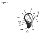
- FIG. 5 is a cut-away perspective view of the male cup of the male user embodiment depicted in FIG. 4 .
- FIG. 6 is a cut-away perspective view of the suction control unit.
- FIG. 7 is a cut-away perspective view of the flow chamber.
- FIGS. 1-8 a new and novel apparatus for an automatic bladder relief system embodying the principles and concepts of the present invention and generally designated collectively comprising two main components in the female user embodiment by the reference numeral 1 and 11 in FIG. 1, and in the male user embodiment by the reference numeral 1 and 57 in FIG. 4 .
- the Suction Control Unit ( 1 ) is a re-usable piece of hardware containing a suction vacuum pump ( 2 ), DC motor ( 5 ), rechargeable battery pack ( 7 ) and recharge circuitry ( 9 ).
- a built-in, battery-powered suction vacuum pump ( 2 ) sucks the urine from the Male Cup ( 57 ) in the male user embodiment and Female Pad ( 11 ) of the female user embodiment through a suction hose ( 13 ) and deposits the collected fluid into a Urine Collection Bag ( 3 ).
- Quick-disconnect hose couplings ( 17 ) connect and disconnect the Urine Collection Bag ( 3 ) and suction hose ( 13 ) from the Suction Control Unit ( 1 ).
- the Suction Control Unit ( 1 ) has two modes of operation: one power “ON/OFF” button ( 19 ) and one button that turns the unit “ON” and then “OFF” after a timed interval ( 21 ).
- a small, high-power DC motor is used, similar to those used in cordless vacuum cleaners.
- the DC motor ( 5 ) spins the vacuum pump impeller ( 23 ) to provide the suction required to draw the urine from the urine cavity ( 56 ) of the Male Cup ( 57 ).
- the system uses a filter ( 25 ) of charcoal or other material to deodorize the exhaust air.
- a battery pack ( 27 ) of rechargeable Nickel-Metal Hydride (NIMH) batteries are used to provide the power supply for the DC motor ( 5 ).
- a two-digit LCD Status Display ( 29 ) with backlight indicates the amount of time remaining in the battery charge, and the number of bladder relieves left in the power supply charge.
- the recharge circuitry allows the battery pack to be plugged into a wall outlet for recharging without damaging the batteries.
- a flow chamber ( 31 ) is contained in the Suction Control Unit ( 5 ).
- the flow chamber ( 31 ) begins at the Suction Control Unit Air/Liquid Inlet ( 33 ) and ends at both the Suction Control Unit Liquid Outlet ( 35 ) and the Suction Control Unit air exhaust outlet ( 37 ).
- This flow chamber ( 31 ) separates moisture from the vacuum airflow and channels the liquid to the Suction Control Unit Liquid Outlet ( 35 ) and the air to the Suction Control Unit Air Exhaust Outlet ( 37 ).
- the Suction Control Unit Air Exhaust Outlet ( 37 ) is fitted with a deodorizing air Filter ( 25 ).
- the Male Cup ( 57 ) is a disposable soft cup, approximately the same size and shape as a men's athletic protective cup.
- FIG. 5 shows a cut-away view of a Male Cup ( 37 ).
- the cup has four layers: a facing layer ( 39 M), wicking layer ( 41 M), urine collection layer ( 43 M) and Moisture Proof Outer Layer ( 45 M).
- the Moisture Proof Outer Layer ( 45 M) is attached to and contains the facing layer ( 39 M), wicking layer ( 41 M), urine collection layer ( 43 M) along the edges thereof by means of the Outer Layer Wall ( 46 M).
- a Urine Cavity ( 56 ) is defined by the urine collection layer ( 43 M) and the Moisture Proof Outer Layer ( 45 M) in the inside cup area ( 53 M).
- the facing layer ( 39 M), which lies against the skin, is made of a soft, non-woven, non-absorbent polymer.
- the wicking layer ( 41 M) is made of a woven polymer. It pulls moisture away from the facing layer ( 39 M) and prevents it from going back through the facing layer ( 39 M), much like a one-way fluid check valve.
- the urine collection layer ( 43 M) is made of an open cell foam material or other material capable of collecting fluid, and provides a Urine Cavity ( 56 ) in its placement juxtaposed to the Moisture Proof Outer Layer ( 45 M) for the vacuum suction airflow produced by the Suction Vacuum Pump ( 2 ) to suck fluids and moisture out of the Male Cup ( 57 ) and away from the body.
- One-way airflow inlet holes ( 48 ) in the top of the Male Cup ( 57 ) facilitate the evacuation of liquids and provide air flow for drying the Male Cup's ( 57 ) layers.
- An isolation membrane ( 50 ) made of a thin, flexible material such as silicon rubber comfortably keeps a man's penis inside the Male Cup ( 57 ) compartment and prevents any leaking.
- the cup front ( 52 ) is made of a stretchable material such as silicon rubber that opens automatically to accommodate size changes.
- the suction hose ( 13 ) at the front of the Male Cup ( 57 ) is connected to the Suction Control Unit ( 1 ).
- the Suction Control Unit ( 1 ) sucks all fluids from the Male Cup ( 57 ) through the suction hose ( 13 ) and deposits them into the Urine Collection Bag ( 3 ).
- the flexible, disposable suction hose ( 13 ) is outfitted with a quick-disconnect plug ( 51 ) on the end that connects to the Suction Control Unit ( 1 ).
- the suction hose ( 13 ) may be made of a convoluted, easily bendable material with spiral construction. This allows a smaller bending radius so that the suction hose ( 13 ) can be stowed in a person's clothing or flight suit while not in use, and permits all of the urine to drain out of the suction hose ( 13 ).
- the Moisture-Proof Outer Layer ( 45 M) of the Male Cup ( 57 ) is made of dense rubber to hold the Male Cup ( 57 ) in place.
- the Male Cup ( 57 ) is also held in place with a standard athletic jock strap.
- Most of the outer portion of the Male Cup ( 57 ) is constructed of soft rubber.
- the system is compatible with many types of Urine Collection Bags ( 3 ) including a disposable plastic bag containing super absorbent polymer crystals with a 500 cc urine capacity, and a larger, 1600 cc capacity Urine Collection Bag ( 3 ). Users who do not want to wear a Urine Collection Bag ( 3 ) for a long period of time can use smaller Urine Collection Bags ( 3 ). A zip lock top on the smaller Urine Collection Bags ( 3 ) allows its use as a standard piddle pack. Users who prefer not to change Urine Collection Bags ( 3 ) after each urination can wear a larger leg or pocket Urine Collection Bag ( 3 ). A quick-disconnect similar to the quick-disconnect plug ( 51 ) can also be built into the Urine Collection Bags ( 3 ) for easy attachment and replacement.
- the Suction Control Unit ( 1 ) can be packaged to double as a pilot's kneeboard as depicted in FIG. 2 .
- the kneeboard is molded and adjustable to fit the curve of the thigh.
- the aircrew member can carry the Suction Control Unit ( 1 ) in his helmet bag or wear it strapped to a thigh without giving the appearance of wearing bladder relief equipment.
- the quick-disconnect plug ( 51 ) hose couplings allow aircrew members to wait until they are seated in their aircraft or until they have to urinate to connect the Urine Collection Bag ( 3 ) and the suction hose ( 13 ) of the Male Cup ( 57 ) to the Suction Control Unit ( 1 ).
- the size and shape of the Urine Collection Bag ( 3 ) is designed to fit within the limited confines of the aircraft cockpit and navigator's seat. Piddle packs used by some male pilots are too long and difficult to open to its full length in a cockpit.
- the Suction Control Unit ( 1 ) can be mounted to the person's wheelchair and the hoses concealed under the person's clothing. Many urinary incontinent adults are not in wheelchairs, but are bedridden. A larger urine collection bag ( 3 ) that does not contain super-absorbent polymer can be attached to the Suction Control Unit ( 1 ) that can be emptied and reused. For ambulatory adults and children, a quiet Suction Control Unit ( 1 ) can be housed in a fanny pack that can also hold a concealed Urine Collection Bag ( 3 ).
- a moisture sensor ( 55 ) is installed in the Male Cup ( 57 ) to automatically activate the Suction Control Unit ( 1 ) when moisture is sensed in the urine cavity ( 56 ).
- the Suction Control Unit ( 1 ) is a reusable piece of hardware containing a suction vacuum pump ( 2 ), DC motor ( 5 ), rechargeable battery pack ( 7 ) and recharge circuitry ( 9 ).
- a built-in, battery-powered suction vacuum pump ( 2 ) sucks the urine from the Female Pad ( 11 ) through a suction hose ( 13 ) at the front of pad and deposits the urine into a Urine Collection Bag ( 3 ).
- Quick-disconnect hose couplings ( 17 ) connect and disconnect the Urine Collection Bag ( 3 ) and the suction hose ( 13 )from the Suction Control Unit ( 1 ).
- the Suction Control Unit ( 1 ) has two modes of operation: one power “ON/OFF” button ( 19 ) and one button that turns the unit “ON” and then “OFF” after a timed interval ( 21 ).
- a small, high-power DC motor ( 5 ) is used, similar to those used in cordless vacuum cleaners.
- the DC motor ( 5 ) spins the vacuum pump impeller ( 23 ) to provide the suction required to draw the urine from the Female Pad ( 11 ).
- the system uses a filter ( 25 ) of charcoal or other material to deodorize the exhaust air.
- a battery pack ( 27 ) of rechargeable Nickel-Metal Hydride (NIMH) batteries are used to provide the power supply for the DC motor.
- a two-digit LCD Status Display ( 29 ) with backlight indicates the amount of time remaining in the battery charge, and the number of bladder relieves left in the power supply charge.
- the recharge circuitry allows the battery pack ( 27 ) to be plugged into a wall outlet for recharging without damaging the batteries.
- a flow chamber ( 31 ) is contained in the Suction Control Unit ( 1 ).
- the flow chamber ( 31 ) begins at the Suction Control Unit Air/Liquid Inlet ( 33 ) and ends at both the Suction Control Unit Liquid Outlet ( 35 ) and the Suction Control Unit Air Exhaust Outlet ( 37 ).
- This flow chamber ( 31 ) separates moisture from the vacuum airflow and channels the liquid to the Suction Control Unit Liquid Outlet ( 35 ) and the air to the Suction Control Unit Air Exhaust Outlet ( 37 ).
- the Suction Control Unit Air Exhaust Outlet ( 37 ) is fitted with a deodorizing air filter ( 25 ).
- the Female Pad ( 11 ) is a disposable urine collection pad similar in size to a large feminine pad used for menstruation.
- FIG. 3 shows an expanded view of the Female Pad ( 11 ).
- the Female Pad ( 11 ) has four layers: a facing layer ( 39 ), wicking layer ( 41 ), urine collection layer ( 43 ) and moisture-proof outer layer ( 45 ).
- the Moisture Proof Outer Layer ( 45 ) is attached to and contains the facing layer ( 39 ), wicking layer ( 41 ), urine collection layer ( 43 ) along the edges thereof by means of the Outer Layer Wall ( 46 ).
- a Urine Cavity ( 56 ) is defined by the urine collection layer ( 43 ) and the Moisture Proof Outer Layer ( 45 ) in the inside cup area ( 53 ).
- the wicking layer ( 41 ) is made of a woven polymer. It pulls moisture away from the facing layer ( 39 ) and prevents it from going back through the facing layer ( 39 ), much like a one-way fluid check valve.
- the urine collection layer ( 43 ) is made of open cell foam or other material or other material capable of collecting fluid, and provides a Urine Cavity ( 56 ) in its placement juxtaposed to the Moisture Proof Outer Layer ( 45 ) for the vacuum suction airflow produced by the Suction Vacuum Pump ( 2 ) to suck fluids and moisture out of the Female Pad ( 11 ) and away from the body.
- the Moisture Proof Outer Layer ( 45 ) a moisture-proof barrier made of soft, flexible plastic, wraps around the sides of the Female Pad ( 11 ) to prevent side leakage.
- One-way airflow inlet holes ( 47 ) in the back end of the Female Pad ( 11 ) facilitate the evacuation of liquids and provide air flow for drying the Female Pad's ( 11 ) layers.
- the Female Pad ( 11 ) has a contoured shape for a more comfortable and reliable fit.
- Soft sealing strips ( 49 ) around the Female Pad ( 11 ) face perimeter prevent side leaks.
- the Female Pad ( 11 ) is held in place with a comfortable but sturdy undergarment available in women's apparel stores.
- the suction hose ( 13 ) at the front of the Female Pad ( 11 ) is connected to the Suction Control Unit ( 1 ).
- the Suction Control Unit ( 1 ) sucks all fluids from the Female Pad ( 11 ) through the suction hose ( 13 ) and deposits them into the Urine Collection Bag ( 3 ).
- the flexible, disposable suction hose ( 13 ) is outfitted with a quick-disconnect plug ( 51 ) on the end that connects to the Suction Control Unit ( 1 ).
- the suction hose ( 13 ) may be made of a convoluted, easily bendable material with spiral construction. This allows a smaller bending radius so that the suction hose ( 13 ) can be stowed in a person's clothing or flight suit while not in use, and permits all of the urine to drain out of the suction hose ( 13 ).
- the system is compatible with many types of Urine Collection Bags ( 3 ) including a disposable plastic bag containing super absorbent polymer crystals with a 500 cc urine capacity, and a larger, 1600 cc capacity bag. Users who do not want to wear a Urine Collection Bag ( 3 ) for a long period of time can use smaller Urine Collection Bags ( 3 ). Users who prefer not to change Urine Collection Bags ( 3 ) after each urination can wear a larger leg or pocket Urine Collection Bags ( 3 ). A quick-disconnect similar to the quick-disconnect plug ( 51 ) can also be built into the Urine Collection Bags ( 3 ) for easy attachment and replacement.
- the Suction Control Unit ( 1 ) can be packaged to double as a pilot's kneeboard as depicted in FIG. 2 .
- the kneeboard is molded and adjustable to fit the curve of the thigh.
- the aircrew member can carry the Suction Control Unit ( 1 ) in her helmet bag or wear it strapped to a thigh without giving the appearance of wearing bladder relief equipment.
- the quick-disconnect plug ( 51 ) suction hose ( 13 ) couplings allow aircrew members to wait until they are seated in their aircraft or until they have to urinate to connect the Urine Collection Bag ( 3 ) and the Female Pad ( 11 ) suction hose ( 13 ) to the Suction Control Unit ( 1 ).
- the size and shape of the Urine Collection Bag ( 13 ) is designed to fit within the limited confines of the aircraft cockpit and navigator's seat
- Suction Control Unit ( 1 ) Wheelchair users require a quieter, more discreet version of the Suction Control Unit ( 1 ) (i.e. with concealed hoses).
- the Suction Control Unit ( 1 ) can be mounted to the person's wheelchair and the hoses concealed under the person's clothing. Many urinary incontinent adults are not in wheelchairs, but are bedridden.
- a larger urine collection bag ( 3 ) that does not contain super absorbent polymer can be attached to the Suction Control Unit ( 1 ) that can be emptied and reused.
- a quiet Suction Control Unit ( 1 ) can be housed in a fanny pack that can also hold a concealed Urine Collection Bag ( 3 ).
- a moisture sensor ( 55 ) is installed in the Female Pad ( 11 ) to automatically activate the Suction Control Unit ( 1 ) when moisture is sensed in the urine cavity ( 56 ).
- a quieter, more discreet version of the Suction Control Unit ( 1 ) for wheelchair users i.e. with concealed hoses.
- the Suction Control Unit ( 1 ) could be mounted to the person's wheelchair and the suction hoses ( 13 ) concealed under the person's clothing.
- Many urinary incontinent adults are not in wheelchairs, but are bedridden.
- a larger urine collection bag ( 3 ) that does not contain super-absorbent polymer can be used that can be emptied by staff/care-givers and reused.
- a moisture sensor ( 55 ) can be installed in the Female Pad ( 11 ) and Male Cup ( 57 ) that will automatically activate the Suction Control Unit ( 1 ) when moisture is sensed in the urine cavity ( 56 ).
Abstract
Description
Claims (6)
Priority Applications (21)
| Application Number | Priority Date | Filing Date | Title |
|---|---|---|---|
| US10/369,240 US6706027B2 (en) | 2002-02-26 | 2003-02-19 | Automatic bladder relief system |
| PCT/US2003/006011 WO2003071931A2 (en) | 2002-02-26 | 2003-02-25 | Automatic bladder relief system |
| IL16368003A IL163680A0 (en) | 2002-02-26 | 2003-02-25 | Automatic bladder relief system |
| RU2004129287/14A RU2004129287A (en) | 2002-02-26 | 2003-02-25 | AUTOMATIC SYSTEM FOR TREATING THE BLADDER |
| BR0307826-4A BR0307826A (en) | 2002-02-26 | 2003-02-25 | Automatic relief system, bladder type |
| KR10-2004-7013234A KR20040091663A (en) | 2002-02-26 | 2003-02-25 | Automatic bladder relief system |
| NZ534498A NZ534498A (en) | 2002-02-26 | 2003-02-25 | Automatic bladder relief system |
| EA200400978A EA006587B1 (en) | 2002-02-26 | 2003-02-25 | Automatic bladder relief system |
| EP03709380A EP1478315A4 (en) | 2002-02-26 | 2003-02-25 | Automatic bladder relief system |
| CA002476695A CA2476695A1 (en) | 2002-02-26 | 2003-02-25 | Automatic bladder relief system |
| MXPA04008311A MXPA04008311A (en) | 2002-02-26 | 2003-02-25 | Automatic bladder relief system. |
| JP2003570684A JP2005518237A (en) | 2002-02-26 | 2003-02-25 | Automatic bladder relaxation system |
| AU2003212440A AU2003212440A1 (en) | 2002-02-26 | 2003-02-25 | Automatic bladder relief system |
| CNB038046784A CN1289041C (en) | 2002-02-26 | 2003-02-25 | Automatic bladder relief system |
| US10/418,852 US6918899B2 (en) | 2002-02-26 | 2003-04-18 | Automatic bladder relief system |
| US10/885,355 US7135012B2 (en) | 2002-02-26 | 2004-07-06 | Automatic self cleaning bladder relief system |
| US11/005,800 US7131964B2 (en) | 2002-02-26 | 2004-12-07 | Automatic self cleaning bladder relief system and failsafe |
| US11/047,143 US7141043B2 (en) | 2002-02-26 | 2005-01-29 | Automatic self cleaning bladder relief and hydration system |
| US11/472,162 US7335189B2 (en) | 2002-02-26 | 2006-06-21 | Automatic self cleaning bladder relief with battery pad system |
| US11/977,024 US20080091153A1 (en) | 2002-02-26 | 2007-10-23 | Automatic self cleaning bladder relief with diaper pad system |
| US12/077,762 US7875011B2 (en) | 2002-02-26 | 2008-03-22 | Cooling, heating, bladder relief, gas, hydration and nutrition chem-bio suit connectivity system |
Applications Claiming Priority (2)
| Application Number | Priority Date | Filing Date | Title |
|---|---|---|---|
| US35967202P | 2002-02-26 | 2002-02-26 | |
| US10/369,240 US6706027B2 (en) | 2002-02-26 | 2003-02-19 | Automatic bladder relief system |
Related Child Applications (1)
| Application Number | Title | Priority Date | Filing Date |
|---|---|---|---|
| US10/418,852 Continuation-In-Part US6918899B2 (en) | 2002-02-26 | 2003-04-18 | Automatic bladder relief system |
Publications (2)
| Publication Number | Publication Date |
|---|---|
| US20030163120A1 US20030163120A1 (en) | 2003-08-28 |
| US6706027B2 true US6706027B2 (en) | 2004-03-16 |
Family
ID=27760555
Family Applications (1)
| Application Number | Title | Priority Date | Filing Date |
|---|---|---|---|
| US10/369,240 Expired - Lifetime US6706027B2 (en) | 2002-02-26 | 2003-02-19 | Automatic bladder relief system |
Country Status (14)
| Country | Link |
|---|---|
| US (1) | US6706027B2 (en) |
| EP (1) | EP1478315A4 (en) |
| JP (1) | JP2005518237A (en) |
| KR (1) | KR20040091663A (en) |
| CN (1) | CN1289041C (en) |
| AU (1) | AU2003212440A1 (en) |
| BR (1) | BR0307826A (en) |
| CA (1) | CA2476695A1 (en) |
| EA (1) | EA006587B1 (en) |
| IL (1) | IL163680A0 (en) |
| MX (1) | MXPA04008311A (en) |
| NZ (1) | NZ534498A (en) |
| RU (1) | RU2004129287A (en) |
| WO (1) | WO2003071931A2 (en) |
Cited By (33)
| Publication number | Priority date | Publication date | Assignee | Title |
|---|---|---|---|---|
| US20040143229A1 (en) * | 2003-01-17 | 2004-07-22 | Easter William Craig | Vacuum assisted relief system (VARS) |
| US20050033248A1 (en) * | 2003-08-06 | 2005-02-10 | Hitachi, Ltd. | Automatic urine disposal device and urine receptacle used therefor |
| US20060084932A1 (en) * | 2004-10-20 | 2006-04-20 | Hiroshi Koizumi | Automatic urine collecting apparatus |
| US20060178649A1 (en) * | 2005-02-08 | 2006-08-10 | Feng Ma | Methods of using a canned vacuum source particularly in a disposable urine collection kit with a built-in vacuum pressure |
| US20080281284A1 (en) * | 2007-05-08 | 2008-11-13 | Garfield Michael H | Fluid collection system |
| US20080277002A1 (en) * | 2007-05-08 | 2008-11-13 | Paul Hendrixson | Coupler |
| US20090260140A1 (en) * | 2008-04-17 | 2009-10-22 | Birbara Philip J | Self-cleansing portable urine collection device |
| US20100211032A1 (en) * | 2007-10-18 | 2010-08-19 | Convatec Technologies Inc. | Aspiration system for removing urine discharged by the human body, and liquid sensor therefor |
| WO2011132043A1 (en) | 2010-04-24 | 2011-10-27 | Carlos Richer | Liquid handling system designed to extract liquids from capillary structures using a vacuum source or a vacuum generator to be used on diapers and the like |
| US20150342425A1 (en) * | 2014-05-27 | 2015-12-03 | Big Foot Suction, Llc | Floor suction device |
| US10226376B2 (en) | 2014-03-19 | 2019-03-12 | Purewick Corporation | Apparatus and methods for receiving discharged urine |
| US10376406B2 (en) | 2016-07-27 | 2019-08-13 | Purewick Corporation | Male urine collection device using wicking material |
| US10376407B2 (en) | 2016-08-16 | 2019-08-13 | Purewick Corporation | Using wicking material to collect urine from a male for transport |
| US10390989B2 (en) | 2014-03-19 | 2019-08-27 | Purewick Corporation | Apparatus and methods for receiving discharged urine |
| US20200390591A1 (en) * | 2018-05-01 | 2020-12-17 | Purewick Corporation | Fluid collection garments |
| US10952889B2 (en) | 2016-06-02 | 2021-03-23 | Purewick Corporation | Using wicking material to collect liquid for transport |
| US10973678B2 (en) | 2016-07-27 | 2021-04-13 | Purewick Corporation | Apparatus and methods for receiving discharged urine |
| US20210236323A1 (en) * | 2018-05-01 | 2021-08-05 | Purewick Corporation | Fluid collection devices, systems, and methods |
| US11090183B2 (en) | 2014-11-25 | 2021-08-17 | Purewick Corporation | Container for collecting liquid for transport |
| USD928946S1 (en) | 2016-06-02 | 2021-08-24 | Purewick Corporation | Urine receiving apparatus |
| USD929578S1 (en) | 2019-06-06 | 2021-08-31 | Purewick Corporation | Urine collection assembly |
| US11298063B2 (en) | 2019-10-20 | 2022-04-12 | Bao Q Tran | Hydrogen powered device |
| US11376152B2 (en) | 2014-03-19 | 2022-07-05 | Purewick Corporation | Apparatus and methods for receiving discharged urine |
| US11382786B2 (en) * | 2014-03-19 | 2022-07-12 | Purewick Corporation | Apparatus and methods for receiving discharged urine |
| US20220265462A1 (en) * | 2020-04-10 | 2022-08-25 | Purewick Corporation | Fluid collection assemblies including one or more leak prevention features |
| USD967409S1 (en) | 2020-07-15 | 2022-10-18 | Purewick Corporation | Urine collection apparatus cover |
| US20220331147A1 (en) * | 2021-04-19 | 2022-10-20 | Lyv Life Inc. DBA Cora | Menstrual disc and methods of use |
| US20220339023A1 (en) * | 2021-01-19 | 2022-10-27 | Purewick Corporation | Variable fit fluid collection devices, systems, and methods |
| WO2023018475A3 (en) * | 2021-06-11 | 2023-04-20 | Triton Systems, Inc. | Bladder collection system |
| US20230255815A1 (en) * | 2021-02-26 | 2023-08-17 | Purewick Corporation | Fluid collection devices having a sump between a tube opening and a barrier, and related systems and methods |
| US11801186B2 (en) | 2020-09-10 | 2023-10-31 | Purewick Corporation | Urine storage container handle and lid accessories |
| US11938054B2 (en) | 2021-03-10 | 2024-03-26 | Purewick Corporation | Bodily waste and fluid collection with sacral pad |
| US11944740B2 (en) | 2018-05-01 | 2024-04-02 | Purewick Corporation | Fluid collection devices, related systems, and related methods |
Families Citing this family (14)
| Publication number | Priority date | Publication date | Assignee | Title |
|---|---|---|---|---|
| JP2007259898A (en) * | 2006-03-27 | 2007-10-11 | Takuo Mochizuki | Urine suction apparatus |
| KR100857897B1 (en) * | 2006-04-25 | 2008-09-10 | 한메딕스 주식회사 | Collection apparatus of the body fluid |
| RU2592022C2 (en) * | 2010-04-08 | 2016-07-20 | Мохамед МОКРЭЙН | Monitoring interference generating liquids |
| GB2503823B (en) * | 2011-11-15 | 2015-06-03 | Albert Medical Devices Ltd | Fluid Collection and expulsion apparatus |
| US11779485B2 (en) | 2016-07-11 | 2023-10-10 | Sage Products Llc | Devices and systems for urine collection |
| CN107952119B (en) * | 2017-12-11 | 2020-02-04 | 南京医事达生物科技有限公司 | Urological department catheterization external member |
| EP3752110B1 (en) * | 2018-02-14 | 2022-03-23 | Sage Products, LLC | Devices and systems for urine collection |
| USD1010109S1 (en) | 2019-07-23 | 2024-01-02 | Sage Products, Llc | Urine collection device |
| US11389321B2 (en) * | 2019-11-19 | 2022-07-19 | Michael Cooks | Female catheter assembly |
| US11207206B2 (en) | 2020-05-14 | 2021-12-28 | Cm Technologies, Inc. | Fluid removal device |
| CN111772914A (en) * | 2020-06-24 | 2020-10-16 | 南通市第一人民医院 | Waistband type urine collecting device for nursing of urinary incontinence |
| US11628085B2 (en) | 2020-08-04 | 2023-04-18 | Cm Technologies, Inc. | Fecal management systems and methods |
| CN112754752A (en) * | 2021-01-26 | 2021-05-07 | 南京医科大学 | Novel liquid excrement collecting and treating device capable of preventing epidemic prevention clothes from being taken off |
| CN113180966B (en) * | 2021-05-25 | 2022-09-09 | 张丽萍 | Convenient urethral catheterization device who deposits nursing of old bed patient usefulness |
Citations (8)
| Publication number | Priority date | Publication date | Assignee | Title |
|---|---|---|---|---|
| US4447939A (en) | 1981-03-25 | 1984-05-15 | The Kendall Company | Device for collecting body liquids |
| US4538100A (en) | 1980-03-10 | 1985-08-27 | Creative Technology, Inc. | DC to AC inverter and motor control system |
| US4747166A (en) | 1987-05-15 | 1988-05-31 | Kuntz David H | Fluid aspiration system for the management of urinary incontinence |
| US5454798A (en) | 1993-05-14 | 1995-10-03 | Mentor Corporation | Disposable urine bag |
| US5678564A (en) | 1992-08-07 | 1997-10-21 | Bristol Myers Squibb | Liquid removal system |
| WO2000057784A1 (en) | 1999-03-26 | 2000-10-05 | Brunel University | Urine collection device |
| US6342049B1 (en) | 1997-12-10 | 2002-01-29 | Laura L. Nichols | Female urine collection device |
| US6500158B1 (en) | 1997-03-26 | 2002-12-31 | The Trustees Of Columbia University In The City Of New York | Method of inducing negative pressure in the urinary collecting system and apparatus therefor |
Family Cites Families (3)
| Publication number | Priority date | Publication date | Assignee | Title |
|---|---|---|---|---|
| US4886508A (en) * | 1988-07-11 | 1989-12-12 | Washington Douglas L | Ladies external catheter assembly |
| US6186990B1 (en) * | 1997-02-05 | 2001-02-13 | Reachgood Industrial Company | To a human bodily fluid collection device and method of collecting and absorbing the same |
| EP1112728A1 (en) * | 1999-12-23 | 2001-07-04 | The Procter & Gamble Company | Liquid removal system having improved dryness of the user facing surface |
-
2003
- 2003-02-19 US US10/369,240 patent/US6706027B2/en not_active Expired - Lifetime
- 2003-02-25 BR BR0307826-4A patent/BR0307826A/en not_active IP Right Cessation
- 2003-02-25 CN CNB038046784A patent/CN1289041C/en not_active Expired - Fee Related
- 2003-02-25 KR KR10-2004-7013234A patent/KR20040091663A/en not_active Application Discontinuation
- 2003-02-25 EA EA200400978A patent/EA006587B1/en unknown
- 2003-02-25 RU RU2004129287/14A patent/RU2004129287A/en not_active Application Discontinuation
- 2003-02-25 CA CA002476695A patent/CA2476695A1/en not_active Abandoned
- 2003-02-25 EP EP03709380A patent/EP1478315A4/en not_active Withdrawn
- 2003-02-25 WO PCT/US2003/006011 patent/WO2003071931A2/en active Application Filing
- 2003-02-25 JP JP2003570684A patent/JP2005518237A/en active Pending
- 2003-02-25 NZ NZ534498A patent/NZ534498A/en unknown
- 2003-02-25 IL IL16368003A patent/IL163680A0/en unknown
- 2003-02-25 AU AU2003212440A patent/AU2003212440A1/en not_active Abandoned
- 2003-02-25 MX MXPA04008311A patent/MXPA04008311A/en unknown
Patent Citations (8)
| Publication number | Priority date | Publication date | Assignee | Title |
|---|---|---|---|---|
| US4538100A (en) | 1980-03-10 | 1985-08-27 | Creative Technology, Inc. | DC to AC inverter and motor control system |
| US4447939A (en) | 1981-03-25 | 1984-05-15 | The Kendall Company | Device for collecting body liquids |
| US4747166A (en) | 1987-05-15 | 1988-05-31 | Kuntz David H | Fluid aspiration system for the management of urinary incontinence |
| US5678564A (en) | 1992-08-07 | 1997-10-21 | Bristol Myers Squibb | Liquid removal system |
| US5454798A (en) | 1993-05-14 | 1995-10-03 | Mentor Corporation | Disposable urine bag |
| US6500158B1 (en) | 1997-03-26 | 2002-12-31 | The Trustees Of Columbia University In The City Of New York | Method of inducing negative pressure in the urinary collecting system and apparatus therefor |
| US6342049B1 (en) | 1997-12-10 | 2002-01-29 | Laura L. Nichols | Female urine collection device |
| WO2000057784A1 (en) | 1999-03-26 | 2000-10-05 | Brunel University | Urine collection device |
Cited By (48)
| Publication number | Priority date | Publication date | Assignee | Title |
|---|---|---|---|---|
| US7018366B2 (en) * | 2003-01-17 | 2006-03-28 | William Craig Easter | Vacuum assisted relief system (VARS) |
| US20040143229A1 (en) * | 2003-01-17 | 2004-07-22 | Easter William Craig | Vacuum assisted relief system (VARS) |
| US7390320B2 (en) * | 2003-08-06 | 2008-06-24 | Hitachi, Ltd. | Automatic urine disposal device and urine receptacle used therefor |
| US20050033248A1 (en) * | 2003-08-06 | 2005-02-10 | Hitachi, Ltd. | Automatic urine disposal device and urine receptacle used therefor |
| US7438706B2 (en) * | 2004-10-20 | 2008-10-21 | Hitachi, Ltd. | Automatic urine collecting apparatus |
| US20060084932A1 (en) * | 2004-10-20 | 2006-04-20 | Hiroshi Koizumi | Automatic urine collecting apparatus |
| US20060178649A1 (en) * | 2005-02-08 | 2006-08-10 | Feng Ma | Methods of using a canned vacuum source particularly in a disposable urine collection kit with a built-in vacuum pressure |
| US8512301B2 (en) * | 2005-02-08 | 2013-08-20 | Feng Ma | Canned vacuum |
| US20080281284A1 (en) * | 2007-05-08 | 2008-11-13 | Garfield Michael H | Fluid collection system |
| US20080277002A1 (en) * | 2007-05-08 | 2008-11-13 | Paul Hendrixson | Coupler |
| US20100211032A1 (en) * | 2007-10-18 | 2010-08-19 | Convatec Technologies Inc. | Aspiration system for removing urine discharged by the human body, and liquid sensor therefor |
| US20100234820A1 (en) * | 2007-10-18 | 2010-09-16 | Conva Tec Technologies Inc. | Aspiration system and body interface device for removing urine discharged by the human body |
| US8303554B2 (en) * | 2007-10-18 | 2012-11-06 | Convatec Technologies, Inc. | Aspiration system and body interface device for removing urine discharged by the human body |
| US20090260140A1 (en) * | 2008-04-17 | 2009-10-22 | Birbara Philip J | Self-cleansing portable urine collection device |
| US8046848B2 (en) | 2008-04-17 | 2011-11-01 | Beechwood Technologies Lc | Self-cleansing portable urine collection device |
| WO2011132043A1 (en) | 2010-04-24 | 2011-10-27 | Carlos Richer | Liquid handling system designed to extract liquids from capillary structures using a vacuum source or a vacuum generator to be used on diapers and the like |
| US10226376B2 (en) | 2014-03-19 | 2019-03-12 | Purewick Corporation | Apparatus and methods for receiving discharged urine |
| US11806266B2 (en) * | 2014-03-19 | 2023-11-07 | Purewick Corporation | Apparatus and methods for receiving discharged urine |
| US11382786B2 (en) * | 2014-03-19 | 2022-07-12 | Purewick Corporation | Apparatus and methods for receiving discharged urine |
| US10390989B2 (en) | 2014-03-19 | 2019-08-27 | Purewick Corporation | Apparatus and methods for receiving discharged urine |
| US11376152B2 (en) | 2014-03-19 | 2022-07-05 | Purewick Corporation | Apparatus and methods for receiving discharged urine |
| US20150342425A1 (en) * | 2014-05-27 | 2015-12-03 | Big Foot Suction, Llc | Floor suction device |
| US9943201B2 (en) * | 2014-05-27 | 2018-04-17 | Big Foot Suction, Llc | Floor suction device |
| US11090183B2 (en) | 2014-11-25 | 2021-08-17 | Purewick Corporation | Container for collecting liquid for transport |
| US10952889B2 (en) | 2016-06-02 | 2021-03-23 | Purewick Corporation | Using wicking material to collect liquid for transport |
| USD928946S1 (en) | 2016-06-02 | 2021-08-24 | Purewick Corporation | Urine receiving apparatus |
| US10973678B2 (en) | 2016-07-27 | 2021-04-13 | Purewick Corporation | Apparatus and methods for receiving discharged urine |
| US11628086B2 (en) | 2016-07-27 | 2023-04-18 | Purewick Corporation | Apparatus and methods for receiving discharged urine |
| US10376406B2 (en) | 2016-07-27 | 2019-08-13 | Purewick Corporation | Male urine collection device using wicking material |
| US10376407B2 (en) | 2016-08-16 | 2019-08-13 | Purewick Corporation | Using wicking material to collect urine from a male for transport |
| US20200390591A1 (en) * | 2018-05-01 | 2020-12-17 | Purewick Corporation | Fluid collection garments |
| US20210236323A1 (en) * | 2018-05-01 | 2021-08-05 | Purewick Corporation | Fluid collection devices, systems, and methods |
| US11944740B2 (en) | 2018-05-01 | 2024-04-02 | Purewick Corporation | Fluid collection devices, related systems, and related methods |
| US11938053B2 (en) * | 2018-05-01 | 2024-03-26 | Purewick Corporation | Fluid collection devices, systems, and methods |
| US11529252B2 (en) * | 2018-05-01 | 2022-12-20 | Purewick Corporation | Fluid collection garments |
| USD929578S1 (en) | 2019-06-06 | 2021-08-31 | Purewick Corporation | Urine collection assembly |
| US11298063B2 (en) | 2019-10-20 | 2022-04-12 | Bao Q Tran | Hydrogen powered device |
| US20220265462A1 (en) * | 2020-04-10 | 2022-08-25 | Purewick Corporation | Fluid collection assemblies including one or more leak prevention features |
| USD967409S1 (en) | 2020-07-15 | 2022-10-18 | Purewick Corporation | Urine collection apparatus cover |
| US11801186B2 (en) | 2020-09-10 | 2023-10-31 | Purewick Corporation | Urine storage container handle and lid accessories |
| US20220339023A1 (en) * | 2021-01-19 | 2022-10-27 | Purewick Corporation | Variable fit fluid collection devices, systems, and methods |
| US11865030B2 (en) * | 2021-01-19 | 2024-01-09 | Purewick Corporation | Variable fit fluid collection devices, systems, and methods |
| US20230255815A1 (en) * | 2021-02-26 | 2023-08-17 | Purewick Corporation | Fluid collection devices having a sump between a tube opening and a barrier, and related systems and methods |
| US11925575B2 (en) * | 2021-02-26 | 2024-03-12 | Purewick Corporation | Fluid collection devices having a sump between a tube opening and a barrier, and related systems and methods |
| US11938054B2 (en) | 2021-03-10 | 2024-03-26 | Purewick Corporation | Bodily waste and fluid collection with sacral pad |
| US11583433B2 (en) * | 2021-04-19 | 2023-02-21 | Lyv Life Inc. | Menstrual disc and methods of use |
| US20220331147A1 (en) * | 2021-04-19 | 2022-10-20 | Lyv Life Inc. DBA Cora | Menstrual disc and methods of use |
| WO2023018475A3 (en) * | 2021-06-11 | 2023-04-20 | Triton Systems, Inc. | Bladder collection system |
Also Published As
| Publication number | Publication date |
|---|---|
| US20030163120A1 (en) | 2003-08-28 |
| EA200400978A1 (en) | 2004-12-30 |
| IL163680A0 (en) | 2005-12-18 |
| CN1638708A (en) | 2005-07-13 |
| AU2003212440A1 (en) | 2003-09-09 |
| JP2005518237A (en) | 2005-06-23 |
| EP1478315A4 (en) | 2008-06-04 |
| NZ534498A (en) | 2006-03-31 |
| BR0307826A (en) | 2005-04-12 |
| RU2004129287A (en) | 2005-06-10 |
| EA006587B1 (en) | 2006-02-24 |
| WO2003071931A2 (en) | 2003-09-04 |
| WO2003071931A3 (en) | 2004-02-19 |
| CA2476695A1 (en) | 2003-09-04 |
| KR20040091663A (en) | 2004-10-28 |
| MXPA04008311A (en) | 2004-11-26 |
| CN1289041C (en) | 2006-12-13 |
| EP1478315A2 (en) | 2004-11-24 |
Similar Documents
| Publication | Publication Date | Title |
|---|---|---|
| US6706027B2 (en) | Automatic bladder relief system | |
| US6918899B2 (en) | Automatic bladder relief system | |
| US7135012B2 (en) | Automatic self cleaning bladder relief system | |
| US7335189B2 (en) | Automatic self cleaning bladder relief with battery pad system | |
| US7131964B2 (en) | Automatic self cleaning bladder relief system and failsafe | |
| US7141043B2 (en) | Automatic self cleaning bladder relief and hydration system | |
| US20080091153A1 (en) | Automatic self cleaning bladder relief with diaper pad system | |
| US7018366B2 (en) | Vacuum assisted relief system (VARS) | |
| US7896857B2 (en) | Urine collection assembly | |
| US9737433B2 (en) | Disposable wearable urinary collection apparatus | |
| US8394074B2 (en) | Undergarment for incontinent person and treatment device connected to an undergarment | |
| US20220395391A1 (en) | Bladder collection system | |
| US20080208149A1 (en) | Male apron for receiving and storing excreted body fluids and associated method | |
| WO2021211568A1 (en) | Female urinary capture device configured to be secured to the vulva | |
| EP2991596B1 (en) | A catheter collection and drainage device | |
| WO1991004714A2 (en) | Compact universal catheter assembly | |
| CN112107421A (en) | Fluid-carrying applicator | |
| US20220087853A1 (en) | Micturition device | |
| US20190374373A1 (en) | Wearable urinary collection apparatus | |
| US20170340475A1 (en) | Disposable wearable urinary collection apparatus | |
| CA2359091C (en) | Close-coupled urinary collection device | |
| WO2023149884A1 (en) | Direct disposal urine collection system and related methods background | |
| EP1269945A1 (en) | Human waste collection bag comprising stress relief means |
Legal Events
| Date | Code | Title | Description |
|---|---|---|---|
| FPAY | Fee payment |
Year of fee payment: 4 |
|
| AS | Assignment |
Owner name: MALONE, PATRICK, VERMONT Free format text: SECURITY INTEREST;ASSIGNOR:HARVIE, MARK;REEL/FRAME:026106/0162 Effective date: 20110329 |
|
| AS | Assignment |
Owner name: KEYBANK NATIONAL ASSOCIATION, AS COLLATERAL AGENT, Free format text: SECURITY INTEREST;ASSIGNOR:HARVIE, MARK;REEL/FRAME:026171/0834 Effective date: 20110329 |
|
| FPAY | Fee payment |
Year of fee payment: 8 |
|
| REMI | Maintenance fee reminder mailed | ||
| LAPS | Lapse for failure to pay maintenance fees | ||
| FP | Lapsed due to failure to pay maintenance fee |
Effective date: 20160316 |
|
| PRDP | Patent reinstated due to the acceptance of a late maintenance fee |
Effective date: 20170907 |
|
| FEPP | Fee payment procedure |
Free format text: SURCHARGE, PETITION TO ACCEPT PYMT AFTER EXP, UNINTENTIONAL. (ORIGINAL EVENT CODE: M2558); ENTITY STATUS OF PATENT OWNER: SMALL ENTITY Free format text: PETITION RELATED TO MAINTENANCE FEES FILED (ORIGINAL EVENT CODE: PMFP) Free format text: PETITION RELATED TO MAINTENANCE FEES GRANTED (ORIGINAL EVENT CODE: PMFG) |
|
| MAFP | Maintenance fee payment |
Free format text: PAYMENT OF MAINTENANCE FEE, 12TH YR, SMALL ENTITY (ORIGINAL EVENT CODE: M2553) Year of fee payment: 12 |
|
| STCF | Information on status: patent grant |
Free format text: PATENTED CASE |