EP3646073B1 - Connecteurs de fibres optiques compacts, ensembles de câbles et leurs procédés de fabrication - Google Patents
Connecteurs de fibres optiques compacts, ensembles de câbles et leurs procédés de fabrication Download PDFInfo
- Publication number
- EP3646073B1 EP3646073B1 EP17817572.5A EP17817572A EP3646073B1 EP 3646073 B1 EP3646073 B1 EP 3646073B1 EP 17817572 A EP17817572 A EP 17817572A EP 3646073 B1 EP3646073 B1 EP 3646073B1
- Authority
- EP
- European Patent Office
- Prior art keywords
- housing
- ferrule
- connector
- fiber optic
- cable
- Prior art date
- Legal status (The legal status is an assumption and is not a legal conclusion. Google has not performed a legal analysis and makes no representation as to the accuracy of the status listed.)
- Active
Links
- 239000000835 fiber Substances 0.000 title claims description 121
- 230000000712 assembly Effects 0.000 title description 9
- 238000000429 assembly Methods 0.000 title description 9
- 238000000034 method Methods 0.000 title description 3
- 230000007704 transition Effects 0.000 claims description 42
- 239000000428 dust Substances 0.000 claims description 15
- 241000237509 Patinopecten sp. Species 0.000 claims description 3
- 235000020637 scallop Nutrition 0.000 claims description 3
- 210000005069 ears Anatomy 0.000 claims description 2
- 230000014759 maintenance of location Effects 0.000 description 44
- 230000013011 mating Effects 0.000 description 29
- 238000006243 chemical reaction Methods 0.000 description 27
- 230000003287 optical effect Effects 0.000 description 27
- 238000010276 construction Methods 0.000 description 24
- 238000013461 design Methods 0.000 description 23
- 239000013307 optical fiber Substances 0.000 description 20
- 238000003780 insertion Methods 0.000 description 13
- 230000037431 insertion Effects 0.000 description 13
- 230000002401 inhibitory effect Effects 0.000 description 12
- 238000007789 sealing Methods 0.000 description 12
- 239000000853 adhesive Substances 0.000 description 11
- 230000001070 adhesive effect Effects 0.000 description 11
- 239000004593 Epoxy Substances 0.000 description 7
- 238000004891 communication Methods 0.000 description 6
- 230000008878 coupling Effects 0.000 description 6
- 238000010168 coupling process Methods 0.000 description 6
- 238000005859 coupling reaction Methods 0.000 description 6
- 238000004519 manufacturing process Methods 0.000 description 6
- 238000005452 bending Methods 0.000 description 4
- 238000009826 distribution Methods 0.000 description 4
- 230000000717 retained effect Effects 0.000 description 4
- 241000196324 Embryophyta Species 0.000 description 3
- 238000003466 welding Methods 0.000 description 3
- 230000007613 environmental effect Effects 0.000 description 2
- 239000000463 material Substances 0.000 description 2
- 238000005259 measurement Methods 0.000 description 2
- 230000036961 partial effect Effects 0.000 description 2
- 230000002441 reversible effect Effects 0.000 description 2
- 241000723418 Carya Species 0.000 description 1
- 239000000654 additive Substances 0.000 description 1
- 230000000996 additive effect Effects 0.000 description 1
- 238000003491 array Methods 0.000 description 1
- 230000005540 biological transmission Effects 0.000 description 1
- 230000000295 complement effect Effects 0.000 description 1
- 238000012986 modification Methods 0.000 description 1
- 230000004048 modification Effects 0.000 description 1
- 238000003860 storage Methods 0.000 description 1
- 238000013519 translation Methods 0.000 description 1
Images


Classifications
-
- G—PHYSICS
- G02—OPTICS
- G02B—OPTICAL ELEMENTS, SYSTEMS OR APPARATUS
- G02B6/00—Light guides; Structural details of arrangements comprising light guides and other optical elements, e.g. couplings
- G02B6/24—Coupling light guides
- G02B6/36—Mechanical coupling means
- G02B6/38—Mechanical coupling means having fibre to fibre mating means
- G02B6/3807—Dismountable connectors, i.e. comprising plugs
- G02B6/3873—Connectors using guide surfaces for aligning ferrule ends, e.g. tubes, sleeves, V-grooves, rods, pins, balls
- G02B6/3874—Connectors using guide surfaces for aligning ferrule ends, e.g. tubes, sleeves, V-grooves, rods, pins, balls using tubes, sleeves to align ferrules
- G02B6/3878—Connectors using guide surfaces for aligning ferrule ends, e.g. tubes, sleeves, V-grooves, rods, pins, balls using tubes, sleeves to align ferrules comprising a plurality of ferrules, branching and break-out means
- G02B6/3879—Linking of individual connector plugs to an overconnector, e.g. using clamps, clips, common housings comprising several individual connector plugs
-
- G—PHYSICS
- G02—OPTICS
- G02B—OPTICAL ELEMENTS, SYSTEMS OR APPARATUS
- G02B6/00—Light guides; Structural details of arrangements comprising light guides and other optical elements, e.g. couplings
- G02B6/24—Coupling light guides
- G02B6/36—Mechanical coupling means
- G02B6/38—Mechanical coupling means having fibre to fibre mating means
- G02B6/3807—Dismountable connectors, i.e. comprising plugs
- G02B6/381—Dismountable connectors, i.e. comprising plugs of the ferrule type, e.g. fibre ends embedded in ferrules, connecting a pair of fibres
- G02B6/3825—Dismountable connectors, i.e. comprising plugs of the ferrule type, e.g. fibre ends embedded in ferrules, connecting a pair of fibres with an intermediate part, e.g. adapter, receptacle, linking two plugs
-
- G—PHYSICS
- G02—OPTICS
- G02B—OPTICAL ELEMENTS, SYSTEMS OR APPARATUS
- G02B6/00—Light guides; Structural details of arrangements comprising light guides and other optical elements, e.g. couplings
- G02B6/24—Coupling light guides
- G02B6/36—Mechanical coupling means
- G02B6/38—Mechanical coupling means having fibre to fibre mating means
- G02B6/3807—Dismountable connectors, i.e. comprising plugs
- G02B6/381—Dismountable connectors, i.e. comprising plugs of the ferrule type, e.g. fibre ends embedded in ferrules, connecting a pair of fibres
- G02B6/3826—Dismountable connectors, i.e. comprising plugs of the ferrule type, e.g. fibre ends embedded in ferrules, connecting a pair of fibres characterised by form or shape
- G02B6/3831—Dismountable connectors, i.e. comprising plugs of the ferrule type, e.g. fibre ends embedded in ferrules, connecting a pair of fibres characterised by form or shape comprising a keying element on the plug or adapter, e.g. to forbid wrong connection
-
- G—PHYSICS
- G02—OPTICS
- G02B—OPTICAL ELEMENTS, SYSTEMS OR APPARATUS
- G02B6/00—Light guides; Structural details of arrangements comprising light guides and other optical elements, e.g. couplings
- G02B6/24—Coupling light guides
- G02B6/36—Mechanical coupling means
- G02B6/38—Mechanical coupling means having fibre to fibre mating means
- G02B6/3807—Dismountable connectors, i.e. comprising plugs
- G02B6/3833—Details of mounting fibres in ferrules; Assembly methods; Manufacture
- G02B6/3834—Means for centering or aligning the light guide within the ferrule
- G02B6/3835—Means for centering or aligning the light guide within the ferrule using discs, bushings or the like
- G02B6/3837—Means for centering or aligning the light guide within the ferrule using discs, bushings or the like forwarding or threading methods of light guides into apertures of ferrule centering means
-
- G—PHYSICS
- G02—OPTICS
- G02B—OPTICAL ELEMENTS, SYSTEMS OR APPARATUS
- G02B6/00—Light guides; Structural details of arrangements comprising light guides and other optical elements, e.g. couplings
- G02B6/24—Coupling light guides
- G02B6/36—Mechanical coupling means
- G02B6/38—Mechanical coupling means having fibre to fibre mating means
- G02B6/3807—Dismountable connectors, i.e. comprising plugs
- G02B6/3833—Details of mounting fibres in ferrules; Assembly methods; Manufacture
- G02B6/3851—Ferrules having keying or coding means
-
- G—PHYSICS
- G02—OPTICS
- G02B—OPTICAL ELEMENTS, SYSTEMS OR APPARATUS
- G02B6/00—Light guides; Structural details of arrangements comprising light guides and other optical elements, e.g. couplings
- G02B6/24—Coupling light guides
- G02B6/36—Mechanical coupling means
- G02B6/38—Mechanical coupling means having fibre to fibre mating means
- G02B6/3807—Dismountable connectors, i.e. comprising plugs
- G02B6/3869—Mounting ferrules to connector body, i.e. plugs
- G02B6/387—Connector plugs comprising two complementary members, e.g. shells, caps, covers, locked together
-
- G—PHYSICS
- G02—OPTICS
- G02B—OPTICAL ELEMENTS, SYSTEMS OR APPARATUS
- G02B6/00—Light guides; Structural details of arrangements comprising light guides and other optical elements, e.g. couplings
- G02B6/24—Coupling light guides
- G02B6/36—Mechanical coupling means
- G02B6/38—Mechanical coupling means having fibre to fibre mating means
- G02B6/3807—Dismountable connectors, i.e. comprising plugs
- G02B6/3873—Connectors using guide surfaces for aligning ferrule ends, e.g. tubes, sleeves, V-grooves, rods, pins, balls
- G02B6/3885—Multicore or multichannel optical connectors, i.e. one single ferrule containing more than one fibre, e.g. ribbon type
-
- G—PHYSICS
- G02—OPTICS
- G02B—OPTICAL ELEMENTS, SYSTEMS OR APPARATUS
- G02B6/00—Light guides; Structural details of arrangements comprising light guides and other optical elements, e.g. couplings
- G02B6/24—Coupling light guides
- G02B6/36—Mechanical coupling means
- G02B6/38—Mechanical coupling means having fibre to fibre mating means
- G02B6/3807—Dismountable connectors, i.e. comprising plugs
- G02B6/389—Dismountable connectors, i.e. comprising plugs characterised by the method of fastening connecting plugs and sockets, e.g. screw- or nut-lock, snap-in, bayonet type
- G02B6/3893—Push-pull type, e.g. snap-in, push-on
-
- G—PHYSICS
- G02—OPTICS
- G02B—OPTICAL ELEMENTS, SYSTEMS OR APPARATUS
- G02B6/00—Light guides; Structural details of arrangements comprising light guides and other optical elements, e.g. couplings
- G02B6/24—Coupling light guides
- G02B6/36—Mechanical coupling means
- G02B6/38—Mechanical coupling means having fibre to fibre mating means
- G02B6/3807—Dismountable connectors, i.e. comprising plugs
- G02B6/3897—Connectors fixed to housings, casing, frames or circuit boards
-
- G—PHYSICS
- G02—OPTICS
- G02B—OPTICAL ELEMENTS, SYSTEMS OR APPARATUS
- G02B6/00—Light guides; Structural details of arrangements comprising light guides and other optical elements, e.g. couplings
- G02B6/24—Coupling light guides
- G02B6/36—Mechanical coupling means
- G02B6/38—Mechanical coupling means having fibre to fibre mating means
- G02B6/3807—Dismountable connectors, i.e. comprising plugs
- G02B6/381—Dismountable connectors, i.e. comprising plugs of the ferrule type, e.g. fibre ends embedded in ferrules, connecting a pair of fibres
- G02B6/3818—Dismountable connectors, i.e. comprising plugs of the ferrule type, e.g. fibre ends embedded in ferrules, connecting a pair of fibres of a low-reflection-loss type
- G02B6/3821—Dismountable connectors, i.e. comprising plugs of the ferrule type, e.g. fibre ends embedded in ferrules, connecting a pair of fibres of a low-reflection-loss type with axial spring biasing or loading means
-
- G—PHYSICS
- G02—OPTICS
- G02B—OPTICAL ELEMENTS, SYSTEMS OR APPARATUS
- G02B6/00—Light guides; Structural details of arrangements comprising light guides and other optical elements, e.g. couplings
- G02B6/24—Coupling light guides
- G02B6/36—Mechanical coupling means
- G02B6/38—Mechanical coupling means having fibre to fibre mating means
- G02B6/3807—Dismountable connectors, i.e. comprising plugs
- G02B6/3833—Details of mounting fibres in ferrules; Assembly methods; Manufacture
- G02B6/3834—Means for centering or aligning the light guide within the ferrule
- G02B6/3841—Means for centering or aligning the light guide within the ferrule using rods, balls for light guides
-
- G—PHYSICS
- G02—OPTICS
- G02B—OPTICAL ELEMENTS, SYSTEMS OR APPARATUS
- G02B6/00—Light guides; Structural details of arrangements comprising light guides and other optical elements, e.g. couplings
- G02B6/24—Coupling light guides
- G02B6/36—Mechanical coupling means
- G02B6/38—Mechanical coupling means having fibre to fibre mating means
- G02B6/3807—Dismountable connectors, i.e. comprising plugs
- G02B6/3833—Details of mounting fibres in ferrules; Assembly methods; Manufacture
- G02B6/3834—Means for centering or aligning the light guide within the ferrule
- G02B6/3843—Means for centering or aligning the light guide within the ferrule with auxiliary facilities for movably aligning or adjusting the fibre within its ferrule, e.g. measuring position or eccentricity
-
- G—PHYSICS
- G02—OPTICS
- G02B—OPTICAL ELEMENTS, SYSTEMS OR APPARATUS
- G02B6/00—Light guides; Structural details of arrangements comprising light guides and other optical elements, e.g. couplings
- G02B6/24—Coupling light guides
- G02B6/36—Mechanical coupling means
- G02B6/38—Mechanical coupling means having fibre to fibre mating means
- G02B6/3807—Dismountable connectors, i.e. comprising plugs
- G02B6/3833—Details of mounting fibres in ferrules; Assembly methods; Manufacture
- G02B6/3847—Details of mounting fibres in ferrules; Assembly methods; Manufacture with means preventing fibre end damage, e.g. recessed fibre surfaces
- G02B6/3849—Details of mounting fibres in ferrules; Assembly methods; Manufacture with means preventing fibre end damage, e.g. recessed fibre surfaces using mechanical protective elements, e.g. caps, hoods, sealing membranes
-
- G—PHYSICS
- G02—OPTICS
- G02B—OPTICAL ELEMENTS, SYSTEMS OR APPARATUS
- G02B6/00—Light guides; Structural details of arrangements comprising light guides and other optical elements, e.g. couplings
- G02B6/24—Coupling light guides
- G02B6/36—Mechanical coupling means
- G02B6/38—Mechanical coupling means having fibre to fibre mating means
- G02B6/3807—Dismountable connectors, i.e. comprising plugs
- G02B6/3869—Mounting ferrules to connector body, i.e. plugs
- G02B6/3871—Ferrule rotatable with respect to plug body, e.g. for setting rotational position ; Fixation of ferrules after rotation
-
- G—PHYSICS
- G02—OPTICS
- G02B—OPTICAL ELEMENTS, SYSTEMS OR APPARATUS
- G02B6/00—Light guides; Structural details of arrangements comprising light guides and other optical elements, e.g. couplings
- G02B6/24—Coupling light guides
- G02B6/36—Mechanical coupling means
- G02B6/38—Mechanical coupling means having fibre to fibre mating means
- G02B6/3807—Dismountable connectors, i.e. comprising plugs
- G02B6/3887—Anchoring optical cables to connector housings, e.g. strain relief features
- G02B6/3889—Anchoring optical cables to connector housings, e.g. strain relief features using encapsulation for protection, e.g. adhesive, molding or casting resin
-
- G—PHYSICS
- G02—OPTICS
- G02B—OPTICAL ELEMENTS, SYSTEMS OR APPARATUS
- G02B6/00—Light guides; Structural details of arrangements comprising light guides and other optical elements, e.g. couplings
- G02B6/24—Coupling light guides
- G02B6/36—Mechanical coupling means
- G02B6/38—Mechanical coupling means having fibre to fibre mating means
- G02B6/3807—Dismountable connectors, i.e. comprising plugs
- G02B6/389—Dismountable connectors, i.e. comprising plugs characterised by the method of fastening connecting plugs and sockets, e.g. screw- or nut-lock, snap-in, bayonet type
-
- G—PHYSICS
- G02—OPTICS
- G02B—OPTICAL ELEMENTS, SYSTEMS OR APPARATUS
- G02B6/00—Light guides; Structural details of arrangements comprising light guides and other optical elements, e.g. couplings
- G02B6/24—Coupling light guides
- G02B6/36—Mechanical coupling means
- G02B6/38—Mechanical coupling means having fibre to fibre mating means
- G02B6/3807—Dismountable connectors, i.e. comprising plugs
- G02B6/3895—Dismountable connectors, i.e. comprising plugs identification of connection, e.g. right plug to the right socket or full engagement of the mating parts
-
- G—PHYSICS
- G02—OPTICS
- G02B—OPTICAL ELEMENTS, SYSTEMS OR APPARATUS
- G02B6/00—Light guides; Structural details of arrangements comprising light guides and other optical elements, e.g. couplings
- G02B6/24—Coupling light guides
- G02B6/42—Coupling light guides with opto-electronic elements
- G02B6/4201—Packages, e.g. shape, construction, internal or external details
- G02B6/4256—Details of housings
- G02B6/4262—Details of housings characterised by the shape of the housing
-
- G—PHYSICS
- G02—OPTICS
- G02B—OPTICAL ELEMENTS, SYSTEMS OR APPARATUS
- G02B6/00—Light guides; Structural details of arrangements comprising light guides and other optical elements, e.g. couplings
- G02B6/44—Mechanical structures for providing tensile strength and external protection for fibres, e.g. optical transmission cables
- G02B6/4401—Optical cables
-
- G—PHYSICS
- G02—OPTICS
- G02B—OPTICAL ELEMENTS, SYSTEMS OR APPARATUS
- G02B6/00—Light guides; Structural details of arrangements comprising light guides and other optical elements, e.g. couplings
- G02B6/44—Mechanical structures for providing tensile strength and external protection for fibres, e.g. optical transmission cables
- G02B6/4439—Auxiliary devices
- G02B6/444—Systems or boxes with surplus lengths
- G02B6/4441—Boxes
- G02B6/4446—Cable boxes, e.g. splicing boxes with two or more multi fibre cables
-
- G—PHYSICS
- G02—OPTICS
- G02B—OPTICAL ELEMENTS, SYSTEMS OR APPARATUS
- G02B6/00—Light guides; Structural details of arrangements comprising light guides and other optical elements, e.g. couplings
- G02B6/44—Mechanical structures for providing tensile strength and external protection for fibres, e.g. optical transmission cables
- G02B6/4439—Auxiliary devices
- G02B6/4471—Terminating devices ; Cable clamps
- G02B6/4472—Manifolds
-
- G—PHYSICS
- G02—OPTICS
- G02B—OPTICAL ELEMENTS, SYSTEMS OR APPARATUS
- G02B6/00—Light guides; Structural details of arrangements comprising light guides and other optical elements, e.g. couplings
- G02B6/44—Mechanical structures for providing tensile strength and external protection for fibres, e.g. optical transmission cables
- G02B6/4439—Auxiliary devices
- G02B6/4471—Terminating devices ; Cable clamps
- G02B6/4477—Terminating devices ; Cable clamps with means for strain-relieving to interior strengths element
-
- G—PHYSICS
- G02—OPTICS
- G02B—OPTICAL ELEMENTS, SYSTEMS OR APPARATUS
- G02B6/00—Light guides; Structural details of arrangements comprising light guides and other optical elements, e.g. couplings
- G02B6/44—Mechanical structures for providing tensile strength and external protection for fibres, e.g. optical transmission cables
- G02B6/4479—Manufacturing methods of optical cables
Definitions
- the disclosure is directed to fiber optic connectors along with methods for making fiber optic connectors. More specifically, the disclosure is directed to fiber optic connectors having improved or simplified designs along with methods of making.
- Optical fiber is increasingly being used for a variety of applications, including but not limited to broadband voice, video, and data transmission.
- bandwidth demands increase optical fiber is migrating toward subscribers in outdoor communication networks such as in fiber to the premises applications such as FTTx and the like.
- To address this need for making optical connections in communication networks for outdoor environments hardened fiber optic connectors were developed.
- One of the most commercially successful hardened fiber optic connector is the OptiTap ® connector sold by Corning Optical Communications LLC of Hickory, North Carolina, such as disclosed in U.S. Pat. Nos. 7,090,406 and 7,113,679 (the '406 and '679 patents).
- the OptiTap ® connector is a hardened male plug connector for terminating a fiber optic cable and the assembly is configured for optical connection such as with a complementary receptacle.
- hardened describes a connector or receptacle port intended for making an environmentally sealed optical connection suitable for outdoor use
- non-hardened describes a connector or receptacle port that is not intended for making an environmentally sealed optical connection such as the well-known SC connector.
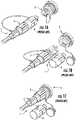
- FIGS. 1A-1C are prior art depictions showing various stages of mating of a preconnectorized cable 1 having a plug connector 5 such as an OptiTap ® connector with a receptacle 3.
- a plug connector 5 such as an OptiTap ® connector
- Receptacle 3 mates plug connector 5 with a standard SC connector (i.e., a non-hardened connector) at a second end (not visible in these views) using an adapter sleeve for aligning ferrules when mating plug connector 5 with the a non-hardened connector.
- SC connector i.e., a non-hardened connector
- Protection of the non-hardened connector side of the receptacle is typically accomplished by mounting the receptacle 3 through a wall of an enclosure or the like so that the non-hardened end of the receptacle is disposed inside the enclosure for environmental protection of the non-hardened connector. As shown by FIGS. 1A-1C , the other end of the receptacle 3 is accessible for receiving the plug connector 5 at the wall of the enclosure. Other applications may mount the receptacle 3 inside an enclosure on a bracket or the like.
- Receptacle 3 allows an optical connection between the hardened connector such as the OptiTap ® male plug connector with a non-hardened connector such as the SC connector at nodes in the optical network that typically transition from an outdoor space to an enclosed and protected space.
- Receptacle 3 is described in further detail in US Pat. No. 6,579,014 .
- Receptacle 3 includes a receptacle housing and an adapter sleeve disposed therein.
- the receptacle 3 receives a non-hardened connector at a second end as represented by the arrow pointing to the left.
- the receptacle 3 typically requires mounting through a wall of a closure, or inside the closure, such as a closure mounted on the side of subscribers premises, disposed in an underground vault or on a pole for protecting the non-hardened connector for outside plant deployments.
- FTTH Fiber-to-the-Home
- FTTx Fiber-to-the-location
- US 5 212 752 A relates to an SC connector which includes enhanced provisions for tuning eccentricity of an optical fiber core or fiber-receiving passageway in the ferrule.
- US 2016/209599 A1 is directed to rugged environmentally sealed connectors that require the use of seals.
- WO 2016/095213 A1 relates to a fiber optic connector having a footprint comprising a threaded portion. The threads are to mate with corresponding internal threads of a port receiving the connector.
- WO2016/095213 further relates to a hardened fiber optic connector having a housing and an outer shroud disposed over the housing. The outer shroud changes the connector footprint and allows for coupling the fiber optic connector with a mating connecting component (for instance a port).
- the disclosure is directed to fiber optic connectors as described and recited in the claim.
- the concepts disclosed allow a compact form-factor for an optical fiber connector suitable for numerous applications and variations as desired.
- the invention provides a fiber optic connector according to claim 1.
- the concepts disclosed advantageously provide fiber optic connectors that allow streamlined manufacture and assembly along with easy and intuitive connectivity with other devices while still having a compact footprint.
- the fiber optic connectors disclosed are explained and depicted with several different embodiments and various other alternative components or optional features that may be incorporated into one or more of the fiber optic connector concepts as desired.
- housings can be modified to use with connector constructions where the ferrule loads from either the rear end of the housing or the ferrule load from the front end of the housing. Fewer parts may be used while providing robust and reliable optical performance.
- the ferrule may cooperate cooperate directly with an housing (e.g., assembled) without using a ferrule holder like conventional fiber optic connectors.
- Other constructions may increase the part count of the connectors for various reasons or could use a ferrule holder if desired.
- the fiber optic connectors advantageously comprise a housing and a ferrule.
- the housing provides a first connector footprint that interfaces with other devices for making an optical connection and various different first connector footprints are disclosed herein that may be used with the connector constructions disclosed.
- the first connector footprints may be defined by a housings having a rear portion (RP) and a front portion (FP).
- First connector footprints may also be further defined by a transition region (TR) disposed between the rear portion (RP) and the front portion (FP) of the housing.
- the housing comprises a part of the rear portion (RP) having a round cross-section (RCS) and a part of the front portion having a non-round cross-section (NRCS).
- the front portion (FP) or the rear portion (RP) of the housing may be further defined in various configurations as disclosed herein while retaining a part of the rear portion (RP) with the round cross-section (RCS) and a part of the front portion (FP) having a non-round cross-section (NRCS).
- the front portion (FP) may have a rectangular cross-section that provides a first orientation feature for the connectors for alignment during mating and inhibit insertion into a non-compliant device or port.
- the housing may be defined as comprising a part of the rear portion (RP) having a polygonal cross-section (PCS) and a part of the front portion having a non-round cross-section (NRCS).
- the front portion (FP) or the rear portion (RP) of this explanatory housing may be further defined in various configurations as disclosed herein while retaining a part of the rear portion (RP) with the polygonal cross-section (PCS) and a part of the front portion (FP) having a non-round cross-section (NRCS).
- the polygonal cross-section (PCS) may be a hexagon, a rectangle, a square or other suitable polygon as desired such as shown in FIG. 76 and 76A .
- Housings disclosed herein define the mating interface for a complimentary device suitable for mating with the connector and the connector footprints disclosed are useful for inhibiting insertion into a non-compliant port or device and damaging either the connector or the device along with assuring a suitable optical operation for the optical connection since the connector and device are matched.
- the housings may have features that aid in the proper alignment or orientation of the connector with the complimentary device such as markings, keys, keyways, etc. without significantly changing the primitive form-factors of the housings that are disclosed and claimed herein.
- a round cross-section may include another feature such as a key or a keyway it is still considered to be a round cross-section.
- housing may have other features such as locking features for securing the optical mating with a complimentary device or threads for securing a dust cap.
- the housing footprints disclosed herein may be further defined by other geometry of the housing(s).
- the transition region (TR) may have different configurations according to the concepts disclosed.
- the transition region (TR) may comprise a first transition portion (TP1) disposed on a first side of the housing and a second transition portion (TP2) disposed on a second side of the housing.
- the first transition portion (TP1) and the second transition portion (TP2) may be spaced apart by an offset distance (OD) in the longitudinal direction.
- housings disclosed herein may have all of the transition portions of the transition region (TR) aligned along a common transverse plane of the connector as desired.
- the transition region (TR) of the housing comprises a threaded portion (TP).
- the first transition portion (TP1) comprises a first riser dimension (FRD) from the non-round cross-section (NRCS) to the round cross-section (RCS)
- the second transition portion (TP2) comprises a second riser dimension (SRD) from the non-round cross-section (NRCS) to the round cross-section (RCS), where the first riser dimension (FRD) is different that the second riser dimension (SRD).
- a part of the front portion (FP) of the housing having the non-round cross-section (NRCS) comprises a rectangular cross-section having rounded corners (RC).
- the rectangular cross-section with rounded corners (RC) is a non-round cross-section (NRCS) due to the rectangular cross-section.
- the rounded corners (RC) may be sized so they have a similar outer dimension (OD) as a dimension (D) for the round cross-section (RCS) or not.
- the rounded corners (RC) may provide stability and snug fit for the mated connector within a port or device when side-pull forces are experienced to inhibit undue optical attenuation by having the round corners transition between the front portion (FP) to the rear portion (RP).
- RP front portion
- RP rear portion
- PCS polygon cross-section
- the housing footprints disclosed herein but not belonging to the present invention may be still further defined by other geometry of the housing(s).
- the front portion (FP) of the housing may comprise another cross-section portion (ACSP).
- the another cross-sectional portion (ACSP) may comprise a SC footprint.
- the SC footprint can, in part, be similar to the inner housing of a conventional SC connector. This particular housing footprint is useful for allowing the connectors disclosed to be backwards compatible into existing devices or ports using well-established connector footprints as desired.
- Housings may also define further features such as a transition region disposed between the rear portion and the front portion with the transition region comprising an asymmetric transition with respect to a longitudinal axis of the housing.
- other features on the housing may define the housing as asymmetric for orientation or mating with compliant devices or ports.
- Another aspect for some of the advantageous connectors disclosed herein, but not belonging to the present invention, comprise one or more features allowing for rotation of the ferrule during assembly for tuning the connector and improving optical performance.
- Some of the connector designs disclosed also offer multi-stage tuning of the ferrule/assembly or infinite tuning of the ferrule/assembly to any desired rotational position for improving optical performance.
- the concepts described herein are suitable for making both indoor and outdoor fiber optic cable assemblies using the connectors disclosed such as drop or distribution cables.
- the fiber optic connectors disclosed may allow for the use of one or more additional components for changing the connector form-factor defined by the particular housing.
- a conversion housing may cooperate with the housing of the connector for changing the fiber optic connector from the first connector footprint defined by the housing to a second connector footprint at least partially defined by the conversion housing. Consequently, the connectors disclosed herein may be converted to be compatible as other well-known commercial connectors for Fiber-to-the-Home applications such as an SC connector or an OptiTap ® connector such as available from Corning Optical Communications of Hickory, NC.
- the concepts disclosed herein may be used with other fiber optic connector types whether hardened or not and are not limited to these particular connector conversions.
- the connector designs disclosed may be hybrid designs with both optical and electrical connectivity. Electrical connectivity may be provided by contacts on or in a portion of the housing of the connector and may be useful for power or data as desired for applications such as FTTx, 5G networks, industrial applications or the like.
- FIGS. 2 , 2A, 3 and 5- 17 disclose connectors where a ferrule 30 is inserted from a rear end 21 of housing 20, and FIGS. 19-43 and FIGS. 46-53 disclose connectors where ferrule 30 is inserted from a front end 23 of the connector 10.
- housings 20 may be modified for using connector designs.
- FIGS. 4A-4E depict an explanatory housing 20 for discussing geometry that generally speaking may be used with any appropriate connector construction as well as have the housing modified or altered for the desired housing design or connector construction.
- housing 20 of FIG. 62 with the threaded transition portion (TP) may be modified or altered for the desired housing design or connector construction.
- FIGS. 44 and 45 disclose concepts related to alternative locking features 20L for use with housings 20 as appropriate.
- FIGS. 46-53 disclose another cable assembly 100 comprising connector 10 concepts disclosing another cable adapter that may be used with appropriate connectors 10 disclosed herein.
- FIG. 54 depicts connector 10 according to the concepts disclosed having another housing footprint.
- FIGS. 56-61 disclose cable assemblies 100 comprising connectors 10 having a first connector footprint where the connectors 10 may be convertible to connectors 10' having a second connector footprint using a conversion housing 80,82.
- FIGS. 70 -78 disclose a connectors where ferrule 30 is disposed within a ferrule holder 49 and inserted from a front end 23 of the connector 10.
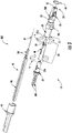
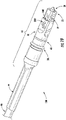
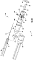
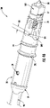
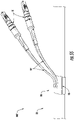
- FIG. 2 is a perspective view and FIG. 3 is an exploded view of cable assembly 100 having connector 10 and a fiber optic cable 90 (hereinafter "cable").
- FIGS. 15 and 16 are longitudinal sectional views of the cable assembly 100 of FIG. 2 showing details of the construction.
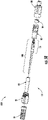
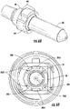
- FIG. 62A depicts cable assembly 100, according to the present invention, having connector 10 with a housing 20 that is similar to the housing 20 for connector 10 of FIG. 2 , but the housing 20 of FIG. 62 and 62A has a different transition region TR. Specifically, the housing 20 of FIG. 62 has a transition region TR with a threaded portion TP and may be used with the connector constructions disclosed herein as appropriate.
- Figures 62 and 62A illustrate the optic fiber connector according to the present invention.
- Connector 10 comprises housing 20 and a ferrule 30.
- Housing 20 comprises a rear end 21 and a front end 23 with a longitudinal passageway 22 extending from the rear end 21 to the front end 23.
- ferrule 30 comprises a fiber bore 32 extending from a rear end 31 to a front end 33.
- Passageway 22 allows one or more optical fibers of cable 90 to pass through the housing 20 for insertion into fiber bore 32 of ferrule 30 such as depicted in FIG. 7 .
- Cable 90 comprises at least one optical fiber 92, one or more strength components 94 and a cable jacket 98.
- Connector 10 or components of connector 10 as depicted in FIGS. 2 , 2A, 3 and 5 -17 allows ferrule 30 to be inserted into housing 20 from rear end 21 of housing 20. Specifically, ferrule 30 is inserted into an opening 21A at the rear end 21 of housing 20.
- Housing 20 depicted in FIG. 62 is similar to the housing 20 FIG. 2 , except it has a different transition region (TR). Specifically, the transition region (TR) of the housing 20 of FIG. 62 comprises a threaded portion; otherwise the concepts of the connector are similar to the other disclosed herein.
- the thread portion (TR) allows the securing of an appropriate dust cap 70 and also allows for the conversion of the connector footprint such as to a hardened connector footprint such as shown in FIGS. 62-69 .
- the concepts of the rear inserted connector constructions may be used with any suitable housing disclosed herein.
- connector 10 of FIG. 3 comprises housing 20, ferrule sub-assembly 60 and cable adapter 59.
- ferrule 30 is a portion of ferrule sub-assembly 60.
- An opening 21A at the rear end 21 of housing 20 is sized for receiving a portion of ferule sub-assembly 60.
- Ferrule sub-assembly 60 is configured to cooperate with the housing 20 for inhibiting the rotation of the ferrule sub-assembly 60 with respect to housing 20 when assembled.
- ferrule sub-assembly 60 may be configured to allow rotation of ferrule 30 for tuning as represented by arrows and angle ⁇ as desired before the ferrule sub-assembly 60 is fully-seated within housing 20 as discussed herein.
- Ferrule sub-assembly 60 also comprises a ferrule carrier 40.
- Ferrule carrier 40 may have different configurations as disclosed herein.
- Ferrule 30 is tunable relative to housing 20 if desired and may have step-tuning in defined increments based on the ferrule geometry.
- other features or designs disclosed herein for the connectors may allow infinite tuning of the ferrule to any desired rotation position. Tuning ferrule 30 allows improved optical performance by turning the ferrule so that any eccentricity in the optical fiber, ferrule or connector is rotated to a known rotational position or quadrant in a uniform manner.
- connectors or other mating devices can be tuned to similar relative rotational positions for improving optical performance such as reducing optical insertion loss of due to optical fiber core misalignment or the like as understood in the art.
- Embodiments disclosed herein may also have a plurality of interfaces between components for tuning of the connector as desired.
- the design of connector 10 of FIG. 3 may also advantageously allow multi-stage tuning if desired.
- Ferrule 30 or other components/assemblies may be tunable in step increments such as by quadrants or be infinitely tuned as desired.
- ferrule sub-assembly 60 may be may be configured to allow rotation of the sub-assembly with respect to cable adapter 59 (or other components) as desired for tuning ferrule 30 as represented by the arrows and angle ⁇ as depicted.
- multi-stage tuning may result in infinite tuning, which means that any desired rotational position desired for any eccentricity of the fiber core within the ferrule 30 is possible.
- the step or degree of tuning at different component interfaces may depend on the particular construction of the ferrule, ferrule carrier, cable adapter or housing with respect to the permitted of rotation and the possible increments of rotation for the components.
- a first-stage of tuning may be step-tuning by quadrant and a second-stage of tuning may be infinite tuning to allow infinite rotation as desired. More specifically, the first-stage step-tuning may be used for gross tuning of the eccentricity of the fiber core such as to the desired quadrant of the and then the second-stage provides infinite tuning by allowing the fine tuning of the eccentricity of the fiber core within the quadrant for precise rotational positioning.
- infinite tuning may accomplished by having one or more components rotate through an angle of ⁇ 180 degrees without step increments, thereby allowing any rotational position for ferrule 30.
- other tuning schemes are possible using the concepts disclosed herein.
- variations of ferrule carrier 40 or ferrule subassembly 60 are possible and disclosed herein for use with any suitable housing 20.
- Connector 10 of FIG. 3 allows ferrule 30 to be rotated or tuned within the ferrule subassembly 60 as depicted.
- Ferrule 30 may be configured to rotate as a step rotation or infinite rotation depending on the particular design.
- ferrule 30 could have a selectively tunable surface 36 that is round for providing infinite rotational positioning or selectively tunable surface of ferrule 30 could comprise a plurality of planar surfaces 36 for step tuning by only allowing certain rotation positions.
- infinite tuning of ferrule 30 may be accomplished by tuning or rotating though an angle ⁇ of ⁇ 180 relative to the ferrule carrier 40 if desired. Being able to rotate one or more components in either direction allows for flexibility in tuning and inhibits excessive twisting of the optical fiber, which is generally undesirable.
- Connector 10 of FIG. 3 also allows ferrule carrier 40 to be rotated for tuning the ferrule relative to housing 20 as depicted.
- ferrule carrier 40 is tunable relative to the housing 20 by way of the rotational position of ferrule carrier 40 relative to cable adapter 59 or rotational position of the cable adapter 59 with respect to the housing.
- ferrule carrier 40 may be tunable though an angle ⁇ of ⁇ 180 relative to the housing 40 or in step-increments such as using ferrule carrier rotational key 41K ( FIG. 5 ) or the like as desired.
- a ferrule carrier rear end 41 may have one or more keys for cooperating with cable adapter 59 and only allowing certain positions for tuning, or the ferrule carrier rear end 41 may simply cooperate with the cable adapter 59 for providing infinite rotational positions for tuning. The details of tuning will be discussed in more detail below.
- connector 10 of FIG. 3 it is possible for connector 10 of FIG. 3 to have to a third interface for tuning.
- the cable adapter 59 may be tunable relative to the rear end 21 of housing 20.
- a flange portion (not numbered) of cable adapter 59 may have one or more keys for cooperating with the rear end 21 of housing 20 and only allowing certain positions for tuning, or the flange portion of cable adapter 59 may simply cooperate with the rear end 21 of housing 20 for providing infinite rotational positions for tuning.
- connector 10 of FIG. 3 provides several different tuning options for manufacturing depending on the desired requirements for the connector.
- FIGS. 4-4E depict an explanatory housing 20 for connectors and will be described in further detail to explain concepts and geometry of housings 20 suitable for use with connector concepts disclosed herein.
- the housing of FIG. 4 is a close-up perspective view of connector 10 having a different construction than the housing 20 depicted in FIGS. 2 and 3
- the housing 20 of FIG. 4 is similar to housing 20 of the connector of FIGS. 2 and 3 .
- the footprint of housing 20 of FIG. 4 may be used with connector constructions that insert the ferrule 30 from the rear end 21 of housing 20 or connector constructions that insert the ferrule 30 from the front end 23 of housing with appropriate modification(s) for the connector construction.
- the longitudinal passageway 22 of the housing 20 may need to be modified for the different connector constructions as appropriate.
- Connectors 10 disclosed herein may use any suitable housing 20 with the desired footprint or construction.
- the disclosure describes several different housings that may be used with connector constructions as appropriate and other variations are also possible.
- FIG. 4 depicts housing 20 and connectors 10 may use a variety of different variations of the housing shown in FIG. 4 or other housings such as the housing 20 shown in FIG. 54 which has the locking feature on a separate component.
- housing 20 may comprise one or more features for alignment during mating and may also comprise other features for securing or locking the connector in a suitable complimentary port or device.
- Housing 20 has a relatively compact form-factor such as having a length L of about 40 millimeters (mm) or less and a cross-section dimension of about 15 mm or less such as 12 mm or less, but other suitable dimensions are possible for the housing.
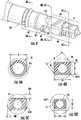
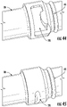
- FIGS. 4A-4D are respective cross-sectional views of the housing of FIG. 4 taken along respective planes defined by line 4A-4A, line 4B-4B, line 4C-4C and line 4D-4D. Lines 4B-4B and 4C-4C are taken at the same cross-section.
- FIG. 4E is a side view of housing 20 that is similar to housing 20 shown in FIG. 4 , but further includes threads 28 like housing 20 depicted in FIGS. 3 and 4 . Threads 28 are disposed on the front portion FR of housing 20 and are discontinuous.
- Housing 20 comprises the rear end 21 and the front end 23 with a longitudinal passageway 22 extending from the rear end 21 to the front end as shown in FIG. 4E .
- Housing 20 of FIGS. 4A-4E comprises a part of the rear portion RP having a round cross-section RCS and a part of the front portion having a non-round cross-section NRCS.
- Transition region TR is disposed between the rear portion RP and the front portion FP of housing 20.
- Transition region TR comprises a first transition portion TP1 disposed on a first side of the housing and a second transition portion TP2 disposed on a second side of the housing.
- first transition portion TP1 and the second transition portion TP2 are spaced apart by an offset distance OD in the longitudinal direction of the housing 20 as best shown in FIG. 4E .
- the offset distance OD for the transition portion TP is useful since it allows connector only to fully-seat into complimentary devices or ports having the matching geometry.
- other housings 20 for connectors disclosed herein may omit the offset distance if desired.
- Housings 20 may also have suitable features or structures for sealing connectors 10.
- the sealing plane should be located at a suitable location along the housing 20 for providing suitable environmental protection as necessary for the desired environment.
- housing 20 may include one or more grooves 20G for receiving an appropriately sized O-ring 65.
- Housings 20 may include other feature or structures for aiding in sealing.
- the housing 20 may have a suitable surface for receiving a portion of a heat shrink 99 or the like for sealing between a portion of the cable 90 and the connector 10. Any suitable heat shrink 99 may be used such as a glue-lined heat shrink.
- other structures or features are possible for aiding in providing a robustly sealed cable assembly 100.
- the transition region TR is disposed between the rear end 21 and the front end 23 where the housing 20 makes a transformational shift in the primitive cross-sectional shapes from a part of a rear portion RP to a part of the front portion FP.
- a primitive cross-section means the outer perimeter of the cross-section without regard for the internal features of the cross-section.
- portions of the cross-sections may include other features that modify the shape of the primitive cross-sections as desired such as a keying feature, retention feature or a locking feature, while still practicing the concepts of the transition region TR or front/rear portions as disclosed herein.
- a front portion FP may have rounded corners or chamfered corners while still being a rectangular cross-section.
- the front portion FP of housing 20 has a rectangular cross-section that provides a first orientation feature for the connectors for alignment during mating and inhibit insertion into a non-compliant device or port.
- the non-round cross-section NRCS has the rectangular cross-section with a width W1 and a height HI as shown in FIG. 4B .
- the rectangular cross-section provides the first orientation feature since the rectangular portion may only be inserted into a complimentary device or port in certain orientations due to its rectangular shape, thereby inhibiting incorrect insertion or insertion into non-compliant devices or ports.
- housing 20 of FIGS. 4A-4E has the first transition portion TP1 that comprises a first riser dimension FRD from the non-round cross-section NRCS to the round cross-section RCS, and the second transition portion TP2 comprises a second riser dimension SRD from the non-round cross-section NRCS to the round cross-section RCS, where the first riser dimension FRD is different that the second riser dimension SRD.
- the riser dimensions are measured perpendicular from the mid-point of the cord defined by the surface of non-round cross-section NCRS as shown in FIG. 4C to the outer surface of the round cross-section RCS.
- the geometry of housing 20 of FIGS. 4A-4E also comprises the non-round cross-section NRCS comprising a rectangular cross-section having rounded corners RC, and the rounded corners RC are sized so they have a similar outer dimension OD as a dimension D for the round cross-section RCS.
- the rounded corners (RC) may provide stability and snug fit for the mated connector 10 within a port or device when side-pull forces are experienced to inhibit undue optical attenuation by having the round corners transition between the front portions FP to the rear portion RP.
- the front portion FP of housing 20 depicted has more than one primitive cross-sectional shape over its length.
- the front portion FP of housing 20 of FIGS. 4-4E also comprises another cross-section portion ACSP.
- the cross-sectional portion may comprise a SC footprint.
- the SC footprint can, in part, be similar to the inner housing of a conventional SC connector. This particular housing footprint is useful for allowing the connectors disclosed to be backwards compatible into existing devices or ports using well-established connector footprints as desired.
- Other embodiments may have connectors configured for LC connector or other known connector footprints as desired.
- the front portion FP of housing 20 may comprise another cross-section portion ACSP with a primitive cross-section that is different than the non-round cross-section NRCS depicted in FIG. 4D .
- the non-round cross-section NRCS changes to another cross-section portion ACSP as shown.
- the another cross-section portion comprises a rectangular cross-section with a width W2 that is less than W1 and a height H2 is similar to height HI.
- height H2 may be equal to height HI.
- the another cross-section portion ACSP has a primitive cross-section that is similar to a cross-section near a front end of a SC connector.
- rear portion RP may have more than one primitive cross-section shape over its length as desired.
- rear portion RP may include one or more retention features or locking features that alter or modify the cross-section.
- housing 20 may also include locking feature 20L so that the connector may secured in an adapter, port or other suitable device.
- locking feature 20L may comprise features integrated into the housing such as one or more of a groove, a shoulder such as shown in FIG. 4E and FIG. 45 , a scallop such as shown in the housing 20 of FIG. 3 , a reverse bayonet such as depicted in FIG. 44 , or a ramp with a ledge as shown in FIG. 63 .
- the locking features 20L advantageously are integrated into the housing 20 and do not require extra components and may be used with any of the disclosed concepts.
- the locking features 20L are subtractive portions from the primitive geometry of the rear portion RP such as a notch in the round rear portion RP. Consequently, having the locking features integrated into the housing 20 (e.g., monolithically formed as part of the housing) may allow denser arrays of connectors in complimentary devices.
- these locking features integrated into the housing 20 are rearward of the sealing location of connectors 10.
- the integrated locking features of housing 20 are disposed rearward of at least one groove 20G that seats O-ring 65. Locking feature 20L may cooperate with features of a complimentary mating device for securing the mating of the connector 10 with the complimentary mating device.
- Housing 20 may also have features that aid in the proper alignment or orientation of the connector with the complimentary device such as markings, keys, keyways, etc. without changing the primitive form-factors of the housings that are disclosed and claimed herein. Additionally, housing may have other features for mating with a complimentary device or threads for securing a dust cap.
- FIG. 2 is a perspective view of connector 10 with a housing 20 similar to the housing 20 depicted in FIG. 4 , but it further includes threads 28 and keying feature 20K.
- FIGS. 25 and 26 depict a fiber optic connector similar to FIG. 20 having an alternative housing 20A that may be used with any suitable fiber optic connector disclosed herein. Housing 20 further comprises a keying feature 20K.
- Keying feature 20K has a predetermined location with respect to an orientation of housing 20 for aligning the form-factor of the housing with a respective mating device.
- the housing 20 or keying feature 20L provides a proper orientation for connection in one orientation, which may be desired for connectors having angled ferrules.
- keying feature 20K ensures correct rotational orientation of the connector 10 during insertion and mating with another device.
- housing 20 is monolithically formed; however, other embodiments could have designs where the housing was formed from one or more components as desired.
- Housing 20 having a plurality of components could be assembled by snap-fitting, adhesive, welding or the like.
- FIGS. 39 and 40 depict a housing 20 having a plurality of components.
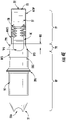
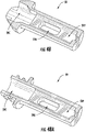
- FIG. 5 is an exploded view of ferrule subassembly 60 shown in connector 10 of FIG. 3 .
- Ferrule subassembly 60 may have several different constructions as depicted herein and still practice the concepts disclosed. For instance, ferrule subassemblies 60 may use different ferrule carrier 40 constructions such as disclosed or desired while still practicing the concepts disclosed.
- Ferrule 30 is a portion of ferrule subassembly 60.
- an opening 21A at the rear end 21 of the housing 20 is sized for receiving a portion of the ferrule subassembly 60.
- the ferrule subassembly 60 When assembled, the ferrule subassembly 60 is configured to cooperate with the housing 20 for inhibiting the rotation of the ferrule subassembly 60 with respect to the housing 20.
- the ferrule subassembly may have a friction fit or interlocking structure that cooperates with the passageway 22 of the housing 20 that inhibits rotation of the ferrule subassembly 60 with respect to housing 20.
- the ferrule subassembly 60 may be free to rotate for tuning or the like until the ferrule subassembly 60 is fixed in position relative to housing 20 such as with an adhesive or the like.
- ferrule subassembly 60 comprises a ferrule carrier and a resilient member 50. Some embodiments of the ferrule subassembly 60 may omit the resilient member 50 and not bias the ferrule 30 forward. If a resilient member 50 is used, ferrule carrier 40 may further comprise a resilient member pocket 46 as shown. As depicted, the resilient member pocket 46 may be configured for receiving the resilient member 50 in a direction transverse to a longitudinal direction of the ferrule carrier 40 (e.g., transverse to the optical fiber passageway) as represented by the arrow.
- ferrule carrier 40 comprises a ferrule carrier rear end 41, a ferrule carrier front end 43 and a ferrule carrier passageway 42 extending from the ferrule carrier rear end 41 to the ferrule carrier front end 43, where the ferrule carrier passageway 42 comprises a fiber buckling zone 47.
- the fiber buckling zone allows the optical fiber 92 to have room to move rearward during mating without causing undue optical attenuation. In other words, during mating the ferrule 30 may be pushed rearward slightly cause the optical fiber 92 of the cable 90 to deflect and in order to inhibit optical attenuation the fiber buckling zone 47 provided for allowing fiber movement.
- Ferrule carrier 40 may have several different designs.
- the ferrule carrier comprises a ferrule carrier front end 43 with the ferrule carrier front end 43 comprising at least one cantilevered portion such as shown in FIG. 10 .
- the at least one cantilevered portion extends from a medial portion of the ferrule carrier and allows the assembly of the ferrule 30 into the ferrule carrier 40.
- the at least one of the first cantilevered portion 43A may also be configured to cooperate with the housing 20 for inhibiting the rotation of the ferrule 39 with respect to the housing 20 when the ferrule subassembly 60 is fully-seated in the housing 20, and allow rotation of the ferrule 30 for tuning when the ferrule subassembly 60 is not seated in the housing 20.
- the front portion of the longitudinal passageway 22 of housing 20 may be sized for snuggly fitting to shoulders 43S disposed on the ferrule carrier front end 43 so that one or more of the cantilevered portions either squeeze the ferrule 30 and inhibit rotation or inhibit the deflection of the at least one cantileved portion so that the ferrule 30 is inhibited from rotating beyond its desired location.
- the ferrule carrier 40 still allows the ferrule 30 to "float" to the desired degree so it can translate such as in the rearward direction (i.e., z-direction) or X-Y directions for allowing the ferrule to move slightly to the desired location for precise alignment during mating.
- the ferrule 30 is biased and may "float" on the resilient member.
- ferrule carrier described herein should not be confused with a ferrule holder that fixes a conventional ferrule directly to the ferrule holder so there is no appreciable movement between the ferrule and the ferrule holder.
- Conventional connectors allow the entire assembly of the ferrule holder/ferrule to be biased by a spring.
- embodiments such as depicted in FIG. 3 , FIG. 17 and FIG. 21 allow the ferrule to float without using a ferrule holder.
- the use of the ferrule holder/ferrule assembly is another component interface where stack-up of tolerances may exist and impact geometry. Consequently, connectors disclosed herein may eliminate the conventional ferrule holder along with the expense and manufacturing time required by using a conventional ferrule holder.
- FIG. 5 depicts the ferrule carrier front end 43 comprising a first cantilevered portion 43A and a second cantilevered portion 43B.
- FIGS. 6 and 7 are longitudinal sectional views of ferrule subassembly 60 of FIG. 3 showing details of the design and assembly.
- FIGS. 8 and 9 respectively are a perspective view and close-up perspective view of ferrule carrier 40 of FIGS. 5-7 depicting details of the ferrule carrier.
- At least one of the first cantilevered portion 43A or the second cantilevered portion 43B are configured to cooperate with the housing 20 for inhibiting the rotation of the ferrule 30 with respect to the housing 20 when the ferrule subassembly 60 is fully-seated in the housing 20, and allow rotation of the ferrule 30 for tuning when the ferrule subassembly is not seated in the housing 20.
- the housing 5 may be sized to cooperate with the housing 20 by fitting into a passageway 22 that inhibits the cantilevered portions 43A,43B from deflecting outwards, thereby inhibiting the rotation of the ferrule 30 with respect to the ferrule carrier 40 when the ferrule carrier front end 43 is fully-seated in the housing 20 since some of the selectively tunable surfaces 36 (in this case the planar surfaces 36S) of ferrule 30 cooperate with ferrule retention structure 43C of the ferrule carrier 40.
- the selectively tunable surfaces 36 in this case the planar surfaces 36S
- Ferrule subassembly 60 is assembled by placing the resilient member 50 into the resilient member pocket 46 by inserting the spring in the transverse direction to the ferrule carrier passageway as best shown in FIG. 5 .
- Ferrule carrier 40 of FIG. 5 allows ferrule 30 to be inserted from the ferrule carrier front end 43 as represented by the arrow.
- the first cantilevered portion 43A and the second cantilevered portion 43B deflect outward as represented by the arrows shown in FIG. 6 .
- the ferrule 30 is seated in the ferrule carrier front end 43 the first cantilevered portion 43A and the second cantilevered portion 43B spring back toward their original positions to capture the ferrule 30.
- one of the first cantilevered portions 43A or the second cantilevered portions 43B comprise a ferrule retention structure 43C. Consequently, when the first and second cantilevered portions 43A,43B are inhibited from deflecting, then ferrule 30 is inhibited from rotating such as when the ferrule subassembly 60 is fully-seated within housing 20. However, when the first and second cantilevered portions 43A, 43B are allow to deflect outwards such as shown in FIG. 6 , then the ferrule 30 may be rotated thru any desired angle ⁇ for tuning.
- ferrule carrier 40 may have other features that allow tuning if desired.
- ferrule carrier rear end 41 may have a ferrule carrier groove 41G or shoulder for cooperating with the cable adapter 59, thereby allowing rotation between the two components in either step increments or infinite increments as desired and discussed herein.
- ferrule carrier 40 may comprise one or more ferrule carrier rotational keys 41K to allow rotational step increments or the ferrule carrier 40 may omit ferrule carrier rotational keys 41K and allow infinite rotational positions relative to the cable adapter 59, which may be keyed to the rear end 21of housing 20.
- Ferrule carrier 40 may be attached to cable adapter in any suitable manner such as adhesive, welding, mechanical fitment, etc.
- cable adapter 59 may integrate the ferrule carrier 40 and cable adapter 59 into a monolithic component.
- using separate cable adapter 59 allows the connectors 10 to be adapted to different cables such as round, flat, different sizes by merely selecting the appropriate sized cable adapter 59 for the desired cable type.
- cable adapter may include one or more flexures 59F at the rear portion for providing cable bending strain-relief if desired instead of using a conventional boot.
- the flexures as depicted are suitable for flat cables that have a preferential bend-characteristic.
- the connectors disclosed herein may allow the ferrule 30 to have a small amount of "float" within ferrule carrier or housing without using a ferrule holder like conventional fiber optic connectors.
- Conventional connectors mount the ferrule within a ferrule holder in a fixed position and then typically the ferrule holder is biased by a spring.
- some of the connector designs disclosed by the present application have the resilient member 50 directly bias the ferrule, which eliminates parts and also allows more flexibility for ferrule selection or tuning.
- the ferrule may be tuned relative to the ferrule carrier or the housing depending on the connector design.
- the high precision geometry ferrule holder is eliminated along with the tolerance stack-up using a conventional connector with a ferrule holder.
- the housings concepts disclosed herein may be used with connectors having ferrule holders such as disclosed in FIGS. 70 -78.
- Ferrule retention structure 43C is configured to cooperate with geometry on ferrule 30. Specifically, ferrule 30 depicted in FIG. 5 has at least one selectively tunable surface 36 that cooperates with the ferrule retention structure 43C. Ferrule retention structure 43C is sized for snugly-fitting to one or more selectively tunable surfaces 36 of ferrule 30 as shown in FIG. 7 . However, when the ferrule carrier 40 is not seated in housing 20, the ferrule 30 may be rotated within ferrule carrier 40 about an angle ⁇ for optically tuning the assembly. Ferrule 30 may have a round selectively tunable surface 36 for infinite tuning, but that requires a tight fit between the ferrule carrier front end 43 and the appropriate portion of the passageway 22 of the housing 20.
- FIGS. 8 and 9 depict detailed views of the ferrule carrier 40 of FIG. 5 .
- the first and second cantilevered portions 43A, 43B of ferrule carrier 40 may have stepped down portions forward of shoulder 43S, thereby allowing robust seating and inhibiting of deflection of the cantilevered arms 43A, 43B.
- Ferrule 30 may have any suitable number of plurality of planar surfaces 36S as desired.
- four planar surface 36S allows quadrant tuning and further planar surfaces allows finer tuning in a first-stage.
- ferrules 30 may have any number of planar surfaces as desired such as six or eight planar surfaces to increase the number of steps for tuning the ferrule.
- quadrant tuning is sufficient and if coupled with an infinite second-stage tuning interface, then the connector advantageously may be tuned to any desirable rotational position in a quick and easy manner during manufacturing.
- FIG. 10 is a perspective view of an alternative ferrule carrier 40' that may be used in the ferrule subassembly 60 and FIGS. 11 and 12 respectively are a partially exploded view and an assembled view of the alternative ferrule carrier 40' in ferrule subassembly 60.
- This ferrule carrier 40' is similar to ferrule carrier 40, but only has first cantilevered arm, and requires loading of the ferrule 30 from the transverse direction like the resilient member 50. Ferrule 30 may still be rotated with respect to ferrule carrier 40', but it may require a slightly larger rotational force to deflect the U-shaped portion or a slightly upward translation of the ferrule 30 to help reduce the rotational force required for the rotation.
- FIGS. 13 and 14 respectively are a partial sectional view and a cross-sectional view of the alternative ferrule carrier 40' of FIGS. 10-12 depicted assembled into ferrule subassembly 60 and disposed in housing 20 of fiber optic connector.
- the passageway 22 of housing 20 may include different geometry for seating the ferrule subassembly 60 within the housing and inhibiting the rotation of ferrule 30 relative to the housing 20 using the alternative ferrule carrier 40'.
- housing 20 comprises a passageway 22 with an internal key 20KI that cooperates with the U-shaped portion of the alternative ferrule carrier 40'. Consequently, the alternative ferrule carrier is inhibited from further rotation with respect to the housing 20.
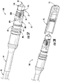
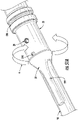
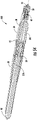
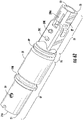
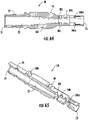
- FIG. 17 is an exploded view of another cable assembly 100 that is similar to the cable assembly 100 of FIG. 2 with a fiber optic connector having a different ferrule subassembly 60 and FIG. 18 is a partially exploded view of the cable assembly 100 of FIG. 17 with the fiber optic cable attached to the ferrule subassembly 60.
- This cable assembly 100 comprises a connector 10 that has a ferrule carrier 40 that is monolithically formed with the cable adapter as depicted. Otherwise, the cable assembly 100 is similar to the cable assembly 100 of FIG. 2 .
- FIGS. 19-43 and FIGS. 46-53 disclose connectors where ferrule 30 is inserted from a front end 23 of the connector 10. These connectors designs are depicted without a ferrule holder as generally discussed herein, but may be used with a ferrule holder if desired. These connector designs are different from the earlier connector designs since they do not use a ferrule carrier; however, these designs can still be optically tuned if desired. Specifically, these connector designs comprise a ferrule 30 that "floats" relative to the housing 20 and uses a different structure for securing the ferrule while allowing the ferrule float. Any suitable housings 20 as described herein may be used for these connectors so long as they are suitably modified for securing the ferrule 30 as disclosed in more detail below.
- FIGS. 19 and 20 are perspective views of cable assembly 100 having a different fiber optic connector 10 with housing 20 that is similar to the housing shown with the fiber optic connector of FIG. 2 , but having ferrule 30 that loads from the front end 23 of housing 20 and secured a transverse ferrule retention member 140.
- FIG. 21 is an exploded view of another cable assembly 100 that is similar to that of FIG. 19 with the connector having a housing having threads on the housing that are discontinuous.
- FIG. 22 is an perspective assembled view of the cable assembly 100 of FIG. 21 and FIG. 23 is a perspective view of the cable assembly 100 of FIG. 22 with a dust cap 70 installed.
- FIG. 24 is a longitudinal sectional view of the cable assembly 100 of FIG. 22 in a vertical direction and
- FIG. 29 is a longitudinal sectional view of a front portion of the fiber optic connector 100 in a horizontal direction.
- connector 10 comprises housing 20, ferrule 30 and transverse ferrule retention member 140.
- Housing 20 is similar to the other housings disclosed herein, but further comprises an opening 129 in an outer surface that is transverse to the longitudinal passageway 22 of housing 20.
- the opening 129 is sized for receiving the transverse ferrule retention member 140 and securing the ferrule 30 in a manner that allows suitable movement so it may float as appropriate as depicted in FIG. 24 .
- Connector 10 may also comprise a band 69 for securing a cable 90 to the connector if desired.
- FIG. 25 is a detailed exploded view of the front end of the cable assembly 100 of FIG. 22 and FIG. 26 is a cross-sectional view taken at the opening 129 of the housing 20 of FIG. 19 showing transverse ferrule retention member 140 securing the ferrule 30.
- ferrule 30 is loaded into the passageway 22 of housing 20 from the front end 23 and secured by the cooperation of the ferrule 30 with the transverse ferrule retention member 140 that is inserted into opening 129 for cooperating with at least one surface of the ferrule 30.
- ferrule 30 is inserted into the passageway 22 until the cooperating surface such as a ferrule retention feature aligns with the opening 129 so that the transverse ferrule retention member 140 may engage the surface and securing the ferrule. Additionally, the at least one surface of the ferrule 30 that serves as the ferrule retention feature cooperates with the transverse ferrule retention member 140 is sized relative to the transverse ferrule retention member so that the ferrule 30 may float.
- the ferrule retention feature may also be the same feature as the at least one selectively tunable surface 36.
- ferrule has at least one selectively tunable surface 36 so that ferrule 30 may have at least two rotational orientations with respect to the housing 20 (and which acts as the ferrule retention feature).
- ferrules 30 may have any suitable numbers of selectively tunable surfaces 36 so the ferrule 30 may have the desired number of rotational positions for tuning the ferrule.
- ferrule may have four, six, eight or any suitable number of selectively tunable surfaces 36 as desired.
- the longitudinal passageway 22 of housing 20 extending from the rear end 21 to the front end 23 also comprises a tuning pocket 24 in cooperation with the longitudinal passageway 22. The tuning pocket 24 allow the rotation or manipulation of the ferrule 30 within the housing as needed.
- the transverse ferrule retention member 140 is secured to the housing 20 using a pair of catches 140C disposed on the arms of the transverse ferrule retention member 140.
- Catches 140C may snap-fit to portions of the housing 20 disposed in opening 129 such ledges.
- FIGS. 27 and 28 respectively depict a detailed view of an alternative transverse ferrule retention member 140 having catches 140C and cross-sectional view showing the alternative transverse ferrule retention member 140 for securing ferrule 130.
- the catches 140C are disposed on a medial portion of the arms of this alternative transverse ferrule retention member 140.
- FIG. 29 is a sectional view of a portion of the housing 20 having a width of opening 129 being larger than the width of the transverse ferrule retention member 140 so that the ferrule 30 may float.
- FIG. 30 is a sectional view depicting tuning pocket 24 of housing 20 that allows rotational tuning of the ferrule 30 during manufacture for improving optical performance. Specifically, when transverse ferrule retention member 140 is disengaged, then the ferrule 30 may be rotated relative to the ferrule.
- tuning pocket 24 allows ferrule 30 to be rotated by a suitable angle ⁇ for optical tuning to a preferred rotational position as represented by the arrow.
- ferrule 30 may be rotated by an angle ⁇ of ⁇ 180 degrees, but other suitable angles are possible.
- FIGS. 31 and 32 depict explanatory ferrules 30 having at least one selectively tunable surface 36.
- FIG. 31 shows a ferrule that may be tuned to quadrants with four selectively tunable surfaces 36.
- the selectively tunable surfaces 36 are configured as planar surfaces as shown. More specifically, the selectively tunable surfaces 36 are formed by a plurality of planar surfaces that are recessed on the ferrule 30. Finer tuning is possible with the concepts disclosed by having more selectively tunable surfaces such as six, eight, ten or twelve, thereby providing more rotational positions for securing the ferrule 30.
- FIG. 31 shows a ferrule that may be tuned to quadrants with four selectively tunable surfaces 36.
- the selectively tunable surfaces 36 are configured as planar surfaces as shown. More specifically, the selectively tunable surfaces 36 are formed by a plurality of planar surfaces that are recessed on the ferrule 30. Finer tuning is possible with the concepts disclosed by having more selectively tunable surfaces such
- the ferrule 30 in FIG. 32 may be secured by transverse retention member 140 and when rotational tuning is required, then the ferrule 30 may be displaced rearward until free rotation portion 36A is aligned with the transverse retention member 140 allowing rotation of the ferrule in either direction and when the desired rotational position is reached the ferrule 30 is allowed to translate to the forward position where the selectively tunable portions 36 engage and cooperate with the transverse ferrule retention member 140 to inhibit rotation of the ferrule 30. Consequently, the transverse ferrule retention member 140 does not need to be removed from housing 20 for tuning.
- FIGS. 33-36 are various views of depicting the housing 20 of the connector 10 of FIG. 23 comprising opening 129 and tuning pocket 24.
- housing 20 is similar to the other housings and may be modified for the desired housing configuration as desired.
- the housing 20 depicts threads 28 that are discontinuous for attaching dust cap 70 such as shown in FIG. 23
- variations are possible that eliminate the threads 28 and use a push-on dust cap.
- other variations to the housing 20 are possible such as changing the mating geometry and using the concepts disclosed with the mating geometry of the housing 20 depicted in FIG. 54 .
- housings 20 may have different retention features or different locking features 20L.
- FIG. 3 comprises a locking feature 20L disposed between rear end 21 and a front end 23 configured as a scallop and the locking feature 20L of the housing of FIG. 4 is configured by a shoulder.
- the shoulder comprises an enlarged annular portion 126 with a flat surface on the rear side.
- FIG. 37 is a perspective view of another cable assembly 100 with still another alternative connector 10 that is similar to connector 10 of FIG. 19 , but further comprises multi-piece housing 20 comprising a nosepiece 160.
- FIG. 38 is a perspective view of the cable assembly 100 with dust cap 70 and
- FIG. 39 is an exploded view of the cable assembly 100.
- the connector 10 comprises a housing 20 having nosepiece that fits about a front end 23.
- using the separate nosepiece 160 provides more access to the passageway 22 of the housing and allows more room and vision for assembly.
- the opening 129 is disposed in a location that is covered by nosepiece 160 so that once the connector is tuned and the nosepiece 160 is secured the transverse ferrule retention member is not visible or accessible.
- Housing 20 of this embodiment also has a different locking feature 20L compared with the housing depicted in FIG. 33-36 and an aperture 29.
- Locking feature 20L is configured as a groove for receiving a clip or other suitable locking feature from a complimentary device for retaining the connector in a mated state when secured.
- This embodiment of the connector also use cable adapter 59 so that the connector may accommodate different cable types by using the appropriately sized cable adapter for the given cable 90.
- FIG. 40 is a front end sectional view of the connector 10 of FIG. 37 showing the nosepiece 160 attached to the front end of housing 20 and
- FIG. 41 is a front end view of the housing showing an attachment interface (not numbered) such as a weld interface disposed on a front portion of the housing 20.
- an attachment interface such as a weld interface disposed on a front portion of the housing 20.
- Nosepiece 160 may be attached in any suitable manner such as adhesive, friction-fit, snap-fit, welding or the like as desired.
- the nosepiece 160 is formed from a translucent material. Using a translucent material for nosepiece 160 allows the use of a UV curable epoxy for securing the nosepiece 160.
- FIGS. 42 and 43 are perspective and side views of a connector 10 similar to FIG. 37 having an alternative housing 20.
- Housing 20 in this embodiment does not have an offset distance among transition portions TP1-TP4. In other words, all of the transition portions TP1-TP4 are aligned.
- this housing 20 comprises keying feature 20K for orienting the connector for mating. Keying feature 20K is a key, but other embodiments may use other suitable structure such as a keyway or the like.
- housings disclosed herein are also possible such as having other shapes for the rear portion RP such as a polygon cross-section PCS, instead of the round cross-section RCS.
- Polygon cross-sections may have any suitable number of side such as four, five, six, seven or eight, but other suitable number of sides are also possible.
- the housing 20 of the connectors may be configured to work with other devices so that a retention feature or locking feature of the connector is intended to cooperate with different devices for maintaining the optical connection at the mating interface.
- FIGS. 44 and 45 are perspective views of portions of alternative housings 20 depicting other locking feature designs. The housings 20 depicted in FIGS. 44 and 45 may be used with any suitable connectors disclosed herein.
- Keying feature 20K has a predetermined location with respect to an orientation of housing 20 for aligning the connector form-factor with a respective mating device. Specifically, the housing 20 provides a proper orientation for connection in one orientation, which may be desired for angled ferrules. In this embodiment, keying feature 20K is disposed on a center line of fiber optic connector 10 and ensures correct rotational orientation during insertion and mating with another device.
- FIG. 46 is a perspective view of still another cable assembly 100 using a connector similar to the connector of FIG. 37 , but having a different cable adapter 59.
- the connector also has a different type of locking feature 20L than the housing 20 of the connector of FIG. 37 .
- the cable adapter 59 of this embodiment that fits into a rear opening 21A of the housing 20.
- using connectors with a separate cable adapter 59 allows the connector to be used with different types cables by merely changing out and selecting the cable adapter that is suitable for the desired cable 90.
- FIG. 47 and 48 respectively are a perspective view and a cross-sectional view the cable adapter 59 of FIG. 46 .
- FIG. 49 is a vertical sectional view and
- FIG. 50 is a horizontal sectional view of the rear portion of cable assembly 100 showing the cable 90 disposed within the cable adapter 59.
- FIGS. 47A and 48A are a perspective view and a cross-sectional view of another cable adapter 59, that is similar to the cable adapter of FIG. 47 .
- cable adapters 59 may comprise an aperture 59A, a recessed surface 59R, a shoulder 59S, a passageway 59P, and a cable saddle 59C or a cable adapter key 59K as desired for any particular embodiment of cable adapter 59.
- cable adapter 59 comprises passageway 59P from a cable adapter front end 59F to a cable adapter rear end 59R. Passageway 59P allows the optical fiber 92 of cable 90 to pass therethrough.
- Housings 20 may include one or more aperture 29 for injecting epoxy or adhesive or the adhesive or epoxy may be placed on the cable adapter before insertion into the housing.
- housing may include two apertures 29 such as show in FIG. 49 so that air may escape as adhesive or epoxy is injected.
- the one or more apertures 29 may be aligned with the apertures 59A of the cable adapter so that the adhesive or epoxy also secures the strength members 94 of cable 90 to the cable adapter 59 that is secured to the housing 20, thereby forming a robust cable/connector attachment and also providing sealing at the rear end.
- Cable saddle 59C is sized and shaped for the particular cable 90 that is intended to be secured using the cable adapter along with the appropriate components as appropriate such as depicted in FIG. 50 .
- the rear portion of the cable adapter 59 may have a cable bend relief area such as a reverse funnel at entrance to the passageway, flexures or other suitable structure for inhibiting sharp bending of the cable near the rear of the cable adapter 59.
- cable adapters 59 may or may not include keys 59K as desired for cooperating with features of the housing.
- the rear portion 59R of the cable adapter 59 of FIG. 47A comprises one or more ribs 59RB suitable for receiving a boot or overmold on the rear portion 59R.
- the ribs 59RB aid in the retention of the boot or overmold.
- FIG. 51 is perspective view of another cable assembly 100 according to the concepts disclosed and FIG. 52 is an exploded view of the cable assembly 100.
- Housing 20 of this embodiment is similar to the housing disclosed herein, but further comprises a keying portion 20KP thats extend into the transition region TR as shown.
- the keying portion 20KP is configured as a female key or subtractive portion on housing 20.
- the keying portion 20KP cooperates with a suitable keying portion in a connection port of a device such as an additive or male portion for inhibiting non-compliant connectors from being inserted into the connection port.
- keying portion 20KP may be arranged as a subtractive portion that removes a side or slice of the housing 20 for creating a D-shaped cross-section over the length of the keying portion 20KP.
- connector 10 of FIG. 52 is similar to that of FIGS. 70 -78 where ferrule 30 disposed within a ferrule holder 49 and inserted from a front end 23 of the connector 10 and is discussed in more detail in relation to those FIGS.
- This embodiment also comprises a boot or overmold 259 disposed on the rear portion 59R of cable adapter 59 as best shown in FIG. 53 .
- a sealing element such as heat shrink 99 is disposed over the boot or overmold 259 as best shown in FIG. 54 .
- the sealing element may also be disposed over a portion of the housing 20 as shown. Placing the sealing element over boot or overmold and a portion of the housing 20 allows for sealing of the cable jacket to the rear of the connector.
- FIG. 51A is a rear perspective view of another cable assembly having cable adapter 59 with flexures 59F for bend-strain relief.
- FIGS. 52A and 53A are a side and sectional views of the cable assembly of FIG. 51A showing heat-shrink 99 before and after being installed.
- the cable adapter 59 may or may be able to have more than one rotational position with respect to the housing 20 depending on how the ends of the components cooperate or not.
- housing 20 may have a stepped down portion at the rear end 21 for receiving a portion of heat shrink 99 and may cover the flexures 59F while also providing further cable bending strain-relief.
- FIG. 54A is a front perspective view of another housing 20 that may be used with the fiber optic connector concepts disclosed herein.
- the securing feature 20L is formed on a separate and distinct component from the housing 20.
- securing feature 120L is disposed on a coupling nut 120 having threads and that rotates about an outer shaft of housing 20 for securing the connector to a complimentary device.
- the housing 20 may not have offset distance between transition portions of the housing 20 such as depicted in this embodiment.
- Connectors disclosed herein may be portions of other cable assemblies as desired.
- FIG. 55 depicts a distribution cable 100' having one or more connectors 10 on tether cables 90' that extend from a mid-span access 93 of a distribution cable.
- other suitable assemblies may use the connectors according to the concepts disclosed herein.
- FIG. 56 is a perspective view of an explanatory connector 10' that further comprises a conversion housing 80 attached about the housing 20 for changing the connector 10' from a first connector footprint to a second connector footprint
- FIG. 57 is a sectional view of the connector 10'.
- the connector 10' may have a first connector footprint such as shown in FIG. 19 and be changed to a second connector footprint such as a SC connector by adding conversion housing 80.
- Conversion housing 80 cooperates with housing 20 for changing from the first connector footprint to the second connector footprint.
- the changing of the first connector footprint to the second connector footprint comprises the use of a single component.
- the changing of the first connector footprint to the second connector footprint may comprise the use of a plurality of components.
- FIG. 58 is a partially exploded view of another connector 100' that may be changed from a cable assembly 100 having first connector footprint 10 to a second connector footprint 10' as shown assembled in FIG. 59 .
- this embodiment of the second connector footprint 10' comprises a hardened connector footprint.
- Hardened connector footprint means that the connector is suitable for outdoor environments without be protected within a closure. Any suitable connector 10 disclosed herein may be used for such a conversion from the first footprint to the second footprint.
- FIG. 58 depicts cable assembly 100 with connector 10 with the plurality of components for the conversion to the second footprint exploded for depicting the assembly of the components.
- the plurality of components are suitable for converting connector 10 to a hardened OptiTap ® compatible connector; however, the plurality of components may be configured for converting connector 10 into other hardened connectors as desired.
- the plurality of components for the conversion to the hardened connector comprise an inner boot 83, an outer boot 87, a conversion housing 82 configured as a shroud, a retaining member 84 configured as a retaining nut and a coupling nut 85.
- the inner boot 83 is slid over up over part of connector 10 and the conversion housing or shroud 82 is slid rearward into position and then the retaining nut 84 is secured to the threads of connector 10.
- FIG. 60 is an assembled view of the fiber optic connector of FIG. 58 showing the hardened second connector footprint with the dust cap 88 installed thereon.
- FIG. 61 is a sectional view of the hardened connector of FIG. 60 .
- FIGS. 62-65 are various views of the another housing 20 of the connector 10, according to the present invention, suitable for receiving a ferrule disposed in a ferrule holder.
- Housing 20 is similar to the housings 20 disclosed herein, but further comprises one or more latch arms 20LA disposed in a front portion FP of housing 20 as depicted.
- the front opening of passageway 22 is sized for allowing the insertion of ferrule holder 49 from the front end 23 of housing 20 such as shown in the cross-section of FIG. 63 .
- Latch arms 20LA are connected at the front end and cantilevered at the rear end so they can be deflected when ferrule holder 49 is inserted and then spring back to retain the ferrule holder 49 once it is fully-inserted.
- FIG. 62A is bottom perspective view of the connector 10 showing the locking feature 20L of housing 20 configured as a ramp (not numbered) with a ledge (not numbered) as the retaining feature for cooperating with a suitable securing feature
- FIG. 66 is a partially exploded view of the front end of connector 10 prior to the ferrule holder 49 and ferrule 30 being inserted into housing 20.
- FIG. 67 is a cross-sectional view of the front end of the connector 10 after the ferrule holder 49 and ferrule 30 are inserted into housing 20 and retained by latch arms 20LA.
- latch arms 20LA have ramp portions for aiding portions of ferrule holder 49 to deflect the latch arms 20LA outward as the ferrule holder 49 is inserted into housing 20 and then spring back over ferrule holder 49 for retaining the same.
- optical fiber 92 of cable 90 is assembled to extend past the front end 23 and resilient member 50 is threaded about optical fiber 92 and then the ferrule holder 49 and ferrule 30 are threaded over optical fiber 92.
- Optical fiber 92 may be clamped in a suitable manner through bores 20C disposed on opposite side of housing 20 as represented by the arrows in FIG. 67 when ferrule holder 49 is being inserted into housing 20. Clamping optical fiber 92 inhibits the optical fiber 92 from pushing rearward or buckling as ferrule holder 49 inserted.
- Ferrule holder 49 is aligned to a suitable rotational position and pushed rearward into housing 20 until retained by latch arms 20LA as depicted in FIG. 67 .
- Optical fiber 92 is secured to ferrule 30 in a suitable fashion and the end face of ferrule 30 is polished.
- ferrule holder 49 may be configured for tuning ferrule 30 relative to housing 20.
- FIG. 68 is a perspective detailed view of the ferrule 30 disposed in ferrule holder 49.
- ferrule holder 49 comprises a plurality of recesses 49R formed in flange 49F for tuning of the connector.
- flange 49F has four recesses 49R allowing four different rotational positions for ferrule holder 49/ferrule 30, thereby allowing quadrant tuning.
- FIG. 69 is a detailed front end view of the connector 10 showing that the front opening of housing 20 is sized for allowing the insertion of the ferrule holders. Additionally, a portion of the passageway 22 is sized to cooperate with the flange 49F and allow different rotational positions.
- the ferrule 30 may be tuned if desired for improving performance such as to a Grade B standard.
- the latch arms 20LA may be deflected outward to release the ferrule holder 49 and then the ferrule holder 49 is rotated to the desired position and inserted back into the housing 20 until it is retained by latch arms 20LA.
- Other embodiments of ferrule holder 49 may have other suitable numbers of rotational positions as desired.
- FIG. 70 is a partially exploded view of connector 10 similar to the connector of FIG. 62A being converted to a second connector footprint.
- This particular conversion uses a plurality of components for converting connector 10 to a hardened OptiTap ® compatible connector; however, the plurality of components may be configured for converting connector 10" into other hardened connectors as desired.
- the plurality of components for the conversion to connector 10" comprise the conversion housing 82 configured as shroud, a retaining member 84 configured as a retaining clip, and a coupling nut 85.
- Shroud 82 may include one or more O-rings 86 for sealing during mating with a complimentary device.
- the shroud 82 is slid into a passageway of coupling nut 85 as shown and then slid over connector 10 from the front end.
- the shroud 82 is rotated so that the internal threads 82T of shroud 82 as best shown in FIG. 71 engage with the threaded portion TP of connector 10 until the shroud 82 is secured to connector 10.
- retaining member 84 is aligned with the front end of the shroud 82 and then pushed onto the connector 10 until it is seated and retained on housing 20, thereby inhibiting the shroud 82 from backing off the threaded portion TP of connector 10 as depicted in FIG. 72 .
- FIG. 73 is a detailed sectional view of the front end of connector 10" showing the retaining member 84 secured to connector 10 and FIGS. 74 and 75 are perspective views of the retaining member 84.
- retaining member 84 comprises an opening 84O at the front for receiving a portion of housing 20 therethrough when installed. Additionally, retaining member 84 also has a front flange 84F shaped to the passageway of shroud 82 so it may be inserted and engage connector 10. Retaining member 84 may also include one or more keyways 84K for allowing the retaining member to slide past keying feature 20K of connector 10.
- Connector 100" may also include a dust cap 88 like connector 10' of FIG. 60 .
- FIGS. 76 and 76A depict perspective view and cross-sectional views of another connector housing that may be used with any of the suitable concepts disclosed.
- the rear portion RP is non-round, and has a polygonal cross-section PCS as shown by the cross-section in FIG. 76A.
- FIG. 76A shows that this housing 20 may have a keying feature 20K which may take any suitable form or may a keying portion 20KP as desired.
- this housing 20 may use any suitable locking feature 20L as desired.
Claims (14)
- Connecteur de fibres optiques (10), comprenant :un boîtier (20) comprenant une extrémité arrière (21) et une extrémité avant (23) avec un passage longitudinal (22) s'étendant de l'extrémité arrière (21) à l'extrémité avant (23) et un élément de verrouillage (20L), dans lequel une partie de la portion arrière (RP) du boîtier (20) comprend une coupe transversale circulaire (RCS) et une partie de la portion avant (FP) du boîtier (20) comprend une coupe transversale non circulaire (NRCS) avec une zone de transition (TR) disposée entre la portion arrière (RP) et la portion avant (FP), la zone de transition (TR) comprenant une portion filetée (TP) ; etune virole (30) comprenant un alésage de fibre (32) s'étendant de l'extrémité arrière (31) à l'extrémité avant (33).
- Connecteur de fibres optiques selon la revendication 1, dans lequel la portion filetée (TP) s'étend de la coupe transversale non circulaire (NRCS) à la coupe transversale circulaire (RCS).
- Connecteur de fibres optiques des revendications 1 ou 2, dans lequel la portion filetée (TP) est adjacente à une fonctionnalité de clé.
- Connecteur de fibres optiques selon l'une quelconque des revendications 1 à 3, dans lequel la portion avant (FP) du boîtier (20) comprend une autre portion en coupe transversale (ACSP).
- Connecteur de fibres optiques selon la revendication 4, dans lequel une autre portion en coupe transversale (ACSP) comprend une empreinte SC.
- Connecteur de fibres optiques selon l'une quelconque des revendications 1 à 5, dans lequel l'élément de verrouillage (20L) est une rainure, un épaulement ou un feston formé dans le boîtier (20).
- Connecteur de fibres optiques selon l'une quelconque des revendications 1 à 5, dans lequel le dispositif de verrouillage (20L) est une rampe avec un rebord formé dans le boîtier (20).
- Connecteur de fibres optiques selon l'une quelconque des revendications 1 à 7, dans lequel une portion de l'extrémité avant (23) du boîtier (20) comprend une ou plusieurs cornes (27).
- Connecteur de fibres optiques selon l'une quelconque des revendications 1 à 8, dans lequel le boîtier (20) comprend moins de trois filetages (28).
- Connecteur de fibres optiques selon la revendication 9, dans lequel les moins de trois filetages (28) sont continus.
- Connecteur de fibres optiques selon l'une quelconque des revendications 1 à 10, comprenant en outre un joint torique (65).
- Connecteur de fibres optiques selon l'une quelconque des revendications 1 à 11, comprenant en outre un bouchon anti-poussière (70).
- Connecteur de fibres optiques selon l'une quelconque des revendications 1 à 12, comprenant aussi outre un adaptateur de câble (59) dimensionné pour tenir dans l'orifice de l'extrémité arrière (21a) du boîtier (20).
- Connecteur de fibres optiques selon l'une quelconque des revendications 1 à 13 étant une portion d'un ensemble de câbles (100).
Priority Applications (2)
| Application Number | Priority Date | Filing Date | Title |
|---|---|---|---|
| EP22202754.2A EP4160288A1 (fr) | 2017-06-28 | 2017-11-30 | Connecteurs de fibres optiques compacts, ensembles de câbles et leurs procédés de fabrication |
| HRP20230221TT HRP20230221T1 (hr) | 2017-06-28 | 2017-11-30 | Kompaktni konektori optičkih vlakana, sklopovi kabela i postupci njihove izrade |
Applications Claiming Priority (4)
| Application Number | Priority Date | Filing Date | Title |
|---|---|---|---|
| US201762526018P | 2017-06-28 | 2017-06-28 | |
| US201762526195P | 2017-06-28 | 2017-06-28 | |
| US201762526011P | 2017-06-28 | 2017-06-28 | |
| PCT/US2017/063991 WO2019005193A1 (fr) | 2017-06-28 | 2017-11-30 | Connecteurs de fibres optiques compacts, ensembles de câbles et leurs procédés de fabrication |
Related Child Applications (2)
| Application Number | Title | Priority Date | Filing Date |
|---|---|---|---|
| EP22202754.2A Division-Into EP4160288A1 (fr) | 2017-06-28 | 2017-11-30 | Connecteurs de fibres optiques compacts, ensembles de câbles et leurs procédés de fabrication |
| EP22202754.2A Division EP4160288A1 (fr) | 2017-06-28 | 2017-11-30 | Connecteurs de fibres optiques compacts, ensembles de câbles et leurs procédés de fabrication |
Publications (2)
| Publication Number | Publication Date |
|---|---|
| EP3646073A1 EP3646073A1 (fr) | 2020-05-06 |
| EP3646073B1 true EP3646073B1 (fr) | 2022-12-21 |
Family
ID=62948390
Family Applications (31)
| Application Number | Title | Priority Date | Filing Date |
|---|---|---|---|
| EP22202754.2A Pending EP4160288A1 (fr) | 2017-06-28 | 2017-11-30 | Connecteurs de fibres optiques compacts, ensembles de câbles et leurs procédés de fabrication |
| EP21205801.0A Pending EP3971625A1 (fr) | 2017-06-28 | 2017-11-30 | Connecteurs de fibres optiques multifibres |
| EP17817987.5A Active EP3646077B1 (fr) | 2017-06-28 | 2017-11-30 | Ports multiples ayant des ports de raccordement formés dans la coque et des éléments de fixation associés |
| EP21169195.1A Pending EP3879321A1 (fr) | 2017-06-28 | 2017-11-30 | Connecteurs de fibres optiques à structure de clavetage |
| EP17817565.9A Active EP3646071B1 (fr) | 2017-06-28 | 2017-11-30 | Connecteurs de fibres optiques compacts ayant de multiples empreintes de connecteur, connecteurs de fibres optiques compacts ayant de multiples empreintes de connecteur, conjointement avec des ensembles de câbles |
| EP17817583.2A Active EP3646074B1 (fr) | 2017-06-28 | 2017-11-30 | Connecteurs de fibres optiques à structure de clavetage |
| EP21202469.9A Active EP3968069B1 (fr) | 2017-06-28 | 2017-11-30 | Connecteurs de fibres optiques compacts |
| EP17817989.1A Active EP3646078B1 (fr) | 2017-06-28 | 2017-11-30 | Multiports et dispositifs ayant un port de connecteur avec une caractéristique de fixation rotative |
| EP22205484.3A Pending EP4170400A1 (fr) | 2017-06-28 | 2017-11-30 | Ports multiples ayant des orifices de connexion formés dans la coque et des éléments de fixation associés |
| EP22202699.9A Pending EP4160287A1 (fr) | 2017-06-28 | 2017-11-30 | Connecteurs de fibres optiques compacts ayant de multiples empreintes de connecteur, conjointement avec des ensembles de câbles et leurs procédés de fabrication |
| EP22169688.3A Pending EP4071529A1 (fr) | 2017-06-28 | 2017-11-30 | Multiports et autres dispositifs à ports de connexion comportant des éléments de fixation et leurs procédés de fabrication |
| EP17817567.5A Pending EP3646072A1 (fr) | 2017-06-28 | 2017-11-30 | Connecteurs de fibres optiques compacts à encombrements multiples de connecteurs, et ensembles de câbles et leurs procédés de fabrication |
| EP17822513.2A Pending EP3646080A1 (fr) | 2017-06-28 | 2017-11-30 | Multiports ayant des ports de connexion avec des éléments de fixation associés et leurs procédés de fabrication |
| EP17817582.4A Active EP3646093B1 (fr) | 2017-06-28 | 2017-11-30 | Connecteurs à fibres optiques multifibres, ensembles câbles et leur procédé de fabrication |
| EP22202692.4A Pending EP4160286A1 (fr) | 2017-06-28 | 2017-11-30 | Connecteurs de fibres optiques compacts ayant de multiples empreintes de connecteur, conjointement avec des ensembles de câbles et leurs procédés de fabrication |
| EP22169690.9A Pending EP4071530A1 (fr) | 2017-06-28 | 2017-11-30 | Multiports et autres dispositifs dotés de ports de connexion à clé et caractéristiques de sécurisation et leurs procédés de fabrication |
| EP17818378.6A Active EP3646079B1 (fr) | 2017-06-28 | 2017-11-30 | Connecteurs de fibres optiques compacts ayant de multiples empreintes de connecteur, conjointement avec des ensembles de câbles et leurs procédés de fabrication |
| EP17817578.2A Active EP3646092B1 (fr) | 2017-06-28 | 2017-11-30 | Connecteurs de fibres optiques compacts |
| EP17817572.5A Active EP3646073B1 (fr) | 2017-06-28 | 2017-11-30 | Connecteurs de fibres optiques compacts, ensembles de câbles et leurs procédés de fabrication |
| EP17868515.2A Pending EP3646081A2 (fr) | 2017-06-28 | 2017-11-30 | Connecteurs de fibres optiques compacts, ensembles de câbles et leurs procédés de fabrication |
| EP17817985.9A Pending EP3646076A1 (fr) | 2017-06-28 | 2017-11-30 | Multiports ayant un insert de port de connexion et leurs procédés de fabrication |
| EP17817984.2A Pending EP3646075A1 (fr) | 2017-06-28 | 2017-11-30 | Multiports ayant des ports de connexion avec des éléments de fixation qui actionnent des flexions et leurs procédés de fabrication |
| EP17817988.3A Active EP3646095B1 (fr) | 2017-06-28 | 2017-11-30 | Multiports ayant des ports de connexion clavetés et des éléments de fixation |
| EP23186921.5A Pending EP4249977A3 (fr) | 2017-06-28 | 2017-11-30 | Connecteurs compacts de fibres optiques |
| EP17817986.7A Active EP3646094B1 (fr) | 2017-06-28 | 2017-11-30 | Multiports ayant des ports de connexion avec des éléments de fixation |
| EP18737793.2A Active EP3646082B1 (fr) | 2017-06-28 | 2018-06-26 | Connecteurs optiques et ports multiples avec éléments de verrou et de verrouillage séparés en rotation |
| EP18742683.8A Pending EP3646087A1 (fr) | 2017-06-28 | 2018-06-26 | Connecteurs de fibre optique et ensembles multiport comprenant des éléments de retenue |
| EP21215643.4A Pending EP3995873A1 (fr) | 2017-06-28 | 2018-06-26 | Ensembles multiport comprenant des éléments de retenue |
| EP21168026.9A Active EP3876013B1 (fr) | 2017-06-28 | 2018-06-26 | Ports multiples avec éléments de verrou séparés en rotation |
| EP18743643.1A Pending EP3646089A1 (fr) | 2017-06-28 | 2018-06-26 | Connecteurs optiques ayant des éléments de verrouillage et de clavetage destinés à l'interfaçage avec du matériel multiport, optitap et sc |
| EP18743172.1A Active EP3646088B1 (fr) | 2017-06-28 | 2018-06-26 | Ensembles multiport comprenant des éléments de retenue |
Family Applications Before (18)
| Application Number | Title | Priority Date | Filing Date |
|---|---|---|---|
| EP22202754.2A Pending EP4160288A1 (fr) | 2017-06-28 | 2017-11-30 | Connecteurs de fibres optiques compacts, ensembles de câbles et leurs procédés de fabrication |
| EP21205801.0A Pending EP3971625A1 (fr) | 2017-06-28 | 2017-11-30 | Connecteurs de fibres optiques multifibres |
| EP17817987.5A Active EP3646077B1 (fr) | 2017-06-28 | 2017-11-30 | Ports multiples ayant des ports de raccordement formés dans la coque et des éléments de fixation associés |
| EP21169195.1A Pending EP3879321A1 (fr) | 2017-06-28 | 2017-11-30 | Connecteurs de fibres optiques à structure de clavetage |
| EP17817565.9A Active EP3646071B1 (fr) | 2017-06-28 | 2017-11-30 | Connecteurs de fibres optiques compacts ayant de multiples empreintes de connecteur, connecteurs de fibres optiques compacts ayant de multiples empreintes de connecteur, conjointement avec des ensembles de câbles |
| EP17817583.2A Active EP3646074B1 (fr) | 2017-06-28 | 2017-11-30 | Connecteurs de fibres optiques à structure de clavetage |
| EP21202469.9A Active EP3968069B1 (fr) | 2017-06-28 | 2017-11-30 | Connecteurs de fibres optiques compacts |
| EP17817989.1A Active EP3646078B1 (fr) | 2017-06-28 | 2017-11-30 | Multiports et dispositifs ayant un port de connecteur avec une caractéristique de fixation rotative |
| EP22205484.3A Pending EP4170400A1 (fr) | 2017-06-28 | 2017-11-30 | Ports multiples ayant des orifices de connexion formés dans la coque et des éléments de fixation associés |
| EP22202699.9A Pending EP4160287A1 (fr) | 2017-06-28 | 2017-11-30 | Connecteurs de fibres optiques compacts ayant de multiples empreintes de connecteur, conjointement avec des ensembles de câbles et leurs procédés de fabrication |
| EP22169688.3A Pending EP4071529A1 (fr) | 2017-06-28 | 2017-11-30 | Multiports et autres dispositifs à ports de connexion comportant des éléments de fixation et leurs procédés de fabrication |
| EP17817567.5A Pending EP3646072A1 (fr) | 2017-06-28 | 2017-11-30 | Connecteurs de fibres optiques compacts à encombrements multiples de connecteurs, et ensembles de câbles et leurs procédés de fabrication |
| EP17822513.2A Pending EP3646080A1 (fr) | 2017-06-28 | 2017-11-30 | Multiports ayant des ports de connexion avec des éléments de fixation associés et leurs procédés de fabrication |
| EP17817582.4A Active EP3646093B1 (fr) | 2017-06-28 | 2017-11-30 | Connecteurs à fibres optiques multifibres, ensembles câbles et leur procédé de fabrication |
| EP22202692.4A Pending EP4160286A1 (fr) | 2017-06-28 | 2017-11-30 | Connecteurs de fibres optiques compacts ayant de multiples empreintes de connecteur, conjointement avec des ensembles de câbles et leurs procédés de fabrication |
| EP22169690.9A Pending EP4071530A1 (fr) | 2017-06-28 | 2017-11-30 | Multiports et autres dispositifs dotés de ports de connexion à clé et caractéristiques de sécurisation et leurs procédés de fabrication |
| EP17818378.6A Active EP3646079B1 (fr) | 2017-06-28 | 2017-11-30 | Connecteurs de fibres optiques compacts ayant de multiples empreintes de connecteur, conjointement avec des ensembles de câbles et leurs procédés de fabrication |
| EP17817578.2A Active EP3646092B1 (fr) | 2017-06-28 | 2017-11-30 | Connecteurs de fibres optiques compacts |
Family Applications After (12)
| Application Number | Title | Priority Date | Filing Date |
|---|---|---|---|
| EP17868515.2A Pending EP3646081A2 (fr) | 2017-06-28 | 2017-11-30 | Connecteurs de fibres optiques compacts, ensembles de câbles et leurs procédés de fabrication |
| EP17817985.9A Pending EP3646076A1 (fr) | 2017-06-28 | 2017-11-30 | Multiports ayant un insert de port de connexion et leurs procédés de fabrication |
| EP17817984.2A Pending EP3646075A1 (fr) | 2017-06-28 | 2017-11-30 | Multiports ayant des ports de connexion avec des éléments de fixation qui actionnent des flexions et leurs procédés de fabrication |
| EP17817988.3A Active EP3646095B1 (fr) | 2017-06-28 | 2017-11-30 | Multiports ayant des ports de connexion clavetés et des éléments de fixation |
| EP23186921.5A Pending EP4249977A3 (fr) | 2017-06-28 | 2017-11-30 | Connecteurs compacts de fibres optiques |
| EP17817986.7A Active EP3646094B1 (fr) | 2017-06-28 | 2017-11-30 | Multiports ayant des ports de connexion avec des éléments de fixation |
| EP18737793.2A Active EP3646082B1 (fr) | 2017-06-28 | 2018-06-26 | Connecteurs optiques et ports multiples avec éléments de verrou et de verrouillage séparés en rotation |
| EP18742683.8A Pending EP3646087A1 (fr) | 2017-06-28 | 2018-06-26 | Connecteurs de fibre optique et ensembles multiport comprenant des éléments de retenue |
| EP21215643.4A Pending EP3995873A1 (fr) | 2017-06-28 | 2018-06-26 | Ensembles multiport comprenant des éléments de retenue |
| EP21168026.9A Active EP3876013B1 (fr) | 2017-06-28 | 2018-06-26 | Ports multiples avec éléments de verrou séparés en rotation |
| EP18743643.1A Pending EP3646089A1 (fr) | 2017-06-28 | 2018-06-26 | Connecteurs optiques ayant des éléments de verrouillage et de clavetage destinés à l'interfaçage avec du matériel multiport, optitap et sc |
| EP18743172.1A Active EP3646088B1 (fr) | 2017-06-28 | 2018-06-26 | Ensembles multiport comprenant des éléments de retenue |
Country Status (16)
| Country | Link |
|---|---|
| US (46) | US10605998B2 (fr) |
| EP (31) | EP4160288A1 (fr) |
| CN (18) | CN110998394A (fr) |
| AU (14) | AU2017421291B2 (fr) |
| BR (13) | BR112019028137A2 (fr) |
| CA (18) | CA3068514A1 (fr) |
| CL (6) | CL2019003883A1 (fr) |
| CO (3) | CO2020000942A2 (fr) |
| ES (12) | ES2906050T3 (fr) |
| HR (12) | HRP20221282T1 (fr) |
| HU (8) | HUE060279T2 (fr) |
| MX (13) | MX2020000096A (fr) |
| PL (13) | PL3646092T3 (fr) |
| PT (2) | PT3646074T (fr) |
| SA (3) | SA519410910B1 (fr) |
| WO (19) | WO2019005197A1 (fr) |
Families Citing this family (72)
| Publication number | Priority date | Publication date | Assignee | Title |
|---|---|---|---|---|
| TWI700283B (zh) | 2014-08-04 | 2020-08-01 | 德商拜耳製藥公司 | 2-(嗎啉-4-基)-1,7-萘啶 |
| CN109073838B (zh) | 2016-03-10 | 2021-03-30 | 康宁光电通信有限责任公司 | 具有套圈缩回平衡的基于套圈的光纤连接器 |
| US10859781B2 (en) | 2016-09-20 | 2020-12-08 | Clearfield, Inc. | Optical fiber distribution systems and components |
| EP3615970A1 (fr) * | 2017-04-25 | 2020-03-04 | CommScope Connectivity Belgium BVBA | Module de connexion destiné à un bloc de gel presse-étoupe |
| US10359577B2 (en) | 2017-06-28 | 2019-07-23 | Corning Research & Development Corporation | Multiports and optical connectors with rotationally discrete locking and keying features |
| US11187859B2 (en) | 2017-06-28 | 2021-11-30 | Corning Research & Development Corporation | Fiber optic connectors and methods of making the same |
| US11668890B2 (en) * | 2017-06-28 | 2023-06-06 | Corning Research & Development Corporation | Multiports and other devices having optical connection ports with securing features and methods of making the same |
| US11300746B2 (en) | 2017-06-28 | 2022-04-12 | Corning Research & Development Corporation | Fiber optic port module inserts, assemblies and methods of making the same |
| HRP20221282T1 (hr) | 2017-06-28 | 2022-12-23 | Corning Research & Development Corporation | Višestruki priključci koji imaju spojne priključke sa ključevima i sigurnosne značajke |
| US11480751B2 (en) * | 2017-07-31 | 2022-10-25 | Commscope Technologies Llc | Optical fiber cable fanout arrangements, components, and methods |
| USD941295S1 (en) | 2017-10-03 | 2022-01-18 | Corning Research & Development Corporation | Multiport for making optical connections |
| USD881132S1 (en) * | 2017-11-30 | 2020-04-14 | Corning Research & Development Corporation | Multiport for making optical connections |
| USD941296S1 (en) | 2017-10-03 | 2022-01-18 | Corning Research & Development Corporation | Multiport for making optical connections |
| USD941821S1 (en) | 2017-10-03 | 2022-01-25 | Corning Research & Development Corporation | Multiport for making optical connections |
| USD878370S1 (en) | 2017-10-03 | 2020-03-17 | Corning Research & Development Corporation | Multiports for making optical connections |
| USD878372S1 (en) | 2017-10-03 | 2020-03-17 | Corning Research & Development Corporation | Multiports for making optical connections |
| USD878371S1 (en) | 2017-10-03 | 2020-03-17 | Corning Research & Development Corporation | Multiports for making optical connections |
| USD1002540S1 (en) | 2017-11-30 | 2023-10-24 | Corning Research & Development Corporation | Connector for making optical connections |
| USD868694S1 (en) * | 2017-11-30 | 2019-12-03 | Corning Research & Development Corporation | Connector for making optical connections |
| WO2019152623A1 (fr) * | 2018-01-31 | 2019-08-08 | Commscope Technologies Llc | Connecteurs de fibres optiques accordables |
| USD935417S1 (en) | 2018-03-29 | 2021-11-09 | Corning Research & Development Corporation | Multiport for making optical connections |
| USD951954S1 (en) | 2018-03-29 | 2022-05-17 | Corning Research & Development Corporation | Double stack multiport for making optical connections |
| US11237342B2 (en) * | 2018-06-28 | 2022-02-01 | Senko Advanced Components, Inc. | Adjustable polarity fiber optic connector assembly with shortened rotatable boot assembly |
| US10641967B1 (en) | 2018-11-16 | 2020-05-05 | Corning Research & Development Corporation | Multiport assemblies including a modular adapter support array |
| US10768382B2 (en) | 2018-11-29 | 2020-09-08 | Corning Research & Development Corporation | Multiport assemblies including access apertures and a release tool |
| USD913246S1 (en) | 2019-06-21 | 2021-03-16 | Corning Research & Development Corporation | Multiport terminal for making optical connections |
| USD888060S1 (en) | 2018-12-28 | 2020-06-23 | Corning Research & Development Corporation | Multiport terminal for making optical connections |
| US11435534B2 (en) * | 2019-06-11 | 2022-09-06 | Clearfield, Inc. | Flexible optical fiber connectors and assemblies |
| EP3983839A1 (fr) * | 2019-06-12 | 2022-04-20 | PPC Broadband Fiber Ltd. | Connecteur de fibres optiques |
| CN112099153A (zh) * | 2019-06-17 | 2020-12-18 | 泰科电子(上海)有限公司 | 连接器模组 |
| JP6792673B1 (ja) * | 2019-06-25 | 2020-11-25 | 日本航空電子工業株式会社 | プラグコネクタ |
| US11294133B2 (en) | 2019-07-31 | 2022-04-05 | Corning Research & Development Corporation | Fiber optic networks using multiports and cable assemblies with cable-to-connector orientation |
| US10845542B1 (en) | 2019-08-19 | 2020-11-24 | Afl Telecommunications Llc | Cable node transition assemblies |
| WO2021046561A1 (fr) * | 2019-09-06 | 2021-03-11 | Opterna Am, Inc. | Modules pour systèmes de distribution de câbles à fibres optiques |
| US11487073B2 (en) | 2019-09-30 | 2022-11-01 | Corning Research & Development Corporation | Cable input devices having an integrated locking feature and assemblies using the cable input devices |
| EP3805827A1 (fr) | 2019-10-07 | 2021-04-14 | Corning Research & Development Corporation | Terminaux à fibres optiques et réseaux à fibres optiques ayant des coupleurs à rapport variable |
| CA3154375A1 (fr) * | 2019-10-18 | 2021-04-22 | Matthew CALVIN | Multiports ayant des ports de connexion optiques avec des elements de fixation fournissant des forces de retenue stables et procedes de fabrication de ceux-ci |
| US11650388B2 (en) | 2019-11-14 | 2023-05-16 | Corning Research & Development Corporation | Fiber optic networks having a self-supporting optical terminal and methods of installing the optical terminal |
| USD940662S1 (en) | 2019-11-22 | 2022-01-11 | Corning Research & Development Corporation | Double stack multiport for making optical connections |
| CN112904504B (zh) * | 2019-12-04 | 2022-09-30 | 烽火通信科技股份有限公司 | 一种预成端型延长接续盒 |
| US11327231B2 (en) * | 2019-12-05 | 2022-05-10 | Commscope Technologies Llc | Flexible splice protector assembly and method for preparing same |
| USD949107S1 (en) | 2019-12-20 | 2022-04-19 | Corning Research & Development Corporation | Dustplug for a multiport optical connection device |
| US11536921B2 (en) | 2020-02-11 | 2022-12-27 | Corning Research & Development Corporation | Fiber optic terminals having one or more loopback assemblies |
| US11796742B1 (en) * | 2020-04-24 | 2023-10-24 | Carlisle Interconnect Technologies, Inc. | Protective seal assembly for connector mating interface |
| WO2021236478A1 (fr) * | 2020-05-20 | 2021-11-25 | Commscope Technologies Llc | Ensembles câbles optiques actifs |
| US20210382238A1 (en) | 2020-06-09 | 2021-12-09 | Senko Advanced Components, Inc. | Multiport assembly and associated components |
| US11303074B2 (en) | 2020-06-22 | 2022-04-12 | Google Llc | Enclosures to constrain the location of connectors in automation applications |
| US11767948B2 (en) | 2020-07-09 | 2023-09-26 | Corning Research & Development Corporation | Wall mount bracket for multiports |
| CN112068257A (zh) * | 2020-08-27 | 2020-12-11 | 华为技术有限公司 | 光纤连接器插头、光纤适配器、连接器组件及通信设备 |
| US11287580B1 (en) * | 2020-09-16 | 2022-03-29 | Berk-Tek Llc | Armored cable and connection for the same |
| US11604320B2 (en) | 2020-09-30 | 2023-03-14 | Corning Research & Development Corporation | Connector assemblies for telecommunication enclosures |
| US11808993B2 (en) * | 2020-11-19 | 2023-11-07 | Corning Research & Development Corporation | Molded ferrule holder with coupling features for optical fiber connectors |
| US20220163731A1 (en) * | 2020-11-24 | 2022-05-26 | Corning Research & Development Corporation | Multiports and other devices having connection port inserts and methods of making the same |
| EP4252055A1 (fr) * | 2020-11-25 | 2023-10-04 | Corning Research & Development Corporation | Multiports et autres dispositifs ayant ports de connexion optiques avec actionneurs rotatifs montés pivotants et procédés de fabrication associés |
| US11927810B2 (en) | 2020-11-30 | 2024-03-12 | Corning Research & Development Corporation | Fiber optic adapter assemblies including a conversion housing and a release member |
| US11880076B2 (en) | 2020-11-30 | 2024-01-23 | Corning Research & Development Corporation | Fiber optic adapter assemblies including a conversion housing and a release housing |
| US11686913B2 (en) | 2020-11-30 | 2023-06-27 | Corning Research & Development Corporation | Fiber optic cable assemblies and connector assemblies having a crimp ring and crimp body and methods of fabricating the same |
| US20220283383A1 (en) * | 2021-03-05 | 2022-09-08 | Commscope Technologies Llc | Pull proof fiber optic connector system |
| DE102021111848A1 (de) * | 2021-05-06 | 2022-11-10 | Odu Gmbh & Co. Kg | Steckervorrichtung, Steckverbinder und Anschlusskabel |
| CN113009643B (zh) * | 2021-05-26 | 2021-08-20 | 中天宽带技术有限公司 | 预制连接器、耦合器及预制连接器组件 |
| US11947167B2 (en) | 2021-05-26 | 2024-04-02 | Corning Research & Development Corporation | Fiber optic terminals and tools and methods for adjusting a split ratio of a fiber optic terminal |
| US20240027693A1 (en) * | 2021-09-01 | 2024-01-25 | Furukawa Electric Latam S.A. | Reinforced optical cable connector |
| CN116338882A (zh) * | 2021-10-09 | 2023-06-27 | 华为技术有限公司 | 连接盒 |
| EP4174545A1 (fr) | 2021-11-02 | 2023-05-03 | Corning Research & Development Corporation | Corps de fixation et ensembles de câbles optiques pour s'accoupler avec de multiples ports compacts |
| KR102597484B1 (ko) * | 2021-12-03 | 2023-11-02 | 유씨엘트레이딩 주식회사 | 옥외용 방수 광섬유 커넥터 |
| KR102597485B1 (ko) * | 2021-12-03 | 2023-11-03 | 유씨엘트레이딩 주식회사 | 광섬유 커넥터의 록킹 및 언록킹의 용이한 기능을 갖는 방수형 푸쉬풀 클로져 |
| WO2023150582A1 (fr) * | 2022-02-02 | 2023-08-10 | Commscope Technologies Llc | Enceinte de télécommunication à configuration de ports de connecteurs dense |
| WO2023192073A1 (fr) | 2022-03-28 | 2023-10-05 | Corning Research & Development Corporation | Système de distribution optique et procédés associés |
| CN115016070B (zh) * | 2022-06-22 | 2023-08-08 | 南京华脉科技股份有限公司 | 一种实现快装的光纤连接器及适配器 |
| US20230417999A1 (en) * | 2022-06-24 | 2023-12-28 | Acon Optics Communications Inc. | Optical-fiber connector with a protective cap and standard connector |
| US20240019654A1 (en) * | 2022-07-12 | 2024-01-18 | Steven E. Kaplan | Molded bulkhead fitting in cover of fiber optic cable closure/housing |
| CN115390196B (zh) * | 2022-09-30 | 2023-08-11 | 烽火通信科技股份有限公司 | 一种光纤连接器 |
Family Cites Families (791)
| Publication number | Priority date | Publication date | Assignee | Title |
|---|---|---|---|---|
| US3074107A (en) | 1958-09-24 | 1963-01-22 | Hitachi Wire And Cable Ltd | Apparatus for manufacturing selfsupporting cables |
| US3532783A (en) | 1968-02-28 | 1970-10-06 | Superior Continental Corp | Method of molding bonded messenger cable |
| US3792284A (en) | 1972-10-13 | 1974-02-12 | Gte Sylvania Inc | Electro-optic transmission link |
| US3912362A (en) | 1973-12-26 | 1975-10-14 | Corning Glass Works | Termination for fiber optic bundle |
| US4003297A (en) | 1975-03-28 | 1977-01-18 | Du-Al Manufacturing Company | Hydraulic cylinder |
| JPS5230447A (en) | 1975-09-03 | 1977-03-08 | Fujikura Ltd | Method of connecting optical fibers |
| JPS5297246A (en) | 1976-02-12 | 1977-08-15 | Mitsubishi Electric Corp | Air conditioner |
| US4077567A (en) | 1976-06-18 | 1978-03-07 | Universal Pneumatic Controls, Inc. | Pneumatic temperature reset differential pressure controller |
| DK139490B (da) | 1976-11-09 | 1979-02-26 | Nordiske Kabel Traad | Lysledende element til brug ved optisk transmission. |
| US4168109A (en) | 1977-05-18 | 1979-09-18 | Kabel-Und Metallwerke Gutehoffnungshuette Ag | Fiber optic connector apparatus with optical fibers having thermally deformable jacket material |
| US4148557A (en) | 1977-07-11 | 1979-04-10 | Hewlett-Packard Company | Adjustable fiber optic connector |
| US4167303A (en) | 1977-07-28 | 1979-09-11 | Amp Incorporated | Light transmitting fiber cable connector |
| CA1093873A (fr) | 1978-06-05 | 1981-01-20 | Helmut H. Lukas | Traduction non-disponible |
| US4336977A (en) | 1978-09-05 | 1982-06-29 | Bunker Ramo Corporation | Crimped connector assembly for fiber optic cables |
| JPS6055971B2 (ja) | 1978-12-08 | 1985-12-07 | 株式会社日立製作所 | 電機巻線 |
| US4423922A (en) | 1978-12-18 | 1984-01-03 | The Boeing Company | Directional coupler for optical communications system |
| US4354731A (en) | 1979-10-02 | 1982-10-19 | E. I. Du Pont De Nemours And Company | Self-aligning optical fiber connector |
| FR2485754A1 (fr) | 1980-06-30 | 1981-12-31 | Perena | Connecteur de fibres optiques |
| US4373777A (en) | 1980-08-11 | 1983-02-15 | International Telephone And Telegraph Corporation | Connector and cable assembly |
| US4413880A (en) * | 1981-01-02 | 1983-11-08 | Bowmar/Ali, Inc. | Adaptable connector for a fiber optic testing device |
| US4440471A (en) | 1981-11-09 | 1984-04-03 | Litton Systems, Inc. | Fiber optic connectors |
| US4461537A (en) | 1981-12-24 | 1984-07-24 | Molex Incorporated | Fiber optic connector assembly |
| JPS58142308A (ja) | 1982-02-18 | 1983-08-24 | Toshiba Corp | 光フアイバコ−ドと光コネクタの接続構体及びその製造方法 |
| JPS58152212A (ja) | 1982-03-05 | 1983-09-09 | Nec Corp | 光コネクタ |
| US4560232A (en) | 1982-03-24 | 1985-12-24 | Phillips Petroleum Company | Vessel with high pressure feedthru |
| US4741590A (en) | 1982-09-07 | 1988-05-03 | Amp Incorporated | Fiber optic connector |
| ATE50071T1 (de) | 1982-11-12 | 1990-02-15 | Univ Leland Stanford Junior | Faseroptikschalter und diskret einstellbare verzoegerungslinie. |
| US4515434A (en) | 1983-03-09 | 1985-05-07 | Allied Corporation | Fiber optic connector |
| JPS59141308U (ja) | 1983-03-10 | 1984-09-21 | 第一電子工業株式会社 | 多芯光フアイバケ−ブル用コネクタ |
| DE3313650A1 (de) | 1983-04-15 | 1984-10-18 | Reich Spezialmaschinen GmbH, 7440 Nürtingen | Vorrichtung zur herstellung eines schleifkoerpers |
| EP0130513A3 (fr) | 1983-06-26 | 1986-12-30 | Allied Corporation | Connecteur pour fibre optique |
| US4547937A (en) | 1983-09-06 | 1985-10-22 | Gerber Legendary Blades | Snap lock connector with push-button release |
| US4783137A (en) | 1983-11-15 | 1988-11-08 | Kosman Karel J | Fiber optic coupling system |
| GB2154333B (en) | 1984-01-25 | 1987-11-25 | Int Standard Electric Corp | Connector coupling for optical waveguides |
| US5076656A (en) | 1984-06-08 | 1991-12-31 | Briggs Robert C | High precision optical fiber connectors |
| US4634214A (en) | 1984-06-22 | 1987-01-06 | At&T Bell Laboratories | Optical fiber connector and article comprising same |
| US4711752A (en) | 1984-06-22 | 1987-12-08 | Itt Corporation | Method and apparatus for molding fiber optic connector ferrule |
| US4715675A (en) | 1984-07-16 | 1987-12-29 | Amp Incorporated | Fiber optic ferrule |
| US4856867A (en) | 1984-09-10 | 1989-08-15 | Gaylin Wayne L | Carrier cable, fiber optic cable, and sheath support assembly |
| US4634858A (en) | 1984-10-17 | 1987-01-06 | Sperry Corporation | Variable coupler fiberoptic sensor |
| GB8432124D0 (en) | 1984-12-19 | 1985-01-30 | Telephone Cables Ltd | Optical cables |
| JPS61145509A (ja) | 1984-12-19 | 1986-07-03 | Fujikura Ltd | 光カプラ− |
| US4684205A (en) | 1985-07-19 | 1987-08-04 | Allied Corporation | Fiber optic connector with compensating mechanism |
| JPS6254204A (ja) | 1985-08-10 | 1987-03-09 | Fujikura Ltd | 光ケ−ブルの分岐接続工法 |
| US4690563A (en) | 1985-08-16 | 1987-09-01 | Grumman Aerospace Corporation | Hole centration gage |
| US4688200A (en) | 1985-09-18 | 1987-08-18 | Western Geophysical Company Of America | Optical system for detecting acoustic wave energy in a fluid medium |
| DE3537684A1 (de) | 1985-10-23 | 1987-04-23 | Rheydt Kabelwerk Ag | Lichtwellenleiterkabel-abzweigung und verfahren zu deren herstellung |
| US4705352A (en) | 1985-12-30 | 1987-11-10 | Amphenol Corporation | Fiber optic connector |
| US4793683A (en) | 1986-05-08 | 1988-12-27 | American Telephone And Telegraph Company, At&T Bell Laboratories | Optical fiber connector |
| JPH0613127B2 (ja) | 1986-07-14 | 1994-02-23 | 石川島播磨重工業株式会社 | 蛇行制御装置 |
| JPS6320111U (fr) | 1986-07-21 | 1988-02-09 | ||
| US4842363A (en) | 1986-08-04 | 1989-06-27 | Amphenol Corporation | Fiber optic connector, tool for assembling fiber optic connector and method of assembling fiber optic connectors |
| JPS6378908A (ja) | 1986-09-19 | 1988-04-09 | 三菱重工業株式会社 | 高所除雪車 |
| JPS6389421A (ja) | 1986-09-30 | 1988-04-20 | Nippon Electric Glass Co Ltd | 板ガラス成形装置 |
| JPH059696Y2 (fr) | 1986-11-10 | 1993-03-10 | ||
| US4854664A (en) | 1986-11-17 | 1989-08-08 | Rockwell International Corporation | Multi-fiber optic cable connector and cable apparatus |
| US4763983A (en) | 1986-12-31 | 1988-08-16 | Sumitomo Electric Research Triangle, Inc. | Optical transmission cable with messenger |
| JPS63282709A (ja) | 1987-05-15 | 1988-11-18 | Nec Corp | 光コネクタのプラグ |
| DE3737842C1 (en) | 1987-11-04 | 1988-09-29 | Krone Ag | Optical fibre connector for push-in systems (drawer systems) in telecommunications engineering |
| US4877303A (en) | 1988-09-22 | 1989-10-31 | Northern Telecom Limited | Fiber optic connector element & method for its use |
| US4964688A (en) | 1988-09-22 | 1990-10-23 | Northern Telecom Limited | Fiber optic connector element and method for its use |
| US5028114A (en) | 1988-09-29 | 1991-07-02 | Siemens Aktiengesellschaft | Plug connector for fiber optic cables |
| US4913514A (en) | 1988-11-22 | 1990-04-03 | Advanced Optical Systems | Fiber optic connector |
| NZ231613A (en) | 1988-12-01 | 1992-04-28 | British Telecomm | Drop cable; carried line in duct and supported by cable |
| JPH0277884U (fr) | 1988-12-01 | 1990-06-14 | ||
| US4902238A (en) | 1989-01-12 | 1990-02-20 | Glenair, Inc. | Electrical connector receptacle cover |
| US4921413A (en) | 1989-02-16 | 1990-05-01 | Siecor Corporation | Apparatus for controlling excess fiber length in a loose tube optical fiber buffer tube |
| US4960318A (en) | 1989-04-25 | 1990-10-02 | Alcatel Na, Inc. | Optical fiber cable |
| US5131735A (en) | 1989-06-15 | 1992-07-21 | Corning Incorporated | Fiber optic coupler |
| GB2233471B (en) * | 1989-06-30 | 1993-02-24 | Philips Nv | Optical fibre connectors |
| US5088804A (en) | 1989-07-12 | 1992-02-18 | Optical Fiber Technologies, Inc. | Method and apparatus for terminating a fiber-optic cable without adhesive |
| JPH0827434B2 (ja) | 1989-07-31 | 1996-03-21 | タツタ電線株式会社 | 光可変結合器及びその光結合度選択方法 |
| US4979792A (en) | 1989-08-21 | 1990-12-25 | Amp Incorporated | Means for keeping keying elements with a connector assembly |
| US5142602A (en) | 1989-09-05 | 1992-08-25 | Labinal Components & Systems, Inc. | Fiber optic connectors |
| US4944568A (en) | 1989-09-05 | 1990-07-31 | Molex Incorporated | Fiber optic connector assembly |
| US4961623A (en) | 1989-09-05 | 1990-10-09 | Siecor Corporation | Preterminated optical cable |
| US5136683A (en) | 1989-09-14 | 1992-08-04 | Mitsubishi Rayon Company, Ltd. | Flame-retardant cable |
| DE58908048D1 (de) | 1989-09-25 | 1994-08-18 | Siemens Ag | Verfahren und Vorrichtung zur Speisung eines Drehspannungsnetzes mit belastbarem Null-Leiter. |
| US5016968A (en) | 1989-09-27 | 1991-05-21 | At&T Bell Laboratories | Duplex optical fiber connector and cables terminated therewith |
| US5673346A (en) | 1989-11-24 | 1997-09-30 | Nippon Telegraph And Telephone Corporation | Optical jack for plug-jack optical connector |
| US5231685A (en) | 1989-11-28 | 1993-07-27 | Kel Corporation | Multi-way electro-optic connector assemblies and optical fiber ferrule assemblies therefor |
| US5007860A (en) | 1990-01-19 | 1991-04-16 | Leviton Manufacturing Co., Inc. | Modular higher density communications coupling system |
| US4994134A (en) | 1990-02-12 | 1991-02-19 | Siecor Corporation | Method of making a ferrule having enhanced concentricity |
| US5095176A (en) | 1990-06-12 | 1992-03-10 | At&T Bell Laboratories | Aerial metallic shielded cable having waterblocking provisions |
| US5073042A (en) | 1990-06-21 | 1991-12-17 | Amp Incorporated | Coupling bushing for various types of optical fiber connectors |
| DE4019733A1 (de) | 1990-06-21 | 1992-01-02 | Rheydt Kabelwerk Ag | Optische verbindung fuer lichtwellenleiter |
| EP0468671B1 (fr) | 1990-07-27 | 1996-01-03 | The Whitaker Corporation | Interconnexion à fibres optiques pour prise murale |
| EP0469671B1 (fr) | 1990-07-30 | 1994-10-19 | Koninklijke Philips Electronics N.V. | Bobine d'arrêt munie d'une perle en matériau magnétique doux |
| US5146519A (en) | 1990-08-28 | 1992-09-08 | Corning Incorporated | Rotary variable optical tap |
| US5085492A (en) | 1990-10-01 | 1992-02-04 | Iris Medical Instruments, Inc. | Optical fiber with electrical encoding |
| US5067783A (en) * | 1990-10-16 | 1991-11-26 | At&T Bell Laboratories | Optical fiber connector buildout system |
| US5155900A (en) | 1990-11-16 | 1992-10-20 | Molex Incorporated | Hand tool for assembling a fiber optic connector |
| US5134677A (en) | 1991-02-15 | 1992-07-28 | Augat Communications Group | Fiber-optic connector and method of assembly |
| US5091990A (en) | 1991-02-15 | 1992-02-25 | Augat Communications Group | Fiber-optic connector |
| FR2673331A1 (fr) | 1991-02-22 | 1992-08-28 | Dassault Aviat | Dispositif pour obturer une cavite de contact d'un connecteur electrique ou optique. |
| US5180890A (en) | 1991-03-03 | 1993-01-19 | Independent Cable, Inc. | Communications transmission cable |
| US5189718A (en) | 1991-04-02 | 1993-02-23 | Siecor Corporation | Composite cable containing light waveguides and electrical conductors |
| GB9106809D0 (en) | 1991-04-02 | 1991-05-22 | Dow Corning Sa | Silicone foams |
| US5129023A (en) | 1991-05-14 | 1992-07-07 | At&T Bell Laboratories | Optical fiber connector having enhanced provisions for interconnection and for prevention of optical and mechanical disconnection |
| JP3032628B2 (ja) | 1991-11-22 | 2000-04-17 | 日鐵溶接工業株式会社 | 光ファイバケーブルとたわみ管との接合部構造 |
| JPH05106765A (ja) | 1991-10-18 | 1993-04-27 | Sekisui Chem Co Ltd | 埋設配管構造 |
| DE4141091A1 (de) | 1991-12-13 | 1993-06-17 | Kabelmetal Electro Gmbh | Verfahren zur herstellung eines lichtwellenleiterkabelelementes |
| DE69214614T2 (de) | 1991-12-16 | 1997-03-20 | Xerox Corp | Wegnehmbares Haltesystem für Sets von Kopierbogen |
| US5210810A (en) | 1991-12-19 | 1993-05-11 | At&T Bell Laboratories | Hermaphroditic connector for single fiber optical cable |
| US5214732A (en) | 1992-01-02 | 1993-05-25 | Adc Telecommunications, Inc. | Optical fiber retention mechanism for securing optical fiber cable |
| JP2821301B2 (ja) | 1992-01-10 | 1998-11-05 | 日本電気株式会社 | 光コネクタ端末構造 |
| JPH05297243A (ja) | 1992-04-15 | 1993-11-12 | Sumitomo Wiring Syst Ltd | 光スターカプラ |
| JPH05297246A (ja) | 1992-04-22 | 1993-11-12 | Sumiden High Precision Kk | 光コネクタ |
| US5224187A (en) | 1992-04-29 | 1993-06-29 | Scientific-Atlanta, Inc. | Fiber optic cable connectors providing strain relief |
| US5212752A (en) * | 1992-05-27 | 1993-05-18 | At&T Bell Laboratories | Optical fiber ferrule connector having enhanced provisions for tuning |
| US5263105A (en) | 1992-05-29 | 1993-11-16 | E. I. Du Pont De Nemours And Company | Connector assembly for connecting an optical fiber cable to a socket |
| GB2268813B (en) | 1992-07-13 | 1995-04-19 | Integrated Optical Components | Packaged optical devices |
| US5245683A (en) | 1992-08-21 | 1993-09-14 | Molex Incorporated | Board mounted fiber optic connector |
| US5367594A (en) | 1992-09-01 | 1994-11-22 | The Whitaker Corporation | Fiber optic splicer-connector |
| US5325454A (en) | 1992-11-13 | 1994-06-28 | International Business Machines, Corporation | Fiber optic connector housing |
| US5390269A (en) | 1992-12-23 | 1995-02-14 | Methode Electronics, Inc. | Fiber optic connector with high resolution tunable fiber holder |
| US5436994A (en) | 1993-02-26 | 1995-07-25 | Ott; Conrad L. | Ferrule holder for fiber optic connector |
| US5276750A (en) | 1993-04-02 | 1994-01-04 | The Whitaker Corporation | Connectors having translational and rotational compliance about the leading edge |
| DE9306328U1 (de) | 1993-04-27 | 1993-08-19 | Niebuhr Optoelektronik Gmbh | Faserhalter |
| JP3316032B2 (ja) | 1993-05-11 | 2002-08-19 | 日清製粉株式会社 | 粉粒体篩機用の篩枠 |
| US5317663A (en) * | 1993-05-20 | 1994-05-31 | Adc Telecommunications, Inc. | One-piece SC adapter |
| US5375183A (en) | 1993-05-25 | 1994-12-20 | The Whitaker Corporation | Overmolded alignment ferrule |
| US5321917A (en) | 1993-07-08 | 1994-06-21 | The Whitaker Corporation | Tool for finishing terminated fiber optic cable |
| US5390272A (en) | 1993-08-31 | 1995-02-14 | Amphenol Corporation | Fiber optic cable connector with strain relief boot |
| US5394494A (en) | 1994-01-27 | 1995-02-28 | General Motors Corporation | Fiber optic inline connector with hermaphroditic alignment and lock means |
| US5425121A (en) | 1994-02-02 | 1995-06-13 | Siecor Corporation | Cable assembly for use with opto-electronic equipment enclosures |
| US5394497A (en) | 1994-02-22 | 1995-02-28 | The Whitaker Corporation | Captivated fiber optic connector |
| US5371823A (en) | 1994-03-04 | 1994-12-06 | Siecor Corporation | Composite cable including a light waveguide cable and a coaxial cable |
| JPH07248434A (ja) | 1994-03-08 | 1995-09-26 | Hitachi Cable Ltd | 光ファイバアレイおよび光ファイバアレイ用アダプタ |
| JP3231542B2 (ja) | 1994-04-15 | 2001-11-26 | 三和電気工業株式会社 | プラグ誤脱防止機構 |
| JPH07318758A (ja) | 1994-05-26 | 1995-12-08 | Nippon Sheet Glass Co Ltd | 光コネクタ |
| US5408570A (en) | 1994-06-30 | 1995-04-18 | Minnesota Mining And Manufacturing Company | Fiber optic housing with low part count |
| US5416874A (en) | 1994-07-01 | 1995-05-16 | Siecor Corporation | Optical receiver stub fitting |
| JP3466285B2 (ja) | 1994-08-09 | 2003-11-10 | 京セラ株式会社 | 光ファイバ整列体 |
| JP3089449B2 (ja) | 1994-08-10 | 2000-09-18 | 株式会社フジクラ | 単心光ファイバのテープ化方法及び装置 |
| US5600747A (en) | 1994-08-12 | 1997-02-04 | The Furukawa Electric Co., Ltd. | Method of collectively connecting multiple optical connectors and aligning and positioning jig for multiple optical connectors used in the method |
| JP3296698B2 (ja) | 1994-08-12 | 2002-07-02 | 古河電気工業株式会社 | 複数光コネクタの整列位置決め治具 |
| JP3398225B2 (ja) | 1994-08-23 | 2003-04-21 | 京セラ株式会社 | 光ファイバ整列体 |
| US5569050A (en) | 1994-12-02 | 1996-10-29 | W. L. Gore & Associates, Inc. | Low-profile, pierce-through connector backshell |
| NZ303594A (en) | 1995-03-31 | 1999-01-28 | Minnesota Mining & Mfg | Optical fibre splice tray arrangement |
| US5631993A (en) | 1995-04-20 | 1997-05-20 | Preformed Line Products Company | Optical fiber splice case |
| JP2804242B2 (ja) | 1995-04-24 | 1998-09-24 | 住友電気工業株式会社 | 光ファイバケーブルの牽引端末および牽引端末における光ファイバ心線の収納方法 |
| US5557696A (en) | 1995-04-24 | 1996-09-17 | Stein; Harold M. | Adaptors for a device for cleaning and polishing an optical fiber |
| US5588077A (en) | 1995-05-22 | 1996-12-24 | Focal Technologies, Inc. | In-line, two-pass, fiber optic rotary joint |
| US5682451A (en) | 1995-05-23 | 1997-10-28 | Minnesota Mining And Manufacturing Company | Device with internal features for rotational alignment of non-cylindrically symmetrical optical elements |
| US5818993A (en) | 1995-05-26 | 1998-10-06 | Nuvisions International, Inc. | Method of positioning and releasably locking an optical fiber in a fixed position |
| US5876071A (en) | 1995-07-28 | 1999-03-02 | Aldridge; James H. | Quick connect/disconnect connector and method for use |
| US6415085B1 (en) | 1995-08-01 | 2002-07-02 | At&T Corp. | Sub-miniature optical fiber cables, and apparatuses and methods for making the sub-miniature optical fiber cables |
| EP0758098A1 (fr) | 1995-08-09 | 1997-02-12 | Molex Incorporated | Adaptateur pour connecteurs à fibres optiques |
| US5608828A (en) | 1995-09-12 | 1997-03-04 | Itt Corporation | Fiber optic connector apparatus |
| US5694507A (en) | 1995-11-01 | 1997-12-02 | Sikorsky Aircraft Corporation | Holder for inserting an optical fiber in a data communication system |
| JP3560090B2 (ja) | 1995-11-06 | 2004-09-02 | 株式会社ジャパンリーコム | ケーブル接続用クロージャ |
| US5781681A (en) | 1995-11-22 | 1998-07-14 | The Whitaker Corporation | Bend limiting strain relief boot |
| DE69608314T2 (de) | 1995-11-22 | 2001-01-04 | Bowthorpe Plc Crawley | Spleissanordnungen für faseroptische kabel |
| JPH09159867A (ja) | 1995-12-07 | 1997-06-20 | Toray Ind Inc | 光コネクターおよびその製造方法 |
| US6045270A (en) | 1995-12-22 | 2000-04-04 | Methode Electronics, Inc. | Massive parallel optical interconnect system |
| US5745627A (en) | 1995-12-28 | 1998-04-28 | Lucent Technologies Inc. | Composite cable for fiber-to-the-curb architecture using centralized power |
| JPH09203831A (ja) | 1996-01-25 | 1997-08-05 | Showa Electric Wire & Cable Co Ltd | 光ファイバテープ心線分岐部の製造方法 |
| US5647045A (en) | 1996-02-23 | 1997-07-08 | Leviton Manufacturing Co., Inc. | Multi-media connection housing |
| WO1997032344A1 (fr) | 1996-02-28 | 1997-09-04 | The Whitaker Corporation | Boitier pour dispositif optoelectronique |
| US5925191A (en) | 1996-05-13 | 1999-07-20 | Stein; Harold M. | Ferrule cleaning rod and method of use |
| JP3325181B2 (ja) | 1996-05-23 | 2002-09-17 | 河村電線工業株式会社 | 光ファイバ切断方法及び切断装置 |
| JP3781825B2 (ja) | 1996-06-07 | 2006-05-31 | 株式会社フジクラ | 光接続部収納トレー |
| JP3765878B2 (ja) | 1996-06-07 | 2006-04-12 | 株式会社フジクラ | 増設用クロージャ、増設用クロージャの組立方法 |
| JP3066739B2 (ja) | 1996-07-15 | 2000-07-17 | セイコーインスツルメンツ株式会社 | 汎用光コネクタ及びベーシックプラグ |
| JP3002864B2 (ja) | 1996-08-06 | 2000-01-24 | セイコーインスツルメンツ株式会社 | 光コネクタ組立用接着剤注入管 |
| JP3515677B2 (ja) | 1996-10-09 | 2004-04-05 | 住友電気工業株式会社 | 光コネクタおよびその取付方法 |
| JPH10339826A (ja) * | 1997-06-09 | 1998-12-22 | Sumitomo Electric Ind Ltd | 光コネクタ、光コネクタの使用方法および光コネクタの取り外し工具 |
| US5796894A (en) | 1996-11-21 | 1998-08-18 | Lucent Technologies, Inc. | Fiber optic connector with improved return loss performance |
| JP3195551B2 (ja) | 1996-12-16 | 2001-08-06 | 東北電力株式会社 | 光ファイバ心線の移動抑止具及び光ファイバ心線の移動抑止方法 |
| JP3515305B2 (ja) | 1997-01-16 | 2004-04-05 | 株式会社フジクラ | 光コネクタ |
| JP3225202B2 (ja) | 1997-01-24 | 2001-11-05 | ヒロセ電機株式会社 | 光コネクタ |
| EP0856761A1 (fr) | 1997-01-31 | 1998-08-05 | Fujikura Ltd. | Cordon optique, cable à ribbon utilisant le cordon et cable à ribbon avec une système de dérivation |
| US6229944B1 (en) | 1997-02-04 | 2001-05-08 | Sumitomo Electric Industries, Ltd. | Optical fiber cable |
| US5796895A (en) | 1997-02-12 | 1998-08-18 | General Motors Corporation | Fiber optic lighting-inline connector |
| US5761359A (en) | 1997-02-13 | 1998-06-02 | Nuvisions International, Inc. | Mounting sleeve for optical fiber connectors and method of use |
| US5862289A (en) | 1997-02-18 | 1999-01-19 | Amphenol Corporation | Adhesiveless fiber optic connector, and an apparatus and method for terminating a fiber optic cable to an adhesiveless fiber optic connector |
| JPH10239559A (ja) | 1997-02-26 | 1998-09-11 | Sumitomo Wiring Syst Ltd | 光伝送装置 |
| US5791918A (en) * | 1997-03-25 | 1998-08-11 | Pierce; William E. | Spark plug connector |
| US5923804A (en) | 1997-03-31 | 1999-07-13 | Siecor Corporation | Fiber optic connector and an associated method of fabrication |
| US5940561A (en) | 1997-04-23 | 1999-08-17 | Siecor Corporation | Adapter assembly for precise alignment of fiber optic connectors |
| US5867621A (en) | 1997-04-23 | 1999-02-02 | Siecor Corporation | Adapter and guide pin assembly for coupling of fiber optic connectors |
| US5782892A (en) | 1997-04-25 | 1998-07-21 | Medtronic, Inc. | Medical lead adaptor for external medical device |
| US5862290A (en) | 1997-05-01 | 1999-01-19 | Lucent Technologies Inc. | Optical fiber cable splice closure |
| JP3378469B2 (ja) | 1997-05-27 | 2003-02-17 | 株式会社正電社 | ケーブル固定具 |
| US5920669A (en) | 1997-06-06 | 1999-07-06 | Siecor Corporation | Receptacle having a rotatable coupling nut for engaging a fiber optic connector assembly |
| JP3475050B2 (ja) | 1997-08-12 | 2003-12-08 | 古河電気工業株式会社 | 光コネクタクリップ |
| JP3370908B2 (ja) | 1997-08-18 | 2003-01-27 | 株式会社フジクラ | 光コネクタ |
| US5961344A (en) | 1997-08-26 | 1999-10-05 | Yazaki Corporation | Cam-actuated terminal connector |
| US5971626A (en) | 1997-08-29 | 1999-10-26 | Siecor Corporation | Fiber optic connector and connector sleeve assembly |
| CN1213783A (zh) | 1997-09-30 | 1999-04-14 | 大宇通信株式会社 | 多纤光缆的端头组件 |
| JPH11119064A (ja) | 1997-10-17 | 1999-04-30 | Fujitsu Ltd | 光伝送端末装置 |
| US6035084A (en) | 1997-11-13 | 2000-03-07 | Mcdonell Douglas Corporation | Fiber optic connector and associated method for establishing an optical connection with an optical fiber embedded within a composite structure |
| US6200040B1 (en) | 1997-11-13 | 2001-03-13 | Tyco Electronics | Fiber splaying pin keeper for fiber optic connector |
| US6108482A (en) | 1998-01-14 | 2000-08-22 | Molex Incorporated | Fiber optic connector receptacle |
| US5926596A (en) | 1998-01-28 | 1999-07-20 | The Whitaker Corporation | Overmolded alignment ferrule |
| JP3098487B2 (ja) | 1998-01-29 | 2000-10-16 | 日本電気株式会社 | 光ケーブル導入構造及び光ケーブル導入接続方法 |
| JP3374068B2 (ja) | 1998-03-26 | 2003-02-04 | 古河電気工業株式会社 | 溝付きスペーサ型光ケーブルの光ファイバ心線移動防止方法 |
| US6079881A (en) | 1998-04-08 | 2000-06-27 | Molex Incorporated | Fiber optic connector receptacle assembly |
| US6224268B1 (en) | 1998-04-23 | 2001-05-01 | The Whitaker Corporation | Plug housing with attached cantilevered latch for a fiber optic connector |
| JP3331406B2 (ja) | 1998-05-18 | 2002-10-07 | 日本航空電子工業株式会社 | ロック用バネ着脱治具 |
| JPH11352368A (ja) | 1998-06-11 | 1999-12-24 | Furukawa Electric Co Ltd:The | 多心光ファイバテープの多心単心変換部 |
| JP3429677B2 (ja) | 1998-06-16 | 2003-07-22 | 富士通アクセス株式会社 | 光ケーブル固定装置 |
| US6188822B1 (en) | 1998-06-22 | 2001-02-13 | Siecor Operations, Llc | Self-supporting fiber optic cable and an apparatus and methods for making the same |
| US6173097B1 (en) | 1998-07-01 | 2001-01-09 | Siecor Operations, Llc | Field installable multifiber connector |
| GB9814399D0 (en) | 1998-07-03 | 1998-09-02 | Raychem Sa Nv | A seal |
| FR2782171B1 (fr) | 1998-08-04 | 2001-11-30 | Pouyet Sa | Dispositif de raccordement de cables a fibres optiques |
| FR2782172B1 (fr) | 1998-08-04 | 2001-11-30 | Pouyet Sa | Dispositif d'entree de cable a fibres optiques |
| US6264374B1 (en) | 1998-09-09 | 2001-07-24 | Amphenol Corporation | Arrangement for integrating a rectangular fiber optic connector into a cylindrical connector |
| DE19849026A1 (de) | 1998-10-23 | 2000-04-27 | Bayerische Motoren Werke Ag | Verfahren zum Befestigen eines Lichtleitfaserendes in einer Kunststoffkontakthülse und entsprechend hergestellter Kunststoffkontakt |
| US6206579B1 (en) | 1998-10-29 | 2001-03-27 | Amphenol Corporation | Arrangement for integrating a rectangular fiber optic connector into a cylindrical connector |
| US6149313A (en) | 1998-12-31 | 2000-11-21 | Siecor Operations, Llc | Gender selectable fiber optic connector and associated fabrication method |
| EP1077384A4 (fr) | 1999-02-05 | 2005-02-09 | Furukawa Electric Co Ltd | Structure de raccordement collectif d'une pluralite de connecteurs optiques, dispositif d'agencement de connecteurs optiques et adaptateur pour connecteurs optiques |
| US6305849B1 (en) | 1999-02-09 | 2001-10-23 | Fiber Systems International | Multi-channel fiber optic connector |
| DE19910163C2 (de) | 1999-02-24 | 2002-05-29 | Infineon Technologies Ag | Optischer Verbinder und Verbindung |
| US6409391B1 (en) | 1999-03-26 | 2002-06-25 | Cogent Light Technologies, Inc. | Fiber optic illumination adaptor assembly for multiple light guide connectors |
| GB9908184D0 (en) | 1999-04-09 | 1999-06-02 | Itt Mfg Enterprises Inc | Optical fibre connector |
| US6350062B2 (en) | 1999-05-07 | 2002-02-26 | Corning Cable Systems Llc | Multifiber ferrule defining alignment holes having a tapered lead-in portion |
| US6234685B1 (en) | 1999-05-13 | 2001-05-22 | Lucent Technologies Inc. | Quick connect fiber optic connector having a deformable barrel |
| US6748146B2 (en) | 1999-05-28 | 2004-06-08 | Corning Cable Systems Llc | Communication cable having a soft housing |
| US6249628B1 (en) | 1999-06-10 | 2001-06-19 | Siecor Operations, Llc | Fiber optic cable units |
| US6634796B2 (en) | 1999-06-30 | 2003-10-21 | Corning Cable Systems Llc | Polarity reversal for fiber optic connections |
| JP4053202B2 (ja) | 1999-08-11 | 2008-02-27 | トヨクニ電線株式会社 | 光通信幹線ケーブル用分岐具および光通信幹線ケーブル |
| US6496641B1 (en) | 1999-08-12 | 2002-12-17 | Bellsouth Intellectual Property Corporation | Fiber optic interface device |
| US6522804B1 (en) | 1999-08-12 | 2003-02-18 | Bellsouth Intellectual Property Corporation | Connectorized outside fiber optic drop |
| US6539147B1 (en) | 1999-08-12 | 2003-03-25 | Bellsouth Intellectual Property Corporation | Connectorized inside fiber optic drop |
| US6427035B1 (en) | 1999-08-12 | 2002-07-30 | Bellsouth Intellectual Property Corporation | Method and apparatus for deploying fiber optic cable to subscriber |
| US6340249B1 (en) | 1999-09-13 | 2002-01-22 | Alcoa Fujikura Limited | Connector assembly and method of securing fiber optic cable to connector |
| US6234683B1 (en) | 1999-09-13 | 2001-05-22 | Stratos Lightwave, Inc. | Field repairable hermaphroditic connector |
| US6404962B1 (en) | 1999-09-15 | 2002-06-11 | Fitel Usa Corp. | Groups of optical fibers closely bound by easily removable buffer encasements, and associated fiber optic cables |
| US6321013B1 (en) | 1999-09-15 | 2001-11-20 | Lucent Technologies, Inc. | Stacks of optical fiber ribbons closely bound by respective buffer encasements, associated methods, and associated fiber optic cables |
| WO2001025830A2 (fr) | 1999-09-16 | 2001-04-12 | Corning Cable Systems Llc | Cable plat |
| US6304698B1 (en) | 1999-09-22 | 2001-10-16 | Milliken & Company | Conduit insert for optical fiber cable |
| US6261006B1 (en) | 1999-09-24 | 2001-07-17 | Amphenol Corporation | Environmental sealing for fiber optic cable assemblies |
| US6293710B1 (en) | 1999-10-06 | 2001-09-25 | Lucent Technologies Inc. | Optical connector having a one-piece housing |
| US6356690B1 (en) | 1999-10-20 | 2002-03-12 | Corning Cable Systems Llc | Self-supporting fiber optic cable |
| JP2001116966A (ja) | 1999-10-21 | 2001-04-27 | Totoku Electric Co Ltd | 屋内用光ファイバケーブル |
| US6256438B1 (en) | 1999-10-29 | 2001-07-03 | Siecor Operations, Llc | Fiber optic drop cable |
| US6789950B1 (en) | 1999-12-01 | 2004-09-14 | 3M Innovative Properties Company | Optical fiber connector system |
| US7422376B2 (en) * | 1999-12-07 | 2008-09-09 | Molex Incorporated | Self-contained fiber optic connector module |
| US6909821B2 (en) | 1999-12-31 | 2005-06-21 | Pirelli Cavi E Sistemi S.P.A. | Network for distributing signals to a plurality of users |
| US6511230B1 (en) | 2000-02-04 | 2003-01-28 | Panduit Corp. | Fiber optic connection system |
| US20030063868A1 (en) | 2000-02-17 | 2003-04-03 | Vernon Fentress | Fiber optic cable termination devices and methods |
| US6626582B2 (en) | 2000-02-17 | 2003-09-30 | Cogent Light Technologies, Inc. | Snap-on connector system for coupling light from an illuminator to a fiber optic |
| US6422764B1 (en) | 2000-03-01 | 2002-07-23 | Panduit Corp. | Clamping mechanism for an optical fiber |
| US6816661B1 (en) | 2000-03-22 | 2004-11-09 | Corning Cable Systems Llc | Multifiber connector, installation tool and associated methods of validating optical fiber continuity |
| JP3857859B2 (ja) | 2000-04-04 | 2006-12-13 | 古河電気工業株式会社 | 光コネクタ用アダプタ |
| US7090406B2 (en) | 2000-05-26 | 2006-08-15 | Corning Cable Systems Llc | Preconnectorized fiber optic drop cables and assemblies |
| US9239441B2 (en) | 2000-05-26 | 2016-01-19 | Corning Cable Systems Llc | Fiber optic drop cables and preconnectorized assemblies having toning portions |
| US7111990B2 (en) | 2000-05-26 | 2006-09-26 | Corning Cable Systems, Llc | Figure-eight preconnectorized fiber optic drop cables and assemblies |
| US7090407B2 (en) | 2000-05-26 | 2006-08-15 | Corning Cable Systems Llc | Preconnectorized fiber optic drop cables and assemblies for efficient deployment |
| US6648520B2 (en) | 2001-09-28 | 2003-11-18 | Corning Cable Systems Llc | Fiber optic plug |
| US7113679B2 (en) | 2000-05-26 | 2006-09-26 | Corning Cable Systems, Llc | Fiber optic drop cables and preconnectorized assemblies having toning portions |
| US6542674B1 (en) | 2000-08-25 | 2003-04-01 | Corning Cable Systems Llc | Fiber optic cables with strength members |
| US6546175B1 (en) | 2000-05-26 | 2003-04-08 | Corning Cable Systems Llc | Self-supporting fiber optic cable |
| US7467896B2 (en) * | 2000-05-26 | 2008-12-23 | Corning Cable Systems Llc | Fiber optic drop cables and preconnectorized assemblies |
| IT1320488B1 (it) | 2000-05-31 | 2003-12-10 | Marconi Comm Spa | Complesso ottico. |
| AU2001260644A1 (en) | 2000-05-31 | 2001-12-11 | Asahi Glass Company, Limited | Optical connector |
| US6375363B1 (en) * | 2000-06-02 | 2002-04-23 | Cisco Technology, Inc. | Multi-part optical safety clip |
| US6685361B1 (en) | 2000-06-15 | 2004-02-03 | Weatherford/Lamb, Inc. | Fiber optic cable connectors for downhole applications |
| US6356390B1 (en) | 2000-06-22 | 2002-03-12 | Thomson Licensing, S.A. | Light valve light source |
| US6529663B1 (en) | 2000-07-31 | 2003-03-04 | Corning Cable Systems Llc | Self-supporting fiber optic cable having a support section with a non-uniform jacket |
| US6439780B1 (en) | 2000-08-31 | 2002-08-27 | Corning Cable Systems Llc | Field-installable fiber optic ribbon connector and installation tool |
| JP3578076B2 (ja) | 2000-10-13 | 2004-10-20 | 住友電気工業株式会社 | 自己支持型ケーブル及びその製造方法 |
| US6466725B2 (en) | 2000-11-29 | 2002-10-15 | Corning Cable Systems Llc | Apparatus and method for splitting optical fibers |
| US6540410B2 (en) | 2000-12-18 | 2003-04-01 | Corning Cable Systems Llc | Panel-mounted fiber optic connector |
| US6619697B2 (en) | 2000-12-27 | 2003-09-16 | Nkf Kabel B.V. | Y-branch splittable connector |
| US6428215B1 (en) | 2000-12-27 | 2002-08-06 | Adc Telecommunications, Inc. | Tunable fiber optic connector and method for assembling |
| US6386891B1 (en) | 2000-12-28 | 2002-05-14 | Hubbell Incorporated | Multiport assembly having a floating electrical circuit board within an enclosure assembly |
| USD460043S1 (en) | 2001-02-15 | 2002-07-09 | Tsui-Tuan Fan Wong | Plug for a decorative light string |
| US20020181893A1 (en) | 2001-02-16 | 2002-12-05 | James White | Strain relief boot assembly for optical fibers |
| JP2002250987A (ja) | 2001-02-23 | 2002-09-06 | Konica Corp | 熱現像感光材料、その製造方法及びそれを用いた画像記録方法 |
| WO2002069012A2 (fr) | 2001-02-27 | 2002-09-06 | Codeon Corporation | Ensemble de connexion de fibres a joint d'etancheite |
| JP3513114B2 (ja) | 2001-03-02 | 2004-03-31 | ヒロセ電機株式会社 | フェルール保持構造 |
| US6579013B2 (en) | 2001-03-15 | 2003-06-17 | Jds Uniphase Corporation | Optical fiber coupler and an optical fiber coupler incorporated within a transceiver module |
| US7346244B2 (en) | 2001-03-23 | 2008-03-18 | Draka Comteq B.V. | Coated central strength member for fiber optic cables with reduced shrinkage |
| US6554489B2 (en) | 2001-03-28 | 2003-04-29 | Corning Cable Systems Llc | Fiber optic cable guide and method of application |
| US6738555B1 (en) | 2001-03-28 | 2004-05-18 | Corning Cable Systems Llc | Furcation kit |
| US6748147B2 (en) | 2001-03-30 | 2004-06-08 | Corning Cable Systems Llc | High strength fiber optic cable |
| US6714708B2 (en) | 2001-03-30 | 2004-03-30 | Corning Cable Systems Llc | Fiber optic with high strength component |
| US6944387B2 (en) * | 2001-04-30 | 2005-09-13 | Telect, Inc. | Fiber optic connector tray system |
| US20020164130A1 (en) | 2001-05-07 | 2002-11-07 | Elkins Robert B. | Fiber optic module attachment including a fiber locating connector |
| US6621964B2 (en) | 2001-05-21 | 2003-09-16 | Corning Cable Systems Llc | Non-stranded high strength fiber optic cable |
| US7302143B2 (en) | 2001-06-04 | 2007-11-27 | Pirelli & C. S.P.A. | Optical cable provide with a mechanically resistant covering |
| JP2003009331A (ja) | 2001-06-18 | 2003-01-10 | Occ Corp | 外装ケーブルにおける外装線の端末部引留め装置 |
| US20030016440A1 (en) | 2001-07-17 | 2003-01-23 | Terra Worx, Inc. | Optical fiber oven |
| US6536956B2 (en) | 2001-07-26 | 2003-03-25 | Corning Cable Systems Llc | Ferrule boot for optical connectors |
| JP2003070143A (ja) | 2001-08-28 | 2003-03-07 | Occ Corp | 外装ケーブルの外装線の端末部引留め装置 |
| US6618526B2 (en) | 2001-09-27 | 2003-09-09 | Corning Cable Systems Llc | Fiber optic cables |
| US6579014B2 (en) | 2001-09-28 | 2003-06-17 | Corning Cable Systems Llc | Fiber optic receptacle |
| JP2003178553A (ja) | 2001-09-29 | 2003-06-27 | Samsung Electronics Co Ltd | ユーザ定義統合情報ファイルが記録された情報貯蔵媒体、その記録方法及び装置 |
| US6672774B2 (en) | 2001-10-05 | 2004-01-06 | Corning Cable Systems Llc | Post-connectorization boot, connectorized fiber optic cable assembly including same, and related methods |
| JP3907991B2 (ja) | 2001-10-09 | 2007-04-18 | 株式会社フジクラ | 光コネクタレセプタクル |
| US6550979B1 (en) | 2001-10-19 | 2003-04-22 | Corning Cable Systems Llc | Floating connector subassembly and connector including same |
| JP3654236B2 (ja) | 2001-11-07 | 2005-06-02 | 株式会社日立製作所 | 電極デバイスの製造方法 |
| DE10154834A1 (de) | 2001-11-08 | 2003-05-22 | Daimler Chrysler Ag | Stecker und Steckeraufnahme für ein optoelektronisches Steckersystem |
| US20030094298A1 (en) | 2001-11-20 | 2003-05-22 | Commscope Properties, Llc | Toneable conduit and method of preparing same |
| US6923579B2 (en) | 2001-11-30 | 2005-08-02 | Corning Cable Systems Llc | Fiber optic component marking with fiber optic indicia |
| JP3816378B2 (ja) | 2001-12-07 | 2006-08-30 | 株式会社フジクラ | 光コネクタレセプタクルおよび光接続部品 |
| US6916120B2 (en) | 2002-01-30 | 2005-07-12 | Adc Telecommunications, Inc. | Fiber optic connector and method |
| US6629782B2 (en) | 2002-02-04 | 2003-10-07 | Adc Telecommunications, Inc. | Tuned fiber optic connector and method |
| EP1335222B1 (fr) | 2002-02-08 | 2005-06-29 | Diamond SA | Partie d'un fiche pour une connection optique |
| BR0201189B1 (pt) | 2002-03-22 | 2010-06-29 | compressor alternativo acionado por motor linear. | |
| JP2003302561A (ja) | 2002-04-10 | 2003-10-24 | Ntt Electornics Corp | 光ファイバ部品およびその製造方法 |
| US6688776B2 (en) | 2002-04-12 | 2004-02-10 | 3M Innovative Properties Company | Interconnect device |
| JP3808795B2 (ja) | 2002-04-16 | 2006-08-16 | 株式会社精工技研 | 光機能部品 |
| KR100884992B1 (ko) | 2002-04-20 | 2009-02-20 | 엘지디스플레이 주식회사 | 액정표시장치 |
| US6678442B2 (en) | 2002-04-24 | 2004-01-13 | Pangrac And Associates Development, Inc. | Fiber optic connector for a segmented FTTH optical network |
| US6702475B1 (en) | 2002-05-07 | 2004-03-09 | Cisco Technology, Inc. | Release system for optical connectors |
| US6771861B2 (en) | 2002-05-07 | 2004-08-03 | Corning Cable Systems Llc | High performance, flexible optical fiber furcation |
| EP1391762B1 (fr) | 2002-08-16 | 2008-01-30 | Agilent Technologies, Inc. | Dispositif de connexion optique pour coupler des connecteurs à un appareil ayant des ports multiples |
| US6877906B2 (en) * | 2002-08-30 | 2005-04-12 | Nippon Telegraph And Telephone | Optical fiber cross-connect with a connection block, an alignment block and a handling device |
| JP4266319B2 (ja) | 2002-09-06 | 2009-05-20 | 株式会社精工技研 | 光コネクタプラグ及び光コネクタ |
| US6789954B2 (en) | 2002-09-13 | 2004-09-14 | Fitel Usa Corp. | Robust fiber connector |
| US6848838B2 (en) * | 2002-09-19 | 2005-02-01 | 3M Innovative Properties Company | Optical fiber plug |
| US6644862B1 (en) | 2002-09-25 | 2003-11-11 | Agilent Technolgies, Inc. | Optical mount |
| US6922512B2 (en) | 2002-10-17 | 2005-07-26 | Alcatel | Non-round filler rods and tubes with superabsorbent water swellable material for large cables |
| US6729773B1 (en) | 2002-11-01 | 2004-05-04 | Itt Manufacturing Enterprises, Inc. | Fiber optic flat ribbon cable strain relief |
| US20040120656A1 (en) | 2002-12-18 | 2004-06-24 | Vladimir Banas | Angled spring push for optical ribbon cable |
| US7231119B2 (en) | 2002-12-19 | 2007-06-12 | Corning Cable Systems, Llc. | Dry fiber optic assemblies and cables |
| US7336873B2 (en) | 2002-12-19 | 2008-02-26 | Corning Cable Systems, Llc. | Optical tube assembly having a dry insert and methods of making the same |
| US6970629B2 (en) | 2002-12-19 | 2005-11-29 | Corning Cable Systems Llc | Optical tube assembly having a dry insert and methods of making the same |
| US6764221B1 (en) | 2002-12-30 | 2004-07-20 | Corning Calde Systems Llc | Flexible, multi-fiber fiber optic jumper |
| US6918704B2 (en) | 2003-01-30 | 2005-07-19 | Panduit Corp. | Tunable fiber optic connector |
| CA2454438A1 (fr) | 2003-02-07 | 2004-08-07 | Hypertronics Corporation | Connecteur |
| US6809265B1 (en) | 2003-04-15 | 2004-10-26 | Delphi Technologies, Inc. | Terminal assembly for a coaxial cable |
| FR2853899B1 (fr) | 2003-04-18 | 2007-12-28 | Air Liquide | Procede de traitement d'un melange gazeux comprenant du propane et du propylene |
| US7001081B2 (en) | 2003-05-22 | 2006-02-21 | 3M Innovative Properties Company | Strain relief boot with flexible extension for guiding fiber optic cable |
| US6913392B2 (en) | 2003-05-27 | 2005-07-05 | Molex Incorporated | Rotationally adjustable fiber optic connector |
| JP2004361521A (ja) | 2003-06-02 | 2004-12-24 | Sumitomo Electric Ind Ltd | テープ状光ファイバ心線 |
| JP2005024789A (ja) | 2003-06-30 | 2005-01-27 | Nec Engineering Ltd | テンションメンバー固定具 |
| JP4131687B2 (ja) | 2003-07-10 | 2008-08-13 | 日本電信電話株式会社 | 光コネクタ及び光コネクタボックス |
| FI20031104A0 (fi) | 2003-07-25 | 2003-07-25 | Nokia Corp | Yksikuituinen suojaus tietoliikenneverkoissa |
| US7366416B2 (en) | 2003-08-11 | 2008-04-29 | General Instrument Corporation | Hub for a passive optical network hub |
| US7011454B2 (en) | 2003-08-25 | 2006-03-14 | Panduit Corp. | Reversible fiber optic stub fiber connector |
| JP4030940B2 (ja) | 2003-08-29 | 2008-01-09 | 日本電信電話株式会社 | 光コネクタ及び光コネクタボックス |
| US6962445B2 (en) | 2003-09-08 | 2005-11-08 | Adc Telecommunications, Inc. | Ruggedized fiber optic connection |
| US6856748B1 (en) | 2003-09-30 | 2005-02-15 | Corning Cable Systems Llc | Interconnection enclosure having a connector port and preterminated optical connector |
| JP2005114860A (ja) | 2003-10-03 | 2005-04-28 | Sumitomo Electric Ind Ltd | 光コネクタ用フェルール及び光コネクタの組立方法 |
| US7216512B2 (en) | 2003-10-31 | 2007-05-15 | Corning Cable Systems, Llc | Method of making an optical fiber by laser cleaving |
| US6983095B2 (en) | 2003-11-17 | 2006-01-03 | Fiber Optic Network Solutions Corporation | Systems and methods for managing optical fibers and components within an enclosure in an optical communications network |
| US7709733B1 (en) | 2003-12-12 | 2010-05-04 | Gary Dean Plankell | Recessed signal-receiver mounting system for a building structure and associated methods |
| US7186038B2 (en) | 2003-12-29 | 2007-03-06 | Adc Telecommunications, Inc. | Telecommunications connector protective device |
| US7120347B2 (en) | 2004-01-27 | 2006-10-10 | Corning Cable Systems Llc | Multi-port optical connection terminal |
| US7013074B2 (en) | 2004-02-06 | 2006-03-14 | Corning Cable Systems Llc | Optical connection closure having at least one connector port |
| EP1730564B1 (fr) | 2004-03-08 | 2009-11-11 | ADC Telecommunications, Inc. | Terminal d'acces de fibre optique |
| US7254303B2 (en) | 2004-03-23 | 2007-08-07 | Corning Cable Systems, Llc. | Optical tube assembly having a dry insert and methods of making the same |
| US7204644B2 (en) | 2004-03-24 | 2007-04-17 | Corning Cable Systems Llc | Field installable optical fiber connector |
| US7104702B2 (en) | 2004-03-24 | 2006-09-12 | Corning Cable Systems Llc | Field installable optical fiber connector |
| US7184634B2 (en) | 2004-03-25 | 2007-02-27 | Corning Cable Systems, Llc. | Fiber optic drop cables suitable for outdoor fiber to the subscriber applications |
| US20050213897A1 (en) | 2004-03-29 | 2005-09-29 | Palmer Jeffrey D | Field-installable fusion spliced fiber optic connector kits and methods therefor |
| US7201518B2 (en) | 2004-04-14 | 2007-04-10 | Adc Telecommunications, Inc. | Fiber optic connector and method |
| JP2005301151A (ja) * | 2004-04-15 | 2005-10-27 | Canare Electric Co Ltd | 光コンタクトユニット及び光プラグ |
| US7085468B2 (en) | 2004-04-22 | 2006-08-01 | Forrester Joseph H | Support fixture and method for supporting subscriber specific fiber optic drop wire |
| JP2005316475A (ja) | 2004-04-29 | 2005-11-10 | Sumitomo Electric Ind Ltd | 光トランシーバ |
| US7270487B2 (en) | 2004-04-30 | 2007-09-18 | Corning Cable Systems Llc | Field installable optical fiber connector |
| US7130519B2 (en) | 2004-05-11 | 2006-10-31 | Preformed Line Products Company | Convertible fiber closure platform |
| US7146090B2 (en) | 2004-06-17 | 2006-12-05 | Corning Cable Systems Llc | Fiber optic cable and plug assembly |
| KR100507543B1 (ko) | 2004-06-30 | 2005-08-09 | 주식회사 골드텔 | 광커넥터 |
| JP4108651B2 (ja) | 2004-07-07 | 2008-06-25 | 株式会社フジクラ | 光配線ユニット |
| US20060045428A1 (en) | 2004-08-24 | 2006-03-02 | Thomas Theuerkorn | Fiber optic receptacle and plug assemblies |
| CN1922523A (zh) * | 2004-09-07 | 2007-02-28 | 康宁光缆系统有限责任公司 | 网络接口设备的连接器端口 |
| US7213975B2 (en) | 2004-09-10 | 2007-05-08 | Adc Telecommunications, Inc. | Hybrid fiber/copper connector system and method |
| US7165893B2 (en) | 2004-09-10 | 2007-01-23 | Hutchinson Technology Incorporated | Multi-fiber optical connect |
| GB2418717B (en) | 2004-09-29 | 2009-08-12 | Miniflex Ltd | Linear member |
| US7044650B1 (en) * | 2004-10-22 | 2006-05-16 | Corning Cable Systems Llc | One-piece fiber optic receptacle having chamfer and alignment ribs |
| US7489849B2 (en) | 2004-11-03 | 2009-02-10 | Adc Telecommunications, Inc. | Fiber drop terminal |
| US7266274B2 (en) * | 2004-11-03 | 2007-09-04 | Corning Cable Systems Llc | Pre-connectorized fiber optic distribution cable having overmolded access location |
| US7680388B2 (en) | 2004-11-03 | 2010-03-16 | Adc Telecommunications, Inc. | Methods for configuring and testing fiber drop terminals |
| US7346256B2 (en) * | 2004-11-04 | 2008-03-18 | Panduit Corp. | Re-terminable LC connector assembly and cam termination tool |
| JP2006146084A (ja) | 2004-11-24 | 2006-06-08 | Sumitomo Electric Ind Ltd | 光ファイバのフェルール取付構造および取付方法 |
| US7033191B1 (en) | 2004-12-02 | 2006-04-25 | Optical Communication Products, Inc. | Pluggable optical transceiver with sliding actuator |
| US7277614B2 (en) | 2004-12-03 | 2007-10-02 | Corning Cable Systems Llc | Tether assembly having individual connector ports |
| US7197215B2 (en) | 2004-12-15 | 2007-03-27 | Corning Cable Systems, Llc. | Fiber optic cables with easy access features |
| CN101084460B (zh) | 2004-12-20 | 2011-07-06 | 莫莱克斯公司 | 光纤连接器组件 |
| US7189008B2 (en) | 2004-12-20 | 2007-03-13 | Molex Incorporated | Indexed optical fiber connector |
| US7428366B2 (en) | 2004-12-22 | 2008-09-23 | Tyco Electronics Corporation | Optical fiber termination apparatus with connector adaptor and method for using the same |
| US7079734B2 (en) | 2004-12-22 | 2006-07-18 | Corning Cable Systems Llc | Fiber optic drop cables suitable for fiber to the subscriber applications |
| US7469091B2 (en) | 2004-12-22 | 2008-12-23 | Tyco Electronics Corporation | Optical fiber termination apparatus and methods for using the same |
| US7302152B2 (en) * | 2004-12-30 | 2007-11-27 | Corning Cable Systems Llc | Overmolded multi-port optical connection terminal having means for accommodating excess fiber length |
| US7261472B2 (en) * | 2005-01-12 | 2007-08-28 | Illum Technologies, Inc. | Ultra-small, form factor single fiber optical interconnect system, with push-push type insertion/withdrawal mechanism and shuttered modular connector and shuttered adapter and method for using same |
| US7264402B2 (en) | 2005-03-10 | 2007-09-04 | Corning Cable Systems Llc | Multi-fiber optic receptacle and plug assembly |
| US7785019B2 (en) | 2005-03-10 | 2010-08-31 | Corning Cable Systems Llc | Multi-fiber fiber optic receptacle and plug assembly |
| JP2006259631A (ja) | 2005-03-18 | 2006-09-28 | Sumitomo Electric Ind Ltd | 光コネクタ |
| US7394964B2 (en) | 2005-03-28 | 2008-07-01 | Adc Telecommunications, Inc. | Dust plug for hardened fiber optic connector |
| US7349605B2 (en) | 2005-04-19 | 2008-03-25 | Adc Telecommunications, Inc. | Fiber breakout with radio frequency identification device |
| US7266265B2 (en) | 2005-05-02 | 2007-09-04 | Pangrac & Associates Development, Inc. | Low-loss shared FTTH distribution network |
| CN101176024B (zh) | 2005-05-19 | 2010-10-27 | 株式会社藤仓 | 连接器座、带连接器座的光电转换器、光连接器固定结构、以及连接器座的组装方法 |
| US7260301B2 (en) | 2005-05-25 | 2007-08-21 | Adc Telecommunications, Inc. | Outside plant fiber distribution enclosure with radial arrangement |
| US7150567B1 (en) | 2005-05-27 | 2006-12-19 | Corning Cable Systems Llc | Fiber optic connector having keyed ferrule holder |
| US7444056B2 (en) | 2005-05-31 | 2008-10-28 | Tyco Electronics Corporation | Optical network architecture and terminals for use in such networks |
| JP2006337637A (ja) | 2005-06-01 | 2006-12-14 | Furukawa Electric Co Ltd:The | 光素子結合ロックキー及び光送受信機 |
| US7492996B2 (en) | 2005-06-21 | 2009-02-17 | Adc Telecommunications, Inc. | Grounding device for armored cable |
| US20060291787A1 (en) | 2005-06-27 | 2006-12-28 | Seddon David A | Fiber optic cable having strength component |
| GB2428217B (en) | 2005-07-13 | 2008-08-27 | Miniflex Ltd | Apparatus and method |
| US20070025665A1 (en) | 2005-07-29 | 2007-02-01 | Dean David L Jr | Multi-fiber fiber optic assembly |
| US20070031100A1 (en) | 2005-08-04 | 2007-02-08 | Garcia Cesar G | Optical fiber distribution cabinet |
| KR100735293B1 (ko) | 2005-08-12 | 2007-07-03 | 삼성전자주식회사 | 파장분할다중 방식의 광원 및 이를 이용한 파장분할다중방식의 수동형 광가입자망 |
| US7330629B2 (en) | 2005-08-31 | 2008-02-12 | Corning Cable Systems Llc | Fiber optic universal bracket apparatus and methods |
| FR2890508A1 (fr) | 2005-09-06 | 2007-03-09 | France Telecom | Dispositif de conversion d'energie et son application a la telealimentation et/ou telecommande de composants optiques actifs deportes dans un reseau de telecommunication optique |
| JP4818666B2 (ja) | 2005-09-09 | 2011-11-16 | 株式会社フジクラ | 光コネクタレセプタクル、光コネクタレセプタクル付き基板 |
| AU2006298709B2 (en) * | 2005-10-05 | 2012-01-12 | CommScope Connectivity Belgium BV | Optical fibre connection devices |
| DE102006000702B4 (de) | 2005-10-10 | 2011-11-10 | Phoenix Contact Gmbh & Co. Kg | Anschlussvorrichtung |
| JP4205093B2 (ja) | 2005-10-31 | 2009-01-07 | 株式会社フジクラ | 光コネクタレセプタクル及び光コネクタ |
| US7454107B2 (en) | 2005-11-01 | 2008-11-18 | Corning Cable Systems Llc | Fiber optic cables suitable for automated preconnectorization |
| US7463803B2 (en) | 2005-11-14 | 2008-12-09 | Corning Cable Systems Llc | Drop cable with fiber optic connector and methods for fabricating same |
| US7753596B2 (en) | 2005-11-22 | 2010-07-13 | Corning Cable Systems Llc | Fiber optic closure methods and apparatus |
| US7418181B2 (en) * | 2006-02-13 | 2008-08-26 | Adc Telecommunications, Inc. | Fiber optic splitter module |
| US7566175B2 (en) * | 2006-02-14 | 2009-07-28 | Emcore Corporation | Ferrule for optical fiber connector |
| FR2899017A1 (fr) | 2006-03-21 | 2007-09-28 | St Microelectronics Sa | Procede de realisation d'un transistor a canal comprenant du germanium |
| US7477824B2 (en) | 2006-04-05 | 2009-01-13 | Adc Telecommunications, Inc. | Universal bracket for mounting a drop terminal |
| US7695197B2 (en) | 2006-04-20 | 2010-04-13 | Tyco Electronics Corporation | Bend limiter |
| US7241056B1 (en) | 2006-06-13 | 2007-07-10 | Panduit Corp. | Reversible fiber optic connector |
| US7228047B1 (en) | 2006-06-16 | 2007-06-05 | Molex Incorporated | Breakout and connector assemblies for use with high count fiber optic cables |
| US7677812B2 (en) | 2006-07-31 | 2010-03-16 | Tyco Electronics Corporation | Strain relief boot for cable connector |
| US7568844B2 (en) | 2006-08-15 | 2009-08-04 | Corning Cable Systems Llc | Ruggedized fiber optic connector assembly |
| US7391952B1 (en) | 2006-08-31 | 2008-06-24 | Corning Cable Systems Llc | Pre-connectorized fiber optic cable network interconnection apparatus |
| CN101522713A (zh) | 2006-09-01 | 2009-09-02 | 津莫吉尼蒂克斯公司 | Il-31单克隆抗体的可变区序列和使用方法 |
| ATE552523T1 (de) * | 2006-09-05 | 2012-04-15 | Prysmian Cables & Systems Ltd | System zum einstecken eines faseroptischen kabels in eine faseroptische buchse und kabeladapter dafür |
| CN101195453A (zh) | 2006-12-05 | 2008-06-11 | 3M创新有限公司 | 线缆松弛处理设备 |
| JP4262740B2 (ja) | 2006-12-12 | 2009-05-13 | 日本航空電子工業株式会社 | 光コネクタ |
| US8498695B2 (en) | 2006-12-22 | 2013-07-30 | Novadaq Technologies Inc. | Imaging system with a single color image sensor for simultaneous fluorescence and color video endoscopy |
| US20080175548A1 (en) | 2007-01-23 | 2008-07-24 | Dennis Michael Knecht | Preconnectorized fiber optic cable assembly |
| US7614797B2 (en) * | 2007-01-24 | 2009-11-10 | Adc Telecommunications, Inc. | Fiber optic connector mechanical interface converter |
| US7572065B2 (en) | 2007-01-24 | 2009-08-11 | Adc Telecommunications, Inc. | Hardened fiber optic connector |
| US7591595B2 (en) | 2007-01-24 | 2009-09-22 | Adc Telelcommunications, Inc. | Hardened fiber optic adapter |
| KR101413275B1 (ko) | 2007-01-29 | 2014-06-30 | 삼성디스플레이 주식회사 | 액정 표시 패널 및 이의 제조 방법 |
| JP4728976B2 (ja) | 2007-02-05 | 2011-07-20 | 山一電機株式会社 | 光コネクタの解除可能なロック機構 |
| US7580607B2 (en) | 2007-02-13 | 2009-08-25 | Preformed Line Products Company | Center-lock aerial slack cable storage bracket |
| US7499622B2 (en) | 2007-02-28 | 2009-03-03 | Corning Cable Systems Llc | Fiber optic drop terminals for multiple dwelling units |
| WO2008111572A1 (fr) | 2007-03-12 | 2008-09-18 | Sumitomo Electric Industries, Ltd. | Fermeture de connexion de câble optique et système d'interconnexion optique |
| US7641398B2 (en) | 2007-03-15 | 2010-01-05 | O'riorden Stephen | Single boot for duplex fiber optic connectors |
| US7738759B2 (en) | 2007-03-16 | 2010-06-15 | 3M Innovative Properties Company | Optical fiber cable inlet device |
| US7512304B2 (en) * | 2007-03-23 | 2009-03-31 | Adc Telecommunications, Inc. | Drop terminal with anchor block for retaining a stub cable |
| USD574775S1 (en) | 2007-04-13 | 2008-08-12 | John Mezzalingua Assoc., Inc. | Fiber optic cable connector |
| US7485804B2 (en) | 2007-04-27 | 2009-02-03 | Thomas & Betts International, Inc. | Multi-media recess data low voltage box with slide-away hidden cover |
| US7806599B2 (en) * | 2007-05-04 | 2010-10-05 | Illum Technologies, Inc. | Super miniature, single fiber optical interconnect system with parallel slider push-push type insertion/withdrawal mechanism and method for using same |
| GB2448935B8 (en) * | 2007-05-04 | 2010-08-25 | Miniflex Ltd | Opticle fibre connector |
| US7677814B2 (en) * | 2007-05-06 | 2010-03-16 | Adc Telecommunications, Inc. | Mechanical interface converter for making non-ruggedized fiber optic connectors compatible with a ruggedized fiber optic adapter |
| US7734138B2 (en) | 2007-05-30 | 2010-06-08 | Corning Cable Systems Llc | Fiber optic connector holders |
| US20080298743A1 (en) | 2007-05-31 | 2008-12-04 | Konstantinos Saravanos | Microsplitter module for optical connectivity |
| US7686519B2 (en) | 2007-06-18 | 2010-03-30 | Adc Telecommunications, Inc. | Hardened fiber optic housing and cable assembly |
| US7628545B2 (en) | 2007-06-18 | 2009-12-08 | Corning Cable Systems Llc | Fiber optic plug assembly with boot and crimp band |
| US7869685B2 (en) | 2007-06-22 | 2011-01-11 | Ofs Fitel, Llc | Connector cover for pulling and water resistance |
| US7639915B2 (en) | 2007-06-28 | 2009-12-29 | Draka Comteq B.V. | Optical fiber cable having a deformable coupling element |
| US7724998B2 (en) | 2007-06-28 | 2010-05-25 | Draka Comteq B.V. | Coupling composition for optical fiber cables |
| US8408811B2 (en) | 2007-07-16 | 2013-04-02 | Corning Cable Systems Llc | Fusion-splice fiber optic connectors and related tools |
| US20090041412A1 (en) | 2007-08-07 | 2009-02-12 | Jeffrey Dean Danley | Laser erosion processes for fiber optic ferrules |
| US7740409B2 (en) | 2007-09-19 | 2010-06-22 | Corning Cable Systems Llc | Multi-port optical connection terminal |
| US7785017B2 (en) | 2007-09-27 | 2010-08-31 | Corning Cable Systems Llc | Strain-relief assemblies and methods for a field-installable fiber optic connector |
| US7628548B2 (en) | 2007-10-01 | 2009-12-08 | Corning Cable Systems Llc | Index-matching gel for nanostructure optical fibers and mechanical splice assembly and connector using same |
| US7742670B2 (en) | 2007-10-01 | 2010-06-22 | Corning Cable Systems Llc | Index-matching gel for nanostructure optical fibers and mechanical splice assembly and connector using same |
| AU2008310798B2 (en) | 2007-10-09 | 2013-11-21 | Adc Telecommunications, Inc. | Mini drop terminal |
| US7903923B2 (en) | 2007-10-09 | 2011-03-08 | Adc Telecommunications, Inc. | Drop terminal releasable engagement mechanism |
| US7713679B2 (en) | 2007-10-22 | 2010-05-11 | Tokyo Ohka Kogyo Co., Ltd. | Resist composition, method of forming resist pattern, novel compound, and acid generator |
| US8467650B2 (en) | 2007-11-09 | 2013-06-18 | Draka Comteq, B.V. | High-fiber-density optical-fiber cable |
| US7567741B2 (en) | 2007-11-26 | 2009-07-28 | Corning Cable Systems Llc | Fiber optic cables and assemblies for fiber toward the subscriber applications |
| US7744286B2 (en) | 2007-12-11 | 2010-06-29 | Adc Telecommunications, Inc. | Hardened fiber optic connection system with multiple configurations |
| US7628640B2 (en) * | 2007-12-14 | 2009-12-08 | Actuant Corporation | Electrical connector for connection to multiple conductors |
| US8238709B2 (en) | 2007-12-18 | 2012-08-07 | Adc Telecommunications, Inc. | Multi-configuration mounting system for fiber distribution hub |
| WO2009089327A2 (fr) | 2008-01-09 | 2009-07-16 | Adc Telecommunications, Inc. | Coffret mural conçu pour être monté en un emplacement d'accès à mi-portée d'un câble de télécommunications |
| KR101212294B1 (ko) | 2008-01-21 | 2012-12-12 | 삼성전자주식회사 | 화상형성장치 |
| KR100850925B1 (ko) | 2008-03-14 | 2008-08-07 | 장종호 | 광섬유 일체형 광어탭터 |
| US7542645B1 (en) | 2008-03-20 | 2009-06-02 | Corning Cable Systems Llc | Airline optical fiber with reduced multipath interference and methods of forming same |
| WO2009118864A1 (fr) | 2008-03-27 | 2009-10-01 | エヌ・ティ・ティ・アドバンステクノロジ株式会社 | Outil de nettoyage de connecteur optique |
| US7889961B2 (en) | 2008-03-27 | 2011-02-15 | Corning Cable Systems Llc | Compact, high-density adapter module, housing assembly and frame assembly for optical fiber telecommunications |
| JP2011517274A (ja) | 2008-04-09 | 2011-05-26 | スリーエム イノベイティブ プロパティズ カンパニー | 電気通信ケーブル入線装置 |
| JP2009265208A (ja) | 2008-04-23 | 2009-11-12 | Sanwa Denki Kogyo Co Ltd | 多連式光アダプタ |
| FR2930997B1 (fr) | 2008-05-06 | 2010-08-13 | Draka Comteq France Sa | Fibre optique monomode |
| WO2009154990A2 (fr) | 2008-05-27 | 2009-12-23 | Adc Telecommunications, Inc. | Câble à fibre optique moussée |
| US8573859B2 (en) | 2008-06-06 | 2013-11-05 | 3M Innovative Properties Company | Field terminable optical fiber connector with splice element |
| US20090317039A1 (en) | 2008-06-19 | 2009-12-24 | Blazer Bradley J | Fiber optic cable having armor with easy access features |
| US7726998B2 (en) * | 2008-07-17 | 2010-06-01 | Thomas & Betts International, Inc. | Locking pin |
| US7708476B2 (en) | 2008-07-18 | 2010-05-04 | Corning Cable Systems Llc | Index-matching gel for nano-engineered optical fibers and mechanical splice assemblies and connectors using same |
| EP2154556B1 (fr) | 2008-08-14 | 2011-11-23 | CCS Technology, Inc. | Dispositif de réception d'un sous-ensemble attribué à un câble de fibre optique et pour le fixer à un assemblage |
| US20100054680A1 (en) * | 2008-08-27 | 2010-03-04 | Lochkovic Gregory A | Optical fiber assemblies for fiber to the subscriber applications |
| US8301004B2 (en) | 2008-08-29 | 2012-10-30 | Corning Cable Systems Llc | Fiber optic cable assemblies employing a furcation body having anti-rotation feature |
| US7903925B2 (en) | 2008-08-29 | 2011-03-08 | Corning Cable Systems Llc | Fiber optic furcation assembly having feature(s) for cable management |
| US7811006B2 (en) | 2008-09-02 | 2010-10-12 | Belden CD (Canada) Inc. | Field installable fiber optic connector and installation tool |
| MX2011002580A (es) | 2008-09-23 | 2011-04-26 | 3M Innovative Properties Co | Cierre de distribucion de fibra con organizador extraible. |
| PT2338076E (pt) | 2008-09-23 | 2013-09-06 | Corning Cable Sys Llc | Conjuntos e cabos de fibra ótica para fibra para as aplicações de subscritor |
| US20100080517A1 (en) | 2008-09-29 | 2010-04-01 | Cline Timothy S | Fiber optic connector assembly employing fiber movement support and method of assembly |
| US8272792B2 (en) | 2008-09-30 | 2012-09-25 | Corning Cable Systems Llc | Retention bodies for fiber optic cable assemblies |
| US8573855B2 (en) | 2008-10-06 | 2013-11-05 | Adc Telecommunications, Inc. | Fanout cable assembly and method |
| US9207421B2 (en) | 2008-10-14 | 2015-12-08 | Corning Cable Systems Llc | Fiber optic network architecture having optical connection terminals in series arrangement |
| JP2010152084A (ja) | 2008-12-25 | 2010-07-08 | Sanwa Denki Kogyo Co Ltd | 光ファイバコネクタ |
| EP2380054A1 (fr) | 2009-01-15 | 2011-10-26 | ADC Telecommunications, INC. | Module à fibre optique, châssis et adaptateur |
| US9711868B2 (en) | 2009-01-30 | 2017-07-18 | Karl Frederick Scheucher | In-building-communication apparatus and method |
| PL2239609T3 (pl) | 2009-02-10 | 2017-05-31 | Tyco Electronics Raychem Bvba | Obudowa na zespół kabla światłowodowego |
| ES2425950T3 (es) | 2009-02-10 | 2013-10-18 | Tyco Electronics Raychem Bvba | Alojamiento para un conjunto de fibra óptica |
| ES2588378T3 (es) | 2009-02-10 | 2016-11-02 | Tyco Electronics Raychem Bvba | Pieza de inserción para un conjunto de fibra óptica y conjunto de fibra óptica que usa dicha una pieza de inserción |
| US7621675B1 (en) * | 2009-02-13 | 2009-11-24 | Ofs Fitel, Llc | Single-piece cable retention housing for hardened outside plant connector |
| US8152385B2 (en) | 2009-02-27 | 2012-04-10 | Corning Cable Systems Llc | Duplex fiber optic assemblies suitable for polarity reversal and methods therefor |
| CN201404194Y (zh) | 2009-03-15 | 2010-02-17 | 杜国军 | 多功能光热干鞋器 |
| CN201522561U (zh) * | 2009-03-31 | 2010-07-07 | 深圳威谊光通技术有限公司 | 直插式光纤快速连接器 |
| EP2237091A1 (fr) | 2009-03-31 | 2010-10-06 | Corning Cable Systems LLC | Terminal à fibres optiques pouvant être assemblé de manière amovible |
| RU2402794C1 (ru) | 2009-04-14 | 2010-10-27 | Закрытое акционерное общество "Центр волоконно-оптических систем передачи информации" (ЗАО "Центр ВОСПИ") | Соединитель для оптических кабелей |
| US20100266245A1 (en) | 2009-04-16 | 2010-10-21 | Hon Hai Precision Ind. Co., Ltd. | Fiber termination for fiber optic connection system |
| CN101866034A (zh) * | 2009-04-17 | 2010-10-20 | 菲特尔美国公司 | 加强型外部线路设备连接器用的单体电缆固位壳体 |
| CN201408274Y (zh) * | 2009-04-24 | 2010-02-17 | 深圳威谊光通技术有限公司 | 预埋式光纤连接器 |
| US20100303426A1 (en) | 2009-05-29 | 2010-12-02 | Baker Hughes Incorporated | Downhole optical fiber spice housing |
| US8025445B2 (en) | 2009-05-29 | 2011-09-27 | Baker Hughes Incorporated | Method of deployment for real time casing imaging |
| US8340485B2 (en) | 2009-05-29 | 2012-12-25 | Corning Cable Systems Llc | Laser-shaped optical fibers along with optical assemblies and methods therefor |
| AU2010263057A1 (en) | 2009-06-19 | 2012-02-02 | Corning Cable Systems Llc | High density and bandwidth fiber optic apparatuses and related equipment and methods |
| JP5537852B2 (ja) | 2009-07-10 | 2014-07-02 | 株式会社フジクラ | 光コネクタとコネクタ嵌合ハウジングの構造 |
| JP5410872B2 (ja) * | 2009-07-27 | 2014-02-05 | モレックス インコーポレイテド | ハイブリッドコネクタ |
| JP2011033698A (ja) | 2009-07-30 | 2011-02-17 | Sumitomo Electric Ind Ltd | 光データリンク |
| IN2012DN00851A (fr) | 2009-07-31 | 2015-07-10 | Corning Cable Sys Llc | |
| US8864390B2 (en) | 2009-08-21 | 2014-10-21 | Molex Incorporated | Optical fiber connector |
| US8931652B2 (en) | 2009-09-03 | 2015-01-13 | Cap N Lock Llc | Lockable cap for a bottle |
| WO2011044090A2 (fr) | 2009-10-09 | 2011-04-14 | Corning Incorporated | Composants, sous-assemblages et assemblages de câbles optiques actifs à photonique intégrée sur silicium |
| CN102576127A (zh) | 2009-10-15 | 2012-07-11 | 康宁股份有限公司 | 用于大芯径光纤的光纤连接器和结构以及所述光纤连接器和结构的制作方法 |
| US9158075B2 (en) | 2009-10-15 | 2015-10-13 | Corning Incorporated | Fiber optic connectors and structures for large core optical fibers and methods for making the same |
| EP2925013B1 (fr) | 2009-10-16 | 2018-07-11 | Xieon Networks S.à r.l. | Réseau optique et procédé de traitement de données dans un réseau optique |
| WO2011049697A1 (fr) * | 2009-10-21 | 2011-04-28 | Corning Cable Systems Llc | Plaque d'adaptateur permettant de fixer un adaptateur à une surface |
| US8180191B2 (en) * | 2009-10-23 | 2012-05-15 | Corning Cable Systems Llc | Mounting platforms for integrally supporting an optical splice tray(s) and/or an optical splitter(s) in a multi-port optical connection terminal and related methods |
| US8164050B2 (en) | 2009-11-06 | 2012-04-24 | Precision Energy Services, Inc. | Multi-channel source assembly for downhole spectroscopy |
| US8272790B2 (en) | 2009-11-24 | 2012-09-25 | Amphenol Fiber Optics | Outdoor transceiver connector |
| EP2333597B1 (fr) | 2009-11-30 | 2016-09-21 | Corning Optical Communications LLC | Ensemble de module à fibres optiques et procédés associés |
| US20110129186A1 (en) * | 2009-11-30 | 2011-06-02 | Lewallen C Paul | Fiber Optic Module Assembly and Associated Methods |
| US8224140B2 (en) | 2009-12-11 | 2012-07-17 | Corning Cable Systems Llc | Cables with bend insensitive optical fibers |
| EP3490090A1 (fr) * | 2010-01-29 | 2019-05-29 | CommScope Connectivity Belgium BVBA | Dispositif de rétention et d'étanchéité de câble |
| EP2355283A1 (fr) | 2010-01-29 | 2011-08-10 | Tyco Electronics Raychem BVBA | Dispositif de scellage de câble, terminaison de câble et dispositif de fixation |
| CN102141655B (zh) * | 2010-02-01 | 2013-07-03 | 鸿富锦精密工业(深圳)有限公司 | 光纤连接器 |
| CN104536099B (zh) | 2010-02-04 | 2017-05-17 | Adc电信公司 | 加固的光纤/电连接系统 |
| US7901147B1 (en) | 2010-02-26 | 2011-03-08 | Corning Cable Systems Llc | Splice protector installation tool and method of use |
| US8376632B2 (en) | 2010-03-11 | 2013-02-19 | Corning Cable Systems Llc | Strain-relief member and fiber optic drop cable assembly using same |
| WO2011116133A1 (fr) * | 2010-03-16 | 2011-09-22 | OFS Fitel LLC, a Delaware Limited Liability Company | Connecteurs simplex pour câbles à fibre optique multicœur |
| JP5672574B2 (ja) | 2010-03-24 | 2015-02-18 | サンシー テレコミュニケーションズ カンパニー,リミテッド | 現場で組付け可能な光ファイバコネクタ |
| CN201704194U (zh) | 2010-04-16 | 2011-01-12 | 信义光伏产业(安徽)控股有限公司 | 一种玻璃压延装置 |
| US8870469B2 (en) | 2010-05-12 | 2014-10-28 | Adc Telecommunications, Inc. | Fiber optic connector and method of applying same to a fiber optic cable |
| US8301003B2 (en) | 2010-05-14 | 2012-10-30 | Corning Cable Systems Llc | Cable network interconnection system with connector package and cable package |
| WO2011146720A2 (fr) | 2010-05-19 | 2011-11-24 | Adc Telecommunications, Inc. | Câble de dérivation plat avec protubérance centrale |
| JP4995305B2 (ja) | 2010-06-04 | 2012-08-08 | サンコール株式会社 | 2芯型光コネクタユニット |
| ES2575887T3 (es) | 2010-06-15 | 2016-07-01 | Commscope Technologies Llc | Sistemas de envoltura de cables, enchufes y métodos para usarlos |
| JP2012013913A (ja) * | 2010-06-30 | 2012-01-19 | Suncall Corp | 光コネクタ |
| JP5138005B2 (ja) | 2010-08-03 | 2013-02-06 | 株式会社精工技研 | 光通信用アダプタ |
| US8472773B2 (en) | 2010-08-06 | 2013-06-25 | Corning Cable Systems Llc | Fiber optic connector holder |
| US8221006B2 (en) | 2010-08-23 | 2012-07-17 | Corning Cable Systems Llc | Fiber optic cable assemblies with mechanically interlocking crimp bands and methods of making the assemblies |
| US8267596B2 (en) | 2010-08-23 | 2012-09-18 | Corning Cable Systems Llc | Fiber optic cable assemblies with fiber access apertures and methods of assembly |
| US8998502B2 (en) | 2010-09-03 | 2015-04-07 | Corning Incorporated | Fiber optic connectors and ferrules and methods for using the same |
| JP5000778B2 (ja) | 2010-09-06 | 2012-08-15 | 株式会社精工技研 | 光コネクタプラグ |
| WO2012037727A1 (fr) | 2010-09-21 | 2012-03-29 | 深圳日海通讯技术股份有限公司 | Connecteur de fibres optiques et procédés d'assemblage de ce dernier |
| US9009414B2 (en) * | 2010-09-21 | 2015-04-14 | Texas Instruments Incorporated | Prefetch address hit prediction to reduce memory access latency |
| CA2810247A1 (fr) | 2010-10-01 | 2012-04-05 | Corning Cable Systems Llc | Ensembles ferrules et connecteurs de fibres optiques transformables |
| WO2012049905A1 (fr) * | 2010-10-15 | 2012-04-19 | 日本電気株式会社 | Dispositif optique, source de lumière et dispositif d'affichage à projection |
| US9279951B2 (en) | 2010-10-27 | 2016-03-08 | Corning Cable Systems Llc | Fiber optic module for limited space applications having a partially sealed module sub-assembly |
| EP2633354A1 (fr) | 2010-10-28 | 2013-09-04 | Corning Cable Systems LLC | Boîtiers pour fibres optiques résistants aux chocs et procédés connexes |
| US8662760B2 (en) | 2010-10-29 | 2014-03-04 | Corning Cable Systems Llc | Fiber optic connector employing optical fiber guide member |
| RU2577086C2 (ru) | 2010-12-01 | 2016-03-10 | 3М Инновейтив Пропертиз Компани | Органайзер для оптоволокна и распределительная коробка |
| JP5707905B2 (ja) | 2010-12-03 | 2015-04-30 | 住友電気工業株式会社 | 光モジュール及び光システム |
| DE102011011523B4 (de) | 2011-02-17 | 2013-05-29 | Tyco Electronics Services Gmbh | Faseroptische Verbindungsanordnung und Adapterhülse |
| US8636425B2 (en) | 2011-03-15 | 2014-01-28 | Adc Telecommunications, Inc. | Fiber optic connector |
| US8702323B2 (en) | 2011-03-15 | 2014-04-22 | Adc Telecommunications, Inc. | Strain relief boot for a fiber optic connector |
| US8556522B2 (en) | 2011-05-27 | 2013-10-15 | Corning Cable Systems Llc | Connectors with components having a label and related cable assemblies |
| US9223106B2 (en) | 2011-06-24 | 2015-12-29 | Commscope Technologies Llc | Fiber termination enclosure with modular plate assemblies |
| WO2013003195A1 (fr) | 2011-06-30 | 2013-01-03 | Corning Cable Systems Llc | Ensembles de bornes de connexion optique multiports prenant en charge une division de signal optique, bornes correspondantes et procédés associés |
| US9405068B2 (en) | 2011-07-01 | 2016-08-02 | Us Conec, Ltd. | Strain relieved adapter for a jacketed cable and boot |
| US8635733B2 (en) | 2012-06-29 | 2014-01-28 | Wunderbrush, Llc | Golf club head and golf shoe cleaner |
| RU2608084C2 (ru) * | 2011-07-11 | 2017-01-13 | Тайко Электроникс Райхем Бвба | Телекоммуникационная коробка с блоком сплайс-пластин |
| WO2013013016A1 (fr) | 2011-07-20 | 2013-01-24 | Panduit Corp. | Ensemble de pack de bouchons de fibre optique |
| US8540435B2 (en) | 2011-07-22 | 2013-09-24 | Corning Cable Systems Llc | Ferrule retainers having access window(s) for accessing and/or referencing a fiber optic ferrule, and related fiber optic connector assemblies, connectors, and referencing methods |
| US8622634B2 (en) | 2011-07-29 | 2014-01-07 | Corning Cable Systems Llc | Optical fiber assemblies and methods of fabricating optical fiber assemblies |
| JP5538328B2 (ja) | 2011-08-15 | 2014-07-02 | 株式会社フジクラ | 光コネクタ保護キャップ、コネクタキャップ付き光ファイバケーブル、キャップ抜き具 |
| CN102955205A (zh) | 2011-08-29 | 2013-03-06 | 鸿富锦精密工业(深圳)有限公司 | 光纤连接器 |
| US9417418B2 (en) | 2011-09-12 | 2016-08-16 | Commscope Technologies Llc | Flexible lensed optical interconnect device for signal distribution |
| US8770861B2 (en) | 2011-09-27 | 2014-07-08 | Tyco Electronics Corporation | Outside plant termination enclosure |
| TWM423387U (en) * | 2011-09-30 | 2012-02-21 | Chun Nien Plastic Led | Safety socket |
| EP2764390B1 (fr) | 2011-10-07 | 2020-12-02 | CommScope Technologies LLC | Cassette de fibres optiques, système et procédé |
| US8876404B2 (en) | 2011-10-12 | 2014-11-04 | Tyco Electronics Corporation | Receptacle connector having internal latching mechanism |
| US8682124B2 (en) | 2011-10-13 | 2014-03-25 | Corning Cable Systems Llc | Access features of armored flat fiber optic cable |
| US20130108220A1 (en) | 2011-10-31 | 2013-05-02 | Marco Antonio Gonzalez Garcia | Systems and methods for providing a ferrule boot |
| CN104169770B (zh) | 2011-10-31 | 2018-08-10 | 康宁光电通信有限责任公司 | 用于包含热缩元件的尾纤模块的应变消除 |
| US8758046B2 (en) | 2011-11-08 | 2014-06-24 | Ortronics, Inc. | Patch cord assemblies, methods and systems |
| CN102511170B (zh) | 2011-11-15 | 2015-04-08 | 华为技术有限公司 | 无源光网络的通道均衡方法和装置 |
| US9977194B2 (en) | 2011-11-15 | 2018-05-22 | Molex, Llc | Wide temperature range optical fiber connector with thermal expansion compensation |
| ES2703235T3 (es) | 2011-11-23 | 2019-03-07 | Adc Telecommunications Inc | Conector de fibra óptica multi-fibra |
| US8534928B2 (en) | 2011-11-28 | 2013-09-17 | Corning Cable Systems Llc | Optical fiber assemblies, optical fiber organizers and methods of fabricating optical fiber assemblies |
| EP2788200B1 (fr) | 2011-12-06 | 2018-07-04 | Mubea Carbo Tech GmbH | Roue composée de matière renforcée de fibres et technique de fabrication d'une roue associée |
| US8727638B2 (en) | 2011-12-21 | 2014-05-20 | Alliance Fiber Optic Products Co., Ltd. | Fiber channel-inter changeable fiber optic connector |
| KR101980128B1 (ko) | 2011-12-30 | 2019-05-21 | 한국전자통신연구원 | 하이브리드 수동형 광가입자망 시스템 |
| KR101317149B1 (ko) | 2012-01-06 | 2013-10-10 | 주식회사 에이제이월드 | 광케이블 단자함 |
| WO2013106183A1 (fr) * | 2012-01-13 | 2013-07-18 | 3M Innovative Properties Company | Connecteur pour coffrets de télécommunications |
| JP5798935B2 (ja) * | 2012-01-17 | 2015-10-21 | 矢崎総業株式会社 | 電気コネクタ |
| US8678668B2 (en) | 2012-01-30 | 2014-03-25 | Corning Cable Systems Llc | Overmolded ferrule boot and methods for making the same |
| JP5827577B2 (ja) | 2012-01-31 | 2015-12-02 | タイコエレクトロニクスジャパン合同会社 | 光ファイバコネクタ |
| RU2619816C2 (ru) | 2012-02-07 | 2017-05-18 | Тайко Электроникс Райхем Бвба | Кабельное концевое устройство в сборе и способ крепления оптоволоконного кабеля к разъему |
| WO2013122752A1 (fr) | 2012-02-13 | 2013-08-22 | Corning Cable Systems Llc | Sous-ensembles câbles à fibre optique et procédés de fabrication desdits sous-ensembles |
| ES2929472T3 (es) | 2012-02-20 | 2022-11-29 | Commscope Technologies Llc | Ensamble de Fibra Optica |
| WO2013126488A1 (fr) | 2012-02-21 | 2013-08-29 | Corning Cable Systems Llc | Sructures et procédé pour la gestion thermique dans un assemblage de câble optique actif (aoc) |
| US8814442B2 (en) | 2012-03-07 | 2014-08-26 | Verizon Patent And Licensing Inc. | Hardened multiport optical connector assembly |
| US10379308B2 (en) | 2012-03-19 | 2019-08-13 | Brian D. Coate | Apparatus and method for splicing all-dielectric self-supporting fiber optic cable |
| ES2738220T3 (es) | 2012-03-20 | 2020-01-20 | Corning Optical Communications LLC | Conectores de fibra óptica simplificados que tienen lentes y método para su fabricación |
| WO2013177234A1 (fr) | 2012-05-21 | 2013-11-28 | Advanced Fiber Products, LLC | Connecteur de fibre optique sc sûr et outils de retrait |
| WO2013177016A1 (fr) | 2012-05-22 | 2013-11-28 | Adc Telecommunications, Inc. | Connecteur de fibre optique renforcé |
| EP2674797B1 (fr) | 2012-06-13 | 2017-08-23 | TE Connectivity Nederland B.V. | Ensemble de fixation de câble pour fixer au moins un câble à un support de câble ainsi qu'un séparateur comprenant ledit ensemble de fixation de câble |
| US9618718B2 (en) * | 2012-06-15 | 2017-04-11 | Commscope Technologies Llc | Universal remote radio unit bird armored fiber optic cable assembly |
| US9435969B2 (en) | 2012-07-11 | 2016-09-06 | Commscope Connectivity Uk Limited | Indicating communications components via illumination |
| US9075205B2 (en) * | 2012-07-11 | 2015-07-07 | Tyco Electronics Corporation | Connectors and adapters with auto-latching features |
| JP5890273B2 (ja) | 2012-07-27 | 2016-03-22 | 日本航空電子工業株式会社 | プラグ及び光コネクタ接続体 |
| JP6122291B2 (ja) | 2012-08-10 | 2017-04-26 | 矢崎総業株式会社 | 光コネクタ及び光コネクタの組立方法 |
| US8974124B2 (en) | 2012-08-16 | 2015-03-10 | Senko Advanced Components, Inc. | Fiber optic connector |
| US9158074B2 (en) | 2012-08-31 | 2015-10-13 | Adc Telecommunications, Inc. | Pivoting fiber optic cable connection device |
| US9696500B2 (en) | 2012-08-31 | 2017-07-04 | Corning Optical Communications LLC | Female hardened optical connectors for use with hybrid receptacle |
| US9081154B2 (en) | 2012-09-12 | 2015-07-14 | Tyco Electronics Raychem Bvba | Method of tuning a fiber optic connector |
| US8998506B2 (en) | 2012-09-14 | 2015-04-07 | 3M Innovative Properties Company | Field terminable ST format optical fiber connector |
| CN106066514A (zh) * | 2012-09-28 | 2016-11-02 | 泰科电子(上海)有限公司 | 光纤连接器组件 |
| ES2792122T3 (es) | 2012-09-28 | 2020-11-10 | Commscope Connectivity Uk Ltd | Casete de fibra óptica |
| PL2717081T3 (pl) * | 2012-10-02 | 2021-05-31 | Corning Research & Development Corporation | Obudowa rozdzielcza do światłowodów |
| JP2014085474A (ja) | 2012-10-23 | 2014-05-12 | Hitachi Metals Ltd | 光通信装置および光コネクタ |
| US20150286011A1 (en) | 2012-10-25 | 2015-10-08 | Adc Telecommunications, Inc. | Fiber optic connectors |
| USD711320S1 (en) | 2012-11-08 | 2014-08-19 | Sunsea Telecommunications Co., Ltd. | Optical fiber plug |
| JP5518979B2 (ja) | 2012-11-09 | 2014-06-11 | 株式会社フジクラ | 光コネクタレセプタクル、レセプタクルハウジング、光コネクタアダプタ、アダプタハウジング |
| US9297976B2 (en) | 2012-11-14 | 2016-03-29 | Clearfield, Inc. | Optical fiber connector |
| CN104823090B (zh) * | 2012-11-30 | 2017-04-05 | 泰科电子公司 | 具有可现场安装的外连接器壳体的光纤连接器 |
| JP2014134746A (ja) | 2013-01-11 | 2014-07-24 | Furukawa Electric Co Ltd:The | コネクタの接続構造、コネクタ、及びトランシーバ |
| US9322998B2 (en) | 2013-01-15 | 2016-04-26 | Corning Cable Systems Llc | Fiber optic connector |
| WO2014123873A1 (fr) | 2013-02-05 | 2014-08-14 | Commscope, Inc. Of North Carolina | Procédés d'installation de câbles à fibre optique à plusieurs cœurs dans des connecteurs, et appareil connexe |
| US9423570B2 (en) | 2013-02-05 | 2016-08-23 | Commscope Technologies Llc | Optical assemblies with managed connectivity |
| US20150268434A1 (en) | 2013-02-06 | 2015-09-24 | Corning Optical Communications LLC | Fiber optic multiport |
| JP5983456B2 (ja) | 2013-02-15 | 2016-08-31 | 日立金属株式会社 | フェルール固定部材 |
| JP5433802B1 (ja) | 2013-02-25 | 2014-03-05 | 日本航空電子工業株式会社 | 光コネクタ |
| US9513444B2 (en) | 2013-02-26 | 2016-12-06 | Corning Optical Communications LLC | Female hardened optical connectors for use with male plug connectors |
| US20140241689A1 (en) | 2013-02-28 | 2014-08-28 | Corning Cable Systems Llc | Ganged fiber optic connector adapter modules and assemblies having reinforcement members and staggered fiber optic connector adapter ports |
| US9482819B2 (en) | 2013-03-04 | 2016-11-01 | Alliance Fiber Optic Products, Inc. | WDM Mux/DeMux on cable and methods of making the same |
| US9989711B2 (en) | 2013-03-11 | 2018-06-05 | Commscope Technologies Llc | Fiber optic connector and fiber optic cable assembly with fiber optic cable anchored to boot of fiber optic connector |
| US9482826B2 (en) | 2013-03-15 | 2016-11-01 | Commscope Technologies Llc | Connector body for making crimp-less fiber optic cable connections |
| CN104051873B (zh) * | 2013-03-15 | 2017-11-07 | 北卡罗来纳康姆斯科普公司 | 柔性开关组件 |
| WO2014151259A1 (fr) | 2013-03-15 | 2014-09-25 | Ortronics, Inc. | Ensembles câbles, procédés et systèmes |
| JP6138533B2 (ja) | 2013-03-18 | 2017-05-31 | 株式会社 オプトクエスト | マルチコアファイバ用光接続器 |
| CN104064903A (zh) | 2013-03-18 | 2014-09-24 | 泰科电子(上海)有限公司 | 连接器锁定装置 |
| WO2014167447A1 (fr) | 2013-04-07 | 2014-10-16 | Tyco Electronics (Shanghai) Co. Ltd. | Ensemble de connexion de fibres optiques |
| JP6044446B2 (ja) | 2013-05-01 | 2016-12-14 | 日立金属株式会社 | フェルール固定部材及びフェルール保持構造 |
| US9429732B2 (en) | 2013-05-03 | 2016-08-30 | Corning Cable Systems Llc | Fiber optic cable crimp assemblies employing integrally connected cable strain relief boots, and related fiber optic connectors, cables, and methods |
| CN203224645U (zh) | 2013-05-10 | 2013-10-02 | 深圳市天阳谷科技发展有限公司 | 保偏耦合器 |
| US8755654B1 (en) | 2013-05-10 | 2014-06-17 | Corning Cable Systems Llc | Coating removal systems for optical fibers |
| EP2999986A1 (fr) | 2013-05-21 | 2016-03-30 | Corning Optical Communications LLC | Ensemble adaptateur de fibres multiples inclinable |
| US8764316B1 (en) * | 2013-05-23 | 2014-07-01 | Corning Cable Systems Llc | Fiber optic connector with vented ferrule holder |
| US9755358B2 (en) * | 2013-06-07 | 2017-09-05 | FCI Asia Pte. Ltd. | Connector assembly |
| WO2014197894A1 (fr) | 2013-06-07 | 2014-12-11 | Adc Telecommunications, Inc. | Dispositif de raccordement dans un système de télécommunication |
| US9459422B2 (en) | 2013-06-28 | 2016-10-04 | Corning Optical Communications LLC | Coupling system for a fiber optic cable |
| GB2515748B (en) | 2013-07-01 | 2018-09-12 | Fibrefab Ltd | Fibre optic adaptor and method for optically connecting fibre optic cable assemblies together |
| US9046660B2 (en) | 2013-07-03 | 2015-06-02 | Nexans | Fiber optic connector |
| CN203396982U (zh) * | 2013-07-12 | 2014-01-15 | 东莞市联思电子有限公司 | 光纤连接器 |
| US9977198B2 (en) * | 2013-07-16 | 2018-05-22 | 3M Innovative Properties Company | High retention force optical coupling |
| MX2016000475A (es) | 2013-07-16 | 2016-04-07 | 3M Innovative Properties Co | Conector para cubiertas de telecomunicaciones. |
| US9618704B2 (en) | 2013-07-31 | 2017-04-11 | Corning Optical Communications LLC | Fiber optic connector sub-assemblies having a front-loading locking ferrule holder and related fiber optic components, devices and methods |
| US20150036982A1 (en) | 2013-08-02 | 2015-02-05 | Adc Telecommunications, Inc. | Taper strain relief boot for ferrule flex connectors |
| US9360646B2 (en) | 2013-08-15 | 2016-06-07 | Corning Optical Communications LLC | Fiber optic ribbon cable |
| WO2015025060A1 (fr) | 2013-08-23 | 2015-02-26 | Tyco Electronics Raychem Bvba | Terminal multi-service et composants pour celui-ci |
| US9733436B2 (en) | 2013-08-24 | 2017-08-15 | CommScope Connectivity Belgium BVBA | Ruggedized fiber optic connectors and connection systems |
| US9594226B2 (en) | 2013-10-18 | 2017-03-14 | Corning Optical Communications LLC | Optical fiber cable with reinforcement |
| EP3060948A4 (fr) | 2013-10-21 | 2017-05-31 | ADC Telecommunications Inc. | Connecteur de fibres optiques à verrouillage rotationnel entre boîtier de connecteur et pièce rapportée arrière |
| US20150144883A1 (en) * | 2013-11-22 | 2015-05-28 | Atmel Corporation | Forming recessed structure with liquid-deposited solution |
| WO2015088887A1 (fr) | 2013-12-11 | 2015-06-18 | Corning Optical Communications LLC | Programme d'amorçage pour des faisceaux de câbles actifs |
| US9207410B2 (en) | 2013-12-23 | 2015-12-08 | Alliance Fiber Optic Products, Inc. | Optical fiber connector assembly |
| JP2015125217A (ja) | 2013-12-26 | 2015-07-06 | 住友電気工業株式会社 | 光結合機構及び光トランシーバ |
| EP3907541B1 (fr) | 2014-01-13 | 2023-12-27 | CommScope Telecommunications (Shanghai) Co. Ltd. | Connecteur à fibre optique |
| USD741803S1 (en) | 2014-01-20 | 2015-10-27 | Perfectvision Manufacturing, Inc. | Coaxial crimp connector |
| CN106165207B (zh) | 2014-02-06 | 2019-11-15 | 富加宜(亚洲)私人有限公司 | 连接器组件 |
| JP6466640B2 (ja) * | 2014-02-07 | 2019-02-06 | 三和電気工業株式会社 | Lc型光コネクタプラグ |
| CN106133571B (zh) * | 2014-02-07 | 2018-12-21 | 泰科电子公司 | 硬化的光功率连接系统 |
| CN104849815B (zh) | 2014-02-14 | 2017-01-18 | 泰科电子(上海)有限公司 | 光纤连接器及其组装方法 |
| USD787448S1 (en) | 2014-08-18 | 2017-05-23 | Interlemo Holding S.A. | Electrical connector |
| JP6611724B2 (ja) | 2014-02-18 | 2019-11-27 | スリーエム イノベイティブ プロパティズ カンパニー | 光フェルール及びコネクタ |
| US9343828B2 (en) | 2014-03-21 | 2016-05-17 | Avx Corporation | Push button power poke home connector |
| JP6320111B2 (ja) | 2014-03-27 | 2018-05-09 | 大阪瓦斯株式会社 | エンジン |
| EP3123221B1 (fr) | 2014-03-28 | 2020-01-01 | CommScope Connectivity Belgium BVBA | Système de connexion pour fibres optiques |
| CA2887523C (fr) | 2014-04-14 | 2017-08-29 | Fujikura, Ltd. | Connecteur optique |
| JP5740800B1 (ja) | 2014-04-30 | 2015-07-01 | Toto株式会社 | 光レセプタクル |
| EP3143444B1 (fr) | 2014-05-12 | 2022-04-06 | Corning Optical Communications LLC | Ensembles câble à fibres optiques pour la terminaison d'un câble à fibres optiques et ses procédés de fabrication |
| JP5736490B1 (ja) * | 2014-05-29 | 2015-06-17 | 株式会社フジクラ | コネクタ付き光ファイバユニット、光コネクタ用ブーツ |
| WO2015197588A1 (fr) * | 2014-06-23 | 2015-12-30 | Tyco Electronics Raychem Bvba | Système de connexion de fibres optiques ayant un mécanisme de couplage rapide |
| CN105445860B (zh) * | 2014-06-24 | 2018-06-26 | 泰科电子(上海)有限公司 | 牵引组件、光纤连接器及其制造方法和组装方法 |
| CN105445861A (zh) | 2014-07-01 | 2016-03-30 | 泰科电子(上海)有限公司 | 插芯器件、制造插芯器件的装置和方法 |
| CN107608032B (zh) * | 2014-07-01 | 2019-12-20 | 泰科电子(上海)有限公司 | 光纤对准装置、插芯器件和插芯器件的制造方法 |
| CN105445862B (zh) | 2014-07-09 | 2018-01-19 | 泰科电子(上海)有限公司 | 光纤连接器及其现场组装方法 |
| CN106716204A (zh) | 2014-07-21 | 2017-05-24 | Te连接荷兰有限责任公司 | 具有锚固至光纤连接器的防护件的光缆的光纤连接器和光缆组件 |
| US11185627B2 (en) | 2014-07-21 | 2021-11-30 | Medtronic Minimed, Inc. | Smart connection interface |
| JP2017529566A (ja) | 2014-08-29 | 2017-10-05 | コーニング オプティカル コミュニケーションズ リミテッド ライアビリティ カンパニー | デュプレックス多心技術とパラレル多心技術との間で移行可能な光ファイバ技術 |
| US9442266B2 (en) | 2014-09-11 | 2016-09-13 | Commscope Technologies Llc | Fiber optic enclosure for retrofitting pedestals in the field |
| JP6402316B2 (ja) | 2014-09-12 | 2018-10-10 | Seiオプティフロンティア株式会社 | 光コネクタ |
| US9383539B2 (en) | 2014-09-23 | 2016-07-05 | Clearfield, Inc. | Pushable multi-fiber connector |
| FR3027058B1 (fr) | 2014-10-13 | 2016-11-04 | Turbomeca | Architecture d'un systeme propulsif d'un helicoptere comprenant un turbomoteur hybride et un systeme de reactivation de ce turbomoteur hybride |
| US20160131851A1 (en) | 2014-11-06 | 2016-05-12 | Corning Optical Communications LLC | Fiber optic connector |
| US10032542B2 (en) | 2014-11-07 | 2018-07-24 | Cable Components Group, Llc | Compositions for compounding, extrusion and melt processing of foamable and cellular halogen-free polymers |
| EP3224661B1 (fr) | 2014-11-26 | 2020-03-25 | Corning Optical Communications LLC | Connecteurs de fibres optiques et sous-ensembles présentant une retenue de membrure de force |
| EP3029501B1 (fr) | 2014-12-02 | 2017-03-15 | CCS Technology, Inc. | Adaptateur optique destiné à être monté sur un réceptacle pour coupler optiquement des câbles optiques connectés |
| JP2016109817A (ja) | 2014-12-04 | 2016-06-20 | 株式会社フジクラ | 光コネクタの係合状態を解除するための工具 |
| JP2016109816A (ja) | 2014-12-04 | 2016-06-20 | 株式会社フジクラ | 光コネクタ用固定部材、光コネクタ及び光コネクタ装置 |
| JP2016109819A (ja) | 2014-12-04 | 2016-06-20 | 株式会社フジクラ | コネクタホルダ |
| CA2971584C (fr) | 2014-12-19 | 2023-08-01 | 3M Innovative Properties Company | Structures et ensembles de connexions a fibre optique renforcee |
| US10180541B2 (en) | 2014-12-19 | 2019-01-15 | CommScope Connectivity Belgium BVBA | Hardened fiber optic connector with pre-compressed spring |
| JP6475974B2 (ja) | 2014-12-25 | 2019-02-27 | 住友電気工業株式会社 | レセプタクルコネクタ及び光結合構造 |
| MX2017009032A (es) | 2015-01-12 | 2017-11-13 | Afl Telecommunications Llc | Alojamiento de terminal de fibra optica. |
| WO2016115288A1 (fr) | 2015-01-15 | 2016-07-21 | Corning Optical Communications LLC | Connecteur de fibre optique avec ensemble anti-traction |
| US9594219B2 (en) | 2015-01-15 | 2017-03-14 | Commscope Technologies Llc | Hermetically sealed telecommunications enclosure with adapter assembly |
| US9551842B2 (en) | 2015-01-15 | 2017-01-24 | Corning Optical Communications LLC | Fiber optic connector with strain relief assembly |
| US9874713B2 (en) * | 2015-01-30 | 2018-01-23 | Commscope Technologies Llc | Indexing terminals having a port arrangement environmentally sealed by a cover |
| MX2017010112A (es) | 2015-02-18 | 2018-05-11 | Adc Communications Australia Pty Ltd | Disposición de terminal de indexación de despliegue rápido. |
| JP6459615B2 (ja) | 2015-02-24 | 2019-01-30 | 住友電気工業株式会社 | 光データリンク |
| EP3278155A1 (fr) | 2015-04-03 | 2018-02-07 | CommScope Connectivity Belgium BVBA | Système économique de connexion de fibre optique durcie |
| US10122117B2 (en) * | 2015-04-14 | 2018-11-06 | Te Connectivity Corporation | Quick connect power connector system |
| BR112017024540A2 (pt) | 2015-05-15 | 2018-07-24 | Corning Optical Communications LLC | conjunto de cabo de fibra óptica para terminação de cabos de fibra óptica e métodos de fabricação |
| TWI591911B (zh) * | 2015-06-02 | 2017-07-11 | 羅新平 | 插座排 |
| CN205912932U (zh) | 2015-08-04 | 2017-02-01 | 朴壮镐 | 紧贴调节式多功能头饰 |
| TWD175498S (zh) | 2015-08-12 | 2016-05-11 | 連展科技股份有限公司 | 光纖連接器之部分 |
| US9645323B2 (en) | 2015-08-27 | 2017-05-09 | Senko Advanced Components, Inc. | Micro hybrid LC duplex adapter |
| EP3345026B1 (fr) | 2015-08-31 | 2020-10-14 | Commscope Technologies LLC | Connecteur de fibres optiques à épissure |
| US10520683B2 (en) * | 2015-09-14 | 2019-12-31 | CommScope Connectivity Belgium BVBA | Ferrule housing with integrated boot |
| WO2017046190A2 (fr) | 2015-09-14 | 2017-03-23 | CommScope Connectivity Belgium BVBA | Enceinte terminale à aspects modulaires et modules pour interfaçage avec l'enceinte terminale |
| WO2017064588A1 (fr) | 2015-10-12 | 2017-04-20 | 3M Innovative Properties Company | Connecteur pour raccorder deux fibres optiques nues |
| EP3362830A4 (fr) | 2015-10-12 | 2019-06-05 | Corning Research & Development Corporation | Dispositif de connexion avec élément mécanique et capteur de fibre intégré, module de dispositif de connexion de fibre, et procédé de connexion de deux fibres |
| CA3004328A1 (fr) | 2015-11-11 | 2017-05-18 | Afl Telecommunications Llc | Bornes de connexion optique pour reseaux de communication a fibre optique |
| EP3374811A1 (fr) * | 2015-11-13 | 2018-09-19 | CommScope Connectivity Belgium BVBA | Obturateur adaptateur à verrou de connecteur intégré |
| US10620385B2 (en) * | 2015-11-30 | 2020-04-14 | Commscope Technologies Llc | Fiber optic connector and assembly thereof |
| JP6649065B2 (ja) | 2015-12-04 | 2020-02-19 | 三和電気工業株式会社 | 光コネクタフェルール用ブーツ |
| WO2017106514A1 (fr) | 2015-12-16 | 2017-06-22 | Commscope Technologies Llc | Connecteur à fibre optique installé sur le terrain |
| US9733123B2 (en) | 2015-12-18 | 2017-08-15 | Captain Jrt Llc | Multi-fiber optical connector assembly that includes an optical connector and a connector housing |
| JP2017127510A (ja) | 2016-01-21 | 2017-07-27 | 住友電気工業株式会社 | Octカテーテルのコネクタ構造及び医療用イメージングシステム |
| CN105467529B (zh) * | 2016-02-16 | 2017-04-12 | 常州太平通讯科技有限公司 | 智能光纤活动连接器装置 |
| US9857540B2 (en) | 2016-02-16 | 2018-01-02 | Corning Optical Communications LLC | Strain relief boot and fiber optic cable assembly including the same |
| EP3419514B1 (fr) | 2016-02-23 | 2023-08-23 | Boston Scientific Scimed, Inc. | Systèmes de fil-guide de détection de pression comprenant un câble de connecteur optique |
| US10705303B2 (en) | 2016-02-26 | 2020-07-07 | Hewlett Packard Enterprise Development Lp | Optical connector assembly connectorized for non-permanent attachment to an optoelectronic substrate assembly |
| CN109073838B (zh) | 2016-03-10 | 2021-03-30 | 康宁光电通信有限责任公司 | 具有套圈缩回平衡的基于套圈的光纤连接器 |
| US9841790B2 (en) * | 2016-04-07 | 2017-12-12 | Dell Products L.P. | Lever release mechanism for a computer component |
| EP3443395A1 (fr) | 2016-04-12 | 2019-02-20 | Corning Research & Development Corporation | Connecteur de fibres optiques pouvant être installé sur place pour câbles à fibres optiques ayant des membrures de force rigides |
| WO2017192461A2 (fr) | 2016-05-02 | 2017-11-09 | Commscope Technologies Llc | Connecteur optique et adaptateur |
| WO2017205190A1 (fr) | 2016-05-26 | 2017-11-30 | Corning Optical Communications LLC | Câble à fibres optiques pourvu d'élément de renforcement allongé encastré dans la couche de blindage |
| US20170343745A1 (en) | 2016-05-31 | 2017-11-30 | Corning Optical Communications LLC | Tunable fiber optic connector |
| AU2017280028B2 (en) | 2016-06-20 | 2021-08-19 | Commscope Technologies Llc | Ferrule-less fiber optic connector |
| US10067299B2 (en) | 2016-06-29 | 2018-09-04 | Corning Optical Communications LLC | Tunable optical fiber connectors and connector and cable sub-assemblies and assemblies |
| CN106058548B (zh) * | 2016-07-25 | 2018-09-21 | 常州市新盛电器有限公司 | 法兰式光电混合连接器 |
| US9762322B1 (en) | 2016-08-12 | 2017-09-12 | Telephone And Data Systems, Inc. | Fiber to the home network incorporating fully connectorized optic fiber tap assembly |
| MX2019001845A (es) | 2016-08-15 | 2019-05-09 | Commscope Technologies Llc | Arquitectura de indexado que incluye una disposicion de abanico. |
| CN109642995A (zh) | 2016-09-01 | 2019-04-16 | 康普技术有限责任公司 | 用于硬化的多光纤连接器的端面清洁凝胶以及方法 |
| US9645331B1 (en) | 2016-09-12 | 2017-05-09 | Yottahn, Inc. | Optical module device and method of manufacturing the same |
| US9766416B1 (en) | 2016-09-12 | 2017-09-19 | Yottahn, Inc. | Optical module and method of manufacturing the same |
| US10606006B2 (en) | 2016-09-20 | 2020-03-31 | Clearfield, Inc. | Optical fiber distribution systems and components |
| US10859781B2 (en) | 2016-09-20 | 2020-12-08 | Clearfield, Inc. | Optical fiber distribution systems and components |
| WO2018083561A1 (fr) | 2016-11-07 | 2018-05-11 | 3M Innovative Properties Company | Connecteur de fibre optique avec outils d'installation intégrés |
| US10261268B2 (en) | 2016-11-14 | 2019-04-16 | Corning Optical Communications LLC | Strain relief assembly for a fiber optic connector |
| TWI608262B (zh) | 2016-11-30 | 2017-12-11 | 林雨晴 | 光纖連接器 |
| EP3336992B1 (fr) | 2016-12-14 | 2021-02-24 | Corning Research & Development Corporation | Dispositif d'entrée de port |
| US10222560B2 (en) | 2016-12-21 | 2019-03-05 | Corning Research & Development Corporation | Traceable fiber optic cable assembly with fiber guide and tracing optical fibers for carrying light received from a light launch device |
| US10451830B2 (en) | 2016-12-29 | 2019-10-22 | Corning Optical Communications LLC | Fiber optic cable assembly and fabrication method using sequentially arranged boots for multi-fiber ferrule |
| WO2018125706A1 (fr) | 2016-12-29 | 2018-07-05 | Corning Optical Communications LLC | Botte de ferrule avec canal de guidage (s) pour ferrule multifibre et procédé de fabrication l'utilisant |
| US20190361177A1 (en) | 2017-01-31 | 2019-11-28 | Sei Optifrontier Co., Ltd. | Optical connector and optical fiber with connector |
| US10591689B2 (en) | 2017-02-06 | 2020-03-17 | Oracle International Corporation | Reflow-compatible optical I/O assembly adapter |
| EP3586446B1 (fr) | 2017-02-24 | 2023-10-25 | Fonex Data Systems Inc. | Procédé de programmation d'émetteurs-récepteurs enfichables |
| EP3593187A4 (fr) | 2017-03-07 | 2021-01-13 | CommScope Technologies LLC | Système de verrouillage de fibres optiques à l'intérieur d'un câble à fibres optiques |
| US10495828B2 (en) | 2017-03-14 | 2019-12-03 | Advanced-Connectek Inc. | Optical fiber connector |
| US20180275356A1 (en) | 2017-03-22 | 2018-09-27 | Corning Optical Communications LLC | Optical shuffle cable, cable assembly, and methods of making the same |
| CN106873088B (zh) * | 2017-04-20 | 2018-08-07 | 浙江融汇通信设备有限公司 | Fc型光纤活动连接器 |
| US9977211B1 (en) | 2017-04-21 | 2018-05-22 | Afl Telecommunications Llc | Optical connection terminals for fiber optic communications networks |
| US10656361B2 (en) | 2017-05-04 | 2020-05-19 | Go!Foton Holdings, Inc. | Cable termination assembly |
| ES1184287Y (es) | 2017-05-11 | 2017-08-23 | Telefonica Sa | Dispositivo óptico universal convertible en conector robusto para exterior |
| US10359577B2 (en) * | 2017-06-28 | 2019-07-23 | Corning Research & Development Corporation | Multiports and optical connectors with rotationally discrete locking and keying features |
| US11300746B2 (en) * | 2017-06-28 | 2022-04-12 | Corning Research & Development Corporation | Fiber optic port module inserts, assemblies and methods of making the same |
| CA3068131A1 (fr) | 2017-06-28 | 2019-01-03 | Corning Research & Development Corporation | Multiports et autres dispositifs a ports de connexion optiques a elements de fixation et leurs procedes de fabrication |
| US11187859B2 (en) | 2017-06-28 | 2021-11-30 | Corning Research & Development Corporation | Fiber optic connectors and methods of making the same |
| HRP20221282T1 (hr) | 2017-06-28 | 2022-12-23 | Corning Research & Development Corporation | Višestruki priključci koji imaju spojne priključke sa ključevima i sigurnosne značajke |
| US11668890B2 (en) * | 2017-06-28 | 2023-06-06 | Corning Research & Development Corporation | Multiports and other devices having optical connection ports with securing features and methods of making the same |
| US11822133B2 (en) | 2017-07-14 | 2023-11-21 | Senko Advanced Components, Inc. | Ultra-small form factor optical connector and adapter |
| JP6363784B1 (ja) | 2017-07-31 | 2018-07-25 | 株式会社精工技研 | 光コネクタプラグおよび二連式の光コネクタプラグ |
| EP3669221A4 (fr) | 2017-08-18 | 2021-07-21 | Commscope Technologies LLC | Fermetures à expansion mst et procédés |
| WO2019077472A1 (fr) | 2017-10-18 | 2019-04-25 | 3M Innovative Properties Company | Système de connexion de fibres optiques |
| US10444442B2 (en) | 2017-11-03 | 2019-10-15 | Senko Advanced Components, Inc. | MPO optical fiber connector |
| CN115933066A (zh) | 2017-12-19 | 2023-04-07 | 美国康涅克有限公司 | 具有推拉极性机构和载体的微型双工连接器 |
| CN117434655A (zh) | 2018-04-06 | 2024-01-23 | 美国康涅克有限公司 | 用于光纤连接器的柔性推拉靴套和压合体 |
| JP1620509S (fr) | 2018-04-26 | 2018-12-17 | ||
| US10962732B2 (en) | 2018-05-03 | 2021-03-30 | Senko Advanced Components, Inc. | Flexible boot with replacable repositioning device therein |
| US10852498B2 (en) | 2018-05-24 | 2020-12-01 | Clearfield, Inc. | Optical fiber distribution systems and components |
| CN110608208A (zh) | 2018-06-14 | 2019-12-24 | 布柯玛蓄能器(天津)有限公司 | 一种缓冲式蓄能器 |
| US11237342B2 (en) | 2018-06-28 | 2022-02-01 | Senko Advanced Components, Inc. | Adjustable polarity fiber optic connector assembly with shortened rotatable boot assembly |
| US11290188B2 (en) | 2018-07-17 | 2022-03-29 | Commscope Technologies Llc | Fiber optical communication system using asymmetric optical waveguide splitter |
| US11073664B2 (en) | 2018-08-13 | 2021-07-27 | Senko Advanced Components, Inc. | Cable boot assembly for releasing fiber optic connector from a receptacle |
| US10921530B2 (en) | 2018-09-12 | 2021-02-16 | Senko Advanced Components, Inc. | LC type connector with push/pull assembly for releasing connector from a receptacle using a cable boot |
| US10921531B2 (en) | 2018-09-12 | 2021-02-16 | Senko Advanced Components, Inc. | LC type connector with push/pull assembly for releasing connector from a receptacle using a cable boot |
| US11644631B2 (en) | 2018-10-02 | 2023-05-09 | Clearfield, Inc. | Sealed optical fiber terminal |
| US11454767B2 (en) | 2018-10-10 | 2022-09-27 | Senko Advanced Components, Inc. | Multi-polarity fiber optic connector having a duplex cable boot assembly |
| US10768376B2 (en) | 2018-10-30 | 2020-09-08 | Sumitomo Electric Industries, Ltd. | Optical connector |
| US10955632B2 (en) | 2018-11-13 | 2021-03-23 | Coming Research & Development Corporation | Fiber optic connector parking device |
| US10768382B2 (en) | 2018-11-29 | 2020-09-08 | Corning Research & Development Corporation | Multiport assemblies including access apertures and a release tool |
| WO2020117642A1 (fr) | 2018-12-04 | 2020-06-11 | Hubbell Incorporated | Attache-câble pour extrémité de fibre optique |
| CA3125271C (fr) | 2018-12-28 | 2024-02-27 | Corning Research & Development Corporation | Ensembles multiport comprenant des elements de montage ou des bouchons anti-poussiere |
| US11435534B2 (en) | 2019-06-11 | 2022-09-06 | Clearfield, Inc. | Flexible optical fiber connectors and assemblies |
| US11294133B2 (en) * | 2019-07-31 | 2022-04-05 | Corning Research & Development Corporation | Fiber optic networks using multiports and cable assemblies with cable-to-connector orientation |
| US11650388B2 (en) * | 2019-11-14 | 2023-05-16 | Corning Research & Development Corporation | Fiber optic networks having a self-supporting optical terminal and methods of installing the optical terminal |
| CN110954996A (zh) | 2019-11-25 | 2020-04-03 | 中航光电科技股份有限公司 | Mpo连接器及光缆组件 |
| CN215578245U (zh) * | 2021-05-14 | 2022-01-18 | 浙江永奇电气科技有限公司 | 一种微动开关组合式辅助开关 |
-
2017
- 2017-11-30 HR HRP20221282TT patent/HRP20221282T1/hr unknown
- 2017-11-30 PL PL17817578T patent/PL3646092T3/pl unknown
- 2017-11-30 HU HUE17817988A patent/HUE060279T2/hu unknown
- 2017-11-30 EP EP22202754.2A patent/EP4160288A1/fr active Pending
- 2017-11-30 HR HRP20221302TT patent/HRP20221302T1/hr unknown
- 2017-11-30 AU AU2017421291A patent/AU2017421291B2/en active Active
- 2017-11-30 ES ES17817582T patent/ES2906050T3/es active Active
- 2017-11-30 AU AU2017421295A patent/AU2017421295B2/en active Active
- 2017-11-30 PT PT178175832T patent/PT3646074T/pt unknown
- 2017-11-30 CN CN201780093746.3A patent/CN110998394A/zh active Pending
- 2017-11-30 AU AU2017421289A patent/AU2017421289B2/en active Active
- 2017-11-30 AU AU2017421287A patent/AU2017421287A1/en not_active Abandoned
- 2017-11-30 EP EP21205801.0A patent/EP3971625A1/fr active Pending
- 2017-11-30 WO PCT/US2017/064072 patent/WO2019005197A1/fr active Application Filing
- 2017-11-30 AU AU2017421290A patent/AU2017421290B2/en active Active
- 2017-11-30 BR BR112019028137-1A patent/BR112019028137A2/pt active IP Right Grant
- 2017-11-30 CA CA3068514A patent/CA3068514A1/fr active Pending
- 2017-11-30 ES ES17817583T patent/ES2884060T3/es active Active
- 2017-11-30 HR HRP20220283TT patent/HRP20220283T1/hr unknown
- 2017-11-30 EP EP17817987.5A patent/EP3646077B1/fr active Active
- 2017-11-30 HU HUE17817582A patent/HUE057671T2/hu unknown
- 2017-11-30 MX MX2020000096A patent/MX2020000096A/es unknown
- 2017-11-30 ES ES21202469T patent/ES2964519T3/es active Active
- 2017-11-30 CN CN201780093692.0A patent/CN111164480A/zh active Pending
- 2017-11-30 CN CN201780094273.9A patent/CN111033338A/zh active Pending
- 2017-11-30 EP EP21169195.1A patent/EP3879321A1/fr active Pending
- 2017-11-30 EP EP17817565.9A patent/EP3646071B1/fr active Active
- 2017-11-30 EP EP17817583.2A patent/EP3646074B1/fr active Active
- 2017-11-30 ES ES17817987T patent/ES2940616T3/es active Active
- 2017-11-30 EP EP21202469.9A patent/EP3968069B1/fr active Active
- 2017-11-30 WO PCT/US2017/064084 patent/WO2019005199A1/fr unknown
- 2017-11-30 CN CN201780094424.0A patent/CN111164482B/zh active Active
- 2017-11-30 CN CN201780094004.2A patent/CN111279239B/zh active Active
- 2017-11-30 PL PL17818378.6T patent/PL3646079T3/pl unknown
- 2017-11-30 EP EP17817989.1A patent/EP3646078B1/fr active Active
- 2017-11-30 EP EP22205484.3A patent/EP4170400A1/fr active Pending
- 2017-11-30 BR BR112019028244-0A patent/BR112019028244A2/pt unknown
- 2017-11-30 BR BR112019028245-9A patent/BR112019028245A2/pt unknown
- 2017-11-30 PL PL17817583T patent/PL3646074T3/pl unknown
- 2017-11-30 WO PCT/US2017/064095 patent/WO2019005203A1/fr unknown
- 2017-11-30 EP EP22202699.9A patent/EP4160287A1/fr active Pending
- 2017-11-30 PL PL17817987.5T patent/PL3646077T3/pl unknown
- 2017-11-30 CA CA3068166A patent/CA3068166A1/fr active Pending
- 2017-11-30 EP EP22169688.3A patent/EP4071529A1/fr active Pending
- 2017-11-30 HR HRP20220022TT patent/HRP20220022T1/hr unknown
- 2017-11-30 MX MX2019015635A patent/MX2019015635A/es unknown
- 2017-11-30 PL PL21202469.9T patent/PL3968069T3/pl unknown
- 2017-11-30 WO PCT/US2017/063862 patent/WO2019005190A2/fr unknown
- 2017-11-30 PL PL17817986.7T patent/PL3646094T3/pl unknown
- 2017-11-30 MX MX2020000097A patent/MX2020000097A/es unknown
- 2017-11-30 CA CA3068183A patent/CA3068183A1/fr active Pending
- 2017-11-30 BR BR112019028133-9A patent/BR112019028133A2/pt unknown
- 2017-11-30 HU HUE17817986A patent/HUE060215T2/hu unknown
- 2017-11-30 ES ES17817578T patent/ES2905853T3/es active Active
- 2017-11-30 EP EP17817567.5A patent/EP3646072A1/fr active Pending
- 2017-11-30 CA CA3068557A patent/CA3068557A1/fr active Pending
- 2017-11-30 PL PL17817572.5T patent/PL3646073T3/pl unknown
- 2017-11-30 CA CA3068235A patent/CA3068235A1/fr active Pending
- 2017-11-30 BR BR112019028263-7A patent/BR112019028263A2/pt unknown
- 2017-11-30 CA CA3067980A patent/CA3067980A1/fr active Pending
- 2017-11-30 MX MX2020000105A patent/MX2020000105A/es unknown
- 2017-11-30 PL PL17817565.9T patent/PL3646071T3/pl unknown
- 2017-11-30 MX MX2020000102A patent/MX2020000102A/es unknown
- 2017-11-30 ES ES17817988T patent/ES2929762T3/es active Active
- 2017-11-30 WO PCT/US2017/064093 patent/WO2019005202A1/fr unknown
- 2017-11-30 EP EP17822513.2A patent/EP3646080A1/fr active Pending
- 2017-11-30 EP EP17817582.4A patent/EP3646093B1/fr active Active
- 2017-11-30 EP EP22202692.4A patent/EP4160286A1/fr active Pending
- 2017-11-30 BR BR112019028252-1A patent/BR112019028252A2/pt unknown
- 2017-11-30 EP EP22169690.9A patent/EP4071530A1/fr active Pending
- 2017-11-30 CA CA3068419A patent/CA3068419A1/fr active Pending
- 2017-11-30 CA CA3067994A patent/CA3067994A1/fr active Pending
- 2017-11-30 HR HRP20230444TT patent/HRP20230444T1/hr unknown
- 2017-11-30 EP EP17818378.6A patent/EP3646079B1/fr active Active
- 2017-11-30 CN CN201780094279.6A patent/CN111051945B/zh active Active
- 2017-11-30 AU AU2017420799A patent/AU2017420799A1/en not_active Abandoned
- 2017-11-30 HU HUE17817578A patent/HUE057385T2/hu unknown
- 2017-11-30 CN CN201780094268.8A patent/CN111065946B/zh active Active
- 2017-11-30 EP EP17817578.2A patent/EP3646092B1/fr active Active
- 2017-11-30 EP EP17817572.5A patent/EP3646073B1/fr active Active
- 2017-11-30 WO PCT/US2017/064092 patent/WO2019005201A1/fr unknown
- 2017-11-30 ES ES17817572T patent/ES2940362T3/es active Active
- 2017-11-30 BR BR112019028238-6A patent/BR112019028238A2/pt unknown
- 2017-11-30 HR HRP20230221TT patent/HRP20230221T1/hr unknown
- 2017-11-30 AU AU2017421286A patent/AU2017421286A1/en not_active Abandoned
- 2017-11-30 MX MX2019015640A patent/MX2019015640A/es unknown
- 2017-11-30 CA CA3068236A patent/CA3068236A1/fr active Pending
- 2017-11-30 HR HRP20230219TT patent/HRP20230219T1/hr unknown
- 2017-11-30 MX MX2019015814A patent/MX2019015814A/es unknown
- 2017-11-30 HU HUE21202469A patent/HUE064357T2/hu unknown
- 2017-11-30 CN CN201780094010.8A patent/CN111051944A/zh active Pending
- 2017-11-30 WO PCT/US2017/064096 patent/WO2019005204A1/fr unknown
- 2017-11-30 EP EP17868515.2A patent/EP3646081A2/fr active Pending
- 2017-11-30 EP EP17817985.9A patent/EP3646076A1/fr active Pending
- 2017-11-30 CA CA3068563A patent/CA3068563A1/fr active Pending
- 2017-11-30 BR BR112019028237-8A patent/BR112019028237A2/pt unknown
- 2017-11-30 WO PCT/US2017/064063 patent/WO2019005195A1/fr unknown
- 2017-11-30 EP EP17817984.2A patent/EP3646075A1/fr active Pending
- 2017-11-30 CA CA3068598A patent/CA3068598A1/fr active Pending
- 2017-11-30 PL PL17817582T patent/PL3646093T3/pl unknown
- 2017-11-30 ES ES17818378T patent/ES2940350T3/es active Active
- 2017-11-30 CA CA3068423A patent/CA3068423A1/fr active Pending
- 2017-11-30 WO PCT/US2017/064071 patent/WO2019005196A1/fr unknown
- 2017-11-30 EP EP17817988.3A patent/EP3646095B1/fr active Active
- 2017-11-30 WO PCT/US2017/064027 patent/WO2019005194A1/fr unknown
- 2017-11-30 EP EP23186921.5A patent/EP4249977A3/fr active Pending
- 2017-11-30 HU HUE17817583A patent/HUE055294T2/hu unknown
- 2017-11-30 WO PCT/US2017/063991 patent/WO2019005193A1/fr unknown
- 2017-11-30 CN CN201780094437.8A patent/CN111051947A/zh active Pending
- 2017-11-30 WO PCT/US2017/063953 patent/WO2019005192A1/fr unknown
- 2017-11-30 PL PL17817988.3T patent/PL3646095T3/pl unknown
- 2017-11-30 AU AU2017421285A patent/AU2017421285B2/en active Active
- 2017-11-30 HR HRP20231506TT patent/HRP20231506T1/hr unknown
- 2017-11-30 CN CN201780094098.3A patent/CN110998395B/zh active Active
- 2017-11-30 AU AU2017420800A patent/AU2017420800B2/en active Active
- 2017-11-30 CN CN201780094420.2A patent/CN111201461B/zh active Active
- 2017-11-30 CN CN201780094419.XA patent/CN111033341B/zh active Active
- 2017-11-30 EP EP17817986.7A patent/EP3646094B1/fr active Active
- 2017-11-30 AU AU2017421288A patent/AU2017421288B2/en active Active
- 2017-11-30 MX MX2019015638A patent/MX2019015638A/es unknown
- 2017-11-30 ES ES17817565T patent/ES2947683T3/es active Active
- 2017-11-30 BR BR112019028248-3A patent/BR112019028248A2/pt unknown
- 2017-11-30 CN CN201780094432.5A patent/CN111051946B/zh active Active
- 2017-11-30 ES ES17817986T patent/ES2929655T3/es active Active
- 2017-11-30 CN CN201780094436.3A patent/CN111149031B/zh active Active
- 2017-11-30 CA CA3068422A patent/CA3068422A1/fr active Pending
- 2017-11-30 AU AU2017420801A patent/AU2017420801A1/en not_active Abandoned
- 2017-11-30 HR HRP20230220TT patent/HRP20230220T1/hr unknown
- 2017-11-30 WO PCT/US2017/063938 patent/WO2019005191A1/fr unknown
- 2017-11-30 WO PCT/US2017/064077 patent/WO2019005198A1/fr unknown
- 2017-11-30 WO PCT/US2017/064087 patent/WO2019005200A1/fr unknown
-
2018
- 2018-06-22 CA CA3068533A patent/CA3068533A1/fr active Pending
- 2018-06-22 PL PL18740073.4T patent/PL3717945T3/pl unknown
- 2018-06-22 US US16/015,588 patent/US10605998B2/en active Active
- 2018-06-22 US US16/015,583 patent/US10429593B2/en active Active
- 2018-06-22 HR HRP20230705TT patent/HRP20230705T1/hr unknown
- 2018-06-26 CN CN201880054466.6A patent/CN110998399B/zh active Active
- 2018-06-26 MX MX2019015641A patent/MX2019015641A/es unknown
- 2018-06-26 EP EP18737793.2A patent/EP3646082B1/fr active Active
- 2018-06-26 CA CA3068043A patent/CA3068043A1/fr active Pending
- 2018-06-26 EP EP18742683.8A patent/EP3646087A1/fr active Pending
- 2018-06-26 ES ES18743172T patent/ES2906963T3/es active Active
- 2018-06-26 US US16/018,918 patent/US10379298B2/en active Active
- 2018-06-26 BR BR112019028127-4A patent/BR112019028127A2/pt unknown
- 2018-06-26 EP EP21215643.4A patent/EP3995873A1/fr active Pending
- 2018-06-26 ES ES18737793T patent/ES2883936T3/es active Active
- 2018-06-26 WO PCT/US2018/039490 patent/WO2019005786A1/fr unknown
- 2018-06-26 WO PCT/US2018/039484 patent/WO2019005782A1/fr unknown
- 2018-06-26 EP EP21168026.9A patent/EP3876013B1/fr active Active
- 2018-06-26 MX MX2019015637A patent/MX2019015637A/es unknown
- 2018-06-26 AU AU2018290780A patent/AU2018290780B2/en active Active
- 2018-06-26 CA CA3068053A patent/CA3068053A1/fr active Pending
- 2018-06-26 BR BR112019028077-4A patent/BR112019028077A2/pt unknown
- 2018-06-26 MX MX2019015634A patent/MX2019015634A/es unknown
- 2018-06-26 US US16/018,997 patent/US10386584B2/en active Active
- 2018-06-26 CN CN201880056460.2A patent/CN111051948B/zh active Active
- 2018-06-26 CA CA3068048A patent/CA3068048A1/fr active Pending
- 2018-06-26 HR HRP20220372TT patent/HRP20220372T1/hr unknown
- 2018-06-26 US US16/019,008 patent/US10429594B2/en active Active
- 2018-06-26 HU HUE18737793A patent/HUE055059T2/hu unknown
- 2018-06-26 WO PCT/US2018/039494 patent/WO2019005789A1/fr unknown
- 2018-06-26 EP EP18743643.1A patent/EP3646089A1/fr active Pending
- 2018-06-26 EP EP18743172.1A patent/EP3646088B1/fr active Active
- 2018-06-26 BR BR112019028063-4A patent/BR112019028063A2/pt unknown
- 2018-06-26 HU HUE18743172A patent/HUE058002T2/hu unknown
- 2018-06-26 BR BR112019028047-2A patent/BR112019028047A2/pt unknown
- 2018-06-26 CA CA3068051A patent/CA3068051A1/fr active Pending
- 2018-06-26 CN CN201880048258.5A patent/CN110998397A/zh active Pending
- 2018-06-26 PL PL18737793T patent/PL3646082T3/pl unknown
- 2018-06-26 PT PT187377932T patent/PT3646082T/pt unknown
- 2018-06-26 WO PCT/US2018/039485 patent/WO2019005783A1/fr active Application Filing
- 2018-06-26 CN CN201880056459.XA patent/CN111065945B/zh active Active
- 2018-06-26 MX MX2019015639A patent/MX2019015639A/es unknown
- 2018-06-26 AU AU2018290774A patent/AU2018290774B2/en active Active
- 2018-06-26 PL PL18743172T patent/PL3646088T3/pl unknown
-
2019
- 2019-07-19 US US16/516,546 patent/US10802228B2/en active Active
- 2019-10-23 US US16/661,991 patent/US11327247B2/en active Active
- 2019-10-24 US US16/662,165 patent/US11656414B2/en active Active
- 2019-10-25 US US16/664,198 patent/US11789214B2/en active Active
- 2019-11-25 US US16/695,025 patent/US11287581B2/en active Active
- 2019-11-25 US US16/695,051 patent/US11300735B2/en active Active
- 2019-11-26 US US16/697,036 patent/US11493699B2/en active Active
- 2019-12-03 US US16/701,918 patent/US11531168B2/en active Active
- 2019-12-05 US US16/704,454 patent/US11487065B2/en active Active
- 2019-12-11 US US16/710,755 patent/US11307364B2/en active Active
- 2019-12-11 US US16/710,675 patent/US11262509B2/en active Active
- 2019-12-11 US US16/710,582 patent/US11493700B2/en active Active
- 2019-12-11 US US16/710,820 patent/US11287582B2/en active Active
- 2019-12-13 US US16/714,033 patent/US11415759B2/en active Active
- 2019-12-17 US US16/716,559 patent/US11624877B2/en active Active
- 2019-12-17 US US16/716,554 patent/US11409055B2/en active Active
- 2019-12-19 MX MX2022008898A patent/MX2022008898A/es unknown
- 2019-12-25 SA SA519410910A patent/SA519410910B1/ar unknown
- 2019-12-25 SA SA519410899A patent/SA519410899B1/ar unknown
- 2019-12-25 SA SA519410902A patent/SA519410902B1/ar unknown
- 2019-12-27 CL CL2019003883A patent/CL2019003883A1/es unknown
- 2019-12-27 CL CL2019003884A patent/CL2019003884A1/es unknown
- 2019-12-27 CL CL2019003882A patent/CL2019003882A1/es unknown
-
2020
- 2020-01-27 CO CONC2020/0000942A patent/CO2020000942A2/es unknown
- 2020-01-28 CO CONC2020/0000960A patent/CO2020000960A2/es unknown
- 2020-01-28 CO CONC2020/0000974A patent/CO2020000974A2/es unknown
- 2020-03-10 US US16/814,461 patent/US11215768B2/en active Active
- 2020-10-12 US US17/068,291 patent/US11460646B2/en active Active
-
2021
- 2021-06-10 US US17/343,961 patent/US11543600B2/en active Active
- 2021-07-29 US US17/388,649 patent/US11886017B2/en active Active
- 2021-08-11 HR HRP20211289TT patent/HRP20211289T1/hr unknown
- 2021-10-22 CL CL2021002779A patent/CL2021002779A1/es unknown
- 2021-10-22 CL CL2021002778A patent/CL2021002778A1/es unknown
- 2021-11-19 US US17/530,749 patent/US11536913B2/en active Active
-
2022
- 2022-02-28 US US17/682,689 patent/US11906792B2/en active Active
- 2022-03-25 US US17/704,231 patent/US11579377B2/en active Active
- 2022-03-25 US US17/704,738 patent/US11914197B2/en active Active
- 2022-03-25 US US17/704,766 patent/US11940656B2/en active Active
- 2022-04-26 CL CL2022001048A patent/CL2022001048A1/es unknown
- 2022-05-05 US US17/737,547 patent/US11966089B2/en active Active
- 2022-06-23 US US17/847,605 patent/US20220326454A1/en active Pending
- 2022-06-30 US US17/854,225 patent/US20220334325A1/en active Pending
- 2022-10-03 US US17/958,600 patent/US20230021507A1/en active Pending
- 2022-11-03 US US17/980,178 patent/US20230057049A1/en active Pending
- 2022-11-03 US US17/980,143 patent/US11892687B2/en active Active
- 2022-11-21 US US17/991,151 patent/US20230079685A1/en active Pending
- 2022-12-01 US US18/072,942 patent/US20230095739A1/en active Pending
- 2022-12-08 US US18/078,076 patent/US11914198B2/en active Active
-
2023
- 2023-01-19 US US18/099,058 patent/US20230152533A1/en active Pending
- 2023-03-08 US US18/119,139 patent/US20230221501A1/en active Pending
- 2023-04-28 US US18/140,941 patent/US20230258878A1/en active Pending
- 2023-07-12 US US18/221,352 patent/US20230358968A1/en active Pending
- 2023-08-30 AU AU2023222885A patent/AU2023222885A1/en active Pending
- 2023-09-26 US US18/372,960 patent/US20240019642A1/en active Pending
- 2023-12-14 US US18/540,395 patent/US20240111103A1/en active Pending
- 2023-12-20 US US18/389,869 patent/US20240118501A1/en active Pending
Also Published As
Similar Documents
| Publication | Publication Date | Title |
|---|---|---|
| EP3646073B1 (fr) | Connecteurs de fibres optiques compacts, ensembles de câbles et leurs procédés de fabrication |
Legal Events
| Date | Code | Title | Description |
|---|---|---|---|
| REG | Reference to a national code |
Ref country code: HR Ref legal event code: TUEP Ref document number: P20230221T Country of ref document: HR |
|
| STAA | Information on the status of an ep patent application or granted ep patent |
Free format text: STATUS: UNKNOWN |
|
| STAA | Information on the status of an ep patent application or granted ep patent |
Free format text: STATUS: THE INTERNATIONAL PUBLICATION HAS BEEN MADE |
|
| PUAI | Public reference made under article 153(3) epc to a published international application that has entered the european phase |
Free format text: ORIGINAL CODE: 0009012 |
|
| STAA | Information on the status of an ep patent application or granted ep patent |
Free format text: STATUS: REQUEST FOR EXAMINATION WAS MADE |
|
| 17P | Request for examination filed |
Effective date: 20200121 |
|
| AK | Designated contracting states |
Kind code of ref document: A1 Designated state(s): AL AT BE BG CH CY CZ DE DK EE ES FI FR GB GR HR HU IE IS IT LI LT LU LV MC MK MT NL NO PL PT RO RS SE SI SK SM TR |
|
| AX | Request for extension of the european patent |
Extension state: BA ME |
|
| DAV | Request for validation of the european patent (deleted) | ||
| DAX | Request for extension of the european patent (deleted) | ||
| GRAP | Despatch of communication of intention to grant a patent |
Free format text: ORIGINAL CODE: EPIDOSNIGR1 |
|
| STAA | Information on the status of an ep patent application or granted ep patent |
Free format text: STATUS: GRANT OF PATENT IS INTENDED |
|
| INTG | Intention to grant announced |
Effective date: 20220623 |
|
| GRAS | Grant fee paid |
Free format text: ORIGINAL CODE: EPIDOSNIGR3 |
|
| GRAA | (expected) grant |
Free format text: ORIGINAL CODE: 0009210 |
|
| STAA | Information on the status of an ep patent application or granted ep patent |
Free format text: STATUS: THE PATENT HAS BEEN GRANTED |
|
| AK | Designated contracting states |
Kind code of ref document: B1 Designated state(s): AL AT BE BG CH CY CZ DE DK EE ES FI FR GB GR HR HU IE IS IT LI LT LU LV MC MK MT NL NO PL PT RO RS SE SI SK SM TR |
|
| REG | Reference to a national code |
Ref country code: GB Ref legal event code: FG4D |
|
| REG | Reference to a national code |
Ref country code: DE Ref legal event code: R096 Ref document number: 602017064853 Country of ref document: DE |
|
| REG | Reference to a national code |
Ref country code: CH Ref legal event code: EP |
|
| REG | Reference to a national code |
Ref country code: AT Ref legal event code: REF Ref document number: 1539387 Country of ref document: AT Kind code of ref document: T Effective date: 20230115 |
|
| REG | Reference to a national code |
Ref country code: IE Ref legal event code: FG4D |
|
| REG | Reference to a national code |
Ref country code: LT Ref legal event code: MG9D |
|
| REG | Reference to a national code |
Ref country code: HR Ref legal event code: T1PR Ref document number: P20230221 Country of ref document: HR |
|
| REG | Reference to a national code |
Ref country code: NL Ref legal event code: MP Effective date: 20221221 |
|
| PG25 | Lapsed in a contracting state [announced via postgrant information from national office to epo] |
Ref country code: SE Free format text: LAPSE BECAUSE OF FAILURE TO SUBMIT A TRANSLATION OF THE DESCRIPTION OR TO PAY THE FEE WITHIN THE PRESCRIBED TIME-LIMIT Effective date: 20221221 Ref country code: NO Free format text: LAPSE BECAUSE OF FAILURE TO SUBMIT A TRANSLATION OF THE DESCRIPTION OR TO PAY THE FEE WITHIN THE PRESCRIBED TIME-LIMIT Effective date: 20230321 Ref country code: LT Free format text: LAPSE BECAUSE OF FAILURE TO SUBMIT A TRANSLATION OF THE DESCRIPTION OR TO PAY THE FEE WITHIN THE PRESCRIBED TIME-LIMIT Effective date: 20221221 Ref country code: FI Free format text: LAPSE BECAUSE OF FAILURE TO SUBMIT A TRANSLATION OF THE DESCRIPTION OR TO PAY THE FEE WITHIN THE PRESCRIBED TIME-LIMIT Effective date: 20221221 |
|
| REG | Reference to a national code |
Ref country code: ES Ref legal event code: FG2A Ref document number: 2940362 Country of ref document: ES Kind code of ref document: T3 Effective date: 20230505 |
|
| REG | Reference to a national code |
Ref country code: AT Ref legal event code: MK05 Ref document number: 1539387 Country of ref document: AT Kind code of ref document: T Effective date: 20221221 |
|
| PG25 | Lapsed in a contracting state [announced via postgrant information from national office to epo] |
Ref country code: RS Free format text: LAPSE BECAUSE OF FAILURE TO SUBMIT A TRANSLATION OF THE DESCRIPTION OR TO PAY THE FEE WITHIN THE PRESCRIBED TIME-LIMIT Effective date: 20221221 Ref country code: LV Free format text: LAPSE BECAUSE OF FAILURE TO SUBMIT A TRANSLATION OF THE DESCRIPTION OR TO PAY THE FEE WITHIN THE PRESCRIBED TIME-LIMIT Effective date: 20221221 Ref country code: GR Free format text: LAPSE BECAUSE OF FAILURE TO SUBMIT A TRANSLATION OF THE DESCRIPTION OR TO PAY THE FEE WITHIN THE PRESCRIBED TIME-LIMIT Effective date: 20230322 |
|
| PG25 | Lapsed in a contracting state [announced via postgrant information from national office to epo] |
Ref country code: NL Free format text: LAPSE BECAUSE OF FAILURE TO SUBMIT A TRANSLATION OF THE DESCRIPTION OR TO PAY THE FEE WITHIN THE PRESCRIBED TIME-LIMIT Effective date: 20221221 |
|
| P01 | Opt-out of the competence of the unified patent court (upc) registered |
Effective date: 20230527 |
|
| PG25 | Lapsed in a contracting state [announced via postgrant information from national office to epo] |
Ref country code: SM Free format text: LAPSE BECAUSE OF FAILURE TO SUBMIT A TRANSLATION OF THE DESCRIPTION OR TO PAY THE FEE WITHIN THE PRESCRIBED TIME-LIMIT Effective date: 20221221 Ref country code: RO Free format text: LAPSE BECAUSE OF FAILURE TO SUBMIT A TRANSLATION OF THE DESCRIPTION OR TO PAY THE FEE WITHIN THE PRESCRIBED TIME-LIMIT Effective date: 20221221 Ref country code: PT Free format text: LAPSE BECAUSE OF FAILURE TO SUBMIT A TRANSLATION OF THE DESCRIPTION OR TO PAY THE FEE WITHIN THE PRESCRIBED TIME-LIMIT Effective date: 20230421 Ref country code: EE Free format text: LAPSE BECAUSE OF FAILURE TO SUBMIT A TRANSLATION OF THE DESCRIPTION OR TO PAY THE FEE WITHIN THE PRESCRIBED TIME-LIMIT Effective date: 20221221 Ref country code: CZ Free format text: LAPSE BECAUSE OF FAILURE TO SUBMIT A TRANSLATION OF THE DESCRIPTION OR TO PAY THE FEE WITHIN THE PRESCRIBED TIME-LIMIT Effective date: 20221221 Ref country code: AT Free format text: LAPSE BECAUSE OF FAILURE TO SUBMIT A TRANSLATION OF THE DESCRIPTION OR TO PAY THE FEE WITHIN THE PRESCRIBED TIME-LIMIT Effective date: 20221221 |
|
| PG25 | Lapsed in a contracting state [announced via postgrant information from national office to epo] |
Ref country code: SK Free format text: LAPSE BECAUSE OF FAILURE TO SUBMIT A TRANSLATION OF THE DESCRIPTION OR TO PAY THE FEE WITHIN THE PRESCRIBED TIME-LIMIT Effective date: 20221221 Ref country code: IS Free format text: LAPSE BECAUSE OF FAILURE TO SUBMIT A TRANSLATION OF THE DESCRIPTION OR TO PAY THE FEE WITHIN THE PRESCRIBED TIME-LIMIT Effective date: 20230421 Ref country code: AL Free format text: LAPSE BECAUSE OF FAILURE TO SUBMIT A TRANSLATION OF THE DESCRIPTION OR TO PAY THE FEE WITHIN THE PRESCRIBED TIME-LIMIT Effective date: 20221221 |
|
| REG | Reference to a national code |
Ref country code: DE Ref legal event code: R097 Ref document number: 602017064853 Country of ref document: DE |
|
| PLBE | No opposition filed within time limit |
Free format text: ORIGINAL CODE: 0009261 |
|
| STAA | Information on the status of an ep patent application or granted ep patent |
Free format text: STATUS: NO OPPOSITION FILED WITHIN TIME LIMIT |
|
| PG25 | Lapsed in a contracting state [announced via postgrant information from national office to epo] |
Ref country code: DK Free format text: LAPSE BECAUSE OF FAILURE TO SUBMIT A TRANSLATION OF THE DESCRIPTION OR TO PAY THE FEE WITHIN THE PRESCRIBED TIME-LIMIT Effective date: 20221221 |
|
| 26N | No opposition filed |
Effective date: 20230922 |
|
| PGFP | Annual fee paid to national office [announced via postgrant information from national office to epo] |
Ref country code: PL Payment date: 20230920 Year of fee payment: 7 |
|
| REG | Reference to a national code |
Ref country code: HR Ref legal event code: ODRP Ref document number: P20230221 Country of ref document: HR Payment date: 20231017 Year of fee payment: 7 |
|
| PGFP | Annual fee paid to national office [announced via postgrant information from national office to epo] |
Ref country code: GB Payment date: 20231013 Year of fee payment: 7 |
|
| PGFP | Annual fee paid to national office [announced via postgrant information from national office to epo] |
Ref country code: ES Payment date: 20231208 Year of fee payment: 7 |
|
| PG25 | Lapsed in a contracting state [announced via postgrant information from national office to epo] |
Ref country code: SI Free format text: LAPSE BECAUSE OF FAILURE TO SUBMIT A TRANSLATION OF THE DESCRIPTION OR TO PAY THE FEE WITHIN THE PRESCRIBED TIME-LIMIT Effective date: 20221221 |
|
| PGFP | Annual fee paid to national office [announced via postgrant information from national office to epo] |
Ref country code: IT Payment date: 20231110 Year of fee payment: 7 Ref country code: IE Payment date: 20231026 Year of fee payment: 7 Ref country code: HR Payment date: 20231017 Year of fee payment: 7 Ref country code: FR Payment date: 20231010 Year of fee payment: 7 Ref country code: DE Payment date: 20231010 Year of fee payment: 7 Ref country code: CH Payment date: 20231201 Year of fee payment: 7 |
|
| PGFP | Annual fee paid to national office [announced via postgrant information from national office to epo] |
Ref country code: BE Payment date: 20231011 Year of fee payment: 7 |