EP1570766B1 - Neigungsverstellbarer Stuhl - Google Patents
Neigungsverstellbarer Stuhl Download PDFInfo
- Publication number
- EP1570766B1 EP1570766B1 EP05075934A EP05075934A EP1570766B1 EP 1570766 B1 EP1570766 B1 EP 1570766B1 EP 05075934 A EP05075934 A EP 05075934A EP 05075934 A EP05075934 A EP 05075934A EP 1570766 B1 EP1570766 B1 EP 1570766B1
- Authority
- EP
- European Patent Office
- Prior art keywords
- spring
- chair
- recline
- seat
- back portion
- Prior art date
- Legal status (The legal status is an assumption and is not a legal conclusion. Google has not performed a legal analysis and makes no representation as to the accuracy of the status listed.)
- Expired - Lifetime
Links
- 230000009471 action Effects 0.000 claims description 31
- 238000005452 bending Methods 0.000 claims description 25
- 230000001419 dependent effect Effects 0.000 claims description 13
- 230000000295 complement effect Effects 0.000 claims description 10
- 230000036316 preload Effects 0.000 claims description 4
- 230000002093 peripheral effect Effects 0.000 description 53
- 230000007246 mechanism Effects 0.000 description 26
- 238000005266 casting Methods 0.000 description 24
- 210000002414 leg Anatomy 0.000 description 18
- 125000006850 spacer group Chemical class 0.000 description 13
- 230000007704 transition Effects 0.000 description 13
- 239000004744 fabric Substances 0.000 description 10
- 230000015572 biosynthetic process Effects 0.000 description 8
- 230000008859 change Effects 0.000 description 8
- 238000010276 construction Methods 0.000 description 8
- 235000004443 Ricinus communis Nutrition 0.000 description 7
- 210000004705 lumbosacral region Anatomy 0.000 description 7
- 239000000969 carrier Substances 0.000 description 5
- 239000000463 material Substances 0.000 description 5
- 229910052751 metal Inorganic materials 0.000 description 5
- 239000002184 metal Substances 0.000 description 5
- 239000004033 plastic Substances 0.000 description 5
- 229920003023 plastic Polymers 0.000 description 5
- 229910052782 aluminium Inorganic materials 0.000 description 3
- XAGFODPZIPBFFR-UHFFFAOYSA-N aluminium Chemical compound [Al] XAGFODPZIPBFFR-UHFFFAOYSA-N 0.000 description 3
- 230000008901 benefit Effects 0.000 description 3
- 230000000694 effects Effects 0.000 description 3
- WYTGDNHDOZPMIW-RCBQFDQVSA-N alstonine Natural products C1=CC2=C3C=CC=CC3=NC2=C2N1C[C@H]1[C@H](C)OC=C(C(=O)OC)[C@H]1C2 WYTGDNHDOZPMIW-RCBQFDQVSA-N 0.000 description 2
- 230000003321 amplification Effects 0.000 description 2
- 230000000712 assembly Effects 0.000 description 2
- 238000000429 assembly Methods 0.000 description 2
- 230000009977 dual effect Effects 0.000 description 2
- 229920002457 flexible plastic Polymers 0.000 description 2
- 238000002347 injection Methods 0.000 description 2
- 239000007924 injection Substances 0.000 description 2
- 230000014759 maintenance of location Effects 0.000 description 2
- 238000003199 nucleic acid amplification method Methods 0.000 description 2
- 238000005728 strengthening Methods 0.000 description 2
- 239000004677 Nylon Substances 0.000 description 1
- 229910000639 Spring steel Inorganic materials 0.000 description 1
- DHKHKXVYLBGOIT-UHFFFAOYSA-N acetaldehyde Diethyl Acetal Natural products CCOC(C)OCC DHKHKXVYLBGOIT-UHFFFAOYSA-N 0.000 description 1
- 125000002777 acetyl group Chemical class [H]C([H])([H])C(*)=O 0.000 description 1
- 239000004411 aluminium Substances 0.000 description 1
- 230000004888 barrier function Effects 0.000 description 1
- 230000006835 compression Effects 0.000 description 1
- 238000007906 compression Methods 0.000 description 1
- 230000007423 decrease Effects 0.000 description 1
- 230000036541 health Effects 0.000 description 1
- 230000002401 inhibitory effect Effects 0.000 description 1
- 230000003993 interaction Effects 0.000 description 1
- 210000003127 knee Anatomy 0.000 description 1
- 230000004048 modification Effects 0.000 description 1
- 238000012986 modification Methods 0.000 description 1
- 239000002991 molded plastic Substances 0.000 description 1
- 230000007935 neutral effect Effects 0.000 description 1
- 229920001778 nylon Polymers 0.000 description 1
- 229920000728 polyester Polymers 0.000 description 1
- 238000010408 sweeping Methods 0.000 description 1
- 230000001360 synchronised effect Effects 0.000 description 1
- 230000003245 working effect Effects 0.000 description 1
Images


Classifications
-
- A—HUMAN NECESSITIES
- A47—FURNITURE; DOMESTIC ARTICLES OR APPLIANCES; COFFEE MILLS; SPICE MILLS; SUCTION CLEANERS IN GENERAL
- A47C—CHAIRS; SOFAS; BEDS
- A47C1/00—Chairs adapted for special purposes
- A47C1/02—Reclining or easy chairs
- A47C1/022—Reclining or easy chairs having independently-adjustable supporting parts
- A47C1/023—Reclining or easy chairs having independently-adjustable supporting parts the parts being horizontally-adjustable seats ; Expandable seats or the like, e.g. seats with horizontally adjustable parts
-
- A—HUMAN NECESSITIES
- A47—FURNITURE; DOMESTIC ARTICLES OR APPLIANCES; COFFEE MILLS; SPICE MILLS; SUCTION CLEANERS IN GENERAL
- A47C—CHAIRS; SOFAS; BEDS
- A47C1/00—Chairs adapted for special purposes
- A47C1/02—Reclining or easy chairs
- A47C1/022—Reclining or easy chairs having independently-adjustable supporting parts
- A47C1/03—Reclining or easy chairs having independently-adjustable supporting parts the parts being arm-rests
- A47C1/0307—Reclining or easy chairs having independently-adjustable supporting parts the parts being arm-rests adjustable rectilinearly in horizontal direction
-
- A—HUMAN NECESSITIES
- A47—FURNITURE; DOMESTIC ARTICLES OR APPLIANCES; COFFEE MILLS; SPICE MILLS; SUCTION CLEANERS IN GENERAL
- A47C—CHAIRS; SOFAS; BEDS
- A47C1/00—Chairs adapted for special purposes
- A47C1/02—Reclining or easy chairs
- A47C1/031—Reclining or easy chairs having coupled concurrently adjustable supporting parts
- A47C1/032—Reclining or easy chairs having coupled concurrently adjustable supporting parts the parts being movably-coupled seat and back-rest
- A47C1/03205—Reclining or easy chairs having coupled concurrently adjustable supporting parts the parts being movably-coupled seat and back-rest having adjustable and lockable inclination
-
- A—HUMAN NECESSITIES
- A47—FURNITURE; DOMESTIC ARTICLES OR APPLIANCES; COFFEE MILLS; SPICE MILLS; SUCTION CLEANERS IN GENERAL
- A47C—CHAIRS; SOFAS; BEDS
- A47C1/00—Chairs adapted for special purposes
- A47C1/02—Reclining or easy chairs
- A47C1/031—Reclining or easy chairs having coupled concurrently adjustable supporting parts
- A47C1/032—Reclining or easy chairs having coupled concurrently adjustable supporting parts the parts being movably-coupled seat and back-rest
- A47C1/03255—Reclining or easy chairs having coupled concurrently adjustable supporting parts the parts being movably-coupled seat and back-rest with a central column, e.g. rocking office chairs
-
- A—HUMAN NECESSITIES
- A47—FURNITURE; DOMESTIC ARTICLES OR APPLIANCES; COFFEE MILLS; SPICE MILLS; SUCTION CLEANERS IN GENERAL
- A47C—CHAIRS; SOFAS; BEDS
- A47C31/00—Details or accessories for chairs, beds, or the like, not provided for in other groups of this subclass, e.g. upholstery fasteners, mattress protectors, stretching devices for mattress nets
- A47C31/12—Means, e.g. measuring means, for adapting chairs, beds or mattresses to the shape or weight of persons
- A47C31/126—Means, e.g. measuring means, for adapting chairs, beds or mattresses to the shape or weight of persons for chairs
-
- A—HUMAN NECESSITIES
- A47—FURNITURE; DOMESTIC ARTICLES OR APPLIANCES; COFFEE MILLS; SPICE MILLS; SUCTION CLEANERS IN GENERAL
- A47C—CHAIRS; SOFAS; BEDS
- A47C7/00—Parts, details, or accessories of chairs or stools
- A47C7/002—Chair or stool bases
- A47C7/004—Chair or stool bases for chairs or stools with central column, e.g. office chairs
-
- A—HUMAN NECESSITIES
- A47—FURNITURE; DOMESTIC ARTICLES OR APPLIANCES; COFFEE MILLS; SPICE MILLS; SUCTION CLEANERS IN GENERAL
- A47C—CHAIRS; SOFAS; BEDS
- A47C7/00—Parts, details, or accessories of chairs or stools
- A47C7/002—Chair or stool bases
- A47C7/006—Chair or stool bases with castors
-
- A—HUMAN NECESSITIES
- A47—FURNITURE; DOMESTIC ARTICLES OR APPLIANCES; COFFEE MILLS; SPICE MILLS; SUCTION CLEANERS IN GENERAL
- A47C—CHAIRS; SOFAS; BEDS
- A47C7/00—Parts, details, or accessories of chairs or stools
- A47C7/02—Seat parts
- A47C7/029—Seat parts of non-adjustable shape adapted to a user contour or ergonomic seating positions
-
- A—HUMAN NECESSITIES
- A47—FURNITURE; DOMESTIC ARTICLES OR APPLIANCES; COFFEE MILLS; SPICE MILLS; SUCTION CLEANERS IN GENERAL
- A47C—CHAIRS; SOFAS; BEDS
- A47C7/00—Parts, details, or accessories of chairs or stools
- A47C7/02—Seat parts
- A47C7/22—Straps or the like for direct user support or for carrying upholstery
-
- A—HUMAN NECESSITIES
- A47—FURNITURE; DOMESTIC ARTICLES OR APPLIANCES; COFFEE MILLS; SPICE MILLS; SUCTION CLEANERS IN GENERAL
- A47C—CHAIRS; SOFAS; BEDS
- A47C7/00—Parts, details, or accessories of chairs or stools
- A47C7/02—Seat parts
- A47C7/28—Seat parts with tensioned springs, e.g. of flat type
- A47C7/282—Seat parts with tensioned springs, e.g. of flat type with mesh-like supports, e.g. elastomeric membranes
-
- A—HUMAN NECESSITIES
- A47—FURNITURE; DOMESTIC ARTICLES OR APPLIANCES; COFFEE MILLS; SPICE MILLS; SUCTION CLEANERS IN GENERAL
- A47C—CHAIRS; SOFAS; BEDS
- A47C7/00—Parts, details, or accessories of chairs or stools
- A47C7/36—Supports for the head or the back
- A47C7/40—Supports for the head or the back for the back
- A47C7/46—Supports for the head or the back for the back with special, e.g. adjustable, lumbar region support profile; "Ackerblom" profile chairs
- A47C7/462—Supports for the head or the back for the back with special, e.g. adjustable, lumbar region support profile; "Ackerblom" profile chairs adjustable by mechanical means
Definitions
- the present invention relates to a reclinable chair.
- the invention relates to a synchro-tilt type chair in which the seat portion lifts in synchronism with reclining action of the back portion.
- the invention is described primarily in the context of commercial office chairs. However, the invention is not limited in its application to commercial office chairs and may have application to any other type of seating such as public seating for theatres, aircraft or domestic seating.
- Reclining office chairs are well known. There are certain disadvantages associated with the conventional form of reclining office chair. One of the disadvantages is that as the occupant of the chair reclines rearwardly, his head drops in height. Therefore, the eye level of the chair's occupant will not be maintained constant. This may pose a difficulty if the occupant is working at a computer terminal where it is desirable to maintain a constant eye level relative to the screen. Additionally, in meetings it is also desirable to maintain a constant eye level relative to the other attendees of the meeting. Any person who undergoes a dip in eye level may effectively drop out of the conversation.
- Another difficulty with conventional reclining chairs is that relative movement between the back portion and the seat portion may lead to frictional grabbing of occupant's shirt, thereby pulling out the occupant's shirt from his trousers.
- US Patent No. 5,871,258 is in respect of a reclining office chair.
- the seat portion of the chair has a front portion connected to a rear portion by a resilient section in order that the rear portion carries most of the occupant's weight.
- the seat portion is operably connected to the reclining mechanism such that as the back portion reclines, the rear portion of the seat also tilts but additionally moves in a downward and forward motion. It will be appreciated that this further only serves to exacerbate the problem of tipping eye level. In this case, not only is the occupant's head dropping on account of their reclining action but also, the rear portion of the seat supporting the occupant's weight is also moving downwardly, with the practically certain result that the eye level of the occupant will dip during reclining action.
- the back portion may be reclinable between a forward active position and a rear most position.
- a forward limit may be provided to define the forward active position
- a rearward recline limit may also define the rear most position.
- the first recline spring may be arranged such that as the main support and the back portion move relative to each other, they bear against the first recline spring, tending to flex the elongate spring portion about the transverse axis thereby biasing the back portion toward the forward active position through the inherent resistance of the spring.
- the arrangement may be such that the main support and the back portion exert no pretension on the first recline spring. This enables the first recline spring to be easily rotated about the longitudinal axis.
- an intermediate portion of the first recline spring bears against the main support with an end portion of the first recline spring bearing against the back portion.
- the ends of the first recline spring bear against the back portion with a central part of the first recline spring bearing against the main support.
- the main support may be in the form of a transversely extending main transom.
- the back may include two spaced arms pivotally mounted to the main transom.
- the first recline spring may extend alongside the main transom with the two ends journaled in each arm and with a central part of the first recline spring bearing against the main transom.
- the invention is not limited to such an arrangement. It is conceivable that in an alternative arrangement the two ends of the first recline spring could be rotatably journaled in the main support with an intermediate part bearing against the back portion.
- the elongate spring portion of the first recline spring is in the form of a flat bar which may be rotated about its longitudinal axis.
- the flat bar can be rotated into a number of positions. There may be three positions, the first with the width dimension of the flat bar arranged to be substantially aligned with the transverse bending axis. This exhibits an easy resistance to bending.
- the flat bar In a second adoptable spring position, the flat bar may be arranged with its width dimension diagonally to the transverse bending axis. This exhibits a medium resistance to bending.
- the width of the flat bar is arranged transverse to the bending axis. With the whole of the width resisting bending, this correlates to the hardest spring position.
- the spring portion is not limited to being in the form of a flat bar and other cross-sections are possible including elliptical or oval cross-sections. There may be more than one elongate spring portion incorporated into the first recline spring.
- cylindrical bosses may be incorporated into the first recline spring.
- the ends of the first recline spring may be fitted with cylindrical bosses to be journaled in the arms of the back portion.
- a cylindrical boss may also be provided at an intermediate portion of the first recline spring where the first recline spring bears against the main support.
- the main support may also incorporate a bearer against which the cylindrical boss bears. This may be in the form of a complementary bore or recess.
- the main support may have a rearward extension which incorporates a semi-cylindrical recess to accommodate the central cylindrical boss of the first recline spring.
- the first recline spring may be integrally formed with the spring portion(s) and the cylindrical boss(es). However, most preferably the bosses slide onto the spring portion.
- the invention may include an actuator to selectively rotate the recline spring.
- the actuator may be in the form of a paddle
- locators are also provided to define each of the plurality of adoptable spring positions.
- the spring positions may be defined by complementary projections and detents provided in one or more of the cylindrical bosses and the corresponding bearer.
- grooves may be provided in the central cylindrical boss with a rib provided in the bearer, the engagement between the rib and each one of the grooves defining each of the adoptable spring positions.
- the invention may also provide a second recline spring.
- the second recline spring may be adjusted as with the first recline spring and accordingly may include all of the features described above in connection with the first recline spring.
- the second recline spring is non-adjustable.
- the arrangement is such that the second recline spring has a pre-load in the forward active position.
- the second recline spring may be already bent or flexed to achieve the pre-load.
- the second recline spring may extend alongside the first recline spring.
- the second recline spring may be journaled in a similar fashion as described above for the first recline spring.
- the second recline spring may be in the form of flat bar.
- the second recline spring is in the form of a rod, preferably a cylindrical rod.
- the back portion may be operably connected to the seat portion whereby the weight of the occupant resists reclining action of the back portion. This may be achieved by way of a four-bar linkage supporting the seat portion with the back portion being operably connected to the four-bar linkage so that reclining action of the back portion brings about a net increase in height of the seat portion.
- This invention may also be said broadly to consist in the parts, elements and features referred to or indicated in the specification of the application, individually or collectively, and any or all combinations of any two or more of said parts, elements or features, and where specific integers are mentioned herein which have known equivalents in the art to which this invention relates, such known equivalents are deemed to be incorporated herein as if individually set forth.
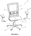
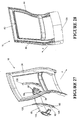
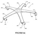
- Figure 1 illustrates an office chair 10 including a main assembly having a seat portion 14 and a back portion 16.
- the seat portion 14 and the back portion 16 are supported above the ground by a supporting frame including a wheeled base 18 and a central support column 20.
- the central support column 20 houses a pneumatic spring (not shown) for height adjustment of the seat portion 14 in conventional fashion.
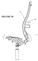
- the pneumatic spring is connected to the main transom 22 of the chair which is illustrated in Figure 4.
- the main transom 22 extends transversely across the chair and is connected to the pneumatic spring by way of central spring connection ring 23.
- Figure 1 also illustrates two detachable arm assemblies 24.
- the arm assemblies 24 each include an upper armrest 26 which is padded for user comfort.
- Each arm assembly 24 includes an upright support structure 28.
- the armrest 26 is mounted to the upper end of the upright support structure 28.
- the lower end of the upright support structure has an elongate attachment portion 30 extending inwardly therefrom at a downwardly inclined angle relative to the upright.support structure 28.
- the elongate attachment portion 30 is releasably engaged within one end of the main transom 22.
- the manner of attachment is not significant to the present invention.
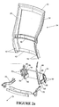
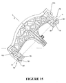
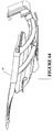
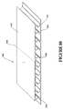
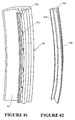
- the back portion 16 is defined by a peripheral frame 34 which is approximately rectangular in shape, as shown in Figure 2.
- the peripheral frame 34 has a mesh fabric stretched over it in a manner described more fully in connection with Figures 81 to 83.
- a lumbar support mechanism 36 is provided within the opening defined by the rectangular peripheral frame 34.
- FIG 2 illustrates more clearly the form of the peripheral frame 34.
- the peripheral frame 34 is constructed of a flexible plastics material such as injection moulded reinforced polyester.
- the peripheral frame 34 is of integral construction and comprises two upright members 38, a top beam 40 and a bottom beam 42.
- the upright members 38 are bowed with a gentle serpentine curve sweeping forwardly in the upward direction and then rearwardly beyond the lumbar region. This is a shape which is comfortable to the chair occupant.
- the upright members 38 include channels 44 which are open in the direction facing rearwardly as shown in Figure 28.
- the upright members 38 are also joined by an intermediate back beam 46.
- the back beam 46 supports the lumbar support mechanism 36.
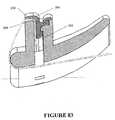
- the back attach casting 48 is an integrally cast component as shown in Figure 2b.
- the back attach casting 48 includes two pairs of sprigs 50 which engage with aligned apertures 52 provided at the bottom of the upright members 38. This enables the lower region of the peripheral frame 34 to be securely fixed to the back attach casting 48.
- An additional snap fitting (not shown) may be provided:
- the back attach casting 48 also includes 2 pairs of opposed walls 54 on opposite sides (more clearly seen in Figure 27). Each pair of spaced walls 54 defines a forwardly extending channel 64 in which a spring carrier 60 is received. Each pair of opposed walls 54 includes aligned slots 56.
- the spring carrier 60 (to be described more fully in connection with Figure 27) has pins 62 on opposite sides to engage with the aligned slots 56.
- the back attach casting 48 includes two forwardly extending hollow projections 66.
- the hollow projections 66 each define a socket 68.
- Two back extension arms 70 are welded within respective sockets 68 of the hollow projections 66.
- each back extension arm 70 includes a forward nose portion 72 and a chin portion 74.
- An extension arm aperture 75 extends through the back extension arm 70 in a position rearwardly of the nose portion 72 and the chin portion 74.
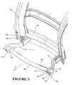
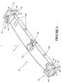
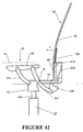
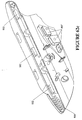
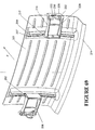
- FIG. 4 illustrates the main transom 22 which extends transversely across the chair as already explained.
- the main transom 22 is supported on a pneumatic spring at central spring support ring 23.
- the main transom is a beam-like construction of diecast aluminium with pivot features 76 formed at opposite ends. At each end, the pivot features comprise opposed supporting webs 78.
- the opposed supporting web 78 have rear aligned apertures 80.
- the extension arm aperture 75 of one of the back extension arms is aligned with the rear aligned apertures 80 on one side of the main transom to receive a main pivot pin (not shown) therethrough.
- the other back extension arm 70 is pivotally attached to the main transom 22 on the other side.
- Each back extension arm is pivotable about the associated main pivot pin and the recline axis R of the back portion 16 is thereby defined.
- a nose portion 72 is defined forwardly of each back extension arm 70.
- the nose portion 72 has two bosses 84 extending sideways from the flanks of the nose portion 72.
- the bosses 84 are receivable within facing slots 86 in the opposed supporting webs 78.
- Each of the facing slots 86 has a base formed therein.
- the bosses 84 move within respective ones of the facing slots 86.
- the bosses 84 will bottom out at the bases of the slots 86 thereby defining forward limits. This is referred to as the "forward active position"of the back portion 16.
- each back extension arm 70 includes a first abutment surface 88 for engagement with a second abutment surface 90 (see Figure 9) provided as part of the rear wall of the main transom 22.
- first abutment surface 88 engages with the second abutment surface 90
- the rearward recline limit of the back portion 16 of the chair will be thereby defined. It would not be possible for the chair portion 16 to recline back any further once the two abutment surfaces come into engagement although flexing of the peripheral frame is still possible in this position.
- One end of the main transom 22 illustrating the pivot features 76 in greater detail can be seen in Figure 6.
- Recline Biasing Device (not forming part of the present invention).
- the inner flanks of the chin portions 74 of both back extension arms 70 include facing aligned slots 92, the left one of which can be seen in the Figure.
- a first recline spring 94 in the form of an elongate bar or leaf spring has each end received in a respective one of the facing slots 92.
- the main transom 22 has a reaction surface 98 against which the first spring 94 engages.
- the reaction surface 98 is centrally disposed and has a depth corresponding to the depth of the first spring 94.
- the reaction surface 98 forms part of an integrally formed projection extending rearwardly from the main transom 22.
- the first recline spring 94 engages against the reaction surface 98, thereby biasing the back portion 16 against reclining action.
- a second recline spring 96 also has one end received in one of the facing slots 92. However, the second recline spring 96 is somewhat shorter than the first recline spring 94 so the second end of the second recline spring 96 is not received within the other facing slot 92 (see Figure 10). As shown, the second spring is also in the form of a elongate spring bar or leaf spring. The second spring 96 lays behind the first spring 94, against the first spring 94, for at least half the length of the first spring 94. An adjustable clamp 100 (see Figure 7) is provided to clamp the free end of the second spring 96 against the first spring 94 and thus alter the curvature of the second spring 96 and thereby alter its spring resistance.
- the second spring 96 is disposed such that increased clamping against the first spring will act to increase its resistance to bending.
- the net force biasing the back portion against recline will thereby be the sum of the spring force provided by the first spring 94 and the spring force provided by the second spring 96.
- the first spring 94 has a factory set spring rate.
- the second spring 96 is selected to have a high spring rate, greater than the spring rate of the first spring 94. Thereby, a small adjustment of the clamping between the first spring 94 and the second spring 96 will bring about an appreciable change in the spring resistance of the second spring 96.
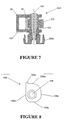
- the adjustable clamp 100 is illustrated in Figure 7.
- the adjustable clamp 100 includes a U-shaped bracket 101 which extends around the two recline springs 94, 96.
- a cam 102 is mounted on axle 103 extending between the two legs of the U-shaped bracket 101.
- the axle 103 is journaled for rotation about an axis 104.
- the cam 102 includes four cam surface portions 105a, 105b, 105c and 105d as shown in Figure 8.
- the cam surface portions are substantially flat as indicated and each is spaced a different amount from the cam axis 104. The spacing decreases in the clockwise direction around the cam 102 from 105a through to 105d.
- the cam 102 bears against the free end of the second spring 96.
- the chair occupant can adjust the position of the cam to determine which of the cam surface portions 105a-105d will bear against the free end of the second spring 96.
- a progressively higher clamping force and hence higher resultant spring rate of the second spring can be obtained as the occupant rotates the cam 102 through to the maximum setting at 105a.
- an extension to the cam 102 is provided to prevent over rotation of the cam 102.
- a knob 103b is provided for user adjustment of the cam 102.
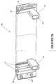
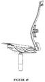
- FIG 5 illustrates a recline lock which may be operated selectively by the user to prevent the back portion from reclining.
- the main transom 22 includes four rearwardly extending projections 106.
- the recline lock comprises an elongate lock bar 107 which has four slots 108 arranged therein, with the lengthwise direction of the slots 108 arranged in the lengthwise direction of the bar 107.
- the slots 108 each receive one of the rearwardly extending projections 106 as shown in Figure 5.
- the elongate lock bar 107 is slidable from side to side between a recline lock position and a recline operative position.
- the projections 106 received in the slots 108 thereby define the limit of travel of the elongate lock bar 107.
- the elongate lock bar 107 is biased toward the recline operative position by spring 109.
- the elongate lock bar 107 can be seen in Figure 10 in which the main transom 22 has been removed for greater clarity.
- the lock bar 107 has at each end a rearwardly extending lock bit 110.
- the lock bits 110 thereby move from side to side with the movement of the elongate lock bar 107.
- Each lock bit is moveable into a recline lock position whereby the lock bit 110 is engaged against a recline locking face 112 provided on the chin portion 74 of the back extension arms.
- the left-hand side lock bit 110 (shown on the right in the figure) moves from a recline operative position in which is it clear of the associated back extension arm 70, to a position in which it is engaged against the recline lock face 112 on the associated arm 70.
- the arrangement in connection with the right hand lock bit 110 (shown in the left in the figure) is slightly different. It can be seen that the associated extension arm 70 has the recline lock face 112. Additionally, the associated arm 70 is provided with the rebate 114 adjacent to the recline lock face 112. In the recline lock position, the lock bit 110 is engaged with the recline lock face 112 whereas in the recline operative position, the left lock bit 110 is received within the rebate 114. When the lock bit is received within the rebate 114, the associated back extension arm 70 can still pivot freely about the recline axis.
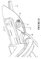
- Figure 12 illustrates the lock bar control lever 116 which is mounted underneath the seat portion 14 in a forward position on the left hand side.
- the lever 116 is connected to cable actuator 118.
- the cable actuator 118 is connected to a control cable 120 which operates in the conventional fashion.
- the control cable 120 controls the position of the elongate lock bar 107 (see Figure 5).
- the cable actuator 118 is rotatable by operation of the control lever 116.
- the cable actuator 118 has a dimple provided on the forward edge which is engageable with the two position detent 122.
- the dimple 121 is locatable in either of two positions, the first of which corresponds to the recline lock position of the elongate lock bar 107, and the second of which corresponds to the recline operative position of the elongate lock bar 107. The user thus selects whether the recline lock is on or off according to the position of the lock bar control lever 116.
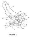
- Figure 13 illustrates a modified form of one of the back extension arms 70'.
- the back extension arm 70' has a forked forward end forming a right fork 93c and a left fork 93d with an extension arm aperture 75' extending transversely through both forks.
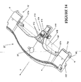
- Two such back extension arms 70' are rotatably mounted about the recline axis R to the main transom 22' as shown in its modified form in Figure 14.
- the main transom 22' has pivot features 76' formed at opposite ends. At each end, the pivot features include a pair of spaced supporting webs in the form of inner and outer lobes 78' through which extends aligned apertures 80'.
- the alignment of the apertures 80' defines the recline axis R about which the back extension arms 70' pivot.
- a pin inserted through each pair of apertures 80' mounts each back extension arm 70' to the main transom 22'.
- the inner lobe 78' is inserted between the forks 93c, 93d of the associated back extension arm 70'.
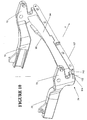
- FIG 13 illustrates an alternative form of recline lock mechanism. It can been seen that the forward end of the back extension arm 70' is provided with a substantially flat upper abutment surface 93 comprised of a forward surface portion 93a, forward of the recline axis R and a rearward surface portion 93b, rearward of the recline axis R.
- the abutment surface 93 lies underneath an upper portion of the main transom (see Figure 16).
- the rearward surface portion 93b thus defines the forward recline limit which will be reached when the back extension arm 70' pivots so that the rearward surface portion 93b abuts the underside of the main transom 22'.
- the rearward recline limit will be defined when arm 70' rotates such that the forward surface portion 93a abuts the underside of the main transom 22'.
- the engagement between the forward surface portion 93a and the underside of the main transom 22' thus defines the rearward recline limit.
- a recline lock may be operated selectively by the user to prevent the back portion from reclining or to set an intermediate recline limit.
- the forward end of the back extension arm 70' is formed with a transversely extending slide 70a in which is slidably mounted a key 107a.
- the slide 70a has a substantially closed inner end 70c which has an V-shaped slot 70b.
- a spring (not shown) is received in the slide 70a between the key 107a and the closed end 70c to bias the key 107a outwardly away from the closed end 70c.
- the key 107a is slidable within the slide against the action of the spring by means of a cable connected to the inner end of the key 107a which is adjustable in the same manner described in Figure 12 (see also Figure 62).
- the key has first and second abutment surfaces 107b and 107c.
- first abutment surface 107b When the key 107a is in the innermost position (relative to the chair as a whole) illustrated in Figure 13, then the first abutment surface 107b does not interfere with the reclining action of the back extension arm 70' as already described. This is referred to as the hyper-recline position, allowing recline of 15°.
- the forward end of the back extension arm 70' is forked as shown to define right and left forks 93c, 93d.
- the key 107a is moved into a position whereby the first abutment surface 107b is aligned with the right fork 93c then the first abutment surface 107b will interfere with the recline action of the back extension arm because the first abutment surface 107b will hit the underside of the main transom 22' before the forward surface portion 93a normally would. This allows recline of 12°.
- FIG 14 illustrates the manner by which the keys 107a may be moved in unison.
- a cable 120' is connected between a cable actuator 118' (see Figure 62) and cable amplification mechanism 410 mounted on the rearward extension 22a of the main transom 22.
- the cable amplification mechanism 410 includes a pair of pivotally mounted amplifiers 412 which have intermeshed teeth for synchronous operation.
- One of the amplifiers 412 has a rearward amplifier extension 414 to which the end of the cable 120' is connected.
- the cable 120' passes through cable guide 416.
- the intermeshing amplifiers 412 will be driven to rotate so that their remote ends move towards each other.
- the remote ends of the amplifiers 412 are connected by respective cables to respective ones of the keys 107a. This cable connection is depicted by phantom line 418.
- the side of the back extension arm 70' includes two bores 92a and 92b which face like bores on the facing side of the other back extension arm (not shown).
- Bore 92a is cylindrical and bore 92b is rectangular as shown.
- first and second recline springs 95, 97 extend between the facing bores.
- the second recline spring 97 is in the form of an elongate bar, the ends of which are received in facing bores 92b of the two back extension arms 70'.
- the main transom 22' includes a rearward extension 22a having a bearing block 98' seated in a complementary recess on the upper surface of the rearward extension 22a.
- the bearing block 98' defines a complementary recess to receive a central portion of the second recline spring 97.
- the second recline spring 97 is caused to bend downwardly at its ends while the intermediate portion is held fixed by being seated in the bearing block 98' on the main transom 22'.
- the second recline spring 97 thus resists rearward recline and biases the back extension arms 70' toward the forward recline limit.
- the second recline spring 97 is preloaded at the forward recline limit by being slightly bent. This is achieved by having the centres of the bores 92b slightly below the centre of the spring in the recess of the bearing block 98'.
- the first recline spring 95 operates on a similar principle but is somewhat more complex.
- the first recline spring 95 is illustrated in greater detail in Figure 17 and comprises a spring portion 95a, in the form of a flat bar.
- the outer ends of the first recline spring 95 are fitted with cylindrical bosses 99a to be received in the facing cylindrical bores 92a provided in the back extension arms 70'.
- a central cylindrical boss 99b is fitted onto the bar 95a.
- the central boss 99b is slotted to allow the bar 95a to pass through.
- the central cylindrical boss 99b is seated in a semi-cylindrical recess provided in the bearing block 98' on the main transom 22'.
- the bearing block 98' may be provided with upstands at its sides to locate the boss 99b relative to its seat in the bearing.
- the flat bar spring portion 95a provides resistance to recline through its inherent resistance to bending about a bending axis arranged transversely to the length of the spring 95. It will be appreciated that with the configuration of the ends of the first spring 95 and the central cylindrical boss 99b bearing against the main transom 22', the bending axis will be defined which extends generally transverse to the longitudinal axis of the spring 95. The arrangement is such that no pre-load is applied to flat spring portion 95a in the forward active position. The central recess in the bearing block 98' and the cylindrical bores 92a are thus aligned for this reason.
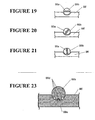
- the first recline spring 95 is adjustable to change the spring rate. This is achieved by rotating the first spring 95 about the longitudinal axis of the spring through the use of paddle 99c which is fixed onto the spring bar portion 95a. It can be seen from the cross-sectional views shown in Figures 19 to 21 that the spring portion 95a has a thickness and a width dimension, the width dimension being greater than the thickness dimension. In Figure 19, the spring 95 is oriented so that the width dimension is arranged substantially parallel to the bending axis. This represents the 'easy' spring position. In Figure 20, the thickness dimension is arranged diagonally to the transverse bending axis. Such an arrangement will present a greater resistance to bending about the transverse axis. This accordingly represents the "medium" spring position.
- the width dimension is arranged transversely to the bending axis. Such an arrangement presents the greatest resistance to bending and is thus deemed the "hard” position for the first recline spring 95.
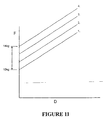
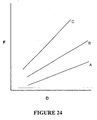
- the first recline spring 95 is thus adjustable through 90° to provide three adoptable spring positions at each of which the spring exhibits a different spring rate. This is visually depicted in Figure 24 which illustrates graphically the change in net spring force over distance as the spring is adjusted between easy (A), medium (B) and hard (C).
- Figure 18 illustrates the first spring 95 in the easy position
- Figure 22 illustrates the first spring 95 in the hard position.
- locators are provided in the form of grooves 99d provided in the cylindrical boss 99b.
- a complementary rib 99e is disposed in the semi-cylindrical recess of the bearing block 98a. The rib 99e can engage with any one of the complementary grooves 99d to accordingly locate the first spring 95 in that position. It may be necessary to remove most of the loading on the first spring 95 in order to change the spring position. Accordingly, it may be necessary to bring the back portion to the forward active position to achieve this.
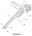
- Figure 25 illustrates in greater detail the form of the cylindrical bosses 99a on the first spring 95.
- the end of each boss is cut away to define a semi-circular rebate 99d thereby defining a diametrical abutment face 99e.
- the end of bore 92a is provided with a projecting quadrant 92c. With the boss 99a assembled in the bore 92a, the quadrant 92c projects into the semi-circular rebate 99d.
- the spring 95 is rotatable through 90° between a first rotatable limit where one face of the quadrant 92c abuts against one half of the diametrical abutment face 99e and a second rotatable limit where the other face of the quadrant 92c abuts against the other half of the diametrical abutment face 99e.
- the interaction between the quadrant 92c and the diametrical abutment face 99e limits the rotation of the spring 95 to 90°.
- the two bores 92a and 92b are shown as formed directly in the sides of the back extension arms 70. It is also envisaged that a plastic insert could be fitted into the side of the arm 70 with the bores 92a and 92b formed in the insert.
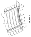
- Figure 27 illustrates a further exploded view of parts assembled with the peripheral frame 34.
- a back attach casting 48 is fixed to the back of the peripheral frame 34.
- the back attach casting 48 has two upright channels 64 arranged at either end, each defined by opposed walls 54.
- the opposed walls 54 have aligned slots 56 arranged therein for receipt of pins 62 provided on a spring carrier 60.
- the specific form of the spring carrier 60 is illustrated more clearly in Figure 29.
- the spring carrier 60 is in the form of an elongate member which is approximately square or rectangular in cross section with the pins 62 being arranged on opposite sides.
- One end of the member is provided with a rebate 124.
- the other end of the spring carrier is forked for pivotal connection with another linkage as will subsequently be explained.
- the forked end has aligned apertures 126.
- the rebate 124 has spaced threaded bores 130 provided therein.
- a leaf spring 128 has a lower end 131 shaped to be received within the rebate 124.
- the lower end 131 has two spaced apertures 133 provided therein. These apertures 133 align with the threaded bores 130 provided on the spring carrier so that the leaf spring 128 may be securely fastened to the spring carrier 60. From the lower end 131 in the upwards direction, the leaf spring 128 gradually increases in width with a slight tapering in thickness, although overall the leaf spring 128 is of generally elongate configuration as shown.
- the leaf spring 128 is constructed from high tensile spring steel.
- Figure 28 illustrates the assembled combination whereby each of the leaf springs lie against the back of the peripheral frame 34 in a respective channel 44.
- the peripheral frame 34 has a degree of flexibility.
- the leaf spring 128 will be caused to act against the lower portion of the peripheral frame thereby increasing its stiffness against rearward flexing.
- the two spring carriers act in unison in a manner which will be described in connection with Figures 30 to 34.
- the stiffness of the lower portion of the peripheral frame 34 can thereby be adjusted by adjustment of the position of the spring carrier 60.
- the channels 64 in which each of the spring carriers 60 are received are closed rearwardly by a rear wall 135 of the back attach casting 48.
- the rear wall 135 defines a stop against which the forked ends 125 of the spring carriers engage, thereby defining the maximum rotation of the spring carrier 60 and thus the maximum stiffness which can be imparted by the leaf spring 128 to the peripheral frame 34.
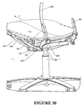
- Figure 30 illustrates the main elements of the recline mechanism.
- the back attach casting 48 has been removed for clarity, together with the right back extension arm 70.
- the left back extension arm 70 is shown in position pivotally connected to the main transom 22.
- the forked end 125 of each spring carrier 60 is connected to a push link 139.
- the lower portion of the peripheral frame 34 has an access opening 143 to enable the push link 139 to engage with the forked end 125 of the spring carrier 60 disposed within the assembled back attach casting 48.
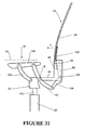
- the forward end of the push link 139 is connected to a drive link 141 (see Figure 30) which is one element of a four bar linkage which will be understood more fully from a consideration of the schematic illustration of Figure 31.
- FIG 31 illustrates only one four bar linkage and it will be apparent to the reader that two such four bar linkages are provided, one on each side of the chair 10.
- the drive link 141 extends at an inclined upwards angle from its connection with push link 139.
- the drive link 141 is curved along its length with the centre of the curve being disposed rearwardly and upwardly.
- the drive link 141 is mainly of rectangular cross section.
- the drive link 141 is pivotally connected at an intermediate location along its length to the main transom 22 for pivoting motion about the recline axis R. Specifically, the drive link 141 is pivotally connected to lie adjacent to the outer one of the opposed supporting webs 78 of the main transom 22. A common pivot pin (not shown) interconnects both of the opposed supporting webs 78, the back attach arm 70 through aperture 75, and the drive link 141.
- the main transom 22 forms another element of the four bar linkage. As has already been explained, the main transom 22 is centrally mounted to the supporting frame at the top of the central support column 20 which incorporates a height adjustable pneumatic spring 145. The height adjustment 145 is selectively operable by the chair occupant. However, the main transom 22 is normally stationary relative to the supporting frame.
- the seat portion 14 is slidably mounted to a seat guide 149 in a manner which will be described more fully in connection with Figures 55 to 60.
- the seat guide 149 thereby forms another element of the four bar linkage.
- the upper end of the drive link 141 is pivotally connected to the seat guide 149.
- Another link in the form of a front support link 151 interconnects the seat guide 149 and the main transom 22.
- the front support link 151 is of generally rectangular cross section and, like the drive link 141 is curved along its length with the centre of curvature disposed upwardly and rearwardly.
- both ends of the drive link 141 are forked.
- the lower end is forked to accommodate the lower end of the push link 139.
- the upper end of the drive link 141 is also forked.
- the seat guide also has a dependent lobe 155 as shown in Figure 32.
- the forked upper ends of drive link 141 are disposed on each side of the lobe 155 and the inner fork is pivotally connected between the lobe 155 and the side wall of the seat guide 149.
- the outer fork is fanned in shape for aesthetic reasons and the pivotal connection does not extend therethrough.
- the upper end of the front support link 141 is also forked with the inner fork being pivotally connected between a seat guide 149 and another lobe 157 (see Figure 32), with the outer fork being of fanned shape.
- the lower end of the front support link 151 is pivotally connected on the outside of the outer one of the opposed supporting webs 78 (see Figure 4) by means of a pin (not shown) extending through aligned forward apertures 153 on the forward end of the opposed supporting webs 78. It will be appreciated that the connection of the lower end of the drive link 141 and the front support link 151 are blind connections as shown for aesthetic reasons.
- the occupant's weight will be taken up by a spring tension in leaf spring 128 as it flexes against the back of the peripheral frame 34. This has the effect of stiffening the back portion against rearward flexing. It will be appreciated that the tension imparted to leaf spring 128 will depend upon the weight of the user W applied to the seat portion 14. The greater the weight W, the greater the tension taken up by the leaf spring 128 and thus the greater the degree of stiffness imparted to the leaf spring 128 to resist rearward flexing of the peripheral frame 34. Accordingly, the stiffness of the peripheral frame 34 will be adjusted according to the weight W of the chair occupant.
- Figure 33 illustrates the downward motion of the seat guide 149 as the user applies weight W. When the occupant alights from the chair, the seat portion 14 will move upwardly as indicated by arrow U in Figure 34.
- the gentle serpentine shape of the peripheral frame 34 is designed to correspond with the shape of the occupant's spine for the comfort of the occupant.
- the ergonomics of the chair are further enhanced because this enables the occupant to exercise his spine.
- the general health of a person's spine is enhanced by movement.
- the stiffness of the back portion in rearward flexing is adjusted according to the occupant's weight. Therefore, within a certain range, the ease of rearward flexing will correlate to the weight of the occupant. Therefore, a light person will be able to obtain full benefit from the rearward flexing action by applying a light force against the peripheral frame.
- the chair is designed so that the occupant will be able to obtain deflection through flexing in the range of 80 mm to 120 mm.
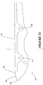
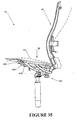
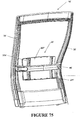
- Figure 35 illustrates the reclining action of the chair 10.
- the seat portion When the user applies their weight to the seat portion 14, the seat portion will move downwardly as already described and adopt a position just above the seat guide 149 as illustrated by the solid lines.
- the leaf spring 128 takes up a corresponding amount of spring tension whereupon the spring carrier 60 and the push link 139 will adopt a more or less fixed position relative to the back attach casting 48. Therefore, as the user leans against the back portion 16, the back attach casting 48, spring carrier 60, push link 139 act in unison driving the drive arm 141 to rotate in a clockwise direction through push link 139.
- the arrangement of the four bar linkage is such that the seat guide 149 will adopt a position with a net increase in height and with an increase in rearward tilt angle compared to the occupied position of the seat guide 149 before recline. In practice, there may be some slight shifting between the leaf spring 128, the spring carrier 60 and the push link 139.
- the occupant's weight W will be counteracting the recline action, together with the bias applied by the first and second recline springs 94, 96.
- the weight of the occupant W will therefore be a variable factor in the ease with which the back portion 16 reclines. If the adjustable second recline spring 96 is set at a constant level then a heavier person will encounter a greater resistance to reclining action than a lighter person. This establishes an automatic correlation between the weight of the person and the resistance to the reclining action. For a large proportion of people who fit within physical norms this automatic adjustment may be sufficient. However, people come in all different shapes and sizes and therefore additional adjustment is required through the use of the clamping adjustment as explained previously. For example, a very tall, light person may obtain leverage through their height which makes the back portion 16 fall back too easily against their low weight W.
- the net increase in height also has the advantage of raising the occupant during recline so that the eye level of the chair occupant can be maintained even though he is undergoing a reclining action.
- the peripheral frame will still be able to flex under additional force applied by the chair occupant.
- the peripheral frame will be capable of undergoing deflection in the range of 80 mm to 120 mm.
- the weight of the user against the back portion will bring about a deflection of up to 20 mm. Therefore, once the recline limit is reached, the occupant still has further deflection available through flexing of the peripheral frame in the range of 60 to 100 mm.
- the seat portion 14 is only supported by the seat guide 149 at a rear portion thereof with a forward portion being unsupported.
- a transition point 161 is disposed behind the forward edge 160 of the seat guide 149.
- the transition point 161 marks the boundary between the planar upper surface 178 of the seat guide 149 and a forwardly inclined lead surface 285.
- the seat portion 149 is foldable transversely at this location.
- the transition point 161 hence defines the division between the rearward portion and the forward portion of the seat portion 14. Since the seat portion 14 is slidable forwardly and rearwardly for seat depth adjustment as will be explained in connection with Figures 55 to 60, the division between rearward portion and forward portion of the seat will vary as a function of seat depth.
- Figure 35 illustrates the changing curvature of the back portion 16 and seat portion 14 in recline.
- the solid lines indicate the forward active position in the occupied configuration.
- the dotted lines illustrate the reclined position.
- the seat guide 149 attains a net increase in height and an increased rearward tilt. This effectively cups the occupant's derrière, negating any inclination to slide forwardly during the recline action.
- the seat portion 14 is also flexible and since the occupant's derrière is undergoing a net increase in height together with increased rearward tilt, a greater amount of weight from the occupant's legs will be brought to bear against the forward portion of the seat portion 14. Accordingly, the seat portion 14, will be allowed to fold transversely at the transition point 161 on the seat guide 149.
- transition point 161 approximately corresponds to the gluteal fold of the occupant's derriere. Therefore, during recline, the occupant's derrière will be cupped between the rear portion of the seat portion 14 and a lower region of the back portion 16 while the forward portion of the seat drops forwardly under the weight of the occupant's legs. Locating the transverse fold at the gluteal fold of the occupant ensures that undesirable pressure will not be brought to bear against the back of the occupant's legs.
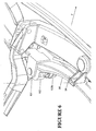
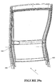
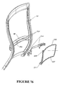
- Figure 36 illustrates in exploded fashion a modified form of the back portion 16'.
- the back portion 16' includes a flexible peripheral frame 34' which is connected to a back attached casting 48'.
- the spring carriers have been obviated and instead there are two unitary leaf springs 128' which bear against the back of the peripheral frame 34'. Additionally, two supplementary springs 450 are also provided, the function of which will be explained.
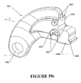
- Figure 39c illustrates the modified form of the push link 139'.
- the push link is arcuate in configuration.
- the push link has an aperture 452 to which it can be pivotally connected to drive link 141' (see Figure 41a and 41b).
- a stepped region 454 having a first abutment face 456 and a second abutment face 458.
- a first pair of gliders 460 Forwardly of the stepped region 454 is a first pair of gliders 460.
- Each glider of the pair 460 is disposed on opposite side faces of the push link 139'.
- a second pair of gliders 462 Disposed directly below the first pair of gliders 460 is a second pair of gliders 462 disposed on opposite side faces of the push link 139'.
- the back attach casting 48' incorporates two pairs of sprigs 50' which engage with aligned apertures (not shown) in the peripheral frame 34' for assembly purposes.
- spaced walls 54' define a forwardly extending channel 64' in which the leaf spring 128' is housed in a manner which will be explained.
- the forwardly extending channel 64' includes two forwardly extending tracks 464 on opposite sides of the channel 64'.
- the tracks 464 each comprise a substantially horizontal ledge 466 which terminates in a downwardly extending flange 468 in the assembled configuration of the push link 139' and the back attach casting 48', the first pair of gliders 460 are disposed to glide along the top surface of the associated ledges 466 whereas the second pair of gliders 462 passes underneath the bottom surface of the associated ledges 466.
- each of the second pair of gliders 462 has a flat abutment surface 470 which abuts against the inside of the downwardly extending flange 468. This defines the forward limit in the sliding movement of the push link 139' relative to the tracks 464.
- Figure 39d illustrates the assembled configuration of the push link 139', the back attach casting 48', the leaf spring 128', the supplementary spring 450 and the peripheral frame 34'.
- the supplementary spring 450 and the leaf spring 128' are arranged such that the first abutment face 456 will come into contact with the supplementary spring 450 prior to the second abutment face 458 coming into contact with the leaf spring 128'.
- the supplementary spring 450 does not have a bearing on the stiffness of the peripheral frame 34'. Therefore, up to a predetermined threshold of the users weight W, there will be no stiffening effect on the peripheral frame 34'.
- the predetermined threshold which is about 50 kg
- the second abutment face 458 of the push link 139' will come into contact with the leaf spring 128'.
- the leaf spring 128' has an initial slightly bent configuration as illustrated in Figure 39d.
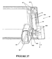
- the leaf spring 128' bears against spring seat 474 disposed at the top of the forwardly extending channel 64' as can be seen in Figure 37.
- the spring seat 474 is concave from side to side to position the leaf spring 128' while being convex from top to bottom as illustrated in cross section in Figure 39d.
- the spring seat 474 defines a point about which the leaf spring 128 bends as the push link 139' moves rearwardly in its tracks 464.
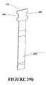
- Figure 39b illustrates in greater detail the form of the supplementary spring 450.
- the supplementary spring is in the form of a leaf spring having an enlarged head formation 478 which includes two bights 480 on opposite edges.
- the bites 480 cooperate with facing complementary locating blocks 482 disposed on opposite sides of the forwardly extending channel 64.
- Figure 41a illustrates certain components of the recline mechanism although the peripheral frame 34' and the back attach casting 48' have been removed for clarity.
- the drive link 141' is pivotally mounted to the main transom 22' at an intermediate location.
- the opposite end of the drive link 141' to that which the push link 139' is attached is pivotally connected with the seat guide 149'.
- the front support link 151' is connected between the seat guide 149' and the main transom 22'.
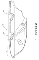
- the drive link 141' and the front support link 151' are also curved about one or more upright axes as well as being curved about a horizontal transverse axis as described with the first example. This renders a more complex shape for the seat guide 149' as depicted in Figure 43.
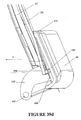
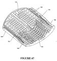
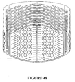
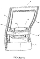
- FIG 46 is a perspective view of a preferred form of the seat portion 14 which is appropriate for use with either embodiment of the chair.
- the seat portion 14 is in the form of a flexible plastic panel, whose flexibility is enhanced by the arrangement of slots as indicated.
- the plastic panel may be injection moulded plastic such as TPR.
- Figure 50 is a longitudinal section through the middle of the seat panel 14 illustrating the general curved configuration with a rolled over edge. The edge drops by an amount of dimension A.
- Figure 51 illustrates the side edge of the seat panel 14. The side edge is flatter than the middle section. Additionally, the forward edge dips down a dimension B, where B is larger than A.
- Figure 52 illustrates a transverse sectional view at about 150 mm from the rear of the seat whereas the view Figure 53 depicts the transverse cross sectional view 120 mm from the front edge.
- FIGS. 50-54 are merely indicative of the moulded shape of the seat panel 14.
- the seat panel is also flexible to accommodate the occupant and to respond to movement of the occupant.
- the arrangement of slots in the seat panel 14 as shown in Figure 46 is designed to enhance the flexibility of the seat panel 14.
- the arrangement of slots in the forward half of the panel is designed to facilitate folding along the transverse fold.
- the slots are arranged in a series of spaced sinuous lines 163 extending transversely across the seat portion 14 with the central part being shaped convex forwardly with the outer parts being shaped concave forwardly.
- the lines of slots 163 are discontinuous.
- the seat portion 14 is dished at least in a rearward part.
- the series of spaced sinuous lines 163 enables the seat panel 14 to fold transversely, even though the rear part is dished.
- the slotted pattern 164 is such as to extend diagonally across the corners following the curvature of the transverse sinuous lines 163. In this way, if the user moves a leg to one of the forward corners then the diagonal arrangement of the slots 164 will enable the forward corner to fold under the weight of the occupant's leg.
- the slots are arranged in a pattern to accommodate the ischial protuberosities of the occupant.
- the slotted pattern provides two spaced, approximately rectangular zones 162 whose locations correspond to the ischial protuberosities of the occupant (assuming the occupant is properly seated with an appropriate seat depth adjustment).
- the two zones 162 interrupt the transverse slot pattern.
- Each zone is comprised of slots arranged in a series of longitudinally extending, transversely spaced sinuous lines.
- the lines of slots are discontinuous.
- the longitudinal arrangement of slots in each zone 162 enables the remaining material between the longitudinal lines of slots to spread apart thereby creating pockets, one for each ischial protuberosity of the seat occupant.
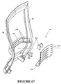
- Figure 47 illustrates longitudinal stiffening webs 165 provided on the underside of seat panel 14. There are five stiffening webs, two disposed along the opposite side edges. A further two are disposed on each side at 60 mm from the corresponding side edge. Another is centrally disposed.
- the longitudinal stiffening webs are constant in height from the back edge of the seat portion until the taper start point 164 from where they progressively reduce in height until a taper finish point 166. (The central web however terminates early)
- the seat portion 14 accommodates a depth adjustment as will be explained in connection with Figures 55 to 60.
- the seat portion folds transversely about the transition point 161 on the seat guide 149.
- the depth of the stiffening ribs in the region at the transition point 161 is shallow thereby offering little resistance to flexing. Generally, this suits a small, light weight person. However, for a larger person, the seat panel will be disposed further forwardly in relation to the seat guide 149. The depth of the stiffening ribs in the location of the transition point 161 will be deeper, thereby offering increased resistance to bending. This suits a larger, heavier person.
- the start taper point 164 is at a position which corresponds to the transition point 161 when the seat is at its full forward position to suit a large person.
- the taper finish point 166 is at a position corresponding to the transition point on the seat guide 149 with the seat in the rear most position to suit a small person.
- the taper start point 164 and the taper finish point 161 define a transition zone therebetween.
- the transverse fold may be disposed at a range of positions within the transition zone, dependent on seat depth adjustment.
- the pattern of transversely extending sinuous lines of slots extends for at least the transition zone.
- Figure 47 also illustrates transverse stiffening webs 168.
- the stiffening webs 168 follow the pattern of the transversely arranged sinuous slots 163.
- the seat panel is moulded in a dished shape.
- the transverse stiffening webs 168 help to retain the shape of the front part without inhibiting the transverse folding action under the weight of the user.
- a back web is provided along the back of the seat panel 14 on the underside as shown in Figure 47.
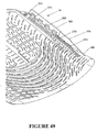
- Figure 49 illustrates in greater detail the arrangement of features along one side edge.
- a series of spacer blocks 270 extending in a line between the taper start point 164 and the taper finish point 166.
- a wedge-shaped gap 272 widening towards the top.
- the seat panel 14 sits atop a seat carriage 167.
- a rear part of the seat panel 14 is secured atop the seat carriage 167 so that forwardly of the seat carriage 167 there will be a gap between the seat guide 149 and the seat panel 14.
- the spacer blocks 270 extend into this gap. As the seat panel 14 folds, the spacer blocks 270 bear against the top of the seat guide 149. It can be seen that the spacer blocks 270 also taper off in height as shown. Furthermore, the spacer blocks 270 will define the maximum curvature of the seat panel along the transverse fold since once the side walls of the wedge- shaped gaps 272 engaged with each other, further curvature will be prevented.
- a guard also extends alongside the spacer blocks 270 to provide a barrier against the user's fingers being trapped.
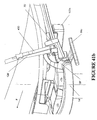
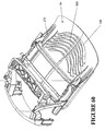
- FIG 55 illustrates the main elements of the seat depth adjustment mechanism.
- the seat guide 149 is one of the elements of the four bar linkage discussed previously.
- the two seat guides 149 provide a guide for a slidable seat carriage 167.
- a rear part of the seat panel 14 illustrated in Figures 47-54 is attached to the carriage 167.
- the rear half only of the seat panel 14 is attached to the seat carriage 167.
- the seat panel 14 may be moved forwardly and rearwardly by the sliding action of the seat carriage 167 on the seat guide 149.
- a longitudinally extending rib 274 engages within a channel 278 (see Figure 55) of the seat carriage 167 and the tab 276 is a snap fit connection within the recess 280 located rearwardly on the seat carriage 167.
- four spaced retention tabs 282 engage against soffit 284 of the carriage 167. The retention tabs 282 retain the seat panel 14 engaged with the seat carriage 167 while the longitudinal rib is the main load bearing part.
- Figure 55 also illustrates the controls for the height adjustable pneumatic spring 145.
- a height adjustment control lever 169 is mounted for pivotal motion on the outside of the right hand seat guide 149.
- the pivotal motion of the height adjustment control lever 169 is replicated by the height adjustment control actuator 170 which is connected to one end of a control cable 172.
- the other end of the control cable 172 is connected to the top end of pneumatic gas spring 145.
- the control cable 172 releases the gas spring in the conventional known manner and the chair occupant adjusts the height of the seat portion 14 to suit his requirements.
- FIG 56 is a further detailed view of the left side of the seat carriage 167.
- the seat guide 149 includes a plastic seat guide liner 176.
- the seat guide liner is of elongate configuration with an upper glide surface 178 and an inner glide surface 180.
- the inner glide surface 180 is spaced from the inner side of the metal part seat guide 149 with a peripheral wall 182 maintaining the inner glide surface 180 in spaced configuration therefrom.
- the seat guide liner 176 is thereby hollow behind the inner glide surface 180.
- the upper glide surface 178 is received within a rebate in the upper surface of the metal part of the seat guide 149 in order that the upper glide surface 178 is contiguous with the upper surface of the metal part of the seat guide 149.
- the seat guide liner 176 provides a bearing surface for easy sliding of the seat carriage 167.
- the seat guide liner 176 may be comprised of nylon or acetal. The reader will appreciate that a symmetrical arrangement is provided on the right hand side of the chair.
- the seat carriage 167 is of unitary cast aluminum construction and comprises two spaced slides, each of which engages with a respective seat guide 149.
- Each slide is of a generally L-shaped configuration having an upright glide surface 186 on an inner wall for sliding engagement with the inner glide surface 180 and a horizontal glide surface 187 for engaging with the upper glide surface 178.
- the carriage is of a symmetrical configuration about a central upright longitudinally extending plane of the chair.
- the two slides provided on the right and left are thereby of opposite configuration.
- the two slides are joined by transversely extending bearers 190.
- the inner glide surface 180 is moulded with a series of archlets which extend from the inner glide surface 180.
- the archlets 184 protrude inwardly (relative to the chair as a whole) to bear against the upright glide surface 186 of the seat carriage 167.
- the archlets may be arranged in any pattern but preferably they are staggered along the length of the inner glide surface 180.
- Both of the seat guide liners 176 have inwardly extending archlets bearing against the associated upright glide surfaces of 186 of the carriage 167.
- the archlets 184 thereby act against the carriage to centre the carriage 167 centrally between the two seat guides 149.
- the resilient archlets 184 will take up any slack between the upright glide surface 186 and the inner glide surface 180. This assists to prevent jamming of the carriage 167 within the seat guides 149.
- Figure 57 illustrates the control for seat depth adjustment.
- the inner wall of both slides 185 have a lower edge with a series of spaced notches 192.
- a seat depth adjustment bar 194 has two teeth 196, each arranged at opposite ends of the bar 194.
- the seat depth adjustment bar 194 is moveable between a latched position in which the teeth 196 engage in a respective one of the notches 192 and an unlatched position in which the carriage 167 is free to slide along the seat guide 149.
- the seat depth adjustment bar 194 is controlled by a seat depth adjustment button 200.
- the seat depth adjustment button 200 is moveable from the latched position against the bias of a spring (not shown) to move the seat depth adjustment bar 194 into the unlatched position whereby the teeth 196 no longer engage in the notches 192.
- the seat carriage 167 can then be slid to an appropriate seat depth whereupon the occupant releases the seat depth adjustment button 200 to enable the teeth 196 to engage with the closest of the notches 192.
- a seat depth stop 174 ( Figure 55) formed as a dependent projection from the seat carriage 167 determines the forward position of the seat carriage 167 as it engages with the adjustment bar 194 or sleeves 158 receiving the ends of the adjustment bar 194.
- the rear limit is defined by a pin (not shown) extending inwardly from the seat guide 149 to engage within a slot of the seat carriage 167.
- the slot is machined to define a stop to engage with the join in the rear most position of the seat portion.
- Figures 58 and 59 illustrate the extended and retracted positions respectively of the seat portion 14.
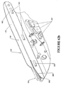
- FIG 61 and 62 illustrate a modified form of the seat carriage 167' and the seat guide 149'.
- the seat carriage 167' is a unitary cast aluminum construction with two spaced slides as explained with the first example, each of which engage with a respective seat guide 149'.
- the two slides are joined by a unitary deck construction having a series of transversely extending ribs as shown.
- the seat guides 149' include seat guide liners 176' having an upper glide surface 178' and an inner glide surface 180' to slidably engage with the respective slide of the seat carriage 167'.
- the seat guide liners 176' will be described in greater detail in connection with Figure 62b and 62c.
- the second example of the chair includes a control lever 169' on the right hand side (left hand side of the figure).
- This lever 169' is a dual actuator for both the seat height adjustment and seat depth adjustment.
- the control lever 169 is mounted for pivotal motion on the outside of the right hand seat guide 149'.
- the control lever 169' effects the operation of a dual actuator 170' mounted on the inside of the right hand seat guide 149'.
- the actuator 170' includes a first actuator portion 170a and a second actuator portion 170b.
- the first actuator portion 170a is connected to cable 172' which connects to the top end of a pneumatic gas spring 145'. As the user raises the control lever 169', the control cable 172' releases the gas spring in the conventional known manner and the chair occupant adjusts the height of the seat portion 14 to suit his requirements.
- the second actuator portion 170b is connected via cable 488 to a pivotable pawl 490.
- the pawl is engageable between any one of a plurality of teeth provided on a rack 492 formed on the underside of the seat carriage 167'.
- the pawl and rack arrangement 490,492 is also duplicated on the other side of the seat carriage 167' as shown in Figure 62.
- the cable 488 passes from the right hand pawl 490 around to the other side of the seat carriage 167' for simultaneous operation of the two pawls 490.
- the user depresses the control lever 169' to operate the second actuator portion 170b to pivot the two pawls against a bias out of engagement with the teeth of the associated rack 492.
- the seat carriage 167' can then be slid to an appropriate seat depth where upon the occupant releases the control lever 169' to enable each of the pawls 490 to engage with the associated rack 492.
- Figure 61 also illustrates a forward cover 495 which is shaped in a serpentine manner for aesthetic purposes to extend in front of the main transom 22'.
- the cover 495 is joined to the seat guides 149' on each side through the use of integrally formed bosses 497 which can be seen in Figure 62b and Figure 62c.
- the seat guide 149' illustrated in Figure 62b includes a seat guide liner 176'.
- the seat guide liner 176' includes an upper glide surface 178' and an inner glide surface 180'.
- the inner glide surface 180 is formed with a series of spaced integral resilient projections 500.
- the integral resilient projections 500 are directed inwardly.
- the seat guide liner 176' is supported on a metal supporting part of the seat guide liner as shown in Figure 62c.
- the inner glide surface 180 is disposed in spaced configuration from the inside of the supporting part of the seat guide 149'.
- the supporting part of the seat guide 149' includes three spaced rests 502.
- the integral resilient projections 500 are shaped like ramps, the ends of which engage against the associated rest 502. The majority of the inner glide surface 180' is thereby resiliently held in spaced configuration from the supporting part of the seat guide 149'.
- a movable comb like formation 504 is incorporated into the seat guide liner 176' as shown in Figure 62b.
- the comb like formation 504 has an upper surface continuous with the upper glide surface 178' and dependent prongs 506 which extend downwardly. The prongs are receivable into a series of corresponding pits 508 formed in the metal supporting part of the seat guide 149'.
- the movable comb like formation 504 is resiliently flexible and would normally extend to fill the gap between the leading edge 285 of the seat guide 149' and the dependent spacer blocks 270'.
- the occupant's weight is not yet bearing on seat panel 14 and thus the seat panel 14 has not yet come to rest on top of the comb like formation 504.
- the dependent spacer blocks are not visible in this view because the seat panel 14 has a peripheral guard to prevent jamming of fingers in the V-shaped gaps of the spacer blocks 270'.
- the spacer blocks 270' will come to bear against the comb like formation 504 which will deflect as the seat portion 14 folds about the transverse fold.
- the comb like formation 504 presents an additional guard to mitigate the likelihood of user's fingers being caught between the seat panel 14 and the seat guide 149'.
- the comb like formation 504 does not interfere with the transverse folding of the seat panel 14.
- Figure 63 illustrates the seat panel 14 in its inward retracted position whereas Figure 64 illustrates the seat panel 14 located in its outer most extended position.
- Figure 81 illustrates the preferred cross section for the upright members 38 of the peripheral frame 34.
- the uprights of the peripheral frame each include a rearwardly open channel 44 in which the leaf spring 128 resides as has been explained previously.
- the upright member 38 also includes a second rearwardly open channel 252 of much narrower configuration than the first mentioned rearwardly open channel 44.
- the second rearwardly open channel 252 receives an attachment strip 254.
- the attachment strip 254 is of extruded resilient plastics material in the form shown.
- the attachment strip 254 has a longitudinal extending lip 550 which engages with retainer portions 552 provided along one of the walls of the channel 252 to assist in holding the attachment strip 254 within the channel 252.
- the attachment strip 254 also includes a part 258 which extends over the edge of the channel 252 when the lip 550 is engaged with retainer portions 552.
- the mesh fabric 260 is sized so that with the attachment strip 254 secured within the second rearwardly open channel 252 on both sides of the back portion 16, the mesh fabric 260 will be relatively taut across the peripheral frame.
- the top of the mesh fabric 260 is also held within a top rearwardly open channel 253, in the same manner.
- the bottom of the mesh fabric 260 is held within a bottom rearwardly open channel 255 in the same manner.
- the attachment strip 254 is a unitary strip extending around the entire periphery of the peripheral frame 34.
- the peripheral frame 34 is of flexible construction, particularly around the region corresponding to the lumbar region of the occupant. Additionally, the mesh fabric is drawn taut across the peripheral frame 34. It is important that the frame does not flex so as to draw in the upright members 38 of the peripheral frame 34 due to the tautness of the mesh fabric 260. Accordingly, the back beam 46 is positioned so as to correspond approximately with the lumbar region of the seat occupant. This maintains the spacing of the upright members 38, particularly in the lumbar region where the frame 34 bends. The bending of the peripheral frame 34 close to the lumbar region of the occupant is encouraged by the serpentine shape of the peripheral frame 34 as well as being encouraged by the cantilevered connection of the peripheral frame 34.
- the mesh fabric 260 may have a degree of resiliency but this is somewhat limited. It is preferable that the mesh fabric should be able to maintain tension over a reasonably long period of time. It is desirable that the mesh fabric 260 is not overly stretched. For this reason, it is desirable that the neutral axis of bending be close to the front surface of the upright members 38 of the peripheral frame 34. Accordingly, the cross section of the peripheral frame 34 is designed to have the bulk of material on the forward face so that bending occurs as close as possible toward the forward face of the upright member 38. In bending, there will be some compression of the walls defining the channel 252 in the lumbar region. Additionally, there may be some flexing of the two walls of the channel 252 towards each other.
- FIG 84 illustrates a preferred form of the wheeled base 18.
- the wheeled base includes five radially extending legs 300.
- Each of the legs is supported by a respective castor 302.
- the five legs 300 make up an unitary cast leg assembly.
- Each leg is elongate and substantially plate-like in thickness, strengthened by a strengthening web 304 extending longitudinally along each leg 300.
- the strengthening webs 304 terminate at their inner ends at a centrally disposed annular boss 306.
- each of the legs 300 is provided with an integrally formed dependent connector 308.
- Each dependent connector 308 is in the form of a socket or sleeve.
- the end of each leg 300 terminates in a clip-on bumper 301 comprised of resilient plastic or rubber material.
- FIG 86 illustrates the form of the castor 302.
- Each castor 302 comprises two spaced wheel portions 312.
- the wheel portions 312 are rotatably mounted on an axle 314 forming part of an axle assembly 316 illustrated in Figure 87.
- the axle assembly 316 incorporates the axle 314, a connector pin 318 and an intermediate body portion 320 interconnecting the axle 314 and the connector pin 318.
- the wheel portions 312 are received on opposite ends of the axle 314 and rotatably held there by means of a snap-fitting.
- the connector pin 318 is disposed between the two wheel portions 312. Furthermore, there is a further gap provided between the connector pin 318 and the wheel portions 312 to receive at least part of the dependent connector 308.
- the connector pin 318 releasably engages with the dependent connector 308 enabling the pin to rotate within the dependent connector 308 about the longitudinal axis of the pin 318.
- a snap-fit connection may be provided therebetween.
- Figure 89 illustrates in schematic form, the underside of the slotted seat panel 14.
- a scabbard which is curved in form.
- the scabbard 350 houses an instruction slide 352 which is also curved and slides in and out of the scabbard at one end. From above, the instruction slide 352 has printed indicia thereon providing user instructions to the seat occupant.
Landscapes
- Dentistry (AREA)
- General Health & Medical Sciences (AREA)
- Health & Medical Sciences (AREA)
- Engineering & Computer Science (AREA)
- Mechanical Engineering (AREA)
- Chairs For Special Purposes, Such As Reclining Chairs (AREA)
- Seats For Vehicles (AREA)
- Chair Legs, Seat Parts, And Backrests (AREA)
- Chairs Characterized By Structure (AREA)
- Special Chairs (AREA)
- Accommodation For Nursing Or Treatment Tables (AREA)
- Electroplating And Plating Baths Therefor (AREA)
- Orthopedics, Nursing, And Contraception (AREA)
- Materials For Medical Uses (AREA)
- Prostheses (AREA)
Claims (20)
- Stuhl (10) mit:- einem Tragrahmen;- einer Hauptabstützung (22'), die von dem Tragrahmen gehalten wird;- einem Sitz (14), der über dem Tragrahmen abgestützt wird;- einem neigungsverstellbaren Rückenlehnenabschnitt (16), der im Hinblick- auf eine Neigungsverstellung in Bezug auf die Hauptabstützung mit der Hauptabstützung funktionsfähig verbunden ist; dadurch gekennzeichnet, dass der Stuhl folgendes besitzt:- eine erste Feder zur Neigungsverstellung (95) mit einem langen Federabschnitt (95a), wobei die Längen-, Breiten- und Stärkenabmessung derart ausfällt, dass die Breite größer ist als die Stärke, und die Längsachse mit der Länge des langen Federabschnitts fluchtet, und wobei die Feder zur Neigungsverstellung zwischen der Hauptabstützung und dem neigungsverstellbaren Rückenlehnenabschnitt funktionsfähig verbunden ist, um der Neigungsverstellung des Rückenlehnenabschnittes durch Biegen um eine Achse quer zur Längsachse Widerstand zu bieten, wobei die erste Feder zur Neigungsverstellung um die Längsachse herum drehbar ist, um eine von einer Vielzahl an Federpositionen einzunehmen, in der die Feder jeweils eine andere Federkonstante als Widerstand gegen die Biegung um die Querachse besitzt.
- Stuhl nach Anspruch 1, wobei der Rückenlehnenabschnitt (16) zwischen einer nach vorn gerichteten, aktiven Position und einer am weitesten nach hinten gerichteten Position geneigt werden kann, und eine Grenze für die Neigung nach vorn vorhanden ist, um die nach vorn gerichtete Position des Rückenlehnenabschnittes zu definieren, und wobei die erste Feder zur Neigungsverstellung (95) derart angeordnet ist, dass - während sich die Hauptabstützung (22') und der Rückenlehnenabschnitt (16) während der Neigungsverstellung zueinander hin bewegen - jedes von ihnen gegen die erste Feder zur Neigungsverstellung drückt und dazu tendiert, den langen Federabschnitt um die Querachse herum zu biegen, so dass der Rückenlehnenabschnitt durch den natürlichen Widerstand der Feder in Richtung nach vorn gerichtete, aktive Position vorgespannt wird.
- Stuhl nach Anspruch 2, wobei an der nach vorn gerichteten, aktiven Position keine Vorspannung auf die erste Feder zur Neigungsverstellung ausgeübt wird.
- Stuhl nach einem der Ansprüche 1 bis 3, wobei ein Zwischenabschnitt der ersten Feder zur Neigungsverstellung gegen die Hauptabstützung drückt, und ein Endabschnitt der ersten Feder zur Neigungsverstellung gegen den Rückenlehnenabschnitt drückt.
- Stuhl nach einem der Ansprüche 1 bis 3, wobei die Enden der ersten Feder zur Neigungsverstellung gegen den Rückenlehnenabschnitt drücken, wobei ein Zwischenteil der ersten Feder zur Neigungsverstellung gegen die Hauptabstützung drückt.
- Stuhl nach Anspruch 5, wobei die Hauptabstützung einen quer verlaufenden Hauptquerträger (22') besitzt, und der Rückenlehnenabschnitt (16) zwei beabstandete Arme besitzt, die drehbar an dem Hauptquerträger montiert sind, wobei die erste Feder zur Neigungsverstellung entlang dem Hauptquerträger verläuft, und die beiden Enden in jedem Arm lagern und ein Zwischenteil der ersten Feder zur Neigungsverstellung gegen den Hauptquerträger drückt.
- Stuhl nach Anspruch 6, wobei der Hauptquerträger eine Verlängerung nach hinten (22a) besitzt.
- Stuhl nach Anspruch 7, wobei die Enden der ersten Feder zur Neigungsverstellung mit zylinderförmigen Vorsprüngen (99a) befestigt sind, die in den Armen des Rückenlehnenabschnittes gelagert werden, und das Zwischenteil einen zylinderförmigen Vorsprung (99b) besitzt, der gegen den Hauptquerträger drückt.
- Stuhl nach Anspruch 8, wobei der Hauptquerträger einen Träger mit einer zusätzlichen Bohrung oder Vertiefung aufweist, gegen die der zylinderförmige Vorsprung (99b) drückt.
- Stuhl nach einem der Ansprüche 1 bis 9, wobei Lokalisierer bereitgestellt werden, um jede der Vielzahl einnehmbarer Federpositionen zu definieren.
- Stuhl nach Anspruch 10 in Abhängigkeit von Anspruch 9, wobei die Lokalisierer zusätzliche Nocken (99e) und Feststellvorrichtungen (99d) besitzen, die sich in einem oder mehreren der zylinderförmigen Vorsprünge und dem entsprechenden Träger befinden.
- Stuhl nach einem der Ansprüche 1 bis 11, wobei der lange Federabschnitt der ersten Feder zur Neigungsverstellung die Form eines flachen Stabes besitzt.
- Stuhl nach Anspruch 12, wobei drei Federpositionen vorhanden sind, wobei die Breitenabmessung des flachen Stabes bei der ersten Position im wesentlichen mit der querverlaufenden Biegungsachse fluchtet, eine zweite einnehmbare Federposition eine Breitenabmessung besitzt, welche diagonal zu der querverlaufenden Biegungsachse angeordnet ist, und die Breite des flachen Stabes bei der dritten Federposition quer zu der Biegungsachse angeordnet ist.
- Stuhl nach einem der Ansprüche 1 bis 13, wobei mehr als ein langer Federabschnitt in die erste Feder zur Neigungsverstellung integriert ist.
- Stuhl nach einem der Ansprüche 1 bis 14, wobei die erste Feder zur Neigungsverstellung ein Bedienelement (99c) zur selektiven Drehung der ersten Feder zur Neigungsverstellung durch den Benutzer besitzt.
- Stuhl nach einem der Ansprüche 1 bis 15, der weiterhin eine zweite Feder zur Neigungsverstellung (97) besitzt.
- Stuhl nach Anspruch 16, wobei die zweite Feder zur Neigungsverstellung verstellbar ist.
- Stuhl nach Anspruch 16, wobei die zweite Feder zur Neigungsverstellung nicht verstellbar ist.
- Stuhl nach einem der Ansprüche 16 bis 18 in Abhängigkeit von Anspruch 2, wobei die zweite Feder zur Neigungsverstellung in der nach vorn gerichteten, aktiven Position eine Vorspannung aufweist.
- Stuhl nach einem der Ansprüche 1 bis 9, wobei der Rückenlehnenabschnitt mit dem Sitz funktionsfähig verbunden ist, wobei das Gewicht der auf dem Stuhl sitzenden Person dabei hilft, der Neigung des Rückenlehnenabschnittes zu widerstehen.
Applications Claiming Priority (6)
| Application Number | Priority Date | Filing Date | Title |
|---|---|---|---|
| US23691600P | 2000-09-28 | 2000-09-28 | |
| US23693200P | 2000-09-28 | 2000-09-28 | |
| US23692500P | 2000-09-28 | 2000-09-28 | |
| US23693300P | 2000-09-28 | 2000-09-28 | |
| US236933P | 2000-09-28 | ||
| EP01308188A EP1192877B1 (de) | 2000-09-28 | 2001-09-26 | Neigungsverstellbarer Stuhl |
Related Parent Applications (1)
| Application Number | Title | Priority Date | Filing Date |
|---|---|---|---|
| EP01308188A Division EP1192877B1 (de) | 2000-09-28 | 2001-09-26 | Neigungsverstellbarer Stuhl |
Publications (2)
| Publication Number | Publication Date |
|---|---|
| EP1570766A1 EP1570766A1 (de) | 2005-09-07 |
| EP1570766B1 true EP1570766B1 (de) | 2007-02-14 |
Family
ID=41112157
Family Applications (5)
| Application Number | Title | Priority Date | Filing Date |
|---|---|---|---|
| EP05075934A Expired - Lifetime EP1570766B1 (de) | 2000-09-28 | 2001-09-26 | Neigungsverstellbarer Stuhl |
| EP01308196A Expired - Lifetime EP1192875B1 (de) | 2000-09-28 | 2001-09-26 | Armlehnengefüge für einen Stuhl |
| EP01308204A Expired - Lifetime EP1192879B1 (de) | 2000-09-28 | 2001-09-26 | Sitz für einen neigbaren Bürostuhl |
| EP05023365A Expired - Lifetime EP1621109B1 (de) | 2000-09-28 | 2001-09-26 | Armlehnengefüge für einen Stuhl |
| EP01308188A Expired - Lifetime EP1192877B1 (de) | 2000-09-28 | 2001-09-26 | Neigungsverstellbarer Stuhl |
Family Applications After (4)
| Application Number | Title | Priority Date | Filing Date |
|---|---|---|---|
| EP01308196A Expired - Lifetime EP1192875B1 (de) | 2000-09-28 | 2001-09-26 | Armlehnengefüge für einen Stuhl |
| EP01308204A Expired - Lifetime EP1192879B1 (de) | 2000-09-28 | 2001-09-26 | Sitz für einen neigbaren Bürostuhl |
| EP05023365A Expired - Lifetime EP1621109B1 (de) | 2000-09-28 | 2001-09-26 | Armlehnengefüge für einen Stuhl |
| EP01308188A Expired - Lifetime EP1192877B1 (de) | 2000-09-28 | 2001-09-26 | Neigungsverstellbarer Stuhl |
Country Status (10)
| Country | Link |
|---|---|
| US (8) | US6817667B2 (de) |
| EP (5) | EP1570766B1 (de) |
| JP (3) | JP4936415B2 (de) |
| AT (5) | ATE359010T1 (de) |
| AU (5) | AU783829B2 (de) |
| CA (3) | CA2357855C (de) |
| DE (6) | DE60114961T2 (de) |
| GB (1) | GB2368278B (de) |
| MX (3) | MXPA01009801A (de) |
| NZ (8) | NZ513929A (de) |
Families Citing this family (272)
| Publication number | Priority date | Publication date | Assignee | Title |
|---|---|---|---|---|
| WO2003024277A1 (en) * | 2001-09-20 | 2003-03-27 | Ergomedics, Inc. | System for providing lumbar motion and support |
| US6811218B2 (en) | 2001-12-14 | 2004-11-02 | Kimball International, Inc. | Chair with conforming seat |
| DE10397009A5 (de) * | 2002-02-13 | 2014-11-13 | Herman Miller, Inc. | Neigesessel mit flexibler Lehne, einstellbaren Armlehnen und einstellbarer Sitztiefe und Verfahren für seine Verwendung |
| NZ518944A (en) | 2002-05-14 | 2004-09-24 | Formway Furniture Ltd | Height adjustable arm for chair with outer stem releasably lockable to inner stem by engagement of recesses |
| JP2004129751A (ja) * | 2002-10-09 | 2004-04-30 | Honda Motor Co Ltd | 自動車シート |
| GB0227182D0 (en) * | 2002-11-21 | 2002-12-24 | Rassoulian Hamid | An ergonomic aid to reduce shoulder and torso loads for operating working in static working postures |
| US6908158B2 (en) | 2003-01-02 | 2005-06-21 | Haworth, Inc. | Lateral motion chair arm mechanism for chair arm |
| FR2850079B1 (fr) * | 2003-01-17 | 2006-01-13 | Time Sport Int | Pedale cycliste de securite |
| WO2004098947A1 (en) | 2003-05-03 | 2004-11-18 | Jan Dirkse Pelser | Lower back support cushioning |
| US7097247B2 (en) * | 2003-06-05 | 2006-08-29 | Steelcase Development Corporation | Seating unit with adjustable lumbar device |
| USD511914S1 (en) * | 2003-11-21 | 2005-11-29 | Hni Technologies Inc. | Chair pad |
| US7472432B2 (en) * | 2003-12-30 | 2009-01-06 | Letty Ann Owen | Bathtub insert “Take-Five” |
| US6969116B2 (en) * | 2003-12-30 | 2005-11-29 | Hni Technologies Inc. | Chair with backward and forward passive tilt capabilities |
| US7066546B2 (en) * | 2003-12-30 | 2006-06-27 | Hni Technologies Inc. | Horizontally adjustable chair armrest |
| US7922245B1 (en) * | 2004-02-17 | 2011-04-12 | Sawhney Ravi K | Portable table and seating combination |
| US20050189807A1 (en) * | 2004-02-27 | 2005-09-01 | Norman Christopher J. | Chair with functional armrest |
| USD559571S1 (en) * | 2004-04-20 | 2008-01-15 | Vitra Patente Ag | Chair |
| FR2876998B1 (fr) * | 2004-10-22 | 2007-01-19 | Batscap Sa | Procede de preparation de gamma-liv205 |
| US8226166B2 (en) * | 2004-12-23 | 2012-07-24 | Schukra Geraetebau Gmbh | Seating element and seating system |
| DE102004062219B4 (de) * | 2004-12-23 | 2008-12-24 | Schukra Gerätebau AG | Sitzelement und Sitzsystem |
| USD545076S1 (en) * | 2005-02-28 | 2007-06-26 | Haworth, Inc. | Office chair |
| EP1855569B1 (de) | 2005-03-01 | 2022-02-16 | Haworth, Inc. | Rückenlehne eines stuhl mit lenden- und beckenstützen |
| US8235468B2 (en) | 2005-03-01 | 2012-08-07 | Haworth, Inc. | Arm assembly for a chair |
| CN102423202B (zh) * | 2005-03-01 | 2015-07-29 | 霍沃思公司 | 椅子的臂装置 |
| US7341313B2 (en) * | 2005-04-08 | 2008-03-11 | Steelcase Development Corporation | Adjustable armrest with motion control |
| US20060249060A1 (en) * | 2005-05-05 | 2006-11-09 | Formway Furniture Limited | Height adjustable furniture component |
| JP4448487B2 (ja) * | 2005-11-04 | 2010-04-07 | 株式会社岡村製作所 | 椅子の背凭れ装置 |
| US20070205648A1 (en) * | 2006-03-06 | 2007-09-06 | Tsung-Chieh Huang | Elastic assembly of chair cushion |
| US20070222266A1 (en) * | 2006-03-21 | 2007-09-27 | Ditto Sales, Inc. | Nestable and stackable chair |
| US7971935B2 (en) * | 2006-03-24 | 2011-07-05 | Humanscale Corporation | Ergonomic side chair |
| US7837265B2 (en) * | 2006-03-24 | 2010-11-23 | Hni Corporation | Reclining chair with enhanced adjustability |
| DE202006016212U1 (de) * | 2006-09-22 | 2008-02-14 | GLÖCKL, Josef | Ergonomischer Sitz |
| JP5301446B2 (ja) | 2006-10-04 | 2013-09-25 | フォームウェイ ファーニチャー リミテッド | 椅子 |
| DE202006015822U1 (de) * | 2006-10-16 | 2007-03-15 | Ballendat, Martin | Stuhlrücken sowie Stuhl hiermit |
| US20080122274A1 (en) * | 2006-11-28 | 2008-05-29 | Trevor Edwards | Aircraft seat cover assembly |
| TWM315539U (en) * | 2007-01-31 | 2007-07-21 | Chuan Hsing Chemical Industry | Armrest plate capable of sliding left, right, forwardly and backwardly |
| WO2008112918A1 (en) | 2007-03-13 | 2008-09-18 | Hni Technologies Inc. | Dynamic chair back lumbar support system |
| US8061778B2 (en) * | 2007-03-13 | 2011-11-22 | Hni Technologies Inc. | Adjustable arm for chair |
| CN101677688B (zh) * | 2007-03-13 | 2011-09-07 | Hni技术公司 | 用于座椅的六连杆机构和控制器 |
| US7367628B1 (en) * | 2007-03-16 | 2008-05-06 | Po-Chuan Tsai | Armrest that will not produce noise during adjustment |
| USD597349S1 (en) * | 2007-05-14 | 2009-08-04 | Steelcase Sa | Chair backrest support |
| US7604298B2 (en) * | 2007-06-01 | 2009-10-20 | Steelcase Development Corporation | Chair back attachment and method of assembly |
| DE102007027578A1 (de) * | 2007-06-12 | 2008-12-18 | Bock 1 Gmbh & Co. Kg | Sitzhöhenverstellung für einen Bürostuhl |
| US8016360B2 (en) * | 2007-08-01 | 2011-09-13 | Hni Technologies Inc. | Adjustable arm rest for chair |
| EP2798977B1 (de) | 2007-09-20 | 2017-11-08 | Herman Miller, Inc. | Lasttragende Struktur |
| DE202008002081U1 (de) * | 2008-02-15 | 2008-08-21 | Mey-Tech | Auslösekopf und Auslösevorrichtung für eine Gasfeder |
| USD576814S1 (en) * | 2008-02-22 | 2008-09-16 | Ivars S.P.A. | Office chair |
| AU2009234514B2 (en) * | 2008-04-08 | 2014-05-01 | Formway Furniture Limited | Injection moulding method |
| USD600051S1 (en) | 2008-04-09 | 2009-09-15 | Formway Furniture Limited | Chair back |
| USD604535S1 (en) | 2008-04-09 | 2009-11-24 | Formway Furniture Limited | Chair |
| CN102098945B (zh) | 2008-05-02 | 2013-11-06 | 霍沃思公司 | 用于重力响应式椅子的张力机构 |
| WO2009151545A2 (en) | 2008-05-26 | 2009-12-17 | Steelcase Inc. | Conforming back for a seating unit |
| US8216416B2 (en) | 2008-06-06 | 2012-07-10 | Knoll, Inc. | Chair and method for assembling the chair |
| US8246117B2 (en) * | 2008-06-06 | 2012-08-21 | Knoll, Inc. | Armrest apparatus |
| JP5124405B2 (ja) * | 2008-09-22 | 2013-01-23 | ファミリー株式会社 | 椅子型マッサージ機 |
| US20100078975A1 (en) * | 2008-09-30 | 2010-04-01 | Ming-Shiang Kang | Structure of a single-part elastic waist support |
| KR100903215B1 (ko) * | 2008-10-10 | 2009-06-18 | 주식회사 시디즈 | 틸팅 가능 의자 |
| EP2337476B1 (de) * | 2008-10-21 | 2012-08-15 | Vitra Patente AG | Rückenlehne für einen stuhl |
| JP5451027B2 (ja) * | 2008-10-21 | 2014-03-26 | 株式会社イトーキ | ロッキング椅子 |
| KR20110090904A (ko) * | 2008-10-29 | 2011-08-10 | 오카무라 가부시키가이샤 | 의자의 등받이 |
| CA131020S (en) | 2008-12-12 | 2010-02-03 | Formway Furniture Ltd | Chair |
| CA2950118C (en) | 2008-12-12 | 2019-04-23 | Formway Furniture Limited | A chair, a support, and components |
| USD601827S1 (en) | 2008-12-18 | 2009-10-13 | Formway Furniture Limited | Furniture base |
| US8317269B2 (en) | 2008-12-24 | 2012-11-27 | Mity-Lite, Inc. | Mesh stacking chair |
| US8033598B2 (en) | 2008-12-24 | 2011-10-11 | Mity-Lite, Inc. | Mesh folding chair |
| US8322787B2 (en) | 2008-12-24 | 2012-12-04 | Mity-Lite, Inc. | Clamping joint for a chair |
| US8454093B2 (en) | 2008-12-24 | 2013-06-04 | Mity-Lite, Inc. | Mesh chair with open-end hoop |
| US7967379B2 (en) * | 2008-12-29 | 2011-06-28 | L&P Property Management Company | Seat with independently adjustable user support assemblies |
| US8002351B2 (en) | 2009-01-26 | 2011-08-23 | Knoll, Inc. | Support member |
| US8157329B2 (en) * | 2009-02-25 | 2012-04-17 | Knoll, Inc. | Furniture and method of furniture component attachment |
| EP2233117B1 (de) | 2009-03-23 | 2011-12-21 | Taiwan An I Co., Ltd. | Mechanismus zum Anpassen von Rollstuhlarmlehnen |
| USD599127S1 (en) | 2009-04-13 | 2009-09-01 | Mity-Lite, Inc. | Mesh folding chair |
| US8696534B2 (en) * | 2009-06-19 | 2014-04-15 | Sihar Ahmad Karwan | Total abs office chair |
| US8944507B2 (en) * | 2009-10-13 | 2015-02-03 | Herman Miller, Inc. | Ergonomic adjustable chair mechanisms |
| US8505186B2 (en) * | 2009-11-03 | 2013-08-13 | Knoll, Inc. | Method of fabricating a chair |
| USD648554S1 (en) | 2009-11-04 | 2011-11-15 | Mity-Lite, Inc. | Mesh stacking chair |
| USD690523S1 (en) * | 2009-11-06 | 2013-10-01 | Patra Co., Ltd | Office chair |
| US20110148157A1 (en) * | 2009-12-15 | 2011-06-23 | Faurecia Automotive Seating, Inc. | Vehicle seat with pelvis-motion regulator |
| JP5562023B2 (ja) * | 2009-12-25 | 2014-07-30 | 株式会社イトーキ | 椅子 |
| USD647314S1 (en) * | 2010-01-19 | 2011-10-25 | Chueng Shine Co., Ltd. | Chair frame |
| USD637423S1 (en) | 2010-04-13 | 2011-05-10 | Herman Miller, Inc. | Chair |
| USD650206S1 (en) | 2010-04-13 | 2011-12-13 | Herman Miller, Inc. | Chair |
| USD639091S1 (en) | 2010-04-13 | 2011-06-07 | Herman Miller, Inc. | Backrest |
| USD653061S1 (en) | 2010-04-13 | 2012-01-31 | Herman Miller, Inc. | Chair |
| USD657166S1 (en) | 2010-04-13 | 2012-04-10 | Herman Miller, Inc. | Chair |
| US8449037B2 (en) | 2010-04-13 | 2013-05-28 | Herman Miller, Inc. | Seating structure with a contoured flexible backrest |
| USD652657S1 (en) | 2010-04-13 | 2012-01-24 | Herman Miller, Inc. | Chair |
| USD655522S1 (en) * | 2010-04-26 | 2012-03-13 | Haworth, Inc. | Office chair |
| JP6039544B2 (ja) | 2010-05-05 | 2016-12-07 | オールスティール インコーポレイテッドAllsteel Inc. | ガラス突き合わせ壁パネルのための可動式の解体可能な壁パネルシステムの設置方法 |
| USD641573S1 (en) * | 2010-05-10 | 2011-07-19 | Fuh Shyan Co., Ltd. | Chair back frame |
| US8616640B2 (en) | 2010-05-20 | 2013-12-31 | Knoll, Inc. | Chair |
| USD646092S1 (en) | 2010-06-09 | 2011-10-04 | Office Master | Office chair |
| USD650615S1 (en) * | 2010-07-16 | 2011-12-20 | Whalen Furniture Manufacturing, Inc. | Chair base |
| DE202010008894U1 (de) | 2010-10-26 | 2010-12-30 | Vitra Patente Ag | Höhenverstellbare Lumbalstütze für einen Stuhl |
| USD660612S1 (en) | 2010-11-16 | 2012-05-29 | Mity-Lite, Inc. | Mesh banquet chair |
| US8678505B2 (en) * | 2010-12-21 | 2014-03-25 | Tachi-S Co., Ltd. | Seat cushion of vehicle seat |
| DE202011001282U1 (de) * | 2011-01-10 | 2012-04-18 | Bock 1 Gmbh & Co. Kg | Armlehne, insbesondere für einen Bürostuhl |
| US20120242130A1 (en) * | 2011-03-21 | 2012-09-27 | Yu-Ching Hung | Chair with waist rest and armrests |
| US8991922B2 (en) | 2011-06-02 | 2015-03-31 | Formway Furniture Limited | Lumbar support for a chair |
| US9498066B2 (en) | 2011-08-04 | 2016-11-22 | Cramer Llc | Ergonomic seating assemblies and methods |
| JP5823820B2 (ja) * | 2011-10-28 | 2015-11-25 | 株式会社岡村製作所 | 椅子 |
| CA145425S (en) * | 2011-10-31 | 2012-12-13 | Okamura Corp | Chair |
| US8950813B2 (en) * | 2012-01-12 | 2015-02-10 | Ali Nawaz | Integrated adjustable headrest |
| US8919880B2 (en) | 2012-03-27 | 2014-12-30 | Haworth, Inc. | Flexible seating surface |
| US9504326B1 (en) * | 2012-04-10 | 2016-11-29 | Humanscale Corporation | Reclining chair |
| US9693632B2 (en) | 2012-06-01 | 2017-07-04 | Aaron Duke | Chair and chair tilt control assembly |
| USD683552S1 (en) * | 2012-06-05 | 2013-06-04 | Yao-Chuan Wu | Chair frame |
| US8991921B2 (en) | 2012-07-20 | 2015-03-31 | Steelcase Inc. | Seating unit with seat position and depth adjustment assembly |
| EP2887835B1 (de) | 2012-08-23 | 2018-04-18 | Lear Corporation | Thorakale unterstützungsstruktur und ein sitz mit der thorakalen unterstützungsstruktur |
| WO2014031819A1 (en) | 2012-08-23 | 2014-02-27 | Lear Corporation | Thoracic region comfort seating system |
| USD699061S1 (en) * | 2012-09-20 | 2014-02-11 | Steelcase Inc. | Arm assembly |
| USD694536S1 (en) | 2012-09-20 | 2013-12-03 | Steelcase Inc. | Chair |
| USD697730S1 (en) | 2012-09-20 | 2014-01-21 | Steelcase Inc. | Chair |
| USD942767S1 (en) | 2012-09-20 | 2022-02-08 | Steelcase Inc. | Chair assembly |
| USD683151S1 (en) | 2012-09-20 | 2013-05-28 | Steelcase Inc. | Chair |
| USD694540S1 (en) | 2012-09-20 | 2013-12-03 | Steelcase Inc. | Chair |
| USD702981S1 (en) | 2012-09-20 | 2014-04-22 | Steelcase Inc. | Chair |
| USD694537S1 (en) | 2012-09-20 | 2013-12-03 | Steelcase Inc. | Chair |
| US11304528B2 (en) | 2012-09-20 | 2022-04-19 | Steelcase Inc. | Chair assembly with upholstery covering |
| USD707976S1 (en) | 2013-06-07 | 2014-07-01 | Steelcase Inc. | Chair |
| USD683150S1 (en) | 2012-09-20 | 2013-05-28 | Steelcase Inc. | Chair |
| US8998339B2 (en) | 2012-09-20 | 2015-04-07 | Steelcase Inc. | Chair assembly with upholstery covering |
| USD699957S1 (en) | 2012-09-20 | 2014-02-25 | Steelcase Inc. | Chair |
| USD698164S1 (en) | 2012-09-20 | 2014-01-28 | Steelcase Inc. | Chair |
| USD699959S1 (en) | 2012-09-20 | 2014-02-25 | Steelcase Inc. | Chair |
| USD701053S1 (en) | 2012-09-20 | 2014-03-18 | Steelcase Inc. | Chair |
| USD698165S1 (en) | 2012-09-20 | 2014-01-28 | Steelcase Inc. | Chair |
| USD688907S1 (en) | 2012-09-20 | 2013-09-03 | Steelcase Inc. | Arm assembly |
| USD699958S1 (en) | 2012-09-20 | 2014-02-25 | Steelcase Inc. | Chair |
| USD697728S1 (en) | 2012-09-20 | 2014-01-21 | Steelcase Inc. | Chair |
| USD694538S1 (en) | 2012-09-20 | 2013-12-03 | Steelcase Inc. | Chair |
| USD697727S1 (en) | 2012-09-20 | 2014-01-21 | Steeelcase Inc. | Chair |
| US8973990B2 (en) | 2012-09-20 | 2015-03-10 | Steelcase Inc. | Chair assembly |
| USD697729S1 (en) | 2012-09-20 | 2014-01-21 | Steelcase Inc. | Chair |
| US11229294B2 (en) | 2012-09-20 | 2022-01-25 | Steelcase Inc. | Chair assembly with upholstery covering |
| USD697726S1 (en) | 2012-09-20 | 2014-01-21 | Steelcase Inc. | Chair |
| USD781605S1 (en) | 2015-04-24 | 2017-03-21 | Steelcase Inc. | Chair |
| USD694539S1 (en) | 2012-09-20 | 2013-12-03 | Steelcase Inc. | Chair |
| USD698166S1 (en) | 2012-09-20 | 2014-01-28 | Steelcase Inc. | Chair |
| USD706547S1 (en) | 2013-06-07 | 2014-06-10 | Steelcase Inc. | Chair |
| US9661930B2 (en) | 2012-09-21 | 2017-05-30 | Steelcase Inc. | Chair construction |
| USD703987S1 (en) | 2013-06-07 | 2014-05-06 | Steelcase Inc. | Chair |
| USD721529S1 (en) | 2013-06-07 | 2015-01-27 | Steelcase Inc. | Handle apparatus |
| JP6059505B2 (ja) * | 2012-10-19 | 2017-01-11 | 株式会社岡村製作所 | ランバーサポート装置、及びそれを備える椅子 |
| JP6130647B2 (ja) * | 2012-11-06 | 2017-05-17 | コクヨ株式会社 | 椅子 |
| USD695034S1 (en) | 2012-11-13 | 2013-12-10 | Steelcase Inc. | Chair |
| US9044098B2 (en) | 2012-11-16 | 2015-06-02 | Holland Plastics Corporation | Adjustable armrest assembly |
| US9320360B2 (en) | 2012-12-14 | 2016-04-26 | Holland Plastics Corporation | Armrest assembly |
| CN105101845B (zh) | 2013-03-15 | 2018-11-09 | Hni技术公司 | 具有触发的靠背弯曲的椅子 |
| EP2981466B1 (de) * | 2013-04-05 | 2021-06-02 | St Engineering Aerospace Ltd. | Sitzstruktur für einen fahrgastsitz sowie fahrgastsitz |
| WO2014163582A1 (en) * | 2013-04-05 | 2014-10-09 | Singapore Technologies Aerospace Ltd | Seat pan for a passenger seat and passenger seat |
| US9138058B2 (en) | 2013-04-23 | 2015-09-22 | Office for Metropolitan Architecture (O.M.A.) Stedebouw B.V | Seating device having a height adjustment mechanism |
| USD703988S1 (en) | 2013-06-07 | 2014-05-06 | Steelcase Inc. | Chair |
| USD704487S1 (en) | 2013-06-07 | 2014-05-13 | Steelcase Inc. | Chair |
| USD696545S1 (en) | 2013-07-30 | 2013-12-31 | Steelcase, Inc. | Rear surface of a chair back |
| USD711127S1 (en) | 2013-09-20 | 2014-08-19 | Formway Furniture Limited | Chair |
| JP5646725B2 (ja) * | 2013-12-26 | 2014-12-24 | 株式会社イトーキ | ロッキング椅子 |
| EP3089722B1 (de) * | 2013-12-31 | 2018-11-21 | Medline Industries, Inc., | Verschachtelung persönlicher beförderungsmittel mit rädern |
| US9380879B2 (en) | 2014-02-24 | 2016-07-05 | Knoll, Inc. | Chair back swivel mechanism |
| US9351575B2 (en) | 2014-04-11 | 2016-05-31 | Knoll, Inc. | Armrest mechanism for a chair |
| USD731833S1 (en) | 2014-04-17 | 2015-06-16 | Allsteel Inc. | Chair |
| WO2015161281A1 (en) | 2014-04-17 | 2015-10-22 | Hni Technologies Inc. | Chair and chair control assemblies, systems, and methods |
| CN106455820A (zh) | 2014-04-17 | 2017-02-22 | Hni技术公司 | 扶手 |
| WO2015160693A1 (en) | 2014-04-17 | 2015-10-22 | Hni Technologies Inc. | Flex lumbar support |
| US9801470B2 (en) | 2014-10-15 | 2017-10-31 | Hni Technologies Inc. | Molded chair with integrated support and method of making same |
| USD743180S1 (en) | 2014-10-15 | 2015-11-17 | Hni Technologies Inc. | Chair |
| USD789256S1 (en) | 2014-12-30 | 2017-06-13 | Medline Industries, Inc. | Wheeled personal conveyance |
| CN107105900A (zh) | 2015-01-16 | 2017-08-29 | 赫尔曼米勒有限公司 | 分区域悬挂就坐结构 |
| KR101664651B1 (ko) * | 2015-01-16 | 2016-10-10 | 현대자동차주식회사 | 목 상해 저감 성능이 향상되는 차량용 시트 |
| CN107666843A (zh) | 2015-03-14 | 2018-02-06 | 赫尔曼米勒有限公司 | 用于椅子的机械结构组合件以及带有这种机械结构组合件的椅子 |
| US10182656B2 (en) | 2015-04-13 | 2019-01-22 | Steelcase Inc. | Seating components with laminated bonding material |
| USD804840S1 (en) | 2016-04-12 | 2017-12-12 | Steelcase Inc. | Chair |
| WO2016168185A1 (en) | 2015-04-13 | 2016-10-20 | Steelcase Inc. | Seating arrangement |
| US10966527B2 (en) | 2017-06-09 | 2021-04-06 | Steelcase Inc. | Seating arrangement and method of construction |
| USD804841S1 (en) | 2016-04-12 | 2017-12-12 | Steelcase Inc. | Chair |
| US11259637B2 (en) | 2015-04-13 | 2022-03-01 | Steelcase Inc. | Seating arrangement |
| USD821793S1 (en) | 2016-04-12 | 2018-07-03 | Steelcase Inc. | Seating shell |
| USD804875S1 (en) | 2016-04-12 | 2017-12-12 | Steelcase Inc. | Chair |
| USD808187S1 (en) | 2016-04-12 | 2018-01-23 | Steelcase Inc. | Seating shell |
| USD804209S1 (en) | 2016-04-12 | 2017-12-05 | Steelcase Inc. | Chair |
| US10194750B2 (en) | 2015-04-13 | 2019-02-05 | Steelcase Inc. | Seating arrangement |
| USD802951S1 (en) | 2016-04-12 | 2017-11-21 | Steelcase Inc. | Chair |
| USD804839S1 (en) | 2016-04-12 | 2017-12-12 | Steelcase Inc. | Chair |
| USD804876S1 (en) | 2016-04-12 | 2017-12-12 | Steelcase Inc. | Chair |
| DE102016106236B4 (de) * | 2015-04-16 | 2025-03-20 | Sico Incorporated | Tisch- und sitzvorrichtung |
| USD758774S1 (en) | 2015-04-24 | 2016-06-14 | Steelcase Inc. | Headrest assembly |
| USD760526S1 (en) | 2015-04-24 | 2016-07-05 | Steelcase Inc. | Headrest assembly |
| USD781604S1 (en) | 2015-04-24 | 2017-03-21 | Steelcase Inc. | Chair |
| USD759415S1 (en) | 2015-04-24 | 2016-06-21 | Steelcase Inc. | Headrest |
| US9883748B2 (en) | 2015-05-15 | 2018-02-06 | Knoll, Inc. | Training device for a seating device and method of using the same |
| US9565945B2 (en) | 2015-05-15 | 2017-02-14 | Knoll, Inc. | Seating device having a height adjustment mechanism |
| US9585485B2 (en) | 2015-05-15 | 2017-03-07 | Knoll, Inc. | Seating device having a tilt mechanism |
| US9713381B2 (en) | 2015-06-11 | 2017-07-25 | Davis Furniture Industries, Inc. | Chair |
| US10021530B2 (en) * | 2015-07-07 | 2018-07-10 | Tome, Inc. | Occupancy system and method for detecting presence of individuals in a plurality of defined areas or rooms |
| USD767320S1 (en) * | 2015-07-17 | 2016-09-27 | Yang Xingchang | Chair back |
| US9648957B2 (en) * | 2015-08-05 | 2017-05-16 | Dongguan Kentec Office Seating Co., Ltd. | Chair with back tilt adjustment structure |
| USD779248S1 (en) * | 2016-02-12 | 2017-02-21 | Haworth, Inc. | Armrests for a chair |
| DE102016104638A1 (de) | 2016-03-14 | 2017-09-14 | Burkhard Schmitz | Stuhl |
| CN205696722U (zh) * | 2016-03-23 | 2016-11-23 | 吴耀全 | 一种座椅底座 |
| USD799877S1 (en) * | 2016-03-28 | 2017-10-17 | Exemplis Llc | Lumbar support frame |
| USD799254S1 (en) * | 2016-03-28 | 2017-10-10 | Exemplis Llc | Seatback frame |
| USD932203S1 (en) | 2016-04-12 | 2021-10-05 | Steelcase Inc. | Seating arrangement |
| US9795220B1 (en) * | 2016-05-09 | 2017-10-24 | Atec International Team Co., Ltd. | Quickly released and fastened adjustment mechanism |
| US10463153B2 (en) | 2016-06-09 | 2019-11-05 | Steelcase Inc. | Seating arrangement |
| USD845692S1 (en) | 2016-06-13 | 2019-04-16 | Herman Miller, Inc. | Chair and chair components |
| USD845050S1 (en) | 2016-06-13 | 2019-04-09 | Herman Miller, Inc. | Chair and chair components |
| GB2553750B (en) * | 2016-06-28 | 2019-06-05 | Posturite Ltd | Seat tilting mechanism |
| US10219627B2 (en) | 2016-09-29 | 2019-03-05 | Steelcase Inc. | Compliant seating structure |
| EP3568318B1 (de) | 2017-01-13 | 2021-03-03 | Crown Equipment Corporation | Industriefahrzeugarmlehne |
| US10231546B2 (en) | 2017-03-02 | 2019-03-19 | Knoll, Inc. | Chair back tilt mechanism |
| US9844272B1 (en) * | 2017-04-25 | 2017-12-19 | Seachrome Corporation | Lift assist systems and methods for adjustable seats |
| USD869890S1 (en) | 2017-12-05 | 2019-12-17 | Steelcase Inc. | Chairback |
| US11291305B2 (en) | 2017-12-05 | 2022-04-05 | Steelcase Inc. | Compliant backrest |
| USD870479S1 (en) | 2017-12-05 | 2019-12-24 | Steelcase Inc. | Chair |
| USD869872S1 (en) | 2017-12-05 | 2019-12-17 | Steelcase Inc. | Chair |
| USD869889S1 (en) | 2017-12-05 | 2019-12-17 | Steelcase Inc. | Chairback |
| US10813463B2 (en) | 2017-12-05 | 2020-10-27 | Steelcase Inc. | Compliant backrest |
| US10485346B2 (en) | 2018-01-22 | 2019-11-26 | Knoll, Inc. | Chair tilt mechanism |
| US10463155B2 (en) | 2018-01-22 | 2019-11-05 | Knoll, Inc. | Fastenerless arm pad attachment mechanism |
| US10383448B1 (en) | 2018-03-28 | 2019-08-20 | Haworth, Inc. | Forward tilt assembly for chair seat |
| USD888479S1 (en) | 2018-06-04 | 2020-06-30 | Steelcase Inc. | Chair arm |
| USD891842S1 (en) | 2018-06-04 | 2020-08-04 | Steelcase Inc. | Chair arm |
| USD898496S1 (en) * | 2018-06-11 | 2020-10-13 | Exemplis Llc | Chair |
| JP7440503B2 (ja) * | 2018-10-25 | 2024-02-28 | イリノイ トゥール ワークス インコーポレイティド | 圧縮制限部を有する懸架織布を備えた椅子 |
| ES3035683T3 (en) | 2019-02-21 | 2025-09-08 | Steelcase Inc | Body support member |
| EP3741258B1 (de) * | 2019-05-20 | 2025-11-05 | BOCK 1 GmbH & Co. KG | Stuhl mit sitzneigemechanik |
| USD907383S1 (en) | 2019-05-31 | 2021-01-12 | Steelcase Inc. | Chair with upholstered back |
| USD907935S1 (en) | 2019-05-31 | 2021-01-19 | Steelcase Inc. | Chair |
| ES3012782T3 (en) | 2019-06-04 | 2025-04-10 | Yeti Coolers Llc | Portable chair |
| US11147379B2 (en) | 2019-08-22 | 2021-10-19 | Mity-Lite, Inc. | Cushion for folding chair |
| USD912418S1 (en) * | 2019-08-26 | 2021-03-09 | Zhejiang Zhongwei Smart Furniture Co., Ltd. | Chair |
| USD913004S1 (en) * | 2019-08-26 | 2021-03-16 | Zhejiang Zhongwei Smart Furniture Co., Ltd. | Chair |
| WO2021055441A1 (en) | 2019-09-18 | 2021-03-25 | Steelcase Inc. | Body support member with lattice structure |
| USD909084S1 (en) * | 2019-10-22 | 2021-02-02 | Henglin Home Furnishings Co., Ltd. | Chair |
| KR102703383B1 (ko) * | 2019-10-23 | 2024-09-04 | 현대자동차주식회사 | 자동차용 메쉬 타입 시트 |
| USD940487S1 (en) * | 2019-11-29 | 2022-01-11 | Tung-Hua Su | Chair lumbar support |
| US11357329B2 (en) | 2019-12-13 | 2022-06-14 | Steelcase Inc. | Body support assembly and methods for the use and assembly thereof |
| US11690457B2 (en) | 2020-02-04 | 2023-07-04 | Hni Technologies Inc. | Chair with flexible internal support |
| USD935824S1 (en) | 2020-02-19 | 2021-11-16 | Steelcase Inc. | Seat |
| USD936984S1 (en) | 2020-02-19 | 2021-11-30 | Steelcase Inc. | Chair |
| USD961317S1 (en) | 2020-02-19 | 2022-08-23 | Steelcase Inc. | Backrest |
| USD937595S1 (en) | 2020-02-19 | 2021-12-07 | Steelcase Inc. | Chair |
| USD961281S1 (en) | 2020-02-19 | 2022-08-23 | Steelcase Inc. | Chair |
| USD937024S1 (en) | 2020-02-19 | 2021-11-30 | Steelcase Inc. | Backrest |
| USD936985S1 (en) | 2020-02-19 | 2021-11-30 | Steelcase Inc. | Chair |
| USD961280S1 (en) | 2020-02-19 | 2022-08-23 | Steelcase Inc. | Chair |
| US11617444B2 (en) | 2020-03-02 | 2023-04-04 | Steelcase Inc. | Body support assembly and methods for the use and assembly thereof |
| USD944025S1 (en) * | 2020-05-14 | 2022-02-22 | Foshan Orcco Furniture Co., Ltd | Chair |
| USD929784S1 (en) * | 2020-05-20 | 2021-09-07 | Tung-Hua Su | Chair backrest |
| USD952385S1 (en) * | 2020-07-17 | 2022-05-24 | Zhejiang Yuyue Furniture Co., Ltd. | Chair part |
| US11690455B2 (en) | 2020-09-18 | 2023-07-04 | Dinkar Chellaram | Synchronous-tilt reclining chair |
| USD995179S1 (en) | 2021-01-20 | 2023-08-15 | Steelcase Inc. | Chair with lumbar support |
| USD988048S1 (en) | 2021-01-20 | 2023-06-06 | Steelcase Inc. | Lumbar support |
| US11812870B2 (en) | 2021-02-10 | 2023-11-14 | Steelcase Inc. | Body support structure |
| USD995180S1 (en) | 2021-05-12 | 2023-08-15 | Steelcase Inc. | Chair with lumbar support |
| USD988049S1 (en) | 2021-05-12 | 2023-06-06 | Steelcase Inc. | Lumbar support |
| US11510495B1 (en) | 2021-05-14 | 2022-11-29 | Steelcase Inc. | Chair having an accessory hook |
| USD1009536S1 (en) | 2021-05-17 | 2024-01-02 | Steelcase Inc. | Chair |
| US11944208B2 (en) | 2021-06-14 | 2024-04-02 | Knoll, Inc. | Chair and method of making the chair |
| US20240306821A1 (en) * | 2021-07-05 | 2024-09-19 | Secretlab Sg Pte. Ltd. | A lumbar support assembly and related method, and a backrest assembly |
| US11564500B1 (en) * | 2021-08-04 | 2023-01-31 | Alberto Palma | Mesh chair with full lumbar back support |
| DE102021004095A1 (de) | 2021-08-10 | 2023-02-16 | Brunner GmbH. | Sitzmöbel mit Schnittstellenufer für Anbaueinheiten |
| TWI831081B (zh) * | 2021-11-11 | 2024-02-01 | 國立陽明交通大學 | 模組化氣動體感裝置 |
| DE102021131278B4 (de) | 2021-11-29 | 2025-05-22 | Bock 1 Gmbh & Co. Kg | Sitzträgerbausatz für einen Stuhl |
| US12440031B2 (en) | 2022-09-01 | 2025-10-14 | Haworth, Inc. | Back support for a chair |
| KR102506194B1 (ko) * | 2022-09-05 | 2023-03-07 | 주식회사 린백 | 3d 탄력구조의 분할형 요추받침구를 갖는 의자용 등받이체 |
| KR102506195B1 (ko) * | 2022-09-05 | 2023-03-07 | 주식회사 린백 | 3d 탄력구조의 일체형 요추받침구를 갖는 의자용 등받이체 |
| USD1063474S1 (en) | 2022-09-07 | 2025-02-25 | Steelcase Inc. | Chair |
| US11622631B1 (en) * | 2022-09-15 | 2023-04-11 | Jay A. Berkowitz | Apparatus and method for assembling a modular ergonomic chair without using fasteners |
| CN115804513B (zh) * | 2022-11-03 | 2025-10-31 | 顾家家居股份有限公司 | 一种双向调速装置及可调沙发椅 |
| CN116326958B (zh) * | 2023-01-31 | 2025-09-26 | 厦门新技术集成有限公司 | 弹性垫 |
| USD1105782S1 (en) * | 2023-11-02 | 2025-12-16 | Zhejiang Hengjian Household Co., Ltd. | Chair |
Family Cites Families (560)
| Publication number | Priority date | Publication date | Assignee | Title |
|---|---|---|---|---|
| US3124092A (en) | 1964-03-10 | Plastic mating dies and metallic holder supports therefor | ||
| US323060A (en) | 1885-07-28 | Territory | ||
| US226082A (en) | 1880-03-30 | Chair-seat | ||
| US272579A (en) | 1883-02-20 | William h | ||
| US614235A (en) | 1898-11-15 | Chair | ||
| US662247A (en) | 1900-05-04 | 1900-11-20 | George E Parker | Coated wire. |
| US662647A (en) | 1900-05-21 | 1900-11-27 | Martin V B Howe | Chair-seat. |
| US799128A (en) | 1904-07-02 | 1905-09-12 | John F Wilmot | Adjustable reclining-chair. |
| US779128A (en) | 1904-08-30 | 1905-01-03 | Everett N Mummey | Furnace-door opener. |
| US1120686A (en) | 1913-09-25 | 1914-12-15 | Edward T Burrowes | Metal fly-screen. |
| DE588534C (de) | 1930-08-14 | 1933-11-20 | Stefan Mangold | Polster, Kissen, Matratze, Schwimmkoerper, Waermeflasche o. dgl. |
| US2083838A (en) * | 1934-05-19 | 1937-06-15 | Fritz Cross Company | Chair |
| US2063732A (en) * | 1934-11-30 | 1936-12-08 | Florence L Gailey | Chair |
| US2059940A (en) * | 1935-08-05 | 1936-11-03 | Harry A Freedman | Beach chair |
| US2071974A (en) | 1936-03-24 | 1937-02-23 | William H Gunlocke | Chair back |
| US2365200A (en) | 1942-03-16 | 1944-12-19 | Lorenz Anton | Adjustable chair |
| US2471024A (en) | 1946-10-04 | 1949-05-24 | Roy A Cramer | Chair with tilting back and automatically shiftable seat |
| US2590995A (en) | 1948-09-10 | 1952-04-01 | Sackner Prod Inc | Woven fabric adapted for use as upholstery covers and the like |
| US2612211A (en) | 1950-05-16 | 1952-09-30 | American Seating Co | Removable cushion plate and seat standard |
| US2845997A (en) | 1954-03-09 | 1958-08-05 | Curtiss Wright Corp | Foamed plastic seat and the like |
| US2796918A (en) | 1954-09-15 | 1957-06-25 | Norman P Martin | Article of repose for supporting the body of a person |
| US2858572A (en) | 1954-09-23 | 1958-11-04 | Burdick Richard | Method of making advertising signs |
| US2833339A (en) | 1955-06-22 | 1958-05-06 | Shirley S Liljengren | Seat construction |
| US2804129A (en) | 1955-06-23 | 1957-08-27 | Beauty Products Ltd | Cushion construction |
| US2962764A (en) | 1956-03-01 | 1960-12-06 | Oceana International Inc | Process for the manufacture of molded articles |
| US2887692A (en) | 1956-05-23 | 1959-05-26 | Gosman Clarence Berveir | Inflatable cushion or the like |
| US3009578A (en) | 1958-04-15 | 1961-11-21 | Gulf Research Development Co | Pre-stressed reinforced ion-exchange membrane and method of making same |
| US3015148A (en) | 1958-04-23 | 1962-01-02 | Us Rubber Co | Spacer fabrics and method of making them |
| DE1121944B (de) * | 1958-09-26 | 1962-01-11 | Johann Schwarz | Rueckenlehne, insbesondere fuer Kraftfahrzeugsitze |
| US3041109A (en) | 1958-09-29 | 1962-06-26 | Miller Herman Inc | Web and spreader furniture construction |
| US3112987A (en) | 1959-03-26 | 1963-12-03 | Austin Motor Co Ltd | Production of cushioned seats |
| US3030640A (en) | 1960-01-13 | 1962-04-24 | Air Pillow & Cushions Inc | Inflated articles |
| US3115678A (en) | 1960-10-07 | 1963-12-31 | Collins & Aikman Corp | Apparatus for molding plastic carpets |
| GB934239A (en) | 1961-06-22 | 1963-08-14 | Vitafoam Ltd | Improvements in or relating to upholstered furniture |
| US3165359A (en) | 1961-09-26 | 1965-01-12 | Production Engineering Company | Woven support for furniture |
| US3107991A (en) | 1962-01-02 | 1963-10-22 | Arundale Mfg Company | Screen |
| US3214314A (en) | 1962-02-12 | 1965-10-26 | Francis W Rowbottam | Method for screen assembly |
| US3139305A (en) | 1962-05-09 | 1964-06-30 | Gen Steel Products Inc | Reclining chair and fixture |
| GB969585A (en) | 1962-07-30 | 1964-09-09 | Vickers Armstrong Aircraft Ltd | Improvements in the manufacture of mirrors |
| US3222698A (en) | 1962-12-13 | 1965-12-14 | Gen Motors Corp | Resilient plastic seat elements |
| US3301931A (en) | 1963-07-30 | 1967-01-31 | Madeline F Mcgill | Method of making looped snells |
| US3165356A (en) * | 1963-12-17 | 1965-01-12 | Douglas J Geier | Shock absorbing support and restraint means |
| SE335101B (de) | 1964-06-30 | 1971-05-10 | Mo Och Domsjoe Ab | |
| US3279849A (en) * | 1964-07-13 | 1966-10-18 | Bostrom Corp | Cushion |
| US3319274A (en) | 1965-01-25 | 1967-05-16 | Raymond R Upton | Mattress with sag-resistant insert |
| US3273877A (en) | 1965-04-26 | 1966-09-20 | Gen Motors Corp | Seat structure |
| US3298743A (en) | 1965-06-10 | 1967-01-17 | Knoll Associates | Connector means for upholstery-frame connection |
| US3314721A (en) | 1966-01-25 | 1967-04-18 | Leland C Smith | Chair construction |
| US3337267A (en) | 1966-01-27 | 1967-08-22 | Royal Dev Co | Positionable chair |
| US3399926A (en) | 1966-12-27 | 1968-09-03 | Bruce A. Hehn | Furniture construction |
| FR1539220A (fr) | 1967-04-06 | 1968-09-13 | Elastomer Ag | Procédé et dispositif pour la fabrication de sièges d'ameublement, de voitures et similaires, et sièges ainsi obtenus |
| US3431022A (en) | 1967-05-29 | 1969-03-04 | Steelcase Inc | Chair construction |
| DE1654205C3 (de) | 1967-07-26 | 1974-03-07 | Jose Roberto Ribeiro Bastos | Matratze |
| US3399883A (en) | 1967-08-29 | 1968-09-03 | Thomas J. Mckey | Seat construction |
| GB1257927A (de) * | 1968-11-27 | 1971-12-22 | ||
| FR2045120A5 (de) | 1969-06-03 | 1971-02-26 | Dupart Jean | |
| US3620568A (en) | 1969-06-26 | 1971-11-16 | Boeing Co | Aircraft crewseat |
| DE1933456A1 (de) * | 1969-07-02 | 1971-06-03 | Eisenburger Kuno Dipl Ing | Zwei- oder mehrschichtige Auflage,Bezug u.dgl. fuer Sitz und Liegemoebel |
| GB1222908A (en) | 1969-10-15 | 1971-02-17 | Ford Motor Co | Seats |
| US3589967A (en) | 1969-10-20 | 1971-06-29 | Junichi Shirakawa | Method of upholstering |
| BE760088A (fr) | 1969-12-17 | 1971-05-17 | Giroflex Entwicklungs Ag | Chaise basculante |
| US3637877A (en) * | 1970-06-03 | 1972-01-25 | Phillips Petroleum Co | Modifiers for selective hydrogenation catalysts for cyclic polyenes |
| US3652126A (en) | 1970-08-31 | 1972-03-28 | Universal Oil Prod Co | Pneumatic adjustment system for seat back panel |
| NL7018604A (de) | 1970-12-21 | 1972-06-23 | ||
| GB1343305A (en) | 1971-04-01 | 1974-01-10 | Werner P G | Adjustable resiliently hinged device for chairs and the like |
| US3724402A (en) * | 1971-06-11 | 1973-04-03 | Gen Housewares Corp | Webbed panel for chairs |
| SE372878B (de) * | 1972-03-14 | 1975-01-20 | K Borggren | |
| US3770235A (en) | 1972-03-20 | 1973-11-06 | Flexible Co | Resiliently supported seat |
| US3869172A (en) * | 1973-06-28 | 1975-03-04 | Pontiac Furniture Ind | Chair reclining mechanism |
| NL7309461A (nl) | 1973-07-06 | 1975-01-08 | Robert Johannes Van Seenus | Invalidestoel- of wagen. |
| US4040661A (en) | 1974-11-04 | 1977-08-09 | Uop Inc. | Vehicle seat with headrest movement responsive to seat back tilting |
| US3942835A (en) | 1974-12-23 | 1976-03-09 | Mohasco Corporation | Recliner rester chair with projectible legrest and headrest, and hardware therefor |
| US3937518A (en) | 1975-01-09 | 1976-02-10 | Mohasco Corporation | Recliner lounger T-cushion chair with projectible headrest and legrest, and hardware therefor |
| JPS5191531A (en) * | 1975-02-06 | 1976-08-11 | Ranbaa sahootochoseisochi | |
| US3974532A (en) | 1975-03-10 | 1976-08-17 | Mitsuyoshi Hamasu | Padding for mattresses and like articles |
| US4043592A (en) | 1975-09-05 | 1977-08-23 | Steelcase Inc. | Adjustable seat back mechanism |
| US3992059A (en) * | 1975-10-06 | 1976-11-16 | Lear Siegler, Inc. | Seat edge construction |
| US4054317A (en) | 1976-01-13 | 1977-10-18 | Herman Miller, Inc. | Chair construction |
| US4025113A (en) | 1976-04-09 | 1977-05-24 | Royal Development Company, Inc. | Linkage mechanism for handle operated recliner chair |
| US4017118A (en) | 1976-04-19 | 1977-04-12 | Cawley Reginald E | Patient supporting device |
| US4062590A (en) * | 1976-05-24 | 1977-12-13 | Fixtures Manufacturing Corporation | Chair structure |
| JPS5419935Y2 (de) * | 1976-06-07 | 1979-07-20 | ||
| DE2640163A1 (de) | 1976-09-07 | 1978-03-16 | Daimler Benz Ag | Kopfstuetze fuer ein kraftfahrzeug |
| DE2647168A1 (de) | 1976-10-19 | 1978-04-20 | Budimirov Gmbh | Sitzteil |
| US4205880A (en) * | 1977-03-31 | 1980-06-03 | Trotman Helen H | Body supporting and spacing structure |
| US4157203A (en) | 1977-05-09 | 1979-06-05 | Center For Design Research And Development N.V. | Articulated double back for chairs |
| NZ184194A (en) | 1977-05-25 | 1981-02-11 | J S J Mccaskey | Hose guiding apparatus for travelling irrigator |
| US4122568A (en) | 1977-06-10 | 1978-10-31 | Bastos Jose R R | Mattress of the hard surface type |
| US4143910A (en) | 1977-09-12 | 1979-03-13 | Klaus Geffers | Chair having synchronously coupled tiltable seat and back rest |
| JPS5715736Y2 (de) | 1977-11-30 | 1982-04-01 | ||
| US4390204A (en) | 1978-01-04 | 1983-06-28 | Gregg Fleishman | Portable furniture |
| US4202581A (en) | 1978-01-04 | 1980-05-13 | Gregg Fleishman | Support means for portable furniture |
| US4145020A (en) | 1978-01-19 | 1979-03-20 | Kustom Fit Manufacturing Company | Retractable apparatus for supporting an element |
| US4159148A (en) | 1978-01-27 | 1979-06-26 | Schulz Terry H | Folding arm rest accessory |
| US4154478A (en) | 1978-02-09 | 1979-05-15 | Cohune William H | Portable headrest |
| DE2810577A1 (de) | 1978-03-11 | 1979-09-20 | Volkswagenwerk Ag | Fahrzeug, insbesondere personenkraftfahrzeug |
| US4205878A (en) | 1978-08-02 | 1980-06-03 | Wooten James D | Pull out headrest |
| JPS5621321Y2 (de) | 1978-08-23 | 1981-05-20 | ||
| JPS5588713A (en) * | 1978-12-27 | 1980-07-04 | Tachikawa Spring Co | Sheet for car in synthetic resin |
| US4318556A (en) | 1979-06-11 | 1982-03-09 | Rowland David L | Chair and seat-back unit therefor |
| US4380352A (en) | 1979-06-11 | 1983-04-19 | Knoll International, Inc. | Reclining chair |
| GB2055173A (en) | 1979-06-13 | 1981-02-25 | Dunlop Ltd | Unitary resilient suspension device |
| CH645795A5 (en) | 1979-07-23 | 1984-10-31 | Drabert Soehne | Chair, in particular visual display unit chair |
| GB2057257B (en) | 1979-09-01 | 1984-05-10 | Turner Willenhall Ltd H R | Seats |
| US4295681A (en) * | 1980-02-19 | 1981-10-20 | Uop Inc. | Seat having lumbar support and vertical height adjustment mechanism therefor |
| DE2940641A1 (de) | 1979-10-06 | 1981-04-16 | Joachim Prof. Dr.Med. 6200 Wiesbaden Eichler | Sitzmoebel |
| JPS5746979Y2 (de) | 1979-12-27 | 1982-10-15 | ||
| DE3163545D1 (en) * | 1980-01-21 | 1984-06-20 | Bernard Curtis Watkin | Chair shells |
| DE3004585A1 (de) | 1980-02-08 | 1981-08-13 | Wilkhahn Wilkening + Hahne GmbH + Co, 3252 Bad Münder | Sitzmoebel mit an einer tragschale angebrachter polsterung |
| DE3014255A1 (de) | 1980-04-14 | 1981-10-15 | Drabert Söhne Minden (Westf.), 4950 Minden | Rueckenlehne fuer sitzmoebel, insbesondere buerositzmoebel |
| US4345733A (en) | 1980-04-28 | 1982-08-24 | Center For Design Research And Development N.V. | Mounting device for a chair seat |
| US4390206A (en) | 1980-05-01 | 1983-06-28 | Steelcase, Incorporated | Synchrotilt chair control |
| DE3017163A1 (de) | 1980-05-05 | 1981-11-12 | Schmitz & Söhne GmbH & Co KG, 5757 Wickede | Vorrichtung zum loesen und festlegen einer die rueckenlehne eines stuhles haltenden blattfeder |
| US4299645A (en) | 1980-05-30 | 1981-11-10 | Newsom Charles R | Method for assembling fabric to an article of furniture |
| JPS5737345U (de) * | 1980-08-13 | 1982-02-27 | ||
| US4415203A (en) | 1980-08-15 | 1983-11-15 | Cawley Reginald E | Dental chair |
| GB2082901A (en) | 1980-08-22 | 1982-03-17 | Ring Mekanikk As | A flexible coupling device between a fixed part and a pivotable and adjustable part |
| US4362334A (en) * | 1980-10-14 | 1982-12-07 | Accu-Back, Inc. | Portable folding orthopedic seat |
| DE3038880C2 (de) | 1980-10-15 | 1985-05-02 | Martin Stoll GmbH, 7890 Waldshut-Tiengen | Vorrichtung zur stufenweisen Abstandsverstellung von zwei Stuhlteilen |
| JPS57136413A (en) | 1981-02-19 | 1982-08-23 | Aisin Seiki | Air supply and discharge system of air lumber support |
| US4429917A (en) | 1981-04-29 | 1984-02-07 | Hauserman Inc. Int. Furniture & Textile Division | Chair |
| DE3118248C2 (de) * | 1981-05-08 | 1985-05-30 | Daimler-Benz Ag, 7000 Stuttgart | Polster, insbesondere Sitz- und/oder Rückenpolster aus Schaumstoff |
| US4502731A (en) | 1981-06-01 | 1985-03-05 | Snider Robert A | Seat frame |
| US4479679A (en) | 1981-06-08 | 1984-10-30 | Steelcase Inc. | Body weight chair control |
| DE3139448C2 (de) | 1981-10-03 | 1984-06-07 | Kusch & Co Sitzmöbelwerke KG, 5789 Hallenberg | Stuhl |
| GB2107576A (en) | 1981-10-16 | 1983-05-05 | Brian Barr Richardson | Adjustable seat back |
| US4466662A (en) | 1981-11-12 | 1984-08-21 | The United States Of America As Represented By The Secretary Of The Air Force | Powered articulated headrest system |
| US4451081A (en) | 1982-01-06 | 1984-05-29 | Mohasco Corporation | Headrest for a reclining chair |
| DE3207352A1 (de) * | 1982-03-02 | 1983-09-08 | Wilkhahn Wilkening + Hahne GmbH + Co, 3252 Bad Münder | Sessel |
| SE440443B (sv) | 1982-03-30 | 1985-08-05 | Jan Dranger | Mobelkonstruktion |
| JPS58206703A (ja) * | 1982-05-26 | 1983-12-02 | アイシン精機株式会社 | ランバ−サポ−ト |
| US4498702A (en) | 1982-06-11 | 1985-02-12 | Steelcase Inc. | Seating unit with front flex area |
| JPS5932420A (ja) | 1982-08-13 | 1984-02-21 | 株式会社タチエス | 車両用座席等のヘツドレスト装置 |
| DE3232771A1 (de) | 1982-09-03 | 1984-03-08 | Wilkhahn Wilkening + Hahne GmbH + Co, 3252 Bad Münder | Arbeits-sitzmoebel |
| US4515406A (en) | 1982-09-28 | 1985-05-07 | Takara Company, New York, Inc. | Headrest for medical treatment chair |
| USD279635S (en) | 1982-09-29 | 1985-07-16 | Hag A/S | Support unit for adjusting a chair seat depth |
| EP0107627B1 (de) | 1982-10-22 | 1986-01-02 | Castelli S.P.A. | Stuhl mit einer aus mehreren gelenkten Segmenten bestehender Rückenlehne |
| US4570994A (en) | 1982-12-17 | 1986-02-18 | Charles Lowrey | Foldable chair |
| WO1984002455A1 (en) | 1982-12-20 | 1984-07-05 | Robert H Graebe | Constant force cushion |
| EP0114600B1 (de) * | 1983-01-21 | 1986-08-27 | Pierre Schmitz | Stuhl, insbesondere Bürostuhl |
| US4496190A (en) | 1983-02-10 | 1985-01-29 | Uop Inc. | Parallel folding armrest |
| JPS59137151U (ja) | 1983-03-03 | 1984-09-13 | アイシン精機株式会社 | ランバ−サポ−ト |
| US4558904A (en) * | 1983-03-23 | 1985-12-17 | Schultz Moses R | Hoop chair |
| US4534593A (en) | 1983-05-06 | 1985-08-13 | Practical Technology Incorporated | Vehicle seat lumbar support insert and method of utilizing the same |
| CH662257A5 (de) | 1983-07-20 | 1987-09-30 | Syntech Sa | Arbeitsstuhl. |
| US4560199A (en) | 1983-07-22 | 1985-12-24 | Pamont Ag | Recliner chair |
| DE3335148A1 (de) | 1983-09-28 | 1985-04-11 | Wilkhahn Wilkening + Hahne GmbH + Co, 3252 Bad Münder | Vorrichtung zur gefederten schwenkbewegung eines bauteiles |
| US4652050A (en) | 1984-01-11 | 1987-03-24 | Herman Miller, Inc. | Chair tilt mechanism |
| FR2558360A1 (fr) | 1984-01-23 | 1985-07-26 | Vinel Pierre | Perfectionnements aux sieges, de bureau en particulier |
| GB8404356D0 (en) | 1984-02-20 | 1984-03-28 | Deshayes Eames | Vehicle seat |
| US4580837A (en) | 1984-04-25 | 1986-04-08 | Car Tec Inc. | Vehicle seat |
| NO159335C (no) | 1984-05-08 | 1988-12-21 | Haag A S | Laasbar vippemekanisme for stolsete eller lignende. |
| USD289591S (en) | 1984-05-08 | 1987-05-05 | Hag A/S | Chair control unit |
| NO842262L (no) | 1984-06-05 | 1985-12-06 | Haag A S | Mekanisk loefteanordning. |
| AU4316385A (en) | 1984-06-08 | 1985-12-12 | Hauserman Inc. | Office chair |
| AU571974B2 (en) | 1984-06-08 | 1988-04-28 | Hauserman Inc. | Recline chair with headrest mounted on back for arcuate extension and retraction |
| DE3424688A1 (de) | 1984-07-05 | 1986-01-16 | Drabert Söhne Minden (Westf.), 4950 Minden | Sitzmoebel mit armlehne |
| GB8425908D0 (en) | 1984-10-12 | 1984-11-21 | Anderle E | Seat with dynamic lumbar support |
| DE3570973D1 (en) | 1984-10-23 | 1989-07-20 | Protoned Bv | Chair |
| FR2575051B1 (fr) | 1984-12-21 | 1987-02-27 | Linguanotto Ets | Siege, notamment siege de travail, a plusieurs positions |
| GB8500542D0 (en) | 1985-01-09 | 1985-02-13 | Dmi Fabrications Ltd | Seat support columns |
| USD296959S (en) | 1985-03-04 | 1988-08-02 | Hag A/S | Chair |
| US4733910A (en) | 1985-03-18 | 1988-03-29 | Sebel Furniture Ltd. | Article of furniture |
| JPH046596Y2 (de) * | 1985-03-23 | 1992-02-24 | ||
| DE3524602A1 (de) | 1985-07-10 | 1987-01-22 | Guenther Ing Grad Selzer | Vorrichtung zum einstellen insbesondere der neigung der rueckenlehne eines sitzes |
| US4920591A (en) | 1985-07-16 | 1990-05-01 | Hiroshi Sekido | Air support for chair and method for manufacturing chair utilizing the air support |
| DE3527783A1 (de) | 1985-08-02 | 1987-02-12 | Froescher August Gmbh Co Kg | Verstelleinrichtung fuer die stufenweise arretierbare hoehenverstellung von rueckenlehnen an arbeitsstuehlen |
| FR2586180B3 (fr) | 1985-08-19 | 1987-11-27 | Gerard Paul | Procede pour realiser un meuble de repos articule et meuble obtenu par le procede |
| FR2586541A2 (fr) | 1985-08-19 | 1987-03-06 | Gerard Paul | Procede et meuble de repos articule suivant ce procede |
| US4660887A (en) | 1985-09-11 | 1987-04-28 | The Shaw-Walker Company | Ergonomic support |
| JPS62176408A (ja) | 1986-01-30 | 1987-08-03 | 株式会社三幸ポライト | 中吊り構造とその製造方法 |
| EP0296157A1 (de) | 1986-02-04 | 1988-12-28 | PAXON, John Bernard | Elastisches stützkissen |
| DE3604534A1 (de) | 1986-02-13 | 1987-08-20 | Hartmut Lohmeyer | Sitzmoebel mit einem sitz und einer in sich elastisch nachgebenden rueckenlehne |
| US4691961A (en) | 1986-02-14 | 1987-09-08 | Parma Corporation | Recliner with headrest |
| DE8607194U1 (de) | 1986-03-15 | 1986-04-30 | Drabert Söhne Minden (Westf.), 4950 Minden | Sitzmöbel |
| US5050931A (en) | 1986-04-10 | 1991-09-24 | Steelcase Inc. | Controlled deflection front lip for seating |
| US5567012A (en) | 1986-04-10 | 1996-10-22 | Steelcase, Inc. | Chair control |
| NO160896C (no) | 1986-05-09 | 1989-06-14 | Jurek Buchacz | Stillbar sitteanordning. |
| DE8614186U1 (de) | 1986-05-26 | 1986-07-17 | Drabert Söhne GmbH & Co, 4950 Minden | Stuhl |
| DE8614185U1 (de) | 1986-05-26 | 1986-07-17 | Drabert Söhne GmbH & Co, 4950 Minden | Stuhl |
| DE3632131C2 (de) | 1986-06-04 | 2001-12-13 | Hartmut S Engel | Funktions-Sitzmöbel |
| US4711491A (en) | 1986-06-09 | 1987-12-08 | Jonathan Ginat | Swivel tilt mechanism for chair |
| IT206947Z2 (it) | 1986-06-12 | 1987-10-26 | Pro Cord Srl | Sedia con schienale articolato |
| US4725095A (en) * | 1986-07-11 | 1988-02-16 | Johnson Service Company | Vehicle seat with mechanical lumbar support having two degrees of freedom |
| US4730871A (en) | 1986-08-14 | 1988-03-15 | Nepsco, Inc. | Adjustable back rest |
| US4720146A (en) | 1986-08-28 | 1988-01-19 | General Motors Corporation | Vehicle seat headrest apparatus and method |
| DE3635044A1 (de) | 1986-10-15 | 1988-04-28 | Rolf Voelkle | Sessel |
| DE3635244A1 (de) | 1986-10-16 | 1988-04-28 | Dauphin F W Buerositzmoebel | Stuhl, insbesondere buerostuhl, mit hoehenverstellbarer rueckenlehne |
| US4693515A (en) | 1986-10-27 | 1987-09-15 | Itt Corporation | Headrest for an automotive vehicle seat |
| US4778218A (en) | 1986-12-12 | 1988-10-18 | Prince Corporation | Adjustable headrest |
| DE3700447A1 (de) | 1987-01-09 | 1988-07-21 | Vogt Bueromoebel | Sitzmoebel |
| ATE56599T1 (de) | 1987-01-30 | 1990-10-15 | Equus Marketing Ag | Stuhl, insbesondere buerostuhl mit einem sitz und einer mehrteiligen rueckenlehne. |
| GB8706129D0 (en) | 1987-03-14 | 1987-04-15 | Phr Furniture Ltd | Pedestal chairs |
| US4834454A (en) | 1987-05-15 | 1989-05-30 | Faultless-Doerner Manufacturing Inc. | Office chair with tiltable seat and back |
| IT1210753B (it) | 1987-05-20 | 1989-09-20 | Pro Cord Srl | Sopporto oscillante per sedie sedili e simili |
| US4752101A (en) | 1987-06-12 | 1988-06-21 | Allsteel Inc. | Tilt control arrangement for office furniture chair |
| US4869448A (en) | 1987-06-22 | 1989-09-26 | Kenyon William E | Head restraint for vehicles |
| FR2620607B1 (fr) | 1987-09-22 | 1991-03-15 | Strafor Sa | Siege ergonomique |
| JPH053080Y2 (de) * | 1987-09-30 | 1993-01-26 | ||
| NO168985C (no) | 1987-10-19 | 1992-04-29 | Ekornes Fabrikker As J E | Anordning ved stol. |
| US5026117A (en) | 1987-11-10 | 1991-06-25 | Steelcase Inc. | Controller for seating and the like |
| IT1219016B (it) | 1988-02-12 | 1990-04-24 | Tis Tecnologia Innovazione Sti | Elemento di molleggio e contenimento laterale per una seduta e o uno schienale di un sedile e sedile in corporante tale elemento |
| US4848838A (en) | 1988-08-18 | 1989-07-18 | Pelton & Crane Company | Curved articulating headrest support bar |
| US4863218A (en) | 1988-08-18 | 1989-09-05 | Pelton & Crane | Articulated headrest mechanism |
| US4889385A (en) | 1988-03-09 | 1989-12-26 | American Seating Company | Chair seat-and-back support |
| AU617070B2 (en) | 1988-04-25 | 1991-11-14 | Charles O. Perry | Reclining chair |
| EP0400097A1 (de) | 1988-04-30 | 1990-12-05 | Korfmacher Trading Gmbh | Lagerungs- oder stützmatte, insbesondere für verpackungszwecke |
| IT1219314B (it) | 1988-05-18 | 1990-05-03 | Pro Cord Srl | Sedia con sedile oscillante |
| DE3841024C1 (de) | 1988-12-06 | 1989-10-05 | Siegfried 3012 Langenhagen De Maisenhaelder | |
| NO165054C (no) | 1988-09-07 | 1990-12-19 | Asbjoernsen & Jan Lade A S Sve | Anordning ved omstillbar ryggstoepute paa stol. |
| JPH0213436U (de) | 1988-07-11 | 1990-01-26 | ||
| NO166684C (no) | 1988-07-27 | 1991-08-28 | Ring Mekanikk As | Laaseanordning for stolseter. |
| US4892356A (en) * | 1988-07-27 | 1990-01-09 | Chromcraft Furniture Corp. | Chair shell |
| US4881777A (en) | 1988-08-22 | 1989-11-21 | General Motors Corporation | Apparatus and method of utilization thereof of a profile headrest |
| JP2592108B2 (ja) | 1988-08-31 | 1997-03-19 | コクヨ株式会社 | 背もたれ付椅子 |
| US4871208A (en) | 1988-09-06 | 1989-10-03 | Dewey Hodgdon | Chair tilt control mechanism |
| US4869552A (en) | 1988-09-14 | 1989-09-26 | Shelby Williams Industries, Inc. | Flexible backrest assembly for a chair |
| US4962964A (en) | 1988-11-03 | 1990-10-16 | Warren Snodgrass | Flexible plastic seating shell |
| US5015034A (en) | 1988-11-25 | 1991-05-14 | Prince Corporation | Upholstery system |
| FR2641453A1 (fr) | 1989-01-11 | 1990-07-13 | Creaseat | Fauteuil de repos |
| US4979778A (en) | 1989-01-17 | 1990-12-25 | Brayton International, Inc. | Synchrotilt chair |
| JPH02102836U (de) * | 1989-01-31 | 1990-08-15 | ||
| IT1233062B (it) * | 1989-02-03 | 1992-03-14 | Motrol Spa | Serratura con incremento del carico di chiusura ed apertura elettrica particolarmente per applicazioni automobilistiche |
| US4943114A (en) | 1989-02-06 | 1990-07-24 | Giancarlo Piretti | Chair backrest linkage mechanism |
| US4914836A (en) | 1989-05-11 | 1990-04-10 | Zvi Horovitz | Cushioning and impact absorptive structure |
| US5009467A (en) | 1989-05-30 | 1991-04-23 | Mccoy David C | Adjustable armrest for chair |
| US4911501A (en) | 1989-06-09 | 1990-03-27 | Harter Corporation | Suspension mechanism for connecting chair backs and seats to a pedestal |
| JPH0711647Y2 (ja) | 1989-07-27 | 1995-03-22 | アイシン精機株式会社 | ヘツドレスト装置 |
| JPH0379748A (ja) * | 1989-08-23 | 1991-04-04 | Sumitomo Metal Ind Ltd | 合金化処理炉 |
| US5013272A (en) | 1989-09-06 | 1991-05-07 | N.A. Taylor Company, Inc. | Rafting cushion |
| US5013089A (en) * | 1989-09-15 | 1991-05-07 | General Motors Corporation | Thin profile integrated suspension and seat trim cover |
| WO1991003969A1 (en) | 1989-09-21 | 1991-04-04 | Alan Powell | Seat |
| US5101811A (en) | 1989-09-25 | 1992-04-07 | Sumner Brunswick | Fitted seating apparatus and manufacture |
| US4951995A (en) | 1989-10-10 | 1990-08-28 | Steelcase Inc. | Arm height adjustment mechanism for a chair |
| JPH0360600U (de) * | 1989-10-18 | 1991-06-13 | ||
| US5292097A (en) | 1989-10-31 | 1994-03-08 | Russell Edwin R | Work surface support |
| US5052068A (en) | 1989-11-14 | 1991-10-01 | Graebe Robert H | Contoured seat cushion |
| US5039567A (en) | 1989-12-04 | 1991-08-13 | Supracor Systems, Inc. | Resilient panel having anisotropic flexing characteristics and method of making same |
| US5617595A (en) | 1989-12-04 | 1997-04-08 | Supracor Systems Corporation | Contoured seat cushion comprised of honeycomb cores |
| US5444881A (en) | 1989-12-04 | 1995-08-29 | Supracor Systems, Inc. | Anatomical support apparatus |
| WO1991009554A1 (de) | 1989-12-29 | 1991-07-11 | Wilkhahn Wilkening + Hahne Gmbh + Co. | Synchronverstelleinrichtung für bürostühle oder dergleichen |
| US5567011A (en) | 1990-03-09 | 1996-10-22 | Sessini; Lorenza | Cushion for anatomical support, especially for the lumbar and cervical regions, to fit onto seat backs |
| BR9007397A (pt) | 1990-03-26 | 1992-04-28 | Nihon Kenkozoshin Kenkyukai Kk | Colchao almofadado |
| US5044027A (en) | 1990-04-09 | 1991-09-03 | Moon Benny C | Cushion construction |
| US5154485A (en) * | 1990-05-11 | 1992-10-13 | Fleishman Gregg R | Spring plate furniture |
| US5088790A (en) * | 1990-05-21 | 1992-02-18 | Lear Seating Corporation | Adjustable lumbar support mechanism for a vehicular seat |
| US5044030A (en) | 1990-06-06 | 1991-09-03 | Fabrico Manufacturing Corporation | Multiple layer fluid-containing cushion |
| US5050933A (en) | 1990-07-02 | 1991-09-24 | Marta Tornero | Stacking chair with collapsible arms |
| JPH0443140U (de) * | 1990-08-09 | 1992-04-13 | ||
| SE467235B (sv) | 1990-08-17 | 1992-06-22 | Ergonomiprodukter I Bodafors A | Laasanordning |
| US5076643A (en) | 1990-08-20 | 1991-12-31 | Lear Seating Corporation | Lumbar support |
| US5100201A (en) | 1990-09-21 | 1992-03-31 | J.G. Furniture Systems Inc. | Passive ergonomic work chair |
| US5080430A (en) | 1990-09-25 | 1992-01-14 | Castro Convertible Corporation | Reclining chair |
| US5407249A (en) | 1990-10-15 | 1995-04-18 | Bonutti; Peter M. | Armrest assembly |
| JP3300346B2 (ja) | 1990-10-23 | 2002-07-08 | ダブバンド・プロプライエタリー・リミテッド | 椅子または座席用バックサポート |
| US5134735A (en) * | 1990-11-05 | 1992-08-04 | E. R. Carpenter Company, Inc. | Mattress cushion with multiple zones |
| JPH04197315A (ja) | 1990-11-29 | 1992-07-16 | Nissan Motor Co Ltd | シート |
| IT221607Z2 (it) | 1991-02-06 | 1994-07-23 | Ge 2 Srl | Tutore dinamico perfezionato per la prevenzione delle lombalgie da posizione assisa |
| ITTO910109A1 (it) | 1991-02-15 | 1992-08-16 | Pro Cord Srl | Sedia con schienale oscillante |
| DE69200320T2 (de) | 1991-02-20 | 1994-12-01 | Isao Hosoe | Ergonomisch verbesserter stuhl oder armstuhl. |
| US5144708A (en) | 1991-02-26 | 1992-09-08 | Dielectrics Industries | Check valve for fluid bladders |
| US5215350A (en) * | 1991-03-20 | 1993-06-01 | Tachi-S Co., Ltd. | Lumbar support device |
| GB9107273D0 (en) | 1991-04-06 | 1991-05-22 | Project Office Furniture Plc | Improved chair |
| AU636223B2 (en) | 1991-04-29 | 1993-04-22 | Feltex Commercial Interiors Pty. Ltd. | Height adjustable chair armrest assembly |
| JPH0817730B2 (ja) | 1991-05-21 | 1996-02-28 | 株式会社イトーキ | 背と座がシンクロ動作する椅子におけるシェル構造体 |
| JPH06500944A (ja) | 1991-05-24 | 1994-01-27 | エクウス・マーケティング・アーゲー | 作業用椅子、特に事務用椅子 |
| US5318346A (en) | 1991-05-30 | 1994-06-07 | Steelcase Inc. | Chair with zero front rise control |
| DK0517933T3 (da) | 1991-06-10 | 1995-08-21 | Siemens Ag | Tandlæge-patientstol med indstillelig hovedstøtte |
| US5137329A (en) | 1991-06-24 | 1992-08-11 | Ritter-Smith Incorporated | Articulated lumbar support for a seat |
| US5195199A (en) | 1991-07-03 | 1993-03-23 | Sereboff Joel L | Fluid cushion |
| US5113540A (en) | 1991-07-03 | 1992-05-19 | Sereboff Joel L | Fluid cushion with passages for ischial spines |
| WO1993003653A1 (en) | 1991-08-22 | 1993-03-04 | Peter James Riddle | Weight compensating chair backrest |
| DE4128954A1 (de) * | 1991-08-30 | 1993-06-09 | Eca Gmbh & Co. Kg, 5632 Wermelskirchen, De | Sitzteil eines fahrzeugsitzes |
| US5286083A (en) * | 1991-10-07 | 1994-02-15 | Core Products International, Inc. | Lumbar support back rest |
| JP2919131B2 (ja) | 1991-10-22 | 1999-07-12 | 株式会社イトーキクレビオ | 椅子の傾動制御装置 |
| US5190348A (en) | 1991-10-25 | 1993-03-02 | Findlay Industries | Self-inflating support device including curved memory plate |
| DE4135948C2 (de) | 1991-10-31 | 1993-12-23 | Rolf Voelkle | Stuhl, insbesondere Bürodrehstuhl |
| US5314235A (en) | 1991-11-05 | 1994-05-24 | Johnson David G | Portable back support |
| US5249839A (en) * | 1991-11-12 | 1993-10-05 | Steelcase Inc. | Split back chair |
| US5265938A (en) | 1991-12-05 | 1993-11-30 | Westinghouse Electric Corp. | Adjustable arm for a chair |
| USD345060S (en) | 1992-01-16 | 1994-03-15 | JSJ Seating Corporation | Chair |
| US5308142A (en) | 1992-01-23 | 1994-05-03 | Steelcase, Inc. | Chair with arm mounted motion control |
| US5318341A (en) * | 1992-01-28 | 1994-06-07 | Hoover Universal, Inc. | Vehicle seat assembly with structural seat back to accommodate seat belt loads applied to seat back |
| US5314237A (en) | 1992-02-12 | 1994-05-24 | Kimball International Marketing, Inc. | Reclining chair |
| US5308145A (en) | 1992-02-12 | 1994-05-03 | Kimball International Marketing, Inc. | Reclining chair |
| US5324096A (en) | 1992-03-02 | 1994-06-28 | Hon Industries Inc. | Adjustable height chair arm |
| IT227805Y1 (it) | 1992-03-09 | 1998-01-21 | Pro Cord Srl | Piastra per il collegamento di sedile, schienale e piedi, specialmente per sedile |
| US5288134A (en) | 1992-03-09 | 1994-02-22 | Hoover Universal, Inc. | Seat assembly with integrated seat cushion and seat track frame |
| US5243722A (en) | 1992-04-06 | 1993-09-14 | Ignaty Gusakov | Fluid cushion |
| CA2066928C (en) | 1992-04-23 | 1998-09-29 | Saul Feldberg | Adjustable arm rest assembly |
| US5637076A (en) | 1992-05-26 | 1997-06-10 | Ergomedics, Inc. | Apparatus and method for continuous passive motion of the lumbar region |
| BR9307983B1 (pt) | 1992-06-15 | 2010-07-27 | estrutura de assento e método de fabricação da mesma. | |
| JPH0789973B2 (ja) * | 1992-08-28 | 1995-10-04 | 株式会社内田洋行 | 椅 子 |
| IT228485Y1 (it) | 1992-09-09 | 1998-02-19 | Cofemo Spa | Dispositivo per la regolazione di altezza dei braccioli di poltrone |
| DE4230230A1 (de) | 1992-09-10 | 1994-03-17 | Dauphin Friedrich W Gmbh | Armlehne für Sitzmöbel |
| CH684153A5 (de) | 1992-09-16 | 1994-07-29 | Syntech Sa | Vorrichtung zur stufenförmigen Höheneinstellung von Stuhllehnen für Arme und Rücken. |
| DE4233628A1 (de) | 1992-10-06 | 1994-04-07 | Comforto Gmbh | Stuhl, insbesondere Büro- oder Arbeitsstuhl |
| DE4233627A1 (de) | 1992-10-06 | 1994-04-07 | Comforto Gmbh | Stuhl mit Rückenlehne |
| CH685277A5 (de) | 1992-10-08 | 1995-05-31 | Syntech Sa | Stuhlmechanik. |
| ES2082682B1 (es) | 1992-10-14 | 1997-02-16 | Serrano Antonio Bustamante | Asiento. |
| CN2135961Y (zh) | 1992-10-19 | 1993-06-16 | 欣业企业股份有限公司 | 可调整高度的椅子扶手 |
| US5330255A (en) | 1992-11-12 | 1994-07-19 | Davidson Textron Inc. | Seat integrated inflatable neck support |
| US5308028A (en) | 1992-11-17 | 1994-05-03 | Gary Kornberg | Headrest support for a wheelchair |
| US5560682A (en) | 1992-12-01 | 1996-10-01 | Klasse Pty Ltd | Adjustment mechanism for a chair |
| CA2084794A1 (en) | 1992-12-08 | 1994-06-09 | Gary King Neil | Armrest assembly |
| FR2700455B1 (fr) * | 1993-01-18 | 1995-04-14 | Grosfillex Sarl | Panneau à décor transformable pour meubles divers et notamment pour sièges. |
| US5388892A (en) | 1993-04-02 | 1995-02-14 | Tornero; Lino E. | Mechanism for the relative positioning of telescoping members |
| US5340191A (en) | 1993-04-07 | 1994-08-23 | The Lane Company, Inc. | Reclining chair having pop-up headrest |
| DE4312113C1 (de) | 1993-04-14 | 1994-10-27 | Mauser Waldeck Ag | Sitzmöbel |
| US5360074A (en) | 1993-04-21 | 1994-11-01 | Baker Hughes, Incorporated | Method and composition for preserving core sample integrity using an encapsulating material |
| JPH08509399A (ja) | 1993-04-30 | 1996-10-08 | ヘンダーソンズ・インダストリーズ・ピーテイワイ・リミテツド | 腰椎支持具の調整 |
| DE4314975C1 (de) | 1993-05-06 | 1995-03-16 | Grammer Ag | Abgefedertes Sitzgestell, insbes. für einen Fahrzeugsitz |
| JP2500932Y2 (ja) * | 1993-05-12 | 1996-06-12 | 株式会社内田洋行 | 椅 子 |
| IT1270378B (it) | 1993-05-27 | 1997-05-05 | Pro Cord Srl | Sedia pieghevole con schienale oscillante |
| IT1270377B (it) | 1993-05-27 | 1997-05-05 | Pro Cord Srl | Sedia con schienale oscillante |
| DE4317610C2 (de) | 1993-05-27 | 2002-04-11 | Dauphin Friedrich W Gmbh | Höhenverstellbare Armlehne für einen Stuhl |
| US5393125A (en) | 1993-05-28 | 1995-02-28 | Steelcase Inc. | Height adjustable chair arm assembly |
| US5439267A (en) | 1993-05-28 | 1995-08-08 | Steelcase Inc. | Chair with adjustable arm assemblies |
| AU7244294A (en) | 1993-06-02 | 1994-12-20 | Sava Cvek | Articulated support chair |
| US5419617A (en) | 1993-06-08 | 1995-05-30 | Hon Industries, Inc. | Detachable chair arm |
| US5415459A (en) | 1993-06-08 | 1995-05-16 | Hon Industries, Inc. | Adjustable width arm rest |
| US5372487A (en) | 1993-06-10 | 1994-12-13 | Dielectrics Industries | Inlet check valve for pump mechanism |
| JP3305498B2 (ja) | 1993-07-07 | 2002-07-22 | アップリカ▲葛▼西株式会社 | 子供用座席装置 |
| DE4327373C2 (de) | 1993-08-14 | 1997-07-17 | Girsberger Holding Ag | Stuhl, insbesondere Bürostuhl |
| US5791736A (en) | 1993-08-31 | 1998-08-11 | Heygarth South Pty. Ltd. | Ergonomic seating apparatus with inclined femoral portion |
| US5382079A (en) | 1993-10-25 | 1995-01-17 | Chromcraft Revington, Inc. | Adjustable arm attachable to a chair body |
| ATE174192T1 (de) | 1993-11-10 | 1998-12-15 | Senne Lizenz & Produkte Gmbh | Polsterelement mit einer vielzahl von in regelmässigen mustern angeordneten federelementen |
| US5380065A (en) * | 1993-12-22 | 1995-01-10 | Reimers Furniture Mfg., Inc. | Mechanical linkage for an arm rest |
| AUPM314693A0 (en) * | 1993-12-24 | 1994-01-27 | Henderson's Industries Pty Ltd | Adjustable lumbar support |
| AT399994B (de) | 1994-03-03 | 1995-08-25 | Kutschi Franz Ing | Federkern |
| DE4410383C2 (de) | 1994-03-25 | 1996-07-25 | Desanta | Stuhl |
| US5484187A (en) | 1994-04-11 | 1996-01-16 | Doerner Products Ltd. | Chair armrest adjustment mechanism |
| JP2980185B2 (ja) * | 1994-04-12 | 1999-11-22 | アイコ株式会社 | 椅子の座の傾動方法および傾動自在の座を備えた椅子 |
| JPH07275080A (ja) * | 1994-04-15 | 1995-10-24 | Araco Corp | 車両用シートのアームレスト |
| SE502496C2 (sv) | 1994-04-25 | 1995-10-30 | Feal Ab | Lägesinställbart armstöd |
| US5577807A (en) | 1994-06-09 | 1996-11-26 | Steelcase Inc. | Adjustable chair actuator |
| AU2954695A (en) | 1994-06-10 | 1996-01-05 | Haworth Inc. | Ergonomic chair |
| US5435626A (en) | 1994-06-21 | 1995-07-25 | Lai; Yu-Shan | Armrest-adjusting mechanism |
| US6098000A (en) | 1994-06-24 | 2000-08-01 | Mccord Winn Textron Inc. | Interactive, individually controlled, multiple bladder seating comfort adjustment system and method |
| JPH0824079A (ja) * | 1994-07-15 | 1996-01-30 | Itoki Crebio Corp | 椅子の肘掛け装置 |
| AUPM694194A0 (en) | 1994-07-20 | 1994-08-11 | Henderson's Industries Pty Ltd | Lumbar support adjustment |
| US5486035A (en) | 1994-08-01 | 1996-01-23 | Koepke; Marcus C. | Occupant weight operated chair |
| DE4427754C2 (de) | 1994-08-05 | 1997-09-11 | Mauser Office Gmbh | Stuhl, insbesondere Drehstuhl |
| US5462335A (en) * | 1994-08-18 | 1995-10-31 | Perfection Spring & Stamping Corp. | Adjustable lumbar support for seat backs |
| US5567010A (en) | 1994-08-29 | 1996-10-22 | Bostrom Seating, Inc. | Adjustable lumbar support |
| CA2131736A1 (en) | 1994-09-09 | 1996-03-10 | David Quennell | Back support |
| US5558399A (en) | 1994-09-13 | 1996-09-24 | Serber; Hector | Seat and lumbar motion chair, assembly and method |
| GB9418996D0 (en) | 1994-09-21 | 1994-11-09 | Avitools S Pte Limited | A writing tablet assembly |
| GB9500022D0 (en) | 1995-01-04 | 1995-03-01 | Unwalla Jamshed | Integrated seat and back and mechanism for chairs |
| US5542743A (en) | 1995-01-20 | 1996-08-06 | Hon Industries Inc. | Task chair |
| DE29502429U1 (de) | 1995-02-15 | 1995-11-02 | Froli Kunststoffe Heinrich Fromme, 33758 Schloß Holte-Stukenbrock | Armlehne für ein Sitzelement |
| US5782536A (en) | 1995-02-17 | 1998-07-21 | Steelcase Inc. | Modular chair construction and method of assembly |
| US6296312B1 (en) | 1995-02-21 | 2001-10-02 | Neutral Posture Ergonomics, Inc. | Armrest assembly |
| AT402602B (de) * | 1995-02-28 | 1997-07-25 | Eckhard Hansen Dipl Ing | Stuhl stuhl |
| CA2144903A1 (en) | 1995-03-17 | 1996-09-18 | Global Total Office | Adjustable cushion |
| JP3343772B2 (ja) * | 1995-03-20 | 2002-11-11 | 株式会社岡村製作所 | 椅子の座部 |
| US5560439A (en) | 1995-04-17 | 1996-10-01 | Delwiche; Robert A. | Method and apparatus for reducing the vibration and whirling of drill bits and the bottom hole assembly in drilling used to drill oil and gas wells |
| DK172786B1 (da) | 1995-05-02 | 1999-07-19 | Haag As | Møbel med to op til hinanden liggende drejelige støttedele |
| JPH08299097A (ja) | 1995-05-12 | 1996-11-19 | Kotobuki:Kk | 椅 子 |
| US5647638A (en) | 1995-06-07 | 1997-07-15 | Haworth, Inc. | Height-adjustable chair arm assembly |
| US5577811A (en) | 1995-06-07 | 1996-11-26 | Hon Industries Inc. | Ergonomic chair |
| US5641203A (en) | 1995-06-07 | 1997-06-24 | Herman Miller Inc. | Adjustable arm rest assembly |
| US5620233A (en) | 1995-06-07 | 1997-04-15 | Jami, Inc. | Adjusting mechanism for selectively positioning chair components |
| US5599067A (en) | 1995-06-07 | 1997-02-04 | Herman Miller, Inc. | Adjustable arm rest assembly |
| US5765914A (en) | 1995-06-07 | 1998-06-16 | Herman Miller, Inc. | Chair with a tilt control mechanism |
| US5725276A (en) | 1995-06-07 | 1998-03-10 | Ginat; Jonathan | Tilt back chair and control |
| US5667277A (en) | 1995-06-07 | 1997-09-16 | Herman Miller Inc. | Height adjustable arm rest assembly |
| DE19521121C2 (de) * | 1995-06-09 | 1998-04-09 | Brose Fahrzeugteile | Vorrichtung zum Verbinden eines Armfensterhebers mit der verschiebbaren Fensterscheibe eines Kraftfahrzeugs |
| US5711575A (en) | 1995-06-09 | 1998-01-27 | Herman Miller, Inc. | Office chair and adjustable lumbar support therefor |
| GB2302270A (en) | 1995-06-16 | 1997-01-15 | Inst Of Occupational Safety & Health Council Of Labor Affairs | Work chair |
| US5613736A (en) | 1995-07-19 | 1997-03-25 | Schaked; Baruch | Removable headrest |
| US5666861A (en) | 1995-09-07 | 1997-09-16 | Caterpillar Inc. | Armrest adjusting mechanism |
| US5645314A (en) * | 1995-09-21 | 1997-07-08 | Liou; Yaw-Tyng | Ventilation cushion for chairs |
| US5588703A (en) * | 1995-10-12 | 1996-12-31 | Tachi-S Co., Ltd. | Lumbar support device for vehicle seat |
| US5662384A (en) | 1995-11-14 | 1997-09-02 | Peter W. Linley | Dynamic seating support system |
| US5649740A (en) | 1995-11-27 | 1997-07-22 | Hodgdon; Dewey | Chair tilt control mechanism |
| US5826940A (en) | 1995-11-27 | 1998-10-27 | Hodgdon; Dewey | Reactive multi-position chair |
| DE29519794U1 (de) * | 1995-12-13 | 1997-04-10 | Ropp, Horst von der, Dipl.-Ing., 50735 Köln | Armstütze |
| NO955140L (no) | 1995-12-18 | 1997-06-19 | Opsvik As Peter | Anordning for regulering av vippemotstanden til et stolsete |
| IT1282240B1 (it) | 1995-12-22 | 1998-03-16 | Alta S R L | Dispositivo di regolazione dell'inclinazione dello schienale rispetto al sedile in poltroncine in genere |
| US5676483A (en) | 1996-01-30 | 1997-10-14 | Corel, Inc. | Laterally adjustable armrest for a chair |
| US5562324A (en) | 1996-02-02 | 1996-10-08 | Lear Seating Corporation | Lumbar support actuation |
| US5868466A (en) | 1996-02-02 | 1999-02-09 | Lear Corporation | Flexible membrane back support |
| DE19603789A1 (de) | 1996-02-02 | 1997-08-07 | Wilkhahn Wilkening & Hahne | Arretierbare Verstelleinrichtung |
| US5791733A (en) | 1996-02-09 | 1998-08-11 | Knoll, Inc. | Adjustable lumbar support |
| US5586810A (en) | 1996-02-12 | 1996-12-24 | Liu; Yang-Ting | Adjustable headrest |
| US5649741A (en) | 1996-02-16 | 1997-07-22 | Northfield Metal Products Ltd. | Adjusting mechanism |
| US5823619A (en) | 1996-03-04 | 1998-10-20 | Trw Occupant Restraint Systems Gmbh | Vehicle seat |
| NL1002523C2 (nl) * | 1996-03-04 | 1997-09-05 | Rudimec B V | Kantelbare kantoorstoel. |
| US5655814A (en) * | 1996-03-07 | 1997-08-12 | Shin Yeh Enterprise Co., Ltd. | Adjustable chair-armrest assembly |
| US5590934A (en) | 1996-03-07 | 1997-01-07 | Shin Yeh Enterprise Co., Ltd. | Adjustable chair-armrest assembly |
| EP0801913A1 (de) | 1996-04-16 | 1997-10-22 | Cke Technologies Inc. | Rückenlehne für einen Stuhl |
| US5810439A (en) | 1996-05-09 | 1998-09-22 | Haworth, Inc. | Forward-rearward tilt control for chair |
| US5664842A (en) | 1996-05-24 | 1997-09-09 | Shin Yeh Enterprise Co., Ltd. | Height-adjustable armrest unit for a chair |
| EP0809957B1 (de) | 1996-05-30 | 2002-11-20 | GRAHL GmbH | Stuhl, insbesondere Drehstuhl, mit Armlehnen |
| US5749628A (en) | 1996-06-11 | 1998-05-12 | Fixtures Manufacturing Corporation | Vertically adjustable chair arm with rotatable armrest |
| US5806927A (en) | 1997-04-11 | 1998-09-15 | American Components, Inc. | Adjustable lumbar seat support |
| US6056360A (en) | 1996-06-17 | 2000-05-02 | American Components, Inc. | Adjustable lumbar seat support |
| JPH1071046A (ja) | 1996-06-26 | 1998-03-17 | Aisin Seiki Co Ltd | シート装置 |
| US5669665A (en) | 1996-06-28 | 1997-09-23 | The First Years Inc. | Car seat cushion |
| US5845352A (en) | 1996-07-12 | 1998-12-08 | Roho, Inc. | Foam-air hybrid cushion and method of making same |
| USD383349S (en) * | 1996-07-12 | 1997-09-09 | Carpenter Company | Cushion pad |
| US5791735A (en) | 1996-07-16 | 1998-08-11 | Sunrise Medical Hhg Inc. | Headrest assembly with user actuacted pivotal support assembly |
| US5775774A (en) | 1996-08-12 | 1998-07-07 | Okano; Hiroshi | Tilt mechanism for chairs |
| WO1998008424A1 (en) | 1996-08-26 | 1998-03-05 | Barry James Dixon | Chair |
| DE19634665A1 (de) | 1996-08-28 | 1998-03-05 | Jungjohann Thomas | Sitzmöbelelement, insbesondere Polstermöbelelement, mit einer gekoppelten Rückenlehnen- und Sitzverstellung |
| DE19639741C2 (de) | 1996-09-06 | 1998-07-09 | Thomas Jungjohann | Sitzmöbelelement, insbesondere Polstermöbelelement, mit einer gekoppelten Rückenlehnen- und Sitzverstellung |
| US6120099A (en) | 1996-09-24 | 2000-09-19 | Autoliv Development | Head-rest |
| JPH10113251A (ja) * | 1996-10-11 | 1998-05-06 | Inaba Seisakusho:Kk | 肘掛け付き椅子 |
| BR9706831A (pt) | 1996-10-11 | 2001-10-16 | Giroflex Entwicklungs Ag | Cadeira, particularmente uma cadeira de escritório |
| JP3278170B2 (ja) | 1996-10-14 | 2002-04-30 | プロトネツド ベスローテン フェンノートシャップ | 椅子用フレーム構造、調節機構およびパッド付きカバー |
| US5829839A (en) | 1996-10-17 | 1998-11-03 | Haworth, Inc. | Height-adjustable chair arm assembly having gear-type adjusting mechanism |
| US5890245A (en) | 1996-11-05 | 1999-04-06 | Therapy Concepts, Inc. | Disposable ventilating mattress and method of making same |
| US6053579A (en) | 1996-12-27 | 2000-04-25 | Haworth, Inc. | Height-Adjustable chair arm assembly having cam-type adjusting mechanism |
| US5887946A (en) * | 1997-01-03 | 1999-03-30 | Raftery Design, Inc. | Chair with movable back support |
| DE19702328A1 (de) | 1997-01-23 | 1998-07-30 | Comforto Gmbh | Stuhl mit Synchronmechanik |
| US5755488A (en) | 1997-03-06 | 1998-05-26 | Steelcase Inc. | Chair with adjustable seat |
| US6139103A (en) | 1997-03-12 | 2000-10-31 | Leggett & Platt, Inc. | Synchronized chair seat and backrest tilt control mechanism |
| USD436749S1 (en) | 1997-03-25 | 2001-01-30 | Vitra Patente Ag | Chair |
| JPH10272031A (ja) * | 1997-03-31 | 1998-10-13 | Aiko Kk | 椅子の座の傾動方法および傾動自在の座を備えた椅子 |
| US5829721A (en) * | 1997-04-04 | 1998-11-03 | Jurik; Ladislav | Support |
| US5769497A (en) * | 1997-04-04 | 1998-06-23 | Fusco Industrial Corporation | Arm support structure |
| DE29706901U1 (de) | 1997-04-16 | 1997-05-22 | Friedola Gebr. Holzapfel GmbH & Co KG, 37276 Meinhard | Rutschfestes Sitzkissen |
| DE19716347A1 (de) | 1997-04-18 | 1998-10-22 | Willi Schillig Polstermoebelwe | Sitzmöbel mit einem in eine Ruheposition bewegbaren Sitzrückenrahmen |
| AUPO633697A0 (en) | 1997-04-22 | 1997-05-15 | Henderson's Industries Pty Ltd | Lumbar support mount |
| DE19717077B4 (de) | 1997-04-23 | 2004-11-18 | Bock-1 Gmbh & Co. | Höhenverstellbare Armlehne, insbesondere für einen Bürostuhl |
| JP3136280B2 (ja) | 1997-04-28 | 2001-02-19 | 株式会社いのうえアソシエーツ | 椅 子 |
| US5934758A (en) | 1997-04-30 | 1999-08-10 | Haworth, Inc. | Membrane chair |
| US5951109A (en) | 1997-04-30 | 1999-09-14 | Haworth, Inc. | Chairback with side torsional movement |
| US6059363A (en) | 1997-04-30 | 2000-05-09 | Haworth, Inc. | Chairback with side torsional movement |
| US5909924A (en) | 1997-04-30 | 1999-06-08 | Haworth, Inc. | Tilt control for chair |
| TW318351U (en) | 1997-05-23 | 1997-10-21 | Tay Huah Furniture Corp | Height adjustment structure for armrest of chair (2) |
| IT1293910B1 (it) | 1997-05-28 | 1999-03-11 | Pro Cord Srl | Bracciolo di sedia, e sedia utilizzante tale bracciolo. |
| US6076892A (en) | 1997-06-04 | 2000-06-20 | Knoll, Inc. | Multi-adjustable armrest assembly |
| US5839786A (en) | 1997-06-06 | 1998-11-24 | Stylex, Inc. | Adjustable armrest |
| US5795026A (en) | 1997-06-06 | 1998-08-18 | Haworth, Inc. | Height adjustable chair arm |
| US5860699A (en) | 1997-06-23 | 1999-01-19 | Mccord Winn Textron Inc. | Adjustable lumbar seating system |
| US5967613A (en) | 1997-08-11 | 1999-10-19 | Piccard Corporation | Wheelchair support and attachment system |
| US5975636A (en) | 1997-08-12 | 1999-11-02 | Koch; Roger | Assembly for filling void between cushions of reclining seats |
| CA2244955C (en) | 1997-08-13 | 2006-12-05 | Magna Interior Systems Inc. | Adjustable comfort seat |
| US6059370A (en) | 1997-09-19 | 2000-05-09 | Sunrise Medical Hhg Inc. | Wheelchair seat back pelvic support system |
| US5895095A (en) | 1997-09-29 | 1999-04-20 | Chen; Su-Jan | Adjustable armrest assemblies for chairs |
| US5931537A (en) | 1997-09-30 | 1999-08-03 | Gollin & Co., Inc. | Adjustable chair arm assembly |
| US6095611A (en) * | 1997-10-07 | 2000-08-01 | Roho, Inc. | Modular backrest system for a wheelchair |
| US5931536A (en) | 1997-10-16 | 1999-08-03 | Wu; Yao-Chuan | Adjustable armrest of a chair |
| US5951110A (en) | 1997-10-17 | 1999-09-14 | Irwin Seating Company | Contoured plastic seat back |
| TW381996B (en) | 1997-10-21 | 2000-02-11 | Delta Tooling Co Ltd | Cushion and seat having a net-shaped skin |
| US5871258A (en) | 1997-10-24 | 1999-02-16 | Steelcase Inc. | Chair with novel seat construction |
| US6220661B1 (en) | 1999-04-19 | 2001-04-24 | Steelcase Development Inc. | Chair back and method of assembly |
| US5997093A (en) | 1997-11-13 | 1999-12-07 | Gollin & Co., Inc. | Adjustable chair arm |
| DE19752536C1 (de) | 1997-11-27 | 1998-07-09 | Daimler Benz Ag | Kindersitz für Fahrzeuge |
| US5971484A (en) | 1997-12-03 | 1999-10-26 | Steelcase Development Inc. | Adjustable armrest for chairs |
| DE19756700C1 (de) | 1997-12-19 | 1998-12-17 | Daimler Benz Ag | Einstellbarer Fahrzeugsitz |
| JP3529646B2 (ja) * | 1997-12-25 | 2004-05-24 | 株式会社イトーキクレビオ | 椅 子 |
| US5927804A (en) | 1998-02-11 | 1999-07-27 | Trw Inc. | Vehicle occupant protection apparatus |
| US6250715B1 (en) | 1998-01-21 | 2001-06-26 | Herman Miller, Inc. | Chair |
| US6235391B1 (en) * | 1998-02-03 | 2001-05-22 | Foamex L.P. | Filling material for cushions |
| DE19805178C2 (de) | 1998-02-10 | 2000-07-13 | Daimler Chrysler Ag | Polster für Sitzteil und/oder Rückenlehne eines Fahrzeugsitzes |
| AU2261699A (en) | 1998-02-12 | 1999-08-30 | Magna Interior Systems Inc. | Automotive seat assembly having a retractable headrest |
| JPH11225849A (ja) | 1998-02-13 | 1999-08-24 | Plus Corp | 椅子の肘掛け高さ調節装置 |
| US6053577A (en) | 1998-02-20 | 2000-04-25 | Steelcase Development Inc. | Chair with adjustable armrest |
| US5848823A (en) | 1998-02-26 | 1998-12-15 | Su; Wen-Fa | Chair armrest adjuster |
| US5884975A (en) | 1998-02-26 | 1999-03-23 | Su; Wen-Fa | Chair armrest |
| US5927811A (en) | 1998-02-27 | 1999-07-27 | Shin Yen Enterprise Co., Ltd. | Adjustable chair-armrest assembly |
| US6062649A (en) | 1998-03-03 | 2000-05-16 | Steelcase Development Inc. | Chair back construction |
| DE19810768B4 (de) * | 1998-03-06 | 2009-09-24 | Drabert Gmbh | Bürostuhl |
| US5934749A (en) | 1998-03-31 | 1999-08-10 | Seats, Inc. | Vehicle seat with removable bolsters and pivoting headrest members |
| US6186594B1 (en) | 1998-04-07 | 2001-02-13 | Corporation De L'ecole Polytechnique | Flexible contour wheelchair backrest |
| US5967608A (en) | 1998-05-06 | 1999-10-19 | Bytec Incorporated | Pneumatic lumbar adjustment system |
| DE29808982U1 (de) | 1998-05-18 | 1998-09-17 | TRW Occupant Restraint Systems GmbH & Co. KG, 73553 Alfdorf | Kopfstütze mit Gassackmodul |
| DE29901666U1 (de) * | 1999-02-03 | 2000-03-16 | Froli Kunststoffe Heinrich Fromme, 33758 Schloß Holte-Stukenbrock | Armstütze, insbesondere für Büro- und Drehstühle |
| PT958765E (pt) | 1998-05-22 | 2003-12-31 | Froli Kunststoffwerk Fromme H | Apoio de bracos particularmente para cadeiras de escritorio e giratorias |
| DE19823632C1 (de) | 1998-05-27 | 1999-09-30 | Roeder Peter | Stuhl, insbesondere Bürostuhl |
| US5954393A (en) | 1998-05-28 | 1999-09-21 | Haworth, Inc. | Chair with removable worksurface |
| US5997094A (en) | 1998-06-05 | 1999-12-07 | Stylex, Inc. | Stackable chair with lumbar support |
| DE19828254C2 (de) * | 1998-06-25 | 2000-07-20 | Daimler Chrysler Ag | Sitz- und/oder Liegevorrichtung, insbesondere Fahr- oder Flugzeugsitz |
| JP2000014486A (ja) * | 1998-07-03 | 2000-01-18 | Okamura Corp | 椅子の肘掛け装置 |
| IT245520Y1 (it) | 1998-07-16 | 2002-03-22 | Beniamino Miotto | Dispositivo meccanico particolarmente per la movimentazione sincronadi sedile e schienale di una sedia. |
| US5876097A (en) * | 1998-07-20 | 1999-03-02 | Cao; Zi-Wen | Adjustable armrest device |
| US5911478A (en) * | 1998-07-22 | 1999-06-15 | Goodman; Lloyd | Sling chair with removable sling |
| US5975632A (en) | 1998-09-02 | 1999-11-02 | Ginat; Jonathan | Chair having a backrest with an adjustable contour |
| USD413875S (en) | 1998-09-08 | 1999-09-14 | JSJ Seating Corporation | Arm/wrist rest |
| US6106069A (en) | 1998-09-15 | 2000-08-22 | Bock-1 Gmbh & Co. | Universal seat carrier panel for office chairs |
| AUPP651198A0 (en) | 1998-10-15 | 1998-11-05 | Best, Ken | Bedside/operating table patient support frame |
| WO2000022959A1 (de) | 1998-10-20 | 2000-04-27 | Protoned B.V. | Stuhlmechanik |
| USD440068S1 (en) | 1998-10-20 | 2001-04-10 | Vitra Patente Ag | Office furniture |
| USD436457S1 (en) | 1998-10-20 | 2001-01-23 | Vitra Patente Ag | Chair |
| DE19848400A1 (de) | 1998-10-21 | 2000-05-25 | Dlw Bueroeinrichtungen Gmbh | Stuhl |
| USD437497S1 (en) | 1998-10-21 | 2001-02-13 | Vitra Patente Ag | Chair |
| US6557939B1 (en) | 1998-10-21 | 2003-05-06 | Vitra Patente Ag | Adjustment mechanism, back cover and arm rest for a chair |
| US6209958B1 (en) | 1998-10-23 | 2001-04-03 | Haworth, Inc. | Universal tilt mechanism for a chair |
| US6176548B1 (en) | 1998-10-23 | 2001-01-23 | Haworth, Inc. | Tilt mechanism for chair having adjustable spring characteristics |
| DE59908642D1 (de) | 1998-11-24 | 2004-04-01 | Thomas Hilfen Hilbeg Gmbh & Co | Sitz für einen Schiebewagen, Stuhl oder dergleichen |
| USD417793S (en) | 1998-12-11 | 1999-12-21 | Haworth, Inc. | Chair |
| US6182315B1 (en) | 1998-12-30 | 2001-02-06 | Seven States Enterprise Co., Ltd. | Structure of three-layer venting mattress |
| US6079785A (en) | 1999-01-12 | 2000-06-27 | Steelcase Development Inc. | Chair having adjustable lumbar support |
| US6022078A (en) | 1999-01-13 | 2000-02-08 | Chang; Yung-Tsung | Headrest of a seat with adjustable positioning rods |
| US5975639A (en) | 1999-01-22 | 1999-11-02 | Wilson; John T. | Armrest for ergonomic chair |
| WO2000047086A1 (en) | 1999-02-12 | 2000-08-17 | Schukra Manufacturing Inc. | Adjustable back support for seats |
| US6030041A (en) | 1999-03-02 | 2000-02-29 | Hsiao; Jin-Long | Back pad adjusting structure |
| US6017091A (en) | 1999-03-04 | 2000-01-25 | Cao; Zi-Wen | Adjustable armrest assembly |
| USD439450S1 (en) | 1999-03-04 | 2001-03-27 | Shepherd Products, Inc. | Sleeve for a height adjustable arm rest unit |
| IT249888Y1 (it) | 1999-03-09 | 2003-06-09 | Imarc Spa | Dispositivo di regolazione dell'altezza in particolare per schienalee braccioli in sedie da ufficio. |
| US6074012A (en) | 1999-03-30 | 2000-06-13 | Wu; Yao Chuan | Adjustable armrest device |
| USD435746S1 (en) | 1999-04-09 | 2001-01-02 | Softview Computer Products Corp. | Chair arm |
| US6709058B1 (en) * | 1999-04-09 | 2004-03-23 | Humanscale Corp. | Ergonomic chair |
| AT407003B (de) | 1999-04-12 | 2000-11-27 | Sdm Hansen Ag | Armauflage für ein sitzmöbel |
| US6220663B1 (en) | 1999-04-13 | 2001-04-24 | Neutral Posture Ergonomics, Inc. | Pump assembly for a chair |
| US6059362A (en) * | 1999-04-14 | 2000-05-09 | Lin; Chung Ming | Adjustable waist support device for chairs |
| US6425637B1 (en) | 1999-04-19 | 2002-07-30 | Steelcase Development Corporation | Cushion construction for furniture |
| US6179384B1 (en) | 1999-04-21 | 2001-01-30 | Steelcase Development Inc. | Force adjusting device |
| ATE269653T1 (de) | 1999-04-23 | 2004-07-15 | Vitra Patente Ag | Polster eines sitzes oder eines liegemöbels mit einem desorbierenden feuchtigkeitsspeicher |
| US6412869B1 (en) | 1999-05-27 | 2002-07-02 | Steelcase Development Corporation | Nestable synchrotilt chair |
| AUPQ073099A0 (en) | 1999-05-31 | 1999-06-24 | Russell, Edwin Robin | Working surface adjustment |
| EP1057428A1 (de) | 1999-06-01 | 2000-12-06 | Desital Holland B.V. | Armlehne für einen Stuhl |
| USD433854S (en) | 1999-06-04 | 2000-11-21 | Softview Computer Products Corp. | Ergonomic stool |
| AR026126A1 (es) | 1999-06-04 | 2003-01-29 | Softview Comp Products Corp | Una silla reclinable |
| US6174031B1 (en) | 1999-06-07 | 2001-01-16 | Haworth, Inc. | Actuator handle for an office chair |
| DE29910250U1 (de) | 1999-06-11 | 1999-11-04 | Fehlbaum & Co., Birsfelden | Verstellbare Armlehne für einen Stuhl |
| EP1191863A4 (de) * | 1999-06-17 | 2004-06-09 | Steelcase Inc | Stuhlkonstruktion |
| US6062647A (en) | 1999-07-08 | 2000-05-16 | Mei; Teng-Fu | Adjustable armrest assembly |
| DE19932558C2 (de) | 1999-07-13 | 2001-06-13 | Grabe Rainer | Stuhl, insbesondere Bürodrehstuhl |
| TW392477U (en) * | 1999-07-31 | 2000-06-01 | Tay Huah Furniture Corp | Adjustable armrest of office chair |
| US6279184B1 (en) | 1999-08-11 | 2001-08-28 | Comfort Research, Llc | Frameless chair |
| USD423261S (en) | 1999-08-31 | 2000-04-25 | Haworth, Inc. | Chair |
| US6227511B1 (en) * | 1999-09-15 | 2001-05-08 | Sean M. De Costa | Detachable beverage holder |
| JP2001161491A (ja) | 1999-12-04 | 2001-06-19 | Kokuyo Co Ltd | 椅 子 |
| DE19959104A1 (de) | 1999-12-08 | 2001-06-13 | Bock 1 Gmbh & Co | Höhenverstellbare Armlehne für Stühle, insbesondere für Bürostühle |
| US6343839B1 (en) | 1999-12-17 | 2002-02-05 | Steelcase Development Corporation | Flexible armrest construction |
| US6168236B1 (en) | 2000-01-10 | 2001-01-02 | Su-Jan Chen | Easy-to-assemble/recycle armrest |
| US6334650B1 (en) | 2000-01-12 | 2002-01-01 | Cheng Chien-Chuan | Flexible seat pad with position-adjustable nape and waist rests |
| US6139106A (en) | 2000-01-19 | 2000-10-31 | Aldridge; Kathleen M. | Headrest for dental use |
| US6295674B1 (en) | 2000-01-21 | 2001-10-02 | Sleeper Solutions | Foldable sleeper sofa mattress and method of manufacturing |
| US6296313B1 (en) | 2000-02-07 | 2001-10-02 | Wen Sang Plastics Co., Ltd | Adjusting device for an armrest of a chair |
| US6132001A (en) | 2000-02-08 | 2000-10-17 | Su; Wen-Fa | Adjustment device for an arm of a chair |
| US6322146B1 (en) | 2000-02-14 | 2001-11-27 | Fisher Dynamics Corporation | Linear recliner with plastic housing |
| US6139107A (en) | 2000-03-17 | 2000-10-31 | Lee; Ching-Yang | Armrest adjusting mechanism |
| DE10014283A1 (de) | 2000-03-22 | 2001-10-04 | Haworth Bueroeinrichtung Gmbh | Sitz |
| DE10014164A1 (de) | 2000-03-23 | 2001-10-04 | Haworth Bueroeinrichtung Gmbh | Stuhl mit einer ein höhenverstellbares Lordosenteil aufweisenden Rückenlehne |
| DE20005818U1 (de) * | 2000-03-29 | 2001-08-02 | König + Neurath AG, 61184 Karben | Sitz- und/oder Rückenlehnenbespannung eines Stuhls |
| US6209961B1 (en) | 2000-04-04 | 2001-04-03 | Su-Jan Chen | Level-adjustable and swivelable armrest assembly |
| US6382719B1 (en) | 2000-05-04 | 2002-05-07 | Steelcase Development Corporation | Back construction |
| DE10026475A1 (de) | 2000-05-27 | 2001-12-06 | Haworth Bueroeinrichtung Gmbh | Stuhl |
| IT1320404B1 (it) | 2000-06-06 | 2003-11-26 | Pro Cord Srl | Bracciolo per sedia, poltrona o simile, e sedia utilizzante talebracciolo. |
| US6460932B1 (en) * | 2000-06-09 | 2002-10-08 | Krueger International, Inc. | Arm height adjustment mechanism for a chair |
| US6409268B1 (en) * | 2000-06-09 | 2002-06-25 | Stylex, Inc. | Flexible chair back |
| US6540950B1 (en) | 2000-09-20 | 2003-04-01 | Dahti, Inc. | Carrier and attachment method for load bearing fabric |
| AU2002215030A1 (en) | 2000-10-18 | 2002-04-29 | Roder Haworth Buro-Sitzmobel Gmbh | Chair |
| AU2002224783A1 (en) | 2000-10-18 | 2002-04-29 | Roder Haworth Buro-Sitzmobel Gmbh | Office chair |
| US6422652B1 (en) | 2000-11-29 | 2002-07-23 | Haworth, Inc. | Height adjusting mechanism |
| US6450577B1 (en) | 2000-12-04 | 2002-09-17 | Haworth, Inc. | Multifunction tilt control with single actuator |
| US6663177B2 (en) * | 2000-12-13 | 2003-12-16 | Lear Corporation | Advanced elastomeric integral suspension seating system |
| US6354662B1 (en) * | 2001-01-04 | 2002-03-12 | Tung-Hua Su | Waistrest assembly for a chair |
| US6842959B2 (en) | 2001-01-25 | 2005-01-18 | Dahti, Inc. | Load bearing fabric attachment and associated method |
| CA2525902A1 (en) | 2001-01-25 | 2002-07-25 | Jsj Seating Company Texas, L.P. | Office chair |
| US6315362B1 (en) | 2001-05-18 | 2001-11-13 | Yi Chun Enterprise Ltd. | Height adjustment mechanism for chair backrest or arm |
| US6572190B2 (en) * | 2001-06-15 | 2003-06-03 | Hon Technology Inc. | Lumbar support for a chair |
| US6336680B1 (en) | 2001-07-05 | 2002-01-08 | Ching-Yang Lee | Height-adjustment mechanism for armrest |
| US6497392B1 (en) * | 2001-08-31 | 2002-12-24 | Jason L. Perkins | Ergonomic forearm and wrist support device |
| DE10200355A1 (de) * | 2002-01-08 | 2003-07-17 | Dauphin Friedrich W Gmbh | Stuhl |
-
2001
- 2001-06-28 AU AU54083/01A patent/AU783829B2/en not_active Ceased
- 2001-09-03 NZ NZ513929A patent/NZ513929A/xx not_active IP Right Cessation
- 2001-09-03 NZ NZ524340A patent/NZ524340A/en not_active IP Right Cessation
- 2001-09-03 NZ NZ513931A patent/NZ513931A/xx unknown
- 2001-09-03 NZ NZ524339A patent/NZ524339A/en not_active IP Right Cessation
- 2001-09-03 NZ NZ524338A patent/NZ524338A/en not_active IP Right Cessation
- 2001-09-03 NZ NZ524337A patent/NZ524337A/en not_active IP Right Cessation
- 2001-09-03 NZ NZ513927A patent/NZ513927A/en not_active IP Right Cessation
- 2001-09-03 NZ NZ513928A patent/NZ513928A/en not_active IP Right Cessation
- 2001-09-04 AU AU65653/01A patent/AU783444B2/en not_active Ceased
- 2001-09-04 AU AU65651/01A patent/AU784330B2/en not_active Ceased
- 2001-09-04 AU AU65654/01A patent/AU784055B2/en not_active Expired
- 2001-09-04 AU AU65650/01A patent/AU783591B2/en not_active Ceased
- 2001-09-17 US US09/953,816 patent/US6817667B2/en not_active Expired - Fee Related
- 2001-09-17 US US09/953,839 patent/US6874852B2/en not_active Expired - Fee Related
- 2001-09-17 US US09/953,850 patent/US6802566B2/en not_active Expired - Fee Related
- 2001-09-17 US US09/954,000 patent/US6908159B2/en not_active Expired - Lifetime
- 2001-09-26 AT AT05023365T patent/ATE359010T1/de active
- 2001-09-26 EP EP05075934A patent/EP1570766B1/de not_active Expired - Lifetime
- 2001-09-26 AT AT01308188T patent/ATE311133T1/de active
- 2001-09-26 DE DE60114961T patent/DE60114961T2/de not_active Expired - Lifetime
- 2001-09-26 DE DE60115356T patent/DE60115356T2/de not_active Expired - Lifetime
- 2001-09-26 AT AT01308196T patent/ATE310427T1/de active
- 2001-09-26 DE DE60126691T patent/DE60126691T2/de not_active Expired - Lifetime
- 2001-09-26 DE DE60127880T patent/DE60127880T2/de not_active Expired - Lifetime
- 2001-09-26 DE DE60115176T patent/DE60115176T2/de not_active Expired - Lifetime
- 2001-09-26 AT AT05075934T patent/ATE353575T1/de active
- 2001-09-26 EP EP01308196A patent/EP1192875B1/de not_active Expired - Lifetime
- 2001-09-26 DE DE10148616A patent/DE10148616A1/de not_active Withdrawn
- 2001-09-26 EP EP01308204A patent/EP1192879B1/de not_active Expired - Lifetime
- 2001-09-26 EP EP05023365A patent/EP1621109B1/de not_active Expired - Lifetime
- 2001-09-26 AT AT01308204T patent/ATE309723T1/de active
- 2001-09-26 EP EP01308188A patent/EP1192877B1/de not_active Expired - Lifetime
- 2001-09-27 JP JP2001296450A patent/JP4936415B2/ja not_active Expired - Fee Related
- 2001-09-27 CA CA002357855A patent/CA2357855C/en not_active Expired - Lifetime
- 2001-09-27 CA CA002357948A patent/CA2357948C/en not_active Expired - Lifetime
- 2001-09-27 JP JP2001296978A patent/JP4958351B2/ja not_active Expired - Lifetime
- 2001-09-27 GB GB0123286A patent/GB2368278B/en not_active Expired - Lifetime
- 2001-09-27 JP JP2001297412A patent/JP4958352B2/ja not_active Expired - Lifetime
- 2001-09-27 CA CA002357852A patent/CA2357852C/en not_active Expired - Fee Related
- 2001-09-28 MX MXPA01009801A patent/MXPA01009801A/es active IP Right Grant
- 2001-09-28 MX MXPA01009800A patent/MXPA01009800A/es active IP Right Grant
- 2001-09-28 MX MXPA01009802A patent/MXPA01009802A/es active IP Right Grant
-
2003
- 2003-01-29 US US10/353,309 patent/US6910741B2/en not_active Expired - Lifetime
-
2004
- 2004-09-24 US US10/949,501 patent/US20050035638A1/en not_active Abandoned
-
2006
- 2006-03-28 US US11/390,956 patent/US7441839B2/en not_active Expired - Fee Related
-
2008
- 2008-09-05 US US12/205,332 patent/US7798573B2/en not_active Expired - Fee Related
Also Published As
Similar Documents
| Publication | Publication Date | Title |
|---|---|---|
| EP1570766B1 (de) | Neigungsverstellbarer Stuhl | |
| US7048335B2 (en) | Seating unit with crossbar seat support | |
| US6394549B1 (en) | Seating unit with reclineable back and forwardly movable seat | |
| AU2004245072B2 (en) | Seating with comfort surface |
Legal Events
| Date | Code | Title | Description |
|---|---|---|---|
| PUAI | Public reference made under article 153(3) epc to a published international application that has entered the european phase |
Free format text: ORIGINAL CODE: 0009012 |
|
| AC | Divisional application: reference to earlier application |
Ref document number: 1192877 Country of ref document: EP Kind code of ref document: P |
|
| AK | Designated contracting states |
Kind code of ref document: A1 Designated state(s): AT BE CH CY DE DK ES FI FR GB GR IE IT LI LU MC NL PT SE TR |
|
| 17P | Request for examination filed |
Effective date: 20060220 |
|
| AKX | Designation fees paid |
Designated state(s): AT BE CH CY DE DK ES FI FR GB GR IE IT LI LU MC NL PT SE TR |
|
| GRAP | Despatch of communication of intention to grant a patent |
Free format text: ORIGINAL CODE: EPIDOSNIGR1 |
|
| GRAS | Grant fee paid |
Free format text: ORIGINAL CODE: EPIDOSNIGR3 |
|
| GRAA | (expected) grant |
Free format text: ORIGINAL CODE: 0009210 |
|
| AC | Divisional application: reference to earlier application |
Ref document number: 1192877 Country of ref document: EP Kind code of ref document: P |
|
| AK | Designated contracting states |
Kind code of ref document: B1 Designated state(s): AT BE CH CY DE DK ES FI FR GB GR IE IT LI LU MC NL PT SE TR |
|
| PG25 | Lapsed in a contracting state [announced via postgrant information from national office to epo] |
Ref country code: NL Free format text: LAPSE BECAUSE OF FAILURE TO SUBMIT A TRANSLATION OF THE DESCRIPTION OR TO PAY THE FEE WITHIN THE PRESCRIBED TIME-LIMIT Effective date: 20070214 Ref country code: FI Free format text: LAPSE BECAUSE OF FAILURE TO SUBMIT A TRANSLATION OF THE DESCRIPTION OR TO PAY THE FEE WITHIN THE PRESCRIBED TIME-LIMIT Effective date: 20070214 Ref country code: DK Free format text: LAPSE BECAUSE OF FAILURE TO SUBMIT A TRANSLATION OF THE DESCRIPTION OR TO PAY THE FEE WITHIN THE PRESCRIBED TIME-LIMIT Effective date: 20070214 |
|
| REG | Reference to a national code |
Ref country code: GB Ref legal event code: FG4D |
|
| REG | Reference to a national code |
Ref country code: CH Ref legal event code: NV Representative=s name: BRAUNPAT BRAUN EDER AG Ref country code: CH Ref legal event code: EP |
|
| REF | Corresponds to: |
Ref document number: 60126691 Country of ref document: DE Date of ref document: 20070329 Kind code of ref document: P |
|
| REG | Reference to a national code |
Ref country code: IE Ref legal event code: FG4D |
|
| PG25 | Lapsed in a contracting state [announced via postgrant information from national office to epo] |
Ref country code: SE Free format text: LAPSE BECAUSE OF FAILURE TO SUBMIT A TRANSLATION OF THE DESCRIPTION OR TO PAY THE FEE WITHIN THE PRESCRIBED TIME-LIMIT Effective date: 20070514 |
|
| PG25 | Lapsed in a contracting state [announced via postgrant information from national office to epo] |
Ref country code: ES Free format text: LAPSE BECAUSE OF FAILURE TO SUBMIT A TRANSLATION OF THE DESCRIPTION OR TO PAY THE FEE WITHIN THE PRESCRIBED TIME-LIMIT Effective date: 20070525 |
|
| PG25 | Lapsed in a contracting state [announced via postgrant information from national office to epo] |
Ref country code: PT Free format text: LAPSE BECAUSE OF FAILURE TO SUBMIT A TRANSLATION OF THE DESCRIPTION OR TO PAY THE FEE WITHIN THE PRESCRIBED TIME-LIMIT Effective date: 20070716 |
|
| NLV1 | Nl: lapsed or annulled due to failure to fulfill the requirements of art. 29p and 29m of the patents act | ||
| ET | Fr: translation filed | ||
| PLBE | No opposition filed within time limit |
Free format text: ORIGINAL CODE: 0009261 |
|
| STAA | Information on the status of an ep patent application or granted ep patent |
Free format text: STATUS: NO OPPOSITION FILED WITHIN TIME LIMIT |
|
| 26N | No opposition filed |
Effective date: 20071115 |
|
| PG25 | Lapsed in a contracting state [announced via postgrant information from national office to epo] |
Ref country code: MC Free format text: LAPSE BECAUSE OF NON-PAYMENT OF DUE FEES Effective date: 20070930 Ref country code: IT Free format text: LAPSE BECAUSE OF FAILURE TO SUBMIT A TRANSLATION OF THE DESCRIPTION OR TO PAY THE FEE WITHIN THE PRESCRIBED TIME-LIMIT Effective date: 20070214 Ref country code: GR Free format text: LAPSE BECAUSE OF FAILURE TO SUBMIT A TRANSLATION OF THE DESCRIPTION OR TO PAY THE FEE WITHIN THE PRESCRIBED TIME-LIMIT Effective date: 20070515 |
|
| PG25 | Lapsed in a contracting state [announced via postgrant information from national office to epo] |
Ref country code: CY Free format text: LAPSE BECAUSE OF FAILURE TO SUBMIT A TRANSLATION OF THE DESCRIPTION OR TO PAY THE FEE WITHIN THE PRESCRIBED TIME-LIMIT Effective date: 20070214 |
|
| PG25 | Lapsed in a contracting state [announced via postgrant information from national office to epo] |
Ref country code: LU Free format text: LAPSE BECAUSE OF NON-PAYMENT OF DUE FEES Effective date: 20070926 |
|
| PG25 | Lapsed in a contracting state [announced via postgrant information from national office to epo] |
Ref country code: TR Free format text: LAPSE BECAUSE OF FAILURE TO SUBMIT A TRANSLATION OF THE DESCRIPTION OR TO PAY THE FEE WITHIN THE PRESCRIBED TIME-LIMIT Effective date: 20070214 |
|
| REG | Reference to a national code |
Ref country code: FR Ref legal event code: PLFP Year of fee payment: 16 |
|
| PGFP | Annual fee paid to national office [announced via postgrant information from national office to epo] |
Ref country code: CH Payment date: 20160927 Year of fee payment: 16 Ref country code: IE Payment date: 20160927 Year of fee payment: 16 |
|
| PGFP | Annual fee paid to national office [announced via postgrant information from national office to epo] |
Ref country code: AT Payment date: 20160901 Year of fee payment: 16 |
|
| PGFP | Annual fee paid to national office [announced via postgrant information from national office to epo] |
Ref country code: BE Payment date: 20160927 Year of fee payment: 16 |
|
| REG | Reference to a national code |
Ref country code: FR Ref legal event code: PLFP Year of fee payment: 17 |
|
| REG | Reference to a national code |
Ref country code: CH Ref legal event code: PL |
|
| REG | Reference to a national code |
Ref country code: AT Ref legal event code: MM01 Ref document number: 353575 Country of ref document: AT Kind code of ref document: T Effective date: 20170926 |
|
| REG | Reference to a national code |
Ref country code: IE Ref legal event code: MM4A |
|
| REG | Reference to a national code |
Ref country code: BE Ref legal event code: MM Effective date: 20170930 |
|
| PG25 | Lapsed in a contracting state [announced via postgrant information from national office to epo] |
Ref country code: IE Free format text: LAPSE BECAUSE OF NON-PAYMENT OF DUE FEES Effective date: 20170926 Ref country code: CH Free format text: LAPSE BECAUSE OF NON-PAYMENT OF DUE FEES Effective date: 20170930 Ref country code: LI Free format text: LAPSE BECAUSE OF NON-PAYMENT OF DUE FEES Effective date: 20170930 |
|
| PG25 | Lapsed in a contracting state [announced via postgrant information from national office to epo] |
Ref country code: AT Free format text: LAPSE BECAUSE OF NON-PAYMENT OF DUE FEES Effective date: 20170926 Ref country code: BE Free format text: LAPSE BECAUSE OF NON-PAYMENT OF DUE FEES Effective date: 20170930 |
|
| REG | Reference to a national code |
Ref country code: FR Ref legal event code: PLFP Year of fee payment: 18 |
|
| PGFP | Annual fee paid to national office [announced via postgrant information from national office to epo] |
Ref country code: GB Payment date: 20200928 Year of fee payment: 20 Ref country code: FR Payment date: 20200925 Year of fee payment: 20 Ref country code: DE Payment date: 20200929 Year of fee payment: 20 |
|
| REG | Reference to a national code |
Ref country code: DE Ref legal event code: R071 Ref document number: 60126691 Country of ref document: DE |
|
| REG | Reference to a national code |
Ref country code: GB Ref legal event code: PE20 Expiry date: 20210925 |
|
| PG25 | Lapsed in a contracting state [announced via postgrant information from national office to epo] |
Ref country code: GB Free format text: LAPSE BECAUSE OF EXPIRATION OF PROTECTION Effective date: 20210925 |