EP1570766B1 - A reclinable chair - Google Patents
A reclinable chair Download PDFInfo
- Publication number
- EP1570766B1 EP1570766B1 EP05075934A EP05075934A EP1570766B1 EP 1570766 B1 EP1570766 B1 EP 1570766B1 EP 05075934 A EP05075934 A EP 05075934A EP 05075934 A EP05075934 A EP 05075934A EP 1570766 B1 EP1570766 B1 EP 1570766B1
- Authority
- EP
- European Patent Office
- Prior art keywords
- spring
- chair
- recline
- seat
- back portion
- Prior art date
- Legal status (The legal status is an assumption and is not a legal conclusion. Google has not performed a legal analysis and makes no representation as to the accuracy of the status listed.)
- Expired - Lifetime
Links
Images


Classifications
-
- A—HUMAN NECESSITIES
- A47—FURNITURE; DOMESTIC ARTICLES OR APPLIANCES; COFFEE MILLS; SPICE MILLS; SUCTION CLEANERS IN GENERAL
- A47C—CHAIRS; SOFAS; BEDS
- A47C1/00—Chairs adapted for special purposes
- A47C1/02—Reclining or easy chairs
- A47C1/022—Reclining or easy chairs having independently-adjustable supporting parts
- A47C1/023—Reclining or easy chairs having independently-adjustable supporting parts the parts being horizontally-adjustable seats ; Expandable seats or the like, e.g. seats with horizontally adjustable parts
-
- A—HUMAN NECESSITIES
- A47—FURNITURE; DOMESTIC ARTICLES OR APPLIANCES; COFFEE MILLS; SPICE MILLS; SUCTION CLEANERS IN GENERAL
- A47C—CHAIRS; SOFAS; BEDS
- A47C1/00—Chairs adapted for special purposes
- A47C1/02—Reclining or easy chairs
- A47C1/022—Reclining or easy chairs having independently-adjustable supporting parts
- A47C1/03—Reclining or easy chairs having independently-adjustable supporting parts the parts being arm-rests
- A47C1/0307—Reclining or easy chairs having independently-adjustable supporting parts the parts being arm-rests adjustable rectilinearly in horizontal direction
-
- A—HUMAN NECESSITIES
- A47—FURNITURE; DOMESTIC ARTICLES OR APPLIANCES; COFFEE MILLS; SPICE MILLS; SUCTION CLEANERS IN GENERAL
- A47C—CHAIRS; SOFAS; BEDS
- A47C1/00—Chairs adapted for special purposes
- A47C1/02—Reclining or easy chairs
- A47C1/031—Reclining or easy chairs having coupled concurrently adjustable supporting parts
- A47C1/032—Reclining or easy chairs having coupled concurrently adjustable supporting parts the parts being movably-coupled seat and back-rest
- A47C1/03205—Reclining or easy chairs having coupled concurrently adjustable supporting parts the parts being movably-coupled seat and back-rest having adjustable and lockable inclination
-
- A—HUMAN NECESSITIES
- A47—FURNITURE; DOMESTIC ARTICLES OR APPLIANCES; COFFEE MILLS; SPICE MILLS; SUCTION CLEANERS IN GENERAL
- A47C—CHAIRS; SOFAS; BEDS
- A47C1/00—Chairs adapted for special purposes
- A47C1/02—Reclining or easy chairs
- A47C1/031—Reclining or easy chairs having coupled concurrently adjustable supporting parts
- A47C1/032—Reclining or easy chairs having coupled concurrently adjustable supporting parts the parts being movably-coupled seat and back-rest
- A47C1/03255—Reclining or easy chairs having coupled concurrently adjustable supporting parts the parts being movably-coupled seat and back-rest with a central column, e.g. rocking office chairs
-
- A—HUMAN NECESSITIES
- A47—FURNITURE; DOMESTIC ARTICLES OR APPLIANCES; COFFEE MILLS; SPICE MILLS; SUCTION CLEANERS IN GENERAL
- A47C—CHAIRS; SOFAS; BEDS
- A47C31/00—Details or accessories for chairs, beds, or the like, not provided for in other groups of this subclass, e.g. upholstery fasteners, mattress protectors, stretching devices for mattress nets
- A47C31/12—Means, e.g. measuring means for adapting chairs, beds or mattresses to the shape or weight of persons
- A47C31/126—Means, e.g. measuring means for adapting chairs, beds or mattresses to the shape or weight of persons for chairs
-
- A—HUMAN NECESSITIES
- A47—FURNITURE; DOMESTIC ARTICLES OR APPLIANCES; COFFEE MILLS; SPICE MILLS; SUCTION CLEANERS IN GENERAL
- A47C—CHAIRS; SOFAS; BEDS
- A47C7/00—Parts, details, or accessories of chairs or stools
- A47C7/002—Chair or stool bases
- A47C7/004—Chair or stool bases for chairs or stools with central column, e.g. office chairs
-
- A—HUMAN NECESSITIES
- A47—FURNITURE; DOMESTIC ARTICLES OR APPLIANCES; COFFEE MILLS; SPICE MILLS; SUCTION CLEANERS IN GENERAL
- A47C—CHAIRS; SOFAS; BEDS
- A47C7/00—Parts, details, or accessories of chairs or stools
- A47C7/002—Chair or stool bases
- A47C7/006—Chair or stool bases with castors
-
- A—HUMAN NECESSITIES
- A47—FURNITURE; DOMESTIC ARTICLES OR APPLIANCES; COFFEE MILLS; SPICE MILLS; SUCTION CLEANERS IN GENERAL
- A47C—CHAIRS; SOFAS; BEDS
- A47C7/00—Parts, details, or accessories of chairs or stools
- A47C7/02—Seat parts
- A47C7/029—Seat parts of non-adjustable shape adapted to a user contour or ergonomic seating positions
-
- A—HUMAN NECESSITIES
- A47—FURNITURE; DOMESTIC ARTICLES OR APPLIANCES; COFFEE MILLS; SPICE MILLS; SUCTION CLEANERS IN GENERAL
- A47C—CHAIRS; SOFAS; BEDS
- A47C7/00—Parts, details, or accessories of chairs or stools
- A47C7/02—Seat parts
- A47C7/22—Straps or the like for direct user support or for carrying upholstery
-
- A—HUMAN NECESSITIES
- A47—FURNITURE; DOMESTIC ARTICLES OR APPLIANCES; COFFEE MILLS; SPICE MILLS; SUCTION CLEANERS IN GENERAL
- A47C—CHAIRS; SOFAS; BEDS
- A47C7/00—Parts, details, or accessories of chairs or stools
- A47C7/02—Seat parts
- A47C7/28—Seat parts with tensioned springs, e.g. of flat type
- A47C7/282—Seat parts with tensioned springs, e.g. of flat type with mesh-like supports, e.g. elastomeric membranes
-
- A—HUMAN NECESSITIES
- A47—FURNITURE; DOMESTIC ARTICLES OR APPLIANCES; COFFEE MILLS; SPICE MILLS; SUCTION CLEANERS IN GENERAL
- A47C—CHAIRS; SOFAS; BEDS
- A47C7/00—Parts, details, or accessories of chairs or stools
- A47C7/36—Support for the head or the back
- A47C7/40—Support for the head or the back for the back
- A47C7/46—Support for the head or the back for the back with special, e.g. adjustable, lumbar region support profile; "Ackerblom" profile chairs
- A47C7/462—Support for the head or the back for the back with special, e.g. adjustable, lumbar region support profile; "Ackerblom" profile chairs adjustable by mechanical means
Definitions
- the present invention relates to a reclinable chair.
- the invention relates to a synchro-tilt type chair in which the seat portion lifts in synchronism with reclining action of the back portion.
- the invention is described primarily in the context of commercial office chairs. However, the invention is not limited in its application to commercial office chairs and may have application to any other type of seating such as public seating for theatres, aircraft or domestic seating.
- Reclining office chairs are well known. There are certain disadvantages associated with the conventional form of reclining office chair. One of the disadvantages is that as the occupant of the chair reclines rearwardly, his head drops in height. Therefore, the eye level of the chair's occupant will not be maintained constant. This may pose a difficulty if the occupant is working at a computer terminal where it is desirable to maintain a constant eye level relative to the screen. Additionally, in meetings it is also desirable to maintain a constant eye level relative to the other attendees of the meeting. Any person who undergoes a dip in eye level may effectively drop out of the conversation.
- Another difficulty with conventional reclining chairs is that relative movement between the back portion and the seat portion may lead to frictional grabbing of occupant's shirt, thereby pulling out the occupant's shirt from his trousers.
- US Patent No. 5,871,258 is in respect of a reclining office chair.
- the seat portion of the chair has a front portion connected to a rear portion by a resilient section in order that the rear portion carries most of the occupant's weight.
- the seat portion is operably connected to the reclining mechanism such that as the back portion reclines, the rear portion of the seat also tilts but additionally moves in a downward and forward motion. It will be appreciated that this further only serves to exacerbate the problem of tipping eye level. In this case, not only is the occupant's head dropping on account of their reclining action but also, the rear portion of the seat supporting the occupant's weight is also moving downwardly, with the practically certain result that the eye level of the occupant will dip during reclining action.
- the back portion may be reclinable between a forward active position and a rear most position.
- a forward limit may be provided to define the forward active position
- a rearward recline limit may also define the rear most position.
- the first recline spring may be arranged such that as the main support and the back portion move relative to each other, they bear against the first recline spring, tending to flex the elongate spring portion about the transverse axis thereby biasing the back portion toward the forward active position through the inherent resistance of the spring.
- the arrangement may be such that the main support and the back portion exert no pretension on the first recline spring. This enables the first recline spring to be easily rotated about the longitudinal axis.
- an intermediate portion of the first recline spring bears against the main support with an end portion of the first recline spring bearing against the back portion.
- the ends of the first recline spring bear against the back portion with a central part of the first recline spring bearing against the main support.
- the main support may be in the form of a transversely extending main transom.
- the back may include two spaced arms pivotally mounted to the main transom.
- the first recline spring may extend alongside the main transom with the two ends journaled in each arm and with a central part of the first recline spring bearing against the main transom.
- the invention is not limited to such an arrangement. It is conceivable that in an alternative arrangement the two ends of the first recline spring could be rotatably journaled in the main support with an intermediate part bearing against the back portion.
- the elongate spring portion of the first recline spring is in the form of a flat bar which may be rotated about its longitudinal axis.
- the flat bar can be rotated into a number of positions. There may be three positions, the first with the width dimension of the flat bar arranged to be substantially aligned with the transverse bending axis. This exhibits an easy resistance to bending.
- the flat bar In a second adoptable spring position, the flat bar may be arranged with its width dimension diagonally to the transverse bending axis. This exhibits a medium resistance to bending.
- the width of the flat bar is arranged transverse to the bending axis. With the whole of the width resisting bending, this correlates to the hardest spring position.
- the spring portion is not limited to being in the form of a flat bar and other cross-sections are possible including elliptical or oval cross-sections. There may be more than one elongate spring portion incorporated into the first recline spring.
- cylindrical bosses may be incorporated into the first recline spring.
- the ends of the first recline spring may be fitted with cylindrical bosses to be journaled in the arms of the back portion.
- a cylindrical boss may also be provided at an intermediate portion of the first recline spring where the first recline spring bears against the main support.
- the main support may also incorporate a bearer against which the cylindrical boss bears. This may be in the form of a complementary bore or recess.
- the main support may have a rearward extension which incorporates a semi-cylindrical recess to accommodate the central cylindrical boss of the first recline spring.
- the first recline spring may be integrally formed with the spring portion(s) and the cylindrical boss(es). However, most preferably the bosses slide onto the spring portion.
- the invention may include an actuator to selectively rotate the recline spring.
- the actuator may be in the form of a paddle
- locators are also provided to define each of the plurality of adoptable spring positions.
- the spring positions may be defined by complementary projections and detents provided in one or more of the cylindrical bosses and the corresponding bearer.
- grooves may be provided in the central cylindrical boss with a rib provided in the bearer, the engagement between the rib and each one of the grooves defining each of the adoptable spring positions.
- the invention may also provide a second recline spring.
- the second recline spring may be adjusted as with the first recline spring and accordingly may include all of the features described above in connection with the first recline spring.
- the second recline spring is non-adjustable.
- the arrangement is such that the second recline spring has a pre-load in the forward active position.
- the second recline spring may be already bent or flexed to achieve the pre-load.
- the second recline spring may extend alongside the first recline spring.
- the second recline spring may be journaled in a similar fashion as described above for the first recline spring.
- the second recline spring may be in the form of flat bar.
- the second recline spring is in the form of a rod, preferably a cylindrical rod.
- the back portion may be operably connected to the seat portion whereby the weight of the occupant resists reclining action of the back portion. This may be achieved by way of a four-bar linkage supporting the seat portion with the back portion being operably connected to the four-bar linkage so that reclining action of the back portion brings about a net increase in height of the seat portion.
- This invention may also be said broadly to consist in the parts, elements and features referred to or indicated in the specification of the application, individually or collectively, and any or all combinations of any two or more of said parts, elements or features, and where specific integers are mentioned herein which have known equivalents in the art to which this invention relates, such known equivalents are deemed to be incorporated herein as if individually set forth.
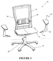
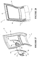
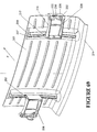
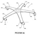
- Figure 1 illustrates an office chair 10 including a main assembly having a seat portion 14 and a back portion 16.
- the seat portion 14 and the back portion 16 are supported above the ground by a supporting frame including a wheeled base 18 and a central support column 20.
- the central support column 20 houses a pneumatic spring (not shown) for height adjustment of the seat portion 14 in conventional fashion.
- the pneumatic spring is connected to the main transom 22 of the chair which is illustrated in Figure 4.
- the main transom 22 extends transversely across the chair and is connected to the pneumatic spring by way of central spring connection ring 23.
- Figure 1 also illustrates two detachable arm assemblies 24.
- the arm assemblies 24 each include an upper armrest 26 which is padded for user comfort.
- Each arm assembly 24 includes an upright support structure 28.
- the armrest 26 is mounted to the upper end of the upright support structure 28.
- the lower end of the upright support structure has an elongate attachment portion 30 extending inwardly therefrom at a downwardly inclined angle relative to the upright.support structure 28.
- the elongate attachment portion 30 is releasably engaged within one end of the main transom 22.
- the manner of attachment is not significant to the present invention.
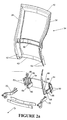
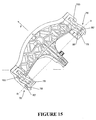
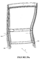
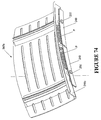
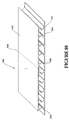
- the back portion 16 is defined by a peripheral frame 34 which is approximately rectangular in shape, as shown in Figure 2.
- the peripheral frame 34 has a mesh fabric stretched over it in a manner described more fully in connection with Figures 81 to 83.
- a lumbar support mechanism 36 is provided within the opening defined by the rectangular peripheral frame 34.
- FIG 2 illustrates more clearly the form of the peripheral frame 34.
- the peripheral frame 34 is constructed of a flexible plastics material such as injection moulded reinforced polyester.
- the peripheral frame 34 is of integral construction and comprises two upright members 38, a top beam 40 and a bottom beam 42.
- the upright members 38 are bowed with a gentle serpentine curve sweeping forwardly in the upward direction and then rearwardly beyond the lumbar region. This is a shape which is comfortable to the chair occupant.
- the upright members 38 include channels 44 which are open in the direction facing rearwardly as shown in Figure 28.
- the upright members 38 are also joined by an intermediate back beam 46.
- the back beam 46 supports the lumbar support mechanism 36.
- the back attach casting 48 is an integrally cast component as shown in Figure 2b.
- the back attach casting 48 includes two pairs of sprigs 50 which engage with aligned apertures 52 provided at the bottom of the upright members 38. This enables the lower region of the peripheral frame 34 to be securely fixed to the back attach casting 48.
- An additional snap fitting (not shown) may be provided:
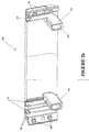
- the back attach casting 48 also includes 2 pairs of opposed walls 54 on opposite sides (more clearly seen in Figure 27). Each pair of spaced walls 54 defines a forwardly extending channel 64 in which a spring carrier 60 is received. Each pair of opposed walls 54 includes aligned slots 56.
- the spring carrier 60 (to be described more fully in connection with Figure 27) has pins 62 on opposite sides to engage with the aligned slots 56.
- the back attach casting 48 includes two forwardly extending hollow projections 66.
- the hollow projections 66 each define a socket 68.
- Two back extension arms 70 are welded within respective sockets 68 of the hollow projections 66.
- each back extension arm 70 includes a forward nose portion 72 and a chin portion 74.
- An extension arm aperture 75 extends through the back extension arm 70 in a position rearwardly of the nose portion 72 and the chin portion 74.
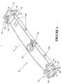
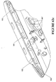
- FIG. 4 illustrates the main transom 22 which extends transversely across the chair as already explained.
- the main transom 22 is supported on a pneumatic spring at central spring support ring 23.
- the main transom is a beam-like construction of diecast aluminium with pivot features 76 formed at opposite ends. At each end, the pivot features comprise opposed supporting webs 78.
- the opposed supporting web 78 have rear aligned apertures 80.
- the extension arm aperture 75 of one of the back extension arms is aligned with the rear aligned apertures 80 on one side of the main transom to receive a main pivot pin (not shown) therethrough.
- the other back extension arm 70 is pivotally attached to the main transom 22 on the other side.
- Each back extension arm is pivotable about the associated main pivot pin and the recline axis R of the back portion 16 is thereby defined.
- a nose portion 72 is defined forwardly of each back extension arm 70.
- the nose portion 72 has two bosses 84 extending sideways from the flanks of the nose portion 72.
- the bosses 84 are receivable within facing slots 86 in the opposed supporting webs 78.
- Each of the facing slots 86 has a base formed therein.
- the bosses 84 move within respective ones of the facing slots 86.
- the bosses 84 will bottom out at the bases of the slots 86 thereby defining forward limits. This is referred to as the "forward active position"of the back portion 16.
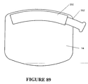
- each back extension arm 70 includes a first abutment surface 88 for engagement with a second abutment surface 90 (see Figure 9) provided as part of the rear wall of the main transom 22.
- first abutment surface 88 engages with the second abutment surface 90
- the rearward recline limit of the back portion 16 of the chair will be thereby defined. It would not be possible for the chair portion 16 to recline back any further once the two abutment surfaces come into engagement although flexing of the peripheral frame is still possible in this position.
- One end of the main transom 22 illustrating the pivot features 76 in greater detail can be seen in Figure 6.
- Recline Biasing Device (not forming part of the present invention).
- the inner flanks of the chin portions 74 of both back extension arms 70 include facing aligned slots 92, the left one of which can be seen in the Figure.
- a first recline spring 94 in the form of an elongate bar or leaf spring has each end received in a respective one of the facing slots 92.
- the main transom 22 has a reaction surface 98 against which the first spring 94 engages.
- the reaction surface 98 is centrally disposed and has a depth corresponding to the depth of the first spring 94.
- the reaction surface 98 forms part of an integrally formed projection extending rearwardly from the main transom 22.
- the first recline spring 94 engages against the reaction surface 98, thereby biasing the back portion 16 against reclining action.
- a second recline spring 96 also has one end received in one of the facing slots 92. However, the second recline spring 96 is somewhat shorter than the first recline spring 94 so the second end of the second recline spring 96 is not received within the other facing slot 92 (see Figure 10). As shown, the second spring is also in the form of a elongate spring bar or leaf spring. The second spring 96 lays behind the first spring 94, against the first spring 94, for at least half the length of the first spring 94. An adjustable clamp 100 (see Figure 7) is provided to clamp the free end of the second spring 96 against the first spring 94 and thus alter the curvature of the second spring 96 and thereby alter its spring resistance.
- the second spring 96 is disposed such that increased clamping against the first spring will act to increase its resistance to bending.
- the net force biasing the back portion against recline will thereby be the sum of the spring force provided by the first spring 94 and the spring force provided by the second spring 96.
- the first spring 94 has a factory set spring rate.
- the second spring 96 is selected to have a high spring rate, greater than the spring rate of the first spring 94. Thereby, a small adjustment of the clamping between the first spring 94 and the second spring 96 will bring about an appreciable change in the spring resistance of the second spring 96.
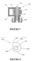
- the adjustable clamp 100 is illustrated in Figure 7.
- the adjustable clamp 100 includes a U-shaped bracket 101 which extends around the two recline springs 94, 96.
- a cam 102 is mounted on axle 103 extending between the two legs of the U-shaped bracket 101.
- the axle 103 is journaled for rotation about an axis 104.
- the cam 102 includes four cam surface portions 105a, 105b, 105c and 105d as shown in Figure 8.
- the cam surface portions are substantially flat as indicated and each is spaced a different amount from the cam axis 104. The spacing decreases in the clockwise direction around the cam 102 from 105a through to 105d.
- the cam 102 bears against the free end of the second spring 96.
- the chair occupant can adjust the position of the cam to determine which of the cam surface portions 105a-105d will bear against the free end of the second spring 96.
- a progressively higher clamping force and hence higher resultant spring rate of the second spring can be obtained as the occupant rotates the cam 102 through to the maximum setting at 105a.
- an extension to the cam 102 is provided to prevent over rotation of the cam 102.
- a knob 103b is provided for user adjustment of the cam 102.
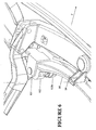
- FIG 5 illustrates a recline lock which may be operated selectively by the user to prevent the back portion from reclining.
- the main transom 22 includes four rearwardly extending projections 106.
- the recline lock comprises an elongate lock bar 107 which has four slots 108 arranged therein, with the lengthwise direction of the slots 108 arranged in the lengthwise direction of the bar 107.
- the slots 108 each receive one of the rearwardly extending projections 106 as shown in Figure 5.
- the elongate lock bar 107 is slidable from side to side between a recline lock position and a recline operative position.
- the projections 106 received in the slots 108 thereby define the limit of travel of the elongate lock bar 107.
- the elongate lock bar 107 is biased toward the recline operative position by spring 109.
- the elongate lock bar 107 can be seen in Figure 10 in which the main transom 22 has been removed for greater clarity.
- the lock bar 107 has at each end a rearwardly extending lock bit 110.
- the lock bits 110 thereby move from side to side with the movement of the elongate lock bar 107.
- Each lock bit is moveable into a recline lock position whereby the lock bit 110 is engaged against a recline locking face 112 provided on the chin portion 74 of the back extension arms.
- the left-hand side lock bit 110 (shown on the right in the figure) moves from a recline operative position in which is it clear of the associated back extension arm 70, to a position in which it is engaged against the recline lock face 112 on the associated arm 70.
- the arrangement in connection with the right hand lock bit 110 (shown in the left in the figure) is slightly different. It can be seen that the associated extension arm 70 has the recline lock face 112. Additionally, the associated arm 70 is provided with the rebate 114 adjacent to the recline lock face 112. In the recline lock position, the lock bit 110 is engaged with the recline lock face 112 whereas in the recline operative position, the left lock bit 110 is received within the rebate 114. When the lock bit is received within the rebate 114, the associated back extension arm 70 can still pivot freely about the recline axis.
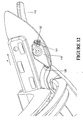
- Figure 12 illustrates the lock bar control lever 116 which is mounted underneath the seat portion 14 in a forward position on the left hand side.
- the lever 116 is connected to cable actuator 118.
- the cable actuator 118 is connected to a control cable 120 which operates in the conventional fashion.
- the control cable 120 controls the position of the elongate lock bar 107 (see Figure 5).
- the cable actuator 118 is rotatable by operation of the control lever 116.
- the cable actuator 118 has a dimple provided on the forward edge which is engageable with the two position detent 122.
- the dimple 121 is locatable in either of two positions, the first of which corresponds to the recline lock position of the elongate lock bar 107, and the second of which corresponds to the recline operative position of the elongate lock bar 107. The user thus selects whether the recline lock is on or off according to the position of the lock bar control lever 116.
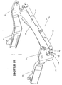
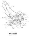
- Figure 13 illustrates a modified form of one of the back extension arms 70'.
- the back extension arm 70' has a forked forward end forming a right fork 93c and a left fork 93d with an extension arm aperture 75' extending transversely through both forks.
- Two such back extension arms 70' are rotatably mounted about the recline axis R to the main transom 22' as shown in its modified form in Figure 14.
- the main transom 22' has pivot features 76' formed at opposite ends. At each end, the pivot features include a pair of spaced supporting webs in the form of inner and outer lobes 78' through which extends aligned apertures 80'.
- the alignment of the apertures 80' defines the recline axis R about which the back extension arms 70' pivot.
- a pin inserted through each pair of apertures 80' mounts each back extension arm 70' to the main transom 22'.
- the inner lobe 78' is inserted between the forks 93c, 93d of the associated back extension arm 70'.
- FIG 13 illustrates an alternative form of recline lock mechanism. It can been seen that the forward end of the back extension arm 70' is provided with a substantially flat upper abutment surface 93 comprised of a forward surface portion 93a, forward of the recline axis R and a rearward surface portion 93b, rearward of the recline axis R.
- the abutment surface 93 lies underneath an upper portion of the main transom (see Figure 16).
- the rearward surface portion 93b thus defines the forward recline limit which will be reached when the back extension arm 70' pivots so that the rearward surface portion 93b abuts the underside of the main transom 22'.
- the rearward recline limit will be defined when arm 70' rotates such that the forward surface portion 93a abuts the underside of the main transom 22'.
- the engagement between the forward surface portion 93a and the underside of the main transom 22' thus defines the rearward recline limit.
- a recline lock may be operated selectively by the user to prevent the back portion from reclining or to set an intermediate recline limit.
- the forward end of the back extension arm 70' is formed with a transversely extending slide 70a in which is slidably mounted a key 107a.
- the slide 70a has a substantially closed inner end 70c which has an V-shaped slot 70b.
- a spring (not shown) is received in the slide 70a between the key 107a and the closed end 70c to bias the key 107a outwardly away from the closed end 70c.
- the key 107a is slidable within the slide against the action of the spring by means of a cable connected to the inner end of the key 107a which is adjustable in the same manner described in Figure 12 (see also Figure 62).
- the key has first and second abutment surfaces 107b and 107c.
- first abutment surface 107b When the key 107a is in the innermost position (relative to the chair as a whole) illustrated in Figure 13, then the first abutment surface 107b does not interfere with the reclining action of the back extension arm 70' as already described. This is referred to as the hyper-recline position, allowing recline of 15°.
- the forward end of the back extension arm 70' is forked as shown to define right and left forks 93c, 93d.
- the key 107a is moved into a position whereby the first abutment surface 107b is aligned with the right fork 93c then the first abutment surface 107b will interfere with the recline action of the back extension arm because the first abutment surface 107b will hit the underside of the main transom 22' before the forward surface portion 93a normally would. This allows recline of 12°.
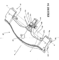
- FIG 14 illustrates the manner by which the keys 107a may be moved in unison.
- a cable 120' is connected between a cable actuator 118' (see Figure 62) and cable amplification mechanism 410 mounted on the rearward extension 22a of the main transom 22.
- the cable amplification mechanism 410 includes a pair of pivotally mounted amplifiers 412 which have intermeshed teeth for synchronous operation.
- One of the amplifiers 412 has a rearward amplifier extension 414 to which the end of the cable 120' is connected.
- the cable 120' passes through cable guide 416.
- the intermeshing amplifiers 412 will be driven to rotate so that their remote ends move towards each other.
- the remote ends of the amplifiers 412 are connected by respective cables to respective ones of the keys 107a. This cable connection is depicted by phantom line 418.
- the side of the back extension arm 70' includes two bores 92a and 92b which face like bores on the facing side of the other back extension arm (not shown).
- Bore 92a is cylindrical and bore 92b is rectangular as shown.
- first and second recline springs 95, 97 extend between the facing bores.
- the second recline spring 97 is in the form of an elongate bar, the ends of which are received in facing bores 92b of the two back extension arms 70'.
- the main transom 22' includes a rearward extension 22a having a bearing block 98' seated in a complementary recess on the upper surface of the rearward extension 22a.
- the bearing block 98' defines a complementary recess to receive a central portion of the second recline spring 97.
- the second recline spring 97 is caused to bend downwardly at its ends while the intermediate portion is held fixed by being seated in the bearing block 98' on the main transom 22'.
- the second recline spring 97 thus resists rearward recline and biases the back extension arms 70' toward the forward recline limit.
- the second recline spring 97 is preloaded at the forward recline limit by being slightly bent. This is achieved by having the centres of the bores 92b slightly below the centre of the spring in the recess of the bearing block 98'.
- the first recline spring 95 operates on a similar principle but is somewhat more complex.
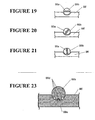
- the first recline spring 95 is illustrated in greater detail in Figure 17 and comprises a spring portion 95a, in the form of a flat bar.
- the outer ends of the first recline spring 95 are fitted with cylindrical bosses 99a to be received in the facing cylindrical bores 92a provided in the back extension arms 70'.
- a central cylindrical boss 99b is fitted onto the bar 95a.
- the central boss 99b is slotted to allow the bar 95a to pass through.
- the central cylindrical boss 99b is seated in a semi-cylindrical recess provided in the bearing block 98' on the main transom 22'.
- the bearing block 98' may be provided with upstands at its sides to locate the boss 99b relative to its seat in the bearing.
- the flat bar spring portion 95a provides resistance to recline through its inherent resistance to bending about a bending axis arranged transversely to the length of the spring 95. It will be appreciated that with the configuration of the ends of the first spring 95 and the central cylindrical boss 99b bearing against the main transom 22', the bending axis will be defined which extends generally transverse to the longitudinal axis of the spring 95. The arrangement is such that no pre-load is applied to flat spring portion 95a in the forward active position. The central recess in the bearing block 98' and the cylindrical bores 92a are thus aligned for this reason.
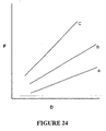
- the first recline spring 95 is adjustable to change the spring rate. This is achieved by rotating the first spring 95 about the longitudinal axis of the spring through the use of paddle 99c which is fixed onto the spring bar portion 95a. It can be seen from the cross-sectional views shown in Figures 19 to 21 that the spring portion 95a has a thickness and a width dimension, the width dimension being greater than the thickness dimension. In Figure 19, the spring 95 is oriented so that the width dimension is arranged substantially parallel to the bending axis. This represents the 'easy' spring position. In Figure 20, the thickness dimension is arranged diagonally to the transverse bending axis. Such an arrangement will present a greater resistance to bending about the transverse axis. This accordingly represents the "medium" spring position.
- the width dimension is arranged transversely to the bending axis. Such an arrangement presents the greatest resistance to bending and is thus deemed the "hard” position for the first recline spring 95.
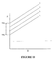
- the first recline spring 95 is thus adjustable through 90° to provide three adoptable spring positions at each of which the spring exhibits a different spring rate. This is visually depicted in Figure 24 which illustrates graphically the change in net spring force over distance as the spring is adjusted between easy (A), medium (B) and hard (C).
- Figure 18 illustrates the first spring 95 in the easy position
- Figure 22 illustrates the first spring 95 in the hard position.
- locators are provided in the form of grooves 99d provided in the cylindrical boss 99b.
- a complementary rib 99e is disposed in the semi-cylindrical recess of the bearing block 98a. The rib 99e can engage with any one of the complementary grooves 99d to accordingly locate the first spring 95 in that position. It may be necessary to remove most of the loading on the first spring 95 in order to change the spring position. Accordingly, it may be necessary to bring the back portion to the forward active position to achieve this.
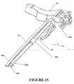
- Figure 25 illustrates in greater detail the form of the cylindrical bosses 99a on the first spring 95.
- the end of each boss is cut away to define a semi-circular rebate 99d thereby defining a diametrical abutment face 99e.
- the end of bore 92a is provided with a projecting quadrant 92c. With the boss 99a assembled in the bore 92a, the quadrant 92c projects into the semi-circular rebate 99d.
- the spring 95 is rotatable through 90° between a first rotatable limit where one face of the quadrant 92c abuts against one half of the diametrical abutment face 99e and a second rotatable limit where the other face of the quadrant 92c abuts against the other half of the diametrical abutment face 99e.
- the interaction between the quadrant 92c and the diametrical abutment face 99e limits the rotation of the spring 95 to 90°.
- the two bores 92a and 92b are shown as formed directly in the sides of the back extension arms 70. It is also envisaged that a plastic insert could be fitted into the side of the arm 70 with the bores 92a and 92b formed in the insert.
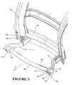
- Figure 27 illustrates a further exploded view of parts assembled with the peripheral frame 34.
- a back attach casting 48 is fixed to the back of the peripheral frame 34.
- the back attach casting 48 has two upright channels 64 arranged at either end, each defined by opposed walls 54.
- the opposed walls 54 have aligned slots 56 arranged therein for receipt of pins 62 provided on a spring carrier 60.
- the specific form of the spring carrier 60 is illustrated more clearly in Figure 29.
- the spring carrier 60 is in the form of an elongate member which is approximately square or rectangular in cross section with the pins 62 being arranged on opposite sides.
- One end of the member is provided with a rebate 124.
- the other end of the spring carrier is forked for pivotal connection with another linkage as will subsequently be explained.
- the forked end has aligned apertures 126.
- the rebate 124 has spaced threaded bores 130 provided therein.
- a leaf spring 128 has a lower end 131 shaped to be received within the rebate 124.
- the lower end 131 has two spaced apertures 133 provided therein. These apertures 133 align with the threaded bores 130 provided on the spring carrier so that the leaf spring 128 may be securely fastened to the spring carrier 60. From the lower end 131 in the upwards direction, the leaf spring 128 gradually increases in width with a slight tapering in thickness, although overall the leaf spring 128 is of generally elongate configuration as shown.
- the leaf spring 128 is constructed from high tensile spring steel.
- Figure 28 illustrates the assembled combination whereby each of the leaf springs lie against the back of the peripheral frame 34 in a respective channel 44.
- the peripheral frame 34 has a degree of flexibility.
- the leaf spring 128 will be caused to act against the lower portion of the peripheral frame thereby increasing its stiffness against rearward flexing.
- the two spring carriers act in unison in a manner which will be described in connection with Figures 30 to 34.
- the stiffness of the lower portion of the peripheral frame 34 can thereby be adjusted by adjustment of the position of the spring carrier 60.
- the channels 64 in which each of the spring carriers 60 are received are closed rearwardly by a rear wall 135 of the back attach casting 48.
- the rear wall 135 defines a stop against which the forked ends 125 of the spring carriers engage, thereby defining the maximum rotation of the spring carrier 60 and thus the maximum stiffness which can be imparted by the leaf spring 128 to the peripheral frame 34.
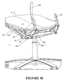
- Figure 30 illustrates the main elements of the recline mechanism.
- the back attach casting 48 has been removed for clarity, together with the right back extension arm 70.
- the left back extension arm 70 is shown in position pivotally connected to the main transom 22.
- the forked end 125 of each spring carrier 60 is connected to a push link 139.
- the lower portion of the peripheral frame 34 has an access opening 143 to enable the push link 139 to engage with the forked end 125 of the spring carrier 60 disposed within the assembled back attach casting 48.
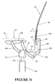
- the forward end of the push link 139 is connected to a drive link 141 (see Figure 30) which is one element of a four bar linkage which will be understood more fully from a consideration of the schematic illustration of Figure 31.
- FIG 31 illustrates only one four bar linkage and it will be apparent to the reader that two such four bar linkages are provided, one on each side of the chair 10.
- the drive link 141 extends at an inclined upwards angle from its connection with push link 139.
- the drive link 141 is curved along its length with the centre of the curve being disposed rearwardly and upwardly.
- the drive link 141 is mainly of rectangular cross section.
- the drive link 141 is pivotally connected at an intermediate location along its length to the main transom 22 for pivoting motion about the recline axis R. Specifically, the drive link 141 is pivotally connected to lie adjacent to the outer one of the opposed supporting webs 78 of the main transom 22. A common pivot pin (not shown) interconnects both of the opposed supporting webs 78, the back attach arm 70 through aperture 75, and the drive link 141.
- the main transom 22 forms another element of the four bar linkage. As has already been explained, the main transom 22 is centrally mounted to the supporting frame at the top of the central support column 20 which incorporates a height adjustable pneumatic spring 145. The height adjustment 145 is selectively operable by the chair occupant. However, the main transom 22 is normally stationary relative to the supporting frame.
- the seat portion 14 is slidably mounted to a seat guide 149 in a manner which will be described more fully in connection with Figures 55 to 60.
- the seat guide 149 thereby forms another element of the four bar linkage.
- the upper end of the drive link 141 is pivotally connected to the seat guide 149.
- Another link in the form of a front support link 151 interconnects the seat guide 149 and the main transom 22.
- the front support link 151 is of generally rectangular cross section and, like the drive link 141 is curved along its length with the centre of curvature disposed upwardly and rearwardly.
- both ends of the drive link 141 are forked.
- the lower end is forked to accommodate the lower end of the push link 139.
- the upper end of the drive link 141 is also forked.
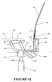
- the seat guide also has a dependent lobe 155 as shown in Figure 32.
- the forked upper ends of drive link 141 are disposed on each side of the lobe 155 and the inner fork is pivotally connected between the lobe 155 and the side wall of the seat guide 149.
- the outer fork is fanned in shape for aesthetic reasons and the pivotal connection does not extend therethrough.
- the upper end of the front support link 141 is also forked with the inner fork being pivotally connected between a seat guide 149 and another lobe 157 (see Figure 32), with the outer fork being of fanned shape.
- the lower end of the front support link 151 is pivotally connected on the outside of the outer one of the opposed supporting webs 78 (see Figure 4) by means of a pin (not shown) extending through aligned forward apertures 153 on the forward end of the opposed supporting webs 78. It will be appreciated that the connection of the lower end of the drive link 141 and the front support link 151 are blind connections as shown for aesthetic reasons.
- the occupant's weight will be taken up by a spring tension in leaf spring 128 as it flexes against the back of the peripheral frame 34. This has the effect of stiffening the back portion against rearward flexing. It will be appreciated that the tension imparted to leaf spring 128 will depend upon the weight of the user W applied to the seat portion 14. The greater the weight W, the greater the tension taken up by the leaf spring 128 and thus the greater the degree of stiffness imparted to the leaf spring 128 to resist rearward flexing of the peripheral frame 34. Accordingly, the stiffness of the peripheral frame 34 will be adjusted according to the weight W of the chair occupant.
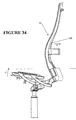
- Figure 33 illustrates the downward motion of the seat guide 149 as the user applies weight W. When the occupant alights from the chair, the seat portion 14 will move upwardly as indicated by arrow U in Figure 34.
- the gentle serpentine shape of the peripheral frame 34 is designed to correspond with the shape of the occupant's spine for the comfort of the occupant.
- the ergonomics of the chair are further enhanced because this enables the occupant to exercise his spine.
- the general health of a person's spine is enhanced by movement.
- the stiffness of the back portion in rearward flexing is adjusted according to the occupant's weight. Therefore, within a certain range, the ease of rearward flexing will correlate to the weight of the occupant. Therefore, a light person will be able to obtain full benefit from the rearward flexing action by applying a light force against the peripheral frame.
- the chair is designed so that the occupant will be able to obtain deflection through flexing in the range of 80 mm to 120 mm.
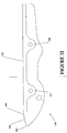
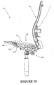
- Figure 35 illustrates the reclining action of the chair 10.
- the seat portion When the user applies their weight to the seat portion 14, the seat portion will move downwardly as already described and adopt a position just above the seat guide 149 as illustrated by the solid lines.
- the leaf spring 128 takes up a corresponding amount of spring tension whereupon the spring carrier 60 and the push link 139 will adopt a more or less fixed position relative to the back attach casting 48. Therefore, as the user leans against the back portion 16, the back attach casting 48, spring carrier 60, push link 139 act in unison driving the drive arm 141 to rotate in a clockwise direction through push link 139.
- the arrangement of the four bar linkage is such that the seat guide 149 will adopt a position with a net increase in height and with an increase in rearward tilt angle compared to the occupied position of the seat guide 149 before recline. In practice, there may be some slight shifting between the leaf spring 128, the spring carrier 60 and the push link 139.
- the occupant's weight W will be counteracting the recline action, together with the bias applied by the first and second recline springs 94, 96.
- the weight of the occupant W will therefore be a variable factor in the ease with which the back portion 16 reclines. If the adjustable second recline spring 96 is set at a constant level then a heavier person will encounter a greater resistance to reclining action than a lighter person. This establishes an automatic correlation between the weight of the person and the resistance to the reclining action. For a large proportion of people who fit within physical norms this automatic adjustment may be sufficient. However, people come in all different shapes and sizes and therefore additional adjustment is required through the use of the clamping adjustment as explained previously. For example, a very tall, light person may obtain leverage through their height which makes the back portion 16 fall back too easily against their low weight W.
- the net increase in height also has the advantage of raising the occupant during recline so that the eye level of the chair occupant can be maintained even though he is undergoing a reclining action.
- the peripheral frame will still be able to flex under additional force applied by the chair occupant.
- the peripheral frame will be capable of undergoing deflection in the range of 80 mm to 120 mm.
- the weight of the user against the back portion will bring about a deflection of up to 20 mm. Therefore, once the recline limit is reached, the occupant still has further deflection available through flexing of the peripheral frame in the range of 60 to 100 mm.
- the seat portion 14 is only supported by the seat guide 149 at a rear portion thereof with a forward portion being unsupported.
- a transition point 161 is disposed behind the forward edge 160 of the seat guide 149.
- the transition point 161 marks the boundary between the planar upper surface 178 of the seat guide 149 and a forwardly inclined lead surface 285.
- the seat portion 149 is foldable transversely at this location.
- the transition point 161 hence defines the division between the rearward portion and the forward portion of the seat portion 14. Since the seat portion 14 is slidable forwardly and rearwardly for seat depth adjustment as will be explained in connection with Figures 55 to 60, the division between rearward portion and forward portion of the seat will vary as a function of seat depth.
- Figure 35 illustrates the changing curvature of the back portion 16 and seat portion 14 in recline.
- the solid lines indicate the forward active position in the occupied configuration.
- the dotted lines illustrate the reclined position.
- the seat guide 149 attains a net increase in height and an increased rearward tilt. This effectively cups the occupant's derrière, negating any inclination to slide forwardly during the recline action.
- the seat portion 14 is also flexible and since the occupant's derrière is undergoing a net increase in height together with increased rearward tilt, a greater amount of weight from the occupant's legs will be brought to bear against the forward portion of the seat portion 14. Accordingly, the seat portion 14, will be allowed to fold transversely at the transition point 161 on the seat guide 149.
- transition point 161 approximately corresponds to the gluteal fold of the occupant's derriere. Therefore, during recline, the occupant's derrière will be cupped between the rear portion of the seat portion 14 and a lower region of the back portion 16 while the forward portion of the seat drops forwardly under the weight of the occupant's legs. Locating the transverse fold at the gluteal fold of the occupant ensures that undesirable pressure will not be brought to bear against the back of the occupant's legs.
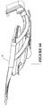
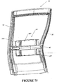
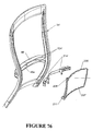
- Figure 36 illustrates in exploded fashion a modified form of the back portion 16'.
- the back portion 16' includes a flexible peripheral frame 34' which is connected to a back attached casting 48'.
- the spring carriers have been obviated and instead there are two unitary leaf springs 128' which bear against the back of the peripheral frame 34'. Additionally, two supplementary springs 450 are also provided, the function of which will be explained.
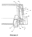
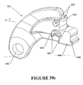
- Figure 39c illustrates the modified form of the push link 139'.
- the push link is arcuate in configuration.
- the push link has an aperture 452 to which it can be pivotally connected to drive link 141' (see Figure 41a and 41b).
- a stepped region 454 having a first abutment face 456 and a second abutment face 458.
- a first pair of gliders 460 Forwardly of the stepped region 454 is a first pair of gliders 460.
- Each glider of the pair 460 is disposed on opposite side faces of the push link 139'.
- a second pair of gliders 462 Disposed directly below the first pair of gliders 460 is a second pair of gliders 462 disposed on opposite side faces of the push link 139'.
- the back attach casting 48' incorporates two pairs of sprigs 50' which engage with aligned apertures (not shown) in the peripheral frame 34' for assembly purposes.
- spaced walls 54' define a forwardly extending channel 64' in which the leaf spring 128' is housed in a manner which will be explained.
- the forwardly extending channel 64' includes two forwardly extending tracks 464 on opposite sides of the channel 64'.
- the tracks 464 each comprise a substantially horizontal ledge 466 which terminates in a downwardly extending flange 468 in the assembled configuration of the push link 139' and the back attach casting 48', the first pair of gliders 460 are disposed to glide along the top surface of the associated ledges 466 whereas the second pair of gliders 462 passes underneath the bottom surface of the associated ledges 466.
- each of the second pair of gliders 462 has a flat abutment surface 470 which abuts against the inside of the downwardly extending flange 468. This defines the forward limit in the sliding movement of the push link 139' relative to the tracks 464.
- Figure 39d illustrates the assembled configuration of the push link 139', the back attach casting 48', the leaf spring 128', the supplementary spring 450 and the peripheral frame 34'.
- the supplementary spring 450 and the leaf spring 128' are arranged such that the first abutment face 456 will come into contact with the supplementary spring 450 prior to the second abutment face 458 coming into contact with the leaf spring 128'.
- the supplementary spring 450 does not have a bearing on the stiffness of the peripheral frame 34'. Therefore, up to a predetermined threshold of the users weight W, there will be no stiffening effect on the peripheral frame 34'.
- the predetermined threshold which is about 50 kg
- the second abutment face 458 of the push link 139' will come into contact with the leaf spring 128'.
- the leaf spring 128' has an initial slightly bent configuration as illustrated in Figure 39d.
- the leaf spring 128' bears against spring seat 474 disposed at the top of the forwardly extending channel 64' as can be seen in Figure 37.
- the spring seat 474 is concave from side to side to position the leaf spring 128' while being convex from top to bottom as illustrated in cross section in Figure 39d.
- the spring seat 474 defines a point about which the leaf spring 128 bends as the push link 139' moves rearwardly in its tracks 464.
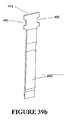
- Figure 39b illustrates in greater detail the form of the supplementary spring 450.
- the supplementary spring is in the form of a leaf spring having an enlarged head formation 478 which includes two bights 480 on opposite edges.
- the bites 480 cooperate with facing complementary locating blocks 482 disposed on opposite sides of the forwardly extending channel 64.
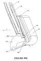
- Figure 41a illustrates certain components of the recline mechanism although the peripheral frame 34' and the back attach casting 48' have been removed for clarity.
- the drive link 141' is pivotally mounted to the main transom 22' at an intermediate location.
- the opposite end of the drive link 141' to that which the push link 139' is attached is pivotally connected with the seat guide 149'.
- the front support link 151' is connected between the seat guide 149' and the main transom 22'.
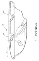
- the drive link 141' and the front support link 151' are also curved about one or more upright axes as well as being curved about a horizontal transverse axis as described with the first example. This renders a more complex shape for the seat guide 149' as depicted in Figure 43.
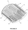
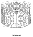
- FIG 46 is a perspective view of a preferred form of the seat portion 14 which is appropriate for use with either embodiment of the chair.
- the seat portion 14 is in the form of a flexible plastic panel, whose flexibility is enhanced by the arrangement of slots as indicated.
- the plastic panel may be injection moulded plastic such as TPR.
- Figure 50 is a longitudinal section through the middle of the seat panel 14 illustrating the general curved configuration with a rolled over edge. The edge drops by an amount of dimension A.
- Figure 51 illustrates the side edge of the seat panel 14. The side edge is flatter than the middle section. Additionally, the forward edge dips down a dimension B, where B is larger than A.
- Figure 52 illustrates a transverse sectional view at about 150 mm from the rear of the seat whereas the view Figure 53 depicts the transverse cross sectional view 120 mm from the front edge.
- FIGS. 50-54 are merely indicative of the moulded shape of the seat panel 14.
- the seat panel is also flexible to accommodate the occupant and to respond to movement of the occupant.
- the arrangement of slots in the seat panel 14 as shown in Figure 46 is designed to enhance the flexibility of the seat panel 14.
- the arrangement of slots in the forward half of the panel is designed to facilitate folding along the transverse fold.
- the slots are arranged in a series of spaced sinuous lines 163 extending transversely across the seat portion 14 with the central part being shaped convex forwardly with the outer parts being shaped concave forwardly.
- the lines of slots 163 are discontinuous.
- the seat portion 14 is dished at least in a rearward part.
- the series of spaced sinuous lines 163 enables the seat panel 14 to fold transversely, even though the rear part is dished.
- the slotted pattern 164 is such as to extend diagonally across the corners following the curvature of the transverse sinuous lines 163. In this way, if the user moves a leg to one of the forward corners then the diagonal arrangement of the slots 164 will enable the forward corner to fold under the weight of the occupant's leg.
- the slots are arranged in a pattern to accommodate the ischial protuberosities of the occupant.
- the slotted pattern provides two spaced, approximately rectangular zones 162 whose locations correspond to the ischial protuberosities of the occupant (assuming the occupant is properly seated with an appropriate seat depth adjustment).
- the two zones 162 interrupt the transverse slot pattern.
- Each zone is comprised of slots arranged in a series of longitudinally extending, transversely spaced sinuous lines.
- the lines of slots are discontinuous.
- the longitudinal arrangement of slots in each zone 162 enables the remaining material between the longitudinal lines of slots to spread apart thereby creating pockets, one for each ischial protuberosity of the seat occupant.
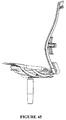
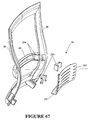
- Figure 47 illustrates longitudinal stiffening webs 165 provided on the underside of seat panel 14. There are five stiffening webs, two disposed along the opposite side edges. A further two are disposed on each side at 60 mm from the corresponding side edge. Another is centrally disposed.
- the longitudinal stiffening webs are constant in height from the back edge of the seat portion until the taper start point 164 from where they progressively reduce in height until a taper finish point 166. (The central web however terminates early)
- the seat portion 14 accommodates a depth adjustment as will be explained in connection with Figures 55 to 60.
- the seat portion folds transversely about the transition point 161 on the seat guide 149.
- the depth of the stiffening ribs in the region at the transition point 161 is shallow thereby offering little resistance to flexing. Generally, this suits a small, light weight person. However, for a larger person, the seat panel will be disposed further forwardly in relation to the seat guide 149. The depth of the stiffening ribs in the location of the transition point 161 will be deeper, thereby offering increased resistance to bending. This suits a larger, heavier person.
- the start taper point 164 is at a position which corresponds to the transition point 161 when the seat is at its full forward position to suit a large person.
- the taper finish point 166 is at a position corresponding to the transition point on the seat guide 149 with the seat in the rear most position to suit a small person.
- the taper start point 164 and the taper finish point 161 define a transition zone therebetween.
- the transverse fold may be disposed at a range of positions within the transition zone, dependent on seat depth adjustment.
- the pattern of transversely extending sinuous lines of slots extends for at least the transition zone.
- Figure 47 also illustrates transverse stiffening webs 168.
- the stiffening webs 168 follow the pattern of the transversely arranged sinuous slots 163.
- the seat panel is moulded in a dished shape.
- the transverse stiffening webs 168 help to retain the shape of the front part without inhibiting the transverse folding action under the weight of the user.
- a back web is provided along the back of the seat panel 14 on the underside as shown in Figure 47.
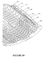
- Figure 49 illustrates in greater detail the arrangement of features along one side edge.
- a series of spacer blocks 270 extending in a line between the taper start point 164 and the taper finish point 166.
- a wedge-shaped gap 272 widening towards the top.
- the seat panel 14 sits atop a seat carriage 167.
- a rear part of the seat panel 14 is secured atop the seat carriage 167 so that forwardly of the seat carriage 167 there will be a gap between the seat guide 149 and the seat panel 14.
- the spacer blocks 270 extend into this gap. As the seat panel 14 folds, the spacer blocks 270 bear against the top of the seat guide 149. It can be seen that the spacer blocks 270 also taper off in height as shown. Furthermore, the spacer blocks 270 will define the maximum curvature of the seat panel along the transverse fold since once the side walls of the wedge- shaped gaps 272 engaged with each other, further curvature will be prevented.
- a guard also extends alongside the spacer blocks 270 to provide a barrier against the user's fingers being trapped.
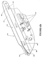
- FIG 55 illustrates the main elements of the seat depth adjustment mechanism.
- the seat guide 149 is one of the elements of the four bar linkage discussed previously.
- the two seat guides 149 provide a guide for a slidable seat carriage 167.
- a rear part of the seat panel 14 illustrated in Figures 47-54 is attached to the carriage 167.
- the rear half only of the seat panel 14 is attached to the seat carriage 167.
- the seat panel 14 may be moved forwardly and rearwardly by the sliding action of the seat carriage 167 on the seat guide 149.
- a longitudinally extending rib 274 engages within a channel 278 (see Figure 55) of the seat carriage 167 and the tab 276 is a snap fit connection within the recess 280 located rearwardly on the seat carriage 167.
- four spaced retention tabs 282 engage against soffit 284 of the carriage 167. The retention tabs 282 retain the seat panel 14 engaged with the seat carriage 167 while the longitudinal rib is the main load bearing part.
- Figure 55 also illustrates the controls for the height adjustable pneumatic spring 145.
- a height adjustment control lever 169 is mounted for pivotal motion on the outside of the right hand seat guide 149.
- the pivotal motion of the height adjustment control lever 169 is replicated by the height adjustment control actuator 170 which is connected to one end of a control cable 172.
- the other end of the control cable 172 is connected to the top end of pneumatic gas spring 145.
- the control cable 172 releases the gas spring in the conventional known manner and the chair occupant adjusts the height of the seat portion 14 to suit his requirements.
- FIG 56 is a further detailed view of the left side of the seat carriage 167.
- the seat guide 149 includes a plastic seat guide liner 176.
- the seat guide liner is of elongate configuration with an upper glide surface 178 and an inner glide surface 180.
- the inner glide surface 180 is spaced from the inner side of the metal part seat guide 149 with a peripheral wall 182 maintaining the inner glide surface 180 in spaced configuration therefrom.
- the seat guide liner 176 is thereby hollow behind the inner glide surface 180.
- the upper glide surface 178 is received within a rebate in the upper surface of the metal part of the seat guide 149 in order that the upper glide surface 178 is contiguous with the upper surface of the metal part of the seat guide 149.
- the seat guide liner 176 provides a bearing surface for easy sliding of the seat carriage 167.
- the seat guide liner 176 may be comprised of nylon or acetal. The reader will appreciate that a symmetrical arrangement is provided on the right hand side of the chair.
- the seat carriage 167 is of unitary cast aluminum construction and comprises two spaced slides, each of which engages with a respective seat guide 149.
- Each slide is of a generally L-shaped configuration having an upright glide surface 186 on an inner wall for sliding engagement with the inner glide surface 180 and a horizontal glide surface 187 for engaging with the upper glide surface 178.
- the carriage is of a symmetrical configuration about a central upright longitudinally extending plane of the chair.
- the two slides provided on the right and left are thereby of opposite configuration.
- the two slides are joined by transversely extending bearers 190.
- the inner glide surface 180 is moulded with a series of archlets which extend from the inner glide surface 180.
- the archlets 184 protrude inwardly (relative to the chair as a whole) to bear against the upright glide surface 186 of the seat carriage 167.
- the archlets may be arranged in any pattern but preferably they are staggered along the length of the inner glide surface 180.
- Both of the seat guide liners 176 have inwardly extending archlets bearing against the associated upright glide surfaces of 186 of the carriage 167.
- the archlets 184 thereby act against the carriage to centre the carriage 167 centrally between the two seat guides 149.
- the resilient archlets 184 will take up any slack between the upright glide surface 186 and the inner glide surface 180. This assists to prevent jamming of the carriage 167 within the seat guides 149.
- Figure 57 illustrates the control for seat depth adjustment.
- the inner wall of both slides 185 have a lower edge with a series of spaced notches 192.
- a seat depth adjustment bar 194 has two teeth 196, each arranged at opposite ends of the bar 194.
- the seat depth adjustment bar 194 is moveable between a latched position in which the teeth 196 engage in a respective one of the notches 192 and an unlatched position in which the carriage 167 is free to slide along the seat guide 149.
- the seat depth adjustment bar 194 is controlled by a seat depth adjustment button 200.
- the seat depth adjustment button 200 is moveable from the latched position against the bias of a spring (not shown) to move the seat depth adjustment bar 194 into the unlatched position whereby the teeth 196 no longer engage in the notches 192.
- the seat carriage 167 can then be slid to an appropriate seat depth whereupon the occupant releases the seat depth adjustment button 200 to enable the teeth 196 to engage with the closest of the notches 192.
- a seat depth stop 174 ( Figure 55) formed as a dependent projection from the seat carriage 167 determines the forward position of the seat carriage 167 as it engages with the adjustment bar 194 or sleeves 158 receiving the ends of the adjustment bar 194.
- the rear limit is defined by a pin (not shown) extending inwardly from the seat guide 149 to engage within a slot of the seat carriage 167.
- the slot is machined to define a stop to engage with the join in the rear most position of the seat portion.
- Figures 58 and 59 illustrate the extended and retracted positions respectively of the seat portion 14.
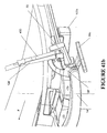
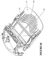
- FIG 61 and 62 illustrate a modified form of the seat carriage 167' and the seat guide 149'.
- the seat carriage 167' is a unitary cast aluminum construction with two spaced slides as explained with the first example, each of which engage with a respective seat guide 149'.
- the two slides are joined by a unitary deck construction having a series of transversely extending ribs as shown.
- the seat guides 149' include seat guide liners 176' having an upper glide surface 178' and an inner glide surface 180' to slidably engage with the respective slide of the seat carriage 167'.
- the seat guide liners 176' will be described in greater detail in connection with Figure 62b and 62c.
- the second example of the chair includes a control lever 169' on the right hand side (left hand side of the figure).
- This lever 169' is a dual actuator for both the seat height adjustment and seat depth adjustment.
- the control lever 169 is mounted for pivotal motion on the outside of the right hand seat guide 149'.
- the control lever 169' effects the operation of a dual actuator 170' mounted on the inside of the right hand seat guide 149'.
- the actuator 170' includes a first actuator portion 170a and a second actuator portion 170b.
- the first actuator portion 170a is connected to cable 172' which connects to the top end of a pneumatic gas spring 145'. As the user raises the control lever 169', the control cable 172' releases the gas spring in the conventional known manner and the chair occupant adjusts the height of the seat portion 14 to suit his requirements.
- the second actuator portion 170b is connected via cable 488 to a pivotable pawl 490.
- the pawl is engageable between any one of a plurality of teeth provided on a rack 492 formed on the underside of the seat carriage 167'.
- the pawl and rack arrangement 490,492 is also duplicated on the other side of the seat carriage 167' as shown in Figure 62.
- the cable 488 passes from the right hand pawl 490 around to the other side of the seat carriage 167' for simultaneous operation of the two pawls 490.
- the user depresses the control lever 169' to operate the second actuator portion 170b to pivot the two pawls against a bias out of engagement with the teeth of the associated rack 492.
- the seat carriage 167' can then be slid to an appropriate seat depth where upon the occupant releases the control lever 169' to enable each of the pawls 490 to engage with the associated rack 492.
- Figure 61 also illustrates a forward cover 495 which is shaped in a serpentine manner for aesthetic purposes to extend in front of the main transom 22'.
- the cover 495 is joined to the seat guides 149' on each side through the use of integrally formed bosses 497 which can be seen in Figure 62b and Figure 62c.
- the seat guide 149' illustrated in Figure 62b includes a seat guide liner 176'.
- the seat guide liner 176' includes an upper glide surface 178' and an inner glide surface 180'.
- the inner glide surface 180 is formed with a series of spaced integral resilient projections 500.
- the integral resilient projections 500 are directed inwardly.
- the seat guide liner 176' is supported on a metal supporting part of the seat guide liner as shown in Figure 62c.
- the inner glide surface 180 is disposed in spaced configuration from the inside of the supporting part of the seat guide 149'.
- the supporting part of the seat guide 149' includes three spaced rests 502.
- the integral resilient projections 500 are shaped like ramps, the ends of which engage against the associated rest 502. The majority of the inner glide surface 180' is thereby resiliently held in spaced configuration from the supporting part of the seat guide 149'.
- a movable comb like formation 504 is incorporated into the seat guide liner 176' as shown in Figure 62b.
- the comb like formation 504 has an upper surface continuous with the upper glide surface 178' and dependent prongs 506 which extend downwardly. The prongs are receivable into a series of corresponding pits 508 formed in the metal supporting part of the seat guide 149'.
- the movable comb like formation 504 is resiliently flexible and would normally extend to fill the gap between the leading edge 285 of the seat guide 149' and the dependent spacer blocks 270'.
- the occupant's weight is not yet bearing on seat panel 14 and thus the seat panel 14 has not yet come to rest on top of the comb like formation 504.
- the dependent spacer blocks are not visible in this view because the seat panel 14 has a peripheral guard to prevent jamming of fingers in the V-shaped gaps of the spacer blocks 270'.
- the spacer blocks 270' will come to bear against the comb like formation 504 which will deflect as the seat portion 14 folds about the transverse fold.
- the comb like formation 504 presents an additional guard to mitigate the likelihood of user's fingers being caught between the seat panel 14 and the seat guide 149'.
- the comb like formation 504 does not interfere with the transverse folding of the seat panel 14.
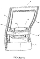
- Figure 63 illustrates the seat panel 14 in its inward retracted position whereas Figure 64 illustrates the seat panel 14 located in its outer most extended position.
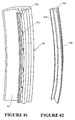
- Figure 81 illustrates the preferred cross section for the upright members 38 of the peripheral frame 34.
- the uprights of the peripheral frame each include a rearwardly open channel 44 in which the leaf spring 128 resides as has been explained previously.
- the upright member 38 also includes a second rearwardly open channel 252 of much narrower configuration than the first mentioned rearwardly open channel 44.
- the second rearwardly open channel 252 receives an attachment strip 254.
- the attachment strip 254 is of extruded resilient plastics material in the form shown.
- the attachment strip 254 has a longitudinal extending lip 550 which engages with retainer portions 552 provided along one of the walls of the channel 252 to assist in holding the attachment strip 254 within the channel 252.
- the attachment strip 254 also includes a part 258 which extends over the edge of the channel 252 when the lip 550 is engaged with retainer portions 552.
- the mesh fabric 260 is sized so that with the attachment strip 254 secured within the second rearwardly open channel 252 on both sides of the back portion 16, the mesh fabric 260 will be relatively taut across the peripheral frame.
- the top of the mesh fabric 260 is also held within a top rearwardly open channel 253, in the same manner.
- the bottom of the mesh fabric 260 is held within a bottom rearwardly open channel 255 in the same manner.
- the attachment strip 254 is a unitary strip extending around the entire periphery of the peripheral frame 34.
- the peripheral frame 34 is of flexible construction, particularly around the region corresponding to the lumbar region of the occupant. Additionally, the mesh fabric is drawn taut across the peripheral frame 34. It is important that the frame does not flex so as to draw in the upright members 38 of the peripheral frame 34 due to the tautness of the mesh fabric 260. Accordingly, the back beam 46 is positioned so as to correspond approximately with the lumbar region of the seat occupant. This maintains the spacing of the upright members 38, particularly in the lumbar region where the frame 34 bends. The bending of the peripheral frame 34 close to the lumbar region of the occupant is encouraged by the serpentine shape of the peripheral frame 34 as well as being encouraged by the cantilevered connection of the peripheral frame 34.
- the mesh fabric 260 may have a degree of resiliency but this is somewhat limited. It is preferable that the mesh fabric should be able to maintain tension over a reasonably long period of time. It is desirable that the mesh fabric 260 is not overly stretched. For this reason, it is desirable that the neutral axis of bending be close to the front surface of the upright members 38 of the peripheral frame 34. Accordingly, the cross section of the peripheral frame 34 is designed to have the bulk of material on the forward face so that bending occurs as close as possible toward the forward face of the upright member 38. In bending, there will be some compression of the walls defining the channel 252 in the lumbar region. Additionally, there may be some flexing of the two walls of the channel 252 towards each other.
- FIG 84 illustrates a preferred form of the wheeled base 18.
- the wheeled base includes five radially extending legs 300.
- Each of the legs is supported by a respective castor 302.
- the five legs 300 make up an unitary cast leg assembly.
- Each leg is elongate and substantially plate-like in thickness, strengthened by a strengthening web 304 extending longitudinally along each leg 300.
- the strengthening webs 304 terminate at their inner ends at a centrally disposed annular boss 306.
- each of the legs 300 is provided with an integrally formed dependent connector 308.
- Each dependent connector 308 is in the form of a socket or sleeve.
- the end of each leg 300 terminates in a clip-on bumper 301 comprised of resilient plastic or rubber material.
- FIG 86 illustrates the form of the castor 302.
- Each castor 302 comprises two spaced wheel portions 312.
- the wheel portions 312 are rotatably mounted on an axle 314 forming part of an axle assembly 316 illustrated in Figure 87.
- the axle assembly 316 incorporates the axle 314, a connector pin 318 and an intermediate body portion 320 interconnecting the axle 314 and the connector pin 318.
- the wheel portions 312 are received on opposite ends of the axle 314 and rotatably held there by means of a snap-fitting.
- the connector pin 318 is disposed between the two wheel portions 312. Furthermore, there is a further gap provided between the connector pin 318 and the wheel portions 312 to receive at least part of the dependent connector 308.
- the connector pin 318 releasably engages with the dependent connector 308 enabling the pin to rotate within the dependent connector 308 about the longitudinal axis of the pin 318.
- a snap-fit connection may be provided therebetween.
- Figure 89 illustrates in schematic form, the underside of the slotted seat panel 14.
- a scabbard which is curved in form.
- the scabbard 350 houses an instruction slide 352 which is also curved and slides in and out of the scabbard at one end. From above, the instruction slide 352 has printed indicia thereon providing user instructions to the seat occupant.
Landscapes
- Dentistry (AREA)
- General Health & Medical Sciences (AREA)
- Health & Medical Sciences (AREA)
- Engineering & Computer Science (AREA)
- Mechanical Engineering (AREA)
- Chairs For Special Purposes, Such As Reclining Chairs (AREA)
- Seats For Vehicles (AREA)
- Chair Legs, Seat Parts, And Backrests (AREA)
- Chairs Characterized By Structure (AREA)
- Special Chairs (AREA)
- Accommodation For Nursing Or Treatment Tables (AREA)
- Electroplating And Plating Baths Therefor (AREA)
- Orthopedics, Nursing, And Contraception (AREA)
- Materials For Medical Uses (AREA)
- Prostheses (AREA)
Abstract
Description
- The present invention relates to a reclinable chair. In particular, although not exclusively, the invention relates to a synchro-tilt type chair in which the seat portion lifts in synchronism with reclining action of the back portion. The invention is described primarily in the context of commercial office chairs. However, the invention is not limited in its application to commercial office chairs and may have application to any other type of seating such as public seating for theatres, aircraft or domestic seating.
- Reclining office chairs are well known. There are certain disadvantages associated with the conventional form of reclining office chair. One of the disadvantages is that as the occupant of the chair reclines rearwardly, his head drops in height. Therefore, the eye level of the chair's occupant will not be maintained constant. This may pose a difficulty if the occupant is working at a computer terminal where it is desirable to maintain a constant eye level relative to the screen. Additionally, in meetings it is also desirable to maintain a constant eye level relative to the other attendees of the meeting. Any person who undergoes a dip in eye level may effectively drop out of the conversation.
- Another difficulty with conventional reclining chairs is that relative movement between the back portion and the seat portion may lead to frictional grabbing of occupant's shirt, thereby pulling out the occupant's shirt from his trousers.
- US Patent No. 5,871,258 is in respect of a reclining office chair. The seat portion of the chair has a front portion connected to a rear portion by a resilient section in order that the rear portion carries most of the occupant's weight. The seat portion is operably connected to the reclining mechanism such that as the back portion reclines, the rear portion of the seat also tilts but additionally moves in a downward and forward motion. It will be appreciated that this further only serves to exacerbate the problem of tipping eye level. In this case, not only is the occupant's head dropping on account of their reclining action but also, the rear portion of the seat supporting the occupant's weight is also moving downwardly, with the practically certain result that the eye level of the occupant will dip during reclining action.
- US Patent No. 5,314,237 raises the vertical height of the seat support during recline and thereby claims to achieve consistent vertical eye level. However, the chair disclosed in this US patent suffers from another shortcoming. As the seat portion lifts, the forward edge of the seat portion will accordingly be raised and thereby act as a hard edge bearing against the back of the occupant's knees. This can lead to circulatory problems for the occupant and/or lifting of the users feet from the floor with consequent poor posture.
- Flexing of seat backs in the lumbar region of the user is also a desirable feature of modem office chairs. Chair occupants come in a wide range of different sizes and weights and it is therefore necessary for chair manufacturers to produce a chair which caters for a wide range of occupant sizes and weights. A larger, weightier person will be able to flex a chair back easily. On the otherhand, a person of light build may only be able to flex the back portion with a high degree of force. Accordingly, a person of light build may not receive much satisfaction from the feature of a flexible back portion.
- Another common feature of reclinable chairs is the use of recline springs to resist rearward recline. Adjustment mechanisms are often provided to adjust the spring tension of the recline springs to suit the build of the occupant of the chair. Where such adjustment mechanism operate directly against the action of the spring eg by way of a rotatable knob, generally a large number of turns of the knob are required in order to gradually stiffen the spring. Otherwise, the knob would be too stiff to turn in order to bring about the required adjustment.
- It is therefore an object of the present invention to provide a chair which overcomes or at least addresses some of the foregoing disadvantages.
- In accordance with a first aspect of the present invention there is provided a chair according to
claim 1. - The back portion may be reclinable between a forward active position and a rear most position. For this purpose, a forward limit may be provided to define the forward active position and a rearward recline limit may also define the rear most position. In recline action, the main support and the back portion move relative to each other. The first recline spring may be arranged such that as the main support and the back portion move relative to each other, they bear against the first recline spring, tending to flex the elongate spring portion about the transverse axis thereby biasing the back portion toward the forward active position through the inherent resistance of the spring. However, at the forward active position, the arrangement may be such that the main support and the back portion exert no pretension on the first recline spring. This enables the first recline spring to be easily rotated about the longitudinal axis.
- In a preferred form of the invention, an intermediate portion of the first recline spring bears against the main support with an end portion of the first recline spring bearing against the back portion. In a more preferred form of the invention, the ends of the first recline spring bear against the back portion with a central part of the first recline spring bearing against the main support. More specifically, the main support may be in the form of a transversely extending main transom. Furthermore, the back may include two spaced arms pivotally mounted to the main transom. In this form of the invention, the first recline spring may extend alongside the main transom with the two ends journaled in each arm and with a central part of the first recline spring bearing against the main transom. However, the invention is not limited to such an arrangement. It is conceivable that in an alternative arrangement the two ends of the first recline spring could be rotatably journaled in the main support with an intermediate part bearing against the back portion.
- Preferably, the elongate spring portion of the first recline spring is in the form of a flat bar which may be rotated about its longitudinal axis. It will be appreciated that the flat bar can be rotated into a number of positions. There may be three positions, the first with the width dimension of the flat bar arranged to be substantially aligned with the transverse bending axis. This exhibits an easy resistance to bending. In a second adoptable spring position, the flat bar may be arranged with its width dimension diagonally to the transverse bending axis. This exhibits a medium resistance to bending. In a third adoptable position, the width of the flat bar is arranged transverse to the bending axis. With the whole of the width resisting bending, this correlates to the hardest spring position.
- The spring portion is not limited to being in the form of a flat bar and other cross-sections are possible including elliptical or oval cross-sections. There may be more than one elongate spring portion incorporated into the first recline spring.
- Where the first recline spring bears against the back portion and the main support, cylindrical bosses may be incorporated into the first recline spring. For example, the ends of the first recline spring may be fitted with cylindrical bosses to be journaled in the arms of the back portion. Similarly, a cylindrical boss may also be provided at an intermediate portion of the first recline spring where the first recline spring bears against the main support. In this connection, the main support may also incorporate a bearer against which the cylindrical boss bears. This may be in the form of a complementary bore or recess. In particular, the main support may have a rearward extension which incorporates a semi-cylindrical recess to accommodate the central cylindrical boss of the first recline spring.
- The first recline spring may be integrally formed with the spring portion(s) and the cylindrical boss(es). However, most preferably the bosses slide onto the spring portion.
- Furthermore, the invention may include an actuator to selectively rotate the recline spring. The actuator may be in the form of a paddle
- Advantageously, locators are also provided to define each of the plurality of adoptable spring positions. The spring positions may be defined by complementary projections and detents provided in one or more of the cylindrical bosses and the corresponding bearer. For example, grooves may be provided in the central cylindrical boss with a rib provided in the bearer, the engagement between the rib and each one of the grooves defining each of the adoptable spring positions.
- The invention may also provide a second recline spring. The second recline spring may be adjusted as with the first recline spring and accordingly may include all of the features described above in connection with the first recline spring. However, in a most preferred form of the invention the second recline spring is non-adjustable. Preferably, the arrangement is such that the second recline spring has a pre-load in the forward active position. The second recline spring may be already bent or flexed to achieve the pre-load. The second recline spring may extend alongside the first recline spring. The second recline spring may be journaled in a similar fashion as described above for the first recline spring. The second recline spring may be in the form of flat bar. However, in a preferred form of the invention, the second recline spring is in the form of a rod, preferably a cylindrical rod.
- In addition to the action of the first and optional second recline springs, the back portion may be operably connected to the seat portion whereby the weight of the occupant resists reclining action of the back portion. This may be achieved by way of a four-bar linkage supporting the seat portion with the back portion being operably connected to the four-bar linkage so that reclining action of the back portion brings about a net increase in height of the seat portion.
- This invention may also be said broadly to consist in the parts, elements and features referred to or indicated in the specification of the application, individually or collectively, and any or all combinations of any two or more of said parts, elements or features, and where specific integers are mentioned herein which have known equivalents in the art to which this invention relates, such known equivalents are deemed to be incorporated herein as if individually set forth.
- The invention consists in the foregoing and also envisages constructions of which the following gives examples.
- In order that the invention may be more fully understood, some embodiments will now be described by way of example with reference to the Figures in which:
- Figure 1 is a perspective, partially exploded view of a first example of a chair, which does not have all the features of the present invention;
- Figure 2a is an exploded perspective view of a back portion of the chair shown in Figure 1;
- Figure 2b is a perspective view of a back attach casting forming part of the back portion of the chair illustrated in Figure 2a;
- Figure 3 is an assembled view of a lower portion of the back portion of the chair illustrated in Figure 2;
- Figure 4 is a perspective view of a main transom of the chair of Figure 1;
- Figure 5 is a perspective view of an assembly from the underside of the main transom illustrated in Figure 4;
- Figure 6 is a perspective view of the assembled chair looking down upon the main transom illustrated in Figure 4;
- Figure 7 illustrates an adjustable clamp;
- Figure 8 is a plan view of the cam for the adjustable clamp;
- Figure 9 is an enlarged perspective view of a portion of the main transom illustrated in Figure 4;
- Figure 10 is a perspective view of the chair of Figure 1 from the underside with the main transom removed, illustrating certain components of a recline lock;
- Figure 11 is a graph illustrating the change in resistance to backward recline achievable by the adjustable clamp illustrated in Figures 6-8;
- Figure 12 is a perspective view of a control lever for the recline lock;
- Figure 13 is a perspective view of a modified form of the back extension arm in accordance with a second example of the chair, having all the features of the present invention;
- Figure 14 is a perspective view of a modified form of the main transom from above in accordance with the second example of the chair;
- Figure 15 is a perspective view of a modified form of the transom of Figure 14 from below;
- Figure 16 is a perspective view illustrating the modified form of the back extension arm of Figure 13 in assembly with the modified form of the main transom of Figures 14 and 15;
- Figure 17 is a perspective view of a modified form of a first recline spring in accordance with the second example of the chair;
- Figure 18 is a perspective view illustrating the first recline spring of Figure 17 in assembly with the back extension arms and the main transom together with a second recline spring;
- Figure 19 is a diagrammatic illustration of a first adoptable position of the first recline spring;
- Figure 20 is a diagrammatic illustration of a second adoptable position of the first recline spring;
- Figure 21 is a diagrammatic illustration of a third adoptable spring position of the first recline spring;
- Figure 22 is a perspective view similar to Figure 18 with the first recline spring in the third adoptable spring position;
- Figure 23 is a diagrammatic view illustrating engagement between a part of the first recline spring and a part of the main transom;
- Figure 24 is a graphical illustration of the change in spring constant as the first recline spring of the second embodiment is rotated through the three adoptable spring positions illustrated in Figures 19 to 21;
- Figure 25 is a more detailed view of the assembly as in Figures 18 and 16, with additional parts removed for clarity;
- Figure 26 is a further perspective view of the modified form of the back extension arm 70' of Figure 13, shown from another angle;
- Figure 27 is a further exploded view of parts making up the back portion of the first example;
- Figure 28 is a perspective view from the rear of the assembled parts illustrated in Figure 27;
- Figure 29 is a perspective view illustrating in exploded fashion, a spring carrier and a leaf spring as used in the first example;
- Figure 30 is a perspective view of the chair of the first example from the side rear, with certain parts removed for clarity;
- Figure 31 is a schematic view of the main elements of the recline mechanism of the chair of the first example;
- Figure 32 is a side view of a seat guide, being one of the elements shown in Figure 31;
- Figure 33 is a side view of the chair of the first example illustrated in Figure 1, illustrating the arrangement of the main links with occupant weight applied to the seat portion;
- Figure 34 is a side view as per Figure 33, except with the occupant weight removed from the seat portion.
- Figure 35 is a side view of the chair of Figure 1, illustrating the recline action of the chair;
- Figure 36 is an exploded view of the parts making up the back portion according to the second example of the chair;
- Figure 37 is a front perspective view of a detail of the back attach casting forming part of the back portion of the chair according to the second example;
- Figure 38 is a perspective view of the leaf spring as used in the second example;
- Figure 39a is a rear perspective view of the assembled parts of Figure 36;
- Figure 39b is a perspective view of a supplementary spring forming part of the back portion of the chair;
- Figure 39c is a perspective view of a push link forming part of the recline mechanism of the second example;
- Figure 39d is cross-sectional view of a detail of the back portion assembled with the push link of Figure 39c;
- Figure 40 is a front perspective view of the back frame together with the back extension arms and recline springs of Figure 25 assembled with the back frame;
- Figure 41a is a perspective view of the chair according to the second example from the rear, with certain parts removed for clarity;
- Figure 41b is a perspective view of a detail of Figure 41 a;
- Figure 42 is a schematic view of the main elements of the recline mechanism of the chair according to the second example;
- Figure 43 is a perspective underside view of the seat guide, one of the main elements of the recline mechanism of the chair according to the second example;
- Figure 44 is a side view of the main parts of the recline mechanism of the chair according to the second example;
- Figure 45 is a side view as per Figure 44, except with the seat added;
- Figure 46 is a perspective view of a seat panel which may be used with either the first or second example of chair;
- Figure 47 is a perspective view of the underside of the seat panel shown in Figure 46;
- Figure 48 is a plan view of the underside of the seat panel illustrated in Figure 46;
- Figure 49 is a perspective view of a detail of the underside of the seat panel illustrated in Figure 47;
- Figure 50 is a schematic longitudinal sectional view through the middle of the seat panel illustrated in Figure 46;
- Figure 51 is a schematic view of the side edge;
- Figure 52 is a schematic transverse sectional view through the seat panel at approximately 150 mm forward of the rear edge;
- Figure 53 is a schematic transverse sectional view at approximately 120 mm from the front edge;
- Figure 54 is a schematic view of the front edge of the seat panel illustrated in Figure 46;
- Figure 55 is a perspective view of the chair according to the first example with the seat panel removed to show a seat depth adjustment mechanism;
- Figure 56 is a perspective view showing similar detail to Figure 55;
- Figure 57 is a perspective view with the seat panel removed, showing the workings of the seat depth adjustment mechanism;
- Figure 58 is a side view of a portion of the chair with the seat panel in an extended position;
- Figure 59 is a side view of a portion of a chair illustrated in Figure 58 with the seat panel in a retracted position;
- Figure 60 is an underside perspective view of the portion of the chair illustrated in Figures 58 and 59 illustrating the seat depth adjustment mechanism;
- Figure 61 is a perspective view of the chair according to a second example with the seat panel removed to show a seat depth adjustment mechanism;
- Figure 62a is a different perspective view showing a similar detail to Figure 61;
- Figure 62b is a perspective view of the opposite side the seat guide to that shown in Figure 43;
- Figure 62c is a perspective view of the seat guide as shown in Figure 62b except with a portion removed.
- Figure 63 is a side view of a portion of the chair with the seat panel in a retracted position;
- Figure 64 is a side view of the portion of the chair of Figure 63 with the seat panel in an extended position;
- Figure 65 is an underside view of the portion of the chair illustrated in Figures 63 and 64 illustrating the seat depth adjustment mechanism.
- Figures 66 to 80 show views relating to a lumbar support mechanism, not forming part of the present invention.
- Figure 81 is a perspective view of an upright member of the back frame, cut-through to show the cross-section;
- Figure 82 is a perspective view of a piece of insert strip;
- Figure 83 is an assembled view in cross-section of the upright member of the back frame and the insert strip;
- Figure 84 is a perspective view of a preferred form of a wheeled base;
- Figure 85 is an underside perspective view of the leg assembly forming part of the wheeled base illustrated in Figure 84;
- Figure 86 is a perspective view of a castor forming part of the mobile base illustrated in Figure 84;
- Figure 87 is a perspective view of an axle assembly forming part of the castor illustrated in Figure 86;
- Figure 88 is a perspective view of a topper pad, not forming part of the present invention;
- Figure 89 is a schematic bottom view of a slightly modified form of the seat panel; and
- Figure 90 is a perspective, partly exploded view of a chair in accordance with the second example of the chair.
- Since the Figures illustrate the chair from various different angles as convenient to explain certain parts, an arrow marked "F" has been inserted into the drawings where appropriate. Accordingly the terms forward, rearward, left side and right side should be construed accordingly.
- Figure 1 illustrates an
office chair 10 including a main assembly having aseat portion 14 and aback portion 16. Theseat portion 14 and theback portion 16 are supported above the ground by a supporting frame including awheeled base 18 and acentral support column 20. Thecentral support column 20 houses a pneumatic spring (not shown) for height adjustment of theseat portion 14 in conventional fashion. The pneumatic spring is connected to themain transom 22 of the chair which is illustrated in Figure 4. Themain transom 22 extends transversely across the chair and is connected to the pneumatic spring by way of centralspring connection ring 23. - Figure 1 also illustrates two
detachable arm assemblies 24. Thearm assemblies 24 each include anupper armrest 26 which is padded for user comfort. Eacharm assembly 24 includes anupright support structure 28. Thearmrest 26 is mounted to the upper end of theupright support structure 28. The lower end of the upright support structure has anelongate attachment portion 30 extending inwardly therefrom at a downwardly inclined angle relative to theupright.support structure 28. - The
elongate attachment portion 30 is releasably engaged within one end of themain transom 22. The manner of attachment is not significant to the present invention. - The
back portion 16 is defined by aperipheral frame 34 which is approximately rectangular in shape, as shown in Figure 2. In the finished chair theperipheral frame 34 has a mesh fabric stretched over it in a manner described more fully in connection with Figures 81 to 83. Within the opening defined by the rectangularperipheral frame 34, alumbar support mechanism 36 is provided. - Figure 2 illustrates more clearly the form of the
peripheral frame 34. Theperipheral frame 34 is constructed of a flexible plastics material such as injection moulded reinforced polyester. Theperipheral frame 34 is of integral construction and comprises twoupright members 38, atop beam 40 and abottom beam 42. Theupright members 38 are bowed with a gentle serpentine curve sweeping forwardly in the upward direction and then rearwardly beyond the lumbar region. This is a shape which is comfortable to the chair occupant. Theupright members 38 includechannels 44 which are open in the direction facing rearwardly as shown in Figure 28. Theupright members 38 are also joined by anintermediate back beam 46. Theback beam 46 supports thelumbar support mechanism 36. - Rigidly connected to the lower end of the
peripheral frame 34 is a back attach casting 48. The back attach casting 48 is an integrally cast component as shown in Figure 2b. The back attach casting 48 includes two pairs ofsprigs 50 which engage with alignedapertures 52 provided at the bottom of theupright members 38. This enables the lower region of theperipheral frame 34 to be securely fixed to the back attach casting 48. An additional snap fitting (not shown) may be provided: - The back attach casting 48 also includes 2 pairs of opposed
walls 54 on opposite sides (more clearly seen in Figure 27). Each pair of spacedwalls 54 defines a forwardly extendingchannel 64 in which aspring carrier 60 is received. Each pair of opposedwalls 54 includes alignedslots 56. The spring carrier 60 (to be described more fully in connection with Figure 27) haspins 62 on opposite sides to engage with the alignedslots 56. - Furthermore, the back attach casting 48 includes two forwardly extending
hollow projections 66. Thehollow projections 66 each define asocket 68. Two backextension arms 70 are welded withinrespective sockets 68 of thehollow projections 66. - Referring to Figure 3 for greater clarity, each
back extension arm 70 includes aforward nose portion 72 and achin portion 74. Anextension arm aperture 75 extends through theback extension arm 70 in a position rearwardly of thenose portion 72 and thechin portion 74. - Reference is now made to Figure 4 which illustrates the
main transom 22 which extends transversely across the chair as already explained. Themain transom 22 is supported on a pneumatic spring at centralspring support ring 23. The main transom is a beam-like construction of diecast aluminium with pivot features 76 formed at opposite ends. At each end, the pivot features comprise opposed supportingwebs 78. The opposed supportingweb 78 have rear alignedapertures 80. In the assembled chair, theextension arm aperture 75 of one of the back extension arms is aligned with the rear alignedapertures 80 on one side of the main transom to receive a main pivot pin (not shown) therethrough. Likewise the otherback extension arm 70 is pivotally attached to themain transom 22 on the other side. Each back extension arm is pivotable about the associated main pivot pin and the recline axis R of theback portion 16 is thereby defined. - As mentioned above, a
nose portion 72 is defined forwardly of eachback extension arm 70. Thenose portion 72 has twobosses 84 extending sideways from the flanks of thenose portion 72. Thebosses 84 are receivable within facingslots 86 in the opposed supportingwebs 78. Each of the facingslots 86 has a base formed therein. During rotation of theback extension arm 70 about pivot R, thebosses 84 move within respective ones of the facingslots 86. In the forward most position of theback portion 16 in its pivoting action about the recline axis R, thebosses 84 will bottom out at the bases of theslots 86 thereby defining forward limits. This is referred to as the "forward active position"of theback portion 16. - The
chin portion 74 of eachback extension arm 70 includes afirst abutment surface 88 for engagement with a second abutment surface 90 (see Figure 9) provided as part of the rear wall of themain transom 22. On each side, when thefirst abutment surface 88 engages with thesecond abutment surface 90, the rearward recline limit of theback portion 16 of the chair will be thereby defined. It would not be possible for thechair portion 16 to recline back any further once the two abutment surfaces come into engagement although flexing of the peripheral frame is still possible in this position. One end of themain transom 22 illustrating the pivot features 76 in greater detail can be seen in Figure 6. - Recline Biasing Device (not forming part of the present invention).
- Referring to Figure 3 the inner flanks of the
chin portions 74 of bothback extension arms 70 include facing alignedslots 92, the left one of which can be seen in the Figure. Afirst recline spring 94 in the form of an elongate bar or leaf spring has each end received in a respective one of the facingslots 92. As shown in Figure 4, themain transom 22 has areaction surface 98 against which thefirst spring 94 engages. Thereaction surface 98 is centrally disposed and has a depth corresponding to the depth of thefirst spring 94. Thereaction surface 98 forms part of an integrally formed projection extending rearwardly from themain transom 22. As theback portion 16 reclines rearwardly about the recline axis R, thefirst recline spring 94 engages against thereaction surface 98, thereby biasing theback portion 16 against reclining action. - A
second recline spring 96 also has one end received in one of the facingslots 92. However, thesecond recline spring 96 is somewhat shorter than thefirst recline spring 94 so the second end of thesecond recline spring 96 is not received within the other facing slot 92 (see Figure 10). As shown, the second spring is also in the form of a elongate spring bar or leaf spring. Thesecond spring 96 lays behind thefirst spring 94, against thefirst spring 94, for at least half the length of thefirst spring 94. An adjustable clamp 100 (see Figure 7) is provided to clamp the free end of thesecond spring 96 against thefirst spring 94 and thus alter the curvature of thesecond spring 96 and thereby alter its spring resistance. Thesecond spring 96 is disposed such that increased clamping against the first spring will act to increase its resistance to bending. The net force biasing the back portion against recline will thereby be the sum of the spring force provided by thefirst spring 94 and the spring force provided by thesecond spring 96. With the second spring more tightly clamped to thefirst spring 94, the resultant spring resistance will be higher than for a more relaxed clamping between the two springs. Thefirst spring 94 has a factory set spring rate. Thesecond spring 96 is selected to have a high spring rate, greater than the spring rate of thefirst spring 94. Thereby, a small adjustment of the clamping between thefirst spring 94 and thesecond spring 96 will bring about an appreciable change in the spring resistance of thesecond spring 96. - The
adjustable clamp 100 is illustrated in Figure 7. Theadjustable clamp 100 includes aU-shaped bracket 101 which extends around the two recline springs 94, 96. Acam 102 is mounted onaxle 103 extending between the two legs of theU-shaped bracket 101. Theaxle 103 is journaled for rotation about anaxis 104. Thecam 102 includes fourcam surface portions cam axis 104. The spacing decreases in the clockwise direction around thecam 102 from 105a through to 105d. Thecam 102 bears against the free end of thesecond spring 96. - The chair occupant can adjust the position of the cam to determine which of the
cam surface portions 105a-105d will bear against the free end of thesecond spring 96. A progressively higher clamping force and hence higher resultant spring rate of the second spring can be obtained as the occupant rotates thecam 102 through to the maximum setting at 105a. At 105e, an extension to thecam 102 is provided to prevent over rotation of thecam 102. Aknob 103b is provided for user adjustment of thecam 102. - The change in the net spring force over distance is illustrated graphically in Figure 11 for each of the positions of the
cam 102. Inposition 1, the clamping is such that no force is contributed from thesecond spring 96. The first spring thereby offers an initial resistance of typically 10 kg. As the cam position is adjusted, the second spring contributes to the overall force so that the initial resistance to recline is increased above 10 kg, say approximately 11 kg. It will be appreciated that in changing the force offered by the second spring from 0 kg to approximately 1 kg, it is only necessary to act against a maximum of approximately 1 kg of force offered by thesecond spring 96. This is considerably lesser force than if thefirst spring 94 was adjusted to increase its initial resistance from 10 kg to 11 kg since the whole of the spring force would need to be acted against to bring about the required adjustment. In the particular embodiment described in which the first andsecond springs second spring 96 may bring about some change in the spring constant of the first spring. However, this is not graphically illustrated in Figure 9. - Figure 5 illustrates a recline lock which may be operated selectively by the user to prevent the back portion from reclining. As can be seen in Figure 4, the
main transom 22 includes four rearwardly extendingprojections 106. The recline lock comprises anelongate lock bar 107 which has fourslots 108 arranged therein, with the lengthwise direction of theslots 108 arranged in the lengthwise direction of thebar 107. Theslots 108 each receive one of therearwardly extending projections 106 as shown in Figure 5. Theelongate lock bar 107 is slidable from side to side between a recline lock position and a recline operative position. Theprojections 106 received in theslots 108 thereby define the limit of travel of theelongate lock bar 107. Theelongate lock bar 107 is biased toward the recline operative position byspring 109. - The
elongate lock bar 107 can be seen in Figure 10 in which themain transom 22 has been removed for greater clarity. Thelock bar 107 has at each end a rearwardly extendinglock bit 110. Thelock bits 110 thereby move from side to side with the movement of theelongate lock bar 107. Each lock bit is moveable into a recline lock position whereby thelock bit 110 is engaged against arecline locking face 112 provided on thechin portion 74 of the back extension arms. The left-hand side lock bit 110 (shown on the right in the figure) moves from a recline operative position in which is it clear of the associated backextension arm 70, to a position in which it is engaged against therecline lock face 112 on the associatedarm 70. - The arrangement in connection with the right hand lock bit 110 (shown in the left in the figure) is slightly different. It can be seen that the associated
extension arm 70 has therecline lock face 112. Additionally, the associatedarm 70 is provided with therebate 114 adjacent to therecline lock face 112. In the recline lock position, thelock bit 110 is engaged with therecline lock face 112 whereas in the recline operative position, theleft lock bit 110 is received within therebate 114. When the lock bit is received within therebate 114, the associated backextension arm 70 can still pivot freely about the recline axis. - Figure 12 illustrates the lock
bar control lever 116 which is mounted underneath theseat portion 14 in a forward position on the left hand side. Thelever 116 is connected tocable actuator 118. Thecable actuator 118 is connected to acontrol cable 120 which operates in the conventional fashion. Thecontrol cable 120 controls the position of the elongate lock bar 107 (see Figure 5). Thecable actuator 118 is rotatable by operation of thecontrol lever 116. Thecable actuator 118 has a dimple provided on the forward edge which is engageable with the twoposition detent 122. Thedimple 121 is locatable in either of two positions, the first of which corresponds to the recline lock position of theelongate lock bar 107, and the second of which corresponds to the recline operative position of theelongate lock bar 107. The user thus selects whether the recline lock is on or off according to the position of the lockbar control lever 116. - Many of the parts described in connection with the second example will be similar in many respects to corresponding parts in the first example. Where the parts are essentially equivalent, like reference numerals are used. Where the parts differ in construction but perform an equivalent or analogous function, a prime (') will be used following the relevant reference numeral.
- Figure 13 illustrates a modified form of one of the back extension arms 70'. The back extension arm 70' has a forked forward end forming a
right fork 93c and aleft fork 93d with an extension arm aperture 75' extending transversely through both forks. Two such back extension arms 70' are rotatably mounted about the recline axis R to themain transom 22' as shown in its modified form in Figure 14. From Figure 15, it can be seen that themain transom 22' has pivot features 76' formed at opposite ends. At each end, the pivot features include a pair of spaced supporting webs in the form of inner and outer lobes 78' through which extends aligned apertures 80'. The alignment of the apertures 80' defines the recline axis R about which the back extension arms 70' pivot. A pin inserted through each pair of apertures 80' mounts each back extension arm 70' to themain transom 22'. The inner lobe 78' is inserted between theforks - From Figure 13, it can be seen that the rearward end of the
upper abutment surface 93 has askid 93e which engages withcomplementary ramp 76a on themain transom 22'. Theramp 76a is curved with a centre of curvature centred on the recline axis R. This defines a potential pinching point where the occupant of the chair might jam his fingers or shirt tails etc. Therefore outer lobe 78' extends rearwardly beyond theramp 76a to act as a guard. Figure 16 illustrates one of the back extension arms 70' rotatably mounted to themain transom 22'. - Figure 13 illustrates an alternative form of recline lock mechanism. It can been seen that the forward end of the back extension arm 70' is provided with a substantially flat
upper abutment surface 93 comprised of aforward surface portion 93a, forward of the recline axis R and arearward surface portion 93b, rearward of the recline axis R. In assembly of the back extension arm 70' with themain transom 22', theabutment surface 93 lies underneath an upper portion of the main transom (see Figure 16). Therearward surface portion 93b thus defines the forward recline limit which will be reached when the back extension arm 70' pivots so that therearward surface portion 93b abuts the underside of themain transom 22'. Conversely, the rearward recline limit will be defined when arm 70' rotates such that theforward surface portion 93a abuts the underside of themain transom 22'. The engagement between theforward surface portion 93a and the underside of themain transom 22' thus defines the rearward recline limit. - A recline lock may be operated selectively by the user to prevent the back portion from reclining or to set an intermediate recline limit. As seen in Figure 13, the forward end of the back extension arm 70' is formed with a transversely extending
slide 70a in which is slidably mounted a key 107a. Theslide 70a has a substantially closedinner end 70c which has an V-shapedslot 70b. A spring (not shown) is received in theslide 70a between the key 107a and theclosed end 70c to bias the key 107a outwardly away from theclosed end 70c. The key 107a is slidable within the slide against the action of the spring by means of a cable connected to the inner end of the key 107a which is adjustable in the same manner described in Figure 12 (see also Figure 62). The key has first and second abutment surfaces 107b and 107c. When the key 107a is in the innermost position (relative to the chair as a whole) illustrated in Figure 13, then thefirst abutment surface 107b does not interfere with the reclining action of the back extension arm 70' as already described. This is referred to as the hyper-recline position, allowing recline of 15°. - As already explained, the forward end of the back extension arm 70' is forked as shown to define right and left
forks first abutment surface 107b is aligned with theright fork 93c then thefirst abutment surface 107b will interfere with the recline action of the back extension arm because thefirst abutment surface 107b will hit the underside of themain transom 22' before theforward surface portion 93a normally would. This allows recline of 12°. When the key 107a is moved so that thesecond abutment surface 107c is aligned with theright fork 93c then thesecond abutment surface 107c is disposed such that any recline of the back extension arm 70' is prevented or at least largely prevented. A recline lock is thereby defined. - Figure 14 illustrates the manner by which the
keys 107a may be moved in unison. A cable 120' is connected between a cable actuator 118' (see Figure 62) andcable amplification mechanism 410 mounted on therearward extension 22a of themain transom 22. Thecable amplification mechanism 410 includes a pair of pivotally mountedamplifiers 412 which have intermeshed teeth for synchronous operation. One of theamplifiers 412 has arearward amplifier extension 414 to which the end of the cable 120' is connected. The cable 120' passes throughcable guide 416. As the cable 120' operates on therearward amplifer extension 414 to move it downwardly from the perspective shown in Figure 14, theintermeshing amplifiers 412 will be driven to rotate so that their remote ends move towards each other. The remote ends of theamplifiers 412 are connected by respective cables to respective ones of thekeys 107a. This cable connection is depicted byphantom line 418. - In Figure 13, it can be seen that the side of the back extension arm 70' includes two
bores Bore 92a is cylindrical and bore 92b is rectangular as shown. As shown in Figure 18, first and second recline springs 95, 97 extend between the facing bores. Thesecond recline spring 97 is in the form of an elongate bar, the ends of which are received in facingbores 92b of the two back extension arms 70'. - The
main transom 22' includes arearward extension 22a having a bearing block 98' seated in a complementary recess on the upper surface of therearward extension 22a. The bearing block 98' defines a complementary recess to receive a central portion of thesecond recline spring 97. As the back extension arms 70' recline relative to themain transom 22', thesecond recline spring 97 is caused to bend downwardly at its ends while the intermediate portion is held fixed by being seated in the bearing block 98' on themain transom 22'. Thesecond recline spring 97 thus resists rearward recline and biases the back extension arms 70' toward the forward recline limit. Thesecond recline spring 97 is preloaded at the forward recline limit by being slightly bent. This is achieved by having the centres of thebores 92b slightly below the centre of the spring in the recess of the bearing block 98'. - The
first recline spring 95 operates on a similar principle but is somewhat more complex. Thefirst recline spring 95 is illustrated in greater detail in Figure 17 and comprises aspring portion 95a, in the form of a flat bar. The outer ends of thefirst recline spring 95 are fitted withcylindrical bosses 99a to be received in the facingcylindrical bores 92a provided in the back extension arms 70'. Additionally, a centralcylindrical boss 99b is fitted onto thebar 95a. Thecentral boss 99b is slotted to allow thebar 95a to pass through. As shown in Figure 18, the centralcylindrical boss 99b is seated in a semi-cylindrical recess provided in the bearing block 98' on themain transom 22'. The bearing block 98' may be provided with upstands at its sides to locate theboss 99b relative to its seat in the bearing. The flatbar spring portion 95a provides resistance to recline through its inherent resistance to bending about a bending axis arranged transversely to the length of thespring 95. It will be appreciated that with the configuration of the ends of thefirst spring 95 and the centralcylindrical boss 99b bearing against themain transom 22', the bending axis will be defined which extends generally transverse to the longitudinal axis of thespring 95. The arrangement is such that no pre-load is applied toflat spring portion 95a in the forward active position. The central recess in the bearing block 98' and thecylindrical bores 92a are thus aligned for this reason. - The
first recline spring 95 is adjustable to change the spring rate. This is achieved by rotating thefirst spring 95 about the longitudinal axis of the spring through the use ofpaddle 99c which is fixed onto thespring bar portion 95a. It can be seen from the cross-sectional views shown in Figures 19 to 21 that thespring portion 95a has a thickness and a width dimension, the width dimension being greater than the thickness dimension. In Figure 19, thespring 95 is oriented so that the width dimension is arranged substantially parallel to the bending axis. This represents the 'easy' spring position. In Figure 20, the thickness dimension is arranged diagonally to the transverse bending axis. Such an arrangement will present a greater resistance to bending about the transverse axis. This accordingly represents the "medium" spring position. Furthermore, in Figure 21, the width dimension is arranged transversely to the bending axis. Such an arrangement presents the greatest resistance to bending and is thus deemed the "hard" position for thefirst recline spring 95. Thefirst recline spring 95 is thus adjustable through 90° to provide three adoptable spring positions at each of which the spring exhibits a different spring rate. This is visually depicted in Figure 24 which illustrates graphically the change in net spring force over distance as the spring is adjusted between easy (A), medium (B) and hard (C). Furthermore, Figure 18 illustrates thefirst spring 95 in the easy position whereas Figure 22 illustrates thefirst spring 95 in the hard position. - Referring to Figure 23, in order to locate the
first recline spring 95 in the adoptable spring positions, locators are provided in the form ofgrooves 99d provided in thecylindrical boss 99b. Acomplementary rib 99e is disposed in the semi-cylindrical recess of the bearing block 98a. Therib 99e can engage with any one of thecomplementary grooves 99d to accordingly locate thefirst spring 95 in that position. It may be necessary to remove most of the loading on thefirst spring 95 in order to change the spring position. Accordingly, it may be necessary to bring the back portion to the forward active position to achieve this. - Figure 25 illustrates in greater detail the form of the
cylindrical bosses 99a on thefirst spring 95. The end of each boss is cut away to define asemi-circular rebate 99d thereby defining adiametrical abutment face 99e. As can be seen in Figure 26, the end ofbore 92a is provided with a projectingquadrant 92c. With theboss 99a assembled in thebore 92a, thequadrant 92c projects into thesemi-circular rebate 99d. Thespring 95 is rotatable through 90° between a first rotatable limit where one face of thequadrant 92c abuts against one half of thediametrical abutment face 99e and a second rotatable limit where the other face of thequadrant 92c abuts against the other half of thediametrical abutment face 99e. The interaction between thequadrant 92c and thediametrical abutment face 99e limits the rotation of thespring 95 to 90°. In Figure 26, the twobores back extension arms 70. It is also envisaged that a plastic insert could be fitted into the side of thearm 70 with thebores - Figure 27 illustrates a further exploded view of parts assembled with the
peripheral frame 34. As described previously, a back attach casting 48 is fixed to the back of theperipheral frame 34. The back attach casting 48 has twoupright channels 64 arranged at either end, each defined byopposed walls 54. Theopposed walls 54 have alignedslots 56 arranged therein for receipt ofpins 62 provided on aspring carrier 60. The specific form of thespring carrier 60 is illustrated more clearly in Figure 29. Thespring carrier 60 is in the form of an elongate member which is approximately square or rectangular in cross section with thepins 62 being arranged on opposite sides. One end of the member is provided with arebate 124. The other end of the spring carrier is forked for pivotal connection with another linkage as will subsequently be explained. The forked end has alignedapertures 126. - The
rebate 124 has spaced threadedbores 130 provided therein. Aleaf spring 128 has alower end 131 shaped to be received within therebate 124. Thelower end 131 has two spacedapertures 133 provided therein. Theseapertures 133 align with the threaded bores 130 provided on the spring carrier so that theleaf spring 128 may be securely fastened to thespring carrier 60. From thelower end 131 in the upwards direction, theleaf spring 128 gradually increases in width with a slight tapering in thickness, although overall theleaf spring 128 is of generally elongate configuration as shown. Theleaf spring 128 is constructed from high tensile spring steel. - As can be seen in Figure 27, there are two spring carriers provided on opposite sides of the back portion, each received within a respective one of the
channels 64 and mounted for pivotal movement about an axis defined through the bases of the alignedslots 56. - Figure 28 illustrates the assembled combination whereby each of the leaf springs lie against the back of the
peripheral frame 34 in arespective channel 44. As already described theperipheral frame 34 has a degree of flexibility. By rotating the spring carrier aboutpins 62 so that the forkedend 125 moves rearwardly, theleaf spring 128 will be caused to act against the lower portion of the peripheral frame thereby increasing its stiffness against rearward flexing. The two spring carriers act in unison in a manner which will be described in connection with Figures 30 to 34. The stiffness of the lower portion of theperipheral frame 34 can thereby be adjusted by adjustment of the position of thespring carrier 60. Further, thechannels 64 in which each of thespring carriers 60 are received are closed rearwardly by arear wall 135 of the back attach casting 48. Therear wall 135 defines a stop against which the forked ends 125 of the spring carriers engage, thereby defining the maximum rotation of thespring carrier 60 and thus the maximum stiffness which can be imparted by theleaf spring 128 to theperipheral frame 34. - Figure 30 illustrates the main elements of the recline mechanism. The back attach casting 48 has been removed for clarity, together with the right back
extension arm 70. The leftback extension arm 70 is shown in position pivotally connected to themain transom 22. The forkedend 125 of eachspring carrier 60 is connected to apush link 139. Reverting to Figure 3, it can be seen that the lower portion of theperipheral frame 34 has an access opening 143 to enable thepush link 139 to engage with the forkedend 125 of thespring carrier 60 disposed within the assembled back attach casting 48. The forward end of thepush link 139 is connected to a drive link 141 (see Figure 30) which is one element of a four bar linkage which will be understood more fully from a consideration of the schematic illustration of Figure 31. Figure 31 illustrates only one four bar linkage and it will be apparent to the reader that two such four bar linkages are provided, one on each side of thechair 10. Thedrive link 141 extends at an inclined upwards angle from its connection withpush link 139. Thedrive link 141 is curved along its length with the centre of the curve being disposed rearwardly and upwardly. Thedrive link 141 is mainly of rectangular cross section. - The
drive link 141 is pivotally connected at an intermediate location along its length to themain transom 22 for pivoting motion about the recline axis R. Specifically, thedrive link 141 is pivotally connected to lie adjacent to the outer one of the opposed supportingwebs 78 of themain transom 22. A common pivot pin (not shown) interconnects both of the opposed supportingwebs 78, the back attacharm 70 throughaperture 75, and thedrive link 141. - The
main transom 22 forms another element of the four bar linkage. As has already been explained, themain transom 22 is centrally mounted to the supporting frame at the top of thecentral support column 20 which incorporates a height adjustablepneumatic spring 145. Theheight adjustment 145 is selectively operable by the chair occupant. However, themain transom 22 is normally stationary relative to the supporting frame. - The
seat portion 14 is slidably mounted to aseat guide 149 in a manner which will be described more fully in connection with Figures 55 to 60. Theseat guide 149 thereby forms another element of the four bar linkage. The upper end of thedrive link 141 is pivotally connected to theseat guide 149. Another link in the form of afront support link 151 interconnects theseat guide 149 and themain transom 22. Thefront support link 151 is of generally rectangular cross section and, like thedrive link 141 is curved along its length with the centre of curvature disposed upwardly and rearwardly. - From Figure 30 it can be seen that both ends of the
drive link 141 are forked. The lower end is forked to accommodate the lower end of thepush link 139. The upper end of thedrive link 141 is also forked. The seat guide also has adependent lobe 155 as shown in Figure 32. The forked upper ends ofdrive link 141 are disposed on each side of thelobe 155 and the inner fork is pivotally connected between thelobe 155 and the side wall of theseat guide 149. The outer fork is fanned in shape for aesthetic reasons and the pivotal connection does not extend therethrough. Likewise, the upper end of thefront support link 141 is also forked with the inner fork being pivotally connected between aseat guide 149 and another lobe 157 (see Figure 32), with the outer fork being of fanned shape. The lower end of thefront support link 151 is pivotally connected on the outside of the outer one of the opposed supporting webs 78 (see Figure 4) by means of a pin (not shown) extending through alignedforward apertures 153 on the forward end of the opposed supportingwebs 78. It will be appreciated that the connection of the lower end of thedrive link 141 and thefront support link 151 are blind connections as shown for aesthetic reasons. - The operation of the recline mechanism will now be explained in connection with Figure 31. Reference is only made to the four bar linkage elements on one side of the chair. The reader will appreciate that the elements are duplicated on the other side of the chair. As already stated above, the
back portion 16 is reclinable about recline axis R. First and second recline springs bias theseat portion 16 into the forward active position. In the unoccupied state, the arrangement of the elements of the four bar linkage is determined by the spring tension ofleaf spring 128. The natural resiliency of theleaf spring 128 will tend to straighten theleaf spring 128 thereby urging thespring carrier 60 in a clockwise direction about thepins 62. This determines the position of the push link in the unoccupied state of the chair. With no force exerted on theseat guide 149, the elements of the four bar linkage will be held in an unoccupied position on account of the natural resiliency of thespring 128 acting throughpush link 139. - When a user bears weight W against the
seat portion 14, this will be taken up by theseat guide 149 whereby thedrive link 141 will be driven to rotate in an anticlockwise direction around recline axis R. This will cause thepush link 139 to move generally upwardly and rearwardly thereby rotatingspring carrier 60 anticlockwise about pivot pins 62. The lower portion of theperipheral frame 34 is rigidly held within back attach casting 48 which is stopped in its forward active position as already explained. With anticlockwise rotation of thespring carrier 60, theleaf spring 128 will be caused to bend with the upper part pushing against the back of theperipheral frame 34. Depending upon the flexibility of theperipheral frame 34, the occupant's weight will be taken up by a spring tension inleaf spring 128 as it flexes against the back of theperipheral frame 34. This has the effect of stiffening the back portion against rearward flexing. It will be appreciated that the tension imparted toleaf spring 128 will depend upon the weight of the user W applied to theseat portion 14. The greater the weight W, the greater the tension taken up by theleaf spring 128 and thus the greater the degree of stiffness imparted to theleaf spring 128 to resist rearward flexing of theperipheral frame 34. Accordingly, the stiffness of theperipheral frame 34 will be adjusted according to the weight W of the chair occupant. - If the occupant's weight W exceeds a predetermined level then the
leaf spring 128 will be tensioned to a point where the forkedend 125 of thespring carrier 60 engages against therear wall 135 of the back attach casting 48. This provides a limit to the amount of tension imparted to theleaf spring 128. The limit is reached at about 80 kg. Figure 33 illustrates the downward motion of theseat guide 149 as the user applies weight W. When the occupant alights from the chair, theseat portion 14 will move upwardly as indicated by arrow U in Figure 34. - As already mentioned, the gentle serpentine shape of the
peripheral frame 34 is designed to correspond with the shape of the occupant's spine for the comfort of the occupant. With the flexing action of the back portion, the ergonomics of the chair are further enhanced because this enables the occupant to exercise his spine. The general health of a person's spine is enhanced by movement. The stiffness of the back portion in rearward flexing is adjusted according to the occupant's weight. Therefore, within a certain range, the ease of rearward flexing will correlate to the weight of the occupant. Therefore, a light person will be able to obtain full benefit from the rearward flexing action by applying a light force against the peripheral frame. Also, a heavier person will encounter a greater resistance to flexing, ensuring that the peripheral frame is not too floppy for a large person. The chair is designed so that the occupant will be able to obtain deflection through flexing in the range of 80 mm to 120 mm. - Figure 35 illustrates the reclining action of the
chair 10. When the user applies their weight to theseat portion 14, the seat portion will move downwardly as already described and adopt a position just above theseat guide 149 as illustrated by the solid lines. Once a user has applied their weight to theseat portion 14, theleaf spring 128 takes up a corresponding amount of spring tension whereupon thespring carrier 60 and thepush link 139 will adopt a more or less fixed position relative to the back attach casting 48. Therefore, as the user leans against theback portion 16, the back attach casting 48,spring carrier 60, push link 139 act in unison driving thedrive arm 141 to rotate in a clockwise direction throughpush link 139. The arrangement of the four bar linkage is such that theseat guide 149 will adopt a position with a net increase in height and with an increase in rearward tilt angle compared to the occupied position of theseat guide 149 before recline. In practice, there may be some slight shifting between theleaf spring 128, thespring carrier 60 and thepush link 139. - Since the
seat portion 14 undergoes a net increase in height with the rearward recline action, the occupant's weight W will be counteracting the recline action, together with the bias applied by the first and second recline springs 94, 96. The weight of the occupant W will therefore be a variable factor in the ease with which theback portion 16 reclines. If the adjustablesecond recline spring 96 is set at a constant level then a heavier person will encounter a greater resistance to reclining action than a lighter person. This establishes an automatic correlation between the weight of the person and the resistance to the reclining action. For a large proportion of people who fit within physical norms this automatic adjustment may be sufficient. However, people come in all different shapes and sizes and therefore additional adjustment is required through the use of the clamping adjustment as explained previously. For example, a very tall, light person may obtain leverage through their height which makes theback portion 16 fall back too easily against their low weight W. - The net increase in height also has the advantage of raising the occupant during recline so that the eye level of the chair occupant can be maintained even though he is undergoing a reclining action.
- Once the chair is fully reclined (as determined by the
first abutment surface 88 engaging against second abutment surface 90), the peripheral frame will still be able to flex under additional force applied by the chair occupant. As already mentioned, it is considered that the peripheral frame will be capable of undergoing deflection in the range of 80 mm to 120 mm. During the recline action, it is considered that the weight of the user against the back portion will bring about a deflection of up to 20 mm. Therefore, once the recline limit is reached, the occupant still has further deflection available through flexing of the peripheral frame in the range of 60 to 100 mm. - As explained subsequently in connection with Figures 55 to 60, the
seat portion 14 is only supported by theseat guide 149 at a rear portion thereof with a forward portion being unsupported. As shown in Figure 32, atransition point 161 is disposed behind theforward edge 160 of theseat guide 149. Thetransition point 161 marks the boundary between the planarupper surface 178 of theseat guide 149 and a forwardly inclinedlead surface 285. Theseat portion 149 is foldable transversely at this location. Thetransition point 161 hence defines the division between the rearward portion and the forward portion of theseat portion 14. Since theseat portion 14 is slidable forwardly and rearwardly for seat depth adjustment as will be explained in connection with Figures 55 to 60, the division between rearward portion and forward portion of the seat will vary as a function of seat depth. - Figure 35 illustrates the changing curvature of the
back portion 16 andseat portion 14 in recline. The solid lines indicate the forward active position in the occupied configuration. The dotted lines illustrate the reclined position. As theback portion 16 reclines, theseat guide 149 attains a net increase in height and an increased rearward tilt. This effectively cups the occupant's derrière, negating any inclination to slide forwardly during the recline action. Theseat portion 14 is also flexible and since the occupant's derrière is undergoing a net increase in height together with increased rearward tilt, a greater amount of weight from the occupant's legs will be brought to bear against the forward portion of theseat portion 14. Accordingly, theseat portion 14, will be allowed to fold transversely at thetransition point 161 on theseat guide 149. To achieve maximum benefit from the cupping action, the occupant ought to adjust the seat depth so that with his derriere abutting the back portion,transition point 161 approximately corresponds to the gluteal fold of the occupant's derriere. Therefore, during recline, the occupant's derrière will be cupped between the rear portion of theseat portion 14 and a lower region of theback portion 16 while the forward portion of the seat drops forwardly under the weight of the occupant's legs. Locating the transverse fold at the gluteal fold of the occupant ensures that undesirable pressure will not be brought to bear against the back of the occupant's legs. - Figure 36 illustrates in exploded fashion a modified form of the back portion 16'. As with the previous embodiment, the back portion 16' includes a flexible peripheral frame 34' which is connected to a back attached casting 48'. In this embodiment, the spring carriers have been obviated and instead there are two unitary leaf springs 128' which bear against the back of the peripheral frame 34'. Additionally, two
supplementary springs 450 are also provided, the function of which will be explained. - Figure 39c illustrates the modified form of the push link 139'. The push link is arcuate in configuration. At one end, the push link has an
aperture 452 to which it can be pivotally connected to drive link 141' (see Figure 41a and 41b). At the other end of push link 139' is a steppedregion 454 having afirst abutment face 456 and asecond abutment face 458. Forwardly of the steppedregion 454 is a first pair ofgliders 460. Each glider of thepair 460 is disposed on opposite side faces of the push link 139'. Disposed directly below the first pair ofgliders 460 is a second pair ofgliders 462 disposed on opposite side faces of the push link 139'. - Referring to Figure 37, one side of the back attach casting 48' is shown in greater detail. The back attach casting 48' incorporates two pairs of sprigs 50' which engage with aligned apertures (not shown) in the peripheral frame 34' for assembly purposes. As with the previous embodiment, spaced walls 54' define a forwardly extending channel 64' in which the leaf spring 128' is housed in a manner which will be explained. The forwardly extending channel 64' includes two forwardly extending
tracks 464 on opposite sides of the channel 64'. Thetracks 464 each comprise a substantiallyhorizontal ledge 466 which terminates in a downwardly extendingflange 468 in the assembled configuration of the push link 139' and the back attach casting 48', the first pair ofgliders 460 are disposed to glide along the top surface of the associatedledges 466 whereas the second pair ofgliders 462 passes underneath the bottom surface of the associatedledges 466. As can be seen from Figure 39c, each of the second pair ofgliders 462 has aflat abutment surface 470 which abuts against the inside of the downwardly extendingflange 468. This defines the forward limit in the sliding movement of the push link 139' relative to thetracks 464. - Figure 39d illustrates the assembled configuration of the push link 139', the back attach casting 48', the leaf spring 128', the
supplementary spring 450 and the peripheral frame 34'. - The operation of the recline mechanism has already been described in connection with Figure 31 and the operation is not substantially different in the second example and thus can be understood by reference to Figure 31 already described. When a user's weight bears against the
seat portion 14, this will be taken up by theseat guide 149 whereby thedrive link 141 will be driven to rotate in an anti-clockwise direction about the recline axis R. In the present embodiment, rotation of thedrive link 141 will cause the aperture in the push link 139' to move generally upwardly and rearwardly. This causes a consequent sliding of the first and second pair ofgliders tracks 464. Thesupplementary spring 450 and the leaf spring 128' are arranged such that thefirst abutment face 456 will come into contact with thesupplementary spring 450 prior to thesecond abutment face 458 coming into contact with the leaf spring 128'. This means that up to a predetermined threshold of the user's weight W, the push link 139' will bear against thesupplementary spring 450. Thesupplementary spring 450 does not have a bearing on the stiffness of the peripheral frame 34'. Therefore, up to a predetermined threshold of the users weight W, there will be no stiffening effect on the peripheral frame 34'. After the predetermined threshold is reached, which is about 50 kg, thesecond abutment face 458 of the push link 139' will come into contact with the leaf spring 128'. The leaf spring 128' has an initial slightly bent configuration as illustrated in Figure 39d. The leaf spring 128' bears againstspring seat 474 disposed at the top of the forwardly extending channel 64' as can be seen in Figure 37. Thespring seat 474 is concave from side to side to position the leaf spring 128' while being convex from top to bottom as illustrated in cross section in Figure 39d. By being forwardly convex as illustrated, thespring seat 474 defines a point about which theleaf spring 128 bends as the push link 139' moves rearwardly in itstracks 464. Similar to the first embodiment, as the spring 128' is pushed from its lower end to flex aboutspring seat 474, above thespring seat 474 it will bear against the back of the peripheral frame 34' thereby increasing the stiffness of the peripheral frame 34'. Furthermore, as with the first embodiment, at a certain point the push link 139' and/or the leaf spring 128' will bear against the back attach casting 48' where upon no further movement will be possible. This will define the tension limit for the leaf spring 128'. - Figure 39b illustrates in greater detail the form of the
supplementary spring 450. The supplementary spring is in the form of a leaf spring having anenlarged head formation 478 which includes twobights 480 on opposite edges. Thebites 480 cooperate with facing complementary locating blocks 482 disposed on opposite sides of the forwardly extendingchannel 64. - Figure 41a illustrates certain components of the recline mechanism although the peripheral frame 34' and the back attach casting 48' have been removed for clarity. As in the previous example, the drive link 141' is pivotally mounted to the
main transom 22' at an intermediate location. The opposite end of the drive link 141' to that which the push link 139' is attached is pivotally connected with the seat guide 149'. Similarly, the front support link 151' is connected between the seat guide 149' and themain transom 22'. In this example, the drive link 141' and the front support link 151' are also curved about one or more upright axes as well as being curved about a horizontal transverse axis as described with the first example. This renders a more complex shape for the seat guide 149' as depicted in Figure 43. - Figure 46 is a perspective view of a preferred form of the
seat portion 14 which is appropriate for use with either embodiment of the chair. Theseat portion 14 is in the form of a flexible plastic panel, whose flexibility is enhanced by the arrangement of slots as indicated. The plastic panel may be injection moulded plastic such as TPR. - It will be noted that while the
seat panel 14 is depicted in the computer generated drawings of Figures 47-49 to be a flat panel, the seat panel is in fact dish shaped as can be seen from the schematic views illustrating the various cross-sections in Figures 50 to 54. Figure 50 is a longitudinal section through the middle of theseat panel 14 illustrating the general curved configuration with a rolled over edge. The edge drops by an amount of dimension A. Figure 51 illustrates the side edge of theseat panel 14. The side edge is flatter than the middle section. Additionally, the forward edge dips down a dimension B, where B is larger than A. Figure 52 illustrates a transverse sectional view at about 150 mm from the rear of the seat whereas the view Figure 53 depicts the transverse crosssectional view 120 mm from the front edge. This is essentially a flat shape. Therefore, the rear part of the seat behind 120 mm from the front edge is essentially dished for user comfort whereas in front of this, the seat portion inclines downwardly in the forward direction. Additionally, as can be seen in Figure 54, the front edge is also curved so as to incline downwardly toward the sides. - The illustrations in Figures 50-54 are merely indicative of the moulded shape of the
seat panel 14. The seat panel is also flexible to accommodate the occupant and to respond to movement of the occupant. The arrangement of slots in theseat panel 14 as shown in Figure 46 is designed to enhance the flexibility of theseat panel 14. The arrangement of slots in the forward half of the panel is designed to facilitate folding along the transverse fold. In particular, it can be seen that the slots are arranged in a series of spacedsinuous lines 163 extending transversely across theseat portion 14 with the central part being shaped convex forwardly with the outer parts being shaped concave forwardly. The lines ofslots 163 are discontinuous. As already explained, theseat portion 14 is dished at least in a rearward part. This dishing may be accentuated by the occupant in the seat. The series of spacedsinuous lines 163 enables theseat panel 14 to fold transversely, even though the rear part is dished. Furthermore, at the front corners, the slottedpattern 164 is such as to extend diagonally across the corners following the curvature of the transversesinuous lines 163. In this way, if the user moves a leg to one of the forward corners then the diagonal arrangement of theslots 164 will enable the forward corner to fold under the weight of the occupant's leg. - In the rear half of the panel, the slots are arranged in a pattern to accommodate the ischial protuberosities of the occupant. In particular, the slotted pattern provides two spaced, approximately
rectangular zones 162 whose locations correspond to the ischial protuberosities of the occupant (assuming the occupant is properly seated with an appropriate seat depth adjustment). The twozones 162 interrupt the transverse slot pattern. Each zone is comprised of slots arranged in a series of longitudinally extending, transversely spaced sinuous lines. The lines of slots are discontinuous. The longitudinal arrangement of slots in eachzone 162 enables the remaining material between the longitudinal lines of slots to spread apart thereby creating pockets, one for each ischial protuberosity of the seat occupant. - Figure 47 illustrates
longitudinal stiffening webs 165 provided on the underside ofseat panel 14. There are five stiffening webs, two disposed along the opposite side edges. A further two are disposed on each side at 60 mm from the corresponding side edge. Another is centrally disposed. The longitudinal stiffening webs are constant in height from the back edge of the seat portion until thetaper start point 164 from where they progressively reduce in height until ataper finish point 166. (The central web however terminates early) Theseat portion 14 accommodates a depth adjustment as will be explained in connection with Figures 55 to 60. The seat portion folds transversely about thetransition point 161 on theseat guide 149. - It will be appreciated that if the
seat panel 14 is located in a rearward position in order to suit a small person then the depth of the stiffening ribs in the region at thetransition point 161 is shallow thereby offering little resistance to flexing. Generally, this suits a small, light weight person. However, for a larger person, the seat panel will be disposed further forwardly in relation to theseat guide 149. The depth of the stiffening ribs in the location of thetransition point 161 will be deeper, thereby offering increased resistance to bending. This suits a larger, heavier person. - The
start taper point 164 is at a position which corresponds to thetransition point 161 when the seat is at its full forward position to suit a large person. Thetaper finish point 166 is at a position corresponding to the transition point on theseat guide 149 with the seat in the rear most position to suit a small person. The taper startpoint 164 and thetaper finish point 161 define a transition zone therebetween. The transverse fold may be disposed at a range of positions within the transition zone, dependent on seat depth adjustment. The pattern of transversely extending sinuous lines of slots extends for at least the transition zone. - Figure 47 also illustrates
transverse stiffening webs 168. The stiffeningwebs 168 follow the pattern of the transversely arrangedsinuous slots 163. As already explained, the seat panel is moulded in a dished shape. However, it is desirable to limit curvature, especially about a longitudinal axis at the front part of the seat portion. Accordingly, thetransverse stiffening webs 168 help to retain the shape of the front part without inhibiting the transverse folding action under the weight of the user. Additionally, a back web is provided along the back of theseat panel 14 on the underside as shown in Figure 47. - Figure 49 illustrates in greater detail the arrangement of features along one side edge. Between the two
longitudinal webs 165 is a series of spacer blocks 270 extending in a line between thetaper start point 164 and thetaper finish point 166. Between each of the spacer blocks 270 is a wedge-shapedgap 272 widening towards the top. As will be explained in connection with Figures 55 to 60, theseat panel 14 sits atop aseat carriage 167. Depending upon the position of theseat carriage 167 relative to theseat guide 149, there will normally be a forward portion of the seat guide 149 (including the lead surface 285) in front of theseat carriage 167. A rear part of theseat panel 14 is secured atop theseat carriage 167 so that forwardly of theseat carriage 167 there will be a gap between theseat guide 149 and theseat panel 14. The spacer blocks 270 extend into this gap. As theseat panel 14 folds, the spacer blocks 270 bear against the top of theseat guide 149. It can be seen that the spacer blocks 270 also taper off in height as shown. Furthermore, the spacer blocks 270 will define the maximum curvature of the seat panel along the transverse fold since once the side walls of the wedge- shapedgaps 272 engaged with each other, further curvature will be prevented. A guard also extends alongside the spacer blocks 270 to provide a barrier against the user's fingers being trapped. - Figure 55 illustrates the main elements of the seat depth adjustment mechanism. The
seat guide 149 is one of the elements of the four bar linkage discussed previously. There are two seat guides 149 disposed on opposite sides of the chair. The two seat guides 149 provide a guide for aslidable seat carriage 167. A rear part of theseat panel 14 illustrated in Figures 47-54 is attached to thecarriage 167. The rear half only of theseat panel 14 is attached to theseat carriage 167. Theseat panel 14 may be moved forwardly and rearwardly by the sliding action of theseat carriage 167 on theseat guide 149. - As shown in Figure 49, rearwardly of the spacer blocks 270 on the underside of the
seat panel 14 is alongitudinally extending rib 274 and then ashort tab 276 spaced rearwardly of thelongitudinally extending rib 274. Therib 274 engages within a channel 278 (see Figure 55) of theseat carriage 167 and thetab 276 is a snap fit connection within therecess 280 located rearwardly on theseat carriage 167. Furthermore, four spacedretention tabs 282 engage againstsoffit 284 of thecarriage 167. Theretention tabs 282 retain theseat panel 14 engaged with theseat carriage 167 while the longitudinal rib is the main load bearing part. - Figure 55 also illustrates the controls for the height adjustable
pneumatic spring 145. A heightadjustment control lever 169 is mounted for pivotal motion on the outside of the righthand seat guide 149. The pivotal motion of the heightadjustment control lever 169 is replicated by the heightadjustment control actuator 170 which is connected to one end of acontrol cable 172. The other end of thecontrol cable 172 is connected to the top end ofpneumatic gas spring 145. As the user lifts the heightadjustment control lever 169, thecontrol cable 172 releases the gas spring in the conventional known manner and the chair occupant adjusts the height of theseat portion 14 to suit his requirements. - Figure 56 is a further detailed view of the left side of the
seat carriage 167. Theseat guide 149 includes a plasticseat guide liner 176. The seat guide liner is of elongate configuration with anupper glide surface 178 and aninner glide surface 180. Theinner glide surface 180 is spaced from the inner side of the metalpart seat guide 149 with aperipheral wall 182 maintaining theinner glide surface 180 in spaced configuration therefrom. Theseat guide liner 176 is thereby hollow behind theinner glide surface 180. Theupper glide surface 178 is received within a rebate in the upper surface of the metal part of theseat guide 149 in order that theupper glide surface 178 is contiguous with the upper surface of the metal part of theseat guide 149. Theseat guide liner 176 provides a bearing surface for easy sliding of theseat carriage 167. As such, theseat guide liner 176 may be comprised of nylon or acetal. The reader will appreciate that a symmetrical arrangement is provided on the right hand side of the chair. - The
seat carriage 167 is of unitary cast aluminum construction and comprises two spaced slides, each of which engages with arespective seat guide 149. Each slide is of a generally L-shaped configuration having anupright glide surface 186 on an inner wall for sliding engagement with theinner glide surface 180 and ahorizontal glide surface 187 for engaging with theupper glide surface 178. The carriage is of a symmetrical configuration about a central upright longitudinally extending plane of the chair. The two slides provided on the right and left are thereby of opposite configuration. The two slides are joined by transversely extendingbearers 190. - The
inner glide surface 180 is moulded with a series of archlets which extend from theinner glide surface 180. Thearchlets 184 protrude inwardly (relative to the chair as a whole) to bear against theupright glide surface 186 of theseat carriage 167. The archlets may be arranged in any pattern but preferably they are staggered along the length of theinner glide surface 180. Both of theseat guide liners 176 have inwardly extending archlets bearing against the associated upright glide surfaces of 186 of thecarriage 167. Thearchlets 184 thereby act against the carriage to centre thecarriage 167 centrally between the two seat guides 149. Furthermore, in the event that the parts are not accurately tooled, theresilient archlets 184 will take up any slack between theupright glide surface 186 and theinner glide surface 180. This assists to prevent jamming of thecarriage 167 within the seat guides 149. - Figure 57 illustrates the control for seat depth adjustment. The inner wall of both slides 185 have a lower edge with a series of spaced
notches 192. A seatdepth adjustment bar 194 has twoteeth 196, each arranged at opposite ends of thebar 194. The seatdepth adjustment bar 194 is moveable between a latched position in which theteeth 196 engage in a respective one of thenotches 192 and an unlatched position in which thecarriage 167 is free to slide along theseat guide 149. The seatdepth adjustment bar 194 is controlled by a seatdepth adjustment button 200. The seatdepth adjustment button 200 is moveable from the latched position against the bias of a spring (not shown) to move the seatdepth adjustment bar 194 into the unlatched position whereby theteeth 196 no longer engage in thenotches 192. Theseat carriage 167 can then be slid to an appropriate seat depth whereupon the occupant releases the seatdepth adjustment button 200 to enable theteeth 196 to engage with the closest of thenotches 192. - A seat depth stop 174 (Figure 55) formed as a dependent projection from the
seat carriage 167 determines the forward position of theseat carriage 167 as it engages with theadjustment bar 194 orsleeves 158 receiving the ends of theadjustment bar 194. The rear limit is defined by a pin (not shown) extending inwardly from theseat guide 149 to engage within a slot of theseat carriage 167. The slot is machined to define a stop to engage with the join in the rear most position of the seat portion. - Figures 58 and 59 illustrate the extended and retracted positions respectively of the
seat portion 14. - Figure 61 and 62 illustrate a modified form of the seat carriage 167' and the seat guide 149'. The seat carriage 167' is a unitary cast aluminum construction with two spaced slides as explained with the first example, each of which engage with a respective seat guide 149'. The two slides are joined by a unitary deck construction having a series of transversely extending ribs as shown.
- As with the previous example, the seat guides 149' include seat guide liners 176' having an upper glide surface 178' and an inner glide surface 180' to slidably engage with the respective slide of the seat carriage 167'. The seat guide liners 176' will be described in greater detail in connection with Figure 62b and 62c.
- As shown in Figure 61, the second example of the chair includes a control lever 169' on the right hand side (left hand side of the figure). This lever 169' is a dual actuator for both the seat height adjustment and seat depth adjustment. The
control lever 169 is mounted for pivotal motion on the outside of the right hand seat guide 149'. The control lever 169' effects the operation of a dual actuator 170' mounted on the inside of the right hand seat guide 149'. The actuator 170' includes afirst actuator portion 170a and asecond actuator portion 170b. Thefirst actuator portion 170a is connected to cable 172' which connects to the top end of a pneumatic gas spring 145'. As the user raises the control lever 169', the control cable 172' releases the gas spring in the conventional known manner and the chair occupant adjusts the height of theseat portion 14 to suit his requirements. - The
second actuator portion 170b is connected viacable 488 to apivotable pawl 490. The pawl is engageable between any one of a plurality of teeth provided on arack 492 formed on the underside of the seat carriage 167'. The pawl and rack arrangement 490,492 is also duplicated on the other side of the seat carriage 167' as shown in Figure 62. Thecable 488 passes from theright hand pawl 490 around to the other side of the seat carriage 167' for simultaneous operation of the twopawls 490. The user depresses the control lever 169' to operate thesecond actuator portion 170b to pivot the two pawls against a bias out of engagement with the teeth of the associatedrack 492. The seat carriage 167' can then be slid to an appropriate seat depth where upon the occupant releases the control lever 169' to enable each of thepawls 490 to engage with the associatedrack 492. - Figure 61 also illustrates a
forward cover 495 which is shaped in a serpentine manner for aesthetic purposes to extend in front of themain transom 22'. Thecover 495 is joined to the seat guides 149' on each side through the use of integrally formedbosses 497 which can be seen in Figure 62b and Figure 62c. - As already explained, the seat guide 149' illustrated in Figure 62b includes a seat guide liner 176'. The seat guide liner 176' includes an upper glide surface 178' and an inner glide surface 180'. Thus, the seat guide liner 176' is essentially L-shaped in configuration. The
inner glide surface 180 is formed with a series of spaced integralresilient projections 500. The integralresilient projections 500 are directed inwardly. The seat guide liner 176' is supported on a metal supporting part of the seat guide liner as shown in Figure 62c. Theinner glide surface 180 is disposed in spaced configuration from the inside of the supporting part of the seat guide 149'. Additionally, the supporting part of the seat guide 149' includes three spaced rests 502. The integralresilient projections 500 are shaped like ramps, the ends of which engage against the associatedrest 502. The majority of the inner glide surface 180' is thereby resiliently held in spaced configuration from the supporting part of the seat guide 149'. - It can been seen in Figure 59 of the first example that a gap exists between the top surface of the
seat guide 149 and the spacer blocks 270 which extend from theseat panel 14. This gap might be one in which the occupant can get their fingers caught. Accordingly, a movable comb likeformation 504 is incorporated into the seat guide liner 176' as shown in Figure 62b. The comb likeformation 504 has an upper surface continuous with the upper glide surface 178' anddependent prongs 506 which extend downwardly. The prongs are receivable into a series of correspondingpits 508 formed in the metal supporting part of the seat guide 149'. The movable comb likeformation 504 is resiliently flexible and would normally extend to fill the gap between theleading edge 285 of the seat guide 149' and the dependent spacer blocks 270'. For instance, see Figure 63 although in Figure 63, the occupant's weight is not yet bearing onseat panel 14 and thus theseat panel 14 has not yet come to rest on top of the comb likeformation 504. Additionally, the dependent spacer blocks are not visible in this view because theseat panel 14 has a peripheral guard to prevent jamming of fingers in the V-shaped gaps of the spacer blocks 270'. When the user's weight bears forwardly of theseat panel 14, the spacer blocks 270' will come to bear against the comb likeformation 504 which will deflect as theseat portion 14 folds about the transverse fold. In this way, the comb likeformation 504 presents an additional guard to mitigate the likelihood of user's fingers being caught between theseat panel 14 and the seat guide 149'. However, the comb likeformation 504 does not interfere with the transverse folding of theseat panel 14. - Figure 63 illustrates the
seat panel 14 in its inward retracted position whereas Figure 64 illustrates theseat panel 14 located in its outer most extended position. - Figure 81 illustrates the preferred cross section for the
upright members 38 of theperipheral frame 34. - As has been described previously, the uprights of the peripheral frame each include a rearwardly
open channel 44 in which theleaf spring 128 resides as has been explained previously. Theupright member 38 also includes a second rearwardlyopen channel 252 of much narrower configuration than the first mentioned rearwardlyopen channel 44. The second rearwardlyopen channel 252 receives anattachment strip 254. Theattachment strip 254 is of extruded resilient plastics material in the form shown. Theattachment strip 254 has a longitudinal extendinglip 550 which engages withretainer portions 552 provided along one of the walls of thechannel 252 to assist in holding theattachment strip 254 within thechannel 252. Theattachment strip 254 also includes apart 258 which extends over the edge of thechannel 252 when thelip 550 is engaged withretainer portions 552. The mesh fabric 260 is sized so that with theattachment strip 254 secured within the second rearwardlyopen channel 252 on both sides of theback portion 16, the mesh fabric 260 will be relatively taut across the peripheral frame. The top of the mesh fabric 260 is also held within a top rearwardly open channel 253, in the same manner. The bottom of the mesh fabric 260 is held within a bottom rearwardly open channel 255 in the same manner. Theattachment strip 254 is a unitary strip extending around the entire periphery of theperipheral frame 34. - As already explained, the
peripheral frame 34 is of flexible construction, particularly around the region corresponding to the lumbar region of the occupant. Additionally, the mesh fabric is drawn taut across theperipheral frame 34. It is important that the frame does not flex so as to draw in theupright members 38 of theperipheral frame 34 due to the tautness of the mesh fabric 260. Accordingly, theback beam 46 is positioned so as to correspond approximately with the lumbar region of the seat occupant. This maintains the spacing of theupright members 38, particularly in the lumbar region where theframe 34 bends. The bending of theperipheral frame 34 close to the lumbar region of the occupant is encouraged by the serpentine shape of theperipheral frame 34 as well as being encouraged by the cantilevered connection of theperipheral frame 34. - The mesh fabric 260 may have a degree of resiliency but this is somewhat limited. It is preferable that the mesh fabric should be able to maintain tension over a reasonably long period of time. It is desirable that the mesh fabric 260 is not overly stretched. For this reason, it is desirable that the neutral axis of bending be close to the front surface of the
upright members 38 of theperipheral frame 34. Accordingly, the cross section of theperipheral frame 34 is designed to have the bulk of material on the forward face so that bending occurs as close as possible toward the forward face of theupright member 38. In bending, there will be some compression of the walls defining thechannel 252 in the lumbar region. Additionally, there may be some flexing of the two walls of thechannel 252 towards each other. - Figure 84 illustrates a preferred form of the
wheeled base 18. The wheeled base includes five radially extendinglegs 300. Each of the legs is supported by arespective castor 302. As more clearly illustrated in Figure 85, the fivelegs 300 make up an unitary cast leg assembly. Each leg is elongate and substantially plate-like in thickness, strengthened by a strengtheningweb 304 extending longitudinally along eachleg 300. The strengtheningwebs 304 terminate at their inner ends at a centrally disposedannular boss 306. At their outer ends, each of thelegs 300 is provided with an integrally formeddependent connector 308. Eachdependent connector 308 is in the form of a socket or sleeve. As the legs are substantially plate-like in configuration, the end of eachleg 300 terminates in a clip-on bumper 301 comprised of resilient plastic or rubber material. - Figure 86 illustrates the form of the
castor 302. Eachcastor 302 comprises two spacedwheel portions 312. Thewheel portions 312 are rotatably mounted on anaxle 314 forming part of anaxle assembly 316 illustrated in Figure 87. Theaxle assembly 316 incorporates theaxle 314, aconnector pin 318 and anintermediate body portion 320 interconnecting theaxle 314 and theconnector pin 318. Thewheel portions 312 are received on opposite ends of theaxle 314 and rotatably held there by means of a snap-fitting. In the assembled configuration illustrated in Figure 86, theconnector pin 318 is disposed between the twowheel portions 312. Furthermore, there is a further gap provided between theconnector pin 318 and thewheel portions 312 to receive at least part of thedependent connector 308. Theconnector pin 318 releasably engages with thedependent connector 308 enabling the pin to rotate within thedependent connector 308 about the longitudinal axis of thepin 318. A snap-fit connection may be provided therebetween. In assembled configuration of theleg 300 and thecastor 302, only a small clearance need be provided between the underside of theleg 300 and the top of thecastor 302. This provides for a compact arrangement of low height (typically less than 65mm), causing minimal disruption to the movement of the chair occupant's feet under the seat portion. - Figure 89 illustrates in schematic form, the underside of the slotted
seat panel 14. Mounted to the underside of theseat panel 14 is a scabbard which is curved in form. Thescabbard 350 houses aninstruction slide 352 which is also curved and slides in and out of the scabbard at one end. From above, theinstruction slide 352 has printed indicia thereon providing user instructions to the seat occupant. - The foregoing describes embodiments of the present invention and features not forming part of the present invention and modifications may be made thereto without departing from the scope of the appended claims.
Claims (20)
- A chair (10) having:a supporting frame;a main support (22') supported by the supporting frame;a seat portion (14) supported above the supporting frame;a reclinable back portion (16) operably connected with the main support for reclining action relative to the main support; characterised in that the chair comprisesa first recline spring (95) comprising an elongate spring portion (95a) having dimensions of length, width and thickness wherein the width is greater than the thickness and further having a longitudinal axis aligned with the length of the elongate spring portion, the recline spring being operably connected between the main support and the reclinable back portion for resisting reclining action of the back portion through bending about an axis transverse to the longitudinal axis, wherein the first recline spring is rotatable about the longitudinal axis to adopt any one of a plurality of spring positions, at each of which the spring portion exhibits a differing spring rate in resistance to bending about the transverse axis.
- A chair as claimed in Claim 1, wherein the back portion (16) is reclinable between a forward active position and a rear most position and a forward limit is provided to define the forward active position of the back portion and wherein the first recline spring (95) is arranged such that as the main support (22') and the back portion (16) move relative to each other during recline action, each bears against the first recline spring, tending to flex the elongate spring portion about the transverse axis thereby biasing the back portion toward the forward active position through the inherent resistance of the spring.
- A chair as claimed in Claim 2, wherein, at the forward active position, no pretension is exerted on the first recline spring.
- A chair as claimed in any one of Claims 1 to 3, wherein an intermediate portion of the first recline spring bears against the main support with an end portion of the first recline spring bearing against the back portion.
- A chair as claimed in any one of Claims 1 to 3, wherein the ends of the first recline spring bear against the back portion with an intermediate part of the first recline spring bearing against the main support.
- A chair as claimed in Claim 5, wherein the main support comprises a transversely extending main transom (22') and the back portion (16) includes two spaced arms pivotally mounted to the main transom with the first recline spring extending alongside the main transom with the two ends journaled in each arm and with an intermediate part of the first recline spring bearing against the main transom.
- A chair as claimed in Claim 6, wherein the main transom has a rearward extension (22a).
- A chair as claimed in Claim 7, wherein the ends of the first recline spring are fitted with cylindrical bosses (99a) to be journaled in the arms of the back portion and the intermediate part has a cylindrical boss (99b) to bear against the main transom.
- A chair as claimed in Claim 8, wherein the main transom incorporates a bearer having a complementary bore or recess against which the cylindrical boss (99b) bears.
- A chair as claimed in any one of Claims 1 to 9, wherein locators are provided to define each of the plurality of adoptable spring position.
- A chair as claimed in Claim 10 when dependent on Claim 9, wherein the locators comprise complementary projections (99e) and detents (99d) provided in one or more of the cylindrical bosses and the corresponding bearer.
- A chair as claimed in any one of Claims 1 to 11, wherein the elongate spring portion of the first recline spring is in the form of a flat bar.
- A chair as claimed in Claim 12, wherein there are three spring positions, the first with the width dimension of the flat bar arranged substantially aligned with the transverse bending axis, a second adoptable spring position having the width dimension arranged diagonally to the transverse bending axis and a third with the width of the flat bar arranged transversely to the bending axis.
- A chair as claimed in any one of Claims 1 to 13, wherein there is more than one elongate spring portion incorporated into the first recline spring.
- A chair as claimed in any one of Claims 1 to 14, wherein the first recline spring includes an actuator (99c) for selective user rotation of the first recline spring.
- A chair as claimed in any one of Claims 1 to 15, further including a second recline spring (97).
- A chair as claimed in Claim 16, wherein the second recline spring is adjustable.
- A chair as claimed in Claim 16, wherein the second recline spring is non-adjustable.
- A chair as claimed in any one of Claims 16 to 18 when dependent on Claim 2, wherein the second recline spring exhibits a preload in the forward active position.
- A chair as claimed in any one of Claims 1 to 19, wherein the back portion is operably connected to the seat portion whereby the weight of the occupant assists in resisting reclining action of the back portion.
Applications Claiming Priority (6)
| Application Number | Priority Date | Filing Date | Title |
|---|---|---|---|
| US23693200P | 2000-09-28 | 2000-09-28 | |
| US23692500P | 2000-09-28 | 2000-09-28 | |
| US23691600P | 2000-09-28 | 2000-09-28 | |
| US23693300P | 2000-09-28 | 2000-09-28 | |
| US236933P | 2000-09-28 | ||
| EP01308188A EP1192877B1 (en) | 2000-09-28 | 2001-09-26 | A reclinable chair |
Related Parent Applications (1)
| Application Number | Title | Priority Date | Filing Date |
|---|---|---|---|
| EP01308188A Division EP1192877B1 (en) | 2000-09-28 | 2001-09-26 | A reclinable chair |
Publications (2)
| Publication Number | Publication Date |
|---|---|
| EP1570766A1 EP1570766A1 (en) | 2005-09-07 |
| EP1570766B1 true EP1570766B1 (en) | 2007-02-14 |
Family
ID=41112157
Family Applications (5)
| Application Number | Title | Priority Date | Filing Date |
|---|---|---|---|
| EP01308204A Expired - Lifetime EP1192879B1 (en) | 2000-09-28 | 2001-09-26 | Seat for a reclining office chair |
| EP01308188A Expired - Lifetime EP1192877B1 (en) | 2000-09-28 | 2001-09-26 | A reclinable chair |
| EP05075934A Expired - Lifetime EP1570766B1 (en) | 2000-09-28 | 2001-09-26 | A reclinable chair |
| EP01308196A Expired - Lifetime EP1192875B1 (en) | 2000-09-28 | 2001-09-26 | Arm assembly for a chair |
| EP05023365A Expired - Lifetime EP1621109B1 (en) | 2000-09-28 | 2001-09-26 | Arm assembly for a chair |
Family Applications Before (2)
| Application Number | Title | Priority Date | Filing Date |
|---|---|---|---|
| EP01308204A Expired - Lifetime EP1192879B1 (en) | 2000-09-28 | 2001-09-26 | Seat for a reclining office chair |
| EP01308188A Expired - Lifetime EP1192877B1 (en) | 2000-09-28 | 2001-09-26 | A reclinable chair |
Family Applications After (2)
| Application Number | Title | Priority Date | Filing Date |
|---|---|---|---|
| EP01308196A Expired - Lifetime EP1192875B1 (en) | 2000-09-28 | 2001-09-26 | Arm assembly for a chair |
| EP05023365A Expired - Lifetime EP1621109B1 (en) | 2000-09-28 | 2001-09-26 | Arm assembly for a chair |
Country Status (10)
| Country | Link |
|---|---|
| US (8) | US6908159B2 (en) |
| EP (5) | EP1192879B1 (en) |
| JP (3) | JP4958351B2 (en) |
| AT (5) | ATE353575T1 (en) |
| AU (5) | AU783829B2 (en) |
| CA (3) | CA2357948C (en) |
| DE (6) | DE10148616A1 (en) |
| GB (1) | GB2368278B (en) |
| MX (3) | MXPA01009801A (en) |
| NZ (8) | NZ513931A (en) |
Families Citing this family (252)
| Publication number | Priority date | Publication date | Assignee | Title |
|---|---|---|---|---|
| WO2003024277A1 (en) * | 2001-09-20 | 2003-03-27 | Ergomedics, Inc. | System for providing lumbar motion and support |
| US6811218B2 (en) | 2001-12-14 | 2004-11-02 | Kimball International, Inc. | Chair with conforming seat |
| US7249802B2 (en) | 2002-02-13 | 2007-07-31 | Herman Miller, Inc. | Back support structure |
| NZ518944A (en) * | 2002-05-14 | 2004-09-24 | Formway Furniture Ltd | Height adjustable arm for chair with outer stem releasably lockable to inner stem by engagement of recesses |
| JP2004129751A (en) * | 2002-10-09 | 2004-04-30 | Honda Motor Co Ltd | Automobile seat |
| GB0227182D0 (en) * | 2002-11-21 | 2002-12-24 | Rassoulian Hamid | An ergonomic aid to reduce shoulder and torso loads for operating working in static working postures |
| US6908158B2 (en) | 2003-01-02 | 2005-06-21 | Haworth, Inc. | Lateral motion chair arm mechanism for chair arm |
| FR2850079B1 (en) * | 2003-01-17 | 2006-01-13 | Time Sport Int | CYCLIST SAFETY PEDAL |
| WO2004098947A1 (en) | 2003-05-03 | 2004-11-18 | Jan Dirkse Pelser | Lower back support cushioning |
| US7097247B2 (en) * | 2003-06-05 | 2006-08-29 | Steelcase Development Corporation | Seating unit with adjustable lumbar device |
| US7066546B2 (en) * | 2003-12-30 | 2006-06-27 | Hni Technologies Inc. | Horizontally adjustable chair armrest |
| US6969116B2 (en) * | 2003-12-30 | 2005-11-29 | Hni Technologies Inc. | Chair with backward and forward passive tilt capabilities |
| US7472432B2 (en) * | 2003-12-30 | 2009-01-06 | Letty Ann Owen | Bathtub insert “Take-Five” |
| US7922245B1 (en) * | 2004-02-17 | 2011-04-12 | Sawhney Ravi K | Portable table and seating combination |
| US20050189807A1 (en) * | 2004-02-27 | 2005-09-01 | Norman Christopher J. | Chair with functional armrest |
| FR2876998B1 (en) * | 2004-10-22 | 2007-01-19 | Batscap Sa | PROCESS FOR PREPARING GAMMA-LIV205 |
| DE102004062219B4 (en) * | 2004-12-23 | 2008-12-24 | Schukra Gerätebau AG | Seat element and seating system |
| US8226166B2 (en) * | 2004-12-23 | 2012-07-24 | Schukra Geraetebau Gmbh | Seating element and seating system |
| US8235468B2 (en) | 2005-03-01 | 2012-08-07 | Haworth, Inc. | Arm assembly for a chair |
| CN105832036B (en) | 2005-03-01 | 2019-12-17 | 霍沃思公司 | Seat back with lumbar and pelvic supports |
| CN102423202B (en) * | 2005-03-01 | 2015-07-29 | 霍沃思公司 | The arm assembly of chair |
| US7234779B2 (en) * | 2005-04-08 | 2007-06-26 | Steelcase Development Corporation | Armrest with height adjustment mechanism |
| US20060249060A1 (en) * | 2005-05-05 | 2006-11-09 | Formway Furniture Limited | Height adjustable furniture component |
| JP4448487B2 (en) * | 2005-11-04 | 2010-04-07 | 株式会社岡村製作所 | Chair backrest device |
| US20070205648A1 (en) * | 2006-03-06 | 2007-09-06 | Tsung-Chieh Huang | Elastic assembly of chair cushion |
| US20070222266A1 (en) * | 2006-03-21 | 2007-09-27 | Ditto Sales, Inc. | Nestable and stackable chair |
| US7837265B2 (en) | 2006-03-24 | 2010-11-23 | Hni Corporation | Reclining chair with enhanced adjustability |
| US7971935B2 (en) * | 2006-03-24 | 2011-07-05 | Humanscale Corporation | Ergonomic side chair |
| DE102006045340B4 (en) * | 2006-09-22 | 2016-07-21 | Aeris Gmbh | Ergonomic seat |
| CA2911124C (en) * | 2006-10-04 | 2017-09-26 | Formway Furniture Limited | Chair recline mechanism composed of deformable members |
| DE202006015822U1 (en) * | 2006-10-16 | 2007-03-15 | Ballendat, Martin | Chair back has outer chair back framework with two chair back framework legs, internal clamping frame with two lateral clamping frame legs, between which flexible covering is arranged |
| US20080122274A1 (en) * | 2006-11-28 | 2008-05-29 | Trevor Edwards | Aircraft seat cover assembly |
| TWM315539U (en) * | 2007-01-31 | 2007-07-21 | Chuan Hsing Chemical Industry | Armrest plate capable of sliding left, right, forwardly and backwardly |
| WO2008112918A1 (en) | 2007-03-13 | 2008-09-18 | Hni Technologies Inc. | Dynamic chair back lumbar support system |
| US8061778B2 (en) * | 2007-03-13 | 2011-11-22 | Hni Technologies Inc. | Adjustable arm for chair |
| WO2008112919A1 (en) * | 2007-03-13 | 2008-09-18 | Hni Technologies Inc. | Six bar mechanism and control for chair |
| US7367628B1 (en) * | 2007-03-16 | 2008-05-06 | Po-Chuan Tsai | Armrest that will not produce noise during adjustment |
| US7604298B2 (en) | 2007-06-01 | 2009-10-20 | Steelcase Development Corporation | Chair back attachment and method of assembly |
| DE102007027578A1 (en) * | 2007-06-12 | 2008-12-18 | Bock 1 Gmbh & Co. Kg | Seat height adjustment for an office chair |
| WO2009018402A1 (en) * | 2007-08-01 | 2009-02-05 | Hni Technologies Inc. | Adjustable arm rest for a chair |
| BRPI0817119B8 (en) | 2007-09-20 | 2022-08-02 | Miller Herman Inc | STRUCTURE FOR LOAD SUPPORT AND METHOD TO MAKE A LOAD SUPPORT STRUCTURE |
| DE202008002081U1 (en) * | 2008-02-15 | 2008-08-21 | Mey-Tech | Release head and release device for a gas spring |
| US9003635B2 (en) * | 2008-04-08 | 2015-04-14 | Formway Furniture Limited | Injection moulding method |
| USD604535S1 (en) | 2008-04-09 | 2009-11-24 | Formway Furniture Limited | Chair |
| USD600051S1 (en) | 2008-04-09 | 2009-09-15 | Formway Furniture Limited | Chair back |
| CN102098945B (en) | 2008-05-02 | 2013-11-06 | 霍沃思公司 | Tension mechanism for a weight-responsive chair |
| EP2252179B1 (en) | 2008-05-26 | 2012-07-11 | Steelcase Inc. | Conforming back for a seating unit |
| US8246117B2 (en) * | 2008-06-06 | 2012-08-21 | Knoll, Inc. | Armrest apparatus |
| US8216416B2 (en) | 2008-06-06 | 2012-07-10 | Knoll, Inc. | Chair and method for assembling the chair |
| JP5124405B2 (en) * | 2008-09-22 | 2013-01-23 | ファミリー株式会社 | Chair type massage machine |
| US20100078975A1 (en) * | 2008-09-30 | 2010-04-01 | Ming-Shiang Kang | Structure of a single-part elastic waist support |
| KR100903215B1 (en) * | 2008-10-10 | 2009-06-18 | 주식회사 시디즈 | Tilting chair |
| JP5451027B2 (en) * | 2008-10-21 | 2014-03-26 | 株式会社イトーキ | Rocking chair |
| ES2392577T3 (en) * | 2008-10-21 | 2012-12-12 | Vitra Patente Ag | Backrest for a chair |
| WO2010050204A1 (en) * | 2008-10-29 | 2010-05-06 | 株式会社岡村製作所 | Chair backrest |
| AU2009325216B2 (en) | 2008-12-12 | 2015-12-10 | Formway Furniture Limited | A chair, a support, and components |
| CA131020S (en) | 2008-12-12 | 2010-02-03 | Formway Furniture Ltd | Chair |
| US8317269B2 (en) | 2008-12-24 | 2012-11-27 | Mity-Lite, Inc. | Mesh stacking chair |
| US8454093B2 (en) | 2008-12-24 | 2013-06-04 | Mity-Lite, Inc. | Mesh chair with open-end hoop |
| US8038221B2 (en) | 2008-12-24 | 2011-10-18 | Mity-Lite, Inc. | Folding mesh chair with nesting hoops |
| US8322787B2 (en) | 2008-12-24 | 2012-12-04 | Mity-Lite, Inc. | Clamping joint for a chair |
| US7967379B2 (en) * | 2008-12-29 | 2011-06-28 | L&P Property Management Company | Seat with independently adjustable user support assemblies |
| US8002351B2 (en) * | 2009-01-26 | 2011-08-23 | Knoll, Inc. | Support member |
| US8157329B2 (en) * | 2009-02-25 | 2012-04-17 | Knoll, Inc. | Furniture and method of furniture component attachment |
| EP2233117B1 (en) | 2009-03-23 | 2011-12-21 | Taiwan An I Co., Ltd. | Wheelchair armrest adjusting mechanism |
| US8696534B2 (en) * | 2009-06-19 | 2014-04-15 | Sihar Ahmad Karwan | Total abs office chair |
| US8944507B2 (en) * | 2009-10-13 | 2015-02-03 | Herman Miller, Inc. | Ergonomic adjustable chair mechanisms |
| US8505186B2 (en) | 2009-11-03 | 2013-08-13 | Knoll, Inc. | Method of fabricating a chair |
| USD648554S1 (en) | 2009-11-04 | 2011-11-15 | Mity-Lite, Inc. | Mesh stacking chair |
| US20110148157A1 (en) * | 2009-12-15 | 2011-06-23 | Faurecia Automotive Seating, Inc. | Vehicle seat with pelvis-motion regulator |
| JP5562023B2 (en) * | 2009-12-25 | 2014-07-30 | 株式会社イトーキ | Chair |
| US8449037B2 (en) * | 2010-04-13 | 2013-05-28 | Herman Miller, Inc. | Seating structure with a contoured flexible backrest |
| USD637423S1 (en) | 2010-04-13 | 2011-05-10 | Herman Miller, Inc. | Chair |
| USD650206S1 (en) | 2010-04-13 | 2011-12-13 | Herman Miller, Inc. | Chair |
| USD653061S1 (en) | 2010-04-13 | 2012-01-31 | Herman Miller, Inc. | Chair |
| USD639091S1 (en) | 2010-04-13 | 2011-06-07 | Herman Miller, Inc. | Backrest |
| USD657166S1 (en) | 2010-04-13 | 2012-04-10 | Herman Miller, Inc. | Chair |
| USD652657S1 (en) | 2010-04-13 | 2012-01-24 | Herman Miller, Inc. | Chair |
| USD655522S1 (en) * | 2010-04-26 | 2012-03-13 | Haworth, Inc. | Office chair |
| CN107023096A (en) | 2010-05-05 | 2017-08-08 | 奥斯蒂尔公司 | Removable and disassembled board wall system for docking glaze facing-wall board |
| US8616640B2 (en) | 2010-05-20 | 2013-12-31 | Knoll, Inc. | Chair |
| DE202010008894U1 (en) | 2010-10-26 | 2010-12-30 | Vitra Patente Ag | Height-adjustable lumbar support for a chair |
| USD660612S1 (en) | 2010-11-16 | 2012-05-29 | Mity-Lite, Inc. | Mesh banquet chair |
| US8678505B2 (en) * | 2010-12-21 | 2014-03-25 | Tachi-S Co., Ltd. | Seat cushion of vehicle seat |
| DE202011001282U1 (en) * | 2011-01-10 | 2012-04-18 | Bock 1 Gmbh & Co. Kg | Armrest, especially for an office chair |
| US20120242130A1 (en) * | 2011-03-21 | 2012-09-27 | Yu-Ching Hung | Chair with waist rest and armrests |
| US8991922B2 (en) | 2011-06-02 | 2015-03-31 | Formway Furniture Limited | Lumbar support for a chair |
| WO2013020088A2 (en) | 2011-08-04 | 2013-02-07 | Cramer Llc | Ergonomic seating assemblies and methods |
| JP5823820B2 (en) * | 2011-10-28 | 2015-11-25 | 株式会社岡村製作所 | Chair |
| US8950813B2 (en) * | 2012-01-12 | 2015-02-10 | Ali Nawaz | Integrated adjustable headrest |
| US8919880B2 (en) | 2012-03-27 | 2014-12-30 | Haworth, Inc. | Flexible seating surface |
| US9504326B1 (en) * | 2012-04-10 | 2016-11-29 | Humanscale Corporation | Reclining chair |
| US9693632B2 (en) | 2012-06-01 | 2017-07-04 | Aaron Duke | Chair and chair tilt control assembly |
| US8991921B2 (en) | 2012-07-20 | 2015-03-31 | Steelcase Inc. | Seating unit with seat position and depth adjustment assembly |
| CN104602569A (en) | 2012-08-23 | 2015-05-06 | 李尔公司 | Thoracic region comfort seating system |
| CN104582535B (en) | 2012-08-23 | 2018-02-13 | 李尔公司 | Regio pectoris comfortably takes a seat system |
| USD697728S1 (en) | 2012-09-20 | 2014-01-21 | Steelcase Inc. | Chair |
| USD942767S1 (en) | 2012-09-20 | 2022-02-08 | Steelcase Inc. | Chair assembly |
| USD694540S1 (en) | 2012-09-20 | 2013-12-03 | Steelcase Inc. | Chair |
| USD698164S1 (en) | 2012-09-20 | 2014-01-28 | Steelcase Inc. | Chair |
| USD688907S1 (en) | 2012-09-20 | 2013-09-03 | Steelcase Inc. | Arm assembly |
| USD702981S1 (en) | 2012-09-20 | 2014-04-22 | Steelcase Inc. | Chair |
| US8973990B2 (en) | 2012-09-20 | 2015-03-10 | Steelcase Inc. | Chair assembly |
| US11304528B2 (en) | 2012-09-20 | 2022-04-19 | Steelcase Inc. | Chair assembly with upholstery covering |
| USD701053S1 (en) | 2012-09-20 | 2014-03-18 | Steelcase Inc. | Chair |
| USD697727S1 (en) | 2012-09-20 | 2014-01-21 | Steeelcase Inc. | Chair |
| USD697729S1 (en) | 2012-09-20 | 2014-01-21 | Steelcase Inc. | Chair |
| US8998339B2 (en) | 2012-09-20 | 2015-04-07 | Steelcase Inc. | Chair assembly with upholstery covering |
| USD683151S1 (en) | 2012-09-20 | 2013-05-28 | Steelcase Inc. | Chair |
| USD697726S1 (en) | 2012-09-20 | 2014-01-21 | Steelcase Inc. | Chair |
| USD698165S1 (en) | 2012-09-20 | 2014-01-28 | Steelcase Inc. | Chair |
| USD699957S1 (en) | 2012-09-20 | 2014-02-25 | Steelcase Inc. | Chair |
| USD698166S1 (en) | 2012-09-20 | 2014-01-28 | Steelcase Inc. | Chair |
| USD694539S1 (en) | 2012-09-20 | 2013-12-03 | Steelcase Inc. | Chair |
| USD694538S1 (en) | 2012-09-20 | 2013-12-03 | Steelcase Inc. | Chair |
| USD697730S1 (en) | 2012-09-20 | 2014-01-21 | Steelcase Inc. | Chair |
| USD683150S1 (en) | 2012-09-20 | 2013-05-28 | Steelcase Inc. | Chair |
| USD707976S1 (en) | 2013-06-07 | 2014-07-01 | Steelcase Inc. | Chair |
| USD699061S1 (en) | 2012-09-20 | 2014-02-11 | Steelcase Inc. | Arm assembly |
| USD781605S1 (en) | 2015-04-24 | 2017-03-21 | Steelcase Inc. | Chair |
| USD694537S1 (en) | 2012-09-20 | 2013-12-03 | Steelcase Inc. | Chair |
| USD694536S1 (en) | 2012-09-20 | 2013-12-03 | Steelcase Inc. | Chair |
| USD699958S1 (en) | 2012-09-20 | 2014-02-25 | Steelcase Inc. | Chair |
| USD699959S1 (en) | 2012-09-20 | 2014-02-25 | Steelcase Inc. | Chair |
| US11229294B2 (en) * | 2012-09-20 | 2022-01-25 | Steelcase Inc. | Chair assembly with upholstery covering |
| USD706547S1 (en) | 2013-06-07 | 2014-06-10 | Steelcase Inc. | Chair |
| US9661930B2 (en) | 2012-09-21 | 2017-05-30 | Steelcase Inc. | Chair construction |
| USD703987S1 (en) | 2013-06-07 | 2014-05-06 | Steelcase Inc. | Chair |
| USD721529S1 (en) | 2013-06-07 | 2015-01-27 | Steelcase Inc. | Handle apparatus |
| JP6059505B2 (en) * | 2012-10-19 | 2017-01-11 | 株式会社岡村製作所 | Lumber support device and chair provided with the same |
| JP6130647B2 (en) * | 2012-11-06 | 2017-05-17 | コクヨ株式会社 | Chair |
| USD695034S1 (en) | 2012-11-13 | 2013-12-10 | Steelcase Inc. | Chair |
| US9044098B2 (en) | 2012-11-16 | 2015-06-02 | Holland Plastics Corporation | Adjustable armrest assembly |
| US9320360B2 (en) | 2012-12-14 | 2016-04-26 | Holland Plastics Corporation | Armrest assembly |
| WO2014144143A1 (en) | 2013-03-15 | 2014-09-18 | Hni Technologies Inc. | Chair with activated back flex |
| EP2981466B1 (en) * | 2013-04-05 | 2021-06-02 | St Engineering Aerospace Ltd. | Seat structure for a passenger seat and passenger seat |
| WO2014163582A1 (en) * | 2013-04-05 | 2014-10-09 | Singapore Technologies Aerospace Ltd | Seat pan for a passenger seat and passenger seat |
| US9138058B2 (en) | 2013-04-23 | 2015-09-22 | Office for Metropolitan Architecture (O.M.A.) Stedebouw B.V | Seating device having a height adjustment mechanism |
| USD703988S1 (en) | 2013-06-07 | 2014-05-06 | Steelcase Inc. | Chair |
| USD704487S1 (en) | 2013-06-07 | 2014-05-13 | Steelcase Inc. | Chair |
| USD696545S1 (en) | 2013-07-30 | 2013-12-31 | Steelcase, Inc. | Rear surface of a chair back |
| USD711127S1 (en) | 2013-09-20 | 2014-08-19 | Formway Furniture Limited | Chair |
| JP5646725B2 (en) * | 2013-12-26 | 2014-12-24 | 株式会社イトーキ | Rocking chair |
| CA2935667C (en) * | 2013-12-31 | 2022-03-22 | Medline Industries, Inc. | Nesting wheeled personal conveyances |
| US9380879B2 (en) | 2014-02-24 | 2016-07-05 | Knoll, Inc. | Chair back swivel mechanism |
| US9351575B2 (en) | 2014-04-11 | 2016-05-31 | Knoll, Inc. | Armrest mechanism for a chair |
| CN106455821A (en) | 2014-04-17 | 2017-02-22 | Hni技术公司 | Chair and chair control assemblies, systems, and methods |
| US9592757B2 (en) | 2014-04-17 | 2017-03-14 | Hni Technologies Inc. | Armrest |
| CN106455824A (en) | 2014-04-17 | 2017-02-22 | Hni技术公司 | Flex lumbar support |
| USD731833S1 (en) | 2014-04-17 | 2015-06-16 | Allsteel Inc. | Chair |
| US9801470B2 (en) | 2014-10-15 | 2017-10-31 | Hni Technologies Inc. | Molded chair with integrated support and method of making same |
| USD743180S1 (en) | 2014-10-15 | 2015-11-17 | Hni Technologies Inc. | Chair |
| USD789256S1 (en) | 2014-12-30 | 2017-06-13 | Medline Industries, Inc. | Wheeled personal conveyance |
| KR101664651B1 (en) * | 2015-01-16 | 2016-10-10 | 현대자동차주식회사 | Seat for vehicle having improved passenger' neck injury reduction performance |
| WO2016115488A1 (en) | 2015-01-16 | 2016-07-21 | Herman Miller, Inc. | Zoned suspension seating structure |
| DE102016104644A1 (en) | 2015-03-14 | 2016-09-15 | Burkhard Schmitz | Mechanism assembly for a chair and chair with such a mechanical assembly |
| US10194750B2 (en) | 2015-04-13 | 2019-02-05 | Steelcase Inc. | Seating arrangement |
| US10966527B2 (en) | 2017-06-09 | 2021-04-06 | Steelcase Inc. | Seating arrangement and method of construction |
| USD821793S1 (en) | 2016-04-12 | 2018-07-03 | Steelcase Inc. | Seating shell |
| USD804841S1 (en) | 2016-04-12 | 2017-12-12 | Steelcase Inc. | Chair |
| US10182656B2 (en) | 2015-04-13 | 2019-01-22 | Steelcase Inc. | Seating components with laminated bonding material |
| USD804839S1 (en) | 2016-04-12 | 2017-12-12 | Steelcase Inc. | Chair |
| USD808187S1 (en) | 2016-04-12 | 2018-01-23 | Steelcase Inc. | Seating shell |
| US11259637B2 (en) | 2015-04-13 | 2022-03-01 | Steelcase Inc. | Seating arrangement |
| JP6826043B2 (en) | 2015-04-13 | 2021-02-03 | スティールケース インコーポレイテッド | Seating structure |
| USD804875S1 (en) | 2016-04-12 | 2017-12-12 | Steelcase Inc. | Chair |
| USD804840S1 (en) | 2016-04-12 | 2017-12-12 | Steelcase Inc. | Chair |
| USD802951S1 (en) | 2016-04-12 | 2017-11-21 | Steelcase Inc. | Chair |
| USD804209S1 (en) | 2016-04-12 | 2017-12-05 | Steelcase Inc. | Chair |
| USD804876S1 (en) | 2016-04-12 | 2017-12-12 | Steelcase Inc. | Chair |
| DE102016106236A1 (en) * | 2015-04-16 | 2016-10-20 | Sico Incorporated | STOOL SEAT |
| USD781604S1 (en) | 2015-04-24 | 2017-03-21 | Steelcase Inc. | Chair |
| USD758774S1 (en) | 2015-04-24 | 2016-06-14 | Steelcase Inc. | Headrest assembly |
| USD759415S1 (en) | 2015-04-24 | 2016-06-21 | Steelcase Inc. | Headrest |
| USD760526S1 (en) | 2015-04-24 | 2016-07-05 | Steelcase Inc. | Headrest assembly |
| US9585485B2 (en) | 2015-05-15 | 2017-03-07 | Knoll, Inc. | Seating device having a tilt mechanism |
| US9565945B2 (en) | 2015-05-15 | 2017-02-14 | Knoll, Inc. | Seating device having a height adjustment mechanism |
| US9883748B2 (en) | 2015-05-15 | 2018-02-06 | Knoll, Inc. | Training device for a seating device and method of using the same |
| US9713381B2 (en) | 2015-06-11 | 2017-07-25 | Davis Furniture Industries, Inc. | Chair |
| US10021530B2 (en) * | 2015-07-07 | 2018-07-10 | Tome, Inc. | Occupancy system and method for detecting presence of individuals in a plurality of defined areas or rooms |
| USD767320S1 (en) * | 2015-07-17 | 2016-09-27 | Yang Xingchang | Chair back |
| US9648957B2 (en) * | 2015-08-05 | 2017-05-16 | Dongguan Kentec Office Seating Co., Ltd. | Chair with back tilt adjustment structure |
| USD779248S1 (en) * | 2016-02-12 | 2017-02-21 | Haworth, Inc. | Armrests for a chair |
| DE102016104638A1 (en) | 2016-03-14 | 2017-09-14 | Burkhard Schmitz | chair |
| CN205696722U (en) * | 2016-03-23 | 2016-11-23 | 吴耀全 | A kind of seat base |
| USD799254S1 (en) * | 2016-03-28 | 2017-10-10 | Exemplis Llc | Seatback frame |
| USD799877S1 (en) * | 2016-03-28 | 2017-10-17 | Exemplis Llc | Lumbar support frame |
| USD932203S1 (en) | 2016-04-12 | 2021-10-05 | Steelcase Inc. | Seating arrangement |
| US9795220B1 (en) * | 2016-05-09 | 2017-10-24 | Atec International Team Co., Ltd. | Quickly released and fastened adjustment mechanism |
| US10463153B2 (en) * | 2016-06-09 | 2019-11-05 | Steelcase Inc. | Seating arrangement |
| USD845050S1 (en) * | 2016-06-13 | 2019-04-09 | Herman Miller, Inc. | Chair and chair components |
| USD845692S1 (en) | 2016-06-13 | 2019-04-16 | Herman Miller, Inc. | Chair and chair components |
| GB2553750B (en) * | 2016-06-28 | 2019-06-05 | Posturite Ltd | Seat tilting mechanism |
| EP3518708A4 (en) | 2016-09-29 | 2020-05-27 | Steelcase Inc. | Compliant seating structure |
| KR102404298B1 (en) | 2017-01-13 | 2022-06-07 | 크라운 이큅먼트 코포레이션 | industrial vehicle armrest |
| US10231546B2 (en) | 2017-03-02 | 2019-03-19 | Knoll, Inc. | Chair back tilt mechanism |
| US9844272B1 (en) * | 2017-04-25 | 2017-12-19 | Seachrome Corporation | Lift assist systems and methods for adjustable seats |
| USD869890S1 (en) | 2017-12-05 | 2019-12-17 | Steelcase Inc. | Chairback |
| US11291305B2 (en) | 2017-12-05 | 2022-04-05 | Steelcase Inc. | Compliant backrest |
| USD870479S1 (en) | 2017-12-05 | 2019-12-24 | Steelcase Inc. | Chair |
| US10813463B2 (en) | 2017-12-05 | 2020-10-27 | Steelcase Inc. | Compliant backrest |
| USD869889S1 (en) | 2017-12-05 | 2019-12-17 | Steelcase Inc. | Chairback |
| USD869872S1 (en) | 2017-12-05 | 2019-12-17 | Steelcase Inc. | Chair |
| US10485346B2 (en) | 2018-01-22 | 2019-11-26 | Knoll, Inc. | Chair tilt mechanism |
| US10463155B2 (en) | 2018-01-22 | 2019-11-05 | Knoll, Inc. | Fastenerless arm pad attachment mechanism |
| US10383448B1 (en) | 2018-03-28 | 2019-08-20 | Haworth, Inc. | Forward tilt assembly for chair seat |
| USD891842S1 (en) | 2018-06-04 | 2020-08-04 | Steelcase Inc. | Chair arm |
| USD888479S1 (en) | 2018-06-04 | 2020-06-30 | Steelcase Inc. | Chair arm |
| USD898496S1 (en) * | 2018-06-11 | 2020-10-13 | Exemplis Llc | Chair |
| KR20210079357A (en) * | 2018-10-25 | 2021-06-29 | 일리노이즈 툴 워크스 인코포레이티드 | Seat comprising suspension fabric with compression limiters |
| EP3927215A4 (en) | 2019-02-21 | 2023-03-15 | Steelcase Inc. | Body support assembly and methods for the use and assembly thereof |
| EP3741258A1 (en) * | 2019-05-20 | 2020-11-25 | BOCK 1 GmbH & Co. KG | Chair with seat tilt mechanism |
| USD907935S1 (en) | 2019-05-31 | 2021-01-19 | Steelcase Inc. | Chair |
| USD907383S1 (en) | 2019-05-31 | 2021-01-12 | Steelcase Inc. | Chair with upholstered back |
| CA3140720A1 (en) | 2019-06-04 | 2020-12-10 | Yeti Coolers, Llc | Portable chair |
| US11147379B2 (en) | 2019-08-22 | 2021-10-19 | Mity-Lite, Inc. | Cushion for folding chair |
| USD913004S1 (en) * | 2019-08-26 | 2021-03-16 | Zhejiang Zhongwei Smart Furniture Co., Ltd. | Chair |
| USD912418S1 (en) * | 2019-08-26 | 2021-03-09 | Zhejiang Zhongwei Smart Furniture Co., Ltd. | Chair |
| WO2021055441A1 (en) | 2019-09-18 | 2021-03-25 | Steelcase Inc. | Body support member with lattice structure |
| USD909084S1 (en) * | 2019-10-22 | 2021-02-02 | Henglin Home Furnishings Co., Ltd. | Chair |
| DE102020208133A1 (en) * | 2019-10-23 | 2021-04-29 | Hyundai Motor Company | Reticulated seat for a vehicle |
| USD940487S1 (en) * | 2019-11-29 | 2022-01-11 | Tung-Hua Su | Chair lumbar support |
| US11357329B2 (en) | 2019-12-13 | 2022-06-14 | Steelcase Inc. | Body support assembly and methods for the use and assembly thereof |
| US11690457B2 (en) | 2020-02-04 | 2023-07-04 | Hni Technologies Inc. | Chair with flexible internal support |
| USD961281S1 (en) | 2020-02-19 | 2022-08-23 | Steelcase Inc. | Chair |
| USD961280S1 (en) | 2020-02-19 | 2022-08-23 | Steelcase Inc. | Chair |
| USD935824S1 (en) | 2020-02-19 | 2021-11-16 | Steelcase Inc. | Seat |
| USD937024S1 (en) | 2020-02-19 | 2021-11-30 | Steelcase Inc. | Backrest |
| USD936984S1 (en) | 2020-02-19 | 2021-11-30 | Steelcase Inc. | Chair |
| USD961317S1 (en) | 2020-02-19 | 2022-08-23 | Steelcase Inc. | Backrest |
| USD936985S1 (en) | 2020-02-19 | 2021-11-30 | Steelcase Inc. | Chair |
| USD937595S1 (en) | 2020-02-19 | 2021-12-07 | Steelcase Inc. | Chair |
| WO2021178206A1 (en) | 2020-03-02 | 2021-09-10 | Steelcase Inc. | Body support assembly and methods for the use and assembly thereof |
| USD944025S1 (en) * | 2020-05-14 | 2022-02-22 | Foshan Orcco Furniture Co., Ltd | Chair |
| USD929784S1 (en) * | 2020-05-20 | 2021-09-07 | Tung-Hua Su | Chair backrest |
| USD952385S1 (en) * | 2020-07-17 | 2022-05-24 | Zhejiang Yuyue Furniture Co., Ltd. | Chair part |
| US11690455B2 (en) | 2020-09-18 | 2023-07-04 | Dinkar Chellaram | Synchronous-tilt reclining chair |
| USD995179S1 (en) | 2021-01-20 | 2023-08-15 | Steelcase Inc. | Chair with lumbar support |
| USD988048S1 (en) | 2021-01-20 | 2023-06-06 | Steelcase Inc. | Lumbar support |
| WO2022173799A1 (en) | 2021-02-10 | 2022-08-18 | Steelcase Inc. | Body support structure |
| USD988049S1 (en) | 2021-05-12 | 2023-06-06 | Steelcase Inc. | Lumbar support |
| USD995180S1 (en) | 2021-05-12 | 2023-08-15 | Steelcase Inc. | Chair with lumbar support |
| US11510495B1 (en) | 2021-05-14 | 2022-11-29 | Steelcase Inc. | Chair having an accessory hook |
| USD1009536S1 (en) | 2021-05-17 | 2024-01-02 | Steelcase Inc. | Chair |
| US11944208B2 (en) | 2021-06-14 | 2024-04-02 | Knoll, Inc. | Chair and method of making the chair |
| US11564500B1 (en) * | 2021-08-04 | 2023-01-31 | Alberto Palma | Mesh chair with full lumbar back support |
| DE102021004095A1 (en) | 2021-08-10 | 2023-02-16 | Brunner GmbH. | Seating furniture with interface for add-on units |
| TWI831081B (en) * | 2021-11-11 | 2024-02-01 | 國立陽明交通大學 | Modular pneumatic somatosensory device |
| DE102021131278A1 (en) | 2021-11-29 | 2023-06-01 | Bock 1 Gmbh & Co. Kg | Seat support kit for a chair |
| KR102506195B1 (en) * | 2022-09-05 | 2023-03-07 | 주식회사 린백 | Backrest body for chair with lumbar support of three-dimensional elastic structure |
| KR102506194B1 (en) * | 2022-09-05 | 2023-03-07 | 주식회사 린백 | Backrest body for chair with lumbar support of three-dimensional elastic structure |
| US11622631B1 (en) * | 2022-09-15 | 2023-04-11 | Jay A. Berkowitz | Apparatus and method for assembling a modular ergonomic chair without using fasteners |
Family Cites Families (529)
| Publication number | Priority date | Publication date | Assignee | Title |
|---|---|---|---|---|
| US226082A (en) | 1880-03-30 | Chair-seat | ||
| US272579A (en) | 1883-02-20 | William h | ||
| US323060A (en) | 1885-07-28 | Territory | ||
| US614235A (en) | 1898-11-15 | Chair | ||
| US3124092A (en) | 1964-03-10 | Plastic mating dies and metallic holder supports therefor | ||
| US662247A (en) | 1900-05-04 | 1900-11-20 | George E Parker | Coated wire. |
| US662647A (en) | 1900-05-21 | 1900-11-27 | Martin V B Howe | Chair-seat. |
| US799128A (en) | 1904-07-02 | 1905-09-12 | John F Wilmot | Adjustable reclining-chair. |
| US779128A (en) | 1904-08-30 | 1905-01-03 | Everett N Mummey | Furnace-door opener. |
| US1120686A (en) | 1913-09-25 | 1914-12-15 | Edward T Burrowes | Metal fly-screen. |
| DE588534C (en) | 1930-08-14 | 1933-11-20 | Stefan Mangold | Cushions, pillows, mattresses, floats, hot water bottles or the like. |
| US2083838A (en) * | 1934-05-19 | 1937-06-15 | Fritz Cross Company | Chair |
| US2063732A (en) * | 1934-11-30 | 1936-12-08 | Florence L Gailey | Chair |
| US2059940A (en) * | 1935-08-05 | 1936-11-03 | Harry A Freedman | Beach chair |
| US2071974A (en) | 1936-03-24 | 1937-02-23 | William H Gunlocke | Chair back |
| US2365200A (en) | 1942-03-16 | 1944-12-19 | Lorenz Anton | Adjustable chair |
| US2471024A (en) | 1946-10-04 | 1949-05-24 | Roy A Cramer | Chair with tilting back and automatically shiftable seat |
| US2590995A (en) | 1948-09-10 | 1952-04-01 | Sackner Prod Inc | Woven fabric adapted for use as upholstery covers and the like |
| US2612211A (en) | 1950-05-16 | 1952-09-30 | American Seating Co | Removable cushion plate and seat standard |
| US2845997A (en) | 1954-03-09 | 1958-08-05 | Curtiss Wright Corp | Foamed plastic seat and the like |
| US2796918A (en) | 1954-09-15 | 1957-06-25 | Norman P Martin | Article of repose for supporting the body of a person |
| US2858572A (en) | 1954-09-23 | 1958-11-04 | Burdick Richard | Method of making advertising signs |
| US2833339A (en) | 1955-06-22 | 1958-05-06 | Shirley S Liljengren | Seat construction |
| US2804129A (en) | 1955-06-23 | 1957-08-27 | Beauty Products Ltd | Cushion construction |
| US2962764A (en) | 1956-03-01 | 1960-12-06 | Oceana International Inc | Process for the manufacture of molded articles |
| US2887692A (en) | 1956-05-23 | 1959-05-26 | Gosman Clarence Berveir | Inflatable cushion or the like |
| US3009578A (en) | 1958-04-15 | 1961-11-21 | Gulf Research Development Co | Pre-stressed reinforced ion-exchange membrane and method of making same |
| US3015148A (en) | 1958-04-23 | 1962-01-02 | Us Rubber Co | Spacer fabrics and method of making them |
| DE1121944B (en) * | 1958-09-26 | 1962-01-11 | Johann Schwarz | Backrest, especially for motor vehicle seats |
| US3041109A (en) | 1958-09-29 | 1962-06-26 | Miller Herman Inc | Web and spreader furniture construction |
| US3112987A (en) | 1959-03-26 | 1963-12-03 | Austin Motor Co Ltd | Production of cushioned seats |
| US3030640A (en) | 1960-01-13 | 1962-04-24 | Air Pillow & Cushions Inc | Inflated articles |
| US3115678A (en) | 1960-10-07 | 1963-12-31 | Collins & Aikman Corp | Apparatus for molding plastic carpets |
| GB934239A (en) | 1961-06-22 | 1963-08-14 | Vitafoam Ltd | Improvements in or relating to upholstered furniture |
| US3165359A (en) | 1961-09-26 | 1965-01-12 | Production Engineering Company | Woven support for furniture |
| US3107991A (en) | 1962-01-02 | 1963-10-22 | Arundale Mfg Company | Screen |
| US3214314A (en) | 1962-02-12 | 1965-10-26 | Francis W Rowbottam | Method for screen assembly |
| US3139305A (en) | 1962-05-09 | 1964-06-30 | Gen Steel Products Inc | Reclining chair and fixture |
| GB969585A (en) | 1962-07-30 | 1964-09-09 | Vickers Armstrong Aircraft Ltd | Improvements in the manufacture of mirrors |
| US3222698A (en) | 1962-12-13 | 1965-12-14 | Gen Motors Corp | Resilient plastic seat elements |
| US3301931A (en) | 1963-07-30 | 1967-01-31 | Madeline F Mcgill | Method of making looped snells |
| US3165356A (en) * | 1963-12-17 | 1965-01-12 | Douglas J Geier | Shock absorbing support and restraint means |
| SE335101B (en) | 1964-06-30 | 1971-05-10 | Mo Och Domsjoe Ab | |
| US3279849A (en) * | 1964-07-13 | 1966-10-18 | Bostrom Corp | Cushion |
| US3319274A (en) | 1965-01-25 | 1967-05-16 | Raymond R Upton | Mattress with sag-resistant insert |
| US3273877A (en) | 1965-04-26 | 1966-09-20 | Gen Motors Corp | Seat structure |
| US3298743A (en) | 1965-06-10 | 1967-01-17 | Knoll Associates | Connector means for upholstery-frame connection |
| US3314721A (en) | 1966-01-25 | 1967-04-18 | Leland C Smith | Chair construction |
| US3337267A (en) | 1966-01-27 | 1967-08-22 | Royal Dev Co | Positionable chair |
| US3399926A (en) | 1966-12-27 | 1968-09-03 | Bruce A. Hehn | Furniture construction |
| FR1539220A (en) | 1967-04-06 | 1968-09-13 | Elastomer Ag | Method and device for the manufacture of upholstery seats, cars and the like, and seats thus obtained |
| US3431022A (en) | 1967-05-29 | 1969-03-04 | Steelcase Inc | Chair construction |
| DE1654205C3 (en) | 1967-07-26 | 1974-03-07 | Jose Roberto Ribeiro Bastos | mattress |
| US3399883A (en) | 1967-08-29 | 1968-09-03 | Thomas J. Mckey | Seat construction |
| GB1257927A (en) * | 1968-11-27 | 1971-12-22 | ||
| FR2045120A5 (en) | 1969-06-03 | 1971-02-26 | Dupart Jean | |
| US3620568A (en) | 1969-06-26 | 1971-11-16 | Boeing Co | Aircraft crewseat |
| DE1933456A1 (en) * | 1969-07-02 | 1971-06-03 | Eisenburger Kuno Dipl Ing | Two- or multi-layer edition, cover and the like. for seat and lounge furniture |
| GB1222908A (en) | 1969-10-15 | 1971-02-17 | Ford Motor Co | Seats |
| US3589967A (en) | 1969-10-20 | 1971-06-29 | Junichi Shirakawa | Method of upholstering |
| BE760088A (en) | 1969-12-17 | 1971-05-17 | Giroflex Entwicklungs Ag | Rocking chair |
| US3637877A (en) * | 1970-06-03 | 1972-01-25 | Phillips Petroleum Co | Modifiers for selective hydrogenation catalysts for cyclic polyenes |
| US3652126A (en) | 1970-08-31 | 1972-03-28 | Universal Oil Prod Co | Pneumatic adjustment system for seat back panel |
| NL7018604A (en) | 1970-12-21 | 1972-06-23 | ||
| GB1343305A (en) | 1971-04-01 | 1974-01-10 | Werner P G | Adjustable resiliently hinged device for chairs and the like |
| US3724402A (en) * | 1971-06-11 | 1973-04-03 | Gen Housewares Corp | Webbed panel for chairs |
| SE372878B (en) * | 1972-03-14 | 1975-01-20 | K Borggren | |
| US3770235A (en) | 1972-03-20 | 1973-11-06 | Flexible Co | Resiliently supported seat |
| US3869172A (en) * | 1973-06-28 | 1975-03-04 | Pontiac Furniture Ind | Chair reclining mechanism |
| NL7309461A (en) | 1973-07-06 | 1975-01-08 | Robert Johannes Van Seenus | DISABLED SEAT OR CAR. |
| US4040661A (en) | 1974-11-04 | 1977-08-09 | Uop Inc. | Vehicle seat with headrest movement responsive to seat back tilting |
| US3942835A (en) | 1974-12-23 | 1976-03-09 | Mohasco Corporation | Recliner rester chair with projectible legrest and headrest, and hardware therefor |
| US3937518A (en) | 1975-01-09 | 1976-02-10 | Mohasco Corporation | Recliner lounger T-cushion chair with projectible headrest and legrest, and hardware therefor |
| JPS5191531A (en) * | 1975-02-06 | 1976-08-11 | Ranbaa sahootochoseisochi | |
| US3974532A (en) | 1975-03-10 | 1976-08-17 | Mitsuyoshi Hamasu | Padding for mattresses and like articles |
| US4043592A (en) | 1975-09-05 | 1977-08-23 | Steelcase Inc. | Adjustable seat back mechanism |
| US3992059A (en) * | 1975-10-06 | 1976-11-16 | Lear Siegler, Inc. | Seat edge construction |
| US4054317A (en) | 1976-01-13 | 1977-10-18 | Herman Miller, Inc. | Chair construction |
| US4025113A (en) | 1976-04-09 | 1977-05-24 | Royal Development Company, Inc. | Linkage mechanism for handle operated recliner chair |
| US4017118A (en) | 1976-04-19 | 1977-04-12 | Cawley Reginald E | Patient supporting device |
| US4062590A (en) * | 1976-05-24 | 1977-12-13 | Fixtures Manufacturing Corporation | Chair structure |
| JPS5419935Y2 (en) | 1976-06-07 | 1979-07-20 | ||
| DE2640163A1 (en) | 1976-09-07 | 1978-03-16 | Daimler Benz Ag | HEADREST FOR A MOTOR VEHICLE |
| DE2647168A1 (en) | 1976-10-19 | 1978-04-20 | Budimirov Gmbh | SEAT PART |
| US4205880A (en) * | 1977-03-31 | 1980-06-03 | Trotman Helen H | Body supporting and spacing structure |
| US4157203A (en) | 1977-05-09 | 1979-06-05 | Center For Design Research And Development N.V. | Articulated double back for chairs |
| NZ184194A (en) | 1977-05-25 | 1981-02-11 | J S J Mccaskey | Hose guiding apparatus for travelling irrigator |
| US4122568A (en) | 1977-06-10 | 1978-10-31 | Bastos Jose R R | Mattress of the hard surface type |
| US4143910A (en) | 1977-09-12 | 1979-03-13 | Klaus Geffers | Chair having synchronously coupled tiltable seat and back rest |
| JPS5715736Y2 (en) | 1977-11-30 | 1982-04-01 | ||
| US4202581A (en) | 1978-01-04 | 1980-05-13 | Gregg Fleishman | Support means for portable furniture |
| US4390204A (en) | 1978-01-04 | 1983-06-28 | Gregg Fleishman | Portable furniture |
| US4145020A (en) | 1978-01-19 | 1979-03-20 | Kustom Fit Manufacturing Company | Retractable apparatus for supporting an element |
| US4159148A (en) | 1978-01-27 | 1979-06-26 | Schulz Terry H | Folding arm rest accessory |
| US4154478A (en) | 1978-02-09 | 1979-05-15 | Cohune William H | Portable headrest |
| DE2810577A1 (en) | 1978-03-11 | 1979-09-20 | Volkswagenwerk Ag | VEHICLE, IN PARTICULAR PERSONAL VEHICLE |
| US4205878A (en) | 1978-08-02 | 1980-06-03 | Wooten James D | Pull out headrest |
| JPS5621321Y2 (en) | 1978-08-23 | 1981-05-20 | ||
| JPS5588713A (en) * | 1978-12-27 | 1980-07-04 | Tachikawa Spring Co | Sheet for car in synthetic resin |
| US4380352A (en) | 1979-06-11 | 1983-04-19 | Knoll International, Inc. | Reclining chair |
| GB2055173A (en) * | 1979-06-13 | 1981-02-25 | Dunlop Ltd | Unitary resilient suspension device |
| CH645795A5 (en) | 1979-07-23 | 1984-10-31 | Drabert Soehne | Chair, in particular visual display unit chair |
| GB2057257B (en) | 1979-09-01 | 1984-05-10 | Turner Willenhall Ltd H R | Seats |
| US4295681A (en) * | 1980-02-19 | 1981-10-20 | Uop Inc. | Seat having lumbar support and vertical height adjustment mechanism therefor |
| DE2940641A1 (en) | 1979-10-06 | 1981-04-16 | Joachim Prof. Dr.Med. 6200 Wiesbaden Eichler | Chair with adjustable back support for patients - has adjustable resilient bands with resetting force to counteract muscle strain |
| JPS5746979Y2 (en) | 1979-12-27 | 1982-10-15 | ||
| ATE7451T1 (en) * | 1980-01-21 | 1984-06-15 | Bernard Curtis Watkin | SEAT SHELLS. |
| DE3004585A1 (en) | 1980-02-08 | 1981-08-13 | Wilkhahn Wilkening + Hahne GmbH + Co, 3252 Bad Münder | SEAT FURNITURE WITH UPHOLSTERY ATTACHED TO A CARRIER |
| DE3014255A1 (en) | 1980-04-14 | 1981-10-15 | Drabert Söhne Minden (Westf.), 4950 Minden | BACKREST FOR SEAT FURNITURE, ESPECIALLY OFFICE SEAT FURNITURE |
| US4345733A (en) | 1980-04-28 | 1982-08-24 | Center For Design Research And Development N.V. | Mounting device for a chair seat |
| US4314728A (en) | 1980-05-01 | 1982-02-09 | Steelcase Inc. | Chair control |
| DE3017163A1 (en) | 1980-05-05 | 1981-11-12 | Schmitz & Söhne GmbH & Co KG, 5757 Wickede | Plate spring for chair back - is released or fixed using elongated hole with catch, compression plate and lever |
| US4299645A (en) | 1980-05-30 | 1981-11-10 | Newsom Charles R | Method for assembling fabric to an article of furniture |
| US4415203A (en) | 1980-08-15 | 1983-11-15 | Cawley Reginald E | Dental chair |
| GB2082901A (en) | 1980-08-22 | 1982-03-17 | Ring Mekanikk As | A flexible coupling device between a fixed part and a pivotable and adjustable part |
| US4362334A (en) * | 1980-10-14 | 1982-12-07 | Accu-Back, Inc. | Portable folding orthopedic seat |
| DE3038880C2 (en) | 1980-10-15 | 1985-05-02 | Martin Stoll GmbH, 7890 Waldshut-Tiengen | Device for the gradual adjustment of the distance between two chair parts |
| JPS57136413A (en) | 1981-02-19 | 1982-08-23 | Aisin Seiki | Air supply and discharge system of air lumber support |
| US4429917A (en) | 1981-04-29 | 1984-02-07 | Hauserman Inc. Int. Furniture & Textile Division | Chair |
| DE3118248C2 (en) * | 1981-05-08 | 1985-05-30 | Daimler-Benz Ag, 7000 Stuttgart | Cushions, in particular seat and / or back cushions made of foam |
| US4502731A (en) | 1981-06-01 | 1985-03-05 | Snider Robert A | Seat frame |
| US4479679A (en) | 1981-06-08 | 1984-10-30 | Steelcase Inc. | Body weight chair control |
| DE3139448C2 (en) | 1981-10-03 | 1984-06-07 | Kusch & Co Sitzmöbelwerke KG, 5789 Hallenberg | chair |
| GB2107576A (en) | 1981-10-16 | 1983-05-05 | Brian Barr Richardson | Adjustable seat back |
| US4466662A (en) | 1981-11-12 | 1984-08-21 | The United States Of America As Represented By The Secretary Of The Air Force | Powered articulated headrest system |
| US4451081A (en) | 1982-01-06 | 1984-05-29 | Mohasco Corporation | Headrest for a reclining chair |
| DE3207352A1 (en) * | 1982-03-02 | 1983-09-08 | Wilkhahn Wilkening + Hahne GmbH + Co, 3252 Bad Münder | ARMCHAIR |
| SE440443B (en) | 1982-03-30 | 1985-08-05 | Jan Dranger | Furniture design |
| JPS58206703A (en) * | 1982-05-26 | 1983-12-02 | アイシン精機株式会社 | Lamber support |
| US4498702A (en) | 1982-06-11 | 1985-02-12 | Steelcase Inc. | Seating unit with front flex area |
| JPS5932420A (en) | 1982-08-13 | 1984-02-21 | 株式会社タチエス | Headrest apparatus of car seat |
| DE3232771A1 (en) | 1982-09-03 | 1984-03-08 | Wilkhahn Wilkening + Hahne GmbH + Co, 3252 Bad Münder | WORK SEAT |
| US4515406A (en) | 1982-09-28 | 1985-05-07 | Takara Company, New York, Inc. | Headrest for medical treatment chair |
| USD279635S (en) | 1982-09-29 | 1985-07-16 | Hag A/S | Support unit for adjusting a chair seat depth |
| GR79649B (en) | 1982-10-22 | 1984-10-31 | Castelli Spa | |
| US4570994A (en) | 1982-12-17 | 1986-02-18 | Charles Lowrey | Foldable chair |
| EP0129589B1 (en) | 1982-12-20 | 1989-02-08 | GRAEBE, Robert H. | Constant force cushion |
| DE3460513D1 (en) * | 1983-01-21 | 1986-10-02 | Pierre Schmitz | Chair, in particular an office chair |
| US4496190A (en) | 1983-02-10 | 1985-01-29 | Uop Inc. | Parallel folding armrest |
| JPS59137151U (en) | 1983-03-03 | 1984-09-13 | アイシン精機株式会社 | Lumbar support |
| US4558904A (en) * | 1983-03-23 | 1985-12-17 | Schultz Moses R | Hoop chair |
| US4534593A (en) | 1983-05-06 | 1985-08-13 | Practical Technology Incorporated | Vehicle seat lumbar support insert and method of utilizing the same |
| CH662257A5 (en) | 1983-07-20 | 1987-09-30 | Syntech Sa | WORK CHAIR. |
| US4560199A (en) | 1983-07-22 | 1985-12-24 | Pamont Ag | Recliner chair |
| DE3335148A1 (en) | 1983-09-28 | 1985-04-11 | Wilkhahn Wilkening + Hahne GmbH + Co, 3252 Bad Münder | DEVICE FOR SPRING SWIVELING OF A COMPONENT |
| US4652050A (en) | 1984-01-11 | 1987-03-24 | Herman Miller, Inc. | Chair tilt mechanism |
| FR2558360A1 (en) | 1984-01-23 | 1985-07-26 | Vinel Pierre | Improvements to chairs, particularly office chairs |
| GB8404356D0 (en) | 1984-02-20 | 1984-03-28 | Deshayes Eames | Vehicle seat |
| US4580837A (en) | 1984-04-25 | 1986-04-08 | Car Tec Inc. | Vehicle seat |
| NO159335C (en) | 1984-05-08 | 1988-12-21 | Haag A S | RELEASABLE VIP MECHANISM FOR CHAIRS OR SIMILAR. |
| USD289591S (en) | 1984-05-08 | 1987-05-05 | Hag A/S | Chair control unit |
| NO842262L (en) | 1984-06-05 | 1985-12-06 | Haag A S | MECHANICAL ELEVATOR. |
| AU4316385A (en) | 1984-06-08 | 1985-12-12 | Hauserman Inc. | Office chair |
| AU571974B2 (en) | 1984-06-08 | 1988-04-28 | Hauserman Inc. | Recline chair with headrest mounted on back for arcuate extension and retraction |
| DE3424688A1 (en) | 1984-07-05 | 1986-01-16 | Drabert Söhne Minden (Westf.), 4950 Minden | SEAT FURNITURE WITH ARMREST |
| GB8425908D0 (en) | 1984-10-12 | 1984-11-21 | Anderle E | Seat with dynamic lumbar support |
| EP0179357B1 (en) | 1984-10-23 | 1989-06-14 | Protoned B.V. | Chair |
| FR2575051B1 (en) | 1984-12-21 | 1987-02-27 | Linguanotto Ets | SEAT, IN PARTICULAR WORKING SEAT, IN SEVERAL POSITIONS |
| GB8500542D0 (en) | 1985-01-09 | 1985-02-13 | Dmi Fabrications Ltd | Seat support columns |
| USD296959S (en) | 1985-03-04 | 1988-08-02 | Hag A/S | Chair |
| US4733910A (en) | 1985-03-18 | 1988-03-29 | Sebel Furniture Ltd. | Article of furniture |
| DE3524602A1 (en) | 1985-07-10 | 1987-01-22 | Guenther Ing Grad Selzer | DEVICE FOR ADJUSTING IN PARTICULAR THE INCLINATION OF THE BACKREST OF A SEAT |
| US4920591A (en) | 1985-07-16 | 1990-05-01 | Hiroshi Sekido | Air support for chair and method for manufacturing chair utilizing the air support |
| DE3527783A1 (en) | 1985-08-02 | 1987-02-12 | Froescher August Gmbh Co Kg | ADJUSTING DEVICE FOR THE STEP-BY-STEP LOCKING HEIGHT ADJUSTMENT OF BACKRESTS ON WORK CHAIRS |
| FR2586180B3 (en) | 1985-08-19 | 1987-11-27 | Gerard Paul | METHOD FOR PRODUCING AN ARTICULATED REST FURNITURE AND FURNITURE OBTAINED BY THE METHOD |
| FR2586541A2 (en) | 1985-08-19 | 1987-03-06 | Gerard Paul | Method and articulated reclining chair according to this method |
| US4660887A (en) | 1985-09-11 | 1987-04-28 | The Shaw-Walker Company | Ergonomic support |
| JPS62176408A (en) | 1986-01-30 | 1987-08-03 | 株式会社三幸ポライト | Suspension structure and its production |
| AU6936687A (en) | 1986-02-04 | 1987-08-25 | Paxon, J.B. | Resilient support cushion |
| US4691961A (en) | 1986-02-14 | 1987-09-08 | Parma Corporation | Recliner with headrest |
| DE8607194U1 (en) | 1986-03-15 | 1986-04-30 | Drabert Söhne Minden (Westf.), 4950 Minden | Seating |
| US5050931A (en) | 1986-04-10 | 1991-09-24 | Steelcase Inc. | Controlled deflection front lip for seating |
| US5567012A (en) | 1986-04-10 | 1996-10-22 | Steelcase, Inc. | Chair control |
| NO160896C (en) | 1986-05-09 | 1989-06-14 | Jurek Buchacz | ADJUSTABLE SEATING DEVICE. |
| DE3617624A1 (en) | 1986-05-26 | 1987-12-03 | Drabert Soehne | CHAIR |
| DE3617623A1 (en) | 1986-05-26 | 1987-12-03 | Drabert Soehne | CHAIR |
| DE3632131C2 (en) | 1986-06-04 | 2001-12-13 | Hartmut S Engel | Functional seating |
| US4711491A (en) | 1986-06-09 | 1987-12-08 | Jonathan Ginat | Swivel tilt mechanism for chair |
| IT206947Z2 (en) | 1986-06-12 | 1987-10-26 | Pro Cord Srl | CHAIR WITH ARTICULATED BACKREST |
| US4725095A (en) * | 1986-07-11 | 1988-02-16 | Johnson Service Company | Vehicle seat with mechanical lumbar support having two degrees of freedom |
| US4730871A (en) | 1986-08-14 | 1988-03-15 | Nepsco, Inc. | Adjustable back rest |
| US4720146A (en) | 1986-08-28 | 1988-01-19 | General Motors Corporation | Vehicle seat headrest apparatus and method |
| DE3635044A1 (en) | 1986-10-15 | 1988-04-28 | Rolf Voelkle | ARMCHAIR |
| DE8627648U1 (en) | 1986-10-16 | 1988-09-01 | Dauphin F W Buerositzmoebel | Chair, especially office chair, with height-adjustable backrest |
| US4693515A (en) | 1986-10-27 | 1987-09-15 | Itt Corporation | Headrest for an automotive vehicle seat |
| US4778218A (en) | 1986-12-12 | 1988-10-18 | Prince Corporation | Adjustable headrest |
| DE3700447A1 (en) | 1987-01-09 | 1988-07-21 | Vogt Bueromoebel | SEAT FURNITURE |
| EP0277912B1 (en) | 1987-01-30 | 1990-09-19 | Equus Marketing Ag | Chair, especially an office chair with a seat and a composite back support |
| GB8706129D0 (en) | 1987-03-14 | 1987-04-15 | Phr Furniture Ltd | Pedestal chairs |
| US4834454A (en) | 1987-05-15 | 1989-05-30 | Faultless-Doerner Manufacturing Inc. | Office chair with tiltable seat and back |
| IT1210753B (en) | 1987-05-20 | 1989-09-20 | Pro Cord Srl | SWINGING SUPPORT FOR SEATS AND SIMILAR CHAIRS |
| US4752101A (en) | 1987-06-12 | 1988-06-21 | Allsteel Inc. | Tilt control arrangement for office furniture chair |
| US4869448A (en) | 1987-06-22 | 1989-09-26 | Kenyon William E | Head restraint for vehicles |
| FR2620607B1 (en) | 1987-09-22 | 1991-03-15 | Strafor Sa | ERGONOMIC SEAT |
| JPH053080Y2 (en) * | 1987-09-30 | 1993-01-26 | ||
| NO168985C (en) | 1987-10-19 | 1992-04-29 | Ekornes Fabrikker As J E | DEVICE AT CHAIR. |
| US5026117A (en) | 1987-11-10 | 1991-06-25 | Steelcase Inc. | Controller for seating and the like |
| IT1219016B (en) | 1988-02-12 | 1990-04-24 | Tis Tecnologia Innovazione Sti | SPRING AND LATERAL CONTAINMENT ELEMENT FOR A SEAT AND OR BACK OF A SEAT AND SEAT IN CORPORATE SUCH ELEMENT |
| US4863218A (en) | 1988-08-18 | 1989-09-05 | Pelton & Crane | Articulated headrest mechanism |
| US4848838A (en) | 1988-08-18 | 1989-07-18 | Pelton & Crane Company | Curved articulating headrest support bar |
| US4889385A (en) | 1988-03-09 | 1989-12-26 | American Seating Company | Chair seat-and-back support |
| AU617070B2 (en) | 1988-04-25 | 1991-11-14 | Charles O. Perry | Reclining chair |
| EP0400097A1 (en) | 1988-04-30 | 1990-12-05 | Korfmacher Trading Gmbh | Storage or supporting mat, in particular for packaging purposes |
| IT1219314B (en) | 1988-05-18 | 1990-05-03 | Pro Cord Srl | CHAIR WITH OSCILLATING SEAT |
| DE3841024C1 (en) | 1988-12-06 | 1989-10-05 | Siegfried 3012 Langenhagen De Maisenhaelder | |
| NO165054C (en) | 1988-09-07 | 1990-12-19 | Asbjoernsen & Jan Lade A S Sve | DEVICE FOR ADJUSTABLE SEAT PUSHING ON CHAIR. |
| US4892356A (en) * | 1988-07-27 | 1990-01-09 | Chromcraft Furniture Corp. | Chair shell |
| US4881777A (en) | 1988-08-22 | 1989-11-21 | General Motors Corporation | Apparatus and method of utilization thereof of a profile headrest |
| JP2592108B2 (en) | 1988-08-31 | 1997-03-19 | コクヨ株式会社 | Chair with backrest |
| US4871208A (en) | 1988-09-06 | 1989-10-03 | Dewey Hodgdon | Chair tilt control mechanism |
| US4869552A (en) | 1988-09-14 | 1989-09-26 | Shelby Williams Industries, Inc. | Flexible backrest assembly for a chair |
| US4962964A (en) * | 1988-11-03 | 1990-10-16 | Warren Snodgrass | Flexible plastic seating shell |
| US5015034A (en) | 1988-11-25 | 1991-05-14 | Prince Corporation | Upholstery system |
| FR2641453A1 (en) | 1989-01-11 | 1990-07-13 | Creaseat | Reclining armchair |
| US4979778A (en) | 1989-01-17 | 1990-12-25 | Brayton International, Inc. | Synchrotilt chair |
| JPH02102836U (en) * | 1989-01-31 | 1990-08-15 | ||
| IT1233062B (en) * | 1989-02-03 | 1992-03-14 | Motrol Spa | LOCK WITH INCREASED CLOSING LOAD AND ELECTRIC OPENING PARTICULARLY FOR AUTOMOTIVE APPLICATIONS |
| US4943114A (en) | 1989-02-06 | 1990-07-24 | Giancarlo Piretti | Chair backrest linkage mechanism |
| US4914836A (en) | 1989-05-11 | 1990-04-10 | Zvi Horovitz | Cushioning and impact absorptive structure |
| US5009467A (en) | 1989-05-30 | 1991-04-23 | Mccoy David C | Adjustable armrest for chair |
| US4911501A (en) | 1989-06-09 | 1990-03-27 | Harter Corporation | Suspension mechanism for connecting chair backs and seats to a pedestal |
| JPH0711647Y2 (en) | 1989-07-27 | 1995-03-22 | アイシン精機株式会社 | Headless device |
| JPH0379748A (en) * | 1989-08-23 | 1991-04-04 | Sumitomo Metal Ind Ltd | Alloying treatment furnace |
| US5013272A (en) | 1989-09-06 | 1991-05-07 | N.A. Taylor Company, Inc. | Rafting cushion |
| US5013089A (en) * | 1989-09-15 | 1991-05-07 | General Motors Corporation | Thin profile integrated suspension and seat trim cover |
| US5101811A (en) | 1989-09-25 | 1992-04-07 | Sumner Brunswick | Fitted seating apparatus and manufacture |
| US4951995A (en) | 1989-10-10 | 1990-08-28 | Steelcase Inc. | Arm height adjustment mechanism for a chair |
| JPH0360600U (en) * | 1989-10-18 | 1991-06-13 | ||
| US5292097A (en) | 1989-10-31 | 1994-03-08 | Russell Edwin R | Work surface support |
| US5052068A (en) | 1989-11-14 | 1991-10-01 | Graebe Robert H | Contoured seat cushion |
| US5039567A (en) | 1989-12-04 | 1991-08-13 | Supracor Systems, Inc. | Resilient panel having anisotropic flexing characteristics and method of making same |
| US5444881A (en) | 1989-12-04 | 1995-08-29 | Supracor Systems, Inc. | Anatomical support apparatus |
| US5617595A (en) | 1989-12-04 | 1997-04-08 | Supracor Systems Corporation | Contoured seat cushion comprised of honeycomb cores |
| EP0461228B1 (en) | 1989-12-29 | 1994-08-31 | Wilkhahn Wilkening + Hahne GmbH + Co. | Synchronous adjusting device for office chairs or the like |
| US5567011A (en) | 1990-03-09 | 1996-10-22 | Sessini; Lorenza | Cushion for anatomical support, especially for the lumbar and cervical regions, to fit onto seat backs |
| DE69011116T2 (en) | 1990-03-26 | 1994-11-10 | Nihon Kenkozoshin Kenkyukai Kk | UPHOLSTERY MAT. |
| US5044027A (en) | 1990-04-09 | 1991-09-03 | Moon Benny C | Cushion construction |
| US5154485A (en) * | 1990-05-11 | 1992-10-13 | Fleishman Gregg R | Spring plate furniture |
| US5088790A (en) * | 1990-05-21 | 1992-02-18 | Lear Seating Corporation | Adjustable lumbar support mechanism for a vehicular seat |
| US5044030A (en) | 1990-06-06 | 1991-09-03 | Fabrico Manufacturing Corporation | Multiple layer fluid-containing cushion |
| US5050933A (en) | 1990-07-02 | 1991-09-24 | Marta Tornero | Stacking chair with collapsible arms |
| JPH0443140U (en) * | 1990-08-09 | 1992-04-13 | ||
| SE467235B (en) | 1990-08-17 | 1992-06-22 | Ergonomiprodukter I Bodafors A | LAASANORDNING |
| US5076643A (en) | 1990-08-20 | 1991-12-31 | Lear Seating Corporation | Lumbar support |
| US5100201A (en) * | 1990-09-21 | 1992-03-31 | J.G. Furniture Systems Inc. | Passive ergonomic work chair |
| US5080430A (en) | 1990-09-25 | 1992-01-14 | Castro Convertible Corporation | Reclining chair |
| US5407249A (en) | 1990-10-15 | 1995-04-18 | Bonutti; Peter M. | Armrest assembly |
| US5134735A (en) * | 1990-11-05 | 1992-08-04 | E. R. Carpenter Company, Inc. | Mattress cushion with multiple zones |
| JPH04197315A (en) | 1990-11-29 | 1992-07-16 | Nissan Motor Co Ltd | Seat |
| IT221607Z2 (en) | 1991-02-06 | 1994-07-23 | Ge 2 Srl | DYNAMIC GUARD PERFECTED FOR THE PREVENTION OF LUMBALGIA FROM ASSISA POSITION |
| ITTO910109A1 (en) | 1991-02-15 | 1992-08-16 | Pro Cord Srl | CHAIR WITH OSCILLATING BACKREST |
| WO1992014386A1 (en) | 1991-02-20 | 1992-09-03 | Isao Hosoe | Ergonomically improved chair or armchair |
| US5144708A (en) | 1991-02-26 | 1992-09-08 | Dielectrics Industries | Check valve for fluid bladders |
| US5215350A (en) * | 1991-03-20 | 1993-06-01 | Tachi-S Co., Ltd. | Lumbar support device |
| GB9107273D0 (en) | 1991-04-06 | 1991-05-22 | Project Office Furniture Plc | Improved chair |
| AU636223B2 (en) | 1991-04-29 | 1993-04-22 | Feltex Commercial Interiors Pty. Ltd. | Height adjustable chair armrest assembly |
| JPH0817730B2 (en) | 1991-05-21 | 1996-02-28 | 株式会社イトーキ | Shell structure in chair with back and seat synchronized movement |
| US5318346A (en) | 1991-05-30 | 1994-06-07 | Steelcase Inc. | Chair with zero front rise control |
| DK0517933T3 (en) | 1991-06-10 | 1995-08-21 | Siemens Ag | Dentist-patient chair with adjustable headrest |
| US5137329A (en) | 1991-06-24 | 1992-08-11 | Ritter-Smith Incorporated | Articulated lumbar support for a seat |
| US5113540A (en) | 1991-07-03 | 1992-05-19 | Sereboff Joel L | Fluid cushion with passages for ischial spines |
| US5195199A (en) | 1991-07-03 | 1993-03-23 | Sereboff Joel L | Fluid cushion |
| DE4128954A1 (en) * | 1991-08-30 | 1993-06-09 | Eca Gmbh & Co. Kg, 5632 Wermelskirchen, De | SEAT PART OF A VEHICLE SEAT |
| US5286083A (en) * | 1991-10-07 | 1994-02-15 | Core Products International, Inc. | Lumbar support back rest |
| JP2919131B2 (en) | 1991-10-22 | 1999-07-12 | 株式会社イトーキクレビオ | Chair tilt control device |
| US5190348A (en) | 1991-10-25 | 1993-03-02 | Findlay Industries | Self-inflating support device including curved memory plate |
| DE4135948C2 (en) | 1991-10-31 | 1993-12-23 | Rolf Voelkle | Chair, in particular office swivel chair |
| US5314235A (en) | 1991-11-05 | 1994-05-24 | Johnson David G | Portable back support |
| US5249839A (en) * | 1991-11-12 | 1993-10-05 | Steelcase Inc. | Split back chair |
| US5265938A (en) | 1991-12-05 | 1993-11-30 | Westinghouse Electric Corp. | Adjustable arm for a chair |
| USD345060S (en) | 1992-01-16 | 1994-03-15 | JSJ Seating Corporation | Chair |
| US5308142A (en) | 1992-01-23 | 1994-05-03 | Steelcase, Inc. | Chair with arm mounted motion control |
| US5318341A (en) * | 1992-01-28 | 1994-06-07 | Hoover Universal, Inc. | Vehicle seat assembly with structural seat back to accommodate seat belt loads applied to seat back |
| US5314237A (en) | 1992-02-12 | 1994-05-24 | Kimball International Marketing, Inc. | Reclining chair |
| US5308145A (en) | 1992-02-12 | 1994-05-03 | Kimball International Marketing, Inc. | Reclining chair |
| US5324096A (en) | 1992-03-02 | 1994-06-28 | Hon Industries Inc. | Adjustable height chair arm |
| IT227805Y1 (en) | 1992-03-09 | 1998-01-21 | Pro Cord Srl | PLATE FOR CONNECTION OF SEAT, BACKREST AND FEET, ESPECIALLY FOR SEAT |
| US5288134A (en) | 1992-03-09 | 1994-02-22 | Hoover Universal, Inc. | Seat assembly with integrated seat cushion and seat track frame |
| US5243722A (en) | 1992-04-06 | 1993-09-14 | Ignaty Gusakov | Fluid cushion |
| CA2066928C (en) | 1992-04-23 | 1998-09-29 | Saul Feldberg | Adjustable arm rest assembly |
| US5637076A (en) | 1992-05-26 | 1997-06-10 | Ergomedics, Inc. | Apparatus and method for continuous passive motion of the lumbar region |
| DE69334200T2 (en) | 1992-06-15 | 2008-12-24 | Herman Miller, Inc., Zeeland | Backrest for a chair |
| JPH0789973B2 (en) * | 1992-08-28 | 1995-10-04 | 株式会社内田洋行 | Chair |
| IT228485Y1 (en) | 1992-09-09 | 1998-02-19 | Cofemo Spa | DEVICE FOR HEIGHT ADJUSTMENT OF ARMCHAIR ARMRESTS |
| DE4230230A1 (en) | 1992-09-10 | 1994-03-17 | Dauphin Friedrich W Gmbh | Armrest for seating |
| CH684153A5 (en) | 1992-09-16 | 1994-07-29 | Syntech Sa | Device for stepwise height adjustment of chair backs for arms and back. |
| DE4233627A1 (en) | 1992-10-06 | 1994-04-07 | Comforto Gmbh | Chair with backrest |
| DE4233628A1 (en) | 1992-10-06 | 1994-04-07 | Comforto Gmbh | Chair, especially office or work chair |
| CH685277A5 (en) | 1992-10-08 | 1995-05-31 | Syntech Sa | Chair mechanism. |
| CN2135961Y (en) | 1992-10-19 | 1993-06-16 | 欣业企业股份有限公司 | Adjustable height chair armrest |
| US5330255A (en) | 1992-11-12 | 1994-07-19 | Davidson Textron Inc. | Seat integrated inflatable neck support |
| US5308028A (en) | 1992-11-17 | 1994-05-03 | Gary Kornberg | Headrest support for a wheelchair |
| AU668431B2 (en) | 1992-12-01 | 1996-05-02 | Klasse Pty Ltd | Adjustment mechanism for a chair |
| CA2084794A1 (en) | 1992-12-08 | 1994-06-09 | Gary King Neil | Armrest assembly |
| FR2700455B1 (en) * | 1993-01-18 | 1995-04-14 | Grosfillex Sarl | Panel with transformable decoration for various pieces of furniture and in particular for seats. |
| US5388892A (en) | 1993-04-02 | 1995-02-14 | Tornero; Lino E. | Mechanism for the relative positioning of telescoping members |
| US5340191A (en) | 1993-04-07 | 1994-08-23 | The Lane Company, Inc. | Reclining chair having pop-up headrest |
| DE4312113C1 (en) | 1993-04-14 | 1994-10-27 | Mauser Waldeck Ag | Seating |
| US5360074A (en) | 1993-04-21 | 1994-11-01 | Baker Hughes, Incorporated | Method and composition for preserving core sample integrity using an encapsulating material |
| DE4314975C1 (en) | 1993-05-06 | 1995-03-16 | Grammer Ag | Suspended seat frame, especially for a vehicle seat |
| JP2500932Y2 (en) * | 1993-05-12 | 1996-06-12 | 株式会社内田洋行 | Chair |
| IT1270378B (en) | 1993-05-27 | 1997-05-05 | Pro Cord Srl | FOLDING CHAIR WITH OSCILLATING BACKREST |
| IT1270377B (en) | 1993-05-27 | 1997-05-05 | Pro Cord Srl | CHAIR WITH OSCILLATING BACKREST |
| DE4317610C2 (en) | 1993-05-27 | 2002-04-11 | Dauphin Friedrich W Gmbh | Height-adjustable armrest for a chair |
| US5439267A (en) | 1993-05-28 | 1995-08-08 | Steelcase Inc. | Chair with adjustable arm assemblies |
| US5393125A (en) | 1993-05-28 | 1995-02-28 | Steelcase Inc. | Height adjustable chair arm assembly |
| AU7244294A (en) | 1993-06-02 | 1994-12-20 | Sava Cvek | Articulated support chair |
| US5415459A (en) | 1993-06-08 | 1995-05-16 | Hon Industries, Inc. | Adjustable width arm rest |
| US5419617A (en) * | 1993-06-08 | 1995-05-30 | Hon Industries, Inc. | Detachable chair arm |
| US5372487A (en) | 1993-06-10 | 1994-12-13 | Dielectrics Industries | Inlet check valve for pump mechanism |
| JP3305498B2 (en) | 1993-07-07 | 2002-07-22 | アップリカ▲葛▼西株式会社 | Child seat device |
| DE4327373C2 (en) | 1993-08-14 | 1997-07-17 | Girsberger Holding Ag | Chair, especially office chair |
| WO1995006424A1 (en) | 1993-08-31 | 1995-03-09 | Heygarth South Pty. Ltd. | Ergonomic seating apparatus with inclined femoral portion |
| US5382079A (en) | 1993-10-25 | 1995-01-17 | Chromcraft Revington, Inc. | Adjustable arm attachable to a chair body |
| DE59407440D1 (en) * | 1993-11-10 | 1999-01-21 | Senne Lizenz & Produkte Gmbh | Upholstery element with a large number of spring elements arranged in regular patterns |
| US5380065A (en) * | 1993-12-22 | 1995-01-10 | Reimers Furniture Mfg., Inc. | Mechanical linkage for an arm rest |
| AUPM314693A0 (en) * | 1993-12-24 | 1994-01-27 | Henderson's Industries Pty Ltd | Adjustable lumbar support |
| AT399994B (en) * | 1994-03-03 | 1995-08-25 | Kutschi Franz Ing | SPRING CORE |
| DE4410383C2 (en) * | 1994-03-25 | 1996-07-25 | Desanta | chair |
| US5484187A (en) | 1994-04-11 | 1996-01-16 | Doerner Products Ltd. | Chair armrest adjustment mechanism |
| JP2980185B2 (en) * | 1994-04-12 | 1999-11-22 | アイコ株式会社 | Chair tilting method and chair with tiltable seat |
| JPH07275080A (en) * | 1994-04-15 | 1995-10-24 | Araco Corp | Armrest of seat for vehicle |
| SE502496C2 (en) | 1994-04-25 | 1995-10-30 | Feal Ab | Position adjustable armrest |
| US5577807A (en) | 1994-06-09 | 1996-11-26 | Steelcase Inc. | Adjustable chair actuator |
| WO1995034233A1 (en) | 1994-06-10 | 1995-12-21 | Haworth, Inc. | Ergonomic chair |
| US5435626A (en) | 1994-06-21 | 1995-07-25 | Lai; Yu-Shan | Armrest-adjusting mechanism |
| US6098000A (en) | 1994-06-24 | 2000-08-01 | Mccord Winn Textron Inc. | Interactive, individually controlled, multiple bladder seating comfort adjustment system and method |
| JPH0824079A (en) * | 1994-07-15 | 1996-01-30 | Itoki Crebio Corp | Arm rest device for chair |
| AUPM694194A0 (en) | 1994-07-20 | 1994-08-11 | Henderson's Industries Pty Ltd | Lumbar support adjustment |
| US5486035A (en) * | 1994-08-01 | 1996-01-23 | Koepke; Marcus C. | Occupant weight operated chair |
| DE4427754C2 (en) | 1994-08-05 | 1997-09-11 | Mauser Office Gmbh | Chair, especially swivel chair |
| US5462335A (en) * | 1994-08-18 | 1995-10-31 | Perfection Spring & Stamping Corp. | Adjustable lumbar support for seat backs |
| US5567010A (en) | 1994-08-29 | 1996-10-22 | Bostrom Seating, Inc. | Adjustable lumbar support |
| US5558399A (en) | 1994-09-13 | 1996-09-24 | Serber; Hector | Seat and lumbar motion chair, assembly and method |
| GB9418996D0 (en) | 1994-09-21 | 1994-11-09 | Avitools S Pte Limited | A writing tablet assembly |
| GB9500022D0 (en) | 1995-01-04 | 1995-03-01 | Unwalla Jamshed | Integrated seat and back and mechanism for chairs |
| US5542743A (en) | 1995-01-20 | 1996-08-06 | Hon Industries Inc. | Task chair |
| DE29502429U1 (en) | 1995-02-15 | 1995-11-02 | Froli Kunststoffe Heinrich Fromme, 33758 Schloß Holte-Stukenbrock | Armrest for a seat element |
| US5782536A (en) | 1995-02-17 | 1998-07-21 | Steelcase Inc. | Modular chair construction and method of assembly |
| US6296312B1 (en) | 1995-02-21 | 2001-10-02 | Neutral Posture Ergonomics, Inc. | Armrest assembly |
| AT402602B (en) | 1995-02-28 | 1997-07-25 | Eckhard Hansen Dipl Ing | CHAIR CHAIR |
| CA2144903A1 (en) | 1995-03-17 | 1996-09-18 | Global Total Office | Adjustable cushion |
| JP3343772B2 (en) * | 1995-03-20 | 2002-11-11 | 株式会社岡村製作所 | Chair seat |
| US5560439A (en) | 1995-04-17 | 1996-10-01 | Delwiche; Robert A. | Method and apparatus for reducing the vibration and whirling of drill bits and the bottom hole assembly in drilling used to drill oil and gas wells |
| DK172786B1 (en) | 1995-05-02 | 1999-07-19 | Haag As | Furniture with two adjacent swivel supports |
| JPH08299097A (en) | 1995-05-12 | 1996-11-19 | Kotobuki:Kk | Chair |
| US5641203A (en) * | 1995-06-07 | 1997-06-24 | Herman Miller Inc. | Adjustable arm rest assembly |
| US5647638A (en) | 1995-06-07 | 1997-07-15 | Haworth, Inc. | Height-adjustable chair arm assembly |
| US5620233A (en) | 1995-06-07 | 1997-04-15 | Jami, Inc. | Adjusting mechanism for selectively positioning chair components |
| US5667277A (en) | 1995-06-07 | 1997-09-16 | Herman Miller Inc. | Height adjustable arm rest assembly |
| US5725276A (en) | 1995-06-07 | 1998-03-10 | Ginat; Jonathan | Tilt back chair and control |
| US5765914A (en) | 1995-06-07 | 1998-06-16 | Herman Miller, Inc. | Chair with a tilt control mechanism |
| US5599067A (en) | 1995-06-07 | 1997-02-04 | Herman Miller, Inc. | Adjustable arm rest assembly |
| DE19521121C2 (en) * | 1995-06-09 | 1998-04-09 | Brose Fahrzeugteile | Device for connecting an arm window lifter to the sliding window pane of a motor vehicle |
| US5711575A (en) | 1995-06-09 | 1998-01-27 | Herman Miller, Inc. | Office chair and adjustable lumbar support therefor |
| GB2302270A (en) | 1995-06-16 | 1997-01-15 | Inst Of Occupational Safety & Health Council Of Labor Affairs | Work chair |
| US5613736A (en) | 1995-07-19 | 1997-03-25 | Schaked; Baruch | Removable headrest |
| US5666861A (en) | 1995-09-07 | 1997-09-16 | Caterpillar Inc. | Armrest adjusting mechanism |
| US5645314A (en) * | 1995-09-21 | 1997-07-08 | Liou; Yaw-Tyng | Ventilation cushion for chairs |
| US5588703A (en) * | 1995-10-12 | 1996-12-31 | Tachi-S Co., Ltd. | Lumbar support device for vehicle seat |
| US5662384A (en) | 1995-11-14 | 1997-09-02 | Peter W. Linley | Dynamic seating support system |
| US5649740A (en) | 1995-11-27 | 1997-07-22 | Hodgdon; Dewey | Chair tilt control mechanism |
| US5826940A (en) | 1995-11-27 | 1998-10-27 | Hodgdon; Dewey | Reactive multi-position chair |
| DE29519794U1 (en) * | 1995-12-13 | 1997-04-10 | Ropp, Horst von der, Dipl.-Ing., 50735 Köln | Armrest |
| NO955140L (en) | 1995-12-18 | 1997-06-19 | Opsvik As Peter | Device for adjusting the rocking resistance of a chair seat |
| US5676483A (en) | 1996-01-30 | 1997-10-14 | Corel, Inc. | Laterally adjustable armrest for a chair |
| US5562324A (en) | 1996-02-02 | 1996-10-08 | Lear Seating Corporation | Lumbar support actuation |
| DE19603789A1 (en) | 1996-02-02 | 1997-08-07 | Wilkhahn Wilkening & Hahne | Lockable armrest adjuster for office chair |
| US5868466A (en) | 1996-02-02 | 1999-02-09 | Lear Corporation | Flexible membrane back support |
| US5791733A (en) | 1996-02-09 | 1998-08-11 | Knoll, Inc. | Adjustable lumbar support |
| US5586810A (en) | 1996-02-12 | 1996-12-24 | Liu; Yang-Ting | Adjustable headrest |
| US5649741A (en) | 1996-02-16 | 1997-07-22 | Northfield Metal Products Ltd. | Adjusting mechanism |
| US5823619A (en) | 1996-03-04 | 1998-10-20 | Trw Occupant Restraint Systems Gmbh | Vehicle seat |
| NL1002523C2 (en) | 1996-03-04 | 1997-09-05 | Rudimec B V | Tilting office chair. |
| US5590934A (en) | 1996-03-07 | 1997-01-07 | Shin Yeh Enterprise Co., Ltd. | Adjustable chair-armrest assembly |
| US5655814A (en) * | 1996-03-07 | 1997-08-12 | Shin Yeh Enterprise Co., Ltd. | Adjustable chair-armrest assembly |
| EP0801913A1 (en) | 1996-04-16 | 1997-10-22 | Cke Technologies Inc. | Backrest for chair |
| US5810439A (en) | 1996-05-09 | 1998-09-22 | Haworth, Inc. | Forward-rearward tilt control for chair |
| US5664842A (en) | 1996-05-24 | 1997-09-09 | Shin Yeh Enterprise Co., Ltd. | Height-adjustable armrest unit for a chair |
| EP0809957B1 (en) | 1996-05-30 | 2002-11-20 | GRAHL GmbH | Chair, particularly swivel chair, with armrests |
| US5749628A (en) | 1996-06-11 | 1998-05-12 | Fixtures Manufacturing Corporation | Vertically adjustable chair arm with rotatable armrest |
| US5806927A (en) | 1997-04-11 | 1998-09-15 | American Components, Inc. | Adjustable lumbar seat support |
| US6056360A (en) | 1996-06-17 | 2000-05-02 | American Components, Inc. | Adjustable lumbar seat support |
| JPH1071046A (en) | 1996-06-26 | 1998-03-17 | Aisin Seiki Co Ltd | Seat device |
| US5669665A (en) | 1996-06-28 | 1997-09-23 | The First Years Inc. | Car seat cushion |
| USD383349S (en) * | 1996-07-12 | 1997-09-09 | Carpenter Company | Cushion pad |
| US5791735A (en) | 1996-07-16 | 1998-08-11 | Sunrise Medical Hhg Inc. | Headrest assembly with user actuacted pivotal support assembly |
| US5775774A (en) | 1996-08-12 | 1998-07-07 | Okano; Hiroshi | Tilt mechanism for chairs |
| DE19634665A1 (en) | 1996-08-28 | 1998-03-05 | Jungjohann Thomas | Seating furniture element, in particular upholstered furniture element, with a coupled backrest and seat adjustment |
| DE19639741C2 (en) | 1996-09-06 | 1998-07-09 | Thomas Jungjohann | Seating furniture element, in particular upholstered furniture element, with a coupled backrest and seat adjustment |
| US6120099A (en) | 1996-09-24 | 2000-09-19 | Autoliv Development | Head-rest |
| DK0884964T3 (en) | 1996-10-11 | 2002-07-15 | Wolfgang Emmenegger | Chair, especially an office chair |
| JPH10113251A (en) * | 1996-10-11 | 1998-05-06 | Inaba Seisakusho:Kk | Chair with armrest |
| JP3278170B2 (en) | 1996-10-14 | 2002-04-30 | プロトネツド ベスローテン フェンノートシャップ | Chair frame structure, adjustment mechanism and padded cover |
| US5829839A (en) | 1996-10-17 | 1998-11-03 | Haworth, Inc. | Height-adjustable chair arm assembly having gear-type adjusting mechanism |
| US5890245A (en) | 1996-11-05 | 1999-04-06 | Therapy Concepts, Inc. | Disposable ventilating mattress and method of making same |
| US6053579A (en) | 1996-12-27 | 2000-04-25 | Haworth, Inc. | Height-Adjustable chair arm assembly having cam-type adjusting mechanism |
| US5887946A (en) * | 1997-01-03 | 1999-03-30 | Raftery Design, Inc. | Chair with movable back support |
| DE19702328A1 (en) | 1997-01-23 | 1998-07-30 | Comforto Gmbh | Chair with synchronous mechanism |
| US5755488A (en) | 1997-03-06 | 1998-05-26 | Steelcase Inc. | Chair with adjustable seat |
| US6139103A (en) | 1997-03-12 | 2000-10-31 | Leggett & Platt, Inc. | Synchronized chair seat and backrest tilt control mechanism |
| USD436749S1 (en) | 1997-03-25 | 2001-01-30 | Vitra Patente Ag | Chair |
| JPH10272031A (en) * | 1997-03-31 | 1998-10-13 | Aiko Kk | Chair seat inclining method and chair provided with freely inclining seat |
| US5769497A (en) * | 1997-04-04 | 1998-06-23 | Fusco Industrial Corporation | Arm support structure |
| US5829721A (en) * | 1997-04-04 | 1998-11-03 | Jurik; Ladislav | Support |
| DE29706901U1 (en) | 1997-04-16 | 1997-05-22 | Friedola Gebr. Holzapfel GmbH & Co KG, 37276 Meinhard | Non-slip seat cushion |
| DE29707003U1 (en) | 1997-04-18 | 1997-06-19 | Willi Schillig Polstermöbelwerke, 96237 Ebersdorf | Seating furniture with a seat back frame that can be moved into a rest position |
| DE19717077B4 (en) | 1997-04-23 | 2004-11-18 | Bock-1 Gmbh & Co. | Height-adjustable armrest, especially for an office chair |
| JP3136280B2 (en) | 1997-04-28 | 2001-02-19 | 株式会社いのうえアソシエーツ | Chair |
| US5951109A (en) | 1997-04-30 | 1999-09-14 | Haworth, Inc. | Chairback with side torsional movement |
| US5934758A (en) | 1997-04-30 | 1999-08-10 | Haworth, Inc. | Membrane chair |
| US6059363A (en) | 1997-04-30 | 2000-05-09 | Haworth, Inc. | Chairback with side torsional movement |
| US5909924A (en) | 1997-04-30 | 1999-06-08 | Haworth, Inc. | Tilt control for chair |
| TW318351U (en) | 1997-05-23 | 1997-10-21 | Tay Huah Furniture Corp | Height adjustment structure for armrest of chair (2) |
| IT1293910B1 (en) | 1997-05-28 | 1999-03-11 | Pro Cord Srl | ARMREST OF CHAIR, AND CHAIR USING SUCH ARMREST. |
| US6076892A (en) | 1997-06-04 | 2000-06-20 | Knoll, Inc. | Multi-adjustable armrest assembly |
| US5839786A (en) | 1997-06-06 | 1998-11-24 | Stylex, Inc. | Adjustable armrest |
| US5795026A (en) | 1997-06-06 | 1998-08-18 | Haworth, Inc. | Height adjustable chair arm |
| US5860699A (en) | 1997-06-23 | 1999-01-19 | Mccord Winn Textron Inc. | Adjustable lumbar seating system |
| US5967613A (en) | 1997-08-11 | 1999-10-19 | Piccard Corporation | Wheelchair support and attachment system |
| US5975636A (en) | 1997-08-12 | 1999-11-02 | Koch; Roger | Assembly for filling void between cushions of reclining seats |
| CA2244955C (en) | 1997-08-13 | 2006-12-05 | Magna Interior Systems Inc. | Adjustable comfort seat |
| US6059370A (en) | 1997-09-19 | 2000-05-09 | Sunrise Medical Hhg Inc. | Wheelchair seat back pelvic support system |
| US5895095A (en) | 1997-09-29 | 1999-04-20 | Chen; Su-Jan | Adjustable armrest assemblies for chairs |
| US5931537A (en) * | 1997-09-30 | 1999-08-03 | Gollin & Co., Inc. | Adjustable chair arm assembly |
| US6095611A (en) * | 1997-10-07 | 2000-08-01 | Roho, Inc. | Modular backrest system for a wheelchair |
| US5931536A (en) | 1997-10-16 | 1999-08-03 | Wu; Yao-Chuan | Adjustable armrest of a chair |
| US5951110A (en) | 1997-10-17 | 1999-09-14 | Irwin Seating Company | Contoured plastic seat back |
| TW381996B (en) | 1997-10-21 | 2000-02-11 | Delta Tooling Co Ltd | Cushion and seat having a net-shaped skin |
| US5979984A (en) | 1997-10-24 | 1999-11-09 | Steelcase Development Inc. | Synchrotilt chair with forwardly movable seat |
| US5997093A (en) | 1997-11-13 | 1999-12-07 | Gollin & Co., Inc. | Adjustable chair arm |
| DE19752536C1 (en) | 1997-11-27 | 1998-07-09 | Daimler Benz Ag | Child seat for motor vehicle |
| US5971484A (en) | 1997-12-03 | 1999-10-26 | Steelcase Development Inc. | Adjustable armrest for chairs |
| DE19756700C1 (en) | 1997-12-19 | 1998-12-17 | Daimler Benz Ag | Adjustable vehicle seat |
| JP3529646B2 (en) * | 1997-12-25 | 2004-05-24 | 株式会社イトーキクレビオ | Chair |
| US5927804A (en) | 1998-02-11 | 1999-07-27 | Trw Inc. | Vehicle occupant protection apparatus |
| US6250715B1 (en) | 1998-01-21 | 2001-06-26 | Herman Miller, Inc. | Chair |
| US6235391B1 (en) * | 1998-02-03 | 2001-05-22 | Foamex L.P. | Filling material for cushions |
| DE19805178C2 (en) * | 1998-02-10 | 2000-07-13 | Daimler Chrysler Ag | Upholstery for seat part and / or backrest of a vehicle seat |
| ATE218453T1 (en) | 1998-02-12 | 2002-06-15 | Magna Interior Sys Inc | MOTOR VEHICLE SEAT WITH A RETRACTABLE HEADREST |
| JPH11225849A (en) | 1998-02-13 | 1999-08-24 | Plus Corp | Armrest height adjustment device for chair |
| US6053577A (en) | 1998-02-20 | 2000-04-25 | Steelcase Development Inc. | Chair with adjustable armrest |
| US5884975A (en) | 1998-02-26 | 1999-03-23 | Su; Wen-Fa | Chair armrest |
| US5848823A (en) | 1998-02-26 | 1998-12-15 | Su; Wen-Fa | Chair armrest adjuster |
| US5927811A (en) | 1998-02-27 | 1999-07-27 | Shin Yen Enterprise Co., Ltd. | Adjustable chair-armrest assembly |
| DE19810768B4 (en) * | 1998-03-06 | 2009-09-24 | Drabert Gmbh | office chair |
| US5934749A (en) | 1998-03-31 | 1999-08-10 | Seats, Inc. | Vehicle seat with removable bolsters and pivoting headrest members |
| US6186594B1 (en) | 1998-04-07 | 2001-02-13 | Corporation De L'ecole Polytechnique | Flexible contour wheelchair backrest |
| US5967608A (en) | 1998-05-06 | 1999-10-19 | Bytec Incorporated | Pneumatic lumbar adjustment system |
| DE29808982U1 (en) | 1998-05-18 | 1998-09-17 | TRW Occupant Restraint Systems GmbH & Co. KG, 73553 Alfdorf | Headrest with gas bag module |
| ATE245922T1 (en) | 1998-05-22 | 2003-08-15 | Froli Kunststoffwerk Fromme H | ARMRESTS, ESPECIALLY FOR OFFICE AND SWIVEL CHAIRS |
| DE29901666U1 (en) * | 1999-02-03 | 2000-03-16 | Froli Kunststoffe Heinrich Fromme, 33758 Schloß Holte-Stukenbrock | Armrest, especially for office and swivel chairs |
| DE19823632C1 (en) | 1998-05-27 | 1999-09-30 | Roeder Peter | Office chair |
| US5954393A (en) | 1998-05-28 | 1999-09-21 | Haworth, Inc. | Chair with removable worksurface |
| US5997094A (en) | 1998-06-05 | 1999-12-07 | Stylex, Inc. | Stackable chair with lumbar support |
| DE19828254C2 (en) * | 1998-06-25 | 2000-07-20 | Daimler Chrysler Ag | Sitting and / or lying device, in particular driving or aircraft seat |
| JP2000014486A (en) * | 1998-07-03 | 2000-01-18 | Okamura Corp | Armrest device of chair |
| IT245520Y1 (en) | 1998-07-16 | 2002-03-22 | Beniamino Miotto | MECHANICAL DEVICE PARTICULARLY FOR THE SYNCHRONOUS HANDLING OF THE SEAT AND BACK OF A CHAIR. |
| US5876097A (en) * | 1998-07-20 | 1999-03-02 | Cao; Zi-Wen | Adjustable armrest device |
| US5911478A (en) * | 1998-07-22 | 1999-06-15 | Goodman; Lloyd | Sling chair with removable sling |
| US5975632A (en) | 1998-09-02 | 1999-11-02 | Ginat; Jonathan | Chair having a backrest with an adjustable contour |
| USD413875S (en) | 1998-09-08 | 1999-09-14 | JSJ Seating Corporation | Arm/wrist rest |
| US6106069A (en) | 1998-09-15 | 2000-08-22 | Bock-1 Gmbh & Co. | Universal seat carrier panel for office chairs |
| USD436457S1 (en) | 1998-10-20 | 2001-01-23 | Vitra Patente Ag | Chair |
| USD440068S1 (en) | 1998-10-20 | 2001-04-10 | Vitra Patente Ag | Office furniture |
| USD437497S1 (en) | 1998-10-21 | 2001-02-13 | Vitra Patente Ag | Chair |
| DE19848400A1 (en) | 1998-10-21 | 2000-05-25 | Dlw Bueroeinrichtungen Gmbh | Chair has flexible cover and adjustable back rest to give better support of the back |
| US6209958B1 (en) | 1998-10-23 | 2001-04-03 | Haworth, Inc. | Universal tilt mechanism for a chair |
| US6176548B1 (en) | 1998-10-23 | 2001-01-23 | Haworth, Inc. | Tilt mechanism for chair having adjustable spring characteristics |
| ATE260064T1 (en) | 1998-11-24 | 2004-03-15 | Thomas Hilfen Hilbeg Gmbh & Co | SEAT FOR A PUSH CAR, CHAIR OR THE LIKE |
| USD417793S (en) | 1998-12-11 | 1999-12-21 | Haworth, Inc. | Chair |
| US6182315B1 (en) | 1998-12-30 | 2001-02-06 | Seven States Enterprise Co., Ltd. | Structure of three-layer venting mattress |
| US6079785A (en) | 1999-01-12 | 2000-06-27 | Steelcase Development Inc. | Chair having adjustable lumbar support |
| US6022078A (en) | 1999-01-13 | 2000-02-08 | Chang; Yung-Tsung | Headrest of a seat with adjustable positioning rods |
| US5975639A (en) | 1999-01-22 | 1999-11-02 | Wilson; John T. | Armrest for ergonomic chair |
| WO2000047086A1 (en) | 1999-02-12 | 2000-08-17 | Schukra Manufacturing Inc. | Adjustable back support for seats |
| US6030041A (en) | 1999-03-02 | 2000-02-29 | Hsiao; Jin-Long | Back pad adjusting structure |
| USD439450S1 (en) | 1999-03-04 | 2001-03-27 | Shepherd Products, Inc. | Sleeve for a height adjustable arm rest unit |
| US6017091A (en) | 1999-03-04 | 2000-01-25 | Cao; Zi-Wen | Adjustable armrest assembly |
| US6074012A (en) | 1999-03-30 | 2000-06-13 | Wu; Yao Chuan | Adjustable armrest device |
| US6709058B1 (en) | 1999-04-09 | 2004-03-23 | Humanscale Corp. | Ergonomic chair |
| USD435746S1 (en) | 1999-04-09 | 2001-01-02 | Softview Computer Products Corp. | Chair arm |
| AT407003B (en) | 1999-04-12 | 2000-11-27 | Sdm Hansen Ag | ARM REST FOR A SEAT FURNITURE |
| US6220663B1 (en) | 1999-04-13 | 2001-04-24 | Neutral Posture Ergonomics, Inc. | Pump assembly for a chair |
| US6059362A (en) * | 1999-04-14 | 2000-05-09 | Lin; Chung Ming | Adjustable waist support device for chairs |
| US6179384B1 (en) | 1999-04-21 | 2001-01-30 | Steelcase Development Inc. | Force adjusting device |
| US6412869B1 (en) * | 1999-05-27 | 2002-07-02 | Steelcase Development Corporation | Nestable synchrotilt chair |
| AUPQ073099A0 (en) | 1999-05-31 | 1999-06-24 | Russell, Edwin Robin | Working surface adjustment |
| EP1057428A1 (en) | 1999-06-01 | 2000-12-06 | Desital Holland B.V. | Chair arm-rest |
| AR026126A1 (en) | 1999-06-04 | 2003-01-29 | Softview Comp Products Corp | A RECLINABLE CHAIR |
| USD433854S (en) | 1999-06-04 | 2000-11-21 | Softview Computer Products Corp. | Ergonomic stool |
| US6174031B1 (en) | 1999-06-07 | 2001-01-16 | Haworth, Inc. | Actuator handle for an office chair |
| DE29910250U1 (en) | 1999-06-11 | 1999-11-04 | Fehlbaum & Co., Birsfelden | Adjustable armrest for a chair |
| WO2000078185A2 (en) * | 1999-06-17 | 2000-12-28 | Steelcase Inc. | Chair construction |
| US6062647A (en) | 1999-07-08 | 2000-05-16 | Mei; Teng-Fu | Adjustable armrest assembly |
| DE19932558C2 (en) | 1999-07-13 | 2001-06-13 | Grabe Rainer | Chair, in particular office swivel chair |
| TW392477U (en) * | 1999-07-31 | 2000-06-01 | Tay Huah Furniture Corp | Adjustable armrest of office chair |
| US6279184B1 (en) | 1999-08-11 | 2001-08-28 | Comfort Research, Llc | Frameless chair |
| USD423261S (en) | 1999-08-31 | 2000-04-25 | Haworth, Inc. | Chair |
| US6227511B1 (en) * | 1999-09-15 | 2001-05-08 | Sean M. De Costa | Detachable beverage holder |
| JP2001161491A (en) | 1999-12-04 | 2001-06-19 | Kokuyo Co Ltd | Chair |
| DE19959104A1 (en) | 1999-12-08 | 2001-06-13 | Bock 1 Gmbh & Co | Height-adjustable armrests for chairs, especially for office chairs |
| US6343839B1 (en) | 1999-12-17 | 2002-02-05 | Steelcase Development Corporation | Flexible armrest construction |
| US6168236B1 (en) | 2000-01-10 | 2001-01-02 | Su-Jan Chen | Easy-to-assemble/recycle armrest |
| US6139106A (en) | 2000-01-19 | 2000-10-31 | Aldridge; Kathleen M. | Headrest for dental use |
| US6295674B1 (en) | 2000-01-21 | 2001-10-02 | Sleeper Solutions | Foldable sleeper sofa mattress and method of manufacturing |
| US6296313B1 (en) | 2000-02-07 | 2001-10-02 | Wen Sang Plastics Co., Ltd | Adjusting device for an armrest of a chair |
| US6132001A (en) | 2000-02-08 | 2000-10-17 | Su; Wen-Fa | Adjustment device for an arm of a chair |
| US6322146B1 (en) | 2000-02-14 | 2001-11-27 | Fisher Dynamics Corporation | Linear recliner with plastic housing |
| US6139107A (en) | 2000-03-17 | 2000-10-31 | Lee; Ching-Yang | Armrest adjusting mechanism |
| DE20005818U1 (en) * | 2000-03-29 | 2001-08-02 | König + Neurath AG, 61184 Karben | Seat and / or backrest covering of a chair |
| US6209961B1 (en) | 2000-04-04 | 2001-04-03 | Su-Jan Chen | Level-adjustable and swivelable armrest assembly |
| US6382719B1 (en) | 2000-05-04 | 2002-05-07 | Steelcase Development Corporation | Back construction |
| DE10026475A1 (en) | 2000-05-27 | 2001-12-06 | Haworth Bueroeinrichtung Gmbh | chair |
| IT1320404B1 (en) | 2000-06-06 | 2003-11-26 | Pro Cord Srl | ARMREST FOR CHAIR, ARMCHAIR OR SIMILAR, AND CHAIR USING TALEBRACCIOLO. |
| US6460932B1 (en) * | 2000-06-09 | 2002-10-08 | Krueger International, Inc. | Arm height adjustment mechanism for a chair |
| US6409268B1 (en) * | 2000-06-09 | 2002-06-25 | Stylex, Inc. | Flexible chair back |
| WO2002032261A2 (en) | 2000-10-18 | 2002-04-25 | Röder Haworth Büro-Sitzmöbel Gmbh | Office chair |
| US6422652B1 (en) | 2000-11-29 | 2002-07-23 | Haworth, Inc. | Height adjusting mechanism |
| US6450577B1 (en) | 2000-12-04 | 2002-09-17 | Haworth, Inc. | Multifunction tilt control with single actuator |
| US6663177B2 (en) * | 2000-12-13 | 2003-12-16 | Lear Corporation | Advanced elastomeric integral suspension seating system |
| US6354662B1 (en) * | 2001-01-04 | 2002-03-12 | Tung-Hua Su | Waistrest assembly for a chair |
| US6842959B2 (en) * | 2001-01-25 | 2005-01-18 | Dahti, Inc. | Load bearing fabric attachment and associated method |
| CA2368923C (en) | 2001-01-25 | 2006-03-14 | Jsj Seating Company Texas, L.P. | Office chair |
| US6315362B1 (en) | 2001-05-18 | 2001-11-13 | Yi Chun Enterprise Ltd. | Height adjustment mechanism for chair backrest or arm |
| US7014269B2 (en) * | 2001-06-15 | 2006-03-21 | Hon Technology Inc. | Chair back construction |
| US6336680B1 (en) | 2001-07-05 | 2002-01-08 | Ching-Yang Lee | Height-adjustment mechanism for armrest |
| US6497392B1 (en) * | 2001-08-31 | 2002-12-24 | Jason L. Perkins | Ergonomic forearm and wrist support device |
| DE10200355A1 (en) * | 2002-01-08 | 2003-07-17 | Dauphin Friedrich W Gmbh | chair |
-
2001
- 2001-06-28 AU AU54083/01A patent/AU783829B2/en not_active Ceased
- 2001-09-03 NZ NZ513931A patent/NZ513931A/en unknown
- 2001-09-03 NZ NZ524337A patent/NZ524337A/en not_active IP Right Cessation
- 2001-09-03 NZ NZ513929A patent/NZ513929A/en not_active IP Right Cessation
- 2001-09-03 NZ NZ524339A patent/NZ524339A/en not_active IP Right Cessation
- 2001-09-03 NZ NZ524338A patent/NZ524338A/en not_active IP Right Cessation
- 2001-09-03 NZ NZ513927A patent/NZ513927A/en not_active IP Right Cessation
- 2001-09-03 NZ NZ513928A patent/NZ513928A/en not_active IP Right Cessation
- 2001-09-03 NZ NZ524340A patent/NZ524340A/en not_active IP Right Cessation
- 2001-09-04 AU AU65654/01A patent/AU784055B2/en not_active Expired
- 2001-09-04 AU AU65650/01A patent/AU783591B2/en not_active Ceased
- 2001-09-04 AU AU65653/01A patent/AU783444B2/en not_active Ceased
- 2001-09-04 AU AU65651/01A patent/AU784330B2/en not_active Ceased
- 2001-09-17 US US09/954,000 patent/US6908159B2/en not_active Expired - Lifetime
- 2001-09-17 US US09/953,816 patent/US6817667B2/en not_active Expired - Fee Related
- 2001-09-17 US US09/953,850 patent/US6802566B2/en not_active Expired - Fee Related
- 2001-09-17 US US09/953,839 patent/US6874852B2/en not_active Expired - Fee Related
- 2001-09-26 AT AT05075934T patent/ATE353575T1/en active
- 2001-09-26 EP EP01308204A patent/EP1192879B1/en not_active Expired - Lifetime
- 2001-09-26 EP EP01308188A patent/EP1192877B1/en not_active Expired - Lifetime
- 2001-09-26 EP EP05075934A patent/EP1570766B1/en not_active Expired - Lifetime
- 2001-09-26 DE DE10148616A patent/DE10148616A1/en not_active Withdrawn
- 2001-09-26 AT AT01308204T patent/ATE309723T1/en active
- 2001-09-26 DE DE60114961T patent/DE60114961T2/en not_active Expired - Lifetime
- 2001-09-26 DE DE60115356T patent/DE60115356T2/en not_active Expired - Lifetime
- 2001-09-26 EP EP01308196A patent/EP1192875B1/en not_active Expired - Lifetime
- 2001-09-26 DE DE60127880T patent/DE60127880T2/en not_active Expired - Lifetime
- 2001-09-26 AT AT05023365T patent/ATE359010T1/en active
- 2001-09-26 AT AT01308196T patent/ATE310427T1/en active
- 2001-09-26 EP EP05023365A patent/EP1621109B1/en not_active Expired - Lifetime
- 2001-09-26 AT AT01308188T patent/ATE311133T1/en active
- 2001-09-26 DE DE60126691T patent/DE60126691T2/en not_active Expired - Lifetime
- 2001-09-26 DE DE60115176T patent/DE60115176T2/en not_active Expired - Lifetime
- 2001-09-27 GB GB0123286A patent/GB2368278B/en not_active Expired - Lifetime
- 2001-09-27 CA CA002357948A patent/CA2357948C/en not_active Expired - Lifetime
- 2001-09-27 JP JP2001296978A patent/JP4958351B2/en not_active Expired - Lifetime
- 2001-09-27 JP JP2001297412A patent/JP4958352B2/en not_active Expired - Lifetime
- 2001-09-27 JP JP2001296450A patent/JP4936415B2/en not_active Expired - Fee Related
- 2001-09-27 CA CA002357855A patent/CA2357855C/en not_active Expired - Lifetime
- 2001-09-27 CA CA002357852A patent/CA2357852C/en not_active Expired - Fee Related
- 2001-09-28 MX MXPA01009801A patent/MXPA01009801A/en active IP Right Grant
- 2001-09-28 MX MXPA01009802A patent/MXPA01009802A/en active IP Right Grant
- 2001-09-28 MX MXPA01009800A patent/MXPA01009800A/en active IP Right Grant
-
2003
- 2003-01-29 US US10/353,309 patent/US6910741B2/en not_active Expired - Lifetime
-
2004
- 2004-09-24 US US10/949,501 patent/US20050035638A1/en not_active Abandoned
-
2006
- 2006-03-28 US US11/390,956 patent/US7441839B2/en not_active Expired - Fee Related
-
2008
- 2008-09-05 US US12/205,332 patent/US7798573B2/en not_active Expired - Fee Related
Also Published As
Similar Documents
| Publication | Publication Date | Title |
|---|---|---|
| EP1570766B1 (en) | A reclinable chair | |
| US7048335B2 (en) | Seating unit with crossbar seat support | |
| US6394549B1 (en) | Seating unit with reclineable back and forwardly movable seat | |
| AU2004245072B2 (en) | Seating with comfort surface |
Legal Events
| Date | Code | Title | Description |
|---|---|---|---|
| PUAI | Public reference made under article 153(3) epc to a published international application that has entered the european phase |
Free format text: ORIGINAL CODE: 0009012 |
|
| AC | Divisional application: reference to earlier application |
Ref document number: 1192877 Country of ref document: EP Kind code of ref document: P |
|
| AK | Designated contracting states |
Kind code of ref document: A1 Designated state(s): AT BE CH CY DE DK ES FI FR GB GR IE IT LI LU MC NL PT SE TR |
|
| 17P | Request for examination filed |
Effective date: 20060220 |
|
| AKX | Designation fees paid |
Designated state(s): AT BE CH CY DE DK ES FI FR GB GR IE IT LI LU MC NL PT SE TR |
|
| GRAP | Despatch of communication of intention to grant a patent |
Free format text: ORIGINAL CODE: EPIDOSNIGR1 |
|
| GRAS | Grant fee paid |
Free format text: ORIGINAL CODE: EPIDOSNIGR3 |
|
| GRAA | (expected) grant |
Free format text: ORIGINAL CODE: 0009210 |
|
| AC | Divisional application: reference to earlier application |
Ref document number: 1192877 Country of ref document: EP Kind code of ref document: P |
|
| AK | Designated contracting states |
Kind code of ref document: B1 Designated state(s): AT BE CH CY DE DK ES FI FR GB GR IE IT LI LU MC NL PT SE TR |
|
| PG25 | Lapsed in a contracting state [announced via postgrant information from national office to epo] |
Ref country code: NL Free format text: LAPSE BECAUSE OF FAILURE TO SUBMIT A TRANSLATION OF THE DESCRIPTION OR TO PAY THE FEE WITHIN THE PRESCRIBED TIME-LIMIT Effective date: 20070214 Ref country code: FI Free format text: LAPSE BECAUSE OF FAILURE TO SUBMIT A TRANSLATION OF THE DESCRIPTION OR TO PAY THE FEE WITHIN THE PRESCRIBED TIME-LIMIT Effective date: 20070214 Ref country code: DK Free format text: LAPSE BECAUSE OF FAILURE TO SUBMIT A TRANSLATION OF THE DESCRIPTION OR TO PAY THE FEE WITHIN THE PRESCRIBED TIME-LIMIT Effective date: 20070214 |
|
| REG | Reference to a national code |
Ref country code: GB Ref legal event code: FG4D |
|
| REG | Reference to a national code |
Ref country code: CH Ref legal event code: NV Representative=s name: BRAUNPAT BRAUN EDER AG Ref country code: CH Ref legal event code: EP |
|
| REF | Corresponds to: |
Ref document number: 60126691 Country of ref document: DE Date of ref document: 20070329 Kind code of ref document: P |
|
| REG | Reference to a national code |
Ref country code: IE Ref legal event code: FG4D |
|
| PG25 | Lapsed in a contracting state [announced via postgrant information from national office to epo] |
Ref country code: SE Free format text: LAPSE BECAUSE OF FAILURE TO SUBMIT A TRANSLATION OF THE DESCRIPTION OR TO PAY THE FEE WITHIN THE PRESCRIBED TIME-LIMIT Effective date: 20070514 |
|
| PG25 | Lapsed in a contracting state [announced via postgrant information from national office to epo] |
Ref country code: ES Free format text: LAPSE BECAUSE OF FAILURE TO SUBMIT A TRANSLATION OF THE DESCRIPTION OR TO PAY THE FEE WITHIN THE PRESCRIBED TIME-LIMIT Effective date: 20070525 |
|
| PG25 | Lapsed in a contracting state [announced via postgrant information from national office to epo] |
Ref country code: PT Free format text: LAPSE BECAUSE OF FAILURE TO SUBMIT A TRANSLATION OF THE DESCRIPTION OR TO PAY THE FEE WITHIN THE PRESCRIBED TIME-LIMIT Effective date: 20070716 |
|
| NLV1 | Nl: lapsed or annulled due to failure to fulfill the requirements of art. 29p and 29m of the patents act | ||
| ET | Fr: translation filed | ||
| PLBE | No opposition filed within time limit |
Free format text: ORIGINAL CODE: 0009261 |
|
| STAA | Information on the status of an ep patent application or granted ep patent |
Free format text: STATUS: NO OPPOSITION FILED WITHIN TIME LIMIT |
|
| 26N | No opposition filed |
Effective date: 20071115 |
|
| PG25 | Lapsed in a contracting state [announced via postgrant information from national office to epo] |
Ref country code: MC Free format text: LAPSE BECAUSE OF NON-PAYMENT OF DUE FEES Effective date: 20070930 Ref country code: IT Free format text: LAPSE BECAUSE OF FAILURE TO SUBMIT A TRANSLATION OF THE DESCRIPTION OR TO PAY THE FEE WITHIN THE PRESCRIBED TIME-LIMIT Effective date: 20070214 Ref country code: GR Free format text: LAPSE BECAUSE OF FAILURE TO SUBMIT A TRANSLATION OF THE DESCRIPTION OR TO PAY THE FEE WITHIN THE PRESCRIBED TIME-LIMIT Effective date: 20070515 |
|
| PG25 | Lapsed in a contracting state [announced via postgrant information from national office to epo] |
Ref country code: CY Free format text: LAPSE BECAUSE OF FAILURE TO SUBMIT A TRANSLATION OF THE DESCRIPTION OR TO PAY THE FEE WITHIN THE PRESCRIBED TIME-LIMIT Effective date: 20070214 |
|
| PG25 | Lapsed in a contracting state [announced via postgrant information from national office to epo] |
Ref country code: LU Free format text: LAPSE BECAUSE OF NON-PAYMENT OF DUE FEES Effective date: 20070926 |
|
| PG25 | Lapsed in a contracting state [announced via postgrant information from national office to epo] |
Ref country code: TR Free format text: LAPSE BECAUSE OF FAILURE TO SUBMIT A TRANSLATION OF THE DESCRIPTION OR TO PAY THE FEE WITHIN THE PRESCRIBED TIME-LIMIT Effective date: 20070214 |
|
| REG | Reference to a national code |
Ref country code: FR Ref legal event code: PLFP Year of fee payment: 16 |
|
| PGFP | Annual fee paid to national office [announced via postgrant information from national office to epo] |
Ref country code: CH Payment date: 20160927 Year of fee payment: 16 Ref country code: IE Payment date: 20160927 Year of fee payment: 16 |
|
| PGFP | Annual fee paid to national office [announced via postgrant information from national office to epo] |
Ref country code: AT Payment date: 20160901 Year of fee payment: 16 |
|
| PGFP | Annual fee paid to national office [announced via postgrant information from national office to epo] |
Ref country code: BE Payment date: 20160927 Year of fee payment: 16 |
|
| REG | Reference to a national code |
Ref country code: FR Ref legal event code: PLFP Year of fee payment: 17 |
|
| REG | Reference to a national code |
Ref country code: CH Ref legal event code: PL |
|
| REG | Reference to a national code |
Ref country code: AT Ref legal event code: MM01 Ref document number: 353575 Country of ref document: AT Kind code of ref document: T Effective date: 20170926 |
|
| REG | Reference to a national code |
Ref country code: IE Ref legal event code: MM4A |
|
| REG | Reference to a national code |
Ref country code: BE Ref legal event code: MM Effective date: 20170930 |
|
| PG25 | Lapsed in a contracting state [announced via postgrant information from national office to epo] |
Ref country code: IE Free format text: LAPSE BECAUSE OF NON-PAYMENT OF DUE FEES Effective date: 20170926 Ref country code: CH Free format text: LAPSE BECAUSE OF NON-PAYMENT OF DUE FEES Effective date: 20170930 Ref country code: LI Free format text: LAPSE BECAUSE OF NON-PAYMENT OF DUE FEES Effective date: 20170930 |
|
| PG25 | Lapsed in a contracting state [announced via postgrant information from national office to epo] |
Ref country code: AT Free format text: LAPSE BECAUSE OF NON-PAYMENT OF DUE FEES Effective date: 20170926 Ref country code: BE Free format text: LAPSE BECAUSE OF NON-PAYMENT OF DUE FEES Effective date: 20170930 |
|
| REG | Reference to a national code |
Ref country code: FR Ref legal event code: PLFP Year of fee payment: 18 |
|
| PGFP | Annual fee paid to national office [announced via postgrant information from national office to epo] |
Ref country code: GB Payment date: 20200928 Year of fee payment: 20 Ref country code: FR Payment date: 20200925 Year of fee payment: 20 Ref country code: DE Payment date: 20200929 Year of fee payment: 20 |
|
| REG | Reference to a national code |
Ref country code: DE Ref legal event code: R071 Ref document number: 60126691 Country of ref document: DE |
|
| REG | Reference to a national code |
Ref country code: GB Ref legal event code: PE20 Expiry date: 20210925 |
|
| PG25 | Lapsed in a contracting state [announced via postgrant information from national office to epo] |
Ref country code: GB Free format text: LAPSE BECAUSE OF EXPIRATION OF PROTECTION Effective date: 20210925 |