EP0809957B1 - Chair, particularly swivel chair, with armrests - Google Patents
Chair, particularly swivel chair, with armrests Download PDFInfo
- Publication number
- EP0809957B1 EP0809957B1 EP97101798A EP97101798A EP0809957B1 EP 0809957 B1 EP0809957 B1 EP 0809957B1 EP 97101798 A EP97101798 A EP 97101798A EP 97101798 A EP97101798 A EP 97101798A EP 0809957 B1 EP0809957 B1 EP 0809957B1
- Authority
- EP
- European Patent Office
- Prior art keywords
- chair according
- support plate
- sliding element
- chair
- screw
- Prior art date
- Legal status (The legal status is an assumption and is not a legal conclusion. Google has not performed a legal analysis and makes no representation as to the accuracy of the status listed.)
- Expired - Lifetime
Links
- 238000006073 displacement reaction Methods 0.000 claims description 3
- 238000013016 damping Methods 0.000 claims 2
- 230000037431 insertion Effects 0.000 claims 1
- 238000003780 insertion Methods 0.000 claims 1
- 238000010276 construction Methods 0.000 description 3
Images

Classifications
-
- A—HUMAN NECESSITIES
- A47—FURNITURE; DOMESTIC ARTICLES OR APPLIANCES; COFFEE MILLS; SPICE MILLS; SUCTION CLEANERS IN GENERAL
- A47C—CHAIRS; SOFAS; BEDS
- A47C1/00—Chairs adapted for special purposes
- A47C1/02—Reclining or easy chairs
- A47C1/022—Reclining or easy chairs having independently-adjustable supporting parts
- A47C1/03—Reclining or easy chairs having independently-adjustable supporting parts the parts being arm-rests
Definitions
- the invention relates to a chair according to the preamble of claim 1.
- Such a chair described in US 5 407 249 A is equipped with armrests, at which on the one hand the support tube is pivotable about two vertical axes, while on the other hand, the armrest itself relative to the support tube about a further vertical axis pivotable and additionally essentially horizontally in the longitudinal direction is movable.
- This chair is located directly on the armrest assigned vertical axis of rotation coaxial to the vertical central axis of the end section the support tube to which the armrest is attached.
- This last-mentioned axis of rotation is essentially formed by a bearing bush inserted into the end of the supporting tube, into which a bearing journal is inserted, which carries a holder on which a sliding body is screwed, along which the armrest support plate provided with a sliding guide is displaceable in the horizontal direction.
- the well-known construction is therefore extremely complex in terms of construction.
- the invention has for its object in the area of the armrest assigned axis of rotation and the sliding construction of the armrest with simple Adequate variability for different armrest positions to reach.
- This arrangement not only opens up the possibility of pivoting accordingly and moving the armrest to bring it into a desired position even better but, as will be shown below, it can also be done with simple constructive means Medium easy disassembly and fixation of the armrest achieved become.
- the training according to the invention opens in simple way the possibility that the sliding body in at least one predetermined position Trajectory is fixable. This can be done by a releasable locking happen. It is also possible to fix the slider by Screwing in a screw by a given one Hole in the lower boundary wall of the support plate in a receptacle of the sliding body.
- the axle bolt can be screw Be a slewing ring between armrest and support tube, so that it is possible with the chair according to the invention optionally a swiveling armrest with or without Provide possibility of displacement.
- the Armrests 9 at the upper ends of the support tubes 4 an axis of rotation D is pivotally attached.
- This helps the support tube 4 is eccentric at its upper end arranged to the central axis M of the support tube 4 Connection plate 10 through which an outside of Support tube 4 and eccentric to the central axis M lying axle pin 6 is guided, the Axis of rotation D forms.
- This axle pin 6 is as Trained screw whose head in the Connection plate 10 is rotatably mounted and in a receptacle designed as a screw nut 7 is screwed, which is in a rectangular Slider 8 is located within a Support plate 11 on the underside of the armrest 9 is arranged displaceably guided.
- the Support plate 11 on which a suitable cushion 12 has a lower boundary wall 11.1 and an upper boundary wall 11.2 between which the sliding body 8 by straight lateral Guides 15 guided (see Figure 3) slides.
- a suitable cushion 12 In the lower boundary wall 11.1 of the support plate 11 there is a slot 13 through which the Axle pin 6 is guided.
- the upper boundary wall 11.2 is above the ends of the slot 13 Openings 14 for inserting the screw nut 7 Mistake.
- the length of the sliding body 8 receiving sliding guide essentially depends on the length of the armrest 9 or the support plate 11.
- Figure 2 shows on the left side in full lines the one extreme position of the armrest 9 relative to Axle pin 6 and dash-dotted on the right side the other extreme position. In Figure 1 these are Extreme positions are also shown, whereby additionally the two armrests in different Angular positions shown relative to the seat 2 are.
- FIGS. 3 and 4 see the armrest 9 and the support plate 11 in different positions of the displacement path fix.
- FIG Slider 8 another receptacle 17 for one Screw nut arranged by an additional Opening 16 in the upper boundary wall 11.2 is accessible.
- the bottom Boundary wall 11.1 in one Direction parallel to slot 13 three holes 18.1, 18.2 and 18.3 arranged by which screws insertable and into the receptacle 17 of the sliding body 8 in a corresponding position of the sliding body 8 are screwable.
- connection plate 10 is between the connection plate 10 and the support plate 11 a clamping device arranged.
- This clamping device comprises one in the Connection plate 10 provided vertical threaded bore, in which a preferably a high thread pitch having screw element 22 is guided, at the Top of a disc-shaped clamping element 21 and whose underside is a horizontally extending one Operating handle 20 are attached.
Landscapes
- Health & Medical Sciences (AREA)
- Dentistry (AREA)
- General Health & Medical Sciences (AREA)
- Chair Legs, Seat Parts, And Backrests (AREA)
- Special Chairs (AREA)
- Chairs Characterized By Structure (AREA)
Abstract
Description
Die Erfindung betrifft einen Stuhl gemäß dem Oberbegriff des Patentanspruchs 1.The invention relates to a chair according to the preamble of
Ein derartiger in der US 5 407 249 A beschriebener Stuhl ist mit Armlehnen ausgerüstet, bei denen einerseits das Tragrohr um zwei Vertikalachsen verschwenkbar ist, während andererseits die Armlehne selbst relativ zu dem Tragrohr um eine weitere Vertikalachse verschwenkbar und zusätzlich noch im wesentlichen horizontal in Längsrichtung verschiebbar ist. Bei diesem Stuhl liegt die unmittelbar der Armlehne zugeordnete vertikale Drehachse koaxial zur vertikalen Mittelachse des Endabschnitts des Tragrohres, an dem die Armlehne befestigt ist. Diese zuletzt genannte Drehachse ist im wesentlichen durch eine in das Tragrohrende eingesetzte Lagerbüchse gebildet, in die ein Lagerzapfen eingesetzt ist, der eine Halterung trägt, an der ein Gleitkörper festgeschraubt ist, entlang dem die mit einer Gleitführung versehene Armlehnen-Stützplatte in horizontaler Richtung verschiebbar ist. Die bekannte Konstruktion ist damit in konstruktiver Hinsicht außerordentlich aufwendig.Such a chair described in US 5 407 249 A is equipped with armrests, at which on the one hand the support tube is pivotable about two vertical axes, while on the other hand, the armrest itself relative to the support tube about a further vertical axis pivotable and additionally essentially horizontally in the longitudinal direction is movable. This chair is located directly on the armrest assigned vertical axis of rotation coaxial to the vertical central axis of the end section the support tube to which the armrest is attached. This last-mentioned axis of rotation is essentially formed by a bearing bush inserted into the end of the supporting tube, into which a bearing journal is inserted, which carries a holder on which a sliding body is screwed, along which the armrest support plate provided with a sliding guide is displaceable in the horizontal direction. The well-known construction is therefore extremely complex in terms of construction.
Der Erfindung liegt die Aufgabe zugrunde, im Bereich der unmittelbar der Armlehne zugeordneten Drehachse und der Verschiebekonstruktion der Armlehne mit einfachen Mitteln eine ausreichend große Variabilität für unterschiedliche Armlehnenstellungen zu erreichen.The invention has for its object in the area of the armrest assigned axis of rotation and the sliding construction of the armrest with simple Adequate variability for different armrest positions to reach.
Zur Lösung dieser Aufgabe dienen die Merkmale des Kennzeichens des Patentanspruchs 1.The features of the characterizing part of
Diese Anordnung eröffnet nicht nur die Möglichkeit, durch entsprechendes Verschwenken und Verschieben die Armlehne noch besser in eine gewünschte Position zu bringen, sondern es kann, wie weiter unten gezeigt wird, hierdurch auch mit einfachen konstruktiven Mitteln eine leichte Demontierbarkeit und eine Fixiermöglichkeit der Armlehne erreicht werden. This arrangement not only opens up the possibility of pivoting accordingly and moving the armrest to bring it into a desired position even better but, as will be shown below, it can also be done with simple constructive means Medium easy disassembly and fixation of the armrest achieved become.
Weiterhin eröffnet die erfindungsgemäße Ausbildung in einfacher Weise die Möglichkeit, daß der Gleitkörper in mindestens einer vorgegebenen Stellung der Verschiebungsbahn fixierbar ist. Dies kann durch eine lösbare Arretierung geschehen. Es ist aber auch möglich, die Fixierung des Gleitkörpers durch Einschrauben einer Schraube durch eine vorgegebene Bohrung in der unteren Begrenzungswand der Stützplatte in eine Aufnahme des Gleitkörpers zu bewirken. Diese Schraube kann im Prinzip der Achsbolzen der Drehverbindung zwischen Armlehne und Tragrohr sein, so daß es möglich ist, bei dem erfindungsgemäßen Stuhl wahlweise eine verschwenkbare Armlehne mit oder ohne Verschiebungsmöglichkeit vorzusehen.Furthermore, the training according to the invention opens in simple way the possibility that the sliding body in at least one predetermined position Trajectory is fixable. This can be done by a releasable locking happen. It is also possible to fix the slider by Screwing in a screw by a given one Hole in the lower boundary wall of the support plate in a receptacle of the sliding body. This In principle, the axle bolt can be screw Be a slewing ring between armrest and support tube, so that it is possible with the chair according to the invention optionally a swiveling armrest with or without Provide possibility of displacement.
Die Erfindung wird im folgenden anhand der Zeichnungen
näher beschrieben.
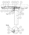
Bei dem in Figur 1 dargestellten Stuhl 1 sind an der
Unterseite der Stuhlsitzfläche 2 zwei gekrümmte Rohrabschnitte
3 befestigt, auf die vertikal ausgerichtete
Rohrabschnitte 4 teleskopartig aufgesteckt sind, die
Tragrohre für die weiter unten näher erläuterten Armlehnen
9 darstellen. Die Rohrabschnitte 4 sind mittels
einer nur angedeuteten Rasteinrichtung 5 in
verschiedenen Höhenstellungen relativ zu den
Rohrabschnitten 3 positionierbar.In the
Wie insbesondere aus Figur 2 ersichtlich, sind die
Armlehnen 9 an den oberen Enden der Tragrohre 4 um
eine Drehachse D verschwenkbar befestigt. Hierzu trägt
das Tragrohr 4 an seinem oberen Ende eine exzentrisch
zur Mittelachse M des Tragrohres 4 angeordnete
Anschlußplatte 10, durch die ein außerhalb des
Tragrohres 4 und exzentrisch zur Mittelachse M
liegender Achsbolzen 6 geführt ist, der die
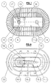
Drehachse D bildet. Dieser Achsbolzen 6 ist als
Schraube ausgebildet, deren Kopf in der
Anschlußplatte 10 drehbar gelagert ist und die in
eine als Schraubenmutter 7 ausgebildete Aufnahme
eingeschraubt ist, welche sich in einem rechteckigen
Gleitkörper 8 befindet, der innerhalb einer
Stützplatte 11 an der Unterseite der Armlehne 9
verschiebbar geführt angeordnet ist. Die
Stützplatte 11, auf die ein geeignetes Polster 12
aufgezogen ist, besitzt eine untere Begrenzungswand
11.1 und eine obere Begrenzungswand 11.2 zwischen
denen der Gleitkörper 8 durch geradlinige seitliche
Führungen 15 geführt (siehe Figur 3) gleitet. In der
unteren Begrenzungswand 11.1 der Stützplatte 11
befindet sich ein Schlitz 13, durch den der
Achsbolzen 6 geführt ist. Die obere Begrenzungswand
11.2 ist oberhalb der Enden des Schlitzes 13 mit
Öffnungen 14 zum Einsetzen der Schraubenmutter 7
versehen. Die Länge der den Gleitkörper 8
aufnehmenden Gleitführung hängt im wesentlichen von
der Länge der Armlehne 9 bzw. der Stützplatte 11 ab.As can be seen in particular from FIG. 2, the
Figur 2 zeigt auf der linken Seite in vollen Linien
die eine Extremstellung der Armlehne 9 relativ zum
Achsbolzen 6 und auf der rechten Seite strichpunktiert
die andere Extremstellung. In Figur 1 sind diese
Extremstellungen ebenfalls dargestellt, wobei
zusätzlich die beiden Armlehnen in unterschiedlichen
Winkelstellungen relativ zur Sitzfläche 2 dargestellt
sind.Figure 2 shows on the left side in full lines
the one extreme position of the
An der in Figur 4 gezeigten Unterseite der
Stützplatte 11 befinden sich Kontaktrippen 19 und
Griffrippen 20 zur besseren Handhabung der
Armlehne 9.On the underside of the
Weiterhin ist aus den Figuren 3 und 4 eine Möglichkeit
zu ersehen, die Armlehne 9 bzw. die Stützplatte 11 in
unterschiedlichen Stellungen der Verschiebungsbahn zu
fixieren. Hierzu ist, wie in Figur 3 dargestellt, im
Gleitkörper 8 eine weitere Aufnahme 17 für eine
Schraubenmutter angeordnet, die durch eine zusätzliche
Öffnung 16 in der oberen Begrenzungswand 11.2
zugänglich ist. An der Unterseite, also in der unteren
Begrenzungswand 11.1, sind, wie Figur 4 zeigt, in einer
Richtung parallel zum Schlitz 13 drei Bohrungen 18.1,
18.2 und 18.3 angeordnet, durch welche Schrauben
einführbar und in die Aufnahme 17 des Gleitkörpers 8
in einer entsprechenden Stellung des Gleitkörpers 8
einschraubbar sind. Damit ist die Stützplatte 11
gegenüber dem Gleitkörper 8 in einer der durch die
Bohrungen 18.1 bis 18.3 vorgegebenen Stellungen
fixierbar.Furthermore, one possibility is shown in FIGS. 3 and 4
to see the
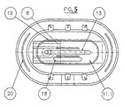
Entsprechend Figur 5 ist in der unteren Begrenzungswand
11.1 anstelle von drei Bohrungen 18.1, 18.2 und 18.3
eine Langlochbohrung 18 angebracht, durch welche eine
Schraube in die Aufnahme 17 des Gleitkörpers 8 einschraubbar
ist. Dadurch besteht die Möglichkeit, auch
die Stützplatte 11 gegenüber dem Gleitkörper 8 in
unterschiedliche Stellungen zu verschieben.According to Figure 5 is in the lower boundary wall
11.1 instead of three holes 18.1, 18.2 and 18.3
an
Bei der durch die Langlochbohrung 18 oder die
Bohrungen 18.1 bis 18.3 geführten und in die Aufnahme
17 des Gleitkörpers 8 eingeschraubten Schraube kann
es sich übrigens um den in der Anschlußplatte 10
gelagerten Achsbolzen 6 selbst handeln. Es ist also
möglich, die Armlehne 9 in einer der drei Stellungen
zwar noch gegenüber dem Tragrohr 4 verdrehbar aber
unverschiebbar zu fixieren, indem der Achsbolzen 6
aus der Aufnahme 7 gelöst und durch eine der
Bohrungen 18.1 bis 18.3 geführt und in die Aufnahme
17 des Gleitkörpers 8 eingeschraubt wird. When through the
Gemäß den Figuren 2 und 2a ist zwischen der Anschlußplatte
10 und der Stützplatte 11 eine Klemmeinrichtung
angeordnet. Diese Klemmeinrichtung umfaßt eine in der
Anschlußplatte 10 vorgesehene vertikale Gewindebohrung,
in der ein vorzugsweise eine hohe Gewindesteigung
aufweisendes Schraubenelement 22 geführt ist, an deren
Oberseite ein scheibenförmiges Klemmelement 21 und an
deren Unterseite ein sich horizontal erstreckender
Betätigungsgriff 20 angebracht sind.According to Figures 2 and 2a is between the
Claims (11)
- A chair, in particular a rotary chair, having armrests (9), each of which has a support plate (11) provided with a sliding guideway (15) by means of which the support plate (11) may be displaced horizontally along a sliding element (8) which is mounted to rotate and is secured such that it is rotatable about a vertical axis (D) of rotation on a vertically adjustable carrier tube, characterised in that the axis (D) of rotation is constructed in the form of an axial pin (6) and is mounted, eccentrically with respect to the centre axis (M) of the carrier tube (4), in a connection plate (10) arranged fixed to the upper end of the carrier tube (4), and in that the sliding element (8) is mounted to rotate on the axial pin (6).
- A chair according to Claim 1, characterised in that the lower limit wall (11.1) of the support plate (11) has a slot (13) for the axial pin (6).
- A chair according to Claim 1, characterised in that the axial pin (6) is constructed as a screw which is guided through the connection plate (10), screwed into a receiver (7) in the sliding element (8) and mounted to rotate in the connection plate (10).
- A chair according to Claim 1, characterised in that the upper limit wall (11.2) of the support plate (11) has above the slot (13) at least one opening (14) for the insertion of a screw nut (7).
- A chair according to Claim 1, characterised in that the sliding element (8) is in the shape of a rectangle.
- A chair according to Claim 1, characterised in that the sliding element (8) is fixable in at least one predetermined position of the displacement path.
- A chair according to Claim 6, characterised in that fixing of the sliding element (8) may be performed by a releasable locking means.
- A chair according to Claim 6, characterised in that fixing of the sliding element (8) may be performed by screwing a screw through a predetermined bore (18.1 to 18.3) in the lower limit wall (11.1) of the support plate (11) and into a receiver (17) in the sliding element (8).
- A chair according to one of Claims 1 to 5, characterised in that the lower limit wall (11.1) of the support plate (11) is provided with an elongate bore (18) through which a screw may be screwed into a receiver (17) in the sliding element (18).
- A chair according to Claim 1, characterised by a clamping device arranged between the connection plate (10) and the support plate (11).
- A chair according to Claim 10, characterised in that the damping device includes a screw element (22) which is mounted to rotate in a threaded bore in the connection plate (10) and preferably has a high thread pitch, to the upper side of which a disc-shaped damping element (21) is secured and to the lower side of which a horizontally extending securing handle (20) is secured.
Applications Claiming Priority (4)
| Application Number | Priority Date | Filing Date | Title |
|---|---|---|---|
| DE29609607U | 1996-05-30 | ||
| DE29609607U DE29609607U1 (en) | 1996-05-30 | 1996-05-30 | Chair, in particular swivel chair, with armrests |
| DE29614274U | 1996-08-17 | ||
| DE29614274U DE29614274U1 (en) | 1996-08-17 | 1996-08-17 | Chair, in particular swivel chair with armrests |
Publications (3)
| Publication Number | Publication Date |
|---|---|
| EP0809957A2 EP0809957A2 (en) | 1997-12-03 |
| EP0809957A3 EP0809957A3 (en) | 1999-12-29 |
| EP0809957B1 true EP0809957B1 (en) | 2002-11-20 |
Family
ID=26059028
Family Applications (1)
| Application Number | Title | Priority Date | Filing Date |
|---|---|---|---|
| EP97101798A Expired - Lifetime EP0809957B1 (en) | 1996-05-30 | 1997-02-05 | Chair, particularly swivel chair, with armrests |
Country Status (3)
| Country | Link |
|---|---|
| EP (1) | EP0809957B1 (en) |
| AT (1) | ATE227951T1 (en) |
| DE (1) | DE59708747D1 (en) |
Families Citing this family (8)
| Publication number | Priority date | Publication date | Assignee | Title |
|---|---|---|---|---|
| ES2205633T3 (en) * | 1998-05-22 | 2004-05-01 | Froli Kunststoffwerk Heinrich Fromme Ohg | SUPPORTS, ESPECIALLY FOR OFFICE CHAIRS AND ROTATING CHAIRS. |
| DE29910250U1 (en) | 1999-06-11 | 1999-11-04 | Fehlbaum & Co., Birsfelden | Adjustable armrest for a chair |
| AU783829B2 (en) | 2000-09-28 | 2005-12-08 | Formway Furniture Limited | A reclinable chair |
| DE10142371A1 (en) * | 2001-08-27 | 2003-03-20 | Viasit Buerositzmoebel Gmbh | Arm rest for office chair has horizontal support plate mounted on top of support post which fits into guide slot in arm rest, allowing it to slide horizontally and to be rotated |
| NZ518944A (en) | 2002-05-14 | 2004-09-24 | Formway Furniture Ltd | Height adjustable arm for chair with outer stem releasably lockable to inner stem by engagement of recesses |
| DE50205453D1 (en) | 2002-10-04 | 2006-02-02 | Stoll Sedus Ag | armrest |
| US7341313B2 (en) | 2005-04-08 | 2008-03-11 | Steelcase Development Corporation | Adjustable armrest with motion control |
| DE102011008172A1 (en) * | 2011-01-10 | 2012-07-12 | Bock 1 Gmbh & Co. Kg | Armrest, especially for an office chair |
Family Cites Families (3)
| Publication number | Priority date | Publication date | Assignee | Title |
|---|---|---|---|---|
| NO894388D0 (en) * | 1989-11-03 | 1989-11-03 | Mathis Olav Nordnes | SUSPENSION SUPPORT FOR USE IN SITTING WORK. |
| US5407249A (en) * | 1990-10-15 | 1995-04-18 | Bonutti; Peter M. | Armrest assembly |
| CA2162781C (en) * | 1995-11-14 | 2000-05-23 | David Novis | Arm support device |
-
1997
- 1997-02-05 EP EP97101798A patent/EP0809957B1/en not_active Expired - Lifetime
- 1997-02-05 DE DE59708747T patent/DE59708747D1/en not_active Expired - Fee Related
- 1997-02-05 AT AT97101798T patent/ATE227951T1/en not_active IP Right Cessation
Also Published As
| Publication number | Publication date |
|---|---|
| DE59708747D1 (en) | 2003-01-02 |
| EP0809957A3 (en) | 1999-12-29 |
| EP0809957A2 (en) | 1997-12-03 |
| ATE227951T1 (en) | 2002-12-15 |
Similar Documents
| Publication | Publication Date | Title |
|---|---|---|
| EP0647499B1 (en) | Pivoting and sliding jack clamp | |
| EP0670123B1 (en) | Height adjustable work table | |
| DE3235361C2 (en) | ||
| DE9016769U1 (en) | Climbing training device | |
| EP0809957B1 (en) | Chair, particularly swivel chair, with armrests | |
| DE8803519U1 (en) | Base for one device | |
| DE3736757C1 (en) | Table milling device | |
| DE4431286C2 (en) | Linear guide | |
| DE3141158C2 (en) | Guide device for a retractable and retractable insert in the body of a cabinet | |
| EP1563775B1 (en) | Parallel guides | |
| DE3238784C2 (en) | ||
| DE3933023A1 (en) | Pivoted arm support for desk-top computers - allows units to be supported clear of surface of desk | |
| EP1123859B1 (en) | Saddle support post | |
| DE9406396U1 (en) | Work and assembly table | |
| DE19924579A1 (en) | Releasable fastener for vehicle seat has transverse bars at front and rear with locking devices, where transverse bars fit in holes in channels formed in longitudinal rails | |
| DE9013522U1 (en) | Fastening for a bearing body of a longitudinal guide with a running element | |
| DE29609607U1 (en) | Chair, in particular swivel chair, with armrests | |
| DE29511267U1 (en) | Armrest | |
| EP0813377B1 (en) | Clamp for adjustable-height seat-backs | |
| DE29614274U1 (en) | Chair, in particular swivel chair with armrests | |
| DE3145942C2 (en) | "Work table with table frame and worktop" | |
| CH683231A5 (en) | Desk top support with horizontal axis | |
| DE102004008230B3 (en) | Device for supporting the spine | |
| DE1580609A1 (en) | Seat frame, especially for motor vehicles | |
| DE29500292U1 (en) | Swivel castor arrangement with a device for determining the direction |
Legal Events
| Date | Code | Title | Description |
|---|---|---|---|
| PUAI | Public reference made under article 153(3) epc to a published international application that has entered the european phase |
Free format text: ORIGINAL CODE: 0009012 |
|
| AK | Designated contracting states |
Kind code of ref document: A2 Designated state(s): AT BE CH DE DK GB LI NL SE |
|
| PUAL | Search report despatched |
Free format text: ORIGINAL CODE: 0009013 |
|
| AK | Designated contracting states |
Kind code of ref document: A3 Designated state(s): AT BE CH DE DK GB LI NL SE |
|
| 17P | Request for examination filed |
Effective date: 20000602 |
|
| GRAG | Despatch of communication of intention to grant |
Free format text: ORIGINAL CODE: EPIDOS AGRA |
|
| GRAG | Despatch of communication of intention to grant |
Free format text: ORIGINAL CODE: EPIDOS AGRA |
|
| GRAH | Despatch of communication of intention to grant a patent |
Free format text: ORIGINAL CODE: EPIDOS IGRA |
|
| 17Q | First examination report despatched |
Effective date: 20020516 |
|
| GRAH | Despatch of communication of intention to grant a patent |
Free format text: ORIGINAL CODE: EPIDOS IGRA |
|
| GRAA | (expected) grant |
Free format text: ORIGINAL CODE: 0009210 |
|
| AK | Designated contracting states |
Kind code of ref document: B1 Designated state(s): AT BE CH DE DK GB LI NL SE |
|
| REF | Corresponds to: |
Ref document number: 227951 Country of ref document: AT Date of ref document: 20021215 Kind code of ref document: T |
|
| REG | Reference to a national code |
Ref country code: GB Ref legal event code: FG4D Free format text: NOT ENGLISH |
|
| REG | Reference to a national code |
Ref country code: CH Ref legal event code: EP |
|
| REF | Corresponds to: |
Ref document number: 59708747 Country of ref document: DE Date of ref document: 20030102 |
|
| PG25 | Lapsed in a contracting state [announced via postgrant information from national office to epo] |
Ref country code: SE Free format text: LAPSE BECAUSE OF FAILURE TO SUBMIT A TRANSLATION OF THE DESCRIPTION OR TO PAY THE FEE WITHIN THE PRESCRIBED TIME-LIMIT Effective date: 20030220 Ref country code: DK Free format text: LAPSE BECAUSE OF FAILURE TO SUBMIT A TRANSLATION OF THE DESCRIPTION OR TO PAY THE FEE WITHIN THE PRESCRIBED TIME-LIMIT Effective date: 20030220 |
|
| REG | Reference to a national code |
Ref country code: CH Ref legal event code: NV Representative=s name: A. BRAUN, BRAUN, HERITIER, ESCHMANN AG PATENTANWAE |
|
| GBT | Gb: translation of ep patent filed (gb section 77(6)(a)/1977) |
Effective date: 20030401 |
|
| PLBE | No opposition filed within time limit |
Free format text: ORIGINAL CODE: 0009261 |
|
| STAA | Information on the status of an ep patent application or granted ep patent |
Free format text: STATUS: NO OPPOSITION FILED WITHIN TIME LIMIT |
|
| 26N | No opposition filed |
Effective date: 20030821 |
|
| PGFP | Annual fee paid to national office [announced via postgrant information from national office to epo] |
Ref country code: NL Payment date: 20050215 Year of fee payment: 9 |
|
| PGFP | Annual fee paid to national office [announced via postgrant information from national office to epo] |
Ref country code: BE Payment date: 20050218 Year of fee payment: 9 Ref country code: AT Payment date: 20050218 Year of fee payment: 9 |
|
| PGFP | Annual fee paid to national office [announced via postgrant information from national office to epo] |
Ref country code: CH Payment date: 20050221 Year of fee payment: 9 |
|
| PGFP | Annual fee paid to national office [announced via postgrant information from national office to epo] |
Ref country code: GB Payment date: 20050223 Year of fee payment: 9 |
|
| PG25 | Lapsed in a contracting state [announced via postgrant information from national office to epo] |
Ref country code: GB Free format text: LAPSE BECAUSE OF NON-PAYMENT OF DUE FEES Effective date: 20060205 Ref country code: AT Free format text: LAPSE BECAUSE OF NON-PAYMENT OF DUE FEES Effective date: 20060205 |
|
| PG25 | Lapsed in a contracting state [announced via postgrant information from national office to epo] |
Ref country code: LI Free format text: LAPSE BECAUSE OF NON-PAYMENT OF DUE FEES Effective date: 20060228 Ref country code: CH Free format text: LAPSE BECAUSE OF NON-PAYMENT OF DUE FEES Effective date: 20060228 Ref country code: BE Free format text: LAPSE BECAUSE OF NON-PAYMENT OF DUE FEES Effective date: 20060228 |
|
| PG25 | Lapsed in a contracting state [announced via postgrant information from national office to epo] |
Ref country code: NL Free format text: LAPSE BECAUSE OF NON-PAYMENT OF DUE FEES Effective date: 20060901 |
|
| REG | Reference to a national code |
Ref country code: CH Ref legal event code: PL |
|
| GBPC | Gb: european patent ceased through non-payment of renewal fee |
Effective date: 20060205 |
|
| NLV4 | Nl: lapsed or anulled due to non-payment of the annual fee |
Effective date: 20060901 |
|
| PGFP | Annual fee paid to national office [announced via postgrant information from national office to epo] |
Ref country code: DE Payment date: 20061228 Year of fee payment: 11 |
|
| BERE | Be: lapsed |
Owner name: *GRAHL G.M.B.H. Effective date: 20060228 |
|
| PG25 | Lapsed in a contracting state [announced via postgrant information from national office to epo] |
Ref country code: DE Free format text: LAPSE BECAUSE OF NON-PAYMENT OF DUE FEES Effective date: 20080902 |