EP0809957B1 - Chaise, notamment chaise tournante, avec appuis-bras - Google Patents
Chaise, notamment chaise tournante, avec appuis-bras Download PDFInfo
- Publication number
- EP0809957B1 EP0809957B1 EP97101798A EP97101798A EP0809957B1 EP 0809957 B1 EP0809957 B1 EP 0809957B1 EP 97101798 A EP97101798 A EP 97101798A EP 97101798 A EP97101798 A EP 97101798A EP 0809957 B1 EP0809957 B1 EP 0809957B1
- Authority
- EP
- European Patent Office
- Prior art keywords
- chair according
- support plate
- sliding element
- chair
- screw
- Prior art date
- Legal status (The legal status is an assumption and is not a legal conclusion. Google has not performed a legal analysis and makes no representation as to the accuracy of the status listed.)
- Expired - Lifetime
Links
- 238000006073 displacement reaction Methods 0.000 claims description 3
- 238000013016 damping Methods 0.000 claims 2
- 230000037431 insertion Effects 0.000 claims 1
- 238000003780 insertion Methods 0.000 claims 1
- 238000010276 construction Methods 0.000 description 3
Images

Classifications
-
- A—HUMAN NECESSITIES
- A47—FURNITURE; DOMESTIC ARTICLES OR APPLIANCES; COFFEE MILLS; SPICE MILLS; SUCTION CLEANERS IN GENERAL
- A47C—CHAIRS; SOFAS; BEDS
- A47C1/00—Chairs adapted for special purposes
- A47C1/02—Reclining or easy chairs
- A47C1/022—Reclining or easy chairs having independently-adjustable supporting parts
- A47C1/03—Reclining or easy chairs having independently-adjustable supporting parts the parts being arm-rests
Definitions
- the invention relates to a chair according to the preamble of claim 1.
- Such a chair described in US 5 407 249 A is equipped with armrests, at which on the one hand the support tube is pivotable about two vertical axes, while on the other hand, the armrest itself relative to the support tube about a further vertical axis pivotable and additionally essentially horizontally in the longitudinal direction is movable.
- This chair is located directly on the armrest assigned vertical axis of rotation coaxial to the vertical central axis of the end section the support tube to which the armrest is attached.
- This last-mentioned axis of rotation is essentially formed by a bearing bush inserted into the end of the supporting tube, into which a bearing journal is inserted, which carries a holder on which a sliding body is screwed, along which the armrest support plate provided with a sliding guide is displaceable in the horizontal direction.
- the well-known construction is therefore extremely complex in terms of construction.
- the invention has for its object in the area of the armrest assigned axis of rotation and the sliding construction of the armrest with simple Adequate variability for different armrest positions to reach.
- This arrangement not only opens up the possibility of pivoting accordingly and moving the armrest to bring it into a desired position even better but, as will be shown below, it can also be done with simple constructive means Medium easy disassembly and fixation of the armrest achieved become.
- the training according to the invention opens in simple way the possibility that the sliding body in at least one predetermined position Trajectory is fixable. This can be done by a releasable locking happen. It is also possible to fix the slider by Screwing in a screw by a given one Hole in the lower boundary wall of the support plate in a receptacle of the sliding body.
- the axle bolt can be screw Be a slewing ring between armrest and support tube, so that it is possible with the chair according to the invention optionally a swiveling armrest with or without Provide possibility of displacement.
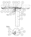
- the Armrests 9 at the upper ends of the support tubes 4 an axis of rotation D is pivotally attached.
- This helps the support tube 4 is eccentric at its upper end arranged to the central axis M of the support tube 4 Connection plate 10 through which an outside of Support tube 4 and eccentric to the central axis M lying axle pin 6 is guided, the Axis of rotation D forms.
- This axle pin 6 is as Trained screw whose head in the Connection plate 10 is rotatably mounted and in a receptacle designed as a screw nut 7 is screwed, which is in a rectangular Slider 8 is located within a Support plate 11 on the underside of the armrest 9 is arranged displaceably guided.
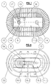
- the Support plate 11 on which a suitable cushion 12 has a lower boundary wall 11.1 and an upper boundary wall 11.2 between which the sliding body 8 by straight lateral Guides 15 guided (see Figure 3) slides.
- a suitable cushion 12 In the lower boundary wall 11.1 of the support plate 11 there is a slot 13 through which the Axle pin 6 is guided.
- the upper boundary wall 11.2 is above the ends of the slot 13 Openings 14 for inserting the screw nut 7 Mistake.
- the length of the sliding body 8 receiving sliding guide essentially depends on the length of the armrest 9 or the support plate 11.
- Figure 2 shows on the left side in full lines the one extreme position of the armrest 9 relative to Axle pin 6 and dash-dotted on the right side the other extreme position. In Figure 1 these are Extreme positions are also shown, whereby additionally the two armrests in different Angular positions shown relative to the seat 2 are.
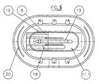
- FIGS. 3 and 4 see the armrest 9 and the support plate 11 in different positions of the displacement path fix.
- FIG Slider 8 another receptacle 17 for one Screw nut arranged by an additional Opening 16 in the upper boundary wall 11.2 is accessible.
- the bottom Boundary wall 11.1 in one Direction parallel to slot 13 three holes 18.1, 18.2 and 18.3 arranged by which screws insertable and into the receptacle 17 of the sliding body 8 in a corresponding position of the sliding body 8 are screwable.
- connection plate 10 is between the connection plate 10 and the support plate 11 a clamping device arranged.
- This clamping device comprises one in the Connection plate 10 provided vertical threaded bore, in which a preferably a high thread pitch having screw element 22 is guided, at the Top of a disc-shaped clamping element 21 and whose underside is a horizontally extending one Operating handle 20 are attached.
Landscapes
- Health & Medical Sciences (AREA)
- Dentistry (AREA)
- General Health & Medical Sciences (AREA)
- Chair Legs, Seat Parts, And Backrests (AREA)
- Chairs Characterized By Structure (AREA)
- Special Chairs (AREA)
Claims (11)
- Chaise, en particulier chaise pivotante, comprenant des accoudoirs (9) qui présentent respectivement une plaque d'appui (11) munie d'une glissière de guidage (15) à l'aide de laquelle la plaque d'appui (11) peut être déplacée dans le sens horizontal le long d'un corps coulissant (8) monté à rotation qui est fixé sur un tube support réglable dans le sens vertical et peut pivoter autour d'un axe de rotation (D) vertical, caractérisée en ce que l'axe de rotation (D) est réalisé sous la forme d'un pivot central (6) et monté, de façon excentrique par rapport à l'axe médian (M) du tube support (4), dans une plaque de jonction (10) fixée à l'extrémité supérieure du tube porteur (4) et en ce que le corps coulissant (8) est monté à rotation sur le pivot central (6)
- Chaise selon la revendication 1, caractérisée en ce que la paroi de limitation inférieure (11.1) de la plaque d'appui (11) présente une fente (13) pour le pivot central (6).
- Chaise selon la revendication 1, caractérisée en ce que le pivot central (6) est réalisé sous forme de vis guidée à travers la plaque de jonction (10), laquelle vis est vissée dans un logement (7) dans le corps coulissant (8) et est logée de manière rotative dans la plaque de jonction (10).
- Chaise selon la revendication 1, caractérisée en ce que la paroi de limitation supérieure (11.2) de la plaque d'appui (11) présente, au-dessus de la fente (13), au moins une ouverture (14) pour l'insertion d'un écrou (7).
- Chaise selon la revendication 1, caractérisée en ce que le corps coulissant (8) a la forme d'un rectangle.
- Chaise selon la revendication 1, caractérisée en ce que le corps coulissant (8) peut être fixé dans au moins une position prédéfinie de la trajectoire de déplacement.
- Chaise selon la revendication 6, caractérisée en ce que la fixation du corps coulissant (8) est réalisable par un dispositif d'arrêt amovible.
- Chaise selon la revendication 6, caractérisée en ce que la fixation du corps coulissant (8) peut se faire en vissant une vis dans un logement (17) du corps coulissant (8), à travers un alésage prédéfini (18.1 à 18.3) situé dans la paroi de délimitation inférieure (11.1) de la plaque d'appui (11).
- Chaise selon l'une quelconque des revendications 1 à 6, caractérisée en ce que la paroi de délimitation inférieure (11.1) de la plaque d'appui (11) est munie d'un trou oblong (18) à travers lequel une vis peut être vissée dans un logement (17) du corps coulissant (18).
- Chaise selon la revendication 1, caractérisée en ce qu'il est prévu un dispositif de serrage disposé entre la plaque de jonction (10) et la plaque d'appui (11).
- Chaise selon la revendication 10, caractérisée en ce que le dispositif de serrage comprend un élément de vissage (22) monté à rotation dans un alésage fileté de la plaque de jonction (10) et présentant un pas de vis de préférence élevé, un élément de serrage (21) en forme de disque étant fixé sur le côté supérieur du pas de vis et une poignée de commande (20) s'étendant horizontalement étant fixée sur son côté inférieur.
Applications Claiming Priority (4)
| Application Number | Priority Date | Filing Date | Title |
|---|---|---|---|
| DE29609607U DE29609607U1 (de) | 1996-05-30 | 1996-05-30 | Stuhl, insbesondere Drehstuhl, mit Armlehnen |
| DE29609607U | 1996-05-30 | ||
| DE29614274U DE29614274U1 (de) | 1996-08-17 | 1996-08-17 | Stuhl, insbesondere Drehstuhl mit Armlehnen |
| DE29614274U | 1996-08-17 |
Publications (3)
| Publication Number | Publication Date |
|---|---|
| EP0809957A2 EP0809957A2 (fr) | 1997-12-03 |
| EP0809957A3 EP0809957A3 (fr) | 1999-12-29 |
| EP0809957B1 true EP0809957B1 (fr) | 2002-11-20 |
Family
ID=26059028
Family Applications (1)
| Application Number | Title | Priority Date | Filing Date |
|---|---|---|---|
| EP97101798A Expired - Lifetime EP0809957B1 (fr) | 1996-05-30 | 1997-02-05 | Chaise, notamment chaise tournante, avec appuis-bras |
Country Status (3)
| Country | Link |
|---|---|
| EP (1) | EP0809957B1 (fr) |
| AT (1) | ATE227951T1 (fr) |
| DE (1) | DE59708747D1 (fr) |
Families Citing this family (8)
| Publication number | Priority date | Publication date | Assignee | Title |
|---|---|---|---|---|
| DE59906411D1 (de) * | 1998-05-22 | 2003-09-04 | Froli Kunststoffwerk Fromme H | Armstütze, insbesondere für Büro- und Drehstühle |
| DE29910250U1 (de) | 1999-06-11 | 1999-11-04 | Fehlbaum & Co., Birsfelden | Verstellbare Armlehne für einen Stuhl |
| AU783829B2 (en) | 2000-09-28 | 2005-12-08 | Formway Furniture Limited | A reclinable chair |
| DE10142371A1 (de) * | 2001-08-27 | 2003-03-20 | Viasit Buerositzmoebel Gmbh | Armlehne |
| NZ518944A (en) | 2002-05-14 | 2004-09-24 | Formway Furniture Ltd | Height adjustable arm for chair with outer stem releasably lockable to inner stem by engagement of recesses |
| ES2252372T3 (es) | 2002-10-04 | 2006-05-16 | Sedus Stoll Ag | Reposabrazos. |
| US7234779B2 (en) | 2005-04-08 | 2007-06-26 | Steelcase Development Corporation | Armrest with height adjustment mechanism |
| DE102011008172A1 (de) | 2011-01-10 | 2012-07-12 | Bock 1 Gmbh & Co. Kg | Armlehne, insbesondere für einen Bürostuhl |
Family Cites Families (3)
| Publication number | Priority date | Publication date | Assignee | Title |
|---|---|---|---|---|
| NO894388D0 (no) * | 1989-11-03 | 1989-11-03 | Mathis Olav Nordnes | Underarmstoette for bruk ved sittende arbeid. |
| US5407249A (en) * | 1990-10-15 | 1995-04-18 | Bonutti; Peter M. | Armrest assembly |
| CA2162781C (fr) * | 1995-11-14 | 2000-05-23 | David Novis | Appuie-bras |
-
1997
- 1997-02-05 EP EP97101798A patent/EP0809957B1/fr not_active Expired - Lifetime
- 1997-02-05 DE DE59708747T patent/DE59708747D1/de not_active Expired - Fee Related
- 1997-02-05 AT AT97101798T patent/ATE227951T1/de not_active IP Right Cessation
Also Published As
| Publication number | Publication date |
|---|---|
| EP0809957A3 (fr) | 1999-12-29 |
| DE59708747D1 (de) | 2003-01-02 |
| ATE227951T1 (de) | 2002-12-15 |
| EP0809957A2 (fr) | 1997-12-03 |
Similar Documents
| Publication | Publication Date | Title |
|---|---|---|
| EP0670123B1 (fr) | Table de travail à hauteur modifiable | |
| DE3235361C2 (fr) | ||
| EP0647499A2 (fr) | Serre-joints | |
| EP3854263B1 (fr) | Accoudoir, en particulier pour une chaise de bureau | |
| EP0809957B1 (fr) | Chaise, notamment chaise tournante, avec appuis-bras | |
| DE8803519U1 (de) | Untersatz für ein Gerät | |
| DE3736757C1 (de) | Tischfraeseinrichtung | |
| DE4431286C2 (de) | Linearführung | |
| AT393797B (de) | Bindung fuer snowboards | |
| DE3141158C2 (de) | Führungsvorrichtung für einen ein- und ausfahrbaren Einsatz im Korpus eines Schrankes | |
| EP1563775B1 (fr) | Guides parallèles | |
| DE3238784C2 (fr) | ||
| DE3933023A1 (de) | Schwenkarm-geraetetraeger fuer edv- und buerogeraete | |
| EP1123859B1 (fr) | Tige de selle | |
| DE9406396U1 (de) | Arbeits- und Montagetisch | |
| DE19924579A1 (de) | Einrichtung zur lösbaren Befestigung eines Sitzes, insbesondere eines Fahrzeugsitzes | |
| DE9013522U1 (de) | Befestigung für einen ein Laufelement aufweisenden Lagerkörper einer Längsführung | |
| DE29609607U1 (de) | Stuhl, insbesondere Drehstuhl, mit Armlehnen | |
| DE29511267U1 (de) | Armstütze | |
| DE29614274U1 (de) | Stuhl, insbesondere Drehstuhl mit Armlehnen | |
| DE3145942C2 (de) | "Arbeitstisch mit Tischgestell und Arbeitsplatte" | |
| DE9405110U1 (de) | Sitzhalter mit Einstellmechanismus | |
| CH683231A5 (de) | Vorrichtung zum Abstützen einer Arbeitsplatte. | |
| DE102004008230B3 (de) | Vorrichtung zur Stützung der Wirbelsäule | |
| DE29510446U1 (de) | Rückenlehnenklemmung |
Legal Events
| Date | Code | Title | Description |
|---|---|---|---|
| PUAI | Public reference made under article 153(3) epc to a published international application that has entered the european phase |
Free format text: ORIGINAL CODE: 0009012 |
|
| AK | Designated contracting states |
Kind code of ref document: A2 Designated state(s): AT BE CH DE DK GB LI NL SE |
|
| PUAL | Search report despatched |
Free format text: ORIGINAL CODE: 0009013 |
|
| AK | Designated contracting states |
Kind code of ref document: A3 Designated state(s): AT BE CH DE DK GB LI NL SE |
|
| 17P | Request for examination filed |
Effective date: 20000602 |
|
| GRAG | Despatch of communication of intention to grant |
Free format text: ORIGINAL CODE: EPIDOS AGRA |
|
| GRAG | Despatch of communication of intention to grant |
Free format text: ORIGINAL CODE: EPIDOS AGRA |
|
| GRAH | Despatch of communication of intention to grant a patent |
Free format text: ORIGINAL CODE: EPIDOS IGRA |
|
| 17Q | First examination report despatched |
Effective date: 20020516 |
|
| GRAH | Despatch of communication of intention to grant a patent |
Free format text: ORIGINAL CODE: EPIDOS IGRA |
|
| GRAA | (expected) grant |
Free format text: ORIGINAL CODE: 0009210 |
|
| AK | Designated contracting states |
Kind code of ref document: B1 Designated state(s): AT BE CH DE DK GB LI NL SE |
|
| REF | Corresponds to: |
Ref document number: 227951 Country of ref document: AT Date of ref document: 20021215 Kind code of ref document: T |
|
| REG | Reference to a national code |
Ref country code: GB Ref legal event code: FG4D Free format text: NOT ENGLISH |
|
| REG | Reference to a national code |
Ref country code: CH Ref legal event code: EP |
|
| REF | Corresponds to: |
Ref document number: 59708747 Country of ref document: DE Date of ref document: 20030102 |
|
| PG25 | Lapsed in a contracting state [announced via postgrant information from national office to epo] |
Ref country code: SE Free format text: LAPSE BECAUSE OF FAILURE TO SUBMIT A TRANSLATION OF THE DESCRIPTION OR TO PAY THE FEE WITHIN THE PRESCRIBED TIME-LIMIT Effective date: 20030220 Ref country code: DK Free format text: LAPSE BECAUSE OF FAILURE TO SUBMIT A TRANSLATION OF THE DESCRIPTION OR TO PAY THE FEE WITHIN THE PRESCRIBED TIME-LIMIT Effective date: 20030220 |
|
| REG | Reference to a national code |
Ref country code: CH Ref legal event code: NV Representative=s name: A. BRAUN, BRAUN, HERITIER, ESCHMANN AG PATENTANWAE |
|
| GBT | Gb: translation of ep patent filed (gb section 77(6)(a)/1977) |
Effective date: 20030401 |
|
| PLBE | No opposition filed within time limit |
Free format text: ORIGINAL CODE: 0009261 |
|
| STAA | Information on the status of an ep patent application or granted ep patent |
Free format text: STATUS: NO OPPOSITION FILED WITHIN TIME LIMIT |
|
| 26N | No opposition filed |
Effective date: 20030821 |
|
| PGFP | Annual fee paid to national office [announced via postgrant information from national office to epo] |
Ref country code: NL Payment date: 20050215 Year of fee payment: 9 |
|
| PGFP | Annual fee paid to national office [announced via postgrant information from national office to epo] |
Ref country code: BE Payment date: 20050218 Year of fee payment: 9 Ref country code: AT Payment date: 20050218 Year of fee payment: 9 |
|
| PGFP | Annual fee paid to national office [announced via postgrant information from national office to epo] |
Ref country code: CH Payment date: 20050221 Year of fee payment: 9 |
|
| PGFP | Annual fee paid to national office [announced via postgrant information from national office to epo] |
Ref country code: GB Payment date: 20050223 Year of fee payment: 9 |
|
| PG25 | Lapsed in a contracting state [announced via postgrant information from national office to epo] |
Ref country code: GB Free format text: LAPSE BECAUSE OF NON-PAYMENT OF DUE FEES Effective date: 20060205 Ref country code: AT Free format text: LAPSE BECAUSE OF NON-PAYMENT OF DUE FEES Effective date: 20060205 |
|
| PG25 | Lapsed in a contracting state [announced via postgrant information from national office to epo] |
Ref country code: LI Free format text: LAPSE BECAUSE OF NON-PAYMENT OF DUE FEES Effective date: 20060228 Ref country code: CH Free format text: LAPSE BECAUSE OF NON-PAYMENT OF DUE FEES Effective date: 20060228 Ref country code: BE Free format text: LAPSE BECAUSE OF NON-PAYMENT OF DUE FEES Effective date: 20060228 |
|
| PG25 | Lapsed in a contracting state [announced via postgrant information from national office to epo] |
Ref country code: NL Free format text: LAPSE BECAUSE OF NON-PAYMENT OF DUE FEES Effective date: 20060901 |
|
| REG | Reference to a national code |
Ref country code: CH Ref legal event code: PL |
|
| GBPC | Gb: european patent ceased through non-payment of renewal fee |
Effective date: 20060205 |
|
| NLV4 | Nl: lapsed or anulled due to non-payment of the annual fee |
Effective date: 20060901 |
|
| PGFP | Annual fee paid to national office [announced via postgrant information from national office to epo] |
Ref country code: DE Payment date: 20061228 Year of fee payment: 11 |
|
| BERE | Be: lapsed |
Owner name: *GRAHL G.M.B.H. Effective date: 20060228 |
|
| PG25 | Lapsed in a contracting state [announced via postgrant information from national office to epo] |
Ref country code: DE Free format text: LAPSE BECAUSE OF NON-PAYMENT OF DUE FEES Effective date: 20080902 |