EP0809957A2 - Chair, particularly swivel chair, with armrests - Google Patents
Chair, particularly swivel chair, with armrests Download PDFInfo
- Publication number
- EP0809957A2 EP0809957A2 EP97101798A EP97101798A EP0809957A2 EP 0809957 A2 EP0809957 A2 EP 0809957A2 EP 97101798 A EP97101798 A EP 97101798A EP 97101798 A EP97101798 A EP 97101798A EP 0809957 A2 EP0809957 A2 EP 0809957A2
- Authority
- EP
- European Patent Office
- Prior art keywords
- chair according
- sliding body
- chair
- axis
- support tube
- Prior art date
- Legal status (The legal status is an assumption and is not a legal conclusion. Google has not performed a legal analysis and makes no representation as to the accuracy of the status listed.)
- Granted
Links
- 238000006073 displacement reaction Methods 0.000 claims description 4
- 238000010276 construction Methods 0.000 description 1
Images


Classifications
-
- A—HUMAN NECESSITIES
- A47—FURNITURE; DOMESTIC ARTICLES OR APPLIANCES; COFFEE MILLS; SPICE MILLS; SUCTION CLEANERS IN GENERAL
- A47C—CHAIRS; SOFAS; BEDS
- A47C1/00—Chairs adapted for special purposes
- A47C1/02—Reclining or easy chairs
- A47C1/022—Reclining or easy chairs having independently-adjustable supporting parts
- A47C1/03—Reclining or easy chairs having independently-adjustable supporting parts the parts being arm-rests
Definitions
- the invention relates to a chair, in particular a swivel chair, with armrests, each of which is rotatably attached to a telescopically adjustable vertical support tube about a vertical axis, each armrest being displaceable in the horizontal direction along a straight guide relative to the axis of rotation which is fixedly connected to the support tube.
- Such a chair is described for example in the utility model DE-GM 295 03 943.4 with older seniority.
- the axis of rotation of the armrest is coaxial with the central axis of the support tube.
- the invention is based, to achieve even greater variability of the different positions with simple means for positioning the individual armrest the task. Furthermore, a simple possibility should be created to disassemble the armrests from the support tube and, if necessary, to fix them again in a fixed position on the support tube.
- the chair according to the invention is characterized in that the axis of rotation of the armrests is arranged eccentrically to the central axis of the support tube.
- This arrangement not only opens up the possibility of bringing the armrest into a desired position even better by correspondingly pivoting and shifting it, but, as will be shown further below, simple disassembly and fixing of the armrest can also be achieved as a result .
- the axis of rotation can be arranged in the form of an axle bolt in the area of the upper end of the support tube and a sliding body can be rotatably mounted over the axle bolt, which can be displaced in a sliding guide of a support plate of the armrest. It has proven to be advantageous if the axle bolt is mounted in a connection plate fixedly arranged at the upper end of the support tube. Furthermore, the axle bolt can be guided through the connecting plate Be screw formed, which is screwed into the sliding body and rotatably mounted in the connection plate. In this way, the rotary connection between armrest and support tube is easily accessible and can be removed by loosening the screw.
- the inventive design opens up the possibility that the sliding body can be fixed in at least one predetermined position of the displacement path. This can be done by releasable locking.
- this screw can be the axle bolt of the rotary connection between armrest and support tube, so that it is possible to provide a pivotable armrest with or without the possibility of displacement in the chair according to the invention.
- two curved tube sections 3 are attached to the underside of the chair seat surface 2, onto which vertically aligned tube sections 4 are telescopically attached, which represent support tubes for the armrests 9 explained in more detail below.
- the pipe sections 4 can be positioned relative to the pipe sections 3 in different height positions by means of a latching device 5, which is only indicated.
- the armrests 9 are fastened to the upper ends of the support tubes 4 so as to be pivotable about an axis of rotation D.
- the support tube 4 carries at its upper end an eccentrically arranged to the central axis M of the support tube 4 connecting plate 10 through which an outside of the support tube 4 and eccentric to the central axis M axis pin 6 is guided, which forms the axis of rotation D.
- This axle pin 6 is designed as a screw, the head of which is rotatably mounted in the connection plate 10 and which is screwed into a receptacle designed as a screw nut 7, which is located in a rectangular sliding body 8 which is displaceable within a support plate 11 on the underside of the armrest 9 is arranged guided.
- the support plate 11, on which a suitable cushion 12 is drawn, has a lower boundary wall 11.1 and an upper boundary wall 11.2 between which the sliding body 8 by straight lateral Guides 15 guided (see Figure 3) slides.
- the upper boundary wall 11.2 is provided above the ends of the slot 13 with openings 14 for inserting the nut 7.
- the length of the sliding guide receiving the sliding body 8 essentially depends on the length of the armrest 9 or the support plate 11.
- Figure 2 shows on the left side in full lines the one extreme position of the armrest 9 relative to the axle pin 6 and on the right side dash-dot line the other extreme position. These extreme positions are also shown in FIG. 1, the two armrests also being shown in different angular positions relative to the seat surface 2.
- FIGS. 3 and 4 show one possibility of fixing the armrest 9 or the support plate 11 in different positions of the displacement path.
- a further receptacle 17 for a screw nut is arranged in the sliding body 8 and is accessible through an additional opening 16 in the upper boundary wall 11.2.
- the support plate 11 can thus be fixed relative to the sliding body 8 in one of the positions specified by the bores 18.1 to 18.3.
- an elongated hole 18 is made in the lower boundary wall 11.1 instead of three holes 18.1, 18.2 and 18.3, through which a screw can be screwed into the receptacle 17 of the sliding body 8. This makes it possible to also shift the support plate 11 into different positions relative to the sliding body 8.
- the screw guided through the elongated hole 18 or the holes 18.1 to 18.3 and screwed into the receptacle 17 of the sliding body 8 can be the axle bolt 6 itself mounted in the connecting plate 10. It is therefore possible to fix the armrest 9 in one of the three positions while still rotatable but immovable with respect to the support tube 4, in that the axle bolt 6 is released from the receptacle 7 and guided through one of the bores 18.1 to 18.3 and into the receptacle 17 of the sliding body 8 is screwed in.
- a clamping device is arranged between the connection plate 10 and the support plate 11.
- This clamping device comprises a vertical threaded bore provided in the connection plate 10, in which a screw element 22, preferably having a high thread pitch, is guided, on the upper side of which a disk-shaped clamping element 21 and on the underside of which a horizontally extending actuating handle 20 are attached.
Landscapes
- Health & Medical Sciences (AREA)
- Dentistry (AREA)
- General Health & Medical Sciences (AREA)
- Chair Legs, Seat Parts, And Backrests (AREA)
- Chairs Characterized By Structure (AREA)
- Special Chairs (AREA)
Abstract
Ein Stuhl, insbesondere Drehstuhl, mit Armlehnen (9), die jeweils um eine vertikale Achse drehbar an einem teleskopartig verstellbaren vertikalen Tragrohr (4) befestigt sind, wobei jede Armlehne (9) gegenüber der fest mit dem Tragrohr (4) verbundenen Drehachse entlang einer geradlinigen Führung in horizontaler Richtung verschiebbar ist, ist dadurch gekennzeichnet, daß die Drehachse (D) der Armlehnen (9) jeweils exzentrisch zur Mittelachse (M) des Tragrohrs (4) angeordnet ist.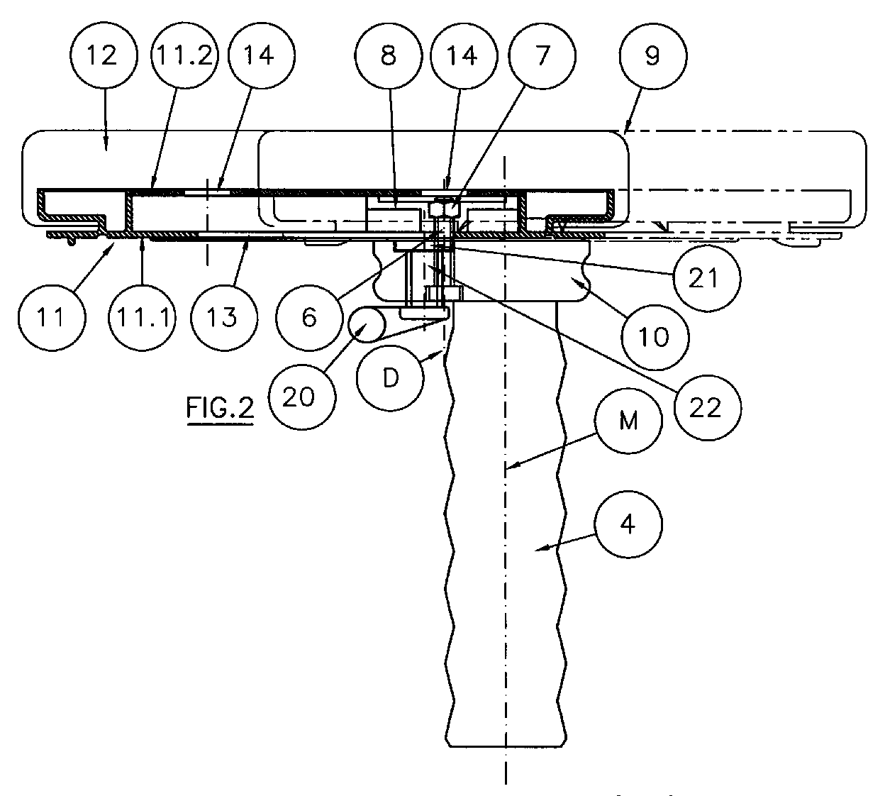
Description
Die Erfindung betrifft einen Stuhl, insbesondere Drehstuhl, mit Armlehnen, die jeweils um eine vertikale Achse drehbar an einem teleskopartig verstellbaren vertikalen Tragrohr befestigt sind, wobei jede Armlehne gegenüber der fest mit dem Tragrohr verbundenen Drehachse entlang einer geradlinigen Führung in horizontaler Richtung verschiebbar ist.The invention relates to a chair, in particular a swivel chair, with armrests, each of which is rotatably attached to a telescopically adjustable vertical support tube about a vertical axis, each armrest being displaceable in the horizontal direction along a straight guide relative to the axis of rotation which is fixedly connected to the support tube.
Ein derartiger Stuhl ist beispielsweise in dem Gebrauchsmuster DE-GM 295 03 943.4 mit älterem Zeitrang beschrieben.Such a chair is described for example in the utility model DE-GM 295 03 943.4 with older seniority.
Bei dieser älteren Lösung liegt die Drehachse der Armlehne koaxial zur Mittelachse des Tragrohrs.In this older solution, the axis of rotation of the armrest is coaxial with the central axis of the support tube.
Der Erfindung liegt die Aufgabe zugrunde, mit einfachen Mitteln für das Positionieren der einzelnen Armlehne eine noch größere Variabilität der unterschiedlichen Stellungen zu erreichen. Weiterhin sollte eine einfache Möglichkeit geschaffen werden, die Armlehnen vom Tragrohr zu demontieren und ggf. fixiert in einer festen Position wieder am Tragrohr zu montieren.The invention is based, to achieve even greater variability of the different positions with simple means for positioning the individual armrest the task. Furthermore, a simple possibility should be created to disassemble the armrests from the support tube and, if necessary, to fix them again in a fixed position on the support tube.
Zur Lösung dieser Aufgabe ist der erfindungsgemäße Stuhl dadurch gekennzeichnet, daß die Drehachse der Armlehnen jeweils exzentrisch zur Mittelachse des Tragrohres angeordnet ist.To achieve this object, the chair according to the invention is characterized in that the axis of rotation of the armrests is arranged eccentrically to the central axis of the support tube.
Diese Anordnung eröffnet nicht nur die Möglichkeit, durch entsprechendes Verschwenken und Verschieben die Armlehne noch besser in eine gewünschte Position zu bringen, sondern es kann, wie weiter unten gezeigt wird, hierdurch auch mit einfachen konstruktiven Mitteln eine leichte Demontierbarkeit und eine Fixiermöglichkeit der Armlehne erreicht werden.This arrangement not only opens up the possibility of bringing the armrest into a desired position even better by correspondingly pivoting and shifting it, but, as will be shown further below, simple disassembly and fixing of the armrest can also be achieved as a result .
Ähnlich wie bei der älteren Konstruktion kann die Drehachse in Form eines Achsbolzens im Bereich des oberen Endes des Tragrohres angeordnet sein und über den Achsbolzen ein Gleitkörper drehbar gelagert sein, der in einer Gleitführung einer Stützplatte der Armlehne verschiebbar ist. Dabei hat es sich als vorteilhaft erwiesen, wenn der Achsbolzen in einer am oberen Ende des Tragrohres fest angeordneten Anschlußplatte gelagert ist. Weiterhin kann der Achsbolzen als durch die Anschlußplatte geführte Schraube ausgebildet sein, die in dem Gleitkörper eingeschraubt und in der Anschlußplatte drehbar gelagert ist. Auf diese Weise ist die Drehverbindung zwischen Armlehne und Tragrohr leicht zugänglich und durch Lösen der Schraube demontierbar.Similar to the older construction, the axis of rotation can be arranged in the form of an axle bolt in the area of the upper end of the support tube and a sliding body can be rotatably mounted over the axle bolt, which can be displaced in a sliding guide of a support plate of the armrest. It has proven to be advantageous if the axle bolt is mounted in a connection plate fixedly arranged at the upper end of the support tube. Furthermore, the axle bolt can be guided through the connecting plate Be screw formed, which is screwed into the sliding body and rotatably mounted in the connection plate. In this way, the rotary connection between armrest and support tube is easily accessible and can be removed by loosening the screw.
Weiterhin eröffnet die erfindungsgemäße Ausbildung in einfacher Weise die Möglichkeit, daß der Gleitkörper in mindestens einer vorgegebenen Stellung der Verschiebungsbahn fixierbar ist. Dies kann durch eine lösbare Arretierung geschehen. Es ist aber auch möglich, die Fixierung des Gleitkörpers durch Einschrauben einer Schraube durch eine vorgegebene Bohrung in der unteren Begrenzungswand der Stützplatte in eine Aufnahme des Gleitkörpers zu bewirken. Diese Schraube kann im Prinzip der Achsbolzen der Drehverbindung zwischen Armlehne und Tragrohr sein, so daß es möglich ist, bei dem erfindungsgemäßen Stuhl wahlweise eine verschwenkbare Armlehne mit oder ohne Verschiebungsmöglichkeit vorzusehen.Furthermore, the inventive design opens up the possibility that the sliding body can be fixed in at least one predetermined position of the displacement path. This can be done by releasable locking. However, it is also possible to fix the sliding body by screwing a screw through a predetermined bore in the lower boundary wall of the support plate into a receptacle of the sliding body. In principle, this screw can be the axle bolt of the rotary connection between armrest and support tube, so that it is possible to provide a pivotable armrest with or without the possibility of displacement in the chair according to the invention.
Die Erfindung wird im folgenden anhand der Zeichnungen näher beschrieben.
Figur 1 zeigt in isometrischer Darstellung einen Drehstuhl;Figur 2 zeigt eine Armlehne mit Tragrohr in einer teilweise geschnittenen Seitenansicht;- Figur 2a zeigt eine Draufsicht einer an dem Tragrohr befestigten Anschlußplatte.
Figur 3 zeigt eine Draufsicht auf die Stützplatte einer Armlehne ohne die Polsterung;Figuren 4 und 5 zeigen Ansichten der Stützplatte gemäßFigur 3 von unten.
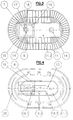
- Figure 1 shows an isometric view of a swivel chair;
- Figure 2 shows an armrest with support tube in a partially sectioned side view;
- FIG. 2a shows a top view of a connection plate attached to the support tube.
- Figure 3 shows a top view of the support plate of an armrest without the padding;
- Figures 4 and 5 show views of the support plate according to Figure 3 from below.
Bei dem in Figur 1 dargestellten Stuhl 1 sind an der Unterseite der Stuhlsitzfläche 2 zwei gekrümmte Rohrabschnitte 3 befestigt, auf die vertikal ausgerichtete Rohrabschnitte 4 teleskopartig aufgesteckt sind, die Tragrohre für die weiter unten näher erläuterten Armlehnen 9 darstellen. Die Rohrabschnitte 4 sind mittels einer nur angedeuteten Rasteinrichtung 5 in verschiedenen Höhenstellungen relativ zu den Rohrabschnitten 3 positionierbar.In the
Wie insbesondere aus Figur 2 ersichtlich, sind die Armlehnen 9 an den oberen Enden der Tragrohre 4 um eine Drehachse D verschwenkbar befestigt. Hierzu trägt das Tragrohr 4 an seinem oberen Ende eine exzentrisch zur Mittelachse M des Tragrohres 4 angeordnete Anschlußplatte 10, durch die ein außerhalb des Tragrohres 4 und exzentrisch zur Mittelachse M liegender Achsbolzen 6 geführt ist, der die Drehachse D bildet. Dieser Achsbolzen 6 ist als Schraube ausgebildet, deren Kopf in der Anschlußplatte 10 drehbar gelagert ist und die in eine als Schraubenmutter 7 ausgebildete Aufnahme eingeschraubt ist, welche sich in einem rechteckigen Gleitkörper 8 befindet, der innerhalb einer Stützplatte 11 an der Unterseite der Armlehne 9 verschiebbar geführt angeordnet ist. Die Stützplatte 11, auf die ein geeignetes Polster 12 aufgezogen ist, besitzt eine untere Begrenzungswand 11.1 und eine obere Begrenzungswand 11.2 zwischen denen der Gleitkörper 8 durch geradlinige seitliche Führungen 15 geführt (siehe Figur 3) gleitet. In der unteren Begrenzungswand 11.1 der Stützplatte 11 befindet sich ein Schlitz 13, durch den der Achsbolzen 6 geführt ist. Die obere Begrenzungswand 11.2 ist oberhalb der Enden des Schlitzes 13 mit Öffnungen 14 zum Einsetzen der Schraubenmutter 7 versehen. Die Länge der den Gleitkörper 8 aufnehmenden Gleitführung hängt im wesentlichen von der Länge der Armlehne 9 bzw. der Stützplatte 11 ab.As can be seen in particular from FIG. 2, the
Figur 2 zeigt auf der linken Seite in vollen Linien die eine Extremstellung der Armlehne 9 relativ zum Achsbolzen 6 und auf der rechten Seite strichpunktiert die andere Extremstellung. In Figur 1 sind diese Extremstellungen ebenfalls dargestellt, wobei zusätzlich die beiden Armlehnen in unterschiedlichen Winkelstellungen relativ zur Sitzfläche 2 dargestellt sind.Figure 2 shows on the left side in full lines the one extreme position of the
An der in Figur 4 gezeigten Unterseite der Stützplatte 11 befinden sich Kontaktrippen 19 und Griffrippen 20 zur besseren Handhabung der Armlehne 9.On the underside of the
Weiterhin ist aus den Figuren 3 und 4 eine Möglichkeit zu ersehen, die Armlehne 9 bzw. die Stützplatte 11 in unterschiedlichen Stellungen der Verschiebungsbahn zu fixieren. Hierzu ist, wie in Figur 3 dargestellt, im Gleitkörper 8 eine weitere Aufnahme 17 für eine Schraubenmutter angeordnet, die durch eine zusätzliche Öffnung 16 in der oberen Begrenzungswand 11.2 zugänglich ist. An der Unterseite, also in der unteren Begrenzungswand 11.1, sind, wie Figur 4 zeigt, in einer Richtung parallel zum Schlitz 13 drei Bohrungen 18.1, 18.2 und 18.3 angeordnet, durch welche Schrauben einführbar und in die Aufnahme 17 des Gleitkörpers 8 in einer entsprechenden Stellung des Gleitkörpers 8 einschraubbar sind. Damit ist die Stützplatte 11 gegenüber dem Gleitkörper 8 in einer der durch die Bohrungen 18.1 bis 18.3 vorgegebenen Stellungen fixierbar.Furthermore, FIGS. 3 and 4 show one possibility of fixing the
Entsprechend Figur 5 ist in der unteren Begrenzungswand 11.1 anstelle von drei Bohrungen 18.1, 18.2 und 18.3 eine Langlochbohrung 18 angebracht, durch welche eine Schraube in die Aufnahme 17 des Gleitkörpers 8 einschraubbar ist. Dadurch besteht die Möglichkeit, auch die Stützplatte 11 gegenüber dem Gleitkörper 8 in unterschiedliche Stellungen zu verschieben.According to FIG. 5, an
Bei der durch die Langlochbohrung 18 oder die Bohrungen 18.1 bis 18.3 geführten und in die Aufnahme 17 des Gleitkörpers 8 eingeschraubten Schraube kann es sich übrigens um den in der Anschlußplatte 10 gelagerten Achsbolzen 6 selbst handeln. Es ist also möglich, die Armlehne 9 in einer der drei Stellungen zwar noch gegenüber dem Tragrohr 4 verdrehbar aber unverschiebbar zu fixieren, indem der Achsbolzen 6 aus der Aufnahme 7 gelöst und durch eine der Bohrungen 18.1 bis 18.3 geführt und in die Aufnahme 17 des Gleitkörpers 8 eingeschraubt wird.Incidentally, the screw guided through the
Gemäß den Figuren 2 und 2a ist zwischen der Anschlußplatte 10 und der Stützplatte 11 eine Klemmeinrichtung angeordnet. Diese Klemmeinrichtung umfaßt eine in der Anschlußplatte 10 vorgesehene vertikale Gewindebohrung, in der ein vorzugsweise eine hohe Gewindesteigung aufweisendes Schraubenelement 22 geführt ist, an deren Oberseite ein scheibenförmiges Klemmelement 21 und an deren Unterseite ein sich horizontal erstreckender Betätigungsgriff 20 angebracht sind.According to Figures 2 and 2a, a clamping device is arranged between the
Claims (13)
Applications Claiming Priority (4)
| Application Number | Priority Date | Filing Date | Title |
|---|---|---|---|
| DE29609607U DE29609607U1 (en) | 1996-05-30 | 1996-05-30 | Chair, in particular swivel chair, with armrests |
| DE29609607U | 1996-05-30 | ||
| DE29614274U DE29614274U1 (en) | 1996-08-17 | 1996-08-17 | Chair, in particular swivel chair with armrests |
| DE29614274U | 1996-08-17 |
Publications (3)
| Publication Number | Publication Date |
|---|---|
| EP0809957A2 true EP0809957A2 (en) | 1997-12-03 |
| EP0809957A3 EP0809957A3 (en) | 1999-12-29 |
| EP0809957B1 EP0809957B1 (en) | 2002-11-20 |
Family
ID=26059028
Family Applications (1)
| Application Number | Title | Priority Date | Filing Date |
|---|---|---|---|
| EP97101798A Expired - Lifetime EP0809957B1 (en) | 1996-05-30 | 1997-02-05 | Chair, particularly swivel chair, with armrests |
Country Status (3)
| Country | Link |
|---|---|
| EP (1) | EP0809957B1 (en) |
| AT (1) | ATE227951T1 (en) |
| DE (1) | DE59708747D1 (en) |
Cited By (8)
| Publication number | Priority date | Publication date | Assignee | Title |
|---|---|---|---|---|
| EP1059051A1 (en) | 1999-06-11 | 2000-12-13 | Vitra Patente AG | Adjustable arm-rest for a chair |
| EP0958765A3 (en) * | 1998-05-22 | 2001-01-10 | FROLI Kunststoffe Heinrich Fromme | Arm support, particularly for office chairs and swivel chairs |
| DE10142371A1 (en) * | 2001-08-27 | 2003-03-20 | Viasit Buerositzmoebel Gmbh | Arm rest for office chair has horizontal support plate mounted on top of support post which fits into guide slot in arm rest, allowing it to slide horizontally and to be rotated |
| EP1405582A1 (en) * | 2002-10-04 | 2004-04-07 | Sedus Stoll AG | Arm-rest |
| US6802566B2 (en) | 2000-09-28 | 2004-10-12 | Formway Furniture Limited | Arm assembly for a chair |
| US6840582B2 (en) | 2002-05-14 | 2005-01-11 | Formway Furniture Limited | Height adjustable arm assembly |
| US7234779B2 (en) | 2005-04-08 | 2007-06-26 | Steelcase Development Corporation | Armrest with height adjustment mechanism |
| DE102011008172A1 (en) * | 2011-01-10 | 2012-07-12 | Bock 1 Gmbh & Co. Kg | Armrest, especially for an office chair |
Family Cites Families (3)
| Publication number | Priority date | Publication date | Assignee | Title |
|---|---|---|---|---|
| NO894388D0 (en) * | 1989-11-03 | 1989-11-03 | Mathis Olav Nordnes | SUSPENSION SUPPORT FOR USE IN SITTING WORK. |
| US5407249A (en) * | 1990-10-15 | 1995-04-18 | Bonutti; Peter M. | Armrest assembly |
| CA2162781C (en) * | 1995-11-14 | 2000-05-23 | David Novis | Arm support device |
-
1997
- 1997-02-05 EP EP97101798A patent/EP0809957B1/en not_active Expired - Lifetime
- 1997-02-05 DE DE59708747T patent/DE59708747D1/en not_active Expired - Fee Related
- 1997-02-05 AT AT97101798T patent/ATE227951T1/en not_active IP Right Cessation
Cited By (14)
| Publication number | Priority date | Publication date | Assignee | Title |
|---|---|---|---|---|
| EP0958765A3 (en) * | 1998-05-22 | 2001-01-10 | FROLI Kunststoffe Heinrich Fromme | Arm support, particularly for office chairs and swivel chairs |
| EP1059051A1 (en) | 1999-06-11 | 2000-12-13 | Vitra Patente AG | Adjustable arm-rest for a chair |
| US7441839B2 (en) | 2000-09-28 | 2008-10-28 | Formway Furniture Limited | Reclinable chair |
| US6802566B2 (en) | 2000-09-28 | 2004-10-12 | Formway Furniture Limited | Arm assembly for a chair |
| US7798573B2 (en) | 2000-09-28 | 2010-09-21 | Formway Furniture Limited | Reclinable chair |
| DE10142371A1 (en) * | 2001-08-27 | 2003-03-20 | Viasit Buerositzmoebel Gmbh | Arm rest for office chair has horizontal support plate mounted on top of support post which fits into guide slot in arm rest, allowing it to slide horizontally and to be rotated |
| US6840582B2 (en) | 2002-05-14 | 2005-01-11 | Formway Furniture Limited | Height adjustable arm assembly |
| EP1405582A1 (en) * | 2002-10-04 | 2004-04-07 | Sedus Stoll AG | Arm-rest |
| CN100435694C (en) * | 2002-10-04 | 2008-11-26 | 塞杜斯.斯托尔股份公司 | a handrail |
| US6948774B2 (en) | 2002-10-04 | 2005-09-27 | Sedus Stoll Ag | Armrest |
| US7341313B2 (en) | 2005-04-08 | 2008-03-11 | Steelcase Development Corporation | Adjustable armrest with motion control |
| US7234779B2 (en) | 2005-04-08 | 2007-06-26 | Steelcase Development Corporation | Armrest with height adjustment mechanism |
| DE102011008172A1 (en) * | 2011-01-10 | 2012-07-12 | Bock 1 Gmbh & Co. Kg | Armrest, especially for an office chair |
| US9113711B2 (en) | 2011-01-10 | 2015-08-25 | Bock 1 Gmbh & Co. Kg | Armrest, in particular for an office chair |
Also Published As
| Publication number | Publication date |
|---|---|
| EP0809957A3 (en) | 1999-12-29 |
| DE59708747D1 (en) | 2003-01-02 |
| ATE227951T1 (en) | 2002-12-15 |
| EP0809957B1 (en) | 2002-11-20 |
Similar Documents
| Publication | Publication Date | Title |
|---|---|---|
| EP0647499A2 (en) | Pivoting and sliding jack clamp | |
| EP0264555A2 (en) | Chair, particularly an office chair, having a backrest adjustable in height | |
| EP3257405A1 (en) | Angle-adjustable bracket | |
| DE2162305B2 (en) | SUSPENSION DEVICE WITH A MAJOR CONSTANT CAPACITY | |
| EP0809957A2 (en) | Chair, particularly swivel chair, with armrests | |
| EP2225014A1 (en) | Guiding device for submersible motor agitators | |
| DE20110746U1 (en) | Snowboard binding | |
| DE3141158C2 (en) | Guide device for a retractable and retractable insert in the body of a cabinet | |
| DE4431286A1 (en) | Linear guide | |
| DE2152569A1 (en) | Hand-operated paper punch | |
| DE4335017A1 (en) | Actuating device for seat supports for chairs, in particular swivel chairs | |
| DE29609607U1 (en) | Chair, in particular swivel chair, with armrests | |
| DE29614274U1 (en) | Chair, in particular swivel chair with armrests | |
| DE2559229C3 (en) | Support leg for scaffolding | |
| DE19924579A1 (en) | Releasable fastener for vehicle seat has transverse bars at front and rear with locking devices, where transverse bars fit in holes in channels formed in longitudinal rails | |
| DE9414064U1 (en) | Height and length adjustable support element for hammocks | |
| DE2216438A1 (en) | PHOTOGRAPHIC TRIPOD | |
| DE29511267U1 (en) | Armrest | |
| DE19613167A1 (en) | Equipment for aligning door frame in door opening in building | |
| DE2815845A1 (en) | DEVICE FOR EASIER RELEASE OF STUCK WHEEL BOLTS AND NUTS | |
| DE4017355C2 (en) | ||
| DE9405110U1 (en) | Seat holder with adjustment mechanism | |
| DE29503943U1 (en) | Chair, in particular swivel chair, with armrests | |
| DE8800440U1 (en) | Data display device | |
| DE10038413A1 (en) | Chair has seat whose height can be adjusted which is made up of lower and upper panels with adjusting plate between them whose front edge projects beyond front edges of seat panels and can be slid along between them |
Legal Events
| Date | Code | Title | Description |
|---|---|---|---|
| PUAI | Public reference made under article 153(3) epc to a published international application that has entered the european phase |
Free format text: ORIGINAL CODE: 0009012 |
|
| AK | Designated contracting states |
Kind code of ref document: A2 Designated state(s): AT BE CH DE DK GB LI NL SE |
|
| PUAL | Search report despatched |
Free format text: ORIGINAL CODE: 0009013 |
|
| AK | Designated contracting states |
Kind code of ref document: A3 Designated state(s): AT BE CH DE DK GB LI NL SE |
|
| 17P | Request for examination filed |
Effective date: 20000602 |
|
| GRAG | Despatch of communication of intention to grant |
Free format text: ORIGINAL CODE: EPIDOS AGRA |
|
| GRAG | Despatch of communication of intention to grant |
Free format text: ORIGINAL CODE: EPIDOS AGRA |
|
| GRAH | Despatch of communication of intention to grant a patent |
Free format text: ORIGINAL CODE: EPIDOS IGRA |
|
| 17Q | First examination report despatched |
Effective date: 20020516 |
|
| GRAH | Despatch of communication of intention to grant a patent |
Free format text: ORIGINAL CODE: EPIDOS IGRA |
|
| GRAA | (expected) grant |
Free format text: ORIGINAL CODE: 0009210 |
|
| AK | Designated contracting states |
Kind code of ref document: B1 Designated state(s): AT BE CH DE DK GB LI NL SE |
|
| REF | Corresponds to: |
Ref document number: 227951 Country of ref document: AT Date of ref document: 20021215 Kind code of ref document: T |
|
| REG | Reference to a national code |
Ref country code: GB Ref legal event code: FG4D Free format text: NOT ENGLISH |
|
| REG | Reference to a national code |
Ref country code: CH Ref legal event code: EP |
|
| REF | Corresponds to: |
Ref document number: 59708747 Country of ref document: DE Date of ref document: 20030102 |
|
| PG25 | Lapsed in a contracting state [announced via postgrant information from national office to epo] |
Ref country code: SE Free format text: LAPSE BECAUSE OF FAILURE TO SUBMIT A TRANSLATION OF THE DESCRIPTION OR TO PAY THE FEE WITHIN THE PRESCRIBED TIME-LIMIT Effective date: 20030220 Ref country code: DK Free format text: LAPSE BECAUSE OF FAILURE TO SUBMIT A TRANSLATION OF THE DESCRIPTION OR TO PAY THE FEE WITHIN THE PRESCRIBED TIME-LIMIT Effective date: 20030220 |
|
| REG | Reference to a national code |
Ref country code: CH Ref legal event code: NV Representative=s name: A. BRAUN, BRAUN, HERITIER, ESCHMANN AG PATENTANWAE |
|
| GBT | Gb: translation of ep patent filed (gb section 77(6)(a)/1977) |
Effective date: 20030401 |
|
| PLBE | No opposition filed within time limit |
Free format text: ORIGINAL CODE: 0009261 |
|
| STAA | Information on the status of an ep patent application or granted ep patent |
Free format text: STATUS: NO OPPOSITION FILED WITHIN TIME LIMIT |
|
| 26N | No opposition filed |
Effective date: 20030821 |
|
| PGFP | Annual fee paid to national office [announced via postgrant information from national office to epo] |
Ref country code: NL Payment date: 20050215 Year of fee payment: 9 |
|
| PGFP | Annual fee paid to national office [announced via postgrant information from national office to epo] |
Ref country code: BE Payment date: 20050218 Year of fee payment: 9 Ref country code: AT Payment date: 20050218 Year of fee payment: 9 |
|
| PGFP | Annual fee paid to national office [announced via postgrant information from national office to epo] |
Ref country code: CH Payment date: 20050221 Year of fee payment: 9 |
|
| PGFP | Annual fee paid to national office [announced via postgrant information from national office to epo] |
Ref country code: GB Payment date: 20050223 Year of fee payment: 9 |
|
| PG25 | Lapsed in a contracting state [announced via postgrant information from national office to epo] |
Ref country code: GB Free format text: LAPSE BECAUSE OF NON-PAYMENT OF DUE FEES Effective date: 20060205 Ref country code: AT Free format text: LAPSE BECAUSE OF NON-PAYMENT OF DUE FEES Effective date: 20060205 |
|
| PG25 | Lapsed in a contracting state [announced via postgrant information from national office to epo] |
Ref country code: LI Free format text: LAPSE BECAUSE OF NON-PAYMENT OF DUE FEES Effective date: 20060228 Ref country code: CH Free format text: LAPSE BECAUSE OF NON-PAYMENT OF DUE FEES Effective date: 20060228 Ref country code: BE Free format text: LAPSE BECAUSE OF NON-PAYMENT OF DUE FEES Effective date: 20060228 |
|
| PG25 | Lapsed in a contracting state [announced via postgrant information from national office to epo] |
Ref country code: NL Free format text: LAPSE BECAUSE OF NON-PAYMENT OF DUE FEES Effective date: 20060901 |
|
| REG | Reference to a national code |
Ref country code: CH Ref legal event code: PL |
|
| GBPC | Gb: european patent ceased through non-payment of renewal fee |
Effective date: 20060205 |
|
| NLV4 | Nl: lapsed or anulled due to non-payment of the annual fee |
Effective date: 20060901 |
|
| PGFP | Annual fee paid to national office [announced via postgrant information from national office to epo] |
Ref country code: DE Payment date: 20061228 Year of fee payment: 11 |
|
| BERE | Be: lapsed |
Owner name: *GRAHL G.M.B.H. Effective date: 20060228 |
|
| PG25 | Lapsed in a contracting state [announced via postgrant information from national office to epo] |
Ref country code: DE Free format text: LAPSE BECAUSE OF NON-PAYMENT OF DUE FEES Effective date: 20080902 |