EP0331976B1 - Apparatus stand - Google Patents
Apparatus stand Download PDFInfo
- Publication number
- EP0331976B1 EP0331976B1 EP89103113A EP89103113A EP0331976B1 EP 0331976 B1 EP0331976 B1 EP 0331976B1 EP 89103113 A EP89103113 A EP 89103113A EP 89103113 A EP89103113 A EP 89103113A EP 0331976 B1 EP0331976 B1 EP 0331976B1
- Authority
- EP
- European Patent Office
- Prior art keywords
- mounting plate
- stand according
- apparatus stand
- columns
- oscillating
- Prior art date
- Legal status (The legal status is an assumption and is not a legal conclusion. Google has not performed a legal analysis and makes no representation as to the accuracy of the status listed.)
- Expired - Lifetime
Links
Images

Classifications
-
- F—MECHANICAL ENGINEERING; LIGHTING; HEATING; WEAPONS; BLASTING
- F16—ENGINEERING ELEMENTS AND UNITS; GENERAL MEASURES FOR PRODUCING AND MAINTAINING EFFECTIVE FUNCTIONING OF MACHINES OR INSTALLATIONS; THERMAL INSULATION IN GENERAL
- F16M—FRAMES, CASINGS OR BEDS OF ENGINES, MACHINES OR APPARATUS, NOT SPECIFIC TO ENGINES, MACHINES OR APPARATUS PROVIDED FOR ELSEWHERE; STANDS; SUPPORTS
- F16M11/00—Stands or trestles as supports for apparatus or articles placed thereon Stands for scientific apparatus such as gravitational force meters
- F16M11/02—Heads
- F16M11/04—Means for attachment of apparatus; Means allowing adjustment of the apparatus relatively to the stand
- F16M11/06—Means for attachment of apparatus; Means allowing adjustment of the apparatus relatively to the stand allowing pivoting
- F16M11/10—Means for attachment of apparatus; Means allowing adjustment of the apparatus relatively to the stand allowing pivoting around a horizontal axis
-
- F—MECHANICAL ENGINEERING; LIGHTING; HEATING; WEAPONS; BLASTING
- F16—ENGINEERING ELEMENTS AND UNITS; GENERAL MEASURES FOR PRODUCING AND MAINTAINING EFFECTIVE FUNCTIONING OF MACHINES OR INSTALLATIONS; THERMAL INSULATION IN GENERAL
- F16M—FRAMES, CASINGS OR BEDS OF ENGINES, MACHINES OR APPARATUS, NOT SPECIFIC TO ENGINES, MACHINES OR APPARATUS PROVIDED FOR ELSEWHERE; STANDS; SUPPORTS
- F16M11/00—Stands or trestles as supports for apparatus or articles placed thereon Stands for scientific apparatus such as gravitational force meters
- F16M11/42—Stands or trestles as supports for apparatus or articles placed thereon Stands for scientific apparatus such as gravitational force meters with arrangement for propelling the support stands on wheels
-
- F—MECHANICAL ENGINEERING; LIGHTING; HEATING; WEAPONS; BLASTING
- F16—ENGINEERING ELEMENTS AND UNITS; GENERAL MEASURES FOR PRODUCING AND MAINTAINING EFFECTIVE FUNCTIONING OF MACHINES OR INSTALLATIONS; THERMAL INSULATION IN GENERAL
- F16M—FRAMES, CASINGS OR BEDS OF ENGINES, MACHINES OR APPARATUS, NOT SPECIFIC TO ENGINES, MACHINES OR APPARATUS PROVIDED FOR ELSEWHERE; STANDS; SUPPORTS
- F16M2200/00—Details of stands or supports
- F16M2200/02—Locking means
- F16M2200/021—Locking means for rotational movement
- F16M2200/024—Locking means for rotational movement by positive interaction, e.g. male-female connections
Definitions
- the two crossbars 37, 45 and the associated components are located below the guide 17 (FIG. 3). They can be covered down.
Abstract
Description
Die Erfindung betrifft einen Geräteträger für mindestens ein ferät, beispielsweise für einen Monitor oder ein Meßgerät, mit zwei, in einem vorgegebenen Abstand an einem Bodenrahmen befestigten, vertikalen Saülen, zwischen denen mindestens eine höhen- und neigungsverstellbare und unter verschiedenen Neigungswinkeln arretierbare Aufnahmeplatte angeordnet ist.The invention relates to a device carrier for at least one device, for example for a monitor or a measuring device, with two vertical columns fixed at a predetermined distance to a floor frame, between which at least one height and tilt adjustable and lockable at different angles of inclination is arranged.
Derartige Geräteträger werden in großer Anzahl in Labors und Büros eingesetzt. Sie dienen üblicherweise zur Aufnahme von Meßgeräten, Sichtgeräten oder Anzeige-Einheiten. Durch die Neigungsverstellbarkeit ist eine ergonomisch richtige Anordnung möglich, d.h. die für den Bediener oder Betrachter relevanten Elemente können mit der optimalen Neigung angeordnet werden.Such equipment carriers are used in large numbers in laboratories and offices. They are usually used to hold measuring devices, display devices or display units. The inclination adjustability enables an ergonomically correct arrangement, i.e. the elements relevant to the operator or viewer can be arranged with the optimal inclination.
Bekannte Geräteträger stützen sich auf einer zentralen Säule ab, an deren freien Ende die Aufnahmeplatte angelenkt ist. Wenngleich diese Konstruktionen in vielen Fällen sehr zufriedenstellend eingesetzt werden können, sind sie dennoch insbesonders für sehr schwere Geräte nicht geeignet, da sie nicht ausreichend standfest sind. Bei schwergewichtigen oder großvolumigen Geräten besteht die Gefahr, daß sie der Belastung nicht standhalten oder daß sie leicht aus dem Gleichgewicht gebracht werden können.Known equipment carriers are supported on a central column, at the free end of which the mounting plate is articulated. Although these constructions can be used very satisfactorily in many cases, they are not particularly suitable for very heavy devices, since they are not sufficiently stable. With heavy or large volume devices there is a risk that they will not withstand the load or that they can easily be unbalanced.
Aus der WO-A-85 01 648 ist ein Geräteständer für ein Bildschirmgerät bekannt, der eine U-förmige Halterung zwischen zwei telekopierbaren Trägerstangen aufweist. Die Höhenverstellung erfolgt mit Hilfe eines Gegengewichtes und ist nur in einem begrenzten Bereich möglich, weil die Schwenkachse durch jeweils einen Schwenkbolzen und einen Drehknopf gebildet ist, die durch die äußeren Teleskopstangen geführt sind. Eine Arretierung erfolgt über eine Halteschraube und einen bogenförmigen Schlitz in den vertikalen Schenkeln der U-förmigen Halterung. Eine aufwendige Mechanik, die in der Bodenplatte angeordnet ist, ermöglicht das Schwenken des Ständers um eine vertikale Achse.
Dieser Geräteständer ist nur als Tischständer zu verwenden und dient lediglich zur Aufnahme eines einzigen Gerätes.From WO-A-85 01 648 a device stand for a display device is known, which has a U-shaped holder between two telescopic support rods. The height is adjusted with the help of a counterweight and is only possible in a limited area because the pivot axis is formed by a pivot pin and a rotary knob, which are guided through the outer telescopic rods. It is locked using a retaining screw and an arcuate slot in the vertical legs of the U-shaped bracket. A complex mechanism, which is arranged in the base plate, enables the stand to be swiveled around a vertical axis.
This device stand can only be used as a table stand and is only used to hold a single device.
Der Erfindung liegt die Aufgabe zugrunde, einen Geräteträger zu schaffen, der mehr als eine Aufnahmeplatte jeweils höhen- und neigungsverstellbar aufnehmen kann und der auch bei Belastung mit schweren Geräten ausreichend standfest ist.The invention has for its object to provide a device carrier that can accommodate more than one mounting plate each adjustable in height and inclination and which is sufficiently stable even when loaded with heavy equipment.
Erfindungsgemäß wird die Aufgabe durch die kennzeichnenden Merkmale des Anspruchs 1 gelöst.According to the invention the object is achieved by the characterizing features of claim 1.
Die Erfindung hat den Vorteil, daß durch die beiden Saülen eine sichere Abstützung je der Aufnahmeplatte und des darauf angeordneten Gerätes gewährleistet ist, wobei durch den schwergewichtigen Bodenrahmen der Schwerpunkt der gesamten Anordnung tief gelegt ist. Ferner liegt der Schwerpunkt des Gerätes aufgrund der Pendelaufhängung unterhalb der Schwenkachse, so daß die Aufnahmeplatte bzw. das darauf angeordnete Gerät keine kritische instabile Lage einnehmen kann. Falls die Arretiereinrichtung von einer Bedienperson gelöst sein sollte und beispielsweise dann eine unsachgemäße Handhabung erfolgen sollte, würde die Aufnahmeplatte selbsttätig eine stabile Lage einnehmen, ohne daß die Geräteanordnung in irgendeiner Weise gefährdet ist. Außerdem stellen die beiden Säulen einen seitlichen Schutz für das betreffende Gerät dar, da sie den Raum über der Aufnahmeplatte auf zwei Seiten ähnlich wie ein Schutzbügel überspannen.The invention has the advantage that the two pillars ensure reliable support for each mounting plate and the device arranged thereon, the center of gravity of the entire arrangement being set low due to the heavy-weight base frame. Furthermore, the center of gravity of the device is below the pivot axis due to the pendulum suspension, so that the mounting plate or the device arranged thereon cannot assume a critical unstable position. If the locking device were to be released by an operator and, for example, improper handling then took place, the receiving plate would automatically assume a stable position without the device arrangement being endangered in any way. In addition, the two columns provide lateral protection for the device in question, since they span the space above the mounting plate on two sides like a protective bracket.
Ein Vorteil der Erfindung besteht darin, daß die Gelenke der Pendelarme an den Säulen höhenverstellbar angeordnet sind. Dies ist auf einfache Weise dadurch möglich, daß Gelenke jeweils einen als Pendelachse dienenden horizontal angeordneten Bolzen umfassen und daß diese Bolzen an den zugehörigen Säulen lösbar befestigt sind.An advantage of the invention is that the joints of the pendulum arms on the pillars are arranged adjustable in height. This is possible in a simple manner in that joints each comprise a horizontally arranged bolt serving as a pendulum axis and in that these bolts are detachably fastened to the associated columns.
Bevorzugt sind die holzen an den Säulen verschraubt. Zur stufenweisen Höhenverstellung sind die Säulen mit in Abständen übereinander angeordneten Schraublöchern versehen Um einz individuelle Höheneinstellung zu gewährleisten, kann es zweckmäßig sein, daß jede Säule mit einer vertikal verlaufenden Befestigungsnut versehen ist, und daß die Bolzen in der Befestigungsnut lösbar festgeklemmt sind. Es müssen daher zur Höhenverstellung lediglich die beiden Bolzen in der Weise gelöst werden, daß sie in den Befestigungsnuten in die gewünschte Position verschoben werden können, wo sie dann durch Anziehen wieder festgeklemmt werden.The wooden are preferably screwed to the columns. For gradual height adjustment, the columns are provided with screw holes arranged at intervals one above the other. it may be appropriate that each column is provided with a vertically extending fastening groove, and that the bolts are releasably clamped in the fastening groove. Therefore, only the two bolts have to be loosened for height adjustment in such a way that they can be moved into the desired position in the fastening grooves, where they are then clamped again by tightening.
Ferner ist es vorteilhaft, daß an der Aufnahmeplatte mindestens ein parallel zur Pendelachse auslenkbarer Riegel zum Eingriff an einem säulenseitigen Gegenstück vorhanden ist, mit welchem die Aufnahmeplatte wahlweise unter unterschiedlichen Neigungswinkeln arretierbar ist. Bevorzugt ist eine zweite derartige Arretiervorrichtung vorhanden, so daß die Bodenplatte bezüglich ihrer Neigung an beiden Säulen abgestützt werden kann.Furthermore, it is advantageous that there is at least one latch that can be deflected parallel to the pendulum axis for engagement on a column-side counterpart with which the receiving plate can be locked at different angles of inclination. A second locking device of this type is preferably provided, so that the base plate can be supported on both columns with respect to its inclination.
Eine besonders betriebssichere Arretierung wird dadurch erreicht, daß das Riegel-Gegenstück als Lochplatte ausgebildet ist, in deren Lochungen der zugehörige Riegel zur stufenweisen Neigungsstellung eingreift.A particularly reliable locking is achieved in that the latch counterpart is designed as a perforated plate, in the perforations of which the associated latch engages for the gradual inclination position.
Erfindungs gemäß ist vorgesehen, daß das säulenseitige Riegel-Gegenstück auf einem Träger angeordnet ist, welcher mit dem zugehörigen Bolzen der Pendelaufhängung schiebefest verbunden ist.According to the invention, it is provided that the column-side locking counterpart is arranged on a carrier which is connected to the associated bolt of the pendulum suspension in a sliding manner.
Um sicherzustellen, daß die Pendelbewegung nicht behindert wird, ist es zweckmäßig, daß die Pendelarme jeweils in einem Gehäuse angeordnet sind, welches auf dem Träger ausgebildet ist. Durch diese Maßnahme kann der Geräteträger auch optisch sehr ansprechend gestaltet werden.In order to ensure that the pendulum movement is not hindered, it is expedient that the pendulum arms are each arranged in a housing which is formed on the carrier. With this measure, the device carrier can also be made very visually appealing.
Es erweist sich dabei als zweckmäßig, daß die der Aufnahmeplatte zugewandte Gehäuse-Frontseite mit einer Öffnung versehen ist, über welche das freie Ende des betreffenden Pendelarms zur Aufnahmeplatte herausgeführt ist, und durch welche der betreffende Riegel in das Gehäuse zum Eingriff in das Gegenstück geführt ist. Die Öffnung kann auch die Funktion haben, den Pendelhub zu begrenzen.It proves to be useful that the receiving plate facing housing front is provided with an opening through which the free end of the pendulum arm in question is led out to the mounting plate, and through which the latch in question is guided into the housing for engagement in the counterpart. The opening can also have the function of limiting the pendulum stroke.
Eine Drehung der Aufnahmeplatte um eine vertikale Achse wird auf einfache Weise dadurch ermöglicht, daß der Bodenrahmen mit Laufrollen versehen ist.A rotation of the receiving plate about a vertical axis is made possible in a simple manner by the fact that the base frame is provided with rollers.
Die mechanische Belastbarkeit des Geräteträgers wird ferner dadurch weiter unterstützt, daß die beiden gegenüberliegenden Träger unterhalb der Aufnahmeplatte mit einem Querholm gegeneinander abgestützt sind. Auf diese Weise werden die beiden Säulen in Höhe des zu tragenden Gerätes quer versteift. Durch die Anordnung des Querholms an den Trägern wird diese Querversteifung auch bei jeder Höhenverstellung mitgeführt, ohne daß der Bediener hierfür eigens tätig werden muß.The mechanical strength of the device carrier is further supported by the fact that the two opposite carriers are supported against each other below the receiving plate with a cross bar. In this way, the two columns are stiffened at the level of the device to be carried. Due to the arrangement of the crossbar on the beams, this cross stiffening is carried along with every height adjustment, without the operator having to do anything for this.
Die bei einer Neigung bzw. Auslenkung der Aufnahmeplatte entstehenden Kräfte werden bevorzugt dadurch auf die Säulen übertragen, daß die Träger die Säulen quer zur Pendelrichtung auf zwei Seiten formschlüssig hintergreifen.The forces arising when the mounting plate is inclined or deflected are preferably transmitted to the columns in that the supports engage behind the columns on two sides in a form-fitting manner transversely to the pendulum direction.
Die Betätigung der beiden Riegel wird dadurch erleichtert, daß sie mit einem gemeinsamen Betätigungshebel in Eingriff stehen, der an einer Frontseite der Aufnahmeplatte angeordnet ist. Durch Betätigung dieses Hebels können die beiden Riegel gegensinnig ausgelenkt werden.The actuation of the two latches is facilitated in that they are in engagement with a common actuation lever which is arranged on a front side of the mounting plate. By actuating this lever, the two bars can be deflected in opposite directions.
Im Hinblick auf den Bedienungskomfort ist es ferner vorteilhaft, daß der Riegel-Betätigungshebel in Fingerreichweite einer Handhabe für die Aufnahmeplatte angeordnet ist. Das hat den Vorteil, daß mit einer Hand sowohl die Riegel ausgelöst als auch die Positionierung der Aufnahmeplatte kontrolliert vorgenommen werden können.In terms of ease of use, it is also advantageous that the latch actuating lever is arranged within the finger's reach of a handle for the mounting plate. This has the advantage that both latches can be used with one hand triggered and the positioning of the mounting plate can be carried out in a controlled manner.
Nachfolgend wird die Erfindung anhand eines Ausführungsbeispiels weiter beschrieben.
- Fig. 1 zeigt schematisch eine Seitenansicht eines Geräteträgers;
- Fig. 2 zeigt schematisch eine Frontalansicht des Geräteträgers gemäß Fig. 1;
- Fig. 3 zeigt eine Aufsicht auf eine Aufnahmeplatte des Geräteträgers und
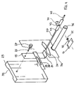
- Fig. 4 zeigt schematisch eine Explosionsdarstellung einer Einzelheit des Geräteträgers.
- Fig. 1 shows schematically a side view of an equipment carrier;
- FIG. 2 schematically shows a front view of the device carrier according to FIG. 1;
- Fig. 3 shows a plan view of a receiving plate of the device carrier and
- Fig. 4 shows schematically an exploded view of a detail of the device carrier.
Wie die Fig. 1 und 2 veranschaulichen, besteht ein in seiner Gesamtheit mit "10" bezeichneter Geräteträger aus einem Bodenrahmen 11 mit Laufrollen 12, über welche der Geräteträger 10 auf einer Stellfläche, beispielsweise dem Fußboden, frei bewegbar ist. Auf dem Bodenrahmen 11 sind zwei vertikale Säulen 13 in vorgegebenem Abstand voneinander angeordnet, so daß eine im wesentlichen gabelartige Anordnung gebildet wird.1 and 2 illustrate, in its entirety with "10" designated equipment carrier consists of a
Zwischen den beiden Säulen 13 ist eine Aufnahmeplatte 14 an zwei Pendelarmen 15 (Fig. 2) aufgehängt, die an den beiden Säulen 13 um eine horizontale Achse schwenkbar angelenkt sind. Durch eine Auslenkung der Pendelarme 15 kann die Aufnahmeplatte 14 wahlweise geneigt werden. In Fig. 1 ist eine geneigte Position gestrichelt veranschaulicht. Die Aufnahmeplatte 14 mit den Pendelarmen 15 ist über die gesamte Länge der Säulen höhenverstellbar gelagert. Die beiden Figuren verdeutlichen, daß grundsätzlich mehrere derartiger an Pendelarme 15 aufgehängte Aufnahmeplatten 14 zwischen zwei Säulen 13 angeordnet werden können. Ebenso ist es ohne weiteres möglich, festehende Regalböden oder ähnliches (nicht dargestellt) zwischen den Säulen 13 anzuordnen. Auf diese Weise kann praktisch ein Geräteturm zusammengestellt werden, wobei die Säulen 13 bis zu 2 m hoch sein können. Um eine ausreichende Standfestigkeit zu erreichen, ist der Bodenrahmen 11 schwergewichtig aus Metallguß hergestellt. Auf diese Weise liegt der Schwerpunkt der gesamten Anordnung relativ tief, selbst wenn auch die auf dem Geräteträger angeordneten Geräte (nicht dargestellt) ein großes Eigengewicht aufweisen.Between the two
Die Fig. 3 veranschaulicht eine Aufsicht auf die Aufnahmeplatte 14 und ihre Aufhängung. Die sich in der Zeichenebene erstreckende Aufnahmeplatte 14 umfaßt im wesentlichen einen metallischen Rahmen 16 und eine oberflächenbündig abschliessende Füllung 17. An einer Frontseite, d.h. in Schwenkrichtung, befindet sich eine stabförmige Handhabe 18, die sich in einem vorgegebenen Abstand über die gesamte Breite der Aufnahmeplatte 14 erstreckt. In dem Zwischenraum zwischen der Handhabe 18 und der Aufnahmeplatte 14 ist eine zentrisch gelagerte doppelflügelige Betätigungsvorrichtung 19 angeordnet, die zum Betätigen eines Querriegels dient, der im einzelnen in Fig. 4 beschrieben ist. Die beiden Flügel 22, 21 sind aus der Zeichenebene heraus auslenkbar, indem die Bedienperson beispielsweise gleichzeitig die Aufnahmeplatte 14 über die Handhabe 18 festhält oder auslenkt.3 illustrates a top view of the
In dem in Fig. 3 dargestellten Beispiel befinden sich die Pendelarme jeweils im Innern eines Trägers 23,24, welcher an der zugehörigen Säule höhenverstellbar verschraubt wird. Dies erfolgt mit Hilfe eines horizontal angeordneten Bolzens 25 bzw. 26, an welchem auch die Pendelarme aufgehängt sind. Die Bolzen 25,26 sind einerseits mit einer von aussen bedienbaren Rändelmutter 28 und andererseits mit einem Kopf 29 bzw. 30 zum höhenverstellbaren Eingriff mit jeweils einer vertikal verlaufenden Nut 31 in der zugehörigen Säule 13 versehen. Um die Darstellung übersichtlich zu halten, ist eine Nut 31 lediglich auf der rechten Figurenseite anhand eines Teilquerschnitts durch die betreffende Säule 13 veranschaulicht. Sinngemäß gelten die hierzu gemachten Ausführungen auch für die Seite mit dem Bolzen 25.In the example shown in FIG. 3, the pendulum arms are each located inside a
Die Nut 31 ist mit zwei L-Schenkeln versehen, welche den Kopf 30 hintergreifen. Durch Drehung der Rändelmutter 28 wird der Bolzen 26 mit dem Kopf 30 an den L-Schenkeln verklemmt bzw. gelöst. Da sich die Nut 31 über die gesamte Länge der Säule 13 erstreckt, kann die Aufnahmeplatte 14 in jede beliebige Höhe verschoben und dort fixiert werden.The groove 31 is provided with two L-legs which engage behind the head 30. By turning the knurled nut 28, the
Die Träger 23,24 sind säulenseitig mit einer halboffenen, in Richtung der Säulen verlaufenden Ausnehmung 32,33 versehen, welche die zugehörigen Säulen 13 formschlüssig umfassen. In Fig. 3 verlaufen die Ausnehmungen 32,33 senkrecht zur Zeichenebene, d.h. sie sind aufgrund des Formschlusses gegen eine Bewegung in der Zeichenebene, insbesondere in Schwenkrichtung der Aufnahmeplatte 14 fixiert.The supports 23, 24 are provided on the column side with a
Die Fig. 4 zeigt, auf welche Weise der Träger 23 sowie der zugehörige Pendelarm 15 mittels des Bolzens 25 aufgehängt sind. Der Träger 23 ist als Gehäuse ausgeformt, in welchem der Pendelarm 15 auslenkbar ist. Der Pendelarm 15 ist an seinem freien Ende mit einem Auflager 34 versehen, an welchem die Aufnahmeplatte 14 befestigt ist. Das Auflager 34 ist durch eine Öffnung 35 in einem Gehäusedeckel 36 nach außen geführt. Die Öffnung 35 dient somit auch als Begrenzung für eine Schwenkbewegung bzw. Pendelbewegung.4 shows the manner in which the
Durch die Öffnung 35 ist ferner ein Querriegel 37 geführt, der an der Aufnahmeplatte, die in dieser Figur nicht dargestellt ist, gelagert ist. Er greift mit seinem freien Ende lösbar wahlweise in eine der Lochungen 38 in einem plattenförmigen Riegel-Gegenstück 39 ein, welches am Träger 23 befestigt ist. Mit Hilfe des Querriegels 37 und der Lochungen 38 ist die Aufnahmeplatte 14 wahlweise mit verschiedenen Auslenkungen bzw. Neigungen arretierbar.A
Der Riegel 37 ist in dem hier gezeigten Beispiel über eine Schenkelfeder 40 vorgespannt, so daß er selbsttätig in eine der Lochungen 38 einrastet. Ausgelenkt wird er mit Hilfe eines Nockens 41 an der Schwenkachse 42 der Betätigungsvorrichtung 19. Der Nocken 41 greift in eine entsprechend geformte Ausnehmung 43 an einer Steuerplatte 44 des Riegels 37 an.The
In Verlängerung des Querriegels 37 befindet sich ein weiterer Querriegel 45, der mit einer zwar spiegelverkehrten, aber ansonsten gleichartigen Anordnung zusammenwirkt, die sich im Innern des Trägers 24 (Fig. 3) befindet.In the extension of the
Die beiden Querriegel 37,45 sowie die zugehörigen Bauteile befinden sich unterhalb der Führung 17 (Fig. 3). Sie können nach unten abgedeckt sein.The two
Unterhalb der Aufnahmeplatte verläuft ein Querholm 46 zwischen den beiden Trägern 23,24, welcher diese gegeneinander abstützt.Below the receiving plate, a
Claims (12)
characterized in that
each mounting plate (14) is disposed to two oscillating arms (15), each of which may be articulated to the columns (13), in that the oscillating arms (15) are arranged in supports (23,24) in the style of a housing, which are arranged between each mounting plate (14) and the columns (13) and which may be adjusted together with the oscillating arms (15) with respect to the height via horizontal bolts (25,26), in that at least one bar counterpart (39) is fixed to one support (23,24) in the style of a housing, a bar (37,45) being provided which is supported at the mounting plate (14) and deflectable in parallel to the oscillating axis and which is adapted to engage in the bar counterpart in a detachable manner by choice under different angles, for locking the mounting plate (14).
characterized in that
the side (36) of the support (23,24) in the style of a housing facing the mounting plate (14) is provided with an opening (35) through which the free end of the associated oscillating arm (15) is passed as an abutment (34) for the mounting plate (14) and through which the associated bar (37,45) which is deflectable in parallel to the oscillating axis, is passed into the casing for engaging in the bar counterpart (39).
characterized in that
the openings (35) serve as a boundary for the oscillating movement, respectively, for the tilt of the mounting plate (14).
characterized in that
the bar counterpart (39) is constructed as a perforated plate, in whose holes (38) engage the associated crossbar (37,45) for continuous tilt adjustment of the mounting plate (14).
characterized in that
the mounting plate (14) is lockable at both sides.
characterized in that
the/the two crossbar(s) (37,45) engage with an operating mechanism (19) located on the front side of the mounting plate (14).
characterized in that
the bolts (25,26) are constructed as oscillating axis and screwed to the columns (13).
characterized in that
each column (13) is provided with a vertically directed fastening groove (31), and in that the bolts (25, 26) are detachably clamped in longitudinally displaceable manner in the fastening groove (31).
characterized in that
the two supports (23,24) in the style of a housing are reciprocally supported with a cross beam (46) below the mounting frame (14).
characterized in that
the two supports (23,24) in the style of a housing positively engage behind the columns (13) on two sides transverse to the oscillating directions.
characterized in that
the base frame (11) is provided with runners (12).
characterized in that
the operating mechanism (19) is located in finger reach of a handle (18) for the mounting plate.
Priority Applications (1)
| Application Number | Priority Date | Filing Date | Title |
|---|---|---|---|
| AT89103113T ATE72698T1 (en) | 1988-03-11 | 1989-02-22 | EQUIPMENT CARRIER. |
Applications Claiming Priority (2)
| Application Number | Priority Date | Filing Date | Title |
|---|---|---|---|
| DE3808233 | 1988-03-11 | ||
| DE3808233A DE3808233A1 (en) | 1988-03-11 | 1988-03-11 | DEVICE CARRIER |
Publications (2)
| Publication Number | Publication Date |
|---|---|
| EP0331976A1 EP0331976A1 (en) | 1989-09-13 |
| EP0331976B1 true EP0331976B1 (en) | 1992-02-19 |
Family
ID=6349527
Family Applications (1)
| Application Number | Title | Priority Date | Filing Date |
|---|---|---|---|
| EP89103113A Expired - Lifetime EP0331976B1 (en) | 1988-03-11 | 1989-02-22 | Apparatus stand |
Country Status (5)
| Country | Link |
|---|---|
| EP (1) | EP0331976B1 (en) |
| JP (1) | JPH0781672B2 (en) |
| AT (1) | ATE72698T1 (en) |
| DE (2) | DE3808233A1 (en) |
| ES (1) | ES2030222T3 (en) |
Cited By (1)
| Publication number | Priority date | Publication date | Assignee | Title |
|---|---|---|---|---|
| US6220186B1 (en) | 1996-05-29 | 2001-04-24 | Usm U. Scharer Sohne Ag | Modular interior furnishing system |
Families Citing this family (5)
| Publication number | Priority date | Publication date | Assignee | Title |
|---|---|---|---|---|
| DE9417283U1 (en) * | 1994-10-27 | 1994-12-22 | Kuhnert Manfred | Holding device for a housing |
| DE29502588U1 (en) * | 1995-02-17 | 1995-04-13 | Hohenloher Spezialmoebel | Device for accommodating a monitor, an input keyboard and a floppy disk drive |
| DE102006005531B4 (en) * | 2006-02-07 | 2013-01-17 | Vega Grieshaber Kg | 1 m field device with a mounting bracket for attachment to a mounting surface |
| DE102006048968A1 (en) * | 2006-10-17 | 2008-04-24 | Fujitsu Siemens Computers Gmbh | Stand for receiving a computer case |
| CN112082056A (en) * | 2020-09-10 | 2020-12-15 | 广州云也科技有限公司 | Novel fuel cell pressure maintaining experiment bench |
Family Cites Families (7)
| Publication number | Priority date | Publication date | Assignee | Title |
|---|---|---|---|---|
| FR1007058A (en) * | 1948-02-18 | 1952-04-30 | Combined receiver of images and sounds | |
| JPS5631092Y2 (en) * | 1977-06-10 | 1981-07-24 | ||
| JPS5719004Y2 (en) * | 1978-06-05 | 1982-04-21 | ||
| DE2831428A1 (en) * | 1978-07-18 | 1980-01-31 | Gottfried Kleinhenz | Swivel support system for TV sets - is adjustable steplessly in horizontal plane to required viewing angle |
| JPS59137675U (en) * | 1982-10-29 | 1984-09-13 | 神崎 六太夫 | tv rackmil stand |
| US4616218A (en) * | 1983-01-03 | 1986-10-07 | International Business Machines Corporation | Adjustable CRT display |
| WO1985001648A1 (en) * | 1983-10-11 | 1985-04-25 | Tektronix, Inc. | Computer terminal stand |
-
1988
- 1988-03-11 DE DE3808233A patent/DE3808233A1/en not_active Withdrawn
-
1989
- 1989-02-22 DE DE8989103113T patent/DE58900828D1/en not_active Expired - Fee Related
- 1989-02-22 EP EP89103113A patent/EP0331976B1/en not_active Expired - Lifetime
- 1989-02-22 ES ES198989103113T patent/ES2030222T3/en not_active Expired - Lifetime
- 1989-02-22 AT AT89103113T patent/ATE72698T1/en active
- 1989-03-06 JP JP1052170A patent/JPH0781672B2/en not_active Expired - Lifetime
Cited By (1)
| Publication number | Priority date | Publication date | Assignee | Title |
|---|---|---|---|---|
| US6220186B1 (en) | 1996-05-29 | 2001-04-24 | Usm U. Scharer Sohne Ag | Modular interior furnishing system |
Also Published As
| Publication number | Publication date |
|---|---|
| DE3808233A1 (en) | 1989-09-21 |
| DE58900828D1 (en) | 1992-03-26 |
| ES2030222T3 (en) | 1992-10-16 |
| JPH01295096A (en) | 1989-11-28 |
| JPH0781672B2 (en) | 1995-09-06 |
| EP0331976A1 (en) | 1989-09-13 |
| ATE72698T1 (en) | 1992-03-15 |
Similar Documents
| Publication | Publication Date | Title |
|---|---|---|
| DE1964682C3 (en) | Drawing table | |
| EP0670123B1 (en) | Height adjustable work table | |
| DE1815331B2 (en) | FOLDING BABY CHAIR | |
| EP0331976B1 (en) | Apparatus stand | |
| DE3448233C2 (en) | ||
| DE10110405C2 (en) | Device for securing ladders and scaffolding stands on uneven terrain | |
| DE2921636A1 (en) | Universal building wall climbing appliance - has guide-rail top swivelling mounting, hoist support bracket and adjustable base support | |
| EP1736393B1 (en) | Supporting trestle for long materials | |
| DE3121869A1 (en) | HOLDING CONSOLE FOR DETACHABLE OBJECT ATTACHMENT TO A WALL RAIL | |
| DE3014489A1 (en) | Panel wiring trolley with pivoted clamp frame - is for large switchgear or distribution panels and allows rapid position adjustment in orthogonal planes | |
| DE2165209A1 (en) | BED, ESPECIALLY SICK BED | |
| DE3309203A1 (en) | Vertically adjustable pedestal frame for theatre stages or the like | |
| DE2352159C3 (en) | Lifting device for automobiles | |
| EP0255055B1 (en) | Lifting podium respectively platform | |
| DE3818922A1 (en) | SUPPORT OF A CARRIER | |
| DE4212943C2 (en) | Height-adjustable children's chair | |
| DE3510707C2 (en) | ||
| DE19538915B4 (en) | On the chassis of a vehicle to be fastened holding device for a container locking device | |
| DE3515808C2 (en) | ||
| DE8013440U1 (en) | SCAFFOLDING LIFTING BRIDGES AND PLATFORMS | |
| DE4140421C2 (en) | Device for bending a structural steel mat consisting of longitudinal bars and cross bars | |
| DE3005577A1 (en) | Vertically adjustable sheet stand - has combined roller and slide runner movable into two operative positions | |
| DE1756208C3 (en) | Roller conveyor | |
| DE4222342A1 (en) | Device for holding a trailer coupling support plate | |
| DE2332883C3 (en) | Support frame for his work platform or the like. |
Legal Events
| Date | Code | Title | Description |
|---|---|---|---|
| PUAI | Public reference made under article 153(3) epc to a published international application that has entered the european phase |
Free format text: ORIGINAL CODE: 0009012 |
|
| AK | Designated contracting states |
Kind code of ref document: A1 Designated state(s): AT CH DE ES FR GB IT LI |
|
| 17P | Request for examination filed |
Effective date: 19900209 |
|
| 17Q | First examination report despatched |
Effective date: 19910419 |
|
| GRAA | (expected) grant |
Free format text: ORIGINAL CODE: 0009210 |
|
| AK | Designated contracting states |
Kind code of ref document: B1 Designated state(s): AT CH DE ES FR GB IT LI |
|
| REF | Corresponds to: |
Ref document number: 72698 Country of ref document: AT Date of ref document: 19920315 Kind code of ref document: T |
|
| REF | Corresponds to: |
Ref document number: 58900828 Country of ref document: DE Date of ref document: 19920326 |
|
| GBT | Gb: translation of ep patent filed (gb section 77(6)(a)/1977) | ||
| ET | Fr: translation filed | ||
| ITF | It: translation for a ep patent filed |
Owner name: STUDIO JAUMANN |
|
| REG | Reference to a national code |
Ref country code: ES Ref legal event code: FG2A Ref document number: 2030222 Country of ref document: ES Kind code of ref document: T3 |
|
| PLBE | No opposition filed within time limit |
Free format text: ORIGINAL CODE: 0009261 |
|
| STAA | Information on the status of an ep patent application or granted ep patent |
Free format text: STATUS: NO OPPOSITION FILED WITHIN TIME LIMIT |
|
| 26N | No opposition filed | ||
| REG | Reference to a national code |
Ref country code: GB Ref legal event code: 746 Effective date: 19930526 |
|
| REG | Reference to a national code |
Ref country code: FR Ref legal event code: DL |
|
| ITPR | It: changes in ownership of a european patent |
Owner name: OFFERTA DI LICENZA AL PUBBLICO |
|
| PGFP | Annual fee paid to national office [announced via postgrant information from national office to epo] |
Ref country code: AT Payment date: 19981218 Year of fee payment: 11 |
|
| PGFP | Annual fee paid to national office [announced via postgrant information from national office to epo] |
Ref country code: CH Payment date: 19990201 Year of fee payment: 11 |
|
| PGFP | Annual fee paid to national office [announced via postgrant information from national office to epo] |
Ref country code: GB Payment date: 19990225 Year of fee payment: 11 |
|
| PGFP | Annual fee paid to national office [announced via postgrant information from national office to epo] |
Ref country code: FR Payment date: 19990226 Year of fee payment: 11 Ref country code: ES Payment date: 19990226 Year of fee payment: 11 Ref country code: DE Payment date: 19990226 Year of fee payment: 11 |
|
| PG25 | Lapsed in a contracting state [announced via postgrant information from national office to epo] |
Ref country code: GB Free format text: LAPSE BECAUSE OF NON-PAYMENT OF DUE FEES Effective date: 20000222 Ref country code: AT Free format text: LAPSE BECAUSE OF NON-PAYMENT OF DUE FEES Effective date: 20000222 |
|
| PG25 | Lapsed in a contracting state [announced via postgrant information from national office to epo] |
Ref country code: ES Free format text: THE PATENT HAS BEEN ANNULLED BY A DECISION OF A NATIONAL AUTHORITY Effective date: 20000223 |
|
| PG25 | Lapsed in a contracting state [announced via postgrant information from national office to epo] |
Ref country code: LI Free format text: LAPSE BECAUSE OF NON-PAYMENT OF DUE FEES Effective date: 20000229 Ref country code: CH Free format text: LAPSE BECAUSE OF NON-PAYMENT OF DUE FEES Effective date: 20000229 |
|
| GBPC | Gb: european patent ceased through non-payment of renewal fee |
Effective date: 20000222 |
|
| REG | Reference to a national code |
Ref country code: CH Ref legal event code: PL |
|
| PG25 | Lapsed in a contracting state [announced via postgrant information from national office to epo] |
Ref country code: FR Free format text: LAPSE BECAUSE OF NON-PAYMENT OF DUE FEES Effective date: 20001031 |
|
| PG25 | Lapsed in a contracting state [announced via postgrant information from national office to epo] |
Ref country code: DE Free format text: LAPSE BECAUSE OF NON-PAYMENT OF DUE FEES Effective date: 20001201 |
|
| REG | Reference to a national code |
Ref country code: FR Ref legal event code: ST |
|
| REG | Reference to a national code |
Ref country code: ES Ref legal event code: FD2A Effective date: 20020204 |
|
| PG25 | Lapsed in a contracting state [announced via postgrant information from national office to epo] |
Ref country code: IT Free format text: LAPSE BECAUSE OF NON-PAYMENT OF DUE FEES;WARNING: LAPSES OF ITALIAN PATENTS WITH EFFECTIVE DATE BEFORE 2007 MAY HAVE OCCURRED AT ANY TIME BEFORE 2007. THE CORRECT EFFECTIVE DATE MAY BE DIFFERENT FROM THE ONE RECORDED. Effective date: 20050222 |