EP1548515A1 - Farbbild-Erzeugungsvorrichtung und Tonernachfüllgerät - Google Patents
Farbbild-Erzeugungsvorrichtung und Tonernachfüllgerät Download PDFInfo
- Publication number
- EP1548515A1 EP1548515A1 EP05005627A EP05005627A EP1548515A1 EP 1548515 A1 EP1548515 A1 EP 1548515A1 EP 05005627 A EP05005627 A EP 05005627A EP 05005627 A EP05005627 A EP 05005627A EP 1548515 A1 EP1548515 A1 EP 1548515A1
- Authority
- EP
- European Patent Office
- Prior art keywords
- image forming
- forming apparatus
- transfer belt
- forming units
- toner
- Prior art date
- Legal status (The legal status is an assumption and is not a legal conclusion. Google has not performed a legal analysis and makes no representation as to the accuracy of the status listed.)
- Granted
Links
- 238000004140 cleaning Methods 0.000 claims description 24
- 230000003287 optical effect Effects 0.000 claims description 22
- 238000000034 method Methods 0.000 claims description 11
- 239000002699 waste material Substances 0.000 claims description 8
- 238000007599 discharging Methods 0.000 description 13
- 238000010438 heat treatment Methods 0.000 description 12
- 239000000843 powder Substances 0.000 description 11
- 239000003086 colorant Substances 0.000 description 4
- 238000011144 upstream manufacturing Methods 0.000 description 4
- 230000000694 effects Effects 0.000 description 3
- 239000000463 material Substances 0.000 description 3
- 230000008901 benefit Effects 0.000 description 2
- 230000015572 biosynthetic process Effects 0.000 description 2
- 229920001971 elastomer Polymers 0.000 description 2
- 230000008569 process Effects 0.000 description 2
- 229920002943 EPDM rubber Polymers 0.000 description 1
- 238000010276 construction Methods 0.000 description 1
- 238000001514 detection method Methods 0.000 description 1
- 239000013013 elastic material Substances 0.000 description 1
- 238000009434 installation Methods 0.000 description 1
- 230000007246 mechanism Effects 0.000 description 1
- 239000002184 metal Substances 0.000 description 1
- 238000012986 modification Methods 0.000 description 1
- 230000004048 modification Effects 0.000 description 1
- 150000002825 nitriles Chemical class 0.000 description 1
- 229920002635 polyurethane Polymers 0.000 description 1
- 239000004814 polyurethane Substances 0.000 description 1
- 239000011347 resin Substances 0.000 description 1
- 229920005989 resin Polymers 0.000 description 1
- 229910052710 silicon Inorganic materials 0.000 description 1
- 239000010703 silicon Substances 0.000 description 1
Images

Classifications
-
- G—PHYSICS
- G03—PHOTOGRAPHY; CINEMATOGRAPHY; ANALOGOUS TECHNIQUES USING WAVES OTHER THAN OPTICAL WAVES; ELECTROGRAPHY; HOLOGRAPHY
- G03G—ELECTROGRAPHY; ELECTROPHOTOGRAPHY; MAGNETOGRAPHY
- G03G21/00—Arrangements not provided for by groups G03G13/00 - G03G19/00, e.g. cleaning, elimination of residual charge
- G03G21/16—Mechanical means for facilitating the maintenance of the apparatus, e.g. modular arrangements
- G03G21/18—Mechanical means for facilitating the maintenance of the apparatus, e.g. modular arrangements using a processing cartridge, whereby the process cartridge comprises at least two image processing means in a single unit
- G03G21/1839—Means for handling the process cartridge in the apparatus body
- G03G21/1842—Means for handling the process cartridge in the apparatus body for guiding and mounting the process cartridge, positioning, alignment, locks
-
- G—PHYSICS
- G03—PHOTOGRAPHY; CINEMATOGRAPHY; ANALOGOUS TECHNIQUES USING WAVES OTHER THAN OPTICAL WAVES; ELECTROGRAPHY; HOLOGRAPHY
- G03G—ELECTROGRAPHY; ELECTROPHOTOGRAPHY; MAGNETOGRAPHY
- G03G15/00—Apparatus for electrographic processes using a charge pattern
- G03G15/01—Apparatus for electrographic processes using a charge pattern for producing multicoloured copies
- G03G15/0105—Details of unit
- G03G15/0131—Details of unit for transferring a pattern to a second base
-
- G—PHYSICS
- G03—PHOTOGRAPHY; CINEMATOGRAPHY; ANALOGOUS TECHNIQUES USING WAVES OTHER THAN OPTICAL WAVES; ELECTROGRAPHY; HOLOGRAPHY
- G03G—ELECTROGRAPHY; ELECTROPHOTOGRAPHY; MAGNETOGRAPHY
- G03G15/00—Apparatus for electrographic processes using a charge pattern
- G03G15/01—Apparatus for electrographic processes using a charge pattern for producing multicoloured copies
- G03G15/0142—Structure of complete machines
- G03G15/0178—Structure of complete machines using more than one reusable electrographic recording member, e.g. one for every monocolour image
- G03G15/0194—Structure of complete machines using more than one reusable electrographic recording member, e.g. one for every monocolour image primary transfer to the final recording medium
-
- G—PHYSICS
- G03—PHOTOGRAPHY; CINEMATOGRAPHY; ANALOGOUS TECHNIQUES USING WAVES OTHER THAN OPTICAL WAVES; ELECTROGRAPHY; HOLOGRAPHY
- G03G—ELECTROGRAPHY; ELECTROPHOTOGRAPHY; MAGNETOGRAPHY
- G03G15/00—Apparatus for electrographic processes using a charge pattern
- G03G15/06—Apparatus for electrographic processes using a charge pattern for developing
- G03G15/08—Apparatus for electrographic processes using a charge pattern for developing using a solid developer, e.g. powder developer
- G03G15/0822—Arrangements for preparing, mixing, supplying or dispensing developer
-
- G—PHYSICS
- G03—PHOTOGRAPHY; CINEMATOGRAPHY; ANALOGOUS TECHNIQUES USING WAVES OTHER THAN OPTICAL WAVES; ELECTROGRAPHY; HOLOGRAPHY
- G03G—ELECTROGRAPHY; ELECTROPHOTOGRAPHY; MAGNETOGRAPHY
- G03G15/00—Apparatus for electrographic processes using a charge pattern
- G03G15/14—Apparatus for electrographic processes using a charge pattern for transferring a pattern to a second base
- G03G15/16—Apparatus for electrographic processes using a charge pattern for transferring a pattern to a second base of a toner pattern, e.g. a powder pattern, e.g. magnetic transfer
- G03G15/1605—Apparatus for electrographic processes using a charge pattern for transferring a pattern to a second base of a toner pattern, e.g. a powder pattern, e.g. magnetic transfer using at least one intermediate support
-
- G—PHYSICS
- G03—PHOTOGRAPHY; CINEMATOGRAPHY; ANALOGOUS TECHNIQUES USING WAVES OTHER THAN OPTICAL WAVES; ELECTROGRAPHY; HOLOGRAPHY
- G03G—ELECTROGRAPHY; ELECTROPHOTOGRAPHY; MAGNETOGRAPHY
- G03G15/00—Apparatus for electrographic processes using a charge pattern
- G03G15/14—Apparatus for electrographic processes using a charge pattern for transferring a pattern to a second base
- G03G15/16—Apparatus for electrographic processes using a charge pattern for transferring a pattern to a second base of a toner pattern, e.g. a powder pattern, e.g. magnetic transfer
- G03G15/1665—Apparatus for electrographic processes using a charge pattern for transferring a pattern to a second base of a toner pattern, e.g. a powder pattern, e.g. magnetic transfer by introducing the second base in the nip formed by the recording member and at least one transfer member, e.g. in combination with bias or heat
- G03G15/167—Apparatus for electrographic processes using a charge pattern for transferring a pattern to a second base of a toner pattern, e.g. a powder pattern, e.g. magnetic transfer by introducing the second base in the nip formed by the recording member and at least one transfer member, e.g. in combination with bias or heat at least one of the recording member or the transfer member being rotatable during the transfer
- G03G15/1685—Structure, details of the transfer member, e.g. chemical composition
-
- G—PHYSICS
- G03—PHOTOGRAPHY; CINEMATOGRAPHY; ANALOGOUS TECHNIQUES USING WAVES OTHER THAN OPTICAL WAVES; ELECTROGRAPHY; HOLOGRAPHY
- G03G—ELECTROGRAPHY; ELECTROPHOTOGRAPHY; MAGNETOGRAPHY
- G03G21/00—Arrangements not provided for by groups G03G13/00 - G03G19/00, e.g. cleaning, elimination of residual charge
- G03G21/16—Mechanical means for facilitating the maintenance of the apparatus, e.g. modular arrangements
- G03G21/1604—Arrangement or disposition of the entire apparatus
- G03G21/1609—Arrangement or disposition of the entire apparatus for space saving, e.g. structural arrangements
-
- G—PHYSICS
- G03—PHOTOGRAPHY; CINEMATOGRAPHY; ANALOGOUS TECHNIQUES USING WAVES OTHER THAN OPTICAL WAVES; ELECTROGRAPHY; HOLOGRAPHY
- G03G—ELECTROGRAPHY; ELECTROPHOTOGRAPHY; MAGNETOGRAPHY
- G03G2215/00—Apparatus for electrophotographic processes
- G03G2215/01—Apparatus for electrophotographic processes for producing multicoloured copies
- G03G2215/0103—Plural electrographic recording members
- G03G2215/0119—Linear arrangement adjacent plural transfer points
-
- G—PHYSICS
- G03—PHOTOGRAPHY; CINEMATOGRAPHY; ANALOGOUS TECHNIQUES USING WAVES OTHER THAN OPTICAL WAVES; ELECTROGRAPHY; HOLOGRAPHY
- G03G—ELECTROGRAPHY; ELECTROPHOTOGRAPHY; MAGNETOGRAPHY
- G03G2215/00—Apparatus for electrophotographic processes
- G03G2215/01—Apparatus for electrophotographic processes for producing multicoloured copies
- G03G2215/0103—Plural electrographic recording members
- G03G2215/0119—Linear arrangement adjacent plural transfer points
- G03G2215/0138—Linear arrangement adjacent plural transfer points primary transfer to a recording medium carried by a transport belt
- G03G2215/0148—Linear arrangement adjacent plural transfer points primary transfer to a recording medium carried by a transport belt the linear arrangement being slanted
-
- G—PHYSICS
- G03—PHOTOGRAPHY; CINEMATOGRAPHY; ANALOGOUS TECHNIQUES USING WAVES OTHER THAN OPTICAL WAVES; ELECTROGRAPHY; HOLOGRAPHY
- G03G—ELECTROGRAPHY; ELECTROPHOTOGRAPHY; MAGNETOGRAPHY
- G03G2221/00—Processes not provided for by group G03G2215/00, e.g. cleaning or residual charge elimination
- G03G2221/16—Mechanical means for facilitating the maintenance of the apparatus, e.g. modular arrangements and complete machine concepts
- G03G2221/1642—Mechanical means for facilitating the maintenance of the apparatus, e.g. modular arrangements and complete machine concepts for the transfer unit
-
- G—PHYSICS
- G03—PHOTOGRAPHY; CINEMATOGRAPHY; ANALOGOUS TECHNIQUES USING WAVES OTHER THAN OPTICAL WAVES; ELECTROGRAPHY; HOLOGRAPHY
- G03G—ELECTROGRAPHY; ELECTROPHOTOGRAPHY; MAGNETOGRAPHY
- G03G2221/00—Processes not provided for by group G03G2215/00, e.g. cleaning or residual charge elimination
- G03G2221/16—Mechanical means for facilitating the maintenance of the apparatus, e.g. modular arrangements and complete machine concepts
- G03G2221/1672—Paper handling
- G03G2221/1675—Paper handling jam treatment
-
- G—PHYSICS
- G03—PHOTOGRAPHY; CINEMATOGRAPHY; ANALOGOUS TECHNIQUES USING WAVES OTHER THAN OPTICAL WAVES; ELECTROGRAPHY; HOLOGRAPHY
- G03G—ELECTROGRAPHY; ELECTROPHOTOGRAPHY; MAGNETOGRAPHY
- G03G2221/00—Processes not provided for by group G03G2215/00, e.g. cleaning or residual charge elimination
- G03G2221/16—Mechanical means for facilitating the maintenance of the apparatus, e.g. modular arrangements and complete machine concepts
- G03G2221/18—Cartridge systems
- G03G2221/183—Process cartridge
Definitions
- the present invention relates to a color image forming apparatus and a toner replenishing apparatus for use in the color image forming apparatus.
- Color image forming systems for color image forming apparatuses are roughly classified into four types of transfer drum system, intermediate transfer system, image-on-image system and tandem system.
- the transfer drum system is a system in which a transfer sheet wound around a transfer drum composed of a dielectric film is disposed opposite to a photosensitive member, and toners of yellow (Y), magenta (M), cyan (C) and black (Bk) are superimposed on the transfer sheet in sequence by repeating an electrophotographic process consisting of formation, development and transferring of an electrostatic latent image with respect to each of the colors, thereby obtaining a full color image.
- the intermediate transfer system is a system in which a full color image is formed by transferring toner images of colors in sequence onto a drum or a belt called an intermediate transfer member in place of the transfer sheet used in the transfer drum system, and then, the full color image is transferred again onto a transfer sheet by one operation.
- the image-on-image system is a system in which an image is transferred onto a transfer sheet by repeating an electrophotographic process consisting of formation, development and transferring of an electrostatic latent image with respect to each of yellow (Y), magenta (M), cyan (C) and black (Bk) directly on a photosensitive member.
- the tandem system is a system in which a full color image is obtained on a transfer sheet by transferring images formed by image forming units in sequence onto a single piece of transfer sheet fed by a transfer belt.
- the color image forming apparatuses using the above-described systems have merits and demerits, respectively.
- the color image forming apparatus of the tandem system has excellent characteristics. Because, for example, it can use a large variety of transfer sheets, obtain a full color image of a high quality, and obtain a full color image at a high speed.
- the characteristic that a full color image can be obtained at a high speed is not provided for the color image forming apparatuses of the other systems, and therefore, is peculiar to the color image forming apparatus of the tandem system.
- each of the image forming units is provided with a photosensitive member having means for charging, developing, cleaning and the like therearound. If the above-described image forming units are juxtaposed on the transfer belt, the image forming apparatus becomes great in width, thereby requiring a large installation space.
- Japanese Patent Application Laid-open No. 10-239938 discloses an image forming apparatus in which a transfer belt is erected vertically. Since image forming units are arranged vertically along the transfer belt, it is possible to provide an image forming apparatus which can be reduced in width and can be installed in a small space.
- the color image forming apparatus comprises a transfer belt device which feeds a transfer member such as a paper and a plurality of image forming units.
- the image forming units are disposed facing towards the transfer belt device.
- the transfer belt device at least in a portion in which the image forming units have been disposed, is arranged such that it is inclined with respect to the ground.
- Each of the image forming unit forms a desired image and sequentially transfers the formed image on the transfer member fed by the transfer belt device.
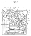
- Fig. 1 is a schematic view showing a color laser printer which is one example of a color image forming apparatus according to the present invention.
- the color laser printer 1 is configured such that a sheet supplying section 2 is provided in the lower portion of the body of the device ("apparatus body") and an image forming section 3 is disposed above the sheet supplying section 2.
- a transfer belt device is slantwise disposed in such a manner as to set a sheet supplying side at the lower portion thereof and a sheet discharging side at the upper portion thereof.
- the transfer belt device 20 includes an endless transfer belt 20 wound around a plurality of, e.g., four belt wheels 22 in the present embodiment.
- At an upper traveling side 21 of the transfer belt 20 are juxtaposed four image forming units 4M, 4C, 4Y and 4Bk for magenta (M), cyan (C), yellow (Y) and black (Bk) in order from below.
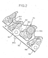
- Fig. 2 is an enlarged view illustrating the image forming unit 4C. Same reference numerals have been provided to the components that perform same or similar functions. as those in Fig. 1, however, a suffix M, C or Y is provided to distinguish the units related to the colors magenta, cyan, or yellow respectively.
- each of the image forming units 4M, 4C, 4Y and 4Bk is provided with a photosensitive drum 5 serving as an image carrier.
- the photosensitive drum 5 is driven to be rotated clockwise by a not shown driving unit.
- a charging roll 6 serving as a charging unit
- an optical writer 7 for performing writing with a laser beam by an optical writing device 8 a developing device 10 serving as developing unit and a cleaning device 9 serving as cleaning unit.
- the developing device 10 is a two-component developing device composed of a toner and a carrier, and is replenished with a toner by a toner replenishing apparatus, described later, according to a consumption of the toner.
- An optical image to be developed with a magenta toner is optically written in a photosensitive drum 5M charged by a charging roll 6M by the writing unit 8, which irradiates a polygon mirror 80 with a laser beam by driving an LED (a laser diode), not shown, and introduces a reflected beam onto the photosensitive drum 5M via a cylinder lens or the like.
- an electrostatic latent image in accordance with image data transmitted from a host machine such as a personal computer is formed on the photosensitive drum 5M.
- the latent image is turned into a visible image with the magenta toner by the developing device 10.
- the writing unit 8 is configured in such a manner as to perform writing in each of the photosensitive drums 5 with the reflected beam from the single polygon mirror 80.
- the writing unit 8 is slantwise disposed substantially in parallel to the transfer belt 20, thereby easily making the length of an optical path up to each of the photosensitive members uniform.
- a sheet designated as a transfer member is supplied from the sheet supplying section 2.
- the supplied sheet once abuts against a registration roller 23 disposed upstream in a direction in which the transfer belt 20 is transported.
- the sheet is fed onto the transfer belt 20 in synchronism with the visible image, and then, reaches a transfer position facing the photosensitive drum 5M as the belt travels.
- the visible image of the magenta toner is transferred onto the sheet by the effect of a transfer roll 24 disposed at the back surface of the transfer belt 20.
- a visible image is formed on the photosensitive drum 5 with a toner of each color in each of the other image forming units 4C, 4Y and 4Bk.
- These visible images are transferred in superimposition every time the sheet fed by the transfer belt 21 reaches each of the transfer positions. Consequently, in the color printer in the present embodiment, a full color image can be transferred onto the sheet in superimposition in as almost short a time as that in a monochromatic case.
- the sheet after the transferring is separated from the transfer belt 20, and then, is fixed by a fixing device 30.
- the fixing device in the present embodiment is of a belt fixing type, in which a relatively soft fixing roller 32, e.g. , a sponge roller is brought into press-contact with a hard pressurizing roller 31.
- a belt 34 is wound around the fixing roller 32 and a heating roller 33 disposed upstream in the sheet feeding direction.
- This belt fixing system has the advantage of, for example, a short warming-up time in comparison with a roller fixing system.
- Operation is selectively switched such that the sheet after the fixation is discharged outside of the apparatus as it is or that the sheet after the fixation is fed to a reversing unit 42 for double-sided printing. If the operation is selected such that the sheet is discharged outside of the apparatus, the sheet is reversed upward, and then, is discharged to a sheet discharging tray 40 disposed at the upper surface of the apparatus body with the reverse thereof oriented upward. It is almost an essential condition for the printer that the sheet is discharged with the reverse thereof oriented upward so as to stack printouts in order of page.
- the sheet is fed to the reversing unit 42, in which the sheet is reversed from obverse to reverse, and then, is fed to a double-sided transporting path 43.
- the double-sided transporting path 43 is slantwise disposed under and substantially in parallel to the transfer belt 20. If the double-sided transporting path 43 is slantwise disposed in the above-described manner, a transporting distance can be shortened or the sheet can be drawn out together with the transfer belt 20 in case of generation of jamming. An image is formed on the reverse of the transfer sheet passing the double-sided transporting path in the same manner as described above, and thereafter, the sheet is discharged to the sheet discharging tray 40.
- the double-sided transporting path 43 is slantwise disposed substantially in parallel to the transfer belt 20 in the present embodiment, so that the transfer member after the fixation can be returned toward the registration roller 23 at a shortest distance.
- the double-sided transporting path 43 is disposed horizontally, the path passes near the upper surface of an upper cassette. In this case, the transfer member must be descended down to the height level of the transporting path, thereby elongating the path.
- the color printer such configured as described above is provided with the four image forming units 4M, 4C, 4Y and 4Bk, and the respective toner images of the colors are sequentially transferred in superimposition onto the sheet while the sheet is fed by the transfer belt device 20. Consequently, it is possible to remarkably shorten an image forming time in comparison with the intermediate transfer system in which only one image forming unit transfers toner images onto an intermediate transfer member in superimposition, and then, transfers the transferred toner images onto a sheet by one operation.
- the traveling side 21 of the transfer belt 20 at which the image forming units are arranged is slantwise inclined as described above, so that the adjacent image forming units 4 are arranged in such a manner that the cleaning device 9 in one of the adjacent image forming units vertically overlaps with the developing device 10 in the other image forming unit, as shown in Fig. 2.
- the adjacent image forming units 4M and 4C are arranged in such a manner that a cleaning device 9M in the image forming unit 4M vertically overlaps with a developing device 10C in the image forming unit 4C. Consequently, it is possible to shorten the lateral length in comparison with an apparatus in which a transfer belt is horizontally disposed.
- the inclination angle of the transfer belt 20 is designated by ⁇ . If the angle ⁇ is small, the developing device 10 and the cleaning device 9 in the adjacent image forming units cannot be disposed in such a manner as to overlap with each other, unlike the above description. In contrast, if the angle ⁇ is about 90°, the lateral length can be remarkably shortened while a vertical height to some extent is needed, thereby making the position of the sheet discharging tray too high. Therefore, it is preferable that the inclination angle ⁇ of the transfer belt 20 should range from 35° to 55°. As shown in Fig.
- a developing position of the developing device 10 i.e., a position at which a magnetic brush formed in a developing roller 11 is brought into contact with the photosensitive drum 5 can be located in a lower right quadrant when the transfer belt 20 is brought into contact with the photosensitive drum 5 in a lower left quadrant, the center O of rotation of the photosensitive drum 5 being regarded as an origin.
- the developing device 10 which is disposed in such a manner as to develop in the lower right quadrant of the photosensitive drum 5, has the advantage of alleviation of coming-off of the toner in comparison with a developing device which is disposed at the same height level as or above the center of rotation of the photosensitive drum 5. Furthermore, when the inclination angle ⁇ of the transfer belt 20 is set between 35° and 55° and the transfer belt 20 is brought into contact with the photosensitive drum 5 in the lower left quadrant, the center O of rotation being regarded as the origin, a cleaning blade 90 and a fur brush 91 of the cleaning device 9 can be brought into contact with the photosensitive drum 5 in an upper left quadrant of the photosensitive drum 5.
- the cleaning device 9 disposed in the above-described manner is more excellent in cleaning property than a cleaning device in which cleaning members such as a cleaning blade are brought into contact with a photosensitive drum 5 substantially right above the photosensitive drum 5.
- the transfer belt 20 is disposed substantially on the diagonal of the printer body.
- the traveling side 21 of the transfer belt 20 is driven to be moved from below to above, and the sheet feeding section and the sheet discharging section are disposed in the lower portion and the upper portion of the main body, respectively, so that both of the transporting path from the sheet feeding section to the transfer belt 20 and the transporting path from the transfer belt 20 to the sheet discharging section can be shortened remarkably advantageously.
- the casing of the image forming apparatus such as the printer is formed into a substantially rectangular parallelepiped.
- the transfer belt 20 is slantwise disposed, spaces, each having a substantially triangular shape in cross section, are defined above and under the transfer belt 20.
- a toner containing vessel 100 is housed in the upper space, and further, a waste toner tank 93 is housed in the lower space.
- the toner containing vessel 100 or the waste toner tank 93 since the toner containing vessel 100 or the waste toner tank 93 has a remarkably greater freedom of a shape, it may be formed into a shape in conformity with the defined triangular space or it may be disposed opposite to the transfer belt 20 with a surface inclined in the same direction as the inclination of the transfer belt 20. Consequently, it is possible to securely eliminate a fear that the space having the triangular shape in cross section becomes a dead space.
- a powder pump 110 i.e., a uniaxial eccentric screw pump of a suction type is disposed in the vicinity of or integrally with the developing device 10.
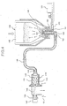
- the powder pump 110 comprises a rotor 142 made of a material having rigidity such as metal and formed into a shape of an eccentric screw, a stator 143 made of an elastic material such as rubber and formed into a shape of a two-thread screw, and a holder 144 enveloping the rotor 142 and the stator 143, being made of a resin material and forming a powder transporting path, as shown in Fig. 4.
- the rotor 142 is driven to be rotated via a gear 46 integrally connected to a drive shaft 145 joined via a pin joint.
- reference numeral 147 designates an electromagnetic clutch, which controls the operation of the powder pump 110.
- a toner sucking portion 148 is disposed at the tip of the holder 144, i.e., at the right end thereof in Fig. 4, and is connected to a toner connecting port 165 formed at a nozzle 160, later described, via a toner conveying tube 149.
- a flexible tube having a diameter of, e.g., 4 mm to 10 mm and being made of a rubber material excellent in toner resistance (for example, polyurethane, nitrile, EPDM, silicon or the like) as the toner conveying tube 49.
- Such a flexible tube can be easily installed vertically or laterally in an arbitrary direction.
- the uniaxial eccentric screw pump serving as the powder pump 110 can continuously convey a constant quantity of toner in a high fixed air ratio, and further, that it can precisely convey a quantity of toner in proportion to the rotational speed of the rotor 142. Therefore, when a toner replenishing command is issued upon detection of an image concentration or the like, the powder pump 110 is actuated to replenish a required quantity of toner to the developing device 40.
- a setting section in the image forming apparatus body in which the toner containing vessel 1 is set, is configured as a unit independent of the developing device 10.
- the nozzle 160 which has a circular shape in cross section and is inserted into a toner bag 102.
- the toner containing vessel 100 is installed from above in the setting section in the image forming apparatus body.
- a projecting member 161 formed into a drill-like shape in cross section is molded integrally with or fixed to the upper portion of the nozzle 160 disposed in the setting section.
- An air supplying path 162 and a toner supplying path 163 are provided continuously from the projecting member 161.
- the inside of the nozzle 160 is formed into a double-pipe structure.
- the toner supplying path 163 is bent leftward in Fig. 4 at the lower end of the nozzle 160, and further, the toner connecting port 65 connected to the toner conveying tube 149 is disposed at the tip of the toner supplying path 163. Moreover, the air supplying path 162 is bent rightward in Fig. 4 above the toner supplying path 163, and reaches an air connecting port 164.
- the air connecting port 164 is connected to an air pump 151 serving as air supplying unit via an air conveying pipe 152 in the present embodiment.
- air pump 151 When the air pump 151 is actuated, air is jetted into the toner containing vessel 100 from the air pump 151 via the air conveying pipe 152 and the air supplying path 162.
- the air jetted inside the toner containing vessel 100 passes toner layers to allow the toner to be diffused and fluidized.
- the toner replenishing apparatus such configured as described above can securely replenish the toner even if each of the image forming units 4M, 4C, 4Y and 4Bk is separated from the toner containing vessel 100.
- the toner containing vessel 100 can be installed at an arbitrary position irrespective of the image forming units 4M, 4C, 4Y and 4Bk. Consequently, in the color printer in which the transfer belt 20 is inclined and each of the image forming units 4M, 4C, 4Y and 4Bk is disposed along the inclination, it is unnecessary to define spaces for toner containers among the image forming units 4M, 4C, 4Y and 4Bk, and therefore, the image forming units 4M, 4C, 4Y and 4Bk can be arranged close to each other.
- the belt fixing device 30 is used in the preferred embodiment shown in Fig. 1, the sheet is fed slantwise from below along the inclined transfer belt 20, so that the heating roller 33 can be disposed lower than the height level of the fixing roller 32.
- the sheet off a nip can be fed substantially in a horizontal direction while sufficiently securing a nip width between the fixing roller 32 and the pressurizing roller 31, so that the sheet can be smoothly fed to the sheet discharging tray 40 disposed at the upper portion of the apparatus body.
- the sheet is fed into the nip between the fixing roller 32 and the pressurizing roller 31 in the horizontal direction, the sheet is fed slantwise downward when it passes. Therefore, a mechanism for reversing the sheet at a great angle is required in order to feed the sheet to the sheet discharging tray 40 disposed at the upper portion of the apparatus body.
- the fixing device 30 my be disposed above the inclined transfer belt 20 and higher than the height level of the optical writing device 8 in the preferred embodiment shown in Fig. 1. Consequently, it is seldom that the optical writing device 8 directly undergoes heat generated in the fixing device 30.
- a substantially V-shaped recess 41 for securing the number of sheets stocked on the sheet discharging tray 40 is defined between the fixing device 30 and the optical writing device 8. With the recess 41, a space outside of the apparatus is defined between the fixing device 30 and the optical writing device 8. With this configuration, it is more seldom that the optical writing device 8 directly undergoes the heat generated in the fixing device 30, thereby remarkably reducing fluctuations in characteristics of the optical system in the optical writing device 8 caused by the heat generated in the fixing device 30.
- the transfer belt 20 is configured in such a manner as to be freely turned on at least one of the belt wheels 22 at the traveling side 21 in the preferred embodiment shown in Fig. 1. With this configuration, it is possible to easily cope with jamming which may occur in the transfer belt 20.
- a belt wheel 22a is designed to be descended down to a position indicated by a chain line. The transfer belt 20 when being descended abuts against only the image forming unit 20Bk for the black color while it is separated from the photosensitive drums 5 in the other image forming units 4.
- the transfer belt device is slantwise disposed in such a manner as to have different height levels at one end and the other end of the traveling side at which the plurality of image forming units are arranged. Therefore, the image forming apparatus can be made compact in both of the vertical and lateral directions.
Landscapes
- Physics & Mathematics (AREA)
- General Physics & Mathematics (AREA)
- Engineering & Computer Science (AREA)
- Computer Vision & Pattern Recognition (AREA)
- Color Electrophotography (AREA)
- Electrostatic Charge, Transfer And Separation In Electrography (AREA)
- Conveyance By Endless Belt Conveyors (AREA)
- Exposure Or Original Feeding In Electrophotography (AREA)
- Dry Development In Electrophotography (AREA)
- Separation, Sorting, Adjustment, Or Bending Of Sheets To Be Conveyed (AREA)
- Counters In Electrophotography And Two-Sided Copying (AREA)
- Fixing For Electrophotography (AREA)
- Cleaning In Electrography (AREA)
- Electrophotography Configuration And Component (AREA)
Applications Claiming Priority (5)
| Application Number | Priority Date | Filing Date | Title |
|---|---|---|---|
| JP2000215004 | 2000-07-14 | ||
| JP2000215004 | 2000-07-14 | ||
| JP2001138526A JP2002091123A (ja) | 2000-07-14 | 2001-05-09 | カラー画像形成装置およびトナー補給装置 |
| JP2001138526 | 2001-05-09 | ||
| EP01116646A EP1172708B1 (de) | 2000-07-14 | 2001-07-13 | Farbbild-Erzeugungsvorrichtung |
Related Parent Applications (2)
| Application Number | Title | Priority Date | Filing Date |
|---|---|---|---|
| EP01116646.9 Division | 2001-07-13 | ||
| EP01116646A Division EP1172708B1 (de) | 2000-07-14 | 2001-07-13 | Farbbild-Erzeugungsvorrichtung |
Publications (2)
| Publication Number | Publication Date |
|---|---|
| EP1548515A1 true EP1548515A1 (de) | 2005-06-29 |
| EP1548515B1 EP1548515B1 (de) | 2011-03-30 |
Family
ID=26596095
Family Applications (2)
| Application Number | Title | Priority Date | Filing Date |
|---|---|---|---|
| EP05005627A Expired - Lifetime EP1548515B1 (de) | 2000-07-14 | 2001-07-13 | Farbbild-Erzeugungsvorrichtung und Tonernachfüllgerät |
| EP01116646A Expired - Lifetime EP1172708B1 (de) | 2000-07-14 | 2001-07-13 | Farbbild-Erzeugungsvorrichtung |
Family Applications After (1)
| Application Number | Title | Priority Date | Filing Date |
|---|---|---|---|
| EP01116646A Expired - Lifetime EP1172708B1 (de) | 2000-07-14 | 2001-07-13 | Farbbild-Erzeugungsvorrichtung |
Country Status (4)
| Country | Link |
|---|---|
| US (5) | US6973283B2 (de) |
| EP (2) | EP1548515B1 (de) |
| JP (1) | JP2002091123A (de) |
| DE (2) | DE60144345D1 (de) |
Families Citing this family (16)
| Publication number | Priority date | Publication date | Assignee | Title |
|---|---|---|---|---|
| JP2002091123A (ja) * | 2000-07-14 | 2002-03-27 | Ricoh Co Ltd | カラー画像形成装置およびトナー補給装置 |
| JP2003233230A (ja) | 2002-02-12 | 2003-08-22 | Ricoh Co Ltd | カラー画像形成装置 |
| JP2004004574A (ja) | 2002-03-29 | 2004-01-08 | Ricoh Co Ltd | 画像形成装置 |
| US7542703B2 (en) * | 2002-05-20 | 2009-06-02 | Ricoh Company, Ltd. | Developing device replenishing a toner or a carrier of a two-ingredient type developer and image forming apparatus including the developing device |
| KR100564958B1 (ko) * | 2002-09-12 | 2006-03-30 | 가부시키가이샤 리코 | 컬러 화상 형성 장치 |
| JP4223264B2 (ja) * | 2002-10-30 | 2009-02-12 | シャープ株式会社 | 離接機構および画像形成装置 |
| US7279743B2 (en) * | 2003-12-02 | 2007-10-09 | Vishay-Siliconix | Closed cell trench metal-oxide-semiconductor field effect transistor |
| EP1610188B1 (de) * | 2004-06-22 | 2012-03-07 | Brother Kogyo Kabushiki Kaisha | Bilderzeugungsvorrichtung |
| JP4490195B2 (ja) * | 2004-07-12 | 2010-06-23 | 株式会社リコー | 画像形成装置 |
| US7555238B2 (en) * | 2004-09-29 | 2009-06-30 | Brother Kogyo Kabushiki Kaisha | Image-forming device and angularly shifted belt unit |
| JP4654004B2 (ja) * | 2004-11-12 | 2011-03-16 | キヤノン株式会社 | 画像形成装置 |
| JP4626370B2 (ja) | 2005-04-11 | 2011-02-09 | ブラザー工業株式会社 | 画像形成装置 |
| JP4921024B2 (ja) * | 2006-04-25 | 2012-04-18 | キヤノン株式会社 | 画像形成装置 |
| US8394563B2 (en) * | 2007-06-08 | 2013-03-12 | Cabot Corporation | Carbon blacks, toners, and composites and methods of making same |
| JP5153222B2 (ja) * | 2007-06-18 | 2013-02-27 | キヤノン株式会社 | 画像形成装置 |
| JP4911728B2 (ja) * | 2008-10-29 | 2012-04-04 | 株式会社沖データ | 画像形成装置 |
Citations (5)
| Publication number | Priority date | Publication date | Assignee | Title |
|---|---|---|---|---|
| US5160946A (en) | 1991-07-19 | 1992-11-03 | Xerox Corporation | Image registration system |
| JPH0887151A (ja) | 1994-09-16 | 1996-04-02 | Toshiba Corp | 画像形成装置 |
| US5854958A (en) | 1995-04-05 | 1998-12-29 | Kabushiki Kaisha Toshiba | Image forming apparatus having test patterns for correcting color discrepancy |
| JPH1195519A (ja) | 1997-09-24 | 1999-04-09 | Sharp Corp | 画像形成装置 |
| US6002897A (en) | 1996-11-20 | 1999-12-14 | Mita Industrial Co. | Image-forming machine with photosensitive drum mount |
Family Cites Families (130)
| Publication number | Priority date | Publication date | Assignee | Title |
|---|---|---|---|---|
| DE2643032C3 (de) * | 1976-09-24 | 1979-05-31 | Lumoprint Zindler Kg, 2000 Hamburg | Magnetbürsten-Entwicklungsvorrichtung |
| JPS61167655A (ja) | 1985-01-21 | 1986-07-29 | Kao Corp | 硫酸化物の製造方法 |
| JPH0784275B2 (ja) | 1986-05-12 | 1995-09-13 | 株式会社リコー | 用紙搬送装置 |
| JPS63170663A (ja) | 1987-01-09 | 1988-07-14 | Konica Corp | 画像形成装置 |
| US5005517A (en) * | 1988-07-06 | 1991-04-09 | Minolta Camera Kabushiki Kaisha | Developing device |
| US5249025A (en) * | 1988-09-29 | 1993-09-28 | Canon Kabushiki Kaisha | Image forming apparatus having cleaning means |
| EP0376617B1 (de) * | 1988-12-27 | 1994-03-02 | Konica Corporation | Farbbilderzeugungsgerät |
| JP2981913B2 (ja) * | 1990-08-22 | 1999-11-22 | コニカ株式会社 | カラー画像形成装置 |
| JP3122791B2 (ja) | 1990-09-13 | 2001-01-09 | コニカ株式会社 | 画像形成装置 |
| JPH04131873A (ja) | 1990-09-25 | 1992-05-06 | Canon Inc | 画像形成装置 |
| US5424814A (en) | 1992-01-11 | 1995-06-13 | Ricoh Company, Ltd. | Developing device with microfields formed on developer carrier |
| US5339141A (en) | 1992-02-16 | 1994-08-16 | Ricoh Company, Ltd. | Developing device with a developer carrier capable of forming numerous microfields thereon |
| JPH05341587A (ja) | 1992-06-08 | 1993-12-24 | Konica Corp | 画像形成装置 |
| JPH0646191A (ja) | 1992-07-21 | 1994-02-18 | Ricoh Co Ltd | 画像形成装置 |
| US5400123A (en) | 1992-07-31 | 1995-03-21 | Ricoh Company, Ltd. | Image forming apparatus capable of erasing an image recorded in a sheet |
| JPH06110261A (ja) | 1992-09-25 | 1994-04-22 | Ricoh Co Ltd | カラー画像形成装置 |
| EP0593072B1 (de) | 1992-10-16 | 1999-09-01 | Canon Kabushiki Kaisha | Bilderzeugungsgerät |
| US5272510A (en) * | 1992-11-13 | 1993-12-21 | Xerox Corporation | Enhanced toner reclaim method and apparatus for a plural color xerographic system |
| JP3364503B2 (ja) | 1992-11-30 | 2003-01-08 | 株式会社リコー | カラー画像形成装置 |
| JPH06194889A (ja) | 1992-12-25 | 1994-07-15 | Konica Corp | カラー画像形成装置 |
| JPH06295127A (ja) | 1993-04-08 | 1994-10-21 | Ricoh Co Ltd | 回転型現像装置 |
| JP3167219B2 (ja) | 1993-04-15 | 2001-05-21 | 株式会社リコー | 回転型現像装置 |
| JPH06332285A (ja) | 1993-05-25 | 1994-12-02 | Ricoh Co Ltd | 回転型現像装置 |
| US5376999A (en) * | 1993-06-08 | 1994-12-27 | Xerox Corporation | Device for minimizing intermediate belt stretch and shrinkage in xerographic copier |
| US5512984A (en) | 1993-08-09 | 1996-04-30 | Ricoh Company, Ltd. | Revolver type developing device for an image forming apparatus |
| US5612771A (en) * | 1993-09-07 | 1997-03-18 | Matsushita Electric Industrial Co., Ltd. | Multi-color electrophotographic printer having multiple image forming units for creating multiple toner images in registry |
| US5621221A (en) | 1993-12-22 | 1997-04-15 | Ricoh Company, Ltd. | Toner end detection device and method |
| US5899597A (en) | 1993-12-22 | 1999-05-04 | Ricoh Company Ltd. | Toner cartridge with an external reflector for a developer apparatus capable of optically end-detecting |
| JPH07210063A (ja) | 1994-01-25 | 1995-08-11 | Ricoh Co Ltd | 画像形成装置 |
| JP3336808B2 (ja) | 1994-04-11 | 2002-10-21 | 株式会社リコー | 回転型現像装置 |
| JPH07287495A (ja) | 1994-04-14 | 1995-10-31 | Fuji Xerox Co Ltd | 画像形成装置 |
| JP3768555B2 (ja) * | 1994-09-19 | 2006-04-19 | 東芝テック株式会社 | 画像形成装置 |
| JPH08146765A (ja) | 1994-09-20 | 1996-06-07 | Ricoh Co Ltd | 現像装置 |
| US5627579A (en) * | 1994-11-29 | 1997-05-06 | Xerox Corporation | Raster scanning optical system and method for adjusting scan line locations on a photoreceptor |
| JP3514398B2 (ja) | 1994-12-07 | 2004-03-31 | 株式会社リコー | 画像形成装置 |
| US5794105A (en) * | 1995-03-03 | 1998-08-11 | Minolta Co., Ltd. | Image forming apparatus and toner for full color development |
| US5828925A (en) * | 1995-03-31 | 1998-10-27 | Canon Kabushiki Kaisha | Image forming apparatus capable of correcting position deviation of image |
| JP3483087B2 (ja) * | 1995-04-14 | 2004-01-06 | 株式会社リコー | 画像形成システム |
| JPH0915933A (ja) | 1995-06-26 | 1997-01-17 | Canon Inc | 画像形成装置及び加熱装置 |
| JPH0934205A (ja) * | 1995-07-20 | 1997-02-07 | Canon Inc | 画像形成装置 |
| JPH0990787A (ja) * | 1995-09-20 | 1997-04-04 | Hitachi Ltd | ベルト定着装置及びそれを用いた電子写真装置、並びにベルト定着装置の定着方法 |
| JPH09269626A (ja) | 1996-04-01 | 1997-10-14 | Ricoh Co Ltd | カラー画像形成装置 |
| US5887228A (en) * | 1995-10-16 | 1999-03-23 | Ricoh Company, Ltd. | Color image forming apparatus including process cartridge |
| JPH09114172A (ja) | 1995-10-23 | 1997-05-02 | Ricoh Co Ltd | カラー画像形成装置 |
| US5923356A (en) | 1995-11-01 | 1999-07-13 | Xerox Corporation | Liquid developing material replenishment control system |
| EP1058161B1 (de) * | 1995-11-20 | 2003-02-26 | Casio Computer Company Limited | Bilderzeugungsgerät mit schwenkbarem Förderband |
| US5963240A (en) | 1996-02-02 | 1999-10-05 | Ricoh Company, Ltd. | Deflecting mirror adjusting device for an image forming apparatus |
| JP3527352B2 (ja) | 1996-02-26 | 2004-05-17 | 株式会社リコー | カラ−画像形成装置 |
| US5839032A (en) | 1996-03-08 | 1998-11-17 | Ricoh Company, Ltd. | Image forming apparatus having selectably controlled sheet discharge paths |
| US6112047A (en) | 1996-03-11 | 2000-08-29 | Ricoh Company, Ltd. | Image forming apparatus having a substantially vertical sheet transport path and a relaying mechanism that cooperate to transfer a sheet to a sheet discharge section |
| JPH09292797A (ja) | 1996-04-25 | 1997-11-11 | Canon Inc | 画像形成装置及びその制御方法 |
| JP3031250B2 (ja) | 1996-06-06 | 2000-04-10 | 富士ゼロックス株式会社 | 画像形成装置 |
| DE69733974T2 (de) * | 1996-06-18 | 2006-06-01 | Ricoh Company, Ltd. | Bilderzeugungsgerät mit Tonerzufuhrvorrichtung |
| JPH1020608A (ja) | 1996-07-03 | 1998-01-23 | Fuji Xerox Co Ltd | カラー画像形成装置 |
| JPH1031027A (ja) | 1996-07-15 | 1998-02-03 | Ricoh Co Ltd | 回転速度検知装置 |
| JP3422180B2 (ja) | 1996-07-26 | 2003-06-30 | 松下電器産業株式会社 | カラー画像形成装置 |
| JP3771328B2 (ja) | 1996-07-31 | 2006-04-26 | 株式会社東芝 | マルチビーム露光装置 |
| JP3654718B2 (ja) | 1996-08-02 | 2005-06-02 | 京セラミタ株式会社 | 画像形成装置 |
| US5903806A (en) * | 1996-08-07 | 1999-05-11 | Konica Corporation | Developing agent replenishing apparatus and cartridge |
| JPH10307496A (ja) * | 1996-10-04 | 1998-11-17 | Ricoh Co Ltd | ベルト定着装置 |
| JPH10171221A (ja) | 1996-10-08 | 1998-06-26 | Ricoh Co Ltd | 画像形成装置及び画像形成方法 |
| JP3537116B2 (ja) | 1996-11-01 | 2004-06-14 | 株式会社リコー | 画像形成装置 |
| JPH10198110A (ja) | 1996-11-18 | 1998-07-31 | Ricoh Co Ltd | カラー画像形成方法 |
| JPH10148993A (ja) * | 1996-11-19 | 1998-06-02 | Canon Inc | 2色画像形成装置 |
| JPH10149056A (ja) | 1996-11-20 | 1998-06-02 | Mita Ind Co Ltd | 画像形成装置及び感光体ユニット |
| JP3762003B2 (ja) * | 1996-12-02 | 2006-03-29 | 株式会社東芝 | 画像形成装置 |
| JPH10171205A (ja) * | 1996-12-16 | 1998-06-26 | Konica Corp | 画像形成装置 |
| JPH10186254A (ja) | 1996-12-25 | 1998-07-14 | Fuji Xerox Co Ltd | 画像形成装置 |
| JPH10207223A (ja) | 1997-01-23 | 1998-08-07 | Ricoh Co Ltd | 画像形成装置 |
| JPH10207171A (ja) | 1997-01-23 | 1998-08-07 | Kyocera Corp | カラー画像形成装置 |
| JPH10213941A (ja) | 1997-01-29 | 1998-08-11 | Ricoh Co Ltd | 電子写真装置 |
| US5875380A (en) | 1997-02-18 | 1999-02-23 | Ricoh Company, Ltd. | Image forming apparatus eliminating influence of fluctuation in speed of a conveying belt to correction of offset in color registration |
| JPH10239938A (ja) | 1997-03-03 | 1998-09-11 | Ricoh Co Ltd | タンデム型カラー画像形成装置 |
| JPH10253906A (ja) | 1997-03-11 | 1998-09-25 | Nippon Hikyumen Lens Kk | 光走査装置 |
| KR100370539B1 (ko) | 1997-04-03 | 2005-01-15 | 가부시키가이샤 리코 | 화상형성장치및방법 |
| US5950055A (en) | 1997-04-18 | 1999-09-07 | Ricoh Company, Ltd. | Powder pump and image forming apparatus having the powder pump and method therefor |
| JPH10293446A (ja) | 1997-04-19 | 1998-11-04 | Ricoh Co Ltd | 静電像現像装置 |
| JPH10333395A (ja) | 1997-06-05 | 1998-12-18 | Fujitsu Ltd | 印刷装置 |
| JP3592485B2 (ja) | 1997-06-12 | 2004-11-24 | 株式会社リコー | 定着装置 |
| JP3408153B2 (ja) * | 1997-06-19 | 2003-05-19 | キヤノン株式会社 | トナー補給容器及び電子写真画像形成装置 |
| JP3386981B2 (ja) | 1997-06-26 | 2003-03-17 | シャープ株式会社 | 画像形成装置 |
| JPH1135226A (ja) * | 1997-07-18 | 1999-02-09 | Fujitsu Ltd | 排出媒体検出装置及びこの装置を有する媒体搬送装置、画像形成装置 |
| JPH11143167A (ja) | 1997-11-14 | 1999-05-28 | Toshiba Corp | 画像形成装置 |
| JPH1184792A (ja) | 1997-09-08 | 1999-03-30 | Kyocera Corp | 画像形成装置 |
| JP3374057B2 (ja) | 1997-09-24 | 2003-02-04 | シャープ株式会社 | 画像形成装置 |
| EP0943970B1 (de) * | 1997-09-29 | 2004-12-01 | Matsushita Electric Industrial Co., Ltd. | Gerät zum erzeugen von vielfachbildern |
| EP0911700B1 (de) * | 1997-10-24 | 2003-07-23 | Oki Data Corporation | Bildaufzeichnungsgerät |
| JPH11143309A (ja) | 1997-11-07 | 1999-05-28 | Ricoh Co Ltd | 画像形成装置 |
| JP3594467B2 (ja) | 1997-11-11 | 2004-12-02 | 株式会社リコー | 画像形成装置 |
| US6035158A (en) * | 1997-11-28 | 2000-03-07 | Matsushita Electric Industrial Co., Ltd. | Image forming apparatus and belt unit thereof |
| JPH11174783A (ja) | 1997-12-10 | 1999-07-02 | Ricoh Co Ltd | 多機能型接触帯電・転写装置 |
| JP3785780B2 (ja) | 1997-12-22 | 2006-06-14 | 京セラ株式会社 | カラー画像形成装置 |
| KR100311004B1 (ko) | 1998-02-16 | 2002-02-19 | 윤종용 | 전자사진방식칼라인쇄기의빔주사장치 |
| JPH11338212A (ja) | 1998-03-25 | 1999-12-10 | Ricoh Co Ltd | 画像形成装置 |
| JP3753862B2 (ja) | 1998-03-26 | 2006-03-08 | 株式会社リコー | 画像形成装置 |
| JPH11327414A (ja) | 1998-05-15 | 1999-11-26 | Mita Ind Co Ltd | 画像形成装置 |
| JPH11338216A (ja) | 1998-05-28 | 1999-12-10 | Canon Inc | カラー画像形成装置 |
| KR100327956B1 (ko) | 1998-06-08 | 2002-03-16 | 이토가 미찌야 | 개선된 전사장치, 방법 및 상기 전사장치 혹은 방법을 사용하는 화상형성장치 |
| JP2000010454A (ja) | 1998-06-19 | 2000-01-14 | Ricoh Co Ltd | 画像形成装置 |
| JP3872231B2 (ja) * | 1998-06-25 | 2007-01-24 | 株式会社リコー | トナー移送装置及び画像形成装置 |
| JP2000039790A (ja) | 1998-07-22 | 2000-02-08 | Ricoh Co Ltd | 定着装置 |
| JP3917761B2 (ja) | 1998-07-24 | 2007-05-23 | 株式会社リコー | トナー補給装置 |
| JP2000066472A (ja) | 1998-08-21 | 2000-03-03 | Konica Corp | 画像形成装置及び複写装置 |
| JP3398064B2 (ja) | 1998-08-21 | 2003-04-21 | シャープ株式会社 | 画像形成装置 |
| JP2000098713A (ja) | 1998-09-18 | 2000-04-07 | Fuji Xerox Co Ltd | 画像形成装置 |
| US6122468A (en) | 1998-10-09 | 2000-09-19 | Ricoh Company, Ltd. | Method and apparatus for forming toner images |
| JP4075160B2 (ja) | 1998-10-16 | 2008-04-16 | 富士ゼロックス株式会社 | 画像形成装置 |
| JP3577228B2 (ja) | 1998-10-16 | 2004-10-13 | 株式会社リコー | 画像形成装置およびこれに用いる作像ユニット |
| JP3579268B2 (ja) | 1998-10-30 | 2004-10-20 | シャープ株式会社 | 画像形成装置 |
| JP3636905B2 (ja) * | 1998-11-13 | 2005-04-06 | 株式会社リコー | トナー供給装置及びそれに用いるトナー補給容器 |
| JP2000235290A (ja) | 1998-12-17 | 2000-08-29 | Fuji Xerox Co Ltd | 画像形成装置 |
| US6185381B1 (en) * | 1998-12-22 | 2001-02-06 | Canon Kabushiiki Kaisha | Image forming apparatus |
| JP2000284557A (ja) * | 1999-03-29 | 2000-10-13 | Canon Inc | 電子写真画像形成装置 |
| JP2000352883A (ja) * | 1999-04-06 | 2000-12-19 | Canon Inc | 画像形成装置 |
| JP3588029B2 (ja) | 1999-04-09 | 2004-11-10 | 株式会社リコー | 電子写真式画像形成装置およびそれに用いるプロセスカートリッジ |
| JP2000318221A (ja) | 1999-05-14 | 2000-11-21 | Ricoh Co Ltd | 画像形成装置 |
| JP2001125332A (ja) | 1999-06-24 | 2001-05-11 | Ricoh Co Ltd | 画像形成装置 |
| JP2001027852A (ja) | 1999-07-14 | 2001-01-30 | Ricoh Co Ltd | 画像形成装置 |
| JP3795709B2 (ja) | 1999-07-19 | 2006-07-12 | 株式会社リコー | 画像形成装置 |
| JP2001092208A (ja) | 1999-09-22 | 2001-04-06 | Ricoh Co Ltd | カラー画像形成装置 |
| JP4149627B2 (ja) | 1999-10-18 | 2008-09-10 | 株式会社リコー | カラー画像形成装置 |
| JP2001117304A (ja) | 1999-10-18 | 2001-04-27 | Canon Inc | 画像形成装置 |
| JP3998877B2 (ja) | 1999-10-29 | 2007-10-31 | 株式会社リコー | 画像形成装置 |
| JP2001166553A (ja) | 1999-12-13 | 2001-06-22 | Ricoh Co Ltd | カラー画像形成装置 |
| JP2001217183A (ja) | 2000-02-04 | 2001-08-10 | Nikon Corp | モータ装置、ステージ装置、露光装置及びデバイス製造方法 |
| US6259877B1 (en) * | 2000-02-18 | 2001-07-10 | Toshiba Tec Kabushiki Kaisha | Toner cartridge and toner supply device |
| JP2002091123A (ja) * | 2000-07-14 | 2002-03-27 | Ricoh Co Ltd | カラー画像形成装置およびトナー補給装置 |
| JP2003233230A (ja) | 2002-02-12 | 2003-08-22 | Ricoh Co Ltd | カラー画像形成装置 |
| JP4122951B2 (ja) | 2002-12-02 | 2008-07-23 | トヨタ自動車株式会社 | 流量調整弁制御システム及びこれを用いた燃料改質装置 |
| JP4131873B2 (ja) | 2006-09-29 | 2008-08-13 | 社会福祉法人富山県社会福祉総合センター | 身体補装具 |
-
2001
- 2001-05-09 JP JP2001138526A patent/JP2002091123A/ja active Pending
- 2001-07-13 EP EP05005627A patent/EP1548515B1/de not_active Expired - Lifetime
- 2001-07-13 DE DE60144345T patent/DE60144345D1/de not_active Expired - Lifetime
- 2001-07-13 EP EP01116646A patent/EP1172708B1/de not_active Expired - Lifetime
- 2001-07-13 US US09/903,787 patent/US6973283B2/en not_active Expired - Lifetime
- 2001-07-13 DE DE60123337T patent/DE60123337T2/de not_active Expired - Lifetime
-
2004
- 2004-08-19 US US10/921,257 patent/US7212764B2/en not_active Expired - Fee Related
-
2006
- 2006-01-25 US US11/338,805 patent/US7436417B2/en not_active Expired - Lifetime
-
2007
- 2007-04-02 US US11/695,439 patent/US7457561B2/en not_active Expired - Lifetime
-
2008
- 2008-06-10 US US12/136,467 patent/US7894744B2/en not_active Expired - Fee Related
Patent Citations (5)
| Publication number | Priority date | Publication date | Assignee | Title |
|---|---|---|---|---|
| US5160946A (en) | 1991-07-19 | 1992-11-03 | Xerox Corporation | Image registration system |
| JPH0887151A (ja) | 1994-09-16 | 1996-04-02 | Toshiba Corp | 画像形成装置 |
| US5854958A (en) | 1995-04-05 | 1998-12-29 | Kabushiki Kaisha Toshiba | Image forming apparatus having test patterns for correcting color discrepancy |
| US6002897A (en) | 1996-11-20 | 1999-12-14 | Mita Industrial Co. | Image-forming machine with photosensitive drum mount |
| JPH1195519A (ja) | 1997-09-24 | 1999-04-09 | Sharp Corp | 画像形成装置 |
Non-Patent Citations (2)
| Title |
|---|
| PATENT ABSTRACTS OF JAPAN vol. 1996, no. 08 30 August 1996 (1996-08-30) * |
| PATENT ABSTRACTS OF JAPAN vol. 1999, no. 09 30 July 1999 (1999-07-30) * |
Also Published As
| Publication number | Publication date |
|---|---|
| DE60144345D1 (de) | 2011-05-12 |
| US20060120775A1 (en) | 2006-06-08 |
| EP1548515B1 (de) | 2011-03-30 |
| EP1172708B1 (de) | 2006-09-27 |
| US20070177902A1 (en) | 2007-08-02 |
| US20050019064A1 (en) | 2005-01-27 |
| US20080247795A1 (en) | 2008-10-09 |
| DE60123337T2 (de) | 2007-04-26 |
| US7436417B2 (en) | 2008-10-14 |
| US7894744B2 (en) | 2011-02-22 |
| US6973283B2 (en) | 2005-12-06 |
| DE60123337D1 (de) | 2006-11-09 |
| JP2002091123A (ja) | 2002-03-27 |
| EP1172708A3 (de) | 2002-04-10 |
| US20020024579A1 (en) | 2002-02-28 |
| US7457561B2 (en) | 2008-11-25 |
| US7212764B2 (en) | 2007-05-01 |
| EP1172708A2 (de) | 2002-01-16 |
Similar Documents
| Publication | Publication Date | Title |
|---|---|---|
| US7457561B2 (en) | Color image forming apparatus, and toner replenishing apparatus | |
| US7899368B2 (en) | Development device, and image forming apparatus and process cartridge using the development device | |
| US7062207B2 (en) | Powder transport apparatus and image forming apparatus that can stabilize replenishment of powder | |
| US7792466B2 (en) | Image forming apparatus and developing device | |
| KR100891117B1 (ko) | 화상형성장치 및 현상제 수용부재 | |
| KR101812749B1 (ko) | 화상형성장치 | |
| US10444664B2 (en) | Conveying device and image forming apparatus incorporating the conveying device | |
| JP2001255723A (ja) | 画像形成装置 | |
| US7603061B2 (en) | Image forming apparatus | |
| CN102314130B (zh) | 显影装置及图像形成装置 | |
| US10281839B2 (en) | Image forming apparatus and developer supply device with first and second transport members configured to transport developer at different speeds | |
| US7079796B2 (en) | Color image forming apparatus with toner recycling mechanism | |
| US20250284226A1 (en) | Developing device, process cartridge, and image forming apparatus | |
| JP2006251371A (ja) | 画像形成装置 | |
| US11353808B1 (en) | Powder transporting device and image forming apparatus | |
| CN100445883C (zh) | 彩色图像形成装置和调色剂供给装置 | |
| JP4340524B2 (ja) | 画像形成装置 | |
| JP2005352401A (ja) | 画像形成装置 | |
| JP2009025724A (ja) | 現像装置、プロセスカートリッジ、画像形成装置、現像方法及び画像形成方法 | |
| JP2006031044A (ja) | 画像形成装置 | |
| JP4496071B2 (ja) | 記録紙搬送装置及び画像形成装置 | |
| KR100896689B1 (ko) | 화상형성장치 및 현상제 수용부재 | |
| CN120722691A (zh) | 粉体供给装置及使用该粉体供给装置的粉体处理系统 | |
| JP2006023660A (ja) | 現像装置 | |
| JPH06282165A (ja) | トナー補給装置 |
Legal Events
| Date | Code | Title | Description |
|---|---|---|---|
| PUAI | Public reference made under article 153(3) epc to a published international application that has entered the european phase |
Free format text: ORIGINAL CODE: 0009012 |
|
| 17P | Request for examination filed |
Effective date: 20050315 |
|
| AC | Divisional application: reference to earlier application |
Ref document number: 1172708 Country of ref document: EP Kind code of ref document: P |
|
| AK | Designated contracting states |
Kind code of ref document: A1 Designated state(s): DE FR GB |
|
| AKX | Designation fees paid |
Designated state(s): DE FR GB |
|
| 17Q | First examination report despatched |
Effective date: 20060621 |
|
| GRAP | Despatch of communication of intention to grant a patent |
Free format text: ORIGINAL CODE: EPIDOSNIGR1 |
|
| GRAS | Grant fee paid |
Free format text: ORIGINAL CODE: EPIDOSNIGR3 |
|
| GRAA | (expected) grant |
Free format text: ORIGINAL CODE: 0009210 |
|
| AC | Divisional application: reference to earlier application |
Ref document number: 1172708 Country of ref document: EP Kind code of ref document: P |
|
| AK | Designated contracting states |
Kind code of ref document: B1 Designated state(s): DE FR GB |
|
| REG | Reference to a national code |
Ref country code: GB Ref legal event code: FG4D |
|
| REF | Corresponds to: |
Ref document number: 60144345 Country of ref document: DE Date of ref document: 20110512 Kind code of ref document: P |
|
| REG | Reference to a national code |
Ref country code: DE Ref legal event code: R096 Ref document number: 60144345 Country of ref document: DE Effective date: 20110512 |
|
| PLBE | No opposition filed within time limit |
Free format text: ORIGINAL CODE: 0009261 |
|
| STAA | Information on the status of an ep patent application or granted ep patent |
Free format text: STATUS: NO OPPOSITION FILED WITHIN TIME LIMIT |
|
| 26N | No opposition filed |
Effective date: 20120102 |
|
| REG | Reference to a national code |
Ref country code: DE Ref legal event code: R097 Ref document number: 60144345 Country of ref document: DE Effective date: 20120102 |
|
| REG | Reference to a national code |
Ref country code: FR Ref legal event code: PLFP Year of fee payment: 16 |
|
| PGFP | Annual fee paid to national office [announced via postgrant information from national office to epo] |
Ref country code: GB Payment date: 20160721 Year of fee payment: 16 Ref country code: DE Payment date: 20160722 Year of fee payment: 16 |
|
| PGFP | Annual fee paid to national office [announced via postgrant information from national office to epo] |
Ref country code: FR Payment date: 20160721 Year of fee payment: 16 |
|
| REG | Reference to a national code |
Ref country code: DE Ref legal event code: R119 Ref document number: 60144345 Country of ref document: DE |
|
| GBPC | Gb: european patent ceased through non-payment of renewal fee |
Effective date: 20170713 |
|
| REG | Reference to a national code |
Ref country code: FR Ref legal event code: ST Effective date: 20180330 |
|
| PG25 | Lapsed in a contracting state [announced via postgrant information from national office to epo] |
Ref country code: GB Free format text: LAPSE BECAUSE OF NON-PAYMENT OF DUE FEES Effective date: 20170713 Ref country code: DE Free format text: LAPSE BECAUSE OF NON-PAYMENT OF DUE FEES Effective date: 20180201 |
|
| PG25 | Lapsed in a contracting state [announced via postgrant information from national office to epo] |
Ref country code: FR Free format text: LAPSE BECAUSE OF NON-PAYMENT OF DUE FEES Effective date: 20170731 |