EP3390296B1 - Herstellung eines quarzglaskörpers in einem mehrkammerofen - Google Patents
Herstellung eines quarzglaskörpers in einem mehrkammerofen Download PDFInfo
- Publication number
- EP3390296B1 EP3390296B1 EP16809881.2A EP16809881A EP3390296B1 EP 3390296 B1 EP3390296 B1 EP 3390296B1 EP 16809881 A EP16809881 A EP 16809881A EP 3390296 B1 EP3390296 B1 EP 3390296B1
- Authority
- EP
- European Patent Office
- Prior art keywords
- silicon dioxide
- range
- ppm
- bis
- less
- Prior art date
- Legal status (The legal status is an assumption and is not a legal conclusion. Google has not performed a legal analysis and makes no representation as to the accuracy of the status listed.)
- Active
Links
Images


Classifications
-
- C—CHEMISTRY; METALLURGY
- C03—GLASS; MINERAL OR SLAG WOOL
- C03B—MANUFACTURE, SHAPING, OR SUPPLEMENTARY PROCESSES
- C03B20/00—Processes specially adapted for the production of quartz or fused silica articles, not otherwise provided for
-
- C—CHEMISTRY; METALLURGY
- C03—GLASS; MINERAL OR SLAG WOOL
- C03B—MANUFACTURE, SHAPING, OR SUPPLEMENTARY PROCESSES
- C03B17/00—Forming molten glass by flowing-out, pushing-out, extruding or drawing downwardly or laterally from forming slits or by overflowing over lips
- C03B17/04—Forming tubes or rods by drawing from stationary or rotating tools or from forming nozzles
-
- C—CHEMISTRY; METALLURGY
- C03—GLASS; MINERAL OR SLAG WOOL
- C03B—MANUFACTURE, SHAPING, OR SUPPLEMENTARY PROCESSES
- C03B19/00—Other methods of shaping glass
- C03B19/10—Forming beads
- C03B19/1005—Forming solid beads
- C03B19/106—Forming solid beads by chemical vapour deposition; by liquid phase reaction
-
- C—CHEMISTRY; METALLURGY
- C03—GLASS; MINERAL OR SLAG WOOL
- C03B—MANUFACTURE, SHAPING, OR SUPPLEMENTARY PROCESSES
- C03B19/00—Other methods of shaping glass
- C03B19/10—Forming beads
- C03B19/1095—Thermal after-treatment of beads, e.g. tempering, crystallisation, annealing
-
- C—CHEMISTRY; METALLURGY
- C03—GLASS; MINERAL OR SLAG WOOL
- C03B—MANUFACTURE, SHAPING, OR SUPPLEMENTARY PROCESSES
- C03B37/00—Manufacture or treatment of flakes, fibres, or filaments from softened glass, minerals, or slags
- C03B37/01—Manufacture of glass fibres or filaments
- C03B37/012—Manufacture of preforms for drawing fibres or filaments
- C03B37/01205—Manufacture of preforms for drawing fibres or filaments starting from tubes, rods, fibres or filaments
- C03B37/01211—Manufacture of preforms for drawing fibres or filaments starting from tubes, rods, fibres or filaments by inserting one or more rods or tubes into a tube
-
- C—CHEMISTRY; METALLURGY
- C03—GLASS; MINERAL OR SLAG WOOL
- C03B—MANUFACTURE, SHAPING, OR SUPPLEMENTARY PROCESSES
- C03B37/00—Manufacture or treatment of flakes, fibres, or filaments from softened glass, minerals, or slags
- C03B37/01—Manufacture of glass fibres or filaments
- C03B37/02—Manufacture of glass fibres or filaments by drawing or extruding, e.g. direct drawing of molten glass from nozzles; Cooling fins therefor
- C03B37/025—Manufacture of glass fibres or filaments by drawing or extruding, e.g. direct drawing of molten glass from nozzles; Cooling fins therefor from reheated softened tubes, rods, fibres or filaments, e.g. drawing fibres from preforms
- C03B37/027—Fibres composed of different sorts of glass, e.g. glass optical fibres
-
- C—CHEMISTRY; METALLURGY
- C03—GLASS; MINERAL OR SLAG WOOL
- C03C—CHEMICAL COMPOSITION OF GLASSES, GLAZES OR VITREOUS ENAMELS; SURFACE TREATMENT OF GLASS; SURFACE TREATMENT OF FIBRES OR FILAMENTS MADE FROM GLASS, MINERALS OR SLAGS; JOINING GLASS TO GLASS OR OTHER MATERIALS
- C03C1/00—Ingredients generally applicable to manufacture of glasses, glazes, or vitreous enamels
- C03C1/02—Pretreated ingredients
- C03C1/022—Purification of silica sand or other minerals
-
- C—CHEMISTRY; METALLURGY
- C03—GLASS; MINERAL OR SLAG WOOL
- C03C—CHEMICAL COMPOSITION OF GLASSES, GLAZES OR VITREOUS ENAMELS; SURFACE TREATMENT OF GLASS; SURFACE TREATMENT OF FIBRES OR FILAMENTS MADE FROM GLASS, MINERALS OR SLAGS; JOINING GLASS TO GLASS OR OTHER MATERIALS
- C03C1/00—Ingredients generally applicable to manufacture of glasses, glazes, or vitreous enamels
- C03C1/02—Pretreated ingredients
- C03C1/026—Pelletisation or prereacting of powdered raw materials
-
- C—CHEMISTRY; METALLURGY
- C03—GLASS; MINERAL OR SLAG WOOL
- C03C—CHEMICAL COMPOSITION OF GLASSES, GLAZES OR VITREOUS ENAMELS; SURFACE TREATMENT OF GLASS; SURFACE TREATMENT OF FIBRES OR FILAMENTS MADE FROM GLASS, MINERALS OR SLAGS; JOINING GLASS TO GLASS OR OTHER MATERIALS
- C03C12/00—Powdered glass; Bead compositions
-
- C—CHEMISTRY; METALLURGY
- C03—GLASS; MINERAL OR SLAG WOOL
- C03C—CHEMICAL COMPOSITION OF GLASSES, GLAZES OR VITREOUS ENAMELS; SURFACE TREATMENT OF GLASS; SURFACE TREATMENT OF FIBRES OR FILAMENTS MADE FROM GLASS, MINERALS OR SLAGS; JOINING GLASS TO GLASS OR OTHER MATERIALS
- C03C3/00—Glass compositions
- C03C3/04—Glass compositions containing silica
- C03C3/06—Glass compositions containing silica with more than 90% silica by weight, e.g. quartz
-
- C—CHEMISTRY; METALLURGY
- C03—GLASS; MINERAL OR SLAG WOOL
- C03B—MANUFACTURE, SHAPING, OR SUPPLEMENTARY PROCESSES
- C03B2201/00—Type of glass produced
- C03B2201/02—Pure silica glass, e.g. pure fused quartz
- C03B2201/03—Impurity concentration specified
- C03B2201/04—Hydroxyl ion (OH)
-
- C—CHEMISTRY; METALLURGY
- C03—GLASS; MINERAL OR SLAG WOOL
- C03C—CHEMICAL COMPOSITION OF GLASSES, GLAZES OR VITREOUS ENAMELS; SURFACE TREATMENT OF GLASS; SURFACE TREATMENT OF FIBRES OR FILAMENTS MADE FROM GLASS, MINERALS OR SLAGS; JOINING GLASS TO GLASS OR OTHER MATERIALS
- C03C2201/00—Glass compositions
- C03C2201/02—Pure silica glass, e.g. pure fused quartz
-
- C—CHEMISTRY; METALLURGY
- C03—GLASS; MINERAL OR SLAG WOOL
- C03C—CHEMICAL COMPOSITION OF GLASSES, GLAZES OR VITREOUS ENAMELS; SURFACE TREATMENT OF GLASS; SURFACE TREATMENT OF FIBRES OR FILAMENTS MADE FROM GLASS, MINERALS OR SLAGS; JOINING GLASS TO GLASS OR OTHER MATERIALS
- C03C2201/00—Glass compositions
- C03C2201/06—Doped silica-based glasses
- C03C2201/08—Doped silica-based glasses containing boron or halide
- C03C2201/11—Doped silica-based glasses containing boron or halide containing chlorine
-
- C—CHEMISTRY; METALLURGY
- C03—GLASS; MINERAL OR SLAG WOOL
- C03C—CHEMICAL COMPOSITION OF GLASSES, GLAZES OR VITREOUS ENAMELS; SURFACE TREATMENT OF GLASS; SURFACE TREATMENT OF FIBRES OR FILAMENTS MADE FROM GLASS, MINERALS OR SLAGS; JOINING GLASS TO GLASS OR OTHER MATERIALS
- C03C2201/00—Glass compositions
- C03C2201/06—Doped silica-based glasses
- C03C2201/20—Doped silica-based glasses containing non-metals other than boron or halide
- C03C2201/23—Doped silica-based glasses containing non-metals other than boron or halide containing hydroxyl groups
-
- C—CHEMISTRY; METALLURGY
- C03—GLASS; MINERAL OR SLAG WOOL
- C03C—CHEMICAL COMPOSITION OF GLASSES, GLAZES OR VITREOUS ENAMELS; SURFACE TREATMENT OF GLASS; SURFACE TREATMENT OF FIBRES OR FILAMENTS MADE FROM GLASS, MINERALS OR SLAGS; JOINING GLASS TO GLASS OR OTHER MATERIALS
- C03C2201/00—Glass compositions
- C03C2201/06—Doped silica-based glasses
- C03C2201/20—Doped silica-based glasses containing non-metals other than boron or halide
- C03C2201/26—Doped silica-based glasses containing non-metals other than boron or halide containing carbon
-
- C—CHEMISTRY; METALLURGY
- C03—GLASS; MINERAL OR SLAG WOOL
- C03C—CHEMICAL COMPOSITION OF GLASSES, GLAZES OR VITREOUS ENAMELS; SURFACE TREATMENT OF GLASS; SURFACE TREATMENT OF FIBRES OR FILAMENTS MADE FROM GLASS, MINERALS OR SLAGS; JOINING GLASS TO GLASS OR OTHER MATERIALS
- C03C2201/00—Glass compositions
- C03C2201/06—Doped silica-based glasses
- C03C2201/30—Doped silica-based glasses containing metals
- C03C2201/32—Doped silica-based glasses containing metals containing aluminium
-
- C—CHEMISTRY; METALLURGY
- C03—GLASS; MINERAL OR SLAG WOOL
- C03C—CHEMICAL COMPOSITION OF GLASSES, GLAZES OR VITREOUS ENAMELS; SURFACE TREATMENT OF GLASS; SURFACE TREATMENT OF FIBRES OR FILAMENTS MADE FROM GLASS, MINERALS OR SLAGS; JOINING GLASS TO GLASS OR OTHER MATERIALS
- C03C2201/00—Glass compositions
- C03C2201/06—Doped silica-based glasses
- C03C2201/30—Doped silica-based glasses containing metals
- C03C2201/40—Doped silica-based glasses containing metals containing transition metals other than rare earth metals, e.g. Zr, Nb, Ta or Zn
-
- C—CHEMISTRY; METALLURGY
- C03—GLASS; MINERAL OR SLAG WOOL
- C03C—CHEMICAL COMPOSITION OF GLASSES, GLAZES OR VITREOUS ENAMELS; SURFACE TREATMENT OF GLASS; SURFACE TREATMENT OF FIBRES OR FILAMENTS MADE FROM GLASS, MINERALS OR SLAGS; JOINING GLASS TO GLASS OR OTHER MATERIALS
- C03C2201/00—Glass compositions
- C03C2201/06—Doped silica-based glasses
- C03C2201/30—Doped silica-based glasses containing metals
- C03C2201/54—Doped silica-based glasses containing metals containing beryllium, magnesium or alkaline earth metals
-
- C—CHEMISTRY; METALLURGY
- C03—GLASS; MINERAL OR SLAG WOOL
- C03C—CHEMICAL COMPOSITION OF GLASSES, GLAZES OR VITREOUS ENAMELS; SURFACE TREATMENT OF GLASS; SURFACE TREATMENT OF FIBRES OR FILAMENTS MADE FROM GLASS, MINERALS OR SLAGS; JOINING GLASS TO GLASS OR OTHER MATERIALS
- C03C2203/00—Production processes
- C03C2203/10—Melting processes
-
- C—CHEMISTRY; METALLURGY
- C03—GLASS; MINERAL OR SLAG WOOL
- C03C—CHEMICAL COMPOSITION OF GLASSES, GLAZES OR VITREOUS ENAMELS; SURFACE TREATMENT OF GLASS; SURFACE TREATMENT OF FIBRES OR FILAMENTS MADE FROM GLASS, MINERALS OR SLAGS; JOINING GLASS TO GLASS OR OTHER MATERIALS
- C03C2203/00—Production processes
- C03C2203/40—Gas-phase processes
- C03C2203/42—Gas-phase processes using silicon halides as starting materials
- C03C2203/44—Gas-phase processes using silicon halides as starting materials chlorine containing
-
- C—CHEMISTRY; METALLURGY
- C03—GLASS; MINERAL OR SLAG WOOL
- C03C—CHEMICAL COMPOSITION OF GLASSES, GLAZES OR VITREOUS ENAMELS; SURFACE TREATMENT OF GLASS; SURFACE TREATMENT OF FIBRES OR FILAMENTS MADE FROM GLASS, MINERALS OR SLAGS; JOINING GLASS TO GLASS OR OTHER MATERIALS
- C03C2203/00—Production processes
- C03C2203/50—After-treatment
-
- G—PHYSICS
- G01—MEASURING; TESTING
- G01N—INVESTIGATING OR ANALYSING MATERIALS BY DETERMINING THEIR CHEMICAL OR PHYSICAL PROPERTIES
- G01N21/00—Investigating or analysing materials by the use of optical means, i.e. using sub-millimetre waves, infrared, visible or ultraviolet light
- G01N21/17—Systems in which incident light is modified in accordance with the properties of the material investigated
- G01N21/41—Refractivity; Phase-affecting properties, e.g. optical path length
- G01N21/412—Index profiling of optical fibres
-
- Y—GENERAL TAGGING OF NEW TECHNOLOGICAL DEVELOPMENTS; GENERAL TAGGING OF CROSS-SECTIONAL TECHNOLOGIES SPANNING OVER SEVERAL SECTIONS OF THE IPC; TECHNICAL SUBJECTS COVERED BY FORMER USPC CROSS-REFERENCE ART COLLECTIONS [XRACs] AND DIGESTS
- Y02—TECHNOLOGIES OR APPLICATIONS FOR MITIGATION OR ADAPTATION AGAINST CLIMATE CHANGE
- Y02P—CLIMATE CHANGE MITIGATION TECHNOLOGIES IN THE PRODUCTION OR PROCESSING OF GOODS
- Y02P40/00—Technologies relating to the processing of minerals
- Y02P40/50—Glass production, e.g. reusing waste heat during processing or shaping
- Y02P40/57—Improving the yield, e-g- reduction of reject rates
Definitions
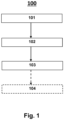
- the invention relates to a method for producing a quartz glass body comprising the method steps i.) providing silicon dioxide granules, wherein the silicon dioxide granules were produced from pyrogenic silicon dioxide powder and the silicon dioxide granules have a BET surface area in a range from 20 to 40 m 2 /g, ii.) forming a glass melt from the silicon dioxide granules in a furnace and iii.) forming a quartz glass body from at least a portion of the glass melt, wherein the furnace has at least a first and a further chamber connected to one another by a passage, wherein the temperature in the further chamber is in a range from 1900 to 2300 °C, and wherein the temperature of the first chamber is lower than the temperature of the further chamber by a range from 1200 to 1800 °C.
- Quartz glass, quartz glass products and products containing quartz glass are known.
- Various processes for producing quartz glass and quartz glass bodies are also already known. Nevertheless, considerable efforts are still being made to demonstrate manufacturing processes by means of which quartz glass of even higher purity, i.e. the absence of impurities, can be produced.
- quartz glass and its processed products have particularly high requirements, for example with regard to homogeneity and purity. This is the case, for example, with quartz glass that is processed into light guides or in lamps. Impurities can cause absorption here. This is disadvantageous because it leads to color changes and to the attenuation of the emitted light.
- Another example of the use of high-purity quartz glass is production steps in semiconductor production. Here, any contamination of the glass body potentially leads to defects in the semiconductors and thus to rejects in production.
- the high-purity quartz glass types used for these processes are therefore very complex to produce. They are expensive.
- quartz glass bodies Known processes for producing quartz glass bodies involve melting silicon dioxide and forming quartz glass bodies from the melt. Irregularities in a glass body, for example due to the inclusion of gases in the form of bubbles, can lead to failure of the glass body under load, especially at high temperatures, or can preclude use for a particular purpose. For example, impurities in the quartz glass-forming raw material can lead to the formation of cracks, bubbles, streaks and
- Discoloration in the quartz glass When used in processes for the production and treatment of semiconductor components, impurities in the glass body can also be worked out and transferred to the treated semiconductor components. This is the case, for example, in etching processes and then leads to rejects in the semiconductor blanks. A frequently occurring problem with the known production processes is therefore the inadequate quality of the quartz glass body.
- quartz glass and raw materials that are produced as a by-product elsewhere for industrial processing to produce quartz glass products, rather than using these by-products as filler material, e.g. in building construction, or disposing of them as waste at great expense.
- These by-products are often separated as fine dust in filters. Fine dust poses further problems, particularly with regard to health, occupational safety and handling.
- EP-A1-0890555 discloses a process for producing silicon dioxide granules with a BET surface area of 40 m 2 /g to 60 m 2 /g.
- the sintered granules are used as starting material for the production of quartz glass bodies.
- An object of the present invention is to at least partially overcome one or more of the disadvantages resulting from the prior art.
- Components are understood to mean in particular devices that can be used for or in reactors for chemical and/or physical treatment steps.
- Foreign atoms are understood to be components that were not deliberately introduced.
- Homogeneity of a property or a substance is a measure of the uniformity of the distribution of this property or substance in a sample.
- the material homogeneity is a measure of the uniformity of the distribution of elements and compounds contained in the light guide, lighting means or semiconductor device, in particular OH, chlorine, metals, in particular aluminum, alkaline earth metals, refractory metals and dopants.
- a further task is to provide a quartz glass body in which the migration of cations is as low as possible.
- a further object is to provide a quartz glass body that has a high homogeneity over the entire length of the quartz glass body.
- a further task is to provide a process with which a quartz glass body can be produced in the most cost- and time-efficient way possible.
- a further object is to provide a method by which a quartz glass body can be produced with low energy expenditure.
- a further object is to provide a method by which a quartz glass body can be produced while avoiding particle entry from the crucible. It is a further object of the invention to provide a high throughput process for producing quartz glass bodies.
- Another task is to further improve the processability of quartz glass bodies.
- a further task is to further improve the fabrication of quartz glass bodies.
- range specifications also include the values referred to as limits.
- a specification of the type "in the range from X to Y" in relation to a size A therefore means that A can assume the values X, Y and values between X and Y.
- Unilaterally limited ranges of the type "up to Y" for a size A correspondingly mean values Y and less than Y.
- a powder is understood to mean particles of dry solid substances with a primary particle size in the range of 1 to less than 100 nm.
- the silicon dioxide granulate can be obtained by granulating silicon dioxide powder.
- Silicon dioxide granulate usually has a BET surface area of 3 m 2 /g or more and a density of less than 1.5 g/cm 3.
- Granulation is the conversion of powder particles into granules.
- silicon dioxide powder particles form aggregates, i.e. larger agglomerates, which are referred to as "silicon dioxide granules". These are often also referred to as "silicon dioxide granulate particles" or "granulate particles”.
- silicon dioxide granules form a granulate, e.g. silicon dioxide granules form "silicon dioxide granules".
- Silicon dioxide granules have a larger particle diameter than silicon dioxide powder.
- silicon dioxide grains are understood to mean silicon dioxide particles that are obtainable by comminuting a silicon dioxide body, in particular a quartz glass body.
- a silicon dioxide grain generally has a density of more than 1.2 g/cm 3 , for example in a range from 1.2 to 2.2 g/cm 3 , and particularly preferably of about 2.2 g/cm 3 . More preferably, the BET surface area of a silicon dioxide grain is generally less than 1 m 2 /g, determined in accordance with DIN ISO 9277:2014-01.
- silicon dioxide particles suitable for the person skilled in the art can be considered as silicon dioxide particles. Silicon dioxide granules and silicon dioxide grains are preferred.
- pyrogenically produced silicon dioxide powder is used.
- the silicon dioxide powder can be any silicon dioxide powder that has at least two particles. Any method that is familiar to the person skilled in the art and appears suitable for the present purpose can be used as the production method.
- the silicon dioxide powder is produced as a by-product in the production of quartz glass, in particular in the production of so-called soot bodies. Silicon dioxide of such origin is often also referred to as "soot dust”.
- a preferred source for the silicon dioxide powder is silicon dioxide particles obtained in the synthetic production of soot bodies using flame hydrolysis burners.
- a rotating carrier tube which has a cylindrical surface, is moved back and forth in a reversing manner along a row of burners.
- the flame hydrolysis burners can be supplied with oxygen and hydrogen as burner gases, as well as the starting materials for the formation of silicon dioxide primary particles.
- the silicon dioxide primary particles preferably have a primary particle size of up to 100 nm.
- the shape of the silicon dioxide primary particles in the silicon dioxide particles can be identified by scanning electron microscopy and the primary particle size can be determined.
- Some of the silicon dioxide particles are deposited on the cylindrical surface of the carrier tube rotating around its longitudinal axis. This is how the soot body is built up layer by layer.
- Another part of the silicon dioxide particles is not deposited on the cylindrical surface of the carrier tube, but accumulates as dust, e.g. in a filter system.
- This other part of the silicon dioxide particles forms the silicon dioxide powder, often also referred to as "soot dust".
- the part of the silicon dioxide particles deposited on the carrier tube is larger than the part of the silicon dioxide particles accumulating as soot dust during the soot body production, based on the total weight of the silicon dioxide particles.
- soot dust is usually disposed of as waste in a complex and costly manner or used as a filler without any added value, e.g. in road construction, as an additive in the dye industry, as a raw material for tile production and for the production of hexafluorosilicic acid, which is used to renovate building foundations.
- it is suitable as a starting material and can be processed into a high-quality product.
- Fumed silica is usually in the form of amorphous silica primary particles or silica particles.
- the silicon dioxide powder can be produced by flame hydrolysis from a gas mixture.
- the silicon dioxide particles are also formed in the flame hydrolysis and removed as silicon dioxide powder before agglomerates or aggregates are formed.
- the silicon dioxide powder previously referred to as soot dust is the main product.
- siloxanes are those selected from the group consisting of hexamethyldisiloxane, hexamethylcyclotrisiloxane (D3), octamethylcyclotetrasiloxane (D4) and decamethylcyclopentasiloxane (D5) or a combination of two or more thereof. If the siloxane comprises D3, D4 and D5, D4 is preferably the main component. The main component is preferably present in a proportion of at least 70% by weight, preferably at least 80% by weight, for example at least 90% by weight or at least 94% by weight, particularly preferably at least 98% by weight, in each case based on the total amount of silicon dioxide powder.
- Preferred silicon alkoxides are tetramethoxysilane and methyltrimethoxysilane.
- Preferred inorganic silicon compounds as starting materials for silicon dioxide powder are silicon halides, silicates, silicon carbide and silicon nitride.
- Particularly preferred inorganic silicon compounds as starting materials for silicon dioxide powder are silicon tetrachloride and trichlorosilane.
- the silicon dioxide powder can be prepared from a compound selected from the group consisting of siloxanes, silicon alkoxides and silicon halides.
- the silicon dioxide powder can be prepared from a compound selected from the group consisting of hexamethyldisiloxane, hexamethylcyclotrisiloxane, octamethylcyclotetrasiloxane and decamethylcyclopentasiloxane, tetramethoxysilane and methyltrimethoxysilane, silicon tetrachloride and trichlorosilane or a combination of two or more thereof, for example from silicon tetrachloride and octamethylcyclotetrasiloxane, particularly preferably from octamethylcyclotetrasiloxane.
- a preferred composition of a suitable gas mixture contains an oxygen content in the flame hydrolysis in a range of 25 to 40 vol.%.
- the hydrogen content can be in a range of 45 to 60 vol.%.
- the silicon tetrachloride content is preferably 5 to 30 vol.%, all of the aforementioned vol.% based on the total volume of the gas stream.
- a combination of the aforementioned volume proportions for oxygen, hydrogen and SiCl 4 is further preferred.
- the flame in the flame hydrolysis preferably has a temperature in a range of 1500 to 2500 °C, for example in a range of 1600 to 2400 °C, particularly preferably in a range of 1700 to 2300 °C.
- the silicon dioxide primary particles formed in the flame hydrolysis are preferably removed as silicon dioxide powder before agglomerates or aggregates form.
- the silicon dioxide powder contains silicon dioxide.
- the silicon dioxide powder preferably contains silicon dioxide in an amount of more than 95% by weight, for example in an amount of more than 98% by weight or more than 99% by weight or more than 99.9% by weight, in each case based on the total weight of the silicon dioxide powder.
- the silicon dioxide powder particularly preferably contains silicon dioxide in an amount of more than 99.99% by weight, based on the total weight of the silicon dioxide powder.
- the silicon dioxide powder preferably has a metal content of metals other than aluminum of less than 5 ppm, for example less than 2 ppm, particularly preferably less than 1 ppm, in each case based on the total weight of the silicon dioxide powder.
- the silicon dioxide powder often has a content of metals other than aluminum in an amount of at least 1 ppb.
- metals are, for example, sodium, lithium, potassium, magnesium, calcium, strontium, germanium, copper, molybdenum, tungsten, titanium, iron and chromium. These can be present, for example, as an element, as an ion, or as part of a molecule or an ion or a complex.
- the silicon dioxide powder preferably has a total proportion of other components of less than 30 ppm, for example less than 20 ppm, particularly preferably less than 15 ppm, the ppm in each case based on the total weight of the silicon dioxide powder.
- the silicon dioxide powder often has a content of other components in an amount of at least 1 ppb.
- Other components are understood to mean all components of the silicon dioxide powder that do not belong to the following group: silicon dioxide, chlorine, aluminum, OH groups.
- the specification of a component when the component is a chemical element, means that it can exist as an element or as an ion in a compound or salt.
- aluminium includes not only metallic aluminium but also aluminium salts, aluminium oxides and aluminium metal complexes.
- chlorine includes not only elemental chlorine but also chlorides such as sodium chloride and hydrogen chloride. The other components are often in the same physical state as the substance in which they are contained.
- the indication of a component when the component is a chemical compound or a functional group, means that the component can be present in the form mentioned, as a charged chemical compound or as a derivative of the chemical compound.
- the indication of the chemical substance ethanol includes, in addition to ethanol, also ethanolate, for example sodium ethanolate.
- OH group also includes silanol, water and metal hydroxides.
- the term derivative for acetic acid also includes acetic acid ester and acetic anhydride.
- At least 70% of the powder particles of the silicon dioxide powder have a primary particle size of less than 100 nm, for example in the range from 10 to 100 nm or from 15 to 100 nm, and particularly preferably in the range from 20 to 100 nm.
- the primary particle size is determined by dynamic light scattering according to ISO 13320:2009-10.
- At least 75% of the powder particles of the silicon dioxide powder have a primary particle size of less than 100 nm, for example in the range from 10 to 100 nm or from 15 to 100 nm, and particularly preferably in the range from 20 to 100 nm.
- At least 80% of the powder particles of the silicon dioxide powder have a primary particle size of less than 100 nm, for example in the range from 10 to 100 nm or from 15 to 100 nm, and particularly preferably in the range from 20 to 100 nm.
- At least 85% of the powder particles of the silicon dioxide powder have a primary particle size of less than 100 nm, for example in the range from 10 to 100 nm or from 15 to 100 nm, and particularly preferably in the range from 20 to 100 nm.
- At least 90% of the powder particles of the silicon dioxide powder have a primary particle size of less than 100 nm, for example in the range from 10 to 100 nm or from 15 to 100 nm, and particularly preferably in the range from 20 to 100 nm.
- At least 95% of the powder particles of the silicon dioxide powder have a primary particle size of less than 100 nm, for example in the range from 10 to 100 nm or from 15 to 100 nm, and particularly preferably in the range from 20 to 100 nm.
- the silicon dioxide powder preferably has a particle size D 10 in the range from 1 to 7 ⁇ m, for example in the range from 2 to 6 ⁇ m or in the range from 3 to 5 ⁇ m, particularly preferably in the range from 3.5 to 4.5 ⁇ m.
- the silicon dioxide powder preferably has a particle size D 50 in the range from 6 to 15 ⁇ m, for example in the range from 7 to 13 ⁇ m or in the range from 8 to 11 ⁇ m, particularly preferably in the range from 8.5 to 10.5 ⁇ m.
- the silicon dioxide powder preferably has a particle size D 90 in the range from 10 to 40 ⁇ m, for example in the range from 15 to 35 ⁇ m, particularly preferably in the range from 20 to 30 ⁇ m.
- the silicon dioxide powder preferably has a specific surface area (BET surface area) in a range from 20 to 60 m 2 /g, for example from 25 to 55 m 2 /g, or from 30 to 50 m 2 /g, particularly preferably from 20 to 40 m 2 /g.
- BET surface area is determined according to the method of Brunauer, Emmet and Teller (BET) using DIN 66132 and is based on gas absorption on the surface to be measured.
- the silicon dioxide powder preferably has a pH of less than 7, for example in the range from 3 to 6.5 or from 3.5 to 6 or from 4 to 5.5, particularly preferably in the range from 4.5 to 5.
- the pH can be determined by means of a single-rod measuring electrode (4% silicon dioxide powder in water).
- the silicon dioxide powder preferably has the feature combination a./b./c. or a./b./f. or a./b./g., more preferably the feature combination a./b./c./f. or a./b./c./g. or a./b./f./g., particularly preferably the feature combination a./b./c./f./g.
- the silicon dioxide powder preferably has the feature combination a./b./c., wherein the BET surface area is in a range of 20 to 40 m 2 /g, the bulk density is in a range of 0.05 to 0.3 g/mL and the carbon content is less than 40 ppm.
- the silicon dioxide powder preferably has the feature combination a./b./f., wherein the BET surface area is in a range of 20 to 40 m 2 /g, the bulk density is in a range of 0.05 to 0.3 g/mL and the total content of metals other than aluminum is in a range of 1 ppb to 1 ppm.
- the silicon dioxide powder preferably has the feature combination a./b./g., wherein the BET surface area is in a range from 20 to 40 m 2 /g, the bulk density is in a range from 0.05 to 0.3 g/mL and at least 70 wt.% of the powder particles have a primary particle size in a range from 20 to less than 100 nm.
- the silicon dioxide powder further preferably has the feature combination a./b./c./f., wherein the BET surface area is in a range of 20 to 40 m 2 /g, the bulk density is in a range of 0.05 to 0.3 g/mL, the carbon content is less than 40 ppm and the total content of metals other than aluminum is in a range of 1 ppb to 1 ppm.
- the silicon dioxide powder further preferably has the feature combination a./b./c./g., wherein the BET surface area is in a range from 20 to 40 m 2 /g, the bulk density is in a range from 0.05 to 0.3 g/mL, the carbon content is less than 40 ppm and at least 70 wt.% of the powder particles have a primary particle size in a range from 20 to less than 100 nm.
- the silicon dioxide powder further preferably has the feature combination a./b./f./g., wherein the BET surface area is in a range from 20 to 40 m 2 /g, the bulk density is in a range from 0.05 to 0.3 g/mL, the total content of metals other than aluminum is in a range from 1 ppb to 1 ppm and at least 70 wt.% of the powder particles have a primary particle size in a range from 20 to less than 100 nm.
- the silicon dioxide powder particularly preferably has the feature combination a./b./c./f./g., wherein the BET surface area is in a range from 20 to 40 m 2 /g, the bulk density is in a range from 0.05 to 0.3 g/mL, the carbon content is less than 40 ppm, the total content of metals other than aluminum is in a range from 1 ppb to 1 ppm and at least 70 wt.% of the powder particles have a primary particle size in a range from 20 to less than 100 nm.
- the silicon dioxide powder is processed in step II to form silicon dioxide granules, wherein the silicon dioxide granules have a larger particle diameter than the silicon dioxide powder.
- step II all methods known to the person skilled in the art that lead to an increase in the particle diameter are suitable for this purpose.
- the silicon dioxide granules have a particle diameter that is larger than the particle diameter of the silicon dioxide powder.
- the particle diameter of the silicon dioxide granules is preferably in a range of 500 to 50,000 times larger than the particle diameter of the silicon dioxide powder, for example 1,000 to 10,000 times larger, particularly preferably 2,000 to 8,000 times larger.
- At least 90% of the silicon dioxide granules provided in step i.) are formed from pyrogenically produced silicon dioxide powder, for example at least 95% by weight or at least 98% by weight, particularly preferably at least 99% by weight or more, in each case based on the total weight of the silicon dioxide granules.
- the granules of the silicon dioxide granulate preferably have a spherical morphology.
- a spherical morphology is understood to mean a round to oval shape of the particles.
- the granules of the silicon dioxide granulate preferably have an average sphericity in a range from 0.7 to 1.3 SPHT3, for example an average sphericity in a range from 0.8 to 1.2 SPHT3, particularly preferably an average sphericity in a range from 0.85 to 1.1 SPHT3.
- the SPHT3 feature is described in the test methods.
- the granules of the silicon dioxide granulate preferably have an average symmetry in a range from 0.7 to 1.3 Symm3, for example an average symmetry in a range from 0.8 to 1.2 Symm3, particularly preferably an average symmetry in a range from 0.85 to 1.1 Symm3.
- the feature of the average symmetry Symm3 is described in the test methods.
- the silicon dioxide granulate preferably has a metal content of metals other than aluminum of less than 1000 ppb, for example less than 500 ppb, particularly preferably less than 100 ppb, in each case based on the total weight of the silicon dioxide granulate.
- the silicon dioxide granulate often has a content of metals other than aluminum in an amount of at least 1 ppb.
- the silicon dioxide granulate often has a metal content of metals other than aluminum of less than 1 ppm, preferably in a range from 40 to 900 ppb, for example in a range from 50 to 700 ppb, particularly preferably in a range from 60 to 500 ppb, in each case based on the total weight of the silicon dioxide granulate.
- Such metals are, for example, sodium, lithium, potassium, magnesium, calcium, strontium, germanium, copper, molybdenum, titanium, iron and chromium. These can exist, for example, as an element, as an ion, or as part of a molecule or an ion or a complex.
- the silicon dioxide granulate can contain other components, for example in the form of molecules, ions or elements.
- the silicon dioxide granulate preferably contains less than 500 ppm, for example less than 300 ppm, particularly preferably less than 100 ppm, in each case based on the total weight of the silicon dioxide granulate, of other components.
- Other components are often contained in an amount of at least 1 ppb.
- the other components can in particular be selected from the group consisting of carbon, fluoride, iodide, bromide, phosphorus or a mixture of at least two of these.
- the silicon dioxide granulate preferably contains less than 10 ppm carbon, for example less than 8 ppm or less than 5 ppm, particularly preferably less than 4 ppm, in each case based on the total weight of the silicon dioxide granulate. Carbon is often contained in the silicon dioxide granulate in an amount of at least 1 ppb.
- the silicon dioxide granulate preferably contains less than 100 ppm, for example less than 80 ppm, particularly preferably less than 70 ppm, in each case based on the total weight of the silicon dioxide granulate, of other components.
- the other components are often present in an amount of at least 1 ppb.
- a liquid is understood to be a substance or a mixture of substances that is liquid at a pressure of 1013 hPa and a temperature of 20 °C.
- a "slurry" in the sense of the present invention means a mixture of at least two substances, wherein the mixture comprises at least one liquid and at least one solid under the conditions under consideration.
- liquids are suitable as liquids.
- the liquid is preferably selected from the group consisting of organic liquids and water.
- the silicon dioxide powder is preferably soluble in the liquid in an amount of less than 0.5 g/L, preferably in an amount of less than 0.25 g/L, particularly preferably in an amount of less than 0.1 g/L, the g/L being given as g of silicon dioxide powder per liter of liquid.
- Polar solvents are preferably suitable as liquids. These can be organic liquids or water.
- the liquid is preferably selected from the group consisting of water, methanol, ethanol, n-propanol, iso-propanol, n-butanol, tert-butanol and mixtures of more than one of these.
- the liquid is particularly preferably water.
- the liquid particularly preferably contains distilled or deionized water.
- the silicon dioxide powder is processed into a slurry.
- the silicon dioxide powder is almost insoluble in the liquid at room temperature, but can be introduced into the liquid in high weight proportions to obtain the slurry.
- the silicon dioxide powder and the liquid can be mixed in any way.
- the silicon dioxide powder can be added to the liquid, or the liquid can be added to the silicon dioxide powder.
- the mixture can be agitated during or after addition. Particularly preferably, the mixture is agitated during and after addition. Examples of agitation are shaking and stirring, or a combination of both.
- the silicon dioxide powder can be added to the liquid while stirring. More preferably, part of the silicon dioxide powder can be added to the liquid, the mixture thus obtained being agitated, and the mixture then being mixed with the remaining part of the silicon dioxide powder.
- a part of the liquid can be added to the silicon dioxide powder, the mixture thus obtained being agitated, and the mixture then being mixed with the remaining part of the liquid.
- the slurry is a suspension in which the silicon dioxide powder is evenly distributed in the liquid.
- evenly is meant that the density and composition of the slurry at any point do not deviate by more than 10% from the average density and composition, each based on the total amount of slurry.
- An even distribution of the silicon dioxide powder in the liquid can be produced or maintained by agitation as previously described, or both.
- the slurry has a liter weight in the range of 1000 to 2000 g/L, for example in the range of 1200 to 1900 g/L or 1300 to 1800 g/L, particularly preferably in the range of 1400 to 1700 g/L.
- the liter weight is determined by weighing a volume-calibrated container.
- the silicon dioxide particles in a 4 wt.% aqueous slurry have a particle size D 10 in a range from 50 to 250 nm, particularly preferably in the range from 100 to 150 nm.
- the silicon dioxide particles in a 4 wt.% aqueous slurry have a particle size D 50 in a range from 100 to 400 nm, particularly preferably in the range from 200 to 250 nm.
- the silicon dioxide particles in a 4 wt.% aqueous slurry have a particle size D 90 in a range from 200 to 600 nm, particularly preferably in a range from 350 to 400 nm.
- the particle size is determined using DIN ISO 13320-1.
- the "isoelectric point” is the pH value at which the zeta potential assumes the value 0.
- the zeta potential is determined according to ISO 13099-2:2012.
- the pH of the slurry is adjusted to a value in the above-mentioned range.
- substances such as NaOH or NH 3 can be added to the slurry to adjust the pH, for example as an aqueous solution.
- the slurry is often agitated in the process.
- the silicon dioxide granulate is obtained by granulating silicon dioxide powder.
- Granulation is the conversion of powder particles into granules.
- larger agglomerates which are referred to as “silicon dioxide granules” are formed by the agglomeration of several silicon dioxide powder particles. These are often also referred to as “silicon dioxide particles”, “silicon dioxide granulate particles” or “granulate particles”.
- silicon dioxide granulate particles As a whole, granules form a granulate, e.g. the silicon dioxide granules form a "silicon dioxide granulate”.
- any granulation process can be selected that is known to the person skilled in the art and appears suitable for granulating silicon dioxide powder.
- Granulation processes can be divided into build-up granulation and press granulation, and further into wet and dry granulation processes.
- Known methods are roll granulation in a granulation plate, spray granulation, centrifugal atomization, fluidized bed granulation, granulation processes using a granulation mill, compaction, roller pressing, briquetting, slurry production or extrusion.
- a silicon dioxide granulate is formed with granules having a spherical morphology; wherein the processing is further preferably carried out by spray granulation or roll granulation.
- a silicon dioxide granulate with granules that have a spherical morphology contains at most 50% granules, preferably at most 40% granules, more preferably at most 20% granules, more preferably between 0 and 50%, between 0 and 40% or between 0 and 20%, or between 10 and 50%, between 10 and 40% or between 10 and 20% granules that do not have a spherical morphology, the percentage in each case based on the total number of granules in the granulate.
- the granules with a spherical morphology have the SPHT3 values already mentioned in this description.
- a silicon dioxide granulate is obtained by spray granulating the slurry.
- Spray granulation is also referred to as spray drying.
- Spray drying is preferably carried out in a spray tower.
- the slurry is pressurized at an elevated temperature.
- the pressurized slurry is then released through a nozzle and sprayed into the spray tower. This results in droplets forming which dry immediately and initially form dry microparticles ("germs").
- the microparticles form a fluidized bed together with a gas stream acting on the particles. They are thus kept in suspension and can thus form a surface for drying further droplets.
- the nozzle through which the slurry is sprayed into the spray tower preferably forms an inlet into the interior of the spray tower.
- the nozzle preferably has a contact surface with the slurry during spraying.
- the "contact surface” is understood to mean the area of the nozzle that comes into contact with the slurry during spraying. Often at least a portion of the nozzle is shaped as a tube through which the slurry is passed during spraying, so that the inside of the hollow tube comes into contact with the slurry.
- the contact surface preferably contains a glass, a plastic or a combination thereof.
- the contact surface preferably contains a glass, particularly preferably quartz glass.
- the contact surface preferably contains a plastic.
- all plastics known to the person skilled in the art that are stable at the process temperatures and do not release any foreign atoms into the slurry are suitable.
- Preferred plastics are polyolefins, for example homo- or copolymers containing at least one olefin, particularly preferably homo- or copolymers containing polypropylene, polyethylene, polybutadiene or combinations of two or more thereof.
- the contact surface preferably consists of a glass, a plastic or a combination thereof, for example selected from the group consisting of quartz glass and polyolefins, particularly preferably selected from the group consisting of quartz glass and homo- or copolymers containing polypropylene, polyethylene, polybutadiene or combinations of two or more thereof.
- the contact surface preferably does not contain any metals, in particular no tungsten, titanium, tantalum, chromium, cobalt, nickel, iron, vanadium, zirconium and manganese.
- the contact surface and the other parts of the nozzle are made of the same or different materials.
- the other parts of the nozzle contain the same material as the contact surface.
- the other parts of the nozzle can contain a different material than the contact surface.
- the contact surface can be coated with a suitable material, such as glass or plastic.
- the nozzle is formed to an extent of more than 70 wt.%, based on the total weight of the nozzle, from an element selected from the group consisting of glass, plastic or a combination of glass and plastic, for example to an extent of more than 75 wt.% or to an extent of more than 80 wt.% or to an extent of more than 85 wt.% or to an extent of more than 90 wt.% or to an extent of more than 95 wt.%, particularly preferably to an extent of more than 99 wt.%.
- the nozzle preferably comprises a nozzle plate.
- the nozzle plate is preferably made of glass, plastic or a combination of glass and plastic.
- the nozzle plate is preferably made of glass, particularly preferably quartz glass.
- the nozzle plate is preferably made of plastic.
- Preferred plastics are polyolefins, for example homo- or copolymers containing at least one olefin, particularly preferably homo- or copolymers containing polypropylene, polyethylene, polybutadiene or combinations of two or more thereof.
- the nozzle plate preferably contains no metals, in particular no tungsten, titanium, tantalum, chromium, cobalt, nickel, iron, vanadium, zirconium and manganese.
- the nozzle preferably comprises a swirl screw.
- the swirl screw is preferably made of glass, plastic or a combination of glass and plastic.
- the swirl screw is preferably made of glass, particularly preferably quartz glass.
- the swirl screw is preferably made of plastic.
- Preferred plastics are polyolefins, for example homo- or copolymers containing at least one olefin, particularly preferably homo- or copolymers containing polypropylene, polyethylene, polybutadiene or combinations of two or more thereof.
- the swirl screw preferably contains no metals, in particular no tungsten, titanium, tantalum, chromium, cobalt, nickel, iron, vanadium, zirconium and manganese.
- the nozzle can also comprise other components.
- Preferred other components are a nozzle body, particularly preferred is a nozzle body surrounding the swirl screw and the nozzle plate, a crosspiece and an impact plate.
- a nozzle comprises one or more, particularly preferably all, of the other components.
- the other components can, independently of one another, in principle consist of any material known to the person skilled in the art and suitable for this purpose, for example a metal-containing material, glass or a plastic.
- the nozzle body is made of glass, particularly preferably quartz glass.
- the other components are made of plastic.
- Preferred plastics are polyolefins, for example homo- or copolymers containing at least one olefin, particularly preferably homo- or copolymers containing polypropylene, polyethylene, polybutadiene or combinations of two or more thereof.
- the other components do not contain any metals, in particular no tungsten, titanium, tantalum, chromium, cobalt, nickel, iron, vanadium, zirconium and manganese.
- the spray tower preferably has a gas inlet and a gas outlet. Gas can be introduced into the interior of the spray tower through the gas inlet and can be discharged through the gas outlet. It is also possible to introduce gas into the spray tower via the nozzle. Gas can also be discharged via the outlet of the spray tower. Furthermore, gas can preferably be supplied via the nozzle and a gas inlet of the spray tower and discharged via the outlet of the spray tower and a gas outlet of the spray tower.
- an atmosphere selected from air, an inert gas, at least two inert gases or a combination of air with at least one inert gas, preferably at least two inert gases, is present in the interior of the spray tower.
- Inert gases are preferably selected from the list consisting of nitrogen, helium, neon, argon, krypton and xenon.
- air, nitrogen or argon is present in the interior of the spray tower, particularly preferably air.
- the atmosphere present in the spray tower is also preferably part of a gas stream.
- the gas stream is preferably introduced into the spray tower via a gas inlet and discharged via a gas outlet. It is also possible to introduce parts of the gas stream via the nozzle and discharge parts of the gas stream via a solids outlet.
- the gas stream can absorb further components in the spray tower. These can originate from the slurry during spray drying and pass into the gas stream.
- a dry gas stream is fed to the spray tower.
- a dry gas stream is understood to mean a gas or a gas mixture whose relative humidity is below the condensation point at the temperature set in the spray tower.
- a relative humidity of 100% corresponds to a water quantity of 17.5 g/m 3 at 20°C.
- the gas is preferably preheated to a temperature in a range from 150 to 450°C, for example from 200 to 420°C or from 300 to 400°C, particularly preferably from 350 to 400°C.
- the interior of the spray tower is preferably temperature-controlled.
- the temperature in the interior of the spray tower is preferably up to 550°C, for example 300 to 500°C, particularly preferably 350 to 450°C.
- the gas stream at the gas inlet preferably has a temperature in a range from 150 to 450°C, for example from 200 to 420°C or from 300 to 400°C, particularly preferably from 350 to 400°C.
- the discharged gas stream preferably has a temperature of less than 170°C, for example from 50 to 150°C, particularly preferably from 100 to 130°C.
- the difference between the temperature of the gas stream when introduced and the gas stream when discharged is in a range from 100 to 330°C, for example from 150 to 300°C.
- the resulting silicon dioxide granules are present as an agglomerate of individual particles of silicon dioxide powder.
- the individual particles of silicon dioxide powder are still recognizable in the agglomerate.
- the average The particle size of the particles of the silicon dioxide powder is preferably in the range from 10 to 1000 nm, for example in the range from 20 to 500 nm or from 30 to 250 nm or from 35 to 200 nm or from 40 to 150 nm, or particularly preferably in the range from 50 to 100 nm.
- the average particle size of these particles is determined according to DIN ISO 13320-1.
- Spray drying can be carried out in the presence of auxiliary materials.
- auxiliary materials In principle, all substances that are known to the person skilled in the art and that appear suitable for the intended purpose can be used as auxiliary materials.
- auxiliary materials that can be considered are so-called binders.
- suitable binders are metal oxides such as calcium oxide, metal carbonates such as calcium carbonate and polysaccharides such as cellulose, cellulose ethers, starch and starch derivatives.
- spray drying in the context of the present invention is carried out without auxiliary substances.
- a portion of the silicon dioxide granulate is separated before, after or before and after removal from the spray tower. All methods known to the person skilled in the art and deemed suitable can be used for the separation. Preferably, the separation is carried out by sifting or sieving.
- particles with a particle size of less than 50 ⁇ m for example with a particle size of less than 70 ⁇ m, particularly preferably with a particle size of less than 90 ⁇ m, are separated by sifting.
- the sifting is preferably carried out by a cyclone, which is preferably arranged in the lower region of the spray tower, particularly preferably above the outlet of the spray tower.
- particles with a particle size of more than 1000 ⁇ m for example with a particle size of more than 700 ⁇ m, particularly preferably with a particle size of more than 500 ⁇ m, are separated by sieving.
- the particles can be sieved using all methods known to the person skilled in the art and suitable for this purpose.
- Sieving is preferably carried out using a vibrating trough.
- the plumb line refers to the direction of the gravity vector.
- the flight path is the path that a droplet of the slurry travels from the moment it exits the nozzle in the gas space of the spray tower to form a granule until the flight and fall process is completed.
- the flight and fall process usually ends when the granule hits the bottom of the spray tower or when the granule hits other granules already on the bottom of the spray tower, whichever occurs first.
- the flight time is the time it takes for a granule to cover the flight distance in the spray tower.
- the granules in the spray tower preferably have a helical flight path.
- At least 60% by weight of the spray granules travel an average flight distance of more than 20 m, for example of more than 30 or of more than 50 or of more than 70 or of more than 100 or of more than 150 or of more than 200 or in a range from 20 to 200 m or from 10 to 150 or from 20 to 100, particularly preferably a range from 30 to 80 m.
- At least 70% by weight of the spray granules travel an average flight distance of more than 20 m, for example of more than 30 or of more than 50 or of more than 70 or of more than 100 or of more than 150 or of more than 200 or in a range from 20 to 200 m or from 10 to 150 or from 20 to 100, particularly preferably a range from 30 to 80 m.
- At least 80% by weight of the spray granules travel an average flight distance of more than 20 m, for example of more than 30 or of more than 50 or of more than 70 or of more than 100 or of more than 150 or of more than 200 or in a range from 20 to 200 m or from 10 to 150 or from 20 to 100, particularly preferably a range from 30 to 80 m.
- At least 90% by weight of the spray granules travel an average flight distance of more than 20 m, for example of more than 30 or of more than 50 or of more than 70 or of more than 100 or of more than 150 or of more than 200 or in a range from 20 to 200 m or from 10 to 150 or from 20 to 100, particularly preferably a range from 30 to 80 m.
- a silica granulate is obtained by roll granulating the slurry.
- the roll granulation is carried out by stirring the slurry in the presence of a gas at an elevated temperature.
- the roll granulation is preferably carried out in a stirring vessel equipped with a stirring tool.
- the stirring vessel preferably rotates in the opposite direction to the stirring tool.
- the stirring vessel preferably also has an inlet through which silicon dioxide powder can be introduced into the stirring vessel, an outlet through which silicon dioxide granules can be removed, a gas inlet and a gas outlet.
- a pin agitator is preferably used to stir the slurry.
- a pin agitator is understood to be a stirring tool that is provided with several elongated pins, the longitudinal axis of which runs coaxially to the axis of rotation of the stirring tool. The movement of the pins preferably describes coaxial circles around the axis of rotation.
- the slurry is adjusted to a pH of less than 7, for example to a pH in the range from 2 to 6.5, particularly preferably to a pH in a range from 4 to 6.
- an inorganic acid is preferably used, for example an acid selected from the group consisting of hydrochloric acid, sulfuric acid, nitric acid and phosphoric acid, particularly preferably hydrochloric acid.
- an atmosphere selected from air, an inert gas, at least two inert gases or a combination of air with at least one inert gas, preferably at least two inert gases, is present in the stirred tank.
- Inert gases are preferably selected from the list consisting of nitrogen, helium, neon, argon, krypton and xenon.
- air, nitrogen or argon is present in the stirred tank, particularly preferably air.
- the atmosphere present in the stirred tank is also preferably part of a gas stream.
- the gas stream is preferably introduced into the stirred tank via the gas inlet and discharged via the gas outlet.
- the gas stream can absorb further components in the stirred tank. These can originate from the slurry during roller granulation and pass into the gas stream.
- a dry gas stream is fed to the stirred tank.
- a “dry gas stream” is understood to mean a gas or a gas mixture whose relative humidity is below the condensation point at the temperature set in the stirred tank.
- the gas is preferably preheated to a temperature in a range from 50 to 300°C, for example from 80 to 250°C, particularly preferably from 100 to 200°C.
- 10 to 150 m 3 of gas per hour are introduced into the stirred tank, for example 20 to 100 m 3 of gas per hour, particularly preferably 30 to 70 m 3 of gas per hour.
- the gas flow dries the slurry during stirring to form silicon dioxide granules.
- the granules formed are removed from the stirring chamber.
- the removed granulate is further dried.
- drying takes place continuously, for example in a rotary kiln.
- Preferred temperatures for drying are in a range from 80 to 250°C, for example in a range from 100 to 200°C, particularly preferably in a range from 120 to 180°C.
- continuous means in relation to a process that it can be operated continuously. This means that the supply and removal of substances and materials involved in the process can take place continuously while the process is being carried out. It is not necessary to interrupt the process for this purpose.
- Continuous as an attribute of an object means that this object is designed in such a way that a process or process step taking place in it can be carried out continuously.
- the granules obtained by roller granulation can be sieved. Sieving can take place before or after drying. Sieving is preferably carried out before drying. Granules with a particle size of less than 50 ⁇ m, for example with a particle size of less than 80 ⁇ m, particularly preferably with a particle size of less than 100 ⁇ m, are preferably sieved out. Granules with a particle size of more than 900 ⁇ m, for example with a particle size of more than 700 ⁇ m, particularly preferably with a particle size of more than 500 ⁇ m, are further preferably sieved out. In principle, larger particles can be sieved out using all methods known to the person skilled in the art and suitable for this purpose. Larger particles are preferably sieved out using a vibrating trough.
- the silicon dioxide granulate obtained by granulation preferably by spray or roll granulation, also referred to as silicon dioxide granulate I
- the silicon dioxide granulate I is treated before it is processed into quartz glass bodies.
- This pretreatment can serve various purposes that either facilitate processing into quartz glass bodies or influence the properties of the resulting quartz glass bodies.
- the silicon dioxide granulate I can be compacted, cleaned, surface modified or dried.
- the silicon dioxide granulate I can be subjected to a thermal, mechanical or chemical treatment or a combination of two or more treatments to obtain a silicon dioxide granulate II.
- the silicon dioxide granulate I has a carbon content w C(1) .
- the carbon content w C(1) is preferably less than 50 ppm, for example in the range of less than 40 ppm or less than 30 ppm, particularly preferably in a range of 1 ppb to 20 ppm, in each case based on the total weight of the silicon dioxide granulate I.
- the silicon dioxide granulate I contains at least two particles.
- the at least two particles can preferably move relative to one another.
- all measures known to the person skilled in the art and deemed suitable can be considered as measures for generating the relative movement.
- Mixing is particularly preferred. In principle, mixing can be carried out in any manner.
- a continuous furnace is preferably selected for this purpose. Accordingly, the at least two particles can preferably move relative to one another by being moved in a continuous furnace, for example a rotary kiln.
- Continuous furnaces are furnaces in which the loading and unloading of the furnace, known as charging, takes place continuously.
- Examples of continuous furnaces are rotary kilns, roller furnaces, conveyor belt furnaces, drive-through furnaces and pusher furnaces.
- Rotary kilns are preferably used for the treatment of silicon dioxide granulate I.
- the silicon dioxide granulate I is treated with a reactant to obtain a silicon dioxide granulate II.
- the treatment is carried out in order to change the concentration of certain substances in the silicon dioxide granulate.
- the silicon dioxide granulate I can have impurities or certain functionalities whose proportion is to be reduced, such as: OH groups, carbon-containing compounds, transition metals, alkali metals and alkaline earth metals.
- the impurities and functionalities can be obtained from the
- the treatment of silicon dioxide granules I can serve various purposes. For example, the use of treated silicon dioxide granules I, i.e. silicon dioxide granules II, can simplify the processing of the silicon dioxide granules into quartz glass bodies.
- the properties of the resulting quartz glass bodies can be adjusted through this selection.
- the silicon dioxide granules I can be cleaned or surface-modified. The treatment of the silicon dioxide granules I can therefore be used to improve the properties of the resulting quartz glass bodies.
- a gas or a combination of several gases is preferably suitable as a reactant. This is also referred to as a gas mixture.
- gases known to the person skilled in the art that are known for the treatment mentioned and appear suitable can be used.
- a gas selected from the group consisting of HCl, Cl 2 , F 2 , O 2 , O 3 , H 2 , C 2 F 4 , C 2 F 6 , HClO 4 , air, inert gas, e.g. N 2 , He, Ne, Ar, Kr, or combinations of two or more thereof is preferably used.
- the treatment is preferably carried out in the presence of a gas or a combination of two or more gases.
- the treatment is preferably carried out in a gas countercurrent or in a gas cocurrent.
- the reactant is preferably selected from the group consisting of HCl, Cl 2 , F 2 , O 2 , O 3 or combinations of two or more thereof.
- Mixtures of two or more of the aforementioned gases are preferably used to treat silicon dioxide granulate I.
- the presence of F, Cl or both enables metals contained as impurities in the silicon dioxide granulate I, such as transition metals, alkali metals and alkaline earth metals, to be removed.
- the aforementioned metals can form gaseous compounds with constituents of the gas mixture under the process conditions, which are then discharged and thus no longer present in the granulate. More preferably, the OH content in the silicon dioxide granulate I can be reduced by treating the silicon dioxide granulate I with these gases.
- a gas mixture of HCl and Cl 2 is used as the reactant.
- the gas mixture preferably has an HCl content in a range from 1 to 30 vol.%, for example in a range from 2 to 15 vol.%, particularly preferably in a range from 3 to 10 vol.%.
- the gas mixture also preferably has a Cl 2 content in a range from 20 to 70 vol.%, for example in a range from 25 to 65 vol.%, particularly preferably in a range from 30 to 60 vol.%.
- the remainder to 100 vol.% can be supplemented by one or more inert gases, e.g. N 2 , He, Ne, Ar, Kr, or by air.
- the proportion of inert gas in reactants is in a range from 0 to less than 50 vol.%, for example in a range from 1 to 40 vol.% or from 5 to 30 vol.%, particularly preferably in a range from 10 to 20 vol.%, in each case based on the total volume of the reactant.
- O 2 , C 2 F 2 , or mixtures thereof with Cl 2 are preferably used for the purification of silicon dioxide granules I which have been prepared from a siloxane or a mixture of several siloxanes.
- the reactant in the form of a gas or gas mixture is preferably brought into contact with the silicon dioxide granules as a gas stream or as part of a gas stream with a throughput in a range of 50 to 2000 L/h, for example in a range of 100 to 1000 L/h, particularly preferably in a range of 200 to 500 L/h.
- a preferred embodiment of the contacting is a contact of gas stream and silicon dioxide granules in a continuous furnace, for example a rotary kiln.
- Another preferred embodiment of the contacting is a fluidized bed process.
- a silicon dioxide granulate II with a carbon content w C(2) is obtained.
- the carbon content w C(2) of the silicon dioxide granulate II is less than the carbon content w C ( 1 ) of the silicon dioxide granulate I, based on the total weight of the respective silicon dioxide granulate.
- w C(2) is 0.5 to 99%, for example 20 to 80% or 50 to 95%, particularly preferably 60 to 99% less than w C(1) .
- the silicon dioxide granulate I is additionally subjected to a thermal or mechanical treatment or a combination of these treatments.
- One or more of these additional treatments can be carried out before or during the treatment with the reactant.
- the additional treatment can also be carried out on the silicon dioxide granulate II.
- the general term "silicon dioxide granulate” used below includes the alternatives “silicon dioxide granulate I” and “silicon dioxide granulate II”. It is also possible to carry out the treatments described below both on the “silicon dioxide granulate I" and on the treated silicon dioxide granulate I, the "silicon dioxide granulate II".
- the treatment of the silicon dioxide granules can serve various purposes. For example, this treatment facilitates the processing of the silicon dioxide granules into quartz glass bodies. The treatment can also influence the properties of the resulting quartz glass bodies. For example, the silicon dioxide granules can be compacted, cleaned, surface modified or dried. This can reduce the specific surface area (BET). Likewise, the bulk density and the average particle size can increase due to agglomerations of silicon dioxide particles.
- the thermal treatment can be carried out dynamically or statically.
- a preferred average residence time of the silicon dioxide granulate during the dynamic thermal treatment depends on the quantity.
- the average residence time of the silicon dioxide granulate during the dynamic thermal treatment is preferably in the range from 10 to 180 min, for example in the range from 20 to 120 min or from 30 to 90 min.
- the average residence time of the silicon dioxide granules during the dynamic thermal treatment is particularly preferably in the range of 30 to 90 min.
- a defined portion of a flow of silicon dioxide granules e.g. one gram, one kilogram or one tonne, is considered a batch for determining the residence time.
- the start and end of the residence time are determined here by the introduction and discharge from the continuous furnace operation.
- the throughput of the silicon dioxide granulate in a continuous process for dynamic thermal treatment is in the range from 1 to 50 kg/h, for example in the range from 5 to 40 kg/h or from 8 to 30 kg/h.
- the throughput here is in the range from 10 to 20 kg/h.
- the treatment time results from the period between loading and subsequent unloading of the furnace.
- the throughput is in a range from 1 to 50 kg/h, for example in the range from 5 to 40 kg/h or from 8 to 30 kg/h. Particularly preferably, the throughput is in the range from 10 to 20 kg/h.
- the throughput can be achieved by a batch of a certain amount which is treated for one hour. According to another embodiment, the throughput can be achieved by a number of batches per hour, for example the amount of a batch corresponding to the throughput per hour divided by the number of batches.
- the treatment time then corresponds to the fraction of an hour resulting from 60 minutes divided by the number of batches per hour.
- the dynamic thermal treatment of the silicon dioxide granules is carried out at a furnace temperature of at least 500°C, for example in the range from 510 to 1700°C or from 550 to 1500°C or from 580 to 1300°C, particularly preferably in the range from 600 to 1200°C.
- the oven has the specified temperature in the oven chamber.
- this temperature deviates from the specified temperature by less than 10% above or below the specified temperature, based on the total treatment time and the entire length of the oven, both at any time during the treatment and at any point in the oven.
- the continuous process of dynamic thermal treatment of the silicon dioxide granulate can be carried out at different furnace temperatures.
- the furnace can have a constant temperature over the treatment time, with the temperature varying in sections over the length of the furnace. Such sections can be of the same length or different lengths.
- a temperature that increases from the inlet of the furnace to the outlet of the furnace is preferred.
- the temperature at the inlet is preferably at least 100°C lower than at the outlet, for example 150°C lower or 200°C lower or 300°C lower or 400°C lower. More preferably, the temperature at the outlet is preferably at least 500°C, for example in the range from 510 to 1700°C or from 550 to 1500°C.
- the temperature at the inlet is preferably at least 300°C, for example from 400 to 1000°C or from 450 to 900°C or from 500 to 800°C or from 550 to 750°C, particularly preferably from 600 to 700°C.
- each of the temperature ranges mentioned at the furnace inlet can be combined with each of the temperature ranges mentioned at the furnace outlet.
- furnace inlet and furnace outlet temperature ranges are: Furnace inlet temperature range [°C] Oven outlet temperature range [°C] 400 - 1000 510 - 1300 450 - 900 550 - 1260 480 - 850 580 - 1200 500 - 800 600 - 1100 530 - 750 630 - 1050
- crucibles arranged in a furnace are preferably used.
- Sintered crucibles or sheet metal crucibles are suitable as crucibles.
- Rolled sheet metal crucibles made of several plates riveted together are preferred.
- Examples of crucible materials include refractory metals, in particular tungsten, molybdenum and tantalum.
- the crucibles can also be made of graphite or, in the case of crucibles made of refractory metals, can be lined with graphite foil.
- the crucibles can also preferably be made of silicon dioxide. Silicon dioxide crucibles are particularly preferably used.
- the average residence time of the silicon dioxide granules during the static thermal treatment depends on the quantity.
- the average residence time of the silicon dioxide granules during the static thermal treatment for a quantity of 20 kg of silicon dioxide granules I is preferably in the range from 10 to 180 minutes, for example in the range from 20 to 120 minutes, particularly preferably in the range from 30 to 90 minutes.
- the static thermal treatment of the silicon dioxide granules is preferably carried out at a furnace temperature of at least 800°C, for example in the range from 900 to 1700°C or from 950 to 1600°C or from 1000 to 1500°C or from 1050 to 1400°C, particularly preferably in the range from 1100 to 1300°C.
- the static thermal treatment of the silicon dioxide granulate I is preferably carried out at a constant oven temperature.
- the static thermal treatment can also be carried out at a varying oven temperature.
- the temperature preferably increases during the course of the treatment, the temperature at the start of the treatment being at least 50°C lower than at the end, for example 70°C lower or 80°C lower or 100°C lower or 110°C lower, and the temperature at the end is preferably at least 800°C, for example in the range from 900 to 1700°C or from 950 to 1600°C or from 1000 to 1500°C or from 1050 to 1400°C, particularly preferably in the range from 1100 to 1300°C.
- the silicon dioxide granulate I can be treated mechanically.
- the mechanical treatment can be carried out to increase the bulk density.
- the mechanical treatment can be combined with the thermal treatment described above.
- the agglomerates in the silicon dioxide granulate and thus the average particle size of the individual, treated silicon dioxide granules in the silicon dioxide granulate can be prevented from becoming too large.
- An increase in the size of the agglomerates can make further processing more difficult or have adverse effects on the properties of the quartz glass bodies produced using the method according to the invention, or mean a combination of both effects.
- Mechanical treatment of the silicon dioxide granulate also promotes uniform contact of the surfaces of the individual silicon dioxide granules with the gas or gases. This is achieved in particular with a combination of simultaneous mechanical and chemical treatment with one or more gases. This can improve the effect of the chemical treatment.
- the mechanical treatment of the silicon dioxide granules can be carried out by moving two or more silicon dioxide granules in a relative motion to each other, for example by rotating the tube of a rotary kiln.
- the silicon dioxide granulate I is treated chemically, thermally and mechanically.
- the silicon dioxide granulate I is treated simultaneously chemically, thermally and mechanically.
- the silicon dioxide granulate I can be treated in a rotary kiln at elevated temperature under an atmosphere containing chlorine and oxygen. Water present in the silicon dioxide granulate I evaporates, organic materials react to form CO and CO 2 . Metal impurities can be converted into volatile, chlorine-containing compounds.
- the silicon dioxide granulate I is treated in a chlorine and oxygen-containing atmosphere in a rotary kiln at a temperature of at least 500°C, preferably in a temperature range from 550 to 1300°C or from 600 to 1260°C or from 650 to 1200°C or from 700 to 1000°C, particularly preferably in a temperature range from 700 to 900°C.
- the chlorine-containing atmosphere contains, for example, HCl or Cl 2 or a combination of both. This treatment brings about a reduction in the carbon content.
- alkali and iron impurities are preferably reduced.
- a reduction in the number of OH groups is also preferably achieved.
- temperatures below 700°C long treatment times can result; at temperatures above 1100°C, there is a risk that the pores of the granulate will close, trapping chlorine or gaseous chlorine compounds.
- the silicon dioxide granulate I can be a chlorine-containing atmosphere and then in an oxygen-containing atmosphere.
- the resulting low concentrations of carbon, hydroxyl groups and chlorine facilitate the melting of the silicon dioxide granulate II.
- the silicon dioxide granulate I has a particle diameter that is larger than the particle diameter of the silicon dioxide powder.
- the particle diameter of the silicon dioxide granulate I is up to 300 times larger than the particle diameter of the silicon dioxide powder, for example up to 250 times larger or up to 200 times larger or up to 150 times larger or up to 100 times larger or up to 50 times larger or up to 20 times larger or up to 10 times larger, particularly preferably 2 to 5 times larger.
- the silicon dioxide granulate thus obtained is also referred to as silicon dioxide granulate II.
- the silicon dioxide granulate II is particularly preferably obtained from the silicon dioxide granulate I in a rotary kiln by means of a combination of thermal, mechanical and chemical treatment.
- the silicon dioxide granulate provided in step i.) is preferably selected from the group consisting of silicon dioxide granulate I, silicon dioxide granulate II and a combination thereof.
- Silicon dioxide granulate I is understood to mean a granulate of silicon dioxide that is produced by granulation of silicon dioxide powder that was obtained during the pyrolysis of silicon compounds in a fuel gas flame.
- Preferred fuel gases are oxyhydrogen gas, natural gas or methane gas, with oxyhydrogen gas being particularly preferred.
- Silicon dioxide granulate II is understood to mean a granulate made of silicon dioxide that is produced by post-treatment of silicon dioxide granulate I. Chemical, thermal and/or mechanical treatments can be considered as post-treatment. This is explained in detail in the description of the provision of the silicon dioxide granulate (process step II of the first subject matter of the invention).
- the OH content also known as hydroxy group content, is the content of OH groups in a material, for example in silicon dioxide powder, in silicon dioxide granulate or in a quartz glass body.
- the content of OH groups is determined spectroscopically in the infrared by comparing the first and third OH bands.
- the chlorine content refers to the content of elemental chlorine or chloride ions in the silicon dioxide granules, the silicon dioxide powder or the quartz glass body.
- the aluminum content refers to the content of elemental aluminum or aluminum ions in the silicon dioxide granules, the silicon dioxide powder or the quartz glass body.
- the silicon dioxide granulate I preferably has a micropore content in a range from 4 to 5 m 2 /g; for example in a range from 4.1 to 4.9 m 2 /g; particularly preferably in a range from 4.2 to 4.8 m 2 /g.
- the silicon dioxide granulate I preferably has a density in a range from 2.1 to 2.3 g/cm 3 , particularly preferably in a range from 2.18 to 2.22 g/cm 3 .
- the silicon dioxide granulate I preferably has an average particle size in a range from 180 to 300 ⁇ m, for example in a range from 220 to 280 ⁇ m, particularly preferably in a range from 230 to 270 ⁇ m.
- the silicon dioxide granulate I preferably has a particle size D 50 in a range from 150 to 300 ⁇ m, for example in a range from 180 to 280 ⁇ m, particularly preferably in a range from 220 to 270 ⁇ m.
- the silicon dioxide granulate I also preferably has a particle size D 10 in a range from 50 to 150 ⁇ m, for example in a range from 80 to 150 ⁇ m, particularly preferably in a range from 100 to 150 ⁇ m.
- the silicon dioxide granulate I also preferably has a particle size D 90 in a range from 250 to 620 ⁇ m, for example in a range from 280 to 550 ⁇ m, particularly preferably in a range from 300 to 450 ⁇ m.
- the silicon dioxide granulate I preferably has the feature combination [A]/[B]/[C] or [A]/[B]/[E] or [A]/[B]/[G], more preferably the feature combination [A]/[B]/[C]/[E] or [A]/[B]/[C]/[G] or [A]/[B]/[E]/[G], particularly preferably the feature combination [A]/[B]/[C]/[E]/[G].
- the silicon dioxide granulate I preferably has the feature combination [A]/[B]/[C], wherein the BET surface area is in a range from 20 to 40 m 2 /g, the average particle size is in a range from 180 to 300 ⁇ m and the bulk density is in a range from 0.6 to 1.1 g/mL.
- the silicon dioxide granulate I preferably has the feature combination [A]/[B]/[E], wherein the BET surface area is in a range from 20 to 40 m 2 /g, the average particle size is in a range from 180 to 300 ⁇ m and the aluminum content is in a range from 1 to 50 ppb.
- the silicon dioxide granulate I preferably has the feature combination [A]/[B]/[G], wherein the BET surface area is in a range of 20 to 40 m 2 /g, the average particle size is in a range of 180 to 300 ⁇ m and the pore volume is in a range of 0.2 to 0.8 mL/g.
- the silicon dioxide granulate I preferably has the feature combination [A]/[B]/[C]/[E], wherein the BET surface area is in a range from 20 to 40 m 2 /g, the average particle size is in a range from 180 to 300 ⁇ m, the bulk density is in a range from 0.6 to 1.1 g/mL and the aluminum content is in a range from 1 to 50 ppb.
- the silicon dioxide granulate I preferably has the feature combination [A]/[B]/[C]/[G], wherein the BET surface area is in a range from 20 to 40 m 2 /g, the average particle size is in a range from 180 to 300 ⁇ m, the bulk density is in a range from 0.6 to 1.1 g/mL and the pore volume is in a range from 0.2 to 0.8 mL/g.
- the silicon dioxide granulate I preferably has the feature combination [A]/[B]/[E]/[G], wherein the BET surface area is in a range from 20 to 40 m 2 /g, the average particle size is in a range from 180 to 300 ⁇ m, the aluminum content is in a range from 1 to 50 ppb and the pore volume is in a range from 0.2 to 0.8 mL/g.
- the silicon dioxide granulate I preferably has the feature combination [A]/[B]/[C]/[E]/[G], wherein the BET surface area is in a range from 20 to 40 m 2 /g, the average particle size is in a range from 180 to 300 ⁇ m, the bulk density is in a range from 0.6 to 1.1 g/mL, the aluminum content is in a range from 1 to 50 ppb and the pore volume is in a range from 0.2 to 0.8 mL/g.
- Particle size is the size of the aggregated particles made up of primary particles present in a silica powder, slurry or silica granules.
- Mean particle size is the arithmetic mean of all particle sizes of the substance in question.
- the D 50 value indicates that 50% of the particles, based on the total number of particles, are smaller than the specified value.
- the D 10 value indicates that 10% of the particles, based on the total number of particles, are smaller than the specified value.
- the D 90 value indicates that 90% of the particles, based on the total number of particles, are smaller than the specified value.
- the particle size is determined using a dynamic image analysis method in accordance with ISO 13322-2:2006-11.
- the silicon dioxide granulate II preferably has a micropore content in a range of 1 to 2 m 2 /g, for example in a range of 1.2 to 1.9 m 2 /g, particularly preferably in a range of 1.3 to 1.8 m 2 /g.
- the silicon dioxide granulate II preferably has a density in a range from 0.5 to 2.0 g/cm 3 , for example from 0.6 to 1.5 g/cm 3 , particularly preferably from 0.8 to 1.2 g/cm 3 .
- the density is determined according to the method described in the test methods.
- the silicon dioxide granulate II preferably has a particle size D 50 in a range from 150 to 250 ⁇ m, for example in a range from 180 to 250 ⁇ m, particularly preferably in a range from 200 to 250 ⁇ m.
- the silicon dioxide granulate II also preferably has a particle size D 10 in a range from 50 to 150 ⁇ m, for example in a range from 80 to 150 ⁇ m, particularly preferably in a range from 100 to 150 ⁇ m.
- the silicon dioxide granulate II preferably has a particle size D 90 in a range from 250 to 450 ⁇ m, for example in a range from 280 to 420 ⁇ m, particularly preferably in a range from 300 to 400 ⁇ m.
- the silicon dioxide granulate II preferably has the feature combination (A)/(B)/(D) or (A)/(B)/(F) or (A)/(B)/(I), more preferably the feature combination (A)/(B)/(D)/(F) or (A)/(B)/(D)/(I) or (A)/(B)/(F)/(I), particularly preferably the feature combination (A)/(B)/(D)/(F)/(I).
- the silicon dioxide granulate II preferably has the feature combination (A)/(B)/(D), wherein the BET surface area is in a range of 10 to 30 m 2 /g, the average particle size is in a range of 150 to 280 ⁇ m and the carbon content is less than 4 ppm.
- the silicon dioxide granulate II preferably has the feature combination (A)/(B)/(F), wherein the BET surface area is in a range from 10 to 30 m 2 /g, the average particle size is in a range from 150 to 280 ⁇ m and the tamped density is in a range from 0.8 to 1.0 g/mL.
- the silicon dioxide granulate II preferably has the feature combination (A)/(B)/(I), wherein the BET surface area is in a range from 10 to 30 m 2 /g, the average particle size is in a range from 150 to 280 ⁇ m and the metal content of metals other than aluminum is in a range from 1 to 400 ppb.
- the silicon dioxide granulate II preferably has the feature combination (A)/(B)/(D)/(F), wherein the BET surface area is in a range of 10 to 30 m 2 /g, the average particle size is in a range of 150 to 280 ⁇ m, the carbon content is less than 4 ppm and the tamped density is in a range of 0.8 to 1.0 g/mL.
- the silicon dioxide granulate II preferably has the feature combination (A)/(B)/(D)/(I), wherein the BET surface area is in a range of 10 to 30 m 2 /g, the average particle size is in a range of 150 to 280 ⁇ m, the carbon content is less than 4 ppm and the metal content of metals other than aluminum is in a range of 1 to 400 ppb.
- the silicon dioxide granulate II preferably has the feature combination (A)/(B)/(F)/(I), wherein the BET surface area is in a range from 10 to 30 m 2 /g, the average particle size is in a range from 150 to 280 ⁇ m, the tamped density is in a range from 0.8 to 1.0 g/mL and the metal content of metals other than aluminum is in a range from 1 to 400 ppb.
- the silicon dioxide granulate II preferably has the feature combination (A)/(B)/(D)/(F)/(I), wherein the BET surface area is in a range of 10 to 30 m 2 /g, the average particle size is in a range of 150 to 280 ⁇ m, the carbon content is less than 4 ppm, the tamped density is in a range of 0.8 to 1.0 g/mL and the metal content of metals other than aluminum is in the range of 1 to 400 ppb.
- a glass melt is formed from the silicon dioxide granulate.
- the silicon dioxide granulate is usually heated until a glass melt is obtained. Heating the silicon dioxide granulate to a glass melt can in principle be carried out in all ways known to the person skilled in the art for this purpose.
- the formation of a glass melt from the silicon dioxide granulate can be carried out by a continuous process.
- the silicon dioxide granulate can preferably be continuously introduced into a furnace or the glass melt can be continuously removed from the furnace, or both.
- the silicon dioxide granulate is continuously introduced into the furnace and the glass melt is continuously removed from the furnace.
- a furnace that has at least one inlet and at least one outlet is suitable for this purpose.
- An inlet is understood to be an opening through which silicon dioxide and possibly other substances can be introduced into the furnace.
- An outlet is understood to be an opening through which at least part of the silicon dioxide can be removed from the furnace.
- the furnace can be oriented vertically and horizontally, for example.
- the furnace is preferably oriented vertically.
- at least one inlet is located above at least one outlet.
- "Above” in the context of internals and features of a furnace, in particular an inlet and outlet means that the internal or feature that is arranged "above” another is at a higher position above sea level.
- “Vertical” is understood to mean that the direct connection between the inlet and the outlet of the furnace has a deviation of no more than 30° from the vertical direction.
- the furnace contains a hanging sheet metal crucible.
- the silicon dioxide granulate is introduced into the hanging sheet metal crucible and heated to obtain a glass melt.
- a sheet metal crucible is understood to mean a crucible that contains at least one rolled sheet.
- a sheet metal crucible preferably has several rolled sheets.
- a hanging sheet metal crucible is understood to mean a sheet metal crucible of the type described above that is arranged hanging in a furnace.
- the hanging sheet metal crucible can in principle consist of all materials known to the person skilled in the art and suitable for melting silicon dioxide.
- the sheet metal of the hanging sheet metal crucible preferably contains a sintered material, for example a sintered metal.
- Sintered metals are understood to mean metals or alloys that are obtained by sintering metal powders.
- the sheet metal of the sheet metal crucible contains at least one element selected from the group consisting of refractory metals.
- Refractory metals are understood to mean the metals of the 4th subgroup (Ti, Zr, Hf), the 5th subgroup (V, Nb, Ta) and the 6th subgroup (Cr, Mo, W).
- the sheet of the sheet metal crucible contains a sintered metal selected from the group consisting of molybdenum, tungsten or a combination thereof. More preferably, the sheet of the sheet metal crucible contains at least one further refractory metal, particularly preferably rhenium, osmium, iridium, ruthenium or a combination of two or more thereof.
- the sheet of the sheet metal crucible comprises an alloy of molybdenum with a refractory metal, or tungsten with a refractory metal.
- Particularly preferred alloying metals are rhenium, osmium, iridium, ruthenium or a combination of two or more thereof.
- the sheet of the sheet metal crucible is an alloy of molybdenum with tungsten, rhenium, osmium, iridium, ruthenium or a combination of two or more thereof.
- the sheet of the sheet metal crucible is an alloy of tungsten with molybdenum, rhenium, osmium, iridium, ruthenium or a combination of two or more thereof.
- the sheet of the sheet metal crucible described above can be coated with a refractory metal.
- the sheet of the sheet metal crucible is coated with rhenium, osmium, iridium, ruthenium, molybdenum or tungsten, or a combination of two or more thereof.
- the sheet and the coating preferably have different compositions.
- a molybdenum sheet is coated with one or more layers of rhenium, osmium, iridium, ruthenium, tungsten or a combination of two or more thereof.
- a tungsten sheet is coated with one or more layers of rhenium, osmium, iridium, ruthenium, molybdenum or a combination of two or more thereof.
- the sheet of the sheet crucible can consist of molybdenum alloyed with rhenium or of tungsten alloyed with rhenium, and can be coated on the inside of the crucible with one or more layers containing rhenium, osmium, iridium, ruthenium or a combination of two or more thereof.
- the sheet of the hanging sheet metal crucible preferably has a density of 95% or more of the theoretical density, for example a density of 95% to 98% or of 96% to 98%. Higher theoretical densities are further preferred, in particular in the range from 98 to 99.95%.
- the theoretical density of a material corresponds to the density of a pore-free and 100% dense material.
- a density of the sheet of the sheet metal crucible of more than 95% of the theoretical density can be obtained, for example, by sintering a sintered metal and then compacting the sintered material.
- a sheet metal crucible is particularly preferably obtainable by sintering a sintered metal, rolling to obtain a sheet and processing the sheet metal into a crucible.
- the hanging metal crucible can be heated in any way that is familiar to the expert and appears suitable for this purpose.
- the hanging metal crucible can be heated, for example, using electrical heating elements (resistive) or by induction.
- resistive heating the solid surface of the metal crucible is heated from the outside and the energy is transferred from there to the inside.
- inductive heating the energy is coupled directly into the side wall of the crucible through coils and from there to the inside of the crucible.
- resistive heating the energy is coupled in by radiation, whereby the solid surface is heated from the outside and the energy is transferred from there to the inside.
- the crucible is preferably heated inductively.
- the energy input into the melting crucible, in particular for melting a melting material is not carried out by heating the melting crucible, or a melting material present therein, or both, by means of a flame, such as a burner flame directed into the melting crucible or onto the melting crucible.
- the hanging arrangement allows the hanging sheet metal crucible to be moved in the furnace.
- the crucible can be moved at least partially in and out of the furnace. If there are different heating zones in the furnace, their temperature profiles are transferred to the crucible in the furnace. By changing the position of the crucible in the furnace, several heating zones, varying heating zones or several varying heating zones in the crucible can be realized.
- the sheet metal crucible has a nozzle.
- the nozzle is made of a nozzle material.
- the nozzle material preferably contains a pre-compressed material, for example with a density in a range of more than 95%, for example from 98 to 100%, particularly preferably from 99 to 99.999%, in each case based on the theoretical density of the nozzle material.
- the nozzle material preferably contains a refractory metal, for example molybdenum, tungsten or a combination thereof with another refractory metal. Molybdenum is particularly preferred as a nozzle material.
- a nozzle containing molybdenum can preferably have a density of 100% of the theoretical density.
- the base plate contained in a sheet metal crucible is thicker than the sides of the sheet metal crucible.
- the base plate is made of the same material as the sides of the sheet metal crucible.
- the base plate of the sheet metal crucible is not rolled sheet metal.
- the base plate is, for example, 1.1 to 5000 times thicker or 2 to 1000 times thicker or 4 to 500 times thicker, particularly preferably 5 to 50 times thicker, in each case with reference to a wall of the sheet metal crucible.
- the furnace includes a hanging or standing sintering crucible.
- the silicon dioxide granules are introduced into the hanging or standing sintering crucible and heated to obtain a glass melt.
- a sintered crucible is a crucible made from a sintered material that contains at least one sintered metal and has a density of no more than 96% of the theoretical density of the metal.
- Sintered metals are metals or alloys obtained by sintering metal powders. The sintered material and the sintered metal in a sintered crucible are not rolled.
- the sintered material of the sintering crucible has a density of 85% or more of the theoretical density of the sintered material, for example a density of 85% to 95% or of 90% to 94%, particularly preferably of 91% to 93%.
- the sintered material can in principle consist of all materials known to the person skilled in the art and suitable for melting silicon dioxide.
- the sintered material is preferably made of at least one of the elements selected from the group consisting of refractory metals, graphite or materials lined with graphite foil.
- the sintered material preferably contains a first sintered metal selected from the group consisting of molybdenum, tungsten and a combination thereof. More preferably, the sintered material also contains at least one further refractory metal which is different from the first sintered metal, particularly preferably selected from the group consisting of molybdenum, tungsten, rhenium, osmium, iridium, ruthenium or a combination of two or more thereof.
- the sintered material contains an alloy of molybdenum with a refractory metal, or tungsten with a refractory metal.
- Particularly preferred alloying metals are rhenium, osmium, iridium, ruthenium or a combination of two or more thereof.
- the sintered material contains an alloy of molybdenum with tungsten, rhenium, osmium, iridium, ruthenium or a combination of two or more thereof.
- the sintered material contains an alloy of tungsten with molybdenum, rhenium, osmium, iridium, ruthenium or a combination of two or more thereof.
- the sintered material described above can include a coating containing a refractory metal, in particular rhenium, osmium, iridium, ruthenium or a combination of two or more thereof.
- the coating contains rhenium, osmium, iridium, ruthenium, molybdenum and tungsten, or a combination of two or more thereof.
- the sintered material and its coating preferably have different compositions.
- a sintered material containing molybdenum is coated with one or more layers of rhenium, osmium, iridium, ruthenium, tungsten or a combination of two or more thereof.
- a sintered material containing tungsten is coated with one or more layers of rhenium, osmium, iridium, ruthenium, molybdenum or a combination of two or more thereof.
- the sintered material can consist of molybdenum alloyed with rhenium or of tungsten alloyed with rhenium, and can be coated on the inside of the crucible with one or more layers containing rhenium, osmium, iridium, ruthenium or a combination of two or more thereof.
- a sintered crucible is manufactured by sintering the sintered material in a mold.
- the sintered crucible can be manufactured as a whole in a mold. It is also possible for individual parts of the sintered crucible to be manufactured in a mold and then processed into the sintered crucible.
- the crucible is manufactured from more than one part, for example from a base plate and one or more side parts. The side parts are preferably manufactured in one piece in relation to the circumference of the crucible.
- the sintered crucible can be made from several side parts arranged one above the other. The side parts of the sintered crucible are preferably sealed by screwing or by a tongue and groove connection.
- Screwing is preferably carried out by producing side parts that have a thread on the edges.
- two side parts to be connected each have a groove on the edges into which a tongue is inserted as a third connecting part, so that a positive connection is formed perpendicular to the crucible wall plane.
- a sintered crucible is particularly preferably made from more than one side part, for example from two or more side parts, particularly preferably from three or more side parts.
- the parts are particularly preferably screwed together.
- the parts are particularly preferably connected by means of a tongue and groove connection.
- the base plate can in principle be connected to the crucible wall by all measures known to the person skilled in the art and suitable for this purpose.
- the base plate is provided with an external thread and is connected to the crucible wall by screwing the base plate into the crucible wall.
- the base plate is connected to the crucible wall by means of screws.
- the base plate is suspended in the sintered crucible, for example by placing the base plate on an inner collar of the crucible wall.
- at least part of the crucible wall and a thickened base plate are sintered in one piece.
- the base plate and the crucible wall are screwed together.
- the base plate and the crucible wall are connected to one another by means of a tongue and groove connection.
- the base plate contained in a sintered crucible is thicker than the sides, for example 1.1 to 20 times thicker or 1.2 to 10 times thicker or 1.5 to 7 times thicker, particularly preferably 2 to 5 times thicker.
- the sides have a constant wall thickness over the circumference and over the height of the sintered crucible.
- the sintered crucible has a nozzle.
- the nozzle is made of a nozzle material.
- the nozzle material preferably contains a pre-compacted material, for example with a density in a range of more than 95%, for example from 98 to 100%, particularly preferably from 99 to 99.999%, in each case based on the theoretical density of the nozzle material.
- the nozzle material preferably contains a refractory metal, for example molybdenum, tungsten or a combination thereof with a refractory metal. Molybdenum is particularly preferred as a nozzle material.
- a nozzle containing molybdenum can preferably have a density of 100% of the theoretical density.
- the hanging sintering crucible can be heated in any way that is familiar to the expert and appears suitable for this purpose.
- the hanging sintering crucible can, for example, be heated inductively or resistively.
- inductive heating the energy is coupled directly into the side wall of the sintering crucible through coils and from there transferred to the inside of the crucible.
- resistive heating the energy is coupled in by radiation, whereby the solid surface is heated from the outside and the energy is transferred from there to its inside. is released.
- the sintering crucible is heated inductively.
- resistive heating the energy is coupled in by radiation, whereby the solid surface is heated from the outside and the energy is released from there to its inside.
- the melting crucible is heated inductively.
- the energy input into the melting crucible, in particular for melting a melting material is not carried out by heating the melting crucible, or a melting material present therein, or both, by means of a flame, such as a burner flame directed into the melting crucible or onto the melting crucible.
- the sintering crucible preferably has one or more than one heating zone, for example one or two or three or more than three heating zones, preferably one or two or three heating zones, particularly preferably one heating zone.
- the heating zones of the sintering crucible can be brought to the same or different temperatures.
- all heating zones can be brought to one temperature or all heating zones to different temperatures or two or more heating zones can be brought to one temperature and one or more heating zones can be brought to other temperatures independently of one another.
- all heating zones are brought to different temperatures, for example the temperature of the heating zones increases in the direction of the material transport of the silicon dioxide granules.
- a hanging sintering crucible is a sintering crucible of the type described above which is arranged in a hanging manner in a furnace.
- the preferred suspension is a suspension attached during the manufacture of the hanging sinter crucible, for example a suspension provided as an integral part of the crucible, particularly preferably a suspension provided as suspension made of the sintered material provided as an integral component of the crucible.
- a suspension made of a different material from the sintered material for example made of aluminum, steel, iron, nickel or copper, preferably made of copper, particularly preferably a cooled suspension made of copper, for example a water-cooled suspension, attached to the sintered crucible is also preferred as a suspension.
- the hanging arrangement allows the hanging sintering crucible to be moved in the furnace.
- the crucible can be moved at least partially into and out of the furnace. If there are different heating zones in the furnace, their temperature profiles are transferred to the crucible in the furnace. By changing the position of the crucible in the furnace, several heating zones, varying heating zones or several varying heating zones in the crucible can be realized.
- a standing sintering crucible is a sintering crucible of the type described above, which is arranged upright in a furnace.
- the upright sintering crucible preferably has a separation of the gas spaces in the furnace and in the area below the furnace.
- the area below the furnace is understood to be the area below the nozzle in which the removed glass melt is located.
- the gas spaces are preferably separated by the surface on which the crucible stands. Gas that is located in the gas space of the furnace between the inner wall of the furnace and the outer wall of the crucible cannot escape downwards into the area below the furnace.
- the removed glass melt has no contact with the gases from the gas space of the furnace. Glass melts removed from a furnace with an upright sintering crucible and quartz glass bodies formed therefrom preferably have a higher Surface purity as glass melts taken from a furnace with a suspended sintering crucible and quartz glass bodies formed therefrom.
- the crucible is connected to the inlet and the outlet of the furnace in such a way that silicon dioxide granules can enter the crucible through the inlet of the furnace via the inlet of the crucible and glass melt can be removed through the outlet of the crucible and the outlet of the furnace.
- the crucible in addition to the at least one inlet, contains at least one opening, preferably several openings, through which gas can be introduced and discharged.
- the crucible comprises at least two openings, whereby at least one can be used as a gas inlet and at least one as a gas outlet.
- the use of at least one opening as a gas inlet and at least one opening as a gas outlet leads to a gas flow in the crucible.
- the silicon dioxide granules are introduced into the crucible through the inlet of the crucible and then heated in the crucible. Heating can be carried out in the presence of a gas or a mixture of two or more gases. During heating, water bound to the silicon dioxide granules can also pass into the gas phase and thus form another gas.
- the gas or mixture of two or more gases is located in the gas space of the crucible.
- the gas space of the crucible is understood to be the area inside the crucible that is not occupied by a solid or liquid phase.
- gases are, for example, hydrogen, inert gases and two or more thereof. Inert gases are understood to be gases that do not react with the substances provided in the crucible up to a temperature of 2400 °C.
- Preferred inert gases are nitrogen, helium, neon, argon, krypton and xenon, particularly preferably argon and helium. Heating is preferably carried out in a reducing atmosphere.
- This can preferably be provided by hydrogen or a combination of hydrogen and an inert gas, for example by a combination of hydrogen and helium, or of hydrogen and nitrogen, or of hydrogen and argon, particularly preferably by a combination of hydrogen and helium.
- an at least partial gas exchange of air, oxygen and water for hydrogen, at least one inert gas, or for a combination of hydrogen and at least one inert gas is carried out on the silicon dioxide granulate.
- the at least partial gas exchange is carried out on the silicon dioxide granulate when the silicon dioxide granulate is introduced, or before heating, or during heating, or during at least two of the aforementioned activities.
- the silicon dioxide granulate is heated in a gas stream of hydrogen and at least one inert gas, for example argon or helium, to melt it.
- the dew point of the gas exiting through the gas outlet is less than 0°C.
- the dew point is the temperature below which a component of the gas or gas mixture under investigation condenses at unchanged pressure. In general, this refers to the condensation of Water.
- the dew point is determined using a dew point mirror hygrometer according to the measurement method described in the Methods section
- the furnace preferably also a crucible located therein, preferably has at least one gas outlet through which gas supplied to the furnace and formed during operation of the furnace is removed.
- the furnace can also have at least one dedicated gas inlet.
- gas can be introduced through the solids feed, also referred to as solids inlet, for example together with the silicon dioxide particles, or before, after, or through a combination of two or more of the aforementioned possibilities.
- the gas that is removed from the furnace through the gas outlet has a dew point of less than 0°C, for example less than -10°C, or less than -20°C, when it leaves the furnace through the gas outlet.
- the dew point is determined according to the measuring method described in the methods section at a slight overpressure of 5 to 20 mbar.
- a suitable measuring device is, for example, a device called "Optidew” from Michell Instruments GmbH, D-61381 Friedrichsdorf.
- the dew point of the gas is preferably determined at a measuring point at a distance of 10 cm or more from the gas outlet of the furnace. This distance is often between 10 cm and 5 m. In this distance range - described here as "at the outlet” - the distance of the measuring point from the gas outlet of the furnace is irrelevant for the result of the dew point measurement.
- the gas is guided from the outlet to the measuring point in a fluid-conducting manner, for example in a hose or a pipe.
- the temperature of the gas at the measuring point is often between 10 and 60°C, for example 20 to 50°C, in particular 20 to 30°C.
- the gas or gas mixture has a dew point of less than -50°C, for example less than -60°C, or less than -70°C, or less than -80°C, before entering the furnace, in particular the crucible.
- a dew point of -60°C is generally not exceeded.
- the following ranges for the dew point upon entry into the furnace are also preferred: from -50 to -100°C; from -60 to -100°C and from -70 to -100°C.
- the dew point of the gas before entering the furnace is at least 50°C lower than when leaving the crucible, for example at least 60°C, or even 80°C.
- the above information applies to measuring the dew point when leaving the crucible. The same applies to measuring the dew point before entering the furnace. Since there is no source of moisture and no possibility of condensation between the measurement location and the furnace, the distance of the measuring point from the gas inlet of the furnace is not important here.
- the furnace in particular the crucible, is operated with a gas exchange rate in a range of 200 to 3000 L/h.
- the dew point is determined in a measuring cell, the measuring cell being separated from the gas exiting through the gas outlet by a membrane.
- the membrane is preferably permeable to moisture.
- This measure can protect the measuring cell from a quantity of dust and other particles in the gas flow that are carried out by the gas flow from the melting furnace, in particular a melting crucible.
- This measure can significantly extend the service life of a measuring probe.
- the service life means the period of time during which the furnace is in operation during which neither the replacement of the measuring probe nor the cleaning of the measuring probe is necessary.
- a dew point mirror measuring device is used to determine the dew point.
- the dew point can be set to a range of less than 0°C, for example less than -10°C, particularly preferably less than -20°C. Further preferably, the dew point can be set to a range of less than 0°C to -100°C, for example less than -10°C to -80°C, particularly preferably less than -20°C to -60°C.
- input material refers to silicon dioxide particles provided for producing a quartz glass body, preferably silicon dioxide granules, silicon dioxide grains or combinations thereof.
- the silicon dioxide particles, the granules and the grains are preferably characterized by the features described in the context of the first subject matter.
- the furnace and the gas flow are preferably characterized by the features described in the context of the first subject matter.
- the gas flow is preferably formed by introducing a gas into the furnace through an inlet and by discharging a gas from the furnace through an outlet.
- the "gas exchange rate" is understood to mean the volume of gas that is led out of the furnace through the outlet per unit of time.
- the gas exchange rate is also referred to as the throughput of the gas flow or the volume throughput.
- the dew point can be adjusted in particular by varying the residual moisture of the input material or the gas exchange rate of the gas flow. For example, the dew point can be increased by increasing the residual moisture of the input material. The dew point can be lowered by reducing the residual moisture of the input material. An increased gas exchange rate can lead to a reduction in the dew point. A reduced gas exchange rate can, on the other hand, result in an increased dew point.
- the gas exchange rate of the gas stream is in a range from 200 to 3000 L/h, for example from 200 to 2000 L/h, particularly preferably from 200 to 1000 L/h.
- the residual moisture content of the input material is preferably in a range from 0.001 wt.% to 5 wt.%, for example from 0.01 to 1 wt.%, particularly preferably from 0.03 to 0.5 wt.%, in each case based on the total weight of the input material.
- the dew point can also be influenced by other measures.
- measures are the dew point of the gas flow when entering the furnace, the furnace temperature and the composition of the gas flow.
- a reduction in the dew point of the gas flow when entering the furnace, a reduction in the furnace temperature or a reduction in the temperature of the gas flow at the outlet of the furnace can lead to a reduction in the dew point of the gas flow at the outlet.
- the temperature of the gas flow at the outlet of the furnace has no influence on the dew point as long as it is above the dew point.
- a silicon dioxide granulate with a high residual moisture content it is preferable to use a gas flow with a high gas exchange rate and a low dew point at the inlet of the furnace.
- a gas flow with a low gas exchange rate and a higher dew point at the inlet of the furnace can be used.
- the gas exchange rate of a gas stream containing helium and hydrogen is particularly preferably in a range of 200 to 3000 L/h.
- the furnace has at least one first and one further chamber connected to one another by a passage, the first and the further chamber having different temperatures, the temperature of the first chamber being lower than the temperature of the further chamber.
- a glass melt is formed from the silicon dioxide granulate.
- This chamber is referred to below as the melting chamber.
- a chamber connected to the melting chamber via a material guide but located upstream is also referred to as a preheating section.
- the melting chamber is a melting furnace.
- the melting furnace can be understood as a synonym for the melting chamber. Accordingly, the statements on the melting furnace also apply to the melting chamber, and vice versa.
- the term preheating section is the same in both views.
- the silicon dioxide granules have a temperature in the range of 20 to 1300°C when entering the furnace.
- the silicon dioxide granulate is not tempered before entering the melting chamber.
- the silicon dioxide granulate has a temperature in a range of 20 to 40°C, particularly preferably 20 to 30°C, when entering the furnace.
- silicon dioxide granulate II is provided according to step i.), it preferably has a temperature in a range of 20 to 40°C, particularly preferably 20 to 30°C, when entering the furnace.
- the silicon dioxide granules are tempered to a temperature in a range of 40 to 1300°C before entering the furnace.
- Tempering means setting the temperature to a selected value.
- tempering can be carried out in all ways known to the person skilled in the art and known for tempering silicon dioxide granules.
- tempering can be carried out in a furnace arranged separately from the melting chamber or in a furnace connected to the melting chamber.
- the tempering takes place in a chamber connected to the melting chamber.
- the furnace comprises a preheating section in which the silicon dioxide can be tempered.
- the preheating section itself is a continuous furnace, particularly preferably a rotary kiln.
- a continuous furnace is understood to be a heated chamber which, during operation, causes the silicon dioxide to move from an inlet of the continuous furnace to an outlet of the continuous furnace.
- the outlet is directly connected to the inlet of the melting furnace. In this way, the silicon dioxide granulate can pass from the preheating section into the melting furnace without any further intermediate steps or measures.
- the preheating section comprises at least one gas inlet and at least one gas outlet.
- Gas can enter the interior, the gas space of the preheating section, through the gas inlet, and it can be discharged through the gas outlet. It is also possible to introduce gas into the preheating section via the inlet for the silicon dioxide granules of the preheating section. Gas can also be discharged via the outlet of the preheating section and then separated from the silicon dioxide granules. Gas can also preferably be supplied to the preheating section via the inlet for the silicon dioxide granules and a gas inlet, and discharged via the outlet of the preheating section and a gas outlet of the preheating section.
- a gas flow is formed in the preheating section by using the gas inlet and the gas outlet.
- gases are, for example, hydrogen, inert gases and two or more thereof.
- Preferred inert gases are nitrogen, helium, neon, argon, krypton and xenon, particularly preferably nitrogen and helium.
- a reducing atmosphere is present in the preheating section. This can preferably be provided by hydrogen or a combination of hydrogen and an inert gas, for example by a combination of hydrogen and helium or of hydrogen and nitrogen, particularly preferably by a combination of hydrogen and helium.
- an oxidizing atmosphere is present in the preheating section. atmosphere. This can preferably be provided by oxygen or a combination of oxygen and one or more other gases, air is particularly preferred. It is also preferably possible to temper the silicon dioxide at reduced pressure in the preheating section.
- the silicon dioxide granules have a temperature in a range from 100 to 1100°C or from 300 to 1000 or from 600 to 900°C when entering the furnace. If silicon dioxide granules II are provided according to step i.), they preferably have a temperature in a range from 100 to 1100°C or from 300 to 1000 or from 600 to 900°C when entering the furnace.
- the furnace contains at least two chambers.
- the furnace contains a first and at least one further chamber.
- the first and the further chamber are connected to one another by a passage.
- the at least two chambers can in principle be arranged in any way in the furnace, preferably vertically or horizontally, particularly preferably vertically.
- the chambers in the furnace are preferably arranged in such a way that when carrying out the method according to the first subject matter of the invention, silicon dioxide granulate passes through the first chamber and is then heated in the further chamber to obtain a glass melt.
- the further chamber preferably has the previously described features of the melting furnace and the crucible arranged therein.
- each of the chambers includes an inlet and an outlet.
- the inlet of the furnace is connected to the inlet of the first chamber by a passage.
- the outlet of the furnace is connected to the outlet of the further chamber by a passage.
- the outlet of the first chamber is connected to the inlet of the further chamber by a passage.
- the chambers are arranged in the furnace such that the silicon dioxide granulate can enter the first chamber through the furnace inlet.
- the chambers are arranged in the furnace such that a silicon dioxide glass melt can be removed from the further chamber through the furnace outlet.
- the silicon dioxide granulate can enter the first chamber through the furnace inlet and a silicon dioxide glass melt can be removed from a further chamber through the furnace outlet.
- the silicon dioxide can pass through the passage as granules or powder from a first chamber to a further chamber in the direction of material transport specified by the method.
- Chambers connected by a passage include arrangements in which further intermediate elements are arranged between a first and a further chamber in the direction of material transport.
- gases, liquids and solids can pass through the passage.
- silicon dioxide powder, slurries of silicon dioxide powder and silicon dioxide granules can pass through the transition between a first and a further chamber.
- all substances introduced into the first chamber pass into the further chamber.
- the passage between the first and the further chamber is closed by the silicon dioxide, so that the gas space of the first and the further chamber are separated from one another, preferably in such a way that different gases or gas mixtures, different pressures or both can be present in the gas spaces.
- the passage is formed by a lock, preferably by a rotary valve.
- the first chamber of the oven preferably has at least one gas inlet and at least one gas outlet.
- the gas inlet can in principle have any shape known to the person skilled in the art and suitable for introducing a gas, for example a nozzle, a valve or a pipe.
- the gas outlet can in principle have any shape known to the person skilled in the art and suitable for discharging a gas, for example a nozzle, a valve or a pipe.
- silicon dioxide granules are introduced into the first chamber through the inlet of the furnace and heated.
- the heating can be carried out in the presence of a gas or a combination of two or more gases.
- the gas or the combination of two or more gases is present in the gas space of the first chamber.
- the gas space of the first chamber is understood to be the area of the first chamber that is not occupied by a solid or liquid phase.
- gases are, for example, hydrogen, oxygen, inert gases and two or more thereof.
- Preferred inert gases are nitrogen, helium, neon, argon, krypton and xenon, particularly preferred are nitrogen, helium and a combination thereof.
- the heating is carried out in a reducing atmosphere. This can preferably be provided by hydrogen or a combination of hydrogen and helium.
- the silicon dioxide granules are heated in the first chamber in a stream of the gas or the combination of two or more gases.
- the silicon dioxide granules in the first chamber are heated at reduced pressure, for example at a pressure of less than 500 mbar or less than 300 mbar, for example 200 mbar or less.
- the first chamber is provided with at least one device with which the silicon dioxide granules are moved.
- the silicon dioxide granules are moved.
- all devices can be selected which are known to the person skilled in the art and which appear suitable for this purpose. Stirring, shaking or swiveling devices are particularly suitable.
- the first chamber of the furnace is a preheating section, particularly preferably a preheating section as described above, which has the features described above.
- the preheating section is preferably connected to the further chamber by a passage. Silicon dioxide from the preheating section preferably passes through a passage into the further chamber.
- the passage between the preheating section and the further chamber can be closed so that no gases introduced into the preheating section pass through the passage into the further chamber.
- the passage between the preheating section and the further chamber are closed so that the silicon dioxide does not come into contact with water.
- the passage between the preheating section and the further chamber can be closed so that the gas space of the preheating section and the first chamber are separated from one another in such a way that different gases or gas mixtures, different pressures or both can be present in the gas spaces.
- the previously described designs are preferably suitable as the passage.
- the first chamber of the furnace is not a preheating section.
- the first chamber is a compensation chamber.
- a compensation chamber is understood to be a chamber of the furnace in which throughput variations in an upstream preheating section or throughput differences between a preheating section and the further chamber are compensated.
- a rotary kiln can be connected upstream of the first chamber as described above. This usually has a throughput that can vary by up to 6% of the average throughput. Silicon dioxide is preferably kept in a compensation chamber at the temperature at which it enters the compensation chamber.
- the furnace it is also possible for the furnace to have a first chamber and more than one further chamber, for example two further chambers or three further chambers or four further chambers or five further chambers or more than five further chambers, particularly preferably two further chambers.
- the first chamber is preferably a preheating section
- the first of the further chambers is an equalization chamber
- the second of the further chambers is the melting chamber, based on the direction of material transport.
- an additive is present in the first chamber.
- the additive is preferably selected from the group consisting of halogens, inert gases, bases, oxygen or a combination of two or more thereof.
- halogens in elemental form and halogen compounds are suitable as additives.
- Preferred halogens are selected from the group consisting of chlorine, fluorine, chlorine-containing compounds and fluorine-containing compounds. Elemental chlorine and hydrogen chloride are particularly preferred.
- inert gases are nitrogen, helium or a combination of these.
- bases are also suitable as additives.
- Preferred bases as additives are inorganic and organic bases.
- Oxygen is also suitable as an additive.
- the oxygen is preferably present as an oxygen-containing atmosphere, for example in combination with an inert gas or a mixture of two or more inert gases, particularly preferably in combination with nitrogen, helium or nitrogen and helium.
- the first chamber can in principle contain any material that is known to the person skilled in the art and is suitable for heating silicon dioxide.
- the first chamber contains at least one element selected from the group consisting of quartz glass, a refractory metal, aluminum and a combination of two or more thereof, particularly preferably the first chamber contains quartz glass or aluminum.
- the temperature in the first chamber does not exceed 600°C if the first chamber contains a polymer or aluminum.
- the temperature in the first chamber is 100 to 1100°C if the first chamber contains quartz glass.
- the first chamber essentially contains quartz glass.
- the silicon dioxide When transporting the silicon dioxide from the first chamber to the further chamber through the passage between the first and the further chamber, the silicon dioxide can in principle be in any state.
- the silicon dioxide is preferably present as a solid, for example as particles, powder or granules.
- the silicon dioxide is transported from the first to the further chamber as granules.
- the further chamber is a crucible made of a sheet or a sintered material which contains a sintered metal, wherein the sheet or the sintered metal is selected from the group consisting of molybdenum, tungsten and a combination thereof.
- the temperatures in the first and in the further chamber are different.
- the temperature in the first chamber is lower than the temperature in the further chamber.
- the temperature difference between the first and the further chamber is in a range of 1500 to 1700°C. More preferably, the temperature in the first chamber is 1500 to 1700°C lower than the temperature in the further chamber.
- the temperature in the further chamber for melting the silicon dioxide granules is preferably in the range of 2100 to 2300°C.
- the residence time in the further chamber is preferably in a range from 1 hour to 50 hours, for example 1 to 30 hours, particularly preferably 5 to 20 hours.
- the residence time means the time required to remove a filling quantity from the melting chamber in accordance with the method while carrying out the method according to the invention from the melting chamber in which the glass melt is formed.
- the filling quantity is the total mass of silicon dioxide present in the melting chamber.
- the silicon dioxide can be present as a solid and as a glass melt.
- the temperature in the additional chamber preferably increases over the length in the direction of material transport.
- the temperature in the additional chamber preferably increases over the length in the direction of material transport by at least 100°C, for example by at least 300°C or by at least 500°C or by at least 700°C, particularly preferably by at least 1000°C.
- the highest temperature in the furnace is preferably 1700 to 2500°C, for example 1900 to 2400°C, particularly preferably 2100 to 2300°C.
- the increase in temperature in the additional chamber can occur uniformly or according to a temperature profile.
- the temperature in the additional chamber decreases before the glass melt is removed from the furnace.
- the temperature in the additional chamber decreases by 50 to 500°C before the glass melt is removed from the furnace, for example by 100°C or by 400°C, particularly preferably by 150 to 300°C.
- the temperature of the glass melt upon removal is 1750 to 2100°C, for example 1850 to 2050°C, particularly preferably 1900 to 2000°C.
- the temperature in the additional chamber preferably increases over the length, in the direction of material transport, and decreases before the glass melt is removed from the furnace.
- the temperature in the additional chamber preferably increases over the length, in the direction of material transport, by at least 100°C, for example by at least 300°C or by at least 500°C or by at least 700°C, particularly preferably by at least 1000°C.
- the highest temperature in the additional chamber is preferably 1700 to 2500°C, for example 1900 to 2400°C, particularly preferably 2100 to 2300°C.
- the temperature in the additional chamber preferably decreases by 50 to 500°C before the glass melt is removed from the furnace, for example by 100°C or by 400°C, particularly preferably by 150 to 300°C.
- the molten glass is removed from the furnace through the outlet, preferably via a nozzle.
- a quartz glass body is formed from at least part of the glass melt. Preferably, at least part of the glass melt produced in step ii) is removed and the quartz glass body is formed from it.
- part of the glass melt produced in step ii) can be removed continuously from the melting furnace or the melting chamber, or after the glass melt has been produced.
- part of the glass melt is removed continuously.
- the glass melt is removed through the outlet from the furnace or the outlet of the melting chamber, in each case preferably via a nozzle.
- the glass melt can be cooled before, during or after removal to a temperature that allows the glass melt to be formed. Cooling the glass melt is associated with an increase in the viscosity of the glass melt.
- the glass melt is preferably cooled to such an extent that the shape formed is retained during forming and at the same time the forming can be carried out as quickly, reliably and with little effort as possible.
- the expert can easily determine the viscosity of the glass melt for forming by varying the temperature of the glass melt on the forming tool.
- the glass melt preferably has Removing a temperature in the range from 1750 to 2100°C, for example 1850 to 2050°C, particularly preferably 1900 to 2000°C.
- the glass melt is cooled after removal to a temperature of less than 500°C, for example less than 200°C or less than 100°C or less than 50°C, particularly preferably to a temperature in the range from 20 to 30°C.
- the quartz glass body formed can be a solid body or a hollow body.
- a solid body is understood to be a body which consists essentially of a single material.
- a solid body can have one or more inclusions, e.g. gas bubbles.
- inclusions in a solid body often have a size of 65 mm 3 or less, for example less than 40 mm 3 , or less than 20 mm 3 , or less than 5 mm 3 , or less than 2 mm 3 , particularly preferably less than 0.5 mm 3 .
- a solid body preferably contains less than 0.02 vol.% of its volume, for example less than 0.01 vol.% or less than 0.001 vol.% of inclusions, in each case based on the total volume of the solid body.
- the quartz glass body has an external shape.
- the external shape is understood to mean the shape of the outer edge of the cross section of the quartz glass body.
- the external shape of the quartz glass body is preferably round, elliptical or polygonal in cross section with three or more corners, for example 4, 5, 6, 7 or 8 corners; the quartz glass body is particularly preferably round.
- the quartz glass body preferably has a length in the range from 100 to 10,000 mm, for example from 1,000 to 4,000 mm, particularly preferably from 1,200 to 3,000 mm.
- the quartz glass body preferably has an outer diameter in the range of 1 to 500 mm, for example in a range of 2 to 400 mm, particularly preferably in a range of 5 to 300 mm.
- the quartz glass body is formed using a nozzle.
- the glass melt is fed through the nozzle.
- the external shape of a quartz glass body formed using a nozzle is determined by the shape of the nozzle opening. If the nozzle opening is round, a cylinder is formed when the quartz glass body is formed. If the nozzle opening has a structure, this structure is transferred to the external shape of the quartz glass body.
- a quartz glass body formed using a nozzle with structures on the opening has an image of the structures in the longitudinal direction on the glass strand.
- the nozzle is integrated into the melting furnace. Preferably, it is integrated into the melting furnace as part of the crucible, particularly preferably as part of the outlet of the crucible.
- the glass melt is removed through the nozzle.
- the outer shape of the quartz glass body is formed by removing at least part of the glass melt through the nozzle.
- the quartz glass body is cooled after forming in order to maintain its shape.
- the quartz glass body is cooled after forming to a temperature which is at least 1000°C below the temperature of the glass melt during forming, for example at least 1500°C or at least 1800°C, particularly preferably 1900 to 1950°C.
- the quartz glass body is cooled to a temperature of less than 500°C, for example less than 200°C or less than 100°C or less than 50°C, particularly preferably to a temperature in the range of 20 to 30°C.
- the resulting quartz glass body can be treated with at least one measure selected from the group consisting of chemical, thermal or mechanical treatment.
- the quartz glass body is chemically post-treated.
- Post-treatment refers to the treatment of a quartz glass body that has already been formed.
- Chemical post-treatment of the quartz glass body is understood to mean in principle any measure that is known to the person skilled in the art and appears suitable for changing the chemical structure or the composition of the surface of the quartz glass body, or both, through the use of substances.
- the chemical post-treatment comprises at least one measure selected from the group consisting of treatment with fluorine compounds and ultrasonic cleaning.
- fluorine compounds are hydrogen fluoride and fluorine-containing acids, for example hydrofluoric acid.
- the liquid preferably has a fluorine compound content in a range of 35 to 55% by weight, preferably in a range of 35 to 45% by weight, the % by weight in each case based on the total amount of liquid.
- the remainder to 100% by weight is usually water.
- demineralized or deionized water is selected as the water.
- Ultrasonic cleaning is preferably carried out in a liquid bath, particularly preferably in the presence of detergents.
- no fluorine compounds such as hydrofluoric acid or hydrogen fluoride, are generally used.
- the quartz glass body is thermally post-treated.
- Thermal post-treatment of the quartz glass body is understood to mean in principle any measure that is known to the person skilled in the art and appears suitable for changing the shape or structure of the quartz glass body or both by the effect of temperature.
- the thermal post-treatment comprises at least one measure selected from the group consisting of tempering, compressing, blowing, drawing out, welding and a combination of two or more thereof.
- the thermal post-treatment is carried out without the aim of removing material.
- Tempering is preferably carried out by heating the quartz glass body in an oven, preferably to a temperature in a range from 900 to 1300 °C, for example in a range from 900 to 1250 °C or from 1040 to 1300 °C, particularly preferably in a range from 1000 to 1050 °C or from 1200 to 1300 °C.
- a temperature of 1300 °C is preferably not exceeded for a continuous period of more than 1 hour, and a temperature of 1300 °C is particularly preferably not exceeded during the entire thermal treatment period.
- tempering can be carried out under reduced pressure, at normal pressure or at elevated pressure, preferably at reduced pressure, particularly preferably in a vacuum.
- the compression is preferably carried out by heating the quartz glass body, preferably to a temperature of about 2100°C, and then forming it during a rotating movement, preferably at a rotational speed of about 60 rpm.
- a quartz glass body in the form of a rod can be formed into a cylinder by compression.
- a quartz glass body can be inflated by blowing a gas into the quartz glass body.
- a quartz glass body can be formed into a large tube by blowing it up.
- the quartz glass body is heated to a temperature of about 2100°C while a rotating movement is carried out, preferably at a rotational speed of about 60 rpm, and the interior is flushed with a gas, preferably at a defined and regulated internal pressure of up to about 100 mbar.
- a large tube is understood to be a tube with an external diameter of at least 500 mm.
- a quartz glass body can preferably be drawn.
- the drawing is preferably carried out by heating the quartz glass body, preferably to a temperature of about 2100°C, and then drawing at a controlled drawing speed to the desired outer diameter of the quartz glass body.
- lamp tubes can be formed from quartz glass bodies by drawing.
- the quartz glass body is mechanically post-treated.
- Mechanical post-treatment of the quartz glass body is understood to mean in principle any measure that is known to the person skilled in the art and appears suitable for changing the shape of the quartz glass body or dividing the quartz glass body into several pieces by means of an abrasive measure.
- the mechanical post-treatment includes at least one measure selected from the group consisting of grinding, drilling, honing, sawing, water jet cutting, laser beam cutting, roughening by sandblasting, milling and a combination of two or more thereof.
- the quartz glass body is treated with a combination of these measures, for example with a combination of a chemical and a thermal post-treatment or a chemical and a mechanical post-treatment or a thermal and a mechanical post-treatment, particularly preferably with a combination of a chemical, a thermal and a mechanical post-treatment.
- the quartz glass body can preferably be subjected to several of the aforementioned measures, independently of one another.
- the method comprises the following method step: iv.) Forming a hollow body with at least one opening from the quartz glass body.
- the hollow body formed has an inner and an outer shape.
- the inner shape is understood to mean the shape of the inner edge of the hollow body in cross section.
- the inner and outer shape of the cross section of the hollow body can be the same or different.
- the inner and outer shape of the hollow body in cross section can be round, elliptical or polygonal with three or more corners, for example 4, 5, 6, 7 or 8 corners.
- the outer shape of the cross section corresponds to the inner shape of the cross section of the hollow body.
- the hollow body has a round inner shape and a round outer shape in cross section.
- the hollow body can differ in its inner and outer shape.
- the hollow body has a round outer shape and a polygonal inner shape in cross section.
- the hollow body has a round outer shape and a hexagonal inner shape in cross section.
- the hollow body preferably has a length in the range from 100 to 10,000 mm, for example from 1,000 to 4,000 mm, particularly preferably from 1,200 to 2,000 mm.
- the hollow body preferably has a wall thickness in a range from 0.8 to 50 mm, for example in a range from 1 to 40 mm or from 2 to 30 mm or from 3 to 20 mm, particularly preferably in a range from 4 to 10 mm.
- the hollow body preferably has an outer diameter of 2.6 to 400 mm, for example in a range of 3.5 to 450 mm, particularly preferably in a range of 5 to 300 mm.
- the hollow body preferably has an inner diameter of 1 to 300 mm, for example in a range of 5 to 280 mm or 10 to 200 mm, particularly preferably in a range of 20 to 100 mm.
- the hollow body contains one or more openings.
- the hollow body contains one opening.
- the hollow body contains an even number of openings, for example 2, 4, 6, 8, 10, 12, 14, 16, 18 or 20 openings.
- the hollow body contains two openings.
- the hollow body is a tube. This shape of the hollow body is particularly preferred if the light guide contains only one core.
- the hollow body can contain more than two openings.
- the openings are preferably located in pairs opposite one another in the ends of the quartz glass body. For example, each end of the quartz glass body has 2, 3, 4, 5, 6, 7 or more than 7 openings, particularly preferably 5, 6 or 7 openings.
- Preferred shapes are, for example, tubes, twin tubes, i.e. tubes with two parallel channels, multi-channel rods, i.e. tubes with more than two parallel channels.
- the hollow body can be formed in any way known to the person skilled in the art.
- the hollow body is preferably formed using a nozzle.
- the nozzle preferably contains a device in the middle of its opening that diverts the molten glass during formation. In this way, a hollow body can be formed from molten glass.
- a hollow body can be formed by using a nozzle and subsequent post-treatment.
- all methods known to the person skilled in the art for producing a hollow body from a solid body are suitable as post-treatment, for example upsetting channels, drilling, honing or grinding.
- a preferred post-treatment is to guide the solid body over one or more mandrels, thereby forming a hollow body.
- the mandrel can also be inserted into the solid body to form a hollow body.
- the hollow body is preferably cooled after formation.
- the hollow body is cooled after forming to a temperature of less than 500°C, for example less than 200°C or less than 100°C or less than 50°C, particularly preferably to a temperature in the range of 20 to 30°C.
- step i.) it is possible to subject the silicon dioxide granulate provided in step i.) to one or more pretreatment steps before it is heated in step ii.) until a glass melt is obtained.
- Pretreatment steps can be thermal or mechanical treatment steps.
- the silicon dioxide granules are compacted before heating in step ii.).
- “Compaction” means a reduction in the BET surface area and a reduction in the pore volume.
- the silicon dioxide granulate is preferably compacted thermally by heating the silicon dioxide granulate or mechanically by exerting pressure on the silicon dioxide granulate, for example rolling or pressing the silicon dioxide granulate.
- the silicon dioxide granulate is preferably compacted by heating.
- the silicon dioxide granulate is particularly preferably compacted by heating by means of a preheating section connected to the melting furnace.
- the silicon dioxide is densified by heating at a temperature in a range of 800 to 1400°C, for example at a temperature in a range of 850 to 1300°C, particularly preferably at a temperature in a range of 900 to 1200°C.
- the BET surface area of the silicon dioxide granules before heating in step ii.) is not reduced to less than 5 m 2 /g, preferably not to less than 7 m 2 /g or not to less than 10 m 2 /g, particularly preferably not to less than 15 m 2 /g. It is further preferred that the BET surface area of the silicon dioxide granules before heating in step ii.) is not reduced compared to the silicon dioxide granules provided in step i.).
- the BET surface area of the silicon dioxide granules is reduced to less than 20 m 2 /g, for example to less than 15 m 2 /g, or to less than 10 m 2 /g, or to a range from more than 5 to less than 20 m 2 /g or from 7 to 15 m 2 /g, particularly preferably to a range from 9 to 12 m 2 /g.
- the BET surface area of the silicon dioxide granules before heating in step ii.) is reduced by less than 40 m 2 /g compared to the silicon dioxide granules provided in step i.), for example by 1 to 20 m 2 /g or by 2 to 10 m 2 /g, particularly preferably by 3 to 8 m 2 /g, the BET surface area after compaction being more than 5 m 2 /g.
- the silicon dioxide granulate III preferably has the feature combination A./F./G. or A./F./H. or A./G./H., particularly preferably the feature combination A./F./G./H.
- the silicon dioxide granulate III preferably has the feature combination A./F./G., wherein the BET surface area is in a range of 10 to 30 m 2 /g, the tamped density is in a range of 1.15 to 1.35 g/mL and the carbon content is less than 4 ppm.
- the silicon dioxide granulate III preferably has the feature combination A./F./H., wherein the BET surface area is in a range from 10 to 30 m 2 /g, the tamped density is in a range from 1.15 to 1.35 g/mL and the chlorine content is in a range from 1 ppb to 200 ppm.
- the silicon dioxide granulate III preferably has the feature combination A./G./H., wherein the BET surface area is in a range of 10 to 30 m 2 /g, the carbon content is less than 4 ppm and the chlorine content is in a range of 1 ppb to 200 ppm.
- the silicon dioxide granulate III preferably has the feature combination A./F./G./H., wherein the BET surface area is in a range of 10 to 30 m 2 /g, the tamped density is in a range of 1.15 to 1.35 g/mL, the carbon content is less than 4 ppm and the chlorine content is in a range of 1 ppb to 200 ppm.
- a silicon component other than silicon dioxide is added in at least one process step.
- the addition of a silicon component other than silicon dioxide is also referred to below as Si doping.
- Si doping can take place in any process step.
- Si doping takes place in step i.) or in step ii.).
- the silicon component other than silicon dioxide can in principle be added in any form, for example as a solid, as a liquid, as a gas, in solution or as a dispersion.
- the silicon component other than silicon dioxide is preferably added as a powder.
- the silicon component other than silicon dioxide is also preferably added as a liquid or as a gas.
- the silicon component other than silicon dioxide is preferably added in an amount in a range from 1 to 100,000 ppm, for example in a range from 10 to 10,000 ppm or from 30 to 1000 ppm or in a range from 50 to 500 ppm, particularly preferably in a range from 80 to 200 ppm, further particularly preferably in a range from 200 to 300 ppm, in each case based on the total weight of silicon dioxide.
- the silicon component other than silicon dioxide can be in solid, liquid or gaseous form. If it is solid, it preferably has an average particle size of up to 10 mm, for example up to 1000 ⁇ m or up to 400 ⁇ m or in a range from 1 to 400 ⁇ m, for example 2 to 200 ⁇ m or 3 to 100 ⁇ m, particularly preferably in a range from 5 to 50 ⁇ m.
- the particle size information is based on the state of the silicon component other than silicon dioxide at room temperature.
- the silicon component preferably has a purity of at least 99.5% by weight, for example of at least 99.8% by weight or of at least 99.9% by weight, or of at least 99.99% by weight, particularly preferably of at least 99.999% by weight, in each case based on the total weight of the silicon component.
- the silicon component preferably has an amount of carbon of not more than 10 ppm, for example not more than 50 ppm, particularly preferably not more than 1 ppm, in each case based on the total weight of the silicon component. This particularly preferably applies to silicon used as a silicon component.
- the silicon component preferably has an amount of impurities selected from the group consisting of Al, Ca, Co, Cr, Cu, Fe, Ge, Hf, K, Li, Mg, Mn, Mo, Na, Nb, Ni, Ti, V, W, Zn, Zr of not more than 250 ppm, for example not more than 150 ppm, particularly preferably not more than 100 ppm, in each case based on the total weight of the silicon component. This particularly preferably applies to silicon used as a silicon component.
- a silicon component other than silicon dioxide is added.
- the silicon component other than silicon dioxide is added during the processing of the silicon dioxide powder to form silicon dioxide granules (step II.).
- the silicon component other than silicon dioxide can be added to the silicon dioxide before, during or after granulation.
- the silicon dioxide can be Si-doped by adding the silicon component other than silicon dioxide to the slurry containing silicon dioxide powder.
- the silicon component other than silicon dioxide is mixed with silicon dioxide powder and then slurried in a liquid, or the silicon component other than silicon dioxide is added to a slurry of silicon dioxide powder in a liquid and slurried, or the silicon dioxide powder is added to a slurry or solution of the silicon component other than silicon dioxide in a liquid and slurried.
- the silicon dioxide can be Si-doped by adding the silicon component other than silicon dioxide during granulation.
- the silicon component other than silicon dioxide can be sprayed into the spray tower through the nozzle together with the slurry, for example.
- the silicon component other than silicon dioxide can preferably be added in solid form or as a slurry, for example after the slurry has been introduced into the stirred tank.
- the silicon dioxide can be Si-doped by adding the silicon component other than silicon dioxide after granulation.
- the silicon dioxide can be doped during the treatment of the silicon dioxide granulate I to form the silicon dioxide granulate II, preferably by adding the silicon component other than silicon dioxide during the thermal or mechanical treatment of the silicon dioxide granulate I.
- the silicon dioxide granulate II is doped with the silicon component other than silicon dioxide.
- the silicon component other than silicon dioxide can also be added during several of the aforementioned stages, in particular during and after the thermal or mechanical treatment of the silicon dioxide granulate I to form the silicon dioxide granulate II.
- the silicon component other than silicon dioxide can in principle be silicon or any silicon-containing compound known to the person skilled in the art and having a reducing effect.
- the silicon component other than silicon dioxide is preferably silicon, a silicon-hydrogen compound, for example a silane, a silicon-oxygen compound, for example silicon monoxide, or a silicon-hydrogen-oxygen compound, for example disiloxane.
- a silicon-hydrogen compound for example a silane
- a silicon-oxygen compound for example silicon monoxide
- silicon-hydrogen-oxygen compound for example disiloxane.
- Examples of preferred silanes are monosilane, disilane, trisilane, tetrasilane, pentasilane, hexasilane, heptasilane, higher homologues and isomers of the aforementioned, and cyclic silanes such as cyclopentasilane.
- a silicon component other than silicon dioxide is added.
- the silicon component other than silicon dioxide can be added directly to the crucible together with the silicon dioxide granules.
- silicon as the silicon component other than silicon dioxide can be added to the crucible together with the silicon dioxide granules.
- the silicon is preferably added as a powder, in particular in the particle size already mentioned for the silicon component other than silicon dioxide.
- the silicon component other than silicon dioxide is added to the silicon dioxide granulate before it is introduced into the crucible.
- the addition can be made at any time after the formation of the granulate, for example in the preheating section, before or during the pre-compaction of the silicon dioxide granulate II or to the silicon dioxide granulate III.
- the melting energy is transferred to the silicon dioxide granules via a solid surface.
- a solid surface is understood to mean a surface that is different from the surface of the silicon dioxide granules and that does not melt or decompose at temperatures to which the silicon dioxide granules are heated for melting.
- Suitable materials for the solid surface are, for example, the materials suitable as crucible materials.
- the solid surface can be any surface known to the person skilled in the art and suitable for this purpose.
- the crucible or a separate component that is not the crucible can be used as the solid surface.
- the solid surface can be heated in all ways known to the person skilled in the art and suitable for these purposes in order to transfer the melting energy to the silicon dioxide granulate.
- the solid surface is preferably heated by resistive heating or induction heating. With inductive heating, the energy is coupled directly into the solid surface through coils and from there released to its inside. With resistive heating, the solid surface is heated from the outside and from there releases the energy to its inside.
- a heating chamber gas with a lower heat capacity, for example an argon atmosphere or an atmosphere containing argon is advantageous.
- the solid surface can be heated electrically or by firing the solid surface with a flame from the outside.
- the solid surface is preferably heated to a temperature that can transfer an amount of energy sufficient to melt the silicon dioxide granulate to the silicon dioxide granulate and/or silicon dioxide granulate that is already partially melted.
- the energy input into the crucible is not carried out by heating the crucible, or a melting material present therein, or both, by means of a flame, such as a burner flame directed into the crucible or onto the crucible.
- a separate component is used as the solid surface, it can be brought into contact with the silicon dioxide granules in any way, for example by placing the component on the silicon dioxide granules or by inserting the component between the granules of the silicon dioxide granules or by sliding the component between the crucible and the silicon dioxide granules or by a combination of two or more of these.
- the component can be heated before or during or before and during the transfer of the melting energy.
- the melting energy is transferred to the silicon dioxide granules via the inside of the crucible.
- the crucible is heated to such an extent that the silicon dioxide granules melt.
- the crucible is preferably heated resistively or inductively. The heat is transferred from the outside to the inside of the crucible.
- the solid surface of the inside of the crucible transfers the melting energy to the silicon dioxide granules.
- the melting energy is not transferred to the silicon dioxide granulate via a gas space. More preferably, the melting energy is not transferred to the silicon dioxide granulate by firing the silicon dioxide granulate with a flame. Examples of these excluded energy transfer paths are directing one or more burner flames from above into the melting crucible, or onto the silicon dioxide, or both.
- the above-described method according to the first aspect of the invention relates to the production of a quartz glass body.
- the quartz glass body preferably has a metal content of metals other than aluminum of less than 1000 ppb, for example less than 500 ppb, particularly preferably less than 100 ppb, in each case based on the total weight of the quartz glass body.
- the quartz glass body often has a content of metals other than aluminum in an amount of at least 1 ppb.
- metals are for example sodium, lithium, potassium, magnesium, calcium, strontium, germanium, copper, molybdenum, titanium, iron and chromium. These can be present as an element, as an ion, or as part of a molecule or an ion or a complex.
- the quartz glass body can contain other components.
- the quartz glass body preferably contains less than 500 ppm, for example less than 450 ppm, particularly preferably less than 400 ppm of other components, with the ppm being based on the total weight of the quartz glass body.
- Other components that can be considered include carbon, fluorine, iodine, bromine and phosphorus. These can be present, for example, as an element, as an ion, or as part of a molecule or an ion or a complex.
- the quartz glass body often contains other components in an amount of at least 1 ppb.
- the quartz glass body preferably contains carbon in an amount of less than 5 ppm, for example less than 4.5 ppm, particularly preferably less than 4 ppm, in each case based on the total weight of the quartz glass body.
- the quartz glass body often has a carbon content in an amount of at least 1 ppb.
- the quartz glass body preferably has a homogeneously distributed OH amount, Cl amount or Al amount.
- An indicator of the homogeneity of the quartz glass body can be expressed in the standard deviation of the OH amount, Cl amount or Al amount.
- the standard deviation is the measure of the spread of the values of a variable, here the OH amount, chlorine amount or aluminum amount, around their arithmetic mean.
- the content of the component to be determined in the sample e.g. OH, chlorine or aluminum, is determined at at least seven measuring points.
- the quartz glass body preferably has the feature combination A]/B]/C] or A]/B]/D] or A]/B]/F], more preferably the feature combination A]/B]/C]/D] or A]/B]/C]/F] or A]B]/D]/F], particularly preferably the feature combination A]/B]/C]/D]/F].
- the quartz glass body preferably has the feature combination A]/B]/C], wherein the OH content is less than 400 ppm, the chlorine content is less than 100 ppm and the aluminum content is less than 80 ppb.
- the quartz glass body preferably has the feature combination A]/B]/D], the OH content is less than 400 ppm, the chlorine content is less than 100 ppm and the ODC content is in a range from 0.1 ⁇ 10 15 to 3 ⁇ 10 15 /cm 3 .
- the quartz glass body preferably has the feature combination A]/B]/C]/D], wherein the OH content is less than 400 ppm, the chlorine content is less than 100 ppm, the aluminum content is less than 80 ppb and the ODC content is in a range from 0.1 ⁇ 10 15 to 3 ⁇ 10 15 /cm 3 .
- the quartz glass body provided in step A/ is obtainable by a process according to the first aspect of the invention comprising as step iv.) the formation of a hollow body with at least one opening from the quartz glass body.
- a core rod is an object which is intended to be introduced into a casing, for example a casing M1, and processed into a light guide.
- the core rod has a core made of quartz glass.
- the core rod contains a core made of quartz glass and a first cladding layer M0 surrounding the core.
- Each core rod has a shape that is selected so that it fits into the quartz glass body.
- the outer shape of a core rod corresponds to the shape of an opening in the quartz glass body.
- the quartz glass body is a tube and the core rod is a rod with a round cross-section.
- the diameter of the core rod is smaller than the inner diameter of the hollow body.
- the diameter of the core rod is 0.1 to 3 mm smaller than the inner diameter of the hollow body, for example 0.3 to 2.5 mm smaller or 0.5 to 2 mm smaller or 0.7 to 1.5 mm smaller, particularly preferably 0.8 to 1.2 mm smaller.
- the ratio of the inner diameter of the quartz glass body to the diameter of the core rod is in the range from 2:1 to 1.0001:1, for example in the range from 1.8:1 to 1.01:1 or in the range from 1.6:1 to 1.005:1 or in the range from 1.4:1 to 1.01:1, particularly preferably in the range from 1.2:1 to 1.05:1.
- an area within the quartz glass body which is not filled by the core rod can be filled with at least one further component, for example a silicon dioxide powder or a silicon dioxide granulate.
- a core rod that is already located in at least one other quartz glass body can be inserted into a quartz glass body.
- the other quartz glass body has an outer diameter that is smaller than the inner diameter of the quartz glass body.
- the core rod inserted into the quartz glass body can also already be located in two or more other quartz glass bodies, for example in 3 or 4 or 5 or 6 or more other quartz glass bodies.
- a quartz glass body thus obtained and provided with one or more core rods is hereinafter referred to as a "precursor".
- the precursor is drawn under heat (step C/).
- the product thus obtained is a light guide with one or more cores and at least one sheath M1.
- the precursor is drawn at a speed in the range from 1 to 100 m/h, for example at a speed in the range from 2 to 50 m/h or from 3 to 30 m/h.
- the quartz glass body is drawn at a speed in the range from 5 to 25 m/h.
- the hot drawing is carried out at a temperature of up to 2500°C, for example at a temperature in the range of 1700 to 2400°C, particularly preferably at a temperature in the range of 2100 to 2300°C.
- the precursor is passed through an oven which heats the precursor from the outside.
- the precursor is extended until the desired thickness of the light guide is achieved.
- the precursor is elongated to 1,000 to 6,000,000 times its length, for example to 10,000 to 500,000 times its length or to 30,000 to 200,000 times its length, in each case based on the length of the quartz glass body provided in step A/.
- the precursor is elongated to 100,000 to 10,000,000 times its length, for example to 150,000 to 5,800,000 times its length or to 160,000 to 640,000 times its length or to 1,440,000 to 5,760,000 times its length or to 1,440,000 to 2,560,000 times its length, in each case based on the length of the quartz glass body provided in step A/.
- the diameter of the precursor is reduced by the elongation by a factor in a range from 100 to 3,500, for example in a range from 300 to 3,000 or from 400 to 800 or from 1,200 to 2,400 or from 1,200 to 1,600, in each case based on the diameter of the quartz glass body provided in step A/.
- the light guide also called optical waveguide, can contain any material that is suitable for conducting or guiding electromagnetic radiation, in particular light.
- Conducting or guiding radiation refers to the expansion of the radiation over the longitudinal extent of the optical fiber without significantly hindering or attenuating the intensity of the radiation.
- the radiation is coupled into the fiber via one end of the optical fiber.
- the optical fiber preferably conducts electromagnetic radiation in a wavelength range of 170 to 5000 nm.
- the attenuation of the radiation by the optical fiber in the respective wavelength range is preferably in a range of 0.1 to 10 dB/km.
- the optical fiber preferably has a transmission rate of up to 50 Tbit/s.
- the optical fiber preferably has a curl parameter of more than 6 m.
- the curl parameter is understood to be the bending radius of a fiber, e.g. a light guide or a sheath M1, which occurs in a freely movable fiber without external force.
- the light guide is preferably designed to be flexible.
- Flexible in the sense of the invention means that the light guide is characterized by a bending radius of 20 mm or less, for example 10 mm or less, particularly preferably less than 5 mm or less.
- a bending radius is the narrowest radius that can be formed without causing the light guide to break and without impairing the ability of the light guide to conduct radiation. Impairment occurs when the light guide is attenuated by a bending radius. Bending of the optical fiber leads to a reduction in the transmitted light by more than 0.1 dB.
- the attenuation is preferably specified at a reference wavelength of 1550 nm.
- the quartz consists of silicon dioxide with less than 1% by weight of other substances, for example with less than 0.5% by weight of other substances, particularly preferably with less than 0.3% by weight of other substances, in each case based on the total weight of the quartz. More preferably, the quartz contains at least 99% by weight of silicon dioxide, based on the total weight of the quartz.
- the light guide preferably has an elongated shape.
- the shape of the light guide is defined by its longitudinal extent L and its cross section Q.
- the light guide preferably has a round outer wall along its longitudinal extent L.
- a cross section Q of the light guide is always determined in a plane that is perpendicular to the outer wall of the light guide. If the light guide is curved in the longitudinal extent L, the cross section Q is determined perpendicular to the tangent at a point on the light guide outer wall.
- the light guide preferably has a diameter d L in a range from 0.04 to 1.5 mm.
- the light guide preferably has a length in a range from 1 m to 100 km.
- the light guide contains one or more cores, for example one core or two cores or three cores or four cores or five cores or six cores or seven cores or more than seven cores, particularly preferably one core.
- more than 90%, for example more than 95%, particularly preferably more than 98% of the electromagnetic radiation guided through the light guide is guided in the cores.
- the wavelength ranges mentioned as preferred that have already been specified for the light guide apply to the transport of light in the cores.
- the material of the cores is selected from the group consisting of glass or quartz glass, or a combination of the two, particularly preferably quartz glass.
- the cores can consist independently of one another of the same material or of different materials.
- all cores are made of the same material, particularly preferably quartz glass.
- Each core has a preferably round cross-section Q K and has an elongated shape with the length L K .
- the cross-section Q K of a core is independent of the cross-section Q K of every other core.
- the cross-sections Q K of the cores can be the same or different.
- the cross-sections Q K of all cores are the same.
- a cross-section Q K of a core is always determined in a plane that is perpendicular to the outer wall of the core or the light guide outer wall. If a core is curved in its longitudinal extent, the cross-section Q K is determined perpendicular to the tangent at a point on the outer wall of this core.
- the length L K of a core is independent of the length L K of every other core.
- the lengths L K of the cores can be the same or different.
- the lengths L K of all cores are the same.
- Each core preferably has a length L K in a range from 1 m to 100 km.
- Each core has a diameter d K .
- the diameter d K of a core is independent of the diameter d K of every other core.
- the diameters d K of the cores can be the same or different.
- the diameters d K of all cores are the same.
- the diameter d K each core in a range from 0.1 to 1000 ⁇ m, for example from 0.2 to 100 ⁇ m or from 0.5 to 50 ⁇ m, particularly preferably from 1 to 30 ⁇ m.
- Each core has at least one refractive index profile perpendicular to the maximum core extension.
- “Refractive index profile” means that the refractive index perpendicular to the maximum core extension is constant or changes.
- the preferred refractive index profile corresponds to a concentric refractive index profile, for example a concentric refractive index profile in which a first region with the maximum refractive index is located in the center of the core, followed by another region with a lower refractive index.
- each core has only one refractive index profile over its length L K.
- the refractive index profile of a core is independent of the refractive index profile of every other core.
- the refractive index profiles of the cores can be the same or different.
- the refractive index profiles of all cores are the same. In principle, it is also possible for a core to have a large number of different refractive index profiles.
- Each refractive index profile perpendicular to the maximum core extension has a maximum refractive index n K.
- Each refractive index profile perpendicular to the maximum core extension can also have further lower refractive indices.
- the lowest refractive index of the refractive index profile is preferably not more than 0.5 lower than the maximum refractive index n K of the refractive index profile.
- the lowest refractive index of the refractive index profile is preferably 0.0001 to 0.15, for example 0.0002 to 0.1, particularly preferably 0.0003 to 0.05 lower than the maximum refractive index n K of the refractive index profile.
- ⁇ r 589 nm (sodium D line)
- p normal pressure
- the refractive index n K of a core is independent of the refractive index n K of every other core.
- the refractive indices n K of the cores can be the same or different.
- the refractive indices n K of all cores are preferably the same.
- Each core of the optical fiber preferably has a density in a range from 1.9 to 2.5 g/cm 3 , for example in a range from 2.0 to 2.4 g/cm 3 , particularly preferably in a range from 2.1 to 2.3 g/cm 3 .
- the cores preferably have a residual moisture content of less than 100 ppb, for example less than 20 ppb or less than 5 ppb, particularly preferably less than 1 ppb, in each case based on the total weight of the core.
- the density of a core is independent of the density of every other core.
- the densities of the cores can be the same or different.
- the densities of all cores are preferably the same.
- each core is characterized by the above features independently of the other cores. It is preferred that all cores have the same features.
- the cores are surrounded by at least one casing M1.
- the casing M1 preferably surrounds the cores over the entire length of the cores.
- the casing M1 preferably surrounds the cores to at least 95%, for example to at least 98% or to at least 99%, particularly preferably to 100% of the outer surface, i.e. the entire outer wall, of the cores.
- the cores are often completely surrounded by the casing M1 except for the ends (the last 1-5 cm in each case). This serves to protect the cores from mechanical damage.
- the shell M1 can contain any material, including silicon dioxide, which has a lower refractive index than at least one point P in the course of the cross-section Q K of the core.
- this at least one point in the course of the cross-section Q K of the core is the point which lies in the center of the core.
- the point P in the course of the cross-section Q K of the core is the point which has a maximum of the refractive index n Kmax in the core.
- the shell M1 has a refractive index n M1 which is at least 0.0001 lower than the refractive index of the core n K at the at least one point in the course of the cross-section Q of the core.
- the shell M1 has a refractive index n M1 which is in a range from 0.0001 to 0.5, for example in a range from 0.0002 to 0.4, particularly preferably in a range from 0.0003 to 0.3 lower than the refractive index of the core n K .
- the casing M1 preferably has a refractive index n M1 in a range from 0.9 to 1.599, for example in a range from 1.30 to 1.59, particularly preferably in a range from 1.40 to 1.57.
- the casing M1 preferably forms a region of the light guide with a constant refractive index n M1 .
- a region with a constant refractive index is understood to mean a region in which the refractive index does not deviate by more than 0.0001 from the average value of the refractive index n M1 in this region.
- the light guide can contain further shells.
- at least one of the further shells, preferably several or all of them, has a refractive index that is lower than the refractive index n K of each core.
- the light guide has one or two or three or four or more than four further shells that surround the shell M1.
- the further shells surrounding the shell M1 have a refractive index that is lower than the refractive index n M1 of the shell M1.
- the light guide preferably has one or two or three or four or more than four further shells which surround the cores and are surrounded by the shell M1, i.e. lie between the cores and the shell M1. Furthermore preferably, the further shells lying between the cores and the shell M1 have a refractive index which is higher than the refractive index n M1 of the shell M1.
- the refractive index decreases from the core of the light guide to the outermost shell.
- the decrease in the refractive index from the core to the outermost shell can be in steps or continuous.
- the decrease in the refractive index can have different sections. More preferably, the refractive index can decrease in steps in at least one section and continuously in at least one other section. The steps can be the same or different. It is entirely possible to provide sections with increasing refractive index between sections with decreasing refractive index.
- the different refractive indices of the various shells can be adjusted, for example, by doping the shell M1, the other shells and/or the cores.
- a core can have a first cladding layer M0 immediately after its production.
- This cladding layer M0 which is immediately adjacent to the core, is sometimes also referred to as an integral cladding layer.
- the cladding layer M0 is closer to the core center than the shell M1 and, if included, the other shells.
- the cladding layer M0 is generally not used to guide light or radiation. Rather, the cladding layer M0 helps to ensure that the radiation remains within the core and is transported there.
- the radiation guided in the core is therefore preferably reflected at the transition from the core to the cladding layer M0.
- This transition from the core to the cladding layer M0 is preferably characterized by a change in the refractive index.
- the refractive index of the cladding layer M0 is preferably smaller than the refractive index n K of the core.
- the cladding layer M0 preferably contains the same material as the core, but has a lower refractive index than the core due to doping or additives.
- the shell preferably has a refractive index homogeneity of less than 1 ⁇ 10 -4 .
- the refractive index homogeneity refers to the maximum deviation of the refractive index at any point on a sample, for example a shell M1 or a quartz glass body, based on the mean value of all refractive indices determined on the sample. To determine the mean value, the refractive index is determined at at least seven measuring points.
- the shell M1 preferably has a metal content of metals other than aluminum of less than 1000 ppb, for example less than 500 ppb, particularly preferably less than 100 ppb, in each case based on the total weight of the shell M1.
- the shell M1 often has a content of metals other than aluminum in an amount of at least 1 ppb.
- metals are, for example, sodium, lithium, potassium, magnesium, calcium, strontium, germanium, copper, molybdenum, titanium, iron and chromium. These can be present, for example, as an element, as an ion, or as part of a molecule or an ion or a complex.
- the shell M1 can contain further components.
- the shell M1 preferably contains less than 500 ppm, for example less than 450 ppm, particularly preferably less than 400 ppm of further components, the ppm being based on the total weight of the shell M1.
- Other components that can be considered are, for example, carbon, fluorine, iodine, bromine and phosphorus. These can be present, for example, as an element, as an ion, or as part of a molecule or an ion or a complex. However, the shell M1 often contains other components in an amount of at least 1 ppb.
- the shell M1 contains less than 5 ppm of carbon, for example less than 4 ppm or less than 3 ppm, particularly preferably less than 2 ppm, in each case based on the total weight of the shell M1.
- the shell M1 often has a carbon content of at least 1 ppb.
- the shell M1 has a homogeneously distributed OH amount, Cl amount or Al amount.
- the sheath M1 has a weight proportion of at least 80 wt. %, for example at least 85 wt. %, particularly preferably at least 90 wt. %, in each case based on the total weight of the sheath M1 and the cores.
- the sheath M1 preferably has a weight proportion of at least 80 wt. %, for example at least 85 wt. %, particularly preferably at least 90 wt. %, in each case based on the total weight of the sheath M1, the cores and the further sheaths lying between the sheath M1 and the cores.
- the sheath M1 preferably has a weight proportion of at least 80 wt. %, for example at least 85 wt. %, particularly preferably at least 90 wt. %, in each case based on the total weight of the light guide.
- the casing M1 preferably has a density in a range from 2.1 to 2.3 g/cm 3 , particularly preferably in a range from 2.18 to 2.22 g/cm 3 .
- a hollow body with at least one opening obtainable by a method according to the first subject matter of the invention including step iv.), is provided (step (i-1)).
- the hollow body has the features described in the context of the first or second subject matter of the invention.
- a hollow body with two openings can be formed from a quartz glass body analogously to step iv.) of the first subject matter of the invention.
- the processing of the quartz glass body into a hollow body with an opening can in principle be carried out using all methods known to the person skilled in the art and suitable for producing hollow glass bodies with an opening. Suitable methods include pressing, blowing, suction or combinations thereof. It is also possible to form a hollow body with one opening from a hollow body with two openings by closing one opening, for example by melting them together.
- the hollow body obtained preferably has the features described in the context of the first and second aspects of the invention.
- the hollow body consists of a material which contains silicon dioxide, preferably in an amount in a range of 98 to 100 wt.%, for example in a range of 99.9 to 100 wt.%, particularly preferably 100 wt.%, in each case based on the total weight of the hollow body.
- the material from which the hollow body is made preferably has at least one, preferably several, for example two, or preferably all of the following features: HK1. a silicon dioxide content of preferably more than 95% by weight, for example more than 97% by weight, particularly preferably more than 99% by weight, based on the total weight of the material; HK2. a density in a range of 2.1 to 2.3 g/cm 3 , particularly preferably in a range of 2.18 to 2.22 g/cm 3 ; HK3.
- an aluminium content of less than 200 ppb for example less than 100 ppb, particularly preferably less than 80 ppb; HK7. a carbon content of less than 5 ppm, for example less than 4.5 ppm, particularly preferably less than 4 ppm; HK8. an ODC content of less than 5*10 15 /cm 3 ; HK9. a metal content of metals other than aluminium of less than 1 ppm, for example less than 0.5 ppm, particularly preferably less than 0.1 ppm; HK10.
- a transformation point Tg in a range of 1150 to 1250°C, particularly preferably in a range of 1180 to 1220°C; where the ppm and ppb are each related to the total weight of the hollow body.
- the hollow body from step (i) is equipped with electrodes, preferably two electrodes, before being filled with a gas.
- the electrodes are connected to an electrical power supply.
- the electrodes are connected to a lamp base.
- the material of the electrodes is preferably selected from the group of metals.
- any metal can be selected as the electrode material that does not oxidize, corrode, melt or otherwise affect its shape or conductivity as an electrode during the operating conditions of the lamp.
- the electrode material is preferably selected from the group consisting of iron, molybdenum, copper, tungsten, rhenium, gold and platinum or at least two of these, with tungsten, molybdenum or rhenium being preferred.
- the hollow body provided in step (i) and optionally equipped with electrodes in step (ii) is filled with a gas.
- Filling can be carried out using any method known to the person skilled in the art and suitable for filling.
- a gas is passed through the at least one opening into the hollow body.
- the hollow body is evacuated before being filled with a gas, preferably to a pressure of less than 2 mbar.
- the hollow body is filled with the gas by subsequently introducing a gas.
- These steps can be repeated to minimize contamination with air, in particular with oxygen.
- these steps are repeated at least twice, for example at least three times or at least four times, particularly preferably at least five times, until the amount of contamination with other gases such as air, in particular oxygen, is sufficiently low. This procedure is particularly preferred for filling hollow bodies with an opening.
- a hollow body contains two or more openings
- the hollow body is preferably filled through one of the openings.
- the air in the hollow body before filling with the gas can escape through at least one other opening.
- the gas is passed through the hollow body until the amount of contamination with other gases such as air, especially oxygen, is sufficiently low.
- the hollow body is filled with an inert gas or a combination of two or more inert gases, for example with nitrogen, helium, neon, argon, krypton, xenon or a combination of two or more thereof, particularly preferably with krypton, xenon or a combination of nitrogen and argon.
- inert gases for example with nitrogen, helium, neon, argon, krypton, xenon or a combination of two or more thereof, particularly preferably with krypton, xenon or a combination of nitrogen and argon.
- Other preferred fillers for hollow bodies of lamps are deuterium and mercury.
- the hollow body is sealed after filling with a gas so that the gas does not escape during further processing, so that no air enters from the outside during further processing, or both.
- Sealing can be done by melting or by placing a closure.
- Suitable closures are, for example, quartz glass closures, which are melted onto the hollow body, or lamp bases.
- the hollow body is sealed by melting.
- the quartz glass body provided has the features of the first subject matter of the invention.
- the quartz glass body is preferably shaped into a shaped body as described in the context of the first, third and fourth aspects of the invention.
- the shaped body can also preferably be formed using techniques known to glassblowers.
- the molded body can be treated after molding.
- all methods described in the context of the first subject matter of the invention that are suitable for post-processing the quartz glass body come into consideration.
- the molded body can preferably be machined, for example by drilling, honing, external grinding, crushing or pulling out.
- Figure 1 shows a flow chart containing the steps 101 to 104 of a method 100 for producing a quartz glass body according to the present invention.
- a first step 101 silicon dioxide granules are provided.
- a glass melt is formed from the silicon dioxide granules.
- molds are used for melting that can be placed in a furnace and removed from it again.
- Such molds are often made from graphite. They produce a negative mold of the casting.
- the silicon dioxide granulate is filled into the mold and initially melted in the mold in the third step 103.
- the quartz glass body is then formed in the same mold by cooling the melt. This is then removed from the mold and further processed, for example in an optional step 104. This procedure is discontinuous.
- the melt is preferably formed under reduced pressure, in particular under vacuum. It is also possible to temporarily expose the furnace to a reducing, hydrogen-containing atmosphere during step 103.
- a quartz glass body is formed.
- the formation of the quartz glass body is preferably carried out here by removing at least part of the glass melt from the crucible and cooling it. The removal preferably takes place through a nozzle at the lower end of the crucible.
- the shape of the quartz glass body can be determined by the design of the nozzle.
- solid bodies can be obtained. Hollow bodies are obtained, for example, if a mandrel is also provided in the nozzle.
- the exemplary method for producing quartz glass bodies, and in particular step 103 preferably takes place continuously.
- a hollow body can be formed from a solid quartz glass body in an optional step 104.
- FIG. 2 shows a flow chart containing the steps 201, 202 and 203 of a method 200 for producing a silicon dioxide granulate I.
- a silicon dioxide powder is provided.
- a silicon dioxide powder is preferably obtained from a synthetic process in which a silicon-containing material, for example a siloxane, a silicon alkoxide or a silicon halide, is converted to silicon dioxide in a pyrogenic process.
- the silicon dioxide powder is mixed with a liquid, preferably with water, to obtain a slurry.
- the silicon dioxide contained in the slurry is converted into a silicon dioxide granulate.
- Granulation is carried out by means of spray granulation.
- the slurry is sprayed through a nozzle into a spray tower and dried to form granules, wherein the contact surface between the nozzle and the slurry contains a glass or a plastic.
- FIG 3 shows a flow chart containing the steps 301, 302, 303 and 304 of a method 300 for producing a silicon dioxide granulate II.
- the steps 301, 302 and 303 run in accordance with the steps 201, 202 and 203 according to Figure 2
- step 304 the silicon dioxide granulate I obtained in step 303 is processed into a silicon dioxide granulate II. This is preferably done by heating the silicon dioxide granulate I in a chlorine-containing atmosphere.
- FIG. 4 shows a flow chart containing the steps 401, 403 and 404 as well as the optional step 402 of a method for producing a light guide.
- a quartz glass body is provided, preferably a quartz glass body produced according to method 100.
- Such a quartz glass body can be a solid or a hollow quartz glass body.
- a hollow quartz glass body is formed from a solid quartz glass body provided in step 401, in accordance with step 104.
- one or more core rods are introduced into the hollow quartz glass body.
- the quartz glass body provided with one or more core rods is processed into a light guide.
- the quartz glass body provided with one or more core rods is preferably heated to soften it and elongated until the desired light guide thickness is achieved.
- FIG. 5 shows a flow chart containing the steps 501, 503 and 504 as well as the optional step 502 of a method for producing a light source.
- a quartz glass body is provided, preferably a quartz glass body produced according to method 100.
- Such a quartz glass body can be a solid or a hollow quartz glass body.
- the quartz glass body provided in step 501 is solid, it is optionally formed into a hollow quartz glass body in a second step 502 in accordance with step 104.
- the hollow quartz glass body is fitted with electrodes.
- the hollow quartz glass body is filled with a gas, preferably with argon, krypton, xenon or a combination thereof.
- a solid quartz glass body is first provided (501), formed into a hollow body (502), fitted with electrodes (503) and filled with a gas (504).
- FIG 6 a preferred embodiment of a furnace 800 with a hanging crucible is shown.
- the crucible 801 is arranged in a hanging manner in the furnace 800.
- the crucible 801 has a suspension 802 in its upper region, as well as a solids inlet 803 and a nozzle 804 as an outlet.
- the crucible 801 is filled with silicon dioxide granules 805 via the solids inlet 803.
- silicon dioxide granules 805 are present in the upper region of the crucible 801, while a glass melt 806 is present in the lower region of the crucible 801.
- the crucible 801 can be heated by heating elements 807 which are arranged on the outside of the crucible wall 810.
- the furnace also has an insulation layer 809 between the heating elements 807 and the furnace outer wall 808.
- the space between the insulation layer 809 and the crucible wall 810 can be filled with a gas and for this purpose has a gas inlet 811 and a gas outlet 812.
- a quartz glass body 813 can be removed from the furnace through the nozzle 804.
- FIG 7 a preferred embodiment of a furnace 900 with a standing crucible is shown.
- the crucible 901 is arranged in a standing manner in the furnace 900.
- the crucible 901 has a base 902, a solids inlet 903 and a nozzle 904 as an outlet.
- the crucible 901 is filled with silicon dioxide granules 905 via the inlet 903.
- silicon dioxide granules 905 are present in the upper region of the crucible, while a glass melt 906 is present in the lower region of the crucible.
- the crucible can be heated by heating elements 907 which are arranged on the outside of the crucible wall 910.
- the furnace also has an insulation layer 909 between the heating elements 907 and the furnace outer wall 908.
- the space between the insulation layer 909 and the crucible wall 910 can be filled with a gas and for this purpose has a gas inlet 911 and a gas outlet 912.
- a quartz glass body 913 can be removed from the
- FIG 8 a preferred embodiment of a crucible 1000 is shown.
- the crucible 1000 has a solid inlet 1001 and a nozzle 1002 as an outlet.
- the crucible 1000 is filled with silicon dioxide granules 1003 via the solid inlet 1001.
- silicon dioxide granules 1003 are present in the upper region of the crucible 1000 as a cone of material 1004, while a glass melt 1005 is present in the lower region of the crucible.
- the crucible 1000 can be filled with a gas. It has a gas inlet 1006 and a gas outlet 1007.
- the gas inlet is a flushing ring attached to the crucible wall above the silicon dioxide granules.
- the gas is released in the interior of the crucible just above the melt level and/or the pouring cone near the crucible wall and flows in the direction of the gas outlet 1007, which is arranged in a ring shape in the lid 1008 of the crucible 1000.
- the resulting gas flow 1010 moves along the crucible wall and washes over it.
- a quartz glass body 1009 can be removed from the crucible 1000 through the nozzle 1002.
- FIG 9 a preferred embodiment of a spray tower 1100 for spray granulation of silicon dioxide is shown.
- the spray tower 1100 comprises a feed 1101 through which a pressurized slurry containing silicon dioxide powder and a liquid is fed to the spray tower.
- a nozzle 1102 At the end of the line there is a nozzle 1102 through which the slurry is introduced into the spray tower in a finely distributed form.
- the nozzle is preferably oriented obliquely upwards so that the slurry is sprayed into the spray tower as fine droplets in the direction of the nozzle alignment and then in an arc falls downwards driven by gravity.
- the spray tower 1100 also comprises a screening device 1104 and a sieve device 1105. Particles that are smaller than a defined particle size are sucked off by the screening device 1104 and removed through the discharge 1106.
- the suction strength of the screening device 1104 can be regulated according to the particle size of the particles to be sucked in. Particles above a defined particle size are sieved off by the sieve device 1105 and removed through the discharge 1107.
- the sieve permeability of the sieve device 1105 can be selected according to the particle size of the particles to be sieved. The remaining particles, a silica granulate of the desired particle size, are removed through outlet 1108.
- Figure 10 is a schematic cross-section through an optical fiber 1200 according to the invention, which has a core 1201 and a sheath M1 1202 surrounding the core 1201.
- Figure 11 shows a schematic plan view of a light guide 1300 which has a cable-shaped structure.
- a part of the core 1301 was shown without the sheath M1 1302.
- the core 1301 it is typical for the core 1301 to be encased over its entire length with the sheath M1 1302.
- FIG 12 shows a preferred embodiment of a crucible 1400.
- the crucible has a solid inlet 1401 and an outlet 1402.
- silicon dioxide granules 1403 are present in a cone 1404 in the upper region of the crucible 1400, while a glass melt 1405 is present in the lower region of the crucible.
- the crucible 1400 has a gas inlet 1406 and a gas outlet 1407.
- the gas inlet 1406 and the gas outlet 1407 are arranged above the cone 1404 of the silicon dioxide granules 1403.
- the gas outlet 1406 comprises a line for gas guidance 1408 and a device 1409 for measuring the dew point of the escaping gas.
- the device 1409 comprises a dew point mirror hygrometer (not shown here). The distance between the crucible and the device 1409 for measuring the dew point can vary.
- a quartz glass body 1410 can be removed through the outlet 1402 of the crucible 1400.
- FIG 13 shows a preferred embodiment of a furnace 1500 that is suitable for a vacuum sintering process, a gas pressure sintering process and in particular a combination thereof.
- the furnace has a pressure-resistant shell 1501 and a thermal insulating layer 1502 from the outside to the inside.
- the space enclosed by this, referred to as the furnace interior can be supplied with a gas or a gas mixture via a gas supply 1504.
- the furnace interior is also provided with a gas outlet 1505 through which gas can be removed.
- an overpressure, a vacuum or even a gas flow can be generated inside the furnace 1500.
- Heating elements 1506 are also provided inside the furnace 1500.
- the interior of the furnace is provided with a so-called “liner” 1507, which separates the furnace chamber 1503 from the heating elements 1506.
- liner which separates the furnace chamber 1503 from the heating elements 1506.
- Melting molds 1508 with melting material 1509 can be introduced.
- the melting mold 1508 can be open on one side (shown here) or completely surround the melting material 1509 (not shown).
- Figure 14 shows a flow chart containing the steps 1601 and 1602 of a method for producing a shaped body.
- a quartz glass body is provided, preferably a quartz glass body produced according to method 100.
- Such a quartz glass body can be a solid or a hollow quartz glass body.
- a shaped body is formed from a solid quartz glass body provided in step 1601.
- the fictitious temperature is determined by Raman spectroscopy based on the Raman scattering intensity at about 606 cm -1 .
- the procedure and evaluation are described in the article by Pfleiderer et. al.; "The UV-induced 210 nm absorption band in fused silica with different thermal history and stoichiometry"; Journal of Non-Crystalline Solids, Volume 159 (1993), pages 145-153 described.
- the OH content of the glass is determined by infrared spectroscopy.
- the method "Optical Detenninations of OH in Fused Silica” (J.A.P. 37, 3991 (1966)) given by D. M. Dodd & D. M. Fraser is used.
- an FTIR spectrometer (Fourier Transform infrared spectrometer, currently System 2000 from Perkin Elmer) is used.
- the spectra can in principle be evaluated using both the absorption band at approx. 3670 cm-1 and the absorption band at approx. 7200 cm-1.
- the band used is selected according to the rule that the transmission loss due to OH absorption is between 10 and 90%.
- Oxygen Deficiency Centers ODCs
- the ODC(I) absorption at 165 nm is determined by a transmission measurement on a sample between 1-2 mm thick using a vacuum UV spectrometer, model VUVAS 2000, from McPherson, Inc. (USA).
- 15g of a quartz glass sample are crushed and treated in nitric acid at a temperature of 70°C to clean it.
- the sample is then rinsed several times with ultrapure water and then dried.
- 2g of the sample are weighed into a nickel crucible and covered with 10g Na 2 CO 3 and 0.5g ZnO.
- the crucible is closed with a Ni lid and annealed at 1000°C for one hour.
- the nickel crucible is then filled with water and boiled until the melt cake has completely dissolved.
- the solution is transferred to a 200ml volumetric flask and filled up to 200ml with ultrapure water.
- the fluoride content of the measuring solution is determined using an ion-sensitive (fluoride) electrode, suitable for the expected concentration range, and a display device according to the manufacturer's specifications, here a fluoride ion-selective electrode and reference electrode F-500 with R503/D on a pMX 3000/pH/ION from Stuttgartlich-Technische Werkmaschinen GmbH.
- the fluoride concentration in the quartz glass is calculated using the fluoride concentration in the solution, the dilution factor and the sample weight.
- 15g of a quartz glass sample are crushed and treated in nitric acid at approx. 70°C to clean it.
- the PTFE insert is removed and the solution is completely transferred to a 100ml volumetric flask. 10ml HNO 3 (65% by weight) and 15ml acetate buffer are added, allowed to cool and filled to 100ml with ultrapure water.
- the measuring solution is transferred to a 150ml beaker.
- the measuring solution has a pH value between 5 and 7.
- the chloride content of the measuring solution is determined using an ion-sensitive (chloride) electrode, suitable for the expected concentration range, and a display device according to the manufacturer's specifications, here an electrode type Cl-500 and reference electrode type R-503/D on a pMX 3000/pH/ION from Stuttgartlich-Technische Werkmaschinen GmbH.
- Chlorine contents ⁇ 50 ppm up to 0.1 ppm in quartz glass are determined using neutron activation analysis (NAA).
- NAA neutron activation analysis
- three drilled pieces, each 3 mm in diameter and 1 cm long, are taken from the quartz glass body to be examined. These are sent to a research institute for analysis, in this case to the Institute for Nuclear Chemistry at the Johannes Gutenberg University in Mainz.
- a research institute for analysis in this case to the Institute for Nuclear Chemistry at the Johannes Gutenberg University in Mainz.
- an agreement is reached with the research institute to carry out a thorough cleaning of the samples in an HF bath on site and only immediately before the measurement.
- Each drilled part is measured several times. The results and the drilled parts are then sent back by the research institute.
- quartz glass samples The transmission of quartz glass samples is determined using commercial grating or FTIR spectrometers from Perkin Elmer (Lambda 900 [190-3000nm] or System 2000 [1000-5000nm]). The choice depends on the required measuring range.
- the sample bodies are polished plane-parallel (surface roughness RMS ⁇ 0.5 nm) and after polishing, the surface is freed of all residues using an ultrasound treatment.
- the sample thickness is 1 cm. If a strong loss of transmission is expected due to contamination, doping, etc., a thicker or thinner sample can be selected in order to remain within the measuring range of the device.
- a sample thickness (measuring length) is selected at which only minor artifacts occur due to the beam passing through the sample and at the same time a sufficiently detectable effect is measured.
- the sample is placed in front of an Ulbrich sphere in the beam path.
- the refractive index distribution of tubes/rods can be characterized using a York Technology Ltd. Preform Profiler P102 or P104. To do this, the rod is placed horizontally in the measuring chamber and the chamber is tightly closed. The measuring chamber is then filled with an immersion oil that has a refractive index at the test wavelength of 633 nm that is very similar to the outermost glass layer at 633 nm. The laser beam then passes through the measuring chamber. A detector is mounted behind the measuring chamber (in the direction of the beam) that determines the deflection angle (beam entry into versus beam exit from the measuring chamber). Assuming the radial symmetry of the refractive index distribution of the rod, the diametrical refractive index curve can be reconstructed using an inverse Abel transformation. These calculations are carried out by the software of the device manufacturer York.
- the refractive index of a sample is determined using the York Technology Ltd. Preform Profiler P104 as described above. For isotropic samples, even when measuring the refractive index distribution, only one value is obtained: the refractive index.
- the quantitative determination of the surface carbon content of silicon dioxide granules and silicon dioxide powder is carried out on an RC612 carbon analyzer from Leco Corporation, USA, by completely oxidizing all surface carbon contamination (except SiC) with oxygen to carbon dioxide.
- 4.0 g of a sample are weighed and placed in a quartz glass boat in the carbon analyzer. The sample is flushed with pure oxygen and heated to 900 °C for 180 seconds.
- the CO 2 formed is detected by the infrared detector of the carbon analyzer. Under these measuring conditions, the detection limit is ⁇ 1 ppm (ppm by weight) carbon.
- a quartz glass boat suitable for this analysis on the above-mentioned carbon analyzer is available as consumables for LECO analyzers with the LECO number 781-335 from laboratory supplies retailers, in this case from Deslis Laborhandel, Flur No 21, D-40235 Düsseldorf (Germany), Deslis No. LQ-130XL.
- Such a boat has the dimensions of width/length/height of approx. 25mm/60mm/15mm.
- the quartz glass boat is filled halfway with sample material. For silicon dioxide powder, a sample weight of 1.0 g can be achieved in this way. The lower detection limit is then ⁇ 1 ppm by weight of carbon.
- a sample weight of 4 g of silicon dioxide granulate (average particle size in the range of 100 to 500 ⁇ m) is achieved in the same quartz glass boat at the same filling level.
- the curl parameter (also called “fibre curl”) is determined according to DIN EN 60793-1-34:2007-01 (German version of the standard IEC 60793-1-34:2006). Measurement is carried out according to the method described in Annex A in sections A.2.1, A.3.2 and A.4.1 ("extrema technique").
- the slurry is adjusted to a concentration of 30% by weight solids using demineralized water (Direct-Q 3UV, Millipore, water quality: 18.2 M ⁇ cm).
- demineralized water Direct-Q 3UV, Millipore, water quality: 18.2 M ⁇ cm.
- the viscosity is then measured using an MCR102 from Anton-Paar. The viscosity is measured at 5 revolutions per minute (rpm). The measurement is carried out at a temperature of 23 °C and an air pressure of 1013 hPa.
- the slurry is adjusted to a concentration of 30% by weight solids using demineralized water (Direct-Q 3UV, Millipore, water quality: 18.2 M ⁇ cm).
- demineralized water Direct-Q 3UV, Millipore, water quality: 18.2 M ⁇ cm.
- the thixotropy is then determined using an Anton-Paar MCR102 with a cone-plate arrangement. The viscosity is measured at 5 and 50 revolutions per minute (rpm). The quotient of the first and second values gives the thixotropy index. The measurement is taken at a temperature of 23 °C.
- a zeta potential measuring cell (Flow Cell, Beckman Coulter) is used for zeta potential measurements.
- the sample is dissolved in demineralized water (Direct-Q 3UV, Millipore, water quality: 18.2 M ⁇ cm) to obtain a 20 mL solution with a concentration of 1 g/L.
- the pH is brought to 7 by adding HNO 3 solutions with concentrations of 0.1 mol/L and 1 mol/L and a NaOH solution with a concentration of 0.1 mol/L.
- the measurement is carried out at a temperature of 23 °C.
- a zeta potential measuring cell (Flow Cell, Beckman Coulter) and an autotitrator (DelsaNano AT, Beckman Coulter) are used for the isoelectric point.
- the sample is dissolved in demineralized water (Direct-Q 3UV, Millipore, water quality: 18.2 M ⁇ cm) to obtain a 20 mL solution with a concentration of 1 g/L.
- the pH is varied by adding HNO 3 solutions with concentrations of 0.1 mol/L and 1 mol/L and a NaOH solution with a concentration of 0.1 mol/L.
- the isoelectric point is the pH value at which the zeta potential is 0. It is measured at a temperature of 23 °C.
- the pH value of the slurry is measured using a WTW 3210 from Stuttgartlich-Technische-Werk Wun GmbH.
- the pH 3210 Set 3 from WTW is used as the electrode. The measurement is taken at a temperature of 23 °C.
- a sample weight m 1 is heated to 500 °C for 4 hours and weighed again after cooling (m 2 ).
- the solids content w is calculated from m 2 /m 1 *100 [wt. %].
- the bulk density is determined according to DIN ISO 697:1984-01 using an SMG 697 from Powtec.
- the bulk material (silicon dioxide powder or granulate) does not form lumps.
- the tamped density is measured according to DIN ISO 787:1995-10.
- the pore size distribution is determined in accordance with DIN 66133 (with a surface tension of 480 mN/m and a contact angle of 140°).
- the Pascal 400 from Porotec is used to measure pore sizes smaller than 3.7 nm.
- the Pascal 140 from Porotec is used to measure pore sizes from 3.7 nm to 100 ⁇ m.
- the sample is subjected to pressure treatment before measurement.
- a manual hydraulic press (order no. 15011 from Specac Ltd., River House, 97 Cray Avenue, Orpington, Kent BR5 4HE, U.K.) is used for this purpose.
- 250 mg of sample material is weighed into a "pellet die" with an inner diameter of 13 mm from Specac Ltd. and loaded with 1 t according to the display. This load is held for 5 s and adjusted if necessary.
- the sample is then relaxed and dried for 4 h at 105 ⁇ 2°C in a convection drying cabinet.
- the sample is weighed into the type 10 penetrometer to an accuracy of 0.001 g and is selected to ensure good reproducibility of the measurement so that the "stem volume used", i.e. the percentage of Hg volume used to fill the penetrometer, is in the range between 20% and 40% of the total Hg volume.
- the penetrometer is then slowly evacuated to 50 ⁇ m Hg and left at this pressure for 5 minutes.
- the following parameters are given directly by the measuring device software: total pore volume, total pore surface area (assuming cylindrical pores), average pore radius, modal pore radius (most common pore radius), peak n. 2 pore radius ( ⁇ m).
- the primary particle size is measured using a scanning electron microscope (SEM) model Zeiss Ultra 55.
- SEM scanning electron microscope
- the sample is suspended in demineralized water (Direct-Q 3UV, Millipore, water quality: 18.2 M ⁇ cm) to obtain an extremely dilute suspension.
- the suspension is treated with the ultrasonic probe (UW 2070, Bandelin electronic, 70 W, 20 kHz) for 1 min and then applied to a carbon adhesive pad.
- the mean particle size in suspension is measured using a Mastersizer 2000, available from Malvern Instruments Ltd., UK, according to their user manual, using the laser diffraction method.
- the sample is suspended in demineralized water (Direct-Q 3UV, Millipore, water quality: 18.2 M ⁇ cm) to obtain 20 mL of suspension with a concentration of 1 g/L.
- the suspension is treated with the ultrasonic probe (UW 2070, Bandelin electronic, 70 W, 20 kHz) for 1 min.
- the particle size and grain size of the solid are measured using a Camsizer XT, available from Retsch Technology GmbH, Germany, according to their instruction manual.
- the software outputs the D10, D50 and D90 values for a sample.
- the static volumetric BET method according to DIN ISO 9277:2010 is used to measure the specific surface area.
- a "NOVA 3000” or a “Quadrasorb” (available from Quantachrome), which works according to the SMART method ("Sorption Method with Adaptive Dosing Rate"), is used for the BET measurement.
- the standards Alumina SARM-13 and SARM-214, available from Quantachrome, are used as reference material.
- the tare weight of the measuring cells used (clean and dry) is weighed.
- the measuring cell type is selected so that the sample material supplied and the filling rod fill the measuring cell as much as possible and the dead space is reduced to a minimum.
- the sample material is placed in the measuring cell.
- the amount of sample material is selected so that the expected measured value corresponds to 10-20 m 2 /g.
- the filler rod is now inserted into the measuring cell and this in turn is fixed in the measuring station of the BET measuring device.
- the sample designation and sample weight are entered into the software.
- the measurement is started.
- the saturation pressure of the nitrogen gas (N2 4.0) is measured.
- the measuring cell is evacuated and cooled down to 77 K using a nitrogen bath.
- the dead space is measured using helium gas (He 4.6). It is evacuated again.
- a multi-point analysis with at least 5 measuring points is carried out.
- N2 4.0 is used as the adsorptive agent.
- the specific surface is given in m2/g.
- the viscosity of the glass is measured using the beam bending viscometer type 401 - TA Instruments with the manufacturer's software WinTA (current version 9.0) under Windows 10 in accordance with the standard DIN ISO 7884-4:1998-02.
- the span between the supports is 45mm.
- Sample bars with a rectangular cross-section are cut from areas of homogeneous material (top and bottom of the sample with fine grinding at least 1000 grain).
- the dew point is determined using a dew point mirror hygrometer called "Optidew” from Michell Instruments GmbH, D-61381 Friedrichsdorf.
- the measuring cell of the The dew point mirror hygrometer is positioned at a distance of 100 cm from the gas outlet of the furnace.
- the measuring device with the measuring cell is connected to the gas outlet of the furnace via a T-piece and a hose (Swagelok PFA, outer diameter: 6 mm).
- the measuring cell is subjected to an overpressure of 10 ⁇ 2 mbar.
- the gas flows through the measuring cell at a rate of 1-2 standard liters/min.
- the measuring cell is located in a room with a temperature of 25°C, 30% relative humidity and an average air pressure of 1013 hPa.
- the residual moisture content of a sample of silicon dioxide granulate is determined using a Moisture Analyzer HX204 from Mettler Toledo.
- the device works according to the principle of thermogravimetry.
- the HX204 is equipped with a halogen lamp as a heating element.
- the drying temperature is 220°C.
- the starting weight of the sample is 10 g ⁇ 10%.
- the "standard" measurement method is selected. Drying is continued until the weight change does not exceed 1 mg / 140 s.
- the residual moisture content is the difference between the starting weight of the sample and the final weight of the sample, divided by the starting weight of the sample.
- the aerosol formed from the atomization of a siloxane with air (A) is introduced under pressure into a flame that is formed by igniting a mixture of oxygen-enriched air (B) and hydrogen.
- An air stream (C) surrounding the flame is also introduced and the process mixture is subsequently cooled with process gas.
- the product is separated on a filter.
- the process parameters are given in Table 1 and the characteristics of the resulting products in Table 2. Experimental data for this example are marked A1-x .
- a quantity of silicon tetrachloride (SiCl 4 ) is vaporized at a temperature T and introduced at a pressure P into a burner flame formed by ignition of a mixture of oxygen-enriched air and hydrogen.
- the mean normalized gas flow at the burner mouth is recorded.
- the process mixture is subsequently cooled with process gas.
- the product was separated on a filter.
- the process parameters are given in Table 3 and the characteristics of the resulting products in Table 4. They are marked B1-x .
- a particle stream of silicon dioxide powder is introduced via the top of a standing column. Steam at a temperature (A) and air are fed in via the base of the column. The column is kept at a temperature (B) at the top of the column and a second temperature (C) at the base of the column by an internal heater. After leaving the column (residence time (D)), the silicon dioxide powder has the properties shown in Table 6 in particular. The process parameters are given in Table 5.
- Example C-1 C-2 Educt: Product from B1-1 B2-1 Supply reactant kg/h 100 100 Supply of steam kg/h 5 5 Temperature of water vapor (A) °C 120 120 Air supply Nm3 /h 4.5 4.5 column Height m 2 2 Inner diameter mm 600 600 T (B) °C 260 260 T (C) °C 425 425 Residence time (D) s 10 10 Silicon dioxide powder
- the silicon dioxide powders obtained in Examples C-1 and C-2 each have a low chlorine content and a moderate pH value in suspension.
- the carbon content of Example C-2 is higher than that of C-1.
- a particle stream of silicon dioxide powder is introduced via the top of a standing column.
- a neutralizing agent and air are fed via the base of the column.
- the column is maintained by an internal heater at a temperature (B) at the column top and a second temperature (C) at the column base.
- the silicon dioxide powder After leaving the column (residence time (D)), the silicon dioxide powder has in particular the properties shown in Table 8.
- the process parameters are given in Table 7.
- Example D-1 Educt: Product from B1-1 Feed reactant kg/h 100 Neutralizing agent ammonia Supply of neutralizing agent kg/h 1.5 Characteristics of neutralizing agent Available from Air Liquide: Ammonia N38, purity ⁇ 99.98 vol.% Air supply Nm3 /h 4.5 column Height m 2 Inner diameter mm 600 T (B) °C 200 T (C) °C 250 Residence time (D) s 10 Silicon dioxide powder
- a silicon dioxide powder is dispersed in demineralized water.
- An intensive mixer type R from Maschinenfabrik Gustav Eirich is used.
- the resulting suspension is conveyed by a diaphragm pump, pressurized and converted into droplets through a nozzle. These are dried in a spray tower and collect at the bottom.
- the process parameters are given in Table 9, the properties of the resulting granules in Table 10.
- Experimental data for this example are marked with E1-x .
- the granules are all open-pored and have a uniform, spherical shape (all microscopic examination). They do not tend to cake or stick together.
- Silicon dioxide granules are first treated in a rotary kiln, optionally at a temperature T1 with oxygen or nitrogen (see Table 11). The silicon dioxide granules are then treated in cocurrent with a chlorine-containing component, the temperature being increased to a temperature T2. The process parameters are given in Table 11, the properties of the treated granules obtained in Table 12.
- an increase in the throughput can be achieved by a) increasing the rotation speed, or b) increasing the inclination of the rotary kiln from the horizontal, or a combination of a) and b).
- the granules after the cleaning step show a significantly reduced carbon content in the case of F1-2, F2-1 and F3-2 (like low-carbon granules, e.g. F1-1).
- F1-2, F1-5, F2-1 and F3-2 show a significantly lower content of alkaline earth metals. SiC formation was not observed.
- Silicon dioxide granulate is subjected to a heat treatment in a pre-chamber in the form of a rotary kiln, which is located upstream of the melting furnace and is connected to it via a further intermediate chamber.
- the rotary kiln is characterized by a temperature profile that increases in the conveying direction.
- a further treated silicon dioxide granulate was obtained.
- heat treatment was omitted during mixing in the rotary kiln.
- Table 13 the properties of the treated granulates obtained in Table 14.
- the rotary kiln is connected to the melting furnace via a conductive connection.
- the granulate treated in example stage G is removed and taken to a melting furnace in which example stage H is then carried out.
- the throughput was chosen as the control variable. This means that the mass flow leaving the rotary kiln is continuously weighed during operation and then the rotation speed and/or the inclination of the rotary kiln are adjusted accordingly. For example, an increase in the throughput can be achieved by a) increasing the rotation speed, or b) increasing the inclination of the rotary kiln from the horizontal, or a combination of a) and b).
- Silicon dioxide granulate according to row 2 of Table 15 is used to produce a quartz glass tube in a vertical crucible drawing process.
- the structure of the vertical furnace for example H5-1 including a vertical crucible is shown in Figure 7 shown schematically, for all other examples with a hanging crucible stands Figure 6 as a schematic illustration.
- the silicon dioxide granulate is added via the solids feed and the interior of the crucible is flushed with a gas mixture.
- a glass melt forms in the crucible, on which a cone of silicon dioxide granulate sits.
- molten glass is taken from the glass melt via a drawing nozzle (if necessary with a mandrel) and drawn vertically downwards as a tube strand.
- the throughput of the system is determined by the weight and viscosity of the glass melt above the nozzle and the hole size specified by the nozzle.
- the throughput can be set to the desired size by varying the amount of silicon dioxide granulate fed in and the temperature.
- the process parameters are given in Table 15 and Table 17 and, if applicable, Table 19; the properties of the quartz glass bodies formed are given in Table 16 and Table 18.
- a gas distribution ring is arranged in the crucible, with which the purge gas is supplied close to the surface of the glass melt.
- An example of such an arrangement is shown in the Figure 8 .
- Example H8-x the dew point was determined at the gas outlet.
- the measuring principle is Figure 12 shown. Between the outlet of the crucible and the measuring point of the dew point, the gas flow covers a distance of 100 cm.
- Table 15 Table 15 ⁇ /b>
- Example H1-1 H1-2 H1-3 H1-4 H1-5 H3-1 H3-2 H4-1 H4-2 Educt product of G1-1 G1-2 G1-3 G1-4 G1-5 G3-1 G3-2 G4-1 G4-2 melting pot Hanging Hanging Hanging Hanging Hanging Hanging Hanging Hanging Hanging Hanging Hanging Hanging Hanging Hanging Hanging Hanging Hanging Hanging Hanging Hanging Hanging Hanging Hanging Hanging Hanging Hanging Hanging Hanging Hanging Hanging Hanging Hanging Hanging Hanging Hanging Hanging Hanging Hanging type Tin crucible Tin crucible Tin crucible Tin crucible Tin crucible Tin crucible Tin crucible Tin crucible Tin crucible Tin crucible Tin crucible Tin crucible Tin crucible Metal type W W W
- the liquid used for the above-mentioned treatment is characterized by the properties given in Table 20 before and after treatment.
- Other metals according to list* total, of which ppm 0.15 1 Approx ppm 0.01 0.3 Mg ppm 0.04 0.09 N/a ppm 0.04 0.1 Cr ppm 0.01 0.01 0.01 No ppm 0.001 0.01 Fe ppm 0.01 0.05 Zr ppm 0.01 0.05 T ppm 0.01 0.05 HF % by weight 40 35 Content of Si-F compounds % by weight 4 6 density g/ cm3 1.14
- Quartz glass bodies with the characteristics specified in Table 21 are crushed to form quartz glass grains.
- 100 kg of the quartz glass body is subjected to a so-called electrodynamic crushing process.
- the starting glass is crushed to the desired grain size in a water basin using electrical pulses. If necessary, the material is sieved with a vibrating sieve to separate out any unwanted fine and coarse particles.
- the quartz glass grain is rinsed, acidified with HF, rinsed again with water and dried.
- the quartz glass grain cleaned in this way has the properties specified in Table 22.
- Example I1-1 I4-1 Educt product of H1-1 H4-1 C content ppm ⁇ 4 ⁇ 4 Cl content ppm ⁇ 50 ⁇ 50 Al content ppb ⁇ 40 ⁇ 40 Total metal content except A1 ppb ⁇ 1000 ⁇ 1000 OH content Ppb 400 80 BET cm2 /g ⁇ 1 ⁇ 1 Bulk density g/ cm3 1.25 1.35 Particle size D10 mm 0.85 0.09 D50 mm 2.21 0.18 D90 mm 3.20 0.27
Landscapes
- Chemical & Material Sciences (AREA)
- Engineering & Computer Science (AREA)
- Materials Engineering (AREA)
- Organic Chemistry (AREA)
- Life Sciences & Earth Sciences (AREA)
- Geochemistry & Mineralogy (AREA)
- Chemical Kinetics & Catalysis (AREA)
- Manufacturing & Machinery (AREA)
- General Chemical & Material Sciences (AREA)
- General Life Sciences & Earth Sciences (AREA)
- Physics & Mathematics (AREA)
- Thermal Sciences (AREA)
- Glass Melting And Manufacturing (AREA)
- Silicon Compounds (AREA)
- Glass Compositions (AREA)
Applications Claiming Priority (2)
| Application Number | Priority Date | Filing Date | Title |
|---|---|---|---|
| EP15201097 | 2015-12-18 | ||
| PCT/EP2016/081519 WO2017103166A2 (de) | 2015-12-18 | 2016-12-16 | Herstellung eines quarzglaskörpers in einem mehrkammerofen |
Publications (2)
| Publication Number | Publication Date |
|---|---|
| EP3390296A2 EP3390296A2 (de) | 2018-10-24 |
| EP3390296B1 true EP3390296B1 (de) | 2024-09-04 |
Family
ID=54850381
Family Applications (1)
| Application Number | Title | Priority Date | Filing Date |
|---|---|---|---|
| EP16809881.2A Active EP3390296B1 (de) | 2015-12-18 | 2016-12-16 | Herstellung eines quarzglaskörpers in einem mehrkammerofen |
Country Status (7)
| Country | Link |
|---|---|
| US (2) | US10730780B2 (enExample) |
| EP (1) | EP3390296B1 (enExample) |
| JP (1) | JP7048053B2 (enExample) |
| KR (1) | KR20180095618A (enExample) |
| CN (1) | CN108698894A (enExample) |
| TW (1) | TW201731782A (enExample) |
| WO (1) | WO2017103166A2 (enExample) |
Families Citing this family (16)
| Publication number | Priority date | Publication date | Assignee | Title |
|---|---|---|---|---|
| JP6940235B2 (ja) | 2015-12-18 | 2021-09-22 | ヘレウス クワルツグラス ゲーエムベーハー ウント コンパニー カーゲー | 高融点金属の溶融坩堝内での石英ガラス体の調製 |
| CN109153593A (zh) | 2015-12-18 | 2019-01-04 | 贺利氏石英玻璃有限两合公司 | 合成石英玻璃粉粒的制备 |
| CN108698883A (zh) | 2015-12-18 | 2018-10-23 | 贺利氏石英玻璃有限两合公司 | 石英玻璃制备中的二氧化硅的喷雾造粒 |
| CN108698894A (zh) | 2015-12-18 | 2018-10-23 | 贺利氏石英玻璃有限两合公司 | 在多腔式烘箱中制备石英玻璃体 |
| KR20180094087A (ko) | 2015-12-18 | 2018-08-22 | 헤래우스 크바르츠글라스 게엠베하 & 컴파니 케이지 | 실리카 과립으로부터 실리카 유리 제품의 제조 |
| KR20180095619A (ko) | 2015-12-18 | 2018-08-27 | 헤래우스 크바르츠글라스 게엠베하 & 컴파니 케이지 | 실리카 유리 제조 동안 규소 함량의 증가 |
| WO2017103153A1 (de) | 2015-12-18 | 2017-06-22 | Heraeus Quarzglas Gmbh & Co. Kg | Glasfasern und vorformen aus quarzglas mit geringem oh-, cl- und al-gehalt |
| TWI733723B (zh) | 2015-12-18 | 2021-07-21 | 德商何瑞斯廓格拉斯公司 | 不透明石英玻璃體的製備 |
| EP3390303B1 (de) | 2015-12-18 | 2024-02-07 | Heraeus Quarzglas GmbH & Co. KG | Herstellung von quarzglaskörpern mit taupunktkontrolle im schmelzofen |
| WO2017103131A1 (de) | 2015-12-18 | 2017-06-22 | Heraeus Quarzglas Gmbh & Co. Kg | Verringern des erdalkalimetallgehalts von siliziumdioxidgranulat durch behandlung von kohlenstoffdotiertem siliziumdioxidgranulat bei hoher temperatur |
| WO2018102531A1 (en) * | 2016-11-30 | 2018-06-07 | Corning Incorporated | Method and apparatuse for controlling glass tube taper |
| CN109160724B (zh) * | 2018-11-14 | 2021-06-22 | 江苏亨通智能科技有限公司 | 石英砣的制备方法 |
| WO2021239475A1 (en) | 2020-05-25 | 2021-12-02 | Evonik Operations Gmbh | Silica granules for thermal treatment |
| CN114249524A (zh) * | 2020-09-22 | 2022-03-29 | 中天科技精密材料有限公司 | 低羟基高纯石英玻璃及其制备方法 |
| JP7730926B2 (ja) * | 2021-05-21 | 2025-08-28 | コーニング インコーポレイテッド | ガラス製造装置及びガラスを製造する方法 |
| EP4108641A1 (de) * | 2021-06-24 | 2022-12-28 | Heraeus Quarzglas GmbH & Co. KG | Formkörper aus opakem quarzglas sowie verfahren zur herstellung desselben |
Family Cites Families (416)
| Publication number | Priority date | Publication date | Assignee | Title |
|---|---|---|---|---|
| DE248928C (enExample) | ||||
| DE144868C (enExample) | ||||
| US3127289A (en) | 1964-03-31 | hoursx | ||
| DE543957C (de) | 1928-03-01 | 1932-02-12 | Heraeus Gmbh W C | Verfahren zum Herstellen von Rohren oder anderen Hohlkoerpern aus Quarz und anderen schwer schmelzbaren Stoffen |
| NL47449C (enExample) | 1937-03-12 | |||
| DE671626C (de) | 1937-03-12 | 1939-02-10 | Patra Patent Treuhand | Schachtofen zum Schmelzen von Quarz |
| DE854073C (de) | 1941-12-07 | 1952-10-30 | Patra Patent Treuhand | Verfahren zum Herstellen von blasenfreiem Quarzglas |
| US3043660A (en) | 1958-03-10 | 1962-07-10 | British Titan Products | Production of silicon dioxide |
| NL272514A (enExample) | 1960-12-16 | |||
| DE1211766B (de) | 1962-06-25 | 1966-03-03 | Patra Patent Treuhand | Herstellung von blasenarmem Quarzrohr |
| US3261676A (en) | 1963-01-24 | 1966-07-19 | Gen Electric | Method for forming silica articles |
| CH420502A (de) | 1964-02-21 | 1966-09-15 | Puell Werner Von | Schmelzeinrichtung zur Herstellung von blasen- und verunreinigungsfreiem Quarzglas |
| US3331673A (en) | 1964-09-23 | 1967-07-18 | Pittsburgh Plate Glass Co | Method and apparatus for improving homogeneity of viscous liquids |
| US3359098A (en) | 1965-02-17 | 1967-12-19 | Allied Chem | Consolidation by chemical sintering |
| US3686113A (en) | 1965-05-24 | 1972-08-22 | Burke Oliver W Jun | Silica pigments and elastomer-silica pigment masterbatches and production processes relating thereto |
| US3694398A (en) | 1965-05-24 | 1972-09-26 | Burke Oliver W Jun | Silica pigments and elastomer-silica pigment masterbatches and production processes relating thereto |
| US3401017A (en) | 1965-08-16 | 1968-09-10 | Oliver W. Burke Jr. | Modified silica pigments and processes for producing the same |
| US3370921A (en) | 1965-11-22 | 1968-02-27 | Frank E. Wagstaff | Crystallization resistant vitreous silica formed by the addition of silicon to silica |
| DE1642994A1 (de) | 1967-01-21 | 1971-06-03 | Degussa | Verfahren zum Reinigen von hochdispersen Oxiden |
| US3523096A (en) | 1967-01-24 | 1970-08-04 | Burke Oliver W Jun | Elastomer-silica pigment wet masterbatching and wet masterbatches |
| GB1254492A (en) | 1968-06-06 | 1971-11-24 | Westinghouse Electric Corp | Method of reducing air lines and water content in the manufacture of silica glass |
| US3711262A (en) * | 1970-05-11 | 1973-01-16 | Corning Glass Works | Method of producing optical waveguide fibers |
| US3717450A (en) | 1970-12-01 | 1973-02-20 | Sylvania Electric Prod | Furnace for manufacture of striationfree quartz tubing |
| US3764286A (en) | 1971-04-22 | 1973-10-09 | Gen Electric | Manufacture of elongated fused quartz member |
| BE819226A (fr) * | 1973-09-05 | 1975-02-27 | Procede et dispositif de prechauffage d'une composition vitrifiable | |
| US4113459A (en) * | 1974-08-14 | 1978-09-12 | Saint-Gobain Industries | Method and apparatus for melting mineral materials |
| JPS51102014A (en) | 1974-11-01 | 1976-09-09 | Komatsu Denshi Kinzoku Kk | Kojundotomeigarasutaino seizohoho |
| DE2505191B2 (de) | 1975-02-07 | 1977-08-18 | Deutsche Gold- Und Silber-Scheideanstalt Vormals Roessler, 6000 Frankfurt | Verfahren zur herstellung einer feinteiligen kieselsaeure durch spruehtrocknung |
| US4047966A (en) | 1976-04-26 | 1977-09-13 | Corning Glass Works | Method of enhancing the refractoriness of high purity fused silica |
| US4042361A (en) | 1976-04-26 | 1977-08-16 | Corning Glass Works | Method of densifying metal oxides |
| US4033780A (en) | 1976-04-26 | 1977-07-05 | Corning Glass Works | Method of enhancing the refractoriness of high purity fused silica |
| JPS534027A (en) | 1976-07-02 | 1978-01-14 | Nippon Telegraph & Telephone | Process for preparing dehydrated glass |
| SU662507A1 (ru) | 1978-01-03 | 1979-05-15 | Brazhkin Evgenij T | Печь дл выработки кварцевого профил |
| US4195982A (en) | 1978-12-26 | 1980-04-01 | Western Electric Company, Incorporated | Method for extruding articles |
| DE2904199A1 (de) | 1979-02-05 | 1980-08-07 | Degussa | Verfahren zur gelenkten herstellung von kieselsaeure mittels flammenhydrolyse |
| DE2909815C2 (de) | 1979-03-13 | 1984-11-22 | Wacker-Chemie GmbH, 8000 München | Verfahren zur Herstellung von hochdispersem Siliciumdioxid |
| NL7903842A (nl) | 1979-05-16 | 1980-11-18 | Philips Nv | Werkwijze voor het bereiden van gedoteerd kwartsglas en daaruit vervaardigde voorwerpen. |
| JPS5664715A (en) | 1979-10-31 | 1981-06-02 | Iseki Agricult Mach | Supporting device of cutting part on combined harvester |
| JPS5724945A (en) | 1980-07-21 | 1982-02-09 | Dainippon Printing Co Ltd | Lithographic printing plate and its preparation |
| DE3028364C2 (de) | 1980-07-26 | 1983-07-21 | Degussa Ag, 6000 Frankfurt | Verfahren und Vorrichtung zur pyrogenen Herstellung von Siliciumdioxid |
| US4413323A (en) | 1980-08-05 | 1983-11-01 | Sundstrand Data Control, Inc. | Digital symbol generator with symbol error checking |
| JPS5767031A (en) | 1980-10-06 | 1982-04-23 | Shin Etsu Chem Co Ltd | Formation of quartz glass |
| US4372771A (en) | 1981-04-02 | 1983-02-08 | Western Electric Company, Inc. | Methods and apparatus for extruding articles |
| JPS57173895A (en) | 1981-04-20 | 1982-10-26 | Casio Computer Co Ltd | Control system for envelope of noise sound in electronic musical instrument |
| DE3227786C2 (de) | 1982-07-24 | 1984-08-02 | Heraeus Quarzschmelze Gmbh, 6450 Hanau | Verfahren zur Herstellung eines Quarzglasrohres |
| DE3227785C2 (de) | 1982-07-24 | 1984-07-19 | Heraeus Quarzschmelze Gmbh, 6450 Hanau | Verfahren zur Herstellung eines stab- oder rohrförmigen Quarzglaskörpers |
| NL8204438A (nl) | 1982-11-16 | 1984-06-18 | Philips Nv | Werkwijze en inrichting voor de continue vervaardiging van langgerekte lichamen uitgaande van een ongesmolten uitgangsmateriaal. |
| DE3320968A1 (de) | 1983-06-10 | 1984-12-13 | Degussa Ag, 6000 Frankfurt | Pyrogen hergestelltes siliciumdioxid, verfahren zu seiner herstellung und verwendung |
| JPS60260434A (ja) * | 1984-06-04 | 1985-12-23 | Shin Etsu Chem Co Ltd | 光伝送用無水ガラス素材の製造方法 |
| DE3581455D1 (de) | 1984-08-30 | 1991-02-28 | Nippon Oxygen Co Ltd | Verfahren zur herstellung von glas. |
| JPS6168340A (ja) | 1984-09-13 | 1986-04-08 | Sumitomo Electric Ind Ltd | 光フアイバ用ガラス母材の製造方法 |
| JPH0436187Y2 (enExample) | 1984-09-20 | 1992-08-26 | ||
| CA1290942C (en) | 1985-03-18 | 1991-10-22 | Michihisa Kyoto | Method for producing glass preform for optical fiber |
| JPS6230633U (enExample) | 1985-08-08 | 1987-02-24 | ||
| JPS6230634U (enExample) | 1985-08-08 | 1987-02-24 | ||
| JPH0455332Y2 (enExample) | 1985-11-29 | 1992-12-25 | ||
| US4828593A (en) | 1986-02-28 | 1989-05-09 | Japan Oxygen Co., Ltd. | Process for the production of glass |
| JPS62212235A (ja) | 1986-02-28 | 1987-09-18 | Nippon Sanso Kk | ガラスの製造法 |
| JPS62202826A (ja) | 1986-02-28 | 1987-09-07 | Nippon Sanso Kk | ガラスの製造法 |
| JPS62212233A (ja) | 1986-02-28 | 1987-09-18 | Nippon Sanso Kk | ガラスの製造法 |
| WO1987005285A1 (fr) | 1986-02-28 | 1987-09-11 | Japan Oxygen Co., Ltd. | Procede de fabrication de verre |
| JPS62212236A (ja) | 1986-02-28 | 1987-09-18 | Nippon Sanso Kk | ガラスの製造法 |
| JPS62212234A (ja) | 1986-02-28 | 1987-09-18 | Nippon Sanso Kk | ガラスの製造法 |
| JPS62246834A (ja) | 1986-04-17 | 1987-10-28 | Mitsubishi Cable Ind Ltd | 光フアイバ母材の製造方法 |
| US4985275A (en) | 1986-06-05 | 1991-01-15 | Ushio Denki Kabushiki Kaisha | Method for producing a fused silica envelope for discharge lamp |
| JPH031528Y2 (enExample) | 1986-08-15 | 1991-01-17 | ||
| GB8627735D0 (en) * | 1986-11-20 | 1986-12-17 | Tsl Group Plc | Vitreous silica |
| JPH085739B2 (ja) | 1986-12-26 | 1996-01-24 | 東芝セラミツクス株式会社 | 石英ガラスルツボの製造方法 |
| JP2703900B2 (ja) | 1987-06-29 | 1998-01-26 | 日本電気株式会社 | 光スイッチ |
| DE3739907A1 (de) | 1987-11-25 | 1989-06-08 | Philips Patentverwaltung | Verfahren zur herstellung von glaskoerpern |
| JPH0532429Y2 (enExample) | 1987-11-30 | 1993-08-19 | ||
| JP2737191B2 (ja) | 1987-12-28 | 1998-04-08 | 東ソー株式会社 | 均質な石英ガラス塊の製造方法 |
| DE3815974C1 (enExample) | 1988-05-10 | 1989-08-24 | Heraeus Quarzschmelze | |
| JPH029783A (ja) | 1988-06-28 | 1990-01-12 | Shin Etsu Chem Co Ltd | 石英ガラスるつぼ |
| JP2764207B2 (ja) | 1988-08-31 | 1998-06-11 | 日本石英硝子株式会社 | 紫外域用有水合成石英ガラス及びその製造方法 |
| US4979973A (en) | 1988-09-13 | 1990-12-25 | Shin-Etsu Chemical Co., Ltd. | Preparation of fused silica glass by hydrolysis of methyl silicate |
| JPH0280329A (ja) | 1988-09-13 | 1990-03-20 | Shin Etsu Chem Co Ltd | 合成石英ガラスの製造方法 |
| JPH02199015A (ja) | 1989-01-27 | 1990-08-07 | Tsukishima Kikai Co Ltd | 合成石英の製造方法 |
| US5141786A (en) | 1989-02-28 | 1992-08-25 | Shin-Etsu Chemical Co., Ltd. | Synthetic silica glass articles and a method for manufacturing them |
| GB8905966D0 (en) | 1989-03-15 | 1989-04-26 | Tsl Group Plc | Improved vitreous silica products |
| JP2676405B2 (ja) | 1989-04-25 | 1997-11-17 | 信越石英株式会社 | 半導体製造装置若しくは治具用石英ガラス及びその製造方法 |
| SU1675244A1 (ru) | 1989-10-16 | 1991-09-07 | Научно-производственное объединение "Хрусталь" | Раствор дл получени грубозернистой матированной поверхности стекла |
| CN1018266B (zh) | 1989-11-08 | 1992-09-16 | 云南省环境科学研究所 | 一种工业型煤生产方法 |
| US5063179A (en) | 1990-03-02 | 1991-11-05 | Cabot Corporation | Process for making non-porous micron-sized high purity silica |
| JPH04219333A (ja) | 1990-03-15 | 1992-08-10 | Tosoh Corp | 石英ガラスの製造方法 |
| JPH04182322A (ja) | 1990-11-14 | 1992-06-29 | Toshiba Ceramics Co Ltd | 石英部材の溶接方法および装置 |
| US5262610A (en) | 1991-03-29 | 1993-11-16 | The United States Of America As Represented By The Air Force | Low particulate reliability enhanced remote microwave plasma discharge device |
| US5244485A (en) * | 1991-04-30 | 1993-09-14 | The Furukawa Electric Co., Ltd. | Method of manufacturing a silica glass preform |
| EP0546196B1 (en) | 1991-06-29 | 1997-05-02 | Shin-Etsu Quartz Products Co., Ltd. | Synthetic quartz glass optical member for excimer laser and production thereof |
| JP2861512B2 (ja) | 1991-07-24 | 1999-02-24 | 旭硝子株式会社 | 石英ガラス光学部材の製造方法 |
| JP2925797B2 (ja) | 1991-07-30 | 1999-07-28 | 古河電気工業株式会社 | 光ファイバ用多孔質母材の精製方法 |
| JPH0742134B2 (ja) | 1991-07-31 | 1995-05-10 | 信越石英株式会社 | 光学部材 |
| JPH05229839A (ja) | 1991-09-06 | 1993-09-07 | Furukawa Electric Co Ltd:The | 石英系ガラス成形体の製造方法 |
| JP3061215B2 (ja) | 1991-09-27 | 2000-07-10 | 日本ユプロ株式会社 | 給湯装置 |
| US5196759B1 (en) | 1992-02-28 | 1996-09-24 | Gen Electric | High temperature lamps having UV absorbing quartz envelope |
| DE4212099C2 (de) | 1992-04-10 | 1994-07-21 | Heraeus Quarzglas | Verfahren und Vorrichtung zur Herstellung eines Verbundkörpers aus Glas |
| GB9210327D0 (en) | 1992-05-14 | 1992-07-01 | Tsl Group Plc | Heat treatment facility for synthetic vitreous silica bodies |
| DE69221152T2 (de) | 1992-05-15 | 1998-02-19 | Shinetsu Quartz Prod | Vertikale wärmebehandlungsvorrichtung und wärmeisolationsmaterial |
| DE69227448T2 (de) | 1992-06-19 | 1999-07-01 | Cu Chemie Uetikon Ag, Uetikon | Verfahren zur Herstellung von Pulvern und Suspensionen von amorphen Siliziumdioxidmikrokugeln |
| US5240488A (en) | 1992-08-14 | 1993-08-31 | At&T Bell Laboratories | Manufacture of vitreous silica product via a sol-gel process using a polymer additive |
| US5540782A (en) | 1992-10-15 | 1996-07-30 | Tokyo Electron Kabushiki Kaisha | Heat treating apparatus having heat transmission-preventing plates |
| DE4237107C2 (de) | 1992-11-03 | 1994-10-06 | Wustlich Holding Gmbh | Beleuchtungsvorrichtung zur Ausleuchtung von Hintergrundflächen |
| DK0598349T3 (da) | 1992-11-19 | 1999-04-26 | Shinetsu Quartz Prod | Fremgangsmåde til fremstilling af et stort kvartsglasrør, samt en præform og en optisk fiber |
| JP3413873B2 (ja) | 1993-05-27 | 2003-06-09 | 三菱化学株式会社 | 合成石英ガラス粉 |
| CA2123019A1 (en) | 1993-06-01 | 1994-12-02 | Stanley M. Antczak | Viscosity tailoring of fused silica |
| US6235669B1 (en) | 1993-06-01 | 2001-05-22 | General Electric Company | Viscosity tailoring of fused silica |
| US6136736A (en) * | 1993-06-01 | 2000-10-24 | General Electric Company | Doped silica glass |
| US5631522A (en) | 1995-05-09 | 1997-05-20 | General Electric Company | Low sodium permeability glass |
| JPH072513A (ja) | 1993-06-15 | 1995-01-06 | Kimmon Mfg Co Ltd | 合成石英ガラス粉の製造方法 |
| IL110898A0 (en) | 1993-09-10 | 1994-11-28 | Narhex Australia Pty Ltd | Polar-substituted hydrocarbons |
| US5585173A (en) | 1993-10-08 | 1996-12-17 | Tosoh Corporation | High-purity, opaque quartz glass, method for producing same and use thereof |
| JP3673900B2 (ja) | 1993-10-08 | 2005-07-20 | 東ソー株式会社 | 高純度不透明石英ガラス及びその製造方法並びにその 用途 |
| JPH07133131A (ja) | 1993-11-04 | 1995-05-23 | Fujikura Ltd | 光ファイバ母材の製法 |
| DE4338807C1 (de) | 1993-11-12 | 1995-01-26 | Heraeus Quarzglas | Formkörper mit hohem Gehalt an Siliziumdioxid und Verfahren zur Herstellung solcher Formkörper |
| US5674792A (en) | 1993-11-12 | 1997-10-07 | Heraeus Quarzglas Gmbh | Shaped body having a high silicon dioxide content and a process for producing such shaped bodies |
| JP3152410B2 (ja) | 1994-04-14 | 2001-04-03 | 信越化学工業株式会社 | 合成石英ガラス部材の製造方法 |
| US5547482A (en) | 1994-07-05 | 1996-08-20 | Chalk; Julie B. | Method of making fused silica articles |
| JP3040315B2 (ja) | 1994-08-03 | 2000-05-15 | 信越化学工業株式会社 | 高粘度合成石英ガラス部材およびその製造方法 |
| US5541826A (en) * | 1994-08-10 | 1996-07-30 | Larry C. Y. Lee | Quartz lamp with quick-release arrangement for bulb replacement |
| JP4181226B2 (ja) | 1994-09-16 | 2008-11-12 | 東ソー株式会社 | 高純度、高耐熱性石英ガラスの製造方法 |
| JPH08100411A (ja) | 1994-09-30 | 1996-04-16 | Kayaba Ind Co Ltd | 壁背面点検車 |
| JP3751326B2 (ja) | 1994-10-14 | 2006-03-01 | 三菱レイヨン株式会社 | 高純度透明石英ガラスの製造方法 |
| JP2810941B2 (ja) | 1994-10-18 | 1998-10-15 | 信越石英株式会社 | 多角柱状シリカガラス棒の製造方法 |
| JP3546494B2 (ja) | 1994-10-27 | 2004-07-28 | 信越化学工業株式会社 | 微細シリカの精製法 |
| US5855860A (en) | 1994-10-27 | 1999-01-05 | Shin-Etsu Chemical Co., Ltd. | Method for porifying fine particulate silica |
| JP3011866B2 (ja) | 1994-11-30 | 2000-02-21 | 信越石英株式会社 | 枚葉式ウエーハ熱処理装置 |
| JP3244975B2 (ja) | 1994-12-05 | 2002-01-07 | 三菱重工業株式会社 | ビードフィラー成形機 |
| DE4445048C2 (de) * | 1994-12-08 | 1997-03-13 | Gvu Mbh | Verfahren zum chemischen Modifizieren von alkylgruppenhaltigen Thermoplasten und nach dem Verfahren erhältliche Thermoplaste |
| JP3128451B2 (ja) | 1994-12-08 | 2001-01-29 | 信越化学工業株式会社 | 合成石英ガラスの製造方法 |
| US6296826B1 (en) | 1994-12-30 | 2001-10-02 | Shin-Etsu Quartz Products Co., Ltd. | Method for the preparation of vitrified silica particles |
| KR19980701375A (ko) | 1995-01-12 | 1998-05-15 | 미우라 아끼라 | 실리카 겔, 합성 석영 유리분말, 석영 유리 성형체, 및 이것들의 제조 방법(silica gel, synthetic quartz glass powder, quartz glassmolding, and processes for producing these) |
| US5772714A (en) | 1995-01-25 | 1998-06-30 | Shin-Etsu Quartz Products Co., Ltd. | Process for producing opaque silica glass |
| EP0725037B2 (de) | 1995-02-04 | 2012-04-25 | Evonik Degussa GmbH | Granulate auf Basis von pyrogen hergestelltem Siliciumdioxid, Verfahren zu ihrer Herstellung und ihre Verwendung |
| EP0737653B1 (en) | 1995-04-10 | 1998-01-14 | Heraeus Quarzglas GmbH | Process for continuously refining of quartz powder |
| WO1996033950A1 (fr) | 1995-04-28 | 1996-10-31 | Mitsubishi Chemical Corporation | Procedes pour produire de la poudre de quartz synthetique et pour produire du verre de quartz forme |
| JPH0912325A (ja) | 1995-06-29 | 1997-01-14 | Nitto Chem Ind Co Ltd | 高純度不透明石英ガラス及びその製造方法並びにその用途 |
| JPH0940434A (ja) | 1995-07-28 | 1997-02-10 | Tosoh Corp | 高純度石英ガラス及びその製造方法 |
| DE19530339A1 (de) | 1995-08-18 | 1997-02-20 | Degussa | Pyrogene Kieselsäure, Verfahren zu ihrer Herstellung und Verwendung |
| JP3210843B2 (ja) | 1995-09-14 | 2001-09-25 | 新日本製鐵株式会社 | 高炉送風湿分の測定方法 |
| WO1997014660A1 (en) | 1995-10-18 | 1997-04-24 | Philips Electronics N.V. | Electric incandescent lamp with a quartz glass lamp vessel |
| JPH09165214A (ja) | 1995-12-19 | 1997-06-24 | Mitsubishi Chem Corp | 合成石英粉の製造方法 |
| US5651827A (en) | 1996-01-11 | 1997-07-29 | Heraeus Quarzglas Gmbh | Single-wafer heat-treatment apparatus and method of manufacturing reactor vessel used for same |
| US5807418A (en) * | 1996-05-21 | 1998-09-15 | Praxair Technology, Inc. | Energy recovery in oxygen-fired glass melting furnaces |
| DE69716822T2 (de) | 1996-07-04 | 2003-09-11 | Tosoh Corp., Shinnanyo | Opakes Quarzglas und Verfahren zu dessen Herstellung |
| JP3585654B2 (ja) | 1996-07-11 | 2004-11-04 | 株式会社パウダリングジャパン | 2段乾燥式スプレードライヤー装置 |
| US6291377B1 (en) | 1997-08-21 | 2001-09-18 | Nikon Corporation | Silica glass and its manufacturing method |
| DE19706556C1 (de) | 1997-02-19 | 1998-08-13 | Heraeus Quarzglas | Vorrichtung zum Ätzen oder zum Abscheiden unter Verwendung eines Plasmas sowie in der Vorrichtung verwendetes rohrförmiges Abschirmelement |
| JPH10265259A (ja) | 1997-03-25 | 1998-10-06 | Toshiba Ceramics Co Ltd | 溶融シリカ質耐火物およびその製造方法 |
| JPH10287416A (ja) | 1997-04-08 | 1998-10-27 | Mitsubishi Chem Corp | 合成石英粉の製造方法 |
| TW440548B (en) | 1997-05-14 | 2001-06-16 | Nippon Kogaku Kk | Synthetic silica glass optical member and method of manufacturing the same |
| US6143676A (en) | 1997-05-20 | 2000-11-07 | Heraeus Quarzglas Gmbh | Synthetic silica glass used with uv-rays and method producing the same |
| JPH10330124A (ja) | 1997-05-30 | 1998-12-15 | Toshiba Corp | 石英ガラスおよびその製造方法、ならびにその石英ガラスを用いた熱処理装置および熱処理方法 |
| JP2001509469A (ja) | 1997-07-08 | 2001-07-24 | コーニング インコーポレイテッド | シリカガラスを形成するための塩化ゲルマニウムとシロキサンとからなる原料ならびにシリカガラス形成方法 |
| DE19729505A1 (de) * | 1997-07-10 | 1999-01-14 | Heraeus Quarzglas | Verfahren zur Herstellung von Si0¶2¶-Granulat |
| KR100230457B1 (ko) | 1997-10-02 | 1999-11-15 | 윤종용 | 실리카 글래스 조성물 및 이를 이용한 실리카 글래스 제조방법 |
| GB2331985B (en) | 1997-12-03 | 2001-11-21 | Tosoh Corp | High purity transparent silica glass and process for producing same |
| JPH11310423A (ja) | 1998-02-27 | 1999-11-09 | Toshiba Ceramics Co Ltd | 合成石英ガラスおよびその製造方法 |
| KR100350616B1 (ko) | 1998-03-16 | 2002-08-30 | 마츠시타 덴끼 산교 가부시키가이샤 | 방전램프의 제조방법 |
| JP4014724B2 (ja) | 1998-03-30 | 2007-11-28 | 東ソー株式会社 | シリカガラスの製造方法 |
| JP2862001B2 (ja) | 1998-04-03 | 1999-02-24 | 旭硝子株式会社 | 石英ガラス光学部材の製造方法 |
| JPH11302081A (ja) | 1998-04-23 | 1999-11-02 | Bridgestone Corp | スプレードライヤー及びそれを用いて得られるセラミック粉体 |
| US5928397A (en) | 1998-05-26 | 1999-07-27 | Bihuniak; Peter P. | Method to produce fused quartz particulates |
| GB9815357D0 (en) | 1998-07-15 | 1998-09-16 | Tsl Group Plc | Improvements in and relating to the manufacture of synthetic vitreous silica ingot |
| DE19847161A1 (de) | 1998-10-14 | 2000-04-20 | Degussa | Mittels Aerosol dotiertes pyrogen hergestelltes Siliciumdioxid |
| JP3775548B2 (ja) | 1998-10-16 | 2006-05-17 | 信越石英株式会社 | 溶接方法 |
| US6162552A (en) | 1998-12-03 | 2000-12-19 | General Electric Company | Rhenium-coated tungsten-based alloy and composite articles and method therefor |
| JP3061215U (ja) | 1999-02-02 | 1999-09-17 | 晴義 山口 | 靴が雪等で滑らないようにする携帯バンド |
| JP2000290026A (ja) | 1999-04-09 | 2000-10-17 | Shinetsu Quartz Prod Co Ltd | エキシマレーザー用光学石英ガラス部材 |
| US6260563B1 (en) | 1999-05-20 | 2001-07-17 | Danieli Technology, Inc. | High speed pickling with recycling of acid |
| US6257737B1 (en) | 1999-05-20 | 2001-07-10 | Philips Electronics Na | Low-profile luminaire having a reflector for mixing light from a multi-color linear array of LEDs |
| JP2001048571A (ja) | 1999-06-04 | 2001-02-20 | Sumitomo Metal Ind Ltd | 短波長光の透過性に優れた石英ガラスとその製造方法 |
| DE19936478A1 (de) | 1999-08-03 | 2001-02-15 | Degussa | Sinterwerkstoffe |
| DE19937861C2 (de) | 1999-08-13 | 2003-03-20 | Heraeus Quarzglas | Verfahren für die Herstellung dichter Quarzglas-Körnung |
| EP1088789A3 (en) | 1999-09-28 | 2002-03-27 | Heraeus Quarzglas GmbH & Co. KG | Porous silica granule, its method of production and its use in a method for producing quartz glass |
| JP2001089125A (ja) | 1999-09-28 | 2001-04-03 | Shinetsu Quartz Prod Co Ltd | 多孔質シリカ顆粒、その製造方法及び該多孔質シリカ顆粒を用いた合成石英ガラス粉の製造方法 |
| JP4548625B2 (ja) | 1999-09-28 | 2010-09-22 | 信越石英株式会社 | 高純度合成石英ガラス粉の製造方法 |
| DE19950496A1 (de) | 1999-10-20 | 2001-04-26 | Cognis Deutschland Gmbh | Verfahren zur Herstellung von Nanopartikelkonzentraten |
| JP4228378B2 (ja) | 1999-11-30 | 2009-02-25 | 岩崎電気株式会社 | 低圧水銀蒸気放電灯 |
| DE19962449C2 (de) | 1999-12-22 | 2003-09-25 | Heraeus Quarzglas | Quarzglastiegel und Verfahren für seine Herstellung |
| DE19962451C1 (de) * | 1999-12-22 | 2001-08-30 | Heraeus Quarzglas | Verfahren für die Herstellung von opakem Quarzglas und für die Durchführung des Verfahrens geeignetes Si0¶2¶-Granulat |
| JP3415533B2 (ja) | 2000-01-12 | 2003-06-09 | エヌイーシーマイクロ波管株式会社 | 高圧放電灯 |
| JP2001220157A (ja) | 2000-02-01 | 2001-08-14 | Tosoh Corp | 非晶質合成シリカ粉体及びこれを用いたガラス成形体 |
| JP2001220126A (ja) | 2000-02-01 | 2001-08-14 | Tosoh Corp | 結晶質合成シリカ粉体及びこれを用いたガラス成形体 |
| JP2001220158A (ja) | 2000-02-01 | 2001-08-14 | Tosoh Corp | 焼結シリカガラス成形体 |
| JP4342758B2 (ja) | 2000-02-07 | 2009-10-14 | 東京エレクトロン株式会社 | 半導体製造装置用石英部材の製造方法、分析方法 |
| US6486084B2 (en) | 2000-02-21 | 2002-11-26 | Ngk Insulators, Ltd. | Composite material and method of producing the same |
| DE10019693B4 (de) | 2000-04-20 | 2006-01-19 | Heraeus Quarzglas Gmbh & Co. Kg | Verfahren zur Herstellung eines Bauteils aus opakem, synthetischen Quarzglas, nach dem Verfahren hergestelltes Quarzglasrohr, sowie Verwendung desselben |
| US6632086B1 (en) | 2000-05-22 | 2003-10-14 | Stanley M. Antczak | Quartz fusion crucible |
| DE60133416T2 (de) | 2000-06-20 | 2009-04-02 | Nippon Aerosil Co., Ltd. | Amorphe feinpartikel aus siliziumdioxid, verfahren zu ihrer herstellung und verwendung. |
| EP1167309B1 (en) | 2000-06-28 | 2006-10-18 | Japan Super Quartz Corporation | Synthetic quartz powder, its production process, and synthetic quartz crucible |
| WO2002009669A2 (en) | 2000-08-01 | 2002-02-07 | Inhale Therapeutic Systems, Inc. | Apparatus and process to produce particles having a narrow size distribution and particles made thereby |
| US6739155B1 (en) | 2000-08-10 | 2004-05-25 | General Electric Company | Quartz making an elongated fused quartz article using a furnace with metal-lined walls |
| JP3796565B2 (ja) | 2000-08-15 | 2006-07-12 | 信越化学工業株式会社 | 球状シリカ微粒子の製造方法 |
| US6679945B2 (en) | 2000-08-21 | 2004-01-20 | Degussa Ag | Pyrogenically prepared silicon dioxide |
| EP1182168B1 (de) | 2000-08-21 | 2004-05-12 | Degussa AG | Pyrogen hergestelltes Siliciumdioxid |
| DE60128302T2 (de) | 2000-08-29 | 2008-01-24 | Heraeus Quarzglas Gmbh & Co. Kg | Plasmafeste Quartzglas-Haltevorrichtung |
| WO2002026647A1 (en) | 2000-09-28 | 2002-04-04 | Corning Incorporated | Optical glass silica soot particles and method of making same |
| JP4889141B2 (ja) | 2000-10-06 | 2012-03-07 | 株式会社トクヤマ | 溶融シリカ粒子の製造方法 |
| DE10053402B4 (de) | 2000-10-24 | 2008-04-17 | Institut für Fügetechnik und Werkstoffprüfung GmbH | Verfahren und Vorrichtung zum thermischen Fügen von Bauteilen aus silikatischen Werkstoffen, Silikat-Verbundwerkstoffen und Silikat-Kompositwerkstoffen |
| JP4371565B2 (ja) | 2000-11-08 | 2009-11-25 | 株式会社トクヤマ | 石英ガラス前駆体及びその製造方法 |
| US6422861B1 (en) | 2000-11-20 | 2002-07-23 | General Electric Company | Quartz fusion furnace and method for forming quartz articles |
| DE10058558C2 (de) | 2000-11-24 | 2002-11-07 | Heraeus Quarzglas | Verfahren und Vorrichtung zur Herstellung eines Quarzglaskörpers |
| FR2819245B1 (fr) | 2001-01-09 | 2004-11-26 | Clariant | Nouvelles suspensions aqueuses de silice colloidale anionique de ph neutre et leur procede de preparation, et leurs applications |
| DE10114698A1 (de) | 2001-03-23 | 2002-09-26 | Heraeus Quarzglas | Bauteil aus Quarzglas sowie Verfahren zur Herstellung desselben |
| DE10114484C2 (de) | 2001-03-24 | 2003-10-16 | Heraeus Quarzglas | Verfahren für die Herstellung eines Komposit-Werkstoffs mit einem SiO¶2¶-Gehalt von mindestens 99 Gew.-%, und Verwendung des nach dem Verfahren erhaltenen Komposit-Werkstoffs |
| JP2002291253A (ja) | 2001-03-27 | 2002-10-04 | Daishinku Corp | 圧電トランス駆動装置 |
| DE10123950A1 (de) | 2001-05-17 | 2002-11-28 | Degussa | Granulate auf Basis von mittels Aerosol mit Aluminiumoxid dotiertem, pyrogen hergestelltem Siliziumdioxid, Verfahren zu ihrer Herstellung und ihre Verwendung |
| JP3582500B2 (ja) | 2001-05-23 | 2004-10-27 | ウシオ電機株式会社 | 超高圧水銀ランプ |
| WO2003008332A1 (en) | 2001-07-19 | 2003-01-30 | Mitsubishi Chemical Corporation | High purity quartz powder and method for production thereof, and formed glass article from the powder |
| JP4066632B2 (ja) | 2001-10-05 | 2008-03-26 | 旭硝子株式会社 | 合成石英ガラス光学体およびその製造方法 |
| EP1304313A1 (en) | 2001-10-22 | 2003-04-23 | Degussa AG | Method for producing ultra-high purity, optical quality, glass articles |
| DE10152328B4 (de) | 2001-10-26 | 2004-09-30 | Heraeus Tenevo Ag | Verfahren zur Herstellung eines Rohres aus Quarzglas, rohrförmiges Halbzeug aus porösem Quarzglas u. Verwendung desselben |
| JP4117641B2 (ja) | 2001-11-26 | 2008-07-16 | ジャパンスーパークォーツ株式会社 | 合成石英粉の処理方法およびその石英ガラス製品 |
| JP3498182B2 (ja) | 2001-12-05 | 2004-02-16 | 東芝セラミックス株式会社 | 半導体用シリカガラス部材とその製造方法 |
| DE10163179A1 (de) | 2001-12-21 | 2003-07-10 | Degussa | Granulate auf Basis von pyrogen hergestelltem Siliziumdioxid, Verfahren zu ihrer Herstellung und ihre Verwendung |
| DE10163938A1 (de) | 2001-12-22 | 2003-07-10 | Degussa | Flammenhydrolytisch hergestelltes Silicium-Titan-Mischoxidpulver mit an der Oberfläche angereichertem Siliciumdioxid, dessen Herstellung und Verwendung |
| JP2003192331A (ja) | 2001-12-26 | 2003-07-09 | Shin Etsu Chem Co Ltd | 親水性シリカ微粉末及びその製造方法 |
| JP3965497B2 (ja) | 2001-12-28 | 2007-08-29 | 日本アエロジル株式会社 | 低増粘性フュームドシリカおよびそのスラリー |
| DE10200234C1 (de) | 2002-01-05 | 2003-04-17 | Schott Glas | Vorrichtung zum Läutern einer Glasschmelze mit einer Unterdruck-Läuterkammer |
| JP4823464B2 (ja) | 2002-02-20 | 2011-11-24 | 株式会社エルブ | 微粉状機能性材料の製造法 |
| US6799440B2 (en) | 2002-02-22 | 2004-10-05 | General Electric Company | Optical fiber deposition tube fused in deuterium atmosphere for attenuation improvement |
| US20030159466A1 (en) | 2002-02-27 | 2003-08-28 | Bowden Bradley F. | Dry pressing of spray dried soot to make EUV components |
| US6832493B2 (en) | 2002-02-27 | 2004-12-21 | Corning Incorporated | High purity glass bodies formed by zero shrinkage casting |
| US20030226377A1 (en) | 2002-03-05 | 2003-12-11 | Barrett W. Tim | Method of making silica-titania extreme ultraviolet elements |
| US6752490B2 (en) | 2002-03-07 | 2004-06-22 | David J. Pickrell | Micro fluid dispensers using flexible hollow glass fibers |
| US6902395B2 (en) | 2002-03-15 | 2005-06-07 | Asm International, N.V. | Multilevel pedestal for furnace |
| DE10211958A1 (de) | 2002-03-18 | 2003-10-16 | Wacker Chemie Gmbh | Hochreines Silica-Pulver, Verfahren und Vorrichtung zu seiner Herstellung |
| DE10225773B4 (de) | 2002-06-10 | 2005-03-31 | Heraeus Tenevo Ag | Jacketrohr aus synthetisch hergestelltem Quarzglas |
| DE10243953B4 (de) | 2002-09-21 | 2005-11-17 | Heraeus Quarzglas Gmbh & Co. Kg | Verfahren für die Herstellung eines Bauteils aus opakem Quarzglas |
| EP1580170B1 (en) | 2002-11-29 | 2019-01-16 | Heraeus Quarzglas GmbH & Co. KG | Method for producing synthetic quartz glass and synthetic quartz glass article |
| DE10258857A1 (de) | 2002-12-17 | 2004-07-08 | Degussa Ag | Pyrogen hergestelltes Siliciumdioxid und Dispersion hiervon |
| US20040118155A1 (en) * | 2002-12-20 | 2004-06-24 | Brown John T | Method of making ultra-dry, Cl-free and F-doped high purity fused silica |
| DE10312970A1 (de) | 2003-03-24 | 2004-10-14 | Degussa Ag | Pyrogenes Siliciumdioxidpulver und Dispersion hiervon |
| DE10329806A1 (de) | 2003-04-09 | 2004-10-21 | Silicaglas Ilmenau Gmbh | Verfahren und Vorrichtungen zur Herstellung von Kieselglasgranulaten mit definierten Formen der Granalien |
| EP1611066B1 (de) | 2003-04-09 | 2008-10-29 | Silicaglas Ilmenau GmbH | Verfahren zur herstellung eines kieselsäuregranulates |
| DE10316661A1 (de) | 2003-04-11 | 2004-11-04 | Degussa Ag | Dispergiermittel enthaltende wässerige Dispersion von hydrophobiertem Siliciumdioxidpulver |
| DE10317066A1 (de) | 2003-04-14 | 2004-11-11 | Degussa Ag | Verfahren zur Herstellung von Metalloxid- und Metalloidoxid-Dispersionen |
| KR20060007434A (ko) | 2003-05-19 | 2006-01-24 | 스미토모 덴키 고교 가부시키가이샤 | 광파이버와 그 제조 방법 |
| DE10325539A1 (de) | 2003-06-04 | 2004-01-08 | Heraeus Tenevo Ag | Quarzglas-Zylinder für die Herstellung eines optischen Bauteils sowie Verfahren für seine Herstellung |
| DE10326049A1 (de) | 2003-06-10 | 2004-12-30 | Degussa Ag | Flammenhydrolytisch hergestelltes Siliciumdioxid, Verfahren zu seiner Herstellung und Verwendung |
| EP1650171A4 (en) | 2003-06-25 | 2011-08-10 | Fujikura Ltd | METHOD AND DEVICE FOR PRODUCING LIGHT FIBER BASIC MATERIAL |
| JP4400136B2 (ja) | 2003-08-05 | 2010-01-20 | ウシオ電機株式会社 | ショートアーク型水銀蒸気放電ランプ |
| JP4385681B2 (ja) | 2003-08-11 | 2009-12-16 | 住友電気工業株式会社 | 光ファイバ母材の製造方法及び光ファイバの製造方法 |
| WO2005019107A1 (en) | 2003-08-20 | 2005-03-03 | Degussa Ag | Purification of finely divided, pyrogenically prepared metal oxide particles |
| JP4470054B2 (ja) | 2003-08-26 | 2010-06-02 | 東ソー株式会社 | 合成石英ガラス及びその製造方法 |
| JP5103707B2 (ja) | 2003-10-06 | 2012-12-19 | 東ソー株式会社 | 高濃度シリカスラリ−及びその製造方法 |
| JP4455030B2 (ja) | 2003-12-03 | 2010-04-21 | 信越石英株式会社 | 透明合成石英ガラスの製造方法 |
| DE102004006017B4 (de) | 2003-12-08 | 2006-08-03 | Heraeus Quarzglas Gmbh & Co. Kg | Verfahren zur Herstellung von laseraktivem Quarzglas und Verwendung desselben |
| US7637126B2 (en) | 2003-12-08 | 2009-12-29 | Heraeus Quarzglas Gmbh & Co. Kg | Method for the production of laser-active quartz glass and use thereof |
| JP2005170706A (ja) | 2003-12-09 | 2005-06-30 | Tosoh Corp | 紫外線吸収合成石英ガラス及びその製造方法 |
| DE10358074A1 (de) | 2003-12-10 | 2005-07-21 | Basf Ag | Verfahren zur Herstellung von Eisenpentacarbonyl |
| JP4470479B2 (ja) * | 2003-12-17 | 2010-06-02 | 旭硝子株式会社 | 光学部材用合成石英ガラスおよびその製造方法 |
| JP2005255423A (ja) | 2004-03-09 | 2005-09-22 | Asahi Glass Co Ltd | 合成石英ガラス製フォトマスク基板およびフォトマスク |
| US8132429B2 (en) | 2004-04-27 | 2012-03-13 | Silitec Fibers Sa | Method for fabricating an optical fiber, preform for fabricating an optical fiber, optical fiber and apparatus |
| US20050258758A1 (en) | 2004-05-21 | 2005-11-24 | Hilary Boehme | Resilient discharge lamp |
| WO2006015763A1 (de) | 2004-08-02 | 2006-02-16 | Heraeus Quarzglas Gmbh & Co. Kg | Vertikal-tiegelziehverfahren zur herstellung eines glaskörpers mit hohem kieselsäuregehalt und vorrichtung zur durchführung des verfahrens |
| DE102004038602B3 (de) * | 2004-08-07 | 2005-12-29 | Heraeus Quarzglas Gmbh & Co. Kg | Elektrogeschmolzenes, synthetisches Quarzglas, insbesondere für den Einsatz in der Lampen- und in der Halbleiterfertigung und Verfahren zur Herstellung desselben |
| DE102005016732A1 (de) | 2004-10-26 | 2006-10-12 | Heraeus Quarzglas Gmbh & Co. Kg | Bauteil mit einer Reflektorschicht |
| DE102004052312A1 (de) | 2004-08-23 | 2006-03-02 | Heraeus Quarzglas Gmbh & Co. Kg | Beschichtetes Bauteil aus Quarzglas sowie Verfahren zur Herstellung des Bauteils |
| DE102004051846B4 (de) | 2004-08-23 | 2009-11-05 | Heraeus Quarzglas Gmbh & Co. Kg | Bauteil mit einer Reflektorschicht sowie Verfahren für seine Herstellung |
| WO2006024440A1 (de) | 2004-08-28 | 2006-03-09 | Heraeus Quarzglas Gmbh & Co. Kg | Fügemittel zum verbinden von bauteilen, verfahren zum verbinden von bauteilen aus hochkieselsäurehaltigem werkstoff unter einsatz des fügemittels, sowie nach dem verfahren erhaltener bauteil-verbund |
| US7166963B2 (en) * | 2004-09-10 | 2007-01-23 | Axcelis Technologies, Inc. | Electrodeless lamp for emitting ultraviolet and/or vacuum ultraviolet radiation |
| JP4111940B2 (ja) | 2004-09-13 | 2008-07-02 | 信越石英株式会社 | 高出力真空紫外線用合成シリカガラス大型板材の製造方法 |
| US7365037B2 (en) | 2004-09-30 | 2008-04-29 | Shin-Etsu Quartz Products Co., Ltd. | Quartz glass having excellent resistance against plasma corrosion and method for producing the same |
| KR100611358B1 (ko) | 2004-11-24 | 2006-08-11 | 한국수력원자력 주식회사 | 전이금속 함유 폐수지 유리화 장치 및 방법 |
| US7452518B2 (en) | 2004-12-28 | 2008-11-18 | Momentive Performance Materials Inc. | Process for treating synthetic silica powder and synthetic silica powder treated thereof |
| US7506521B2 (en) | 2004-12-29 | 2009-03-24 | Corning Incorporated | High transmission synthetic silica glass and method of making same |
| DE102005005196B4 (de) | 2005-02-03 | 2009-04-23 | Heraeus Quarzglas Gmbh & Co. Kg | Verfahren zur Herstellung eines Bauteils aus Quarzglas für den Einsatz in der Halbleiterfertigung und nach dem Verfahren erhaltenes Bauteil |
| US20060176701A1 (en) | 2005-02-04 | 2006-08-10 | Shemit Sylvan R | Reflector-baffle for luminaires |
| EP1700828A1 (en) | 2005-03-09 | 2006-09-13 | Degussa AG | Method for producing ultra-high purity, optical quality, glass articles |
| EP1700824A1 (en) | 2005-03-09 | 2006-09-13 | Degussa AG | Granules based on pyrogenically prepared silicon dioxide, method for their preparation and use thereof |
| US7641969B2 (en) | 2005-03-23 | 2010-01-05 | Fletcher Iii Joseph P | Optical fiber preform with overclad tubes |
| DE102005017739B4 (de) | 2005-04-15 | 2009-11-05 | Heraeus Quarzglas Gmbh & Co. Kg | Halter aus Quarzglas für die Prozessierung von Halbleiterwafern und Verfahren zur Herstellung des Halters |
| EP1717202A1 (en) | 2005-04-29 | 2006-11-02 | Degussa AG | Sintered silicon dioxide materials |
| JP2006335577A (ja) | 2005-05-31 | 2006-12-14 | Shinetsu Quartz Prod Co Ltd | 高透過性エキシマuvランプ用合成石英ガラス管およびその製造方法 |
| US20060281623A1 (en) | 2005-06-10 | 2006-12-14 | General Electric Company | Free-formed quartz glass ingots and method for making the same |
| CN100463851C (zh) | 2005-10-26 | 2009-02-25 | 太原理工大学 | 一种超细疏水性二氧化硅的制取方法 |
| DE102005061274B4 (de) | 2005-12-20 | 2009-04-02 | Heraeus Quarzglas Gmbh & Co. Kg | Verfahren und Vorrichtung zum Ziehen eines Quarzglasstrangs |
| DE102005062066B3 (de) | 2005-12-22 | 2007-01-18 | Heraeus Quarzglas Gmbh & Co. Kg | Verfahren zur Beschichtung eines Bauteils für den Einsatz in einem Tiegelziehverfahren für Quarzglas und nach dem Verfahren erhaltenes beschichtetes Bauteil |
| EP1813574A1 (de) | 2006-01-25 | 2007-08-01 | Degussa GmbH | Zu Schülpen kompaktiertes pyrogen hergestelltes Siliciumdioxid |
| JP5202810B2 (ja) | 2006-02-06 | 2013-06-05 | 古河電気工業株式会社 | グラファイト加熱炉および光ファイバの製造方法 |
| US7651569B2 (en) | 2006-02-28 | 2010-01-26 | Asm International N.V. | Pedestal for furnace |
| EP2028158B1 (en) | 2006-06-09 | 2017-01-18 | Tokuyama Corporation | Dry-process for the preparation of silica particles |
| DE102006033251A1 (de) | 2006-07-18 | 2008-02-07 | Testo Ag | Schutzeinrichtung für einen Feuchtesensor in aggresiver Atmosphäre |
| DE102006039273A1 (de) | 2006-08-22 | 2008-02-28 | Evonik Degussa Gmbh | Pyrogenes Siliciumdioxid zur Verwendung als Hilfsstoff in pharmazeutischen und kosmetischen Zusammensetzungen |
| JP5177979B2 (ja) | 2006-09-05 | 2013-04-10 | 信越石英株式会社 | 半導体製造用複合石英ガラス管 |
| WO2008032698A1 (en) | 2006-09-11 | 2008-03-20 | Tosoh Corporation | Fused quartz glass and process for producing the same |
| DE102006043738B4 (de) | 2006-09-13 | 2008-10-16 | Heraeus Quarzglas Gmbh & Co. Kg | Bauteil aus Quarzglas zum Einsatz bei der Halbleiterfertigung und Verfahren zur Herstellung desselben |
| DE102006049526A1 (de) | 2006-10-20 | 2008-04-24 | Evonik Degussa Gmbh | Stabile wässrige Dispersionen von Siliciumdioxid |
| DE102006055975A1 (de) | 2006-11-24 | 2008-05-29 | Evonik Degussa Gmbh | Granulate von Metallen und Metalloxiden |
| WO2008069194A1 (ja) | 2006-12-05 | 2008-06-12 | Shin-Etsu Quartz Products Co., Ltd. | 合成不透明石英ガラス及びその製造方法 |
| DE102006059779B4 (de) * | 2006-12-15 | 2010-06-24 | Heraeus Quarzglas Gmbh & Co. Kg | Verfahren für die Herstellung eines Hohlzylinders aus synthetischem Quarzglas, nach dem Verfahren erhaltener dickwandiger Hohlzylinder und Verfahren zur Herstellung einer Vorform für optische Fasern |
| CN101323501B (zh) | 2007-01-02 | 2015-10-07 | 德雷卡通信技术公司 | 用于石英玻璃沉积管的连续焙烧方法 |
| DE102007017004A1 (de) | 2007-02-27 | 2008-08-28 | Heraeus Quarzglas Gmbh & Co. Kg | Optisches Bauteil aus synthetischem Quarzglas mit erhöhter Strahlenbeständigkeit, sowie Verfahren zur Herstellung des Bauteils |
| US20080268201A1 (en) | 2007-04-27 | 2008-10-30 | Richard Michael Fiacco | Low OH glass for infrared applications |
| EP1997776B1 (de) | 2007-05-21 | 2011-02-02 | Evonik Degussa GmbH | Pyrogen hergestelltes Siliciumdioxid mit niedriger Verdickungswirkung |
| EP2014622B1 (de) | 2007-07-06 | 2017-01-18 | Evonik Degussa GmbH | Verfahren zur Herstellung eines Kieselglasgranulats |
| DE102007035951A1 (de) | 2007-07-30 | 2009-02-05 | Evonik Degussa Gmbh | Oberflächenmodifizierte, pyrogen hergestellte Kieselsäuren |
| DE102007045097B4 (de) | 2007-09-20 | 2012-11-29 | Heraeus Quarzglas Gmbh & Co. Kg | Verfahren zur Herstellung von co-dotiertem Quarzglas |
| DE102007049158A1 (de) | 2007-10-13 | 2009-04-16 | Evonik Degussa Gmbh | Verwendung von Kieselglasgranulaten |
| DE102007054885A1 (de) | 2007-11-15 | 2009-05-20 | Evonik Degussa Gmbh | Verfahren zur Fraktionierung oxidischer Nanopartikel durch Querstrom-Membranfiltration |
| EP2067751A1 (en) | 2007-11-30 | 2009-06-10 | Heraeus Quarzglas GmbH & Co. KG | Method and device for manufacturing silica glass |
| DE102007059019B4 (de) | 2007-12-06 | 2009-12-24 | Heraeus Quarzglas Gmbh & Co. Kg | Verfahren zum thermischen Fügen oder zum Beschichten von Bauteilen aus hochkieselsäurehaltigem Werkstoff, sowie Vorrichtung zur Durchführung des Verfahrens |
| US8426778B1 (en) | 2007-12-10 | 2013-04-23 | Novellus Systems, Inc. | Tunable-illumination reflector optics for UV cure system |
| DE102007060980A1 (de) | 2007-12-14 | 2009-06-18 | Heraeus Quarzglas Gmbh & Co. Kg | Verfahren zum Verbinden von Bauteilen aus hochkieselsäurehaltigen Werkstoffen |
| JPWO2009096557A1 (ja) * | 2008-01-30 | 2011-05-26 | 旭硝子株式会社 | エネルギー伝送用または紫外光伝送用光ファイバプリフォームおよびその製造方法 |
| US8268740B2 (en) | 2008-02-07 | 2012-09-18 | Corning Incorporated | Halide free glasses having low OH, OD concentrations |
| JP5099849B2 (ja) | 2008-02-14 | 2012-12-19 | 株式会社大阪チタニウムテクノロジーズ | 流動塩化法及び流動塩化炉 |
| JP5075703B2 (ja) | 2008-03-26 | 2012-11-21 | 王子ネピア株式会社 | 吸収性物品 |
| DE102008030115A1 (de) | 2008-06-27 | 2009-12-31 | Heraeus Quarzglas Gmbh & Co. Kg | Verfahren und Vorrichtung zur Herstellung eines Quarzglaszylinders |
| JP2010018470A (ja) | 2008-07-09 | 2010-01-28 | Tosoh Corp | 高純度熔融石英ガラスおよびその製造方法並びに、これを用いた部材および装置 |
| DE102008033945B4 (de) | 2008-07-19 | 2012-03-08 | Heraeus Quarzglas Gmbh & Co. Kg | Verfahren zur Herstellung von mit Stickstoff dotiertem Quarzglas sowie zur Durchführung des Verfahrens geeignete Quarzglaskörnung, Verfahren zur Herstellung eines Quarzglasstrangs und Verfahren zur Herstellung eines Quarzglastiegels |
| WO2010016338A1 (ja) | 2008-08-06 | 2010-02-11 | 旭化成ケミカルズ株式会社 | ゼオライト含有触媒及びその製造方法並びにプロピレンの製造方法 |
| US8578736B2 (en) | 2008-09-23 | 2013-11-12 | Corning Incorporated | Soot radial pressing for optical fiber overcladding |
| CN101723388A (zh) | 2008-10-15 | 2010-06-09 | 赢创德固赛有限责任公司 | 基于热解制备的二氧化硅的颗粒及其制备方法和用途 |
| US8904828B2 (en) | 2008-10-30 | 2014-12-09 | Corning Incorporated | Methods for forming cladding portions of optical fiber preform assemblies |
| DE102008061871B4 (de) | 2008-12-15 | 2012-10-31 | Heraeus Quarzglas Gmbh & Co. Kg | Schmelztiegel für den Einsatz in einem Tiegelziehverfahren für Quarzglas |
| DE102008064284A1 (de) | 2008-12-20 | 2010-06-24 | Evonik Degussa Gmbh | Niedrigoberflächiges, pyrogen hergestelltes Siliciumdioxidpulver |
| JP4849691B2 (ja) | 2008-12-25 | 2012-01-11 | 独立行政法人産業技術総合研究所 | 大面積ダイヤモンド結晶基板及びその製造方法 |
| JP5171605B2 (ja) | 2008-12-26 | 2013-03-27 | 信越石英株式会社 | 放電灯用合成シリカガラス及びその製造方法 |
| CN201348619Y (zh) | 2008-12-30 | 2009-11-18 | 宝山钢铁股份有限公司 | 一种高精度连续退火炉在线露点检测装置 |
| US8263511B2 (en) | 2008-12-31 | 2012-09-11 | Corning Incorporated | High purity fused silica with low absolute refractive index |
| US7998558B2 (en) | 2009-02-27 | 2011-08-16 | Corning Incorporated | Glass sheet with protected edge, edge protector and method for making glass sheet using same |
| DE102009015076A1 (de) | 2009-03-31 | 2010-10-14 | Heraeus Quarzglas Gmbh & Co. Kg | Optisches Filtermaterial aus dotiertem Quarzglas für den Einsatz mit einer UV-Lampe |
| WO2010150586A1 (ja) | 2009-06-22 | 2010-12-29 | 旭硝子株式会社 | 原料供給方法及び原料供給装置、並びにガラス板の製造装置及び製造方法 |
| DE102009030852B3 (de) | 2009-06-26 | 2010-07-08 | Heraeus Quarzglas Gmbh & Co. Kg | Verfahren und Vorrichtung zum Ziehen eines Quarzglaszylinders aus einem Schmelztiegel |
| DE102009032297A1 (de) | 2009-07-09 | 2011-01-13 | Qsil Ag Quarzschmelze Ilmenau | Verfahren zur Herstellung eines hochreinen Quarz-Granulates |
| EP2495220B1 (en) | 2009-10-30 | 2016-07-06 | Asahi Glass Company, Limited | Optical member for deep ultraviolet and process for producing same |
| US8925354B2 (en) | 2009-11-04 | 2015-01-06 | Corning Incorporated | Methods for forming an overclad portion of an optical fiber from pelletized glass soot |
| JP4951057B2 (ja) | 2009-12-10 | 2012-06-13 | 信越石英株式会社 | シリカ容器及びその製造方法 |
| CN101723387A (zh) | 2009-12-11 | 2010-06-09 | 南京大学 | 生产高纯石英砂的方法与装置 |
| DE102009059016B4 (de) | 2009-12-17 | 2019-02-21 | Heraeus Quarzglas Gmbh & Co. Kg | Verfahren zur Behandlung einer aus Quarzsand oder Quarzglas bestehenden Körnung |
| JP5663870B2 (ja) | 2009-12-24 | 2015-02-04 | 東ソー株式会社 | 金属不純物拡散阻止能を有する石英ガラス |
| EP2522627A4 (en) | 2010-01-07 | 2014-03-26 | Mitsubishi Materials Corp | SYNTHETIC AMORPHOUS SILICA POWDER |
| JP2011157260A (ja) | 2010-01-07 | 2011-08-18 | Mitsubishi Materials Corp | 合成非晶質シリカ粉末及びその製造方法 |
| DE102010008162B4 (de) | 2010-02-16 | 2017-03-16 | Heraeus Quarzglas Gmbh & Co. Kg | Verfahren für die Herstellung von Quarzglas für einen Quarzglastiegel |
| WO2011106221A1 (en) | 2010-02-24 | 2011-09-01 | Corning Incorporated | Method of making a densified body by isostatically pressing in deep sea |
| JP5706623B2 (ja) | 2010-03-04 | 2015-04-22 | 信越石英株式会社 | 合成シリカガラス及びその製造方法 |
| DE112011101177B4 (de) | 2010-03-29 | 2020-09-03 | Sumitomo Electric Industries, Ltd. | Verfahren zum Fertigen eines Halbleiter-Einkristalls |
| JP2011207719A (ja) | 2010-03-30 | 2011-10-20 | Mitsubishi Materials Corp | 合成非晶質シリカ粉末とその製造方法 |
| JP2011230987A (ja) | 2010-04-30 | 2011-11-17 | Sumitomo Electric Ind Ltd | ガラス母材製造方法 |
| GB201011582D0 (en) | 2010-07-09 | 2010-08-25 | Heraeus Quartz Uk Ltd | High purity synthetic silica and items such as semiconductor jigs manufactured therefrom |
| CN101891380B (zh) | 2010-07-13 | 2012-07-04 | 长飞光纤光缆有限公司 | 一种大尺寸光纤预制棒及其光纤的制造方法 |
| DE102010039752A1 (de) | 2010-08-25 | 2012-03-01 | Wacker Chemie Ag | Polykristallines Silicium und Verfahren zu dessen Herstellung |
| JP2012066947A (ja) | 2010-09-21 | 2012-04-05 | Tosoh Corp | 金属不純物拡散阻止能を有する石英ガラス |
| US20130219963A1 (en) * | 2010-10-28 | 2013-08-29 | Heraeus Quarzglas Gmbh & Co. Kg | Method for producing synthetic quartz glass granules |
| DE102011004532A1 (de) | 2011-02-22 | 2012-08-23 | Evonik Degussa Gmbh | Hochreines Siliciumdioxidgranulat für Quarzglasanwendungen |
| EP2690066A4 (en) | 2011-03-23 | 2014-08-20 | Mitsubishi Materials Corp | SYNTHETIC AMORPHIC SILICONE POWDER AND MANUFACTURING METHOD THEREFOR |
| CN202063820U (zh) | 2011-05-18 | 2011-12-07 | 陕西科技大学 | 一种玻璃快速熔化坩埚炉 |
| WO2013085574A1 (en) | 2011-07-29 | 2013-06-13 | Momentive Performance Materials, Inc. | Method for making high purity metal oxide particles and materials made thereof |
| US20130047669A1 (en) | 2011-08-31 | 2013-02-28 | Sezhian Annamalai | Method of making a silica-titania glass having a ternary doped critical zone |
| MY165455A (en) | 2011-08-31 | 2018-03-22 | 3M Innovative Properties Co | Silicon-nitride-containing separating layer having high hardness |
| JP5894409B2 (ja) | 2011-10-24 | 2016-03-30 | 長州産業株式会社 | タングステン製品の製造方法 |
| DE102011119341A1 (de) | 2011-11-25 | 2013-05-29 | Heraeus Quarzglas Gmbh & Co. Kg | Verfahren zur Herstellung von synthetischem Quarzglas nach der Sootmethode |
| WO2013079369A1 (en) | 2011-11-30 | 2013-06-06 | Oce-Technologies B.V. | Inkjet print head and method for manufacturing such print head |
| CA2892479C (en) | 2011-11-30 | 2021-07-06 | Bi-En Corp. | Fluid ionized compositions, methods of preparation and uses thereof |
| US9108876B2 (en) | 2011-11-30 | 2015-08-18 | Corning Incorporated | Pressed, multilayered silica soot preforms for the manufacture of single sinter step, complex refractive index profile optical fiber |
| DE102011120412B4 (de) | 2011-12-08 | 2018-03-08 | Heraeus Quarzglas Gmbh & Co. Kg | Excimerlampe mit Emissionsfenster aus Quarzglas mit einem bestimmten Gehalt an Hydroxylgruppen, Wasserstoff und Chlor |
| EP2604618A1 (de) | 2011-12-12 | 2013-06-19 | Sika Technology AG | Metall-Komplexverbindungen als Katalysatoren für Polyurethan-Zusammensetzungen |
| DE102011121153B3 (de) | 2011-12-15 | 2013-03-21 | Heraeus Quarzglas Gmbh & Co. Kg | Verfahren zur Herstellung von synthetischem Quarzglas sowie Quarzglas für den Einsatz als Mantelmaterial einer optischen Faser |
| US20140041575A1 (en) | 2012-03-23 | 2014-02-13 | Shin-Etsu Quartz Products Co., Ltd. | Silica container for pulling single crystal silicon and method for producing the same |
| CN202594940U (zh) | 2012-03-23 | 2012-12-12 | 连云港市东海县宏伟石英制品有限公司 | 一种石英连熔炉 |
| DE102012006410B4 (de) | 2012-03-30 | 2013-11-28 | Heraeus Quarzglas Gmbh & Co. Kg | Verfahren zur Herstellung eines Quarzglas-Hohlzylinders |
| DE102012008123B4 (de) | 2012-04-25 | 2014-12-24 | Heraeus Quarzglas Gmbh & Co. Kg | Verfahren zur Herstellung eines Formkörpers aus elektrogeschmolzenem synthetischem Quarzglas |
| DE102012006914B4 (de) | 2012-04-05 | 2018-01-18 | Heraeus Quarzglas Gmbh & Co. Kg | Verfahren zur Herstellung synthetischer Quarzglaskörnung |
| CN104185613B (zh) * | 2012-04-05 | 2017-05-03 | 赫罗伊斯石英玻璃股份有限两合公司 | 用于由电熔化的合成的石英玻璃制造成形体的方法 |
| DE102012008175A1 (de) | 2012-04-26 | 2013-10-31 | Heraeus Quarzglas Gmbh & Co. Kg | Verfahren zur Herstellung eines SiO2-Granulats |
| DE102012008437B3 (de) | 2012-04-30 | 2013-03-28 | Heraeus Quarzglas Gmbh & Co. Kg | Verfahren zur Herstellung synthetischer Quarzglaskörnung |
| US9457405B2 (en) | 2012-05-29 | 2016-10-04 | H.C. Starck, Inc. | Metallic crucibles and methods of forming the same |
| WO2013181213A1 (en) | 2012-05-31 | 2013-12-05 | Corning Incorporated | Systems and methods for acid-treating glass articles |
| DE102012011946A1 (de) | 2012-06-18 | 2013-12-19 | Heraeus Quarzglas Gmbh & Co. Kg | Verfahren für die Herstellung von Kompositpulver ausKohlenstoff, sowie für einen unter Einsatz des Kompositpulvers erzeugten porösen Verbundwerkstoff für elektrochemische Elektroden |
| CN202989330U (zh) | 2012-10-25 | 2013-06-12 | 宁夏日晶新能源装备股份有限公司 | 新型多晶炉加热装置 |
| JP2014088298A (ja) | 2012-10-31 | 2014-05-15 | Mitsubishi Materials Corp | シリカスラリーの製造方法 |
| DE102012224005B4 (de) | 2012-12-20 | 2015-07-23 | Heraeus Kulzer Gmbh | Verfahren zur Herstellung einer homogenen Lichtverteilung |
| CN103011567B (zh) | 2012-12-28 | 2015-09-23 | 江苏太平洋石英股份有限公司 | 一种石英陶瓷坩埚的制备方法 |
| CN103011552A (zh) | 2013-01-05 | 2013-04-03 | 连云港福东天佑照明电器有限公司 | 一种石英棒连熔炉 |
| US9701564B2 (en) | 2013-01-15 | 2017-07-11 | Corning Incorporated | Systems and methods of glass cutting by inducing pulsed laser perforations into glass articles |
| DE102013101687B3 (de) | 2013-02-20 | 2014-05-22 | Heraeus Quarzglas Gmbh & Co. Kg | Optisches Bauteil aus Quarzglas zur Verwendung in der ArF-Excimerlaser-Lithographie sowie Verfahren zur Herstellung des Bauteils |
| JP5608257B1 (ja) | 2013-04-08 | 2014-10-15 | 信越石英株式会社 | 単結晶シリコン引き上げ用シリカ容器及びその製造方法 |
| US20150114284A1 (en) | 2013-04-08 | 2015-04-30 | Shin-Etsu Quartz Products Co., Ltd. | Silica container for pulling single crystal silicon and method for manufacturing the same |
| DE102013107435B4 (de) | 2013-07-12 | 2015-01-29 | Heraeus Quarzglas Gmbh & Co. Kg | Verfahren zur Herstellung eines Quarzglas-Großrohres |
| CN104368272B (zh) | 2013-08-15 | 2017-07-25 | 确成硅化学股份有限公司 | 干燥塔 |
| US9957431B2 (en) | 2013-11-11 | 2018-05-01 | Heraeus Quarzglas Gmbh & Co. Kg | Composite material, heat-absorbing component, and method for producing the composite material |
| EP2886519B1 (de) | 2013-12-18 | 2016-05-25 | Heraeus Quarzglas GmbH & Co. KG | Vertikal-tiegelziehverfahren zur herstellung eines glaskörpers mit hohem kieselsäuregehalt |
| JPWO2015114956A1 (ja) | 2014-01-29 | 2017-03-23 | 三菱マテリアル株式会社 | 合成非晶質シリカ粉末及びその製造方法 |
| JP6447519B2 (ja) | 2014-02-06 | 2019-01-09 | Agc株式会社 | ガラス物品の製造方法 |
| CN103771690B (zh) | 2014-02-25 | 2016-01-27 | 连云港市东海县宏伟石英制品有限公司 | 一种大口径石英管的生产方法及连熔炉 |
| JP6220051B2 (ja) | 2014-03-12 | 2017-10-25 | 株式会社アライドマテリアル | 坩堝およびそれを用いた単結晶サファイアの製造方法 |
| CN103925791B (zh) | 2014-04-16 | 2015-09-02 | 嵩县开拓者钼业有限公司 | 一种真空加热炉 |
| CN203976973U (zh) | 2014-06-27 | 2014-12-03 | 江西豪安能源科技有限公司 | 一种石英坩埚炉上抽管式装料装置 |
| EP3000790B2 (de) | 2014-09-29 | 2023-07-26 | Heraeus Quarzglas GmbH & Co. KG | Verfahren für die Herstellung von Bauteilen aus synthetischem Quarzglas aus SiO2-Granulat |
| CN104402197A (zh) | 2014-10-24 | 2015-03-11 | 陕西华陆化工环保有限公司 | 一种低含水量石英玻璃体材料制备方法 |
| EP3390298A1 (de) | 2015-12-18 | 2018-10-24 | Heraeus Quarzglas GmbH & Co. KG | Herstellen und nachbehandeln eines quarzglaskörpers |
| TWI793065B (zh) | 2015-12-18 | 2023-02-21 | 德商何瑞斯廓格拉斯公司 | 用於熔融烘箱的氣體沖洗及製備石英玻璃之方法 |
| JP2019506349A (ja) | 2015-12-18 | 2019-03-07 | ヘレウス クワルツグラス ゲーエムベーハー ウント コンパニー カーゲー | 吊り下げ式金属シート坩堝内での石英ガラス体の調製 |
| CN108698894A (zh) | 2015-12-18 | 2018-10-23 | 贺利氏石英玻璃有限两合公司 | 在多腔式烘箱中制备石英玻璃体 |
| TWI733723B (zh) | 2015-12-18 | 2021-07-21 | 德商何瑞斯廓格拉斯公司 | 不透明石英玻璃體的製備 |
| WO2017103131A1 (de) | 2015-12-18 | 2017-06-22 | Heraeus Quarzglas Gmbh & Co. Kg | Verringern des erdalkalimetallgehalts von siliziumdioxidgranulat durch behandlung von kohlenstoffdotiertem siliziumdioxidgranulat bei hoher temperatur |
| KR20180094087A (ko) | 2015-12-18 | 2018-08-22 | 헤래우스 크바르츠글라스 게엠베하 & 컴파니 케이지 | 실리카 과립으로부터 실리카 유리 제품의 제조 |
| CN108698895A (zh) | 2015-12-18 | 2018-10-23 | 贺利氏石英玻璃有限两合公司 | 在悬挂式烧结坩埚中制备石英玻璃体 |
| CN108779015B (zh) | 2015-12-18 | 2021-10-26 | 贺利氏石英玻璃有限两合公司 | 从二氧化硅粉末制备石英玻璃体 |
| KR20180095615A (ko) | 2015-12-18 | 2018-08-27 | 헤래우스 크바르츠글라스 게엠베하 & 컴파니 케이지 | 낮은 OH, Cl, 및 Al 함량을 갖는 발열성 이산화규소 과립으로 제조된 석영 유리 |
| TWI764879B (zh) | 2015-12-18 | 2022-05-21 | 德商何瑞斯廓格拉斯公司 | 降低二氧化矽顆粒之碳含量及石英玻璃體之製備 |
| EP3390303B1 (de) | 2015-12-18 | 2024-02-07 | Heraeus Quarzglas GmbH & Co. KG | Herstellung von quarzglaskörpern mit taupunktkontrolle im schmelzofen |
| TW201731781A (zh) | 2015-12-18 | 2017-09-16 | 何瑞斯廓格拉斯公司 | 於豎立式燒結坩堝中製備石英玻璃體 |
| TW201733930A (zh) | 2015-12-18 | 2017-10-01 | 何瑞斯廓格拉斯公司 | 石英玻璃製備中之二氧化矽粉末的氨處理 |
| WO2017103153A1 (de) | 2015-12-18 | 2017-06-22 | Heraeus Quarzglas Gmbh & Co. Kg | Glasfasern und vorformen aus quarzglas mit geringem oh-, cl- und al-gehalt |
| KR20180095619A (ko) | 2015-12-18 | 2018-08-27 | 헤래우스 크바르츠글라스 게엠베하 & 컴파니 케이지 | 실리카 유리 제조 동안 규소 함량의 증가 |
| CN108698883A (zh) | 2015-12-18 | 2018-10-23 | 贺利氏石英玻璃有限两合公司 | 石英玻璃制备中的二氧化硅的喷雾造粒 |
| JP6940235B2 (ja) | 2015-12-18 | 2021-09-22 | ヘレウス クワルツグラス ゲーエムベーハー ウント コンパニー カーゲー | 高融点金属の溶融坩堝内での石英ガラス体の調製 |
| WO2017103170A1 (de) | 2015-12-18 | 2017-06-22 | Heraeus Quarzglas Gmbh & Co. Kg | Wasserdampfbehandlung von siliziumdioxidpulver bei der herstellung von quarzglas |
| CN109153593A (zh) | 2015-12-18 | 2019-01-04 | 贺利氏石英玻璃有限两合公司 | 合成石英玻璃粉粒的制备 |
| JP6230633B2 (ja) | 2016-01-20 | 2017-11-15 | 株式会社三共 | 遊技機 |
| JP6230634B2 (ja) | 2016-01-26 | 2017-11-15 | ヤフー株式会社 | 生成装置、生成方法、及び生成プログラム |
| US20200123039A1 (en) | 2017-06-14 | 2020-04-23 | Heraeus Quarzglas Gmbh & Co. Kg | Preparation of a quartz glass body |
| CN108218194A (zh) | 2018-02-11 | 2018-06-29 | 连云港福东正佑照明电器有限公司 | 半导体光伏用石英管自动控制加料生产方法和设备 |
-
2016
- 2016-12-16 CN CN201680082168.9A patent/CN108698894A/zh active Pending
- 2016-12-16 KR KR1020187020260A patent/KR20180095618A/ko not_active Withdrawn
- 2016-12-16 JP JP2018530540A patent/JP7048053B2/ja active Active
- 2016-12-16 TW TW105141911A patent/TW201731782A/zh unknown
- 2016-12-16 US US16/061,929 patent/US10730780B2/en active Active
- 2016-12-16 WO PCT/EP2016/081519 patent/WO2017103166A2/de not_active Ceased
- 2016-12-16 EP EP16809881.2A patent/EP3390296B1/de active Active
-
2020
- 2020-08-04 US US16/984,379 patent/US11708290B2/en active Active
Also Published As
| Publication number | Publication date |
|---|---|
| JP7048053B2 (ja) | 2022-04-05 |
| WO2017103166A2 (de) | 2017-06-22 |
| US20200361806A1 (en) | 2020-11-19 |
| US10730780B2 (en) | 2020-08-04 |
| JP2019502636A (ja) | 2019-01-31 |
| TW201731782A (zh) | 2017-09-16 |
| US20190062193A1 (en) | 2019-02-28 |
| KR20180095618A (ko) | 2018-08-27 |
| WO2017103166A9 (de) | 2017-09-28 |
| EP3390296A2 (de) | 2018-10-24 |
| US11708290B2 (en) | 2023-07-25 |
| WO2017103166A3 (de) | 2017-08-10 |
| CN108698894A (zh) | 2018-10-23 |
Similar Documents
| Publication | Publication Date | Title |
|---|---|---|
| EP3390296B1 (de) | Herstellung eines quarzglaskörpers in einem mehrkammerofen | |
| EP3390294B1 (de) | Verringern des erdalkalimetallgehalts von siliziumdioxidgranulat durch behandlung von kohlenstoffdotiertem siliziumdioxidgranulat bei hoher temperatur | |
| EP3390293B1 (de) | Erhöhen des siliziumgehalts bei der herstellung von quarzglas | |
| EP3390297B1 (de) | Herstellungsverfahren für quarzglas | |
| EP3390295B1 (de) | Siliziumdioxidgranulat für die herstellung von quarzglaskörpern | |
| EP3390305B1 (de) | Herstellung von quarzglaskörpern aus siliziumdioxidgranulat | |
| EP3390304B1 (de) | Sprühgranulieren von siliziumdioxid bei der herstellung von quarzglas | |
| EP3390303B1 (de) | Herstellung von quarzglaskörpern mit taupunktkontrolle im schmelzofen | |
| EP3390290B1 (de) | Herstellung eines opaken quarzglaskörpers | |
| EP3390302B1 (de) | Herstellung eines quarzglaskörpers in einem schmelztiegel aus refraktärmetall | |
| EP3390292B1 (de) | Herstellung einer synthetischen quarzglaskörnung | |
| EP3390306A2 (de) | Herstellung eines quarzglaskörpers in einem hängenden sintertiegel | |
| EP3390300A1 (de) | Herstellung eines quarzglaskörpers in einem stehendem sintertiegel | |
| WO2017103133A9 (de) | Herstellen und nachbehandeln eines quarzglaskörpers | |
| EP3390307A2 (de) | Verringern des kohlenstoffgehalts von siliziumdioxidgranulat und herstellung eines quarzglaskörpers | |
| WO2017103112A9 (de) | Herstellung eines quarzglaskörpers in einem hängenden blechtiegel | |
| WO2017103171A9 (de) | Ammoniakbehandlung von siliziumdioxidpulver bei der herstellung von quarzglas | |
| EP3390309A1 (de) | Wasserdampfbehandlung von siliziumdioxidpulver bei der herstellung von quarzglas |
Legal Events
| Date | Code | Title | Description |
|---|---|---|---|
| STAA | Information on the status of an ep patent application or granted ep patent |
Free format text: STATUS: UNKNOWN |
|
| STAA | Information on the status of an ep patent application or granted ep patent |
Free format text: STATUS: THE INTERNATIONAL PUBLICATION HAS BEEN MADE |
|
| PUAI | Public reference made under article 153(3) epc to a published international application that has entered the european phase |
Free format text: ORIGINAL CODE: 0009012 |
|
| STAA | Information on the status of an ep patent application or granted ep patent |
Free format text: STATUS: REQUEST FOR EXAMINATION WAS MADE |
|
| 17P | Request for examination filed |
Effective date: 20180713 |
|
| AK | Designated contracting states |
Kind code of ref document: A2 Designated state(s): AL AT BE BG CH CY CZ DE DK EE ES FI FR GB GR HR HU IE IS IT LI LT LU LV MC MK MT NL NO PL PT RO RS SE SI SK SM TR |
|
| AX | Request for extension of the european patent |
Extension state: BA ME |
|
| DAV | Request for validation of the european patent (deleted) | ||
| DAX | Request for extension of the european patent (deleted) | ||
| STAA | Information on the status of an ep patent application or granted ep patent |
Free format text: STATUS: EXAMINATION IS IN PROGRESS |
|
| 17Q | First examination report despatched |
Effective date: 20191217 |
|
| RAP3 | Party data changed (applicant data changed or rights of an application transferred) |
Owner name: HERAEUS QUARZGLAS GMBH & CO. KG |
|
| GRAP | Despatch of communication of intention to grant a patent |
Free format text: ORIGINAL CODE: EPIDOSNIGR1 |
|
| STAA | Information on the status of an ep patent application or granted ep patent |
Free format text: STATUS: GRANT OF PATENT IS INTENDED |
|
| INTG | Intention to grant announced |
Effective date: 20240404 |
|
| P01 | Opt-out of the competence of the unified patent court (upc) registered |
Effective date: 20240527 |
|
| GRAS | Grant fee paid |
Free format text: ORIGINAL CODE: EPIDOSNIGR3 |
|
| GRAA | (expected) grant |
Free format text: ORIGINAL CODE: 0009210 |
|
| STAA | Information on the status of an ep patent application or granted ep patent |
Free format text: STATUS: THE PATENT HAS BEEN GRANTED |
|
| AK | Designated contracting states |
Kind code of ref document: B1 Designated state(s): AL AT BE BG CH CY CZ DE DK EE ES FI FR GB GR HR HU IE IS IT LI LT LU LV MC MK MT NL NO PL PT RO RS SE SI SK SM TR |
|
| REG | Reference to a national code |
Ref country code: GB Ref legal event code: FG4D Free format text: NOT ENGLISH |
|
| REG | Reference to a national code |
Ref country code: CH Ref legal event code: EP |
|
| REG | Reference to a national code |
Ref country code: IE Ref legal event code: FG4D Free format text: LANGUAGE OF EP DOCUMENT: GERMAN |
|
| REG | Reference to a national code |
Ref country code: DE Ref legal event code: R096 Ref document number: 502016016711 Country of ref document: DE |
|
| REG | Reference to a national code |
Ref country code: NL Ref legal event code: FP |
|
| REG | Reference to a national code |
Ref country code: LT Ref legal event code: MG9D |
|
| PGFP | Annual fee paid to national office [announced via postgrant information from national office to epo] |
Ref country code: DE Payment date: 20241210 Year of fee payment: 9 |
|
| PG25 | Lapsed in a contracting state [announced via postgrant information from national office to epo] |
Ref country code: NO Free format text: LAPSE BECAUSE OF FAILURE TO SUBMIT A TRANSLATION OF THE DESCRIPTION OR TO PAY THE FEE WITHIN THE PRESCRIBED TIME-LIMIT Effective date: 20241204 |
|
| PG25 | Lapsed in a contracting state [announced via postgrant information from national office to epo] |
Ref country code: PL Free format text: LAPSE BECAUSE OF FAILURE TO SUBMIT A TRANSLATION OF THE DESCRIPTION OR TO PAY THE FEE WITHIN THE PRESCRIBED TIME-LIMIT Effective date: 20240904 Ref country code: GR Free format text: LAPSE BECAUSE OF FAILURE TO SUBMIT A TRANSLATION OF THE DESCRIPTION OR TO PAY THE FEE WITHIN THE PRESCRIBED TIME-LIMIT Effective date: 20241205 Ref country code: FI Free format text: LAPSE BECAUSE OF FAILURE TO SUBMIT A TRANSLATION OF THE DESCRIPTION OR TO PAY THE FEE WITHIN THE PRESCRIBED TIME-LIMIT Effective date: 20240904 |
|
| PGFP | Annual fee paid to national office [announced via postgrant information from national office to epo] |
Ref country code: NL Payment date: 20241219 Year of fee payment: 9 |
|
| PG25 | Lapsed in a contracting state [announced via postgrant information from national office to epo] |
Ref country code: BG Free format text: LAPSE BECAUSE OF FAILURE TO SUBMIT A TRANSLATION OF THE DESCRIPTION OR TO PAY THE FEE WITHIN THE PRESCRIBED TIME-LIMIT Effective date: 20240904 |
|
| PG25 | Lapsed in a contracting state [announced via postgrant information from national office to epo] |
Ref country code: LV Free format text: LAPSE BECAUSE OF FAILURE TO SUBMIT A TRANSLATION OF THE DESCRIPTION OR TO PAY THE FEE WITHIN THE PRESCRIBED TIME-LIMIT Effective date: 20240904 |
|
| PG25 | Lapsed in a contracting state [announced via postgrant information from national office to epo] |
Ref country code: HR Free format text: LAPSE BECAUSE OF FAILURE TO SUBMIT A TRANSLATION OF THE DESCRIPTION OR TO PAY THE FEE WITHIN THE PRESCRIBED TIME-LIMIT Effective date: 20240904 |
|
| PG25 | Lapsed in a contracting state [announced via postgrant information from national office to epo] |
Ref country code: ES Free format text: LAPSE BECAUSE OF FAILURE TO SUBMIT A TRANSLATION OF THE DESCRIPTION OR TO PAY THE FEE WITHIN THE PRESCRIBED TIME-LIMIT Effective date: 20240904 Ref country code: RS Free format text: LAPSE BECAUSE OF FAILURE TO SUBMIT A TRANSLATION OF THE DESCRIPTION OR TO PAY THE FEE WITHIN THE PRESCRIBED TIME-LIMIT Effective date: 20241204 |
|
| PG25 | Lapsed in a contracting state [announced via postgrant information from national office to epo] |
Ref country code: RS Free format text: LAPSE BECAUSE OF FAILURE TO SUBMIT A TRANSLATION OF THE DESCRIPTION OR TO PAY THE FEE WITHIN THE PRESCRIBED TIME-LIMIT Effective date: 20241204 Ref country code: PL Free format text: LAPSE BECAUSE OF FAILURE TO SUBMIT A TRANSLATION OF THE DESCRIPTION OR TO PAY THE FEE WITHIN THE PRESCRIBED TIME-LIMIT Effective date: 20240904 Ref country code: NO Free format text: LAPSE BECAUSE OF FAILURE TO SUBMIT A TRANSLATION OF THE DESCRIPTION OR TO PAY THE FEE WITHIN THE PRESCRIBED TIME-LIMIT Effective date: 20241204 Ref country code: LV Free format text: LAPSE BECAUSE OF FAILURE TO SUBMIT A TRANSLATION OF THE DESCRIPTION OR TO PAY THE FEE WITHIN THE PRESCRIBED TIME-LIMIT Effective date: 20240904 Ref country code: HR Free format text: LAPSE BECAUSE OF FAILURE TO SUBMIT A TRANSLATION OF THE DESCRIPTION OR TO PAY THE FEE WITHIN THE PRESCRIBED TIME-LIMIT Effective date: 20240904 Ref country code: GR Free format text: LAPSE BECAUSE OF FAILURE TO SUBMIT A TRANSLATION OF THE DESCRIPTION OR TO PAY THE FEE WITHIN THE PRESCRIBED TIME-LIMIT Effective date: 20241205 Ref country code: FI Free format text: LAPSE BECAUSE OF FAILURE TO SUBMIT A TRANSLATION OF THE DESCRIPTION OR TO PAY THE FEE WITHIN THE PRESCRIBED TIME-LIMIT Effective date: 20240904 Ref country code: ES Free format text: LAPSE BECAUSE OF FAILURE TO SUBMIT A TRANSLATION OF THE DESCRIPTION OR TO PAY THE FEE WITHIN THE PRESCRIBED TIME-LIMIT Effective date: 20240904 Ref country code: BG Free format text: LAPSE BECAUSE OF FAILURE TO SUBMIT A TRANSLATION OF THE DESCRIPTION OR TO PAY THE FEE WITHIN THE PRESCRIBED TIME-LIMIT Effective date: 20240904 |
|
| PG25 | Lapsed in a contracting state [announced via postgrant information from national office to epo] |
Ref country code: PT Free format text: LAPSE BECAUSE OF FAILURE TO SUBMIT A TRANSLATION OF THE DESCRIPTION OR TO PAY THE FEE WITHIN THE PRESCRIBED TIME-LIMIT Effective date: 20250106 Ref country code: IS Free format text: LAPSE BECAUSE OF FAILURE TO SUBMIT A TRANSLATION OF THE DESCRIPTION OR TO PAY THE FEE WITHIN THE PRESCRIBED TIME-LIMIT Effective date: 20250104 |
|
| PG25 | Lapsed in a contracting state [announced via postgrant information from national office to epo] |
Ref country code: RO Free format text: LAPSE BECAUSE OF FAILURE TO SUBMIT A TRANSLATION OF THE DESCRIPTION OR TO PAY THE FEE WITHIN THE PRESCRIBED TIME-LIMIT Effective date: 20240904 Ref country code: SM Free format text: LAPSE BECAUSE OF FAILURE TO SUBMIT A TRANSLATION OF THE DESCRIPTION OR TO PAY THE FEE WITHIN THE PRESCRIBED TIME-LIMIT Effective date: 20240904 |
|
| PG25 | Lapsed in a contracting state [announced via postgrant information from national office to epo] |
Ref country code: EE Free format text: LAPSE BECAUSE OF FAILURE TO SUBMIT A TRANSLATION OF THE DESCRIPTION OR TO PAY THE FEE WITHIN THE PRESCRIBED TIME-LIMIT Effective date: 20240904 |
|
| PG25 | Lapsed in a contracting state [announced via postgrant information from national office to epo] |
Ref country code: CZ Free format text: LAPSE BECAUSE OF FAILURE TO SUBMIT A TRANSLATION OF THE DESCRIPTION OR TO PAY THE FEE WITHIN THE PRESCRIBED TIME-LIMIT Effective date: 20240904 |
|
| PG25 | Lapsed in a contracting state [announced via postgrant information from national office to epo] |
Ref country code: IT Free format text: LAPSE BECAUSE OF FAILURE TO SUBMIT A TRANSLATION OF THE DESCRIPTION OR TO PAY THE FEE WITHIN THE PRESCRIBED TIME-LIMIT Effective date: 20240904 Ref country code: SK Free format text: LAPSE BECAUSE OF FAILURE TO SUBMIT A TRANSLATION OF THE DESCRIPTION OR TO PAY THE FEE WITHIN THE PRESCRIBED TIME-LIMIT Effective date: 20240904 |
|
| REG | Reference to a national code |
Ref country code: DE Ref legal event code: R097 Ref document number: 502016016711 Country of ref document: DE |
|
| PG25 | Lapsed in a contracting state [announced via postgrant information from national office to epo] |
Ref country code: MC Free format text: LAPSE BECAUSE OF FAILURE TO SUBMIT A TRANSLATION OF THE DESCRIPTION OR TO PAY THE FEE WITHIN THE PRESCRIBED TIME-LIMIT Effective date: 20240904 |
|
| PG25 | Lapsed in a contracting state [announced via postgrant information from national office to epo] |
Ref country code: DK Free format text: LAPSE BECAUSE OF FAILURE TO SUBMIT A TRANSLATION OF THE DESCRIPTION OR TO PAY THE FEE WITHIN THE PRESCRIBED TIME-LIMIT Effective date: 20240904 |
|
| PLBE | No opposition filed within time limit |
Free format text: ORIGINAL CODE: 0009261 |
|
| STAA | Information on the status of an ep patent application or granted ep patent |
Free format text: STATUS: NO OPPOSITION FILED WITHIN TIME LIMIT |
|
| REG | Reference to a national code |
Ref country code: CH Ref legal event code: PL |
|
| 26N | No opposition filed |
Effective date: 20250605 |
|
| PG25 | Lapsed in a contracting state [announced via postgrant information from national office to epo] |
Ref country code: LU Free format text: LAPSE BECAUSE OF NON-PAYMENT OF DUE FEES Effective date: 20241216 |
|
| GBPC | Gb: european patent ceased through non-payment of renewal fee |
Effective date: 20241216 |
|
| PG25 | Lapsed in a contracting state [announced via postgrant information from national office to epo] |
Ref country code: SE Free format text: LAPSE BECAUSE OF FAILURE TO SUBMIT A TRANSLATION OF THE DESCRIPTION OR TO PAY THE FEE WITHIN THE PRESCRIBED TIME-LIMIT Effective date: 20240904 |
|
| REG | Reference to a national code |
Ref country code: BE Ref legal event code: MM Effective date: 20241231 |
|
| PG25 | Lapsed in a contracting state [announced via postgrant information from national office to epo] |
Ref country code: GB Free format text: LAPSE BECAUSE OF NON-PAYMENT OF DUE FEES Effective date: 20241216 Ref country code: BE Free format text: LAPSE BECAUSE OF NON-PAYMENT OF DUE FEES Effective date: 20241231 |
|
| PG25 | Lapsed in a contracting state [announced via postgrant information from national office to epo] |
Ref country code: FR Free format text: LAPSE BECAUSE OF NON-PAYMENT OF DUE FEES Effective date: 20241231 |
|
| PG25 | Lapsed in a contracting state [announced via postgrant information from national office to epo] |
Ref country code: CH Free format text: LAPSE BECAUSE OF NON-PAYMENT OF DUE FEES Effective date: 20241231 |
|
| PG25 | Lapsed in a contracting state [announced via postgrant information from national office to epo] |
Ref country code: IE Free format text: LAPSE BECAUSE OF NON-PAYMENT OF DUE FEES Effective date: 20241216 |