EP2850325B1 - A fan - Google Patents
A fan Download PDFInfo
- Publication number
- EP2850325B1 EP2850325B1 EP13718053.5A EP13718053A EP2850325B1 EP 2850325 B1 EP2850325 B1 EP 2850325B1 EP 13718053 A EP13718053 A EP 13718053A EP 2850325 B1 EP2850325 B1 EP 2850325B1
- Authority
- EP
- European Patent Office
- Prior art keywords
- duct
- annular
- air
- fan
- impeller
- Prior art date
- Legal status (The legal status is an assumption and is not a legal conclusion. Google has not performed a legal analysis and makes no representation as to the accuracy of the status listed.)
- Not-in-force
Links
- 230000001629 suppression Effects 0.000 claims description 10
- 239000006260 foam Substances 0.000 claims description 6
- 238000007789 sealing Methods 0.000 claims description 6
- 239000011358 absorbing material Substances 0.000 description 11
- 239000006261 foam material Substances 0.000 description 6
- 230000005540 biological transmission Effects 0.000 description 5
- 238000007906 compression Methods 0.000 description 5
- 229920002943 EPDM rubber Polymers 0.000 description 4
- 239000000853 adhesive Substances 0.000 description 4
- 230000001070 adhesive effect Effects 0.000 description 4
- 230000006835 compression Effects 0.000 description 4
- 239000000463 material Substances 0.000 description 4
- 230000010355 oscillation Effects 0.000 description 4
- 230000007423 decrease Effects 0.000 description 3
- 229920001971 elastomer Polymers 0.000 description 3
- 239000005060 rubber Substances 0.000 description 3
- 238000013459 approach Methods 0.000 description 2
- 230000003247 decreasing effect Effects 0.000 description 2
- 239000004033 plastic Substances 0.000 description 2
- 229920003023 plastic Polymers 0.000 description 2
- 238000001816 cooling Methods 0.000 description 1
- 239000000428 dust Substances 0.000 description 1
- 230000000694 effects Effects 0.000 description 1
- 239000013013 elastic material Substances 0.000 description 1
- 239000013536 elastomeric material Substances 0.000 description 1
- 238000001704 evaporation Methods 0.000 description 1
- 230000008020 evaporation Effects 0.000 description 1
- 230000030279 gene silencing Effects 0.000 description 1
- NJPPVKZQTLUDBO-UHFFFAOYSA-N novaluron Chemical compound C1=C(Cl)C(OC(F)(F)C(OC(F)(F)F)F)=CC=C1NC(=O)NC(=O)C1=C(F)C=CC=C1F NJPPVKZQTLUDBO-UHFFFAOYSA-N 0.000 description 1
- 230000002093 peripheral effect Effects 0.000 description 1
- 238000000926 separation method Methods 0.000 description 1
- 125000006850 spacer group Chemical group 0.000 description 1
- 229920003051 synthetic elastomer Polymers 0.000 description 1
- 239000005061 synthetic rubber Substances 0.000 description 1
- 238000011144 upstream manufacturing Methods 0.000 description 1
Images


Classifications
-
- F—MECHANICAL ENGINEERING; LIGHTING; HEATING; WEAPONS; BLASTING
- F04—POSITIVE - DISPLACEMENT MACHINES FOR LIQUIDS; PUMPS FOR LIQUIDS OR ELASTIC FLUIDS
- F04B—POSITIVE-DISPLACEMENT MACHINES FOR LIQUIDS; PUMPS
- F04B41/00—Pumping installations or systems specially adapted for elastic fluids
- F04B41/06—Combinations of two or more pumps
-
- F—MECHANICAL ENGINEERING; LIGHTING; HEATING; WEAPONS; BLASTING
- F04—POSITIVE - DISPLACEMENT MACHINES FOR LIQUIDS; PUMPS FOR LIQUIDS OR ELASTIC FLUIDS
- F04D—NON-POSITIVE-DISPLACEMENT PUMPS
- F04D29/00—Details, component parts, or accessories
- F04D29/66—Combating cavitation, whirls, noise, vibration or the like; Balancing
- F04D29/661—Combating cavitation, whirls, noise, vibration or the like; Balancing especially adapted for elastic fluid pumps
- F04D29/663—Sound attenuation
- F04D29/664—Sound attenuation by means of sound absorbing material
-
- F—MECHANICAL ENGINEERING; LIGHTING; HEATING; WEAPONS; BLASTING
- F04—POSITIVE - DISPLACEMENT MACHINES FOR LIQUIDS; PUMPS FOR LIQUIDS OR ELASTIC FLUIDS
- F04D—NON-POSITIVE-DISPLACEMENT PUMPS
- F04D17/00—Radial-flow pumps, e.g. centrifugal pumps; Helico-centrifugal pumps
-
- F—MECHANICAL ENGINEERING; LIGHTING; HEATING; WEAPONS; BLASTING
- F04—POSITIVE - DISPLACEMENT MACHINES FOR LIQUIDS; PUMPS FOR LIQUIDS OR ELASTIC FLUIDS
- F04D—NON-POSITIVE-DISPLACEMENT PUMPS
- F04D25/00—Pumping installations or systems
- F04D25/02—Units comprising pumps and their driving means
- F04D25/06—Units comprising pumps and their driving means the pump being electrically driven
-
- F—MECHANICAL ENGINEERING; LIGHTING; HEATING; WEAPONS; BLASTING
- F04—POSITIVE - DISPLACEMENT MACHINES FOR LIQUIDS; PUMPS FOR LIQUIDS OR ELASTIC FLUIDS
- F04D—NON-POSITIVE-DISPLACEMENT PUMPS
- F04D25/00—Pumping installations or systems
- F04D25/02—Units comprising pumps and their driving means
- F04D25/08—Units comprising pumps and their driving means the working fluid being air, e.g. for ventilation
-
- F—MECHANICAL ENGINEERING; LIGHTING; HEATING; WEAPONS; BLASTING
- F04—POSITIVE - DISPLACEMENT MACHINES FOR LIQUIDS; PUMPS FOR LIQUIDS OR ELASTIC FLUIDS
- F04D—NON-POSITIVE-DISPLACEMENT PUMPS
- F04D25/00—Pumping installations or systems
- F04D25/16—Combinations of two or more pumps ; Producing two or more separate gas flows
-
- F—MECHANICAL ENGINEERING; LIGHTING; HEATING; WEAPONS; BLASTING
- F04—POSITIVE - DISPLACEMENT MACHINES FOR LIQUIDS; PUMPS FOR LIQUIDS OR ELASTIC FLUIDS
- F04D—NON-POSITIVE-DISPLACEMENT PUMPS
- F04D29/00—Details, component parts, or accessories
- F04D29/26—Rotors specially for elastic fluids
-
- F—MECHANICAL ENGINEERING; LIGHTING; HEATING; WEAPONS; BLASTING
- F04—POSITIVE - DISPLACEMENT MACHINES FOR LIQUIDS; PUMPS FOR LIQUIDS OR ELASTIC FLUIDS
- F04D—NON-POSITIVE-DISPLACEMENT PUMPS
- F04D29/00—Details, component parts, or accessories
- F04D29/26—Rotors specially for elastic fluids
- F04D29/28—Rotors specially for elastic fluids for centrifugal or helico-centrifugal pumps for radial-flow or helico-centrifugal pumps
- F04D29/281—Rotors specially for elastic fluids for centrifugal or helico-centrifugal pumps for radial-flow or helico-centrifugal pumps for fans or blowers
-
- F—MECHANICAL ENGINEERING; LIGHTING; HEATING; WEAPONS; BLASTING
- F04—POSITIVE - DISPLACEMENT MACHINES FOR LIQUIDS; PUMPS FOR LIQUIDS OR ELASTIC FLUIDS
- F04D—NON-POSITIVE-DISPLACEMENT PUMPS
- F04D29/00—Details, component parts, or accessories
- F04D29/26—Rotors specially for elastic fluids
- F04D29/32—Rotors specially for elastic fluids for axial flow pumps
- F04D29/325—Rotors specially for elastic fluids for axial flow pumps for axial flow fans
-
- F—MECHANICAL ENGINEERING; LIGHTING; HEATING; WEAPONS; BLASTING
- F04—POSITIVE - DISPLACEMENT MACHINES FOR LIQUIDS; PUMPS FOR LIQUIDS OR ELASTIC FLUIDS
- F04D—NON-POSITIVE-DISPLACEMENT PUMPS
- F04D29/00—Details, component parts, or accessories
- F04D29/40—Casings; Connections of working fluid
- F04D29/403—Casings; Connections of working fluid especially adapted for elastic fluid pumps
-
- F—MECHANICAL ENGINEERING; LIGHTING; HEATING; WEAPONS; BLASTING
- F04—POSITIVE - DISPLACEMENT MACHINES FOR LIQUIDS; PUMPS FOR LIQUIDS OR ELASTIC FLUIDS
- F04D—NON-POSITIVE-DISPLACEMENT PUMPS
- F04D29/00—Details, component parts, or accessories
- F04D29/40—Casings; Connections of working fluid
- F04D29/42—Casings; Connections of working fluid for radial or helico-centrifugal pumps
- F04D29/4206—Casings; Connections of working fluid for radial or helico-centrifugal pumps especially adapted for elastic fluid pumps
- F04D29/4226—Fan casings
-
- F—MECHANICAL ENGINEERING; LIGHTING; HEATING; WEAPONS; BLASTING
- F04—POSITIVE - DISPLACEMENT MACHINES FOR LIQUIDS; PUMPS FOR LIQUIDS OR ELASTIC FLUIDS
- F04D—NON-POSITIVE-DISPLACEMENT PUMPS
- F04D29/00—Details, component parts, or accessories
- F04D29/66—Combating cavitation, whirls, noise, vibration or the like; Balancing
- F04D29/661—Combating cavitation, whirls, noise, vibration or the like; Balancing especially adapted for elastic fluid pumps
- F04D29/663—Sound attenuation
- F04D29/665—Sound attenuation by means of resonance chambers or interference
-
- F—MECHANICAL ENGINEERING; LIGHTING; HEATING; WEAPONS; BLASTING
- F04—POSITIVE - DISPLACEMENT MACHINES FOR LIQUIDS; PUMPS FOR LIQUIDS OR ELASTIC FLUIDS
- F04D—NON-POSITIVE-DISPLACEMENT PUMPS
- F04D29/00—Details, component parts, or accessories
- F04D29/66—Combating cavitation, whirls, noise, vibration or the like; Balancing
- F04D29/661—Combating cavitation, whirls, noise, vibration or the like; Balancing especially adapted for elastic fluid pumps
- F04D29/667—Combating cavitation, whirls, noise, vibration or the like; Balancing especially adapted for elastic fluid pumps by influencing the flow pattern, e.g. suppression of turbulence
-
- F—MECHANICAL ENGINEERING; LIGHTING; HEATING; WEAPONS; BLASTING
- F04—POSITIVE - DISPLACEMENT MACHINES FOR LIQUIDS; PUMPS FOR LIQUIDS OR ELASTIC FLUIDS
- F04F—PUMPING OF FLUID BY DIRECT CONTACT OF ANOTHER FLUID OR BY USING INERTIA OF FLUID TO BE PUMPED; SIPHONS
- F04F5/00—Jet pumps, i.e. devices in which flow is induced by pressure drop caused by velocity of another fluid flow
- F04F5/14—Jet pumps, i.e. devices in which flow is induced by pressure drop caused by velocity of another fluid flow the inducing fluid being elastic fluid
- F04F5/16—Jet pumps, i.e. devices in which flow is induced by pressure drop caused by velocity of another fluid flow the inducing fluid being elastic fluid displacing elastic fluids
-
- F—MECHANICAL ENGINEERING; LIGHTING; HEATING; WEAPONS; BLASTING
- F04—POSITIVE - DISPLACEMENT MACHINES FOR LIQUIDS; PUMPS FOR LIQUIDS OR ELASTIC FLUIDS
- F04F—PUMPING OF FLUID BY DIRECT CONTACT OF ANOTHER FLUID OR BY USING INERTIA OF FLUID TO BE PUMPED; SIPHONS
- F04F5/00—Jet pumps, i.e. devices in which flow is induced by pressure drop caused by velocity of another fluid flow
- F04F5/44—Component parts, details, or accessories not provided for in, or of interest apart from, groups F04F5/02 - F04F5/42
- F04F5/46—Arrangements of nozzles
-
- H—ELECTRICITY
- H02—GENERATION; CONVERSION OR DISTRIBUTION OF ELECTRIC POWER
- H02K—DYNAMO-ELECTRIC MACHINES
- H02K5/00—Casings; Enclosures; Supports
- H02K5/24—Casings; Enclosures; Supports specially adapted for suppression or reduction of noise or vibrations
-
- H—ELECTRICITY
- H02—GENERATION; CONVERSION OR DISTRIBUTION OF ELECTRIC POWER
- H02K—DYNAMO-ELECTRIC MACHINES
- H02K7/00—Arrangements for handling mechanical energy structurally associated with dynamo-electric machines, e.g. structural association with mechanical driving motors or auxiliary dynamo-electric machines
- H02K7/14—Structural association with mechanical loads, e.g. with hand-held machine tools or fans
Definitions
- the present invention relates to a fan. Particularly, but not exclusively, the present invention relates to a floor or table-top fan, such as a desk, tower or pedestal fan.
- a conventional domestic fan typically includes a set of blades or vanes mounted for rotation about an axis, and drive apparatus for rotating the set of blades to generate an air flow.
- the movement and circulation of the air flow creates a 'wind chill' or breeze and, as a result, the user experiences a cooling effect as heat is dissipated through convection and evaporation.
- the blades are generated located within a cage which allows an air flow to pass through the housing while preventing users from coming into contact with the rotating blades during use of the fan.
- WO 2009/030879 describes a fan assembly which does not use caged blades to project air from the fan assembly. Instead, the fan assembly comprises a cylindrical base which houses a motor-driven impeller for drawing a primary air flow into the base, and an annular nozzle connected to the base and comprising an annular air outlet through which the primary air flow is emitted from the fan.
- the nozzle defines a central opening through which air in the local environment of the fan assembly is drawn by the primary air flow emitted from the mouth, amplifying the primary air flow.
- both WO 2010/100452 and US2010/226758 also describe such a fan assembly.
- the impeller is located within an impeller housing, and the motor for driving the impeller is located within a motor bucket which is mounted on the impeller housing.
- the impeller housing is supported within the base by a plurality of angularly spaced supports. Each support is, in turn, mounted on a respective support surface extending radially inwardly from the inner surface of the base.
- a lip seal is located on an external side surface of the impeller housing for engaging the internal side surface of the base.
- a substantially annular inlet member is connected to the bottom of the impeller housing for guiding a primary air flow into the impeller housing.
- Silencing foam is provided for reducing noise emissions from the base.
- a first disc-shaped foam member is located beneath the impeller housing, and a second, ring-shaped foam member is located within the motor bucket.
- CN102305220 discloses a blade-free fan which comprises a base, a nozzle positioned on the top of the base and noise reduction components positioned inside the base.
- the base comprises an outer casing, air inlets, air outlets, air ducts between the air inlets and the air outlets, as well as an impeller and an impeller fixture accommodated in the outer casing.
- a first noise-reduction component is disposed on the inner wall of the outer casing, and located at the interface between the air outlets and an internal passage of the nozzle, and in the space between the outer side of the impeller and the inner wall of the outer casing.
- a second noise-reduction component is disposed within the impeller fixture which is internally hollow and provided with through-holes in the outer wall thereof, with its position and shape matching the position and the shape of the impeller fixture.
- the present invention provides a fan for generating an air current according to claim 1, namely a fan, comprising:
- a surface of the guide means which is exposed to the air flow through the body is at least partially lined with sound-absorbing material to reduce the level of broadband noise emitted from the fan.
- the inlet is preferably annular in shape.
- the inlet of the annular noise suppression cavity is preferably located at the lowermost extremity of the annular noise suppression cavity, and thus at a position at which the tortuous section of the air flow path turns through an angle which is greater than 90° from a direction extending away from the air inlet of the body to a direction extending towards the air inlet of the duct.
- the size of the annular noise suppression cavity is also preferably tuned to the wavelength of the rotational tone of the impeller so that the noise suppression cavity can act as a resonator to target a specific wavelength of the noise generated during the use of the fan, as well as generally reduce noise levels.
- the guide means is preferably inclined relative to the rotational axis of the impeller so that the guide means tapers towards a lower surface of the body.
- the guide means is preferably in the form of, or comprises, a substantially conical guide member.
- the guide member preferably depends from an annular rib extending between the body and the duct.
- the air inlet of the body preferably comprises an array of apertures formed in the outer casing of the body.
- the array of apertures preferably extends about the guide means and/or the duct.
- the internal surface of the casing of the body is at least partially lined with sound-absorbing material.
- an annular sheet of sound-absorbing material may be located downstream of the air inlet to reduce the level of broadband noise emitted through the air inlet of the body.
- the air inlet of the duct is preferably outwardly flared to guide the air flow into the duct, and thereby minimise turbulence within the duct upstream of the impeller.
- the duct preferably comprises an inner wall and an outer wall extending about the inner wall.
- the inner wall of the duct preferably forms at least part of a motor housing for housing the motor.
- a portion of the inner wall of the duct is perforated and lined internally with sound-absorbing material.
- the perforated portion of the inner wall is preferably frusto-conical in shape, and tapers towards the outlet of the duct.
- a section of the duct adjacent to this perforated portion of the inner wall preferably houses a diffuser.
- the diffuser is in the form of a plurality of curved stationary blades arranged about the rotational axis of the impeller.
- Each blade preferably have a leading edge located adjacent the impeller, a trailing edge located adjacent the air outlet of the duct, an inner side edge connected to and extending partially about the outer surface of the inner wall, and an outer side edge located opposite to the inner side edge and connected to the outer wall.
- the inner side edges of the blades of the diffuser are preferably integral with the inner wall, whereas the outer side edges of the blades of the diffuser are preferably connected to the outer wall, for example using an adhesive.
- the variation in the cross-sectional area of the air flow path passing through the diffuser, as formed from the intersection with the duct of a plane which extends orthogonally through the rotational axis of the impeller is preferably no greater than 50%, more preferably no greater than 20%, and even more preferably no greater than 10%, of the cross-sectional area of the air flow path at the inlet of the diffuser.
- the compression of the annular seal between the duct and the seat forms an air tight seal which prevents air from leaking back towards the air inlet of the duct along a path extending between the casing and the duct, and so forces the pressurized air flow generated by the impeller to pass to the interior passage of the nozzle.
- the annular seal is preferably formed from material which exhibits no more than 0.01 MPa of stress at 10% compression. Forming the annular seal from a foam material, as opposed to an elastomeric or rubber material, can reduce the transmission of vibrations to the casing through the annular seal.
- the annular seal is formed from a closed cell foam material.
- the foam material is preferably formed from a synthetic rubber, such as EPDM (ethylene propylene diene monomer) rubber.
- the compressive force acting on the annular seal is preferably aligned with the direction of the greatest stiffness of the surface from which the vibrations are to be isolated, that is, the outer casing of the fan. In a preferred embodiment, this direction is parallel to the rotational axis of the impeller.
- the annular seal is preferably spaced from the inner surface of the casing so that vibrations are not transferred radially outwardly from the annular seal to the casing.
- any excessive compression of the annular seal between the duct and the seat could result in an undesirable increase in the transmission of the vibrations from the motor housing to the casing through the annular seal, and so at least one resilient support may be provided between the duct and the seat to reduce the compressive load applied to the annular seal, and so reduce the extent of the deformation of the annular seal.
- the impeller is preferably a mixed flow impeller.
- the impeller preferably comprises a substantially conical hub connected to the motor, and a plurality of blades connected to the hub, with each blade comprising a leading edge located adjacent the air inlet of the impeller housing, a trailing edge, an inner side edge connected to and extending partially about the outer surface of the hub, an outer side edge located opposite to the inner side edge, and a blade tip located at the intersection of the leading edge and the outer side edge.
- the leading edge preferably comprises an inner portion located adjacent the hub, and an outer portion located adjacent the blade tip, with the inner portion being swept rearwardly from the hub to the outer portion, and the outer portion being swept forwardly from the inner portion to the blade tip.
- the localised forward sweep of the leading edge of each blade towards the blade tip can reduce the peak hub-to-tip loading of the blades, which peak is located generally at or towards the leading edges of the blades.
- Blade-to-blade loading at the leading edge of the blade can be reduced by increasing the length of the inner side edge of the blade so that the length of the inner side edge approaches that of the outer side edge, resulting in the inner portion of the leading edge being swept rearwardly from the hub to the outer portion.
- the inner portion of the leading edge is preferably convex, whereas the outer portion of the leading edge is preferably concave.
- the air outlet of the duct is preferably located within the interior passage of the nozzle.
- the nozzle is preferably configured such that the interior passage has a first section and a second section each for receiving a respective portion of the air flow entering the interior passage from the body, and for conveying the portions of the air flow in opposite angular directions about the opening. At least a portion of the second end of the duct is outwardly flared to guide the respective portions of the air flow into the sections of the interior passage.
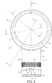
- FIGs 1 and 2 are external views of a fan 10.
- the fan comprises a body 12 having an air inlet 14 in the form of a plurality of apertures formed in the outer casing 16 of the body 12, and through which a primary air flow is drawn into the body 12 from the external environment.
- An annular nozzle 18 having an air outlet 20 for emitting the primary air flow from the fan 10 is connected to the body 12.
- the body 12 further comprises a user interface for allowing a user to control the operation of the fan 10.
- the user interface comprises a plurality of user-operable buttons 22, 24 and a user-operable dial 26.
- the nozzle 18 has an annular shape.
- the nozzle 18 comprises an outer wall 28 extending about an annular inner wall 30.
- each of the walls 28, 30 is formed from a separate component.
- Each of the walls 28, 30 has a front end and a rear end.
- the rear end of the outer wall 28 curves inwardly towards the rear end of the inner wall 30 to define a rear end of the nozzle 18.
- the front end of the inner wall 30 is folded outwardly towards the front end of the outer wall 28 to define a front end of the nozzle 18.
- the front end of the outer wall 28 is inserted into a slot located at the front end of the inner wall 30, and is connected to the inner wall 30 using an adhesive introduced to the slot.
- the inner wall 30 extends about an axis, or longitudinal axis, X to define a bore, or opening, 32 of the nozzle 18.
- the bore 32 has a generally circular cross-section which varies in diameter along the axis X from the rear end of the nozzle 18 to the front end of the nozzle 18.
- the inner wall 30 is shaped so that the external surface of the inner wall 30, that is, the surface that defines the bore 32, has a number of sections.
- the external surface of the inner wall 30 has a convex rear section 34, an outwardly flared frusto-conical front section 36 and a cylindrical section 38 located between the rear section 34 and the front section 36.
- the outer wall 28 comprises a base 40 which is connected to an open upper end of the body 12, and which has an open lower end which provides an air inlet for receiving the primary air flow from the body 12.
- the majority of the outer wall 28 is generally cylindrical shape.
- the outer wall 28 extends about a central axis, or longitudinal axis, Y which is parallel to, but spaced from, the axis X.
- the outer wall 28 and the inner wall 30 are eccentric.
- the axis X is located above the axis Y, with each of the axes X, Y being located in a plane which extends vertically through the centre of the fan 10.
- the rear end of the outer wall 28 is shaped to overlap the rear end of the inner wall 30 to define the air outlet 20 of the nozzle 18 between the inner surface of the outer wall 28 and the outer surface of the inner wall 30.
- the air outlet 20 is in the form of a generally circular slot centred on, and extending about, the axis X.
- the width of the slot is preferably substantially constant about the axis X, and is in the range from 0.5 to 5 mm.
- the overlapping portions of the outer wall 28 and the inner wall 30 are substantially parallel, and are arranged to direct air over the convex rear section 34 of the inner wall 30, which provides a Coanda surface of the nozzle 18.
- a series of angularly spaced spacers may be provided on one of the facing surfaces of the overlapping portions of the outer wall 28 and the inner wall 30 to engage the other facing surface to maintain a regular spacing between these facing surfaces.
- the outer wall 28 and the inner wall 30 define an interior passage 42 for conveying air to the air outlet 20.
- the interior passage 42 extends about the bore 32 of the nozzle 18.
- the cross-sectional area of the interior passage 42 varies about the bore 32.
- the interior passage 42 may be considered to comprise first and second curved sections, indicated generally at 44 and 46 in Figure 3 , which each extend in opposite angular directions about the bore 32. With reference also to Figures 4(b) to 4(d) , each section 44, 46 of the interior passage 42 has a cross-sectional area which decreases in size about the bore 32.
- each section 44, 46 decreases from a first value A 1 located adjacent the base 40 of the nozzle 18 to a second value A 2 located diametrically opposite the base 40, and where ends of the two sections 44, 46 are joined.
- the relative positions of the axes X, Y are such that each section 44, 46 of the interior passage 42 has the same variation in cross-sectional area about the bore 32, with the cross-sectional area of each section 44, 46 decreasing gradually from the first value A 1 to the second value A 2 .
- the variation in the cross-sectional area of the interior passage 42 is preferably such that A 1 ⁇ 1.5A 2 , and more preferably such that A 1 ⁇ 1.8A 2 .
- each section 44, 46 is effected by a variation in the radial thickness of each section 44, 46 about the bore 32; the depth of the nozzle 18, as measured in a direction extending along the axes X, Y is relatively constant about the bore 32.
- a 1 ⁇ 2200 mm 2 and A 2 ⁇ 1200 mm 2 are relatively constant about the bore 32.
- the body 12 comprises a substantially cylindrical main body section 50 mounted on a substantially cylindrical lower body section 52.
- the main body section 50 and the lower body section 52 are preferably formed from plastics material.
- the main body section 50 and the lower body section 52 preferably have substantially the same external diameter so that the external surface of the main body section 50 is substantially flush with the external surface of the lower body section 52.
- the main body section 50 comprises the air inlet 14 through which the primary air flow enters the fan assembly 10.
- the air inlet 14 comprises an array of apertures formed in the section of the outer casing 16 of the body 12 which is defined by the main body section 50.
- the air inlet 14 may comprise one or more grilles or meshes mounted within windows formed in the outer casing 16.
- the main body section 50 is open at the upper end (as illustrated) for connection to the base 40 of the nozzle 18, and to allow the primary air flow to be conveyed from the body 12 to the nozzle 18.
- the main body section 50 may be tilted relative to the lower body section 52 to adjust the direction in which the primary air flow is emitted from the fan assembly 10.
- the upper surface of the lower body section 52 and the lower surface of the main body section 50 may be provided with interconnecting features which allow the main body section 50 to move relative to the lower body section 52 while preventing the main body section 50 from being lifted from the lower body section 52.
- the lower body section 52 and the main body section 50 may comprise interlocking L-shaped members.
- the lower body section 52 is mounted on a base 56 for engaging a surface on which the fan assembly 10 is located.
- the lower body section 52 comprises the aforementioned user interface and a control circuit, indicated generally at 58, for controlling various functions of the fan 10 in response to operation of the user interface.
- the lower body section 52 also houses a mechanism for oscillating the lower body section 52 relative to the base 56.
- the operation of the oscillation mechanism is controlled by the control circuit 58 in response to the user's depression of the button 24 of the user interface.
- the range of each oscillation cycle of the lower body section 52 relative to the base 56 is preferably between 60° and 120°, and the oscillation mechanism is arranged to perform around 3 to 5 oscillation cycles per minute.
- a mains power cable (not shown) for supplying electrical power to the fan 10 extends through an aperture formed in the base 56.
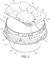
- the main body section 50 comprises a duct 60 having a first end defining an air inlet 62 of the duct 60 and a second end located opposite to the first end and defining an air outlet 64 of the duct 60.
- the duct 60 is aligned within the main body section 50 so that the longitudinal axis of the duct 60 is collinear with the longitudinal axis of the body 12, and so that the air inlet 62 is located beneath the air outlet 64.
- the duct 60 is illustrated in more detail in Figures 5 to 7 .
- the air inlet 62 is defined by an outwardly flared inlet section 66 of an outer wall 67 of the duct 60.
- the inlet section 66 of the outer wall 67 is connected to an impeller housing 68 of the outer wall 67.
- the impeller housing 68 extends about an impeller 70 for drawing the primary air flow into the body 12 of the fan 10.
- the impeller 70 is a mixed flow impeller.
- the impeller 70 comprises a generally conical hub 72, a plurality of impeller blades 74 connected to the hub 72, and a generally frusto-conical shroud 76 connected to the blades 74 so as to surround the hub 72 and the blades 74.
- the blades 74 are preferably integral with the hub 72, which is preferably formed from plastics material.
- the hub 72 and the blades 74 of the impeller 70 are illustrated in more detail in Figures 8 and 9 .
- the impeller 70 comprises nine blades 74.
- Each blade 74 extends partially about the hub 72 by an angle in the range from 60 to 120°, and in this example each blade 74 extends about the hub 72 by an angle of around 105°.
- Each blade 74 has an inner side edge 78 which is connected to the hub 72, and an outer side edge 80 located opposite to the inner side edge 78.
- Each blade 74 also has a leading edge 82 located adjacent the air inlet 62 of the duct 60, a trailing edge 84 located at the opposite end of the blade 74 to the leading edge 82, and a blade tip 86 located at the intersection of the leading edge 82 and the outer side edge 80.
- each side edge 78, 80 is greater than the lengths of the leading edge 82 and the trailing edge 84.
- the length of the outer side edge 80 is preferably in the range from 70 to 90 mm, and in this example is around 80 mm.
- the length of the leading edge 82 is preferably in the range from 15 to 30 mm, and in this example is around 20 mm.
- the length of the trailing edge 84 is preferably in the range from 5 to 15 mm, and in this example is around 10 mm.
- the width of the blade 74 decreases gradually from the leading edge 82 to the trailing edge 84.
- each blade 74 is preferably straight.
- the leading edge 82 of each blade 74 comprises an inner portion 88 located adjacent the hub 72, and an outer portion 90 located adjacent the blade tip 86.
- the inner portion 88 of the leading edge 82 extends within a range from 30 to 80% of the length of the leading edge 82. In this example the inner portion 88 is longer than the outer portion 90, extending within a range from 50 to 70% of the length of the leading edge 82.
- the shape of the blades 74 is designed to minimise noise generated during the rotation of the impeller 70 by reducing pressure gradients across parts of the blades 74.
- the reduction of these pressure gradients can reduce the tendency for the primary air flow to separate from the blades 74, and thus reduce turbulence within the air flow.
- the outer portion 90 of the leading edge 82 is swept forwardly from the inner portion 88 to the blade tip 86. This localised forward sweep of the leading edge 82 of each blade 74 towards the blade tip 86 can reduce the peak hub-to-tip loading of the blades 74.
- the outer portion 90 is concave in shape, curving forwardly from the inner portion 88 to the blade tip 86.
- the inner portion 88 is swept rearwardly from the hub 72 to the outer portion 90 so that the length of the inner side edge 78 approaches that of the outer side edge 80.
- the inner portion 88 of the leading edge 82 is convex in shape, curving rearwardly from the hub 72 to the outer portion 90 of the leading edge 82 to maximise the length of the inner side edge 78.
- the impeller 70 is connected to a rotary shaft 92 extending outwardly from a motor 94 for driving the impeller 70 to rotate about a rotational axis Z.
- the rotational axis Z is collinear with the longitudinal axis of the duct 60 and orthogonal to the axes X, Y.
- the motor 94 is a DC brushless motor having a speed which is variable by the control circuit 58 in response to user manipulation of the dial 26.
- the maximum speed of the motor 94 is preferably in the range from 5,000 to 10,000 rpm.
- the motor 94 is housed within a motor housing.
- the outer wall 67 of the duct 60 surrounds the motor housing, which provides an inner wall 95 of the duct 60.
- the walls 67, 95 of the duct 60 thus define an annular air flow path which extends through the duct 60.
- the motor housing comprises a lower section 96 which supports the motor 94, and an upper section 98 connected to the lower section 96.
- the shaft 92 protrudes through an aperture formed in the lower section 96 of the motor housing to allow the impeller 70 to be connected to the shaft 92.
- the motor 94 is inserted into the lower section 66 of the motor housing before the upper section 68 is connected to the lower section 66.
- the lower section 96 of the motor housing is generally frusto-conical in shape, and tapers inwardly in a direction extending towards the air inlet 62 of the duct 60.
- the hub 72 of the impeller 70 has a conical inner surface which has a similar shape to that of a contiguous part of the outer surface of the lower section 96 of the motor housing.
- the upper section 98 of the motor housing is generally frusto-conical in shape, and tapers inwardly towards the air outlet 64 of the duct 60.
- An annular diffuser 100 is connected to the upper section 98 of the motor housing.
- the diffuser 100 comprises a plurality of blades 102 for guiding the air flow towards the air outlet 64 of the duct 60.
- the shape of the blades 102 is such that the air flow is also straightened as it passes through the diffuser 100.
- the diffuser 100 comprises 13 blades 102.
- Each blade 102 has an inner side edge 104 which is connected to, and preferably integral with, the upper section 98 of the motor housing, and an outer side edge 106 located opposite to the inner side edge 104.
- Each blade 102 also has a leading edge 108 located adjacent the impeller 70, and a trailing edge 110 located at the opposite end of the blade 102 to the leading edge 108.
- the leading edges 108 of the blades 102 define an inlet end of the diffuser 100, and the trailing edges 110 of the blades 100 define an outlet end of the diffuser 100.
- One of the blades 102 defines a passageway 112 through which a cable passes to the motor 94.
- the outer wall 67 of the duct 60 comprises a diffuser housing 114 connected to the upper end of the impeller housing 68, and which extends about the diffuser 100.
- the diffuser housing 114 defines the air outlet 64 of the duct 60.
- the internal surface of the diffuser housing 114 is connected to the outer side edges 106 of the blades 102, for example using an adhesive.
- the diffuser housing 114 and the upper section 98 of the motor housing define a diffuser section of the air flow path through the duct 60.
- the diffuser section of the air flow path is thus annular in shape and converges towards the outlet end of the diffuser 100.
- the diffuser section of the air flow path has a cross-sectional area, as formed from the intersection with the duct 60 of a plane which extends orthogonally through the rotational axis Z of the impeller 70.
- the diffuser 100 is shaped so that the variation in the cross-sectional area of the air flow path along the diffuser section is preferably no greater than 20% of the cross-sectional area of the air flow path at the inlet end of the diffuser 100.
- the upper section 98 of the motor housing is perforated (the perforations are not illustrated in Figure 10 ).
- the inner surface of the upper section 98 of the motor housing is lined with noise absorbing material 115, preferably an acoustic foam material, to suppress broadband noise generated during operation of the fan 10.
- the noise absorbing material 115 is not shown in Figure 7 so as to not obscure the perforations in the upper section 98 of the motor housing, but is illustrated in Figures 3 and 4 .
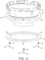
- the impeller housing 68 is mounted on an annular seat 116 located within the main body section 50 of the body 12.
- the seat 116 extends radially inwardly from the inner surface of the outer casing 16 so that an upper surface of the seat 116 is substantially orthogonal to the rotational axis Z of the impeller 70.
- annular seal 118 is located between the impeller housing 68 and the seat 116.
- the annular seal 118 is preferably a foam annular seal, and is preferably formed from a closed cell foam material.
- the annular seal 118 is formed from EPDM (ethylene propylene diene monomer) rubber, but the annular seal 118 may be formed from other closed cell foam material which preferably exhibits no more than 0.01 MPa of stress at 10% compression.
- the outer diameter of the annular seal 118 is preferably smaller than the inner diameter of the outer casing 16 so that the annular seal 118 is spaced from the inner surface of the outer casing 16.
- the annular seal 118 has a lower surface which is in sealing engagement with the upper surface of the seat 116, and an upper surface which is in sealing engagement with the impeller housing 68.
- the impeller housing 68 comprises a recessed seal engaging section 120 extending about an outer wall of the impeller housing 68.
- the seal engaging section 120 of the impeller housing 68 comprises a flange 122 which defines an annular channel for receiving the annular seal 118.
- the flange 122 extends radially outwardly from the outer surface of the impeller housing 68 so that a lower surface of the flange 122 is substantially orthogonal to the rotational axis Z of the impeller 70.
- the internal periphery of a circumferential lip 126 of the flange 122 and the external periphery of the annular seal 118 are preferably scalloped or otherwise shaped to define a plurality of recesses to inhibit relative rotation between the impeller housing 68 and the annular seal 118.
- the seat 116 comprises an aperture to enable a cable (not shown) to pass from the control circuit 58 to the motor 94.
- Each of the flange 122 of the impeller housing 68 and the annular seal 118 is shaped to define a respective recess to accommodate part of the cable.
- One or more grommets or other sealing members may be provided about the cable to inhibit the leakage of air through the aperture, and between the recesses and the internal surface of the outer casing 16.
- a plurality of resilient supports 138 are also provided between the impeller housing 68 and the seat 116 for bearing part of the weight of the duct 60, the impeller 70, the motor 94, and the motor housing.
- the resilient supports 138 are equally spaced from, and equally spaced about, the longitudinal axis of the main body section 50.
- Each resilient support 138 has a first end which is connected to a respective mount 140 located on the flange 122 of the impeller housing 68, and a second end which is received within a recess formed in the seat 116 to inhibit movement of the resilient support 138 along the seat 116 and about the longitudinal axis of the main body section 50.
- each resilient support 138 comprises a spring 144 which is located over a respective mount 140, and a rubber foot 146 which is located with a respective recess of the seat 116.
- the spring 144 and the foot 146 may be replaced by a rod or shaft formed from rubber or other elastic or elastomeric material.
- the plurality of resilient supports 138 may be replaced by a single annular resilient support extending about the annular seal 118.
- the external periphery of the annular seal 118 is further scalloped or otherwise shaped to form a plurality of recesses 148 each for at least partially receiving a respective resilient support 138. This allows the resilient supports 138 to be located closer to the longitudinal axis of the main body section 50 without either decreasing the radial thickness of the annular seal 118 or increasing the diameter of the main body section 50.
- a guide member 150 is provided about the inlet section 66 and the lower end of the impeller housing 68 for guiding the air flow entering the body 12 towards the air inlet 62 of the duct 60.
- the guide member 150 is generally frusto-conical in shape, and tapers inwardly towards the base 56 of the body 12.
- the guide member 150 defines in part a tortuous air flow path between the air inlet 14 of the body 12 and the air inlet 62 of the duct 60, and so serves to block any direct path for noise passing from the air inlet 62 of the duct 60 towards the air inlet 14 of the body 12.
- the guide member 150 depends from an annular rib 152 extending about the impeller housing 68.
- the outer periphery of the rib 152 may be connected to the inner surface of the main body section 50, for example using an adhesive. Alternatively, the inner periphery of the rib 152 may be connected to the outer surface of the impeller housing 68. The outer surface of the guide member 150 which is exposed to the air flow passing through the body 12 is lined with sound-absorbing material 154.
- the guide member 150 is spaced from the external surface of the duct 60 to define an annular noise suppression cavity 156.
- the size of the cavity 156 is tuned to the wavelength of the rotational tone of the impeller 70 so that the cavity 156 can act as a resonator to target a specific wavelength of the noise generated during the use of the fan 10, as well as generally reduce noise levels.
- the cavity 156 has an inlet 158 located between the air inlet 62 of the duct 60 and the guide member 150.
- the inlet 158 is annular in shape, and located at the lowermost extremity of the cavity 156.
- the inlet 158 is positioned at a location where the tortuous section of the air flow path turns through an angle which is greater than 90° from a direction extending away from the air inlet 14 of the body 12, and towards the rotational axis Z of the impeller 70, to a direction extending towards the air inlet 62 of the duct 60.
- the main body section 50 comprises a noise suppression cavity 160 located beneath the air inlet 62 of the duct 60.
- the cavity 160 is also tuned to the wavelength of the rotational tone of the impeller 70.
- the cavity 160 has an inlet 162 which is located beneath the air inlet 62 of the duct 60, and which is preferably concentric with the air inlet 62 of the duct 60.
- a lower wall of the cavity 160 is defined by a concave lower surface 164 of the main body section 50.
- the inlet 162 and an upper wall of the cavity 160 are defined by an annular plate 166 which is connected to the upper peripheral portion of the lower surface 164 of the main body section 50.
- annular sound absorbing member 168 is preferably located between the duct 60 and the cavity 160.
- the annular sound absorbing member 168 is concentric with the inlet 162 of the cavity 160, and has an outer periphery which is in contact with the inner surface of the outer casing 16.
- a sheet of sound absorbing material may be disposed over the annular sound absorbing member 168 to inhibit the ingress of dust into the cavity 160.
- the inner surface of the outer casing 16 is partially lined with sound absorbing material.
- a sheet of sound-absorbing material 172 may be located immediately downstream of the air inlet 14 to reduce the level of broadband noise emitted through the air inlet 14 of the body 12.
- the user presses button 22 of the user interface, in response to which the control circuit 58 activates the motor 94 to rotate the impeller 70.
- the rotation of the impeller 70 causes a primary air flow to be drawn into the body 12 through the air inlet 14.
- the user may control the speed of the motor 94, and therefore the rate at which air is drawn into the body 12 through the air inlet 14, by manipulating the dial 26.
- the rotation of the impeller 70 by the motor 94 generates vibrations which are transferred through the motor housing and the impeller housing 68 towards the seat 116.
- the annular seal 118 located between the impeller housing 68 and the seat 116 is compressed under the weight of the duct 60, the impeller 70, the motor housing and the motor 94 so that it is in sealing engagement with the upper surface of the seat 116 and the lower surface of the flange 122 of the impeller housing 68.
- the annular seal 118 thus not only prevents the primary air flow from returning to the air inlet 62 of the duct 60 along a path extending between the inner surface of the outer casing 16 of the main body section 50 and the outer wall 67 of the duct 60, but also reduces the transmission of these vibrations to the seat 116, and thus to the body 12 of the fan 10.
- the presence of the resilient supports 138 between the impeller housing 68 and the seat 116 inhibits any over-compression of the annular seal 118 over time, which otherwise could increase the transmission of vibrations through the annular seal 118 to the seat 116.
- the flexibility of the resilient supports 138 allows the resilient supports 138 to flex both axially and radially relative to the seat 116, which reduces the transmission of vibrations to the seat 116 through the resilient supports 138.
- the annular seal 118 serves to damp the flexing movement of the resilient supports 138 relative to the seat 116.
- the sound absorbing material 115, 154, 172 and the annular sound absorbing member 168 serve to dampen broadband noise generated within the body 12 of the fan 10.
- the guide member 150 serves to prevent noise from passing directly from the air inlet 62 of the duct 60 to the external environment via the air inlet 14 of the body 12. Undesirable tones generated by the rotational of the impeller 70 are reduced by the cavities 156, 160.
- the rotation of the impeller 70 causes a primary air flow to enter the body 12 through the air inlet 14, and to pass along the tortuous section of the air flow path to the air inlet 62 of the duct 60.
- the primary air flow passes through the impeller housing 68 and the diffuser housing 114 to be emitted from the air outlet 64 of the duct 60.
- the end of the duct 60 in which the air outlet 64 is formed comprises two outwardly flared portions 180.
- the duct 60 is shaped so that when the duct 60 is mounted on the seat 116 this end of the duct 60 protrudes from the open upper end of the main body section 50 of the body 12.
- the flared portions 180 of the duct 60 are located within the interior passage 42 of the nozzle 18.
- the primary air flow is divided into two air streams which pass in opposite angular directions around the bore 32 of the nozzle 18, each within a respective section 44, 46 of the interior passage 42.
- the flared portions 180 of the duct 60 are each shaped to guide a respective air stream into a respective section 44, 46 of the interior passage 42.
- the ends of the flared portions 180 of the duct 60 have a curvature which is substantially the same as that of the contiguous portions of the outer wall 28 of the nozzle 16.
- each flared portion 180 and its contiguous portion of the outer wall 28 of the nozzle 16 is preferably no greater than 10 mm, more preferably no greater than 5 mm so that there is minimal disruption to the profile of the air flow as it enters the interior passage 42 of the nozzle 16.
- air is emitted through the air outlet 20.
- the emission of the primary air flow from the air outlet 20 causes a secondary air flow to be generated by the entrainment of air from the external environment, specifically from the region around the nozzle 18.
- This secondary air flow combines with the primary air flow to produce a combined, or total, air flow, or air current, projected forward from the nozzle 18.
Landscapes
- Engineering & Computer Science (AREA)
- Mechanical Engineering (AREA)
- General Engineering & Computer Science (AREA)
- Physics & Mathematics (AREA)
- Fluid Mechanics (AREA)
- Power Engineering (AREA)
- Structures Of Non-Positive Displacement Pumps (AREA)
- Jet Pumps And Other Pumps (AREA)
Priority Applications (1)
| Application Number | Priority Date | Filing Date | Title |
|---|---|---|---|
| EP18187246.6A EP3418582A1 (en) | 2012-05-16 | 2013-04-19 | Fan comprising perforated sound-absorbing chamber |
Applications Claiming Priority (2)
| Application Number | Priority Date | Filing Date | Title |
|---|---|---|---|
| GB1208616.1A GB2502104B (en) | 2012-05-16 | 2012-05-16 | A fan |
| PCT/GB2013/050990 WO2013171451A2 (en) | 2012-05-16 | 2013-04-19 | A fan |
Related Child Applications (1)
| Application Number | Title | Priority Date | Filing Date |
|---|---|---|---|
| EP18187246.6A Division EP3418582A1 (en) | 2012-05-16 | 2013-04-19 | Fan comprising perforated sound-absorbing chamber |
Publications (2)
| Publication Number | Publication Date |
|---|---|
| EP2850325A2 EP2850325A2 (en) | 2015-03-25 |
| EP2850325B1 true EP2850325B1 (en) | 2018-08-29 |
Family
ID=46458934
Family Applications (2)
| Application Number | Title | Priority Date | Filing Date |
|---|---|---|---|
| EP13718053.5A Not-in-force EP2850325B1 (en) | 2012-05-16 | 2013-04-19 | A fan |
| EP18187246.6A Withdrawn EP3418582A1 (en) | 2012-05-16 | 2013-04-19 | Fan comprising perforated sound-absorbing chamber |
Family Applications After (1)
| Application Number | Title | Priority Date | Filing Date |
|---|---|---|---|
| EP18187246.6A Withdrawn EP3418582A1 (en) | 2012-05-16 | 2013-04-19 | Fan comprising perforated sound-absorbing chamber |
Country Status (9)
| Country | Link |
|---|---|
| US (2) | US9568006B2 (ja) |
| EP (2) | EP2850325B1 (ja) |
| JP (3) | JP5667660B2 (ja) |
| CN (3) | CN105889035B (ja) |
| AU (1) | AU2013261586B2 (ja) |
| CA (1) | CA2873301C (ja) |
| GB (2) | GB2502104B (ja) |
| RU (1) | RU2636302C2 (ja) |
| WO (1) | WO2013171451A2 (ja) |
Families Citing this family (75)
| Publication number | Priority date | Publication date | Assignee | Title |
|---|---|---|---|---|
| GB2468312A (en) | 2009-03-04 | 2010-09-08 | Dyson Technology Ltd | Fan assembly |
| GB2476172B (en) | 2009-03-04 | 2011-11-16 | Dyson Technology Ltd | Tilting fan stand |
| GB2483448B (en) | 2010-09-07 | 2015-12-02 | Dyson Technology Ltd | A fan |
| GB2486019B (en) | 2010-12-02 | 2013-02-20 | Dyson Technology Ltd | A fan |
| GB201119500D0 (en) | 2011-11-11 | 2011-12-21 | Dyson Technology Ltd | A fan assembly |
| GB2498547B (en) | 2012-01-19 | 2015-02-18 | Dyson Technology Ltd | A fan |
| GB2500011B (en) | 2012-03-06 | 2016-07-06 | Dyson Technology Ltd | A Humidifying Apparatus |
| GB2500010B (en) | 2012-03-06 | 2016-08-24 | Dyson Technology Ltd | A humidifying apparatus |
| MY167968A (en) | 2012-03-06 | 2018-10-09 | Dyson Technology Ltd | A fan assembly |
| GB2500017B (en) | 2012-03-06 | 2015-07-29 | Dyson Technology Ltd | A Humidifying Apparatus |
| GB2500012B (en) | 2012-03-06 | 2016-07-06 | Dyson Technology Ltd | A Humidifying Apparatus |
| GB2512192B (en) | 2012-03-06 | 2015-08-05 | Dyson Technology Ltd | A Humidifying Apparatus |
| GB2502104B (en) * | 2012-05-16 | 2016-01-27 | Dyson Technology Ltd | A fan |
| GB2518935B (en) | 2012-05-16 | 2016-01-27 | Dyson Technology Ltd | A fan |
| WO2013171452A2 (en) | 2012-05-16 | 2013-11-21 | Dyson Technology Limited | A fan |
| GB2503907B (en) | 2012-07-11 | 2014-05-28 | Dyson Technology Ltd | A fan assembly |
| AU350140S (en) | 2013-01-18 | 2013-08-13 | Dyson Technology Ltd | Humidifier or fan |
| AU350179S (en) | 2013-01-18 | 2013-08-15 | Dyson Technology Ltd | Humidifier or fan |
| BR302013003358S1 (pt) | 2013-01-18 | 2014-11-25 | Dyson Technology Ltd | Configuração aplicada em umidificador |
| AU350181S (en) | 2013-01-18 | 2013-08-15 | Dyson Technology Ltd | Humidifier or fan |
| GB2510195B (en) | 2013-01-29 | 2016-04-27 | Dyson Technology Ltd | A fan assembly |
| RU2684043C2 (ru) | 2013-01-29 | 2019-04-03 | Дайсон Текнолоджи Лимитед | Вентилятор в сборе |
| BR302013004394S1 (pt) * | 2013-03-07 | 2014-12-02 | Dyson Technology Ltd | Configuração aplicada a ventilador |
| CA152658S (en) * | 2013-03-07 | 2014-05-20 | Dyson Technology Ltd | Fan |
| CA152657S (en) * | 2013-03-07 | 2014-05-20 | Dyson Technology Ltd | Fan |
| CA152655S (en) * | 2013-03-07 | 2014-05-20 | Dyson Technology Ltd | Fan |
| CA152656S (en) * | 2013-03-07 | 2014-05-20 | Dyson Technology Ltd | Fan |
| USD729372S1 (en) * | 2013-03-07 | 2015-05-12 | Dyson Technology Limited | Fan |
| GB2516058B (en) | 2013-07-09 | 2016-12-21 | Dyson Technology Ltd | A fan assembly with an oscillation and tilt mechanism |
| CA154722S (en) | 2013-08-01 | 2015-02-16 | Dyson Technology Ltd | Fan |
| TWD172707S (zh) | 2013-08-01 | 2015-12-21 | 戴森科技有限公司 | 風扇 |
| CA154723S (en) | 2013-08-01 | 2015-02-16 | Dyson Technology Ltd | Fan |
| GB2518638B (en) | 2013-09-26 | 2016-10-12 | Dyson Technology Ltd | Humidifying apparatus |
| CN105317749B (zh) * | 2014-07-18 | 2018-05-08 | 台达电子工业股份有限公司 | 风扇组件及其扇框 |
| GB2528708B (en) | 2014-07-29 | 2016-06-29 | Dyson Technology Ltd | A fan assembly |
| GB2528709B (en) | 2014-07-29 | 2017-02-08 | Dyson Technology Ltd | Humidifying apparatus |
| GB2528704A (en) | 2014-07-29 | 2016-02-03 | Dyson Technology Ltd | Humidifying apparatus |
| JP6386877B2 (ja) * | 2014-10-31 | 2018-09-05 | 豊和化成株式会社 | 空気吹出装置 |
| JP2016090096A (ja) * | 2014-10-31 | 2016-05-23 | 豊和化成株式会社 | 空気吹出装置 |
| TWD179707S (zh) * | 2015-01-30 | 2016-11-21 | 戴森科技有限公司 | 風扇之部分(四) |
| TWD173928S (zh) * | 2015-01-30 | 2016-02-21 | 戴森科技有限公司 | 風扇(一) |
| TWD173929S (zh) * | 2015-01-30 | 2016-02-21 | 戴森科技有限公司 | 風扇(二) |
| TWD173932S (zh) * | 2015-01-30 | 2016-02-21 | 戴森科技有限公司 | 風扇之部分(三) |
| TWD173930S (zh) * | 2015-01-30 | 2016-02-21 | 戴森科技有限公司 | 風扇之部分(一) |
| TWD173931S (zh) * | 2015-01-30 | 2016-02-21 | 戴森科技有限公司 | 風扇之部分(二) |
| CN105982413B (zh) * | 2015-02-13 | 2020-08-18 | 德昌电机(深圳)有限公司 | 降噪扩散器及降噪电吹风机 |
| TWD177268S (zh) * | 2015-06-11 | 2016-07-21 | 戴森科技有限公司 | 風扇(一) |
| TWD178212S (zh) * | 2015-06-11 | 2016-09-11 | 戴森科技有限公司 | 風扇(二) |
| TWD177269S (zh) * | 2015-06-11 | 2016-07-21 | 戴森科技有限公司 | 風扇之部分(一) |
| TWD177270S (zh) * | 2015-06-11 | 2016-07-21 | 戴森科技有限公司 | 風扇之部分(二) |
| TWD178213S (zh) * | 2015-06-11 | 2016-09-11 | 戴森科技有限公司 | 風扇之部分(三) |
| AU366197S (en) * | 2015-06-11 | 2015-12-22 | Dyson Technology Ltd | A fan |
| USD804007S1 (en) * | 2015-11-25 | 2017-11-28 | Vornado Air Llc | Air circulator |
| GB2545269B (en) * | 2015-12-11 | 2018-02-28 | Dyson Technology Ltd | An electric motor |
| KR101985201B1 (ko) * | 2016-05-16 | 2019-06-03 | (주)광개토쇼핑 | 날개 없는 선풍기용 송풍장치 |
| CN106224303A (zh) * | 2016-08-31 | 2016-12-14 | 宁波小恐龙电器有限公司 | 一种中端出风的无叶风扇 |
| CN106698233B (zh) * | 2016-09-13 | 2023-09-05 | 东莞市卓奇峰智能科技有限公司 | 气悬浮支撑机构 |
| CN106762851B (zh) * | 2016-11-15 | 2019-08-30 | 美的集团股份有限公司 | 无叶风扇 |
| CN106762850B (zh) * | 2016-11-15 | 2019-04-30 | 美的集团股份有限公司 | 基座及无叶风扇 |
| CN106321525B (zh) * | 2016-11-15 | 2019-05-31 | 美的集团股份有限公司 | 基座及无叶风扇 |
| US11384956B2 (en) | 2017-05-22 | 2022-07-12 | Sharkninja Operating Llc | Modular fan assembly with articulating nozzle |
| CA3021746A1 (en) | 2017-10-20 | 2019-04-20 | Tti (Macao Commercial Offshore) Limited | Fan |
| US11370529B2 (en) * | 2018-03-29 | 2022-06-28 | Walmart Apollo, Llc | Aerial vehicle turbine system |
| US10926210B2 (en) | 2018-04-04 | 2021-02-23 | ACCO Brands Corporation | Air purifier with dual exit paths |
| USD913467S1 (en) | 2018-06-12 | 2021-03-16 | ACCO Brands Corporation | Air purifier |
| GB2575813B (en) * | 2018-07-23 | 2020-12-09 | Dyson Technology Ltd | A wearable air purifier |
| GB2575812B (en) * | 2018-07-23 | 2020-12-09 | Dyson Technology Ltd | A wearable air purifier |
| GB2575814B (en) * | 2018-07-23 | 2020-12-09 | Dyson Technology Ltd | A wearable air purifier |
| CN110345540B (zh) * | 2019-08-22 | 2020-11-24 | 美的集团股份有限公司 | 吸油烟机 |
| DE102019134354A1 (de) * | 2019-12-13 | 2021-06-17 | Bedek GmbH & Co. KG | Elektromotorvorrichtung mit einem Elektromotor und einer integralen Gebläsevorrichtung |
| CN111156191A (zh) * | 2020-01-20 | 2020-05-15 | 珠海格力电器股份有限公司 | 叶轮、混流风机以及空调器 |
| CN111255738A (zh) * | 2020-01-20 | 2020-06-09 | 珠海格力电器股份有限公司 | 叶轮、混流风机以及空调器 |
| CN111156179A (zh) * | 2020-01-20 | 2020-05-15 | 珠海格力电器股份有限公司 | 消旋结构、混流风机组件及空调器 |
| CN111156203A (zh) * | 2020-01-20 | 2020-05-15 | 珠海格力电器股份有限公司 | 消旋结构、混流风机组件及空调器 |
| GB2606703A (en) * | 2021-04-29 | 2022-11-23 | Dyson Technology Ltd | Noise reduction for air flow devices |
Citations (3)
| Publication number | Priority date | Publication date | Assignee | Title |
|---|---|---|---|---|
| WO2007024955A2 (en) * | 2005-08-24 | 2007-03-01 | Ric Investments, Llc | Blower mounting assembly |
| US20100226758A1 (en) * | 2009-03-04 | 2010-09-09 | Dyson Technology Limited | Fan assembly |
| CN102305220A (zh) * | 2011-08-16 | 2012-01-04 | 江西维特科技有限公司 | 低噪声无叶风扇 |
Family Cites Families (417)
| Publication number | Priority date | Publication date | Assignee | Title |
|---|---|---|---|---|
| GB601222A (en) | 1944-10-04 | 1948-04-30 | Berkeley & Young Ltd | Improvements in, or relating to, electric fans |
| GB593828A (en) | 1945-06-14 | 1947-10-27 | Dorothy Barker | Improvements in or relating to propeller fans |
| GB191322235A (en) | 1913-10-02 | 1914-06-11 | Sidney George Leach | Improvements in the Construction of Electric Fans. |
| US1357261A (en) | 1918-10-02 | 1920-11-02 | Ladimir H Svoboda | Fan |
| US1767060A (en) | 1928-10-04 | 1930-06-24 | W H Addington | Electric motor-driven desk fan |
| US2014185A (en) | 1930-06-25 | 1935-09-10 | Martin Brothers Electric Compa | Drier |
| GB383498A (en) | 1931-03-03 | 1932-11-17 | Spontan Ab | Improvements in or relating to fans, ventilators, or the like |
| US1896869A (en) | 1931-07-18 | 1933-02-07 | Master Electric Co | Electric fan |
| US2035733A (en) | 1935-06-10 | 1936-03-31 | Marathon Electric Mfg | Fan motor mounting |
| US2160666A (en) * | 1936-06-01 | 1939-05-30 | Gen Electric | Fan |
| US2210458A (en) | 1936-11-16 | 1940-08-06 | Lester S Keilholtz | Method of and apparatus for air conditioning |
| US2115883A (en) | 1937-04-21 | 1938-05-03 | Sher Samuel | Lamp |
| US2258961A (en) | 1939-07-26 | 1941-10-14 | Prat Daniel Corp | Ejector draft control |
| US2336295A (en) | 1940-09-25 | 1943-12-07 | Reimuller Caryl | Air diverter |
| GB641622A (en) | 1942-05-06 | 1950-08-16 | Fernan Oscar Conill | Improvements in or relating to hair drying |
| US2433795A (en) | 1945-08-18 | 1947-12-30 | Westinghouse Electric Corp | Fan |
| US2476002A (en) | 1946-01-12 | 1949-07-12 | Edward A Stalker | Rotating wing |
| US2547448A (en) | 1946-02-20 | 1951-04-03 | Demuth Charles | Hot-air space heater |
| US2473325A (en) | 1946-09-19 | 1949-06-14 | E A Lab Inc | Combined electric fan and air heating means |
| US2544379A (en) | 1946-11-15 | 1951-03-06 | Oscar J Davenport | Ventilating apparatus |
| US2488467A (en) | 1947-09-12 | 1949-11-15 | Lisio Salvatore De | Motor-driven fan |
| GB633273A (en) | 1948-02-12 | 1949-12-12 | Albert Richard Ponting | Improvements in or relating to air circulating apparatus |
| US2510132A (en) | 1948-05-27 | 1950-06-06 | Morrison Hackley | Oscillating fan |
| GB661747A (en) | 1948-12-18 | 1951-11-28 | British Thomson Houston Co Ltd | Improvements in and relating to oscillating fans |
| US2620127A (en) | 1950-02-28 | 1952-12-02 | Westinghouse Electric Corp | Air translating apparatus |
| US2583374A (en) | 1950-10-18 | 1952-01-22 | Hydraulic Supply Mfg Company | Exhaust fan |
| FR1033034A (fr) | 1951-02-23 | 1953-07-07 | Support articulé stabilisateur pour ventilateur à hélices flexibles et à vitesses de rotation variables | |
| US2813673A (en) | 1953-07-09 | 1957-11-19 | Gilbert Co A C | Tiltable oscillating fan |
| US2838229A (en) | 1953-10-30 | 1958-06-10 | Roland J Belanger | Electric fan |
| US2765977A (en) | 1954-10-13 | 1956-10-09 | Morrison Hackley | Electric ventilating fans |
| FR1119439A (fr) | 1955-02-18 | 1956-06-20 | Perfectionnements aux ventilateurs portatifs et muraux | |
| US2830779A (en) | 1955-02-21 | 1958-04-15 | Lau Blower Co | Fan stand |
| NL110393C (ja) | 1955-11-29 | 1965-01-15 | Bertin & Cie | |
| CH346643A (de) | 1955-12-06 | 1960-05-31 | K Tateishi Arthur | Elektrischer Ventilator |
| US2808198A (en) | 1956-04-30 | 1957-10-01 | Morrison Hackley | Oscillating fans |
| BE560119A (ja) | 1956-09-13 | |||
| GB863124A (en) | 1956-09-13 | 1961-03-15 | Sebac Nouvelle Sa | New arrangement for putting gases into movement |
| US2922570A (en) | 1957-12-04 | 1960-01-26 | Burris R Allen | Automatic booster fan and ventilating shield |
| US3004403A (en) | 1960-07-21 | 1961-10-17 | Francis L Laporte | Refrigerated space humidification |
| DE1291090B (de) | 1963-01-23 | 1969-03-20 | Schmidt Geb Halm Anneliese | Vorrichtung zur Erzeugung einer Luftstroemung |
| GB1085565A (en) * | 1963-06-27 | 1967-10-04 | Colchester Woods | Mixed flow fans |
| DE1457461A1 (de) | 1963-10-01 | 1969-02-20 | Siemens Elektrogeraete Gmbh | Kofferfoermiges Haartrockengeraet |
| FR1387334A (fr) | 1963-12-21 | 1965-01-29 | Sèche-cheveux capable de souffler séparément de l'air chaud et de l'air froid | |
| US3270655A (en) | 1964-03-25 | 1966-09-06 | Howard P Guirl | Air curtain door seal |
| US3339867A (en) | 1966-06-28 | 1967-09-05 | Electrolux Corp | Motor mount |
| US3518776A (en) | 1967-06-03 | 1970-07-07 | Bremshey & Co | Blower,particularly for hair-drying,laundry-drying or the like |
| US3444817A (en) | 1967-08-23 | 1969-05-20 | William J Caldwell | Fluid pump |
| US3487555A (en) | 1968-01-15 | 1970-01-06 | Hoover Co | Portable hair dryer |
| US3495343A (en) | 1968-02-20 | 1970-02-17 | Rayette Faberge | Apparatus for applying air and vapor to the face and hair |
| US3503138A (en) | 1969-05-19 | 1970-03-31 | Oster Mfg Co John | Hair dryer |
| GB1278606A (en) | 1969-09-02 | 1972-06-21 | Oberlind Veb Elektroinstall | Improvements in or relating to transverse flow fans |
| US3645007A (en) | 1970-01-14 | 1972-02-29 | Sunbeam Corp | Hair dryer and facial sauna |
| DE2944027A1 (de) | 1970-07-22 | 1981-05-07 | Erevanskyj politechničeskyj institut imeni Karla Marksa, Erewan | Ejektor-raumklimageraet der zentral-klimaanlage |
| US3724092A (en) | 1971-07-12 | 1973-04-03 | Westinghouse Electric Corp | Portable hair dryer |
| GB1403188A (en) | 1971-10-22 | 1975-08-28 | Olin Energy Systems Ltd | Fluid flow inducing apparatus |
| JPS517258Y2 (ja) | 1971-11-15 | 1976-02-27 | ||
| US3743186A (en) | 1972-03-14 | 1973-07-03 | Src Lab | Air gun |
| US3885891A (en) | 1972-11-30 | 1975-05-27 | Rockwell International Corp | Compound ejector |
| US3872916A (en) | 1973-04-05 | 1975-03-25 | Int Harvester Co | Fan shroud exit structure |
| US3795367A (en) | 1973-04-05 | 1974-03-05 | Src Lab | Fluid device using coanda effect |
| JPS49150403U (ja) | 1973-04-23 | 1974-12-26 | ||
| US4037991A (en) | 1973-07-26 | 1977-07-26 | The Plessey Company Limited | Fluid-flow assisting devices |
| US3875745A (en) | 1973-09-10 | 1975-04-08 | Wagner Minning Equipment Inc | Venturi exhaust cooler |
| GB1434226A (en) | 1973-11-02 | 1976-05-05 | Roberts S A | Pumps |
| US3943329A (en) | 1974-05-17 | 1976-03-09 | Clairol Incorporated | Hair dryer with safety guard air outlet nozzle |
| CA1055344A (en) | 1974-05-17 | 1979-05-29 | International Harvester Company | Heat transfer system employing a coanda effect producing fan shroud exit |
| US4184541A (en) | 1974-05-22 | 1980-01-22 | International Harvester Company | Heat exchange apparatus including a toroidal-type radiator |
| US4180130A (en) | 1974-05-22 | 1979-12-25 | International Harvester Company | Heat exchange apparatus including a toroidal-type radiator |
| DE2525865A1 (de) | 1974-06-11 | 1976-01-02 | Charbonnages De France | Ventilator |
| GB1495013A (en) | 1974-06-25 | 1977-12-14 | British Petroleum Co | Coanda unit |
| GB1593391A (en) | 1977-01-28 | 1981-07-15 | British Petroleum Co | Flare |
| JPS517258A (ja) | 1974-07-11 | 1976-01-21 | Tsudakoma Ind Co Ltd | Yokoitochoryusochi |
| DE2451557C2 (de) | 1974-10-30 | 1984-09-06 | Arnold Dipl.-Ing. 8904 Friedberg Scheel | Vorrichtung zum Belüften einer Aufenthaltszone in einem Raum |
| JPS5351608Y2 (ja) | 1975-01-10 | 1978-12-09 | ||
| US4061188A (en) | 1975-01-24 | 1977-12-06 | International Harvester Company | Fan shroud structure |
| US4136735A (en) | 1975-01-24 | 1979-01-30 | International Harvester Company | Heat exchange apparatus including a toroidal-type radiator |
| US4173995A (en) | 1975-02-24 | 1979-11-13 | International Harvester Company | Recirculation barrier for a heat transfer system |
| US4332529A (en) | 1975-08-11 | 1982-06-01 | Morton Alperin | Jet diffuser ejector |
| US4046492A (en) | 1976-01-21 | 1977-09-06 | Vortec Corporation | Air flow amplifier |
| JPS5351608A (en) | 1976-10-20 | 1978-05-11 | Asahi Giken Kk | Fluid conveying tube to be installed under the water surface |
| JPS5531911Y2 (ja) | 1976-10-25 | 1980-07-30 | ||
| DK140426B (da) | 1976-11-01 | 1979-08-27 | Arborg O J M | Fremdriftsdyse til transportmidler i luft eller vand. |
| US4113416A (en) | 1977-02-24 | 1978-09-12 | Ishikawajima-Harima Jukogyo Kabushiki Kaisha | Rotary burner |
| JPS5351608U (ja) * | 1977-08-12 | 1978-05-02 | ||
| JPS5719995Y2 (ja) | 1980-05-13 | 1982-04-27 | ||
| JPS56167897A (en) | 1980-05-28 | 1981-12-23 | Toshiba Corp | Fan |
| EP0044494A1 (en) | 1980-07-17 | 1982-01-27 | General Conveyors Limited | Nozzle for ring jet pump |
| JPS5771000U (ja) | 1980-10-20 | 1982-04-30 | ||
| MX147915A (es) | 1981-01-30 | 1983-01-31 | Philips Mexicana S A De C V | Ventilador electrico |
| JPS57157097A (en) | 1981-03-20 | 1982-09-28 | Sanyo Electric Co Ltd | Fan |
| JPS57157097U (ja) | 1981-03-30 | 1982-10-02 | ||
| IL66917A0 (en) | 1981-10-08 | 1982-12-31 | Wright Barry Corp | Vibration isolating seal device for mounting fans and blowers |
| US4568243A (en) | 1981-10-08 | 1986-02-04 | Barry Wright Corporation | Vibration isolating seal for mounting fans and blowers |
| GB2111125A (en) | 1981-10-13 | 1983-06-29 | Beavair Limited | Apparatus for inducing fluid flow by Coanda effect |
| JPS58128034U (ja) | 1982-02-25 | 1983-08-30 | 三洋電機株式会社 | インクジエツトプリンタ |
| US4448354A (en) | 1982-07-23 | 1984-05-15 | The United States Of America As Represented By The Secretary Of The Air Force | Axisymmetric thrust augmenting ejector with discrete primary air slot nozzles |
| US4653976A (en) | 1982-09-30 | 1987-03-31 | General Electric Company | Method of compressing a fluid flow in a multi stage centrifugal impeller |
| US4502837A (en) | 1982-09-30 | 1985-03-05 | General Electric Company | Multi stage centrifugal impeller |
| FR2534983A1 (fr) | 1982-10-20 | 1984-04-27 | Chacoux Claude | Compresseur supersonique a jet |
| JPS5990797U (ja) | 1982-12-13 | 1984-06-20 | 住友軽金属工業株式会社 | 物干金物 |
| US4718870A (en) | 1983-02-15 | 1988-01-12 | Techmet Corporation | Marine propulsion system |
| JPS59167984A (ja) | 1983-03-12 | 1984-09-21 | 日本特殊陶業株式会社 | 抵抗入り点火プラグ |
| JPS59167984U (ja) | 1983-04-27 | 1984-11-10 | 三菱電機株式会社 | 斜流式ダクトフアン |
| JPH0686898B2 (ja) | 1983-05-31 | 1994-11-02 | ヤマハ発動機株式会社 | 車両用vベルト式自動無段変速機 |
| JPS59193689U (ja) | 1983-06-09 | 1984-12-22 | 村田機械株式会社 | 環状または筒状物品の移送用ロボツトハンド |
| JPS60105896A (ja) | 1983-11-14 | 1985-06-11 | Mitsubishi Heavy Ind Ltd | 水熱交換器の空気及び水抜装置 |
| JPS60105896U (ja) | 1983-12-26 | 1985-07-19 | 株式会社日立製作所 | 斜流フアン |
| US4643351A (en) | 1984-06-14 | 1987-02-17 | Tokyo Sanyo Electric Co. | Ultrasonic humidifier |
| JP2594029B2 (ja) | 1984-07-25 | 1997-03-26 | 三洋電機株式会社 | 超音波加湿装置 |
| JPS61116093A (ja) | 1984-11-12 | 1986-06-03 | Matsushita Electric Ind Co Ltd | 扇風機 |
| FR2574854B1 (fr) | 1984-12-17 | 1988-10-28 | Peugeot Aciers Et Outillage | Motoventilateur, notamment pour vehicule automobile, fixe sur des bras supports solidaires de la carrosserie |
| JPH0351913Y2 (ja) | 1984-12-31 | 1991-11-08 | ||
| US4630475A (en) | 1985-03-20 | 1986-12-23 | Sharp Kabushiki Kaisha | Fiber optic level sensor for humidifier |
| US4832576A (en) | 1985-05-30 | 1989-05-23 | Sanyo Electric Co., Ltd. | Electric fan |
| JPS61280787A (ja) | 1985-05-30 | 1986-12-11 | Sanyo Electric Co Ltd | 扇風機 |
| JPH0443895Y2 (ja) | 1985-07-22 | 1992-10-16 | ||
| US4703152A (en) | 1985-12-11 | 1987-10-27 | Holmes Products Corp. | Tiltable and adjustably oscillatable portable electric heater/fan |
| GB2185533A (en) | 1986-01-08 | 1987-07-22 | Rolls Royce | Ejector pumps |
| GB2185531B (en) | 1986-01-20 | 1989-11-22 | Mitsubishi Electric Corp | Electric fans |
| US4732539A (en) | 1986-02-14 | 1988-03-22 | Holmes Products Corp. | Oscillating fan |
| JPH0352515Y2 (ja) | 1986-02-20 | 1991-11-14 | ||
| JPH0674190B2 (ja) | 1986-02-27 | 1994-09-21 | 住友電気工業株式会社 | 金属化面を有する窒化アルミニウム焼結体 |
| JPS62223494A (ja) | 1986-03-21 | 1987-10-01 | Uingu:Kk | 冷風機 |
| US4850804A (en) | 1986-07-07 | 1989-07-25 | Tatung Company Of America, Inc. | Portable electric fan having a universally adjustable mounting |
| US4790133A (en) | 1986-08-29 | 1988-12-13 | General Electric Company | High bypass ratio counterrotating turbofan engine |
| FR2603953B1 (fr) | 1986-09-12 | 1991-02-22 | Peugeot Aciers Et Outillage | Pale profilee d'helice et son application aux motoventilateurs |
| DE3644567C2 (de) | 1986-12-27 | 1993-11-18 | Ltg Lufttechnische Gmbh | Verfahren zum Einblasen von Zuluft in einen Raum |
| JPH0781559B2 (ja) | 1987-01-20 | 1995-08-30 | 三洋電機株式会社 | 送風装置 |
| JPH0821400B2 (ja) | 1987-03-04 | 1996-03-04 | 関西電力株式会社 | 電解液循環型2次電池 |
| JPS63179198U (ja) | 1987-05-11 | 1988-11-21 | ||
| JPS63306340A (ja) | 1987-06-06 | 1988-12-14 | Koichi Hidaka | 殺菌灯点灯回路内蔵細菌防止超音波加湿器 |
| JPH079279B2 (ja) | 1987-07-15 | 1995-02-01 | 三菱重工業株式会社 | タンク底面部の防熱構造及びその施工方法 |
| JPS6421300U (ja) | 1987-07-27 | 1989-02-02 | ||
| JPS6483884A (en) | 1987-09-28 | 1989-03-29 | Matsushita Seiko Kk | Chargeable electric fan |
| JPH0660638B2 (ja) | 1987-10-07 | 1994-08-10 | 松下電器産業株式会社 | 斜流羽根車 |
| JPH01138399A (ja) | 1987-11-24 | 1989-05-31 | Sanyo Electric Co Ltd | 扇風機 |
| JPH0633850B2 (ja) | 1988-03-02 | 1994-05-02 | 三洋電機株式会社 | 機器の俯仰角度調整装置 |
| JPH01138399U (ja) | 1988-03-15 | 1989-09-21 | ||
| JPH0636437Y2 (ja) | 1988-04-08 | 1994-09-21 | 耕三 福田 | 空気循環装置 |
| US4878620A (en) | 1988-05-27 | 1989-11-07 | Tarleton E Russell | Rotary vane nozzle |
| US4978281A (en) | 1988-08-19 | 1990-12-18 | Conger William W Iv | Vibration dampened blower |
| US6293121B1 (en) | 1988-10-13 | 2001-09-25 | Gaudencio A. Labrador | Water-mist blower cooling system and its new applications |
| JPH02146294A (ja) | 1988-11-24 | 1990-06-05 | Japan Air Curtain Corp | 送風機 |
| FR2640857A1 (en) | 1988-12-27 | 1990-06-29 | Seb Sa | Hairdryer with an air exit flow of modifiable form |
| JPH02211400A (ja) | 1989-02-08 | 1990-08-22 | Mitsubishi Electric Corp | 斜流送風機 |
| JPH02218890A (ja) | 1989-02-20 | 1990-08-31 | Matsushita Seiko Co Ltd | 扇風機の首振装置 |
| JPH02248690A (ja) | 1989-03-22 | 1990-10-04 | Hitachi Ltd | 扇風機 |
| WO1990013478A1 (en) | 1989-05-12 | 1990-11-15 | Terence Robert Day | Annular body aircraft |
| JPH033419A (ja) | 1989-05-30 | 1991-01-09 | Nec Corp | 位相同期回路 |
| JPH0695808B2 (ja) | 1989-07-14 | 1994-11-24 | 三星電子株式会社 | 誘導電動機の制御回路及び制御方法 |
| GB2236804A (en) | 1989-07-26 | 1991-04-17 | Anthony Reginald Robins | Compound nozzle |
| GB2237323A (en) * | 1989-10-06 | 1991-05-01 | Coal Ind | Fan silencer apparatus |
| GB2240268A (en) | 1990-01-29 | 1991-07-31 | Wik Far East Limited | Hair dryer |
| US5061405A (en) | 1990-02-12 | 1991-10-29 | Emerson Electric Co. | Constant humidity evaporative wicking filter humidifier |
| FR2658593B1 (fr) | 1990-02-20 | 1992-05-07 | Electricite De France | Bouche d'entree d'air. |
| GB9005709D0 (en) | 1990-03-14 | 1990-05-09 | S & C Thermofluids Ltd | Coanda flue gas ejectors |
| JP2619548B2 (ja) | 1990-03-19 | 1997-06-11 | 株式会社日立製作所 | 送風装置 |
| JPH0443895A (ja) | 1990-06-08 | 1992-02-13 | Matsushita Seiko Co Ltd | 扇風機の操作装置 |
| USD325435S (en) | 1990-09-24 | 1992-04-14 | Vornado Air Circulation Systems, Inc. | Fan support base |
| JPH0499258U (ja) | 1991-01-14 | 1992-08-27 | ||
| CN2085866U (zh) | 1991-03-16 | 1991-10-02 | 郭维涛 | 便携式电扇 |
| US5188508A (en) | 1991-05-09 | 1993-02-23 | Comair Rotron, Inc. | Compact fan and impeller |
| JPH04366330A (ja) | 1991-06-12 | 1992-12-18 | Taikisha Ltd | 誘引型吹き出し装置 |
| JP3146538B2 (ja) | 1991-08-08 | 2001-03-19 | 松下電器産業株式会社 | 非接触高さ計測装置 |
| DE4127134B4 (de) | 1991-08-15 | 2004-07-08 | Papst Licensing Gmbh & Co. Kg | Diagonallüfter |
| US5168722A (en) | 1991-08-16 | 1992-12-08 | Walton Enterprises Ii, L.P. | Off-road evaporative air cooler |
| JPH05263786A (ja) | 1992-07-23 | 1993-10-12 | Sanyo Electric Co Ltd | 扇風機 |
| JPH05157093A (ja) | 1991-12-03 | 1993-06-22 | Sanyo Electric Co Ltd | 扇風機 |
| JPH05164089A (ja) | 1991-12-10 | 1993-06-29 | Matsushita Electric Ind Co Ltd | 軸流ファンモータ |
| US5296769A (en) | 1992-01-24 | 1994-03-22 | Electrolux Corporation | Air guide assembly for an electric motor and methods of making |
| US5762661A (en) | 1992-01-31 | 1998-06-09 | Kleinberger; Itamar C. | Mist-refining humidification system having a multi-direction, mist migration path |
| CN2111392U (zh) | 1992-02-26 | 1992-07-29 | 张正光 | 电扇开关装置 |
| JP3109277B2 (ja) | 1992-09-09 | 2000-11-13 | 松下電器産業株式会社 | 衣類乾燥機 |
| JPH06147188A (ja) | 1992-11-10 | 1994-05-27 | Hitachi Ltd | 扇風機 |
| US5411371A (en) | 1992-11-23 | 1995-05-02 | Chen; Cheng-Ho | Swiveling electric fan |
| US5310313A (en) | 1992-11-23 | 1994-05-10 | Chen C H | Swinging type of electric fan |
| JPH06257591A (ja) | 1993-03-08 | 1994-09-13 | Hitachi Ltd | 扇風機 |
| JPH06280800A (ja) | 1993-03-29 | 1994-10-04 | Matsushita Seiko Co Ltd | 誘引送風装置 |
| JPH06336113A (ja) | 1993-05-28 | 1994-12-06 | Sawafuji Electric Co Ltd | 車載用加湿機 |
| US5317815A (en) | 1993-06-15 | 1994-06-07 | Hwang Shyh Jye | Grille assembly for hair driers |
| JPH0674190A (ja) | 1993-07-30 | 1994-03-15 | Sanyo Electric Co Ltd | 送風機 |
| US5402938A (en) | 1993-09-17 | 1995-04-04 | Exair Corporation | Fluid amplifier with improved operating range using tapered shim |
| US5425902A (en) | 1993-11-04 | 1995-06-20 | Tom Miller, Inc. | Method for humidifying air |
| GB2285504A (en) | 1993-12-09 | 1995-07-12 | Alfred Slack | Hot air distribution |
| JPH07190443A (ja) | 1993-12-24 | 1995-07-28 | Matsushita Seiko Co Ltd | 送風装置 |
| US5407324A (en) | 1993-12-30 | 1995-04-18 | Compaq Computer Corporation | Side-vented axial fan and associated fabrication methods |
| JP2921384B2 (ja) | 1994-03-04 | 1999-07-19 | 株式会社日立製作所 | 斜流ファン |
| DE4418014A1 (de) | 1994-05-24 | 1995-11-30 | E E T Umwelt Und Gastechnik Gm | Verfahren zum Fördern und Vermischen eines ersten Fluids mit einem zweiten, unter Druck stehenden Fluid |
| DE69420745T2 (de) | 1994-06-10 | 2000-04-27 | Ebara Corp | Zentrifugal-oder halbaxialturbomaschinen |
| US5645769A (en) | 1994-06-17 | 1997-07-08 | Nippondenso Co., Ltd. | Humidified cool wind system for vehicles |
| JP3614467B2 (ja) | 1994-07-06 | 2005-01-26 | 鎌田バイオ・エンジニアリング株式会社 | 噴流ポンプ |
| US5577100A (en) | 1995-01-30 | 1996-11-19 | Telemac Cellular Corporation | Mobile phone with internal accounting |
| DE19510397A1 (de) | 1995-03-22 | 1996-09-26 | Piller Gmbh | Gebläseeinheit |
| CA2155482A1 (en) | 1995-03-27 | 1996-09-28 | Honeywell Consumer Products, Inc. | Portable electric fan heater |
| US5518370A (en) | 1995-04-03 | 1996-05-21 | Duracraft Corporation | Portable electric fan with swivel mount |
| FR2735854B1 (fr) | 1995-06-22 | 1997-08-01 | Valeo Thermique Moteur Sa | Dispositif de raccordement electrique d'un moto-ventilateur pour un echangeur de chaleur de vehicule automobile |
| US5620633A (en) | 1995-08-17 | 1997-04-15 | Circulair, Inc. | Spray misting device for use with a portable-sized fan |
| CN2228996Y (zh) | 1995-08-22 | 1996-06-12 | 广东省二轻制冷机公司 | 一种低噪音离心风扇风轮 |
| US6126393A (en) | 1995-09-08 | 2000-10-03 | Augustine Medical, Inc. | Low noise air blower unit for inflating blankets |
| JP3843472B2 (ja) | 1995-10-04 | 2006-11-08 | 株式会社日立製作所 | 車両用換気装置 |
| US5762034A (en) | 1996-01-16 | 1998-06-09 | Board Of Trustees Operating Michigan State University | Cooling fan shroud |
| US5609473A (en) | 1996-03-13 | 1997-03-11 | Litvin; Charles | Pivot fan |
| US5649370A (en) | 1996-03-22 | 1997-07-22 | Russo; Paul | Delivery system diffuser attachment for a hair dryer |
| JP3883604B2 (ja) | 1996-04-24 | 2007-02-21 | 株式会社共立 | 消音装置付ブロワパイプ |
| US5749702A (en) | 1996-10-15 | 1998-05-12 | Air Handling Engineering Ltd. | Fan for air handling system |
| JPH10122188A (ja) * | 1996-10-23 | 1998-05-12 | Matsushita Seiko Co Ltd | 遠心送風機 |
| US5783117A (en) | 1997-01-09 | 1998-07-21 | Hunter Fan Company | Evaporative humidifier |
| US5730582A (en) * | 1997-01-15 | 1998-03-24 | Essex Turbine Ltd. | Impeller for radial flow devices |
| US5862037A (en) | 1997-03-03 | 1999-01-19 | Inclose Design, Inc. | PC card for cooling a portable computer |
| DE19712228B4 (de) | 1997-03-24 | 2006-04-13 | Behr Gmbh & Co. Kg | Befestigungsvorrichtung für einen Gebläsemotor |
| JP2987133B2 (ja) | 1997-04-25 | 1999-12-06 | 日本電産コパル株式会社 | 軸流ファンと軸流ファンの羽根体の製造方法及び軸流ファンの羽根体の製造用金型 |
| US6056518A (en) * | 1997-06-16 | 2000-05-02 | Engineered Machined Products | Fluid pump |
| US6123618A (en) | 1997-07-31 | 2000-09-26 | Jetfan Australia Pty. Ltd. | Air movement apparatus |
| USD398983S (en) | 1997-08-08 | 1998-09-29 | Vornado Air Circulation Systems, Inc. | Fan |
| US6015274A (en) | 1997-10-24 | 2000-01-18 | Hunter Fan Company | Low profile ceiling fan having a remote control receiver |
| US6082969A (en) | 1997-12-15 | 2000-07-04 | Caterpillar Inc. | Quiet compact radiator cooling fan |
| CN1112519C (zh) | 1998-01-14 | 2003-06-25 | 株式会社荏原制作所 | 叶轮和离心式透平机械 |
| JPH11227866A (ja) | 1998-02-17 | 1999-08-24 | Matsushita Seiko Co Ltd | 扇風機の梱包装置 |
| JP3204208B2 (ja) | 1998-04-14 | 2001-09-04 | 松下電器産業株式会社 | 斜流送風機羽根車 |
| US6073881A (en) | 1998-08-18 | 2000-06-13 | Chen; Chung-Ching | Aerodynamic lift apparatus |
| JP4173587B2 (ja) | 1998-10-06 | 2008-10-29 | カルソニックカンセイ株式会社 | ブラシレスモータの空調制御装置 |
| KR20000032363A (ko) | 1998-11-13 | 2000-06-15 | 황한규 | 공기조화기의 흡음재 |
| USD415271S (en) | 1998-12-11 | 1999-10-12 | Holmes Products, Corp. | Fan housing |
| US6269549B1 (en) | 1999-01-08 | 2001-08-07 | Conair Corporation | Device for drying hair |
| JP2000201723A (ja) | 1999-01-11 | 2000-07-25 | Hirokatsu Nakano | セット効果のアップするヘア―ドライヤ― |
| JP3501022B2 (ja) | 1999-07-06 | 2004-02-23 | 株式会社日立製作所 | 電気掃除機 |
| US6155782A (en) | 1999-02-01 | 2000-12-05 | Hsu; Chin-Tien | Portable fan |
| US6348106B1 (en) | 1999-04-06 | 2002-02-19 | Oreck Holdings, Llc | Apparatus and method for moving a flow of air and particulate through a vacuum cleaner |
| FR2794195B1 (fr) | 1999-05-26 | 2002-10-25 | Moulinex Sa | Ventilateur equipe d'une manche a air |
| US6386845B1 (en) | 1999-08-24 | 2002-05-14 | Paul Bedard | Air blower apparatus |
| JP2001128432A (ja) | 1999-09-10 | 2001-05-11 | Jianzhun Electric Mach Ind Co Ltd | 交流電源駆動式直流ブラシレス電動機 |
| DE19950245C1 (de) | 1999-10-19 | 2001-05-10 | Ebm Werke Gmbh & Co Kg | Radialgebläse |
| USD435899S1 (en) | 1999-11-15 | 2001-01-02 | B.K. Rehkatex (H.K.) Ltd. | Electric fan with clamp |
| DE19955517A1 (de) | 1999-11-18 | 2001-05-23 | Leybold Vakuum Gmbh | Schnelllaufende Turbopumpe |
| JP2001140796A (ja) | 1999-11-18 | 2001-05-22 | Matsushita Refrig Co Ltd | 送風機 |
| US6321034B2 (en) | 1999-12-06 | 2001-11-20 | The Holmes Group, Inc. | Pivotable heater |
| US6282746B1 (en) | 1999-12-22 | 2001-09-04 | Auto Butler, Inc. | Blower assembly |
| FR2807117B1 (fr) | 2000-03-30 | 2002-12-13 | Technofan | Ventilateur centrifuge et dispositif d'assistance respiratoire le comportant |
| JP2001295785A (ja) | 2000-04-13 | 2001-10-26 | Nidec Shibaura Corp | 保護ネット付きクロスフローファン |
| JP2002021797A (ja) | 2000-07-10 | 2002-01-23 | Denso Corp | 送風機 |
| JP4276363B2 (ja) | 2000-07-31 | 2009-06-10 | 株式会社小松製作所 | ファン装置の騒音低減機構に用いられる多孔質吸音材の成形方法 |
| US6427984B1 (en) | 2000-08-11 | 2002-08-06 | Hamilton Beach/Proctor-Silex, Inc. | Evaporative humidifier |
| DE10041805B4 (de) | 2000-08-25 | 2008-06-26 | Conti Temic Microelectronic Gmbh | Kühlvorrichtung mit einem luftdurchströmten Kühler |
| US6511288B1 (en) | 2000-08-30 | 2003-01-28 | Jakel Incorporated | Two piece blower housing with vibration absorbing bottom piece and mounting flanges |
| JP4526688B2 (ja) | 2000-11-06 | 2010-08-18 | ハスクバーナ・ゼノア株式会社 | 吸音材付風管及びその製造方法 |
| JP3503822B2 (ja) | 2001-01-16 | 2004-03-08 | ミネベア株式会社 | 軸流ファンモータおよび冷却装置 |
| KR20020061691A (ko) | 2001-01-17 | 2002-07-25 | 엘지전자주식회사 | 터보 압축기의 열손실 저감구조 |
| JP2002213388A (ja) | 2001-01-18 | 2002-07-31 | Mitsubishi Electric Corp | 扇風機 |
| JP2002227799A (ja) | 2001-02-02 | 2002-08-14 | Honda Motor Co Ltd | 可変流量エゼクタおよび該可変流量エゼクタを備えた燃料電池システム |
| US6480672B1 (en) | 2001-03-07 | 2002-11-12 | Holmes Group, Inc. | Flat panel heater |
| FR2821922B1 (fr) | 2001-03-09 | 2003-12-19 | Yann Birot | Dispositif de ventilation multifonction mobile |
| JP2002371998A (ja) | 2001-06-19 | 2002-12-26 | Sanyo Electric Co Ltd | 送風装置 |
| US6599088B2 (en) | 2001-09-27 | 2003-07-29 | Borgwarner, Inc. | Dynamically sealing ring fan shroud assembly |
| US20030059307A1 (en) | 2001-09-27 | 2003-03-27 | Eleobardo Moreno | Fan assembly with desk organizer |
| US6789787B2 (en) | 2001-12-13 | 2004-09-14 | Tommy Stutts | Portable, evaporative cooling unit having a self-contained water supply |
| DE10200913A1 (de) | 2002-01-12 | 2003-07-24 | Vorwerk Co Interholding | Schnelllaufender Elektromotor |
| GB0202835D0 (en) | 2002-02-07 | 2002-03-27 | Johnson Electric Sa | Blower motor |
| AUPS049202A0 (en) | 2002-02-13 | 2002-03-07 | Silverbrook Research Pty. Ltd. | Methods and systems (ap52) |
| ES2198204B1 (es) | 2002-03-11 | 2005-03-16 | Pablo Gumucio Del Pozo | Ventilador vertical para exteriores y/o interiores. |
| EP1345082A1 (en) | 2002-03-15 | 2003-09-17 | ASML Netherlands BV | Lithographic apparatus and device manufacturing method |
| WO2003085262A1 (en) | 2002-03-30 | 2003-10-16 | University Of Central Florida | High efficiency air conditioner condenser fan |
| BR0201397B1 (pt) | 2002-04-19 | 2011-10-18 | arranjo de montagem para um ventilador de refrigerador. | |
| JP2003329273A (ja) | 2002-05-08 | 2003-11-19 | Mind Bank:Kk | 加湿器兼用のミスト冷風器 |
| JP4160786B2 (ja) | 2002-06-04 | 2008-10-08 | 日立アプライアンス株式会社 | 洗濯乾燥機 |
| JP3836050B2 (ja) | 2002-06-07 | 2006-10-18 | 三菱重工業株式会社 | タービン動翼 |
| KR100481600B1 (ko) | 2002-07-24 | 2005-04-08 | (주)앤틀 | 터보 기계 |
| US6830433B2 (en) | 2002-08-05 | 2004-12-14 | Kaz, Inc. | Tower fan |
| US20040049842A1 (en) | 2002-09-13 | 2004-03-18 | Conair Cip, Inc. | Remote control bath mat blower unit |
| US7699580B2 (en) | 2002-12-18 | 2010-04-20 | Lasko Holdings, Inc. | Portable air moving device |
| US7158716B2 (en) | 2002-12-18 | 2007-01-02 | Lasko Holdings, Inc. | Portable pedestal electric heater |
| US20060199515A1 (en) | 2002-12-18 | 2006-09-07 | Lasko Holdings, Inc. | Concealed portable fan |
| JP4131169B2 (ja) | 2002-12-27 | 2008-08-13 | 松下電工株式会社 | ヘアードライヤー |
| JP2004216221A (ja) | 2003-01-10 | 2004-08-05 | Omc:Kk | 霧化装置 |
| US20040149881A1 (en) | 2003-01-31 | 2004-08-05 | Allen David S | Adjustable support structure for air conditioner and the like |
| USD485895S1 (en) | 2003-04-24 | 2004-01-27 | B.K. Rekhatex (H.K.) Ltd. | Electric fan |
| WO2005009098A1 (de) | 2003-07-15 | 2005-01-27 | Ebm-Papst St. Georgen Gmbh & Co. Kg | Minilüfter zur befestigung in einer ausnehmung einer wand |
| EP1498613B1 (de) | 2003-07-15 | 2010-05-19 | EMB-Papst St. Georgen GmbH & Co. KG | Lüfteranordnung, und Verfahren zur Herstellung einer solchen |
| US6752711B1 (en) | 2003-07-16 | 2004-06-22 | Peter Yeung | Motor housing for range hood |
| US7059826B2 (en) | 2003-07-25 | 2006-06-13 | Lasko Holdings, Inc. | Multi-directional air circulating fan |
| US20050053465A1 (en) | 2003-09-04 | 2005-03-10 | Atico International Usa, Inc. | Tower fan assembly with telescopic support column |
| CN2650005Y (zh) | 2003-10-23 | 2004-10-20 | 上海复旦申花净化技术股份有限公司 | 具有软化功能的保湿水雾机 |
| WO2005050026A1 (en) | 2003-11-18 | 2005-06-02 | Distributed Thermal Systems Ltd. | Heater fan with integrated flow control element |
| US7162770B2 (en) * | 2003-11-26 | 2007-01-16 | Electrolux Home Care Products Ltd. | Dust separation system |
| US20050128698A1 (en) | 2003-12-10 | 2005-06-16 | Huang Cheng Y. | Cooling fan |
| US20050163670A1 (en) | 2004-01-08 | 2005-07-28 | Stephnie Alleyne | Heat activated air freshener system utilizing auto cigarette lighter |
| JP4478464B2 (ja) | 2004-01-15 | 2010-06-09 | 三菱電機株式会社 | 加湿機 |
| CA2456249C (en) | 2004-01-26 | 2012-04-10 | Plasticair Inc. | Upblast fan nozzle with wind deflecting panels |
| ZA200500984B (en) | 2004-02-12 | 2005-10-26 | Weir- Envirotech ( Pty) Ltd | Rotary pump |
| CN1680727A (zh) | 2004-04-05 | 2005-10-12 | 奇鋐科技股份有限公司 | 直流风扇马达高压激活低压高转速运转的控制电路 |
| KR100634300B1 (ko) | 2004-04-21 | 2006-10-16 | 서울반도체 주식회사 | 살균 발광다이오드가 장착된 가습기 |
| TWI260485B (en) * | 2004-06-09 | 2006-08-21 | Quanta Comp Inc | Centrifugal fan with resonant silencer |
| US7088913B1 (en) | 2004-06-28 | 2006-08-08 | Jcs/Thg, Llc | Baseboard/upright heater assembly |
| DE102004034733A1 (de) | 2004-07-17 | 2006-02-16 | Siemens Ag | Kühlerzarge mit wenigstens einem elektrisch angetriebenen Lüfter |
| US8485875B1 (en) | 2004-07-21 | 2013-07-16 | Candyrific, LLC | Novelty hand-held fan and object holder |
| US20060018804A1 (en) | 2004-07-23 | 2006-01-26 | Sharper Image Corporation | Enhanced germicidal lamp |
| CN2713643Y (zh) | 2004-08-05 | 2005-07-27 | 大众电脑股份有限公司 | 散热装置 |
| FR2874409B1 (fr) | 2004-08-19 | 2006-10-13 | Max Sardou | Ventilateur de tunnel |
| JP2006089096A (ja) | 2004-09-24 | 2006-04-06 | Toshiba Home Technology Corp | 梱包装置 |
| ITBO20040743A1 (it) | 2004-11-30 | 2005-02-28 | Spal Srl | Impianto di ventilazione, in particolare per autoveicoli |
| CN2888138Y (zh) | 2005-01-06 | 2007-04-11 | 拉斯科控股公司 | 省空间的直立型风扇 |
| US20100171465A1 (en) | 2005-06-08 | 2010-07-08 | Belkin International, Inc. | Charging Station Configured To Provide Electrical Power to Electronic Devices And Method Therefor |
| JP2005307985A (ja) | 2005-06-17 | 2005-11-04 | Matsushita Electric Ind Co Ltd | 電気掃除機用電動送風機及びこれを用いた電気掃除機 |
| KR100748525B1 (ko) | 2005-07-12 | 2007-08-13 | 엘지전자 주식회사 | 냉난방 동시형 멀티 에어컨 및 그의 실내팬 제어방법 |
| US7147336B1 (en) | 2005-07-28 | 2006-12-12 | Ming Shi Chou | Light and fan device combination |
| GB2428569B (en) | 2005-07-30 | 2009-04-29 | Dyson Technology Ltd | Dryer |
| ATE449912T1 (de) | 2005-08-19 | 2009-12-15 | Ebm Papst St Georgen Gmbh & Co | Lüfter |
| WO2007033274A2 (en) | 2005-09-13 | 2007-03-22 | Ingersoll-Rand Company | Impeller for a centrifugal compressor |
| CN2835669Y (zh) | 2005-09-16 | 2006-11-08 | 霍树添 | 立柱式电风扇的送风机构 |
| JP2007092697A (ja) | 2005-09-30 | 2007-04-12 | Sanyo Electric Co Ltd | 電動送風機及びそれを備えた電気掃除機 |
| CN2833197Y (zh) | 2005-10-11 | 2006-11-01 | 美的集团有限公司 | 一种可折叠的风扇 |
| FR2892278B1 (fr) | 2005-10-25 | 2007-11-30 | Seb Sa | Seche-cheveux comportant un dispositif permettant de modifier la geometrie du flux d'air |
| WO2007048206A1 (en) | 2005-10-28 | 2007-05-03 | Resmed Ltd | Single or multiple stage blower and nested volute(s) and/or impeller(s) therefor |
| JP4867302B2 (ja) | 2005-11-16 | 2012-02-01 | パナソニック株式会社 | 扇風機 |
| JP2007138789A (ja) | 2005-11-17 | 2007-06-07 | Matsushita Electric Ind Co Ltd | 扇風機 |
| US7455504B2 (en) | 2005-11-23 | 2008-11-25 | Hill Engineering | High efficiency fluid movers |
| JP2008100204A (ja) | 2005-12-06 | 2008-05-01 | Akira Tomono | 霧発生装置 |
| JP4823694B2 (ja) | 2006-01-13 | 2011-11-24 | 日本電産コパル株式会社 | 小型ファンモータ |
| US7316540B2 (en) | 2006-01-18 | 2008-01-08 | Kaz, Incorporated | Rotatable pivot mount for fans and other appliances |
| GB0601449D0 (en) | 2006-01-25 | 2006-03-08 | Applied Energy Products Ltd | Improved impeller and fan |
| US7478993B2 (en) | 2006-03-27 | 2009-01-20 | Valeo, Inc. | Cooling fan using Coanda effect to reduce recirculation |
| JP4735364B2 (ja) | 2006-03-27 | 2011-07-27 | マックス株式会社 | 換気装置 |
| USD539414S1 (en) | 2006-03-31 | 2007-03-27 | Kaz, Incorporated | Multi-fan frame |
| US7942646B2 (en) | 2006-05-22 | 2011-05-17 | University of Central Florida Foundation, Inc | Miniature high speed compressor having embedded permanent magnet motor |
| CN201027677Y (zh) | 2006-07-25 | 2008-02-27 | 王宝珠 | 新型多功能电扇 |
| JP2008039316A (ja) | 2006-08-08 | 2008-02-21 | Sharp Corp | 加湿機 |
| US8438867B2 (en) | 2006-08-25 | 2013-05-14 | David Colwell | Personal or spot area environmental management systems and apparatuses |
| FR2906980B1 (fr) | 2006-10-17 | 2010-02-26 | Seb Sa | Seche cheveux comportant une buse souple |
| JP4350122B2 (ja) | 2006-12-20 | 2009-10-21 | 株式会社日立産機システム | 斜流ファン |
| US7866958B2 (en) | 2006-12-25 | 2011-01-11 | Amish Patel | Solar powered fan |
| EP1939456B1 (de) | 2006-12-27 | 2014-03-12 | Pfannenberg GmbH | Luftdurchtrittsvorrichtung |
| US20080166224A1 (en) | 2007-01-09 | 2008-07-10 | Steve Craig Giffin | Blower housing for climate controlled systems |
| US7806388B2 (en) | 2007-03-28 | 2010-10-05 | Eric Junkel | Handheld water misting fan with improved air flow |
| US8235649B2 (en) | 2007-04-12 | 2012-08-07 | Halla Climate Control Corporation | Blower for vehicles |
| US7762778B2 (en) | 2007-05-17 | 2010-07-27 | Kurz-Kasch, Inc. | Fan impeller |
| JP2008294243A (ja) | 2007-05-25 | 2008-12-04 | Mitsubishi Electric Corp | 冷却ファンの取付構造 |
| AU2008202487B2 (en) | 2007-06-05 | 2013-07-04 | Resmed Motor Technologies Inc. | Blower with Bearing Tube |
| US7621984B2 (en) | 2007-06-20 | 2009-11-24 | Head waters R&D, Inc. | Electrostatic filter cartridge for a tower air cleaner |
| CN101350549A (zh) | 2007-07-19 | 2009-01-21 | 瑞格电子股份有限公司 | 应用于吊扇的运转装置 |
| US20090026850A1 (en) | 2007-07-25 | 2009-01-29 | King Jih Enterprise Corp. | Cylindrical oscillating fan |
| US7652439B2 (en) | 2007-08-07 | 2010-01-26 | Air Cool Industrial Co., Ltd. | Changeover device of pull cord control and wireless remote control for a DC brushless-motor ceiling fan |
| JP2009044568A (ja) | 2007-08-09 | 2009-02-26 | Sharp Corp | 収納台及び収納構造 |
| GB0814835D0 (en) | 2007-09-04 | 2008-09-17 | Dyson Technology Ltd | A Fan |
| GB2452490A (en) | 2007-09-04 | 2009-03-11 | Dyson Technology Ltd | Bladeless fan |
| US7540474B1 (en) | 2008-01-15 | 2009-06-02 | Chuan-Pan Huang | UV sterilizing humidifier |
| DE202008001613U1 (de) | 2008-01-25 | 2009-06-10 | Ebm-Papst St. Georgen Gmbh & Co. Kg | Lüftereinheit mit einem Axiallüfter |
| CN201180678Y (zh) | 2008-01-25 | 2009-01-14 | 台达电子工业股份有限公司 | 经动态平衡调整的风扇结构 |
| US20090214341A1 (en) | 2008-02-25 | 2009-08-27 | Trevor Craig | Rotatable axial fan |
| JP2009264121A (ja) | 2008-04-22 | 2009-11-12 | Panasonic Corp | 遠心送風機および遠心送風機の騒音低減方法 |
| CN201221477Y (zh) | 2008-05-06 | 2009-04-15 | 王衡 | 充电式风扇 |
| AU325226S (en) | 2008-06-06 | 2009-03-24 | Dyson Technology Ltd | Fan head |
| AU325225S (en) | 2008-06-06 | 2009-03-24 | Dyson Technology Ltd | A fan |
| AU325552S (en) | 2008-07-19 | 2009-04-03 | Dyson Technology Ltd | Fan |
| AU325551S (en) | 2008-07-19 | 2009-04-03 | Dyson Technology Ltd | Fan head |
| JP3146538U (ja) | 2008-09-09 | 2008-11-20 | 宸維 范 | 霧化扇風機 |
| GB2463698B (en) | 2008-09-23 | 2010-12-01 | Dyson Technology Ltd | A fan |
| CN201281416Y (zh) | 2008-09-26 | 2009-07-29 | 黄志力 | 超音波震荡加湿机 |
| GB2464736A (en) | 2008-10-25 | 2010-04-28 | Dyson Technology Ltd | Fan with a filter |
| CA130551S (en) | 2008-11-07 | 2009-12-31 | Dyson Ltd | Fan |
| KR101265794B1 (ko) | 2008-11-18 | 2013-05-23 | 오휘진 | 헤어드라이어노즐 |
| JP5112270B2 (ja) | 2008-12-05 | 2013-01-09 | パナソニック株式会社 | 頭皮ケア装置 |
| GB2466058B (en) | 2008-12-11 | 2010-12-22 | Dyson Technology Ltd | Fan nozzle with spacers |
| CN201349269Y (zh) | 2008-12-22 | 2009-11-18 | 康佳集团股份有限公司 | 情侣遥控器 |
| KR20100072857A (ko) | 2008-12-22 | 2010-07-01 | 삼성전자주식회사 | 휴대 단말기의 인터럽트 제어 방법 및 제어 장치 |
| DE102009007037A1 (de) | 2009-02-02 | 2010-08-05 | GM Global Technology Operations, Inc., Detroit | Ausströmdüse einer Belüftungsvorrichtung oder Klimaanlage für Fahrzeuge |
| GB2468153A (en) | 2009-02-27 | 2010-09-01 | Dyson Technology Ltd | A silencing arrangement |
| GB2468326A (en) | 2009-03-04 | 2010-09-08 | Dyson Technology Ltd | Telescopic pedestal fan |
| GB2468325A (en) | 2009-03-04 | 2010-09-08 | Dyson Technology Ltd | Height adjustable fan with nozzle |
| GB2468315A (en) * | 2009-03-04 | 2010-09-08 | Dyson Technology Ltd | Tilting fan |
| GB2468312A (en) | 2009-03-04 | 2010-09-08 | Dyson Technology Ltd | Fan assembly |
| GB2468323A (en) | 2009-03-04 | 2010-09-08 | Dyson Technology Ltd | Fan assembly |
| GB2468329A (en) * | 2009-03-04 | 2010-09-08 | Dyson Technology Ltd | Fan assembly |
| GB2468328A (en) | 2009-03-04 | 2010-09-08 | Dyson Technology Ltd | Fan assembly with humidifier |
| GB0903682D0 (en) | 2009-03-04 | 2009-04-15 | Dyson Technology Ltd | A fan |
| GB2468319B (en) | 2009-03-04 | 2013-04-10 | Dyson Technology Ltd | A fan |
| GB2468313B (en) | 2009-03-04 | 2012-12-26 | Dyson Technology Ltd | A fan |
| KR101455224B1 (ko) | 2009-03-04 | 2014-10-31 | 다이슨 테크놀러지 리미티드 | 선풍기 |
| GB2468320C (en) | 2009-03-04 | 2011-06-01 | Dyson Technology Ltd | Tilting fan |
| WO2010100462A1 (en) | 2009-03-04 | 2010-09-10 | Dyson Technology Limited | Humidifying apparatus |
| GB2476172B (en) | 2009-03-04 | 2011-11-16 | Dyson Technology Ltd | Tilting fan stand |
| GB2468317A (en) | 2009-03-04 | 2010-09-08 | Dyson Technology Ltd | Height adjustable and oscillating fan |
| GB2473037A (en) | 2009-08-28 | 2011-03-02 | Dyson Technology Ltd | Humidifying apparatus comprising a fan and a humidifier with a plurality of transducers |
| GB2468331B (en) | 2009-03-04 | 2011-02-16 | Dyson Technology Ltd | A fan |
| PL2276933T3 (pl) * | 2009-03-04 | 2011-10-31 | Dyson Technology Ltd | Wentylator |
| ES2356873B1 (es) * | 2009-07-29 | 2012-03-15 | Soler & Palau Research S.L. | Ventilador helicocentr�?fugo insonorizado. |
| CN201502549U (zh) | 2009-08-19 | 2010-06-09 | 张钜标 | 一种带外置蓄电池的风扇 |
| DE102009044349A1 (de) | 2009-10-28 | 2011-05-05 | Minebea Co., Ltd. | Lüfteranordnung |
| DE102009051104A1 (de) * | 2009-10-28 | 2011-05-05 | Mann + Hummel Gmbh | Radialverdichter |
| GB0919473D0 (en) * | 2009-11-06 | 2009-12-23 | Dyson Technology Ltd | A fan |
| CN201568337U (zh) | 2009-12-15 | 2010-09-01 | 叶建阳 | 一种无叶片式电风扇 |
| CN101749288B (zh) | 2009-12-23 | 2013-08-21 | 杭州玄冰科技有限公司 | 一种气流产生方法及装置 |
| TWM394383U (en) | 2010-02-03 | 2010-12-11 | sheng-zhi Yang | Bladeless fan structure |
| GB2479760B (en) | 2010-04-21 | 2015-05-13 | Dyson Technology Ltd | An air treating appliance |
| KR100985378B1 (ko) | 2010-04-23 | 2010-10-04 | 윤정훈 | 날개없는 공기순환용 송풍기 |
| CN201779080U (zh) | 2010-05-21 | 2011-03-30 | 海尔集团公司 | 无扇叶风扇 |
| CN201770513U (zh) | 2010-08-04 | 2011-03-23 | 美的集团有限公司 | 一种用于超声波加湿器的杀菌装置 |
| GB2482548A (en) * | 2010-08-06 | 2012-02-08 | Dyson Technology Ltd | A fan assembly with a heater |
| GB2482549A (en) | 2010-08-06 | 2012-02-08 | Dyson Technology Ltd | A fan assembly with a heater |
| GB2482547A (en) | 2010-08-06 | 2012-02-08 | Dyson Technology Ltd | A fan assembly with a heater |
| CN201802648U (zh) | 2010-08-27 | 2011-04-20 | 海尔集团公司 | 无扇叶风扇 |
| CN101984299A (zh) | 2010-09-07 | 2011-03-09 | 林美利 | 电子冰风机 |
| GB2483448B (en) | 2010-09-07 | 2015-12-02 | Dyson Technology Ltd | A fan |
| CN201763706U (zh) | 2010-09-18 | 2011-03-16 | 任文华 | 无叶片风扇 |
| CN201763705U (zh) | 2010-09-22 | 2011-03-16 | 任文华 | 风扇 |
| CN101936310A (zh) | 2010-10-04 | 2011-01-05 | 任文华 | 无扇叶风扇 |
| GB2484670B (en) | 2010-10-18 | 2018-04-25 | Dyson Technology Ltd | A fan assembly |
| ES2619373T3 (es) | 2010-10-18 | 2017-06-26 | Dyson Technology Limited | Conjunto de ventilador |
| CN101985948A (zh) | 2010-11-27 | 2011-03-16 | 任文华 | 无叶风扇 |
| GB2486019B (en) | 2010-12-02 | 2013-02-20 | Dyson Technology Ltd | A fan |
| TWM407299U (en) | 2011-01-28 | 2011-07-11 | Zhong Qin Technology Co Ltd | Structural improvement for blade free fan |
| CN102095236B (zh) | 2011-02-17 | 2013-04-10 | 曾小颖 | 一种通风装置 |
| CN202165330U (zh) | 2011-06-03 | 2012-03-14 | 刘金泉 | 一种制冷制热无叶风扇 |
| CN102367813A (zh) | 2011-09-30 | 2012-03-07 | 王宁雷 | 一种无叶片风扇的喷嘴 |
| GB2498547B (en) | 2012-01-19 | 2015-02-18 | Dyson Technology Ltd | A fan |
| GB2502104B (en) * | 2012-05-16 | 2016-01-27 | Dyson Technology Ltd | A fan |
| WO2013171452A2 (en) | 2012-05-16 | 2013-11-21 | Dyson Technology Limited | A fan |
| GB2518935B (en) | 2012-05-16 | 2016-01-27 | Dyson Technology Ltd | A fan |
| GB2503907B (en) | 2012-07-11 | 2014-05-28 | Dyson Technology Ltd | A fan assembly |
-
2012
- 2012-05-16 GB GB1208616.1A patent/GB2502104B/en not_active Expired - Fee Related
- 2012-05-16 GB GB1516357.9A patent/GB2532557B/en not_active Expired - Fee Related
-
2013
- 2013-04-19 EP EP13718053.5A patent/EP2850325B1/en not_active Not-in-force
- 2013-04-19 CA CA2873301A patent/CA2873301C/en not_active Expired - Fee Related
- 2013-04-19 EP EP18187246.6A patent/EP3418582A1/en not_active Withdrawn
- 2013-04-19 AU AU2013261586A patent/AU2013261586B2/en not_active Ceased
- 2013-04-19 WO PCT/GB2013/050990 patent/WO2013171451A2/en active Application Filing
- 2013-04-19 RU RU2014150797A patent/RU2636302C2/ru not_active IP Right Cessation
- 2013-05-16 JP JP2013103748A patent/JP5667660B2/ja not_active Expired - Fee Related
- 2013-05-16 CN CN201610222419.0A patent/CN105889035B/zh not_active Expired - Fee Related
- 2013-05-16 US US13/895,667 patent/US9568006B2/en not_active Expired - Fee Related
- 2013-05-16 CN CN201310181088.7A patent/CN103423178B/zh not_active Expired - Fee Related
- 2013-05-16 CN CN2013202663503U patent/CN203272077U/zh not_active Withdrawn - After Issue
-
2014
- 2014-12-12 JP JP2014251906A patent/JP6037244B2/ja not_active Expired - Fee Related
-
2016
- 2016-10-20 JP JP2016206103A patent/JP6337057B2/ja not_active Expired - Fee Related
- 2016-12-29 US US15/394,461 patent/US10309420B2/en not_active Expired - Fee Related
Patent Citations (4)
| Publication number | Priority date | Publication date | Assignee | Title |
|---|---|---|---|---|
| WO2007024955A2 (en) * | 2005-08-24 | 2007-03-01 | Ric Investments, Llc | Blower mounting assembly |
| US20100226758A1 (en) * | 2009-03-04 | 2010-09-09 | Dyson Technology Limited | Fan assembly |
| CN102305220A (zh) * | 2011-08-16 | 2012-01-04 | 江西维特科技有限公司 | 低噪声无叶风扇 |
| US20130045084A1 (en) * | 2011-08-16 | 2013-02-21 | Jiangxi Vita Technology Co., Ltd. | Low-noise bladeless fan |
Also Published As
| Publication number | Publication date |
|---|---|
| CN103423178B (zh) | 2016-05-04 |
| RU2636302C2 (ru) | 2017-11-21 |
| AU2013261586B2 (en) | 2015-11-19 |
| WO2013171451A3 (en) | 2014-04-10 |
| JP2017036734A (ja) | 2017-02-16 |
| CN203272077U (zh) | 2013-11-06 |
| CN105889035B (zh) | 2018-09-11 |
| EP3418582A1 (en) | 2018-12-26 |
| CN103423178A (zh) | 2013-12-04 |
| US20130309080A1 (en) | 2013-11-21 |
| AU2013261586A1 (en) | 2014-11-27 |
| GB2502104A (en) | 2013-11-20 |
| GB2532557B (en) | 2017-01-11 |
| JP2013238239A (ja) | 2013-11-28 |
| EP2850325A2 (en) | 2015-03-25 |
| JP5667660B2 (ja) | 2015-02-12 |
| JP6337057B2 (ja) | 2018-06-06 |
| US10309420B2 (en) | 2019-06-04 |
| US9568006B2 (en) | 2017-02-14 |
| CA2873301C (en) | 2019-07-02 |
| GB2502104B (en) | 2016-01-27 |
| GB2532557A (en) | 2016-05-25 |
| US20170108010A1 (en) | 2017-04-20 |
| GB201516357D0 (en) | 2015-10-28 |
| JP2015045342A (ja) | 2015-03-12 |
| WO2013171451A2 (en) | 2013-11-21 |
| JP6037244B2 (ja) | 2016-12-07 |
| GB201208616D0 (en) | 2012-06-27 |
| CN105889035A (zh) | 2016-08-24 |
| RU2014150797A (ru) | 2016-07-10 |
| CA2873301A1 (en) | 2013-11-21 |
Similar Documents
| Publication | Publication Date | Title |
|---|---|---|
| EP2850325B1 (en) | A fan | |
| EP2867539B1 (en) | A fan | |
| CA2873302C (en) | Air duct configuration for a bladeless fan | |
| GB2502106A (en) | Bladeless fan | |
| GB2502105A (en) | Bladeless fan | |
| AU2015255217B2 (en) | A fan | |
| AU2015261720B2 (en) | A fan |
Legal Events
| Date | Code | Title | Description |
|---|---|---|---|
| PUAI | Public reference made under article 153(3) epc to a published international application that has entered the european phase |
Free format text: ORIGINAL CODE: 0009012 |
|
| 17P | Request for examination filed |
Effective date: 20141111 |
|
| AK | Designated contracting states |
Kind code of ref document: A2 Designated state(s): AL AT BE BG CH CY CZ DE DK EE ES FI FR GB GR HR HU IE IS IT LI LT LU LV MC MK MT NL NO PL PT RO RS SE SI SK SM TR |
|
| AX | Request for extension of the european patent |
Extension state: BA ME |
|
| DAX | Request for extension of the european patent (deleted) | ||
| PUAG | Search results despatched under rule 164(2) epc together with communication from examining division |
Free format text: ORIGINAL CODE: 0009017 |
|
| 17Q | First examination report despatched |
Effective date: 20160817 |
|
| 17Q | First examination report despatched |
Effective date: 20160823 |
|
| B565 | Issuance of search results under rule 164(2) epc |
Effective date: 20160823 |
|
| STAA | Information on the status of an ep patent application or granted ep patent |
Free format text: STATUS: EXAMINATION IS IN PROGRESS |
|
| GRAP | Despatch of communication of intention to grant a patent |
Free format text: ORIGINAL CODE: EPIDOSNIGR1 |
|
| STAA | Information on the status of an ep patent application or granted ep patent |
Free format text: STATUS: GRANT OF PATENT IS INTENDED |
|
| INTG | Intention to grant announced |
Effective date: 20180620 |
|
| GRAS | Grant fee paid |
Free format text: ORIGINAL CODE: EPIDOSNIGR3 |
|
| GRAA | (expected) grant |
Free format text: ORIGINAL CODE: 0009210 |
|
| STAA | Information on the status of an ep patent application or granted ep patent |
Free format text: STATUS: THE PATENT HAS BEEN GRANTED |
|
| RBV | Designated contracting states (corrected) |
Designated state(s): AL AT BE BG CH CY CZ DE DK EE ES FI FR GR HR HU IE IS IT LI LT LU LV MC MK MT NL NO PL PT RO RS SE SI SK SM TR |
|
| AK | Designated contracting states |
Kind code of ref document: B1 Designated state(s): AL AT BE BG CH CY CZ DE DK EE ES FI FR GR HR HU IE IS IT LI LT LU LV MC MK MT NL NO PL PT RO RS SE SI SK SM TR |
|
| REG | Reference to a national code |
Ref country code: CH Ref legal event code: EP |
|
| REG | Reference to a national code |
Ref country code: AT Ref legal event code: REF Ref document number: 1035461 Country of ref document: AT Kind code of ref document: T Effective date: 20180915 |
|
| REG | Reference to a national code |
Ref country code: IE Ref legal event code: FG4D |
|
| REG | Reference to a national code |
Ref country code: DE Ref legal event code: R096 Ref document number: 602013042718 Country of ref document: DE |
|
| REG | Reference to a national code |
Ref country code: NL Ref legal event code: FP |
|
| REG | Reference to a national code |
Ref country code: LT Ref legal event code: MG4D |
|
| PG25 | Lapsed in a contracting state [announced via postgrant information from national office to epo] |
Ref country code: BG Free format text: LAPSE BECAUSE OF FAILURE TO SUBMIT A TRANSLATION OF THE DESCRIPTION OR TO PAY THE FEE WITHIN THE PRESCRIBED TIME-LIMIT Effective date: 20181129 Ref country code: SE Free format text: LAPSE BECAUSE OF FAILURE TO SUBMIT A TRANSLATION OF THE DESCRIPTION OR TO PAY THE FEE WITHIN THE PRESCRIBED TIME-LIMIT Effective date: 20180829 Ref country code: LT Free format text: LAPSE BECAUSE OF FAILURE TO SUBMIT A TRANSLATION OF THE DESCRIPTION OR TO PAY THE FEE WITHIN THE PRESCRIBED TIME-LIMIT Effective date: 20180829 Ref country code: GR Free format text: LAPSE BECAUSE OF FAILURE TO SUBMIT A TRANSLATION OF THE DESCRIPTION OR TO PAY THE FEE WITHIN THE PRESCRIBED TIME-LIMIT Effective date: 20181130 Ref country code: FI Free format text: LAPSE BECAUSE OF FAILURE TO SUBMIT A TRANSLATION OF THE DESCRIPTION OR TO PAY THE FEE WITHIN THE PRESCRIBED TIME-LIMIT Effective date: 20180829 Ref country code: IS Free format text: LAPSE BECAUSE OF FAILURE TO SUBMIT A TRANSLATION OF THE DESCRIPTION OR TO PAY THE FEE WITHIN THE PRESCRIBED TIME-LIMIT Effective date: 20181229 Ref country code: NO Free format text: LAPSE BECAUSE OF FAILURE TO SUBMIT A TRANSLATION OF THE DESCRIPTION OR TO PAY THE FEE WITHIN THE PRESCRIBED TIME-LIMIT Effective date: 20181129 Ref country code: RS Free format text: LAPSE BECAUSE OF FAILURE TO SUBMIT A TRANSLATION OF THE DESCRIPTION OR TO PAY THE FEE WITHIN THE PRESCRIBED TIME-LIMIT Effective date: 20180829 |
|
| REG | Reference to a national code |
Ref country code: AT Ref legal event code: MK05 Ref document number: 1035461 Country of ref document: AT Kind code of ref document: T Effective date: 20180829 |
|
| PG25 | Lapsed in a contracting state [announced via postgrant information from national office to epo] |
Ref country code: AL Free format text: LAPSE BECAUSE OF FAILURE TO SUBMIT A TRANSLATION OF THE DESCRIPTION OR TO PAY THE FEE WITHIN THE PRESCRIBED TIME-LIMIT Effective date: 20180829 Ref country code: HR Free format text: LAPSE BECAUSE OF FAILURE TO SUBMIT A TRANSLATION OF THE DESCRIPTION OR TO PAY THE FEE WITHIN THE PRESCRIBED TIME-LIMIT Effective date: 20180829 Ref country code: LV Free format text: LAPSE BECAUSE OF FAILURE TO SUBMIT A TRANSLATION OF THE DESCRIPTION OR TO PAY THE FEE WITHIN THE PRESCRIBED TIME-LIMIT Effective date: 20180829 |
|
| PG25 | Lapsed in a contracting state [announced via postgrant information from national office to epo] |
Ref country code: EE Free format text: LAPSE BECAUSE OF FAILURE TO SUBMIT A TRANSLATION OF THE DESCRIPTION OR TO PAY THE FEE WITHIN THE PRESCRIBED TIME-LIMIT Effective date: 20180829 Ref country code: AT Free format text: LAPSE BECAUSE OF FAILURE TO SUBMIT A TRANSLATION OF THE DESCRIPTION OR TO PAY THE FEE WITHIN THE PRESCRIBED TIME-LIMIT Effective date: 20180829 Ref country code: IT Free format text: LAPSE BECAUSE OF FAILURE TO SUBMIT A TRANSLATION OF THE DESCRIPTION OR TO PAY THE FEE WITHIN THE PRESCRIBED TIME-LIMIT Effective date: 20180829 Ref country code: CZ Free format text: LAPSE BECAUSE OF FAILURE TO SUBMIT A TRANSLATION OF THE DESCRIPTION OR TO PAY THE FEE WITHIN THE PRESCRIBED TIME-LIMIT Effective date: 20180829 Ref country code: RO Free format text: LAPSE BECAUSE OF FAILURE TO SUBMIT A TRANSLATION OF THE DESCRIPTION OR TO PAY THE FEE WITHIN THE PRESCRIBED TIME-LIMIT Effective date: 20180829 Ref country code: ES Free format text: LAPSE BECAUSE OF FAILURE TO SUBMIT A TRANSLATION OF THE DESCRIPTION OR TO PAY THE FEE WITHIN THE PRESCRIBED TIME-LIMIT Effective date: 20180829 Ref country code: PL Free format text: LAPSE BECAUSE OF FAILURE TO SUBMIT A TRANSLATION OF THE DESCRIPTION OR TO PAY THE FEE WITHIN THE PRESCRIBED TIME-LIMIT Effective date: 20180829 |
|
| PGFP | Annual fee paid to national office [announced via postgrant information from national office to epo] |
Ref country code: FR Payment date: 20190325 Year of fee payment: 7 |
|
| PG25 | Lapsed in a contracting state [announced via postgrant information from national office to epo] |
Ref country code: SK Free format text: LAPSE BECAUSE OF FAILURE TO SUBMIT A TRANSLATION OF THE DESCRIPTION OR TO PAY THE FEE WITHIN THE PRESCRIBED TIME-LIMIT Effective date: 20180829 Ref country code: DK Free format text: LAPSE BECAUSE OF FAILURE TO SUBMIT A TRANSLATION OF THE DESCRIPTION OR TO PAY THE FEE WITHIN THE PRESCRIBED TIME-LIMIT Effective date: 20180829 Ref country code: SM Free format text: LAPSE BECAUSE OF FAILURE TO SUBMIT A TRANSLATION OF THE DESCRIPTION OR TO PAY THE FEE WITHIN THE PRESCRIBED TIME-LIMIT Effective date: 20180829 |
|
| PGFP | Annual fee paid to national office [announced via postgrant information from national office to epo] |
Ref country code: NL Payment date: 20190327 Year of fee payment: 7 |
|
| REG | Reference to a national code |
Ref country code: DE Ref legal event code: R097 Ref document number: 602013042718 Country of ref document: DE |
|
| PLBE | No opposition filed within time limit |
Free format text: ORIGINAL CODE: 0009261 |
|
| STAA | Information on the status of an ep patent application or granted ep patent |
Free format text: STATUS: NO OPPOSITION FILED WITHIN TIME LIMIT |
|
| PGFP | Annual fee paid to national office [announced via postgrant information from national office to epo] |
Ref country code: DE Payment date: 20190220 Year of fee payment: 7 |
|
| 26N | No opposition filed |
Effective date: 20190531 |
|
| PG25 | Lapsed in a contracting state [announced via postgrant information from national office to epo] |
Ref country code: SI Free format text: LAPSE BECAUSE OF FAILURE TO SUBMIT A TRANSLATION OF THE DESCRIPTION OR TO PAY THE FEE WITHIN THE PRESCRIBED TIME-LIMIT Effective date: 20180829 |
|
| REG | Reference to a national code |
Ref country code: CH Ref legal event code: PL |
|
| REG | Reference to a national code |
Ref country code: BE Ref legal event code: MM Effective date: 20190430 |
|
| PG25 | Lapsed in a contracting state [announced via postgrant information from national office to epo] |
Ref country code: LU Free format text: LAPSE BECAUSE OF NON-PAYMENT OF DUE FEES Effective date: 20190419 Ref country code: MC Free format text: LAPSE BECAUSE OF FAILURE TO SUBMIT A TRANSLATION OF THE DESCRIPTION OR TO PAY THE FEE WITHIN THE PRESCRIBED TIME-LIMIT Effective date: 20180829 |
|
| PG25 | Lapsed in a contracting state [announced via postgrant information from national office to epo] |
Ref country code: CH Free format text: LAPSE BECAUSE OF NON-PAYMENT OF DUE FEES Effective date: 20190430 Ref country code: LI Free format text: LAPSE BECAUSE OF NON-PAYMENT OF DUE FEES Effective date: 20190430 |
|
| PG25 | Lapsed in a contracting state [announced via postgrant information from national office to epo] |
Ref country code: BE Free format text: LAPSE BECAUSE OF NON-PAYMENT OF DUE FEES Effective date: 20190430 |
|
| PG25 | Lapsed in a contracting state [announced via postgrant information from national office to epo] |
Ref country code: TR Free format text: LAPSE BECAUSE OF FAILURE TO SUBMIT A TRANSLATION OF THE DESCRIPTION OR TO PAY THE FEE WITHIN THE PRESCRIBED TIME-LIMIT Effective date: 20180829 |
|
| PG25 | Lapsed in a contracting state [announced via postgrant information from national office to epo] |
Ref country code: IE Free format text: LAPSE BECAUSE OF NON-PAYMENT OF DUE FEES Effective date: 20190419 |
|
| PG25 | Lapsed in a contracting state [announced via postgrant information from national office to epo] |
Ref country code: PT Free format text: LAPSE BECAUSE OF FAILURE TO SUBMIT A TRANSLATION OF THE DESCRIPTION OR TO PAY THE FEE WITHIN THE PRESCRIBED TIME-LIMIT Effective date: 20181229 |
|
| REG | Reference to a national code |
Ref country code: DE Ref legal event code: R119 Ref document number: 602013042718 Country of ref document: DE |
|
| REG | Reference to a national code |
Ref country code: NL Ref legal event code: MM Effective date: 20200501 |
|
| PG25 | Lapsed in a contracting state [announced via postgrant information from national office to epo] |
Ref country code: DE Free format text: LAPSE BECAUSE OF NON-PAYMENT OF DUE FEES Effective date: 20201103 Ref country code: FR Free format text: LAPSE BECAUSE OF NON-PAYMENT OF DUE FEES Effective date: 20200430 |
|
| PG25 | Lapsed in a contracting state [announced via postgrant information from national office to epo] |
Ref country code: NL Free format text: LAPSE BECAUSE OF NON-PAYMENT OF DUE FEES Effective date: 20200501 |
|
| PG25 | Lapsed in a contracting state [announced via postgrant information from national office to epo] |
Ref country code: CY Free format text: LAPSE BECAUSE OF FAILURE TO SUBMIT A TRANSLATION OF THE DESCRIPTION OR TO PAY THE FEE WITHIN THE PRESCRIBED TIME-LIMIT Effective date: 20180829 |
|
| PG25 | Lapsed in a contracting state [announced via postgrant information from national office to epo] |
Ref country code: HU Free format text: LAPSE BECAUSE OF FAILURE TO SUBMIT A TRANSLATION OF THE DESCRIPTION OR TO PAY THE FEE WITHIN THE PRESCRIBED TIME-LIMIT; INVALID AB INITIO Effective date: 20130419 Ref country code: MT Free format text: LAPSE BECAUSE OF FAILURE TO SUBMIT A TRANSLATION OF THE DESCRIPTION OR TO PAY THE FEE WITHIN THE PRESCRIBED TIME-LIMIT Effective date: 20180829 |
|
| PG25 | Lapsed in a contracting state [announced via postgrant information from national office to epo] |
Ref country code: MK Free format text: LAPSE BECAUSE OF FAILURE TO SUBMIT A TRANSLATION OF THE DESCRIPTION OR TO PAY THE FEE WITHIN THE PRESCRIBED TIME-LIMIT Effective date: 20180829 |