EP2246594B1 - Continuously variable transmission - Google Patents
Continuously variable transmission Download PDFInfo
- Publication number
- EP2246594B1 EP2246594B1 EP10170489A EP10170489A EP2246594B1 EP 2246594 B1 EP2246594 B1 EP 2246594B1 EP 10170489 A EP10170489 A EP 10170489A EP 10170489 A EP10170489 A EP 10170489A EP 2246594 B1 EP2246594 B1 EP 2246594B1
- Authority
- EP
- European Patent Office
- Prior art keywords
- transmission
- input
- output
- disc
- idler
- Prior art date
- Legal status (The legal status is an assumption and is not a legal conclusion. Google has not performed a legal analysis and makes no representation as to the accuracy of the status listed.)
- Expired - Lifetime
Links
- 230000005540 biological transmission Effects 0.000 title claims abstract description 290
- 230000002441 reversible effect Effects 0.000 abstract description 4
- 230000009977 dual effect Effects 0.000 description 79
- 125000006850 spacer group Chemical group 0.000 description 41
- 238000005096 rolling process Methods 0.000 description 38
- 238000013461 design Methods 0.000 description 22
- 230000033001 locomotion Effects 0.000 description 19
- 230000006870 function Effects 0.000 description 18
- 238000000034 method Methods 0.000 description 18
- 239000000463 material Substances 0.000 description 17
- 238000000576 coating method Methods 0.000 description 12
- 230000007246 mechanism Effects 0.000 description 11
- 238000005461 lubrication Methods 0.000 description 10
- 238000004519 manufacturing process Methods 0.000 description 9
- 238000012546 transfer Methods 0.000 description 9
- 239000011248 coating agent Substances 0.000 description 7
- PXHVJJICTQNCMI-UHFFFAOYSA-N Nickel Chemical compound [Ni] PXHVJJICTQNCMI-UHFFFAOYSA-N 0.000 description 6
- 230000000712 assembly Effects 0.000 description 6
- 238000000429 assembly Methods 0.000 description 6
- 230000008859 change Effects 0.000 description 6
- 230000003247 decreasing effect Effects 0.000 description 6
- 239000000314 lubricant Substances 0.000 description 6
- 239000000919 ceramic Substances 0.000 description 5
- 230000008878 coupling Effects 0.000 description 5
- 238000010168 coupling process Methods 0.000 description 5
- 238000005859 coupling reaction Methods 0.000 description 5
- 230000007423 decrease Effects 0.000 description 5
- 239000002184 metal Substances 0.000 description 5
- 229910052751 metal Inorganic materials 0.000 description 5
- 230000008569 process Effects 0.000 description 5
- 229910052581 Si3N4 Inorganic materials 0.000 description 4
- HQVNEWCFYHHQES-UHFFFAOYSA-N silicon nitride Chemical compound N12[Si]34N5[Si]62N3[Si]51N64 HQVNEWCFYHHQES-UHFFFAOYSA-N 0.000 description 4
- 238000003780 insertion Methods 0.000 description 3
- 230000037431 insertion Effects 0.000 description 3
- 229910052759 nickel Inorganic materials 0.000 description 3
- 239000007787 solid Substances 0.000 description 3
- 239000000853 adhesive Substances 0.000 description 2
- 230000001070 adhesive effect Effects 0.000 description 2
- 230000009286 beneficial effect Effects 0.000 description 2
- 230000008901 benefit Effects 0.000 description 2
- 238000011109 contamination Methods 0.000 description 2
- 230000000694 effects Effects 0.000 description 2
- 230000006872 improvement Effects 0.000 description 2
- 230000013011 mating Effects 0.000 description 2
- 239000000123 paper Substances 0.000 description 2
- 230000036961 partial effect Effects 0.000 description 2
- 238000000623 plasma-assisted chemical vapour deposition Methods 0.000 description 2
- 239000004033 plastic Substances 0.000 description 2
- 238000007747 plating Methods 0.000 description 2
- 230000009467 reduction Effects 0.000 description 2
- 230000002829 reductive effect Effects 0.000 description 2
- HBMJWWWQQXIZIP-UHFFFAOYSA-N silicon carbide Chemical compound [Si+]#[C-] HBMJWWWQQXIZIP-UHFFFAOYSA-N 0.000 description 2
- 229910010271 silicon carbide Inorganic materials 0.000 description 2
- 230000007704 transition Effects 0.000 description 2
- 238000003466 welding Methods 0.000 description 2
- 239000002023 wood Substances 0.000 description 2
- 229910000760 Hardened steel Inorganic materials 0.000 description 1
- 239000004809 Teflon Substances 0.000 description 1
- 229920006362 Teflon® Polymers 0.000 description 1
- -1 babbit Substances 0.000 description 1
- 239000010953 base metal Substances 0.000 description 1
- 238000005452 bending Methods 0.000 description 1
- 238000005524 ceramic coating Methods 0.000 description 1
- 239000011195 cermet Substances 0.000 description 1
- 238000006243 chemical reaction Methods 0.000 description 1
- 150000001875 compounds Chemical group 0.000 description 1
- 230000001419 dependent effect Effects 0.000 description 1
- 238000010586 diagram Methods 0.000 description 1
- 238000006073 displacement reaction Methods 0.000 description 1
- 239000012530 fluid Substances 0.000 description 1
- 239000003292 glue Substances 0.000 description 1
- 238000001764 infiltration Methods 0.000 description 1
- 230000008595 infiltration Effects 0.000 description 1
- 230000000977 initiatory effect Effects 0.000 description 1
- 230000000670 limiting effect Effects 0.000 description 1
- 238000012417 linear regression Methods 0.000 description 1
- 238000001755 magnetron sputter deposition Methods 0.000 description 1
- 238000007567 mass-production technique Methods 0.000 description 1
- 230000004048 modification Effects 0.000 description 1
- 238000012986 modification Methods 0.000 description 1
- 239000002245 particle Substances 0.000 description 1
- 238000005240 physical vapour deposition Methods 0.000 description 1
- 230000002028 premature Effects 0.000 description 1
- 239000000758 substrate Substances 0.000 description 1
- 208000016261 weight loss Diseases 0.000 description 1
Images


Classifications
-
- F—MECHANICAL ENGINEERING; LIGHTING; HEATING; WEAPONS; BLASTING
- F16—ENGINEERING ELEMENTS AND UNITS; GENERAL MEASURES FOR PRODUCING AND MAINTAINING EFFECTIVE FUNCTIONING OF MACHINES OR INSTALLATIONS; THERMAL INSULATION IN GENERAL
- F16H—GEARING
- F16H61/00—Control functions within control units of change-speed- or reversing-gearings for conveying rotary motion ; Control of exclusively fluid gearing, friction gearing, gearings with endless flexible members or other particular types of gearing
- F16H61/66—Control functions within control units of change-speed- or reversing-gearings for conveying rotary motion ; Control of exclusively fluid gearing, friction gearing, gearings with endless flexible members or other particular types of gearing specially adapted for continuously variable gearings
- F16H61/664—Friction gearings
- F16H61/6649—Friction gearings characterised by the means for controlling the torque transmitting capability of the gearing
-
- F—MECHANICAL ENGINEERING; LIGHTING; HEATING; WEAPONS; BLASTING
- F16—ENGINEERING ELEMENTS AND UNITS; GENERAL MEASURES FOR PRODUCING AND MAINTAINING EFFECTIVE FUNCTIONING OF MACHINES OR INSTALLATIONS; THERMAL INSULATION IN GENERAL
- F16H—GEARING
- F16H37/00—Combinations of mechanical gearings, not provided for in groups F16H1/00 - F16H35/00
- F16H37/02—Combinations of mechanical gearings, not provided for in groups F16H1/00 - F16H35/00 comprising essentially only toothed or friction gearings
-
- B—PERFORMING OPERATIONS; TRANSPORTING
- B62—LAND VEHICLES FOR TRAVELLING OTHERWISE THAN ON RAILS
- B62M—RIDER PROPULSION OF WHEELED VEHICLES OR SLEDGES; POWERED PROPULSION OF SLEDGES OR SINGLE-TRACK CYCLES; TRANSMISSIONS SPECIALLY ADAPTED FOR SUCH VEHICLES
- B62M11/00—Transmissions characterised by the use of interengaging toothed wheels or frictionally-engaging wheels
- B62M11/04—Transmissions characterised by the use of interengaging toothed wheels or frictionally-engaging wheels of changeable ratio
- B62M11/14—Transmissions characterised by the use of interengaging toothed wheels or frictionally-engaging wheels of changeable ratio with planetary gears
-
- B—PERFORMING OPERATIONS; TRANSPORTING
- B62—LAND VEHICLES FOR TRAVELLING OTHERWISE THAN ON RAILS
- B62M—RIDER PROPULSION OF WHEELED VEHICLES OR SLEDGES; POWERED PROPULSION OF SLEDGES OR SINGLE-TRACK CYCLES; TRANSMISSIONS SPECIALLY ADAPTED FOR SUCH VEHICLES
- B62M9/00—Transmissions characterised by use of an endless chain, belt, or the like
- B62M9/04—Transmissions characterised by use of an endless chain, belt, or the like of changeable ratio
- B62M9/06—Transmissions characterised by use of an endless chain, belt, or the like of changeable ratio using a single chain, belt, or the like
- B62M9/08—Transmissions characterised by use of an endless chain, belt, or the like of changeable ratio using a single chain, belt, or the like involving eccentrically- mounted or elliptically-shaped driving or driven wheel; with expansible driving or driven wheel
-
- F—MECHANICAL ENGINEERING; LIGHTING; HEATING; WEAPONS; BLASTING
- F16—ENGINEERING ELEMENTS AND UNITS; GENERAL MEASURES FOR PRODUCING AND MAINTAINING EFFECTIVE FUNCTIONING OF MACHINES OR INSTALLATIONS; THERMAL INSULATION IN GENERAL
- F16H—GEARING
- F16H15/00—Gearings for conveying rotary motion with variable gear ratio, or for reversing rotary motion, by friction between rotary members
- F16H15/02—Gearings for conveying rotary motion with variable gear ratio, or for reversing rotary motion, by friction between rotary members without members having orbital motion
- F16H15/04—Gearings providing a continuous range of gear ratios
- F16H15/06—Gearings providing a continuous range of gear ratios in which a member A of uniform effective diameter mounted on a shaft may co-operate with different parts of a member B
- F16H15/26—Gearings providing a continuous range of gear ratios in which a member A of uniform effective diameter mounted on a shaft may co-operate with different parts of a member B in which the member B has a spherical friction surface centered on its axis of revolution
- F16H15/28—Gearings providing a continuous range of gear ratios in which a member A of uniform effective diameter mounted on a shaft may co-operate with different parts of a member B in which the member B has a spherical friction surface centered on its axis of revolution with external friction surface
-
- F—MECHANICAL ENGINEERING; LIGHTING; HEATING; WEAPONS; BLASTING
- F16—ENGINEERING ELEMENTS AND UNITS; GENERAL MEASURES FOR PRODUCING AND MAINTAINING EFFECTIVE FUNCTIONING OF MACHINES OR INSTALLATIONS; THERMAL INSULATION IN GENERAL
- F16H—GEARING
- F16H15/00—Gearings for conveying rotary motion with variable gear ratio, or for reversing rotary motion, by friction between rotary members
- F16H15/02—Gearings for conveying rotary motion with variable gear ratio, or for reversing rotary motion, by friction between rotary members without members having orbital motion
- F16H15/04—Gearings providing a continuous range of gear ratios
- F16H15/40—Gearings providing a continuous range of gear ratios in which two members co-operative by means of balls, or rollers of uniform effective diameter, not mounted on shafts
-
- F—MECHANICAL ENGINEERING; LIGHTING; HEATING; WEAPONS; BLASTING
- F16—ENGINEERING ELEMENTS AND UNITS; GENERAL MEASURES FOR PRODUCING AND MAINTAINING EFFECTIVE FUNCTIONING OF MACHINES OR INSTALLATIONS; THERMAL INSULATION IN GENERAL
- F16H—GEARING
- F16H15/00—Gearings for conveying rotary motion with variable gear ratio, or for reversing rotary motion, by friction between rotary members
- F16H15/48—Gearings for conveying rotary motion with variable gear ratio, or for reversing rotary motion, by friction between rotary members with members having orbital motion
- F16H15/50—Gearings providing a continuous range of gear ratios
- F16H15/503—Gearings providing a continuous range of gear ratios in which two members co-operate by means of balls or rollers of uniform effective diameter, not mounted on shafts
-
- F—MECHANICAL ENGINEERING; LIGHTING; HEATING; WEAPONS; BLASTING
- F16—ENGINEERING ELEMENTS AND UNITS; GENERAL MEASURES FOR PRODUCING AND MAINTAINING EFFECTIVE FUNCTIONING OF MACHINES OR INSTALLATIONS; THERMAL INSULATION IN GENERAL
- F16H—GEARING
- F16H15/00—Gearings for conveying rotary motion with variable gear ratio, or for reversing rotary motion, by friction between rotary members
- F16H15/48—Gearings for conveying rotary motion with variable gear ratio, or for reversing rotary motion, by friction between rotary members with members having orbital motion
- F16H15/50—Gearings providing a continuous range of gear ratios
- F16H15/52—Gearings providing a continuous range of gear ratios in which a member of uniform effective diameter mounted on a shaft may co-operate with different parts of another member
-
- F—MECHANICAL ENGINEERING; LIGHTING; HEATING; WEAPONS; BLASTING
- F16—ENGINEERING ELEMENTS AND UNITS; GENERAL MEASURES FOR PRODUCING AND MAINTAINING EFFECTIVE FUNCTIONING OF MACHINES OR INSTALLATIONS; THERMAL INSULATION IN GENERAL
- F16H—GEARING
- F16H37/00—Combinations of mechanical gearings, not provided for in groups F16H1/00 - F16H35/00
- F16H37/02—Combinations of mechanical gearings, not provided for in groups F16H1/00 - F16H35/00 comprising essentially only toothed or friction gearings
- F16H37/06—Combinations of mechanical gearings, not provided for in groups F16H1/00 - F16H35/00 comprising essentially only toothed or friction gearings with a plurality of driving or driven shafts; with arrangements for dividing torque between two or more intermediate shafts
- F16H37/08—Combinations of mechanical gearings, not provided for in groups F16H1/00 - F16H35/00 comprising essentially only toothed or friction gearings with a plurality of driving or driven shafts; with arrangements for dividing torque between two or more intermediate shafts with differential gearing
- F16H37/0833—Combinations of mechanical gearings, not provided for in groups F16H1/00 - F16H35/00 comprising essentially only toothed or friction gearings with a plurality of driving or driven shafts; with arrangements for dividing torque between two or more intermediate shafts with differential gearing with arrangements for dividing torque between two or more intermediate shafts, i.e. with two or more internal power paths
- F16H37/084—Combinations of mechanical gearings, not provided for in groups F16H1/00 - F16H35/00 comprising essentially only toothed or friction gearings with a plurality of driving or driven shafts; with arrangements for dividing torque between two or more intermediate shafts with differential gearing with arrangements for dividing torque between two or more intermediate shafts, i.e. with two or more internal power paths at least one power path being a continuously variable transmission, i.e. CVT
- F16H37/086—CVT using two coaxial friction members cooperating with at least one intermediate friction member
-
- F—MECHANICAL ENGINEERING; LIGHTING; HEATING; WEAPONS; BLASTING
- F16—ENGINEERING ELEMENTS AND UNITS; GENERAL MEASURES FOR PRODUCING AND MAINTAINING EFFECTIVE FUNCTIONING OF MACHINES OR INSTALLATIONS; THERMAL INSULATION IN GENERAL
- F16H—GEARING
- F16H37/00—Combinations of mechanical gearings, not provided for in groups F16H1/00 - F16H35/00
- F16H37/02—Combinations of mechanical gearings, not provided for in groups F16H1/00 - F16H35/00 comprising essentially only toothed or friction gearings
- F16H37/06—Combinations of mechanical gearings, not provided for in groups F16H1/00 - F16H35/00 comprising essentially only toothed or friction gearings with a plurality of driving or driven shafts; with arrangements for dividing torque between two or more intermediate shafts
- F16H37/08—Combinations of mechanical gearings, not provided for in groups F16H1/00 - F16H35/00 comprising essentially only toothed or friction gearings with a plurality of driving or driven shafts; with arrangements for dividing torque between two or more intermediate shafts with differential gearing
- F16H37/0833—Combinations of mechanical gearings, not provided for in groups F16H1/00 - F16H35/00 comprising essentially only toothed or friction gearings with a plurality of driving or driven shafts; with arrangements for dividing torque between two or more intermediate shafts with differential gearing with arrangements for dividing torque between two or more intermediate shafts, i.e. with two or more internal power paths
- F16H37/084—Combinations of mechanical gearings, not provided for in groups F16H1/00 - F16H35/00 comprising essentially only toothed or friction gearings with a plurality of driving or driven shafts; with arrangements for dividing torque between two or more intermediate shafts with differential gearing with arrangements for dividing torque between two or more intermediate shafts, i.e. with two or more internal power paths at least one power path being a continuously variable transmission, i.e. CVT
- F16H2037/088—Power split variators with summing differentials, with the input of the CVT connected or connectable to the input shaft
-
- F—MECHANICAL ENGINEERING; LIGHTING; HEATING; WEAPONS; BLASTING
- F16—ENGINEERING ELEMENTS AND UNITS; GENERAL MEASURES FOR PRODUCING AND MAINTAINING EFFECTIVE FUNCTIONING OF MACHINES OR INSTALLATIONS; THERMAL INSULATION IN GENERAL
- F16H—GEARING
- F16H37/00—Combinations of mechanical gearings, not provided for in groups F16H1/00 - F16H35/00
- F16H37/02—Combinations of mechanical gearings, not provided for in groups F16H1/00 - F16H35/00 comprising essentially only toothed or friction gearings
- F16H37/06—Combinations of mechanical gearings, not provided for in groups F16H1/00 - F16H35/00 comprising essentially only toothed or friction gearings with a plurality of driving or driven shafts; with arrangements for dividing torque between two or more intermediate shafts
- F16H37/08—Combinations of mechanical gearings, not provided for in groups F16H1/00 - F16H35/00 comprising essentially only toothed or friction gearings with a plurality of driving or driven shafts; with arrangements for dividing torque between two or more intermediate shafts with differential gearing
- F16H37/10—Combinations of mechanical gearings, not provided for in groups F16H1/00 - F16H35/00 comprising essentially only toothed or friction gearings with a plurality of driving or driven shafts; with arrangements for dividing torque between two or more intermediate shafts with differential gearing at both ends of intermediate shafts
- F16H2037/101—Power split variators with one differential at each end of the CVT
-
- F—MECHANICAL ENGINEERING; LIGHTING; HEATING; WEAPONS; BLASTING
- F16—ENGINEERING ELEMENTS AND UNITS; GENERAL MEASURES FOR PRODUCING AND MAINTAINING EFFECTIVE FUNCTIONING OF MACHINES OR INSTALLATIONS; THERMAL INSULATION IN GENERAL
- F16H—GEARING
- F16H37/00—Combinations of mechanical gearings, not provided for in groups F16H1/00 - F16H35/00
- F16H37/02—Combinations of mechanical gearings, not provided for in groups F16H1/00 - F16H35/00 comprising essentially only toothed or friction gearings
- F16H37/06—Combinations of mechanical gearings, not provided for in groups F16H1/00 - F16H35/00 comprising essentially only toothed or friction gearings with a plurality of driving or driven shafts; with arrangements for dividing torque between two or more intermediate shafts
- F16H37/08—Combinations of mechanical gearings, not provided for in groups F16H1/00 - F16H35/00 comprising essentially only toothed or friction gearings with a plurality of driving or driven shafts; with arrangements for dividing torque between two or more intermediate shafts with differential gearing
- F16H37/0833—Combinations of mechanical gearings, not provided for in groups F16H1/00 - F16H35/00 comprising essentially only toothed or friction gearings with a plurality of driving or driven shafts; with arrangements for dividing torque between two or more intermediate shafts with differential gearing with arrangements for dividing torque between two or more intermediate shafts, i.e. with two or more internal power paths
- F16H37/084—Combinations of mechanical gearings, not provided for in groups F16H1/00 - F16H35/00 comprising essentially only toothed or friction gearings with a plurality of driving or driven shafts; with arrangements for dividing torque between two or more intermediate shafts with differential gearing with arrangements for dividing torque between two or more intermediate shafts, i.e. with two or more internal power paths at least one power path being a continuously variable transmission, i.e. CVT
- F16H37/0853—CVT using friction between rotary members having a first member of uniform effective diameter cooperating with different parts of a second member
-
- F—MECHANICAL ENGINEERING; LIGHTING; HEATING; WEAPONS; BLASTING
- F16—ENGINEERING ELEMENTS AND UNITS; GENERAL MEASURES FOR PRODUCING AND MAINTAINING EFFECTIVE FUNCTIONING OF MACHINES OR INSTALLATIONS; THERMAL INSULATION IN GENERAL
- F16H—GEARING
- F16H63/00—Control outputs from the control unit to change-speed- or reversing-gearings for conveying rotary motion or to other devices than the final output mechanism
- F16H63/02—Final output mechanisms therefor; Actuating means for the final output mechanisms
- F16H63/04—Final output mechanisms therefor; Actuating means for the final output mechanisms a single final output mechanism being moved by a single final actuating mechanism
- F16H63/06—Final output mechanisms therefor; Actuating means for the final output mechanisms a single final output mechanism being moved by a single final actuating mechanism the final output mechanism having an indefinite number of positions
- F16H63/067—Final output mechanisms therefor; Actuating means for the final output mechanisms a single final output mechanism being moved by a single final actuating mechanism the final output mechanism having an indefinite number of positions mechanical actuating means
-
- Y—GENERAL TAGGING OF NEW TECHNOLOGICAL DEVELOPMENTS; GENERAL TAGGING OF CROSS-SECTIONAL TECHNOLOGIES SPANNING OVER SEVERAL SECTIONS OF THE IPC; TECHNICAL SUBJECTS COVERED BY FORMER USPC CROSS-REFERENCE ART COLLECTIONS [XRACs] AND DIGESTS
- Y10—TECHNICAL SUBJECTS COVERED BY FORMER USPC
- Y10T—TECHNICAL SUBJECTS COVERED BY FORMER US CLASSIFICATION
- Y10T29/00—Metal working
- Y10T29/49—Method of mechanical manufacture
- Y10T29/49462—Gear making
- Y10T29/49464—Assembling of gear into force transmitting device
-
- Y—GENERAL TAGGING OF NEW TECHNOLOGICAL DEVELOPMENTS; GENERAL TAGGING OF CROSS-SECTIONAL TECHNOLOGIES SPANNING OVER SEVERAL SECTIONS OF THE IPC; TECHNICAL SUBJECTS COVERED BY FORMER USPC CROSS-REFERENCE ART COLLECTIONS [XRACs] AND DIGESTS
- Y10—TECHNICAL SUBJECTS COVERED BY FORMER USPC
- Y10T—TECHNICAL SUBJECTS COVERED BY FORMER US CLASSIFICATION
- Y10T408/00—Cutting by use of rotating axially moving tool
- Y10T408/65—Means to drive tool
Definitions
- the field of the invention relates generally to transmissions, and more particularly the invention relates to continuously variable transmissions.
- a driving hub for a vehicle with a variable adjustable transmission ratio is disclosed.
- This method teaches the use of two iris plates, one on each side of the traction rollers, to tilt the axis of rotation of each of the rollers.
- the use of iris plates can be very complicated due to the large number of parts that are required to adjust the iris plates during transmission shifting.
- Another difficulty with this transmission is that it has a guide ring that is configured to be predominantly stationary in relation to each of the rollers. Since the guide ring is stationary, shifting the axis of rotation of each of the traction rollers is difficult.
- One improvement over this earlier design includes a shaft about which an input disc and an output disc rotate.
- the input disc and output disc are both mounted on the shaft and contact a plurality of balls disposed equidistantly and radially about the shaft.
- the balls are in frictional contact with both discs and transmit power from the input disc to the output disc.
- An idler located concentrically over the shaft and between the balls applies a force to keep the balls separate so as to make frictional contact against the input disc and output disc.
- a key limitation of this design is the absence of means for generating and adequately controlling the axial force acting as normal contact force to keep the input disc and output disc in sufficient frictional contact against the balls as the speed ratio of the transmission changes.
- US-1847027-A discloses a transmission having the features of the pre-characterising portion of Claim 1.
- a transmission having a rotatable disc mounted coaxially about a longitudinal axis of the transmission; a plurality of tiltable balls placed angularly about the longitudinal axis and in contact with the rotatable disc; a nonrotatable disc mounted coaxially about the longitudinal axis and in contact with the plurality of tiltable balls; a rotatable idler placed radially inward of, and in contact with, the plurality of tiltable balls; and a rotatable cage operably coupled to the plurality of tiltable balls; wherein one of the rotatable disc and the rotatable cage is adapted to rotate freely without transferring power; characterized in that the other of the rotatable disc and the rotatable cage is adapted to receive a power input, and the rotatable idler is adapted to provide a power output.
- the transmission further comprises a plurality of ball axles, each axle placed in a respective bore of each ball, and wherein the plurality of ball axles operably couples the plurality of tiltable balls to the cage.
- a plurality of rollers is adapted to couple operably the plurality of ball axles to the cage.
- the rotatable disc is adapted to rotate freely without transferring power and wherein the rotatable cage is adapted to receive a power input.
- the rotatable cage is adapted to rotate freely without transferring power and wherein the rotatable disc is adapted to receive a power input.
- the transmissions described herein are of the type that utilize speed adjuster balls with axes that tilt as described in U.S. patents 6,241,636 , 6,322,475 , and 6,419,608 .
- the embodiments described in these patents and those described herein typically have two sides generally separated by a variator portion, to be described below, an input side and an output side.
- the driving side of the transmission that is the side that receives the torque or the rotational force into the transmission is termed the input side
- the driven side of the transmission or the side that transfers the torque from the transmission out of the transmission is termed the output side.
- An input disc and an output disc are in contact with the speed adjuster balls.
- the point of rolling contact on one disc moves toward the pole or axis of the ball, where it contacts the ball at a circle of decreasing diameter, and the point of rolling contact on the other disc moves toward the equator of the ball, thus contacting the disc at a circle of increasing diameter.
- the input and output discs respectively experience the converse relationship. In this manner, the ratio of rotational speed of the input disc to that of the output disc, or the transmission ratio, can be changed over a wide range by simply tilting the axes of the speed adjuster balls.
- the centers of the balls define the border between the input side and the output side of the transmission and similar components that are located on both the input side of the balls and the output side of the balls are generally described herein with the same reference numbers. Similar components located on both the input and output sides of the transmission generally have the suffix "a" attached at the end of the reference number if they are located on the input side, and the components located on the output side of the transmission generally have the suffix "b" attached at the end of their respective reference numbers.
- an embodiment of a transmission 100 having a longitudinal axis 11 about which multiple speed adjusting balls 1 are radially distributed.
- the speed adjusting balls 1 of some embodiments stay in their angular positions about the longitudinal axis 11, while in other embodiments the balls 1 are free to orbit about the longitudinal axis 11.
- the balls 1 are contacted on their input side by an input disc 34 and on their output side by an output disc 101.
- the input and out put discs 34, 101 are annular discs extending from an inner bore near the longitudinal axis on their respective input and output sides of the balls 1 to a radial point at which they each make contact with the balls 1.
- the input and output discs 34, 101 each have a contact surface that forms the contact area between each disc 34 and 101, and the balls 1.
- each portion of the contact area of the input disc 34 rotates and sequentially contacts each of the balls 1 during each rotation. This is similar for the output disc 101 as well.
- the input disc 34 and the output disc 101 can be shaped as simple discs or can be concave, convex, cylindrical or any other shape, depending on the configuration of the input and output desired. In one embodiment the input and output discs are spoked to make them lighter for weight sensitive applications.
- the rolling contact surfaces of the discs where they engage the speed adjuster balls can have a flat, concave, convex or other shaped profile, depending on the torque and efficiency requirements of the application.
- a concave profile where the discs contact the balls decreases the amount of axial force required to prevent slippage while a convex profile increases efficiency.
- the balls 1 all contact an idler 18 on their respective radially innermost point.
- the idler 18 is a generally cylindrical component that rests coaxially about the longitudinal axis 11 and assists in maintaining the radial position of the balls 1.
- the contact surfaces of the input disc 34 and the output disc 101 can be located generally radially outward from the center of the balls 1, with the idler 18 located radially inward from the balls 1, so that each ball 1 makes three-point contact with the idler 18, the input disc 34, and the output disc 101.
- the input disc 34, the output disc 101, and the idler 18 can all rotate about the same longitudinal axis 11 in many embodiments, and are described in fuller detail below.
- transmissions 100 described herein are rolling traction transmissions
- high axial forces are required to prevent slippage of the input disc 34 and output disc 101 at the ball I contacts.
- deformation of the contact patches where the input disc 34, the output disc 101, and the idler 18 contact the balls 1 becomes a significant problem, reducing efficiency and the life of these components.
- the amount of torque that can be transferred through these contact patches is finite and is is a function of the yield strength of the material from which the balls 1, the input disc, 34, the output disc 101, and the idler 18 are made.
- the friction coefficient of the balls 1, the input disc, 34, the output disc 101, and the idler 18 has a dramatic effect on the amount of axial force required to transfer a given amount of torque and thus greatly affects the efficiency and life of the transmission.
- the friction coefficient of the rolling elements in a traction transmission is a very important variable affecting performance.
- Certain coatings may be applied to the surfaces of the balls 1, the input disc, 34, the output disc 101, and the idler 18 to improve their performance. In fact, such coatings can be used advantageously on the rolling contacting elements of any rolling traction transmission to achieve the same added benefits that are achieved for the embodiments of transmissions described herein. Some coatings have the beneficial effect of increasing the friction coefficient of the surfaces of these rolling elements. Some coatings have a high friction coefficient and also display a variable coefficient of friction, which increases as axial force increases. A high friction coefficient allows less axial force to be required for a given torque, thereby increasing efficiency and life of the transmission. A variable coefficient of friction increases the maximum torque rating of the transmission by decreasing the amount of axial force required to transfer this maximum torque.
- Some coatings possess excellent hardness and wear properties, and can greatly extend the life of the highly loaded rolling elements in a rolling traction transmission.
- a ceramic coating such as silicon nitride can have a high friction coefficient, a variable coefficient of friction which increases as axial force increases, and can also increase the life of the balls 1, the input disc, 34, the output disc 101, and the idler 18 when applied to the surfaces of these components in a very thin layer.
- the coating thickness depends on the material used for the coating and can vary from application to application but typically is in the range of .5 microns to 2 microns for a ceramic and .75 microns to 4 microns for a cermet.
- the process used to apply the coating is important to consider when the balls 1, the input disc, 34, the output disc 101, and the idler 18 are made from hardened steel, which is the material used in many embodiments of the transmissions described herein.
- Some processes used to apply ceramics and cermets require high temperatures and will lower the hardness of the balls 1, the input disc, 34, the output disc 101, and the idler 18, harming performance and contributing to premature failure.
- a low temperature application process is desirable and several are available, including low temperature vacuum plasma, DC pulsed reactive magnetron sputtering, plasma- enhanced chemical vapor deposition (PE-CVD), unbalanced magnetron physical vapor deposition, and plating.
- the plating process is attractive due to its low cost and because a custom bath can be created to achieve desired coating properties.
- Immersing the rolling elements in a bath of silicon carbide or silicon nitride with co-deposited electroless nickel or electroplated nickel with silicon carbide or silicon nitride is a low temperature solution that is well suited for high volume production. It should be noted that other materials can be used in addition to those mentioned.
- the parts are contained in a cage, immersed in the bath, and shaken so that the solution contacts all surfaces. Thickness of the coating is controlled by the length of time that the components are immersed in the bath.
- some embodiments will soak the components using silicon nitride with co-deposited electroless nickel for four (4) hours to achieve the proper coating thickness, although this is just an example and many ways to form the coating and control its thickness are known and can be used taking into account the desired properties, the desired thickness and the substrate or base metal of which the components are made.
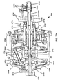
- Figures 1 , 2 , and 3 illustrate an embodiment of a continuously variable transmission 100 that is shrouded in a case 40 which protects the transmission 100, contains lubricant, aligns components of the transmission 100, and absorbs forces of the transmission 100.
- a case cap 67 can, in certain embodiments, cover the case 40.
- the case cap 67 is generally shaped as a disc with a bore, through its center through which an input shaft passes, and that has a set of threads at its outer diameter that thread into a corresponding set of threads on the inner diameter of the case 40.
- the case cap 67 can be fastened to the case 40 or held in place by a snap ring and corresponding groove in the case 40, and would therefore not need to be threaded at its outer diameter.
- the case cap 67 extends to the inside diameter of the case 40 so that case fasteners (not shown) used to bolt the case 40 to the machinery to which the transmission 100 is attached can be passed through corresponding holes in the case cap 67.
- the case cap 67 of the illustrated embodiment has a cylindrical portion extending from an area near its outer diameter toward the output side of the transmission 100 for additional support of other components of the transmission 100.
- a plurality of balls 1 that are typically spherical in shape and are radially distributed substantially evenly or symmetrically about the centerline, or longitudinal axis 11 of rotation of the transmission 100. In the illustrated embodiment, eight balls 1 are used.
- the transmission may include 3, 4, 5, 6, 7, 8, 9, 10, 11, 12, 13, 14, 15 or more balls.
- the provision for more than 3, 4, or 5 balls can more widely distribute the forces exerted on the individual balls 1 and their points of contact with other components of the transmission 100 and can also reduce the force necessary to prevent the transmission 100 from slipping at the ball 1 contact patches.
- Certain embodiments in applications with low torque but a high transmission ratio use few balls 1 of relatively larger diameters, while certain embodiments in applications with high torque and a high transmission ratio can use more balls 1 or relatively larger diameters.
- Other embodiments, in applications with high torque and a low transmission ratio and where high efficiency is not important use more balls 1 of relatively smaller diameters.
- certain embodiments, in applications with low torque and where high efficiency is not important use few balls 1 of relatively smaller diameters.
- Ball axles 3 are inserted through holes that run through the center of each of the balls 1 to define an axis of rotation for each of the balls 1.
- the ball axles 3 are generally elongated shafts over which the balls 1 rotate, and have two ends that extend out of either side of the hole through the balls 1. Certain embodiments have cylindrically shaped ball axles 3, although any shape can be used.
- the balls 1 are mounted to freely rotate about the ball axles 3.
- bearings are utilized to reduce the friction between the outer surface of the ball axles 3 and the surface of the bore through the corresponding ball 1.
- These bearings can be any type of bearings situated anywhere along the contacting surfaces of the balls 1 and their corresponding ball axles 3, and many embodiments will maximize the life and utility of such bearings through standard mechanical principles common in the design of dynamic mechanical systems.
- radial bearings are located at each end of the bore through the balls 1. These bearings can incorporate the inner surface of the bore or the outer surface of the ball axles 3 as their races, or the bearings can include separate races that fit in appropriate cavities formed in the bore of each ball 1 and on each ball axle 3.
- a cavity (not shown) for a bearing is formed by expanding the bore through each ball 1 at least at both ends an appropriate diameter such that a radial bearing, roller, ball or other type, can be fitted into and held within the cavity thus formed.
- the ball axles 3 are coated with a friction reducing material such as babbit, Teflon or other such material.
- Many embodiments also minimize the friction between the ball axles 3 and the balls 1 by introducing lubrication in the bore of the ball axles 3.
- the lubrication can be injected into the bore around the ball axles 3 by a pressure source, or it can be drawn into the bore by the rifling or helical grooves formed on the ball axles 3 themselves. Further discussion of the lubrication of the ball axles 3 is provided below.
- the axes of rotation of the balls 1 are shown tilted in a direction that puts the transmission in a high ratio, wherein the output speed is greater than the input speed. If the ball axles 3 are horizontal, that is parallel to the main axis of the transmission 100, the transmission 100 is in a 1:1 input rotation rate to output rotation rate ratio, wherein the input and output rotation speeds are equal.
- the axes of rotation of the balls 1 are shown tilted in a direction where the transmission 100 is in a low ratio, meaning the output rotation speed is slower than the input rotation speed. For the purpose of simplicity, only the parts that change position or orientation when the transmission 100 is shifted are numbered in Figure 2 .
- Figures 1 , 2 , 4 , and 5 illustrate how the axes of the balls 1 can be tilted in operation to shift the transmission 100.
- a plurality of legs 2 which in most embodiments are generally struts, are attached to the ball axles 3 near each of the ends of the ball axles 3 that extend beyond the ends of the holes bored through the balls 1.
- Each leg 2 extends from its point of attachment to its respective ball axle 3 radially inward toward the axis of the transmission 100.
- each of the legs 2 has a through bore that receives a respective end of one of the ball axles 3.
- the ball axles 3 preferably extend through the legs 2 such that they have an end exposed beyond each leg 2.
- the ball axles 3 advantageously have rollers 4 coaxially and slidingly positioned over the exposed ends of the ball axles 3.
- the rollers 4 are generally cylindrical wheels fitted over the ball axles 3 outside of and beyond the legs 2 and rotate freely about the ball axles 3.
- the rollers 4 can be attached to the ball axles 3 via spring clips or other such mechanism, or they can ride freely over the ball axles 3.
- the rollers 4 can be radial bearings for instance, where the outer races of the bearings form the wheel or rolling surface. As illustrated in Figures 1 and 7 , the rollers 4 and the ends of the ball axles 3 fit inside grooves 86 formed by or in a pair of stators 80a, 80b.
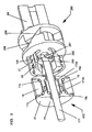
- the stators 80a, 80b of one embodiment are illustrated in Figures 5 and 7 .
- the illustrated input stator 80a and output stator 80b are generally in the form of parallel discs annularly located about the longitudinal axis 11 of the transmission on either side of the balls 1.
- the stators 80a, 80b of many embodiments are comprised of input stator discs 81a and output stator discs 81b, respectively, which are generally annular discs of substantially uniform thickness with multiple apertures to be discussed further below.
- Each input and output stator disc 81a, 81b has a first side that faces the balls 1 and a second side that faces away from the balls 1.
- Multiple stator curves 82 are attached to the first side of the stator discs 81a, 81b.
- the stator curves 82 are curved surfaces attached or affixed to the stator discs 81a, 81b that each have a concave face 90 facing toward the balls 1 and a convex face 91 facing away from the balls 1 and contacting their respective stator discs 81.
- the stator curves 82 are integral with the stator discs 81a, 81b.
- the stator curves 82 of many embodiments have a substantially uniform thickness and have at least one aperture (not separately shown) used to align and attach the stator curves 82 to each other and to the stator discs 81.
- the stator curves 82 of many embodiments, or the stator discs 81a, 81b where integral parts are used, include a slot 710 that accepts a flat spacer 83, which allows further positioning and alignment of the stator curves 82 and stator discs 81a, 81b.
- the flat spacers 83 are generally flat and generally rectangular pieces of rigid material that extend between and interconnect the input stator 80a and the output stator 80b.
- the flat spacers 83 fit within the slots 710 formed in the stator curves 82.
- the flat spacers 83 are not fastened or otherwise connected to the stator curves 82, however, in some embodiments the flat spacers 83 are attached to the stator curves 82 by welding, adhesive, or fastening.
- multiple cylindrical spacers 84 of a generally cylindrical shape with bores at least in each end, are radially positioned inside of the flat spacers 83 and also connect and position the stator discs 81 and stator curves 82.
- the bores of the cylindrical spacers 84 accept one spacer fastener 85 at each end.
- the spacer fasteners 85 are designed to clamp and hold the stator discs 81a, 81b, the stator curves 82, the flat spacers 83, and the cylindrical spacers 84 together, which collectively form the cage 89.
- the cage 89 maintains the radial and angular positions of the balls 1 and aligns the balls 1 with respect to one another.
- each roller 4 fits into and follows a groove 86, which is slightly larger than the diameter of the roller 4, and is formed by the space between each pair of adjacent stator curves 82.
- the rollers 4 therefore roll along the surface of the sides 92, 93 of the stator curves 82, a first side 92 and a second side 93 for each stator curve 82, in order to maintain the plane of movement of the ball axles 3 in line with the longitudinal axis 11 of the transmission 100.
- each roller 4 rolls on a first side 92 of the stator curve 82 on the input side of the transmission 100 and on the corresponding first side 92 of the corresponding output stator curve 82.
- the forces of the transmission 100 prevent the rollers 4 from contacting the second side 93 of the stator curves 82 in normal operation.
- the rollers 4 are slightly smaller in diameter than the width of the grooves 86 formed between the stator curves 82, forming a small gap between the edges of the grooves 86 and the circumference of each corresponding roller.
- stator curves 82 on the input stator 80a and output stator 80b were in perfect alignment, the small gap between the circumferences of the rollers 4 and the grooves 86 would allow the ball axles to slightly tilt and become misaligned with the longitudinal axis 11 of the transmission 100. This condition produces sideslip, a situation where the balls axles 3 are allowed to slightly move laterally, which lowers overall transmission efficiency.
- the stator curves 82 on the input and output sides of the transmission 100 may be slightly offset from each other so that the ball axles 3 remain parallel with the axis of the transmission 100.
- the transmission 100 is shifted to a lower or higher transmission ratio by changing the rotational axes of the balls 1, each one of the pairs of rollers 4, located on the opposite ends of a single ball axle 3, move in opposite directions along their respective corresponding grooves 86 by rolling up or down a respective side of the groove 86.
- the cage 89 can be rigidly attached to the case 40 with one or more case connectors 160.
- the case connectors 160 extend generally perpendicularly from the radial outermost part of the flat spacers 83.
- the case connectors 160 can be fastened to the flat spacers 83 or can be formed integrally with the flat spacers 83.
- the outside diameter formed roughly by the outsides of the case connectors 160 is substantially the same dimension as the inside diameter of the case 40 and holes in both the case 40 and case connectors 160 provide for the use of standard or specialty fasteners, which rigidly attach the case connectors 160 to the case 40, thus bracing and preventing the cage 40 from moving.
- the case 40 has mounting holes providing for the attachment of the case 40 to a frame or other structural body.
- the case connectors 160 can be formed as part of the case 40 and provide a location for attachment of the flat spacers 83 or other cage 89 component in order to mobilize the cage 89.
- FIGS 1 , 5 , and 7 illustrate an embodiment including a pair of stator wheels 30 attached to each of the legs 2 that roll on the concave face 90 of the curved surfaces 82 along a path near the edge of the sides 92, 93.
- the stator wheels 30 are attached to the legs 2 generally in the area where the ball axles 3 pass through the legs 2.
- the stator wheels 30 can be attached to the legs 2 with stator wheel pins 31, which pass through a bore through the legs 2 that is generally perpendicular to the ball axles 3, or by any other attachment method.
- the stator wheels 30 are coaxially and slidingly mounted over the stator wheel pins 31 and secured with standard fasteners, such as snap rings for example.
- the stator wheels 30 are radial bearings with the inner race mounted to the stator wheel pins 31 and the outer race forming the rolling surface.
- one stator wheel 30 is positioned on each side of a leg 2 with enough clearance from the leg 2 to allow the stator wheels 30 to roll radially along the concave faces 90, with respect to the longitudinal axis 11 of the transmission 100, when the transmission 100 is shifted.
- the concave faces 90 are shaped such that they are concentric about a radius from the longitudinal axis 11 of the transmission 100 formed by the center of the balls 1.
- guide wheels 21 are illustrated that can be attached to the end of the legs 2 that are nearest the longitudinal axis 11 of the transmission 100.
- the guide wheels 21 are inserted into a slot formed in the end of the legs 2.
- the guide wheels 21 are held in place in the slots of the legs 21 with guide wheel pins 22, or by any other attachment method.
- the guide wheels 21 are coaxially and slidingly mounted over the guide wheel pins 22, which are inserted into bores formed in the legs 2 on each side of the guide wheels 21 and perpendicular to the plane of the slot.
- the legs 2 are designed to elastically deflect relatively slightly in order to allow for manufacturing tolerances of the parts of the transmission 100.
- the ball 1, the legs 2, the ball axle 3, the rollers 4, the stator wheels 30, the stator wheel pins 31, the guide wheels 21, and the guide wheel pins 22 collectively form the ball/leg assembly 403 seen in Figure 5 .
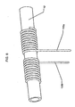
- shifting is actuated by rotating a rod 10 that is positioned outside of the case 40.
- the rod 10 is utilized to wrap an unwrap a flexible input cable 155a and a flexible output cable 155b that are attached to, at their respective first ends, and wrapped around the rod 10, in opposite respective directions.
- the input cable 155a is wrapped counter-clockwise around the rod 10 and the output cable 155b is wrapped clockwise around the rod 10, when looking from right to left as the rod 10 is illustrated in Figure 6 .
- Both the input cable 155a and the output cable 155b extend through holes in the case 40 and then through the first end of an input flexible cable housing 151a, and an output flexible cable housing 151b.
- the input flexible cable housing 151a and the output flexible cable housing 151b of the illustrated embodiment are flexible elongated tubes that guide the input cable 155a and output cable 155b radially inward toward the longitudinal axis 11 then longitudinally out through holes in the stator discs 81a, b and then again radially inward where the second end of the input and output flexible cable housings 151a, b are inserted into and attach to the first end of input and output rigid cable housings 153a, b, respectively.
- the input and output rigid cable housings 153a, b are inflexible tubes through which the cables 155a, b, pass and are guided radially inward from the second ends of the flexible cable housings 151a, b and then direct the cables 155a, b longitudinally through holes in the stator discs 81a, b and toward a second end of the rigid cable housings 153a, b near the idler 18.
- the cables 155a, b are attached at their second ends to an input shift guide 13a, and an output shift guide 13b (described further below) with conventional cable fasteners, or other suitable attachment means.
- the shift guides 13a, 13b position the idler 18 axially along the longitudinal axis 11 and position the legs 3 radially, thereby changing the axes of the balls 1 and the ratio of the transmission 100.
- the input cable 155a unwinds from the rod 10 and the output cable 155b winds onto the rod 10. Therefore, the second end of the output cable 155b applies a tension force to the output shift guide 13b and the input cable 155a is unwinding a commensurate amount from the rod 10. This moves the idler 18 axially toward the output side of the transmission 100 and shifts the transmission 100 toward low.
- the illustrated shift guides 13a, b are each generally of the form of an annular ring with inside and outside diameters, and are shaped so as to have two sides.
- the first side is a generally straight surface that dynamically contacts and axially supports the idler 18 via two sets of idler bearings 17a, 17b, which are each associated with a respective shift guide 13a, b.
- the second side of each shift guide 13a, b, the side facing away from the idler 18, is a cam side that transitions from a straight or flat radial surface 14, towards the inner diameter of the shift guides 13a, b, to a convex curve 97 towards the outer diameter of the shift guides 13a, b.
- a longitudinal tubular sleeve 417a, b extends axially toward the opposing shift guide 13a, b in order to mate with the tubular sleeve 417a, b from that shift guide 13a, b.
- the tubular sleeve of the input side shift guide 13a has part of its inner diameter bored out to accept the tubular sleeve of the output shift guide 13b.
- the cross section side view of the shift guides 13a, b illustrated in Figure 4 shows that, in this embodiment, the flat surface 14 profile of the side facing away from the is perpendicular to the longitudinal axis 11 up to a radial point where the guide wheels 21 contact the shift guides 13 a, b, if the ball axles 3 are parallel with the longitudinal axis 11 of the transmission 100. From this point moving out toward the perimeter of the shift guide 13a, b the profile of the shift guides 13a, b curves in a convex shape.
- the convex curve 97 of a shift guide 13a, b is not a radius but is composed of multiple radii, or is shaped hyperbolically, asymptotically or otherwise.
- the shift guides 13a, b can be attached to each other by either threading the tubular sleeve of the input shift guide 13a with male threads and the tubular sleeve of the output sleeve 13b with female threads, or vice versa, and threading the shift guides 13a, b, together.
- One shift guide 13a, b, either the input or output, can also be pressed into the other shift guide 13a, b.
- the shift guides 13 a, b can also be attached by other methods such as glue, metal adhesive, welding or any other means.
- the convex curves 97 of the two shift guides 13a, b act as cam surfaces, each contacting and pushing the multiple guide wheels 21.
- the flat surface 14 and convex curve 97 of each shift guide 13a, b contact the guide wheels 21 so that as the shift guides 13 a, b, move axially along the longitudinal axis 11, the guide wheels 21 ride along the shift guide 13a, b surface 14, 97 in a generally radial direction forcing the leg 2 radially out from, or in toward, the longitudinal axis 11, thereby changing the angle of the ball axle 3 and the rotational axis of the associated ball 1.
- the idler 18 of some embodiments is located in a trough formed between the first sides and the sleeve portions of the shift guides 13 a, b, and thus moves in unison with the shift guides 13a, b.
- the idler 18 is generally tubular and of one outside diameter and is substantially cylindrical along the central portion of its inside diameter with an input and output idler bearing 17a, b, on each end of its inside diameter.
- the outer diameter and inside diameters of the idler 18 can be non-uniform and can vary or be any shape, such as ramped or curved.
- the idler 18 has two sides, one near the input stator 80a, and one near the output stator 80b.
- the idler bearings 17a, 17b provide rolling contact between the idler 18 and the shift guides 13a, b.
- the idler bearings 17a, 17b are located coaxially around the sleeve portion of the shift guides 13a, b, allowing the idler 18 to freely rotate about the axis of the transmission 100.
- a sleeve 19 is fit around the longitudinal axis 11 of the transmission 100 and fitting inside the inside diameters of the shift guides 13a, b.
- the sleeve 19 is a generally tubular component that is held in operable contact with an inside bearing race surface of each of the shift guides 13a, b by an input sleeve bearing 172a and an output sleeve bearing 172b.
- the sleeve bearings 172a, b provide for rotation of the sleeve 19 by rolling along an outer bearing race complimentary to the races of the shift guides 13a, b.
- the idler 18, the idler bearings 17a, 17b, the sleeve 19, the shift guides 13a, 13b, and the sleeve bearings 172a, 172b collectively form the idler assembly 402, seen in Figure 4 .
- the sleeve 19 of some embodiments has its inside diameter threaded to accept the threaded insertion of an idler rod 171.
- the idler rod 171 is a generally cylindrical rod that lies along the longitudinal axis 11 of the transmission 100. In some embodiments, the idler rod 171 is threaded at least partially along its length to allow insertion into the sleeve 19.
- the first end of the idler rod 171, which faces the output side of the transmission 100, is preferably threaded through the sleeve 19 and extends out past the output side of the sleeve 19 where it is inserted into the inside diameter of the output disc 101.
- the output disc 101 in some embodiments is generally a conical disc that is spoked to reduce weight and has a tubular sleeve portion extending from its inner diameter axially toward the output side of the transmission 100.
- the output disc 101 transfers the output torque to a drive shaft, wheel, or other mechanical device.
- the output disc 101 contacts the balls 1 on their output side and rotates at a speed different than the input rotation of the transmission at ratios other than 1:1.
- the output disc 101 serves to guide and center the idler rod 171 at its first end so that the sleeve 19, idler 18, and shift guides 13a, b stay concentric with the axis of the transmission 100.
- annular bearing may be positioned over the idler rod 171, between the idler rod 171 and the inside diameter of the output disc 101, to minimize friction.
- the idler rod 171, sleeve 19, shift guides 13a, b, and idler 18 are operably connected, and all move axially in unison when the transmission 100 is shifted.
- a conical spring 133 positioned between the input shift guide 13a and stator 80a biases the shifting of the transmission 100 toward low.
- output disc bearings 102 which contact a bearing race near the perimeter of the output disc 101, absorb and transfer axial force generated by the transmission 100 to the case 40.
- the case 40 has a corresponding bearing race to guide the output disc bearings 102.
- the limits of the axial movement of the shift guides 13a, b define the shifting range of the transmission 100.
- Axial movement is limited by inside faces 88a, b, on the stator discs 81a, b, which the shift guides 13a, b, contact.
- shift guide 13a contacts the inside face 88a on the input stator discs 81a
- the shift guide 13b contacts the inside face 88 on the output stator disc 81b.
- the curvature of the convex curves 97 of the shift guides 13a, b is functionally dependent on the distance from the center of a ball 1 to the center of the guide wheel 21, the radius of the guide wheel 21, the angle between lines formed between the two guide wheels 21 and the center of the ball 1, and the angle of tilt of the ball 1 axis.
- An example of such a relationship is described below, with respect to Figures 25, 26 and 27 .
- one or more stator wheels 30 can be attached to each leg 2 with a stator wheel pin 31 that is inserted through a hole in each leg 2.
- the stator wheel pins 31 are of the proper size and design to allow the stator wheels 30 to rotate freely over each stator wheel pin 31.
- the stator wheels 30 roll along the concave curved surfaces 90 of the stator curves 82 that face the balls 1.
- the stator wheels 30 provide axial support to prevent the legs 2 from moving axially and also to ensure that the ball axles 3 tilt easily when the transmission 100 is shifted.
- a spoked input disc 34 located adjacent to the stator 80a, partially encapsulates but generally does not contact the stator 80a.
- the input disc 34 may have two or more spokes or may be a solid disc. The spokes reduce weight and aid in assembly of the transmission 100. In other embodiments a solid disc can be used.
- the input disc 34 has two sides, a first side that contacts with the balls 1, and a second side that faces opposite the first side.
- the input disc 34 is generally an annular disk that fits coaxially over, and extends radially from, a set of female threads or nut 37 at its inner diameter.
- the outside diameter of the input disc 34 is designed to fit within the case 40, if the case 40 used is the type that encapsulates the balls 1 and the input disc 34 and mounts to a rigid support structure 116 such as a chassis or frame with conventional bolts, which are inserted through bolt holes in a flange on the case 40.
- the input disc 34 is in rotating contact with the balls 1 along a circumferential ramped or bearing contact surface on a lip of the first side of the input disc 34, the side facing the balls 1.
- some embodiments of the input disc 34 have a set of female threads 37, or a nut 37, inserted into its inside diameter, and the nut 37 is threaded over a screw 35, thereby engaging the input disc 34 with the screw 35.
- the screw 35 is attached to and rotated by a drive shaft 69.
- the drive shaft 69 is generally cylindrical and has an inner bore, a first end facing axially towards the output side, a second end facing axially toward the input side, and a generally constant diameter.
- the drive shaft 69 is rigidly attached to and rotated by the input torque device, usually a gear, a sprocket, or a crankshaft from a motor.
- the drive shaft 69 has axial splines 109 extending from its second end to engage and rotate a corresponding set of splines formed on the inside diameter of the screw 35.
- a set of central drive shaft ramps 99 which on a first side is generally a set of raised inclined surfaces on an annular disk that is positioned coaxially over the drive shaft 69, have mating prongs that mate with the splines 109 on the drive shaft 99, are rotated by the drive shaft 69, and are capable of moving axially along the drive shaft 69.
- a pin ring 195 contacts a second side of the central drive shaft ramps 99.
- the pin ring 195 is a rigid ring that is coaxially positioned over the idler rod 171, is capable of axial movement and has a transverse bore that functions to hold an idler pin 196 in alignment with the idler rod 171.
- the idler pin 196 is an elongated rigid rod that is slightly longer than the diameter of the pin ring 195 and which is inserted through an elongated slot 173 in the idler rod 171 and extends slightly beyond the pin ring 195 at both its first and second ends when it is inserted into the bore of the pin ring 195.
- the elongated slot 173 in the idler rod 171 allows for axial movement of the idler rod 171 to the right, when viewed as illustrated in Figure 1 , without contacting the pin 196 when the transmission 100 is shifted from 1:1 toward high.
- the idler rod 171 is thus operably connected to the central drive shaft ramps 99 when the transmission is between 1:1 and low so that when the idler rod 171 moves axially the central drive shaft ramps 99 also move axially in conjunction with the idler rod 171.
- the ramp surfaces of the central drive shaft ramps 99 can be helical, curved, linear, or any other shape, and are in operable contact with a set of corresponding central bearing disc ramps 98.
- the central bearing disc ramps 98 have ramp faces that are complimentary to and oppose the central drive shaft ramps 99. On a first side, facing the output side of the transmission 100, the central bearing disc ramps 98 face the central drive shaft ramps 99 and are contacted and driven by the central drive shaft ramps 99.
- the central bearing disc ramps 98 are rigidly attached to a bearing disc 60, a generally annular disc positioned to rotate coaxially about the longitudinal axis 11 of the transmission 100.
- the bearing disc 60 has a bearing race near its perimeter on its side that faces away from the balls 1 that contacts a bearing disc bearing 66.
- the bearing disc bearing 66 is an annular thrust bearing at the perimeter of the bearing disc 60 and is positioned between the bearing disc 60 and the input disc 34.
- the bearing disc bearing 66 provides axial and radial support for the bearing disc 60 and in turn is supported by a bearing race on a case cap 67, which acts with the case 40 to partially encapsulate the inner parts of the transmission 100.
- the case cap 67 is generally an annular disc extending from the drive shaft 69 having a tubular portion extending toward the output end from at or near its perimeter and also having a bore through its center.
- the case cap 67 absorbs axial and radial forces produced by the transmission 100, and seals the transmission 100, thereby preventing lubricant from escaping and contamination from entering.
- the case cap 67 is stationary and, in some embodiments, is rigidly attached to the case 40 with conventional fastening methods or can have male threads on its outside diameter, which mate with corresponding female threads on the inside diameter of the case 40.
- the case cap 67 has a bearing race that contacts the bearing disc bearing 66 near the perimeter of the bearing disc 60 that is located at the inside of the output end of the tubular extension from the case cap 67.
- the case cap 67 also has a second bearing race facing the output side located near the inside diameter of its annular portion that mates with a drive shaft bearing 104.
- the drive shaft bearing 104 is a combination thrust and radial bearing that provides axial and radial support to the drive shaft 69.
- the drive shaft 67 has a bearing race formed on its outside diameter facing the input side that mates with the drive shaft bearing 104, which transfers the axial force produced by the screw 35 to the case cap 67.
- An input bearing 105 adds support to the drive shaft 69.
- the input bearing 105 is coaxially positioned over the drive shaft 69 and mates with a third race on the inside diameter of the case cap 67 facing the input side of the transmission 100.
- a cone nut 106 a generally cylindrical threaded nut with a bearing race designed to provide a running surface for the input bearing 105, is threaded over the drive shaft 69 and supports the input bearing 105.
- a set of multiple perimeter ramps 61 are rigidly attached to the bearing disc 60.
- the perimeter ramps 61 are multiple inclined surfaces that are positioned radially about the longitudinal axis 11 and are positioned against or formed on the bearing disc 60 and face the output side.
- the inclined surfaces can be curved, helical, linear, or another shape and each one creates a wedge that produces and axial force that is applied to one of multiple ramp bearings 62.
- the ramp bearings 62 are spherical but can be cylindrical, conical, or another geometric shape, and are housed in a bearing cage 63.
- the bearing cage 63 of the illustrated embodiment is generally ring shaped with multiple apertures that contain the individual ramp bearings 62.
- a set of input disc ramps 64 are rigidly attached to, or formed as part of, the input disc 34.
- the input disc ramps 64 in some embodiments are complimentary to the perimeter ramps 62 with the ramps facing toward the input side.
- the input disc ramps 64 are in the form of a bearing race that aligns and centers the ramp bearings 62 radially.
- the ramp bearings 62 respond to variations in torque by rolling up or down the inclined faces of the perimeter ramps 61 and the input disc ramps 64.
- an axial force generator 160 is made up of various components that create an axial force that is generated and is applied to the input disc 34 to increase the normal contact force between the input disc 34 and the balls1, which is a component in the friction the input disc 34 utilizes in rotating the balls 1.
- the transmission 100 produces sufficient axial force so that the input disc 34, the balls 1, and the output disc 101 do not slip, or slip only an acceptable amount, at their contact points.
- an appropriate amount of additional axial force is required to prevent slippage.
- more axial force is required to prevent slippage in low than in high or at a 1:1 speed ratio.
- the axial force generator 160 will vary the axial force applied to the balls 1 as the transmission 100 is shifted and also as torque is varied. In some embodiments, the transmission 100 accomplishes both these goals.
- the screw 35 is designed and configured to provide an axial force that is separate and distinct from that produced by the perimeter ramps 61. In some embodiments the screw 35 produces less axial force than the perimeter ramps 61, although in other versions of the transmission 100, the screw 35 is configured to produce more force than the perimeter ramps 61.
- the screw 35 Upon an increase in torque, the screw 35 rotates slightly farther into the nut 37 to increase axial force by an amount proportional to the increase in torque.
- the idler rod 171 moves axially toward the input side, along with the sleeve 19, sleeve bearings 172, shift guides 13a, b, and idler 18.
- the idler rod 171 contacts the central drive shaft ramps 99 through the pin 196 and pin ring 195, causing the central drive shaft ramps 99 to move axially toward the output side.
- the ramped surfaces of the central drive shaft ramps 99 contact the opposing ramped surfaces of the central bearing disc ramps 98, causing the central bearing disc ramps 98 to rotate the bearing disc 67 and engage the perimeter ramps 61 with the ramp bearings 62 and the input disc ramps 64.
- the central drive shaft ramps 99 and the central bearing disc ramps 98 perform a torque splitting function, shifting some of the torque from the screw 35 to the perimeter ramps 61. This increases the percentage of transmitted torque that is directed through the perimeter ramps 61, and due to the fact the perimeter ramps 61 are torque sensitive as described above, the amount of axial force that is generated increases.
- the legs 2 attached to the ball axles 3 transfer the pull to the shift guides 13a, b, and because the shift guides 13a, b, are operably attached to the idler 18 and sleeve 19, an axial force is transferred to the idler rod 171.
- the influence of contact spin increases at all ratios and efficiency decreases.
- a latch 115 rigidly attaches to the side of the input disc 34 that faces the bearing disk 60 and engages a hook 114 that is rigidly attached to a first of two ends of a hook lever 113.
- the hook lever 113 is an elongated strut with the hook 114 at its first end and a hook hinge 116 at its second end.
- the latch 115 has an engaging area or an opening that is larger than the width of the hook 114 and provides extra room for the hook 114 to move radially, with respect to the longitudinal axis 11, within the confines of the latch 114 when the input disc 34 and the bearing disk 60 move relative to each other.
- the hood hinge 116 engages a middle hinge 119 and forms a hinge joint with a first hinge pin 111.
- the middle hinge 119 is integral with a first end of an input disc lever 112, which is a generally elongated strut having two ends.
- the input disc lever 112 On its second end, the input disc lever 112 has an input disc hinge 117, which engages a hinge brace 110 via the use of a second hinge pin 118.
- the hinge brace 110 is generally a base to support the hook 114, the hook lever 113, the hook hinge 116, the first hinge pin 111, the middle hinge 119, the input disc lever 112, the second hinge pin 118, and the input disc hinge 117, and it is rigidly attached to the bearing disc 60 on the side facing the input disc 34.
- a preloader 123 is attached at a first end to the drive shaft 69 and extends radially outward. At a second end the preloader contacts the input disc lever 112, biasing the input disc 34 away from the balls 1, so that on occasions when the input disc 34 disengages from the balls 1, it is biased to remain disconnected.
- the illustrated axial force generator includes one or more reversing levers 261.
- the reversing levers 261 are generally flat, irregularly shaped cam pieces each having an off-center mounted pivot hole with a first side radially inward of the pivot hole and a second side radially outside of the pivot hole. The first side of the reversing levers 261 each fit into the elongated slot 173 in the idler rod 171.
- the reversing levers 261 can be designed to decrease the distance that they move axially toward the input side and increase the force they produce.
- the reversing levers 261 can be designed in this manner to create a mechanical advantage to adjust the axial force that they produce.
- the reversing levers 261 At their second sides, the reversing levers 261 each contact the output side of the central screw ramps 298 when the transmission 100 is shifted toward low.
- the reversing levers 261 are each attached to a lever ring 263 by the reversing pins 262, which can be pressed or threaded into holes in the lever ring 263 to hold the reversing levers 261 in position.
- the lever ring 263 is a ring shaped device that fits around, and slides axially along, the idler rod 171 and has one or more rectangular slots cut through it to allow for insertion and positioning of the reversing levers 261.
- a set of central screw ramps 299 is rigidly attached to and can be rotated by the screw 35.
- the central screw ramps 299 of this embodiment are similar to the central screw ramps 99 illustrated in Figure 4 , in that the central screw ramps 299 are formed as ramps on the second side of a disc having a first side facing the output side and a second side facing the input side. As the transmission 100 is shifted toward low, the second side of the reversing levers 261 pushes against the first side of the central screw ramps 299.
- the central screw ramps 299 which are splined to the drive shaft 69 via the above-described spline 109, are rotated by the drive shaft 69, are capable of axial movement along the longitudinal axis 11, and are similar to the central drive shaft ramps 99 of the previous embodiment, except that the central screw ramps 299 face the input side of the transmission 100 rather than the output side.
- the central screw ramps 299 contact an opposing set of central bearing disc ramps 298, which are free to rotate relative to the drive shaft 69 and are similar to the central bearing disc ramps 98 illustrated in Figure 4 , except that the central bearing disc ramps 298 face the output side of the transmission 100 rather than the input side.
- FIG. 10 a cutaway side view of an alternative embodiment of the transmission 100 of Figure 1 is disclosed.
- the transmission 300 has an alternative cage 389, an alternative disengagement mechanism, and an alternative axial force generator.
- the conical spring 133 is moved to the output side of the transmission 300, biasing the shifting toward high.
- the cage 389 includes input and output stator discs 381a, b, however for ease of viewing, the output stator disc 381b has been removed.
- the output stator 381b of many embodiments is structurally similar to the input stator 381a.
- Multiple stator curves 382 are attached to the stator discs 381a, b and have first sides facing the balls 1 and second sides facing away from the balls 1.
- the second side 391 of each of the stator curves 382 is a flat surface that lays flat against a respective one of the stator discs 181a, b.
- the stator curves 382 have two through holes that are used to attach the stator curves 382 to the stator discs 381a, b with conventional fasteners or other type of attachment mechanism.
- the stator curves 382 have on each of their first sides a rectangular slot into which multiple flat spacers 383 are inserted to connect the stators 381.
- the flat spacers 383 serve to set the distance between the stators 381, create a strong connection between the stators 381, and ensure that the stators 381 are parallel and in alignment.
- the illustrated design incorporates a stator disc 181 that is substantially flat. Therefore, the stator discs 181 can be manufactured utilizing a substantially flat sheet of rigid material.
- the stator discs 181 can be produced from any of a number of inexpensive manufacturing techniques such as stamping, fine blanking, or any other such technique known in the industry.
- the stator discs 181 of this design can be made from thin or sheet metal, plastic, ceramic, wood or paper products or any other material.
- the illustrated design allows for significant reduction in the cost of materials and manufacturing of these otherwise relatively expensive components to a suitably high tolerance.
- an alternative axial force generator includes a generally conical wedge 360 that is positioned and is capable of axial movement along the central axis of the transmission 300.
- the conical wedge 360 is also mated with the spline 109.
- AFG axial force generator
- the AFG lever 362 is a generally elongated part having a first semi-circular end that engages the conical wedge 360 and then extends radially outward from the longitudinal axis 11 to a second end that engages the input disc lever 112.
- the AFG lever 362 is attached to the spline 109 with a fulcrum pin 361 about which the AFG lever 362 rotates.
- the fulcrum pin 361 provides for pivoting of the AFG lever 362 so that the second end of the AFG lever 362 engages the input disc lever 112.
- the input disc lever 112 is operably attached to the bearing disc 60 and rotates the bearing disc 60 so that the perimeter ramps 61 engage, thus shifting input torque from the screw 35 to the perimeter ramps 61.
- the operation of the alternative axial force generator 360 is otherwise the same as the axial force generator previously described and seen in Figures 1 and 4 .
- the transmission 100 of Figure 1 includes one variator.
- the term variator can be used to describe the components of the transmission 100 that vary the input to output speed ratio.
- the assemblies and components comprising the variator 401 of the present embodiment include the ball/leg assembly 403 of Figure 5 , the input disc 34, the output disc 101, the idler assembly 402 of Figure 4 , and the cage 89 of Figure 7 . It should be noted that all components and assemblies of the variator 401 can change to best fit the specific application of the transmission 1700, and in Figure 13 generic forms of the assemblies and components comprising the variator 401 are depicted.
- the embodiment of the transmission 1700 illustrated in Figure 14 is similar to the transmission 100 of but includes two variators 401.
- This configuration is beneficial for applications where high torque capacity is required in a transmission 1700 with a small diameter or overall size.
- This configuration also eliminates radial bearings needed to support the bearing disc 114 and the output disc 101, thereby increasing overall efficiency.
- the convention or marking like components with an "a" and a "b" to differentiate between the input and output sides is not used.
- the input side is to the right and the input is to the left.
- a case 423 that surrounds and encapsulates the transmission 1700.
- the case 423 is generally cylindrical and protects the transmission 1700 from outside elements and contamination and additionally contains lubrication for proper operation.
- the case 423 is attached to an engine, frame, or other rigid body (not shown) with standard fasteners (not shown), which fit through case holes 424.
- the case 423 is open on the input side, the side with the case holes 424 or to the right as illustrated, to accept an input torque.
- Input torque is transmitted from an outside source to an input shaft 425, which is a long, rigid, rod or shaft capable of transmitting torque.
- the input shaft 425 transmits torque to a bearing disc 428 via splines, keying, or other such manner.
- the bearing disc 428 is a disc-shaped rigid component capable of absorbing significant axial forces produced by the transmission 1700 and is similar in design to the bearing disc 60 illustrated in Figure 1 .
- An input shaft bearing 426 is positioned coaxially over the input shaft 425 between a flange 429 on the input end of the input shaft 425 and the bearing disc 428 to allow a small amount of relative movement between the bearing disc 428 and the input shaft 425.
- the bearing disc 429 begins rotating, the perimeter ramps 61, ramp bearings 62, bearing cage 63, input disc ramps 64, and input disc 34 rotate as previously described. This rotates the balls 1 in the first variator 420, is the one on the input side.
- a second input disc 431 is rotated.
- the second input disc 431 is rigidly attached to the input shaft 425, and can be keyed with a backing nut, pressed over the input shaft 425, welded, pinned, or attached by other methods.
- the second input disc 431 is located on the output side of the transmission 1700, opposite the bearing disc 428.
- the second input disc 431 and the bearing disc 428 absorb the considerable axial forces created by the perimeter ramps 61, ramp bearings 62, and input disc ramps 64 that act as normal forces to prevent slippage at the ball/disc contact patches as previously described.
- the second input disc 431 is similar in shape to the input disc 34 previously described and upon rotation of the input shaft 425; it rotates the balls 1 in the second variator 422.
- the second variator 422 is generally a mirror image of the first variator 420 and is positioned farther from the input side of the transmission 1700 so that the first variator 420 is situated between it and the input side.
- the balls 1 in the first variator 420 rotate the output disc 430 through their rolling contact with that component.
- the output disc 430 although serving the same function as the output disc 101 previously described, has two opposing contact surfaces and contacts balls 1 on both variators 420, 422. From the cross sectional view illustrated in Figure 14 , the output disc 430 can be shaped in a shallow arch or upside down shallow "V," the ends of which have a contact surface to contact the balls 1 of the two variators 420, 422.
- the output disc 430 surrounds the second variator 422 and extends toward the output side in a generally cylindrical shape.
- the cylindrical shape of the output disc 430 continues toward the output side of the transmission 1700 surrounding the second input disc 431 after which the diameter of the output disc 430 decreases and then again becomes a generally cylindrical shape of a smaller diameter as it exits the case 423.
- annular bearings 434, 435 may be used to radially align the output disc 431.
- a case bearing 434 is positioned in the bore of the case 423 and over the output disc 430 and an output disc bearing 435 is positioned in the bore of the output disc 430 and over the input shaft 425 to provide additional support.
- the output disc 430 can be made of two pieces that are connected together to form the illustrated output disc 430. This allows for assembly of the second variator 422 inside the cylindrical shell of the output disc 430.
- the ball axles 433 of the transmission 1700 are similar to the ball axles 3 previously described and perform the same function.
- the ball axles 433 serve as the mechanism by which the balls 1 are tilted to vary the speed ratio of the transmission 1700.
- the ball axles 433 are elongated on each of their respective output sides and extend through the walls of the output stators 435.
- the output stators 435 are similar to the output stators 80b previously described, but the multiple radial grooves 436 penetrate all the way through the walls of the output stators 435.
- the grooves 436 of the output stators 435 continue all the way through the output stator 435 walls so that a series of equally spaced radial grooves 436 extend radially from near the bore at the center of the output stator 435 to the perimeter.
- the ball axles 433 have iris rollers 407 positioned coaxially over their elongated output ends.
- the iris rollers 407 are generally cylindrical wheels that are capable of rotating over the ball axles 433 and are designed to fit inside the grooves of an iris plate 409.
- the iris plate 409 is an annular disc or plate with a bore through its center that fits coaxially about the longitudinal axis 11 of the transmission 1700.
- the iris plate 409 is of a thickness that is greater than twice the thickness of each iris roller 407 and has a number of iris grooves extending radially outward from near the bore to near the perimeter of the iris plate 409. As the iris grooves extend radially, their angular position changes as well, so that as the iris plate 409 is rotated angularly about the longitudinal axis 11, the iris grooves provide a camming function along their respective lengths. In other words, the grooves spiral out from near the bore in the center of the iris plate 409 to respective points near its perimeter.
- the iris rollers 407 are radiused along their outside diameters, or have fillets on their outer corners, so that their diameters remain unchanged inside the grooves of the iris plate 409 when the ball axles 433 are tilted.
- the iris plate 409 is of a thickness sufficient to allow iris rollers 407 from both variators 420, 422, to remain inside the grooves of the iris plate 433 at all shifting ratios.
- the iris grooves operate in traditional iris plate fashion and cause the ball axles 433 to move radially inward or outward when the iris plate 409 is rotated.
- the iris plate 409 has a first side facing the first variator and a second side facing the second variator and is coaxially positioned about the longitudinal axis 11 of the transmission 1700 and over abutting bosses on, tubular extensions extending from, the two output stators 435.
- the two output stators 435 can be attached to each other with conventional fasteners through axial holes (not illustrated) in the bosses of the output stators 435.
- the output stator 435 bosses have a hole through their centers and multiple holes positioned radially outward from the center.
- the bosses on the output stators 435 form a space slightly wider than the iris plate 409 to provide freedom of rotation for the iris plate 433 and some embodiments utilize bearings between the bosses and the iris plate 409 to accurately control the position of the iris plate 409 between the output stators 435.
- An iris cable 406 is attached to the first side of the iris plate 409 near the outside diameter of the iris plate 409 and extends longitudinally from the point of connection. The iris cable 406 is routed through the output stator 435 of the first variator 420 in an orientation so that when it is pulled, it rotates the iris plate 409.
- the iris cable 406, after passing through an aperture near the perimeter of the output stator 435 is routed through the case 423 to the outside of the transmission 1700 where it allows for control of the transmission ratio.
- An iris spring 408 is attached to the second side of the iris plate 409 near its outside diameter.
- the iris spring 408 is also attached to the output stator 435 of the second variator 422.
- the iris spring 408 applies a resilient force that resists rotation of the iris plate 409 from tension applied by the iris cable 406. When tension from the iris cable 406 is released, the iris spring 408 returns the iris plate 409 to its at rest position.
- the iris plate 409 can be configured so that when the iris cable 406 is pulled the iris plate 409 shifts the transmission 1700 to a higher transmission ratio, and when tension on the iris cable 406 is released the iris spring 408 shifts the transmission 1700 to a low ratio.
- the iris plate 409 can be configured so that when the iris cable 406 is pulled the iris plate 409 shifts the transmission 1700 to a lower ratio, and when tension on the iris cable 406 is released the iris spring 408 shifts the transmission 1700 to a high ratio.
- embodiments of the transmission 1700 having two variators 420, 422 require a high degree of accuracy in the alignment of the additional rolling elements of the transmission 1700. All of the rolling elements must be aligned with one another or efficiency will suffer and the lifespan of the transmission 1700 will be reduced.
- the input disc 34, the output disc 430, the second input disc 431, and the idler assemblies 402 are aligned on the same longitudinal axis.
- the cage 410 which in these embodiments consist of two cages 89 joined by the output stators 435 as previously described, must also be aligned on the longitudinal axis to accurately position the ball/leg assemblies 403. To accomplish this simply and accurately, all rolling elements are positioned relative to the input shaft 425.
- a first input stator bearing 440 and a second input stator bearing 444 are positioned in the bores of the input stators 440, 444 and over the input shaft 425 to help align the cage 410.
- An output stator bearing 442 positioned in the bore of the output stators 435 and over the input shaft 425 also aligns the cage 410.
- a first guide bearing 441 is positioned in the bore of the first shift guide 13b and over the input shaft 425 and a second guide bearing 443 is positioned in the bore of the second shift guide 13b and over the input shaft 425 to align the first and second idler assemblies 402.
- the cage 410 is attached to the case 423 with the previously described case connectors 383 that fit into case slots 421.
- the case slots 421 are longitudinal grooves in the case 423 that extend to the input side of the case 423, the side of the case 423 that is open.
- the case is mostly closed on the output side, which is not shown in Figure 16 , but is open on the input side and has a mounting flange extending radially from the other wise cylindrical body of the case 423 that case holes 424 for mounting the case 423.
- the transmission 1700 can be inserted into the case 423 where the case connecters 383 are aligned in the case slots 421 in order to resist torque applied to the cage 410 and prevent the cage 410 from rotating.
- Case connector holes 412 in the case 423 allow fasteners to be inserted into corresponding holes in the case connectors 383 to fasten the cage 410 to the case 423.
- FIG 18 illustrates an alternate embodiment of the cage 470 of the transmission 1700.
- the illustrated cage 470 uses four different parts of low cost design and common fasteners to assemble the various components.
- the stators 472 are generally flat disc shaped pieces with multiple radial grooves extending radially outward from near a central bore through which the input shaft 425 rotates.
- the ball axles (item 433 of Figure 14 ) extend through the grooves on the stators 472.
- Multiple holes 471 surrounding the central bore of the stators 472 provide for fastening the stators 472 to other components.
- stators 472 There are four stators 472, which in this embodiment are all similar to one another, forming part of the cage 470.
- Two input stators 472 are at each end of the cage 470 and two output stators 472 are near the center of the cage 472, which are rigidly attached to each other with a stator bridge 477.
- the stator bridge 477 is a disc shaped part with a central bore and through holes positioned between the inside diameter and the outside diameter of the stator bridge 477.
- the holes in the stator bridge 477 are complimentary to the holes on the stators 472 to allow fastening of the stators 472 to the stator bridge 477.
- the iris plate 409 (not shown) is located radially outside of the stator bridge 477 and axially between the output stators 472.
- stator bridge 477 is slightly thicker than the iris plate 409 to allow freedom of rotation of the iris plate 409, while in yet other embodiments, bearings are located between the output stators 472 and the iris plate 409, as well as between the stator bridge 477 and the iris plate 409.
- the outside diameter of the stator bridge 477 therefore serves to locate the inside diameter and set the axis of the iris plate 409.
- Spacers 473 join the input stators 472 to the output stators 472.
- the spacers 473 are made from a flat material, such as sheet or plate metal, and are then formed to produce their unique shape, which serves several purposes.
- the spacers 473 in general, are flat rectangular sheets with holes 475 formed in their centers and having ⁇ perpendicular extensions on each end.
- the spacers 473 set the correct distance between the stators 472, form the structural frame of the cage 470 to prevent the balls 1 from orbiting the longitudinal axis of the transmission 1700, align the stator holes with respect to one another so that the centers of the stators 472 are in alignment and the angular orientation of the stators 472 is the same, prevent the cage 470 from twisting or cocking, and provide rolling concave surfaces 479 on which the stator wheels 30 roll.
- Each spacer 473 is formed with its two ends bent out of plane with the rest of the spacer to form the mounting areas 480 and curved surfaces 479 of the cage 470.
- the spacers 473 have mounting holes 481 on the sides where they contact the stators 472 which line up with corresponding holes on the stators 472 to allow fastening of the spacers 473 to the stators 472.
- the hole 475 near the center of the spacer 473 provides clearance for the ball 1.
- each ball 1 there are two spacers 473 for each ball 1 although more or fewer spacers 473 can be used.
- Each spacer 473 is paired back to back with another in a mirror image to form an I-beam shape.
- rivets 476 may be used to connect the spacers 473 to the stators 472 and to connect the stators 472 to the stator bridge 477. The rivets 476 are tightly pressed into the holes of the stators 472, the spacers 473 and the stator bridge 477 during assembly. Only two rivets 476 are illustrated in Figure 18 , but all can use the same design.
- the spacers 473 used in the first variator 420 also have case connectors 474, which generally extend radially outward from the spacers 473 and then bend generally perpendicularly.
- the case connectors 474 are made from a flat material such as sheet metal, which is stamped and then formed into the final shape.
- the case connectors 474 can be made integral with or rigidly attached to the spacers 473 and extend radially to the case 423 between the input disc 34 and the output disc 430.
- the case connectors 474 are formed as part of the spacers 473 during the manufacturing process of the spacers 473.
- Case connector holes 478 in the perpendicular ends of the case connectors 474 line up with corresponding case connector holes (item 412 of Figure 16 ) so the cage 470 can be anchored to the case 423 with standard fasteners.
- stator discs 472 that are substantially flat and that can be manufactured utilizing a substantially flat sheet of rigid material. Additionally, the spacers 473 with and without the case connectors 474 are also substantially flat and can be formed from flat sheets of material, although in many embodiments the perpendicular ends of the case connectors 474, the mounting areas 480 and the curved surfaces 480 are formed in subsequent bending steps.
- the stator discs 472 and spacers can be produced from any of a number of inexpensive manufacturing techniques such as stamping, fine blanking, or any other such technique known in the industry.
- the stator discs 472 and spacers 473 of this design can be made from thin or sheet metal, plastic, ceramic, wood or paper products or any other material.
- the illustrated design allows for significant reduction in the cost of materials and manufacturing of these otherwise relatively expensive components to a suitably high tolerance.
- the embodiment illustrated in Figure 18 represents a dual-cavity design for a transmission
- the components manufactured through these inexpensive manufacturing processes can be used for a single cavity design of the cage 470 as well.
- two illustrated stators discs 472 can be attached to the spacers 473 having the case connectors 474 to the right of Figure 22 to produce a single cavity design for use with the embodiments described herein.
- FIG 19 illustrates an embodiment of a ball 1 for use with the transmissions 100, 1700 of Figure 1 and Figure 14 .
- This ball 1 has helical grooves 450 that pump lubricant through the ball 1.
- two helical grooves 450 are used that begin at one end of the hole in the ball 1 and continue through to the other end of the hole.
- the helical grooves 450 transport lubricant through the ball 1 to remove heat and provide lubrication between the ball 1 and the ball axles 3, 433 in order to improve efficiency and to improve the lifespan of the transmission 100, 1700.
- FIG 20 illustrates an alternate leg 460 of the ball/leg assembly 403 of Figure 5 .
- the leg 460 is simplified, as compared to the leg 2 illustrated in Figure 5 , and does not have stator wheels 30, a stator wheel pin 31, a guide wheel 21, or a guide wheel pin 22.
- the leg 460 has a convex surface on a first leg side 463 that faces away from the ball 1, which fits into a corresponding concave groove (not shown) on a respective stator 80.
- the leg 460 On a second leg side 465 that faces the ball 1, the leg 460 is concaved and has a convex curve near its radially inward end that forms a leg cam 466, which contacts and is positioned axially and radially by the surfaces of the shift guides 13.
- Transverse and longitudinal lubrication ports 462, 464 allow for lubrication to be fed into the leg and transported to different areas. Lubrication is used to cool the leg and other parts of the transmission 100, 1700 and also to minimize friction where the leg contacts the shift guide 13 and the stator 80. It should be noted that additional ports can be drilled or formed in the leg 460 to direct lubrication to other areas and that any of the port openings may be used as an inlet for the lubrication.
- the longitudinal port 464 is an aperture running through the length of the leg 460, generally in the center and extending through the bottom and also through the ball axle bore 461 at the top of each leg 460.
- the transverse port 462 is a blind hole formed approximately perpendicular to the longitudinal port 464 and extends out and beyond the first leg side 463. In some embodiments, as illustrated, the transverse port 462 intersects with longitudinal port 464 and terminates and does not penetrate the second leg side 465. In some embodiments where the transverse port 462 intersects with the longitudinal port 464, lubricant can enter at the opening of the transverse port 462 and then be transported through port 464.
- the ball axles 3, 433 are press fit in the ball 1 and rotate with the ball 1.
- the ball axles 3, 433 rotate inside the ball axle bores 461 and in the rollers 4.
- Lubricant flows through the top of the leg 460 into the ball axle bore 461 where it provides a fluid layer to reduce friction.
- the goal of this analysis is to find the approximate coordinates of the point where the guide wheel 21 contacts the convex curve 97 on the shift guide 13 as a function of the angle of tilt of the axle of the ball 1. If these coordinates are plotted for various ball axle 3, 433 angles, a curve can be fit through the coordinate points that follow the path of the guide wheel 21/shift guide 13 contact points throughout the shifting range.
- the coordinates begin at the original position of the guide wheel 21/shift guide 13 contact (xo, yo) when the angle of rotation is zero, and then at each incremental angular change during the tilting of the ball 1. By comparing these coordinates, the position of the guide wheel 21/shift guide 13 contact (xn, yn) as a function of the angle of ball 1 tilt (theta) can be determined.
- x ⁇ 1 xo - x_shift guide - x_guide wheel
- x1 and y1 can be determined and then plotted for various values of THETA. This is shown graphically in Figure 23 . With the coordinates in place, it is a simple matter for most CAD programs to fit a curve through them. Methods of curve fitting can include any suitable algorithm, such as for example linear regression, to determine the appropriate curve for such a relationship; although a direct function derived from the relationships described above can be developed as well.
- the transmission 100 can be used as a continuously variable planetary gearset 500.
- the idler 18 functions as a sun gear
- the balls 1 act as planet gears
- the cage 89 holds the balls 1 and functions as a planet carrier
- the input disc 34 is a first ring gear
- the output disc 101 is a second ring gear.
- Each ball 1 contacts the input disc 34, the output disc 101, and the idler 18 and is carried or held in radial position by the cage 89.
- Figure 24 is a skeleton drawing, or a schematic view, of a planetary gearset 500 where, for simplicity, only the top half of the planetary gearset 500 is shown.
- the drawing is cut off at the centerline of the planetary gearset 500, or on the longitudinal axis 11 of the transmission 100.
- the line of contact formed around each of the balls 1 by the output disc 101 forms a variable rolling diameter that allows that portion of each of the balls 1 to function as a first planet gear 501.
- the contact between the balls 1 and idler 18 create a variable rolling diameter, which allows that portion of each of the balls 1 to function as a second planet gear 502.
- the contact between the balls 1 and input disc 34 create a variable rolling diameter, which allows that portion of the balls 1 to function as a third planet gear 503.
- Figure 25 shows the transmission 100 with the first and third planet gears 501, 503 of equal diameter, and the second planet gear 502 at its maximum diameter.
- Figure 26 shows the balls 1 tilted so that the first planet gear 501 is increased in diameter, and the second and third planet gears 502 and 503 are decreased in diameter.
- Figure 27 shows the balls tilted so that the third planet gear 503 is increased in diameter and the first and second planet gears 501 and 502 are decreased in diameter.
- the source of torque between the input disc 34, the idler 18, and/or the cage 89 there are many different speed combinations possible by altering the source of torque between the input disc 34, the idler 18, and/or the cage 89. Additionally, some embodiments utilize more than one input. For example, the input disc 34 and the cage 89 can both provide input torque and can rotate at the same speed or different speeds. One or more sources of input torque can be capable of variable speed to increase the ratio possibilities of the transmission 100. A list is provided below of some of the combinations available by using the transmission 100 as a planetary gearset.
- a source of input torque, or an "input” is coded with an "I”
- an output is coded with an "O”
- a component that is fixed such that it does not rotate about the longitudinal axis 11 is coded with an "F”
- a component that is fixed such that it does not rotate about the longitudinal axis 11 is coded with an "F”
- a component is allowed to rotate freely, it is coded with an "R.”
- “Single In/Single Out” is used to indicate that there is one input and one output
- “Dual In/Single Out” is used to indicate that there are two inputs and one output
- “Single In/ Dual Out” is used to indicate that there is one input and two outputs
- “Dual In/Dual Out” is used to indicate that there are two inputs and two outputs
- “Triple In/Single Out” is used to indicate that there are three inputs and one output
- “Single In/Triple Out” is used to indicate that there is
- the transmission 100 may also be combined through a parallel power path with a planetary gearset 505 to produce many more speed combinations.
- a typical planetary gearset 505 is comprised of a sun gear in the center, multiple planet gears distributed around and engaging the sun gear that are all rotatably attached at their respective centers to a planet carrier, often simply referred to as the carrier, and a ring gear surrounding and engaging the planet gears.
- a planet carrier often simply referred to as the carrier
- a ring gear surrounding and engaging the planet gears.
- the torque input of the transmission 100 is coupled both to the input disc 34 and to a first gear 506, which is generally coaxial with input disc 34 and contacts and rotates a second gear 509 to drive the parallel power path.
- the basic configuration of coupling both the input disc 34 of the transmission 100, or CVT 100, and the input of a parallel power path to a prime mover or other torque source such as a motor or other powering device, is termed "Input Coupled.”
- the second gear 509 is attached to and rotates a gear shaft 508, which in some embodiments rotates a gearbox 507.
- the gearbox 507 can further vary the rotation speed of the parallel power path and can be a conventional geared transmission.
- the gearbox 507 rotates a gearbox shaft 511, which rotates a third gear 510.
- the gear shaft 508 drives the third gear 510.
- the third gear 510 drives the sun, carrier, or ring of the planetary gearset 505 and is of a diameter designed to create a desirable speed/ torque ratio Alternatively, the third gear 510 can be eliminated and the gearbox shaft 508 can rotate the sun, carrier, or ring of the planetary gearset 505 directly.
- the planetary gearset 505 also has an input from the CVT 100 output, which drives another of the sun, carrier or ring.
- the ring gear is the only planeteary gearset 505 component that is being fixed, in order to reduce the overall number of tables that have to be provided herein.
- the sun gear or the planet carrier can also be fixed with corresponding input and output combinations for the other components and those combinations are not provided herein in order to reduce the size of this description, but are easily determined based upon the following two tables.
- the source of torque input drives the planetary gearset 505, which is coupled as an input to the CVT 100.
- One or more components of the CVT 100 are coupled to a parallel power path and to the output of the transmission.
- the parallel power path in this embodiment is as follows: a component of the planetary gearset 505, either the sun, the carrier, or the ring, meshes with a third gear 510, which rotates the gear shaft 508, which in turn drives the previously described gearbox 507.
- the gearbox 507 rotates the gearbox shaft 511, which rotates the second gear 509, which in turn drives the first gear 506.
- the first gear 506 is then mounted on the output shaft of the transmission, which is also coupled to the output of the CVT 100.
- the planetary gearset 505 is coupled to the source of torque to the transmission and then provides torque to both the parallel path and the CVT 100 and the torque from both of these paths is coupled at the output of the vehicle or equipment. If the planetary gearset 505 is coupled thusly to provide torque to the CVT 100 and to the fixed ratio parallel path, and both paths are coupled at the output, such as in a drive shaft, wheel, or other loaded device, the configuration can be referred to as "Output Coupled.” In this basic configuration, the planetary gearset 505 combined with the CVT 100 provides for a very high number of speed combinations and in some cases an infinitely variable transmission can be obtained.
- I refers to the component that is coupled to the planetary gearset 505
- O refers to the component that is coupled to the output of the vehicle or machine
- F refers to a fixed component as just described
- R refers to a component that is free to rotate about its axis, and therefore does not drive any other component.
- the following table titled “Input Coupled Dual Input Power paths,” shows combinations in a basic input coupled arrangement with two sources of torque input into the planetary gearset 505.
- the reference letters provided in this table represent the same components as they did in the previous table except that for the planetary gearset 505, "I1” refers to the output of the CVT 100 and "I2" is the component that is coupled to the parallel path, which in this case is the planetary gear 510.
- the following table titled “Input Coupled Triple Input” refers to embodiments utilizing three sources of input torque into the CVT 100.
- the CVT 100 reference letters refer to the same components as in the previous table and the planetary gearset 505 reference letters represent the same components except for "12," which represents the component that is coupled to the parallel path.
- the parallel path can be eliminated due to the unique arrangement of the embodiments described herein.
- the parallel path is now combined into a collinear arrangement where various components of the CVT and the planetary gearset 505 are coupled to produce all of the combinations described above and below.
- the planetary gearset 505 is coupled to the input of the CVT 100 or, as illustrated in Figure 30 , it can be coupled to the output of the CVT 100.
- the following table, titled "Input Coupled Dual Output Power paths" lists various combinations that are available where there are two outputs from the CVT 100 into the planetary gearset 505.
- the following table titled “Internally Coupled Planetary on Output,” provides many if not all of the combinations available when the planetary gearset 505 is coupled directly to components of the CVT 100.
- the reference letters "O1" indicate a component that is coupled to " I1 " of the planetary gearset 505
- " R” represents a component that is rolling free or a second input
- "F” represents a component that is rigidly attached to a stationary component, such as a fixed casing or to a support structure for the transmission
- O2 " is coupled to " I2 " of the planetary gearset 505.
- I1 refers to a component that is coupled to a first output component of the CVT 100
- O refers to a component providing the output to a vehicle or other loaded device
- F is fixed
- I2 is coupled to a second CVT 100 output component.
- Figure 31 illustrates a perspective view of an embodiment of the transmission 100 combined with a planetary gearset 505 in an output-coupled arrangement.
- the parallel path is eliminated and one or more sources of input torque are coupled to the planetary gearset 505.
- the planetary gearset 505 then has one or two outputs coupled with corresponding one or two of the components of the CVT 100.
- the ring gear 524 is rigidly attached to the case 40 (not shown)
- multiple planet gears 522 are operatively attached to the input disc 34 through their planet shafts 523
- the input is coupled to a planet carrier (not shown), which connects the planet shafts 523.
- the planet gears 522 rotate the sun gear 520 in this arrangement, and the sun gear 520 is also attached to a cage shaft 521, which rotates the cage 89 (not shown).
- the sun gear 520 rotates once each time the planet gears 522 orbit the sun gear 520 and it is also rotated further by the planet gears 522 rotating about their respective axes 523. Therefore, the sun gear 520 and the cage 89 (not shown) rotate faster than the planet carrier (not shown) and the input disc 34.
- the sun gear 520 is twice the size of the planet gears 522
- the sun gear 520 and the cage 89 will rotate at twice the speed of the planet carrier and the input disc 34.
- a range can be produced where the output disc 101 rotates in reverse at one end of the shift range of the CVT 100, and where somewhere between this end and the midpoint of the shift range of the CVT 100, the output disc 101 speed is zero.
- the point in the shift range of the CVT 100 where the output disc 101 speed is zero can be plotted by dividing the speed of the sun gear 520 into the speed of the planet carrier, assuming that all other factors that determine the shift range that provides a zero output speed are constant.
- FIGS 32a , b, and c illustrate one embodiment of a transmission 3600 that is a variation having one source of torque input and that supplies two sources of torque output.
- Figures 32a, b and c illustrate one embodiment of a transmission 3600 that is a variation having one source of torque input and that supplies two sources of torque output.
- the components illustrated are being provided to illustrate to one of skill in the art how to provide power paths and torque output sources that have not been previously illustrated. It is fully understood that many additional components can and will be utilized for operational embodiments, however for simplification of the drawing, many such components have been omitted or are represented schematically as boxes.
- Torque is input through a drive shaft 3669 as in previously described embodiments.
- the drive shaft 3669 of this embodiment is a hollow shaft having two ends and engaging on a first end whatever prime mover is providing torque to the transmission 3600 and engaging at the second end a planet carrier 3630.
- the planet carrier 3630 is a disc positioned coaxial with the longitudinal axis of the transmission 3600 that interfaces at its center with the drive shaft 3669 and extends radially to a radius near that of the inner side of the case 3640 of the transmission 3600.
- the case 3640 is stationary and is fixed to some supporting structure of the vehicle or equipment upon which it is utilized.
- a radial carrier bearing 3631 is located between the inner surface of the case 3640 and the outer edge of the planet carrier 3630.
- the carrier bearing 3631 of some embodiments is a radial bearing that provides radial support to the planet carrier 3630.
- the carrier bearing 3631 is a compound bearing providing both radial and axial support to the planet carrier preventing cocking as well as radial or axial movement.
- a plurality of planet shafts 3632 extend from the planet carrier 3630 from a radial position between the center and the outer edge of the planet carrier 3630.
- the planet shafts 3632 extend axially toward the output end of the transmission 3600 and are generally cylindrical shafts that connect the planet carrier 3630 to the input disc 3634 and each form an axis about which a respective planet gear 3635 rotates.
- the planet shafts 3632 can be formed into the input side of the input disc 3634 or the planet carrier 3630 or can be threaded into either the input disc 3634 or the planet carrier or can be attached by fasteners or otherwise.
- the planet gears 3635 are simple rotary gears that are supported by and rotate about the planet shafts 3632 and many embodiments utilize bearings between the planet gears 3635 and the planet shafts 3632. They can have straight teeth or helical teeth, however where helical gears are used, thrust bearings are used to absorb the axial thrust developed by the transmission of torque by the planet gears 3635.
- the planet gears 3635 engage at two areas along their respective circumferences at any one time as they rotate about their respective axes.
- each planet gear 3635 engages a ring gear 3637.
- the ring gear 3637 is an internal gear formed on or attached to the inner surface of the case 3640.
- the ring gear 3637 is a set of radial teeth formed on the inner surface of the ring gear 3637 and extending radially inward such that the planet gears 3635 can engage with its teeth and ride along the inner surface of the ring gear 3637 as they orbit the longitudinal axis of the transmission 3600.
- the ring gears 3635 engage a sun gear 3620.
- the sun gear 3620 is a radial gear that is mounted coaxially about the longitudinal axis of the transmission 3600 at the center of the planet gears 3635 and engages all of the planet gears 3635.
- the planet gears 3635 are rotated about their respective planet shafts 3632 by their engagement with the ring gear 3637 and therefore both orbit the sun gear 3620 and rotate on their own shafts as they orbit. This results in a rotational energy that is transmitted to the sun gear 3620 that is at a greater speed than the speed input by the drive shaft 3669.
- the drive shaft 3669 also drives the input disc 3634 via the planet carrier 3630 and the planet shafts 3632.
- the planet gears 3635 also drive the sun gear 3620 so that the power from the planet carrier is distributed to the input disc 3634 and the sun gear 3620.
- the sun gear 3620 is rigidly connected to and rotates the cage 3689 of this embodiment.
- the cage 3689 is similar to the embodiments described above, and therefore not all of the components have been illustrated to simplify the drawing and improve the understanding of this description.
- the cage 3689 positions the balls 3601 about the longitudinal axis of the transmission 3600 and because the cage 3689 of this embodiment rotates about its axis, it causes the balls 3601 to orbit the longitudinal axis of the transmission 3600.
- the input disc 3634 which is similar to those described above provides an input torque to the balls 3601 in the same manner as in previous embodiments.
- the sun gear 3620 also provides an input torque to the balls 3601 by rotating the cage 3689, which is added to the input from the input disc 3634.
- the output disc 3611 is rigidly fixed to the case 3640 and does not rotate about its axis. Therefore, the balls 3601 roll along the surface of the output disc 3611 as they orbit the longitudinal axis of the transmission 3600 and rotate about their respective axes.
- the balls 3601 cause the idler 3618 to rotate about its axis as in other embodiments, however in this embodiment, the idler 3618 includes an idler shaft 3610 that extends out beyond the whole formed by the inner diameter of the output disc 3611.
- the balls 3601 drive the idler 3618, which in turn drives the idler shaft 3610, which provides the first torque output from the transmission 3600.
- the idler shaft 3610 can be of a cross-sectional shape that lends itself to easier coupling with devices that would take power from the idler shaft 3610 and in some embodiments, as illustrated, the shape is hexagonal, although any such shape can be used.
- the idler shaft 3610 moves axially during shifting of the transmission 3600.
- the couple between the idler shaft 3610 and the output device (not shown) of this design allows for axial motion of the idler shaft 3618.
- This can be accomplished by allowing a slightly larger output device shaft such that the idler shaft 3610 is free to move within the output device, or by the use of a splined output idler shaft 3610, such as by ball spline.
- the idler 3618 can be splined to the idler shaft 3610 in order to maintain the axial position of the idler shaft 3610.
- the cage 3689 can provide an output power source as well.
- the cage 3689 can be connected on its inner diameter on the output side to a cage shaft 3690.
- the cage shaft 3690 is formed at its end into an output gear or spline to engage and supply power as a second output source.
- cage output bearings 3691 which are either radial bearings to provide radial support or are preferably combination bearings to maintain both axial and radial position of the cage with respect to the case 3640.
- the cage output bearings 3691 are assisted by cage input bearings 3692 which are also radial or preferably combination radial-thrust bearings and position the cage 3689 relative to the input disc 3634.
- the cage input bearings 3692 are designed to allow for such movement by any mechanism known in the industry.
- One embodiment utilizes an outer bearing race that is splined to the inner diameter of the input disc 3634, by a ball spline for example, in order that the input disc 3634 can move axially slightly relative to the outer race of the cage input bearing 3692.
- the shifting mechanism of the embodiment illustrated in Figure 32a is slightly varied from the embodiments illustrated to allow for the output torque supplied by the idler 3618.
- the idler 3618 initiates the shifting by being moved axially upon actuation by the shift rod 3671 and in turn moves the shift guides 3613 axially causing the shifting mechanism to change the axes of the balls 3601 as described above.
- the shift rod 3671 does not thread into the idler 3618 in this embodiment, however and only contacts the idler 3618 via idler input bearings 3674 and idler output bearings 3673.
- the idler input and output bearings 3674, 3673, respectively, are combination thrust and radial bearings that position the idler 3618 both radially and axially along the longitudinal axis of the transmission 3600.
- the input idler bearing 3674 apply axial force to the idler, thereby moving the idler axially to the output end and initiating a change in the transmission ratio.
- the shift rod 3671 of the illustrated embodiment extends beyond the idler 3618 through an inner diameter formed in the center of the sun gear 3620 and into the second end of the drive shaft 3669 where it is held in radial alignment within the drive shaft 3669 by an idler end bearing 3675.
- the shift rod 3671 moves axially within the drive shaft 3669 however and therefore the idler end bearing 3675 of many embodiments allows for this motion.
- many such embodiments utilize a splined outer race that engages a mating spline formed on the inner surface of the drive shaft 3669.
- This splined race allows the race to slide along the inner surface of the drive shaft 3669 as the shift rod 3671 is moved axially back and forth and still provides the radial support used to assist in radially aligning the shift rod 3671.
- the inner bore of the sun gear 3620 can also be supported radially with respect to the shift rod 3671 by a bearing (not illustrated) located between the shift rod 3671 and the sun gear 3620.
- a bearing not illustrated
- the idler 3618 of the embodiment illustrated in Figure 32a moves the shift guides 3613.
- the shift guides 3613 are annular rings coaxially mounted about each end of the idler 3618.
- the illustrated shift guides 3613 are each held in radial and axial position by an inner shift guide bearing 3617 and an outer shift guide bearing 3672.
- the inner and outer shift guide bearings of this embodiment are combination bearings providing both axial and radial support to the shift guides 3613 in order to maintain the axial and radial alignment of the shift guides 3613 in relation to the idler 3618.
- Each of the shift guides 3613 can have a tubular sleeve (not shown) that extends away from the idler 3618 so that the shift guide bearings 3617 and 3672 can be further apart to provide additional support to the shift guides 3613, as needed.
- the shift rod 3671 can be moved axially by any known mechanism for causing axial motion such as an acme threaded end acting as a lead screw or a hydraulically actuated piston or other know mechanisms.
- the paths of power through the transmission 3600 follow to parallel and coaxial paths.
- power enters the transmission 3600 via the drive shaft 3669.
- the power is then split and transmitted through the planet carrier 3630 both to the input disc 3634 and to the sun gear 3620 via the planet gears 3635.
- the latter power path is then transmitted from the sun gear 3620 to the cage 3689 and out of the transmission 3600 via the cage shaft 3689.
- This power path provides a fixed transmission ratio from the drive shaft based upon the dimensions of the sun gear 3620 and the planet gears 3635.
- the second power path is from the planet carrier 3630 through the planet shafts 3632 and to the input disc 3634.
- This power path continues from the input disc 3634 to the balls 3601 and from the balls 3601 to the idler shaft 3618 and out of the transmission 3600 through the idler shaft 3610.
- This unique arrangement allows the two power paths to be transmitted through the transmission 3600 not only in parallel paths but through coaxial paths.
- This type of power transmission allows for a smaller cross-sectional size for the same torque transmission and leads to significant size and weight reductions into a much simpler design compared to other IVTS.
- the output disc 3711 is formed as part of the case of previous embodiments to form a rotating hub shell 3740.
- Such an embodiment is suited well for applications such as motorcycles or a bicycle.
- the input torque is supplied to an input wheel 3730, which can be a pulley for a belt or a sprocket for a chain or some similar device.
- the input wheel 3770 is then attached to the outside of a hollow drive shaft 3769 by press fitting or splining or some other suitable method of maintaining angular alignment of the two rotary components.
- the drive shaft 3769 passes through a removable end of the hub shell 3740 called the end cap 3741.
- the end cap is generally an annularly shaped disc having a bore through its center to allow passage of the drive shaft 3769 into the inside of the transmission 3700 and having an outer diameter that mates with the inner diameter of the hub shell 3740.
- the end cap 3741 can be fastened to the end cap 3740 or it can be threaded into the hub shell to encapsulate the inner components of the transmission 3700.
- the end cap 3741 of the illustrated embodiment has a bearing surface and corresponding bearing on the inside of its outer diameter for positioning and supporting the axial force generator 3760 and has a bearing surface and corresponding bearing at its inner diameter that provides support between the end cap 3741 and the drive shaft 3769.
- the drive shaft 3769 fits over and rotates about an input axle 3751, which is a hollow tube that is anchored to the vehicle frame 3715 by a frame nut 3752 and that provides support for the transmission 3700.
- the input axle 3751 contains the shift rod 3771, which is similar to the shift rods described in previous embodiments, such as that illustrated in Figure 1 .
- the shift rod 3771 of this embodiment is actuated by a shift cap 3743 threaded over the end of the input axle 3751 that extends beyond the vehicle frame 3715.
- the shift cap 3743 is a tubular cap with a set of internal threads formed on its inner surface that mate with a complimentary set of external threads formed on the outer surface of the input axle 3751.
- the end of the shift rod 3771 extends through a hole formed in the input end of the shift cap 3743 and is itself threaded allowing the shift cap 3743 to be fastened to the shift rod 3771.
- the drive shaft 3769 rides on and is supported by the input axle 3751 and one or more shaft support bearings 3772, which can be needle bearings or other radial support bearings.
- the drive shaft 3769 provides torque to an axial force generator 3760 as in previous embodiments.
- Any of the axial force generators described herein can be used with this transmission 3700, and this embodiment utilizes a screw 3735 that is driven by the drive shaft 3769 by splining or other suitable mechanism that distributes torque to the drive disc 3734 and to a bearing disc 3760, as in the previous embodiments.
- a drive seal 3722 is provided between the inner diameter of the input wheel 3770 and the outer diameter of the input axle 3751 beyond the end of the drive shaft 3769 in order to limit the amount of foreign material that is admitted to the inside of the transmission 3700.
- Another seal (not shown) can be used between the case cap 3742 and the input wheel to limit foreign particle infiltration from between the end cap 3741 and the drive shaft 3769.
- the drive seal 3722 can be an o-ring seal, a lip seal or any other suitable seal.
- the illustrated embodiment also utilizes a similar cage 3789 as previously described embodiments however, the illustrated transmission 3700 utilizes axle bearings 3799 to support the balls 1 on their axles 3703.
- the axle bearings 3799 can be needle bearings or other suitable bearings and reduce the friction between the balls and their axles 3703. Any of the various embodiments of balls and ball axles described herein or known to those of skill in the art can be used to reduce the friction that is developed.
- the output axle 3753 is a somewhat tubular support member located in a bore formed in the output end of the hub shell 3740 and between the cage 3789 and the output side vehicle frame3715.
- the output axle 3753 has a bearing race and bearing formed between its outer diameter and the inner diameter of the hub shell 3740 to allow for relative rotation of the two components as the output axle 3753 provides support to the output side of the transmission 3700.
- the output shaft is clamped to the vehicle frame 3715 by an output support nut 3754.
- this transmission 3700 is shifted by applying tension to the shifting cord 3755 that is wrapped around and which applies rotational force to the shift cap 3743.
- the shift cord 3755 is a tether capable of applying a tension force and is actuated by a shifter (not shown) used by the operator to shift the transmission 3700.
- the shift cord 3755 is a guide wire capable of both pulling and pushing so that only one coaxial guide line (not shown) needs to be run to the shifter from the transmission 3700.
- the shifting cord 3755 is conducted by housing stops 3716 to and from the shift cap from the shifter used by the operator.
- the housing stops 3716 are extensions from the vehicle frame 3715 that guide the shifting cord 3755 to the shift cap 3743.
- the stop guides 3716 are somewhat cylindrically shaped extensions having a slot formed along their length through which the shifting cord 3755 passes and is guided.
- the transmission 3700 illustrated in Figure 33a is similar to other embodiments illustrated herein.
- FIG. 33b Another embodiment that is similar to the one illustrated in Figure 33a is illustrated in Figure 33b .
- the output disc 3711 is also fixed to the case 3740, however, the case 3740 is fixed and does not rotate.
- the cage 3789 is free to rotate relative to the output disc 3711 and the case 3740. This means that the output is again through the idler 3718.
- the idler 3718 is attached to a moveable output shaft 3753 similar to that described in the embodiment of Figure 32a .
- the output shaft 3753 terminates at the far end on the output side in an output spline 3754, which allows coupling of the moveable output shaft 3753 to whatever device is being supplied with torque by the transmission 3700.
- torque is supplied to the transmission 3700 via the input shaft 3772 by a chain and sprocket (not shown), by an input gear (not shown) or by other known coupling means.
- the torque then passes through to the input disc 3734 as described in the preceding embodiment.
- the balls 3701 ride along the surface of the output disc 3711 and transfer torque to the idler 3718.
- the shift guides 3713 of this embodiment are supported by bearings 3717on the outer surface of the output shaft 3753.
- This transmission 3700 is shifted by moving the shift rod 3771 axially and is actuated by an actuator 3743.
- the actuator can be the shift cap of Figure 33a , or a wheel or gear controlled by an actuating motor or manually, or the actuator 3743 can be any other mechanism for axially positioning the shift rod 3771, such as one or more hydraulic pistons.
Priority Applications (2)
| Application Number | Priority Date | Filing Date | Title |
|---|---|---|---|
| DK11184545.9T DK2426375T3 (da) | 2003-02-28 | 2004-02-27 | Trinløs transmission |
| EP11184545.9A EP2426375B1 (en) | 2003-02-28 | 2004-02-27 | Continuously variable transmission |
Applications Claiming Priority (5)
| Application Number | Priority Date | Filing Date | Title |
|---|---|---|---|
| US45096503P | 2003-02-28 | 2003-02-28 | |
| US49437603P | 2003-08-11 | 2003-08-11 | |
| US51260003P | 2003-10-16 | 2003-10-16 | |
| US53793804P | 2004-01-21 | 2004-01-21 | |
| EP04715691A EP1597495B1 (en) | 2003-02-28 | 2004-02-27 | Continuously variable transmission |
Related Parent Applications (1)
| Application Number | Title | Priority Date | Filing Date |
|---|---|---|---|
| EP04715691.4 Division | 2004-02-27 |
Related Child Applications (1)
| Application Number | Title | Priority Date | Filing Date |
|---|---|---|---|
| EP11184545.9 Division-Into | 2011-10-10 |
Publications (2)
| Publication Number | Publication Date |
|---|---|
| EP2246594A1 EP2246594A1 (en) | 2010-11-03 |
| EP2246594B1 true EP2246594B1 (en) | 2012-06-27 |
Family
ID=32966706
Family Applications (3)
| Application Number | Title | Priority Date | Filing Date |
|---|---|---|---|
| EP10170489A Expired - Lifetime EP2246594B1 (en) | 2003-02-28 | 2004-02-27 | Continuously variable transmission |
| EP04715691A Expired - Lifetime EP1597495B1 (en) | 2003-02-28 | 2004-02-27 | Continuously variable transmission |
| EP11184545.9A Expired - Lifetime EP2426375B1 (en) | 2003-02-28 | 2004-02-27 | Continuously variable transmission |
Family Applications After (2)
| Application Number | Title | Priority Date | Filing Date |
|---|---|---|---|
| EP04715691A Expired - Lifetime EP1597495B1 (en) | 2003-02-28 | 2004-02-27 | Continuously variable transmission |
| EP11184545.9A Expired - Lifetime EP2426375B1 (en) | 2003-02-28 | 2004-02-27 | Continuously variable transmission |
Country Status (15)
| Country | Link |
|---|---|
| US (26) | US7011600B2 (es) |
| EP (3) | EP2246594B1 (es) |
| JP (9) | JP4667371B2 (es) |
| KR (4) | KR100948685B1 (es) |
| CN (1) | CN102352920A (es) |
| AT (1) | ATE484697T1 (es) |
| AU (2) | AU2004217514B2 (es) |
| BR (1) | BRPI0407856B1 (es) |
| CA (3) | CA2516494C (es) |
| DE (1) | DE602004029557D1 (es) |
| DK (1) | DK2426375T3 (es) |
| ES (1) | ES2443344T3 (es) |
| HK (2) | HK1085783A1 (es) |
| MX (1) | MXPA05009106A (es) |
| WO (1) | WO2004079223A2 (es) |
Families Citing this family (159)
| Publication number | Priority date | Publication date | Assignee | Title |
|---|---|---|---|---|
| US6551210B2 (en) * | 2000-10-24 | 2003-04-22 | Motion Technologies, Llc. | Continuously variable transmission |
| US7296815B2 (en) | 1998-03-02 | 2007-11-20 | Anthony S. Ellsworth | Bicycle suspension apparatus and related method |
| EP1384015B1 (en) * | 2001-04-26 | 2010-12-29 | Fallbrook Technologies Inc. | Continuously variable transmission |
| US7011600B2 (en) * | 2003-02-28 | 2006-03-14 | Fallbrook Technologies Inc. | Continuously variable transmission |
| JP2004316881A (ja) * | 2003-04-18 | 2004-11-11 | Hideo Ogoshi | 楔ローラ伝動装置の伝動ローラ支持機構 |
| US7166052B2 (en) * | 2003-08-11 | 2007-01-23 | Fallbrook Technologies Inc. | Continuously variable planetary gear set |
| US7214159B2 (en) * | 2003-08-11 | 2007-05-08 | Fallbrook Technologies Inc. | Continuously variable planetary gear set |
| CN100554728C (zh) * | 2004-07-21 | 2009-10-28 | 瀑溪技术公司 | 滚动牵引的行星传动 |
| PL1815165T3 (pl) | 2004-10-05 | 2012-09-28 | Fallbrook Ip Co Llc | Przekładnia bezstopniowo zmienna |
| US7430934B2 (en) * | 2005-02-18 | 2008-10-07 | Movine Technology Forward, Inc | Continuously variable transmission (CVT) utilizing an adjustable fulcrum |
| US7771300B2 (en) * | 2005-05-02 | 2010-08-10 | Purdue Research Foundation | Devices for electrically assisting and actuating continuously variable transmissions |
| EP1937965A2 (en) * | 2005-08-22 | 2008-07-02 | Viryd Technologies Inc. | Tubular fluid energy converter |
| DK1938005T3 (da) * | 2005-08-24 | 2014-01-13 | Fallbrook Ip Co Llc | Vindturbine |
| KR20130018976A (ko) | 2005-10-28 | 2013-02-25 | 폴브룩 테크놀로지즈 인크 | 전기 기계 동력 전달 방법 |
| PL1954959T3 (pl) * | 2005-11-22 | 2013-10-31 | Fallbrook Ip Co Llc | Przekładnia bezstopniowa |
| US7434764B2 (en) * | 2005-12-02 | 2008-10-14 | Sikorsky Aircraft Corporation | Variable speed gearbox with an independently variable speed tail rotor system for a rotary wing aircraft |
| CA2930483C (en) | 2005-12-09 | 2017-11-07 | Fallbrook Intellectual Property Company Llc | Continuously variable transmission |
| EP1811202A1 (en) * | 2005-12-30 | 2007-07-25 | Fallbrook Technologies, Inc. | A continuously variable gear transmission |
| US7882762B2 (en) | 2006-01-30 | 2011-02-08 | Fallbrook Technologies Inc. | System for manipulating a continuously variable transmission |
| US7770674B2 (en) * | 2006-03-14 | 2010-08-10 | Fallbrook Technologies Inc. | Wheel chair |
| EP2002154B1 (en) | 2006-03-14 | 2013-10-02 | Fallbrook Intellectual Property Company LLC | Scooter shifter |
| US7866444B2 (en) * | 2006-04-06 | 2011-01-11 | Fairfield Manufacturing Company, Inc. | Cascading oil flow bearing lubrication device |
| US7980973B1 (en) | 2006-05-01 | 2011-07-19 | Purdue Research Foundation | Coaxial electrical actuator for continuously variable transmissions |
| US7980972B1 (en) | 2006-05-01 | 2011-07-19 | Purdue Research Foundation | Roller variator for actuating continuously variable transmissions |
| CN101484350A (zh) * | 2006-05-11 | 2009-07-15 | 瀑溪技术公司 | 连续可变动力传动系统 |
| EP2924262A1 (en) * | 2006-06-26 | 2015-09-30 | Fallbrook Intellectual Property Company LLC | Continuously variable transmission |
| JP5203209B2 (ja) * | 2006-09-08 | 2013-06-05 | 株式会社ミクニ | 無段変速装置 |
| US8376903B2 (en) | 2006-11-08 | 2013-02-19 | Fallbrook Intellectual Property Company Llc | Clamping force generator |
| DE102008003047A1 (de) * | 2007-01-24 | 2008-07-31 | Luk Lamellen Und Kupplungsbau Beteiligungs Kg | Stellvorrichtung mit einem CVT-Planetenwälzgetriebe |
| WO2008095116A2 (en) | 2007-02-01 | 2008-08-07 | Fallbrook Technologies, Inc. | System and methods for control of transmission and/or prime mover |
| CN104121345B (zh) * | 2007-02-12 | 2017-01-11 | 福博科知识产权有限责任公司 | 无级变速器及其方法 |
| CN103438207B (zh) * | 2007-02-16 | 2016-08-31 | 福博科技术公司 | 无限变速式无级变速器、无级变速器及其方法、组件、子组件和部件 |
| US7954574B2 (en) * | 2007-03-23 | 2011-06-07 | Fairfield Manufacturing Company, Inc. | Offset drive system for utility vehicles |
| US8056662B2 (en) * | 2007-03-23 | 2011-11-15 | Fairfield Manufacturing Company, Inc. | Lubrication system for right-angle drives used with utility vehicles |
| EP2573424A3 (en) | 2007-04-24 | 2017-07-26 | Fallbrook Intellectual Property Company LLC | Electric traction drives |
| WO2008154437A1 (en) * | 2007-06-11 | 2008-12-18 | Fallbrook Technologies Inc. | Continuously variable transmission |
| CN101796327B (zh) * | 2007-07-05 | 2014-01-29 | 福博科技术公司 | 无级变速器 |
| US7887032B2 (en) * | 2007-11-07 | 2011-02-15 | Fallbrook Technologies Inc. | Self-centering control rod |
| WO2009065055A2 (en) | 2007-11-16 | 2009-05-22 | Fallbrook Technologies Inc. | Controller for variable transmission |
| US7878935B2 (en) * | 2007-11-26 | 2011-02-01 | Derek Lahr | Continuously variable transmission with external cam |
| KR100863344B1 (ko) * | 2007-12-20 | 2008-10-15 | 주식회사 파워스 | 무단 변속장치 |
| CN102317146B (zh) | 2007-12-21 | 2015-11-25 | 福博科知识产权有限责任公司 | 自动传动装置及用于其的方法 |
| WO2009111328A1 (en) | 2008-02-29 | 2009-09-11 | Fallbrook Technologies Inc. | Continuously and/or infinitely variable transmissions and methods therefor |
| US8317651B2 (en) | 2008-05-07 | 2012-11-27 | Fallbrook Intellectual Property Company Llc | Assemblies and methods for clamping force generation |
| US8535199B2 (en) * | 2008-06-06 | 2013-09-17 | Fallbrook Intellectual Property Company Llc | Infinitely variable transmissions, continuously variable transmissions, methods, assemblies, subassemblies, and components therefor |
| US8133143B2 (en) * | 2008-06-16 | 2012-03-13 | Fairfield Manufacturing Company, Inc. | Gear reducer electric motor assembly with internal brake |
| EP2304272B1 (en) | 2008-06-23 | 2017-03-08 | Fallbrook Intellectual Property Company LLC | Continuously variable transmission |
| US8075437B2 (en) * | 2008-07-30 | 2011-12-13 | Allison Transmission, Inc. | Gear assembly for multi-speed countershaft transmission |
| WO2010017242A1 (en) * | 2008-08-05 | 2010-02-11 | Fallbrook Technologies Inc. | Methods for control of transmission and prime mover |
| US8469856B2 (en) | 2008-08-26 | 2013-06-25 | Fallbrook Intellectual Property Company Llc | Continuously variable transmission |
| EP2342479B1 (en) | 2008-10-14 | 2013-05-15 | Fallbrook Intellectual Property Company LLC | Continuously variable transmission |
| US8167759B2 (en) | 2008-10-14 | 2012-05-01 | Fallbrook Technologies Inc. | Continuously variable transmission |
| NL2002145C (en) * | 2008-10-28 | 2010-04-29 | Mci Mirror Controls Int Nl Bv | Drive unit for mirror adjustment mechanism. |
| TWI378192B (en) * | 2008-11-07 | 2012-12-01 | Ind Tech Res Inst | Speed adjusting mechanism for roller traction toroidal continuously variable transmission |
| US7857080B2 (en) | 2009-01-19 | 2010-12-28 | Hitachi Automotive Products (Usa), Inc. | System for selectively consuming and storing electrical energy in a hybrid vehicle |
| WO2010085483A2 (en) | 2009-01-22 | 2010-07-29 | Orbital Traction, Ltd. | Fluid movement systems including a continuously variable transmission |
| DE112010000456B4 (de) * | 2009-02-16 | 2014-07-10 | Donghwan Byun | Stufenloses Getriebe |
| KR101763655B1 (ko) | 2009-04-16 | 2017-08-01 | 폴브룩 인텔렉츄얼 프로퍼티 컴퍼니 엘엘씨 | 무단 변속기를 위한 고정자 조립체 및 시프팅 장치 |
| CN102112783B (zh) * | 2009-04-23 | 2013-11-27 | 丰田自动车株式会社 | 车辆用变速机的变速控制装置 |
| US8323143B2 (en) | 2009-12-02 | 2012-12-04 | Fairfield Manufacturing Company, Inc. | Integrated spindle-carrier electric wheel drive |
| US8512195B2 (en) | 2010-03-03 | 2013-08-20 | Fallbrook Intellectual Property Company Llc | Infinitely variable transmissions, continuously variable transmissions, methods, assemblies, subassemblies, and components therefor |
| CN102265063B (zh) * | 2010-03-18 | 2014-04-09 | 丰田自动车株式会社 | 无级变速器 |
| EP2554447B1 (en) * | 2010-03-30 | 2020-01-08 | Toyota Jidosha Kabushiki Kaisha | Drive control device for hybrid vehicle |
| DE112010005429B4 (de) | 2010-03-30 | 2015-07-09 | Toyota Jidosha Kabushiki Kaisha | Verbrennungsmotorstartsteuervorrichtung für ein hybridfahrzeug |
| BRPI1001768A2 (pt) | 2010-05-24 | 2012-01-24 | Jose Luiz Bertazzolli | transmissão continuamente variável |
| US9912209B2 (en) * | 2010-07-20 | 2018-03-06 | Differential Dynamics Corporation | Renewable energy marine hydrokinetic or wind turbine |
| US8888643B2 (en) | 2010-11-10 | 2014-11-18 | Fallbrook Intellectual Property Company Llc | Continuously variable transmission |
| AU2012240435B2 (en) | 2011-04-04 | 2016-04-28 | Fallbrook Intellectual Property Company Llc | Auxiliary power unit having a continuously variable transmission |
| CN102844593A (zh) * | 2011-04-20 | 2012-12-26 | 丰田自动车株式会社 | 带式无级变速器的控制装置 |
| CN103890455B (zh) * | 2011-08-26 | 2016-08-24 | 传输Cvt股份有限公司 | 过夹紧保护方法及其夹紧机构 |
| US8439151B2 (en) | 2011-09-23 | 2013-05-14 | Trw Automotive U.S. Llc | Apparatus for use in turning steerable vehicle wheels |
| CN103958989A (zh) * | 2011-10-03 | 2014-07-30 | 福博科知识产权有限责任公司 | 具有无级变速器的制冷系统 |
| US9347532B2 (en) | 2012-01-19 | 2016-05-24 | Dana Limited | Tilting ball variator continuously variable transmission torque vectoring device |
| EP2807403B8 (en) | 2012-01-23 | 2020-06-17 | Fallbrook Intellectual Property Company LLC | Infinitely variable transmissions, continuously variable transmissions methods, assemblies, subassemblies, and components therefor |
| EP2815152A1 (en) | 2012-02-15 | 2014-12-24 | Dana Limited | Transmission and driveline having a tilting ball variator continuously variable transmission |
| EP2839185B1 (en) | 2012-04-19 | 2020-06-10 | Transmission CVT Corp Inc. | Roller position control in a toric-drive cvt |
| US8820186B2 (en) * | 2012-06-06 | 2014-09-02 | Sun Race Sturmey-Archer, Inc. | Transmission capable of multi-speed gear-shifting by reverse motion |
| DE102012014751B3 (de) | 2012-07-26 | 2014-01-02 | Eads Deutschland Gmbh | Hilfsantriebssystem für einen Hubschrauber |
| WO2014019053A1 (en) * | 2012-08-03 | 2014-02-06 | Transmission Cvtcorp Inc. | Over clamping protection method and clamping mechanism therefor |
| CN104769325A (zh) * | 2012-09-06 | 2015-07-08 | 德纳有限公司 | 具有连续式或无限式无级变速机构驱动件的变速器 |
| WO2014039440A1 (en) * | 2012-09-07 | 2014-03-13 | Dana Limited | Cvt based on a ball type cvp including powersplit paths through a bevel gear |
| CN104769329B (zh) | 2012-09-07 | 2017-06-23 | 德纳有限公司 | 球型连续式无级变速器/无限式无级变速器 |
| US9638296B2 (en) | 2012-09-07 | 2017-05-02 | Dana Limited | Ball type CVT including a direct drive mode |
| US9556943B2 (en) | 2012-09-07 | 2017-01-31 | Dana Limited | IVT based on a ball-type CVP including powersplit paths |
| CN104768787A (zh) | 2012-09-07 | 2015-07-08 | 德纳有限公司 | 具有动力分流路径的球型cvt |
| US9599204B2 (en) | 2012-09-07 | 2017-03-21 | Dana Limited | Ball type CVT with output coupled powerpaths |
| US20150226299A1 (en) | 2012-09-07 | 2015-08-13 | Dana Limited | Ball type cvt/ivt including planetary gear sets |
| JP5803878B2 (ja) | 2012-11-05 | 2015-11-04 | トヨタ自動車株式会社 | 無段変速機 |
| WO2014078583A1 (en) | 2012-11-17 | 2014-05-22 | Dana Limited | Continuously variable transmission |
| GB201223469D0 (en) * | 2012-12-27 | 2013-02-13 | Mazaro Nv | Design features to improve power density and efficiency of a reversible variable transmission - RVT |
| US9316159B2 (en) | 2013-01-30 | 2016-04-19 | Pratt & Whitney Canada Corp. | Gas turbine engine with transmission |
| US10094295B2 (en) | 2013-01-30 | 2018-10-09 | Pratt & Whitney Canada Corp. | Gas turbine engine with transmission |
| WO2014124063A1 (en) | 2013-02-08 | 2014-08-14 | Microsoft Corporation | Pervasive service providing device-specific updates |
| WO2014165259A1 (en) * | 2013-03-13 | 2014-10-09 | Dana Limited | Transmission with cvt and ivt variator drive |
| US9322461B2 (en) * | 2013-03-14 | 2016-04-26 | Team Industries, Inc. | Continuously variable transmission with input/output planetary ratio assembly |
| US8827856B1 (en) | 2013-03-14 | 2014-09-09 | Team Industries, Inc. | Infinitely variable transmission with an IVT stator controlling assembly |
| US9057439B2 (en) * | 2013-03-14 | 2015-06-16 | Team Industries, Inc. | Infinitely variable transmission with IVT traction ring controlling assemblies |
| US8814739B1 (en) | 2013-03-14 | 2014-08-26 | Team Industries, Inc. | Continuously variable transmission with an axial sun-idler controller |
| WO2014159755A2 (en) | 2013-03-14 | 2014-10-02 | Dana Limited | Ball type continuously variable transmission |
| US9551404B2 (en) | 2013-03-14 | 2017-01-24 | Dana Limited | Continuously variable transmission and an infinitely variable transmission variator drive |
| US9752500B2 (en) | 2013-03-14 | 2017-09-05 | Pratt & Whitney Canada Corp. | Gas turbine engine with transmission and method of adjusting rotational speed |
| US9133918B2 (en) * | 2013-03-14 | 2015-09-15 | Team Industries, Inc. | Continuously variable transmission with differential controlling assemblies |
| JP6660876B2 (ja) | 2013-04-19 | 2020-03-11 | フォールブルック インテレクチュアル プロパティー カンパニー エルエルシー | 連続可変変速機 |
| WO2014186732A1 (en) * | 2013-05-17 | 2014-11-20 | Dana Limited | 3-mode front-wheel drive continuously variable planetary transmission with stacked gearsets |
| EP3004686B1 (en) | 2013-06-06 | 2018-08-08 | Dana Limited | 3-mode front wheel drive and rear wheel drive continuously variable planetary transmission |
| DE102013220299A1 (de) | 2013-08-23 | 2015-02-26 | Robert Bosch Gmbh | Fahrzeug mit elektrischem Hilfsantrieb und stufenlos verstellbarem Planetengetriebe |
| WO2015073887A1 (en) | 2013-11-18 | 2015-05-21 | Dana Limited | Infinite variable transmission with planetary gear set |
| WO2015073948A2 (en) | 2013-11-18 | 2015-05-21 | Dana Limited | Torque peak detection and control mechanism for cvp |
| JP6003943B2 (ja) * | 2014-04-28 | 2016-10-05 | トヨタ自動車株式会社 | ハイブリッド車両およびハイブリッド車両の制御方法 |
| KR101518378B1 (ko) * | 2014-06-10 | 2015-05-07 | 진흥구 | 무단변속장치 |
| BR112016029669A2 (pt) | 2014-06-17 | 2017-08-22 | Dana Ltd | transmissão variável tendo por base uma caixa de câmbio de três modos com estágio direcional |
| DE102014221512A1 (de) * | 2014-10-23 | 2016-04-28 | Robert Bosch Gmbh | Koaxial angeordnetes Reibringgetriebe für ein mit Motorkraft und/oder Pedalkraft betreibbares Fahrzeug |
| GB201419494D0 (en) * | 2014-10-31 | 2014-12-17 | Torotrak Dev Ltd | Variations |
| JP6241427B2 (ja) * | 2015-01-27 | 2017-12-06 | トヨタ自動車株式会社 | ハイブリッド車両 |
| US10400872B2 (en) | 2015-03-31 | 2019-09-03 | Fallbrook Intellectual Property Company Llc | Balanced split sun assemblies with integrated differential mechanisms, and variators and drive trains including balanced split sun assemblies |
| US9822870B2 (en) * | 2015-04-03 | 2017-11-21 | Allison Transmission, Inc. | Manufacturing technique for variator cooling technologies |
| KR101758361B1 (ko) * | 2015-07-20 | 2017-07-17 | 퍼스텍주식회사 | 로봇용 무단 변속 장치 |
| US10035511B2 (en) * | 2015-07-27 | 2018-07-31 | Cummins Inc. | Method and system for controlling operation of an engine powered device having cyclical duty cycles |
| US10670116B2 (en) | 2015-08-28 | 2020-06-02 | Differential Dynamics Corporation | Control apparatus and method for variable renewable energy |
| US10030594B2 (en) | 2015-09-18 | 2018-07-24 | Dana Limited | Abuse mode torque limiting control method for a ball-type continuously variable transmission |
| EP3353445A4 (en) * | 2015-09-22 | 2019-04-24 | Dana Limited | METHOD FOR INCREASING THE SPEED OF THE ENGINE OF A VEHICLE IN RESPONSE TO A HYDRAULIC LOAD |
| US10047861B2 (en) | 2016-01-15 | 2018-08-14 | Fallbrook Intellectual Property Company Llc | Systems and methods for controlling rollback in continuously variable transmissions |
| JP6575376B2 (ja) * | 2016-01-28 | 2019-09-18 | スズキ株式会社 | 無段変速装置 |
| WO2017161278A1 (en) * | 2016-03-18 | 2017-09-21 | Fallbrook Intellectual Property Company Llc | Continuously variable transmissions systems and methods |
| RU2739507C2 (ru) * | 2016-04-04 | 2020-12-25 | Мазаро Нв | Планетарный вариатор для регулируемой передачи |
| US10023266B2 (en) | 2016-05-11 | 2018-07-17 | Fallbrook Intellectual Property Company Llc | Systems and methods for automatic configuration and automatic calibration of continuously variable transmissions and bicycles having continuously variable transmissions |
| US10253881B2 (en) * | 2016-05-20 | 2019-04-09 | Fallbrook Intellectual Property Company Llc | Systems and methods for axial force generation |
| WO2018005747A1 (en) | 2016-06-29 | 2018-01-04 | Dana Limited | Powertrain |
| WO2018045146A1 (en) | 2016-08-31 | 2018-03-08 | Dana Limited | Electric axle transmission with a ball variator continuously variable planetary transmission with and without torque vectoring for electric and hybrid electric vehicles |
| JP6773297B2 (ja) * | 2016-10-14 | 2020-10-21 | 日本電産シンポ株式会社 | 無段変速機および自転車 |
| CN107339385B (zh) * | 2016-10-31 | 2023-08-15 | 西华大学 | 一种无自旋单环盘式无级变速单元 |
| DE102016223922A1 (de) * | 2016-12-01 | 2018-06-07 | Volkswagen Aktiengesellschaft | Traktionsgetriebe und Antriebseinheit für ein Kraftfahrzeug |
| CN106763626B (zh) * | 2017-01-04 | 2023-08-01 | 芜湖长捷航空动力科技有限责任公司 | 一种直升机变扭变速系统 |
| CN110603182B (zh) | 2017-01-20 | 2022-11-22 | 北极星工业有限公司 | 无级变速器的诊断方法 |
| JP6429339B2 (ja) * | 2017-02-24 | 2018-11-28 | 摩特動力工業股▲ふん▼有限公司Motive Power Industry Co.,Ltd. | 無段変速機構 |
| US20180306283A1 (en) | 2017-04-24 | 2018-10-25 | Fallbrook Intellectual Property Company Llc | Disc with insertable pins and method of manufacture for same |
| JP6453377B2 (ja) * | 2017-05-01 | 2019-01-16 | フォールブルック インテレクチュアル プロパティー カンパニー エルエルシー | 無段変速機 |
| US10392094B2 (en) * | 2017-06-06 | 2019-08-27 | The Boeing Company | Transmissions for rotating coaxial drive shafts in opposite directions |
| WO2019028320A1 (en) | 2017-08-04 | 2019-02-07 | Dana Limited | POWERTRAIN |
| WO2019036324A1 (en) | 2017-08-14 | 2019-02-21 | Dana Limited | MOTORPOWER GROUPS COMPRISING A CONTINUOUS BALL-TYPE VARIATION TRANSMISSION AND A PLANETARY RAVIGNEAUX TRAIN |
| CN109681619B (zh) * | 2017-10-19 | 2022-02-08 | 上海汽车集团股份有限公司 | 一种变速箱的配油系统及配油盘总成 |
| TWI652419B (zh) * | 2017-10-31 | 2019-03-01 | 摩特動力工業股份有限公司 | 持續出力之無段變速器 |
| DE102018008464A1 (de) | 2017-11-02 | 2019-06-27 | Wilfried Donner | Antriebsstrang mit zwei separaten , mittels Zwischengetriebe gekoppelten schaltbaren Getrieben |
| CN107917170A (zh) * | 2017-12-15 | 2018-04-17 | 韩喜胜 | 碟式无级变速装置 |
| CN110005773A (zh) * | 2018-01-04 | 2019-07-12 | 胡莉妮 | 一种钢球无级变速器 |
| PL3543560T3 (pl) * | 2018-03-19 | 2021-06-14 | Rudolf Glassner | Bezstopniowa przekładnia z rozdziałem mocy |
| WO2020015654A1 (zh) * | 2018-07-20 | 2020-01-23 | 杭州三花研究院有限公司 | 电子膨胀阀及其制造方法、热管理组件 |
| US11215268B2 (en) | 2018-11-06 | 2022-01-04 | Fallbrook Intellectual Property Company Llc | Continuously variable transmissions, synchronous shifting, twin countershafts and methods for control of same |
| US11174922B2 (en) | 2019-02-26 | 2021-11-16 | Fallbrook Intellectual Property Company Llc | Reversible variable drives and systems and methods for control in forward and reverse directions |
| US11732639B2 (en) | 2019-03-01 | 2023-08-22 | Pratt & Whitney Canada Corp. | Mechanical disconnects for parallel power lanes in hybrid electric propulsion systems |
| EP3931091A4 (en) | 2019-03-01 | 2023-01-11 | Pratt & Whitney Canada Corp. | DISTRIBUTED PROPULSION CONFIGURATIONS FOR AIRCRAFT WITH MIXED PROPULSION SYSTEMS |
| US11628942B2 (en) | 2019-03-01 | 2023-04-18 | Pratt & Whitney Canada Corp. | Torque ripple control for an aircraft power train |
| US11535392B2 (en) | 2019-03-18 | 2022-12-27 | Pratt & Whitney Canada Corp. | Architectures for hybrid-electric propulsion |
| EP3798076A1 (de) | 2019-09-27 | 2021-03-31 | Traktionssysteme Austria GmbH | Getriebe |
| CN113135253A (zh) * | 2020-01-20 | 2021-07-20 | 八方电气(苏州)股份有限公司 | 电动自行车速度力矩传感器系统及电动自行车 |
| US11486472B2 (en) | 2020-04-16 | 2022-11-01 | United Technologies Advanced Projects Inc. | Gear sytems with variable speed drive |
| CN111425565A (zh) * | 2020-05-09 | 2020-07-17 | 横店集团英洛华电气有限公司 | 可选择性的双出轴减速机构 |
| KR102495338B1 (ko) * | 2021-01-25 | 2023-02-06 | 이문구 | 유성기어장치와 자석의 자력을 이용한 자전거 |
| KR102572815B1 (ko) * | 2021-09-08 | 2023-08-31 | 주식회사 네오오토 | 개선된 원 웨이 클러치를 구비하는 전기자동차용 변속기 |
Family Cites Families (734)
| Publication number | Priority date | Publication date | Assignee | Title |
|---|---|---|---|---|
| US1121210A (en) | 1914-12-15 | Fried Krupp Germaniawerft Ag | Submarine boat. | |
| USRE22761E (en) | 1946-05-28 | Transmission | ||
| US2675713A (en) | 1954-04-20 | Protective mechanism for variable | ||
| GB592320A (en) | 1945-03-13 | 1947-09-15 | Frederick Whigham Mcconnel | Improvements in or relating to variable speed-gears |
| US719595A (en) * | 1901-07-06 | 1903-02-03 | Jacob B Huss | Bicycle driving mechanism. |
| US1207985A (en) | 1914-08-17 | 1916-12-12 | Charles I Null | Antifriction-hanger. |
| US1175677A (en) | 1914-10-24 | 1916-03-14 | Roderick Mcclure | Power-transmitting device. |
| US1380006A (en) * | 1917-08-04 | 1921-05-31 | Hamilton Beach Mfg Co | Variable-speed transmission |
| US1629092A (en) | 1918-09-10 | 1927-05-17 | Whitin Machine Works | Waste-removal apparatus |
| JP3223241B2 (ja) | 1997-03-17 | 2001-10-29 | 本田技研工業株式会社 | ベルト式無段変速機 |
| US1390971A (en) | 1921-01-24 | 1921-09-13 | Samain Pierre | Gearing |
| US1558222A (en) | 1924-01-14 | 1925-10-20 | Beetow Albert | Backlash take-up for gears |
| US1629902A (en) * | 1924-08-07 | 1927-05-24 | Arter Jakob | Power-transmitting device |
| CH118064A (de) | 1924-08-07 | 1926-12-16 | Jakob Arter | Reibungswechselgetriebe. |
| US1686446A (en) | 1926-04-15 | 1928-10-02 | John A Gilman | Planetary transmission mechanism |
| FR620375A (fr) | 1926-06-24 | 1927-04-21 | Dispositif de pression automatique pour plateaux de friction | |
| US1774254A (en) | 1927-06-28 | 1930-08-26 | John F Daukus | Clutch mechanism |
| US1903228A (en) | 1927-10-21 | 1933-03-28 | Gen Motors Corp | Frictional gearing |
| DE498701C (de) | 1927-11-18 | 1930-05-31 | Jakob Arter | Reibkugelwechselgetriebe |
| US1865102A (en) | 1929-05-07 | 1932-06-28 | Frank A Hayes | Variable speed transmission mechanism |
| US1793571A (en) | 1929-12-14 | 1931-02-24 | Frank O Vaughn | Variable-speed drive |
| US1847027A (en) * | 1930-02-19 | 1932-02-23 | Thomsen Thomas Peter | Change-speed gear |
| US1978439A (en) | 1930-04-01 | 1934-10-30 | John S Sharpe | Variable transmission |
| US1850189A (en) | 1930-07-16 | 1932-03-22 | Carl W Weiss | Transmission device |
| GB391448A (en) | 1930-08-02 | 1933-04-27 | Frank Anderson Hayes | Improvements in or relating to friction transmission |
| US1930228A (en) | 1931-05-27 | 1933-10-10 | Perser Corp | Apparatus for viewing stereoscopic pictures |
| US1858696A (en) | 1931-07-08 | 1932-05-17 | Carl W Weiss | Transmission |
| US1856696A (en) * | 1931-07-16 | 1932-05-03 | Wire Novelty Mfg Company | Slide buckle |
| US2131158A (en) | 1932-02-03 | 1938-09-27 | Gen Motors Corp | Continuously variable transmission |
| US2086491A (en) * | 1932-04-11 | 1937-07-06 | Adiel Y Dodge | Variable speed transmission |
| US2109845A (en) | 1932-07-23 | 1938-03-01 | Erban Operating Corp | Power transmission mechanism |
| US2196064A (en) | 1933-02-04 | 1940-04-02 | Erban Patents Corp | Driving energy consumer |
| US2060884A (en) | 1933-09-19 | 1936-11-17 | Erban Operating Corp | Power transmission mechanism |
| US2112763A (en) * | 1933-12-28 | 1938-03-29 | Cloudsley John Leslie | Variable speed power transmission mechanism |
| US2030203A (en) | 1934-05-31 | 1936-02-11 | Gen Motors Corp | Torque loading lash adjusting device for friction roller transmissions |
| US2152796A (en) * | 1935-03-13 | 1939-04-04 | Erban Patents Corp | Variable speed transmission |
| US2134225A (en) | 1935-03-13 | 1938-10-25 | Christiansen Ejnar | Variable speed friction gear |
| US2100629A (en) | 1936-07-18 | 1937-11-30 | Chilton Roland | Transmission |
| US2209254A (en) | 1938-07-29 | 1940-07-23 | Yrjo A Ahnger | Friction transmission device |
| US2259933A (en) | 1939-02-20 | 1941-10-21 | John O Holloway | Clutch coupling for motor vehicles |
| US2325502A (en) | 1940-03-08 | 1943-07-27 | Georges Auguste Felix | Speed varying device |
| US2269434A (en) | 1940-11-18 | 1942-01-13 | Cuyler W Brooks | Automatic transmission mechanism |
| US2595367A (en) | 1943-11-09 | 1952-05-06 | Picanol Jaime | Toroidal variable-speed gear drive |
| US2480968A (en) | 1944-08-30 | 1949-09-06 | Ronai Ernest | Variable transmission means |
| US2469653A (en) | 1945-02-01 | 1949-05-10 | Kopp Jean | Stepless variable change-speed gear with roller bodies |
| US2461258A (en) | 1946-06-06 | 1949-02-08 | Cuyler W Brooks | Automatic transmission mechanism |
| US2596538A (en) | 1946-07-24 | 1952-05-13 | Allen A Dicke | Power transmission |
| US2553465A (en) | 1946-11-30 | 1951-05-15 | Monge Jean Raymond Barthelemy | Manual or power-operated planetary transmission |
| NL82920C (es) | 1948-04-17 | |||
| US2586725A (en) | 1950-02-08 | 1952-02-19 | Roller Gear Corp | Variable-speed transmission |
| US2595538A (en) * | 1950-08-08 | 1952-05-06 | William L Coleman | Downspout strainer |
| US2696888A (en) | 1951-05-26 | 1954-12-14 | Curtiss Wright Corp | Propeller having variable ratio transmission for changing its pitch |
| US2675234A (en) * | 1952-03-14 | 1954-04-13 | Louis E Reames | Hobbyhorse |
| US2716357A (en) | 1952-07-07 | 1955-08-30 | Rennerfelt Sven Bernhard | Continuously variable speed gears |
| US2730904A (en) * | 1952-07-14 | 1956-01-17 | Rennerfelt Sven Bernhard | Continuously variable speed gears |
| US2748614A (en) | 1953-06-23 | 1956-06-05 | Zenas V Weisel | Variable speed transmission |
| US2901924A (en) | 1954-08-05 | 1959-09-01 | New Prod Corp | Accessory drive |
| US2868038A (en) | 1955-05-26 | 1959-01-13 | Liquid Controls Corp | Infinitely variable planetary transmission |
| US2873911A (en) | 1955-05-26 | 1959-02-17 | Librascope Inc | Mechanical integrating apparatus |
| US2913932A (en) | 1955-10-04 | 1959-11-24 | Mcculloch Motors Corp | Variable speed planetary type drive |
| US2874592A (en) | 1955-11-07 | 1959-02-24 | Mcculloch Motors Corp | Self-controlled variable speed planetary type drive |
| US2959063A (en) * | 1956-09-11 | 1960-11-08 | Perbury Engineering Ltd | Infinitely variable change speed gears |
| US2891213A (en) | 1956-10-30 | 1959-06-16 | Electric Control Corp | Constant frequency variable input speed alternator apparatuses |
| BE571424A (es) | 1957-11-12 | |||
| US2931234A (en) | 1957-11-12 | 1960-04-05 | George Cohen 600 Group Ltd | Variable speed friction drive trans-mission units |
| US2931235A (en) | 1957-11-12 | 1960-04-05 | George Cohen 600 Group Ltd | Variable speed friction drive transmissions |
| US2883883A (en) * | 1957-11-13 | 1959-04-28 | Curtiss Wright Corp | Variable speed transmission |
| US2964959A (en) | 1957-12-06 | 1960-12-20 | Gen Motors Corp | Accessory drive transmission |
| DE1171692B (de) | 1958-01-09 | 1964-06-04 | Fabrications Unicum Soc D | Reibungsgetriebe mit mehreren flachen Reibscheiben |
| BE574149A (fr) | 1958-01-09 | 1959-04-16 | Fabrications Unicum Soc D | Dispositif de pression des variateurs de vitesse à friction |
| US3048056A (en) | 1958-04-10 | 1962-08-07 | Gen Motors Corp | Drive system |
| US3035460A (en) | 1958-12-02 | 1962-05-22 | Guichard Louis | Automatic infinitely variablespeed drive |
| US2959070A (en) | 1959-01-09 | 1960-11-08 | Borg Warner | Accessory drive |
| US2959972A (en) | 1959-02-11 | 1960-11-15 | Avco Mfg Corp | Single ball joint roller support for toroidal variable ratio transmissions |
| US3051020A (en) | 1959-02-16 | 1962-08-28 | Thornton Axle Inc | Locking differential with pressure relief device |
| US3008061A (en) | 1959-04-21 | 1961-11-07 | Barden Corp | Slow speed motor |
| US2949800A (en) | 1959-05-11 | 1960-08-23 | Neuschotz Robert | Tool for installing threaded elements |
| US3248960A (en) | 1959-11-13 | 1966-05-03 | Roller Gear Ltd | Variable speed drive transmission |
| GB908002A (en) | 1959-11-27 | 1962-10-10 | Johan Laerum | Food ration kit for sports and military use |
| DE1178259B (de) | 1959-12-03 | 1964-09-17 | Motoren Werke Mannheim Ag | Haupt- und Nebenpleuelstange fuer V-Maschinen |
| US3204476A (en) | 1960-04-05 | 1965-09-07 | William S Rouverol | Variable speed transmission |
| US3237468A (en) | 1960-05-13 | 1966-03-01 | Roller Gear Ltd | Variable speed drive transmission |
| US3246531A (en) | 1960-11-04 | 1966-04-19 | Kashihara Manabu | Infinitely variable speed change gear |
| DE1217166B (de) | 1960-11-04 | 1966-05-18 | Manabu Kashihara | Kugelreibungsgetriebe mit schwenkbaren Kugeln |
| NL290855A (es) | 1961-03-08 | |||
| US3229538A (en) | 1961-09-25 | 1966-01-18 | Roller Gear Ltd | Variable speed drive transmission |
| US3154957A (en) | 1961-10-16 | 1964-11-03 | Kashihara Manabu | Infinitely variable speed change gear utilizing a ball |
| US3086704A (en) | 1961-11-24 | 1963-04-23 | Ryan Aeronautical Co | Cosine-secant multiplier |
| CH398236A (fr) | 1962-09-20 | 1965-08-31 | Yamamoto Sota | Variateur de vitesse continu à friction |
| US3216283A (en) | 1963-03-04 | 1965-11-09 | Ford Motor Co | Variable speed torque transmitting means |
| US3283614A (en) | 1963-04-10 | 1966-11-08 | Gen Motors Corp | Friction drive mechanism |
| US3163050A (en) | 1963-06-19 | 1964-12-29 | Excelermatic | Toroidal transmission bearing means |
| US3273648A (en) | 1963-07-08 | 1966-09-20 | Charles F Barnard | Well tools |
| US3184983A (en) | 1963-10-30 | 1965-05-25 | Excelermatic | Toroidal transmission mechanism with torque loading cam means |
| US3211364A (en) | 1963-10-30 | 1965-10-12 | Lau Blower Co | Blower wheel |
| FR1376401A (fr) | 1963-12-05 | 1964-10-23 | Fabrications Unicum Soc D | Perfectionnements au dispositif de réglage des variateurs de vitesse à friction enparticulier |
| JPS441098Y1 (es) | 1964-12-24 | 1969-01-17 | ||
| JPS422843Y1 (es) | 1965-01-18 | 1967-02-20 | ||
| US3273468A (en) | 1965-01-26 | 1966-09-20 | Fawick Corp | Hydraulic system with regenerative position |
| JPS422844Y1 (es) | 1965-02-06 | 1967-02-20 | ||
| JPS413126Y1 (es) | 1965-08-04 | 1966-02-23 | ||
| US3340895A (en) | 1965-08-27 | 1967-09-12 | Sanders Associates Inc | Modular pressure regulating and transfer valve |
| GB1119988A (en) | 1965-10-14 | 1968-07-17 | Nat Res Dev | Transmission system for interconnecting two rotary machines |
| US3464281A (en) | 1965-10-27 | 1969-09-02 | Hiroshi Azuma | Friction-type automatic variable speed means |
| GB1132473A (en) | 1965-11-15 | 1968-11-06 | James Robert Young | Variable ratio friction transmission and control system therefor |
| US3280646A (en) | 1966-02-02 | 1966-10-25 | Ford Motor Co | Control system for an infinitely variable speed friction drive |
| GB1135141A (en) | 1966-07-04 | 1968-11-27 | Self Changing Gears Ltd | Improved auxiliary overdrive gear |
| JPS47448B1 (es) | 1966-07-08 | 1972-01-07 | ||
| JPS47449B1 (es) * | 1966-07-08 | 1972-01-07 | ||
| US3430504A (en) | 1966-08-29 | 1969-03-04 | Gen Motors Corp | Transmission |
| GB1195205A (en) | 1966-09-12 | 1970-06-17 | Nat Res Dev | Improvements in or relating to Toroidal Race Transmission Units. |
| SE316664B (es) | 1966-11-30 | 1969-10-27 | B Gustavsson | |
| US3407687A (en) | 1967-03-27 | 1968-10-29 | Hayashi Tadashi | Variable ratio power transmission device |
| JPS4629087Y1 (es) | 1967-04-11 | 1971-10-08 | ||
| JPS47962Y1 (es) | 1967-05-09 | 1972-01-14 | ||
| US3477315A (en) | 1967-12-18 | 1969-11-11 | Elmer Fred Macks | Dynamoelectric device with speed change mechanism |
| JPS4720535Y1 (es) | 1968-06-14 | 1972-07-10 | ||
| JPS47207Y1 (es) | 1968-06-24 | 1972-01-07 | ||
| JPS4729762Y1 (es) | 1969-03-03 | 1972-09-06 | ||
| US3581587A (en) | 1969-05-06 | 1971-06-01 | Gen Motors Corp | Transmission |
| US3574289A (en) | 1969-05-06 | 1971-04-13 | Gen Motors Corp | Transmission and control system |
| BE732960A (es) | 1969-05-13 | 1969-10-16 | ||
| JPS4912742B1 (es) * | 1969-10-15 | 1974-03-27 | ||
| JPS4941536B1 (es) * | 1969-11-27 | 1974-11-09 | ||
| NL7004605A (es) | 1970-04-01 | 1971-10-05 | ||
| US3707888A (en) | 1970-07-31 | 1973-01-02 | Roller Gear Ltd | Variable speed transmission |
| US3695120A (en) | 1971-01-14 | 1972-10-03 | Georg Titt | Infinitely variable friction mechanism |
| JPS5232351Y2 (es) | 1971-02-05 | 1977-07-23 | ||
| CH534826A (de) | 1971-02-18 | 1973-03-15 | Zuercher Andre | Reibgetriebe |
| US3727473A (en) | 1971-04-14 | 1973-04-17 | E Bayer | Variable speed drive mechanisms |
| JPS4729762U (es) | 1971-04-24 | 1972-12-05 | ||
| US3774259A (en) * | 1971-05-18 | 1973-11-27 | Shur Brite Wax O Matic Inc | Automatic surface polishing system |
| US3727474A (en) | 1971-10-04 | 1973-04-17 | Fullerton Transiission Co | Automotive transmission |
| JPS5125903B2 (es) | 1971-11-13 | 1976-08-03 | ||
| US3749453A (en) | 1972-03-29 | 1973-07-31 | Westinghouse Air Brake Co | Apparatus for detecting emergency venting of brake pipe |
| US3768715A (en) | 1972-05-01 | 1973-10-30 | Bell & Howell Co | Planetary differential and speed servo |
| JPS5320180B2 (es) | 1972-05-09 | 1978-06-24 | ||
| US3929838A (en) | 1972-05-27 | 1975-12-30 | Bayer Ag | N-methyl-n-(3-trifluoromethylphenylmercapto)-carbamic acid dihydrobenzofuranyl esters |
| US3802284A (en) | 1972-08-02 | 1974-04-09 | Rotax Ltd | Variable-ratio toric drive with hydraulic relief means |
| US3769849A (en) | 1972-08-02 | 1973-11-06 | E Hagen | Bicycle with infinitely variable ratio drive |
| US3987681A (en) | 1972-08-09 | 1976-10-26 | Gulf & Western Industrial Products Company | Clamp for presses |
| JPS5235481B2 (es) | 1972-09-29 | 1977-09-09 | ||
| FR2204697B1 (es) | 1972-10-30 | 1975-01-03 | Metaux Speciaux Sa | |
| US3810398A (en) | 1972-11-16 | 1974-05-14 | Tracor | Toric transmission with hydraulic controls and roller damping means |
| US3820416A (en) | 1973-01-05 | 1974-06-28 | Excelermatic | Variable ratio rotary motion transmitting device |
| DE2310880A1 (de) | 1973-03-05 | 1974-09-12 | Helmut Koerner | Laufring-einstellvorrichtung fuer stufenlos einstellbare kugel-umlaufgetriebe |
| IT1016679B (it) * | 1973-07-30 | 1977-06-20 | Valdenaire J | Dispositivo di trasmissione parti colarmente per autoveicoli |
| GB1376057A (en) | 1973-08-01 | 1974-12-04 | Allspeeds Ltd | Steplessly variable friction transmission gears |
| US4023442A (en) | 1973-08-16 | 1977-05-17 | Oklahoma State University | Automatic control means for infinitely variable transmission |
| JPS5085019A (es) * | 1973-12-03 | 1975-07-09 | ||
| GB1494895A (en) | 1973-12-15 | 1977-12-14 | Raleigh Industries Ltd | Epicyclic change speed gears |
| JPS547337B2 (es) | 1974-02-27 | 1979-04-05 | ||
| JPS5618748Y2 (es) * | 1974-02-28 | 1981-05-01 | ||
| US3866985A (en) | 1974-03-04 | 1975-02-18 | Caterpillar Tractor Co | Track roller |
| GB1469776A (en) | 1974-03-05 | 1977-04-06 | Cam Gears Ltd | Speed control devices |
| GB1461355A (en) | 1974-05-29 | 1977-01-13 | Coates Bros Co Ltd | Rheological agents |
| US3891235A (en) * | 1974-07-02 | 1975-06-24 | Cordova James De | Bicycle wheel drive |
| US3984129A (en) | 1974-07-15 | 1976-10-05 | Hege Advanced Systems Corporation | Reciprocating pedal drive mechanism for a vehicle |
| US3954282A (en) * | 1974-07-15 | 1976-05-04 | Hege Advanced Systems Corporation | Variable speed reciprocating lever drive mechanism |
| JPS5125903A (es) | 1974-08-28 | 1976-03-03 | Hitachi Ltd | |
| JPS51150380A (en) | 1975-06-18 | 1976-12-23 | Babcock Hitachi Kk | Response property variable ae sensor |
| DE2532661C3 (de) | 1975-07-22 | 1978-03-09 | Jean Walterscheid Gmbh, 5204 Lohmar | Teleskopwelle, insbesondere für Landmaschinen |
| JPS5235481U (es) * | 1975-09-04 | 1977-03-12 | ||
| JPS5916719B2 (ja) | 1975-09-13 | 1984-04-17 | 松下電工株式会社 | 放電灯始動装置 |
| US4098146A (en) | 1976-09-10 | 1978-07-04 | Textron Inc. | Traction-drive transmission |
| JPS5350395U (es) * | 1976-09-30 | 1978-04-27 | ||
| JPS5348166A (en) | 1976-10-13 | 1978-05-01 | Toyoda Mach Works Ltd | Stepless change gear |
| FR2379330A1 (fr) * | 1977-02-04 | 1978-09-01 | Zerhoch Vorrichtungs Masch | Machine a dresser les toles et materiaux plats |
| US4177683A (en) | 1977-09-19 | 1979-12-11 | Darmo Corporation | Power transmission mechanism |
| US4193226A (en) * | 1977-09-21 | 1980-03-18 | Kayex Corporation | Polishing apparatus |
| US4159653A (en) | 1977-10-05 | 1979-07-03 | General Motors Corporation | Torque-equalizing means |
| US4169609A (en) | 1978-01-26 | 1979-10-02 | Zampedro George P | Bicycle wheel drive |
| GB1600646A (en) | 1978-03-22 | 1981-10-21 | Olesen H T | Power transmission having a continuously variable gear ratio |
| CA1115218A (en) | 1978-09-01 | 1981-12-29 | Yves J. Kemper | Hybrid power system and method for operating same |
| GB2035481B (en) | 1978-11-16 | 1983-01-19 | Cam Gears Ltd | Speed control systems |
| US4314485A (en) | 1978-11-16 | 1982-02-09 | Cam Gears Limited | Speed control systems |
| CH632071A5 (de) | 1978-11-20 | 1982-09-15 | Beka St Aubin Sa | Variator. |
| US4227712A (en) | 1979-02-14 | 1980-10-14 | Timber Dick | Pedal driven vehicle |
| JPS55135259A (en) | 1979-04-05 | 1980-10-21 | Toyota Motor Corp | Cup-type stepless speed change gear |
| FR2460427A1 (fr) | 1979-06-29 | 1981-01-23 | Seux Jean | Perfectionnements aux variateurs de vitesse |
| JPS5624251A (en) | 1979-07-31 | 1981-03-07 | Mitsubishi Heavy Ind Ltd | Rolling transmission planetary roller device with combined clutch function |
| JPS5647231A (en) | 1979-09-25 | 1981-04-28 | Komatsu Metsuku Kk | Forming method for fan blade of cooling fan |
| JPS56101448A (en) | 1980-01-10 | 1981-08-14 | Nissan Motor Co Ltd | Frictional transmission device |
| JPS56127852A (en) | 1980-03-12 | 1981-10-06 | Toyoda Mach Works Ltd | Stepless transmission device |
| DE3169011D1 (en) * | 1980-05-31 | 1985-03-28 | Bl Tech Ltd | Control systems for continuously variable ratio transmissions |
| GB2080452A (en) | 1980-07-17 | 1982-02-03 | Franklin John Warrender | Variable speed gear box |
| US4391156A (en) | 1980-11-10 | 1983-07-05 | William R. Loeffler | Electric motor drive with infinitely variable speed transmission |
| US4382186A (en) | 1981-01-12 | 1983-05-03 | Energy Sciences Inc. | Process and apparatus for converged fine line electron beam treatment of objects |
| US4382188A (en) | 1981-02-17 | 1983-05-03 | Lockheed Corporation | Dual-range drive configurations for synchronous and induction generators |
| US4526255A (en) | 1981-03-03 | 1985-07-02 | J. I. Case Company | Fluid drive transmission employing lockup clutch |
| US4631469A (en) | 1981-04-14 | 1986-12-23 | Honda Giken Kogyo Kabushiki Kaisha | Device for driving electrical current generator for use in motorcycle |
| DE3215221C2 (de) * | 1981-06-09 | 1984-03-22 | Georg 3300 Braunschweig Ortner | Probenbehälter für Parfüm od. dgl. |
| US4369667A (en) | 1981-07-10 | 1983-01-25 | Vadetec Corporation | Traction surface cooling method and apparatus |
| JPS5823560A (ja) | 1981-07-31 | 1983-02-12 | Seiko Epson Corp | インサ−ト射出型成形金型の2段突出し成形装置 |
| EP0073475B1 (en) | 1981-08-27 | 1988-02-03 | Nissan Motor Co., Ltd. | Control apparatus and method for engine-continuously variable transmission |
| JPS5865361A (ja) | 1981-10-09 | 1983-04-19 | Mitsubishi Electric Corp | ロ−ラ変速機 |
| JPS5899548A (ja) | 1981-12-10 | 1983-06-13 | Honda Motor Co Ltd | ベルト式無段変速機 |
| JPS58126965A (ja) | 1982-01-22 | 1983-07-28 | Hitachi Ltd | ガスタ−ビン用シユラウド |
| US4700581A (en) | 1982-02-05 | 1987-10-20 | William R. Loeffler | Single ball traction drive assembly |
| US4459873A (en) * | 1982-02-22 | 1984-07-17 | Twin Disc, Incorporated | Marine propulsion system |
| DE3272965D1 (en) | 1982-02-25 | 1986-10-09 | Fiat Auto Spa | Epicyclic transmission with steplessly-variable speed control, having tapered planet wheels of dual conicity |
| US4574649A (en) | 1982-03-10 | 1986-03-11 | B. D. Yim | Propulsion and speed change mechanism for lever propelled bicycles |
| FI69867C (fi) | 1982-03-29 | 1986-05-26 | Unilever Nv | Behandling av en tvaettmedelstaong |
| US4494524A (en) | 1982-07-19 | 1985-01-22 | Lee Wagner | Centrifugal heating unit |
| JPS5926657A (ja) | 1982-08-04 | 1984-02-10 | Toyota Motor Corp | 無段変速式動力伝達装置を備えた車両の制御装置 |
| US4501172A (en) | 1982-08-16 | 1985-02-26 | Excelermatic Inc. | Hydraulic speed control arrangement for an infinitely variable transmission |
| JPS5969565A (ja) | 1982-10-13 | 1984-04-19 | Mitsubishi Electric Corp | 無段変速装置 |
| US4512107A (en) * | 1982-11-16 | 1985-04-23 | The Perkin-Elmer Corporation | Automated polisher for cylindrical surfaces |
| JPS59144826A (ja) | 1983-02-02 | 1984-08-20 | Nippon Denso Co Ltd | 一方向性クラツチ |
| JPS59190557A (ja) | 1983-04-13 | 1984-10-29 | Tokyo Gijutsu Kenkyusho:Kk | 摩擦球無段変速機 |
| JPS59217051A (ja) | 1983-05-23 | 1984-12-07 | Toyota Motor Corp | 車両用無段変速機の制御方法 |
| GB2150240B (en) * | 1983-11-17 | 1987-03-25 | Nat Res Dev | Continuously-variable ratio transmission |
| US4781663A (en) | 1984-03-27 | 1988-11-01 | Reswick James B | Torque responsive automatic bicycle transmission with hold system |
| US4617838A (en) | 1984-04-06 | 1986-10-21 | Nastec, Inc. | Variable preload ball drive |
| JPS60247011A (ja) | 1984-05-22 | 1985-12-06 | Nippon Seiko Kk | エンジン補機駆動装置 |
| US4569670A (en) | 1984-05-31 | 1986-02-11 | Borg-Warner Corporation | Variable pulley accessory drive |
| US4567781A (en) | 1984-06-08 | 1986-02-04 | Norman Russ | Steady power |
| JPS6131754A (ja) | 1984-07-21 | 1986-02-14 | Yutaka Abe | 半球コマによる無段変速機 |
| JPS6153423A (ja) | 1984-08-20 | 1986-03-17 | Diesel Kiki Co Ltd | エンジン補機駆動制御装置 |
| US4585429A (en) * | 1984-09-19 | 1986-04-29 | Yamaha Hatsudoki Kabushiki Kaisha | V-belt type continuously variable transmission |
| US4735430A (en) | 1984-11-13 | 1988-04-05 | Philip Tomkinson | Racing bicycle having a continuously variable traction drive |
| JPS61144466A (ja) | 1984-12-17 | 1986-07-02 | Mitsubishi Electric Corp | エンジンの補機駆動装置 |
| JPH0646900B2 (ja) | 1985-01-25 | 1994-06-22 | ヤンマー農機株式会社 | 育苗施設 |
| JPS61176326A (ja) * | 1985-02-01 | 1986-08-08 | 株式会社日立製作所 | 診断装置 |
| US4713976A (en) * | 1985-03-22 | 1987-12-22 | Vern Heinrichs | Differential having a generally spherical differencing element |
| JPS61228155A (ja) | 1985-04-01 | 1986-10-11 | Mitsubishi Electric Corp | エンジンの補機駆動装置 |
| JPS61169464U (es) | 1985-04-03 | 1986-10-21 | ||
| JPS61270552A (ja) | 1985-05-25 | 1986-11-29 | Matsushita Electric Works Ltd | 変速機 |
| US4630839A (en) | 1985-07-29 | 1986-12-23 | Alenax Corp. | Propulsion mechanism for lever propelled bicycles |
| JPH0650169B2 (ja) | 1985-08-01 | 1994-06-29 | 松下電器産業株式会社 | 触媒燃焼装置 |
| GB8522747D0 (en) | 1985-09-13 | 1985-10-16 | Fellows T G | Transmission systems |
| JPS6275170A (ja) | 1985-09-28 | 1987-04-07 | Daihatsu Motor Co Ltd | トルクカム装置 |
| US4744261A (en) | 1985-11-27 | 1988-05-17 | Honeywell Inc. | Ball coupled compound traction drive |
| JPS62127556A (ja) | 1985-11-27 | 1987-06-09 | スペリ− コ−ポレイシヨン | ボ−ル結合複合牽引駆動装置 |
| US4650375A (en) * | 1985-12-02 | 1987-03-17 | James W. Millsap | Drill braking system |
| US4717368A (en) | 1986-01-23 | 1988-01-05 | Aisin-Warner Kabushiki Kaisha | Stepless belt transmission |
| US4735541A (en) | 1986-06-17 | 1988-04-05 | Westinghouse Electric Corp. | Tube drive apparatus employing flexible drive belts |
| US4752211A (en) * | 1986-09-12 | 1988-06-21 | Sabin Darrel B | Flow proportioning system |
| US4838122A (en) | 1986-09-18 | 1989-06-13 | Bridgestone Cycle Co., Ltd. | Speed change device for bicycle |
| JPH0776582B2 (ja) | 1986-11-15 | 1995-08-16 | シンポ工業株式会社 | 車両の自動変速装置 |
| JPS63160465A (ja) | 1986-12-24 | 1988-07-04 | Nec Corp | フアクシミリ走査方式 |
| DE3706716A1 (de) | 1987-03-02 | 1988-09-15 | Planetroll Antriebe Gmbh | Getriebe |
| JPS63219953A (ja) | 1987-03-10 | 1988-09-13 | Kubota Ltd | デイスク式無段変速装置 |
| US4869130A (en) | 1987-03-10 | 1989-09-26 | Ryszard Wiecko | Winder |
| JPS63262877A (ja) | 1987-04-20 | 1988-10-31 | Semiconductor Energy Lab Co Ltd | 超電導素子 |
| EP0288080B1 (en) | 1987-04-24 | 1992-06-17 | Honda Giken Kogyo Kabushiki Kaisha | Belt type continuously variable transmission for vehicles |
| JP2607889B2 (ja) | 1987-08-04 | 1997-05-07 | 光洋精工株式会社 | 減速電動機 |
| JPS6439865A (en) | 1987-08-05 | 1989-02-10 | Toshiba Corp | Private branch exchange |
| JPS6460440A (en) | 1987-08-31 | 1989-03-07 | Fuji Heavy Ind Ltd | Control device for constant speed traveling of vehicle with continuously variable transmission |
| ES2008251A6 (es) | 1987-10-06 | 1989-07-16 | Aranceta Angoitia Inaki | Transmision para bicicletas. |
| JPH01286750A (ja) | 1988-05-10 | 1989-11-17 | Fuji Heavy Ind Ltd | 自動車の発電機 |
| US4909101A (en) | 1988-05-18 | 1990-03-20 | Terry Sr Maurice C | Continuously variable transmission |
| JP2708469B2 (ja) | 1988-06-01 | 1998-02-04 | マツダ株式会社 | エンジンの充発電装置 |
| US4961477A (en) | 1988-06-08 | 1990-10-09 | Sweeney John F | Wheel chair transporter |
| US4857035A (en) | 1988-07-21 | 1989-08-15 | Anderson Cyril F | Continuous, variable power bicycle transmission device |
| US5025685A (en) | 1988-07-29 | 1991-06-25 | Honda Giken Kogyo Kabushiki Kaisha | Controlling device for non-stage transmission for vehicles |
| US5020384A (en) | 1988-10-17 | 1991-06-04 | Excelermatic Inc. | Infinitely variable traction roller transmission |
| US4964312A (en) | 1988-10-17 | 1990-10-23 | Excelermatic Inc. | Infinitely variable traction roller transmission |
| JPH02130224A (ja) | 1988-11-09 | 1990-05-18 | Mitsuboshi Belting Ltd | 補機駆動装置 |
| JPH02157483A (ja) | 1988-12-07 | 1990-06-18 | Nippon Seiko Kk | 風力発電装置 |
| JP2734583B2 (ja) | 1988-12-16 | 1998-03-30 | 日産自動車株式会社 | 無段変速機の変速制御装置 |
| JPH02182593A (ja) | 1989-01-10 | 1990-07-17 | Shimpo Ind Co Ltd | 2輪車の自動変速装置 |
| US5006093A (en) | 1989-02-13 | 1991-04-09 | Toyota Jidosha Kabushiki Kaisha | Hydraulic control apparatus for vehicle power transmitting system having continuously variable transmission |
| JPH02271142A (ja) | 1989-04-12 | 1990-11-06 | Nippondenso Co Ltd | 摩擦無段変速機 |
| JP2568684B2 (ja) | 1989-04-25 | 1997-01-08 | 日産自動車株式会社 | 摩擦車式無段変速機 |
| DE8906491U1 (es) | 1989-05-26 | 1989-07-20 | Rittal-Werk Rudolf Loh Gmbh & Co Kg, 6348 Herborn, De | |
| JPH0826924B2 (ja) | 1989-09-06 | 1996-03-21 | 日産自動車株式会社 | トロイダル型無段変速機 |
| JPH03149442A (ja) | 1989-11-02 | 1991-06-26 | Mitsuo Okamoto | 摩擦式無段変速機 |
| US5044214A (en) | 1989-12-11 | 1991-09-03 | Barber Jr John S | Toroidal transmission with split torque and equalization planetary drive |
| ATE121884T1 (de) | 1989-12-12 | 1995-05-15 | Ascom Tech Ag | Übertragungseinrichtung mit einer optischen übertragungsstrecke. |
| DE3940919A1 (de) | 1989-12-12 | 1991-06-13 | Fichtel & Sachs Ag | Antriebsnabe mit stufenlos verstellbarem reibradgetriebe |
| DE3941768C1 (es) | 1989-12-18 | 1991-02-07 | Qingshan 8000 Muenchen De Liu | |
| JPH03223555A (ja) | 1990-01-26 | 1991-10-02 | Nippon Seiko Kk | トロイダル型無段変速機 |
| CN1054340A (zh) | 1990-02-24 | 1991-09-04 | 李培基 | 差动式变频发电机组 |
| JP2832283B2 (ja) | 1990-04-13 | 1998-12-09 | 富士重工業株式会社 | 無段変速機の制御装置 |
| US5059158A (en) | 1990-05-08 | 1991-10-22 | E.B.T., Inc. | Electronic transmission control system for a bicycle |
| GB9018082D0 (en) | 1990-08-17 | 1990-10-03 | Fellows Thomas G | Improvements in or relating to transmissions of the toroidal-race,rolling-traction type |
| US5121654A (en) | 1990-09-04 | 1992-06-16 | Hector G. Fasce | Propulsion and transmission mechanism for bicycles, similar vehicles and exercise apparatus |
| JPH04151053A (ja) * | 1990-10-12 | 1992-05-25 | Takashi Takahashi | トラクション型変速装置 |
| JPH04166619A (ja) | 1990-10-30 | 1992-06-12 | Mazda Motor Corp | パワーユニットにおける補機駆動装置 |
| US5318403A (en) * | 1990-12-25 | 1994-06-07 | Ebara Corporation | Interstage casing for a pump made of sheet metal and method of manufacturing the same |
| US5125677A (en) | 1991-01-28 | 1992-06-30 | Ogilvie Frank R | Human powered machine and conveyance with reciprocating pedals |
| US5236211A (en) | 1991-02-08 | 1993-08-17 | Ohannes Meguerditchian | Drive system |
| US5156412A (en) | 1991-02-08 | 1992-10-20 | Ohannes Meguerditchian | Rectilinear pedal movement drive system |
| JPH04272553A (ja) * | 1991-02-26 | 1992-09-29 | Suzuki Motor Corp | 摩擦無段変速機 |
| US5562564A (en) | 1991-03-14 | 1996-10-08 | Synkinetics, Inc. | Integral balls and cams type motorized speed converter with bearings arrangement |
| JPH04327055A (ja) * | 1991-04-23 | 1992-11-16 | Nissan Motor Co Ltd | 無段変速機 |
| JP2666608B2 (ja) | 1991-05-28 | 1997-10-22 | 日産自動車株式会社 | 摩擦車式無段変速機 |
| DE4120540C1 (es) | 1991-06-21 | 1992-11-05 | Dr.Ing.H.C. F. Porsche Ag, 7000 Stuttgart, De | |
| DE4126993A1 (de) | 1991-08-16 | 1993-02-18 | Fichtel & Sachs Ag | Antriebsnabe für ein Fahrzeug, insbesondere Fahrrad, mit stufenlos einstellbarem Übersetzungsverhältnis. |
| DE4127030A1 (de) | 1991-08-16 | 1993-02-18 | Fichtel & Sachs Ag | Antriebsnabe mit stufenlos einstellbarem uebersetzungsverhaeltnis |
| DE4127043A1 (de) | 1991-08-16 | 1993-02-18 | Fichtel & Sachs Ag | Antriebsnabe mit stufenlos einstellbarem uebersetzungsverhaeltnis |
| JPH0792107B2 (ja) | 1991-09-26 | 1995-10-09 | エヌティエヌ株式会社 | トルクリミッタ |
| JP3200901B2 (ja) | 1991-12-20 | 2001-08-20 | 株式会社日立製作所 | 電気自動車の駆動装置 |
| US5138894A (en) | 1992-01-06 | 1992-08-18 | Excelermatic Inc. | Axial loading cam arrangement in or for a traction roller transmission |
| JP2578448Y2 (ja) * | 1992-03-13 | 1998-08-13 | 日産自動車株式会社 | ローディングカム装置 |
| AU3759393A (en) | 1992-03-17 | 1993-10-21 | Eryx Limited | Continuously variable transmission system |
| JPH0742799B2 (ja) | 1992-05-20 | 1995-05-10 | 石塚硝子株式会社 | 防虫畳 |
| JP3369594B2 (ja) | 1992-05-29 | 2003-01-20 | 本田技研工業株式会社 | 電気走行車 |
| JP3243653B2 (ja) * | 1992-07-22 | 2002-01-07 | ニッタ株式会社 | 増減速機 |
| JP2588342B2 (ja) | 1992-07-22 | 1997-03-05 | 安徳 佐藤 | 自転車の油圧駆動装置 |
| JPH0650358A (ja) | 1992-07-30 | 1994-02-22 | Ntn Corp | 自動復帰機能付トルクリミッタ |
| JPH0650169A (ja) | 1992-07-31 | 1994-02-22 | Koyo Seiko Co Ltd | エンジン補機駆動用変速ユニット |
| TW218909B (en) | 1992-09-02 | 1994-01-11 | Song-Tyan Uen | A continuous transmission of eccentric slide block clutch type |
| JPH06174030A (ja) * | 1992-12-03 | 1994-06-21 | Jatco Corp | 摩擦車式無段変速機 |
| CA2085022C (en) | 1992-12-10 | 1998-12-08 | Irwin W. Knight | Transmission having torque converter and planetary gear train |
| US5330396A (en) | 1992-12-16 | 1994-07-19 | The Torax Company, Inc. | Loading device for continuously variable transmission |
| GB9300862D0 (en) | 1993-01-18 | 1993-03-10 | Fellows Thomas G | Improvements in or relating to transmissions of the toroidal-race,rolling-traction type |
| US5451070A (en) | 1993-05-26 | 1995-09-19 | Lindsay; Stuart M. W. | Treadle drive system with positive engagement clutch |
| IL106440A0 (en) | 1993-07-21 | 1993-11-15 | Ashot Ashkelon Ind Ltd | Wind turbine transmission apparatus |
| JPH0742799A (ja) | 1993-08-02 | 1995-02-10 | Koyo Seiko Co Ltd | 補機駆動装置 |
| US5385514A (en) | 1993-08-11 | 1995-01-31 | Excelermalic Inc. | High ratio planetary transmission |
| US5375865A (en) | 1993-09-16 | 1994-12-27 | Terry, Sr.; Maurice C. | Multiple rider bicycle drive line system including multiple continuously variable transmissions |
| US5664636A (en) | 1993-10-29 | 1997-09-09 | Yamaha Hatsudoki Kabushiki Kaisha | Vehicle with electric motor |
| JPH07133857A (ja) | 1993-11-10 | 1995-05-23 | Mitsubishi Heavy Ind Ltd | 正逆転用無段変速機 |
| JPH07139600A (ja) | 1993-11-15 | 1995-05-30 | Mazda Motor Corp | トロイダル型無段変速機 |
| US5383677A (en) * | 1994-03-14 | 1995-01-24 | Thomas; Timothy N. | Bicycle body support apparatus |
| JP3448337B2 (ja) | 1994-03-17 | 2003-09-22 | 川崎重工業株式会社 | 油圧式無段変速機 |
| JP3058005B2 (ja) | 1994-04-28 | 2000-07-04 | 日産自動車株式会社 | 無段変速機の制御装置 |
| EP0756675B1 (fr) | 1994-05-04 | 1998-08-12 | Jean Valdenaire | Transmission mecanique a variation continue automatique et son procede de mise en action |
| DE19580740T1 (de) * | 1994-05-31 | 1996-08-22 | Ntn Toyo Bearing Co Ltd | Stufenlos variables Getriebe vom Reibungstyp |
| JP3456267B2 (ja) | 1994-08-26 | 2003-10-14 | 日本精工株式会社 | トロイダル型無段変速機 |
| JPH08135748A (ja) * | 1994-11-04 | 1996-05-31 | Isao Matsui | 自動無段変速機 |
| EP0712731B1 (en) | 1994-11-21 | 1999-10-06 | Riso Kagaku Corporation | Rotary stencil printing machine |
| US5508574A (en) | 1994-11-23 | 1996-04-16 | Vlock; Alexander | Vehicle transmission system with variable speed drive |
| US5799541A (en) | 1994-12-02 | 1998-09-01 | Fichtel & Sachs Ag | Twist-grip shifter for bicycles and a bicycle having a twist-grip shifter |
| JPH08170706A (ja) | 1994-12-14 | 1996-07-02 | Yasukuni Nakawa | 自動無段変速機 |
| JP3595887B2 (ja) | 1995-03-07 | 2004-12-02 | 光洋精工株式会社 | 無段変速装置 |
| EP0759393B1 (en) | 1995-03-13 | 2002-08-21 | Sakae Co., Ltd. | Bicycle and speed change operating device for the same |
| GB9505346D0 (en) | 1995-03-16 | 1995-05-03 | Fellows Thomas G | Improvements in or relating to continuously-variable-ratio transmissions |
| JP3404973B2 (ja) | 1995-03-29 | 2003-05-12 | 日産自動車株式会社 | トロイダル型無段変速機の変速制御装置 |
| JP2973920B2 (ja) | 1995-05-24 | 1999-11-08 | トヨタ自動車株式会社 | ハイブリッド電気自動車 |
| US6054844A (en) | 1998-04-21 | 2000-04-25 | The Regents Of The University Of California | Control method and apparatus for internal combustion engine electric hybrid vehicles |
| JP3097505B2 (ja) | 1995-07-13 | 2000-10-10 | トヨタ自動車株式会社 | 車両用駆動装置 |
| JP3414059B2 (ja) | 1995-07-19 | 2003-06-09 | アイシン・エィ・ダブリュ株式会社 | 車輌用駆動装置 |
| CN2245830Y (zh) | 1995-07-30 | 1997-01-22 | 朱向阳 | 电磁-行星传动无级变速器 |
| US5690346A (en) | 1995-07-31 | 1997-11-25 | Keskitalo; Antti M. | Human powered drive-mechanism with versatile driving modes |
| JPH0989064A (ja) | 1995-09-27 | 1997-03-31 | Ntn Corp | 摩擦式無段変速機 |
| EP0861183B1 (en) | 1995-11-20 | 1999-12-01 | Torotrak (Development) Limited | Position servo system |
| DE69513693T2 (de) | 1995-11-20 | 2000-04-06 | Torotrak Dev Ltd | Positions-servo-system |
| JP3585617B2 (ja) | 1995-12-28 | 2004-11-04 | 本田技研工業株式会社 | 無段変速機付きパワーユニット |
| JP3466201B2 (ja) | 1996-01-11 | 2003-11-10 | シーメンス アクチエンゲゼルシヤフト | 車両における装置に対する制御部 |
| JP3911749B2 (ja) * | 1996-03-29 | 2007-05-09 | マツダ株式会社 | 自動変速機の制御装置 |
| JPH09267647A (ja) | 1996-04-02 | 1997-10-14 | Honda Motor Co Ltd | ハイブリッド車の動力伝達機構 |
| DE19713423C5 (de) | 1996-04-03 | 2015-11-26 | Schaeffler Technologies AG & Co. KG | Vorrichtung und Verfahren zur Betätigung eines Getriebes |
| JP3314614B2 (ja) * | 1996-04-26 | 2002-08-12 | 日産自動車株式会社 | トロイダル型無段変速機のローディングカム |
| JP3355941B2 (ja) | 1996-07-16 | 2002-12-09 | 日産自動車株式会社 | トロイダル型無段変速機 |
| JPH1061739A (ja) | 1996-08-22 | 1998-03-06 | Mamoru Ishikuri | 無段変速装置 |
| JPH1078094A (ja) | 1996-08-30 | 1998-03-24 | Mamoru Ishikuri | ケーシングをプーリとする無段変速装置 |
| JPH1089435A (ja) * | 1996-09-11 | 1998-04-07 | Mamoru Ishikuri | 無段変速装置 |
| US5947797A (en) * | 1996-09-11 | 1999-09-07 | Buzzetti; Mike | Computer-controlled method for polishing |
| JP3480261B2 (ja) | 1996-09-19 | 2003-12-15 | トヨタ自動車株式会社 | 電気自動車の駆動装置 |
| JP3284060B2 (ja) | 1996-09-20 | 2002-05-20 | 株式会社シマノ | 自転車の変速制御方法及びその変速制御装置 |
| EP0832816A1 (en) | 1996-09-26 | 1998-04-01 | Mitsubishi Heavy Industries, Ltd. | Driving unit for electric motor driven bicycle |
| JPH10115355A (ja) | 1996-10-08 | 1998-05-06 | Mamoru Ishikuri | 従動2軸無段変速装置 |
| JPH10115356A (ja) | 1996-10-11 | 1998-05-06 | Isuzu Motors Ltd | 遊星摩擦車式無段変速機 |
| CN1167221A (zh) | 1996-11-08 | 1997-12-10 | 邢万义 | 行星传动无级调速装置 |
| US5888160A (en) | 1996-11-13 | 1999-03-30 | Nsk Ltd. | Continuously variable transmission |
| JP3385882B2 (ja) | 1996-11-19 | 2003-03-10 | 日産自動車株式会社 | トロイダル型無段変速機の油圧制御装置 |
| JPH10194186A (ja) | 1997-01-13 | 1998-07-28 | Yamaha Motor Co Ltd | 電動自転車 |
| JP3670430B2 (ja) | 1997-02-05 | 2005-07-13 | 株式会社モリック | 電動自転車用駆動装置 |
| US6113513A (en) | 1997-02-26 | 2000-09-05 | Nsk Ltd. | Toroidal type continuously variable transmission |
| JP3409669B2 (ja) | 1997-03-07 | 2003-05-26 | 日産自動車株式会社 | 無段変速機の変速制御装置 |
| JP3711688B2 (ja) | 1997-03-22 | 2005-11-02 | マツダ株式会社 | トロイダル式無段変速機 |
| US6186922B1 (en) * | 1997-03-27 | 2001-02-13 | Synkinetics, Inc. | In-line transmission with counter-rotating outputs |
| US6004239A (en) | 1997-03-31 | 1999-12-21 | Ntn Corporation | Friction type continuously variable speed changing mechanism |
| US6079726A (en) | 1997-05-13 | 2000-06-27 | Gt Bicycles, Inc. | Direct drive bicycle |
| JP4128636B2 (ja) * | 1997-05-19 | 2008-07-30 | ウルリッヒ・ロース | 円錐摩擦リング式変速機および円錐摩擦リング式変速機の摩擦リング制御のための方法 |
| JP3341633B2 (ja) | 1997-06-27 | 2002-11-05 | 日産自動車株式会社 | 無段変速機搭載車の変速ショック軽減装置 |
| US5995895A (en) | 1997-07-15 | 1999-11-30 | Case Corporation | Control of vehicular systems in response to anticipated conditions predicted using predetermined geo-referenced maps |
| US6101895A (en) | 1997-07-25 | 2000-08-15 | Shimano, Inc. | Grip for a bicycle shift control device |
| US6119800A (en) | 1997-07-29 | 2000-09-19 | The Gates Corporation | Direct current electric vehicle drive |
| JPH1163130A (ja) | 1997-08-07 | 1999-03-05 | Nidec Shimpo Corp | トラクション伝動装置 |
| JP3618967B2 (ja) | 1997-08-08 | 2005-02-09 | 日産自動車株式会社 | 車両用トロイダル型無段変速機 |
| DE19836558C2 (de) | 1997-08-12 | 2003-03-13 | Nsk Ltd | Stufenlos verstellbares Toroidgetriebesystem |
| US6551210B2 (en) * | 2000-10-24 | 2003-04-22 | Motion Technologies, Llc. | Continuously variable transmission |
| US6241636B1 (en) | 1997-09-02 | 2001-06-05 | Motion Technologies, Llc | Continuously variable transmission |
| US6000707A (en) | 1997-09-02 | 1999-12-14 | Linear Bicycles, Inc. | Linear driving apparatus |
| US6419608B1 (en) * | 1999-10-22 | 2002-07-16 | Motion Technologies, Llc | Continuously variable transmission |
| TW401496B (en) | 1997-09-11 | 2000-08-11 | Honda Motor Co Ltd | Swash plate type continuously variable transmission |
| JP3293531B2 (ja) | 1997-09-19 | 2002-06-17 | 日産自動車株式会社 | 無段変速機の制御装置 |
| US6261200B1 (en) | 1997-10-02 | 2001-07-17 | Nsk Ltd. | Continuously variable transmission |
| JPH11108147A (ja) | 1997-10-02 | 1999-04-20 | Nippon Seiko Kk | 無段変速装置 |
| DE19851995B4 (de) | 1997-11-11 | 2006-01-12 | Nsk Ltd. | Stufenlos verstellbares Toroidgetriebe |
| ATE382811T1 (de) | 1997-11-12 | 2008-01-15 | Folsom Technologies Inc | Hydraulische maschine |
| CN2320843Y (zh) | 1997-11-16 | 1999-05-26 | 陈金龙 | 行星钢球无级变速器 |
| GB9727295D0 (en) | 1997-12-24 | 1998-02-25 | Torotrak Dev Ltd | Improvements in or relating to steplessly-variable-ratio transmission apparatus |
| JP4056130B2 (ja) | 1997-12-26 | 2008-03-05 | 松下電器産業株式会社 | 電動補助自転車における駆動補助装置 |
| EP1045999B1 (en) | 1998-01-12 | 2003-10-08 | Orbital Traction Limited | A continuously variable transmission device |
| JP4478225B2 (ja) | 1998-01-26 | 2010-06-09 | 東京自動機工株式会社 | 伝達車 |
| US6119539A (en) * | 1998-02-06 | 2000-09-19 | Galaxy Shipping Enterprises, Inc. | Infinitely and continuously variable transmission system |
| CA2259771C (en) | 1998-02-19 | 2003-04-01 | Hitachi, Ltd. | Transmission, and vehicle and bicycle using the same |
| JPH11257479A (ja) | 1998-03-10 | 1999-09-21 | Honda Motor Co Ltd | トロイダル型無段変速機の制御装置 |
| JP3853963B2 (ja) | 1998-03-20 | 2006-12-06 | 本田技研工業株式会社 | パワーユニット |
| TW360184U (en) | 1998-04-18 | 1999-06-01 | Jun-Liang Chen | Improved structure for bicycle |
| GB2337090A (en) | 1998-05-08 | 1999-11-10 | Torotrak Dev Ltd | Hydraulic control circuit for a continuously-variable ratio transmission |
| JP2000006877A (ja) | 1998-06-22 | 2000-01-11 | Yamaha Motor Co Ltd | 電動車両用動力ユニット |
| JP3259684B2 (ja) | 1998-06-22 | 2002-02-25 | 日産自動車株式会社 | 車両用トロイダル型無段変速機 |
| JP2000153795A (ja) | 1998-06-29 | 2000-06-06 | Yamaha Motor Co Ltd | 電動補助車両 |
| JP3409701B2 (ja) | 1998-07-03 | 2003-05-26 | 日産自動車株式会社 | ハイブリッド車両の制御装置 |
| DE19831502A1 (de) | 1998-07-14 | 2000-01-20 | Zahnradfabrik Friedrichshafen | Verfahren zur Ansteuerung einer Weg- und/oder Winkelstelleinrichtung ohne Absolutpositionsgeber sowie die Einrichtung selbst |
| JP2000046135A (ja) | 1998-07-28 | 2000-02-18 | Nissan Motor Co Ltd | トロイダル型無段変速機の変速制御装置 |
| US6076846A (en) | 1998-08-06 | 2000-06-20 | Clardy; Carl S. | Bicycle chest rest system |
| KR100696743B1 (ko) | 1998-09-09 | 2007-03-19 | 루크 라멜렌 운트 쿠플룽스바우 베타일리궁스 카게 | 구동 트레인 |
| JP2000120822A (ja) | 1998-10-21 | 2000-04-28 | Nsk Ltd | 無段変速装置 |
| JP3514142B2 (ja) | 1998-11-04 | 2004-03-31 | 日産自動車株式会社 | 車両制御装置 |
| DE19851738A1 (de) | 1998-11-10 | 2000-05-18 | Getrag Getriebe Zahnrad | Triebstrang für ein Kraftfahrzeug |
| JP2000142549A (ja) | 1998-11-11 | 2000-05-23 | Sony Corp | 駆動補助機付き自転車 |
| EP1142744A4 (en) * | 1998-12-01 | 2003-08-27 | Hitachi Ltd | DRIVE DEVICE AND VEHICLE |
| US6676549B1 (en) | 1998-12-18 | 2004-01-13 | Shimano, Inc. | Motion sensor for use with a bicycle sprocket assembly |
| DE19858553A1 (de) * | 1998-12-18 | 2000-06-21 | Zahnradfabrik Friedrichshafen | Stufenlos verstellbares Fahrzeuggetriebe |
| JP3498901B2 (ja) | 1998-12-25 | 2004-02-23 | 日産自動車株式会社 | ベルト式無段変速機の制御装置 |
| US6095940A (en) | 1999-02-12 | 2000-08-01 | The Timken Company | Traction drive transmission |
| JP2000230622A (ja) | 1999-02-15 | 2000-08-22 | Nissan Motor Co Ltd | 変速比無限大無段変速機及び変速比無限大無段変速機の組立方法 |
| DE19908250A1 (de) | 1999-02-25 | 2000-08-31 | Zahnradfabrik Friedrichshafen | Übersetzungsregelung eines stufenlosen Automatgetriebes |
| EP1036954B1 (en) | 1999-03-16 | 2006-08-02 | Sumitomo Heavy Industries, Ltd. | Oscillating internally meshing planetary gear unit and planetary roller mechanism |
| US6325386B1 (en) | 1999-03-30 | 2001-12-04 | Shimano, Inc. | Rotatable seal assembly for a bicycle hub transmission |
| JP4241993B2 (ja) * | 1999-04-01 | 2009-03-18 | パナソニック株式会社 | 炭化水素センサ |
| US6099431A (en) | 1999-05-06 | 2000-08-08 | Ford Global Technologies, Inc. | Method for operating a traction drive automatic transmission for automotive vehicles |
| US6312358B1 (en) | 1999-05-21 | 2001-11-06 | Advanced Technology Institute Of Commuter-Helicopter, Ltd. | Constant speed drive apparatus for aircraft generator and traction speed change apparatus |
| US6045477A (en) | 1999-06-14 | 2000-04-04 | General Motors Corporation | Continuously variable multi-range powertrain with a geared neutral |
| DE19929424A1 (de) | 1999-06-26 | 2001-01-11 | Bosch Gmbh Robert | Reibrad-Umlaufgetriebe mit Kegelrädern |
| JP2001027298A (ja) | 1999-07-15 | 2001-01-30 | Nsk Ltd | トロイダル型無段変速機の回転軸 |
| JP2001071986A (ja) | 1999-09-03 | 2001-03-21 | Akebono Brake Ind Co Ltd | 自転車用自動変速装置 |
| US6663532B1 (en) | 1999-09-20 | 2003-12-16 | Transmisiones Tsp, S. A., De, C.V. | Dual strategy control for a toroidal drive type continuously variable transmission |
| JP3547347B2 (ja) | 1999-09-20 | 2004-07-28 | 株式会社日立製作所 | 車両用電動発電装置 |
| US20080038274A1 (en) * | 1999-09-23 | 2008-02-14 | Foster Keith A | Inhibition of secretion from non-neuronal cells |
| JP2001107827A (ja) | 1999-10-07 | 2001-04-17 | Toyota Motor Corp | 内燃機関の始動装置および内燃機関の始動方法 |
| JP3824821B2 (ja) | 1999-10-08 | 2006-09-20 | 本田技研工業株式会社 | ハイブリッド車両の回生制御装置 |
| KR100731566B1 (ko) | 1999-10-14 | 2007-06-22 | 가켄 세야쿠 가부시키가이샤 | 테트라히드로퀴놀린 유도체 |
| ES2211660T3 (es) | 1999-11-12 | 2004-07-16 | Motion Technologies, Llc | Caja de cambios de variacion continua. |
| JP2001165296A (ja) | 1999-12-06 | 2001-06-19 | Nissan Motor Co Ltd | 変速比無限大無段変速機の変速制御装置 |
| US6499373B2 (en) * | 1999-12-17 | 2002-12-31 | Dale E. Van Cor | Stack of gears and transmission system utilizing the same |
| US6375412B1 (en) | 1999-12-23 | 2002-04-23 | Daniel Christopher Dial | Viscous drag impeller components incorporated into pumps, turbines and transmissions |
| DE60100404T2 (de) | 2000-01-07 | 2004-08-12 | Nissan Motor Co. Ltd. | Stufenloses Getriebe |
| TW582363U (en) | 2000-01-14 | 2004-04-01 | World Ind Co Ltd | Apparatus for changing speed of bicycles |
| JP3804383B2 (ja) | 2000-01-19 | 2006-08-02 | トヨタ自動車株式会社 | 燃料電池を有する車両の制御装置 |
| JP4511668B2 (ja) | 2000-02-02 | 2010-07-28 | 本田技研工業株式会社 | 車両用無段変速機 |
| JP3539335B2 (ja) | 2000-03-10 | 2004-07-07 | トヨタ自動車株式会社 | 無段変速機を備えた車両の制御装置 |
| JP2001328466A (ja) | 2000-03-14 | 2001-11-27 | Nissan Motor Co Ltd | 変速比無限大無段変速機の駆動力制御装置 |
| JP3696474B2 (ja) | 2000-03-17 | 2005-09-21 | ジヤトコ株式会社 | 無段変速機の油圧制御装置 |
| JP3628932B2 (ja) | 2000-03-21 | 2005-03-16 | ジヤトコ株式会社 | 無段変速機の制御装置 |
| JP3630297B2 (ja) | 2000-03-23 | 2005-03-16 | 日産自動車株式会社 | 自動車用トロイダル式無段変速機 |
| DE10014464A1 (de) | 2000-03-23 | 2001-09-27 | Zahnradfabrik Friedrichshafen | Verfahren zum positionsgenauen Zusammenbau einer Planetenrad-Einheit |
| KR20010093412A (ko) | 2000-03-29 | 2001-10-29 | 정헌필 | 무단변속기 |
| JP3458818B2 (ja) | 2000-03-30 | 2003-10-20 | 日産自動車株式会社 | 変速比無限大無段変速機の制御装置 |
| DE10021912A1 (de) | 2000-05-05 | 2001-11-08 | Daimler Chrysler Ag | Stufenloses Fahrzeuggetriebe |
| JP3785901B2 (ja) | 2000-05-19 | 2006-06-14 | トヨタ自動車株式会社 | 無段変速機の変速制御装置 |
| JP3738665B2 (ja) | 2000-05-19 | 2006-01-25 | トヨタ自動車株式会社 | 変速機の油圧制御装置 |
| JP3855599B2 (ja) | 2000-05-23 | 2006-12-13 | トヨタ自動車株式会社 | 車両用無段変速機の制御装置 |
| US6492785B1 (en) | 2000-06-27 | 2002-12-10 | Deere & Company | Variable current limit control for vehicle electric drive system |
| US6358178B1 (en) | 2000-07-07 | 2002-03-19 | General Motors Corporation | Planetary gearing for a geared neutral traction drive |
| US6390948B1 (en) * | 2000-07-12 | 2002-05-21 | Ford Global Technologies, Inc. | Transmission ratio change control during mode transitions in lean burn/DISI engines |
| JP3458830B2 (ja) | 2000-07-21 | 2003-10-20 | 日産自動車株式会社 | 変速比無限大無段変速機の制御装置 |
| JP2002039319A (ja) | 2000-07-27 | 2002-02-06 | Honda Motor Co Ltd | 車両用無段変速装置 |
| US6406399B1 (en) | 2000-07-28 | 2002-06-18 | The Timken Company | Planetary traction drive transmission |
| DE10040039A1 (de) | 2000-08-11 | 2002-02-21 | Daimler Chrysler Ag | Wechselgetriebe-Anordnung |
| US6371878B1 (en) | 2000-08-22 | 2002-04-16 | New Venture Gear, Inc. | Electric continuously variable transmission |
| DE10139119A1 (de) | 2000-09-08 | 2002-03-21 | Luk Lamellen & Kupplungsbau | Drehmomentenfühler |
| US6367833B1 (en) | 2000-09-13 | 2002-04-09 | Shimano, Inc. | Automatic shifting control device for a bicycle |
| JP3415601B2 (ja) | 2000-10-23 | 2003-06-09 | 本田技研工業株式会社 | ハイブリッド車両の制御装置 |
| JP3726670B2 (ja) | 2000-10-25 | 2005-12-14 | 日産自動車株式会社 | トロイダル型無段変速機 |
| JP4254051B2 (ja) | 2000-11-15 | 2009-04-15 | 日本精工株式会社 | トロイダル型無段変速機 |
| GB2369164A (en) | 2000-11-16 | 2002-05-22 | Torotrak Dev Ltd | Hydraulic control of a continuously-variable ratio transmission |
| DE10059450A1 (de) | 2000-11-30 | 2002-06-13 | Zf Batavia Llc | Akustische Erkennung von Variatorschlupf bei CVT-Getrieben |
| JP2002250421A (ja) * | 2000-12-21 | 2002-09-06 | Kayseven Co Ltd | 無段変速機 |
| KR100368658B1 (ko) | 2000-12-27 | 2003-01-24 | 현대자동차주식회사 | 차량용 클러치 |
| JP3531607B2 (ja) | 2000-12-28 | 2004-05-31 | トヨタ自動車株式会社 | トロイダル型無段変速機およびフルトロイダル型無段変速機 |
| CN100362722C (zh) | 2001-01-03 | 2008-01-16 | 加利福尼亚大学董事会 | 混合电动车辆及用于控制混合电动车辆的方法及装置 |
| JP3680739B2 (ja) | 2001-02-06 | 2005-08-10 | 日産自動車株式会社 | 無段変速機の変速制御装置 |
| JP3638876B2 (ja) | 2001-03-01 | 2005-04-13 | 株式会社日立製作所 | 車両の駆動装置及び車両 |
| JP3942836B2 (ja) | 2001-03-09 | 2007-07-11 | ジヤトコ株式会社 | 車両用自動変速機の作動油冷却装置 |
| US6482094B2 (en) | 2001-03-16 | 2002-11-19 | Schenck Rotec Gmbh | Self-aligning splined male shaft head and engagement method |
| JP2002307956A (ja) | 2001-04-11 | 2002-10-23 | Suzuki Motor Corp | 車両用駆動装置 |
| US6390945B1 (en) | 2001-04-13 | 2002-05-21 | Ratio Disc Corp. | Friction gearing continuously variable transmission |
| JP3914999B2 (ja) | 2001-04-19 | 2007-05-16 | 川崎重工業株式会社 | 変速制御方法および変速制御装置 |
| EP1384015B1 (en) * | 2001-04-26 | 2010-12-29 | Fallbrook Technologies Inc. | Continuously variable transmission |
| JP3838052B2 (ja) | 2001-05-08 | 2006-10-25 | 日産自動車株式会社 | トロイダル型無段変速機 |
| JP4378898B2 (ja) | 2001-05-08 | 2009-12-09 | 日本精工株式会社 | トロイダル型無段変速機及び無段変速装置 |
| DE10124265B4 (de) | 2001-05-18 | 2015-10-29 | Gustav Klauke Gmbh | Pumpe |
| US20020179348A1 (en) | 2001-05-30 | 2002-12-05 | Goro Tamai | Apparatus and method for controlling a hybrid vehicle |
| GB0113523D0 (en) | 2001-06-04 | 2001-07-25 | Torotrak Dev Ltd | An Hydraulic control circuit for a continuosly variable transmission |
| JP2002372114A (ja) | 2001-06-13 | 2002-12-26 | Ntn Corp | 摩擦式無段変速機 |
| US6532890B2 (en) | 2001-06-14 | 2003-03-18 | Ad-Ii Engineering Inc. | Speed indicator for a shifting device of bicycle |
| US6434960B1 (en) | 2001-07-02 | 2002-08-20 | Carrier Corporation | Variable speed drive chiller system |
| JP3632634B2 (ja) | 2001-07-18 | 2005-03-23 | 日産自動車株式会社 | ハイブリッド車両の制御装置 |
| US6814170B2 (en) | 2001-07-18 | 2004-11-09 | Nissan Motor Co., Ltd. | Hybrid vehicle |
| JP2003028258A (ja) | 2001-07-19 | 2003-01-29 | Nsk Ltd | トロイダル型無段変速機 |
| JP4186438B2 (ja) | 2001-07-26 | 2008-11-26 | トヨタ自動車株式会社 | 無段変速機を備えた車両の制御装置 |
| JP2003056662A (ja) | 2001-08-09 | 2003-02-26 | Nsk Ltd | トロイダル無段変速機 |
| GB0121739D0 (en) | 2001-09-08 | 2001-10-31 | Milner Peter J | An improved continuously variable transmission |
| JP2003097669A (ja) | 2001-09-27 | 2003-04-03 | Jatco Ltd | トルクスプリット式変速比無限大無段変速機 |
| JP3758546B2 (ja) | 2001-10-05 | 2006-03-22 | 日本精工株式会社 | 無段変速装置 |
| JP3714226B2 (ja) | 2001-10-19 | 2005-11-09 | 日本精工株式会社 | トロイダル型無段変速機 |
| JP3535490B2 (ja) | 2001-10-19 | 2004-06-07 | 本田技研工業株式会社 | 動力伝達装置 |
| DE10155372A1 (de) | 2001-11-10 | 2003-05-22 | Bosch Gmbh Robert | System und Verfahren zur Vorgabe eines Motordrehmomentes und einer Getriebeübersetzung bei einem Fahrzeug mit kontinuierlich verstellbarem Getriebe |
| JP3758151B2 (ja) | 2001-11-22 | 2006-03-22 | 日本精工株式会社 | トロイダル型無段変速機 |
| JP2003161357A (ja) | 2001-11-27 | 2003-06-06 | Ntn Corp | 風力発電機用増速機 |
| TWI268320B (en) | 2001-12-04 | 2006-12-11 | Yamaha Motor Co Ltd | Continuously variable transmission and method of controlling it allowing for control of the axial position of a movable sheave without a sensor for measuring the axial position of the movable sheave on a rotational shaft and for stable control with the movable sheave being held in position |
| JP4284905B2 (ja) | 2001-12-04 | 2009-06-24 | 日産自動車株式会社 | 無段変速機の変速制御装置 |
| JP2003194207A (ja) | 2001-12-25 | 2003-07-09 | Nsk Ltd | トロイダル型無段変速装置 |
| US6932739B2 (en) | 2001-12-25 | 2005-08-23 | Nsk Ltd. | Continuously variable transmission apparatus |
| JP3980352B2 (ja) | 2001-12-28 | 2007-09-26 | ジヤトコ株式会社 | トロイダル型無段変速機のトルクシフト補償装置 |
| JP3775660B2 (ja) | 2002-01-17 | 2006-05-17 | 日本精工株式会社 | トロイダル型無段変速機のローディングカム装置の保持器 |
| CN1434229A (zh) | 2002-01-19 | 2003-08-06 | 刘亚军 | 多传动副无级变速传动装置 |
| US6709355B2 (en) | 2002-01-28 | 2004-03-23 | O'hora Gerard M. | Continuously variable transmission |
| AU2003206639A1 (en) | 2002-02-07 | 2003-09-02 | Luk Lamellen Und Kupplungsbau Beteiligungs Kg | Methods for regulating the gear ratio of an automatic power-branched transmission, and automatic power-branched transmission |
| JP3654868B2 (ja) | 2002-02-21 | 2005-06-02 | 株式会社シマノ | 自転車用変速制御装置及び自転車用変速制御方法 |
| US7011592B2 (en) | 2002-03-08 | 2006-03-14 | Shimano, Inc. | Sprocket assembly for a bicycle |
| GB0207530D0 (en) * | 2002-04-02 | 2002-05-08 | Univ Nottingham | High field strength microwave production and microwave processing of materials e.g. weakening of multi-phase materials |
| US6839617B2 (en) | 2002-04-11 | 2005-01-04 | Nissan Motor Co., Ltd. | Extension of operating range of feedback in CVT ratio control |
| JP4168785B2 (ja) | 2002-04-18 | 2008-10-22 | 日本精工株式会社 | 無段変速装置用トロイダル型無段変速ユニットの変速比の制御方法及び装置 |
| US6740003B2 (en) | 2002-05-02 | 2004-05-25 | Shimano, Inc. | Method and apparatus for controlling a bicycle transmission |
| JP4198937B2 (ja) | 2002-05-17 | 2008-12-17 | 株式会社豊田中央研究所 | トロイダル式cvtの変速制御装置 |
| DE10223425A1 (de) | 2002-05-25 | 2003-12-04 | Bayerische Motoren Werke Ag | Stufenlos regelbares Reibrollen-Toroidgetriebe |
| JP4115166B2 (ja) | 2002-05-31 | 2008-07-09 | 本田技研工業株式会社 | 無段変速装置を備える自転車 |
| US6931316B2 (en) * | 2002-06-05 | 2005-08-16 | Nissan Motor Co., Ltd. | Toroidal continuously variable transmission control apparatus |
| JP4214720B2 (ja) | 2002-06-10 | 2009-01-28 | 日産自動車株式会社 | トロイダル型無段変速機 |
| TWI235214B (en) | 2002-06-18 | 2005-07-01 | Yung-Tung Chen | Transmission system |
| JP2004038722A (ja) | 2002-07-05 | 2004-02-05 | Sunstar Eng Inc | 電動アシスト自転車提供のサーバシステム |
| JP3704662B2 (ja) | 2002-07-10 | 2005-10-12 | 忠弘 島津 | 無段変速機 |
| US6852064B2 (en) | 2002-07-18 | 2005-02-08 | Sauer-Danfoss, Inc. | Hydromechanical transmission electronic control system for high speed vehicles |
| US6781510B2 (en) | 2002-07-24 | 2004-08-24 | Shimano, Inc. | Bicycle computer control arrangement and method |
| US7303503B2 (en) | 2002-08-02 | 2007-12-04 | Nsk Ltd. | Toroidal-type continuously variable transmission |
| JP3921148B2 (ja) | 2002-08-07 | 2007-05-30 | ジヤトコ株式会社 | パワースプリット型無段変速装置 |
| US20050233846A1 (en) | 2002-08-12 | 2005-10-20 | Green Arthur G | Variable radius continuously variable transmission |
| JP4123869B2 (ja) | 2002-08-23 | 2008-07-23 | 日本精工株式会社 | トロイダル型無段変速機及び無段変速装置 |
| US6682432B1 (en) | 2002-09-04 | 2004-01-27 | Kinzou Shinozuka | Multiple shaft diameter flexible coupling system |
| CA2401474C (en) | 2002-09-05 | 2011-06-21 | Ecole De Technologie Superieure | Drive roller control for toric-drive transmission |
| DE10241006A1 (de) | 2002-09-05 | 2004-03-25 | Zf Friedrichshafen Ag | Elektromagnetische Schalteinrichrung eines zweistufigen Planetengetriebes |
| US7574935B2 (en) | 2002-09-30 | 2009-08-18 | Ulrich Rohs | Transmission |
| DE10249485A1 (de) | 2002-10-24 | 2004-05-06 | Zf Friedrichshafen Ag | Leistungsverzweigtes Getriebe |
| US7111860B1 (en) | 2002-10-25 | 2006-09-26 | Jorge Grimaldos | Treadle scooter |
| JP2004162652A (ja) | 2002-11-14 | 2004-06-10 | Nsk Ltd | 風力発電装置 |
| AU2003261558B2 (en) * | 2002-11-15 | 2009-06-11 | Towhaul Corporation | Brake cooling system and method of cooling brakes in an axle |
| JP3832424B2 (ja) | 2002-11-28 | 2006-10-11 | 日本精工株式会社 | 無段変速装置 |
| JP3951904B2 (ja) | 2002-11-29 | 2007-08-01 | 株式会社エクォス・リサーチ | ハイブリッド車用駆動装置 |
| JP3896958B2 (ja) | 2002-12-05 | 2007-03-22 | 日本精工株式会社 | 無段変速装置 |
| ATE353814T1 (de) | 2002-12-06 | 2007-03-15 | Campagnolo Srl | Elektronisch, servobetätigte fahrradgangschaltung und zugehöriges verfahren |
| JP4064806B2 (ja) | 2002-12-19 | 2008-03-19 | ヤマハモーターエレクトロニクス株式会社 | 動力補助用同期電動機の構造 |
| JP3817516B2 (ja) | 2002-12-26 | 2006-09-06 | 本田技研工業株式会社 | ハイブリッド車両の駆動制御装置 |
| US7028570B2 (en) | 2003-01-21 | 2006-04-18 | Honda Motor Co., Ltd. | Transmission |
| JP2004232776A (ja) | 2003-01-31 | 2004-08-19 | Honda Motor Co Ltd | トロイダル無段変速機 |
| US6868949B2 (en) | 2003-02-06 | 2005-03-22 | Borgwarner, Inc. | Start-up clutch assembly |
| EP1593879A4 (en) | 2003-02-10 | 2009-01-14 | Ntn Toyo Bearing Co Ltd | DRIVE TRACTION TRANSMISSION |
| JP2004245326A (ja) | 2003-02-14 | 2004-09-02 | Nsk Ltd | 無段変速装置 |
| US6808053B2 (en) | 2003-02-21 | 2004-10-26 | New Venture Gear, Inc. | Torque transfer device having an electric motor/brake actuator and friction clutch |
| JP4216093B2 (ja) | 2003-02-26 | 2009-01-28 | 日本トムソン株式会社 | 固形潤滑剤入り転がり軸受の製造方法 |
| US6991053B2 (en) | 2003-02-27 | 2006-01-31 | Ford Global Technologies, Llc | Closed-loop power control for hybrid electric vehicles |
| US7011600B2 (en) | 2003-02-28 | 2006-03-14 | Fallbrook Technologies Inc. | Continuously variable transmission |
| US6991679B2 (en) * | 2003-02-28 | 2006-01-31 | Fitel Usa Corporation | Multiple feed applicator assembly for coating optical fibers |
| CN1283258C (zh) | 2003-03-11 | 2006-11-08 | 北京金桥时代生物医药研究发展中心 | 一种抗肝纤维化的药物及其制备方法 |
| EP1606134A4 (en) | 2003-03-19 | 2008-10-08 | Univ California | METHOD AND SYSTEM FOR REGULATING RATE-SHIFTING SPEED IN CONTINUOUSLY VARIABLE TRANSMISSION |
| GB0307038D0 (en) | 2003-03-27 | 2003-04-30 | Torotrak Dev Ltd | System and method for controlling a continuously variable transmission |
| JP2004301251A (ja) | 2003-03-31 | 2004-10-28 | Koyo Seiko Co Ltd | フルトロイダル型無段変速機 |
| NL1023319C2 (nl) | 2003-05-01 | 2004-11-03 | Govers Henricus Johannes Anton | Wegvoertuig met hulpinrichting. |
| US7028475B2 (en) | 2003-05-20 | 2006-04-18 | Denso Corporation | Fluid machine |
| JP2005003063A (ja) | 2003-06-11 | 2005-01-06 | Nissan Motor Co Ltd | 内燃機関の振動低減装置 |
| JP4370842B2 (ja) | 2003-07-14 | 2009-11-25 | 日本精工株式会社 | 無段変速装置 |
| US7214159B2 (en) * | 2003-08-11 | 2007-05-08 | Fallbrook Technologies Inc. | Continuously variable planetary gear set |
| US7166052B2 (en) * | 2003-08-11 | 2007-01-23 | Fallbrook Technologies Inc. | Continuously variable planetary gear set |
| US7070530B2 (en) | 2003-08-26 | 2006-07-04 | The Timken Company | Method and apparatus for power flow management in electro-mechanical transmissions |
| TWI225912B (en) | 2003-09-12 | 2005-01-01 | Ind Tech Res Inst | The mechanism for reverse gear of a belt-type continuously variable transmission |
| JP4054739B2 (ja) | 2003-09-24 | 2008-03-05 | 株式会社シマノ | 自転車用変速制御装置 |
| US20050086334A1 (en) * | 2003-10-17 | 2005-04-21 | Nokia Corporation | System and associated terminal, method and computer program product for recording content usage statistics |
| TWI227206B (en) | 2003-11-13 | 2005-02-01 | Han Jie Technology Co Ltd | Degassing device for hot pipe filler |
| JP2005188694A (ja) | 2003-12-26 | 2005-07-14 | Koyo Seiko Co Ltd | トロイダル型無段変速機 |
| US7316628B2 (en) | 2004-01-13 | 2008-01-08 | The Gates Corporation Ip Law Dept. | Two speed transmission and belt drive system |
| US7010406B2 (en) | 2004-02-14 | 2006-03-07 | General Motors Corporation | Shift inhibit control for multi-mode hybrid drive |
| US7086981B2 (en) | 2004-02-18 | 2006-08-08 | The Gates Corporation | Transmission and constant speed accessory drive |
| US7029075B2 (en) | 2004-02-20 | 2006-04-18 | Shimano Inc. | Bicycle hub sealing assembly |
| JP4588333B2 (ja) | 2004-02-27 | 2010-12-01 | 株式会社モートロン・ドライブ | 回転カム調圧装置 |
| ES2343736T3 (es) | 2004-04-01 | 2010-08-09 | Bhsci Llc | Transmision continuamente variable. |
| JP4332796B2 (ja) | 2004-04-19 | 2009-09-16 | トヨタ自動車株式会社 | 遊星歯車変速機を有する回転電機及びそれを構成する回転子支持軸の製造方法 |
| DE102004022356B3 (de) | 2004-04-30 | 2005-12-01 | Getrag Getriebe- Und Zahnradfabrik Hermann Hagenmeyer Gmbh & Cie Kg | Toroidgetriebe |
| EP1759322A4 (en) | 2004-05-01 | 2008-03-12 | Cadence Design Systems Inc | METHODS AND APPARATUS FOR DESIGNING TOPOLOGIES OF INTEGRATED CIRCUITS |
| JP4151607B2 (ja) | 2004-05-06 | 2008-09-17 | トヨタ自動車株式会社 | ベルト式無段変速機 |
| CN2714896Y (zh) | 2004-05-08 | 2005-08-03 | 颜广博 | 电子多功能无级变速装置 |
| DE102004024031A1 (de) | 2004-05-11 | 2005-12-08 | Getrag Getriebe- Und Zahnradfabrik Hermann Hagenmeyer Gmbh & Cie Kg | Hydraulikkreis für ein Toroidgetriebe |
| US7383748B2 (en) | 2004-05-28 | 2008-06-10 | Rankin Charles G | Automotive drivetrain having deflection compensation |
| US7475758B2 (en) | 2004-06-18 | 2009-01-13 | Hayes Bicycle Group, Inc. | Bicycle disc brake having non-continuous spline surface for quick connection to or release from a wheel hub |
| DE102005063529B4 (de) | 2004-06-21 | 2020-01-16 | Schaeffler Technologies AG & Co. KG | Nasslaufende Doppelkupplung in Lamellenbauweise |
| JP2006046633A (ja) | 2004-07-02 | 2006-02-16 | Yamaha Motor Co Ltd | 車両 |
| JP4729753B2 (ja) | 2004-07-02 | 2011-07-20 | 独立行政法人海上技術安全研究所 | 無段変速機構を有する手動車椅子 |
| EP1781967A2 (en) | 2004-07-07 | 2007-05-09 | Eaton Corporation | Shift point strategy for hybrid electric vehicle transmission |
| CN100554728C (zh) | 2004-07-21 | 2009-10-28 | 瀑溪技术公司 | 滚动牵引的行星传动 |
| US7063195B2 (en) | 2004-07-27 | 2006-06-20 | Ford Global Technologies, Llc | Dual clutch assembly for a motor vehicle powertrain |
| JP4553298B2 (ja) | 2004-08-05 | 2010-09-29 | 本田技研工業株式会社 | 電動車両のモータ冷却構造 |
| CA2479890A1 (en) | 2004-09-27 | 2006-03-27 | Samuel Beaudoin | High efficiency generator system and continuously variable transmission therefor |
| CA2522685C (en) | 2004-10-01 | 2011-09-20 | Laboratoires Mobilis Inc. | Continuously variable transmission |
| PL1815165T3 (pl) | 2004-10-05 | 2012-09-28 | Fallbrook Ip Co Llc | Przekładnia bezstopniowo zmienna |
| US7332881B2 (en) | 2004-10-28 | 2008-02-19 | Textron Inc. | AC drive system for electrically operated vehicle |
| TWM275872U (en) | 2004-12-02 | 2005-09-21 | Wan Way Co Ltd | Improved structure of roller skate frame |
| DE102004060351A1 (de) | 2004-12-15 | 2006-07-06 | Siemens Ag | Elektromotor für Rotation und Axialbewegung |
| US7238139B2 (en) | 2005-01-06 | 2007-07-03 | Ford Global Technologies, Inc. | Electric and hybrid electric powertrain for motor vehicles |
| JP2006200549A (ja) | 2005-01-18 | 2006-08-03 | Fujitsu Ten Ltd | 無段変速機の制御方法及び制御装置 |
| TWI302501B (en) | 2005-02-15 | 2008-11-01 | Honda Motor Co Ltd | Power control unit |
| CA2858039C (en) | 2005-02-22 | 2015-05-12 | Koyo Bearings Usa Llc | Thrust bearing assembly |
| JP4637632B2 (ja) | 2005-03-31 | 2011-02-23 | 株式会社エクォス・リサーチ | 無段変速機 |
| JP2006283900A (ja) | 2005-04-01 | 2006-10-19 | Nsk Ltd | トロイダル型無段変速機及び無段変速装置 |
| EP1710477B1 (de) | 2005-04-07 | 2009-02-25 | Getrag Ford Transmissions GmbH | Schaltventilvorrichtung für ein Schaltsystem eines Schaltgetriebes |
| JP4867192B2 (ja) | 2005-04-14 | 2012-02-01 | 三菱自動車工業株式会社 | 無段変速機の制御装置 |
| US7473202B2 (en) | 2005-04-15 | 2009-01-06 | Eaton Corporation | Continuously variable dual mode transmission |
| TW200637745A (en) | 2005-04-18 | 2006-11-01 | Sanyang Industry Co Ltd | Motorbike mixed power apparatus |
| JP2006300241A (ja) | 2005-04-21 | 2006-11-02 | Pentax Corp | 一方向入出力回転伝達機構 |
| JP4641222B2 (ja) | 2005-06-30 | 2011-03-02 | 本田技研工業株式会社 | 無段変速機制御装置 |
| DE102005031764A1 (de) | 2005-07-07 | 2007-01-18 | Zf Friedrichshafen Ag | Verfahren zum Steuern eines Antriebsstranges eines Fahrzeugs mit einer Antriebsmaschine und mit einem Getriebe |
| JP4157883B2 (ja) | 2005-07-29 | 2008-10-01 | 株式会社シマノ | 自転車用内装変速ハブのキャップ部材 |
| EP1937965A2 (en) | 2005-08-22 | 2008-07-02 | Viryd Technologies Inc. | Tubular fluid energy converter |
| DK1938005T3 (da) | 2005-08-24 | 2014-01-13 | Fallbrook Ip Co Llc | Vindturbine |
| JP4814598B2 (ja) | 2005-09-20 | 2011-11-16 | ヤンマー株式会社 | 油圧式無段変速装置 |
| JP2007085514A (ja) | 2005-09-26 | 2007-04-05 | Nidec-Shimpo Corp | 無段変速機 |
| US8088036B2 (en) | 2005-09-30 | 2012-01-03 | Jtekt Corporation | Drive control device for vehicle |
| US7343236B2 (en) | 2005-10-24 | 2008-03-11 | Autocraft Industries, Inc. | Electronic control system |
| US7285068B2 (en) | 2005-10-25 | 2007-10-23 | Yamaha Hatsudoki Kabushiki Kaisha | Continuously variable transmission and engine |
| KR20130018976A (ko) | 2005-10-28 | 2013-02-25 | 폴브룩 테크놀로지즈 인크 | 전기 기계 동력 전달 방법 |
| JP4375321B2 (ja) | 2005-10-31 | 2009-12-02 | トヨタ自動車株式会社 | 無段変速機の変速制御装置 |
| TWM294598U (en) | 2005-11-08 | 2006-07-21 | Tuan Huei | Improved continuous stepless transmission structure |
| PL1954959T3 (pl) | 2005-11-22 | 2013-10-31 | Fallbrook Ip Co Llc | Przekładnia bezstopniowa |
| CA2930483C (en) | 2005-12-09 | 2017-11-07 | Fallbrook Intellectual Property Company Llc | Continuously variable transmission |
| EP1811202A1 (en) | 2005-12-30 | 2007-07-25 | Fallbrook Technologies, Inc. | A continuously variable gear transmission |
| US7882762B2 (en) | 2006-01-30 | 2011-02-08 | Fallbrook Technologies Inc. | System for manipulating a continuously variable transmission |
| US7770674B2 (en) | 2006-03-14 | 2010-08-10 | Fallbrook Technologies Inc. | Wheel chair |
| EP2002154B1 (en) | 2006-03-14 | 2013-10-02 | Fallbrook Intellectual Property Company LLC | Scooter shifter |
| JP4731505B2 (ja) | 2006-03-17 | 2011-07-27 | ジヤトコ株式会社 | ベルト式無段変速機の油圧制御装置 |
| US20070228687A1 (en) | 2006-03-17 | 2007-10-04 | Rodger Parker | Bicycle propulsion mechanism |
| US9005220B2 (en) * | 2006-04-04 | 2015-04-14 | C.R. Bard, Inc. | Suturing devices and methods with energy emitting elements |
| CN101484350A (zh) | 2006-05-11 | 2009-07-15 | 瀑溪技术公司 | 连续可变动力传动系统 |
| JP2007321931A (ja) | 2006-06-02 | 2007-12-13 | Nsk Ltd | トロイダル型無段変速機 |
| EP2924262A1 (en) | 2006-06-26 | 2015-09-30 | Fallbrook Intellectual Property Company LLC | Continuously variable transmission |
| JP2008014412A (ja) | 2006-07-06 | 2008-01-24 | Jtekt Corp | 車両の駆動制御装置 |
| US7479090B2 (en) | 2006-07-06 | 2009-01-20 | Eaton Corporation | Method and apparatus for controlling a continuously variable transmission |
| US7547264B2 (en) | 2006-08-14 | 2009-06-16 | Gm Global Technology Operations, Inc. | Starter alternator accessory drive system for a hybrid vehicle |
| JP2008057614A (ja) | 2006-08-30 | 2008-03-13 | Yamaha Motor Co Ltd | ベルト式無段階変速装置 |
| US8251863B2 (en) | 2006-09-01 | 2012-08-28 | Hdt Robotics, Inc. | Continuously variable transmission with multiple outputs |
| US8376903B2 (en) | 2006-11-08 | 2013-02-19 | Fallbrook Intellectual Property Company Llc | Clamping force generator |
| JP4928239B2 (ja) | 2006-11-28 | 2012-05-09 | 株式会社クボタ | 作業車 |
| US7860631B2 (en) | 2006-12-08 | 2010-12-28 | Sauer-Danfoss, Inc. | Engine speed control for a low power hydromechanical transmission |
| FR2909938B1 (fr) | 2006-12-15 | 2009-07-17 | Valeo Equip Electr Moteur | Accouplement entre le moteur thermique et le compresseur de climatisation d'un vehicule automobile |
| JP2008155802A (ja) | 2006-12-25 | 2008-07-10 | Toyota Motor Corp | 車両用駆動装置の制御装置 |
| DE102008003047A1 (de) | 2007-01-24 | 2008-07-31 | Luk Lamellen Und Kupplungsbau Beteiligungs Kg | Stellvorrichtung mit einem CVT-Planetenwälzgetriebe |
| US7641588B2 (en) | 2007-01-31 | 2010-01-05 | Caterpillar Inc. | CVT system having discrete selectable speed ranges |
| WO2008095116A2 (en) | 2007-02-01 | 2008-08-07 | Fallbrook Technologies, Inc. | System and methods for control of transmission and/or prime mover |
| CN104121345B (zh) | 2007-02-12 | 2017-01-11 | 福博科知识产权有限责任公司 | 无级变速器及其方法 |
| CN103438207B (zh) | 2007-02-16 | 2016-08-31 | 福博科技术公司 | 无限变速式无级变速器、无级变速器及其方法、组件、子组件和部件 |
| EP2573424A3 (en) | 2007-04-24 | 2017-07-26 | Fallbrook Intellectual Property Company LLC | Electric traction drives |
| US7679207B2 (en) | 2007-05-16 | 2010-03-16 | V3 Technologies, L.L.C. | Augmented wind power generation system using continuously variable transmission and method of operation |
| US9188206B2 (en) | 2007-06-06 | 2015-11-17 | Nsk Ltd. | Toroidal continuously variable transmission |
| WO2008154437A1 (en) | 2007-06-11 | 2008-12-18 | Fallbrook Technologies Inc. | Continuously variable transmission |
| CN101796327B (zh) | 2007-07-05 | 2014-01-29 | 福博科技术公司 | 无级变速器 |
| JP2008002687A (ja) | 2007-09-25 | 2008-01-10 | Fujitsu Ten Ltd | 無段変速機制御装置 |
| JP5029290B2 (ja) | 2007-10-29 | 2012-09-19 | 日産自動車株式会社 | 可変圧縮比エンジン |
| US7887032B2 (en) | 2007-11-07 | 2011-02-15 | Fallbrook Technologies Inc. | Self-centering control rod |
| WO2009065055A2 (en) * | 2007-11-16 | 2009-05-22 | Fallbrook Technologies Inc. | Controller for variable transmission |
| CN102317146B (zh) | 2007-12-21 | 2015-11-25 | 福博科知识产权有限责任公司 | 自动传动装置及用于其的方法 |
| WO2009111328A1 (en) | 2008-02-29 | 2009-09-11 | Fallbrook Technologies Inc. | Continuously and/or infinitely variable transmissions and methods therefor |
| GB0805213D0 (en) | 2008-03-20 | 2008-04-30 | Torotrak Dev Ltd | An electric controller for a continuously variable transmission and a method of control of a continuously variable transmission |
| JP5235481B2 (ja) | 2008-04-23 | 2013-07-10 | 三洋電機株式会社 | 車両用の電源装置 |
| WO2009137572A2 (en) | 2008-05-06 | 2009-11-12 | Alba Therapeutics Corporation | Inhibition of gliadin peptides |
| US8317651B2 (en) | 2008-05-07 | 2012-11-27 | Fallbrook Intellectual Property Company Llc | Assemblies and methods for clamping force generation |
| US8535199B2 (en) | 2008-06-06 | 2013-09-17 | Fallbrook Intellectual Property Company Llc | Infinitely variable transmissions, continuously variable transmissions, methods, assemblies, subassemblies, and components therefor |
| EP2304272B1 (en) | 2008-06-23 | 2017-03-08 | Fallbrook Intellectual Property Company LLC | Continuously variable transmission |
| WO2010017242A1 (en) | 2008-08-05 | 2010-02-11 | Fallbrook Technologies Inc. | Methods for control of transmission and prime mover |
| US8469856B2 (en) | 2008-08-26 | 2013-06-25 | Fallbrook Intellectual Property Company Llc | Continuously variable transmission |
| JP4668307B2 (ja) | 2008-08-29 | 2011-04-13 | ジヤトコ株式会社 | 変速機 |
| JP4603607B2 (ja) | 2008-09-18 | 2010-12-22 | 国立大学法人東北大学 | 車椅子用車輪の駆動旋回装置 |
| BRPI0805746B1 (pt) | 2008-10-02 | 2020-06-09 | Luis Andre Parise | câmbio de transição contínua - ctc |
| US8167759B2 (en) | 2008-10-14 | 2012-05-01 | Fallbrook Technologies Inc. | Continuously variable transmission |
| JP2010144906A (ja) | 2008-12-22 | 2010-07-01 | Equos Research Co Ltd | 無段変速機 |
| US20100181130A1 (en) | 2009-01-21 | 2010-07-22 | Wen-Cheng Chou | Dual-Drivetrain of Power-Assist Vehicle |
| JP5158216B2 (ja) | 2009-02-10 | 2013-03-06 | トヨタ自動車株式会社 | 無段変速機構およびその無段変速機構を用いた変速機 |
| KR101763655B1 (ko) | 2009-04-16 | 2017-08-01 | 폴브룩 인텔렉츄얼 프로퍼티 컴퍼니 엘엘씨 | 무단 변속기를 위한 고정자 조립체 및 시프팅 장치 |
| CN102112783B (zh) | 2009-04-23 | 2013-11-27 | 丰田自动车株式会社 | 车辆用变速机的变速控制装置 |
| WO2010135407A2 (en) | 2009-05-19 | 2010-11-25 | Carrier Corporation | Variable speed compressor |
| US8827864B2 (en) | 2009-10-08 | 2014-09-09 | Ultimate Transmissions Pty Ltd | Full toroidal traction drive |
| US8230961B2 (en) | 2009-11-04 | 2012-07-31 | Toyota Motor Engineering & Manufacturing North America, Inc. | Energy recovery systems for vehicles and wheels comprising the same |
| GB0920546D0 (en) | 2009-11-24 | 2010-01-06 | Torotrak Dev Ltd | Drive mechanism for infinitely variable transmission |
| US8172022B2 (en) * | 2009-11-30 | 2012-05-08 | Toyota Motor Engineering & Manufacturing North America, Inc. | Energy recovery systems for vehicles and vehicle wheels comprising the same |
| US8585529B2 (en) | 2010-01-29 | 2013-11-19 | Wayne Paul Bishop | Positive drive infinitely variable transmission |
| WO2011101991A1 (ja) | 2010-02-22 | 2011-08-25 | トヨタ自動車株式会社 | 動力伝達装置 |
| US8512195B2 (en) | 2010-03-03 | 2013-08-20 | Fallbrook Intellectual Property Company Llc | Infinitely variable transmissions, continuously variable transmissions, methods, assemblies, subassemblies, and components therefor |
| CN102265063B (zh) | 2010-03-18 | 2014-04-09 | 丰田自动车株式会社 | 无级变速器 |
| DE112010005429B4 (de) | 2010-03-30 | 2015-07-09 | Toyota Jidosha Kabushiki Kaisha | Verbrennungsmotorstartsteuervorrichtung für ein hybridfahrzeug |
| US8581463B2 (en) | 2010-06-01 | 2013-11-12 | Lawrence Livermore National Laboratory, Llc | Magnetic bearing element with adjustable stiffness |
| US8382631B2 (en) * | 2010-07-21 | 2013-02-26 | Ford Global Technologies, Llc | Accessory drive and engine restarting system |
| US20120035011A1 (en) | 2010-08-09 | 2012-02-09 | Menachem Haim | Electro mechanical bicycle derailleur actuator system and method |
| NL2005297C2 (nl) | 2010-09-01 | 2012-03-05 | Fides5 B V | Fiets met elektrische aandrijving. |
| US8888643B2 (en) | 2010-11-10 | 2014-11-18 | Fallbrook Intellectual Property Company Llc | Continuously variable transmission |
| JP2012107725A (ja) | 2010-11-18 | 2012-06-07 | Toyota Motor Corp | 無段変速機 |
| US8376889B2 (en) * | 2010-12-07 | 2013-02-19 | Ford Global Technologies, Llc | Transmission producing continuously variable speed ratios |
| JP2012122568A (ja) | 2010-12-09 | 2012-06-28 | Toyota Motor Corp | 無段変速機 |
| DE112011104534B4 (de) | 2010-12-23 | 2023-06-15 | Vandyne Superturbo, Inc. | Verfahren und System zur Übertragung mechanischer Rotationsenergie |
| US8517888B1 (en) | 2011-01-07 | 2013-08-27 | Ernie Brookins | Mechanical power transmission system and method |
| EP2677198B1 (en) | 2011-02-03 | 2018-04-04 | NSK Ltd. | Toroidal continuously variable transmission |
| JP2012172685A (ja) | 2011-02-17 | 2012-09-10 | Nsk Ltd | トロイダル型無段変速機 |
| JP5201272B2 (ja) | 2011-03-29 | 2013-06-05 | トヨタ自動車株式会社 | 無段変速機 |
| JP5626076B2 (ja) | 2011-03-30 | 2014-11-19 | トヨタ自動車株式会社 | 無段変速機及び無段変速機の組立方法 |
| AU2012240435B2 (en) | 2011-04-04 | 2016-04-28 | Fallbrook Intellectual Property Company Llc | Auxiliary power unit having a continuously variable transmission |
| DE102011016672A1 (de) | 2011-04-09 | 2012-10-11 | Peter Strauss | Stufenloses Getriebe |
| JP5500118B2 (ja) | 2011-04-18 | 2014-05-21 | トヨタ自動車株式会社 | 無段変速機 |
| EP2719923A4 (en) | 2011-06-10 | 2016-03-02 | Toyota Motor Co Ltd | TRANSMISSION WITH CONTINUOUS VARIATION |
| JP5783260B2 (ja) | 2011-09-21 | 2015-09-24 | トヨタ自動車株式会社 | 無段変速機 |
| JP5263446B1 (ja) | 2011-09-22 | 2013-08-14 | トヨタ自動車株式会社 | 無段変速機 |
| EP2807403B8 (en) | 2012-01-23 | 2020-06-17 | Fallbrook Intellectual Property Company LLC | Infinitely variable transmissions, continuously variable transmissions methods, assemblies, subassemblies, and components therefor |
| IN2014DN06648A (es) | 2012-02-24 | 2015-05-22 | Toyota Motor Co Ltd | |
| CN104769325A (zh) | 2012-09-06 | 2015-07-08 | 德纳有限公司 | 具有连续式或无限式无级变速机构驱动件的变速器 |
| JP5590098B2 (ja) | 2012-10-31 | 2014-09-17 | トヨタ自動車株式会社 | 無段変速機 |
| DE102012023551A1 (de) | 2012-12-01 | 2014-06-05 | Peter Strauss | Stufenloses Tretlagergetriebe für Fahrräder, Pedelecs und E-Bikes mit optional integrierbarem Elektromotor |
| US8814739B1 (en) | 2013-03-14 | 2014-08-26 | Team Industries, Inc. | Continuously variable transmission with an axial sun-idler controller |
| WO2014159755A2 (en) | 2013-03-14 | 2014-10-02 | Dana Limited | Ball type continuously variable transmission |
| US8827856B1 (en) | 2013-03-14 | 2014-09-09 | Team Industries, Inc. | Infinitely variable transmission with an IVT stator controlling assembly |
| JP6660876B2 (ja) | 2013-04-19 | 2020-03-11 | フォールブルック インテレクチュアル プロパティー カンパニー エルエルシー | 連続可変変速機 |
| WO2014186732A1 (en) | 2013-05-17 | 2014-11-20 | Dana Limited | 3-mode front-wheel drive continuously variable planetary transmission with stacked gearsets |
| DE102014007271A1 (de) | 2013-06-15 | 2014-12-18 | Peter Strauss | Stufenloses Tretlagergetriebe für LEV's ( Light electric vehicles) mit integrierbarem Elektromotor |
| JP2015227690A (ja) | 2014-05-30 | 2015-12-17 | トヨタ自動車株式会社 | 無段変速機 |
| JP2015227691A (ja) | 2014-05-30 | 2015-12-17 | トヨタ自動車株式会社 | 無段変速機 |
| JP5880624B2 (ja) | 2014-05-30 | 2016-03-09 | トヨタ自動車株式会社 | 無段変速機 |
| JP2016014435A (ja) | 2014-07-02 | 2016-01-28 | 株式会社デンソー | シフトレンジ切換制御装置 |
| US9682744B2 (en) | 2014-07-30 | 2017-06-20 | Shimano Inc. | Bicycle shifting control apparatus |
| US20170225742A1 (en) | 2014-08-05 | 2017-08-10 | Fallbrook Intellectual Property Company Llc | Components, systems and methods of bicycle-based network connectivity and methods for controlling a bicycle having network connectivity |
| KR20170038837A (ko) | 2014-08-05 | 2017-04-07 | 폴브룩 인텔렉츄얼 프로퍼티 컴퍼니 엘엘씨 | 자전거-기반 네트워크 연결 구성요소, 시스템 및 방법, 그리고 네트워크 연결을 갖는 자전거의 제어 방법 |
| DE102014221514A1 (de) | 2014-10-23 | 2016-04-28 | Robert Bosch Gmbh | Verstellbares Reibringgetriebe für ein mit Motorkraft und/oder Pedalkraft betreibbares Fahrzeug |
| EP3256373B1 (en) | 2015-02-13 | 2020-12-16 | Civilized Cycles Incorporated | Electric bicycle transmission systems |
| US10400872B2 (en) | 2015-03-31 | 2019-09-03 | Fallbrook Intellectual Property Company Llc | Balanced split sun assemblies with integrated differential mechanisms, and variators and drive trains including balanced split sun assemblies |
| US9896152B2 (en) | 2015-05-25 | 2018-02-20 | Shimano Inc. | Bicycle transmission system |
| US10030594B2 (en) | 2015-09-18 | 2018-07-24 | Dana Limited | Abuse mode torque limiting control method for a ball-type continuously variable transmission |
| US10546052B2 (en) | 2015-10-12 | 2020-01-28 | Sugarcrm Inc. | Structured touch screen interface for mobile forms generation for customer relationship management (CRM) |
| US10047861B2 (en) | 2016-01-15 | 2018-08-14 | Fallbrook Intellectual Property Company Llc | Systems and methods for controlling rollback in continuously variable transmissions |
| WO2017161278A1 (en) | 2016-03-18 | 2017-09-21 | Fallbrook Intellectual Property Company Llc | Continuously variable transmissions systems and methods |
| US10023266B2 (en) | 2016-05-11 | 2018-07-17 | Fallbrook Intellectual Property Company Llc | Systems and methods for automatic configuration and automatic calibration of continuously variable transmissions and bicycles having continuously variable transmissions |
| US10253881B2 (en) | 2016-05-20 | 2019-04-09 | Fallbrook Intellectual Property Company Llc | Systems and methods for axial force generation |
| JP6477656B2 (ja) | 2016-10-14 | 2019-03-06 | トヨタ自動車株式会社 | 動力伝達装置の油路構造 |
| US20180306283A1 (en) | 2017-04-24 | 2018-10-25 | Fallbrook Intellectual Property Company Llc | Disc with insertable pins and method of manufacture for same |
| US10173757B2 (en) | 2017-05-11 | 2019-01-08 | Jimmy Styks Llc | Watersport board fins with fin retention systems and watersport boards containing the same |
-
2004
- 2004-02-26 US US10/788,736 patent/US7011600B2/en not_active Expired - Lifetime
- 2004-02-27 EP EP10170489A patent/EP2246594B1/en not_active Expired - Lifetime
- 2004-02-27 EP EP04715691A patent/EP1597495B1/en not_active Expired - Lifetime
- 2004-02-27 KR KR1020097002092A patent/KR100948685B1/ko active IP Right Grant
- 2004-02-27 AU AU2004217514A patent/AU2004217514B2/en not_active Ceased
- 2004-02-27 ES ES11184545.9T patent/ES2443344T3/es not_active Expired - Lifetime
- 2004-02-27 KR KR1020087020717A patent/KR100908284B1/ko active IP Right Grant
- 2004-02-27 MX MXPA05009106A patent/MXPA05009106A/es active IP Right Grant
- 2004-02-27 KR KR1020087004982A patent/KR100949391B1/ko active IP Right Grant
- 2004-02-27 CN CN2011102604816A patent/CN102352920A/zh active Pending
- 2004-02-27 EP EP11184545.9A patent/EP2426375B1/en not_active Expired - Lifetime
- 2004-02-27 CA CA2516494A patent/CA2516494C/en not_active Expired - Fee Related
- 2004-02-27 WO PCT/US2004/005963 patent/WO2004079223A2/en active Application Filing
- 2004-02-27 CA CA2683006A patent/CA2683006C/en not_active Expired - Lifetime
- 2004-02-27 AT AT04715691T patent/ATE484697T1/de not_active IP Right Cessation
- 2004-02-27 CA CA2707686A patent/CA2707686C/en not_active Expired - Fee Related
- 2004-02-27 DK DK11184545.9T patent/DK2426375T3/da active
- 2004-02-27 DE DE602004029557T patent/DE602004029557D1/de not_active Expired - Lifetime
- 2004-02-27 BR BRPI0407856-0A patent/BRPI0407856B1/pt not_active IP Right Cessation
- 2004-02-27 KR KR1020057016056A patent/KR100885303B1/ko not_active IP Right Cessation
- 2004-02-27 JP JP2006508892A patent/JP4667371B2/ja not_active Expired - Fee Related
-
2005
- 2005-01-05 US US11/030,415 patent/US7238137B2/en active Active
- 2005-01-05 US US11/030,018 patent/US7198585B2/en active Active
- 2005-01-05 US US11/030,211 patent/US7288042B2/en active Active
- 2005-01-05 US US11/030,625 patent/US7125297B2/en active Active
- 2005-01-05 US US11/030,535 patent/US7169076B2/en active Active
- 2005-01-05 US US11/030,361 patent/US7036620B2/en not_active Expired - Lifetime
- 2005-01-05 US US11/030,627 patent/US7396209B2/en not_active Expired - Fee Related
- 2005-01-05 US US11/030,624 patent/US7238138B2/en active Active
- 2005-01-05 US US11/030,512 patent/US7235031B2/en active Active
- 2005-01-05 US US11/030,372 patent/US7238136B2/en active Active
- 2005-01-05 US US11/030,210 patent/US7166056B2/en not_active Expired - Fee Related
- 2005-01-05 US US11/030,209 patent/US7232395B2/en not_active Expired - Fee Related
- 2005-01-05 US US11/030,442 patent/US7250018B2/en active Active
- 2005-07-07 US US11/176,545 patent/US7322901B2/en not_active Expired - Fee Related
-
2006
- 2006-05-20 HK HK06105840.5A patent/HK1085783A1/xx not_active IP Right Cessation
-
2008
- 2008-02-08 US US12/028,664 patent/US8066614B2/en not_active Expired - Fee Related
- 2008-02-08 US US12/028,734 patent/US7727108B2/en active Active
- 2008-02-08 US US12/028,701 patent/US7651437B2/en not_active Expired - Fee Related
- 2008-02-08 US US12/028,732 patent/US7686729B2/en not_active Expired - Fee Related
- 2008-02-08 US US12/028,715 patent/US7731615B2/en not_active Expired - Fee Related
-
2009
- 2009-12-24 AU AU2009251194A patent/AU2009251194B2/en not_active Ceased
- 2009-12-25 JP JP2009294086A patent/JP5070273B2/ja not_active Expired - Fee Related
- 2009-12-25 JP JP2009294348A patent/JP2010144932A/ja active Pending
-
2011
- 2011-04-29 HK HK11104334.4A patent/HK1150246A1/xx not_active IP Right Cessation
- 2011-10-17 US US13/275,163 patent/US8267829B2/en not_active Expired - Fee Related
-
2012
- 2012-08-16 US US13/587,649 patent/US8469853B2/en not_active Expired - Fee Related
- 2012-12-19 JP JP2012276945A patent/JP5735951B2/ja not_active Expired - Fee Related
-
2013
- 2013-06-21 US US13/923,611 patent/US8628443B2/en not_active Expired - Lifetime
- 2013-10-10 JP JP2013212932A patent/JP5759525B2/ja not_active Expired - Fee Related
-
2014
- 2014-01-13 US US14/153,473 patent/US9046158B2/en not_active Expired - Lifetime
- 2014-04-24 JP JP2014090376A patent/JP5844842B2/ja not_active Expired - Fee Related
-
2015
- 2015-05-29 US US14/725,305 patent/US9732848B2/en not_active Expired - Fee Related
- 2015-06-03 JP JP2015113175A patent/JP6198772B2/ja not_active Expired - Fee Related
-
2016
- 2016-11-17 JP JP2016224238A patent/JP6370354B2/ja not_active Expired - Fee Related
-
2017
- 2017-08-11 US US15/675,452 patent/US10428939B2/en not_active Expired - Fee Related
-
2018
- 2018-04-12 JP JP2018076509A patent/JP6503491B2/ja not_active Expired - Fee Related
Also Published As
Similar Documents
| Publication | Publication Date | Title |
|---|---|---|
| EP2246594B1 (en) | Continuously variable transmission |
Legal Events
| Date | Code | Title | Description |
|---|---|---|---|
| PUAI | Public reference made under article 153(3) epc to a published international application that has entered the european phase |
Free format text: ORIGINAL CODE: 0009012 |
|
| AC | Divisional application: reference to earlier application |
Ref document number: 1597495 Country of ref document: EP Kind code of ref document: P |
|
| AK | Designated contracting states |
Kind code of ref document: A1 Designated state(s): AT BE BG CH CY CZ DE DK EE ES FI FR GB GR HU IE IT LI LU MC NL PT RO SE SI SK TR |
|
| 17P | Request for examination filed |
Effective date: 20110427 |
|
| 17Q | First examination report despatched |
Effective date: 20110608 |
|
| REG | Reference to a national code |
Ref country code: HK Ref legal event code: DE Ref document number: 1150246 Country of ref document: HK |
|
| GRAP | Despatch of communication of intention to grant a patent |
Free format text: ORIGINAL CODE: EPIDOSNIGR1 |
|
| GRAS | Grant fee paid |
Free format text: ORIGINAL CODE: EPIDOSNIGR3 |
|
| GRAA | (expected) grant |
Free format text: ORIGINAL CODE: 0009210 |
|
| AC | Divisional application: reference to earlier application |
Ref document number: 1597495 Country of ref document: EP Kind code of ref document: P |
|
| AK | Designated contracting states |
Kind code of ref document: B1 Designated state(s): AT BE BG CH CY CZ DE DK EE ES FI FR GB GR HU IE IT LI LU MC NL PT RO SE SI SK TR |
|
| REG | Reference to a national code |
Ref country code: GB Ref legal event code: FG4D |
|
| REG | Reference to a national code |
Ref country code: CH Ref legal event code: EP |
|
| REG | Reference to a national code |
Ref country code: AT Ref legal event code: REF Ref document number: 564426 Country of ref document: AT Kind code of ref document: T Effective date: 20120715 |
|
| REG | Reference to a national code |
Ref country code: IE Ref legal event code: FG4D |
|
| REG | Reference to a national code |
Ref country code: DE Ref legal event code: R096 Ref document number: 602004038408 Country of ref document: DE Effective date: 20120823 |
|
| REG | Reference to a national code |
Ref country code: NL Ref legal event code: T3 |
|
| REG | Reference to a national code |
Ref country code: SE Ref legal event code: TRGR |
|
| RAP2 | Party data changed (patent owner data changed or rights of a patent transferred) |
Owner name: FALLBROOK INTELLECTUAL PROPERTY COMPANY LLC |
|
| PG25 | Lapsed in a contracting state [announced via postgrant information from national office to epo] |
Ref country code: FI Free format text: LAPSE BECAUSE OF FAILURE TO SUBMIT A TRANSLATION OF THE DESCRIPTION OR TO PAY THE FEE WITHIN THE PRESCRIBED TIME-LIMIT Effective date: 20120627 |
|
| REG | Reference to a national code |
Ref country code: AT Ref legal event code: MK05 Ref document number: 564426 Country of ref document: AT Kind code of ref document: T Effective date: 20120627 |
|
| PG25 | Lapsed in a contracting state [announced via postgrant information from national office to epo] |
Ref country code: SI Free format text: LAPSE BECAUSE OF FAILURE TO SUBMIT A TRANSLATION OF THE DESCRIPTION OR TO PAY THE FEE WITHIN THE PRESCRIBED TIME-LIMIT Effective date: 20120627 Ref country code: GR Free format text: LAPSE BECAUSE OF FAILURE TO SUBMIT A TRANSLATION OF THE DESCRIPTION OR TO PAY THE FEE WITHIN THE PRESCRIBED TIME-LIMIT Effective date: 20120928 |
|
| PG25 | Lapsed in a contracting state [announced via postgrant information from national office to epo] |
Ref country code: EE Free format text: LAPSE BECAUSE OF FAILURE TO SUBMIT A TRANSLATION OF THE DESCRIPTION OR TO PAY THE FEE WITHIN THE PRESCRIBED TIME-LIMIT Effective date: 20120627 Ref country code: BE Free format text: LAPSE BECAUSE OF FAILURE TO SUBMIT A TRANSLATION OF THE DESCRIPTION OR TO PAY THE FEE WITHIN THE PRESCRIBED TIME-LIMIT Effective date: 20120627 Ref country code: SK Free format text: LAPSE BECAUSE OF FAILURE TO SUBMIT A TRANSLATION OF THE DESCRIPTION OR TO PAY THE FEE WITHIN THE PRESCRIBED TIME-LIMIT Effective date: 20120627 Ref country code: AT Free format text: LAPSE BECAUSE OF FAILURE TO SUBMIT A TRANSLATION OF THE DESCRIPTION OR TO PAY THE FEE WITHIN THE PRESCRIBED TIME-LIMIT Effective date: 20120627 Ref country code: RO Free format text: LAPSE BECAUSE OF FAILURE TO SUBMIT A TRANSLATION OF THE DESCRIPTION OR TO PAY THE FEE WITHIN THE PRESCRIBED TIME-LIMIT Effective date: 20120627 Ref country code: CY Free format text: LAPSE BECAUSE OF FAILURE TO SUBMIT A TRANSLATION OF THE DESCRIPTION OR TO PAY THE FEE WITHIN THE PRESCRIBED TIME-LIMIT Effective date: 20120627 |
|
| PG25 | Lapsed in a contracting state [announced via postgrant information from national office to epo] |
Ref country code: PT Free format text: LAPSE BECAUSE OF FAILURE TO SUBMIT A TRANSLATION OF THE DESCRIPTION OR TO PAY THE FEE WITHIN THE PRESCRIBED TIME-LIMIT Effective date: 20121029 |
|
| REG | Reference to a national code |
Ref country code: HK Ref legal event code: GR Ref document number: 1150246 Country of ref document: HK |
|
| PG25 | Lapsed in a contracting state [announced via postgrant information from national office to epo] |
Ref country code: ES Free format text: LAPSE BECAUSE OF FAILURE TO SUBMIT A TRANSLATION OF THE DESCRIPTION OR TO PAY THE FEE WITHIN THE PRESCRIBED TIME-LIMIT Effective date: 20121008 Ref country code: DK Free format text: LAPSE BECAUSE OF FAILURE TO SUBMIT A TRANSLATION OF THE DESCRIPTION OR TO PAY THE FEE WITHIN THE PRESCRIBED TIME-LIMIT Effective date: 20120627 |
|
| PLBE | No opposition filed within time limit |
Free format text: ORIGINAL CODE: 0009261 |
|
| STAA | Information on the status of an ep patent application or granted ep patent |
Free format text: STATUS: NO OPPOSITION FILED WITHIN TIME LIMIT |
|
| 26N | No opposition filed |
Effective date: 20130328 |
|
| REG | Reference to a national code |
Ref country code: DE Ref legal event code: R097 Ref document number: 602004038408 Country of ref document: DE Effective date: 20130328 |
|
| PG25 | Lapsed in a contracting state [announced via postgrant information from national office to epo] |
Ref country code: BG Free format text: LAPSE BECAUSE OF FAILURE TO SUBMIT A TRANSLATION OF THE DESCRIPTION OR TO PAY THE FEE WITHIN THE PRESCRIBED TIME-LIMIT Effective date: 20120927 |
|
| PG25 | Lapsed in a contracting state [announced via postgrant information from national office to epo] |
Ref country code: MC Free format text: LAPSE BECAUSE OF NON-PAYMENT OF DUE FEES Effective date: 20130228 |
|
| PG25 | Lapsed in a contracting state [announced via postgrant information from national office to epo] |
Ref country code: TR Free format text: LAPSE BECAUSE OF FAILURE TO SUBMIT A TRANSLATION OF THE DESCRIPTION OR TO PAY THE FEE WITHIN THE PRESCRIBED TIME-LIMIT Effective date: 20120627 |
|
| PG25 | Lapsed in a contracting state [announced via postgrant information from national office to epo] |
Ref country code: HU Free format text: LAPSE BECAUSE OF FAILURE TO SUBMIT A TRANSLATION OF THE DESCRIPTION OR TO PAY THE FEE WITHIN THE PRESCRIBED TIME-LIMIT; INVALID AB INITIO Effective date: 20040227 |
|
| REG | Reference to a national code |
Ref country code: FR Ref legal event code: PLFP Year of fee payment: 13 |
|
| REG | Reference to a national code |
Ref country code: FR Ref legal event code: PLFP Year of fee payment: 14 |
|
| REG | Reference to a national code |
Ref country code: DE Ref legal event code: R088 Ref document number: 602004038408 Country of ref document: DE |
|
| REG | Reference to a national code |
Ref country code: FR Ref legal event code: PLFP Year of fee payment: 15 |
|
| REG | Reference to a national code |
Ref country code: DE Ref legal event code: R081 Ref document number: 602004038408 Country of ref document: DE Owner name: FALLBROOK INTELLECTUAL PROPERTY COMPANY LLC, C, US Free format text: FORMER OWNER: FALLBROOK TECHNOLOGIES, INC., SAN DIEGO, CALIF., US |
|
| PGFP | Annual fee paid to national office [announced via postgrant information from national office to epo] |
Ref country code: LU Payment date: 20190124 Year of fee payment: 16 |
|
| PGFP | Annual fee paid to national office [announced via postgrant information from national office to epo] |
Ref country code: CZ Payment date: 20190220 Year of fee payment: 16 Ref country code: DE Payment date: 20190122 Year of fee payment: 16 Ref country code: GB Payment date: 20190125 Year of fee payment: 16 Ref country code: IT Payment date: 20190122 Year of fee payment: 16 Ref country code: NL Payment date: 20190128 Year of fee payment: 16 Ref country code: IE Payment date: 20190123 Year of fee payment: 16 Ref country code: FR Payment date: 20190123 Year of fee payment: 16 Ref country code: CH Payment date: 20190125 Year of fee payment: 16 |
|
| PGFP | Annual fee paid to national office [announced via postgrant information from national office to epo] |
Ref country code: SE Payment date: 20190128 Year of fee payment: 16 |
|
| REG | Reference to a national code |
Ref country code: DE Ref legal event code: R119 Ref document number: 602004038408 Country of ref document: DE |
|
| REG | Reference to a national code |
Ref country code: SE Ref legal event code: EUG |
|
| REG | Reference to a national code |
Ref country code: CH Ref legal event code: PL |
|
| REG | Reference to a national code |
Ref country code: NL Ref legal event code: MM Effective date: 20200301 |
|
| GBPC | Gb: european patent ceased through non-payment of renewal fee |
Effective date: 20200227 |
|
| PG25 | Lapsed in a contracting state [announced via postgrant information from national office to epo] |
Ref country code: LU Free format text: LAPSE BECAUSE OF NON-PAYMENT OF DUE FEES Effective date: 20200227 Ref country code: SE Free format text: LAPSE BECAUSE OF NON-PAYMENT OF DUE FEES Effective date: 20200228 Ref country code: CZ Free format text: LAPSE BECAUSE OF NON-PAYMENT OF DUE FEES Effective date: 20200227 |
|
| PG25 | Lapsed in a contracting state [announced via postgrant information from national office to epo] |
Ref country code: CH Free format text: LAPSE BECAUSE OF NON-PAYMENT OF DUE FEES Effective date: 20200229 Ref country code: LI Free format text: LAPSE BECAUSE OF NON-PAYMENT OF DUE FEES Effective date: 20200229 |
|
| PG25 | Lapsed in a contracting state [announced via postgrant information from national office to epo] |
Ref country code: NL Free format text: LAPSE BECAUSE OF NON-PAYMENT OF DUE FEES Effective date: 20200301 |
|
| PG25 | Lapsed in a contracting state [announced via postgrant information from national office to epo] |
Ref country code: DE Free format text: LAPSE BECAUSE OF NON-PAYMENT OF DUE FEES Effective date: 20200901 Ref country code: GB Free format text: LAPSE BECAUSE OF NON-PAYMENT OF DUE FEES Effective date: 20200227 Ref country code: IE Free format text: LAPSE BECAUSE OF NON-PAYMENT OF DUE FEES Effective date: 20200227 Ref country code: FR Free format text: LAPSE BECAUSE OF NON-PAYMENT OF DUE FEES Effective date: 20200229 |
|
| PG25 | Lapsed in a contracting state [announced via postgrant information from national office to epo] |
Ref country code: IT Free format text: LAPSE BECAUSE OF NON-PAYMENT OF DUE FEES Effective date: 20200227 |
|
| P01 | Opt-out of the competence of the unified patent court (upc) registered |
Effective date: 20230601 |