EP1685366B1 - Procede et appareil d'imagerie optique par interferometrie dans le domaine frequentiel - Google Patents
Procede et appareil d'imagerie optique par interferometrie dans le domaine frequentiel Download PDFInfo
- Publication number
- EP1685366B1 EP1685366B1 EP04788614A EP04788614A EP1685366B1 EP 1685366 B1 EP1685366 B1 EP 1685366B1 EP 04788614 A EP04788614 A EP 04788614A EP 04788614 A EP04788614 A EP 04788614A EP 1685366 B1 EP1685366 B1 EP 1685366B1
- Authority
- EP
- European Patent Office
- Prior art keywords
- radiation
- frequency
- sample
- electro
- signal
- Prior art date
- Legal status (The legal status is an assumption and is not a legal conclusion. Google has not performed a legal analysis and makes no representation as to the accuracy of the status listed.)
- Expired - Lifetime
Links
Images


Classifications
-
- H—ELECTRICITY
- H01—ELECTRIC ELEMENTS
- H01S—DEVICES USING THE PROCESS OF LIGHT AMPLIFICATION BY STIMULATED EMISSION OF RADIATION [LASER] TO AMPLIFY OR GENERATE LIGHT; DEVICES USING STIMULATED EMISSION OF ELECTROMAGNETIC RADIATION IN WAVE RANGES OTHER THAN OPTICAL
- H01S5/00—Semiconductor lasers
- H01S5/50—Amplifier structures not provided for in groups H01S5/02 - H01S5/30
- H01S5/5045—Amplifier structures not provided for in groups H01S5/02 - H01S5/30 the arrangement having a frequency filtering function
-
- G—PHYSICS
- G01—MEASURING; TESTING
- G01J—MEASUREMENT OF INTENSITY, VELOCITY, SPECTRAL CONTENT, POLARISATION, PHASE OR PULSE CHARACTERISTICS OF INFRARED, VISIBLE OR ULTRAVIOLET LIGHT; COLORIMETRY; RADIATION PYROMETRY
- G01J9/00—Measuring optical phase difference; Determining degree of coherence; Measuring optical wavelength
- G01J9/02—Measuring optical phase difference; Determining degree of coherence; Measuring optical wavelength by interferometric methods
-
- A—HUMAN NECESSITIES
- A61—MEDICAL OR VETERINARY SCIENCE; HYGIENE
- A61B—DIAGNOSIS; SURGERY; IDENTIFICATION
- A61B5/00—Measuring for diagnostic purposes; Identification of persons
-
- A—HUMAN NECESSITIES
- A61—MEDICAL OR VETERINARY SCIENCE; HYGIENE
- A61B—DIAGNOSIS; SURGERY; IDENTIFICATION
- A61B5/00—Measuring for diagnostic purposes; Identification of persons
- A61B5/0059—Measuring for diagnostic purposes; Identification of persons using light, e.g. diagnosis by transillumination, diascopy, fluorescence
- A61B5/0062—Arrangements for scanning
- A61B5/0066—Optical coherence imaging
-
- G—PHYSICS
- G01—MEASURING; TESTING
- G01B—MEASURING LENGTH, THICKNESS OR SIMILAR LINEAR DIMENSIONS; MEASURING ANGLES; MEASURING AREAS; MEASURING IRREGULARITIES OF SURFACES OR CONTOURS
- G01B9/00—Measuring instruments characterised by the use of optical techniques
- G01B9/02—Interferometers
-
- G—PHYSICS
- G01—MEASURING; TESTING
- G01B—MEASURING LENGTH, THICKNESS OR SIMILAR LINEAR DIMENSIONS; MEASURING ANGLES; MEASURING AREAS; MEASURING IRREGULARITIES OF SURFACES OR CONTOURS
- G01B9/00—Measuring instruments characterised by the use of optical techniques
- G01B9/02—Interferometers
- G01B9/02001—Interferometers characterised by controlling or generating intrinsic radiation properties
- G01B9/02002—Interferometers characterised by controlling or generating intrinsic radiation properties using two or more frequencies
- G01B9/02004—Interferometers characterised by controlling or generating intrinsic radiation properties using two or more frequencies using frequency scans
-
- G—PHYSICS
- G01—MEASURING; TESTING
- G01B—MEASURING LENGTH, THICKNESS OR SIMILAR LINEAR DIMENSIONS; MEASURING ANGLES; MEASURING AREAS; MEASURING IRREGULARITIES OF SURFACES OR CONTOURS
- G01B9/00—Measuring instruments characterised by the use of optical techniques
- G01B9/02—Interferometers
- G01B9/02041—Interferometers characterised by particular imaging or detection techniques
- G01B9/02043—Imaging of the Fourier or pupil or back focal plane, i.e. angle resolved imaging
-
- G—PHYSICS
- G01—MEASURING; TESTING
- G01B—MEASURING LENGTH, THICKNESS OR SIMILAR LINEAR DIMENSIONS; MEASURING ANGLES; MEASURING AREAS; MEASURING IRREGULARITIES OF SURFACES OR CONTOURS
- G01B9/00—Measuring instruments characterised by the use of optical techniques
- G01B9/02—Interferometers
- G01B9/02055—Reduction or prevention of errors; Testing; Calibration
- G01B9/02075—Reduction or prevention of errors; Testing; Calibration of particular errors
- G01B9/02078—Caused by ambiguity
- G01B9/02079—Quadrature detection, i.e. detecting relatively phase-shifted signals
- G01B9/02081—Quadrature detection, i.e. detecting relatively phase-shifted signals simultaneous quadrature detection, e.g. by spatial phase shifting
-
- G—PHYSICS
- G01—MEASURING; TESTING
- G01B—MEASURING LENGTH, THICKNESS OR SIMILAR LINEAR DIMENSIONS; MEASURING ANGLES; MEASURING AREAS; MEASURING IRREGULARITIES OF SURFACES OR CONTOURS
- G01B9/00—Measuring instruments characterised by the use of optical techniques
- G01B9/02—Interferometers
- G01B9/02083—Interferometers characterised by particular signal processing and presentation
- G01B9/02084—Processing in the Fourier or frequency domain when not imaged in the frequency domain
-
- G—PHYSICS
- G01—MEASURING; TESTING
- G01B—MEASURING LENGTH, THICKNESS OR SIMILAR LINEAR DIMENSIONS; MEASURING ANGLES; MEASURING AREAS; MEASURING IRREGULARITIES OF SURFACES OR CONTOURS
- G01B9/00—Measuring instruments characterised by the use of optical techniques
- G01B9/02—Interferometers
- G01B9/0209—Low-coherence interferometers
- G01B9/02091—Tomographic interferometers, e.g. based on optical coherence
-
- G—PHYSICS
- G01—MEASURING; TESTING
- G01J—MEASUREMENT OF INTENSITY, VELOCITY, SPECTRAL CONTENT, POLARISATION, PHASE OR PULSE CHARACTERISTICS OF INFRARED, VISIBLE OR ULTRAVIOLET LIGHT; COLORIMETRY; RADIATION PYROMETRY
- G01J3/00—Spectrometry; Spectrophotometry; Monochromators; Measuring colours
- G01J3/02—Details
- G01J3/0205—Optical elements not provided otherwise, e.g. optical manifolds, diffusers, windows
- G01J3/0208—Optical elements not provided otherwise, e.g. optical manifolds, diffusers, windows using focussing or collimating elements, e.g. lenses or mirrors; performing aberration correction
-
- G—PHYSICS
- G01—MEASURING; TESTING
- G01J—MEASUREMENT OF INTENSITY, VELOCITY, SPECTRAL CONTENT, POLARISATION, PHASE OR PULSE CHARACTERISTICS OF INFRARED, VISIBLE OR ULTRAVIOLET LIGHT; COLORIMETRY; RADIATION PYROMETRY
- G01J3/00—Spectrometry; Spectrophotometry; Monochromators; Measuring colours
- G01J3/02—Details
- G01J3/0205—Optical elements not provided otherwise, e.g. optical manifolds, diffusers, windows
- G01J3/021—Optical elements not provided otherwise, e.g. optical manifolds, diffusers, windows using plane or convex mirrors, parallel phase plates, or particular reflectors
-
- G—PHYSICS
- G01—MEASURING; TESTING
- G01J—MEASUREMENT OF INTENSITY, VELOCITY, SPECTRAL CONTENT, POLARISATION, PHASE OR PULSE CHARACTERISTICS OF INFRARED, VISIBLE OR ULTRAVIOLET LIGHT; COLORIMETRY; RADIATION PYROMETRY
- G01J3/00—Spectrometry; Spectrophotometry; Monochromators; Measuring colours
- G01J3/02—Details
- G01J3/0205—Optical elements not provided otherwise, e.g. optical manifolds, diffusers, windows
- G01J3/0218—Optical elements not provided otherwise, e.g. optical manifolds, diffusers, windows using optical fibers
-
- G—PHYSICS
- G01—MEASURING; TESTING
- G01J—MEASUREMENT OF INTENSITY, VELOCITY, SPECTRAL CONTENT, POLARISATION, PHASE OR PULSE CHARACTERISTICS OF INFRARED, VISIBLE OR ULTRAVIOLET LIGHT; COLORIMETRY; RADIATION PYROMETRY
- G01J3/00—Spectrometry; Spectrophotometry; Monochromators; Measuring colours
- G01J3/02—Details
- G01J3/0264—Electrical interface; User interface
-
- G—PHYSICS
- G01—MEASURING; TESTING
- G01J—MEASUREMENT OF INTENSITY, VELOCITY, SPECTRAL CONTENT, POLARISATION, PHASE OR PULSE CHARACTERISTICS OF INFRARED, VISIBLE OR ULTRAVIOLET LIGHT; COLORIMETRY; RADIATION PYROMETRY
- G01J3/00—Spectrometry; Spectrophotometry; Monochromators; Measuring colours
- G01J3/28—Investigating the spectrum
- G01J3/45—Interferometric spectrometry
- G01J3/453—Interferometric spectrometry by correlation of the amplitudes
-
- G—PHYSICS
- G01—MEASURING; TESTING
- G01J—MEASUREMENT OF INTENSITY, VELOCITY, SPECTRAL CONTENT, POLARISATION, PHASE OR PULSE CHARACTERISTICS OF INFRARED, VISIBLE OR ULTRAVIOLET LIGHT; COLORIMETRY; RADIATION PYROMETRY
- G01J9/00—Measuring optical phase difference; Determining degree of coherence; Measuring optical wavelength
-
- G—PHYSICS
- G01—MEASURING; TESTING
- G01N—INVESTIGATING OR ANALYSING MATERIALS BY DETERMINING THEIR CHEMICAL OR PHYSICAL PROPERTIES
- G01N21/00—Investigating or analysing materials by the use of optical means, i.e. using sub-millimetre waves, infrared, visible or ultraviolet light
- G01N21/17—Systems in which incident light is modified in accordance with the properties of the material investigated
- G01N21/47—Scattering, i.e. diffuse reflection
- G01N21/4795—Scattering, i.e. diffuse reflection spatially resolved investigating of object in scattering medium
-
- G—PHYSICS
- G02—OPTICS
- G02B—OPTICAL ELEMENTS, SYSTEMS OR APPARATUS
- G02B26/00—Optical devices or arrangements for the control of light using movable or deformable optical elements
- G02B26/08—Optical devices or arrangements for the control of light using movable or deformable optical elements for controlling the direction of light
- G02B26/10—Scanning systems
- G02B26/12—Scanning systems using multifaceted mirrors
-
- G—PHYSICS
- G02—OPTICS
- G02B—OPTICAL ELEMENTS, SYSTEMS OR APPARATUS
- G02B27/00—Optical systems or apparatus not provided for by any of the groups G02B1/00 - G02B26/00, G02B30/00
- G02B27/48—Laser speckle optics
-
- G—PHYSICS
- G02—OPTICS
- G02B—OPTICAL ELEMENTS, SYSTEMS OR APPARATUS
- G02B6/00—Light guides; Structural details of arrangements comprising light guides and other optical elements, e.g. couplings
- G02B6/24—Coupling light guides
- G02B6/36—Mechanical coupling means
- G02B6/3604—Rotary joints allowing relative rotational movement between opposing fibre or fibre bundle ends
-
- G—PHYSICS
- G02—OPTICS
- G02F—OPTICAL DEVICES OR ARRANGEMENTS FOR THE CONTROL OF LIGHT BY MODIFICATION OF THE OPTICAL PROPERTIES OF THE MEDIA OF THE ELEMENTS INVOLVED THEREIN; NON-LINEAR OPTICS; FREQUENCY-CHANGING OF LIGHT; OPTICAL LOGIC ELEMENTS; OPTICAL ANALOGUE/DIGITAL CONVERTERS
- G02F1/00—Devices or arrangements for the control of the intensity, colour, phase, polarisation or direction of light arriving from an independent light source, e.g. switching, gating or modulating; Non-linear optics
- G02F1/01—Devices or arrangements for the control of the intensity, colour, phase, polarisation or direction of light arriving from an independent light source, e.g. switching, gating or modulating; Non-linear optics for the control of the intensity, phase, polarisation or colour
- G02F1/09—Devices or arrangements for the control of the intensity, colour, phase, polarisation or direction of light arriving from an independent light source, e.g. switching, gating or modulating; Non-linear optics for the control of the intensity, phase, polarisation or colour based on magneto-optical elements, e.g. exhibiting Faraday effect
- G02F1/093—Devices or arrangements for the control of the intensity, colour, phase, polarisation or direction of light arriving from an independent light source, e.g. switching, gating or modulating; Non-linear optics for the control of the intensity, phase, polarisation or colour based on magneto-optical elements, e.g. exhibiting Faraday effect used as non-reciprocal devices, e.g. optical isolators, circulators
-
- G—PHYSICS
- G02—OPTICS
- G02F—OPTICAL DEVICES OR ARRANGEMENTS FOR THE CONTROL OF LIGHT BY MODIFICATION OF THE OPTICAL PROPERTIES OF THE MEDIA OF THE ELEMENTS INVOLVED THEREIN; NON-LINEAR OPTICS; FREQUENCY-CHANGING OF LIGHT; OPTICAL LOGIC ELEMENTS; OPTICAL ANALOGUE/DIGITAL CONVERTERS
- G02F1/00—Devices or arrangements for the control of the intensity, colour, phase, polarisation or direction of light arriving from an independent light source, e.g. switching, gating or modulating; Non-linear optics
- G02F1/01—Devices or arrangements for the control of the intensity, colour, phase, polarisation or direction of light arriving from an independent light source, e.g. switching, gating or modulating; Non-linear optics for the control of the intensity, phase, polarisation or colour
- G02F1/11—Devices or arrangements for the control of the intensity, colour, phase, polarisation or direction of light arriving from an independent light source, e.g. switching, gating or modulating; Non-linear optics for the control of the intensity, phase, polarisation or colour based on acousto-optical elements, e.g. using variable diffraction by sound or like mechanical waves
-
- H—ELECTRICITY
- H01—ELECTRIC ELEMENTS
- H01S—DEVICES USING THE PROCESS OF LIGHT AMPLIFICATION BY STIMULATED EMISSION OF RADIATION [LASER] TO AMPLIFY OR GENERATE LIGHT; DEVICES USING STIMULATED EMISSION OF ELECTROMAGNETIC RADIATION IN WAVE RANGES OTHER THAN OPTICAL
- H01S3/00—Lasers, i.e. devices using stimulated emission of electromagnetic radiation in the infrared, visible or ultraviolet wave range
- H01S3/005—Optical devices external to the laser cavity, specially adapted for lasers, e.g. for homogenisation of the beam or for manipulating laser pulses, e.g. pulse shaping
- H01S3/0071—Beam steering, e.g. whereby a mirror outside the cavity is present to change the beam direction
-
- H—ELECTRICITY
- H01—ELECTRIC ELEMENTS
- H01S—DEVICES USING THE PROCESS OF LIGHT AMPLIFICATION BY STIMULATED EMISSION OF RADIATION [LASER] TO AMPLIFY OR GENERATE LIGHT; DEVICES USING STIMULATED EMISSION OF ELECTROMAGNETIC RADIATION IN WAVE RANGES OTHER THAN OPTICAL
- H01S3/00—Lasers, i.e. devices using stimulated emission of electromagnetic radiation in the infrared, visible or ultraviolet wave range
- H01S3/005—Optical devices external to the laser cavity, specially adapted for lasers, e.g. for homogenisation of the beam or for manipulating laser pulses, e.g. pulse shaping
- H01S3/0078—Frequency filtering
-
- H—ELECTRICITY
- H01—ELECTRIC ELEMENTS
- H01S—DEVICES USING THE PROCESS OF LIGHT AMPLIFICATION BY STIMULATED EMISSION OF RADIATION [LASER] TO AMPLIFY OR GENERATE LIGHT; DEVICES USING STIMULATED EMISSION OF ELECTROMAGNETIC RADIATION IN WAVE RANGES OTHER THAN OPTICAL
- H01S5/00—Semiconductor lasers
- H01S5/005—Optical components external to the laser cavity, specially adapted therefor, e.g. for homogenisation or merging of the beams or for manipulating laser pulses, e.g. pulse shaping
- H01S5/0071—Optical components external to the laser cavity, specially adapted therefor, e.g. for homogenisation or merging of the beams or for manipulating laser pulses, e.g. pulse shaping for beam steering, e.g. using a mirror outside the cavity to change the beam direction
-
- H—ELECTRICITY
- H01—ELECTRIC ELEMENTS
- H01S—DEVICES USING THE PROCESS OF LIGHT AMPLIFICATION BY STIMULATED EMISSION OF RADIATION [LASER] TO AMPLIFY OR GENERATE LIGHT; DEVICES USING STIMULATED EMISSION OF ELECTROMAGNETIC RADIATION IN WAVE RANGES OTHER THAN OPTICAL
- H01S5/00—Semiconductor lasers
- H01S5/005—Optical components external to the laser cavity, specially adapted therefor, e.g. for homogenisation or merging of the beams or for manipulating laser pulses, e.g. pulse shaping
- H01S5/0078—Optical components external to the laser cavity, specially adapted therefor, e.g. for homogenisation or merging of the beams or for manipulating laser pulses, e.g. pulse shaping for frequency filtering
-
- H—ELECTRICITY
- H01—ELECTRIC ELEMENTS
- H01S—DEVICES USING THE PROCESS OF LIGHT AMPLIFICATION BY STIMULATED EMISSION OF RADIATION [LASER] TO AMPLIFY OR GENERATE LIGHT; DEVICES USING STIMULATED EMISSION OF ELECTROMAGNETIC RADIATION IN WAVE RANGES OTHER THAN OPTICAL
- H01S5/00—Semiconductor lasers
- H01S5/10—Construction or shape of the optical resonator, e.g. extended or external cavity, coupled cavities, bent-guide, varying width, thickness or composition of the active region
- H01S5/1025—Extended cavities
-
- H—ELECTRICITY
- H01—ELECTRIC ELEMENTS
- H01S—DEVICES USING THE PROCESS OF LIGHT AMPLIFICATION BY STIMULATED EMISSION OF RADIATION [LASER] TO AMPLIFY OR GENERATE LIGHT; DEVICES USING STIMULATED EMISSION OF ELECTROMAGNETIC RADIATION IN WAVE RANGES OTHER THAN OPTICAL
- H01S5/00—Semiconductor lasers
- H01S5/10—Construction or shape of the optical resonator, e.g. extended or external cavity, coupled cavities, bent-guide, varying width, thickness or composition of the active region
- H01S5/14—External cavity lasers
-
- A—HUMAN NECESSITIES
- A61—MEDICAL OR VETERINARY SCIENCE; HYGIENE
- A61B—DIAGNOSIS; SURGERY; IDENTIFICATION
- A61B5/00—Measuring for diagnostic purposes; Identification of persons
- A61B5/72—Signal processing specially adapted for physiological signals or for diagnostic purposes
- A61B5/7235—Details of waveform analysis
- A61B5/7253—Details of waveform analysis characterised by using transforms
- A61B5/7257—Details of waveform analysis characterised by using transforms using Fourier transforms
-
- G—PHYSICS
- G01—MEASURING; TESTING
- G01B—MEASURING LENGTH, THICKNESS OR SIMILAR LINEAR DIMENSIONS; MEASURING ANGLES; MEASURING AREAS; MEASURING IRREGULARITIES OF SURFACES OR CONTOURS
- G01B2290/00—Aspects of interferometers not specifically covered by any group under G01B9/02
- G01B2290/45—Multiple detectors for detecting interferometer signals
-
- G—PHYSICS
- G01—MEASURING; TESTING
- G01B—MEASURING LENGTH, THICKNESS OR SIMILAR LINEAR DIMENSIONS; MEASURING ANGLES; MEASURING AREAS; MEASURING IRREGULARITIES OF SURFACES OR CONTOURS
- G01B2290/00—Aspects of interferometers not specifically covered by any group under G01B9/02
- G01B2290/70—Using polarization in the interferometer
-
- G—PHYSICS
- G01—MEASURING; TESTING
- G01J—MEASUREMENT OF INTENSITY, VELOCITY, SPECTRAL CONTENT, POLARISATION, PHASE OR PULSE CHARACTERISTICS OF INFRARED, VISIBLE OR ULTRAVIOLET LIGHT; COLORIMETRY; RADIATION PYROMETRY
- G01J9/00—Measuring optical phase difference; Determining degree of coherence; Measuring optical wavelength
- G01J9/02—Measuring optical phase difference; Determining degree of coherence; Measuring optical wavelength by interferometric methods
- G01J9/0215—Measuring optical phase difference; Determining degree of coherence; Measuring optical wavelength by interferometric methods by shearing interferometric methods
-
- H—ELECTRICITY
- H01—ELECTRIC ELEMENTS
- H01S—DEVICES USING THE PROCESS OF LIGHT AMPLIFICATION BY STIMULATED EMISSION OF RADIATION [LASER] TO AMPLIFY OR GENERATE LIGHT; DEVICES USING STIMULATED EMISSION OF ELECTROMAGNETIC RADIATION IN WAVE RANGES OTHER THAN OPTICAL
- H01S3/00—Lasers, i.e. devices using stimulated emission of electromagnetic radiation in the infrared, visible or ultraviolet wave range
- H01S3/05—Construction or shape of optical resonators; Accommodation of active medium therein; Shape of active medium
- H01S3/08—Construction or shape of optical resonators or components thereof
- H01S3/08004—Construction or shape of optical resonators or components thereof incorporating a dispersive element, e.g. a prism for wavelength selection
- H01S3/08009—Construction or shape of optical resonators or components thereof incorporating a dispersive element, e.g. a prism for wavelength selection using a diffraction grating
-
- H—ELECTRICITY
- H01—ELECTRIC ELEMENTS
- H01S—DEVICES USING THE PROCESS OF LIGHT AMPLIFICATION BY STIMULATED EMISSION OF RADIATION [LASER] TO AMPLIFY OR GENERATE LIGHT; DEVICES USING STIMULATED EMISSION OF ELECTROMAGNETIC RADIATION IN WAVE RANGES OTHER THAN OPTICAL
- H01S3/00—Lasers, i.e. devices using stimulated emission of electromagnetic radiation in the infrared, visible or ultraviolet wave range
- H01S3/05—Construction or shape of optical resonators; Accommodation of active medium therein; Shape of active medium
- H01S3/08—Construction or shape of optical resonators or components thereof
- H01S3/08059—Constructional details of the reflector, e.g. shape
- H01S3/08063—Graded reflectivity, e.g. variable reflectivity mirror
-
- H—ELECTRICITY
- H01—ELECTRIC ELEMENTS
- H01S—DEVICES USING THE PROCESS OF LIGHT AMPLIFICATION BY STIMULATED EMISSION OF RADIATION [LASER] TO AMPLIFY OR GENERATE LIGHT; DEVICES USING STIMULATED EMISSION OF ELECTROMAGNETIC RADIATION IN WAVE RANGES OTHER THAN OPTICAL
- H01S3/00—Lasers, i.e. devices using stimulated emission of electromagnetic radiation in the infrared, visible or ultraviolet wave range
- H01S3/10—Controlling the intensity, frequency, phase, polarisation or direction of the emitted radiation, e.g. switching, gating, modulating or demodulating
- H01S3/105—Controlling the intensity, frequency, phase, polarisation or direction of the emitted radiation, e.g. switching, gating, modulating or demodulating by controlling the mutual position or the reflecting properties of the reflectors of the cavity, e.g. by controlling the cavity length
-
- H—ELECTRICITY
- H01—ELECTRIC ELEMENTS
- H01S—DEVICES USING THE PROCESS OF LIGHT AMPLIFICATION BY STIMULATED EMISSION OF RADIATION [LASER] TO AMPLIFY OR GENERATE LIGHT; DEVICES USING STIMULATED EMISSION OF ELECTROMAGNETIC RADIATION IN WAVE RANGES OTHER THAN OPTICAL
- H01S3/00—Lasers, i.e. devices using stimulated emission of electromagnetic radiation in the infrared, visible or ultraviolet wave range
- H01S3/10—Controlling the intensity, frequency, phase, polarisation or direction of the emitted radiation, e.g. switching, gating, modulating or demodulating
- H01S3/106—Controlling the intensity, frequency, phase, polarisation or direction of the emitted radiation, e.g. switching, gating, modulating or demodulating by controlling devices placed within the cavity
- H01S3/1068—Controlling the intensity, frequency, phase, polarisation or direction of the emitted radiation, e.g. switching, gating, modulating or demodulating by controlling devices placed within the cavity using an acousto-optical device
-
- H—ELECTRICITY
- H01—ELECTRIC ELEMENTS
- H01S—DEVICES USING THE PROCESS OF LIGHT AMPLIFICATION BY STIMULATED EMISSION OF RADIATION [LASER] TO AMPLIFY OR GENERATE LIGHT; DEVICES USING STIMULATED EMISSION OF ELECTROMAGNETIC RADIATION IN WAVE RANGES OTHER THAN OPTICAL
- H01S5/00—Semiconductor lasers
- H01S5/10—Construction or shape of the optical resonator, e.g. extended or external cavity, coupled cavities, bent-guide, varying width, thickness or composition of the active region
- H01S5/14—External cavity lasers
- H01S5/141—External cavity lasers using a wavelength selective device, e.g. a grating or etalon
-
- H—ELECTRICITY
- H01—ELECTRIC ELEMENTS
- H01S—DEVICES USING THE PROCESS OF LIGHT AMPLIFICATION BY STIMULATED EMISSION OF RADIATION [LASER] TO AMPLIFY OR GENERATE LIGHT; DEVICES USING STIMULATED EMISSION OF ELECTROMAGNETIC RADIATION IN WAVE RANGES OTHER THAN OPTICAL
- H01S5/00—Semiconductor lasers
- H01S5/10—Construction or shape of the optical resonator, e.g. extended or external cavity, coupled cavities, bent-guide, varying width, thickness or composition of the active region
- H01S5/14—External cavity lasers
- H01S5/146—External cavity lasers using a fiber as external cavity
Definitions
- the present invention relates generally optical imaging, and more particularly to method and apparatus for performing optical imaging using frequency-domain interferometry.
- optical interferometric reflectometry is a powerful tool for performing non-invasive, high-resolution ( ⁇ 10 ⁇ m), cross-sectional imaging of a biological or other sample, to visualize micro-structural optical properties such as reflection, absorption, scattering, attenuation, birefringence, and spectroscopic analysis.
- interferometric imaging techniques There are a number of interferometric imaging techniques that are known in the art. These techniques in general can be divided into two major categories: (i) time-domain technique, and (ii) frequency-domain technique.
- LCI Low coherence interferometry
- This technique uses a scanning system to vary the reference arm length and acquire the interference signal at a detector. Then, the fringe pattern is demodulated to obtain the coherence envelope of the source cross correlation function.
- Optical coherence tomography is a technique for obtaining two- or three-dimensional images using LCI. OCT is described in U.S. Pat. No. 5,321,501 issued to Swanson et al. Multiple variants of the OCT techniques have been described, but many suffer from less than optimal signal to noise ratio (“SNR”), resulting in non-optimal resolution, low imaging frame rates, and poor depth of penetration. Power usage is a factor in such imaging techniques.
- SNR signal to noise ratio
- Insufficient SNR can also prevent the OCT technique from being used at a high frame rate which is important to avoid motion artifacts and overcome the short measurement time window available, for example, for in-vivo vascular imaging. Therefore, a way to improve SNR and imaging speed (e.g., the frame rate) is desired.
- Spectral interferometry is one of the frequency-domain imaging techniques.
- spectral radar the real part of the cross spectral density of sample and reference arm light is measured with a spectrometer. Depth profile information can be encoded on the cross-spectral density modulation.
- spectral radar concepts to increase SNR of LGI and OCT has been described previously.
- This technique uses a charge coupled device ("CCD") with a large number of pixels (an order of 1,000) to reach scan ranges on the order of a millimeter.
- CCD charge coupled device
- the fast readout of the CCD device makes high-speed imaging possible.
- CCD devices are relatively expensive compared to a single-element photo-receiver.
- the previously described method uses a single CCD to acquire the data. Since the charge storage capacity is limited, it requires a reduction of the reference arm power to approximately the same level as the sample arm power, giving rise to auto correlation noise on the sample arm light. In addition, since no carrier is generated, the 1/f noise will dominate the noise in this system.
- phase instabilities in the interferometer reduce fringe visibility of the cross spectral density modulation. This shortcoming makes the technique vulnerable to motion artifacts.
- C-FMCW Coherent frequency-modulated continuous-wave reflectometry
- U.S. Patent Nos. 5,956,355 and 6,160,826 issued to Swanson et al. describes an optical imaging method and apparatus using this technique.
- the previously described imaging method is based on using a continuously-tuned single-frequency laser as an optical source.
- the tuning wavelength range is required to be several tens of nanometers to achieve ranging resolution of less than 100 microns.
- the instantaneous linewidth of the laser must be less than approximately 0.1 nm to achieve a detection range on the order of 1.0 mm.
- the tuning rate should be greater than 10 kHz for high speed (e.g., video-rate) imaging.
- an external-cavity semiconductor laser can be configured to achieve mode-hop-free single-frequency tuning over several tens of nanometer, the tuning rate has been less than 1 Hz due to stringent requirement on mechanical stability. A way to overcome this speed difficulty is preferable.
- WO 98/ 52021 US 2003/0137669 A1 and WO 98/38907 relate to optical imaging.
- An exemplary optical frequency domain imaging (“OFDI”) system can include a multiple-frequency-mode (or multiple longitudinal or axial-mode) wavelength-swept laser source optically coupled to an interferometer containing a sample under study.
- the system can further include an arrangement which is configured to produce interferometric signals in quadrature between light reflected from a sample and a reference light and a detector disposed to receive the interferometric signals.
- an OFDI system which can operate with source powers that are relatively low compared with source powers of conventional systems and/or which operate at acquisition rates which are relatively high compared with acquisition rates of conventional systems may be provided.
- the use of a swept source results in an imaging system having reduced shot noise and other forms of noise which allows for much lower source powers, or much higher acquisition rates than conventional systems. This can lead to an increased detection sensitivity which results in the ability to provide real time imaging.
- imaging speed can assist practitioners in gastrointestinal, ophthalmic and arterial imaging fields, where motion artifacts are a continuing problem. By increasing a frame rate while maintaining or improving the signal to noise ratio such artifacts can be minimized or in some cases eliminated.
- Exemplary embodiments may also enable the screening of large areas of tissues with OFDI and allows enables the use of clinically viable screening protocols.
- the wavelength-swept laser can be provided that may use an optical band-pass scanning filter in the laser cavity to produce a rapidly-swept multiple-frequency-mode output.
- an optical band-pass scanning filter in the laser cavity it is not necessary to tune the laser cavity length to provide synchronous tuning of the laser spectrum. In other words, it does not require tuning the longitudinal cavity mode of the laser at the same rate as the center wavelength of the laser.
- the detector can be a dual-balanced receiver disposed to accept interferometric signals and to suppress the relative intensity noise in the interferometric signals.
- the gain in signal-to-noise ratio ("SNR") according 10 an exemplary embodiment is advantageous over time-domain approaches such as OCT via a performance of the signal processing in the Fourier-domain.
- the SNR enhancement is by a factor of N, the ratio of the depth range to the spatial resolution.
- the enhancement factor N can reach a few hundreds to several thousand. This increase in SNR enables the imaging by a factor of N times faster, or alternatively allows imaging at the same speed with a source that has N times lower power.
- the exemplary embodiment overcomes two important shortcomings of conventional LCI and OCT, e.g., source availability and scan speed.
- the factor N may reach more than 1,000, and allows construction of OFDI systems that can be more than three orders of magnitude improved from OCT and LCI technology currently in practice.
- the gain in SNR is achieved because, e.g., the shot noise has a white noise spectrum.
- the signal intensity present at the detector at frequency ⁇ contributes only to the signal at frequency ⁇ , but the shot noise is generated at all frequencies.
- the shot noise contribution at each frequency can be reduced, while the signal component remains the same.
- Exemplary embodiments improve current data acquisition speeds and availability of sources compared with OCT.
- Shot noise is due to the statistical fluctuations of the current that are due to the quantized or discrete electric charges. The reduction of shot noise allows for much lower source powers or much higher acquisition rates. Limitations in current data acquisition rates ( ⁇ 4 frames/sec) are imposed by available source power and availability of fast mechanisms for scanning delay. An increase in the sensitivity of the detection by a factor of 8 would allow real time imaging at a speed of about 30 frames per second. An increase of the sensitivity by a factor of about 1,000-2,000 allows for the use of sources with much lower powers and higher spectral bandwidths which are readily available, cheaper to produce, and can generate higher resolution OFDI images.
- efficient detection preferably allows for a significant increase of acquisition speed.
- One limitation in ophthalmic applications is the power that is allowed to enter the eye according to the ANSI standards (approximately 700 microwatts at 830 nm).
- Current data acquisition speed in ophthalmic applications is approximately 100-500 A-lines per second.
- the power efficient detection technique would allow for A-line acquisition rates on the order of about 100,000 A-lines per second, or video rate imaging at about 3,000 A-lines per image.
- an apparatus and method according to claim 1 and claim 17 is presented.
- at least one first electro-magnetic radiation is provided to a sample and at least one second electro-magnetic radiation is provided to a reference.
- a frequency of the first and/or second radiations varies over time.
- An interference is detected between at least one third radiation associated with the first radiation and at least one fourth radiation associated with the second radiation.
- the first electro-magnetic radiation and/or second electro-magnetic radiation have a spectrum which changes over time. The spectrum may contain multiple frequencies at a particular time.
- the first and/or second electro-magnetic radiations have a spectrum whose mean frequency changes substantially continuously over time at a tuning speed that is greater than 100 Tera Hertz per millisecond.
- the third radiation is a radiation coming from the sample
- the at least one fourth radiation is a radiation coming from the reference.
- the frequency of the first, second, third and/or fourth radiation may be shifted.
- An image can be generated based on the detected interference.
- a probe may be used which scans a transverse location of the sample to generate scanning data, and provides the scanning data to the third arrangement so as to generate the image.
- the scanning data may include the detected interference obtained at multiple transverse locations on the sample.
- At least one photodetector and at least one electrical filter may be used which follow a photodetector, which is followed by an electrical filter.
- the electric filter may be a bandpass filter having a center frequency that is approximately the same as a magnitude of the frequency shift by the frequency shifting arrangement.
- a transmission profile of the electrical filter can vary substantially over its passband.
- the probe may include a rotary junction and a fiber-optic catheter. The catheter can be rotated at a speed higher than 30 revolutions per second. At least one
- At least one polarization diverse receive and/or a polarization diverse and dual balanced receiver may be used. It is further possible to track the phase difference between:
- first and second electro-magnetic radiations are emitted, at least one of which has a spectrum whose mean frequency changes substantially continuously over time at a tuning speed that is greater than 100 Tera Hertz per millisecond.
- An apparatus may include at least one first arrangement providing at least one first electro-magnetic radiation to a sample and at least one second electro-magnetic radiation to a reference.
- the apparatus may also include at least one second arrangement adapted for shifting the frequency of the first electro-magnetic radiation and the second electromagnetic radiation, and an interferometer interfering the first and second electro-magnetic radiations to produce an interference signal.
- the apparatus may include at least one second arrangement detecting the interference between the first and second electro-magnetic radiations.
- a system, method, software arrangement and storage medium can be provided for determining particular data associated with at least one of a structure and composition of a tissue.
- information associated with an interferometric signal is received which is formed from at least one first electro-magnetic radiation obtained from a sample and at least one second electro-magnetic radiation obtained from a reference.
- the first and/or second electro-magnetic radiations is/are frequency-shifted.
- the information is sampled to generate sampled data in a first format. Further, the sampled data is transformed into the particular data that is in a second format, the first and second format being different from one another.
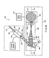
- FIG. 1 shows an exemplary prior art time domain optical coherence tomography (“OCT") system 10 which includes a broadband source 12 that provides a signal to a first arm 14a of two-by-two splitter 14.
- the splitter divides the signal provided thereto at port 14a, and provides a first portion of the signal at a port 14b coupled to a reference arm 16.
- the splitter 14 also provides a second portion of the signal at a port 14c coupled to a sample arm 18.
- the sample arm 18 terminates at a sample volume 19 and an arrangement 22 for providing a lateral scan of the sample volume is disposed in the sample arm 18 prior to the sample volume 19.
- the reference arm 16 terminates in an arrangement 20 for providing an axial scan.
- the arrangements 20 and 22 operate as is generally known in the art.
- interference fringes are formed corresponding to positions that match the distance to the three structures 19a, 19b, 19c in the sample volume 19.
- the single detector 24 is used to detect the interference fringes.
- an image 26 is constructed that maps tissue reflectivity to a given location.
- an exemplary embodiment of the present invention relates to a system which utilizes a detection principle based upon Spectral Radar concepts (further referred to as Spectral Domain OCT) and/or a hybrid method between Spectral Domain and Time Domain OCT that is preferably more sensitive than current state of the art Time Domain OCT, allowing a substantial increase in the acquisition speed to resolution ratio.
- Spectral Domain OCT Spectral Domain OCT
- thermal noise is generated by the feedback resistor
- shot noise is related to the finite nature of the charge quantum resulting in statistical fluctuations on the current
- relative intensity noise is related to the temporal fluctuations due to chaotic character of classical light sources.
- N noise f 4 ⁇ kT R fb + 2 ⁇ ⁇ e 2 ⁇ P ref E v + 2 ⁇ ⁇ eP ref E v 2 ⁇ ⁇ coh
- k is Boltzmann's constant
- T the temperature in Kelvin
- R fb the value of the feedback resistor
- ⁇ coh the coherence time of the source.
- SNR S N noise f ⁇ BW , with BW the signal bandwidth, and parameters S and N noise ( f ) as described above.
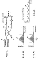
- the best signal to noise performance of Time Domain OCT systems is obtained when the noise is shot noise limited. Shot noise can be reduced significantly by replacing the single element detector with a multi-element array detector. When the detection arm light is spectrally dispersed on the array detector, each element of the array detects a small wavelength fraction of the spectral width of the source. The shot noise is preferably reduced by a factor equal to the number of elements of the array.
- the principle of the signal to noise improvement is based on the white noise characteristic of shot noise and the observation that only electromagnetic waves of the same wavelength produce interference fringes.
- the shot noise power density N noise ( f ) (in units [ W / Hz], [ A 2 / Hz ] or [ V 2 / Hz ]) is proportional to the current (or equivalently the optical power times the quantum efficiency) generated in the detector.
- the shot noise is proportional to the power (or spectral density S( ⁇ ) ) at wavelength ⁇ I .
- a second wavelength ⁇ 2 is preferably coupled into the interferometer.
- the shot noise at this second frequency is preferably the sum of the shot noise generated by the optical power at wavelength ⁇ 1 and ⁇ 2 .
- the shot noise is the sum of the shot noise generated by the optical power at wavelength ⁇ 1 and ⁇ 2 .
- a cross-shot noise term is generated by the simultaneous presence of both wavelengths at the detector.
- the cross shot noise term can be eliminated. In this way, Spectral Domain OCT offers a significant improvement of signal to noise ratio over Time Domain OCT systems.
- the interference term of the OCT signal is proportional to the real part of the Fourier transform of the source spectrum S( ⁇ ), I ⁇ ⁇ z ⁇ oc Re ⁇ exp ik ⁇ ⁇ ⁇ z ⁇ S k ⁇ dk , with ⁇ z the path length difference between sample and reference arm and k the wave vector.
- the OCT signal is given by, I t ⁇ oc Re ⁇ exp 2 ⁇ i ⁇ rv / c ⁇ S ⁇ ⁇ d ⁇ , with v the reference arm mirror velocity.
- the frequency spectrum of the signal is given by a Fourier transform of the signal in the time domain, resulting in a complex function.
- Eq. (9) also preferably directly relates the absolute value of the frequency spectrum,
- each angular frequency of the light source or equivalently each wavelength of the source is represented at its own frequency in the measured interferometric signal.
- the depth profile information I(t) can be obtained from the complex cross spectral density,
- the complex cross spectral density can also be obtained by splitting the signal I(t) in several spectral bands using a dispersive or interferometric element. At each detector, only part of the complex cross spectral density is determined. Combining the cross spectral densities of each detector, the full spectral density of the signal are retrieved. Thus, the same information can be obtained by separating spectral components to individual detectors. Combining the signal of all detectors in software or hardware would result in the same signal as obtained with a single detector.
- the spectrum can be split into two equal halves, where two detectors each detect one half of the spectrum.
- S( ⁇ fc / v ) for f ⁇ f 0
- I 1 ( f ) 0 for f > f 0
- I 2 (f) 0 for f ⁇ f 0
- S( ⁇ fc / v ) for f > f 0 , respectively.
- N noise SD ⁇ oc P ref 1 ⁇ x 0.5 ⁇ BW + P ref 2 ⁇ x 0.5 ⁇ BW 0.5 ⁇ P ref ⁇ BW , which may compared with the shot noise of a single detector in time domain OCT, N noise TD ⁇ oc P ref ⁇ BW .
- the signal remains the same, while the noise is reduced by a factor of 2, resulting in a net SNR gain by a factor of 2.
- N noise 2 ⁇ ⁇ e 2 ⁇ P ref E v ⁇ BW N .
- Spectral Domain OCT enables a SNR improvement over Time Domain OCT of a hundred to a thousand fold, depending on the number of detector elements N.
- a charge coupled array or an integrating device as a detector, such as, but not limited to, a line scan camera
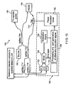
- FIG. 2 shows an exemplary Spectral Domain OCT system 100 which includes an interferometer 102 with a source arm 104, a sample arm 106, a reference arm 108, and a detection arm 110 with a spectral separating unit 112, a detector array 114 comprised of a plurality of detectors and a like plurality of amplifiers 116.
- the amplifiers 116 are coupled through optional analog processing electronics (not shown, but known to those having ordinary skill in the art), and A/D converters (not shown, but known to those skilled in the art) for conversion of signals and through digital band pass filtering ("BPF") units 122 to a processing and display unit 124.
- BPF digital band pass filtering
- the processing and display unit 124 executes data processing and display techniques, and can optionally include the digital band pass filtering ("BPF") units 122 as well as Digital Fast Fourier Transforms (“'DFFTs”) circuits (not shown), in order to provide coherent combination of signals and to perform the data processing and display functions.
- the detector array 114 may be 1 x N for simple intensity ranging and imaging and/or Doppler sensitive detection, 2 x N for dual balanced detection, 2 x N for simple intensity ranging and/or polarization and/or Doppler sensitive detection, or 4 x N for combined dual balanced and polarization and/or Doppler sensitive detection.
- an M x N array may be used for arbitrary number "M" of detectors 114 to allow detection of transverse spatial information on the sample 130.
- Electro-magnetic radiation (e.g., light) is transmitted from the source along the source ann 104 to the splitting unit via and is split between the reference arm 108 and the sample arm 106.
- the light propagates along the sample arm to the tissue sample 130 and through the reference arm 108 to a wavelength dependent phase arrangement.
- the light is reflected from the sample and the wavelength dependent phase arrangement back toward the splitting unit where at least portions of the reflected light are directed toward the spectral separating unit 112 (which may be provided as a grating for example).
- the detection arm light is dispersed by the spectral separating unit 112 and the spectrum is imaged onto the detector array 114.
- the cross spectral density of reference arm 108 and sample arm 106 light can be determined.
- the processing and display unit received the signals fed thereto and performs a Fourier transform of the cross spectral density to generate depth profile information.
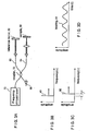
- FIG. 3A shows a block diagram of an exemplary system which illustrates basic principles of a coherent frequency modulated continuous Wave (“C-FMCW”) system using a single-frequency tuning source.
- a monochromatic laser light 70 operable as a frequency chirped laser provides a light signal to an input 72a of a coupler 72.
- the coupler 72 divides the light signal into a reference arm 80 which terminates in a reference mirror 82 and a sample arm 84 which terminates in a sample 86.
- the light propagates down paths 80, 84 and reflects from the reference mirror 82 and sample mirror 86 to provide, via coupler 72, interference signals which are detected by a photo-detector 88.
- a beat signal 94 (see FIG. 3D ) having a frequency f may be detected at the photo detector 88.
- the interference consists of beat notes having frequencies which are proportional to the optical delay difference between the reflection (scatter) point in the sample and the reference mirror.
- the power of each beat frequency component is proportional to the reflectivity of the scatter. Therefore, the image of the sample can be constructed by Fourier transform of the interference data.
- an optical frequency domain imaging (“OFDI”) system includes a wavelength-swept laser source 95 (also referred to herein as a frequency swept source 95) which provides a laser output spectrum comprised of multiple longitudinal modes to an input of a coupler 72.
- the coupler 72 divides the signal fed thereto into the reference arm 80 which terminates in the reference mirror 82 and the sample arm 84 which terminates in the sample 86.
- the optical signals reflect from the reference mirror 82 and the sample 86 to provide, via coupler 72, a spectrum of signals which are detected by a photo-detector 88.
- the center (or mean) wavelength of the signal spectrum is tuned in time by the creation of new longitudinal modes at the leading side of the spectrum and the annihilation of the modes at the trailing side of the spectrum.
- a beat signal 94 can be produced.
- the beat signal 94 can be generated having a beat frequency f which corresponds to the difference in the center frequency of the lights, 96 and 98, from the reference and sample, respectively.
- the frequency spacing between longitudinal modes should be substantially larger than the detection bandwidth.
- the mode beat frequency (relative intensity noise peaks) can be removed by a proper electronic filter, such as low pass filter, prior to digitization.
- the interference signal 94 contains a frequency component that is proportional to the optical delay.
- the image of the sample can be constructed by Fourier transform of the digitized interference data.
- the wavelength-swept laser 95 can be provided which utilizes an optical band-pass scanning filter in the laser cavity to produce a rapidly-swept multiple-frequency-mode output.
- Exemplary filters according to the present invention is described below in conjunction with FIGS. 6 and 9A .
- a single pixel of the image can be constructed from the signal that is recorded as a function of time over the duration of one A-scan through Fourier transform. This is different from the TD OCT where a single pixel is constructed from the data measured at a short period time within one A-scan.
- the detection bandwidth to acquire the same number of data within the same A-scan period is approximately the same for both TD and FD OCT.
- the Fourier transform used for the OFDI technique effectively improves the signal-to-noise ratio compared to TD OCT by constructing a single image pixel from many data points acquired over the whole A-scan period. This effect can result in an ⁇ effective" detection bandwidth that is N-times larger than the actual detection bandwidth.
- the relative intensity noise can be significantly higher than that of a CW broadband light source.
- a laser light results from different statistics and therefore has a different value than the thermal light.
- a wavelength-swept laser with a low RIN level is preferred.
- the laser light with multiple longitudinal modes may have a similar RIN level as the thermal light with the same linewidth. In this case, a means to suppress the RIN is critical to have sufficient SNR, such as the dual balanced detection.
- a swept source results in a system having reduced shot noise and other forms of noise which allows for much lower source powers, or much higher acquisition rates than current systems.
- the increased detection sensitivity allows for real time imaging.
- imaging speed can assist with a problem of motion artifacts, such as in gastrointestinal, ophthalmic and arterial imaging environments.
- By increasing the frame rate while maintaining or improving the signal to noise ratio such artifacts can be minimized.
- the present invention also enables one to screen large areas of tissues with the OFDI technique, and allows clinical viable screening protocols using this method.
- the efficient detection preferably allows for a significant increase of acquisition speed.
- a possible limitation in ophthalmic applications is the power that is allowed to enter the eye according to the ANSI standards (approximately 700 microwatts at 830 nm).
- Current data acquisition speed in ophthalmic applications is approximately 100-500 A-lines per second.
- the power efficient detection would allow for A-line acquisition rates on the order of about 100,000 A-lines per second, or video rate imaging at about 3,000 A-lines per image.
- the gain in SNR is achieved because the shot noise has a white noise spectrum.
- the signal intensity present at the detector at frequency ⁇ (or wavelength ⁇ ) contributes only to the signal at frequency ⁇ , but the shot noise is generated at all frequencies.
- the shot noise contribution at each frequency can be reduced, while the signal component remains the same.
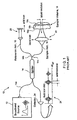
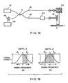
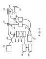
- FIG. 5 shows an exemplary embodiment of a system 99 for performing optical imaging using frequency-domain interferometry ("OFDI") which includes a frequency swept source 100 that emits a narrowband spectrum of which the center wavelength is tuned continuously and repeatedly in time across the bandwidth of the gain medium in the source.
- the instantaneous emission spectrum consists of a plurality of frequency modes of the light source.
- the frequency swept source 100 may be provided in a variety of different ways, some of which are described below.
- the source 100 may, for example, be provided from various gain media, tunable wavelength filters, cavity configurations.
- Devices and methods are known in the art to provide a rapidly-tuned wavelength-swept laser source, such as solid-state lasers, active-ion-doped waveguide lasers, and fiber lasers.
- a wavelength-swept laser in a mode-locked regime can also be used with potential advantage of a lower relative intensity noise (RIN) in a frequency region between harmonics of longitudinal-mode beat frequencies.
- RIN relative intensity noise
- An optical saturable absorber may be incorporated inside a laser cavity or after the output port of the source to lower RIN level.
- the light provided from swept source 100 is directed toward a fiber-optic coupler 102 which divides the light fed thereto into a reference arm 103 and a sample arm 104.
- the coupler 102 has a 90:10 power splitting ratio with 90% of the power being directed toward the sample arm.
- the particular coupling ratio to use in any particular application should be selected such that an amount of power is provided to both the reference arm and the sample arm to allow for proper operation of the exemplary system according to the present invention.
- the power provided to the sample arm passes though a circulator 111, and illuminates a sample 136 to be imaged through a transverse-scanning imaging probe.
- the reference arm provides preferably a fixed optical delay.
- the lights reflected from a reference mirror 124 and from within the sample 136 can be directed through the respective circulators 110, 111 toward a fiber-optic beam splitter (or fused coupler) 150 and interfere between each other to produce interference signals.
- the combining coupler 150 have an equal splitting ratio with minimal polarization dependence and wavelength dependence over the wavelength tuning range of the source. A deviation from equal splitting results in reduction of common mode rejection ratio ("CMRR") of the dual balanced detection.
- CMRR common mode rejection ratio
- the combining coupler 150 is preferably provided as a bulk broadband beam splitter. Those of ordinary skill in the art would understand that other types of couplers (including but not limited to wavelength-flattened fiber fused couplers) may also be used.
- the interference signals are received by a dual balanced receiver 151.
- Output of the receiver 151 is provided to a computing arrangement (e.g., a data acquisition board and computer 160), such that the output is digitized and processed by the computer arrangement to produce an image.
- the data acquisition, transverse scanning, and wavelength tuning are synchronously controlled.
- FIG. 6 shows an exemplary light source 100' which may, for example, be adapted for use as a frequency swept source (such as frequency swept source 100 described above with reference to FIG. 5 ) is provided from an optical filter 170, coupled through a lens 172 and a light path 174 to a light source/controller 176 (hereinafter referred to as "light controller 176").
- the light controller 176 may, in turn, be coupled to one or more applications 178.
- the applications 178 may, for example, correspond to optical imaging processes and/or optical imaging systems, laser machining processes and systems, photolithography and photolithographic systems, laser topography systems, telecommunications processes and systems.
- the exemplary light source 100' provided from the filter 170 and the light controller 176 may be used in a wide variety of different applications, certain general examples of which are described herein.
- the filter 170 allows the light source 100' to operate as a frequency swept source which emits a spectrum of which the center wavelength can be tuned continuously and repeatedly in time across the bandwidth of the light controller 176.
- light source 100' may have an instantaneous emission spectrum comprised of a plurality of frequency modes of the light source/controller 176.
- the optical wavelength filter 170 is configured as a reflection-type filter in that the input and output ports are identical.
- light path 174 may be provided, for example, as an input/output optical fiber and lens 172 may correspond to a collimating lens.
- the light controller 176 can include a number of systems that are specifically adapted to transmit a beam of light (in one embodiment, a collimated beam of light) having a broad frequency (f) spectrum.
- the beam of light can include a plurality of wavelengths, within the visible light spectrum (e.g., red, blue, green).
- the beam of light provided by the light controller can also include a plurality of wavelengths that are defined outside of the visible spectrum (e.g., infrared).
- the light controller 176 can include a unidirectional light transmission ring.
- the light controller 176 can include a linear resonator system.
- the filter 170 includes a wavelength dispersing element 180 adapted to receive the beam of light from the light controller 176 and to separate the beam of light into a plurality of different wavelengths of light each directed along a light path as is known.
- the wavelength dispersing element 180 can include one or more elements adapted to receive the beam of light from the light controller 176, and to separate the beam of light into a plurality of wavelengths of light each directed along a light path.
- the wavelength dispersing element 180 is further operative to direct the plurality of wavelengths of light in a plurality of angular directions or displacements with respect to an optical axis 182.
- the wavelength dispersing element 180 can include a light dispersion element, such as a reflection grating 184.
- the wavelength dispersing element 180 could alternatively be provided as a transmission grating (e.g. a transmission type grating such as Dickson-type holographic grating), a prism, a diffraction grating, an acousto-optic diffraction cell or combinations of one or more of these elements.
- the wavelength dispersing element 180 directs light at each wavelength towards a lens system 186 along paths which are at an angle with respect to the optical axis 182. Each angle is determined by the wavelength dispersing element 180.
- the lens system 186 can include one or more optical elements adapted to receive the separated wavelengths of light from the wavelength dispersing element 180 and to direct or steer and/or focus the wavelengths of light to a predetermined position located on a beam deflection device 188.
- the beam deflection device 188 can be controlled to receive and selectively redirect one or more discrete wavelengths of light back along the optical axis 182 through the lens system 186 to the wavelength dispersing element 180 and back to the light controller 176.
- the beam deflecting device 188 can be formed and/or arranged in a number of ways.
- the beam deflecting device 188 can be provided from elements including, but not limited to, a polygonal mirror, a planar minor disposed on a rotating shaft, a minor disposed on a galvanometer, or an acousto-optic modulator.
- the dispersing element 186 includes a diffraction grating 184, a lens system 186 (which has first and second lenses 190, 192 to form a telescope 193), and the beam deflecting device 188 which is shown as a polygon mirror scanner 194.
- the telescope 193 is provided from the first and second lenses 190, 192 with 4- f configuration.
- the first and second lenses 190, 192 of the telescope 193 are each substantially centered on the optical axis 182.
- the first lens 190 is located at a first distance from the wavelength dispensing element 180 (e.g., diffraction grating 184), which is approximately equal to the focal length F1 of the first lens 190.
- the second lens 192 is located a second distance from the first lens 190, which is approximately equal to the sum of the focal length F1 of the first lens 190 and the focal length F2 of the second lens 192.
- the first lens 190 can receive the collimated discrete wavelengths of light from the wavelength dispersing element 180, and may effectively perform a Fourier Transform on each one of the collimated one or more discrete wavelengths of light to provide an equal one or more converging beams projected onto an image plane (see designated IP of FIG. 6 ).
- the image plane IP is located between the first and second lenses and at a predetermined distance from the first lens, which predetermined distance is defined by the focal length F1 of the first lens.
- the converging beam(s) After propagating through the image plane IP, the converging beam(s) form an equal one or more diverging beams that are received by the second lens.
- the second lens operates to receive the one or more diverging beams and to provide an equal number of collimated beams having predetermined angular displacements with respect to the optical axis 182 for directing or steering the collimated beams to predefined portions of the beam deflection device 188.
- the telescope 193 is configured to provide a number of features, as described above, and further to convert diverging angular dispersion from the grating into converging angular dispersion after the second lens 192, which is desired for proper operation of the filter 170.
- the telescope 193 provides a useful degree of freedom, which controls the tuning range and reduces the beam size at the polygon mirror 194 to avoid a beam clipping.
- the polygon mirror 194 reflects back preferably only the spectral component within a narrow passband as a function of the angle of the front mirror facet of the polygon with respect to the optic axis.
- the reflected narrowband light is diffracted and received by the optical fiber 174.
- the orientation of the incident beam with respect to the optic axis and the rotation direction 198 of the polygon mirror 194 determine the direction of wavelength tuning: wavelength up (positive) scan or down (negative) scan.
- the arrangement in FIG. 6 produces a positive wavelength sweep.
- the mirror 194 is shown in FIG. 6 as having twelve facets, fewer or more than twelve facets can also be used. The particular number of facets to use in any application depends upon the desired scanning rate and scanning range for a particular application. Furthermore, the size of the mirror is selected in accordance with the needs of a particular application taking into account factors including, but not limited to, manufacturability and weight of the mirror 194. It should also be appreciated that lenses 190, 192 may be provided having different focal lengths. The lenses 190, 192 should be selected to provide a focal point at approximately the center point 200 of the mirror 194.
- ⁇ p ⁇ (sin ⁇ + sin ⁇ ) where ⁇ is the optical wavelength, p is the grating pitch, and ⁇ and ⁇ are the incident and diffracted angles of the beam with respect to a nominal axis 202 of the grating, respectively.
- Tuning range of the filter is fundamentally limited by the finite numerical aperture of lens1 20.
- An importance design parameter of the filter, originated from multiple facet nature of the polygon mirror, is the free spectral range, which is described in the following.
- the tuning range of the laser cannot exceed the free spectral range if the gain medium has homogenous broadening, since the laser chooses the wavelength of highest gain.
- the duty cycle of laser tuning by the filter can be, in principle, 100% with no excess loss caused by beam clipping if two necessary conditions are met as follows: W ⁇ cos ⁇ F 1 cos ⁇ 0 ⁇ F 2 ⁇ L and W ⁇ cos ⁇ cos ⁇ 0 ⁇ F 2 - S ⁇ ⁇
- the first equation is derived from the condition that the beamwidth after lens 192 should be smaller than the facet width.
- the second equation is from that the two beams at the lowest and highest wavelengths 204, 206 respectively of the tuning range should not overlap each other at the polygon mirror S in Equation (1) denotes the distance between the lens 192 and the front mirror of the polygon.
- the characteristics of the filter were measured using broadband amplifier spontaneous emission light from a semiconductor optical amplifier (SOA) and an optical spectrum analyzer.
- SOA semiconductor optical amplifier
- the optical spectrum analyzer recorded the nonnalized throughput (reflected) spectrum in peak-hold mode while the polygon mirror was spinning at its maximum speed of 15.7 kHz.
- the measured tuning range was 90nm which is substantially smaller than the theoretical value of 126nm.
- the discrepancy was due to the aberration of the telescope, primarily field curvature, associated with relatively large angular divergence of the beam from the grating. It is expected that the aberration would be improved by using optimized lenses.
- the free spectral range was 73.5nm in agreement with the theoretical calculation.
- the FWHM bandwidth was measured to be 0.12nm. The discrepancy with theoretical limit of 0.11nm may be reasonable considering the aberration and imperfection of the optical elements.
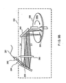
- FIG. 7 shows an extended-cavity semiconductor laser 208 according to an exemplary embodiment of the present invention which can include a filter 210 that may, for example, be similar to the filter 170 described above with reference to FIG. 6 .
- the filter 210 is coupled through a light directing element 212 and a light path 214 to a Faraday circulator 216.
- the filter 210 includes a grating 232 and a polygonal mirror 236.
- the filter 210 may correspond to a polygon-based filter.
- a motor 234 drives the mirror.
- the Faraday circulator 216 of this exemplary embodiment is coupled through polarization controllers 220, 222 to a gain medium 224 which in one exemplary embodiment can be a semiconductor optical amplifier (e.g., SOA, Philips, CQF 882/e) having coupled thereto a current source 226 which provides an injection current to the SOA 224.
- the intracavity elements may be connected by single-mode optical fibers, for example.
- the two polarization controllers 220, 222 can align the polarization states of the intracavity light to align to the axes of maximum efficiency of the grating 232 and of maximum gain of the SOA 224.
- a laser output 228 may be obtained through a 90% port of a fiber-optic fused coupler 230.
- 5% of the laser output may be coupled through a variable wavelength filter 237 having a bandwidth of 0.12nm and is directed toward a photodetector 238.
- the center wavelength of the filter may be fixed at 1290nm.
- the detector signal generates short pulses when the output wavelength of the laser is swept through the narrowband passband of the fixed-wavelength filter. The timing of the sync pulse is controlled by changing the center wavelength of the filter.
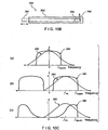
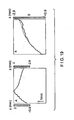
- FIG. 8A shows a graph 240 of an output spectrum of a laser of the type described above with reference to FIG. 7 as measured by an optical spectrum analyzer in peak-hold mode, when the polygon mirror (i.e. mirror 236 in FIG. 7 ) spins at a rate of 15.7 kHz.
- the edge-to-edge sweep range may be from 1282nm to 1355nm over 73nm-width equal to the free-spectral range of the filter.
- the Gaussian-like profile of the measured spectrum, rather than a square profile, is likely due to the polarization-dependent cavity loss caused by polarization sensitivity of the filter and the birefringence in the cavity. It is preferable to adjust the polarization controllers to obtain the maximum sweep range and output power.
- FIG. 8B shows a curve 242 of a laser output in a time domain.
- the upper trace 244 corresponds to a sync signal obtained through the fixed-wavelength filter.
- the amplitude of power variation from facet to facet was less than 3.5%.
- the peak and average output power was 9mW and 6mW, respectively. It should be mentioned that the y-axis scale of curve 240 had to be calibrated from the time-domain measurement, because the optical spectrum analyzer only recorded a time-averaged spectrum due to the laser tuning speed much faster than the sweep speed of the spectrum analyzer.
- a frequency downshift in the optical spectrum of the intracavity laser light may arise as the light passes through an SOA gain medium (e.g. SOA 224 in FIG. 7 ), as a result of intraband four-wave mixing phenomenon.
- the positive wavelength scan can facilitate tuning of the laser spectrum, and thereby produce higher output powers.
- the peak power of the laser output can be measured as a function of the tuning speed.
- the negative tuning speed may be obtained by flipping the position of the collimator and the orientation of the grating with respect to an optic axis (e.g., axis 182 in FIG. 6 ). It is preferable to make the physical parameters of the filter approximately identical in both tuning directions.
- the combined action of self-frequency shift and positive tuning allows higher output to be obtained and enables the laser to be operated at higher tuning speed. Therefore, the positive wavelength scan may be the preferred operation.
- the output power may decrease with increasing tuning speed.
- a short cavity length may be desired to reduce the sensitivity of the output power to the tuning speed. In this case, a free-space laser cavity is preferred.
- FIG. 9A shows an exemplary embodiment of a free-space extended-cavity semiconductor tunable laser 250 according to an exemplary embodiment of the present invention that includes a semiconductor waveguide 252 fabricated on a substrate chip 254 coupled to a polygon scanning filter 255 through a collimating lens 256.
- a front facet 258 may be anti-reflection coated, and an output facet 260 is cleaved or preferably coated with dielectrics to have an optimal reflectivity.
- An output 262 of the laser is obtained through the output coupling lens 264.
- the collimating lenses 256, 264 are preferably provided as aspheric lenses.
- the filter 255 includes a wavelength dispersing element 180' adapted to receive the beam directed thereto from the lens 256.
- the wavelength dispersing element 180' may be similar to wavelength dispersing element 180 described above with reference to FIG. 6 .
- a lens system 186' can be disposed between the wavelength dispersing element 180' and a beam deflection device 188'.
- the wavelength dispersing element 180' and a beam deflection device 188' may be similar to wavelength dispersing element 180 and a beam deflection device 188 described above with reference to FIG. 6 .
- the lens systems 186' includes a pair of lenses 187a, 187b which are preferably provided as achromats having low aberration particularly in field curvature and coma.
- a sync output may be obtained by using a lens 266, a pinhole 268, and a photodetector 270 positioned on the 0-th order diffraction path for the light which is on retro-reflection from a polygon scanner 272.
- the detector generates a short pulse when the focus of the optical beam of a particular wavelength sweeps through the pinhole 268.
- Other types of gain medium may include, but are not limited to, rare-earth-ion doped fiber, Ti:Al 2 O 3 , and Cr 4+ :forsterite.
- FIG. 9B shows another exemplary embodiment of a wavelength tunable filter 280 according to the present invention which may include an optical fiber 281 coupled to an input collimating lens 282, optically coupled to a diffraction grating 284, a focusing lens 286, and a spinning disk 288.
- the diffraction grating 284 may be replaced by other angular dispersive elements such as a prism.
- the diffraction grating 284 can have a concave curvature with a focal length selected such the focusing lens 286 is not needed.
- the reflectors 290 may be deposited on a surface 288a of the spinning disk 288.
- the reflectors 290 comprise multiple narrow stripes periodically and radially patterned.
- the material for the reflectors is preferably gold.
- the disk 288 can be composed of a lightweight plastic or silicon substrate. Instead of the reflectors deposited on the top surface of the disk, the disk can have a series of through holes followed by a single reflector attached to the back surface of the disk.
- the optical beams of different wavelengths may be illuminated on the surface of the disk into a line after being diffracted by the grating and focused by the lens 286 (in those systems which include lens 286).
- the lens 286 in those systems which include lens 286).
- only the beam that impacts the reflectors of the spinning disk may be retro-reflected and received by the optical fiber 281.
- a mirror 292 may be used to facilitate the access of the beam onto the disk.
- filter bandwidth becomes greater, and for w ⁇ w s , the efficiency (reflectivity) of the filter is decreased by beam clipping.
- the orientation of an incident beam 294 with respect to the optic axis of the lens 286 and the spinning direction 288 preferably determines the sense of wavelength tuning.
- the positive wavelength scan is preferable, which is achieved by spinning the disk 288 in a clockwise direction as shown in FIG. 9B .
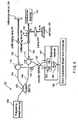
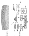
- FIG. 10A shows an exemplary embodiment of an OFDI system 300 for performing optical imaging using frequency-domain interferometry includes a frequency swept source 301 which emits a light signal having an instantaneous emission spectrum comprised of a plurality of frequency modes of the light source.
- Source 301 may, for example, be provided as one of the sources described above with reference to FIGS. 4A , 5 , 6 , 7 , 9 and 9B .
- the light from source 301 can be directed toward a fiber-optic coupler 302 which divides the light fed thereto into a reference arm 303 and a sample arm 304.
- the reference arm 303 preferably includes a polarization circuit 306 and a circulator 308.
- the optional motion artifact circuit 309 may be provided from a lens 310 which directs the light toward a frequency shifter 311, a phase tracker 312 and a dispersion compensator 314. The light passes through optional circuit 309 and is incident upon a reference mirror 316.
- circuit 309 functions to remove or reduce motion artifacts.
- circuit 309 may include all of the elements 310-314, and/or one or more of the circuit elements 310-314.
- the sample arm 304 may include a circulator 318.
- a light signal transmitted from the source 301 propagates from source 301 through the coupler 302 and the circulator 308 to a lens 320 which directs the light toward a scanning mirror 322.
- the scanning mirror 322 may be provided from a wide variety of optical elements including but not limited to, a galvanometer, a piezoelectric actuator or another functionally equivalent device.
- a transverse scanner 324 is coupled to the scanning mirror 322 and a data acquisition board and computer 326. The data acquisition board and computer 326 is also coupled to the frequency swept source 301.
- the OFDI system 300 shown in FIG 10A can also include a polarization diversity balanced detection (“PDBD”) circuit 334 configured to receive signals from the reference arm 303 and/or the sample arm 304.
- PDBD polarization diversity balanced detection
- the reference arm 303 is connected through circulator 308 and polarization control circuit 330 to a reference port of the PDBD circuit 334.
- sample arm 304 is connected through circulator 318 and polarization control circuit 332 to a sample port of the PDBD circuit 334.
- the sample arm 304 collects light reflected from a tissue sample 328 and is combined with the light from the reference arm 303 in the polarization diversity balanced detection (PDBD) circuit 334 to form interference fringes.
- PDBD polarization diversity balanced detection
- the OFDI technique does not require that the optical path length in the reference arm be scanned in time.
- Such fixed delay reference arms may have various configurations that are known to those having ordinary skill in the art.
- the reference arm 303 can be either of reflective and/or transmission type, and can return light back from the mirror 316. The returned light is directed toward the polarization control circuit 330 via the circulator 308. Similarly, the reflected light from the sample 338 can be directed toward a polarization control circuit 332 via the circulator 318. The reference arm can also be transmission with no reflection.
- the polarization control circuit 330 can be used to match the polarization state of the reference-arm light to that of the sample-arm. The total birefringence in the interferometer should be minimized not to induce wavelength-dependent birefringence.
- the polarization controller may include, but is not limited to, a fiber-optic polarization controller based on bending-induced birefringence or squeezing.
- the chromatic dispersion should be matched substantially between the reference and sample arm.
- the result of strong dispersion mismatch may be a loss in the axial resolution.
- Any residual dispersion can likely be compensated by appropriate signal processing, such as nonlinear mapping based on interpolation of the detector data before the Fourier transform. This mapping may also be accomplished, at least in part, by adjusting the optical layout of the wavelength-swept source.
- the source 301 includes a polygon scanner and a telescope
- the distance between the polygon scanner and the telescope can be adjusted to convert wavelength space to wave vector space prior to Fourier transformation.
- the sample arm may be terminated by an optical probe comprising a cleaved (angled, flat, or polished) optical fiber or free space beam.
- a lens 336 (such as, but not limited to, aspherical, gradient index, spherical, diffractive, ball, drum or the like) may be used to focus the beam on or within the sample.
- Beam directing elements (such as, but not limited to, mirror, prism, diffractive optical element or the like) may also be contained within the probe to direct the focused beam to a desired position on the sample.
- the position of the beam may be changed on the sample as a function of time, allowing reconstruction of a two-dimensional image. Altering the position of the focused beam on the sample may be accomplished by the scanning mirror 322.
- the scanning mirror 322 may be provided, for example, from a number of different devices including, but not limited to, a galvanometer, piezoelectric actuator, an electro-optic actuator or the like.
- the sample arm probe may be a fiber optic probe that has an internally moving element, such that the motion is initiated at a proximal end of the probe and the motion is conveyed by a motion transducing arrangement (such as, but not limited to, wire, guidewire, speedometer cable, spring, optical fiber and the like) to the distal end.
- the fiber optic probe may be enclosed in a stationary sheath which is optically transparent where the light exits the probe at the distal end.
- scanning way also be accomplished by moving the optical fiber. For example, by rotating the optical fiber, or linearly translating the optical fiber.
- 10B shows an exemplary embodiment of the probe 359 which includes an inner cable 360 (that may rotate or linearly translate along the axis of the probe), an outer transparent or semi-transparent sheath 362, distal optics 364, and remitted light 366 (which may be at any angle with respect to axis of catheter).
- the detectors 370 may preferably include photodiodes (such as, but not limited to, silicon, InGaAs, extended InGaAs, and the like). Balanced detection can be implemented by subtracting diode signals that are exactly out of phase with respect to the maxima and minima pattern. The difference between two detector signals is obtained by a differential circuit included in PDBD circuit 334 and amplified by trans-impedance amplifiers ("TIA") 360.
- TIA trans-impedance amplifiers
- the dual balanced receiver may be further followed by a low-pass or band-pass filter to reject noise outside the detection bandwidth.
- the dual balanced detection can be implemented as follows.
- the polarization beam splitter 362 receives signals from the reference and sample arms and provides two output signals.
- the two output signals are further split by two non-polarizing beam splitters 364a, 364b, respectively.
- the outputs from each beam splitter 364a, 364b are detected by a dual balanced receiver provided from the four detectors 370.
- the two outputs of the dual balanced receivers are digitized and processed in a computer arrangement to obtain a polarization diversity.
- the receiver output is provided to circuit 326 which acquires and digitizes the signals fed thereto via A/D converters, and stores the digitized signals in a computer for further processing.
- the bandwidth of the TIA is preferably matched to half the sampling rate.
- Gain of the TIA is preferably selected such that the maximum receiver output range is matched to the voltage range of the A/D converter.
- the signals can be selectively subtracted and complex spectral density can be obtained.
- the complex cross spectral density can be converted to a depth profile in the tissue.
- Several methods to process the complex spectral density to obtain depth profile information are known to those skilled in the art, such as, but not limited to, by obtaining at least two signals with a Pi/2 phase shift in the reference arm and then reconnecting the complex spectral density by some linear combination of the two signals, or by squaring the spectral density.
- analog processing can include a trans-impedance amplifier, low pass (band pass) filter, and digitization of the signal. This signal may then be converted to reflectivity as a function of depth by the Fourier transform operation.
- Digital processing includes digitization, digital band pass filtering in either the frequency domain or time domain (FIR or IIR filter) and inverse Fourier transformation to recover the tissue reflectivity as a function of depth.
- the detected non-linear wavelength coordinates is preferably converted to regularly sampled wave-vector space.
- zero padding the signal, Fourier transformation, and inverse Fourier transformation with re-sampling can be utilized for remapping.
- Other interpolation methods known in the art, such as linear, bi-linear, and cubic spline interpolation of the data may also be used to convert wavelength space into regularly sampled k space. This mapping may also be accomplished in part by adjusting the optical layout of the wavelength-swept source. In one example, the distance between the polygon scanner and the telescope may be adjusted to convert wavelength space to wavevector space prior to Fourier transformation.
- Another exemplary embodiment of the present invention can utilize one or more techniques described below to further enhance the performance and functionality of imaging. These techniques are not limited to the OFDI techniques that use a multiple-frequency-mode tuned source, but can be applied in the OFDI technique using a single-frequency tuned source.
- polarization diversity scheme For an application where polarization fading is a problem, a polarization diversity scheme may be used. Various configurations for polarization diversity are known in the art.
- the polarization diversity circuit operates as follows.
- the polarization beam splitter 362 separates the reference-arm and sample-arm light signals depending upon their polarization states.
- the polarization controller 330 is preferably adjusted so that the reference-arm power is split with an equal magnitude by the polarization controller.
- the polarization state of the sample arm power can be assumed to vary randomly due to the probe or sample motion, therefore the separating ratio of the sample arm power by the polarization splitter can vary in time.
- the two output signals at the two output ports of the polarization beam splitter 362 can be detected by a photo receiver, e.g., squared and summed. The resulting signal is independent of the polarization state of the sample arm light.
- the frequency shifter can be, but not limited to, an acousto-optic frequency shifter. In the detection, a proper electronics should be used to demodulate the carrier frequency.
- FIG. 10C shows a graph 380 depicts the fringe visibility curve given by the instantaneous output spectrum of the source.
- the visibility curve has a Gaussian profile if the source's instantaneous spectrum is Gaussian.
- a curve 390 depicts the transmission efficiency profile of an electrical filter, which is optimized for a given Nyquist frequency defined as the half of the sampling frequency.
- Section (a) of FIG. 10C shows a typical case where there is no frequency shifter in the interferometer and the electrical filter is a low pass filter.
- the transmission efficiency curve of the filter, 390 has an exponentially-rising (falling) slope in its low frequency band.
- This filter may be useful in which attenuation is significant and the resulting signal strength decays with depth.
- the slope filter can improve the dynamic range of the detection by effectively suppressing the large signal from the surface relative to that at greater depths.
- a fixed-delay reference arm can be made in various configurations that are known to those having ordinary skill in the art.
- the reference arm can be of either reflective or transmission type.
- the capability of varying the optical delay in the reference arm may be useful when a larger ranging depth is desired, without increasing the data acquisition rate or reducing the instantaneous linewidth of the optical source.
- Such ability is useful in a clinical study where the distance from the imaging lens and the front surface of the sample can varies significantly. Such variation can result from the motion or from the uncontrolled position of a probing catheter.
- a rotating catheter inside a blood vessel can have distance variation by a couple of millimeter over a single A-scan.
- a mechanism in the reference arm 303 may allow for scanning the group delay of the reference arm 303.
- This group delay can be produced by any of a number of techniques known to those having ordinary skill in the art, such as, but not limited to, stretching an optical fiber, free space translational scanning using a piezoelectric transducer, or via a grating based pulse shaping optical delay line.
- the delay can be introduced by a non-mechanical or motionless arrangement.
- non-mechanical what is meant is that there are no mechanically moving parts being utilized. The absence of the mechanically moving parts is believed to reduce the known deficiencies of using mechanical devices to introduce delay.
- the reference arm 303 does not necessarily need to scan over the full ranging depth in the sample, and can preferably scan over at least a fraction of the ranging depth equal to one over the number of detectors (1/N). This scanning feature is different from the conventional delay scanning schemes used in the known LCI and OCT systems.
- the reference arm 303 optionally has a phase modulator mechanism, such as but not limited to, an acoustooptic modulator, electro-optic phase modulator or the like, for generating a carrier frequency.
- Phase tracking is preferable performed to eliminate phase instabilities in the interferometer.
- Phase instabilities can cause individual interferometric fringes to shift in location. If detection is slow relative to the shifting of the fringes, the resulting averaging results in chirping of the interference signal.
- A-scan rate of 10 to 40 kHz results in an effective integration time of 100 to 25 ⁇ s. Phase instabilities arising on a time frame shorter than the integration time should be compensated.
- Phase locking circuitry is commonly used in electronics, and is frequently used in radar and ultrasound. Active phase tracking can be implemented by modulating the interferometer path length difference at 10 MHz with an electro-optic phase modulator in the reference arm over a fraction of the wavelength.
- an error signal By demodulating the intensity measured by one detector at the output of the interferometer at the frequency of the path length modulation, an error signal can be generated indicating in which direction the phase modulator should shift to lock onto a fringe amplitude maximum. By adding an offset to the phase modulator as determined by the error signal, the phase tracker actively locks onto a fringe maximum.
- the phase modulator can modulate the path length difference over a few wavelengths.
- the processing unit can determine if the phase modulator has reached its range limit, and jump by a full wave in phase to maintain lock on a different fringe maximum. This approach exploits the fact that phase should be controlled only modulo 2 ⁇ .
- the processing drives a slower component (e.g., the Rapid Scanning Optical Delay ("RSOD") line) to extend the path length range of the phase modulator/RSOD combination over several millimeters.
- RSOD Rapid Scanning Optical Delay
- Phase locking can be performed on a fringe maximum, minimum, or zero crossing, based on the type of mixing performed in the demodulation circuit.
- the autoranging mechanism may, in one exemplary embodiment, include a processor unit for (a) obtaining a first scan line; (b) locating a surface location "S" of a sample; (c) locating an optimal scan range "R" of the sample; (d) modifying a reference arm delay waveform to provide an output; (e) outputting the output to a reference arm; (f) determining whether the image is complete; and/or (g) moving to the next scan line if the image is not complete or remapping the image using the surface S data and the waveform data stored in the memory storage device if the image is complete.
- a separate, preferably monochromatic, light source can be transmitted into the interferometer.
- the separate source wavelength may be within the wavelength tuning range of the OFDI source or may be centered at a different wavelength than the OFDI source spectrum.
- the separate source is preferably of higher power, and may be combined with the source arm (using wavelength division, multiplexer, grating, prism, filter or the like) travel to the reference and sample arms and return back to the beam recombining element.
- the returned separate source light can then be separated from the OFDI light following transmission back through the beam recombining element (i.e. beam splitter output).
- a separation arrangement can perform spectral separation by a dispersing element, such as a dichroic mirror, filter, grating, prism, wavelength division multiplexer or the like.
- the separate source will be detected separately from the OFDI light using one or more detectors.
- the higher power provided by this separate source can enable detection of a higher amplitude interference pattern, and provide an improved input to the phase tracker, thus enabling more stable phase tracking.
- FIG. 11 an in vivo image of a subject's fingertip (300*500 pixels) acquired at an A-line scan rate of 15.7 kHz is shown using the exemplary embodiment of the system and process according to the present invention.
- the optical sensitivity was measured to be about -100 dB.
- the SNR is superior to an equivalent TD OCT of the same A-line scan rate.
- the vertical line noise arises due to an un-optimized detection when there is a strong mirror-like reflection from the surface of the tissue, but should preferably be eliminated substantially by a detection optimization and/or an appropriate signal processing.
- FIG. 12 shows another exemplary embodiment of a phase tracker system 600 having an extended phase lock range is provided. This done by combining a fast element 602 (which may be provided, for example, as an electro-optic (EO) phase modulator 602) to modulate the path length difference over a small range, and a slower element 604 (which may, for example, be provided as a Rapid Scanning Optical Delay (RSOD) line 604) to modulate the path length over an extended range.
- the detector 606 signal can be mixed with the phase modulator modulation frequency 608 by a mixer 610 and low pass filtered (filter not shown) to generate an error signal.
- the processing unit 612 preferably processes the error signal to generate an offset voltage, and adds this offset voltage to the modulation signal 608, so as to generate the output for the phase modulator driver 614.
- the processing unit 612 can generate a signal to the RSOD 604 to provide extended range tracking of the phase over distances of several millimeters.
- Light source 616, fiber splitter 618, sample arm 620 and reference arm 622 are shown, and are described herein.
- MixerS t sin ⁇ ⁇ ⁇ t ⁇ * cos ⁇ + ⁇ sin ⁇ ⁇ ⁇ ⁇ t ⁇ ;
- Mixer ⁇ 2 ⁇ ⁇ ⁇ C t cos 2 ⁇ ⁇ ⁇ t * cos ⁇ + ⁇ sin ⁇ ⁇ t ;
- Mixer ⁇ 2 ⁇ ⁇ ⁇ S t sin 2 ⁇ ⁇ ⁇ t * cos ⁇ + ⁇ sin ⁇ ⁇ t .
- the signal MixerS(t) and Mixer2 ⁇ C ( t ) are proportional to sin( ⁇ ) and cos( ⁇ ), respectively, with ⁇ the position within a single oscillation of the fringe pattern.
- the mixer outputs MixerS ( t ) and Mixer2 ⁇ C ( t ) are used as an error signal to generate an offset voltage to steer the phase modulator to a new center position that minimizes the error signal, and locks the interferometer output on a fringe maximum or minimum, or a zero crossing, respectively.
- the complex spectral density can now be determined by two consecutive tuning scans, one where the error signal sin( ⁇ ) is minimized, and the next where the error signal cos( ⁇ ) is minimized, resulting in a 90 degrees phase shift between the two interference patterns. Using this mixing arrangement, the complex spectral density can be obtained rapidly and without resorting to an additional mechanical arrangement for changing the phase of the reference arm light.
- Fig. 13 shows a further exemplary embodiment of an OFDI system 700 which includes a phase tracker for providing balanced detection according to the present invention.
- a source 702 provides an electro-magnetic radiation (e.g., light) which passes through a splitter 704, that sends part of the light to a sample probe 706 and the remainder of the light to a Rapid Scanning Optical Delay ("RSOD") line 708.
- RSOD Rapid Scanning Optical Delay
- phase modulator PM 710 Light from the phase modulator PM 710 is transmitted through a splitter 712, and then through two additional splitters 714 and 716, a portion of the output of which is sent as balanced detection outputs to spectral detection units (not shown, but as described elsewhere herein) and the remainder of the output is sent to the phase tracker assembly 720.
- phase tracker detectors D 1 and D 2 , 722 and 724 receive the partial output of the pair of splitters 714 and 716, which in turn send signal to a mixer 726 to generate an error signal.
- a processing unit 728 processes the error signal, where the sum generation of offset voltage and adds this to the modulation signal 730 to generate the output for the phase modulator driver 732.
- Modulation signal shown at box 730, is forwarded to the mixer 726 and the processing unit 726.
- the fringe amplitude could be too small for the phase tracker to lock.
- a secondary source with longer coherence length can be coupled to the system 700, e.g., to provide a larger fringe amplitude to the phase tracker.
- FIGS. 14A-14C show an exemplary embodiment of a method for tracking phase in an imaging system begins in processing blocks 750 and 752 according to the present invention by measuring a signal received from the sample arm and then increasing a phase of the signal. Processing of this exemplary method then proceeds to block 754, in which a first signal partition of the signal defined as x 1 is measured at least one peak of the signal. In decision block 756, a determination is as to whether the signal defined as x 1 has been measured at least one peak of the signal. If in decision block 756, it is determined that the signal defined as x 1 has been measured at at least one peak of the signal, then processing returns to block 754 and the signal is again measured.
- decision block 756 it is determined that the signal defined as x 1 has not been measured at at least one peak of the signal, then processing flows to a decision block 758, where a determination is made as to whether to adjust the signal.
- the adjustment may be, e.g., an increase or a decrease in the phase of the signal by an incremental amount as shown in blocks 760 and 762. Regardless of whether an increase or a decrease in the phase of the signal is made, processing returns to processing block 754, where a second signal partition of the signal is measured at its peak. Blocks 756-762 are then repeated for such measured signal. It should be noted that the functions of blocks 750-762 may be performed in parallel and/or series with other imaging processes.
- the adjustment of phase " ⁇ " can be defined as A(x 2 -x 1 ), where "A" is a constant and that the process of determining whether to increase or decrease the phase of the signal by an incremental amount may further comprise the substeps of (1) determining whether A(x 2 -x 1 ) is within range of the phase modulator; and (2) changing ⁇ by an amount equal to A(x 2 -x 1 ) if A(x 2 -x 1 ) is within the range or changing ⁇ by an amount equal to A(x 2 -x 1 )-m2 ⁇ if A(x 2 -x 1 ) is outside of the range, where M is an integer greater than 1.
- the method may optionally further comprise a substep (3) re-measuring signal x 1 .
- the data recorded by the detector in time may not be sampled as a strictly linear function of the optical frequency ⁇ or wave number k.
- the Fourier transform can link z and k space (or t and ⁇ ). Because of the non-linear sampling in k, the acquired spectrum is interpolated to create evenly spaced samples in the k domain.
- the tuning slope of the laser could be adjusted in such a way that the light is samples in equal intervals in k space, such that the interpolation becomes obsolete.
- the detection timing could be designed to sample the light evenly spread in the k domain, such that the interpolation becomes obsolete.
- dispersion in the sample and reference arm of the interferometer should preferably be balanced.
- Dispersion imbalance can also be corrected by digital processing.
- Phase chirping induced by motions can also be corrected by digital processing.
- the motion artifact correction the axial movement of the sample is measured, and a proper nonlinear mapping can be calculated from the velocity of the movement.
- interpolation techniques are known to those having ordinary skill in the art. This includes, but is not limited to, simple two-point interpolation, FFT zero-padding followed by two-point interpolation, and rigorous interpolation with the sinc function dictated by the Nyquist theorem.
- An exemplary embodiment of the present invention may also provide a probe for locating atherosclerotic plaque in a blood vessel, comprising: an interferometer; a spectral separating unit which splits signal received from the interferometer into a plurality of optical frequencies; and a detector arrangement capable of detecting at least a portion of the optical frequencies received from the spectral separating unit.
- the maximum ranging depth can likely be limited by the finite width of the coherence function of the laser output because the coherence length is often compromised to obtain higher tuning speed, higher output power, or wider tuning range.
- the finite coherence length may cause the visibility of the interference fringe to decrease as the path length difference of the interferometer increases. This result in the degradation of SNR, and therefore limits the maximum ranging depth.
- the inability to distinguish between a positive and negative electrical frequency in a conventional interferometry may lead to the ambiguity between positive and negative depths.
- the reference delay of the interferometer should be adjusted so that the image presents at only either positive or negative depth. This further may limit the ranging depth for a given coherence length of the source.
- quadrature interference signals have been measured based on active or passive phase biasing using a piezoelectric actuator, birefringence plate or 3x3 coupler. These techniques may provide otherwise overlapping images associated with positive and negative depths, but tended to leave significant residual artifacts due to the difficulty of producing stable quadrature signals. In this paper, we propose and demonstrate a simple technique that effectively eliminates the ambiguity between positive and negative depths.
- the exemplary technique according to the exemplary embodiment of the present invention uses an optical frequency shifter in the interferometer to provide a constant frequency shift of the detector signal. This allows both sides of the coherence range to be used without crosstalk, and can double the ranging depth.
- the same concept has been described above in the context of 1-dimensional optical frequency domain reflectometry using rotating birefringence plates at 58 Hz or a recirculating frequency shifting loop.
- an acousto-optic frequency shifter is used, and the technique is applied to high-speed OFDI with several orders of magnitude faster ranging speed.
- a signal processing technique according to a further exemplary embodiment of the present invention is provided to accommodate a nonlinear tuning slope of the swept source in the frequency shifting technique.
- FIG. 15 shows a high level diagram of an OFDI system which includes a wavelength-swept source 95, singlemode-fiber interferometer employing an optical frequency shifter 311 in a reference arm 80, a photodetector 88, and a signal processor 160.
- FIGS. 16(a) and 16(b) illustrate the effect of the frequency shift.
- the fringe visibility or the coherence function has a peak value at the zero depth and decrease as the depth increases.
- the coherence length Zc indicates the depth where the visibility drops to 0.5 and thereby the SNR drops by 6 dB.
- a single side of the coherence range can be used due to the sign ambiguity of the signal frequency (hatched region).
- both sides of the coherence range from -z c to z c can be utilized without any image crosstalk between the negative and positive depths.
- Nonlinearity in v(t) with respect to time results in frequency chirping of the signal at a constant depth and causes the degradation of axial resolution.
- the detector signal may be sampled with nonlinear time interval compensating for the frequency chirping.
- the detector signal can be sampled with a constant time interval, and then the sampled data be mapped to a uniform v-space by interpolation prior to discrete Fourier transform ("DFT"). Both methods have been demonstrated to yield a transform-limited axial resolution. However, these methods are not applicable directly in the frequency shifting technique. Both the nonlinear sampling and interpolation method can result in artificial chirping of the frequency shift, leading to sub optimal axial resolution.
- a modified interpolation method can be used to achieve nearly transform-limited axial resolution over the entire ranging depth.
- the exemplary technique may be as follows:
- FIG. 17 depicts the experimental setup of an exemplary OFDI system employing two acousto-optic frequency shifters (FS1 800 and FS2 802, Brimrose Inc. AMF-25-1.3) according to an exemplary embodiment of the present invention.
- the use of two frequency shifters balanced the material dispersion of the acousto-optic crystals automatically.
- the insertion loss of each device including fiber coupling may be less than 2.5 dB.
- the sampling rate of the digitizer can be 10 MHz.
- the probe 810 may include a galvanometer mirror and an imaging lens produced a probe beam with a confocal parameter of 1.1 mm.
- An optical tap coupler 820 can be used in conjunction with a narrowband filter 830 and a photodetector 834 to generate a TTL trigger signal in an electrical circuit 836.
- the TTL signal may be used as a trigger in analog to digital conversion.
- the interference signal can be measured using a dual balanced receiver 151.
- the detector signal was further processed prior to digitization using a low pass electrical filter 840.
- Other types of electrical filters such as a band pass filter and a slope filter.
- the transmission of the slope filter may have an exponentially-rising (falling) slope in its low frequency band. This filter may be useful in which attenuation is significant and the resulting signal strength decays with depth.
- the slope filter can improve the dynamic range of the detection by effectively suppressing the large signal from the surface relative to that at greater depths.
- the sampled data acquired at each depth was processed with and without the mapping process.
- FIGS. 18(a) and 18(b) show exemplary results, where the y-axis represents the square of the DFT amplitudes normalized to the value at zero frequency, and the bottom and top x-axes represent the signal frequency and the depth z, respectively.
- the point spread function suffers from significant broadening and large degradation of the peak power as the depth increases, because of the nonlinearity of our swept laser [see FIG.
- 18(c) and 18(d) show the point spread functions measured with and without the mapping process, respectively.
- the peak of the signal power occurring at the zero depth present at a frequency of 2.5 MHz is at least approximately equal to the net acousto-optic frequency shift.
- the nearly transform-limited axial resolution observed in FIG. 18(d) validates the mapping technique.
- the reduction in the signal power is less than 5 dB over the entire depth span of 5.8 mm, demonstrating the benefit of the frequency shifting technique in terms of extending the ranging depth.
- Each image was obtained using the mapping technique described above.
- the surface of the tissue was placed with an angle with respect to the probe beam axis, and the reference mirror was positioned such that the signal was present at both positive and negative depths in the image.
- the tissue image is contained within the effective ranging depth of 2.8 mm, i.e. the top half of the total depth span.
- the relatively large variation in the sample location resulted in the imaging folding artifact.
- B the entire positive and negative depths could be displayed without ambiguity taking advantage of the ranging depth increased to 5.8 mm by the frequency shifting technique.
Landscapes
- Physics & Mathematics (AREA)
- General Physics & Mathematics (AREA)
- Spectroscopy & Molecular Physics (AREA)
- Health & Medical Sciences (AREA)
- Optics & Photonics (AREA)
- Life Sciences & Earth Sciences (AREA)
- Engineering & Computer Science (AREA)
- Electromagnetism (AREA)
- General Health & Medical Sciences (AREA)
- Nonlinear Science (AREA)
- Pathology (AREA)
- Condensed Matter Physics & Semiconductors (AREA)
- Medical Informatics (AREA)
- Biomedical Technology (AREA)
- Heart & Thoracic Surgery (AREA)
- Molecular Biology (AREA)
- Surgery (AREA)
- Animal Behavior & Ethology (AREA)
- Public Health (AREA)
- Veterinary Medicine (AREA)
- Biophysics (AREA)
- Radiology & Medical Imaging (AREA)
- Nuclear Medicine, Radiotherapy & Molecular Imaging (AREA)
- Signal Processing (AREA)
- Plasma & Fusion (AREA)
- Power Engineering (AREA)
- Human Computer Interaction (AREA)
- Chemical & Material Sciences (AREA)
- Analytical Chemistry (AREA)
- Biochemistry (AREA)
- Immunology (AREA)
- Mathematical Physics (AREA)
- Investigating Or Analysing Materials By Optical Means (AREA)
- Instruments For Measurement Of Length By Optical Means (AREA)
Claims (17)
- Dispositif d'interférométrie dans le domaine des fréquences optiques comportant :au moins un premier agencement (702) produisant au moins un premier rayonnement électromagnétique vers un échantillon (706) et au moins un deuxième rayonnement électromagnétique vers une référence (708) dans une branche de référence, dans lequel une fréquence de rayonnement produit par le au moins un premier agencement varie dans le temps,dans lequel la branche de référence est une branche de référence de type à transmission où un retard est introduit sans pièce mécaniquement mobile,au moins un deuxième agencement détectant une interférence entre au moins un troisième rayonnement associé au au moins un premier rayonnement et au moins un quatrième rayonnement associé au au moins un deuxième rayonnement,dans lequel le au moins un troisième rayonnement est un rayonnement en provenance de l'échantillon, et le au moins un quatrième rayonnement est un rayonnement en provenance de la référence, etdans lequel les premier et/ou deuxième rayonnements électromagnétiques ont un spectre dont la fréquence moyenne varie de manière continue dans le temps à une vitesse d'accord supérieure à 100 térahertz par milliseconde.
- Dispositif selon la revendication 1,
comportant en outre un troisième agencement qui fait glisser la fréquence d'au moins un rayonnement parmi le au moins un premier rayonnement électromagnétique, le au moins un deuxième rayonnement électromagnétique, le au moins un troisième rayonnement électromagnétique ou le au moins un quatrième rayonnement électromagnétique. - Dispositif selon la revendication 1,
comportant également au moins un quatrième agencement générant une image basée sur l'interférence détectée. - Dispositif selon la revendication 3,
comportant de plus une sonde qui balaie un emplacement transversal de l'échantillon pour générer des données de balayage, et qui délivre les données de balayage au quatrième agencement de manière à générer l'image. - Dispositif selon la revendication 4,
dans lequel les données de balayage incluent l'interférence détectée obtenue en de multiples emplacements transversaux sur l'échantillon. - Dispositif selon la revendication 1 ou 2,
dans lequel le au moins un deuxième agencement comporte au moins un photodétecteur et au moins un filtre analogique électrique qui suit le au moins un photodétecteur. - Dispositif selon la revendication 6,
dans lequel le au moins un filtre analogique électrique est un filtre passe-bande ayant une fréquence centrale qui est approximativement la même que la grandeur de la fréquence changée par l'agencement de glissement de fréquence. - Dispositif selon la revendication 7,
dans lequel un profil de transmission du au moins un filtre analogique électrique varie sensiblement sur sa bande passante. - Dispositif selon la revendication 4, dans lequel la sonde comporte une liaison rotative et un cathéter à fibre optique.
- Dispositif selon la revendication 9,
dans lequel le cathéter tourne à une vitesse supérieure à 30 tours par seconde. - Dispositif selon la revendication 1,
comportant également au moins un modulateur de polarisation qui est configuré pour moduler une polarisation du rayonnement électromagnétique. - Dispositif selon la revendication 1,
dans lequel le au moins un deuxième agencement est configuré pour détecter un état de polarisation d'au moins un rayonnement parmi les premier et deuxième rayonnements électromagnétiques. - Dispositif selon la revendication 1,
dans lequel le au moins un deuxième agencement comporte au moins un dispositif de réception à deux fréquences équilibré qui est configuré pour éliminer ou réduire une autocorrélation associée au au moins un troisième rayonnement. - Dispositif selon la revendication 1,
dans lequel le au moins un deuxième agencement comporte au moins un dispositif de réception en diversité de polarisation. - Dispositif selon la revendication 1,
dans lequel le au moins un deuxième agencement comporte au moins un dispositif de réception en diversité de polarisation et à deux fréquences équilibré qui est configuré pour éliminer ou réduire une autocorrélation associée au au moins un troisième rayonnement. - Dispositif selon la revendication 1,
comportant en outre au moins un cinquième agencement (720) qui est spécifiquement configuré pour suivre la différence de phase entre au moins un rayonnement parmi :• le au moins un premier rayonnement électromagnétique et le au moins un deuxième rayonnement électromagnétique, ou• le au moins un troisième rayonnement électromagnétique et le au moins un quatrième rayonnement électromagnétique. - Procédé d'interférométrie dans le domaine des fréquences optiques comportant les étapes consistant à :produire au moins un premier rayonnement électromagnétique vers un échantillon et au moins un deuxième rayonnement électromagnétique vers une référence dans une branche de référence, dans lequel une fréquence du au moins un rayonnement parmi les premier et deuxième rayonnements varie dans le temps,dans lequel la branche de référence est une branche de référence de type à transmission, introduisant un retard sans utiliser de pièce mécaniquement mobile,détecter une interférence entre au moins un troisième rayonnement associé au au moins un premier rayonnement et au moins un quatrième rayonnement associé au au moins un deuxième rayonnement,dans lequel le au moins un troisième rayonnement est un rayonnement en provenance de l'échantillon, et le au moins un quatrième rayonnement est un rayonnement en provenance de la référence ; etdans lequel une fréquence moyenne d'un spectre des premier et/ou deuxième rayonnements électromagnétiques varie de manière continue dans le temps à une vitesse d'accord supérieure à 100 térahertz par milliseconde.
Priority Applications (6)
| Application Number | Priority Date | Filing Date | Title |
|---|---|---|---|
| EP10182394.6A EP2293031B8 (fr) | 2003-10-27 | 2004-09-08 | Procédé et appareil pour une source de lumière à réglage de longueur d'onde |
| EP15190655.9A EP3009815B1 (fr) | 2003-10-27 | 2004-09-08 | Procédé et appareil pour réaliser l'imagerie optique à l'aide d'une interférométrie de domaine de fréquence |
| EP10182442.3A EP2270448B1 (fr) | 2003-10-27 | 2004-09-08 | Procédé et appareil pour réaliser l'imagerie optique à l'aide d'interférométrie de domaine de fréquence |
| EP10182358.1A EP2280256B1 (fr) | 2003-10-27 | 2004-09-08 | Procédé et appareil de l'imagerie optique avec de l'interférométrie dans le domaine de fréquence |
| EP10182341.7A EP2278287B1 (fr) | 2003-10-27 | 2004-09-08 | Procédé et appareil de l'imagerie optique avec de l'interférométrie dans le domaine de fréquence |
| EP10182424A EP2270447A1 (fr) | 2003-10-27 | 2004-09-08 | Procédé et appareil pour réaliser l'imagerie optique à l'aide d'interférométrie de domaine de fréquence |
Applications Claiming Priority (2)
| Application Number | Priority Date | Filing Date | Title |
|---|---|---|---|
| US51476903P | 2003-10-27 | 2003-10-27 | |
| PCT/US2004/029148 WO2005047813A1 (fr) | 2003-10-27 | 2004-09-08 | Procede et appareil d'imagerie optique par interferometrie dans le domaine frequentiel |
Related Child Applications (10)
| Application Number | Title | Priority Date | Filing Date |
|---|---|---|---|
| EP10182341.7A Division EP2278287B1 (fr) | 2003-10-27 | 2004-09-08 | Procédé et appareil de l'imagerie optique avec de l'interférométrie dans le domaine de fréquence |
| EP10182394.6A Division EP2293031B8 (fr) | 2003-10-27 | 2004-09-08 | Procédé et appareil pour une source de lumière à réglage de longueur d'onde |
| EP15190655.9A Division EP3009815B1 (fr) | 2003-10-27 | 2004-09-08 | Procédé et appareil pour réaliser l'imagerie optique à l'aide d'une interférométrie de domaine de fréquence |
| EP10182358.1A Division EP2280256B1 (fr) | 2003-10-27 | 2004-09-08 | Procédé et appareil de l'imagerie optique avec de l'interférométrie dans le domaine de fréquence |
| EP10182442.3A Division EP2270448B1 (fr) | 2003-10-27 | 2004-09-08 | Procédé et appareil pour réaliser l'imagerie optique à l'aide d'interférométrie de domaine de fréquence |
| EP10182442.3 Division-Into | 2010-09-29 | ||
| EP10182394.6 Division-Into | 2010-09-29 | ||
| EP10182424.1 Division-Into | 2010-09-29 | ||
| EP10182358.1 Division-Into | 2010-09-29 | ||
| EP10182341.7 Division-Into | 2010-09-29 |
Publications (2)
| Publication Number | Publication Date |
|---|---|
| EP1685366A1 EP1685366A1 (fr) | 2006-08-02 |
| EP1685366B1 true EP1685366B1 (fr) | 2011-06-15 |
Family
ID=34590115
Family Applications (7)
| Application Number | Title | Priority Date | Filing Date |
|---|---|---|---|
| EP10182358.1A Expired - Lifetime EP2280256B1 (fr) | 2003-10-27 | 2004-09-08 | Procédé et appareil de l'imagerie optique avec de l'interférométrie dans le domaine de fréquence |
| EP10182394.6A Expired - Lifetime EP2293031B8 (fr) | 2003-10-27 | 2004-09-08 | Procédé et appareil pour une source de lumière à réglage de longueur d'onde |
| EP15190655.9A Expired - Lifetime EP3009815B1 (fr) | 2003-10-27 | 2004-09-08 | Procédé et appareil pour réaliser l'imagerie optique à l'aide d'une interférométrie de domaine de fréquence |
| EP04788614A Expired - Lifetime EP1685366B1 (fr) | 2003-10-27 | 2004-09-08 | Procede et appareil d'imagerie optique par interferometrie dans le domaine frequentiel |
| EP10182424A Withdrawn EP2270447A1 (fr) | 2003-10-27 | 2004-09-08 | Procédé et appareil pour réaliser l'imagerie optique à l'aide d'interférométrie de domaine de fréquence |
| EP10182341.7A Expired - Lifetime EP2278287B1 (fr) | 2003-10-27 | 2004-09-08 | Procédé et appareil de l'imagerie optique avec de l'interférométrie dans le domaine de fréquence |
| EP10182442.3A Expired - Lifetime EP2270448B1 (fr) | 2003-10-27 | 2004-09-08 | Procédé et appareil pour réaliser l'imagerie optique à l'aide d'interférométrie de domaine de fréquence |
Family Applications Before (3)
| Application Number | Title | Priority Date | Filing Date |
|---|---|---|---|
| EP10182358.1A Expired - Lifetime EP2280256B1 (fr) | 2003-10-27 | 2004-09-08 | Procédé et appareil de l'imagerie optique avec de l'interférométrie dans le domaine de fréquence |
| EP10182394.6A Expired - Lifetime EP2293031B8 (fr) | 2003-10-27 | 2004-09-08 | Procédé et appareil pour une source de lumière à réglage de longueur d'onde |
| EP15190655.9A Expired - Lifetime EP3009815B1 (fr) | 2003-10-27 | 2004-09-08 | Procédé et appareil pour réaliser l'imagerie optique à l'aide d'une interférométrie de domaine de fréquence |
Family Applications After (3)
| Application Number | Title | Priority Date | Filing Date |
|---|---|---|---|
| EP10182424A Withdrawn EP2270447A1 (fr) | 2003-10-27 | 2004-09-08 | Procédé et appareil pour réaliser l'imagerie optique à l'aide d'interférométrie de domaine de fréquence |
| EP10182341.7A Expired - Lifetime EP2278287B1 (fr) | 2003-10-27 | 2004-09-08 | Procédé et appareil de l'imagerie optique avec de l'interférométrie dans le domaine de fréquence |
| EP10182442.3A Expired - Lifetime EP2270448B1 (fr) | 2003-10-27 | 2004-09-08 | Procédé et appareil pour réaliser l'imagerie optique à l'aide d'interférométrie de domaine de fréquence |
Country Status (8)
| Country | Link |
|---|---|
| US (8) | US7733497B2 (fr) |
| EP (7) | EP2280256B1 (fr) |
| JP (7) | JP5567246B2 (fr) |
| KR (2) | KR101321413B1 (fr) |
| CN (6) | CN103293126B (fr) |
| AT (1) | ATE513181T1 (fr) |
| TW (2) | TWI463177B (fr) |
| WO (1) | WO2005047813A1 (fr) |
Families Citing this family (511)
| Publication number | Priority date | Publication date | Assignee | Title |
|---|---|---|---|---|
| ATE454845T1 (de) | 2000-10-30 | 2010-01-15 | Gen Hospital Corp | Optische systeme zur gewebeanalyse |
| US9295391B1 (en) * | 2000-11-10 | 2016-03-29 | The General Hospital Corporation | Spectrally encoded miniature endoscopic imaging probe |
| AT503309B1 (de) | 2001-05-01 | 2011-08-15 | Gen Hospital Corp | Vorrichtung zur bestimmung von atherosklerotischem belag durch messung von optischen gewebeeigenschaften |
| US7355716B2 (en) | 2002-01-24 | 2008-04-08 | The General Hospital Corporation | Apparatus and method for ranging and noise reduction of low coherence interferometry LCI and optical coherence tomography OCT signals by parallel detection of spectral bands |
| US8054468B2 (en) | 2003-01-24 | 2011-11-08 | The General Hospital Corporation | Apparatus and method for ranging and noise reduction of low coherence interferometry LCI and optical coherence tomography OCT signals by parallel detection of spectral bands |
| AU2004225188B2 (en) | 2003-03-31 | 2010-04-15 | The General Hospital Corporation | Speckle reduction in optical coherence tomography by path length encoded angular compounding |
| US7515626B2 (en) * | 2003-05-29 | 2009-04-07 | Novera Optics, Inc. | Light source capable of lasing that is wavelength locked by an injected light signal |
| JP2007526620A (ja) | 2003-06-06 | 2007-09-13 | ザ・ジェネラル・ホスピタル・コーポレイション | 波長同調発信源装置及びその方法 |
| US7733497B2 (en) | 2003-10-27 | 2010-06-08 | The General Hospital Corporation | Method and apparatus for performing optical imaging using frequency-domain interferometry |
| WO2005054780A1 (fr) | 2003-11-28 | 2005-06-16 | The General Hospital Corporation | Procede et appareil d'imagerie codee de maniere spectrale tridimensionnelle |
| JP2005331866A (ja) * | 2004-05-21 | 2005-12-02 | Alps Electric Co Ltd | ホログラム装置 |
| KR101239250B1 (ko) | 2004-05-29 | 2013-03-05 | 더 제너럴 하스피탈 코포레이션 | 광간섭 단층촬영 화상 진단에서 반사층을 이용한 색 분산보상을 위한 프로세스, 시스템 및 소프트웨어 배열 |
| EP1771755B1 (fr) | 2004-07-02 | 2016-09-21 | The General Hospital Corporation | Sonde d'imagerie endoscopique comprenant des fibres double gaine |
| US7573627B2 (en) * | 2004-07-27 | 2009-08-11 | The George Washington University | Amplified bimorph scanning mirror, optical system and method of scanning |
| EP1782020B1 (fr) | 2004-08-06 | 2012-10-03 | The General Hospital Corporation | Logiciel de determination d'au moins un emplacement dans un echantillon par tomographie a coherence optique, systeme et procede associes |
| ATE538714T1 (de) | 2004-08-24 | 2012-01-15 | Gen Hospital Corp | Verfahren, system und software-anordnung zur bestimmung des elastizitätsmoduls |
| US8208995B2 (en) | 2004-08-24 | 2012-06-26 | The General Hospital Corporation | Method and apparatus for imaging of vessel segments |
| KR101269455B1 (ko) | 2004-09-10 | 2013-05-30 | 더 제너럴 하스피탈 코포레이션 | 광 간섭 영상화를 위한 시스템 및 방법 |
| JP4997112B2 (ja) | 2004-09-29 | 2012-08-08 | ザ ジェネラル ホスピタル コーポレイション | 少なくとも1つの電磁放射を伝送させるための装置およびその製造方法 |
| US20060088068A1 (en) * | 2004-10-13 | 2006-04-27 | Intune Technologies | Low noise swept wavelength laser system and method |
| EP1807722B1 (fr) | 2004-11-02 | 2022-08-10 | The General Hospital Corporation | Dispositif rotationnel a fibres optiques, systeme optique pour imager un echantillon |
| EP2278267A3 (fr) | 2004-11-24 | 2011-06-29 | The General Hospital Corporation | Interféromètre à chemin commun pour OCT endoscopique |
| WO2006058346A1 (fr) | 2004-11-29 | 2006-06-01 | The General Hospital Corporation | Ensembles, dispositifs, endoscopes, catheters et methodes d'imagerie optique permettant d'eclairer et de detecter simultanement plusieurs points sur un echantillon |
| US7493227B2 (en) | 2005-03-17 | 2009-02-17 | The Board Of Trustees Of The Leland Stanford Junior University | Method for determining the complex scattering function of an optical coherence tomography sample |
| US7369953B2 (en) * | 2005-03-17 | 2008-05-06 | The Board Of Trustees Of The Leland Stanford Junior University | Femtosecond spectroscopy using minimum phase functions |
| WO2006107795A1 (fr) | 2005-04-05 | 2006-10-12 | The Board Of Trustees Of The Leland Stanford Junior University | Traitement d'images optiques au moyen de fonctions de phase minimale |
| DE602006010993D1 (de) | 2005-04-28 | 2010-01-21 | Gen Hospital Corp | Bewertung von bildmerkmalen einer anatomischen struktur in optischen kohärenztomographiebildern |
| EP1887926B1 (fr) | 2005-05-31 | 2014-07-30 | The General Hospital Corporation | Systeme et procede qui utilisent des techniques d'interferometrie d'heterodyne a codage spectral pour l'imagerie |
| US9060689B2 (en) * | 2005-06-01 | 2015-06-23 | The General Hospital Corporation | Apparatus, method and system for performing phase-resolved optical frequency domain imaging |
| US7391520B2 (en) * | 2005-07-01 | 2008-06-24 | Carl Zeiss Meditec, Inc. | Fourier domain optical coherence tomography employing a swept multi-wavelength laser and a multi-channel receiver |
| JP2007010589A (ja) * | 2005-07-01 | 2007-01-18 | Nidek Co Ltd | 物体測定装置 |
| EP1744119A1 (fr) | 2005-07-15 | 2007-01-17 | Proximion Fiber Systems AB | Tomographie par cohérence optique avec une source à balayage |
| JP4804820B2 (ja) * | 2005-07-15 | 2011-11-02 | サンテック株式会社 | 光断層画像表示システム |
| EP2597457B1 (fr) * | 2005-07-28 | 2018-03-14 | Bioptigen, Inc. | Systèmes d'imagerie à tomographie en cohérence optique dans le domaine de fréquence |
| EP2207008A1 (fr) | 2005-08-09 | 2010-07-14 | The General Hospital Corporation | Dispositif et procédé servant à effectuer une démodulation en quadrature à base de polarisation en tomographie à cohérence optique |
| US20070049833A1 (en) | 2005-08-16 | 2007-03-01 | The General Hospital Corporation | Arrangements and methods for imaging in vessels |
| US7843572B2 (en) | 2005-09-29 | 2010-11-30 | The General Hospital Corporation | Method and apparatus for optical imaging via spectral encoding |
| JP2007101262A (ja) * | 2005-09-30 | 2007-04-19 | Fujifilm Corp | 光断層画像化装置 |
| JP2007101263A (ja) * | 2005-09-30 | 2007-04-19 | Fujifilm Corp | 光断層画像化装置 |
| US7450241B2 (en) | 2005-09-30 | 2008-11-11 | Infraredx, Inc. | Detecting vulnerable plaque |
| WO2007047690A1 (fr) | 2005-10-14 | 2007-04-26 | The General Hospital Corporation | Imagerie fluorescente codee par frequence et par spectre |
| US7295293B2 (en) * | 2005-10-21 | 2007-11-13 | Hewlett-Packard Development Company, L.P. | Apparatus and method for testing a reflector coating |
| GB2432066A (en) * | 2005-11-02 | 2007-05-09 | Oti Ophthalmic Technologies | Optical coherence tomography imaging using repeated scan at slowly changing wavelength |
| EP1785690A1 (fr) * | 2005-11-10 | 2007-05-16 | Haag-Streit Ag | Procédé et dispositif destiné à la détermination de valeurs géométriques d un objet |
| EP1793220B1 (fr) * | 2005-12-01 | 2009-08-26 | Pergam-Suisse Ag | Détection mobile à distance de fluides par laser |
| EP1959816B1 (fr) * | 2005-12-06 | 2011-07-20 | Carl Zeiss Meditec AG | Mesure interferometrique d'un organe |
| JP4642653B2 (ja) * | 2005-12-27 | 2011-03-02 | 富士フイルム株式会社 | 光断層画像化装置 |
| JP5680826B2 (ja) | 2006-01-10 | 2015-03-04 | ザ ジェネラル ホスピタル コーポレイション | 1以上のスペクトルを符号化する内視鏡技術によるデータ生成システム |
| WO2007084903A2 (fr) | 2006-01-19 | 2007-07-26 | The General Hospital Corporation | Dispositif de collecte d'information pour une structure utilisant des techniques d'endoscopie à codage spectral, et procédé d'élaboration correspondant |
| WO2007084995A2 (fr) | 2006-01-19 | 2007-07-26 | The General Hospital Corporation | Procedes et systemes pour visualiser de maniere optique des organes intracavitaires epitheliaux lors d'un balayage au faisceau |
| US7538859B2 (en) | 2006-02-01 | 2009-05-26 | The General Hospital Corporation | Methods and systems for monitoring and obtaining information of at least one portion of a sample using conformal laser therapy procedures, and providing electromagnetic radiation thereto |
| WO2007149601A2 (fr) | 2006-02-01 | 2007-12-27 | The General Hospital Corporation | Appareil destiné à commander au moins l'une d'au moins deux sections d'au moins une fibre |
| JP5524487B2 (ja) | 2006-02-01 | 2014-06-18 | ザ ジェネラル ホスピタル コーポレイション | コンフォーマルレーザ治療手順を用いてサンプルの少なくとも一部分に電磁放射を放射する方法及びシステム。 |
| US9777053B2 (en) | 2006-02-08 | 2017-10-03 | The General Hospital Corporation | Methods, arrangements and systems for obtaining information associated with an anatomical sample using optical microscopy |
| US7982879B2 (en) | 2006-02-24 | 2011-07-19 | The General Hospital Corporation | Methods and systems for performing angle-resolved fourier-domain optical coherence tomography |
| JP4755934B2 (ja) * | 2006-03-31 | 2011-08-24 | 富士フイルム株式会社 | 波長可変レーザ装置および光断層画像化装置 |
| JP4804977B2 (ja) * | 2006-03-22 | 2011-11-02 | 富士フイルム株式会社 | 波長可変レーザ装置および光断層画像化装置 |
| JP4838029B2 (ja) * | 2006-03-30 | 2011-12-14 | テルモ株式会社 | 画像診断装置およびその処理方法 |
| JP4838032B2 (ja) * | 2006-03-31 | 2011-12-14 | テルモ株式会社 | 画像診断装置およびその処理方法 |
| US7742173B2 (en) | 2006-04-05 | 2010-06-22 | The General Hospital Corporation | Methods, arrangements and systems for polarization-sensitive optical frequency domain imaging of a sample |
| WO2007133961A2 (fr) * | 2006-05-10 | 2007-11-22 | The General Hospital Corporation | Processus, agencements et systèmes pour obtenir une imagerie de domaine de fréquence d'un échantillon |
| WO2007133964A2 (fr) | 2006-05-12 | 2007-11-22 | The General Hospital Corporation | Processus, agencements et systèmes pour produire une carte d'épaisseur de couche de fibres sur la base d'images de tomographie à cohérence optique |
| US7835650B2 (en) * | 2006-07-11 | 2010-11-16 | Drexel University | Optical domain frequency down-conversion of microwave signals |
| WO2008010996A2 (fr) * | 2006-07-17 | 2008-01-24 | Bioptigen, Inc. | procédés, systèmes et produits-programmes informatiques pour enlever des artefacts indésirables dans des systèmes de tomographie à cohérence optique du domaine de Fourier (fdoct) utilisant une modulation de phase continue et modulateurs de phase associés |
| US9867530B2 (en) | 2006-08-14 | 2018-01-16 | Volcano Corporation | Telescopic side port catheter device with imaging system and method for accessing side branch occlusions |
| EP1892501A3 (fr) | 2006-08-23 | 2009-10-07 | Heliotis AG | Microscopie tridimensionnelle colorimétrique |
| WO2008024948A2 (fr) | 2006-08-25 | 2008-02-28 | The General Hospital Corporation | Appareil et procédés permettant d'améliorer l'imagerie de tomographie par cohérence optique mettant en œuvre des techniques de filtrage volumétrique |
| US8838213B2 (en) * | 2006-10-19 | 2014-09-16 | The General Hospital Corporation | Apparatus and method for obtaining and providing imaging information associated with at least one portion of a sample, and effecting such portion(s) |
| US20080097158A1 (en) * | 2006-10-20 | 2008-04-24 | Infraredx, Inc. | Noise Suppression System and Method in Catheter Pullback and Rotation System |
| JP5406427B2 (ja) * | 2006-11-17 | 2014-02-05 | 株式会社トプコン | 断層画像処理方法、装置およびプログラムならびにこれを用いた光断層画像化システム |
| JP4869895B2 (ja) * | 2006-12-07 | 2012-02-08 | 富士フイルム株式会社 | 光断層画像化装置 |
| JP2008145375A (ja) * | 2006-12-13 | 2008-06-26 | Fujifilm Corp | 光断層画像化システム |
| JP4996918B2 (ja) | 2006-12-26 | 2012-08-08 | 株式会社トプコン | 光画像計測装置及び光画像計測装置を制御するプログラム |
| JP4996917B2 (ja) * | 2006-12-26 | 2012-08-08 | 株式会社トプコン | 光画像計測装置及び光画像計測装置を制御するプログラム |
| CN105581776B (zh) | 2007-01-10 | 2018-10-16 | 光学实验室成像公司 | 用于可调谐滤波器线性化的装置和方法以及线性化可调谐滤波器 |
| EP2102583A2 (fr) * | 2007-01-19 | 2009-09-23 | The General Hospital Corporation | Appareil et procédé pour contrôler la profondeur de télémétrie dans une imagerie de domaine de fréquence optique |
| EP2104968A1 (fr) * | 2007-01-19 | 2009-09-30 | The General Hospital Corporation | Réflexion de disque rotatif pour balayage de longueurs d'onde rapide de lumière à large bande dispersée |
| US9063117B2 (en) | 2007-02-21 | 2015-06-23 | Paul L. Gourley | Micro-optical cavity with fluidic transport chip for bioparticle analysis |
| US8209128B1 (en) * | 2007-02-21 | 2012-06-26 | Paul L. Gourley | Nanolaser spectroscopy and micro-optical resonators for detecting, analyzing, and manipulating bioparticles |
| US8094982B2 (en) * | 2007-03-08 | 2012-01-10 | Oclaro (North America), Inc. | Fiber lens assembly for optical device |
| JP5558839B2 (ja) | 2007-03-23 | 2014-07-23 | ザ ジェネラル ホスピタル コーポレイション | 角度走査及び分散手順を用いて波長掃引レーザを利用するための方法、構成及び装置 |
| US10534129B2 (en) | 2007-03-30 | 2020-01-14 | The General Hospital Corporation | System and method providing intracoronary laser speckle imaging for the detection of vulnerable plaque |
| JP4933336B2 (ja) * | 2007-04-13 | 2012-05-16 | サンテック株式会社 | 光断層画像表示システム及び光断層画像表示方法 |
| US8045177B2 (en) | 2007-04-17 | 2011-10-25 | The General Hospital Corporation | Apparatus and methods for measuring vibrations using spectrally-encoded endoscopy |
| WO2008137637A2 (fr) | 2007-05-04 | 2008-11-13 | The General Hospital Corporation | Procédés, agencements et systèmes pour obtenir des informations associées à un échantillon à l'aide d'une microscopie optique |
| US8395781B2 (en) | 2007-07-12 | 2013-03-12 | Volcano Corporation | Automatic calibration systems and methods of use |
| WO2009009799A1 (fr) | 2007-07-12 | 2009-01-15 | Volcano Corporation | Cathéter pour imagerie in-vivo |
| JP5481376B2 (ja) * | 2007-07-12 | 2014-04-23 | ヴォルカノ コーポレイション | 光コヒーレンストモグラフィー用のクロック制御方法 |
| US9596993B2 (en) | 2007-07-12 | 2017-03-21 | Volcano Corporation | Automatic calibration systems and methods of use |
| WO2009009802A1 (fr) | 2007-07-12 | 2009-01-15 | Volcano Corporation | Cathéter oct-ivus pour imagerie luminale simultanée |
| US7999945B2 (en) * | 2007-07-18 | 2011-08-16 | The George Washington University | Optical coherence tomography / acoustic radiation force imaging probe |
| JP5183989B2 (ja) * | 2007-07-19 | 2013-04-17 | 株式会社ミツトヨ | 形状測定装置 |
| US20090040527A1 (en) * | 2007-07-20 | 2009-02-12 | Paul Dan Popescu | Method and apparatus for speckle noise reduction in electromagnetic interference detection |
| US8210682B2 (en) * | 2007-07-26 | 2012-07-03 | Manouchehr Motamedi | Method and apparatus for early diagnosis of Alzheimer's using non-invasive eye tomography by Teraherts |
| WO2009018456A2 (fr) | 2007-07-31 | 2009-02-05 | The General Hospital Corporation | Systèmes et procédés pour fournir des motifs de balayage de faisceau pour une imagerie dans le domaine de la fréquence optique doppler de vitesse élevée |
| WO2009029843A1 (fr) | 2007-08-31 | 2009-03-05 | The General Hospital Corporation | Système et procédé pour une microscopie par fluorescence à auto-interférence, et support lisible par ordinateur associé à ceux-ci |
| EP2037214A1 (fr) * | 2007-09-14 | 2009-03-18 | Leica Geosystems AG | Dispositif et appareil de mesure pour la mesure de surfaces |
| DE102007046507B4 (de) * | 2007-09-28 | 2024-10-31 | Carl Zeiss Meditec Ag | Kurzkoheränz-Interferometer |
| WO2009049296A2 (fr) * | 2007-10-12 | 2009-04-16 | The General Hospital Corporation | Systèmes et procédés d'imagerie optique de structures anatomiques luminales |
| US7787112B2 (en) * | 2007-10-22 | 2010-08-31 | Visiongate, Inc. | Depth of field extension for optical tomography |
| US7933021B2 (en) | 2007-10-30 | 2011-04-26 | The General Hospital Corporation | System and method for cladding mode detection |
| US8582934B2 (en) * | 2007-11-12 | 2013-11-12 | Lightlab Imaging, Inc. | Miniature optical elements for fiber-optic beam shaping |
| KR100926039B1 (ko) * | 2007-11-13 | 2009-11-11 | 한국표준과학연구원 | 초정밀 및 고분해능의 테라헤르츠 분광기 및 그 측정방법 |
| CN101214145B (zh) * | 2008-01-03 | 2010-08-04 | 中国科学院上海光学精密机械研究所 | 大探测深度的频域光学相干层析成像方法及系统 |
| US9332942B2 (en) | 2008-01-28 | 2016-05-10 | The General Hospital Corporation | Systems, processes and computer-accessible medium for providing hybrid flourescence and optical coherence tomography imaging |
| US11123047B2 (en) | 2008-01-28 | 2021-09-21 | The General Hospital Corporation | Hybrid systems and methods for multi-modal acquisition of intravascular imaging data and counteracting the effects of signal absorption in blood |
| KR100947464B1 (ko) * | 2008-02-13 | 2010-03-17 | 에스엔유 프리시젼 주식회사 | 두께 측정장치 |
| JP2009218511A (ja) * | 2008-03-12 | 2009-09-24 | Optical Comb Inc | 波長可変光学系及びこれを用いた光源 |
| US8062316B2 (en) | 2008-04-23 | 2011-11-22 | Avinger, Inc. | Catheter system and method for boring through blocked vascular passages |
| US8548571B2 (en) | 2009-12-08 | 2013-10-01 | Avinger, Inc. | Devices and methods for predicting and preventing restenosis |
| US9125562B2 (en) | 2009-07-01 | 2015-09-08 | Avinger, Inc. | Catheter-based off-axis optical coherence tomography imaging system |
| US8696695B2 (en) | 2009-04-28 | 2014-04-15 | Avinger, Inc. | Guidewire positioning catheter |
| US7898656B2 (en) | 2008-04-30 | 2011-03-01 | The General Hospital Corporation | Apparatus and method for cross axis parallel spectroscopy |
| US8593619B2 (en) | 2008-05-07 | 2013-11-26 | The General Hospital Corporation | System, method and computer-accessible medium for tracking vessel motion during three-dimensional coronary artery microscopy |
| US20090289833A1 (en) * | 2008-05-23 | 2009-11-26 | Johnson Paul A | Sparse array millimeter wave imaging system |
| JP2011521747A (ja) | 2008-06-02 | 2011-07-28 | ライトラブ イメージング, インコーポレイテッド | 光コヒーレンストモグラフィ画像から組織特徴を取得する定量的方法 |
| EP2288948A4 (fr) | 2008-06-20 | 2011-12-28 | Gen Hospital Corp | Coupleur fondu de fibres optiques et procédé associé |
| WO2010009144A2 (fr) * | 2008-07-14 | 2010-01-21 | The General Hospital Corporation | Appareil configuré pour produire un rayonnement électromagnétique à balayage de longueur d’onde |
| WO2010009136A2 (fr) | 2008-07-14 | 2010-01-21 | The General Hospital Corporation | Appareil et procédés d'endoscopie couleur |
| CN101660945B (zh) | 2008-08-27 | 2013-02-20 | 中国科学院光电技术研究所 | 快速图像重构方法 |
| EP2344020B1 (fr) | 2008-10-14 | 2020-05-20 | Lightlab Imaging, Inc. | Détection de support d'endoprothèse et de mesure afférente, et affichage au moyen de la tomographie par cohérence optique |
| US8275226B2 (en) * | 2008-12-09 | 2012-09-25 | Spectral Applied Research Ltd. | Multi-mode fiber optically coupling a radiation source module to a multi-focal confocal microscope |
| US8937724B2 (en) | 2008-12-10 | 2015-01-20 | The General Hospital Corporation | Systems and methods for extending imaging depth range of optical coherence tomography through optical sub-sampling |
| DE102008063225A1 (de) | 2008-12-23 | 2010-07-01 | Carl Zeiss Meditec Ag | Vorrichtung zur Swept Source Optical Coherence Domain Reflectometry |
| JP5373389B2 (ja) | 2008-12-26 | 2013-12-18 | カール ツァイス メディテック インコーポレイテッド | 光構造情報取得装置及びその光干渉信号処理方法 |
| JP5479047B2 (ja) * | 2008-12-26 | 2014-04-23 | キヤノン株式会社 | 撮像装置および撮像方法 |
| US20100171960A1 (en) * | 2009-01-07 | 2010-07-08 | Nxtar Technologies, Inc. | For path imbalance measurement of the two arms fiber optic interferometer |
| US9615748B2 (en) | 2009-01-20 | 2017-04-11 | The General Hospital Corporation | Endoscopic biopsy apparatus, system and method |
| JP2012515930A (ja) | 2009-01-26 | 2012-07-12 | ザ ジェネラル ホスピタル コーポレーション | 広視野の超解像顕微鏡を提供するためのシステム、方法及びコンピューターがアクセス可能な媒体 |
| US9178330B2 (en) | 2009-02-04 | 2015-11-03 | The General Hospital Corporation | Apparatus and method for utilization of a high-speed optical wavelength tuning source |
| WO2010104956A1 (fr) * | 2009-03-10 | 2010-09-16 | Lockheed Martin Corporation | Neurone "leaky integrate-and-fire" optique |
| US9351642B2 (en) | 2009-03-12 | 2016-05-31 | The General Hospital Corporation | Non-contact optical system, computer-accessible medium and method for measurement at least one mechanical property of tissue using coherent speckle technique(s) |
| JP5738271B2 (ja) * | 2009-04-03 | 2015-06-24 | エグザロス・アクチェンゲゼルシャフトExalos Ag | 光モジュール |
| US8693745B2 (en) | 2009-05-04 | 2014-04-08 | Duke University | Methods and computer program products for quantitative three-dimensional image correction and clinical parameter computation in optical coherence tomography |
| AU2010253912B2 (en) * | 2009-05-28 | 2015-03-05 | Avinger, Inc. | Optical Coherence Tomography for biological imaging |
| EP2448502B1 (fr) | 2009-07-01 | 2022-04-06 | Avinger, Inc. | Cathéter d'athérectomie pourvu d'une pointe déplaçable de manière latérale |
| US11490826B2 (en) | 2009-07-14 | 2022-11-08 | The General Hospital Corporation | Apparatus, systems and methods for measuring flow and pressure within a vessel |
| EP2470886A4 (fr) * | 2009-08-26 | 2016-11-02 | Tomophase Inc | Imagerie optique tissulaire basée sur l'imagerie optique dans le domaine des fréquences |
| WO2011022829A1 (fr) * | 2009-08-27 | 2011-03-03 | University Of New Brunswick | Système et procédé danalyse brillouin |
| EA201270426A1 (ru) | 2009-09-14 | 2012-12-28 | Мемориал Слоан-Кеттеринг Кэнсер Сентер | Устройство, система и способ обеспечения управления и фокусировки лазера для выполнения разреза, удаления и абляции ткани в малоинвазивной хирургии |
| US12426789B2 (en) | 2009-09-23 | 2025-09-30 | Lightlab Imaging, Inc. | Blood vessel lumen morphology and minimum lumen area measurements data collection by intravascular imaging systems for stenosis or stent planning |
| ES2660147T3 (es) | 2009-09-23 | 2018-03-21 | Lightlab Imaging, Inc. | Sistemas de depuración de sangre in vivo en una luz |
| US9138147B2 (en) * | 2009-09-23 | 2015-09-22 | Lightlab Imaging, Inc. | Lumen morphology image reconstruction based on the scan line data of OCT |
| US8193966B2 (en) * | 2009-10-15 | 2012-06-05 | The Boeing Company | Wire detection systems and methods |
| JP5852300B2 (ja) * | 2009-12-02 | 2016-02-03 | オリンパス株式会社 | 光検出装置、顕微鏡および内視鏡 |
| US8514284B2 (en) | 2009-12-17 | 2013-08-20 | Raytheon Company | Textured pattern sensing and detection, and using a charge-scavenging photodiode array for the same |
| KR20130004326A (ko) | 2010-03-05 | 2013-01-09 | 더 제너럴 하스피탈 코포레이션 | 특정 해상도에서 적어도 하나의 해부학적 구조의 미세 영상을 제공하는 시스템, 방법 및 컴퓨터 접근 가능 매체 |
| US8660324B2 (en) * | 2010-03-29 | 2014-02-25 | Raytheon Company | Textured pattern sensing using partial-coherence speckle interferometry |
| US8780182B2 (en) * | 2010-03-31 | 2014-07-15 | Raytheon Company | Imaging system and method using partial-coherence speckle interference tomography |
| KR101011575B1 (ko) * | 2010-04-13 | 2011-01-27 | 경북대학교 산학협력단 | 비침습적 우량종자 선별 방법 및 장치 |
| US8218927B2 (en) * | 2010-04-19 | 2012-07-10 | National Research Council Of Canada | Optical catheter with rotary optical cap |
| US9069130B2 (en) | 2010-05-03 | 2015-06-30 | The General Hospital Corporation | Apparatus, method and system for generating optical radiation from biological gain media |
| US11105686B2 (en) | 2010-05-10 | 2021-08-31 | University of Pittshurgh-Of the Commonwealth System of Higher Education | Spatial-domain low-coherence quantitative phase microscopy |
| US9557154B2 (en) | 2010-05-25 | 2017-01-31 | The General Hospital Corporation | Systems, devices, methods, apparatus and computer-accessible media for providing optical imaging of structures and compositions |
| US9795301B2 (en) | 2010-05-25 | 2017-10-24 | The General Hospital Corporation | Apparatus, systems, methods and computer-accessible medium for spectral analysis of optical coherence tomography images |
| US20120022338A1 (en) | 2010-05-28 | 2012-01-26 | The General Hospital Corporation | Apparatus, systems, methods and computer-accessible medium for analyzing information regarding cardiovascular diseases and functions |
| US10285568B2 (en) | 2010-06-03 | 2019-05-14 | The General Hospital Corporation | Apparatus and method for devices for imaging structures in or at one or more luminal organs |
| US10401793B2 (en) * | 2010-06-17 | 2019-09-03 | Purdue Research Foundation | Digital holographic method of measuring cellular activity and measuring apparatus with improved stability |
| CN102142892B (zh) * | 2010-06-30 | 2014-12-17 | 华为技术有限公司 | 一种探测脉冲的产生方法和相干光时域反射仪 |
| WO2014039096A1 (fr) | 2012-09-06 | 2014-03-13 | Avinger, Inc. | Stylet de réintroduction destiné à un cathéter |
| US10363062B2 (en) | 2011-10-17 | 2019-07-30 | Avinger, Inc. | Atherectomy catheters and non-contact actuation mechanism for catheters |
| JP2013531542A (ja) | 2010-07-01 | 2013-08-08 | アビンガー・インコーポレイテッド | 長手方向に移動可能なドライブシャフトを有するアテローム切除カテーテル |
| WO2014039099A1 (fr) | 2012-09-06 | 2014-03-13 | Avinger, Inc. | Cathéters d'athérectomie à ballon et à système d'imagerie |
| US11382653B2 (en) | 2010-07-01 | 2022-07-12 | Avinger, Inc. | Atherectomy catheter |
| US8279437B2 (en) * | 2010-07-14 | 2012-10-02 | Hewlett-Packard Development Company, L.P. | Multi-wavelength Raman light detection for detecting a species |
| KR20120025234A (ko) * | 2010-09-07 | 2012-03-15 | 경북대학교 산학협력단 | 발광다이오드 소자의 결함검사 장치 및 방법 |
| US9510758B2 (en) | 2010-10-27 | 2016-12-06 | The General Hospital Corporation | Apparatus, systems and methods for measuring blood pressure within at least one vessel |
| US8593644B2 (en) * | 2010-12-13 | 2013-11-26 | Southwest Research Institute | White light optical profilometer for measuring complex surfaces |
| US11141063B2 (en) | 2010-12-23 | 2021-10-12 | Philips Image Guided Therapy Corporation | Integrated system architectures and methods of use |
| US20120162662A1 (en) * | 2010-12-27 | 2012-06-28 | Axsun Technologies, Inc. | Actively Mode Locked Laser Swept Source for OCT Medical Imaging |
| US10371499B2 (en) | 2010-12-27 | 2019-08-06 | Axsun Technologies, Inc. | Laser swept source with controlled mode locking for OCT medical imaging |
| US8437007B2 (en) | 2010-12-30 | 2013-05-07 | Axsun Technologies, Inc. | Integrated optical coherence tomography system |
| US9046337B2 (en) * | 2010-12-30 | 2015-06-02 | Volcano Corporation | Integrated OCT detector system with transimpedance amplifier |
| US11040140B2 (en) | 2010-12-31 | 2021-06-22 | Philips Image Guided Therapy Corporation | Deep vein thrombosis therapeutic methods |
| WO2012100213A2 (fr) * | 2011-01-21 | 2012-07-26 | Duke University | Systèmes et procédés permettant une tomographie par cohérence optique à résolution des artefacts de conjugué complexe |
| JP2012183152A (ja) * | 2011-03-04 | 2012-09-27 | Tomey Corporation | 光干渉測定方法および光干渉測定装置 |
| WO2012129404A1 (fr) * | 2011-03-22 | 2012-09-27 | Brigham And Women's Hospital, Inc. | Détermination de caractéristiques d'une matière utilisant des corrélations de photons du deuxième ordre |
| WO2012127880A1 (fr) * | 2011-03-24 | 2012-09-27 | 株式会社ニコン | Dispositif d'observation et procédé d'observation |
| CA2831306C (fr) | 2011-03-28 | 2018-11-20 | Avinger, Inc. | Dispositifs traversant une occlusion, imagerie et dispositifs d'atherectomie |
| US9949754B2 (en) | 2011-03-28 | 2018-04-24 | Avinger, Inc. | Occlusion-crossing devices |
| US9179843B2 (en) | 2011-04-21 | 2015-11-10 | Hassan Ghaderi MOGHADDAM | Method and system for optically evaluating proximity to the inferior alveolar nerve in situ |
| JP6240064B2 (ja) | 2011-04-29 | 2017-11-29 | ザ ジェネラル ホスピタル コーポレイション | 散乱媒質の深さ分解した物理的及び/又は光学的特性を決定する方法 |
| EP2702351A4 (fr) * | 2011-04-29 | 2014-11-05 | Optovue Inc | Imagerie améliorée à pointage en temps réel utilisant la tomographie par cohérence optique (tco) |
| US9297702B2 (en) * | 2011-05-10 | 2016-03-29 | Phase Sensitive Innovations, Inc. | Coherence switching |
| US8913248B2 (en) | 2011-06-06 | 2014-12-16 | Carl Zeiss Meditec, Inc. | Systems and methods for improved balanced detection in optical coherence tomography imaging |
| US8873066B2 (en) * | 2011-07-14 | 2014-10-28 | Insight Photonic Solutions, Inc. | System and method for improved resolution, higher scan speeds and reduced processing time in scans involving swept-wavelength interferometry |
| JP2014523536A (ja) * | 2011-07-19 | 2014-09-11 | ザ ジェネラル ホスピタル コーポレイション | 光コヒーレンストモグラフィーにおいて偏波モード分散補償を提供するためのシステム、方法、装置およびコンピュータアクセス可能な媒体 |
| US8582109B1 (en) | 2011-08-01 | 2013-11-12 | Lightlab Imaging, Inc. | Swept mode-hopping laser system, methods, and devices for frequency-domain optical coherence tomography |
| CN102322880B (zh) * | 2011-08-18 | 2013-06-05 | 天津大学 | 偏振敏感的分布式光频域反射扰动传感装置和解调方法 |
| US10241028B2 (en) | 2011-08-25 | 2019-03-26 | The General Hospital Corporation | Methods, systems, arrangements and computer-accessible medium for providing micro-optical coherence tomography procedures |
| US9360630B2 (en) | 2011-08-31 | 2016-06-07 | Volcano Corporation | Optical-electrical rotary joint and methods of use |
| JP2013075035A (ja) * | 2011-09-30 | 2013-04-25 | Canon Inc | 光断層像撮像方法、光断層像撮像装置およびプログラム |
| US9400246B2 (en) * | 2011-10-11 | 2016-07-26 | Kla-Tencor Corporation | Optical metrology tool equipped with modulated illumination sources |
| JP2015502562A (ja) | 2011-10-18 | 2015-01-22 | ザ ジェネラル ホスピタル コーポレイション | 再循環光学遅延を生成および/または提供するための装置および方法 |
| US8748805B2 (en) * | 2011-11-07 | 2014-06-10 | Gooch And Housego Plc | Polarization diversity detector with birefringent diversity element |
| US8831321B1 (en) | 2011-11-07 | 2014-09-09 | Lightlab Imaging, Inc. | Side branch detection methods, systems and devices |
| US9345406B2 (en) | 2011-11-11 | 2016-05-24 | Avinger, Inc. | Occlusion-crossing devices, atherectomy devices, and imaging |
| US20130169971A1 (en) * | 2011-11-23 | 2013-07-04 | Wasatch Photonics, Inc. | Oct imaging system for curved samples |
| KR101258557B1 (ko) | 2011-11-24 | 2013-05-02 | 고려대학교 산학협력단 | 주파수 영역 광간섭 단층촬영 정보처리 장치 및 방법 |
| US8864309B2 (en) * | 2011-12-05 | 2014-10-21 | Bioptigen, Inc. | Optical imaging systems having input beam shape control and path length control |
| JP5900950B2 (ja) * | 2012-01-05 | 2016-04-06 | 国立大学法人 筑波大学 | 波長走査型光干渉断層計及びその位相安定化プログラム |
| DE102012000702B3 (de) * | 2012-01-16 | 2013-02-21 | Karlsruher Institut für Technologie | Optische Kohärenztomographie mit erweitertem Dynamikbereich |
| JP5938926B2 (ja) | 2012-01-31 | 2016-06-22 | 株式会社ニデック | 光断層像撮影装置及びノイズ除去方法 |
| US9237851B2 (en) | 2012-02-03 | 2016-01-19 | Ninepoint Medical, Inc. | Imaging system producing multiple registered images of a body lumen |
| JP5936893B2 (ja) * | 2012-03-21 | 2016-06-22 | 株式会社トプコン | 光画像計測装置及び偏波コントローラ |
| JPWO2013141112A1 (ja) * | 2012-03-23 | 2015-08-03 | 住友電気工業株式会社 | 干渉測定装置 |
| US9629528B2 (en) | 2012-03-30 | 2017-04-25 | The General Hospital Corporation | Imaging system, method and distal attachment for multidirectional field of view endoscopy |
| US8777412B2 (en) | 2012-04-05 | 2014-07-15 | Bioptigen, Inc. | Surgical microscopes using optical coherence tomography and related methods |
| EP2662661A1 (fr) | 2012-05-07 | 2013-11-13 | Leica Geosystems AG | Appareil de mesure doté d'un interféromètre et d'un milieu d'absorption définissant un spectre de raies épais |
| WO2013172974A1 (fr) | 2012-05-14 | 2013-11-21 | Avinger, Inc. | Ensembles de pilotage de cathéter d'athérectomie |
| WO2013172972A1 (fr) | 2012-05-14 | 2013-11-21 | Avinger, Inc. | Tomographie à cohérence optique ayant une fibre à gradient d'indice pour imagerie biologique |
| US11406412B2 (en) | 2012-05-14 | 2022-08-09 | Avinger, Inc. | Atherectomy catheters with imaging |
| CN103427334B (zh) | 2012-05-14 | 2018-09-25 | 三星电子株式会社 | 用于发射波长扫描光的方法和设备 |
| US9441944B2 (en) | 2012-05-16 | 2016-09-13 | Axsun Technologies Llc | Regenerative mode locked laser swept source for OCT medical imaging |
| US11490797B2 (en) | 2012-05-21 | 2022-11-08 | The General Hospital Corporation | Apparatus, device and method for capsule microscopy |
| WO2013180516A1 (fr) * | 2012-06-01 | 2013-12-05 | 한국생산기술연구원 | Générateur de laser pulsé et système de détection à fibres optiques l'utilisant |
| DE102012211549B3 (de) * | 2012-07-03 | 2013-07-04 | Polytec Gmbh | Vorrichtung und Verfahren zur interferometrischen Vermessung eines Objekts |
| CA2879528C (fr) * | 2012-07-27 | 2021-01-05 | Thorlabs, Inc. | Laser a cavite courte accordable mems |
| JP6227652B2 (ja) | 2012-08-22 | 2017-11-08 | ザ ジェネラル ホスピタル コーポレイション | ソフトリソグラフィを用いてミニチュア内視鏡を製作するためのシステム、方法、およびコンピュータ・アクセス可能媒体 |
| US8687201B2 (en) | 2012-08-31 | 2014-04-01 | Lightlab Imaging, Inc. | Optical coherence tomography control systems and methods |
| US11284916B2 (en) | 2012-09-06 | 2022-03-29 | Avinger, Inc. | Atherectomy catheters and occlusion crossing devices |
| US9498247B2 (en) | 2014-02-06 | 2016-11-22 | Avinger, Inc. | Atherectomy catheters and occlusion crossing devices |
| US20140100454A1 (en) | 2012-10-05 | 2014-04-10 | Volcano Corporation | Methods and systems for establishing parameters for three-dimensional imaging |
| US9324141B2 (en) | 2012-10-05 | 2016-04-26 | Volcano Corporation | Removal of A-scan streaking artifact |
| US10568586B2 (en) | 2012-10-05 | 2020-02-25 | Volcano Corporation | Systems for indicating parameters in an imaging data set and methods of use |
| CA2887421A1 (fr) | 2012-10-05 | 2014-04-10 | David Welford | Systemes et procedes pour amplifier la lumiere |
| US9286673B2 (en) | 2012-10-05 | 2016-03-15 | Volcano Corporation | Systems for correcting distortions in a medical image and methods of use thereof |
| US9292918B2 (en) | 2012-10-05 | 2016-03-22 | Volcano Corporation | Methods and systems for transforming luminal images |
| US11272845B2 (en) | 2012-10-05 | 2022-03-15 | Philips Image Guided Therapy Corporation | System and method for instant and automatic border detection |
| US9367965B2 (en) | 2012-10-05 | 2016-06-14 | Volcano Corporation | Systems and methods for generating images of tissue |
| US9858668B2 (en) | 2012-10-05 | 2018-01-02 | Volcano Corporation | Guidewire artifact removal in images |
| US10070827B2 (en) | 2012-10-05 | 2018-09-11 | Volcano Corporation | Automatic image playback |
| US9307926B2 (en) | 2012-10-05 | 2016-04-12 | Volcano Corporation | Automatic stent detection |
| JP5772783B2 (ja) | 2012-10-17 | 2015-09-02 | 住友電気工業株式会社 | 光断層画像取得装置 |
| US9840734B2 (en) | 2012-10-22 | 2017-12-12 | Raindance Technologies, Inc. | Methods for analyzing DNA |
| TWI493507B (zh) * | 2012-11-07 | 2015-07-21 | Univ Nat Taiwan | 超音波成像系統 |
| US20140149018A1 (en) * | 2012-11-29 | 2014-05-29 | Ford Global Technologies, Llc | Engine with laser ignition and measurement |
| US20140149023A1 (en) * | 2012-11-29 | 2014-05-29 | Ford Global Technologies, Llc | Method and system for engine position control |
| US20140153083A1 (en) * | 2012-11-30 | 2014-06-05 | Massachusetts Institute Of Technology | Rin reduced optical source for optical coherence tomography |
| CN102934986B (zh) * | 2012-12-04 | 2014-08-27 | 天津迈达医学科技股份有限公司 | 基于gpu平台的眼科频域oct系统和处理方法 |
| EP2929327B1 (fr) | 2012-12-05 | 2019-08-14 | Perimeter Medical Imaging, Inc. | Système et procédé pour une imagerie oct grand angle |
| US9400169B2 (en) | 2012-12-06 | 2016-07-26 | Lehigh University | Apparatus and method for space-division multiplexing optical coherence tomography |
| CA2892810C (fr) | 2012-12-12 | 2020-07-07 | Lightlab Imaging, Inc. | Procede et appareil de determination automatisee d'un contour de lumiere d'un vaisseau sanguin |
| JP6322210B2 (ja) | 2012-12-13 | 2018-05-09 | ボルケーノ コーポレイション | 標的化された挿管のためのデバイス、システム、および方法 |
| US11406498B2 (en) | 2012-12-20 | 2022-08-09 | Philips Image Guided Therapy Corporation | Implant delivery system and implants |
| WO2014107287A1 (fr) | 2012-12-20 | 2014-07-10 | Kemp Nathaniel J | Système de tomographie en cohérence optique reconfigurable entre différents modes d'imagerie |
| US10942022B2 (en) | 2012-12-20 | 2021-03-09 | Philips Image Guided Therapy Corporation | Manual calibration of imaging system |
| US10939826B2 (en) | 2012-12-20 | 2021-03-09 | Philips Image Guided Therapy Corporation | Aspirating and removing biological material |
| US9730613B2 (en) | 2012-12-20 | 2017-08-15 | Volcano Corporation | Locating intravascular images |
| EP2934311B1 (fr) | 2012-12-20 | 2020-04-15 | Volcano Corporation | Cathéters de transition sans heurt |
| US9612105B2 (en) | 2012-12-21 | 2017-04-04 | Volcano Corporation | Polarization sensitive optical coherence tomography system |
| US9486143B2 (en) | 2012-12-21 | 2016-11-08 | Volcano Corporation | Intravascular forward imaging device |
| US10058284B2 (en) | 2012-12-21 | 2018-08-28 | Volcano Corporation | Simultaneous imaging, monitoring, and therapy |
| JP2016507892A (ja) | 2012-12-21 | 2016-03-10 | デイビッド ウェルフォード, | 光の波長放出を狭幅化するためのシステムおよび方法 |
| EP2936241B1 (fr) | 2012-12-21 | 2020-10-21 | Nathaniel J. Kemp | Mise en tampon optique efficace en énergie utilisant un commutateur optique actif à maintien de polarisation |
| JP2016501625A (ja) | 2012-12-21 | 2016-01-21 | ジェローム マイ, | 可変線密度での超音波撮像 |
| WO2014100530A1 (fr) | 2012-12-21 | 2014-06-26 | Whiseant Chester | Système et procédé pour l'orientation et le fonctionnement de cathéter |
| JP2016501623A (ja) | 2012-12-21 | 2016-01-21 | アンドリュー ハンコック, | 画像信号のマルチ経路処理のためのシステムおよび方法 |
| EP2936426B1 (fr) | 2012-12-21 | 2021-10-13 | Jason Spencer | Système et procédé de traitement graphique de données médicales |
| WO2014100606A1 (fr) | 2012-12-21 | 2014-06-26 | Meyer, Douglas | Cathéter d'imagerie ultrasonore rotatif muni d'un télescope de corps de cathéter étendu |
| ES2845600T3 (es) | 2013-01-09 | 2021-07-27 | Univ California | Aparato y métodos para la obtención de imágenes de fluorescencia utilizando excitación multiplexada por radiofrecuencia |
| JP6053138B2 (ja) * | 2013-01-24 | 2016-12-27 | 株式会社日立エルジーデータストレージ | 光断層観察装置及び光断層観察方法 |
| JP6560126B2 (ja) | 2013-01-28 | 2019-08-14 | ザ ジェネラル ホスピタル コーポレイション | 光周波数ドメインイメージングに重ね合わせされる拡散分光法を提供するための装置および方法 |
| WO2014120791A1 (fr) | 2013-01-29 | 2014-08-07 | The General Hospital Corporation | Appareil, systèmes et procédés pour donner des informations sur la valvule aortique |
| US20140285810A1 (en) * | 2013-01-29 | 2014-09-25 | The General Hospital Corporation | Apparatus and method for facilitating mesoscopic spectrally encoded tomography co-registered with optical frequency domain imaging and/or spectrally encoded confocal microscopy |
| US11179028B2 (en) | 2013-02-01 | 2021-11-23 | The General Hospital Corporation | Objective lens arrangement for confocal endomicroscopy |
| CN103190956A (zh) * | 2013-02-27 | 2013-07-10 | 胡建明 | 基于oct成像系统的激光治疗仪 |
| TWI486615B (zh) * | 2013-03-06 | 2015-06-01 | Ind Tech Res Inst | 量測裝置及其光學元件與其操作方法 |
| EP2965263B1 (fr) | 2013-03-07 | 2022-07-20 | Bernhard Sturm | Segmentation multimodale dans des images intravasculaires |
| US10226597B2 (en) | 2013-03-07 | 2019-03-12 | Volcano Corporation | Guidewire with centering mechanism |
| SG10201707238QA (en) | 2013-03-07 | 2017-10-30 | Univ Nanyang Tech | Optical imaging device and method for imaging a sample |
| US9173591B2 (en) | 2013-03-08 | 2015-11-03 | Lightlab Imaging, Inc. | Stent visualization and malapposition detection systems, devices, and methods |
| US11154313B2 (en) | 2013-03-12 | 2021-10-26 | The Volcano Corporation | Vibrating guidewire torquer and methods of use |
| EP2967391A4 (fr) | 2013-03-12 | 2016-11-02 | Donna Collins | Systèmes et procédés de diagnostic d'une maladie microvasculaire coronarienne |
| JP6339170B2 (ja) | 2013-03-13 | 2018-06-06 | ジンヒョン パーク | 回転式血管内超音波装置から画像を生成するためのシステム及び方法 |
| US9301687B2 (en) | 2013-03-13 | 2016-04-05 | Volcano Corporation | System and method for OCT depth calibration |
| US11026591B2 (en) | 2013-03-13 | 2021-06-08 | Philips Image Guided Therapy Corporation | Intravascular pressure sensor calibration |
| US10426590B2 (en) | 2013-03-14 | 2019-10-01 | Volcano Corporation | Filters with echogenic characteristics |
| US10219887B2 (en) | 2013-03-14 | 2019-03-05 | Volcano Corporation | Filters with echogenic characteristics |
| US10292677B2 (en) | 2013-03-14 | 2019-05-21 | Volcano Corporation | Endoluminal filter having enhanced echogenic properties |
| US12343198B2 (en) | 2013-03-14 | 2025-07-01 | Philips Image Guided Therapy Corporation | Delivery catheter having imaging capabilities |
| AU2014237811B2 (en) | 2013-03-15 | 2018-02-15 | Amo Wavefront Sciences, Llc | Angular multiplexed optical coherence tomography systems and methods |
| US11096717B2 (en) | 2013-03-15 | 2021-08-24 | Avinger, Inc. | Tissue collection device for catheter |
| US8922782B2 (en) * | 2013-03-15 | 2014-12-30 | Axsun Technologies, Inc. | OCT medical imaging system using gain waveguide array swept source |
| EP2967491B1 (fr) | 2013-03-15 | 2022-05-11 | The General Hospital Corporation | Un système endoscopique transoesophageal pour déterminer une saturation veineuse mixte en oxygène d'une artère pulmonaire |
| EP2967371B1 (fr) | 2013-03-15 | 2024-05-15 | Avinger, Inc. | Dispositifs de traversée d'occlusion totale chronique à l'aide d'imagerie |
| CN105228514B (zh) | 2013-03-15 | 2019-01-22 | 阿维格公司 | 光学压力传感器组件 |
| JP6039493B2 (ja) * | 2013-04-25 | 2016-12-07 | キヤノン株式会社 | 波長掃引光源の光周波数校正方法とそのプログラム及び記憶媒体、光周波数校正装置、光干渉断層計測装置 |
| US9784681B2 (en) | 2013-05-13 | 2017-10-10 | The General Hospital Corporation | System and method for efficient detection of the phase and amplitude of a periodic modulation associated with self-interfering fluorescence |
| US10184782B2 (en) | 2013-05-17 | 2019-01-22 | Ninepoint Medical, Inc. | Frequency-domain optical coherence tomography with extended field-of-view and reduction of aliasing artifacts |
| EP3042150B1 (fr) | 2013-05-17 | 2018-08-29 | NinePoint Medical, Inc. | Procédé d'affichage des images de tomographie par cohérence optique d'une lumière |
| US9949634B2 (en) | 2013-06-04 | 2018-04-24 | Bioptigen, Inc. | Hybrid telescope for optical beam delivery and related systems and methods |
| US9683928B2 (en) | 2013-06-23 | 2017-06-20 | Eric Swanson | Integrated optical system and components utilizing tunable optical sources and coherent detection and phased array for imaging, ranging, sensing, communications and other applications |
| US9464883B2 (en) | 2013-06-23 | 2016-10-11 | Eric Swanson | Integrated optical coherence tomography systems and methods |
| EP3019096B1 (fr) | 2013-07-08 | 2023-07-05 | Avinger, Inc. | Système d'identification de limitante élastique pour guider une thérapie interventionnelle |
| CN105452834A (zh) * | 2013-07-18 | 2016-03-30 | 埃西勒国际通用光学公司 | 用于确定眼镜片的视觉效果的方法 |
| WO2015009932A1 (fr) | 2013-07-19 | 2015-01-22 | The General Hospital Corporation | Appareil d'imagerie et procédé utilisant une endoscopie à champ de vision multidirectionnel |
| US9425860B2 (en) * | 2013-07-19 | 2016-08-23 | Biosense Webster (Israel), Ltd. | Two wire signal transmission |
| EP3021735A4 (fr) | 2013-07-19 | 2017-04-19 | The General Hospital Corporation | Détermination de mouvement oculaire au moyen d'une imagerie de la rétine avec rétroaction d'un mouvement de l'oeil par imagerie de la rétine et fournir des informations en retour pour l'acquisition de signaux venant de la rétine |
| EP3025173B1 (fr) | 2013-07-26 | 2021-07-07 | The General Hospital Corporation | Appareil avec dispositif laser utilisant de la dispersion optique pour applications en tomographie en cohérence optique dans le domaine de fourier |
| WO2015017375A2 (fr) | 2013-07-29 | 2015-02-05 | Bioptigen, Inc. | Tomographie par cohérence optique (oct) procédurale pour la chirurgie et systèmes et procédés associés |
| DE102013215422B4 (de) * | 2013-08-06 | 2022-02-24 | Olympus Winter & Ibe Gmbh | Optisches System eines Stereo-Videoendoskops mit seitlicher Blickrichtung und Stereo-Videoendoskop mit seitlicher Blickrichtung |
| CN107872661B (zh) | 2013-08-16 | 2020-01-07 | 杜比实验室特许公司 | 用于多调制显示器的光场模型化技术的系统和方法 |
| WO2015031589A1 (fr) | 2013-08-28 | 2015-03-05 | Bioptigen, Inc. | Affichages tête haute pour microscopes chirurgicaux intégrés à tomographie par cohérence optique |
| US9404800B2 (en) * | 2013-10-11 | 2016-08-02 | The University Of Hong Kong | Wavelength-encoded tomography |
| US11076171B2 (en) | 2013-10-25 | 2021-07-27 | Microsoft Technology Licensing, Llc | Representing blocks with hash values in video and image coding and decoding |
| US10264290B2 (en) | 2013-10-25 | 2019-04-16 | Microsoft Technology Licensing, Llc | Hash-based block matching in video and image coding |
| US20150133778A1 (en) * | 2013-11-04 | 2015-05-14 | Medlumics S.L. | Diagnostic Device for Dermatology with Merged OCT and Epiluminescence Dermoscopy |
| CN105765370B (zh) * | 2013-12-04 | 2018-09-14 | 微技术设备有限公司 | 用于太赫兹图像的高对比度、近实时采集的系统和方法 |
| US11571112B2 (en) | 2014-01-07 | 2023-02-07 | The General Hospital Corporation | Method and apparatus for recording microscopic images from within a living person or organism using an implantable device |
| WO2015105870A1 (fr) | 2014-01-08 | 2015-07-16 | The General Hospital Corporation | Procédé et appareil pour imagerie microscopique |
| US9291500B2 (en) * | 2014-01-29 | 2016-03-22 | Raytheon Company | Configurable combination spectrometer and polarizer |
| JP6775914B2 (ja) | 2014-01-31 | 2020-10-28 | ザ ジェネラル ホスピタル コーポレイション | 光干渉法において振幅および位相を使用した多次元速度測定を実施する方法および装置 |
| WO2015116986A2 (fr) | 2014-01-31 | 2015-08-06 | The General Hospital Corporation | Système et procédé pour faciliter une imagerie volumétrique manuelle et/ou automatique avec un retour de tension ou d'effort en temps réel au moyen d'un dispositif d'imagerie amarré |
| JP6539669B2 (ja) | 2014-02-06 | 2019-07-03 | アビンガー・インコーポレイテッドAvinger, Inc. | 粥腫切除カテーテル及び閉塞横断装置 |
| GB2523097B (en) * | 2014-02-12 | 2016-09-28 | Jaguar Land Rover Ltd | Vehicle terrain profiling system with image enhancement |
| EP3114841B1 (fr) | 2014-03-04 | 2020-06-10 | Microsoft Technology Licensing, LLC | Décisions de basculement de bloc et de mode de saut du côté encodeur, lors d'une intraprédiction de copie de blocs |
| WO2015131325A1 (fr) * | 2014-03-04 | 2015-09-11 | Microsoft Technology Licensing, Llc | Construction de table de hachage et vérification de disponibilité pour une mise en correspondance de blocs par hachage |
| EP3120130B1 (fr) | 2014-03-18 | 2023-07-26 | The Regents of the University of California | Cytomètre en flux parallèle utilisant un multiplexage à radiofréquence, et procédé |
| WO2015153982A1 (fr) | 2014-04-04 | 2015-10-08 | The General Hospital Corporation | Appareil et procédé de commande de la propagation et/ou de la transmission d'un rayonnement électromagnétique dans un ou des guides d'ondes flexibles |
| JP6261450B2 (ja) * | 2014-05-30 | 2018-01-17 | 株式会社トーメーコーポレーション | 眼科装置 |
| EP3155361B1 (fr) | 2014-06-10 | 2024-08-14 | Carl Zeiss Meditec, Inc. | Systèmes et procédés d'imagerie améliorée à base interférométrique en domaine fréquentiel |
| CN105706450B (zh) | 2014-06-23 | 2019-07-16 | 微软技术许可有限责任公司 | 根据基于散列的块匹配的结果的编码器决定 |
| EP3166512B1 (fr) | 2014-07-08 | 2020-08-19 | Avinger, Inc. | Dispositifs traversant une occlusion totale chronique à vitesse élevée |
| US11166668B2 (en) | 2014-07-24 | 2021-11-09 | Lightlab Imaging, Inc. | Pre and post stent planning along with vessel visualization and diagnostic systems, devices, and methods for automatically identifying stent expansion profile |
| JP2017525435A (ja) | 2014-07-25 | 2017-09-07 | ザ ジェネラル ホスピタル コーポレイション | インビボ・イメージングおよび診断のための機器、デバイスならびに方法 |
| JP6462119B2 (ja) | 2014-09-30 | 2019-01-30 | マイクロソフト テクノロジー ライセンシング,エルエルシー | コンピューティングデバイス |
| WO2016056996A1 (fr) * | 2014-10-07 | 2016-04-14 | Nanyang Technological University | Procédés pour améliorer une définition axiale dans une tomographie en cohérence optique |
| JP6469413B2 (ja) * | 2014-10-20 | 2019-02-13 | 株式会社トプコン | データ処理方法及びoct装置 |
| CN104280139A (zh) * | 2014-10-27 | 2015-01-14 | 广州飞拓优视光电科技有限公司 | 一种动态相位测量装置及方法 |
| CN104345168A (zh) * | 2014-11-07 | 2015-02-11 | 中国工程物理研究院激光聚变研究中心 | 一种扫描频域干涉仪 |
| US9940723B2 (en) | 2014-12-12 | 2018-04-10 | Lightlab Imaging, Inc. | Systems and methods to detect and display endovascular features |
| CN104568842B (zh) * | 2015-01-12 | 2017-08-29 | 南京理工大学 | 结合fdoct测量生物组织群延迟色散的装置及方法 |
| CN104570545B (zh) * | 2015-01-22 | 2017-07-14 | 上海交通大学 | 全光可调谐宽带线性调频信号的产生装置 |
| WO2016125207A1 (fr) * | 2015-02-06 | 2016-08-11 | オリンパス株式会社 | Dispositif de balayage à fibre optique et dispositif d'endoscope de balayage |
| JP2016151524A (ja) | 2015-02-18 | 2016-08-22 | ソニー株式会社 | スペックルイメージング装置、スペックルイメージングシステム及びスペックルイメージング方法 |
| US10959712B2 (en) | 2015-03-10 | 2021-03-30 | The General Hospital Corporation | Apparatus, method and computer-accessible medium for obtaining tissue sample |
| US10211587B2 (en) * | 2015-03-31 | 2019-02-19 | Versitech Limited | Spatial chirped cavity for temporally stretching/compressing optical pulses |
| JP6869951B2 (ja) | 2015-04-16 | 2021-05-12 | ジェンテュイティ・リミテッド・ライアビリティ・カンパニーGentuity, LLC | 撮像システム |
| US20160357007A1 (en) | 2015-05-05 | 2016-12-08 | Eric Swanson | Fixed distal optics endoscope employing multicore fiber |
| KR101731728B1 (ko) * | 2015-05-12 | 2017-05-02 | 한국과학기술원 | 관상동맥 혈관 고속 스캐닝 장치 및 방법 |
| US10222956B2 (en) | 2015-05-17 | 2019-03-05 | Lightlab Imaging, Inc. | Intravascular imaging user interface systems and methods |
| US10646198B2 (en) | 2015-05-17 | 2020-05-12 | Lightlab Imaging, Inc. | Intravascular imaging and guide catheter detection methods and systems |
| US10109058B2 (en) | 2015-05-17 | 2018-10-23 | Lightlab Imaging, Inc. | Intravascular imaging system interfaces and stent detection methods |
| US10140712B2 (en) | 2015-05-17 | 2018-11-27 | Lightlab Imaging, Inc. | Detection of stent struts relative to side branches |
| US9996921B2 (en) | 2015-05-17 | 2018-06-12 | LIGHTLAB IMAGING, lNC. | Detection of metal stent struts |
| CN104848928B (zh) * | 2015-05-27 | 2018-04-03 | 深圳市生强科技有限公司 | 基于宽谱光源干涉原理的高速振动测量系统及方法 |
| CN104856652B (zh) * | 2015-06-01 | 2017-06-09 | 南京沃福曼医疗科技有限公司 | 一种血管内断层成像系统 |
| CN105096445B (zh) * | 2015-06-26 | 2017-12-22 | 广州广电运通金融电子股份有限公司 | 一种票券图像采集系统 |
| CN105092037B (zh) * | 2015-06-29 | 2017-08-25 | 杭州路弘科技有限公司 | 一种获得测量光谱的方法 |
| US10568520B2 (en) | 2015-07-13 | 2020-02-25 | Avinger, Inc. | Micro-molded anamorphic reflector lens for image guided therapeutic/diagnostic catheters |
| US10338795B2 (en) | 2015-07-25 | 2019-07-02 | Lightlab Imaging, Inc. | Intravascular data visualization and interface systems and methods |
| DK3136143T3 (en) * | 2015-08-26 | 2020-05-18 | Max Planck Gesellschaft | Hollow-Core Fibre and Method of Manufacturing Thereof |
| EP4675259A2 (fr) | 2015-08-31 | 2026-01-07 | Spryte Medical, Inc. | Système d'imagerie comprenant une sonde d'imagerie et des dispositifs de distribution |
| WO2017049085A1 (fr) | 2015-09-16 | 2017-03-23 | The General Hospital Corporation | Appareil et procédés pour dispositif d'imagerie à tunnel miroir et pour fournir des faisceaux à pseudo-fonction de bessel dans un système optique miniaturisé pour imagerie |
| CN108474728B (zh) | 2015-10-13 | 2022-04-26 | 贝克顿·迪金森公司 | 多模态荧光成像流式细胞术系统 |
| KR101712890B1 (ko) * | 2015-10-13 | 2017-03-08 | 한국표준과학연구원 | 연속파 THz 빔 스캔을 이용한 고속 3차원 영상 탐지 장치 |
| WO2017082830A1 (fr) | 2015-11-13 | 2017-05-18 | Heptagon Micro Optics Pte. Ltd. | Acquisition de données de distance avec systèmes de télémétrie optique |
| EP3376941A1 (fr) | 2015-11-18 | 2018-09-26 | Lightlab Imaging, Inc. | Détection d'entretoises d'endoprothèse par rapport aux branches latérales |
| US9787405B2 (en) * | 2015-11-19 | 2017-10-10 | Elenion Advanced Technology, LLC | Optical dual resonator modulation system and method, and optical dual resonator modulator therefor |
| EP3800646B1 (fr) | 2015-11-23 | 2025-11-05 | Lightlab Imaging, Inc. | Détection et validation d'ombres dans des images intravasculaires |
| CN105588847B (zh) * | 2016-01-05 | 2019-02-26 | 佛山科学技术学院 | 一种用于近透明矿物质的大深度oct扫描装置及方法 |
| US9846128B2 (en) * | 2016-01-19 | 2017-12-19 | Applied Materials Israel Ltd. | Inspection system and a method for evaluating an exit pupil of an inspection system |
| US11278248B2 (en) | 2016-01-25 | 2022-03-22 | Avinger, Inc. | OCT imaging catheter with lag correction |
| CA3014324A1 (fr) | 2016-02-12 | 2017-08-17 | The General Hospital Corporation | Appareil et procedes d'imagerie a grande vitesse et a longue plage de profondeurs par tomographie par coherence optique |
| JP2017142192A (ja) | 2016-02-12 | 2017-08-17 | 株式会社トーメーコーポレーション | 光干渉断層計 |
| US10551245B2 (en) * | 2016-02-12 | 2020-02-04 | Canon U.S.A., Inc. | Simple monolithic optical element for forward-viewing spectrally encoded endoscopy |
| JP6358277B2 (ja) * | 2016-03-04 | 2018-07-18 | 沖電気工業株式会社 | 光ファイバ歪み及び温度測定装置並びに光ファイバ歪み及び温度測定方法 |
| CN109564151B (zh) | 2016-03-17 | 2023-01-24 | 贝克顿·迪金森公司 | 使用高通量荧光流式细胞仪进行细胞分选 |
| US10996402B2 (en) | 2016-03-24 | 2021-05-04 | Canon U.S.A., Inc. | Multi-channel optical fiber rotary junction |
| JP6959255B2 (ja) | 2016-04-01 | 2021-11-02 | アビンガー・インコーポレイテッドAvinger, Inc. | 粥腫切除用カテーテルデバイス |
| CN105699980B (zh) * | 2016-04-11 | 2017-11-28 | 中国科学院光电研究院 | 一种高精度激光测距装置与测量方法 |
| ES2908571T3 (es) | 2016-04-14 | 2022-05-03 | Lightlab Imaging Inc | Identificación de ramas de un vaso sanguíneo |
| US10067055B1 (en) | 2016-05-11 | 2018-09-04 | Pendar Technologies, Llc | Devices and methods for coherent detection using chirped laser pulses |
| US10631754B2 (en) | 2016-05-16 | 2020-04-28 | Lightlab Imaging, Inc. | Intravascular absorbable stent detection and diagnostic methods and systems |
| US10969571B2 (en) * | 2016-05-30 | 2021-04-06 | Eric Swanson | Few-mode fiber endoscope |
| US11344327B2 (en) | 2016-06-03 | 2022-05-31 | Avinger, Inc. | Catheter device with detachable distal end |
| WO2018006041A1 (fr) | 2016-06-30 | 2018-01-04 | Avinger, Inc. | Cathéter d'athérectomie avec pointe distale formable |
| EP3482155B1 (fr) | 2016-07-05 | 2023-09-06 | The General Hospital Corporation | Sonde de guide d'ondes optique à trajet commun et procédé de fabrication |
| US10401610B2 (en) | 2016-07-15 | 2019-09-03 | Canon Usa, Inc. | Spectrally encoded probe with multiple diffraction orders |
| TWI583123B (zh) * | 2016-07-28 | 2017-05-11 | 國立中央大學 | 頻譜分離裝置 |
| JP6730125B2 (ja) * | 2016-08-01 | 2020-07-29 | 株式会社ディスコ | 計測装置 |
| JP6730124B2 (ja) * | 2016-08-01 | 2020-07-29 | 株式会社ディスコ | 厚み計測装置 |
| CN106251292B (zh) * | 2016-08-09 | 2019-04-16 | 央视国际网络无锡有限公司 | 一种图片分辨率提升方法 |
| CN106289090B (zh) * | 2016-08-24 | 2018-10-09 | 广东工业大学 | 一种牙科树脂内应变场的测量装置 |
| US10390039B2 (en) | 2016-08-31 | 2019-08-20 | Microsoft Technology Licensing, Llc | Motion estimation for screen remoting scenarios |
| EP3520114A1 (fr) | 2016-09-28 | 2019-08-07 | Lightlab Imaging, Inc. | Système et procédés de planification d'endoprothèse à l'aide d'une représentation de vaisseau |
| CN107894204B (zh) | 2016-10-04 | 2020-02-21 | 财团法人工业技术研究院 | 干涉仪及其成像方法 |
| TWI639809B (zh) * | 2016-10-04 | 2018-11-01 | 財團法人工業技術研究院 | 干涉儀及其成像方法 |
| WO2018072154A1 (fr) * | 2016-10-19 | 2018-04-26 | 华为技术有限公司 | Procédé, appareil, et système de détection |
| US10898068B2 (en) | 2016-11-01 | 2021-01-26 | Canon U.S.A., Inc. | Multi-bandwidth spectrally encoded endoscope |
| US10554961B2 (en) * | 2016-11-08 | 2020-02-04 | Kevin Vora | Three-dimensional volumetric display using photoluminescent materials |
| JP2019537845A (ja) * | 2016-11-14 | 2019-12-26 | 寧波傲視智絵光電科技有限公司Ningbo Onsight Co., Ltd. | レーザ走査方法及びレーザ走査装置 |
| US11095877B2 (en) | 2016-11-30 | 2021-08-17 | Microsoft Technology Licensing, Llc | Local hash-based motion estimation for screen remoting scenarios |
| WO2018119077A1 (fr) | 2016-12-21 | 2018-06-28 | Acucela Inc. | Système de tomographie par cohérence optique à faible coût, mobile et miniaturisé pour applications ophtalmiques à domicile |
| WO2018122916A1 (fr) * | 2016-12-26 | 2018-07-05 | オリンパス株式会社 | Dispositif de balayage de fibres optiques et endoscope |
| US11543232B2 (en) * | 2017-01-05 | 2023-01-03 | Dental Imaging Technologies Corporation | 3D intraoral camera using frequency modulation |
| JP6648891B2 (ja) * | 2017-01-18 | 2020-02-14 | 公立大学法人大阪 | 物質含有量を断層可視化する装置および方法 |
| EP3573585B1 (fr) * | 2017-01-30 | 2022-10-26 | Alcon Inc. | Système de découpe d'un volet à l'aide d'une tomographie par cohérence optique sensible à la polarisation |
| EP3373034B1 (fr) * | 2017-03-06 | 2020-02-26 | Nxp B.V. | Appareil de détection et de télémétrie |
| CN108572142B (zh) * | 2017-03-09 | 2020-09-22 | 清华大学 | 一种高信噪比的光计算光学相干成像系统 |
| WO2018173031A1 (fr) * | 2017-03-24 | 2018-09-27 | Ariel Scientific Innovations Ltd. | Système et procédé de compensation de diffraction |
| CN106990120B (zh) * | 2017-05-02 | 2020-04-21 | 河北大学 | 一种太阳能电池片的质量检测方法及其检测装置 |
| CN107170692B (zh) * | 2017-05-02 | 2020-04-21 | 河北大学 | 一种太阳能电池片制绒质量检测方法 |
| GB201707239D0 (en) * | 2017-05-05 | 2017-06-21 | Univ Edinburgh | Optical system and method |
| US10895692B2 (en) | 2017-06-01 | 2021-01-19 | Canon U.S.A., Inc. | Fiber optic rotary joints and methods of using and manufacturing same |
| US11135773B2 (en) | 2017-06-23 | 2021-10-05 | Applied Materials, Inc. | Additive manufacturing with multiple mirror scanners |
| DE102017115922C5 (de) * | 2017-07-14 | 2023-03-23 | Precitec Gmbh & Co. Kg | Verfahren und Vorrichtung zur Messung und Einstellung eines Abstands zwischen einem Bearbeitungskopf und einem Werkstück sowie dazugehöriges Verfahren zur Regelung |
| EP3655748B1 (fr) | 2017-07-18 | 2023-08-09 | Perimeter Medical Imaging, Inc. | Récipient d'échantillon pour stabiliser et aligner des échantillons de tissu biologique excisés pour analyse ex vivo |
| US20190021601A1 (en) * | 2017-07-19 | 2019-01-24 | Colgate-Palmolive Company | Compact Imaging System and Method Therefor |
| CN107402029B (zh) * | 2017-08-08 | 2019-08-20 | 电子科技大学 | 利用正交信号提高分布式光纤传感测量速度的方法及系统 |
| RU2672794C1 (ru) * | 2017-08-22 | 2018-11-19 | Общество с ограниченной ответственностью "Лаборатория электронных и оптических систем" | Способ и устройство для распределенного контроля физических воздействий |
| US11259702B2 (en) | 2017-08-29 | 2022-03-01 | Canon U.S.A., Inc. | Fiber optic imaging probe having cladding mode pullback trigger, and control method therefor |
| US10825152B2 (en) | 2017-09-14 | 2020-11-03 | Canon U.S.A., Inc. | Distortion measurement and correction for spectrally encoded endoscopy |
| US20190101489A1 (en) * | 2017-09-29 | 2019-04-04 | Michael John Darwin | Method and Apparatus for Simultaneously Measuring 3Dimensional Structures and Spectral Content of Said Structures |
| CN107655821B (zh) * | 2017-11-14 | 2024-06-04 | 苏州市职业大学 | 一种低频力学谱仪上改变自由衰减频率的调频平衡装置 |
| JP7160935B2 (ja) | 2017-11-28 | 2022-10-25 | ジェンテュイティ・リミテッド・ライアビリティ・カンパニー | 撮像システム |
| US10529096B2 (en) * | 2018-03-02 | 2020-01-07 | Synaptive Medical (Barbados) Inc. | System and method for characterizing tissue organization using polarization sensitive optical coherence tomography |
| KR102080786B1 (ko) * | 2018-03-13 | 2020-02-24 | 주식회사 에이아이인사이트 | 편광 빔 스플리터와 선형편광필터를 사용한 플루오레세인 형광 안저 혈관조영장치 |
| WO2019194283A1 (fr) * | 2018-04-04 | 2019-10-10 | 株式会社ニコン | Dispositif ophtalmique et élément réfléchissant concave |
| US12167867B2 (en) | 2018-04-19 | 2024-12-17 | Avinger, Inc. | Occlusion-crossing devices |
| US11175327B2 (en) * | 2018-04-20 | 2021-11-16 | Toyo Corporation | Radiated emission measurement method and radiated emission measurement system |
| US10942259B2 (en) * | 2018-04-27 | 2021-03-09 | Tdk Corporation | Light scanning sensor capable of steering both transmit and receive signals |
| US10948733B2 (en) * | 2018-05-09 | 2021-03-16 | The Regents Of The University Of California | Systems, methods, and devices for detecting magneto-optic Kerr effect |
| WO2019236888A1 (fr) * | 2018-06-06 | 2019-12-12 | Boston Medical Center Corporation | Systèmes et procédés de tomographie par cohérence optique visible et dans le proche infrarouge à base de fibres |
| CN112262292B (zh) * | 2018-06-19 | 2022-04-05 | 三菱电机株式会社 | 光测距装置以及加工装置 |
| JP7402866B2 (ja) | 2018-06-20 | 2023-12-21 | アキュセラ インコーポレイテッド | 家庭用眼科用途のための小型化モバイル低コスト光干渉断層撮影システム |
| WO2020015809A1 (fr) * | 2018-07-16 | 2020-01-23 | Max-Planck-Gesellschaft zur Förderung der Wissenschaften e. V. | Interférométrie à superposition interférométrique achromatique de champs électromagnétiques |
| JP6935370B2 (ja) * | 2018-07-24 | 2021-09-15 | アンリツ株式会社 | 信号発生装置および該装置を用いた周波数特性表示方法 |
| ES2993052T3 (en) * | 2018-07-30 | 2024-12-20 | Massachusetts Gen Hospital | Active quadrature demodulation for subsampled/circular ranging optical coherence tomography |
| KR102122350B1 (ko) * | 2018-11-08 | 2020-06-12 | 세종대학교 산학협력단 | 기하 위상 스캐닝 홀로그래피 시스템 |
| EP3841736A4 (fr) | 2018-09-17 | 2022-05-18 | Gentuity LLC | Système d'imagerie avec chemin optique |
| CN109171659B (zh) * | 2018-09-28 | 2024-07-30 | 南京航空航天大学 | 基于琼斯矩阵的光纤型扫频偏振敏感oct成像方法及系统 |
| DE102018007757A1 (de) | 2018-10-02 | 2020-04-02 | Carl Zeiss Meditec Ag | Verfahren zur Kompensation der von bewegten Messobjekten erzeugten Artefakte in Messignalen von Swept-Source-OCT-Systemen |
| CN109793496A (zh) * | 2018-12-04 | 2019-05-24 | 苏州大学 | 一种结合传感器和ss-oct技术测试眼压的装置及应用 |
| US11045075B2 (en) | 2018-12-10 | 2021-06-29 | Covidien Lp | System and method for generating a three-dimensional model of a surgical site |
| US11801113B2 (en) | 2018-12-13 | 2023-10-31 | Covidien Lp | Thoracic imaging, distance measuring, and notification system and method |
| US11617493B2 (en) | 2018-12-13 | 2023-04-04 | Covidien Lp | Thoracic imaging, distance measuring, surgical awareness, and notification system and method |
| US11172184B2 (en) | 2018-12-13 | 2021-11-09 | Covidien Lp | Systems and methods for imaging a patient |
| CN109459611B (zh) * | 2018-12-16 | 2020-01-10 | 华中科技大学 | 基于干涉仪的太赫兹短脉冲信号的抗干扰频谱测量方法 |
| TWI682150B (zh) | 2018-12-27 | 2020-01-11 | 財團法人工業技術研究院 | 自動校準光干涉裝置及光干涉裝置自動校準方法 |
| CN109633196B (zh) * | 2019-01-15 | 2022-02-08 | 中国工程物理研究院激光聚变研究中心 | 一种全光纤啁啾脉冲速度干涉仪 |
| US11175126B2 (en) | 2019-04-08 | 2021-11-16 | Canon U.S.A., Inc. | Automated polarization control |
| US11448496B2 (en) * | 2019-04-16 | 2022-09-20 | Hi Llc | Non-invasive optical detection system and method using partially balanced interferometric parallel detection |
| US11060843B2 (en) * | 2019-04-16 | 2021-07-13 | Hi Llc | Interferometric parallel detection using digital rectification and integration |
| US11119039B2 (en) * | 2019-04-16 | 2021-09-14 | Hi Llc | Interferometric parallel detection using analog data compression |
| EP3962346A4 (fr) | 2019-04-30 | 2023-04-19 | Gentuity LLC | Sonde d'imagerie dotée d'un élément de mise sous pression de fluide |
| CN110176709A (zh) * | 2019-05-10 | 2019-08-27 | 中国科学院半导体研究所 | 集成傅里叶域锁模光电振荡器及应用和通讯系统 |
| EP3972477A4 (fr) | 2019-05-21 | 2023-05-24 | Gentuity LLC | Systèmes et procédés pour un traitement de patients basé sur l'oct |
| JP7276444B2 (ja) * | 2019-06-10 | 2023-05-18 | 株式会社ニコン | 計測装置 |
| WO2020248046A1 (fr) * | 2019-06-11 | 2020-12-17 | UNIVERSITé LAVAL | Polarimètre et procédé de détermination d'un état de polarisation d'un faisceau lumineux entrant |
| US11707186B2 (en) | 2019-06-14 | 2023-07-25 | Canon U.S.A., Inc. | Fluorescence or auto-fluorescence trigger or triggers |
| US11913886B2 (en) * | 2019-06-17 | 2024-02-27 | Georgia Tech Research Corporation | Low-aberration high-speed-compatible optical delay lines and methods thereof |
| EP3997439A4 (fr) | 2019-07-10 | 2023-07-19 | Becton, Dickinson and Company | Circuits intégrés reconfigurables pour ajuster une classification de tri de cellules |
| JP2022553223A (ja) | 2019-10-18 | 2022-12-22 | アビンガー・インコーポレイテッド | 閉塞横断装置 |
| US11469571B2 (en) * | 2019-11-21 | 2022-10-11 | Kla Corporation | Fast phase-shift interferometry by laser frequency shift |
| WO2021113530A1 (fr) * | 2019-12-03 | 2021-06-10 | Massachusetts Institute Of Technology | Extension de dosages fluorescents in vivo destinée à la détection biomédicale : spectroscopie à modulation de longueur d'onde |
| IT201900023229A1 (it) * | 2019-12-06 | 2021-06-06 | Adige Spa | Procedimento e sistema per la determinazione della posizione di un elemento di un sistema ottico in un complesso di lavorazione o misura di un oggetto tramite misure interferometriche parallele |
| WO2021134087A1 (fr) | 2019-12-26 | 2021-07-01 | Acucela Inc. | Système d'alignement de patient par tomographie par cohérence optique pour applications ophtalmiques à domicile |
| US11579176B2 (en) | 2019-12-30 | 2023-02-14 | Industrial Technology Research Institute | Sensing system and sensing signal measuring method thereof |
| US10880014B1 (en) * | 2020-01-03 | 2020-12-29 | Cisco Technology, Inc. | Active relative intensity noise mitigation using nested interferometers, and trans-impedance amplifier |
| US11156894B2 (en) * | 2020-02-28 | 2021-10-26 | Taiwan Semiconductor Manufacturing Co., Ltd. | Apparatus, circuits and methods for reducing mismatch in an electro-optic modulator |
| CA3111302A1 (fr) * | 2020-03-09 | 2021-09-09 | Thorlabs Quantum Electronics, Inc. | Ensemble laser ajustable et methode de commande |
| CN111609819B (zh) * | 2020-04-10 | 2022-03-25 | 桂林电子科技大学 | 一种超光滑表面粗糙度测量系统 |
| EP3900609B1 (fr) | 2020-04-23 | 2022-10-05 | Optos PLC | Système d'imagerie de tomographie à cohérence optique de source à balayage |
| US11681093B2 (en) | 2020-05-04 | 2023-06-20 | Eric Swanson | Multicore fiber with distal motor |
| US11802759B2 (en) | 2020-05-13 | 2023-10-31 | Eric Swanson | Integrated photonic chip with coherent receiver and variable optical delay for imaging, sensing, and ranging applications |
| CN111637846B (zh) * | 2020-05-26 | 2022-02-08 | 太原理工大学 | 多点并行的高速混沌布里渊动态应变监测装置及方法 |
| JP7411913B2 (ja) | 2020-06-03 | 2024-01-12 | パナソニックIpマネジメント株式会社 | Oct計測装置及びoct計測方法 |
| US11202085B1 (en) | 2020-06-12 | 2021-12-14 | Microsoft Technology Licensing, Llc | Low-cost hash table construction and hash-based block matching for variable-size blocks |
| US12326363B2 (en) * | 2020-07-30 | 2025-06-10 | Answeray Inc. | Spectroscope |
| US10959613B1 (en) | 2020-08-04 | 2021-03-30 | Acucela Inc. | Scan pattern and signal processing for optical coherence tomography |
| US11972561B2 (en) | 2020-08-06 | 2024-04-30 | Canon U.S.A., Inc. | Auto-pullback triggering method for intracoronary imaging apparatuses or systems using blood clearing |
| US11747204B2 (en) * | 2020-08-07 | 2023-09-05 | The Johns Hopkins University | High sensitivity frequency-domain spectroscopy system |
| CN116390683A (zh) | 2020-08-14 | 2023-07-04 | 奥克塞拉有限公司 | 用于光学相干断层扫描a扫描去弯曲的系统和方法 |
| CN112066901B (zh) * | 2020-08-27 | 2022-03-08 | 中国科学院上海光学精密机械研究所 | 超声可调光谱干涉测量装置和测量方法 |
| WO2022043935A1 (fr) * | 2020-08-27 | 2022-03-03 | Nova Ltd. | Métrologie optique à haut débit |
| WO2022055608A2 (fr) * | 2020-09-11 | 2022-03-17 | Associated Universities, Inc. | Outils géométriques et procédés pour mesurer une phase de fermeture pour une reconnaissance de propriétés robustes dans des images interférométriques |
| US11393094B2 (en) | 2020-09-11 | 2022-07-19 | Acucela Inc. | Artificial intelligence for evaluation of optical coherence tomography images |
| CN112197941B (zh) * | 2020-09-17 | 2022-06-21 | 暨南大学 | 一种在片上波导上的原位损耗测量装置及方法 |
| AU2021352417A1 (en) | 2020-09-30 | 2023-04-06 | Acucela Inc. | Myopia prediction, diagnosis, planning, and monitoring device |
| KR102790004B1 (ko) | 2020-10-12 | 2025-04-03 | 삼성전자주식회사 | 주파수 도메인을 이용한 이미지 센서의 검사 방법 및 이를 수행하는 검사 시스템 |
| CN112327270B (zh) * | 2020-11-04 | 2024-10-29 | 国科光芯(海宁)科技股份有限公司 | 一种片上集成混沌雷达芯片及其制备方法 |
| US12078526B2 (en) * | 2020-11-10 | 2024-09-03 | Nec Corporation | Reduced complexity polarization combining method for coherent DAS |
| EP4029430A1 (fr) | 2021-01-13 | 2022-07-20 | Optos PLC | Instrument de tomographie par cohérence optique et procédé de tomographie à cohérence optique |
| CN113433688B (zh) * | 2021-01-29 | 2023-03-24 | 中国科学院长春光学精密机械与物理研究所 | 一种基于微透镜阵列与光子集成芯片干涉成像方法及系统 |
| JP7609660B2 (ja) * | 2021-03-05 | 2025-01-07 | 株式会社トプコン | 光波距離計および光学的ノイズ信号の算出方法 |
| WO2022192128A2 (fr) * | 2021-03-08 | 2022-09-15 | Castle Biosciences, Inc. | Détermination de pronostic et de traitement sur la base de facteurs cliniques-pathologiques et de scores de profil d'expression de multiples gènes continus |
| US12137976B2 (en) * | 2021-03-13 | 2024-11-12 | Optos Plc | Optical coherence tomography instrument and alignment method |
| EP4312717A4 (fr) | 2021-03-24 | 2025-02-19 | Acucela Inc. | Dispositif de surveillance de mesure de longueur axiale |
| JP7738410B2 (ja) * | 2021-06-01 | 2025-09-12 | 株式会社ディスコ | レーザー加工装置 |
| CN113259007B (zh) * | 2021-06-24 | 2022-05-17 | 上海交通大学 | 级联的光学频率传递装置和传递方法 |
| WO2023023017A1 (fr) | 2021-08-16 | 2023-02-23 | Spectrawave, Inc. | Systèmes optiques rotatifs à modalités multiples et leurs procédés d'utilisation |
| US12101123B2 (en) * | 2021-12-13 | 2024-09-24 | Shanghai Jiao Tong University | Distributed optical millimeter wave terahertz transfer system and transfer method |
| CN114252476B (zh) * | 2021-12-14 | 2022-08-05 | 华中科技大学 | 用于亚毫米级样品面内热导率测量的光学装置及测量方法 |
| US12216051B2 (en) | 2022-01-21 | 2025-02-04 | Onto Innovation Inc. | Dynamic phase-shift interferometer utilizing a synchronous optical frequency-shift |
| CN114964329B (zh) * | 2022-05-22 | 2023-03-14 | 上海交通大学 | 双边带光频域反射仪 |
| CN115102630B (zh) * | 2022-08-29 | 2022-11-04 | 北京中科国光量子科技有限公司 | 一种基于偏振无关延迟干涉仪的自相干接收装置 |
| CN115523948B (zh) * | 2022-10-09 | 2024-08-02 | 广东感芯激光科技有限公司 | 利用气体吸收光谱参考的干涉仪绝对位移解调系统及方法 |
| KR102741580B1 (ko) * | 2022-11-09 | 2024-12-12 | 부산대학교 산학협력단 | 광지연 다중 발생 기준단을 이용하여 측정 거리를 향상시키는 광간섭계 측정 장치 |
| DE112024000612T5 (de) * | 2023-01-23 | 2025-11-13 | Ipg Photonics Corporation | Optische kohärenztomographie mit swept-source und verbesserter signalerkennung |
| US20240418497A1 (en) * | 2023-06-19 | 2024-12-19 | Kineolabs, Inc. | Relative intensity noise Cat's-eye swept source laser for OCT and spectroscopy |
| US12085387B1 (en) | 2023-09-23 | 2024-09-10 | Hamamatsu Photonics K.K. | Optical coherence tomography system for subsurface inspection |
| US20250110281A1 (en) * | 2023-09-29 | 2025-04-03 | Microsoft Technology Licensing, Llc | Device for transmitting data from solid core optical fibers to a hollow core fiber and method of use thereof |
| US12566240B2 (en) * | 2023-10-25 | 2026-03-03 | City University Of Hong Kong | Integrated lithium niobate photonic millimeter-wave radar |
| TWI892331B (zh) * | 2023-11-28 | 2025-08-01 | 中央研究院 | 掃描裝置及iscat共軛焦顯微鏡系統及其觀察方法 |
| CN117572444B (zh) * | 2024-01-17 | 2024-03-15 | 赛丽科技(苏州)有限公司 | 一种调频连续波激光雷达测距测速系统及方法 |
| CN117647900B (zh) * | 2024-01-30 | 2024-04-02 | 中国科学院长春光学精密机械与物理研究所 | 相位调制光限幅器及其设计方法 |
| KR102763593B1 (ko) * | 2024-07-11 | 2025-02-07 | 동원산업 주식회사 | Fmcw 다채널 라이다와 그 생성 방법 및 fmcw 다채널 라이다를 이용한 차량 자율주행 방법 |
| CN120594454A (zh) * | 2025-06-06 | 2025-09-05 | 广东普洛宇飞生物科技有限公司 | 谱域光学相干层析成像系统以及工作方法 |
| CN120651785A (zh) * | 2025-06-06 | 2025-09-16 | 广东普洛宇飞生物科技有限公司 | 一种激光光学加工装置及其加工方法 |
Citations (4)
| Publication number | Priority date | Publication date | Assignee | Title |
|---|---|---|---|---|
| WO1998038907A1 (fr) * | 1997-03-06 | 1998-09-11 | Massachusetts Institute Of Technology | Instrument d'analyse a balayage optique de tissu vivant |
| WO1998052021A1 (fr) * | 1997-05-16 | 1998-11-19 | Massachusetts Institute Of Technology | Ligne de retard optique a commande de phase de reseau |
| US20030137669A1 (en) * | 2001-08-03 | 2003-07-24 | Rollins Andrew M. | Aspects of basic OCT engine technologies for high speed optical coherence tomography and light source and other improvements in optical coherence tomography |
| WO2003062802A2 (fr) * | 2002-01-24 | 2003-07-31 | The General Hospital Corporation | Appareil et procede de telemetrie et de reduction du bruit pour des signaux d'interferometrie a faible coherence (ifc) et de tomographie a coherence optique (tco) comprenant la detection d'un ensemble parallele de bandes spectrales |
Family Cites Families (566)
| Publication number | Priority date | Publication date | Assignee | Title |
|---|---|---|---|---|
| US164639A (en) * | 1875-06-22 | Improvement in combined cradles and bedsteads | ||
| US86347A (en) * | 1869-02-02 | Improvement in the manufacture of tin-lined lead pipes | ||
| US86013A (en) * | 1869-01-19 | Improvement in wash-boilers | ||
| US150829A (en) * | 1874-05-12 | Improvement in machines for cleaning cog-wheels | ||
| US24015A (en) * | 1859-05-17 | John l | ||
| US52547A (en) * | 1866-02-13 | Improvement in breech-loading fire-arms | ||
| US54268A (en) * | 1866-04-24 | Improvement in mode of ventilating millstones | ||
| US146339A (en) * | 1874-01-13 | Improvement in machines for cutting and cooking fish | ||
| US35295A (en) * | 1862-05-20 | Improvement in water-elevators | ||
| US188855A (en) * | 1877-03-27 | Improvement in can-jackets | ||
| US53673A (en) * | 1866-04-03 | Improved railway-frog | ||
| US2650A (en) * | 1842-05-28 | Improvement in cultivators fob vines | ||
| US77949A (en) * | 1868-05-19 | Emory barnes | ||
| US91322A (en) * | 1869-06-15 | Improvement in velocipede | ||
| US38040A (en) * | 1863-03-31 | Improvement in treating phosphatic guanos | ||
| US273777A (en) * | 1883-03-13 | Purifying water | ||
| US28114A (en) * | 1860-05-01 | Vfagon-shaft shackle | ||
| US236700A (en) * | 1881-01-18 | Machine for cleaning cotton | ||
| US75841A (en) * | 1868-03-24 | Samuel n | ||
| US65421A (en) * | 1867-06-04 | Peter paradis and robert reillt | ||
| US2339754A (en) * | 1941-03-04 | 1944-01-25 | Westinghouse Electric & Mfg Co | Supervisory apparatus |
| US3030816A (en) * | 1960-06-03 | 1962-04-24 | Specialties Dev Corp | Control device |
| US3090753A (en) | 1960-08-02 | 1963-05-21 | Exxon Research Engineering Co | Ester oil compositions containing acid anhydride |
| US3082105A (en) * | 1960-09-29 | 1963-03-19 | Bethlehem Steel Corp | Chrome silica brick |
| US3120137A (en) * | 1961-01-03 | 1964-02-04 | Ingersoll Rand Canada | Apparatus for forming varying shaped bores in hollow members |
| GB1257778A (fr) | 1967-12-07 | 1971-12-22 | ||
| US3601480A (en) | 1968-07-10 | 1971-08-24 | Physics Int Co | Optical tunnel high-speed camera system |
| JPS4932484U (fr) | 1972-06-19 | 1974-03-20 | ||
| US3872407A (en) | 1972-09-01 | 1975-03-18 | Us Navy | Rapidly tunable laser |
| JPS584481Y2 (ja) | 1973-06-23 | 1983-01-26 | オリンパス光学工業株式会社 | ナイシキヨウシヤヘンカンコウガクケイ |
| FR2253410A5 (fr) | 1973-12-03 | 1975-06-27 | Inst Nat Sante Rech Med | |
| US4002650A (en) * | 1973-12-10 | 1977-01-11 | The Standard Oil Company (Ohio) | Preparation of maleic anhydride from n-butane |
| US3941121A (en) * | 1974-12-20 | 1976-03-02 | The University Of Cincinnati | Focusing fiber-optic needle endoscope |
| US3983507A (en) | 1975-01-06 | 1976-09-28 | Research Corporation | Tunable laser systems and method |
| US3973219A (en) | 1975-04-24 | 1976-08-03 | Cornell Research Foundation, Inc. | Very rapidly tuned cw dye laser |
| US4030831A (en) | 1976-03-22 | 1977-06-21 | The United States Of America As Represented By The Secretary Of The Navy | Phase detector for optical figure sensing |
| US4141362A (en) * | 1977-05-23 | 1979-02-27 | Richard Wolf Gmbh | Laser endoscope |
| US4224929A (en) | 1977-11-08 | 1980-09-30 | Olympus Optical Co., Ltd. | Endoscope with expansible cuff member and operation section |
| DE2964775D1 (en) | 1978-03-09 | 1983-03-24 | Nat Res Dev | Measurement of small movements |
| GB2030313A (en) | 1978-06-29 | 1980-04-02 | Wolf Gmbh Richard | Endoscopes |
| FR2448728A1 (fr) | 1979-02-07 | 1980-09-05 | Thomson Csf | Dispositif joint tournant pour liaison par conducteurs optiques et systeme comportant un tel dispositif |
| US4263843A (en) * | 1979-07-30 | 1981-04-28 | Aluminum Company Of America | Method and apparatus for controlled removal of excess slurry from organic foam |
| US4300816A (en) | 1979-08-30 | 1981-11-17 | United Technologies Corporation | Wide band multicore optical fiber |
| US4295738A (en) | 1979-08-30 | 1981-10-20 | United Technologies Corporation | Fiber optic strain sensor |
| JPS6019334Y2 (ja) | 1979-09-25 | 1985-06-11 | 日本バ−ンデイ株式会社 | 電線接続装置 |
| US4428643A (en) | 1981-04-08 | 1984-01-31 | Xerox Corporation | Optical scanning system with wavelength shift correction |
| US5065331A (en) | 1981-05-18 | 1991-11-12 | Vachon Reginald I | Apparatus and method for determining the stress and strain in pipes, pressure vessels, structural members and other deformable bodies |
| GB2106736B (en) | 1981-09-03 | 1985-06-12 | Standard Telephones Cables Ltd | Optical transmission system |
| US4479499A (en) | 1982-01-29 | 1984-10-30 | Alfano Robert R | Method and apparatus for detecting the presence of caries in teeth using visible light |
| US5302025A (en) | 1982-08-06 | 1994-04-12 | Kleinerman Marcos Y | Optical systems for sensing temperature and other physical parameters |
| US4601036A (en) * | 1982-09-30 | 1986-07-15 | Honeywell Inc. | Rapidly tunable laser |
| HU187188B (en) | 1982-11-25 | 1985-11-28 | Koezponti Elelmiszeripari | Device for generating radiation of controllable spectral structure |
| CH663466A5 (fr) * | 1983-09-12 | 1987-12-15 | Battelle Memorial Institute | Procede et dispositif pour determiner la position d'un objet par rapport a une reference. |
| US4639999A (en) | 1984-11-02 | 1987-02-03 | Xerox Corporation | High resolution, high efficiency I.R. LED printing array fabrication method |
| GB8427744D0 (en) * | 1984-11-02 | 1996-11-13 | Plessey Co Plc | Improvements in or relating to hydrophones |
| US4763977A (en) | 1985-01-09 | 1988-08-16 | Canadian Patents And Development Limited-Societe | Optical fiber coupler with tunable coupling ratio and method of making |
| EP0590268B1 (fr) | 1985-03-22 | 1998-07-01 | Massachusetts Institute Of Technology | Sonde comprenant des fibres optiques destiné à l'analyse spectrale de tissus |
| US5318024A (en) | 1985-03-22 | 1994-06-07 | Massachusetts Institute Of Technology | Laser endoscope for spectroscopic imaging |
| US4734578A (en) | 1985-03-27 | 1988-03-29 | Olympus Optical Co., Ltd. | Two-dimensional scanning photo-electric microscope |
| US4607622A (en) | 1985-04-11 | 1986-08-26 | Charles D. Fritch | Fiber optic ocular endoscope |
| US4631498A (en) | 1985-04-26 | 1986-12-23 | Hewlett-Packard Company | CW Laser wavemeter/frequency locking technique |
| US4650327A (en) | 1985-10-28 | 1987-03-17 | Oximetrix, Inc. | Optical catheter calibrating assembly |
| US5040889A (en) | 1986-05-30 | 1991-08-20 | Pacific Scientific Company | Spectrometer with combined visible and ultraviolet sample illumination |
| CA1290019C (fr) | 1986-06-20 | 1991-10-01 | Hideo Kuwahara | Recepteur de signaux lumineux a dedoublement |
| US4770492A (en) | 1986-10-28 | 1988-09-13 | Spectran Corporation | Pressure or strain sensitive optical fiber |
| JPH0824665B2 (ja) * | 1986-11-28 | 1996-03-13 | オリンパス光学工業株式会社 | 内視鏡装置 |
| US4744656A (en) | 1986-12-08 | 1988-05-17 | Spectramed, Inc. | Disposable calibration boot for optical-type cardiovascular catheter |
| US4751706A (en) | 1986-12-31 | 1988-06-14 | The United States Of America As Represented By The Secretary Of The Army | Laser for providing rapid sequence of different wavelengths |
| US4834111A (en) | 1987-01-12 | 1989-05-30 | The Trustees Of Columbia University In The City Of New York | Heterodyne interferometer |
| GB2209221B (en) | 1987-09-01 | 1991-10-23 | Litton Systems Inc | Hydrophone demodulator circuit and method |
| US5202931A (en) | 1987-10-06 | 1993-04-13 | Cell Analysis Systems, Inc. | Methods and apparatus for the quantitation of nuclear protein |
| JPH01167898A (ja) * | 1987-12-04 | 1989-07-03 | Internatl Business Mach Corp <Ibm> | 音声認識装置 |
| US4909631A (en) | 1987-12-18 | 1990-03-20 | Tan Raul Y | Method for film thickness and refractive index determination |
| US4890901A (en) | 1987-12-22 | 1990-01-02 | Hughes Aircraft Company | Color corrector for embedded prisms |
| US4892406A (en) | 1988-01-11 | 1990-01-09 | United Technologies Corporation | Method of and arrangement for measuring vibrations |
| FR2626367B1 (fr) * | 1988-01-25 | 1990-05-11 | Thomson Csf | Capteur de temperature multipoints a fibre optique |
| FR2626383B1 (fr) | 1988-01-27 | 1991-10-25 | Commissariat Energie Atomique | Procede de microscopie optique confocale a balayage et en profondeur de champ etendue et dispositifs pour la mise en oeuvre du procede |
| US4925302A (en) * | 1988-04-13 | 1990-05-15 | Hewlett-Packard Company | Frequency locking device |
| US5730731A (en) * | 1988-04-28 | 1998-03-24 | Thomas J. Fogarty | Pressure-based irrigation accumulator |
| US4998972A (en) * | 1988-04-28 | 1991-03-12 | Thomas J. Fogarty | Real time angioscopy imaging system |
| US4905169A (en) | 1988-06-02 | 1990-02-27 | The United States Of America As Represented By The United States Department Of Energy | Method and apparatus for simultaneously measuring a plurality of spectral wavelengths present in electromagnetic radiation |
| US5242437A (en) | 1988-06-10 | 1993-09-07 | Trimedyne Laser Systems, Inc. | Medical device applying localized high intensity light and heat, particularly for destruction of the endometrium |
| DE68929464T2 (de) | 1988-07-13 | 2003-11-20 | Optiscan Pty Ltd | Rastermikroskop |
| GB8817672D0 (en) | 1988-07-25 | 1988-09-01 | Sira Ltd | Optical apparatus |
| US5214538A (en) | 1988-07-25 | 1993-05-25 | Keymed (Medical And Industrial Equipment) Limited | Optical apparatus |
| US4868834A (en) | 1988-09-14 | 1989-09-19 | The United States Of America As Represented By The Secretary Of The Army | System for rapidly tuning a low pressure pulsed laser |
| DE3833602A1 (de) * | 1988-10-03 | 1990-02-15 | Krupp Gmbh | Spektrometer zur gleichzeitigen intensitaetsmessung in verschiedenen spektralbereichen |
| US4940328A (en) | 1988-11-04 | 1990-07-10 | Georgia Tech Research Corporation | Optical sensing apparatus and method |
| US4966589A (en) | 1988-11-14 | 1990-10-30 | Hemedix International, Inc. | Intravenous catheter placement device |
| ATE133545T1 (de) | 1988-12-21 | 1996-02-15 | Massachusetts Inst Technology | Verfahren für laserinduzierte fluoreszenz von gewebe |
| US5046501A (en) | 1989-01-18 | 1991-09-10 | Wayne State University | Atherosclerotic identification |
| US5085496A (en) | 1989-03-31 | 1992-02-04 | Sharp Kabushiki Kaisha | Optical element and optical pickup device comprising it |
| US5317389A (en) * | 1989-06-12 | 1994-05-31 | California Institute Of Technology | Method and apparatus for white-light dispersed-fringe interferometric measurement of corneal topography |
| US4965599A (en) | 1989-11-13 | 1990-10-23 | Eastman Kodak Company | Scanning apparatus for halftone image screen writing |
| US5133035A (en) | 1989-11-14 | 1992-07-21 | Hicks John W | Multifiber endoscope with multiple scanning modes to produce an image free of fixed pattern noise |
| US4984888A (en) | 1989-12-13 | 1991-01-15 | Imo Industries, Inc. | Two-dimensional spectrometer |
| KR930003307B1 (ko) | 1989-12-14 | 1993-04-24 | 주식회사 금성사 | 입체용 프로젝터 |
| US5251009A (en) | 1990-01-22 | 1993-10-05 | Ciba-Geigy Corporation | Interferometric measuring arrangement for refractive index measurements in capillary tubes |
| US5033829A (en) | 1990-02-15 | 1991-07-23 | Dara Faroughy | Overlapping polarizer panels capable of generating light and dark and colored patterns |
| DD293205B5 (de) | 1990-03-05 | 1995-06-29 | Zeiss Carl Jena Gmbh | Lichtleiterfuehrung fuer ein medizinisches Beobachtungsgeraet |
| US5039193A (en) | 1990-04-03 | 1991-08-13 | Focal Technologies Incorporated | Fibre optic single mode rotary joint |
| US5262644A (en) | 1990-06-29 | 1993-11-16 | Southwest Research Institute | Remote spectroscopy for raman and brillouin scattering |
| US5197470A (en) * | 1990-07-16 | 1993-03-30 | Eastman Kodak Company | Near infrared diagnostic method and instrument |
| GB9015793D0 (en) * | 1990-07-18 | 1990-09-05 | Medical Res Council | Confocal scanning optical microscope |
| US5845639A (en) | 1990-08-10 | 1998-12-08 | Board Of Regents Of The University Of Washington | Optical imaging methods |
| US5127730A (en) | 1990-08-10 | 1992-07-07 | Regents Of The University Of Minnesota | Multi-color laser scanning confocal imaging system |
| JP3104984B2 (ja) | 1990-09-27 | 2000-10-30 | オリンパス光学工業株式会社 | 断層像観察用光走査装置 |
| US5305759A (en) * | 1990-09-26 | 1994-04-26 | Olympus Optical Co., Ltd. | Examined body interior information observing apparatus by using photo-pulses controlling gains for depths |
| JPH04135551A (ja) | 1990-09-27 | 1992-05-11 | Olympus Optical Co Ltd | 光三次元像観察装置 |
| US5241364A (en) | 1990-10-19 | 1993-08-31 | Fuji Photo Film Co., Ltd. | Confocal scanning type of phase contrast microscope and scanning microscope |
| US5250186A (en) | 1990-10-23 | 1993-10-05 | Cetus Corporation | HPLC light scattering detector for biopolymers |
| US5202745A (en) * | 1990-11-07 | 1993-04-13 | Hewlett-Packard Company | Polarization independent optical coherence-domain reflectometry |
| US5275594A (en) | 1990-11-09 | 1994-01-04 | C. R. Bard, Inc. | Angioplasty system having means for identification of atherosclerotic plaque |
| JP3035336B2 (ja) * | 1990-11-27 | 2000-04-24 | 興和株式会社 | 血流測定装置 |
| US5228001A (en) | 1991-01-23 | 1993-07-13 | Syracuse University | Optical random access memory |
| US5956335A (en) | 1991-01-25 | 1999-09-21 | Cabletron Systems, Inc. | Many to few group address translation through a network bridge |
| US5784162A (en) | 1993-08-18 | 1998-07-21 | Applied Spectral Imaging Ltd. | Spectral bio-imaging methods for biological research, medical diagnostics and therapy |
| US6198532B1 (en) | 1991-02-22 | 2001-03-06 | Applied Spectral Imaging Ltd. | Spectral bio-imaging of the eye |
| FR2673568A1 (fr) | 1991-03-08 | 1992-09-11 | Atochem | Dispositif pour extrudeuse permettant le gainage d'au moins deux ames par un materiau de meme nature. procede de gainage en resultant. |
| US5293872A (en) * | 1991-04-03 | 1994-03-15 | Alfano Robert R | Method for distinguishing between calcified atherosclerotic tissue and fibrous atherosclerotic tissue or normal cardiovascular tissue using Raman spectroscopy |
| US5465147A (en) | 1991-04-29 | 1995-11-07 | Massachusetts Institute Of Technology | Method and apparatus for acquiring images using a ccd detector array and no transverse scanner |
| US6111645A (en) | 1991-04-29 | 2000-08-29 | Massachusetts Institute Of Technology | Grating based phase control optical delay line |
| US5956355A (en) | 1991-04-29 | 1999-09-21 | Massachusetts Institute Of Technology | Method and apparatus for performing optical measurements using a rapidly frequency-tuned laser |
| US6564087B1 (en) * | 1991-04-29 | 2003-05-13 | Massachusetts Institute Of Technology | Fiber optic needle probes for optical coherence tomography imaging |
| US6485413B1 (en) | 1991-04-29 | 2002-11-26 | The General Hospital Corporation | Methods and apparatus for forward-directed optical scanning instruments |
| US5748598A (en) * | 1995-12-22 | 1998-05-05 | Massachusetts Institute Of Technology | Apparatus and methods for reading multilayer storage media using short coherence length sources |
| US5321501A (en) | 1991-04-29 | 1994-06-14 | Massachusetts Institute Of Technology | Method and apparatus for optical imaging with means for controlling the longitudinal range of the sample |
| US6134003A (en) * | 1991-04-29 | 2000-10-17 | Massachusetts Institute Of Technology | Method and apparatus for performing optical measurements using a fiber optic imaging guidewire, catheter or endoscope |
| US6501551B1 (en) | 1991-04-29 | 2002-12-31 | Massachusetts Institute Of Technology | Fiber optic imaging endoscope interferometer with at least one faraday rotator |
| US5441053A (en) | 1991-05-03 | 1995-08-15 | University Of Kentucky Research Foundation | Apparatus and method for multiple wavelength of tissue |
| US5281811A (en) | 1991-06-17 | 1994-01-25 | Litton Systems, Inc. | Digital wavelength division multiplex optical transducer having an improved decoder |
| US5208651A (en) | 1991-07-16 | 1993-05-04 | The Regents Of The University Of California | Apparatus and method for measuring fluorescence intensities at a plurality of wavelengths and lifetimes |
| WO1993003672A1 (fr) | 1991-08-20 | 1993-03-04 | Redd Douglas C B | Analyse optique histochimique, detection in vivo et guidage en temps reel pour l'ablation de tissus alteres au moyen d'un systeme de detection spectroscopique raman |
| DE4128744C1 (fr) * | 1991-08-29 | 1993-04-22 | Siemens Ag, 8000 Muenchen, De | |
| DE69218386T2 (de) | 1991-12-30 | 1997-09-04 | Philips Electronics Nv | Optische Einrichtung und mit einer solchen optischen Einrichtung versehenes Gerät zum Abtasten einer Informationsebene |
| US5353790A (en) | 1992-01-17 | 1994-10-11 | Board Of Regents, The University Of Texas System | Method and apparatus for optical measurement of bilirubin in tissue |
| US5212667A (en) | 1992-02-03 | 1993-05-18 | General Electric Company | Light imaging in a scattering medium, using ultrasonic probing and speckle image differencing |
| US5217456A (en) | 1992-02-24 | 1993-06-08 | Pdt Cardiovascular, Inc. | Device and method for intra-vascular optical radial imaging |
| US5248876A (en) | 1992-04-21 | 1993-09-28 | International Business Machines Corporation | Tandem linear scanning confocal imaging system with focal volumes at different heights |
| US5283795A (en) | 1992-04-21 | 1994-02-01 | Hughes Aircraft Company | Diffraction grating driven linear frequency chirped laser |
| US5486701A (en) * | 1992-06-16 | 1996-01-23 | Prometrix Corporation | Method and apparatus for measuring reflectance in two wavelength bands to enable determination of thin film thickness |
| US5716324A (en) | 1992-08-25 | 1998-02-10 | Fuji Photo Film Co., Ltd. | Endoscope with surface and deep portion imaging systems |
| US5348003A (en) | 1992-09-03 | 1994-09-20 | Sirraya, Inc. | Method and apparatus for chemical analysis |
| US5772597A (en) | 1992-09-14 | 1998-06-30 | Sextant Medical Corporation | Surgical tool end effector |
| US5698397A (en) | 1995-06-07 | 1997-12-16 | Sri International | Up-converting reporters for biological and other assays using laser excitation techniques |
| DE69309953T2 (de) * | 1992-11-18 | 1997-09-25 | Spectrascience Inc | Diagnosebildgerät |
| US5383467A (en) * | 1992-11-18 | 1995-01-24 | Spectrascience, Inc. | Guidewire catheter and apparatus for diagnostic imaging |
| JPH06178776A (ja) | 1992-12-14 | 1994-06-28 | Toshiba Corp | 超音波診断装置 |
| JPH06222242A (ja) | 1993-01-27 | 1994-08-12 | Shin Etsu Chem Co Ltd | 光ファイバカプラおよびその製造方法 |
| US5987346A (en) | 1993-02-26 | 1999-11-16 | Benaron; David A. | Device and method for classification of tissue |
| JP3112595B2 (ja) * | 1993-03-17 | 2000-11-27 | 安藤電気株式会社 | 光周波数シフタを用いる光ファイバ歪位置測定装置 |
| FI93781C (fi) | 1993-03-18 | 1995-05-26 | Wallac Oy | Biospesifinen multiparametrinen määritysmenetelmä |
| DE4309056B4 (de) | 1993-03-20 | 2006-05-24 | Häusler, Gerd, Prof. Dr. | Verfahren und Vorrichtung zur Ermittlung der Entfernung und Streuintensität von streuenden Punkten |
| DE4310209C2 (de) * | 1993-03-29 | 1996-05-30 | Bruker Medizintech | Optische stationäre Bildgebung in stark streuenden Medien |
| US5485079A (en) | 1993-03-29 | 1996-01-16 | Matsushita Electric Industrial Co., Ltd. | Magneto-optical element and optical magnetic field sensor |
| DE4314189C1 (de) * | 1993-04-30 | 1994-11-03 | Bodenseewerk Geraetetech | Vorrichtung zur Untersuchung von Lichtleitfasern aus Glas mittels Heterodyn-Brillouin-Spektroskopie |
| US5424827A (en) | 1993-04-30 | 1995-06-13 | Litton Systems, Inc. | Optical system and method for eliminating overlap of diffraction spectra |
| SE501932C2 (sv) | 1993-04-30 | 1995-06-26 | Ericsson Telefon Ab L M | Anordning och förfarande för dispersionskompensering i ett fiberoptiskt transmissionssystem |
| US5454807A (en) | 1993-05-14 | 1995-10-03 | Boston Scientific Corporation | Medical treatment of deeply seated tissue using optical radiation |
| EP0627643B1 (fr) | 1993-06-03 | 1999-05-06 | Hamamatsu Photonics K.K. | Système optique de balayage à laser utilisant un axicon |
| JP3234353B2 (ja) | 1993-06-15 | 2001-12-04 | 富士写真フイルム株式会社 | 断層情報読取装置 |
| GB9320500D0 (en) * | 1993-10-05 | 1993-11-24 | Rensihaw Plc | Interferometric distance measuring apparatus |
| US5803082A (en) | 1993-11-09 | 1998-09-08 | Staplevision Inc. | Omnispectramammography |
| US5983125A (en) | 1993-12-13 | 1999-11-09 | The Research Foundation Of City College Of New York | Method and apparatus for in vivo examination of subcutaneous tissues inside an organ of a body using optical spectroscopy |
| US5450203A (en) | 1993-12-22 | 1995-09-12 | Electroglas, Inc. | Method and apparatus for determining an objects position, topography and for imaging |
| US5411016A (en) * | 1994-02-22 | 1995-05-02 | Scimed Life Systems, Inc. | Intravascular balloon catheter for use in combination with an angioscope |
| US5590660A (en) * | 1994-03-28 | 1997-01-07 | Xillix Technologies Corp. | Apparatus and method for imaging diseased tissue using integrated autofluorescence |
| DE4411017C2 (de) | 1994-03-30 | 1995-06-08 | Alexander Dr Knuettel | Optische stationäre spektroskopische Bildgebung in stark streuenden Objekten durch spezielle Lichtfokussierung und Signal-Detektion von Licht unterschiedlicher Wellenlängen |
| TW275570B (fr) * | 1994-05-05 | 1996-05-11 | Boehringer Mannheim Gmbh | |
| US5459325A (en) | 1994-07-19 | 1995-10-17 | Molecular Dynamics, Inc. | High-speed fluorescence scanner |
| US6159445A (en) | 1994-07-20 | 2000-12-12 | Nycomed Imaging As | Light imaging contrast agents |
| ES2233727T3 (es) | 1994-08-18 | 2005-06-16 | Carl Zeiss Meditec Ag | Aparato quirurgico asistido por tomografia de coherencia optica. |
| JPH0886746A (ja) | 1994-09-14 | 1996-04-02 | Naohiro Tanno | 高感度光波反射測定装置及び該装置を利用した 光波エコートモグラフィー装置 |
| US5491524A (en) * | 1994-10-05 | 1996-02-13 | Carl Zeiss, Inc. | Optical coherence tomography corneal mapping apparatus |
| US5740808A (en) * | 1996-10-28 | 1998-04-21 | Ep Technologies, Inc | Systems and methods for guilding diagnostic or therapeutic devices in interior tissue regions |
| US5817144A (en) | 1994-10-25 | 1998-10-06 | Latis, Inc. | Method for contemporaneous application OF laser energy and localized pharmacologic therapy |
| US6033721A (en) * | 1994-10-26 | 2000-03-07 | Revise, Inc. | Image-based three-axis positioner for laser direct write microchemical reaction |
| US5566267A (en) | 1994-12-15 | 1996-10-15 | Ceram Optec Industries Inc. | Flat surfaced optical fibers and diode laser medical delivery devices |
| US5600486A (en) * | 1995-01-30 | 1997-02-04 | Lockheed Missiles And Space Company, Inc. | Color separation microlens |
| US5648848A (en) | 1995-02-01 | 1997-07-15 | Nikon Precision, Inc. | Beam delivery apparatus and method for interferometry using rotatable polarization chucks |
| GB9503016D0 (en) | 1995-02-16 | 1995-04-05 | Smiths Industries Plc | Ventilation control |
| DE19506484C2 (de) | 1995-02-24 | 1999-09-16 | Stiftung Fuer Lasertechnologie | Verfahren und Vorrichtung zur selektiven nichtinvasiven Lasermyographie (LMG) |
| RU2100787C1 (ru) | 1995-03-01 | 1997-12-27 | Геликонов Валентин Михайлович | Оптоволоконный интерферометр и оптоволоконный пьезоэлектрический преобразователь |
| WO1996028212A1 (fr) | 1995-03-09 | 1996-09-19 | Innotech Usa, Inc. | Instrument de chirurgie au laser et procede d'utilisation correspondant |
| US5526338A (en) | 1995-03-10 | 1996-06-11 | Yeda Research & Development Co. Ltd. | Method and apparatus for storage and retrieval with multilayer optical disks |
| US5697373A (en) | 1995-03-14 | 1997-12-16 | Board Of Regents, The University Of Texas System | Optical method and apparatus for the diagnosis of cervical precancers using raman and fluorescence spectroscopies |
| US5735276A (en) * | 1995-03-21 | 1998-04-07 | Lemelson; Jerome | Method and apparatus for scanning and evaluating matter |
| US5926592A (en) | 1995-03-24 | 1999-07-20 | Optiscan Pty Ltd | Optical fibre confocal imager with variable near-confocal control |
| US5565983A (en) | 1995-05-26 | 1996-10-15 | The Perkin-Elmer Corporation | Optical spectrometer for detecting spectra in separate ranges |
| US5621830A (en) * | 1995-06-07 | 1997-04-15 | Smith & Nephew Dyonics Inc. | Rotatable fiber optic joint |
| US5785651A (en) | 1995-06-07 | 1998-07-28 | Keravision, Inc. | Distance measuring confocal microscope |
| WO1997001167A1 (fr) | 1995-06-21 | 1997-01-09 | Massachusetts Institute Of Technology | Appareil et procede permettant d'acceder a des donnees enregistrees sur des supports optiques multichouches |
| ATA107495A (de) | 1995-06-23 | 1996-06-15 | Fercher Adolf Friedrich Dr | Kohärenz-biometrie und -tomographie mit dynamischem kohärentem fokus |
| WO1997008538A1 (fr) * | 1995-08-24 | 1997-03-06 | Purdue Research Foundation | Imagerie et spectroscopie des tissus, basees sur la duree de vie de la fluorescence et autres supports programmables |
| US6016197A (en) | 1995-08-25 | 2000-01-18 | Ceramoptec Industries Inc. | Compact, all-optical spectrum analyzer for chemical and biological fiber optic sensors |
| FR2738343B1 (fr) | 1995-08-30 | 1997-10-24 | Cohen Sabban Joseph | Dispositif de microstratigraphie optique |
| US6615071B1 (en) | 1995-09-20 | 2003-09-02 | Board Of Regents, The University Of Texas System | Method and apparatus for detecting vulnerable atherosclerotic plaque |
| JP2000511786A (ja) | 1995-09-20 | 2000-09-12 | テキサス・ハート・インスティチュート | 管壁における温度差の検出 |
| US6763261B2 (en) * | 1995-09-20 | 2004-07-13 | Board Of Regents, The University Of Texas System | Method and apparatus for detecting vulnerable atherosclerotic plaque |
| DE19542955C2 (de) | 1995-11-17 | 1999-02-18 | Schwind Gmbh & Co Kg Herbert | Endoskop |
| US5719399A (en) * | 1995-12-18 | 1998-02-17 | The Research Foundation Of City College Of New York | Imaging and characterization of tissue based upon the preservation of polarized light transmitted therethrough |
| JP3699761B2 (ja) | 1995-12-26 | 2005-09-28 | オリンパス株式会社 | 落射蛍光顕微鏡 |
| US5748318A (en) | 1996-01-23 | 1998-05-05 | Brown University Research Foundation | Optical stress generator and detector |
| US5840023A (en) | 1996-01-31 | 1998-11-24 | Oraevsky; Alexander A. | Optoacoustic imaging for medical diagnosis |
| US5642194A (en) | 1996-02-05 | 1997-06-24 | The Regents Of The University Of California | White light velocity interferometer |
| US5862273A (en) * | 1996-02-23 | 1999-01-19 | Kaiser Optical Systems, Inc. | Fiber optic probe with integral optical filtering |
| WO1997035203A1 (fr) | 1996-03-19 | 1997-09-25 | University Of Utah Research Foundation | Appareil d'oscillation et methodes d'immunodosage fluorescent homogene a plusieurs echantillons a analyser |
| US5843000A (en) | 1996-05-07 | 1998-12-01 | The General Hospital Corporation | Optical biopsy forceps and method of diagnosing tissue |
| ATA84696A (de) * | 1996-05-14 | 1998-03-15 | Adolf Friedrich Dr Fercher | Verfahren und anordnungen zur kontrastanhebung in der optischen kohärenztomographie |
| US5883717A (en) * | 1996-06-04 | 1999-03-16 | Northeastern University | Optical quadrature interferometry utilizing polarization to obtain in-phase and quadrature information |
| US6020963A (en) * | 1996-06-04 | 2000-02-01 | Northeastern University | Optical quadrature Interferometer |
| US5795295A (en) | 1996-06-25 | 1998-08-18 | Carl Zeiss, Inc. | OCT-assisted surgical microscope with multi-coordinate manipulator |
| US5842995A (en) | 1996-06-28 | 1998-12-01 | Board Of Regents, The Univerisity Of Texas System | Spectroscopic probe for in vivo measurement of raman signals |
| US6296608B1 (en) | 1996-07-08 | 2001-10-02 | Boston Scientific Corporation | Diagnosing and performing interventional procedures on tissue in vivo |
| US6245026B1 (en) | 1996-07-29 | 2001-06-12 | Farallon Medsystems, Inc. | Thermography catheter |
| US6396941B1 (en) * | 1996-08-23 | 2002-05-28 | Bacus Research Laboratories, Inc. | Method and apparatus for internet, intranet, and local viewing of virtual microscope slides |
| US5840075A (en) | 1996-08-23 | 1998-11-24 | Eclipse Surgical Technologies, Inc. | Dual laser device for transmyocardial revascularization procedures |
| US6544193B2 (en) | 1996-09-04 | 2003-04-08 | Marcio Marc Abreu | Noninvasive measurement of chemical substances |
| JPH1090603A (ja) | 1996-09-18 | 1998-04-10 | Olympus Optical Co Ltd | 内視鏡光学系 |
| US5801831A (en) | 1996-09-20 | 1998-09-01 | Institute For Space And Terrestrial Science | Fabry-Perot spectrometer for detecting a spatially varying spectral signature of an extended source |
| WO1998013715A1 (fr) | 1996-09-27 | 1998-04-02 | Vincent Lauer | Microscope generant une representation tridimensionnelle d'un objet |
| DE19640495C2 (de) | 1996-10-01 | 1999-12-16 | Leica Microsystems | Vorrichtung zur konfokalen Oberflächenvermessung |
| US5843052A (en) | 1996-10-04 | 1998-12-01 | Benja-Athon; Anuthep | Irrigation kit for application of fluids and chemicals for cleansing and sterilizing wounds |
| US5752518A (en) | 1996-10-28 | 1998-05-19 | Ep Technologies, Inc. | Systems and methods for visualizing interior regions of the body |
| US6044288A (en) * | 1996-11-08 | 2000-03-28 | Imaging Diagnostics Systems, Inc. | Apparatus and method for determining the perimeter of the surface of an object being scanned |
| US5872879A (en) | 1996-11-25 | 1999-02-16 | Boston Scientific Corporation | Rotatable connecting optical fibers |
| US6517532B1 (en) | 1997-05-15 | 2003-02-11 | Palomar Medical Technologies, Inc. | Light energy delivery head |
| US6437867B2 (en) | 1996-12-04 | 2002-08-20 | The Research Foundation Of The City University Of New York | Performing selected optical measurements with optical coherence domain reflectometry |
| US6249630B1 (en) | 1996-12-13 | 2001-06-19 | Imra America, Inc. | Apparatus and method for delivery of dispersion-compensated ultrashort optical pulses with high peak power |
| US5871449A (en) * | 1996-12-27 | 1999-02-16 | Brown; David Lloyd | Device and method for locating inflamed plaque in an artery |
| US5991697A (en) | 1996-12-31 | 1999-11-23 | The Regents Of The University Of California | Method and apparatus for optical Doppler tomographic imaging of fluid flow velocity in highly scattering media |
| US5760901A (en) | 1997-01-28 | 1998-06-02 | Zetetic Institute | Method and apparatus for confocal interference microscopy with background amplitude reduction and compensation |
| US5801826A (en) | 1997-02-18 | 1998-09-01 | Williams Family Trust B | Spectrometric device and method for recognizing atomic and molecular signatures |
| US5836877A (en) | 1997-02-24 | 1998-11-17 | Lucid Inc | System for facilitating pathological examination of a lesion in tissue |
| US6010449A (en) * | 1997-02-28 | 2000-01-04 | Lumend, Inc. | Intravascular catheter system for treating a vascular occlusion |
| US6120516A (en) | 1997-02-28 | 2000-09-19 | Lumend, Inc. | Method for treating vascular occlusion |
| US5968064A (en) | 1997-02-28 | 1999-10-19 | Lumend, Inc. | Catheter system for treating a vascular occlusion |
| CA2283949A1 (fr) * | 1997-03-13 | 1998-09-17 | Haishan Zeng | Procede et dispositif de detection du rejet d'un tissu greffe |
| US6078047A (en) | 1997-03-14 | 2000-06-20 | Lucent Technologies Inc. | Method and apparatus for terahertz tomographic imaging |
| US5994690A (en) | 1997-03-17 | 1999-11-30 | Kulkarni; Manish D. | Image enhancement in optical coherence tomography using deconvolution |
| GB9707414D0 (en) | 1997-04-11 | 1997-05-28 | Imperial College | Anatomical probe |
| AU7221398A (en) | 1997-04-29 | 1998-11-24 | Nycomed Imaging As | Method of demarcating tissue |
| JP2001526650A (ja) | 1997-04-29 | 2001-12-18 | ニユコメド・イメージング・アクシエセルカペト | 光画像造影剤 |
| US6117128A (en) | 1997-04-30 | 2000-09-12 | Kenton W. Gregory | Energy delivery catheter and method for the use thereof |
| US5887009A (en) * | 1997-05-22 | 1999-03-23 | Optical Biopsy Technologies, Inc. | Confocal optical scanning system employing a fiber laser |
| WO1998053733A1 (fr) * | 1997-05-26 | 1998-12-03 | Hitachi, Ltd. | Appareil d'inspection dans lequel un interferometre optique est utilise |
| JP3332802B2 (ja) * | 1997-05-30 | 2002-10-07 | 武晃 吉村 | 光周波数掃引式断層画像測定装置 |
| US6002480A (en) | 1997-06-02 | 1999-12-14 | Izatt; Joseph A. | Depth-resolved spectroscopic optical coherence tomography |
| AU7711498A (en) * | 1997-06-02 | 1998-12-21 | Joseph A. Izatt | Doppler flow imaging using optical coherence tomography |
| US6208415B1 (en) * | 1997-06-12 | 2001-03-27 | The Regents Of The University Of California | Birefringence imaging in biological tissue using polarization sensitive optical coherent tomography |
| US5920390A (en) | 1997-06-26 | 1999-07-06 | University Of North Carolina | Fiberoptic interferometer and associated method for analyzing tissue |
| US6048349A (en) | 1997-07-09 | 2000-04-11 | Intraluminal Therapeutics, Inc. | Systems and methods for guiding a medical instrument through a body |
| US6058352A (en) | 1997-07-25 | 2000-05-02 | Physical Optics Corporation | Accurate tissue injury assessment using hybrid neural network analysis |
| US5921926A (en) | 1997-07-28 | 1999-07-13 | University Of Central Florida | Three dimensional optical imaging colposcopy |
| US5892583A (en) | 1997-08-21 | 1999-04-06 | Li; Ming-Chiang | High speed inspection of a sample using superbroad radiation coherent interferometer |
| US6014214A (en) * | 1997-08-21 | 2000-01-11 | Li; Ming-Chiang | High speed inspection of a sample using coherence processing of scattered superbroad radiation |
| US6069698A (en) * | 1997-08-28 | 2000-05-30 | Olympus Optical Co., Ltd. | Optical imaging apparatus which radiates a low coherence light beam onto a test object, receives optical information from light scattered by the object, and constructs therefrom a cross-sectional image of the object |
| US6297018B1 (en) | 1998-04-17 | 2001-10-02 | Ljl Biosystems, Inc. | Methods and apparatus for detecting nucleic acid polymorphisms |
| US5920373A (en) | 1997-09-24 | 1999-07-06 | Heidelberg Engineering Optische Messysteme Gmbh | Method and apparatus for determining optical characteristics of a cornea |
| US5951482A (en) | 1997-10-03 | 1999-09-14 | Intraluminal Therapeutics, Inc. | Assemblies and methods for advancing a guide wire through body tissue |
| US6193676B1 (en) * | 1997-10-03 | 2001-02-27 | Intraluminal Therapeutics, Inc. | Guide wire assembly |
| US6091984A (en) | 1997-10-10 | 2000-07-18 | Massachusetts Institute Of Technology | Measuring tissue morphology |
| US5955737A (en) | 1997-10-27 | 1999-09-21 | Systems & Processes Engineering Corporation | Chemometric analysis for extraction of individual fluorescence spectrum and lifetimes from a target mixture |
| US6486997B1 (en) * | 1997-10-28 | 2002-11-26 | 3M Innovative Properties Company | Reflective LCD projection system using wide-angle Cartesian polarizing beam splitter |
| US6052186A (en) * | 1997-11-05 | 2000-04-18 | Excel Precision, Inc. | Dual laser system for extended heterodyne interferometry |
| US6134010A (en) | 1997-11-07 | 2000-10-17 | Lucid, Inc. | Imaging system using polarization effects to enhance image quality |
| US6037579A (en) | 1997-11-13 | 2000-03-14 | Biophotonics Information Laboratories, Ltd. | Optical interferometer employing multiple detectors to detect spatially distorted wavefront in imaging of scattering media |
| US6107048A (en) | 1997-11-20 | 2000-08-22 | Medical College Of Georgia Research Institute, Inc. | Method of detecting and grading dysplasia in epithelial tissue |
| AU2242099A (en) | 1998-01-28 | 1999-08-16 | Ht Medical Systems, Inc. | Interface device and method for interfacing instruments to medical procedure simulation system |
| US6165170A (en) | 1998-01-29 | 2000-12-26 | International Business Machines Corporation | Laser dermablator and dermablation |
| US6134033A (en) | 1998-02-26 | 2000-10-17 | Tyco Submarine Systems Ltd. | Method and apparatus for improving spectral efficiency in wavelength division multiplexed transmission systems |
| EP2267506A3 (fr) | 1998-02-26 | 2011-03-02 | The General Hospital Corporation | Microscopie confocale avec codage multispectral |
| US6048742A (en) * | 1998-02-26 | 2000-04-11 | The United States Of America As Represented By The Secretary Of The Air Force | Process for measuring the thickness and composition of thin semiconductor films deposited on semiconductor wafers |
| US6831781B2 (en) | 1998-02-26 | 2004-12-14 | The General Hospital Corporation | Confocal microscopy with multi-spectral encoding and system and apparatus for spectroscopically encoded confocal microscopy |
| US6174291B1 (en) | 1998-03-09 | 2001-01-16 | Spectrascience, Inc. | Optical biopsy system and methods for tissue diagnosis |
| US6066102A (en) * | 1998-03-09 | 2000-05-23 | Spectrascience, Inc. | Optical biopsy forceps system and method of diagnosing tissue |
| US6151522A (en) | 1998-03-16 | 2000-11-21 | The Research Foundation Of Cuny | Method and system for examining biological materials using low power CW excitation raman spectroscopy |
| CN1201901A (zh) * | 1998-03-20 | 1998-12-16 | 清华大学 | 绝对距离测量的波长扫描干涉系统及其信号处理方法 |
| US6175669B1 (en) * | 1998-03-30 | 2001-01-16 | The Regents Of The Universtiy Of California | Optical coherence domain reflectometry guidewire |
| US6384915B1 (en) | 1998-03-30 | 2002-05-07 | The Regents Of The University Of California | Catheter guided by optical coherence domain reflectometry |
| DE19814057B4 (de) * | 1998-03-30 | 2009-01-02 | Carl Zeiss Meditec Ag | Anordnung zur optischen Kohärenztomographie und Kohärenztopographie |
| JP3023674B2 (ja) | 1998-04-17 | 2000-03-21 | セイコーインスツルメンツ株式会社 | 微小揺動ミラー素子及びこれを用いたレーザ走査装置 |
| WO1999057507A1 (fr) | 1998-05-01 | 1999-11-11 | Board Of Regents, The University Of Texas System | Procede et dispositif d'imagerie sous-surfacique |
| US6996549B2 (en) | 1998-05-01 | 2006-02-07 | Health Discovery Corporation | Computer-aided image analysis |
| JPH11326826A (ja) | 1998-05-13 | 1999-11-26 | Sony Corp | 照明方法及び照明装置 |
| US6053613A (en) * | 1998-05-15 | 2000-04-25 | Carl Zeiss, Inc. | Optical coherence tomography with new interferometer |
| US5995223A (en) | 1998-06-01 | 1999-11-30 | Power; Joan Fleurette | Apparatus for rapid phase imaging interferometry and method therefor |
| KR20010083041A (ko) | 1998-06-02 | 2001-08-31 | 추후 | 파수 도메인 반사측정과 배경 진폭 감소 및 보상을 사용한공초점 간섭 마이크로스코피용 방법 및 장치 |
| JPH11352409A (ja) | 1998-06-05 | 1999-12-24 | Olympus Optical Co Ltd | 蛍光検出装置 |
| US20020052002A1 (en) | 1998-06-10 | 2002-05-02 | Niehaus Gary D. | Detection and amplification of ligands |
| US6549801B1 (en) * | 1998-06-11 | 2003-04-15 | The Regents Of The University Of California | Phase-resolved optical coherence tomography and optical doppler tomography for imaging fluid flow in tissue with fast scanning speed and high velocity sensitivity |
| AU5101699A (en) | 1998-07-15 | 2000-02-07 | Corazon Technologies, Inc. | Methods and devices for reducing the mineral content of vascular calcified lesions |
| US6166373A (en) | 1998-07-21 | 2000-12-26 | The Institute For Technology Development | Focal plane scanner with reciprocating spatial window |
| AU6417599A (en) | 1998-10-08 | 2000-04-26 | University Of Kentucky Research Foundation, The | Methods and apparatus for (in vivo) identification and characterization of vulnerable atherosclerotic plaques |
| US6274871B1 (en) | 1998-10-22 | 2001-08-14 | Vysis, Inc. | Method and system for performing infrared study on a biological sample |
| US6324419B1 (en) | 1998-10-27 | 2001-11-27 | Nejat Guzelsu | Apparatus and method for non-invasive measurement of stretch |
| WO2000030225A1 (fr) | 1998-11-13 | 2000-05-25 | Research And Development Institute, Inc. | Reference de frequence programmable permettant une stabilisation d'une frequence laser et generateur arbitraire d'horloge optique utilisant le marquage de trous spectraux constant |
| DE69932485T2 (de) * | 1998-11-20 | 2007-01-11 | Fuji Photo Film Co. Ltd., Minamiashigara | Blutgefäss Bilddarstellungssystem |
| US5975697A (en) | 1998-11-25 | 1999-11-02 | Oti Ophthalmic Technologies, Inc. | Optical mapping apparatus with adjustable depth resolution |
| US6352502B1 (en) | 1998-12-03 | 2002-03-05 | Lightouch Medical, Inc. | Methods for obtaining enhanced spectroscopic information from living tissue, noninvasive assessment of skin condition and detection of skin abnormalities |
| US6191862B1 (en) * | 1999-01-20 | 2001-02-20 | Lightlab Imaging, Llc | Methods and apparatus for high speed longitudinal scanning in imaging systems |
| US6272376B1 (en) | 1999-01-22 | 2001-08-07 | Cedars-Sinai Medical Center | Time-resolved, laser-induced fluorescence for the characterization of organic material |
| US6445944B1 (en) | 1999-02-01 | 2002-09-03 | Scimed Life Systems | Medical scanning system and related method of scanning |
| US6615072B1 (en) * | 1999-02-04 | 2003-09-02 | Olympus Optical Co., Ltd. | Optical imaging device |
| US6185271B1 (en) * | 1999-02-16 | 2001-02-06 | Richard Estyn Kinsinger | Helical computed tomography with feedback scan control |
| DE19908883A1 (de) | 1999-03-02 | 2000-09-07 | Rainer Heintzmann | Verfahren zur Erhöhung der Auflösung optischer Abbildung |
| CA2367804A1 (fr) * | 1999-03-29 | 2000-10-05 | Mark A. Hamm | Systemes de couplage a fibre optique monomode |
| US6859275B2 (en) * | 1999-04-09 | 2005-02-22 | Plain Sight Systems, Inc. | System and method for encoded spatio-spectral information processing |
| US6208841B1 (en) * | 1999-05-03 | 2001-03-27 | Qualcomm Incorporated | Environmental simulator for a wireless communication device |
| US6264610B1 (en) | 1999-05-05 | 2001-07-24 | The University Of Connecticut | Combined ultrasound and near infrared diffused light imaging system |
| US6353693B1 (en) * | 1999-05-31 | 2002-03-05 | Sanyo Electric Co., Ltd. | Optical communication device and slip ring unit for an electronic component-mounting apparatus |
| US6611833B1 (en) | 1999-06-23 | 2003-08-26 | Tissueinformatics, Inc. | Methods for profiling and classifying tissue using a database that includes indices representative of a tissue population |
| US6993170B2 (en) | 1999-06-23 | 2006-01-31 | Icoria, Inc. | Method for quantitative analysis of blood vessel structure |
| US6208887B1 (en) * | 1999-06-24 | 2001-03-27 | Richard H. Clarke | Catheter-delivered low resolution Raman scattering analyzing system for detecting lesions |
| US7426409B2 (en) | 1999-06-25 | 2008-09-16 | Board Of Regents, The University Of Texas System | Method and apparatus for detecting vulnerable atherosclerotic plaque |
| GB9915082D0 (en) | 1999-06-28 | 1999-08-25 | Univ London | Optical fibre probe |
| US6359692B1 (en) | 1999-07-09 | 2002-03-19 | Zygo Corporation | Method and system for profiling objects having multiple reflective surfaces using wavelength-tuning phase-shifting interferometry |
| ES2279767T3 (es) | 1999-07-30 | 2007-09-01 | Ceramoptec Gmbh | Sistema de laser de diodo medico de doble longitud de onda. |
| EP1199986B1 (fr) | 1999-07-30 | 2005-06-01 | Boston Scientific Limited | Accouplement d'entrainement pouvant subir rotation et translation, destine a un ensemble catheter |
| KR100329042B1 (ko) * | 1999-08-03 | 2002-03-18 | 윤덕용 | 광섬유 구조물 변형 감지시스템 |
| US6445939B1 (en) | 1999-08-09 | 2002-09-03 | Lightlab Imaging, Llc | Ultra-small optical probes, imaging optics, and methods for using same |
| JP2001046321A (ja) | 1999-08-09 | 2001-02-20 | Asahi Optical Co Ltd | 内視鏡装置 |
| JP3869589B2 (ja) | 1999-09-02 | 2007-01-17 | ペンタックス株式会社 | ファイババンドル及び内視鏡装置 |
| US6687010B1 (en) * | 1999-09-09 | 2004-02-03 | Olympus Corporation | Rapid depth scanning optical imaging device |
| US6198956B1 (en) * | 1999-09-30 | 2001-03-06 | Oti Ophthalmic Technologies Inc. | High speed sector scanning apparatus having digital electronic control |
| US6308092B1 (en) | 1999-10-13 | 2001-10-23 | C. R. Bard Inc. | Optical fiber tissue localization device |
| US6393312B1 (en) * | 1999-10-13 | 2002-05-21 | C. R. Bard, Inc. | Connector for coupling an optical fiber tissue localization device to a light source |
| WO2001027679A1 (fr) | 1999-10-15 | 2001-04-19 | Cellavision Ab | Microscope et procede de fabrication d'une image composite de haute resolution |
| US6538817B1 (en) | 1999-10-25 | 2003-03-25 | Aculight Corporation | Method and apparatus for optical coherence tomography with a multispectral laser source |
| JP2001125009A (ja) | 1999-10-28 | 2001-05-11 | Asahi Optical Co Ltd | 内視鏡装置 |
| CN1409818A (zh) | 1999-11-19 | 2003-04-09 | 乔宾伊冯公司 | 小型光谱荧光计 |
| US7236637B2 (en) | 1999-11-24 | 2007-06-26 | Ge Medical Systems Information Technologies, Inc. | Method and apparatus for transmission and display of a compressed digitized image |
| DE50005933D1 (de) | 1999-11-24 | 2004-05-06 | Haag Streit Ag Koeniz | Verfahren und vorrichtung zur messung optischer eigenschaften wenigstens zweier voneinander distanzierter bereiche in einem transparenten und/oder diffusiven gegenstand |
| JP2003516531A (ja) | 1999-12-09 | 2003-05-13 | オーティーアイ オフサルミック テクノロジーズ インク | 可変奥行き解像力を有する光学マッピング装置 |
| US6738144B1 (en) | 1999-12-17 | 2004-05-18 | University Of Central Florida | Non-invasive method and low-coherence apparatus system analysis and process control |
| US6680780B1 (en) * | 1999-12-23 | 2004-01-20 | Agere Systems, Inc. | Interferometric probe stabilization relative to subject movement |
| US6445485B1 (en) | 2000-01-21 | 2002-09-03 | At&T Corp. | Micro-machine polarization-state controller |
| EP1251779A1 (fr) | 2000-01-27 | 2002-10-30 | National Research Council of Canada | Spectroscopie proche infrarouge visible dans l'evaluation des brulures |
| US6475210B1 (en) | 2000-02-11 | 2002-11-05 | Medventure Technology Corp | Light treatment of vulnerable atherosclerosis plaque |
| US6556305B1 (en) * | 2000-02-17 | 2003-04-29 | Veeco Instruments, Inc. | Pulsed source scanning interferometer |
| US6618143B2 (en) | 2000-02-18 | 2003-09-09 | Idexx Laboratories, Inc. | High numerical aperture flow cytometer and method of using same |
| US6751490B2 (en) * | 2000-03-01 | 2004-06-15 | The Board Of Regents Of The University Of Texas System | Continuous optoacoustic monitoring of hemoglobin concentration and hematocrit |
| US6687013B2 (en) | 2000-03-28 | 2004-02-03 | Hitachi, Ltd. | Laser interferometer displacement measuring system, exposure apparatus, and electron beam lithography apparatus |
| US6593101B2 (en) | 2000-03-28 | 2003-07-15 | Board Of Regents, The University Of Texas System | Enhancing contrast in biological imaging |
| US6567585B2 (en) | 2000-04-04 | 2003-05-20 | Optiscan Pty Ltd | Z sharpening for fibre confocal microscopes |
| US6692430B2 (en) | 2000-04-10 | 2004-02-17 | C2Cure Inc. | Intra vascular imaging apparatus |
| AU2001259188A1 (en) | 2000-04-27 | 2001-11-07 | Iridex Corporation | Method and apparatus for real-time detection, control and recording of sub-clinical therapeutic laser lesions during ocular laser photocoagulation |
| WO2001082786A2 (fr) * | 2000-05-03 | 2001-11-08 | Flock Stephen T | Imagerie optique de structures anatomiques internes et de biomolecules |
| US6301048B1 (en) | 2000-05-19 | 2001-10-09 | Avanex Corporation | Tunable chromatic dispersion and dispersion slope compensator utilizing a virtually imaged phased array |
| US6441959B1 (en) | 2000-05-19 | 2002-08-27 | Avanex Corporation | Method and system for testing a tunable chromatic dispersion, dispersion slope, and polarization mode dispersion compensator utilizing a virtually imaged phased array |
| US6560259B1 (en) | 2000-05-31 | 2003-05-06 | Applied Optoelectronics, Inc. | Spatially coherent surface-emitting, grating coupled quantum cascade laser with unstable resonance cavity |
| JP4460117B2 (ja) | 2000-06-29 | 2010-05-12 | 独立行政法人理化学研究所 | グリズム |
| US6757467B1 (en) | 2000-07-25 | 2004-06-29 | Optical Air Data Systems, Lp | Optical fiber system |
| US6441356B1 (en) | 2000-07-28 | 2002-08-27 | Optical Biopsy Technologies | Fiber-coupled, high-speed, angled-dual-axis optical coherence scanning microscopes |
| US6882432B2 (en) | 2000-08-08 | 2005-04-19 | Zygo Corporation | Frequency transform phase shifting interferometry |
| US6972894B2 (en) | 2000-08-11 | 2005-12-06 | Crystal Fibre A/S | Optical wavelength converter |
| US7625335B2 (en) | 2000-08-25 | 2009-12-01 | 3Shape Aps | Method and apparatus for three-dimensional optical scanning of interior surfaces |
| DE10042840A1 (de) | 2000-08-30 | 2002-03-14 | Leica Microsystems | Vorrichtung und Verfahren zur Anregung von Fluoreszenzmikroskopmarkern bei der Mehrphotonen-Rastermikroskopie |
| WO2002021170A1 (fr) | 2000-09-05 | 2002-03-14 | Arroyo Optics, Inc. | Systeme et procede pour la fabrication de composants ayant une longueur de trajet optique precise |
| JP3564373B2 (ja) * | 2000-09-08 | 2004-09-08 | 独立行政法人 科学技術振興機構 | 光計測システム |
| JP2002095634A (ja) | 2000-09-26 | 2002-04-02 | Fuji Photo Film Co Ltd | 内視鏡装置 |
| ATE454845T1 (de) | 2000-10-30 | 2010-01-15 | Gen Hospital Corp | Optische systeme zur gewebeanalyse |
| ATE437350T1 (de) | 2000-10-31 | 2009-08-15 | Univ Danmarks Tekniske | Optische verstärkung bei der kohärenten optischen frequenzmodulierten dauer-reflektometrie |
| JP3842101B2 (ja) * | 2000-10-31 | 2006-11-08 | 富士写真フイルム株式会社 | 内視鏡装置 |
| US6687036B2 (en) | 2000-11-03 | 2004-02-03 | Nuonics, Inc. | Multiplexed optical scanner technology |
| US9295391B1 (en) | 2000-11-10 | 2016-03-29 | The General Hospital Corporation | Spectrally encoded miniature endoscopic imaging probe |
| WO2002038806A2 (fr) * | 2000-11-13 | 2002-05-16 | Gnothis Holding Sa | Identification de polymorphismes d'acide nucleique |
| US6665075B2 (en) | 2000-11-14 | 2003-12-16 | Wm. Marshurice University | Interferometric imaging system and method |
| DE10057539B4 (de) | 2000-11-20 | 2008-06-12 | Robert Bosch Gmbh | Interferometrische Messvorrichtung |
| US6558324B1 (en) * | 2000-11-22 | 2003-05-06 | Siemens Medical Solutions, Inc., Usa | System and method for strain image display |
| US6856712B2 (en) * | 2000-11-27 | 2005-02-15 | University Of Washington | Micro-fabricated optical waveguide for use in scanning fiber displays and scanned fiber image acquisition |
| US7027633B2 (en) | 2000-11-30 | 2006-04-11 | Foran David J | Collaborative diagnostic systems |
| JP4786027B2 (ja) * | 2000-12-08 | 2011-10-05 | オリンパス株式会社 | 光学系及び光学装置 |
| US6501878B2 (en) | 2000-12-14 | 2002-12-31 | Nortel Networks Limited | Optical fiber termination |
| US6687007B1 (en) * | 2000-12-14 | 2004-02-03 | Kestrel Corporation | Common path interferometer for spectral image generation |
| US6515752B2 (en) | 2000-12-28 | 2003-02-04 | Coretek, Inc. | Wavelength monitoring system |
| WO2002054046A1 (fr) | 2000-12-28 | 2002-07-11 | Dmitri Olegovich Lapotko | Procede et dispositif d'examen phototermique d'irregularites microscopique |
| EP2289598A1 (fr) | 2000-12-28 | 2011-03-02 | Palomar Medical Technologies, Inc. | Procédé et appareil pour le traitement thérapeutique de la peau |
| EP1221581A1 (fr) | 2001-01-04 | 2002-07-10 | Universität Stuttgart | Interféromètre |
| US7285091B2 (en) * | 2001-01-11 | 2007-10-23 | The Johns Hopkins University | Assessment of tooth structure using laser based ultrasonics |
| US7177491B2 (en) | 2001-01-12 | 2007-02-13 | Board Of Regents The University Of Texas System | Fiber-based optical low coherence tomography |
| US6697652B2 (en) | 2001-01-19 | 2004-02-24 | Massachusetts Institute Of Technology | Fluorescence, reflectance and light scattering spectroscopy for measuring tissue |
| EP1358443A2 (fr) | 2001-01-22 | 2003-11-05 | Jonathan E. Roth | Procede et appareil de tomographie par coherence optique sensible a la polarisation |
| US6775007B2 (en) | 2001-01-29 | 2004-08-10 | Joseph A. Izatt | Frequency-encoded parallel OCT and associated systems and methods |
| US20020140942A1 (en) | 2001-02-17 | 2002-10-03 | Fee Michale Sean | Acousto-optic monitoring and imaging in a depth sensitive manner |
| US6654127B2 (en) | 2001-03-01 | 2003-11-25 | Carl Zeiss Ophthalmic Systems, Inc. | Optical delay line |
| US6721094B1 (en) | 2001-03-05 | 2004-04-13 | Sandia Corporation | Long working distance interference microscope |
| IL142773A (en) | 2001-03-08 | 2007-10-31 | Xtellus Inc | Fiber optic damper |
| US6563995B2 (en) | 2001-04-02 | 2003-05-13 | Lightwave Electronics | Optical wavelength filtering apparatus with depressed-index claddings |
| US6552796B2 (en) * | 2001-04-06 | 2003-04-22 | Lightlab Imaging, Llc | Apparatus and method for selective data collection and signal to noise ratio enhancement using optical coherence tomography |
| US7139598B2 (en) | 2002-04-04 | 2006-11-21 | Veralight, Inc. | Determination of a measure of a glycation end-product or disease state using tissue fluorescence |
| US20020158211A1 (en) | 2001-04-16 | 2002-10-31 | Dakota Technologies, Inc. | Multi-dimensional fluorescence apparatus and method for rapid and highly sensitive quantitative analysis of mixtures |
| DE10118760A1 (de) | 2001-04-17 | 2002-10-31 | Med Laserzentrum Luebeck Gmbh | Verfahren zur Ermittlung der Laufzeitverteilung und Anordnung |
| EP2333521B1 (fr) | 2001-04-30 | 2019-12-04 | The General Hospital Corporation | Procédé et appareil permettant d'améliorer la clarté et la sensibilité de l'image en tomographie à cohérence optique au moyen d'une interaction permettant de contrôler les propriétés focales et la synchronisation de cohérence |
| US7616986B2 (en) | 2001-05-07 | 2009-11-10 | University Of Washington | Optical fiber scanner for performing multimodal optical imaging |
| US6701181B2 (en) | 2001-05-31 | 2004-03-02 | Infraredx, Inc. | Multi-path optical catheter |
| US6615062B2 (en) * | 2001-05-31 | 2003-09-02 | Infraredx, Inc. | Referencing optical catheters |
| WO2003003975A2 (fr) * | 2001-06-04 | 2003-01-16 | The General Hospital Corporation | Detection et therapie de plaques vulnerables a l'aide de composes photodynamiques |
| US6879851B2 (en) | 2001-06-07 | 2005-04-12 | Lightlab Imaging, Llc | Fiber optic endoscopic gastrointestinal probe |
| DE10129651B4 (de) | 2001-06-15 | 2010-07-08 | Carl Zeiss Jena Gmbh | Verfahren zur Kompensation der Dispersion in Signalen von Kurzkohärenz- und/oder OCT-Interferometern |
| US6702744B2 (en) * | 2001-06-20 | 2004-03-09 | Advanced Cardiovascular Systems, Inc. | Agents that stimulate therapeutic angiogenesis and techniques and devices that enable their delivery |
| US20040166593A1 (en) | 2001-06-22 | 2004-08-26 | Nolte David D. | Adaptive interferometric multi-analyte high-speed biosensor |
| US6685885B2 (en) * | 2001-06-22 | 2004-02-03 | Purdue Research Foundation | Bio-optical compact dist system |
| JP3502067B2 (ja) * | 2001-06-29 | 2004-03-02 | 富士写真フイルム株式会社 | 光散乱媒体の屈折率分布情報の計測装置 |
| DE10137530A1 (de) | 2001-08-01 | 2003-02-13 | Presens Prec Sensing Gmbh | Anordnung und Verfahren zur Mehrfach-Fluoreszenzmessung |
| US20030030816A1 (en) * | 2001-08-11 | 2003-02-13 | Eom Tae Bong | Nonlinearity error correcting method and phase angle measuring method for displacement measurement in two-freqency laser interferometer and displacement measurement system using the same |
| US6900899B2 (en) | 2001-08-20 | 2005-05-31 | Agilent Technologies, Inc. | Interferometers with coated polarizing beam splitters that are rotated to optimize extinction ratios |
| US20030045798A1 (en) | 2001-09-04 | 2003-03-06 | Richard Hular | Multisensor probe for tissue identification |
| JP3502076B2 (ja) * | 2001-09-10 | 2004-03-02 | 富士写真フイルム株式会社 | 光散乱媒体の吸光計測装置 |
| EP1293925A1 (fr) | 2001-09-18 | 2003-03-19 | Agfa-Gevaert | Méthode d'évaluation de radiographies |
| US6961123B1 (en) | 2001-09-28 | 2005-11-01 | The Texas A&M University System | Method and apparatus for obtaining information from polarization-sensitive optical coherence tomography |
| DE10150934A1 (de) | 2001-10-09 | 2003-04-10 | Zeiss Carl Jena Gmbh | Verfahren und Anordnung zur tiefenaufgelösten Erfassung von Proben |
| US6980299B1 (en) | 2001-10-16 | 2005-12-27 | General Hospital Corporation | Systems and methods for imaging a sample |
| US6658278B2 (en) | 2001-10-17 | 2003-12-02 | Terumo Cardiovascular Systems Corporation | Steerable infrared imaging catheter having steering fins |
| US7006231B2 (en) * | 2001-10-18 | 2006-02-28 | Scimed Life Systems, Inc. | Diffraction grating based interferometric systems and methods |
| JP2003199701A (ja) * | 2001-10-31 | 2003-07-15 | Olympus Optical Co Ltd | 光走査型観察装置、走査型観察装置の設定方法及び光走査プローブ装置 |
| US6661513B1 (en) | 2001-11-21 | 2003-12-09 | Roygbiv, Llc | Refractive-diffractive spectrometer |
| US7588535B2 (en) | 2001-12-11 | 2009-09-15 | C2Cure Inc. | Apparatus, method and system for intravascular photographic imaging |
| US20030216719A1 (en) | 2001-12-12 | 2003-11-20 | Len Debenedictis | Method and apparatus for treating skin using patterns of optical energy |
| CN1424570A (zh) * | 2001-12-12 | 2003-06-18 | 周坤 | 相位测量旋光角度装置 |
| JP4068566B2 (ja) | 2001-12-14 | 2008-03-26 | アジレント・テクノロジーズ・インク | 特に波長可変レーザのための再帰反射デバイス |
| US7736301B1 (en) | 2001-12-18 | 2010-06-15 | Advanced Cardiovascular Systems, Inc. | Rotatable ferrules and interfaces for use with an optical guidewire |
| US7365858B2 (en) * | 2001-12-18 | 2008-04-29 | Massachusetts Institute Of Technology | Systems and methods for phase measurements |
| US6975891B2 (en) | 2001-12-21 | 2005-12-13 | Nir Diagnostics Inc. | Raman spectroscopic system with integrating cavity |
| US6947787B2 (en) | 2001-12-21 | 2005-09-20 | Advanced Cardiovascular Systems, Inc. | System and methods for imaging within a body lumen |
| EP1324051A1 (fr) | 2001-12-26 | 2003-07-02 | Kevin R. Forrester | Appareil pour la mesurage de mouvement |
| US20080154090A1 (en) | 2005-01-04 | 2008-06-26 | Dune Medical Devices Ltd. | Endoscopic System for In-Vivo Procedures |
| EP2290318B1 (fr) | 2002-01-11 | 2015-08-26 | The General Hospital Corporation | Dispositif d'imagerie OCT avec une ligne focale axiale pour meilleure résolution et profondeur de champ |
| US7072045B2 (en) | 2002-01-16 | 2006-07-04 | The Regents Of The University Of California | High resolution optical coherence tomography with an improved depth range using an axicon lens |
| US7355716B2 (en) * | 2002-01-24 | 2008-04-08 | The General Hospital Corporation | Apparatus and method for ranging and noise reduction of low coherence interferometry LCI and optical coherence tomography OCT signals by parallel detection of spectral bands |
| EP1475606A4 (fr) | 2002-02-14 | 2007-04-04 | Imalux Corp | Procede d'examen d'objet et interferometre optique permettant la mise en oeuvre dudit procede |
| US20030165263A1 (en) | 2002-02-19 | 2003-09-04 | Hamer Michael J. | Histological assessment |
| US7116887B2 (en) | 2002-03-19 | 2006-10-03 | Nufern | Optical fiber |
| US7006232B2 (en) * | 2002-04-05 | 2006-02-28 | Case Western Reserve University | Phase-referenced doppler optical coherence tomography |
| US7113818B2 (en) | 2002-04-08 | 2006-09-26 | Oti Ophthalmic Technologies Inc. | Apparatus for high resolution imaging of moving organs |
| US7016048B2 (en) | 2002-04-09 | 2006-03-21 | The Regents Of The University Of California | Phase-resolved functional optical coherence tomography: simultaneous imaging of the stokes vectors, structure, blood flow velocity, standard deviation and birefringence in biological samples |
| US20030236443A1 (en) | 2002-04-19 | 2003-12-25 | Cespedes Eduardo Ignacio | Methods and apparatus for the identification and stabilization of vulnerable plaque |
| US7503904B2 (en) | 2002-04-25 | 2009-03-17 | Cardiac Pacemakers, Inc. | Dual balloon telescoping guiding catheter |
| JP4135551B2 (ja) | 2002-05-07 | 2008-08-20 | 松下電工株式会社 | ポジションセンサ |
| JP3834789B2 (ja) | 2002-05-17 | 2006-10-18 | 独立行政法人科学技術振興機構 | 自律型超短光パルス圧縮・位相補償・波形整形装置 |
| US7272252B2 (en) | 2002-06-12 | 2007-09-18 | Clarient, Inc. | Automated system for combining bright field and fluorescent microscopy |
| WO2003105678A2 (fr) | 2002-06-12 | 2003-12-24 | Advanced Research And Technology Institute, Inc. | Procede et appareil d'amelioration de la resolution laterale et axiale dans le domaine de l'ophtalmoscopie |
| US7072047B2 (en) | 2002-07-12 | 2006-07-04 | Case Western Reserve University | Method and system for quantitative image correction for optical coherence tomography |
| JP3950378B2 (ja) | 2002-07-19 | 2007-08-01 | 新日本製鐵株式会社 | 同期機 |
| US7283247B2 (en) | 2002-09-25 | 2007-10-16 | Olympus Corporation | Optical probe system |
| AU2003272667A1 (en) | 2002-09-26 | 2004-04-19 | Bio Techplex Corporation | Method and apparatus for screening using a waveform modulated led |
| US6842254B2 (en) * | 2002-10-16 | 2005-01-11 | Fiso Technologies Inc. | System and method for measuring an optical path difference in a sensing interferometer |
| US7734332B2 (en) | 2002-10-18 | 2010-06-08 | Ariomedica Ltd. | Atherectomy system with imaging guidewire |
| JP4246986B2 (ja) | 2002-11-18 | 2009-04-02 | 株式会社町田製作所 | 振動物体観察システム及び声帯観察用処理装置 |
| US6847449B2 (en) | 2002-11-27 | 2005-01-25 | The United States Of America As Represented By The Secretary Of The Navy | Method and apparatus for reducing speckle in optical coherence tomography images |
| EP1426799A3 (fr) | 2002-11-29 | 2005-05-18 | Matsushita Electric Industrial Co., Ltd. | Démultiplexeur optique, multiplexeur/démultiplexeur optique, et dispositif optique |
| DE10260256B9 (de) | 2002-12-20 | 2007-03-01 | Carl Zeiss | Interferometersystem und Meß-/Bearbeitungswerkzeug |
| GB0229734D0 (en) | 2002-12-23 | 2003-01-29 | Qinetiq Ltd | Grading oestrogen and progesterone receptors expression |
| JP4148771B2 (ja) | 2002-12-27 | 2008-09-10 | 株式会社トプコン | 医療機械のレーザ装置 |
| US7123363B2 (en) | 2003-01-03 | 2006-10-17 | Rose-Hulman Institute Of Technology | Speckle pattern analysis method and system |
| US8054468B2 (en) | 2003-01-24 | 2011-11-08 | The General Hospital Corporation | Apparatus and method for ranging and noise reduction of low coherence interferometry LCI and optical coherence tomography OCT signals by parallel detection of spectral bands |
| US7761139B2 (en) | 2003-01-24 | 2010-07-20 | The General Hospital Corporation | System and method for identifying tissue using low-coherence interferometry |
| US7075658B2 (en) | 2003-01-24 | 2006-07-11 | Duke University | Method for optical coherence tomography imaging with molecular contrast |
| US6943892B2 (en) | 2003-01-29 | 2005-09-13 | Sarnoff Corporation | Instrument having a multi-mode optical element and method |
| JP4338412B2 (ja) | 2003-02-24 | 2009-10-07 | Hoya株式会社 | 共焦点プローブおよび共焦点顕微鏡 |
| US7271918B2 (en) | 2003-03-06 | 2007-09-18 | Zygo Corporation | Profiling complex surface structures using scanning interferometry |
| AU2004225188B2 (en) | 2003-03-31 | 2010-04-15 | The General Hospital Corporation | Speckle reduction in optical coherence tomography by path length encoded angular compounding |
| JP4135550B2 (ja) | 2003-04-18 | 2008-08-20 | 日立電線株式会社 | 半導体発光デバイス |
| US7110109B2 (en) | 2003-04-18 | 2006-09-19 | Ahura Corporation | Raman spectroscopy system and method and specimen holder therefor |
| WO2004098396A2 (fr) | 2003-05-01 | 2004-11-18 | The Cleveland Clinic Foundation | Procede et appareil pour mesurer une caracteristique d'une sous-couche de retine |
| WO2004100068A2 (fr) | 2003-05-05 | 2004-11-18 | D3D, L.P. | Imagerie de tomographie par coherence optique |
| CN100522043C (zh) | 2003-05-12 | 2009-08-05 | 富士能株式会社 | 气囊式内窥镜 |
| US7376455B2 (en) | 2003-05-22 | 2008-05-20 | Scimed Life Systems, Inc. | Systems and methods for dynamic optical imaging |
| WO2004111929A2 (fr) | 2003-05-28 | 2004-12-23 | Duke University | Systeme ameliore de tomographie par coherence optique dans le domaine de fourier |
| WO2004111661A2 (fr) * | 2003-05-30 | 2004-12-23 | Duke University | Systeme et procede d'interferometrie en quadrature a large bande et a faible coherence |
| US6943881B2 (en) | 2003-06-04 | 2005-09-13 | Tomophase Corporation | Measurements of optical inhomogeneity and other properties in substances using propagation modes of light |
| US7263394B2 (en) | 2003-06-04 | 2007-08-28 | Tomophase Corporation | Coherence-gated optical glucose monitor |
| JP2007526620A (ja) * | 2003-06-06 | 2007-09-13 | ザ・ジェネラル・ホスピタル・コーポレイション | 波長同調発信源装置及びその方法 |
| US7458683B2 (en) | 2003-06-16 | 2008-12-02 | Amo Manufacturing Usa, Llc | Methods and devices for registering optical measurement datasets of an optical system |
| US7170913B2 (en) | 2003-06-19 | 2007-01-30 | Multiwave Photonics, Sa | Laser source with configurable output beam characteristics |
| US20040260182A1 (en) | 2003-06-23 | 2004-12-23 | Zuluaga Andres F. | Intraluminal spectroscope with wall contacting probe |
| WO2005017495A2 (fr) | 2003-08-14 | 2005-02-24 | University Of Central Florida | Capteur interferometrique permettant de caracteriser des matieres |
| US7539530B2 (en) | 2003-08-22 | 2009-05-26 | Infraredx, Inc. | Method and system for spectral examination of vascular walls through blood during cardiac motion |
| US20050083534A1 (en) | 2003-08-28 | 2005-04-21 | Riza Nabeel A. | Agile high sensitivity optical sensor |
| JP2005077964A (ja) | 2003-09-03 | 2005-03-24 | Fujitsu Ltd | 分光装置 |
| US20050057680A1 (en) * | 2003-09-16 | 2005-03-17 | Agan Martin J. | Method and apparatus for controlling integration time in imagers |
| US20050059894A1 (en) | 2003-09-16 | 2005-03-17 | Haishan Zeng | Automated endoscopy device, diagnostic method, and uses |
| US7935055B2 (en) | 2003-09-19 | 2011-05-03 | Siemens Medical Solutions Usa, Inc. | System and method of measuring disease severity of a patient before, during and after treatment |
| US6949072B2 (en) | 2003-09-22 | 2005-09-27 | Infraredx, Inc. | Devices for vulnerable plaque detection |
| US7142835B2 (en) | 2003-09-29 | 2006-11-28 | Silicon Laboratories, Inc. | Apparatus and method for digital image correction in a receiver |
| US7733497B2 (en) * | 2003-10-27 | 2010-06-08 | The General Hospital Corporation | Method and apparatus for performing optical imaging using frequency-domain interferometry |
| DE10351319B4 (de) | 2003-10-31 | 2005-10-20 | Med Laserzentrum Luebeck Gmbh | Interferometer für die optische Kohärenztomographie |
| US7130320B2 (en) | 2003-11-13 | 2006-10-31 | Mitutoyo Corporation | External cavity laser with rotary tuning element |
| WO2005054780A1 (fr) | 2003-11-28 | 2005-06-16 | The General Hospital Corporation | Procede et appareil d'imagerie codee de maniere spectrale tridimensionnelle |
| US7359062B2 (en) | 2003-12-09 | 2008-04-15 | The Regents Of The University Of California | High speed spectral domain functional optical coherence tomography and optical doppler tomography for in vivo blood flow dynamics and tissue structure |
| DE10358735B4 (de) | 2003-12-15 | 2011-04-21 | Siemens Ag | Kathetereinrichtung umfassend einen Katheter, insbesondere einen intravaskulären Katheter |
| EP1722669A4 (fr) | 2004-02-27 | 2009-05-27 | Optiscan Pty Ltd | Element optique |
| US7190464B2 (en) | 2004-05-14 | 2007-03-13 | Medeikon Corporation | Low coherence interferometry for detecting and characterizing plaques |
| US7242480B2 (en) | 2004-05-14 | 2007-07-10 | Medeikon Corporation | Low coherence interferometry for detecting and characterizing plaques |
| KR101239250B1 (ko) | 2004-05-29 | 2013-03-05 | 더 제너럴 하스피탈 코포레이션 | 광간섭 단층촬영 화상 진단에서 반사층을 이용한 색 분산보상을 위한 프로세스, 시스템 및 소프트웨어 배열 |
| EP1771755B1 (fr) | 2004-07-02 | 2016-09-21 | The General Hospital Corporation | Sonde d'imagerie endoscopique comprenant des fibres double gaine |
| DE102004035269A1 (de) | 2004-07-21 | 2006-02-16 | Rowiak Gmbh | Laryngoskop mit OCT |
| KR101269455B1 (ko) | 2004-09-10 | 2013-05-30 | 더 제너럴 하스피탈 코포레이션 | 광 간섭 영상화를 위한 시스템 및 방법 |
| JP4997112B2 (ja) | 2004-09-29 | 2012-08-08 | ザ ジェネラル ホスピタル コーポレイション | 少なくとも1つの電磁放射を伝送させるための装置およびその製造方法 |
| US7113625B2 (en) | 2004-10-01 | 2006-09-26 | U.S. Pathology Labs, Inc. | System and method for image analysis of slides |
| SE0402435L (sv) | 2004-10-08 | 2006-04-09 | Trajan Badju | Förfarande och system för alstring av tredimensionella bilder |
| JP5175101B2 (ja) | 2004-10-29 | 2013-04-03 | ザ ジェネラル ホスピタル コーポレイション | 偏光感応性光コヒーレンストモグラフィを用いて偏光非解消の偏光パラメータを測定するジョーンズ行列に基づく解析を行うシステム及び方法 |
| EP1807722B1 (fr) | 2004-11-02 | 2022-08-10 | The General Hospital Corporation | Dispositif rotationnel a fibres optiques, systeme optique pour imager un echantillon |
| US7417740B2 (en) | 2004-11-12 | 2008-08-26 | Medeikon Corporation | Single trace multi-channel low coherence interferometric sensor |
| GB0425419D0 (en) | 2004-11-18 | 2004-12-22 | Sira Ltd | Interference apparatus and method and probe |
| WO2006058187A2 (fr) | 2004-11-23 | 2006-06-01 | Robert Eric Betzig | Microscopie optique de reseau cristallin |
| GB0426609D0 (en) | 2004-12-03 | 2005-01-05 | Ic Innovations Ltd | Analysis |
| JP2006162366A (ja) | 2004-12-06 | 2006-06-22 | Fujinon Corp | 光断層映像装置 |
| US7450242B2 (en) | 2004-12-10 | 2008-11-11 | Fujifilm Corporation | Optical tomography apparatus |
| US7336366B2 (en) * | 2005-01-20 | 2008-02-26 | Duke University | Methods and systems for reducing complex conjugate ambiguity in interferometric data |
| US7342659B2 (en) | 2005-01-21 | 2008-03-11 | Carl Zeiss Meditec, Inc. | Cross-dispersed spectrometer in a spectral domain optical coherence tomography system |
| US7330270B2 (en) | 2005-01-21 | 2008-02-12 | Carl Zeiss Meditec, Inc. | Method to suppress artifacts in frequency-domain optical coherence tomography |
| HU227859B1 (en) | 2005-01-27 | 2012-05-02 | E Szilveszter Vizi | Real-time 3d nonlinear microscope measuring system and its application |
| US7267494B2 (en) | 2005-02-01 | 2007-09-11 | Finisar Corporation | Fiber stub for cladding mode coupling reduction |
| US7860555B2 (en) | 2005-02-02 | 2010-12-28 | Voyage Medical, Inc. | Tissue visualization and manipulation system |
| US7664300B2 (en) | 2005-02-03 | 2010-02-16 | Sti Medical Systems, Llc | Uterine cervical cancer computer-aided-diagnosis (CAD) |
| EP1910996A1 (fr) | 2005-02-23 | 2008-04-16 | Lyncee Tec S.A. | Procede et dispositif de detection de front d'onde |
| JP4628820B2 (ja) | 2005-02-25 | 2011-02-09 | サンテック株式会社 | 波長走査型ファイバレーザ光源 |
| US7530948B2 (en) | 2005-02-28 | 2009-05-12 | University Of Washington | Tethered capsule endoscope for Barrett's Esophagus screening |
| KR20080013919A (ko) | 2005-04-22 | 2008-02-13 | 더 제너럴 하스피탈 코포레이션 | 스펙트럼 도메인 편광 민감형 광간섭 단층촬영을 제공할 수있는 장치, 시스템 및 방법 |
| WO2006116362A2 (fr) | 2005-04-25 | 2006-11-02 | The Trustees Of Boston University | Substrats structures pour le profilage optique de surface |
| JP2008541096A (ja) | 2005-05-13 | 2008-11-20 | ザ ジェネラル ホスピタル コーポレイション | 化学的試料および生体試料の高感度検出用スペクトル領域光コヒーレンス反射計測を実行可能な装置、システム、および方法 |
| JP5166250B2 (ja) | 2005-05-25 | 2013-03-21 | エクスプレッション、パソロジー、インコーポレイテッド | 組織病理学的に処理した生物学的試料からのプロテオームの適用範囲を増加させるための、液体組織標品を用いたマルチプレックス方法 |
| EP1887926B1 (fr) | 2005-05-31 | 2014-07-30 | The General Hospital Corporation | Systeme et procede qui utilisent des techniques d'interferometrie d'heterodyne a codage spectral pour l'imagerie |
| US9060689B2 (en) | 2005-06-01 | 2015-06-23 | The General Hospital Corporation | Apparatus, method and system for performing phase-resolved optical frequency domain imaging |
| US7391520B2 (en) | 2005-07-01 | 2008-06-24 | Carl Zeiss Meditec, Inc. | Fourier domain optical coherence tomography employing a swept multi-wavelength laser and a multi-channel receiver |
| JP4376837B2 (ja) | 2005-08-05 | 2009-12-02 | サンテック株式会社 | 波長走査型レーザ光源 |
| US7668342B2 (en) | 2005-09-09 | 2010-02-23 | Carl Zeiss Meditec, Inc. | Method of bioimage data processing for revealing more meaningful anatomic features of diseased tissues |
| KR100743591B1 (ko) * | 2005-09-23 | 2007-07-27 | 한국과학기술원 | 사이드 로브가 제거된 공초점 자가 간섭 현미경 |
| US7843572B2 (en) | 2005-09-29 | 2010-11-30 | The General Hospital Corporation | Method and apparatus for optical imaging via spectral encoding |
| US7400410B2 (en) | 2005-10-05 | 2008-07-15 | Carl Zeiss Meditec, Inc. | Optical coherence tomography for eye-length measurement |
| WO2007044612A2 (fr) | 2005-10-07 | 2007-04-19 | Bioptigen, Inc. | Systemes d'imagerie utilisant des lumieres non polarisees, et procedes et controleurs associes |
| ES2541851T3 (es) | 2005-10-11 | 2015-07-27 | Duke University | Sistemas y método para interferometría endoscópica de baja coherencia resuelta en ángulo basada en fibra |
| WO2007044786A2 (fr) | 2005-10-11 | 2007-04-19 | Zygo Corporation | Procédé et système d'interférométrie à décomposition spectrale |
| US7408649B2 (en) | 2005-10-26 | 2008-08-05 | Kla-Tencor Technologies Corporation | Method and apparatus for optically analyzing a surface |
| WO2007084903A2 (fr) | 2006-01-19 | 2007-07-26 | The General Hospital Corporation | Dispositif de collecte d'information pour une structure utilisant des techniques d'endoscopie à codage spectral, et procédé d'élaboration correspondant |
| WO2007084995A2 (fr) | 2006-01-19 | 2007-07-26 | The General Hospital Corporation | Procedes et systemes pour visualiser de maniere optique des organes intracavitaires epitheliaux lors d'un balayage au faisceau |
| WO2007084945A1 (fr) | 2006-01-19 | 2007-07-26 | The General Hospital Corporation | Systemes et procedes pour realiser des mesures rapides de durees de vies de la fluorescence, de l'excitation et de l'emission spectrale |
| EP1983859A1 (fr) | 2006-01-20 | 2008-10-29 | Aghedo, Owen Anthony | Nettoyeur de pinceau a peinture |
| GB0601183D0 (en) | 2006-01-20 | 2006-03-01 | Perkinelmer Ltd | Improvements in and relating to imaging |
| US9777053B2 (en) | 2006-02-08 | 2017-10-03 | The General Hospital Corporation | Methods, arrangements and systems for obtaining information associated with an anatomical sample using optical microscopy |
| US8184367B2 (en) | 2006-02-15 | 2012-05-22 | University Of Central Florida Research Foundation | Dynamically focused optical instrument |
| DE102006008990B4 (de) | 2006-02-23 | 2008-05-21 | Atmos Medizintechnik Gmbh & Co. Kg | Verfahren und Anordnung zur Erzeugung eines dem Öffnungszustand der Stimmlippen des Kehlkopfes entsprechenden Signals |
| JP2007271761A (ja) | 2006-03-30 | 2007-10-18 | Fujitsu Ltd | 分光装置および波長分散制御装置 |
| US7742173B2 (en) | 2006-04-05 | 2010-06-22 | The General Hospital Corporation | Methods, arrangements and systems for polarization-sensitive optical frequency domain imaging of a sample |
| WO2007127395A2 (fr) | 2006-04-28 | 2007-11-08 | Bioptigen, Inc. | Procédés, systèmes et produits-programmes informatiques pour tomographie par cohérence optique (oct) à l'aide d'une compensation de dispersion automatique |
| WO2007133964A2 (fr) | 2006-05-12 | 2007-11-22 | The General Hospital Corporation | Processus, agencements et systèmes pour produire une carte d'épaisseur de couche de fibres sur la base d'images de tomographie à cohérence optique |
| EP1859727A1 (fr) | 2006-05-26 | 2007-11-28 | Stichting voor de Technische Wetenschappen | Dispositif de déclenchement optique pour la stroboscopie et dispositif stroposcopique |
| US7599074B2 (en) | 2006-06-19 | 2009-10-06 | The Board Of Trustees Of The Leland Stanford Junior University | Grating angle magnification enhanced angular sensor and scanner |
| US20070291277A1 (en) | 2006-06-20 | 2007-12-20 | Everett Matthew J | Spectral domain optical coherence tomography system |
| WO2008027927A2 (fr) | 2006-08-28 | 2008-03-06 | Thermo Electron Scientific Instruments Llc | Microscopie spectroscopique avec analyse par image |
| US8838213B2 (en) | 2006-10-19 | 2014-09-16 | The General Hospital Corporation | Apparatus and method for obtaining and providing imaging information associated with at least one portion of a sample, and effecting such portion(s) |
| US20080138011A1 (en) | 2006-10-26 | 2008-06-12 | Furukawa Electric North America, Inc. | Production of optical pulses at a desired wavelength utilizing higher-order-mode (HOM) fiber |
| US20080204762A1 (en) | 2007-01-17 | 2008-08-28 | Duke University | Methods, systems, and computer program products for removing undesired artifacts in fourier domain optical coherence tomography (FDOCT) systems using integrating buckets |
| GB0701812D0 (en) * | 2007-01-31 | 2007-03-14 | Qinetiq Ltd | Antenna system and radar system incorporating the same |
| KR20100014457A (ko) | 2007-03-26 | 2010-02-10 | 고쿠리츠 다이가쿠 호우징 도쿄 가이요우 다이가쿠 | 어류의 Vasa 유전자를 사용한 생식세포 마커 |
| BRPI0810177A2 (pt) | 2007-04-10 | 2014-12-30 | Univ Southern California | Métodos e sistemas para medição de fluxo sanguíneo usando tomografia de coerência doppler |
| US9332942B2 (en) | 2008-01-28 | 2016-05-10 | The General Hospital Corporation | Systems, processes and computer-accessible medium for providing hybrid flourescence and optical coherence tomography imaging |
| JP5192247B2 (ja) | 2008-01-29 | 2013-05-08 | 並木精密宝石株式会社 | Octプローブ |
| US7898656B2 (en) | 2008-04-30 | 2011-03-01 | The General Hospital Corporation | Apparatus and method for cross axis parallel spectroscopy |
| US8184298B2 (en) | 2008-05-21 | 2012-05-22 | The Board Of Trustees Of The University Of Illinois | Spatial light interference microscopy and fourier transform light scattering for cell and tissue characterization |
| JP5324839B2 (ja) | 2008-06-19 | 2013-10-23 | 株式会社トプコン | 光画像計測装置 |
| JP5546112B2 (ja) | 2008-07-07 | 2014-07-09 | キヤノン株式会社 | 眼科撮像装置および眼科撮像方法 |
| US8133127B1 (en) | 2008-07-21 | 2012-03-13 | Synder Terrance W | Sports training device and methods of use |
| KR101522850B1 (ko) | 2010-01-14 | 2015-05-26 | 삼성전자주식회사 | 움직임 벡터를 부호화, 복호화하는 방법 및 장치 |
| MX2014001496A (es) | 2011-08-12 | 2014-04-30 | Ascendis Pharma As | Composicion de liberacion sostenida de prostaciclina. |
-
2004
- 2004-09-08 US US10/577,562 patent/US7733497B2/en not_active Expired - Lifetime
- 2004-09-08 CN CN201310023630.6A patent/CN103293126B/zh not_active Expired - Lifetime
- 2004-09-08 CN CN201310022851.1A patent/CN103181753B/zh not_active Expired - Lifetime
- 2004-09-08 KR KR1020067010382A patent/KR101321413B1/ko not_active Expired - Lifetime
- 2004-09-08 AT AT04788614T patent/ATE513181T1/de not_active IP Right Cessation
- 2004-09-08 EP EP10182358.1A patent/EP2280256B1/fr not_active Expired - Lifetime
- 2004-09-08 WO PCT/US2004/029148 patent/WO2005047813A1/fr not_active Ceased
- 2004-09-08 JP JP2006536622A patent/JP5567246B2/ja not_active Expired - Lifetime
- 2004-09-08 EP EP10182394.6A patent/EP2293031B8/fr not_active Expired - Lifetime
- 2004-09-08 CN CNA2004800317730A patent/CN1875242A/zh active Pending
- 2004-09-08 KR KR1020137003757A patent/KR101384553B1/ko not_active Expired - Lifetime
- 2004-09-08 EP EP15190655.9A patent/EP3009815B1/fr not_active Expired - Lifetime
- 2004-09-08 CN CN2013100269850A patent/CN103082996A/zh active Pending
- 2004-09-08 EP EP04788614A patent/EP1685366B1/fr not_active Expired - Lifetime
- 2004-09-08 EP EP10182424A patent/EP2270447A1/fr not_active Withdrawn
- 2004-09-08 CN CN2013100234300A patent/CN103181754A/zh active Pending
- 2004-09-08 EP EP10182341.7A patent/EP2278287B1/fr not_active Expired - Lifetime
- 2004-09-08 EP EP10182442.3A patent/EP2270448B1/fr not_active Expired - Lifetime
- 2004-09-08 CN CN201310023749.3A patent/CN103284691B/zh not_active Expired - Lifetime
- 2004-09-09 TW TW101113267A patent/TWI463177B/zh not_active IP Right Cessation
- 2004-09-09 TW TW093127328A patent/TWI397715B/zh not_active IP Right Cessation
-
2008
- 2008-06-13 US US12/139,314 patent/US7969578B2/en not_active Expired - Lifetime
-
2010
- 2010-06-07 US US12/795,529 patent/US8384909B2/en active Active
-
2011
- 2011-07-27 US US13/191,885 patent/US8355138B2/en not_active Expired - Lifetime
- 2011-08-01 JP JP2011168745A patent/JP2011215164A/ja active Pending
- 2011-08-01 JP JP2011168738A patent/JP5667007B2/ja not_active Expired - Lifetime
- 2011-08-01 JP JP2011168731A patent/JP5411216B2/ja not_active Expired - Lifetime
- 2011-08-01 JP JP2011168804A patent/JP5681060B2/ja not_active Expired - Lifetime
- 2011-08-01 JP JP2011168802A patent/JP5755966B2/ja not_active Expired - Lifetime
-
2012
- 2012-12-19 US US13/720,507 patent/US8705046B2/en not_active Expired - Lifetime
-
2014
- 2014-04-08 JP JP2014079364A patent/JP5795658B2/ja not_active Expired - Lifetime
- 2014-04-18 US US14/256,361 patent/US9377290B2/en not_active Expired - Lifetime
-
2016
- 2016-04-27 US US15/140,125 patent/US9812846B2/en not_active Expired - Fee Related
-
2017
- 2017-09-21 US US15/711,873 patent/US20180226773A1/en not_active Abandoned
Patent Citations (4)
| Publication number | Priority date | Publication date | Assignee | Title |
|---|---|---|---|---|
| WO1998038907A1 (fr) * | 1997-03-06 | 1998-09-11 | Massachusetts Institute Of Technology | Instrument d'analyse a balayage optique de tissu vivant |
| WO1998052021A1 (fr) * | 1997-05-16 | 1998-11-19 | Massachusetts Institute Of Technology | Ligne de retard optique a commande de phase de reseau |
| US20030137669A1 (en) * | 2001-08-03 | 2003-07-24 | Rollins Andrew M. | Aspects of basic OCT engine technologies for high speed optical coherence tomography and light source and other improvements in optical coherence tomography |
| WO2003062802A2 (fr) * | 2002-01-24 | 2003-07-31 | The General Hospital Corporation | Appareil et procede de telemetrie et de reduction du bruit pour des signaux d'interferometrie a faible coherence (ifc) et de tomographie a coherence optique (tco) comprenant la detection d'un ensemble parallele de bandes spectrales |
Also Published As
Similar Documents
| Publication | Publication Date | Title |
|---|---|---|
| EP1685366B1 (fr) | Procede et appareil d'imagerie optique par interferometrie dans le domaine frequentiel |
Legal Events
| Date | Code | Title | Description |
|---|---|---|---|
| PUAI | Public reference made under article 153(3) epc to a published international application that has entered the european phase |
Free format text: ORIGINAL CODE: 0009012 |
|
| 17P | Request for examination filed |
Effective date: 20060522 |
|
| AK | Designated contracting states |
Kind code of ref document: A1 Designated state(s): AT BE BG CH CY CZ DE DK EE ES FI FR GB GR HU IE IT LI LU MC NL PL PT RO SE SI SK TR |
|
| AX | Request for extension of the european patent |
Extension state: AL LT LV MK |
|
| 17Q | First examination report despatched |
Effective date: 20061109 |
|
| RAX | Requested extension states of the european patent have changed |
Extension state: LV Payment date: 20060522 Extension state: LT Payment date: 20060522 Extension state: AL Payment date: 20060522 Extension state: MK Payment date: 20060522 |
|
| DAX | Request for extension of the european patent (deleted) | ||
| GRAP | Despatch of communication of intention to grant a patent |
Free format text: ORIGINAL CODE: EPIDOSNIGR1 |
|
| RIN1 | Information on inventor provided before grant (corrected) |
Inventor name: BOER, JOHANNES FITZGERALD, PH. D. Inventor name: TEARNEY, GUILLERMO J., MD, PH. D. Inventor name: BOUMA, BRETT EUGENE, PH. D. Inventor name: YUN, SEOK HYUN, PH. D. |
|
| GRAS | Grant fee paid |
Free format text: ORIGINAL CODE: EPIDOSNIGR3 |
|
| GRAA | (expected) grant |
Free format text: ORIGINAL CODE: 0009210 |
|
| AK | Designated contracting states |
Kind code of ref document: B1 Designated state(s): AT BE BG CH CY CZ DE DK EE ES FI FR GB GR HU IE IT LI LU MC NL PL PT RO SE SI SK TR |
|
| REG | Reference to a national code |
Ref country code: GB Ref legal event code: FG4D Ref country code: CH Ref legal event code: EP |
|
| REG | Reference to a national code |
Ref country code: IE Ref legal event code: FG4D |
|
| REG | Reference to a national code |
Ref country code: DE Ref legal event code: R096 Ref document number: 602004033109 Country of ref document: DE Effective date: 20110721 |
|
| REG | Reference to a national code |
Ref country code: NL Ref legal event code: T3 |
|
| PG25 | Lapsed in a contracting state [announced via postgrant information from national office to epo] |
Ref country code: SE Free format text: LAPSE BECAUSE OF FAILURE TO SUBMIT A TRANSLATION OF THE DESCRIPTION OR TO PAY THE FEE WITHIN THE PRESCRIBED TIME-LIMIT Effective date: 20110615 |
|
| PG25 | Lapsed in a contracting state [announced via postgrant information from national office to epo] |
Ref country code: CY Free format text: LAPSE BECAUSE OF FAILURE TO SUBMIT A TRANSLATION OF THE DESCRIPTION OR TO PAY THE FEE WITHIN THE PRESCRIBED TIME-LIMIT Effective date: 20110615 Ref country code: AT Free format text: LAPSE BECAUSE OF FAILURE TO SUBMIT A TRANSLATION OF THE DESCRIPTION OR TO PAY THE FEE WITHIN THE PRESCRIBED TIME-LIMIT Effective date: 20110615 Ref country code: SI Free format text: LAPSE BECAUSE OF FAILURE TO SUBMIT A TRANSLATION OF THE DESCRIPTION OR TO PAY THE FEE WITHIN THE PRESCRIBED TIME-LIMIT Effective date: 20110615 Ref country code: GR Free format text: LAPSE BECAUSE OF FAILURE TO SUBMIT A TRANSLATION OF THE DESCRIPTION OR TO PAY THE FEE WITHIN THE PRESCRIBED TIME-LIMIT Effective date: 20110916 Ref country code: FI Free format text: LAPSE BECAUSE OF FAILURE TO SUBMIT A TRANSLATION OF THE DESCRIPTION OR TO PAY THE FEE WITHIN THE PRESCRIBED TIME-LIMIT Effective date: 20110615 |
|
| PG25 | Lapsed in a contracting state [announced via postgrant information from national office to epo] |
Ref country code: BE Free format text: LAPSE BECAUSE OF FAILURE TO SUBMIT A TRANSLATION OF THE DESCRIPTION OR TO PAY THE FEE WITHIN THE PRESCRIBED TIME-LIMIT Effective date: 20110615 |
|
| PG25 | Lapsed in a contracting state [announced via postgrant information from national office to epo] |
Ref country code: CZ Free format text: LAPSE BECAUSE OF FAILURE TO SUBMIT A TRANSLATION OF THE DESCRIPTION OR TO PAY THE FEE WITHIN THE PRESCRIBED TIME-LIMIT Effective date: 20110615 Ref country code: PT Free format text: LAPSE BECAUSE OF FAILURE TO SUBMIT A TRANSLATION OF THE DESCRIPTION OR TO PAY THE FEE WITHIN THE PRESCRIBED TIME-LIMIT Effective date: 20111017 Ref country code: EE Free format text: LAPSE BECAUSE OF FAILURE TO SUBMIT A TRANSLATION OF THE DESCRIPTION OR TO PAY THE FEE WITHIN THE PRESCRIBED TIME-LIMIT Effective date: 20110615 |
|
| PG25 | Lapsed in a contracting state [announced via postgrant information from national office to epo] |
Ref country code: SK Free format text: LAPSE BECAUSE OF FAILURE TO SUBMIT A TRANSLATION OF THE DESCRIPTION OR TO PAY THE FEE WITHIN THE PRESCRIBED TIME-LIMIT Effective date: 20110615 Ref country code: RO Free format text: LAPSE BECAUSE OF FAILURE TO SUBMIT A TRANSLATION OF THE DESCRIPTION OR TO PAY THE FEE WITHIN THE PRESCRIBED TIME-LIMIT Effective date: 20110615 Ref country code: PL Free format text: LAPSE BECAUSE OF FAILURE TO SUBMIT A TRANSLATION OF THE DESCRIPTION OR TO PAY THE FEE WITHIN THE PRESCRIBED TIME-LIMIT Effective date: 20110615 |
|
| PLBE | No opposition filed within time limit |
Free format text: ORIGINAL CODE: 0009261 |
|
| STAA | Information on the status of an ep patent application or granted ep patent |
Free format text: STATUS: NO OPPOSITION FILED WITHIN TIME LIMIT |
|
| PG25 | Lapsed in a contracting state [announced via postgrant information from national office to epo] |
Ref country code: MC Free format text: LAPSE BECAUSE OF NON-PAYMENT OF DUE FEES Effective date: 20110930 |
|
| REG | Reference to a national code |
Ref country code: CH Ref legal event code: PL |
|
| 26N | No opposition filed |
Effective date: 20120316 |
|
| PG25 | Lapsed in a contracting state [announced via postgrant information from national office to epo] |
Ref country code: IT Free format text: LAPSE BECAUSE OF FAILURE TO SUBMIT A TRANSLATION OF THE DESCRIPTION OR TO PAY THE FEE WITHIN THE PRESCRIBED TIME-LIMIT Effective date: 20110615 |
|
| REG | Reference to a national code |
Ref country code: IE Ref legal event code: MM4A |
|
| PG25 | Lapsed in a contracting state [announced via postgrant information from national office to epo] |
Ref country code: DK Free format text: LAPSE BECAUSE OF FAILURE TO SUBMIT A TRANSLATION OF THE DESCRIPTION OR TO PAY THE FEE WITHIN THE PRESCRIBED TIME-LIMIT Effective date: 20110615 |
|
| REG | Reference to a national code |
Ref country code: DE Ref legal event code: R097 Ref document number: 602004033109 Country of ref document: DE Effective date: 20120316 |
|
| PG25 | Lapsed in a contracting state [announced via postgrant information from national office to epo] |
Ref country code: IE Free format text: LAPSE BECAUSE OF NON-PAYMENT OF DUE FEES Effective date: 20110908 Ref country code: CH Free format text: LAPSE BECAUSE OF NON-PAYMENT OF DUE FEES Effective date: 20110930 Ref country code: LI Free format text: LAPSE BECAUSE OF NON-PAYMENT OF DUE FEES Effective date: 20110930 |
|
| PG25 | Lapsed in a contracting state [announced via postgrant information from national office to epo] |
Ref country code: ES Free format text: LAPSE BECAUSE OF FAILURE TO SUBMIT A TRANSLATION OF THE DESCRIPTION OR TO PAY THE FEE WITHIN THE PRESCRIBED TIME-LIMIT Effective date: 20110926 |
|
| PG25 | Lapsed in a contracting state [announced via postgrant information from national office to epo] |
Ref country code: LU Free format text: LAPSE BECAUSE OF NON-PAYMENT OF DUE FEES Effective date: 20110908 |
|
| PG25 | Lapsed in a contracting state [announced via postgrant information from national office to epo] |
Ref country code: BG Free format text: LAPSE BECAUSE OF FAILURE TO SUBMIT A TRANSLATION OF THE DESCRIPTION OR TO PAY THE FEE WITHIN THE PRESCRIBED TIME-LIMIT Effective date: 20110915 |
|
| PG25 | Lapsed in a contracting state [announced via postgrant information from national office to epo] |
Ref country code: TR Free format text: LAPSE BECAUSE OF FAILURE TO SUBMIT A TRANSLATION OF THE DESCRIPTION OR TO PAY THE FEE WITHIN THE PRESCRIBED TIME-LIMIT Effective date: 20110615 |
|
| PG25 | Lapsed in a contracting state [announced via postgrant information from national office to epo] |
Ref country code: HU Free format text: LAPSE BECAUSE OF FAILURE TO SUBMIT A TRANSLATION OF THE DESCRIPTION OR TO PAY THE FEE WITHIN THE PRESCRIBED TIME-LIMIT Effective date: 20110615 |
|
| REG | Reference to a national code |
Ref country code: FR Ref legal event code: PLFP Year of fee payment: 13 |
|
| REG | Reference to a national code |
Ref country code: FR Ref legal event code: PLFP Year of fee payment: 14 |
|
| REG | Reference to a national code |
Ref country code: FR Ref legal event code: PLFP Year of fee payment: 15 |
|
| P01 | Opt-out of the competence of the unified patent court (upc) registered |
Effective date: 20230526 |
|
| PGFP | Annual fee paid to national office [announced via postgrant information from national office to epo] |
Ref country code: NL Payment date: 20230926 Year of fee payment: 20 Ref country code: GB Payment date: 20230927 Year of fee payment: 20 |
|
| PGFP | Annual fee paid to national office [announced via postgrant information from national office to epo] |
Ref country code: FR Payment date: 20230925 Year of fee payment: 20 Ref country code: DE Payment date: 20230927 Year of fee payment: 20 |
|
| REG | Reference to a national code |
Ref country code: DE Ref legal event code: R071 Ref document number: 602004033109 Country of ref document: DE |
|
| REG | Reference to a national code |
Ref country code: NL Ref legal event code: MK Effective date: 20240907 |
|
| REG | Reference to a national code |
Ref country code: GB Ref legal event code: PE20 Expiry date: 20240907 |
|
| PG25 | Lapsed in a contracting state [announced via postgrant information from national office to epo] |
Ref country code: GB Free format text: LAPSE BECAUSE OF EXPIRATION OF PROTECTION Effective date: 20240907 |
|
| PG25 | Lapsed in a contracting state [announced via postgrant information from national office to epo] |
Ref country code: GB Free format text: LAPSE BECAUSE OF EXPIRATION OF PROTECTION Effective date: 20240907 |