US6943881B2 - Measurements of optical inhomogeneity and other properties in substances using propagation modes of light - Google Patents
Measurements of optical inhomogeneity and other properties in substances using propagation modes of light Download PDFInfo
- Publication number
- US6943881B2 US6943881B2 US10/860,094 US86009404A US6943881B2 US 6943881 B2 US6943881 B2 US 6943881B2 US 86009404 A US86009404 A US 86009404A US 6943881 B2 US6943881 B2 US 6943881B2
- Authority
- US
- United States
- Prior art keywords
- optical
- sample
- light
- waveguide
- reflected
- Prior art date
- Legal status (The legal status is an assumption and is not a legal conclusion. Google has not performed a legal analysis and makes no representation as to the accuracy of the status listed.)
- Active, expires
Links
- 230000003287 optical effect Effects 0.000 title claims abstract description 296
- 238000005259 measurement Methods 0.000 title claims description 28
- 239000000126 substance Substances 0.000 title description 19
- 238000000034 method Methods 0.000 claims abstract description 59
- 239000000523 sample Substances 0.000 claims description 322
- 230000010287 polarization Effects 0.000 claims description 77
- 230000005855 radiation Effects 0.000 claims description 50
- 238000001514 detection method Methods 0.000 claims description 47
- 230000003595 spectral effect Effects 0.000 claims description 43
- 239000000835 fiber Substances 0.000 claims description 30
- WQZGKKKJIJFFOK-GASJEMHNSA-N Glucose Natural products OC[C@H]1OC(O)[C@H](O)[C@@H](O)[C@@H]1O WQZGKKKJIJFFOK-GASJEMHNSA-N 0.000 claims description 19
- 239000008103 glucose Substances 0.000 claims description 19
- 239000000463 material Substances 0.000 claims description 19
- 230000008859 change Effects 0.000 claims description 18
- 230000004044 response Effects 0.000 claims description 14
- 230000036961 partial effect Effects 0.000 claims description 11
- 210000004207 dermis Anatomy 0.000 claims description 9
- 210000003491 skin Anatomy 0.000 claims description 8
- 239000013307 optical fiber Substances 0.000 claims description 6
- 230000008569 process Effects 0.000 claims description 6
- 238000012545 processing Methods 0.000 claims description 6
- 230000007246 mechanism Effects 0.000 claims description 5
- 230000002441 reversible effect Effects 0.000 claims description 5
- 238000004891 communication Methods 0.000 claims description 4
- 239000004973 liquid crystal related substance Substances 0.000 claims description 3
- 239000013078 crystal Substances 0.000 claims description 2
- GQYHUHYESMUTHG-UHFFFAOYSA-N lithium niobate Chemical compound [Li+].[O-][Nb](=O)=O GQYHUHYESMUTHG-UHFFFAOYSA-N 0.000 claims description 2
- 239000010453 quartz Substances 0.000 claims description 2
- VYPSYNLAJGMNEJ-UHFFFAOYSA-N silicon dioxide Inorganic materials O=[Si]=O VYPSYNLAJGMNEJ-UHFFFAOYSA-N 0.000 claims description 2
- GWEVSGVZZGPLCZ-UHFFFAOYSA-N titanium dioxide Inorganic materials O=[Ti]=O GWEVSGVZZGPLCZ-UHFFFAOYSA-N 0.000 claims description 2
- 230000003111 delayed effect Effects 0.000 claims 8
- 238000003491 array Methods 0.000 claims 1
- 238000013461 design Methods 0.000 abstract description 26
- 238000010521 absorption reaction Methods 0.000 description 18
- 230000009102 absorption Effects 0.000 description 17
- 230000010355 oscillation Effects 0.000 description 15
- 238000002281 optical coherence-domain reflectometry Methods 0.000 description 10
- 210000002615 epidermis Anatomy 0.000 description 9
- 238000001228 spectrum Methods 0.000 description 9
- 230000008901 benefit Effects 0.000 description 7
- 210000004369 blood Anatomy 0.000 description 6
- 239000008280 blood Substances 0.000 description 6
- 238000012544 monitoring process Methods 0.000 description 6
- 238000001615 p wave Methods 0.000 description 6
- 238000005070 sampling Methods 0.000 description 6
- 210000001519 tissue Anatomy 0.000 description 6
- 230000009286 beneficial effect Effects 0.000 description 5
- 230000000737 periodic effect Effects 0.000 description 5
- 230000001902 propagating effect Effects 0.000 description 5
- 238000004458 analytical method Methods 0.000 description 4
- 230000001427 coherent effect Effects 0.000 description 4
- 230000001419 dependent effect Effects 0.000 description 4
- 238000002835 absorbance Methods 0.000 description 3
- 230000005540 biological transmission Effects 0.000 description 3
- 238000000576 coating method Methods 0.000 description 3
- 230000003993 interaction Effects 0.000 description 3
- 238000000926 separation method Methods 0.000 description 3
- 241000282412 Homo Species 0.000 description 2
- 241001465754 Metazoa Species 0.000 description 2
- 238000000862 absorption spectrum Methods 0.000 description 2
- 238000012512 characterization method Methods 0.000 description 2
- 239000012141 concentrate Substances 0.000 description 2
- 230000008878 coupling Effects 0.000 description 2
- 238000010168 coupling process Methods 0.000 description 2
- 238000005859 coupling reaction Methods 0.000 description 2
- 230000005684 electric field Effects 0.000 description 2
- 210000003722 extracellular fluid Anatomy 0.000 description 2
- 239000000203 mixture Substances 0.000 description 2
- 238000012014 optical coherence tomography Methods 0.000 description 2
- 210000000056 organ Anatomy 0.000 description 2
- 230000010363 phase shift Effects 0.000 description 2
- 230000002829 reductive effect Effects 0.000 description 2
- 238000007920 subcutaneous administration Methods 0.000 description 2
- 241000282461 Canis lupus Species 0.000 description 1
- 230000002411 adverse Effects 0.000 description 1
- 238000005452 bending Methods 0.000 description 1
- 210000004204 blood vessel Anatomy 0.000 description 1
- 239000011248 coating agent Substances 0.000 description 1
- 206010012601 diabetes mellitus Diseases 0.000 description 1
- 230000000694 effects Effects 0.000 description 1
- 230000007613 environmental effect Effects 0.000 description 1
- 238000005562 fading Methods 0.000 description 1
- 238000001914 filtration Methods 0.000 description 1
- 230000014509 gene expression Effects 0.000 description 1
- 230000010354 integration Effects 0.000 description 1
- 238000011835 investigation Methods 0.000 description 1
- 238000012423 maintenance Methods 0.000 description 1
- 238000004519 manufacturing process Methods 0.000 description 1
- 206010033675 panniculitis Diseases 0.000 description 1
- 239000000049 pigment Substances 0.000 description 1
- 238000002310 reflectometry Methods 0.000 description 1
- 239000004065 semiconductor Substances 0.000 description 1
- 230000002269 spontaneous effect Effects 0.000 description 1
- 230000003068 static effect Effects 0.000 description 1
- 210000004304 subcutaneous tissue Anatomy 0.000 description 1
- 238000013519 translation Methods 0.000 description 1
- XLYOFNOQVPJJNP-UHFFFAOYSA-N water Substances O XLYOFNOQVPJJNP-UHFFFAOYSA-N 0.000 description 1
Images


Classifications
-
- A—HUMAN NECESSITIES
- A61—MEDICAL OR VETERINARY SCIENCE; HYGIENE
- A61B—DIAGNOSIS; SURGERY; IDENTIFICATION
- A61B5/00—Measuring for diagnostic purposes; Identification of persons
- A61B5/0059—Measuring for diagnostic purposes; Identification of persons using light, e.g. diagnosis by transillumination, diascopy, fluorescence
-
- G—PHYSICS
- G01—MEASURING; TESTING
- G01N—INVESTIGATING OR ANALYSING MATERIALS BY DETERMINING THEIR CHEMICAL OR PHYSICAL PROPERTIES
- G01N21/00—Investigating or analysing materials by the use of optical means, i.e. using sub-millimetre waves, infrared, visible or ultraviolet light
- G01N21/17—Systems in which incident light is modified in accordance with the properties of the material investigated
- G01N21/55—Specular reflectivity
-
- A—HUMAN NECESSITIES
- A61—MEDICAL OR VETERINARY SCIENCE; HYGIENE
- A61B—DIAGNOSIS; SURGERY; IDENTIFICATION
- A61B5/00—Measuring for diagnostic purposes; Identification of persons
- A61B5/0059—Measuring for diagnostic purposes; Identification of persons using light, e.g. diagnosis by transillumination, diascopy, fluorescence
- A61B5/0062—Arrangements for scanning
- A61B5/0066—Optical coherence imaging
-
- A—HUMAN NECESSITIES
- A61—MEDICAL OR VETERINARY SCIENCE; HYGIENE
- A61B—DIAGNOSIS; SURGERY; IDENTIFICATION
- A61B5/00—Measuring for diagnostic purposes; Identification of persons
- A61B5/0059—Measuring for diagnostic purposes; Identification of persons using light, e.g. diagnosis by transillumination, diascopy, fluorescence
- A61B5/0073—Measuring for diagnostic purposes; Identification of persons using light, e.g. diagnosis by transillumination, diascopy, fluorescence by tomography, i.e. reconstruction of 3D images from 2D projections
-
- A—HUMAN NECESSITIES
- A61—MEDICAL OR VETERINARY SCIENCE; HYGIENE
- A61B—DIAGNOSIS; SURGERY; IDENTIFICATION
- A61B5/00—Measuring for diagnostic purposes; Identification of persons
- A61B5/145—Measuring characteristics of blood in vivo, e.g. gas concentration, pH value; Measuring characteristics of body fluids or tissues, e.g. interstitial fluid, cerebral tissue
- A61B5/14532—Measuring characteristics of blood in vivo, e.g. gas concentration, pH value; Measuring characteristics of body fluids or tissues, e.g. interstitial fluid, cerebral tissue for measuring glucose, e.g. by tissue impedance measurement
-
- A—HUMAN NECESSITIES
- A61—MEDICAL OR VETERINARY SCIENCE; HYGIENE
- A61B—DIAGNOSIS; SURGERY; IDENTIFICATION
- A61B5/00—Measuring for diagnostic purposes; Identification of persons
- A61B5/145—Measuring characteristics of blood in vivo, e.g. gas concentration, pH value; Measuring characteristics of body fluids or tissues, e.g. interstitial fluid, cerebral tissue
- A61B5/1455—Measuring characteristics of blood in vivo, e.g. gas concentration, pH value; Measuring characteristics of body fluids or tissues, e.g. interstitial fluid, cerebral tissue using optical sensors, e.g. spectral photometrical oximeters
- A61B5/14558—Measuring characteristics of blood in vivo, e.g. gas concentration, pH value; Measuring characteristics of body fluids or tissues, e.g. interstitial fluid, cerebral tissue using optical sensors, e.g. spectral photometrical oximeters by polarisation
-
- G—PHYSICS
- G01—MEASURING; TESTING
- G01B—MEASURING LENGTH, THICKNESS OR SIMILAR LINEAR DIMENSIONS; MEASURING ANGLES; MEASURING AREAS; MEASURING IRREGULARITIES OF SURFACES OR CONTOURS
- G01B9/00—Measuring instruments characterised by the use of optical techniques
- G01B9/02—Interferometers
- G01B9/02001—Interferometers characterised by controlling or generating intrinsic radiation properties
- G01B9/0201—Interferometers characterised by controlling or generating intrinsic radiation properties using temporal phase variation
-
- G—PHYSICS
- G01—MEASURING; TESTING
- G01B—MEASURING LENGTH, THICKNESS OR SIMILAR LINEAR DIMENSIONS; MEASURING ANGLES; MEASURING AREAS; MEASURING IRREGULARITIES OF SURFACES OR CONTOURS
- G01B9/00—Measuring instruments characterised by the use of optical techniques
- G01B9/02—Interferometers
- G01B9/02041—Interferometers characterised by particular imaging or detection techniques
- G01B9/02044—Imaging in the frequency domain, e.g. by using a spectrometer
-
- G—PHYSICS
- G01—MEASURING; TESTING
- G01B—MEASURING LENGTH, THICKNESS OR SIMILAR LINEAR DIMENSIONS; MEASURING ANGLES; MEASURING AREAS; MEASURING IRREGULARITIES OF SURFACES OR CONTOURS
- G01B9/00—Measuring instruments characterised by the use of optical techniques
- G01B9/02—Interferometers
- G01B9/02055—Reduction or prevention of errors; Testing; Calibration
- G01B9/02056—Passive reduction of errors
- G01B9/02057—Passive reduction of errors by using common path configuration, i.e. reference and object path almost entirely overlapping
-
- G—PHYSICS
- G01—MEASURING; TESTING
- G01B—MEASURING LENGTH, THICKNESS OR SIMILAR LINEAR DIMENSIONS; MEASURING ANGLES; MEASURING AREAS; MEASURING IRREGULARITIES OF SURFACES OR CONTOURS
- G01B9/00—Measuring instruments characterised by the use of optical techniques
- G01B9/02—Interferometers
- G01B9/0209—Low-coherence interferometers
- G01B9/02091—Tomographic interferometers, e.g. based on optical coherence
-
- G—PHYSICS
- G01—MEASURING; TESTING
- G01J—MEASUREMENT OF INTENSITY, VELOCITY, SPECTRAL CONTENT, POLARISATION, PHASE OR PULSE CHARACTERISTICS OF INFRARED, VISIBLE OR ULTRAVIOLET LIGHT; COLORIMETRY; RADIATION PYROMETRY
- G01J3/00—Spectrometry; Spectrophotometry; Monochromators; Measuring colours
- G01J3/02—Details
- G01J3/0205—Optical elements not provided otherwise, e.g. optical manifolds, diffusers, windows
- G01J3/021—Optical elements not provided otherwise, e.g. optical manifolds, diffusers, windows using plane or convex mirrors, parallel phase plates, or particular reflectors
-
- G—PHYSICS
- G01—MEASURING; TESTING
- G01J—MEASUREMENT OF INTENSITY, VELOCITY, SPECTRAL CONTENT, POLARISATION, PHASE OR PULSE CHARACTERISTICS OF INFRARED, VISIBLE OR ULTRAVIOLET LIGHT; COLORIMETRY; RADIATION PYROMETRY
- G01J3/00—Spectrometry; Spectrophotometry; Monochromators; Measuring colours
- G01J3/02—Details
- G01J3/0205—Optical elements not provided otherwise, e.g. optical manifolds, diffusers, windows
- G01J3/0218—Optical elements not provided otherwise, e.g. optical manifolds, diffusers, windows using optical fibers
-
- G—PHYSICS
- G01—MEASURING; TESTING
- G01J—MEASUREMENT OF INTENSITY, VELOCITY, SPECTRAL CONTENT, POLARISATION, PHASE OR PULSE CHARACTERISTICS OF INFRARED, VISIBLE OR ULTRAVIOLET LIGHT; COLORIMETRY; RADIATION PYROMETRY
- G01J3/00—Spectrometry; Spectrophotometry; Monochromators; Measuring colours
- G01J3/02—Details
- G01J3/0205—Optical elements not provided otherwise, e.g. optical manifolds, diffusers, windows
- G01J3/0224—Optical elements not provided otherwise, e.g. optical manifolds, diffusers, windows using polarising or depolarising elements
-
- G—PHYSICS
- G01—MEASURING; TESTING
- G01J—MEASUREMENT OF INTENSITY, VELOCITY, SPECTRAL CONTENT, POLARISATION, PHASE OR PULSE CHARACTERISTICS OF INFRARED, VISIBLE OR ULTRAVIOLET LIGHT; COLORIMETRY; RADIATION PYROMETRY
- G01J3/00—Spectrometry; Spectrophotometry; Monochromators; Measuring colours
- G01J3/28—Investigating the spectrum
- G01J3/42—Absorption spectrometry; Double beam spectrometry; Flicker spectrometry; Reflection spectrometry
-
- G—PHYSICS
- G01—MEASURING; TESTING
- G01N—INVESTIGATING OR ANALYSING MATERIALS BY DETERMINING THEIR CHEMICAL OR PHYSICAL PROPERTIES
- G01N21/00—Investigating or analysing materials by the use of optical means, i.e. using sub-millimetre waves, infrared, visible or ultraviolet light
- G01N21/17—Systems in which incident light is modified in accordance with the properties of the material investigated
- G01N21/21—Polarisation-affecting properties
-
- G—PHYSICS
- G01—MEASURING; TESTING
- G01N—INVESTIGATING OR ANALYSING MATERIALS BY DETERMINING THEIR CHEMICAL OR PHYSICAL PROPERTIES
- G01N21/00—Investigating or analysing materials by the use of optical means, i.e. using sub-millimetre waves, infrared, visible or ultraviolet light
- G01N21/17—Systems in which incident light is modified in accordance with the properties of the material investigated
- G01N21/25—Colour; Spectral properties, i.e. comparison of effect of material on the light at two or more different wavelengths or wavelength bands
- G01N21/27—Colour; Spectral properties, i.e. comparison of effect of material on the light at two or more different wavelengths or wavelength bands using photo-electric detection ; circuits for computing concentration
-
- G—PHYSICS
- G01—MEASURING; TESTING
- G01N—INVESTIGATING OR ANALYSING MATERIALS BY DETERMINING THEIR CHEMICAL OR PHYSICAL PROPERTIES
- G01N21/00—Investigating or analysing materials by the use of optical means, i.e. using sub-millimetre waves, infrared, visible or ultraviolet light
- G01N21/17—Systems in which incident light is modified in accordance with the properties of the material investigated
- G01N21/47—Scattering, i.e. diffuse reflection
- G01N21/4738—Diffuse reflection, e.g. also for testing fluids, fibrous materials
- G01N21/474—Details of optical heads therefor, e.g. using optical fibres
-
- G—PHYSICS
- G01—MEASURING; TESTING
- G01N—INVESTIGATING OR ANALYSING MATERIALS BY DETERMINING THEIR CHEMICAL OR PHYSICAL PROPERTIES
- G01N21/00—Investigating or analysing materials by the use of optical means, i.e. using sub-millimetre waves, infrared, visible or ultraviolet light
- G01N21/17—Systems in which incident light is modified in accordance with the properties of the material investigated
- G01N21/47—Scattering, i.e. diffuse reflection
- G01N21/4795—Scattering, i.e. diffuse reflection spatially resolved investigating of object in scattering medium
-
- G—PHYSICS
- G01—MEASURING; TESTING
- G01N—INVESTIGATING OR ANALYSING MATERIALS BY DETERMINING THEIR CHEMICAL OR PHYSICAL PROPERTIES
- G01N21/00—Investigating or analysing materials by the use of optical means, i.e. using sub-millimetre waves, infrared, visible or ultraviolet light
- G01N21/17—Systems in which incident light is modified in accordance with the properties of the material investigated
- G01N21/47—Scattering, i.e. diffuse reflection
- G01N21/49—Scattering, i.e. diffuse reflection within a body or fluid
-
- G—PHYSICS
- G02—OPTICS
- G02B—OPTICAL ELEMENTS, SYSTEMS OR APPARATUS
- G02B21/00—Microscopes
- G02B21/06—Means for illuminating specimens
-
- A—HUMAN NECESSITIES
- A61—MEDICAL OR VETERINARY SCIENCE; HYGIENE
- A61B—DIAGNOSIS; SURGERY; IDENTIFICATION
- A61B2562/00—Details of sensors; Constructional details of sensor housings or probes; Accessories for sensors
- A61B2562/02—Details of sensors specially adapted for in-vivo measurements
- A61B2562/0233—Special features of optical sensors or probes classified in A61B5/00
- A61B2562/0242—Special features of optical sensors or probes classified in A61B5/00 for varying or adjusting the optical path length in the tissue
-
- G—PHYSICS
- G01—MEASURING; TESTING
- G01B—MEASURING LENGTH, THICKNESS OR SIMILAR LINEAR DIMENSIONS; MEASURING ANGLES; MEASURING AREAS; MEASURING IRREGULARITIES OF SURFACES OR CONTOURS
- G01B2290/00—Aspects of interferometers not specifically covered by any group under G01B9/02
- G01B2290/35—Mechanical variable delay line
-
- G—PHYSICS
- G01—MEASURING; TESTING
- G01B—MEASURING LENGTH, THICKNESS OR SIMILAR LINEAR DIMENSIONS; MEASURING ANGLES; MEASURING AREAS; MEASURING IRREGULARITIES OF SURFACES OR CONTOURS
- G01B2290/00—Aspects of interferometers not specifically covered by any group under G01B9/02
- G01B2290/40—Non-mechanical variable delay line
-
- G—PHYSICS
- G01—MEASURING; TESTING
- G01B—MEASURING LENGTH, THICKNESS OR SIMILAR LINEAR DIMENSIONS; MEASURING ANGLES; MEASURING AREAS; MEASURING IRREGULARITIES OF SURFACES OR CONTOURS
- G01B2290/00—Aspects of interferometers not specifically covered by any group under G01B9/02
- G01B2290/45—Multiple detectors for detecting interferometer signals
-
- G—PHYSICS
- G01—MEASURING; TESTING
- G01B—MEASURING LENGTH, THICKNESS OR SIMILAR LINEAR DIMENSIONS; MEASURING ANGLES; MEASURING AREAS; MEASURING IRREGULARITIES OF SURFACES OR CONTOURS
- G01B2290/00—Aspects of interferometers not specifically covered by any group under G01B9/02
- G01B2290/70—Using polarization in the interferometer
-
- G—PHYSICS
- G01—MEASURING; TESTING
- G01N—INVESTIGATING OR ANALYSING MATERIALS BY DETERMINING THEIR CHEMICAL OR PHYSICAL PROPERTIES
- G01N21/00—Investigating or analysing materials by the use of optical means, i.e. using sub-millimetre waves, infrared, visible or ultraviolet light
- G01N21/17—Systems in which incident light is modified in accordance with the properties of the material investigated
- G01N21/47—Scattering, i.e. diffuse reflection
- G01N2021/4704—Angular selective
- G01N2021/4709—Backscatter
-
- G—PHYSICS
- G01—MEASURING; TESTING
- G01N—INVESTIGATING OR ANALYSING MATERIALS BY DETERMINING THEIR CHEMICAL OR PHYSICAL PROPERTIES
- G01N21/00—Investigating or analysing materials by the use of optical means, i.e. using sub-millimetre waves, infrared, visible or ultraviolet light
- G01N21/17—Systems in which incident light is modified in accordance with the properties of the material investigated
- G01N21/47—Scattering, i.e. diffuse reflection
- G01N2021/4792—Polarisation of scatter light
Definitions
- This application relates to non-invasive, optical probing of various substances, including but not limited to, skins, body tissues and organs of humans and animals.
- ODR optical coherence domain reflectometry
- the light from a light source is split into a sampling beam and a reference beam which propagate in two separate optical paths, respectively.
- the light source may be partially coherent source.
- the sampling beam is directed along its own optical path to impinge on the substances under study, or sample, while the reference beam is directed in a separate path towards a reference surface.
- the beams reflected from the sample and from the reference surface are then brought to overlap with each other to optically interfere. Because of the wavelength-dependent phase delay the interference results in no observable interference fringes unless the two optical path lengths of the sampling and reference beams are very similar. This provides a physical mechanism for ranging.
- a beam splitter may be used to split the light from the light source and to combine the reflected sampling beam and the reflected reference beam for detection at an optical detector.
- This use of the same device for both splitting and recombining the radiation is essentially based on the well-known Michelson interferometer.
- the discoveries and the theories of the interference of partially coherent light are summarized by Born and Wolf in “Principles of Optics”, Pergamon Press (1980).
- Optical interferometers based on fiber-optic components were used in various instruments that use low-coherence light as means of characterizing substances.
- Various embodiments of the fiber-optic OCDR exist such as devices disclosed by Sorin et al in U.S. Pat. No. 5,202,745, by Marcus et al in U.S. Pat. No. 5,659,392, by Mandella et al in U.S. Pat. No. 6,252,666, and by Tearney et al in U.S. Pat. No. 6,421,164.
- the application of OCDR in medical diagnoses in certain optical configurations has come to known as “optical coherence tomography” (OCT).
- FIG. 1 illustrates a typical optical layout used in many fiber-optic OCDR systems described in the U.S. Pat. No. 6,421,164 and other publications.
- a fiber splitter is engaged to two optical fibers that respectively guide the sampling and reference beams in a Michelson configuration.
- the optical radiation from the low-coherence source is first physically separated into two separate beams where the sampling beam travels in a sample waveguide to interact with the sample while the reference beam travels in a reference waveguide.
- the fiber splitter than combines the reflected radiation from the sample and the reference light from the reference waveguide to cause interference.
- the designs, techniques and exemplary implementations for non-invasive optical probing described in this application use the superposition and interplay of different optical waves and modes propagating along substantially the same optical path inside one or more common optical waveguides.
- one of the optical waves or modes interacts with the substance under study its superposition with another wave or mode can be used for the purpose of acquiring information about the optical properties of the substance.
- the manipulation of the fiber may cause a significant fluctuation and drift of the differential phase between the sample and reference light beams.
- This fluctuation and draft may adversely affect the measurements.
- the fluctuation and drift in the differential phase between the two beams may lead to technical difficulties in phase sensitive measurements as absolute valuation of refractive indices and measurements of birefringence.
- optical radiation is not physically separated to travel different optical paths. Instead, all propagation waves and modes are guided along essentially the same optical path through one or more common optical waveguides.
- Such designs with the common optical path may be advantageously used to stabilize the relative phase among different radiation waves and modes in the presence of environmental fluctuations in the system such as variations in temperatures, physical movements of the system especially of the waveguides, and vibrations and acoustic impacts to the waveguides and system.
- the present systems are designed to do away with the two-beam-path configurations in various interferometer-based systems in which sample light and reference light travel in different optical paths in part to significantly reduce the above fluctuation and drift in the differential phase delay.
- the present systems have a “built-in” stability of the differential optical path by virtue of their optical designs and are beneficial for some phase-sensitive measurement, such as the determination of the absolute reflection phase and birefringence.
- the techniques and devices described in this application simplify the structures and the optical configurations of devices for optical probing by using the common optical path to guide light.
- OCDR systems such as systems in aforementioned patents, it may be difficult to perform direct measurements of the optical inhomogeneity with regard to these and other spectral characteristics.
- the systems and techniques described in this application may be configured to allow for direct measurements of these and other spectral characteristics of a sample.
- Exemplary implementations are described below to illustrate various features and advantages of the systems and techniques.
- One of such features is methods and apparatus for acquiring information regarding optical inhomogeneity in substance by a non-invasive means with the help of a low-coherence radiation.
- Another feature is to achieve high signal stability and high signal-to-noise ratio by eliminating the need of splitting the light radiation into a sample path and a reference path.
- Additional features include, for example, a platform on which phase-resolved measurements such as birefringence and absolute refractive indices can be made, capability of acquiring optical inhomogeneity with regard to the spectral absorbance, solving the problem of signal drifting and fading caused by the polarization variation in various interferometer-based optical systems, and an effective use of the source radiation with simple optical arrangements.
- Advantages of the systems and techniques described here include, among others, enhanced performance and apparatus reliability, simplified operation and maintenance, simplified optical layout, reduced apparatus complexity, reduced manufacturing complexity and cost.
- one method for optically measuring a sample includes the following steps.
- a beam of guided light in a first propagation mode is directed to a sample.
- a first portion of the guided light in the first propagation mode is directed away from the sample at a location near the sample before the first portion reaches the sample.
- a second portion in the first propagation mode is directed to reach the sample.
- a reflection of the second portion from the sample is controlled to be in a second propagation mode different from the first propagation mode to produce a reflected second portion.
- Both the reflected first portion in the first propagation mode and the reflected second portion in the second propagation mode are then directed through a common waveguide into a detection module to extract information from the reflected second portion on the sample.
- Another method for optically measuring a sample is also described.
- light in a first propagation mode is directed to a vicinity of a sample under measurement.
- a first portion of the light in the first propagation mode is then directed to propagate away from the sample at the vicinity of the sample without reaching the sample.
- a second portion of the light in the first propagation mode is directed to the sample to cause reflection at the sample.
- the reflected light from the sample is controlled to be in a second propagation mode that is independent from the first propagation mode to co-propagate with the first portion along a common optical path.
- the first portion in the first propagation mode and the reflected light in the second propagation mode are used to obtain information of the sample.
- This application further describes exemplary implementations of devices and systems for optically measuring samples.
- One example of such devices includes a waveguide to receive and guide an input beam in a first propagation mode, and a probe head coupled to the waveguide to receive the input beam and to reflect a first portion of the input beam back to the waveguide in the first propagation mode and direct a second portion of the input beam to a sample.
- This probe head collects reflection of the second portion from the sample and exports to the waveguide the reflection as a reflected second portion in a second propagation mode different from the first propagation mode.
- This device further includes a detection module to receive the reflected first portion and the reflected second portion in the waveguide and to extract information of the sample carried by the reflected second portion.
- an apparatus for optically measuring a sample to include a light source, a waveguide supporting at least a first and a second independent propagation modes and guiding the light radiation from the light source in the first propagation mode to the vicinity of a sample under examination, a probe head that terminates the waveguide in the vicinity of the sample and reverses the propagation direction of a portion of the first propagation mode in the waveguide while transmitting the remainder of the light radiation to the sample, the probe head operable to convert reflected light from the sample into the second propagation mode, and a differential delay modulator that transmits the light in both the first and the second propagation modes from the probe head and the waveguide and varies the relative optical path length between the first and the second propagation modes.
- a mode combiner is included to receive light from the differential delay modulator and operable to superpose the first and the second propagation modes by converting a portion of each mode to a pair of new modes.
- At least one photodetector is used in this apparatus to receive light in at least one of the two new modes.
- an electronic controller is used in communication with the photodetector and is operable to extract information of the sample from the output of the photodetector.
- a device in yet another example, is described to include an optical waveguide, an optical probe head and an optical detection module.
- the optical waveguide is to guide an optical radiation in a first optical mode.
- the optical probe head is coupled to the optical waveguide to receive the optical radiation.
- the optical probe head is operable to (1) redirect a portion of the optical radiation back to the optical waveguide while transmitting the remaining radiation to a sample, (2) receive and direct the reflected or backscattered radiation from the sample into the waveguide, and (3) control the reflected or the backscattered light from the sample to be in a second optical mode different from the first optical mode.
- the optical detection module is used to receive the radiation redirected by the probe head through the waveguide and to convert optical radiation in the first and second optical modes, at least in part, into a common optical mode.
- a further example for a device for optically measuring a sample includes an input waveguide, an output waveguide and a probe head.
- the input waveguide supports a first and a second different propagation modes and is used to receive and guide an input beam in the first propagation mode.
- the output waveguide supports a first and a second different propagation modes.
- the probe head is coupled to the input waveguide to receive the input beam and to the output waveguide to export light.
- the probe head is operable to direct a first portion of the input beam in the first propagation mode into the output waveguide and direct a second portion of the input beam to a sample.
- the probe head collects reflection of the second portion from the sample and exports to the output waveguide the reflection as a reflected second portion in the second propagation mode.
- this device includes a detection module to receive the reflected first portion and the reflected second portion in the output waveguide and to extract information of the sample carried by the reflected second portion.
- This application also describes an example of an apparatus for optically measuring a sample.
- a first waveguide capable of maintaining at least one propagation mode is used.
- a light source that emits radiation is used to excite the propagation mode in the first waveguide.
- a light director is used to terminate the first waveguide with its first port, to pass the light mode entering the first port, at least in part, through a second port, and to pass the light modes entering the second port, at least in part, through a third port.
- the apparatus also includes a second waveguide that supports at least two independent propagation modes and having a first end coupled to the second port and a second end.
- a probe head is coupled to the second end of the second waveguide and operable to reverse the propagation direction of the light in part back to the second waveguide and to transmit the remainder to the sample.
- This probe head is operable to transform the collected light from the sample reflection to an orthogonal mode supported by the second waveguide and direct light in the orthogonal mode into the second waveguide.
- a third waveguide is also included which supports at least two independent propagation modes and is connected to the third port of the light director to receive light therefrom.
- a differential delay modulator is used to connect to the third waveguide to receive light from the second waveguide and imposes a variable phase delay and a variable path length on one mode in reference to the other.
- a fourth waveguide supporting at least two independent modes is coupled to the differential delay modulator to receive light therefrom.
- a detection subsystem is positioned to receive light from the fourth waveguide and to superpose the two propagation modes from the fourth waveguide to form two new modes, mutually orthogonal. This detection subsystem includes two photo-detectors respectively receiving
- FIG. 1 shows an example of a conventional optical sensing device based on the well-known Michelson interferometer with reference and sample beams in two separate optical paths.
- FIG. 2 shows one example of a sensing device according to one implementation.
- FIG. 3 shows an exemplary implementation of the system depicted in FIG. 2 .
- FIG. 4 shows one exemplary implementation of the probe head and one exemplary implementation of the polarization-selective reflector (PSR) used in FIG. 3 .
- PSR polarization-selective reflector
- FIGS. 5A and 5B illustrate another exemplary optical sensing system that use three waveguides and a light director to direct light in two modes to and from the probe head in measuring a sample.
- FIG. 6 illustrates the waveform of the intensity received at the detector in the system in FIGS. 5A and 5B as a function of the phase where the detected light intensity exhibits an oscillating waveform that possesses a base frequency and its harmonics.
- FIG. 7 shows one exemplary operation of the described system in FIG. 5B or the system in FIG. 3 for acquiring images of optical inhomogeneity.
- FIGS. 8A and 8B illustrate one exemplary design of the optical layout of the optical sensing system and its system implementation with an electronic controller where light in a single mode is used as the input light.
- FIG. 9 shows another example of a system implementation where the optical probe head receives light in a single input mode and converts part of light into a different mode.
- FIGS. 10A and 10B show two examples of the possible designs for the probe head used in sensing systems where the input light is in a single mode.
- FIG. 11 shows one implementation of a light director that includes a polarization-maintaining optical circulator and two polarization beam splitters.
- FIG. 12 illustrates an example of the optical differential delay modulator used in present optical sensing systems where an external control signal is applied to control a differential delay element to change and modulate the relative delay in the output.
- FIGS. 12A and 12B illustrate two exemplary devices for implementing the optical differential delay modulator in FIG. 12 .
- FIGS. 13A and 13B illustrate two examples of a mechanical variable delay element suitable for implementing the optical differential delay modulator shown in FIG. 12 B.
- FIG. 14A shows an exemplary implementation of the delay device in FIG. 12B as part of or the entire differential delay modulator.
- FIG. 14B shows a delay device based on the design in FIG. 14A where the mirror and the variable optical delay line are implemented by the mechanical delay device in FIG. 13 A.
- FIG. 15 illustrates an optical sensing system as an alternative to the device shown in FIG. 5 B.
- FIG. 16 shows a system based on the design in FIG. 2 where a tunable filter is inserted in the input waveguide to filter the input light in two different modes.
- FIG. 17 shows another exemplary system based on the design in FIG. 8A where a tunable filter is inserted in the input waveguide to filter the input light in a single mode.
- FIG. 18 illustrates the operation of the tunable bandpass filter in the devices in FIGS. 16 and 17 .
- FIG. 19A illustrates an example of a human skin tissue where the optical sensing technique described here can be used to measure the glucose concentration in the dermis layer between the epidermis and the subcutaneous layers.
- FIG. 19B shows some predominant glucose absorption peaks in blood in a wavelength range between 1 and 2.5 microns.
- FIG. 20 illustrates one exemplary implementation of the detection subsystem in FIG. 3 where two diffraction gratings are used to separate different spectral components in the output light beams from the polarizing beam splitter.
- Energy in light traveling in an optical path such as an optical waveguide may be in different propagation modes. Different propagation modes may be in various forms. States of optical polarization of light are examples of such propagation modes. Two independent propagation modes do not mix with one another in the absence of a coupling mechanism. As an example, two orthogonally polarization modes do not interact with each other even though the two modes propagate along the same optical path or waveguide and are spatially overlap with each other.
- the exemplary techniques and devices described in this application use two independent propagation modes in light in the same optical path or waveguide to measure optical properties of a sample.
- a probe head may be used to direct the light to the sample, either in two propagation modes or in a single propagation modes, and receive the reflected or back-scattered light from the sample.
- one beam of guided light in a first propagation mode may be directed to a sample.
- a first portion of the first propagation mode may be arranged to be reflected before reaching the sample while the a second portion in the first propagation mode is allowed to reach the sample.
- the reflection of the second portion from the sample is controlled in a second propagation mode different from the first propagation mode to produce a reflected second portion.
- Both the reflected first portion in the first propagation mode and the reflected second portion in the second propagation mode are directed through a common waveguide into a detection module to extract information from the reflected second portion on the sample.
- optical radiation in both a first propagation mode and a second, different propagation mode may be guided through an optical waveguide towards a sample.
- the radiation in the first propagation mode is directed away from the sample without reaching the sample.
- the radiation in the second propagation mode is directed to interact with the sample to produce returned radiation from the interaction.
- Both the returned radiation in the second propagation mode and the radiation in the first propagation mode are coupled into the optical waveguide away from the sample.
- the returned radiation in the second propagation mode and the radiation in the first propagation mode from the optical waveguide are then used to extract information of the sample.
- two independent modes are confined to travel in the same waveguides or the same optical path in free space except for the extra distance traveled by the probing light between the probe head and the sample.
- This feature stabilizes the relative phase, or differential optical path, between the two modes of light, even in the presence of mechanical movement of the waveguides.
- This is in contrast to interferometer sensing devices in which sample light and reference light travel in different optical paths.
- These interferometer sensing devices with separate optical paths are prone to noise caused by the variation in the differential optical path, generally complex in optical configurations, and difficult to operate and implement.
- the examples described below based on waveguides are in part designed to overcome these and other limitations.
- FIG. 2 shows one example of a sensing device according to one implementation.
- This device directs light in two propagation modes along the same waveguide to an optical probe head near a sample 205 for acquiring information of optical inhomogeneity in the sample.
- a sample holder may be used to support the sample 205 in some applications.
- Light radiation from a broadband light source 201 is coupled into the first dual-mode waveguide 271 to excite two orthogonal propagation modes, 001 and 002 .
- a light director 210 is used to direct the two modes to the second dual-mode waveguide 272 that is terminated by a probe head 220 .
- the probe head 220 may be configured to perform at least the following functions.
- the first function of the probe head 220 is to reverse the propagation direction of a portion of light in the waveguide 272 in the mode 001 ; the second function of the probe head 220 is to reshape and deliver the remaining portion of the light in mode 002 to the sample 205 ; and the third function of the probe head 220 is to collect the light reflected from the sample 205 back to the second dual-mode waveguide 272 .
- the back traveling light in both modes 001 and 002 is then directed by light director 210 to the third waveguide 273 and further propagates towards differential delay modulator 250 .
- the differential delay modulator 250 is capable of varying the relative optical path length and optical phase between the two modes 001 and 002 .
- a detection subsystem 260 is used to superpose the two propagation modes 001 and 002 to form two new modes, mutually orthogonal, to be received by photo-detectors. Each new mode is a mixture of the modes 001 and 002 .
- the superposition of the two modes 001 and 002 in the detection subsystem 260 allows for a range detection.
- the light entering the detection subsystem 260 in the mode 002 is reflected by the sample, bearing information about the optical inhomogeneity of the sample 205 , while the other mode, 001 , bypassing the sample 205 inside probe head 220 . So long as these two modes 001 and 002 remain independent through the waveguides their superposition in the detection subsystem 260 may be used to obtain information about the sample 205 without the separate optical paths used in some conventional Michelson interferometer systems.
- the amplitude of the mode 001 is E 001 in a first linear polarization and that of the mode 002 is E 002 in a second, orthogonal linear polarization in the first waveguide 271 .
- the sample 205 can be characterized by an effective reflection coefficient r that is complex in nature; the differential delay modulator 350 can be characterized by a pure phase shift ⁇ exerted on the mode 001 .
- I B 1 2 ⁇ [ E 001 2 + E 002 2 -
- ⁇ is the phase delay associated with the reflection from the sample.
- the two phases, ⁇ and ⁇ For a broadband light source 201 in FIG. 2 , consider the two phases, ⁇ and ⁇ to be dependent on wavelength. If the two modes 001 and 002 experience significantly different path lengths when they reach the detection system 260 , the overall phase angle, ⁇ , should be significantly wavelength dependant as well. Consequently the measured signal, being an integration of Eq. (3) over the source spectrum, yields a smooth function even though ⁇ is being varied. The condition for a significant oscillation to occur in the measured signal is when the two modes 001 and 002 experience similar path lengths at the location of their superposition. In this case the overall phase angle, ⁇ , becomes wavelength independent or nearly wavelength independent.
- an oscillation in the measured signal indicates a reflection, in the other mode, from a distance that equalizes the optical path lengths traveled by the two modes 001 and 002 . Therefore the system depicted in FIG. 2 can be utilized for ranging reflection sources.
- phase-sensitive measurements can be performed with the system in FIG. 2 with relative ease.
- the following describes an exemplary method based on the system in FIG. 2 for the determination of the absolute phase associated with the radiation reflected from the sample 205 .
- a sinusoidal modulation is applied to the differential phase by the differential delay modulator 250 , with a modulation magnitude of M and a modulation frequency of ⁇ .
- sin ⁇ ; (5a) A 2 ⁇ E 001 E 002 J 2 ( M )
- Eq. (5a) and (5b) can be used to solve for
- FIG. 3 shows an exemplary implementation of the system depicted in FIG. 2 .
- the spectrum of source 201 may be chosen to satisfy the desired ranging resolution. The broader the spectrum is the better the ranging resolution.
- Various light sources may be used as the source 201 .
- SLED semiconductor superluminescent light emitting diodes
- ASE amplified spontaneous emission
- a polarization controller 302 may be used to control the state of polarization in order to proportion the magnitudes of the two modes, 001 and 002 , in the input waveguide 371 .
- the waveguide 371 and other waveguides 372 and 373 may be dual-mode waveguides and are capable of supporting two independent polarization modes which are mutually orthogonal.
- One kind of practical and commercially available waveguide is the polarization maintaining (PM) optical fiber.
- a polarization maintaining fiber can carry two independent polarization modes, namely, the s-wave polarized along its slow axis and the p-wave polarized along its fast axis. In good quality polarization maintaining fibers these two modes can have virtually no energy exchange, or coupling, for substantial distances.
- Polarization preserving circulator 310 directs the flow of optical waves according to the following scheme: the two incoming polarization modes from fiber 371 are directed into the fiber 372 ; the two incoming polarization modes from fiber 372 are directed to the fiber 373 .
- a polarization-preserving circulator 310 may be used to maintain the separation of the two independent polarization modes. For instance, the s-wave in the fiber 371 should be directed to the fiber 372 as s-wave or p-wave only. Certain commercially available polarization-preserving circulators are adequate for the purpose.
- the system in FIG. 3 implements an optical probe head 320 coupled to the waveguide 372 for optically probing the sample 205 .
- the probe head 320 delivers a portion of light received from the waveguide 372 , the light in one mode (e.g., 002 ) of the two modes 001 and 002 , to the sample 205 and collects reflected and back-scattered light in the same mode 002 from the sample 205 .
- the returned light in the mode 002 collected from the sample 205 carries information of the sample 205 and is processed to extract the information of the sample 205 .
- the light in the other mode 001 in the waveguide 372 propagating towards the probe head 320 is reflected back by the probe head 320 . Both the returned light in the mode 002 and the reflected light in the mode 001 are directed back by the probe head 320 into the waveguide 372 and to the differential delay modulator 250 and the detection system 260 through the circulator 310 and the waveguide 373 .
- the probe head 320 includes a lens system 321 and a polarization-selective reflector (PSR) 322 .
- the lens system 321 is to concentrate the light energy into a small area, facilitating spatially resolved studies of the sample in a lateral direction.
- the polarization-selective reflector 322 reflects the mode 001 back and transmits the mode 002 .
- the light in the mode 002 transmits through the probe head 320 to impinge on the sample 205 .
- Back reflected or scattered the light from the sample 205 is collected by the lens system 321 to propagate towards the circulator 310 along with the light in the mode 001 reflected by PSR 322 in the waveguide 372 .
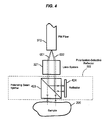
- FIG. 4 shows details of the probe head 320 and an example of the polarization-selective reflector (PSR) 322 according to one implementation.
- the PSR 322 includes a polarizing beam splitter (PBS) 423 and a reflector or mirror 424 in a configuration as illustrated where the PBS 423 transmits the selected mode (e.g., mode 002 ) to the sample 205 and reflects and diverts the other mode (e.g., mode 001 ) away from the sample 205 and to the reflector 424 .
- the reflected mode 001 is directed back to the PBS 423 and the lens system 321 .
- the reflector 424 may be a reflective coating on one side of beam splitter 423 .
- the reflector 424 should be aligned to allow the reflected radiation to re-enter the polarization-maintaining fiber 372 .
- the transmitted light in the mode 002 impinges the sample 205 and the light reflected and back scattered by the sample 205 in the mode 002 transmits through the PBS 423 to the lens system 321 .
- the lens system 321 couples the light in both the modes 001 and 002 into the fiber 372 .
- the detection system 260 includes a polarizing beam splitter 361 , and two photodetectors 362 and 363 .
- the polarizing beam splitter 361 is used to receive the two independent polarization modes 001 and 002 from the modulator 250 and superposes the two independent polarization modes 001 and 002 .
- the beam splitter 361 may be oriented in such a way that, each independent polarization is split into two parts and, for each independent polarization mode, the two split portions possess the same amplitude.
- the polarizing beam splitter 361 may be oriented so that the incident plane of its reflection surface makes a 45-degree angle with one of the two independent polarization mode, 001 or 002 .
- the system in FIG. 3 further implements an electronic controller or control electronics 370 to receive and process the detector outputs from the photodetectors 362 and 363 and to control operations of the systems.
- the electronic controller 370 may be used to control the probe head 320 and the differential delay modulator 250 .
- Differential delay modulator 250 under the control of the electronics and programs, generates a form of differential phase modulation as the differential path length scans through a range that matches a range of depth inside the sample 205 .
- the electronic controller 370 may also be programmed to record and extract the amplitude of the oscillation in the measured signal characterized by Eq. (3) at various differential path lengths generated by the modulator 250 . Accordingly, a profile of reflection as a function of the depth can be obtained as a one-dimensional representation of the sample inhomogeneity at a selected location on the sample 205 .
- the probe head 320 may be controlled via a position scanner such as a translation stage or a piezo-electric positioner so that the probing light scans in a lateral direction, perpendicular to the light propagation direction. For every increment of the lateral scan a profile of reflection as a function of depth can be recorded with the method described above. The collected information can then be displayed on a display and interface module 372 to form a cross-sectional image that reveals the inhomogeneity of the sample 205 .
- a position scanner such as a translation stage or a piezo-electric positioner
- a lateral scanning mechanism may be implemented in each device described in this application to change the relative lateral position of the optical probe head and the sample to obtain a 2-dimensional map of the sample.
- a xy-scanner for example, may be engaged either to the optical head or to a sample holder that holds the sample to effectuate this scanning in response to a position control signal generated from the electronic controller 370 .
- FIGS. 5A and 5B illustrate another exemplary system that use waveguides 271 , 272 , and 273 and a light director 210 to direct light in two modes to and from the probe head 320 in measuring the sample 205 .
- a first optical polarizer 510 is oriented with respect to the polarization axes of the PM waveguide 271 to couple radiation from the broadband light source 201 into the waveguide 271 in two orthogonal linear polarization modes as the independent propagation modes.
- An optical phase modulator 520 is coupled in the waveguide 271 to modulate the optical phase of light in one guided mode relative to the other.
- VDGD variable differential group delay
- a second optical polarizer 540 and an optical detector 550 are used here to form a detection system.
- the second polarizer 540 is oriented to project both of the guided waves onto the same polarization direction so that the changes in optical path difference and the optical phase difference between the two propagation modes cause intensity variations, detectable by the detector 550 .
- the light from the source 201 is typically partially polarized.
- the polarizer 510 may be aligned so that maximum amount of light from the source 201 is transmitted and that the transmitted light is coupled to both of the guided modes in the waveguide 271 with the substantially equal amplitudes.
- E the electric field transmitting the polarizer
- the light has a finite spectral width (broadband or partially coherent).
- the VDGD 530 or a static phase shift in the modulator 520 may be used to adjust the phase difference between the two modes to eliminate ⁇ .
- the waveform of I is graphically shown in FIG. 4 .
- FIG. 6 illustrates the waveform of the intensity I received at the detector 550 as a function of the phase.
- the detected light intensity exhibits an oscillating waveform that possesses a base frequency of ⁇ and its harmonics.
- the amplitudes of the base frequency and each of the harmonics are related to ⁇ and
- the mathematical expressions for the relationships between r and the harmonics can be derived.
- sin ⁇ ; (13a) A 2 ⁇ 0.5
- FIG. 7 further shows one exemplary operation of the described system in FIG. 5B or the system in FIG. 3 for acquiring images of optical inhomogeneity.
- the relative phase delay between the two modes is changed, e.g., increased by an increment, to a fixed value for measuring the sample 205 at a corresponding depth. This may be accomplished in FIG. 5B by using the differential delay device 530 or the bias in the differential delay modulator 250 in FIG. 3 .
- a modulation driving signal is sent to the modulator 520 in FIG. 5B or the modulator 250 in FIG. 3 to modulate the relative phase delay between the two modes around the fixed value.
- the electronic controller 370 controls the differential delay device 530 in FIG. 5B or the bias in the differential delay modulator 250 in FIG. 3 to change the relative phase delay between the two modes to a different fixed value for measuring the sample 205 at a different depth.
- This process iterates as indicated by the processing loop 740 until desired measurements of the sample at different depths at the same location are completed.
- electronic controller 370 controls the probe head 320 to laterally move to a new location on the sample 205 and repeat the above measurements again until all desired locations on the sample 205 are completed. This operation is represented by the processing loop 750 .
- the electronic controller 370 processes each measurement to compute the values of ⁇ and
- the computed data is sent to the display module 372 .
- light for sensing the sample 205 is not separated into two parts that travel along two different optical paths.
- Two independent propagation modes of the light are guided essentially in the same waveguide at every location along the optical path except for the extra distance traveled by one mode between the probe head 320 and the sample 205 .
- the two modes are continuously guided in the same waveguide at every location along the optical path to the detection module.
- the light from the light source to the probe head may be controlled in a single propagation mode (e.g., a first propagation mode) rather than two different modes.
- the probe head may be designed to cause a first portion of the first mode to reverse its propagation direction while directing the remaining portion, or a second portion, to reach the sample.
- the reflection or back scattered light of the second portion from the sample is collected by the probe head and is controlled in the second propagation mode different from the first mode to produce a reflected second portion.
- Both the reflected first portion in the first propagation mode and the reflected second portion in the second propagation mode are directed by the probe head through a common waveguide into the detection module for processing.
- this alternative design further improves the stability of the relative phase delay between the two modes at the detection module and provides additional implementation benefits.
- FIGS. 8A and 8B illustrate one exemplary design of the optical layout of the optical sensing system and its system implementation with an electronic controller.
- An input waveguide 871 is provided to direct light in a first propagation mode, e.g., the mode 001 , from the broadband light source 201 to a light director 810 .
- the waveguide 871 may be a mode maintaining waveguide designed to support at least one propagation mode such as the mode 001 or 002 .
- the waveguide 871 When light is coupled into the waveguide 871 in a particular mode such as the mode 001 , the waveguide 871 essentially maintains the light in the mode 001 .
- a polarization maintaining fiber supporting two orthogonal linear polarization modes, for example, may be used as the waveguide 871 .
- dual-mode waveguides 272 and 273 are used to direct the light.
- a light director 510 is used to couple the waveguides 871 , 272 , and 273 , to convey the mode 001 from the input waveguide 871 to one of the two modes (e.g., modes 001 and 002 ) supported by the dual-mode waveguide 272 , and to direct light in two modes from the waveguide 272 to the dual-mode waveguide 273 .
- the light director 810 couples the light in the mode 001 from the waveguide 871 into the same mode 001 in the waveguide 272 .
- the light director 810 may couple the light in the mode 001 from the waveguide 871 into the different mode 002 in the waveguide 272 .
- the dual-mode waveguide 271 is terminated at the other end by a probe head 820 which couples a portion of light to the sample 205 for sensing.
- the probe head 820 is designed differently from the prove head 320 in that the probe head 830 converts part of light in the mode 001 into the other different mode 002 when the light is reflected or scattered back from the sample 205 .
- the probe head 820 converts that part of light in the mode 002 into the other different mode 001 when the light is reflected or scattered back from the sample 205 .
- the probe head 820 performs these functions: a) to reverse the propagation direction of a small portion of the incoming radiation in mode 001 ; b) to reshape the remaining radiation and transmit it to the sample 205 ; and c) to convert the radiation reflected from the sample 205 to an independent mode 002 supported by the dual-mode waveguide 272 . Since the probe head 820 only converts part of the light into the other mode supported by the waveguide 272 , the probe head 820 is a partial mode converter in this regard.
- the probe head 820 Due to the operations of the probe head 820 , there are two modes propagating away from the probe head 820 , the mode 001 that bypasses the sample 205 and the mode 002 for light that originates from sample reflection or back scattering. From this point on, the structure and operations of the rest of the system shown in FIG. 8A may be similar to the systems in FIGS. 2 , 3 , 5 A, and 5 B.
- FIG. 8B shows an exemplary implementation of the design in FIG. 8A where an electronic controller 3370 is used to control the differential delay modulator 250 and the probe head 820 and a display and interface module 372 is provided.
- Radiation from broadband light source 201 which may be partially polarized, is further polarized and controlled by an input polarization controller 802 so that only a single polarization mode is excited in polarization-maintaining fiber 371 as the waveguide 871 in FIG. 8A.
- a polarization preserving circulator may be used to implement the light director 810 for routing light from the waveguide 371 to the waveguide 372 and from the waveguide 372 to the waveguide 373 .
- the probe head 820 in FIG. 8B may be designed to include a lens system 821 similar to the lens system 321 , a partial reflector 822 , and a polarization rotator 823 .
- the partial reflector 822 is used to reflect the first portion of light received from the waveguide 372 back to the waveguide 372 without changing its propagation mode and transmits light to and from the sample 205 .
- the polarization rotator 823 is used to control the light from the sample 205 to be in the mode 002 upon entry of the waveguide 372 .
- FIG. 9 shows another example of a system implementation where the optical probe head 820 receives light in a single input mode and converts part of light into a different mode.
- An input polarizer 510 is used in the input PM fiber 272 to control the input light in the single polarization mode.
- a phase modulator 520 and a variable differential group delay device 530 are coupled to the output PM fiver 273 to control and modulate the relative phase delay of the two modes before optical detection.
- An output polarizer 540 is provided to mix the two modes and the detector 550 is used to detect the output from the output polarizer 540 .
- FIGS. 10A and 10B show two examples of the possible designs for the probe head 820 including a partially reflective surface 1010 , a lens system 1020 , and a quarter-wave plate 1030 for rotating the polarization and to convert the mode.
- the termination or end facet of polarization-maintaining fiber 372 is used as the partial reflector 1010 .
- An uncoated termination of an optical fiber reflects approximately 4% of the light energy. Coatings can be used to alter the reflectivity of the termination to a desirable value.
- the lens system 1020 reshapes and delivers the remaining radiation to sample 205 .
- the other role played by the lens system 1020 is to collect the radiation reflected from the sample 205 back into the polarization-maintaining fiber 372 .
- the quarter wave plate 1030 is oriented so that its optical axis make a 45-degree angle with the polarization direction of the transmitted light. Reflected light from the sample 205 propagates through the quarter wave plate 1030 once again to become polarized in a direction perpendicular to mode 001 , i.e. mode 002 .
- the quarter wave plate 1030 may be replaced by a Faraday rotator.
- the head design in FIG. 10B changes the positions of the lens system 1020 and the quarter wave plate or Faraday rotator 1030 .
- the light director 810 or the polarization preserving circulator may be constructed with a polarization-maintaining optical circulator 1110 and two polarization beam splitters 1120 and 1130 as shown in FIG. 11 .
- the polarization-maintaining circulator 1110 is used to convey only one polarization mode among its three ports, rather than both modes as in the case shown in FIGS. 3 , 5 A and 5 B.
- the polarizing beam splitter 1120 and 1130 are coupled to polarization-maintaining circulator 1110 so that both polarization modes entering Port 2 are conveyed to Port 3 and remain independent.
- FIG. 12 illustrates the general design of the modulator 250 where an external control signal is applied to control a differential delay element to change and modulate the relative delay in the output. Either mechanical or non-mechanical elements may be used to produce the desired relative delay between the two modes and the modulation on the delay.
- a non-mechanical design may include one or more segments of tunable birefringent materials such as liquid crystal materials or electro-optic birefringent materials such as lithium niobate crystals in conjunction with one or more fixed birefringent materials such as quartz and rutile.
- the fixed birefringent material provides a fixed delay between two modes and the tunable birefringent material provides the tuning and modulation functions in the relative delay between the two modes.
- FIG. 12A illustrates an example of this non-mechanical design where the two modes are not physically separated and are directed through the same optical path with birefringent segments which alter the relative delay between two polarization modes.
- FIG. 12B shows a different design where the two modes in the received light are separated by a mode splitter into two different optical paths.
- a variable delay element is inserted in one optical path to adjust and modulate the relative delay in response to an external control signal.
- a mode combiner is then used to combine the two modes together in the output.
- the mode splitter and the mode combiner may be polarization beams splitters when two orthogonal linear polarizations are used as the two modes.
- variable delay element in one of the two optical paths may be implemented in various-configurations.
- the variable delay element may be a mechanical element.
- a mechanical implementation of the device in FIG. 12B may be constructed by first separating the radiation by polarization modes with a polarizing beam splitter, one polarization mode propagating through a fixed optical path while the other propagating through a variable optical path having a piezoelectric stretcher of polarization maintaining fibers, or a pair of collimators both facing a mechanically movable retroreflector in such a way that the light from one collimator is collected by the other through a trip to and from the retroreflector, or a pair collimators optically linked through double passing a rotatable optical plate and bouncing off a reflector.
- FIGS. 13A and 13B illustrate two examples of a mechanical variable delay element suitable for FIG. 12 B.
- a mechanical variable delay device may be used to change the optical path length of a light beam at high speeds and may have various applications other than what is illustrated in FIG. 12 B.
- the optical systems in this application may use such a delay device.
- the mechanical delay device shown in FIG. 13A includes an optical beam splitter 1310 , a rotating optical plate 1320 which may be a transparent plate, and a mirror or reflector 1330 .
- the beam splitter 1310 is used as the input port and the output port for the device.
- the rotating optical plate 1320 is placed between the mirror 1330 and the beam splitter 1310 .
- the input light beam 1300 is received by the beam splitter 1310 along the optical path directing from the beam splitter 1310 to the mirror 1330 through the rotating optical plate 1320 .
- a portion of the light 1300 transmitting through the beam splitter 1310 is the beam 1301 which impinges on and transmits through the rotating optical plate 1320 .
- the mirror or other optical reflector 1330 is oriented to be perpendicular to the light beam incident to the optical plate 1310 from the opposite side.
- the reflected light beam 1302 from the mirror 1320 traces the same optical path back traveling until it encounters the Beam Splitter 1310 .
- the Beam Splitter 1310 deflects part of the back traveling light 1302 to a different direction as the output beam 1303 .
- the variation of the optical path length is caused by the rotation of the Optical Plate 1320 .
- the Optical Plate 1320 may be made of a good quality optical material.
- the two optical surfaces may be flat and well polished to minimize distortion to the light beam.
- the two surfaces should be parallel to each other so that the light propagation directions on both sides of the Optical Plate 1320 are parallel.
- the thickness of the Optical Plate 1320 may be chosen according to the desirable delay variation and the range of the rotation angle.
- the optical path length experienced by the light beam is determined by the rotation angle of the Optical Plate 1320 . When the surfaces of the Optical Plate 1320 is perpendicular to the light beam (incident angle is zero), the path length is at its minimum. The path length increases as the incident angle increases.
- the Optical Plate 1320 may be mounted on a motor for periodic variation of the optical delay.
- a good quality mirror with a flat reflecting surface should be used to implement the mirror 1330 .
- the reflecting surface of the mirror 1330 may be maintained to be perpendicular to the light beam.
- a linearly polarized light is used as the input beam 1300 in FIG. 13A , it is beneficial to have the polarization direction of the light parallel to the incident plane (in the plane of the paper) as less reflection occurs at the surfaces of Optical Plate 1320 for this polarization compared to other polarization directions.
- Antireflection coatings can be used to further reduce the light reflection on the surfaces of the Optical Plate 1320 .
- the beam splitter 1310 used in FIG. 13A uses both its optical transmission and optical reflection to direct light.
- This aspect of the beam splitter 1310 causes reflection loss in the output of the device due to the reflection loss when the input light 1300 first enters the device through transmission of the beam splitter 1310 and the transmission loss when the light exits the device through reflection of the beam splitter 1310 .
- a maximum of 25% of the total input light may be left in the output light if the beam splitter is a 50/50 beam splitter.
- an optical circulator may be used in place of the beam splitter 1320 .
- optical circulator 1340 illustrates an example where the optical circulator 1340 with 3 ports is used to direct input light to the optical plate 1320 and the mirror 1330 and directs returned light to the output port.
- the optical circulator 1340 may be designed to direct nearly all light entering its port 1 to port 2 and nearly all light entering its port 2 to the port 3 with nominal optical loss and hence significantly reduces the optical loss in the device.
- Commercially available optical circulators either free-space or fiber-based, may be used to implement the circulator 1340 .
- FIG. 14A shows an exemplary implementation of the delay device in FIG. 12B as part of or the entire differential delay modulator 250 .
- a first optical mode splitter 1410 is used to separate two modes in the waveguide 373 into two paths having two mirrors 1431 and 1432 , respectively.
- a second optical mode splitter 1440 which is operated as a mode combiner, is used to combine the two modes into an output. If the two modes are two orthogonal linear polarizations, for example, polarization beam splitters may be used to implement the 1410 and 1440 .
- a variable optical delay line or device 1420 is placed in the upper path to control the differential delay between the two paths. The output may be coupled into another dual-mode waveguide 1450 leading to the detection module or directly sent into the detection module.
- FIG. 14B shows a delay device based on the design in FIG. 14A where the mirror 1432 and the variable optical delay line 1420 are implemented by the mechanical delay device in FIG. 13 A.
- the mechanical delay device in FIG. 13B may also be used to implement the device in FIG. 14 A.
- a single dual-mode waveguide 272 or 372 is used as an input and output waveguide for the probe head 220 , 320 , or 820 .
- the input light either in a single mode or two independent modes, is directed into the probe head through that dual-mode waveguide 272 or 372 , and the output light in the two independent modes is also directed from the probe head to the detection subsystem or detector.
- the single dual-mode waveguide 272 or 372 may be replaced by two separate waveguides, one to direct input light from the light source to the probe head and another to direct light from the probe head to the detection subsystem or detector.
- the device in FIG. 2 may have a second waveguide different from the waveguide 272 to direct reflected light in two different modes from the optical probe head 220 to the modulator 250 and the detection subsystem 260 .
- the light director 210 may be eliminated. This may be an advantage.
- the optics within the probe head may be designed to direct the reflected light in two modes to the second waveguide.
- FIG. 15 illustrates an example for this design as an alternative to the device shown in FIG. 5 B.
- the probing light is delivered to the sample 205 through one dual-mode waveguide 1510 and the reflected/scattered light is collected by the probe head 320 and is directed through another dual-mode waveguide 1520 .
- the mirror 424 may be oriented and aligned so that the light is reflected into the waveguide 1520 instead of the waveguide 1510 .
- This design may be applied to other devices based on the disclosure of this application, including the exemplary devices in FIGS. 2 , 3 , 8 A, 8 B and 9 .
- the above-described devices and techniques may be used to obtain optical measurements of a given location of the sample at different depths by controlling the relative phase delay between two modes at different values and optical measurements of different locations of the sample to get a tomographic map of the sample at a given depth or various depths by laterally changing the relative position of the probe head over the sample.
- Such devices and techniques may be further used to perform other measurements on a sample, including spectral selective measurements on a layer of a sample.
- a tunable bandpass filter may be used to either filter the light incident to the probe head to select a desired spectral window within the broadband spectrum of the incident light to measure the response of the sample and to vary the center wavelength of the spectral window to measure a spectral distribution of the responses of the sample.
- This tuning of the bandpass filter allows a variable portion of the source spectrum to pass while measuring the distribution of the complex reflection coefficient of the sample.
- the broadband light may be sent to the optical probe head without optical filtering and the spectral components at different wavelengths in the output light from the probe head may be selected and measured to measure the response of the sample around a selected wavelength or the spectral distribution of the responses of the sample.
- a tunable optical bandpass filter may be inserted in the optical path of the output light from the probe head to filter the light.
- a grating or other diffractive optical element may be used to optically separate different spectral components in the output light to be measured by the detection subsystem or the detector.
- FIG. 16 shows a system based on the design in FIG. 2 where a tunable filter 1610 is inserted in the input waveguide 271 to filter the input light in two different modes.
- FIG. 17 shows another exemplary system based on the design in FIG. 8A where a tunable filter 1710 is inserted in the input waveguide 871 to filter the input light in a single mode.
- a tunable filter may be placed in other locations.
- FIG. 18 illustrates the operation of the tunable bandpass filter in the devices in FIGS. 16 and 17 .
- the filter selects a narrow spectral band within the spectrum of the light source to measure the spectral feature of the sample.
- the devices and techniques of this application may be used to select a layer within a sample to measure by properly processing the measured data.
- the absorption characteristics of a layer bounded by interfaces I and II is to be measured.
- the spectral absorption of the substance in the layer is characterized by a wavelength-dependent attenuation coefficient ⁇ h ( ⁇ ) and that of other volume is characterized by ⁇ g ( ⁇ ).
- ⁇ h wavelength-dependent attenuation coefficient
- ⁇ g ⁇
- the substance in the vicinity of interface I (II) possesses an effective and wavelength independent reflection coefficient r I (r II ).
- an optical filter 1610 or 1710 with a bass band tunable across the characteristic absorption of the sample 205 may be used to measure the spectral responses of the sample 205 centered at different wavelengths.
- the differential delay modulator 250 is adjusted so that the path length traveled by one mode (e.g., the mode 001 ) matches that of radiation reflected from interface I in the other mode (e.g., the mode 002 ).
- the pass band of filter 1610 or 1710 may be scanned while recording the oscillation of the measured signal due to a periodic differential phase generated by the modulator 250 .
- the differential delay modulator 250 is adjusted again to change the differential delay so that the path length traveled by the mode 001 matches that of radiation reflected from interface II in the mode 002 .
- the pass band of the optical filter 1610 or 1710 may be designed to be sufficiently narrow to resolve the absorption characteristics of interest and at the meantime broad enough to differentiate the layer of interest.
- the following example for monitoring the glucose level by optically probing a patient's skin shows that this arrangement is reasonable and practical.
- the designated layer may be the dermis layer where glucose is concentrated in a network of blood vessels and interstitial fluid.
- FIG. 19A illustrates an example of a human skin tissue where the coherence gating technique described here can be used to measure the glucose concentration in the dermis layer between the epidermis and the subcutaneous layers.
- the dermis layer may be optically selected and measured with the coherence gating technique. It is known that the superficial epidermis layer, owing to its pigment content, is the dominant source of NIR absorption. Because of the absence of blood, however, the epidermis yields no useful information for glucose monitoring.
- the coherent gating technique can be applied to acquire solely the absorbance spectrum of the dermis layer by rejecting the absorptions of the epidermis and the subcutaneous tissues.
- An additional advantage of this technique is from the fact that dermis exhibits less temperature variation compared to the epidermis. It is known that surface temperature variation causes shifts of water absorption, hampering glucose monitoring.
- FIG. 19B shows some predominant glucose absorption peaks in blood in a wavelength range between 1 and 2.5 microns.
- the width of these peaks are approximately 150 nm.
- the bandwidth of the tunable bandpass filter may be chosen to be around 30 nm.
- human skin consists of a superficial epidermis layer that is typically 0.1 mm thick. Underneath epidermis is the dermis, approximately 1 mm thick, where glucose concentrates in blood and interstitial fluids.
- the above analysis indicates that it is possible to use the apparatus shown in FIGS. 16 and 17 to isolate the absorption characteristics of the dermis from that of the epidermis and other layers.
- the tunable bandpass filter 1610 or 1710 may be operated to acquire the absorption characteristics of an isolated volume inside a sample.
- FIG. 20 illustrates one exemplary implementation of the detection subsystem 260 in FIG. 3 where two diffraction gratings 2010 and 2020 are used to separate different spectral components in the output light beams from the polarizing beam splitter 361 .
- a lens 2012 is positioned to collect the diffracted components from the grating 2010 and focus different spectral components to different locations on its focal plane.
- a detector array 2014 with multiple photodetector elements is placed at the focal plane of the lens 2012 so that different spectral components are received by different photodetector elements.
- a second lens 2022 and a detector array 2024 are used in the optical path of the diffracted components in a similar way. In devices shown in FIGS. 5A , 5 B, 8 A, and 8 B where a single optical detector is used for measurements, a single grating, a lens, and a detector array may be used.
- each detector element receives light in a small wavelength interval.
- the photocurrents from all elements in an array can be summed to form a signal which is equivalent to the signal received in each single detector without the grating shown in FIG. 3 .
- the spectral information of the sample can be obtained.
Abstract
Description
-
- 1. Ser. No. 60/475,673 entitled “Method and Apparatus for Acquiring Images of Optical Inhomogeneity in Substances” and filed Jun. 4, 2003;
- 2. Ser. No. 60/514,768 entitled “Coherence-Gated Optical Glucose Monitor” and filed Oct. 27, 2003;
- 3. Ser. No. 60/526,935 entitled “Method and Apparatus for Acquiring Images of Optical Inhomogeneity in Substances” and filed Dec. 4, 2003; and
- 4. Ser. 60/561,588 entitled “Acquiring Information of Optical Inhomogeneity and Other Properties in Substances” and filed Apr. 12, 2004.
It is assumed that all components in the system, except for the
where φ is the phase delay associated with the reflection from the sample. A convenient way to characterize the reflection coefficient r is to measure the difference of the above two intensities, i.e.
I A−I B =|r|E 001 E 002 cos(Γ−φ). (3)
If Γ is modulated by the
I A −I B =|r|E 001 E 002 cos[M sin(Ωt)−φ]. (4)
It is clear from Eq. (4) that the measured exhibits an oscillation at a base frequency of Ω and oscillations at harmonic frequencies of the base frequency Ω. The amplitudes of the base frequency and each of the harmonics are related to φ and |r|. The relationships between r and the harmonics can be derived. For instance, the amplitude of the base-frequency oscillation and the second harmonic can be found from Eq. (4) to be:
A Ω =E 001 E 002 J 1(M)|r|sin φ; (5a)
A 2Ω =E 001 E 002 J 2(M)|r|cos φ, (5b)
where J1 and J2 are Bessel functions of the first and second order, respectively. Eq. (5a) and (5b) can be used to solve for |r| and φ, i.e. the complete characterization of r. We can therefore completely characterize the complex reflection coefficient r by analyzing the harmonic content of various orders in the measured signal. In particular, the presence of the base-frequency component in the measured is due to the presence of φ.
where the electric field transmitting the polarizer is denoted as E. It should be appreciated that the light has a finite spectral width (broadband or partially coherent). The fields can be described by the following Fourier integral:
E=∫E ω e jωt dω. (7)
For the simplicity of the analysis, a thin slice of the spectrum, i.e. a lightwave of a specific wavelength, is considered below. Without loosing generality, it is assumed that all the components, including polarizers, waveguides, Router, PSR and VDGD, are lossless. Let us designate the reflection coefficient of the sample r, that is complex in nature. The p-wave picks up an optical phase, Γ, relative to the s-wave as they reach the second polarizer 540:
The light that passes through
The intensity of the light that impinges on the
where phase angle δ reflects the complex nature of the reflection coefficient of the
r=|r|e jδ. (11)
Assuming the
where phase angle φ is the accumulated phase slip between the two modes, not including the periodic modulation due to the
A 106 =0.5|E| 2 J 1(M)|r|sin δ; (13a)
A 2Ω=0.5|E| 2 J 2(M)|r|cos δ, (13b)
where J1 and J2 are Bessel functions of the first and second order, respectively. Eq. (13a) and (13b) can be used to solve for |r| and δ, i.e. the complete characterization of r.
It is easy to see that if the range of φ(λ) is comparable to π for the bandwidth of the light source no oscillation in I can be observed as oscillations for different wavelengths cancel out because of their phase difference. This phenomenon is in close analogy to the interference of white light wherein color fringes are visible only when the path difference is small (the film is thin). The above analysis demonstrates that the use of a broadband light source enables range detection using the proposed apparatus. In order to do so, let the s-wave to have a longer optical path in the system compared to the p-wave (not including its round-trip between Probing Head and Sample). For any given path length difference in the system there is a matching distance between Probing Head and Sample, z, that cancels out the path length difference. If an oscillation in I is observed the p-wave must be reflected from this specific distance z. By varying the path length difference in the system and record the oscillation waveforms we can therefore acquire the reflection coefficient r as a function of the longitudinal distance z, or depth. By moving Probing Head laterally, we can also record the variation of r in the lateral directions.
A I(λ)=r I e −2μ
where zI is the distance of interface I measured from the top surface of the
A II(λ)=r II e −2μ
where zII is the distance of interface II measured from interface I. To acquire the absorption characteristics of the layer bounded by the interfaces I and II, Eq. (7) and Eq. (6) can be used to obtain the following ratio:
Notably, this equation provides the information on the absorption characteristics of the layer of interest only and this allows measurement on the layer. This method thus provides a “coherence gating” mechanism to optically acquire the absorbance spectrum of a particular and designated layer beneath a sample surface.
Therefore, the coherence gating implemented with the devices in
Claims (83)
Priority Applications (13)
| Application Number | Priority Date | Filing Date | Title |
|---|---|---|---|
| US10/860,094 US6943881B2 (en) | 2003-06-04 | 2004-06-03 | Measurements of optical inhomogeneity and other properties in substances using propagation modes of light |
| PCT/US2004/017649 WO2005001522A2 (en) | 2003-06-04 | 2004-06-04 | Measurements of optical inhomogeneity and other properties in substances using propagation modes of light |
| CA2528417A CA2528417C (en) | 2003-06-04 | 2004-06-04 | Measurements of optical inhomogeneity and other properties in substances using propagation modes of light |
| US10/963,948 US7263394B2 (en) | 2003-06-04 | 2004-10-12 | Coherence-gated optical glucose monitor |
| US11/200,498 US7259851B2 (en) | 2003-06-04 | 2005-08-08 | Optical measurements of properties in substances using propagation modes of light |
| US11/842,913 US7456965B2 (en) | 2003-06-04 | 2007-08-21 | Optical measurements of properties in substances using propagation modes of light |
| US12/323,396 US20090073444A1 (en) | 2003-06-04 | 2008-11-25 | Optical measurements of properties in substances using propagation modes of light |
| US12/569,835 US7999938B2 (en) | 2003-06-04 | 2009-09-29 | Measurements of optical inhomogeneity and other properties in substances using propagation modes of light |
| US12/572,889 US20100091282A1 (en) | 2003-06-04 | 2009-10-02 | Optical Measurements of Properties in Substances Using Propagation Modes of Light |
| US12/947,823 US20110063616A1 (en) | 2003-06-04 | 2010-11-16 | Optical measurements of properties in substances using propagation modes of light |
| US13/195,823 US20110285996A1 (en) | 2003-06-04 | 2011-08-01 | Optical measurements of properties in substances using propagation modes of light |
| US13/481,733 US20130100442A1 (en) | 2003-06-04 | 2012-05-25 | Optical measurements of properties in substances using propagation modes of light |
| US14/049,196 US9134231B2 (en) | 2003-06-04 | 2013-10-08 | Optical measurements of properties in substances using propagation modes of light |
Applications Claiming Priority (5)
| Application Number | Priority Date | Filing Date | Title |
|---|---|---|---|
| US47567303P | 2003-06-04 | 2003-06-04 | |
| US51476803P | 2003-10-27 | 2003-10-27 | |
| US52693503P | 2003-12-04 | 2003-12-04 | |
| US56158804P | 2004-04-12 | 2004-04-12 | |
| US10/860,094 US6943881B2 (en) | 2003-06-04 | 2004-06-03 | Measurements of optical inhomogeneity and other properties in substances using propagation modes of light |
Related Parent Applications (1)
| Application Number | Title | Priority Date | Filing Date |
|---|---|---|---|
| US10/861,697 Continuation-In-Part US6903820B2 (en) | 2003-06-04 | 2004-06-04 | Measurements of substances using two different propagation modes of light through a common optical path |
Related Child Applications (5)
| Application Number | Title | Priority Date | Filing Date |
|---|---|---|---|
| US10/567,185 Continuation-In-Part US7595879B2 (en) | 2003-06-04 | 2004-06-04 | Optically measuring substances using propagation modes of light |
| PCT/US2004/017649 Continuation-In-Part WO2005001522A2 (en) | 2003-06-04 | 2004-06-04 | Measurements of optical inhomogeneity and other properties in substances using propagation modes of light |
| US10/963,948 Continuation-In-Part US7263394B2 (en) | 2003-06-04 | 2004-10-12 | Coherence-gated optical glucose monitor |
| US11/200,498 Continuation US7259851B2 (en) | 2003-06-04 | 2005-08-08 | Optical measurements of properties in substances using propagation modes of light |
| US11/567,185 Continuation-In-Part US8121915B1 (en) | 2006-08-16 | 2006-12-05 | Generating financial plans using a personal information aggregator |
Publications (2)
| Publication Number | Publication Date |
|---|---|
| US20050018202A1 US20050018202A1 (en) | 2005-01-27 |
| US6943881B2 true US6943881B2 (en) | 2005-09-13 |
Family
ID=37544710
Family Applications (11)
| Application Number | Title | Priority Date | Filing Date |
|---|---|---|---|
| US10/860,094 Active 2024-08-23 US6943881B2 (en) | 2003-06-04 | 2004-06-03 | Measurements of optical inhomogeneity and other properties in substances using propagation modes of light |
| US10/567,185 Active 2025-07-12 US7595879B2 (en) | 2003-06-04 | 2004-06-04 | Optically measuring substances using propagation modes of light |
| US10/861,697 Active US6903820B2 (en) | 2003-06-04 | 2004-06-04 | Measurements of substances using two different propagation modes of light through a common optical path |
| US11/200,498 Active US7259851B2 (en) | 2003-06-04 | 2005-08-08 | Optical measurements of properties in substances using propagation modes of light |
| US11/842,913 Active US7456965B2 (en) | 2003-06-04 | 2007-08-21 | Optical measurements of properties in substances using propagation modes of light |
| US12/323,396 Abandoned US20090073444A1 (en) | 2003-06-04 | 2008-11-25 | Optical measurements of properties in substances using propagation modes of light |
| US12/569,835 Active US7999938B2 (en) | 2003-06-04 | 2009-09-29 | Measurements of optical inhomogeneity and other properties in substances using propagation modes of light |
| US12/572,889 Abandoned US20100091282A1 (en) | 2003-06-04 | 2009-10-02 | Optical Measurements of Properties in Substances Using Propagation Modes of Light |
| US12/947,823 Abandoned US20110063616A1 (en) | 2003-06-04 | 2010-11-16 | Optical measurements of properties in substances using propagation modes of light |
| US13/195,823 Abandoned US20110285996A1 (en) | 2003-06-04 | 2011-08-01 | Optical measurements of properties in substances using propagation modes of light |
| US13/481,733 Abandoned US20130100442A1 (en) | 2003-06-04 | 2012-05-25 | Optical measurements of properties in substances using propagation modes of light |
Family Applications After (10)
| Application Number | Title | Priority Date | Filing Date |
|---|---|---|---|
| US10/567,185 Active 2025-07-12 US7595879B2 (en) | 2003-06-04 | 2004-06-04 | Optically measuring substances using propagation modes of light |
| US10/861,697 Active US6903820B2 (en) | 2003-06-04 | 2004-06-04 | Measurements of substances using two different propagation modes of light through a common optical path |
| US11/200,498 Active US7259851B2 (en) | 2003-06-04 | 2005-08-08 | Optical measurements of properties in substances using propagation modes of light |
| US11/842,913 Active US7456965B2 (en) | 2003-06-04 | 2007-08-21 | Optical measurements of properties in substances using propagation modes of light |
| US12/323,396 Abandoned US20090073444A1 (en) | 2003-06-04 | 2008-11-25 | Optical measurements of properties in substances using propagation modes of light |
| US12/569,835 Active US7999938B2 (en) | 2003-06-04 | 2009-09-29 | Measurements of optical inhomogeneity and other properties in substances using propagation modes of light |
| US12/572,889 Abandoned US20100091282A1 (en) | 2003-06-04 | 2009-10-02 | Optical Measurements of Properties in Substances Using Propagation Modes of Light |
| US12/947,823 Abandoned US20110063616A1 (en) | 2003-06-04 | 2010-11-16 | Optical measurements of properties in substances using propagation modes of light |
| US13/195,823 Abandoned US20110285996A1 (en) | 2003-06-04 | 2011-08-01 | Optical measurements of properties in substances using propagation modes of light |
| US13/481,733 Abandoned US20130100442A1 (en) | 2003-06-04 | 2012-05-25 | Optical measurements of properties in substances using propagation modes of light |
Country Status (4)
| Country | Link |
|---|---|
| US (11) | US6943881B2 (en) |
| JP (1) | JP4756218B2 (en) |
| CA (1) | CA2528417C (en) |
| WO (1) | WO2005001522A2 (en) |
Cited By (20)
| Publication number | Priority date | Publication date | Assignee | Title |
|---|---|---|---|---|
| US20060079762A1 (en) * | 2004-10-12 | 2006-04-13 | Norris Peter E | Integrated disease diagnosis and treatment system |
| US20060153739A1 (en) * | 2005-01-13 | 2006-07-13 | Hilderbrand Glen D | Methods and systems for testing materials |
| US20060176472A1 (en) * | 2005-02-10 | 2006-08-10 | Picosolve Inc. | Polarization independent optical sampling arrangement |
| US20060215076A1 (en) * | 2005-03-22 | 2006-09-28 | Karim John H | Selective light transmitting and receiving system and method |
| US20070015969A1 (en) * | 2005-06-06 | 2007-01-18 | Board Of Regents, The University Of Texas System | OCT using spectrally resolved bandwidth |
| US20070103683A1 (en) * | 2003-06-04 | 2007-05-10 | Feiling Wang | Optically measuring substances using propagation modes of light |
| WO2007140356A2 (en) * | 2006-05-26 | 2007-12-06 | Medeikon Corporation | Polarization insensitive multiple probe |
| US20080267562A1 (en) * | 2007-04-24 | 2008-10-30 | Feiling Wang | Delivering light via optical waveguide and multi-view optical probe head |
| US7809420B2 (en) | 2003-06-25 | 2010-10-05 | Nellcor Puritan Bennett Llc | Hat-based oximeter sensor |
| US7822453B2 (en) | 2002-10-01 | 2010-10-26 | Nellcor Puritan Bennett Llc | Forehead sensor placement |
| US7831298B1 (en) | 2005-10-04 | 2010-11-09 | Tomophase Corporation | Mapping physiological functions of tissues in lungs and other organs |
| US20110029049A1 (en) * | 2009-04-29 | 2011-02-03 | Tomophase Corporation | Image-Guided Thermotherapy Based On Selective Tissue Thermal Treatment |
| US20110066035A1 (en) * | 2008-02-29 | 2011-03-17 | Tomophase Corporation | Temperature profile mapping and guided thermotherapy |
| US8257274B2 (en) | 2008-09-25 | 2012-09-04 | Nellcor Puritan Bennett Llc | Medical sensor and technique for using the same |
| US8364220B2 (en) | 2008-09-25 | 2013-01-29 | Covidien Lp | Medical sensor and technique for using the same |
| US8412297B2 (en) | 2003-10-01 | 2013-04-02 | Covidien Lp | Forehead sensor placement |
| US8498681B2 (en) | 2004-10-05 | 2013-07-30 | Tomophase Corporation | Cross-sectional mapping of spectral absorbance features |
| US8515515B2 (en) | 2009-03-25 | 2013-08-20 | Covidien Lp | Medical sensor with compressible light barrier and technique for using the same |
| US8781548B2 (en) | 2009-03-31 | 2014-07-15 | Covidien Lp | Medical sensor with flexible components and technique for using the same |
| US8964017B2 (en) | 2009-08-26 | 2015-02-24 | Tomophase, Inc. | Optical tissue imaging based on optical frequency domain imaging |
Families Citing this family (259)
| Publication number | Priority date | Publication date | Assignee | Title |
|---|---|---|---|---|
| WO2002036015A1 (en) | 2000-10-30 | 2002-05-10 | The General Hospital Corporation | Optical methods and systems for tissue analysis |
| US9295391B1 (en) | 2000-11-10 | 2016-03-29 | The General Hospital Corporation | Spectrally encoded miniature endoscopic imaging probe |
| DE10297689B4 (en) | 2001-05-01 | 2007-10-18 | The General Hospital Corp., Boston | Method and device for the determination of atherosclerotic coating by measurement of optical tissue properties |
| US7355716B2 (en) | 2002-01-24 | 2008-04-08 | The General Hospital Corporation | Apparatus and method for ranging and noise reduction of low coherence interferometry LCI and optical coherence tomography OCT signals by parallel detection of spectral bands |
| US7259906B1 (en) | 2002-09-03 | 2007-08-21 | Cheetah Omni, Llc | System and method for voice control of medical devices |
| US8054468B2 (en) | 2003-01-24 | 2011-11-08 | The General Hospital Corporation | Apparatus and method for ranging and noise reduction of low coherence interferometry LCI and optical coherence tomography OCT signals by parallel detection of spectral bands |
| CA2519937C (en) | 2003-03-31 | 2012-11-20 | Guillermo J. Tearney | Speckle reduction in optical coherence tomography by path length encoded angular compounding |
| US9134231B2 (en) * | 2003-06-04 | 2015-09-15 | Tomophase, Inc. | Optical measurements of properties in substances using propagation modes of light |
| EP2008579B1 (en) | 2003-06-06 | 2016-11-09 | The General Hospital Corporation | Process and apparatus for a wavelength tuned light source |
| EP1673007B1 (en) | 2003-10-03 | 2016-06-01 | Academisch Medisch Centrum bij de Universiteit van Amsterdam | System and method for imaging the reflectance of a substrate |
| EP3009815B1 (en) | 2003-10-27 | 2022-09-07 | The General Hospital Corporation | Method and apparatus for performing optical imaging using frequency-domain interferometry |
| US7230684B2 (en) * | 2004-03-10 | 2007-06-12 | Raytheon Company | Method and apparatus for range finding with a single aperture |
| WO2005117534A2 (en) | 2004-05-29 | 2005-12-15 | The General Hospital Corporation | Process, system and software arrangement for a chromatic dispersion compensation using reflective layers in optical coherence tomography (oct) imaging |
| WO2006014392A1 (en) | 2004-07-02 | 2006-02-09 | The General Hospital Corporation | Endoscopic imaging probe comprising dual clad fibre |
| JP5053845B2 (en) | 2004-08-06 | 2012-10-24 | ザ ジェネラル ホスピタル コーポレイション | Method, system and software apparatus for determining at least one position in a sample using optical coherence tomography |
| WO2006024015A1 (en) | 2004-08-24 | 2006-03-02 | The General Hospital Corporation | Method and apparatus for imaging of vessel segments |
| ATE538714T1 (en) | 2004-08-24 | 2012-01-15 | Gen Hospital Corp | METHOD, SYSTEM AND SOFTWARE ARRANGEMENT FOR DETERMINING THE ELASTIC MODULE |
| EP1787105A2 (en) | 2004-09-10 | 2007-05-23 | The General Hospital Corporation | System and method for optical coherence imaging |
| WO2006037132A1 (en) | 2004-09-29 | 2006-04-06 | The General Hospital Corporation | System and method for optical coherence imaging |
| EP1807722B1 (en) * | 2004-11-02 | 2022-08-10 | The General Hospital Corporation | Fiber-optic rotational device, optical system for imaging a sample |
| EP1825214A1 (en) | 2004-11-24 | 2007-08-29 | The General Hospital Corporation | Common-path interferometer for endoscopic oct |
| EP1816949A1 (en) | 2004-11-29 | 2007-08-15 | The General Hospital Corporation | Arrangements, devices, endoscopes, catheters and methods for performing optical imaging by simultaneously illuminating and detecting multiple points on a sample |
| US9131861B2 (en) * | 2004-11-30 | 2015-09-15 | Academisch Medisch Centrum | Pulsed lighting imaging systems and methods |
| US7230710B2 (en) * | 2004-12-21 | 2007-06-12 | Axsun Technologies, Inc. | Polarization controlling fiber probe for semiconductor source spectroscopy system |
| EP2461131B1 (en) | 2005-03-17 | 2017-08-09 | The Board of Trustees of The Leland Stanford Junior University | Apparatus and method for frequency-domain optical coherence tomography |
| US7369953B2 (en) | 2005-03-17 | 2008-05-06 | The Board Of Trustees Of The Leland Stanford Junior University | Femtosecond spectroscopy using minimum phase functions |
| US7643952B2 (en) | 2005-04-05 | 2010-01-05 | The Board Of Trustees Of The Leland Stanford Junior University | Optical image processing using minimum phase functions |
| JP2008538612A (en) * | 2005-04-22 | 2008-10-30 | ザ ジェネラル ホスピタル コーポレイション | Configuration, system, and method capable of providing spectral domain polarization sensitive optical coherence tomography |
| EP2085929A1 (en) | 2005-04-28 | 2009-08-05 | The General Hospital Corporation | Evaluating optical coherence tomography information for an anatomical structure |
| US7505150B2 (en) * | 2005-05-13 | 2009-03-17 | Laytec Gmbh | Device and method for the measurement of the curvature of a surface |
| EP1887926B1 (en) | 2005-05-31 | 2014-07-30 | The General Hospital Corporation | System and method which use spectral encoding heterodyne interferometry techniques for imaging |
| JP5702049B2 (en) | 2005-06-01 | 2015-04-15 | ザ ジェネラル ホスピタル コーポレイション | Apparatus, method and system for performing phase resolved optical frequency domain imaging |
| US7428053B2 (en) * | 2005-07-08 | 2008-09-23 | Imalux Corporation | Common path frequency domain optical coherence reflectometry/tomography device |
| EP2207008A1 (en) | 2005-08-09 | 2010-07-14 | The General Hospital Corporation | Apparatus and method for performing polarization-based quadrature demodulation in optical coherence tomography |
| EP1928306B1 (en) | 2005-09-29 | 2021-01-13 | General Hospital Corporation | Optical coherence tomography systems and methods including fluorescence microscopic imaging of one or more biological structures |
| US7450241B2 (en) * | 2005-09-30 | 2008-11-11 | Infraredx, Inc. | Detecting vulnerable plaque |
| WO2007047690A1 (en) | 2005-10-14 | 2007-04-26 | The General Hospital Corporation | Spectral- and frequency- encoded fluorescence imaging |
| US7728985B2 (en) * | 2005-11-14 | 2010-06-01 | Imalux Corporation | Polarization-sensitive common path optical coherence reflectometry/tomography device |
| US20070109554A1 (en) * | 2005-11-14 | 2007-05-17 | Feldchtein Felix I | Polarization sensitive optical coherence device for obtaining birefringence information |
| JP2007178409A (en) * | 2005-12-28 | 2007-07-12 | Topcon Corp | Apparatus for measuring optical image |
| JP5680826B2 (en) | 2006-01-10 | 2015-03-04 | ザ ジェネラル ホスピタル コーポレイション | Data generation system using endoscopic technology for encoding one or more spectra |
| US8145018B2 (en) | 2006-01-19 | 2012-03-27 | The General Hospital Corporation | Apparatus for obtaining information for a structure using spectrally-encoded endoscopy techniques and methods for producing one or more optical arrangements |
| EP2289398A3 (en) | 2006-01-19 | 2011-04-06 | The General Hospital Corporation | Methods and systems for optical imaging of epithelial luminal organs by beam scanning thereof |
| EP2659851A3 (en) | 2006-02-01 | 2014-01-15 | The General Hospital Corporation | Apparatus for applying a plurality of electro-magnetic radiations to a sample |
| JP5524487B2 (en) | 2006-02-01 | 2014-06-18 | ザ ジェネラル ホスピタル コーポレイション | A method and system for emitting electromagnetic radiation to at least a portion of a sample using a conformal laser treatment procedure. |
| EP1988825B1 (en) | 2006-02-08 | 2016-12-21 | The General Hospital Corporation | Arrangements and systems for obtaining information associated with an anatomical sample using optical microscopy |
| JP5044126B2 (en) * | 2006-02-23 | 2012-10-10 | オリンパス株式会社 | Endoscope observation apparatus and operation method of endoscope for image formation |
| EP1987318B1 (en) | 2006-02-24 | 2015-08-12 | The General Hospital Corporation | Methods and systems for performing angle-resolved fourier-domain optical coherence tomography |
| CN101466298B (en) | 2006-04-05 | 2011-08-31 | 通用医疗公司 | Methods arrangements and systems for polarization-sensitive optical frequency domain imaging of a sample |
| JP4925278B2 (en) * | 2006-04-25 | 2012-04-25 | パナソニック株式会社 | Optical biological information measuring method and apparatus |
| EP3150110B1 (en) | 2006-05-10 | 2020-09-02 | The General Hospital Corporation | Processes, arrangements and systems for providing frequency domain imaging of a sample |
| US7782464B2 (en) | 2006-05-12 | 2010-08-24 | The General Hospital Corporation | Processes, arrangements and systems for providing a fiber layer thickness map based on optical coherence tomography images |
| EP2051623A2 (en) * | 2006-08-09 | 2009-04-29 | Koninklijke Philips Electronics N.V. | Light-emitting apparatus, particularly for flow measurements |
| US9867530B2 (en) | 2006-08-14 | 2018-01-16 | Volcano Corporation | Telescopic side port catheter device with imaging system and method for accessing side branch occlusions |
| CN101589301B (en) | 2006-08-25 | 2012-11-07 | 通用医疗公司 | Apparatus and methods for enhancing optical coherence tomography imaging using volumetric filtering techniques |
| US20100087739A1 (en) * | 2006-09-26 | 2010-04-08 | Koninklijke Philips Electronics N.V. | Apparatus for optical body analysis |
| WO2008049118A2 (en) | 2006-10-19 | 2008-04-24 | The General Hospital Corporation | Apparatus and method for obtaining and providing imaging information associated with at least one portion of a sample and effecting such portion(s) |
| JP2008139170A (en) * | 2006-12-01 | 2008-06-19 | Fuji Heavy Ind Ltd | System for detecting impact |
| JP5052116B2 (en) * | 2006-12-19 | 2012-10-17 | 富士フイルム株式会社 | Optical tomographic imaging system |
| EP2102583A2 (en) | 2007-01-19 | 2009-09-23 | The General Hospital Corporation | Apparatus and method for controlling ranging depth in optical frequency domain imaging |
| US7949019B2 (en) | 2007-01-19 | 2011-05-24 | The General Hospital | Wavelength tuning source based on a rotatable reflector |
| WO2008090599A1 (en) * | 2007-01-22 | 2008-07-31 | School Juridical Person Kitasato Institute | Optical-coherence-tomography apparatus |
| WO2008116010A1 (en) * | 2007-03-19 | 2008-09-25 | The General Hospital Corporation | System and method for providing noninvasive diagnosis of compartment syndrome exemplary laser speckle imaging procedure |
| WO2008118781A2 (en) | 2007-03-23 | 2008-10-02 | The General Hospital Corporation | Methods, arrangements and apparatus for utilizing a wavelength-swept laser using angular scanning and dispersion procedures |
| US10534129B2 (en) | 2007-03-30 | 2020-01-14 | The General Hospital Corporation | System and method providing intracoronary laser speckle imaging for the detection of vulnerable plaque |
| US8045177B2 (en) | 2007-04-17 | 2011-10-25 | The General Hospital Corporation | Apparatus and methods for measuring vibrations using spectrally-encoded endoscopy |
| US8115919B2 (en) | 2007-05-04 | 2012-02-14 | The General Hospital Corporation | Methods, arrangements and systems for obtaining information associated with a sample using optical microscopy |
| WO2009009799A1 (en) | 2007-07-12 | 2009-01-15 | Volcano Corporation | Catheter for in vivo imaging |
| US9596993B2 (en) | 2007-07-12 | 2017-03-21 | Volcano Corporation | Automatic calibration systems and methods of use |
| US10219780B2 (en) | 2007-07-12 | 2019-03-05 | Volcano Corporation | OCT-IVUS catheter for concurrent luminal imaging |
| US9375158B2 (en) | 2007-07-31 | 2016-06-28 | The General Hospital Corporation | Systems and methods for providing beam scan patterns for high speed doppler optical frequency domain imaging |
| JP5536650B2 (en) | 2007-08-31 | 2014-07-02 | ザ ジェネラル ホスピタル コーポレイション | System and method for self-interfering fluorescence microscopy and associated computer-accessible media |
| WO2009073259A2 (en) * | 2007-09-14 | 2009-06-11 | University Of Rochester | Common-path interferometer rendering amplitude and phase of scattered light |
| US20090131801A1 (en) * | 2007-10-12 | 2009-05-21 | The General Hospital Corporation | Systems and processes for optical imaging of luminal anatomic structures |
| WO2009059034A1 (en) | 2007-10-30 | 2009-05-07 | The General Hospital Corporation | System and method for cladding mode detection |
| US9332942B2 (en) * | 2008-01-28 | 2016-05-10 | The General Hospital Corporation | Systems, processes and computer-accessible medium for providing hybrid flourescence and optical coherence tomography imaging |
| US11123047B2 (en) | 2008-01-28 | 2021-09-21 | The General Hospital Corporation | Hybrid systems and methods for multi-modal acquisition of intravascular imaging data and counteracting the effects of signal absorption in blood |
| FR2930048B1 (en) * | 2008-04-15 | 2010-05-28 | Commissariat Energie Atomique | NON-DESTRUCTIVE TEST OF AN OPTICAL COUPLER INTEGRATED IN AN INTEGRATED OPTICAL CIRCUIT. |
| US9125562B2 (en) * | 2009-07-01 | 2015-09-08 | Avinger, Inc. | Catheter-based off-axis optical coherence tomography imaging system |
| US8062316B2 (en) | 2008-04-23 | 2011-11-22 | Avinger, Inc. | Catheter system and method for boring through blocked vascular passages |
| US8696695B2 (en) | 2009-04-28 | 2014-04-15 | Avinger, Inc. | Guidewire positioning catheter |
| US9498600B2 (en) | 2009-07-01 | 2016-11-22 | Avinger, Inc. | Atherectomy catheter with laterally-displaceable tip |
| US7898656B2 (en) | 2008-04-30 | 2011-03-01 | The General Hospital Corporation | Apparatus and method for cross axis parallel spectroscopy |
| WO2009137701A2 (en) | 2008-05-07 | 2009-11-12 | The General Hospital Corporation | System, method and computer-accessible medium for tracking vessel motion during three-dimensional coronary artery microscopy |
| WO2009155536A2 (en) | 2008-06-20 | 2009-12-23 | The General Hospital Corporation | Fused fiber optic coupler arrangement and method for use thereof |
| KR20110059701A (en) | 2008-07-08 | 2011-06-03 | 하인즈 인스트루먼츠 인코포레이티드 | High throughput birefringence measurement |
| EP2309923B1 (en) | 2008-07-14 | 2020-11-25 | The General Hospital Corporation | Apparatus and methods for color endoscopy |
| JPWO2010044322A1 (en) * | 2008-10-17 | 2012-03-15 | コニカミノルタオプト株式会社 | Optical tomograph |
| US20110208063A1 (en) * | 2008-11-06 | 2011-08-25 | Drexel University | NON-CONTACT FREQUENCY DOMAIN NEAR INFRARED ABSORPTION (fNIR) DEVICE FOR ASSESSING TISSUE DAMAGE |
| US8937724B2 (en) | 2008-12-10 | 2015-01-20 | The General Hospital Corporation | Systems and methods for extending imaging depth range of optical coherence tomography through optical sub-sampling |
| US9615748B2 (en) | 2009-01-20 | 2017-04-11 | The General Hospital Corporation | Endoscopic biopsy apparatus, system and method |
| JP2012515930A (en) | 2009-01-26 | 2012-07-12 | ザ ジェネラル ホスピタル コーポレーション | System, method and computer-accessible medium for providing a wide-field super-resolution microscope |
| CN104134928A (en) | 2009-02-04 | 2014-11-05 | 通用医疗公司 | Apparatus and method for utilization of a high-speed optical wavelength tuning source |
| WO2010105197A2 (en) | 2009-03-12 | 2010-09-16 | The General Hospital Corporation | Non-contact optical system, computer-accessible medium and method for measuring at least one mechanical property of tissue using coherent speckle techniques(s) |
| AU2010253912B2 (en) * | 2009-05-28 | 2015-03-05 | Avinger, Inc. | Optical Coherence Tomography for biological imaging |
| US8879070B2 (en) * | 2009-06-11 | 2014-11-04 | University Of Tsukuba | Two beams formed by Wollaston prism in sample arm in an optical coherence tomography apparatus |
| CN102469943A (en) | 2009-07-14 | 2012-05-23 | 通用医疗公司 | Apparatus, systems and methods for measuring flow and pressure within a vessel |
| JP5629455B2 (en) | 2009-12-14 | 2014-11-19 | キヤノン株式会社 | Interferometer |
| PT2542154T (en) | 2010-03-05 | 2020-11-25 | Massachusetts Gen Hospital | Systems, methods and computer-accessible medium which provide microscopic images of at least one anatomical structure at a particular resolution |
| CN102792151B (en) | 2010-03-23 | 2015-11-25 | 加州理工学院 | For the super resolution optofluidic microscope of 2D and 3D imaging |
| US9069130B2 (en) | 2010-05-03 | 2015-06-30 | The General Hospital Corporation | Apparatus, method and system for generating optical radiation from biological gain media |
| JPWO2011145652A1 (en) * | 2010-05-19 | 2013-07-22 | 塩野義製薬株式会社 | Defocused optical rotation measurement device, optical rotation measurement method, and defocused optical fiber optical system |
| WO2011149972A2 (en) | 2010-05-25 | 2011-12-01 | The General Hospital Corporation | Systems, devices, methods, apparatus and computer-accessible media for providing optical imaging of structures and compositions |
| WO2011150069A2 (en) | 2010-05-25 | 2011-12-01 | The General Hospital Corporation | Apparatus, systems, methods and computer-accessible medium for spectral analysis of optical coherence tomography images |
| GB201009233D0 (en) | 2010-06-02 | 2010-07-21 | Univ St Andrews | Optical coherence tomography |
| US10285568B2 (en) | 2010-06-03 | 2019-05-14 | The General Hospital Corporation | Apparatus and method for devices for imaging structures in or at one or more luminal organs |
| US9116300B2 (en) | 2010-06-25 | 2015-08-25 | Nanjing University | Multi-mode interferometer techniques |
| US11382653B2 (en) | 2010-07-01 | 2022-07-12 | Avinger, Inc. | Atherectomy catheter |
| US10548478B2 (en) | 2010-07-01 | 2020-02-04 | Avinger, Inc. | Balloon atherectomy catheters with imaging |
| US9345510B2 (en) | 2010-07-01 | 2016-05-24 | Avinger, Inc. | Atherectomy catheters with longitudinally displaceable drive shafts |
| US9569664B2 (en) * | 2010-10-26 | 2017-02-14 | California Institute Of Technology | Methods for rapid distinction between debris and growing cells |
| US9426429B2 (en) | 2010-10-26 | 2016-08-23 | California Institute Of Technology | Scanning projective lensless microscope system |
| US9643184B2 (en) | 2010-10-26 | 2017-05-09 | California Institute Of Technology | e-Petri dishes, devices, and systems having a light detector for sampling a sequence of sub-pixel shifted projection images |
| EP2632324A4 (en) | 2010-10-27 | 2015-04-22 | Gen Hospital Corp | Apparatus, systems and methods for measuring blood pressure within at least one vessel |
| US20130248695A1 (en) * | 2010-10-29 | 2013-09-26 | Duncan MacIntyre | Method and apparatus for analyte detection |
| KR101652399B1 (en) * | 2010-12-07 | 2016-09-12 | 삼성전자주식회사 | 3D display apparatus and method of displaying 3D image |
| US11141063B2 (en) | 2010-12-23 | 2021-10-12 | Philips Image Guided Therapy Corporation | Integrated system architectures and methods of use |
| US11040140B2 (en) | 2010-12-31 | 2021-06-22 | Philips Image Guided Therapy Corporation | Deep vein thrombosis therapeutic methods |
| CN103534627A (en) | 2011-03-03 | 2014-01-22 | 加州理工学院 | Light guided pixel |
| JP6205344B2 (en) | 2011-03-28 | 2017-09-27 | アビンガー・インコーポレイテッドAvinger, Inc. | Occlusion crossing device, imaging device and atherectomy device |
| US9949754B2 (en) | 2011-03-28 | 2018-04-24 | Avinger, Inc. | Occlusion-crossing devices |
| JP6240064B2 (en) | 2011-04-29 | 2017-11-29 | ザ ジェネラル ホスピタル コーポレイション | Method for determining depth-resolved physical and / or optical properties of a scattering medium |
| EP2715422B1 (en) * | 2011-05-23 | 2021-07-21 | Intuitive Surgical Operations, Inc. | Variable polarization separation via beam splitter rotation |
| WO2012162808A1 (en) * | 2011-05-31 | 2012-12-06 | Tornado Medical Systems, Inc. | Dispersed fourier transform spectrometer, methods and systems |
| WO2013013049A1 (en) | 2011-07-19 | 2013-01-24 | The General Hospital Corporation | Systems, methods, apparatus and computer-accessible-medium for providing polarization-mode dispersion compensation in optical coherence tomography |
| CA2872378C (en) | 2011-07-20 | 2016-01-12 | University Of Washington Through Its Center For Commercialization | Photonic blood typing |
| US10241028B2 (en) | 2011-08-25 | 2019-03-26 | The General Hospital Corporation | Methods, systems, arrangements and computer-accessible medium for providing micro-optical coherence tomography procedures |
| WO2013033592A1 (en) | 2011-08-31 | 2013-03-07 | Volcano Corporation | Optical-electrical rotary joint and methods of use |
| JP6356604B2 (en) | 2011-10-17 | 2018-07-11 | アビンガー・インコーポレイテッドAvinger, Inc. | Atherotomy catheters and non-contact actuation mechanisms for catheters |
| WO2013066631A1 (en) | 2011-10-18 | 2013-05-10 | The General Hospital Corporation | Apparatus and methods for producing and/or providing recirculating optical delay(s) |
| US20130107274A1 (en) * | 2011-10-28 | 2013-05-02 | Tomophase Corporation | Optical imaging and mapping using propagation modes of light |
| US9345406B2 (en) | 2011-11-11 | 2016-05-24 | Avinger, Inc. | Occlusion-crossing devices, atherectomy devices, and imaging |
| US10031138B2 (en) | 2012-01-20 | 2018-07-24 | University Of Washington Through Its Center For Commercialization | Hierarchical films having ultra low fouling and high recognition element loading properties |
| CN104412526B (en) * | 2012-03-08 | 2018-07-27 | 阿尔卡特朗讯 | Multimode optical communication equipment with mode mixture |
| US9326686B2 (en) | 2012-03-12 | 2016-05-03 | Ivwatch, Llc | System and method for mitigating the effects of tissue blood volume changes to aid in diagnosing infiltration or extravasation in animalia tissue |
| EP2833776A4 (en) | 2012-03-30 | 2015-12-09 | Gen Hospital Corp | Imaging system, method and distal attachment for multidirectional field of view endoscopy |
| WO2013172972A1 (en) | 2012-05-14 | 2013-11-21 | Avinger, Inc. | Optical coherence tomography with graded index fiber for biological imaging |
| US11406412B2 (en) | 2012-05-14 | 2022-08-09 | Avinger, Inc. | Atherectomy catheters with imaging |
| WO2013172974A1 (en) | 2012-05-14 | 2013-11-21 | Avinger, Inc. | Atherectomy catheter drive assemblies |
| WO2013177154A1 (en) | 2012-05-21 | 2013-11-28 | The General Hospital Corporation | Apparatus, device and method for capsule microscopy |
| DE102012104874B4 (en) * | 2012-06-05 | 2016-05-19 | Technische Universität München | Optical measuring system with polarization compensation and corresponding method |
| US20150018646A1 (en) * | 2013-07-12 | 2015-01-15 | Sandeep Gulati | Dynamic sample mapping noninvasive analyzer apparatus and method of use thereof |
| EP2888616A4 (en) | 2012-08-22 | 2016-04-27 | Gen Hospital Corp | System, method, and computer-accessible medium for fabrication minature endoscope using soft lithography |
| US9498247B2 (en) | 2014-02-06 | 2016-11-22 | Avinger, Inc. | Atherectomy catheters and occlusion crossing devices |
| US10335173B2 (en) | 2012-09-06 | 2019-07-02 | Avinger, Inc. | Re-entry stylet for catheter |
| US11284916B2 (en) | 2012-09-06 | 2022-03-29 | Avinger, Inc. | Atherectomy catheters and occlusion crossing devices |
| US9286673B2 (en) | 2012-10-05 | 2016-03-15 | Volcano Corporation | Systems for correcting distortions in a medical image and methods of use thereof |
| JP2015532536A (en) | 2012-10-05 | 2015-11-09 | デイビッド ウェルフォード, | System and method for amplifying light |
| US9367965B2 (en) | 2012-10-05 | 2016-06-14 | Volcano Corporation | Systems and methods for generating images of tissue |
| US10070827B2 (en) | 2012-10-05 | 2018-09-11 | Volcano Corporation | Automatic image playback |
| CA2887360A1 (en) | 2012-10-05 | 2014-04-10 | Nathaniel J. Kemp | Methods and systems for establishing parameters, playback, and artifact removal three-dimensional imaging |
| US9858668B2 (en) | 2012-10-05 | 2018-01-02 | Volcano Corporation | Guidewire artifact removal in images |
| US11272845B2 (en) | 2012-10-05 | 2022-03-15 | Philips Image Guided Therapy Corporation | System and method for instant and automatic border detection |
| US9307926B2 (en) | 2012-10-05 | 2016-04-12 | Volcano Corporation | Automatic stent detection |
| US9292918B2 (en) | 2012-10-05 | 2016-03-22 | Volcano Corporation | Methods and systems for transforming luminal images |
| US10568586B2 (en) | 2012-10-05 | 2020-02-25 | Volcano Corporation | Systems for indicating parameters in an imaging data set and methods of use |
| US9324141B2 (en) | 2012-10-05 | 2016-04-26 | Volcano Corporation | Removal of A-scan streaking artifact |
| EP2720388A1 (en) | 2012-10-15 | 2014-04-16 | Koninklijke Philips N.V. | An optical frequency domain reflectometry (OFDR) system |
| US9840734B2 (en) | 2012-10-22 | 2017-12-12 | Raindance Technologies, Inc. | Methods for analyzing DNA |
| US9417127B2 (en) * | 2012-10-23 | 2016-08-16 | Eric Udd | Fiber grating sensor system for measuring key parameters during high speed |
| JP6038619B2 (en) * | 2012-12-04 | 2016-12-07 | 株式会社日立エルジーデータストレージ | Polarization-sensitive optical measuring device |
| JP6322210B2 (en) | 2012-12-13 | 2018-05-09 | ボルケーノ コーポレイション | Devices, systems, and methods for targeted intubation |
| US10942022B2 (en) | 2012-12-20 | 2021-03-09 | Philips Image Guided Therapy Corporation | Manual calibration of imaging system |
| WO2014099899A1 (en) | 2012-12-20 | 2014-06-26 | Jeremy Stigall | Smooth transition catheters |
| JP2016504589A (en) | 2012-12-20 | 2016-02-12 | ナサニエル ジェイ. ケンプ, | Optical coherence tomography system reconfigurable between different imaging modes |
| US11406498B2 (en) | 2012-12-20 | 2022-08-09 | Philips Image Guided Therapy Corporation | Implant delivery system and implants |
| US10939826B2 (en) | 2012-12-20 | 2021-03-09 | Philips Image Guided Therapy Corporation | Aspirating and removing biological material |
| EP2934282B1 (en) | 2012-12-20 | 2020-04-29 | Volcano Corporation | Locating intravascular images |
| US10191220B2 (en) | 2012-12-21 | 2019-01-29 | Volcano Corporation | Power-efficient optical circuit |
| WO2014099760A1 (en) | 2012-12-21 | 2014-06-26 | Mai Jerome | Ultrasound imaging with variable line density |
| US10413317B2 (en) | 2012-12-21 | 2019-09-17 | Volcano Corporation | System and method for catheter steering and operation |
| US9226711B2 (en) | 2012-12-21 | 2016-01-05 | Volcano Corporation | Laser direct structured catheter connection for intravascular device |
| US9486143B2 (en) | 2012-12-21 | 2016-11-08 | Volcano Corporation | Intravascular forward imaging device |
| CA2895769A1 (en) | 2012-12-21 | 2014-06-26 | Douglas Meyer | Rotational ultrasound imaging catheter with extended catheter body telescope |
| US9612105B2 (en) | 2012-12-21 | 2017-04-04 | Volcano Corporation | Polarization sensitive optical coherence tomography system |
| US10327695B2 (en) | 2012-12-21 | 2019-06-25 | Volcano Corporation | Functional gain measurement technique and representation |
| JP2016508757A (en) | 2012-12-21 | 2016-03-24 | ジェイソン スペンサー, | System and method for graphical processing of medical data |
| US9383263B2 (en) | 2012-12-21 | 2016-07-05 | Volcano Corporation | Systems and methods for narrowing a wavelength emission of light |
| JP2016501623A (en) | 2012-12-21 | 2016-01-21 | アンドリュー ハンコック, | System and method for multipath processing of image signals |
| US10058284B2 (en) | 2012-12-21 | 2018-08-28 | Volcano Corporation | Simultaneous imaging, monitoring, and therapy |
| JP6053138B2 (en) * | 2013-01-24 | 2016-12-27 | 株式会社日立エルジーデータストレージ | Optical tomographic observation apparatus and optical tomographic observation method |
| EP2948758B1 (en) | 2013-01-28 | 2024-03-13 | The General Hospital Corporation | Apparatus for providing diffuse spectroscopy co-registered with optical frequency domain imaging |
| WO2014120791A1 (en) | 2013-01-29 | 2014-08-07 | The General Hospital Corporation | Apparatus, systems and methods for providing information regarding the aortic valve |
| WO2014121082A1 (en) | 2013-02-01 | 2014-08-07 | The General Hospital Corporation | Objective lens arrangement for confocal endomicroscopy |
| US9770172B2 (en) | 2013-03-07 | 2017-09-26 | Volcano Corporation | Multimodal segmentation in intravascular images |
| US10226597B2 (en) | 2013-03-07 | 2019-03-12 | Volcano Corporation | Guidewire with centering mechanism |
| US20140276923A1 (en) | 2013-03-12 | 2014-09-18 | Volcano Corporation | Vibrating catheter and methods of use |
| CN105228518B (en) | 2013-03-12 | 2018-10-09 | 火山公司 | System and method for diagnosing coronal microvascular diseases |
| US9301687B2 (en) | 2013-03-13 | 2016-04-05 | Volcano Corporation | System and method for OCT depth calibration |
| CN105120759B (en) | 2013-03-13 | 2018-02-23 | 火山公司 | System and method for producing image from rotation intravascular ultrasound equipment |
| US11026591B2 (en) | 2013-03-13 | 2021-06-08 | Philips Image Guided Therapy Corporation | Intravascular pressure sensor calibration |
| US10219887B2 (en) | 2013-03-14 | 2019-03-05 | Volcano Corporation | Filters with echogenic characteristics |
| US10292677B2 (en) | 2013-03-14 | 2019-05-21 | Volcano Corporation | Endoluminal filter having enhanced echogenic properties |
| CN105208947B (en) | 2013-03-14 | 2018-10-12 | 火山公司 | Filter with echoing characteristic |
| WO2014142954A1 (en) | 2013-03-15 | 2014-09-18 | Avinger, Inc. | Tissue collection device for catheter |
| JP6291025B2 (en) | 2013-03-15 | 2018-03-14 | アビンガー・インコーポレイテッドAvinger, Inc. | Optical pressure sensor assembly |
| US10478072B2 (en) | 2013-03-15 | 2019-11-19 | The General Hospital Corporation | Methods and system for characterizing an object |
| US9854979B2 (en) | 2013-03-15 | 2018-01-02 | Avinger, Inc. | Chronic total occlusion crossing devices with imaging |
| JP6094300B2 (en) * | 2013-03-25 | 2017-03-15 | 株式会社東京精密 | White interference measurement method and white interference measurement apparatus |
| EP2792996A1 (en) * | 2013-04-17 | 2014-10-22 | Nederlandse Organisatie voor toegepast -natuurwetenschappelijk onderzoek TNO | Interferometric distance sensing device and method |
| WO2014179292A1 (en) * | 2013-04-29 | 2014-11-06 | The Charlotte-Mecklenburg Hospital Authority D/B/A Carolinas Healthcare System | Device, system, and method for insertion of a medical device into a subject |
| WO2014186353A1 (en) | 2013-05-13 | 2014-11-20 | The General Hospital Corporation | Detecting self-interefering fluorescence phase and amplitude |
| EP3019096B1 (en) | 2013-07-08 | 2023-07-05 | Avinger, Inc. | System for identification of elastic lamina to guide interventional therapy |
| EP4349242A2 (en) | 2013-07-19 | 2024-04-10 | The General Hospital Corporation | Imaging apparatus and method which utilizes multidirectional field of view endoscopy |
| US10117576B2 (en) | 2013-07-19 | 2018-11-06 | The General Hospital Corporation | System, method and computer accessible medium for determining eye motion by imaging retina and providing feedback for acquisition of signals from the retina |
| WO2015013651A2 (en) | 2013-07-26 | 2015-01-29 | The General Hospital Corporation | System, apparatus and method utilizing optical dispersion for fourier-domain optical coherence tomography |
| EP3076881B1 (en) | 2013-11-18 | 2022-01-05 | Koninklijke Philips N.V. | Guided thrombus dispersal catheter |
| US10687832B2 (en) | 2013-11-18 | 2020-06-23 | Koninklijke Philips N.V. | Methods and devices for thrombus dispersal |
| WO2015105870A1 (en) | 2014-01-08 | 2015-07-16 | The General Hospital Corporation | Method and apparatus for microscopic imaging |
| WO2015108942A1 (en) | 2014-01-14 | 2015-07-23 | Volcano Corporation | Vascular access evaluation and treatment |
| US10874409B2 (en) | 2014-01-14 | 2020-12-29 | Philips Image Guided Therapy Corporation | Methods and systems for clearing thrombus from a vascular access site |
| EP3094273A1 (en) | 2014-01-14 | 2016-11-23 | Volcano Corporation | Devices and methods for forming vascular access |
| WO2015108957A1 (en) | 2014-01-14 | 2015-07-23 | Volcano Corporation | Systems for improving an av access site |
| EP3094241B1 (en) | 2014-01-14 | 2018-07-04 | Volcano Corporation | Systems and methods for evaluating hemodialysis arteriovenous fistula maturation |
| EP3094274A1 (en) | 2014-01-14 | 2016-11-23 | Volcano Corporation | Catheter assembly for vascular access site creation |
| WO2015116986A2 (en) | 2014-01-31 | 2015-08-06 | The General Hospital Corporation | System and method for facilitating manual and/or automatic volumetric imaging with real-time tension or force feedback using a tethered imaging device |
| CA2938972A1 (en) | 2014-02-06 | 2015-08-13 | Avinger, Inc. | Atherectomy catheters and occlusion crossing devices |
| WO2015153982A1 (en) | 2014-04-04 | 2015-10-08 | The General Hospital Corporation | Apparatus and method for controlling propagation and/or transmission of electromagnetic radiation in flexible waveguide(s) |
| EP3142564A4 (en) | 2014-04-11 | 2017-07-19 | Koninklijke Philips N.V. | Imaging and treatment device |
| WO2016007652A1 (en) | 2014-07-08 | 2016-01-14 | Avinger, Inc. | High speed chronic total occlusion crossing devices |
| CN116172611A (en) | 2014-07-15 | 2023-05-30 | 皇家飞利浦有限公司 | Intrahepatic bypass apparatus and method |
| ES2907287T3 (en) | 2014-07-25 | 2022-04-22 | Massachusetts Gen Hospital | Apparatus for imaging and in vivo diagnosis |
| DE102014216829B4 (en) * | 2014-08-25 | 2021-08-05 | Trumpf Laser- Und Systemtechnik Gmbh | Device and method for temperature-compensated interferometric distance measurement during laser processing of workpieces |
| US20170219485A1 (en) * | 2014-10-01 | 2017-08-03 | Purdue Research Foundation | Organism Identification |
| AU2015367283B2 (en) * | 2014-12-14 | 2021-05-20 | Cylite Pty Ltd | Multichannel optical receivers |
| JP2018503813A (en) | 2014-12-19 | 2018-02-08 | ユニヴァーシティー オブ ユタ リサーチ ファウンデーション | Interferometry system and related methods |
| KR102356454B1 (en) | 2015-02-17 | 2022-01-27 | 삼성전자주식회사 | Dual coupler device, spectroscope including the dual coupler device, and non-invasive biometric sensor including the spectroscope |
| JP6772161B2 (en) | 2015-02-20 | 2020-10-21 | コーニンクレッカ フィリップス エヌ ヴェKoninklijke Philips N.V. | Atherosclerosis device with imaging |
| US9970819B2 (en) * | 2015-03-23 | 2018-05-15 | Si-Ware Systems | High performance parallel spectrometer device |
| US10905394B2 (en) | 2015-04-20 | 2021-02-02 | Philips Image Guided Therapy Corporation | Dual lumen diagnostic catheter |
| EP3106828B1 (en) * | 2015-06-16 | 2023-06-07 | Academisch Medisch Centrum | Common-path integrated low coherence interferometry system and method therefor |
| US10568520B2 (en) | 2015-07-13 | 2020-02-25 | Avinger, Inc. | Micro-molded anamorphic reflector lens for image guided therapeutic/diagnostic catheters |
| RU2615035C1 (en) * | 2015-09-22 | 2017-04-03 | Государственное бюджетное образовательное учреждение высшего профессионального образования "Нижегородская государственная медицинская академия" Министерства Здравоохранения Российской Федерации (ГБОУ ВПО НижГМА Минздрава России) | Device for recording images of cross-polarization low-coherence optical interferometry |
| US11278248B2 (en) | 2016-01-25 | 2022-03-22 | Avinger, Inc. | OCT imaging catheter with lag correction |
| EP3420338B1 (en) * | 2016-02-26 | 2023-05-03 | Single Technologies AB | Method and apparatus for high throughput imaging |
| US9554738B1 (en) * | 2016-03-30 | 2017-01-31 | Zyomed Corp. | Spectroscopic tomography systems and methods for noninvasive detection and measurement of analytes using collision computing |
| JP6959255B2 (en) | 2016-04-01 | 2021-11-02 | アビンガー・インコーポレイテッドAvinger, Inc. | Catheter device for porridge resection |
| US10305253B2 (en) | 2016-05-11 | 2019-05-28 | Massachusetts Institute Of Technology | Methods and apparatus for mode-locking on-chip lasers |
| WO2017198800A1 (en) | 2016-05-20 | 2017-11-23 | Koninklijke Philips N.V. | Devices and methods for stratification of patients for renal denervation based on intravascular pressure and cross-sectional lumen measurements |
| EP3263018A1 (en) | 2016-06-29 | 2018-01-03 | Koninklijke Philips N.V. | Devices and methods for stratification of patients for renal denervation based on intravascular pressure and wall thickness measurements |
| US20190200884A1 (en) | 2016-05-20 | 2019-07-04 | Koninklijke Philips N.V. | Devices and methods for stratification of patients for renal denervation based on intravascular pressure and wall thickness measurements |
| US9952269B2 (en) * | 2016-05-20 | 2018-04-24 | Kerim Akel | Measurement of complex dielectric constant and permeability |
| JP2019518543A (en) | 2016-06-03 | 2019-07-04 | アビンガー・インコーポレイテッドAvinger, Inc. | Catheter device having a removable distal end |
| EP3475649A4 (en) | 2016-06-23 | 2020-04-22 | University of Utah Research Foundation | Interferometry system and associated methods |
| US11162781B2 (en) | 2016-06-23 | 2021-11-02 | University Of Utah Research Foundation | Interferometry systems and methods |
| US11224459B2 (en) | 2016-06-30 | 2022-01-18 | Avinger, Inc. | Atherectomy catheter with shapeable distal tip |
| CN106595863B (en) * | 2016-12-29 | 2018-05-15 | 中国科学院光电技术研究所 | A kind of method for improving liquid crystal tunable filter rebuilding spectrum precision and resolution ratio |
| DE102017115922C5 (en) * | 2017-07-14 | 2023-03-23 | Precitec Gmbh & Co. Kg | Method and device for measuring and setting a distance between a machining head and a workpiece and associated method for regulation |
| EP3545821A1 (en) * | 2018-03-27 | 2019-10-02 | Koninklijke Philips N.V. | Device, system and method for extracting physiological information indicative of at least one vital sign of a subject |
| WO2020002177A1 (en) | 2018-06-28 | 2020-01-02 | Koninklijke Philips N.V. | Internal ultrasound assisted local therapeutic delivery |
| EP3813677A1 (en) | 2018-06-28 | 2021-05-05 | Koninklijke Philips N.V. | External targeted delivery of active therapeutic agents |
| CN109062018A (en) * | 2018-10-19 | 2018-12-21 | 许之敏 | A kind of three wavelength reflection formula digital holographic microscopes |
| EP3895120A4 (en) * | 2018-12-10 | 2022-08-24 | Voxeleron LLC | System and method for obtaining measurements from imaging data |
| US11500154B1 (en) * | 2019-10-18 | 2022-11-15 | Apple Inc. | Asymmetric optical power splitting system and method |
| US11793400B2 (en) | 2019-10-18 | 2023-10-24 | Avinger, Inc. | Occlusion-crossing devices |
| IL272180B (en) * | 2020-01-22 | 2022-07-01 | Evgeny Seider | An apparatus for non-invasive measurement of glucose in blood |
| US11906778B2 (en) | 2020-09-25 | 2024-02-20 | Apple Inc. | Achromatic light splitting device with a high V number and a low V number waveguide |
| US11846574B2 (en) | 2020-10-29 | 2023-12-19 | Hand Held Products, Inc. | Apparatuses, systems, and methods for sample capture and extraction |
| US20220148862A1 (en) * | 2020-11-12 | 2022-05-12 | Applied Materials, Inc. | Optical cable for interferometric endpoint detection |
Citations (12)
| Publication number | Priority date | Publication date | Assignee | Title |
|---|---|---|---|---|
| US5202745A (en) | 1990-11-07 | 1993-04-13 | Hewlett-Packard Company | Polarization independent optical coherence-domain reflectometry |
| US5321501A (en) | 1991-04-29 | 1994-06-14 | Massachusetts Institute Of Technology | Method and apparatus for optical imaging with means for controlling the longitudinal range of the sample |
| US5659392A (en) | 1995-03-22 | 1997-08-19 | Eastman Kodak Company | Associated dual interferometric measurement apparatus for determining a physical property of an object |
| US6134003A (en) | 1991-04-29 | 2000-10-17 | Massachusetts Institute Of Technology | Method and apparatus for performing optical measurements using a fiber optic imaging guidewire, catheter or endoscope |
| US6252666B1 (en) | 1998-03-13 | 2001-06-26 | Optreal Biopsy Technologies, Inc. | Method and apparatus for performing optical coherence-domain reflectometry and imaging through a scattering medium employing a power-efficient interferometer |
| US6282011B1 (en) | 1991-04-29 | 2001-08-28 | Massachusetts Institute Of Technology | Grating based phase control optical delay line |
| US6377840B1 (en) * | 1999-06-03 | 2002-04-23 | Hutchinson Technology Incorporated | Signal acquisition and processing system for reduced output signal drift in a spectrophotometric instrument |
| US6501551B1 (en) | 1991-04-29 | 2002-12-31 | Massachusetts Institute Of Technology | Fiber optic imaging endoscope interferometer with at least one faraday rotator |
| US6522407B2 (en) * | 1999-01-22 | 2003-02-18 | The Regents Of The University Of California | Optical detection dental disease using polarized light |
| US20030137669A1 (en) * | 2001-08-03 | 2003-07-24 | Rollins Andrew M. | Aspects of basic OCT engine technologies for high speed optical coherence tomography and light source and other improvements in optical coherence tomography |
| US6608717B1 (en) * | 1999-01-29 | 2003-08-19 | Colorado State University Research Foundation | Optical coherence microscope and methods of use for rapid in vivo three-dimensional visualization of biological function |
| US6753966B2 (en) * | 2000-03-10 | 2004-06-22 | Textron Systems Corporation | Optical probes and methods for spectral analysis |
Family Cites Families (69)
| Publication number | Priority date | Publication date | Assignee | Title |
|---|---|---|---|---|
| JPS55130640A (en) | 1979-03-30 | 1980-10-09 | Olympus Optical Co | Endoscope |
| IT1206462B (en) | 1984-08-07 | 1989-04-27 | Anic Spa | MULTI-WAVE LENGTH PULSED LIGHT PHOTOMETER FOR NON-INVASIVE MONITORING. |
| US4878492A (en) | 1987-10-08 | 1989-11-07 | C. R. Bard, Inc. | Laser balloon catheter |
| JPH0711613B2 (en) | 1988-02-10 | 1995-02-08 | 日立電線株式会社 | Rotary joint for polarization maintaining optical fiber |
| US4991938A (en) | 1989-04-07 | 1991-02-12 | Gte Laboratories Incorporated | Quasi-achromatic optical isolators and circulators using prisms with total internal fresnel reflection |
| DE69029712T2 (en) | 1989-11-20 | 1997-05-28 | Hamamatsu Photonics Kk | Device for the diagnosis and treatment of cancer provided with a laser beam generator |
| US5784162A (en) | 1993-08-18 | 1998-07-21 | Applied Spectral Imaging Ltd. | Spectral bio-imaging methods for biological research, medical diagnostics and therapy |
| US6485413B1 (en) | 1991-04-29 | 2002-11-26 | The General Hospital Corporation | Methods and apparatus for forward-directed optical scanning instruments |
| JPH0538369A (en) | 1991-08-05 | 1993-02-19 | Ishikawajima Harima Heavy Ind Co Ltd | Therapeutic device for cancer |
| TW275570B (en) | 1994-05-05 | 1996-05-11 | Boehringer Mannheim Gmbh | |
| US6423055B1 (en) | 1999-07-14 | 2002-07-23 | Cardiofocus, Inc. | Phototherapeutic wave guide apparatus |
| US5803909A (en) * | 1994-10-06 | 1998-09-08 | Hitachi, Ltd. | Optical system for measuring metabolism in a body and imaging method |
| WO1996023315A1 (en) * | 1995-01-24 | 1996-08-01 | International Business Machines Corporation | Cathode ray tube display apparatus with reduced stray magnetic fields |
| DE69709714T2 (en) | 1996-02-05 | 2002-08-14 | Diasense Inc | DEVICE FOR THE NON-INVASIVE DETERMINATION OF GLUCOSE |
| US5912762A (en) * | 1996-08-12 | 1999-06-15 | Li; Li | Thin film polarizing device |
| US6201989B1 (en) | 1997-03-13 | 2001-03-13 | Biomax Technologies Inc. | Methods and apparatus for detecting the rejection of transplanted tissue |
| JPH1172431A (en) * | 1997-08-28 | 1999-03-16 | Olympus Optical Co Ltd | Optical tomographic imaging apparatus |
| RU2148378C1 (en) * | 1998-03-06 | 2000-05-10 | Геликонов Валентин Михайлович | Device for performing optic coherent tomography, optic fiber scanning device and method for diagnosing biological tissue in vivo |
| US6034774A (en) | 1998-06-26 | 2000-03-07 | Eastman Kodak Company | Method for determining the retardation of a material using non-coherent light interferometery |
| JP2000131222A (en) * | 1998-10-22 | 2000-05-12 | Olympus Optical Co Ltd | Optical tomographic image device |
| JP4286351B2 (en) | 1998-11-13 | 2009-06-24 | 富士通株式会社 | Optical add / drop circuit |
| US6615072B1 (en) * | 1999-02-04 | 2003-09-02 | Olympus Optical Co., Ltd. | Optical imaging device |
| JP4076003B2 (en) | 1999-02-19 | 2008-04-16 | 株式会社日立製作所 | Biological light measurement device |
| JP4484373B2 (en) | 1999-03-29 | 2010-06-16 | 株式会社日立メディコ | Biological light measurement device |
| DE60008072T2 (en) | 1999-08-05 | 2004-08-05 | Broncus Technologies, Inc., Mountain View | METHOD AND DEVICES FOR PRODUCING COLLATERAL CHANNELS IN THE LUNG |
| AU6894500A (en) | 1999-08-06 | 2001-03-05 | Board Of Regents, The University Of Texas System | Optoacoustic monitoring of blood oxygenation |
| US6725073B1 (en) * | 1999-08-17 | 2004-04-20 | Board Of Regents, The University Of Texas System | Methods for noninvasive analyte sensing |
| JP3631056B2 (en) * | 1999-08-26 | 2005-03-23 | 独立行政法人科学技術振興機構 | Light wave reflection tomography observation device |
| US6687010B1 (en) * | 1999-09-09 | 2004-02-03 | Olympus Corporation | Rapid depth scanning optical imaging device |
| US6738144B1 (en) * | 1999-12-17 | 2004-05-18 | University Of Central Florida | Non-invasive method and low-coherence apparatus system analysis and process control |
| JP2001241929A (en) * | 2000-03-01 | 2001-09-07 | Nikon Corp | Method and apparatus for measuring aspherical shape, projection optical system and exposing method |
| CN1252468C (en) | 2000-05-02 | 2006-04-19 | 富士胶片株式会社 | Ultrasonic probe and ultrasonic diagnosing device using same |
| JP3594875B2 (en) * | 2000-05-25 | 2004-12-02 | 独立行政法人 科学技術振興機構 | Optical image measurement device using two-dimensional optical heterodyne detection method |
| JP3714854B2 (en) * | 2000-06-30 | 2005-11-09 | 株式会社ミツトヨ | Planar shape measuring method in phase shift interference fringe simultaneous imaging device |
| US6451009B1 (en) | 2000-09-12 | 2002-09-17 | The Regents Of The University Of California | OCDR guided laser ablation device |
| US6585639B1 (en) | 2000-10-27 | 2003-07-01 | Pulmonx | Sheath and method for reconfiguring lung viewing scope |
| EP1362252A4 (en) | 2001-01-12 | 2006-02-01 | Univ Texas | Method and apparatus for differential phase optical coherence tomography |
| US20020126347A1 (en) | 2001-03-07 | 2002-09-12 | Hogan Josh N. | High data rate multiple wavelength encoding |
| JP2002263055A (en) | 2001-03-12 | 2002-09-17 | Olympus Optical Co Ltd | Tip hood for endoscope |
| US6570659B2 (en) | 2001-03-16 | 2003-05-27 | Lightlab Imaging, Llc | Broadband light source system and method and light source combiner |
| US6498492B1 (en) * | 2001-03-23 | 2002-12-24 | Rosemount Analytical Inc. | Process of measuring conductivity using a pH analyzer |
| US6847453B2 (en) * | 2001-11-05 | 2005-01-25 | Optiphase, Inc. | All fiber autocorrelator |
| JP2005510773A (en) | 2001-11-26 | 2005-04-21 | イー・アイ・デュポン・ドウ・ヌムール・アンド・カンパニー | Method and apparatus for minimizing optical losses in multiplex transmission of multiple tunable laser sources |
| JP3869257B2 (en) * | 2001-12-07 | 2007-01-17 | オリンパス株式会社 | Optical imaging device |
| US6746465B2 (en) | 2001-12-14 | 2004-06-08 | The Regents Of The University Of California | Catheter based balloon for therapy modification and positioning of tissue |
| CN1623085A (en) | 2002-01-24 | 2005-06-01 | 通用医疗公司 | Apparatus and method for ranging and noise reduction of low coherence interferometry LCI and optical coherence tomography OCT signals by parallel detection of spectral bands |
| US6709402B2 (en) | 2002-02-22 | 2004-03-23 | Datex-Ohmeda, Inc. | Apparatus and method for monitoring respiration with a pulse oximeter |
| US20030187319A1 (en) | 2002-03-29 | 2003-10-02 | Olympus Optical Co., Ltd. | Sentinel lymph node detecting apparatus, and method thereof |
| US6819810B1 (en) | 2002-04-09 | 2004-11-16 | Oplink Communications, Inc. | Depolarizer |
| US20050053109A1 (en) | 2002-06-03 | 2005-03-10 | Josh Hogan | Integrated multiple wavelength system |
| US6891984B2 (en) * | 2002-07-25 | 2005-05-10 | Lightlab Imaging, Llc | Scanning miniature optical probes with optical distortion correction and rotational control |
| US6813333B2 (en) | 2002-11-27 | 2004-11-02 | Ge Medical Systems Global Technology Company, Llc | Methods and apparatus for detecting structural, perfusion, and functional abnormalities |
| US7023563B2 (en) * | 2003-02-14 | 2006-04-04 | Chian Chiu Li | Interferometric optical imaging and storage devices |
| JP2004317437A (en) | 2003-04-18 | 2004-11-11 | Olympus Corp | Optical imaging apparatus |
| US6943881B2 (en) * | 2003-06-04 | 2005-09-13 | Tomophase Corporation | Measurements of optical inhomogeneity and other properties in substances using propagation modes of light |
| US7263394B2 (en) * | 2003-06-04 | 2007-08-28 | Tomophase Corporation | Coherence-gated optical glucose monitor |
| US7353055B2 (en) | 2003-06-18 | 2008-04-01 | Hogan Josh N | Non-invasive analysis system |
| US7120340B2 (en) | 2003-06-19 | 2006-10-10 | Corning Incorporated | Single polarization optical fiber laser and amplifier |
| US7254429B2 (en) | 2004-08-11 | 2007-08-07 | Glucolight Corporation | Method and apparatus for monitoring glucose levels in a biological tissue |
| US8498681B2 (en) * | 2004-10-05 | 2013-07-30 | Tomophase Corporation | Cross-sectional mapping of spectral absorbance features |
| US7970458B2 (en) | 2004-10-12 | 2011-06-28 | Tomophase Corporation | Integrated disease diagnosis and treatment system |
| US7248907B2 (en) | 2004-10-23 | 2007-07-24 | Hogan Josh N | Correlation of concurrent non-invasively acquired signals |
| US7428053B2 (en) | 2005-07-08 | 2008-09-23 | Imalux Corporation | Common path frequency domain optical coherence reflectometry/tomography device |
| US7831298B1 (en) | 2005-10-04 | 2010-11-09 | Tomophase Corporation | Mapping physiological functions of tissues in lungs and other organs |
| US20080033300A1 (en) | 2006-08-04 | 2008-02-07 | Anh Hoang | Systems and methods for monitoring temperature during electrosurgery or laser therapy |
| US8280470B2 (en) | 2006-11-03 | 2012-10-02 | Volcano Corporation | Analyte sensor method and apparatus |
| US7706646B2 (en) | 2007-04-24 | 2010-04-27 | Tomophase Corporation | Delivering light via optical waveguide and multi-view optical probe head |
| WO2009108950A2 (en) | 2008-02-29 | 2009-09-03 | Tomophase Corporation | Temperature profile mapping and guided thermotherapy |
| US8467858B2 (en) * | 2009-04-29 | 2013-06-18 | Tomophase Corporation | Image-guided thermotherapy based on selective tissue thermal treatment |
-
2004
- 2004-06-03 US US10/860,094 patent/US6943881B2/en active Active
- 2004-06-04 US US10/567,185 patent/US7595879B2/en active Active
- 2004-06-04 CA CA2528417A patent/CA2528417C/en active Active
- 2004-06-04 WO PCT/US2004/017649 patent/WO2005001522A2/en active Application Filing
- 2004-06-04 JP JP2006515173A patent/JP4756218B2/en active Active
- 2004-06-04 US US10/861,697 patent/US6903820B2/en active Active
-
2005
- 2005-08-08 US US11/200,498 patent/US7259851B2/en active Active
-
2007
- 2007-08-21 US US11/842,913 patent/US7456965B2/en active Active
-
2008
- 2008-11-25 US US12/323,396 patent/US20090073444A1/en not_active Abandoned
-
2009
- 2009-09-29 US US12/569,835 patent/US7999938B2/en active Active
- 2009-10-02 US US12/572,889 patent/US20100091282A1/en not_active Abandoned
-
2010
- 2010-11-16 US US12/947,823 patent/US20110063616A1/en not_active Abandoned
-
2011
- 2011-08-01 US US13/195,823 patent/US20110285996A1/en not_active Abandoned
-
2012
- 2012-05-25 US US13/481,733 patent/US20130100442A1/en not_active Abandoned
Patent Citations (14)
| Publication number | Priority date | Publication date | Assignee | Title |
|---|---|---|---|---|
| US5202745A (en) | 1990-11-07 | 1993-04-13 | Hewlett-Packard Company | Polarization independent optical coherence-domain reflectometry |
| US6501551B1 (en) | 1991-04-29 | 2002-12-31 | Massachusetts Institute Of Technology | Fiber optic imaging endoscope interferometer with at least one faraday rotator |
| US5459570A (en) | 1991-04-29 | 1995-10-17 | Massachusetts Institute Of Technology | Method and apparatus for performing optical measurements |
| US6134003A (en) | 1991-04-29 | 2000-10-17 | Massachusetts Institute Of Technology | Method and apparatus for performing optical measurements using a fiber optic imaging guidewire, catheter or endoscope |
| US6282011B1 (en) | 1991-04-29 | 2001-08-28 | Massachusetts Institute Of Technology | Grating based phase control optical delay line |
| US6421164B2 (en) | 1991-04-29 | 2002-07-16 | Massachusetts Institute Of Technology | Interferometeric imaging with a grating based phase control optical delay line |
| US5321501A (en) | 1991-04-29 | 1994-06-14 | Massachusetts Institute Of Technology | Method and apparatus for optical imaging with means for controlling the longitudinal range of the sample |
| US5659392A (en) | 1995-03-22 | 1997-08-19 | Eastman Kodak Company | Associated dual interferometric measurement apparatus for determining a physical property of an object |
| US6252666B1 (en) | 1998-03-13 | 2001-06-26 | Optreal Biopsy Technologies, Inc. | Method and apparatus for performing optical coherence-domain reflectometry and imaging through a scattering medium employing a power-efficient interferometer |
| US6522407B2 (en) * | 1999-01-22 | 2003-02-18 | The Regents Of The University Of California | Optical detection dental disease using polarized light |
| US6608717B1 (en) * | 1999-01-29 | 2003-08-19 | Colorado State University Research Foundation | Optical coherence microscope and methods of use for rapid in vivo three-dimensional visualization of biological function |
| US6377840B1 (en) * | 1999-06-03 | 2002-04-23 | Hutchinson Technology Incorporated | Signal acquisition and processing system for reduced output signal drift in a spectrophotometric instrument |
| US6753966B2 (en) * | 2000-03-10 | 2004-06-22 | Textron Systems Corporation | Optical probes and methods for spectral analysis |
| US20030137669A1 (en) * | 2001-08-03 | 2003-07-24 | Rollins Andrew M. | Aspects of basic OCT engine technologies for high speed optical coherence tomography and light source and other improvements in optical coherence tomography |
Cited By (51)
| Publication number | Priority date | Publication date | Assignee | Title |
|---|---|---|---|---|
| US7899509B2 (en) | 2002-10-01 | 2011-03-01 | Nellcor Puritan Bennett Llc | Forehead sensor placement |
| US8452367B2 (en) | 2002-10-01 | 2013-05-28 | Covidien Lp | Forehead sensor placement |
| US7822453B2 (en) | 2002-10-01 | 2010-10-26 | Nellcor Puritan Bennett Llc | Forehead sensor placement |
| US20110285996A1 (en) * | 2003-06-04 | 2011-11-24 | Tomophase Corporation | Optical measurements of properties in substances using propagation modes of light |
| US7999938B2 (en) | 2003-06-04 | 2011-08-16 | Tomophase Corporation | Measurements of optical inhomogeneity and other properties in substances using propagation modes of light |
| US20110063616A1 (en) * | 2003-06-04 | 2011-03-17 | Feiling Wang | Optical measurements of properties in substances using propagation modes of light |
| US7456965B2 (en) | 2003-06-04 | 2008-11-25 | Tomophase Corporation | Optical measurements of properties in substances using propagation modes of light |
| US20070103683A1 (en) * | 2003-06-04 | 2007-05-10 | Feiling Wang | Optically measuring substances using propagation modes of light |
| US20130100442A1 (en) * | 2003-06-04 | 2013-04-25 | Tomophase Corporation | Optical measurements of properties in substances using propagation modes of light |
| US20100091282A1 (en) * | 2003-06-04 | 2010-04-15 | Tomophase Corporation | Optical Measurements of Properties in Substances Using Propagation Modes of Light |
| US20100014093A1 (en) * | 2003-06-04 | 2010-01-21 | Feiling Wang | Measurements of Optical Inhomogeneity and Other Properties in Substances Using Propagation Modes of Light |
| US20080030740A1 (en) * | 2003-06-04 | 2008-02-07 | Tomophase Corporation | Optical Measurements of Properties in Substances Using Propagation Modes of Light |
| US7595879B2 (en) * | 2003-06-04 | 2009-09-29 | Tomophase Corporation | Optically measuring substances using propagation modes of light |
| US20090073444A1 (en) * | 2003-06-04 | 2009-03-19 | Tomophase Corporation | Optical measurements of properties in substances using propagation modes of light |
| US7813779B2 (en) | 2003-06-25 | 2010-10-12 | Nellcor Puritan Bennett Llc | Hat-based oximeter sensor |
| US7809420B2 (en) | 2003-06-25 | 2010-10-05 | Nellcor Puritan Bennett Llc | Hat-based oximeter sensor |
| US7979102B2 (en) | 2003-06-25 | 2011-07-12 | Nellcor Puritan Bennett Llc | Hat-based oximeter sensor |
| US7877127B2 (en) | 2003-06-25 | 2011-01-25 | Nellcor Puritan Bennett Llc | Hat-based oximeter sensor |
| US7877126B2 (en) | 2003-06-25 | 2011-01-25 | Nellcor Puritan Bennett Llc | Hat-based oximeter sensor |
| US8412297B2 (en) | 2003-10-01 | 2013-04-02 | Covidien Lp | Forehead sensor placement |
| US8498681B2 (en) | 2004-10-05 | 2013-07-30 | Tomophase Corporation | Cross-sectional mapping of spectral absorbance features |
| US20060079762A1 (en) * | 2004-10-12 | 2006-04-13 | Norris Peter E | Integrated disease diagnosis and treatment system |
| US7970458B2 (en) | 2004-10-12 | 2011-06-28 | Tomophase Corporation | Integrated disease diagnosis and treatment system |
| US20060153739A1 (en) * | 2005-01-13 | 2006-07-13 | Hilderbrand Glen D | Methods and systems for testing materials |
| US20060176472A1 (en) * | 2005-02-10 | 2006-08-10 | Picosolve Inc. | Polarization independent optical sampling arrangement |
| US7199870B2 (en) * | 2005-02-10 | 2007-04-03 | Picosolve Inc. | Polarization independent optical sampling arrangement |
| US20060215076A1 (en) * | 2005-03-22 | 2006-09-28 | Karim John H | Selective light transmitting and receiving system and method |
| WO2006101712A3 (en) * | 2005-03-22 | 2008-01-17 | Technologies4All Inc | Selective light transmitting and receiving system and method |
| WO2006101712A2 (en) * | 2005-03-22 | 2006-09-28 | Technologies4All, Inc. | Selective light transmitting and receiving system and method |
| US7783337B2 (en) * | 2005-06-06 | 2010-08-24 | Board Of Regents, The University Of Texas System | OCT using spectrally resolved bandwidth |
| US20070015969A1 (en) * | 2005-06-06 | 2007-01-18 | Board Of Regents, The University Of Texas System | OCT using spectrally resolved bandwidth |
| US9526425B2 (en) | 2005-06-06 | 2016-12-27 | Board Of Regents, The University Of Texas System | OCT using spectrally resolved bandwidth |
| US7831298B1 (en) | 2005-10-04 | 2010-11-09 | Tomophase Corporation | Mapping physiological functions of tissues in lungs and other organs |
| WO2007140356A2 (en) * | 2006-05-26 | 2007-12-06 | Medeikon Corporation | Polarization insensitive multiple probe |
| US20070285669A1 (en) * | 2006-05-26 | 2007-12-13 | Ajgaonkar Mahesh U | Polarization insensitive multiple probe |
| WO2007140356A3 (en) * | 2006-05-26 | 2008-04-10 | Medeikon Corp | Polarization insensitive multiple probe |
| US7869054B2 (en) | 2006-05-26 | 2011-01-11 | Medeikon Corporation | Polarization insensitive multiple probe |
| US8041162B2 (en) | 2007-04-24 | 2011-10-18 | Tomophase Corporation | Delivering light via optical waveguide and multi-view optical probe head |
| US8666209B2 (en) | 2007-04-24 | 2014-03-04 | Tomophase Corporation | Delivering light via optical waveguide and multi-view optical probe head |
| US20080267562A1 (en) * | 2007-04-24 | 2008-10-30 | Feiling Wang | Delivering light via optical waveguide and multi-view optical probe head |
| US20100201985A1 (en) * | 2007-04-24 | 2010-08-12 | Tomophase Corporation | Delivering Light Via Optical Waveguide and Multi-View Optical Probe Head |
| US7706646B2 (en) | 2007-04-24 | 2010-04-27 | Tomophase Corporation | Delivering light via optical waveguide and multi-view optical probe head |
| US20110066035A1 (en) * | 2008-02-29 | 2011-03-17 | Tomophase Corporation | Temperature profile mapping and guided thermotherapy |
| US8452383B2 (en) | 2008-02-29 | 2013-05-28 | Tomophase Corporation | Temperature profile mapping and guided thermotherapy |
| US8257274B2 (en) | 2008-09-25 | 2012-09-04 | Nellcor Puritan Bennett Llc | Medical sensor and technique for using the same |
| US8364220B2 (en) | 2008-09-25 | 2013-01-29 | Covidien Lp | Medical sensor and technique for using the same |
| US8515515B2 (en) | 2009-03-25 | 2013-08-20 | Covidien Lp | Medical sensor with compressible light barrier and technique for using the same |
| US8781548B2 (en) | 2009-03-31 | 2014-07-15 | Covidien Lp | Medical sensor with flexible components and technique for using the same |
| US8467858B2 (en) | 2009-04-29 | 2013-06-18 | Tomophase Corporation | Image-guided thermotherapy based on selective tissue thermal treatment |
| US20110029049A1 (en) * | 2009-04-29 | 2011-02-03 | Tomophase Corporation | Image-Guided Thermotherapy Based On Selective Tissue Thermal Treatment |
| US8964017B2 (en) | 2009-08-26 | 2015-02-24 | Tomophase, Inc. | Optical tissue imaging based on optical frequency domain imaging |
Also Published As
| Publication number | Publication date |
|---|---|
| US20050286055A1 (en) | 2005-12-29 |
| US20100091282A1 (en) | 2010-04-15 |
| US20110063616A1 (en) | 2011-03-17 |
| JP4756218B2 (en) | 2011-08-24 |
| CA2528417A1 (en) | 2005-01-06 |
| US7456965B2 (en) | 2008-11-25 |
| US20130100442A1 (en) | 2013-04-25 |
| US20100014093A1 (en) | 2010-01-21 |
| WO2005001522A2 (en) | 2005-01-06 |
| US7259851B2 (en) | 2007-08-21 |
| WO2005001522A3 (en) | 2005-08-18 |
| JP2006526790A (en) | 2006-11-24 |
| US20090073444A1 (en) | 2009-03-19 |
| US7595879B2 (en) | 2009-09-29 |
| CA2528417C (en) | 2012-09-11 |
| US20040246490A1 (en) | 2004-12-09 |
| US20110285996A1 (en) | 2011-11-24 |
| US20080030740A1 (en) | 2008-02-07 |
| US20050018202A1 (en) | 2005-01-27 |
| US6903820B2 (en) | 2005-06-07 |
| US20070103683A1 (en) | 2007-05-10 |
| US7999938B2 (en) | 2011-08-16 |
Similar Documents
| Publication | Publication Date | Title |
|---|---|---|
| US6943881B2 (en) | Measurements of optical inhomogeneity and other properties in substances using propagation modes of light | |
| US7263394B2 (en) | Coherence-gated optical glucose monitor | |
| US8498681B2 (en) | Cross-sectional mapping of spectral absorbance features | |
| US9134231B2 (en) | Optical measurements of properties in substances using propagation modes of light | |
| US7970458B2 (en) | Integrated disease diagnosis and treatment system | |
| EP1639331B1 (en) | Measurements of optical inhomogeneity and other properties in substances using propagation modes of light | |
| US7831298B1 (en) | Mapping physiological functions of tissues in lungs and other organs | |
| US7061622B2 (en) | Aspects of basic OCT engine technologies for high speed optical coherence tomography and light source and other improvements in optical coherence tomography | |
| US7869054B2 (en) | Polarization insensitive multiple probe | |
| WO2006079013A1 (en) | Low coherence interferometry for detecting and characterizing plaques | |
| KR20060086843A (en) | Measurements of optical inhomogeneity and other properties in substances using propagation modes of light |
Legal Events
| Date | Code | Title | Description |
|---|---|---|---|
| AS | Assignment |
Owner name: TOMOPHASE CORPORATION, MASSACHUSETTS Free format text: ASSIGNMENT OF ASSIGNORS INTEREST;ASSIGNOR:WANG, FEILING;REEL/FRAME:015432/0325 Effective date: 20040603 |
|
| STCF | Information on status: patent grant |
Free format text: PATENTED CASE |
|
| FPAY | Fee payment |
Year of fee payment: 4 |
|
| FEPP | Fee payment procedure |
Free format text: PAYOR NUMBER ASSIGNED (ORIGINAL EVENT CODE: ASPN); ENTITY STATUS OF PATENT OWNER: LARGE ENTITY |
|
| FEPP | Fee payment procedure |
Free format text: PAT HOLDER NO LONGER CLAIMS SMALL ENTITY STATUS, ENTITY STATUS SET TO UNDISCOUNTED (ORIGINAL EVENT CODE: STOL); ENTITY STATUS OF PATENT OWNER: LARGE ENTITY |
|
| FPAY | Fee payment |
Year of fee payment: 8 |
|
| FEPP | Fee payment procedure |
Free format text: PAYOR NUMBER ASSIGNED (ORIGINAL EVENT CODE: ASPN); ENTITY STATUS OF PATENT OWNER: LARGE ENTITY Free format text: PAYER NUMBER DE-ASSIGNED (ORIGINAL EVENT CODE: RMPN); ENTITY STATUS OF PATENT OWNER: LARGE ENTITY |
|
| AS | Assignment |
Owner name: TOMOPHASE CORPORATION, MASSACHUSETTS Free format text: CHANGE OF ADDRESS;ASSIGNOR:TOMOPHASE CORPORATION;REEL/FRAME:033264/0534 Effective date: 20051101 |
|
| AS | Assignment |
Owner name: SAMSUNG ELECTRONICS CO., LTD., KOREA, REPUBLIC OF Free format text: ASSIGNMENT OF ASSIGNORS INTEREST;ASSIGNOR:TOMOPHASE CORPORATION;REEL/FRAME:033296/0839 Effective date: 20140616 |
|
| FPAY | Fee payment |
Year of fee payment: 12 |