JP6356604B2 - Atherotomy catheters and non-contact actuation mechanisms for catheters - Google Patents
Atherotomy catheters and non-contact actuation mechanisms for catheters Download PDFInfo
- Publication number
- JP6356604B2 JP6356604B2 JP2014535997A JP2014535997A JP6356604B2 JP 6356604 B2 JP6356604 B2 JP 6356604B2 JP 2014535997 A JP2014535997 A JP 2014535997A JP 2014535997 A JP2014535997 A JP 2014535997A JP 6356604 B2 JP6356604 B2 JP 6356604B2
- Authority
- JP
- Japan
- Prior art keywords
- catheter
- shaft
- pull
- distal end
- magnetic
- Prior art date
- Legal status (The legal status is an assumption and is not a legal conclusion. Google has not performed a legal analysis and makes no representation as to the accuracy of the status listed.)
- Expired - Fee Related
Links
- YPWFISCTZQNZAU-UHFFFAOYSA-N C1CCSCC1 Chemical compound C1CCSCC1 YPWFISCTZQNZAU-UHFFFAOYSA-N 0.000 description 1
Images


Classifications
-
- A—HUMAN NECESSITIES
- A61—MEDICAL OR VETERINARY SCIENCE; HYGIENE
- A61B—DIAGNOSIS; SURGERY; IDENTIFICATION
- A61B17/00—Surgical instruments, devices or methods, e.g. tourniquets
- A61B17/32—Surgical cutting instruments
- A61B17/3205—Excision instruments
- A61B17/3207—Atherectomy devices working by cutting or abrading; Similar devices specially adapted for non-vascular obstructions
- A61B17/320758—Atherectomy devices working by cutting or abrading; Similar devices specially adapted for non-vascular obstructions with a rotating cutting instrument, e.g. motor driven
-
- A—HUMAN NECESSITIES
- A61—MEDICAL OR VETERINARY SCIENCE; HYGIENE
- A61B—DIAGNOSIS; SURGERY; IDENTIFICATION
- A61B17/00—Surgical instruments, devices or methods, e.g. tourniquets
- A61B2017/00017—Electrical control of surgical instruments
- A61B2017/00022—Sensing or detecting at the treatment site
- A61B2017/00057—Light
-
- A—HUMAN NECESSITIES
- A61—MEDICAL OR VETERINARY SCIENCE; HYGIENE
- A61B—DIAGNOSIS; SURGERY; IDENTIFICATION
- A61B17/00—Surgical instruments, devices or methods, e.g. tourniquets
- A61B2017/00367—Details of actuation of instruments, e.g. relations between pushing buttons, or the like, and activation of the tool, working tip, or the like
- A61B2017/00398—Details of actuation of instruments, e.g. relations between pushing buttons, or the like, and activation of the tool, working tip, or the like using powered actuators, e.g. stepper motors, solenoids
-
- A—HUMAN NECESSITIES
- A61—MEDICAL OR VETERINARY SCIENCE; HYGIENE
- A61B—DIAGNOSIS; SURGERY; IDENTIFICATION
- A61B17/00—Surgical instruments, devices or methods, e.g. tourniquets
- A61B2017/00831—Material properties
- A61B2017/00876—Material properties magnetic
-
- A—HUMAN NECESSITIES
- A61—MEDICAL OR VETERINARY SCIENCE; HYGIENE
- A61B—DIAGNOSIS; SURGERY; IDENTIFICATION
- A61B17/00—Surgical instruments, devices or methods, e.g. tourniquets
- A61B17/22—Implements for squeezing-off ulcers or the like on the inside of inner organs of the body; Implements for scraping-out cavities of body organs, e.g. bones; Calculus removers; Calculus smashing apparatus; Apparatus for removing obstructions in blood vessels, not otherwise provided for
- A61B2017/22038—Implements for squeezing-off ulcers or the like on the inside of inner organs of the body; Implements for scraping-out cavities of body organs, e.g. bones; Calculus removers; Calculus smashing apparatus; Apparatus for removing obstructions in blood vessels, not otherwise provided for with a guide wire
- A61B2017/22039—Implements for squeezing-off ulcers or the like on the inside of inner organs of the body; Implements for scraping-out cavities of body organs, e.g. bones; Calculus removers; Calculus smashing apparatus; Apparatus for removing obstructions in blood vessels, not otherwise provided for with a guide wire eccentric
-
- A—HUMAN NECESSITIES
- A61—MEDICAL OR VETERINARY SCIENCE; HYGIENE
- A61B—DIAGNOSIS; SURGERY; IDENTIFICATION
- A61B17/00—Surgical instruments, devices or methods, e.g. tourniquets
- A61B17/22—Implements for squeezing-off ulcers or the like on the inside of inner organs of the body; Implements for scraping-out cavities of body organs, e.g. bones; Calculus removers; Calculus smashing apparatus; Apparatus for removing obstructions in blood vessels, not otherwise provided for
- A61B2017/22094—Implements for squeezing-off ulcers or the like on the inside of inner organs of the body; Implements for scraping-out cavities of body organs, e.g. bones; Calculus removers; Calculus smashing apparatus; Apparatus for removing obstructions in blood vessels, not otherwise provided for for crossing total occlusions, i.e. piercing
-
- A—HUMAN NECESSITIES
- A61—MEDICAL OR VETERINARY SCIENCE; HYGIENE
- A61B—DIAGNOSIS; SURGERY; IDENTIFICATION
- A61B17/00—Surgical instruments, devices or methods, e.g. tourniquets
- A61B17/28—Surgical forceps
- A61B17/29—Forceps for use in minimally invasive surgery
- A61B2017/2926—Details of heads or jaws
- A61B2017/2927—Details of heads or jaws the angular position of the head being adjustable with respect to the shaft
-
- A—HUMAN NECESSITIES
- A61—MEDICAL OR VETERINARY SCIENCE; HYGIENE
- A61B—DIAGNOSIS; SURGERY; IDENTIFICATION
- A61B17/00—Surgical instruments, devices or methods, e.g. tourniquets
- A61B17/32—Surgical cutting instruments
- A61B17/3205—Excision instruments
- A61B17/3207—Atherectomy devices working by cutting or abrading; Similar devices specially adapted for non-vascular obstructions
- A61B17/320783—Atherectomy devices working by cutting or abrading; Similar devices specially adapted for non-vascular obstructions through side-hole, e.g. sliding or rotating cutter inside catheter
- A61B2017/320791—Atherectomy devices working by cutting or abrading; Similar devices specially adapted for non-vascular obstructions through side-hole, e.g. sliding or rotating cutter inside catheter with cutter extending outside the cutting window
-
- A—HUMAN NECESSITIES
- A61—MEDICAL OR VETERINARY SCIENCE; HYGIENE
- A61B—DIAGNOSIS; SURGERY; IDENTIFICATION
- A61B90/00—Instruments, implements or accessories specially adapted for surgery or diagnosis and not covered by any of the groups A61B1/00 - A61B50/00, e.g. for luxation treatment or for protecting wound edges
- A61B90/08—Accessories or related features not otherwise provided for
- A61B2090/0813—Accessories designed for easy sterilising, i.e. re-usable
-
- A—HUMAN NECESSITIES
- A61—MEDICAL OR VETERINARY SCIENCE; HYGIENE
- A61B—DIAGNOSIS; SURGERY; IDENTIFICATION
- A61B90/00—Instruments, implements or accessories specially adapted for surgery or diagnosis and not covered by any of the groups A61B1/00 - A61B50/00, e.g. for luxation treatment or for protecting wound edges
- A61B90/36—Image-producing devices or illumination devices not otherwise provided for
- A61B90/361—Image-producing devices, e.g. surgical cameras
- A61B2090/3614—Image-producing devices, e.g. surgical cameras using optical fibre
-
- A—HUMAN NECESSITIES
- A61—MEDICAL OR VETERINARY SCIENCE; HYGIENE
- A61B—DIAGNOSIS; SURGERY; IDENTIFICATION
- A61B90/00—Instruments, implements or accessories specially adapted for surgery or diagnosis and not covered by any of the groups A61B1/00 - A61B50/00, e.g. for luxation treatment or for protecting wound edges
- A61B90/36—Image-producing devices or illumination devices not otherwise provided for
- A61B90/37—Surgical systems with images on a monitor during operation
- A61B2090/373—Surgical systems with images on a monitor during operation using light, e.g. by using optical scanners
- A61B2090/3735—Optical coherence tomography [OCT]
Landscapes
- Health & Medical Sciences (AREA)
- Surgery (AREA)
- Life Sciences & Earth Sciences (AREA)
- Medical Informatics (AREA)
- Animal Behavior & Ethology (AREA)
- Engineering & Computer Science (AREA)
- Biomedical Technology (AREA)
- Heart & Thoracic Surgery (AREA)
- Vascular Medicine (AREA)
- Molecular Biology (AREA)
- Nuclear Medicine, Radiotherapy & Molecular Imaging (AREA)
- General Health & Medical Sciences (AREA)
- Public Health (AREA)
- Veterinary Medicine (AREA)
- Surgical Instruments (AREA)
- Media Introduction/Drainage Providing Device (AREA)
- Endoscopes (AREA)
Description
(関連出願の相互参照)
本特許出願は、米国仮特許出願第61/548,179号(発明の名称"OCCLUSION-CROSSING DEVICES, IMAGING, AND ATHERECTOMY DEVICES"、出願日2011年10月17日)の優先権を主張するものであり、その全体が参照により組み込まれる。また本特許出願は、米国仮特許出願第61/646,843(発明の名称"ATHERECTOMY CATHETERS WITH IMAGING"、出願日2012年5月14日)の優先権を主張するものであり、その全体が参照により組み込まれる。
(Cross-reference of related applications)
This patent application claims priority from US Provisional Patent Application No. 61 / 548,179 (Title of Invention "OCCLUSION-CROSSING DEVICES, IMAGING, AND ATHERECTOMY DEVICES", filing date October 17, 2011). Yes, which is incorporated by reference in its entirety. This patent application claims priority of US Provisional Patent Application No. 61 / 646,843 (Title of Invention “ATHERECTOMY CATHETERS WITH IMAGING”, filing date May 14, 2012), which is incorporated by reference in its entirety. Is incorporated by
本明細書で言及するすべての刊行物と特許出願は、あたかもそれぞれの刊行物または特許出願が具体的かつ個別に参照して組み込まれているように示されるかのごとく、その全体が同程度に本明細書に組み込まれる。 All publications and patent applications mentioned in this specification are to the same extent as if each publication or patent application was shown to be incorporated specifically and individually by reference. Incorporated herein.
本明細書では、アテローム切除カテーテルについて説明している。具体的には、カテーテルの遠位端(患者側端、distal end)領域を屈曲させてカッターを露出させるように構成されたプルシャフト(pull shaft)とプルワイヤ機構を含むアテローム切除カテーテルについて説明している。本明細書では、閉塞クロッシング(occlusion-crossing)カテーテルやアテローム切除カテーテルなどのカテーテルを駆動する非接触型機構についても説明している。具体的には、カテーテルと接触しないでカテーテルの動き(例えば切断要素および/または撮像素子の回転)を制御することにより、非滅菌ドライバを使用する場合であってもカテーテルの滅菌状態を維持する非接触型磁気駆動システムについて説明している。 This specification describes an atherectomy catheter. Specifically, an atherectomy catheter including a pull shaft and a pull wire mechanism configured to bend the distal end (distal end) region of the catheter to expose the cutter is described. Yes. This document also describes non-contact mechanisms for driving catheters such as occlusion-crossing catheters and atherectomy catheters. Specifically, by controlling the movement of the catheter (eg, rotation of the cutting element and / or imaging element) without contact with the catheter, the non-sterile driver is used to maintain the sterile state of the catheter. A contact-type magnetic drive system is described.
末梢動脈疾患(peripheral artery disease)(PAD)は、米国だけで何百万人もの人々に影響を与える。PADは、治療せず放置すると悲惨な結果に至る可能性のある危険な病気である。PADは、50歳以上の患者では切断手術(amputation)の主要な要因であり、米国では毎年約16万件の切断手術の要因である。 Peripheral artery disease (PAD) affects millions of people in the United States alone. PAD is a dangerous disease that can have disastrous consequences if left untreated. PAD is a major factor in amputation in patients over the age of 50, and approximately 160,000 amputation operations annually in the United States.
末梢動脈疾患(PAD)は、最も多くはプラークや脂肪性物質が動脈壁の内壁(inner lining)に沿って集まるアテローム性動脈硬化により生じる進行性の血管狭窄である。この物質は経時的に硬化すると共に厚くなり、腕や脚、胃、腎臓への血液循環を妨げる可能性がある。この狭窄は閉塞を形成し、動脈を流れる血流を完全に、または部分的に制限する。これらの閉塞のうち最も大きな影響を与えるものは、慢性完全閉塞(CTO)と呼ばれている。CTOにより脳や心臓への血液循環が低下し、脳卒中や心臓病の危険性を増加させることもある。 Peripheral arterial disease (PAD) is progressive vascular stenosis caused by atherosclerosis, most often plaque and fatty substances collect along the inner lining of the arterial wall. This material hardens and thickens over time and can interfere with blood circulation to the arms, legs, stomach, and kidneys. This stenosis creates an occlusion and completely or partially restricts blood flow through the artery. The most influential of these obstructions is called chronic total occlusion (CTO). CTO may reduce blood circulation to the brain and heart, increasing the risk of stroke and heart disease.
PADに対するインタベンション(interventional)治療には、血管内膜切除術(endarterectomy)および/またはアテローム切除術などがある。血管内膜切除術では、閉塞した動脈からプラークを外科的に除去し、血流を回復させまたは向上させる。一般的に、アテローム切除術のような血管内治療は、狭窄または閉塞した血管を拡張し(open)または広げる(widen)低侵襲技術である。他の治療法として、動脈を拡張する血管形成術(angioplasty)もある。例えばバルーン血管形成術は、典型的に、脚や腕の血管にカテーテルを挿入する工程、閉塞部内にバルーンが位置するようにカテーテルを配置する工程を伴う。カテーテルに接続されたバルーンは、膨張して動脈を拡張する。続いて医師がステントと呼ばれる金網の管を閉塞領域に留置することにより、動脈が拡張された状態を維持できる。 Interventional treatment for PAD includes endarterectomy and / or atherectomy. In endarterectomy, plaque is surgically removed from the occluded artery to restore or improve blood flow. In general, endovascular treatments such as atherectomy are minimally invasive techniques that open or widen stenotic or occluded blood vessels. Another treatment is angioplasty that dilates the artery. For example, balloon angioplasty typically involves inserting a catheter into a leg or arm blood vessel and placing the catheter so that the balloon is positioned within the occlusion. A balloon connected to the catheter is inflated to dilate the artery. Subsequently, the doctor can maintain the expanded state of the artery by placing a wire mesh tube called a stent in the occluded region.
従来のアテローム切除装置は多くの課題に悩まされており、これにより当該装置の市場での採用は非常に限られていた。これらの課題としては、(1)大規模な血管アクセス装置に対するニーズ、(2)装置の導入と制御を困難にする固定の(rigid)遠位アセンブリの存在、(3)一定でかつ予測通りの切断長さに対するニーズ、(4)予測通りの切断深さに対するニーズ、(5)充分な組織の収集と除去に対する要求、(6)簡易なユーザの操作に対するニーズなどがある。本明細書で説明するシステムと装置により、これらの障害を克服でき、偏心性病変、種々の疾患状態および蛇行性構造(tortuous anatomy)で必要となる精度を可能とする、安全で信頼性の高いシンプルな切断システムを医師に提供できる。 Conventional atherectomy devices suffer from a number of challenges, which have limited their use in the marketplace. These challenges include: (1) the need for a large vascular access device, (2) the presence of a rigid distal assembly that makes the device difficult to install and control, (3) constant and predictable There is a need for cutting length, (4) a need for the expected cutting depth, (5) a need for sufficient tissue collection and removal, and (6) a need for simple user operations. The systems and devices described herein can overcome these obstacles and enable the accuracy required for eccentric lesions, various disease states, and tortuous anatomy, and is safe and reliable A simple cutting system can be provided to the doctor.
さらに、多くの低侵襲技術(例えばアテローム切除術、血管形成術など)では、コンポーネントの回転運動および/または前後動(例えば、切断、撮像および/または組織の詰め込み(packing))が必要となる。ただし、このような作動(activation)には、一般的にカテーテルに接続された駆動システムを使用することが必要となる。しかし、使い捨ての駆動システムは高価であって実現が困難である。一方、再利用可能な駆動システムは、手術野の無菌状態の維持には問題がある可能性がある。それゆえ、必要とされているのは、滅菌野で容易に保持可能な再利用可能駆動システムである。 Furthermore, many minimally invasive techniques (eg, atherectomy, angioplasty, etc.) require rotational movement and / or back and forth movement of components (eg, cutting, imaging and / or tissue packing). However, such activation generally requires the use of a drive system connected to the catheter. However, disposable drive systems are expensive and difficult to implement. On the other hand, reusable drive systems can be problematic in maintaining aseptic conditions in the surgical field. Therefore, what is needed is a reusable drive system that can be easily held in a sterile field.
本発明は、回転式(rotatable)カッターを用いて血管から閉塞材料を切除するように構成されたアテローム切除カテーテルに関する。回転式カッターは、例えばプルワイヤを介してノーズコーンに連結されたプルシャフトによる遠位端(distal tip)の屈曲を通じて露出させることができる。回転式カッターは円形(例えば環状)プロファイルを有してもよい。 The present invention relates to an atherectomy catheter configured to ablate occlusive material from a blood vessel using a rotatable cutter. The rotary cutter can be exposed, for example, through bending of the distal tip by a pull shaft connected to the nose cone via a pull wire. The rotary cutter may have a circular (eg, annular) profile.
一般的に、一態様で、アテローム切除カテーテルは、
屈曲可能な(deflectable)遠位端、
遠位端に対して近位側(手元側, proximally)にある回転式カッター、
回転式カッターを回転させるように構成されたカッター用ドライブシャフト、
ドライブシャフトと中心を共有し、遠位端に連結されたプルシャフト(pull shaft)
を備える。
プルシャフトは、当該プルシャフトを引くことにより遠位端が屈曲し、これにより回転式カッターが露出するように構成されている。
In general, in one aspect, an atherectomy catheter is
A deflectable distal end,
A rotary cutter located proximally (proximally) with respect to the distal end,
Cutter drive shaft configured to rotate the rotary cutter,
Pull shaft that shares the center with the drive shaft and is connected to the distal end
Is provided.
The pull shaft is configured so that the distal end is bent by pulling the pull shaft, thereby exposing the rotary cutter.
この実施形態と他の実施形態は、次の特徴のうちの1つまたは複数を含んでもよい。
・アテローム切除カテーテルは、回転式カッターに連結されたOCT撮像用光ファイバを備えてもよい。
・ドライブシャフトは中空であってもよく、ドライブシャフト内にOCT撮像用光ファイバが延びてもよい。
・光ファイバは回転式カッターに取り付けられ、その他の部分(otherwise)はドライブシャフト内で自由に浮遊した状態であってもよい。
・光ファイバは、ドライブシャフトから軸外に(off-axis)延びてもよい。
・プルシャフトは、遠位端と該プルシャフトの両方に連結されたプルワイヤを介して遠位端に連結されてもよい。
・プルシャフトとプルワイヤは、ドライブシャフトに対して移動可能であってもよい。
・アテローム切除カテーテルは、ヒンジ機構を介して遠位端に連結されたアウターシャフトを備えてもよい。
・プルシャフトはアウターシャフトと中心を共有してもよく、さらにドライブシャフトとアウターシャフトとの間に配置されてもよい。
・プルシャフトは、カテーテルの方向性に影響を与えることなく遠位端を屈曲させるように構成されてもよい。
This and other embodiments may include one or more of the following features.
• The atherectomy catheter may comprise an OCT imaging optical fiber coupled to a rotary cutter.
-A drive shaft may be hollow and the optical fiber for OCT imaging may extend in a drive shaft.
The optical fiber is attached to a rotary cutter and the other part may be free floating in the drive shaft.
The optical fiber may extend off-axis from the drive shaft.
The pull shaft may be connected to the distal end via a pull wire connected to both the distal end and the pull shaft.
-The pull shaft and pull wire may be movable relative to the drive shaft.
• The atherectomy catheter may comprise an outer shaft connected to the distal end via a hinge mechanism.
The pull shaft may share the center with the outer shaft, and may be disposed between the drive shaft and the outer shaft.
The pull shaft may be configured to bend the distal end without affecting the catheter orientation.
一般的に、一態様で、アテローム切除カテーテルは、
カテーテル本体、
屈曲可能な遠位端、
回転式カッター、
プルワイヤ
を備える。
屈曲可能な遠位端は、カテーテルの遠位領域にヒンジで連結されている(hinged)。
回転式カッターは、屈曲可能な遠位端に対して近位側にある。
プルワイヤは、屈曲可能な遠位端に取り付けられ、カッターとヒンジの外側で近位側に(proximally lateral)延びている。
プルワイヤは、近位側に引かれて屈曲可能な遠位端を屈曲させるように構成されている。
In general, in one aspect, an atherectomy catheter is
Catheter body,
Bendable distal end,
Rotary cutter,
A pull wire is provided.
The bendable distal end is hinged to the distal region of the catheter.
The rotary cutter is proximal to the bendable distal end.
The pull wire is attached to the bendable distal end and extends proximally laterally outside the cutter and hinge.
The pull wire is configured to bend proximally to bend the bendable distal end.
この実施形態と他の実施形態は、次の特徴のうちの1つまたは複数を含んでもよい。
・アテローム切除カテーテルは、回転式カッターに連結されたOCT撮像用光ファイバを備えてもよい。
・光ファイバは回転式カッターに連結されてもよく、その他の部分はカテーテル本体内で自由に浮遊した状態であってもよい。
・アテローム切除カテーテルは、カテーテル本体内に延び且つプルワイヤに連結されたプルシャフトを備えてもよく、プルシャフトは、プルワイヤを近位側に引いて遠位端を屈曲させるように構成されてもよい。
・プルワイヤとプルシャフトは、カテーテル本体のアウターシャフトに対して移動可能であってもよい。
・プルシャフトは、アウターシャフトと中心を共有してもよい。
・アテローム切除カテーテルは、回転式カッターを回転させるように構成されたドライブシャフトを備えてもよい。
・ドライブシャフトは中空であってもよく、ドライブシャフト内にOCT撮像用光ファイバが延びてもよい。
・プルワイヤは、カテーテルの方向性に影響を与えることなく遠位端を屈曲させるように構成されてもよい。
・遠位端の屈曲によりカッターが露出してもよい。
This and other embodiments may include one or more of the following features.
• The atherectomy catheter may comprise an OCT imaging optical fiber coupled to a rotary cutter.
The optical fiber may be connected to a rotary cutter, and the other part may be in a freely floating state within the catheter body.
The atherectomy catheter may comprise a pull shaft extending into the catheter body and connected to the pull wire, the pull shaft may be configured to pull the pull wire proximally to bend the distal end .
-The pull wire and pull shaft may be movable relative to the outer shaft of the catheter body.
-The pull shaft may share the center with the outer shaft.
• The atherectomy catheter may comprise a drive shaft configured to rotate the rotary cutter.
-A drive shaft may be hollow and the optical fiber for OCT imaging may extend in a drive shaft.
The pull wire may be configured to bend the distal end without affecting the directionality of the catheter.
-The cutter may be exposed by bending the distal end.
また、本発明は、カテーテルシステムを駆動する非接触型駆動システムに関する。
例えば、カテーテルは、磁気駆動素子と噛み合うように構成された磁気応答素子を含んでもよく、当該磁気駆動素子は非滅菌状態であってもよく、滅菌手術野の外側に載置されてカテーテルを駆動することができる。応答要素と駆動要素は、カテーテルシャフトの前後方(例えば時計回りと反時計回り)の回転および/またはカテーテルシャフトの平行移動を制御する磁気歯車を与えるように構成されてもよい。
The present invention also relates to a non-contact drive system for driving a catheter system.
For example, the catheter may include a magnetic response element configured to mate with a magnetic drive element, the magnetic drive element may be non-sterile and is mounted outside the sterile surgical field to drive the catheter can do. The response element and the drive element may be configured to provide a magnetic gear that controls forward and rearward rotation (eg, clockwise and counterclockwise) of the catheter shaft and / or translation of the catheter shaft.
一般的に、一態様で、カテーテルのシャフトを非接触型作動させるシステムは、カテーテルとドライバとを備える。
カテーテルは、カテーテルの近位端からカテーテルの遠位端に延びるシャフトと、該シャフトの近位端に取り付けられた磁気応答要素とを含む。
ドライバは、磁気応答要素を有し、かつ、カテーテルの近位端を受けるように構成されている。
磁気応答要素と磁気駆動要素とは磁気的に係合するように構成され、ドライバの作動がシャフトの作動を生じさせる。
In general, in one aspect, a system for non-contact actuation of a catheter shaft includes a catheter and a driver.
The catheter includes a shaft extending from the proximal end of the catheter to the distal end of the catheter, and a magnetic response element attached to the proximal end of the shaft.
The driver has a magnetic response element and is configured to receive the proximal end of the catheter.
The magnetic response element and the magnetic drive element are configured to be magnetically engaged, and actuation of the driver causes actuation of the shaft.
この実施形態と他の実施形態は、次の特徴のうちの1つまたは複数を含んでもよい。
・カテーテルは、回転式カッターを含んでもよい。
・シャフトは、回転式カッターに連結されたドライブシャフトであってもよい。
・ドライバの作動により、ドライブシャフトの回転と回転式カッターの回転が生じてもよい。
・ドライバの作動により、ドライブシャフトと回転式カッターの平行移動が生じてもよい。
・回転式カッターは、付属のOCTセンサを含んでもよい。
・シャフトは、カテーテルのアウターシャフトであってもよい。
・ドライバの作動により、アウターシャフトが長手方向に平行移動してもよい。
・ドライバの作動により、アウターシャフトが回転してもよい。
・応答要素は、ベアリングの周りに円周方向に配列した磁石を含んでもよく、当該ベアリングは、シャフトに取り付けられてもよい。
・磁石は、交互に極性が並ぶように円の外周に配置されてもよい。
・ドライバは、磁石を有する回転子を含み、当該磁石は、回転子の周りに円周方向に配列してもよい。
・ドライバは、応答要素と駆動要素が係合できるようにカテーテルを保持するように構成されたチャネルを含んでもよい。
This and other embodiments may include one or more of the following features.
The catheter may include a rotary cutter.
-The shaft may be a drive shaft connected to a rotary cutter.
The rotation of the drive shaft and the rotation of the rotary cutter may be caused by the operation of the driver.
-The drive shaft and the rotary cutter may be moved in parallel by the operation of the driver.
The rotary cutter may include an attached OCT sensor.
-The shaft may be the outer shaft of the catheter.
-The outer shaft may be translated in the longitudinal direction by the operation of the driver.
-The outer shaft may be rotated by the operation of the driver.
The response element may include magnets arranged circumferentially around the bearing, which may be attached to the shaft;
-A magnet may be arrange | positioned on the outer periphery of a circle | round | yen so that polarity may line up alternately.
The driver may include a rotor having magnets that are arranged circumferentially around the rotor.
The driver may include a channel configured to hold the catheter so that the response element and the drive element can engage.
一般的に、一態様で、カテーテルのシャフトを非接触型作動させるシステムは、カテーテルとドライバとを備える。
カテーテルは、当該カテーテルの近位端からカテーテルの遠位端に延びるシャフトを含む。
ドライバは、カテーテルの近位端を受けると共に駆動機構を用いてシャフトを作動させるように構成されている。
システムは、ドライバがシャフトの作動を妨げることなく、駆動機構とシャフトとの間に滅菌被覆を介在させることができるように構成されている。
In general, in one aspect, a system for non-contact actuation of a catheter shaft includes a catheter and a driver.
The catheter includes a shaft that extends from the proximal end of the catheter to the distal end of the catheter.
The driver is configured to receive the proximal end of the catheter and actuate the shaft using a drive mechanism.
The system is configured so that a sterilization coating can be interposed between the drive mechanism and the shaft without the driver interfering with the operation of the shaft.
この実施形態と他の実施形態は、次の特徴のうちの1つまたは複数を含んでもよい。
・カテーテルは、回転式カッターを含んでもよい。
・シャフトは、回転式カッターに連結されたドライブシャフトであってもよい。
・ドライバの作動により、ドライブシャフトの回転と回転式カッターの回転が生じてもよい。
・ドライバの作動により、ドライブシャフトと回転式カッターの平行移動が生じてもよい。
・回転式カッターは、付属のOCTセンサを含んでもよい。
・シャフトは、カテーテルのアウターシャフトであってもよい。
・ドライバの作動により、アウターシャフトが長手方向に平行移動してもよい。
・ドライバの作動により、アウターシャフトが回転してもよい。
・応答要素は、ベアリングの周りに円周方向に配列した磁石を含んでもよく、当該ベアリングは、シャフトに取り付けられてもよい。
・磁石は、交互に極性が並ぶように円の外周に配置されてもよい。
・ドライバは、磁石を有する回転子を含み、当該磁石は、回転子の周りに円周方向に配列してもよい。
・ドライバは、応答要素と駆動要素が係合できるようにカテーテルを保持するように構成されたチャネルを含んでもよい。
This and other embodiments may include one or more of the following features.
The catheter may include a rotary cutter.
-The shaft may be a drive shaft connected to a rotary cutter.
The rotation of the drive shaft and the rotation of the rotary cutter may be caused by the operation of the driver.
-The drive shaft and the rotary cutter may be moved in parallel by the operation of the driver.
The rotary cutter may include an attached OCT sensor.
-The shaft may be the outer shaft of the catheter.
-The outer shaft may be translated in the longitudinal direction by the operation of the driver.
-The outer shaft may be rotated by the operation of the driver.
The response element may include magnets arranged circumferentially around the bearing, which may be attached to the shaft;
-A magnet may be arrange | positioned on the outer periphery of a circle | round | yen so that polarity may line up alternately.
The driver may include a rotor having magnets that are arranged circumferentially around the rotor.
The driver may include a channel configured to hold the catheter so that the response element and the drive element can engage.
一般的に、一態様で、カテーテルのシャフトを作動させる(driving actuation)方法は、
カテーテルとドライバとの間に滅菌被覆を配置する工程、
滅菌被覆を介して、カテーテルの応答要素を駆動要素に磁気的に係合させる工程、
応答要素に連結されたカテーテルのシャフトが作動するように駆動要素を作動させる工程
を含む。
In general, in one aspect, a method of driving actuation of the catheter includes:
Placing a sterile coating between the catheter and the driver;
Magnetically engaging the response element of the catheter to the drive element via the sterile coating;
Actuating the drive element such that a catheter shaft coupled to the response element is actuated.
この実施形態と他の実施形態は、次の特徴のうちの1つまたは複数を含んでもよい。
・駆動要素を作動させる工程は、シャフトが回転するように駆動要素を回転させることを含んでもよい。
・駆動要素を作動させる工程は、シャフトが長手方向に平行移動するように駆動要素を長手方向に平行移動させることを含んでもよい。
This and other embodiments may include one or more of the following features.
• actuating the drive element may include rotating the drive element such that the shaft rotates;
• actuating the drive element may include translating the drive element longitudinally such that the shaft translates longitudinally;
一般的に、一態様で、カテーテルのシャフトを作動させる方法は、
カテーテルとドライバとの間に滅菌被覆を配置する工程、
滅菌被覆を介して、カテーテルのシャフトをドライバの駆動要素に係合させる工程、
駆動要素に接することなくシャフトが作動するように駆動要素を作動させる工程
を含む。
In general, in one aspect, a method of operating a catheter shaft includes:
Placing a sterile coating between the catheter and the driver;
Engaging the shaft of the catheter with the driver's drive element through the sterile coating;
Actuating the drive element such that the shaft is actuated without contacting the drive element.
この実施形態と他の実施形態は、次の特徴のうちの1つまたは複数を含んでもよい。
・駆動要素を作動させる工程は、シャフトが回転するように駆動要素を回転させることを含んでもよい。
・駆動要素を作動させる工程は、シャフトが長手方向に平行移動するように駆動要素を長手方向に移動させることを含んでもよい。
This and other embodiments may include one or more of the following features.
• actuating the drive element may include rotating the drive element such that the shaft rotates;
-Actuating the drive element may comprise moving the drive element longitudinally such that the shaft translates longitudinally;
一般的に、一態様で、カテーテル内のシャフトを駆動する非接触型駆動装置は、
ハウジング、
カテーテルの先端領域を受けるハウジング内のチャネル、
ハウジングを有しない磁気駆動要素
を備える。
チャネルは、カテーテルがチャネルの表面に直接に接触しないように滅菌ドレープに覆われるように構成されてもよい。
磁気駆動要素は、チャネル内に磁界を生成し且つチャネル内に保持されたカテーテル内の磁気応答要素を駆動するように構成された複数の磁石または磁化可能要素を含んでいてもよい。
In general, in one aspect, a non-contact drive that drives a shaft in a catheter includes:
housing,
A channel in the housing that receives the distal region of the catheter,
A magnetic drive element having no housing is provided.
The channel may be configured to be covered with a sterile drape so that the catheter does not directly contact the surface of the channel.
The magnetic drive element may include a plurality of magnets or magnetizable elements configured to generate a magnetic field in the channel and drive a magnetic response element in a catheter held in the channel.
この実施形態と他の実施形態は、次の特徴のうちの1つまたは複数を含んでもよい。
・複数の磁石または磁化可能要素は、回転磁界を生成して磁気応答要素を回転させるように構成されてもよい。
・複数の磁石または磁化可能要素は、長手方向に平行移動して磁気応答要素を長手方向に移動させるように構成されてもよい。
・磁気チャネルは隙間であり、当該隙間は、カテーテルの先端領域を該隙間の上に配置できるように構成されてもよい。
・ドライバは、磁石を有する回転子を備え、当該磁石は、回転子の周りに円周方向に配列してもよい。
・磁気駆動要素は、チャネル内に動的磁界を生成して磁気応答要素の回転を駆動するように構成されてもよい。
This and other embodiments may include one or more of the following features.
The plurality of magnets or magnetizable elements may be configured to generate a rotating magnetic field to rotate the magnetic response element.
The plurality of magnets or magnetizable elements may be configured to translate in the longitudinal direction to move the magnetic response element in the longitudinal direction.
The magnetic channel is a gap, and the gap may be configured such that the tip region of the catheter can be placed over the gap.
The driver may include a rotor having magnets, and the magnets may be arranged circumferentially around the rotor.
The magnetic drive element may be configured to generate a dynamic magnetic field in the channel to drive the rotation of the magnetic response element.
<カテーテルの作動の非接触型制御>
本明細書で説明する非接触型カテーテル駆動システムは、1つまたは複数の駆動要素を有する磁気ドライバを含む。当該駆動要素は、カテーテルの一部である(またはカテーテルに取り付けられた)応答要素と磁気的に相互作用するように、カテーテルから分離した状態を維持されてもよい。磁気ドライバは、カテーテルの応答要素に磁気的に係合して、カテーテルまたはカテーテルハンドルに直接に接触することなくカテーテルの要素を作動させる。このシステムにより、カテーテル(例えばカテーテル内でのドライブシャフトの回転)の非接触型制御が可能となるので、非滅菌の磁気ドライバを用いた場合であっても、患者を包囲する滅菌野が損なわれない状態を維持できる。例えば、磁気ドライバは、滅菌被覆(例えばバッグまたはシート)で覆われてもよい。滅菌被覆は、カテーテルを係合させてカテーテルの1つまたは複数の要素を作動(例えば、回転、操縦(steering)または横方向運動)させつつ、損なわれない(剥離しない、引き裂かれない)状態を維持可能である。
<Non-contact control of catheter operation>
The non-contact catheter drive system described herein includes a magnetic driver having one or more drive elements. The drive element may be kept separate from the catheter to magnetically interact with a response element that is part of (or attached to) the catheter. The magnetic driver magnetically engages the catheter response element to actuate the catheter element without direct contact with the catheter or catheter handle. This system allows non-contact control of the catheter (for example, rotation of the drive shaft within the catheter), thus compromising the sterile field surrounding the patient, even with non-sterile magnetic drivers. Can maintain the state. For example, the magnetic driver may be covered with a sterile coating (eg, a bag or sheet). The sterilization coating remains intact (does not peel or tear) while engaging the catheter and actuating one or more elements of the catheter (eg, rotating, steering or lateral movement). It can be maintained.
一般的に、非接触型カテーテルドライバは、1つまたは複数の駆動要素を含んでもよい。当該駆動要素は、非接触型カテーテルドライバのチャネル内に配置され(固定され)、カテーテル内の磁気応答要素の動きを駆動するのに充分な強度を有する移動磁界を発生させることができるものである。非接触型カテーテルドライバと駆動しているカテーテルとの間に、滅菌ドレープなどが配置(pace)されてもよい。ドレープはドライバの作動を妨げず、ドライバは滅菌野(例えばドレープ)を破壊してカテーテルに影響を与える必要がない。 In general, a non-contact catheter driver may include one or more drive elements. The drive element is disposed (fixed) in the channel of the non-contact catheter driver and is capable of generating a moving magnetic field having sufficient strength to drive the movement of the magnetic response element within the catheter. . A sterile drape or the like may be placed between the non-contact catheter driver and the driving catheter. The drape does not interfere with the driver's operation and the driver need not destroy the sterile field (eg, drape) and affect the catheter.
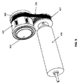
図1から図3は、カテーテル内の回転式ドライブシャフトに連結可能な磁気応答要素の一例を示す。図1を参照し、磁気応答要素100は、カテーテルのドライブシャフトとの係合のために、当該磁気応答要素100を貫通するチャネル105を有するハウジング103を含んでもよい。さらに、応答要素100は、中央の磁気ベアリング101を含んでもよい。ベアリング101は、(例えば接着剤を介して)カテーテルのドライブシャフトに固定的に取り付けられるように構成されたベアリングチャネル107を含んでもよい。ベアリング101はハウジング103内で回転し、これにより同様にカテーテルドライブシャフトを回転させることができる(ドライブシャフトは、ハウジング103に対してベアリング101と共に回転することになる)。
1 to 3 show an example of a magnetic response element that can be coupled to a rotary drive shaft in a catheter. Referring to FIG. 1, the magnetic response element 100 may include a
ベアリング101は、反対の極性(すなわちN、S、N、S)の磁区を保持するように構成された1組の磁気ホルダ109(例えばベアリング101内のポケット)を含んでもよい。例えば、ベアリングの外周の周りに配置された1から20個の磁気ホルダ109が存在してもよい。図2には、ベアリング101の外周の周りに設けられた6つのホルダ109(各ホルダ109は単一の磁石213を有する)の単純構成について示している。他の実施形態では、ホルダごとに2つ以上の磁石を配列できる。以下でさらに説明するように、磁区は磁気ドライバと相互作用して、カテーテルシャフトの回転を駆動しうる。
The
幾つかの実施形態では、単一のカテーテルと共に使用してカテーテル内の種々のシャフトを駆動する(例えば、切断要素の回転とカッターの回転を駆動する)ために、複数の磁気応答要素100が存在してもよい。 In some embodiments, there are a plurality of magnetic response elements 100 for use with a single catheter to drive the various shafts within the catheter (eg, drive the rotation of the cutting element and the rotation of the cutter). May be.
さらに、幾つかの実施形態では、直列に配列し且つ単一のドライブシャフトに固定された複数の磁気応答要素100が存在してもよい。一構成で、その列の各応答要素100は、異なる数または配列の磁区または磁石213を含んでもよく、その結果、種々の速度で逆回転(counter-rotate)および/または回転するようにシャフトが構成されてもよい。他の構成で、その列の各応答要素100は同一の磁区または磁石213の配列を有してもよいが、好都合には、その列の配列はドライブシャフトを回転させるためにより大きいトルクを付与しうる。
Further, in some embodiments, there may be multiple magnetic response elements 100 arranged in series and secured to a single drive shaft. In one configuration, each responsive element 100 in the row may include a different number or arrangement of magnetic domains or
図3に示すように、ハウジング103は、カテーテルのドライブシャフトとの係合のために、当該ハウジング103を貫通するチャネル105を有する。さらに、ハウジング103は、ロック機構(例えば、搭載されたドライバの内部でハウジング103がスライドしない状態を維持するように構成されたスナップロック333)を含んでもよい。
As shown in FIG. 3, the
図4Aから図6Bは、搭載または保持可能な磁気ドライバの一例を示しており、この磁気ドライバは、応答要素を係合させて装置内でドライブシャフトの回転を駆動することができる。ドライバにより、カテーテルを滅菌野内に置くことができる。 4A-6B illustrate an example of a magnetic driver that can be mounted or held, which can engage a response element to drive rotation of the drive shaft within the device. The driver can place the catheter in the sterile field.
図4A、図4Bを参照すると、磁気ドライバ400は、応答要素(例えば応答要素100)に係合するためのコネクタ423(例えば円筒状のチャネルまたは開口部)を有するハウジング411を含む。コネクタ423は、応答要素100のハウジング103上でロック機構と連結する(例えばスナップロック333と接触する)ように構成された機構を含んでもよい。
4A and 4B, the
さらに、磁気ドライバ400は、第1ギヤ417に接続されたモータ415を含んでもよい。第1ギヤ417は、ベルト525を介して第2ギヤ419に係合してもよい(図5参照)。第2ギヤ419はドライバ回転子421に接続されてもよい。ドライバ回転子421は、磁区を保持するように構成された磁気ホルダ409(例えば回転子421内のポケット)を含んでもよい。
Further, the
ホルダ409および/またはポケット内の磁区は、応答要素(例えば応答要素100)のホルダ109および磁区(domain)に対して整列する(align)ように(ただし反対の極性を有するように)構成されてもよい。したがって、図5に示すように、例えば、6つのホルダ409(それぞれ単一の磁石513を有する)が存在してもよい。
The magnetic domains in the holder 409 and / or pocket are configured to align (but have opposite polarity) with respect to the
図6A、図6Bに示すように、ハウジング411は、応答要素100に係合するためのコネクタ423を含む。コネクタ423は、途切れなく封止された内部を有しうる中空チャネルであってもよい。
As shown in FIGS. 6A and 6B, the
磁気ドライバ400を使用して、応答要素(例えば応答要素100)を有するカテーテルの回転を駆動することができる。一実施形態で、応答要素100のハウジング103は、コネクタ423の開口部にスライドして入るように構成されてもよい。ハウジングがスライドインする際に、応答要素100の磁区はドライバの磁区に対して整列しうる。例えば、図5に示す磁石513は、図2に示す磁石213に対して整列しうる。したがって、モータ415が作動すると第1ギヤ417が回転し、これがベルト525を作動させ、第2ギヤ419、そして回転子421を回転させることになる。回転子421の磁石513とベアリング101の磁石213との間の相互作用によりベアリング101が回転し、これによりベアリング101に連結されたドライブシャフトがギヤ417,419と同じ時計/反時計回りに回転することになる。このようなドライブシャフトの回転により、カテーテルによる切断、撮像が可能となる。したがって、カテーテルと応答要素100のハウジング103を静止させつつ、磁区間の相互作用によりドライブシャフトを回転させることができる。
A
好都合なことに、この非接触型駆動システムを使用することにより、磁気ドライバ400を非滅菌野に置きつつカテーテルの滅菌状態を維持できる。例えば、滅菌バッグまたは滅菌シートをハウジング101の上に配置し、あるいはコネクタ423内部に並べて、カテーテルと磁気ドライバ400とが直接に接触するのを避けることができる。
Advantageously, by using this non-contact drive system, the catheter can be kept sterile while the
カテーテルのドライブシャフトと共に使用する応答要素100について上で説明したが、カテーテルのいずれのシャフト(例えばアウタートルクシャフト)に対しても同様に使用できる。 Although the response element 100 for use with a catheter drive shaft has been described above, it can be used for any catheter shaft (eg, an outer torque shaft) as well.
図7、図8は、応答要素とドライバを含む非接触型システムの他の例を示しており、この例では、カテーテルのシャフト(例えばドライブシャフトやトルクシャフト)に回転運動をさせることができる。応答要素700は応答要素100と同じように構成できる。したがって応答要素700は、カテーテルのシャフトに固定的に取り付けられるように構成されたベアリングチャネル707を有するベアリング701を含んでもよい。ベアリング701は、反対の極性の磁区(例えば単一の磁石713(図8参照))を保持するように構成された1組の磁気ホルダ709(例えばベアリング701内のポケット)を含んでもよい。
7 and 8 show another example of a non-contact type system including a response element and a driver. In this example, a catheter shaft (for example, a drive shaft or a torque shaft) can be rotated. The
磁気ドライバ800は、第1ギヤ817に接続されたモータ815を含んでもよい。第1ギヤ817は、ギヤ817,819の間に延びるベルトを介して第2ギヤ819に係合してもよい。この実施形態では、第1ギヤ817が第1回転子821に連結され、第2ギヤ819が第2回転子822に連結されてもよい。回転子821,822のそれぞれが、磁区を保持するように構成された磁気ホルダ809(例えば回転子821,822内のポケット)を含んでもよい。ホルダ809および/またはホルダ内の磁区は、応答要素700のホルダ709および磁区に対して整列するように(ただし反対の極性を有するように)構成されてもよい。したがって、各回転子821,822は、交流磁界を生成するように、同じ回転子上で隣接する磁石の極性と反対の極性を有するように搭載された複数の磁石813(図8参照)を含む。これにより、応答要素とドライバの仮想的な(virtual)磁気歯車の適切な「かみ合い」と位置合わせを確実に行うことができる。磁気ドライバ800は、応答要素700を保持するように(すなわち応答要素700が内部に置かれるように)構成された隙間またはチャネル827を有するハウジング811内に包含されてもよい(図8参照)。
The
磁気ドライバ800を使用して、応答要素700が取り付けられるカテーテルのシャフトの回転を駆動することができる。これを行うために、(カテーテルのシャフトに連結された)応答要素700はチャネル827内に配置されてもよい。したがって応答要素700は、第1回転子821と第2回転子822との間に位置してもよい。モータ715が作動すると第1ギヤ717が回転し、これがベルトを作動させ、そして第2ギヤ719を回転させることになる。ギヤ717,719が回転すると、回転子821,822が回転することになる。回転子821,822が回転すると、ベアリング701の磁区と回転子821の磁区との間の相互作用に起因して、ベアリング701が反対方向(例えば回転子821,822が反時計回りに回転する場合には、時計回り)に回転することになる。
A
例えば、図8に示すように、磁石713aは磁石813aと相互作用することになる。回転子821が時計回りに回転すると、2つの磁石713a,813aの間の引力によりベアリング701が反時計回りに回転することになる。このようにして、磁石713b,813bは互いに接近し、これら磁石713b,813bの間の引力によりベアリング701は反時計回りに回転を続けることになる。時計回りに回転する回転子821,822の磁石813とベアリング701の磁石713との間の連続的な相互作用により、ベアリング700が反時計回りに回転を続けることになる。
For example, as shown in FIG. 8, the magnet 713a interacts with the
一実施形態で、回転子821,822は、各回転子821,822でホルダ709が互いにわずかにずれる(offset)(図8に最もよく表れている)ように位置決めされている。好都合なことに、このずれにより、ベアリング701上の磁石713は第2回転子822の磁石813と相互作用し、続いて第1回転子821の磁石813と相互作用する。これにより、ベアリング701をより滑らかに回転させることができる。この第1回転子821の磁石と第2回転子822の磁石との間の前後の(back-and-form)変位により、両回転子821,822の磁石813が相互作用して同時に離れた場合には生じるだろうベアリング701の回転の低速化または振動(jolting)が避けられる。
In one embodiment, the
好都合なことに、応答要素700とドライバ800により、カテーテルのドライブシャフトを非接触で作動させることができる。その結果、滅菌野を維持しつつカテーテルを作動させることができる。例えば、ハウジング811の上に、かつ/またはチャネル827を覆って(line)滅菌野と非滅菌野とを分離するように、滅菌バッグまたは滅菌シートが配置されてもよい。単に応答要素700を有するカテーテルをハウジング811の上に配置してドライブシャフトを作動させることができるので、このシステムにより、カテーテルとドライバのはめ込み(snapping)または物理的接続が必要とされる選択肢よりも滅菌が容易な選択肢が得られる。
Conveniently, the
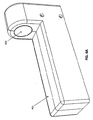
図9は、応答要素とドライバを含む非接触型システムの例を示しており、このシステムを使用して、カテーテルのコンポーネントに並進直線運動をさせることができる。応答要素900は、カテーテルのアウターシャフトまたはトルクシャフトに固定的に取り付けられるように構成されたベアリング901を含んでもよい。ベアリング901は、磁石を内部に保持するように構成された1組の磁気ホルダ909(例えばベアリング901内のポケット)を含んでもよい。一実施形態で、ベアリング901は、平行移動のみを行う(回転しない)ように構成されてもよい。結果として、ホルダ909は、同じ極性の磁区または磁石を含んでもよい。磁気ホルダ909は、ベアリング901がドライバ1000で置かれる向きとは無関係にドライバ1000に対して係合できるように、ベアリング901の外周の周囲に延びてもよい。
FIG. 9 shows an example of a non-contact system that includes a response element and a driver, which can be used to cause translational linear motion of the components of the catheter. The
磁気ドライバ1000は、応答要素900を保持するように(すなわち応答要素900が内部に置かれるように)構成された隙間またはチャネル1027を有するハウジング1011内に包含されてもよい。チャネル1027は、その周りに、磁区を保持するように構成された磁気ホルダ1009(例えばドライバ1000内のポケット)を含んでもよい。ホルダ1009および/またはホルダ内の磁区は、ホルダ909および応答要素900の磁区に対して整列するように(ただし反対の極性を有するように)構成されてもよい。
The
磁気ドライバ1000は、連結部1051を介してスライドベアリングプレートに沿ってスライドするように構成されてもよい。さらに、磁気ドライバ1000は、当該ドライバ1000を平行移動させるためのモータに接続されるように構成されたコネクタ1021を含んでもよい。例えば、回転モータに取り付けられたねじ棒にコネクタ1021が連結されて、当該モータの回転によりドライバ1000を平行移動させるようにしてもよい。
The
磁気ドライバ1000を使用して、応答要素900に取り付けられたトルクシャフトの直線的並進運動を駆動することができる。このようにするために、(カテーテルのトルクシャフトに連結された)応答要素900はチャネル1027内に配置されてもよい。ドライバ1000が直線的に移動するので、ドライバ1000の磁区と応答要素900の磁区との間の相互作用により、応答要素900、そして取り付けられたトルクシャフトが同様に直線的に移動することになる。その結果、トルクシャフトを前方に(遠位側に)または後方に(近位側に)向けて駆動することができる。このような遠位または近位の動きを使用して、例えば、アテローム切除手術中にアテローム切除装置のノーズコーンを開き且つ/またはノーズコーン内に組織を詰めることができる。
A
カテーテルのトルクシャフトに直線運動させるものとして応答要素900とドライバ1000を説明したが、それを使用してカテーテルの他のシャフト、例えばカッターに取り付けられたドライブシャフトに直線運動をさせることができる。
Although the
好都合なことに、応答要素900とドライバ1000により、カテーテルのドライブシャフトの非接触型の直線駆動が可能となる。その結果、滅菌野を維持しつつカテーテルを作動させることができる。例えば、ハウジング1011の上に、かつ/またはチャネル1027を覆って滅菌野と非滅菌野とが分離するように、滅菌バッグまたは滅菌シートが配置されてもよい。単に応答要素800を有するカテーテルをハウジング1011の上に配置してドライブシャフトを作動させることができるので、このシステムにより、カテーテルとドライバのスナッピングや物理的接続が必要とされる選択肢よりも滅菌が容易な選択肢が得られる。
Advantageously, the
幾つかの実施形態では、駆動システムを使用して、カテーテルの一要素(または複数の要素)に直線運動と回転運動の両方を行わせることができる。例えばシステムは、カテーテルの1つまたは複数のシャフト上に、応答要素と駆動要素の組み合わせを含んでもよい。図10Aから図13を参照すると、駆動システム1300は、カテーテルのアウタートルクシャフトに回転運動と直線的並進運動を行わせる磁気応答要素1100aおよびドライバ1200aと、カテーテルのドライブシャフトに回転運動を行わせる応答要素1100bおよびドライバ1200bとを含んでもよい。
In some embodiments, a drive system can be used to cause one element (or elements) of the catheter to perform both linear and rotational movement. For example, the system may include a combination of response and drive elements on one or more shafts of the catheter. Referring to FIGS. 10A-13, the drive system 1300 includes a
図11を参照すると、第1磁気応答要素1100aは、応答要素900と同様に、カテーテルのトルクシャフトに固定的に取り付けられるように構成されたベアリング1101aを含んでもよい。ベアリング1101aは、内部の磁石を保持するように構成された1組の磁気ホルダ1109a(例えばシャフト1101a内のポケット)を含んでもよい。磁区は、反対の極性を有する領域内に配置されてもよい。すなわち、外周の周りで隣接する磁石は、反対の極性を有してもよい。
Referring to FIG. 11, the first
図12と図13に最も表れているように、ドライバ1200aは、回転子1201a(回転子1201aを平行移動させるためのモータ1165に接続された)と、回転子1201aの回転を駆動するモータ1167とを含んでもよい。回転子1201aは、磁区を保持するように構成された磁気ホルダ1209a(例えば回転子1201a内のポケット)を含んでもよい。ホルダ1209aおよび/またはポケット内の磁区は、第1磁気応答要素1100a上のホルダ1109aに対して整列するように(ただし反対の極性を有するように)構成されてもよい。図4Aから図6Bのドライバ400と同様に、ドライバ1200aは、当該ドライバ1200aのハウジング111内のコネクタ1123に応答要素1101aをはめ込んで応答要素1101aの磁石の周囲に回転子1201aを整列させることにより、応答要素1101aを有するカテーテルのシャフトを作動させるように構成されてもよい。
As best shown in FIGS. 12 and 13, the
回転子1201aの磁石と応答要素1101aの磁石との間の相互作用に起因して、回転子1201aの回転(モータ1167による)により応答要素1101aが、そして取り付けられたカテーテルシャフト(例えばトルクシャフト)が回転することになる。さらに、回転子1201の並進(モータ1165と、コネクタ1121を貫通して延びるねじ棒1163)により、応答要素、そしてトルクシャフトが直線的に平行移動することになる。図10Aと図10Bに示すように、スライド運動により応答要素1100aのベアリング1101aが入れ子式に出入りする(telescope in and out)。一実施形態で、ドライバは、アテローム切除カテーテルと共に使用されてもよい。ドライブシャフト要素の回転により、アテローム切除カテーテルのカッターおよび/または撮像素子を回転させることができる。アテローム切除カテーテルのトルクシャフトの回転によりカテーテルを方向付ける(direct or orient)ことができ、ドライブシャフトに対するトルクシャフトの平行移動により、アテローム切除カテーテルの遠位端を屈曲させてカッターを露出させることができる。
Due to the interaction between the magnet of the
再び図11を参照すると、第2応答要素1100bは同様に、周囲に磁区1109bを有するベアリング1101bを含んでもよい。応答要素1100bは、カテーテルのドライブシャフトとの係合のために、当該磁気応答要素1100bを貫通するチャネル1105を含んでもよい。さらに、第2駆動要素1200bは、回転子1201bと磁気ホルダ1209bを含んでもよい。応答要素1100bは、当該応答要素1100bの磁石と回転子1201bの磁石とが整列するように、回転子1201bにスライドして入るように構成されてもよい。したがって、モータ1169による回転子1200bの回転により、回転子1201b、そして応答要素1100bと取り付けられたドライブシャフトが回転することになる。一実施形態では、このドライブシャフトの回転により、ドライブシャフトの遠位端に取り付けられた遠位カッターが回転しうる。
Referring again to FIG. 11, the
幾つかの実施形態では、磁石の力により、ドライバが加えることができる「引く」力(pull power)の大きさが調節されてもよい。また、回転運動と並進運動の両方で伝導する力は、磁石の強さと配列により制限されてもよい。 In some embodiments, the magnitude of the “pull power” that the driver can apply may be adjusted by the force of the magnet. Also, the force conducted in both rotational and translational movements may be limited by the strength and alignment of the magnets.
幾つかの実施形態では、コントローラを使用して、本明細書で説明しているドライバを制御してもよい。 In some embodiments, a controller may be used to control the drivers described herein.
<プルワイヤ作動機構を有するアテローム切除カテーテル>
変位させることができる(displaceable)遠位端を有するアテローム切除カテーテルは、テンドン(tendon)、ワイヤ、ロッド、ファイバ、メンバ(member)などとして構成された、横方向作動要素および/または外部作動要素を含んでもよい。この作動要素は、一般的にカテーテルの遠位端に取り付けられる(ヒンジ連結されてもよいが)と共に、カテーテルの近位部分に対して移動可能であり、その結果、これを移動させて(押してまたは引いて)遠位端を作動または変位させ、アテローム切除装置のカッターを露出させることができるようになっている。幾つかの例では、これをプルワイヤ作動機構と称してもよい。プルワイヤの近位端は、遠位カッターの近くから近位ハンドルに向けて、カテーテルの長さの下方で全体的にまたは部分的に延びるプルシャフトに取り付けられてもよい。幾つかの実施形態で、プルワイヤはカテーテルの長さの下方で近位側に延びる。
<Atherotomy catheter with pull wire actuation mechanism>
An atherectomy catheter having a displaceable distal end includes lateral and / or external actuation elements configured as tendons, wires, rods, fibers, members, etc. May be included. This actuating element is generally attached to the distal end of the catheter (which may be hinged) and is movable relative to the proximal portion of the catheter so that it can be moved (pushed) (Or pull) the distal end can be actuated or displaced to expose the cutter of the atherectomy device. In some examples, this may be referred to as a pull wire actuation mechanism. The proximal end of the pull wire may be attached to a pull shaft that extends wholly or partially below the length of the catheter from near the distal cutter toward the proximal handle. In some embodiments, the pull wire extends proximally below the length of the catheter.
例えば一実施形態で、アテローム切除装置はプルワイヤ作動機構を含む。明らかなことだが、「プルワイヤ」横方向作動要素は、テンドン、ワイヤ、ロッド、メンバなどであってよく、ワイヤに限定されない。本明細書では作動要素をプルワイヤと称することがあるが、他の構造を使用してもよいと理解すべきである。 For example, in one embodiment, the atherectomy device includes a pull wire actuation mechanism. Obviously, the “pull wire” lateral actuating elements may be tendons, wires, rods, members, etc. and are not limited to wires. Although the actuating element may be referred to herein as a pull wire, it should be understood that other structures may be used.
図14Aから図15Bに、インナープルシャフト1402とプルワイヤ1524を有するアテローム切除装置1400の一例を示す。プルワイヤはカテーテル本体の上で横方向に変位し、遠位端(ノーズコーン領域)とカテーテル本体の残りの部分との間のヒンジ連結された領域に架かっている(span)。アテローム切除カテーテル1400は、カテーテル本体1404と、カテーテル本体1404の遠位端にあるカッター1406と、カテーテル本体1404の遠位端にある先端領域またはノーズコーン1408を含んでもよい。ノーズコーン1408は切除組織を蓄えておくために中空であってもよい。切除組織は後から取り外して調べられる。さらに、ノーズコーン1408は切断窓1430を含むことができ、この切断窓1430を通じてカッター1406の刃先1412を露出させることができる。ノーズコーン1408は、屈曲機構(例えばヒンジ機構1410)を介してカテーテル本体1404に取り付けられていて、ノーズコーン1408が屈曲するとカテーテル本体の長手軸から離れるようにしてもよい。使用時には、この屈曲により、切断窓1430を通じて刃先1412を露出させ、かつ/またはアテローム切除カテーテル1400を挿入する血管の壁に径方向にカッター1406を押し付けることができる。さらに、アテローム切除カテーテル1400は、ノーズコーンが開き位置のときに屈曲しすぎないようにするためのストッパ1892(図18参照)を含んでもよい。
FIGS. 14A to 15B show an example of an
図15Bに示すように、アテローム切除カテーテル1400は、カッター1406の刃先1412に対して近位側に取り付けられた撮像素子(OCT(例えば共通光路OCT)用光ファイバ1514など)を含んでもよい。光ファイバ1514は、細長い本体の中心を通って(例えばカッター1406に連結されたドライブシャフト1516を通って)OCT用の信号を送信可能である。光ファイバ1514は、例えばカッター1406の開口部1518内にあるカテーテルの遠位端に取り付けられてもよい。光ファイバ1514のその他の部分は、カテーテル本体1404内で自由に浮遊した状態であってもよい。他の実施形態で、光ファイバはカテーテル本体内でドライブシャフトに取り付けられる。他の実施形態で、光ファイバは、ドライブシャフトから軸外し(off-axis)されている。さらに、反射要素(例えばミラー1520)をカッター1406の開口部1518内に配置して、光ファイバ1514から出射して組織に入る光を放射状に方向付けることができる。光ファイバ1514の遠位端は、刃先1412から3mm未満の位置に(例えば刃先1412に隣接して)配置されてもよい。刃先の近くに撮像素子を有することにより、生じる画像として、切除される血管部分に対して近接したものが揃う。これにより、アテローム切除手術中の医師に対して好都合な視野が与えられる。
As shown in FIG. 15B, the
アテローム切除カテーテル1400のカテーテル本体1404はアウターシャフト1522を含んでもよく、当該アウターシャフト1522は、所望の位置に向けて遠位カッター1406および/または撮像素子を配置するように調節される(例えば、手動で、あるいは上記磁気ドライバのようなドライバを介して調節される)ように構成されてもよい。プルシャフト1402はアウターシャフト内に延びていてもよく、アウターシャフト1522およびインナードライブシャフト1516と中心を共有してもよい。好都合なことに、シャフト系と中心を共有する(同心円をなす)プルシャフト1402を使用することにより、装置の長さを貫通する偏心(off-center)コンポーネントにより導入されるだろうホイッピング(whip)または不規則なカテーテル本体の回転を避けることができる。すなわち、カテーテルの方向性に影響を与えることなくノーズコーンを開閉できる。プルワイヤ1524は、一端でプルシャフト1402の遠位端に、他端でノーズコーン1408の中央部に取り付けられてもよい。プルワイヤは、カテーテルの外表面に沿って延びてもよい。プルシャフト1402は、前後に(近位側および/または遠位側に)、例えば手動でまたはドライバ(例えば上記磁気ドライバ)を用いて平行移動するように構成されてもよい。このプルシャフト1402の平行移動により、プルワイヤ1524を引いたり押したりでき、これによりノーズコーン1408が、1つのモードでは屈曲して中心軸から離れ、別のモードではニュートラル(屈曲なし)の位置へ戻る。そしてノーズコーン1408は、カテーテルの残りの部分の面内外で作動し、回転するカッター1406を露出させまたは保護する。一例で、この屈曲は、ヒンジ機構1410周りの回転を通じて生じうる。例えばヒンジ機構1410は、回転および/またはスライドする継ぎ手であってもよい。この継ぎ手により、プルシャフト1402により力が加えられたときにノーズコーン1408の屈曲が可能となる。ノーズコーン1408を屈曲させることにより、回転するカッター1406が露出する。図14C(閉じた構成(closed configuration)のカテーテルを示す)と図14D(遠位端が屈曲したカテーテルを示す)にこれを示す。
The
幾つかの例で、プルシャフトは、ノーズコーン1408とカテーテル本体1404との間の継ぎ手に対して遠位側にある領域でノーズコーン1408に連結されていてもよく、また、遠位端領域を引いて曲がる(または押して延びる)ようにヒンジ(例えばリビングヒンジ)として機能してもよい。
In some examples, the pull shaft may be coupled to the
上記の通り、アテローム切除カテーテル1400のカテーテル本体1404は、プルシャフト1402と中心を共有して延びる(例えばプルシャフト1402内に延びる)ドライブシャフト1516を含んでもよい。ドライブシャフト1516は、(カテーテル本体1404とノーズコーン1408との間に配置された)カッター1406に取り付けられてもよく、カッター1406を回転させるように構成されてもよい。カッター1406の回転により、刃先1412の回転運動による切断を行うことができ、また、撮像素子を用いて血管内径の壁コンポーネントを撮像するのに必要な回転を生じさせることができる。ドライブシャフト1516は、最大2000rpm(例えば一方向に約1000rpm)で回転させることができる。ただし、両方向の回転と種々の速度が可能である。
As described above, the
好都合なことに、別個のアウターシャフト、プルシャフトおよびドライブシャフトを有することにより、屈曲機構を作動/停止させるのに必要な並進運動から、切断要素の回転運動を分離することができる。この分離により、ノーズコーンを屈曲させ/非屈曲状態とする(undeflect)のに使用される軸方向の平行移動中の張力または圧縮力(生じる画像に歪みを生じさせる可能性がある)がドライブシャフトに加わるのを避けることができる。さらにこの分離により、全要素(引いて駆動する)が1つの駆動システムに連結されていることに関連して遠位機構の設計を単純化でき、これにより血管(例えば冠動脈)に応じたサイズまで装置を小型化できる。 Conveniently, having a separate outer shaft, pull shaft and drive shaft allows the rotational movement of the cutting element to be separated from the translational movement required to activate / deactivate the bending mechanism. This separation causes the axial translational tension or compressive force used to bend / undeflect the nose cone (which may cause distortion in the resulting image). You can avoid joining. This separation also simplifies the design of the distal mechanism in relation to all elements (pulling and driving) being connected to one drive system, thereby reducing the size according to the vessel (eg coronary artery) The device can be miniaturized.
幾つかの実施形態では、装置の遠位部分および/またはノーズコーン1408に、モノレールガイドワイヤ管腔1844が配置されている。モノレール管腔1844内にガイドワイヤを配置することにより、光ファイバ要素とプルシャフト要素のための余地(room)がカテーテル本体1404内に生じる。さらに、切断窓1430に対向するようにガイドワイヤ管腔1844を配置することにより、対象の病変部に向けてカッターを方向付けるための、OCTを介して視認できる追加の要素が得られる(以下でさらに説明する)。モノレールガイドワイヤ管腔を使用する場合、ガイドワイヤは、カテーテル本体の外側に沿って延びていてもよく、例えばガイドワイヤ管腔に達するまで自由に浮遊した状態であってもよい(図20Hから図20Kを参照して以下で示しかつ説明するように)。
In some embodiments, a
図16Aと図16Bを参照すると、ハンドル1600を使用してプルシャフトの作動を制御できる。プルシャフトは、ハンドル1600内のプルシャフト「プラグ」1626に連結されてもよい。このプラグ1626からの延長部を、ユーザに利用可能とし、さらにハンドルの長さに沿って遠位側/近位側に、手動でまたはドライバ(例えば上記磁気ドライバ)を用いて平行移動させてもよい。このプルシャフトの近位側および遠位側の動きにより、ノーズコーンの屈曲/非屈曲状態を生じさせることができる。ハンドル1600内の並進プラグ1626は、カッターを移動させて組織をノーズコーン内に詰めるために、切断要素/撮像素子を移動させる機構から分離してもよい。したがって、プルシャフトプラグ1626により、切断と撮像を制御する駆動システムから独立してノーズコーンの屈曲角度を操作できる。ノブ1628のような回転機構を使用してアウターシャフトを回転させ(この場合もやはり手動でまたはドライバ(例えば上記磁気ドライバ)を用いて)、カッターを適切な位置に方向付けてもよい。
Referring to FIGS. 16A and 16B, the
この例では、OCT撮像サブシステムのイメージセンサは、回転するカッターに対してすぐ近位側に連結されている。したがってカテーテルは、カテーテルの残りの部分に対して一直線に並びまたは屈曲した(カッターを露出させて)遠位端で撮像を行うことができ、あるいは幾つかの例で、撮像系は遠位端が屈曲して切断部が係合する際に幾分制限された視野が得られる。これは、OCTイメージセンサが遠位端の周りを回転し、その一部を遠位端および/またはプルシャフトが塞ぐ場合に生じることがあるところ、カッターを係合させる動作に対する直接のフィードバックが得られるので有用であろう。例えば、図17Aと図17Bを参照すると、アテローム切除カテーテル1400の撮像素子の回転により、アテローム切除カテーテルを挿入する血管の内側の画像を生成できる。図17Aを参照すると、ノーズコーンが閉じていると、OCT画像1740にマーク(mark)1742が表示されることがある。マーク1742は、ノーズコーンの周囲に延びるハウジング部分(すなわち、切断窓が占有しない部分)に対応することになる。このマーク1742は常にカッターの位置に対向しているので、マーク1742を使用して、所望の位置へ向かうアウターシャフトの回転を通じてアテローム切除カッターを所望の位置まで移動させることができる。図3Bを参照すると、ノーズコーンが開いている場合、OCT画像1750において、ハウジングに対応する同様の(ただし短い)マーク1744が表示されることがある。再度このマーク1744を使用して、アテローム切除カッターを所望の位置まで移動させることができる。さらに、このマーク1744の長さを使用して、ノーズコーンがカテーテルの主軸からどれだけ屈曲しているかを示すことができ、これにより切断深度をリアルタイムに測定するツールが得られる。
In this example, the image sensor of the OCT imaging subsystem is connected immediately proximal to the rotating cutter. Thus, the catheter can be imaged at the distal end that is aligned or bent (exposing the cutter) with respect to the rest of the catheter, or in some instances, the imaging system has a distal end at the distal end. A somewhat limited field of view is obtained when the cut is engaged by bending. This can occur when the OCT image sensor rotates around the distal end and the distal end and / or pull shaft occludes a portion of it, providing direct feedback on the action of engaging the cutter. Will be useful. For example, referring to FIGS. 17A and 17B, rotation of the imaging element of the
図18を参照すると、幾つかの実施形態では、アテローム切除カテーテル1400の1本または複数本のシャフトを軸方向に平行移動させて、切開した組織をノーズコーン1408内に詰めることができる。したがって、図18に示すように、ドライブシャフト1516は軸方向に平行移動する(手動でまたは上記磁気ドライバのようなドライバを用いて)ように構成されてもよく、これにより、カッターの遠位面を使用して前進し、切断した組織をノーズコーン1408内に詰めることができるようにカッターが軸方向に平行移動することができる。ドライブシャフト1516、そしてカッター1406と撮像素子をノーズコーン1408内に押し込む場合、モノレールガイドワイヤ管腔1844をマーカとして使用してカッターの位置を決定できる。
Referring to FIG. 18, in some embodiments, one or more shafts of the
図19を参照すると、ハンドル1900は、ドライブシャフトとプルシャフトの平行移動を独立して制御することを可能にするように構成されてもよい。このハンドル1900は、ハンドル1600に示すハンドルに「カッターバレル」1954を追加したものに相当する。カッターバレル1954により、カッター/撮像素子の位置を制御するドライブシャフトとユーザの相互作用が可能となる。このカッターバレル1954を近位側/遠位側に平行移動させて、カッターと撮像素子を開放/包装してもよい。すなわち、使用時にはカッターバレル1954を近位側に引いてカッターを後側に引き、次にプルシャフトバレル1926を近位側に引いてノーズコーンを落とすと共にカッターを露出させてもよい(カッターバレルを近位側に引いてからプルシャフトバレル1926を近位側に引くことにより、ノーズコーンが下に落ちる際のカッターの好適な位置決めを確実に行うことができる)。ノーズコーンを閉じるために、これと逆のこと−プルシャフトバレル1926を遠位側に押してノーズコーンを閉じ、続いてカッターバレル1954を前方に押して組織を詰めてもよい。プルシャフトバレル1926とカッターバレル1954との間のばね1956により、ノーズコーンが開いてカッターが引き戻されるときに、カッターを確実に最後まで引き戻すことができる。
Referring to FIG. 19, the
さらに、カテーテル1400は、カッターに近接した洗浄ポートを含んでもよい。ハンドル1600またはハンドル1900は、生理食塩水および/または造影剤(contrast)を遠位撮像素子の位置に送ることを可能にする洗浄入口ポート1658,1958を含んでもよい。明瞭なOCT画像を得るために、遠位側の位置でフラッシングを行って血液を移動させることができる。
Further, the
<非接触型駆動システムおよび/またはプルワイヤを作動させて使用するためのカテーテル>
他のカテーテルの実施形態は、図1から図13に関連して本明細書で説明する非接触型駆動システムおよび/または図14Aから図19に関連して説明するプルワイヤ作動機構と共に用いられてもよい。
<Catheter for activating and using a non-contact drive system and / or pull wire>
Other catheter embodiments may also be used with the non-contact drive system described herein in connection with FIGS. 1-13 and / or the pull wire actuation mechanism described with reference to FIGS. 14A-19. Good.
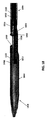
例えば、図20Aから図20Kは、アテローム切除カテーテル2000を示す。ノーズコーン2008は、カテーテル本体2004から屈曲可能であって、カッター2012の回転式の刃先2012を露出させる。OCTイメージセンサを構成する光ファイバの端部が連結するカッター2006と撮像用シャーシは、一体となって回転する。ドライブシャフト2016は、センサとカッターの両方を回転させる。図9から図20で、システムは、ドライブシャフト2016の横方向(近位側から遠位側)の動きによりノーズコーン2008の変位が生じて回転式のリングカッター2006を露出させまたは保護するように構成されている。
For example, FIGS. 20A-20K illustrate an
アテローム切除カテーテル2000の光ファイバは、ドライブシャフト2016の中央管腔領域内に保持されてもよい(それ自体がカテーテルの中央にある)。これらの例で、光ファイバは、遠位端が回転するときに自身がねじれてもよい。光ファイバの遠位端は、回転式カッター2006に固定的に取り付けられてもよい。それゆえ、ファイバの端部は、光ファイバシャーシまたはハウジングを通りシャーシの外周近傍の領域まで上方に及んでいてもよく、シャーシはその位置でミラー要素2020の方に方向付けられ、カテーテルから到来して周囲の組織(例えば血管)に入る光束を方向付けることができる。好適なエポキシや樹脂を使用して、ファイバの端部を適当な位置に保持してもよい。
The optical fiber of
例えば、ドライブシャフトを回転させてカッター2006および/またはOCTイメージセンサを回転させる場合、ドライブシャフト2016は一方向にのみ駆動されてもよい。他の実施形態で、シャフト2006は時計回りに約300回から約500回だけ回転し、続いて回転方向を反対にして、このサイクル(時計回り、反時計回り)を繰り返してもよい。このように、ドライブシャフトの管腔内の光ファイバは、300回から500回だけ回転し、続いて反転してもよい。ファイバが中空のシャフト内で回転し、これにより(上で図示および説明した)ドライブシャフト周囲の巻き付き(wrapping)を使用する例より多く回転させるようにしてもよい。驚くべきことに、実質的にOCTシステムとファイバ光学系の性能に悪影響を与えることなく、管腔内でのねじれと非ねじれを繰り返すことができる。光ファイバはカテーテルの中心(例えばドライブシャフトの中心)に位置するが、カテーテルの遠位端ではやはり軸外であって、そこで撮像素子は装置のエッジから少し変位している(図示しているように)。
For example, when rotating the drive shaft to rotate the
カテーテル2000は、上記磁気駆動システムを使用して、ドライブシャフト2016の運動(回転運動または横方向運動)および/またはアウターシャフトの運動(回転運動または横方向運動)を行うことができるように構成されてもよい。
図14のアテローム切除装置1400に関連して上で説明したように、アテローム切除装置2000は、ノーズコーン内にモノレールガイドワイヤチャネルを含んでもよい。図20Gから図20Kに、カテーテルに沿って延びる例示的なガイドワイヤ2086を示している。
As described above in connection with
さらに、幾つかの実施形態で、カテーテル2000には、ノーズコーン2008を屈曲させるプルシャフトおよび/またはプルワイヤが取り付けられてもよい。
Further, in some embodiments, the
係属中の米国特許出願第13/433,049号(発明の名称"OCCLUSION-CROSSING DEVICES, IMAGING, AND ATHERECTOMY DEVICES"、出願日2012年3月28日)でも同様の閉塞クロッシング装置について説明しており、これは参照により本明細書に組み込まれる。 Pending US Patent Application No. 13 / 433,049 (Title of Invention “OCCLUSION-CROSSING DEVICES, IMAGING, AND ATHERECTOMY DEVICES”, filing date March 28, 2012) also describes similar occlusion crossing devices. Which is incorporated herein by reference.
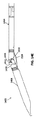
例えば図21Aから図21Iは、上記磁気駆動システムおよび/またはプルワイヤ機構と共に使用可能なカテーテル2100の他の例を示す。カテーテル2100は、回転式遠位端2182と、ガイドワイヤが通過する中央管腔2184と、光ファイバケーブルを含む回転式OCTイメージセンサとを含むガイドワイヤ留置(placement)カテーテルとして構成される。このような装置を使用して、ガイドワイヤを無理矢理押して慢性完全閉塞(CTO)を通過させた場合には発生したであろう血管の損傷なしに、CTOを横断させてガイドワイヤを留置することができる。このような装置を「撮像部を有するCTOクロッシング装置」または「CTO撮像・クロッシング装置」と呼んでもよい。図21Aは、CTOを横切ってガイドワイヤを留置するためのCTO撮像・クロッシング装置の一例の側面図を示す。この例で、近位端は、ハンドル2186またはコントローラ(ここでは、装置の動作を制御するためのセンサと歯車要素を含むハウジングとして示している)を含む。図21Bは、21Aの装置の遠位端の拡大図を示しており、これは図21Cから図21Eでも同様である。これらの図で、回転式遠位端2182は、CTO材料にかみ合い(そして通過する)ためのらせん切り欠き領域を含む。図21Fと図21Gは、この装置の先端領域(回転式遠位端)のみを示す。先端部の外縁は滑らかでかつ曲がっており、血管壁に損傷を与えないようになっている。またこの例で、先端部はOCT撮像用光ファイバ(OCTイメージセンサを構成しうる)のためのマウント部を含む。したがって、OCT撮像用光ファイバの遠位端は、回転式遠位端に固定されてもよい(例えば、接着剤、エポキシ樹脂などで接着されてもよい)。
For example, FIGS. 21A through 21I illustrate another example of a
図21Hは、先端部の遠位端の拡大図を示す。図21Iは、図21Hと同じ図を示しているが、先端部が回転する際に回転式OCTセンサ(ファイバ端部)が撮像する領域が円板で示されている。このように、このシステムは、遠位端周囲の領域(例えば血管の壁、壁の内部を含む)の360°視野を与えうる。OCT画像は、ある深さだけ血管内に侵入することができ、それゆえ血管壁の表面と内部で種々の構造の解明が可能となる。この例で、視野は、撮像を遮る3つの領域によって妨害される。これらの領域は、外周の周囲の基準マークを可能にするように配置されている。カテーテル遠位領域全体を回転させて、これらの閉塞領域の位置を変えてもよい。 FIG. 21H shows an enlarged view of the distal end of the tip. FIG. 21I shows the same view as FIG. 21H, but the area that is imaged by the rotary OCT sensor (fiber end) as the tip rotates is shown as a disc. Thus, the system can provide a 360 ° field of view around the distal end (eg, including the wall of the blood vessel, the interior of the wall). The OCT image can penetrate into the blood vessel by a certain depth, and therefore various structures can be elucidated on the surface and inside of the blood vessel wall. In this example, the field of view is obstructed by three areas that block imaging. These areas are arranged to allow reference marks around the periphery. The entire distal region of the catheter may be rotated to change the position of these occluded regions.
遠位端2182の作動は、ドライバ(例えば上記磁気ドライバ)により制御されてもよい)。さらに、例えばカテーテルの遠位端に、使用しないときには回転式遠位端を保護するためのハウジングが存在する場合には、カテーテル2100に上記と同様のプルワイヤ機構が取り付けられてもよい。
The actuation of the
係属中の米国特許出願第13/433,049号(発明の名称"OCCLUSION-CROSSING DEVICES, IMAGING, AND ATHERECTOMY DEVICES"、出願日2012年3月28日)でも同様の閉塞クロッシング装置について説明しており、これは参照により本明細書に組み込まれる。 Pending US Patent Application No. 13 / 433,049 (Title of Invention “OCCLUSION-CROSSING DEVICES, IMAGING, AND ATHERECTOMY DEVICES”, filing date March 28, 2012) also describes similar occlusion crossing devices. Which is incorporated herein by reference.
磁気駆動システムおよび/またはプルワイヤ屈曲機構と共に使用するための他のカテーテルデザインが可能であると理解すべきである。 It should be understood that other catheter designs for use with magnetic drive systems and / or pull wire bending mechanisms are possible.
<結論>
本明細書では、具体的で例示的な少なくとも幾つかの装置を含む装置について説明しており、寸法を提供している。これらの寸法は、一般的に説明した本発明の範囲内にありつつ変化しうると理解するべきである。したがって、これらの図はスケール通りに示されていないことがある。明示しない限り、これらの寸法は単に例示的であることを意図しており、限定的でない。
<Conclusion>
This specification describes a device, including at least some specific and exemplary devices, and provides dimensions. It should be understood that these dimensions may vary while remaining within the generally described scope of the invention. Therefore, these figures may not be shown to scale. Unless explicitly stated, these dimensions are intended to be exemplary only and not limiting.
材料や製造技術など、本発明に関する追加の詳細については、当業者の水準で採用することができる。一般的にまたは必然的に利用される追加の作用の点で、本発明の方法の態様について同じことが当てはまりうる。また、説明した本発明の例のいずれかの選択的な特徴は、独立してあるいは本明細書で説明した特徴の1つまたは複数と組み合わせて、記述され、かつ特許請求の範囲に記載されることがあると考えられる。同様に、単数形のものへの参照は、同じものが複数存在する可能性を含んでいる。より具体的には、本明細書と添付の請求項で用いる単数形「一つの」(a)、「および、〜と」(and)、「前記」(said)、「その、当該」(the)は、文脈上明確に指示されていない限り、複数の指示対象(referent)を含む。さらに、特許請求の範囲は、任意の選択的要素を除外しないように作成されてもよいことに留意すべきである。したがって、このように述べたのは、請求項の要素の記載に関連して「単に」「のみ」といった排他的な用語を使用すること、あるいは「消極的」限定を使用することに対する先行記述(antecedent basis)とすることを意図したからである。本明細書中、他で定義しない限り、本明細書で使用するすべての科学技術用語は、この発明が属する分野の当業者が通常理解するのと同じ意味を有する。本発明の範囲は、本明細書で説明した例によって限定されず、特許請求の範囲で用いた用語の明確な意味によってのみ限定される。 Additional details regarding the present invention, such as materials and manufacturing techniques, can be employed at the level of those skilled in the art. The same may be true for the method aspects of the present invention in terms of additional actions that are commonly or necessarily utilized. Also, optional features of any of the described examples of the invention are described and recited in the claims independently or in combination with one or more of the features described herein. There seems to be something. Similarly, a reference to the singular includes the possibility that there are a plurality of the same. More specifically, as used herein and in the appended claims, the singular forms “a”, “and”, “and”, “said”, “the” (the) ) Includes multiple referents unless specifically indicated in context. It should further be noted that the claims may be drafted so as not to exclude any optional elements. Thus, this is stated because of the preceding statements regarding the use of exclusive terms such as `` simply '' and `` only '' in connection with the description of the elements of the claim, or the use of `` reactive '' restrictions ( This is because it was intended to be an antecedent basis. In this specification, unless defined otherwise, all technical and scientific terms used herein have the same meaning as commonly understood by one of ordinary skill in the art to which this invention belongs. The scope of the invention is not limited by the examples described herein, but only by the clear meaning of the terms used in the claims.
Claims (9)
カテーテル本体に連結された屈曲可能な遠位端、
遠位端の近位にある回転式カッター、
回転式カッターを回転させるように構成されたカッター用ドライブシャフト、
ドライブシャフトと中心を共有するプルシャフトであって、該プルシャフトの遠位端部に取り付けられたプルワイヤを通じて遠位端に連結されたプルシャフト
を備え、
プルシャフトは、該プルシャフトを近位側に引くことによりプルワイヤが引っ張られて遠位端がカテーテル本体の長手軸から離れる方向に屈曲し、これにより回転式カッターが露出するように構成された、
アテローム切除カテーテル。 An elongated catheter body,
A bendable distal end connected to the catheter body,
A rotary cutter, proximal to the distal end,
Cutter drive shaft configured to rotate the rotary cutter,
A pull shaft sharing a center with the drive shaft, the pull shaft connected to the distal end through a pull wire attached to the distal end of the pull shaft;
The pull shaft is configured such that pulling the pull shaft proximally pulls the pull wire and bends the distal end away from the longitudinal axis of the catheter body, thereby exposing the rotary cutter.
Atherotomy catheter.
請求項1に記載のアテローム切除カテーテル。 With an OCT imaging optical fiber connected to a rotary cutter,
The atherectomy catheter according to claim 1.
ドライブシャフト内にOCT撮像用光ファイバが延びる、
請求項1に記載のアテローム切除カテーテル。 The drive shaft is hollow
An optical fiber for OCT imaging extends in the drive shaft.
The atherectomy catheter according to claim 1.
その他の部分はドライブシャフト内で自由に浮遊した状態である、
請求項3に記載のアテローム切除カテーテル。 The optical fiber is connected to a rotary cutter,
Other parts are free floating in the drive shaft,
The atherectomy catheter according to claim 3.
請求項1に記載のアテローム切除カテーテル。 The optical fiber extends off-axis from the drive shaft and from the proximal side to the distal side along the length of the catheter.
The atherectomy catheter according to claim 1.
請求項1に記載のアテローム切除カテーテル。 The pull shaft and pull wire are movable with respect to the drive shaft,
The atherectomy catheter according to claim 1.
請求項1に記載のアテローム切除カテーテル。 With an outer shaft connected to the distal end via a hinge mechanism,
The atherectomy catheter according to claim 1.
請求項7に記載のアテローム切除カテーテル。 The pull shaft shares the center with the outer shaft, and is disposed between the drive shaft and the outer shaft.
The atherectomy catheter according to claim 7.
請求項1に記載のアテローム切除カテーテル。 The pull shaft is configured to bend the distal end without rotating the catheter,
The atherectomy catheter according to claim 1.
Applications Claiming Priority (5)
| Application Number | Priority Date | Filing Date | Title |
|---|---|---|---|
| US201161548179P | 2011-10-17 | 2011-10-17 | |
| US61/548,179 | 2011-10-17 | ||
| US201261646843P | 2012-05-14 | 2012-05-14 | |
| US61/646,843 | 2012-05-14 | ||
| PCT/US2012/060672 WO2013059363A1 (en) | 2011-10-17 | 2012-10-17 | Atherectomy catheters and non-contact actuation mechanism for catheters |
Publications (3)
| Publication Number | Publication Date |
|---|---|
| JP2015504319A JP2015504319A (en) | 2015-02-12 |
| JP2015504319A5 JP2015504319A5 (en) | 2015-12-03 |
| JP6356604B2 true JP6356604B2 (en) | 2018-07-11 |
Family
ID=48086487
Family Applications (1)
| Application Number | Title | Priority Date | Filing Date |
|---|---|---|---|
| JP2014535997A Expired - Fee Related JP6356604B2 (en) | 2011-10-17 | 2012-10-17 | Atherotomy catheters and non-contact actuation mechanisms for catheters |
Country Status (4)
| Country | Link |
|---|---|
| US (1) | US10363062B2 (en) |
| EP (2) | EP2768406B1 (en) |
| JP (1) | JP6356604B2 (en) |
| WO (1) | WO2013059363A1 (en) |
Cited By (1)
| Publication number | Priority date | Publication date | Assignee | Title |
|---|---|---|---|---|
| US11304723B1 (en) | 2020-12-17 | 2022-04-19 | Avantec Vascular Corporation | Atherectomy devices that are self-driving with controlled deflection |
Families Citing this family (40)
| Publication number | Priority date | Publication date | Assignee | Title |
|---|---|---|---|---|
| US8062316B2 (en) | 2008-04-23 | 2011-11-22 | Avinger, Inc. | Catheter system and method for boring through blocked vascular passages |
| US9125562B2 (en) * | 2009-07-01 | 2015-09-08 | Avinger, Inc. | Catheter-based off-axis optical coherence tomography imaging system |
| US9498600B2 (en) | 2009-07-01 | 2016-11-22 | Avinger, Inc. | Atherectomy catheter with laterally-displaceable tip |
| US8696695B2 (en) | 2009-04-28 | 2014-04-15 | Avinger, Inc. | Guidewire positioning catheter |
| AU2010253912B2 (en) | 2009-05-28 | 2015-03-05 | Avinger, Inc. | Optical Coherence Tomography for biological imaging |
| EP2509498B1 (en) | 2009-12-08 | 2020-09-16 | Avinger, Inc. | Devices for predicting and preventing restenosis |
| US9345510B2 (en) | 2010-07-01 | 2016-05-24 | Avinger, Inc. | Atherectomy catheters with longitudinally displaceable drive shafts |
| US10548478B2 (en) | 2010-07-01 | 2020-02-04 | Avinger, Inc. | Balloon atherectomy catheters with imaging |
| US11382653B2 (en) | 2010-07-01 | 2022-07-12 | Avinger, Inc. | Atherectomy catheter |
| JP6205344B2 (en) | 2011-03-28 | 2017-09-27 | アビンガー・インコーポレイテッドAvinger, Inc. | Occlusion crossing device, imaging device and atherectomy device |
| US9949754B2 (en) | 2011-03-28 | 2018-04-24 | Avinger, Inc. | Occlusion-crossing devices |
| US10300246B2 (en) | 2011-08-23 | 2019-05-28 | Jaywant Philip Parmar | EM guidance device for a device enabled for endovascular navigation placement including a remote operator capability and EM endoluminal imaging technique |
| US9345406B2 (en) | 2011-11-11 | 2016-05-24 | Avinger, Inc. | Occlusion-crossing devices, atherectomy devices, and imaging |
| US11406412B2 (en) | 2012-05-14 | 2022-08-09 | Avinger, Inc. | Atherectomy catheters with imaging |
| WO2013172974A1 (en) | 2012-05-14 | 2013-11-21 | Avinger, Inc. | Atherectomy catheter drive assemblies |
| WO2013172972A1 (en) | 2012-05-14 | 2013-11-21 | Avinger, Inc. | Optical coherence tomography with graded index fiber for biological imaging |
| US10335173B2 (en) | 2012-09-06 | 2019-07-02 | Avinger, Inc. | Re-entry stylet for catheter |
| US9498247B2 (en) | 2014-02-06 | 2016-11-22 | Avinger, Inc. | Atherectomy catheters and occlusion crossing devices |
| US11284916B2 (en) | 2012-09-06 | 2022-03-29 | Avinger, Inc. | Atherectomy catheters and occlusion crossing devices |
| US9636138B2 (en) | 2012-12-12 | 2017-05-02 | Covidien Lp | Tissue-removing catheter including force-transmitting member for actuating a cutter housing |
| EP2931148B1 (en) * | 2012-12-12 | 2016-09-21 | Covidien LP | Cutter for tissue-removing catheter |
| US9283040B2 (en) * | 2013-03-13 | 2016-03-15 | The Spectranetics Corporation | Device and method of ablative cutting with helical tip |
| WO2014142954A1 (en) | 2013-03-15 | 2014-09-18 | Avinger, Inc. | Tissue collection device for catheter |
| US9854979B2 (en) | 2013-03-15 | 2018-01-02 | Avinger, Inc. | Chronic total occlusion crossing devices with imaging |
| JP6291025B2 (en) | 2013-03-15 | 2018-03-14 | アビンガー・インコーポレイテッドAvinger, Inc. | Optical pressure sensor assembly |
| EP3019096B1 (en) | 2013-07-08 | 2023-07-05 | Avinger, Inc. | System for identification of elastic lamina to guide interventional therapy |
| US9622766B2 (en) * | 2013-08-22 | 2017-04-18 | Misonix Incorporated | Ultrasonic instrument assembly and method for manufacturing same |
| US9402534B2 (en) * | 2013-12-18 | 2016-08-02 | Novartis Ag | Two dimensional forward scanning probe |
| CA2938972A1 (en) | 2014-02-06 | 2015-08-13 | Avinger, Inc. | Atherectomy catheters and occlusion crossing devices |
| WO2016007652A1 (en) | 2014-07-08 | 2016-01-14 | Avinger, Inc. | High speed chronic total occlusion crossing devices |
| EP3182874B1 (en) | 2014-08-22 | 2023-06-14 | Parmar, Jaywant P. | Advanced electromagnetic motion and tracking peripherally inserted central venous catheter system with extended endovascular applications |
| US10667673B2 (en) | 2014-10-23 | 2020-06-02 | Koninklijke Philips N.V. | Handheld catheter driver with endoscope mount utilizing friction-driven wheel mechanism |
| US10568520B2 (en) | 2015-07-13 | 2020-02-25 | Avinger, Inc. | Micro-molded anamorphic reflector lens for image guided therapeutic/diagnostic catheters |
| US11278248B2 (en) | 2016-01-25 | 2022-03-22 | Avinger, Inc. | OCT imaging catheter with lag correction |
| JP6959255B2 (en) | 2016-04-01 | 2021-11-02 | アビンガー・インコーポレイテッドAvinger, Inc. | Catheter device for porridge resection |
| JP2019518543A (en) | 2016-06-03 | 2019-07-04 | アビンガー・インコーポレイテッドAvinger, Inc. | Catheter device having a removable distal end |
| US11224459B2 (en) | 2016-06-30 | 2022-01-18 | Avinger, Inc. | Atherectomy catheter with shapeable distal tip |
| DE102019115125B3 (en) * | 2019-06-05 | 2020-09-10 | Carl Zeiss Meditec Ag | Injector assembly for inserting an intraocular lens |
| US11793400B2 (en) | 2019-10-18 | 2023-10-24 | Avinger, Inc. | Occlusion-crossing devices |
| CN113425390B (en) * | 2021-06-30 | 2022-10-11 | 佛山市柏康机器人技术有限公司 | Magnetic drive type flexible needle puncture mechanism |
Family Cites Families (467)
| Publication number | Priority date | Publication date | Assignee | Title |
|---|---|---|---|---|
| US3908637A (en) | 1974-04-22 | 1975-09-30 | Louis W Doroshow | Rigid urethral instrument |
| GB1531659A (en) | 1977-07-21 | 1978-11-08 | Gekhman B | Apparatus for disintegration of urinary concretions |
| US4527553A (en) | 1980-04-28 | 1985-07-09 | Upsher Michael S | Laryngoscope with improved light source |
| US4621353A (en) | 1982-09-09 | 1986-11-04 | Burroughs Corporation | Optical memory system providing improved focusing control and improved beam combining and separating apparatus |
| US4487206A (en) | 1982-10-13 | 1984-12-11 | Honeywell Inc. | Fiber optic pressure sensor with temperature compensation and reference |
| FR2541784B1 (en) | 1983-02-25 | 1986-05-16 | Thomson Csf | DEVICE FOR STATIC DEFLECTION OF AN INFRARED BEAM |
| US5178153A (en) | 1984-03-08 | 1993-01-12 | Einzig Robert E | Fluid flow sensing apparatus for in vivo and industrial applications employing novel differential optical fiber pressure sensors |
| US5041082A (en) | 1986-06-16 | 1991-08-20 | Samuel Shiber | Mechanical atherectomy system and method |
| US4926858A (en) | 1984-05-30 | 1990-05-22 | Devices For Vascular Intervention, Inc. | Atherectomy device for severe occlusions |
| US4552554A (en) | 1984-06-25 | 1985-11-12 | Medi-Tech Incorporated | Introducing catheter |
| US4686982A (en) | 1985-06-19 | 1987-08-18 | John Nash | Spiral wire bearing for rotating wire drive catheter |
| US4654024A (en) | 1985-09-04 | 1987-03-31 | C.R. Bard, Inc. | Thermorecanalization catheter and method for use |
| US5182291A (en) | 1986-02-14 | 1993-01-26 | Sanofi | Pyrozala-pyridyl aminoabkoxyphenol compounds |
| US4771774A (en) | 1986-02-28 | 1988-09-20 | Devices For Vascular Intervention, Inc. | Motor drive unit |
| US5000185A (en) | 1986-02-28 | 1991-03-19 | Cardiovascular Imaging Systems, Inc. | Method for intravascular two-dimensional ultrasonography and recanalization |
| US4691708A (en) | 1986-03-10 | 1987-09-08 | Cordis Corporation | Optical pressure sensor for measuring blood pressure |
| JPH0732758B2 (en) | 1986-05-21 | 1995-04-12 | オリンパス光学工業株式会社 | Endoscope |
| SE453561B (en) | 1986-06-25 | 1988-02-15 | Radisensor Ab | MINIATURIZED SENSOR FOR PHYSIOLOGICAL PRESSURE SEATS |
| US4841977A (en) | 1987-05-26 | 1989-06-27 | Inter Therapy, Inc. | Ultra-thin acoustic transducer and balloon catheter using same in imaging array subassembly |
| US4857046A (en) | 1987-10-21 | 1989-08-15 | Cordis Corporation | Drive catheter having helical pump drive shaft |
| US5047040A (en) | 1987-11-05 | 1991-09-10 | Devices For Vascular Intervention, Inc. | Atherectomy device and method |
| US4920961A (en) | 1988-06-02 | 1990-05-01 | Circon Corporation | System for disconnetably mounting an endoscope sheath with an endoscope tool |
| EP0347098B1 (en) | 1988-06-13 | 1996-02-28 | Samuel Shiber | Atherectomy system with a guide-wire |
| SE460396B (en) | 1988-07-29 | 1989-10-09 | Radisensor Ab | MINIATURIZED SENSOR DEVICE FOR SEATING PHYSIOLOGICAL PRESSURE IN VIVO |
| US5099850A (en) | 1989-01-17 | 1992-03-31 | Olympus Optical Co., Ltd. | Ultrasonic diagnostic apparatus |
| US5431673A (en) * | 1989-02-17 | 1995-07-11 | American Biomed, Inc. | Distal atherectomy catheter |
| US5226909A (en) | 1989-09-12 | 1993-07-13 | Devices For Vascular Intervention, Inc. | Atherectomy device having helical blade and blade guide |
| US5085662A (en) | 1989-11-13 | 1992-02-04 | Scimed Life Systems, Inc. | Atherectomy catheter and related components |
| US5054501A (en) | 1990-05-16 | 1991-10-08 | Brigham & Women's Hospital | Steerable guide wire for cannulation of tubular or vascular organs |
| US5674232A (en) | 1990-06-05 | 1997-10-07 | Halliburton; Alexander George | Catheter and method of use thereof |
| BE1003189A5 (en) | 1990-07-27 | 1992-01-07 | B A Cosurvey Optics S P R L B | PRESSURE SENSOR. |
| JP3467268B2 (en) | 1990-08-06 | 2003-11-17 | アキュレイズ,インコーポレイテッド | Fiber optic laser catheter |
| US5142155A (en) | 1991-03-11 | 1992-08-25 | Hewlett-Packard Company | Catheter tip fluorescence-quenching fiber optic pressure sensor |
| US6564087B1 (en) | 1991-04-29 | 2003-05-13 | Massachusetts Institute Of Technology | Fiber optic needle probes for optical coherence tomography imaging |
| US6485413B1 (en) | 1991-04-29 | 2002-11-26 | The General Hospital Corporation | Methods and apparatus for forward-directed optical scanning instruments |
| US6501551B1 (en) | 1991-04-29 | 2002-12-31 | Massachusetts Institute Of Technology | Fiber optic imaging endoscope interferometer with at least one faraday rotator |
| US5956355A (en) | 1991-04-29 | 1999-09-21 | Massachusetts Institute Of Technology | Method and apparatus for performing optical measurements using a rapidly frequency-tuned laser |
| US5465147A (en) | 1991-04-29 | 1995-11-07 | Massachusetts Institute Of Technology | Method and apparatus for acquiring images using a ccd detector array and no transverse scanner |
| US6134003A (en) | 1991-04-29 | 2000-10-17 | Massachusetts Institute Of Technology | Method and apparatus for performing optical measurements using a fiber optic imaging guidewire, catheter or endoscope |
| WO1992019930A1 (en) | 1991-04-29 | 1992-11-12 | Massachusetts Institute Of Technology | Method and apparatus for optical imaging and measurement |
| US7074231B2 (en) | 1991-06-13 | 2006-07-11 | Advanced Cardiovascular Systems, Inc. | Convertible mode vascular catheter system |
| US5190050A (en) | 1991-11-08 | 1993-03-02 | Electro-Catheter Corporation | Tip deflectable steerable catheter |
| ATE150953T1 (en) | 1992-01-13 | 1997-04-15 | Schneider Usa Inc | SURGICAL CUTTING INSTRUMENT |
| US5192291A (en) | 1992-01-13 | 1993-03-09 | Interventional Technologies, Inc. | Rotationally expandable atherectomy cutter assembly |
| GB9207532D0 (en) | 1992-04-07 | 1992-05-20 | Innovata Biomed Ltd | Medical connection system |
| JPH0627343A (en) | 1992-07-06 | 1994-02-04 | Nippon Telegr & Teleph Corp <Ntt> | Optical fiber juncture for optical fiber amplifier |
| US5312415A (en) | 1992-09-22 | 1994-05-17 | Target Therapeutics, Inc. | Assembly for placement of embolic coils using frictional placement |
| US5383460A (en) | 1992-10-05 | 1995-01-24 | Cardiovascular Imaging Systems, Inc. | Method and apparatus for ultrasound imaging and atherectomy |
| US5333142A (en) | 1992-10-26 | 1994-07-26 | The United States Of America As Represented By The Secretary Of The Navy | Technique for intracavity sum frequency generation |
| US5643297A (en) | 1992-11-09 | 1997-07-01 | Endovascular Instruments, Inc. | Intra-artery obstruction clearing apparatus and methods |
| US5383467A (en) | 1992-11-18 | 1995-01-24 | Spectrascience, Inc. | Guidewire catheter and apparatus for diagnostic imaging |
| US5460168A (en) * | 1992-12-25 | 1995-10-24 | Olympus Optical Co., Ltd. | Endoscope cover assembly and cover-system endoscope |
| US5429136A (en) | 1993-04-21 | 1995-07-04 | Devices For Vascular Intervention, Inc. | Imaging atherectomy apparatus |
| JPH08509642A (en) | 1993-04-28 | 1996-10-15 | フォーカル,インコーポレイテッド | Device and method for intraluminal photothermoforming |
| US6017359A (en) | 1993-05-25 | 2000-01-25 | Vascular Solutions, Inc. | Vascular sealing apparatus |
| US5383896A (en) | 1993-05-25 | 1995-01-24 | Gershony; Gary | Vascular sealing device |
| US5951583A (en) | 1993-05-25 | 1999-09-14 | Vascular Solutions, Inc. | Thrombin and collagen procoagulant and process for making the same |
| US5868778A (en) | 1995-10-27 | 1999-02-09 | Vascular Solutions, Inc. | Vascular sealing apparatus and method |
| US5579767A (en) | 1993-06-07 | 1996-12-03 | Prince; Martin R. | Method for imaging abdominal aorta and aortic aneurysms |
| US5366464A (en) | 1993-07-22 | 1994-11-22 | Belknap John C | Atherectomy catheter device |
| CH687228A5 (en) | 1993-09-15 | 1996-10-31 | Synthes Ag | Drill head. |
| DE69433410T2 (en) | 1993-10-07 | 2004-10-07 | Boston Scient Corp | dilatation catheter |
| US5437284A (en) | 1993-12-30 | 1995-08-01 | Camino Laboratories, Inc. | System and method for in vivo calibration of a sensor |
| DE69514262T2 (en) | 1994-03-23 | 2001-10-11 | Yasuo Hashimoto | Optical fiber catheter |
| JP2869020B2 (en) | 1994-03-23 | 1999-03-10 | 康男 橋本 | Cancer treatment device |
| US5507795A (en) | 1994-04-29 | 1996-04-16 | Devices For Vascular Intervention, Inc. | Catheter with perfusion system |
| US6032673A (en) | 1994-10-13 | 2000-03-07 | Femrx, Inc. | Methods and devices for tissue removal |
| US5836957A (en) | 1994-12-22 | 1998-11-17 | Devices For Vascular Intervention, Inc. | Large volume atherectomy device |
| US5632754A (en) | 1994-12-23 | 1997-05-27 | Devices For Vascular Intervention | Universal catheter with interchangeable work element |
| DE19504261A1 (en) | 1995-02-09 | 1996-09-12 | Krieg Gunther | Angioplasty catheter for dilating and / or opening blood vessels |
| US5681336A (en) | 1995-09-07 | 1997-10-28 | Boston Scientific Corporation | Therapeutic device for treating vien graft lesions |
| JP2000511786A (en) | 1995-09-20 | 2000-09-12 | テキサス・ハート・インスティチュート | Detection of temperature difference in pipe wall |
| US6615071B1 (en) | 1995-09-20 | 2003-09-02 | Board Of Regents, The University Of Texas System | Method and apparatus for detecting vulnerable atherosclerotic plaque |
| US5556405A (en) | 1995-10-13 | 1996-09-17 | Interventional Technologies Inc. | Universal dilator with reciprocal incisor |
| RU2185859C2 (en) | 1995-10-20 | 2002-07-27 | Надим М. Закка | Device for removing stenoses and supporting vascular walls |
| US5907425A (en) | 1995-12-19 | 1999-05-25 | The Board Of Trustees Of The Leland Stanford Junior University | Miniature scanning confocal microscope |
| US5843050A (en) | 1995-11-13 | 1998-12-01 | Micro Therapeutics, Inc. | Microcatheter |
| SE9504334D0 (en) | 1995-12-04 | 1995-12-04 | Pacesetter Ab | Guidewire assembly |
| US5733296A (en) | 1996-02-06 | 1998-03-31 | Devices For Vascular Intervention | Composite atherectomy cutter |
| NL1003172C2 (en) | 1996-05-20 | 1997-11-21 | Cordis Europ | Catheter insertion sheath with occlusion balloon. |
| EP0812568B1 (en) | 1996-06-11 | 2003-10-22 | Roke Manor Research Limited | Catheter tracking system |
| US5795295A (en) | 1996-06-25 | 1998-08-18 | Carl Zeiss, Inc. | OCT-assisted surgical microscope with multi-coordinate manipulator |
| US6080170A (en) | 1996-07-26 | 2000-06-27 | Kensey Nash Corporation | System and method of use for revascularizing stenotic bypass grafts and other occluded blood vessels |
| US5779721A (en) | 1996-07-26 | 1998-07-14 | Kensey Nash Corporation | System and method of use for revascularizing stenotic bypass grafts and other blood vessels |
| US6830577B2 (en) | 1996-07-26 | 2004-12-14 | Kensey Nash Corporation | System and method of use for treating occluded vessels and diseased tissue |
| US6929481B1 (en) | 1996-09-04 | 2005-08-16 | Immersion Medical, Inc. | Interface device and method for interfacing instruments to medical procedure simulation systems |
| US5830145A (en) | 1996-09-20 | 1998-11-03 | Cardiovascular Imaging Systems, Inc. | Enhanced accuracy of three-dimensional intraluminal ultrasound (ILUS) image reconstruction |
| US5904651A (en) | 1996-10-28 | 1999-05-18 | Ep Technologies, Inc. | Systems and methods for visualizing tissue during diagnostic or therapeutic procedures |
| US5722403A (en) | 1996-10-28 | 1998-03-03 | Ep Technologies, Inc. | Systems and methods using a porous electrode for ablating and visualizing interior tissue regions |
| US5872879A (en) | 1996-11-25 | 1999-02-16 | Boston Scientific Corporation | Rotatable connecting optical fibers |
| US5899915A (en) | 1996-12-02 | 1999-05-04 | Angiotrax, Inc. | Apparatus and method for intraoperatively performing surgery |
| US6010449A (en) | 1997-02-28 | 2000-01-04 | Lumend, Inc. | Intravascular catheter system for treating a vascular occlusion |
| US6120516A (en) | 1997-02-28 | 2000-09-19 | Lumend, Inc. | Method for treating vascular occlusion |
| US6508825B1 (en) | 1997-02-28 | 2003-01-21 | Lumend, Inc. | Apparatus for treating vascular occlusions |
| US5843103A (en) | 1997-03-06 | 1998-12-01 | Scimed Life Systems, Inc. | Shaped wire rotational atherectomy device |
| US6183487B1 (en) | 1997-03-06 | 2001-02-06 | Scimed Life Systems, Inc. | Ablation device for reducing damage to vessels and/or in-vivo stents |
| US6758854B1 (en) | 1997-05-09 | 2004-07-06 | St. Jude Medical | Splittable occlusion balloon sheath and process of use |
| US6048349A (en) | 1997-07-09 | 2000-04-11 | Intraluminal Therapeutics, Inc. | Systems and methods for guiding a medical instrument through a body |
| US6013072A (en) | 1997-07-09 | 2000-01-11 | Intraluminal Therapeutics, Inc. | Systems and methods for steering a catheter through body tissue |
| US5987995A (en) | 1997-07-17 | 1999-11-23 | Sentec Corporation | Fiber optic pressure catheter |
| WO1999004700A1 (en) * | 1997-07-24 | 1999-02-04 | Mcguckin James F Jr | Urinary catheter |
| GB9717580D0 (en) | 1997-08-19 | 1997-10-22 | Curry Paul | Device for opening blocked tubes |
| US6402719B1 (en) | 1997-09-05 | 2002-06-11 | Cordis Webster, Inc. | Steerable DMR catheter with infusion tube |
| EP0904797A3 (en) | 1997-09-24 | 2000-08-09 | ECLIPSE SURGICAL TECHNOLOGIES, Inc. | Steerable catheter with tip alignment and surface contact detector |
| US5951482A (en) | 1997-10-03 | 1999-09-14 | Intraluminal Therapeutics, Inc. | Assemblies and methods for advancing a guide wire through body tissue |
| US6193676B1 (en) | 1997-10-03 | 2001-02-27 | Intraluminal Therapeutics, Inc. | Guide wire assembly |
| WO1999023958A1 (en) | 1997-11-07 | 1999-05-20 | Prolifix Medical, Inc. | Methods and systems for treating obstructions in a body lumen |
| US6183432B1 (en) | 1997-11-13 | 2001-02-06 | Lumend, Inc. | Guidewire and catheter with rotating and reciprocating symmetrical or asymmetrical distal tip |
| US6110164A (en) | 1997-12-05 | 2000-08-29 | Intratherapeutics, Inc. | Guideless catheter segment |
| US6027514A (en) | 1997-12-17 | 2000-02-22 | Fox Hollow Technologies, Inc. | Apparatus and method for removing occluding material from body lumens |
| US6231546B1 (en) | 1998-01-13 | 2001-05-15 | Lumend, Inc. | Methods and apparatus for crossing total occlusions in blood vessels |
| US20050171478A1 (en) | 1998-01-13 | 2005-08-04 | Selmon Matthew R. | Catheter system for crossing total occlusions in vasculature |
| US6416527B1 (en) | 1998-01-28 | 2002-07-09 | St. Jude Medical Cardiovascular Group, Inc. | Vessel cutting device |
| US6824550B1 (en) | 2000-04-06 | 2004-11-30 | Norbon Medical, Inc. | Guidewire for crossing occlusions or stenosis |
| US6175669B1 (en) | 1998-03-30 | 2001-01-16 | The Regents Of The Universtiy Of California | Optical coherence domain reflectometry guidewire |
| US6482217B1 (en) | 1998-04-10 | 2002-11-19 | Endicor Medical, Inc. | Neuro thrombectomy catheter |
| US6001112A (en) | 1998-04-10 | 1999-12-14 | Endicor Medical, Inc. | Rotational atherectomy device |
| US6666874B2 (en) | 1998-04-10 | 2003-12-23 | Endicor Medical, Inc. | Rotational atherectomy system with serrated cutting tip |
| US6290668B1 (en) | 1998-04-30 | 2001-09-18 | Kenton W. Gregory | Light delivery catheter and methods for the use thereof |
| US6307985B1 (en) | 1998-07-10 | 2001-10-23 | Micro Therapeutics, Inc. | Optical transmission system |
| US6290689B1 (en) | 1999-10-22 | 2001-09-18 | Corazón Technologies, Inc. | Catheter devices and methods for their use in the treatment of calcified vascular occlusions |
| US6440124B1 (en) | 1998-07-22 | 2002-08-27 | Endovasix, Inc. | Flexible flow apparatus and method for the disruption of occlusions |
| US6319227B1 (en) | 1998-08-05 | 2001-11-20 | Scimed Life Systems, Inc. | Automatic/manual longitudinal position translator and rotary drive system for catheters |
| US6106515A (en) | 1998-08-13 | 2000-08-22 | Intraluminal Therapeutics, Inc. | Expandable laser catheter |
| US6241744B1 (en) | 1998-08-14 | 2001-06-05 | Fox Hollow Technologies, Inc. | Apparatus for deploying a guidewire across a complex lesion |
| JP2003524758A (en) | 1998-09-11 | 2003-08-19 | ジョセフ エイ. イザット, | Interferometer for optical coherence area reflectometry and optical coherence tomography using reciprocal optics |
| US6398755B1 (en) | 1998-10-06 | 2002-06-04 | Scimed Life Systems, Inc. | Driveable catheter system |
| US6228076B1 (en) | 1999-01-09 | 2001-05-08 | Intraluminal Therapeutics, Inc. | System and method for controlling tissue ablation |
| US6134002A (en) | 1999-01-14 | 2000-10-17 | Duke University | Apparatus and method for the rapid spectral resolution of confocal images |
| US6445944B1 (en) | 1999-02-01 | 2002-09-03 | Scimed Life Systems | Medical scanning system and related method of scanning |
| US6855123B2 (en) | 2002-08-02 | 2005-02-15 | Flow Cardia, Inc. | Therapeutic ultrasound system |
| CA2365291A1 (en) | 1999-03-15 | 2000-09-21 | David Forster | Shielded atherectomy device |
| US6911026B1 (en) * | 1999-07-12 | 2005-06-28 | Stereotaxis, Inc. | Magnetically guided atherectomy |
| US20040044350A1 (en) * | 1999-04-09 | 2004-03-04 | Evalve, Inc. | Steerable access sheath and methods of use |
| US6645217B1 (en) | 1999-05-15 | 2003-11-11 | Advanced Cardiovascular Systems, Inc. | Over-the-wire atherectomy catheter |
| US6719769B2 (en) | 1999-11-15 | 2004-04-13 | Cardica, Inc. | Integrated anastomosis tool with graft vessel attachment device and cutting device |
| US6294775B1 (en) | 1999-06-08 | 2001-09-25 | University Of Washington | Miniature image acquistion system using a scanning resonant waveguide |
| US6563105B2 (en) | 1999-06-08 | 2003-05-13 | University Of Washington | Image acquisition with depth enhancement |
| US6546272B1 (en) | 1999-06-24 | 2003-04-08 | Mackinnon Nicholas B. | Apparatus for in vivo imaging of the respiratory tract and other internal organs |
| US6445939B1 (en) | 1999-08-09 | 2002-09-03 | Lightlab Imaging, Llc | Ultra-small optical probes, imaging optics, and methods for using same |
| US8328829B2 (en) | 1999-08-19 | 2012-12-11 | Covidien Lp | High capacity debulking catheter with razor edge cutting window |
| US20030125757A1 (en) | 2000-12-20 | 2003-07-03 | Fox Hollow Technologies, Inc. | Debulking catheters and methods |
| US7887556B2 (en) | 2000-12-20 | 2011-02-15 | Fox Hollow Technologies, Inc. | Debulking catheters and methods |
| US6638233B2 (en) | 1999-08-19 | 2003-10-28 | Fox Hollow Technologies, Inc. | Apparatus and methods for material capture and removal |
| US7713279B2 (en) | 2000-12-20 | 2010-05-11 | Fox Hollow Technologies, Inc. | Method and devices for cutting tissue |
| US6299622B1 (en) * | 1999-08-19 | 2001-10-09 | Fox Hollow Technologies, Inc. | Atherectomy catheter with aligned imager |
| US20030120295A1 (en) | 2000-12-20 | 2003-06-26 | Fox Hollow Technologies, Inc. | Debulking catheters and methods |
| US7708749B2 (en) | 2000-12-20 | 2010-05-04 | Fox Hollow Technologies, Inc. | Debulking catheters and methods |
| US6447525B2 (en) | 1999-08-19 | 2002-09-10 | Fox Hollow Technologies, Inc. | Apparatus and methods for removing material from a body lumen |
| WO2001015609A1 (en) | 1999-08-31 | 2001-03-08 | Fox Hollow Technologies | Atherectomy catheter with a rotating and telescoping cutter |
| US6687010B1 (en) | 1999-09-09 | 2004-02-03 | Olympus Corporation | Rapid depth scanning optical imaging device |
| DK176336B1 (en) | 1999-12-22 | 2007-08-20 | Asahi Optical Co Ltd | Endoscopic tissue collection instrument |
| US7036979B2 (en) | 2000-01-28 | 2006-05-02 | Asahi Kasei Kabushiki Kaisha | Photothermal transducing spectroscopic analyzer |
| US6579298B1 (en) | 2000-02-29 | 2003-06-17 | Scimed Life Systems, Inc. | Method and apparatus for treating vein graft lesions |
| US6565588B1 (en) | 2000-04-05 | 2003-05-20 | Pathway Medical Technologies, Inc. | Intralumenal material removal using an expandable cutting device |
| US20040243162A1 (en) | 2000-04-05 | 2004-12-02 | Pathway Medical Technologies, Inc. | Interventional catheter assemblies and control systems |
| US8475484B2 (en) | 2000-04-05 | 2013-07-02 | Medrad, Inc. | Liquid seal assembly for a rotating torque tube |
| EP1267989B1 (en) | 2000-04-05 | 2006-07-19 | Pathway Medical Technologies, Inc. | Intralumenal material removal systems and methods |
| US10092313B2 (en) | 2000-04-05 | 2018-10-09 | Boston Scientific Limited | Medical sealed tubular structures |
| US7344546B2 (en) | 2000-04-05 | 2008-03-18 | Pathway Medical Technologies | Intralumenal material removal using a cutting device for differential cutting |
| US6517528B1 (en) | 2000-04-13 | 2003-02-11 | Scimed Life Systems, Inc. | Magnetic catheter drive shaft clutch |
| US6454717B1 (en) | 2000-04-13 | 2002-09-24 | Scimed Life Systems, Inc. | Concentric catheter drive shaft clutch |
| US6975898B2 (en) | 2000-06-19 | 2005-12-13 | University Of Washington | Medical imaging, diagnosis, and therapy using a scanning single optical fiber system |
| US7555333B2 (en) | 2000-06-19 | 2009-06-30 | University Of Washington | Integrated optical scanning image acquisition and display |
| US6511474B1 (en) | 2000-07-12 | 2003-01-28 | Corpak, Inc. | Bolus for non-occluding high flow enteral feeding tube |
| US6575995B1 (en) | 2000-07-14 | 2003-06-10 | Advanced Cardiovascular Systems, Inc. | Expandable cage embolic material filter system and method |
| US6572643B1 (en) | 2000-07-19 | 2003-06-03 | Vascular Architects, Inc. | Endoprosthesis delivery catheter assembly and method |
| AU8571801A (en) | 2000-09-04 | 2002-03-22 | Forskningsct Riso | Optical amplification in coherence reflectometry |
| US6856712B2 (en) | 2000-11-27 | 2005-02-15 | University Of Washington | Micro-fabricated optical waveguide for use in scanning fiber displays and scanned fiber image acquisition |
| US6845190B1 (en) | 2000-11-27 | 2005-01-18 | University Of Washington | Control of an optical fiber scanner |
| US20020072706A1 (en) | 2000-12-11 | 2002-06-13 | Thomas Hiblar | Transluminal drug delivery catheter |
| US7699790B2 (en) * | 2000-12-20 | 2010-04-20 | Ev3, Inc. | Debulking catheters and methods |
| US7927784B2 (en) | 2000-12-20 | 2011-04-19 | Ev3 | Vascular lumen debulking catheters and methods |
| US20050154407A1 (en) | 2000-12-20 | 2005-07-14 | Fox Hollow Technologies, Inc. | Method of evaluating drug efficacy for treating atherosclerosis |
| US20050222519A1 (en) | 2000-12-20 | 2005-10-06 | Fox Hollow Technologies, Inc. | Debulking catheters and methods |
| US20100121360A9 (en) | 2000-12-20 | 2010-05-13 | Fox Hollow Technologies, Inc | Testing a patient population having a cardiovascular condition for drug efficacy |
| US20060235366A1 (en) | 2000-12-20 | 2006-10-19 | Fox Hollow Technologies, Inc. | Method of evaluating a treatment for vascular disease |
| EP1345542B1 (en) | 2000-12-20 | 2011-02-23 | Fox Hollow Technologies, Inc. | Debulking catheter |
| US20060032508A1 (en) | 2000-12-20 | 2006-02-16 | Fox Hollow Technologies, Inc. | Method of evaluating a treatment for vascular disease |
| US20040167554A1 (en) | 2000-12-20 | 2004-08-26 | Fox Hollow Technologies, Inc. | Methods and devices for reentering a true lumen from a subintimal space |
| IL140780A0 (en) | 2001-01-08 | 2002-02-10 | Gaber Benny | Deflectable guiding apparatus |
| US6503261B1 (en) | 2001-01-17 | 2003-01-07 | Scimed Life Systems, Inc. | Bi-directional atherectomy burr |
| US6497649B2 (en) | 2001-01-21 | 2002-12-24 | University Of Washington | Alleviating motion, simulator, and virtual environmental sickness by presenting visual scene components matched to inner ear vestibular sensations |
| US6760112B2 (en) | 2001-02-17 | 2004-07-06 | Lucent Technologies Inc. | Grin-fiber lens based optical endoscopes |
| US6542665B2 (en) | 2001-02-17 | 2003-04-01 | Lucent Technologies Inc. | GRIN fiber lenses |
| US20020115931A1 (en) | 2001-02-21 | 2002-08-22 | Strauss H. William | Localizing intravascular lesions on anatomic images |
| US6522452B2 (en) | 2001-04-26 | 2003-02-18 | Jds Uniphase Corporation | Latchable microelectromechanical structures using non-newtonian fluids, and methods of operating same |
| DE10297689B4 (en) | 2001-05-01 | 2007-10-18 | The General Hospital Corp., Boston | Method and device for the determination of atherosclerotic coating by measurement of optical tissue properties |
| US7766856B2 (en) | 2001-05-06 | 2010-08-03 | Stereotaxis, Inc. | System and methods for advancing a catheter |
| US7616986B2 (en) | 2001-05-07 | 2009-11-10 | University Of Washington | Optical fiber scanner for performing multimodal optical imaging |
| US7329223B1 (en) | 2001-05-31 | 2008-02-12 | Abbott Cardiovascular Systems Inc. | Catheter with optical fiber sensor |
| US6879851B2 (en) | 2001-06-07 | 2005-04-12 | Lightlab Imaging, Llc | Fiber optic endoscopic gastrointestinal probe |
| US20030032880A1 (en) | 2001-06-13 | 2003-02-13 | Pauliina Moore | Apparatus and method for ultrasonically identifying vulnerable plaque |
| US6702744B2 (en) | 2001-06-20 | 2004-03-09 | Advanced Cardiovascular Systems, Inc. | Agents that stimulate therapeutic angiogenesis and techniques and devices that enable their delivery |
| US6728571B1 (en) | 2001-07-16 | 2004-04-27 | Scimed Life Systems, Inc. | Electronically scanned optical coherence tomography with frequency modulated signals |
| JP4326942B2 (en) | 2001-07-17 | 2009-09-09 | フォックス・ホロー・テクノロジーズ・インコーポレーテッド | Liquid exchange system for local irrigation and aspiration with controlled liquid volume |
| US20030045835A1 (en) | 2001-08-30 | 2003-03-06 | Vascular Solutions, Inc. | Method and apparatus for coagulation and closure of pseudoaneurysms |
| US6961123B1 (en) | 2001-09-28 | 2005-11-01 | The Texas A&M University System | Method and apparatus for obtaining information from polarization-sensitive optical coherence tomography |
| US7507245B2 (en) | 2001-10-19 | 2009-03-24 | Cardiovascular Systems, Inc. | Rotational angioplasty device with abrasive crown |
| US6749344B2 (en) | 2001-10-24 | 2004-06-15 | Scimed Life Systems, Inc. | Connection apparatus for optical coherence tomography catheters |
| FR2832505B1 (en) | 2001-11-16 | 2008-07-04 | Inst Francais Du Petrole | OPTICAL FIBER REFRACTOMETER |
| FR2832516B1 (en) | 2001-11-19 | 2004-01-23 | Tokendo Sarl | ROTARY ENDOSCOPES WITH A DEVIED DISTAL VIEW |
| US7557929B2 (en) | 2001-12-18 | 2009-07-07 | Massachusetts Institute Of Technology | Systems and methods for phase measurements |
| US6947787B2 (en) | 2001-12-21 | 2005-09-20 | Advanced Cardiovascular Systems, Inc. | System and methods for imaging within a body lumen |
| US7729742B2 (en) | 2001-12-21 | 2010-06-01 | Biosense, Inc. | Wireless position sensor |
| US7493156B2 (en) | 2002-01-07 | 2009-02-17 | Cardiac Pacemakers, Inc. | Steerable guide catheter with pre-shaped rotatable shaft |
| WO2003079272A1 (en) | 2002-03-15 | 2003-09-25 | University Of Washington | Materials and methods for simulating focal shifts in viewers using large depth of focus displays |
| US6869414B2 (en) | 2002-03-22 | 2005-03-22 | Cardiac Pacemakers, Inc. | Pre-shaped catheter with proximal articulation and pre-formed distal end |
| RU2218191C2 (en) | 2002-04-11 | 2003-12-10 | Научно-исследовательский институт радиоэлектроники и лазерной техники Московского государственного технического университета им. Н.Э.Баумана | Endovasal mini robot |
| US7738945B2 (en) | 2002-04-19 | 2010-06-15 | University Of Washington | Method and apparatus for pseudo-projection formation for optical tomography |
| US7811825B2 (en) | 2002-04-19 | 2010-10-12 | University Of Washington | System and method for processing specimens and images for optical tomography |
| US20050085708A1 (en) | 2002-04-19 | 2005-04-21 | University Of Washington | System and method for preparation of cells for 3D image acquisition |
| US20110201924A1 (en) | 2002-04-30 | 2011-08-18 | The General Hospital Corporation | Method and Apparatus for Improving Image Clarity and Sensitivity in Optical Tomography Using Dynamic Feedback to Control Focal Properties and Coherence Gating |
| US6852109B2 (en) | 2002-06-11 | 2005-02-08 | Intraluminal Therapeutics, Inc. | Radio frequency guide wire assembly with optical coherence reflectometry guidance |
| US6891984B2 (en) | 2002-07-25 | 2005-05-10 | Lightlab Imaging, Llc | Scanning miniature optical probes with optical distortion correction and rotational control |
| US20040039371A1 (en) | 2002-08-23 | 2004-02-26 | Bruce Tockman | Coronary vein navigator |
| US7076135B2 (en) | 2002-09-20 | 2006-07-11 | Nippon Telegraph And Telephone Corporation | Optical module and manufacturing method therefor |
| WO2004034869A2 (en) | 2002-10-18 | 2004-04-29 | Arieh Sher | Atherectomy system with imaging guidewire |
| US20040147934A1 (en) | 2002-10-18 | 2004-07-29 | Kiester P. Douglas | Oscillating, steerable, surgical burring tool and method of using the same |
| US7493154B2 (en) | 2002-10-23 | 2009-02-17 | Medtronic, Inc. | Methods and apparatus for locating body vessels and occlusions in body vessels |
| US6849064B2 (en) | 2002-10-25 | 2005-02-01 | James S. Hamada | Minimal access lumbar diskectomy instrumentation and method |
| US6867753B2 (en) | 2002-10-28 | 2005-03-15 | University Of Washington | Virtual image registration in augmented display field |
| EP1592992B1 (en) | 2003-01-24 | 2012-05-30 | University of Washington | Optical beam scanning system for compact image display or image acquisition |
| US7474407B2 (en) | 2003-02-20 | 2009-01-06 | Applied Science Innovations | Optical coherence tomography with 3d coherence scanning |
| WO2004113962A2 (en) | 2003-03-03 | 2004-12-29 | Montana State University-Bozeman | Miniature confocal optical device, system, and method |
| US7715896B2 (en) | 2003-03-21 | 2010-05-11 | Boston Scientific Scimed, Inc. | Systems and methods for internal tissue penetration |
| US20040254599A1 (en) | 2003-03-25 | 2004-12-16 | Lipoma Michael V. | Method and apparatus for pre-lancing stimulation of puncture site |
| US6934444B2 (en) | 2003-04-10 | 2005-08-23 | Sioptical, Inc. | Beam shaping and practical methods of reducing loss associated with mating external sources and optics to thin silicon waveguides |
| US8246640B2 (en) * | 2003-04-22 | 2012-08-21 | Tyco Healthcare Group Lp | Methods and devices for cutting tissue at a vascular location |
| DE10323217A1 (en) | 2003-05-22 | 2004-12-16 | Siemens Ag | Optical coherent tomography system of examination of tissues or organs, has position sensor at tip of catheter and reconstructs volume image based on sectional images and associated position data |
| USD489973S1 (en) | 2003-06-02 | 2004-05-18 | Vascular Solutions, Inc. | Medical device package |
| US7488340B2 (en) | 2003-06-02 | 2009-02-10 | Vascular Solutions, Inc. | Vascular access closure system |
| US6943881B2 (en) | 2003-06-04 | 2005-09-13 | Tomophase Corporation | Measurements of optical inhomogeneity and other properties in substances using propagation modes of light |
| US7150749B2 (en) | 2003-06-13 | 2006-12-19 | Sherwood Services Ag | Vessel sealer and divider having elongated knife stroke and safety cutting mechanism |
| US7311723B2 (en) | 2003-07-11 | 2007-12-25 | University Of Washington | Scanning laser device and methods of use |
| AU2004268576A1 (en) | 2003-08-21 | 2005-03-10 | Ischem Corporation | Automated methods and systems for vascular plaque detection and analysis |
| US7608048B2 (en) | 2003-08-28 | 2009-10-27 | Goldenberg Alec S | Rotating soft tissue biopsy needle |
| US7758625B2 (en) | 2003-09-12 | 2010-07-20 | Abbott Vascular Solutions Inc. | Delivery system for medical devices |
| EP3045136B1 (en) | 2003-09-12 | 2021-02-24 | Vessix Vascular, Inc. | Selectable eccentric remodeling and/or ablation of atherosclerotic material |
| DE602004028382D1 (en) | 2003-10-03 | 2010-09-09 | Medtronic Inc | ADVANCED GUIDE SLIDE AND DEVICE |
| AU2004279388B2 (en) | 2003-10-03 | 2010-10-14 | Boston Scientific Limited | Systems for a delivering a medical implant to an anatomical location in a patient |
| JP2005114473A (en) | 2003-10-06 | 2005-04-28 | Hitachi Medical Corp | Light detection method and biological light-measuring instrument |
| US20070255252A1 (en) | 2003-10-07 | 2007-11-01 | Mehta Bharat A | Embolectomy Catheter |
| EP3009815B1 (en) | 2003-10-27 | 2022-09-07 | The General Hospital Corporation | Method and apparatus for performing optical imaging using frequency-domain interferometry |
| EP1691666B1 (en) | 2003-12-12 | 2012-05-30 | University of Washington | Catheterscope 3d guidance and interface system |
| US20050141843A1 (en) | 2003-12-31 | 2005-06-30 | Invitrogen Corporation | Waveguide comprising scattered light detectable particles |
| DE102004001498B4 (en) | 2004-01-09 | 2008-01-10 | Siemens Ag | Catheter for insertion into a vessel |
| US20050159731A1 (en) | 2004-01-16 | 2005-07-21 | Lee Don W. | Intravascular catheter |
| US7706863B2 (en) | 2004-01-21 | 2010-04-27 | University Of Washington | Methods for assessing a physiological state of a mammalian retina |
| DE102004008371B4 (en) | 2004-02-20 | 2006-05-24 | Siemens Ag | atherectomy |
| DE102004008370B4 (en) | 2004-02-20 | 2006-06-01 | Siemens Ag | Catheter for performing and monitoring rotablation |
| CA2555966C (en) | 2004-03-04 | 2012-07-10 | Straub Medical Ag | Catheter for sucking, fragmenting and removing material extractable from blood vessels |
| JP2005249704A (en) | 2004-03-08 | 2005-09-15 | Fujinon Corp | Tomographic apparatus |
| US20050203425A1 (en) | 2004-03-10 | 2005-09-15 | Phil Langston | Coaxial dual lumen pigtail catheter |
| EP1750569B1 (en) | 2004-03-23 | 2012-05-09 | California Institute Of Technology | Forward scanning imaging optical fiber probe |
| US7126693B2 (en) | 2004-03-29 | 2006-10-24 | Carl Zeiss Meditec, Inc. | Simple high efficiency optical coherence domain reflectometer design |
| DE102004015640B4 (en) | 2004-03-31 | 2007-05-03 | Siemens Ag | Apparatus for performing a cutting-balloon intervention with OCT monitoring |
| US20050228428A1 (en) | 2004-04-07 | 2005-10-13 | Afsar Ali | Balloon catheters and methods for manufacturing balloons for balloon catheters |
| US20050251116A1 (en) | 2004-05-05 | 2005-11-10 | Minnow Medical, Llc | Imaging and eccentric atherosclerotic material laser remodeling and/or ablation catheter |
| US7242480B2 (en) | 2004-05-14 | 2007-07-10 | Medeikon Corporation | Low coherence interferometry for detecting and characterizing plaques |
| US20060049587A1 (en) | 2004-09-09 | 2006-03-09 | Cornwell Webster R | Tool connector |
| US20060064009A1 (en) | 2004-09-21 | 2006-03-23 | Webler William E | Vessel imaging devices and methods |
| WO2006037132A1 (en) | 2004-09-29 | 2006-04-06 | The General Hospital Corporation | System and method for optical coherence imaging |
| EP1807722B1 (en) | 2004-11-02 | 2022-08-10 | The General Hospital Corporation | Fiber-optic rotational device, optical system for imaging a sample |
| DE102005045071A1 (en) | 2005-09-21 | 2007-04-12 | Siemens Ag | Catheter device with a position sensor system for the treatment of a partial and / or complete vascular occlusion under image monitoring |
| EP1825214A1 (en) | 2004-11-24 | 2007-08-29 | The General Hospital Corporation | Common-path interferometer for endoscopic oct |
| CN101076290B (en) | 2004-12-09 | 2011-11-23 | 铸造品股份有限公司 | Aortic valve repair |
| US8983582B2 (en) | 2004-12-20 | 2015-03-17 | Advanced Cardiovascular Systems, Inc. | Methods and apparatuses for positioning within an internal channel |
| US7455649B2 (en) | 2005-01-05 | 2008-11-25 | Vascular Solutions, Inc. | Abdominal tissue support for femoral puncture procedures |
| WO2006076731A1 (en) | 2005-01-12 | 2006-07-20 | University Of Florida Research Foundation, Inc. | Full circumferential scanning oct intravascular imaging probe based on scanning mems miror |
| US7854755B2 (en) | 2005-02-01 | 2010-12-21 | Boston Scientific Scimed, Inc. | Vascular catheter, system, and method |
| CA2596277C (en) | 2005-02-04 | 2012-07-10 | Ams Research Corporation | Needle design for male transobturator sling |
| WO2006086700A2 (en) | 2005-02-10 | 2006-08-17 | Lightlab Imaging, Inc. | Optical coherence tomography apparatus and methods |
| US20060190024A1 (en) | 2005-02-24 | 2006-08-24 | Bei Nianjiong | Recovery catheter apparatus and method |
| US7530948B2 (en) | 2005-02-28 | 2009-05-12 | University Of Washington | Tethered capsule endoscope for Barrett's Esophagus screening |
| US20060252993A1 (en) | 2005-03-23 | 2006-11-09 | Freed David I | Medical devices and systems |
| JP2006288775A (en) | 2005-04-12 | 2006-10-26 | Hitachi Medical Corp | System for supporting endoscopic surgery |
| US20060229646A1 (en) | 2005-04-12 | 2006-10-12 | Sparks Kurt D | Forward-directed atherectomy catheter |
| US7794413B2 (en) | 2005-04-19 | 2010-09-14 | Ev3, Inc. | Libraries and data structures of materials removed by debulking catheters |
| US20060264907A1 (en) | 2005-05-02 | 2006-11-23 | Pulsar Vascular, Inc. | Catheters having stiffening mechanisms |
| DE102005021061B4 (en) | 2005-05-06 | 2011-12-15 | Siemens Ag | Method for tomographic imaging of a cavity by optical coherence tomography (OCT) and an OCT device for carrying out the method |
| US8027714B2 (en) | 2005-05-27 | 2011-09-27 | Magnetecs, Inc. | Apparatus and method for shaped magnetic field control for catheter, guidance, control, and imaging |
| JP4643361B2 (en) | 2005-05-30 | 2011-03-02 | オリンパス株式会社 | Endoscope treatment tool and endoscope treatment tool system |
| EP1887946A2 (en) | 2005-06-06 | 2008-02-20 | The Board Of Regents, The University Of Texas System | Oct using spectrally resolved bandwidth |
| EP1903944B1 (en) | 2005-06-24 | 2017-04-19 | Volcano Corporation | Co-registration of graphical image data representing three-dimensional vascular features |
| DE102005029897A1 (en) | 2005-06-27 | 2007-01-04 | Siemens Ag | Picture giving procedure with optical coherence tomography catheter for visualizing molecular functional processes in vulnerable plaques of a blood vessel of a patient, comprises producing tomography picture of contrast agent-marked plaque |
| WO2007002969A1 (en) | 2005-07-04 | 2007-01-11 | Medizinische Universität Wien | Optical coherence tomography probe device |
| WO2007008788A2 (en) | 2005-07-08 | 2007-01-18 | Imalux Corporation | Common-path frequency-domain optical coherence reflectometer and optical coherence tomography device |
| US7428053B2 (en) | 2005-07-08 | 2008-09-23 | Imalux Corporation | Common path frequency domain optical coherence reflectometry/tomography device |
| DE102005032961A1 (en) | 2005-07-14 | 2007-01-18 | Siemens Ag | Method and device for generating an image by means of optical coherence tomography |
| US20070038173A1 (en) | 2005-07-27 | 2007-02-15 | Fox Hollow Technologies, Inc. | Methods affecting markers in patients having vascular disease |
| US7844348B2 (en) | 2005-08-09 | 2010-11-30 | Greatbatch Ltd. | Fiber optic assisted medical lead |
| US20070088230A1 (en) | 2005-09-06 | 2007-04-19 | Fmd Co., Ltd | Medical instrument and medical equipment for treatment, and rotational handle device |
| DE102005045088B4 (en) | 2005-09-21 | 2007-05-16 | Siemens Ag | Optical coherence tomography system |
| DE102005045373A1 (en) | 2005-09-22 | 2007-04-05 | Siemens Ag | catheter device |
| DE602006018032D1 (en) | 2005-09-29 | 2010-12-16 | Bioptigen Inc | PORTABLE OPTICAL COHERENCE TOMOGRAPHY DEVICES AND RELATED SYSTEMS |
| WO2007041542A2 (en) | 2005-09-30 | 2007-04-12 | Cornova, Inc. | Systems and methods for analysis and treatment of a body lumen |
| JP2007101249A (en) | 2005-09-30 | 2007-04-19 | Fujifilm Corp | Optical tomographic imaging method and apparatus |
| JP4545696B2 (en) | 2005-09-30 | 2010-09-15 | 富士フイルム株式会社 | Optical probe |
| WO2007044612A2 (en) | 2005-10-07 | 2007-04-19 | Bioptigen, Inc. | Imaging systems using unpolarized light and related methods and controllers |
| JP4850495B2 (en) | 2005-10-12 | 2012-01-11 | 株式会社トプコン | Fundus observation apparatus and fundus observation program |
| US8047996B2 (en) | 2005-10-31 | 2011-11-01 | Volcano Corporation | System and method for reducing angular geometric distortion in an imaging device |
| US20070106147A1 (en) | 2005-11-01 | 2007-05-10 | Altmann Andres C | Controlling direction of ultrasound imaging catheter |
| US7728985B2 (en) | 2005-11-14 | 2010-06-01 | Imalux Corporation | Polarization-sensitive common path optical coherence reflectometry/tomography device |
| JP2007135947A (en) | 2005-11-21 | 2007-06-07 | Fujifilm Corp | Optical probe and optical tomographic imaging system |
| US8537203B2 (en) | 2005-11-23 | 2013-09-17 | University Of Washington | Scanning beam with variable sequential framing using interrupted scanning resonance |
| DE102005059262B4 (en) | 2005-12-12 | 2008-02-07 | Siemens Ag | catheter device |
| EP2659851A3 (en) | 2006-02-01 | 2014-01-15 | The General Hospital Corporation | Apparatus for applying a plurality of electro-magnetic radiations to a sample |
| US7989207B2 (en) | 2006-02-17 | 2011-08-02 | Tyco Healthcare Group Lp | Testing lumenectomy samples for markers of non-vascular diseases |
| JP4454030B2 (en) | 2006-02-21 | 2010-04-21 | 国立大学法人 筑波大学 | Image processing method for three-dimensional optical tomographic image |
| EP1991314A2 (en) | 2006-03-03 | 2008-11-19 | University of Washington | Multi-cladding optical fiber scanner |
| US7785286B2 (en) | 2006-03-30 | 2010-08-31 | Volcano Corporation | Method and system for imaging, diagnosing, and/or treating an area of interest in a patient's body |
| US7846175B2 (en) | 2006-04-03 | 2010-12-07 | Medrad, Inc. | Guidewire and collapsable filter system |
| US8808310B2 (en) | 2006-04-20 | 2014-08-19 | Integrated Vascular Systems, Inc. | Resettable clip applier and reset tools |
| WO2007131078A2 (en) | 2006-05-04 | 2007-11-15 | Centocor, Inc. | Inflammatory condition progression, diagnosis and treatment monitoring methods, systems, apparatus, and uses |
| US20070270647A1 (en) | 2006-05-19 | 2007-11-22 | Ams Research Corporation | Handle for Multifunction Endoscope |
| US20070276419A1 (en) | 2006-05-26 | 2007-11-29 | Fox Hollow Technologies, Inc. | Methods and devices for rotating an active element and an energy emitter on a catheter |
| US20070288036A1 (en) | 2006-06-09 | 2007-12-13 | Niranjan Seshadri | Assembly for crossing a chronic total occlusion and method therefor |
| US20090018566A1 (en) | 2006-06-30 | 2009-01-15 | Artheromed, Inc. | Atherectomy devices, systems, and methods |
| US9492192B2 (en) | 2006-06-30 | 2016-11-15 | Atheromed, Inc. | Atherectomy devices, systems, and methods |
| US7981128B2 (en) | 2006-06-30 | 2011-07-19 | Atheromed, Inc. | Atherectomy devices and methods |
| US9314263B2 (en) * | 2006-06-30 | 2016-04-19 | Atheromed, Inc. | Atherectomy devices, systems, and methods |
| US20080045986A1 (en) | 2006-06-30 | 2008-02-21 | Atheromed, Inc. | Atherectomy devices and methods |
| US8007506B2 (en) | 2006-06-30 | 2011-08-30 | Atheromed, Inc. | Atherectomy devices and methods |
| EP2037821B1 (en) | 2006-06-30 | 2022-06-22 | Atheromed, Inc. | Atherectomy devices |
| US8628549B2 (en) | 2006-06-30 | 2014-01-14 | Atheromed, Inc. | Atherectomy devices, systems, and methods |
| JP4984706B2 (en) | 2006-07-19 | 2012-07-25 | 株式会社デンソー | Manufacturing method of microstructure |
| US20080033396A1 (en) | 2006-08-01 | 2008-02-07 | Percutaneous Systems, Inc. | Vascular sheaths and methods for their deployment |
| US7674253B2 (en) | 2006-08-18 | 2010-03-09 | Kensey Nash Corporation | Catheter for conducting a procedure within a lumen, duct or organ of a living being |
| US20080058629A1 (en) | 2006-08-21 | 2008-03-06 | University Of Washington | Optical fiber scope with both non-resonant illumination and resonant collection/imaging for multiple modes of operation |
| US7538886B2 (en) | 2006-08-22 | 2009-05-26 | Imalux Corporation | Common path time domain optical coherence reflectometry/tomography device |
| EP1892501A3 (en) | 2006-08-23 | 2009-10-07 | Heliotis AG | Colorimetric three-dimensional microscopy |
| JP5139298B2 (en) | 2006-08-24 | 2013-02-06 | テルモ株式会社 | Connection device, auxiliary device and adapter fixing member |
| JPWO2008029506A1 (en) | 2006-09-04 | 2010-01-21 | 学校法人北里研究所 | Optical coherence tomography device |
| US7821643B2 (en) | 2006-09-06 | 2010-10-26 | Imalux Corporation | Common path systems and methods for frequency domain and time domain optical coherence tomography using non-specular reference reflection and a delivering device for optical radiation with a partially optically transparent non-specular reference reflector |
| US20080065205A1 (en) | 2006-09-11 | 2008-03-13 | Duy Nguyen | Retrievable implant and method for treatment of mitral regurgitation |
| US7840283B1 (en) | 2006-09-21 | 2010-11-23 | Pacesetter, Inc. | Bipolar screw-in lead |
| US8068921B2 (en) | 2006-09-29 | 2011-11-29 | Vivant Medical, Inc. | Microwave antenna assembly and method of using the same |
| US7824089B2 (en) | 2006-10-03 | 2010-11-02 | Alcon, Inc. | Gradient index surgical illuminator |
| EP3103404B1 (en) | 2006-10-04 | 2021-09-01 | Boston Scientific Limited | Interventional catheters |
| US8394078B2 (en) | 2006-10-04 | 2013-03-12 | Medrad, Inc. | Interventional catheters incorporating an active aspiration system |
| AU2007309000B2 (en) | 2006-10-26 | 2013-02-28 | Cook Medical Technologies Llc | Biopsy collection device |
| JP4869877B2 (en) | 2006-11-17 | 2012-02-08 | 富士フイルム株式会社 | Optical tomographic imaging system |
| EP2104919A2 (en) | 2006-11-27 | 2009-09-30 | Koninklijke Philips Electronics N.V. | System and method for fusing real-time ultrasound images with pre-acquired medical images |
| US7879004B2 (en) | 2006-12-13 | 2011-02-01 | University Of Washington | Catheter tip displacement mechanism |
| JP2008145376A (en) | 2006-12-13 | 2008-06-26 | Fujifilm Corp | Optical tomographic imaging system |
| US20080146942A1 (en) | 2006-12-13 | 2008-06-19 | Ep Medsystems, Inc. | Catheter Position Tracking Methods Using Fluoroscopy and Rotational Sensors |
| DE202006018883U1 (en) | 2006-12-14 | 2007-02-15 | Aesculap Ag & Co. Kg | Surgical obturator, comprises control element securing the cutting device in an active position |
| US8961551B2 (en) | 2006-12-22 | 2015-02-24 | The Spectranetics Corporation | Retractable separating systems and methods |
| JP4389032B2 (en) | 2007-01-18 | 2009-12-24 | 国立大学法人 筑波大学 | Optical coherence tomography image processing device |
| KR101517252B1 (en) | 2007-01-19 | 2015-05-04 | 써니브룩 헬스 사이언시즈 센터 | Scanning mechanisms for imaging probe |
| US20100141956A1 (en) | 2007-01-20 | 2010-06-10 | Rainer Leitgeb | Dual beam heterodyne fourier domain optical coherence tomography |
| JP2008183208A (en) | 2007-01-30 | 2008-08-14 | Hoya Corp | Oct probe and oct system |
| WO2009134686A1 (en) | 2008-04-27 | 2009-11-05 | Loma Vista Medical, Inc. | Biological navigation device |
| US7946997B2 (en) | 2007-02-16 | 2011-05-24 | Radi Medical Systems Ab | Measurement system to measure a physiological condition in a body |
| US20080221388A1 (en) | 2007-03-09 | 2008-09-11 | University Of Washington | Side viewing optical fiber endoscope |
| US20080243030A1 (en) | 2007-04-02 | 2008-10-02 | University Of Washington | Multifunction cannula tools |
| US8840566B2 (en) | 2007-04-02 | 2014-09-23 | University Of Washington | Catheter with imaging capability acts as guidewire for cannula tools |
| JP2008253492A (en) | 2007-04-04 | 2008-10-23 | Fujifilm Corp | Tomographic image processing method, apparatus and program |
| US7583872B2 (en) | 2007-04-05 | 2009-09-01 | University Of Washington | Compact scanning fiber device |
| US7813538B2 (en) | 2007-04-17 | 2010-10-12 | University Of Washington | Shadowing pipe mosaicing algorithms with application to esophageal endoscopy |
| EP2432015A1 (en) | 2007-04-18 | 2012-03-21 | Invisage Technologies, Inc. | Materials, systems and methods for optoelectronic devices |
| US7952718B2 (en) | 2007-05-03 | 2011-05-31 | University Of Washington | High resolution optical coherence tomography based imaging for intraluminal and interstitial use implemented with a reduced form factor |
| WO2009006335A1 (en) | 2007-06-28 | 2009-01-08 | Gore Enterprise Holdings, Inc. | Improved catheter |
| US8852112B2 (en) * | 2007-06-28 | 2014-10-07 | W. L. Gore & Associates, Inc. | Catheter with deflectable imaging device and bendable electrical conductor |
| JP5291304B2 (en) | 2007-06-29 | 2013-09-18 | テルモ株式会社 | Optical cable and optical interference diagnostic imaging apparatus using the same |
| WO2009005779A1 (en) | 2007-06-29 | 2009-01-08 | Atheromed, Inc. | Atherectomy devices, systems, and methods |
| US7972299B2 (en) | 2007-07-09 | 2011-07-05 | Cook Medical Technologies Llc | Balloon catheter with deflation mechanism |
| WO2009009799A1 (en) | 2007-07-12 | 2009-01-15 | Volcano Corporation | Catheter for in vivo imaging |
| US10219780B2 (en) | 2007-07-12 | 2019-03-05 | Volcano Corporation | OCT-IVUS catheter for concurrent luminal imaging |
| US20090024084A1 (en) | 2007-07-16 | 2009-01-22 | Peritec Biosciences Ltd. | Multi-lumen catheter assembly and method of providing relative motion thereto |
| US20090028507A1 (en) | 2007-07-27 | 2009-01-29 | Ashley Wesley Jones | Fiber optic adapter with integrated shutter |
| JP5608556B2 (en) | 2007-08-10 | 2014-10-15 | ボード・オブ・リージエンツ,ザ・ユニバーシテイ・オブ・テキサス・システム | Forward imaging optical coherence tomography (OCT) system and probe |
| DE102007039556B3 (en) | 2007-08-22 | 2009-01-22 | Carl Mahr Holding Gmbh | Optical microprobe |
| JP5022841B2 (en) | 2007-09-14 | 2012-09-12 | Hoya株式会社 | Endoscopic high-frequency treatment instrument |
| US8489190B2 (en) | 2007-10-08 | 2013-07-16 | Ais Gmbh Aachen Innovative Solutions | Catheter device |
| US8236016B2 (en) | 2007-10-22 | 2012-08-07 | Atheromed, Inc. | Atherectomy devices and methods |
| WO2009062105A2 (en) * | 2007-11-08 | 2009-05-14 | Angiodynamics, Inc. | Device and method for providing power to lighting elements for use as a visual indicator in a medical probe |
| US7813609B2 (en) | 2007-11-12 | 2010-10-12 | Lightlab Imaging, Inc. | Imaging catheter with integrated reference reflector |
| US8582934B2 (en) | 2007-11-12 | 2013-11-12 | Lightlab Imaging, Inc. | Miniature optical elements for fiber-optic beam shaping |
| US8613721B2 (en) | 2007-11-14 | 2013-12-24 | Medrad, Inc. | Delivery and administration of compositions using interventional catheters |
| US20090137893A1 (en) | 2007-11-27 | 2009-05-28 | University Of Washington | Adding imaging capability to distal tips of medical tools, catheters, and conduits |
| US7791009B2 (en) | 2007-11-27 | 2010-09-07 | University Of Washington | Eliminating illumination crosstalk while using multiple imaging devices with plural scanning devices, each coupled to an optical fiber |
| US8059274B2 (en) | 2007-12-07 | 2011-11-15 | The Spectranetics Corporation | Low-loss polarized light diversion |
| JP5129562B2 (en) | 2007-12-27 | 2013-01-30 | 富士フイルム株式会社 | Optical tomographic imaging method and system |
| US8983580B2 (en) | 2008-01-18 | 2015-03-17 | The Board Of Trustees Of The University Of Illinois | Low-coherence interferometry and optical coherence tomography for image-guided surgical treatment of solid tumors |
| US20110009741A1 (en) | 2008-01-21 | 2011-01-13 | The Regents Of The University Of California | Endovascular Optical Coherence Tomography Device |
| WO2009094214A1 (en) | 2008-01-22 | 2009-07-30 | Volk Donald A | Real image forming eye examination lens utilizing two reflecting surfaces |
| JP2009201969A (en) | 2008-02-01 | 2009-09-10 | Fujifilm Corp | Oct optical probe and optical tomography imaging apparatus |
| US20090208143A1 (en) | 2008-02-19 | 2009-08-20 | University Of Washington | Efficient automated urothelial imaging using an endoscope with tip bending |
| US8784440B2 (en) | 2008-02-25 | 2014-07-22 | Covidien Lp | Methods and devices for cutting tissue |
| US8348429B2 (en) | 2008-03-27 | 2013-01-08 | Doheny Eye Institute | Optical coherence tomography device, method, and system |
| US8125645B2 (en) | 2008-03-31 | 2012-02-28 | Fujifilm Corporation | Optical tomographic imaging system, tomographic image acquiring method, and optical tomographic image forming method |
| US8374680B2 (en) | 2008-04-21 | 2013-02-12 | Medtronic Vascular, Inc. | Needleless catheters and methods for true lumen re-entry in treatment of chronic total occlusions and other disorders |
| US9125562B2 (en) | 2009-07-01 | 2015-09-08 | Avinger, Inc. | Catheter-based off-axis optical coherence tomography imaging system |
| US9498600B2 (en) | 2009-07-01 | 2016-11-22 | Avinger, Inc. | Atherectomy catheter with laterally-displaceable tip |
| US8062316B2 (en) | 2008-04-23 | 2011-11-22 | Avinger, Inc. | Catheter system and method for boring through blocked vascular passages |
| US8696695B2 (en) | 2009-04-28 | 2014-04-15 | Avinger, Inc. | Guidewire positioning catheter |
| US20100125253A1 (en) | 2008-11-17 | 2010-05-20 | Avinger | Dual-tip Catheter System for Boring through Blocked Vascular Passages |
| JP5538368B2 (en) | 2008-05-15 | 2014-07-02 | アクサン・テクノロジーズ・インコーポレーテッド | OCT coupling probe and integrated system |
| US8757812B2 (en) | 2008-05-19 | 2014-06-24 | University of Washington UW TechTransfer—Invention Licensing | Scanning laser projection display devices and methods for projecting one or more images onto a surface with a light-scanning optical fiber |
| ES2517915T3 (en) | 2008-06-02 | 2014-11-04 | Lightlab Imaging, Inc. | Quantitative methods to obtain characteristics of a tissue from optical coherence tomography images |
| WO2009148317A1 (en) | 2008-06-05 | 2009-12-10 | Technische Universiteit Delft | Automatic catheter positioning system |
| JP5340648B2 (en) | 2008-06-12 | 2013-11-13 | オリンパスメディカルシステムズ株式会社 | Subject information calculation apparatus and subject information calculation method |
| CN102066998B (en) | 2008-06-20 | 2014-04-16 | 泰尔茂株式会社 | Connection device and optical imaging device |
| US8313493B2 (en) | 2008-07-10 | 2012-11-20 | Cook Medical Technologies Llc | Hydraulic guidewire advancement system |
| US20100023033A1 (en) | 2008-07-25 | 2010-01-28 | Medtronic Vescular, Inc. | Hydrodynamic Thrombectomy Catheter |
| JP2010042182A (en) | 2008-08-18 | 2010-02-25 | Fujifilm Corp | Laser treatment device |
| US8711471B2 (en) | 2008-08-21 | 2014-04-29 | Nlight Photonics Corporation | High power fiber amplifier with stable output |
| JP2010081957A (en) | 2008-09-29 | 2010-04-15 | Olympus Corp | Light source device |
| US20100081873A1 (en) | 2008-09-30 | 2010-04-01 | AiHeart Medical Technologies, Inc. | Systems and methods for optical viewing and therapeutic intervention in blood vessels |
| US8414604B2 (en) | 2008-10-13 | 2013-04-09 | Covidien Lp | Devices and methods for manipulating a catheter shaft |
| ES2615826T3 (en) | 2008-11-11 | 2017-06-08 | Shifamed Holdings, Llc | Low Profile Electrode Set |
| US8864654B2 (en) | 2010-04-20 | 2014-10-21 | Jeffrey B. Kleiner | Method and apparatus for performing retro peritoneal dissection |
| FR2939281B1 (en) | 2008-12-10 | 2014-07-04 | Affflex Europ | DEVICE FOR SAMPLING AN ANIMAL TISSUE SAMPLE |
| US8403916B2 (en) * | 2009-02-26 | 2013-03-26 | Enteroptyx | Surgical instrument having a magnetically driven detachable tool assembly |
| DE102009014489B4 (en) | 2009-03-23 | 2011-03-10 | Siemens Aktiengesellschaft | Catheter and medical device |
| RU2509537C2 (en) | 2009-04-29 | 2014-03-20 | ТАЙКО ХЕЛСКЕА ГРУП эЛПи | Methods and devices for tissue cutting and cleansing |
| US8632557B2 (en) | 2009-05-12 | 2014-01-21 | Cardiovascular Systems, Inc. | Rotational atherectomy device and method to improve abrading efficiency |
| CA2761774C (en) | 2009-05-14 | 2014-09-16 | Tyco Healthcare Group Lp | Easily cleaned atherectomy catheters and methods of use |
| DE102009021580B3 (en) | 2009-05-15 | 2010-11-25 | Medizinisches Laserzentrum Lübeck GmbH | Forward scanning OCT endoscope |
| AU2010253912B2 (en) | 2009-05-28 | 2015-03-05 | Avinger, Inc. | Optical Coherence Tomography for biological imaging |
| US8226566B2 (en) | 2009-06-12 | 2012-07-24 | Flowcardia, Inc. | Device and method for vascular re-entry |
| CN102469943A (en) | 2009-07-14 | 2012-05-23 | 通用医疗公司 | Apparatus, systems and methods for measuring flow and pressure within a vessel |
| US8523867B2 (en) | 2009-07-31 | 2013-09-03 | Zimmer Gmbh | Orthopaedic reamer |
| US8151648B2 (en) | 2009-08-03 | 2012-04-10 | University Of Maryland | Ultra-miniature fiber-optic pressure sensor system and method of fabrication |
| US8388582B2 (en) | 2009-08-12 | 2013-03-05 | Medrad, Inc. | Systems and methods for operating interventional catheters using a common operating console and adaptive interface components |
| US8435228B2 (en) | 2009-08-12 | 2013-05-07 | Medrad, Inc. | Interventional catheter assemblies incorporating guide wire brake and management systems |
| US20110071401A1 (en) | 2009-09-24 | 2011-03-24 | Boston Scientific Scimed, Inc. | Systems and methods for making and using a stepper motor for an intravascular ultrasound imaging system |
| US20110092955A1 (en) | 2009-10-07 | 2011-04-21 | Purdy Phillip D | Pressure-Sensing Medical Devices, Systems and Methods, and Methods of Forming Medical Devices |
| EP2506783B1 (en) | 2009-12-02 | 2016-06-29 | Covidien LP | Methods and devices for cutting tissue |
| EP2509498B1 (en) | 2009-12-08 | 2020-09-16 | Avinger, Inc. | Devices for predicting and preventing restenosis |
| EP2509519B1 (en) | 2009-12-11 | 2019-08-07 | Covidien LP | Material removal device having improved material capture efficiency |
| US8478384B2 (en) | 2010-01-19 | 2013-07-02 | Lightlab Imaging, Inc. | Intravascular optical coherence tomography system with pressure monitoring interface and accessories |
| CA2787496C (en) | 2010-02-26 | 2018-04-10 | The Board Of Trustees Of The Leland Stanford Junior University | Systems and methods for endoluminal valve creation |
| US8738151B2 (en) | 2010-04-28 | 2014-05-27 | Medtronic, Inc. | Body portal anchors and systems |
| US10285568B2 (en) | 2010-06-03 | 2019-05-14 | The General Hospital Corporation | Apparatus and method for devices for imaging structures in or at one or more luminal organs |
| JP5690928B2 (en) | 2010-06-14 | 2015-03-25 | コヴィディエン リミテッド パートナーシップ | Substance removal device |
| US20110319905A1 (en) | 2010-06-23 | 2011-12-29 | Palme Robert A | Multiple function vascular device |
| US10548478B2 (en) | 2010-07-01 | 2020-02-04 | Avinger, Inc. | Balloon atherectomy catheters with imaging |
| US9345510B2 (en) | 2010-07-01 | 2016-05-24 | Avinger, Inc. | Atherectomy catheters with longitudinally displaceable drive shafts |
| JP2013542776A (en) | 2010-10-06 | 2013-11-28 | スミス アンド ネフュー インコーポレーテッド | System for use in tissue repair |
| WO2012061935A1 (en) | 2010-11-09 | 2012-05-18 | Opsens Inc. | Guidewire with internal pressure sensor |
| BR112013011632A2 (en) | 2010-11-11 | 2016-08-09 | Covidien Lp | flexible cytoreduction catheters with imaging and methods of use and manufacture |
| JP6205344B2 (en) | 2011-03-28 | 2017-09-27 | アビンガー・インコーポレイテッドAvinger, Inc. | Occlusion crossing device, imaging device and atherectomy device |
| US8801713B2 (en) | 2011-04-07 | 2014-08-12 | DePuy Synthes Products, LLC | Surgical drill instrument with motor and locking mechanism to receive an attachment and a cutting burr |
| US20120289971A1 (en) | 2011-05-11 | 2012-11-15 | Merit Medical Systems, Inc. | Multiple lumen retrieval device and method of using |
| WO2012166332A1 (en) | 2011-05-27 | 2012-12-06 | Lightlab Imaging, Inc. | Optical coherence tomography and pressure based systems and methods |
| WO2013003757A2 (en) | 2011-06-30 | 2013-01-03 | The Spectranetics Corporation | Reentry catheter and method thereof |
| WO2013033592A1 (en) | 2011-08-31 | 2013-03-07 | Volcano Corporation | Optical-electrical rotary joint and methods of use |
| WO2013033490A1 (en) | 2011-08-31 | 2013-03-07 | Volcano Corporation | Rotational imaging systems with stabilizers |
| US9345406B2 (en) | 2011-11-11 | 2016-05-24 | Avinger, Inc. | Occlusion-crossing devices, atherectomy devices, and imaging |
| CA2801744C (en) | 2012-01-17 | 2015-10-13 | Covidien Lp | Material removal device and method of use |
| US20130211221A1 (en) | 2012-02-08 | 2013-08-15 | Imricor Medical Systems, Inc. | System and method for identifying and communicating with an interventional medical device |
| US8967885B2 (en) | 2012-02-23 | 2015-03-03 | Corning Incorporated | Stub lens assemblies for use in optical coherence tomography systems |
| GB201203994D0 (en) | 2012-03-07 | 2012-04-18 | Everingham John S | medical applicator |
| JP5579218B2 (en) | 2012-03-28 | 2014-08-27 | 株式会社東芝 | Manufacturing method of pressure sensing element |
| US9036966B2 (en) | 2012-03-28 | 2015-05-19 | Corning Incorporated | Monolithic beam-shaping optical systems and methods for an OCT probe |
| WO2013172972A1 (en) | 2012-05-14 | 2013-11-21 | Avinger, Inc. | Optical coherence tomography with graded index fiber for biological imaging |
| US20130317519A1 (en) | 2012-05-25 | 2013-11-28 | Hansen Medical, Inc. | Low friction instrument driver interface for robotic systems |
| US9498247B2 (en) | 2014-02-06 | 2016-11-22 | Avinger, Inc. | Atherectomy catheters and occlusion crossing devices |
| US9854979B2 (en) | 2013-03-15 | 2018-01-02 | Avinger, Inc. | Chronic total occlusion crossing devices with imaging |
| JP6291025B2 (en) | 2013-03-15 | 2018-03-14 | アビンガー・インコーポレイテッドAvinger, Inc. | Optical pressure sensor assembly |
| WO2014142954A1 (en) | 2013-03-15 | 2014-09-18 | Avinger, Inc. | Tissue collection device for catheter |
| CA2938972A1 (en) | 2014-02-06 | 2015-08-13 | Avinger, Inc. | Atherectomy catheters and occlusion crossing devices |
| EP3319680A4 (en) | 2015-07-06 | 2018-12-19 | Avinger, Inc. | Self-alignment mechanism for imaging catheter and drive assembly |
| US10568520B2 (en) | 2015-07-13 | 2020-02-25 | Avinger, Inc. | Micro-molded anamorphic reflector lens for image guided therapeutic/diagnostic catheters |
-
2012
- 2012-10-17 JP JP2014535997A patent/JP6356604B2/en not_active Expired - Fee Related
- 2012-10-17 EP EP12842182.3A patent/EP2768406B1/en active Active
- 2012-10-17 EP EP19205130.8A patent/EP3653151A1/en not_active Withdrawn
- 2012-10-17 US US13/654,357 patent/US10363062B2/en active Active
- 2012-10-17 WO PCT/US2012/060672 patent/WO2013059363A1/en active Application Filing
Cited By (1)
| Publication number | Priority date | Publication date | Assignee | Title |
|---|---|---|---|---|
| US11304723B1 (en) | 2020-12-17 | 2022-04-19 | Avantec Vascular Corporation | Atherectomy devices that are self-driving with controlled deflection |
Also Published As
| Publication number | Publication date |
|---|---|
| US20130096589A1 (en) | 2013-04-18 |
| EP2768406A4 (en) | 2015-05-27 |
| JP2015504319A (en) | 2015-02-12 |
| US10363062B2 (en) | 2019-07-30 |
| EP2768406B1 (en) | 2019-12-04 |
| EP2768406A1 (en) | 2014-08-27 |
| WO2013059363A1 (en) | 2013-04-25 |
| EP3653151A1 (en) | 2020-05-20 |
Similar Documents
| Publication | Publication Date | Title |
|---|---|---|
| JP6356604B2 (en) | Atherotomy catheters and non-contact actuation mechanisms for catheters | |
| US11382653B2 (en) | Atherectomy catheter | |
| JP7021278B2 (en) | Chronic complete occlusion fast crossing device | |
| US10349974B2 (en) | Atherectomy catheters with longitudinally displaceable drive shafts | |
| US11903677B2 (en) | Occlusion-crossing devices, imaging, and atherectomy devices | |
| US20230329746A1 (en) | Atherectomy catheter with laterally-displaceable tip |
Legal Events
| Date | Code | Title | Description |
|---|---|---|---|
| A521 | Request for written amendment filed |
Free format text: JAPANESE INTERMEDIATE CODE: A523 Effective date: 20151016 |
|
| A621 | Written request for application examination |
Free format text: JAPANESE INTERMEDIATE CODE: A621 Effective date: 20151016 |
|
| A977 | Report on retrieval |
Free format text: JAPANESE INTERMEDIATE CODE: A971007 Effective date: 20160923 |
|
| A131 | Notification of reasons for refusal |
Free format text: JAPANESE INTERMEDIATE CODE: A131 Effective date: 20161025 |
|
| A521 | Request for written amendment filed |
Free format text: JAPANESE INTERMEDIATE CODE: A523 Effective date: 20170124 |
|
| A131 | Notification of reasons for refusal |
Free format text: JAPANESE INTERMEDIATE CODE: A131 Effective date: 20170620 |
|
| A601 | Written request for extension of time |
Free format text: JAPANESE INTERMEDIATE CODE: A601 Effective date: 20170919 |
|
| A521 | Request for written amendment filed |
Free format text: JAPANESE INTERMEDIATE CODE: A523 Effective date: 20171206 |
|
| TRDD | Decision of grant or rejection written | ||
| A01 | Written decision to grant a patent or to grant a registration (utility model) |
Free format text: JAPANESE INTERMEDIATE CODE: A01 Effective date: 20180515 |
|
| A61 | First payment of annual fees (during grant procedure) |
Free format text: JAPANESE INTERMEDIATE CODE: A61 Effective date: 20180614 |
|
| R150 | Certificate of patent or registration of utility model |
Ref document number: 6356604 Country of ref document: JP Free format text: JAPANESE INTERMEDIATE CODE: R150 |
|
| LAPS | Cancellation because of no payment of annual fees |