JP5629455B2 - Interferometer - Google Patents
Interferometer Download PDFInfo
- Publication number
- JP5629455B2 JP5629455B2 JP2009283432A JP2009283432A JP5629455B2 JP 5629455 B2 JP5629455 B2 JP 5629455B2 JP 2009283432 A JP2009283432 A JP 2009283432A JP 2009283432 A JP2009283432 A JP 2009283432A JP 5629455 B2 JP5629455 B2 JP 5629455B2
- Authority
- JP
- Japan
- Prior art keywords
- light
- beam splitter
- polarization beam
- interferometer
- polarization
- Prior art date
- Legal status (The legal status is an assumption and is not a legal conclusion. Google has not performed a legal analysis and makes no representation as to the accuracy of the status listed.)
- Expired - Fee Related
Links
Images


Classifications
-
- G—PHYSICS
- G01—MEASURING; TESTING
- G01B—MEASURING LENGTH, THICKNESS OR SIMILAR LINEAR DIMENSIONS; MEASURING ANGLES; MEASURING AREAS; MEASURING IRREGULARITIES OF SURFACES OR CONTOURS
- G01B9/00—Measuring instruments characterised by the use of optical techniques
- G01B9/02—Interferometers
- G01B9/02055—Reduction or prevention of errors; Testing; Calibration
- G01B9/02062—Active error reduction, i.e. varying with time
- G01B9/02064—Active error reduction, i.e. varying with time by particular adjustment of coherence gate, i.e. adjusting position of zero path difference in low coherence interferometry
-
- G—PHYSICS
- G01—MEASURING; TESTING
- G01B—MEASURING LENGTH, THICKNESS OR SIMILAR LINEAR DIMENSIONS; MEASURING ANGLES; MEASURING AREAS; MEASURING IRREGULARITIES OF SURFACES OR CONTOURS
- G01B9/00—Measuring instruments characterised by the use of optical techniques
- G01B9/02—Interferometers
- G01B9/02015—Interferometers characterised by the beam path configuration
- G01B9/02017—Interferometers characterised by the beam path configuration with multiple interactions between the target object and light beams, e.g. beam reflections occurring from different locations
- G01B9/02018—Multipass interferometers, e.g. double-pass
-
- G—PHYSICS
- G01—MEASURING; TESTING
- G01B—MEASURING LENGTH, THICKNESS OR SIMILAR LINEAR DIMENSIONS; MEASURING ANGLES; MEASURING AREAS; MEASURING IRREGULARITIES OF SURFACES OR CONTOURS
- G01B9/00—Measuring instruments characterised by the use of optical techniques
- G01B9/02—Interferometers
- G01B9/02055—Reduction or prevention of errors; Testing; Calibration
- G01B9/02056—Passive reduction of errors
- G01B9/02057—Passive reduction of errors by using common path configuration, i.e. reference and object path almost entirely overlapping
-
- G—PHYSICS
- G01—MEASURING; TESTING
- G01B—MEASURING LENGTH, THICKNESS OR SIMILAR LINEAR DIMENSIONS; MEASURING ANGLES; MEASURING AREAS; MEASURING IRREGULARITIES OF SURFACES OR CONTOURS
- G01B9/00—Measuring instruments characterised by the use of optical techniques
- G01B9/02—Interferometers
- G01B9/0209—Low-coherence interferometers
-
- G—PHYSICS
- G01—MEASURING; TESTING
- G01B—MEASURING LENGTH, THICKNESS OR SIMILAR LINEAR DIMENSIONS; MEASURING ANGLES; MEASURING AREAS; MEASURING IRREGULARITIES OF SURFACES OR CONTOURS
- G01B2290/00—Aspects of interferometers not specifically covered by any group under G01B9/02
- G01B2290/70—Using polarization in the interferometer
Landscapes
- Physics & Mathematics (AREA)
- General Physics & Mathematics (AREA)
- Instruments For Measurement Of Length By Optical Means (AREA)
- Length Measuring Devices By Optical Means (AREA)
Description
本発明は、物体の移動によって生ずる光の位相情報を参照光、測定光を合波させる事で光の変調として検出し、受光素子で電気信号に変換することで変位情報を電気信号に変換する干渉計に関する。 In the present invention, phase information of light generated by the movement of an object is detected as light modulation by combining reference light and measurement light, and displacement information is converted into an electric signal by converting it into an electric signal by a light receiving element. Related to interferometer.
従来より、ステージ等の物体の変位を測定する装置として、高精度、高分解能な特徴を持つレーザー干渉計が使用されてきた。図7に従来の干渉計の構成図を示す。光源1より射出された波長λ(633nm)を持つレーザー光11は、偏光ビームスプリッタ(Polarization Beam Splitter:PBS)2に入射し、PBS面2Pで参照光12aと測定光12bとに分割される。参照光12aは参照ミラー4aで反射され再び元の光路を通って再びPBS2に入射する。この時1/4λ板3aを2回透過する事で、P波がS波に変換される為今度はPBS面2Pで透過し光束13aとなり反射素子5に入射する。一方測定光12bは反射面4bで反射されもとの光路を戻りPBS2に再び入射する。この時光束12bは1/4λ板3bを2回透過する事でS波がP波に変換され今度はPBS面2Pで反射され光束13bとなり、参照光13aと同じく反射素子5に入射する。この後参照光は再びPBS2を透過し光束14aとなり、測定光は再びPBS2を反射し光束14bとなる。光束14a、14bは1/4λ板を2回透過してPBS2に再び入射し、合波され光束15となり、反射面4bの移動によって1/4λ周期の干渉信号が得られる。
Conventionally, a laser interferometer having high-precision and high-resolution characteristics has been used as an apparatus for measuring the displacement of an object such as a stage. FIG. 7 shows a configuration diagram of a conventional interferometer. A
図7に示される従来の干渉計においては、光路中に多数の反射面が存在する。例えば1/4λ板3bの反射面21bで反射した成分は、通常の測定光と同様の光路をたどり最終的には光束15と重なり、やはり反射面4bの移動によって変調される。しかし、1/4λ板3bの反射面21bで反射した成分は、反射面4bに1回のみの反射で到達している為、変調量も通常の反射成分の半分しか得られず1/2λ周期の干渉信号となる。例えば反射面21bの反射防止コート(Antireflection coat:ARコート)の反射率が0.2%あったとすると、反射面21bで反射したゴースト光(迷光)から生じる干渉信号は、波動光学的にはメインの信号の干渉強度と比較し、約9%もの干渉強度となる。仮に0.01%の超低反射率のARコートを施したとしても、2.5%の干渉強度を発生する。受光素子16から出力された、電気信号はすべてのゴースト光起因の正弦波信号も重畳される為図8のような波形となる。通常は、得られた変位に応じて変調された正弦波周期信号を電気分割しサブナノメーターの分解能を得る事が出来る。しかし、ゴースト光に起因した成分が重畳された信号となると、図9のようなリニアリティの劣化が発生し、誤差量は数〜数十nmまで達するため、超高精度用途では大きな問題となった。
In the conventional interferometer shown in FIG. 7, there are many reflecting surfaces in the optical path. For example, the component reflected by the
本発明は、ゴースト光に起因した干渉計の測定精度の低下を抑制することを目的とする。 An object of the present invention is to suppress a decrease in measurement accuracy of an interferometer caused by ghost light.
本発明の一側面は、干渉計であって、光源と、前記光源から射出された光のうち第1偏光成分を参照光として反射し、第2偏光成分を測定光として透過する第1偏光ビームスプリッタと、複屈折材料の素子と、前記第1偏光ビームスプリッタを透過し被検面である反射面で反射され前記第1偏光ビームスプリッタを透過した測定光と前記第1偏光ビームスプリッタで反射された参照光との干渉光を受光する受光素子と、を備え、前記参照光と前記測定光とは、前記素子を介して前記第1偏光ビームスプリッタから前記受光素子に至り、前記測定光および前記参照光は、それらが可干渉となる光路長をそれぞれ有し、かつ前記測定光および前記参照光の少なくとも一方の迷光は、前記測定光および前記参照光とは可干渉とならない光路長を有するように、前記素子の厚さと前記反射面の位置とが定められている、ことを特徴とする。 One aspect of the present invention is an interferometer, which includes a light source and a first polarization beam that reflects the first polarization component of the light emitted from the light source as reference light and transmits the second polarization component as measurement light. A splitter, a birefringent material element, the measurement light transmitted through the first polarizing beam splitter, reflected by the reflecting surface that is the test surface, and transmitted through the first polarizing beam splitter, and reflected by the first polarizing beam splitter. A light receiving element that receives interference light with the reference light, wherein the reference light and the measurement light reach the light receiving element from the first polarization beam splitter via the element, and the measurement light and the measurement light the reference light has the optical path length thereof becomes coherent, respectively, and wherein at least one of stray light of the measurement light and the reference light having a light path length does not become coherent and the measuring light and the reference light As such, the position of the thickness and the reflecting surface of the device is defined, characterized in that.
本発明によれば、ゴースト光に起因した干渉計の測定精度の低下を抑制することができる。 According to the present invention, it is possible to suppress a decrease in measurement accuracy of the interferometer caused by ghost light.
以下、図面を用いて本発明の実施例を説明する。 Embodiments of the present invention will be described below with reference to the drawings.
[実施例1]
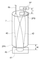
図1、図2に実施例1の干渉計の構成図を示す。光源1より射出された波長λ(633nm)を持つレーザー光はシングルモードファイバー6aに導光され、分波器9、シングルモードファイバー6bを経て、光検出部10へ導かれる。ファイバー6bから射出された直線偏光のレーザー光は、屈折率分布型レンズ(Gradient Index Lens:Grinレンズ)7でコリメートされ、複屈折材料の素子であるルチル板8に導入される。厚さがTのルチル板8の端面には第1偏光ビームスプリッタとしてのPBS膜2Pが蒸着されている。すなわち、ルチル板8は、ファイバー6bの端部とPBS膜2Pとの間に配置される。PBS膜2Pは、光源1から射出された光のうち、P波(第1偏光成分)を参照光として透過し、S波(第2偏光成分)を測定光として透過する。PBS膜2Pは、微小構造で構成されたPBS膜を用いることが好適である。測定光であるS波は、PBS膜2Pを透過し被検面である反射面4bで反射されて再び同一光路を通り、ルチル板8及びGrinレンズ7を通過し集光されて再びファイバー6bに導入される。一方参照光であるP波は、ルチル板8及びGrinレンズ7を通り、集光されて再びファイバー6bに導入される。測定光であるS波と参照光であるP波とは、ファイバー6bを再び透過して分波器9に導入され、今度はファイバー6cへと導かれる。ファイバー6cの端面から発散された光束はレンズ31で平行光とされ、1/4λ板3を透過し、偏光板3Bを通る。受光素子16は、測定光と参照光との干渉光を受光する。反射面4bが光軸方向に移動すると、測定光S波の位相のみ変化する為、1/4λ板3を透過した光束は、回転する直線偏光となる。光束は、さらに偏光板3Bを通ると光の明暗信号となり、1/2λ=316.5nmで1周期変化するサイン信号となる。
[Example 1]
1 and 2 show a configuration diagram of the interferometer of the first embodiment. Laser light having a wavelength λ (633 nm) emitted from the
図2に示す光学系は以上説明したようにフィゾー型の干渉計を構成しているため、光検出部10が小型に構成されている。フィゾー光学系は通常参照光と測定光の光路長は異なっているため、光源は縦シングルモードでコヒーレンシーの高い光源に限られる。しかし、実施例1の干渉計は、ルチル板8使用することで以下のような特徴を有する。ルチル板8の異常光線軸を上記P波の偏光軸に一致させると、P波のルチル透過光路長はS波のルチル透過光路長よりT×0.3だけ長い。つまり幾何学的にはP波とS波は透過して反射面4bに照射されたS波の方がPBS膜2Pの端面と反射面4bとの間の距離WDだけ光路長が長く見える。しかし、実際にはWDがT×0.3である場合に、P波とS波との波動光学的光路長が一致する。すなわち、PBS膜2Pの前段に設けたルチル板8の作用で、フィゾー干渉計でありながら、測定光と参照光の光路長を合わせることが可能である。よって、低コヒーレンシー光源を使用してもPBS膜2Pから離れた位置で信号を出力する事が可能となるため光源の選択の幅が広い。例えば、光源にスーパールミネッセントダイオード(SLD)光源や白色干渉光を使用すれば、微少範囲のピーク検出などにも利用でき利用価値が高い。また、低コヒーレンシー光源を用いると、反射面4b又はPBS膜2Pで規定回数反射しなかったP波、S波のゴースト光で、正規回数反射したP波、S波と光路長が異なっている。その為、ゴースト光(迷光)は干渉信号を生じないので、ゴースト光に起因した測定精度の低減を大幅に防止することが可能となる。本実施例では複屈折材料の素子をルチル板で構成した。しかし、ルチル板と同様に複屈折効果をもつ材料、例えば方解石や、イットリウム・バナデート等で複屈折材料の素子を構成しても同様の効果が得られる。
Since the optical system shown in FIG. 2 constitutes a Fizeau interferometer as described above, the
[実施例2]
図3に実施例2の干渉計の構成図を示す。実施例2では、実施例1と比べ、光検出部10の構成が異なっており、具体的には光検出部10に対して光束を射出するファイバー6bがGrinレンズ7の中心からオフセットした位置に設置されている。また、ファイバー6bが光束を射出する箇所とGrinレンズ上の反対位置にはミラー面5Pが設置してある。ミラー面5Pは、反射面4bで反射されPBS膜2Pを透過した測定光とPBS膜2Pで反射された参照光とをPBS膜2Pに向けて反射する第1ミラー面を構成している。
[Example 2]
FIG. 3 shows a configuration diagram of the interferometer of the second embodiment. In the second embodiment, the configuration of the
ファイバー6bから射出された光束40はPBS膜2Pを透過する測定光41とPBS膜2Pで反射された参照光42とに分割され。測定光41は、PBS膜2Pから、反射面4b、PBS膜2P、ミラー面5P、PBS膜2P、反射面4b、PBS膜2P及びルチル板8を順次経由してファイバー6bに至る。一方、参照光42は、PBS膜2Pから、ミラー面5P、PBS膜2P及びルチル板8を順次経由してファイバー6bに至る。
The
実施例2の干渉計は、以上のようなダブルパスのフィゾー干渉計を構成している為、反射面4bの移動に対して、1/4λで1周期のサイン信号が得られる。このような構成の場合、PBS膜2Pの消光比の性能で、ある程度の漏れ光(ゴースト光)が発生する。例えば、透過するべきS波が反射して再び内部光学系を通ってPBS膜2Pで透過すると反射面4bの移動に対して1/2λで1周期の信号が出力される。しかし、SLD光源などブロードな波長を持った光源を使用した場合、漏れ光とメインの参照光、測定光ともに光路長が異なっている為干渉信号を発生しない。実施例2においても、このようにゴースト光成分を干渉しないようにする事が可能となる為、変位信号の干渉信号の品質が高くなる為非常に高精度な計測に適用することが可能となる。
Since the interferometer of the second embodiment constitutes the double-pass Fizeau interferometer as described above, a sine signal of ¼λ and one period can be obtained with respect to the movement of the reflecting
[実施例3]
図4は実施例3の干渉計の構成図を示す。実施例3では、実施例1に比較し光検出部10の構成が異なるだけで、光源1、受光素子16は共通である。ファイバー6bから射出されたレーザー光40はGrinレンズ7で平行光束となり、PBS膜2PAに照射される。PBS膜2PAは半導体プロセスなどを利用した微少構造で構成され、P波はPBS膜2PAで反射され、S波はPBS膜2PAを透過する様に微少構造の向きが設定されている。よって、測定光41となるS波は、PBS膜2PAを透過して反射面4bで反射され、再びPBS膜2PAを透過し再びGrinレンズ7で集光光束となりPBS膜2PBに集光照射される。一方、参照光42となるP波は、PBS膜2PAで反射され、測定光41と同様にGrinレンズ7で集光光束となりPBS膜2PBに照射される。PBS膜2PBは、PBS膜2PA同様に微細構造をもつPBS膜であるが、PBS膜2PAと微細構造の向きが垂直方向に設定してある為、測定光41であるS波を反射し、参照光42であるP波を透過する。PBS膜2PBは、反射面4bで反射されPBS膜2PAを透過した測定光41をPBS膜2PAに向けて反射するとともにPBS膜2PAで反射された参照光42を透過する第2偏光ビームスプリッタを構成している。PBS膜2PBを透過した参照光42は、PBS膜2PBと距離Tだけ離れた位置に設置してあるフレネルミラー5Pで反射され、元の光路を帰って再びPBS膜2PBに入射する。フレネルミラー5Pの面は、PBS膜2PBを透過した参照光42をPBS膜2PBに向けて反射する第2ミラー面を構成している。測定光41であるS波と、参照光42であるP波はPBS膜2PAに再度入射し、測定光41はPBS膜2PAを透過し反射面4bで反射されPBS膜2PAを再度透過し、PBS膜2PAで再び反射された参照光42と合波されファイバー6bに集光される。上記構成ではT=WDの場合に測定光41と参照光42との波動光学的光路長は等しくなり、実施例1、2と同様にPBS膜2PAから空間的にはなれた位置で等光路の干渉計が構成できる。したがって、実施例3においても、SLDなどの光源を使用した干渉計の構成がフィゾータイプの光学系で構成できるので、ゴースト光に対しても実施例2と同様の効果が得られる。本実施例では、PBS膜2PBを透過した参照光をPBS膜2PBに向けて反射する第2ミラー面としてフレネルミラー5Pの面を使用した。しかし、第2ミラー面として球面ミラーの面を使用することもできる。また、本実施例では、PBS膜2PBと第2ミラーとしてのフレネルミラーとを個別に設置した。しかし、PBS膜2PBとフレネルミラーとが単一の基板に形成されたものを使用することもできる。
[Example 3]
FIG. 4 shows a configuration diagram of the interferometer of the third embodiment. In the third embodiment, the
[実施例4]
図5は実施例4の干渉計の構成図を示す。実施例4の干渉計は、PBS膜2Pを反射面4bが位置するべき面に対して傾斜するように配置されていることを除けば実施例2の干渉計と同様の構成をとる。このPBS膜2Pを傾斜させることは、ゴースト光成分の除去により効果がある。ダブルパスの光路中1回目に反射面4bとPBS膜2Pで反射した光束はそれぞれ光束42Aと光束42Bとに分離されるが、ミラー面5Pで反射されて再び反射面4bとPBS膜2Pで反射されてファイバー6bに向かう光束は正確に重なり合波される。つまり反射面4bに正規回数照射した光束はファイバー6bに向かい干渉信号となるが、反射面4bに正規回数照射しなかったゴースト光成分は最終的に光束44となり、ファイバー6bに導入できない。実施例4の干渉計は、微少のゴースト光を除去するのにさらに効果的である為、最終的な信号の歪みが少なく、信号対雑音比(SN比)もより高いものとする事が出来るため超高精度計測により効果的である。
[Example 4]
FIG. 5 shows a configuration diagram of the interferometer of the fourth embodiment. The interferometer of the fourth embodiment has the same configuration as that of the interferometer of the second embodiment except that the
[実施例5]
図6は実施例5の干渉計の構成図を示す。実施例4の干渉計は、PBS膜2PAを反射面4bが位置するべき面に対して傾斜するように配置されていることを除けば実施例3の干渉計と同様の構成をとる。PBS膜2PAが傾斜されていることは実施例4と同様な効果をもち、超高精度計測に効果的である。
[Example 5]
FIG. 6 shows a configuration diagram of the interferometer of the fifth embodiment. The interferometer of the fourth embodiment has the same configuration as the interferometer of the third embodiment except that the PBS film 2PA is disposed so as to be inclined with respect to the surface on which the
実施例1〜5は、レーザー光など光の位相変調を光の強度変調に変換し微少変位を計測する干渉計、変位計に適用できる。 The first to fifth embodiments can be applied to an interferometer and a displacement meter that measure phase displacement by converting phase modulation of light such as laser light into light intensity modulation.
Claims (10)
光源と、
前記光源から射出された光のうち第1偏光成分を参照光として反射し、第2偏光成分を測定光として透過する第1偏光ビームスプリッタと、
複屈折材料の素子と、
前記第1偏光ビームスプリッタを透過し被検面である反射面で反射され前記第1偏光ビームスプリッタを透過した測定光と前記第1偏光ビームスプリッタで反射された参照光との干渉光を受光する受光素子と、
を備え、
前記参照光と前記測定光とは、前記素子を介して前記第1偏光ビームスプリッタから前記受光素子に至り、
前記測定光および前記参照光は、それらが可干渉となる光路長をそれぞれ有し、かつ前記測定光および前記参照光の少なくとも一方の迷光は、前記測定光および前記参照光とは可干渉とならない光路長を有するように、前記素子の厚さと前記反射面の位置とが定められている、ことを特徴とする干渉計。 An interferometer,
A light source;
A first polarization beam splitter that reflects the first polarization component of the light emitted from the light source as reference light and transmits the second polarization component as measurement light;
A birefringent material element;
Interference light between the measurement light transmitted through the first polarization beam splitter, reflected by the reflection surface as the test surface and transmitted through the first polarization beam splitter, and the reference light reflected by the first polarization beam splitter is received. A light receiving element;
With
The reference light and the measurement light reach the light receiving element from the first polarization beam splitter via the element,
The measurement light and the reference light has the optical path length thereof becomes coherent, respectively, and wherein at least one of stray light of the measurement light and the reference light, wherein the measuring light and the reference light does not become coherent The interferometer, wherein the thickness of the element and the position of the reflecting surface are determined so as to have an optical path length.
光源と、
前記光源から射出された光のうち第1偏光成分を参照光として反射し、第2偏光成分を測定光として透過する第1偏光ビームスプリッタと、
複屈折材料の素子と、
ファイバと、
前記第1偏光ビームスプリッタを透過し被検面である反射面で反射され前記第1偏光ビームスプリッタを透過した測定光と前記第1偏光ビームスプリッタで反射された参照光との干渉光を受光する受光素子と、
を備え、
前記参照光と前記測定光とは、前記素子および前記ファイバを介して前記第1偏光ビームスプリッタから前記受光素子に至る、ことを特徴とする干渉計。 An interferometer,
A light source;
A first polarization beam splitter that reflects the first polarization component of the light emitted from the light source as reference light and transmits the second polarization component as measurement light;
A birefringent material element;
Fiber,
Interference light between the measurement light transmitted through the first polarization beam splitter, reflected by the reflection surface as the test surface and transmitted through the first polarization beam splitter, and the reference light reflected by the first polarization beam splitter is received. A light receiving element;
With
The interferometer, wherein the reference light and the measurement light reach the light receiving element from the first polarization beam splitter via the element and the fiber.
光源と、
前記光源から射出された光のうち第1偏光成分を参照光として反射し、第2偏光成分を測定光として透過する第1偏光ビームスプリッタと、
複屈折材料の素子と、
前記第1偏光ビームスプリッタを透過し被検面である反射面で反射され前記第1偏光ビームスプリッタを透過した測定光と前記第1偏光ビームスプリッタで反射された参照光との干渉光を受光する受光素子と、
を備え、
前記参照光と前記測定光とは、前記素子を介して前記第1偏光ビームスプリッタから前記受光素子に至り、
前記第1偏光ビームスプリッタは、前記素子の端面に形成されている、ことを特徴とする干渉計。 An interferometer,
A light source;
A first polarization beam splitter that reflects the first polarization component of the light emitted from the light source as reference light and transmits the second polarization component as measurement light;
A birefringent material element;
Interference light between the measurement light transmitted through the first polarization beam splitter, reflected by the reflection surface as the test surface and transmitted through the first polarization beam splitter, and the reference light reflected by the first polarization beam splitter is received. A light receiving element;
With
The reference light and the measurement light reach the light receiving element from the first polarization beam splitter via the element,
The interferometer, wherein the first polarization beam splitter is formed on an end face of the element.
前記測定光は、前記第1偏光ビームスプリッタから前記反射面、前記第1偏光ビームスプリッタ、前記第1ミラー面、前記第1偏光ビームスプリッタ、前記反射面、前記第1偏光ビームスプリッタ及び前記素子を順次経由して前記受光素子に至り、
前記参照光は、前記第1偏光ビームスプリッタから前記第1ミラー面、前記第1偏光ビームスプリッタ及び前記素子を順次経由して前記受光素子に至る、ことを特徴とする請求項1乃至請求項3のいずれか1項に記載の干渉計。 A first mirror surface that reflects the measurement light reflected by the reflection surface and transmitted through the first polarization beam splitter and the reference light reflected by the first polarization beam splitter toward the first polarization beam splitter; In addition,
The measurement light passes from the first polarization beam splitter to the reflection surface, the first polarization beam splitter, the first mirror surface, the first polarization beam splitter, the reflection surface, the first polarization beam splitter, and the element. To the light receiving element via the sequence,
4. The reference light from the first polarizing beam splitter to the light receiving element through the first mirror surface, the first polarizing beam splitter, and the element in order. The interferometer according to any one of the above.
光源と、
前記光源から射出された光のうち第1偏光成分を参照光として反射し、第2偏光成分を測定光として透過する第1偏光ビームスプリッタと、
前記第1偏光ビームスプリッタを透過し被検面である反射面で反射され前記第1偏光ビームスプリッタを透過した測定光を前記第1偏光ビームスプリッタに向けて反射し、かつ前記第1偏光ビームスプリッタで反射された参照光を透過する第2偏光ビームスプリッタと、
前記第2偏光ビームスプリッタを透過した参照光を前記第2偏光ビームスプリッタに向けて反射する第2ミラー面と、
前記測定光と前記参照光との干渉光を受光する受光素子と、
を備え、
前記測定光は、前記第1偏光ビームスプリッタから前記反射面、前記第1偏光ビームスプリッタ、前記第2偏光ビームスプリッタ、前記第1偏光ビームスプリッタ、前記反射面及び前記第1偏光ビームスプリッタを順次経由して前記受光素子に至り、
前記参照光は、前記第1偏光ビームスプリッタから前記第2偏光ビームスプリッタ、前記第2ミラー面、前記第2偏光ビームスプリッタ及び前記第1偏光ビームスプリッタを順次経由して前記受光素子に至る、ことを特徴とする干渉計。 An interferometer,
A light source;
A first polarization beam splitter that reflects the first polarization component of the light emitted from the light source as reference light and transmits the second polarization component as measurement light;
The measurement light that has passed through the first polarizing beam splitter, reflected by the reflecting surface that is the test surface, and transmitted through the first polarizing beam splitter is reflected toward the first polarizing beam splitter, and the first polarizing beam splitter. A second polarizing beam splitter that transmits the reference light reflected by
A second mirror surface that reflects the reference light transmitted through the second polarizing beam splitter toward the second polarizing beam splitter;
A light receiving element that receives interference light between the measurement light and the reference light;
With
The measurement light sequentially passes from the first polarization beam splitter to the reflection surface, the first polarization beam splitter, the second polarization beam splitter, the first polarization beam splitter, the reflection surface, and the first polarization beam splitter. To the light receiving element,
The reference light passes from the first polarizing beam splitter to the light receiving element via the second polarizing beam splitter, the second mirror surface, the second polarizing beam splitter, and the first polarizing beam splitter in order. Interferometer characterized by.
Priority Applications (3)
| Application Number | Priority Date | Filing Date | Title |
|---|---|---|---|
| JP2009283432A JP5629455B2 (en) | 2009-12-14 | 2009-12-14 | Interferometer |
| EP10191358.0A EP2336714B1 (en) | 2009-12-14 | 2010-11-16 | Interferometer |
| US12/966,210 US9372066B2 (en) | 2009-12-14 | 2010-12-13 | Interferometer |
Applications Claiming Priority (1)
| Application Number | Priority Date | Filing Date | Title |
|---|---|---|---|
| JP2009283432A JP5629455B2 (en) | 2009-12-14 | 2009-12-14 | Interferometer |
Publications (3)
| Publication Number | Publication Date |
|---|---|
| JP2011123037A JP2011123037A (en) | 2011-06-23 |
| JP2011123037A5 JP2011123037A5 (en) | 2013-02-07 |
| JP5629455B2 true JP5629455B2 (en) | 2014-11-19 |
Family
ID=43646496
Family Applications (1)
| Application Number | Title | Priority Date | Filing Date |
|---|---|---|---|
| JP2009283432A Expired - Fee Related JP5629455B2 (en) | 2009-12-14 | 2009-12-14 | Interferometer |
Country Status (3)
| Country | Link |
|---|---|
| US (1) | US9372066B2 (en) |
| EP (1) | EP2336714B1 (en) |
| JP (1) | JP5629455B2 (en) |
Families Citing this family (3)
| Publication number | Priority date | Publication date | Assignee | Title |
|---|---|---|---|---|
| JP5993207B2 (en) * | 2012-05-22 | 2016-09-14 | 東京エレクトロン株式会社 | Optical interference system and substrate processing apparatus |
| CN105258635A (en) * | 2015-11-09 | 2016-01-20 | 中国科学院长春光学精密机械与物理研究所 | Standard reference lens for broadband Fizeau laser interferometer |
| CN110006349A (en) * | 2019-04-29 | 2019-07-12 | 西安交通大学 | A kind of high tolerance is total to optical path grating interferometer |
Family Cites Families (23)
| Publication number | Priority date | Publication date | Assignee | Title |
|---|---|---|---|---|
| US3520615A (en) * | 1965-10-25 | 1970-07-14 | Vickers Ltd | Optical phase measuring apparatus |
| JPS6055206A (en) * | 1983-09-05 | 1985-03-30 | Japan Aviation Electronics Ind Ltd | Light interference meter |
| JPH0454406A (en) * | 1990-06-25 | 1992-02-21 | Toyota Autom Loom Works Ltd | Optical displacement gauge |
| US5153669A (en) * | 1991-03-27 | 1992-10-06 | Hughes Danbury Optical Systems, Inc. | Three wavelength optical measurement apparatus and method |
| JPH0571913A (en) | 1991-09-11 | 1993-03-23 | Fuji Xerox Co Ltd | Interferometer |
| US6229619B1 (en) * | 1996-02-12 | 2001-05-08 | Massachusetts Institute Of Technology | Compensation for measurement uncertainty due to atmospheric effects |
| JPH1166600A (en) * | 1997-08-08 | 1999-03-09 | Tdk Corp | Light receiving and emitting device and optical pickup apparatus |
| US6455861B1 (en) * | 1998-11-24 | 2002-09-24 | Cambridge Research & Instrumentation, Inc. | Fluorescence polarization assay system and method |
| JP2000234914A (en) * | 1999-02-15 | 2000-08-29 | Tokimec Inc | Strain detector |
| JP2001256654A (en) * | 2000-03-13 | 2001-09-21 | Optware:Kk | Optical information recording device, optical information reproducing device, optical information recording/ reproducing device and optical information recording medium |
| EP1099943B1 (en) * | 2000-08-16 | 2003-01-08 | Agilent Technologies, Inc. (a Delaware corporation) | Wavemeter comprising coarse and fine measuring units |
| WO2002093237A1 (en) * | 2001-05-15 | 2002-11-21 | Optellios, Inc. | Polarization analysis unit, calibration method and optimization therefor |
| US6778280B2 (en) * | 2001-07-06 | 2004-08-17 | Zygo Corporation | Interferometry system and method employing an angular difference in propagation between orthogonally polarized input beam components |
| US6897962B2 (en) * | 2002-04-18 | 2005-05-24 | Agilent Technologies, Inc. | Interferometer using beam re-tracing to eliminate beam walk-off |
| US6943881B2 (en) * | 2003-06-04 | 2005-09-13 | Tomophase Corporation | Measurements of optical inhomogeneity and other properties in substances using propagation modes of light |
| WO2005003862A1 (en) * | 2003-07-05 | 2005-01-13 | Carl Zeiss Smt Ag | Device for the polarization-specific examination of an optical system |
| JP4514209B2 (en) | 2004-10-15 | 2010-07-28 | キヤノン株式会社 | Position detection apparatus and method |
| JP4939765B2 (en) * | 2005-03-28 | 2012-05-30 | 株式会社日立製作所 | Displacement measuring method and apparatus |
| JP4914040B2 (en) * | 2005-07-28 | 2012-04-11 | キヤノン株式会社 | Interference measurement device |
| WO2007019574A2 (en) * | 2005-08-09 | 2007-02-15 | The General Hospital Corporation | Apparatus, methods and storage medium for performing polarization-based quadrature demodulation in optical coherence tomography |
| JP4810693B2 (en) * | 2007-02-09 | 2011-11-09 | 富士フイルム株式会社 | Lightwave interference measurement device |
| JP5305732B2 (en) * | 2008-05-13 | 2013-10-02 | キヤノン株式会社 | Interferometer |
| US20110075153A1 (en) * | 2009-09-25 | 2011-03-31 | Hogan Josh N | Compact isolated analysis system |
-
2009
- 2009-12-14 JP JP2009283432A patent/JP5629455B2/en not_active Expired - Fee Related
-
2010
- 2010-11-16 EP EP10191358.0A patent/EP2336714B1/en not_active Not-in-force
- 2010-12-13 US US12/966,210 patent/US9372066B2/en not_active Expired - Fee Related
Also Published As
| Publication number | Publication date |
|---|---|
| EP2336714A1 (en) | 2011-06-22 |
| EP2336714B1 (en) | 2014-05-21 |
| US9372066B2 (en) | 2016-06-21 |
| US20110141479A1 (en) | 2011-06-16 |
| JP2011123037A (en) | 2011-06-23 |
Similar Documents
| Publication | Publication Date | Title |
|---|---|---|
| US9880377B1 (en) | Multiple wavelengths real time phase shift interference microscopy | |
| JP5087186B1 (en) | Iso-optical path interferometer | |
| Kimbrough et al. | Low-coherence vibration insensitive Fizeau interferometer | |
| CN104931125B (en) | Two-way linear polarization is interfered and single Wo Lasite prismatic decomposition formula homodyne laser vibration measurer | |
| WO2020098227A1 (en) | Method and device for correcting non-linear errors of single-frequency laser interferometer | |
| JP5305732B2 (en) | Interferometer | |
| CN104897271B (en) | Single channel linear polarization is interfered and single Wo Lasite prismatic decomposition formula homodyne laser vibration measurer | |
| US7652771B2 (en) | Interferometer with Double Polarizing Beam Splitter | |
| JP7233536B2 (en) | Method, interferometer and signal processor for measuring input phase and/or input amplitude, respectively, of an input optical field | |
| JPH05500712A (en) | optical measuring device | |
| JP5965167B2 (en) | White light interference measurement device | |
| CN102401630B (en) | Spatial phase shift Fizeau spherical interferometer | |
| JPH02228505A (en) | Interferometer | |
| JP5629455B2 (en) | Interferometer | |
| TW200928301A (en) | Apparatus for measuring displacement by using wavelength-modulated heterodyne grating interferometer | |
| WO2017126215A1 (en) | Phase shift amount measurement device | |
| JP4869656B2 (en) | Interferometer | |
| JP5348224B2 (en) | Displacement measuring method and apparatus | |
| JP7489833B2 (en) | Displacement Detection Device | |
| JP2006064451A (en) | Interferometer | |
| CN2419594Y (en) | Optical Measuring Instrument for Object Vibration Amplitude | |
| RU2303237C2 (en) | Interferometer device for measuring optical thickness of a transparent layer or a gap | |
| Nakata et al. | Common-path double-pass optical interferometry using a wire-grid polarizer as a reference mirror | |
| JP3964260B2 (en) | Shape measuring device | |
| JP2014025766A (en) | Replacement detection apparatus |
Legal Events
| Date | Code | Title | Description |
|---|---|---|---|
| A521 | Request for written amendment filed |
Free format text: JAPANESE INTERMEDIATE CODE: A523 Effective date: 20121213 |
|
| A621 | Written request for application examination |
Free format text: JAPANESE INTERMEDIATE CODE: A621 Effective date: 20121213 |
|
| A977 | Report on retrieval |
Free format text: JAPANESE INTERMEDIATE CODE: A971007 Effective date: 20130920 |
|
| A131 | Notification of reasons for refusal |
Free format text: JAPANESE INTERMEDIATE CODE: A131 Effective date: 20130927 |
|
| A521 | Request for written amendment filed |
Free format text: JAPANESE INTERMEDIATE CODE: A523 Effective date: 20131126 |
|
| A131 | Notification of reasons for refusal |
Free format text: JAPANESE INTERMEDIATE CODE: A131 Effective date: 20140425 |
|
| A521 | Request for written amendment filed |
Free format text: JAPANESE INTERMEDIATE CODE: A523 Effective date: 20140624 |
|
| TRDD | Decision of grant or rejection written | ||
| A01 | Written decision to grant a patent or to grant a registration (utility model) |
Free format text: JAPANESE INTERMEDIATE CODE: A01 Effective date: 20140905 |
|
| A61 | First payment of annual fees (during grant procedure) |
Free format text: JAPANESE INTERMEDIATE CODE: A61 Effective date: 20141006 |
|
| R151 | Written notification of patent or utility model registration |
Ref document number: 5629455 Country of ref document: JP Free format text: JAPANESE INTERMEDIATE CODE: R151 |
|
| LAPS | Cancellation because of no payment of annual fees |