EP1486779B1 - Capteur de NOx - Google Patents
Capteur de NOx Download PDFInfo
- Publication number
- EP1486779B1 EP1486779B1 EP04020248A EP04020248A EP1486779B1 EP 1486779 B1 EP1486779 B1 EP 1486779B1 EP 04020248 A EP04020248 A EP 04020248A EP 04020248 A EP04020248 A EP 04020248A EP 1486779 B1 EP1486779 B1 EP 1486779B1
- Authority
- EP
- European Patent Office
- Prior art keywords
- internal space
- oxygen
- electrode
- pumping
- sensing device
- Prior art date
- Legal status (The legal status is an assumption and is not a legal conclusion. Google has not performed a legal analysis and makes no representation as to the accuracy of the status listed.)
- Expired - Lifetime
Links
Images


Classifications
-
- G—PHYSICS
- G01—MEASURING; TESTING
- G01N—INVESTIGATING OR ANALYSING MATERIALS BY DETERMINING THEIR CHEMICAL OR PHYSICAL PROPERTIES
- G01N27/00—Investigating or analysing materials by the use of electric, electrochemical, or magnetic means
- G01N27/26—Investigating or analysing materials by the use of electric, electrochemical, or magnetic means by investigating electrochemical variables; by using electrolysis or electrophoresis
- G01N27/416—Systems
- G01N27/417—Systems using cells, i.e. more than one cell and probes with solid electrolytes
- G01N27/419—Measuring voltages or currents with a combination of oxygen pumping cells and oxygen concentration cells
-
- G—PHYSICS
- G01—MEASURING; TESTING
- G01N—INVESTIGATING OR ANALYSING MATERIALS BY DETERMINING THEIR CHEMICAL OR PHYSICAL PROPERTIES
- G01N33/00—Investigating or analysing materials by specific methods not covered by groups G01N1/00 - G01N31/00
- G01N33/0004—Gaseous mixtures, e.g. polluted air
- G01N33/0009—General constructional details of gas analysers, e.g. portable test equipment
- G01N33/0027—General constructional details of gas analysers, e.g. portable test equipment concerning the detector
- G01N33/0036—Specially adapted to detect a particular component
- G01N33/0037—Specially adapted to detect a particular component for NOx
-
- Y—GENERAL TAGGING OF NEW TECHNOLOGICAL DEVELOPMENTS; GENERAL TAGGING OF CROSS-SECTIONAL TECHNOLOGIES SPANNING OVER SEVERAL SECTIONS OF THE IPC; TECHNICAL SUBJECTS COVERED BY FORMER USPC CROSS-REFERENCE ART COLLECTIONS [XRACs] AND DIGESTS
- Y02—TECHNOLOGIES OR APPLICATIONS FOR MITIGATION OR ADAPTATION AGAINST CLIMATE CHANGE
- Y02A—TECHNOLOGIES FOR ADAPTATION TO CLIMATE CHANGE
- Y02A50/00—TECHNOLOGIES FOR ADAPTATION TO CLIMATE CHANGE in human health protection, e.g. against extreme weather
- Y02A50/20—Air quality improvement or preservation, e.g. vehicle emission control or emission reduction by using catalytic converters
Definitions
- the present invention relates to a sensing device for measuring a component contained in a measurement gas, and more particularly to a gas sensor for determining the concentration of NOx as a component of for example a combustion gas, and a method for determining the NOx concentration.
- a known method of measuring NOx in combustion gases employs a sensor having an oxygen-ion conductive solid electrolyte, such as zirconia, and a Pt-containing electrode and a Rh-containing electrode formed thereon.
- This method utilizes the ability of Rh to reduce NOx, and determines the NOx concentration by measuring an electromotive force induced between the two electrodes.
- this sensor tends to suffer from noise, since the electromotive force varies to a great extent with a change in the concentration of oxygen contained in the combustion gases, but varies a small extent in response to a change in the NOx concentration.
- a first and a second pair of an electrochemical pumping cell and sensing cell are prepared, and a limiting current is measured by a sensor having the first pair of pumping and sensing cells, under the oxygen partial pressure that does not allow reduction of NOxwhile a limiting current is measured by a sensor having the second pair of pumping and sensing cells, under the oxygen partial pressure which allows reduction of NOx, so as to measure the NOx concentration based on a difference in the limiting currents of the two sensors.
- a first and a second sensing element 61, 62 which are formed independently of each other, have respective internal spaces 65, 66 which communicate with an exterior measurement-gas space through corresponding diffusion resistance portions 63, 64, and respective electrochemical pumping cells 67, 68 using solid electrolyte.
- the first sensing element 61 effects pumping of only oxygen under a predetermined diffusion resistance, and the oxygen concentration is obtained by multiplying the pumping current Ip 1 by a current sensitivity coefficient K 1 .
- the second sensing element 62 having an electrode or catalyst capable of reducing NOx effects pumping of both oxygen and NOx under a predetermined diffusion resistance, and a sum of the oxygen and NOx concentrations is obtained by multiplying the pumping current Ip 2 by a current sensitivity coefficient K 2 .
- the dependency of the pumping current of one of the sensors on the oxygen concentration differs from that of the other sensor.
- the oxygen concentration is generally several percentages of exhaust gases, whereas the NOx concentration is several hundreds of ppm, which is about 1/100 of the oxygen. If the dependency of the pumping current on the oxygen concentration slightly differs between the two sensors, therefore, a difference in the limiting currents due to the varied oxygen concentration becomes larger than a change in the limiting currents due to NOx to be measured.
- the known method involves other problems.
- the pumping current may be undesirably changed, resulting in reduced measuring accuracy.
- the measurement results may involve some abnormality. Further, a difference in the chronological changes in the characteristics between the two sensors may lead to measuring errors, making the sensors undurable for use for a long period of time.
- US-A-5049254 discloses an electrochemical device and method which measures the percentage of exhaust gas recirculation in a combined intake air and exhaust gas mixture of an internal combustion engine.
- Gas to be measured enters a first chamber of the device through an aperture.
- oxygen is pumped out by a first electrochemical pump cell to which a constant voltage is applied.
- the gas passes to a second chamber in which a constant higher voltage across a second electrochemical pump cell causes dissociation of all CO 2 and H 2 O in the second chamber.
- Current flowing in the second cell is measured and is proportional to the percentage of CO 2 and H 2 O in the gas measured.
- the present invention may be practiced for an NOx sensor wich is able to measure an increased range of NOx, in combustion gases produced under a wide range of the air/fuel ratio, that is, from a rich-burn combustion gas produced by combustion of a fuel-rich air-fuel mixture to a lean-burn combustion gas produced by combustion of a fuel-lean air-fuel mixture.
- a sensing device for measuring a concentration of NOx as a component of a measurement gas as set out in claim 1.
- concentration of Nox can be measured with high accuracy, without being affected by the oxygen concentration or its variation in the measurement gas,assuring improved operating response even in repeated measurements, and improved measuring accuracy for a long period of time. Further, the present method enables measurement of an increased range of NOx, in combustion gases produced under a wide range of the air/fuel ratio, that is, from a rich burn region using excessive fuel to a lean burn region using excessive air, without being affected by oil ash.
- the second internal space may be filled with a porous body having the second diffusion resistance.
- the oxygen partial pressure in the first internal space is detected, and the oxygen pumping action of the first electrochemical cell is controlled by varying a voltage applied to the first electrochemical cell, based on the detected oxygen partial pressure, so that the oxygen partial pressure in the first internal space is regulated to a constant value.
- the oxygen pumping action of the second electrochemical cell is effected by applying thereto a constant voltage which provides a diffusion limiting current to the gas component, the oxygen partial pressure of the atmosphere in the second internal space being regulated by application of the diffusion limiting current.
- the elevated temperature of the second internal space is not lower than the elevated temperature of the first internal space.
- the oxygen partial pressure in the second internal space is not higher than the oxygen partial pressure in the first internal space.
- one of the pair of electrodes of the electrochemical cell of the second oxygen pumping means which is disposed in the second internal space, may serve as the catalyst.
- the sensing device has a sensing element which includes the first and second oxygen-ion conductive solid electrolytes as integral parts thereof, the first and second internal spaces, the first and second diffusion means and the first and second oxygen pumping means being formed in the sensing element.
- the sensing element may have a narrow, flat space having a predetermined diffusion resistance, which space has an opening exposed to the external measurement-gas space, the flat space comprising the first and second diffusion means, the first internal space consisting of a first portion of the flat space adjacent to the opening, in which the first oxygen pumping means is provided, the second internal space consisting of a second portion of the flat space remote from the opening and inside of the first portion, in which the second oxygen pumping means is provided.
- first and second oxygen-ion conductive solid electrolytes may form an oxygen-ion conductive solid electrolyte layer, or two separate oxygen-ion conductive solid electrolyte layers.
- the sensing device as described above may further include a porous body filling the opening of the flat space of the sensing element, the porous body having a predetermined diffusion resistance.
- the sensing device further includes a heater for heating the first and second internal spaces to respective predetermined temperatures.
- the sensing device can effectively operates even at a relatively low temperature, while effectively decomposing the gas component of the measurement gas.
- the second internal space may be formed separately from the first internal space within the sensing element.
- the second diffusion means may consist of a porous body having the second diffusion resistance, the second internal space being filled with the porous body.
- the sensing device further includes oxygen partial pressure detecting means for detecting the oxygen partial pressure of the atmosphere in the first internal space, the first oxygen pumping means applying a controlled current to the pair of electrodes of the electrochemical cell of the first pumping means, on the basis of the oxygen partial pressure detected by the detecting means, so as to regulate the oxygen partial pressure in the first internal space, with improved accuracy and ease.
- a reference-gas chamber containing a reference gas is formed in the sensing element, separately from the first and second internal spaces, the oxygen partial pressure detecting means comprising an electrochemical cell which comprises an oxygen-ion conductive solid electrolyte extending between the reference-gas chamber and the first internal space, a reference electrode located in the reference-gas chamber and formed in contact with the solid electrolyte, and a measuring electrode located in the first internal space and formed in contact with the solid electrolyte.
- the reference-gas chamber is preferably exposed at an opening thereof to an ambient atmosphere, such that the ambient atmosphere is introduced into the reference-gas chamber through the opening, to provide the reference gas.
- the electrochemical cell of the second oxygen pumping means may comprise an oxygen-ion conductive solid electrolyte extending between the second internal space and the reference-gas chamber, a first pumping electrode located in the second internal space and formed in contact with the solid electrolyte, and a second pumping electrode located in the reference-gas chamber and formed in contact with the solid electrolyte.
- the oxygen-ion conductive solid electrolyte of the electrochemical cell of the second oxygen pumping means and the oxygen-ion conductive solid electrolyte of the electrochemical cell of the oxygen partial pressure detecting means constitute an integral oxygen-ion conductive solid electrolyte
- the second pumping electrode and the reference electrode formed on the solid electrolyte constitute a common electrode.
- the first pumping electrode of the electrochemical cell of the second oxygen pumping means which is disposed in the second internal space, may also serve as the catalyst. This leads to a simplified process of manufacturing the device.
- the above-indicated first pumping electrode may be formed of a porous cermet consisting of a ceramic, and a metal which is able to reduce or decompose the gas component having bonded oxygen.
- the catalyst may be disposed in the second internal space, in the vicinity of the first pumping electrode of the electrochemical cell of the second oxygen pumping means, or may be superposed on the first pumping electrode of the electrochemical cell of the second oxygen pumping means.
- the above-indicated heater may be located nearer to the second internal space than to the first internal space within the sensing element, so that the second internal space is heated to a higher temperature than the first internal space. With the heater thus located, the gas component can be more easily reduced or decomposed in the second internal space.
- the above-indicated second diffusion resistance of the second diffusion means is preferably determined to be larger than the first diffusion resistance of the first diffusion means. This effectively eliminates an adverse influence on the measurement of the gas component of the measurement gas, due to clogging by oil ash.
- reference numeral 2 denotes an elongate, planar sensing element having a relatively large length.
- This sensing element 2 has an integral laminar structure including a plurality of highly dense, gastight oxygen-ion conductive solid electrolyte layers 4a, 4b, 4c, 4d, 4e which are superposed on each other, as shown in Fig. 2.
- Each of the solid electrolyte layers 4a-4e is formed of a known oxygen-ion conductive solid electrolyte material, such as zirconia.
- the thus integrally formed sensing element 2 is produced by firing unfired solid electrolyte layers into an integral laminar structure, as known in the art.
- a first internal space 6 and a second internal space 8 are separately formed such that the second internal space 8 is located nearer to the distal end of the sensing element 2.
- Each internal space 6, 8 has a rectangular shape as seen in a plane parallel to opposite major surfaces of the element 2.
- a reference-gas channel 10 serving as a reference-gas chamber is formed in the longitudinal direction of the sensing element 2, such that the channel 10 is open at the proximal end of the element 2, for communication with the atmosphere.
- the first and second internal spaces 6, 8 and reference-gas channel 10 are formed in substantial the same plane, by closing respective apertures formed through the solid electrolyte layer 4b, with the upper and lower solid electrolyte layers 4a, 4c.
- the sensing element 2 further has a first diffusion controlling passage 12 as a first diffusion means, which is formed through the thickness of the upper solid electrolyte layer 4a.
- the first diffusion controlling passage 12 communicates the first internal space 6 with an exterior space where a measurement gas to be measured by the NOx sensor is present, so that the measurement gas is introduced into the first internal space 6 through the passage 12, under a predetermined diffusion resistance provided by the passage 12.
- second diffusion means in the form of a second diffusion controlling passage 14 is formed in the solid electrolyte layer 4b, to extend between the first and second internal spaces 6, 8.
- This second diffusion controlling passage 14 communicates with the first and second internal spaces 6, 8, so that the atmosphere in the first internal space 6 is introduced into the second internal space 8 through the passage 14, under a predetermined diffusion resistance provided by the passage 14.
- Inner electrode (pumping electrode) 16 which is a rectangular porous platinum electrode, is formed on the inner surface of the solid electrolyte layer 4a which is exposed to the first internal space 6.
- These electrodes 16, 18 and solid electrolyte layer 4a constitute an electrochemical cell of first oxygen pumping means, that is, a first electrochemical pumping cell.
- each of the porous platinum electrodes 16, 18 consists of a cermet electrode formed of a mixture of platinum and zirconia (ZrO 2 ).
- These measuring electrode 22, reference electrode 24 and solid electrolyte layer 4c constitute an electrochemical cell of oxygen partial pressure detecting means, that is, an electrochemical sensing cell.
- EMF electromotive force
- This electromotive force is measured by a potentiometer 26, to thus detect the oxygen partial pressure in the atmosphere in the first internal space 6. Then, a voltage of the variable power supply 20 is regulated or controlled, on the basis of the level of the oxygen partial pressure as detected by the potentiometer 26, whereby the oxygen partial pressure in the atmosphere in the first internal space 6 is kept at a constant level.
- Internal pumping electrode (first pumping electrode) 28 is formed on the surface of the solid electrolyte layer 4c, such that the electrode 28 is located within the second internal space 8.
- This internal pumping electrode 28 is formed of porous cermet consisting of rhodium (Rh) as a metal capable of reducing NOx, and zirconia as a ceramic material.
- the electrode 28 also functions as an NOx reduction catalyst which is able to reduce NOx present in the atmosphere in the second internal space 8.
- a constant voltage is applied between the internal pumping electrode 28 and the reference electrode (second pumping electrode) 24 disposed in the reference-gas channel 10, by means of a power supply 30, oxygen in the atmosphere within the second internal space 8 is pumped out into the reference-gas channel 10.
- the reference electrode 24 also functions as a pumping electrode, and cooperates with the internal pumping electrode 28 and solid electrolyte layer 4c to constitute an electrochemical cell of second oxygen pumping means, that is, a second electrochemical pumping cell.
- Ammeter 32 is adapted to detect a pumping current which flows by the pumping action of the second oxygen pumping means.
- the constant voltage applied by the power supply 30 is determined so as to provide a limiting current that enables the second electrochemical pumping cell to effect the pumping of the oxygen generated by reduction of NOx, which is introduced into the second internal space 28, under the diffusion resistance provided by the second diffusion resistance channel 14.
- the sensing element 2 also incorporates an alumina insulating layer 34 which is laminated integrally on the solid electrolyte layers 4c, 4e, such that the layer 34 is surrounded by three solid electrolyte layers 4c, 4e and 4d.
- Heater 36 is embedded within the alumina insulating layer 34, and is operated by an external power supply. As shown in Fig. 2, the heater 36 is located in a distal end portion of the sensing element 2 in which the second internal space 8 is formed, so that the second internal space 8 is heated to a higher temperature than the first internal space 6, in other words, the internal pumping electrode 28 is heated to a higher temperature than the inner electrode 16 and measuring electrode 22.
- the heater 36 is located so that the inner electrode 16 and measuring electrode 22 in the first internal space 6 is heated up to 400°C-600°C while the internal pumping electrode 28 in the second internal space 8 is heated up to 700°C-900°C, as the temperature of the measurement gas varies in the range from 300°C to 850°C.
- the thus constructed sensing element 2 is positioned at its distal end portion within the external measurement-gas space.
- the measurement gas is introduced into the first internal space 6, through the first diffusion controlling passage 12, under a predetermined diffusion resistance.
- the measurement gas in the first internal space 6 is subjected to the oxygen pumping action in which a suitable voltage is applied between the inner and outer electrodes 16, 18 of the first electrochemical pumping cell, so that the oxygen partial pressure in the first internal space 6 is controlled to a predetermined level, for example, 10 -6 atm.
- a voltage applied between the two electrodes 16, 18 of the first electrochemical pumping cell by the variable power supply 20 is regulated so that the electromotive force induced between the measuring electrode 22 and the reference electrode 24 of the electrochemical sensing cell, which is detected by the potentiometer 26, is equal to 203mV at 500°C, for example, according to the Nernst equation known in the art.
- the oxygen partial pressure in the first internal space 6 can be easily controlled to 10 -6 atm as desired.
- the voltage applied to the first electrochemical pumping cell is regulated so that the above-described electromotive force corresponds to a difference between a desired oxygen concentration in the first internal space 6 and the oxygen concentration of the reference gas.
- the first diffusion controlling passage 12 functions to reduce an amount of oxygen in the measurement gas diffusing into the first internal space 6, and thus restrict a current flowing through the first electrochemical pumping cell, upon application of a voltage to the pumping cell.
- the oxygen partial pressure is controlled so that NOx contained in the atmosphere is not reduced by the inner electrode 16 and the measuring electrode 22, that is, the reaction: NO ⁇ 1/2N 2 + 1/2O 2 , for example, does not take place, even at a high temperature elevated by the external measurement gas and the heater 36. If NOx in the atmosphere is reduced in the first internal space 6, NOx cannot be accurately measured in the second internal space 8, as described later. In this sense, it is necessary to establish appropriate conditions or environment in the first internal space 6 so that NOx is not reduced by a component (at least a component of the inner electrode 16 of the first electrochemical pumping cell), which might otherwise be involved in reduction of NOx in the first internal space 6.
- the measurement gas whose oxygen partial pressure has been controlled in the first internal space 6 in the above manner, is then introduced into the second internal space 8, through the second diffusion controlling passage 14, under a predetermined diffusion resistance. Then, the measurement gas in the second internal space 8 is subjected to an oxygen pumping action, in which a predetermined or constant voltage, e.g., 449mV, is applied at 700°C between the internal pumping electrode 28 and the reference electrode 24 of the second electrochemical pumping cell, so that oxygen is pumped from the second internal space 8 into the reference-gas channel 10. As a result, the oxygen concentration is reduced down to 10 -10 atm in the second internal space 8, particularly at the three phase boundary of the internal pumping electrode 28.
- a predetermined or constant voltage e.g., 449mV
- the current flowing through the second electrochemical pumping cell is proportional to the oxygen concentration of the atmosphere in the second internal space 8, that is, a sum of the oxygen concentration of the atmosphere in the first internal space 6 and the concentration of oxygen generated by reduction of NOx at the internal pumping electrode 28. Since the oxygen concentration of the atmosphere in the first internal space 6 is kept a constant, as described above, the current flowing through the second electrochemical pumping cell is proportional to the concentration of NOx.
- the NOx concentration corresponds to an amount of NOx which is diffused under the resistance of the second diffusion controlling passage 14. In this manner, the measurement of the NOx concentration can be effected.
- the current flowing through the second electrochemical pumping cell corresponds to 50.02ppm, that is, a sum of the concentration of oxygen (50ppm) generated by reduction of NO and the oxygen concentration (0.02ppm) of the atmosphere in the first internal space 6.
- the pumping current value of the second electrochemical pumping cell substantially represents the amount of NO reduced, and does not depend much on the oxygen concentration of the measurement gas.
- the measurement gas is introduced into the first internal space 6, through the first diffusion controlling passage 12, and the oxygen partial pressure in the first internal space 6 is regulated to a predetermined, desirably low level, by the pumping action of the first electrochemical pumping cell 56 serving as oxygen concentration control means. NOx is not reduced in this first internal space 6. Then, the atmosphere in the first internal space 6, having the thus regulated oxygen pressure, is introduced, through the second diffusion controlling passage 14, into the second internal space 8 where NOx is reduced.
- the oxygen generated by reduction of NOx is then pumped out from the second internal space 8, by means of the second electrochemical pumping cell 58, and the amount of NOx in the measurement gas is measured on the basis of a magnitude of a current flowing through the second electrochemical cell 58.
- K is a current sensitivity coefficient
- Ip 3 is a current flowing through the second electrochemical pumping cell 58
- A is a constant indicative of a small amount of oxygen remaining in the first internal space 6.
- the graph of Fig. 3 shows one example of the relationship between the temperatures at the electrodes in the respective internal spaces 6, 8 and the oxygen partial pressures in these internal spaces 6, 8 which are controlled in the manner as described above.
- the first electrode is a cermet Pt electrode containing ZrO 2 and Pt in the volume ratio of 40 : 60, which electrode is co-fired with a ZrO 2 substrate at 1400°C
- the second electrode is a cermet Rh electrode containing ZrO 2 and Rh in the volume ratio of 40 : 60.
- This graph also shows the capability of these electrodes to reduce NO in relation to the oxygen partial pressure and the temperature at each internal space. It will be apparent from Fig. 3 that the Pt electrode is only capable of reducing NO at a relatively high temperature, under a relatively low oxygen partial pressure, while the Rh electrode is capable of reducing NO at a relatively low temperature, under a relatively high oxygen partial pressure.
- the temperature of the first electrodes that is, the Pt electrodes (inner electrode 16 and measuring electrode 22) disposed in the first internal space 6, is controlled to within a range in which NO is not reduced by the first electrodes.
- the oxygen partial pressure in the first internal space 6 is set to 10 -6 atm, as shown in Fig. 3, the location and power of the heater 36 are determined so that the temperature in the first internal space 8 is equal to or lower than 650°C, even when the temperature of the measurement gas is 900°C (which is approximately the maximum temperature of the exhaust gases of automobiles).
- the measurement gas whose oxygen partial pressure is controlled to 10 -6 atm in the first internal space 6 is then introduced, through the second diffusion controlling passage 14, into the second internal space 8 where a voltage of 450mV is applied to the internal pumping electrode 28 and the reference electrode 24, to pump out oxygen from the second internal space 8 into the reference-gas channel 10.
- the oxygen partial pressure at the three phase boundary of the internal pumping electrode 28 is lowered to about 10 -10 atm (which corresponds to the electromotive force of 450mV that develops across the internal pumping electrode 28 and the reference electrode 24).
- the second electrode that is, the Rh electrode as the internal pumping electrode 28, is capable of reducing NO at 410°C or higher, under the oxygen partial pressure of 10 -10 atm.
- the location and power of the heater 36 are determined so that the temperature of the internal pumping electrode 28 (or second electrode) disposed in the second internal space 8 is equal to or higher than 410°C, even when the temperature of the measurement gas is 300°C (which is approximately the lowest temperature of the automobile exhaust gases).
- NO is reduced at the three phase boundary of the internal pumping electrode 28 as the second electrode, to generate oxygen which causes a current to flow through the second electrochemical pumping cell.
- the magnitude of this current is proportional to the concentration of NO.
- the oxygen partial pressure in the first internal space 6 is controlled to 10 -6 atm while the oxygen partial pressure in the second internal space 8, more precisely, at the three phase boundary of the internal pumping electrode 28 (second electrode), is controlled to 10 -10 atm.
- the location and power of the heater 36 are determined so that the temperature at the inner electrode 16 and the measuring electrode 22 disposed in the first internal space 6 is not higher than 650°C, and the temperature at the internal pumping electrode 28 in the second internal space 8 is not lower than 410°C, as the temperature of the automobile exhaust gases varies over the full range of 300 to 900°C, for example.
- a desired temperature of the sensing element 2 may be achieved by controlling the power of the heater 36, depending upon the temperature of the measurement gas, e.g., exhaust gases
- the temperature of the element may be easily controlled as desired by merely applying a suitable voltage to the heater 36, without controlling its power. That is, the sensing element 2 generally has a higher temperature at its distal end portion exposed to the exhaust gases. If the heater 36 is positioned close to the distal end of the element 2, and the second internal space 8 including the internal pumping electrode 28 is provided in the distal end portion while the first internal space 6 including the inner electrode 16 and measuring electrode 22 is located apart from the distal end, the above-indicated desired temperatures of these electrodes can be achieved by applying a suitable voltage to the heater 36.
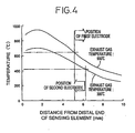
- Fig. 4 is a graph showing results of a test for determining the location of the heater in the sensing element.
- a sensing element used for the test has a platinum heater embedded in a ZrO 2 solid electrolyte substrate, at one of various points of the element which range from 1mm to 6mm as measured from its distal end.
- the ZrO 2 substrate has a width of 4.2mm, a thickness of 1.3mm and a length of 62mm
- the platinum heater has a heating portion having a width of 3.6mm and a length of 5mm, and has a resistance of 8 ⁇ at room temperature.
- a voltage of 12V is applied to the platinum heater, and the temperatures at the above-described various points of the element are measured when exposed to exhaust gases having 300°C and 900°C.
- the temperature of the sensing element is 650°C or lower in its region which is 5.2mm or more away from the distal end of the element, when the exhaust gas has the maximum temperature of 900°C. Therefore, the first electrodes, i.e., the inner electrode 16 and measuring electrode 22 are located in the above region that is 5.2mm or more away from the distal end.
- the temperature of the sensing element is 410°C or higher in its region which is 0 - 6.2mm away from the distal end of the element. Therefore, the second electrode, i,e, the internal pumping electrode 28, is located in the above region that is in the 0 - 6.2mm distance from the distal end.
- the NOx sensor according to the present invention in which the temperatures of the respective electrodes are controlled as shown in the graph of Fig. 3. It is to be noted that the distribution of the temperatures in the sensing element as described above can be achieved as desired, by suitably selecting the power (resistance), size (length) and location of the heater.
- Fig. 5 is a graph showing the relationship between the NO concentration measured by the above-described NOx sensor, and the pumping current (diffusion limiting current: Ip). It is found in this graph that the pumping current (Ip) is linearly proportional to the NO concentration. Thus, the NO concentration can be easily obtained by measuring the current (Ip). In this case, Ip is 0.03 ⁇ A when NO is equal to 0 ppm, which means that the pumping current of 0.03 ⁇ A is required to pump out an amount of oxygen which corresponds to a difference between the oxygen concentration (10 6 atm) in the atmosphere in the first internal space 6, and the oxygen concentration in the atmosphere in the second internal space 8, more precisely, at the three phase boundary of the internal pumping electrode 28.
- the same pumping current may cause an error when the NO concentration to be measured is lower than 10ppm. It is therefore preferable that the pumping current is as closest to 0 as possible when NO is equal to 0ppm. This can be achieved either by controlling the oxygen partial pressure in the atmosphere in the first internal space 6 to the possibly lowest level while avoiding reduction of NOx, or by equalizing the oxygen partial pressure in the first internal space 6 with that in the second internal space 6, measured at the three phase boundary of the internal pumping electrode 28.
- Fig. 6 is a graph showing a second example of the relationship between the temperatures at the electrodes in the first and second internal spaces 6, 8, and the oxygen partial pressures in these internal spaces 6, 8 which are controlled in the manner as described above.
- the oxygen partial pressure in the first internal space 6, and the oxygen partial pressure at the three phase boundary of the internal pumping electrode 28 (second electrode) in the second internal space 8 are both controlled to 10-8 atm.
- the heater 36 is provided so that the temperature at the first electrodes (inner electrode 16 and measuring electrode 22) is 490°C or lower, and the temperature at the second electrode (internal pumping electrode 28) is 430°C or higher.
- Fig. 7 is a graph showing the relationship between the pumping current (Ip) and the NO concentration measured by the NOx sensor of the second example. Since the oxygen partial pressures in the first internal space 6 and at the three phase boundary of the second electrode (internal pumping electrode 28) in the second internal space 8 are controlled to the same value in this example, Ip is 0 ⁇ A where NO is equal to 0ppm.
- Fig. 8 is a graph showing a third example of the relationship between the temperatures at the electrodes and the oxygen partial pressures.
- the first electrodes (inner electrode 16 and measuring electrode 22) and the second electrode (internal pumping electrode 28) are both comprised of Pt electrodes, and the oxygen partial pressures in the first internal space 6 and at the three phase boundary of the second electrode (internal pumping electrode 28) in the second internal space 8 are both controlled to 10-6 atm.
- the heater 36 is provided so that the temperature at the first electrodes is lower than 650°C, and the temperature at the second electrode is 650°C or higher.
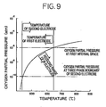
- Fig. 9 is a graph showing a fourth example of the relationship between the temperatures at the electrodes and the oxygen partial pressures.
- the first electrodes (inner electrode 16 and measuring electrode 22) and the electrode (internal pumping electrode 28) are both comprised of Pt electrodes, and the oxygen partial pressure in the first internal space 6 is controlled to 10 -6 atm while the oxygen partial pressure at the three phase boundary of the second electrode (internal pumping electrode 28) in the second internal space 8 is controlled to 10 -10 atm.
- the heater 36 is provided so that the first electrodes are heated to 650°C or lower, and the second electrode is heated up to 430°C or higher.
- a pumping current IP 0 flows when NO is equal to 0ppm, as described above.
- This pumping current IP 0 is kept a constant if the oxygen partial pressure in the first and second internal spaces 6, 8 are kept constant, and can therefore be easily subtracted from the pumping current Ip.
- Fig. 10 is a graph showing the relationship between the pumping current Ip and the NO concentration measured by the NOx sensor of this example.
- the measurement gas is introduced into the first internal space, where the oxygen concentration of the gas is controlled to a predetermined value by the oxygen pumping action of the first electrochemical pumping cell, while the oxygen partial pressure and the temperature are suitably controlled to avoid reduction of NOx. Then, the measurement gas having the predetermined oxygen concentration is introduced from the first internal space into the second internal space, where the temperature and oxygen concentration are determined so that the NOx component in the gas is reduced at the three phase boundary of the NOx reduction catalyst (internal pumping electrode 28) disposed in the second internal space. A pumping current measured upon the oxygen pumping action of the second electrochemical pumping cell is proportional to the NOx concentration of the measurement gas. Thus, NOx can be effectively determined on the basis of the pumping current, without being affected by the oxygen concentration of the measurement gas.
- the first internal space 6 is positioned downstream of the first diffusion controlling passage 12, and the second diffusion controlling passage 14 is positioned downstream of the first internal space 6, as seen in the direction of flow of the measurement gas. Therefore, clogging due to oil ash may take place at the first diffusion controlling passage 12, but not likely at the second diffusion controlling passage 14. If the diffusion resistance values D1, D2 of the first and second diffusion controlling passages 12, 14 are determined to satisfy the relationship: D1 + ⁇ « D2, where ⁇ is a variation of the diffusion resistance due to clogging, the measurement of the NOx concentration is not affected by such clogging.
- the clogging of the first diffusion controlling passage 12 only results in reduction of the pumping current for keeping the oxygen concentration in the first internal space at a constant level, and will not affect the measurement of NOx since the gas containing NOx is substantially diffused through the second diffusion controlling passage 14.
- the first electrodes (16, 22) disposed in the first internal space 6 are cermet electrodes containing Pt, while the second electrode (28) is a cermet electrode containing Rh.
- the first and second electrodes are both comprised of cermet electrodes containing Pt, in accordance with the present invention.
- the electrode materials are not necessarily limited to those employed in the above examples.
- the first electrode may be a cermet electrode containing Au or an alloy of Au and Pt. Since the Au/Pt cermet electrode as the first electrode is less likely to reduce NOx, the oxygen partial pressure and temperature in the first internal space can be more freely determined from within increased allowable ranges.
- both the first and second electrodes may be Au-containing electrodes, with a Rh- or Pt-containing electrode or a catalyst superposed on the second electrode.
- the catalyst may be a ceramic porous layer formed of alumina, which loads thereon an NOx reducing metal.
- the first and second electrodes may be Pt-containing electrodes, with a Rh-containing catalyst electrode disposed on the second Pt electrode. It is also possible that the first and second electrodes made of the same material are exposed to different temperatures, for example.
- the first and second electrodes are cermet electrodes comprised of a metal and a suitable ceramic material.
- a porous cermet electrode is desirably employed which is formed of a ceramic and Pt capable of reducing NOx.
- An NOx reduction catalyst may be provided in the vicinity of the internal pumping electrode 28 disposed in the second internal space 8, or an NOx reduction catalyst 42 as shown in Fig. 11 may be laminated by printing or other method on the internal pumping electrode 28.
- This catalyst 42 is a porous alumina layer loading an NOx reducing catalyst, such as rhodium.
- the heater 36 is located on the side of the second internal space 8, so that the second internal space 8 is heated to a higher temperature than the first internal space 6, whereby the NOx reduction catalyst 42 performs its function more effectively.
- the measurement gas consists of exhaust gases generated under a rich burn engine operation
- the gas contains large amounts of unburned components, such as CO and HC, which may react with NOx to cause a measuring error of the NOx sensor.
- the first internal space 6 is preferably filled with an oxidation catalyst 38 formed from porous alumina, for example, for oxidizing the unburned components, such as CO and HC, in the measurement gas, as shown in Fig. 12.
- the polarity of the first electrochemical pumping cell is reversed with respect to that in the case of a lean burn engine operation. That is, oxygen in the measurement gas is pumped from the exterior space into the first internal space 6.
- the provision of the oxidation catalyst 38 in the first internal space 6 is effective for eliminating influences due to the reducing gases, such as CO and HC, even when the measurement gas is produced as a result of the rich burn operation.
- the catalyst 38 may be provided on a portion of the solid electrolyte layer 4c between the first diffusion controlling passage 12 and the measuring electrode 22, or may be provided by printing on the inner electrode 16. That is, the oxidation catalyst 38 may be located anywhere provided the unburned components, such as CO and HC, are oxidized before the measurement gas reaches the second internal space 8.
- the oxidation can be promoted if the inner electrode 16 functions as an oxidation catalyst. Even if the inner electrode 16 consists of an Au or Au/Pt alloy electrode which does not serve as an oxidation catalyst, the unburned components in the measurement gas can be oxidized under appropriate conditions, including the oxygen partial pressure and the temperature, in the first internal space 6. These conditions must be also advantageous for measurement of NOx, assuring the oxygen partial pressure which is as low as possible and closest to that of the second internal space 8. For example, the oxidation can readily take place in the first internal space 6 if the oxygen partial pressure is at least 10 -10 atm at 500°C, and at least 10 -15 atm at 600°C.
- the measurement gas is controlled in the first internal space 6, to provide an atmosphere which is effective for measurement of NOx. More specifically, oxygen is pumped out from or pumped into the atmosphere in the first internal space 6, by the pumping action of the first electrochemical cell, so that the oxygen partial pressure in the space 6 is kept at a constant level which is almost the same as that in the second internal space 8, and which enables oxidation of the unburned components, such as CO and HC, contained in the measurement gas. Consequently, the oxidation of the unburned components is effected, thereby to avoid reaction between such unburned components and NOx, assuring more accurate measurement of the NOx concentration.
- This is particularly effective with respect to a measurement gas which is produced as a result of combustion under a rich burn engine operation, and thus contains considerably large amounts of carbon monoxide, hydrocarbon and other unburned components.
- the oxidation of the unburned components in the measurement gas as described above is effective for eliminating any influence by the unburned components on the NOx measurement accuracy, with respect to exhaust gases produced not only under the rich burn engine operation, but also under the lean burn engine condition which may produce slight amounts of such unburned components as described above.
- the oxidation catalyst 38 may be laminated on the upper solid electrolyte layer 4a, as shown in Fig. 13, such that the catalyst 38 is located in the external measurement gas space while closing an open end of the first diffusion controlling passage 12. This is effective mainly for eliminating measuring errors due to CO and HC produced when the engine operates under lean A/F condition. This embodiment is not suitable for the rich burn engine operation since the whole amounts of CO and HC cannot be oxidized due to shortage of oxygen in the measurement gas.
- additional solid electrolyte layers 4f and 4g are superposed on the solid electrolyte layer 4a, with a gas inlet channel 40 defined by these three solid electrolyte layers 4f, 4g, 4a.
- the oxidation catalyst 38 is located in the gas inlet channel 40. In this case, the oxidation of CO, HC and others is more effectively promoted since the oxidation catalyst 38 is located in a relatively high-temperature distal end portion of the sensor, as compared with the embodiment of Fig. 12.
- the oxygen is pumped from the second electrode (28) to the reference electrode 24 in the illustrated embodiments.
- the second electrode (28) may cooperate with the outer electrode 18 of the first electrochemical pumping cell, to constitute a second electrochemical pumping cell, so as to pump the oxygen in the second internal space 8 toward the outer electrode 18. It is also possible to provide another electrode in the second internal space 8 to pump out oxygen in the second internal space 8, in addition to the second electrode (28) as the NOx reduction catalyst.
- oxygen may be pumped from the additional pump-out electrode toward the reference electrode, the outer electrode 18, or a further electrode adapted to pump out the oxygen, so as to regulate the oxygen concentration at the three phase boundary of the NOx reductio catalyst electrode.
- the oxygen partial pressure in the first internal space 6 is regulated by continuously varying a voltage to be applied to the pumping electrodes 16, 18 of the first electrochemical pumping cell, based on the level of the electromotive force detected at the electrochemical sensing cell.
- a constant voltage may be applied to these pumping electrodes 16, 18, or a single electrochemical cell may serve as both a pumping cell and a sensing cell at different shared time.
- the reference electrode 24 is not necessarily held in communication with the atmosphere through the reference-gas channel 10. Rather, the reference electrode 24 may be disposed in a space in which the oxygen that is pumped out from the second electrode (28) is stored.
- the second internal space and the second diffusion means may be constituted by a space which is filled with a porous body. More specifically, the second internal space 8 and the second diffusion controlling passage 4 of the sensing element 2 shown in Fig. 2 may be replaced by an arrangement as shown in Fig. 15, in which an internal space adjacent to the first internal space 6 is filled with a porous body 44 made of alumina, for example, to provide both the second diffusion means and the second internal space. This arrangement simplifies the internal structure of the NOx sensor.
- the diffusion resistance of the second diffusion means (44) is determined to be larger than that of the first diffusion controlling passage 12, such that the atmosphere in the first internal space 6 is not influenced by the atmosphere in the second internal space.
- the porous body 44 may be printed on the internal pumping electrode 28, as shown in Fig. 21. In this arrangement, the porous body 44 constitutes the second diffusion means, and the porous body 44 itself substantially provides the second internal space.
- a voltage applied between the two electrodes 16, 18 of the first electrochemical pumping cell is controlled so that an electromotive force of 203mV is induced at 500°C between the measuring electrode 22 in the first internal space 6, and the reference electrode 24.
- a constant voltage is applied between the internal pumping electrode 28 and the reference electrode 24 of the second electrochemical pumping cell, so that an electromotive force of 449mV is induced at 700°C between these electrodes 28, 24.
- the NO concentration linearly varies with the pumping current (Ip) of the second electrochemical pumping cell, as shown in the graph of Fig. 16. Accordingly, the NO concentration is determined by measuring the magnitude of the pumping current (Ip).
- the arrangement of the sensing element as shown in Fig. 15 may be modified such that the porous structure of the second diffusion means 44 loads therein an NOx reduction catalyst, or such that an oxidation catalyst for oxidizing the unburned components, such as CO and HC, is disposed in the first internal space 6.
- the present sensing element may be modified as needed, while assuring NOx detecting characteristics similar to those of the sensing element of Fig. 15.
- the materials for the electrodes (16, 22) disposed in the first internal space 6 and the electrode (28) disposed in the second internal space (second diffusion means 44) are suitably selected such that the electrode (28) in the second internal space has the same or higher capability of reducing NOx than the electrodes (16, 22) in the first internal space 6.
- an NOx reduction catalyst layer may be provided on the electrode (28) in the second internal space.
- the location of the reference electrode and the the reference-gas chamber and the kind of the reference gas are suitably selected, such that the electromotive force determined according to the Nernst equation is induced between the measuring electrode in the first internal space 6 and the reference electrode.
- the position and power of the heater are suitably selected such that the temperature at the electrodes in the first internal space 6 is lower than the temperature at the electrode in the second internal space (second diffusion means 44).
- the NOx sensor according to the present invention may have the first and second diffusion means in the form of a narrow, flat space having a predetermined diffusion resistance.
- the flat space is formed in the sensing element so as to be open to the external measurement-gas space, as shown in Fig. 17 by way of example.
- the sensing element 2 as shown in Fig. 17 has an integral laminar structure including six oxygen-ion conductive solid electrolyte layers 4a, 4b, 4c, 4h, 4d, 4e which are superposed on each other in this order.
- the second uppermost solid electrolyte layer 4b has a rectangular cutout or notch at its distal end portion, which provides a narrow, flat space 50 having a predetermined diffusion resistance.
- the flat space 50 is open at the distal end of the sensing element 2, and extends over a suitable length in the longitudinal direction of the element 2. That is, the flat space 50 has an elongate, rectangular shape as seen in a plane parallel to the major surfaces of the sensing element 2, and is open at one of the opposite short sides to the external measurement-gas space.
- the external measurement gas is introduced through the opening of the flat space 50, and reaches an innermost part of the flat space 50, under a predetermined diffusion resistance.
- the flat space 50 itself constitutes the first and second diffusion means.
- the inner electrode (pumping electrode) 16 of the first electrochemical pumping cell is provided in a portion of the flat space 50 adjacent to its opening, which portion forms the first internal space 6, while the internal pumping electrode 28 of the second electrochemical pumping cell is provided in a deeper portion of the flat space 50 inside of the first internal space 6, which portion forms the second internal space 8.
- reference-gas channel 10 is formed through the solid electrolyte layer 4h, such that the channel 10 is open at a proximal end of the sensing element, for communication with the atmosphere.
- Reference electrode 24 disposed in the reference-gas channel 10 cooperates with the measuring electrode 22 provided in the flat space 50 to constitute the electrochemical sensing cell, and cooperates with the internal pumping electrode 28 to constitute the second electrochemical pumping cell.
- the reference electrode 24 also serves as one of the pumping electrodes.
- the other parts of the NOx sensor as shown in Fig. 17 are similar to those of the NOx sensor of Fig. 2, and the same reference numerals are used in the figures for the corresponding elements, of which no detailed description will be provided.
- the specific structures for the flat space 50 and the reference-gas channel 10 formed in the sensing element 2 are shown in detail in Figs. 10 and 11 of JP-B2-5-18059 , from which the structure of the sensing element of Fig. 17 is to be understood.
- Fig. 18 shows a modified embodiment of the sensing element 2 as shown in Fig. 17.
- an open end portion of the flat space 50 is filled with a porous body 52 having a predetermined diffusion resistance.
- the measurement gas is introduced through the porous body 52 into the flat space 50, under the predetermined diffusion resistance, and the introduced gas is subjected to an oxygen pumping action of the first oxygen pumping means, in the first internal space 6 provided by a portion of the flat space 50 adjacent to the porous body 52.
- the provision of the porous body 52 is advantageous in that the diffusion of the gas into the first internal space 6 can be controlled with high reliability, and that unburned components, such as CO and HC, are effectively oxidized at the porous body 52.
- the effective decomposition and reduction of NOx are achieved due to a temperature difference between the first and second internal spaces 6, 8.
- the atmospheres in the first and second internal spaces 8 do not necessarily have different temperatures.
- the temperature of both of the first and second internal spaces 6, 8 is set to 600°C, the Pt electrode (16) disposed in the first internal space 6 will not reduce NOx under the oxygen partial pressure of about 10 -6 atm or higher, while the Rh electrode (28) disposed in the second internal space 8 will reduce NOx under the oxygen partial pressure of 10 -5 atm or lower.
- the measurement of NOx can be effected under a condition where the temperature of the first internal space is higher than that of the second internal space.
- the alloy electrode containing Pt and 1% of Au which does not reduce NOx at 800°C under the oxygen partial pressure of 10 -15 atm, may be employed for measurement of NOx, even if the first internal space is kept at 800°C with the oxygen partial pressure of 10 -10 atm, and the second internal space is kept at 600°C with the oxygen partial pressure of 10 -10 atm.
- Fig. 19 is a graph showing the relationship between the electromotive force and the oxygen partial pressure at a temperature of 600°C. If the oxygen partial pressure of the atmosphere in the first internal space 6 is regulated so that the electromotive force at the measuring electrode 22 of the electrochemical sensing cell is 150mV, the oxygen partial pressure in the first internal space 6 becomes equal to about 10 -4 atm, and therefore NOx is not reduced in the first internal space 6. If 450mV is applied to the internal pumping electrode 28 of the second electrochemical pumping cell, which electrode is disposed in the second internal space 8, the oxygen partial pressure at the three phase boundary of the pumping electrode 28 becomes equal to about 10 -11 atm, and therefore NOx is reduced at the internal pumping electrode 28. The oxygen generated by the reduction of NOx can be detected by the pumping current of the second electrochemical pumping cell.
- the graph of Fig. 20 shows the relationship between the NO concentration and the pumping current (Ip).
Claims (25)
- Capteur pour la mesure d'une concentration en NOx en tant que composant gazeux d'un gaz de mesure, comprenant:un moyen définissant un premier espace interne (6) qui communique avec un espace de gaz de mesure externe où le gaz de mesure est présent;un premier moyen de diffusion (12) pour introduire le gaz de mesure contenant NOx dudit espace de gaz de mesure externe dans ledit premier espace interne (6) avec une première résistance à la diffusion;un premier moyen de pompage d'oxygène (4a, 16, 18) comprenant une cellule électrochimique ayant un premier électrolyte solide conducteur de l'ion oxygène (4a), et une paire d'électrodes (16, 18) qui y sont formées, pour effectuer une action de pompage de l'oxygène par rapport audit premier espace interne (6) de façon que la pression partielle d'oxygène de l'atmosphère dans le premier espace interne soit régulée à un niveau prédéterminé;un moyen définissant un second espace interne (8) qui communique avec ledit premier espace interne;un second moyen de diffusion (14, 44) pour introduire l'atmosphère dudit premier espace interne dans ledit second espace interne (8), avec une seconde résistance à la diffusion;un catalyseur dans ledit second espace interne (8) approprié pour catalyser la décomposition de NOx;un second moyen de pompage de l'oxygène (4c, 24, 28) comprenant une cellule électrochimique ayant un second électrolyte solide conducteur de l'ion oxygène (4c) et une paire d'électrodes (24,28) qui y sont formées, pour pomper l'oxygène hors de l'atmosphère dans ledit second espace interne, un moyen contrôlant la tension appliquée audit second moyen de pompage de l'oxygène de façon que la pression partielle de l'oxygène de l'atmosphère dans le second espace interne soit régulée à une valeur prédéterminée qui permet la décomposition de NOx pour en dériver l'oxygène;ce par quoi NOx présent dans l'atmosphère du second espace interne est décomposé, ledit second moyen de pompage de l'oxygène étant agencé pour pomper l'oxygène produit lors de la décomposition de NOx vers l'extérieur; etun moyen de détection de courant (32) pour détecter un courant de pompage s'écoulant à travers ledit second moyen de pompage de l'oxygène,où ledit premier moyen de pompage de l'oxygène (4a, 16, 18) est agencé pour réguler ladite pression partielle d'oxygène de l'atmosphère dans ledit premier espace interne (6) audit niveau prédéterminé qui n'affecte sensiblement pas la mesure du composant NOx dans le second espace interne (8) et qui ne convertit pas NO en N2 et O2 dans ledit premier espace interne, ainsi NO reste dans l'atmosphère introduite dans ledit second espace interne (8) pour permettre la mesure du composant NOx dans ledit second espace interne,
et
où une dite électrode (28) de ladite paire d'électrodes dudit second moyen de pompage d'oxygène, laquelle électrode (28) est disposée dans ledit second espace interne (8), est une électrode en Pt ou électrode en cermet contenant Pt. - Capteur selon la revendication 1, où l'une (28) de ladite paire d'électrodes de ladite cellule électrochimique dudit second moyen dé pompage d'oxygène, qui est disposée dans ledit second espace interne, comprend ledit catalyseur.
- Capteur selon la revendication 1 ou la revendication 2, comprenant un élément, capteur (2) qui contient lesdits premier et second électrolytes solides conducteurs de l'ion oxygène en tant que parties intégrales, lesdits premier et second espaces internes, lesdits premier et second moyens de diffusion et lesdits premier et second moyens de pompage de l'oxygène étant formés dans ledit élément capteur.
- Capteur selon la revendication 3, où ledit élément capteur a un espace plat, étroit (50) ayant une résistance prédéterminée à la diffusion, lequel espace a une ouverture exposée audit espace du gaz de mesure externe, ledit espace plat comprenant lesdits premier et second moyens de diffusion, ledit premier espace interne consistant en une première portion dudit premier espace plat adjacente à ladite ouverture dans laquelle ledit premier moyen de pompage d'oxygène est prévu, ledit second espace interne consistant en une seconde portion dudit espace plat qui est éloignée de ladite ouverture et à l'intérieur de ladite première portion, où ledit second moyen de pompage d'oxygène est prévu.
- Capteur selon la revendication 3 ou 4, où lesdits premier et second électrolytes solides conducteurs de l'ion oxygène forment une couche d'électrolyte solide conducteur de l'ion oxygène.
- Capteur selon la revendication 3 ou 4, où lesdits premier et second électrolytes solides conducteurs de l'ion oxygène forment différentes couches d'éléctrolyte solide conducteur de l'ion oxygène.
- Capteur selon la revendication 4, comprenant de plus un corps poreux (52) remplissant ladite ouverture dudit espace plat dudit élément capteur, lesdits corps poreux ayant une résistance prédéterminée à la diffusion.
- Capteur selon l'une quelconque des revendications 1 à 7, où ledit premier espace interne est rempli d'un corps poreux ayant une résistance prédéterminée à la diffusion.
- Capteur selon l'une quelconque des revendications 1 à 8, où ledit second moyen de diffusion comprend un corps poreux (44) ayant ladite seconde résistance à la diffusion, ledit second espace interné étant rempli dudit corps poreux.
- Capteur selon l'une quelconque des revendications 1 à 8, où ledit second espacé interne est formé séparément dudit premier espace interne dans ledit élément capteur.
- Capteur selon l'une quelconque des revendications 1 à 10, comprenant de plus un réchauffeur (36) pour chauffer lesdits premier et second espaces internes à des températures respectives prédéterminées.
- Capteur selon la revendication 11, où ledit réchauffeur est placé plus près dudit second espace interne que dudit premier espace interne dans ledit élément capteur de façon que le second espace interne soit chauffé à une plus haute température que le premier espace interne.
- Capteur selon l'une quelconque des revendications 1 à 12 comprenant de plus un catalyseur d'oxydation (38) pour oxyder les composants non brûlés contenus dans le gaz de mesuré avant que le gaz n'atteigne ledit second espace interne.
- Capteur selon l'une quelconque des revendications 1 à 13 comprenant de plus un moyen de détection de la pression partielle d'oxygène (4c, 24, 28) pour détecter la pression partielle d'oxygène de l'atmosphère dans ledit premier espace interne, ledit premier moyen de pompage de l'oxygène appliquant un courant contrôlé à ladite paire d'électrodes de ladite cellule électrochimique dudit premier moyen de pompage sur la base de la pression partielle d'oxygène détectée par ledit moyen de détection afin de réguler la pression partielle d'oxygène dans le premier espace interne.
- Capteur selon la revendication 14 où une chambre de gaz de référence (10) contenant un gaz de référence est formée dans ledit élément capteur, séparément desdits premier et second espaces internes, ledit moyen détectant la pression partielle d'oxygène comprenant une cellule électrochimique qui comprend un électrolyte solide conducteur de l'ion oxygène (4c) s'étendant entre ladite chambre de gaz de référence et ledit espace interne, une électrode de référence (24) placée dans ladite chambre du gaz de référence et formée en contact avec ledit électrolyte solide et une électrode, de mesuré (22) placée dans ledit premier espace interne et formée en contact avec ledit électrolyte solide.
- Capteur selon la revendication 15, où ladite chambre de gaz de référence est exposée à une ouverture de celle-ci à une atmosphère ambiante de façon que l'atmosphère ambiante soit introduite dans la chambre de gaz de référence par ladite ouverture pour produire ledit gaz de référence.
- Capteur selon la revendication 15 ou 16, où la cellule électrochimique dudit second moyen de pompage de l'oxygène , comprend un électrolyte solide conducteur de l'ion oxygène (4c) qui s'étend entre ledit second espace interne et ladite chambre de gaz de référence, une première électrode de pompage (28) placée dans ledit second espace interne et formée en contact avec ledit électrolyte solide et une seconde électrode dé pompage (24) placée dans ladite chambre de gaz de référence et formée en contact avec ledit électrolyte solide.
- Capteur selon la revendication 17 où ledit électrolyte solide conducteur de l'ion oxygène de la cellule électrochimique dudit second moyen de pompage de l'oxygène et ledit électrolyte solide conducteur de l'ion oxygène de la cellule électrochimique dudit moyen détecteur de la pression partielle d'oxygène constituent un électrolyte solide conducteur de l'ion oxygène intégral et où ladite seconde électrode de pompage et ladite électrode de référence formée sur l'électrolyte solide constituent une électrode commune.
- Capteur selon la revendication 17 ou 18 où ladite première électrode de pompage de la cellule électrochimique dudit second moyen de pompage de l'oxygène, qui se trouve dans ledit second espace interne, comprend ledit catalyseur.
- Capteur selon la revendication 19, où ladite première électrode de pompage comprend un cermet poreux consistant en une céramique et un métal qui est capable de réduire ou de décomposer le composant gazeux ayant lié l'oxygène.
- Capteur selon la revendication 1, où ledit catalyseur est disposé dans ledit second espace interne à proximité de ladite première électrode de pompage de la cellule électrochimique dudit second moyen de pompage de l'oxygène.
- Capteur selon la revendication 1, où ledit catalyseur est supperposé sur ladite première électrode de pompage de la cellule électrochimique dudit second moyen de pompage de l'oxygène.
- Capteur selon la revendication 4, où ladite seconde résistance à la diffusion dudit second moyen de diffusion est plus importante que ladite première résistance dudit premier moyen de diffusion.
- Capteur selon l'une quelconque des revendications 1 à 23, où l'une (16) de ladite paire d'électrodes de ladite cellule électrochimique dudit premier moyen de pompage d'oxygène qui se trouve dans ledit premier espace interne (6) est une électrode contenant Au.
- Capteur selon la revendication 24 où ladite électrode (16) dudit premier moyen de pompage d'oxygène disposé dans ledit premier espace interne est une électrode en cermet contenant un alliage de Au et Pt.
Applications Claiming Priority (8)
| Application Number | Priority Date | Filing Date | Title |
|---|---|---|---|
| JP8306994 | 1994-04-21 | ||
| JP8306994 | 1994-04-21 | ||
| JP1459895 | 1995-01-31 | ||
| JP1459895 | 1995-01-31 | ||
| JP4855195 | 1995-03-08 | ||
| JP7048551A JP2885336B2 (ja) | 1994-04-21 | 1995-03-08 | 被測定ガス中のNOx濃度の測定方法及び測定装置 |
| EP00102029A EP1001262B1 (fr) | 1994-04-21 | 1995-04-20 | Méthode pour mesurer un composant de gaz |
| EP95302646A EP0678740B1 (fr) | 1994-04-21 | 1995-04-20 | Méthode et dispositif pour mesurer un composant de gaz |
Related Parent Applications (1)
| Application Number | Title | Priority Date | Filing Date |
|---|---|---|---|
| EP00102029A Division EP1001262B1 (fr) | 1994-04-21 | 1995-04-20 | Méthode pour mesurer un composant de gaz |
Publications (3)
| Publication Number | Publication Date |
|---|---|
| EP1486779A2 EP1486779A2 (fr) | 2004-12-15 |
| EP1486779A3 EP1486779A3 (fr) | 2004-12-22 |
| EP1486779B1 true EP1486779B1 (fr) | 2007-12-05 |
Family
ID=27280704
Family Applications (6)
| Application Number | Title | Priority Date | Filing Date |
|---|---|---|---|
| EP04020248A Expired - Lifetime EP1486779B1 (fr) | 1994-04-21 | 1995-04-20 | Capteur de NOx |
| EP10180312A Withdrawn EP2270484A1 (fr) | 1994-04-21 | 1995-04-20 | Capteur électrochimique de NOx |
| EP06008269A Expired - Lifetime EP1710568B1 (fr) | 1994-04-21 | 1995-04-20 | Capteur électrochimique de NOx |
| EP00102029A Expired - Lifetime EP1001262B1 (fr) | 1994-04-21 | 1995-04-20 | Méthode pour mesurer un composant de gaz |
| EP04020249A Expired - Lifetime EP1484604B1 (fr) | 1994-04-21 | 1995-04-20 | Procédé de mesure de la concentration de NOx dans un gaz |
| EP95302646A Expired - Lifetime EP0678740B1 (fr) | 1994-04-21 | 1995-04-20 | Méthode et dispositif pour mesurer un composant de gaz |
Family Applications After (5)
| Application Number | Title | Priority Date | Filing Date |
|---|---|---|---|
| EP10180312A Withdrawn EP2270484A1 (fr) | 1994-04-21 | 1995-04-20 | Capteur électrochimique de NOx |
| EP06008269A Expired - Lifetime EP1710568B1 (fr) | 1994-04-21 | 1995-04-20 | Capteur électrochimique de NOx |
| EP00102029A Expired - Lifetime EP1001262B1 (fr) | 1994-04-21 | 1995-04-20 | Méthode pour mesurer un composant de gaz |
| EP04020249A Expired - Lifetime EP1484604B1 (fr) | 1994-04-21 | 1995-04-20 | Procédé de mesure de la concentration de NOx dans un gaz |
| EP95302646A Expired - Lifetime EP0678740B1 (fr) | 1994-04-21 | 1995-04-20 | Méthode et dispositif pour mesurer un composant de gaz |
Country Status (3)
| Country | Link |
|---|---|
| EP (6) | EP1486779B1 (fr) |
| JP (1) | JP2885336B2 (fr) |
| DE (4) | DE69521451T2 (fr) |
Cited By (2)
| Publication number | Priority date | Publication date | Assignee | Title |
|---|---|---|---|---|
| DE102008040314A1 (de) | 2008-07-10 | 2010-01-14 | Robert Bosch Gmbh | Verfahren zur Messung von einer Gasspezies geringer Konzentration in einem Gasstrom |
| US11193853B2 (en) | 2019-01-28 | 2021-12-07 | Cummins Emission Solutions Inc. | Remanufacturable sensing assemblies and methods of remanufacture |
Families Citing this family (172)
| Publication number | Priority date | Publication date | Assignee | Title |
|---|---|---|---|---|
| DE4442272A1 (de) * | 1994-11-28 | 1996-05-30 | Roth Technik Gmbh | Vorrichtung und Verfahren zur Bestimmung von gasförmigen Bestandteilen in Gasgemischen |
| JP3450084B2 (ja) * | 1995-03-09 | 2003-09-22 | 日本碍子株式会社 | 可燃ガス成分の測定方法及び測定装置 |
| JP3050781B2 (ja) * | 1995-10-20 | 2000-06-12 | 日本碍子株式会社 | 被測定ガス中の所定ガス成分の測定方法及び測定装置 |
| US5948964A (en) * | 1995-10-20 | 1999-09-07 | Ngk Insulators, Ltd. | NOx sensor and method of measuring NOx |
| JP3272215B2 (ja) * | 1995-10-20 | 2002-04-08 | 日本碍子株式会社 | NOxセンサ及びNOx測定方法 |
| JP3311218B2 (ja) * | 1995-11-02 | 2002-08-05 | 松下電器産業株式会社 | 炭化水素センサ |
| JP3623065B2 (ja) * | 1996-02-23 | 2005-02-23 | 日本碍子株式会社 | 窒素酸化物センサ |
| JP3647181B2 (ja) * | 1996-02-23 | 2005-05-11 | 日本碍子株式会社 | 窒素酸化物の測定方法 |
| JP3619344B2 (ja) * | 1996-02-23 | 2005-02-09 | 日本碍子株式会社 | 窒素酸化物の測定装置 |
| JP3671100B2 (ja) * | 1996-02-23 | 2005-07-13 | 日本碍子株式会社 | 酸化物センサ |
| JP3537983B2 (ja) * | 1996-03-21 | 2004-06-14 | 日本碍子株式会社 | ガスセンサ |
| JPH09318594A (ja) * | 1996-03-25 | 1997-12-12 | Ngk Insulators Ltd | ガスセンサおよび被測定ガス中の特定成分量の測定方法 |
| JP3488591B2 (ja) * | 1996-03-28 | 2004-01-19 | 日本碍子株式会社 | 酸化物センサ |
| JP3537628B2 (ja) | 1996-05-16 | 2004-06-14 | 日本碍子株式会社 | 窒素酸化物の測定方法 |
| JP3563399B2 (ja) * | 1996-05-30 | 2004-09-08 | 日本碍子株式会社 | ガス分析計 |
| JP3470012B2 (ja) * | 1996-05-30 | 2003-11-25 | 日本碍子株式会社 | ガス分析計及びその校正方法 |
| US6071393A (en) * | 1996-05-31 | 2000-06-06 | Ngk Spark Plug Co., Ltd. | Nitrogen oxide concentration sensor |
| JP3293741B2 (ja) * | 1996-06-06 | 2002-06-17 | 株式会社リケン | NOxセンサ |
| JPH1068346A (ja) * | 1996-06-21 | 1998-03-10 | Ngk Insulators Ltd | エンジン排ガス系の制御法 |
| JP3692182B2 (ja) * | 1996-06-28 | 2005-09-07 | 日本碍子株式会社 | ガスセンサ、ガスセンサの制御方法及びガス濃度制御器 |
| JP3692183B2 (ja) * | 1996-06-28 | 2005-09-07 | 日本碍子株式会社 | ガスセンサ及びガス濃度制御器 |
| JP4087914B2 (ja) * | 1996-07-25 | 2008-05-21 | 日本碍子株式会社 | 脱硝システム及び脱硝方法 |
| DE19652968C2 (de) * | 1996-09-02 | 2003-11-13 | Bosch Gmbh Robert | Meßanordnung zur Bestimmung von Gasbestandteilen in Gasgemischen |
| WO1998012550A1 (fr) * | 1996-09-17 | 1998-03-26 | Kabushiki Kaisha Riken | Capteur de gaz |
| JP3544437B2 (ja) * | 1996-09-19 | 2004-07-21 | 日本碍子株式会社 | ガスセンサ |
| JP3520163B2 (ja) * | 1996-09-30 | 2004-04-19 | 日本特殊陶業株式会社 | 酸素センサの制御方法及び装置 |
| JP3863974B2 (ja) * | 1996-10-31 | 2006-12-27 | 株式会社日本自動車部品総合研究所 | ガス検出装置 |
| JP3675997B2 (ja) * | 1996-10-31 | 2005-07-27 | 株式会社日本自動車部品総合研究所 | ガス検出装置 |
| JP3332761B2 (ja) * | 1996-11-08 | 2002-10-07 | 日本特殊陶業株式会社 | 酸素濃度・窒素酸化物濃度測定方法及び装置 |
| EP0845670B1 (fr) | 1996-12-02 | 2000-09-06 | Ngk Spark Plug Co., Ltd | Méthode et appareil pour mesurer la concentration d'oxydes d'azote |
| US6695964B1 (en) | 1996-12-02 | 2004-02-24 | Ngk Spark Plug Co., Ltd. | Method and apparatus for measuring NOx gas concentration |
| JP3873351B2 (ja) * | 1997-02-06 | 2007-01-24 | 株式会社デンソー | NOxセンサ素子 |
| JP3623066B2 (ja) * | 1997-02-12 | 2005-02-23 | 日本碍子株式会社 | ガスセンサ |
| US6228252B1 (en) | 1997-02-13 | 2001-05-08 | Ngk Spark Plug Co. Ltd. | Apparatus for detecting concentration of nitrogen oxide |
| US6290840B1 (en) | 1997-03-04 | 2001-09-18 | Ngk Insulators, Ltd. | Gas sensor and method for controlling gas sensor |
| JP3583890B2 (ja) * | 1997-03-04 | 2004-11-04 | 日本碍子株式会社 | ガスセンサ及びガスセンサの制御方法 |
| US6068747A (en) * | 1997-03-10 | 2000-05-30 | Denso Corporation | Solid electrolyte gas sensor |
| EP1074833A1 (fr) | 1997-03-21 | 2001-02-07 | Ngk Spark Plug Co., Ltd | Procédé et appareil de mesure de la concentration d'oxydes d'azote |
| JP3610182B2 (ja) * | 1997-03-27 | 2005-01-12 | 日本碍子株式会社 | ガスセンサ |
| DE69837023T2 (de) * | 1997-03-28 | 2007-11-22 | NGK Spark Plug Co., Ltd., Nagoya | NOx Sensor |
| JP3571494B2 (ja) * | 1997-05-20 | 2004-09-29 | 日本碍子株式会社 | ガスセンサ |
| JP3760573B2 (ja) * | 1997-06-11 | 2006-03-29 | 株式会社デンソー | NOxセンサの製造方法及びNOxセンサ |
| US6082176A (en) * | 1997-06-13 | 2000-07-04 | Ngk Spark Plug Co., Ltd. | NOx-concentration detecting apparatus |
| JP3876506B2 (ja) * | 1997-06-20 | 2007-01-31 | 株式会社デンソー | ガス濃度の測定方法及び複合ガスセンサ |
| JPH1114589A (ja) * | 1997-06-23 | 1999-01-22 | Ngk Insulators Ltd | ガスセンサ |
| US6303011B1 (en) | 1997-06-23 | 2001-10-16 | Kabushiki Kaisha Riken | Gas sensor |
| US6290829B1 (en) | 1997-07-14 | 2001-09-18 | Ngk Insulators, Ltd. | Gas sensor |
| JPH1137972A (ja) * | 1997-07-14 | 1999-02-12 | Ngk Insulators Ltd | ガスセンサ |
| JP3372195B2 (ja) * | 1997-08-14 | 2003-01-27 | 日本特殊陶業株式会社 | NOxガス濃度検出器及び検出器に用いる電極の製造方法 |
| JP3566089B2 (ja) * | 1997-09-09 | 2004-09-15 | 日本特殊陶業株式会社 | ガスセンサとそれを用いたガスセンサシステム、及びガスセンサの製造方法 |
| EP0916941B1 (fr) * | 1997-10-14 | 2003-06-04 | NGK Spark Plug Co. Ltd. | Procédé et dispositif pour détecter une condition de fonctionnement d'un catalyseur NOx à occlusion |
| JP3878339B2 (ja) | 1997-11-14 | 2007-02-07 | 株式会社リケン | 窒素酸化物センサ |
| JP3656882B2 (ja) * | 1997-11-17 | 2005-06-08 | 日本碍子株式会社 | 電気化学的素子の製造方法 |
| US6623618B1 (en) | 1997-12-22 | 2003-09-23 | Ngk Insulators, Ltd. | Gas sensor and method for controlling the same |
| JP3701114B2 (ja) | 1997-12-22 | 2005-09-28 | 日本碍子株式会社 | NOx分解電極の酸化防止方法 |
| US6344134B1 (en) | 1998-01-16 | 2002-02-05 | Ngk Spark Plug Co., Ltd. | Method for measuring NOx concentration and NOx concentration sensor |
| DE69937511T2 (de) | 1998-01-28 | 2008-09-18 | NGK Spark Plug Co., Ltd., Nagoya | NOx-Sensor |
| US6133042A (en) * | 1998-02-10 | 2000-10-17 | Ford Global Technologies, Inc. | Modulated oxygen-flux method and apparatus to improve the performance of a calorimetric gas sensor |
| JP3671109B2 (ja) | 1998-02-19 | 2005-07-13 | 日本碍子株式会社 | ガスセンサ |
| EP1890139B1 (fr) | 1998-02-20 | 2012-12-12 | NGK Spark Plug Co., Ltd. | Système de capteur de NOx avec unité de circuit de commande |
| JP3896685B2 (ja) * | 1998-03-23 | 2007-03-22 | 株式会社デンソー | 内燃機関の空燃比制御装置 |
| US6274016B1 (en) | 1998-06-29 | 2001-08-14 | Kabushiki Kaisha Riken | Nitrogen oxide gas sensor |
| JP3701124B2 (ja) | 1998-07-08 | 2005-09-28 | 日本碍子株式会社 | ガスセンサ及び窒素酸化物センサ |
| US6623617B2 (en) | 1998-08-10 | 2003-09-23 | Ngk Spark Plug Co., Ltd. | Method and apparatus for measuring concentration of a component in a gas |
| JP4005273B2 (ja) | 1998-09-16 | 2007-11-07 | 株式会社デンソー | ガス濃度検出装置 |
| JP3983422B2 (ja) | 1998-09-29 | 2007-09-26 | 株式会社デンソー | ガス濃度検出装置 |
| JP2000137018A (ja) | 1998-11-02 | 2000-05-16 | Denso Corp | ガス濃度検出装置とそれに用いるガス濃度センサ |
| JP3835022B2 (ja) | 1998-11-04 | 2006-10-18 | 株式会社デンソー | ガスセンサ素子 |
| DE19955125A1 (de) | 1998-11-16 | 2000-06-21 | Denso Corp | Gassensor und Verfahren zur Messung der Konzentration eines bestimmten Gases |
| JP4153113B2 (ja) | 1998-12-04 | 2008-09-17 | 株式会社デンソー | ガス濃度検出装置 |
| JP3540177B2 (ja) * | 1998-12-04 | 2004-07-07 | 日本特殊陶業株式会社 | ガスセンサ及びそれを用いた可燃性ガス成分濃度測定装置 |
| JP4205792B2 (ja) | 1998-12-04 | 2009-01-07 | 日本碍子株式会社 | NOx分解電極及びNOx濃度測定装置 |
| EP1026501B1 (fr) | 1999-02-03 | 2010-10-06 | Denso Corporation | Dispositif de mesure de la concentration d'un gaz avec compensation d'erreurs du signal de sortie |
| DE19912102C2 (de) | 1999-03-18 | 2002-09-05 | Bosch Gmbh Robert | Elektrochemischer Gassensor |
| JP3829026B2 (ja) | 1999-04-19 | 2006-10-04 | 日本碍子株式会社 | ガスセンサ |
| JP4625189B2 (ja) * | 1999-05-19 | 2011-02-02 | ローベルト ボツシユ ゲゼルシヤフト ミツト ベシユレンクテル ハフツング | 電気化学的ガスセンサによる燃焼混合物の定義されたリッチ/リーン制御のための方法 |
| DE19930636A1 (de) * | 1999-07-02 | 2001-01-18 | Bosch Gmbh Robert | Elektrochemischer Gassensor und Verfahren zur Bestimmung von Gaskomponenten |
| DE19941051C2 (de) * | 1999-08-28 | 2003-10-23 | Bosch Gmbh Robert | Sensorelement zur Bestimmung der Sauerstoffkonzentration in Gasgemischen und Verfahren zur Herstellung desselben |
| US6401522B1 (en) * | 1999-09-22 | 2002-06-11 | Ngk Insulators, Ltd. | Gas analyzer and method of calibrating the same |
| DE19960338A1 (de) * | 1999-12-15 | 2001-07-05 | Bosch Gmbh Robert | Gassensor zur Bestimmung der Konzentration von Gaskomponenten in Gasgemischen und dessen Verwendung |
| DE10112786A1 (de) | 2000-03-17 | 2002-10-10 | Denso Corp | In einer Abgasanlage einer Brennkraftmaschine einsetzbares Gasmeßelement |
| JP4563601B2 (ja) | 2000-03-31 | 2010-10-13 | 株式会社デンソー | 複合積層型センサ素子 |
| JP4563606B2 (ja) | 2000-03-31 | 2010-10-13 | 株式会社デンソー | 積層型センサ素子 |
| DE10023062B4 (de) * | 2000-05-11 | 2015-10-15 | Volkswagen Ag | Messeinrichtung zur Konzentrationsbestimmung von Gaskomponenten im Abgas einer Brennkraftmaschine und Verfahren zur Steuerung eines Betriebs der Messeinrichtung |
| DE10035036C1 (de) * | 2000-07-19 | 2001-11-22 | Bosch Gmbh Robert | Elektrochemisches Sensorelement |
| DE10048240B4 (de) * | 2000-09-29 | 2007-02-08 | Robert Bosch Gmbh | Gassensorelement und Verfahren zur Bestimmung der Konzentration einer Gaskomponente in einem Gasgemisch |
| DE10049685A1 (de) * | 2000-10-07 | 2002-04-11 | Volkswagen Ag | Verfahren und Vorrichtung zur Eigendiagnose eines NOX-Sensors |
| JP4682465B2 (ja) * | 2000-10-31 | 2011-05-11 | 株式会社デンソー | ガス濃度検出装置 |
| DE10058014C2 (de) * | 2000-11-23 | 2002-12-12 | Bosch Gmbh Robert | Sensorelement eines Gassensors |
| EP1350090A4 (fr) * | 2000-12-07 | 2006-06-07 | Aep Emtech Llc | Detecteur d'oxygene et de nox combine |
| DE10064667A1 (de) * | 2000-12-22 | 2002-07-04 | Siemens Ag | Mehrstufiger, Gassensor, Betriebs- und Herstellungsverfahren |
| DE10116184A1 (de) * | 2001-03-31 | 2002-10-10 | Bosch Gmbh Robert | Verfahren und Vorrichtung zur Erfassung der Konzentration einer sauerstoffhaltigen Verbindung in einem Meßgas |
| US6581571B2 (en) | 2001-06-12 | 2003-06-24 | Deere & Company | Engine control to reduce emissions variability |
| JP2003083936A (ja) | 2001-06-25 | 2003-03-19 | Denso Corp | ガスセンサ素子 |
| JP3776386B2 (ja) | 2001-09-05 | 2006-05-17 | 株式会社デンソー | ガスセンサ素子及びガス濃度の検出方法 |
| DE10147052C1 (de) * | 2001-09-25 | 2003-06-12 | Siemens Ag | Sensor zur simultanen Detektion von unterschiedlichen Gasen mit variiertem Elektrodenmaterial |
| DE10147107C1 (de) * | 2001-09-25 | 2003-06-05 | Siemens Ag | Verfahren und Vorrichtung zur simultanen Detektion von unterschiedlichen Gasen |
| JP3916945B2 (ja) | 2001-12-12 | 2007-05-23 | 株式会社デンソー | ガスセンサ素子 |
| JP3880507B2 (ja) | 2001-12-27 | 2007-02-14 | 株式会社日本自動車部品総合研究所 | ガス濃度検出装置 |
| JP3880506B2 (ja) * | 2001-12-27 | 2007-02-14 | 株式会社日本自動車部品総合研究所 | ガス濃度検出装置 |
| DE10207229A1 (de) * | 2002-02-21 | 2003-09-04 | Bosch Gmbh Robert | Katalytisch aktive Schicht |
| JP3993122B2 (ja) * | 2002-05-29 | 2007-10-17 | 株式会社デンソー | ガスセンサ素子及び含水素ガスの測定方法 |
| DE10226207B4 (de) * | 2002-06-13 | 2017-08-03 | Volkswagen Ag | Verfahren und Vorrichtung zur Konzentrationsbestimmung einer Methankomponente |
| DE10232355B4 (de) * | 2002-07-17 | 2005-12-15 | Robert Bosch Gmbh | Elektrochemischer Messfühler zur Messung der Konzentration von Stickoxiden |
| JP4178885B2 (ja) | 2002-08-30 | 2008-11-12 | 株式会社デンソー | ガス濃度検出装置 |
| DE10339967A1 (de) | 2002-08-30 | 2004-04-15 | Denso Corp., Kariya | Mehrschicht-Gassensorelement |
| JP4003879B2 (ja) * | 2003-02-13 | 2007-11-07 | 株式会社日本自動車部品総合研究所 | ガスセンサ素子の製造方法およびガスセンサ素子 |
| JP4283686B2 (ja) * | 2003-02-20 | 2009-06-24 | 株式会社日本自動車部品総合研究所 | ガスセンサ素子とガスセンサ素子の制御方法および製造方法。 |
| DE50312612D1 (de) * | 2003-02-27 | 2010-05-27 | Bosch Gmbh Robert | Verfahren zur Bestimmung von Ammoniak |
| DE10308394A1 (de) * | 2003-02-27 | 2004-09-09 | Robert Bosch Gmbh | Sensorelement eines Gassensors |
| JP4568514B2 (ja) | 2003-03-31 | 2010-10-27 | 日本碍子株式会社 | ガスセンサ |
| JP4174004B2 (ja) | 2003-03-31 | 2008-10-29 | 日本碍子株式会社 | ガスセンサ |
| US7763154B2 (en) | 2003-09-03 | 2010-07-27 | Robert Bosch Gmbh | Method and sensor element for determining a gas in a gas mixture |
| US7785457B2 (en) | 2003-09-03 | 2010-08-31 | Robert Bosch Gmbh | Sensor element and method for determining ammonia |
| JP2005283266A (ja) * | 2004-03-29 | 2005-10-13 | Ngk Insulators Ltd | ガスセンサ素子 |
| JP4165652B2 (ja) * | 2004-07-26 | 2008-10-15 | 日本碍子株式会社 | ガスセンサ |
| EP1722219A1 (fr) | 2005-05-10 | 2006-11-15 | Sumitomo Electric Industries, Ltd. | Capteur de gaz |
| WO2007015366A1 (fr) | 2005-08-02 | 2007-02-08 | Ngk Insulators, Ltd. | Capteur de gaz |
| DE102006008227A1 (de) * | 2006-02-22 | 2007-08-23 | Robert Bosch Gmbh | Gassensor |
| WO2007119311A1 (fr) | 2006-03-15 | 2007-10-25 | Ngk Insulators, Ltd. | Procede de correction du signal de sortie d'un detecteur de nox |
| DE102006061954A1 (de) | 2006-12-29 | 2008-07-03 | Robert Bosch Gmbh | Sensorelement mit zusätzlicher Fettgasregelung |
| DE102006062055A1 (de) * | 2006-12-29 | 2008-07-03 | Robert Bosch Gmbh | Sensorelement mit Offsetstrom durch H2O-Zersetzung |
| DE102006062051A1 (de) | 2006-12-29 | 2008-07-03 | Robert Bosch Gmbh | Sensorelement mit zusätzlicher Diagnosefunktion |
| DE102007049715A1 (de) | 2006-12-29 | 2008-07-03 | Robert Bosch Gmbh | Sensorelement mit abgeschirmter Referenzelektrode |
| DE102006062059A1 (de) | 2006-12-29 | 2008-07-03 | Robert Bosch Gmbh | Sensorelement mit abgeschirmter Oxidelektrode |
| DE102006061955A1 (de) | 2006-12-29 | 2008-07-03 | Robert Bosch Gmbh | Sensorelement mit brenngassensitiver Anode |
| DE102006062060A1 (de) | 2006-12-29 | 2008-07-03 | Robert Bosch Gmbh | Sensorelement mit innen liegender Anode |
| DE102007049716A1 (de) | 2006-12-29 | 2008-07-03 | Robert Bosch Gmbh | Gassensor mit gasdicht abgeschirmtem Hohlraum |
| DE102006062056A1 (de) | 2006-12-29 | 2008-07-03 | Robert Bosch Gmbh | Sensorelement mit unterdrückter Fettgasreaktion |
| DE102007049713A1 (de) | 2006-12-29 | 2008-07-03 | Robert Bosch Gmbh | Sensorelement zur Messung einer Gasgemischzusammensetzung |
| DE102006062057A1 (de) | 2006-12-29 | 2008-07-03 | Robert Bosch Gmbh | Sauerstoffsensor mit zusätzlicher Brenngasdetektion |
| DE102006062054A1 (de) | 2006-12-29 | 2008-07-03 | Robert Bosch Gmbh | Sensorelement mit Messgasrückführung |
| DE102006062053A1 (de) | 2006-12-29 | 2008-07-03 | Robert Bosch Gmbh | Verfahren zur Herstellung eines Sensorelements für Gasgemische |
| DE102007054391A1 (de) | 2007-11-14 | 2009-05-20 | Robert Bosch Gmbh | Gassensor mit zeitlich variierendem Referenzpotential |
| DE102007057707A1 (de) * | 2007-11-30 | 2009-06-04 | Robert Bosch Gmbh | Verfahren zum Betreiben eines Gassensors zur Bestimmung der Konzentration von Gaskomponenten im Abgas von Brennkraftmaschinen |
| DE102007061947A1 (de) | 2007-12-21 | 2009-06-25 | Robert Bosch Gmbh | Schneller Breitband-Abgassensor |
| DE102007062800A1 (de) * | 2007-12-27 | 2009-07-02 | Robert Bosch Gmbh | Verfahren zur Bestimmung einer Gaszusammensetzung in einem Messgasraum |
| DE102007062733A1 (de) | 2007-12-27 | 2009-07-02 | Robert Bosch Gmbh | Sensorelement mit verbesserter Vergiftungsresistenz |
| JP5005564B2 (ja) | 2008-01-28 | 2012-08-22 | 日本碍子株式会社 | 積層体の形成方法、センサ素子の作製方法、およびセンサ素子 |
| EP2093562B1 (fr) | 2008-02-19 | 2017-08-30 | Denso Corporation | Système dispositif de contrôle du capteur de gaz |
| JP4680276B2 (ja) | 2008-03-17 | 2011-05-11 | 株式会社デンソー | ガスセンサ素子 |
| JP5420183B2 (ja) | 2008-03-19 | 2014-02-19 | 日本碍子株式会社 | 積層体からのセンサ素子用素子体の切り出し方法、センサ素子の製造方法、センサ素子、およびガスセンサ |
| JP4575470B2 (ja) | 2008-03-27 | 2010-11-04 | 日本碍子株式会社 | センサ素子およびガスセンサ |
| JP5155712B2 (ja) | 2008-03-28 | 2013-03-06 | 日本碍子株式会社 | ガスセンサ、NOxセンサ、およびガスセンサの作製方法 |
| JP4980974B2 (ja) | 2008-03-31 | 2012-07-18 | 日本碍子株式会社 | ガスセンサおよびその制御装置ならびにNOx濃度測定方法 |
| JP2009244140A (ja) | 2008-03-31 | 2009-10-22 | Ngk Insulators Ltd | ガスセンサおよびNOxセンサ |
| JP5053151B2 (ja) | 2008-03-31 | 2012-10-17 | 日本碍子株式会社 | ガスセンサおよびNOxセンサ |
| DE102008001223A1 (de) | 2008-04-17 | 2009-10-22 | Robert Bosch Gmbh | Beheizte Sprungsonde mit vereinfachter elektrischer Kontaktierung |
| DE102009027276A1 (de) * | 2009-06-29 | 2010-12-30 | Robert Bosch Gmbh | Sensorelement zur Bestimmung einer Eigenschaft eines Gases |
| JP5119212B2 (ja) * | 2009-07-01 | 2013-01-16 | 株式会社日本自動車部品総合研究所 | アンモニア濃度検出方法 |
| JP4999894B2 (ja) | 2009-08-17 | 2012-08-15 | 日本碍子株式会社 | ガスセンサ |
| JP5530890B2 (ja) | 2009-10-13 | 2014-06-25 | 日本碍子株式会社 | ガスセンサ |
| JP5073841B2 (ja) * | 2011-03-25 | 2012-11-14 | 日本碍子株式会社 | センサ素子の製造方法 |
| JP5367044B2 (ja) * | 2011-10-13 | 2013-12-11 | 株式会社日本自動車部品総合研究所 | ガスセンサ素子および内燃機関用ガスセンサ |
| DE102012206476A1 (de) | 2012-04-19 | 2013-10-24 | Robert Bosch Gmbh | Verfahren zum Betrieb eines Sensorelements zur Erfassung eines Sauerstoffanteils eines Gases in einem Messgasraum |
| JP2012198247A (ja) * | 2012-07-24 | 2012-10-18 | Ngk Insulators Ltd | ガスセンサおよびNOxセンサ |
| CN102914575A (zh) * | 2012-08-14 | 2013-02-06 | 尚沃医疗电子无锡有限公司 | 气体传感器 |
| JP2014214237A (ja) * | 2013-04-26 | 2014-11-17 | 三菱重工業株式会社 | 乾留装置 |
| JP5918177B2 (ja) * | 2013-08-02 | 2016-05-18 | 日本碍子株式会社 | ガスセンサ |
| JP6352215B2 (ja) | 2014-07-10 | 2018-07-04 | 株式会社デンソー | ガスセンサ素子 |
| JP6392104B2 (ja) * | 2014-12-10 | 2018-09-19 | 日本特殊陶業株式会社 | ガスセンサ素子及びガスセンサ |
| CN104897743A (zh) * | 2015-03-27 | 2015-09-09 | 北京京能电力股份有限公司石景山热电厂 | 火电厂锅炉烟气脱硝烟道灰中氨的分析测定方法 |
| JP6233343B2 (ja) * | 2015-04-02 | 2017-11-22 | トヨタ自動車株式会社 | ガスセンサの異常診断システム |
| JP6602257B2 (ja) * | 2016-05-17 | 2019-11-06 | 日本特殊陶業株式会社 | ガスセンサ素子 |
| JP6758215B2 (ja) * | 2017-02-14 | 2020-09-23 | 株式会社Soken | アンモニアセンサ素子 |
| JP6740949B2 (ja) | 2017-03-31 | 2020-08-19 | 日立金属株式会社 | ガスセンサ |
| US20220236212A1 (en) | 2021-01-22 | 2022-07-28 | Ngk Insulators, Ltd. | SENSOR ELEMENT OF NOx SENSOR |
| DE102022000154A1 (de) | 2021-01-22 | 2022-07-28 | Ngk Insulators, Ltd. | SENSORELEMENT EINES NOx-SENSORS UND VERFAHREN ZUR HERSTELLUNG EINES SENSORELEMENTS EINES NOx-SENSORS |
| US20220236210A1 (en) | 2021-01-22 | 2022-07-28 | Ngk Insulators, Ltd. | Sensor element of gas sensor |
| WO2024062818A1 (fr) * | 2022-09-22 | 2024-03-28 | 日本碍子株式会社 | Capteur de gaz et procédé de mesure de concentration utilisant un capteur de gaz |
| WO2024070326A1 (fr) * | 2022-09-29 | 2024-04-04 | 日本碍子株式会社 | Capteur de gaz et procédé de mesure de concentration à l'aide d'un capteur de gaz |
| WO2024075397A1 (fr) * | 2022-10-06 | 2024-04-11 | 日本碍子株式会社 | Capteur de gaz et procédé de mesure de concentration au moyen d'un capteur de gaz |
Family Cites Families (18)
| Publication number | Priority date | Publication date | Assignee | Title |
|---|---|---|---|---|
| EP0060944B1 (fr) * | 1981-03-23 | 1986-03-05 | Westinghouse Electric Corporation | Sonde pour un mélange gazeux combustible à l'oxygène |
| JPS61109289A (ja) * | 1984-11-01 | 1986-05-27 | 日本碍子株式会社 | セラミツクヒ−タおよびその製造方法 |
| JPS61243355A (ja) | 1985-04-19 | 1986-10-29 | Ngk Insulators Ltd | 電気化学的装置 |
| JPH0672861B2 (ja) | 1986-08-04 | 1994-09-14 | 日本碍子株式会社 | NOxセンサ |
| JPH07119739B2 (ja) * | 1986-12-27 | 1995-12-20 | 日本碍子株式会社 | 空燃比測定装置における出力補正方法 |
| US5049254A (en) * | 1987-05-29 | 1991-09-17 | Ford Motor Company | Exhaust gas recirculation sensor |
| JP2554661B2 (ja) | 1987-08-06 | 1996-11-13 | 日産自動車株式会社 | 排気ガスセンサ |
| JPH0820410B2 (ja) | 1988-02-19 | 1996-03-04 | 日産自動車株式会社 | 窒素酸化物濃度の計測装置 |
| JP2636883B2 (ja) * | 1988-04-30 | 1997-07-30 | 日本碍子株式会社 | NOx濃度測定装置 |
| US5034112A (en) * | 1988-05-19 | 1991-07-23 | Nissan Motor Company, Ltd. | Device for measuring concentration of nitrogen oxide in combustion gas |
| JPH07119741B2 (ja) * | 1988-06-30 | 1995-12-20 | 本田技研工業株式会社 | 比例型排気濃度センサにおける出力補正方法 |
| US4909072A (en) * | 1988-07-22 | 1990-03-20 | Ford Motor Company | Measurement and control of exhaust gas recirculation with an oxygen pumping device |
| US5145566A (en) * | 1988-09-30 | 1992-09-08 | Ford Motor Company | Method for determining relative amount of oxygen containing gas in a gas mixture |
| DE3924644A1 (de) * | 1989-07-26 | 1991-01-31 | Asea Brown Boveri | Messvorrichtung |
| JP2518059B2 (ja) | 1989-09-28 | 1996-07-24 | 三菱電機株式会社 | 空調換気扇 |
| DE4007856A1 (de) * | 1990-03-13 | 1991-09-19 | Bosch Gmbh Robert | Sensorelement fuer eine sauerstoffgrenzstromsonde zur bestimmung des (lambda)-wertes von gasgemischen |
| US5217588A (en) * | 1992-02-27 | 1993-06-08 | Gte Laboratories Incorporated | Method and apparatus for sensing NOx |
| DE4311851A1 (de) * | 1993-04-10 | 1994-10-13 | Bosch Gmbh Robert | Sensoranordnung zur Bestimmung von Gaskomponenten und/oder von Gaskonzentrationen von Gasgemischen |
-
1995
- 1995-03-08 JP JP7048551A patent/JP2885336B2/ja not_active Expired - Lifetime
- 1995-04-20 EP EP04020248A patent/EP1486779B1/fr not_active Expired - Lifetime
- 1995-04-20 DE DE69521451T patent/DE69521451T2/de not_active Expired - Lifetime
- 1995-04-20 EP EP10180312A patent/EP2270484A1/fr not_active Withdrawn
- 1995-04-20 DE DE69535659T patent/DE69535659T2/de not_active Expired - Lifetime
- 1995-04-20 DE DE69533778T patent/DE69533778T2/de not_active Expired - Lifetime
- 1995-04-20 EP EP06008269A patent/EP1710568B1/fr not_active Expired - Lifetime
- 1995-04-20 EP EP00102029A patent/EP1001262B1/fr not_active Expired - Lifetime
- 1995-04-20 EP EP04020249A patent/EP1484604B1/fr not_active Expired - Lifetime
- 1995-04-20 DE DE69535008T patent/DE69535008T2/de not_active Expired - Lifetime
- 1995-04-20 EP EP95302646A patent/EP0678740B1/fr not_active Expired - Lifetime
Cited By (2)
| Publication number | Priority date | Publication date | Assignee | Title |
|---|---|---|---|---|
| DE102008040314A1 (de) | 2008-07-10 | 2010-01-14 | Robert Bosch Gmbh | Verfahren zur Messung von einer Gasspezies geringer Konzentration in einem Gasstrom |
| US11193853B2 (en) | 2019-01-28 | 2021-12-07 | Cummins Emission Solutions Inc. | Remanufacturable sensing assemblies and methods of remanufacture |
Also Published As
| Publication number | Publication date |
|---|---|
| DE69521451D1 (de) | 2001-08-02 |
| DE69535008D1 (de) | 2006-06-29 |
| DE69533778D1 (de) | 2004-12-23 |
| EP1710568B1 (fr) | 2011-06-08 |
| EP0678740A1 (fr) | 1995-10-25 |
| DE69535659D1 (de) | 2008-01-17 |
| DE69535659T2 (de) | 2008-11-13 |
| EP1484604A3 (fr) | 2004-12-22 |
| DE69521451T2 (de) | 2002-05-02 |
| EP2270484A1 (fr) | 2011-01-05 |
| EP1001262A1 (fr) | 2000-05-17 |
| EP1484604A2 (fr) | 2004-12-08 |
| JP2885336B2 (ja) | 1999-04-19 |
| EP1710568A3 (fr) | 2007-04-04 |
| DE69535008T2 (de) | 2006-12-07 |
| EP1486779A3 (fr) | 2004-12-22 |
| EP1710568A2 (fr) | 2006-10-11 |
| DE69533778T2 (de) | 2005-10-27 |
| EP0678740B1 (fr) | 2001-06-27 |
| JPH08271476A (ja) | 1996-10-18 |
| EP1484604B1 (fr) | 2006-05-24 |
| EP1001262B1 (fr) | 2004-11-17 |
| EP1486779A2 (fr) | 2004-12-15 |
Similar Documents
| Publication | Publication Date | Title |
|---|---|---|
| EP1486779B1 (fr) | Capteur de NOx | |
| US5939615A (en) | Method of measuring a gas component and sensing device for measuring the gas component | |
| EP0769693B1 (fr) | Méthode et dispositif pour mesurer un composant prédéterminé d'un gaz à mesurer | |
| US5879525A (en) | Apparatus for measuring combustible gas component by burning component | |
| EP0769694A1 (fr) | Capteur pour NOx et méthode de mesure associée | |
| US5948964A (en) | NOx sensor and method of measuring NOx | |
| US5985118A (en) | Solid electrolyte gas concentration detector | |
| EP1004877A2 (fr) | Capteur de gaz, méthode de sa fabrication et système utilisant ce capteur de gaz | |
| EP0743431B1 (fr) | Méthode et système de détection de la détérioration d'un catalyseur de gaz d'échappement | |
| JP3664558B2 (ja) | ガスセンサ | |
| JP3619344B2 (ja) | 窒素酸化物の測定装置 | |
| JP3771569B2 (ja) | NOxセンサ | |
| JP3511468B2 (ja) | 被測定ガス中のNOx濃度の測定方法 | |
| EP1324027B1 (fr) | Elément capteur de gaz | |
| JP3798412B2 (ja) | NOxセンサ | |
| JP3571039B2 (ja) | 被測定ガス中のNOx濃度の測定装置 | |
| JP3756123B2 (ja) | NOxセンサ並びにNOx濃度の測定方法 |
Legal Events
| Date | Code | Title | Description |
|---|---|---|---|
| PUAI | Public reference made under article 153(3) epc to a published international application that has entered the european phase |
Free format text: ORIGINAL CODE: 0009012 |
|
| PUAL | Search report despatched |
Free format text: ORIGINAL CODE: 0009013 |
|
| 17P | Request for examination filed |
Effective date: 20040916 |
|
| AC | Divisional application: reference to earlier application |
Ref document number: 1001262 Country of ref document: EP Kind code of ref document: P Ref document number: 0678740 Country of ref document: EP Kind code of ref document: P |
|
| AK | Designated contracting states |
Kind code of ref document: A2 Designated state(s): DE FR GB IT |
|
| AK | Designated contracting states |
Kind code of ref document: A3 Designated state(s): DE FR GB IT |
|
| AKX | Designation fees paid |
Designated state(s): DE FR GB IT |
|
| GRAP | Despatch of communication of intention to grant a patent |
Free format text: ORIGINAL CODE: EPIDOSNIGR1 |
|
| GRAS | Grant fee paid |
Free format text: ORIGINAL CODE: EPIDOSNIGR3 |
|
| GRAA | (expected) grant |
Free format text: ORIGINAL CODE: 0009210 |
|
| AC | Divisional application: reference to earlier application |
Ref document number: 1001262 Country of ref document: EP Kind code of ref document: P Ref document number: 0678740 Country of ref document: EP Kind code of ref document: P |
|
| AK | Designated contracting states |
Kind code of ref document: B1 Designated state(s): DE FR GB IT |
|
| REG | Reference to a national code |
Ref country code: GB Ref legal event code: FG4D |
|
| REF | Corresponds to: |
Ref document number: 69535659 Country of ref document: DE Date of ref document: 20080117 Kind code of ref document: P |
|
| ET | Fr: translation filed | ||
| PLBE | No opposition filed within time limit |
Free format text: ORIGINAL CODE: 0009261 |
|
| STAA | Information on the status of an ep patent application or granted ep patent |
Free format text: STATUS: NO OPPOSITION FILED WITHIN TIME LIMIT |
|
| 26N | No opposition filed |
Effective date: 20080908 |
|
| PGFP | Annual fee paid to national office [announced via postgrant information from national office to epo] |
Ref country code: GB Payment date: 20140416 Year of fee payment: 20 |
|
| PGFP | Annual fee paid to national office [announced via postgrant information from national office to epo] |
Ref country code: DE Payment date: 20140430 Year of fee payment: 20 Ref country code: IT Payment date: 20140314 Year of fee payment: 20 Ref country code: FR Payment date: 20140409 Year of fee payment: 20 |
|
| REG | Reference to a national code |
Ref country code: DE Ref legal event code: R071 Ref document number: 69535659 Country of ref document: DE |
|
| REG | Reference to a national code |
Ref country code: GB Ref legal event code: PE20 Expiry date: 20150419 |
|
| PG25 | Lapsed in a contracting state [announced via postgrant information from national office to epo] |
Ref country code: GB Free format text: LAPSE BECAUSE OF EXPIRATION OF PROTECTION Effective date: 20150419 |