WO2014185033A1 - 熱画像センサ、およびユーザインターフェース - Google Patents
熱画像センサ、およびユーザインターフェース Download PDFInfo
- Publication number
- WO2014185033A1 WO2014185033A1 PCT/JP2014/002434 JP2014002434W WO2014185033A1 WO 2014185033 A1 WO2014185033 A1 WO 2014185033A1 JP 2014002434 W JP2014002434 W JP 2014002434W WO 2014185033 A1 WO2014185033 A1 WO 2014185033A1
- Authority
- WO
- WIPO (PCT)
- Prior art keywords
- thermal image
- image sensor
- temperature
- user
- infrared
- Prior art date
Links
- 238000001514 detection method Methods 0.000 claims abstract description 320
- 238000012545 processing Methods 0.000 claims description 47
- 238000009826 distribution Methods 0.000 claims description 40
- 230000007246 mechanism Effects 0.000 claims description 23
- 238000003491 array Methods 0.000 claims description 13
- 230000003287 optical effect Effects 0.000 claims description 13
- 239000000463 material Substances 0.000 claims description 6
- 230000005855 radiation Effects 0.000 abstract description 13
- 239000003570 air Substances 0.000 description 238
- 238000004378 air conditioning Methods 0.000 description 151
- 238000010586 diagram Methods 0.000 description 74
- 230000000694 effects Effects 0.000 description 67
- 230000004048 modification Effects 0.000 description 67
- 238000012986 modification Methods 0.000 description 67
- 238000000034 method Methods 0.000 description 44
- 230000008859 change Effects 0.000 description 36
- 238000010438 heat treatment Methods 0.000 description 35
- 238000004891 communication Methods 0.000 description 32
- 238000005259 measurement Methods 0.000 description 32
- 238000001816 cooling Methods 0.000 description 30
- 238000005286 illumination Methods 0.000 description 25
- 230000035807 sensation Effects 0.000 description 24
- 238000003384 imaging method Methods 0.000 description 23
- 230000036760 body temperature Effects 0.000 description 21
- 238000009833 condensation Methods 0.000 description 21
- 230000005494 condensation Effects 0.000 description 21
- 230000006870 function Effects 0.000 description 18
- 238000009529 body temperature measurement Methods 0.000 description 14
- 239000011521 glass Substances 0.000 description 14
- 238000007664 blowing Methods 0.000 description 13
- 239000000758 substrate Substances 0.000 description 12
- 238000009423 ventilation Methods 0.000 description 11
- 230000006872 improvement Effects 0.000 description 10
- 239000011159 matrix material Substances 0.000 description 10
- 238000009434 installation Methods 0.000 description 8
- 230000003313 weakening effect Effects 0.000 description 8
- 230000033001 locomotion Effects 0.000 description 7
- 239000003507 refrigerant Substances 0.000 description 7
- 230000035900 sweating Effects 0.000 description 7
- 230000008901 benefit Effects 0.000 description 6
- 230000007423 decrease Effects 0.000 description 6
- 230000009467 reduction Effects 0.000 description 6
- 238000003287 bathing Methods 0.000 description 5
- 230000008569 process Effects 0.000 description 5
- 230000035945 sensitivity Effects 0.000 description 5
- 206010019345 Heat stroke Diseases 0.000 description 4
- 238000004590 computer program Methods 0.000 description 4
- 230000007613 environmental effect Effects 0.000 description 4
- 238000003860 storage Methods 0.000 description 4
- 238000005728 strengthening Methods 0.000 description 4
- 210000004243 sweat Anatomy 0.000 description 4
- 239000004215 Carbon black (E152) Substances 0.000 description 3
- UGFAIRIUMAVXCW-UHFFFAOYSA-N Carbon monoxide Chemical compound [O+]#[C-] UGFAIRIUMAVXCW-UHFFFAOYSA-N 0.000 description 3
- 125000002066 L-histidyl group Chemical group [H]N1C([H])=NC(C([H])([H])[C@](C(=O)[*])([H])N([H])[H])=C1[H] 0.000 description 3
- 230000009471 action Effects 0.000 description 3
- 230000006399 behavior Effects 0.000 description 3
- 229910002091 carbon monoxide Inorganic materials 0.000 description 3
- 238000005520 cutting process Methods 0.000 description 3
- 238000007791 dehumidification Methods 0.000 description 3
- 238000006073 displacement reaction Methods 0.000 description 3
- 238000001035 drying Methods 0.000 description 3
- 229930195733 hydrocarbon Natural products 0.000 description 3
- 150000002430 hydrocarbons Chemical class 0.000 description 3
- 238000009413 insulation Methods 0.000 description 3
- 239000004065 semiconductor Substances 0.000 description 3
- 229910052710 silicon Inorganic materials 0.000 description 3
- 239000010703 silicon Substances 0.000 description 3
- 230000007704 transition Effects 0.000 description 3
- XLYOFNOQVPJJNP-UHFFFAOYSA-N water Substances O XLYOFNOQVPJJNP-UHFFFAOYSA-N 0.000 description 3
- 230000006750 UV protection Effects 0.000 description 2
- 238000010521 absorption reaction Methods 0.000 description 2
- 230000017531 blood circulation Effects 0.000 description 2
- 230000027288 circadian rhythm Effects 0.000 description 2
- 230000003247 decreasing effect Effects 0.000 description 2
- 210000005069 ears Anatomy 0.000 description 2
- 239000000446 fuel Substances 0.000 description 2
- 210000003128 head Anatomy 0.000 description 2
- 239000004973 liquid crystal related substance Substances 0.000 description 2
- 230000029849 luteinization Effects 0.000 description 2
- 235000012054 meals Nutrition 0.000 description 2
- 230000003821 menstrual periods Effects 0.000 description 2
- 238000003672 processing method Methods 0.000 description 2
- 230000000630 rising effect Effects 0.000 description 2
- 238000005070 sampling Methods 0.000 description 2
- 230000003595 spectral effect Effects 0.000 description 2
- 238000002834 transmittance Methods 0.000 description 2
- PFNQVRZLDWYSCW-UHFFFAOYSA-N (fluoren-9-ylideneamino) n-naphthalen-1-ylcarbamate Chemical compound C12=CC=CC=C2C2=CC=CC=C2C1=NOC(=O)NC1=CC=CC2=CC=CC=C12 PFNQVRZLDWYSCW-UHFFFAOYSA-N 0.000 description 1
- 241001465754 Metazoa Species 0.000 description 1
- 230000002159 abnormal effect Effects 0.000 description 1
- 239000012080 ambient air Substances 0.000 description 1
- 238000013459 approach Methods 0.000 description 1
- 238000000149 argon plasma sintering Methods 0.000 description 1
- 244000309466 calf Species 0.000 description 1
- 238000002485 combustion reaction Methods 0.000 description 1
- 230000003750 conditioning effect Effects 0.000 description 1
- 238000012790 confirmation Methods 0.000 description 1
- 238000010411 cooking Methods 0.000 description 1
- 230000003111 delayed effect Effects 0.000 description 1
- 239000002274 desiccant Substances 0.000 description 1
- 230000006866 deterioration Effects 0.000 description 1
- 230000037213 diet Effects 0.000 description 1
- 235000005911 diet Nutrition 0.000 description 1
- 238000001704 evaporation Methods 0.000 description 1
- 230000008020 evaporation Effects 0.000 description 1
- 238000001413 far-infrared spectroscopy Methods 0.000 description 1
- 230000003325 follicular Effects 0.000 description 1
- 210000001061 forehead Anatomy 0.000 description 1
- 230000014509 gene expression Effects 0.000 description 1
- 229910052732 germanium Inorganic materials 0.000 description 1
- GNPVGFCGXDBREM-UHFFFAOYSA-N germanium atom Chemical compound [Ge] GNPVGFCGXDBREM-UHFFFAOYSA-N 0.000 description 1
- 210000004907 gland Anatomy 0.000 description 1
- 230000017525 heat dissipation Effects 0.000 description 1
- 230000020169 heat generation Effects 0.000 description 1
- WPYVAWXEWQSOGY-UHFFFAOYSA-N indium antimonide Chemical compound [Sb]#[In] WPYVAWXEWQSOGY-UHFFFAOYSA-N 0.000 description 1
- 230000010365 information processing Effects 0.000 description 1
- 238000012905 input function Methods 0.000 description 1
- 238000007689 inspection Methods 0.000 description 1
- 239000003350 kerosene Substances 0.000 description 1
- 230000000938 luteal effect Effects 0.000 description 1
- 238000004519 manufacturing process Methods 0.000 description 1
- 238000000691 measurement method Methods 0.000 description 1
- 230000005906 menstruation Effects 0.000 description 1
- 239000000203 mixture Substances 0.000 description 1
- 230000011599 ovarian follicle development Effects 0.000 description 1
- 230000016087 ovulation Effects 0.000 description 1
- 230000027758 ovulation cycle Effects 0.000 description 1
- 230000000624 ovulatory effect Effects 0.000 description 1
- 230000035935 pregnancy Effects 0.000 description 1
- 238000002360 preparation method Methods 0.000 description 1
- 230000002265 prevention Effects 0.000 description 1
- 239000000047 product Substances 0.000 description 1
- 230000004044 response Effects 0.000 description 1
- 229920006395 saturated elastomer Polymers 0.000 description 1
- SBIBMFFZSBJNJF-UHFFFAOYSA-N selenium;zinc Chemical compound [Se]=[Zn] SBIBMFFZSBJNJF-UHFFFAOYSA-N 0.000 description 1
- 238000004904 shortening Methods 0.000 description 1
- 238000004611 spectroscopical analysis Methods 0.000 description 1
- 239000000126 substance Substances 0.000 description 1
- 239000013589 supplement Substances 0.000 description 1
- 230000002123 temporal effect Effects 0.000 description 1
- 238000012549 training Methods 0.000 description 1
- 238000012546 transfer Methods 0.000 description 1
Images


Classifications
-
- F—MECHANICAL ENGINEERING; LIGHTING; HEATING; WEAPONS; BLASTING
- F24—HEATING; RANGES; VENTILATING
- F24F—AIR-CONDITIONING; AIR-HUMIDIFICATION; VENTILATION; USE OF AIR CURRENTS FOR SCREENING
- F24F11/00—Control or safety arrangements
- F24F11/30—Control or safety arrangements for purposes related to the operation of the system, e.g. for safety or monitoring
-
- B—PERFORMING OPERATIONS; TRANSPORTING
- B60—VEHICLES IN GENERAL
- B60H—ARRANGEMENTS OF HEATING, COOLING, VENTILATING OR OTHER AIR-TREATING DEVICES SPECIALLY ADAPTED FOR PASSENGER OR GOODS SPACES OF VEHICLES
- B60H1/00—Heating, cooling or ventilating [HVAC] devices
- B60H1/00642—Control systems or circuits; Control members or indication devices for heating, cooling or ventilating devices
- B60H1/00735—Control systems or circuits characterised by their input, i.e. by the detection, measurement or calculation of particular conditions, e.g. signal treatment, dynamic models
- B60H1/00742—Control systems or circuits characterised by their input, i.e. by the detection, measurement or calculation of particular conditions, e.g. signal treatment, dynamic models by detection of the vehicle occupants' presence; by detection of conditions relating to the body of occupants, e.g. using radiant heat detectors
-
- F—MECHANICAL ENGINEERING; LIGHTING; HEATING; WEAPONS; BLASTING
- F24—HEATING; RANGES; VENTILATING
- F24F—AIR-CONDITIONING; AIR-HUMIDIFICATION; VENTILATION; USE OF AIR CURRENTS FOR SCREENING
- F24F11/00—Control or safety arrangements
- F24F11/30—Control or safety arrangements for purposes related to the operation of the system, e.g. for safety or monitoring
- F24F11/46—Improving electric energy efficiency or saving
-
- F—MECHANICAL ENGINEERING; LIGHTING; HEATING; WEAPONS; BLASTING
- F24—HEATING; RANGES; VENTILATING
- F24F—AIR-CONDITIONING; AIR-HUMIDIFICATION; VENTILATION; USE OF AIR CURRENTS FOR SCREENING
- F24F11/00—Control or safety arrangements
- F24F11/50—Control or safety arrangements characterised by user interfaces or communication
- F24F11/52—Indication arrangements, e.g. displays
-
- F—MECHANICAL ENGINEERING; LIGHTING; HEATING; WEAPONS; BLASTING
- F24—HEATING; RANGES; VENTILATING
- F24F—AIR-CONDITIONING; AIR-HUMIDIFICATION; VENTILATION; USE OF AIR CURRENTS FOR SCREENING
- F24F11/00—Control or safety arrangements
- F24F11/70—Control systems characterised by their outputs; Constructional details thereof
- F24F11/72—Control systems characterised by their outputs; Constructional details thereof for controlling the supply of treated air, e.g. its pressure
- F24F11/74—Control systems characterised by their outputs; Constructional details thereof for controlling the supply of treated air, e.g. its pressure for controlling air flow rate or air velocity
- F24F11/77—Control systems characterised by their outputs; Constructional details thereof for controlling the supply of treated air, e.g. its pressure for controlling air flow rate or air velocity by controlling the speed of ventilators
-
- G—PHYSICS
- G01—MEASURING; TESTING
- G01J—MEASUREMENT OF INTENSITY, VELOCITY, SPECTRAL CONTENT, POLARISATION, PHASE OR PULSE CHARACTERISTICS OF INFRARED, VISIBLE OR ULTRAVIOLET LIGHT; COLORIMETRY; RADIATION PYROMETRY
- G01J5/00—Radiation pyrometry, e.g. infrared or optical thermometry
- G01J5/0022—Radiation pyrometry, e.g. infrared or optical thermometry for sensing the radiation of moving bodies
- G01J5/0025—Living bodies
-
- G—PHYSICS
- G01—MEASURING; TESTING
- G01J—MEASUREMENT OF INTENSITY, VELOCITY, SPECTRAL CONTENT, POLARISATION, PHASE OR PULSE CHARACTERISTICS OF INFRARED, VISIBLE OR ULTRAVIOLET LIGHT; COLORIMETRY; RADIATION PYROMETRY
- G01J5/00—Radiation pyrometry, e.g. infrared or optical thermometry
- G01J5/02—Constructional details
- G01J5/025—Interfacing a pyrometer to an external device or network; User interface
-
- G—PHYSICS
- G01—MEASURING; TESTING
- G01J—MEASUREMENT OF INTENSITY, VELOCITY, SPECTRAL CONTENT, POLARISATION, PHASE OR PULSE CHARACTERISTICS OF INFRARED, VISIBLE OR ULTRAVIOLET LIGHT; COLORIMETRY; RADIATION PYROMETRY
- G01J5/00—Radiation pyrometry, e.g. infrared or optical thermometry
- G01J5/02—Constructional details
- G01J5/04—Casings
- G01J5/047—Mobile mounting; Scanning arrangements
-
- F—MECHANICAL ENGINEERING; LIGHTING; HEATING; WEAPONS; BLASTING
- F24—HEATING; RANGES; VENTILATING
- F24F—AIR-CONDITIONING; AIR-HUMIDIFICATION; VENTILATION; USE OF AIR CURRENTS FOR SCREENING
- F24F2110/00—Control inputs relating to air properties
-
- F—MECHANICAL ENGINEERING; LIGHTING; HEATING; WEAPONS; BLASTING
- F24—HEATING; RANGES; VENTILATING
- F24F—AIR-CONDITIONING; AIR-HUMIDIFICATION; VENTILATION; USE OF AIR CURRENTS FOR SCREENING
- F24F2120/00—Control inputs relating to users or occupants
- F24F2120/10—Occupancy
-
- F—MECHANICAL ENGINEERING; LIGHTING; HEATING; WEAPONS; BLASTING
- F24—HEATING; RANGES; VENTILATING
- F24F—AIR-CONDITIONING; AIR-HUMIDIFICATION; VENTILATION; USE OF AIR CURRENTS FOR SCREENING
- F24F2120/00—Control inputs relating to users or occupants
- F24F2120/10—Occupancy
- F24F2120/12—Position of occupants
-
- F—MECHANICAL ENGINEERING; LIGHTING; HEATING; WEAPONS; BLASTING
- F24—HEATING; RANGES; VENTILATING
- F24F—AIR-CONDITIONING; AIR-HUMIDIFICATION; VENTILATION; USE OF AIR CURRENTS FOR SCREENING
- F24F2120/00—Control inputs relating to users or occupants
- F24F2120/10—Occupancy
- F24F2120/14—Activity of occupants
-
- G—PHYSICS
- G01—MEASURING; TESTING
- G01B—MEASURING LENGTH, THICKNESS OR SIMILAR LINEAR DIMENSIONS; MEASURING ANGLES; MEASURING AREAS; MEASURING IRREGULARITIES OF SURFACES OR CONTOURS
- G01B11/00—Measuring arrangements characterised by the use of optical techniques
- G01B11/02—Measuring arrangements characterised by the use of optical techniques for measuring length, width or thickness
- G01B11/026—Measuring arrangements characterised by the use of optical techniques for measuring length, width or thickness by measuring distance between sensor and object
-
- G—PHYSICS
- G01—MEASURING; TESTING
- G01B—MEASURING LENGTH, THICKNESS OR SIMILAR LINEAR DIMENSIONS; MEASURING ANGLES; MEASURING AREAS; MEASURING IRREGULARITIES OF SURFACES OR CONTOURS
- G01B11/00—Measuring arrangements characterised by the use of optical techniques
- G01B11/02—Measuring arrangements characterised by the use of optical techniques for measuring length, width or thickness
- G01B11/06—Measuring arrangements characterised by the use of optical techniques for measuring length, width or thickness for measuring thickness ; e.g. of sheet material
- G01B11/0608—Height gauges
-
- G—PHYSICS
- G01—MEASURING; TESTING
- G01J—MEASUREMENT OF INTENSITY, VELOCITY, SPECTRAL CONTENT, POLARISATION, PHASE OR PULSE CHARACTERISTICS OF INFRARED, VISIBLE OR ULTRAVIOLET LIGHT; COLORIMETRY; RADIATION PYROMETRY
- G01J5/00—Radiation pyrometry, e.g. infrared or optical thermometry
- G01J2005/0077—Imaging
-
- G—PHYSICS
- G01—MEASURING; TESTING
- G01V—GEOPHYSICS; GRAVITATIONAL MEASUREMENTS; DETECTING MASSES OR OBJECTS; TAGS
- G01V8/00—Prospecting or detecting by optical means
- G01V8/10—Detecting, e.g. by using light barriers
- G01V8/20—Detecting, e.g. by using light barriers using multiple transmitters or receivers
Definitions
- the present invention relates to a thermal image sensor used in an air conditioner or the like.
- an air conditioner a configuration is known in which the temperature detector measures the temperature of air drawn into the air conditioner and feeds back the measured temperature to the air conditioner.
- Such an air conditioner adjusts the air flow rate and the like based on the feedback temperature, and as a result, the indoor temperature is adjusted.
- the configuration of the infrared detector (thermal image sensor) as described above has room for examination.
- the present invention provides a thermal image sensor suitable for measuring the amount of activity.
- a thermal image sensor includes a plurality of infrared detection elements for detecting infrared rays in a detection area, and infrared rays of a target area of one thermal image in the plurality of infrared rays.
- the scanning section scans the detection area in the scanning direction, and the plurality of infrared detection elements include infrared detection elements whose arrangement positions in predetermined directions corresponding to the scanning direction are different from each other .
- a thermal image sensor suitable for measuring the amount of activity is realized.
- FIG. 1 is an external view of an air conditioner using a thermal image sensor.
- FIG. 2 is a view showing an example of a thermal image sensor in which infrared light receiving elements are arranged in a matrix.
- FIG. 3 is a schematic view of the room to be sensed by the thermal image sensor.
- FIG. 4 is a diagram for explaining a method of measuring the temperature distribution of the thermal image sensor in the form of a matrix.
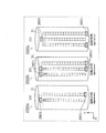
- FIG. 5 is a view showing an example of a thermal image sensor in which infrared light receiving elements are arranged in a line.
- FIG. 6 is a diagram for explaining a method of measuring the temperature distribution of the linear thermal image sensor.
- FIG. 7 is a block diagram showing a system configuration of an air conditioner provided with a thermal image sensor.
- FIG. 8 is a block diagram showing a system configuration of an air conditioning apparatus in which an image processing unit is provided outside the apparatus.
- FIG. 9 is a flowchart of the judgment of the high temperature period and the low temperature period.
- FIG. 10A is a first diagram for describing an example in which the positions of all the observation areas are changed according to the position of the user.
- FIG. 10B is a second diagram for describing an example in which the positions of all the observation areas are changed according to the position of the user.
- FIG. 11A is a first diagram illustrating an example of a user interface of an air conditioner.
- FIG. 11B is a second diagram illustrating an example of the user interface of the air conditioner.
- FIG. 11C is a third diagram illustrating an example of the user interface of the air conditioner.
- FIG. 11D is a block diagram of a user interface of the air conditioner.
- FIG. 12 is an external view of a thermal image sensor according to the second embodiment.
- FIG. 13 is a diagram for explaining a method of measuring the temperature distribution of the thermal image sensor according to the second embodiment.
- (A) of FIG. 14 is a figure which shows the thermal image sensor which concerns on the modification 1 of Embodiment 2.
- FIG. (C) of FIG. 15 is a diagram showing the observation area of the thermal image sensor shown in (a) of FIG.
- FIG. 15 is a diagram of the thermal image sensor shown in (b) of FIG. It is a figure which shows an observation area.
- FIGS. 16 (a) to 16 (d) are diagrams showing a thermal image sensor according to a third modification of the second embodiment.
- (E) to (h) of FIG. 16 are diagrams showing observation areas of the thermal image sensor shown in (a) to (d) of FIG. (A) and (b) of FIG. 17 is a figure which shows the thermal image sensor based on the modification 4 of Embodiment 2.
- FIG. (A) and (b) of FIG. 18 is a figure which shows the thermal image sensor based on the modification 5 of Embodiment 2.
- FIG. 19 is a figure which shows the thermal image sensor based on the modification 6 of Embodiment 2.
- FIG. (C) and (d) of FIG. 19 is a figure which shows the observation area of the thermal image sensor shown by (a) and (b) of FIG. (A) to (c) of FIG. 20 are diagrams showing a thermal image sensor according to a seventh modification of the second embodiment.
- (D) to (f) of FIG. 20 are views showing observation areas of the thermal image sensor shown in (a) to (c) of FIG.
- FIG. 21 is a diagram showing an example of a method of constructing a half observation pixel.
- FIG. 22 is a diagram for explaining improvement in image quality due to pixel shift.
- FIG. 23 is a view showing an example of the observation area in the case where the arrangement of the light receiving element row is deviated in the X direction.
- FIG. 24 is a figure for demonstrating the resolution increase by a light-shielding plate.
- (A) of FIG. 25 is a figure which shows the thermal image sensor based on the modification 8 of Embodiment 2.
- FIG. (B) of FIG. 25 is a view showing an observation area of the thermal image sensor shown in (a) of FIG.
- FIG. 26 is a diagram showing another example of the observation area according to the eighth modification of the second embodiment.
- FIG. 27 is a diagram for explaining scanning in the Y direction.
- FIG. 28 is a diagram showing an example of an observation area in the case where two or more types of light receiving elements having different sizes are arranged in the thermal image sensor according to the eighth modification.
- FIG. 29 is a view showing an example of a thermal image sensor configured to shift a light receiving sensor (light receiving element).
- FIG. 30 is a diagram illustrating an example of a thermal image sensor that performs scanning by moving components other than the light receiving sensor.
- FIG. 31 is a diagram showing a first example of the on-vehicle air conditioner according to Embodiment 3.
- FIG. 32 is a diagram showing a second example of the on-vehicle air conditioner according to Embodiment 3.
- FIG. 33 is a diagram illustrating an example of a user interface according to the third embodiment.
- FIG. 34 is a view showing an on-vehicle air conditioner in which a windshield is included in an observation area.
- FIG. 35 is a flowchart of a ventilation operation based on condensation prediction.
- FIG. 36 is another example of the flowchart of the ventilation operation based on condensation prediction.
- FIG. 37 is a view showing a transport apparatus provided with a scattered light amount measuring means.
- FIG. 38 is a schematic view of a room in which an air conditioner provided with an infrared detector according to Embodiment 4 is installed.
- FIG. 39A is a perspective view of an infrared detector according to Embodiment 4.
- FIG. 39B is a side view of the infrared detector according to Embodiment 4.
- FIG. 40A is a conceptual diagram showing a detection area of an infrared detector according to Embodiment 4.
- FIG. 40B is a conceptual diagram showing a detection area of the infrared detector according to the fourth embodiment.
- FIG. 40C is a conceptual diagram showing a detection area of the infrared detector according to the fourth embodiment.
- FIG. 40D is a conceptual diagram showing a detection region of the infrared detector according to the fourth embodiment.
- FIG. 40E is a conceptual diagram showing a detection region of the infrared detector according to the fourth embodiment.
- FIG. 41 is a perspective view of the infrared detector in which the infrared detection elements are linearly arranged in the vertical direction.
- FIG. 42A is a conceptual diagram showing a detection area of the infrared detector of FIG.
- FIG. 42B is a conceptual diagram showing a detection area of the infrared detector of FIG. 41.
- FIG. 42C is a conceptual diagram showing a detection area of the infrared detector of FIG.
- FIG. 43A is a perspective view of an infrared detector according to Variation 1 of Embodiment 4.
- FIG. 43B is a top view of the infrared detector according to Variation 1 of Embodiment 4.
- 44A is a perspective view of an infrared detector according to Variation 2 of Embodiment 4.
- FIG. FIG. 44B is a top view of the infrared detector according to Variation 2 of Embodiment 4.
- FIG. 45 is a perspective view of the infrared detector according to the third modification of the fourth embodiment.
- FIG. 45 is a perspective view of the infrared detector according to the third modification of the fourth embodiment.
- FIG. 46 is a perspective view of an infrared detector in which an imaging lens is attached to a mirror.
- FIG. 47 is a perspective view of the infrared detector according to the fourth modification of the fourth embodiment.
- FIG. 48A is a conceptual diagram showing a detection area in scanning in the vertical direction.
- FIG. 48B is a conceptual diagram showing a detection area in scanning in the vertical direction.
- FIG. 48C is a conceptual diagram showing a detection area in vertical scanning.
- FIG. 49 is a diagram for describing an example in which illumination is to be detected.
- FIG. 50 is a conceptual diagram showing a detection area when illumination is detected.
- 51A is a perspective view of an infrared detector according to Variation 5 of Embodiment 4.
- FIG. 51B is a top view of an infrared detector according to Variation 5 of Embodiment 4.
- FIG. FIG. 52 is a conceptual diagram showing a detection region of the infrared detector according to the fifth modification of the fourth embodiment.
- FIG. 53 is a diagram for explaining the improvement of the resolution of the infrared image.
- FIG. 54 is a perspective view of an infrared detector according to Variation 6 of Embodiment 4.
- FIG. 55 is a diagram for explaining the change of the resolution of the infrared image.
- FIG. 56 is a view for explaining cutting out of the infrared detection element array from the wafer.
- FIG. 57 is a schematic view of a room in which a lighting device including an infrared detector is installed on a ceiling surface.
- FIG. 58 is a diagram showing an example of a thermal image sensor in which a plurality of one-dimensional light receiving sensors are provided adjacent to each other.
- a thermal image sensor includes a plurality of infrared detection elements that detect infrared rays in a detection area, and a plurality of infrared detection elements that detect infrared rays in a target area of one thermal image. And a scanning unit configured to scan the detection area in a scanning direction, and the plurality of infrared detection elements include infrared detection elements having different arrangement positions in a predetermined direction corresponding to the scanning direction.
- the plurality of infrared detection elements may be arranged side by side in a direction intersecting with any of the predetermined direction and a direction perpendicular to the predetermined direction.
- the plurality of infrared detection elements are arranged such that the detection range of one infrared detection element included in the plurality of infrared detection elements overlaps the detection range of an infrared detection element adjacent to the one infrared detection element. May be
- the plurality of infrared detection elements may be arranged side by side in a direction intersecting the predetermined direction at an angle of 45 degrees.
- the plurality of infrared detection elements may be formed of a plurality of element arrays each configured by a part of the plurality of infrared detection elements, and the plurality of element arrays may be mutually different in position in the predetermined direction .
- each of the plurality of element rows may be configured by an infrared detection element arranged in a direction perpendicular to the predetermined direction.
- the plurality of element rows intersect the element row configured by the infrared detection elements arranged in the direction perpendicular to the predetermined direction, the predetermined direction, and any direction perpendicular to the predetermined direction.
- the number of infrared detection elements constituting one element row among the plurality of element rows may be different from the number of infrared detection elements constituting another element row.
- the plurality of infrared detection elements may include at least two types of infrared detection elements having different shapes, heat capacities, sizes, and materials.
- the scanning unit may scan the detection area in the scanning direction by moving the plurality of infrared detection elements in the predetermined direction.
- the optical system may further include an optical system for causing infrared rays from an object to be incident on the plurality of infrared detection elements, and the scanning unit may scan the detection area in the scanning direction by moving the optical system.
- a vertical scanning unit may be provided which scans the detection range in a direction perpendicular to the scanning direction.
- a mechanism may be provided to change the angle of the intersecting direction with respect to the predetermined direction by rotating the plurality of infrared detection elements.
- a user interface is a user interface of an air conditioner including a thermal image sensor for generating a thermal image representing the distribution of the temperature of a target area, which receives setting of a target temperature of room temperature And a second setting receiving unit that receives a setting of a target temperature of a specific part of the target area.
- a third setting reception unit for receiving the setting of the wind direction and the air volume of the air conditioner is provided, and when the target temperature is set in each of the first setting reception unit and the second setting reception unit, The third setting receiving unit may not receive the setting of the wind direction and the air volume.
- the display unit may further include a display unit for displaying at least the wind direction and the air volume, and when the target temperature is set in each of the first setting reception unit and the second setting reception unit, the display unit may further include: It may be displayed that the setting to the setting reception unit is invalid.
- the air conditioner detects the position of a person present in the target area by performing image processing on the thermal image sensor, and the display unit further displays the detected temperature of the position of the person You may
- the temperature of the position of the person may include at least one of the temperature of the position of the person's face, the temperature of the person's hand, and the temperature of the person's foot.
- the second setting reception unit receives setting of a target temperature for at least one of a position of a person's face, a position of a person's hand, and a position of a person's foot as a target temperature of the specific part. It is also good.
- An air conditioner measures a surrounding temperature and obtains a thermal image composed of a plurality of pixels representing a distribution of the temperature, and the thermal image acquired from the thermal image sensor And at least one of a wind direction, an air volume, a temperature, and a humidity, based on an image processing unit that detects a position of a specific part of a human body, and information on the position of the specific part detected by the image processing unit. And a device control unit that controls the
- the position of the specific part may be a position of a human face.
- the position of the specific part may be either the position of a human hand or the position of a foot.
- the image processing unit may detect one or a plurality of pixels having a predetermined temperature as a position of a human face among a plurality of pixels constituting the thermal image.
- the image processing unit detects a region in which a plurality of pixels having a temperature change within a predetermined time are grouped as a predetermined number or more as a position of a human body, and is detected as a position of a human body.
- the posture of the human body is detected from the shape or distribution of the human body, and a part of the area detected as the position of the human body is detected based on the information on the detected posture, the position of the human hand or It may be detected as the position of the foot.
- the image processing unit determines an action state of a person based on whether or not a pixel detected as a position of the specific part moves in a predetermined time, and the device control unit determines whether the pixel control unit The wind direction, the air volume, the temperature, or the humidity may be controlled based on the behavior state.
- a sensor height / angle change unit may be provided to change the height or angle of the thermal image sensor.
- the image processing apparatus may further include a communication unit that transmits data of the thermal image acquired from the thermal image sensor or data detected by the image processing unit to the server via the network.
- Embodiment 1 [Findings Based on Embodiment 1] First, the knowledge which became the basis of the air conditioning apparatus which concerns on Embodiment 1 is demonstrated.
- a human body detection unit that estimates a rough position of a human face or a foot from the acquired thermal image.
- Patent Document 2 does not disclose a specific method for estimating the position of a person's face or the position of a foot, and has not been sufficiently studied. Moreover, in the air conditioning apparatus described in Patent Document 2, no consideration is given to the user's state or activity state.
- Patent Document 2 discloses a method for acquiring high-resolution two-dimensional thermal image data, but does not discuss how to use the acquired data for control.
- an air conditioner having a thermal image sensor which performs optimal control according to the state of the user, will be described.
- FIG. 1 is an external view of an air conditioner using a thermal image sensor.
- An air conditioning apparatus 10 shown in FIG. 1 has a substantially box-like main body having a suction port 11 for sucking air in a room, a blowout port 12 for blowing harmonized air, and a thermal image sensor 13 for acquiring thermal image data. It consists of fourteen.
- the air sucked into the main body 14 from the suction port 11 is heated or cooled by a heating unit or a cooling unit (not shown) inside the main body 14, and is returned into the room from the blowout port 12.
- a blower such as a fan is provided inside the main body 14. This makes it possible to heat or cool more air in a short time.
- a heat sink such as fins is generally provided inside the main body 14 to heat or cool the air, thereby heating or cooling the air more efficiently. It becomes possible.
- the air conditioner 10 is provided with a heat exchanger (not shown) such as a compressor or Peltier to heat or cool the heat dissipation plate.
- the heat exchanger may be installed outdoors.
- the equipment provided in the room of the air conditioner 10 becomes compact, and the heat of the heat exchanger itself is not released into the room when the air in the room is cooled, so that the room air can be efficiently cooled.
- the heat exchanger and the heat sink may be connected by a heat pipe or a refrigerant pipe having a small thermal resistance. Thereby, the heating or cooling of the air is performed more efficiently.
- thermal image sensor 13 Either of the thermal image sensor 20 and the thermal image sensor 30 described below may be adopted as the thermal image sensor 13 of the air conditioner 10.
- FIG. 2 is a view showing a thermal image sensor 20 which is an example of the thermal image sensor 13.
- the thermal image sensor 20 includes a two-dimensional light receiving sensor 21 in which infrared light receiving elements are arranged in a matrix, and a lens 22.
- thermopile using a thermoelectromotive force
- bolometer using temperature change of resistance value
- non-contact type radiation thermometer such as a pyroelectric sensor using a pyroelectric effect, or the like
- the lens 22 a lens made of silicon, ZnS, or the like, which has high infrared transmittance, is used.
- the infrared light incident on the lens 22 from each direction is designed to be incident on different light receiving elements.
- FIG. 3 is a schematic view of the room (observation area) to be sensed by the thermal image sensor 20.
- FIG. 4 is a diagram for explaining a method of measuring the temperature distribution of the thermal image sensor 20. As shown in FIG.
- the infrared rays emitted from each observation pixel 51 are two-dimensional as shown in FIG.
- the light enters the light receiving elements of the light receiving sensor 21.
- the observation pixel 51 means the area
- the temperature distribution around the air conditioner 10 is calculated from the amount of infrared light incident on each light receiving element of the two-dimensional light receiving sensor 21.
- the temperature (thermal image data) of each observation pixel 51 in the entire observation area 50 is constantly (every sampling period) in the entire two-dimensional light receiving sensor 21. 1 frame) is measured.
- the timing at which the thermal image data is acquired may not be one frame every sampling period. Thermal image data may be acquired at a timing designated by the user.
- FIG. 5 is a view showing a thermal image sensor 30 which is another example of the thermal image sensor 13.
- the thermal image sensor 30 includes a rotating unit 31, a one-dimensional light receiving sensor 32 in which light receiving elements are arranged in a line, and a lens 33.
- a stepping motor, a servomotor, or the like is used for the rotation unit 31, and a stepping motor, a servomotor, or the like is used.
- the rotary unit 31 is not necessarily used for the thermal image sensor 30, and another drive mechanism may be used as long as it is a scanning unit (scanning unit) that changes the direction of the light receiving element.
- the rotating portion 31 is considered to be more suitable for miniaturization than other drive mechanisms.
- the one-dimensional light receiving sensor 32 is a noncontact radiation such as a thermopile using a thermoelectromotive force, a bolometer using temperature change of resistance value, and a pyroelectric sensor using pyroelectric effect. A thermometer is used.
- the lens 33 a lens made of Si, ZnS, or the like, which has high infrared transmittance as in the lens 22, is used.
- FIG. 6 is a diagram for explaining a method of measuring the temperature distribution of the thermal image sensor 30. As shown in FIG.
- the observation pixel 51 in the line observation area 61 shown in FIG. 6 becomes the observation pixel 51 which can measure the temperature at one time.
- the line observation area 61 moves in a direction perpendicular to the line axis direction (Y direction in FIG. 6) (hereinafter, also described as a scanning direction or X direction), and a thermal image As in the case of the sensor 20, thermal image data of the entire observation area 50 around the air conditioner 10 can be obtained.
- the width in the X direction of the entire observation area 50 corresponds to 160 degrees.
- the rotation unit 31 measures the temperature of each observation pixel 51 while rotating the one-dimensional light receiving sensor 32. Therefore, the time (frame interval) required to acquire the thermal image data of the entire observation area 50 in the thermal image sensor 30 is longer than the time of acquiring the thermal image data of the entire observation area 50 in the thermal image sensor 20 described above. long.
- the light receiving elements aligned in the Y direction move (rotate) in the X direction, but even if the light receiving elements aligned in the X direction move (rotated) in the Y direction Good.
- a photodiode be used for the two-dimensional light receiving sensor 21 and the one-dimensional light receiving sensor 32.
- the use of a photodiode enables high-speed acquisition of thermal image data.
- a means (heating unit) for heating the light receiving sensor is provided also in the case where the two-dimensional light receiving sensor 21 and the one-dimensional light receiving sensor 32 are photodiodes.
- a heater or Peltier is used for the heating unit.
- the heating unit When the heating unit is provided and a photodiode is used as a light receiving sensor, it is desirable that a photodiode made of indium antimony be employed.
- a photodiode made of indium antimony be employed.
- the concentration of components CO2, CO, H2O
- the air conditioning apparatus 10 be provided with a voice notification means (notification unit) as means for prompting the user to ventilate.
- the ventilating part which replaces
- the ventilating part is specifically a ventilating window that can be controlled by the air conditioner 10, but it is desirable that such a ventilating window be provided with a filter. This makes it possible to reduce the entry of indoor air such as pollen accompanying ventilation.
- thermal image sensor 13 it is desirable that two-dimensional scanning be performed using a plurality of rotating units.
- the rotating unit may be able to rotate the thermal image sensor in, for example, a pan-tilt (roll) direction. This makes it possible to construct a more inexpensive and high-performance thermal image sensor.
- FIG. 7 is a block diagram showing a system configuration of the air conditioner 10.
- the air conditioner 10 includes a frame memory 15, an arithmetic processing unit 16, an environment measuring device 17, a heat exchanger 18 a, a blower 18 b, and a wind direction adjuster 18 c.
- the arithmetic processing unit 16 includes an image processing unit 16a and a device control unit 16b.
- the above structure is not an essential structure in the air conditioning apparatus 10, and one or several structures may be missing.
- the thermal image sensor 13 acquires an electrical signal (thermal electromotive force in the case of a thermopile) from the light receiving element, and creates two-dimensional thermal image data based on the acquired electrical signal.
- the configuration of the thermal image sensor 13 is as described above.
- the frame memory 15 stores the created two-dimensional thermal image data.
- the frame memory 15 is not particularly limited as long as it has a general storage function such as a semiconductor memory.
- the frame memory 15 may be provided inside the air conditioning apparatus 10 or may be externally attached to the air conditioning apparatus 10.
- the arithmetic processing unit 16 acquires two-dimensional thermal image data stored in the frame memory 15 and performs arithmetic processing.
- the arithmetic processing unit 16 is not particularly limited as long as it has an arithmetic function, such as a microcomputer.
- the image processing unit 16a performs image processing to detect the position and the amount of clothes, temperature distribution in the room, and the like from the thermal image data based on the thermal image data stored in the frame memory 15. I do. A specific example of the image processing algorithm in the image processing unit 16a will be described later. Then, the image processing unit 16a outputs information such as the position of the user, the temperature of the user's hand or face, the temperature of the wall, and the like to the device control unit 16b.
- the device control unit 16 b controls the heat exchanger 18 a such as a compressor, the blower 18 b such as a fan, and the wind direction adjuster 18 c such as a louver based on the information output from the image processing unit 16 a (room temperature control, air volume control, And control information for controlling the wind direction).
- the control information calculated by the device control unit 16b is, for example, the number of rotations of the blower 18b and the angle of inclination of the louver in the wind direction adjuster 18c.
- the control target of the device control unit 16b is not limited to the heat exchanger 18a, the blower 18b, and the wind direction adjuster 18c.
- the air conditioning apparatus 10 may include an environment measuring device 17 that measures room temperature and humidity, and may control the room temperature and the air volume based on room temperature, humidity, and the like.
- environmental information such as room temperature and humidity obtained from the environmental measurement device 17 be transmitted to the image processing unit 16a. The reason will be described later.
- the environmental information preferably includes the outside air temperature, the illuminance inside and outside the room, and the radiant heat from the outside. The reason for this will be described later.
- FIG. 8 is a block diagram showing a system configuration of an air conditioning apparatus in which an image processing unit is provided outside the apparatus.
- the air conditioner 10 a includes a communication unit 19, and the thermal image data is transmitted to the server 80 via the communication unit 19.
- the image processing unit 81 in the server 80 calculates the position of the user, the state of the user (the temperature of the hand or face, the amount of clothes, the posture, etc.) and the temperature of the wall.
- the thermal image data is periodically transmitted to the server 80 through the communication unit 19, the sensitivity deterioration of the thermal image sensor can be confirmed, and the sensor sensitivity can be corrected.
- Wi-Fi registered trademark
- Bluetooth registered trademark
- the communication unit 19 transmits thermal image data to the outdoor server 80 using a network such as the Internet. May be transmitted.
- the data transmitted by the communication unit 19 may not be thermal image data, but may be sensor output from the thermal image sensor 13.
- the environment information is also transmitted to the server 80 by the communication unit 19.
- thermal image sensor 20 and the thermal image sensor 30 may be used as the thermal image sensor 13.
- the observation pixel 51 of 30 to 40 ° C. in the thermal image data of each frame is detected and detected.
- the position of the observation pixel 51 having a temperature of 30 to 40 ° C. and a temperature change of 1 ° C. or more from one frame before may be set as the face position of the user. According to such a configuration, the position of the user can be detected more accurately because the heating element other than human has small positional movement between the frames and temperature variation between the frames.
- the air conditioning apparatus 10 avoids the user and blows air (the device control unit 16b controls the wind direction adjuster 18c), for example, to prevent the skin of the user from drying. Is possible.
- the air conditioning apparatus 10 recognizes that the user is a cold or a flu, and it is possible to strengthen the humidification.
- the face temperature measurement of the user by the thermal image sensor 13 may be performed. That is, even if the air conditioning apparatus 10 itself is not in operation (stopped state), the measurement by the thermal image sensor 13 may be continuously performed. Thereby, for example, when the user goes to bed in a state where the device control unit 16 b and the heat exchanger 18 a are stopped, coexistence of reduction of power consumption and prevention of heat stroke becomes possible.
- each observation pixel 51 20 cm x 20 cm or less is desirable. This makes it possible to measure the user's face temperature more accurately, and to prevent heatstroke more accurately.
- the setting room area differs depending on the model, but the size of each observation pixel 51 is, for example, 3.6 m or 8 tatami (about 10 tatami (about 10 m 2 )).
- the height is 20 cm ⁇ 20 cm or less at a location apart by 7.2 m for the air conditioner 10 for 12 tatami (about 19 m 2 ).
- the total number of observation pixels 51 is larger than 512 by making the size of the observation pixels 51 smaller than 20 cm ⁇ 20 cm, in this case, there is an advantage that higher resolution measurement can be performed.
- the “fixed time” is, for example, 1 minute to 60 minutes.
- the air conditioner 10 has a function to lower the air flow to lower the noise level when it is determined that the user is sleeping, a function to lower the illuminance such as an LED to be turned on during operation, and weakening cooling and heating. It is possible to provide the user with a function of reducing power consumption and the like.
- weakening of cooling and heating can be realized by reducing the number of revolutions or rotational speed of the compressor. Further, as a method of strengthening cooling and heating, it is realized by increasing the number of revolutions or rotational speed of the compressor.
- the air conditioner 10 may be provided with a storage device (memory) different from the frame memory 15 for storing information of the wake-up time and the like.
- a storage device memory
- whether or not the user uses the function provided by the air conditioning apparatus 10 may be selected by the user through a user interface such as a remote control. This allows the user to select a function that suits his / her wishes. The selection of the function may be performed via a network using a smartphone, a TV, or the like.
- the air conditioner 10 may have an indoor lighting function. Thereby, the air conditioning apparatus 10 can provide the user with the function of lighting the illumination near the wake-up time. Moreover, when the air conditioning apparatus 10 is provided with the above-mentioned communication part 19, you may light the illuminating device provided in the exterior of the air conditioning apparatus 10 via a communication network.
- the temperature of the user's face while sleeping may be regularly stored in a storage unit separate from the frame memory 15. This makes it possible to estimate the user's basal body temperature from the temperature of the face just before getting up and provide the user with daily basal body temperature information.
- air conditioning control may be performed such that the humidity becomes higher than usual during the menstrual period in which the basal body temperature decreases.
- air conditioning control may be performed such that the humidity becomes higher than usual during the menstrual period in which the basal body temperature decreases.
- the humidity control unit is, for example, a type of humidity control unit that acquires moisture from an outdoor unit and releases it into the room, but is a type of humidity control unit that releases water in a water supply tank provided by the user into the room. May be
- the air conditioning apparatus 10 calculates the temperature which is the boundary between the high temperature period and the low temperature period from the daily basal body temperature, and determines whether the current high temperature period or the low temperature period. Good.
- FIG. 9 is a flowchart of the judgment of the high temperature period and the low temperature period.
- the air conditioning apparatus 10 accumulates daily basal body temperature history information (S11), and calculates the boundary temperature between the high temperature period and the low temperature period (S12). And the air conditioning apparatus 10 measures the basal body temperature of the day (S13).
- the luteal phase S22
- the first half and the second half of the luteal phase may be distinguished, and in the second half, UV protection may be recommended.
- blood circulation promotion and humidification by bathing may be recommended during menstruation (S23), and it may be notified that it is a time when it is easy to lose weight during the follicular phase, and a diet by exercise may be recommended (S24).
- Such a configuration makes it easier for female users to manage their physical condition in accordance with the menstrual cycle.
- the notification to the female user and the timing of the recommendation may be notified in advance several days earlier.
- the female user can perform schedule management such as preparation of an ultraviolet protection product and reservation of a training gym in advance.
- schedule management such as preparation of an ultraviolet protection product and reservation of a training gym in advance.
- a method of increasing the temperature measurement frequency of an arbitrary part using the rotational thermal image sensor 30 a method of reducing the rotational speed only while measuring the temperature of the observation pixel 51 of the arbitrary part, or the measurement frequency A method is used in which only the observation pixel 51 to be increased is measured by reciprocating.
- the air conditioning apparatus 10 may store the daily wake-up time of the user, and may increase the measurement frequency of the temperature of the user's face in the time zone near the wake-up time. Thereby, coexistence with reduction of power consumption and measurement accuracy of basic body temperature is attained.
- FIGS. 10A and 10B are diagrams for explaining an example in which the position of the entire observation area 50 is changed according to the position of the user.
- the installation angle changer is a rotation mechanism such as a stepping motor or a servomotor.
- the temperature may change within a predetermined time, and the position of the observation pixel 51 of 30 ° C. or higher may be recognized as the position of the user's body.
- the “predetermined time” here is, for example, 1 minute to 60 minutes.
- the position of the observation pixel 51 at 25 ° C. or higher may be recognized as the position of the user's body.
- the observation pixel 51 which is a temperature higher than a predetermined temperature higher than room temperature and whose temperature changes within a predetermined time is the position of the user's body.
- the air conditioning apparatus 10 can also estimate the height of the user from the vertical width (the length in the Y direction) of the plurality of observation pixels 51 formed in succession in which the user's body is determined to be located. In such a method, it is difficult to accurately estimate the height of the user because the vertical width of the observation pixel 51 corresponding to the user's body varies depending on the posture (standing position, sitting position, etc.) of the user. However, since the measurement result of the vertical width of the observation pixel 51 for each user is stored periodically, it is possible to estimate the height at standing position from the maximum value of the vertical width of the observation pixel 51.
- the air conditioning apparatus 10 can automatically change the room temperature setting according to the user in the room by the identification of the user.
- the air conditioning apparatus 10 may include means for estimating the distance between the user and the thermal image sensor 13. This makes it possible to estimate the height of the user more accurately.
- means for measuring the distance between the air conditioner 10 and the floor is used. For example, if a non-contact distance measuring means such as a laser focus type or an ultrasonic type is installed on the bottom of the air conditioner 10, the distance to the floor may be measured.
- the air conditioning apparatus 10 can calculate how far each observation pixel 51 is separated from the floor surface immediately below the air conditioning apparatus 10 based on the distance between the floor surface and the thermal image sensor 13. That is, it is also possible to calculate the distance between the user standing on the floor and the air conditioner 10.
- the height of the user can be measured more accurately by inputting the height (the distance from the floor to the installation position) of the installation position of the air conditioning apparatus 10 by the user himself or the installer of the air conditioning apparatus 10 It becomes possible.
- the air conditioning apparatus 10 may be provided with means for measuring how much the installation angle of the air conditioning apparatus 10 is inclined from the direction (vertical direction) perpendicular to the floor surface. As a result, even when the air conditioner 10 is installed at an angle, such as when the installation surface of the air conditioner 10 is not a surface (wall) perpendicular to the floor surface, the height of the user, the user and the air conditioning It is possible to estimate the distance to the device 10 more accurately.
- the illumination unit be a dedicated illumination unit that irradiates light only to the entire observation area 50 by the thermal image sensor 13.
- Such illumination means allow the user to accurately grasp the position of the entire observation area 50.
- the thermal image sensor 13 may be provided with far infrared light irradiation means, or may be adjacent to the far infrared light irradiation means. And, in such a case, the optical system of the thermal image sensor 13 is such that the density of the far infrared light received as a result of the irradiation decreases as the far infrared light is irradiated to the object located far from the far infrared irradiation means. It is desirable that the system be designed.
- the air conditioner 10 having such a configuration compares the thermal image data of the thermal image sensor 13 when the far infrared light is irradiated toward the observation area with the thermal image data of the thermal image sensor 13 when the infrared light is not irradiated. By doing this, the distance between each part in the observation area and the thermal image sensor 13 can be grasped. The reason is that the observation pixel 51 closer to the thermal image sensor 13 becomes the observation pixel 51 as the observation pixel 51 has a larger amount of change between the thermal image data during irradiation and the thermal image data during non-irradiation.
- the air conditioning apparatus 10 can grasp an air flow obstacle in the room (such as a closet installed on the side of the air conditioning apparatus 10), and performs control to deliver the air flow to the user while avoiding the obstacle. it can. By changing the wind direction in the direction where there is no obstacle, efficient air conditioning can be performed, and a reduction in power consumption can be realized.
- the air conditioning apparatus 10 can detect the observation pixel 51 corresponding to the hand or foot of the user. That is, the air conditioning apparatus 10 can measure the temperature of the observation pixel 51 corresponding to the user's hand or foot.
- the air conditioning apparatus 10 measures the temperature of the user's hand and performs automatic control so that the temperature of the user's hand becomes around 30 ° C., it is possible to save the user the trouble of adjusting the room temperature.
- Such automatic control has the effect of preventing excessive heating and cooling for users who have difficulty operating the air conditioner by themselves, such as sleeping and children, and also has a power saving effect.
- cooling by the air conditioner 10 if the temperature of the user's hand is less than 30 ° C., the cooling is weakened, and if the temperature of the user's hand is 30 ° C. or more, the cooling is performed. Control etc. to strengthen can be considered. Note that the cooling is enhanced by increasing the heat transfer from the heat exchanger 18a to the indoor and the outdoor, and the cooling is weakened by the reduction. When the heat exchanger 18a is a compressor, the cooling is enhanced by increasing the rotational speed, and the cooling is weakened by decreasing the rotational speed. The same can be said for winter heating.
- the temperature of the user's hand is 30 ° C. or higher. It is possible to reduce the state of being heated or the state of being cooled despite the temperature of the user's hand being 30 ° C. or less. That is, power saving can be achieved.
- dehumidification may be performed instead of cooling enhancement.
- the air conditioner 10 is provided with a heat exchanger 18a, but an air conditioner provided with a heater or a heat generating means (heat generating unit) such as kerosene combustion, or air provided with a humidification / dehumidification function instead of a heating / cooling function. Similar control is possible in the conditioning device.
- a heat exchanger 18a an air conditioner provided with a heater or a heat generating means (heat generating unit) such as kerosene combustion, or air provided with a humidification / dehumidification function instead of a heating / cooling function. Similar control is possible in the conditioning device.
- the heating power is reduced by reducing the driving power of the heat exchanger 18a when heating, and by increasing the driving power of the heat exchanger 18a when cooling. You should be strengthened.
- the heating by the heating unit may be weakened, the humidification may be weakened, or the dehumidification may be enhanced. This is because the temperature of the hand rises as the temperature or humidity of the user increases, and the temperature of the hand decreases as the temperature or humidity decreases.
- the same automatic control as the temperature of the hand may be performed.
- the same automatic control may be performed by measuring the temperature of parts other than the hands and feet, but the hands and feet, in particular the hands and feet, are suitable as an index for measuring the comfort of the user.
- the inventors of the present invention have found that the temperature of the hand and foot is higher in sensitivity than the temperature of the other part as an index of thermal sensation and comfort. Therefore, highly accurate temperature control is realized by using the temperature of the limb as an index.
- 11A, 11B, and 11C are diagrams showing an example of the user interface of the air conditioning apparatus 10.
- a remote control 70 provided with a display unit 74 having an input function such as a touch panel is illustrated as an example of a user interface.
- the form of the user interface is not limited to such an aspect, and the aspect may be such that the input unit (setting acceptance unit) and the display unit 74 are separated.
- the user interface of the air conditioning apparatus 10 may not be such a dedicated remote control.
- a smartphone or a tablet terminal in which the application is installed may be used as the remote control 70 of the air conditioner 10.
- the user interface of the air conditioner 10 has the following features.
- the user In the conventional air conditioner, it is common for the user to set the room temperature, air volume and air direction using a remote control.
- the user can set the target hand temperature or the target foot temperature as shown in FIG. 11A. This allows, for example, the user to set the desired hand temperature (foot temperature) as the target temperature.
- specific target temperatures for hand temperature and foot temperature are set, but for the user interface, for example, options (icons such as “warm”, “medium”, and “cold” (icons) ) May be displayed.
- options icons such as “warm”, “medium”, and “cold” (icons)
- the icon can be displayed larger because the number of characters displayed on the user interface is small, and visibility can be improved.
- a user who does not know his own optimal hand temperature can more easily select air conditioning control based on his own hand temperature.
- “warm”, “medium”, and “cold” correspond to, for example, the user's hand temperature of 31 ° C., 30 ° C., and 29 ° C., respectively.
- the air conditioner 10 has a mode (hand temperature control mode) for controlling the air conditioner 10 based on the hand temperature and a mode (foot temperature control mode) for controlling the air conditioner 10 based on the foot temperature. It may be a selectable configuration. In this case, the user performs mode selection, for example, through the user interface.
- the target hand temperature is surrounded by a thick frame, which indicates that the user has selected the hand temperature control mode.
- the user selects the foot temperature control mode when barefooting, and selects the hand temperature control mode when wearing slippers, etc.
- the mode is set according to the user's state (for example, the state of clothing) It can be changed.
- the air conditioning apparatus 10 can more accurately estimate the thermal comfort of the user and reflect it on the air conditioning.
- a thermal image (a human-shaped icon in FIG. 11B) that visually represents the current temperature of the user may be displayed.
- icons are displayed that are colored according to the user's body temperature (in FIG. 11B, the darker the color, the darker the color the higher the temperature). For example, areas with high body temperature are displayed in red, and areas with low body temperature are displayed in blue.
- the user can grasp his / her current temperature at a glance.
- the user can easily estimate the setting of the target hand temperature and the target foot temperature.
- the user interface may be configured to be able to change the target room temperature, the target hand temperature and the target foot temperature directly from the screen shown in FIG. 11B.
- the user can change the target room temperature, the target hand temperature, and the target foot temperature by performing an input operation such as touching or rubbing an area on the user interface corresponding to a point where the user wants to raise the temperature. Mode can be considered.
- FIG. 11D is a block diagram showing a system configuration of the remote control 70.
- the remote control 70 includes a first setting receiving unit 71, a second setting receiving unit 72, a third setting receiving unit 73, a display unit 74, and a remote control control unit 75 (control unit). , Remote control communication unit 76 (communication unit).
- the remote control 70 is a user interface of the air-conditioning apparatus 10 including the thermal image sensor 13 for generating a thermal image representing the distribution of the temperature of the target area (for example, the room).
- the first setting accepting unit 71 accepts setting of a target temperature of room temperature.
- the first setting receiving unit 71 is a touch panel (an area for setting a target room temperature shown in FIG. 11A) superimposed on the display unit 74, but may be a hardware key.
- the second setting receiving unit 72 receives the setting of the target temperature of the specific part of the target area.
- the second setting reception unit 72 receives setting of a target temperature for at least one of the position of a human face, the position of a human hand, and the position of a human foot as a target temperature of a specific part.
- the second setting receiving unit 72 is a touch panel (an area for setting a target foot temperature and a target hand temperature shown in FIG. 11A), but may be a hardware key.
- the third setting reception unit 73 receives the setting of the wind direction and the air volume of the air conditioner 10.
- the third setting receiving unit 73 is a touch panel (an area for setting the air volume level and the air direction shown in FIG. 11A), but may be a hardware key.
- the third setting receiving unit does not receive the setting of the wind direction and the air volume.
- “do not accept setting” means that the remote control control unit 75 does not recognize the input accepted by the third setting accepting unit 73 as a valid input, or the third setting accepting unit 73 accepts It means that the remote control unit 75 does not transmit the input to the air conditioner 10 as a command.
- the display unit 74 displays an image as shown in FIGS. 11A to 11C.
- the display unit 74 displays the target room temperature, the target foot temperature, the target hand temperature, the wind direction, and the air volume.
- the display unit 74 is a liquid crystal panel or an organic EL panel.
- the display unit 74 displays the temperature of the position of the person detected based on the thermal image data.
- the position of the person here includes at least one of the position of the person's face, the position of the person's hand, and the position of the person's foot.
- the display unit 74 displays the temperature of the human body by the color of the humanoid icon as shown in FIG. 11B, but the temperature may be displayed by numbers.
- the display unit 74 makes the wind direction and air volume columns wash-out (gray).
- the remote control control unit 75 transmits commands according to the settings received by the first setting receiving unit 71, the second setting receiving unit 72, and the third setting receiving unit 73 to the air conditioner 10 through the remote control communication unit 76. Further, based on the thermal image data (information related to the thermal image) received by the remote control communication unit 76, a human-shaped icon indicating a body temperature as shown in FIG. 11B is displayed on the display unit 74.
- the remote control communication unit 76 is a communication module for the remote control control unit 75 to transmit a command to the air conditioner 10.
- the remote control communication unit 76 also receives thermal image data from the air conditioner 10 (thermal image sensor 13).
- the remote control communication unit 76 is, for example, a wireless communication module using an infrared ray or the like.
- the air conditioner 10 is provided with a communication unit that communicates with the remote control communication unit 76.
- the comfort of the user is influenced not only by the body surface temperature of the user but also by the deep temperature of the user. For this reason, as in “face temperature and hand temperature” and “neck temperature and foot temperature”, at least two locations of the temperature near the deep temperature (face, neck, etc.) and end body surface temperature (hand, foot, etc.) Temperature may be measured. Thus, the user's comfort can be estimated more accurately and reflected in the air conditioning.
- the air conditioning apparatus 10 may identify whether the user wears glasses, a mask, gloves, socks, slippers, and the like based on the thermal image data. In addition, the air conditioning apparatus 10 notifies the user that the temperature measurement accuracy is lowered because the user wears glasses, a mask, gloves, socks, slippers, etc. based on the above detection result. May be provided. For example, the warning is displayed on the user interface of FIGS. 11A and 11B, thereby realizing the notification to the user.
- the user may switch the mode to the foot temperature control mode or remove the gloves. it can. Thereby, the temperature measurement accuracy of the air conditioning apparatus 10 is improved.
- a notification unit by voice may be used. Thereby, notification to the user is performed in real time.
- voice and character display notification means are used, the accuracy of notification to an environment where it is difficult to hear sounds or to a user who is using an audio device can be improved.
- the user can be identified by the following method whether the user has mounted
- whether the user wears a glove can be identified by comparing the temperature of the observation pixel 51 corresponding to the palm with the temperature of the observation pixel 51 corresponding to the upper arm, and for socks and slippers, This can be identified by comparing the temperature of the corresponding observation pixel 51 with the temperature of the observation pixel 51 corresponding to a calf.
- the size of each observation pixel 51 is preferably 10 cm ⁇ 10 cm or less.
- the size of the observation pixel 51 is, for example, 3.6 m or 8 tatami (about 10 tatami (about 10 m 2 )).
- the height is 10 cm ⁇ 10 cm or less at a distance of 7.2 m for the air conditioner 10 for 12 mats (about 19 m 2 ). Further, as the size of the observation pixel 51 is reduced, it is desirable that the total number of observation pixels 51 be increased to more than 512.
- the air conditioning apparatus 10 may measure the temperature of the outermost surface of the clothes of the user based on the thermal image data. Thereby, the heat insulation (dressing amount) of the clothes worn by the user is estimated as one of the user states. It is judged that the lower the temperature of the outermost surface of the clothes is, the higher the heat insulation of the clothes, and if it is judged that the heat insulation is high, the cooling can be reinforced (weakening of the heating). Since the relationship between the thermal sensation and the temperature of the hands and feet changes depending on the amount of clothing of the user, the amount of clothing of the user is estimated, and the air conditioning set temperature is corrected based on the amount of clothing to warm the user. Air conditioning tailored to the cold is realized.
- the air conditioning apparatus 10 includes means for measuring the temperature distribution in the room.
- the air conditioning is realized in accordance with the thermal sensation of the user in which the radiation from the room is taken into consideration.
- the measurement of the temperature distribution in the room is performed by, for example, the thermal image sensor 13.
- the air conditioning apparatus 10 be provided with means for measuring the humidity in the room.
- the air conditioning is realized in accordance with the thermal sensation of the user in which the humidity of the room is taken into consideration.
- measurement of humidity is performed, for example with a common hygrometer.
- the relationship between the thermal sensation of the user and the temperature of the hands and feet is influenced by the amount of exercise, the amount of activity, and the posture of the user.
- the air conditioning apparatus 10 it is desirable for the air conditioning apparatus 10 to include means for measuring the amount of movement, the amount of activity, and the posture of the user.
- air conditioning adapted to the thermal sensation of the user in which the amount of exercise, activity, and posture of the user are taken into consideration is realized.
- the amount of exercise, the amount of activity, and the posture of the user are calculated from, for example, an image acquired by the thermal image sensor 13.
- the air conditioner 10 be provided with means (timekeeping unit) for measuring the current time. Air conditioning is realized in accordance with the thermal sensation of the user in which the influence of the circadian rhythm is taken into consideration.
- the relationship between the thermal sensation of the user and the temperature of the hands and feet is influenced by the user's actions such as eating and bathing.
- the air conditioning apparatus 10 it is desirable for the air conditioning apparatus 10 to include means for grasping the user's behavior such as eating and bathing.
- air conditioning adapted to the thermal sensation in which the user's action is considered is realized.
- the air conditioning apparatus 10 may know that the user is at a meal around the table and the number of users around the table is eating.
- it can be grasped that the user is taking a bath based on the information of the user's body temperature. For this reason, it is grasped
- the relationship between the thermal sensation of the user and the temperature of the hands and feet is also affected by the season.
- the air conditioning apparatus 10 it is desirable to have a means to measure a date and time and external temperature.
- air conditioning can be performed in accordance with the thermal sensation of the user in consideration of the season.
- the air conditioning apparatus 10 includes means for measuring the amount of sweating of the user.
- the air conditioning is realized in accordance with the thermal sensation in which the amount of sweat is taken into consideration.
- the means for measuring the amount of sweating of the user is, for example, a wearable sensor that measures the electrical conductivity of the skin or a spectral sensor in the far infrared region.
- the amount of sweating of the user may be estimated as follows. In general, moisture tends to absorb light of wavelength 6-7 ⁇ m. Therefore, for example, if the air conditioning apparatus 10 includes means for measuring infrared light of 7 ⁇ m or less and means for measuring infrared light of 7 ⁇ m or more, the amount of infrared light received by the two measuring means Humidity distribution can be measured from the ratio. Then, if the ambient humidity of the user is higher than the ambient humidity, it is estimated that the humidity is increased by sweat evaporation. Thus, the air conditioning apparatus 10 may estimate the amount of sweating from the humidity distribution around the user.
- the air conditioning apparatus 10 may perform the same measurement using the absorption wavelength of near-infrared moisture, such as 1.5 micrometers and 1.9 micrometers. If the spectroscopy method using these infrared rays is used, the air conditioning apparatus 10 can measure the amount of sweat of a user non-contactingly. That is, the air conditioning apparatus 10 can measure the amount of sweating of the user who is not wearing the wearable sensor.
- the absorption wavelength of near-infrared moisture such as 1.5 micrometers and 1.9 micrometers. If the spectroscopy method using these infrared rays is used, the air conditioning apparatus 10 can measure the amount of sweat of a user non-contactingly. That is, the air conditioning apparatus 10 can measure the amount of sweating of the user who is not wearing the wearable sensor.
- the air conditioning apparatus 10 measures the moisture on the skin surface of the area exposed from the clothes, such as the face, neck, hands, and feet, using the far-infrared spectroscopy technique to estimate the amount of sweating. May be
- the air conditioning apparatus 10 may measure the temperature of the user's nose based on the thermal image data. This makes it possible to estimate the stress state of the user.
- the air conditioning apparatus 10 estimated the thermal sensation of the user using the temperature of a hand or the temperature of a leg, and demonstrated the example which performs air conditioning control.
- the air conditioning apparatus 10 may measure the temperature of any of the user's cheeks, nose, ears, and chin based on the thermal image data. This makes estimation of the user's thermal sensation more accurate. In addition, even when the user wears gloves and slippers, it is possible to accurately estimate the thermal sensation.
- each observation pixel 51 is preferably 5 cm ⁇ 5 cm or less. By setting the size of the observation pixel 51 to 5 cm ⁇ 5 cm or less, it is possible to more accurately measure the user's nose temperature.
- the setting room area differs depending on the model. For example, in the case of the air conditioner 10 for 6 tatami (about 10 m 2 ), 3.6 m, and for the air conditioner for 8 tatami (about 13 m 2 ), 4.
- the size of the observation pixel 51 at a distance of 7.2 m be 5 cm ⁇ 5 cm or less. Further, as the size of the observation pixel 51 is reduced, it is desirable that the total number of observation pixels 51 be increased to more than 512.
- the air conditioning apparatus 10 may measure the temperature difference between the temperature of the upper body of the user and the temperature of the lower body based on the thermal image data. Thereby, since it can be determined whether or not the user is cool, the air conditioning apparatus 10 can strengthen the heating of the user's feet at the time of heating. In addition, whether or not to use such a function may be selectable by the user through the above-described user interface. This allows the user to select the desired function.
- the hand temperature (foot temperature) may differ for each user. For this reason, it is desirable that the air conditioning apparatus 10 be provided with means that can set who the priority user is. As a result, even in a room where there are a plurality of users with different hand temperatures (foot temperatures), air harmony control can be performed with the hand temperatures (foot temperatures) as the target value.
- FIG. 11A shows an example in which “B” is selected from the four options (icons) “A”, “B”, “Max”, and “Min” as the priority user.
- the air conditioner 10 can measure the height of the user in the room from the thermal image data as described above, and can identify the user in the room. Therefore, user names registered in advance instead of A and B ("father", “one sister”, personal names, etc.) may be displayed as options (icons).
- the air conditioner 10 controls the user's hand with the highest hand temperature among the users in the room to reach the target hand temperature. Transition to mode When “Min” shown in the example of FIG. 11A is selected, the air conditioner 10 controls the user's hand with the lowest hand temperature among the users in the room to reach the target hand temperature. Transition to mode Such a mode may be prepared as an option.
- control is performed using the body temperature of the user closest to the air conditioner 10 as an indicator, and conversely, control using the body temperature of the user farthest from the air conditioner 10 as an indicator
- a mode to be performed may be prepared. Further, a mode may be prepared in which an arbitrary position is set, and the user's body temperature close to the set position is used as an index.
- the body temperature (hand temperature, foot temperature) of a plurality of users in the room are different, air is blown in the direction of the user whose temperature is high in the cooling mode, and is blown in the direction of the user whose temperature is low in the heating mode.
- the adjustment of the wind direction and the wind volume may provide different ambient temperature environments for each user. Thereby, a plurality of users can provide a comfortable indoor environment together.
- the wind direction and the air volume may be adjusted such that each of two or more parts (for example, hands and feet) of one user reaches the target temperature.
- the target hand temperature and the target foot temperature are boxed (selected by the user).
- the wind direction and the air volume can not be set from the user interface. That is, as shown in FIG. 11C, on the user interface, the wind direction and the wind volume are displayed as washout (grayed out). Instead of the washout display, it may be notified that the setting of the wind direction and the air volume can not be changed.
- the air conditioning apparatus 10 may grasp the room layout from the thermal image data of the room. This enables air conditioning in accordance with the user's behavior.
- the air conditioning apparatus 10 can detect the position of the user's face while sleeping, it can also detect the position of the user's pillow. Then, the air conditioning apparatus 10 can suppress drying of the skin on the face and drying of the throat by blowing air while avoiding the user's face while the user is sleeping.
- the air conditioner 10 may detect the position of the table and store the position in a storage unit in the air conditioner 10. As a result, it is possible to recognize that the user is staying in the vicinity of the dining table as a meal and control such as weakening heating in the winter. For example, the air conditioning apparatus 10 can recognize a place where the user stays for 10 to 60 minutes from a predetermined time (for example, 7:00 AM) as a dining table.
- a predetermined time for example, 7:00 AM
- the air conditioning apparatus 10 can determine that the user is eating a pan dish. When it is determined in the winter season as described above, the air conditioning apparatus 10 can perform control such as further weakening heating. At this time, if the air conditioning apparatus 10 has a dehumidifying function, dehumidifying may be performed together with heating weakening. In addition, whether or not to use such a function may be selected by the user through a user interface such as a remote control. This allows the user to select a function that suits his / her wishes.
- the air conditioner 10 according to the first embodiment has been described above.
- the air conditioner 10 is described as being installed indoors, but may be realized for use in vehicles.
- the specific example of a vehicle-mounted air conditioning apparatus is mentioned later.
- the air conditioner 10 measures the temperature of the user's hands and feet using the thermal image sensor 13.
- a wearable temperature measuring device (watch-type wearable terminal or the like having a communication unit)
- the temperature of the user's hands and feet may be measured using a terminal (e.g., a terminal built in shoes (or socks)).
- the temperature measurement device periodically notifies the temperature of the user's hands and feet to the air conditioner 10 via the communication unit, and the same effect can be obtained.
- the method using the thermal image sensor 13 has an advantage of being able to measure the temperatures of the hands and feet of the user who is not wearing the temperature measurement device.
- Embodiment 1 demonstrated the air conditioning apparatus 10 which incorporates the thermal image sensor 13, for example, the thermal image sensor 13 and the air conditioning apparatus 10 are provided separately, and are network-connected by the communication part. It is also good. However, in such a case, it is desirable to set the installation position of each of the thermal image sensor 13 and the air conditioner 10, and the integrated configuration described in the first embodiment does not require the setting of the installation position. It has the advantage of being
- the thermal image sensor 20 in which the light receiving elements are arranged in a matrix as described in the first embodiment has a large number of light receiving elements, so the size becomes large and the cost is high.
- the cost of the thermal image sensor 20 can be reduced by reducing the size of each light receiving element arranged in a matrix, but in such a case, the sensitivity is lowered, so that the temperature measurement accuracy is lowered.
- the thermal image sensor 30 in which the light receiving elements are arranged in a line is less in cost because the number of light receiving elements is smaller than that of the thermal image sensor 20.
- the thermal image sensor 30 takes a long time of several seconds or more to measure thermal image data of one frame. For this reason, it is difficult for the thermal image sensor 30 to measure the movement (the amount of activity) of a moving object such as a person or a pet.
- the measurement of the amount of activity enables control of the air conditioner in consideration of the amount of activity of each user. For example, since a user with a large amount of activity rises in temperature, more appropriate control can be performed by measuring the amount of activity and strengthening cooling and weakening heating.
- Patent Document 2 a high resolution two-dimensional thermal image is obtained by shifting the thermal image sensor in which light receiving elements are arranged in one dimension (one row) by a predetermined amount at a change point in the scanning direction and then performing the next scan. A method of generating data is disclosed. However, Patent Document 2 does not discuss measurement of the amount of activity.
- the second embodiment aims to construct a thermal image sensor that is inexpensive and suitable for measuring the amount of activity.
- FIG. 12 is an external view of a thermal image sensor according to the second embodiment.
- FIG. 13 is a diagram for explaining a method of measuring the temperature distribution of the thermal image sensor according to the second embodiment.
- the thermal image sensor 1000 shown in FIG. 12 includes a rotating unit 31 and a lens 33.
- the thermal image sensor 1000 unlike the thermal image sensor 30, includes two rows of one-dimensional light receiving sensors 32 arranged in a line (one-dimensional light receiving sensors 32a and 32b).
- the observation pixels 51 which can simultaneously measure the temperature of the thermal image sensor 1000 become observation pixels 51 included in two of the 1 ⁇ 16 line observation area 61a and the line observation area 61b.
- the rotation unit 31 rotates, each of the line observation areas 61a and 61b is scanned in the right direction (X axis + direction) in FIG. That is, the observation pixel 51 whose temperature has been measured by being included in the line observation area 61b is thereafter included in the line observation area 61a, and the temperature is measured again.
- the thermal image sensor 1000 compares the thermal image data of each observation pixel 51 targeted for the line observation area 61a with the thermal image data of each observation pixel 51 targeted for the line observation area 61b. It is possible to measure a change in thermal image data (hereinafter also referred to as a thermal image time change) in the measurement time difference of two lines. Thereby, the thermal image sensor 1000 can detect whether there is a moving object such as a person or an animal.
- the thermal image sensor 1000 it is possible to make the following determination based on the thermal image time change.
- the relational expressions of thermal image time change and activity amount described in (2) and (3) above are set according to the difference in time measured in the line observation areas 61a and 61b and the speed of movement of the object (expected range) Be done. For example, the time change of the temperature of each observation pixel 51 is calculated, and the integrated value (for example, the integrated value of one vertical line) is defined as the thermal image time change of each vertical line, and the amount of activity is proportional to this. Is considered.
- the width of one step is an integral fraction of the interval between the line observation areas 61a and 61b in the scanning direction (the interval between the one-dimensional light receiving sensor 32a and the one-dimensional light receiving sensor 32b). It is desirable to be 1 / integer.
- the observation pixel 51 that is the target of the line observation area 61b becomes the target of the line observation area 61a after several steps. That is, by measuring the amount of infrared rays in the same observation pixel 51 at different times, it is possible to detect a moving object more accurately by simpler processing.
- the light receiving elements When the temperature of the same observation pixel 51 is measured a plurality of times by shifting the time using the number of light receiving elements corresponding to a part of the entire observation area 50, the light receiving elements have a long side in the scanning direction (rotational direction). Preferably, it is a rectangle arranged to be In such a configuration, by rotating the light receiving sensor by a width equal to or less than the width of the light receiving element in the rotational direction, thermal image data with high S / N and enhanced resolution in both directions (X and Y directions) can be obtained.
- the thermal image sensor 1000 measures the temperature of the same observation pixel 51 a plurality of times at different times using the number of light receiving sensors corresponding to a part of the entire observation area 50.
- the thermal image sensor that measures the amount of activity of an object based on such a concept is not limited to the configuration as the thermal image sensor 1000.
- the thermal image sensor according to the second embodiment it is not necessary to measure the amount of infrared radiation at the same place (same observation pixel 51) at different times, but the amount of infrared radiation emitted from places having different positions or areas may be different Examples of measuring are included. Even with the amount of infrared radiation emitted from places having different positions and areas, a moving body can be detected using the amount of infrared radiation emitted from a near area or an area where a part of the areas overlap.
- thermal image sensor for simplification, the arrangement and rotation direction of the light receiving element, and the shape and scanning direction of the observation area (observation pixel 51) where temperature measurement is simultaneously performed are illustrated.
- the structure of a thermal image sensor according to the following modification is the same as that of the thermal image sensor 30, 1000 unless otherwise noted, and includes a rotating portion 31, a light receiving sensor, and a lens 33.
- FIG. 14 [Modification 1 of Embodiment 2]
- A) of FIG. 14 is a figure which shows the thermal image sensor which concerns on the modification 1 of Embodiment 2.
- FIG. (B) of FIG. 14 is a figure which shows the observation area of the thermal image sensor shown by (a) of FIG.
- the thermal image sensor 1300 includes three rows (one-dimensional light receiving sensors 32a, 32b, and 32c) of one-dimensional light receiving sensors 32 arranged in a line. That is, when the thermal image sensor 1300 is used, three rows of line observation areas 61a, 61b and 61c are constructed as shown in (b) of FIG. Therefore, the thermal image sensor 1300 can more accurately measure the amount (speed) of movement of a moving object.
- the distance between the one-dimensional light receiving sensor 32 a and the one-dimensional light receiving sensor 32 b (here, the distance means the distance in the rotational direction. The same applies hereinafter) and one-dimensional. It is desirable that the distance between the light receiving sensor 32b and the one-dimensional light receiving sensor 32c be different. This is because a moving object can be measured using thermal image data acquired at a plurality of different time differences, so that a more accurate measurement of the difference in moving speed of the moving object can be realized.
- FIG. 15 [Modification 2 of Embodiment 2] (A) and (b) of FIG. 15 is a figure which shows the thermal image sensor based on the modification 2 of Embodiment 2.
- FIG. (C) of FIG. 15 is a diagram showing the observation area of the thermal image sensor shown in (a) of FIG. 15, and (d) of FIG. 15 is a diagram of the thermal image sensor shown in (b) of FIG. It is a figure which shows an observation area.
- the thermal image sensor according to the second modification includes a first light receiving element row (first light receiving element rows 1401a and 1402b) which is one row of one-dimensional light receiving sensor 32, a first light receiving element row 1401a, and a rotational direction.
- a second light receiving element group (a second light receiving element row 1402a and a second light receiving element group 1402b) whose intervals are not constant is provided.
- the thermal image sensor according to the second modification can measure the moving speed of the moving body with high accuracy.
- the thermal image sensor 1400 a shown in (a) of FIG. 15 the light receiving elements belonging to the first light receiving element row 1401 a and the second light receiving element row are located closer to the lower side (Y axis ⁇ side) in the vertical direction.
- the light receiving element is arranged such that the distance from the light receiving element belonging to 1402a is wide. Therefore, when the thermal image sensor 1400a is used, the line observation area 61 and the oblique line observation area 1401 are constructed as shown in (c) of FIG. With the thermal image sensor 1400a, the line observation area can be configured more inexpensively.
- the thermal image sensor 1400b shown in (b) of FIG. 15 the light receiving elements belonging to the second light receiving element group 1402b are arranged so that their horizontal positions become random. That is, by using the thermal image sensor 1400b, as shown in (d) of FIG. 15, the line observation area 61 and the non-line observation area 1402 are constructed.
- the thermal image sensor 1400 b is configured to be able to measure the moving speed of a smaller object with high accuracy.
- the positional relationship in the X direction between the first light receiving element row 1401a and the second light receiving element row 1402a may be reversed. That is, the first light receiving element row 1401a may be disposed closer to the X axis + side than the second light receiving element row 1402a.
- the distance between the light receiving element belonging to the first light receiving element row 1401a and the light receiving element belonging to the second light receiving element row 1402a may extend toward the Y axis + side or may extend toward the Y axis ⁇ side. Good. The same applies to the arrangement of light receiving elements in the thermal image sensor described in the third and subsequent modifications.
- FIGS. 16 (a) to 16 (d) are diagrams showing a thermal image sensor according to a third modification of the second embodiment.
- (E) to (h) of FIG. 16 are diagrams showing observation areas of the thermal image sensor shown in (a) to (d) of FIG.
- the thermal image sensor according to the third modification includes a plurality of light receiving elements of different sizes. This makes it possible to ensure high temperature accuracy by the large observation pixel (light receiving element) and to achieve high resolution by the small observation pixel (light receiving element).
- the first size and the size in the X direction are different from those of the first light receiving element array 1501a formed of the first size of light receiving elements
- a second light receiving element array 1502a formed of light receiving elements of a second size (small in size in the X direction) is disposed in parallel.
- the observation area shown in (e) of FIG. 16 is constructed.
- the second light receiving element rows 1502 b may be arranged in parallel to one another.
- first light receiving element row 1501 b light receiving elements of the first size and light receiving elements of the second size are alternately arranged in the Y direction.
- second light receiving element row 1502b light receiving elements of the first size and light receiving elements of the second size are alternately arranged in the Y direction.
- a set of light receiving elements adjacent in the X direction includes a light receiving element of a first size and a light receiving element of a second size.
- the observation area shown in (f) of FIG. 16 is constructed. As described above, in the configuration in which light receiving elements having different widths in the X direction are provided, the resolution in the X direction of the thermal image data is improved.
- a first light receiving element row 1501c formed of light receiving elements of a first size, a first size, a size in the X direction, and the like
- a second light receiving element row 1502c which is a light receiving element of a third size different in size in the Y direction (all smaller)
- the observation area shown in (g) of FIG. 16 is constructed.
- the first size and the size in the Y direction are different from the first light receiving element array 1501d formed of the first size light receiving elements.
- a second light receiving element row 1502d formed of light receiving elements of a fourth size may be arranged in parallel.
- the observation area shown in (h) of FIG. 16 is constructed. Further, by concentrating the light receiving elements of the fourth size at a specific location, it is possible to particularly improve the resolution of the specific area in which the light receiving elements are dense.
- FIG. 17 [Modification 4 of Embodiment 2] (A) and (b) of FIG. 17 is a figure which shows the thermal image sensor based on the modification 4 of Embodiment 2.
- FIG. 17 shows the thermal image sensor based on the modification 4 of Embodiment 2.
- the thermal image sensor which concerns on the modification 4 has a several light receiving element from which heat capacity differs.
- the thermal image sensor according to the fourth modification includes two types of light receiving elements: a light receiving element 1601 and a light receiving element 1602 having a smaller heat capacity than the light receiving element 1601.
- the first light receiving element row 1601a consisting only of the light receiving elements 1601 and the second light receiving element row 1602a consisting only of the light receiving elements 1602 are arranged in parallel. ing.
- the light receiving elements 1601 and the light receiving elements 1602 alternate in the Y direction in any of the first light receiving element row 1601b and the second light receiving element row 1602b. Be placed.
- a set of light receiving elements adjacent in the X direction includes the light receiving element 1601 and the light receiving element 1602.
- thermopiles having different thicknesses are used as light receiving elements having different heat capacities.
- FIG. 18 is a figure which shows the thermal image sensor based on the modification 5 of Embodiment 2.
- FIG. The thermal image sensor according to the fifth modification includes two types of light receiving elements of light receiving elements 1701 and light receiving elements 1702 made of different materials. Specifically, for example, a combination in which the light receiving element 1701 is a thermopile and the light receiving element 1702 is a photodiode can be considered.
- a first light receiving element row 1701a consisting only of the light receiving elements 1701 and a second light receiving element row 1702a consisting only of the light receiving elements 1702 are arranged in parallel. ing.
- the light receiving elements 1701 and the light receiving elements 1702 alternate in the Y direction in any of the first light receiving element row 1701b and the second light receiving element row 1702b. Be placed.
- a set of light receiving elements adjacent in the X direction includes a light receiving element 1701 and a light receiving element 1702.
- Such a configuration is more expensive than the configuration (Modified Example 4) in which the thickness of the thermopile is changed, but is a better configuration in achieving both improvement in temperature accuracy and quick measurement of an object.
- FIG. 19 [Modification 6 of Embodiment 2]
- (A) and (b) of FIG. 19 is a figure which shows the thermal image sensor based on the modification 6 of Embodiment 2.
- FIG. (C) and (d) of FIG. 19 is a figure which shows the observation area of the thermal image sensor shown by (a) and (b) of FIG.
- the thermal image sensor according to the sixth modification includes a plurality of light receiving element arrays different in number. More specifically, the thermal image sensor 1800a shown in (a) of FIG. 19 has a smaller number of light receiving elements than the first light receiving element row 1801a and the first light receiving element row 1801a (the number of light receiving elements is And a second light receiving element row 1802a, which is a half of the first light receiving element row 1801a.
- the thermal image sensor 1800 b shown in (b) of FIG. 19 includes a first light receiving element row 1801 b and a second light receiving element row 1802 b having a smaller number of light receiving elements than the first light receiving element row 1801 b.
- the thermal image sensor 1800a and the thermal image sensor 1800b differ in whether the plurality of light receiving elements are discretely (every other one) or continuously arranged in the second light receiving element row.
- the thermal image sensor 1800a the observation area shown in (c) of FIG. 19 is constructed, and according to the thermal image sensor 1800b, the observation area shown in (d) of FIG. 19 is constructed.
- the number of light receiving elements can be reduced compared to the thermal image sensor 1000, so that the thermal image sensors 1800a and 1800b can detect a moving object at lower cost than the thermal image sensor 1000.
- the thermal image sensor 1800a has the merit of being able to detect a moving body regardless of the position of the moving body, and the thermal image sensor 1800b has a point that detection accuracy of the moving body detected in a specific area where light receiving elements are dense is high. It is a merit.
- FIG. 20 are diagrams showing a thermal image sensor according to a seventh modification of the second embodiment.
- (D) to (f) of FIG. 20 are views showing observation areas of the thermal image sensor shown in (a) to (c) of FIG.
- the thermal image sensor according to the seventh modification has a plurality of light receiving element rows, and the arrangement of the light receiving elements in each light receiving element row is shifted in the direction (Y direction) perpendicular to the rotation direction.
- the thermal image sensor 2000a shown in FIG. 20 (a) includes two light receiving element rows, and the thermal image sensor 2000b shown in FIG. 20 (b) and the thermal image sensor shown in FIG. 20 (c) 2000 c includes three light receiving element arrays.
- thermal image sensor 2000a As in the line observation areas 1910 and 1911 shown in (d) of FIG. 20, a plurality of line observation areas in which the position of each observation pixel 51 is shifted in the Y direction are constructed. Similarly, according to the thermal image sensor 2000b, a plurality of line observation areas as shown in (e) of FIG. 20 are constructed. Thus, thermal image data with high sensitivity and high resolution in the Y direction can be obtained.
- the displacement amount of the observation pixels 51 in the Y direction be 1/2 of the width of each observation pixel 51 (of the light receiving elements)
- the thermal image sensor 2000b provided with three light receiving element rows it is desirable to be 1/3, and in the case of a thermal image sensor provided with n light receiving elements, it is 1 / n (n is a natural number). Thereby, a higher resolution thermal image can be obtained with a smaller number of pixels.
- the effect of increasing the resolution can be obtained even if the shift amount is not 1 / n, but the effect becomes larger as it approaches 1 / n.
- half-viewing pixels 1901-1906 be constructed at the end of the line viewing area.
- a light receiving element half-end light receiving element whose length in the Y direction is different from usual be provided at the end of the light receiving element array.
- the half observation pixels 1901 and 1904 constructed by the thermal image sensor 2000 a have a length in the Y direction which is half that of the observation pixels 1907 and 1908.
- the half observation pixels 1903 and 1905 constructed by the thermal image sensor 2000b have a length in the Y direction of two thirds of that of the normal observation pixel 51, and the half observation pixels 1902 and 1906 have a length in the Y direction. Is one third of the normal observation pixel 51.
- thermal image data with higher temperature accuracy high S / N
- the width of the half observation pixels 1901 to 1906 in the Y direction is most preferably the same as the displacement amount (displacement width) of the observation pixel 51, and a higher S / N is possible. Even when the amount of deviation is different, a certain effect can be obtained.
- the half observation pixel as described above is constructed by providing the thermal image sensor with a light receiving element having a small pixel size.
- the temperature is known to be a part of the light receiving element (this light receiving element has the same pixel size as the other pixels) located at the end of the light receiving element row. It can also be constructed by hiding (edge cutting) with a blindfold member 3801.
- FIG. 22 is a diagram for explaining improvement in image quality due to pixel shift.
- the half observation pixel 1901 includes only the indoor fixed section 2001, and the observation pixel 1909 includes the indoor fixed section 2002 and the indoor fixed section 2003. Both are included.
- observation pixel 1907 includes the indoor fixed sections 2001 and 2002
- observation pixel 1908 includes the indoor fixed sections 2003 and 2004.
- the amount of infrared light emitted from the indoor fixed section 2001 is calculated from the data of the amount of infrared light of the half observation pixel 1901 at the time of step 1 ((a) of FIG. 22).
- the amount of infrared light emitted from the indoor fixed section 2002 is the data of the amount of infrared light of the observation pixel 1907 at the time of step 3 ((b) in FIG. 22) and the time at step 1 ((a) in FIG. It is calculated from the difference with the data of the light quantity of the infrared rays of the half observation pixel 1901.
- the amount of infrared light emitted from the indoor fixed section 2003 is the data of the infrared light quantity of the observation pixel 1909 at the time of step 1 ((a) in FIG. 22) and the data of the indoor fixed section 2002 calculated as described above. It is calculated from the difference between it and the amount of infrared light.
- the amount of infrared light emitted from the indoor fixed section 2004 is calculated from the data of the infrared light quantity of the observation pixel 1908 at the time of step 3 ((b) in FIG. 22) and the indoor fixed section 2003 calculated as described above. It is calculated from the difference in the amount of light emitted from the infrared gland. The same applies to the following.
- one row of light receiving elements is added to the thermal image sensor 2000 a as in the thermal image sensor 2000 c shown in (c) of FIG.
- a line observation area 2101 is further constructed.
- the line observation area 2101 is a line observation area which is not pixel-shifted with any of the line observation areas 1910 and 1911 (here, 1910).
- the half observation pixel 1901 is not constructed because the half light receiving element is not provided in the thermal image sensor 2000a.
- the amount of infrared light is the same as that of the observation pixel 1907, and the amount of infrared light of the indoor fixed section 2001 is calculated.
- FIG. 23 is a view showing an example of the observation area in the case where the arrangement of the light receiving element row is deviated in the X direction.
- the intervals of the plurality of line observation areas may be shifted from the integral multiple of the width of each line observation area.
- the intervals are shifted by 1/2 pixel when the line observation area is 2 columns and by 1 / n pixel when the line observation area is n columns. Is desirable. Thereby, high resolution of the thermal image data in the X direction is realized.
- the width (rotation amount) of 1 step of the rotating unit 31 is made smaller than the width of the light receiving element (for example, half or 1/1 3) is desirable. Also in such a configuration, the high resolution of thermal image data is realized as in the case where the interval of the line observation area is shifted. However, from the viewpoint of speeding up measurement, a configuration in which the intervals of the line observation areas are shifted is desirable.
- FIG. 24 is a figure for demonstrating the resolution increase by a light-shielding plate.
- At least one light shielding plate 2301 is provided in the vicinity of the thermal image sensor (in FIG. 24, two light shielding plates are provided) Lines located at the left and right ends of the entire observation area 50 Infrared rays may be blocked in part of the observation area.
- the place where the light shielding plate 2301 is disposed is not particularly limited as long as the infrared rays at the end of the entire observation area 50 can be blocked. As a result, the same high resolution as in the configuration in which the interval of the line observation area is shifted is realized.
- FIG. 25 is a figure which shows the thermal image sensor based on the modification 8 of Embodiment 2.
- FIG. (B) of FIG. 25 is a view showing an observation area of the thermal image sensor shown in (a) of FIG.
- the boundary directions a and b of the adjacent light receiving elements are inclined with respect to both the X direction and the Y direction. . More specifically, the boundary direction a intersects the X direction and the Y direction at an angle of 45 degrees, and the boundary direction b intersects the X direction and the Y direction at an angle of 45 degrees.
- the observation area (observation pixel) shown in (b) of FIG. 25 is constructed.
- two lines of line observation areas are constructed in which the center of the observation pixels is shifted in the X direction by 1/2 pixel (one pixel here corresponds to the length of the diagonal of the square observation pixel). And, the area of each observation pixel (each light receiving element) can be made larger.
- the distance between two line observation areas is at least one pixel or more.
- the interval (distance in the X direction) of the line observation areas can be set to one pixel or less, and the thermal image sensor 2500 detects the motion of the moving body at higher speed. be able to.
- the area of each light receiving element can be further increased, and the measurement area of the light receiving element is increased, whereby the temperature measurement accuracy is improved.
- thermal image sensor 2500 if the width (rotation amount) of one step in the scanning direction (rotational direction) is one pixel or less, high resolution of thermal image data can be achieved in both the X direction and the Y direction.
- the principle of high resolution is the same as that of the seventh modification.
- the thermal image sensor 2500 has high accuracy in measuring the speed (activity amount) of a moving body.
- the width of one step in the scanning direction is preferably 1 / n pixels (e.g., 1/2 pixel).
- FIG. 26 is a diagram showing another example of the observation area according to the eighth modification of the second embodiment.
- the observation area shown in FIG. 26 is constructed of one light receiving element row, and in the light receiving element row, the light receiving element rows are arranged in a direction intersecting with both the X direction and the Y direction.
- the thermal image sensor for constructing the observation area shown in FIG. 26 is simply realized by tilting and arranging the one-dimensional light receiving sensor 32 of the thermal image sensor 30 described in FIG. It is possible. Further, the thermal image sensor constructing the observation area shown in FIG. 26 can acquire thermal image data of all the observation areas at higher speed.
- FIG. 27 is a diagram for explaining scanning in the Y direction. As shown in FIG. 27, when a heat source (a person's face) is detected in the entire observation area by scanning in the X direction, the thermal image sensor further scans only the heat source periphery in the Y direction. Thereby, when the heat source detected by the scan in the X direction is a human body, the height measurement accuracy of the detected human body is enhanced.
- a heat source a person's face
- FIG. 28 is a diagram showing an example of an observation area in the case where two or more types of light receiving elements having different sizes are arranged in the thermal image sensor according to the eighth modification.
- the observation area shown in FIG. 28 includes an observation pixel 2602 of a normal size and a half observation pixel 2601 smaller than the observation pixel 2602. Such a configuration provides higher S / N thermal image data.
- the length of one side of the half observation pixel 2601 is preferably half of the length of one side of the observation pixel 2602, and as a result, higher thermal image data of S / N can be obtained.
- the observation area may include a half observation pixel of which the side is half the size of the half observation pixel 2601 (the area is 1 ⁇ 4). As a result, even higher S / N thermal image data can be obtained.
- the thermal image sensor according to the second embodiment basically includes a rotating unit 31, light receiving sensors of respective aspects, and a lens 33, as with the thermal image sensors 30 and 1000.
- FIG. 29 is a view showing an example of a thermal image sensor configured to shift a light receiving sensor (light receiving element).
- the thermal image sensor 2700 shown in FIG. 29 includes a lens 22 similar to that described in FIG. 2 and a light receiving sensor 2701 in which light receiving elements are arranged similarly to the thermal image sensor 1400 a shown in FIG. Equipped with The light receiving sensor 2701 is shifted (scanned) on the back surface of the lens 22 (opposite the observation target).
- the thermal image sensor 2700 constitutes an observation area similar to that of the thermal image sensor 1400a as an example, but the arrangement of the light receiving elements in the thermal image sensor 2700 is opposite to the left and right and the upper and lower depending on the configuration of the optical system It may be
- FIG. 30 is a diagram illustrating an example of a thermal image sensor that performs scanning by moving components other than the light receiving sensor.
- the thermal image sensor 2800 includes a mirror 2801, a lens 2802 and a light receiving sensor 2803.
- the mirror 2801 reflects infrared radiation emitted from the observation target and causes the lens 2802 to be incident.
- the light receiving sensor 2803 receives the infrared light reflected by the mirror 2801 through the lens 2802.
- the light receiving sensor 2803 itself does not move or rotate, but scanning is performed by rotating the mirror 2801.
- the rotation of the mirror is performed by a drive unit (not shown) or the like.
- the lens 2802 is disposed between the mirror 2801 and the light receiving sensor 2803.
- the lens 2802 may be bonded to the reflection surface of the mirror 2801 or the mirror 2801 and the observation target. May be placed between
- the lens 2802 may be omitted, and the mirror 2801 may be a concave mirror.
- the arrangement of the light receiving elements is the arrangement shown in (a) of FIG. 15, but may be another arrangement.
- the arrangement of the observation pixels of the thermal image sensor capable of measuring the moving body and the resolution as described in the second embodiment, and the image processing method are general image sensors that generate an image by scanning using a line sensor. Applicable to Such arrangement of observation pixels and an image processing method may be used, for example, in an inspection apparatus using a line sensor used in a factory production line.
- the air conditioner 10 according to the first embodiment includes the thermal image sensor according to the second embodiment, whereby the air conditioner 10 more accurately detects the user and measures the body surface temperature of the user. Air conditioning can be performed.
- the thermal image sensor includes a plurality of infrared light receiving elements (hereinafter, also described as infrared detection elements) for detecting infrared rays in an observation area (hereinafter, also described as a detection area), and a target of one thermal image. And a scanning unit configured to scan the detection area in the scanning direction in order to cause the plurality of infrared detection elements to detect infrared rays in the area to be
- the plurality of infrared detection elements include infrared detection elements having different arrangement positions in a predetermined direction (for example, the rotation direction of the rotating unit 31).
- the predetermined direction corresponds to the scanning direction in the arrangement of the plurality of infrared detection elements.
- the plurality of infrared detection elements are arranged side by side in a direction intersecting with a predetermined direction and a direction perpendicular to the predetermined direction. .
- each of the plurality of infrared detection elements is constituted by a part of the plurality of infrared detection elements, and is composed of a plurality of element rows having mutually different positions in a predetermined direction.
- an element array is the one-dimensional light receiving sensors 32a, 32b and 32c shown in FIGS.
- the plurality of element rows are arranged in a direction intersecting the predetermined direction and any direction perpendicular to the predetermined direction, with the element row including the infrared detection elements arranged in the direction perpendicular to the predetermined direction.
- an element array formed of infrared detection elements is the first light receiving element array 1401a and the second light receiving element array 1402a of FIG.
- the number of infrared detection elements constituting one element line among a plurality of element lines may be different from the number of infrared detection elements constituting another element line.
- the plurality of infrared detection elements may include at least two types of infrared detection elements having different shapes, heat capacities, sizes, and materials.
- the scanning unit of the thermal image sensor according to the second embodiment may scan the detection area in the scanning direction by moving the plurality of infrared detection elements in a predetermined direction.
- a scanning unit is, for example, the rotating unit 31.
- the scanning unit may scan the detection area in the scanning direction by moving an optical system that causes infrared light from the object to be incident on the plurality of infrared detection elements and the optical system.
- a scanning unit is, for example, a mechanism for driving the lens 22 shown in FIG. 29 or a mechanism for rotating the mirror 2801 shown in FIG.
- the thermal image sensor according to the second embodiment is cheaper than the thermal image sensor 20 in which the infrared detection elements are arranged in a matrix, and is more than the thermal image sensor 30 in which the infrared detection elements are arranged in a line. It is suitable for measuring human activity.
- an on-vehicle air conditioner that performs air conditioning in the vehicle and a transport device will be described based on the temperature distribution in the vehicle.
- the air conditioning apparatus 10 which concerns on Embodiment 1 is applied to a transport apparatus
- the transport apparatus according to the third embodiment is a transport apparatus including the air conditioning apparatus described in the first embodiment or the following, various measurement means (hygrometer, scattered light amount measurement means, etc.).
- the on-vehicle air conditioning apparatus includes heat exchange means and air blowing means, and heats or cools the air taken into the air conditioning apparatus from inside the car and discharges it into the car to perform air conditioning in the car.
- the system includes means for measuring the temperature of the user, and by controlling the heat exchange means and the air blowing means based on the body surface temperature of the user, air conditioning can be performed according to the user's condition. it can.
- FIG. 31 is a diagram showing a first example of the on-vehicle air conditioner according to Embodiment 3.
- FIG. 32 is a diagram showing a second example of the on-vehicle air conditioner according to Embodiment 3.
- the on-vehicle air conditioner 3100 shown in FIG. 31 and the on-vehicle air conditioner 3200 shown in FIG. 32 include a compressor 3000 as heat exchange means, and further include an evaporator 3001, a condenser 3002, and a receiver 3003.
- the refrigerant compressed by the compressor 3000 is supplied to the condenser 3002 and cooled by the outside air.
- the refrigerant whose liquefaction has advanced by this is sent to the receiver 3003.
- the refrigerant sent to the receiver 3003 is separated into a liquefied refrigerant and a non-liquefied refrigerant, and water is removed by a desiccant or the like.
- the liquefied refrigerant is injected from the minute nozzle hole of the expansion valve into the evaporator 3001 and vaporized, and the evaporator 3001 is cooled by removing heat around the evaporator 3001.
- the air taken in from the inside of the vehicle by the intake means 3005 is applied to the cooled evaporator 3001 and returned to the inside by the air blowing means 3004.
- the air fed into the vehicle from the blower is applied to the evaporator 3001 for cooling, so the temperature of the air in the vehicle can be reduced.
- a method of using exhaust heat of the engine is used as in a general on-vehicle air conditioner.
- a compressor as in a home air conditioning device, thereby providing a more efficient vehicle air conditioning device.
- the on-vehicle air conditioners 3100 and 3200 include means for heating or cooling the air in the car as described above, and also include means for measuring the temperature of the user. Hereinafter, means for measuring the temperature of the user will be described.
- a temperature sensor 3006 is provided at a portion in contact with the user such as a steering wheel or a chair in order to measure the temperature of the user.
- a thermal image sensor 3101 is provided in the car in order to measure the temperature of the user.
- the thermal image sensor 3101 may be any thermal image sensor.
- the thermal image sensor 3101 for example, the thermal image sensor described in the first, second, and fourth embodiments is employed.
- a method in which a plurality of temperature sensors are used like the on-vehicle air conditioner 3100 is desirable in that it is possible to measure the temperature of each part of the user's body more inexpensively.
- the method of using the thermal image sensor 3101 like the on-vehicle air conditioner 3200 is preferable in that measurement of a part where the steering wheel and the chair are not in contact and measurement of the environmental temperature in the vehicle can be realized by one sensor. .
- both a contact type temperature sensor and a thermal image sensor may be used in combination.
- a contact type temperature sensor and a thermal image sensor may be used in combination.
- the system configuration of the on-vehicle air conditioner 3200 is the same as that of the air conditioner 10 (or the air conditioner 10a) described in the first embodiment, and thus the detailed description is omitted. Similar to the first embodiment, the on-vehicle air conditioner 3200 calculates the position of the seat where the user is seated, the body surface temperature of the user, and the temperature of the side glass around the user based on the output of the thermal image sensor 3101. In addition, the device control unit of the on-vehicle air conditioner 3200 adjusts the rotational speed and the air flow rate of the compressor to perform air conditioning according to the user's state and environment.
- the driver's seat be included in the observation area (not shown) of the thermal image sensor 3101, whereby air conditioning can be performed in accordance with the temperature of the surface of the driver.
- the observation area of the thermal image sensor 3101 may include only the area around the steering wheel of the driver's seat. Thus, air conditioning can be performed in accordance with the driver's body surface temperature (hand temperature) using the minimum observation area.
- the thermal image sensor 3101 can measure the temperature of the user's hand immediately, regardless of the position of the handle held by the user, unlike the contact-type temperature sensor installed on the handle. In addition, since the observation area is small, inexpensive thermal image data with high resolution can be obtained, and the hand temperature measurement accuracy is also high.
- a passenger seat may be included in the observation area of the thermal image sensor 3101. As a result, it becomes possible to perform air conditioning adapted to each of the driver and the passenger in the front passenger seat.
- the observation area of the thermal image sensor 3101 may include a rear seat as in the observation area 3102 shown in FIG. 31, whereby the body surface temperature of each same passenger including the passenger in the rear seat can be determined. Combined air conditioning becomes possible.
- the on-vehicle air conditioners 3100 and 3200 include a plurality of air blowing means.
- the on-vehicle air conditioners 3100 and 3200 can accurately adjust the air temperature around each user.
- the on-vehicle air conditioners 3100 and 3200 have a plurality of intake means. This allows the on-vehicle air conditioners 3100 and 3200 to accurately adjust the air temperature around each user.
- the on-vehicle air conditioners 3100 and 3200 have a user interface. It is desirable that the on-vehicle air conditioners 3100 and 3200 particularly include the user interface as described in Embodiment 1 with reference to FIGS. 11A to 11C.
- the air blowing means, the air suction means and the user interface be individually installed for each seat. This allows the user sitting in each seat to set the temperature individually.
- the air blowing means, the air suction means, and the user interface be integrated.
- a cheaper car air conditioner can be realized.
- the on-vehicle air conditioners 3100 and 3200 perform air conditioning such that the body surface temperature of the selected user becomes the target temperature.
- An on-vehicle air conditioner can be realized at a lower cost than when air blowing means are provided individually for each seat.
- FIG. 33 is a diagram illustrating an example of a user interface according to the third embodiment.
- the driver can control the air conditioning of all the seats.
- each seat is given a symbol such as A to E indicating the position of the seat, and a human-shaped icon is displayed on each seat.
- the body surface temperature of each user is represented by a color (represented by shades of color in the figure).
- the human-shaped icon is displayed as a solid line when there is a user in the seat, and as a broken line when there is no user in the seat. Thereby, the state of the user in the car can be grasped more intuitively.
- the presence or absence of the user is determined from the thermal image data. For example, the presence or absence of an object at 30 ° C. or higher is the determination condition.
- a target temperature for each user is displayed on the user interface, and the target temperature can be changed for each user.
- a frame pointing the foot of the A seat icon and a frame pointing the hand of the B seat icon are displayed, and a target temperature is displayed inside each frame. This means that a foot temperature of 28 ° C. is set as the target for the A seat user, and a hand temperature of 30 ° C. is set for the B seat user.
- the target temperature of the environment is 25 ° C. It means that it is set.
- the target temperature in the vehicle can be grasped at a glance.
- a handle mark may be displayed on the user interface. Thereby, the position of the driver's seat can be grasped more intuitively.
- the remaining distance that can be traveled is estimated from the remaining fuel and the current air conditioning setting state.
- the estimated distance may be displayed. This allows the user to grasp the remaining travelable distance in real time.
- the distance to the destination and the destination arrival probability may be displayed on the user interface. This enables the user to adjust the air conditioning in consideration of the destination arrival probability.
- the user interface may include a travelable distance and a means (e.g., a triangular icon) for increasing or decreasing the destination arrival probability. This enables the user to select one of the air conditioning and the destination arrival probability that he / she wishes to prioritize.
- a means e.g., a triangular icon
- the target temperature (set temperature) for each user is automatically changed in order to realize the set travelable distance.
- the set temperature of each user is lowered, and in the case of cooling, the set temperature of each user is increased in order to extend the travelable distance.
- the target temperature is changed so that the destination arrival probability is 90%.
- the observation area 3102 of the thermal image sensor 3101 may include a side glass.
- the on-vehicle air conditioner 3200 measures the temperature of the side glass, the radiation heat from the side glass to the user can be taken into consideration. Thereby, the on-vehicle air conditioner 3200 can more accurately measure the thermal sensation of the user, and the air conditioning according to the thermal sensation is realized.
- the observation area 3102 of the thermal image sensor 3101 includes side glasses on both the driver's seat side and the front passenger's side.
- the on-vehicle air conditioner 3200 can perform air conditioning of each seat in accordance with the radiation amount from the side glass of each of the driver's seat and the passenger's seat. For example, the target temperature is set lower as the seat is closer to a high temperature (high radiation amount) side glass.
- FIG. 34 is a view showing an on-vehicle air conditioner in which a windshield is included in an observation area.
- a windshield 3203 is included in the observation area 3201 of the on-vehicle air conditioner 3300 shown in FIG.
- the vehicle-mounted air conditioning apparatus 3300 shown by FIG. 34 is further equipped with a hygrometer 3202, and the windshield from both the humidity in the vehicle and the temperature (saturated vapor pressure) of the windshield 3203 obtained by the thermal image sensor 3101 The humidity of the 3203 surface can be calculated.
- the on-vehicle air conditioner 3300 can predict condensation on the windshield 3203, and can prevent condensation by taking in air outside the vehicle before condensation on the windshield 3203.
- the on-vehicle air conditioner 3300 may include means for dehumidifying the air in the vehicle.
- the on-vehicle air conditioner 3300 can prevent condensation without ventilating when air outside the vehicle is dirty.
- the thermal image sensor 3101 for measuring the temperature of a wide area such as the driver's seat, the passenger's seat, the side glass on both sides, and the windshield 3203 is a rotating unit 31 as shown in the first and second embodiments. It is good to be the composition provided with. This is because a high-range high-resolution thermal image sensor 3101 can be realized inexpensively.
- the hygrometer 3202 may be integral with the thermal image sensor 3101 or may be separate. When the hygrometer 3202 is separate from the thermal image sensor 3101, each of the hygrometer 3202 and the thermal image sensor 3101 includes a communication unit, and the on-vehicle air conditioner 3300 transmits the both information transmitted from the communication unit. In addition, a signal processing unit that predicts condensation may be provided.
- FIG. 35 is a flowchart of a ventilation operation based on condensation prediction.
- the signal processing unit of the on-vehicle air conditioner 3300 measures the temperature of the windshield using the thermal image sensor 3101 (S21), and measures the humidity (acquiring the sensor output of the hygrometer 3202) using the hygrometer 3202 (S21) S22). Then, the signal processing unit predicts condensation, that is, calculates the humidity on the front surface of the windshield based on the measurement results (S23).
- the signal processing unit determines that "no condensation" (No in S24), and regularly measures the surface temperature of the windshield and humidity. Continue (S21 and S22).
- the signal processing unit determines that "condensation is likely to occur" (Yes in S24) and checks whether the user is ventilated (S25). At this time, confirmation to the user may be performed by voice or may be performed by displaying characters via a display such as a car navigation system. In response to this, the user responds by voice or panel operation, etc., and if the user does not approve ventilation (No in S26), the signal processing unit stops the processing. In this case, after waiting for an arbitrary time, the signal processing unit may confirm again to the user, and may stop the process if it is determined that approval can not be obtained a plurality of times.
- the dehumidifier may be operated (ON) when the user does not approve the ventilation (No in S26). (S28).
- the on-vehicle air conditioner 3300 can prevent condensation without ventilating.
- the signal processing unit may confirm to the user whether the dehumidifier is to be turned on before the dehumidifier is turned on.
- the on-vehicle air conditioner 3300 includes a means for measuring the state of air outside the vehicle.
- the on-vehicle air conditioner 3300 can perform air conditioning in consideration of the state of air outside the vehicle by providing a spectral sensor that measures the concentration of carbon monoxide and the concentration of hydrocarbon outside the vehicle. For example, ventilate when the air outside the vehicle is clean (low carbon monoxide concentration or hydrocarbon concentration), and use a dehumidifier when the air outside the vehicle is dirty (high carbon monoxide concentration or hydrocarbon concentration) It is possible to make a choice.
- a user interface such as a voice or a touch panel for notifying the user of the state of air outside the vehicle and confirming the determination of the user may be provided. This enables air conditioning in line with the user's intention.
- the transport apparatus (mobile body) provided with the on-vehicle air conditioner 3300 may include a scattered light amount measuring unit that measures the amount of light scattered on the front surface and the rear surface of the windshield.
- FIG. 37 is a view showing a transport apparatus provided with a scattered light amount measuring means.
- the transport device 3400 shown in FIG. 37 includes scattered light amount measuring means 3501. As a result, for example, if the amount of light scattering increases on the front and back of the windshield despite the fact that the surface humidity of the windshield on the inside of the car is as low as 80% or less, dew condensation occurs on the outside of the windshield (outside the vehicle) It can be determined that
- the transport device 3400 automatically operate the wiper to remove the scattering due to the condensation.
- a system is realized in which condensation is automatically removed without the need for the user to confirm which condensation is inside or outside the vehicle.
- the scattered light amount measuring unit 3501 has, for example, a laser light source and a photodiode, and obliquely irradiates the laser light to the windshield, and measures the light amount of the returned laser light by the photodiode.
- the configuration is used.
- the scattered light amount measuring means 3501 there is a configuration using a camera for photographing the front through the windshield. In the image acquired by the camera, the change in color between adjacent pixels is small in the condensed portion, and the image in the non-condensed portion continues to greatly change during traveling. Therefore, the scattering of light can be measured.
- the transport device 3400 (or the on-vehicle air conditioner 3300) may include a communication unit. By this, it is possible to share the location (area) where the transport device 3400 was traveling when condensation occurs on the outside of the windshield on the cloud. Therefore, the transportation device 3400 can present the area where the windshield is likely to be dewed to other transportation devices that do not include the scattered light amount measuring unit 3501.
- the transport device 3400 can transmit history information indicating that the user bathed before boarding and having eaten via the communication unit. It can be acquired from the home's system bus, and cooking appliances such as a microwave. By using the information acquired in this manner, air conditioning adapted to the user's thermal sensation is realized.
- the on-vehicle air conditioner according to Embodiment 3 may measure the temperature of the user's forehead and a plurality of parts such as hands, feet, nose, ears, and cheeks, as in Embodiment 1. Air conditioning is implemented with the temperature of the body part as the target temperature.
- the cooling is enhanced by increasing the number of rotations, and the cooling is weakened by reducing the number of rotations.
- the on-vehicle air conditioner according to the third embodiment identifies whether the user wears glasses, a mask, gloves, socks, slippers, etc. based on the thermal image data. It is also good.
- the measurement accuracy is lowered by wearing glasses, a mask, gloves, socks, slippers, etc. to the user based on the above detection result. You may provide the means to notify that. The method of realizing these is described in the first embodiment, and therefore the description thereof is omitted.
- the on-vehicle air conditioner according to the third embodiment may include means for measuring the amount of clothes, radiant heat, humidity, posture, activity, exercise, time, sweat, and season based on thermal image data. This enables air conditioning adapted to the user's thermal sensation.
- description is abbreviate
- the on-vehicle air conditioner according to Embodiment 3 may include an illumination unit that illuminates the observation area of the thermal image sensor 3101.
- the thermal image sensor 3101 of the on-vehicle air conditioner may have the illumination unit 3502, or the illumination unit may be provided adjacent to the thermal image sensor 3101.
- the illumination unit is preferably an illumination unit that emits light only to the observation area of the thermal image sensor 3101. Thus, the user can accurately grasp the position of the observation area.
- the thermal image sensor 3101 of the on-vehicle air conditioner according to Embodiment 3 may include far infrared light irradiation means, or may be adjacent to the far infrared light irradiation means.
- the optical system is designed such that the far infrared light density received as a result of the irradiation decreases as the far infrared light is irradiated to the object located far from the far infrared irradiation means. Is desirable.
- the on-vehicle air conditioner having such a configuration compares the thermal image data in the case where far-infrared light is irradiated toward the observation area with the thermal image data in the case where the far-infrared light is not irradiated. And the thermal image sensor 3101 can be grasped. This is because the closer to the thermal image sensor 13 the area is located, as the amount of change between the thermal image data during irradiation and the thermal image data during non-irradiation is larger. As a result, the on-vehicle air conditioner can grasp an air flow obstacle in the car (such as a large luggage placed in the front passenger seat), and can deliver the air flow to the user while avoiding the obstacle. Therefore, the reduction of power consumption is realized by selectively blowing air only from the air blowing means having no obstacle with the user.
- the transport device when the transport device (or the on-vehicle air conditioner) of the third embodiment includes the thermal image sensor, the transport device can grasp whether there is a person in each seat. Unlike the sensor that measures the weight on the seat surface, grasping the position of the user using a thermal image sensor is superior in that the luggage is not misrecognized as a person. Therefore, the transport device of the third embodiment can be controlled to issue a seat belt wearing instruction only when, for example, the user is seated at the front passenger seat.
- Embodiment 4 [Findings Based on Embodiment 4] It has been known that, even under the same temperature and humidity environment, the perceived temperature of a person changes depending on how much the body is moving. For example, even if the person is in an environment where the temperature is 25 ° C. and the humidity is 50%, which is a comfortable environment when the person usually stands still, the person feels hot if the person is vigorously exercising.
- parameters such as the temperature and air volume of the air conditioner can be adjusted according to the amount of activity of the person. Such adjustment can provide a comfortable environment even for people with a large amount of activity.
- Patent Document 1 there is proposed a configuration for improving comfort by calculating an activity amount from data obtained from an infrared detector and feeding back the activity amount to an air conditioner.
- an infrared detector is used as a detector, and in order to widen the detection range of the infrared detector, an array-like infrared detector is specified as in It is proposed to scan in the direction.
- an infrared detector capable of detecting the amount of human activity in a wide range.
- the infrared detector in the fourth embodiment is a device corresponding to the thermal image sensor in the first to third embodiments
- the infrared detection element in the fourth embodiment is the light receiving element in the first to third embodiments. Is an element corresponding to
- FIG. 38 is a schematic view of a room in which the air conditioning apparatus 100 including the infrared detector according to the fourth embodiment is installed.
- 39A is a perspective view of an infrared detector according to Embodiment 4
- FIG. 39B is a side view of the infrared detector according to Embodiment 4.
- FIG. 39A is a perspective view of an infrared detector according to Embodiment 4
- FIG. 39B is a side view of the infrared detector according to Embodiment 4.
- the infrared detector 101 according to Embodiment 4 is mounted on the air conditioner 100.
- the desk 103 is placed in the air conditioning apparatus 100 and the air conditioning apparatus 100 is installed in a room in which the person 102 lives.
- the infrared detector 101 (thermal image sensor) includes infrared detection elements 105a to 105f (light receiving elements), and the respective infrared detection elements 105a to 105f are rotors 104a to 104f ( Mounted on the rotating part). Each of the rotors 104a to 104f rotates clockwise when the infrared detector 101 is viewed from above.
- the side surface 107a of the rotor 104a is perpendicular to the upper surface 106a of the rotor 104a, but the side surface 107b of the rotor 104b is inclined at ⁇ b ° with respect to the upper surface 106b of the rotor 104b.
- the diameter of the rotor 104b becomes thinner toward the lower side.
- the side surface 107c of the rotor 104c is inclined inward by ⁇ c ° larger than ⁇ b ° with respect to the upper surface 106c of the rotor 104c, and the diameter of the rotor 104c becomes thinner toward the lower side.
- the side surface 17d of the rotor 104d is inclined inward by ⁇ d ° larger than ⁇ c ° with respect to the upper surface 106d of the rotor 104d, and the diameter of the rotor 104d becomes thinner toward the lower side.
- the rotors 104e and 104f and the side surfaces ⁇ b, ⁇ c, ⁇ d, ⁇ e, and ⁇ f of the respective rotors are such that the lower the rotor is, the more the infrared detection elements mounted are on the lower side. The relationship of ⁇ f is satisfied.
- each of the infrared detection elements 105a to 105f can measure the temperature at a position at which the indoor height is different.
- the infrared detecting elements 105a to 105f detect (measure) the upper inside of the room as the infrared detecting elements located above, the positions of the infrared detecting elements and the measuring positions do not necessarily have such a correspondence relationship. It is also good. Also, the side surface 107a of the rotor 104a may be inclined at an angle not perpendicular to the top surface 106a, as with the side surfaces of other rotors. Further, by attaching a lens or the like to each of the infrared detection elements 105a to 105f, the range and position to be measured (detected) may be adjusted.
- the infrared detection elements 105a to 105f are arranged in a state of being shifted by predetermined intervals in the rotational direction of the rotors 104a to 104f.
- infrared detection elements 105a to 105f are attached little by little in the forward direction with respect to the direction of rotation as the lower rotor is reached.
- FIGS. 40A to 40E are conceptual diagrams showing detection areas of the infrared detector 101.
- FIG. 40A to 40E are conceptual diagrams showing detection areas of the infrared detector 101.
- the infrared detection elements 105a to 105f mounted on the infrared detector 101 are disposed in a state of being shifted by a predetermined interval in the rotational direction. Therefore, places where the infrared detection elements detect infrared rays (places of measuring the temperature) are shifted in the horizontal direction of the infrared image, that is, in the scanning direction by a predetermined interval.
- FIG. 40A conceptually shows detection areas 108a to 108f of the respective infrared detection elements 105a to 105f at the start of detection.
- the infrared detecting element 105f is most in the rotational direction (hereinafter, the direction corresponding to the scanning direction in the arrangement of the infrared detecting elements (here, the rotational direction) may also be described as the scanning direction). It is ahead. For this reason, the detection area 108f is located at the most advanced position in the scanning direction. Further, the positions in the scanning direction detected by the respective infrared detection elements are shifted by predetermined intervals.
- the desk 103 is in the detection area of the infrared detector 101 but the person 102 is not yet.
- FIG. 40B is a diagram showing detection areas 108a to 108f one frame after the start of detection (the state of FIG. 40A).
- the rotation direction of the infrared detector 101 is clockwise. Therefore, the detection area one frame after the start of detection is shifted by one pixel to the right with respect to the detection area at the start of detection shown in FIG. 40A. Even at the time of FIG. 40B, the desk 103 is in the detection area, but the person 102 is not in the detection area.
- FIG. 40C is a diagram showing detection regions 108a to 108f two frames after the start of detection.
- the detection areas 108a to 108f are shifted by two pixels to the right from the start of detection. Therefore, at the time of FIG. 40C, the left foot 102a of the person 102 enters the detection area 108f, and the temperature measurement of the left foot 102a is started. Thereafter, three frames after the start of detection (not shown), the left foot 102a of the person 102 enters the detection area 108e, and thereafter, the person 102 is sequentially captured in each detection range.
- the period during which one of the detection areas 108a to 108f is capturing the person 102 is two frames after the detection start From (FIG. 40C) to after 9 frames (FIG. 40D).
- the detection area 108a most delayed in the scanning direction captures the head 102b of the person 102.
- the person 102 is to be detected by any one of the infrared detection elements 105a to 105f in 8 frames (from 2 frames to 9 frames after) of 11 frames.
- each rotor 104a to 104f of the infrared detector 101 rotates in the opposite direction (reverses the direction), as shown in FIG. 40E.
- the person 102 continues to be a detection target from two frames later to 12 frames later.
- each detection area returns to the position at the start of detection 20 frames after one detection element reciprocates. Therefore, the person 102 is to be detected by any of the infrared detection elements 105a to 105f in 11 frames (from 2 frames to 12 frames after) of 20 frames.
- FIG. 41 is a perspective view of the infrared detector in which the infrared detection elements 105a to 105f are linearly arranged in the vertical direction.
- 42A to 42C are conceptual diagrams showing detection areas of the infrared detector of FIG.
- the arrangement of the infrared detection elements is not shifted with respect to the rotation direction.
- the detection regions 109a to 109f of the infrared detector 110 are aligned in the vertical direction at the leftmost end of the scanning range.
- the person 102 is a detection target of the infrared detection elements 105a to 105f only in three of the 11 frames (7 frames to 9 frames).
- each detection area reaches the right end of the scanning range and each rotor 104a to 104f of the infrared detector 110 rotates in the opposite direction (reverses the direction), the detection start time shown in FIG. 42A It takes 20 frames before each detection area returns to the position of.
- the person 102 is the object of detection of the infrared detection elements 105a to 105f only in 7 frames after 7 frames to 9 frames after detection start and in 6 frames after 11 frames after 13 frames (that is, 6 frames in 20 frames). It does not take.
- the infrared detector 101 As described above, in the infrared detector 101, at least one infrared detection element is shifted in the scanning direction. According to the infrared detector 101, the following effects can be obtained.
- the temperature distribution in the room obtained by the first scan (first thermal image data) and the temperature distribution in the room obtained by the second scan
- the amount of activity is estimated from the difference with (the second thermal image data).
- thermopile element using silicon or the like when used as the infrared detection element, it may take several seconds to detect one frame. Assuming that three seconds are required for detection of one frame, in the example described in FIGS. 40A to 40D, 33 seconds are required for a total of 11 frames to obtain one thermal image data.
- the human 102 can detect only three of the eleven frames. That is, the temperature distribution of the person 102 is measured only for 9 seconds in 33 seconds, and the time during which the activity amount of the person 102 is not acquired is long.
- the infrared detector 101 since the infrared detection elements 105a to 105f are shifted and disposed, as described above, the temperature of the person 102 in 8 frames in 11 frames, that is, 24 seconds in 33 seconds. The distribution is measured. Therefore, although the infrared detector 101 is a scanning infrared detector, the amount of activity of the person 102 can be acquired in almost all time zones.
- the infrared detector 101 the amount of activity of the person 102 can be accurately grasped. And the air conditioning apparatus 100 provided with the infrared detector 101 can perform comfortable air conditioning according to the amount of activity of the person measured accurately.
- the infrared detector 110 can measure the temperature distribution of the person 102 only in six of the twenty frames, that is, 18 seconds in 60 seconds as described above.
- the infrared detector 101 can measure the temperature distribution of the person 102 in 11 frames out of 20 frames as described above, that is, in 33 seconds in 60 seconds. That is, although the infrared detector 101 is a scanning infrared detector, the amount of activity of the person 102 can be acquired in many hours.
- the number of infrared detection elements is six, but the number of infrared detection elements is not particularly limited.
- the attachment positions of all the infrared detection elements in each rotor are shifted in the scanning direction by a predetermined amount.
- an effect of being able to detect a person for many hours can be obtained. That is, how to shift the infrared detection element is not limited to the aspect as the infrared detector 101.
- the rotational direction of the rotor, the scan width of one frame, and other scan parameters in the infrared detector 101 are an example, and are not particularly limited. Various changes may be made without departing from the spirit of the infrared detector 101.
- FIG. 43A is a perspective view of an infrared detector according to Variation 1 of Embodiment 4.
- FIG. 43B is a top view of the infrared detector according to Variation 1 of Embodiment 4.
- the infrared detector 200 shown in FIGS. 43A and 43B includes an infrared detection element array 202 formed on a substrate 201, and further includes an imaging lens 205 fixed on the substrate 201 by a mount (not shown).
- the substrate 201 is fixed to the shaft 204, and the rotation of the shaft 204 causes the infrared detection element array 202 and the imaging lens 205 provided on the substrate 201 to rotate integrally. Thereby, the infrared detector 200 can scan in the left-right direction.
- the imaging lens 205 may be formed of a material such as germanium, ZnSe (zinc selenide), silicon, or the like which has low absorption of infrared light.
- in the infrared detector 200 in the infrared detection element array 202, rectangular infrared detection elements 203a to 203f are arranged in an oblique direction. That is, in the infrared detector 200, the infrared detection element array 202 (infrared detection elements 203a to 203f) is disposed at a predetermined angle with respect to the scanning direction on the same plane.
- the infrared detector 200 rotates clockwise, but when each detection region reaches the right end of the scanning range, when inverting the scanning direction, it rotates even counterclockwise. Good.
- FIG. 44A is a perspective view of an infrared detector according to Variation 2 of Embodiment 4.
- FIG. 44B is a top view of the infrared detector according to Variation 2 of Embodiment 4.
- the infrared detector 210 shown in FIGS. 44A and 44B is similar to the infrared detector 200, but by the absence of the axis 204 and the mechanism in which the imaging lens 205 is not fixed to the substrate 201 and is not shown. As shown in FIG. 44B, the points that can be shifted to the left and right (scanning direction) are different.
- Such an infrared detector 210 can acquire the activity amount of the person 102 in almost all time despite the scanning type as in the case of reversing the scanning direction in the infrared detector 101. That is, according to the infrared detector 210, the amount of activity of the person 102 can be accurately grasped. And the air conditioning apparatus 100 provided with the infrared detector 210 can perform comfortable air conditioning according to the amount of activity of the person measured accurately.
- FIG. 45 is a perspective view of the infrared detector according to the third modification of the fourth embodiment.
- An infrared detector 220 shown in FIG. 45 includes an infrared detection element array 202 provided on a substrate 201 and an imaging lens 205.
- the infrared detection element array 202 and the imaging lens 205 are the same as those included in the infrared detector 200.
- the substrate 201, the infrared detection element array 202, and the imaging lens 205 are not moved at all, and the mirror 221 provided above the imaging lens 205 rotates around the axis 222 as a central axis. This point is different from the infrared detector 200. Specifically, the mirror 221 reflects the infrared rays incident from the left side in FIG. 45 downward. The reflected infrared light passes through the imaging lens 205, and an infrared distribution is imaged on the infrared detection element array 202.
- the infrared detector 220 is scanning in spite of being human at almost all time. 102 activity amounts can be acquired. That is, according to the infrared detector 220, the amount of activity of the person 102 can be accurately grasped. And the air conditioning apparatus 100 provided with the infrared detector 220 can perform comfortable air conditioning according to the amount of activity of the person measured accurately.
- the movable portion is only the mirror 221 centered on the axis 222, and the mirror 221 has no wiring or the like. For this reason, the infrared detector 220 also has an advantage that the configuration is simplified and can be configured to have a long life and a low cost.
- FIG. 46 is a perspective view of the infrared detector in which the imaging lens 205 is attached to the mirror 221. As shown in FIG.
- the infrared detector 230 shown in FIG. 46 is similar to the infrared detector 220, except that the imaging lens 205 is attached to the mirror 221.
- the mirror 221 to which the imaging lens 205 is attached is illustrated as the lens-mounted mirror 231.
- the infrared light incident on the imaging lens 205 passes through the imaging lens to reach the mirror 221, is reflected by the mirror 221, and then passes through the imaging lens 205 again.
- the infrared light emitted from the imaging lens 205 is incident on the infrared detection element array 202, whereby an infrared distribution is formed on the infrared detection element array 202.
- the infrared detector 230 produces the same effect as the above-described infrared detector 220. Further, in the infrared detector 230, since the infrared light is transmitted twice through the same imaging lens 205, the focal distance can be shortened even though it is a single lens, so that the measurement range of the temperature distribution is wider. It also has the effect of being able to
- FIG. 47 is a perspective view of the infrared detector according to the fourth modification of the fourth embodiment.
- the infrared detector 240 shown in FIG. 47 is similar to the infrared detector 200. However, in the infrared detector 240, the inside of the substrate 201 is hollowed out, and the infrared detection element array 202 supported by the shaft 241 is provided in the hollowed portion.
- the axis 241 is an axis extending in the horizontal direction and is supported by the substrate 201, whereby the infrared detection element array 202 can be rotated in the vertical direction in FIG.
- the imaging lens 205 is fixed to the infrared detection element array 202 by a mount not shown.
- the infrared detector 240 can receive infrared light in a wide range. A wide range of temperature distribution can be obtained.
- FIGS. 48A to 48C are conceptual diagrams showing detection areas in vertical scanning.
- FIG. 48A is a diagram showing a detection area at the start of scanning in the vertical direction.
- FIG. 48B is a view showing a detection area in the case of scanning upward from the state of FIG. 48A
- FIG. 48C is a view showing a detection area in the case of scanning downward from the state of FIG.
- the air conditioning apparatus 100 including the infrared detector 240 can perform comfortable air conditioning according to the amount of activity of a person.
- a method of detecting the person 102 by the temperature distribution for example, a portion where an object within a predetermined temperature range of about 30 to 36 ° C. is detected among the detected temperature distribution is detected (determined as the person 102 ) Can be considered.
- various methods are considered, such as a method of judging as a person when the area
- FIG. 49 is a diagram for describing an example in which objects other than the person 102 are considered as targets of interest (detection targets).
- FIG. 50 is a conceptual diagram showing a detection area in the case of vertically scanning a room provided with illumination.
- the infrared detector 240 can not detect the unlit illumination 242 because the illumination does not generate heat in the unlit state. However, the lighting that is lit is detectable because it generates heat.
- the infrared detector 240 detects the temperature distribution in the periphery of the temperature variation region, for example, when the temperature variation region is generated, by scanning the wide range vertically and horizontally, and the position of the temperature variation region is longer than a predetermined period. If it does not change, it can be recognized that the part is not a person but a home appliance (operation of).
- the home appliance is, for example, the illumination shown in FIG. 49 and FIG. 50 or a device with other heat generation.
- the infrared detector 240 further detects the amount of power consumption in the room or home and analyzes the transition of the amount of power consumption to determine what kind of home appliance operation has started. it can. For example, by acquiring (storing) information on the power consumption of a home electric appliance, which is about 50 W for ceiling lighting and about 100 W for liquid crystal television, infrared detector 240 can be operated before and after operation. Household appliances can be identified from the difference in power consumption.
- the infrared detector 240 intensively scans the periphery of the part, and the part becomes high temperature above a predetermined temperature or below a predetermined temperature When the temperature becomes low, a warning may be issued to the user (person 102).
- a household electrical appliance that generates abnormal heat is assumed as the high temperature part, and for example, a state in which the door of the freezer is opened is assumed as the low temperature part.
- the infrared detector 240 can achieve security and security in the home besides air conditioning.
- the mechanism of the infrared detector 240 is an example, and is not particularly limited as long as the mechanism can scan in the vertical and horizontal directions. Various changes may be made to the infrared detector 240 without departing from the scope of the invention.
- FIG. 51A is a perspective view of an infrared detector according to Variation 5 of Embodiment 4.
- FIG. 51B is a top view of an infrared detector according to Variation 5 of Embodiment 4.
- FIG. 51A is a perspective view of an infrared detector according to Variation 5 of Embodiment 4.
- FIG. 51B is a top view of an infrared detector according to Variation 5 of Embodiment 4.
- Infrared detector 250 shown in FIG. 51A is similar to infrared detector 200.
- the infrared detection elements 203a to 203f are arranged (arranged) such that their sides are perpendicular or parallel to the scanning direction.
- the infrared detection element 203b is in contact with the infrared detection element 203a only at the top left corner.
- the infrared detection elements 253a to 253f are arranged with the sides inclined by ⁇ ° as shown in FIG. 51A. Furthermore, the infrared detection elements 253a to 253f are in contact with the adjacent infrared detection elements not on the apex but on the side.
- the infrared detector 200 and the infrared detector array 252 are the same in other parts, and the infrared detector 250 is wide by the imaging lens 205 mounted on the substrate 201 being rotated about the axis 204. The temperature distribution of the range can be detected.
- FIG. 52 is a conceptual view showing a detection area of the infrared detector 250. As shown in FIG.
- the areas detected by the infrared detection elements 253a to 253f are detection areas 258a to 258f, respectively.
- the detection target of the detection area 258a of the infrared detection element 253a is the area A (an area extending in the scanning direction of the vertical width A).
- the detection target of the detection area 258b of the infrared detection element 253b is the area B
- the detection areas of the detection areas 258c to 258f of the infrared detection elements 253c to 253f are also the area C to the area F, respectively.
- the upper half of the region A is the region (1)
- the overlapping portion of the region A and the region B is the region (2)
- the overlapping portion of the region B and the region C is the region (3).
- this heating element is detected from both of the infrared detection elements 253b and 253c, but not from the infrared detection element 253a and the infrared detection element 253d.
- a heating element is present in the area (3).
- FIG. 53 is a diagram for explaining the improvement of the resolution of the infrared image.
- the infrared detection element 108 and the infrared detection element 258 of the same size (area) are illustrated.
- the detection width in the vertical direction of the infrared detection element 108 is X
- the detection width Y in the vertical direction of the infrared detection element 258 is half the route half of X due to the above-described overlapping effect. It becomes smaller. That is, the resolution of the infrared image measured by the arrangement such as the infrared detection element 258 is twice as high as that of the infrared image measured by the arrangement such as the infrared detection element 108.
- the resolution of the infrared image can be improved by arranging the infrared detection elements so that the detection ranges overlap in the direction perpendicular to the scanning direction.
- angle ⁇ is described as 45 °, this is an example. In the direction perpendicular to the scanning direction, other angles may be used as long as the detection ranges of the adjacent infrared detection elements overlap, and other arrangements may be used.
- FIG. 54 is a perspective view of an infrared detector according to Variation 6 of Embodiment 4.
- the infrared detection elements 263a to 263f constituting the infrared detection element array 262 are inclined at an angle ⁇ with respect to the waterside direction.
- the angle ⁇ can be changed around the rotation mechanism 264, and the axis 261 can scan in the vertical direction by holding the infrared detection element array 262.
- FIG. 55 is a diagram for explaining the change of the resolution of the infrared image.
- detection areas 268a to 268f are detection areas of the infrared detection elements 263a to 263f, respectively.
- the detection range of the detection area 268c is the area C.
- the area B detection range of the detection area 268b
- the area D detection range of the detection area 268d
- the area A detection range of the detection area 268a
- the area E Detection range of detection area 268e
- the infrared detector 260 can also scan in the vertical direction by rotating the shaft 261. Therefore, even when the object of interest is at the upper or lower side, the infrared detector 260 performs scanning in the horizontal direction after aligning the infrared detection element array 262 with the vertical direction of the object of interest. Only the position of the object can be scanned.
- the infrared detector 260 may stop scanning in the horizontal direction by the shaft 204 and may scan in the vertical direction by the shaft 261 when the horizontal position of the target of interest is known. Also in this case, the infrared detector 260 obtains two-dimensionally high resolution images by rotating the infrared detection elements 263a to 263f around the rotation mechanism 264 in accordance with the width of the target in the horizontal direction. Can.
- FIG. 56 is a view for explaining cutting out of the infrared detection element array from the wafer.
- the infrared detection element is manufactured by a semiconductor process.
- the infrared detection element arrays 271 such as the infrared detection element arrays 252 and 262 are cut out from the wafer 270, adjacent infrared detection elements in each infrared detection element array 271 are in contact with one another.
- a large number of infrared detection element arrays can be cut out from a single wafer 270.
- six infrared detection element arrays 271 are obtained from one wafer 270. Therefore, the infrared detection element arrays 252 and 262 also have an advantage that they can be manufactured inexpensively.
- the configuration described in the fourth embodiment is merely an example, and the number of infrared detection elements constituting the infrared detection element array, the drive mechanism of the shaft 204 and the shaft 261, and the rotation of the rotation mechanism 264 and the like.
- the mechanism and the like are not particularly limited. Various modifications and changes may be made without departing from the spirit of the invention. In addition, the above-described embodiments and variations of them may be combined.
- the thermal image sensor (infrared detector) causes a plurality of infrared detection elements to detect a plurality of infrared light receiving elements that detect infrared rays in the detection area and a plurality of infrared detection elements to be an object of one thermal image. And a scanning unit that scans the detection area in the scanning direction.
- the plurality of infrared detection elements include infrared detection elements having different arrangement positions in a predetermined direction (for example, the rotational directions of the rotors 104a to 104f).
- the predetermined direction corresponds to the scanning direction in the arrangement of the plurality of infrared detection elements.
- the plurality of infrared detection elements are arranged side by side in a direction crossing the predetermined direction and any direction perpendicular to the predetermined direction.
- the detection range of one infrared detection element included in the plurality of infrared detection elements is one. It may be arranged to overlap with the detection range of the infrared detection element adjacent to the infrared detection element.
- the detection range means a range in which the detection area moves at the time of scanning.
- the scanning unit of the thermal image sensor according to the fourth embodiment may scan the detection region in the scanning direction by moving the plurality of infrared detection elements in a predetermined direction.
- the operation unit in this case is, for example, a drive mechanism of the rotors 104a to 104f, the shaft 204, and the like.
- the thermal image sensor according to the fourth embodiment may scan the detection region in the scanning direction by moving an optical system that causes infrared rays from an object to be incident on a plurality of infrared detection elements and the optical system.
- the scanning unit in this case is, for example, a drive mechanism for the shaft 222 or the like.
- the thermal image sensor according to the fourth embodiment may further include a vertical scanning unit that scans a detection range in a direction perpendicular to the scanning direction.
- the vertical scanning unit is, for example, a drive mechanism such as the shaft 261.
- the thermal image sensor according to the fourth embodiment may have a mechanism for changing the angle of the intersecting direction with respect to the predetermined direction by rotating a plurality of infrared detection elements.
- a mechanism is, for example, a rotation mechanism 264.
- the thermal image sensor according to the fourth embodiment is less expensive than the thermal image sensor 20 in which the infrared detection elements are arranged in a matrix, and is more than the thermal image sensor 30 in which the infrared detection elements are arranged in a line. It is suitable for measuring human activity.
- FIG. 57 is a schematic view of a room in which a lighting device 300 including an infrared detector 301 is installed on a ceiling surface.
- a person 102 and a desk 103 exist as an example.
- any of the infrared detectors 101, 200, 210, 220, 230, 240, 250, and 260 described in Embodiment 4 may be used.
- the illuminating device 300 provided with the infrared detector 301 can estimate an individual from the detected height of the person 102, for example, and can perform illumination control based on the estimation result.
- the lighting device 300 may change the color (light emission color) of the light according to the presence of the person estimated by the infrared detector 301. Further, in a simple example, the lighting device 300 may turn on / off the lighting according to the presence or absence of a person. In addition, when the infrared detector 301 detects that a person is watching a television indoors, the lighting device 300 controls the illumination to be slightly dark to improve the visibility of the television. Can.
- the lighting device 300 may darken the light or turn it off. Conversely, if it can be determined that the person 102 has got up, the lighting device 300 may turn on the lighting. Such control can reduce power consumption while improving convenience.
- Embodiment 5 Comprising:
- the detection result of the infrared detector 301 may be used for other control of the illuminating device 300.
- FIG. Although the lighting apparatus 300 is installed on the ceiling surface in FIG. 57, it may be installed on the wall surface.
- the infrared detector 301 may be mounted on another device.
- the infrared detector 301 may be mounted on, for example, a television.
- a television detects the viewer of the television using the infrared detector 301, proposes a television program according to the profile of the detected viewer, or powers the television when the viewer is not detected. It can be cut automatically.
- FIG. 58 is a diagram showing an example of a thermal image sensor in which a plurality of one-dimensional light receiving sensors are provided adjacent to each other.
- the thermal image sensor 2900a shown in (a) of FIG. 58 includes two one-dimensional light receiving sensors in which the positions of the light receiving elements in the Y direction are aligned.
- the two one-dimensional light receiving sensors of the thermal image sensor 2900a are adjacent (close) in the X direction.
- the position in the Y direction of the light receiving element is shifted by a half of the vertical width (the length of “h” in the figure) of the light receiving element. It has two one-dimensional light receiving sensors.
- the two one-dimensional light receiving sensors of the thermal image sensor 2900 b are adjacent in the X direction.
- the position of the light receiving element in the Y direction is shifted by 1 ⁇ 4 of the vertical width of the light receiving element (the length of “h” in the figure). It is equipped with four one-dimensional light receiving sensors.
- the four one-dimensional light receiving sensors of the thermal image sensor 2900 c are adjacent in the X direction.
- the present invention may be realized, for example, as an electric device (home appliance) such as an air conditioner, an on-vehicle air conditioner, a lighting device, and a television as described above.
- the present invention may be realized as a program for operating an information processing terminal such as a smartphone as a user interface (user interface device) or as a non-temporary recording medium storing such a program.
- each component may be configured by dedicated hardware or may be realized by executing a software program suitable for each component.
- Each component may be realized by a program execution unit such as a CPU or a processor reading and executing a software program recorded in a recording medium such as a hard disk or a semiconductor memory.
- another processing unit may execute the processing executed by a specific processing unit.
- the order of a plurality of processes may be changed, or a plurality of processes may be executed in parallel.
- the processing of the arithmetic processing unit included in the air conditioning apparatus may be performed by a user interface (smart phone).
- thermal image sensor and the user interface
- the present invention is not limited to this embodiment. Without departing from the spirit of the present invention, various modifications that can be conceived by those skilled in the art may be applied to the present embodiment, and modes configured by combining components in different embodiments may also be in the scope of one or more aspects. May be included within.
- the thermal image sensor of the present invention is relatively inexpensive and is useful as a thermal image sensor suitable for measuring the amount of human activity.
- Thermal image sensor 10a, 100 Air conditioner 11 Suction port 12 Air outlet 13
Priority Applications (6)
| Application Number | Priority Date | Filing Date | Title |
|---|---|---|---|
| CN201480001856.9A CN104471362B (zh) | 2013-05-17 | 2014-05-08 | 热图像传感器、以及用户界面 |
| US14/414,711 US9939164B2 (en) | 2013-05-17 | 2014-05-08 | Thermal image sensor and user interface |
| JP2014555017A JP5853110B2 (ja) | 2013-05-17 | 2014-05-08 | 熱画像センサ、及び、空気調和機 |
| MYPI2015000080A MY182329A (en) | 2013-05-17 | 2014-05-08 | Thermal image sensor and user interface |
| US15/906,185 US10641509B2 (en) | 2013-05-17 | 2018-02-27 | Thermal image sensor and user interface |
| US16/835,529 US11320162B2 (en) | 2013-05-17 | 2020-03-31 | Thermal image sensor and user interface |
Applications Claiming Priority (6)
| Application Number | Priority Date | Filing Date | Title |
|---|---|---|---|
| JP2013-105304 | 2013-05-17 | ||
| JP2013-105302 | 2013-05-17 | ||
| JP2013105302 | 2013-05-17 | ||
| JP2013105304 | 2013-05-17 | ||
| US201361827153P | 2013-05-24 | 2013-05-24 | |
| US61/827,153 | 2013-05-24 |
Related Child Applications (2)
| Application Number | Title | Priority Date | Filing Date |
|---|---|---|---|
| US14/414,711 A-371-Of-International US9939164B2 (en) | 2013-05-17 | 2014-05-08 | Thermal image sensor and user interface |
| US15/906,185 Division US10641509B2 (en) | 2013-05-17 | 2018-02-27 | Thermal image sensor and user interface |
Publications (1)
| Publication Number | Publication Date |
|---|---|
| WO2014185033A1 true WO2014185033A1 (ja) | 2014-11-20 |
Family
ID=51898025
Family Applications (1)
| Application Number | Title | Priority Date | Filing Date |
|---|---|---|---|
| PCT/JP2014/002434 WO2014185033A1 (ja) | 2013-05-17 | 2014-05-08 | 熱画像センサ、およびユーザインターフェース |
Country Status (5)
| Country | Link |
|---|---|
| US (3) | US9939164B2 (zh) |
| JP (4) | JP5853110B2 (zh) |
| CN (5) | CN104471362B (zh) |
| MY (1) | MY182329A (zh) |
| WO (1) | WO2014185033A1 (zh) |
Cited By (20)
| Publication number | Priority date | Publication date | Assignee | Title |
|---|---|---|---|---|
| CN105865636A (zh) * | 2015-02-06 | 2016-08-17 | 松下知识产权经营株式会社 | 红外线检测装置 |
| WO2016154282A1 (en) * | 2015-03-23 | 2016-09-29 | The Trustees Of Princeton University | Spherical-motion average radiant temperature sensor |
| WO2016157283A1 (ja) * | 2015-03-27 | 2016-10-06 | 三菱電機株式会社 | 端末装置、空調機およびウェアラブル端末 |
| WO2016170734A1 (ja) * | 2015-04-24 | 2016-10-27 | パナソニックIpマネジメント株式会社 | 加熱調理器 |
| JP2016194535A (ja) * | 2015-02-06 | 2016-11-17 | パナソニックIpマネジメント株式会社 | 赤外線検出装置 |
| WO2017002346A1 (ja) * | 2015-07-01 | 2017-01-05 | パナソニックIpマネジメント株式会社 | 空調制御装置 |
| WO2017008193A1 (zh) * | 2015-07-10 | 2017-01-19 | 吴鹏 | 中央空调的调度方法及系统 |
| JPWO2016157311A1 (ja) * | 2015-03-27 | 2017-07-27 | 三菱電機株式会社 | 空気調和機 |
| JP2018004617A (ja) * | 2016-06-23 | 2018-01-11 | パナソニックIpマネジメント株式会社 | 赤外線検出装置 |
| EP3232236A4 (en) * | 2014-12-08 | 2018-02-28 | Panasonic Intellectual Property Management Co., Ltd. | Detection device and vehicle control device using same |
| JP2018048904A (ja) * | 2016-09-21 | 2018-03-29 | セイコーNpc株式会社 | 赤外線検出装置 |
| US20180208016A1 (en) * | 2017-01-23 | 2018-07-26 | TSI Products, Inc. | Vehicle Roof Fan |
| CN108344048A (zh) * | 2018-04-02 | 2018-07-31 | 广东美的制冷设备有限公司 | 空调器 |
| JP2018524538A (ja) * | 2015-06-12 | 2018-08-30 | ユニバーシティー オブ メリーランド,カレッジ パーク | コンフォートユニット及びシステム、それらを用いる方法及び装置 |
| JPWO2018012053A1 (ja) * | 2016-07-13 | 2019-04-25 | ソニー株式会社 | 画像処理装置及び画像処理方法 |
| KR20190106608A (ko) * | 2018-03-06 | 2019-09-18 | 동서콘트롤(주) | 실내 공기조화 통합 제어 시스템 |
| JP2019178859A (ja) * | 2018-03-30 | 2019-10-17 | ダイキン工業株式会社 | 環境調整システム |
| JP2020071702A (ja) * | 2018-10-31 | 2020-05-07 | ポーラ化成工業株式会社 | 体調管理支援装置、体調管理支援プログラム及び体調管理支援方法 |
| WO2021152671A1 (ja) * | 2020-01-27 | 2021-08-05 | 三菱電機株式会社 | 温度特定システム |
| WO2021223427A1 (zh) * | 2020-10-12 | 2021-11-11 | 青岛海尔空调器有限总公司 | 具有干发功能的空调的控制方法和装置 |
Families Citing this family (99)
| Publication number | Priority date | Publication date | Assignee | Title |
|---|---|---|---|---|
| WO2014185061A1 (ja) | 2013-05-17 | 2014-11-20 | パナソニック インテレクチュアル プロパティ コーポレーション オブ アメリカ | センサー搭載装置 |
| KR20140144863A (ko) * | 2013-06-12 | 2014-12-22 | 삼성전자주식회사 | 공기조화기 및 그 제어방법 |
| US9982906B2 (en) * | 2014-10-23 | 2018-05-29 | Vivint, Inc. | Real-time temperature management |
| TWI678518B (zh) * | 2014-11-03 | 2019-12-01 | 光澄科技股份有限公司 | 半導體光學感測器 |
| JP7127986B2 (ja) * | 2014-11-18 | 2022-08-30 | コーニンクレッカ フィリップス エヌ ヴェ | 組織特性を視覚化する装置 |
| JP2018503106A (ja) | 2014-12-27 | 2018-02-01 | ガーディアン オプティカル テクノロジーズ リミテッドGuardian Optical Technologies Ltd. | 表面振動を検出するためのシステムおよび方法 |
| JP6447915B2 (ja) * | 2015-03-13 | 2019-01-09 | パナソニックIpマネジメント株式会社 | 負荷制御装置 |
| JP6443188B2 (ja) * | 2015-04-02 | 2018-12-26 | 株式会社デンソー | 車両空調用表示装置 |
| JP6418176B2 (ja) * | 2015-04-02 | 2018-11-07 | 株式会社デンソー | 車両用空調設定装置 |
| CN106157520B (zh) * | 2015-04-21 | 2018-08-14 | 信泰光学(深圳)有限公司 | 主动防护系统 |
| JP2016219153A (ja) * | 2015-05-15 | 2016-12-22 | アズビル株式会社 | 制御装置、制御システムおよび機器制御デバイス |
| US10698111B2 (en) * | 2015-05-15 | 2020-06-30 | Sikorsky Aircraft Corporation | Adaptive point cloud window selection |
| JP6505514B2 (ja) * | 2015-06-10 | 2019-04-24 | パナソニック株式会社 | 空気調和機、センサシステムおよびその温冷感推定方法 |
| JP6090383B2 (ja) * | 2015-07-31 | 2017-03-08 | ダイキン工業株式会社 | 空調制御システム |
| CN105258279A (zh) * | 2015-09-25 | 2016-01-20 | 四川长虹电器股份有限公司 | 一种空调控制方法及空调 |
| JP6703893B2 (ja) * | 2015-12-01 | 2020-06-03 | パナソニック インテレクチュアル プロパティ コーポレーション オブ アメリカPanasonic Intellectual Property Corporation of America | 体調推定装置、及び、体調推定システム |
| EP3175786A1 (en) | 2015-12-01 | 2017-06-07 | Panasonic Intellectual Property Corporation of America | Estimation of physical conditions |
| JP6617284B2 (ja) * | 2016-02-04 | 2019-12-11 | パナソニックIpマネジメント株式会社 | 人検知装置と、人検知装置を用いた空調制御装置 |
| US20170229073A1 (en) * | 2016-02-05 | 2017-08-10 | Honeywell International Inc. | Wall module with multi-pixel passive infrared sensor |
| KR20170099157A (ko) * | 2016-02-23 | 2017-08-31 | 삼성전자주식회사 | 온도 정보를 제공하는 방법 및 이를 지원하는 전자 장치 |
| JP6528705B2 (ja) * | 2016-03-11 | 2019-06-12 | 株式会社デンソー | 輻射ヒータ装置 |
| AU2016403463B2 (en) * | 2016-04-22 | 2019-10-03 | Mitsubishi Electric Corporation | Air conditioner |
| CN108291736B (zh) * | 2016-05-23 | 2021-02-26 | 翰昂汽车零部件有限公司 | 可移动空气调节装置 |
| KR102413687B1 (ko) * | 2016-05-23 | 2022-06-28 | 한온시스템 주식회사 | 로봇 공조장치 |
| CN109477655B (zh) * | 2016-08-08 | 2021-04-20 | 三菱电机株式会社 | 空调机 |
| WO2018029805A1 (ja) * | 2016-08-10 | 2018-02-15 | 三菱電機株式会社 | 空気調和機の室内機 |
| JP2018032243A (ja) * | 2016-08-25 | 2018-03-01 | 三菱電機ビルテクノサービス株式会社 | 情報処理装置及びプログラム |
| JP6925461B2 (ja) * | 2016-08-25 | 2021-08-25 | 三菱電機株式会社 | 空気調和装置、空気調和方法及びプログラム |
| EP3988852A1 (en) * | 2016-08-25 | 2022-04-27 | Mitsubishi Electric Corporation | Air conditioning device, air conditioning method, and program |
| CN106369753B (zh) * | 2016-09-12 | 2019-05-14 | 珠海格力电器股份有限公司 | 一种空调器及其控制方法和装置 |
| JP6658907B2 (ja) * | 2016-10-11 | 2020-03-04 | 三菱電機株式会社 | 空気調和装置 |
| US11214119B2 (en) * | 2016-11-01 | 2022-01-04 | Ford Motor Company | Methods and apparatus for vehicle HVAC control using portable devices |
| TWI725097B (zh) * | 2016-12-27 | 2021-04-21 | 原相科技股份有限公司 | 偵測生理資訊之穿戴式裝置 |
| JP6702206B2 (ja) * | 2017-01-23 | 2020-05-27 | 株式会社デンソー | 車両用空調装置 |
| US10272742B2 (en) * | 2017-01-26 | 2019-04-30 | GM Global Technology Operations LLC | HVAC systems and methods for controlling zoned interior temperatures of a vehicle including display of thermographic anthropomorphic figures |
| US11185235B2 (en) | 2017-03-27 | 2021-11-30 | Panasonic Intellectual Property Management Co., Ltd. | Information processing method, information processing device, and recording medium |
| JP6486403B2 (ja) * | 2017-03-29 | 2019-03-20 | アイリスオーヤマ株式会社 | 空気調和機、携帯装置および空気調和システム |
| CN107167851B (zh) * | 2017-05-18 | 2023-12-26 | 深圳通感微电子有限公司 | 分区式红外探测器及分区式红外探测方法 |
| CN108946656A (zh) * | 2017-05-25 | 2018-12-07 | 联华电子股份有限公司 | 半导体制作工艺 |
| RU2655947C1 (ru) * | 2017-07-10 | 2018-05-30 | Акционерное общество "НПО "Орион" | Инфракрасное крупноформатное сканирующее матричное фотоприемное устройство |
| TWI633307B (zh) * | 2017-07-29 | 2018-08-21 | 中原大學 | 光熱偏折熱量測系統 |
| CN107478338B (zh) * | 2017-08-07 | 2020-05-19 | 松下电器机电(中国)有限公司 | 一种提高红外线阵列传感器采样分辨率的方法及装置 |
| JP6899291B2 (ja) * | 2017-09-08 | 2021-07-07 | リンナイ株式会社 | 暖房システム |
| CN107631802B (zh) * | 2017-09-11 | 2020-10-09 | 深圳市沃特沃德股份有限公司 | 被动式红外探测器的控制方法和装置 |
| US10465495B2 (en) * | 2017-10-02 | 2019-11-05 | Petrolog Automation, Inc | Polished-rod thermal imaging system for preventing failures in the operation of a sucker rod pump |
| US10469590B2 (en) | 2018-01-02 | 2019-11-05 | Scanalytics, Inc. | System and method for smart building control using directional occupancy sensors |
| US11015832B2 (en) | 2018-01-12 | 2021-05-25 | Carrier Corporation | Thermographic sensing of human thermal conditions to improve thermal comfort |
| JP6775536B2 (ja) * | 2018-01-31 | 2020-10-28 | 日立グローバルライフソリューションズ株式会社 | プログラム、並びにプログラムとプログラムを有する操作端末と家電製品とを有する家電製品システム |
| CN108444071B (zh) * | 2018-02-06 | 2019-12-03 | 珠海格力电器股份有限公司 | 一种传感器位置控制方法、装置及空调 |
| US11913771B2 (en) * | 2018-03-26 | 2024-02-27 | Nec Corporation | Information processing device, object measuring system, object measuring method, and program storing medium |
| US10634380B2 (en) * | 2018-04-10 | 2020-04-28 | Osram Sylvania Inc. | System for monitoring occupancy and activity in a space |
| JP2019194508A (ja) * | 2018-05-01 | 2019-11-07 | 株式会社東芝 | 快適性指標計算装置、プログラムおよび快適性指標計算方法 |
| KR102393439B1 (ko) * | 2018-05-15 | 2022-05-03 | 현대모비스 주식회사 | 차량용 라이다 장치 |
| WO2020003416A1 (ja) * | 2018-06-27 | 2020-01-02 | 三菱電機株式会社 | 空調装置、空調システム及び温度計測方法 |
| CN109186044B (zh) * | 2018-07-11 | 2021-03-19 | 青岛海信日立空调系统有限公司 | 一种人体感知方法、装置及空调器 |
| CN109059176B (zh) * | 2018-07-27 | 2020-12-22 | 广东美的制冷设备有限公司 | 空气调节器及其控制方法和控制装置 |
| AU2019326971B2 (en) * | 2018-08-27 | 2022-02-24 | Daikin Industries, Ltd. | Partition |
| JP7172394B2 (ja) * | 2018-10-01 | 2022-11-16 | 三菱電機株式会社 | 空気調和装置及び生体情報解析システム |
| JP7086219B2 (ja) * | 2018-12-10 | 2022-06-17 | 三菱電機株式会社 | 空調機、制御装置、空調システム、空調制御方法及びプログラム |
| EP3666564B1 (en) * | 2018-12-12 | 2023-10-11 | Ningbo Geely Automobile Research & Development Co., Ltd. | A system and method for estimating climate needs |
| JP7268407B2 (ja) * | 2019-03-05 | 2023-05-08 | 三菱電機株式会社 | 送風システム |
| JP7434725B2 (ja) * | 2019-05-23 | 2024-02-21 | 三菱電機株式会社 | 空調装置 |
| KR102661364B1 (ko) * | 2019-07-05 | 2024-04-25 | 엘지전자 주식회사 | 열적 쾌적성 기반의 공조 방법 및 공조기 |
| SE543333C2 (en) * | 2019-07-05 | 2020-12-01 | Jondetech Sensors Ab Publ | Method of producing a thermal image with an IR sensor |
| DE112019007651T5 (de) * | 2019-08-23 | 2022-07-07 | Mitsubishi Electric Corporation | Klimatisierungssystem |
| CN114391080A (zh) * | 2019-09-17 | 2022-04-22 | 大金工业株式会社 | 空调室内机 |
| FR3101022B1 (fr) * | 2019-09-23 | 2022-10-21 | Psa Automobiles Sa | Procédé de régulation de la température au sein de l’habitacle d’un véhicule automobile |
| WO2021084686A1 (ja) * | 2019-10-31 | 2021-05-06 | 三菱電機株式会社 | 空気調和機 |
| CN112788080B (zh) * | 2019-11-08 | 2023-09-05 | 珠海一微半导体股份有限公司 | 扫地机器人的控制方法、扫地机器人及介质 |
| CN113668201B (zh) * | 2020-04-30 | 2023-10-03 | 云米互联科技(广东)有限公司 | 循环扇控制方法、循环扇、循环扇控制系统及存储介质 |
| US20210344852A1 (en) * | 2020-05-04 | 2021-11-04 | Rebellion Photonics, Inc. | Apparatuses, systems, and methods for thermal imaging |
| US20210344851A1 (en) * | 2020-05-04 | 2021-11-04 | Rebellion Photonics, Inc. | Apparatuses, systems, and methods for thermal imaging |
| CN111649456A (zh) * | 2020-05-25 | 2020-09-11 | 珠海格力电器股份有限公司 | 用于精确确定人体位置的空调控制方法、装置及空调机组 |
| WO2021240570A1 (ja) * | 2020-05-25 | 2021-12-02 | 三菱電機株式会社 | 空調制御システム、コントローラおよび空調制御方法 |
| US11598671B2 (en) * | 2020-06-17 | 2023-03-07 | Microsoft Technology Licensing, Llc | Body temperature estimation via thermal intensity distribution |
| US11604098B2 (en) * | 2020-06-23 | 2023-03-14 | Microsoft Technology Licensing, Llc | Distance correction for body temperature estimation |
| CN111879415B (zh) * | 2020-08-05 | 2021-09-03 | 杭州海康威视数字技术股份有限公司 | 测温管理方法、装置及系统 |
| CN112066526A (zh) * | 2020-08-17 | 2020-12-11 | Tcl空调器(中山)有限公司 | 一种空调的控制方法和计算机设备 |
| US11204281B1 (en) * | 2020-09-03 | 2021-12-21 | Sensormatic Electronics, LLC | Enhanced temperature measurement techniques |
| CN112179923A (zh) * | 2020-10-12 | 2021-01-05 | 云南电网有限责任公司电力科学研究院 | 一种x射线机的控制方法及装置 |
| WO2022137366A1 (ja) * | 2020-12-22 | 2022-06-30 | 三菱電機株式会社 | 空気調和システム |
| US11472258B2 (en) * | 2021-01-11 | 2022-10-18 | GM Global Technology Operations LLC | Vehicle climate control system with clothing level compensation |
| CN112945389B (zh) * | 2021-01-29 | 2023-10-31 | 华中科技大学 | 一种涡轮机末级动叶片温度的非接触式测量系统及方法 |
| CN113074818B (zh) * | 2021-03-30 | 2022-03-29 | 清华大学 | 通过红外热成像从室外快速获取室内空气温度的方法 |
| CN113119695A (zh) * | 2021-04-08 | 2021-07-16 | 一汽奔腾轿车有限公司 | 一种香氛系统个性化功能实现方法 |
| CN113375276B (zh) * | 2021-06-28 | 2022-07-19 | 海信(广东)空调有限公司 | 空调器控制方法和空调器 |
| CN113375275B (zh) * | 2021-06-28 | 2023-01-10 | 海信(广东)空调有限公司 | 空调器控制方法和空调器 |
| CN113375278B (zh) * | 2021-06-28 | 2022-12-27 | 海信(广东)空调有限公司 | 空调器控制方法和空调器 |
| CN113375282B (zh) * | 2021-06-28 | 2022-12-13 | 海信(广东)空调有限公司 | 空调器控制方法和空调器 |
| CN113375279B (zh) * | 2021-06-28 | 2023-07-11 | 海信(广东)空调有限公司 | 空调器控制方法和空调器 |
| CN113375280B (zh) * | 2021-06-28 | 2022-12-27 | 海信(广东)空调有限公司 | 空调器控制方法和空调器 |
| CN113375277A (zh) * | 2021-06-28 | 2021-09-10 | 海信(广东)空调有限公司 | 空调器控制方法和空调器 |
| CN113375283B (zh) * | 2021-06-28 | 2023-05-05 | 海信(广东)空调有限公司 | 空调器控制方法和空调器 |
| JP7433278B2 (ja) | 2021-09-01 | 2024-02-19 | 日立ジョンソンコントロールズ空調株式会社 | センサ装置および空気調和機 |
| CN114166862B (zh) * | 2022-02-14 | 2022-04-19 | 常州海图电子科技有限公司 | 基于机器视觉的高速首尾绳智能检测系统 |
| CN114963413B (zh) * | 2022-04-21 | 2023-07-04 | 日立楼宇技术(广州)有限公司 | 一种空调的控制方法、装置、设备及存储介质 |
| US11485149B1 (en) * | 2022-06-21 | 2022-11-01 | CreateMe Technologies LLC | System and method for thermal-visual servoing |
| CN115031367B (zh) * | 2022-06-29 | 2023-10-13 | 海信(广东)空调有限公司 | 空调器及其控制方法 |
| CN115046292B (zh) * | 2022-06-29 | 2023-10-17 | 海信(广东)空调有限公司 | 空调器及其控制方法 |
Citations (7)
| Publication number | Priority date | Publication date | Assignee | Title |
|---|---|---|---|---|
| JPS61154279A (ja) * | 1984-12-26 | 1986-07-12 | Fujitsu Ltd | 赤外線撮像装置 |
| JPH02140628A (ja) * | 1988-11-19 | 1990-05-30 | Fujitsu Ltd | 赤外線撮像装置 |
| JPH03220018A (ja) * | 1990-01-24 | 1991-09-27 | Zexel Corp | 自動車用空調制御装置 |
| JPH0875545A (ja) * | 1994-09-08 | 1996-03-22 | Matsushita Electric Ind Co Ltd | 焦電型赤外線検出装置 |
| JPH1093764A (ja) * | 1996-09-13 | 1998-04-10 | Nikon Corp | 一次元検出器 |
| JPH11230832A (ja) * | 1998-02-17 | 1999-08-27 | Nec Sanei Kk | 赤外線放射温度測定装置 |
| WO2011120657A1 (en) * | 2010-04-01 | 2011-10-06 | Excelitas Technologies Gmbh & Co. Kg | Radiation sensor |
Family Cites Families (91)
| Publication number | Priority date | Publication date | Assignee | Title |
|---|---|---|---|---|
| JPS5915379A (ja) * | 1982-07-15 | 1984-01-26 | Matsushita Electric Ind Co Ltd | 熱赤外撮像カメラ |
| US4873442A (en) * | 1985-12-09 | 1989-10-10 | Hughes Aircraft Company | Method and apparatus for scanning thermal images |
| US5075553A (en) * | 1989-10-23 | 1991-12-24 | General Electric Company | IR sensor for a scanned staggered element linear array having improved cold shielding |
| US5244035A (en) | 1990-01-24 | 1993-09-14 | Zexel Corporation | Air-conditioner for automobiles |
| JPH03281423A (ja) * | 1990-03-30 | 1991-12-12 | Nippondenso Co Ltd | 空気調和装置 |
| JPH0432378A (ja) * | 1990-05-29 | 1992-02-04 | Mitsubishi Heavy Ind Ltd | 赤外線撮像装置 |
| US5281818A (en) * | 1990-06-11 | 1994-01-25 | Matsushita Electric Industrial Co., Ltd. | Pyro-electric type infrared detector |
| FR2676153B1 (fr) * | 1991-04-30 | 1993-07-16 | Thomson Trt Defense | Procede de formation d'image infrarouge de haute resolution et camera thermique a balayage monodirectionnel destine a sa mise en óoeuvre. |
| US5528038A (en) * | 1991-05-07 | 1996-06-18 | Matsushita Electric Industrial Co., Ltd. | Temperature distribution measurement apparatus and its application to a human body detecting system |
| JPH05118614A (ja) * | 1991-10-25 | 1993-05-14 | Mitsubishi Heavy Ind Ltd | 空気調和機 |
| JP2827645B2 (ja) * | 1991-12-19 | 1998-11-25 | ノーリツ鋼機株式会社 | 写真焼付機の測光装置 |
| JPH05236210A (ja) | 1992-02-06 | 1993-09-10 | Nec Corp | 高分解能撮像方式 |
| US5258621A (en) * | 1992-02-25 | 1993-11-02 | General Electric Company | Cold shield for a scanned linear IR detector array |
| DE69320523T2 (de) * | 1992-04-21 | 1999-01-07 | Mitsubishi Electric Corp | Menschliche Körper-Detektionsanordnung |
| JP3010459B2 (ja) * | 1992-08-03 | 2000-02-21 | 松下電器産業株式会社 | 温度分布測定装置および人体検知システム |
| JP2978374B2 (ja) * | 1992-08-21 | 1999-11-15 | 松下電器産業株式会社 | 画像処理装置及び画像処理方法並びに空気調和機の制御装置 |
| JP2677128B2 (ja) | 1992-09-17 | 1997-11-17 | 松下電器産業株式会社 | 熱画像検出装置 |
| NL9300312A (nl) * | 1993-02-19 | 1994-09-16 | Hollandse Signaalapparaten Bv | Optische aftastinrichting. |
| US5660471A (en) * | 1993-02-26 | 1997-08-26 | Matsushita Electric Industrial Co., Ltd. | Temperature distribution measuring device and measuring method |
| JPH07172154A (ja) | 1993-12-20 | 1995-07-11 | Nippondenso Co Ltd | 自動車用空気調和装置 |
| US5453618A (en) * | 1994-01-31 | 1995-09-26 | Litton Systems, Inc. | Miniature infrared line-scanning imager |
| JP3159869B2 (ja) * | 1994-05-09 | 2001-04-23 | 松下電器産業株式会社 | 熱物体検出装置および測定法 |
| JP3302180B2 (ja) | 1994-07-20 | 2002-07-15 | 株式会社日本クライメイトシステムズ | 電気自動車用空調装置 |
| JPH0862044A (ja) * | 1994-08-18 | 1996-03-08 | Matsushita Electric Ind Co Ltd | 熱画像検出装置 |
| JPH09159531A (ja) * | 1995-10-06 | 1997-06-20 | Matsushita Electric Ind Co Ltd | 温度検出装置 |
| JPH09210702A (ja) * | 1996-02-05 | 1997-08-15 | Fuji Heavy Ind Ltd | 電気自動車のナビゲーションシステム |
| JPH10160580A (ja) * | 1996-12-04 | 1998-06-19 | Zexel Corp | 熱画像の判定方法と空気調和装置の制御方法 |
| JP3062590B2 (ja) * | 1997-03-24 | 2000-07-10 | 防衛庁技術研究本部長 | 走査型赤外線検出器 |
| JPH11168688A (ja) * | 1997-12-02 | 1999-06-22 | Fuji Photo Film Co Ltd | ディジタルカメラ装置ならびにその記録および/または再生処理方法 |
| US6882364B1 (en) | 1997-12-02 | 2005-04-19 | Fuji Photo Film Co., Ltd | Solid-state imaging apparatus and signal processing method for transforming image signals output from a honeycomb arrangement to high quality video signals |
| JPH11182969A (ja) | 1997-12-19 | 1999-07-06 | Calsonic Corp | 空気調和装置 |
| JP3612697B2 (ja) | 1998-01-30 | 2005-01-19 | マツダ株式会社 | ハイブリッド電気自動車における走行表示装置 |
| JPH11337151A (ja) * | 1998-05-22 | 1999-12-10 | Mitsubishi Electric Corp | 空気調和機の制御装置および制御方法 |
| JP2000172827A (ja) * | 1998-12-03 | 2000-06-23 | Sharp Corp | 人体検知装置およびそれを用いた空気調和機 |
| JP3436164B2 (ja) | 1999-01-07 | 2003-08-11 | 日産自動車株式会社 | 赤外線ラインセンサ |
| EP1116611A1 (de) * | 2000-01-17 | 2001-07-18 | Siemens Aktiengesellschaft | Verfahren zum Regeln einer Klimaanlage und Klimaanlage für ein Kraftfahrzeug |
| JP4401582B2 (ja) * | 2001-02-26 | 2010-01-20 | 富士通株式会社 | 赤外線撮像装置 |
| FR2827223B1 (fr) * | 2001-07-13 | 2006-01-21 | Valeo Climatisation | Dispositif et procede de commande d'un appareil de climatisation pour vehicule automobile, et appareil de climatisation equipe d'un tel dispositif |
| JP3833931B2 (ja) * | 2001-11-29 | 2006-10-18 | アルパイン株式会社 | 燃費表示方法及び燃費表示装置 |
| JP2003326936A (ja) | 2002-05-09 | 2003-11-19 | Denso Corp | 車両用防曇装置 |
| JP4033004B2 (ja) | 2003-03-10 | 2008-01-16 | 株式会社デンソー | 自動車用空調装置の室内循環モードへの切り替え方法 |
| JP4010282B2 (ja) * | 2003-06-16 | 2007-11-21 | 日産自動車株式会社 | 車両用空調装置 |
| JP4315832B2 (ja) * | 2004-02-17 | 2009-08-19 | 三菱電機株式会社 | 熱型赤外センサ素子および熱型赤外センサアレイ |
| US8653419B2 (en) * | 2004-05-17 | 2014-02-18 | Exatec Llc | Window defroster assembly having transparent conductive layer |
| US7791638B2 (en) * | 2004-09-29 | 2010-09-07 | Immersive Media Co. | Rotating scan camera |
| JP2006118220A (ja) * | 2004-10-21 | 2006-05-11 | Nippon Dempa Kogyo Co Ltd | エアコン操作可能なキーレスエントリシステム |
| JP4257994B2 (ja) * | 2004-12-15 | 2009-04-30 | 三菱電機株式会社 | 赤外線撮像素子と赤外線センサ |
| US7461551B2 (en) | 2005-03-17 | 2008-12-09 | Denso Corporation | Window fog detecting apparatus |
| JP4534973B2 (ja) | 2005-11-29 | 2010-09-01 | 株式会社デンソー | 窓曇り検出装置 |
| JP2008131291A (ja) | 2006-11-20 | 2008-06-05 | Olympus Corp | 撮像装置 |
| DE102007018571A1 (de) | 2007-04-18 | 2008-10-23 | Robert Bosch Gmbh | Vorrichtung zur Steuerung der Belüftungseinrichtung für einen Kraftfahrzeuginnenraum |
| JP2008298665A (ja) * | 2007-06-01 | 2008-12-11 | Mitsubishi Electric Corp | 赤外線センサ及び赤外線検出装置 |
| US7690421B2 (en) * | 2007-08-10 | 2010-04-06 | Honda Motor Co., Ltd. | Low humidity detection system and method thereof |
| JP2009150699A (ja) | 2007-12-19 | 2009-07-09 | Seiko Npc Corp | 測定対象物の位置測定システム |
| JP5013208B2 (ja) * | 2008-03-26 | 2012-08-29 | 株式会社デンソー | エアコン制御方法及びエアコン制御装置 |
| US8302417B2 (en) * | 2008-04-23 | 2012-11-06 | GM Global Technology Operations LLC | Air conditioning system with cold thermal storage and evaporator temperature control |
| JP2009280017A (ja) | 2008-05-20 | 2009-12-03 | Toyota Motor Corp | 車両換気装置 |
| JP2009288066A (ja) * | 2008-05-29 | 2009-12-10 | Mitsubishi Electric Corp | 赤外線センサ |
| JP5111445B2 (ja) * | 2008-09-10 | 2013-01-09 | 三菱電機株式会社 | 空気調和機 |
| JP5300602B2 (ja) | 2008-10-31 | 2013-09-25 | 三菱電機株式会社 | 空気調和機 |
| US7786418B2 (en) * | 2008-11-21 | 2010-08-31 | Raytheon Company | Multimode seeker system with RF transparent stray light baffles |
| JP5472584B2 (ja) | 2008-11-21 | 2014-04-16 | ソニー株式会社 | 撮像装置 |
| KR101569414B1 (ko) * | 2008-12-26 | 2015-11-16 | 엘지전자 주식회사 | 공기조화기 및 그 동작방법 |
| JP5478075B2 (ja) | 2009-01-06 | 2014-04-23 | 三菱電機株式会社 | 空気調和装置 |
| KR101466292B1 (ko) * | 2009-01-23 | 2014-12-11 | 엘지전자 주식회사 | 공기조화기 |
| JP5111417B2 (ja) | 2009-03-13 | 2013-01-09 | 三菱電機株式会社 | 空気調和機 |
| JP5548936B2 (ja) * | 2009-04-15 | 2014-07-16 | パナソニック株式会社 | 温度分布検出装置 |
| JP5247595B2 (ja) * | 2009-06-01 | 2013-07-24 | 三菱電機株式会社 | 空気調和機 |
| CN101576380A (zh) * | 2009-06-22 | 2009-11-11 | 北京世纪桑尼科技有限公司 | 测定旋转元件角度位置的方法及其装置 |
| JP5789760B2 (ja) * | 2009-08-06 | 2015-10-07 | パナソニックIpマネジメント株式会社 | 空気調和機 |
| KR101144050B1 (ko) * | 2009-12-03 | 2012-06-01 | 현대자동차주식회사 | 전기자동차의 공기조화장치와 그 제어방법 |
| JP5644121B2 (ja) * | 2010-01-26 | 2014-12-24 | セイコーエプソン株式会社 | 熱型光検出器、熱型光検出装置、電子機器および熱型光検出器の製造方法 |
| JP5300793B2 (ja) * | 2010-06-11 | 2013-09-25 | 三菱電機株式会社 | 空気調和機 |
| US10639961B2 (en) * | 2010-07-07 | 2020-05-05 | Ford Global Technologies, Llc | Partial air inlet control strategy for air conditioning system |
| JP5510194B2 (ja) | 2010-08-30 | 2014-06-04 | 三菱自動車工業株式会社 | 車両の航続距離演算装置 |
| CN102205782B (zh) * | 2010-10-15 | 2013-06-19 | 浙江吉利汽车研究院有限公司 | 自动防雾空调系统及防雾方法 |
| US8433455B2 (en) * | 2010-10-29 | 2013-04-30 | GM Global Technology Operations LLC | Electrical vehicle range prediction |
| US9079507B2 (en) * | 2010-10-29 | 2015-07-14 | GM Global Technology Operations LLC | Electric driving range calculator |
| US20120143410A1 (en) * | 2010-12-01 | 2012-06-07 | Aptera Motors, Inc. | Interactive driver system for an electric vehicle |
| CN102288243B (zh) * | 2011-05-12 | 2012-10-17 | 通标标准技术服务(上海)有限公司 | 一种客车能耗检测方法 |
| JP2013027234A (ja) * | 2011-07-25 | 2013-02-04 | Alpine Electronics Inc | 車両用消費電力管理装置 |
| JP5403006B2 (ja) | 2011-07-31 | 2014-01-29 | 株式会社デンソー | 車両用空調装置 |
| JP5876253B2 (ja) * | 2011-08-31 | 2016-03-02 | セコム株式会社 | 不審物体監視システム |
| KR101620400B1 (ko) | 2011-12-26 | 2016-05-23 | 엘지전자 주식회사 | 전기 차량의 제어 장치 및 그 방법 |
| US8839632B2 (en) * | 2012-03-09 | 2014-09-23 | Visteon Global Technologies, Inc. | Control strategy for a zonal heating, ventilating, and air conditioning system of a vehicle |
| DE102012208970A1 (de) * | 2012-05-29 | 2013-12-05 | Manitowoc Crane Group France Sas | Automatisierte Führerkabinen-Klimaregelung |
| US20140074329A1 (en) * | 2012-09-07 | 2014-03-13 | Chrysler Group Llc | Vehicle electric range estimation |
| JP5734263B2 (ja) * | 2012-11-16 | 2015-06-17 | 三菱電機株式会社 | 空気調和機の室内機 |
| JP2015096413A (ja) * | 2013-10-11 | 2015-05-21 | パナソニック インテレクチュアル プロパティ コーポレーション オブアメリカPanasonic Intellectual Property Corporation of America | 処理方法、プログラム、処理装置および検出システム |
| JP5900781B1 (ja) * | 2014-11-21 | 2016-04-06 | パナソニックIpマネジメント株式会社 | 赤外線検出装置 |
| US9517705B1 (en) * | 2015-06-23 | 2016-12-13 | Atieva, Inc. | Electric vehicle driving range optimization system with dynamic feedback |
-
2014
- 2014-05-08 WO PCT/JP2014/002434 patent/WO2014185033A1/ja active Application Filing
- 2014-05-08 US US14/414,711 patent/US9939164B2/en active Active
- 2014-05-08 CN CN201480001856.9A patent/CN104471362B/zh active Active
- 2014-05-08 JP JP2014555017A patent/JP5853110B2/ja active Active
- 2014-05-08 MY MYPI2015000080A patent/MY182329A/en unknown
- 2014-05-08 CN CN201811018351.XA patent/CN108909407B/zh active Active
- 2014-05-08 CN CN201811019161.XA patent/CN109228820A/zh active Pending
- 2014-05-08 CN CN201811018453.1A patent/CN109238472B/zh active Active
- 2014-05-08 CN CN201811018647.1A patent/CN108981932B/zh active Active
-
2015
- 2015-03-25 JP JP2015062867A patent/JP5802852B2/ja active Active
- 2015-07-14 JP JP2015140868A patent/JP6282615B2/ja active Active
-
2018
- 2018-01-24 JP JP2018009678A patent/JP6640889B2/ja active Active
- 2018-02-27 US US15/906,185 patent/US10641509B2/en active Active
-
2020
- 2020-03-31 US US16/835,529 patent/US11320162B2/en active Active
Patent Citations (7)
| Publication number | Priority date | Publication date | Assignee | Title |
|---|---|---|---|---|
| JPS61154279A (ja) * | 1984-12-26 | 1986-07-12 | Fujitsu Ltd | 赤外線撮像装置 |
| JPH02140628A (ja) * | 1988-11-19 | 1990-05-30 | Fujitsu Ltd | 赤外線撮像装置 |
| JPH03220018A (ja) * | 1990-01-24 | 1991-09-27 | Zexel Corp | 自動車用空調制御装置 |
| JPH0875545A (ja) * | 1994-09-08 | 1996-03-22 | Matsushita Electric Ind Co Ltd | 焦電型赤外線検出装置 |
| JPH1093764A (ja) * | 1996-09-13 | 1998-04-10 | Nikon Corp | 一次元検出器 |
| JPH11230832A (ja) * | 1998-02-17 | 1999-08-27 | Nec Sanei Kk | 赤外線放射温度測定装置 |
| WO2011120657A1 (en) * | 2010-04-01 | 2011-10-06 | Excelitas Technologies Gmbh & Co. Kg | Radiation sensor |
Cited By (36)
| Publication number | Priority date | Publication date | Assignee | Title |
|---|---|---|---|---|
| EP3232236A4 (en) * | 2014-12-08 | 2018-02-28 | Panasonic Intellectual Property Management Co., Ltd. | Detection device and vehicle control device using same |
| CN105865636B (zh) * | 2015-02-06 | 2022-01-11 | 松下知识产权经营株式会社 | 红外线检测装置 |
| CN105865636A (zh) * | 2015-02-06 | 2016-08-17 | 松下知识产权经营株式会社 | 红外线检测装置 |
| JP2019168469A (ja) * | 2015-02-06 | 2019-10-03 | パナソニックIpマネジメント株式会社 | 赤外線検出装置及び空気調和機 |
| JP2016194535A (ja) * | 2015-02-06 | 2016-11-17 | パナソニックIpマネジメント株式会社 | 赤外線検出装置 |
| US10378960B2 (en) | 2015-02-06 | 2019-08-13 | Panasonic Intellectual Property Management Co., Ltd. | Infrared detecting device |
| US10288488B2 (en) | 2015-02-06 | 2019-05-14 | Panasonic Intellectual Property Management Co., Ltd. | Infrared detecting device |
| US10718670B2 (en) | 2015-03-23 | 2020-07-21 | The Trustees Of Princeton University | Spherical-motion average radiant temperature sensor |
| WO2016154282A1 (en) * | 2015-03-23 | 2016-09-29 | The Trustees Of Princeton University | Spherical-motion average radiant temperature sensor |
| JPWO2016157283A1 (ja) * | 2015-03-27 | 2017-06-29 | 三菱電機株式会社 | 端末装置、空調機およびウェアラブル端末 |
| JPWO2016157311A1 (ja) * | 2015-03-27 | 2017-07-27 | 三菱電機株式会社 | 空気調和機 |
| WO2016157283A1 (ja) * | 2015-03-27 | 2016-10-06 | 三菱電機株式会社 | 端末装置、空調機およびウェアラブル端末 |
| US10571144B2 (en) | 2015-03-27 | 2020-02-25 | Mitsubishi Electric Corporation | Terminal device, air conditioner, and wearable terminal |
| JPWO2016170734A1 (ja) * | 2015-04-24 | 2018-02-22 | パナソニックIpマネジメント株式会社 | 加熱調理器 |
| WO2016170734A1 (ja) * | 2015-04-24 | 2016-10-27 | パナソニックIpマネジメント株式会社 | 加熱調理器 |
| US10801750B2 (en) | 2015-06-12 | 2020-10-13 | University Of Maryland, College Park | Comfort units and systems, methods, and devices for use thereof |
| JP2018524538A (ja) * | 2015-06-12 | 2018-08-30 | ユニバーシティー オブ メリーランド,カレッジ パーク | コンフォートユニット及びシステム、それらを用いる方法及び装置 |
| WO2017002346A1 (ja) * | 2015-07-01 | 2017-01-05 | パナソニックIpマネジメント株式会社 | 空調制御装置 |
| WO2017008193A1 (zh) * | 2015-07-10 | 2017-01-19 | 吴鹏 | 中央空调的调度方法及系统 |
| JP2020193987A (ja) * | 2016-06-23 | 2020-12-03 | パナソニックIpマネジメント株式会社 | 赤外線検出装置 |
| JP2018004617A (ja) * | 2016-06-23 | 2018-01-11 | パナソニックIpマネジメント株式会社 | 赤外線検出装置 |
| JPWO2018012053A1 (ja) * | 2016-07-13 | 2019-04-25 | ソニー株式会社 | 画像処理装置及び画像処理方法 |
| JP2018048904A (ja) * | 2016-09-21 | 2018-03-29 | セイコーNpc株式会社 | 赤外線検出装置 |
| US20180208016A1 (en) * | 2017-01-23 | 2018-07-26 | TSI Products, Inc. | Vehicle Roof Fan |
| US10239381B2 (en) * | 2017-01-23 | 2019-03-26 | TSI Products, Inc. | Vehicle roof fan |
| KR20190106608A (ko) * | 2018-03-06 | 2019-09-18 | 동서콘트롤(주) | 실내 공기조화 통합 제어 시스템 |
| KR102103586B1 (ko) * | 2018-03-06 | 2020-04-23 | 동서콘트롤(주) | 실내 공기조화 통합 제어 시스템 |
| JP2019178859A (ja) * | 2018-03-30 | 2019-10-17 | ダイキン工業株式会社 | 環境調整システム |
| CN108344048B (zh) * | 2018-04-02 | 2020-04-21 | 广东美的制冷设备有限公司 | 空调器 |
| CN108344048A (zh) * | 2018-04-02 | 2018-07-31 | 广东美的制冷设备有限公司 | 空调器 |
| JP2020071702A (ja) * | 2018-10-31 | 2020-05-07 | ポーラ化成工業株式会社 | 体調管理支援装置、体調管理支援プログラム及び体調管理支援方法 |
| JP7132820B2 (ja) | 2018-10-31 | 2022-09-07 | ポーラ化成工業株式会社 | 体調管理支援装置、体調管理支援プログラム及び体調管理支援方法 |
| WO2021152671A1 (ja) * | 2020-01-27 | 2021-08-05 | 三菱電機株式会社 | 温度特定システム |
| JPWO2021152671A1 (zh) * | 2020-01-27 | 2021-08-05 | ||
| JP7162763B2 (ja) | 2020-01-27 | 2022-10-28 | 三菱電機株式会社 | 温度特定システム |
| WO2021223427A1 (zh) * | 2020-10-12 | 2021-11-11 | 青岛海尔空调器有限总公司 | 具有干发功能的空调的控制方法和装置 |
Also Published As
| Publication number | Publication date |
|---|---|
| CN108909407B (zh) | 2022-02-11 |
| US9939164B2 (en) | 2018-04-10 |
| JP6282615B2 (ja) | 2018-02-21 |
| CN108981932B (zh) | 2020-08-18 |
| US20180187910A1 (en) | 2018-07-05 |
| CN108981932A (zh) | 2018-12-11 |
| JP6640889B2 (ja) | 2020-02-05 |
| CN104471362A (zh) | 2015-03-25 |
| JPWO2014185033A1 (ja) | 2017-02-23 |
| US10641509B2 (en) | 2020-05-05 |
| JP2015222260A (ja) | 2015-12-10 |
| CN108909407A (zh) | 2018-11-30 |
| JP5853110B2 (ja) | 2016-02-09 |
| US20150204556A1 (en) | 2015-07-23 |
| CN109238472A (zh) | 2019-01-18 |
| JP2018077256A (ja) | 2018-05-17 |
| MY182329A (en) | 2021-01-19 |
| US11320162B2 (en) | 2022-05-03 |
| US20200224906A1 (en) | 2020-07-16 |
| JP2015164844A (ja) | 2015-09-17 |
| CN104471362B (zh) | 2018-09-07 |
| JP5802852B2 (ja) | 2015-11-04 |
| CN109238472B (zh) | 2020-05-26 |
| CN109228820A (zh) | 2019-01-18 |
Similar Documents
| Publication | Publication Date | Title |
|---|---|---|
| JP6640889B2 (ja) | 熱画像センサ、及び、ユーザインターフェース | |
| JP5866585B1 (ja) | 受光センサ、それを用いた空気調和機および電子調理器 | |
| JP6471868B2 (ja) | 受光センサ、それを用いた空気調和機および電子調理器 | |
| JP2019073288A (ja) | 制御装置、制御方法、空気調和機、及び、車両 | |
| KR101523424B1 (ko) | 공기 조화기 | |
| JP6046579B2 (ja) | 空気調和機 | |
| JP5258816B2 (ja) | 空気調和機 | |
| JP2017075732A (ja) | 空気調和機 | |
| JP2016023833A (ja) | 空気調和機 | |
| JP2018128155A (ja) | 空気調和機 | |
| JP2011117627A (ja) | 空気調和機 |
Legal Events
| Date | Code | Title | Description |
|---|---|---|---|
| ENP | Entry into the national phase |
Ref document number: 2014555017 Country of ref document: JP Kind code of ref document: A |
|
| 121 | Ep: the epo has been informed by wipo that ep was designated in this application |
Ref document number: 14797947 Country of ref document: EP Kind code of ref document: A1 |
|
| WWE | Wipo information: entry into national phase |
Ref document number: 14414711 Country of ref document: US |
|
| WWE | Wipo information: entry into national phase |
Ref document number: IDP00201500235 Country of ref document: ID |
|
| NENP | Non-entry into the national phase |
Ref country code: DE |
|
| 122 | Ep: pct application non-entry in european phase |
Ref document number: 14797947 Country of ref document: EP Kind code of ref document: A1 |